A Software-Defined Baseband for Satellite Ground Operations
272
DOCTORAL THESIS A Software-Defined Baseband for Satellite Ground Operations Feasibility and Design Moses Browne Mwakyanjala Onboard Space Systems
-
Upload
khangminh22 -
Category
Documents
-
view
3 -
download
0
Transcript of A Software-Defined Baseband for Satellite Ground Operations

DOCTORA L T H E S I S
Moses B
rowne M
wakyanjala A
Software-D
efined Baseband for Satellite G
round Operations
Department of Computer Science, Electrical and Space EngineeringDivision of Space Technology
ISSN 1402-1544ISBN 978-91-7790-717-6 (print)ISBN 978-91-7790-718-3 (pdf)
Luleå University of Technology 2021
A Software-Defined Baseband for
Satellite Ground OperationsFeasibility and Design
Moses Browne Mwakyanjala
Onboard Space Systems
133006-LTU_Mwakyanjala.indd Alla sidor133006-LTU_Mwakyanjala.indd Alla sidor 2021-01-07 10:032021-01-07 10:03
A Software-Defined Baseband forSatellite Ground Operations
Feasibility and Design
Moses Browne Mwakyanjala
Department of Computer Science, Electrical and Space EngineeringLulea University of Technology
Lulea, Sweden
Supervisors:
Jaap van de BeekElcio Jeronimo de Oliveira

ii

To my parents...
iii

iv

Abstract
Satellite telemetry, tracking, and command (TT&C) is a crucial activity needed to main-tain the health of a spacecraft or sometimes to facilitate payload data download. TT&Cground operations are facilitated by a communication device known in the TT&C com-munity as a baseband. State-of-the-art baseband systems currently in the market haveseveral financial and technical limitations. Financial drawbacks include high capital ex-penditure, operational expenditure, maintenance costs, and high upgrade costs, whiletechnical limitations include both upgradability and scalability.
This thesis presents the feasibility study of a software-defined baseband (SDB) as aviable alternative to existing basebands. The SDB considered here is implemented on aradio architecture that consists of a general-purpose processor for performing radio func-tions and low-cost commercial-off-the-shelf, software-defined radio frontends for signalsampling. The research questions focus on the feasibility and design aspects of this SDB.
This thesis approaches the design of the SDB with a software development cyclethat involves functional analysis (design), verification, and validation of the radio func-tions constituting the SDB system. The radio functions are the telemetry receiver andthe telecommand transmitter. Functional analysis is performed through functional flowblock diagrams. The verification process is performed through simulations that take intoaccount realistic channel impairments for missions operating in the S-band and charac-terized by the Consultative Committee for Space Data Systems (CCSDS) as category Amissions (less than 2 million km). Validation is performed on a laboratory testbed andseveral orbiting satellites.
Through the above software development cycle, the telemetry receiver and telecom-mand transmitter are developed using the open-source GNU radio development kit. Mod-ulation schemes, line codes, and filters along with CCSDS forward error correction codescommonly employed in TT&C communications are successfully designed, verified in simu-lations, and validated in a hardware testbed. The performance results from the validationtests demonstrate that it is feasible to implement the SDB TT&C radio functions on theadopted radio architecture.
Finally, this thesis investigates in detail the novel concept of multiple spacecraft peraperture (MSPA) that enables communication with several spacecraft from a single an-tenna. It focuses on in-band interference and out-of-band emissions arising from radiatingmultiple telecommand links from a low-cost SDR frontend. An MSPA transceiver is suc-cessfully developed and integrated into the SDB system. Validation tests show that itis feasible for the integrated MSPA transceiver to radiate two telecommand links whileconforming to spectral regulations.
v

vi

Synopsis
This thesis contains an introduction and the following journal, conference and technicalreport contributions:
• Moses Browne Mwakyanjala, Reza Emami, Jaap van de Beek, ”Functional Analysisof Software-defined Radio Baseband for Satellite Ground Operations,” Journal ofSpacecraft and Rockets, Vol.56, nr 2, pp 458-475, March 2019.
• Moses Browne Mwakyanjala, Cristobal Nieto-Peroy, M. Reza Emami, Jaap van deBeek, ”Concurrent development and verification of an all-software baseband forsatellite ground operations”, International Journal on Satellite Communicationsand Networking, Vol.38, nr.2, pp.209-226, March/April 2020.
• Moses Browne Mwakyanjala, Elcio, Jaap van de Beek, ”Validation of an all-softwarebaseband system for satellite telemetry and telecommand”, submitted to Interna-tional Journal on Satellites and Networking, 2020.
• Moses Browne Mwakyanjala, ”Advanced Software Defined Radios for SatelliteGround Stations”, Technical Report, ISSN 1402-1537, Lulea University of Tech-nology, 2020
• Moses Browne Mwakyanjala, Reza Emami, Jaap van de Beek, ”Software-definedradio transceiver for QB50 CubeSat telemetry and telecommand,” in Proceedings ofthe 34th AIAA International Communications Satellite Systems Conference (ICSSC2016), Cleveland, Ohio, 18-20 October 2016.
• Moses Browne Mwakyanjala, Reza Emami, Jaap van de Beek, ”Verification of phaseand frequency modulation for software-defined radio baseband systems using fielddata,” in Proceedings of the Joint Conference of the AIAA International Commu-nications Satellite Systems Conference (ICSSC 2017), Trieste, Italy, 16-19 October2017.
• M. B. Mwakyanjala, Petrus Hyvonen, Elcio Jeronimo de Oliveira and J. van deBeek, ”Feasibility of Using a Software-Defined Baseband for MSPA Ground Oper-ations,” Submitted to International Journal of Satellite Communications and Net-working
vii

viii
Contents
Part I 1
Chapter 1 – Introduction 3
1.1 Motivation . . . . . . . . . . . . . . . . . . . . . . . . . . . . . . . . . . . 3
1.2 Background . . . . . . . . . . . . . . . . . . . . . . . . . . . . . . . . . . 4
1.3 Problem Statement . . . . . . . . . . . . . . . . . . . . . . . . . . . . . . 7
1.4 Scope . . . . . . . . . . . . . . . . . . . . . . . . . . . . . . . . . . . . . 8
1.5 Development Life Cycle . . . . . . . . . . . . . . . . . . . . . . . . . . . 8
1.6 Contributions . . . . . . . . . . . . . . . . . . . . . . . . . . . . . . . . . 9
1.7 Thesis Outline . . . . . . . . . . . . . . . . . . . . . . . . . . . . . . . . . 11
Chapter 2 – The Development Platform 15
2.1 Radio Architectures . . . . . . . . . . . . . . . . . . . . . . . . . . . . . . 15
2.2 The SDB Development Platform . . . . . . . . . . . . . . . . . . . . . . . 17
Chapter 3 – Telemetry Receiver 21
3.1 Functional Analysis for the SDB Telemetry Receiver . . . . . . . . . . . . 21
3.2 Verification of the SDB Telemetry Receiver . . . . . . . . . . . . . . . . . 22
3.3 Validation of the SDB Telemetry Receiver . . . . . . . . . . . . . . . . . 28
Chapter 4 – Telecommand Transmitter 35
4.1 Functional Analysis for the TC Transmitter . . . . . . . . . . . . . . . . 35
4.2 Verification of the SDB TC Transmitter . . . . . . . . . . . . . . . . . . 36
4.3 Validation of the SDB telecommand Transmitter . . . . . . . . . . . . . . 37
Chapter 5 – Multiple Spacecraft Per Aperture 39
5.1 Introduction . . . . . . . . . . . . . . . . . . . . . . . . . . . . . . . . . . 39
5.2 Development of the 2-MSPA TC Transmitter . . . . . . . . . . . . . . . . 40
5.3 Development of the 2-MSPA TM Receiver . . . . . . . . . . . . . . . . . 44
Chapter 6 – Conclusions and Future Work 49
6.1 Conclusions . . . . . . . . . . . . . . . . . . . . . . . . . . . . . . . . . . 49
6.2 Future Work . . . . . . . . . . . . . . . . . . . . . . . . . . . . . . . . . . 50
References 51
ix

Part II 57
Paper A 591 Introduction . . . . . . . . . . . . . . . . . . . . . . . . . . . . . . . . . . 612 Functional analysis for telemetry . . . . . . . . . . . . . . . . . . . . . . 643 Functional analysis for telecommand . . . . . . . . . . . . . . . . . . . . 784 Functional analysis for ranging . . . . . . . . . . . . . . . . . . . . . . . . 865 Conclusion . . . . . . . . . . . . . . . . . . . . . . . . . . . . . . . . . . . 966 Acknowledgement . . . . . . . . . . . . . . . . . . . . . . . . . . . . . . . 96
Paper B 1011 Introduction . . . . . . . . . . . . . . . . . . . . . . . . . . . . . . . . . . 1032 System architecture and channel modelling . . . . . . . . . . . . . . . . . 1063 Behavior-driven development methodology . . . . . . . . . . . . . . . . . 1144 System Development and Verification . . . . . . . . . . . . . . . . . . . . 1185 Conclusion . . . . . . . . . . . . . . . . . . . . . . . . . . . . . . . . . . . 1306 Acknowledgments . . . . . . . . . . . . . . . . . . . . . . . . . . . . . . . 131
Paper C 1371 Introduction . . . . . . . . . . . . . . . . . . . . . . . . . . . . . . . . . . 1392 SDB functional analysis and the hardware testbed . . . . . . . . . . . . . 1423 Laboratory validation of the telecommand transmitter . . . . . . . . . . 1464 Laboratory validation of the telemetry receiver . . . . . . . . . . . . . . . 1505 Field validation of the telemetry receiver by orbiting satellites . . . . . . 1606 Conclusion . . . . . . . . . . . . . . . . . . . . . . . . . . . . . . . . . . . 162
Paper D 1671 Introduction to software-defined radios . . . . . . . . . . . . . . . . . . . 1692 SDR Hardware Components . . . . . . . . . . . . . . . . . . . . . . . . . 1703 Software Defined Radios Architecture . . . . . . . . . . . . . . . . . . . . 1754 Application frameworks for GPP-based SDR platforms . . . . . . . . . . 1795 Commercial-off-the-shelf SDR frontends . . . . . . . . . . . . . . . . . . . 1806 Conclusion . . . . . . . . . . . . . . . . . . . . . . . . . . . . . . . . . . . 185
Paper E 1891 Introduction . . . . . . . . . . . . . . . . . . . . . . . . . . . . . . . . . . 1912 Development . . . . . . . . . . . . . . . . . . . . . . . . . . . . . . . . . 1923 Setup and Deployment . . . . . . . . . . . . . . . . . . . . . . . . . . . . 2024 Conclusion . . . . . . . . . . . . . . . . . . . . . . . . . . . . . . . . . . . 2115 Acknowledgement . . . . . . . . . . . . . . . . . . . . . . . . . . . . . . . 211
Paper F 2151 Introduction . . . . . . . . . . . . . . . . . . . . . . . . . . . . . . . . . . 2172 Verification of PCM/PM on the downlink . . . . . . . . . . . . . . . . . 2203 Verification of PCM/FM on the uplink . . . . . . . . . . . . . . . . . . . 2254 Conclusion . . . . . . . . . . . . . . . . . . . . . . . . . . . . . . . . . . . 229
x

5 Acknowledgement . . . . . . . . . . . . . . . . . . . . . . . . . . . . . . . 230
Paper G 2331 Introduction . . . . . . . . . . . . . . . . . . . . . . . . . . . . . . . . . . 2352 Evaluation of multiple uplink carrier method on the SDB . . . . . . . . . 2393 Case study: Multiple Uplink Carrier for near-Earth missions . . . . . . . 2444 Feasibility of MSPA in megaconstellations . . . . . . . . . . . . . . . . . 2525 Conclusion . . . . . . . . . . . . . . . . . . . . . . . . . . . . . . . . . . . 254
xi

xii

Acknowledgments
This work has been made successful by contributions from many individuals over theyears. The list of these individuals is long. Below are a few acknowledgments.
I would like to begin by expressing my gratitude to my supervisors Jaap and Elcio.This work would not have been possible without your guidance and encouragement overthe years. I would also like to thank my former supervisor, Prof. Reza Emami. Yoursupervision set the foundation for the success of my research project.
I would also like to express my gratitude to the staff and associates at the SwedishSpace Corporation. Christer Jonsson, Petrus Hyvonen, Anna Rathsman, Joakim Berggren,Lennart Jonasson, Sven Nilsson, and Kenneth Westerberg. Thank you for the guidanceyou have provided over the years.
This work would also not be possible without the help of an untold number of indi-viduals from the space industry. To all the staff at NASA and ESA that assisted me overthe years. Thanks for all the help.
To the LTU staff. To all friends and colleagues at Rymdcampus. Thanks for makingmy studies at LTU memorable. To Chris and Sumeet. Cheers for all the good times.
To my parents. Dad and Mom, thanks for all the support during my education.
Finally, I would like to thank the Swedish Space Corporation and the Rymd forInnovation och Tillvaxt (RIT) project for hosting this Ph.D. process. The funds fromthe Swedish National Space Agency (SNSA) and the European Regional DevelopmentFund are also appreciated.
Moses Browne MwakyanjalaLulea, December 2020
xiii

xiv

Part I
1

2

Chapter 1
Introduction
“The secret of change is to focus all of your energy,not on fighting the old, but building on the new.”
Socrates
1.1 Motivation
A 2014 lunar encounter of the NASA’s International Sun-Earth (ISEE-3) spacecraft sentshockwaves across the space community. Originally sent to the Earth’s magnetospherein 1978, the spacecraft was, in 1983, sent on a new mission to study the Giacobini-Zinnerand Halley comets. After the mission, it remained on an earth-like solar orbit[1].
After three decades of quiet cruising in the deep of space, a lunar encounter was ex-pected on the 10th of August, 2014. In the encounter, the spacecraft would go within 50km off the surface of the moon. A group of enthusiasts established a reboot campaignaiming at resurrecting the spacecraft and dispatching it to another mission. The groupasked NASA for communication equipment to facilitate the revival campaign. The re-sponse from NASA was a NO, as the original communication equipment was long gone.With limited time and financial resources, it was not feasible for the team to rebuilda piece of 36-year-old communication equipment that could potentially cost millions ofdollars[1].
Enter software-defined radio (SDR) to the rescue. SDR technology enables the de-velopment of any radio functions in software. The only required components are a radiofrequency (RF) frontend for sampling and digitization of the RF signal and a processingplatform, such as a consumer personal computer. By using the GNU Radio developmentkit[2], an Ettus USRP RF frontend[3] and a personal computer, the ISEE-3 reboot teamwas able to receive information from the spacecraft (Telemetry (TM)), narrow its loca-tion (Tracking), and send control information (Command (TC)). The team was able toutilize the SDR-based TT&C communication equipment to dispatch the spacecraft to anew mission.
The successful story of ISEE-3 recovery prompted the Swedish Space Corporation
3

4 Introduction
(SSC), one of the largest TT&C service providers in the world, to investigate the useof low-cost SDRs in their business model. In collaboration with Lulea University ofTechnology (LTU), this Ph.D. research work was initiated in 2015 to prototype TT&Ccommunication equipment with the same architecture as that employed by the ISEE-3reboot team, the architecture of the future.
1.2 Background
Satellite telemetry, tracking, and command (TT&C) is a crucial part of any space mis-sion. It involves the gathering, collection, and processing of spacecraft onboard data toensure the unerring operation of a spacecraft[4]. Typically, the TT&C subsystem aboarda spacecraft includes one or more transponders associated with quasi-omnidirectionalantennas to ensure RF link availability from the ground[5]. The TT&C system on theground typically includes a communication device known in the TT&C community as abaseband, a device that performs radio functions including transmission, reception, andranging.
LAN/WAN
Amplification Baseband Mission Control Center #1
Baseband
Baseband
RF Switch Matrix
Up/DownConverter
AmplificationUp/DownConverter
AmplificationUp/DownConverter
RF/Optical
... ...
SecureInterface
Server
Mission Control Center #2
RF IF IP
IP
RF
S, X, K and Ka bands
Figure 1.1: An example of a typical TT&C station
A baseband typically consists of a telemetry receiver, a telecommand transmitter,and a ranging transceiver. These constituents of a baseband are required to offer sup-port to multiple missions. This requirement poses compatibility challenges as most oftoday’s TT&C systems employ a variety of standards ranging from broadband satellitecommunications[6] to military standards (e.g., NATO’s standard agreement (STANAG)4486[7]). Established in 1982, the Consultative Committee for Space Data Systems(CCSDS) provides a set of standard recommendations that ensure compatibility in com-munications and data systems for spaceflight. Observed by 27 nations, CCSDS strivesto ensure interagency compatibility among member nations. It provides standardization

1.2. Background 5
in the following areas[8]:
1. Spacecraft onboard services
2. Spacelink services
3. Space internetworking services
4. Missions operations and information management services
5. System engineering recommendations
6. Cross-support services
The most relevant set of standards for baseband systems falls under spacelink ser-vices. The spacelink services, along with corresponding OSI layers, are illustrated inFig. 1.2. The physical layer provides recommendations on several physical layer pa-rameters including data rates, line codes, frequency bands, modulation schemes, andhardware tolerances. These parameters are specified for both CCSDS categories A (be-low 2 million km) and B (above 2 million km). The synchronization and channelcoding layer provides recommendations for frame synchronization and forward errorcorrection (FEC). The datalink layer deals with virtual channels. Virtual channels arelogical channels that multiplex multiple logical communication links onto a single physi-cal channel. The CCSDS recommendations are published in color-coded books includingthose representing current recommendations (Blue), information reports (Green), rec-ommended practices (Magenta), experimental (Orange), record (Yellow), and historical(Silver).
The corresponding CCSDS books for telemetry communication links are also illus-trated in Fig. 1.2. The Radio Frequency and Modulation Systems book[9] providesrecommendations for data rates, line codes (NRZ-L/M/S and BP-L/M/S)[10][11], fre-quency bands (S, X, K and Ka), matched-filters and modulation schemes. As an example,the book recommends the use of binary phase-shift keying (BPSK), quaternary phase-shift keying (QPSK), offset QPSK (oQPSK), pulse code modulation/ frequency and phasemodulations (PCM/PM, PCM/FM), and Gaussian minimum shift keying (GMSK)[12].An example of recommended filters are integrate-and-dump (IDF), square root-raisedcosine (SRRC), and raised cosine (RC). It also provides recommendations for hardwaretolerances and channel impairments including frequency, phase, and time offsets, I/Qimbalance, phase noise mask, and Doppler shift and rate. The TM Synchronizationand Channel Coding book[13] recommends the use of convolutional, Reed-Solomon,Concatenated convolutional and Reed-Solomon, low-density parity-check (LDPC), andTurbo codes. The book also specifies a frame format known as channel data access unit(CADU) along with two classes of frame synchronizers. The TM Space Data LinkProtocol and Space Datalink Security Protocol book[14] recommends eight vir-tual link services, namely, virtual channel packet (VCP), virtual channel access (VCA),virtual channel frame secondary header (VC FSH), virtual channel operational controlfield (VC OCF), virtual channel frame(VCF), master channel frame secondary header

6 Introduction
(MC FSH), master channel operational control field (MC OCF), and master channelframe (MCF) services.The Radio Frequency and Modulation Systems book also includes recommenda-tions for the telecommand transmitter physical layer. Among them are data rates forlow-, medium- and high-rate modulation schemes. These correspond to PCM/PSK/PM,PCM/PM and BPSK modulation schemes, respectively. The TC Synchronization andChannel Coding book[15] recommends the use of BCH or LDPC FEC code along with aspecific packet format referred to as communications link transmission unit (CLTU). TheTC Space Data Link Protocol and Space Datalink Security Protocol book[16]recommends the use of seven virtual link services, namely, MAP Packet (MAPP), VirtualChannel Packet (VCP), MAP Access (MAPA), Virtual Channel Access (VCA), VirtualChannel Frame (VCF), Master Channel Frame (MCF) and COP Management.
PHYSICAL LAYER
DATA LINK SUBLAYER
NETWORK AND HIGHER LAYERS
NETWORK AND UPPER LAYERS
DATALINK PROTOCOL SUBLAYER
SYNCHRONIZATION AND CHANNEL CODING SUBLAYER
PHYSICAL LAYER
TM SPACE DATA LINK PROTOCOL & SPACE DATALINK SECURITY
PROTOCOL
TM SYNCHRONIZATION AND CHANNEL CODING
RADIO FREQUENCY AND MODULATION SYSTEMS
OSI LAYERS CCSDS LAYERS CCSDS PROTOCOLS(TELEMETRY)
TC SPACE DATA LINK PROTOCOL
TC SYNCHRONIZATION AND CHANNEL CODING
RADIO FREQUENCY AND MODULATION SYSTEMS
CCSDS PROTOCOLS(TELECOMMAND)
Figure 1.2: CCSDS layers and protocols
Ranging standards are not included in Fig. 1.2. There is only a set of CCSDS booksthat recommend a pseudonoise (PN) ranging standard[17]. The PN ranging standardapplies to deep space missions (Category B). Other ranging standards such as multi-tone (e.g., ESA[18]) and hybrid multitone-PN (ESA Code[19]) ranging standards are notspecified by CCSDS.

1.3. Problem Statement 7
1.3 Problem Statement
In today’s market, satellite operators and TT&C service providers employ basebands thatare typically robust, mission-proven, and rich with features needed to support multiplic-ities of mission requirements. However, the employed state-of-the-art (SoTA) basebandspresent several shortcomings:
1. High capital expenditure
2. Costly updates and upgrades
3. Lack of flexibility to match the pace of development in satellite onboard systems
4. Poor scalability
5. An extensive RF infrastructure requirement, which is not a green approach
The first problem addressed by this Ph.D. thesis is the design and development of aCCSDS-compliant software-defined baseband (SDB) that addresses the challenges posedby SoTA basebands. The SDB TT&C radio functions consisting of a telemetry receiver,a telecommand transmitter, and an MSPA transceiver are developed by using the open-source GNU Radio development kit[2]. The second problem addressed is the evaluationof the feasibility of operating the SDB on a radio architecture that consists of a general-purpose processor (GPP) such as a personal computer for signal processing and a low-cost commercial-off-the-shelf (CoTS) SDR frontend. Thus, this Ph.D. thesis answers thefollowing research questions:
RQ 1: Is it feasible to reliably operate commonly used CCSDS-compliantTT&C radio functions on a radio architecture that employs a general-purpose processor (GPP) and a low-cost SDR frontend?There are already products in the market that implement the TT&C radio func-tions on the radio architecture adopted in this thesis. An example of this isAmergint’s satTRAC[20]. There are also cloud-based solutions including Kratos’quantumRadio[21], Microsoft’s Azure Orbital[22], and Amazon’s AWS ground sta-tions [23]. Most of these products employ bespoke RF frontends that lack thegeneric advantage of CoTS frontends that include low cost, shorter lead times, andgenericity. However, most of the bespoke RF frontends are mission-proven andreliable. Thus, this research question probes the feasibility of using low-cost CoTSSDR frontends on high-end applications such as satellite TT&C.
RQ 2: How could the TT&C radio functions of RQ1 be designed andhow can reliable operation be assured?The late Steve Jobs once asserted that design is how it works. The design of primaryTT&C radio functions, i.e., telemetry receiver, telecommand transmitter, and aranging transceiver, is not itself novel. However, the development, verification, andvalidation of these radio functions on unproven low-cost SDR frontends and open-source solutions such as the GNU Radio development kit employed in this thesis

8 Introduction
is not straightforward. Thus, this research question investigates how the requiredfeatures of the SDB radio functions are systematically designed, optimized, verified,and validated to assure reliable operations.
RQ 3: How to design the novel multiple spacecraft per aperture (MSPA)radio functions for the SDB?Understandably, the integration of MSPA functionality in SoTA basebands couldeither be costly or impossible without a redesign of the entire baseband. Thisresearch question posits the need to investigate the feasibility of radiating multipleuplink signals from the low-cost frontend employed by the SDB.
1.4 Scope
This Ph.D. work aims to develop the SDB system for TT&C ground operations. The taskat hand entails a systematic approach in the development of the following SDB TT&Cradio functions:
Telemetry Receiver: The receiver is primarily optimized for CCSDS categoryA missions operating in the S-band. It supports CCSDS-recommended line codes,matched-filters, modulation schemes, FEC codes, and frame format (CADU).
Telecommand Transmitter: The transmitter is also developed to be fully com-patible with CCSDS recommendations in terms of data rates, line codes, modula-tion schemes, and packet format (CLTU).
Ranging Transceiver: The ranging function is not developed. However, a fullfunctional analysis for multitone, PN, and hybrid PN-tone ranging is presented inPaper A[24].
MSPA Transceiver: This research area involves the design and verification ofthe CCSDS-recommended multiple uplink carriers MSPA method based on thefrequency division multiple access (FDMA) scheme.
1.5 Development Life Cycle
The development of SDB TT&C radio functions on the adopted architecture may takeadvantage of software engineering practices that would otherwise be prohibitively ex-pensive on hardware-based architectures. Thus, the development follows a cycle thatincludes functional analysis, verification, and validation. These terms have been used tomean different things in other fields of engineering. However, in this work, the followingdefinitions are used:
Functional Analysis: Functional analysis involves the breakdown of a systeminto its basic functional blocks. Several systems engineering tools can be used to

1.6. Contributions 9
systematically present the system breakdown. In this work, the functional flowblock diagram (FFBD) tool[25] is adopted to represent the functional breakdownof the SDB system. The functional analysis for the telemetry receiver, telecommandtransmitter and ranging transceiver is detailed in Paper A[24]. Functional analysisfor the MSPA transceiver is presented in paper G.
Verification: Verification ensures a system conforms to specifications. For theSDB system, the verification process involved the use of GNU Radio simula-tions. The simulations attempted to capture all the distortions present in realisticTT&C channels. The impairments include satellite transponder, orbital dynamics,TT&C station and SDR frontend distortions. In paper B[26], a verification processfor the telemetry receiver and the telecommand transmitter based on behavior-driven development (BDD)[27] is detailed. The evaluation criteria are bit errorrate (BER), word error rate (WER) and frame error rate (FER). The verificationprocess for an MSPA telemetry receiver is presented in paper G.
Validation: Validation ensures that the implemented system performs as expected.For the SDB system, the validation process involves laboratory testing as wellas testing with orbiting satellites[28]. The laboratory testbed includes a SoTAbaseband unit, a satellite emulator, and a high-fidelity spectrum analyzer. Thesatellite emulator is used to validate the SDB telecommand transmitter. Using thehigh-fidelity spectrum analyzer, the telecommand transmitter is further validatedin terms of modulation index, power spectrum, and the physical layer operationsprocedures (PLOP). The SoTA baseband unit is used to validate the SDB telemetryreceiver in terms of BER and FER performance. The telemetry receiver is furthervalidated by orbiting satellites tracked from the ESRANGE space station in Kiruna,Sweden. A more complete account of the validation process for the telemetryreceiver and telecommand transmitter is detailed in paper C[29]. The validationprocess for the MSPA telecommand transmitter is presented in paper G.
1.6 Contributions
This research work deals with the assessment of the feasibility of operating a multimissionSDB on a radio architecture that employs a GPP for signal processing and a low-costSDR frontend. The GPP used is a Dell PrecisionTM T7400 Workstation[30] with anIntel 5400 chipset[31]. The SDR frontend used is the USRP x310[32] which supportsan instantaneous bandwidth of up to 120 MHz. This undertaking presents substantialchallenges and lessons that other researchers could learn from. These are summarized inthe contributions below:
C1: This thesis shows that it is feasible to reliably receive typical S-bandtelemetry waveforms on the adopted architectureTelemetry signals in the S-band have a maximum bandwidth of approximately 6MHz. The SDB telemetry receiver can demodulate up 4 MHz of instantaneous

10 Introduction
bandwidth. The employed general-purpose processor (GPP) can accommodate thecomputational load required to decode a subset of commonly employed CCSDScodes at this real-time bandwidth. These are convolutional, Reed-Solomon, andconcatenated codes. The bit and frame error rate (BER/FER) performance forthese commonly employed CCSDS forward error correction (FEC) codes showsminimal degradation compared to CCSDS empirical models. The real-time perfor-mance for Turbo and LDPC is not performed on the employed GPP. However, theperformance evaluation for the LDPC C2 code is performed on a low-end laptop.It also shows minimal degradation when compared to CCSDS empirical models.These findings are presented in paper C[29].
C2: This thesis shows that it is feasible to operate the SDB telecom-mand transmitter on the adopted architectureThe signals radiated by the SDR frontend show acceptable modulation index vari-ation as well as spectral conformance per CCSDS guidelines. This contribution isdetailed in paper C[29].
C3: This thesis shows how to systematicallydesign TT&C radio func-tions for the SDBThe system breakdown presented by multilevel functional flow block diagrams (FF-BDs) in this thesis abstracts a generic design of a telemetry receiver, a telecommandtransmitter, and a ranging transceiver. The development of any generic basebandsystem can employ these designs. Paper A[24] details this contribution.
C4: This thesis shows how to systematically verify the SDB telemetryreceiverThe thesis demonstrates the application of test- and behavior-driven development(TDD/BDD) in concurrent development and verification of TT&C radio functions.The verification process takes into account simulated TT&C channel conditionsthat include satellite transponder, orbital dynamics, TT&C station, and SDR fron-tend distortions. Bit, frame and word error rate (BER/FER/WER) are the perfor-mance metrics adopted by the BDD verification tests. This contribution is detailedin paper B[26].
C5: This thesis shows how to systematically validate the SDB telemetryreceiver and telecommand transmitterThis contribution begins with an elaboration of the evaluated performance metricsalong with the laboratory testbed. The validation tests for the SDB telemetry re-ceiver are used to optimize synchronization parameters for maximum bit and frameerror rate (BER/FER) performance. The validation tests for the SDB telecommandtransmitter are used to optimize parameters that determine the power spectrum,modulation index, and data rate of the radiated telecommand signals. This contri-bution is detailed in paper C[29].
C6: This thesis shows that it is feasible to radiate multiple uplink signals

1.7. Thesis Outline 11
from a single low-cost SDR frontend with sufficient interference suppres-sionThe SDB MSPA transceiver based on the CCSDS multiple uplink carrier MSPAmethod shows minimal in-band interference and out-of-band (OOB) emissions. Thesame was observed when the SDB MSPA transceiver was connected to a typicalnear-Earth solid-state power amplifier (SSPA). Furthermore, we present an initialassessment of using MSPA for megaconstellations.
1.7 Thesis Outline
The thesis can be visualized in two dimensions. The first dimension consists of SDBTT&C radio functions that are covered in chapters three, four, and five. The seconddimension is the development cycle, which is spanned by each of the aforementionedchapters. As explained before, the development cycle includes functional analysis, ver-ification, and validation. The relationship between the two dimensions is illustrated inFig. 1.3. The ellipses in the diagram represent the SDB radio function along with thecycle of development for a particular paper, denoted by alphabets A to G.
Figure 1.3: Thesis structure. The chapters 2 to 5 refer to the chapters in part one of thethesis. The letters A to G refer to the papers in part two of the thesis.
The thesis is divided into two parts. The first part presents an introduction spanningsix chapters. In chapter two, the SDB development platform is presented. The chapterdiscusses SDR technology, CoTS frontends, the GNU Radio development kit as well as

12 Introduction
initial proof-of-concept work. The development life cycle for SDB components (telemetry,telecommand, and MSPA) is presented in chapters three, four, and five. Chapter sixconcludes the thesis with an overview of future work.
The second part of the thesis presents seven scientific papers. These are:
• Paper A: Functional Analysis of Software-defined Radio Baseband for SatelliteGround Operations [24](Journal)
Source: Journal article published by Journal of Spacecraft and Rockets Vol.56, No. 2, March-April 2019, pp 528 - 475
Summary: The paper presents an approach to designing an SDB system forgenerically interacting with both CCSDS-compliant and other TT&C systems.The paper provides an architecture for abstracting a ground station from asatellite operator while still providing the functions that integrate tightly withthe RF system.
Author Contribution: Moses Browne Mwakyanjala performed the full sys-tem design of a TT&C baseband. The design was performed through func-tional breakdown of each function constituting the signal processing chain ofthe telemetry receiver, telecommand transmitter and ranging transceiver. Thebreakdown of the telemetry receiver and telecommand transmitter was per-formed after an extensive study of all constituent signal processing functions(modulation, synchronization, etc.) and at least 10 CCSDS blue and greenbooks. The breakdown of the ranging transceiver was performed after thestudy of signal processing functions for five ranging standards. The systembreakdown was presented by means of FFBDs, which were proposed by RezaEmami. Moses Browne Mwakyanjala drafted all the manuscipts and handledthe revision process before final publication.
• Paper B: Concurrent development and verification of an all-software baseband forsatellite ground operations [26](Journal)
Source: Journal article published by International Journal of Satellite Com-munications and Networking. 2020; Volume 38: pp 209 - 227
Summary: This paper presents the verification process of a TT&C SDBsystem based on the GNU Radio development kit and CoTS SDR frontends.The verification is presented for uncoded and coded BPSK performed againsta realistic TT&C channel model. The verified FEC codes include CCSDSCC(7,1/2) convolutional code, two families of Reed-Solomon codes as well asconcatenated Reed-Solomon and convolutional codes.
Author Contribution: Reza Emami proposed the use of test- and behavior-driven development (TDD and BDD). Moses Browne Mwakyanjala imple-mented the SDB system along with TT&C channel models with CCSDSchannel impairment specifications. He also implemented BER/FER evalu-ation tools that were employed during the TDD/BDD verification process.

1.7. Thesis Outline 13
Moses Browne Mwakyanjala drafted all the manuscipts and handled the revi-sion process before final publication
• Paper C: Validation of a software-defined baseband system for satellite telemetryand telecommand [29](Journal)
Source: Journal article published by International Journal of Satellite Com-munications and Networking. 2020; Volume 38: pp 209 - 227
Summary: This paper presents the validation of an SDB system for TT&Coperations. The SBD system runs on a Linux GPP and employs the USRPx310 frontend. The validation campaign involves the use of a testbed consist-ing of a SoTA baseband unit, a spectrum analyzer, a satellite emulator andIF interface to an antenna that tracks S-band satellites.
Author Contribution: Moses Browne Mwakyanjala designed and imple-mented a laboratory testbed and demonstrated how to systematically vali-date a TT&C baseband (such as the implemented SDB system) by specifyingand conducting a suite of validation tests on the telemetry receiver and thetelecommand transmitter.
• Paper D: Software-Defined Radios for Satellite Ground Stations [33](Technical Re-port)
Source: Published on LTU library as a technical report.
Summary: This nonpeer reviewed technical report presents a literature sur-vey on SDR hardware platforms, development kits and their utility in spacecommunications.
Author Contribution: The survey was performed by Moses Browne Mwakyan-jala.
• Paper E: Software-defined radio transceiver for QB50 CubeSat telemetry and telecom-mand [34] (Conference)
Source: Conference paper published in Proceedings of the 34th AIAA In-ternational Communications Satellite Systems Conference, 2016, Cleveland,OH
Summary: This paper presents the prototyping of a GMSK SDB systemfor satellite telemetry and telecommand for a QB50[35] CubeSat, QB50-LTU-OC[36], developed at Lulea University of Technology. The GMSK SDB systemis demonstrated in both laboratory and in-orbit operations.
Author Contribution: Moses Browne Mwakyanjala developed the idea ofvalidating the SDR-based development platform by supporting TT&C opera-tions for an orbiting satellite. As part of the validation process, a basebandfor supporting the QB50 CubeSat was prototyped.

14 Introduction
• Paper F: Verification of phase and frequency modulation for software-defined radiobaseband system using field data[37](Conference)
Source: Conference paper published in Proceedings of the 35th AIAA Inter-national Communications Satellite Systems Conference, 2017, Trieste, Italy
Summary: This paper presents the prototyping of an SDB system for receiv-ing telemetry from the Odin satellite[38]. The prototype was demonstratedagainst signals emulated by a SoTA baseband. It was also demonstrated forrealistic signals from the satellite.
Author Contribution: Moses Browne Mwakyanjala developed the idea ofvalidating the SDR-based development platform by supporting TT&C opera-tions for an orbiting satellite. As part of the validation process, a basebandfor supporting the Odin satellite was prototyped.
• Paper G: Feasibility of Using a Software-Defined Baseband for MSPA GroundOperations [39](Journal)
Source: Journal article submitted to International Journal of Satellite Com-munications and Networking
Summary: This paper presents the prototyping of a short-term FDMA-based2-MSPA transceiver
Author Contribution: Moses Browne Mwakyanjala conducted an exten-sive feasibility study of using the SDB to support MSPA ground operations.As part of the feasibility, he developed and tested an FDMA-based 2-MSPAtransceiver.Also, Petrus Hyvonen developed Orekit[40] simulations that eval-uated the feasibility of employing MSPA ground operations for megaconstel-lations such as StarLink[41].

Chapter 2
The Development Platform
“Design is not just what it looks like and feels like.Design is how it works.”
Steve Jobs
2.1 Radio Architectures
The first task of this Ph.D. work is the selection of a radio architecture for the devel-opment of the SDB system. We can define a radio architecture as a comprehensive,consistent set of radio functions, components, and design rules according to which aradio may be organized, designed, and constructed. A specific architecture entails apartitioning of radio functions and components, as illustrated in Fig. 2.1.
Network and Applications
· Authentication· Routing (TCP/IP)· Source
RFE
· Band Selection (Filter)· RF Up-conversion· High Power Amplifier
Tx Antenna
· MIMO · Beamforming· Nulling
Mixed Signal (Analog-Digital)
· D/A Converter
Digital Signal Processing
·Modulation·Encoding·Encryption
RFE
· Band Selection (Filter)· RF Down-conversion· Low Noise Amplifier
Mixed Signal (Analog-Digital)
· A/D Converter
Digital Signal Processing
·Demodulation·Decoding·Decryption
Network and Applications
· Authentication· Routing (TCP/IP)· Sink
Rx Antenna
· MIMO · Beamforming· Nulling
Figure 2.1: Generic radio system illustrating physical layer processing and hardwaredevices
Radio systems deployed terrestrial and satellite communication systems employ anamalgam of analog, digital, and software elements. For this reason, it is not easy toclassify radio architectures in terms of hardware components. A more comprehensiveclassification criterion for radio architectures is the ability of the radio to adapt to different
15

16 The Development Platform
radio waveforms. Based on this criterion, the wireless innovation forum (WIF) definestiers of radio architectures[42] in Table 2.1.
Table 2.1: Channel impairment specifications.
Tier Technology Description0 Hardware Radio (HR) The radio employs hardware compo-
nents only. The waveforms can only beadapted through physical interventiononly
1 Software Controlled Radio (SCR) The SCR consists of both software andhardware elements. It contains mul-tiple waveforms implemented in spe-cific hardware elements. The wave-forms cannot be directly adapted bysoftware elements but rather set by se-lecting respective hardware elements.
2 Software Defined Radio (SDR) In SDRs, RF interface (antenna), ra-dio frequency (amplification, hetero-dyning, etc.), and digitization (digital-to-analog and analog-to-digital conver-sion) operations are controlled by hard-ware elements. Waveform generationand adaptability is entirely controlledby software elements.
3 Ideal Software Radio (ISR) In ISRs, programmability is extendedto the entire system, except for the RFinterface and the antenna. Radiofre-quency and digitization functions aresoftware-defined.
4 Ultimate Software Radio (USR) A USR is a hypothetical radio archi-tecture that supports a broad range offrequencies, air interfaces, and applica-tion software.
The development (design, verification, and validation) and deployment of radio func-tions on tier 0 (HR) and 1 (SCR) architectures face several challenges due to the in-volvement of hardware elements in the development cycle. The challenges arise frommany factors such as lack of flexibility and reusability of hardware development plat-forms. For a complex system such as a TT&C baseband, these challenges translate into

2.2. The SDB Development Platform 17
high development effort and cost. Tier 3 architectures do not face these challenges asthe development and deployment of radio functions on this tier (SDR) can be performedthrough standard software engineering processes. This is because SDR development in-volves software elements alone. For that reason, and the fact that tiers 3 (ISR) and 4(USR) are not easily available, a development platform based on the SDR architectureis selected.
2.2 The SDB Development Platform
As mentioned in the previous section, the SDB development testbed is based on SDRradio architecture. The WIF defines software-defined radio as a radio in which someor all of the physical layer functions are software-defined [42]. The SDR architecturedivides the radio functions and components illustrated in Fig. 2.1 into an RF frontend(RFFE) and a signal processing device. The RFFE performs radiofrequency functionsand sampling. The signal processing device performs signal processing and higher-levelfunctions. The SDR architecture is illustrated in Fig. 2.2.
AntennaAntenna
Satellite Systems
Satellite Systems
Terrestrial systems
Terrestrial systems
RF Frontend
A/D/A
SDR Platform
NetworkAnd
Applications
RFIC
SignalProcessing
Device
Figure 2.2: The SDR architecture
Signal processing devices include general-purpose processors (GPP), programmablegate arrays (FPGA), digital signal processors (DSP), application-specific integrated cir-cuits (ASIC), and special-purpose units (SPU), such as a graphics card. The selection ofa signal processing device is a tradeoff between throughput, power consumption, devel-opment effort, and cost. These tradeoffs are summarized in Fig. 2.3[43].
Either signal processing device in Fig. 2.3 can realize a TT&C baseband. With theavailable financial resources, allocated time, and know-how available for the project,a development platform based on a GPP-based architecture is selected for the devel-

18 The Development Platform
Figure 2.3: The tradeoffs between signal processing devices[43]
opment of SDB radio functions. The selected platform consists of a Dell PrecisionTM
T7400 workstation[30] as a signal processing device and a USRP x310[32] commercial-off-the-shelf (CoTS) SDR frontend, as illustrated in Fig. 2.4. The platform requires lessdevelopment effort than platforms based on other signal processing devices. The biggestchallenges with this development platform are low throughput and high power consump-tion. Throughput is not very critical for S-band TT&C operations as these missionsare characterized by low bit rates. Some SoTA baseband systems include a GPP, inthe form of a consumer PC. The power consumption of the selected architecture is thuscomparable to that of SoTA baseband systems.
USRP X310 Dell Precision T7400 Workstation
10 Gb Ethernet
Figure 2.4: Hardware realization for the SDB development platform showing the teleme-try receiver and telecommand transmitter

2.2. The SDB Development Platform 19
At the moment, the adopted development platform costs less than SEK 100,000.Cheaper options also exist in the market. The USRP X310 RF frontend has a 45-Watt peak power consumption. The consumer PC has the power consumption of astandard desktop PC. The USRP X310 provides 120 MHz of instantaneous bandwidthat a receive frequency between 10 MHz and 6 GHz. Developed using the GNU Radiodevelopment kit[2], the SDB can process up to 4 MHz of instantaneous bandwidth. GNURadio has already been used in terrestrial[44][45] and satellite ground applications[46][47].The default GNU Radio installation provides a set of parameterizable modules thatcan perform a variety of functions including filtering, FFT, synchronization (frequency,phase, and symbol time), modulation, demodulation, FEC, etc. GNU Radio provides aninterface for incorporating user-made out-of-tree (OOT) modules[48] that are not part ofthe GNU Radio installation. The OOTs can be implemented in either C++ or Python.In papers E and F, two rapid prototypes developed for TT&C operations for QB50-LTU-OC[36] and Odin[38] satellites are presented. The prototypes serve as validation that theadopted development platform is suitable for TT&C communications.
It should be noted that by using a more powerful GPP or a private cloud of GPPs, theadopted architecture can be used to realize a full software-defined TT&C ground station,as illustrated in Fig. 2.5. By moving the SDR RF frontend closer to the antenna, theneed for longer RF or optical cables (which range from a few meters to a few kilometers),downconverters and upconverters can be eliminated. This result in a much GREENERTT&C station. It should be noted that, at this moment, most CoTS SDRs have amaximum frequency range of 6 GHz. Thus, anything above the S-band, e.g., X-, C-,K- and Ka bands which are expected to be more prevalent in the future, would requirefrequency up- and downconverters. However, there exist CoTS SDRs, such as Per VicesCyan[49], that could reach 18 GHz, but they are prohibitively expensive.
LAN/WAN
Amplification Mission Control Center #1
EthernetSwitch
SDR
Amplification SDR
Amplification SDR
...
Mission Control Center #2
Ethernet IP
RF RF Ethernet
TTC #2
SDB Processing Pool
CoTS Cloud Server
TTC #3TTC #2
TTC #5 TTC #NTTC #4
Figure 2.5: SDR-based satellite ground operations architecture

20 The Development Platform

Chapter 3
Telemetry Receiver
“Any plan conceived in moderation must fail whenthe circumstances are set in extremes.”
Klemens von Metternich
3.1 Functional Analysis for the SDB Telemetry Re-
ceiver
The functional breakdown of the SDB telemetry receiver is illustrated in the FFBD inFig. 3.1. The FFBD includes three essential functional blocks that could be found in anygeneric baseband receiver. These are bit synchronization, CCSDS FEC decoding, anddata delivery service.
FEC and Frame Sync
·Convolutional ·Frame Sync·De-randomizer·Reed-Solomon·Concatenated codes·Turbo·LDPC
Bit Synchronization
·Hardware interface (e.g. USRP UHD)·Demodulation (M-ary PSK, CPM)·Synchronization (freq,time,phase)·Equalization (CMA Algorithm)·Line decoding (NRZ-L/M/S and BP-L/M/S)
MCC Data Delivery Interface
· CCSDS SLE· Native API
Soft/Hard bits CADU
Figure 3.1: Top-level functional flow block diagram (FFBD) for the SDB telemetry re-ceiver.
The Bit synchronization block includes the entire process of receiving raw RFsignals and the signal processing involved to produce soft or hard bits. For the SDBtelemetry receiver, it interfaces the receiver with the SDR interface through hardwaredrivers such as the Ettus UHD. It also encompasses all aspects of filtering, synchronization
21

22 Telemetry Receiver
(carrier, phase, and timing), equalization, constellation demapping, and soft/hard bitdecision.
The FEC decoding and frame synchronization block is another crucial blockfor any baseband receiver. For the SDB telemetry receiver, the functional analysisfor the FEC decoding function covers FEC codes presented in the CCSDS blue bookstandard[13]. These are convolutional, Reed-Solomon, Turbo, and LDPC. Other aspectsof this functional block include differential decoding, derandomization, and frame syn-chronization.
The Data delivery interface provides an interface for satellite operators to interactwith a baseband system. The functional analysis for the mission control center (MCC)data delivery interface outlines two sets of APIs that can be employed. The first one isbased on native user-defined APIs that can be accessed through standard TCP/IP ports.The second type of API is based on CCSDS space link extensions (SLE). An exampleof SLE services[50] for telemetry are return all frames (RAF), return channel frames(RCF), return frame secondary header (RFSH), return operational control field (ROCF)and return space packet (RSP). The SLE services are implemented by a proprietarypackage independent of the SDB.
A complete functional analysis that covers telemetry, telecommand, and ranging isfound in paper A[24]. The rest of this chapter covers the verification and validation of thetelemetry receiver core functionality. These are bit synchronization and FEC decoding.
3.2 Verification of the SDB Telemetry Receiver
This section presents the verification process for the SDB telemetry receiver. It startswith the simulation setup, which describes the structure of the simulation and the channelmodel. This is followed by the performance evaluation of bit synchronization and FECdecoding.
3.2.1 Simulation Setup
The simulation setup is illustrated in Fig. 3.2. The setup consists of a telemetry framegenerator, a transmitter, channel impairments, the SDB telemetry receiver, and bench-marking utilities. The telemetry transfer frame block generates transfer frame datathrough a pseudorandom binary sequence (PRBS) generator. The transmitter performsFEC coding (convolutional, Reed-Solomon, concatenated, and LDPC codes) and mod-ulation (BPSK, QPSK, oQPSK, PCM/PM, and PCM/FM). The channel impairmentblock encompasses all distortions in a telemetry link including[51] transponder imper-fections (clock instability, frequency and phase offsets, phase noise, HPA nonlinearity,and OMUX delay spread), orbital dynamics (Doppler shift and rate), TT&C groundstation distortions (frequency offsets, phase offsets, phase noise, and AWGN) and SDRfrontend distortions (I/Q imbalance, DC offset, clock instability, and phase noise). TheSDB receiver block consists of bit synchronization and FEC decoding subblocks. Bitsynchronization performs reception of BPSK, QPSK, oQPSK, PCM/PM, and PCM/FM

3.2. Verification of the SDB Telemetry Receiver 23
modulation schemes, whereas the FEC decoding subblock decodes the supported FECcodes. The system benchmarking has evaluation tools for bit synchronization and FECdecoding. Bit synchronization is evaluated by BER performance comparison againsttheoretical models, whereas FEC decoding is evaluated by BER, FER, and WER perfor-mance comparison against empirical performance models presented in the CCSDS greenbook[52].
TM Transfer Frames Generation
Channel Impairments· Satellite modulator imperfections (clock, frequency, phase and noise)· Satellite HPA non-linearity· Satellite OMUX delay spread· Orbital dynamics (Doppler shift and rate)· TT&C Station RF chain (frequency and phase offsets, AWGN)· SDR frontend distortions (IQ-imbalance, DC offset, Clock instability, phase noise)
Bit synchronization· BPSK, QPSK, oQPSK, PCM/PM, PCM/FM
FEC Decoding· Viterbi· Reed-Solomon· Concatenated Viterbi + RS
The SDB System
Bit synchronization· Bit error rate· Module-specific optimization
FEC Decoding· Bit error rate· Frame error rate· Word error rate
System Benchmarking
TM Tran
sfer Fram
es (R
efe
ren
ce)
Transmitter · FEC Coding· Modulation
Figure 3.2: Verification setup
The simulation starts with the generation of telemetry frames by the PRBS generator.The generated telemetry frames go into two streams. The first stream goes directly tothe benchmarking utilities and serves as a reference point for BER, FER, and WERcalculation. The second stream goes through the telemetry transmitter and channelimpairments before it is received and decoded by the SDB telemetry receiver. The

24 Telemetry Receiver
processed telemetry frames from the SDB telemetry receiver go into the benchmarkingutilities for computation of BER, FER, and WER.
3.2.2 Performance Evaluation
This section starts with the verification of bit synchronization performed in two stages.The first stage involves performance evaluation for individual impairments. As illus-trated in Fig. 3.2, the impairments are AWGN, phase offset, symbol rate offsets, carrierfrequency offset, phase noise, orbital dynamics, OMUX delay spread, and HPA nonlineardistortions. In this way, individual SDB blocks corresponding to a specific channel im-pairment are verified independently. The second stage of the verification process, whichis the only stage presented in this section, involves the performance evaluation under thecombined effect of all channel impairments. The application of this verification method-ology and corresponding GNU Radio simulations for BPSK are detailed in paper B[26].
TM Transfer Frame Generation
Transmitter
Channel Impairments
SDB Telemetry Receiver
BER Computation
Figure 3.3: GNU Radio flowgraph for verification of BPSK bit synchronization
The GNU Radio simulation used to verify BPSK bit synchronization is illustratedFig. 3.3. With minimal modification, the same flowgraph is used for the verification ofQPSK, oQPSK, PCM/PM, and PCM/FM modulations.
The constituent blocks of the flowgraph are logically grouped into units that rep-

3.2. Verification of the SDB Telemetry Receiver 25
resent the verification setup illustrated in Fig. 3.2. The logical units are TelemetryTransfer Frame Generation, Transmitter, Channel Impairments, SDB teleme-try receiver and BER Computation.
The simulation starts with the Telemetry Transfer Frame Generation unit thatgenerates a periodic PRBS through the PRBS Source B block. The three subsequentblocks (Throttle,Pack K Bits and Stream To Tagged Stream) ensure the generatedPRBS is maintained at the correct bit rate and format expected by the createCADUblock. The createCADU block randomizes (optionally) the received telemetry transferframes and appends an ASM pattern, which is 0x1ACFF1D in this case. The subsequentblock, Unpack K Bits, converts the CADU into binary stream format expected by thetransmitter.
The binary sequence received by the Transmitter unit is line-coded by the enco-deNRZ block. In this simulation, NRZ-L is used. Following the line coding is thepulse shaping by an SRRC filter. This is performed by the bpskPulseShapeRRCblock. Pulse shaping is followed by BPSK I/Q mapping, performed by the bpskIQMapblock. The generated I/Q samples go through the channel impairment unit through the”TXP SINK” virtual sink.
The transmitted I/Q signals are received by the Channel Impairments unit throughthe ”TXP SINK” virtual source. The first impairment introduced to the signal is thetransponder symbol timing offset which is introduced by the txpTimeOffset block.The next impairment is transponder I/Q imbalance, introduced by the txpIQImbalanceblock. Following I/Q imbalance is the phase offset, introduced by the phaseError block.The transponder frequency offset is introduced by the txpFreqOffset block, which gen-erates the offset as a function of oscillator stability and operating carrier frequency, whichis 2.2Ghz (S-Band) in this case. Amplifier nonlinear distortions are introduced by thetxpSSPA block, which implements the AM/AM and AM/PM transfer characteristicsof the ESA 10-Watt SSPA[12]. The configured value of input backoff (IBO = -3dB) cor-responds to the nonlinear region of the SSPA. Following the SSPA is the OMUX, whichis a 5-th order IIR elliptic filter. The orbitalDynamics block introduces a worst-caseDoppler profile for S-band Category A missions. The remaining channel impairments areAWGN, TT&C ground station phase noise, and SDR frontend distortions; these are im-plemented by the Fast Noise, gsPhaseNoise and sdrDistortions blocks, respectively.After all the impairments have been introduced to the signals, the distorted signals aretransmitted to the SDB telemetry receiver through the ”SDB INPUT” virtual sink.
The SDB telemetry receiver receives signals from the Channel Impairmentsunit through the ”SDB INPUT” virtual source. The receiver starts with course carrierrecovery, performed by the FFTAcquisition block. The next step is symbol timingrecovery, which is performed by the Polyphase Clock Sync block. Following symboltiming recovery is the Costa’s Loop block, which performs phase recovery. The nextblock is a binary slicer, implemented by the bpskDecision block. The next block isdecodeNRZ block, which performs line decoding. The line code employed in this simu-lation is NRZ-L. The final block is CADUSync, which uses the CCSDS-recommendedstate-based frame recovery strategy[52]. Since there is no FEC code employed in this

26 Telemetry Receiver
simulation, the CADU contains uncoded telemetry transfer frames.The recovered transfer frames from the SDB telemetry receiver go into the BER
Computation unit. By using the PRBS Sink block, BER measurements are performedalong with calculations of confidence level. The confidence level assumed throughout thesimulation is above 95%.
The performance of linear modulation schemes supported by the SDB telemetry re-ceiver is illustrated in Fig. 3.4. These modulation schemes are BPSK, QPSK, oQPSKand PCM/PM. The theoretical performance is the same for all, and it can be expressed
in terms of the operating bit energy to noise ratio(
Eb
No
)by the equation
BER = Q
(√2Eb
No
)(3.1)
The performance curves in Fig. 3.4 are evaluated under all channel impairments inFig. 3.2 with the SSPA set at the saturation region (IBO = -3 dB). The confidence level isabove 95% for all simulations. The performance for all modulation schemes is within 1 dBof the theoretical performance. However, there is a significant performance degradationin BPSK and oQPSK for Eb
Novalues of less than 3 dB. This degradation reflects cycle
slips that occur at low Eb
Noenvironment. A further optimization of loop bandwidth for
all PLL-based synchronization blocks, including the Costa’s Loop and the PolyphaseClock Sync blocks, is needed to improve the performance.
Eb/No [dB]
-2 0 2 4 6 8 10
Bit E
rro
r R
ate
10 -6
10 -5
10 -4
10 -3
10 -2
10 -1
10 0
BPSK
QPSK
oQPSK
PCM/BP-L
Theory
Figure 3.4: Performance of supported linear modulations
The performance of the only simulated nonlinear modulation scheme, PCM/FM, is

3.2. Verification of the SDB Telemetry Receiver 27
illustrated in Fig. 3.5. Similar to the performance evaluation of the linear modulationschemes presented above, the performance of PCM/FM is also evaluated under all channelimpairments in Fig. 3.2 at a confidence interval of more than 95%. The PCM/FMbit synchronizer implementation employs the limiter-discriminator architecture which,unlike its maximum likelihood counterpart, is based on symbol-by-symbol detection.The theoretical performance of a PCM/FM symbol-by-symbol detector is expressed interms of Eb
Noby the equation[53]:
BER = Q
(√Eb
No
(1− sin(2πh)
sin(2πh)
))(3.2)
where h is the modulation index. The performance of the PCM/FM bit synchronizer iswithin 1.5 dB of the ideal symbol-by-symbol detector.
Eb/No [dB]
0 1 2 3 4 5 6 7 8 9 10
Bit E
rro
r R
ate
10 -4
10 -3
10 -2
10 -1
10 0
PCM/FM
Theory (Single-Symbol Detection )
Figure 3.5: Performance of PCM/FM
The verification of FEC decoders follows the verification of the bit synchronizers.This is also performed in two stages. The first stage is used for the optimization ofindividual FEC decoders. For example, for the Viterbi decoder, this stage is used foroptimizing truncation length and number of quantization bits. For a fair comparisonagainst CCSDS Green Book performance models, only AWGN is included in the sim-ulation. The first stage is performed on all four of five CCSDS codes which are con-volutional, Reed-Solomon, concatenated, and LDPC codes. A sample result for Reed-Solomon RS(255,223) and RS(255,239) codes under AWGN is illustrated in Fig. 3.6. Thesimulation was run for unshortened Reed-Solomon codes. The interleave depth was I =

28 Telemetry Receiver
1. In this case, WER is similar to FER.
Eb/No [dB]
0 1 2 3 4 5 6 7
Bit E
rro
r R
ate
10 -10
10 -9
10 -8
10 -7
10 -6
10 -5
10 -4
10 -3
10 -2
10 -1
BER CCSDS GB RS(255,223)
BER Simulated RS(255,223)
BER CCSDS GB RS(255,239)
BER Simulated RS(255,239)
Eb/No [dB]
0 1 2 3 4 5 6 7
Fra
me
Err
or
Ra
te
10 -8
10 -7
10 -6
10 -5
10 -4
10 -3
10 -2
10 -1
10 0
FER CCSDS GB RS(255,223)
FER Simulated RS(255,223)
FER CCSDS GB RS(255,239)
FER Simulated RS(255,239)
RS (255,239)
RS (255,223)
RS (225,223)
RS (255,239)
Figure 3.6: The BER and FER for CCSDS RS(255,223) and RS(255,239) under AWGN
The second stage of the verification process facilitates the end-to-end performanceevaluation of the FEC decoders. The stage involves the simulation of the three supportedFEC codes under all the channel impairments listed in Fig. 3.2. A sample performancecurve for CCSDS RS(255,223) and RS(255,239) Reed-Solomon codes under all channelimpairments is illustrated in Fig. 3.7. Similar to the previous simulations, this simulationalso assumes an interleave depth of I = 1. In this simulation, the SDB receiver suffers adegradation loss of less than 0.5 dB.
3.3 Validation of the SDB Telemetry Receiver
Verification of the SDB telemetry receiver through simulations is followed by validationthrough a laboratory testbed. The validation process ensures that the telemetry receivercan work in a realistic scenario with a performance level that is within an acceptablemargin. The realistic scenario in this context is a telemetry link from an orbiting S-bandLEO satellite.
Figure 3.8 illustrates the hardware testbed employed in the validation campaign.The testbed includes a SoTA baseband unit and an IF interface connected to an S-bandantenna. The antenna tracks and receives signals from LEO satellites. The SDB systemitself runs on a Linux computer on the right side of the diagram. It is connected to aUSRP X310 SDR frontend by a 10-Gbe Ethernet cable. The USRP X310 input can be

3.3. Validation of the SDB Telemetry Receiver 29
EbNo [dB]
0 1 2 3 4 5 6 7
Bit E
rro
r R
ate
10 -10
10 -9
10 -8
10 -7
10 -6
10 -5
10 -4
10 -3
10 -2
10 -1
10 0
BER CCSDS GB RS(255,223);AWGN
BER RS(255,223) Simulated;All impairments
BER CCSDS GB RS(255,239);AWGN
BER RS(255,239) Simulated;All impairments
EbNo [dB]
0 1 2 3 4 5 6 7F
ram
e E
rro
r R
ate
10 -8
10 -7
10 -6
10 -5
10 -4
10 -3
10 -2
10 -1
10 0
FER CCSDS GB RS(255,223);AWGN
FER RS(255,223) Simulated;All impairments
FER CCSDS GB RS(255,239);AWGN
FER RS(255,239) Simulated;All impairments
RS(255,223)
RS(255,239)
RS(255,223)
RS(255,239)
Figure 3.7: The BER and FER for CCSDS RS(255,223) and RS(255,239) under allchannel impairments
connected to either baseband or antenna IF interfaces. A complete description of thetestbed and the validation campaign is presented in paper C[29].
TT&C Station IF Interface
State-of-the-artBaseband unit
USRP X310 The SDB system
10 Gbe Eth
Spectrum Analyzer
RF Switch
TM Signals
Figure 3.8: Testbed setup for telemetry receiver validation
This campaign validates the SDB telemetry receiver in two stages. The first stageinvolves the evaluation of BER and FER performance for all supported CCSDS FECcodes and modulation schemes. This stage of validation employs the SoTA basebandunit as it has an interface for setting the transmitter C
Noand an interface for setting

30 Telemetry Receiver
predefined telemetry frames needed for the evaluation of BER and FER. The secondstage of the validation campaign involves the demodulation and decoding of telemetrydata from S-band LEO satellites.
3.3.1 Validation of the SDB telemetry receiver with the Base-band Unit
In this first stage of the validation campaign, a stream of predefined telemetry transferframes are coded, modulated and transmitted by the baseband unit. The C
Novalue for
suppressed modulation schemes is set according to the relation
C
No
[dBHz] =Eb
No
[dB] + 10 log (ρR) (3.3)
where R is the bit rate and ρ is the FEC coding rate. For modulation schemes withresidual carriers, namely, the PCM/PM family, the C
Novalue is set according to the
equationC
No
[dBHz] =Eb
No
[dB] + 10 log (ρR) + 20 log (sin(h)) (3.4)
where h is the modulation index.
The baseband unit employed in this stage of the validation campaign is intendedto introduce the channel impairments illustrated in Fig. 3.2. The transponder I/Q im-balance, frequency instability, and symbol rate offset are introduced by the equivalentimpairments in the baseband. There is no way of introducing SSPA nonlinear distor-tion and OMUX group delay variation. The orbital dynamics effects, such as Dopplershift and rate, are introduced by the baseband by specifying the sweep range and rate,respectively. There is no way of introducing the TT&C station phase noise. The re-ceived AWGN is introduced by setting the C
Novalue according to equations 3.3 and 3.4.
The SDR impairments, including phase noise, clock instability, and I/Q imbalance, areintroduced by the USRP X310.
The first validation test encompasses the optimization and performance evaluationof the SDB bit synchronizers. The BER evaluation reveals the dependence of BERperformance on the loop bandwidth of the phase recovery blocks. These blocks areCosta and phase-locked loops (PLL). An optimal loop bandwidth for each modulationscheme was obtained by evaluating the BER performance over a range of loop bandwidthvalues. Figure 3.9 illustrates the BER performance for optimal loop bandwidth values.In the graph, the BER performance of a BPSK link on an AWGN channel serves as thereference performance.
The second validation test encompasses the evaluation and optimization of the per-formance of the Viterbi decoder. The BER and FER performance show that the Viterbidecoder is sensitive to Costa’s/PLL cycle slips and the frame synchronization strategy.Cycle slips are overcome by employing the optimal loop bandwidth discussed previously.The frame synchronization strategy is optimized by optimizing the threshold value of the

3.3. Validation of the SDB Telemetry Receiver 31
Eb/No [dB]
0 1 2 3 4 5 6 7
Bit E
rro
r R
ate
10 -4
10 -3
10 -2
10 -1
10 0
BPSK
QPSK
oQPSK
PCM/PM
GMSK
Theory
Figure 3.9: Performance of bit synchronization
employed Massey algorithm which is detailed in the functional analysis section. Illus-trated in Fig. 3.10 are the BER and FER performance curves for the Viterbi decoder forBPSK, oQPSK, and GMSK, in which the BER degradation is, respectively, 2.2 dB, 1.0dB and 1.2 dB, and the performance degradation in FER performance is 0.8 dB, 0.1 dB,and 1.2 dB, respectively.
The third validation test involves the performance evaluation of the Reed-Solomondecoder. The performance curve in Fig. 3.11 shows that the performance of CCSDSRS(255,223) suffers a loss of 1.1 dB for BPSK and 1.8 dB for oQPSK. The FER degra-dation is 1.0 dB for BPSK and 1.3 dB for oQPSK.
The final validation test involves the performance evaluation of concatenated codes.Figure 3.12 illustrates the BER and FER performance curves for concatenated codeson BPSK, oQPSK, and GMSK. The performance degradation with respect to CCSDSGreen Book is slightly worse in comparison to convolutional and Reed-Solomon codes inFigures 3.10 and 3.11, respectively. As explained previously, this phenomenon arises dueto the reduced C
Noresulting from the low coding rate. The BER and FER performance
degradation results on BPSK, oQPSK, and GMSK are, respectively, 2.3 dB, 2.2 dB, and1.2 dB.
3.3.2 Validation of the SDB telemetry receiver with OrbitingSatellites
Validation with orbiting satellites poses several challenges to the traditional BER, WER,and FER performance metrics. The three performance metrics are difficult to evaluatein this setting because the data in the telemetry transfer frames are not known a priori.

32 Telemetry Receiver
Eb/No [dB]
0 1 2 3 4 5 6
Bit E
rro
r R
ate
10 -7
10 -6
10 -5
10 -4
10 -3
10 -2
10 -1
10 0
BPSK + CCSDS CC(7,1/2)
oQPSK + CCSDS CC(7,1/2)
GMSK + CCSDS CC(7,1/2)
BER CCSDS GB CC(7,1/2);AWGN
Eb/No [dB]
0 1 2 3 4 5 6 7
Fra
me
Err
or
Ra
te
10 -5
10 -4
10 -3
10 -2
10 -1
10 0
BPSK + CCSDS CC(7,1/2)
oQPSK + CCSDS CC(7,1/2)
GMSK + CCSDS CC(7,1/2)
FER CCSDS GB CC(7,1/2);AWGN
Figure 3.10: Performance of the Viterbi decoder
Eb/No [dB]
0 1 2 3 4 5 6 7 8
Bit E
rro
r R
ate
10 -10
10 -9
10 -8
10 -7
10 -6
10 -5
10 -4
10 -3
10 -2
10 -1
BPSK + CCSDS RS(255,223)
oQPSK + CCSDS RS(255,223)
BER CCSDS RS(255,223);AWGN
Eb/No [dB]
0 1 2 3 4 5 6 7 8
Fra
me
Err
or
Ra
te
10 -8
10 -7
10 -6
10 -5
10 -4
10 -3
10 -2
10 -1
10 0
BPSK + CCSDS RS(255,223)
oQPSK + CCSDS RS(255,223)
FER CCSDS RS(255,223);AWGN
Figure 3.11: Performance of the Reed-Solomon decoder
Even if the data are known a priori, the Eb
Novalues are not known and vary according to
the satellite trajectory. Finally, even if the data content of the telemetry transfer framesand Eb
Novalues are known, a typical LEO satellite pass lasts for approximately 10 min-
utes, which makes it impossible to evaluate the performance metrics at any meaningfulconfidence level, which typically requires hours.

3.3. Validation of the SDB Telemetry Receiver 33
Eb/No [dB]
0 1 2 3 4 5
Bit E
rro
r R
ate
10 -6
10 -5
10 -4
10 -3
10 -2
10 -1
10 0
BPSK + CCSDS CC(7,1/2) + RS(255,223)
oQPSK + CCSDS CC(7,1/2) + RS(255,223)
GMSK + CCSDS CC(7,1/2) + RS(255,223)
BER CCSDS GB CC(7,1/2) + RS(255,223);AWGN
Eb/No [dB]
0 1 2 3 4 5B
it E
rro
r R
ate
10 -5
10 -4
10 -3
10 -2
10 -1
10 0
BPSK + CCSDS CC(7,1/2) + RS(255,223)
oQPSK + CCSDS CC(7,1/2) + RS(255,223)
GMSK + CCSDS CC(7,1/2) + RS(255,223)
FER CCSDS GB CC(7,1/2) + RS(255,223);AWGN
Figure 3.12: Performance of the Concatenated decoder
Thus, in this case, a constellation diagram and power spectrum are the only toolsavailable for validating the bit synchronizer. On the other hand, there are alternativeways of validating FEC decoders rather than BER, FER, and WER. Some of the decoderscan report the number of uncorrected errors, which can serve as a validating tool.
The left part of Fig. 3.13 illustrates the power spectrum from a satellite transmittinga square-shaped BPSK signal at 2000000 bps. The center of the spectrum analyzerdisplay window is 70 MHz. Several TT&C ground stations employ this IF frequency.The window extends from 66 to 74 MHz, reflecting a sample rate of 8 MBaud, four timesthe symbol rate. The null-to-null bandwidth of the BPSK signal is 4 MHz, twice thesymbol rate as expected from an NRZ spectrum. Displayed on the right side of Fig. 3.13is the constellation diagram of the demodulated signal. The constellation points clusteraround ±1 on the in-phase axis. The deviation from the ideal location, ±1, reflects thepresence of AWGN and other uncompensated channel impairments.

34 Telemetry Receiver
Figure 3.13: Received and demodulated signals from a candidate satellite.
The satellite above employs concatenated codes. The Reed-Solomon decoder showszero errors. This observation suggests that the decoder works as expected.

Chapter 4
Telecommand Transmitter
“By failing to prepare, you are preparing to fail”
Benjamin Franklin
4.1 Functional Analysis for the TC Transmitter
The functional breakdown of the SDB telecommand transmitter is illustrated by theFFBD in Fig. 4.1. The FFBD consists of MCC Data Transfer Interface, FEC andframe generation and Bit Modulation blocks.
MCC Data Transfer Interface
· CCSDS SLE· Native API
FEC and Frame Generation
·Randomizer·BCH/LDPC Encoding·CLTU Generation
Bit Modulation
· Line decoding (NRZ-L/M/S and BP-L/M/S)· Modulation (PCM/BPSK/PM, PCM/PM,BPSK)· PLOP· Doppler pre-steering· Hardware Interface (e.g. USRP UHD)
CLTUTC
Frames
Figure 4.1: Top-level functional flow block diagram (FFBD) for the telecommand trans-mitter
The MCC Data Transfer Interface interfaces a user with the SDB telecommandtransmitter through TCP/IP sockets. This interface is currently facilitated by nativeAPIs as the SDB does not include CCSDS SLE services. The SLE services are [50]forward space packet (FSP), forward telecommand virtual channel access (FTCVCA),forward telecommand frame (FTCF), and forward communications link transmission unit(FCLTU).
The CCSDS ECC and Frame Generation block performs BCH or LDPC FECcoding on the incoming transfer frames. It also reformats them into communication link
35

36 Telecommand Transmitter
transfer units (CLTUs), which are the standard CCSDS uplink data units.
The Bit Modulation block performs modulation and transmission of the incomingbitstream. As mentioned in the introduction chapter, the supported modulation schemesinclude PCM/BPSK/PM and PCM/PM and BPSK. The block also handles the CCSDSphysical layer operations procedures (PLOP), which manages the transmission of carriermodulation modes (CMM)s that modulates the carrier. These are a pure sinusoidal signal(CMM-1), acquisition sequence (CMM-2), CLTU (CMM-3) and idle sequence (CMM-4).The transmission sequence for both PLOP-1 and PLOP-2 is illustrated in Fig. 4.2. Itshould be noted that the control link control word (CLCW) ”NO RF AVAILABLE” and”NO BIT LOCK” flags may be checked before the sequence moves from one CMM toanother. The ”NO RF AVAILABLE” may be optionally checked before moving fromCMM-1 to CMM-2. Similarly, the ”NO BIT LOCK” may be optionally checked beforemoving from CMM-2/4 to CMM-3.
Start OR CMM-1 CMM-2 CMM-3CMM-4 CMM-1CMM-4OR OR Finished? End
PLOPVERSION?
No
YesPLOP-2
PLOP-1
Figure 4.2: Signal sequence for the physical layer operations procedure versions 1 and 2.
Due to the predictability of a spacecraft Doppler profile, the Bit Modulation blockcan optionally perform Doppler presteering to reduce carrier frequency offset on thesatellite telecommand receiver. The block also performs I/Q transmission to the SDRfrontend through an interfacing hardware driver such as the Ettus UHD.
4.2 Verification of the SDB TC Transmitter
Bit modulation functionality was simultaneously developed and verified during the veri-fication of the telemetry receiver described in the previous chapter. The verified blocksinclude line coding, constellation mapping, pulse shaping, and I/Q modulation.
As mentioned in the introduction chapter, the figures of merit for a telecommandtransmitter include modulation index uncertainty, power spectrum conformity, and properoperation of the PLOP sequence. The modulation index uncertainty is strongly depen-dent on the hardware, which makes it difficult to verify in simulations. On the otherhand, it is possible to verify the functionality of the CLTU and FEC encoders throughsimulations. Thus, the CCSDS telecommand FEC codes, BCH, LDPC(n=128,k=64) andLDPC(n=512,k=256), were successfully verified through simulations.

4.3. Validation of the SDB telecommand Transmitter 37
4.3 Validation of the SDB telecommand Transmitter
The testbed setup for validation of the SDB telecommand transmitter is illustrated inFig. 4.3. The SDB telecommand transmitter runs on the same program instance as theSDB telemetry receiver. The program instance runs on the Linux computer connectedto the USRP X310 through a 10-Gigabit Ethernet connection. The telecommand signalstransmitted by the USRP X310 are received by the spectrum analyzer, baseband unit,and satellite emulator for analysis.
USRP X310
State-of-the-artBaseband unit
Spectrum Analyzer
Satellite Emulator
TC SignalsThe SDB system
10 Gbe Eth
Figure 4.3: Testbed setup for telecommand transmitter validation
The GNU Radio flowgraph for the transmitter is illustrated in Fig. 4.4. The flow-graph transmits a PCM/PSK/PM signal at 2000 bps on a 16-kHz sinusoidal subcarrier.Three message strobes generate telecommand user data and the previously mentionedCLCW ”NO RF AVAILABLE” and ”NO BIT LOCK” flags; these strobe messages areperiodically generated after 1, 5, and 10 seconds respectively. The TCMultiplex blockreceives telecommand user data. It reformats the data into telecommand transfer frames.The telecommand transfer frames are received by the CLTU block that performs BCHcoding, in this case, randomization, and CLTU formatting. At the center of the flow-graph is the PLOP block, which supports PLOP-1 and 2. The upper and lower inputports receive CLCW flags and CLTUs respectively. The ”NO RF AVAILABLE” and”NO BIT LOCK” flags are optionally checked if the CMM-1 and CMM-2 Check flagsare ON. The timeout for the two flags are respectively specified by CMM-1 RF Set Timeand CMM-2 RF Fall Time parameters. The CMM-1 and CMM-2 offset and masks,respectively, specify the location of the CLCW byte as well as the flag bits. The idlepattern and length specify the fill pattern for CMM-4. The last two parameters specifythe line code and bit rate. The CMMs generated by the PLOP block are modulated bythe TCModulator block. The final block, UHD: USRP Sink transmits the incomingI/Q signals to the SDR frontend.
The spectrum analyzer facilitates the validation of the power spectrum and modula-tion index of the PCM/BPSK/PM signal transmitted by the GNU Radio flowgraph inFig. 4.4. The power spectrum was validated through comparison with empirical models.

38 Telecommand Transmitter
TC Messages
NO RF AVAILABLE FLAG GENERATOR
NO BIT LOCK FLAG GENERATOR
Figure 4.4: GNU Radio flowgraph for CCSDS telecommand transmitter
Modulation index stability was validated through the observation of carrier power dropbetween CMM-1 and CMM-2.
The baseband facilitates the validation of the data integrity of the transmitted CLTUs.The CLTUs are checked for proper byte order and endianness. This process is performedfor all modulation schemes and line codes.
Finally, the satellite emulator is used for the end-to-end validation campaign by receiv-ing signals from the SDB telecommand transmitter in Fig. 4.4. As illustrated in Fig. 4.5,the satellite emulator achieves PLL lock upon the reception of the pure sinusoidal signal(CMM-1). Bit lock is similarly achieved upon the reception of the acquisition sequence(CMM-2). Finally, all the 10 transmitted CLTUs (CMM-3) are successfully received bythe satellite emulator.
CLTU 1
CLTU 2
CLTU 3
CLTU 4
CLTU 5 + No RF Available
CLTU 6
CLTU 7
CLTU 8
CLTU 9
CLTU 10 + No Bit Lock
CLTU and CLCW Generators SDB TC Link Satellite Emulator
CMM-1
CMM-2
CMM-3
CLTU 11
PLL : UNLOCKEDBIT : UNLOCKED
PLL : LOCKEDBIT : UNLOCKED
PLL : LOCKEDBIT : LOCKED
PLL : LOCKEDBIT : UNLOCKED
CMM-1
10 CLTUs Received
Figure 4.5: Time sequence illustrating the interaction between the SDB and the satelliteemulator

Chapter 5
Multiple Spacecraft Per Aperture
“Revolution is an idea which has found its bayonets”
Napoleone Bonaparte
5.1 Introduction
Satellite operators need regular TT&C sessions to maintain spacecraft health and payloaddata download. Each session, sometimes referred to as ”a pass”, is associated with a costof using TT&C station facilities. This cost could increase for multispacecraft missionssuch as clusters[54] and fractionated spacecraft[55]. Borrowed from deep space opera-tions, MSPA[56][57] schemes can reduce this cost by enabling the support of multiplespacecraft in a single pass using a single antenna. This is only possible if the spacecraftare within the antenna beamwidth, as illustrated in Fig. 5.1.
3 dB Power Drop
Primary Spacecraft
Secondary Spacecraft
Side Lobes
Diameter
Figure 5.1: Parabolic antenna pattern with primary and secondary spacecraft.
39

40 Multiple Spacecraft Per Aperture
The latest CCSDS blue book has put forward a list of recommended methods forMSPA operations[9]. These are time multiplexed uplink (short-term), flexible turnaroundratios (intermediate-term), multiple uplink carrier (intermediate-term) and code divisionmultiple access (CDMA)(long-term). The multiple uplink carrier method that employsFDMA on the uplink and downlink is adopted for the SDB due to the following reasons:
1. Imposes no need for redesign of TT&C transponders for current or future missions.
2. Requires minor changes to the current TT&C station infrastructure.
3. Illustrates a proven solution in both deep space[57] and near-Earth[58] missions.
The adopted MSPA solution supports two spacecraft, i.e., 2-MSPA. As illustrated inFig. 5.1, the antenna is configured to track the ”primary spacecraft”. TT&C operationswith the ”secondary spacecraft” are only possible if the secondary spacecraft is withinhalf-power beam-width (HPBW) of the tracking antenna. The worst case loss in the linkbudget for the secondary satellite is thus 3 dB. The development cycle of for both the2-MSPA telecommand transmitter and telemetry receiver are presented in the followingsections.
5.2 Development of the 2-MSPA TC Transmitter
The 2-MSPA telecommand transmitter is designed to support two concurrent telecom-mand links. To avoid interference between the telecommand links, the frequency allo-cation plan in Fig. 5.2 is recommended. The two telecommand links are separated bythe sweep range, which is 300 kHz for CCSDS category A missions operating in the S-band. The signal bandwidth of 100 kHz assumed in this case is the spectrum requirementrecommended by ITU-R[59] for low-rate telecommand links employing PCM/PSK/PMmodulation with a 16 kHz sinusoidal subcarrier.
ITU-R BW Sat 1 ITU-R BW Sat 2Sweep Range + Offsets
Secondary TC Link (Sat 2)
Primary TC Link (Sat 1)
60 dB
Figure 5.2: Frequency plan for 2-MSPA Telecommand Links
The FFBD for the 2-MSPA telecommand transmitter is illustrated in Fig. 5.3. The

5.2. Development of the 2-MSPA TC Transmitter 41
individual telecommand transmitters are functionally similar to the telecommand trans-mitter illustrated by the FFBD in Fig. 4.1. The FFBD includes a scaling block, whichcontrols the magnitude of the I/Q signal fed into the hardware interface. The hardwareinterface controls the gain of the employed USRP B210. The gain is adjustable from 0.0to 1.0.
HardwareInterface+
Primary TC Transmitter
Secondary TC Transmitter
PLOP CMM
PLOP CMM
Scale
Figure 5.3: The FFBD for the 2-MSPA Telecommand Transmitter
It was mentioned in the previous chapter that verification of a telecommand trans-mitter by GNU Radio simulations is not very informative as the characteristics of thetransmitted signals strongly depend on the hardware. Thus, a hardware testbed inFig. 5.4 is used for the validation campaign of the 2-MSPA telecommand transmitter.
USRP B210TC SignalsThe
SDB systemUSB 3.0
Spectrum Analyzer
Figure 5.4: Laboratory testbed for validation of the SDB 2-MSPA telecommand trans-mitter

42 Multiple Spacecraft Per Aperture
The first validation test evaluates out-of-band (OOB) emissions from the SDB. Usingthe employed USRP B210, OOB emissions are caused by
1. DC offset
2. Digital-to-analog (DAC) signal clipping
3. Nonlinearity in the internal HPA
As demonstrated in Paper G[39], DC offset can simply be shifted out of the band ofinterest. Then, an external filter could be used to eliminate it later. On the other hand,the spurious power from the DAC signal clipping and HPA nonlinearity can be mitigatedby optimization of the scaling factor and USRP gain. The tradeoff is to maximum outputpower at the least OOB emission levels. This optimization is illustrated in Fig. 5.5. Wecan deduce that the maximum spurious-free power (i.e., spurious levels of less than -60dBc) is -11.73 dBm. This is obtained at a scaling factor of 3 and USRP gain of 0.8.
I/Q Signal Amplitude
0.1 0.2 0.3 0.4 0.5 0.6 0.7
SD
B P
ow
er
(dB
m)
-50
-40
-30
-20
-10
0
10
201-MSPA Power (USRP Gain = 1.0)
2-MSPA Power (USRP Gain = 1.0)
2-MSPA Power (USRP Gain = 0.9)
2-MSPA Power (USRP Gain = 0.8)
2-MSPA Power (USRP Gain = 0.5)
I/Q Signal Amplitude
0.1 0.2 0.3 0.4 0.5 0.6 0.7
Ma
xim
um
Sp
urio
us (
dB
c)
-60
-55
-50
-45
-40
-35
-30
-25
-20
-15
-101-MSPA Spurious (USRP Gain = 1.0)
2-MSPA Spurious (USRP Gain = 1.0)
2-MSPA Spurious (USRP Gain = 0.9)
2-MSPA Spurious (USRP Gain = 0.8)
2-MSPA Spurious (USRP Gain = 0.5)
Figure 5.5: The relationship between amplitude scale factor, USRP power and OOBemissions.
The final test evaluates in-band interference. Ideally, the effects of in-band interfer-ence are evaluated through BER evaluation at the satellite. Since a satellite transponderis not available for this experiment, another method for evaluation of the effect of in-bandinterference is employed. In this method, in-band interference is evaluated by observ-ing the distortion in the modulation index. It was described in chapter 4.1 that themodulation index can be characterized by a carrier power drop when the telecommand

5.2. Development of the 2-MSPA TC Transmitter 43
transmitter transitions from CMM-1 to CMM-2. For a modulation index β, the carrierpower drop (∆) is
∆ = −20Log10 (Jo (β)) (5.1)
where Jo (.) is Bessel function of the first kind.
Illustrated in Fig. 5.6 is the power drop measured from the output of the USRP B210.As it can be seen, the power drop is within the upper and lower bounds of 0.5% of theexpected value.
Modulation Index (Radians)
0.4 0.5 0.6 0.7 0.8 0.9 1 1.1 1.2 1.3 1.4
Ca
rrie
r D
rop
(d
B)
0
0.5
1
1.5
2
2.5
3
3.5
4
4.5
5
Upper Bound
Lower Bound
2-MSPA Power Drop
Figure 5.6: Carrier power drop
For completion, a typical solid-state power amplifier (SSPA)[60] employed in near-Earth missions (CCSDS Category A) is included in the testbed as illustrated in Fig. 5.7.The purpose of this test is to ascertain whether a linearizer is needed.
The SSPA is fed with the maximum spurious-free output power from the SDB, -11.73dBm. The SSPA output is illustrated in Fig. 5.8. As it can be seen, there are IMPproducts of up to -17 dBc, which violates the spectral requirement as stipulated by thespectral mask in Fig. 5.2. Thus, a linearizer is needed for this particular SSPA amplifier.
Since the SDB is entirely designed in software, a software-defined linearizer (SDL)illustrated in Fig. 5.9 is proposed. In this setup, a bandpass filter is employed to eliminatethe DC offset. A variable attenuator is used to control the power level of the feedbacksignal to the USRP.

44 Multiple Spacecraft Per Aperture
USRP B210TC Signals
The SDB system
USB 3.0 SSPASpectrum Analyzer
Figure 5.7: Laboratory testbed for validation of the SDB 2-MSPA telecommand trans-mitter with an SSPA
Figure 5.8: Intermodulation products from the SSPA.
5.3 Development of the 2-MSPA TM Receiver
The 2-MSPA receiver is designed to concurrently receive and process telemetry from twospacecraft. To limit the effects of interference, the frequency plan illustrated in Fig. 5.10
USRP B210TC SignalsThe
SDB systemUSB 3.0 SSPA
Spectrum Analyzer
Band-Pass Filter
VariableAttenuator
Figure 5.9: The proposed hardware setup for the software-defined linearizer.

5.3. Development of the 2-MSPA TM Receiver 45
is recommended. In the figure, two SRRC-shaped telemetry links are separated by aguard-band equal to the Doppler range. The Doppler range for CCSDS category Amissions in the S-band is 250 kHz.
Rs(1 + α) Rs(1 + α)DopplerRange
Secondary TM Link (Sat 2)
Primary TM Link (Sat 1)
Figure 5.10: Frequency plan for the 2-MSPA Telemetry links
Illustrated in Fig. 5.11 is the FFBD of the 2-MSPA telemetry receiver. It is closelyrelated to the its single-link counterpart in Fig. 3.1. The FFBD in Fig. 5.11 has twoseparate telemetry receive chains for the reception and processing of telemetry signalsfrom the primary and secondary spacecraft. Thus, the hardware interface must have asample rate high enough to accommodate the required signal bandwidth.
HardwareInterface
BandpassFilter
BandpassFilter
Primary TM Receiver
Secondary TM Receiver
Figure 5.11: The FFBD for the 2-MSPA Telemetry Receiver
The simulation setup used to verify the 2-MSPA telemetry receiver is illustrated inFig. 5.12. The simulated telemetry signal received by the 2-MSPA telemetry receiver isgenerated by two telemetry link simulators. Each of the links is functionally similar to thelink employed by the single-link simulation setup illustrated in Fig. 3.2. The secondary

46 Multiple Spacecraft Per Aperture
telemetry link can accordingly adjust transmitted C/No based on pointing angle θ.
Satellite 1
Pointing Angle
Satellite 2
Channel Impairments
Channel Impairments
AWGN
+ MSPAReceiver
Primary TM Link
Secondary TM Link
Figure 5.12: Simulation setup for the verification of the 2-MSPA telemetry receiver
The verification process starts by evaluating the effects of interference from the sec-ondary to the primary spacecraft. Illustrated in Fig. 5.13 is the BER performance forthe primary link under worst- (θsat1 = 0, θsat2 = 0) and best- (θsat1 = 0, θsat2 = θ3dB) casescenarios. To isolate the effect of interference, a BER performance curve for single-linkperformance from Fig. 3.4 is included. As it can be seen, the secondary spacecraft inducesBER degradations of 0.4 dB and 0.2 dB for the worst- and best-case scenarios mentionedpreviously. The performance of the secondary spacecraft is also evaluated. Included inFig. 5.13 is the BER performance curve for the secondary spacecraft evaluated for theworst-case scenario (θsat1 = 0, θsat2 = θ3dB). In this setting, the BER performance forthe secondary telemetry link is degraded by θ3dB with respect to the single-link case,reflecting the θ3dB loss in C/No caused by antenna pointing offset.
The validation of the 2-MSPA telemetry receiver was not conducted. If it were con-ducted in the future it should involve a modified version of the single-link testbed inFig. 3.8. The modified testbed should include at least two basebands for emulatingmultiple spacecraft. Similar to the single-link case, the validation tests should start bycharacterizing the BER and FER performance for both primary and secondary links.This should be followed by field tests where the 2-MSPA telemetry receiver is fed with acomposite signal from two orbiting satellites.

5.3. Development of the 2-MSPA TM Receiver 47
0 1 2 3 4 5 6 7 8 9 1010 -6
10 -5
10 -4
10 -3
10 -2
10 -1
10 0
Primary Link (Best Case)
Primary Link (Worst Case)
Secondary Link(Worst Case)
Single Link
BPSK Theory
Figure 5.13: BER performance for the 2-MSPA telemetry Receiver

48 Multiple Spacecraft Per Aperture

Chapter 6
Conclusions and Future Work
“One’s work may be finished someday, but one’seducation never.”
Alexandre Dumas
6.1 Conclusions
Low-cost commercial-off-the-shelf SDR frontends offer a platform for rapid developmentand deployment of wireless systems. Using a standard personal computer and the open-source GNU radio development kit, a low-cost software-defined baseband (SDB) systemfor satellite telemetry and telecommand was developed. Since the SDB system is en-tirely developed in software, the development of supported radio functions was based onsoftware engineering practices that include functional analysis (design), verification bysimulations and validation by a laboratory testbed and orbiting satellites. Developedand tested for CCSDS category A missions in the S-band, the SDB system includes thefollowing radio functions:
1. Telemetry ReceiverThe TM receiver supports a number of modulation schemes typically employedin TM links including BPSK, QPSK, oQPSK, PCM/PM, PCM/FM and GMSK.Several line codes, including NRZ-L/M/S and BP-L/M/S, are supported. The TMreceiver also supports a number of CCSDS FEC codes, namely, Reed-Solomon,convolutional and concatenated codes. Two families of CCSDS frame synchronizersbased on finite-state machines and correlation are also supported.
2. Telecommand TransmitterThe TC transmitter is compatible with CCSDS standards. It supports PLOP-1 andPLOP-2 transmission procedures along with CLTU format, BCH encoding and anoptional randomizer. Three modulation schemes employed for low-, medium- andhigh-rate TC links, namely, PCM/PSK/PM, PCM/PM and BPSK are supported.Both NRZ-L/M/S and BP-L/M/S line codes are supported.
49

50 Conclusions and Future Work
3. MSPA TransceiverThe 2-MSPA transceiver, consisting of a 2-MSPA TM receiver and a 2-MSPA TCtransmitter was also developed. The transceiver employs FDMA for the support oftwo simultaneous links on both the uplink and downlink.
6.2 Future Work
The developed SDB system has demonstrated the cost effectiveness of the employedarchitecture. To fully tap the potential of this architecture for the future of TT&Coperations, the following warrants further investigation:
1. Field validationThe SDB was validated in a laboratory environment with a testbed and a handfulorbiting satellites. Further in-field validation is need. In this validation campaign,the SDB should be tested in TT&C operations with parallel SoTA basebands.Using the SoTA baseband as a reference for many satellite passes, BER and FERcan be accurately computed.
2. Throughput improvementLow throughput is an inherent setback of using a GPP for signal processing. How-ever, GPP throughput can still be improved through code optimization. Anotheroption is the employment of single-instruction multiple data (SIMD) libraries, whichare typically available in most Linux distributions.
3. Implementation of ranging functionRanging is a crucial part of TT&C operations. It is needed for an accurate estab-lishment of orbital position of a spacecraft. The three variants of ranging methods- multitone, pseudonoise (PN) and hybrid tone-PN - should be implemented.
4. Feasibility study for deep space missionsIt is true that deep space missions (CCSDS category B) pose very stringent hard-ware requirements compared to near-Earth missions (CCSDS category A). Thearchitecture employed by the SDB will prove invaluable for deep space operations,especially in novel applications such as MSPA. Thus, this research question shouldbe addressed.

References
[1] J. Davis, “After decades of silence, a vintage spacecraft says hello to Earth.”https://www.planetary.org/blogs/jason-davis/2014/20140606-decades-silence-isee.html. (Accessed on 07/26/2020).
[2] GNURadio, “Gnuradio.” https://www.gnuradio.org/. (Accessed on 09/03/2020).
[3] Ettus Research, “USRP B210 USB Software Defined Radio (SDR) - Ettus Research.”https://www.ettus.com/all-products/ub210-kit/. (Accessed on 09/03/2020).
[4] J. Pelton, S. Madry, and S. Camacho-Lara, Handbook of Satellite Applications.Springer, 2nd ed., 2017.
[5] G. Maral and M. Bosquet, Satellite Communication Systems. Wiley, 5th ed., 2009.
[6] Datum Systems, “Psm500 series - datum systems.” https://datumsystems.com/
product/psm500-series/. (Accessed on 10/27/2020).
[7] ComTech, “Dmd2050e mil-std-188-165a/stanag 4486 edn 3 compliant uni-versal satellite modem.” https://www.comtechefdata.com/files/datasheets/
ds-dmd2050E.pdf. (Accessed on 10/27/2020).
[8] Consultative Committee for Space Data Systems, “CCSDS.org - The Consulta-tive Committee for Space Data Systems (CCSDS).” https://public.ccsds.org/
default.aspx. (Accessed on 11/30/2020).
[9] Consultative Committee for Space Data Systems (CCSDS), Radio frequency andmodulation systems - Part 1 Earth stations and spacecraft. No. 401.0-B-30 in BlueBook, Washington DC: CCSDS Secretariat, National Aeronautics and Space Ad-ministration , Feb 2020.
[10] Deep Space Network, Telemetry Data Decoding. No. 208 in DSN No. 810-005-208,Rev. B, California: Jet Propulsion Laboratory California Institute of Technology ,2013.
[11] J. Bergmans, Digital Baseband Transmission and Recording. Springer, Boston, MA,1 ed., 1996.
51

52 References
[12] Consultative Committee for Space Data Systems (CCSDS), Bandwidth-EfficientModulations : Summary Of Definition, Implementation, And Performance.No. 413.0-G-3 in Green Book, Washington DC: CCSDS Secretariat, National Aero-nautics and Space Administration , Feb 2018.
[13] Consulative Committee for Space Data Systems (CCSDS), TM Synchronization andChannel Coding. No. 131.0-B-3 in Blue Book, Washington DC: CCSDS Secretariat,National Aeronautics and Space Administration , Sept 2017.
[14] Consulative Committee for Space Data Systems (CCSDS), TM Space Data LinkProtocol. No. 132.0-B-2 in Blue Book, Washington DC: CCSDS Secretariat, NationalAeronautics and Space Administration , Sept 2015.
[15] Consulative Committee for Space Data Systems (CCSDS), TC Synchronization andChannel Coding. No. 231.0-B-3 in Blue Book, Washington DC: CCSDS Secretariat,National Aeronautics and Space Administration , Sept 2017.
[16] Consulative Committee for Space Data Systems (CCSDS), TC Space Data LinkProtocol. No. 232.0-B-3 in Blue Book, Washington DC: CCSDS Secretariat, NationalAeronautics and Space Administration , Sept 2015.
[17] Consulative Committee for Space Data Systems (CCSDS), Pseudo-noise (PN) rang-ing systems. No. CCSDS 414.1-B-2 in Blue Book, Washington DC: CCSDS Secre-tariat, National Aeronautics and Space Administration , 2014.
[18] P. Maldari, “ESA’s new high-performance tone-ranging system,” ESA Bulletin,vol. 34, pp. 54–59, May 1983.
[19] R. D. Gaudenzi, E. E. Lijphart, and E. Vassallo, “A new high performance multi-purpose satellite tracking system,” IEEE Transactions on Aerospace and ElectronicSystems, vol. 29, pp. 27–43, Jan 1993.
[20] AMERGINT Technologies, “satTRAC Modems — AMERGINT Technolo-gies.” https://www.amergint.com/products/sattrac-modems/. (Accessed on10/27/2020).
[21] Kratos, “quantumradio.” https://www.kratosdefense.com/products/space/
satellites/ttc-devices-and-software/quantumradio. (Accessed on10/23/2020).
[22] Microsoft Azure, “Azure orbital — microsoft azure.” https://azure.microsoft.
com/en-us/services/orbital/. (Accessed on 10/23/2020).
[23] Amazon Web Services, “Aws ground station.” https://aws.amazon.com/
ground-station/. (Accessed on 10/23/2020).

References 53
[24] M. B. Mwakyanjala, M. R. Emami, and J. van de Beek, “Functional analysis ofsoftware-defined radio baseband for satellite ground operations,” Journal of Space-craft and Rockets, vol. 56, pp. 458–475, March 2019.
[25] National Aeronautics and Space Administration, Systems Engineering Handbook.No. SP-2007-6105 Rev 1 in Blue Book, Washington DC: National Aeronautics andSpace Administration, 2017.
[26] M. B. Mwakyanjala, C. Nieto-Peroy, M. R. Emami, and J. van de Beek, “Concurrentdevelopment and verification of all-software basebands for satellite ground opera-tions,” International Journal of Satellite Communications and Networking, vol. 36,no. 6, pp. 503–527, 2019.
[27] S. Nelson-Smith, Test-Driven Infrastructure with Chef. Sebastopol, USA: O’ReillyMedia Inc., second ed., 2013.
[28] Consultative Committee for Space Data Systems (CCSDS), Radio frequencyand modulation systems - spacecraft-earth station compatibility test procedures.No. CCSDS 412.0-G-1 in Green Book, Washington DC: CCSDS Secretariat, Na-tional Aeronautics and Space Administration , May 1992.
[29] M. B. Mwakyanjala, Elcio Jeronimo de Oliveira, and J. van de Beek, “Validationof a software-defined baseband system for satellite telemetry and telecommand,”International Journal of Satellite Communications and Networking, vol. 36, no. 6,pp. 503–527, 2020.
[30] Dell, “Dell Precision T7400 Workstation.” https://www.dell.com/downloads/
global/products/precn/en/precn_t7400_specsheet.pdf. (Accessed on11/13/2020).
[31] Intel, “Intel 5400 memory controller product specifications.”https://ark.intel.com/content/www/us/en/ark/products/34474/
intel-5400-memory-controller.html. (Accessed on 11/13/2020).
[32] Ettus Research, “USRP X310 High Performance Software Defined Radio.” https:
//www.ettus.com/all-products/x310-kit/. (Accessed on 09/03/2020).
[33] M. Mwakyanjala, “Software-defined radios for satellite ground stations : Literaturesurvey,” tech. rep., Lulea University of Technology, Space Technology, 2020.
[34] M. Mwakyanjala, R. Emami, and J. van de Beek, “Software-defined radio transceiverfor QB50 CubeSat telemetry and telecommand,” International CommunicationsSatellite Systems Conferences (ICSSC), American Institute of Aeronautics and As-tronautics, Oct 2016.
[35] Seventh Framework Program, “An international network of 50 cubesats for multi-point, in-situ measurements in the lower thermosphere and re-entry research,” tech.rep., European Commission, may 2015.

54 References
[36] Gunter’s Space Page, “qbee50-LTU-OC (QB50 SE01) - Gunter’s Space Page.”https://space.skyrocket.de/doc_sdat/qbee.htm. (Accessed on 09/03/2020).
[37] M. Mwakyanjala, R. Emami, and J. van de Beek, “Verification of phase and fre-quency modulation for software-defined radio baseband systems using field data,”International Communications Satellite Systems Conferences (ICSSC), AmericanInstitute of Aeronautics and Astronautics, Oct 2017.
[38] European Space Agency, “Odin - Earth Online - ESA.” https://earth.esa.int/
web/guest/missions/3rd-party-missions/current-missions/odin. (Accessedon 11/30/2020).
[39] M. B. Mwakyanjala, P. Hyvonen, Elcio Jeronimo de Oliveira, and J. van de Beek,“Feasibility of using a software-defined baseband for mspa ground operations,” In-ternational Journal of Satellite Communications and Networking.
[40] Orekit, “An accurate and efficient core layer for space flight dynamics applications.”https://www.orekit.org/, Sep 2020. Accessed on Sep 3rd.
[41] Wikipedia, “Starlink - wikipedia.” https://en.wikipedia.org/wiki/Starlink.(Accessed on 12/12/2020).
[42] Wireless Innovation Forum, “Introduction to Software Definied Radio — WInnFo-rum SDR 101.” https://winnf.memberclicks.net/Introduction_to_SDR. (Ac-cessed on 09/03/2020).
[43] E. Grayver, Implementing Software Defined Radio. Springer New York HeidelbergDordrecht London, 2013.
[44] J. Friedt, “Gnuradio as a digital signal processing environment: Application toacoustic wireless sensor measurement and time and frequency analysis of periodicsignals,” Joint European Frequency and Time Forum International Frequency Con-trol Symposium (EFTF/IFC), pp. 278–281, July 2013.
[45] A. Al-safi, L. Narasimhan, and B. Bazuin, “Design and implementation of proto-type potable base station for catastrophic situation,” IEEE 7th Annual UbiquitousComputing, Electronics Mobile Communication Conference (UEMCON), pp. 1–6,Oct 2016.
[46] A. Tkacenko, M. J. Kilzer, M. D. Chase, S. C. Clancy, H. Xie, J. L. Torgerson,and G. J. Miles, “Variable coded modulation (vcm) cognitive radio higher-orderconstellation receiver operation,” The Interplanetary Network Progress Report, pp. 1– 22, may 2018.
[47] A. Thomas, J. M. Leveau, and S. Augarde, “Study of a full software ccsds receiver,”SpaceOps Conferences, American Institute of Aeronautics and Astronautics, May2018.

References 55
[48] GNURadio, “OutOfTreeModules - GNU Radio.” https://wiki.gnuradio.org/
index.php/OutOfTreeModules. (Accessed on 09/03/2020).
[49] Per Vices, “Per vices sdr solutions high performance software defined radios.” https:
//pervices.com/shop/. (Accessed on 11/30/2020).
[50] Consultative Committee for Space Data Systems (CCSDS), CCSDS Cross SupportReference Model- Part 1: Space Link Extension Services. No. CCSDS 910.4-B-2 inBlue Book, Washington DC: CCSDS Secretariat, National Aeronautics and SpaceAdministration , Oct 2005.
[51] European Telecommunications Standards Institute, Digital Video Broadcasting(DVB);Implementation guidelines for the second generation system for Broadcasting,Interactive Services, News Gathering and other broadband satellite applications;Part2: S2 Extensions (DVB-S2X). No. ETSI TR 102 376-2 V1.1.1 (2015-11) in EuropeanStandard (Telecommunications series), Valbonne France: European Telecommuni-cations Standards Institute , 2015.
[52] Consultative Committee for Space Data Systems (CCSDS), TM Synchronization andchannel coding-Summary of concept and rationale. No. 130.1-G-3 in Green Book,Washington DC: CCSDS Secretariat, National Aeronautics and Space Administra-tion , June 2020.
[53] J. Proakis, Digital communications. McGraw-Hill series in electrical and computerengineering, McGraw-Hill, 4th ed ed., 2000.
[54] C. Amin, “Cluster multiple spacecraft per aperture operations,” SpaceOps Confer-ences, American Institute of Aeronautics and Astronautics ER, May 2016.
[55] O. Brown and P. Eremenko, The Value Proposition for Fractionated Space Architec-tures.
[56] S. Marti and E. Vassallo, “Future multiple uplink per aperture access schemes,”SpaceOps Conferences, American Institute of Aeronautics and Astronautics, Jun2012.
[57] Z. J. Towfic, D. Heckman, D. Morabito, R. Rogalin, C. Okino, and D. S. Abraham,“Simulation and analysis of opportunistic mspa for multiple cubesat deployments,”SpaceOps Conferences, American Institute of Aeronautics and Astronautics, May2018.
[58] European Space Agency, “ESA - First time controlling two spacecraft withone dish.” https://www.esa.int/Enabling_Support/Operations/First_time_
controlling_two_spacecraft_with_one_dish. (Accessed on 09/03/2020).
[59] International Telecommunication Union, Spectrum requirements for future EESSmissions operating under a potential new EESS uplink allocation in the 7-8 GHz

56 References
range. No. ITU-R SA.2272 in SA Series, Washington DC: International Telecom-munication Union, 2013.
[60] Empower RF Systems, Inc, “Solid state broadband high power amplifier.” https:
//www.empowerrf.com/pdfs/1119.pdf. (Accessed on 09/03/2020).

Part II
57

58

Paper A
Functional Analysis ofSoftware-defined Radio Baseband
for Satellite Ground Operations
Authors:Moses B. Mwakyanjala, M. Reza Emami and Jaap van de Beek
Reformatted version of paper originally published in:Journal of Spacecraft and Rockets Vol. 56, No. 2, March-April 2019, pp 528 - 475
c© 2019, American Institute of Aeronautics and Astronautics, Reprinted with permission.
59

60

Functional Analysis of Software-defined Radio
Baseband for Satellite Ground Operations
Moses B. Mwakyanjala, M. Reza Emami and Jaap van de Beek
Abstract
This paper presents functional analysis and system specifications of a baseband systemusing software-defined radio (SDR) technology. The analysis is primarily based on thelatest blue-book standards from the Consultative Committee for Space Data Systems(CCSDS). It covers telemetry, telecommand, and ranging, as well as some specificationsof the associated physical layers. The SDR-based baseband system is envisioned tosupport ground operations in the form of a software-as-a-Service (SaaS) private cloud.
Nomenclature
Q Ranging quality factorR Unambiguous rangeTint Integration timeΦ Phase shift of a ranging signal in degreeshm Modulation index for signal mPr
N◦Ranging power over noise spectral density
Cm Pseudonoise code mTchip Pseudonoise chip periodFclock Pseudonoise ranging clock frequencyLm Code length of pseudonoise code mc Speed of lighterf (·) Error function
1 Introduction
A baseband system is a system that performs radio reception and transmission functions.In a typical satellite ground operations setup, customers connect to the baseband systemsvia a secure server located at the service-provider’s telemetry, telecommand and tracking(TT&C) station, as shown in Fig. 1. Satellite telecommanding (forward link) is achievedby transferring raw transfer frames (TF) from the customer’s mission control center(MCC) to the TT&C station. With the help of the baseband systems, these raw transferframes are encoded and processed, according to the standards defined by the Consultative
61

62 Paper A
Committee for Space Data Systems (CCSDS), as well as mission specifications, in orderto obtain communication link transmission units (CLTUs), and transmit them to thesatellite as modulated radio waveforms. On the telemetry side (return link), the channelaccess data units (CADUs) are extracted by the baseband systems after demodulation ofradio waveforms received from the satellite. The CADUs are then decoded and processedinto telemetry TFs, according to CCSDS standards, and delivered to the customer MCC.
The CCSDS standards follow a layered architecture similarly to other networkingstandards. Figure 2 shows the CCSDS standard layers used for telemetry and telecom-mand in relationship to the open system interconnect (OSI) layers. The respective pro-tocols that implement these layers for telemetry and telecommand are depicted on theright. The protocols used for telemetry are TM Synchronization and Channel Coding[1],for frame synchronization, and error control coding(ECC) and TM Space Data LinkProtocol[2] for CCSDS virtual channel (VC) extraction. The protocols used for telecom-mand are TC Space Data Link Protocol[3], for CCSDS VC aggregation, and TC Syn-chronization and Channel Coding[4] for ECC. The physical layer standard specificationis Radio Frequency and Modulation Systems-Part 1: Earth Stations and Spacecraft[5].Data transfer/delivery can be optionally performed by the suite of CCSDS Space LinkExtension (SLE) services summarized in the CCSDS Cross Support Reference Model-Part 1: Space Link Extension Services Standard[6].
TT&C Station
Internet
Baseband
Baseband
Baseband
Satellite operator #1 Mission Control Center(MCC)
Satellite Operator #2 Mission Control Center(MCC)
Server
Figure 1: Hardware-based satellite ground operations architecture
Software-defined radio (SDR) technology is a collection of hardware and softwaretechnologies that enable low-cost and reconfigurable system architectures for wirelessnetworks and user terminals[7]. Commercial-off-the-shelf (CoTS) SDR frontends havebecome less expensive and more accessible at standards capable of supporting satelliteground operations as specified by CCSDS physical layer hardware requirements (clock andfrequency stability, phase purity e.t.c)[5]. The use of SDR-based baseband systems canprovide solutions to a number of problems and issues inherent in the architecture shown

1. Introduction 63
PHYSICAL LAYER
DATA LINK SUBLAYER
NETWORK AND HIGHER LAYERS
NETWORK AND UPPER LAYERS
DATALINK PROTOCOL SUBLAYER
SYNCHRONIZATION AND CHANNEL CODING SUBLAYER
PHYSICAL LAYER
TM SPACE DATA LINK PROTOCOL & SPACE DATALINK SECURITY
PROTOCOL
TM SYNCHRONIZATION AND CHANNEL CODING
RADIO FREQUENCY AND MODULATION SYSTEMS
OSI LAYERS CCSDS LAYERS CCSDS PROTOCOLS(TELEMETRY)
TC SPACE DATA LINK PROTOCOL
TC SYNCHRONIZATION AND CHANNEL CODING
RADIO FREQUENCY AND MODULATION SYSTEMS
CCSDS PROTOCOLS(TELECOMMAND)
Figure 2: CCSDS layers and protocols
in Fig. 1. The envisioned SDR-based baseband system architecture in Fig. 3 consists of acloud of general-purpose computers connected to SDR frontends that receives/transmitsI/Q signals. In summary, the use of SDR-based baseband systems with CoTS SDRfrontends will address the following issues:
1. Low costs of development and maintanance. The development of current hardware-based baseband systems is quite high, since it involves low-level hardware andsoftware development. The use of CoTS SDR frontends and open-source SDRapplication frameworks such as, GNU Radio[8], Open-Source SCA Implementation:Embedded (OSSIE)[7], Xmidas[7], Liquid DSP[9], etc., can lower development costsand time.
2. Good track of operational code, since software updates are not dependent on thehardware. Software updates for the current hardware-based baseband systems areexpensive, as they are licensed and may involve hardware change.
3. Homogeneity between different units, since version control is relatively easy tomanage in an all-software system.
4. High level of operational redundancy, since the software can be executed on parallelcomputers in a private cloud, as shown in Fig. 3.
5. Room for technological improvement. The use of SDR-based baseband systemswould allow integration of new techniques in digital signal processing and digitalcommunications, including adaptive coding and modulation (ACM) and multiplespacecraft per aperture (MSPA)[10][11][12] capabilities.

64 Paper A
6. Easy integration of support for current and future missions that are not compliantwith CCSDS standards.
This paper details the functional analysis of services that the SDR-based baseband systemis envisioned to provide, including telemetry, telecommand and ranging. Due to thelarge array of features corresponding to different standards, the paper will attempt toefficiently capture the functional analysis using functional flow block diagram (FFBD)approach [13]. The main focus of the FFBD approach is to capture ”what to do,” ratherthan ”how to do it”. Section II presents functional analysis of telemetry services. Theanalysis of telecommand services will be presented in section III. Section IV discussessatellite ranging, including tone ranging, pseudonoise (PN) ranging and hybrid PN-toneranging techniques. Section V concludes the paper.
SDR TT&C Station
SDR Private Cloud
Internet
Satellite operator #1 Mission Control Center(MCC)
Satellite Operator #2 Mission Control Center(MCC)
Interface Server
Figure 3: SDR-based satellite ground operations architecture
2 Functional analysis for telemetry
The CCSDS telemetry[1][2] chain is shown in Fig. 4. The top-level FFBD of telemetryat the receiving end is shown in Fig. 5. Bits are received by the bit synchronizationblock (function 1.0). If no other services are required by the customer, these bits can bedelivered directly to the customer MCC. The CCSDS frame synchronization and ECDblock (function 2.0) performs frame synchronization and error control decoding on thereceived CADU/channel symbols. The output of the CCSDS frame synchronization andECD block are properly decoded TM-TFs, which can either be delivered directly tothe customer MCC or to the CCSDS VC channel extraction block (function 3.0). Therecovered VC SDUs from the CCSDS VC extraction block are eventually delivered to thecustomer MCC. For non-CCSDS missions, the received bits from the bit synchronizationblock are delivered to the Non-CCSDS mission processing block (function 4.0) which

2. Functional analysis for telemetry 65
performs custom frame synchronization, ECD and VC extraction specific to the missionbefore delivery to the customer MCC. For missions using the virtual channel extractionservice, the data delivery functionality can be realized by either native or CCSDS SLEdelivery services. The commonly used CCSDS SLE delivery services include return allframes (RAF), return channel frames (RCF), return frame secondary header (RFSH),return operational control field (ROCF) and return space packet (RSP).
TM SPACE DATA LINK PROTOCOL
TM SYNCHRONIZATION AND CHANNEL CODING SUBLAYER
RADIO FREQUENCY AND MODULATION SYSTEMS
App 1 App nApp 2
TM SPACE DATA LINK PROTOCOL
TM SYNCHRONIZATION AND CHANNEL CODING SUBLAYER
RADIO FREQUENCY AND MODULATION SYSTEMS
App 1 App nApp 2
Sending End (Satellite) Receiving End (Ground Station)
Transfer Frames(TF) Transfer Frames(TF)
CADU/Channel Symbols CADU/Channel Symbols
Service Data Unit (SDU)
Service Data Unit (SDU)
Figure 4: CCSDS telemetry chain
2.1 Bit synchronization
This block recovers bits from received I/Q signals. The channel is generally considerednon-linear, line of sight (time-invariant) with a non-flat frequency response and additivewhite Gaussian noise (AWGN)[14]. The synchronizer is envisioned to support line codesand modulation schemes commonly found in space communications. The lines codesare[15] biphase-level/mark/space (BP-L/M/S), non-return-to-zero-level/mark/space (NRZ-L/M/S), differential biphase -/mark/space (DBP-M/S), delay modulation - mark/space(DM-M/S)[16] and randomized NRZ (R-NRZ). The line codes can be represented as finitestate machines (FSMs)[17]. The system envisions support for both suppressed and resid-ual carrier systems[18]. Suppressed carrier modulation schemes are binary phase shift

66 Paper A
2.0
CCSDS Frame Synchronization and ECD
(CCSDS 131.0-B-2Blue BookAug 2011)
4.0
Non-CCSDS Mission Processing
3.0
CCSDS VC Extraction(CCSDS 232.0-B-2
Blue BookSept 2015)
OR
1.0
Bit Synchronization
5.0
MCC Data Delivery InterfaceCCSDS SLENative API
Figure 5: Top level FFBD for telemetry receiving end (return link)
keying (BPSK)[19], frequency shift keying (FSK)[20], Gaussian frequency shift keying(GFSK)[20], quadrature phase shift keying (QPSK)[19], unbalanced quadrature phaseshift keying (UQPSK)[21], π
4-QPSK[20], four variants of shaped offset QPSK[22][20]
(SOQPSK-A/B/Mil/TG). Residual carrier modulation schemes envisioned are phasemodulation (PCM/PM)[21] and frequency modulation (PCM/FM)[21]. The FFBD forbit synchronization is shown in Fig. 6. This is however not a canonical implementationas the functions may be performed in a different order.
1.12Line Decoding
BP-LBP-MBP-S
NRZ-LNRZ-MNRZ-SDBP-MDBP-SDM-MDM-SR-NRZ
NRZ-L + V35NRZ-M + V35
1.7Baseband
DemodulationBPSKFSK
GFSKQPSK
UQPSKπ/4- QPSKSOQPSK-ASOQPSK-B
SOQPSK-MILSOQPSK-TG
PCM/PMPCM/FM
(2.0)RefCCSDS ECC and
Frame Synchronizatiion
(4.0)RefNon-CCSDS Data
Processing
1.1
I/Q Signal Acquisition
1.4
Automatic Gain Controller (AGC)
1.2
Doppler Compensation
1.5
Course Carrier Frequency Recovery
1.8
Symbol TimingRecovery
1.9Channel
Equalization
1.10
Carrier Phase Recovery
1.3
Diversity CombiningOR
1.6
Matched Filtering
1.11
Decision
(5.0) Ref.MCC Data Delivery Interface
Figure 6: FFBD for bit synchronization
1. I/Q signal acquisition (function 1.1)This is a hardware-independent block for receiving signals from the SDR fron-

2. Functional analysis for telemetry 67
tend. In a number of CoTs SDR frontends, downconversion is performed by a free-running (non-coherent downconversion) oscillator (DDS) and sampling is performedby an analogue-to-digital converter (ADC) with a fixed clock (non-synchronoussampling).
2. Doppler compensation (function 1.2)This functionality uses real-time Doppler shift derived from satellite ephemeris bypredictive mathematical models. This process is performed at the baseband levelrather than the carrier frequency to prevent continuous frequency reconfigurationof the SDR frontend DDS.
3. Diversity combining (function 1.3)Polarization mismatch degrades RF signal reception quality. The diversity com-bining block aggregates multiple received signals from different SDR frontend RFinput sources configured to receive RF signals in different polarizations.
4. Automatic gain controller (function 1.4)Automatic gain controller (AGC) block maintains a constant level of the receivedsignal. This is useful for synchronization blocks that use tracking loops that dependson a constant signal level.
5. Carrier frequency recovery (function 1.5)Frequency offset between transmitter and receiver carrier oscillators arise due toclock instability and Doppler shift. Several algorithsm such as data-aided (DA),decision-directed (DD), non-data-aided (NDA) and clock-aided (CA) can be used.Some of these are feedback algorithms such as frequency-locked loop (FLL)[23] orfeedforward algorithms such as delay-and-multiply[24].
6. Matched filtering (function 1.6)A matched filter is used to maximize the signal-to-noise-ratio (SNR) of the receivedsignal by filtering the noise and minimizing intersymbol interference (ISI).
7. Baseband demodulation (function 1.7)Baseband demodulation involves the translation of received I/Q signals into I/Qsymbols for a specified modulation scheme. This could be a simple assignment forlinear modulation schemes such as BPSK or differentiation for FSK-type modula-tion schemes.
8. Symbol time recovery (function 1.8)Symbol time recovery involves the synchronization of the transmitter and receiversymbol clocks. There are feedback and feedforward symbol timing recovery algo-rithms which can be either DA, DD or NDA. An example of a commonly usedfeedback system consists four major components: a time error detector (TED),a loop filter, an interpolation controller and an interpolator[24]. An example ofalgorithms that could be used for error detection are maximum likelihood, early-late , zero-crossing, Gardner and Mueller and Muller TEDs. A second or higher

68 Paper A
order loop, such as the proportional-plus-integrator, can be used as a loop filter.Interpolation control can be performed by a modulo-1 counter or a recursive inter-polation control. The piecewise interpolator or polyphase interpolator can be usedfor interpolation[19].
9. Equalization (function 1.9)Equalization is required to mitigate any remaining ISI. There is no guarantee ofa pilot signal and hence blind equalization algorithms such as constant-modulusalgorithm (CMA)[25], reduced constellation algorithm (RCA) and multi-modulusalgorithm (MMA) can be employed[26].
10. Carrier phase recovery (function 1.10)Carrier phase recovery involves the synchronization of transmitter and receivercarrier phases.The algorithms for carrier phase recovery can also be either DA, DD,NDA or CA. The maximum-likelihood phase synchronizer and the Costas loop (forsuppressed carrier modulation types) are examples of algorithms commonly used.
11. Decision (function 1.11)The decision function involves the mapping of synchronized information symbolsinto hard or soft bits. Both mid-raiser and mid-tread quantizers can be used tooutput soft decisions.
12. Line decoding (function 1.12)Line decoding involves the mapping of quantized voltage levels into informationbits.
2.2 CCSDS Frame Synchronization and Error Control Decod-ing
To ensure maximum flexibility, CCSDS specifies a number of ECC options[1]. The FFBDin Fig. 7 shows eight ECC options as summarized in table 1.
Table 1: A summary of coding options
Coding option CADU payload TF size (bytes)Uncoded TM-TFs 2048 Maximum
Convolutional code only TM-TFs 2048 MaximumPunctured convolutional code only TM-TFs 2048 Maximum
Reed-Solomon code only Reed-Solomon Codeblocks (223 or 239)× Interleave depthConcatenated Reed-Solomon and convolutional code Reed-Solomon Codeblocks (223 or 239)× Interleave depth
Concatenated Reed-Solomon and punctured convolutional code Reed-Solomon Codeblocks (223 or 239)× Interleave depthTurbo codes only Turbo codewords 223, 446, 892 and 1115
LDPC Only LDPC codewords 892, 128 for rate-78, 512,2018 for rate-1
2, 23, 45
The following sections present specification and operation of the blocks of the FFBDabove.

2. Functional analysis for telemetry 69
2.4
Frame Synchronization
2.6
Reed-SolomonDecoding
2.1
Convolutional Decoding
OR
(3.0) Ref.CCSDS VC Extraction
2.7
Turbo Decoding
2.5
Descrambling
2.8
LDPC Decoding
OR
(1.0)RefBit
SynchronizationOR
(5.0) Ref.MCC Data Delivery
Interface
2.2
Punctured Convolutional Decoding
2.3
Differential DecodingOR OROR
Figure 7: FBBD for CCSDS Error Control Decoding
Convolutional decoding
This block performs convolutional decoding for the basic convolutional code specifiedin table 2[1] by means of the Viterbi algorithm. The output of the G2 path can beoptionally inverted to maximize bit transition density. For modulation schemes withmore than one bit per symbol, the inverter can not guarantee enough bit transition andhence a scrambler may be employed. Otherwise, the output can be split into two pathsand inverted separately.
Table 2: Basic convolutional code specifications
Parameter ValueNomenclature Convolutional code with maximum-likelihood decodingCode rate r = 1
2
Constraint length K = 7 bitsConnection vectors G1 = 1111001,G2 = 1011011Symbol inversion Output path of G2
Punctured convolutional decoding
Punctured convolutional codes allow high coding rates at the expense of error perfor-mance. The encoder specifications[1] are shown in table 3. The decoding process issimilar to that of unpunctured convolutional codes in section 2.2. The channel sym-bols received by the bit synchronization block (function 1.0) are dupunctured first beforeViterbi decoding. The depuncturing process involves an insertion of null symbols speci-fied by puncture matrices specified in table 4.

70 Paper A
Table 3: Punctured convolutional code specifications
Parameter ValueNomenclature Punctured convolutional code with maximum-likelihood decodingCode rate r = 1
2, punctured to r = 2
3, 3
4, 5
6, 7
8
Constraint length K = 7 bitsConnection vectors G1 = 1111001,G2 = 1011011Symbol inversion None
Table 4: Puncturing matrices
Puncture matrix Code rate
M =
[1 01 1
]r = 2
3
M =
[1 0 11 1 0
]r = 3
4
M =
[1 0 1 0 11 1 0 1 0
]r = 5
6
M =
[1 0 0 0 1 0 11 1 1 1 0 1 0
]r = 7
8
Differential decoding
Phase ambiguity arises at the receiver when a phase-locked loop (PLL) or a Costas loophas been used for carrier phase recovery[19]. Phase ambiguity manifests itself as a flip ofthe channel symbols. Differential encoding and unique word detection method are amongthe recommended methods of phase ambiguity resolution[5]. Differential encoding canbe applied before or after ECC. The choice of a configuration must consider the natureof the ECC in use as well as overall system performance.
In the first configuration, differential encoding is performed before ECC. This will onlywork for transparent ECC codes such as convolutional codes. In the second configuration,differential encoding is performed after ECC. This configuration is not favored as itinvolves differential detection which can degrade overall performance. Based on thesefactors, the eight CCSDS ECC options have been configured to resolve phase ambiguityas summarized below.
1. UncodedIn uncoded systems, there is no ECC. Either differential decoding or unique worddetection method can be used for phase ambiguity resolution.
2. Convolutional coding onlyConvolutional codes are transparent and hence configuration one is applicable.

2. Functional analysis for telemetry 71
Therefore, either differential decoding or unique word detection method can beused.
3. Punctured convolutional code onlyPunctured convolutional codes are also transparent. Similar to basic convolutionalcode, differential decoding or unique word detection can be used for phase ambiguityresolution.
4. Reed-Solomon code onlyReed-Solomon codes are transparent making them suitable for configuration one.However, Reed-Solomon codes lose their transparency when they are shortened.Phase ambiguity needs to be resolved before any decoding. Therefore, the uniqueword detection method is used for phase ambiguity resolution.
5. A concatenation of convolutional and Reed-Solomon codesIn systems that use this ECC option, phase ambiguity resolution can be performedby either differential decoding or unique word detection method.
6. A concatenation of punctured convolutional and Reed-Solomon codesBoth differential decoding and unique word detection method can be used to per-form phase ambiguity resolution.
7. Turbo code onlyThe Turbo codes used in CCSDS standard[1] are non-transparent and hence con-figuration one cannot be used. Configuration two is known to cause severe per-formance degradation. Therefore, phase ambiguity resolution is performed by theunique word detection method.
8. Low-density parity-check (LDPC) code onlyLike Turbo codes, LDPC codes are also non-transparent and hence configurationone cannot be used. Phase ambiguity resolution is therefore performed by theunique word detection method.
Frame synchronization
The main functions of frame synchronization are payload extraction from the CADUand phase ambiguity resolution. Telemetry data consists of a contiguous trail of CADUsas shown in Fig. 8. A CADU consists of a payload and an ASM. The payload can beeither one of the data units specified in table 1. An ASM is a pattern that enables nodesynchronization. CCSDS specifies seven ASM patterns to accommodate different codingoptions specified by the standard as shown in table 5.
Descrambling
To ensure adequate bit transition density, CCSDS specifies the following requirements forboth category A (below 2 million kilometers) and category B (above 2 million kilometers)missions[5]

72 Paper A
ASM PAYLOAD ASM PAYLOAD ASM PAYLOAD ASM
Figure 8: Channel Access Data Unit (CADU)
Table 5: Attached Sync Markers (ASM) patterns
Error Correction Code ASM hexadecimal patternUncoded, convolutional, Reed-Solomon, concatenated, andrate- 7/8 LDPC
1ACFFC1D
Rate-1/2 Turbo and rates 1/2, 2/3, and 4/5 LDPC 034776C7272895B0Rate-1/3 Turbo 25D5C0CE8990F6C9461BF79CRate-1/4 Turbo 034776C7272895B0
FCB88938D8D76A4FRate-1/6 Turbo 25D5C0CE8990F6C9461BF79C
DA2A3F31766F0936B9E40863
• The maximum strings of either zeros or ones must be limited to 64 bits.
• The bit transition density for category A missions must be at least 125 transitionsfor every 1000 consecutive symbols.
• The bit transition density for category B missions must be at least 275 transitionsfor every 1000 consecutive symbols.
A scrambler is used to ensure adequate bit transition density. CCSDS proposes anadditive scrambler with the following polynomial[1]
h (x) = x8 + x7 + x5 + x3 + 1 (1)
The seed value of this scrambler is all ones.
Reed-Solomon decoding
This block performs Reed-Solomon decoding for the code specified in table 6. It isa systematic code capable of correcting either E = 16 symbols when it is used as a(255,223)-Reed-Solomon code or E = 8 when it is used as a (255,239)-Reed-Solomoncode. Code interleaving can be used to improve the performance of this code in channelswith impulsive noise. The interleave depths specified for this code are I = 1 , 2, 3, 4, 5or 8. When an interleaver is used, the Reed-Solomon encoder input is kI and the output isnI symbols. The interleaving process starts by multiplexing the incoming TM-TF symbolsinto I different frames of k symbols. A Reed-Solomon encoder calculates and adds parity

2. Functional analysis for telemetry 73
symbols to these I frames of size k into I frames of size n symbols. Following the encoderis a demultiplexer which combines the I frames and their parity symbols into an nI symbolReed-Solomon block. The combined effect of a multiplexer and demultiplexer result intoa Reed-Solomon codeblock where the original data stream remains unchanged.
Table 6: Reed-Solomon code specifications
Parameter ValueNumber of bits per symbol J = 8Error correction capability E = 8, 16Interleave depth I = 1 , 2, 3, 4, 5, 8Symbols per codeblock n = 2J − 1 = 255Information symbols per codeblock k = n − 2EField generator polynomial f (x) = x8 + x7 + x2 + x + 1
Code generator polynomial g (x) =∏127+E
j=128−E(x− α11j
)Code characteristics (255,223) Reed-Solomon code when E = 16
(255,239) Reed-Solomon code when E = 8(n-q,k-q) shortened Reed-Solomon code
Maximum TM TF length Lengthmax = (255− 2E− q) · I for octet compatibilityLengthmax = (255− q) · I isa multiple of four for 32 bits compatibility
Reed-Solomon decoding is shown by the FFBD in Fig. 9. Reed-Solomon symbolscan be presented in either conventional or Berlekamp (dual-basis) representation. Theconversion from Berlekamp to conventional representation is achieved by multiplying theBerlekamp symbols by a Berlekamp-to-conventional conversion matrix, T−1αι , given inequation 2. On the other hand, the conversion from conventional to Berlekamp notationis achieved by multiplying the conventional symbols by the conventional-to-Berlekampconversion matrix, Tαι, given in equation 3
T−1αι =
1 0 0 1 1 0 1 11 1 0 1 1 1 0 10 0 1 1 1 1 1 00 0 0 1 1 1 0 00 0 1 1 0 1 1 11 0 1 1 0 0 1 10 1 1 0 0 0 0 01 0 0 1 0 1 0 0
(2)

74 Paper A
Tαι =
1 0 0 0 1 1 0 11 1 1 0 1 1 1 11 1 1 0 1 1 0 01 0 0 0 0 1 1 01 1 1 1 1 0 1 01 0 0 1 1 0 0 11 0 1 0 1 1 1 10 1 1 1 1 0 1 1
(3)
(2.5) Ref.Descrambler
2.6.1
I-Channel Multiplexer
(2.4) Ref.Frame Synchronization
(3.0) Ref.CCSDS VC Extraction(2.3) Ref.
Differential Decoding
(5.0) Ref.MCC Data Delivery
Interface
(2.1) Ref.Convolutional
Decoding
OR
2.6.2
Berlekamp to Conventional
Data Conversion
2.6.3
Conventional Reed-Solomon
Decoding
2.6.4
Conventional to Berlekamp
Data Conversion
2.6.5
Conventional Reed-Solomon
Decoding
2.6.6
I-Channel Demultiplexer
OR
Berlekamp Reed-Solomon Decoding
Figure 9: The FBBD of the Reed-Solomon decoder
Turbo decoding
CCSDS specifies a systematic parallel concatenated turbo code with two recursive com-ponent codes. Each convolutional element has 16 states. Supported rates are 1
2, 13, 14
and16. Turbo codes are decoded by an iterative soft-decision process[27].
LDPC decoding
LDPC codes are a class of linear block codes. CCSDS specifies a (8160,7136) LDPC codewith coding rate of R = 223
255. This code is a modified version of a basic (8176,7156). The
standard also specifies punctured versions of this code with rates 12, 23
and 45. Decoding
can be performed by the sum-product algorithm[27]
2.3 CCSDS Virtual Channel Extraction
CCSDS VC extraction is performed according to the TM Space Data Link Protocol[2].The TM Space Data Link Protocol is a logical protocol that channelizes one physical

2. Functional analysis for telemetry 75
channel into a number of different VCs. A number of VCs can be aggregated into onemaster channel. A combination of master channels and VCs result into service accesspoint (SAP) address space. A SAP address is included in the header of each TM-TF.There are three parts of this address: transfer frame version number (TFVN), spacecraftidentifier (SCID), and virtual channel identifier (VCID). The concatenation of TFVNand SCID is known as a master channel identifier (MCID), and the concatenation of anMCID and a VCID is called a global virtual channel identifier (GVCID).
The TM Space Data Link Protocol provides eight services operating on the SAPaddress space. There are five services provided for the virtual channel: virtual channelpacket (VCP), virtual channel access (VCA), virtual channel frame secondary header(VC FSH), virtual channel operational control field (VC OCF), and virtual channelframe(VCF). The SAP address for these services is GVCID. For the master channel,there are three services: master channel frame secondary header (MC FSH), masterchannel operational control field (MC OCF), and master channel frame (MCF) services.The SAP address for these services is MCID[2].Depending on the mode of data flow, the services can be asynchronous, synchronous orperiodic. In both cases, the services can have the following characteristics:
1. UnidirectionalThe data flow is one way. All services are unidirectional.
2. UnconfirmedNo acknowledgment is given.
3. IncompleteThere is no retransmission mechanisms such as Automatic Repeat Request (ARQ)but can optionally signal gaps in the received frame sequence. All services areincomplete. With the exception of the VCP service, all the services can optionallydeliver a loss flag to indicate a missing frame.
4. Sequence preservingAll services deliver SDUs in a preserved sequence.
Table 7: A summary of TM services
Service name Service data unit Size Data flow Address Number of usersVCP Packet Variable Asynchronous GVCID + PVN MultipleVCA VCA SDU Fixed Asynchronous or Periodic GVCID 1VC FSH FSH SDU Fixed Synchronous or Periodic GVCID 1VC OCF OCF SDU Fixed Synchronous or Periodic GVCID 1VCF Transfer frame Fixed Asynchronous or Periodic GVCID 1MC FSH FSH SDU Fixed Synchronous or Periodic GVCID 1MC OCF OCF SDU Fixed Synchronous or Periodic GVCID 1MCF Transfer frame Fixed Asynchronous or Periodic MCID 1

76 Paper A
CCSDS VC extraction involves the process of extracting SDUs from received TM-TFsand their delivery to end user applications. The TM-TF format is shown in Fig. 10. TheTM-TFs consists of four parts
1. Transfer frame primary headerThis field contains master channel identifier, virtual channel identifier, operationalcontrol field, master channel frame count, virtual channel frame count and transferframe data field status.
2. Transfer frame secondary headerThis field contains an ID and a datafield.
3. Transfer frame data fieldThis field contains data that is to be delivered to user applications. It can be apacket, an SDU or an idle frame.
4. Transfer frame trailerThis is an optional field which contains an optional operational control field (OCF)and an optional frame error control field (FECF). The OCF field allows synchro-nized transmission of data from either a master channel or a virtual channel. Theframe error control field is a 16-bit field used for error control. Its calculation isbased on cyclic redundancy check (CRC) techniques with a generator polynomialgiven by equation 4.
g (x) = x16 + x12 + x5 + 1 (4)
6 octets
Transfer frame primary header
TM Transfer Frame
Transfer frame secondary header
VariesUp to 64 octets
Transfer frame data fieldTransfer frame trailer(Optional)
OCF(Optional) FECF(Optional)
4 octets 2 octets
Figure 10: Telemetry transfer frame and segment header formats
The FFBD of CCSDS VC extraction is shown in figure 11. Transfer frames are receivedfrom the CCSDS frame synchronization and ECD block. The all frames reception blockreceives all TFs of a physical channel. The block performs CRC checks by comparing theTFs calculated CRC value to the FECF if present. All TFs that fail the CRC check aredropped. The remaining blocks perform either demultiplexing, reception or forwarding ofSDUs to user data. There is a demultiplexer for master and virtual channels. The policyinvolved in multiplexing and queuing is specified apriori based on system requirements.The master channel demultiplexer routes received TM-TFs into several master channels

2. Functional analysis for telemetry 77
present in a physical channel. It can detect sequence discontinuity by examining themaster channel frame count field in the transfer frame primary header. A loss flagcan be optionally delivered to the subsequent blocks along with the data. The virtualchannel demultiplexer routes received TM-TFs into several virtual channels present in amaster channel. It can also detect and report sequence discontinuity by examining thevirtual channel frame count field in the transfer frame primary header and deliver a lossflag. The reception functions receive and process demultiplexed TM-TFs. They can alsodetect and deliver an optional loss flag. There is a reception block for every master andvirtual channel. Data delivery itself is performed by forwarding blocks which use a setof service.indication() primitives unique to each service as summarized in table 8[2].
Table 8: A summary of delivery primitives
Service name Delivery primitiveVCP VCP.indication(Packet, GVCID,Packet Version Number,Packet Quality
Indicator (optional), Verification Status Code (optional))VCA VCA.indication(VCA SDU, VCA Status Fields,GVCID,VCA SDU Loss
Flag (optional),Verification Status Code (optional))VC FSH VC FSH.indication (FSH SDU,GVCID,FSH SDU Loss Flag (optional))VC OCF VC OCF.indication (OCF SDU,GVCID,OCF SDU Loss Flag (op-
tional))VCF VCF.indication(Frame,GVCID,Frame Loss Flag (optional))MC FSH MC FSH.indication (FSH SDU,MCID,FSH SDU Loss Flag (optional))MC OCF MC OCF.indication (OCF SDU,MCID,OCF SDU Loss Flag (optional))MCF MCF.indication(Frame,MCID,Frame Loss Flag (optional))
2.4 Non-CCSDS Mission Processing
Non-CCSDS mission processing feature caters for missions which are compliant witha subset of common framing and ECC standards. These standards, such as amateurX25 (AX.25), digital video broadcasting - satellite (DVB-S), digital video broadcasting- satellite - second generation (DVB-S2) are foreseen to be used in future satellite mis-sions. For non-CCSDS missions that do not fall in this category, telemetry is sent tothe data delivery interface block directly. For maximum flexibility, a set of standardnon-CCSDS protocols is used in conjunction with generic and customizable framing andECC functionality as shown in Fig. 12.

78 Paper A
3.7
Virtual Channel Demultiplexing
3.3
Master Channel Frame Service SDU
forwarding
3.2
Master Channel Demultiplexing
(2.0)RefCCSDS EEC
3.1
All frames reception
3.4
Master Channel Reception
3.6
MC_FSH Service Packet forwarding
3.5
MC_OCF Service Packet forwarding
3.9
Virtual Channel Reception
3.8
VC Frame Service SDU forwarding
3.10VCP Service SDU
forwarding
3.11
VCA Service SDU Forwarding
3.12
VC_FSH SDU Forwarding
3.13
VC_OCF SDU Forwarding
OR
OR
(5.0)RefMCC Data Delivery Interface
Figure 11: The FFBD of CCSDS virtual channel extraction
4.2 Framing
AX.25 DeframingDVB-S Deframing
DVB-S2 Deframing
4.1 Error Control Decoding
DVB-S ECCDVB-S2 ECC
Generic differential decodingGeneric convolutional decoding
Generic descramblingGeneric BCH decoding
Generic Reed-Solomon decodingGeneric Turbo decodingGeneric LPDC decoding
(5.0)RefMCC Data Delivery
Interface
(1.0)RefBit Synchronization
OROR
Figure 12: Non-CCSDS mission processing
3 Functional analysis for telecommand
The CCSDS telecommand[4][3] chain is shown in Fig. 13. The FFBD for the telecommandchain is shown in figure 14. Frames are received by the MCC data transfer interface(function 1.0). For missions using the virtual channel aggregation service, the datatransfer functionality can be realized either natively or by CCSDS SLE services. Thecommonly used CCSDS SLE services for telecommand include forward space packet(FSP), forward telecommand virtual channel access (FTCVCA), forward telecommandframe (FTCF) as well as forward communications link transmission unit (FCLTU). Incase no framing or ECC is required, the received frames can be directly transmitted bythe bit modulation block (function 5.0). The CCSDS VC aggregation block (function 2.0)aggregates VC SDUs from user applications into TC-TFs. The TC-TFs are transferredto the CCSDS ECC and frame generation block (function 3.0) for ECC and CLTUs

3. Functional analysis for telecommand 79
generation and are transmitted by the bit modulation block. Framing and ECC for non-CCSDS missions are processed in a similar way by the non-CCSDS mission processingblock (function 4.0).
TC SPACE DATA LINK PROTOCOL
TC SYNCHRONIZATION AND CHANNEL CODING SUBLAYER
RADIO FREQUENCY AND MODULATION SYSTEMS
App 1 App nApp 2
TC SPACE DATA LINK PROTOCOL
TC SYNCHRONIZATION AND CHANNEL CODING SUBLAYER
RADIO FREQUENCY AND MODULATION SYSTEMS
App 1 App nApp 2
Sending End (Ground Station) Receiving End (Satellite)
Transfer Frames(TF) Transfer Frames(TF)
CLTUs CLTUs
Service Data Unit (SDU)
Service Data Unit (SDU)
Figure 13: CCSDS telecommand chain
3.1 CCSDS Virtual Channel Aggregation
The CCSDS VC aggregation functionality is specified by the CCSDS TC space datalinkprotocol[3]. The SAP address space of the CCSDS TC space datalink protocol[3] isvery similar to the SAP address space of the TM space datalink protocol. The onlyexception is the addition of the multiplexer access point (MAP) on the address space.This protocol provides seven services operating on the SAP address space. There are twoservices for the MAP channel: MAP packet and MAP access; four services for the VC:VC packet, VC channel access, VC frame and command operational procedure (COPmanagement) services and one service for the master channel: master channel frameservice. Both of these services, with the exception of the VC frame, master channelframe, and COP management services, can be either Type-A or Type-B service. Type-A

80 Paper A
1.0
MCC Data Transfer InterfaceCCSDS SLENative API
3.0
CCSDS ECC and Frame Generation(CCSDS 231.0-B-2
Blue BookSept 2010)
4.0
Non-CCSDS Mission Processing
2.0
CCSDS VC Aggregation(CCSDS 232.0-B-3
Blue BookSept 2015)
OR
5.0
Bit Modulation
OR
Figure 14: Top level FFBD for telecommand at the sending end
services use automatic repeat request (ARQ) and a sequence-controlled mechanism thatensures lossless, non-duplicated and in-sequence delivery of application SDUs. Type-B(expedited) services are less reliable and are mainly used in emergency and in cases whereretransmission is handled by higher-level protocols.
Table 9: A summary of TC services
Service name Service data unit Service type Address Number of usersMAPP Packet Type-A and -B GMAP ID + PVN MultipleVCP Packet Type-A and -B GVCID + PVN MultipleMAPA MAP SDU Type-A and -B GMAP ID 1VCA VCA SDU Type-A and -B GVCID 1VCF Transfer frame N/A GVCID 1MCF Transfer frame N/A MCID 1COP N/A N/A GVCID 1
CCSDS VC aggregation is the process of generating TC-TFs from user applicationSDUs. The TC-TF format is shown in Fig. 15. The TC-TFs consist of three fields
1. Transfer frame primary headerThis field contains eight data fields: TFVN, bypass flag, control command flag,reserved spare, SCID, frame length and frame sequence number.
2. Transfer frame data fieldThis field contains data units to be transmitted. These data units can carry eithercontrol information (e.g. Unlock and Set(V(R) commands) (Type-C) or frame dataunits (FDU) (Type-D) which contains application SDUs. It can be observed that

3. Functional analysis for telecommand 81
6 octets
Transfer frame primary header
TC Transfer Frame
Transfer frame data field
Up to 1019 octets
FECF
Segment Header
Sequence flags FECF(Optional)
2 bits 6 bits
Figure 15: Telecommand transfer frame and segment header formats
the MAP address is not part of the transfer frame primary header. For servicesusing the MAP channel, MAP address must be specified by means of the segmentheader in Fig. 15 which is placed at the beginning of the transfer frame data field.
3. Frame error control fieldThe FECF used is similar to the one used in telemetry as specified in section 2.3.
2.1
MAP Processing
2.2
MAP Generation
2.3
MAP Multiplexing
2.4
VC Packet Service Processing
2.7
Virtual Channel Generation
2.8
Virtual Channel Frame Service
Processing
2.9
Virtual Channel Multiplexing
2.10
Master Channel Frame Service
Processing
2.11
Master Channel Multiplexing
2.12
All Frames Generation
OR
OR
OR
OR
(1.0)RefMCC Data Transfer Interface
(3.0)RefCCSDS ECC and Frame Generation
OR
2.6
COP Management
Service Processing
2.5
VC Access Service
Processing
Figure 16: The FFBD of CCSDS virtual channel aggregation
The CCSDS VC aggregation is presented by the FFBD in Fig. 16. There are multi-plexers for MAP, virtual and master channel. The policy involved in multiplexing andqueuing is also specified apriori based on system requirements. The service processingblock for MAPP, MAPA and VCP performs reception and processing of user applicationSDUs before transmission. The processing involves blocking and segmentation of SDUsinto properly formatted FDUs. On the other hand, the service processing blocks for theVCA, VCF and MCF services do not perform any blocking or segmentation on the SDUs

82 Paper A
before transmission. Of special interest in the FFBD are the COP management andVC channel generation blocks. The COP management block performs processing andtransmission of directives for the communication operation procedures (COP) service fora particular virtual channel. COP ensures a sequential delivery of transfer frames with-out duplication or omission. It is a closed-loop procedure involving a frame operationsprocedure (FOP) at the sending end and a frame acceptance and reporting mechanism(FARM). FARM reports on the acceptance status of transfer frames transmitted byFOP by sending communications link control words (CLCW). The VC channel genera-tion block performs frame operations procedure (FOP) and frame generation procedures.FOP controls transmission and retransmission of FDUs from MAP multiplexing block,the VC packet processing block, or a VCA processing block based on the report from theCLCW. It also receives directives from the COP management packet processing. Framegeneration procedures generates TC-TFs by attaching a transfer frame primary headerto each FDU or control command delivered by the FOP. The delivery of processed SDUsand directives to the CCSDS ECC and frame generation block is performed by the allframes generation block after error control coding based on CRC. User applications mayaccess services through service.request() primitives summarized in table 10.
Table 10: A summary of delivery primitives
Service name Delivery primitiveMAPP MAPP.request(Packet,GVCID,MAP ID,Packet Version Number,SDU
ID, Service Type)MAPA MAPA.request(MAP SDU,GVCID,MAP ID,SDU ID,Service Type)VCP VCP.request(Packet, GVCID,Packet Version Number,SDU ID,Service
Type)VCA VCA.request(VCA SDU,GVCID,SDU ID,Service Type)VCF VCF.request(Frame,GVCID)MCF MCF.request(Frame,MCID)COP Directive.request(GVCID,Directive ID,Directive Type,Directive Quali-
fier)
3.2 CCSDS ECC and Frame Generation
The CCSDS ECC and frame generation is performed according to the TC Synchroniza-tion and Channel Coding[4] protocol. Transfer frames are sent to this block by using theChannelAccess.request(Frame,Repetitions) primitive. The FFBD in Fig. 17 shows thatthis block has optional scrambling, a modified Bose- Chaudhuri-Hocquenghem (BCH)encoding and CLTU generation.

3. Functional analysis for telecommand 83
3.2
BCH Encoding
3.1
Scrambler
3.3
CLTU Generation
(5.0)RefBit Modulation
(2.0)RefCCSDS VC
Aggregation
OR(1.0)Ref
MCC Data Transfer Interface
OR
Figure 17: The FFBD of CCSDS ECC and Frame Generation
Scrambling
Scrambling is used to ensure an adequate bit transition density. The scrambler used theTC Synchronization and Channel Coding[4] protocol has the similar properties to theone employed by the TM Synchronization and Channel Coding[1] presented in section2.2. The generator polynomial is given by the equation
h (x) = x8 + x7 + x5 + x3 + 1 (5)
BCH coding
The only ECC provided is a modified (63,56) BCH code. This is a systematic code witha total length of 63 bits and seven parity bits. The parity bits are complemented to aidsynchronization and detection of bit slippage. In order to obtain a codeblock with anintegral number of octets, a filler bit is appended to the parity bits. This results in a64-bit BCH code. The appended filler bit must always be set to zero. Fill bits sequenceof alternating zeros and ones with a first zero bit are appended if the CLTU does not fitexactly in an integral number of BCH codeblocks.
56 Information bits
Information
64 bit BCH CodeBlock
Error Control
7 parity check bits (Complemented) 1 appended filler bit (Must be set to 0)
Figure 18: BCH codeblock

84 Paper A
Table 11: Modified BCH code specifications
Parameter ValueCode characteristics (64,56) Modified BCH codeNumber of information bits 56Number of parity bits 7Number of filler bits 1Code generator polynomial g (x) = x7 + x6 + x2 + 1
CLTU generation
The CLTU is the data unit transmitted by the TC Synchronization and Channel Codingprotocol. It controls synchronization and delimiting of the beginning of user data[4]. Incase there is no phase ambiguity resolution mechanism employed in the physical layerat the receiving end, the start sequence of the CLTU can be used for phase ambiguityresolution as a unique word. The CLTU has three parts as shown in Fig. 19
16 bits
Start sequence
Communications Link Transmission UnitEncoded Data
Length of one BCH codeblockBCH Codeblocks
Tail sequence
Figure 19: CLTU structure codeblock
1. Start sequenceThis is a 16-bit sequence that delimits the start of CLTU data. The sequence hasthe value1110101110010000.
2. Encoded dataThis contains BCH codeblocks to be sent to the receiving end.
3. Tail sequenceThis is a sequence which delimits the end of the codeblock. The sequence has thevalue1100010111000101110001011100010111000101110001011100010101111001.

3. Functional analysis for telecommand 85
3.3 Non-CCSDS mission processing
Telecommand non-CCSDS mission processing, just like its telemetry counterpart, catersfor missions which are compliant with a subset of framing and ECC standards that areforeseen to be used in future missions[28]. These protocols are AX.25[29], DVB-S[30] andDVB-S2[31]. The FFBD is depicted in Fig. 20.
4.1 Framing
AX.25 FramingDVB-S Framing
DVB-S2 Framing
4.2 Error Control Coding
DVB-S ECCDVB-S2 ECC
Generic differential encodingGeneric convolutional coding
Generic scramblingGeneric BCH Coding
Generic Reed-Solomon codingGeneric Turbo codingGeneric LPDC coding
(1.0)RefMCC Data Transfer
Interface
(5.0)RefBit Modulation
OROR
Figure 20: Non-CCSDS mission processing
3.4 Bit modulation
This block involves a chain of functionality for transmitting information bits from thesending end to the receiving end: line coding, modulation as well as I/Q signal transmis-sion through the SDR frontend. The FFBD for bit modulation is depicted in Fig. 21. Ofspecial interest in this FFBD is the physical layer operations procedures (PLOP) func-tionality. PLOP is a procedure that sequentially transmits carrier modulation modes(CMMs) in table 12. The two PLOP standards are shown in Fig. 22.
5.1
Line CodingBP-LBP-MBP-S
NRZ-LNRZ-MNRZ-SDBP-MDBP-SDM-MDM-SR-NRZ
NRZ-L + V35NRZ-M + V35
5.3
Baseband Modulation
BPSKFSK
GFSKQPSK
UQPSKπ/4- QPSKSOQPSK-ASOQPSK-B
SOQPSK-MILSOQPSK-TG
PCM/PMPCM/FM
OR
(3.0)RefCCSDS ECC and Frame Generation
(4.0)RefNon-CCSDS
Data Processing
OR
5.4
PLOP 1 Transmission
5.5
PLOP 2 Transmission
5.6
Non-PLOP Transmission
Procedure
5.8
I/Q Signal Transmission
(1.0)RefMCC Data Transfer Interface
5.2
Pulse Shaping
5.7
DopplerCompensation
Figure 21: FFBD for bit modulation

86 Paper A
Table 12: Carrier modulation modes
Mode State CommentsCMM-1 Unmodulated
carrier onlyOnly a sinusoidal carrier at a desired frequency is transmitted.
CMM-2 Carrier mod-ulated withacquisitionsequence
Acquisition sequence is a sequence of bytes that aide synchro-nization. It consists of an alternating sequence of zeros andones with a minimum of 16 octets.
CMM-3 Carrier mod-ulated withCLTU
Carrier modulated by telecommands to be transmitted
CMM-4 Carrier modu-lated with idlesequence
An idle sequence maintains symbol synchronization in the ab-sence of CLTUs. It consists of an unconstrained number ofalternating ones and zeros
4 Functional analysis for ranging
Satellite ranging involves measurement of propagation delay by transmission and recep-tion of ranging signals between the ground station and the satellite in either coherentor non-coherent mode. This measured delay is a sum of the two-way propagation de-lay, atmospheric delay and delay in the ranging loop transmission line (antenna, cables,TT&C transponder, measuring equipment(baseband), etc.) Atmospheric delay can beeliminated by knowledge of the total electronic content (TEC), while the other delayscan be eliminated by calibration before the satellite is launched[32]. Ranging suffers fromsystemic and random errors. Systemic errors are caused by RF circuitry delay change,range calibration residual errors, dynamic error, multipath effect error, and transmissionline delay error. Random errors are mainly due to the thermal noise[33].
Ranging granularity (accuracy) and maximum distance (ambiguity) are functions ofthe ranging signal parameters. The state-of-the-art ranging systems utilize tone ranging,pseudonoise ranging and hybrid PN-tone ranging, as shown in the FFBD of Fig. 23. TheMCC data transfer interface block transfers commands and configuration parametersfrom the MCC to the baseband system. Configuration parameters include sequence tim-ing and ambiguity resolution, minimum and maximum satellite-to-earth distances, tonefrequencies to be used, as well as calibration inputs. The MCC data delivery interfaceblock delivers ranging data to the MCC. This includes raw phase measurements (mini-mum, maximum, standard deviation,) two-way propagation delay, one-way distance, aswell as a quality factor Q that quantifies the degree of validity of ranging measurementsas a percentage between 0 and 100.

4. Functional analysis for ranging 87
CMM-2
CMM-4 (Optional)
CMM-3
CMM-1
PLOP-1
CMM-4 (Optional)
CMM-1
Start
End
CMM-2
CMM-4 (Optional)
CMM-3
CMM-1
CMM-4 (Optional)
CMM-1
Start
End
PLOP-2
Repeat
CMM-3
Start
End
Repeat
Non-PLOP
Figure 22: Transmission procedures
OR
6.1
Tone ranging rx
(1.0)RefMCC Data Transfer Interface
6.2
PN ranging rx
(5.8)RefI/Q Signal
Transmission
(1.1)RefI/Q Signal
Acquisition
(5.0)RefMCC Data Delivery Interface
Transmission chainReception chain
6.3
Hybrid PN-Tone rx
OR
7.1
Tone ranging tx
7.2
PN ranging tx
7.3
Hybrid PN-Tone tx
Figure 23: Top level FFBD for ranging
4.1 Tone ranging
Tone ranging utilizes pure unmodulated sine wave subcarriers (tones) on a PM or FMcarrier[34]. Range is related to the propagation delay τ , transmit/receive tone phase shift

88 Paper A
and tone frequency F by equation 6.
R =cτ
2=
cΦ
720× F(6)
From equation 6, it can be deduced that for a given phase shift measurement error, a tonewith lower frequency (higher wavelength) will experience more ranging error than a tonewith higher frequency (lower wavelength). Therefore, a higher tone, called a major tone,is used for phase shift measurement. Due to the periodic nature of the ranging tone, themeasured phase shift is given by equation 7, where nm is the number of complete cyclesof tone Fm in tone Fm+1.
Φ = 360× n1 + ΦMajor (7)
The process of determining the number of complete cycles n is known as range ambiguityresolution. Phase ambiguity resolution is achieved by sending another tone of a lower fre-quency, called the minor tone, along with the major tone. The maximum non-ambiguousrange is thus given by equation 8.
Rmax =1
2× c
FMinor
(8)
Typically, tone ranging systems use more than one minor tone for range ambiguity resolu-tion. Given that the tones Fm , Fm+1 to Fm+N are arranged from higher to lower frequencyand that phase measurements have been performed successfully, the non-ambiguous ma-jor tone (F1) phase shift is given by modifying equation 7 into equation 9, where km arematching ratios Fm+1
Fmof Fm and Fm+1.
Φ = (nmkm−1km−2...k2 + ...n2k2 + n1)× 360 + Φ1 (9)
One way of measuring phase shifts used in equation 9 is by processing all tones at thesame time. This method, known as the simultaneous multitone method, is not practicabledue to high power consumption. There are two other alternatives commonly known astime-sharing multitone methods[33], shown in Fig. 24. The first method is based onsignal replication, where a major tone is sent along with a sequence of minor tonesat a time. The second method is based on direct phase measurements, where individualtones, from the lowest to the highest frequency, are transmitted sequentially. Several toneranging standards are based on these methods, including ESA 100K, ESA-like, UniversalS-band (USB), Lockheed Martin Corps (LMCO) and Inmarsat standards. The summaryof these standards is shown in table 13. Some of these standards specify the frequency oftones as well as their transmission order (ESA, LMCO, Inmarsat), whereas some othersare programmable (ESA-like, USB). To limit the bandwidth, the tones used for rangemeasurements (virtual tones) are folded (real tones) before they are transmitted.
Signal replication method: ESA, ESA-like and USB tone standards
The tone transmission sequence of tone ranging standards is shown in Fig. 24. The majortone is transmitted first to allow the baseband and the satellite ranging transponder to

4. Functional analysis for ranging 89
T0 T1 T2 T3 T4 T5 T6 T7 Tm
20 kHz
16 kHz
16.8 kHz
16.16 kHz
16.032 kHz
16.008 kHz
100 kHz (Major)
Initial acquisition Ambiguity resolution
Range Measurement
T0 T1 T2 T3 Tm
283 Hz
3968 Hz
Ambiguity resolutionRange
Measurement
35 Hz
27.778 kHz
ESA 100K Tone Standard Inmarsat/LMCO Standards
Figure 24: Tone ranging standards
Table 13: State-of-the-art ranging tone ranging standards
Standard Virtual tones (kHz) Real tones (kHz)ESA 100K Major : 100 Major : 100
Minor :20, 4, 0.8, 0.16, 0.032, 0.008
Minor :20, 16, 16.8, 16.16, 16.032, 16.008
Inmarsat and LMCO Major : 27.77 Major : 27.77Minor : 27.77, 3.968, 0.283, 0.035 Minor : 27.77, 3.968, 0.283, 0.035
ESA-like and USB Programmable Programmable
be locked at time T1. The PLL on baseband recovers the transponded major tone signal.This replica, by means of frequency division, is used to derive another replica the firstminor tone. The first minor tone is then transmitted along with the major tone up totime T2. There is an option of adjusting the phase of the minor tones on the ground tocompensate for non-linearities in the ranging transponder. The phase difference betweenthe received minor tone and its replicated version is recorded. The process is repeatedfor all the remaining minor tones. After all minor tones have been transmitted alongwith the major tone, the major tone is transmitted alone for range measurement. Dueto the relative motion of the satellite with respect to the TT&C ground station, therecorded minor tone phase shifts must be adjusted to compensate for this movement.This is achieved by integrating the Doppler shift with respect to time. The phase shiftincrement for a minor tone m at the end of range measurement TM is given by equation10 where fd,m is the Doppler shift of a tone m. There exists a number of algorithmsfor performing Doppler integration including single-point sampling method, multipoint

90 Paper A
average method and fragment accumulation method[33]
∆Φm =
∫ TM
Tm
fd,m (t) dt (10)
After the phase shifts for all the tones have been calculated and adjusted, ambiguity reso-lution and range calculation can be performed according to equation 9 and 6, respectively.The entire process is summarized by the FFBD in Fig. 25.
OR6.1.1
Major tone generation
(1.0)RefMCC Data Transfer Interface 6.1.2
Minor tone generation
6.1.4
PM/FM Modulation
(5.8)RefI/Q Signal
Transmission
(1.1)RefI/Q Signal
Acquisition
7.1.2Major tone
recovery
7.1.3Minor tone
recovery
7.1.1
PM/FM demodulation and Doppler extraction
AND
7.1.4Doppler
Integration
(5.0)RefMCC Data Delivery Interface
Transmission chain
Reception chain
6.1.3Phase
adjustment0° - 360°
AND
t? ORt < T1, t > T7
t > T1, t < T7
t?7.1.5
Ambiguity Resolution
t > T7
t > T1, t < T7
7.1.6
Range Calculation
N
Figure 25: FFBD for tone ranging based on signal replication
Direct phase measurement method: Inmarsat and LMCO tone standards
The tone transmission sequence of standards based on direct phase measurement is shownin Fig. 24[35]. Typically, individual tones are transmitted sequentially from the lowestfrequency to the highest. The minor tones are used for ambiguity resolution and themajor tone is used for range measurement. In both Inmarsat and LMCO standards,the minor tones are FM modulated at 19 kHz and 27.77 kHz, respectively. After allthe tones have been transmitted, the recorded phase shifts between transmitted andPLL-recovered tones are adjusted according to equation 10 to compensate for satellitemovement during range measurement. After the phase shifts for all the tones have beencalculated and adjusted, ambiguity resolution and range calculation can be performed

4. Functional analysis for ranging 91
according to equation 9 and 6, respectively. The entire process is summarized by theFFBD in Fig. 26.
OR
6.1.1
Major tone generation
(1.0)RefMCC Data Transfer Interface
6.1.2
Minor tone generation
6.1.3
FM Modulation
(5.7)RefI/Q Signal
Transmission
(1.1)RefI/Q Signal
Acquisition
7.1.6Major tone
recovery
7.1.2FM
demodulation
7.1.1Ranging signal demodulation and Doppler
extraction
AND
7.1.3Minor tone
recovery
7.1.5Ambiguity resolution
7.1.7Range
calculation
(5.0)RefMCC Data Delivery Interface
Transmission chain
Reception chain
t?t < T3
t > T3
6.1.4Ranging
signal modulation
7.1.4Doppler
Integrationt?
t < T3
t > T3
N
Figure 26: FFBD for tone ranging based on direct phase measurement
4.2 Pseudonoise ranging : The CCSDS PN Ranging Standard
The PN ranging is frequently employed in deep space missions, due to its robustness inlow SNR environment and good correlation properties. The CCSDS PN ranging standardspecifies both generative and transparent ranging. In generative ranging, the spacecraftrecovers the ranging code and re-modulates it on the downlink. This removes the uplinknoise, and can result in superior power performance over transparent ranging, in which theranging signal is retransmitted without PN code acquisition. Transparent ranging resultsin simple spacecraft transponder design at the expense of ranging accuracy. To enabletracking loop pre-steering by the residual carrier, the PN signal must be coherent with thecarrier. Some ranging systems may still use non-coherent transponders or transceivers tominimize costs at the expense of degraded performance due to frequency mismatch. Themaximum one-way unambiguous range is given by equation 11[34]. Ranging accuracy isdetermined by the chip period Tchip and code length L.
Rmax =1
2×[
L
Rchip
]× c (11)

92 Paper A
The PN ranging process is summarized by the FFBD in Fig. 27. After receiving com-mands from the MCC Data Transfer Interface, the ranging uplink chain starts by gen-erating the ranging code. The CCSDS PN ranging standard[36] specifies two compositecodes, which are weighted-voting balanced Tausworthe(v=2) (T2B) and weighted-votingbalanced Tausworthe(v=4) (T4B), with component subcodes and properties shown in ta-ble 14. The composite code is formed by a logical combination of the periodic component
Table 14: Properties of component codes
m Cm Lm RT4Bm RT2B
m
1 +1 -1 2 0.9387 0.62742 +1 +1 +1 -1 -1 +1 -1 7 0.0613 0.24473 +1 +1 +1 -1 -1 -1 +1 -1 +1 +1 -1 11 0.0613 0.24814 +1 +1 +1 +1 -1 -1 -1 +1 -1 -1 +1 +1 -1 +1 -1 15 0.0613 0.24905 +1 +1 +1 +1 -1 +1 -1 +1 -1 -1 -1 -1 +1 +1 -1 +1 +1 -1 -1 19 0.0613 0.24966 +1 +1 +1 +1 +1 -1 +1 -1 +1 +1 -1 -1 +1 +1 -1 -1 +1 -1 +1 -1 -1 -1 -1 23 0.0613 0.2496
codes, Cm (i), generated according to equation 12.
Cm (i) = Cm (i mod Li) (12)
The component code with the highest frequency, C1 is commonly referred to as theranging clock, and it has a frequency given by equation 13.
Fclock =Rchip
2=
1
2× Tchip
(13)
Since the composite codes are formed by a logical combination of periodic subcodes, theywill also be periodic with a length in chips given by
L = LCM (L1,L2, ...,L6) =6∏
m=1
Lm = 2× 7× 11× 15× 19× 23 = 1, 009, 470 Chips
(14)The T4B and T2B signals are given by equations 15 and 16 respectively.
CT4B (i) = Signum (4C1 (i) + C2 (i)− C3 (i)− C4 (i) + C5 (i)− C6 (i)) (15)
CT2B (i) = Signum (2C1 (i) + C2 (i)− C3 (i)− C4 (i) + C5 (i)− C6 (i)) (16)
The code components C3 (i), C4 (i) and C6 (i) are inverted to improve bit transitiondensity necessary for minimization of the DC component[37]. It can be seen that theT4B code allocates more energy to the ranging clock than the T2B code. This results inhigher in-phase correlation RT4B
m compared to RT4Bm , as shown in table 14. As a result,
T4B has better accuracy than T2B. On the other hand, T2B has higher acquisition

4. Functional analysis for ranging 93
probability and shorter acquisition time at lower Pr
N◦. For this reason, it can be used in
transparent ranging.
Following PN code generation is an optional baseband shaping filter with an im-pulse response given by equation 17. This filter converts the PN code into half-periodsine waves. Baseband filtering is necessary to prevent interference with telemetry andtelecommand channels at high modulation indices and chip rates.[36].
h (t) = sin
(πt
Tchip
)for t ∈ [0,Tchip] and 0 elsewhere (17)
The baseband-shaped signal is linearly phase-modulated. Doppler compensation fromephemeris data can be applied before transmission by the SDR frontend. The rangingsignal received by the spacecraft is processed in either regenerative or non-regenerativemode, and retransmitted to a ground station coherently or non-coherently.
Back at the ground station, Doppler compensation from ephemeris data is used tomitigate received carrier Doppler shift. The carrier is then tracked, and the ranging signalis demodulated. After demodulation, the chip rate acquisition and tracking performsphase, frequency and timing recovery of the PN signal chips. In coherent operation,Doppler rate aiding can enable the tracking loops to operate without frequency errorsand hence lower loop bandwidths. This is especially important in low Pr
N◦deep space
environment.
Following chip acquisition is PN code acquisition and tracking. This process is doneby correlation of the received composite PN code with the local replicas of componentcodes.The pairs of component codes Cm (i) maybe in phase (less than one chip phasedifference) or out-of-phase (Lm − 1 chip phase difference). The ranging clock itself isantipodal. Correlation can be done by serial or parallel correlators. In serial correlation,the correlator for each component code correlates the received composite PN code withthe local replica of a component code by shifting replica by 1 to (Lm − 1) chips. Athreshold detector is then used to identify the phase shift in chips. For T4B and T2B,a total of six correlators for each component code is required. In parallel correlation,there is a correlator for every phase shift for each component code. The total numberof correlators required for T4B and T2B is 76 correlators. Parallel correlation employsa maximum search algorithm which identifies the phase shift in chips corresponding tomaximum correlation value[38]. The phase shift of each component code is then used tocalculate the delay by means of the Chinese remainder theorem[39].
For PN ranging, a quality factor can be defined by the probability of successful ac-quisition of ambiguity-resolving component codes C2 (i) to C2 (i). Defining acquisitionprobability of component code Cm (i) as Pm, the quality factor is given by
Q = Pacq =6∏
m=2
Pm (18)

94 Paper A
6.2.1
PN Code Generation
(1.0)RefMCC Data Transfer Interface
6.2.2
Baseband Shaping
6.2.3
PM Modulation
(5.8)RefI/Q Signal
Transmission
(1.1)RefI/Q Signal
Acquisition
(5.0)RefMCC Data Delivery Interface
7.2.2
Carrier Tracking and Ranging Signal Demodulation
7.2.3
Chip Rate Acquisition and
Tracking
7.2.4
Code Acquisition and Tracking
7.2.5
Ambiguity Resolution and
Range calculation
Transmission chain
Reception chain
6.2.4
Doppler Compensation
7.2.1
Doppler Compensation
Figure 27: FFBD for PN ranging
where the acquisition probability of individual component codes is given by[40].
Pm =1√π
∫ ∞−∞
e−x2
1 + erf(
x + AcRm
√Tint × Pr
N◦
)2
Lm−1
dx (19)
where Rm is correlation factors given in table 14, and Ac is the fractional loss of correlationamplitude due to frequency mismatch. This factor takes values from 0 to 1. The typicalvalue is 1 for coherent transponders and less than 1 for non-coherent ones[40]. Giventhat the acquisition probability is a function of Pr
N◦, the value of Pr
N◦after ranging signal
demodulation must be monitored all ranging measurements.
4.3 Hybrid PN-tone ranging : The ESA Code Standard
In hybrid PN-tone ranging systems, a sequence of PN codes is used for ambiguity reso-lution, and a sinusoidal major tone is used for range measurements. One of the state-of-the-art hybrid PN-tone standards is the ESA code standard[41]. The hardware-based im-plementation of the code is part of the ESA’s multipurpose tracking system (MPTS)[41].The standard can be used for both near-earth and deep space missions. The one-waydistance ambiguity is determined by the settable code length 2M, as given by equation[34]20.
Rmax =1
2× 2M × c
Fmajor
(20)
The major tone frequency Fmajor is also settable between 100 kHz and 1.5 Mhz[41],depending on accuracy requirements. The ambiguity-resolving component codes Cm areperiodic NRZ sub-harmonically derived from the major tone. Their periods are givenby[42]
Tm =2m
Fmajor
for 0 ≤ m ≤ 20 (21)

4. Functional analysis for ranging 95
Due to poor correlation properties, the component codes above cannot be used in acomposite manner as employed by the CCSDS T4B and T2B signals. For this reason,the components codes are transmitted sequentially rather than a composite, which makesit possible to use sequential acquisition by integration and dump rather than correlationsearch[42].
The ranging process is summarized by the FFBD in Fig. 28. At the ground station,a pure major tone is phase-modulated on the carrier and transmitted to the spacecraftwhere it is transponded back to the ground station. Carrier Doppler shift is extracted,and the ranging signal is demodulated. The demodulated tone is recovered by a PLL.In coherent operation, the extracted Doppler shift can be used for Doppler rate aidingto enable the PLL to work with a narrow loop bandwidth. The major tone is phase-modulated by the lowest PN code and modulated on the uplink for transmission. Theprocess is repeated until the longest code is transmitted. The PN code acquisition isperformed by correlation of the received PN code and a local replica. This determinesthe phase shift in major tone cycles N. Accurate phase measurement is performed bytransmission of the pure tone alone, which establishes the ambiguous phase shift Φ◦. Theunambiguous range is calculated according to equation 22.
R =(N× 360◦ + Φ◦) c
720× FMajor
(22)
6.3.1
Major tone generation(1.0)RefMCC Data Transfer Interface 6.3.2
PN Code Generation
(1.1)RefI/Q Signal
Acquisition
7.3.1PM
demodulation and Doppler extraction
AND
(5.0)RefMCC Data Delivery Interface
Transmission chain
Reception chain
6.3.3
Major Tone Modulation
6.3.4Phase
Modulation
(5.8)RefI/Q Signal
Transmission
AND
OR
7.3.3
Major tone demodulation
7.3.4
PN code acquistion
7.3.5
Ambiguity resolution
7.3.2
Major tone Recovery
m?m = 0, m = M
m > 0, m < M
m?m > 0, m < M
7.3.6
Range Calculation
N
m = M
Figure 28: The FFBD for Hybrid PN-tone ranging ranging
The quality factor can be defined in terms of the probability of correct ambiguity

96 Paper A
resolution. This is given by equation 23[42].
Q = Pamb =
[1− 2erf
(√Pr
N◦sin2 (hr) Tint
)+ erf2
(√Pr
N◦sin2 (hr) Tint
)]M/2(23)
5 Conclusion
The functional analysis of a generic SDR-based baseband system was detailed in thispaper using FFBDs. The analysis covered the design of all aspects of satellite ground op-erations, including telemetry, telecommand and ranging. The analysis for telemetry andtelecommand functionality was done mainly based on current CCSDS blue-book stan-dards, though other standards were also considered, such as AX.25, DVB-S and DVB-S2.For ranging, the functional analysis of three technique was discussed: pseudonoise, tonesand hybrid pseudonoise-tone ranging. The PN ranging technique is based on CCSDSstandards while the hybrid-tone technique is based on ESA code standard. For the toneranging technique, a variety of standards, including the Inmarsat, ESA 100K, LMCO,ESA-like and USB tone standards were considered. The SDR-based system is envisionedto improve traditional satellite ground operations architecture (Fig. 1) into a software-as-as-Service (SaaS) cloud (Fig. 3).
6 Acknowledgement
The authors would like to thank the Swedish National Space Agency (SNSA) and theSwedish Space Corporation (SSC) for assistance in the technical work and the fundingthey provided for this project.

References 97
References
[1] Consulative Committee for Space Data Systems (CCSDS), TM Synchronization andChannel Coding. No. 131.0-B-2 in Blue Book, Washington DC: CCSDS Secretariat,National Aeronautics and Space Administration , 2011.
[2] Consulative Committee for Space Data Systems (CCSDS), TM Space Data LinkProtocol. No. 132.0-B-2 in Blue Book, Washington DC: CCSDS Secretariat, NationalAeronautics and Space Administration , 2015.
[3] Consulative Committee for Space Data Systems (CCSDS), TC Space Data LinkProtocol. No. 232.0-B-3 in Blue Book, Washington DC: CCSDS Secretariat, NationalAeronautics and Space Administration , 2015.
[4] Consulative Committee for Space Data Systems (CCSDS), TC Synchronization andChannel Coding. No. 231.0-B-2 in Blue Book, Washington DC: CCSDS Secretariat,National Aeronautics and Space Administration , 2010.
[5] Consulative Committee for Space Data Systems (CCSDS), Radio frequency and mod-ulation systems - Part 1 Earth stations and spacecraft. No. 401.0-B-26 in Blue Book,Washington DC: CCSDS Secretariat, National Aeronautics and Space Administra-tion , Oct 2016.
[6] Consulative Committee for Space Data Systems (CCSDS), CCSDS Cross SupportReference Model- Part 1: Space Link Extension Services. No. CCSDS 910.4-B-2 inBlue Book, Washington DC: CCSDS Secretariat, National Aeronautics and SpaceAdministration , Oct 2005.
[7] E. Grayver, Implementing Software Defined Radio. Springer New York HeidelbergDordrecht London, 2013.
[8] GNURadio, “Gnuradio.” https://www.gnuradio.org/, 2018.
[9] LiquidSDR.org, “Liquid dsp.” https://liquidsdr.org/, 2018.
[10] Z. J. Towfic, D. Heckman, D. Morabito, R. Rogalin, C. Okino, and D. S. Abraham,ch. Simulation and Analysis of Opportunistic MSPA for Multiple Cubesat Deploy-ments. SpaceOps Conferences, American Institute of Aeronautics and Astronautics,May 2018.
[11] C. Amin, ch. Cluster Multiple Spacecraft Per Aperture operations. SpaceOps Con-ferences, American Institute of Aeronautics and Astronautics ER, May 2016.
[12] S. Marti and E. Vassallo, ch. Future Multiple Uplink per Aperture Access Schemes.SpaceOps Conferences, American Institute of Aeronautics and Astronautics, Jun2012.

98 Paper A
[13] National Aeronautics and Space Administration, Systems Engineering Handbook.No. SP-2007-6105 Rev 1 in Blue Book, Washington DC: National Aeronautics andSpace Administration, 2017.
[14] S. A. F. Heinrich Meyr, Marc Moeneclaey, Digital communication receivers: syn-chronization, channel estimation, and signal processing. Wiley series in telecommu-nications and signal processing, Vol. 2, Wiley-Interscience, 2nd ed., 1997.
[15] Deep Space Network, Telemetry Data Decoding. No. 208 in DSN No. 810-005-208,Rev. B, California: Jet Propulsion Laboratory California Institute of Technology ,2013.
[16] M. Hecht and A. Guida, “Delay modulation,” Proceedings of the IEEE, vol. 57,pp. 1314–1316, July 1969.
[17] J. W. M. Bergmans, Digital Baseband Transmission and Recording. Springer US,1 ed., 1996.
[18] European Cooperation for Space Standardization, Radio Frequency and Modulation.No. ECSS-E-ST-50-05C Rev. 2 in Space Engneering, Noordwijk, The Netherlands:ECSS Secretariat ,ESA-ESTEC Requirements and Standards Division , 2011.
[19] M. Rice, Digital Communications : A discrete-time approach. PEARSON PrenticeHall, 2009.
[20] M. K. Simon, Bandwidth-Efficient Digital Modulation with Application to Deep-Space Communications. JPL Deep-Space Communications and Navigation Series,John Wiley, 2003.
[21] J. H. Y. e. Joseph H. Yuen (auth.), Deep Space Telecommunications Systems Engi-neering. Applications of Communications Theory, Springer US, 1 ed., 1983.
[22] F. Tao, W. Xudong, and Z. Busheng, “A novel carrier synchronization methodfor soqpsk signal in satellite communication,” in 2014 International Conference onInformation and Communications Technologies (ICT 2014), pp. 1–5, May 2014.
[23] F. Harris, E. Venosa, X. Chen, and C. Dick, “Band edge filters perform non data-aided carrier and timing synchronization of software defined radio qam receivers,”in The 15th International Symposium on Wireless Personal Multimedia Communi-cations, pp. 271–275, Sept 2012.
[24] U. Mengali, Synchronization Techniques for Digital Receivers (Applications of Com-munications Theory). Plenum Press, New York, 1 ed., 1997.
[25] D. Godard, “Self-recovering equalization and carrier tracking in two-dimensionaldata communication systems,” IEEE Transactions on Communications, vol. 28,pp. 1867–1875, Nov 1980.

References 99
[26] P. Golden, H. Dedieu, and K. Jacobsen, Fundamentals of DSL Technology Copyright2006. Auerbach publications, 2006.
[27] J. Moreira and P. Farrell, Essentials of Error-Control Coding. John Wiley & SonsLtd,, 2006.
[28] Consulative Committee for Space Data Systems (CCSDS), CCSDS PROTOCOLSOVER DVB-S2 - SUMMARY OF DEFINITION,IMPLEMENTATION, AND PER-FORMANCE. No. 130.12-G-1 in Green Book, Washington DC: CCSDS Secretariat,National Aeronautics and Space Administration, 2016.
[29] W. A. Beech, D. E. Nielsen, and J. Taylor, AX.25 Link Access Protocol for AmateurPacket Radio. No. Version 2.2, Newington, Connecticut, United States: AmericanRadio Relay League (ARRL) and the Tucson Amateur Packet Radio Corporation(TAPR), 1984.
[30] European Telecommunications Standards Institute, Digital Video Broadcasting(DVB);Framing structure, channel coding and modulation for 11/12 GHz satelliteservices. No. ETSI EN 300 421 V1.1.2 (1997-08) in European Standard (Telecom-munications series), Valbonne France: European Telecommunications StandardsInstitute , 1997.
[31] European Telecommunications Standards Institute, Digital Video Broadcasting(DVB); Second generation framing structure, channel coding and modulation sys-tems for Broadcasting, Interactive Services, News Gathering and other broadbandsatellite applications (DVB-S2). No. ETSI EN 302 307 V1.2.1 (2009-08) in EuropeanStandard (Telecommunications series), Valbonne France: European Telecommuni-cations Standards Institute , 2009.
[32] P. Maldari, “ESA’s new high-performance tone-ranging system,” ESA Bulletin,vol. 34, pp. 54–59, May 1983.
[33] J. Liu, Spacecraft TT&C and Information Transmission Theory and Technologies.Springer Aerospace Technology, Springer-Verlag Berlin Heidelberg, 1 ed., 2015.
[34] European Telecommunications Standards Institute, Satellite Earth Stations and Sys-tems (SES); Technical analysis of Spread Spectrum Solutions for Telemetry Com-mand and Ranging (TCR) of Geostationary Communications Satellites. No. ETSITR 101 956 V1.1.1 (2001-09) in European Standard (Telecommunications series),France: European Telecommunications Standards Institute , 2001.
[35] C. Sabato and M. Newell, “Modulated range tone system,” July 7 1992. US Patent5,128,680.
[36] Consulative Committee for Space Data Systems (CCSDS), Pseudo-noise (PN) rang-ing systems. No. CCSDS 414.1-B-2 in Blue Book, Washington DC: CCSDS Secre-tariat, National Aeronautics and Space Administration , 2014.

100
[37] J. L. Massey, G. Boscagli, and E. Vassallo, “Regenerative pseudo-noise (pn) rangingsequences for deep-space missions,” International Journal of Satellite Communica-tions and Networking, vol. 25, no. 3, pp. 285–304, 2007.
[38] Consulative Committee for Space Data Systems (CCSDS), Pseudo-noise (PN) rang-ing systems. No. CCSDS 414.0-G-2 in Green Book, Washington DC: CCSDS Secre-tariat, National Aeronautics and Space Administration , 2014.
[39] J. Hamkins, P. Kinman, H. Xie, V. Vilnrotter, and S. Dolinar, “Telemetry ranging:Signal processing,” The Interplanetary Network Progress Report, pp. 15 – 17, feb2016.
[40] Deep Space Network, Pseudo-Noise and Regenerative Ranging. No. 214 in DSN No.810-005, 214, Rev. A, California: Jet Propulsion Laboratory California Institute ofTechnology , 2015.
[41] European Cooperation for Space Standardization, Ranging and Doppler tracking.No. ECSS-E-ST-50-02C in Space Engneering, Noordwijk, The Netherlands: ECSSSecretariat ,ESA-ESTEC Requirements and Standards Division , 2008.
[42] R. D. Gaudenzi, E. E. Lijphart, and E. Vassallo, “A new high performance multi-purpose satellite tracking system,” IEEE Transactions on Aerospace and ElectronicSystems, vol. 29, pp. 27–43, Jan 1993.

Paper B
Concurrent development andverification of an all-softwarebaseband for satellite ground
operations
Authors:Moses B. Mwakyanjala, Cristobal Nieto-Peroy, M. Reza Emami and Jaap van de Beek
Reformatted version of paper originally published in:International Journal of Satellite Communications and Networking. 2020; Volume 38:pp 209 - 227
c© 2019 John Wiley & Sons, Ltd., Reprinted with permission.
101

102

Concurrent development and verification of an
all-software baseband for satellite ground operations
Moses B. Mwakyanjala, Cristobal Nieto-Peroy, M. Reza Emami and Jaap van de Beek
Abstract
Communication systems are adopting all-software architectures, due to their scala-bility, extensibility, flexibility and cost-effectiveness. This paper introduces a concurrentapproach to the development and verification of baseband systems for satellite groundoperations, based on the behavior-driven development methodology. The open-sourceGNU Radio development kit is used for developing the software-defined radio basebandsignal processing, as well as simulating the satellite and realistic channel impairments.The system performance at the end shows deviations of less than 1 dB with respectto the ideal performance and the Green Book standards specified by the ConsultativeCommittee for Space Data Systems.
1 Introduction
Satellite telemetry and telecommand (TM/TC) involves the collection and processing ofonboard data as well as analysis and response coordination on the ground. Onboard datainclude, but not limited to, resource status, satellite attitude, modes of operation, andhealth of each subsystem and the payload[1]. The TM/TC links are typically low-ratecommunication links with data rates of a few kilobits per second (Kbps) for the TCchannel and a higher rate for the TM channel. For scientific telemetry, the data rate onthe TM channel is in the order of a few megabits per second (Mbps). The critical natureof TM/TC operations mandates a dedicated communication link with a host of standardsand protocols, such as the Consultative Committee for Space Data Systems (CCSDS)standards suite. To ensure reliability, which is a fundamental feature of TM/TC links,a suitably replicated transponder(s) associated with one or more antennas with quasi-omnidirectional radiation pattern is employed. However, TM/TC links can be reroutedthrough payload transponders in certain cases if available, such as those in broadcastsatellites[2]. Ground operations, on the other hand, typically use a multi-mission, general-purpose baseband system for TM/TC operations[1]. The baseband system we present inthis paper is based on software-defined radio (SDR) technology[3] and commercial-off-the-shelf (CoTS) frontends. The SDR-based baseband (SBB) system assumes CCSDScategory A missions (less than 2 million kilometers from Earth) that operate underthe S-band (2 GHz band) within the Space Operation Services (SOS)[4]. The S-banduplink frequency band for the SOS is between 2025 and 2120 MHz, while the downlink is
103

104 Paper B
allocated to the 2200 to 2300 MHz frequency band[2].Due to limited bandwidth, whichis typically less than 6 MHz, the typical data rate at these bands is tens of Mbps.
The state-of-the-art baseband systems, albeit employing some degree of software ele-ments, depend on dedicated hardware, such as field programmable gate arrays (FPGAs),digital signal processors (DSPs), and application-specific integrated circuits (ASICs).Hence, their hardware dependency deprives them of taking the full advantage of theSDR-based system architectures, including scalability, extensibility, flexibility and cost-effectiveness. Nevertheless, such commonly-used baseband systems have an establishedverification and validation cycles from the experience accumulated over the decades, infull compliance with the CCSDS standards. The CCSDS standards dictate stringentrequirements on TM/TC communication systems to ensure link quality, interagency op-erability and conformity to national and international radiofrequency policies. Suchrequirements include hardware conditions, such as phase noise, nonlinearities and insta-bilities. They also define conditions for operational parameters that account for certainchallenges in space communication systems, including link budget, satellite dynamics,multipath propagation, occupied bandwidth, etc. In order to fully utilize SBB systemsfor real-life missions, it is imperative to ensure that such newly-developed systems meetall the CCSDS requirements.
The SBB system we present in this paper was developed with the GNU Radio de-velopment kit[5]. The GNU Radio kit has been deployed in a number of signal pro-cessing research projects, including acoustics[6], first responder basestation[7], cognitiveradio[8][9], and low-capacity ground stations for CubeSat missions[10][11]. The GNU Ra-dio kit has also been used for prototyping high-performance SBB systems by researchersat Zodiac Aerospace[12] and NASA Jet Propulsion Laboratory[13]. In both researchprojects, several performance bottlenecks associated with the open-source GNU Radioand commercial off-the-shelf SDR frontends were encountered when the systems weredeployed. Therefore, traditional software engineering methodologies, such as code-and-fix and test-last (TL) programming, may be inappropriate when system development isbased on immature open-source kits such as GNU Radio and CoTS SDR frontends. Inthis paper, we present a concurrent approach to the development and verification of SBBsystems by using the behavior-driven development (BDD) methodology.
The test-driven development (TDD) methodology, as a precursor of BDD (see Sec-tion 3 for the difference), has been adopted in a number of aerospace applications, such asthe NASA’s Johnson’s Space Center TRICK simulation tookit[14] and the attitude andorbit control system (AOCS) of the OHB-led Small GEO satellite consortium[15]. How-ever, the BDD methodology has not been widely adopted in the aerospace industry[16].The BDD methodology is a software development process that conjoins the developmentprocess with automated acceptance tests for all the functionalities that make up thesystem[17]. The key feature of BDD is that the acceptance tests for each functionalityare written before the functional code. The SBB system is comprised of functionalityfor the support of TM and TC links. The functionalities involved in the TM link arebit synchronization and forward error correction (FEC) decoding, whereas the function-alities involved in the TC link are FEC coding and bit modulation. The acceptance

1. Introduction 105
tests for the SBB system are based on performance evaluation, including bit error rate(BER), word error rate (WER) and frame error rate (FER), rather than the traditionalBDD assertions[18]. The SBB system TM link BER characterization involves the ver-ification of bit synchronization functionality against established theoretical models foreach modulation scheme, whereas the FER characterization checks the performance offorward error correction (FEC) codes against the performance specified by CCSDS[19]for our case. On the other hand, the SBB system TC link performance is evaluated byoutput power characterization, transmitter error vector magnitude (EVM), transmitterfrequency stability as well as transmitter power spectrum[20].
Random Data Generation· TM frames generation· Bit modulation
Channel Impairments· Satellite modulator imperfections (clock, frequency, phase and noise)· Satellite HPA non-linearity· Satellite OMUX delay spread· Orbital dynamics (Doppler shift and rate)· TT&C Station RF chain (frequency and phase offsets, AWGN)· SDR frontend distortions (IQ-imbalance, DC offset, Clock instability, phase noise)
Bit synchronization· BER evaluation· Module-specific evaluation
FEC Decoding· BER evaluation· FER/WER evaluation· FEC-specific evaluation
The SBB System
Figure 1: The BDD simulation model for the TM link.
Ideally, spacecraft-ground station compatibility tests involve a satellite ”suitcase”[21],which is an engineering model of the spacecraft communication subsystem and on-boarddata handling unit. In this paper, however, the BDD process for the SBB system isconducted purely on GNU Radio simulations without involving any external hardware.In addition to simulating a satellite, the GNU Radio BDD cycles capture major channelimpairments expected in realistic satellite links, as shown in Fig. 1 for the TM link.The impairments on the TM link include transponder amplifier nonlinearities, outputmultiplexer (OMUX) delay spread, symbol timing offsets, orbital dynamics for categoryA missions (e.g. Doppler shift), TT&C station impairments including phase noise, phaseand frequency offset. The impairments also include SDR frontend distortions, such asphase noise, I/Q-imbalance and DC offset. The evaluation tests for the SBB sytem TClink are highly dependent on the hardware, which cannot be captured by simulationsalone. Therefore, the tests for TC link are not included in the verification process.Section 2 of the paper presents an overview of the SBB system architecture and the TMchannel model. Section 3 discusses the utilization of BDD methodology for the SBBsystems. Section 4 presents the BDD-based development and verification of the SBBsystem. Section 5 concludes the paper.

106 Paper B
2 System architecture and channel modelling
The SBB system is designed to support multiple missions with different modulationschemes and forward error correction (FEC) codes. Consequently, a number of modu-lation schemes common in satellite TM/TC are supported, including binary phase-shiftkeying (BPSK), quartenary phase-shift keying (QPSK), offset QPSK (oQPSK), pulsecode modulation/ frequency and phase modulations (PCM/PM, PCM/FM) and Gaus-sian minimum shift keying (GMSK)[22]. The SBB system will support a number ofpulse-shaping filters including square-root-raised cosine (SRRC), raised cosine (RC) andintegral filters. Two variations of line codes commonly used in satellite TM/TC[23] ;non-return-to-zero-level/mark/space (NRZ-L/M/S) and biphase-L/M/S are supported.Both TM and TC links are fully compliant with the CCSDS (blue book) framing andforward error correction codes (convolutional, Reed-Solomon, Turbo and LDPC codes)for the TM link[24] and a modified BCH code for the TC link[25]. The system breakdownwe present in this section builds on the functional analysis of the TM and TC links forthe SBB system presented by the authors in a previous work[26]. We present the channelmodels we have used in this work after the functional analysis.
2.1 Telemetry link architecture
The TM link is responsible for receiving data from the satellite. It involves bit syn-chronization (function 1.0), CCSDS FEC decoding (function 2.0), and data transfer tothe operator’s MCC (function 5.0), as summarized by the functional flow block diagram(FFBD) of Fig. 2[26]. Similar to the TC link, virtual channel extraction (function 3.0)and non-CCSDS mission processing (function 4.0) are not presented in this work. Datatransfer to the MCC’s is supported by native APIs. The ”OR” function represents mul-tiple options for functional flows.
2.0
CCSDS Frame Sync and ECD(CCSDS 131.0-B-2 Blue Book 2011)
4.0
Non-CCSDS Mission Processing
3.0
CCSDS VC Extraction(CCSDS 232.0-B-2 Blue Book 2015)
OR
1.0
Bit Synchronization
5.0
MCC Data Delivery InterfaceCCSDS SLENative API
Figure 2: Top level FFBD for the TM link[26]. The implemented functions follow thesolid line[Colour figure can be viewed at wileyonlinelibrary.com]

2. System architecture and channel modelling 107
Bit synchronization
Bit synchronization is at the center of the TM link. It is responsible for recoveringinformation bits from a typically weak and noisy satellite signal received through animperfect channel. Channel impairments are modelled in the next section. The signalis received by the I/Q signal acquisition functionality (function 1.1), which is a wrap-per that interfaces the system with the hardware. Signal reception is proceeded by aDC offset and I/Q imbalance correction functionality (function 1.2). Similar to the bitmodulator, the bit synchronizer also includes an optional Doppler compensation func-tionality (function 1.3). There is also an optional diversity combiner (function 1.4) thatcan combine signals received from multiple sources. An automatic gain controller (AGC)(function 1.5) is included to maintain a constant signal level required by synchroniza-tion blocks (frequency, timing and phase)[27]. The bit synchronizer includes varioustypes of FFT-based acquisition for course frequency recovery (function 1.6). These arebased on absolute-law, square-law, fourth-law and signal centroid[28]. I/Q demodu-lation (function 1.8), which is dependent on the modulation type is performed aftermatched filtering (function 1.7). The bit synchronizer has three different symbol syn-chronizers (function 1.9). These are the generalized MSK[29] symbol synchronizer forGFSK, polyphase symbol synchronizer[30] for RRC-based signals and a maximum like-lihood symbol synchronizer[27]. An equalizer (function 1.10) is used to eliminate lineardistortions. No pilot signal is assumed and therefore, a blind equalizer, based on theconstant modulus algorithm (CMA)[31] with variable step-size is used[32]. The phasesynchronization functionality (function 1.11) performs fine frequency and phase recoveryfor coherent demodulation (BPSK, QPSK, OQPSK, PCM/PM). The decision functional-ity (function 1.12) is a quantizer that can output hard (1 bit quantization), soft (multiplebits quantization) and unquantized (infinity quantization) decisions. Quantization is per-formed by either a mid-riser or mid-tread quantizer with threshold levels recommendedby CCSDS[19]. Line decoding (function 1.13) recovers binary information from the deci-sions. Line decoding can also be performed after Viterbi decoding if convolutional codingis employed.
The CCSDS frame synchronization and error control decoding
The CCSDS standard recommends eight FEC codes[24] that can be selected accordingto mission requirements. As shown in the FFBD of Fig. 4, the recommended coding op-tions are uncoded, convolutional coding only, punctured convoluational code only, Reed-Solomon only, a concatenation of Reed-Solomon and convolutional code, a concatenationof Reed-Solomon and punctured convolutional code, LDPC code only and Turbo codeonly. Frame synchronization is a paramount feature of the TM link. There are twofamilies of frame synchronizers implemented by the SBB. These are state-machine andargmax synchronizers. Argmax synchronizers are typically used at low SNR environ-ment, which some families of FEC codes, notably Turbo and LDPC codes, are expectedto operate. The matching functions implemented are soft correlator, hard correlator andthe modified Massey algorithm[19].

108 Paper B
1.13
Line DecodingBP-L/M/S
NRZ-L/M/S
1.8
I/Q DemodulationBPSKQPSK
OQPSKGFSK
PCM/PMPCM/FM
(3.0)RefCCSDS ECC and
Frame Synchronizatiion
(4.0)RefNon-CCSDS Data
Processing
1.1
I/Q Signal Acquisition
1.5
Automatic Gain Controller
(AGC)
1.3
Doppler Compensation
1.6
FFT-based AcquisitionAbsolute lawSquare-lawFourth-law
Signal Centroid
1.9
Symbol Timing RecoveryPolyphase
Maximum-likelihoodGeneralized MSK
1.10
Channel EqualizationCMA(2,2) with variable µ
1.11
Carrier Phase RecoveryCosta’s Loop
1.4
Diversity Combining
OR
1.7
Matched FilteringLow-pass
SRRC
OR
1.12
Soft DecisionMid-treadMid-riser
(5.0) Ref.MCC Data Delivery Interface
OR
1.2
DC Offset and I/Q Imbalance Correction
Figure 3: The FFBD for bit synchronization[26] [Colour figure can be viewed at wiley-onlinelibrary.com]
2.4
Frame Synchronization· State-based· ArgMax
2.6
Reed-SolomonDecoding
RS(223,255), RS(239,255)
2.1
Convolutional DecodingCC(7,½)
OR
(3.0) Ref.CCSDS VC Extraction
2.7
Turbo DecodingR = 1/2, 1/3, 1/4, or 1/6
2.5
Descrambling
2.8
LDPC DecodingC2 (8160,7136)
AR4JA (R=1/2, 2/3, 4/5, 7/8)
OR
(1.0)RefBit
Synchronization
OR
(5.0) Ref.MCC Data Delivery
Interface
2.2
Punctured Convolutional DecodingCC(7,½)
R = 1/2, 2/3, 3/4, 5/6, 7/8
2.3
Differential DecodingOR OROR
Figure 4: The FFBD for the telemetry frame synchronization and channel decoding[26][Colour figure can be viewed at wileyonlinelibrary.com]
2.2 Telemetry link channel model
The channel model for the SBB TM link used in the BDD process is shown in Fig. 5.The model is loosely based on the direct-to-home (DTH) scenario presented in DVB-S2Ximplementation guidelines[33][34]. It has been modified to represent realistic challengesencountered in a TM communication link. This includes transponder (modulator, os-cillator, high power amplifier (HPA), filtering) distortions, spacecraft orbital dynamics,TM/TC ground station frequency and phase errors, as well as SDR frontend impairments.It is imperative for the SBB to be able to cope with the maximum level of distortions,as recommended by the CCSDS standards. It should be noted that the figures presentedcorrespond to CCSDS category A missions operating in the S-band region (2 GHz)[4].
Telemetry transponder: A typical TM transponder consists of a TM encoderand modulator, filters, a frequency upconverter and a high power amplifier (HPA).

2. System architecture and channel modelling 109
TM Encoder and Modulator
OMUXSSPA
TM Transponder
Doppler AWGNRF Chain Imperfections
· Frequency· Phase
X + XSDR Distortions· IQ Imbalance· DC Offset· Phase noise· Clock Instability
Channel Propagation TT&C Station RF Chain SDR
Figure 5: The channel model. The model is loosely based on the DTH scenario presentedin DVB-S2X implementation guidelines[33][Colour figure can be viewed at wileyonlineli-brary.com]
Each of these components introduce distortions to the TM link. The modulatorclock introduces symbol rate offset, which is recommended to be within ±100ppm.The modulator is also subject to phase and amplitude imbalance, which is recom-mended to be less than 5◦/0.5dB. The oscillator used by the frequency upconverteris subject to frequency instability, which is recommended to be within ±20ppm. Inthis work, we consider the nonlinear distortions (manifested as warping and clus-tering of the signal constellation[35]) of a typical TM satellite HPA, such as theESA’s 10-Watt solid-state power amplifier (SSPA) operating in linear region with-out any signal predistortion. The amplitude-to-amplitude modulation (AM/AM)and amplitude-to-phase modulation (AM/PM) characteristics of this amplifier canbe found in the CCSDS standards[22].
Since the nonlinear distortions introduce spectral regrowth, the OMUX filters outthe out-of-band spectra from the SSPA. The OMUX is subject to group delayvariations, which is recommended to be within 10% of the signal duration. Wehave modelled the OMUX filter as a 5th-order Elliptic filter with passband ripple0.1dB and stop-band attenuation 40 dB. The filter amplitude and group delayresponses are shown in Fig. 6 for a symbol rate of 2.5Ms/s and sample rate 10Ms/s.The symbol duration is thus 0.4µs. The group delay variation at the band-edges isbetween 0.23µs and 0.33µs, corresponding to 33% and 83% of the signal duration,much higher than the CCSDS specified figures.
Spacecraft orbital dynamics: The spacecraft in category A missions can typi-cally reach a maximum velocity of 10km/s and a maximum acceleration of about380m/s2. For S-band missions, these figures correspond to a maximum Doppler shiftof±125kHz and maximum Doppler rate of±3kHz/s. The hypothetical Doppler pro-file is shown in Fig. 7. Orbital dynamics, in combination with spacecraft geometry,may also introduce signal fading. Fading can be observed, for example, when thereare two hemispherical antennas located at opposite sides of the spacecraft with thenominal one pointing to Earth. In this case, spinning, such as when the satelliteis in safe mode, will introduce signal fading. However, even in this case, the co-

110 Paper B
Figure 6: Frequency and Group delay response of the OMUX filter. The filter is modelledas a 5th-order elliptic filter with 0.1dB pass-band ripple[Colour figure can be viewed atwileyonlinelibrary.com]
herence time would be much higher than the symbol rate for fast fading to occur.Therefore, fast fading is not included in the channel model.
Figure 7: The hypothetical worst-case Doppler profile for category A missions in S-band(2 GHz). The SBB will have to cope with a Doppler shift equal to magnitude of thecurve, ±125kHz and Doppler rate equal to the slope of the curve, ±3kHz/s. [Colourfigure can be viewed at wileyonlinelibrary.com]
TM/TC station RF chain imperfections: The RF chain is responsible for sig-nal reception at the antennas, downconversion to intermediate frequency (typicallyaround 70 MHz) and transmission to the baseband systems. Of great concern to

2. System architecture and channel modelling 111
our application are additive white Gaussian noise (AWGN) and phase noise. Weuse the CCSDS phase noise mask specified for symbol rates between 1 to 100Ms/s.The mask is shown in Fig. 8.
Figure 8: The CCSDS phase noise mask for symbol rates from 1Ms/s to 100Ms/s [Colourfigure can be viewed at wileyonlinelibrary.com]
SDR DC offset and I/Q imbalance: The DC offset and I/Q imbalance artifactsarise from the nature of homodyne receivers, which form the integral part of anSDR frontend. The DC offset artifact arises due to local oscillator (LO) self-mixing,which may be caused by LO leakage, LO reradiation or strong in-band interferer[36].On the other hand, I/Q imbalance is a result of phase imbalance between the LOI/Q components. I/Q imbalance result in cross-talk in the I/Q channels[37].
The specified values for the distortions above are summarized in Table 1.
2.3 Telecommand link architecture
The TC link operations involve the reception and processing of user telecommands intocommunication link transfer units (CLTU) and transmission to space, as summarizedin the FFBD[26] of Fig. 9. Telecommands are received by the mission control center(MCC) data transfer block (function 1.0) through native APIs or CCSDS space link

112 Paper B
Table 1: Channel impairment specifications.
Impairments Satellite transponder Orbital dynamics TT&C station SDR frontend ValuesModulator I/Q imbalance X 5◦ / 0.5dB
Frequency instability X ± 20 ppmSymbol rate offset X ± 100 ppm
SSPA nonlinear distortion X CCSDS[22]OMUX group delay variation X 10%
Doppler shift X ± 125 kHzDoppler rate X ± 3 kHz/s
TM/TC station phase noise X Fig. 8Received AWGN X X VariableSDR phase noise X 1◦ rms
SDR clock stability GPS/No GPS X ± 20ppb / ± 2.5ppmSDR I/Q imbalance X
extension (SLE) services[38]. Virtual channel aggregation (function 2.0) and operationsfor non-CCSDS protocols (function 4.0) are not presented in this work, and hence theyare connected by dotted lines. The received telecommands undergo scrambling and BCHencoding (function 3.0) before transmission (function 5.0).
1.0
MCC Data Transfer InterfaceCCSDS SLENative API
3.0
CCSDS ECC and Frame Generation(CCSDS 231.0-B-2 Blue Book 2010)
4.0
Non-CCSDS Mission Processing
2.0
CCSDS VC Aggregation(CCSDS 232.0-B-3 Blue Book 2015)
OR
5.0
Bit Modulation
OR
Figure 9: Top level FFBD for the TC link[26]. The implemented functions follow thesolid line[Colour figure can be viewed at wileyonlinelibrary.com]
The CCSDS FEC and frame generation
The CCSDS FEC and frame generation functionality is summarized by the FFBD[26]in Fig. 10. There is an optional scrambler (function 3.1) which is based on an additivescrambler with an all-ones initial register value and a scrambling polynomial
h (x) = x8 + x7 + x5 + x3 + 1 (1)
Following scrambling is a modified (63,56) BCH code. For octet compatibility, the(63,56) BCH code is modified into a (64,56) BCH code by an addition of a filler bit, whichis always set to zero. A pattern of alternating ones and zeros is appended to CLTUs witha size that in not an integral number of BCH codeblocks. The generator polynomial for

2. System architecture and channel modelling 113
3.2
BCH Encoding
3.1
Scrambler
3.3
CLTU Generation
(5.0)RefBit Modulation
(2.0)RefCCSDS VC
Aggregation
OR(1.0)Ref
MCC Data Transfer Interface
OR
Figure 10: The FFBD for the telecommand link framing and FEC[26]. Implementedfunctions follow the solid line[Colour figure can be viewed at wileyonlinelibrary.com]
the (63,56) BCH code is given by:
g (x) = x7 + x6 + x2 + 1 (2)
The CLTU enables data delimitation and synchronization. The first part of the CLTU isa 16-bit start sequence, 0xEB90, that delimits the start of the CLTU. This is followed bydata field, which are BCH codeblocks. The last part of the CLTU is a 64-bit tail sequence,0xC5C5C5C5C5C5C579, that delimits the end of the CLTU[25]. The full structure ofthe CLTU is illustrated in Fig. 11.
16 bits
Start sequence
Communications Link Transmission UnitEncoded Data
Length of one BCH codeblockBCH Codeblocks
Tail sequence
Figure 11: CLTU format[26][Colour figure can be viewed at wileyonlinelibrary.com]
Bit modulation
The modulator operations are summarized by the FFBD[26] in Fig. 12. From thesix line codes (function 5.1), NRZ-L, NRZ-M and NRZ-S are implemented as two-statefinite state machines (FSM) while BP-L, BP-M and BP-S are implemented as four-stateFSM[39]. For the 4-ary modulations, i.e., QPSK and OQPSK, the standard CCSDSconstellation or its inverted version are used[4]. The basic 2-ary constellation is used forthe remaining modulation schemes: BPSK, GMSK, PCM/PM and PCM/FM. The SBBsystem is designed to operate at four samples per symbol for 2-ary and eight samples

114 Paper B
per symbol for 4-ary modulation schemes. The I/Q modulation functionality (function5.4) maps the oversampled filter output into the inphase and quadrature componentsas per modulation scheme. There is an optional Doppler precompensation functionality(function 5.5) that use Doppler data derived from predictive ephemeris models. TheSBB system does not support either version of the physical layer transmission procedure(PLOP-1 and PLOP-2). The I/Q transmission functionality is a wrapper for the driverthat interfaces the SBB system with the physical SDR frontend.
5.1
Line CodingBP-LBP-MBP-S
NRZ-LNRZ-MNRZ-S
5.4
IQ Modulation
BPSKQPSK
OQPSKGFSK
PCM/PMPCM/FM
OR
(3.0)RefCCSDS ECC and
Frame Generation
(4.0)RefNon-CCSDS Data
Processing
OR
5.6
PLOP 1 Transmission
5.7
PLOP 2 Transmission
5.8
Non-PLOP Transmission
Procedure
5.9
I/Q Signal Transmission
(1.0)RefMCC Data Transfer Interface
5.3
Pulse ShapingIntegral
RRCRC
Gaussian
5.2
Constellation Map
CCSDSInverted CCSDS
5.5
Doppler Precompensation
OR
Figure 12: FFBD for bit modulation[Colour figure can be viewed at wileyonlineli-brary.com]
3 Behavior-driven development methodology
Software-defined radios are embedded systems capable of replicating an entire radio de-vice with a clear division between a generic resource platform and the software appli-cation that performs all the radio functions. A major inconvenience with traditionalhardware-based radio equipment is that they are hard to modify and made usable forvarious applications, and any error in the implementation is quite difficult and costly tofix after the device is manufactured. The versatility of SDR opens up the feasibility ofdeveloping radio equipment through a computer science approach. In particular, agilemethodologies, which have created a significant impact on the current practices in soft-ware development, can be applied to the SDR development. Two of such methodologiesTDD[17] and BDD [40], both of which are examples of test-first approaches, where testsare first introduced before the production code is written[41].
The TDD methodology begins with identifying the expected outputs for each ele-ment in the system. These outputs are the technical specifications that will define theexecutable unit tests. The methodology then continues with considering a unit test andchecking for its proper operation. The test must fail at this stage, since the functionality

3. Behavior-driven development methodology 115
that the test is supposed to verify has not been implemented yet. Hence, if the testpasses, it needs to be modified accordingly, in order to reflect the lack of the intendedspecific functionality. The process continues with the incremental development of theproduction code by including individual functions that fulfill each test requirements. Inother words, after each function is developed, all the tests created thus far are checked,and the developer should remain in the developing stage as long as any of them fails.Once all tests have passed, the code that has been developed thus far can be refactoredwith the condition that it must pass the tests again before moving on. Code refactoringmeans enhancing the code to improve internal consistency, clarity, and maintainabilitywithout changing its behavior[42]. The TDD methodology does not specify any con-straint on refactoring, and it is up to the developer’s standards[42]. The developmentcycle is repeated considering a new test and its corresponding function. No function thatis not targeted by any of the implemented tests must be included in the code. At the endof the process, all functions have been successfully tested together, and any failure thatmight have appeared had to be immediately corrected before adding more functions tothe code. Additional tests (and functions) can be introduced to the development processat any time, which makes it possible to modify the system rapidly and effectively.
The BDD methodology is an evolution of its TDD counterpart. The methodologyworks with the same principles; however, there is a difference with respect to the spec-ification of the tests. The TDD methodology specifies tests as unit tests, i.e., each testis designed for checking whether its corresponding function performs correctly, whereasthe BDD methodology specifies tests as acceptance tests, i.e., the tests are designed forchecking whether the overall behavior of the code is correct and according to systemspecifications. In other words, TDD focuses on the execution of each specific function ata time, while BDD considers the effect of the function on the entire system’s operation.Moreover, BDD may still include TDD methodology within its development stage.
Despite some difficulties with implementing TDD and BDD methodologies, mainlydue to the lack of proper infrastructure or coordination in the development team, theyoffer clear advantages compared to the test-last approaches, including the capability ofearly and systematic detection and correction of defects, compatibility assurance betweendifferent functions, and facilitating system modularity and reusability [40].
The BDD methodology has been adopted in this paper for the development of theSBB system. Particularly, this methodology changes the focus from individual functionaltests to performance evaluation through simulation of the system. Although SDRs areembedded systems and both hardware and software should be equally considered, thepaper focuses on the software development, and does not address the hardware specifica-tions. Hence, the proposed approach to the SBB system development can be implementedusing any generic SDR hardware platform. The current methodology assumes that basicfunctions, such as down conversion and RF sampling, are already implemented in thehardware and the drivers, leaving the remaining development to the application software.
Figure 13 presents the activity diagram of the BDD methodology that has beenimplemented for the development of the SBB. The implementation begins with gatheringthe requirements, e.g., the need for coherent communications, as well as specifying the

116 Paper B
system in smaller functional elements, e.g., carrier phase recovery. For this application,instead of utilizing assertions for testing purposes, the methodology defines tests as theimpairments found in the SBB’s communication channel, e.g. carrier offset, and measureshow that specific channel impairment affects any feature of system performance, e.g.,BER variation. In other words, tests are all documented sources of deviation from theproper functioning of the system.
Figure 13: Methodology activity diagram[Colour figure can be viewed at wileyonlineli-brary.com]

3. Behavior-driven development methodology 117
After all requirements are gathered, various tests are defined in the first stage. Ateach time, one channel impairment from the corpus shown in Fig. 1 is considered, andsimulation of the channel impairment and its executable test is created. Then, the testis challenged twice: For the first time, the acceptance test must fail in the absence ofthe corresponding function that is yet to be developed. For the second time, the channelimpairment is varied while the test is being executed to check whether system outputvaries according to the theoretical model. For example, a test is defined to introducephase offset to the simulation; First, such an offset must cause BER degradation withouthaving a carrier recovery circuit in the simulation, such as Costa’s loop. Secondly, byvarying the phase offset the BER should also vary accordingly. These two actions wouldnot only confirm that the defined test is effective, but also verify certain aspects of thesimulation.
The second stage of the methodology is code development. The corresponding func-tion is developed in the SBB production code to correct for the specific channel im-pairment. In this stage, the simulation is run and the function is corrected until theperformance obtained in the simulation corresponds to the desired output performance.At this point, all the previous tests must be re-examined to make sure that the SBBproduction code passes all of them.
A third stage can be performed for code refactoring, given that the code still passes thespecific test as well as all the previous ones. The above-mentioned activities are repeatedconsidering a new test in every iteration until all channel impairments are corrected.
The proposed approach to the SBB development is customized to the channel modelsderived from CCSDS Standards, as presented in Section 2.2, since they already define abaseline for the acceptance tests of baseband equipment. In such standards every chan-nel impairment has an individual model, and therefore every function can be developedand verified separately. However, the result of the test does not reflect the actual oper-ation of every function but its individual effect on the output performance of the entiresystem. The accumulation of channel impairments throughout the SBB developmentusing the proposed approach would gradually make the simulations more complex andtime-consuming. Nevertheless, adding one channel impairment at the time and repeat-ing the BDD steps are imperative in achieving an error-free code at the end, which mayeventually save time for code diagnosis and debugging.

118 Paper B
4 System Development and Verification
The functionalities of the SBB system have been outlined in the system architecturepresented in section 2. In this section, the proposed BDD-based approach is appliedto the concurrent development and verification of TM bit synchronization and FECdecoding.
4.1 Development and verification of TM bit synchronization
The blocks involved in bit synchronization are presented in Fig. 3. All the modulationschemes : BPSK, QPSK, OQPSK, PCM/PM, PCM/FM and GMSK, were developedusing the BDD-based approach and by utilizing the impairments listed in Table 1 asacceptance tests. For brevity, only the development of BPSK is presented in this section.The GNU Radio flowgraph used for the BDD cycle of BPSK is illustrated in Fig. 14. Thetransmitter pulse shape is based on a square-root raised-cosine (SRRC)[27] filter with aroll-off factor of α = 0.35, and the line code used is NRZ-L. The flowgraph includes all thechannel impairments in Table 1. It should be noted that only one impairment or a fewinter-related impairments were tested at a time to uncouple the errors that might havearised during the development phase so they can be corrected as soon as they appear.The combined effect of all impairments in Table 1 is presented later in the section. Allimpairments were simulated under AWGN channel with bit energy-to-noise-ratio (Eb/No)from 0 to 10 dBs.
The effects of AWGN
The AWGN was used as the channel impairment (BDD acceptance test) during thedevelopment of blocks for a basic BPSK receiver, i.e., matched filter, I/Q demodulation,constellation demapping, and line decoding. In particular, this acceptance test is focusedon the performance of the matched filter. The failing test involves a BPSK receiver with asecond-order, low-pass filter (LPF). This filter is not matched to the pulse shaping filterat the transmitter, which is a square-root-raised-cosine (SRRC) filter. Therefore, thelow-pass filter is expected to be unable to compensate for intersymbol interference (ISI).The effect of ISI is confirmed by observing BER degradation with respect to the (desired)theoretical values. Then, a proper SRRC matched filter was designed for receiver, thesystem performance was simulated again under AWGN, and the BER variation becamevery close to its theoretical values. The results of both stages 1 and 2 of the BDD cycleare shown in Fig. 15.
The effects of phase step error and phase noise
Phase step error and phase noise channel impairments were used during the developmentand verification of a phase recovery circuit, which is based on the Costa’s loop algorithm.As per stage 1 of the BDD cycle, the failing test involves the basic BPSK receiver pre-sented in 4.1 in the presence of phase step error and phase noise without any means of
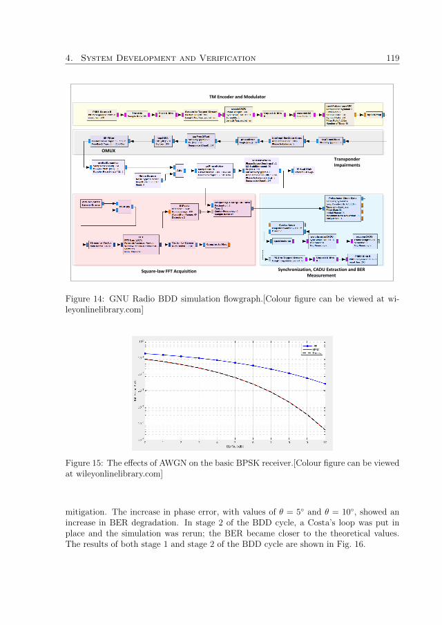
4. System Development and Verification 119
Square-law FFT Acquisition Synchronization, CADU Extraction and BER Measurement
TM Encoder and Modulator
Transponder Impairments
OMUX
Figure 14: GNU Radio BDD simulation flowgraph.[Colour figure can be viewed at wi-leyonlinelibrary.com]
Figure 15: The effects of AWGN on the basic BPSK receiver.[Colour figure can be viewedat wileyonlinelibrary.com]
mitigation. The increase in phase error, with values of θ = 5◦ and θ = 10◦, showed anincrease in BER degradation. In stage 2 of the BDD cycle, a Costa’s loop was put inplace and the simulation was rerun; the BER became closer to the theoretical values.The results of both stage 1 and stage 2 of the BDD cycle are shown in Fig. 16.

120 Paper B
Figure 16: The effects of phase step and phase noise.[Colour figure can be viewed atwileyonlinelibrary.com]
The effects of carrier frequency offset
Carrier frequency offset was used during the development and verification of a coursecarrier acquisition circuit. Carrier frequency offset is a combination of satellite, TT&Cstation and SDR frontend oscillator offsets, as well as orbital dynamics effects (Dopplershift and rate). Since carrier recovery involves both course and fine frequency recovery,stage 1 of the BDD cycle involves the simulation of the BPSK receiver presented insection 4.1 in the presence of frequency offsets above the acquisition range of the Costa’sloop. As expected, the Costa’s loop was not able to lock, and BER characterizationwas not possible. Stage 2 of the BDD cycle involves the placement of the square-LawFFT unit for course frequency recovery. As shown in Fig. 17, the square-law FFT coursefrequency acquisition unit is able to extract the carrier from a noisy signal and use thederived carrier to center the received signal around baseband. The BER characterizationfor three common cases of frequency offset: less than 10% of, approximately equal to,and larger than symbol rate are shown in Fig. 18
The effects of timing offsets
Timing offsets were used during the development and verification of the symbol timerecovery block. Timing offsets accounts for the clock instabilities of the satellite TMmodulator and the SDR frontend. Timing offset manifests itself as the spreading of thesignal constellation. Stage 1 of the BDD cycle involves the simulation of the basic receiverpresented in 4.1 in the presence of time offset without the symbol time recovery block.As expected, the increase in symbol time offset, e.g. 10ppm and 100ppm, resulted intoan increase in BER degradation. During stage 2 of the BDD cycle, the polyphase filterbank time recovery block[30] was put in place and the simulation was rerun. The resultsof both stages of the BDD cycle are shown in Fig. 19.

4. System Development and Verification 121
Figure 17: A GNU Radio plot showing course carrier frequency recovery by the square-law FFT unit at carrier power to noise spectral density of C/No = 68.01 dB−Hz.[Colourfigure can be viewed at wileyonlinelibrary.com]
Figure 18: The effects of carrier frequencyoffset .[Colour figure can be viewed at wi-leyonlinelibrary.com]
Figure 19: The effects of timing off-sets.[Colour figure can be viewed at wiley-onlinelibrary.com]
The effects of SSPA nonlinear distortions
The effects of SSPA distortions were considered to check whether a functional blockis required for compensating the impairment. The SSPA nonlinearity causes spectralregrowth in both linear and compression regions as shown in Fig. 20. Stage 1 of the BDDcycle involved the simulation of the basic BPSK receiver when the SSPA was operatingin compression region, e.g., at input back-off (IBO) = -3 dB. As expected, there wasBER degradation, with maximum loss of 1 dB. This effect can be mitigated by eithera pre-distorter at the satellite or a nonlinear equalizer at the ground station. However,since the SSPA is expected to operate in the linear region, neither of these blocks neededto be implemented. Therefore, Stage 2 of the BDD cycle merely involved the verificationof BER performance when the SSPA operates in the linear region, e.g., IBO = -10 dB.In this region, the maximum BER loss was less than 0.5 dB. The performance results forboth stage 1 and 2 of the BDD cycle are reported in Fig. 22.

122 Paper B
Figure 20: GNU Radio plot showing spectral regrowth at different values of IBO.[Colourfigure can be viewed at wileyonlinelibrary.com]
The effects of OMUX group delay distortion
The group delay distortion of the OMUX was used during the development and verifi-cation of the linear equalizer. Stage 1 of the BDD cycle involves the simulation of thebasic BPSK receiver of section 4.1 when an OMUX is introduced to filter out-of-bandemissions caused by the SSPA spectral regrowth, as shown in Fig. 21. As expected, theSSPA introduced linear distortions that a matched filter alone is unable to cope with.During stage 2 of the BDD cycle, a PFB symbol time synchronizer and a CMA equalizerwere put in place, and the simulation was rerun under different SSPA operating regions.As shown in Fig. 23, the combination of the PFB and CMA blocks was able to mitigatethe effects of the OMUX group delay distortion with performance loss of 0.8 and 1.4 dBfor linear and nonlinear SSPA regions, respectively.
Figure 21: GNU Radio plot showing OMUX filter with the SSPA at IBO = -3dB.[Colourfigure can be viewed at wileyonlinelibrary.com]

4. System Development and Verification 123
Figure 22: BER degradation caused bySSPA nonlinearity at different IBO val-ues.[Colour figure can be viewed at wiley-onlinelibrary.com]
Figure 23: BER degradation due to thecombined effect of the OMUX and theSSPA at different IBO values.[Colour figurecan be viewed at wileyonlinelibrary.com]
The effects of I/Q-imbalance
The I/Q imbalance is introduced into the channel by the modulator at the satellite andthe SDR frontend in order to examine the need for a functional block to mitigate the I/Qbranches interference. Stage 1 of the BDD cycle involved the simulation of basic BPSKreceiver under I/Q imbalance and without any mitigation measures. As expected forthe case of BPSK, I/Q imbalance causes minimal BER degradation as shown in Fig. 24,hence no mitigation technique was included.
Figure 24: The effects of I/Q-Imbalance.[Colour figure can be viewed atwileyonlinelibrary.com]
Figure 25: The combined effect of all chan-nel impairments on bit error rate.[Colourfigure can be viewed at wileyonlineli-brary.com]
The effect of all channel impairments
After the simulation of each impairment, the simulator was used to evaluate the combinedeffect of all impairments summarized in Table 1. The combined effect is observed by
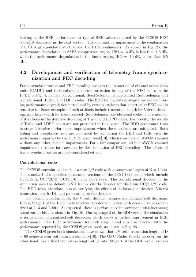
124 Paper B
looking at the BER performance at typical SNR values required by the CCSDS FECcodes[19] discussed in the next section. The dominating impairment is the combinationof OMUX group-delay distortion and the HPA nonlinearity. As shown in Fig. 25, theperformance degradation at SSPA compression region, IBO = -3 dB, is less than 1.5 dB,while the performance degradation in the linear region, IBO = -10 dB, is less than 0.5dB.
4.2 Development and verification of telemetry frame synchro-nization and FEC decoding
Frame synchronization and FEC decoding involves the extraction of channel access dataunits (CADU) and their subsequent error correction by any of the FEC codes in theFFBD of Fig. 4, namely convolutional, Reed-Solomon, concatenated Reed-Solomon andconvolutional, Turbo, and LDPC codes. The BDD failing tests in stage 1 involve monitor-ing performance degradation introduced by certain artifacts that a particular FEC code issensitive to. Some examples of such artifacts include truncation length for Viterbi decod-ing, interleave depth for concatenated Reed-Solomon convolutional codes, and a numberof iterations in the iterative decoding of Turbo and LDPC codes. For brevity, the resultsof Turbo and LDPC codes are not presented in this paper. The BDD acceptance testsin stage 2 involve performance improvement when these artifacts are mitigated. Bothfailing and acceptance tests are confirmed by comparing the BER and FER with theperformance reported by the CCSDS green book[19], which considers an AWGN channelwithout any other channel impairments. For a fair comparison, all but AWGN channelimpairment is taken into account by the simulation of FEC decoding. The effects offrame synchronization are not considered either.
Convolutional code
The CCSDS convolutional code is a rate-1/2 code with a constraint length of K = 7 bits.The standard also specifies punctured versions of the CC(7,1/2) code, which includeCC(7,2/3), CC(7,3/4), CC(7,5/6), and CC(7,7/8). The convolutional decoder in thesimulation uses the default GNU Radio Viterbi decoder for the basic CC(7,1/2) code.The BDD tests, therefore, aim at verifying the effects of decision quantization, Viterbitruncation length (D), and puncturing on the decoder.
For optimum performance, the Viterbi decoder requires unquantized soft decisions.Hence, Stage 1 of the BDD cycle involves decoder simulation with decision values quan-tized at 1, 3 and 6 bits. As expected, there is performance improvement with increasingquantization bits, as shown in Fig. 26. During stage 2 of the BDD cycle, the simulationis rerun under unquantized soft decisions, which shows a further improvement in BERperformance. The BER performance for both stage 1 and 2 is also checked with theperformance reported by the CCSDS green book, as shown in Fig. 26.
The CCSDS green book simulations have shown that a Viterbi truncation length of D= 60 achieves near optimum performance[19]. The GNU Radio Viterbi decoder, on theother hand, has a fixed truncation length of 32 bits. Stage 1 of the BDD cycle involves

4. System Development and Verification 125
the simulation and verification of FER performance for different frame lengths. As shownin Fig. 26, the GNU Radio Viterbi experiences minimal performance degradation. Sincethe truncation length is fixed, no mitigation measures should be taken in stage 2 of theBDD cycle.
Figure 26: The BER and FER performance of the GNU Radio CC(7,1/2) decoder com-pared with results obtained from the CCSDS green book[19].[Colour figure can be viewedat wileyonlinelibrary.com]
The CCSDS puncture matrices for the basic CC(7,1/2)[24] code are shown in table2[26].The GNU Radio puncture and depuncture blocks expect an equivalent puncture patternand size, which are also shown in the table. Stage 1 of the BDD cycle involves BER andFER simulations for the punctured codes. Fig. 27 shows the performance of the GNURadio punctured codes compared with the performance specified by the CCSDS greenbook[19], where the BER performance degradation of 2.4 dB between the CC(7,1/2) andCC(7,7/8) is confirmed. Since puncturing is an FEC feature rather than an impairment,no mitigation measures are required by stage 2 of the BDD cycle.
Table 2: Puncturing matrices
Puncture matrix Code rate GNU Radio Puncture Pattern GNU Radio Puncture size
M =
[1 01 1
]r = 2
31101 = 0xD 4
M =
[1 0 11 1 0
]r = 3
4110110 = 0x36 6
M =
[1 0 1 0 11 1 0 1 0
]r = 5
61101100110 = 0x366 10
M =
[1 0 0 0 1 0 11 1 1 1 0 1 0
]r = 7
811010101100110 = 0x3566 14

126 Paper B
Figure 27: The BER and FER performance of the GNU Radio CC(7,1/2) punctureddecoder compared with results obtained from the CCSDS green book[19].[Colour figurecan be viewed at wileyonlinelibrary.com]
Reed-Solomon code
The BDD tests for Reed-Solomon codes involve comparing the BER and FER perfor-mance with the CCSDS green book[19]. As for the case of the CCSDS green book[19],the simulation was run with an interleave depth of I = 1. In this case, WER is the sameas FER. The performance of the developed Reed-Solomon decoder is reported in Fig. 28.
Concatenated Reed-Solomon and convolutional code
The first BDD failing test for concatenated Reed-Solomon and convolutional code wascomparing BER with the CCSDS green book[19].The BER test was simulated for fullRS(255,223) and shortened RS(255,239) with an interleave depth of I = 16. The BERperformance of the decoder is close to the CCSDS performance as reported by the curvesin Fig. 29.
Unlike Reed-Solomon codes, the WER of concatenated Reed-Solomon codes is sensi-tive to finite interleaving. The second BDD failing test, therefore, involved performanceverification under finite interleaving. The performance criteria used is WER under in-terleave depth of I = 5. The performance curves for full RS(255,223) and RS(255,239)compared with the CCSDS green book[19] are shown in Fig. 30.
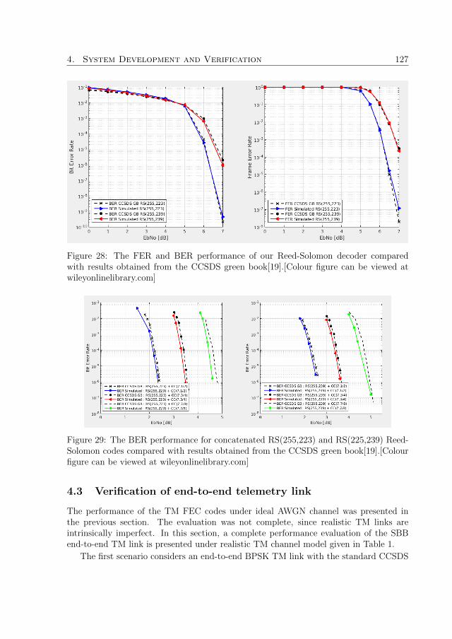
4. System Development and Verification 127
Figure 28: The FER and BER performance of our Reed-Solomon decoder comparedwith results obtained from the CCSDS green book[19].[Colour figure can be viewed atwileyonlinelibrary.com]
Figure 29: The BER performance for concatenated RS(255,223) and RS(225,239) Reed-Solomon codes compared with results obtained from the CCSDS green book[19].[Colourfigure can be viewed at wileyonlinelibrary.com]
4.3 Verification of end-to-end telemetry link
The performance of the TM FEC codes under ideal AWGN channel was presented inthe previous section. The evaluation was not complete, since realistic TM links areintrinsically imperfect. In this section, a complete performance evaluation of the SBBend-to-end TM link is presented under realistic TM channel model given in Table 1.
The first scenario considers an end-to-end BPSK TM link with the standard CCSDS

128 Paper B
Figure 30: The WER performance for concatenated RS(255,223) and RS(225,239)I = 5 Reed-Solomon codes compared with results obtained from the CCSDS greenbook[19].[Colour figure can be viewed at wileyonlinelibrary.com]
CC(7,1/2) convolutional code with performance curves depicted in Fig. 31. The Viterbialgorithm is sensitive to imperfect carrier synchronization, i.e. tracking phase jitter,which for our case, is introduced by the Costa’s loop[43]. The loop phase error processis Tikhonov-distributed and its variance is inverse proportional to Eb/No; a fact thatcould explain the poor performance at Eb/No below 2 dB. It can be seen from Fig. 31that the SBB’s BER and FER performance curves under all impairments are within 0.5dB of the corresponding CCSDS Green Book curves under AWGN alone.
In the second scenario, we consider an end-to-end BPSK TM link with the standardRS(255,223) and RS(255,239) CCSDS Reed-Solomon codes with performance curves de-picted in Fig. 32. The performance of Reed-Solomon codes are directly dependent onthe performance of the underlying modulation scheme, which is BPSK link in this case.From Fig. 25, the performance degradation of the BPSK link in the region of interestfor Reed-Solomon codes is around 0.5 dB for an IBO of -10 dB. This performance losstranslates into an end-to-end performance degradation of less than 0.5 dB.
In the third scenario, we consider an end-to-end BPSK TM link with concatenatedCCSDS RS(255,223) and RS(255,239) Reed-Solomon codes as well as the unpuncturedCCSDS CC(7,1/2) convolutional code. The Eb/No region of interest for the CCSDSReed-Solomon families is larger than 5 dB, while that of the CCSDS CC(7,1/2) is largerthan 4 dB. From the BER and WER curves in Figs. 29 and 30, the region of interest forthe concatenated and unpunctured CCSDS CC(7,1/2) is around 1.5 - 2.5 dB, a regionseverely affected by tracking phase jitter. The SBB’s performance has been comparedwith specified CCSDS performance with Reed-Solomon code interleave depth set to I =1. In this configuration, Reed-Solomon WER is equivalent to FER. The RS(255,223)concatenated code suffers a maximum BER and FER degradation of 1 dB, and theRS(255,239) concatenated code suffers a maximum BER and FER degradation of 0.6dB.

4. System Development and Verification 129
Figure 31: The end-to-end BER and FER performance for CC(7,1/2) code comparedwith results obtained from the CCSDS green book[19].The frame length used is L = 8920bits, corresponding to RS(255,223) with interleave depth I = 5. [Colour figure can beviewed at wileyonlinelibrary.com]
Figure 32: The end-to-end BER and FER performance for RS(255,223) andRS(225,239) Reed-Solomon codes compared with results obtained from the CCSDS greenbook[19].[Colour figure can be viewed at wileyonlinelibrary.com]
4.4 Development and verification of telecommand link
The TC link for the bit modulation block, Fig. 12, including line coding, constellationmapping, pulse shaping and I/Q modulation, was simultaneously developed and verifiedas part of the TM link BDD process in Secs. 4.1 and 4.2.
The verification of figures of merit for TC, including output power, transmitter EVM,

130 Paper B
Figure 33: The end-to-end BER and FER performance for Concatenated RS(255,223)and RS(255,239) + CC(7,1/2) code compared with results obtained from the CCSDSgreen book[19]. [Colour figure can be viewed at wileyonlinelibrary.com]
and frequency stability, are highly dependent on the SDR frontend hardware. Therefore,the verification of TC link should be done on a hardware basis.
5 Conclusion
A new approach, based on the behavior-driven development (BDD) methodology, wasintroduced to the concurrent development and verification of SDR-based baseband (SBB)systems for satellite ground operations. An open-source GNU Radio development kitwas used for the SBB system synthesis and analysis. The BDD tests were performed byintroducing channel impairments to the TM and TC blocks, and proper codes were thencreated to pass the acceptance tests. The SBB system performance at the end showsdegradations within 1 dB of the performance recommended by the CCSDS Green Bookstandards. The developed system has a potential to transform the business model for theground operations, due to its scalability, extensibility, flexibility and cost-effectiveness.Therefore, It would be possible to replace the costly state-of-the-art baseband systemswith a private cloud and affordable SDR frontends. But, before the verified design isused in real-life TT&C operations, extensive hardware-in-the-loop simulations must beconducted. The next step in our work is, therefore, running simulations that include asatellite ”suitcase” as well as orbiting spacecraft.

6. Acknowledgments 131
6 Acknowledgments
The authors would like to thank the Swedish Space Corporation (SSC) for the assistancein some of the technical works of this study. The funding provisions by the SwedishNational Space Agency (SNSA), the SSC, and Rymd for Innovation och Tillvaxt (RIT)are also acknowledged.

132 Paper B
References
[1] P. J. N, M. Scott, and C.-L. Sergio, Handbook of Satellite Applications. Springer,2nd ed., 2012.
[2] G. Maral and M. Bosquet, Satellite Communication Systems. WILEY, fifth ed.,2009.
[3] E. Grayver, Implementing Software Defined Radio. Springer New York HeidelbergDordrecht London, 2013.
[4] Consultative Committee for Space Data Systems (CCSDS), Radio frequency andmodulation systems - Part 1 Earth stations and spacecraft. No. 401.0-B-26 in BlueBook, Washington DC: CCSDS Secretariat, National Aeronautics and Space Ad-ministration , Oct 2016.
[5] GNURadio, “Gnuradio.” https://www.gnuradio.org/, 2018.
[6] J. . Friedt, “Gnuradio as a digital signal processing environment: Application toacoustic wireless sensor measurement and time and frequency analysis of periodicsignals,” Joint European Frequency and Time Forum International Frequency Con-trol Symposium (EFTF/IFC), pp. 278–281, July 2013.
[7] A. Al-safi, L. Narasimhan, and B. Bazuin, “Design and implementation of proto-type potable base station for catastrophic situation,” IEEE 7th Annual UbiquitousComputing, Electronics Mobile Communication Conference (UEMCON), pp. 1–6,Oct 2016.
[8] X. Wenhao, L. Lun, T. Xin, P. Khanh, B. Erik, C. Genshe, W. Gang, and S. Dan,“Sdr-based adaptive waveform tool with efficient channel estimation for satcomsystems,” International Communications Satellite Systems Conferences (ICSSC),American Institute of Aeronautics and Astronautics, Oct 2016.
[9] N. Hu and Y. Yao, “Radio access behavior (rab) based cognitive radio classifica-tion and identification,” IEEE International Conference on Communications (ICC),pp. 5588–5592, June 2012.
[10] M. Mwakyanjala, R. Emami, and J. van de Beek, “Software-defined radio transceiverfor qb50 cubesat telemetry and telecommand,” International Communications Satel-lite Systems Conferences (ICSSC), American Institute of Aeronautics and Astronau-tics, Oct 2016.
[11] M. R. Maheshwarappa and C. P. Bridges, “Software defined radios for small satel-lites,” NASA/ESA Conference on Adaptive Hardware and Systems (AHS), pp. 172–179, July 2014.

References 133
[12] A. Thomas, J.-M. Leveau, and S. Augarde, “Study of a full software ccsds receiver,”SpaceOps Conferences, American Institute of Aeronautics and Astronautics, May2018.
[13] A. Tkacenko, M. J. Kilzer, M. D. Chase, S. C. Clancy, H. Xie, J. L. Torgerson,and G. J. Miles, “Variable coded modulation (vcm) cognitive radio higher-orderconstellation receiver operation,” The Interplanetary Network Progress Report, pp. 1– 22, may 2018.
[14] J. Penn, “Testability, test automation and test driven development for the tricksimulation toolkit,” AIAA SciTech Forum, American Institute of Aeronautics andAstronautics, Jan 2014.
[15] S. Berge, A. Edfors, T. Olsson, and B.Lubke-Ossenbeck, “Advanced aocs designon the first small geo telecom satellite,” 60th International Astronautical Congress,2009.
[16] M. Kuhrmann, J. Munch, P. Diebold, O. Linssen, and C. R. Prause, “On the useof hybrid development approaches in software and systems development: construc-tion and test of the helena survey,” in Lecture Notes in Informatics (M. Engstler,M. Fazal-Baqaie, E. Hanser, O. Linssen, M. Mikusz, and A. Volland, eds.), (Bonn),pp. 59–68, Gesellschaft fur Informatik e.V., 2016.
[17] K. Beck, Test-driven development by example. Addison-Wesley Signature Series,Addison-Wesley Professional, 2002.
[18] D. Lubke and T. van Lessen, “Modeling test cases in bpmn for behavior-drivendevelopment,” IEEE Software, vol. 33, pp. 15–21, Sep. 2016.
[19] Consultative Committee for Space Data Systems (CCSDS), TM Synchronization andchannel coding-Summary of concept and rationale. No. 130.1-G-2 in Green Book,Washington DC: CCSDS Secretariat, National Aeronautics and Space Administra-tion , Nov 2012.
[20] Consultative Committee for Space Data Systems (CCSDS), Radio frequencyand modulation systems - spacecraft-earth station compatibility test procedures.No. CCSDS 412.0-G-1 in Green Book, Washington DC: CCSDS Secretariat, Na-tional Aeronautics and Space Administration , May 1992.
[21] J. Vila, J. Manuel Cebrian, J. Batlle, T. Carles, I. Vega, S. Marti, and L. Santos,“Next generation of integrated modem and baseband unit (imbu mk-iv) groundsegment validation tool,” SpaceOps Conferences, American Institute of Aeronauticsand Astronautics, May 2018.
[22] Consultative Committee for Space Data Systems (CCSDS), BANDWIDTH-EFFICIENT MODULATIONS : SUMMARY OF DEFINITION, IMPLEMENTA-TION, AND PERFORMANCE. No. 413.0-G-3 in Green Book, Washington DC:CCSDS Secretariat, National Aeronautics and Space Administration , Feb 2018.

134 Paper B
[23] Deep Space Network, Telemetry Data Decoding. No. 208 in DSN No. 810-005-208,Rev. B, California: Jet Propulsion Laboratory California Institute of Technology ,2013.
[24] Consulative Committee for Space Data Systems (CCSDS), TM Synchronization andChannel Coding. No. 131.0-B-2 in Blue Book, Washington DC: CCSDS Secretariat,National Aeronautics and Space Administration , 2011.
[25] Consulative Committee for Space Data Systems (CCSDS), TC Synchronization andChannel Coding. No. 231.0-B-2 in Blue Book, Washington DC: CCSDS Secretariat,National Aeronautics and Space Administration , 2010.
[26] M. B. Mwakyanjala, M. R. Emami, and J. van de Beek, “Functional analysis ofsoftware-defined radio baseband for satellite ground operations,” Journal of Space-craft and Rockets, pp. 1–18, Jan 2019.
[27] M. Rice, Digital Communications: A Discrete-Time Approach. Prentice Hall, UpperSaddle River, New Jersey 07458, United States, 1 ed., 2008.
[28] J. Roberson, E. Valles, K. Tarasov, E. Grayver, and K. King, “A flexible softwarebased emwin/hrit prototype solution for the goes-r transition,” Tech. Rep. ATR-2010(5482)-1, GOES-R Program Office National Oceanic and Atmospheric Admin-istration, oct 2009.
[29] A. N. D’Andrea, U. Mengali, and R. Reggiannini, “A digital approach to clockrecovery in generalized minimum shift keying,” IEEE Transactions on VehicularTechnology, vol. 39, pp. 227–234, Aug 1990.
[30] F. J. Harris and M. Rice, “Multirate digital filters for symbol timing synchronizationin software defined radios,” IEEE Selected Areas in Communications, pp. 2346 –2357, dec 2001.
[31] D. Godard, “Self-recovering equalization and carrier tracking in two-dimensionaldata communication systems,” IEEE Transactions on Communications, vol. 28,pp. 1867–1875, November 1980.
[32] Y. Gao and X. Qiu, “A new variable step size cma blind equalization algorithm,”24th Chinese Control and Decision Conference (CCDC), pp. 315–317, May 2012.
[33] European Telecommunications Standards Institute, Digital Video Broadcasting(DVB);Implementation guidelines for the second generation system for Broadcasting,Interactive Services, News Gathering and other broadband satellite applications;Part2: S2 Extensions (DVB-S2X). No. ETSI TR 102 376-2 V1.1.1 (2015-11) in EuropeanStandard (Telecommunications series), Valbonne France: European Telecommuni-cations Standards Institute , 2015.

135
[34] N. Mazzali, S. Boumard, J. Kinnunen, B. S. M. R., M. Kiviranta, and N. Alagha,“Enhancing mobile services with dvb-s2x superframing,” International Journal ofSatellite Communications and Networking, vol. 36, no. 6, pp. 503–527, 2018.
[35] G. E. Corazza, Digital Satellite Communications (Information Technology: Trans-mission, Processing and Storage). Springer, 1 ed., 2007.
[36] R. Svitek and S. Raman, “Dc offsets in direct-conversion receivers: Characterizationand implications,” IEEE Microwave magazine, 2005.
[37] E. Grayver, Implementing Software Defined Radio. Springer New York HeidelbergDordrecht London, 2013.
[38] ConsulTative Committee for Space Data Systems (CCSDS), CCSDS Cross SupportReference Model- Part 1: Space Link Extension Services. No. CCSDS 910.4-B-2 inBlue Book, Washington DC: CCSDS Secretariat, National Aeronautics and SpaceAdministration , Oct 2005.
[39] J. W. M. Bergmans, Digital Baseband Transmission and Recording. Springer,Boston, MA, 1 ed., 1996.
[40] S. Nelson-Smith, Test-Driven Infrastructure with Chef. Sebastopol, USA: O’ReillyMedia Inc., second ed., 2013.
[41] L. Madeyski, Test-Driven Development: An Empirical Evaluation of Agile Practice.Springer-Verlag Berlin Heidelberg, 1 ed., 2010.
[42] M. Fowler and K. Beck, Refactoring: Improving the design of existing code. Boston,USA: Addison-Wesley Professional, second ed., 2018.
[43] J. H. Y. e. Joseph H. Yuen (auth.), Deep Space Telecommunications Systems Engi-neering. Applications of Communications Theory, Springer US, 1 ed., 1983.

136

Paper C
Validation of a software-definedbaseband system for satellitetelemetry and telecommand
Authors:Moses B. Mwakyanjala, Jaap van de Beek and Elcio Jeronimo de Oliveira
Reformatted version of paper submitted to:International Journal of Satellite Communications and Networking
c© 2020 John Wiley & Sons, Ltd., Reprinted with permission.
137

138

Validation of a software-defined baseband system for
satellite telemetry and telecommand
Moses B. Mwakyanjala, Jaap van de Beek and Elcio Jeronimo de Oliveira
Abstract
This paper presents the validation of a software-defined baseband (SDB) system forsatellite telemetry and telecommand (TM/TC). The baseband system was developedusing the open-source GNU Radio development kit. It runs on a personal computerconnected to a commercial-off-the-shelf (CoTS) RF frontend. The validation processwas performed by the use of a mission-qualified satellite emulator, a state-of-the-artbaseband unit, and orbiting satellites. The baseband is designed to offer multimissionsupport. Hence it includes a suite of modulation schemes, line codes, matched filters, andCCSDS forward error correction codes (convolutional, Reed-Solomon, concatenated, andlow-density parity-check (LDPC)) typically employed in TM/TC missions. The figuresof merit used for the validation of the TM receiver are bit error rate (BER) and frameerror rate (FER). For the TC transmitter, the validated features are modulation index,power spectrum, and the physical layer operations procedures (PLOP).
1 Introduction
Satellite telemetry and telecommand (TM/TC) is a crucial part of every space mission.It involves the gathering, collection, and processing of spacecraft onboard data to en-sure the unerring operation of the satellite[1]. Typically, the TM/TC subsystem aboarda satellite includes one or more transponders associated with quasi-omnidirectional an-tennas to ensure RF link availability from the ground[2]. The TM/TC system on theground typically includes a baseband system, a device that performs radio functions in-cluding transmission, reception, and forward error correction (FEC). In this paper, wepresent the validation of a low-cost software-defined baseband (SDB) system developedusing the open-source GNU Radio software-defined radio (SDR) development kit[3]. TheSDB system runs on a standard Linux computer connected to the Ettus USRP X310[4]commercial-off-the-shelf (CoTS) RF frontend. The SDB system is primarily optimizedfor Consultative Committee for Space Data Systems (CCSDS) category A (less than 2million kilometers) missions operating in S-band.
Reliability is a paramount feature of any baseband system involved in TM/TC groundoperations. To achieve reliability for the SDB system, the authors begun with an exten-sive analysis of the functional design, which was presented in a previous work[5]. This wasfollowed by the verification process which involved extensive simulations, evaluation, andoptimization of the SDB system performance. A small part of this verification process,
139
140 Paper C
which was done for binary phase-shift keying (BPSK) and several CCSDS FEC codes,was presented by the authors in another work[6]. The next step required to ensure thereliability of the SDB system is validation, a process that is carried out on a laboratorytestbed and orbiting satellites and is the subject of this paper. In the validation cam-paign, the SDB system was subjected to a suite of validation tests that were agreed uponafter a discussion with different stakeholders including satellite operators and TM/TCtransponder manufacturers. The suite of validation tests is based on standard industrialsatellite-ground station compatibility tests such as those presented by Yang et al[7]. Itshould be noted that the TM and TC communication links have different requirementsand hence different validation tests, as shown in Fig. 1. The validation tests on the TCtransmitter include the characterization of modulation index, power spectrum, and theend-to-end validation of the physical layer operations procedures (PLOP). The validationtests on the TM receiver include bit error rate (BER) for bit synchronization and frameerror rate (FER) characterization for CCSDS FEC codes[8].
The hardware testbed consists of a state-of-the-art (SoTA) baseband unit, a satelliteemulator, a spectrum analyzer, and a 70 Mhz IF interface connected to an antennaswitch matrix that enables communication with orbiting satellites. The testbed wasconfigured for two separate setups for TM receiver and TC transmitter validation. Forthe TM receiver validation, the output of the SoTA baseband was connected to the inputport of the SDB system. On the other hand, the SDB TC transmitter was validatedby directly connecting the output of the SDB system to a spectrum analyzer for thecharacterization of modulation index and power spectrum. The end-to-end validation ofthe TC transmitter PLOP function was performed by connecting the output of the SDBsystem to the satellite emulator.
To the best of our knowledge, most of the publicly available literature sources thatdetail the performance of TM/TC basebands do not take into account realistic channelconditions encountered in TM/TC links. Thus, they do not address the related synchro-nization issues. Baldi et al. presented the performance evaluation of the new TC codingoptions in additive white Gaussian noise (AWGN)[9] and jamming channels[10]. Bothscenarios assumed perfect synchronization. The continuation work by Baldi et al.[11]presented the performance of TM/TC links in a channel with solar scintillations. Thiswork also assumed perfect synchronization.The final work by Baldi et al on the topicemploys the ENTRust simulator that takes into account channel impairments includingorbital, plasma, and AWGN[12]. An extensive analysis of loop bandwidth optimization ispresented. However, the work does not involve a physical hardware-based testbed. Thus,it does not consider the effects of hardware tolerances and their effects on synchroniza-tion. Mwakyanjala et al.[6] presented the evaluation of TM receiver performance undersimulated channel conditions. This evaluation did not involve a laboratory testbed, andthus it did not fully capture the synchronization issues. An elaborate evaluation of low-density parity-check (LDPC) and Turbo decoders for a TM receiver was presented byAndrews et al. [13]. The evaluation was performed on an FPGA-based testbed at theNASA’s Jet Propulsion Laboratory (JPL). Similarly, this work considered only AWGN.Thus, none of the issues related to synchronization were presented.

1. Introduction 141
Propagation Channel
TelemetryFEC encoder
and Modulator
Telecommand Demodulator
and FEC Decoder
RF ReceiverRF
Transmitter
RF Transmitter
RFReceiver
The SDB TM
Demodulator and FEC Decoder
The SDB TC FEC
Encoder and Modulator
Applications Applications
SDR FrontendUSRP X310
TM Transponder
TC Transponder
Satellite TM/TC
Transponders
Figure 1: Block diagram of the SDB system. The system runs on a Linux computer. TheSDR frontend, Ettus USRP X310, interfaces the system with the RF environment, whichis typically an IF port connected to a TM/TC antenna. The TC transmitter performancewas validated by the characterization of modulation index, power spectrum, and the end-to-end validation of the physical layer operations procedures (PLOP). On the other hand,the TM receiver performance was validated by BER and FER characterization.[Colourfigure can be viewed at wileyonlinelibrary.com]
In this paper, we present the validation campaign of the SDB TC transmitter andTM receiver on a laboratory testbed that emulates realistic channel conditions in S-bandTM/TC links along with impairments associated with low-cost CoTS RF frontends. Weshow that the power spectrum from the SDB transmitter radiating from the CoTS RFfrontend conforms to theoretical models. Characterization of the TC transmitter modu-lation index results in curves that are very close to theoretical models. Using the satelliteemulator, we demonstrate that the TC transmitter can transmit the PLOP carrier mod-ulation modes (CMMs) as expected. We also show that, after extensive optimizationof synchronization parameters to account for channel impairments, in particular Costasloop bandwidth, the performance of the SDB TM receiver receiving from the CoTS RFfrontend is within 1 dB of ideal performance for uncoded BPSK when an optimum Costasloop bandwidth from 0.15% to 0.5% of the symbol rate is employed. For coded BPSK,the performance is compared to CCSDS Green Book curves[14]. We show that this is

142 Paper C
within 1 dB for the Reed-Solomon code, 2 dB for the convolutional code, and 2 dB forconcatenated codes. Through simulations, we show that the SDB LDPC decoder per-forms comparably to the CCSDS reference decoder. In this work, we do not take intoaccount the validation of Turbo codes. This can be found in Baldi et al.[11] and Andrewset al.[13]. Finally, we show that the SDB is capable of operating in a realistic TM/TCscenario by communicating with three different orbiting satellites.
The paper is organized into six sections. Section 2 presents an overview of the SDBfunctional analysis and the hardware testbed. Section 3 presents the validation method-ology for the SDB TC transmitter. Section 4 covers the validation methodology for theSDB TM receiver for coded and uncoded BPSK. Section 5 presents field validation of theSDB TM receiver by a suite of orbiting satellites tracked from the Esrange Space Stationin Kiruna, Sweden. Section 6 concludes the paper.
2 SDB functional analysis and the hardware testbed
In this section, we present the functional analysis of the SDB system and the hardwaretestbed. The functional analysis presents the functional breakdown of the TM/TC radiofunctions that compose the SDB system. The testbed covers the laboratory setup thatwas used during the validation campaign.
2.1 SDB functional analysis
The SDB system is designed to support multiple TM/TC missions. For that reason,the TC transmitter supports three modulation schemes for what CCSDS defines as low-,medium-, and high-rate modulations. These are PCM/PSK/PM, PCM/PM, and BPSKwith maximum bit rates of 4000 bps, 256000 bps, and 2.048 Mbps[15] respectively. TheTM receiver supports multiple modulation schemes including BPSK, quadrature phase-shift keying (QPSK), offset QPSK (oQPSK), pulse code modulation/frequency and phasemodulations (PCM/PM, PCM/FM), and Gaussian minimum shift keying (GMSK)[16].The TM receiver also supports several matched filters including square-root-raised co-sine (SRRC), raised cosine (RC), and integrate-and-dump (IDF) filters. Two variations ofline codes commonly used in satellite TM/TC[17]; non-return-to-zero-level/mark/space(NRZ-L/M/S) and biphase-L/M/S are supported by both the TM receiver and the TCtransmitter. The functional breakdown of the SDB is summarized in Fig. 2. A morecomprehensive functional analysis of the SDB system, which includes telemetry, telecom-mand, and ranging was presented by the authors in a previous work[5].
The TC transmitter is illustrated in the upper part of Fig. 2. Telecommands arereceived by the MCC data transfer interface (Function 1.0). TC transfer is performed byAPIs native to the SDB system since CCSDS SLE transfer services[18], including forwardspace packet (FSP), forward TC virtual channel access (FTCVCA), forward TC frame(FTCF) as well as forward communications link transmission unit (FCLTU) have beenimplemented in a separate proprietary package. The received TCs are further processedby FEC and frame generation (Function 2.0) to generate channel link transfer units

2. SDB functional analysis and the hardware testbed 143
2.0
FEC and Frame Sync·Convolutional ·Frame Sync·Derandomizer·Reed-Solomon·Concatenated codes·Turbo·LDPC
1.0
Bit Synchronization·Hardware interface (e.g. USRP UHD)·Demodulation (M-ary PSK,PM,GMSK)·Filtering (SRRC,RF,IDF)·Synchronization (freq,time,phase)·Equalization (CMA)·Line decoding (NRZ-L/M/S and BP-L/M/S)
3.0
MCC Data Delivery InterfaceCCSDS SLENative API
1.0
MCC Data Transfer InterfaceCCSDS SLENative API
2.0
FEC and Frame Generation·Randomizer·BCH and LDPC Encoding·CLTU Generation
3.0
Bit Modulation·Line Coding (NRZ-L/M/S and BP-L/M/S)·Modulation (PCM/PSK/PM,PM,BPSK)·PLOP·Hardware Interface (e.g. USRP UHD)
Soft/Hard bits
CADU/TM
Frames
CLTUTC
Frames
SDB TELEMETRY RECEIVER
SDB TELECOMMAND TRANSMITTER
Figure 2: System Architecture[Colour figure can be viewed at wileyonlinelibrary.com]
(CLTU) after optional randomization and FEC encoding. The FEC codes specified inthe standard[19] are BCH and two families of LDPC codes namely LDPC(n=128,k=64)and LDPC (n=512,k=256). The encoded CLTUs are transferred to the bit modulationfunction (Function 3.0) for transmission to the spacecraft.
To maximize the acceptance rate of TCs, the CCSDS standard proposes the use ofan acknowledgment-based close-loop procedure referred to as the PLOP[19]. In this pro-cedure, the ground station transmits CMMs which the satellite acknowledges by sendingthe communications link control word (CLCW) NO RF AVAILABLE and NO BITLOCK flags. Upon the reception of CLTUs, the PLOP starts by transmitting an un-modulated carrier (CMM-1). When the satellite locks to the carrier, it transmits theNO RF AVAILABLE to the ground station. Upon the reception of the NO RFAVAILABLE flag, the ground station transmits an acquisition sequence (CMM-2) andoptionally an idle sequence (CMM-4). When the satellite bit synchronizer locks to theacquisition sequence, it transmits the NO BIT LOCK flag to the ground station. Uponthe reception of the NO BIT LOCK, the ground station transmits modulated CLTUs(CMM-3) and optionally the CMM-4 idle sequence. The operation of versions 1 and 2of the PLOP is illustrated in Fig. 3. The I/Q samples from the PLOP are transferred tothe hardware frontend through a hardware interface such as the Ettus UHD[20].
The lower part of Fig. 2 illustrates the functional design of the TM receiver. The firstfunctional unit (Function 1.0) summarizes the operations of the bit synchronizer. The I/Qsamples are received from a hardware interface such as the Ettus USRP Hardware Driver(UHD)[20]. The demodulation, synchronization, and equalization functions generate softsymbols, which are delivered to the CCSDS FEC decoding and frame synchronization[21]functions (Function 2.0). The supported FEC codes are convolutional, Reed-Solomon,concatenated, and C2 LDPC code. There is also an optional derandomizer, which canbe used to improve bit transition density. The frame synchronizer is based on finite statemachines (FSM) with SEARCH, CHECK, FLYWHEEL, and LOCK states as recom-

144 Paper C
Start OR CMM-1 CMM-2 CMM-3CMM-4 CMM-1CMM-4OR OR Finished? End
PLOPVERSION?
No
YesPLOP-2
PLOP-1
Figure 3: Signal sequence for the physical layer operations procedure versions 1 and2.[Colour figure can be viewed at wileyonlinelibrary.com]
mended by CCSDS standards[14]. The channel data access units (CADU)s extracted byFunction 2.0 are delivered to the mission control center (MCC) data delivery interface(Function 3.0) for delivery to the end-user. The delivery is performed by APIs native tothe SDB system. Similarly, the CCSDS space link extension (SLE) delivery services[18]including return all frames (RAF), return channel frames (RCF), return frame secondaryheader (RFSH), return operational control field (ROCF), and return space packet (RSP)have been implemented in another proprietary package.
2.2 Hardware testbed
The upper part of Fig. 4 illustrates the testbed setup for the SDB TC transmitter. TheSDB system runs on a Linux computer connected to the USRP X310 through an ether-net connection. The physical characteristics of the TC transmitter including modulationindex and power spectrum are validated by a spectrum analyzer connected to the outputport of the USRP X310. The TM receiver of the SoTA baseband unit is used to validatethe integrity of TC transfer frames transmitted by the SDB. The PLOP validation en-compasses validation of the entire TC transmitter chain, which is facilitated by the useof the satellite emulator compliant with CCSDS TC space link[22], TC synchronizationand FEC coding[19] as well as the command operations procedure (COP)[23].
The validation setup for the SDB TM receiver is illustrated in the lower part ofFig. 4. The TC transmitter of the SoTA baseband unit is used to emulate a satelliteTM transponder for BER and FER measurements. In addition to the generation ofTM transfer frames needed for BER and FER measurements, the baseband unit alsointroduces modulator I/Q imbalance, frequency instability and symbol rate offset aswould a realistic TM transponder (Txp). The baseband unit has an internal AWGNgenerator which sets the operating carrier power-to-noise spectral density (C/No) foraccurate BER and FER measurements. The baseband is also equipped with a frequencysweeping unit which has been repurposed to emulate Doppler shift and rate. A completelist of channel impairments considered during BER and FER measurements and theirsources are summarized in Table 1.

2. SDB functional analysis and the hardware testbed 145
TT&C Station IF Interface
USRP X310
State-of-the-artBaseband unit
Spectrum Analyzer
Satellite Emulator
TELEMETRY RECEIVER TEST SETUP
TELECOMMAND TRANSMITTER TEST SETUPTC SignalsThe
SDB system10 Gbe Eth
State-of-the-artBaseband unit
USRP X310 The SDB system
10 Gbe Eth
Spectrum Analyzer
RF Switch
TM Signals
Figure 4: The hardware testbed[Colour figure can be viewed at wileyonlinelibrary.com]
Table 1: Channel impairments introduced by the testbed during BER and FER mea-surements.
Impairments Baseband Unit SDR frontend ValueTxp Modulator I/Q imbalance X –Txp Frequency instability X –Txp Symbol rate offset X –Sweep range X ± 150 kHzSweep rate X ± 3 kHz/sAWGN X –SDR phase noise X –SDR clock instability X –SDR I/Q imbalance X –
In addition to BER and FER measurements by the baseband unit, the SDB sys-tem must be further validated against orbiting satellites. Thus, the hardware testbedincludes an IF interface to a parabolic dish antenna configured to receive signals fromorbiting S-band satellites. In this setup, the channel model includes transponder am-plifier nonlinearities, output multiplexer (OMUX) delay spread, symbol timing offsets,orbital dynamics for category A missions (e.g. Doppler shift and rate), TM/TC stationimpairments including phase noise, phase offset, and frequency offset. The impairmentsalso include SDR frontend distortions, including phase noise, I/Q-imbalance, and DCoffset[6].

146 Paper C
3 Laboratory validation of the telecommand trans-
mitter
The flowgraph used for the validation of the TC transmitter is illustrated in Fig. 5. On theleft side of the flowgraph, there are message strobes that generate TCs and CLCW NORF AVAILABLE and NO BIT LOCK flags[22]. The strobes generate messages after1, 5, and 10 seconds respectively. The TC Multiplexer block reformats the generated TCsinto valid TC transfer frames. The transfer frames are received by the PLOP block afterCLTU generation. Both PLOP-1 and PLOP-2 are supported. The CMM-1 and CMM-2check options specify whether the PLOP waits for NO RF AVAILABLE and NOBIT LOCK flags respectively. The waiting time is specified in seconds by the RF Setand Fall times respectively. The locations of the flags are specified by the respective byteoffsets and masks. The CMMs generated by the PLOP are modulated and transmitted bythe TC Modulator, which supports PCM/PSK/PM, PCM/PM, and BPSK modulations.The modulator provides sinusoid and square subcarriers for PCM/PSK/PM. To avoidinterference with ranging signals, the modulator provides the carrier frequency argument,which can be used to specify the center frequency of the TC signals.
NO BIT LOCK FLAG GENERATOR
NO RF AVAILABLE FLAG GENERATOR
TC Messages
Figure 5: GNU Radio flowgraph for the SDB TC transmitter.[Colour figure can be viewedat wileyonlinelibrary.com]
The suite of tests for validation of the TC transmitter includes the characterizationof the modulation index and the radiated power spectrum. The tests were performed fora PCM/BPSK/PM signal with a bit rate of 2000 bps and a 16000 Hz sinusoid subcarrier.The modulation index used was 1 radian.
3.1 Power spectrum characterization
Power spectrum characterization validates the ability of the SDB system to transmit asignal with accurate bit rate, carrier and subcarrier frequencies. The power spectrum ofthe PCM/BPSK/PM signal is given by the equation[24]
3. Laboratory validation of the telecommand transmitter 147
S (f) = PTJ20 (β) δ (f − fc) + PT
∑i Even
J2i (β) [δ (f − fc − ifsc) + δ (f − fc + ifsc)]+
PT
∑k Odd
J2k (β) [Sd (f − fc − kfsc) + Sd (f − fc + kfsc)] , f ≥ 0
(1)
where β is the modulation index, Jk (.) is the kth-order Bessel function, fc and fsc arecarrier and subcarrier frequency respectively. The power spectrum of the underlying linecode is presented by Sd (f) given by the equation[24]
Sd (f) =
{1Rs
sin2(πf/Rs)
(πf/Rs)2For NRZ− Shaped Data
1Rs
sin4(πf/2Rs)
(πf/2Rs)4For Biphase− Shaped Data
(2)
The first term in equation 1 represents the residual carrier, the second term representsintermodulation loss components, and the last term represents the data components. Formodulation indices between 0.1 and 1.5, the information is concentrated at the first Besselimage. For this reason, the significant intermodulation component is concentrated at thefirst even Bessel function i.e. i = 2. This is located at a frequency which is twicethe subcarrier frequency away from the residual carrier. Similarly, the significant datacomponent is concentrated at the first odd Bessel function i.e k = 1. This is located ata frequency that is one subcarrier frequency away from the residual carrier. The signalspectrum can be validated by comparing the theoretical spectrum predicted by equation1 with a signal transmitted by the SDB.
The upper part of Fig. 6 illustrates the theoretical signal spectrum from equation 1.The lower part Fig. 6 illustrates the signal spectrum when an acquisition sequence (CMM-2) was transmitted by the flowgraph of Fig. 5 and captured by a spectrum analyzer. Asexpected, both spectra show the 2000 bps data signal at 16000 Hz from the carrier. Theintermodulation loss components can be seen at 32000 Hz from the carrier, twice thesubcarrier frequency.
3.2 Modulation index characterization
The power and subcarrier components, Pc and Pd, can be directly derived from equation1. These are, respectively,
Pc = PTJ20 (β) (3)
Pd = 2PTJ21 (β) (4)
The remaining power represents the power in intermodulation components. The twoequations above demonstrate that power allocation is directly dependent on the modu-lation index, β. Thus, for power limited communication systems, the modulation indexrepresents the tradeoff between synchronization accuracy and achievable bit rate. There-fore, the modulation index of the SDB TC transmitter must be validated.

148 Paper C
Figure 6: Power spectra for PCM/PSK/PM signals. The upper figure illustrates the the-oretical power spectrum plotted from Equation 1. The lower figure illustrates the modu-lated acquisition sequence (CMM-2) spectrum captured by a spectrum analyzer.[Colourfigure can be viewed at wileyonlinelibrary.com]
One way of validating the modulation index is through the measurement of carrierpower drop before and after data modulation. This is the same as carrier power dropbetween PLOP CMM-1 and CMM-2 as illustrated in Fig. 6 for a modulation index of 1radian. The power drop is mathematically given by the equation
∆ = −20Log (Jo (β)) (5)
Illustrated in Fig. 7 is the measured carrier power drop for modulation indices rang-ing from 0.4 to 1.4 radians. The power drop is very close to theoretical values. Thisobservation concludes that the SDB TC transmitter is performing as expected.
3.3 Physical layer operations procedures
The validation of the PLOP entails the validation of the entire SDB TC link. The processwas performed in two stages. The first stage was aimed at the validation of CLTU gener-

3. Laboratory validation of the telecommand transmitter 149
SDB Modulation Index (Radians)
0.4 0.5 0.6 0.7 0.8 0.9 1 1.1 1.2 1.3 1.4
Po
we
r D
rop
(d
B)
0
0.5
1
1.5
2
2.5
3
3.5
4
4.5
5
Theoretical Power Drop
Measured Power Drop
Figure 7: The relationship between SDB modulation index and carrier powerdrop.[Colour figure can be viewed at wileyonlinelibrary.com]
ation function, byte endianness, line codes, and modulation schemes. The first stage wasperformed by connecting the output of the SDB transmitter to the SoTA baseband TMreceiver. The SDB transmitter was configured with BCH(n=64,k=56) FEC code alongwith all permutations of modulation schemes (PCM/BPSK/PM, PCM/PM, and BPSK)and line codes (NRZ-L/M/S and BP-L/M/S). The data received by the SoTA basebandshowed validly formatted CLTUs with proper byte endianness for all permutations. Onthe other hand, the CLTUs with LDPC(n=128,k=64) and LDPC(n=512,k=256) FECswere instead verified by software simulations, with special TC frames capable of ”sift-ing” rows of the LDPC generator matrices specified in Tables 4-1 and 4-2 of the latestCCSDS blue book[19]. The rows of Table 4-1 (1st, 17th, 33rd, or 49th), which correspondto LDPC(n=128,k=64), were sifted by 64-bit TC frames with a one in a correspondingposition (i.e. all zeros except bit 1, 17, 33, or 49). Similarly, the rows of Table 4-2 (1st,65th, 129th, or 193rd), which correspond to LDPC(n=512,k=128), were sifted by 256-bitTC frames with a one in a corresponding position (i.e. all zeros except bit 1, 65, 129, or193).
Finally, the output of the SDB transmitter with BCH-encoded CLTUs was connectedto the satellite emulator for the validation of the PLOP sequence illustrated in Fig. 3in section 2.1. To emulate a realistic scenario where the CLCW flags are not provideddue to security reasons, the satellite emulator was not configured to send CLCW NORF AVAILABLE and NO BIT LOCK flags. The flags were instead emulated bythe message strobes as illustrated by the flowgraph of Fig. 5. The strobes generated theCLTUs, CLCW NO RF AVAILABLE and NO BIT LOCK flags [22] after 1, 5, and10 seconds respectively. The timeout for NO RF AVAILABLE and NO BIT LOCK

150 Paper C
flags are specified by the CMM-1 RF Set Time and CMM-2 RF Fall Time whichwere set to 10 and 15 seconds respectively. If the timeout expires before a CLCW flag isreceived, the PLOP sequence terminates and reports a failure. The interaction betweenthe SDB and the satellite emulator for PLOP-2 is illustrated by the time sequence inFig. 8. The statuses of the emulator PLL and bit lock are displayed on the right side ofthe time-sequence diagram.
When the first CLTU is received at t = 1 second, the SDB transmits the CMM-1signal and waits for the NO RF AVAILABLE. The NO RF AVAILABLE is receivedat t = 5 seconds, 5 seconds before CMM-1 RF Set Time timeout. Upon the receptionof the NO RF AVAILABLE, the SDB transmits the CMM-2 signal and waits for theNO BIT LOCK flag, which is received at t = 10 seconds, 10 seconds before CMM-2RF Fall Time timeout. At this point, the satellite emulator had achieved both PLLand bit lock, a condition necessary for the satellite emulator to allow CLTU (CMM-3)reception. When CMM-3 is transmitted, the satellite emulator successfully receives the10 CLTUs.
CLTU 1
CLTU 2
CLTU 3
CLTU 4
CLTU 5 + No RF Available
CLTU 6
CLTU 7
CLTU 8
CLTU 9
CLTU 10 + No Bit Lock
CLTU and CLCW Generators SDB TC Link Satellite Emulator
CMM-1
CMM-2
CMM-3
CLTU 11
PLL : UNLOCKEDBIT : UNLOCKED
PLL : LOCKEDBIT : UNLOCKED
PLL : LOCKEDBIT : LOCKED
PLL : LOCKEDBIT : UNLOCKED
CMM-1
10 CLTUs Received
Figure 8: Time sequence illustrating the interaction between the SDB and the satelliteemulator.[Colour figure can be viewed at wileyonlinelibrary.com]
4 Laboratory validation of the telemetry receiver
In this section, we present the results from the validation campaign of the SDB TM re-ceiver against the hardware testbed. The SDB TM receiver is validated by BER and FERperformance measured after signal reception from the SoTA baseband unit. The SDB

4. Laboratory validation of the telemetry receiver 151
TM receiver consists of bit and frame synchronization along with FEC decoding blocks.The ultimate validation test for bit synchronization is BER. The frame synchronizationand FEC decoding block can be validated through both BER and FER measurements.The validation process was performed on all supported modulation schemes and linecodes. However, in this work, we will concentrate on the BPSK modulation schemeonly along with four out of the five supported CCSDS FEC codes namely convolutional,Reed-Solomon, concatenated, and LDPC codes.
4.1 Validation of BPSK bit synchronization
The flowgraph of the BPSK receiver is illustrated in Fig. 9. The I/Q signals are receivedfrom the RF frontend at 4 Mbaud, four times higher than the bit rate, 1 Mbps. Theautomatic gain control (AGC) is used to maintain a fixed signal amplitude, which isnecessary for synchronization blocks that require a constant-level signal. An FFT-basedcarrier acquisition tracks a carrier generated by square law and uses it to shift the receivedsignal to baseband. Following carrier frequency recovery is matched filtering and symboltime recovery. Symbol time recovery is performed by the maximum likelihood time errordetector (TED). Symbol time recovery is followed by an equalizer which eliminates anyremaining ISI. Typically, there is no pilot signal associated with the TM link. Therefore,a blind equalizer, based on the constant modulus algorithm (CMA)[25] with variablestep-size is used[26]. The final step is carrier phase recovery, which is performed bythe Costas loop. This is followed by the frame synchronization of CADUs and themeasurement of BER performance by the pseudorandom binary signal (PRBS) sink block.The Costas loop is also followed by a histogram at the bottom of the flowgraph thatmeasures constellation statistics.
Figure 9: GNU Radio flowgraph illustrating the implementation of a BPSK re-ceiver.[Colour figure can be viewed at wileyonlinelibrary.com]

152 Paper C
During the validation process, several parameters for different blocks were optimizedto maximize BER performance. The BER performance was particularly sensitive to theloop bandwidth of the Costas loop, as shown in the BER curves of Fig. 10. The optimumloop bandwidth, which ranges between 0.15% to 0.5% of the symbol rate will be assumedthroughout this paper.
Eb/No [dB]
0 1 2 3 4 5 6 7 8 9 10
Bit E
rro
r R
ate
10 -6
10 -5
10 -4
10 -3
10 -2
10 -1
10 0
Theory
Lw = 0.5%
Lw = 0.1%
Lw = 0.05%
Figure 10: BER performance for BPSK. The optimum loop bandwidth, which rangesbetween 0.15% to 0.5% of the symbol rate will be assumed throughout this paper[Colourfigure can be viewed at wileyonlinelibrary.com]
For the completion of the validation test, signal statistics after bit synchronizationwere also validated against theory as shown in Fig. 11. Before synchronization, bothin-phase and quadrature signals were zero mean and Gaussian distributed. The phasewas uniformly distributed between 0 and 2π. After synchronization, the quadraturesignal maintained the same distribution while the in-phase signal becomes a sum of twoGaussian distributions with a ±1 mean, as predicted by theory.
4.2 Validation of Reed-Solomon decoder
The flowgraph for the BPSK receiver with a Reed-Solomon decoder is illustrated inFig. 12. The decoder receives RS codeblocks from the frame synchronizer. The multi-state (SEARCH, CHECK, FLYWHEEL, LOCK) FSM frame synchronizer described insection 2 is used. The attached synchronization marker (ASM) pattern is found by abit-by-bit with input hard bits. An ASM is found when the comparison logic output hasfewer unmatched bits than the synchronization threshold.

4. Laboratory validation of the telemetry receiver 153
(a) Before Synchronization (b) After Synchronization
Figure 11: Signal statistics before and after synchronization[Colour figure can be viewedat wileyonlinelibrary.com]
The first parameter of the decoder is the family of the Reed-Solomon code. TheCCSDS RS(255,223) and RS(255,239) families along with conventional and dual-basisdata encodings are supported. The FERT and WERT flags enable FER and WERmeasurement. These are calculated in terms of transmitted and received number offrames and words respectively. For an end-to-end link, FER and WER are also influencedby the frame synchronizer. Therefore, another block outside the Reed-Solomon decoderis required for more accurate FER and WER measurements. The Pass All flag of theRS decoder is thus enabled and the FERT and WERT flags are disabled. To accuratelyperform FER and WER measurements, each frame header is encoded with a 64-bitsequence number along with a 16-bit cyclic redundancy check (CRC) tail. The framesequence number represents the number of transmitted frames. The message count blockreceives frames from the RS decoder. Using the CRC, the message count block keepstrack of the number of valid frames received. Thus, the block can accurately calculateFER and WER. The same PRBS block used for measuring the BER of uncoded BPSKis also used in this case. The performance curves for non-shortened CCSDS RS(255,223)and RS(255,239) are illustrated in Fig. 13. An interleave depth of I = 1 is used asinterleave depth does not influence the performance of non-concatenated Reed-Solomoncodes. The performance loss for both codes is approximately 1 dB with respect to Fig5-7 and 5-8 of CCSDS green book performance curves[14]. The loss is attributed to thesynchronization loss of the Costas loop. The loss is exacerbated by a low loop signal-to-noise ratio (SNR) reduced by coding. However, the loss is not too severe due to the highcoding rate of the two codes. In this regard, the optimization of loop bandwidth of theCostas loop is of paramount importance. An optimum loop bandwidth of 0.2% of thebit rate was used in this case.

154 Paper C
Figure 12: GNU Radio flowgraph illustrating the implementation of a BPSK receiverwith a Reed-Solomon decoder.[Colour figure can be viewed at wileyonlinelibrary.com]
Eb/No [dB]
0 1 2 3 4 5 6 7 8
Bit E
rro
r R
ate
10 -10
10 -9
10 -8
10 -7
10 -6
10 -5
10 -4
10 -3
10 -2
10 -1
BER CCSDS GB RS(255,223)
BER SDB RS(255,223)
BER CCSDS GB RS(255,239)
BER SDB RS(255,239)
Eb/No [dB]
0 1 2 3 4 5 6 7 8
Fra
me
Err
or
Ra
te
10 -8
10 -7
10 -6
10 -5
10 -4
10 -3
10 -2
10 -1
10 0
FER CCSDS GB RS(255,223)
FER SDB RS(255,223)
FER CCSDS GB RS(255,239)
FER SDB RS(255,239)
Figure 13: Validation of Reed-Solomon decoder.[Colour figure can be viewed at wileyon-linelibrary.com]
4.3 Validation of convolutional decoder
The convolutional code specified by the CCSDS standards is a rate-1/2 code with aconstraint length of K = 7. The encoder produces two bits for every input bit. Forsuccessful decoding, the order of encoded bits must be preserved. However, in practicalcommunications, the decoder has no way of knowing which bit comes first. This isthe classical node synchronization problem for convolutional codes[14]. The approach

4. Laboratory validation of the telemetry receiver 155
adopted in this work was the use of frame synchronization for both node and CADUsynchronization. This approach takes advantage of the constant encoded ASM. For astandard 32-bit ASM, the CCSDS CC(7,1/2) encoder produces a 64-bit pattern consistingof a 12-bit unknown pattern depending on the previous CADU and a constant 52-bitpattern. The 52-bit pattern is correlated against received soft symbols thereby achievingboth node and soft frame synchronization simultaneously.
Figure 14: GNU Radio flowgraph illustrating the implementation of a BPSK receiverwith a Viterbi decoder.[Colour figure can be viewed at wileyonlinelibrary.com]
The soft frame synchronizer belongs to the family of argmax frame synchronizersdescribed in CCSDS Green Book[14]. It accepts floating-point complex input. Thecomplex input is quantized with an 8-bit resolution. The metrics used during correlationwere precomputed and stored in a lookup table. The use of lookup tables significantlyimproves throughput. The quantized soft input is first split into odd and even positionsand correlated against rotated variations of the 52-bit constant encoded ASM pattern.The four rotations correspond to no phase shift (0◦), 90◦ phase shift, I/Q swap (180◦
phase shift), and 90◦ phase shift and I/Q swap (270◦ phase shift). The argmax matchingfunction is based on the simplified Massey algorithm given by[27]
f (s, y) =
{0 sign(y) = s|y| otherwise
(6)
where y is the input soft bits and s is the synchronization pattern. The output is zerowhen there is a perfect match. Otherwise, the output is the number of symbols withthe wrong sign qualified by their magnitude. An ASM is found when the output of thematching function is less than the synchronization threshold. Unlike the hard frame syn-chronizers used for uncoded BPSK and RS codes in Figs. 10 and 13, the synchronizationthreshold for the correlation-based soft frame synchronizer is much higher. As illustratedin the flowgraph of Fig. 14, a synchronization threshold of 25 bits was used. After an

156 Paper C
ASM is found, the same FSM logic with SEARCH, CHECK, FLYWHEEL, and LOCKstates is used.
The procedure presented for Reed-Solomon codes for FER and BER measurementswas also employed for the CC(7,1/2) convolutional decoder. The decoder works on the8-bit quantized soft frames from the frame synchronizer. The log-likelihood metrics usedby the decoder were precomputed for 8-bit soft values and saved in a lookup table.The traceback length used was 48 bits. The performance curves for CC(7,1/2) codeare illustrated in Fig. 15. There is a performance loss of 2.1 dB in BER and 0.7 dBin FER performance with respect to Fig. 4-10 and 4-11 of the CCSDS Green book[14].Much the same as Reed-Solomon and other FEC codes, the coding rate of the CC(7,1/2)introduces a 3-dB reduction in transmitted power and hence received C/No. This resultsin a significant reduction of loop SNR which attributes to high synchronization errorsat low Eb/No values. The degradation of BER and FER performance also depends onframe synchronization strategy. The synchronization threshold must be optimized.
Eb/No [dB]
0 1 2 3 4 5 6
Bit E
rro
r R
ate
10 -7
10 -6
10 -5
10 -4
10 -3
10 -2
10 -1
10 0
BER CCSDS GB CC(7,1/2)
BER SDB CC(7,1/2)
Eb/No [dB]
0 1 2 3 4 5 6
Fra
me
Err
or
Ra
te
10 -5
10 -4
10 -3
10 -2
10 -1
10 0
FER CCSDS GB CC(7,1/2)
FER SDB CC(7,1/2)
Figure 15: Validation of CCSDS CC(7,1/2) decoder.[Colour figure can be viewed atwileyonlinelibrary.com]
4.4 Validation of concatenated Reed-Solomon and convolutionaldecoders
The flowgraph for BPSK with concatenated Reed-Solomon and convolutional decoder isillustrated in Fig. 16. Concatenated codes are sensitive to interleave depth. The BERand FER performances improve with increasing interleave depth as illustrated in Figures

4. Laboratory validation of the telemetry receiver 157
6-6, 6-7, 6-8, and 6-9 of the CCSDS Green book[14]. In this validation test, an interleavedepth of 1 was selected to represent the worst-case performance of concatenated codes.As presented in section 4.3, node and frame synchronization are jointly performed witha synchronization threshold of 25 bits. On the other hand, Reed-Solomon decoding isperformed as described in section 4.2.
Figure 16: GNU Radio flowgraph illustrating the implementation of a BPSK receiverwith concatenated Reed-Solomon and Viterbi decoders.[Colour figure can be viewed atwileyonlinelibrary.com]
As it can be seen in Fig. 17, both BER and FER performance of the concatenateddecoders suffer degradation of 2 dB with respect to Figures 6-6, 6-7, 6-8, and 6-9 of theCCSDS Green book[14]. The degradation is attributed to synchronization losses causedby reduced loop SNR which is a consequence of employing a low-rate FEC code[28].The low coding rates of the concatenated CC(7,1/2) with RS(255,223) and RS(255,239)codes lower the transmitted power and hence the received C/No by -3.6 and -3.3 dBrespectively. Thus, the degradation can be mitigated by further optimization of Costasloop bandwidth[28] as well as the synchronization strategy.
4.5 Verification of LDPC decoder
The CCSDS standard[8] specifies two families of LDPC codes for TM links. The high-rate family, LDPC C2(n=8160,k=7136)[29] is specified for near-Earth (CCSDS categoryA) missions. The second family based on accumulate, repeat-by-4, jagged accumulate(AR4JA)[30] is a low-rate LDPC family specified for deep space (CCSDS category B)missions. The implemented LDPC decoder is transparent to the LDPC family used.However, since the SDB is customized for near-Earth missions, we only focus on the C2code. The C2 LDPC encoder and decoder have been successfully integrated into the

158 Paper C
Eb/No [dB]
0 1 2 3 4 5
Bit E
rro
r R
ate
10 -6
10 -5
10 -4
10 -3
10 -2
10 -1
10 0
BER CCSDS GB RS(255,223) + Conv
BER SDB RS(255,223) + Conv
BER CCSDS GB RS(255,239) + Conv
BER SDB RS(255,239) + Conv
Eb/No [dB]
0 1 2 3 4 5
Fra
me
Err
or
Ra
te
10 -5
10 -4
10 -3
10 -2
10 -1
10 0
FER CCSDS GB RS(255,223)
FER RS(255,223) + Conv
FER CCSDS GB RS(255,239) + Conv
FER SDB RS(255,239) + Conv
Figure 17: Validation of concatenated CCSDS Reed-Solomon and CC(7,1/2) de-coders.[Colour figure can be viewed at wileyonlinelibrary.com]
testbed. However, validation tests were not run. Thus, we rely on software simulationsand hence the process becomes verification rather than validation.
The implemented decoder is based on the belief-propagation algorithm. The algo-rithm operates by iteratively passing extrinsic information between variable nodes andcheck nodes in a Tanner graph constructed from the LDPC parity check matrix[31]. Theextrinsic information between variable nodes (denoted by vi) and check nodes (denotedby cj) are respectively updated according to the equations
vi = λi +∑j 6=i
cj (7)
and
cj = 2tanh−1
(∏j 6=i
tanhvi
2
)(8)
with all values expressed in log-likelihood ratios (LLR)[8].
The flowgraph of the LDPC simulation under BPSK is illustrated in Fig. 18. Of par-ticular importance is the LdpcCaduSync block. In addition to frame synchronization,the LdpcCaduSync block also performs LDPC decoding. The frame synchronizationparameters have already been described in the previous sections. The parameters cor-responding to LDPC decoding are the number of decoding iterations and an Alist file.The Alist format[32] is used to conveniently represent large LDPC parity check matrices,such as the 1022× 8176 C2 parity check matrix in this case.

4. Laboratory validation of the telemetry receiver 159
Figure 18: GNU Radio flowgraph illustrating the implementation of a BPSK receiverwith LDPC decoder.[Colour figure can be viewed at wileyonlinelibrary.com]
The performance of LDPC codes depends on the code as well as the implementationof the decoder. Thus, the CCSDS green book[14] uses the performance of the JPLdecoder performance as a reference[13]. The performance curves for the JPL and SDBLDPC decoders are illustrated in Fig. 19 for a small range of Eb/No values. HigherEb/No values were not simulated due to the computational demand required to performmeasurements at a high confidence level.
Eb/No [dB]
3 3.1 3.2 3.3 3.4 3.5 3.6 3.7 3.8 3.9
Bit E
rro
r R
ate
10 -5
10 -4
10 -3
10 -2
10 -1
CCSDS/JPL LDPC C2
SDB LDPC C2
Figure 19: Verification of the LDPC decoder.[Colour figure can be viewed at wileyon-linelibrary.com]

160 Paper C
5 Field validation of the telemetry receiver by orbit-
ing satellites
The SDB system was further validated by receiving telemetry from CCSDS-compliantLEO satellites operating in S-band. In this scenario, the SDB TM receiver was subjectedto all the channel impairments in Table 1. A suite of satellites was selected to validatethe modulation schemes supported by the SDB TM receiver. The three satellites, herebyreferred to as satellites 1, 2, and 3, employ concatenated convolutional and Reed-Solomoncodes. Validation with orbiting satellites poses several challenges to the evaluation ofBER and FER. The two performance metrics are difficult to evaluate in this settingbecause the data in the TM transfer frames are not known a priori. Even if the dataare known apriori, the C/No values are not known and vary with time according tothe satellite trajectory. And finally, even if the data content of the TM transfer framesand C/No values are known apriori, a typical LEO satellite pass lasts for about 10minutes, which makes it hard to evaluate the performance metrics at any meaningfulconfidence level. Therefore, a rudimentary way for validating bit synchronization of theTM receiver is by observing the constellation diagrams of the demodulated signals. Sinceall the candidate satellites employ concatenated codes, the number of errors reportedby the decoders can also provide a rudimentary way of validating the FEC decodingfunctionality.
Figure 20: Received and demodulated signals from satellite 1.[Colour figure can be viewedat wileyonlinelibrary.com]
The power spectrum of the received signal from satellite 1 is illustrated on the leftside of Fig. 20. The satellite transmits a BPSK signal with a data rate of 2000000 bps.The SDB TM receiver sampled the transmitted signal at four samples per symbol. Sincesatellite 1 uses a square pulse-shaping filter, the integrate-and-dump filter was used asthe SDB matched filter. The signal constellation after demodulation is illustrated on theright side of Fig. 20. The Viterbi decoder was monitored for error rate, which was found

5. Field validation of the telemetry receiver by orbiting satellites 161
to be zero. Further validation was provided by the Reed-Solomon decoder, which alsoreported zero frame and word error rates.
Figure 21: Received and demodulated signals from satellite 2.[Colour figure can be viewedat wileyonlinelibrary.com]
Satellite 2 transmits TM data at a rate of 235294 bps. The modulation scheme usedis QPSK, pulse-shaped by the square filter. The transmitted signal was sampled at foursamples per symbol, which for QPSK, is equivalent to twice the bit rate. The powerspectrum of the received signal is illustrated on the left side of Fig. 21. The constellationdiagram of the demodulated signal is illustrated on the right. In this case, the Viterbiand Reed-Solomon decoders also reported error-free performance.
Figure 22: Received and demodulated signals from satellite 3.[Colour figure can be viewedat wileyonlinelibrary.com]

162 Paper C
Satellite 3 was used to validate the SDB oQPSK modulation scheme. As illustratedin Fig. 22, an SRRC pulse-shaping filter is employed to transmit the TM data at a rate of1024000 bps. The constellation diagram of the demodulated signal is illustrated on theright side of Fig. 22. Similar to the previous two cases, the Viterbi and Reed-Solomondecoders reported error-free performance.
The SDB system successfully communicated with satellites 1, 2, and 3. Bit synchro-nization was successful for BPSK, QPSK, and oQPSK respectively. The Viterbi andReed-Solomon decoders also performed as expected. Since this validation was performedat a realistic commercial TT&C infrastructure, we can conclude that the SDB system isone step closer to becoming mission ready.
6 Conclusion
The validation methodology for a software-defined baseband (SDB) system has been pre-sented. The process was first conducted in a laboratory environment, where a commercialbaseband and a satellite emulator were used. The performance results for the SDB TMreceiver, which were presented for uncoded and coded BPSK, showed appreciable degra-dation, which was expected for a practical communication system. The results for powerspectrum, modulation index, and PLOP operations validated the SDB TC transmitter.Finally, the SDB TM receiver was further validated by successfully receiving and de-coding signals from orbiting LEO satellites. Further work is needed to make the SDBsystem usable in practical TM/TC missions. Single instruction, multiple data (SIMD)optimization is needed to improve data throughput. Data delivery system, such as SLEservices, are needed to facilitate data transfer between the SDB and end-users. Rang-ing functionality is an indispensable part of most TM/TC missions. This includes tone,pseudo-noise, and novel ranging techniques such as telemetry-ranging. Furthermore, anextensive validation campaign with more satellites is also be needed.
Acknowledgments
The authors would like to thank the Swedish Space Corporation (SSC) for assistancein some of the technical works of this study. The funding provisions by the SwedishNational Space Agency (SNSA), the SSC, and Rymd for Innovation och Tillvaxt (RIT)are also acknowledged.

References 163
References
[1] J. Pelton, S. Madry, and S. Camacho-Lara, Handbook of Satellite Applications.Springer, 2nd ed., 2017.
[2] G. Maral and M. Bosquet, Satellite Communication Systems. Wiley, 5th ed., 2009.
[3] GNURadio, “Gnuradio.” https://www.gnuradio.org/, Sep 2020. Accessed on Sep3rd.
[4] Ettus Research, “Usrp b210 usb software defined radio (sdr).” https://www.ettus.
com/all-products/ub210-kit/, Sep 2020. Accessed on Sep 3rd.
[5] M. Mwakyanjala, M. Emami, and J. van de Beek, “Functional analysis of software-defined radio baseband for satellite ground operations,” Journal of Spacecraft andRockets, vol. 56, pp. 458–475, Jan 2019.
[6] M. Mwakyanjala, C. Nieto-Peroy, M. Emami, and J. van de Beek, “Concurrentdevelopment and verification of an all-software baseband for satellite ground opera-tions,” International Journal of Satellite Communications and Networking, vol. 38,no. 2, pp. 209–227, 2020.
[7] Y. Liu, S. Yu, H. Hu, Z. Li, Y. Dai, and X. Zhang, “Design and validation of svomon board tt c system,” 2020 IEEE International Instrumentation and MeasurementTechnology Conference (I2MTC), pp. 1–5, 2020.
[8] Consultative Committee for Space Data Systems (CCSDS), TM Synchronizationand Channel Coding (131.0-B-3 Blue Book). National Aeronautics and Space Ad-ministration, Washington DC: CCSDS Secretariat, Sep 2017.
[9] M. Baldi, F. Chiaraluce, R. Garello, N. Maturo, I. Aguilar, and S. Cioni, “Analysisand performance evaluation of new coding options for space telecommand links -part i: Awgn channels,” International Journal of Satellite Communications andNetworking, vol. 33, no. 6, pp. 509–525, 2015.
[10] M. Baldi, F. Chiaraluce, R. Garello, N. Maturo, I. Aguilar, and S. Cioni, “Analysisand performance evaluation of new coding options for space telecommand links -part ii: jamming channels,” International Journal of Satellite Communications andNetworking, vol. 33, no. 6, pp. 527–542, 2015.
[11] M. Baldi, F. Chiaraluce, N. Maturo, G. Ricciutelli, A. Ardito, F. Barbaglio, S. Finoc-chiaro, L. Simone, R. Abello, J. Vicente, and M. Mercolino, “Coded transmissionsfor space links affected by solar scintillation: Baseband analysis,” Int. J. Satell.Commun. Netw., vol. 37, pp. 571–587, 2019.
[12] M. Baldi, F. Chiaraluce, N. Maturo, G. Ricciutelli, A. Ardito, F. Barbaglio, S. Finoc-chiaro, L. Simone, R. Abello, J. Vicente, and M. Mercolino, “End-to-end simulations

164 Paper C
of coded transmissions in space links affected by solar scintillation,” IEEE Transac-tions on Aerospace and Electronic Systems, vol. 56, no. 4, pp. 3259–3275, 2020.
[13] K. Andrews, D. Divsalar, S. Dolinar, J. Hamkins, C. Jones, and F. Pollara, “Thedevelopment of turbo and ldpc codes for deep-space applications,” Proceedings ofthe IEEE, vol. 95, no. 11, pp. 2142–2156, 2007.
[14] Consultative Committee for Space Data Systems (CCSDS), TM Synchronization andchannel coding-Summary of concept and rationale (130.1-G-3 Green Book). NationalAeronautics and Space Administration, Washington DC: CCSDS Secretariat, June2020.
[15] Consultative Committee for Space Data Systems (CCSDS), Radio frequency andmodulation systems - Part 1 Earth stations and spacecraft (401.0-B-26 Blue Book).National Aeronautics and Space Administration, Washington DC: CCSDS Secre-tariat, Oct 2016.
[16] Consultative Committee for Space Data Systems (CCSDS), Bandwidth-EfficicientModulations : Summary of Definition, Implementation, and Performance (413.0-G-3 Green Book). National Aeronautics and Space Administration, Washington DC:CCSDS Secretariat, Feb 2018.
[17] Deep Space Network, Telemetry Data Decoding. No. 208 in DSN 810-005-208, Rev.B,, California: Jet Propulsion Laboratory California Institute of Technology , 2013.
[18] Consultative Committee for Space Data Systems (CCSDS), CCSDS Cross SupportReference Model- Part 1: Space Link Extension Services (910.4-B-2 Blue Book. Na-tional Aeronautics and Space Administration, Washington DC: CCSDS Secretariat,Oct 2005.
[19] Consultative Committee for Space Data Systems (CCSDS), TC Synchronization andChannel Coding (231.0-B-3 Blue Book). National Aeronautics and Space Adminis-tration, Washington DC: CCSDS Secretariat, Sep 2017.
[20] Ettus Research, “Uhd - ettus knowledge base.” https://kb.ettus.com/UHD, oct2020. Accessed on Oct 13th.
[21] M. Chiani and M. Martini, “Analysis of optimum frame synchronization based onperiodically embedded sync words,” IEEE Transactions on Communications, vol. 55,pp. 2056 – 2060, Dec 2007.
[22] Consultative Committee for Space Data Systems (CCSDS), TC Space Data LinkProtocol (232.0-B-3 Blue Book). National Aeronautics and Space Administration,Washington DC: CCSDS Secretariat, 2015.
[23] Consultative Committee for Space Data Systems (CCSDS), Communications Oper-ations Procedures - 1 (COP-1) (232.1-B-2 Blue Book). National Aeronautics andSpace Administration, Washington DC: CCSDS Secretariat, 2019.

165
[24] M. Shihabi, T. Nguyen, and S. Hinedi, “A comparison of telemetry signals in thepresence and absence of a subcarrier,” IEEE Transactions on Electromagnetic Com-patibility, vol. 36, no. 1, pp. 60–73, 1994.
[25] D. Godard, “Self-recovering equalization and carrier tracking in two-dimensionaldata communication systems,” IEEE Transactions on Communications, vol. 28,pp. 1867–1875, November 1980.
[26] Y. Gao and X. Qiu, “A new variable step size cma blind equalization algorithm,”24th Chinese Control and Decision Conference (CCDC), pp. 315–317, May 2012.
[27] J. Massey, “Optimum frame synchronization,” IEEE Transactions on Communica-tions, vol. 20, no. 2, pp. 115–119, 1972.
[28] K. Liu, “The effects of receiver tracking phase error on the performance of the con-catenated Reed-Solomon/Viterbi channel coding system.” NASA STI/Recon Tech-nical Report., sep 1981.
[29] W. Fong, “White paper for low density parity check (ldpc) codes for ccsds channelcoding blue book,” NASA/GSFC, 2002.
[30] J. Hamkins, “Performance of low-density parity-check coded modulation,” 2010IEEE Aerospace Conference, pp. 1–14, 2010.
[31] G. Liva, S. Song, L. Lan, Y. Zhang, S. Lin, and W. Ryan, “Design of ldpc codes: Asurvey and new results,” Journal of Communication Software and Systems, vol. 2,pp. 191–211, Sept 2006.
[32] “alist format.” http://www.inference.org.uk/mackay/codes/alist.html, Sep2020. Accessed on Sep 30th.

166

Paper D
Software-Defined Radios forSatellite Ground Stations
Authors:Moses B. Mwakyanjala
Reformatted version of paper originally published in:Lulea University of Technology
c© 2020 LTU library
167

168

Software-Defined Radios for Satellite Ground
Stations
Moses B. Mwakyanjala
Abstract
This report presents a literature survery on software-defined radio (SDR) technologyand commercial-off-the-shelf (CoTS) SDR frontends. The survey on SDR technologycovers hardware components with special emphasis on signal processing devices. On theother hand, the survey on CoTS covers two SDR platforms that are considered for thedevelopment of a software defined satellite ground station. This development is part ofa project jointly hosted by Lulea Tekniska Universitet (LTU) and the Swedish SpaceCorporation (SSC). It is titled ”Advanced Software Defined Radio technology fornew satellite ground equipment architecture”
1 Introduction to software-defined radios
This literature survey was conducted jointly by LTU and SSC. It was undertaken toinvestigate the use of software-defined radios (SDRs) in satellite ground stations.
The Wireless Innovation Forum has given the following definition of SDRA software defined radio is a radio in which some or all parts of the physicallayer functions are software defined
The physical layer in the definition of SDR given above is the lowest layer of theOSI system. This layer manages and controls information transmitted at bit level. Thearchitecture for a generic radio system is illustrated in Fig. 1.
Network and Applications
· Authentication· Routing (TCP/IP)· Source
RFE
· Band Selection (Filter)· RF Up-conversion· High Power Amplifier
Tx Antenna
· MIMO · Beamforming· Nulling
Mixed Signal (Analog-Digital)
· D/A Converter
Digital Signal Processing
·Modulation·Encoding·Encryption
RFE
· Band Selection (Filter)· RF Down-conversion· Low Noise Amplifier
Mixed Signal (Analog-Digital)
· A/D Converter
Digital Signal Processing
·Demodulation·Decoding·Decryption
Network and Applications
· Authentication· Routing (TCP/IP)· Sink
Rx Antenna
· MIMO · Beamforming· Nulling
Figure 1: Generic radio system
SDR technology can leverage the power brought by theoretical advances in digital
169

170 Paper D
signal processing (DSP) and digital communications at a low cost and efficiently. Asenvisioned by Mitola in 1995, it is one of the greatest innovations in the evolution of radiotelecommunications. It brings about a number of possibilities which are either impossibleor too complex to be implemented in traditional radios. Some of the advantages are:[1][2].
1. Scalable, extendible and modular design to support evolution over time
2. Application or waveform upgrade without hardware change
3. Commercial-off-the-shelf (CoTS) solutions have made SDR an affordable technol-ogy
4. Enables quick prototyping for research and development
5. Reconfigurability allows efficient use of resources under varying conditions. Someof new technologies that have been pushed forward by this feature include adaptivecoding and modulation (ACM), cognitive radio (GR) and Green radio
Like any other new technology, SDRs have a number of operational and practical disad-vantages including:
1. High power consumption
2. Vulnerability to software threats
3. High performance field programmable gate arrays (FPGAs), DSPs as well as mixedsignal converters1 with high bandwidth are required
4. Limited scope to the physical layer renders SDRs incapable of taking advantage ofthroughput improvement from upper OSI layers
2 SDR Hardware Components
The essence of SDR technology is the replacement of hardware-based RF chain andsignal processing framework by one or multiple blocks which can be fully controlled bya software. In terms of hardware components, SDR technology transfigure the genericarchitecture illustrated in Fig. 1 into the topology illustrated in Fig. 2.
2.1 Overview
It can be seen in the figure 2 that the SDR hardware is composed of radio frequencyfrontend (RFFE), analog-to-digital and digital-to-analog (ADC and DAC) convertersand a signal processing device. In some cases, the RFFE and analog-to-digital or digital-to-analog (A/D/A) are implemented in a single chip referred to as a radio frequencyintegrated circuit (RFIC).
1ADC and DAC

2. SDR Hardware Components 171
AntennaAntenna
Satellite Systems
Satellite Systems
Terrestrial systems
Terrestrial systems
RF Frontend
A/D/A
SDR Platform
NetworkAnd
Applications
RFIC
SignalProcessing
Device
Figure 2: Generic SDR-based radio system
A/D/A ConvertersThese converters perform mixed-signal operations that transfigures signals fromdigital to analog domains and vice versa.
Radio Frequency Front EndAn RFFE is needed for both frequency down- and up-conversion for the receivingand transmitting chains respectively. Due to limitations in sampling capabilities,the RFFE is combined with a filter designed to choose only a small frequency bandof interest. The most preferred RFFE architecture is the homodyne architectureotherwise known as Zero-IF since it translates received waveform directly into DCat the receiving chain or directly translates the baseband signal directly into RFat the transmitter chain unlike the more popular heterodyne architecture whichperforms frequency translations to an intermediate frequency first before the desiredfrequency. At the receiver side, the homodyne RFFE shifts the received signal toa lower frequency for practical reasons such as realistic filter implementation withlow Q-factors. Since homodyne receivers do not utilize any intermediate frequency,they have the following advantages[3]
1. There is no image problem.
2. Due to absence of image problem, there is no need for extra hardware suchas image-rejecting filters. This makes the homodyne architecture capable ofacting as a universal RFFE.
However, the homodyne receiver has a number of drawbacks including second orderdistortions, flicker noise, IQ mismatch and DC-offsets.

172 Paper D
Conversely, a homodyne transmitter also have a number of useful and practicalfeatures for SDR platforms. Some of the advantages are
1. Baseband and DACs operate at a rate proportional to bandwidth of the signaland hence consumes less power
2. High carrier frequency can be supported with minimal increase in power con-sumption.
Like its receiver counterpart, homodyne transmitters also experience a few issues asa result of directly converting a baseband signal into RF. Some of the disadvantagesare[1]
1. Any IQ imbalance can result in creation of an inverted frequency image.
2. Any DC-offset can result in local oscillator (LO) leakage through RF port2
IQ-imbalance is caused by gain mismatches in In-phase and Quadrature chains.DC-offset is a DC level which appears as interference at the middle of a desiredband. IQ-imbalance and DC-offsets are artifacts of homodyne transceivers.DC-offsets arise from signal self-mixing. In the case of a homodyne receiver ortransmitter, DC-offsets are caused by the self-mix of the LO with itself. This canarise in three different mechanisms as elaborated below[3]:
1. LO leakageThis happens when signal from a powerful LO leaks into the mixer. Worstcase scenario is when this signal leaks into the low-noise amplifier (LNA).
2. ReradiationIn this mechanism, the signal leaked from the LO is reradiated back to thereceiver chain. In this case it gets amplified by the LNA and traverses all theway to the mixer resulting in self-mixing and hence DC-offsets
3. Strong inband interfererIn this mechanism, a powerful interfering signal from either inside the homo-dyne transceiver or outside gets into the mixer.
Signal processing devicesA signal processing device determines signal processing properties of an SDR plat-form including bandwidth, power, level of reconfiguration and ultimately its cost.The signal processing device is responsible for generation, reception and transmis-sion of telecommunication waveforms. In this context, a waveform is referred to asa signal with specific values for all parameters such as carrier frequency, data rate,modulation scheme, coding, pseudonoise sequence (PN) etc.
2To be elaborated in the next section

2. SDR Hardware Components 173
2.2 Signal processing devices
There are at least five families of signal processing devices that have been deployed in cur-rent SDR platforms. These are general-purpose processor GPP,FPGA, DSP, specializedprocessing units (SPU) and Hybrid devices[1]. The selection of which signal processingdevice to use depends on the type of application.
General Purpose Processors
A GPP is a traditional processor used in almost all computers and smart phones. Someof the GPP devices available in the market are Intel, AMD, ARM and MIPS microproces-sors. GPPs have been optimized to support control which makes them the best candidateto a huge array of applications in both traditional user computers and specialized SDRplatforms. In traditional user computers, GPPs can host complex operating systems suchas Windows, Linux or MacOs. These operating systems can in turn support traditionaluser applications such as word processing, datasheet, presentation and other specializedapplications. In SDR devices, GPPs can be used support digital signal processing as wellas network stacks and applications.
Field Programmable Gate Arrays
FPGA is a user-reconfigurable microchip used in traditional electronic systems in suchareas as aerospace and defense, medical applications, application-specific intergrated cir-cuit (ASIC) prototyping, consumer electronics, communication systems etc. The biggestmanufacturers of FPGA microchips are Xilinx and Altera with a combined control ofover 80% of the global FPGA market. Xilinx offers a number of FPGA families namelyVirtex, Kintex, Artix, Zynq, Spartan and EasyPath families[4]. Altera has a number ofFPGA series namely Stratix, Arria, Cyclone and MAX 10 series[5].The FPGA fabric is composed of logic blocks and interconnection wires that a user canuse to specify different functions. The specification is achieved through a hardware de-scription language (HDL) such as VHDL and Verilog. FPGAs can be classified based onthe type of memory registers used to carry out the configuration. Some of the familiesare[1]
1. SRAM-based FPGA familyThis family uses volatile memory registers to configure the FPGA fabric. Due tomemory volatility, FPGA configuration is lost when the FPGA is powered down.Therefore, an external device with non-volatile memory such as a micro-controlleris needed to load the configuration every time the FPGA is powered on. One ofthe advantages of this family is that it uses small part of the FPGA microchip andleaves room for FPGA fabric used for user applications and hence all big FPGAssuch as those offered by Xilinx and Altera are SRAM-based.
2. FLASH-based FPGA familyThis family uses non-volatile flash registers which do not require an external non-volatile device to load configurations. Unlike SRAM-based family FPGAs, FLASH

174 Paper D
registers do not consume power resulting in lower idle power consumption. Thisfamily has higher radiation resistance making them a good candidate for spaceapplications. However, flash registers are bigger and hence leaves little room foruser applications. Microsemi is an example of a vendor of this family of FPGAs.
3. Antifuse FPGAsThis family can only be programmed once. It uses chemical switches which closepermanently after programming. The large size of antifuse registers leaves littleroom for user logic. Antifuse FPGAs are resistant to radiation and hence they areused extensively in aerospace applications. An example of a vendor of this familyis Actel.
Due to their inability to reconfigure after programming, Antifuse FPGAs have not beendeployed in SDR applications. On the other hand, FLASH-based FPGAs can be recon-figured. However, due to little programmable user logic fabric, they are not fast enoughto carry out complicated SDR tasks.
Most of FPGA-based SDR platforms in both space and terrestrial applications there-fore use SRAM-based FPGA. Unlike GPPs, FPGAs are not optimized for extensivecontrol applications. However, since they are optimized for a particular task, FPGAsoffers higher throughput than GPPs.
Digital Signal Processors
DSPs are microprocessors which have been optimized for intensive calculations. Theyare not well optimized for control applications. Therefore, DSPs do not have a need forperipheral control as well as complicated caches and hence use less power than GPPs.Texas Instruments offers a number of digital signal processors including the C55x,C66x and C674x families[6]. Other vendors are AMD and Freescale.
Specialized Processing Units
SPUs are devices which are used in very specific applications. These devices do not fitin any other category mentioned above. The main idea is to tweak these specializeddevices into SDR processing platforms since both use the same computation principles.This tweaking always involve more than one processing device and hence multi-core SDRplatform.One example of SPU is a graphics processing unit (GPU). A GPU can be five timesmore powerful than a GPP and three times more powerful than a DSP. GPU vendorshave started market powerful processing devices based on GPU for other applications inwhat is known as general-purpose graphics processing unit (GPGPU). A GPGPU can beprogrammed in CUDA programming language provided by NVIDIA. OpenCL is an opensource programming language that can also be used to program GPGPUs. Both of theseprogramming languages are not very intuitive and hence the programming of GPGPUsis still very challenging.

3. Software Defined Radios Architecture 175
SPUs can be used in conjunction with GPPs to bring about heterogeneous multi-coreSDR platforms. A GPP is needed for control in most cases.
Hybrid solutions
Hybrid solutions are processing platforms which contain two or more processing devicesin a single chip. One architecture combines a GPP and DSP cores. An example is theTexas Instrument C6000 system-on-a-chip (SoC) solutions which combines multicoreTexas Instrument DSP and ARM processors[7]. The C6000 family has a number of solu-tions namely OMAP-L138, 66AK2E05, 66AK2H14 and 66AK2L06. Another architecturecombines a GPP and an FPGA. An example is the Zynq SoC by Xilinx which containsan ARM processor and the FPGA fabric.
Tradeoffs between processing devices
The selection of a right processing device depends on the type of application and thebudget. There are four different trade-offs that could guide a developer towards selectingthe best option namely throughput, power consumption, development effort and cost.These trade-offs are summarized by the diagram below[1].
3 Software Defined Radios Architecture
An SDR architecture depends on the type of processing devices that make up the SDRhardware as discussed in the previous section. Current SDR platforms can be categorizedin the following groups[1]
1. All-software platforms using GPPs
2. Accelerated GPP based platforms. Device acceleration can be provided by anFPGA or SPU.
3. FPGA-based platforms
3.1 GPP-based SDR architecture
GPPs are inherently flexible processing devices and hence very interesting for SDR de-velopment. Waveform generation involves execution of multiple functions which a GPPcan execute easily as it can fetch appropriate instructions from memory.The low cost of GPPs makes GPP-based platforms ideal for lab prototyping where powerrequirements are not a big concern. GPPs, unlike other platforms can be programmedby a number of high-level programming languages such as C, C++, Python, Ada3 etc.
3General-purpose High-level programming languages are more intuitive and elegant than specializedlanguages like HDL (Verilog and VHDL) or Nvidia’s CUDA

176 Paper D
Figure 3: Trade-offs between different processing devices
The widely-available programming skill set4 for GPP-based SDR platforms makes themeasy to adopt.
3.2 Accelerated GPP-based SDR architecture
There has been a number of platforms that have successfully mapped SDR blocks into amulti-core platform. Some of these implementations are described below[8]
1. IMEC’s BEAR PlatformThis platform is made up of 6 different cores with a carefully mapped data flow.Processing power is supplemented by two accelerators. Control is performed by oneARM processor as a GPP is more suitable for control tasks. Baseband processing
4High-level language skill sets are often transferable

3. Software Defined Radios Architecture 177
is performed by two Dynamically Reconfigurable Embedded System (DRES) pro-cessors. Finally, coarse time synchronization needed by Digital Front End (DFE)is performed by three Application Specific Instruction Set Processor (ASIP)s
2. Sandberg SB3500This platform has four different cores. Control is performed by a GPP which is theARM processor. Data processing is performed by custom-made processors calledSandblasters
3. Infeneon MusicThis platform consists of four different cores supplemented by a number of accel-erators. They are both used to carry out different physical layer functions.
4. St-Ericsson Extreme Vector Processing(EVP) PlatformThis platform is powered by 16-wide Single Instruction Multiple Data (SIMD) pro-cessor. It has five different slots with three slots dedicated to vector data processingand two slots dedicated for scalar data processing.
5. ARM/University of Michigan Ardberg platformThis system is equipped with four different cores. There is one core dedicated forcontrol and two cores dedicated for baseband processing.
Custom-made accelerated SDR platforms have also been employed by NASA’s Communi-cations, Navigation, and Networking reConfigurable Testbed (CoNNeCT) project whichdeveloped an SDR platform as a testbed aboard the international space station (ISS).This testbed is known as SCAN. There are three SDR platforms in the SCAN testbed.These were manufactured by different companies as listed below[9].
1. Harris SDR platformHarris SDR is made up of four Xilinx Vertex IV FPGAs, 1 GFLOP DSP, AITech950 single-board computers (SBC) running VxWorks RTOS and an S-band to Ka-band converter
2. General Dynamics SDR platformThis platform consists of ACTEL RTAX, one 3 million gate Xilinx QPRO VirtexII FPGA, a Coldfire microprocessor and an RF conversion module.
3. JPL SDR platformThis one consists of Actel RTAX 2000, 2 Virtex II Xilinx FPGAs, ACTEL AT697with SPARC V8 processor and an RF conversion module.
3.3 FPGA-based SDR architecture
It was explained before that FPGAs can support a relatively higher throughput com-pared to other processing devices. This is because they use dedicated circuitry to carryout different tasks. This makes them less flexible for control application compared to

178 Paper D
GPPs which switch from one function to another by reading instructions from mem-ory. Regardless of their inflexibility, FPGAs can be used to implement high performanceSDRs. The support of multiple waveform is the most important functionality of an SDRplatform. FPGAs have can use the following methods to create different waveform[1]
1. Separate configuration for each required waveformEach waveform of interest can be implemented in a separate file that can be loadedwhen needed. A typical waveform can take up to 40Mb which could take up to100microseconds to be fully loaded. This method is very easy to implement.However, it becomes impractical when the number of waveforms required to imple-ment a particular radio is large.
2. Configuration of multiple waveforms Another approach is by creating a firmwarewith all desired waveforms. Instead of loading an entire file for a particular wave-form, a few registers can be modified at runtime to bring about the required wave-form.
3. Partial reconfiguration Partial reconfiguration is a feature which enables run-time change to both datapath5 and signal flow. It is supported by both Xilinxand Altera FPGAs. Partial reconfiguration can therefore be used to generate anumber of waveforms by changing the appropriate circuitry responsible for a certainwaveform parameter at run-time.
In theory, FPGAs can implement SDR platforms even though they are poor in handlingcontrol functions. Current FPGA-based SDR achieve control functionality by one of thefollowing ways
1. Using a dedicated GPP for control alongside the FPGA. Examples are Ettus uni-versal software radio peripherals (USRPs).
2. Using an embedded microcontroller for control. A microcontroller can be embeddedinside the FPGA fabric
3. Using an embedded GPP for control. These are hybrid signal processing deviceswhich includes a GPP and FPGA fabric into one chip. A good example is theXilinx Zinq SoC.
5Datapath is a collection of different blocks. For example, modulation block, signal acquisition blocketc.

4. Application frameworks for GPP-based SDR platforms 179
4 Application frameworks for GPP-based SDR plat-
forms
The biggest advantage of GPP-based SDR platforms is that different radio specificationscan be implemented entirely by software. To this end, a number of application frameworksfor implementing radio functions have been developed. The most popular ones are GNURadio and OSSIE. Other known application frameworks are Microsoft SORA, LabViewand X-Midas.
4.1 GNU Radio
GNU Radio is an intuitive application framework for SDR development. It providesa number of libraries which can be used to implement radio functions including signalprocessing, error correction and signal acquisition. It is an open-source software whichmakes it the best candidate for prototyping.GNU Radio comes with a GUI tool which can be used to implement a radio blockdiagram in a drag-and-drop fashion. Data is passed from block to block by means ofcircular buffers. The implementation behind these blocks is written in Python thoughthe actual signal processing is implemented in C++ since it is more efficient. Some of thesignal processing functions have been customized for high speed real-time operation bytaking advantage of single instruction, multiple data (SIMD) instructions which comeswith specific processor type. GNU radio has a multi-threaded scheduler which enableseach block to run separately.
4.2 Open-Source SCA Implementation: Embedded (OSSIE)
Open-Source Software Communications Architecture (SCA) Implementation: Embedded(OSSIE) is an open-source application framework based on SCA standard. It also comeswith a drag-and-drop GUI tool for easier programming. OSSIE supports secure androbust SDR-based systems since it is based on a sophisticated military standard. SinceOSSIE is based on SCA which specifies a specific XML ontology, connections betweenblocks is specified by XML files. Actual connections are performed by a middleware. Themiddleware used by OSSIE is common object request broker architecture (CORBA).
4.3 Microsoft Research Software Radio (SORA)
SORA is an SDR platform that was initialized by Microsoft Research in Asia. Unlike thepreviously discussed application frameworks , SORA framework contains hardware ele-ment. The hardware component is known as Radio Control Board (RCB). Its main taskis to interconnect the RF frontend and the GPP[10]. SORA is available to institutionsand it is not a commercial product[1].

180 Paper D
4.4 LabVIEW
Laboratory Virtual Instrument Engineering Workbench is an SDR application frameworkdeveloped by National Instruments. Like GNU Radio, LabVIEW supports creation ofradio functionality through a GUI environment. GUI elements are referred to as Vir-tual Instruments (VI). Their operations and appearances are identical to their hardwarecounterparts. LabVIEW has a lot libraries which can be used to realize sophisticatedradio circuitry and communication protocols.
4.5 Mathworks Matlab and Simulink
Matlab/Simulink are high level mathematical computer packages which are capable ofinteracting directly with hardware. Latest versions have the capability of interactingwith a number of SDR platforms including the USRP.
5 Commercial-off-the-shelf SDR frontends
There is a number of CoTS SDR platforms in the market today. This section presents twoaccelerated GPP-based platforms. These are Crimson SDR and Ettus B210 platforms.One of these will be used for the development of the software-defined satellite groundstation.
5.1 CRIMSON SDR platform
CRIMSON is an SDR platform that operates between 0 to 6 Ghz. It has 4 transmit andreceive chains. It provides an instantaneous bandwidth of 322 MHz. Signal processing canbe done on the platform itself or sent through 10GBe interfaces to an external processingplatform. Its price ranges from USD 6750 to USD 7750 depending on extra peripheralsincluded in the development kit[11].
Crimson external interface
Management functions are generally carried out over a web page, hosted by the CRIM-SON transceiver, and accessible using Ethernet port on the front face of the device anddata is sent over the 10Gbps SFP+ ports. Receive and transmit antennas connect to theSMA connectors on the front of the device. Listed below is a list of available interfaces.
1. Gigabit management portInterface the external world with the Linux operating system running on thetransceiver FPGA silicon. This provides a unified interface to control remainingdevices.
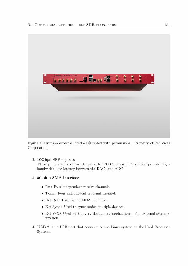
5. Commercial-off-the-shelf SDR frontends 181
Figure 4: Crimson external interfaces[Printed with permissions : Property of Per VicesCorporation]
2. 10Gbps SFP+ portsThese ports interface directly with the FPGA fabric. This could provide high-bandwidth, low latency between the DACs and ADCs
3. 50 ohm SMA interface
• Rx : Four independent receive channels.
• Txgit : Four independent transmit channels.
• Ext Ref : External 10 MHZ reference.
• Ext Sync : Used to synchronize multiple devices.
• Ext VCO: Used for the very demanding applications. Full external synchro-nization.
4. USB 2.0 : a USB port that connects to the Linux system on the Hard ProcessorSystems.

182 Paper D
5. Micro-SD slot : The FPGA and Hard Processor System may be rebooted orconfigured using an external Micro-SD card.
6. Mini-SIM slot : Directly connects to the FPGA.
7. ICE320 Power: Standard computer power cable. Accepts either 120V or 240V.
Crimson operating system
Since Crimson has an embedded GPP, it can host any operating system preferably variousLinux distributions. The following applications can be used to provide an interface tothe operating system.
1. Management : Achieved through a provided Web GUI.
2. SSH
3. UART app
Crimson processing platform
The processing device of this platform is FPGA-based. As it was discussed in section 3.2,one of the FPGA-based architectures involve implementation of a GPP on the FPGAfor control. This platform is powered by Altera Arria V ST[12]. The Altera ArriaV ST has an embedded ARM Cortex-9 processor programmed on the FPGA fabric.The platform also has an Atmel ATxmega256A3 microcontroller. The role of themicro-controller is to communicate with transmission, reception and time blocks.
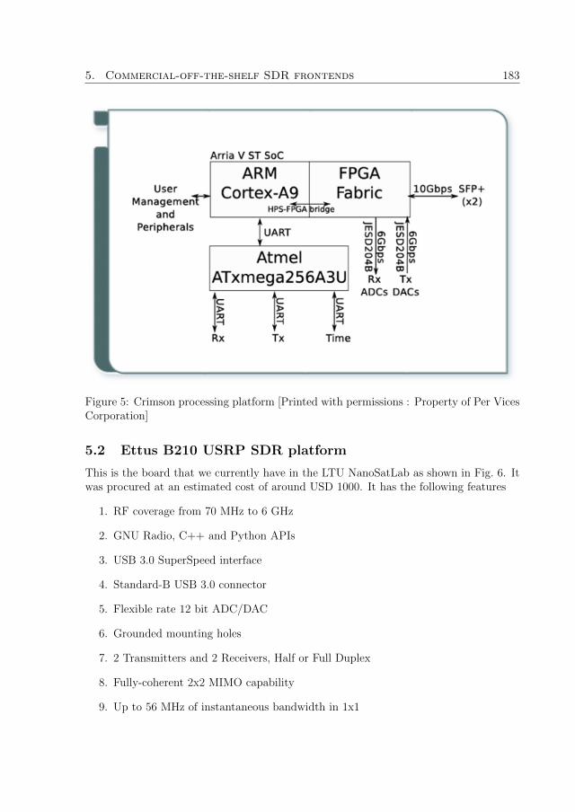
5. Commercial-off-the-shelf SDR frontends 183
Figure 5: Crimson processing platform [Printed with permissions : Property of Per VicesCorporation]
5.2 Ettus B210 USRP SDR platform
This is the board that we currently have in the LTU NanoSatLab as shown in Fig. 6. Itwas procured at an estimated cost of around USD 1000. It has the following features
1. RF coverage from 70 MHz to 6 GHz
2. GNU Radio, C++ and Python APIs
3. USB 3.0 SuperSpeed interface
4. Standard-B USB 3.0 connector
5. Flexible rate 12 bit ADC/DAC
6. Grounded mounting holes
7. 2 Transmitters and 2 Receivers, Half or Full Duplex
8. Fully-coherent 2x2 MIMO capability
9. Up to 56 MHz of instantaneous bandwidth in 1x1

184 Paper D
10. Up to 30.72 MHz of instantaneous bandwidth in 2x2
11. Includes DC power supply
12. GPIO capability
Ettus B210 external interface
The board has a number of interfaces that are used to connect it to a GPP via USBcable or to other clocking and GPS modules. A list of all interfaces is given below
1. External powerExternal power has not been used. All power will be supplied by the USB 3.0 cableconnection
2. USB ConnectorThe USB connector seems to be capable of providing power. The LED on the boardindicates that power is received from the USB cable.
3. External PPS inputThere is no means of providing PPS signals to the board at the moment. Therefore,this clocking mechanism will not be used
4. GPS antennaGPS antenna is not needed as GPSDO will not be used to provide clock reference.
5. External 10 Mhz inputThis is the clocking mechanism that will be used
6. Radiofrequency interfacesThere are four RF interfaces on the board. These will be discussed in the nextsection.
Processing architecture
Ettus B210 belongs to a class of Ettus Bus series. Bus series platforms are connected tothe computer through a USB connection. The board therefore has USB 3 PHY whichreceive samples from the USB connector.
The architecture of this frontend is illustrated in Fig. 7. The samples are processedby the FPGA. This platform is powered by an FPGA which is Xilinx Spartan 6XC6SLX150 FPGA. There is no embedded or external GPP. However, the FPGAcontains the USRP Hardware Driver (UHD) which handles transport control and syn-chronization between the USRP and the GPP. Therefore, this USRP can be programmedas if it were an all-software GPP platform. There are also four different DSP logic foreach of the transmitters and receivers implemented on the FPGA fabric.

6. Conclusion 185
Figure 6: Ettus USRP B210 in the lab
Attached to the Spartan FPGA is a system clock and time generation module. This mod-ule is connected to SMA external interface, SMA 1PPS and GPSDO modules. Thesemodules provide synchronization.The RF input and output are connected to the RF frontend. In this board, the RFfrontend is implemented in an integrated RFIC. The RFIC used is Analog DevicesAD9361[13] which is a Zero-IF transceiver as illustrated in Fig. 8. Its two receiversare equipped with automatic gain controllers (AGCs), IQ-imbalance and DC offset cor-rections and hence there is no need to implement these in digital baseband. There is anADC with high dynamic range for each in-phase and quadrature channel. They digitizethe signal and pass it through decimation filters and then 128-tap FIR filters to producea 12-bit output signal at a desired sampling rate. The two transmitters are also directconversion.Following the RFIC is an RF front-end switch network. This block routes RF signals totheir appropriate ports.
6 Conclusion
A literature survey on SDR technology was presented. The survey covered SDR hard-ware components with particular interest in signal processing devices. There were FP-GAs, ASICs, DSPs, GPPs and SPUs. A multiplicity of practical implementations ofSDR architectures in particular those that are based on accelerated GPP-based architec-ture were presented. Application frameworks, including GNU Radio, OSSIE, Microsoft

186 Paper D
Figure 7: Ettus USRP B210 architecture
SORA, LabView and Mathworks MatLab/Simulink were presented in the context of SDRapplication development. An overview of two CoTS SDR frontends, namely Crimson andEttus USRP was also presented. Based on the tradeoffs presented in Fig. 3, a GPP-basedarchitecture based on Ettus USRP and GNU Radio was selected for all the developmenttasks during the course of the PhD work. The Ettus USRP board was chosen over theCrimson board due to its significantly lower cost. The selected development platform isillustrated in Fig. 9. In the platform, the Ettus USRP board is connected to a personalcomputer by a USB 3.0 cable. The IF interface to the ground station RF chain is doneby a set of SMA cables. The personal computer runs Ubuntu Linux distribution andGNU Radio.

6. Conclusion 187
Figure 8: Analog Devices AD9361 RFIC[Printed with Permissions : Property of AnalogDevices]
AntennaAntenna
Satellite Systems
Satellite Systems
TT&C RFInterface
Linux · Ubuntu · GNU Radio
USRPB210
Figure 9: The SDR platform used for development

188
References
[1] E. Grayver, Implementing Software Defined Radio. Springer New York HeidelbergDordrecht London, 2013.
[2] M. R. Maheshwarappa and C. P. Bridges, “Software defined radios for small satel-lites,” IEEE Communications Magazine, 2015.
[3] R. Svitek and S. Raman, “Dc offsets in direct-conversion receivers: Characterizationand implications,” IEEE Microwave magazine, 2005.
[4] “Fpga leadership across multiple process nodes.”http://www.xilinx.com/products/silicon-devices/fpga.html, dec 2015.
[5] “Altera fpgas.” https://www.altera.com/products/fpga/overview.html, dec2015.
[6] “Digital Signal Processor Selection.” http://www.ti.com/lsds/ti/processors/
dsp/products.page#o4=ACTIVE\&p2094=CommunicationsandTelecom&p2095=
Linux, dec 2015.
[7] “C6000 multicore dsp + arm soc.” http://www.ti.com/lsds/ti/processors/dsp/c6000 dsp-arm/overview.page, dec 2015.
[8] M. Palkovic, P. Raghavan, M. Li, A. Dejonghe, L. V. der Perre, and F. Cattho, “Sig-nal processing on multicore platforms,” IEEE Signal Processing Magazine, pp. 22 –33, 2010.
[9] S. K. Johnson, R. C. Reinhart, and T. J. Kacpura, “Connect’s approach for thedevelopment of three software defined radios for space application.”
[10] T. S. C. Team, The Sora Manual. Microsoft Research, 1.7 ed., aug 2012.
[11] Per Vices Corporation, Crimson user manual, may 2015.
[12] Altera Corporation, Arria V Device Overview, jan 2015.
[13] Analog Devices, RF Agile Transceiver - AD9361, 2014.

Paper E
Software-defined radio transceiverfor QB50 CubeSat telemetry and
telecommand
Authors:Moses B. Mwakyanjala, M. Reza Emami and Jaap van de Beek
Reformatted version of paper originally published in:Proceedings of the 34th AIAA International Communications Satellite Systems Confer-ence, 2016, Cleveland, OH
c© 2016, American Institute of Aeronautics and Astronautics, Reprinted with permission.
189

190

Software-defined radio transceiver for QB50
CubeSat telemetry and telecommand
Moses B. Mwakyanjala, M. Reza Emami and Jaap van de Beek
Abstract
This paper presents the development of a ground system based on software-definedradio for supporting both ground testing and space telemetry and telecommand of oneof the nanosatellites in the QB50 mission. The QB50 project is an ongoing EuropeanCommission Seventh Framework initiative, which aims at launching a constellation of 50CubeSats in the lower thermosphere to carry out in-situ scientific measurements. Thepaper discusses the implementation of amateur radio protocols and telecommunicationmodulation schemes on the ground system. The system setup, deployment and schedulingare also discussed using two separate ground stations. The use of different software fortesting the system is detailed, the results show the operability of the developed groundsystem.
1 Introduction
The QB50[1] mission is a project initiated by the European Commission Seventh Frame-work (FP7) in late 2011 for launching a cluster of 50 CubeSats in the lower thermosphereto carry out in-situ scientific measurements. The nanosatellites will be in a circular or-bit at nearly 380Km altitude. The primary goal of the initiative is to facilitate access tospace for small scale research missions. One important component of the QB50 mission isproper ground systems for telemetry and telecommand. Hardware transceivers are oftenexpensive, inflexible and with limited support for new protocols in space communications.
This paper presents the development of a transceiver based on Software-Defined Radio(SDR), which has been used for performing transmission/reception tests, as well as futureoperations, of one of the QB50 CubeSats developed at the Onboard Space Systems groupof Lulea University of Technology in partnership with the UK-based Open Cosmos, Ltd.The nanosatellite is scheduled to be launched by early 2017.
The CubeSat platform consists of a global positioning system (GPS), attitude deter-mination and control system (ADCS), onboard computer (OBC), electronic power system(EPS), and NanoCom AX100 transceiver. The GomSpace NanoCom AX100 transceiveruses Gaussian Frequency Shift Keying (GFSK) for modulation/demodulation[3]. Theallocated frequency is 435.8 MHz with GFSK modulation index set at 0.6667. Internalcommunications between the satellite platform and the payload are supported by theCubeSat Space Protocol (CSP)[4]. The Telemetry/Telecommand (TM/TC) tasks aredone by encapsulating the CSP frames inside AX.25 frames. The AX.25 protocol is used
191

192 Paper E
as part of the QB50 mandatory requirements[5]. The payload on the CubeSat is a scienceunit for the Flux-φ-Probe experiment (FIPEX)[6], measuring time-resolved behavior ofmolecular and atomic oxygen as a key parameter of the lower thermosphere.
The telemetry data consists of whole orbit data (WOD), FIPEX housekeeping data(SU-HK), FIPEX science data (SU-SDP), and miscellaneous information. The wholeorbit data set is collected over the entire orbit once every minute. It contains platformhousekeeping information for monitoring the health and status of the platform. The SU-HK data set contains information about the health and status of the FIPEX payload.In addition, the SU-SDP data set contains readings of the FIPEX payload. Telemetry isforwarded to QB50 data processing and archiving center (DPAC) servers as part of theQB50 requirements. The Telecommand data consists of encrypted messages that can beused to control the nanosatellite and make requests for telemetry. Some of these requestsare WOD packet request, SU-HK request and SU-SDP requests.
Section II of the paper details development of the transceiver and its verification.Section III covers ground system setup, deployment, and testing in two different stations.Section IV concludes the paper.
2 Development
The transceiver software has two distinct parts, namely signal processing application(SPA) and a proprietary TM/TC application developed by our industrial partner, OpenCosmos, Ltd. The TM/TC application handles the generation of telecommand and pro-cessing of telemetry messages. Another application, called frame processing application(FPA), was developed for conducting all the basic tests to ensure that the SPA cancommunicate with the satellite without any problems (Fig.1). To ensure portability,communications to and from the SPA are achieved via TCP sockets. The SPA modulewas developed in GNU radio, due to the presence of robust signal processing utilities,while the FPA module was developed in C++.
On the telemetry chain, the received signal is processed by the SPA module first. Thevalidated TM frames from the SPA are sent to the FPA in the testing configuration or tothe TM/TC application in the final configuration. The processed telemetry by either ofthe two programs is then forwarded to QB50 DPAC servers. On the telecommand chain,test telecommand frames generated by the FPA or actual telecommand frames generatedby the TM/TC application are sent to the SPA to be modulated and transmitted to thesatellite.
2.1 Signal processing application
The main role of the SPA is to demodulate the received signal and extract AX.25 frames aswell as modulation and transmission of AX.25 telecommands. The received signal is mod-ulated in GFSK with a modulation index of h = 0.6667. The data rate is R = 9600 kbps.Since GFSK carries a single bit per symbol, then baud rate = 9600 baud. To ensure ro-bust operation, the received signal is upsampled by a factor of 36. Total signal bandwidth

2. Development 193
Signal Processing Application
(SPA)GNU Radio
Modulation/DemodulationScrambler/DescramblerNRZI coding/decoding
Frame Check and Synchronization
TCP communication
Frame Processing Application
(FPA)C++
AX25 framing/deframingCSP framing/deframing
Beacon deframingDPAC Interfacing
TCP communication
Telemetry and Telecommand ApplicationAX25 framing/deframingCSP framing/deframing
WOD downloadSU_HK download
SU_SDP downloadScience script upload
DPAC InterfacingTCP communication
QB50 DPAC Servers
USRP UHD Driver
TESTING TESTING
FINAL FINAL
Figure 1: Ground station software architecture
is given by
bandwidth = baud rate× (1 + h) = 16000 Hz (1)
This results into a sampling rate of
sample rate = bandwidth× upsampling factor = 576000 baud (2)
The samples per symbol, sps, is therefore calculated as
sps =bandwidth
baudrate= 60 (3)
The SPA is divided into two logical parts, namely the reception and transmission chains.The flowgraph of each part will be presented separately for simplicity. However, thesetwo logical parts belong to one SPA flowgraph.
SPA reception chain
The flowgraph of the SPA reception chain is presented in Fig. 2. The first threeblocks, UHD:USRP Source, Power Squelch and Frequency Xlating FIR Filter ensurethat the received signal is preprocessed properly before demodulation. Signal receptionis performed by the UHD:USRP Source block, which interfaces the GNU Radio withuniversal software radio peripheral (USRP) hardware hriver (UHD). This block allowsthe user to specify radio parameters of the hardware front-end, namely the antenna to beused, antenna gain, frequency and sampling rate. The employed antenna is TX/RX. Theantenna gain has been set to be tunable from 0 to 70 dBs, with a default value of 50 dBs.

194 Paper E
Very high gain values may result into signal clipping by the USRP analogue-to-digitalconverters (ADC)s.
Following the UHD:USRP Source block is the Power Squelch block. This moduleblocks signals below a certain threshold value. The threshold used here is -100 dB. Thisvalue will block noise from passing into the demodulation chain, and hence reducingunnecessary computer processing power. However, the power squelch and UHD:USRPSource blocks would not guarantee a noiseless signal. The Frequency Xlating FIR Filterblock, therefore, filters the incoming signal and shifts the bandwidth of interest to DCfor easier demodulation.
Figure 2: SPA reception chain flowgraph
The filtered signal from the three blocks discussed above is sent to a GFSK demodu-lator. In GNU Radio, GFSK demodulation can be achieved by the GFSK Demod block.This is a hierarchical block composed of three different blocks, namely Quadrature De-mod block for FM demodulation, Clock Recovery MM block that implements Muellerand Muller synchronization algorithm, and the Binary Slicer block that makes decisionsabout the value of the recovered bit. All tests using GFSK Demod block failed, becausethe Clock Recovery MM block was unable to lock to real-world signals captured by thehardware. Demodulation had to be reimplemented by using another clock recovery al-gorithm based on polyphase filter banks. This algorithm has already been implementedin GNU Radio by the block Polyphase Clock Sync. Demodulation was therefore im-plemented by concatenation of the three blocks in GRC without the use of a unifiedhierarchical block.
The Quadrature Demod block expects one gain parameter. The gain is related to themodulation index and samples per symbol by
G =sps
π × h(4)

2. Development 195
Following the Quadrature Demod block is the Polyphase Clock Sync block[7]. This blockexpects a number of parameters including number of samples per symbol, loop band-width, number of filters in the filter bank, an initial phase and the output samples persymbol. The number of samples per symbol is set at the default value of 60, the loopbandwidth is set at 2×π
100. The number of filters used is 64 with an initial phase of 32.
Since GFSK carries one bit per symbol, the output samples per symbol value is set at1. The signal from Polyphase Clock Sync is passed to the Binary Slicer block that isa quantizer with two distinct values corresponding to binary 0 and binary 1. A samplevalue below 0 falls into the binary 0. Conversely, a sample value above 0 falls into binary1.
The next two blocks after the Binary Slicer ensure that the received binary streamis recovered properly without a loss of synchronization. This is achieved by data scram-bling and Non-Return-to-Zero-Inverted (NRZI) encoding. Therefore, the reception chainincludes a descrambler and an NRZI decoder.
The scrambler used is the multiplicative scrambler proposed by James Miller (G3RUH)[8] for use in 9600 baud packet radio for amateur radio communications. The scramblingpolynomial is given by
p (x) = x17 + x12 + 1 (5)
The GNU Radio block Descrambler implements a multiplicative descrambler of a givenmask, seed and length. The mask can be calculated from the scrambling polynomial. InGNU Radio, the polynomial has to be written in least significant bit (LSB) first orderbefore the mask is calculated[9]. For the polynomial above, the mask is calculated as
mask = 00000000000100001 = 0x21 (6)
The NanoCom AX100 transceiver uses a seed with a value of 0x00. The same seed valueis used by the Descrambler block. From the source code of this block, it can be deducedthat the length in this context refers to the number of bit positions that a shift registerneeds to move when a new bit is being inserted. Therefore, the length can be calculatedas
length = deg (p (x))− 1 (7)
Following the Descrambler are two blocks that implement NRZI decoding. NRZI decod-ing is achieved by concatenating Differential Decoder and Invert Bit Value blocks.
Following NRZI decoding is bit synchronization and frame recovery. This has beenimplemented by an out-of-tree ax25 rx block. The process is aided by the preamble andpostamble, which are included in the transmitted data stream. This block also performsAX.25 CRC-16 checks to ensure that output AX.25 frames sent to either the FPA orTM/TC application are error-free. Framing will be discussed further in section 2.2.
After successful frame recovery, the frame is sent to either the FPA in testing config-uration or the TM/TC application in the final configuration via a TCP socket. The TCPconnectivity is performed by the asynchronous Socket PDU block in server mode. A localIP address, 127.0.0.1, and an arbitrary port number 5001 are used by this application.

196 Paper E
SPA transmission chain
The SPA transmission chain is presented in the flowgraph given in Fig. 3. Data fromFPA are received through a TCP socket via the Socket PDU block operating in servermode with an IP address of 127.0.0.1 and an arbitrary port number 5002. This data isreceived asynchronously. To operate synchronously at the specified sampling rate, thedata must be passed synchronously to other GNU Radio blocks. This is achieved byusing the PDU to Tagged Stream block.
The synchronous bit stream is passed through an NRZI encoder, which is carried outby a concatenation of the Invert Bit Values and the Differential Encoder blocks.
NRZI-encoded bit stream is scrambled by using the same G3RUH scrambling poly-nomial presented in 2.1 to ensure bit synchronization when the data stream is receivedby the NanoCom AX100 transceiver.
GFSK modulation is performed by the GFSK Mod block. This block accepts datathat are packed into bytes. Therefore, another block, Pack K Bits, which has been setto pack 8 bits into one byte is used. The GFSK Mod block accepts three parameters,namely number of samples per symbol, sensitivity and time-bandwidth product (BT).The default value of samples per symbol, 60, has been used. The sensitivity is related tothe modulation index and the number of samples per symbol by
Sensitivity =1
Gain=π × h
sps(8)
Transmission by the USRP board is achieved through the UHD:USRP Sink block. Beforethe modulated signal is passed through this block, care must be taken to make surethat the amplitude is less than one, so as to avoid signal clipping by digital-to-analogueconverters (DACs). This is achieved by multiplying the signal by a factor with a valueof less than one, in our case 0.7.
Figure 3: SPA transmission chain flowgraph
2.2 Frame Processing application
The frame processing application performs high-level communication with the CubeSat.It is also equipped with an interface to QB50 DPAC servers. The main tasks are therefore

2. Development 197
AX.25 framing/deframing, CSP framing/deframing, and QB50 DPAC interfacing.
AX.25 and CSP framing
The QB50 requirements specify that AX.25 unnumbered information (UI) frames[10],which follows connectionless procedure, be used for communication between all QB50CubeSats and ground stations[5]. AX.25 and CSP framing are therefore done accordingto the NanoCom AX100 AX.25 and CSP framing format as shown in Fig. 4. It can be seenfrom the diagram that NanoCom AX100 sorrounds all AX.25 frames by trailing bytes ofpreamble and postamble. These have been put in place to enable frame synchronization.CSP has been encoded using Reed-Solomon code, RS(255,233), capable of correcting upto 16 bytes of data.
PREAMBLE50 x 0X7E
AX.25 HEADER16 Bytes
AX.25 DATA [CSP data]
AX.25 CRC-162 Bytes
POSTAMBLE24 x 0X7E
CSP HEADER4 Bytes
DATA0 – 65535 Bytes
CSP CRC-324 Bytes
Figure 4: AX.25 and CSP framing
QB50 DPAC interfacing
QB50 DPAC provides a common portal that can be accessed from the web [11]. However,access is granted to verified and registered users only. This portal provides access to anumber of tools as well as useful information regarding the QB50 project. There is a listof all satellites and their corresponding status, including uploaded data. There is also alist of ground stations that support QB50 satellites. All QB50 CubeSats in orbit can betracked via a live satellite tracking tool available on this portal. However, at the timeof writing of this paper, there are only two QB50 CubeSats that are in orbit. These areQB50 precursor satellites namely QB50P1 and QB50P2.

198 Paper E
Of utmost importance is the upload interface. This is the only point where datareceived by ground systems from the QB50 nanosatellites are uploaded. The portalprovides a HTTP form for manual file upload. This is a simple GUI form that enablesusers to upload files from their local computers. The drawback of this manual interfaceis that one needs to log in first every time before uploading a file.
An alternative to the manual interface is provided in the form of an automatic HTTPpost request. This does not require any login. The required HTTP fields are listed below:
• AUTHIDThis is a 32-character-long key that is needed to authenticate the user, since thereis no login required. This key is provided to the verified and registered users only.
• FILEThis is the file to be uploaded to the QB50 DPAC servers.
• FILETYPEQB50 DPAC servers expect files of appropriate format. There are six different filetypes that are accepted by the system, namely
1. Beacon data (BEA),
2. Whole Orbit Data (WOD),
3. Science Unit Data (SD),
4. Audio files (WAV),
5. Miscellaneous files (MISC),
6. Test upload (TEST).
• CUBESATThis is the name of the CubeSat whose data are to be uploaded. In our case, theCubeSat designated name is ON01SE.
• CTIMEThis is the satellite contact time in UTC when the data were recorded.
• CHKSUMThis is an optional MD5 checksum to ensure data integrity.
After a HTTP POST request with fields above has been received, the server will respondby giving the sender a status report. This report is given in terms of HTTP return codeslisted below:
• 200 - OK. This means that the file has been accepted and uploaded successfully.
• 401 - Unauthorized. The HTTP POST did not use a correct AUTHID value.
• 413 - File size is too large. This means that the file size is larger than the specifiedmaximum file size of 1 MB.

2. Development 199
• 422 - Unprocessed request. This code is returned when submitted parameters arenot correct.
• 500 - Internal server error. There has been an error when user request was beingprocessed. A user needs to try again after a short time.
• 503 - Service unavailable. The server is off-line for maintenance.
The FPA uses a free Linux tool curl[12] to perform HTTP POST requests.
2.3 Laboratory tests and results
End-to-end tests were performed in the laboratory, which correspond to the testing loopof the software architecture shown in Fig. 1. All communications between the CubeSatand the SDR-based ground station were in real time. The aim of these tests was to verifyreception and decoding, encoding and transmission as well as DPAC interfacing.
Reception and decoding
This test was performed by receiving and decoding the beacon transmitted by the Cube-Sat. The beacon format is shown in Fig. 5. The beacon has 12 bytes of WOD dataformatted according to QB50 official format[13]. There is also one byte of power in-formation, one byte with a list of enabled services, and one byte with a list of servicesrunning. These correspond to ADCS, FIPEX, GPS and OCOBC status.
WOD 12 Bytes
Power Info1 Byte
Services Enabled1 Byte
Services Running1 Byte
RESERVED15 Bytes
Figure 5: CubeSat beacon
Figure 6 shows a successfully demodulated and extracted AX.25 beacon frame in rawhexadecimal format. It can be seen that the frame is sent from SE-01 to SE-01. Inaddition to CSP header and the beacon data itself, there is also a reserved field of 15bytes that will be used in the future. For the time being, these have been filled withASCII characters, which is the name of our industrial partner.
Table 1 lists the decoded data according to the beacon format shown in Fig. 5. Allparameters in the WOD information field have been decoded successfully, except for thecommunications unit temperature. This is because there is no means of reading the

200 Paper E
Figure 6: Raw AX.25 Frames
temperature of the NanoCom AX100 transceiver. The remaining parameters have alsobeen decoded successfully, since the beacon was recorded when the ADCS, FIPEX, GPSand OCOBC were turned off.
Encoding and transmission
The NanoCom AX100 transceiver has ping functionality, with which valid encoded framessent to CSP ping port are echoed back. In addition, the transceiver also keeps the recordof the number of valid frames received. This feature can also be used to verify whethertransmitted frames have been received successfully. Therefore, a number of test frameswith different combinations of hexadecimal data were used to perform such tests, asdescribed below:
Each test frame consists of 16 test patterns with each pattern having a size of eightbytes, totaling 128 bytes per frame. There is a total of seven primary patterns, resultinginto seven test frames. Each test frame can also be rearranged into a transpose of itself,resulting into a total of 14 test frames. The test patterns used are
1. all zeros,0x00,0x00,0x00,0x00,0x00,0x00,0x00,0x00
2. all ones,0xff,0xff,0xff,0xff,0xff,0xff,0xff,0xff
3. increasing numbers,0, 1, 2, 3, 4, 5, 6, 7
4. bits,1, 2, 4, 8, 16, 32, 64, 128
5. inverted bits,254,253,251,247,239,223,191,127
6. alternating patterns,0xf0,0x0f,0xcc,0x33,0xaa,0x55,0x3c,0x66

2. Development 201
Table 1: Decoded ONSE01 beacon from Kiruna ground station
Parameter ValueWOD Information
Beacon number 1Satellite ID SE-01
Epoch 517061358 secondsMode 0
Battery voltage(Volts) 7.4Battery current(Amperes) 0.093933v3 bus current(Amperes) 0.1255V bus current(Amperes) 0
Comms temperature(Celcius) NAEPS temperature(Celcius) 30
Battery temperature(Celcius) 30Power Information
ADCS OFFFIPEX OFFGPS OFF
OCOBC OFFServices Enabled
ADCS DISABLEDFIPEX DISABLED
OCOBC DISABLEDServices Running
ADCS NOT RUNNINGFIPEX NOT RUNNING
OCOBC NOT RUNNING
7. text.’P’, ’O’, ’T’, ’A’, ’T’, ’O’, ’E’, ’S’
After the test frames were sent, the CubeSat was able to echo the received frame. Itwas verified that the test frames received were the same as those that were transmitted.In addition, there was an increment of 14 frames in the NanoCom frame counter, whichfurther verified that the frames were successfully received and that the echoed messageswere not coming from somewhere else rather than the CubeSat.
DPAC interfacing
The recorded beacon file was uploaded to QB50 DPAC servers in both test (TEST) andAX.25 beacon file (BEA) modes. In both cases, the received HTTP response code was200, indicating that the file was uploaded successfully. Another conducted test was the
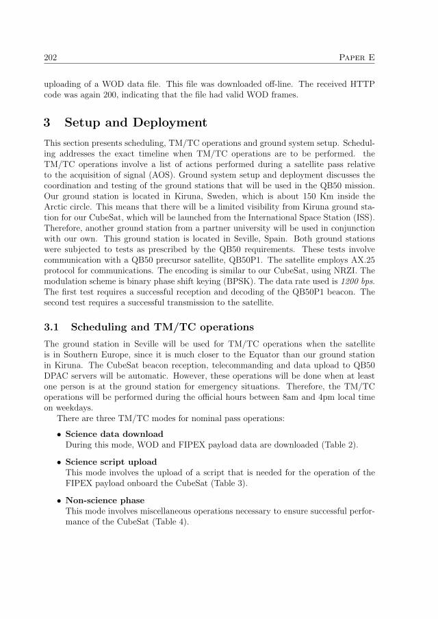
202 Paper E
uploading of a WOD data file. This file was downloaded off-line. The received HTTPcode was again 200, indicating that the file had valid WOD frames.
3 Setup and Deployment
This section presents scheduling, TM/TC operations and ground system setup. Schedul-ing addresses the exact timeline when TM/TC operations are to be performed. theTM/TC operations involve a list of actions performed during a satellite pass relativeto the acquisition of signal (AOS). Ground system setup and deployment discusses thecoordination and testing of the ground stations that will be used in the QB50 mission.Our ground station is located in Kiruna, Sweden, which is about 150 Km inside theArctic circle. This means that there will be a limited visibility from Kiruna ground sta-tion for our CubeSat, which will be launched from the International Space Station (ISS).Therefore, another ground station from a partner university will be used in conjunctionwith our own. This ground station is located in Seville, Spain. Both ground stationswere subjected to tests as prescribed by the QB50 requirements. These tests involvecommunication with a QB50 precursor satellite, QB50P1. The satellite employs AX.25protocol for communications. The encoding is similar to our CubeSat, using NRZI. Themodulation scheme is binary phase shift keying (BPSK). The data rate used is 1200 bps.The first test requires a successful reception and decoding of the QB50P1 beacon. Thesecond test requires a successful transmission to the satellite.
3.1 Scheduling and TM/TC operations
The ground station in Seville will be used for TM/TC operations when the satelliteis in Southern Europe, since it is much closer to the Equator than our ground stationin Kiruna. The CubeSat beacon reception, telecommanding and data upload to QB50DPAC servers will be automatic. However, these operations will be done when at leastone person is at the ground station for emergency situations. Therefore, the TM/TCoperations will be performed during the official hours between 8am and 4pm local timeon weekdays.
There are three TM/TC modes for nominal pass operations:
• Science data downloadDuring this mode, WOD and FIPEX payload data are downloaded (Table 2).
• Science script uploadThis mode involves the upload of a script that is needed for the operation of theFIPEX payload onboard the CubeSat (Table 3).
• Non-science phaseThis mode involves miscellaneous operations necessary to ensure successful perfor-mance of the CubeSat (Table 4).

3. Setup and Deployment 203
Table 2: Nominal pass operation for science download
Time TaskAOS - 3 min Start antenna tracking and point towards the estimated AOS horizon
AOS Listen to beacon transmissions from CubeSatAOS + 1 min Perform initial health-check: request full HK packet using the command [qb hk]> 10◦ elevation Requesting WOD data> 10◦ elevation Requesting FIPEX data(SU HSK and SU SDP parameters)
LOS - 1 Park-position of antenna
Table 3: Nominal pass operation for science script upload
Time TaskAOS - 3 min Start antenna tracking and point towards the estimated AOS horizon
AOS Listen to beacon transmissions from CubeSatAOS + 1 min Perform initial health-check: request full HK packet using the command [qb hk]> 10◦ elevation Requesting WOD data> 10◦ elevation Upload science script
LOS - 1 Park-position of antenna
Table 4: Nominal pass operation for non-science phase
Time TaskAOS - 3 min Start antenna tracking and point towards estimated AOS horizon
AOS Listen to beacon transmissions from CubeSatAOS + 1 min Perform initial health-check: request full HK packet using the command [qb hk]> 10◦ elevation Start commanding> 10◦ elevation Download system and reset logs> 10◦ elevation Take image and download list of files> 10◦ elevation Schedule and upload commands for out-of-sight operations
LOS - 1 Park-position of antenna

204 Paper E
Table 5: NanoSatLab component specifications
Parameter InformationGround station name SK2UL
University Lulea University of TechnologyCity Kiruna
Altitude 382m
Latitude 67.7NLongitude 20.3E
Tower CUE DEEOperating frequencies 144 - 146 MHz, 432-438 MHz
Antenna 1 (2m - VHF) (Gain: 13 dB) (Beamwidth : 44 deg) CUE DEE 15 x 144Antenna 2 (70 cm - UHF) (Gain: 14 dB) (Beamwidth : 40 deg) CUE DEE 17 x 432
Antenna rotor Yaesu G-5400BRotor computer interface Yaesu GS 232B
Rotor computer interface driver RS 232Radio 1 ICOM 910HRadio 2 YAESU FT-736 R
3.2 Kiruna ground station
The NanoSatLab Laboratory at the Lulea University of Technology in Kiruna, Sweden, isthe main laboratory housing the satellite ground station and the platform for SDR-basedground station development. There are also facilities at the laboratory for other aspects ofnanosatellite technology, such as a clean room, Machanical and electronic manufacturingfacilities, and hardware-in-the-loop simulation platforms for development and test ofCubeSats. The laboratory’s ground station is equipped with certain components, aslisted in Table 5, which facilitate satellite communications and SDR developments ingeneral.
Software-defined radio ground station setup
The block diagram of the SDR-based ground station setup is shown in Fig. 7. Thereis a PC hosting Ubuntu 12.10 and a number of software, namely GNU radio, Eclipseintegrated developer environment (IDE) used for C++ and Python application devel-opment, and GPredict[14] for satellite tracking and rotator control. The PC also has aUSB connection to the Ettus board. The board is connected to a low noise amplifier(LNA) on the reception side and a high power amplifier (HPA) on the transmission side.These amplifiers are connected to the antenna on the roof via standard radio frequencycables. The PC is also connected to a GS-232B rotator controller. Through this con-troller, a program such as GPredict, can control a number of different rotators, includingYaesu G-5400B rotator that is used by our ground station. GPredict is used to tracksatellites based on latest two-line elements (TLE) provided by NORAD. With the helpof Linux daemons, rotctld and ritctld, GPredict can communicate with a controller suchas GS-232B. GPredict can also predict satellite Doppler shift, and pass this informationto a transceiver via a TCP socket. This helps the transceiver to mitigate the effect of

3. Setup and Deployment 205
Doppler shift. The SDR board used in this development is the Ettus B210. This is an
SDR PlatformUSRP
Rotator unit (AZ/EL)
Yaesu G-5400B
Computer InterfaceGS-232B
LNA
HPA
Rotator
RF
Inte
rfa
ce
Figure 7: Kiruna satellite ground station
FPGA-based board powered by the Xilinx Spartan 6 XC6SLX150 FPGA. Its architectureis shown in Fig. 8. A general purpose processor (GPP) is an important part of any SDRboard. However, there is neither a GPP chip on the board nor an embedded GPP on theXilinx FPGA fabric. Therefore, the board must be connected to an external GPP via aUSB 3.0 interface. The FPGA contains the USRP UHD, which handles transport con-trol and synchronization between the USRP and the external GPP. Therefore, this SRDboard can be programmed as if it was an all-software GPP platform. There are also twodifferent DSP logic modules for each of the transmitters and receivers implemented onthe FPGA fabric. Attached to the Spartan FPGA is a system clock and time generationmodule. This module is connected to SMA external interface, SMA 1PPS and GPSDOmodules. These modules provide synchronization.
The RF input and output are connected to the RF front-end. On the Ettus board,the RF front-end is implemented on an integrated radio frequency integrated circuit(RFIC). The RFIC used is Analog Devices AD9361[15] which is a Zero-IF transceiver.Its two receivers are equipped with automatic gain controllers (AGCs), IQ-imbalance andDC-offset corrections[16], and hence there is no need for implementing these functionsin digital baseband. There is an ADC with high dynamic range for each in-phase andquadrature channel. They digitize the signal and pass it through decimation filters and128-tap FIR filters to produce a 12-bit output signal at a desired sampling rate. The twotransmitters are also direct conversion. Following the RFIC is an RF front-end switchnetwork module. This module routes RF signals to their appropriate ports.
QB50 tests for Kiruna ground station
According to the QB50 requirements, a two way communication to QB50P1 was required.However, only beacon reception and decoding tests have been performed, since the coor-

206 Paper E
Figure 8: Ettus USRP B210 architecture
dination process with QB50P1 proprietors to grant permission for telecommanding thenanosatellite has not been finalized during the writing of this paper. An applicationfor receiving and decoding QB50P1 beacon was developed. Signal processing and frameextraction tasks are performed in GNU radio, while beacon decoding task is performedby a separate C++ application. The flowgraph of the BPSK-based signal processingapplication used to demodulate and extract AX.25 frames from QB50P1 nanosatellite isshown in Fig. 9.

3. Setup and Deployment 207
Figure 9: QB50P1 BPSK-based signal processing application flowgraph
The QB50P1 nanosatellite has two AX.25 beacons. However, the implemented C++decoder can decode the first beacon frame only. This beacon has a large number ofparameters divided into six fields, namely beacon frame field information, TRXUV fieldinformation, antenna field information, electrical power subsystem(EPS) field informa-tion, solar panels field information, and V2 operations field information. Full beaconinformation can be found in [17]. A decoded beacon is shown in Table 6.

208 Paper E
Table 6: Decoded QB50P1 beacon from Kiruna ground station
Parameter ValueFrame Field Information
Source callsign QB50P1Destination callsign QB50P1
Software ID V2 softwareSatellite ID QB50P1Frame Type AX.25 beacon #1
Operational Mode Nominal modeBoot Counter 632
Packet Counter 271Commands Received 0
Commands Valid 0Satellite Uptime 395
Data Valid 1 0xffData Valid 2 0xffData Valid 3 0x3f
TRXUV Field InformationTRXUV Doppler 173
TRXUV RSSI 149TRXUV Reflected power 14.2291 mWTRXUV Forward power 12.4242 mW
TRXUV TX Current 24.095 mATRXUV RX Current 93.22 mA
TRXUV PA Temperature 153.604 deg. CTRXUV Bus Voltage 0.516128 V
Antenna Field InformationAntenna deployment status - A 0x00
Antenna temperature - A 155.878 deg. CAntenna deployment status - B 0x00
Antenna temperature - B 155.586 deg. CElectrical Power System (EPS) Field Information
Boost Converter 1 Voltage 258 mVBoost Converter 2 Voltage 344 mVBoost Converter 3 Voltage 348 mV
Battery Voltage 599 mVBoost Converter 1 Current 95 mABoost Converter 2 Current 77 mABoost Converter 3 Current 174 mATotal photovoltaic current 94 mA
Total system current 64 mASwitched channel current - 3v3 #1 6 mASwitched channel current - 3v3 #2 4 mASwitched channel current - 3v3 #3 3 mASwitched channel current - 5v #1 91 mASwitched channel current - 5v #2 1 mASwitched channel current - 5v #3 0 mABoost Converter 1 Temperature 9 deg. CBoost Converter 2 Temperature 8 deg. CBoost Converter 3 Temperature 8 deg. C
Battery Temperature 6 deg. CChannel status 0x9EPS boot cause 0x4Battery mode Normal
EPS Powerpoint tracking mode Maximum Power Point TrackingSolar Panel Field Information
Solar panel 0 temperature 27.4844 deg. CSolar panel 1 temperature 23.4844 deg. CSolar panel 2 temperature 17.4844 deg. CSolar panel 3 temperature 20.9844 deg. CSolar panel 4 temperature 26.9844 deg. C
V2 Operations Field InformationSU last response ID 0x0
SU thermocouple temperature -273 deg. CLog OK markers 0x77WOD log entries 3880
SU log entries 3880

3. Setup and Deployment 209
3.3 Seville ground station
The Seville ground station uses a commercial turn-key ground station kit developed byInnovative Solutions in Space (ISIS). This ground station kit (GSKit) has a full radiofrequency circuitry, including antennas and amplifiers. The antennas can be rotated bythe antenna rotator controllable by a software, which is also part of the kit. Communica-tions with satellites is handled by an SDR-based transceiver. This transceiver supportsUHF, VHF and optional S-band communications. GSKit is controlled by a GUI-basedsoftware. Some key features of the SDR transceiver are[18]
• VHF and UHF downlink capability
• VHF and UHF uplink capability
• Dual band full duplex
• Downlink up to 9600 bps (Raised-Cosine BPSK, AFSK, FSK, GMSK)
• Uplink configurable to 1200, 2400, 4800, 9600 bps (AFSK, FSK, BPSK)
• AX.25 support in both uplink and downlink
TCP interface
The GSKit software has a command line interface whereby demodulated data can be vi-sualized. However, in order to ensure that the transceiver is compatible with other appli-cations, there are KISS and raw binary data interfaces. Through these interfaces, uplinkand downlink data can be exchanged between GSKit and any TCP-based application[19].The raw binary data interface, which can be accessed via TCP port 3210, has been se-lected. A sublayer for interfacing applications with GSKit has been developed. Thissublayer wraps application data according to the frame format used by GSKit software.The transmit and receive frame formats are given in Fig. 10 and Fig. 11, respectively.
PacketSend Frame Command (0x56)
1 Byte
Frame Length(Unsigned int32)
4 Bytes
HEADER PAYLOAD
Figure 10: Transmit frame data structure

210 Paper E
Data Rate(unsigned int32)
4 Bytes
Receive Frame Command (0x55)1 Byte
Frame Length(Unsigned int32)
4 Bytes
HEADER PAYLOAD
Modulation name length
(unsigned char)1 Byte
Modulation name
(unsigned char[])
RSSI (IEEE 754 double)
Frequency (IEEE 754 double)
UTC Time from Epoch
(unsigned long)
Packet (unsigned char[])
Packet Length(unsigned short)
Figure 11: Receive frame data structure
QB50 tests for Seville ground station
The Seville ground station was also tested according to QB50 specifications. Like it wasin the case of the Kiruna ground station, only the beacon reception and decoding testwas performed. The decoded beacon is shown in Table 7.
3.4 Final system setup
The final system setup is shown in Fig. 12, depicting that both Kiruna and Seville groundstations will be used for operating our nanosatellite. However, the Seville ground stationwill be used exclusively during Launch and Early Orbit Phase (LEOP), due to its betterorbit visibility. Nominal operations will involve both ground stations.
Third Party Servers
TM/TC Application
SEVILLE Ground Station
GSKit
KIRUNA Ground Station
Signal Processing Application (SPA)
0N01SE CubeSat
Figure 12: Final system setup

4. Conclusion 211
4 Conclusion
The development and deployment of an SDR-based ground system was detailed for oper-ating one of the QB50 CubeSats. The main advantages of this ground system are that itis a reconfigurable system and has been developed at a significantly lower cost and fasterpace, compared to its counterpart hardware-based ground stations. The nanosatellitetransceiver can be readily reconfigured in-orbit when needed. Due to its inherent recon-figurability, the ground station can adjust accordingly to support the new configurationswithout a need to change the hardware. The Ground system deployment and setup,as well as TM/TC scheduling, were also discussed. The TM/TC scheduling has beenplanned to minimize the load on the ground system. Due to its geographical location,the SDR-based ground system in Kiruna will have to share the load of another groundstation in Seville, Spain. Both ground stations have been verified according to the QB50specifications. Verification was performed through communications with the QB50 pre-cursor nanonosatellite QB50P1.
5 Acknowledgement
The authors would like to thank the engineers at Open Cosmos Ltd., in the UnitedKingdom for their assistance in some of the technical works resulting in this manuscript.

212 Paper E
Table 7: Decoded QB50P1 beacon from Seville ground station
Parameter ValueFrame Field Information
Source callsign QB50P1Destination callsign QB50P1
Software ID V2 softwareSatellite ID QB50P1Frame Type AX.25 beacon #1
Operational Mode Nominal modeBoot Counter 599
Packet Counter 991Commands Received 0
Commands Valid 0Satellite Uptime 3995
Data Valid 1 0xffData Valid 2 0xffData Valid 3 0x3f
TRXUV Field InformationTRXUV Doppler 152
TRXUV RSSI 170TRXUV Reflected power 14.2291 mWTRXUV Forward power 12.7533 mW
TRXUV TX Current 24.49 mATRXUV RX Current 93.22 mA
TRXUV PA Temperature 149.462 deg. CTRXUV Bus Voltage 4.32257 V
Antenna Field InformationAntenna deployment status - A 0x00
Antenna temperature - A 152.372 deg. CAntenna deployment status - B 0x00
Antenna temperature - B 152.08 deg. CElectrical Power System (EPS) Field Information
Boost Converter 1 Voltage 359 mVBoost Converter 2 Voltage 508 mVBoost Converter 3 Voltage 391 mV
Battery Voltage 561 mVBoost Converter 1 Current 30 mABoost Converter 2 Current 193 mABoost Converter 3 Current 221 mATotal photovoltaic current 100 mA
Total system current 64 mASwitched channel current - 3v3 #1 6 mASwitched channel current - 3v3 #2 4 mASwitched channel current - 3v3 #3 3 mASwitched channel current - 5v #1 75 mASwitched channel current - 5v #2 1 mASwitched channel current - 5v #3 0 mABoost Converter 1 Temperature 4 deg. CBoost Converter 2 Temperature 4 deg. CBoost Converter 3 Temperature 3 deg. C
Battery Temperature 1 deg. CChannel status 0x9EPS boot cause 0x4Battery mode Normal
EPS Powerpoint tracking mode Maximum Power Point TrackingSolar Panel Field Information
Solar panel 0 temperature 21.4844 deg. CSolar panel 1 temperature 17.9844 deg. CSolar panel 2 temperature 3.48438 deg. CSolar panel 3 temperature 14.9844 deg. CSolar panel 4 temperature 25.4844 deg. C
V2 Operations Field InformationSU last response ID 0x0
SU thermocouple temperature -273 deg. CLog OK markers 0x77WOD log entries 3880
SU log entries 3880

References 213
References
[1] Seventh Framework Program, “An international network of 50 cubesats for multi-point, in-situ measurements in the lower thermosphere and re-entry research,” tech.rep., European Commission, may 2015.
[2] GomSpace, “Nanocom communication modules.”http://gomspace.com/index.php?p=products-ax100. Accessed: 2016-07-08.
[3] T. Svedek, M. Herceg, and T. Matic, “A simple signal shaper for gmsk/gfsk andmsk modulator based on sigma-delta look-up table,” Radioengineering, pp. 230 –237, jun 2009.
[4] GomSpace, “Cubesat Space Protocol - A small network-layer delivery protocol de-signed for Cubesats.” https://github.com/GomSpace/libcsp. Accessed: 2016-22-08.
[5] QB50, “System requirements and recommendations,” tech. rep., QB50, feb 2015.
[6] QB50, “Manual for the fipexonqb50 science unit,” tech. rep., QB50, dec 2014.
[7] F. J. Harris and M. Rice, “Multirate digital filters for symbol timing synchronizationin software defined radios,” IEEE Selected Areas in Communications, pp. 2346 –2357, dec 2001.
[8] AMSAT UK, “9600 baud packet radio modem design.”http://www.amsat.org/amsat/articles/g3ruh/109.html. Accessed: 2016-07-08.
[9] Daniel Estevez, “Scramblers and their implementation in GNUradio.”http://destevez.net/2016/05/scramblers-and-their-implementation-in-gnuradio/.Accessed: 2016-22-08.
[10] W. A. Beech, D. E. Nielsen, and J. Taylor, “AX.25 Link Access Protocol for AmateurPacket Radio,” tech. rep., Tucson Amateur Packet Radio Corporation, July 1998.
[11] QB50, “Qb50 dpac.” https://upload.qb50.eu/. Accessed: 2016-07-08.
[12] D. Stenberg, “curl.1 the man page.” https://curl.haxx.se/docs/manpage.html. Ac-cessed: 2016-07-08.
[13] QB50, “Whole orbit data.” https://www.qb50.eu/index.php/tech-docs/category/15-whole-orbital-data. Accessed: 2016-22-08.
[14] A. Csete, “About Gpredict.” http://gpredict.oz9aec.net/. Accessed: 2016-22-08.
[15] Analog Devices, RF Agile Transceiver - AD9361, 2014.
[16] R. Svitek and S. Raman, “Dc offsets in direct-conversion receivers: Characterizationand implications,” IEEE Microwave magazine, 2005.

214
[17] ISIS, “Isis qb50p ax.25 beacon decoder.” http://www.isispace.nl/wp-content/uploads/2016/06/qb50p ax25beacon.pdf. Accessed: 2016-08-08.
[18] Innovative Solutions in Space (ISIS), “Isis ground station datasheet v2.2,” tech. rep.,ISIS, 2015.
[19] Innovative Solutions in Space (ISIS), Ground Station User Manual. Innovative So-lutions in Space (ISIS), 1.4 ed., 2014.

Paper F
Verification of phase and frequencymodulation for software-defined
radio baseband system using fielddata
Authors:Moses B. Mwakyanjala, M. Reza Emami and Jaap van de Beek
Reformatted version of paper originally published in:Proceedings of the 35th AIAA International Communications Satellite Systems Confer-ence, 2017, Trieste, Italy
c© 2017, American Institute of Aeronautics and Astronautics, Reprinted with permission.
215

216

Verification of phase and frequency modulation for
software-defined radio baseband system using field
data
Moses B. Mwakyanjala, M. Reza Emami and Jaap van de Beek
Abstract
This paper presents the verification of phase and frequency modulation schemes for asoftware-defined radio baseband system that is being prototyped to support satellitetelemetry, telecommand and ranging. It presents the theory behind the two modulationschemes, implementation and verification against emulated signals from a space-qualifiedhardware-based baseband system as well as from the Odin satellite.
Nomenclature
P Total carrier powerω0 Carrier angular velocityθi Modulation index of i-th subcarrier in a PCM/PM schemeβ Modulation index of direct PCM/FMs (t) Modulated signald (t) Normalized data sequenceM Number of subcarriers in a PCM/PM schemeI (t) In-phase componentQ (t) Quadrature componentK Constraint length of a convolutional codeG Connection vectors of a convolutional coder Code rate
1 Introduction
A software-defined radio (SDR) baseband system is being prototyped. This SDR-basedbaseband system is envisioned to support telemetry, telecommand, ranging and Dopplermeasurements in the form of Software-as-a-Service (SaaS) private cloud as shown inFig. 1. The telemetry and telecommand functionality is designed to support the latestblue-book standards from the Consultative Committee for Space Data Systems (CCSDS)[1].The protocols used for telemetry (TM) are TM Synchronization and Channel Coding[2]for frame synchronization and error control coding(ECC) and TM Space Data Link
217

218 Paper F
SDR TT&C Station
SDR Private Cloud
Internet
Satellite operator #1 Mission Control Center(MCC)
Satellite Operator #2 Mission Control Center(MCC)
Interface Server
Figure 1: SDR-based satellite management architecture
Protocol[3] for CCSDS virtual channel (VC) extraction as shown by the functional flowblock diagram (FFBD) in Fig. 2[1]. The protocols used for telecommand (TC) are TC
2.0
CCSDS Frame Synchronization and ECD
(CCSDS 131.0-B-2Blue BookAug 2011)
4.0
Non-CCSDS Data Processing
3.0
CCSDS VC Extraction(CCSDS 232.0-B-2
Blue BookSept 2015)
OR
1.0
Bit Synchronization
5.0
MCC Data Delivery Interface
Figure 2: Top level FFBD for telemetry receiving end
Space Data Link Protocol[4] for CCSDS VC aggregation and TC Synchronization andChannel Coding[5] for error correction coding (ECC) as shown by the FFBD in Fig. 3.
The ranging functionality is envisaged to support ranging for category A (below 2million kilometers) and category B (above 2 million kilometers) missions. These aretone-ranging ranging standards[6] (ESA 100K tone[7], Inmarsat tone, Lockheed Mar-tin Corporation (LMCO) tone, ESA-like tone, USB tone), pseudonoise (PN) ranging(CCSDS Pseudonoise (PN) Systems blue-book standard[8]) as well as hybrid PN-tone

1. Introduction 219
1.0
MCC Data Transfer Interface
3.0
CCSDS ECC and Frame Generation(CCSDS 231.0-B-2
Blue BookSept 2010)
4.0
Non-CCSDS Data Processing
2.0
CCSDS VC Aggregation(CCSDS 232.0-B-3
Blue BookSept 2015)
OR
5.0
Bit Modulation
OR
Figure 3: Top level FFBD for telecommand at the sending end
ranging (The ESA code standard[9]). Bit synchronization and modulation support anarray of line codes and modulation schemes to carter to different mission specifications.The synchronizer supports line codes and modulation schemes commonly found in spacecommunications. The line codes that the system can support are[10] biphase-level (BP-L), biphase-mark (BP-M), biphase-space (BP-S), non-return-to-zero-level (NRZ-L), non-return-to-zero-mark (NRZ-M), non-return-to-zero-space (NRZ-S), differential biphase -space (DBP-S), differential biphase - mark (DBP-M), delay modulation - mark (DM-M)[11], delay modulation - space (DM-S)[11], randomized non-return-to-zero (R-NRZ),NRZ-L + V35 and NRZ-M + V35. The system supports both suppressed and residualcarrier systems[12] . Suppressed carrier modulation schemes that can be supported arebinary phase shift keying (BPSK)[13], frequency shift keying (FSK)[14], Gaussian fre-quency shift keying (GFSK)[14], quadrature phase shift keying (QPSK)[13], unbalancedquadrature phase shift keying (UQPSK)[15], π
4-QPSK[14], four variants of shaped offset
QPSK[16][14] (SOQPSK-A, SOQPSK-B, SOQPSK-MIL, SOQPSK-TG) and frequencymodulation (PCM/FM)[15]. Residual carrier modulation scheme that can be supportedsupported is phase modulation (PCM/PM)[15].
The paper presents a systematic approach to verifying the phase and frequency mod-ulation schemes in SDR baseband systems. The verification is aided by using signalsfrom the ODIN satellite[17]. The ODIN satellite is a scientific satellite launched in 2001.It is a joint mission by space agencies of Sweden, Canada, Finland and France. Thesatellite is at the sun-synchronous orbit with an altitude of about 620 Km. The scientificmissions carried out by ODIN fall under astronomy and aeronomy categories. The as-tronomy mission objective is to perform detailed studies of the physics and the chemistryof the interstellar medium by observing emissions from comets, planets, circumstellar en-volopes, nearby galaxies, giant molecular clouds, and nearby dark clouds. The aeronomymission addresses scientific problem areas in the atmosphere and mesosphere, such asstratospheric and mesospheric ozone science, summer mesospheric science, and couplingof atmospheric regions.

220 Paper F
The ODIN satellite uses PCM/PM for downlink and PCM/FM for uplink. StandardCCSDS convolutional code[2] is used in the downlink while no ECC is used in the uplink.There is a number of custom packet formats supported by the satellite. These packetsare used for the transfer of TM data from platform and payload to the mission controlcenter (MCC) as well as the transfer of TC from the MCC to the satellite. The TM/TCfunctions are handled by a separate framework created specifically for the satellite. Therole of the SDR-based baseband system will not include any TM or TC processing, butrather transmission of packets to/from the TM/TC framework via TCP sockets. Sincethe SDR-based baseband system will be relaying data to the TM/TC application, it willtherefore act as stand-alone TCP server.
The Ettus USRP X310[18] SDR board is used for prototyping and testing the base-band. The USRP X310 operates from DC to 6 Ghz. The instantaneous bandwidth is 120Mhz. It has two simplex channels for reception and two full-duplex channels. The ADCand DAC resolutions are 14 and 16 bits respectively. When an optional GPS receiver isconnected, the board can achieve clock stability of 20 parts per billion. On the telemetryside, the USRP X310 samples and down-converts RF signals from the satellite into I/Qcomplex baseband signal. The opposite is done on the telecommand side; symbols to betransmitted are expressed in I/Q format, up-converted by the USRP X310 into RF sig-nals and transmitted to the satellite. There is a number of application frameworks thatcan be used to process I/Q signals. The application framework selected for this basebandis GNU radio[19]. GNU radio is an open-source framework equipped with a large arrayof off-the-shelf blocks that can carry out digital communications, signal processing andforward-error correction (FEC) functions. Custom blocks can also be written in eitherC++ or Python. GNU Radio is licensed under the GNU General Public License (GPL)version 3 or later. All of the code is copyright of the Free Software Foundation.
The following sections present the implementation and verification of PCM/PM andPCM/FM for the Odin satellite. Section II presents PCM/PM for the downlink whilesection III presents PCM/FM for the uplink. Section IV concludes the paper.
2 Verification of PCM/PM on the downlink
PCM/PM modulation is a modulation scheme in which information is modulated directlyon the carrier phase. In addition to being an efficient binary signalling scheme, constantenvolope of the PCM/PM scheme make suitable for both category A and B missions.The ideal PCM/PM signal is expressed by:
s (t) =√
2P sin
[ω0t +
M∑i=1
θidi (t)
](1)
PCM/PM with subcarriers is not employed by the Odin satellite. Therefore, M = 1. Inthis case, the PCM/PM signal takes the form:
s (t)M=1 =√
2P cos θ1 sinω0t +√
2Pd1 (t) sin θ1 cosω0t (2)

2. Verification of PCM/PM on the downlink 221
The signal can be decomposed into I/Q format expressed by[15]:
s (t)M=1 = I (t) cosω0t−Q(t) sinω0t (3)
where
I (t) =√
2Ps1 (t) sin θ1 (4)
and
Q (t) = −√
2P cos θ1 (5)
2.1 GNU radio implementation for PCM/PM downlink
From the FFBD in Fig. 2, the tasks involved in downlink are bit synchronization (function1.0), non-CCSDS data processing for framing and ECC that is not compatible withCCSDS (function 4.0) as well as MCC data delivery interface (function 5.0). The FFBDbreakdown for functions 1.0, 4.0 and 5.0 is outlined in parallel with respective GNU radioimplementation shown in Fig. 4.
Figure 4: GNU radio implementation for PCM/PM downlink

222 Paper F
Bit synchronization
The FFBD for bit synchronization (function 1.0) is shown in Fig. 5. The functionsinvolved in bit synchronization are outline below
1.10
Line DecodingBP-LBP-MBP-S
NRZ-LNRZ-MNRZ-SDBP-MDBP-SDM-MDM-SR-NRZ
NRZ-L + V35NRZ-M + V35
1.6
Baseband Demodulation
BPSKFSK
GFSKQPSK
UQPSKπ/4- QPSKSOQPSK-ASOQPSK-B
SOQPSK-MILSOQPSK-TG
PCM/PMPCM/FM
(3.0)RefCCSDS ECC and
Frame Synchronizatiion
(4.0)RefNon-CCSDS Data
Processing
OR
1.1
I/Q Signal Acquisition
1.3
Automatic Gain Controller (AGC)
1.4
Assisted Doppler Correction
1.5
Carrier Frequency Recovery
1.7
Symbol Timing RecoveryMaximum likelihood TED
Early-late TEDZero-crossing TED
Gardner TED Mueller and Muller TED
1.8
Channel EqualizationCMA
LMS DD
1.9
Carrier Phase RecoveryCostas Loop
ML phase synchronizer
OR
OR
1.2
Diversity CombiningOR
Figure 5: FFBD for bit synchronization
1. I/Q signal acquisition (function 1.1)This block receives I/Q signals from the SDR front-end. The corresponding GNUradio implementation is the UHD:USRP Source block.
2. Diversity combining (function 1.2)This is an optional block that can improve signal-to-noise ratio (SNR) by takingadvantage of diversity. However, only one antenna port was used and hence thisblock is not employed.
3. Automatic gain controller (function 1.3)This block maintains a constant signal level which is useful for tracking loops thatdepend on signal level in calculating loop coeffients[13]. The corresponding GNUradio implementation is the AGC2 block.
4. Assisted Doppler shift correction (function 1.4)This block performs coarse Doppler correction. Doppler shift is predicted by anexternal software. Since the Doppler shift for Odin is much less relative to thesymbol rate, this block is not necessary.
5. Carrier frequency recovery (function 1.5)This block synchronizes transmitter and receiver carrier oscillator frequency. Thecorresponding GNU radio implementation is the FLL Band-Edge block[20].

2. Verification of PCM/PM on the downlink 223
6. Baseband demodulation (function 1.6)With PCM/PM, the inphase and quadrature components are as defined by theequations 4 and 5. Since PCM/PM is linear, mathematical calculations of theinphase and quadrature components are not needed[15].
7. Symbol time recovery (function 1.7)This block synchronizes transmitter and receiver data clocks. The correspondingGNU radio implementation is the Polyphase Clock Sync block. The implemen-tation is based on maximum likelihood error detector[21].
8. Equalization (function 1.8)This block mitigates the effect of channel non-linearities. The corresponding GNUradio implementation is the constant-modulus algorithm (CMA)[22] equalizer block.
9. Carrier phase recovery (function 1.9)This block synchronizes transmitter and receiver carrier phase. Residual carrierreceivers such as PCM/PM perform this task by tracking the residual component.Suppressed carrier receivers such as BPSK can use a Costas loop[13]. GNU radiohas only Costas Loop block for carrier phase synchronization. A combinationof GNU radio DC Blocker and Costas Loop blocks can perform carrier phasesynchronization for PCM/PM.
10. Line decoding (function 1.10)The Odin downlink is based on the NRZ-L line code. For PCM/PM, the infor-mation is on inphase channel. This is extracted by the GNU radio Complex toReal. Since there are two distinct levels for PM, binary 1 and 0, symbol decisionis performed by a signum function. This is performed by the GNU radio BinarySlicer block.
Non-CCSDS data processing
The FFBD for Non-CCSDS data processing is shown in Fig. 6. This block performsdeframing and customizable ECC for protocols that are foreseen to be used in futurespace applications including amateur X25 (AX.25), digital video broadcasting - satellite(DVB-S), digital video broadcasting - satellite - second generation (DVB-S2) .
1. Error control decoding (function 4.1)This block performs decoding for various error control codes. The code used forOdin is the standard CCSDS convolutional code specificied in table 1. The GNUradio implementation is the FEC Extended Decoder block. The parameters forthis block include constraint length, connection vectors and puncture patterns.
2. DeframingThe Odin satellite uses a custom frame format. Therefore, this optional blockis bypassed. The data is therefore forwarded to the MCC which has a specificdeframer.

224 Paper F
4.2 Framing
AX.25 DeframingDVB-S Deframing
DVB-S2 Deframing
4.1 Error Control Decoding
DVB-S ECCDVB-S2 ECC
Generic differential decodingGeneric convolutional decoding
Generic descramblingGeneric BCH decoding
Generic Reed-Solomon decodingGeneric Turbo decodingGeneric LPDC decoding
(5.0)RefMCC Data Delivery
Interface
(1.0)RefBit Synchronization
OROR
Figure 6: Non-CCSDS data processing
Table 1: Basic convolutional code specifications
Parameter ValueNomenclature Convolutional code with maximum-likelihood decodingCode rate r = 1
2
Constraint length K = 7 bitsConnection vectors G1 = 1111001,G2 = 1011011Symbol inversion Output path of G2
MCC data delivery interface
This block (function 5.0) delivers data to the MCC via standard TCP/IP sockets. TheGNU radio implementation is the TCP Sink block. The block parameters are IP address,port number and operation mode (server or client).
2.2 Simulation results
The software simulation was performed by transmitting and receiving AX.25 packets.The binary data was read from a file. The received signal and the constellation diagramafter phase carrier recovery are shown in Fig. 7. From the received signal, it can be seenthat the data rate used was 24kbps and a sampling rate of 240baud. The test messageswere received as shown Fig. 8.
2.3 Verification commercial baseband
The receiver was verified under a commercial baseband system. The data to the basebandsystem was also read from a test file. Similar to the simulation, the data rate and samplerate used are 24kbps and 240baud. The baseband was connected to the Ettus USRP viastandard SMA cable. The received signal as well as the equalized and locked symbolsare shown in Fig. 9. It can be seen that the signal is slightly noisier compared to thesimulation. Fig. 10 shows the received data and the synchronization word.

3. Verification of PCM/FM on the uplink 225
Figure 7: Received waveform and constellation diagram from the simulation
2.4 Verification with Odin signals
The Odin satellite signals were received by the USRP and processed by the flowgraphin Fig. 4. From the graph and constellation diagram of Fig. 11, the signal was not fullysynchronized.
3 Verification of PCM/FM on the uplink
PCM/FM is a modulation scheme in which information is modulated directly on thecarrier frequency. Similar to PCM/PM, PCM/FM has a constant envelope which makesit suitable to both category A and B missions. The ideal PCM/FM signal is expressedby[15]:
s (t) =√
2P cos [ω0t + βd (t)] (6)
The signal can be expanded and take the form:
s (t) =√
2P cos β cosω0t−√
2Pd (t) sin β sinω0t (7)

226 Paper F
Figure 8: Received test messages from the simulation
Figure 9: Received waveform and constellation diagram from the baseband
The signal can be decomposed into I/Q format expressed by:
s (t) = I (t) cosω0t−Q(t) sinω0t (8)

3. Verification of PCM/FM on the uplink 227
Figure 10: Received test messages from the baseband
whereI (t) =
√2P cos β (9)
andQ (t) =
√2Pd (t) sin β (10)
3.1 GNU radio implementation for PCM/FM uplink
From the FFBD in Fig. 3, the tasks involved in uplink are MCC data transfer (function1.0) and bit modulation (function 5.0) since there is no framing or ECC on the uplink.The FFBD breakdown for functions 1.0 and 5.0 is outlined in parallel with respectiveGNU radio implementation shown in Fig. 12.
MCC data transfer interface (function 1.0)
This block receives telecommands from the MCC. This data can be received throughTCP sockets. The GNU radio implementation is the TCP Source block. The blockparameters are IP address, port number and operation mode (server or client).
Bit modulation (function 5.0)
The FFBD for bit modulation (function 5.0) is shown in Fig. 13. The functions involvedare outlined below:
1. Line coding (function 5.1)The line code used on the uplink is NRZ-L. The GNU radio implementation involvesupsampling of the bit stream and pulse shaping performed by the Raised CosineFilter block.

228 Paper F
Figure 11: Received Odin signal
Figure 12: GNU radio implementation for PCM/FM uplink
2. Baseband modulation (function 5.2)The baseband modulation used is PCM/FM. The input bits are modulated accord-

4. Conclusion 229
5.1
Line CodingBP-LBP-MBP-S
NRZ-LNRZ-MNRZ-SDBP-MDBP-SDM-MDM-SR-NRZ
NRZ-L + V35NRZ-M + V35
5.2
Baseband Modulation
BPSKFSK
GFSKQPSK
UQPSKπ/4- QPSKSOQPSK-ASOQPSK-B
SOQPSK-MILSOQPSK-TG
PCM/PMPCM/FM
OR
(3.0)RefCCSDS ECC and Frame Generation
(4.0)RefNon-CCSDS
Data Processing
OR
5.3
PLOP 1 Transmission
5.4
PLOP 2 Transmission
5.5
Non-PLOP Transmission
Procedure
5.6
I/Q Signal Transmission
(1.0)RefMCC Data Transfer Interface
Figure 13: FFBD for bit modulation
ing to the equations 9 and 10. The GNU radio implementation is the custom-madefm mod block.
3. Non-PLOP transmission (function 5.5)Physical layer operations procedure (PLOP) is a mechanism for transmitting amodulated signal to the satellite[5]. However, in this implementation, no PLOP isused.
4. I/Q signal transmission (function 5.6)This block transmits the modulated I/Q signal through the SDR front-end. TheGNU radio implementation is the UHD:USRP Sink.
3.2 Results
Transmission to the satellite was not possible due to security reasons. Therefore, theFM waveform generated by the program was compared to the FM waveform generatedby the commercial baseband of the same configuration parameters. As it can be seen inFig. 14, the two waveforms have the same shape.
4 Conclusion
The paper presented an overall functionality of the SDR-based baseband with specialemphasis on PCM/PM and PCM/FM modulation schemes which are used by the Odinsatellite. The modulation schemes were tested by using simulations, a commercial base-band system as well as real-time satellite signals from the Odin satellite. The developedreceiver was able to process signals from the simulation and the commercial baseband.However, the methodology used failed to synchronize properly to real-world signals from

230 Paper F
Figure 14: Comparison of GNU radio and baseband waveforms
the Odin satellite. This suggests the use of another phase synchronizer rather than a com-bination of a DC blocker and a Costas loop. On the uplink, the signal generated by theSDR-based baseband system was compared with the signal generated by a commercialbaseband. The two signals appeared to be identical.
5 Acknowledgement
The authors would like to thank the Swedish Space Corporation at Esrange for theirassistance in some of the technical works resulting in this manuscript. The fundingprovisions by the Swedish National Space Board (SNSB) and Rymd for Innovation ochTillvaxt (RIT) are also acknowledged.

References 231
References
[1] M. B. Mwakyanjala, M. Emami, and J. van de Beek, “Software-defined radio base-band system for satellite management services,” In Proceedings of the AIAA Spaceand Astronautics Forum and Exposition (AIAA Space 2017), Sept 2017.
[2] Consulative Committee for Space Data Systems (CCSDS), TM Synchronization andChannel Coding. No. 131.0-B-2 in Blue Book, Washington DC: CCSDS Secretariat,National Aeronautics and Space Administration , 2011.
[3] Consulative Committee for Space Data Systems (CCSDS), TM Space Data LinkProtocol. No. 132.0-B-2 in Blue Book, Washington DC: CCSDS Secretariat, NationalAeronautics and Space Administration , 2015.
[4] Consulative Committee for Space Data Systems (CCSDS), TC Space Data LinkProtocol. No. 232.0-B-3 in Blue Book, Washington DC: CCSDS Secretariat, NationalAeronautics and Space Administration , 2015.
[5] Consulative Committee for Space Data Systems (CCSDS), TC Synchronization andChannel Coding. No. 231.0-B-2 in Blue Book, Washington DC: CCSDS Secretariat,National Aeronautics and Space Administration , 2010.
[6] P. Maldari, “ESA’s new high-performance tone-ranging system,” ESA Bulletin,vol. 34, pp. 54–59, May 1983.
[7] European Telecommunications Standards Institute, Satellite Earth Stations and Sys-tems (SES); Technical analysis of Spread Spectrum Solutions for Telemetry Com-mand and Ranging (TCR) of Geostationary Communications Satellites. No. ETSITR 101 956 V1.1.1 (2001-09) in European Standard (Telecommunications series),France: European Telecommunications Standards Institute , 2001.
[8] Consulative Committee for Space Data Systems (CCSDS), Pseudo-noise (PN) rang-ing systems. No. CCSDS 414.1-B-2 in Blue Book, Washington DC: CCSDS Secre-tariat, National Aeronautics and Space Administration , 2014.
[9] European Cooperation for Space Standardization, Ranging and Doppler tracking.No. ECSS-E-ST-50-02C in Space Engneering, Noordwijk, The Netherlands: ECSSSecretariat ,ESA-ESTEC Requirements and Standards Division , 2008.
[10] Deep Space Network, Telemetry Data Decoding. No. 208 in DSN No. 810-005-208,Rev. B, California: Jet Propulsion Laboratory California Institute of Technology ,2013.
[11] M. Hecht and A. Guida, “Delay modulation,” Proceedings of the IEEE, vol. 57,pp. 1314–1316, July 1969.

232
[12] European Cooperation for Space Standardization, Radio Frequency and Modulation.No. ECSS-E-ST-50-05C Rev. 2 in Space Engneering, Noordwijk, The Netherlands:ECSS Secretariat ,ESA-ESTEC Requirements and Standards Division , 2011.
[13] M. Rice, Digital Communications : A discrete-time approach. PEARSON PrenticeHall, 2009.
[14] M. K. Simon, Bandwidth-Efficient Digital Modulation with Application to Deep-Space Communications. JPL Deep-Space Communications and Navigation Series,John Wiley, 2003.
[15] J. H. Y. e. Joseph H. Yuen (auth.), Deep Space Telecommunications Systems Engi-neering. Applications of Communications Theory, Springer US, 1 ed., 1983.
[16] F. Tao, W. Xudong, and Z. Busheng, “A novel carrier synchronization methodfor soqpsk signal in satellite communication,” in 2014 International Conference onInformation and Communications Technologies (ICT 2014), pp. 1–5, May 2014.
[17] E. S. Agency, “Odin.” https://earth.esa.int/web/guest/missions/3rd-party-missions/current-missions/odin.
[18] Ettus Research, “usrp.” https://www.ettus.com/content/files/X300 X310 Spec Sheet.pdf.
[19] GNURadio, “Gnuradio.” https://www.gnuradio.org/.
[20] F. Harris, E. Venosa, X. Chen, and C. Dick, “Band edge filters perform non data-aided carrier and timing synchronization of software defined radio qam receivers,”in The 15th International Symposium on Wireless Personal Multimedia Communi-cations, pp. 271–275, Sept 2012.
[21] F. J. Harris, Multirate Signal Processing for Communication Systems. Prentice Hall,1 ed., 2004.
[22] D. Godard, “Self-recovering equalization and carrier tracking in two-dimensionaldata communication systems,” IEEE Transactions on Communications, vol. 28,pp. 1867–1875, Nov 1980.

Paper G
Feasibility of Using aSoftware-Defined Baseband for
MSPA Ground Operations
Authors:M. B. Mwakyanjala, Petrus Hyvonen, Elcio Jeronimo de Oliveira and Jaap van de Beek
Reformatted version of paper submitted to:International Journal of Satellite Communications and Networking
c© 2020 John Wiley & Sons, Ltd., Reprinted with permission.
233

234

Feasibility of Using a Software-Defined Baseband for
MSPA Ground Operations
Moses Browne Mwakyanjala, Petrus Hyvonen, Elcio Jeronimo de Oliveira and Jaap vande Beek
Abstract
This paper presents the feasibility of performing MSPA ground operations by usinga low-cost software-defined baseband (SDB). The SDB is a CCSDS-compliant basebandthat employs a personal computer for signal processing and a low-cost commercial-off-the-shelf RF frontend for RF signal sampling. The SDB is customized to offer traditionalTT&C services for near-Earth missions operating in S-band. The study starts by review-ing MSPA methods already studied by space agencies such as NASA and ESA beforegoing to MSPA methods proposed in the latest CCSDS blue book on RF and modulationsystems. The feasibility of operating the CCSDS-proposed multiple uplink carrier MSPAmethod using the SDB is assessed after evaluating in-band interference and out-of-bandemissions from the uplink signals radiated by the low-cost RF frontend employed by theSDB. Furthermore, we present a case study where the SDB is used in MSPA operationson a typical solid-state amplifier (SSPA) amplifier typically used in near-Earth missions.
1 Introduction
Telemetry, tracking, and command (TT&C) is an integral part of any space mission. Itencompasses all the actions and processes needed to maintain the health of a spacecraft.Typically, a spacecraft includes a dedicated TT&C transponder onboard. On the ground,a TT&C station employs a baseband, a device that facilitates TT&C communications.TT&C ground stations typically contain a limited number of antennas and basebands.High capital investments are required to address the new demand brought by the increas-ing number of missions. This situation is especially true in deep space missions. Thenumber of active and planned deep-space spacecraft is slowly outnumbering the few avail-able deep-space antennas. Techniques such as multiple spacecraft per aperture (MSPA)are being employed to address the scarcity of antennas. MSPA enables communicationsto multiple spacecraft through a single antenna, provided the spacecraft are within theantenna beamwidth (θ) as illustrated in Fig. 1.
For over a decade, NASA has been conducting deep-space MSPA operations[1] throughits Deep Space Network (DSN). In the early days, the system was able to operate twospacecraft in what was known as 2-MSPA. This required the addition of an extra receiver.Only one uplink was supported and hence only one spacecraft could operate in coher-ent mode with support for ranging while the other operated in a one-way non-coherent
235

236 Paper G
TT&C Station RF Infrastructure
MSPABaseband
Mission #1Operator
Mission #2Operator
TM/TC
TM/TC
θ
Figure 1: Simultaneous mission support by an MSPA-capable baseband. The two satel-lites on the left fall within the beamwidth of the TM/TC antenna, θ. Once upgraded,the SDB will be able to offer MSPA support.[Color figure can be viewed at wileyonlineli-brary.com]
mode. The two spacecraft had to share the uplink for the duration of the pass. Withthe addition of extra receivers, the DSN now supports 4-MSPA, with support for a singleuplink[2]. With the introduction of deep space CubeSats constellations, this trend of di-mensioning the DSN MSPA capacity by increasing the number of receivers was found tobe prohibitively costly. The concept of opportunistic MSPA (OMSPA) was introduced[2].In the OMSPA scheme, a group of CubeSats transmits telemetry in an open-loop fashionwhen they are close to a host spacecraft. The DSN then employs a signal recorder thatcaptures a wideband IF signal for offline demodulation and decoding. The first demon-stration validated the OMSPA scheme by receiving telemetry data from Mars Odysseyspacecraft that acted as a CubeSat and the Mars Reconnaissance Orbiter (MRO) thatacted as the host[3]. The success rate in terms of recovered frames was 99.95%. A sim-ulation was done as part of the second demonstration of the OMSPA scheme[2]. Thesimulation involved 10 CubeSats following an orbit similar to that of the lunar-boundExploration Mission 1 (EM-1). The simulation verified the feasibility of OMSPA in theEM-1 scenario. Both n-MSPA and OMSPA schemes offer reduced ”aperture fee” on theDSN[1].
An extensive study of MSPA communications has also been conducted by the Euro-pean Space Agency (ESA) for operations on Mars. The study outlined several MSPA so-lutions based on standard multiple access schemes including[4] carrier frequency divisionmultiplex (CFDM), carrier frequency division multiple access (CFDMA), code divisionmultiplex (CDM), code division multiple access (CDMA), single-carrier ConsultativeCommittee for Space Data Systems (CCSDS) packet telecommand (SC-CCSDS-PT),subcarrier frequency division multiple access (SFDMA) and CFDMA with adjustableturnaround frequency ratios (ATFR). ESA adopted FDMA for currently flying missions(short-term solution) and CDMA for future missions (long-term solution). The ESA

1. Introduction 237
proposal for the implementation of the short-term solution[5] based on FDMA showedthat only two simultaneous users can be practically supported when using the ESA’S 20-Kw Klystron high power amplifier (HPA) due to high intermodulation products (IMP).To support more users, ESA proposed the use of amplitude switching multiplex (ASM)to suppress IMPs. In ASM, the coherent mode for multiple users is made possible bymaintaining the power of the command-transmitting user at 20 dB above command-non-transmitting (but carrier-locked) users. All users get the chance to transmit basedon this multiplexing procedure. The IMPs were shown to decrease through the use ofsignal pre-distortion. Using the same 20-kW Klystron HPA, the long-term solution[5]based on CDMA exhibited more than 60dBc for out-of-band (OOB) emission at higherinput-backoff (IBO) values. Since this value violates spectral mask requirements, it wasconcluded that a linearizer was needed. On the other hand, the inband distortion due tothe HPA and multiple access interferences was shown to degrade the error performance byless than 0.3 dB. On the 26th of January this year, 2020, for the first time, ESA was ableto perform deep-space MSPA operation for the Mars Express and the ExoMars Trace GasOrbiter (TGO) spacecraft[6]. The MSPA operations were performed through the ESA’sEuropean Space Tracking (ESTRACK) network. A non-deep space MSPA operation wasperformed by ESA on the scientific four-satellite constellation known as Cluster as earlyas 2014. This constellation is located in the highly elliptical orbit (HEO) with an apogeeand perigee at 20,000 and 111,000 km respectively. The MSPA operation was performedon two satellites, designated as ”primary” and ”shadow” track respectively. MSPA wasmade possible by the addition of a secondary receiving chain. However, no secondarytransmitting chain was added, and hence, only a single uplink was possible[7].
The MSPA methods already deployed or currently studied are diffuse. Thus, CCSDSis currently standardizing MSPA methods for interagency compatibility[8]. The proposedmethods, along with the required changes are listed below:
1. Time Multiplexed Uplink MSPAReferred to as a short-term, this method allows transmission from a single an-tenna to multiple spacecraft with different uplink and downlink frequencies. Thetransmissions are sequential and separated in time. This method provides reducedthroughput as simultaneous communication links are not supported. No changesto the TT&C ground station and spacecraft transponder are required.
2. Flexible Turnaround Ratios MSPAThis method is termed intermediate-term. The standard is still under develop-ment. In this method, a single antenna transmits to multiple spacecraft on a singlefrequency. The TCs are multiplexed based on spacecraft identifiers (ID). The space-craft transmits telemetry in different frequencies (different turnaround ratios). Thissolution may require transponder changes to accommodate turnaround ratios. Nochanges to the ground station uplink chain are required. However, the downlinkrequires an FDMA TM receiver.
3. Multiple Uplink Carrier MSPAThis method is also termed intermediate-term. The standard is also under devel-

238 Paper G
opment. Similar to ESA’s short-term solution, this MSPA solution enables simul-taneous uplinks and downlinks using FDMA. This method has been proven in bothdeep space[6] and near-Earth[7] missions. Similar to the previous method, thismethod also requires an FDMA TM receiver to accommodate multiple spacecraft.It also requires an FDMA TC transmitter.
4. Code Division Multiple Access MSPAThis method is termed long-term. Studies are currently ongoing. It is similarto ESA’s long-term solution as it employs CDMA on both uplink and downlinkfor simultaneous support of multiple communication links. In addition to newtransponders, this method requires a complete redesign of the TT&C basebands.
In this work, we present the feasibility study of operating the third CCSDS MSPAmethod, multiple uplink carriers, on a low-cost software-defined baseband (SDB). Thislow-cost CCSDS-compliant SDB has been successfully designed[9], verified through sim-ulations [10] and validated through laboratory testbed and field tests. The SDB wasdeveloped using GNU Radio[11] development kit and employs the USRP[12] commercial-off-the-shelf (CoTS) frontend. The SDB targets CCSDS category A missions operatingin S-band. To the best of our knowledge, the feasibility study presented in this work hasnot been presented in the open literature to date.
As reported by papers from NASA and ESA presented previously, the challenges oftransmitting multiple uplink carriers include in-band interference and OOB emissionsarising from IMPs in non-linear amplifiers. Since the low-cost SDR frontend employedby the SDB contain internal SSPA amplifiers, the level of IMPs must be evaluated toascertain the need for linearization. In addition to this, in-band interference and OOBemissions arising from the combination of the low-cost SDR frontend and a typical am-plifier employed in TT&C systems (either an SSPA for near-Earth or TWTA/Klystronfor deep space) must also be evaluated. Thus, this work contributes the following to thebody of research:
1. We show the feasibility of radiating multiple uplinks using a low-cost USRP B210SDR frontend that costs around SEK 13,620.00[12]. The transmitter achieves amaximum transmit power of -11.73 dBm while maintaining OOB emissions of lessthan 60 dBc. At this power level, in-band interference appears to induce a modu-lation index distortion of less than 0.5%.
2. We show that a linearizer is required to radiate multiple links from a typical 50-Watt SSPA[13] amplifier employed in near-Earth missions. Thus, we propose asoftware-defined linearizer. Simulations on the downlink show that interferencefrom adjacent satellites induces degradation of 0.4 dB when the interfering satelliteis directly above (worst-case interference) and 0.2 dB when the interfering satelliteis at the periphery of the antenna main lobe (best-case interference). These results,in turn, highlights the untapped potential of MSPA in near-Earth missions.
3. We show an initial assessment of the potential of MSPA TT&C for megaconstella-tions.

2. Evaluation of multiple uplink carrier method on the SDB 239
We organize the paper into five sections. Section 2 presents the evaluation of the mul-tiple uplink carrier MSPA method on the SDB’s low-cost SDR frontend. This evaluationconsiders in-band interference and OOB emissions. Section 3 presents a case study wherethe SDB supports MSPA ground operations for near-Earth missions. The section startsby studying the geometry of Earth orbits and identifying candidate mission profiles thatcan take advantage of MSPA operations. It then looks into the evaluation of the uplinkthat involves evaluation of in-band interference and OOB emissions from a typical SSPAemployed in near-Earth missions. The downlink is evaluated by simulations that takeinto account realistic channel models that include transponder distortions, orbital dy-namics, TT&C station RF chain, and SDR frontend distortions. Section 4 looks into theorbital geometry of the StarLink megaconstellation and assesses the feasibility of usingMSPA. Section 5 concludes the paper.
2 Evaluation of multiple uplink carrier method on
the SDB
Simultaneous transmission of two or more TC links in an n-FDMA MSPA setting posesseveral challenges in TT&C operations. The challenges include:
1. Interference on the MSPA spacecraft TC receiverTraditionally, each spacecraft has an allocated TC frequency band. However, dueto orbital dynamics (Doppler shift and rate) as well as carrier offset on the TCtransmitter, the allocated frequency bands between two spacecraft may overlapand cause harmful interference. Thus, we propose a minimum guard band equalto the sum of the uplink sweep range and twice the maximum allowable carrierfrequency offset. The proposed guard bands for the 2- and 7-GHz bands in CCSDScategory A missions are presented in Table 1.
Table 1: Proposed guard bands for CCSDS category A missions.
Frequency band Sweep range Carrier offset Guard band2 Ghz 300 kHz 200ppm 300 kHz7 Ghz 1 MHz 200ppm 1 Mhz
2. Inband interference at the TT&C station uplinkIn-band interference primarily arises from IMPs from nonlinear HPAs. Inbandinterference causes BER degradation at the spacecraft TC receiver. It may alsoperturb the distribution of power between and data and residual carriers i.e. mod-ulation index distortion.

240 Paper G
3. Out-of-band emissions at the TT&C station uplinkHigh order IMP ( ¿ 100) such as those experienced on the NASA’s 20-Kw deep spaceKlystron HPA[14] may cause interference to other spacecraft even if the guard bandproposed previously is in effect. In the extreme case, OOB emissions may interferewith the TM signals, and thus inducing BER degradation on the TM receiver.
The remaining part of this section is devoted to the evaluation of inband interferenceand OOB emissions for two approaches of n-FDMA TC transmitter implementations.This evaluation provides a guideline as to whether infrastructure change i.e. additionof a linearizer is required. The 2-FDMA transmitter radiates carrier modulation modu-lations (CMMs) according to the CCSDS physical layer operations procedures (PLOP)illustrated in Fig. 2. The radiated CMMs are CMM-1 (unmodulated carrier), CMM-2(Modulated acquisition sequence), CMM-3 (Modulated CLTUs), and CMM-4 (Modu-lated idle sequence). Spacecraft status is reported by the communication link controlword (CLWC) transmitted through TM transfer frames.
Start OR CMM-1 CMM-2 CMM-3CMM-4 CMM-1CMM-4OR OR Finished? End
PLOPVERSION?
No
YesPLOP-2
PLOP-1
Figure 2: Signal sequence for the physical layer operations procedure versions 1 and2.[Color figure can be viewed at wileyonlinelibrary.com]
The two TC links radiated by the 2-FDMA TC transmitter employ PCM/PSK/PMmodulation operating at 2000 bps data rate with a 16 kHz sinusoidal subcarrier. Low-rate TC links typically employ this modulation scheme. The bandwidth requirement forboth links is 100 kHz per ITU-R specifications[15]. Thus, we use the spectral mask inFig. 3 for evaluation of OOB emissions.
The laboratory testbed in Fig. 4 is used for the evaluation of the 2-MSPA TC trans-mitter. The testbed consists of a consumer Linux PC running the SDB with the recom-mended FDMA TC transmitters, a USRP B210, and a spectrum analyzer.
The 2-MSPA telecommand transmitter is illustrated in Fig. 5. The flowgraph hasthree message strobes on the top-left part. These strobes generate telecommands andCLCW flags. The TCMultiplexer block reformats received telecommands into telecom-mand transfer frames as specified by CCSDS blue books[16]. The CLTU block refor-mats received telecommand transfer frames received from the TCMultiplexer block.The block supports CCSDS FECs codes that are BCH and two short low-density parity-check (LDPC) codes i.e. LDPC(512,256) and LDPC(128,64). The PLOP block managesthe transmissions of signals (CMMs) according to the procedure outlined in Fig. 2. TheCMMs are modulated by two TCModulator blocks that emulate two telecommand

2. Evaluation of multiple uplink carrier method on the SDB 241
ITU-R BW Sat 1 ITU-R BW Sat 2Sweep Range + Offsets
Secondary TC Link (Sat 2)
Primary TC Link (Sat 1)
60 dB
Figure 3: Proposed spectral mask for 2-FDMA TC links. In this case, both satellitesoccupy a bandwidth of 100 kHz per ITU-R specifications.[Color figure can be viewed atwileyonlinelibrary.com]
USRP B210TC SignalsThe
SDB systemUSB 3.0
Spectrum Analyzer
Figure 4: Laboratory testbed for validation of SDB 2-MSPA TC transmitter.[Color figurecan be viewed at wileyonlinelibrary.com]
links. The modulated CMMs from the two modulators are scaled before they are com-bined and transmitted by the UHD: USRP Sink block. The USRP normalized gain isadjustable from 0.0 to 1.0.
The first test investigates OOB emissions from the 2-MSPA telecommand transmitter.The OOB emissions arise from a combination of SDR DC offset, SDR digital-to-analogconverter (DAC) signal clipping, and SDR amplifier nonlinearity. The employed SDRfrontend, USRP B210, cannot be calibrated to eliminate DC offset. Thus, the UHD:USRP Sink block has been configured in software to shift the DC offset outside theband of interest as illustrated in Fig. 6. This way, the DC offset can be eliminated by anexternal hardware filter before feeding the transmitter signal to an amplifier.
The spurious emissions arising from DAC signal clipping are eliminated by scalingdown the I/Q signal in such a way that the maximum value does not fall outside theDAC dynamic range. Thus, the sum of the I/Q signals from the two modulators mustbe maintained below 1.0, which is the maximum value of the DAC input. Fig. 7 il-lustrates the relationship between the scaling factor, maximum spurious emissions, andthe transmitted power for different settings of the USRP gain value. Measurements for

242 Paper G
Figure 5: GNU Radio implementation of the 2-MSPA telecommand transmitter.[Colorfigure can be viewed at wileyonlinelibrary.com]
(a) Before DC Offset Shifting (b) After DC Offset Shifting
Figure 6: SDR DC offset before and after shifting. Before shifting, the DC offset com-ponent interferes with the band of interest. After shifting, the DC spike falls outside thefrequency band of interest. [Colour figure can be viewed at wileyonlinelibrary.com]
1-MSPA are included as a reference point. USRP gain values of 1.0 and 0.9 achieve aminimum spurious emission of -57 dBc. This occurs at a scaling factor of 0.1 that corre-sponds to output power levels of -4.48 and -12.92 dBm respectively. USRP gain value of0.8 achieves minimum spurious emissions of below -60 dBc for scaling factors below 0.4.This corresponds to an output power of -11.73 dBm for a scaling factor of 0.3. For theUSRP gain value of 0.5, spurious emissions are below -60 dBc for scaling factors below0.6. This corresponds to a transmitted power level of -34.79 dBm for a scaling factor of0.5.
The second and final test investigates in-band interference. As mentioned previously,inband interference causes BER degradation at the spacecraft TC receiver and modula-

2. Evaluation of multiple uplink carrier method on the SDB 243
Scaling Factor
0.1 0.2 0.3 0.4 0.5 0.6 0.7
SD
B P
ow
er
(dB
m)
-50
-40
-30
-20
-10
0
10
201-MSPA Power (USRP Gain = 1.0)
2-MSPA Power (USRP Gain = 1.0)
2-MSPA Power (USRP Gain = 0.9)
2-MSPA Power (USRP Gain = 0.8)
2-MSPA Power (USRP Gain = 0.5)
Scaling Factor
0.1 0.2 0.3 0.4 0.5 0.6 0.7
Ma
xim
um
Sp
urio
us (
dB
c)
-60
-55
-50
-45
-40
-35
-30
-25
-20
-15
-101-MSPA Spurious (USRP Gain = 1.0)
2-MSPA Spurious (USRP Gain = 1.0)
2-MSPA Spurious (USRP Gain = 0.9)
2-MSPA Spurious (USRP Gain = 0.8)
2-MSPA Spurious (USRP Gain = 0.5)
Figure 7: The relationship between I/Q signal magnitude, USRP power and OOB emis-sions.[Color figure can be viewed at wileyonlinelibrary.com]
tion index distortion at the ground TC transmitter. Since the testbed lacks a spacecraftTC receiver for evaluation of BER degradation, we use the measurement of modulationindex accuracy to indicate the level of inband interference. The modulation index can beevaluated by observing the carrier drop (∆C) before and after modulation is turned on.In terms of the CCSDS PLOP, this carrier drop occurs when a TC transmitter transitionsfrom CMM-1 to CMM-2. The carrier drop for PCM/PSK/PM with sinusoidal subcarrieris related to the modulation index (β) by the equation
∆C = −20Log10 (Jo (β)) (1)
where Jo (.) is the zeroth-order Bessel function of the first kind. The measured powerdrop from one of the 2-MSPA links is illustrated in Fig. 8. The power drop is within0.5% of the expected theoretical value in equation 1.

244 Paper G
Modulation Index (Radians)
0.4 0.5 0.6 0.7 0.8 0.9 1 1.1 1.2 1.3 1.4
Ca
rrie
r D
rop
(d
B)
0
0.5
1
1.5
2
2.5
3
3.5
4
4.5
5
Upper Bound
Lower Bound
2-MSPA Power Drop
Figure 8: Evaluation of modulation index and carrier power drop.[Color figure can beviewed at wileyonlinelibrary.com]
3 Case study: Multiple Uplink Carrier for near-Earth
missions
Illustrated in Fig. 9 is the MSPA spacecraft tracking strategy adopted in this work.In this strategy, the antenna tracks the ”primary spacecraft”. Communication links to”secondary spacecraft” are only possible if and only if the secondary spacecraft fallswithin antenna beamwidth, that is, less than half of the half-power beamwidth (HPBW)(θ3dB) away from the primary spacecraft. The secondary spacecraft experiences a 3-dBloss in signal-to-noise ratio (SNR) in the worst-case scenario.
From Fig. 9, it is clear that the probability for an MSPA window increases with thesize of the beam width. The HPBW is approximated by the equation:
θ3dB = 70 (c/fD) (2)
where c is the speed of light, f is the carrier frequency and D is the antenna diameter.In the direction θ with respect to the primary spacecraft, the antenna gain is related toθ3dB by the equation:
G (θ) = Gmax,dBi − 12 (θ/θ3dB)2 (3)
The maximum antenna gain, Gmax, is given by the equation:
Gmax = η (πDf/c)2 = η (π70/θ3dB)2 (4)
where η is the antenna efficiency.

3. Case study: Multiple Uplink Carrier for near-Earth missions 245
3 dB Power Drop
Primary Spacecraft
Secondary Spacecraft
Side Lobes
Diameter
Figure 9: Parabolic antenna pattern with primary and secondary spacecraft.[Color figurecan be viewed at wileyonlinelibrary.com]
The three equations above show that antenna gain and beamwidth vary inversely.The beam width can be increased at the expense of the antenna gain. Therefore, atradeoff between wider MSPA angle and antenna diameter must be made with respectto the link budget.
We refer to the maximum seperation distance between primary and second spacecraftas beam radius. The beam radius is given by:
R = Sθ3dB
2(5)
where S is the slant range.One of the challenges of operating MSPA in Earth orbits is a smaller beam radius
caused by a shorter slant range. This in turn requires small antenna terminals andhence reduced antenna gain. In Fig. 10, we catalog the relationship between beamradius and antenna diameter for 2, 7, 12, and 26 GHz bands for typical altitudes in lowearth orbit (LEO), medium Earth orbit (MEO), geosynchronous Earth orbit (GEO), andhighly elliptical Earth orbit (HEO). Note that the actual slant range is typically severalmagnitudes higher than the satellite altitude, depending on the elevation angle of thesatellite pass. In rare cases, the slant range equals the satellite altitude when the satelliteis directly above the tracking antenna i.e. at an elevation angle of 90◦.
Any multi-spacecraft mission can take advantage of MSPA operation as long as theseparation between individual satellites obeys the empirical models illustrated in Fig. 10.These mission profiles can easily take advantage of MSPA operations since, by definition,the constituent satellites in the mission are very close to each other:
1. Fractionated spacecraftA fractionated spacecraft is a spacecraft decomposed into modules that interactwirelessly to deliver the same capability as the original monolithic spacecraft. Since

246 Paper G
Antenna Diameter (Meters)
0 5 10 15
Be
am
Ra
diu
s (
km
)
0
10
20
30
40
50
60
70Beam Radius at LEO (h = 710 km)
2 Ghz
7 Ghz
12 Ghz
26 Ghz
Antenna Diameter (Meters)
0 5 10 15
Be
am
Ra
diu
s (
km
)
0
200
400
600
800
1000Beam Radius at MEO (h = 10000 km)
2 Ghz
7 Ghz
12 Ghz
26 Ghz
Antenna Diameter (Meters)
0 5 10 15
Be
am
Ra
diu
s (
km
)
0
500
1000
1500
2000
2500
3000
3500Beam Radius at GEO (h = 35838 km)
2 Ghz
7 Ghz
12 Ghz
26 Ghz
Antenna Diameter (Meters)
0 5 10 15
Be
am
Ra
diu
s (
km
)
0
2000
4000
6000
8000
10000
12000Beam Radius at HEO (h = 110000 km)
2 Ghz
7 Ghz
12 Ghz
26 Ghz
Figure 10: Beam radius at Earth orbits for standard TM/TC frequencies.[Color figurecan be viewed at wileyonlinelibrary.com]
the modules are typically a few meters apart, the probability of obtaining an MSPAwindow is fairly high[17].
2. Spacecraft clustersSpacecraft clusters, such as those employed in scientific missions, make a greatcandidate for MSPA operations. An example is the Cluster[2] described in theintroduction chapter.
3. Co-located GEO satellitesCo-location refers to the placement of multiple spacecraft within the same GEOstation. Since the GEO station is typically 75-km wide, co-located GEO spacecraftcan take advantage of MSPA.
4. MegaconstellationsMegaconstellations are massively huge constellations of satellites aiming at pro-viding global internet coverage. Examples include SpaceX’s StarLink, OneWeb,Amazon’s Kuiper, LeoSat, Telesat, COMMStellation, and Boeing with a total esti-mate of 17,000 satellites[18]. The analysis of megaconstellations is more involvingthan the previous three cases. Thus, we dedicate section 4 to the analysis of MSPAin megaconstellations.

3. Case study: Multiple Uplink Carrier for near-Earth missions 247
3.1 MSPA on the uplink
The laboratory testbed in Fig. 11 is used for the evaluation of the SDB TC and the SSPA.The testbed consists of a consumer Linux PC running the SDB with the recommendedFDMA TC transmitters, a USRP B210, an S-band class AB solid-state power amplifier(SSPA)[13] and a spectrum analyzer.
USRP B210TC Signals
The SDB system
USB 3.0 SSPASpectrum Analyzer
Figure 11: Laboratory testbed for validation of SDB 2-MSPA TC transmitter.[Colorfigure can be viewed at wileyonlinelibrary.com]
The SDB was configured to transmit two TC links at a maximum spurious-free powerlevel of -11.73 dBm. The two TC links were received and amplified by the SSPA asillustrated in Fig. 12. Intermodulation products in the order of up to -15 dBc can beseen. This concludes that a linearizer is needed.
Figure 12: Intermodulation products from the SSPA.[Color figure can be viewed at wi-leyonlinelibrary.com]
Since the SDB is entirely software-defined, we propose the use of a software-defined

248 Paper G
linearizer (SDL). It will be possible to integrate the SDL directly into the SDB withminimal external hardware intervention as illustrated in Fig. 13. The required externalhardware includes a bandpass filter to eliminate the SDR DC offset discussed in section 2and a variable attenuator to control the power level of the feedback from the SSPA tothe USRP.
USRP B210TC SignalsThe
SDB systemUSB 3.0 SSPA
Spectrum Analyzer
Band-Pass Filter
VariableAttenuator
Figure 13: The proposed hardware setup for the software-defined linearizer.[Color figurecan be viewed at wileyonlinelibrary.com]
3.2 MSPA on the downlink
Similar to traditional single-spacecraft per aperture TM links, MSPA TM links alsoexperience the traditional channel impairments. For telemetry links employing an SDR-based baseband system, the full catalog of channel impairments include the following:
1. Satellite transponder imperfections (Clock, Frequency, Phase, I/Q imbalance, HPAnonlinearity, and OMUX group delay spread)
2. Orbital dynamics (Doppler shift and rate)
3. TT&C ground station imperfections (Frequency, Phase, Phase noise, and AWGN)
4. SDR frontend distortions (I/Q imbalance, DC offset, clock instability, phase noise,etc)
A thorough analysis, specification and implementation of the channel impairmentslisted above can be found in a previous work[10]. A summary of the specification forS-band TM links is presented in Table 2.
In addition to the traditional channel impairments listed above, MSPA telemetry linksincur channel interference as well. From the NASA study of the feasibility of MSPA, it

3. Case study: Multiple Uplink Carrier for near-Earth missions 249
Table 2: Channel impairment specifications[10].
Impairments Satellite transponder Orbital dynamics TT&C station SDR frontend ValuesModulator I/Q imbalance X 5◦/0.5dBFrequency instability X ±20ppmSymbol rate offset X ±100ppmSSPA nonlinear distortion X CCSDS[19]OMUX group delay variation X 10%Doppler shift X ±125KhzDoppler rate X ±3Khz/sTM/TC station phase noise X CCSDS[8]Received AWGN X X VariableSDR phase noise X 1◦rmsSDR clock stability GPS/No GPS X ±20ppb / ±2.5ppmSDR I/Q imbalance X
was shown that higher intermodulation products (¿ 100) from the 20-kW deep spaceKlystron HPA on the uplink interfered with the downlink signal[14]. From the study ofthe S-band amplifier presented in the previous section, we showed that this was not thecase for SSPAs. The only potential source of interference we consider is thus emissionsfrom the ”secondary” satellites.
A GNU Radio simulation with an abstract structure illustrated in Fig. 14 was set up toevaluate the performance of the MSPA TM receiver. This simulation setup includes bothtraditional channel impairments detailed previously as well as channel interference. Thesimulation considers 2 Mbps BPSK TM signals from two satellites. The signals are shapedby a square-root raised-cosine (SRRC) filter with a roll-off factor of α = 0.35. Sincewe consider MSPA operation in S-band, the Doppler range assumed is 250khz, whichwe have theorized as the minimum separation required (without considering oscillatorfrequency offsets) to avoid interference. The ideal MSPA signal spectrum is illustrated inFig. 15. This spectrum is further distorted by the HPA through the induction of spectralregrowth due to nonlinear transfer characteristics. The HPA employed in this simulationis the standard ESA 10-Watt SSPA whose transfer characteristics can be found in oneof CCSDS Green Books[19]. Typically, an OMUX is employed to limit OOB emissionsthat may arise. The OMUX employed in this simulation is a fifth-order elliptic filter.
We start the MSPA receiver performance evaluation by evaluating the effects of inter-ference from the secondary to the primary spacecraft. Illustrated in Fig. 16 is BER perfor-mance for primary link under worst (θsat1 = 0, θsat2 = 0) and best (θsat1 = 0, θsat2 = θ3dB)case scenarios. In order to isolate the effect of interference, a BER performance curvefor single-link performance under the impairments in Table 2 is included. As it can beseen, the secondary spacecraft induces BER degradations of 0.4dB and 0.2dB for worst-and best-case scenarios mentioned previously. The performance of the secondary space-craft is also evaluated. Included in Fig. 16 is BER performance curve for the secondaryspacecraft evaluated for the worst-case scenario (θsat1 = 0, θsat2 = θ3dB). In this setting,the BER performance for the secondary TM link is degraded by θ3dB with respect tothe single-link case, reflecting the θ3dB loss in C/No caused by antenna pointing offset asillustrated in Fig. 17.

250 Paper G
Satellite 1
Pointing Angle
Satellite 2
Channel Impairments
Channel Impairments
AWGN
+ MSPAReceiver
Primary TM Link
Secondary TM Link
Figure 14: Simulation setup for the verification of the 2-MSPA TM receiver
Sat 1 BW Sat 2 BWDoppler Range + Offsets
Secondary TM Link (Sat 2)
Primary TM Link (Sat 1)
Figure 15: Proposed frequency plan for 2-MSPA TM links
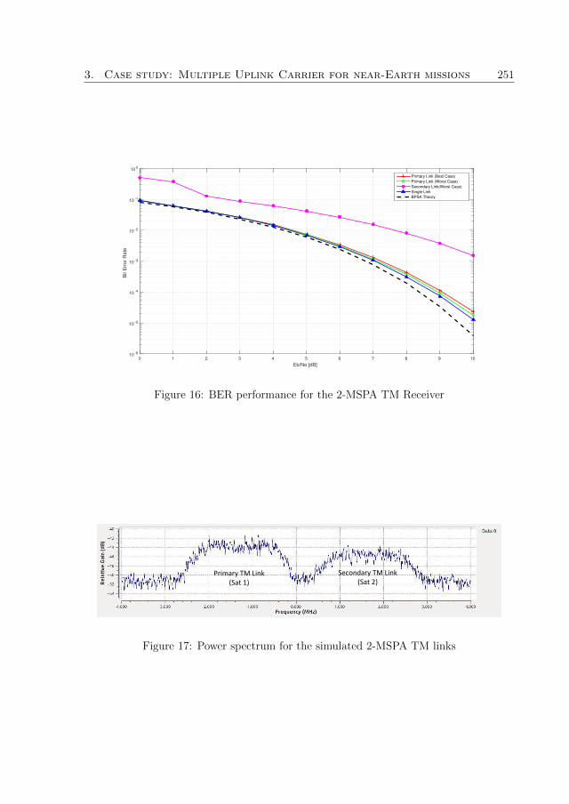
3. Case study: Multiple Uplink Carrier for near-Earth missions 251
Eb/No [dB]
0 1 2 3 4 5 6 7 8 9 10
Bit E
rro
r R
ate
10 -6
10 -5
10 -4
10 -3
10 -2
10 -1
10 0
Primary Link (Best Case)
Primary Link (Worst Case)
Secondary Link(Worst Case)
Single Link
BPSK Theory
Figure 16: BER performance for the 2-MSPA TM Receiver
Primary TM Link (Sat 1)
Secondary TM Link (Sat 2)
Figure 17: Power spectrum for the simulated 2-MSPA TM links

252 Paper G
4 Feasibility of MSPA in megaconstellations
Megaconstellations are constellations with a significantly large number of satellites. Theyaim at providing global coverage, commonly for communications. Example of mega-constellations includes SpaceX’s StarLink, OneWeb, Amazon’s Kuiper, LeoSat, Telesat,COMMStellation, and Boeing. These megaconstellations have more than 100’s or 1000’ssatellites each, and if they are all realized, they will result in a total estimate of 17,000satellites. With this large number of satellites, new challenges concerning interference,frequency assignment, and coordination occurs with regards to TT&C operations. MSPAis a technique that mitigates these challenges by operating in an interference-tolerantmode and potentially utilizing the fact that several spacecraft may be in the antennabeam simultaneously as an opportunity for MSPA.
In satellite constellations, the satellites are typically distributed over several orbitalplanes and spread within each orbital plane. The probability of having more than onespacecraft within an antenna beam will depend on several parameters, such as orbitinclination, antenna beamwidth, and latitude of the site. To make a first assessment ofthe possibility of MSPA for megaconstellations, we perform a simulation. As a baseline forthe simulation, we use the SpaceX StarLink Wikipedia data[20] along with other publicly-available literature sources. The employed data shall be seen as only an example of suchconstellation and has no further relevance. We use the open-source Orekit simulationtool[21] to perform the simulation. The simulated constellation has 1584 satellites spreadacross 72 orbital planes with 22 satellites per plane at a 550-km altitude. The simulationassumes a ground station located in Wisconsin, USA.
The antenna apertures available range between 0.5 and 7 meters. This range falls fromthe size of a consumer size parabolic antenna to the size of a typical antenna for high-endsatellite operators. With this, we simulate the probability of seeing multiple satellites inthe same antenna beam when TT&C frequencies are employed. The frequency and theantenna size affect the antenna beamwidth, a parameter that determines the resultingnumber of satellites in the antenna beam. We assume that the antenna is a full-motionantenna tracking one of the spacecraft above 5-degree elevation. The resulting probabilityof having several spacecraft within the antenna beam, for our single case, is illustratedin Fig. 18. For the smallest aperture, 0.5 m, there is always another satellite in the mainbeam for S-band frequency. There may be several different satellites visible during thepass, but there will always be at least one.
As these constellations are likely to use many antennas, there is an advantage toutilize small antennas to reduce cost. One way to mitigate the interference effects couldbe to use MSPA and perhaps take advantage of the opportunity to communicate withseveral spacecraft. Some conditions that apply for this is that the link budget still needsto hold as the antenna gain becomes lower with a wide antenna beam. Also, we needsimulations to evaluate the duration of mutual visibility and that the setup time for thelink allows this operation. Another factor to consider is that the general interference toother spacecraft outside the constellation may increase using small antennas.
We start with a simulation that assumes S-band (2.2 GHz), 1.8 m antennas, and the

4. Feasibility of MSPA in megaconstellations 253
Antenna Diameter (Meters)
1 2 3 4 5 6 7
Pro
ba
bili
ty o
f M
utu
al V
isib
ility
0
0.1
0.2
0.3
0.4
0.5
0.6
0.7
0.8
0.9
1
2.1 Ghz
7.2 Ghz
12.2 Ghz
23.0 Ghz
Figure 18: Probability of mutual visibility for a StarLink-like megaconstellation.
constellation setup above. The simulation shows a 38% mutual visibility during the passof a selected satellite. Fig. 19 illustrates the distribution of mutual visibility duration. Weassume that 15 seconds are needed to establish communications. With these assumptions,51% of the time consists of mutual visibility windows longer than 15-second durations.These windows can potentially support MSPA-based TT&C operations.
0.5 1.0 1.5 2.0 2.5Duration of Mutual Visibility [Minutes]
0
10
20
30
40
50
60
Coun
t of e
vent
s
Figure 19: Duration of mutual visibility for a StarLink-like megaconstellation.

254 Paper G
5 Conclusion
The feasibility of using a software-defined baseband (SDB) for MSPA ground operationshas been presented. The SDB transmitter has shown low out-of-band (OOB) missionsas well as minimal in-band interference. A case study that shows the utility of the SDBMSPA transceiver on near-Earth ground operations has also been presented. In the casestudy, we showed that a linearizer is needed to suppress intermodulation products (IMPs)on a typical SSPA amplifier. We recommended a software-defined linearizer that can beimplemented inside the SDB itself. The case study also shows that the SDB MSPAreceiver experiences minimal BER degradation so long as the separation in transmittingsatellite frequencies accounts for Doppler range and frequency offsets. Finally, the papershows that it is feasible to employ MSPA in TT&C operations for megaconstellations.
Acknowledgments
The authors would like to thank the Swedish Space Corporation (SSC) for the assistancein some of the technical works of this study. The funding provisions by the SwedishNational Space Agency (SNSA), the SSC, and Rymd for Innovation och Tillvaxt (RIT)are also acknowledged.

References 255
References
[1] National Aeronautics and Space Administration, “Mission operations and commu-nication services,” space communications and navigation program, National Aero-nautics and Space Administration, 2016.
[2] Z. Towfic, D. Heckman, D. Morabito, R. Rogalin, C. Okino, and D. Abraham,“Simulation and analysis of opportunistic mspa for multiple cubesat deployments,”SpaceOps Conferences, American Institute of Aeronautics and Astronautics, May2018.
[3] D. Abraham, S. Finley, D. Heckman, N. Lay, C. Lush, and B. MacNeal, “Oppor-tunistic mspa demonstration #1: Final report,” IPN Progress Report, vol. 42, pp. 1– 27, feb 2015.
[4] S. Marti and E. Vassallo, “Future multiple uplink per aperture access schemes,”AIAA SpaceOps Conferences, Jun 2012.
[5] S. Marti, S. Rawson, P. Maguire, and A. Aroumont, “Multiple spacecrafts per aper-ture (mspa) - short term and long-term solutions to ttc ground station design chal-lenges,” 6th ESA International Workshop on Tracking, Telemetry and CommandSystems for Space Applications, Sept 2013.
[6] European Space Agency, “First time controlling two spacecraft with onedish.” https://www.esa.int/Enabling_Support/Operations/First_time_
controlling_two_spacecraft_with_one_dish, 2020. Originally Published Feb5th.
[7] C. Amin, B. Sousa, M. Arza, M. Bartesaghi, and T. Costa, “Cluster multiple space-craft per aperture operations,” AIAA SpaceOps Conferences, May 2016.
[8] Consultative Committee for Space Data Systems (CCSDS), Radio frequency andmodulation systems - Part 1 Earth stations and spacecraft (401.0-B-26 Blue Book).National Aeronautics and Space Administration, Washington DC: CCSDS Secre-tariat, Oct 2016.
[9] M. Mwakyanjala, M. Emami, and J. van de Beek, “Functional analysis of software-defined radio baseband for satellite ground operations,” Journal of Spacecraft andRockets, vol. 56, pp. 458–475, Jan 2019.
[10] M. Mwakyanjala, C. Nieto-Peroy, M. Emami, and J. van de Beek, “Concurrentdevelopment and verification of an all-software baseband for satellite ground opera-tions,” International Journal of Satellite Communications and Networking, vol. 38,no. 2, pp. 209–227, 2020.
[11] GNURadio, “Gnuradio.” https://www.gnuradio.org/, Sep 2020. Accessed on Sep3rd.

256 Paper G
[12] Ettus Research, “Usrp b210 usb software defined radio (sdr).” https://www.ettus.
com/all-products/ub210-kit/, Sep 2020. Accessed on Sep 3rd.
[13] Empower RF Systems, Inc, “Solid state broadband high power amplifier.” https:
//www.empowerrf.com/pdfs/1119.pdf, Sep 2020. Accessed on Sep 3rd.
[14] T. Cornish, “Single-aperture multiple-carrier uplink using a 20 kilowatt x-bandtransmitter,” The Telecommunications and Mission Operations Progress Report,pp. 1 – 20, feb 2001.
[15] International Telecommunication Union, Spectrum requirements for future EESSmissions operating under a potential new EESS uplink allocation in the 7-8 GHzrange (ITU-R SA.2272). Washington DC: International Telecommunication Union,2013.
[16] Consultative Committee for Space Data Systems (CCSDS), TC Space Data LinkProtocol (232.0-B-3 Blue Book). National Aeronautics and Space Administration,Washington DC: CCSDS Secretariat, 2015.
[17] O. Brown and P. Eremenko, “The value proposition for fractionated space architec-tures,” AIAA Space 2006, June 2012.
[18] European Commission, “Low-earth orbit satellites: Spectrum access,” Digital Trans-formation Monitor, vol. 1, pp. 1–6, jul 2017.
[19] Consultative Committee for Space Data Systems (CCSDS), Bandwidth-EfficicientModulations : Summary of Definition, Implementation, and Performance (413.0-G-3 Green Book). National Aeronautics and Space Administration, Washington DC:CCSDS Secretariat, Feb 2018.
[20] Wikipedia, “Starlink - wikipedia.” https://en.wikipedia.org/wiki/Starlink.(Accessed on 12/12/2020).
[21] Orekit, “An accurate and efficient core layer for space flight dynamics applications.”https://www.orekit.org/, Sep 2020. Accessed on Sep 3rd.

DOCTORA L T H E S I S
Moses B
rowne M
wakyanjala A
Software-D
efined Baseband for Satellite G
round Operations
Department of Computer Science, Electrical and Space EngineeringDivision of Space Technology
ISSN 1402-1544ISBN 978-91-7790-717-6 (print)ISBN 978-91-7790-718-3 (pdf)
Luleå University of Technology 2021
A Software-Defined Baseband for
Satellite Ground OperationsFeasibility and Design
Moses Browne Mwakyanjala
Onboard Space Systems
133006-LTU_Mwakyanjala.indd Alla sidor133006-LTU_Mwakyanjala.indd Alla sidor 2021-01-07 10:032021-01-07 10:03