A Review of RFID Sensors, the New Frontier of Internet of Things
34
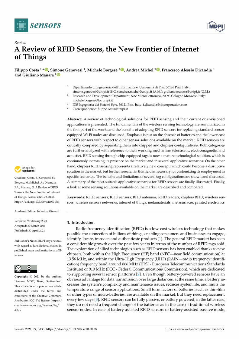
sensors Review A Review of RFID Sensors, the New Frontier of Internet of Things Filippo Costa 1, * , Simone Genovesi 1 , Michele Borgese 2 , Andrea Michel 1 , Francesco Alessio Dicandia 3 and Giuliano Manara 1 Citation: Costa, F.; Genovesi, S.; Borgese, M.; Michel, A.; Dicandia, F.A.; Manara, G. A Review of RFID Sensors, the New Frontier of Internet of Things. Sensors 2021, 21, 3138. https://doi.org/10.3390/s21093138 Academic Editor: Federico Alimenti Received: 9 February 2021 Accepted: 30 March 2021 Published: 30 April 2021 Publisher’s Note: MDPI stays neutral with regard to jurisdictional claims in published maps and institutional affil- iations. Copyright: © 2021 by the authors. Licensee MDPI, Basel, Switzerland. This article is an open access article distributed under the terms and conditions of the Creative Commons Attribution (CC BY) license (https:// creativecommons.org/licenses/by/ 4.0/). 1 Dipartimento di Ingegneria dell’Informazione, Università di Pisa, 56126 Pisa, Italy; [email protected] (S.G.); [email protected] (A.M.); [email protected] (G.M.) 2 Research and Development Department, Siae Microelettronica, 20093 Cologno Monzese, Italy; [email protected] 3 IDS Ingegneria dei Sistemi SpA, 56121 Pisa, Italy; [email protected] * Correspondence: fi[email protected] Abstract: A review of technological solutions for RFID sensing and their current or envisioned applications is presented. The fundamentals of the wireless sensing technology are summarized in the first part of the work, and the benefits of adopting RFID sensors for replacing standard sensor- equipped Wi-Fi nodes are discussed. Emphasis is put on the absence of batteries and the lower cost of RFID sensors with respect to other sensor solutions available on the market. RFID sensors are critically compared by separating them into chipped and chipless configurations. Both categories are further analyzed with reference to their working mechanism (electronic, electromagnetic, and acoustic). RFID sensing through chip-equipped tags is now a mature technological solution, which is continuously increasing its presence on the market and in several applicative scenarios. On the other hand, chipless RFID sensing represents a relatively new concept, which could become a disruptive solution in the market, but further research in this field is necessary for customizing its employment in specific scenarios. The benefits and limitations of several tag configurations are shown and discussed. A summary of the most suitable applicative scenarios for RFID sensors are finally illustrated. Finally, a look at some sensing solutions available on the market are described and compared. Keywords: RFID; sensors; RFID sensors; RFID antennas; RFID readers; chipless RFID; wireless sen- sors; wireless sensors networks; internet of things; metamaterials; metasurfaces; printed electronics 1. Introduction Radio frequency identification (RFID) is a low-cost wireless technology that makes possible the connection of billions of things, enabling consumers and businesses to engage, identify, locate, transact, and authenticate products [1]. The general RFID market has seen a considerable growth over the past few years in terms of the number of RFID tags sold. The exploration of allied technologies such as RFID sensors has been enabled thanks to new chipsets, both within the High Frequency (HF) band (NFC—near field communication) at 13.56 MHz, and within the Ultra-High Frequency (UHF) (RAIN—radio frequency identifi- cation) frequency band around 866 MHz (ETSI - European Telecommunications Standards Institute) or 910 MHz (FCC - Federal Communications Commission), which are dedicated to supporting several sensor platforms [2]. Even though battery-powered sensors have an obvious advantage for data transmission over large distances, at the same time, a battery in- creases the system’s complexity and maintenance issues, reduces system life, and limits the temperature range of sensor applications. Small form factors of batteries, such as thin-film or other types of micro-batteries, are available on the market, but they need replacement every few days [3]. RFID sensors can be fully passive, or battery powered; in the latter case, they do not need a frequent change of the batteries as in the case of traditional wireless sensor nodes. In case of battery assisted RFID sensors or battery-assisted passive mode, Sensors 2021, 21, 3138. https://doi.org/10.3390/s21093138 https://www.mdpi.com/journal/sensors
-
Upload
khangminh22 -
Category
Documents
-
view
1 -
download
0
Transcript of A Review of RFID Sensors, the New Frontier of Internet of Things
sensors
Review
A Review of RFID Sensors, the New Frontier of Internetof Things
Filippo Costa 1,* , Simone Genovesi 1, Michele Borgese 2 , Andrea Michel 1 , Francesco Alessio Dicandia 3
and Giuliano Manara 1
�����������������
Citation: Costa, F.; Genovesi, S.;
Borgese, M.; Michel, A.; Dicandia,
F.A.; Manara, G. A Review of RFID
Sensors, the New Frontier of Internet
of Things. Sensors 2021, 21, 3138.
https://doi.org/10.3390/s21093138
Academic Editor: Federico Alimenti
Received: 9 February 2021
Accepted: 30 March 2021
Published: 30 April 2021
Publisher’s Note: MDPI stays neutral
with regard to jurisdictional claims in
published maps and institutional affil-
iations.
Copyright: © 2021 by the authors.
Licensee MDPI, Basel, Switzerland.
This article is an open access article
distributed under the terms and
conditions of the Creative Commons
Attribution (CC BY) license (https://
creativecommons.org/licenses/by/
4.0/).
1 Dipartimento di Ingegneria dell’Informazione, Università di Pisa, 56126 Pisa, Italy;[email protected] (S.G.); [email protected] (A.M.); [email protected] (G.M.)
2 Research and Development Department, Siae Microelettronica, 20093 Cologno Monzese, Italy;[email protected]
3 IDS Ingegneria dei Sistemi SpA, 56121 Pisa, Italy; [email protected]* Correspondence: [email protected]
Abstract: A review of technological solutions for RFID sensing and their current or envisionedapplications is presented. The fundamentals of the wireless sensing technology are summarized inthe first part of the work, and the benefits of adopting RFID sensors for replacing standard sensor-equipped Wi-Fi nodes are discussed. Emphasis is put on the absence of batteries and the lower costof RFID sensors with respect to other sensor solutions available on the market. RFID sensors arecritically compared by separating them into chipped and chipless configurations. Both categoriesare further analyzed with reference to their working mechanism (electronic, electromagnetic, andacoustic). RFID sensing through chip-equipped tags is now a mature technological solution, which iscontinuously increasing its presence on the market and in several applicative scenarios. On the otherhand, chipless RFID sensing represents a relatively new concept, which could become a disruptivesolution in the market, but further research in this field is necessary for customizing its employment inspecific scenarios. The benefits and limitations of several tag configurations are shown and discussed.A summary of the most suitable applicative scenarios for RFID sensors are finally illustrated. Finally,a look at some sensing solutions available on the market are described and compared.
Keywords: RFID; sensors; RFID sensors; RFID antennas; RFID readers; chipless RFID; wireless sen-sors; wireless sensors networks; internet of things; metamaterials; metasurfaces; printed electronics
1. Introduction
Radio frequency identification (RFID) is a low-cost wireless technology that makespossible the connection of billions of things, enabling consumers and businesses to engage,identify, locate, transact, and authenticate products [1]. The general RFID market has seena considerable growth over the past few years in terms of the number of RFID tags sold.The exploration of allied technologies such as RFID sensors has been enabled thanks to newchipsets, both within the High Frequency (HF) band (NFC—near field communication) at13.56 MHz, and within the Ultra-High Frequency (UHF) (RAIN—radio frequency identifi-cation) frequency band around 866 MHz (ETSI - European Telecommunications StandardsInstitute) or 910 MHz (FCC - Federal Communications Commission), which are dedicatedto supporting several sensor platforms [2]. Even though battery-powered sensors have anobvious advantage for data transmission over large distances, at the same time, a battery in-creases the system’s complexity and maintenance issues, reduces system life, and limits thetemperature range of sensor applications. Small form factors of batteries, such as thin-filmor other types of micro-batteries, are available on the market, but they need replacementevery few days [3]. RFID sensors can be fully passive, or battery powered; in the latter case,they do not need a frequent change of the batteries as in the case of traditional wirelesssensor nodes. In case of battery assisted RFID sensors or battery-assisted passive mode,
Sensors 2021, 21, 3138. https://doi.org/10.3390/s21093138 https://www.mdpi.com/journal/sensors
Sensors 2021, 21, 3138 2 of 34
a simple circuit is built around the memory chip, thus enabling the chip to switch to alocal energy-assisted mode only when it senses a certain stimulus [4]. Instead, chip-basedpassive sensors acquire the power required for activation from the reader through wirelesspower transfer.
Different RFID sensors are currently proposed in terms of architecture, complexity,and system requirements. A chip-based design, where the sensor is integrated inside thechip, provides a reliable configuration, since the sensing and communication functionsare separated. Since embedding the sensor increases both tag size and cost, an alternativesolution is the functional integration of the antenna and the sensor component. The chal-lenge is then to transform the RFID tag antenna into a sensor. In antenna-based RFIDsensors, the response is more dependent on the environment. Today’s generation of passivetags has the ability to sense several environmental parameters such as light, humidity,and temperature, becoming a key technology for “object-based” services. The role of RFIDsystems can be extended, and even involve ubiquitous computing by moving from simplepassive tags to smart tags that can perform different functions, thanks to integrated sensorsand a microcontroller unit (MCU). Research is also active on the so-called chipless RFsensors that do not employ Integrated Circuits (ICs) and may offer the benefits of a longerlife and lower cost. Chipless RFID, also known as passive RFID sensors, are compatiblewith planar technology, allowing them to be produced by roll-to-roll processing.
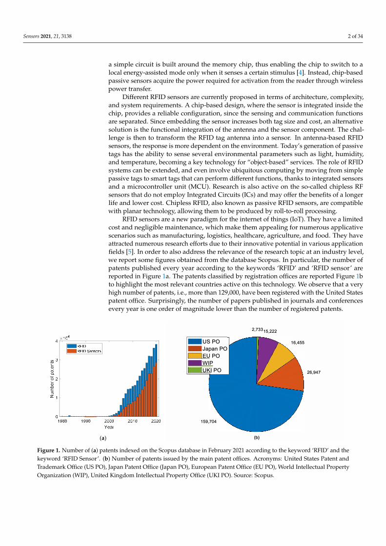
RFID sensors are a new paradigm for the internet of things (IoT). They have a limitedcost and negligible maintenance, which make them appealing for numerous applicativescenarios such as manufacturing, logistics, healthcare, agriculture, and food. They haveattracted numerous research efforts due to their innovative potential in various applicationfields [5]. In order to also address the relevance of the research topic at an industry level,we report some figures obtained from the database Scopus. In particular, the number ofpatents published every year according to the keywords ‘RFID’ and ‘RFID sensor’ arereported in Figure 1a. The patents classified by registration offices are reported Figure 1bto highlight the most relevant countries active on this technology. We observe that a veryhigh number of patents, i.e., more than 129,000, have been registered with the United Statespatent office. Surprisingly, the number of papers published in journals and conferencesevery year is one order of magnitude lower than the number of registered patents.
Sensors 2021, 21, x FOR PEER REVIEW 2 of 35
or battery powered; in the latter case, they do not need a frequent change of the batteries as in the case of traditional wireless sensor nodes. In case of battery assisted RFID sensors or battery-assisted passive mode, a simple circuit is built around the memory chip, thus enabling the chip to switch to a local energy-assisted mode only when it senses a certain stimulus [4]. Instead, chip-based passive sensors acquire the power required for activation from the reader through wireless power transfer.
Different RFID sensors are currently proposed in terms of architecture, complexity, and system requirements. A chip-based design, where the sensor is integrated inside the chip, provides a reliable configuration, since the sensing and communication functions are separated. Since embedding the sensor increases both tag size and cost, an alternative solution is the functional integration of the antenna and the sensor component. The chal-lenge is then to transform the RFID tag antenna into a sensor. In antenna-based RFID sen-sors, the response is more dependent on the environment. Today’s generation of passive tags has the ability to sense several environmental parameters such as light, humidity, and temperature, becoming a key technology for “object-based” services. The role of RFID systems can be extended, and even involve ubiquitous computing by moving from simple passive tags to smart tags that can perform different functions, thanks to integrated sen-sors and a microcontroller unit (MCU). Research is also active on the so-called chipless RF sensors that do not employ Integrated Circuits (ICs) and may offer the benefits of a longer life and lower cost. Chipless RFID, also known as passive RFID sensors, are compatible with planar technology, allowing them to be produced by roll-to-roll processing.
RFID sensors are a new paradigm for the internet of things (IoT). They have a limited cost and negligible maintenance, which make them appealing for numerous applicative scenarios such as manufacturing, logistics, healthcare, agriculture, and food. They have attracted numerous research efforts due to their innovative potential in various applica-tion fields [5]. In order to also address the relevance of the research topic at an industry level, we report some figures obtained from the database Scopus. In particular, the num-ber of patents published every year according to the keywords ‘RFID’ and ‘RFID sensor’ are reported in Figure 1a. The patents classified by registration offices are reported Figure 1b to highlight the most relevant countries active on this technology. We observe that a very high number of patents, i.e., more than 129,000, have been registered with the United States patent office. Surprisingly, the number of papers published in journals and confer-ences every year is one order of magnitude lower than the number of registered patents.
(a) (b)
Figure 1. Number of (a) patents indexed on the Scopus database in February 2021 according to the keyword ‘RFID’ and the keyword ‘RFID Sensor’. (b) Number of patents issued by the main patent offices. Acronyms: United States Patent and Trademark Office (US PO), Japan Patent Office (Japan PO), European Patent Office (EU PO), World Intellectual Property Organization (WIP), United Kingdom Intellectual Property Office (UKI PO). Source: Scopus.
2. From Wi-Fi Nodes to RFID Sensors
(http://creativecommons.org/li-
censes/by/4.0/).
-USPO-Japan POI IEU PO -WIP
I IUKI PO
159,704
2,733 15,222
16,455
26,947
(b)
Figure 1. Number of (a) patents indexed on the Scopus database in February 2021 according to the keyword ‘RFID’ and thekeyword ‘RFID Sensor’. (b) Number of patents issued by the main patent offices. Acronyms: United States Patent andTrademark Office (US PO), Japan Patent Office (Japan PO), European Patent Office (EU PO), World Intellectual PropertyOrganization (WIP), United Kingdom Intellectual Property Office (UKI PO). Source: Scopus.
Sensors 2021, 21, 3138 3 of 34
2. From Wi-Fi Nodes to RFID Sensors
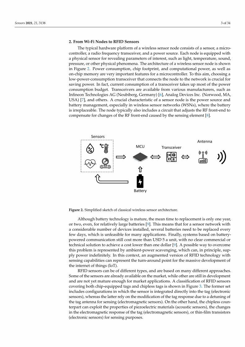
The typical hardware platform of a wireless sensor node consists of a sensor, a micro-controller, a radio frequency transceiver, and a power source. Each node is equipped witha physical sensor for revealing parameters of interest, such as light, temperature, sound,pressure, or other physical phenomena. The architecture of a wireless sensor node is shownin Figure 2. Power consumption, chip footprint, and computational power, as well ason-chip memory are very important features for a microcontroller. To this aim, choosing alow-power-consumption transceiver that connects the node to the network is crucial forsaving power. In fact, current consumption of a transceiver takes up most of the powerconsumption budget. Transceivers are available from various manufacturers, such asInfineon Technologies AG (Neubiberg, Germany) [6], Analog Devices Inc. (Norwood, MA,USA) [7], and others. A crucial characteristic of a sensor node is the power source andbattery management, especially in wireless sensor networks (WSNs), where the batteryis irreplaceable. The node typically also includes a circuit that adjusts the RF front-end tocompensate for changes of the RF front-end caused by the sensing element [8].
MCU
Transceiver
Antenna
Battery
MCU
Sensors
Figure 2. Simplified sketch of classical wireless sensor architecture.
Although battery technology is mature, the mean time to replacement is only one year,or two, even, for relatively large batteries [9]. This means that for a sensor network witha considerable number of devices installed, several batteries need to be replaced everyfew days, which is unfeasible for many applications. Finally, systems based on battery-powered communication still cost more than USD 5 a unit, with no clear commercial ortechnical solution to achieve a cost lower than one dollar [9]. A possible way to overcomethis problem is represented by ambient-power scavenging, which can, in principle, sup-ply power indefinitely. In this context, an augmented version of RFID technology withsensing capabilities can represent the turn-around point for the massive development ofthe internet of things (IoT).
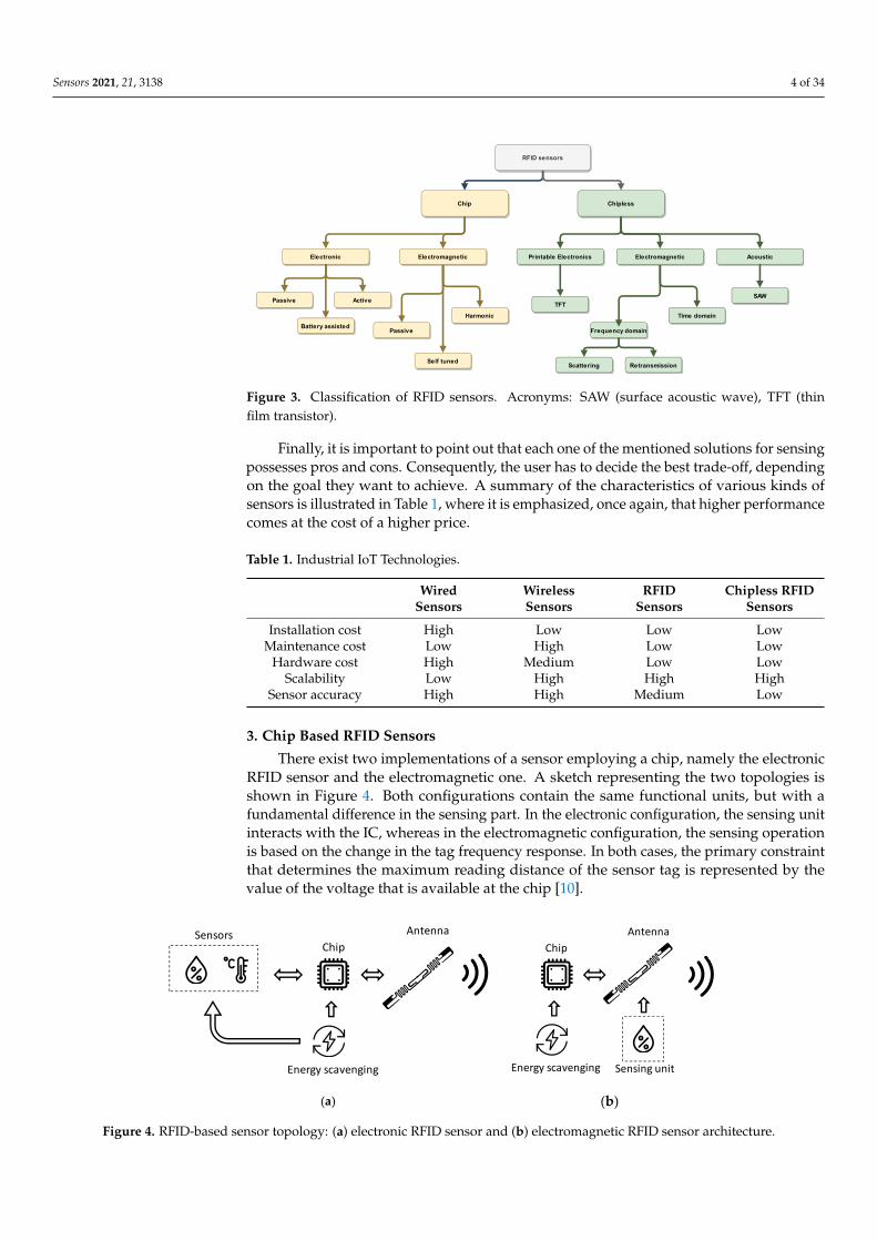
RFID sensors can be of different types, and are based on many different approaches.Some of the sensors are already available on the market, while other are still in developmentand are not yet mature enough for market applications. A classification of RFID sensorscovering both chip-equipped tags and chipless tags is shown in Figure 3. The former setincludes configurations in which the sensor is integrated directly into the tag (electronicsensors), whereas the latter rely on the modification of the tag response due to a detuning ofthe tag antenna for sensing (electromagnetic sensors). On the other hand, the chipless coun-terpart can exploit the properties of piezoelectric materials (acoustic sensors), the changesin the electromagnetic response of the tag (electromagnetic sensors), or thin-film transistors(electronic sensors) for sensing purposes.
Sensors 2021, 21, 3138 4 of 34Sensors 2021, 21, x FOR PEER REVIEW 5 of 36
Figure 3. Classification of RFID sensors. Acronyms: SAW (surface acoustic wave), TFT (thin film
transistor).
Finally, it is important to point out that each one of the mentioned solutions for sens-
ing possesses pros and cons. Consequently, the user has to decide the best trade-off, de-
pending on the goal they want to achieve. A summary of the characteristics of various
kinds of sensors is illustrated in Table 1, where it is emphasized, once again, that higher
performance comes at the cost of a higher price.
Table 1. Industrial IoT Technologies.
Wired
Sensors
Wireless
Sensors
RFID
Sensors
Chipless RFID
Sensors
Installation cost High Low Low Low
Maintenance cost Low High Low Low
Hardware cost High Medium Low Low
Scalability Low High High High
Sensor accuracy High High Medium Low
3. Chip Based RFID Sensors
There exist two implementations of a sensor employing a chip, namely the electronic
RFID sensor and the electromagnetic one. A sketch representing the two topologies is
shown in Figure 4. Both configurations contain the same functional units, but with a fun-
damental difference in the sensing part. In the electronic configuration, the sensing unit
interacts with the IC, whereas in the electromagnetic configuration, the sensing operation
is based on the change in the tag frequency response. In both cases, the primary constraint
that determines the maximum reading distance of the sensor tag is represented by the
value of the voltage that is available at the chip [10].
(a) (b)
Figure 4. RFID-based sensor topology: (a) electronic RFID sensor and (b) electromagnetic RFID
sensor architecture.
Figure 3. Classification of RFID sensors. Acronyms: SAW (surface acoustic wave), TFT (thinfilm transistor).
Finally, it is important to point out that each one of the mentioned solutions for sensingpossesses pros and cons. Consequently, the user has to decide the best trade-off, dependingon the goal they want to achieve. A summary of the characteristics of various kinds ofsensors is illustrated in Table 1, where it is emphasized, once again, that higher performancecomes at the cost of a higher price.
Table 1. Industrial IoT Technologies.
WiredSensors
WirelessSensors
RFIDSensors
Chipless RFIDSensors
Installation cost High Low Low LowMaintenance cost Low High Low Low
Hardware cost High Medium Low LowScalability Low High High High
Sensor accuracy High High Medium Low
3. Chip Based RFID Sensors
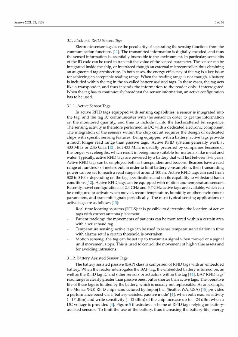
There exist two implementations of a sensor employing a chip, namely the electronicRFID sensor and the electromagnetic one. A sketch representing the two topologies isshown in Figure 4. Both configurations contain the same functional units, but with afundamental difference in the sensing part. In the electronic configuration, the sensing unitinteracts with the IC, whereas in the electromagnetic configuration, the sensing operationis based on the change in the tag frequency response. In both cases, the primary constraintthat determines the maximum reading distance of the sensor tag is represented by thevalue of the voltage that is available at the chip [10].
Sensors 2021, 21, x FOR PEER REVIEW 5 of 36
Figure 3. Classification of RFID sensors. Acronyms: SAW (surface acoustic wave), TFT (thin film
transistor).
Finally, it is important to point out that each one of the mentioned solutions for sens-
ing possesses pros and cons. Consequently, the user has to decide the best trade-off, de-
pending on the goal they want to achieve. A summary of the characteristics of various
kinds of sensors is illustrated in Table 1, where it is emphasized, once again, that higher
performance comes at the cost of a higher price.
Table 1. Industrial IoT Technologies.
Wired
Sensors
Wireless
Sensors
RFID
Sensors
Chipless RFID
Sensors
Installation cost High Low Low Low
Maintenance cost Low High Low Low
Hardware cost High Medium Low Low
Scalability Low High High High
Sensor accuracy High High Medium Low
3. Chip Based RFID Sensors
There exist two implementations of a sensor employing a chip, namely the electronic
RFID sensor and the electromagnetic one. A sketch representing the two topologies is
shown in Figure 4. Both configurations contain the same functional units, but with a fun-
damental difference in the sensing part. In the electronic configuration, the sensing unit
interacts with the IC, whereas in the electromagnetic configuration, the sensing operation
is based on the change in the tag frequency response. In both cases, the primary constraint
that determines the maximum reading distance of the sensor tag is represented by the
value of the voltage that is available at the chip [10].
(a) (b)
Figure 4. RFID-based sensor topology: (a) electronic RFID sensor and (b) electromagnetic RFID
sensor architecture.
Figure 4. RFID-based sensor topology: (a) electronic RFID sensor and (b) electromagnetic RFID sensor architecture.
Sensors 2021, 21, 3138 5 of 34
3.1. Electronic RFID Sensors Tags
Electronic sensor tags have the peculiarity of separating the sensing functions from thecommunication functions [11]. The transmitted information is digitally encoded, and thusthe sensed information is essentially insensible to the environment. In particular, some bitsof the ID code can be used to transmit the value of the sensed parameter. The sensor can beintegrated inside the chip, or interfaced though an external microcontroller, thus obtainingan augmented tag architecture. In both cases, the energy efficiency of the tag is a key issuefor achieving an acceptable reading range. When the reading range is not enough, a batteryis included within the tag in the so-called battery assisted tags. In these cases, the tag actslike a transponder, and thus it sends the information to the reader only if interrogated.When the tag has to continuously broadcast the sensor information, an active configurationhas to be used.
3.1.1. Active Sensor Tags
In active RFID tags equipped with sensing capabilities, a sensor is integrated intothe tag, and the tag IC communicates with the sensor in order to get the informationon the monitored quantity, and thus to include it into the backscattered bit sequence.The sensing activity is therefore performed in DC with a dedicated electronic component.The integration of the sensors within the chip circuit requires the design of dedicatedchips with specific sensing features. Being equipped with a battery, active tags providea much longer read range than passive tags. Active RFID systems generally work at433 MHz or 2.45 GHz [12], but 433 MHz is usually preferred by companies because ofthe longer wavelengths, which result in being more suitable for materials like metal andwater. Typically, active RFID tags are powered by a battery that will last between 3–5 years.Active RFID tags can be employed both as transponders and beacons. Beacons have a readrange of hundreds of meters but, in order to limit battery consumption, their transmittingpower can be set to reach a read range of around 100 m. Active RFID tags can cost from$20 to $100+ depending on the tag specifications and on its capability to withstand harshconditions [12]. Active RFID tags can be equipped with motion and temperature sensors.Recently, novel configurations of 2.4 GHz and 5.7 GHz active tags are available, which canbe configured to activate when moved, record temperature, humidity or other environmentparameters, and transmit signals periodically. The most typical sensing applications ofactive tags are as follows [13]:
- Real-time locating systems (RTLS): it is possible to determine the location of activetags with correct antenna placement.
- Patient tracking: the movements of patients can be monitored within a certain areawith a wrist band tag.
- Temperature sensing: active tags can be used to sense temperature variation in timewith alarms set if a certain threshold is overtaken.
- Motion sensing: the tag can be set up to transmit a signal when moved or a signaluntil movement stops. This is used to control the movement of high value assets andfor avoiding intrusions.
3.1.2. Battery Assisted Sensor Tags
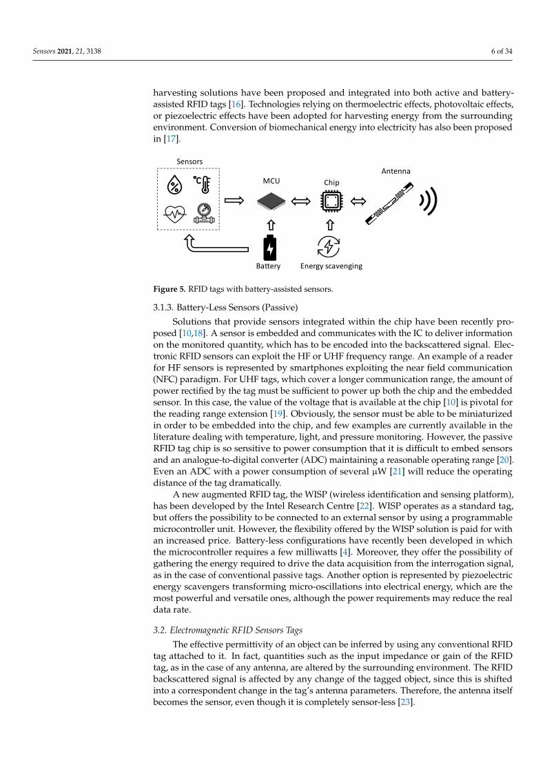
The battery assisted passive (BAP) class is comprised of RFID tags with an embeddedbattery. When the reader interrogates the BAP tag, the embedded battery is turned on, aswell as the RFID tag IC and other sensors or actuators within the tag [14]. BAP RFID tags’read range is clearly greater than passive ones, but is shorter than active tags. The operativelife of these tags is limited by the battery, which is usually not replaceable. As an example,the Monza X-2K RFID chip manufactured by Impinj Inc. (Seattle, WA, USA) [15] providesa performance boost via a ‘battery-assisted passive mode’ [4], when both read sensitivity(−17 dBm) and write sensitivity (−12 dBm) of the chip increase up to −24 dBm when aDC voltage is provided [4]. Figure 5 illustrates a scheme of RFID tags relying on battery-assisted sensors. To limit the use of the battery, thus increasing the battery-life, energy
Sensors 2021, 21, 3138 6 of 34
harvesting solutions have been proposed and integrated into both active and battery-assisted RFID tags [16]. Technologies relying on thermoelectric effects, photovoltaic effects,or piezoelectric effects have been adopted for harvesting energy from the surroundingenvironment. Conversion of biomechanical energy into electricity has also been proposedin [17].
Sensors 2021, 21, x FOR PEER REVIEW 7 of 36
on battery-assisted sensors. To limit the use of the battery, thus increasing the battery-life,
energy harvesting solutions have been proposed and integrated into both active and bat-
tery-assisted RFID tags [16]. Technologies relying on thermoelectric effects, photovoltaic
effects, or piezoelectric effects have been adopted for harvesting energy from the sur-
rounding environment. Conversion of biomechanical energy into electricity has also been
proposed in [17].
Figure 5. RFID tags with battery-assisted sensors.
3.1.3. Battery-Less Sensors (Passive)
Solutions that provide sensors integrated within the chip have been recently pro-
posed [10,18]. A sensor is embedded and communicates with the IC to deliver information
on the monitored quantity, which has to be encoded into the backscattered signal. Elec-
tronic RFID sensors can exploit the HF or UHF frequency range. An example of a reader
for HF sensors is represented by smartphones exploiting the near field communication
(NFC) paradigm. For UHF tags, which cover a longer communication range, the amount
of power rectified by the tag must be sufficient to power up both the chip and the embed-
ded sensor. In this case, the value of the voltage that is available at the chip [10] is pivotal
for the reading range extension [19]. Obviously, the sensor must be able to be miniaturized
in order to be embedded into the chip, and few examples are currently available in the
literature dealing with temperature, light, and pressure monitoring. However, the passive
RFID tag chip is so sensitive to power consumption that it is difficult to embed sensors
and an analogue-to-digital converter (ADC) maintaining a reasonable operating range
[20]. Even an ADC with a power consumption of several µW [21] will reduce the operating
distance of the tag dramatically.
A new augmented RFID tag, the WISP (wireless identification and sensing platform),
has been developed by the Intel Research Centre [22]. WISP operates as a standard tag,
but offers the possibility to be connected to an external sensor by using a programmable
microcontroller unit. However, the flexibility offered by the WISP solution is paid for with
an increased price. Battery-less configurations have recently been developed in which the
microcontroller requires a few milliwatts [4]. Moreover, they offer the possibility of gath-
ering the energy required to drive the data acquisition from the interrogation signal, as in
the case of conventional passive tags. Another option is represented by piezoelectric en-
ergy scavengers transforming micro-oscillations into electrical energy, which are the most
powerful and versatile ones, although the power requirements may reduce the real data
rate.
3.2. Electromagnetic RFID Sensors Tags
The effective permittivity of an object can be inferred by using any conventional RFID
tag attached to it. In fact, quantities such as the input impedance or gain of the RFID tag,
as in the case of any antenna, are altered by the surrounding environment. The RFID
backscattered signal is affected by any change of the tagged object, since this is shifted
Figure 5. RFID tags with battery-assisted sensors.
3.1.3. Battery-Less Sensors (Passive)
Solutions that provide sensors integrated within the chip have been recently pro-posed [10,18]. A sensor is embedded and communicates with the IC to deliver informationon the monitored quantity, which has to be encoded into the backscattered signal. Elec-tronic RFID sensors can exploit the HF or UHF frequency range. An example of a readerfor HF sensors is represented by smartphones exploiting the near field communication(NFC) paradigm. For UHF tags, which cover a longer communication range, the amount ofpower rectified by the tag must be sufficient to power up both the chip and the embeddedsensor. In this case, the value of the voltage that is available at the chip [10] is pivotal forthe reading range extension [19]. Obviously, the sensor must be able to be miniaturizedin order to be embedded into the chip, and few examples are currently available in theliterature dealing with temperature, light, and pressure monitoring. However, the passiveRFID tag chip is so sensitive to power consumption that it is difficult to embed sensorsand an analogue-to-digital converter (ADC) maintaining a reasonable operating range [20].Even an ADC with a power consumption of several µW [21] will reduce the operatingdistance of the tag dramatically.
A new augmented RFID tag, the WISP (wireless identification and sensing platform),has been developed by the Intel Research Centre [22]. WISP operates as a standard tag,but offers the possibility to be connected to an external sensor by using a programmablemicrocontroller unit. However, the flexibility offered by the WISP solution is paid for withan increased price. Battery-less configurations have recently been developed in whichthe microcontroller requires a few milliwatts [4]. Moreover, they offer the possibility ofgathering the energy required to drive the data acquisition from the interrogation signal,as in the case of conventional passive tags. Another option is represented by piezoelectricenergy scavengers transforming micro-oscillations into electrical energy, which are themost powerful and versatile ones, although the power requirements may reduce the realdata rate.
3.2. Electromagnetic RFID Sensors Tags
The effective permittivity of an object can be inferred by using any conventional RFIDtag attached to it. In fact, quantities such as the input impedance or gain of the RFIDtag, as in the case of any antenna, are altered by the surrounding environment. The RFIDbackscattered signal is affected by any change of the tagged object, since this is shiftedinto a correspondent change in the tag’s antenna parameters. Therefore, the antenna itselfbecomes the sensor, even though it is completely sensor-less [23].
Sensors 2021, 21, 3138 7 of 34
Electromagnetic tags rely on the modification of the tag response due to an occasionalmodification of the antenna. The antenna behavior can be modified essentially for tworeasons: a change in the electrical conductivity of the antenna, or a part of it; or because of achange of the dielectric permittivity of the medium surrounding the antenna, or a part of it.In the first case, the sensor is classified as resistive, and in the second case, the sensor can beclassified as capacitive. Notably, in both cases, the transduction mechanism is influencingradio frequency waves and thus the sensors are referred to as electromagnetic.
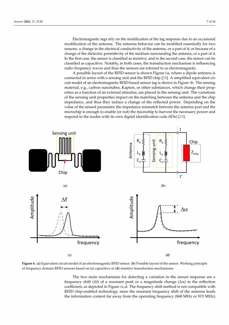
A possible layout of the RFID sensor is shown Figure 6a, where a dipole antenna isconnected in series with a sensing unit and the RFID chip [24]. A simplified equivalent cir-cuit model of an electromagnetic RFID-based sensor tag is shown in Figure 6b. The sensingmaterial, e.g., carbon nanotubes, Kapton, or other substances, which change their prop-erties as a function of an external stimulus, are placed in the sensing unit. The variationsof the sensing unit properties impact on the matching between the antenna and the chipimpedance, and thus they induce a change of the reflected power. Depending on thevalue of the sensed parameter, the impedance mismatch between the antenna port and themicrochip is enough to enable (or not) the microchip to harvest the necessary power andrespond to the reader with its own digital identification code (IDn) [23].
Sensors 2021, 21, x FOR PEER REVIEW 8 of 36
into a correspondent change in the tag’s antenna parameters. Therefore, the antenna itself
becomes the sensor, even though it is completely sensor-less [23].
Electromagnetic tags rely on the modification of the tag response due to an occasional
modification of the antenna. The antenna behavior can be modified essentially for two
reasons: a change in the electrical conductivity of the antenna, or a part of it; or because of
a change of the dielectric permittivity of the medium surrounding the antenna, or a part
of it. In the first case, the sensor is classified as resistive, and in the second case, the sensor
can be classified as capacitive. Notably, in both cases, the transduction mechanism is in-
fluencing radio frequency waves and thus the sensors are referred to as electromagnetic.
A possible layout of the RFID sensor is shown Figure 6a, where a dipole antenna is
connected in series with a sensing unit and the RFID chip [24]. A simplified equivalent
circuit model of an electromagnetic RFID-based sensor tag is shown in Figure 6b. The
sensing material, e.g., carbon nanotubes, Kapton, or other substances, which change their
properties as a function of an external stimulus, are placed in the sensing unit. The varia-
tions of the sensing unit properties impact on the matching between the antenna and the
chip impedance, and thus they induce a change of the reflected power. Depending on the
value of the sensed parameter, the impedance mismatch between the antenna port and
the microchip is enough to enable (or not) the microchip to harvest the necessary power
and respond to the reader with its own digital identification code (IDn) [23].
The two main mechanisms for detecting a variation in the sensor response are a fre-
quency shift (f) of a resonant peak or a magnitude change (α) in the reflection coeffi-
cient, as depicted in Figure 6c–d. The frequency shift method is not compatible with RFID
chip-enabled technology, since the resonant frequency shift of the antenna leads the in-
formation content far away from the operating frequency (868 MHz or 915 MHz). There-
fore, magnitude change configuration is the most popular approach for RFID-based sen-
sors.
An alternative sensor topology consists of equipping the tag with a real sensor (mo-
tion, temperature, pressure, or other), which could be either connected in a region of the
tag’s antenna or distributed over the antenna surface as a paint. The variation in the im-
pedance loading caused by the change of the environment will produce a change of the
tag’s radar cross-section and, hence, a backscattered power modulation, as in the case of
sensor-less tags [23].
(a) (b)
Sensing unit
Chip
Ca
La
Ra
An
ten
na Chip
Zchip
Ca
La
Ra
Sen
sin
g u
nit
1
1’
Sensors 2021, 21, x FOR PEER REVIEW 9 of 36
(c) (d)
Figure 6. (a) Equivalent circuit model of an electromagnetic RFID sensor. (b) Possible layout of the sensor. Working prin-
ciple of frequency domain RFID sensors based on (c) capacitive or (d) resistive transduction mechanisms.
3.2.1. Self-Tuned Chips
In the case of electromagnetic RFID sensor tags, the antenna accomplishes two dif-
ferent functions, namely the communication and the sensing tasks. However, they cannot
be pursued independently or maximized at the same time, since the sensing is performed
at the expense of the communication function. In fact, the tag must suffer a certain level
of mismatch in order to indirectly provide information about the variation of the meas-
urements. The reason for this is that the sensing information is strictly related to the de-
tuning level of the RFID tag, and hence the communication and sensing capabilities have
conflicting requirements. A recent solution to this problem has been offered by self-tuning
microchips [25–27] that can cope with the undesired tag detuning without harming the
sensing function [28]. The equivalent circuit of an RFID tag with self-tuning capability is
illustrated in Figure 7a. The working principle can be explained by considering that the
RFID tag is placed on an item that drastically alters its antenna impedance with respect to
the free space case. This means that the original antenna is detuned, and the impedance
ZA = RA + jXA, which was designed to properly match the impedance of the chip, ZC, may
be far from the optimal condition ZC = (ZA)*, and therefore the communication may be
severely compromised.
(a) (b)
Figure 7. (a) Equivalent circuit of an RFID tag equipped with a self-tuning chip and (b) an example of the exploitation of
the autotuning feature for indirect sensing.
frequency
Am
plit
ud
e f
frequency
Am
plit
ud
e
a
Figure 6. (a) Equivalent circuit model of an electromagnetic RFID sensor. (b) Possible layout of the sensor. Working principleof frequency domain RFID sensors based on (c) capacitive or (d) resistive transduction mechanisms.
The two main mechanisms for detecting a variation in the sensor response are afrequency shift (∆f) of a resonant peak or a magnitude change (∆α) in the reflectioncoefficient, as depicted in Figure 6c,d. The frequency shift method is not compatible withRFID chip-enabled technology, since the resonant frequency shift of the antenna leadsthe information content far away from the operating frequency (868 MHz or 915 MHz).
Sensors 2021, 21, 3138 8 of 34
Therefore, magnitude change configuration is the most popular approach for RFID-basedsensors.
An alternative sensor topology consists of equipping the tag with a real sensor (motion,temperature, pressure, or other), which could be either connected in a region of the tag’santenna or distributed over the antenna surface as a paint. The variation in the impedanceloading caused by the change of the environment will produce a change of the tag’s radarcross-section and, hence, a backscattered power modulation, as in the case of sensor-lesstags [23].
3.2.1. Self-Tuned Chips
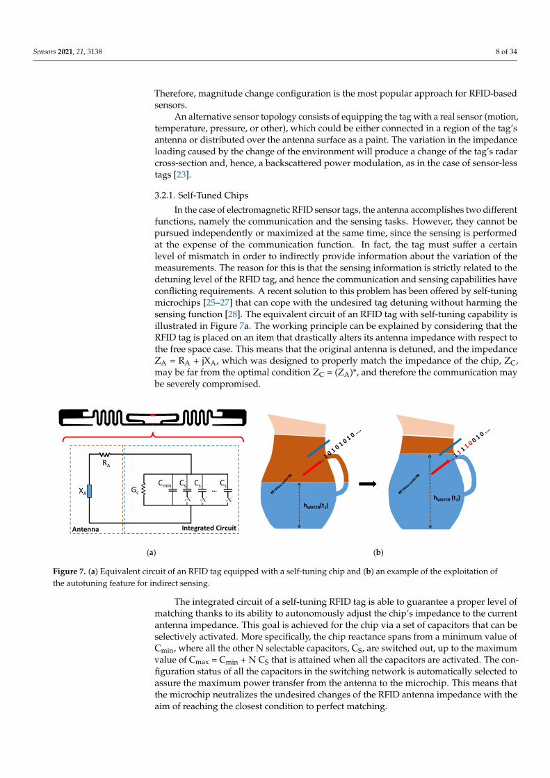
In the case of electromagnetic RFID sensor tags, the antenna accomplishes two differentfunctions, namely the communication and the sensing tasks. However, they cannot bepursued independently or maximized at the same time, since the sensing is performedat the expense of the communication function. In fact, the tag must suffer a certainlevel of mismatch in order to indirectly provide information about the variation of themeasurements. The reason for this is that the sensing information is strictly related to thedetuning level of the RFID tag, and hence the communication and sensing capabilities haveconflicting requirements. A recent solution to this problem has been offered by self-tuningmicrochips [25–27] that can cope with the undesired tag detuning without harming thesensing function [28]. The equivalent circuit of an RFID tag with self-tuning capability isillustrated in Figure 7a. The working principle can be explained by considering that theRFID tag is placed on an item that drastically alters its antenna impedance with respect tothe free space case. This means that the original antenna is detuned, and the impedanceZA = RA + jXA, which was designed to properly match the impedance of the chip, ZC,may be far from the optimal condition ZC = (ZA)*, and therefore the communication maybe severely compromised.
Sensors 2021, 21, x FOR PEER REVIEW 9 of 36
(c) (d)
Figure 6. (a) Equivalent circuit model of an electromagnetic RFID sensor. (b) Possible layout of the sensor. Working prin-
ciple of frequency domain RFID sensors based on (c) capacitive or (d) resistive transduction mechanisms.
3.2.1. Self-Tuned Chips
In the case of electromagnetic RFID sensor tags, the antenna accomplishes two dif-
ferent functions, namely the communication and the sensing tasks. However, they cannot
be pursued independently or maximized at the same time, since the sensing is performed
at the expense of the communication function. In fact, the tag must suffer a certain level
of mismatch in order to indirectly provide information about the variation of the meas-
urements. The reason for this is that the sensing information is strictly related to the de-
tuning level of the RFID tag, and hence the communication and sensing capabilities have
conflicting requirements. A recent solution to this problem has been offered by self-tuning
microchips [25–27] that can cope with the undesired tag detuning without harming the
sensing function [28]. The equivalent circuit of an RFID tag with self-tuning capability is
illustrated in Figure 7a. The working principle can be explained by considering that the
RFID tag is placed on an item that drastically alters its antenna impedance with respect to
the free space case. This means that the original antenna is detuned, and the impedance
ZA = RA + jXA, which was designed to properly match the impedance of the chip, ZC, may
be far from the optimal condition ZC = (ZA)*, and therefore the communication may be
severely compromised.
(a) (b)
Figure 7. (a) Equivalent circuit of an RFID tag equipped with a self-tuning chip and (b) an example of the exploitation of
the autotuning feature for indirect sensing.
frequency
Am
plit
ud
e f
frequency
Am
plit
ud
e
a
Figure 7. (a) Equivalent circuit of an RFID tag equipped with a self-tuning chip and (b) an example of the exploitation ofthe autotuning feature for indirect sensing.
The integrated circuit of a self-tuning RFID tag is able to guarantee a proper level ofmatching thanks to its ability to autonomously adjust the chip’s impedance to the currentantenna impedance. This goal is achieved for the chip via a set of capacitors that can beselectively activated. More specifically, the chip reactance spans from a minimum value ofCmin, where all the other N selectable capacitors, CS, are switched out, up to the maximumvalue of Cmax = Cmin + N CS that is attained when all the capacitors are activated. The con-figuration status of all the capacitors in the switching network is automatically selected toassure the maximum power transfer from the antenna to the microchip. This means thatthe microchip neutralizes the undesired changes of the RFID antenna impedance with theaim of reaching the closest condition to perfect matching.
Sensors 2021, 21, 3138 9 of 34
The adaptive matching feature exhibited by this kind of RFID tag can also be advan-tageously exploited for sensing purposes. In fact, the self-tunable chip sends to the RFIDreader the information written in its memory, as well as the state of the selectable capacitors.This string of bits is related to the detuning undergone by the RFID tag, and indirectlyprovides information on the environmental change in which the tag is operating. It is thenpossible to infer the value of a physical parameter that affects the tag from the state ofthe automatic tuning network. Figure 7b illustrates an applicative scenario in which anRFID tag is applied to a container in which the level of water (hWATER) can change overtime. Every time the tag is interrogated, it also provides the status of the internal matchingnetwork that allows it to be matched and running in the complex operational environment.The encoded sequence of the capacitors selected in the tunable matching network at timet1 is embedded in the backscattered signal. When the water level is changed at time t2,the tunable matching network is set to the new status of the capacitors, since the effect ofthe environment has changed. The change of the matching network settings that has beenencoded in the backscattered signal allows for indirectly estimating the level of the water.Obviously, the limited number of capacitors in the switching network, and also their rangeof values, have an impact on the resolution of the monitored physical parameter [29].
3.2.2. Harmonic Tags
An alternative implementation of RFID sensors is based on the so-called harmonic orsecondary radar [30]. In this configuration, the tag receives the interrogation at a certainfrequency, and it scatters back at a harmonic frequency. A typical implementation ofharmonic tags employs the second harmonic frequency (2f0).
The reason for using harmonic tag configuration relies on the possibility of obtaining abetter immunity of the tag response in the presence of clutter. Indeed, it can be reasonablyassumed that most of the objects surrounding that tag do not possess nonlinear properties,which may cause the reflection of harmonic frequencies.
An harmonic transponder is usually synthesized through a Schottky diode and anantenna [30–32]. The Schottky diode should be able to perform the frequency multipli-cation as efficiently as possible to 2f0. The antenna allows for radiating the upconvertedfrequency signal. One issue is that the antenna matching should be guaranteed both at thefundamental and the second harmonic frequencies. This aspect makes the transponderdesign more complex if compared to standard RFID tags. An additional challenge is thatthe tags need to comply with existing frequency regulations.
4. Chipless Sensors
Chipless RFID sensor tags, like the electromagnetic RFID sensors, exploit the changesin antenna behavior that is dependent on the change in the physical environmental param-eter that has to be measured [33]. However, differently from classical electromagnetic RFIDsensors, the tag does not include a chip. It is basically a simple passive antenna or resonator.An electromagnetic wave impinging onto the chipless tag is mostly backscattered at theresonance frequency of the resonator, which acts as a spatial filter. Therefore, by observingthe spectral response of the backscattered signal, a peak can be observed at the resonancefrequency of the resonator, or resonant frequencies, in the case of multiple resonators.This technology appears to be promising for designing low-cost, green, and printablesensors [34]. The sensing capabilities are obtained through a frequency shift of the resonantpeaks in the backscattered response generated by the change in external parameters sur-rounding the tag. The absence of a chip and a battery gives the opportunity to significantlydecrease the cost of the sensor and to achieve a theoretically infinite lifetime. Given theabsence of any electronic circuit, chipless RFID sensors are potentially suitable for harshenvironments [33,35–37]. Clearly, one of the main limitations is that the reliable reading ofthe sensor can be guaranteed only under specific conditions. Chipless RFIDs rely on pas-sive transduction mechanisms such as capacitance or surface resistance change, but even amechanical perturbation of an RF resonatorallows for realizing cheap devices [36,38,39].
Sensors 2021, 21, 3138 10 of 34
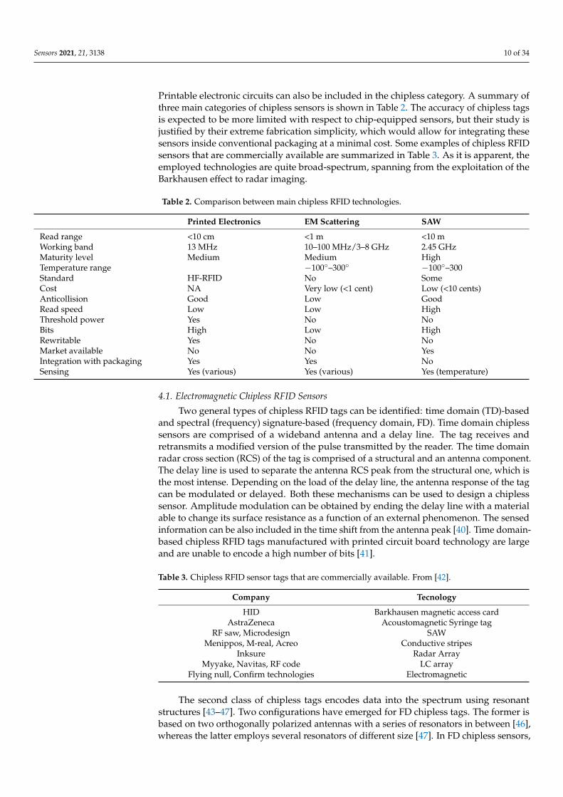
Printable electronic circuits can also be included in the chipless category. A summary ofthree main categories of chipless sensors is shown in Table 2. The accuracy of chipless tagsis expected to be more limited with respect to chip-equipped sensors, but their study isjustified by their extreme fabrication simplicity, which would allow for integrating thesesensors inside conventional packaging at a minimal cost. Some examples of chipless RFIDsensors that are commercially available are summarized in Table 3. As it is apparent, theemployed technologies are quite broad-spectrum, spanning from the exploitation of theBarkhausen effect to radar imaging.
Table 2. Comparison between main chipless RFID technologies.
Printed Electronics EM Scattering SAW
Read range <10 cm <1 m <10 mWorking band 13 MHz 10–100 MHz/3–8 GHz 2.45 GHzMaturity level Medium Medium HighTemperature range −100◦–300◦ −100◦–300Standard HF-RFID No SomeCost NA Very low (<1 cent) Low (<10 cents)Anticollision Good Low GoodRead speed Low Low HighThreshold power Yes No NoBits High Low HighRewritable Yes No NoMarket available No No YesIntegration with packaging Yes Yes NoSensing Yes (various) Yes (various) Yes (temperature)
4.1. Electromagnetic Chipless RFID Sensors
Two general types of chipless RFID tags can be identified: time domain (TD)-basedand spectral (frequency) signature-based (frequency domain, FD). Time domain chiplesssensors are comprised of a wideband antenna and a delay line. The tag receives andretransmits a modified version of the pulse transmitted by the reader. The time domainradar cross section (RCS) of the tag is comprised of a structural and an antenna component.The delay line is used to separate the antenna RCS peak from the structural one, which isthe most intense. Depending on the load of the delay line, the antenna response of the tagcan be modulated or delayed. Both these mechanisms can be used to design a chiplesssensor. Amplitude modulation can be obtained by ending the delay line with a materialable to change its surface resistance as a function of an external phenomenon. The sensedinformation can be also included in the time shift from the antenna peak [40]. Time domain-based chipless RFID tags manufactured with printed circuit board technology are largeand are unable to encode a high number of bits [41].
Table 3. Chipless RFID sensor tags that are commercially available. From [42].
Company Tecnology
HID Barkhausen magnetic access cardAstraZeneca Acoustomagnetic Syringe tag
RF saw, Microdesign SAWMenippos, M-real, Acreo Conductive stripes
Inksure Radar ArrayMyyake, Navitas, RF code LC array
Flying null, Confirm technologies Electromagnetic
The second class of chipless tags encodes data into the spectrum using resonantstructures [43–47]. Two configurations have emerged for FD chipless tags. The former isbased on two orthogonally polarized antennas with a series of resonators in between [46],whereas the latter employs several resonators of different size [47]. In FD chipless sensors,
Sensors 2021, 21, 3138 11 of 34
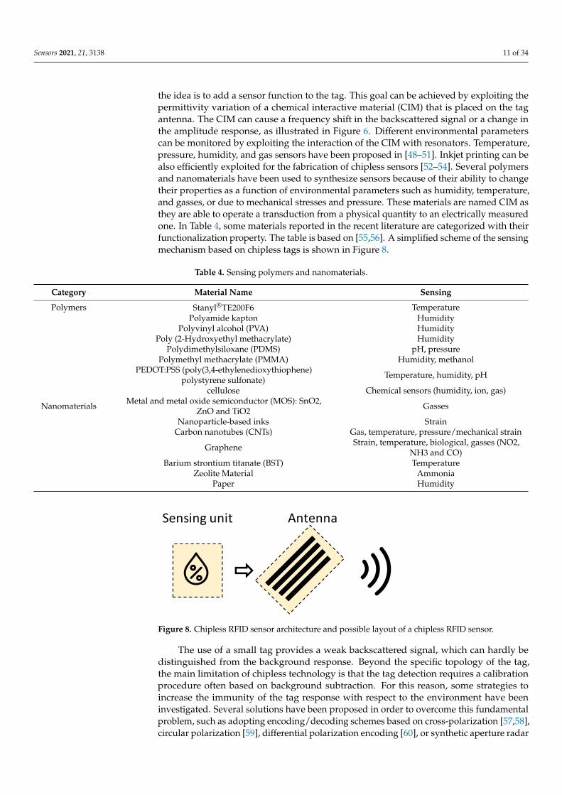
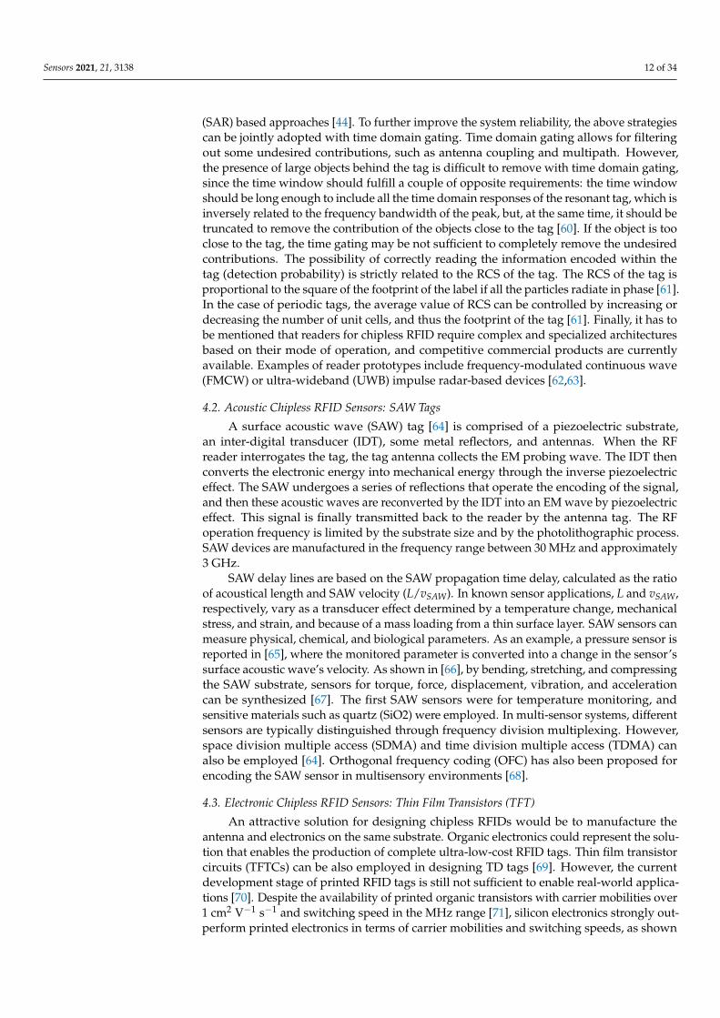
the idea is to add a sensor function to the tag. This goal can be achieved by exploiting thepermittivity variation of a chemical interactive material (CIM) that is placed on the tagantenna. The CIM can cause a frequency shift in the backscattered signal or a change inthe amplitude response, as illustrated in Figure 6. Different environmental parameterscan be monitored by exploiting the interaction of the CIM with resonators. Temperature,pressure, humidity, and gas sensors have been proposed in [48–51]. Inkjet printing can bealso efficiently exploited for the fabrication of chipless sensors [52–54]. Several polymersand nanomaterials have been used to synthesize sensors because of their ability to changetheir properties as a function of environmental parameters such as humidity, temperature,and gasses, or due to mechanical stresses and pressure. These materials are named CIM asthey are able to operate a transduction from a physical quantity to an electrically measuredone. In Table 4, some materials reported in the recent literature are categorized with theirfunctionalization property. The table is based on [55,56]. A simplified scheme of the sensingmechanism based on chipless tags is shown in Figure 8.
Table 4. Sensing polymers and nanomaterials.
Category Material Name Sensing
Polymers Stanyl®TE200F6 TemperaturePolyamide kapton Humidity
Polyvinyl alcohol (PVA) HumidityPoly (2-Hydroxyethyl methacrylate) Humidity
Polydimethylsiloxane (PDMS) pH, pressurePolymethyl methacrylate (PMMA) Humidity, methanol
PEDOT:PSS (poly(3,4-ethylenedioxythiophene)polystyrene sulfonate) Temperature, humidity, pH
cellulose Chemical sensors (humidity, ion, gas)
Nanomaterials Metal and metal oxide semiconductor (MOS): SnO2,ZnO and TiO2 Gasses
Nanoparticle-based inks StrainCarbon nanotubes (CNTs) Gas, temperature, pressure/mechanical strain
Graphene Strain, temperature, biological, gasses (NO2,NH3 and CO)
Barium strontium titanate (BST) TemperatureZeolite Material Ammonia
Paper Humidity
Sensors 2021, 21, x FOR PEER REVIEW 13 of 36
Barium strontium titanate (BST) Temperature
Zeolite Material Ammonia
Paper Humidity
The use of a small tag provides a weak backscattered signal, which can hardly be
distinguished from the background response. Beyond the specific topology of the tag, the
main limitation of chipless technology is that the tag detection requires a calibration pro-
cedure often based on background subtraction. For this reason, some strategies to increase
the immunity of the tag response with respect to the environment have been investigated.
Several solutions have been proposed in order to overcome this fundamental problem,
such as adopting encoding/decoding schemes based on cross-polarization [57,58], circular
polarization [59], differential polarization encoding [60], or synthetic aperture radar (SAR)
based approaches [44]. To further improve the system reliability, the above strategies can
be jointly adopted with time domain gating. Time domain gating allows for filtering out
some undesired contributions, such as antenna coupling and multipath. However, the
presence of large objects behind the tag is difficult to remove with time domain gating,
since the time window should fulfill a couple of opposite requirements: the time window
should be long enough to include all the time domain responses of the resonant tag, which
is inversely related to the frequency bandwidth of the peak, but, at the same time, it should
be truncated to remove the contribution of the objects close to the tag [60]. If the object is
too close to the tag, the time gating may be not sufficient to completely remove the unde-
sired contributions. The possibility of correctly reading the information encoded within
the tag (detection probability) is strictly related to the RCS of the tag. The RCS of the tag
is proportional to the square of the footprint of the label if all the particles radiate in phase
[61]. In the case of periodic tags, the average value of RCS can be controlled by increasing
or decreasing the number of unit cells, and thus the footprint of the tag [61]. Finally, it has
to be mentioned that readers for chipless RFID require complex and specialized architec-
tures based on their mode of operation, and competitive commercial products are cur-
rently available. Examples of reader prototypes include frequency-modulated continuous
wave (FMCW) or ultra-wideband (UWB) impulse radar-based devices [62,63].
Figure 8. Chipless RFID sensor architecture and possible layout of a chipless RFID sensor.
4.2. Acoustic Chipless RFID Sensors: SAW Tags
A surface acoustic wave (SAW) tag [64] is comprised of a piezoelectric substrate, an
inter-digital transducer (IDT), some metal reflectors, and antennas. When the RF reader
interrogates the tag, the tag antenna collects the EM probing wave. The IDT then converts
the electronic energy into mechanical energy through the inverse piezoelectric effect. The
SAW undergoes a series of reflections that operate the encoding of the signal, and then
these acoustic waves are reconverted by the IDT into an EM wave by piezoelectric effect.
This signal is finally transmitted back to the reader by the antenna tag. The RF operation
frequency is limited by the substrate size and by the photolithographic process. SAW de-
vices are manufactured in the frequency range between 30 MHz and approximately 3
GHz.
Figure 8. Chipless RFID sensor architecture and possible layout of a chipless RFID sensor.
The use of a small tag provides a weak backscattered signal, which can hardly bedistinguished from the background response. Beyond the specific topology of the tag,the main limitation of chipless technology is that the tag detection requires a calibrationprocedure often based on background subtraction. For this reason, some strategies toincrease the immunity of the tag response with respect to the environment have beeninvestigated. Several solutions have been proposed in order to overcome this fundamentalproblem, such as adopting encoding/decoding schemes based on cross-polarization [57,58],circular polarization [59], differential polarization encoding [60], or synthetic aperture radar
Sensors 2021, 21, 3138 12 of 34
(SAR) based approaches [44]. To further improve the system reliability, the above strategiescan be jointly adopted with time domain gating. Time domain gating allows for filteringout some undesired contributions, such as antenna coupling and multipath. However,the presence of large objects behind the tag is difficult to remove with time domain gating,since the time window should fulfill a couple of opposite requirements: the time windowshould be long enough to include all the time domain responses of the resonant tag, which isinversely related to the frequency bandwidth of the peak, but, at the same time, it should betruncated to remove the contribution of the objects close to the tag [60]. If the object is tooclose to the tag, the time gating may be not sufficient to completely remove the undesiredcontributions. The possibility of correctly reading the information encoded within thetag (detection probability) is strictly related to the RCS of the tag. The RCS of the tag isproportional to the square of the footprint of the label if all the particles radiate in phase [61].In the case of periodic tags, the average value of RCS can be controlled by increasing ordecreasing the number of unit cells, and thus the footprint of the tag [61]. Finally, it has tobe mentioned that readers for chipless RFID require complex and specialized architecturesbased on their mode of operation, and competitive commercial products are currentlyavailable. Examples of reader prototypes include frequency-modulated continuous wave(FMCW) or ultra-wideband (UWB) impulse radar-based devices [62,63].
4.2. Acoustic Chipless RFID Sensors: SAW Tags
A surface acoustic wave (SAW) tag [64] is comprised of a piezoelectric substrate,an inter-digital transducer (IDT), some metal reflectors, and antennas. When the RFreader interrogates the tag, the tag antenna collects the EM probing wave. The IDT thenconverts the electronic energy into mechanical energy through the inverse piezoelectriceffect. The SAW undergoes a series of reflections that operate the encoding of the signal,and then these acoustic waves are reconverted by the IDT into an EM wave by piezoelectriceffect. This signal is finally transmitted back to the reader by the antenna tag. The RFoperation frequency is limited by the substrate size and by the photolithographic process.SAW devices are manufactured in the frequency range between 30 MHz and approximately3 GHz.
SAW delay lines are based on the SAW propagation time delay, calculated as the ratioof acoustical length and SAW velocity (L/vSAW). In known sensor applications, L and vSAW,respectively, vary as a transducer effect determined by a temperature change, mechanicalstress, and strain, and because of a mass loading from a thin surface layer. SAW sensors canmeasure physical, chemical, and biological parameters. As an example, a pressure sensor isreported in [65], where the monitored parameter is converted into a change in the sensor’ssurface acoustic wave’s velocity. As shown in [66], by bending, stretching, and compressingthe SAW substrate, sensors for torque, force, displacement, vibration, and accelerationcan be synthesized [67]. The first SAW sensors were for temperature monitoring, andsensitive materials such as quartz (SiO2) were employed. In multi-sensor systems, differentsensors are typically distinguished through frequency division multiplexing. However,space division multiple access (SDMA) and time division multiple access (TDMA) canalso be employed [64]. Orthogonal frequency coding (OFC) has also been proposed forencoding the SAW sensor in multisensory environments [68].
4.3. Electronic Chipless RFID Sensors: Thin Film Transistors (TFT)
An attractive solution for designing chipless RFIDs would be to manufacture theantenna and electronics on the same substrate. Organic electronics could represent the solu-tion that enables the production of complete ultra-low-cost RFID tags. Thin film transistorcircuits (TFTCs) can be also employed in designing TD tags [69]. However, the currentdevelopment stage of printed RFID tags is still not sufficient to enable real-world applica-tions [70]. Despite the availability of printed organic transistors with carrier mobilities over1 cm2 V−1 s−1 and switching speed in the MHz range [71], silicon electronics strongly out-perform printed electronics in terms of carrier mobilities and switching speeds, as shown
Sensors 2021, 21, 3138 13 of 34
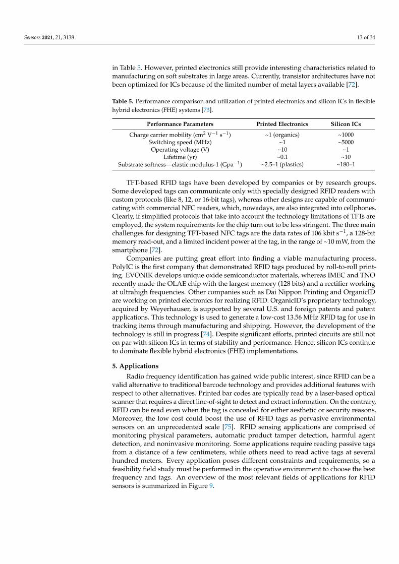
in Table 5. However, printed electronics still provide interesting characteristics related tomanufacturing on soft substrates in large areas. Currently, transistor architectures have notbeen optimized for ICs because of the limited number of metal layers available [72].
Table 5. Performance comparison and utilization of printed electronics and silicon ICs in flexiblehybrid electronics (FHE) systems [73].
Performance Parameters Printed Electronics Silicon ICs
Charge carrier mobility (cm2 V−1 s−1) ~1 (organics) ~1000Switching speed (MHz) ~1 ~5000Operating voltage (V) ~10 ~1
Lifetime (yr) ~0.1 ~10Substrate softness—elastic modulus-1 (Gpa−1) ~2.5–1 (plastics) ~180–1
TFT-based RFID tags have been developed by companies or by research groups.Some developed tags can communicate only with specially designed RFID readers withcustom protocols (like 8, 12, or 16-bit tags), whereas other designs are capable of communi-cating with commercial NFC readers, which, nowadays, are also integrated into cellphones.Clearly, if simplified protocols that take into account the technology limitations of TFTs areemployed, the system requirements for the chip turn out to be less stringent. The three mainchallenges for designing TFT-based NFC tags are the data rates of 106 kbit s−1, a 128-bitmemory read-out, and a limited incident power at the tag, in the range of ~10 mW, from thesmartphone [72].
Companies are putting great effort into finding a viable manufacturing process.PolyIC is the first company that demonstrated RFID tags produced by roll-to-roll print-ing. EVONIK develops unique oxide semiconductor materials, whereas IMEC and TNOrecently made the OLAE chip with the largest memory (128 bits) and a rectifier workingat ultrahigh frequencies. Other companies such as Dai Nippon Printing and OrganicIDare working on printed electronics for realizing RFID. OrganicID’s proprietary technology,acquired by Weyerhauser, is supported by several U.S. and foreign patents and patentapplications. This technology is used to generate a low-cost 13.56 MHz RFID tag for use intracking items through manufacturing and shipping. However, the development of thetechnology is still in progress [74]. Despite significant efforts, printed circuits are still noton par with silicon ICs in terms of stability and performance. Hence, silicon ICs continueto dominate flexible hybrid electronics (FHE) implementations.
5. Applications
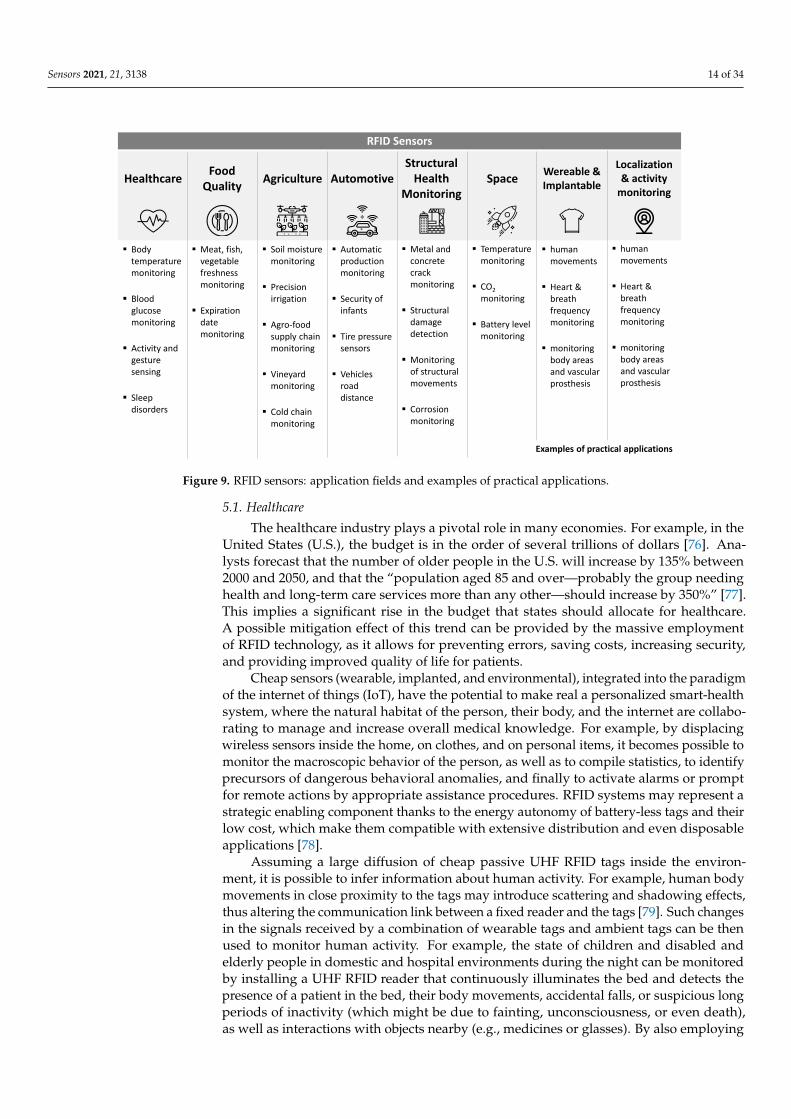
Radio frequency identification has gained wide public interest, since RFID can be avalid alternative to traditional barcode technology and provides additional features withrespect to other alternatives. Printed bar codes are typically read by a laser-based opticalscanner that requires a direct line-of-sight to detect and extract information. On the contrary,RFID can be read even when the tag is concealed for either aesthetic or security reasons.Moreover, the low cost could boost the use of RFID tags as pervasive environmentalsensors on an unprecedented scale [75]. RFID sensing applications are comprised ofmonitoring physical parameters, automatic product tamper detection, harmful agentdetection, and noninvasive monitoring. Some applications require reading passive tagsfrom a distance of a few centimeters, while others need to read active tags at severalhundred meters. Every application poses different constraints and requirements, so afeasibility field study must be performed in the operative environment to choose the bestfrequency and tags. An overview of the most relevant fields of applications for RFIDsensors is summarized in Figure 9.
Sensors 2021, 21, 3138 14 of 34
RFID Sensors
Healthcare
▪ Body temperature monitoring
▪ Blood glucose monitoring
▪ Activity and gesture sensing
▪ Sleep disorders
Food Quality
▪ Meat, fish, vegetable freshness monitoring
▪ Expiration date monitoring
Agriculture
▪ Soil moisture monitoring
▪ Precision irrigation
▪ Agro-food supply chain monitoring
▪ Vineyard monitoring
▪ Cold chain monitoring
Automotive
▪ Automatic production monitoring
▪ Security of infants
▪ Tire pressure sensors
▪ Vehiclesroad distance
Structural Health
Monitoring
▪ Metal and concrete crack monitoring
▪ Structural damage detection
▪ Monitoring of structural movements
▪ Corrosion monitoring
Space
▪ Temperature monitoring
▪ CO2
monitoring
▪ Battery level monitoring
Wereable & Implantable
▪ human movements
▪ Heart & breath frequency monitoring
▪ monitoring body areas and vascular prosthesis
Localization& activity
monitoring
▪ human movements
▪ Heart & breath frequency monitoring
▪ monitoring body areas and vascular prosthesis
Examples of practical applications
Figure 9. RFID sensors: application fields and examples of practical applications.
5.1. Healthcare
The healthcare industry plays a pivotal role in many economies. For example, in theUnited States (U.S.), the budget is in the order of several trillions of dollars [76]. Ana-lysts forecast that the number of older people in the U.S. will increase by 135% between2000 and 2050, and that the “population aged 85 and over—probably the group needinghealth and long-term care services more than any other—should increase by 350%” [77].This implies a significant rise in the budget that states should allocate for healthcare.A possible mitigation effect of this trend can be provided by the massive employmentof RFID technology, as it allows for preventing errors, saving costs, increasing security,and providing improved quality of life for patients.
Cheap sensors (wearable, implanted, and environmental), integrated into the paradigmof the internet of things (IoT), have the potential to make real a personalized smart-healthsystem, where the natural habitat of the person, their body, and the internet are collabo-rating to manage and increase overall medical knowledge. For example, by displacingwireless sensors inside the home, on clothes, and on personal items, it becomes possible tomonitor the macroscopic behavior of the person, as well as to compile statistics, to identifyprecursors of dangerous behavioral anomalies, and finally to activate alarms or promptfor remote actions by appropriate assistance procedures. RFID systems may represent astrategic enabling component thanks to the energy autonomy of battery-less tags and theirlow cost, which make them compatible with extensive distribution and even disposableapplications [78].
Assuming a large diffusion of cheap passive UHF RFID tags inside the environ-ment, it is possible to infer information about human activity. For example, human bodymovements in close proximity to the tags may introduce scattering and shadowing effects,thus altering the communication link between a fixed reader and the tags [79]. Such changesin the signals received by a combination of wearable tags and ambient tags can be thenused to monitor human activity. For example, the state of children and disabled andelderly people in domestic and hospital environments during the night can be monitoredby installing a UHF RFID reader that continuously illuminates the bed and detects thepresence of a patient in the bed, their body movements, accidental falls, or suspicious longperiods of inactivity (which might be due to fainting, unconsciousness, or even death),as well as interactions with objects nearby (e.g., medicines or glasses). By also employing
Sensors 2021, 21, 3138 15 of 34
temperature or humidity RFID sensors, even fever evolution and urine loss could be takenunder control.
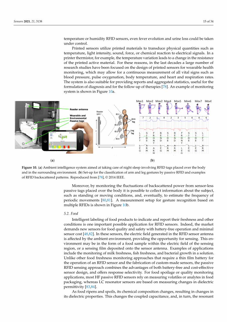
Printed sensors utilize printed materials to transduce physical quantities such astemperature, light intensity, sound, force, or chemical reaction to electrical signals. In aprinter thermistor, for example, the temperature variation leads to a change in the resistanceof the printed active material. For these reasons, in the last decades a large number ofresearch studies have been focused on the design of printed sensors for wearable healthmonitoring, which may allow for a continuous measurement of all vital signs such asblood pressure, pulse oxygenation, body temperature, and heart and respiration rates.The system is also suitable for providing reports and aggregated statistics, useful for theformulation of diagnosis and for the follow-up of therapies [78]. An example of monitoringsystem is shown in Figure 10a.
Figure 10. (a) Ambient intelligence system aimed at taking care of night sleep involving RFID tags placed over the bodyand in the surrounding environment. (b) Set-up for the classification of arm and leg gestures by passive RFID and examplesof RFID backscattered patterns. Reproduced from [78], © 2014 IEEE.
Moreover, by monitoring the fluctuations of backscattered power from sensor-lesspassive tags placed over the body it is possible to collect information about the subject,such as standing or moving conditions, and, eventually, to estimate the frequency ofperiodic movements [80,81]. A measurement setup for gesture recognition based onmultiple RFIDs is shown in Figure 10b.
5.2. Food
Intelligent labeling of food products to indicate and report their freshness and otherconditions is one important possible application for RFID sensors. Indeed, the marketdemands new sensors for food quality and safety with battery-free operation and minimalsensor cost [48,82]. In these sensors, the electric field generated in the RFID sensor antennais affected by the ambient environment, providing the opportunity for sensing. This en-vironment may be in the form of a food sample within the electric field of the sensingregion, or a sensing film deposited onto the sensor antenna. Examples of applicationsinclude the monitoring of milk freshness, fish freshness, and bacterial growth in a solution.Unlike other food freshness monitoring approaches that require a thin film battery forthe operation of an RFID sensor and the fabrication of custom-made sensors, the passiveRFID sensing approach combines the advantages of both battery-free and cost-effectivesensor design, and offers response selectivity. For food spoilage or quality monitoringapplications, most HF passive RFID sensors rely on measuring volatiles or analytes in foodpackaging, whereas LC resonator sensors are based on measuring changes in dielectricpermittivity [83,84].
As food ripens and spoils, its chemical composition changes, resulting in changes inits dielectric properties. This changes the coupled capacitance, and, in turn, the resonant

Sensors 2021, 21, 3138 16 of 34
frequency of the sensor. These sensors are either attached to food packaging or placedon the surface of the food itself. The approach has been demonstrated using conformaladhesive LC resonators attached to the surface of a banana skin or cheese [85], as a 3Dprinted LC resonator integrated in a milk package cap [30], and as a planar LC resonatorattached to the surface of a milk package (Figure 11). The depth of interaction between thefood and the sensor (the penetration depth) depends on the operating frequency of thesensor, electric conductivity, and the dielectric polarization loss of the food [48].
Sensors 2021, 21, x FOR PEER REVIEW 17 of 36
(a) (b)
Figure 10. (a) Ambient intelligence system aimed at taking care of night sleep involving RFID tags placed over the body
and in the surrounding environment. (b) Set-up for the classification of arm and leg gestures by passive RFID and exam-
ples of RFID backscattered patterns. Reproduced from [78], © 2014 IEEE.
5.2. Food
Intelligent labeling of food products to indicate and report their freshness and other
conditions is one important possible application for RFID sensors. Indeed, the market de-
mands new sensors for food quality and safety with battery-free operation and minimal
sensor cost [48,82]. In these sensors, the electric field generated in the RFID sensor antenna
is affected by the ambient environment, providing the opportunity for sensing. This envi-
ronment may be in the form of a food sample within the electric field of the sensing region,
or a sensing film deposited onto the sensor antenna. Examples of applications include the
monitoring of milk freshness, fish freshness, and bacterial growth in a solution. Unlike
other food freshness monitoring approaches that require a thin film battery for the oper-
ation of an RFID sensor and the fabrication of custom-made sensors, the passive RFID
sensing approach combines the advantages of both battery-free and cost-effective sensor
design, and offers response selectivity. For food spoilage or quality monitoring applica-
tions, most HF passive RFID sensors rely on measuring volatiles or analytes in food pack-
aging, whereas LC resonator sensors are based on measuring changes in dielectric per-
mittivity [83,84].
As food ripens and spoils, its chemical composition changes, resulting in changes in
its dielectric properties. This changes the coupled capacitance, and, in turn, the resonant
frequency of the sensor. These sensors are either attached to food packaging or placed on
the surface of the food itself. The approach has been demonstrated using conformal adhe-
sive LC resonators attached to the surface of a banana skin or cheese [85], as a 3D printed
LC resonator integrated in a milk package cap [30], and as a planar LC resonator attached
to the surface of a milk package (Figure 11). The depth of interaction between the food
and the sensor (the penetration depth) depends on the operating frequency of the sensor,
electric conductivity, and the dielectric polarization loss of the food [48].
(a) (b) (c)
Figure 11. (a,b) A wireless passive sensor demonstration of a “smart cap”, containing the 3D-printed LC-resonant circuit.The degradation of the liquid food inside the liquid package can cause changes in the dielectric constant and a shift inthe resonance frequency of the LC circuity. (c) A wireless inductive reader is used to monitor the signals in real time.Reproduced from [86].
5.3. Agriculture
The development of RFID systems for smart agriculture applications has attractedconsiderable research efforts in recent years [87]. The precision agriculture system, throughthe exploitation of RFID technology, allows farmers to maximize the yield by increasing ef-ficiencies, productivity, and profitability, while minimizing unintended impacts on wildlifeand the environment [88]. In fact, the real time information acquired by RFID sensorsprovides helpful data for farmers to adjust crop strategies at any time by taking into accountthe environmental condition alteration. Among smart agriculture paradigms, leaf sensingrepresents a new technology, which is used for the detection of plants’ health, such aswater status [89,90]. An example of a low-cost and low-power system for leaf sensingusing a plant backscatter sensor tag is presented in [90]. A schematic representation of themoisture monitoring RFID system and its practical implementation is reported in Figure 12.More in detail, a sensor measures the temperature differential between the leaf and theair, which is directly related to the plant water stress. A Morse code modulation was usedfor wireless communication with a low-cost receiver by backscattering RF signals from an868 MHz carrier emitter. An example of an RFID soil moisture sensing system is reportedin [91], which exploits two RFID tags on a pot with a low-pass filtered differential minimumresponse threshold (DMRT) to estimate the soil moisture level. The extensive measurementcampaigns revealed high soil moisture detection accuracy, able to considerably improve theproductivity. A passive UHF RFID tag for soil moisture and an environment temperaturesensor for low cost agriculture applications was developed in [92]. The soil moisture sensorhas been implemented by exploiting the capacitance variation of a passive inter digitalcapacitive, due to soil permittivity modification, while the environmental temperature wasobtained by using an RFID chip with a temperature sensor.
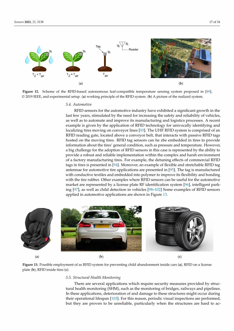
Sensors 2021, 21, 3138 17 of 34
Sensors 2021, 21, x FOR PEER REVIEW 18 of 36
Figure 11. (a-b) A wireless passive sensor demonstration of a “smart cap”, containing the 3D-printed LC-resonant circuit.
The degradation of the liquid food inside the liquid package can cause changes in the dielectric constant and a shift in the
resonance frequency of the LC circuity. (c) A wireless inductive reader is used to monitor the signals in real time. Repro-
duced from [86].
5.3. Agriculture
The development of RFID systems for smart agriculture applications has attracted
considerable research efforts in recent years [87]. The precision agriculture system,
through the exploitation of RFID technology, allows farmers to maximize the yield by
increasing efficiencies, productivity, and profitability, while minimizing unintended im-
pacts on wildlife and the environment [88]. In fact, the real time information acquired by
RFID sensors provides helpful data for farmers to adjust crop strategies at any time by
taking into account the environmental condition alteration. Among smart agriculture par-
adigms, leaf sensing represents a new technology, which is used for the detection of
plants’ health, such as water status [89,90]. An example of a low-cost and low-power sys-
tem for leaf sensing using a plant backscatter sensor tag is presented in [90]. A schematic
representation of the moisture monitoring RFID system and its practical implementation
is reported in Figure 12. More in detail, a sensor measures the temperature differential
between the leaf and the air, which is directly related to the plant water stress. A Morse
code modulation was used for wireless communication with a low-cost receiver by
backscattering RF signals from an 868 MHz carrier emitter. An example of an RFID soil
moisture sensing system is reported in [91], which exploits two RFID tags on a pot with a
low-pass filtered differential minimum response threshold (DMRT) to estimate the soil
moisture level. The extensive measurement campaigns revealed high soil moisture detec-
tion accuracy, able to considerably improve the productivity. A passive UHF RFID tag for
soil moisture and an environment temperature sensor for low cost agriculture applica-
tions was developed in [92]. The soil moisture sensor has been implemented by exploiting
the capacitance variation of a passive inter digital capacitive, due to soil permittivity mod-
ification, while the environmental temperature was obtained by using an RFID chip with
a temperature sensor.
(a) (b)
Figure 12. Scheme of the RFID-based autonomous leaf-compatible temperature sensing system proposed in [89], © 2019
IEEE, and experimental setup. (a) working principle of the RFID system. (b) A picture of the realized system.
5.4. Automotive
RFID sensors for the automotive industry have exhibited a significant growth in the
last few years, stimulated by the need for increasing the safety and reliability of vehicles,
as well as to automate and improve its manufacturing and logistics processes. A recent
example is given by the application of RFID technology for univocally identifying and
localizing tires moving on conveyor lines [93]. The UHF RFID system is comprised of an
RFID reading gate, located above a conveyor belt, that interacts with passive RFID tags
hosted on the moving tires. RFID tag sensors can he zbe embedded in tires to provide
information about the tires’ general condition, such as pressure and temperature. How-
ever, a big challenge for the adoption of RFID sensors in this case is represented by the
Figure 12. Scheme of the RFID-based autonomous leaf-compatible temperature sensing system proposed in [89],© 2019 IEEE, and experimental setup. (a) working principle of the RFID system. (b) A picture of the realized system.
5.4. Automotive
RFID sensors for the automotive industry have exhibited a significant growth in thelast few years, stimulated by the need for increasing the safety and reliability of vehicles,as well as to automate and improve its manufacturing and logistics processes. A recentexample is given by the application of RFID technology for univocally identifying andlocalizing tires moving on conveyor lines [93]. The UHF RFID system is comprised of anRFID reading gate, located above a conveyor belt, that interacts with passive RFID tagshosted on the moving tires. RFID tag sensors can he zbe embedded in tires to provideinformation about the tires’ general condition, such as pressure and temperature. However,a big challenge for the adoption of RFID sensors in this case is represented by the ability toprovide a robust and reliable implementation within the complex and harsh environmentof a factory manufacturing tires. For example, the detuning effects of commercial RFIDtags in tires is presented in [94]. Moreover, an example of flexible and stretchable RFID tagantennae for automotive tire applications are presented in [95]. The tag is manufacturedwith conductive textiles and embedded into polymer to improve its flexibility and bondingwith the tire rubber. Other examples where RFID sensors can be useful for the automotivemarket are represented by a license plate RF identification system [96], intelligent park-ing [97], as well as child detection in vehicles [98–102] Some examples of RFID sensorsapplied in automotive applications are shown in Figure 13.
Sensors 2021, 21, x FOR PEER REVIEW 19 of 36
ability to provide a robust and reliable implementation within the complex and harsh en-
vironment of a factory manufacturing tires. For example, the detuning effects of commer-
cial RFID tags in tires is presented in [94]. Moreover, an example of flexible and stretchable
RFID tag antennae for automotive tire applications are presented in [95]. The tag is man-
ufactured with conductive textiles and embedded into polymer to improve its flexibility
and bonding with the tire rubber. Other examples where RFID sensors can be useful for
the automotive market are represented by a license plate RF identification system [96],
intelligent parking [97], as well as child detection in vehicles [98-102] Some examples of
RFID sensors applied in automotive applications are shown in Figure 13.
(a) (b) (c)
Figure 13. Possible employment of as RFID system for preventing child abandonment inside cars (a), RFID on a license
plate (b), RFID inside tires (c).
5.5. Structural Health Monitoring
There are several applications which require security measures provided by struc-
tural health monitoring (SHM), such as the monitoring of bridges, railways and pipelines.
In these applications, deterioration of and damage to these structures might occur during
their operational lifespan [103]. For this reason, periodic visual inspections are performed,
but they are proven to be unreliable, particularly when the structures are hard to access.
Consequently, several non-destructive testing and evaluation (NDT & E) approaches,
such as ultrasonic [104], pulsed eddy current (PEC) [105], and eddy current pulsed ther-
mography (ECPT), were developed for monitoring defects in structures with good reso-
lution, sensitivity, and reliability. Cabled large-scale sensor networks are very suitable for
real time acquisition applications, because of their good performance. On the other hand,
the use of these networks for manual data collection is rarely justified by the costs, instal-
lation difficulties, and maintenance [106]. Wireless sensor networks (WSNs) are cheaper
and simpler to install by removing the electric wiring from traditional sensors. Spatial
granularity is a crucial problem for possible upcoming applications. Battery-powered sen-
sors are used for existing wireless sensing applications. Unfortunately, these sensors have
reduced battery life and are more expensive than RFID sensors. Consequently, this re-
stricts the granularity of their deployment and motivates low-cost, wireless, and passive
sensor production for large-scale networks and applications for big data. Thanks to its
low-cost, wireless, and “sensing-friendly” capabilities, radio frequency identification
(RFID) technology can play a strategic role. The following paragraphs explain several ex-
amples of controlled parameters in structural health monitoring applications.
Strain detection: to detect deformation or structural change that occurs in our sur-
rounding infrastructure, strain sensors (gauges) are needed. In order to produce an effec-
tive strain sensor, researchers are looking for a material that, in response to a small applied
strain, can display a significant structural change [107].
Crack detection: the development of fatigue cracks accounts for more than 50% of me-
chanical failures. The conventional crack sensing methods make use of lead wiring for
data extraction, which is inefficient and costly for the positioning and maintenance of
large lengths [108]. In [109], through the mutual-coupling between two patch antennas, it
Figure 13. Possible employment of as RFID system for preventing child abandonment inside cars (a), RFID on a licenseplate (b), RFID inside tires (c).
5.5. Structural Health Monitoring
There are several applications which require security measures provided by struc-tural health monitoring (SHM), such as the monitoring of bridges, railways and pipelines.In these applications, deterioration of and damage to these structures might occur duringtheir operational lifespan [103]. For this reason, periodic visual inspections are performed,but they are proven to be unreliable, particularly when the structures are hard to ac-
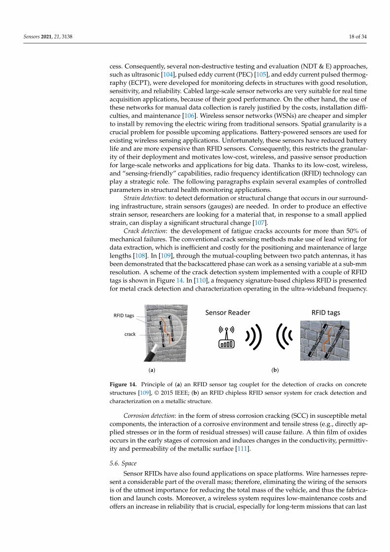
Sensors 2021, 21, 3138 18 of 34
cess. Consequently, several non-destructive testing and evaluation (NDT & E) approaches,such as ultrasonic [104], pulsed eddy current (PEC) [105], and eddy current pulsed thermog-raphy (ECPT), were developed for monitoring defects in structures with good resolution,sensitivity, and reliability. Cabled large-scale sensor networks are very suitable for real timeacquisition applications, because of their good performance. On the other hand, the use ofthese networks for manual data collection is rarely justified by the costs, installation diffi-culties, and maintenance [106]. Wireless sensor networks (WSNs) are cheaper and simplerto install by removing the electric wiring from traditional sensors. Spatial granularity is acrucial problem for possible upcoming applications. Battery-powered sensors are used forexisting wireless sensing applications. Unfortunately, these sensors have reduced batterylife and are more expensive than RFID sensors. Consequently, this restricts the granular-ity of their deployment and motivates low-cost, wireless, and passive sensor productionfor large-scale networks and applications for big data. Thanks to its low-cost, wireless,and “sensing-friendly” capabilities, radio frequency identification (RFID) technology canplay a strategic role. The following paragraphs explain several examples of controlledparameters in structural health monitoring applications.
Strain detection: to detect deformation or structural change that occurs in our surround-ing infrastructure, strain sensors (gauges) are needed. In order to produce an effectivestrain sensor, researchers are looking for a material that, in response to a small appliedstrain, can display a significant structural change [107].
Crack detection: the development of fatigue cracks accounts for more than 50% ofmechanical failures. The conventional crack sensing methods make use of lead wiring fordata extraction, which is inefficient and costly for the positioning and maintenance of largelengths [108]. In [109], through the mutual-coupling between two patch antennas, it hasbeen demonstrated that the backscattered phase can work as a sensing variable at a sub-mmresolution. A scheme of the crack detection system implemented with a couple of RFIDtags is shown in Figure 14. In [110], a frequency signature-based chipless RFID is presentedfor metal crack detection and characterization operating in the ultra-wideband frequency.
Sensors 2021, 21, x FOR PEER REVIEW 20 of 36
has been demonstrated that the backscattered phase can work as a sensing variable at a
sub-mm resolution. A scheme of the crack detection system implemented with a couple
of RFID tags is shown in Figure 14. In [110], a frequency signature-based chipless RFID is
presented for metal crack detection and characterization operating in the ultra-wideband
frequency.
Corrosion detection: in the form of stress corrosion cracking (SCC) in susceptible metal
components, the interaction of a corrosive environment and tensile stress (e.g., directly
applied stresses or in the form of residual stresses) will cause failure. A thin film of oxides
occurs in the early stages of corrosion and induces changes in the conductivity, permittiv-
ity and permeability of the metallic surface [111].
(a) (b)
Figure 14. Principle of (a) an RFID sensor tag couplet for the detection of cracks on concrete struc-
tures [109], © 2015 IEEE; (b) an RFID chipless RFID sensor system for crack detection and charac-
terization on a metallic structure.
5.6. Space
Sensor RFIDs have also found applications on space platforms. Wire harnesses rep-
resent a considerable part of the overall mass; therefore, eliminating the wiring of the sen-
sors is of the utmost importance for reducing the total mass of the vehicle, and thus the
fabrication and launch costs. Moreover, a wireless system requires low-maintenance costs
and offers an increase in reliability that is crucial, especially for long-term missions that
can last years. An example of this is represented by the adoption of a RAIN RFID tag chip
by the U.S. National Space Agency (NASA) [112]. The tag mounts a Monza X-8K Dura
chip that can monitor temperature, CO2, and battery levels. A different approach for
achieving the sensing function is provided by SAW RF tags [113]. In this case, two phase-
matched SAW RF tags are coupled with a Van Atta antenna array. A combination of code
diversity and time diversity has allowed for producing a set of 16 sensors that operate
simultaneously in the field of view of the wireless sensor system. On the other hand, the
Van Atta array provides a completely passive capability for tracking the probing direction
and, at the same time, guarantees the beam-steering capability for properly retransmitting
the encoded information. This configuration exhibits a remarkable read range, it can be
employed for monitoring temperature and pressure, and it is robust enough to be de-
ployed in a harsh environment. It is worth noting that, to reduce the weight of a satellite,
the RFID reader itself is required to be compact in size and lightweight, as with the one
proposed in [114] working within the 5725–5850 MHz frequency range.
5.7. Localization and Activity Monitoring
Even if, in these applications, RFIDs were not used as transducers for sensing pur-
poses, RFID tags are still employed to extract useful information which exceeds the simple
tracking of objects. RFID sensor networks are a promising approach for indoor activity
monitoring [115–117]. A variety of experiments have been performed for tracking and
tracing, indoors and outdoors. For example, in transportation systems, including buses,
subways, and trains, the City of London implemented a system for outdoor data collec-
tion. The main goal was to use payments and access cards equipped with this connectivity
technology to track users of the transport network. The level of usage, number of travelers,
Figure 14. Principle of (a) an RFID sensor tag couplet for the detection of cracks on concretestructures [109], © 2015 IEEE; (b) an RFID chipless RFID sensor system for crack detection andcharacterization on a metallic structure.
Corrosion detection: in the form of stress corrosion cracking (SCC) in susceptible metalcomponents, the interaction of a corrosive environment and tensile stress (e.g., directly ap-plied stresses or in the form of residual stresses) will cause failure. A thin film of oxidesoccurs in the early stages of corrosion and induces changes in the conductivity, permittiv-ity and permeability of the metallic surface [111].
5.6. Space
Sensor RFIDs have also found applications on space platforms. Wire harnesses repre-sent a considerable part of the overall mass; therefore, eliminating the wiring of the sensorsis of the utmost importance for reducing the total mass of the vehicle, and thus the fabrica-tion and launch costs. Moreover, a wireless system requires low-maintenance costs andoffers an increase in reliability that is crucial, especially for long-term missions that can last
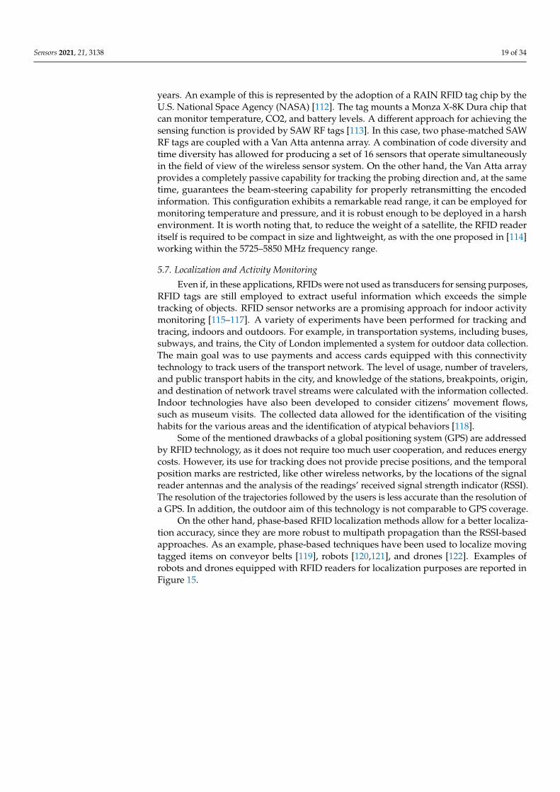
Sensors 2021, 21, 3138 19 of 34
years. An example of this is represented by the adoption of a RAIN RFID tag chip by theU.S. National Space Agency (NASA) [112]. The tag mounts a Monza X-8K Dura chip thatcan monitor temperature, CO2, and battery levels. A different approach for achieving thesensing function is provided by SAW RF tags [113]. In this case, two phase-matched SAWRF tags are coupled with a Van Atta antenna array. A combination of code diversity andtime diversity has allowed for producing a set of 16 sensors that operate simultaneouslyin the field of view of the wireless sensor system. On the other hand, the Van Atta arrayprovides a completely passive capability for tracking the probing direction and, at the sametime, guarantees the beam-steering capability for properly retransmitting the encodedinformation. This configuration exhibits a remarkable read range, it can be employed formonitoring temperature and pressure, and it is robust enough to be deployed in a harshenvironment. It is worth noting that, to reduce the weight of a satellite, the RFID readeritself is required to be compact in size and lightweight, as with the one proposed in [114]working within the 5725–5850 MHz frequency range.
5.7. Localization and Activity Monitoring
Even if, in these applications, RFIDs were not used as transducers for sensing purposes,RFID tags are still employed to extract useful information which exceeds the simpletracking of objects. RFID sensor networks are a promising approach for indoor activitymonitoring [115–117]. A variety of experiments have been performed for tracking andtracing, indoors and outdoors. For example, in transportation systems, including buses,subways, and trains, the City of London implemented a system for outdoor data collection.The main goal was to use payments and access cards equipped with this connectivitytechnology to track users of the transport network. The level of usage, number of travelers,and public transport habits in the city, and knowledge of the stations, breakpoints, origin,and destination of network travel streams were calculated with the information collected.Indoor technologies have also been developed to consider citizens’ movement flows,such as museum visits. The collected data allowed for the identification of the visitinghabits for the various areas and the identification of atypical behaviors [118].
Some of the mentioned drawbacks of a global positioning system (GPS) are addressedby RFID technology, as it does not require too much user cooperation, and reduces energycosts. However, its use for tracking does not provide precise positions, and the temporalposition marks are restricted, like other wireless networks, by the locations of the signalreader antennas and the analysis of the readings’ received signal strength indicator (RSSI).The resolution of the trajectories followed by the users is less accurate than the resolution ofa GPS. In addition, the outdoor aim of this technology is not comparable to GPS coverage.
On the other hand, phase-based RFID localization methods allow for a better localiza-tion accuracy, since they are more robust to multipath propagation than the RSSI-basedapproaches. As an example, phase-based techniques have been used to localize movingtagged items on conveyor belts [119], robots [120,121], and drones [122]. Examples ofrobots and drones equipped with RFID readers for localization purposes are reported inFigure 15.
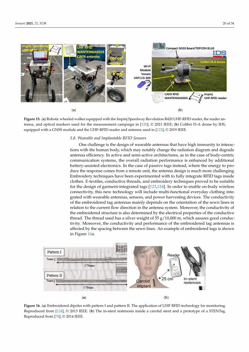
Sensors 2021, 21, 3138 20 of 34
Sensors 2021, 21, x FOR PEER REVIEW 21 of 36
and public transport habits in the city, and knowledge of the stations, breakpoints, origin,
and destination of network travel streams were calculated with the information collected.
Indoor technologies have also been developed to consider citizens′ movement flows, such
as museum visits. The collected data allowed for the identification of the visiting habits
for the various areas and the identification of atypical behaviors [118].
Some of the mentioned drawbacks of a global positioning system (GPS) are ad-
dressed by RFID technology, as it does not require too much user cooperation, and re-
duces energy costs. However, its use for tracking does not provide precise positions, and
the temporal position marks are restricted, like other wireless networks, by the locations
of the signal reader antennas and the analysis of the readings′ received signal strength
indicator (RSSI). The resolution of the trajectories followed by the users is less accurate
than the resolution of a GPS. In addition, the outdoor aim of this technology is not com-
parable to GPS coverage.
On the other hand, phase-based RFID localization methods allow for a better locali-
zation accuracy, since they are more robust to multipath propagation than the RSSI-based
approaches. As an example, phase-based techniques have been used to localize moving
tagged items on conveyor belts [119], robots [120,121], and drones [122]. Examples of ro-
bots and drones equipped with RFID readers for localization purposes are reported in
Figure 15.
(a) (b)
Figure 15. (a) Robotic wheeled walker equipped with the Impinj Speedway Revolution R420 UHF-RFID reader, the reader
antenna, and optical markers used for the measurement campaign in [120], © 2021 IEEE; (b) Colibrì I3-A drone by IDS,
equipped with a GNSS module and the UHF-RFID reader and antenna used in [122], © 2019 IEEE.
5.8. Wearable and Implantable RFID Sensors
One challenge is the design of wearable antennas that have high immunity to inter-
actions with the human body, which may notably change the radiation diagram and de-
grade antenna efficiency. In active and semi-active architectures, as in the case of body-
centric communication systems, the overall radiation performance is enhanced by addi-
tional battery-assisted electronics. In the case of passive tags instead, where the energy to
produce the response comes from a remote unit, the antenna design is much more chal-
lenging. Embroidery techniques have been experimented with to fully integrate RFID tags
inside clothes. E-textiles, conductive threads, and embroidery techniques proved to be
suitable for the design of garment-integrated tags [123,124]. In order to enable on-body
wireless connectivity, this new technology will include multi-functional everyday cloth-
ing integrated with wearable antennas, sensors, and power harvesting devices. The con-
ductivity of the embroidered tag antennas mainly depends on the orientation of the sewn
lines in relation to the current flow direction in the antenna system. Moreover, the con-
ductivity of the embroidered structure is also determined by the electrical properties of
the conductive thread. The thread used has a silver weight of 55 g/10,000 m, which assures
Figure 15. (a) Robotic wheeled walker equipped with the Impinj Speedway Revolution R420 UHF-RFID reader, the reader an-tenna, and optical markers used for the measurement campaign in [120], © 2021 IEEE; (b) Colibrì I3-A drone by IDS,equipped with a GNSS module and the UHF-RFID reader and antenna used in [122], © 2019 IEEE.
5.8. Wearable and Implantable RFID Sensors
One challenge is the design of wearable antennas that have high immunity to interac-tions with the human body, which may notably change the radiation diagram and degradeantenna efficiency. In active and semi-active architectures, as in the case of body-centriccommunication systems, the overall radiation performance is enhanced by additionalbattery-assisted electronics. In the case of passive tags instead, where the energy to pro-duce the response comes from a remote unit, the antenna design is much more challenging.Embroidery techniques have been experimented with to fully integrate RFID tags insideclothes. E-textiles, conductive threads, and embroidery techniques proved to be suitablefor the design of garment-integrated tags [123,124]. In order to enable on-body wirelessconnectivity, this new technology will include multi-functional everyday clothing inte-grated with wearable antennas, sensors, and power harvesting devices. The conductivityof the embroidered tag antennas mainly depends on the orientation of the sewn lines inrelation to the current flow direction in the antenna system. Moreover, the conductivity ofthe embroidered structure is also determined by the electrical properties of the conductivethread. The thread used has a silver weight of 55 g/10,000 m, which assures good conduc-tivity. Moreover, the conductivity and performance of the embroidered tag antennas isaffected by the spacing between the sewn lines. An example of embroidered tags is shownin Figure 16a.
Figure 16. (a) Embroidered dipoles with pattern I and pattern II. The application of UHF RFID technology for monitoring.Reproduced from [124], © 2013 IEEE. (b) The in-stent restenosis inside a carotid stent and a prototype of a STENTag.Reproduced from [78], © 2014 IEEE.
Sensors 2021, 21, 3138 21 of 34
The maximum read range which is currently achievable with an RFID transmittercompliant with the regional power emission constraints is almost 5–6 m. Current linkperformances are already enough for tracking a person equipped with two tags overfront/rear torso or over the arms within a regular size room [78].
In entertainment, healthcare, and medical applications, a wearable tag supplied withpassive accelerometers can be applied on the arms for the tracking of human motion.In some common sleep disorders, such as restless leg syndrome and periodic limb move-ments, wearable tags with inertial switches have been shown to detect limb movements.Tags applied to the chest may also be useful to detect breath. Generally, wireless motiontracking systems may help to produce data to support diagnosis and track a patient’sbehavior discreetly within a structure, and generate notifications about unusual activities,such as when the patient falls down or remains motionless for long periods [125].
RFID technology has been also demonstrated to be potentially useful for takingcare of the human health-state internally by labeling body prostheses, sutures, stents,or orthopedic fixing. Each item could be monitored in real time or on demand by the IoTinfrastructure for the ambitious goal of monitoring biophysical processes in evolution,such as tissue regrowth and prosthesis displacement. In this case, tags are inserted in theprosthesis, converting them into multi-functional devices capable of generating informationin addition to providing the original medical functionality. In the design of implantabletags, the key challenge is to create a convenient communication link by using a readerpower that complies with power emission regulation. Nowadays, the creation of an RFIDconnection with subcutaneous implants up to 0.1–0.5 m from the reader is now feasible,with promising applications for tracking some specific areas of the body, and vascularprotheses. In order to automatically scan the health-state of a prosthesis without the directinvolvement of the patient, a direct link to a reader-equipped door located at a distance of0.5 m may be sufficient. On the other hand, deeper implants such as implants within thestomach remain a real challenge, even over the long term, for passive RFID systems undercurrent power regulations [78].
A vascular stent implanted into an artery to restore natural blood flow after an-gioplasty is an example of near-subcutaneous protheses sufficient for RFID integration,as shown in Figure 16b. As presented in [126], the RFID tag features have been stronglyincorporated into the stent geometry itself to act as a self-sensor by exploiting the depen-dency of the input impedance of the tag and back-radiation on the dielectric properties ofthe tissues in the immediate vicinity of the so-obtained STENTag. This makes it possible todetect the process of in-stent restenosis (ISR), e.g., diffuse proliferation of neointima earlyafter implantation, or new atherosclerotic plaque, even at a distance of time, which mightcause new occlusion of the vessel.
6. Commercial RFID Sensors
RFID technology has become extremely popular in recent years for both localiza-tion and sensing applications. This technology is widely used within the IoT paradigm,where the demand for low-power and low-cost wireless devices is increasing. From thisperspective, RFID sensors respond to different needs of the IoT, as they are power efficient,small and easy to use. The use of innovative materials and manufacturing techniques,combined with increasingly advanced data collection techniques make RFID sensors evenmore appealing for IoT applications where sensing capabilities are required. Moreover,each RFID sensor has its own identification number, which makes it unique, making thecollection of data from the sensor unambiguous. Finally, compared to other sensing andidentification techniques, RFIDs are extremely advantageous, as they can be used in harshenvironments, do not require a line-of-sight connection, and allow real-time collection ofdata from multiple sensors simultaneously. For these reasons, RFID sensors have raisedgreat interest, not only in the world of scientific research, but also from industries. In fact,there are many companies that have heavily invested in RFID technology, such as TI, NXP,and ON Semicondutors.
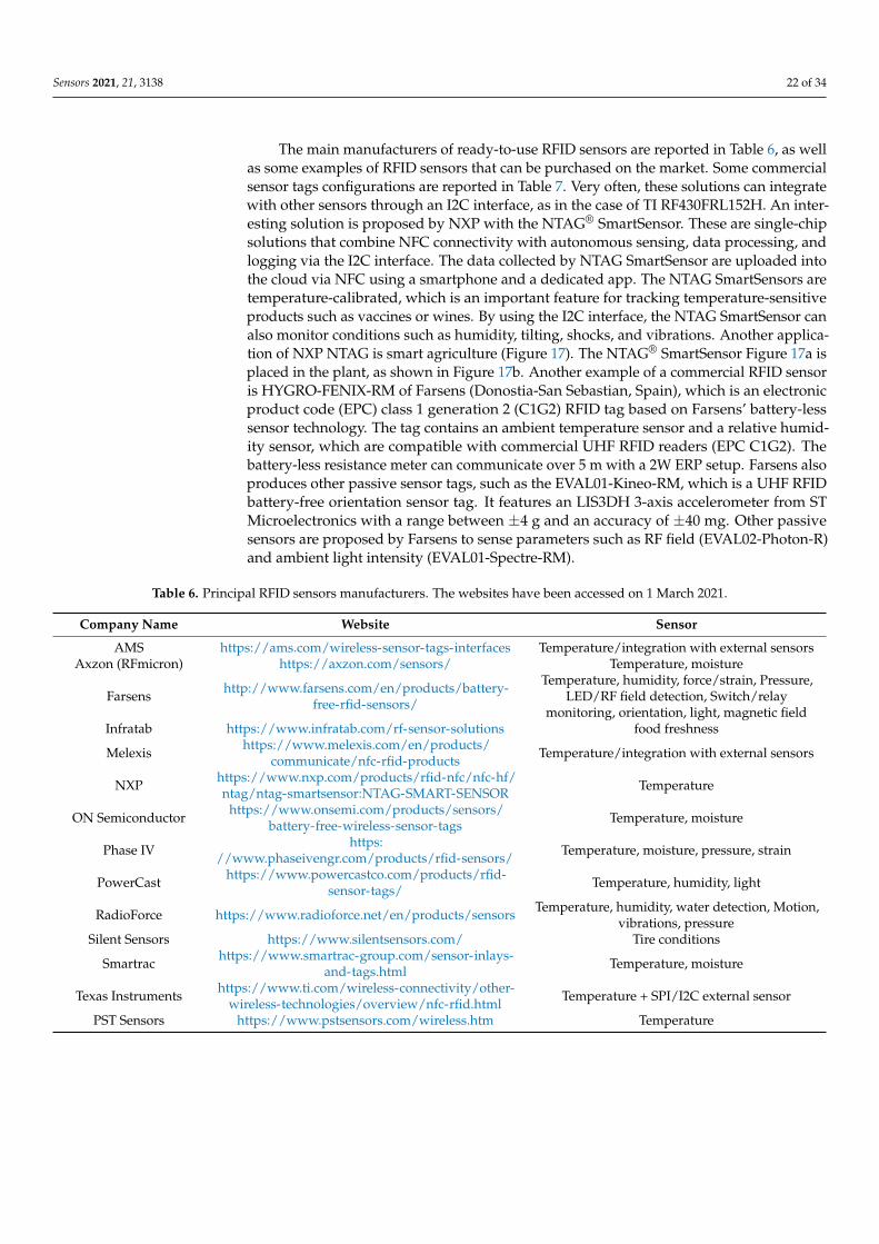
Sensors 2021, 21, 3138 22 of 34
The main manufacturers of ready-to-use RFID sensors are reported in Table 6, as wellas some examples of RFID sensors that can be purchased on the market. Some commercialsensor tags configurations are reported in Table 7. Very often, these solutions can integratewith other sensors through an I2C interface, as in the case of TI RF430FRL152H. An inter-esting solution is proposed by NXP with the NTAG® SmartSensor. These are single-chipsolutions that combine NFC connectivity with autonomous sensing, data processing, andlogging via the I2C interface. The data collected by NTAG SmartSensor are uploaded intothe cloud via NFC using a smartphone and a dedicated app. The NTAG SmartSensors aretemperature-calibrated, which is an important feature for tracking temperature-sensitiveproducts such as vaccines or wines. By using the I2C interface, the NTAG SmartSensor canalso monitor conditions such as humidity, tilting, shocks, and vibrations. Another applica-tion of NXP NTAG is smart agriculture (Figure 17). The NTAG® SmartSensor Figure 17a isplaced in the plant, as shown in Figure 17b. Another example of a commercial RFID sensoris HYGRO-FENIX-RM of Farsens (Donostia-San Sebastian, Spain), which is an electronicproduct code (EPC) class 1 generation 2 (C1G2) RFID tag based on Farsens’ battery-lesssensor technology. The tag contains an ambient temperature sensor and a relative humid-ity sensor, which are compatible with commercial UHF RFID readers (EPC C1G2). Thebattery-less resistance meter can communicate over 5 m with a 2W ERP setup. Farsens alsoproduces other passive sensor tags, such as the EVAL01-Kineo-RM, which is a UHF RFIDbattery-free orientation sensor tag. It features an LIS3DH 3-axis accelerometer from STMicroelectronics with a range between ±4 g and an accuracy of ±40 mg. Other passivesensors are proposed by Farsens to sense parameters such as RF field (EVAL02-Photon-R)and ambient light intensity (EVAL01-Spectre-RM).
Table 6. Principal RFID sensors manufacturers. The websites have been accessed on 1 March 2021.
Company Name Website Sensor
AMS https://ams.com/wireless-sensor-tags-interfaces Temperature/integration with external sensorsAxzon (RFmicron) https://axzon.com/sensors/ Temperature, moisture
Farsens http://www.farsens.com/en/products/battery-free-rfid-sensors/
Temperature, humidity, force/strain, Pressure,LED/RF field detection, Switch/relay
monitoring, orientation, light, magnetic fieldInfratab https://www.infratab.com/rf-sensor-solutions food freshness
Melexis https://www.melexis.com/en/products/communicate/nfc-rfid-products Temperature/integration with external sensors
NXP https://www.nxp.com/products/rfid-nfc/nfc-hf/ntag/ntag-smartsensor:NTAG-SMART-SENSOR Temperature
ON Semiconductor https://www.onsemi.com/products/sensors/battery-free-wireless-sensor-tags Temperature, moisture
Phase IV https://www.phaseivengr.com/products/rfid-sensors/ Temperature, moisture, pressure, strain
PowerCast https://www.powercastco.com/products/rfid-sensor-tags/ Temperature, humidity, light
RadioForce https://www.radioforce.net/en/products/sensors Temperature, humidity, water detection, Motion,vibrations, pressure
Silent Sensors https://www.silentsensors.com/ Tire conditions
Smartrac https://www.smartrac-group.com/sensor-inlays-and-tags.html Temperature, moisture
Texas Instruments https://www.ti.com/wireless-connectivity/other-wireless-technologies/overview/nfc-rfid.html Temperature + SPI/I2C external sensor
PST Sensors https://www.pstsensors.com/wireless.htm Temperature
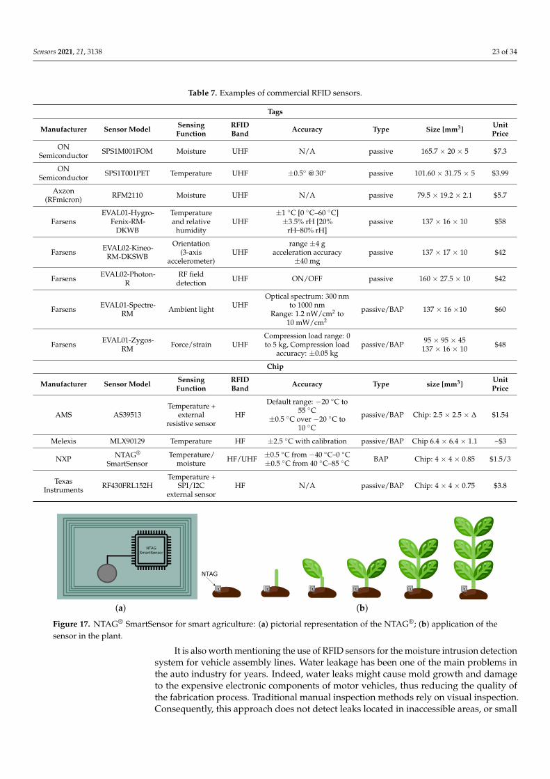
Sensors 2021, 21, 3138 23 of 34
Table 7. Examples of commercial RFID sensors.
Tags
Manufacturer Sensor Model SensingFunction
RFIDBand Accuracy Type Size [mm3] Unit
Price
ONSemiconductor SPS1M001FOM Moisture UHF N/A passive 165.7 × 20 × 5 $7.3
ONSemiconductor SPS1T001PET Temperature UHF ±0.5◦ @ 30◦ passive 101.60 × 31.75 × 5 $3.99
Axzon(RFmicron) RFM2110 Moisture UHF N/A passive 79.5 × 19.2 × 2.1 $5.7
FarsensEVAL01-Hygro-
Fenix-RM-DKWB
Temperatureand relative
humidityUHF
±1 ◦C [0 ◦C–60 ◦C]±3.5% rH [20%
rH–80% rH]passive 137 × 16 × 10 $58
Farsens EVAL02-Kineo-RM-DKSWB
Orientation(3-axis
accelerometer)UHF
range ±4 gacceleration accuracy
±40 mgpassive 137 × 17 × 10 $42
Farsens EVAL02-Photon-R
RF fielddetection UHF ON/OFF passive 160 × 27.5 × 10 $42
Farsens EVAL01-Spectre-RM Ambient light UHF
Optical spectrum: 300 nmto 1000 nm
Range: 1.2 nW/cm2 to10 mW/cm2
passive/BAP 137 × 16 ×10 $60
Farsens EVAL01-Zygos-RM Force/strain UHF
Compression load range: 0to 5 kg, Compression load
accuracy: ±0.05 kgpassive/BAP 95 × 95 × 45
137 × 16 × 10 $48
Chip
Manufacturer Sensor Model SensingFunction
RFIDBand Accuracy Type size [mm3] Unit
Price
AMS AS39513Temperature +
externalresistive sensor
HF
Default range: −20 ◦C to55 ◦C
±0.5 ◦C over −20 ◦C to10 ◦C
passive/BAP Chip: 2.5 × 2.5 × ∆ $1.54
Melexis MLX90129 Temperature HF ±2.5 ◦C with calibration passive/BAP Chip 6.4 × 6.4 × 1.1 ~$3
NXP NTAG®
SmartSensorTemperature/
moisture HF/UHF ±0.5 ◦C from −40 ◦C–0 ◦C±0.5 ◦C from 40 ◦C–85 ◦C BAP Chip: 4 × 4 × 0.85 $1.5/3
TexasInstruments RF430FRL152H
Temperature +SPI/I2C
external sensorHF N/A passive/BAP Chip: 4 × 4 × 0.75 $3.8
(a) (b)
Figure 17. NTAG® SmartSensor for smart agriculture: (a) pictorial representation of the NTAG®; (b) application of thesensor in the plant.
It is also worth mentioning the use of RFID sensors for the moisture intrusion detectionsystem for vehicle assembly lines. Water leakage has been one of the main problems inthe auto industry for years. Indeed, water leaks might cause mold growth and damageto the expensive electronic components of motor vehicles, thus reducing the quality ofthe fabrication process. Traditional manual inspection methods rely on visual inspection.Consequently, this approach does not detect leaks located in inaccessible areas, or small
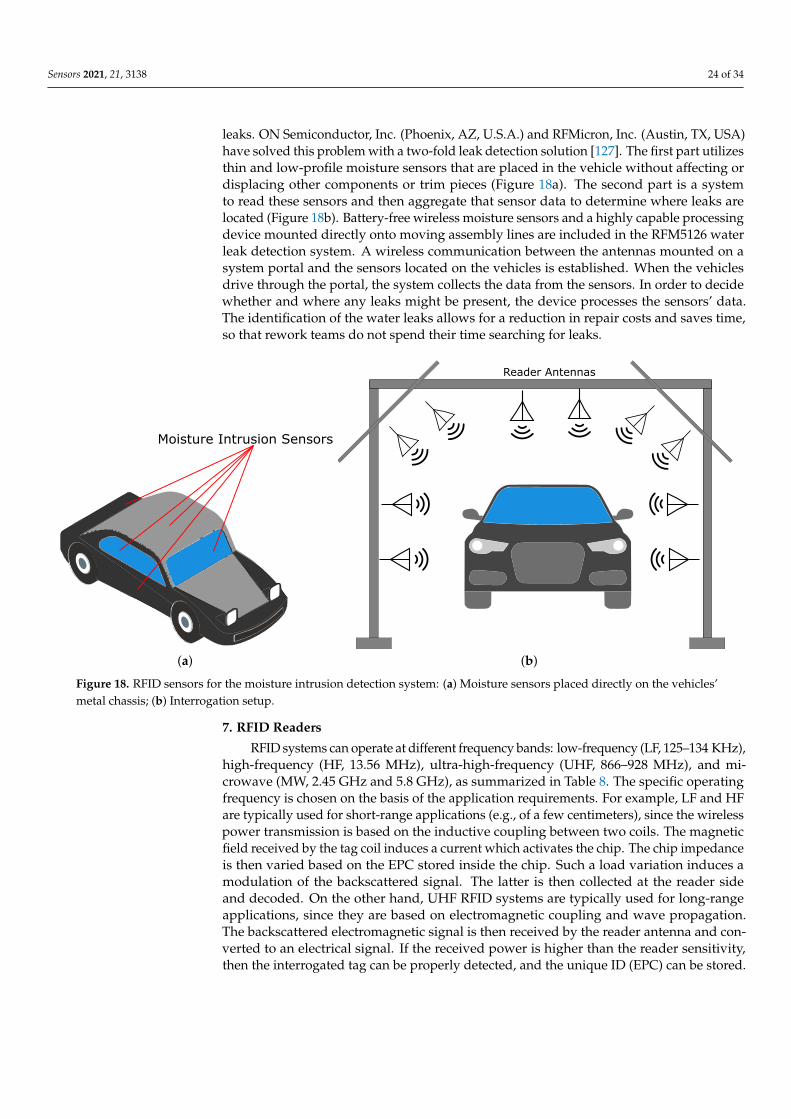
Sensors 2021, 21, 3138 24 of 34
leaks. ON Semiconductor, Inc. (Phoenix, AZ, U.S.A.) and RFMicron, Inc. (Austin, TX, USA)have solved this problem with a two-fold leak detection solution [127]. The first part utilizesthin and low-profile moisture sensors that are placed in the vehicle without affecting ordisplacing other components or trim pieces (Figure 18a). The second part is a systemto read these sensors and then aggregate that sensor data to determine where leaks arelocated (Figure 18b). Battery-free wireless moisture sensors and a highly capable processingdevice mounted directly onto moving assembly lines are included in the RFM5126 waterleak detection system. A wireless communication between the antennas mounted on asystem portal and the sensors located on the vehicles is established. When the vehiclesdrive through the portal, the system collects the data from the sensors. In order to decidewhether and where any leaks might be present, the device processes the sensors’ data.The identification of the water leaks allows for a reduction in repair costs and saves time,so that rework teams do not spend their time searching for leaks.
(a) (b)
Figure 18. RFID sensors for the moisture intrusion detection system: (a) Moisture sensors placed directly on the vehicles’metal chassis; (b) Interrogation setup.
7. RFID Readers
RFID systems can operate at different frequency bands: low-frequency (LF, 125–134 KHz),high-frequency (HF, 13.56 MHz), ultra-high-frequency (UHF, 866–928 MHz), and mi-crowave (MW, 2.45 GHz and 5.8 GHz), as summarized in Table 8. The specific operatingfrequency is chosen on the basis of the application requirements. For example, LF and HFare typically used for short-range applications (e.g., of a few centimeters), since the wirelesspower transmission is based on the inductive coupling between two coils. The magneticfield received by the tag coil induces a current which activates the chip. The chip impedanceis then varied based on the EPC stored inside the chip. Such a load variation induces amodulation of the backscattered signal. The latter is then collected at the reader sideand decoded. On the other hand, UHF RFID systems are typically used for long-rangeapplications, since they are based on electromagnetic coupling and wave propagation.The backscattered electromagnetic signal is then received by the reader antenna and con-verted to an electrical signal. If the received power is higher than the reader sensitivity,then the interrogated tag can be properly detected, and the unique ID (EPC) can be stored.
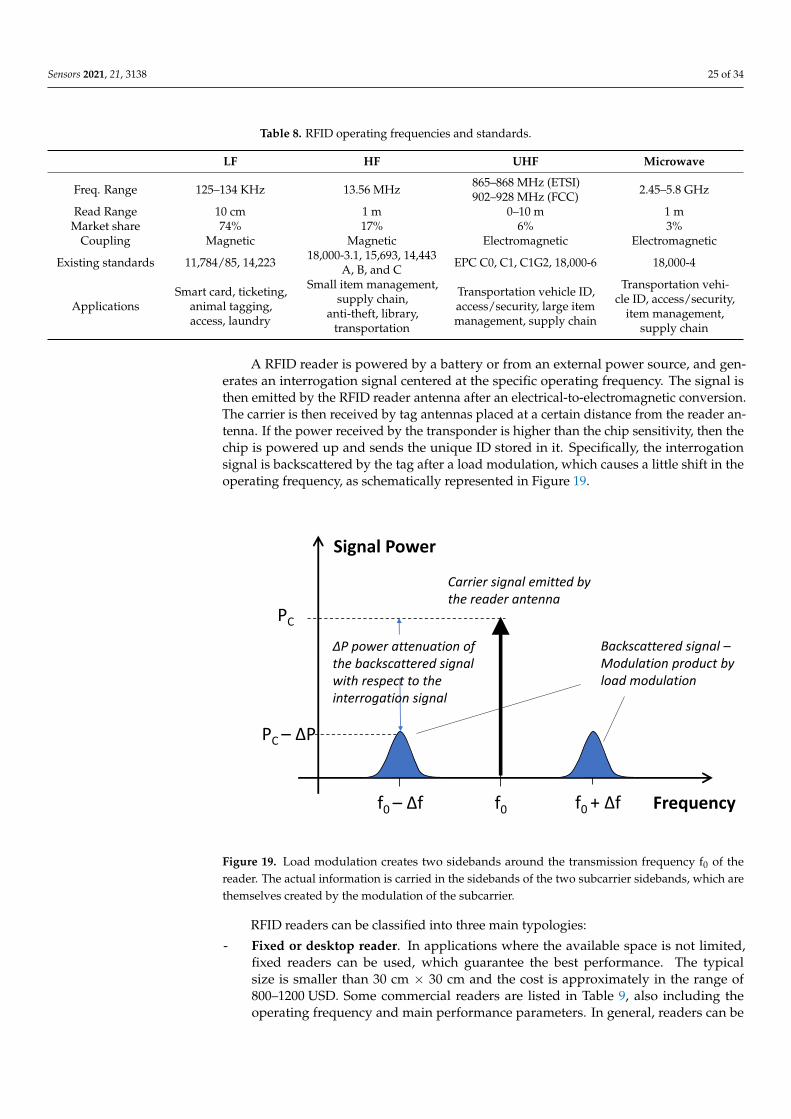
Sensors 2021, 21, 3138 25 of 34
Table 8. RFID operating frequencies and standards.
LF HF UHF Microwave
Freq. Range 125–134 KHz 13.56 MHz 865–868 MHz (ETSI)902–928 MHz (FCC) 2.45–5.8 GHz
Read Range 10 cm 1 m 0–10 m 1 mMarket share 74% 17% 6% 3%
Coupling Magnetic Magnetic Electromagnetic Electromagnetic
Existing standards 11,784/85, 14,223 18,000-3.1, 15,693, 14,443A, B, and C EPC C0, C1, C1G2, 18,000-6 18,000-4
ApplicationsSmart card, ticketing,
animal tagging,access, laundry
Small item management,supply chain,
anti-theft, library,transportation
Transportation vehicle ID,access/security, large itemmanagement, supply chain
Transportation vehi-cle ID, access/security,
item management,supply chain
A RFID reader is powered by a battery or from an external power source, and gen-erates an interrogation signal centered at the specific operating frequency. The signal isthen emitted by the RFID reader antenna after an electrical-to-electromagnetic conversion.The carrier is then received by tag antennas placed at a certain distance from the reader an-tenna. If the power received by the transponder is higher than the chip sensitivity, then thechip is powered up and sends the unique ID stored in it. Specifically, the interrogationsignal is backscattered by the tag after a load modulation, which causes a little shift in theoperating frequency, as schematically represented in Figure 19.
PC – ΔP
Frequency
Carrier signal emitted by the reader antenna
Signal Power
f0
PC
f0 – Δf f0 + Δf
Backscattered signal –Modulation product by load modulation
ΔP power attenuation of the backscattered signalwith respect to the interrogation signal
Figure 19. Load modulation creates two sidebands around the transmission frequency f0 of thereader. The actual information is carried in the sidebands of the two subcarrier sidebands, which arethemselves created by the modulation of the subcarrier.
RFID readers can be classified into three main typologies:
- Fixed or desktop reader. In applications where the available space is not limited,fixed readers can be used, which guarantee the best performance. The typicalsize is smaller than 30 cm × 30 cm and the cost is approximately in the range of800–1200 USD. Some commercial readers are listed in Table 9, also including theoperating frequency and main performance parameters. In general, readers can be
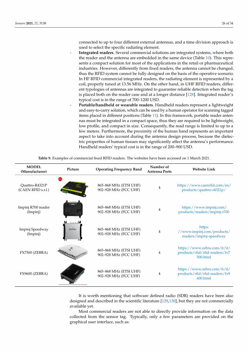
Sensors 2021, 21, 3138 26 of 34
connected to up to four different external antennas, and a time division approach isused to select the specific radiating element.
- Integrated readers. Several commercial solutions are integrated systems, where boththe reader and the antenna are embedded in the same device (Table 10). This repre-sents a compact solution for most of the applications in the retail or pharmaceuticalindustries. However, differently from fixed readers, the antenna cannot be changed,thus the RFID system cannot be fully designed on the basis of the operative scenario.In HF RFID commercial integrated readers, the radiating element is represented by acoil, properly tuned at 13.56 MHz. On the other hand, in UHF RFID readers, differ-ent typologies of antennas are integrated to guarantee reliable detection when the tagis placed both on the reader case and at a longer distance [128]. Integrated reader’stypical cost is in the range of 700–1200 USD.
- Portable/handheld or wearable readers. Handheld readers represent a lightweightand easy-to-carry solution, which can be used by a human operator for scanning taggeditems placed in different positions (Table 11). In this framework, portable reader anten-nas must be integrated in a compact space, thus they are required to be lightweight,low profile, and compact in size. Consequently, the read range is limited to up to afew meters. Furthermore, the proximity of the human hand represents an importantaspect to take into account during the antenna design process, because the dielec-tric properties of human tissues may significantly affect the antenna’s performance.Handheld readers’ typical cost is in the range of 200–900 USD.
Table 9. Examples of commercial fixed RFID readers. The websites have been accessed on 1 March 2021.
MODEL(Manufacturer) Picture Operating Frequency Band Number of
Antenna Ports Website Link
Quattro-R4321P(CAEN RFID s.r.l.)
Sensors 2021, 21, x FOR PEER REVIEW 28 of 36
industries. However, differently from fixed readers, the antenna cannot be changed,
thus the RFID system cannot be fully designed on the basis of the operative scenario.
In HF RFID commercial integrated readers, the radiating element is represented by a
coil, properly tuned at 13.56 MHz. On the other hand, in UHF RFID readers, different
typologies of antennas are integrated to guarantee reliable detection when the tag is
placed both on the reader case and at a longer distance [130]. Integrated reader’s typ-
ical cost is in the range of 700–1200 USD.
- Portable/handheld or wearable readers. Handheld readers represent a lightweight
and easy-to-carry solution, which can be used by a human operator for scanning
tagged items placed in different positions (Table 11). In this framework, portable
reader antennas must be integrated in a compact space, thus they are required to be
lightweight, low profile, and compact in size. Consequently, the read range is limited
to up to a few meters. Furthermore, the proximity of the human hand represents an
important aspect to take into account during the antenna design process, because the
dielectric properties of human tissues may significantly affect the antenna’s perfor-
mance. Handheld readers’ typical cost is in the range of 200–900 USD.
It is worth mentioning that software defined radio (SDR) readers have been also de-
signed and described in the scientific literature [131,132], but they are not commercially
available yet.
Table 9. Examples of commercial fixed RFID readers. The websites have been accessed on 1 March 2021.
MODEL
(Manufacturer) Picture Operating Frequency Band
Number of An-
tenna Ports Website Link
Quattro‐R4321P
(CAEN RFID s.r.l.)
865–868 MHz (ETSI UHF)
902–928 MHz (FCC UHF) 4
https://www.caenr-
fid.com/en/pro-
ducts/quattro-r4321p/
Impinj R700 reader
(Impinj)
865–868 MHz (ETSI UHF)
902–928 MHz (FCC UHF) 4
https://www.im-
pinj.com/products/rea-
ders/impinj-r700
Impinj Speedway
(Impinj)
865–868 MHz (ETSI UHF)
902–928 MHz (FCC UHF) 4
https://www.im-
pinj.com/products/rea-
ders/impinj-speedway
FX7500 (ZEBRA) 865–868 MHz (ETSI UHF)
902–928 MHz (FCC UHF) 4
https://www.zebra.co
m/it/it/pro-
ducts/rfid/rfid-rea-
ders/fx7500.html
FX9600 (ZEBRA) 865–868 MHz (ETSI UHF)
902–928 MHz (FCC UHF) 4
https://www.zebra.co
m/it/it/pro-
ducts/rfid/rfid-rea-
ders/fx9600.html
Table 10. Examples of commercial integrated RFID readers. The websites have been accessed on 1 March 2021.
MODEL
(Manufacturer) Picture
Operating Frequency
Band
Nominal Read
Range Website Link
IceKey HF (Tertium
Technology) 13.56 MHz (HF) 10 cm
https://www.tertiumtechno-
logy.com/products/desktop-
hf/
865–868 MHz (ETSI UHF)902–928 MHz (FCC UHF) 4 https://www.caenrfid.com/en/
products/quattro-r4321p/
Impinj R700 reader(Impinj)
Sensors 2021, 21, x FOR PEER REVIEW 28 of 36
industries. However, differently from fixed readers, the antenna cannot be changed,
thus the RFID system cannot be fully designed on the basis of the operative scenario.
In HF RFID commercial integrated readers, the radiating element is represented by a
coil, properly tuned at 13.56 MHz. On the other hand, in UHF RFID readers, different
typologies of antennas are integrated to guarantee reliable detection when the tag is
placed both on the reader case and at a longer distance [130]. Integrated reader’s typ-
ical cost is in the range of 700–1200 USD.
- Portable/handheld or wearable readers. Handheld readers represent a lightweight
and easy-to-carry solution, which can be used by a human operator for scanning
tagged items placed in different positions (Table 11). In this framework, portable
reader antennas must be integrated in a compact space, thus they are required to be
lightweight, low profile, and compact in size. Consequently, the read range is limited
to up to a few meters. Furthermore, the proximity of the human hand represents an
important aspect to take into account during the antenna design process, because the
dielectric properties of human tissues may significantly affect the antenna’s perfor-
mance. Handheld readers’ typical cost is in the range of 200–900 USD.
It is worth mentioning that software defined radio (SDR) readers have been also de-
signed and described in the scientific literature [131,132], but they are not commercially
available yet.
Table 9. Examples of commercial fixed RFID readers. The websites have been accessed on 1 March 2021.
MODEL
(Manufacturer) Picture Operating Frequency Band
Number of An-
tenna Ports Website Link
Quattro‐R4321P
(CAEN RFID s.r.l.)
865–868 MHz (ETSI UHF)
902–928 MHz (FCC UHF) 4
https://www.caenr-
fid.com/en/pro-
ducts/quattro-r4321p/
Impinj R700 reader
(Impinj)
865–868 MHz (ETSI UHF)
902–928 MHz (FCC UHF) 4
https://www.im-
pinj.com/products/rea-
ders/impinj-r700
Impinj Speedway
(Impinj)
865–868 MHz (ETSI UHF)
902–928 MHz (FCC UHF) 4
https://www.im-
pinj.com/products/rea-
ders/impinj-speedway
FX7500 (ZEBRA) 865–868 MHz (ETSI UHF)
902–928 MHz (FCC UHF) 4
https://www.zebra.co
m/it/it/pro-
ducts/rfid/rfid-rea-
ders/fx7500.html
FX9600 (ZEBRA) 865–868 MHz (ETSI UHF)
902–928 MHz (FCC UHF) 4
https://www.zebra.co
m/it/it/pro-
ducts/rfid/rfid-rea-
ders/fx9600.html
Table 10. Examples of commercial integrated RFID readers. The websites have been accessed on 1 March 2021.
MODEL
(Manufacturer) Picture
Operating Frequency
Band
Nominal Read
Range Website Link
IceKey HF (Tertium
Technology) 13.56 MHz (HF) 10 cm
https://www.tertiumtechno-
logy.com/products/desktop-
hf/
865–868 MHz (ETSI UHF)902–928 MHz (FCC UHF) 4 https://www.impinj.com/
products/readers/impinj-r700
Impinj Speedway(Impinj)
Sensors 2021, 21, x FOR PEER REVIEW 28 of 36
industries. However, differently from fixed readers, the antenna cannot be changed,
thus the RFID system cannot be fully designed on the basis of the operative scenario.
In HF RFID commercial integrated readers, the radiating element is represented by a
coil, properly tuned at 13.56 MHz. On the other hand, in UHF RFID readers, different
typologies of antennas are integrated to guarantee reliable detection when the tag is
placed both on the reader case and at a longer distance [130]. Integrated reader’s typ-
ical cost is in the range of 700–1200 USD.
- Portable/handheld or wearable readers. Handheld readers represent a lightweight
and easy-to-carry solution, which can be used by a human operator for scanning
tagged items placed in different positions (Table 11). In this framework, portable
reader antennas must be integrated in a compact space, thus they are required to be
lightweight, low profile, and compact in size. Consequently, the read range is limited
to up to a few meters. Furthermore, the proximity of the human hand represents an
important aspect to take into account during the antenna design process, because the
dielectric properties of human tissues may significantly affect the antenna’s perfor-
mance. Handheld readers’ typical cost is in the range of 200–900 USD.
It is worth mentioning that software defined radio (SDR) readers have been also de-
signed and described in the scientific literature [131,132], but they are not commercially
available yet.
Table 9. Examples of commercial fixed RFID readers. The websites have been accessed on 1 March 2021.
MODEL
(Manufacturer) Picture Operating Frequency Band
Number of An-
tenna Ports Website Link
Quattro‐R4321P
(CAEN RFID s.r.l.)
865–868 MHz (ETSI UHF)
902–928 MHz (FCC UHF) 4
https://www.caenr-
fid.com/en/pro-
ducts/quattro-r4321p/
Impinj R700 reader
(Impinj)
865–868 MHz (ETSI UHF)
902–928 MHz (FCC UHF) 4
https://www.im-
pinj.com/products/rea-
ders/impinj-r700
Impinj Speedway
(Impinj)
865–868 MHz (ETSI UHF)
902–928 MHz (FCC UHF) 4
https://www.im-
pinj.com/products/rea-
ders/impinj-speedway
FX7500 (ZEBRA) 865–868 MHz (ETSI UHF)
902–928 MHz (FCC UHF) 4
https://www.zebra.co
m/it/it/pro-
ducts/rfid/rfid-rea-
ders/fx7500.html
FX9600 (ZEBRA) 865–868 MHz (ETSI UHF)
902–928 MHz (FCC UHF) 4
https://www.zebra.co
m/it/it/pro-
ducts/rfid/rfid-rea-
ders/fx9600.html
Table 10. Examples of commercial integrated RFID readers. The websites have been accessed on 1 March 2021.
MODEL
(Manufacturer) Picture
Operating Frequency
Band
Nominal Read
Range Website Link
IceKey HF (Tertium
Technology) 13.56 MHz (HF) 10 cm
https://www.tertiumtechno-
logy.com/products/desktop-
hf/
865–868 MHz (ETSI UHF)902–928 MHz (FCC UHF) 4
https://www.impinj.com/products/
readers/impinj-speedway
FX7500 (ZEBRA)
Sensors 2021, 21, x FOR PEER REVIEW 28 of 36
industries. However, differently from fixed readers, the antenna cannot be changed,
thus the RFID system cannot be fully designed on the basis of the operative scenario.
In HF RFID commercial integrated readers, the radiating element is represented by a
coil, properly tuned at 13.56 MHz. On the other hand, in UHF RFID readers, different
typologies of antennas are integrated to guarantee reliable detection when the tag is
placed both on the reader case and at a longer distance [130]. Integrated reader’s typ-
ical cost is in the range of 700–1200 USD.
- Portable/handheld or wearable readers. Handheld readers represent a lightweight
and easy-to-carry solution, which can be used by a human operator for scanning
tagged items placed in different positions (Table 11). In this framework, portable
reader antennas must be integrated in a compact space, thus they are required to be
lightweight, low profile, and compact in size. Consequently, the read range is limited
to up to a few meters. Furthermore, the proximity of the human hand represents an
important aspect to take into account during the antenna design process, because the
dielectric properties of human tissues may significantly affect the antenna’s perfor-
mance. Handheld readers’ typical cost is in the range of 200–900 USD.
It is worth mentioning that software defined radio (SDR) readers have been also de-
signed and described in the scientific literature [131,132], but they are not commercially
available yet.
Table 9. Examples of commercial fixed RFID readers. The websites have been accessed on 1 March 2021.
MODEL
(Manufacturer) Picture Operating Frequency Band
Number of An-
tenna Ports Website Link
Quattro‐R4321P
(CAEN RFID s.r.l.)
865–868 MHz (ETSI UHF)
902–928 MHz (FCC UHF) 4
https://www.caenr-
fid.com/en/pro-
ducts/quattro-r4321p/
Impinj R700 reader
(Impinj)
865–868 MHz (ETSI UHF)
902–928 MHz (FCC UHF) 4
https://www.im-
pinj.com/products/rea-
ders/impinj-r700
Impinj Speedway
(Impinj)
865–868 MHz (ETSI UHF)
902–928 MHz (FCC UHF) 4
https://www.im-
pinj.com/products/rea-
ders/impinj-speedway
FX7500 (ZEBRA) 865–868 MHz (ETSI UHF)
902–928 MHz (FCC UHF) 4
https://www.zebra.co
m/it/it/pro-
ducts/rfid/rfid-rea-
ders/fx7500.html
FX9600 (ZEBRA) 865–868 MHz (ETSI UHF)
902–928 MHz (FCC UHF) 4
https://www.zebra.co
m/it/it/pro-
ducts/rfid/rfid-rea-
ders/fx9600.html
Table 10. Examples of commercial integrated RFID readers. The websites have been accessed on 1 March 2021.
MODEL
(Manufacturer) Picture
Operating Frequency
Band
Nominal Read
Range Website Link
IceKey HF (Tertium
Technology) 13.56 MHz (HF) 10 cm
https://www.tertiumtechno-
logy.com/products/desktop-
hf/
865–868 MHz (ETSI UHF)902–928 MHz (FCC UHF) 4
https://www.zebra.com/it/it/products/rfid/rfid-readers/fx7
500.html
FX9600 (ZEBRA)
Sensors 2021, 21, x FOR PEER REVIEW 28 of 36
industries. However, differently from fixed readers, the antenna cannot be changed,
thus the RFID system cannot be fully designed on the basis of the operative scenario.
In HF RFID commercial integrated readers, the radiating element is represented by a
coil, properly tuned at 13.56 MHz. On the other hand, in UHF RFID readers, different
typologies of antennas are integrated to guarantee reliable detection when the tag is
placed both on the reader case and at a longer distance [130]. Integrated reader’s typ-
ical cost is in the range of 700–1200 USD.
- Portable/handheld or wearable readers. Handheld readers represent a lightweight
and easy-to-carry solution, which can be used by a human operator for scanning
tagged items placed in different positions (Table 11). In this framework, portable
reader antennas must be integrated in a compact space, thus they are required to be
lightweight, low profile, and compact in size. Consequently, the read range is limited
to up to a few meters. Furthermore, the proximity of the human hand represents an
important aspect to take into account during the antenna design process, because the
dielectric properties of human tissues may significantly affect the antenna’s perfor-
mance. Handheld readers’ typical cost is in the range of 200–900 USD.
It is worth mentioning that software defined radio (SDR) readers have been also de-
signed and described in the scientific literature [131,132], but they are not commercially
available yet.
Table 9. Examples of commercial fixed RFID readers. The websites have been accessed on 1 March 2021.
MODEL
(Manufacturer) Picture Operating Frequency Band
Number of An-
tenna Ports Website Link
Quattro‐R4321P
(CAEN RFID s.r.l.)
865–868 MHz (ETSI UHF)
902–928 MHz (FCC UHF) 4
https://www.caenr-
fid.com/en/pro-
ducts/quattro-r4321p/
Impinj R700 reader
(Impinj)
865–868 MHz (ETSI UHF)
902–928 MHz (FCC UHF) 4
https://www.im-
pinj.com/products/rea-
ders/impinj-r700
Impinj Speedway
(Impinj)
865–868 MHz (ETSI UHF)
902–928 MHz (FCC UHF) 4
https://www.im-
pinj.com/products/rea-
ders/impinj-speedway
FX7500 (ZEBRA) 865–868 MHz (ETSI UHF)
902–928 MHz (FCC UHF) 4
https://www.zebra.co
m/it/it/pro-
ducts/rfid/rfid-rea-
ders/fx7500.html
FX9600 (ZEBRA) 865–868 MHz (ETSI UHF)
902–928 MHz (FCC UHF) 4
https://www.zebra.co
m/it/it/pro-
ducts/rfid/rfid-rea-
ders/fx9600.html
Table 10. Examples of commercial integrated RFID readers. The websites have been accessed on 1 March 2021.
MODEL
(Manufacturer) Picture
Operating Frequency
Band
Nominal Read
Range Website Link
IceKey HF (Tertium
Technology) 13.56 MHz (HF) 10 cm
https://www.tertiumtechno-
logy.com/products/desktop-
hf/
865–868 MHz (ETSI UHF)902–928 MHz (FCC UHF) 4
https://www.zebra.com/it/it/products/rfid/rfid-readers/fx9
600.html
It is worth mentioning that software defined radio (SDR) readers have been alsodesigned and described in the scientific literature [129,130], but they are not commerciallyavailable yet.
Most commercial readers are not able to directly provide information on the datacollected from the sensor tag. Typically, only a few parameters are provided on thegraphical user interface, such as:
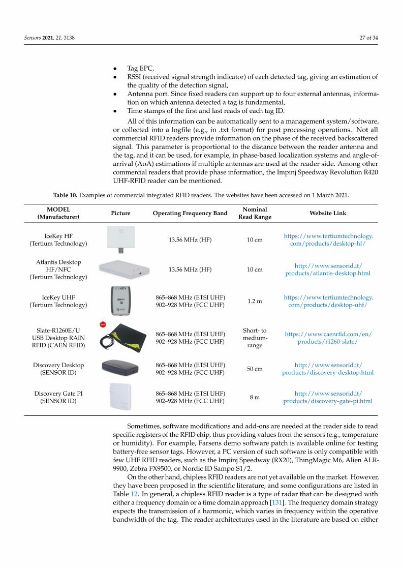
Sensors 2021, 21, 3138 27 of 34
• Tag EPC,• RSSI (received signal strength indicator) of each detected tag, giving an estimation of
the quality of the detection signal,• Antenna port. Since fixed readers can support up to four external antennas, informa-
tion on which antenna detected a tag is fundamental,• Time stamps of the first and last reads of each tag ID.
All of this information can be automatically sent to a management system/software,or collected into a logfile (e.g., in .txt format) for post processing operations. Not allcommercial RFID readers provide information on the phase of the received backscatteredsignal. This parameter is proportional to the distance between the reader antenna andthe tag, and it can be used, for example, in phase-based localization systems and angle-of-arrival (AoA) estimations if multiple antennas are used at the reader side. Among othercommercial readers that provide phase information, the Impinj Speedway Revolution R420UHF-RFID reader can be mentioned.
Table 10. Examples of commercial integrated RFID readers. The websites have been accessed on 1 March 2021.
MODEL(Manufacturer) Picture Operating Frequency Band Nominal
Read Range Website Link
IceKey HF(Tertium Technology)
Sensors 2021, 21, x FOR PEER REVIEW 28 of 36
industries. However, differently from fixed readers, the antenna cannot be changed,
thus the RFID system cannot be fully designed on the basis of the operative scenario.
In HF RFID commercial integrated readers, the radiating element is represented by a
coil, properly tuned at 13.56 MHz. On the other hand, in UHF RFID readers, different
typologies of antennas are integrated to guarantee reliable detection when the tag is
placed both on the reader case and at a longer distance [130]. Integrated reader’s typ-
ical cost is in the range of 700–1200 USD.
- Portable/handheld or wearable readers. Handheld readers represent a lightweight
and easy-to-carry solution, which can be used by a human operator for scanning
tagged items placed in different positions (Table 11). In this framework, portable
reader antennas must be integrated in a compact space, thus they are required to be
lightweight, low profile, and compact in size. Consequently, the read range is limited
to up to a few meters. Furthermore, the proximity of the human hand represents an
important aspect to take into account during the antenna design process, because the
dielectric properties of human tissues may significantly affect the antenna’s perfor-
mance. Handheld readers’ typical cost is in the range of 200–900 USD.
It is worth mentioning that software defined radio (SDR) readers have been also de-
signed and described in the scientific literature [131,132], but they are not commercially
available yet.
Table 9. Examples of commercial fixed RFID readers. The websites have been accessed on 1 March 2021.
MODEL
(Manufacturer) Picture Operating Frequency Band
Number of An-
tenna Ports Website Link
Quattro‐R4321P
(CAEN RFID s.r.l.)
865–868 MHz (ETSI UHF)
902–928 MHz (FCC UHF) 4
https://www.caenr-
fid.com/en/pro-
ducts/quattro-r4321p/
Impinj R700 reader
(Impinj)
865–868 MHz (ETSI UHF)
902–928 MHz (FCC UHF) 4
https://www.im-
pinj.com/products/rea-
ders/impinj-r700
Impinj Speedway
(Impinj)
865–868 MHz (ETSI UHF)
902–928 MHz (FCC UHF) 4
https://www.im-
pinj.com/products/rea-
ders/impinj-speedway
FX7500 (ZEBRA) 865–868 MHz (ETSI UHF)
902–928 MHz (FCC UHF) 4
https://www.zebra.co
m/it/it/pro-
ducts/rfid/rfid-rea-
ders/fx7500.html
FX9600 (ZEBRA) 865–868 MHz (ETSI UHF)
902–928 MHz (FCC UHF) 4
https://www.zebra.co
m/it/it/pro-
ducts/rfid/rfid-rea-
ders/fx9600.html
Table 10. Examples of commercial integrated RFID readers. The websites have been accessed on 1 March 2021.
MODEL
(Manufacturer) Picture
Operating Frequency
Band
Nominal Read
Range Website Link
IceKey HF (Tertium
Technology) 13.56 MHz (HF) 10 cm
https://www.tertiumtechno-
logy.com/products/desktop-
hf/ 13.56 MHz (HF) 10 cm https://www.tertiumtechnology.
com/products/desktop-hf/
Atlantis DesktopHF/NFC
(Tertium Technology)
Sensors 2021, 21, x FOR PEER REVIEW 29 of 36
Atlantis Desktop
HF/NFC (Tertium
Technology)
13.56 MHz (HF) 10 cm http://www.sensorid.it/pro-
ducts/atlantis-desktop.html
IceKey UHF (Tertium
Technology)
865–868 MHz (ETSI
UHF)
902–928 MHz (FCC
UHF)
1.2 m
https://www.tertiumtechno-
logy.com/products/desktop-
uhf/
Slate‐R1260E/U
USB Desktop RAIN
RFID (CAEN RFID)
865–868 MHz (ETSI
UHF)
902–928 MHz (FCC
UHF)
Short- to me-
dium-range
https://www.caenr-
fid.com/en/products/r1260-
slate/
Discovery Desktop
(SENSOR ID)
865–868 MHz (ETSI
UHF)
902–928 MHz (FCC
UHF)
50 cm
http://www.sensorid.it/pro-
ducts/discovery-desk-
top.html
Discovery Gate PI
(SENSOR ID)
865–868 MHz (ETSI
UHF)
902–928 MHz (FCC
UHF)
8 m http://www.sensorid.it/pro-
ducts/discovery-gate-pi.html
Most commercial readers are not able to directly provide information on the data
collected from the sensor tag. Typically, only a few parameters are provided on the graph-
ical user interface, such as:
• Tag EPC,
• RSSI (received signal strength indicator) of each detected tag, giving an estimation of
the quality of the detection signal,
• Antenna port. Since fixed readers can support up to four external antennas, infor-
mation on which antenna detected a tag is fundamental,
• Time stamps of the first and last reads of each tag ID.
All of this information can be automatically sent to a management system/software,
or collected into a logfile (e.g., in .txt format) for post processing operations. Not all com-
mercial RFID readers provide information on the phase of the received backscattered sig-
nal. This parameter is proportional to the distance between the reader antenna and the
tag, and it can be used, for example, in phase-based localization systems and angle-of-
arrival (AoA) estimations if multiple antennas are used at the reader side. Among other
commercial readers that provide phase information, the Impinj Speedway Revolution
R420 UHF-RFID reader can be mentioned.
Sometimes, software modifications and add-ons are needed at the reader side to read
specific registers of the RFID chip, thus providing values from the sensors (e.g., tempera-
ture or humidity). For example, Farsens demo software patch is available online for test-
ing battery-free sensor tags. However, a PC version of such software is only compatible
with few UHF RFID readers, such as the Impinj Speedway (RX20), ThingMagic M6, Alien
ALR-9900, Zebra FX9500, or Nordic ID Sampo S1/2.
Table 11. Examples of commercial handheld RFID readers. The websites have been accessed on 1 March, 2021.
MODEL (Manufactu-
rer) Picture
Operating Frequency
Band
Nominal Read
Range Website Link
BLUEBERRY HS HF
(Tertium Technology)
13.56 MHz (HF) 6 cm
https://www.tertium-
technology.com/pro-
ducts/desktop-hf/
13.56 MHz (HF) 10 cm http://www.sensorid.it/products/atlantis-desktop.html
IceKey UHF(Tertium Technology)
Sensors 2021, 21, x FOR PEER REVIEW 29 of 36
Atlantis Desktop
HF/NFC (Tertium
Technology)
13.56 MHz (HF) 10 cm http://www.sensorid.it/pro-
ducts/atlantis-desktop.html
IceKey UHF (Tertium
Technology)
865–868 MHz (ETSI
UHF)
902–928 MHz (FCC
UHF)
1.2 m
https://www.tertiumtechno-
logy.com/products/desktop-
uhf/
Slate‐R1260E/U
USB Desktop RAIN
RFID (CAEN RFID)
865–868 MHz (ETSI
UHF)
902–928 MHz (FCC
UHF)
Short- to me-
dium-range
https://www.caenr-
fid.com/en/products/r1260-
slate/
Discovery Desktop
(SENSOR ID)
865–868 MHz (ETSI
UHF)
902–928 MHz (FCC
UHF)
50 cm
http://www.sensorid.it/pro-
ducts/discovery-desk-
top.html
Discovery Gate PI
(SENSOR ID)
865–868 MHz (ETSI
UHF)
902–928 MHz (FCC
UHF)
8 m http://www.sensorid.it/pro-
ducts/discovery-gate-pi.html
Most commercial readers are not able to directly provide information on the data
collected from the sensor tag. Typically, only a few parameters are provided on the graph-
ical user interface, such as:
• Tag EPC,
• RSSI (received signal strength indicator) of each detected tag, giving an estimation of
the quality of the detection signal,
• Antenna port. Since fixed readers can support up to four external antennas, infor-
mation on which antenna detected a tag is fundamental,
• Time stamps of the first and last reads of each tag ID.
All of this information can be automatically sent to a management system/software,
or collected into a logfile (e.g., in .txt format) for post processing operations. Not all com-
mercial RFID readers provide information on the phase of the received backscattered sig-
nal. This parameter is proportional to the distance between the reader antenna and the
tag, and it can be used, for example, in phase-based localization systems and angle-of-
arrival (AoA) estimations if multiple antennas are used at the reader side. Among other
commercial readers that provide phase information, the Impinj Speedway Revolution
R420 UHF-RFID reader can be mentioned.
Sometimes, software modifications and add-ons are needed at the reader side to read
specific registers of the RFID chip, thus providing values from the sensors (e.g., tempera-
ture or humidity). For example, Farsens demo software patch is available online for test-
ing battery-free sensor tags. However, a PC version of such software is only compatible
with few UHF RFID readers, such as the Impinj Speedway (RX20), ThingMagic M6, Alien
ALR-9900, Zebra FX9500, or Nordic ID Sampo S1/2.
Table 11. Examples of commercial handheld RFID readers. The websites have been accessed on 1 March, 2021.
MODEL (Manufactu-
rer) Picture
Operating Frequency
Band
Nominal Read
Range Website Link
BLUEBERRY HS HF
(Tertium Technology)
13.56 MHz (HF) 6 cm
https://www.tertium-
technology.com/pro-
ducts/desktop-hf/
865–868 MHz (ETSI UHF)902–928 MHz (FCC UHF) 1.2 m https://www.tertiumtechnology.
com/products/desktop-uhf/
Slate-R1260E/UUSB Desktop RAINRFID (CAEN RFID)
Sensors 2021, 21, x FOR PEER REVIEW 29 of 36
Atlantis Desktop
HF/NFC (Tertium
Technology)
13.56 MHz (HF) 10 cm http://www.sensorid.it/pro-
ducts/atlantis-desktop.html
IceKey UHF (Tertium
Technology)
865–868 MHz (ETSI
UHF)
902–928 MHz (FCC
UHF)
1.2 m
https://www.tertiumtechno-
logy.com/products/desktop-
uhf/
Slate‐R1260E/U
USB Desktop RAIN
RFID (CAEN RFID)
865–868 MHz (ETSI
UHF)
902–928 MHz (FCC
UHF)
Short- to me-
dium-range
https://www.caenr-
fid.com/en/products/r1260-
slate/
Discovery Desktop
(SENSOR ID)
865–868 MHz (ETSI
UHF)
902–928 MHz (FCC
UHF)
50 cm
http://www.sensorid.it/pro-
ducts/discovery-desk-
top.html
Discovery Gate PI
(SENSOR ID)
865–868 MHz (ETSI
UHF)
902–928 MHz (FCC
UHF)
8 m http://www.sensorid.it/pro-
ducts/discovery-gate-pi.html
Most commercial readers are not able to directly provide information on the data
collected from the sensor tag. Typically, only a few parameters are provided on the graph-
ical user interface, such as:
• Tag EPC,
• RSSI (received signal strength indicator) of each detected tag, giving an estimation of
the quality of the detection signal,
• Antenna port. Since fixed readers can support up to four external antennas, infor-
mation on which antenna detected a tag is fundamental,
• Time stamps of the first and last reads of each tag ID.
All of this information can be automatically sent to a management system/software,
or collected into a logfile (e.g., in .txt format) for post processing operations. Not all com-
mercial RFID readers provide information on the phase of the received backscattered sig-
nal. This parameter is proportional to the distance between the reader antenna and the
tag, and it can be used, for example, in phase-based localization systems and angle-of-
arrival (AoA) estimations if multiple antennas are used at the reader side. Among other
commercial readers that provide phase information, the Impinj Speedway Revolution
R420 UHF-RFID reader can be mentioned.
Sometimes, software modifications and add-ons are needed at the reader side to read
specific registers of the RFID chip, thus providing values from the sensors (e.g., tempera-
ture or humidity). For example, Farsens demo software patch is available online for test-
ing battery-free sensor tags. However, a PC version of such software is only compatible
with few UHF RFID readers, such as the Impinj Speedway (RX20), ThingMagic M6, Alien
ALR-9900, Zebra FX9500, or Nordic ID Sampo S1/2.
Table 11. Examples of commercial handheld RFID readers. The websites have been accessed on 1 March, 2021.
MODEL (Manufactu-
rer) Picture
Operating Frequency
Band
Nominal Read
Range Website Link
BLUEBERRY HS HF
(Tertium Technology)
13.56 MHz (HF) 6 cm
https://www.tertium-
technology.com/pro-
ducts/desktop-hf/
865–868 MHz (ETSI UHF)902–928 MHz (FCC UHF)
Short- tomedium-
range
https://www.caenrfid.com/en/products/r1260-slate/
Discovery Desktop(SENSOR ID)
Sensors 2021, 21, x FOR PEER REVIEW 29 of 36
Atlantis Desktop
HF/NFC (Tertium
Technology)
13.56 MHz (HF) 10 cm http://www.sensorid.it/pro-
ducts/atlantis-desktop.html
IceKey UHF (Tertium
Technology)
865–868 MHz (ETSI
UHF)
902–928 MHz (FCC
UHF)
1.2 m
https://www.tertiumtechno-
logy.com/products/desktop-
uhf/
Slate‐R1260E/U
USB Desktop RAIN
RFID (CAEN RFID)
865–868 MHz (ETSI
UHF)
902–928 MHz (FCC
UHF)
Short- to me-
dium-range
https://www.caenr-
fid.com/en/products/r1260-
slate/
Discovery Desktop
(SENSOR ID)
865–868 MHz (ETSI
UHF)
902–928 MHz (FCC
UHF)
50 cm
http://www.sensorid.it/pro-
ducts/discovery-desk-
top.html
Discovery Gate PI
(SENSOR ID)
865–868 MHz (ETSI
UHF)
902–928 MHz (FCC
UHF)
8 m http://www.sensorid.it/pro-
ducts/discovery-gate-pi.html
Most commercial readers are not able to directly provide information on the data
collected from the sensor tag. Typically, only a few parameters are provided on the graph-
ical user interface, such as:
• Tag EPC,
• RSSI (received signal strength indicator) of each detected tag, giving an estimation of
the quality of the detection signal,
• Antenna port. Since fixed readers can support up to four external antennas, infor-
mation on which antenna detected a tag is fundamental,
• Time stamps of the first and last reads of each tag ID.
All of this information can be automatically sent to a management system/software,
or collected into a logfile (e.g., in .txt format) for post processing operations. Not all com-
mercial RFID readers provide information on the phase of the received backscattered sig-
nal. This parameter is proportional to the distance between the reader antenna and the
tag, and it can be used, for example, in phase-based localization systems and angle-of-
arrival (AoA) estimations if multiple antennas are used at the reader side. Among other
commercial readers that provide phase information, the Impinj Speedway Revolution
R420 UHF-RFID reader can be mentioned.
Sometimes, software modifications and add-ons are needed at the reader side to read
specific registers of the RFID chip, thus providing values from the sensors (e.g., tempera-
ture or humidity). For example, Farsens demo software patch is available online for test-
ing battery-free sensor tags. However, a PC version of such software is only compatible
with few UHF RFID readers, such as the Impinj Speedway (RX20), ThingMagic M6, Alien
ALR-9900, Zebra FX9500, or Nordic ID Sampo S1/2.
Table 11. Examples of commercial handheld RFID readers. The websites have been accessed on 1 March, 2021.
MODEL (Manufactu-
rer) Picture
Operating Frequency
Band
Nominal Read
Range Website Link
BLUEBERRY HS HF
(Tertium Technology)
13.56 MHz (HF) 6 cm
https://www.tertium-
technology.com/pro-
ducts/desktop-hf/
865–868 MHz (ETSI UHF)902–928 MHz (FCC UHF) 50 cm http://www.sensorid.it/
products/discovery-desktop.html
Discovery Gate PI(SENSOR ID)
Sensors 2021, 21, x FOR PEER REVIEW 29 of 36
Atlantis Desktop
HF/NFC (Tertium
Technology)
13.56 MHz (HF) 10 cm http://www.sensorid.it/pro-
ducts/atlantis-desktop.html
IceKey UHF (Tertium
Technology)
865–868 MHz (ETSI
UHF)
902–928 MHz (FCC
UHF)
1.2 m
https://www.tertiumtechno-
logy.com/products/desktop-
uhf/
Slate‐R1260E/U
USB Desktop RAIN
RFID (CAEN RFID)
865–868 MHz (ETSI
UHF)
902–928 MHz (FCC
UHF)
Short- to me-
dium-range
https://www.caenr-
fid.com/en/products/r1260-
slate/
Discovery Desktop
(SENSOR ID)
865–868 MHz (ETSI
UHF)
902–928 MHz (FCC
UHF)
50 cm
http://www.sensorid.it/pro-
ducts/discovery-desk-
top.html
Discovery Gate PI
(SENSOR ID)
865–868 MHz (ETSI
UHF)
902–928 MHz (FCC
UHF)
8 m http://www.sensorid.it/pro-
ducts/discovery-gate-pi.html
Most commercial readers are not able to directly provide information on the data
collected from the sensor tag. Typically, only a few parameters are provided on the graph-
ical user interface, such as:
• Tag EPC,
• RSSI (received signal strength indicator) of each detected tag, giving an estimation of
the quality of the detection signal,
• Antenna port. Since fixed readers can support up to four external antennas, infor-
mation on which antenna detected a tag is fundamental,
• Time stamps of the first and last reads of each tag ID.
All of this information can be automatically sent to a management system/software,
or collected into a logfile (e.g., in .txt format) for post processing operations. Not all com-
mercial RFID readers provide information on the phase of the received backscattered sig-
nal. This parameter is proportional to the distance between the reader antenna and the
tag, and it can be used, for example, in phase-based localization systems and angle-of-
arrival (AoA) estimations if multiple antennas are used at the reader side. Among other
commercial readers that provide phase information, the Impinj Speedway Revolution
R420 UHF-RFID reader can be mentioned.
Sometimes, software modifications and add-ons are needed at the reader side to read
specific registers of the RFID chip, thus providing values from the sensors (e.g., tempera-
ture or humidity). For example, Farsens demo software patch is available online for test-
ing battery-free sensor tags. However, a PC version of such software is only compatible
with few UHF RFID readers, such as the Impinj Speedway (RX20), ThingMagic M6, Alien
ALR-9900, Zebra FX9500, or Nordic ID Sampo S1/2.
Table 11. Examples of commercial handheld RFID readers. The websites have been accessed on 1 March, 2021.
MODEL (Manufactu-
rer) Picture
Operating Frequency
Band
Nominal Read
Range Website Link
BLUEBERRY HS HF
(Tertium Technology)
13.56 MHz (HF) 6 cm
https://www.tertium-
technology.com/pro-
ducts/desktop-hf/
865–868 MHz (ETSI UHF)902–928 MHz (FCC UHF) 8 m http://www.sensorid.it/
products/discovery-gate-pi.html
Sometimes, software modifications and add-ons are needed at the reader side to readspecific registers of the RFID chip, thus providing values from the sensors (e.g., temperatureor humidity). For example, Farsens demo software patch is available online for testingbattery-free sensor tags. However, a PC version of such software is only compatible withfew UHF RFID readers, such as the Impinj Speedway (RX20), ThingMagic M6, Alien ALR-9900, Zebra FX9500, or Nordic ID Sampo S1/2.
On the other hand, chipless RFID readers are not yet available on the market. However,they have been proposed in the scientific literature, and some configurations are listed inTable 12. In general, a chipless RFID reader is a type of radar that can be designed witheither a frequency domain or a time domain approach [131]. The frequency domain strategyexpects the transmission of a harmonic, which varies in frequency within the operativebandwidth of the tag. The reader architectures used in the literature are based on either
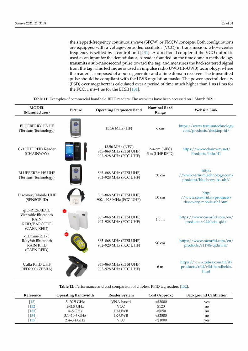
Sensors 2021, 21, 3138 28 of 34
the stepped-frequency continuous wave (SFCW) or FMCW concepts. Both configurationsare equipped with a voltage-controlled oscillator (VCO) in transmission, whose centerfrequency is settled by a control unit [131]. A directional coupler at the VCO output isused as an input for the demodulator. A reader founded on the time domain methodologytransmits a sub-nanosecond pulse toward the tag, and measures the backscattered signalfrom the tag. This technique is used in impulse radio UWB (IR-UWB) technology, wherethe reader is composed of a pulse generator and a time domain receiver. The transmittedpulse should be compliant with the UWB regulation masks. The power spectral density(PSD) over megahertz is calculated over a period of time much higher than 1 ns (1 ms forthe FCC, 1 ms–1 µs for the ETSI) [131].
Table 11. Examples of commercial handheld RFID readers. The websites have been accessed on 1 March 2021.
MODEL(Manufacturer) Picture Operating Frequency Band Nominal Read
Range Website Link
BLUEBERRY HS HF(Tertium Technology)
Sensors 2021, 21, x FOR PEER REVIEW 29 of 36
Atlantis Desktop
HF/NFC (Tertium
Technology)
13.56 MHz (HF) 10 cm http://www.sensorid.it/pro-
ducts/atlantis-desktop.html
IceKey UHF (Tertium
Technology)
865–868 MHz (ETSI
UHF)
902–928 MHz (FCC
UHF)
1.2 m
https://www.tertiumtechno-
logy.com/products/desktop-
uhf/
Slate‐R1260E/U
USB Desktop RAIN
RFID (CAEN RFID)
865–868 MHz (ETSI
UHF)
902–928 MHz (FCC
UHF)
Short- to me-
dium-range
https://www.caenr-
fid.com/en/products/r1260-
slate/
Discovery Desktop
(SENSOR ID)
865–868 MHz (ETSI
UHF)
902–928 MHz (FCC
UHF)
50 cm
http://www.sensorid.it/pro-
ducts/discovery-desk-
top.html
Discovery Gate PI
(SENSOR ID)
865–868 MHz (ETSI
UHF)
902–928 MHz (FCC
UHF)
8 m http://www.sensorid.it/pro-
ducts/discovery-gate-pi.html
Most commercial readers are not able to directly provide information on the data
collected from the sensor tag. Typically, only a few parameters are provided on the graph-
ical user interface, such as:
• Tag EPC,
• RSSI (received signal strength indicator) of each detected tag, giving an estimation of
the quality of the detection signal,
• Antenna port. Since fixed readers can support up to four external antennas, infor-
mation on which antenna detected a tag is fundamental,
• Time stamps of the first and last reads of each tag ID.
All of this information can be automatically sent to a management system/software,
or collected into a logfile (e.g., in .txt format) for post processing operations. Not all com-
mercial RFID readers provide information on the phase of the received backscattered sig-
nal. This parameter is proportional to the distance between the reader antenna and the
tag, and it can be used, for example, in phase-based localization systems and angle-of-
arrival (AoA) estimations if multiple antennas are used at the reader side. Among other
commercial readers that provide phase information, the Impinj Speedway Revolution
R420 UHF-RFID reader can be mentioned.
Sometimes, software modifications and add-ons are needed at the reader side to read
specific registers of the RFID chip, thus providing values from the sensors (e.g., tempera-
ture or humidity). For example, Farsens demo software patch is available online for test-
ing battery-free sensor tags. However, a PC version of such software is only compatible
with few UHF RFID readers, such as the Impinj Speedway (RX20), ThingMagic M6, Alien
ALR-9900, Zebra FX9500, or Nordic ID Sampo S1/2.
Table 11. Examples of commercial handheld RFID readers. The websites have been accessed on 1 March, 2021.
MODEL (Manufactu-
rer) Picture
Operating Frequency
Band
Nominal Read
Range Website Link
BLUEBERRY HS HF
(Tertium Technology)
13.56 MHz (HF) 6 cm
https://www.tertium-
technology.com/pro-
ducts/desktop-hf/
13.56 MHz (HF) 6 cm https://www.tertiumtechnology.com/products/desktop-hf/
C71 UHF RFID Reader(CHAINWAY)
Sensors 2021, 21, x FOR PEER REVIEW 30 of 36
C71 UHF RFID
Reader (CHAINWAY)
13.56 MHz (NFC)
865–868 MHz (ETSI UHF)
902–928 MHz (FCC UHF)
2–4 cm (NFC)
3 m (UHF RFID)
https://www.chain-
way.net/Pro-
ducts/Info/41
BLUEBERRY HS UHF
(Tertium Technology)
865–868 MHz (ETSI UHF)
902–928 MHz (FCC UHF) 30 cm
https://www.tertium-
technology.com/pro-
dotto/blueberry-hs-uhf/
Discovery Mobile
UHF (SENSOR ID)
865–868 MHz (ETSI UHF)
902÷928 MHz (FCC UHF) 50 cm
http://www.senso-
rid.it/products/dis-
covery-mobile-uhf.html
qID‐R1240IE/IU
Wearable Bluetooth
RAIN RFID/BAR-
CODE (CAEN RFID)
865–868 MHz (ETSI UHF)
902–928 MHz (FCC UHF) 1.5 m
https://www.caenr-
fid.com/en/pro-
ducts/r1240ieiu-qid/
qIDmini‐R1170I
Keyfob Bluetooth
RAIN RFID (CAEN
RFID)
865–868 MHz (ETSI UHF)
902–928 MHz (FCC UHF) 90 cm
https://www.caenr-
fid.com/en/pro-
ducts/r1170i-qidmini/
Culla RFID UHF
RFD2000 (ZEBRA)
865–868 MHz (ETSI UHF)
902–928 MHz (FCC UHF) 6 m
https://www.zebra.com/i
t/it/products/rfid/rfid-
handhelds.html
On the other hand, chipless RFID readers are not yet available on the market. How-
ever, they have been proposed in the scientific literature, and some configurations are
listed in Table 12. In general, a chipless RFID reader is a type of radar that can be designed
with either a frequency domain or a time domain approach [133]. The frequency domain
strategy expects the transmission of a harmonic, which varies in frequency within the op-
erative bandwidth of the tag. The reader architectures used in the literature are based on
either the stepped-frequency continuous wave (SFCW) or FMCW concepts. Both config-
urations are equipped with a voltage-controlled oscillator (VCO) in transmission, whose
center frequency is settled by a control unit [133]. A directional coupler at the VCO output
is used as an input for the demodulator. A reader founded on the time domain method-
ology transmits a sub-nanosecond pulse toward the tag, and measures the backscattered
signal from the tag. This technique is used in impulse radio UWB (IR-UWB) technology,
where the reader is composed of a pulse generator and a time domain receiver. The trans-
mitted pulse should be compliant with the UWB regulation masks. The power spectral
density (PSD) over megahertz is calculated over a period of time much higher than 1 ns
(1 ms for the FCC, 1 ms–1 μs for the ETSI) [133].
Table 12. Performance and cost comparison of chipless RFID tag readers [134].
Reference Operating bandwidth Reader System Cost (approx.) Background calibration
[43] 5–20.5 GHz VNA-based > $3000 yes
[134] 2–2.5 GHz VCO $120 no
[135] 4–8 GHz IR-UWB <$650 no
[136] 3.1–10.6 GHz IR-UWB <$2500 no
[137] 2.4–3.4 GHz VCO <$1000 yes
8. Conclusions
13.56 MHz (NFC)865–868 MHz (ETSI UHF)902–928 MHz (FCC UHF)
2–4 cm (NFC)3 m (UHF RFID)
https://www.chainway.net/Products/Info/41
BLUEBERRY HS UHF(Tertium Technology)
Sensors 2021, 21, x FOR PEER REVIEW 30 of 36
C71 UHF RFID
Reader (CHAINWAY)
13.56 MHz (NFC)
865–868 MHz (ETSI UHF)
902–928 MHz (FCC UHF)
2–4 cm (NFC)
3 m (UHF RFID)
https://www.chain-
way.net/Pro-
ducts/Info/41
BLUEBERRY HS UHF
(Tertium Technology)
865–868 MHz (ETSI UHF)
902–928 MHz (FCC UHF) 30 cm
https://www.tertium-
technology.com/pro-
dotto/blueberry-hs-uhf/
Discovery Mobile
UHF (SENSOR ID)
865–868 MHz (ETSI UHF)
902÷928 MHz (FCC UHF) 50 cm
http://www.senso-
rid.it/products/dis-
covery-mobile-uhf.html
qID‐R1240IE/IU
Wearable Bluetooth
RAIN RFID/BAR-
CODE (CAEN RFID)
865–868 MHz (ETSI UHF)
902–928 MHz (FCC UHF) 1.5 m
https://www.caenr-
fid.com/en/pro-
ducts/r1240ieiu-qid/
qIDmini‐R1170I
Keyfob Bluetooth
RAIN RFID (CAEN
RFID)
865–868 MHz (ETSI UHF)
902–928 MHz (FCC UHF) 90 cm
https://www.caenr-
fid.com/en/pro-
ducts/r1170i-qidmini/
Culla RFID UHF
RFD2000 (ZEBRA)
865–868 MHz (ETSI UHF)
902–928 MHz (FCC UHF) 6 m
https://www.zebra.com/i
t/it/products/rfid/rfid-
handhelds.html
On the other hand, chipless RFID readers are not yet available on the market. How-
ever, they have been proposed in the scientific literature, and some configurations are
listed in Table 12. In general, a chipless RFID reader is a type of radar that can be designed
with either a frequency domain or a time domain approach [133]. The frequency domain
strategy expects the transmission of a harmonic, which varies in frequency within the op-
erative bandwidth of the tag. The reader architectures used in the literature are based on
either the stepped-frequency continuous wave (SFCW) or FMCW concepts. Both config-
urations are equipped with a voltage-controlled oscillator (VCO) in transmission, whose
center frequency is settled by a control unit [133]. A directional coupler at the VCO output
is used as an input for the demodulator. A reader founded on the time domain method-
ology transmits a sub-nanosecond pulse toward the tag, and measures the backscattered
signal from the tag. This technique is used in impulse radio UWB (IR-UWB) technology,
where the reader is composed of a pulse generator and a time domain receiver. The trans-
mitted pulse should be compliant with the UWB regulation masks. The power spectral
density (PSD) over megahertz is calculated over a period of time much higher than 1 ns
(1 ms for the FCC, 1 ms–1 μs for the ETSI) [133].
Table 12. Performance and cost comparison of chipless RFID tag readers [134].
Reference Operating bandwidth Reader System Cost (approx.) Background calibration
[43] 5–20.5 GHz VNA-based > $3000 yes
[134] 2–2.5 GHz VCO $120 no
[135] 4–8 GHz IR-UWB <$650 no
[136] 3.1–10.6 GHz IR-UWB <$2500 no
[137] 2.4–3.4 GHz VCO <$1000 yes
8. Conclusions
865–868 MHz (ETSI UHF)902–928 MHz (FCC UHF) 30 cm
https://www.tertiumtechnology.com/
prodotto/blueberry-hs-uhf/
Discovery Mobile UHF(SENSOR ID)
Sensors 2021, 21, x FOR PEER REVIEW 30 of 36
C71 UHF RFID
Reader (CHAINWAY)
13.56 MHz (NFC)
865–868 MHz (ETSI UHF)
902–928 MHz (FCC UHF)
2–4 cm (NFC)
3 m (UHF RFID)
https://www.chain-
way.net/Pro-
ducts/Info/41
BLUEBERRY HS UHF
(Tertium Technology)
865–868 MHz (ETSI UHF)
902–928 MHz (FCC UHF) 30 cm
https://www.tertium-
technology.com/pro-
dotto/blueberry-hs-uhf/
Discovery Mobile
UHF (SENSOR ID)
865–868 MHz (ETSI UHF)
902÷928 MHz (FCC UHF) 50 cm
http://www.senso-
rid.it/products/dis-
covery-mobile-uhf.html
qID‐R1240IE/IU
Wearable Bluetooth
RAIN RFID/BAR-
CODE (CAEN RFID)
865–868 MHz (ETSI UHF)
902–928 MHz (FCC UHF) 1.5 m
https://www.caenr-
fid.com/en/pro-
ducts/r1240ieiu-qid/
qIDmini‐R1170I
Keyfob Bluetooth
RAIN RFID (CAEN
RFID)
865–868 MHz (ETSI UHF)
902–928 MHz (FCC UHF) 90 cm
https://www.caenr-
fid.com/en/pro-
ducts/r1170i-qidmini/
Culla RFID UHF
RFD2000 (ZEBRA)
865–868 MHz (ETSI UHF)
902–928 MHz (FCC UHF) 6 m
https://www.zebra.com/i
t/it/products/rfid/rfid-
handhelds.html
On the other hand, chipless RFID readers are not yet available on the market. How-
ever, they have been proposed in the scientific literature, and some configurations are
listed in Table 12. In general, a chipless RFID reader is a type of radar that can be designed
with either a frequency domain or a time domain approach [133]. The frequency domain
strategy expects the transmission of a harmonic, which varies in frequency within the op-
erative bandwidth of the tag. The reader architectures used in the literature are based on
either the stepped-frequency continuous wave (SFCW) or FMCW concepts. Both config-
urations are equipped with a voltage-controlled oscillator (VCO) in transmission, whose
center frequency is settled by a control unit [133]. A directional coupler at the VCO output
is used as an input for the demodulator. A reader founded on the time domain method-
ology transmits a sub-nanosecond pulse toward the tag, and measures the backscattered
signal from the tag. This technique is used in impulse radio UWB (IR-UWB) technology,
where the reader is composed of a pulse generator and a time domain receiver. The trans-
mitted pulse should be compliant with the UWB regulation masks. The power spectral
density (PSD) over megahertz is calculated over a period of time much higher than 1 ns
(1 ms for the FCC, 1 ms–1 μs for the ETSI) [133].
Table 12. Performance and cost comparison of chipless RFID tag readers [134].
Reference Operating bandwidth Reader System Cost (approx.) Background calibration
[43] 5–20.5 GHz VNA-based > $3000 yes
[134] 2–2.5 GHz VCO $120 no
[135] 4–8 GHz IR-UWB <$650 no
[136] 3.1–10.6 GHz IR-UWB <$2500 no
[137] 2.4–3.4 GHz VCO <$1000 yes
8. Conclusions
865–868 MHz (ETSI UHF)902÷928 MHz (FCC UHF) 50 cm
http://www.sensorid.it/products/
discovery-mobile-uhf.html
qID-R1240IE/IUWearable Bluetooth
RAINRFID/BARCODE
(CAEN RFID)
Sensors 2021, 21, x FOR PEER REVIEW 30 of 36
C71 UHF RFID
Reader (CHAINWAY)
13.56 MHz (NFC)
865–868 MHz (ETSI UHF)
902–928 MHz (FCC UHF)
2–4 cm (NFC)
3 m (UHF RFID)
https://www.chain-
way.net/Pro-
ducts/Info/41
BLUEBERRY HS UHF
(Tertium Technology)
865–868 MHz (ETSI UHF)
902–928 MHz (FCC UHF) 30 cm
https://www.tertium-
technology.com/pro-
dotto/blueberry-hs-uhf/
Discovery Mobile
UHF (SENSOR ID)
865–868 MHz (ETSI UHF)
902÷928 MHz (FCC UHF) 50 cm
http://www.senso-
rid.it/products/dis-
covery-mobile-uhf.html
qID‐R1240IE/IU
Wearable Bluetooth
RAIN RFID/BAR-
CODE (CAEN RFID)
865–868 MHz (ETSI UHF)
902–928 MHz (FCC UHF) 1.5 m
https://www.caenr-
fid.com/en/pro-
ducts/r1240ieiu-qid/
qIDmini‐R1170I
Keyfob Bluetooth
RAIN RFID (CAEN
RFID)
865–868 MHz (ETSI UHF)
902–928 MHz (FCC UHF) 90 cm
https://www.caenr-
fid.com/en/pro-
ducts/r1170i-qidmini/
Culla RFID UHF
RFD2000 (ZEBRA)
865–868 MHz (ETSI UHF)
902–928 MHz (FCC UHF) 6 m
https://www.zebra.com/i
t/it/products/rfid/rfid-
handhelds.html
On the other hand, chipless RFID readers are not yet available on the market. How-
ever, they have been proposed in the scientific literature, and some configurations are
listed in Table 12. In general, a chipless RFID reader is a type of radar that can be designed
with either a frequency domain or a time domain approach [133]. The frequency domain
strategy expects the transmission of a harmonic, which varies in frequency within the op-
erative bandwidth of the tag. The reader architectures used in the literature are based on
either the stepped-frequency continuous wave (SFCW) or FMCW concepts. Both config-
urations are equipped with a voltage-controlled oscillator (VCO) in transmission, whose
center frequency is settled by a control unit [133]. A directional coupler at the VCO output
is used as an input for the demodulator. A reader founded on the time domain method-
ology transmits a sub-nanosecond pulse toward the tag, and measures the backscattered
signal from the tag. This technique is used in impulse radio UWB (IR-UWB) technology,
where the reader is composed of a pulse generator and a time domain receiver. The trans-
mitted pulse should be compliant with the UWB regulation masks. The power spectral
density (PSD) over megahertz is calculated over a period of time much higher than 1 ns
(1 ms for the FCC, 1 ms–1 μs for the ETSI) [133].
Table 12. Performance and cost comparison of chipless RFID tag readers [134].
Reference Operating bandwidth Reader System Cost (approx.) Background calibration
[43] 5–20.5 GHz VNA-based > $3000 yes
[134] 2–2.5 GHz VCO $120 no
[135] 4–8 GHz IR-UWB <$650 no
[136] 3.1–10.6 GHz IR-UWB <$2500 no
[137] 2.4–3.4 GHz VCO <$1000 yes
8. Conclusions
865–868 MHz (ETSI UHF)902–928 MHz (FCC UHF) 1.5 m https://www.caenrfid.com/en/
products/r1240ieiu-qid/
qIDmini-R1170IKeyfob Bluetooth
RAIN RFID(CAEN RFID)
Sensors 2021, 21, x FOR PEER REVIEW 30 of 36
C71 UHF RFID
Reader (CHAINWAY)
13.56 MHz (NFC)
865–868 MHz (ETSI UHF)
902–928 MHz (FCC UHF)
2–4 cm (NFC)
3 m (UHF RFID)
https://www.chain-
way.net/Pro-
ducts/Info/41
BLUEBERRY HS UHF
(Tertium Technology)
865–868 MHz (ETSI UHF)
902–928 MHz (FCC UHF) 30 cm
https://www.tertium-
technology.com/pro-
dotto/blueberry-hs-uhf/
Discovery Mobile
UHF (SENSOR ID)
865–868 MHz (ETSI UHF)
902÷928 MHz (FCC UHF) 50 cm
http://www.senso-
rid.it/products/dis-
covery-mobile-uhf.html
qID‐R1240IE/IU
Wearable Bluetooth
RAIN RFID/BAR-
CODE (CAEN RFID)
865–868 MHz (ETSI UHF)
902–928 MHz (FCC UHF) 1.5 m
https://www.caenr-
fid.com/en/pro-
ducts/r1240ieiu-qid/
qIDmini‐R1170I
Keyfob Bluetooth
RAIN RFID (CAEN
RFID)
865–868 MHz (ETSI UHF)
902–928 MHz (FCC UHF) 90 cm
https://www.caenr-
fid.com/en/pro-
ducts/r1170i-qidmini/
Culla RFID UHF
RFD2000 (ZEBRA)
865–868 MHz (ETSI UHF)
902–928 MHz (FCC UHF) 6 m
https://www.zebra.com/i
t/it/products/rfid/rfid-
handhelds.html
On the other hand, chipless RFID readers are not yet available on the market. How-
ever, they have been proposed in the scientific literature, and some configurations are
listed in Table 12. In general, a chipless RFID reader is a type of radar that can be designed
with either a frequency domain or a time domain approach [133]. The frequency domain
strategy expects the transmission of a harmonic, which varies in frequency within the op-
erative bandwidth of the tag. The reader architectures used in the literature are based on
either the stepped-frequency continuous wave (SFCW) or FMCW concepts. Both config-
urations are equipped with a voltage-controlled oscillator (VCO) in transmission, whose
center frequency is settled by a control unit [133]. A directional coupler at the VCO output
is used as an input for the demodulator. A reader founded on the time domain method-
ology transmits a sub-nanosecond pulse toward the tag, and measures the backscattered
signal from the tag. This technique is used in impulse radio UWB (IR-UWB) technology,
where the reader is composed of a pulse generator and a time domain receiver. The trans-
mitted pulse should be compliant with the UWB regulation masks. The power spectral
density (PSD) over megahertz is calculated over a period of time much higher than 1 ns
(1 ms for the FCC, 1 ms–1 μs for the ETSI) [133].
Table 12. Performance and cost comparison of chipless RFID tag readers [134].
Reference Operating bandwidth Reader System Cost (approx.) Background calibration
[43] 5–20.5 GHz VNA-based > $3000 yes
[134] 2–2.5 GHz VCO $120 no
[135] 4–8 GHz IR-UWB <$650 no
[136] 3.1–10.6 GHz IR-UWB <$2500 no
[137] 2.4–3.4 GHz VCO <$1000 yes
8. Conclusions
865–868 MHz (ETSI UHF)902–928 MHz (FCC UHF) 90 cm https://www.caenrfid.com/en/
products/r1170i-qidmini/
Culla RFID UHFRFD2000 (ZEBRA)
Sensors 2021, 21, x FOR PEER REVIEW 30 of 36
C71 UHF RFID
Reader (CHAINWAY)
13.56 MHz (NFC)
865–868 MHz (ETSI UHF)
902–928 MHz (FCC UHF)
2–4 cm (NFC)
3 m (UHF RFID)
https://www.chain-
way.net/Pro-
ducts/Info/41
BLUEBERRY HS UHF
(Tertium Technology)
865–868 MHz (ETSI UHF)
902–928 MHz (FCC UHF) 30 cm
https://www.tertium-
technology.com/pro-
dotto/blueberry-hs-uhf/
Discovery Mobile
UHF (SENSOR ID)
865–868 MHz (ETSI UHF)
902÷928 MHz (FCC UHF) 50 cm
http://www.senso-
rid.it/products/dis-
covery-mobile-uhf.html
qID‐R1240IE/IU
Wearable Bluetooth
RAIN RFID/BAR-
CODE (CAEN RFID)
865–868 MHz (ETSI UHF)
902–928 MHz (FCC UHF) 1.5 m
https://www.caenr-
fid.com/en/pro-
ducts/r1240ieiu-qid/
qIDmini‐R1170I
Keyfob Bluetooth
RAIN RFID (CAEN
RFID)
865–868 MHz (ETSI UHF)
902–928 MHz (FCC UHF) 90 cm
https://www.caenr-
fid.com/en/pro-
ducts/r1170i-qidmini/
Culla RFID UHF
RFD2000 (ZEBRA)
865–868 MHz (ETSI UHF)
902–928 MHz (FCC UHF) 6 m
https://www.zebra.com/i
t/it/products/rfid/rfid-
handhelds.html
On the other hand, chipless RFID readers are not yet available on the market. How-
ever, they have been proposed in the scientific literature, and some configurations are
listed in Table 12. In general, a chipless RFID reader is a type of radar that can be designed
with either a frequency domain or a time domain approach [133]. The frequency domain
strategy expects the transmission of a harmonic, which varies in frequency within the op-
erative bandwidth of the tag. The reader architectures used in the literature are based on
either the stepped-frequency continuous wave (SFCW) or FMCW concepts. Both config-
urations are equipped with a voltage-controlled oscillator (VCO) in transmission, whose
center frequency is settled by a control unit [133]. A directional coupler at the VCO output
is used as an input for the demodulator. A reader founded on the time domain method-
ology transmits a sub-nanosecond pulse toward the tag, and measures the backscattered
signal from the tag. This technique is used in impulse radio UWB (IR-UWB) technology,
where the reader is composed of a pulse generator and a time domain receiver. The trans-
mitted pulse should be compliant with the UWB regulation masks. The power spectral
density (PSD) over megahertz is calculated over a period of time much higher than 1 ns
(1 ms for the FCC, 1 ms–1 μs for the ETSI) [133].
Table 12. Performance and cost comparison of chipless RFID tag readers [134].
Reference Operating bandwidth Reader System Cost (approx.) Background calibration
[43] 5–20.5 GHz VNA-based > $3000 yes
[134] 2–2.5 GHz VCO $120 no
[135] 4–8 GHz IR-UWB <$650 no
[136] 3.1–10.6 GHz IR-UWB <$2500 no
[137] 2.4–3.4 GHz VCO <$1000 yes
8. Conclusions
865–868 MHz (ETSI UHF)902–928 MHz (FCC UHF) 6 m
https://www.zebra.com/it/it/products/rfid/rfid-handhelds.
html
Table 12. Performance and cost comparison of chipless RFID tag readers [132].
Reference Operating Bandwidth Reader System Cost (Approx.) Background Calibration
[43] 5–20.5 GHz VNA-based >$3000 yes[132] 2–2.5 GHz VCO $120 no[133] 4–8 GHz IR-UWB <$650 no[134] 3.1–10.6 GHz IR-UWB <$2500 no[135] 2.4–3.4 GHz VCO <$1000 yes
Sensors 2021, 21, 3138 29 of 34
8. Conclusions
A comprehensive overview of RFID sensing technology has been presented. The ad-vantages of RFID sensors with respect to classical battery-equipped sensor nodes arehighlighted. Then, a detailed classification of RFID sensors is provided, and the differentarchitectures are described and discussed. The main areas of application of RFID sensorshave been presented. Finally, some commercial RFID sensing solutions are summarized,as well as the readers available on the market.
Author Contributions: Conceptualization, F.C.; writing—original draft preparation, F.C., S.G., M.B.,A.M. and F.A.D.; review and editing, F.C., S.G., M.B., A.M., F.A.D. and G.M.; supervision, G.M.All authors have read and agreed to the published version of the manuscript.
Funding: This work was partially supported by the Italian Ministry of Education and Research(MIUR) in the framework of the CrossLab project (Departments of Excellence) and PRIN2017GREEN TAGS “Chipless radio frequency identification (RFID) for GREEN TAGging and Sens-ing” (2017NT5W7Z).
Institutional Review Board Statement: Not applicable.
Informed Consent Statement: Not applicable.
Data Availability Statement: Not applicable.
Acknowledgments: In this section, you can acknowledge any support given which is not covered bythe author contribution or funding sections. This may include administrative and technical support,or donations in kind (e.g., materials used for experiments).
Conflicts of Interest: The authors declare no conflict of interest.
References1. RFID Forecasts, Players and Opportunities 2018–2028: IDTechEx. Available online: https://www.idtechex.com/en/research-
report/rfid-forecasts-players-and-opportunities-2018-2028/642 (accessed on 27 August 2020).2. RFID Sensors 2018–2028: Forecasts, Players, Opportunities: IDTechEx. Available online: https://www.idtechex.com/en/
research-report/rfid-sensors-2018-2028-forecasts-players-opportunities/556 (accessed on 27 August 2020).3. Potyrailo, R.A.; Morris, W.G.; Sivavec, T.; Tomlinson, H.W.; Klensmeden, S.; Lindh, K. RFID Sensors Based on Ubiquitous Passive
13.56-MHz RFID Tags and Complex Impedance Detection. Wirel. Commun. Mob. Comput. 2009, 9, 1318–1330. [CrossRef]4. De Donno, D.; Stefanizzi, M.L.; Catarinucci, L.; Mainetti, L.; Patrono, L.; Tarricone, L. Integrating Passive UHF RFID Tags with
WSN Nodes: Challenges and Opportunities. J. Commun. Softw. Syst. 2014, 10, 99–106. [CrossRef]5. Cui, L.; Zhang, Z.; Gao, N.; Meng, Z.; Li, Z. Radio Frequency Identification and Sensing Techniques and Their Applications—A
Review of the State-of-the-Art. Sensors 2019, 19, 4012. [CrossRef] [PubMed]6. AG, I.T. Transceivers—Infineon Technologies. Available online: https://www.infineon.com/cms/en/product/transceivers/
(accessed on 3 September 2020).7. RF Integrated Transmitters, Receivers, & Transceivers|Analog Devices. Available online: https://www.analog.com/en/
products/rf-microwave/integrated-transceivers-transmitters-receivers.html (accessed on 20 March 2021).8. Rokhsaz, S.; Young, B.D.; Younis, A.; Paulos, J.J.; Misra, A.; Cooke, B.; Hassoun, M. Radio Frequency Identification (RFID) Tag(s)
and Sensor(s). U.S. Patent 9748632 B2, 29 August 2017.9. Philipose, M.; Smith, J.R.; Jiang, B.; Mamishev, A.; Roy, S.; Sundara-Rajan, K. Battery-Free Wireless Identification and Sensing.
IEEE Pervasive Comput. 2005, 4, 37–45. [CrossRef]10. Pardo, D.; Vaz, A.; Gil, S.; Gomez, J.; Ubarretxena, A.; Puente, D.; Morales-Ramos, R.; Garcia-Alonso, A.; Berenguer, R.
Design Criteria for Full Passive Long Range UHF RFID Sensor for Human Body Temperature Monitoring. In Proceedings of the2007 IEEE International Conference on RFID, Grapevine, TX, USA, 26–28 March 2007; pp. 141–148.
11. MIT Engineers Configure RFID Tags to Work as Sensors. Available online: https://news.mit.edu/2018/mit-engineers-configure-rfid-tags-to-work-as-sensors-0613 (accessed on 24 August 2020).
12. Active RFID vs. Passive RFID: What’s the Difference? Available online: https://www.atlasrfidstore.com/rfid-insider/active-rfid-vs-passive-rfid (accessed on 21 September 2020).
13. RFID EDUCATION—Kontinental Establishment. Available online: http://www.ce.com.pk/rfid-solution/ (accessed on9 February 2021).
14. RFID Tag—Battery Assisted Passive Tags—Corerfid. Available online: https://www.corerfid.com/rfid-technology/rfid-tracking/(accessed on 9 February 2021).
15. Monza X-2K Dura Datasheet. Available online: https://support.impinj.com/hc/en-us/articles/202756848-Monza-X-2K-Dura-Datasheet (accessed on 15 March 2021).
Sensors 2021, 21, 3138 30 of 34
16. Hande, A.; Bridgelall, R.; Bhatia, D. Energy Harvesting for Active RF Sensors and ID Tags. In Energy Harvesting Technologies;Priya, S., Inman, D.J., Eds.; Springer: Boston, MA, USA, 2009; pp. 459–492, ISBN 978-0-387-76464-1.
17. Self-Powered Smart Active RFID Tag Integrated with Wearable Hybrid Nanogenerator. Nano Energy 2019, 64, 103911. [CrossRef]18. Vaz, A.; Ubarretxena, A.; Zalbide, I.; Pardo, D.; Solar, H.; Garcia-Alonso, A.; Berenguer, R. Full Passive UHF Tag with a
Temperature Sensor Suitable for Human Body Temperature Monitoring. IEEE Trans. Circuits Syst. II Express Briefs 2010, 57, 95–99.[CrossRef]
19. Catarinucci, L.; Colella, R.; Esposito, A.; Tarricone, L.; Zappatore, M. RFID Sensor-Tags Feeding a Context-Aware Rule-BasedHealthcare Monitoring System. J. Med. Syst. 2012, 36, 3435–3449. [CrossRef]
20. Shenghua, Z.; Nanjian, W. A Novel Ultra Low Power Temperature Sensor for UHF RFID Tag Chip. In Proceedings of the 2007IEEE Asian Solid-State Circuits Conference, Jeju, Korea, 12–14 November 2007; pp. 464–467.
21. Sosa, C. How to Use Power Scaling to Maximize Power Savings in a SAR ADC System. Available online: https://www.ti.com/lit/an/slyt754/slyt754.pdf (accessed on 9 February 2021).
22. Yeager, D.J.; Powledge, P.S.; Prasad, R.; Wetherall, D.; Smith, J.R. Wirelessly-Charged UHF Tags for Sensor Data Collection.In Proceedings of the 2008 IEEE International Conference on RFID, Las Vegas, NV, USA, 16–17 April 2008; pp. 320–327.
23. Marrocco, G. Pervasive Electromagnetics: Sensing Paradigms by Passive RFID Technology. IEEE Wirel. Commun. 2010, 17, 10–17.[CrossRef]
24. Kim, S.; Kawahara, Y.; Georgiadis, A.; Collado, A.; Tentzeris, M.M. Low-Cost Inkjet-Printed Fully Passive RFID Tags forCalibration-Free Capacitive/Haptic Sensor Applications. IEEE Sens. J. 2015, 15, 3135–3145. [CrossRef]
25. AutoTuneTM Technology White Paper. Available online: https://support.impinj.com/hc/en-us/articles/202356796-AutoTune-Technology-White-Paper (accessed on 28 January 2021).
26. RFM3300-D Magnus®-S3 M3D Passive Sensor, IC. Available online: https://axzon.com/rfm3300-d-magnus-s3-m3d-passive-sensor-ic/ (accessed on 9 February 2021).
27. Sensor Patch|Avery Dennison|RFID. Available online: https://rfid.averydennison.com/content/rfid/na/en/home/product-finder/sensor-patch.html (accessed on 28 January 2021).
28. Wegleiter, H.; Schweighofer, B.; Deinhammer, C.; Holler, G.; Fulmek, P. Automatic Antenna Tuning Unit to Improve RFIDSystem Performance. IEEE Trans. Instrum. Meas. 2011, 60, 2797–2803. [CrossRef]
29. Caccami, M.C.; Marrocco, G. Electromagnetic Modeling of Self-Tuning RFID Sensor Antennas in Linear and Nonlinear Regimes.IEEE Trans. Antennas Propag. 2018, 66, 2779–2787. [CrossRef]
30. Rasilainen, K.; Viikari, V.V. Transponder Designs for Harmonic Radar Applications. Available online: https://www.hindawi.com/journals/ijap/2015/565734/ (accessed on 2 September 2020).
31. Rasilainen, K.; Ilvonen, J.; Lehtovuori, A.; Hannula, J.-M.; Viikari, V. On Design and Evaluation of Harmonic Transponders.IEEE Trans. Antennas Propag. 2015, 63, 15–23. [CrossRef]
32. Alimenti, F.; Roselli, L. Theory of Zero-Power RFID Sensors Based on Harmonic Generation and Orthogonally Polarized Antennas.Prog. Electromagn. Res. 2013, 134, 337–357. [CrossRef]
33. Dey, S.; Saha, J.K.; Karmakar, N.C. Smart Sensing: Chipless RFID Solutions for the Internet of Everything. IEEE Microw. Mag.2015, 16, 26–39. [CrossRef]
34. Genovesi, S.; Costa, F.; Borgese, M.; Dicandia, A.F.; Manara, G.; Tedjini, S.; Perret, E. Enhanced Chipless RFID Tags forSensors Design. In Proceedings of the 2016 IEEE International Symposium on Antennas and Propagation (APSURSI), Fajardo,PR, USA, 26 June–1 July 2016; pp. 1275–1276.
35. Vena, A.; Perret, E.; Kaddour, D.; Baron, T. Toward a Reliable Chipless RFID Humidity Sensor Tag Based on Silicon Nanowires.IEEE Trans. Microw. Theory Tech. 2016, 64, 2977–2985. [CrossRef]
36. Amin, E.M.; Saha, J.K.; Karmakar, N.C. Smart Sensing Materials for Low-Cost Chipless RFID Sensor. IEEE Sens. J. 2014,14, 2198–2207. [CrossRef]
37. Genovesi, S.; Costa, F.; Borgese, M.; Dicandia, F.A.; Monorchio, A.; Manara, G. Chipless RFID Sensor for Rotation Monitor-ing. In Proceedings of the 2017 IEEE International Conference on RFID Technology Application (RFID-TA), Warsaw, Poland,20–22 September 2017; pp. 233–236.
38. Ando, B.; Baglio, S. Inkjet-Printed Sensors: A Useful Approach for Low Cost, Rapid Prototyping. IEEE Instrum. Meas. Mag. 2011,14, 36–40. [CrossRef]
39. Lázaro, A.; Villarino, R.; Costa, F.; Genovesi, S.; Gentile, A.; Buoncristiani, L.; Girbau, D. Chipless Dielectric Constant Sensor forStructural Health Testing. IEEE Sens. J. 2018, 18, 5576–5585. [CrossRef]
40. Ramos, A.; Girbau, D.; Lazaro, A.; Villarino, R. Wireless Concrete Mixture Composition Sensor Based on Time-Coded UWB RFID.IEEE Microw. Wirel. Compon. Lett. 2015, 25, 681–683. [CrossRef]
41. Lazaro, A.; Ramos, A.; Girbau, D.; Villarino, R. Chipless UWB RFID Tag Detection Using Continuous Wavelet Transform.IEEE Antennas Wirel. Propag. Lett. 2011, 10, 520–523. [CrossRef]
42. Harrop, P.; Das, R. Printed and Chipless RFID Forecasts, Technologies & Players 2009–2029. Available online: https://www.giiresearch.com/report/ix243391-rfid-forecasts-players-opportunities-2012-2022.html (accessed on 9 February 2021).
43. Blischak, A.T.; Manteghi, M. Embedded Singularity Chipless RFID Tags. IEEE Trans. Antennas Propag. 2011, 59, 3961–3968.[CrossRef]
Sensors 2021, 21, 3138 31 of 34
44. Costa, F.; Borgese, M.; Gentile, A.; Buoncristiani, L.; Genovesi, S.; Dicandia, F.A.; Bianchi, D.; Monorchio, A.; Manara, G.Robust Reading Approach for Moving Chipless RFID Tags by Using ISAR Processing. IEEE Trans. Microw. Theory Tech. 2018,66, 2442–2451. [CrossRef]
45. Gupta, S.; Nikfal, B.; Caloz, C. Chipless RFID System Based on Group Delay Engineered Dispersive Delay Structures.IEEE Antennas Wirel. Propag. Lett. 2011, 10, 1366–1368. [CrossRef]
46. Preradovic, S.; Balbin, I.; Karmakar, N.C.; Swiegers, G.F. Multiresonator-Based Chipless RFID System for Low-Cost Item Tracking.IEEE Trans. Microw. Theory Tech. 2009, 57, 1411–1419. [CrossRef]
47. Vena, A.; Perret, E.; Tedjini, S. Chipless RFID Tag Using Hybrid Coding Technique. IEEE Trans. Microw. Theory Tech. 2011,59, 3356–3364. [CrossRef]
48. Raju, R.; Bridges, G.E.; Bhadra, S. Wireless Passive Sensors for Food Quality Monitoring: Improving the Safety of Food Products.IEEE Antennas Propag. Mag. 2020, 76–89. [CrossRef]
49. Fletcher, R.R.; Gershenfeld, N.A. Remotely Interrogated Temperature Sensors Based on Magnetic Materials. IEEE Trans. Magn.2000, 36, 2794–2795. [CrossRef]
50. Buff, W.; Klett, S.; Rusko, M.; Ehrenpfordt, J.; Goroli, M. Passive Remote Sensing for Temperature and Pressure Using SAWResonator Devices. IEEE Trans. Ultrason. Ferroelectr. Freq. Control 1998, 45, 1388–1392. [CrossRef]
51. Schueler, M.; Mandel, C.; Puentes, M.; Jakoby, R. Metamaterial Inspired Microwave Sensors. IEEE Microw. Mag. 2012, 13, 57–68.[CrossRef]
52. Feng, Y.; Xie, L.; Chen, Q.; Zheng, L.-R. Low-Cost Printed Chipless RFID Humidity Sensor Tag for Intelligent Packaging.IEEE Sens. J. 2015, 15, 3201–3208. [CrossRef]
53. Javed, N.; Habib, A.; Amin, Y.; Loo, J.; Akram, A.; Tenhunen, H. Directly Printable Moisture Sensor Tag for Intelligent Packaging.IEEE Sens. J. 2016, 16, 6147–6148. [CrossRef]
54. Borgese, M.; Dicandia, F.; Costa, F.; Genovesi, S.; Manara, G. An Inkjet Printed Chipless RFID Sensor for Wireless HumidityMonitoring. IEEE Sens. J. 2017, 17, 4699–4707. [CrossRef]
55. Karmakar, N.C.; Amin, E.M.; Saha, J.K. Chipless RFID Sensors; John Wiley & Sons: Hoboken, NJ, USA, 2016; ISBN 978-1-118-93600-9.56. Mc Gee, K.; Anandarajah, P.; Collins, D. A Review of Chipless Remote Sensing Solutions Based on RFID Technology. Sensors 2019,
19, 4829. [CrossRef]57. Costa, F.; Gentile, A.; Genovesi, S.; Buoncristiani, L.; Lazaro, A.; Villarino, R.; Girbau, D. A Depolarizing Chipless RF Label for
Dielectric Permittivity Sensing. IEEE Microw. Wirel. Compon. Lett. 2018, 28, 371–373. [CrossRef]58. Vena, A.; Perret, E.; Tedjni, S. A Depolarizing Chipless RFID Tag for Robust Detection and Its FCC Compliant UWB Reading Sys-
tem. IEEE Trans. Microw. Theory Tech. 2013, 61, 2982–2994. [CrossRef]59. Genovesi, S.; Costa, F.; Dicandia, F.A.; Borgese, M.; Manara, G. Orientation-Insensitive and Normalization-Free Reading Chipless
RFID System Based on Circular Polarization Interrogation. IEEE Trans. Antennas Propag. 2020, 68, 2370–2378. [CrossRef]60. Costa, F.; Genovesi, S.; Monorchio, A. Normalization-Free Chipless RFIDs by Using Dual-Polarized Interrogation. IEEE Trans.
Microw. Theory Tech. 2016, 64, 310–318. [CrossRef]61. Borgese, M.; Genovesi, S.; Manara, G.; Costa, F. Radar Cross Section of Chipless RFID Tags and BER Performance.
IEEE Trans. Antennas Propag. 2020, 1. [CrossRef]62. Aliasgari, J.; Forouzandeh, M.; Karmakar, N. Chipless RFID Readers for Frequency-Coded Tags: Time-Domain or Frequency-
Domain? IEEE J. Radio Freq. Identif. 2020, 4, 146–158. [CrossRef]63. Garbati, M.; Perret, E.; Siragusa, R. Chipless RFID Reader Design for Ultra-Wideband Technology: Design, Realization and Characteriza-
tion; Elsevier: Amsterdam, The Netherlands, 2018; ISBN 978-0-08-102761-5.64. Plessky, V.P.; Reindl, L.M. Review on SAW RFID Tags. IEEE Trans. Ultrason. Ferroelectr. Freq. Control. 2010, 57, 654–668. [CrossRef]65. Pohl, A.; Ostermayer, G.; Reindl, L.; Seifert, F. Monitoring the Tire Pressure at Cars Using Passive SAW Sensors. In Proceedings of
the 1997 IEEE Ultrasonics Symposium Proceedings. An International Symposium (Cat. No.97CH36118), Toronto, ON, Canada,5–8 October 1997; Volume 1, pp. 471–474.
66. Seifert, F.; Bulst, W.-E.; Ruppel, C. Mechanical Sensors Based on Surface Acoustic Waves. Sens. Actuators Phys. 1994, 44, 231–239.[CrossRef]
67. Pohl, A. A Review of Wireless SAW Sensors. IEEE Trans. Ultrason. Ferroelectr. Freq. Control. 2000, 47, 317–332. [CrossRef][PubMed]
68. Puccio, D.; Malocha, D.C.; Gallagher, D.; Hines, J. SAW Sensors Using Orthogonal Frequency Coding. In Proceedings of the 2004IEEE International Frequency Control Symposium and Exposition, Montreal, QC, Canada, 23–27 August 2004; pp. 307–310.
69. Das, R.; Harrop, P. RFID Forecasts, Players and Opportunities 2009–2019. Available online: https://www.idtechex.com/en/research-report/printed-and-chipless-rfid-forecasts-technologies-and-players-2009-2019/225 (accessed on 9 February 2021).
70. Cantatore, E.; Geuns, T.C.T.; Gelinck, G.H.; van Veenendaal, E.; Gruijthuijsen, A.F.A.; Schrijnemakers, L.; Drews, S.;de Leeuw, D.M. A 13.56-MHz RFID System Based on Organic Transponders. IEEE J. Solid-State Circuits 2007, 42, 84–92.[CrossRef]
71. Conti, S.; Pimpolari, L.; Calabrese, G.; Worsley, R.; Majee, S.; Polyushkin, D.K.; Paur, M.; Pace, S.; Keum, D.H.; Fabbri, F.; et al. Low-Voltage 2D Materials-Based Printed Field-Effect Transistors for Integrated Digital and Analog Electronics on Paper. Nat. Commun.2020, 11, 3566. [CrossRef]
72. Myny, K. The Development of Flexible Integrated Circuits Based on Thin-Film Transistors. Nat. Electron. 2018, 1, 30–39. [CrossRef]

Sensors 2021, 21, 3138 32 of 34
73. Khan, Y.; Thielens, A.; Muin, S.; Ting, J.; Baumbauer, C.; Arias, A.C. A New Frontier of Printed Electronics: Flexible Hybrid Elec-tronics. Adv. Mater. 2020, 32, 1905279. [CrossRef]
74. Towards Electronic Product Coding with RFID Tags Based on Hybrid Organic-Oxide Complementary Thin-Film Technol-ogy|ORICLA Project|FP7|CORDIS|European Commission. Available online: https://cordis.europa.eu/project/id/247798(accessed on 14 September 2020).
75. Want, R. Enabling Ubiquitous Sensing with RFID. Computer 2004, 37, 84–86. [CrossRef]76. Payton, F.C.; Pare, G.; Le Rouge, C.M.; Reddy, M. Health Care IT: Process, People, Patients and Interdisciplinary Considerations.
J. Assoc. Inf. Syst. 2011, 12, 4. [CrossRef]77. Wiener, J.M.; Tilly, J. Population Ageing in the United States of America: Implications for Public Programmes. Int. J. Epidemiol.
2002, 31, 776–781. [CrossRef]78. Amendola, S.; Lodato, R.; Manzari, S.; Occhiuzzi, C.; Marrocco, G. RFID Technology for IoT-Based Personal Healthcare in
Smart Spaces. IEEE Internet Things J. 2014, 1, 144–152. [CrossRef]79. TASA: Tag-Free Activity Sensing Using RFID Tag Arrays—IEEE Journals & Magazine. Available online: https://ieeexplore.
ieee.org/abstract/document/5477420?casa_token=ecj9UpnmNgYAAAAA:KVKxKGYdeBlHI0NO8_Z1tEOVRWL6CTldHC41eEGVvZqwudQVDhfZ83B_dUKe3Awzcx2Q6OH4fIE (accessed on 26 September 2020).
80. Krigslund, R.; Dosen, S.; Popovski, P.; Dideriksen, J.L.; Pedersen, G.F.; Farina, D. A Novel Technology for Motion Capture UsingPassive UHF RFID Tags. IEEE Trans. Biomed. Eng. 2013, 60, 1453–1457. [CrossRef]
81. Manzari, S.; Occhiuzzi, C.; Marrocco, G. Feasibility of Body-Centric Systems Using Passive Textile RFID Tags. IEEE Antennas Propag. Mag.2012, 54, 49–62. [CrossRef]
82. Potyrailo, R.A.; Nagraj, N.; Tang, Z.; Mondello, F.J.; Surman, C.; Morris, W. Battery-Free Radio Frequency Identification (RFID)Sensors for Food Quality and Safety. J. Agric. Food Chem. 2012, 60, 8535–8543. [CrossRef]
83. Fletcher, R.R. Low-Cost Electromagnetic Tagging: Design and Implementation. Ph.D. Thesis, Massachusetts Institute of Technol-ogy, Cambridge, MA, USA, 2002.
84. TagSense, RFID, Sensors, Chipless, Consulting, Development, Vendor. Available online: http://www.tagsense.com/ingles/products/product_chipless.html (accessed on 23 September 2020).
85. Tao, H.; Brenckle, M.A.; Yang, M.; Zhang, J.; Liu, M.; Siebert, S.M.; Averitt, R.D.; Mannoor, M.S.; McAlpine, M.C.; Rogers, J.A.;et al. Silk-Based Conformal, Adhesive, Edible Food Sensors. Adv. Mater. 2012, 24, 1067–1072. [CrossRef]
86. Wu, S.-Y.; Yang, C.; Hsu, W.; Lin, L. 3D-Printed Microelectronics for Integrated Circuitry and Passive Wireless Sensors.Microsyst. Nanoeng. 2015, 1, 1–9. [CrossRef]
87. Ruiz-Garcia, L.; Lunadei, L. The Role of RFID in Agriculture: Applications, Limitations and Challenges. Comput. Electron. Agric.2011, 79, 42–50. [CrossRef]
88. García, L.; Parra, L.; Jimenez, J.M.; Lloret, J.; Lorenz, P. IoT-Based Smart Irrigation Systems: An Overview on the Recent Trends onSensors and IoT Systems for Irrigation in Precision Agriculture. Sensors 2020, 20, 1042. [CrossRef]
89. Palazzi, V.; Gelati, F.; Vaglioni, U.; Alimenti, F.; Mezzanotte, P.; Roselli, L. Leaf-Compatible Autonomous RFID-Based WirelessTemperature Sensors for Precision Agriculture. In Proceedings of the 2019 IEEE Topical Conference on Wireless Sensors andSensor Networks (WiSNet), Orlando, FL, USA, 20–23 January 2019; pp. 1–4.
90. Daskalakis, S.N.; Goussetis, G.; Assimonis, S.D.; Tentzeris, M.M.; Georgiadis, A. A UW Backscatter-Morse-Leaf Sensor forLow-Power Agricultural Wireless Sensor Networks. IEEE Sens. J. 2018, 18, 7889–7898. [CrossRef]
91. Wang, J.; Chang, L.; Aggarwal, S.; Abari, O.; Keshav, S. Soil Moisture Sensing with Commodity RFID Systems. In Proceedingsof the 18th International Conference on Mobile Systems, Applications, and Services, Toronto, ON, Canada, 15–19 June 2020;Association for Computing Machinery: New York, NY, USA, 2020; pp. 273–285.
92. Da Fonseca, N.S.S.M.; Freire, R.C.S.; Batista, A.; Fontgalland, G.; Tedjini, S. A Passive Capacitive Soil Moisture and EnvironmentTemperature UHF RFID Based Sensor for Low Cost Agricultural Applications. In Proceedings of the 2017 SBMO/IEEE MTT-SInternational Microwave and Optoelectronics Conference (IMOC), Aguas de Lindoia, Brazil, 27–30 August 2017; pp. 1–4.
93. Caccami, M.C.; Amendola, S.; Occhiuzzi, C. Method and System for Reading RFID Tags Embedded into Tires on Convey-ors. In Proceedings of the 2019 IEEE International Conference on RFID Technology and Applications (RFID-TA), Pisa, Italy,25–27 September 2019; pp. 141–144.
94. Grosinger, J.; Mayer, L.W.; Mecklenbrauker, C.F.; Scholtz, A.L. Input Impedance Measurement of a Dipole Antenna Mounted on aCar Tire. In Proceedings of the 2009 International Symposium on Antennas and Propagation (ISAP 2009), Bangkok, Thailand,20–23 October 2009.
95. Shao, S.; Kiourti, A.; Burkholder, R.; Volakis, J. Broadband and Flexible Textile RFID Tags for Tires. In Proceedings of the 2014IEEE Antennas and Propagation Society International Symposium (APSURSI), Memphis, TN, USA, 6–11 July 2014; p. 1507.
96. Liang, Z.; Ouyang, J.; Yang, F.; Zhou, L. Design of License Plate RFID Tag Antenna Using Characteristic Mode Pattern Synthesis.IEEE Trans. Antennas Propag. 2017, 65, 4964–4970. [CrossRef]
97. Mobashsher, A.T.; Pretorius, A.J.; Abbosh, A.M. Low-Profile Vertical Polarized Slotted Antenna for On-Road RFID-EnabledIntelligent Parking. IEEE Trans. Antennas Propag. 2020, 68, 527–532. [CrossRef]
98. Lee, J.K.; Spach, D.R. Wireless System to Detect Presence of Child in a Baby Car Seat. U.S. Patent 773,322,8 B2, 8 June 2010.99. Leschke, A.; Weinert, F.; Obermeier, M.; Kubica, S.; Bonaiuto, V. Method for Classification of Frontal Collision Events in Passenger
Cars Based on Measurement of Local Component-Specific Decelerations. Int. J. Automot. Technol. 2020, 21, 785–794. [CrossRef]
Sensors 2021, 21, 3138 33 of 34
100. Available online: Https://Shop.Semiperdo.Com/Prodotto/Mymi-Dispositivo-Anti-Abbandono-Bimbi-in-Auto/ (accessed on16 March 2021).
101. Available online: Https://Www.Rfid-Wiot-Search.Com/Toennjes-Less-Bureaucracy-More-Security-Vehicles-Equipped-with-Rfid-1508 (accessed on 16 March 2021).
102. Clever Tyres—How Tyres, TPMS and RFID Are Combining. Available online: https://www.tyrepress.com/2014/03/clever-tyres-how-tyres-tpms-and-rfid-are-combining/ (accessed on 30 January 2021).
103. Zhang, J.; Tian, G.Y.; Marindra, A.M.J.; Sunny, A.I.; Zhao, A.B. A Review of Passive RFID Tag Antenna-Based Sensors and Systemsfor Structural Health Monitoring Applications. Sensors 2017, 17, 265. [CrossRef]
104. Hernandez-Valle, F.; Clough, A.R.; Edwards, R.S. Stress Corrosion Cracking Detection Using Non-Contact Ultrasonic Techniques.Corros. Sci. 2014, 78, 335–342. [CrossRef]
105. Tian, G.Y.; He, Y.; Adewale, I.; Simm, A. Research on Spectral Response of Pulsed Eddy Current and NDE Applications.Sens. Actuators Phys. 2013, 189, 313–320. [CrossRef]
106. Cook, B.S.; Vyas, R.; Kim, S.; Thai, T.; Le, T.; Traille, A.; Aubert, H.; Tentzeris, M.M. RFID-Based Sensors for Zero-PowerAutonomous Wireless Sensor Networks. IEEE Sens. J. 2014, 14, 2419–2431. [CrossRef]
107. Bae, S.-H.; Lee, Y.; Sharma, B.K.; Lee, H.-J.; Kim, J.-H.; Ahn, J.-H. Graphene-Based Transparent Strain Sensor. Carbon 2013,51, 236–242. [CrossRef]
108. Kalansuriya, P.; Bhattacharyya, R.; Sarma, S. RFID Tag Antenna-Based Sensing for Pervasive Surface Crack Detection. IEEE Sens.J. 2013, 13, 1564–1570. [CrossRef]
109. Caizzone, S.; DiGiampaolo, E. Wireless Passive RFID Crack Width Sensor for Structural Health Monitoring. IEEE Sens. J. 2015,15, 6767–6774. [CrossRef]
110. Marindra, A.M.J.; Tian, G.Y. Chipless RFID Sensor Tag for Metal Crack Detection and Characterization. IEEE Trans. Microw.Theory Tech. 2018, 66, 2452–2462. [CrossRef]
111. Gotoh, Y.; Hirano, H.; Nakano, M.; Fujiwara, K.; Takahashi, N. Electromagnetic Nondestructive Testing of Rust Region in Steel.IEEE Trans. Magn. 2005, 41, 3616–3618. [CrossRef]
112. Available online: https://www.Impinj.Com/Library/Customer-Stories/Nasa-Scientists-Use-Rain-Rfid-to-Monitor-Spac (ac-cessed on 1 March 2021).
113. Hines, J.H.; Solie, L.P.; Tucker, D.Y.G.; Hines, A.T. Individually Identifiable Surface Acoustic Wave Sensors, Tags and Systems.U.S. Patent 9,537,677, 3 January 2017.
114. Qi, C.; Griffin, J.D.; Durgin, G.D. Low-Power and Compact Microwave RFID Reader for Sensing Applications in Space. In Proceed-ings of the 2018 IEEE International Conference on RFID Technology Application (RFID-TA), Macau, China, 26–28 September 2018;pp. 1–6.
115. Bandy, W.R.; Peeters, J.P. Radio Frequency Identification (RFID) Based Sensor Networks. U.S. Patent 749,225,4 B2, 17 August 2006.116. Buettner, M.; Prasad, R.; Philipose, M.; Wetherall, D. Recognizing Daily Activities with RFID-Based Sensors. In Proceedings of the
11th International Conference on Ubiquitous Computing, New York, NY, USA, 19–20 September 2009; Association for ComputingMachinery: New York, NY, USA, 2009; pp. 51–60.
117. Motroni, A.; Buffi, A.; Nepa, P. A Survey on Indoor Vehicle Localization through RFID Technology. IEEE Access 2021,9, 17921–17942. [CrossRef]
118. Mora-Mora, H.; Gilart-Iglesias, V.; Gil, D.; Sirvent-Llamas, A. A Computational Architecture Based on RFID Sensors forTraceability in Smart Cities. Sensors 2015, 15, 13591–13626. [CrossRef] [PubMed]
119. Buffi, A.; Nepa, P.; Lombardini, F. A Phase-Based Technique for Localization of UHF-RFID Tags Moving on a Conveyor Belt:Performance Analysis and Test-Case Measurements. IEEE Sens. J. 2015, 15, 387–396. [CrossRef]
120. Bernardini, F.; Buffi, A.; Fontanelli, D.; Macii, D.; Magnago, V.; Marracci, M.; Motroni, A.; Nepa, P.; Tellini, B. Robot-Based IndoorPositioning of UHF-RFID Tags: The SAR Method With Multiple Trajectories. IEEE Trans. Instrum. Meas. 2021, 70, 1–15. [CrossRef]
121. Magnago, V.; Palopoli, L.; Buffi, A.; Tellini, B.; Motroni, A.; Nepa, P.; Macii, D.; Fontanelli, D. Ranging-Free UHF-RFID RobotPositioning Through Phase Measurements of Passive Tags. IEEE Trans. Instrum. Meas. 2020, 69, 2408–2418. [CrossRef]
122. Buffi, A.; Motroni, A.; Nepa, P.; Tellini, B.; Cioni, R. A SAR-Based Measurement Method for Passive-Tag Positioning with a FlyingUHF-RFID Reader. IEEE Trans. Instrum. Meas. 2019, 68, 845–853. [CrossRef]
123. Kennedy, T.F.; Fink, P.W.; Chu, A.W.; Champagne, N.J.; Lin, G.Y.; Khayat, M.A. Body-Worn E-Textile Antennas: The Good,the Low-Mass, and the Conformal. IEEE Trans. Antennas Propag. 2009, 57, 910–918. [CrossRef]
124. Moradi, E.; Koski, K.; Ukkonen, L.; Rahmat-Samii, Y.; Björninen, T.; Sydänheimo, L. Embroidered RFID Tags in Body-CentricCommunication. In Proceedings of the 2013 International Workshop on Antenna Technology (iWAT), Karlsruhe, Germany,4–6 March 2013; pp. 367–370.
125. Occhiuzzi, C.; Cippitelli, S.; Marrocco, G. Modeling, Design and Experimentation of Wearable RFID Sensor Tag. IEEE Trans.Antennas Propag. 2010, 58, 2490–2498. [CrossRef]
126. Occhiuzzi, C.; Contri, G.; Marrocco, G. Design of Implanted RFID Tags for Passive Sensing of Human Body: The STENTag.IEEE Trans. Antennas Propag. 2012, 60, 3146–3154. [CrossRef]
127. White Papers. Available online: https://www.onsemi.com/support/design-resources/white-papers?rpn=SPSXM001FOM(accessed on 9 September 2020).
Sensors 2021, 21, 3138 34 of 34
128. Michel, A.; Nepa, P.; Qing, X.; Chen, Z.N. Considering High-Performance Near-Field Reader Antennas: Comparisons ofProposed Antenna Layouts for Ultrahigh-Frequency Near-Field Radio-Frequency Identification. IEEE Antennas Propag. Mag.2018, 60, 14–26. [CrossRef]
129. Catarinucci, L.; De Donno, D.; Colella, R.; Ricciato, F.; Tarricone, L. A Cost-Effective SDR Platform for Performance Characteriza-tion of RFID Tags. IEEE Trans. Instrum. Meas. 2012, 61, 903–911. [CrossRef]
130. Solic, P.; Blazevic, Z.; Skiljo, M.; Patrono, L.; Colella, R.; Rodrigues, J.J. Gen2 RFID as IoT Enabler: Characterization andPerformance Improvement. IEEE Wirel. Commun. 2017, 24, 33–39. [CrossRef]
131. Garbati, M.; Perret, E.; Siragusa, R.; Halope, C. Ultrawideband Chipless RFID: Reader Technology From SFCW to IR-UWB.IEEE Microw. Mag. 2019, 20, 74–88. [CrossRef]
132. Boggioni, L.; Monti, L.; Terranova, S.; Costa, F.; Genovesi, S.; Manara, G. Low-Cost Portable Reader for Frequency DomainChipless Tags: Architecture and Experimental Results on Depolarizing Tags. Electronics 2019, 8, 35. [CrossRef]
133. Koswatta, R.V.; Karmakar, N.C. A Novel Reader Architecture Based on UWB Chirp Signal Interrogation for Multiresonator-BasedChipless RFID Tag Reading. IEEE Trans. Microw. Theory Tech. 2012, 60, 2925–2933. [CrossRef]
134. Garbati, M.; Siragusa, R.; Perret, E.; Halopé, C. Impact of an IR-UWB Reading Approach on Chipless RFID Tag. IEEE Microw.Wirel. Compon. Lett. 2017, 27, 678–680. [CrossRef]
135. Buchanan, N.B.; Fusco, V. Single VCO Chipless RFID Near-Field Reader. Electron. Lett. 2016, 52, 1958–1960. [CrossRef]