a research study to definitize - a bio-isolator suit system (biss)
574
* NASA CR - 66441 GE DOCUMENT 67SD888 25 AUGUST 1967 A RESEARCH STUDY TO DEFINITIZE A BIO - ISOLATOR SUIT SYSTEM (BISS) FINAL REPORT ~ Hard COPY (HC) Microfiche (MF) I , ff653 July65 GENERAL(@ = ELECTRIC RE- ENTRY SYSTEMS DEPARTMENT (3%
-
Upload
khangminh22 -
Category
Documents
-
view
0 -
download
0
Transcript of a research study to definitize - a bio-isolator suit system (biss)
*
NASA CR-66441
GE DOCUMENT 67SD888
25 AUGUST 1967
A RESEARCH STUDY TO DEFINITIZE A B I O- I S O L A T O R SUIT SYSTEM (BISS)
FINAL REPORT
~
Hard COPY (HC)
Microfiche (MF) I
, f f653 J u l y 6 5
G E N E R A L ( @ = E L E C T R I C RE-ENTRY SYSTEMS DEPARTMENT
(3%
NASA CR-66441 25 AUGUST 1967
FINAL REPORT
A RESEARCH STUDY TO DEFINITIZE A EIO-LSOLATOR ZUIT SYSTEM
(BIS S)
D i s t r i b u t i o n of t h i s r e p o r t i s provided i n the i n t e r e s t of information exchange. Respons ib i l i ty f o r t he contents r e s ides i n t he au thor or organ- i z a t i o n t h a t prepared i t .
Prepared under Contract No. NAS 1-6537 by
G E N E R A L E L E C T R I C RE-ENTRY SYSTEMS DEPARTMENT
A Depurfaetrl Oj The . I l tsde oird Spnce D u 1 m t r 3198 Chestnut Street, Philadelphia 4. Penna.
f o r
NATIONAL AERONAUTICS AND SPACE ADMINISTRATION
i
TABLE OF CONTENTS
1.0 SUMMARY ................................................ 1
2.0 INTRODUCTION ........................................... 2 2.1 ............................................. 2.2 Program Object ives 6 2.3 Summary of Conclusions ................................. 7
Background 2 .....................................
3.0 3 .1 3 .2 3.3 3 .3 .1 3.3.2 3.3.3
4.0 4 . 1 4 .1 .1 4.1.2 4 .1 .3 4 .2 4.3 4 .4 4 .5 4.6 4.7 4.7.1 4.7.2 4.7.3 4.8 4.8.1 4.8.2 4.8.3 4 .9
5.0 5.1 5 .1 .1 5.1.2 5.2 5.2.1 5.2.2 5.2.3
SYSTEM DESCRIPTION 1 2 System Concept ......................................... 1 2 System Criteria 14 System Operation 14
Emergency Egress .................................... 1 5 BISS S u i t Maintenance ............................... 16
..................................... ........................................ .......................................
BISS Operation i n a Nominal Assembly/Fter i l izer ..... 14
BISS SUBSYSTEWS AND ANCILLARY EOUIPMENT ................ 17
Rig id i ty ............................................ 19
Hatch Assembly 54
Reef ing/Boom/BISS Occupant I n t e r a c t i o n ................. 72 Donning Rack ........................................... 7 4 L i f e Support ........................................... 78
Requirements ........................................ 7 8
Design Trade-offs ................................... 84
Su i t and Tunnel 17 Configurat ion Se lec t ion 17
Descr ip t ion 24
Tunnel Reefing Mechanism 56 Tunnel Support Boom 62
........................................ ............................. ......................................... ......................................... ............................... ....................................
Descr ip t ion ......................................... 8 1
Communications Subsystem ............................... 95 Requirements ........................................ 95 Design Trade-offs ................................... 97 Descr ip t ion ......................................... 98
Medical Monitoring ..................................... 101
SUPPORTING STUDIES ..................................... 104 Bio- Integri ty and Leak Detect ion ....................... 104
Detect ion of Holes by Physical Techniques ........... 105 Tenta t ive Leak Check Procedures ..................... 109
Human Fac tors and Man-Machine Analysis ................. 110 Entry and Egress .................................... 110 Work S h i f t Duration ................................. 111 Occupant Comfort .................................... 113
ii

TABLE OF CONTEFITS (CONTINUED)
5.2.4 5.2.5 5.2.6 5.2.7 5.2.8 5.2.9 5.3 5.4 5.4.1 5.5 5.5.1 5.5.2 5.5.3 5.5.4 5.5.5 5.5.6 5.5.7
V i s i b i l i t y .......................................... 114 Mobility and Dexter i ty .............................. 114 Operator Population and Su i t Team Composition ....... 115 Personnel Se l ec t ion and Training .................... 116 Spec ia l Tool Requirements ........................... 118 Work-Team Planning .................................. 119
Maintenance Philosophy ............................. 122
Hygiene ................................................ 119 Maintenance ............................................ 122
Safety ................................................. 125 Accidental Loss of Breathing A i r .................... 1-28 'Noxious Toxic Contamination of I n t e r n a l B'ISS Su i t ... 132 Accidental Occupant In ju ry P o t e n t i a l ................ 132 Emergency Rescue and Egress Considerat ions .......... 132 Warning Lights ...................................... 133 Rescue Team ......................................... 134 Redundancy .......................................... 134
6.0 INTEGRATED TEST PLAN ................................... 135 6 .1 Background ............................................. 135 6.2 BISS Test and Demonstration Plan ....................... 135
7.0 7.1 7.2 7.2.1 7.2.2 7.2.3 7.2.4 7.2.5 7.2.6 7.2.7 7.2.8 7.2.9 7.2.10 7.2.11 7.2.12 7.2.13 7.3 7.3.1 7.3.2 7.3.3
7.3.4 7.3.5
ANALYSIS OF CANDIDATE MATERIALS ........................ 136 General ................................................ 136 Phys ica l Test ing ........................................ 138
Neoprene Rubber. XA-3785-2 .......................... 138 S i l i cone Rubber. SE-555 ............................. 140 Armalon 414-141 (Glass Fabric) ...................... 140
Gold-Coated Polyimide Film. Kapton Polyimide F i l m ... 141 Butyl Rubber, T-5595 ................................ 142 A l l y l Diglycol Carbonate. CR-39 ..................... 142
Epoxy Glass Laminate, PD-177 ........................ 143 Epoxy Glass Laminate, T e x t o l i t e 11546 ............... 145 Opt ica l Glass ....................................... 145
Fungus Growth T e s t .................................. 148 Mycelial Penet ra t ion T e s t ........................... 150
Armalon 408-128 (Glass Fabric) ...................... 140 141 Armalon 97-001 (Teflon Fabric) ......................
Lexan Polycarbonate ................................. 142
Bonds ............................................... 146 148 Chemical and Bio logica l Test ing of Materials ...........
Transfer of Microorganisms, Liquids & Gases Across S u i t Yaterials ...................................... 153 Retent ion & Release of D i s in fec t an t s by Materials ... 168 H e l m e t Cleaning and Dis infec t ion .................... 1 7 1
iii
TABLE OF CONTENTS (CONTINUED)
8.0 8.1 8.2 8.2.1 8.2.2 8.2.3 8.2.4 8.2.5 8.3 8.4 8.5 8.5.1 8.5.2 8.5.3 8.5.4 8.5.5 8.5.6 8.6 8.6.1 8.6.2 8.6.3 8.6.4 8.7 8.7.1 8.7.2 8.7.3 8.7.4 8.7.5 8.7.6 8.7.7 8.7.8 8.7.9 8.7.10 8.7.11
9.0 9.1 9.2 9.2.1 9.2.2 9.3 9.4 9.5 9.6
MOCK-UP TEST PROGRAM ................................... 172 Introduction ........................................... 172 Phase I Testing ........................................ 173
Mock-up Equipment Construction ...................... 173 Quantitative Tests .................................. 173 Qualitative Tests ................................... 173 Mock-up Improvement ................................. 180 Tests Performed ..................................... 180
Implications for Phase I1 BISS ......................... 204 Phase I Test Conclusions ............................... 205
Outer Suit .......................................... 205 Under Suit .......................................... 206 Tunnel and Hatch .................................... 208 Life Support ........................................ 208 Monitoring .......................................... 209 Communications ...................................... 209
Preparation for Phase I1 Mock-up Testing ............... 210 Suit Procurement .................................... 210 Program Support Equipment ........................... 212 Life Support Equipment .............................. 213 Communications ...................................... 215
Purpose ............................................. 216
Test Results ........................................... 181
Phase I1 Testing ....................................... 216
Revision of Integrated Test Plan .................... 216 Endurance Test Sequence ............................. 217
Anthropometric Measurements ......................... 227 Pressure Tryout Tests ............................... 233
Helmet Air Analysis ................................. 259 Mock-up Helmet Disinfection Treatment ............... 264 Medical Monitoring Phase I1 Tests ................... 265
266 Comclusions .........................................
Test Configuration .................................. 218
Endurance Tests ..................................... 234
RECOMMENDATIONS FOR FUTURE WORK ........................ 270 Background ............................................. 270 Systems Studies ........................................ 270
Tunnel Reefing and Support .......................... 270 Operational Plans ................................... 271
Materials Studies ...................................... 271 Design Extension ....................................... 272 Final Detailing ........................................ 273 Engineering Model Fabrication & Testtng ................ 274
10.0 APPENDICES .............................................. 275
APPENDICES
il
T
.J
I<
T,
F?
N
27 5 Bio- Isolator S u i t Svstem Cr i te r ia .......................... 296 Vertical BISS Tunnel I n v e s t i g a t i o n ......................... 3 0 4 Tr ip Report Medical Monitoring Discussion ..................
S e n s i t i v i t y Analysis of Continuous Leak Detect ion Systems . . 309
32 3 S a n i t a t i o n of t h e BISS S u i t . . . . . . . . . . . . . . . . . . . . . . . . . . . . . . . . . . 32 7 In tegrated T e s t F lan ....................................... 4 2 2 BISS Tes t and Demonstration Plan . . . . . . . . . . . . . . . v . . I . . . . . . . .
4 2 7 Mater ia l s Test ing Equipment ................................ 4 3 2 ? l a t e r i a l Proper ty Data Sheets ....................&.........
Bio- Isolator S u i t System S p e c i f i c a t i o n ..................... 472
BISS Outer S u i t and Tunnel Spec i f i ca t ion ................... 496
BISS Undersuit Spec i f i ca t ion ............................... 5.22
Communication Subsystem f o r BISS S p e c i f i c a t i o n ............. 537
L i f e Support Subsystem f o r BISS S p e c i f i c a t i o n .............. 551
V
ILLUSTRATIONS
1 . 2 . 3A . 3B . 4 . 5 . 6 . 7 . 8 . 9 . 10 . 11 . 12 13 . 14 . 15 . 16 . 17 . 18 . 19 20 * 21 . 22 . 23 . 24 . 25 . 26 . 27 . 27A . 28 . 29 30 . 31 . 32 33 34 . 35 . 36 . 37 * 38 . 38 . 38 . 39 .
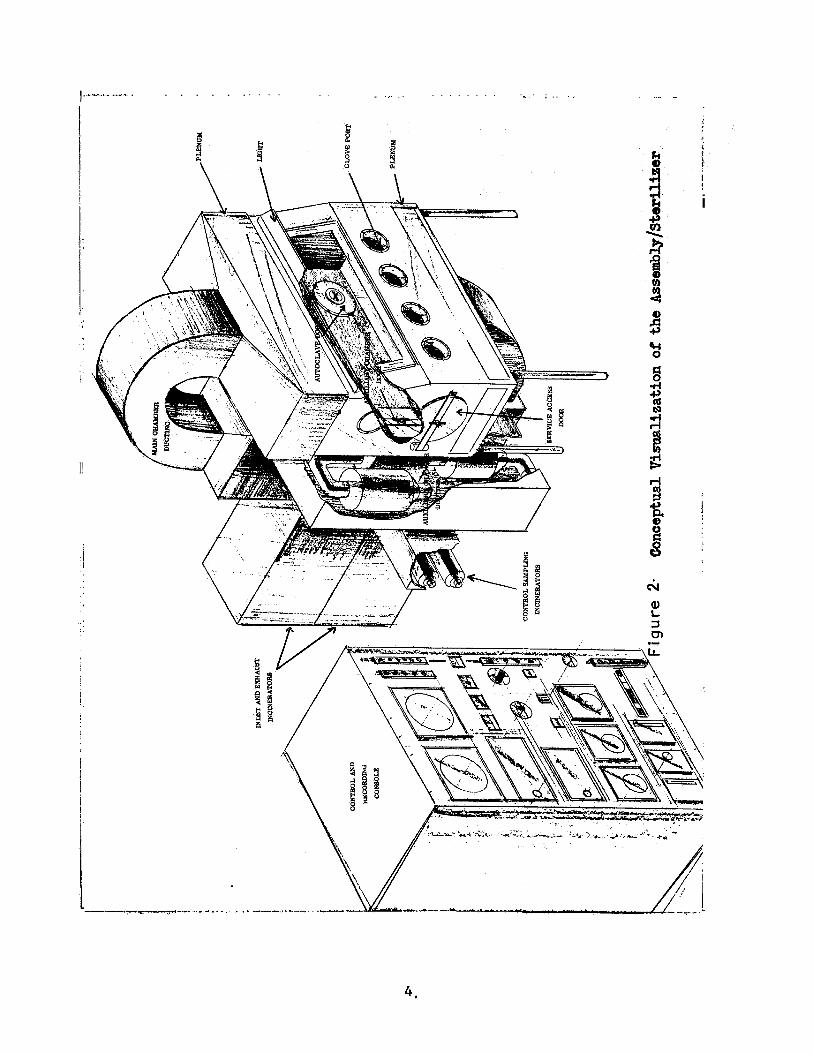
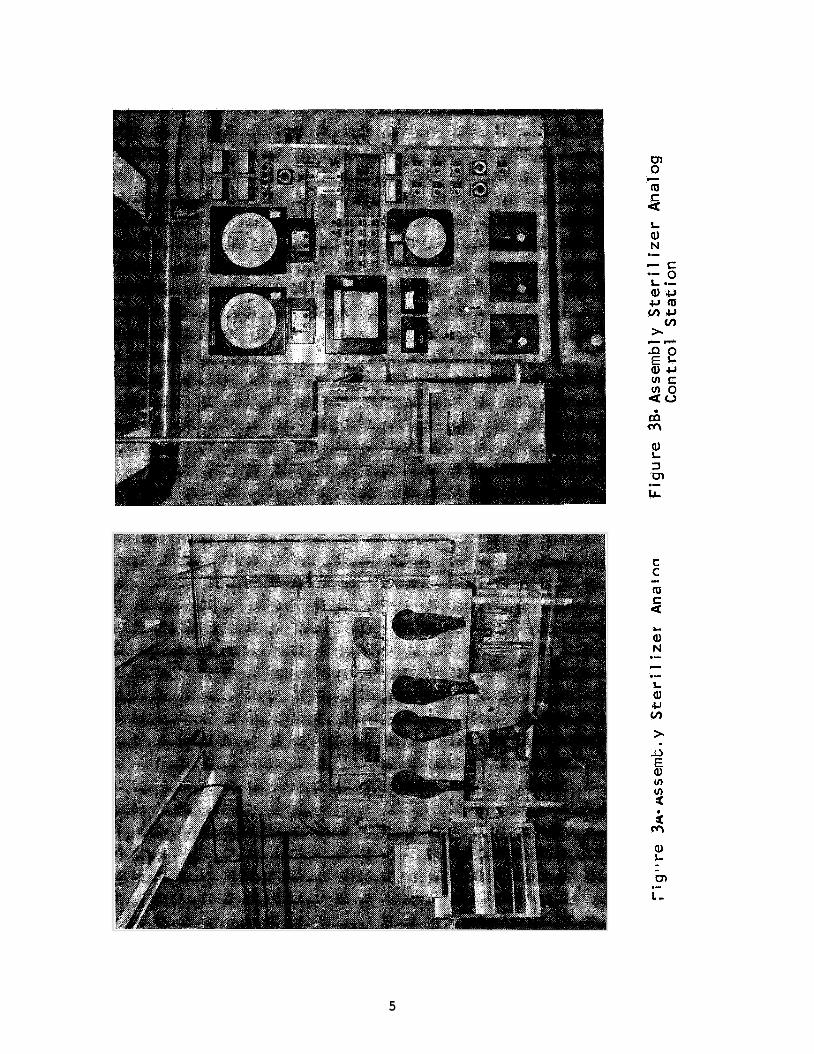
Assembly/Sterilizer Facility .................................. 3 Conceptual Visualization of the Assembly/Sterilizer ........... 4 Assembly/Sterilizer Analog .................................... 5 Assembly/Sterilizer Analog Control Station .................... 5 General BISS Configuration ................................... 13 Scape Suit ................................................... 18 BISS Phase I Undersuit Rear View ............................. 26 Phase 11 undersuit Front View A .............................. 27 Phase I1 Undersuit, Front View B ............................. 27 Phase I1 Undersuit Side View ................................. 28 Life Support Plenum and Air Distribution System (Back of Phase I1 Suit ................................................ 30 Phase XI Foam Plenum Interface ............................... 31 Phase I1 Helmet Air Distribution Device ...................... 32 Helmet Exhaust Parts and Communication Hard Points (Phase II).32 BISS Phase I1 Undersuit ...................................... 33 Final Undersuit Front View ................................... 34 Final Undersuit Rear View .................................... 34 Final Helmet Air Distribution Device ......................... 34 BISS Phase I Outer Suit ...................................... 36 Phase I1 BISS Outer Suit .................................... 3 8 Phase I1 Helmet Neck Ring .................................... 39 Phase I1 Helmet-Yoke Assembly Concept ........................ 40 Phase I1 Suit Adjustment Straps ............................. 42 Phase I1 Helmet and Yoke Side View .......................... 4 3 Phase 11 Helmet and Yoke Bottom View ......................... 44 Phase 11 Suit - Boot Interface ............................... 44 Phase I1 Suit-Glove Interface ................................ 4 5 Final Suit Body-Side View .................................... 47 Final Suit Body - Rear View .................................. 47 Front View of Final Outer Suit Showing Adjustment Strap ...... 47 Final Helmet and Yoke Assembly ............................... 48 Final Boot and Interface ..................................... 49 Final Glove and Interface .................................... 49 Tunnel for Phase I1 BISS Mock-up ............................. 52 Tunnel and Detail of Swivel-Grommet Construction ............. 53 Hatch Assembly ............................................... 55 Domed Piston Reefing Aid ..................................... 58 Possible Reefing Mechanisms ................................... 6 0 Required Mobility Volume ..................................... 63 Overlap of Working Volumes (Plan View) ....................... 6 4 Overlap of Working Volume (View B) ........................... 6 5 Overlap of Working Volumes (View C) .......................... 66 Effects of Vehicle Sections on Mobility with Non-Articulated Boom (Telescoping Boom Only) ................................. 68
vi
ILLUSTRATIONS (CONTINUED)
40 . 41 . 42 . 4 3 . 44 . 4 5 . 4 6 . 47 . 4 8 . 49 . 50 . 5 1 . 52
53 . 54 . 55 . 5 6 . 57 . 58 . 59 . 6 0 . 6 1 . 62 . 6 3 . 6 4 . 65 . 66 . 67 . 6 8 . 69 . 7 0 . 7 1 . 7 2 . 7 3 . 7 4 . 7 5 .
Vertical Ascent of BISS Worker ................................ 7 0 Minimum Recommended Articulation of Tunnel Support Boom ....... 7 1 Loss of Work Volume if Reefing Tube Extends into Chamber and Boom Has Only One Horizontal Articulation Joint ............... 7 3 BISS Donning Rack ............................................. 7 5 BISS Boot Plate and Box Clamp ................................. 7 6 BISS Boot Clamp ............................................... 77
BISS Life Support Subsystem Schematic Diagram ................. 82 Minimum BISS Communications System as Implemented for BISS Phase I1 Mock-up .............................................. 99 BISS Assembly/Sterilizer Interface Concept ................... 126 Antechamber Dimensions ....................................... 127 Lexan Distortions ............................................ 144 Test Chamber for Permeability of Materials to Microorganisms and Gases .................................................... 155 Planchet Test Chamber Construction ........................... 156 Viable Cuture Test Apparatus ................................. 158 Test Apparatus for the Measurement of Helium Permzability .... 166 Release of Ethylene Oxide From Candidate Materials .......... 169 Front View of 'Eenney Chamber with Hard Tube and Safety Access Door .................................................. 174 Phase I Life Support Console ................................. 175 Phase I Air Cooled Undersuit and Unmodified Outersuit ........ 1 7 6 Rear View of Air-Cooled Undersuit Showing Life Support Gear and Thermocouple Connectors .................................. 177 Subject in Phase I Outer Suit (Before Modifications) ......... 178 Water Cooled Supply Apparatus (Thermal Control Unit) ......... 179 Vortex Tube Life Support System .............................. 182 SAS Comfort Ratings - Individual Runs ........................ 199 SAS Average Comfort Ratings .................................. 200 Belted Waist Plenum ........................................ . . 211
Assembly Test Object ......................................... 214 Organization of Personnel and Equipment for Phase I1 Testing .. 215 Test Conductor's Console ..................................... 220 Medical Monitoring Equipment at the Medical Monitor's Test
Life Support Gas Supply Operating Region ...................... 79
BISS Donning Rack & Chamber Support Equipment ................ 213
Data Recorder's Station ...................................... 222 Phase 11 Outer Suit Rear View Inner Suit ..................... 223 Phase I1 Outer Suit Front View of Inner Suit .................. 224 BISS Differential Pressure - 0" Water ........................ 225 BISS Differential Pressure - 2" Water ........................ 226
vi i
ILLUSTRATIONS (CONTINUED)
76 . 77 . 78 . 79 . 80 . 81 .
Preparation for Taking Wrist Flexion Measurement ............... 230 Assembly Test Object Disassembly by Suited Subject .............. 252 Taking Shoulder Adduction Measurement .......................... 232 Suited Subject Climbing Ladder .............................. 2 5 5 Suited Subject Bending at Waist ................................ 256 Suited Subject Doing Knee Bends ................................ 257
viii
TABLES
I I1 I11
IV V VI VI1 VI11 IX X
XI XI I XI11 XIV
xv XVI
XVI I
XVIII XIX
XX XXI
XXI I
XXIII
XXIV XXV XXVI
XXVII XXVIII XXIX xxx XXXI XXXII
20 Suit Hardness Trade-off .............................. 22 Tunnel Hardness Trade-off ............................
Typical Metabolic Heat Production and Air Flow 80 81 Experimentally Developed Air Flow Rates for BISS ..... 85 Body Environment Control System Trade-off ............ 88 Undersuit Test Comparison ............................ 90 Air Supply Location Trade-off ........................ 92 Separate Undersuit/Integrated Suit Trade-off ......... 94 Cool Air Source Trade-off ............................
Estimated Final Weights of Fabricated BISS 139 Candidate Materials .................................. 149 Fungus Growth Tests .................................. 152 Results of Mycelial Penetration Tests ................ 157 Transport of Microorganism Through Known Holes .......
Transfer of Microorganisms Across Silicone Rubber 159 SE-555 ...............................................
Transfer of Microorganisms Across Armalon 408-128
Transfer of Microorganisms Across Armalon 414-141 161 Virgin Material ......................................
Transfer of Microorganisms Across Virgin Gold-Coated 161 Polyimide ............................................ 162
Transfer of Microorganisms Across Neoprene Rubber
Requirements for Physical Activity ...................
Virgin Material ..................................... . I60
Transfer of Microorganisms Across Armalon 97-001
Transfer of Microorganisms Across Butyl Rubber
..... XA-37852 . . . . . . . . . . . . . . . . . . . . . . . . . . . . . . . . . . . . . . . . . . . . . I63
16 3
164
....... Transfer of Microorganisms Across Bonded Silicone Rubber 83-555 ........................................ Transfer of Microorganisms Across Bonded Armalon
Leak Rates of Helium Through Punctured and Non- 167 Punctured Material ................................... 167 Leak Rates of Helium Through Experimentation ......... 170
Peracetic Acid Determination Using Potentiometric 171 Titration ............................................ 186 SAS Confort Ratings for Exercycle Runs ...............
Temperature (OF) Comparisons-Based on SAS Responses . .I88 Temperature (OF) Comparisons-Based on SAS Responses . . I89
202 System Test Ratings .................................. 228 Anthropometric Data ..................................
SAS Ratings and Corresponding Life Support Values for 2 36 Subjects Across Time .................................
97-001 . . . . . . . . . . . . . . . . . . . . . . . . . . . . . . . . . . . . . . . . . . . . . . . 165
Results of Isopropanol Disinfectant Test .............
ix
TABLES (CONTINUED)
XXXIII
XXXIV xxxv XXXVI XXXVII
xxxvIII XXXIX
XL
XLI XLII XLIII XLIV XLV
XLVIII XLIX
SAS Ratings and Corresponding Life Support Values Over Time Across Subjects ............................ 237 Grouped. Normalized Comfort Data ..................... 239 SAS Rating Scale Intercorrelations ................... 241 Life Support Parameter Intercorrelation .............. 242 SAS Rating Scale/Life Support Parameter Cross Correlation 243 Speaker's Word List - Test Conductor to Subject B .... 246 Listener's Word List - Test Conductor to Subject B .. 247 Communications SAS Ratings for Each Subject and Trial ................................................ 249 Modified Harvard Word Test Results ................... 250 Balanced Variables for Dexterity Tests ............... 253 SAS Dexterity Ratings ................................ 253 Disassembly/Assembly Completion Times ................ 258 Mobility SAS Ratings and Times ....................... 258 Atmospheric and Alveolar Air ......................... 262 BISS Helmet Air Analysis ............................. 263
..........................................
X
A RESmRCH STUDY TO DEFINITIZE A BIO-ISOLATOR SUIT SYSTEM (BISS)
FINAL REPORT
bY General Electric, Re-entry Systems Department
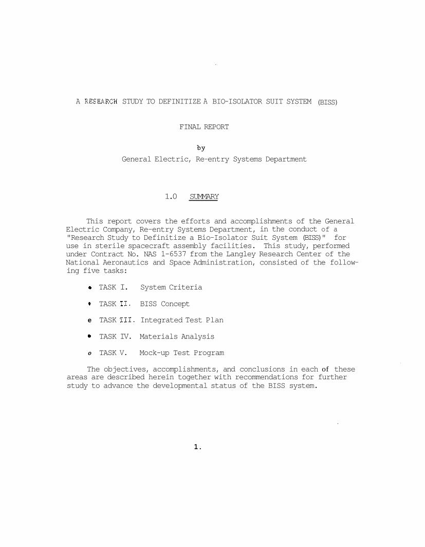
1.0 SUMMARY
This report covers the efforts and accomplishments of the General Electric Company, Re-entry Systems Department, in the conduct of a "Research Study to Definitize a Bio-Isolator Suit System (BISS)" for use in sterile spacecraft assembly facilities. This study, performed under Contract No. NAS 1-6537 from the Langley Research Center of the National Aeronautics and Space Administration, consisted of the follow- ing five tasks:
e TASK I. System Criteria
0 TASK 11. BISS Concept
e TASK 111. Integrated Test Plan
0 TASK IV. Materials Analysis
0 TASK V. Mock-up Test Program
The objectives, accomplishments, and conclusions in each of these areas are described herein together with recommendations for further study to advance the developmental status of the BISS system.
1.
2.0 LNTRODUCTION
2.1 BACKGROUND
Programs for interplanetary missions such as Voyager require sterile flight vehicles if they are to enter the atmosphere or land on the surface of extra-terrestrial planets. Two basic concepts have been proposed for the achievement of the sterility of the spacecraft. "Terminal Sterilization" and"Assembly/Sterilizer'l processing.
These are called
Terminal sterilization refers to the concept in which a vehicle is assembled and check-out in a clean room, decontaminated with a gaseous biocidal agent (ETO), sealed in a canister, and then exposed to dry heat sterilization. vehicle is possible without recontamination.
Subsequent to sterilization, no access to the flight
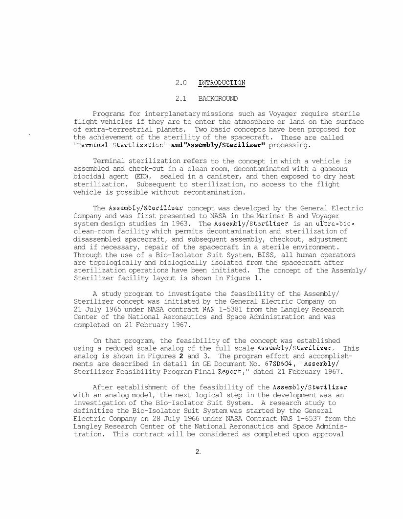
The Assembly/Sterilizer concept was developed by the General Electric Company and was first presented to NASA in the Mariner B and Voyager system design studies in 1963. clean-room facility which permits decontamination and sterilization of disassembled spacecraft, and subsequent assembly, checkout, adjustment and if necessary, repair of the spacecraft in a sterile environment. Through the use of a Bio-Isolator Suit System, BISS, all human operators are topologically and biologically isolated from the spacecraft after sterilization operations have been initiated. The concept of the Assembly/ Sterilizer facility layout is shown in Figure 1.
The Assembly/Sterilizer is an ultra-bio-
A study program to investigate the feasibility of the Assembly/ Sterilizer concept was initiated by the General Electric Company on 21 July 1965 under NASA contract NAS 1-5381 from the Langley Research Center of the National Aeronautics and Space Administration and was completed on 21 February 1967.
On that program, the feasibility of the concept was established using a reduced scale analog of the full scale Assembly/Sterilizer. analog is shown in Figures 2 and 3. ments are described in detail in GE Document No. 67SD604, "Assembly/ Sterilizer Feasibility Program Final Report," dated 21 February 1967.
This The program effort and accomplish-
After establishment of the feasibility of the Assembly/Sterilizer with an analog model, the next logical step in the development was an investigation of the Bio-Isolator Suit System. definitize the Bio-Isolator Suit System was started by the General Electric Company on 28 July 1966 under NASA Contract NAS 1-6537 from the Langley Research Center of the National Aeronautics and Space Adminis- tration.
A research study to
This contract will be considered as completed upon approval
2.
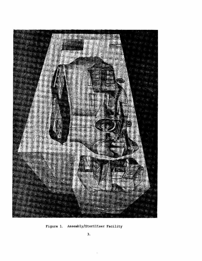
Figure 1. Assembly/Sterilizer Facility
3.
. . . . . . . . .,.. - ... . . . . . . . . . . . . . . . . . ~ . , - ~. , .. . _ , , ._ . .
I!
I)
i
0 0 m c c
a L 9) N .- c .- L Q) CI v)
r L3 E Q) In
c
2 4
2 m
3 cn LL .-
5
by NASA of this Final Report. program are the subject of this document.
The efforts and accomplishments of this
2.2 PROGRAM OBJECTIVES
It was the objective of this program to develop BISS functional requirements by investigating and defining system criteria, concepts, and materials. A laboratory test program was performed with functional mock-ups of BISS. Although these mock-ups were not intended to possess the environmental tolerance or bio-integrity of prime BISS systems, they did permit evaluation and development of the BISS concept and aided the functional definition of such a system. mance of five tasks to accomphish the objectives:
The program required the perfor-
TASK I.
TASK 11.
TASK 111.
TASK IV.
TASK V.
System Criteria
BISS Concept
Integrated Test Plan
Materials Analysis
Mock-up Test Program
The objective of the system criteria task was to provide a quanti- tative description of the criteria in a form useable as definitive guide lines for the development of the BISS concept.
The BISS Concept task consisted of the investigation of design para- meters and alternatives and man/machine interfaces to define design requirements for a BISS system satisfying the criteria. closely related to the mock-up test program task which provided experi- mental evaluation and verification of the evolving concept. In addition to conceptual descriptions, the primary output of this task is the func- tional description of the BISS system and major elements thereof in the form of MIL type specifications.
This task was
The Integrated Test Plan task required the preparation and documen- tation of a coordinated plan for the laboratory investigations on the program and preparation of a plan for the test and demonstration of engin- eering models on a subsequent test program.
The objective of the Materials Analysis task was to identify and inves- tigate candidate BISS suit materials by literature search, supplier con- ferences, and laboratory testing to determine their suitability for use
6.
in the BISS program. criteria :
Suitability was to be determined largely on four
Bio-integrity
Physical parameters
e Special environmental effects
e Effects of abrasion and other working conditions on the materials
The purpose of the Mock-up Test Program task was to provide basic experience with a mock-up suit and tunnel, entrance hatchway, life support equipment, and communications subsystem to support a suited worker. The suit and tunnel and life support and communications subsystems for the mock-up were to employ adaptations of available comercia1 equipment. The mock-up was to simulate BISS working conditions in a pressurized cham- ber to determine:
(1) Feasible means of access to and egress from the suit through the hatch and tunnel;
(2) Criteria for a man/machine interface which will provide a comfortable, hygienic working environment and permit the worker to accomplish the normal vehicle assembly and test tasks.
2.3 SUMMARY OF CONCLUSIONS
The outputs of the several program tasks have permitted the degree of definitization of the BISS nical scope of the program. of specifications appended hereto and augmented by the technical discussions of this report.
system consistent with the fiscal and tech- This definitization is documented in the form
The BISS suit concept has been fully developed and has been demon- strated in an essentially prime configuration mock-up. and its associated helmet were fabricated in a more sophisticated config- uration than the adaptations of a commercially available, special purpose, soft, industrial suit called for by the Statement of Work for the mock-up task. Very early in the concept development study and mock-up planning it was recognized that development of much of the detail necessary to specify an appropriate mock-up suit required experience with some form of tunnel-suit in a very similar environment and work situation. this experience was not available, it was determined that the most effi- cient course of action was to perform mock-up studies in two phases:
The mock-up suit
Since
7.
Phase I using a minimal adaptation of an inexpensive commercial suit, and Phase 11 employing a specially constructed mock-up of a refined design providing an excellent simulation of a prime BISS suit. This course of action was pursued with the result that the mock-up pro- gram demonstrated the feasibility and utility of a suit which conf€g- urationally requires only minor adaptation for prime BISS system defini- tion. The helmet used with the Phase I1 suit is of prime system quality and would be useable in systems with a maximum exposure temperature of + 270°F. For higher temperatures an alternate design would be required.
The tunnel concept developed in Task I1 was realized in the mock-up and has been shown to be satisfactory. the tunnel by vertical stringers and reefing the tunnel Over a hard tube have also been satisfactorily demonstrated. A detailed study of mechan- ical systems for reefing and supporting the tunnel was beyond the scope of the program. However, the design problems associated with this ancil- lary equipment were investigated to the extent of identifying the major problems to be solved and recommending concepts for further investigation.
Any reefing mechanism must have means for positive attachment to
The basic ideas of supporting
the tunnel to apply driving forces. device as part of the mechanism but also incorporation of graspable attachment points on the tunnel (or continuous grasping strips). Of necessity, therefore, the completion of tunnel definition must be con- current with completion of a tunnel reefing mechanism definition.
This requires not only a grasping
The life support subsystem concept has been fully developed and reduced to breadboard equipment demonstrated in the mock-up testing. The life support equipment supplys conditioned air to a specially designed undersuit. the BISS suit occupant and is directly applicable to a prime system with minor detail design changes.
The system gave excellent environment control for
A communications subsystem concept was developed and reduced to hard- ware for the mock-up testing. tional in concept and implementation. equipment is unique. speakers are mounted on the upper chest of the occupant's undersuit permitting satisfactory two-way talk-at-will communications for the suited operator without encumbering him with a head-set or requiring that the transducers be able to withstand the severe environment which exists in the outer suit during sterilization.
The majority of the subsystem is conven-
Transducers in the form of a microphone and small The BISS occupant's communication
8.
Supporting studies have been performed in the areas of bio-integrity and leak detection, human factors, hygiene, maintenance, and safety. These studies played a two-fold role in the concept development: they have provided inputs to the study and definition of the concepts for the BfSS equipment; and secondly, they have provided one means of assessing the developed concepts against the prescribed system criteria. In this latter role, the supporting studies were augmented by a formal design review of the BISS concept. assured that the results of the equipment concept study areas constituted a workable, integrated system satisfying the system criteria. The design review is not reported herein as a separate technical area because no non-compliant concept features or supporting study conclusions were iden- tified. The design review did contribute significantly towards the crystalization of recommendations for future study, and this contribvi- tion is reflected in the recommendations section of this report.
first
This review and the supporting studies
The integrated test program was executed in accordance with the integrated test plan with some modifications to facilitate work, to improve experiment sensitivities, or to delete testing shown to be superfluous by early test results. stration plan for subsequent work was formulated. The work performed in the integrated test program consisted of physical and biological testing of candidate BISS materials and two phases of testing of mock-ups of the BISS system.
Also, a preliminary test and demon-
Testing of candidate materials was a part of the overall materials analysis task. In this task numerous candidate materials were screened for applicability in each of the following areas: gloves, boots, helmet, and undersuit. Candidate materials thus identi- fied were subjected to biological and physical testing to augment pub- lished characteristics data. Based on these tests and the published data, recommended materials have been identified which satisfy the requirements in each of the areas. ble materials, techniques of bonding materials were investigated with the objective of defining acceptable techniques for bonding in the fabrica- tion of a prime BISS system.
outer suit and tunnel,
Following the identification of suita-
In each of the areas investigated, bonding techniques were identi- fied and tested with resultant demonstration of one or more techniques in each area with good mechadcal properties. cal testing indicated permeability to micro-organisms either with a virgin bond or after stress treatments. Thus, this attempted advancement of the state-of-the-art, proving microbiological integrity of bonded materials, has not been accomplished within the scope of the present program. This is not felt to be an inherent limitation, but represents an area requiring further study and experimentation. effect are contained herein.
Subsequent micro-biologi-
Appropriate recommendations to this
9 .

In the mock-up testing, typical prime BISS system operations were investigated in a two-phased program. Phase I, employing a very elemen- tary outer suit and tunnel, permitted early verification of the evolving system concept and provided information necessary for definition of a much more refined suit for the primary investigative efforts performed in Phase 11. Through the use of a two-phased program, it has been possi- ble to demonstrate, using a nearly prime configuration suit, the full operational feasibility of the BISS suit concept. Repeated successful cycles of entry and egress were accomplished with intermediate perfor- mance of a wide variety of simulated spacecraft assembly tasks. primary emphasis in the mock-up testing was on ascertaining or verifying the man/machine interface in terms of criteria for a comfortable, hygienic work environment for a suited worker to accomplish normal flight vehicle assembly and test tasks. Throughout the test program personnel were observed to monitor their response to the environment and specific tests were performed to ascertain what physical limitations, if any, the BISS imposed on the suit occupant.
The
The mock-up program was highly successful. The test results show that occupant comfort can be maintained in a hygienic environment while performing a wide range of physical tasks. No significant decrement in performance capability, compared with normal operations, was noted beyond work shift duration limitations and manual dexterity reductions normally associated with gloved operations.
Although it was not the objective of this program to document a final detailed design of a prime BISS system, the degree of technical descrip- tion in the resultant specifications is in some aspects less than anti- cipated at the outset of the program. This is due to the inherent nature of research programs of prescribed scope. In particular, when investiga- ting a wholly new system the full degree of complexity of some of the systems interface problems and design details is usually not apparent prior to performance of the investigation; and secondly, accurate predic- tion of the effort required to satisfy new and unique requirements with existing techniques is impossible. in consideration of tunnel reefing and in the bonding investigation, respectively. foregoing material. The effect is that further study is required to provide the desired degree of definition of tunnel interface with the reefing mechanism and BISS outer suit bonding techniques.
These two difficulties have arisen
The-nature of these two problems has been discussed in the
Recommendations for future work are provided in a separate section of this report. studies, development, and detailed design effort, beyond the scope of the present contract, required to advance the developmental state of the BISS
The recommendations fall into two basic categories:
10.
to that of a fully detailed design for a prime BISS system; and further operational support studies required to effect optimal integration of ;.he prime BISS system into an Operational Assembly/Sterilizer facility. An example of the former is the extension of the tunnel reefing and support study. An example of the latter is the need to study the operational plans for processing specific flight systems through the facility, so that the communications subsystem concepts developed and demonstrated on the present program can be incorporated in an optimal communications system in the Assembly/Sterilizer.
11.
3.0 SYSTEM DESCRIPTION
3 . 1 SYSTEM CONCEPT
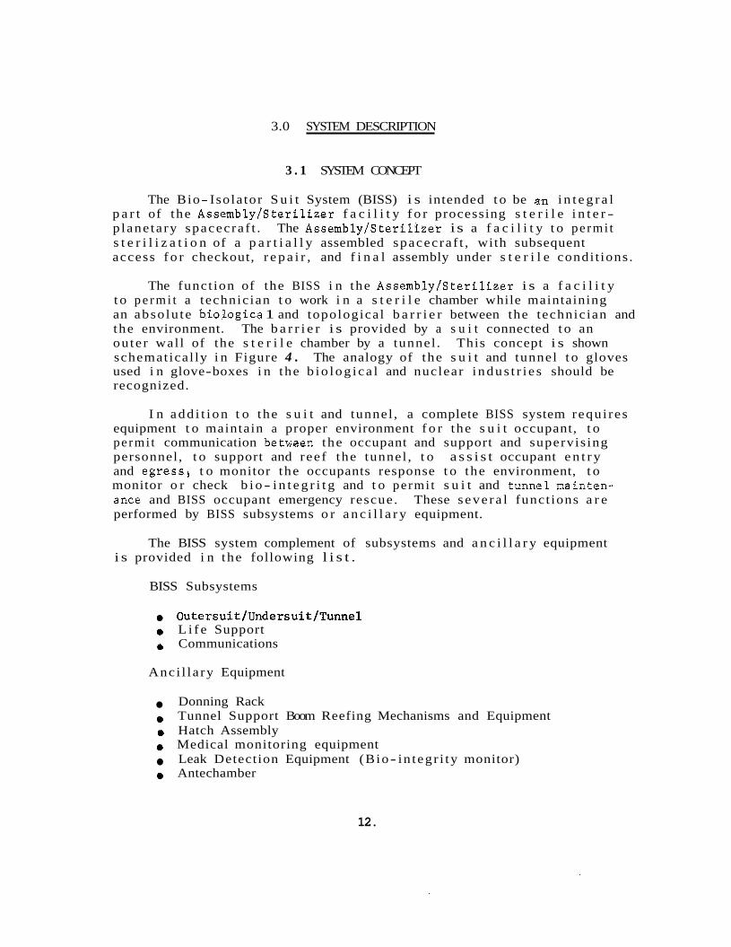
The Bio- Isolator S u i t System (BISS) i s intended t o be an i n t e g r a l p a r t of the Assembly/Ster i l izer f a c i l i t y f o r processing s t e r i l e i n t e r - p lane ta ry spacecraf t . The Assembly/Ster i l izer i s a f a c i l i t y t o permi t s t e r i l i z a t i o n of a p a r t i a l l y assembled spacecraf t , with subsequent access f o r checkout, r e p a i r , and f i n a l assembly under s t e r i l e condi t ions .
The funct ion of the BISS i n the AssemblylSter i l izer i s a f a c i l i t y t o p e r m i t a technician t o work i n a s t e r i l e chamber while maintaining an abso lu te biologica 1 and topological b a r r i e r between the technician and the environment. The b a r r i e r i s provided by a s u i t connected t o an ou te r wal l of the s t e r i l e chamber by a tunnel . This concept i s shown schematical ly i n Figure 4 . used i n glove-boxes i n the b io log i ca l and nuclear i ndus t r i e s should be recognized.
The analogy of the s u i t and tunnel t o gloves
I n add i t i on t o the s u i t and tunnel , a complete BISS system requi res equipment t o maintain a proper environment f o r the s u i t occupant, t o pe rmi t communication betwoen the occupant and support and supervis ing personnel, t o support and reef the tunnel , t o a s s i s t occupant e n t r y and egress4 t o monitor the occupants response t o the environment, t o monitor o r check b i o - i n t e g r i t g and t o permi t s u i t and tunne lmain ten- ance and BISS occupant emergency rescue. These s eve ra l funct ions a r e performed by BISS subsystems o r a n c i l l a r y equipment.
The BISS system complement of subsystems and a n c i l l a r y equipment i s provided i n the following l i s t .
BISS Subsystems
0 Outersuit/Undersuit/Tunnel 0 L i f e Support
Communications
Anci l la ry Equipment
Donning Rack
0 Hatch Assembly 0 Medical monitoring equipment
Leak Detection Equipment (Bio- in tegr i ty monitor) 0 Antechamber
Tunnel Support Boom Reefing Mechanisms and Equipment
12.
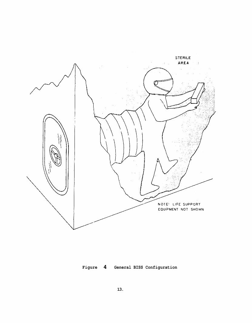
Figure 4 General BISS Configuration
13.

3 . 2 SYSTEM CRITERIA
Def in i t i on of the system c r i t e r i a was one of t he f i v e major t a sks on the cont rac t . The c r i t e r i a e s t a b l i s h the bas i c requirements f o r the system i n n i n e a reas :
1. Configurat ion 2 . B io- In teg r i ty 3. Technician Environment' 4. Technician Safe ty 5. Human Fac tors 6 . Hygiene 7. Equipment Environment 8. BISS Endurance 9. S t e r i l e Maintenance
The system c r i t e r i a were formulated during the f i r s t qua r t e r of the program and served a s a d i r e c t i v e document f o r the development of the concept of the BISS system, subsystems, and a n c i l l a r y equipment. Upon completion of the concept development and mock-up tes t program t a sks of the con t r ac t , the c r i t e r i a were reviewed and revised t o maintain consis tency with the evolving BISS system.
The revised system c r i t e r i a a r e presented i n Appendix A here to .
3.3 SYSTEM OPERATION
Understanding of the BISS system concept and the r o l e of each of the subsystems and items of a n c i l l a r y equipment i s aided by cons idera t ion of the employment of BISS i n t he Assembly/Ster i l izer . d i scuss ion descr ibes the BISS opera t ions i n p a r t of a nominal flow and then covers one emergency condit ion and a maintenance procedure. r a t i o n a l e behind each of the procedural s t eps should become c l e a r a f t e r reading the d e t a i l e d desc r ip t ions of the following sec t ions .
The following
The
3.3.1 BISS Operation i n a Nominal Assembly/Ster i l izer
P r i o r t o the i n i t i a t i o n of an Assembly/Ster i l izer cyc le , the BISS s u i t and tunnel would have been put i n place, a t tached t o t he tunnel r ee f ing and support equipment, and leak checked. The antechamber/main chamber door would be l e f t open and the s u i t , tunnel , and tunnel mechanisms would then be decontaminated and s t e r i l i z e d along with the main chamber and i t s conten ts . During these t reatments the tunnel i s i n a reefed condi t ion and the s u i t i s supported by the donning rack.
14.
During the f i n a l phases of the p o s t - s t e r i l i z a t i o n cool down, BISS system opera t ion i s i n i t i a t e d . The l i f e support and communications system a r e checked o u t , EKG e l ec t rodes a r e a t tached t o the BISS tech- n ic ians ' to rso , and the technic ians su i t- up i n t h e i r undersu i t s . The undersu i t s a r e then connected t o t he l i f e support and communications subsystems t o complete e n t r y prepara t ions .
When t h e Assembly/Ster i l izer chambers have reached ambient temper- a t u r e , t he BISS support personnel open the hatch t o the tunnel and the technic ian climbs through the tunnel i n t o the s u i t . This i s made poss ib l e by a hard tube which runs the f u l l length o f the reefed tunnel from the ha tch t o t he t u n n e l / s u i t i n t e r f ace . I n climbing i n t o the s u i t the technic ian f i r s t pu ts h i s f e e t down i n t o the boots , then puts h i s head i n t o the helmet and h i s arms i n t o the s leeves . He i s now prepared t o disengage the s u i t from the donning rack and move i n t o the chamber.
The technic ian moves ou t i n t o t he chamber, and the tunnel and sup- port extends a s he moves forward. A s the t echn ic i an moves away from the end of the hard tube, t he tunnel co l lapses r a d i a l l y behind him. The technic ian i s now f r e e t o move about i n the main chamber and perform h i s assigned work t a sks . The tunnel support and r ee f ing mechanisms f o 1 low h i s movements .
While i n t he chamber, the technic ian can converse with h i s fel low workers o r support and supervisory personnel by means of the communica- t i ons system. H i s environment i s continuously monitored and cont ro l led by l i f e support personnel , and h i s response t o the environment is monitored by medica 1 personnel.
A t t h e completion of the requi red work, o r the end o f the work s h i f t , t he technic ian backs towards t he antechamber and the tunnel i s reefed. When he has reached the donning rack he a t t a c h e s the s u i t t o the rack and climbs out i n t o t he hard tunnel and then ou t through the hatch. Following each occupancy, the necessary s u i t d i s i n f e c t i o n procedures a r e performed p r i o r t o e n t r y of t he next technic ian .
3 . 3 . 2 Emergency Egress
I f it becomes necessary f o r a technic ian t o leave the s u i t ime- A d i a t e l y , he r e t u r n s t o t he antechamber and climbs out of the s u i t .
d i sab led technic ian can be aided i n the r e t u r n t o h i s antechamber by one o r more o t h e r s u i t e d technic ians in the chamber. Then personnel ou ts ide t he chamber can a i d the d isabled occupant i n g e t t i n g out of the s u i t .
15.
I n extreme emergency condit ions, e i t h e r o f the procedures can be followed: Support personnel can don a i r- packs , open emergency hatches t o t h e main chamber, take a n a i r- pack t o the d isab led occupant, cu t h i m o u t of h i s s u i t , put the a i r- pack on him, and remove him from t h e chamber. A l t e rna t ive ly , t h e d isab led BISS occupant could be returned t o h i s antechamber by BISS su i t ed personnel then the antechamber could be closed and the above procedure followed i n the antechamber r a t h e r than i n t he main Assembly/Ster i l izer chamber. Thus, the antechamber permits emergency rescue using most d r a s t i c techniques without compromising the s t e r i l i t y of t he chamber and i t s conten ts .
3 . 3 . 3 BXSS S u i t Maintenance
I n t he event t h a t a BISS s u i t is determined t o be i n need of r e p a i r o r replacement while t h e main chamber i s i n a s ter i le condi t ion , these opera t ions can be performed without compromising the s t e r i l i t y of the main chamber. The antechamber i s sealed o f f from the main chamber, then BISS support personnel can open a maintenance hatchway i n t o the antechamber and e f f e c t any necessary r e p a i r s o r replacement. Upon completion of these t a sks , t he antechamber maintenance hatchway i s sealed and the antechamber and i t s contents a r e s t e r i l i z e d . Once ster- i l i t y has been r e- es t ab l i shed , the antechamber door i n t o the main chamber can be re-opened and the BISS s u i t can be put back i n t o oper- a t i o n .
16.
4 . 0 BISS SUBSYSTEMS AND ANCILLARY EQUIPMENT
4.1 SUIT AND TUNNEL
4.1.1 Configurat ion Se lec t ion
The s e l e c t i o n of a s u i t employing a tunnel was made p r i o r t o the study under t he subjec t con t r ac t . The following d iscuss ion g ives the background on t h i s s e l ec t ion .
The s u i t and tunnel a r e the h e a r t of the BISS system and provide the phys ica l envelope which forms t he b a r r i e r between the technic ian and the s t e r i l e environment. The maintenance of an absolu te b io log ica l b a r r i e r suggested the tunnel concept which achieves b io log ica l i s o l a - t ion through top0 logica 1 is0 l a t ion.
Two fundamentally d i f f e r e n t s u i t system concepts a r e employed f o r i s o l a t i o n of a technic ian from an i n d u s t r i a l o r labora tory environment and were considered f o r poss ib le app l i ca t ion i n the Assembly/Ster i l i - ze r , These a r e :
1) 2) Free s u i t with l i f e l i n e s (gas supply and exhaust)
Free s u i t wi th l i f e support back pack
Examples of t h e f i r s t c l a s s a r e the SCAPE* s u i t shown i n Figure 5 , used f o r rocket motor fue l ing and some f i r e f i g h t i n g s u i t s . Examples of the second c l a s s a r e deep d iv ing s u i t s , the INFAB*used f o r f a b r i - ca t ion of s p e c i a l t y s teels i n an argon atmosphere a t Universal Cyclops Spec ia l ty S t e e l Divis ion, and a system used a t Lobund Laboratory (Notre Dame) f o r gnotobio logica l experimentation.
E i t h e r one of two b a s i c schemes can be used t o introduce a man i n e i t h e r type of f r e e s u i t i n t o a s p e c i a l environment chamber. The f i r s t i s t he use of a s p e c i a l "lock" o r antechamber. For t he purposes of t he Assembly/Ster i l izer t h i s scheme i s not f e a s i b l e because chemical s t e r i l a n t s (such a s used a t Notre Dame) a r e no t s u f f i c i e n t l y r e l i a b l e and steam o r dry hea t s t e r i l i z a t i o n t reatments a r e not p rac t i cab le f o r a s u i t with a man i n i t . I n t h e second scheme p a r t o f the s u i t i s i n t e g r a l with t he wa l l o r f l o o r of t he chamber. The technic ian e n t e r s
9:
JcJ: I n e r t Fab r i ca t ion Se l f Contained Atmospheric P ro tec t ive Ensemble
17.
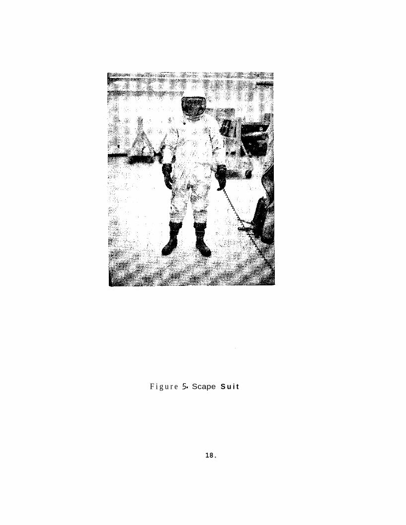
F i g u r e 5. Scape S u i t
18.
t h i s p a r t of the s u i t , e f f e c t s a s e a l t o the rest of t h e s u i t , and then detaches the s u i t from the chamber su r face . This scheme i s a k i n t o that used i n table- top i s o l a t o r s f o r gnotobiological experimentat ion. A pro- posal f o r implementation of t h i s b a s i c scheme f o r a s u i t system has been made by TrexlerWJ; This proposal does not appear t o o f f e r the r e l i a b i l i t y required f o r the BISS system.
Any f r e e s u i t system has the inherent hazard t h a t each in t roduct ion of a man i n t o the chamber poses a t h r e a t t o the s t e r i l i t y of the sys- t e m and t h i s t h r e a t i s repeated a t l e a s t t w i c e per man during the nor- mal e i g h t hour work s h i f t i n an i n d u s t r i a l a p p l i c a t i o n .
These f a c t o r s lead t o the s e l e c t i o n of t h e genera l conf igura t ion o f a s u i t with a t tached tunnel f o r the BZSS.
4.1.2 R i g i d i t y
Once t h e genera l BISS conf igura t ion of a s u i t and tunnel had been se lec ted , i t was necessary t o determine the optimum degree of hardness f o r these two elements of the system. These were t h e f i r s t two t rade- o f f s i n the concept development under t h e sub jec t con t rac t . Since
the s u i t and tunnel have d i f f e r e n t requirements, the hardness t rade- o f f s w e r e made separa te ly .
4 .1.2.1 S u i t
Severa l d i f f e r E n t degrees of s u i t hardness can be defined ranging from a very l i g h t weight, f l e x i b l e membrance envelope (monofilament less than 5 m i l s t h i ck ) t o a completely r i g i d s u i t with a r t i c u l a t e d j o i n t s (e.g. a deep diviiig s u i t ) . For t h e purposes of a t rade- off evaluat ion, t h r e e degrees of hardness w e r e evaluated:
S o f t - F l e x i b l e s u i t f ab r i ca ted o f re inforced o r composite
Semirigid - S o f t s u i t modified by the a d d i t i o n of r i g i d metal mater ia 1.
o r p l a s t i c limb (and p o s s i b l y t o r s o ) sec t ions bonded t o t h e f l e x i b l e s h e l l .
t o r s a sec t ions interconnected by a r t i c u l a t e d j o i n t s . Rigid - Hard S u i t composed of r i g i d metal o r p l a s t i c limb and
These th ree types of s u i t s were judged t o be equivalent i n terms of hygiene i n t e r f a c e s with t h e tunnel and l i f e support and communica-
J- .I- J- ' - '~'~ P.C. T rex le r "The Detection and Elimination of Contamination from Germfree Operations", 1965 Proceedin s of the For th Annual Tech- n i c a l Meeting and Exhibit of the A 2 5 C .
19.

t i ons subsystems, and decontamination and s t e r i l i z a t i o n compat ib i l i ty . However, t he re a r e s eve ra l important parameters f o r which the s u i t s a r e not equiva len t . i s provided i n Table I.
The t rade-off comparison based on these parameters
T A B U I. SUIT HARDNESS TRADE-OFF (NOTE 1) ~
PARAMETER
Weight
S iz ing F i t
Mob i 1 i t y
Ease of Entry . and Egress Phys i ca 1 I n jury P ro tec t ion Emergency Egress
J o i n t Sea l i n g
J o i n t Fat igue
Puncture Resis tance
c o s t
SOFT SUIT
1
1
1
3
3
1
1
1
3
1
SEMIRIGID
2
2
2
1
2
2
R I G I D
3
3
3
2
3
3
3
3
Note (1) - Rating of 1 i s bes t , 3 i s worst
Se l ec t ion of a s u i t type from Table I. could be made by ass igning a weighting f a c t o r t o each parameter and then der iv ing a r a t i n g score f o r each s u i t type. However, s ince the s o f t s u i t ranks f i r s t i n a l l but t h ree of the eleven parameters, a more d i r e c t approach i s t o t e n t a t i v e - l y select the s o f t s u i t and a s ses s t he s ign i f i cance of the l a s t p lace r a t i n g i n these th ree parameters.
Ease of e n t r y and egress f o r the s o f t s u i t was evaluated i n t he mock-up test (See Sec t ion 8.0) and was found t o be adequate. e n t r y and egress t i m e s a r e w i th in the l i m i t s set by the system c r i t e r i a .
Phys ica l i n j u r y p ro t ec t ion i n an i n d u s t r i a l environment i s normally
The
concerned pr imar i ly with t he head, hands, and f e e t inasmuch a s t hese a r e t he t h r e e a r e a s most sub jec t t o in jury . w i l l have a hard helmet and s o f t gloves; f u r t h e r , s teel toe caps can
Any reasonable BISS s u i t ,
20.
be incorporated i n s o f t s u i t boots , Thus phys ica l p ro t ec t ion of the three most l i k e l y i n j u r y a r e a s i s e s s e n t i a l l y equiva len t f o r a l l t h r ee s u i t s . The semi- rigid and r i g i d s u i t s do o f f e r b e t t e r protec- t i o n of limbs and to r so , bu t any de f i c i ency of t he s o f t s u i t i n t h i s respec t can be minimized by proper work procedures. mobile, s o f t s u i t e d worker can b e t t e r avoid a p o t e n t i a l i n j u r y s i t u a - t i on .
Also , the more
Puncture r e s i s t a n c e i s an important f a c t o r i n b io- in t eg r i ty . The s o f t gloves common t o a l l t h r ee s u i t types a r e the most l i k e l y s i t e fo r occurence of a puncture, minimize the advantage i n t h i s respec t of t he semi- rigid o r r i g i d s u i t . I n t h e ma te r i a l s a n a l y s i s e f f o r t on the con t r ac t (See Sec t ion 7.0) puncture r e s i s t a n c e i s one of the tes ts performed t o select materials f o r a s o f t BISS s u i t . of t h i s a n a l y s i s i nd ica t e t h a t a s o f t s u i t system with high puncture r e s i s t ance i s f e a s i b l e .
The r e s u l t s
The s o f t s u i t was se l ec t ed f o r t he BISS. None of the l a s t place r a t i n g s f o r t he s o f t s u i t i n Table I. rep resen t s a major reason f o r s e l e c t i o n of one of the o t h e r s u i t s , and o v e r a l l t rade-off r a t i n g s t rong ly favors the s o f t s u i t .
Any f r e e s u i t system has t he inherent hazard t h a t each in t roduct ion of a man i n t o the chamber poses a t h r e a t t o the s t e r i l i t y of the system and t h i s t h r e a t i s repeated a t l e a s t t w i c e per man during the normal e i g h t hour work s h i f t i n an i n d u s t r i a l app l i ca t ion .
These f a c t o r s lead t o the s e l e c t i o n of the genera l conf igura t ion of a s u i t with a t tached tunnel f o r t he BISS.
4.1.2.2 Tunnel
The optimum degree of r i g i d i t y f o r the tunnel r equ i r e s a t rade- off eva lua t ion independent o f the ind iv idua l parameters of the s u i t r i g i d - i t y t r ade- o f f , but not independent of t he s u i t t rade- off o v e r a l l r e s u l t . I n p a r t i c u l a r , a tunnel of f i xed c ros s s ec t ion when used with a s o f t s u i t r e s u l t s i n gn unbalanced force tending t o push the occupant back i n t o the tunne 1. *
* A p o s i t i v e , inward pressure gradien t of up t o four inches of water (gage) i s maintained across the s u i t and tunnel ou te r sur faces . This r e s u l t s i n an unbalanced force of 5 .202 l b s per inch of water per square foo t of tunnel- sui t i n t e r f a c e opening. Depending on the na tu re of the s u i t end tunnel and t h e i r i n t e r f a c e , t h i s force tends t o co l l apse t he tunnel a x i a l l y and/or push the s u i t occupant i n t o the tunnel .
21.

Three degrees of tunnel hardness were considered:
S o f t - Flex ib l e tunnel f ab r i ca t ed of re inforced o r composite mater- i a 1, supported v e r t i c a l l y by an overhead load balancing device, and f r e e t o co l lapse a x i a l l y and r a d i a l l y .
Semi-rigid - S o f t tunnel modified by the add i t i on of circumferen- t i a l support r i ngs and constant fo rce a x i a l extension a id s .
Rigid - Ar t i cu l a t ed hard tunnel of f ixed length and c ross s ec t i on supported v e r t i c a l l y by c a s t e r s o r d o l l i e s on each tunnel sec t ion .
TABLE 11. TUNNEL HaRDNESS TRADEcOFF (NOTE 1)
P A W T E R
Weight
Mobili ty Horiz.
V e r t
Ease of Entry and Egress
Ease of Rescue
SOFT
1
1
Unbalanced forces on Occupant 1
Obstruction of Working Space 1
Disrupt ion of laminar gas flow 1 ( i f used)
Vert ica 1 load balancing
Ease of Reefing
J o i n t Sea l i n g
J o i n t Fat igue
Matgr ia l f a t i gue due t o r ee f ing
Damage Resis tance
Ma in t a inab i l i t y Note (1) Rating of 1 i s
2
1
SEMIRIGID
2
1 :st, 3 i s worst.
RIGID
3
3
non-existent
3
3
3
3
3
1
not poss ib le
2
3
not poss ib le
1
22.
A simple unweighted summation of t he parameter r a t i n g s i n Table 11. ind ica t e s t h a t t h e s o f t tunnel i s most d e s i r a b l e and the r i g i d tunnel i s l e a s t des i r ab l e . The two major parameters no t covered i n the t a b l e a r e c o s t and complexity. would have required a depth of design d e t a i l on each tunnel type incons i s t en t with t he s t a t u s of the concept development a t t he po in t a t which the t rade- off was made. However, t h e d i f f e r s n c e s i n these parameters f o r the t h ree tunnel types a r e f e l t t o be small r e l a t i v e t o the o v e r a l l cos t and complexity o f the Assembly/Ster i l izer f a c i l i t y of which the tunnel w i l l be one element.
Meaningful eva lua t ion of these parameters
Also not shown e x p l i c i t l y i n the t a b l e i s the need f o r (or u t i l i t y o f ) a n antechamber f o r the t h ree tunnel types. r i g i d tunnel could not use an antechamber. Because i t i s not a x i a l l y compressible, the r i g i d tunnel could not be withdrawn i n t o an antechamber. Thus the f ea tu re s of su i t - tunne l maintenance and d r a s t i c emergency pro- cedures ( c u t t i n g a man ou t of a s u i t ) without contaminating the s t e r i l e Assemblyb te r i l i ze r main chamber a r e not ava i l ab l e f o r the r i g i d tunnel system.
Of the t h ree , only the
Any reasonable weighting of the s ign i f i cance of t he seve ra l t rade- o f f parameters c l e a r l y favors the s o f t o r semi- r ig id tunnel over the r i g i d type. Further t rade-off between these two i s heavi ly dependent on two parameters: ease of r ee f ing and unbalanced forces on the s u i t occupant. The r ee f ing mechanism (See Sec t ion 4.3) f o r e i t h e r the s o f t o r semirigid tunnel w i l l be q u i t e soph i s t i ca t ed , probably being more com- plex f o r the s o f t tunnel . Any advantage gained on t h i s po in t f o r the semirigid tunnel i s o f f s e t t o some degree by the g r e a t e r complexity of the tunnel i t s e l f i n comparison with the s o f t tunnel .
The problem of force unbalance f o r the semi- rigid tunnel i s s i g n i f - ican t . The unbalance f o r a 5 square foo t t unne l- su i t i n t e r f a c e i s on the o rde r o f 26 pounds per inch o f water pressure d i f f e r e n t i a l across the s u i t and tunnel ou te r sur faces . The r e s u l t i s high l o c a l pressures on the s u i t occupant a t t he i n t e r f a c e circumference i n equi l ibr ium with a low force d i s t r i b u t e d r a t h e r uniformly over t h e f r o n t of h i s body. The e f f e c t i s t o tend t o push the occupant ou t through the tunnel . This would cause very exhaust ing and poss ib ly in ju r ious stress on the occupant. A body-contoured p l a t e could be a t tached t o the back of the occupant t o e q u i l i b r a t e t he forces without high l o c a l forces ; however, such a p l a t e would make e n t r y and eg res s much more d i f f i c u l t and would very adverse ly a f f e c t occupant mob i l i t y and comfort.
I n summary, t he s o f t tunnel is the most d e s i r a b l e of t he t h ree types s tudied and was se l ec t ed f o r t he BISS. This tunnel concept has been shown i n the mock-up tests (see Sec t ion 8.0) t o be f e a s i b l e .
23.
4.1.3 Descript ion
4.1.3.1 S u i t
- Upon selection .of a s o f t s u i t , a t rade-off was made t o determine the optimum way of incorpora t ing the l i f e support funct ions and s u i t com- munications t ransducers i n t he s u i t . It was determined t h a t a double s u i t concept was d e s i r a b l e employing an ou te r s u i t f o r the microbiolog- i c a l b a r r i e r and an undersu i t a s a personal ized garment with l i f e support and communications i n t e r f a c e s .
The o u t e r s u i t i s an anthropomorphically shaped, mul t i- layer p l a s t i c laminate garment which has a t tached t o i t r e l a t i v e l y form- f i t t ing gloves, semi- rigid boots (e.g. f i reman's boots) , and a fishbowl helmet and '1.
support harness (or yoke). The o u t e r s u i t i n t e r f a c e s with t h e tunnel by means of a 104"circum- ference opening i n t he back of t he s u i t .
Support r i n g s f lank the elbows and th ighs .
The undersu i t i s a mul t i- layer undergarment which permits a i r c i r- c u l a t i o n f o r body cooling. An i n t e r f a c e i s provided on the undersu i t f o r t he l i f e support subsystem plenums. The undersu i t a l s o provides two p l a t e s which serve a s attachment poin ts f o r the communications sys- t e m t ransducers .
4.1.3.1.1 Undersuit - The primary funct ions of the undersu i t a r e :
0 To provide an i n t e r f a c e f o r the l i f e support suppl ies of breath- ing a i r and cool ing medium.
To provide body cool ing capab i l i t y .
To provide mounting f o r t he occupant 's communications t rans- ducer s .
0 To a c t a s a personal undergarment promoting good hygiene and containing personal bac t e r i a .
To r e l i e v e e f f e c t s , such a s chafing, r e s u l t i n g from compression o f the s o f t o u t e r s u i t aga ins t the occupant 's body.
e To minimize the range of s u i t elements t h a t must be designed t o withstand s t e r i l i z a t i o n .
The provis ion of body cooling cgpab i l i t y i s a p a r t i c u l a r l y impor- t a n t func t ion of the undersu i t . To permit comfort and e f f i c i e n c y f o r extended opera t ions i n the BISS, i t i s necessary t o remove excess body
24.
hea t . I n providing a c a p a b i l i t y t o do so , the undersui t a c t s a s an adjunct t o the l i f e support subsystem.
Two types of cooling undersu i t s , l i q u i d cooled and gas cooled, have been developed f o r space s u i t and o the r app l i ca t ions . Both types of 1
undersui ts were inves t iga ted by t rade- off a n a l y s i s and experimentation t o s e l e c t the optimum undersui t f o r t h e BISS. An a i r- cooled undersu i t , designed by GE on t h e program was compared with a commercially a v a i l - a b l e watercooled undersui t . The a i r- cooled s u i t was se lec ted . The t rade- o f f s and experimental r e s u l t s which lead t o t h i s s e l e c t i o n a r e d i s e cussed i n Sect ions 4.7.3.1 and 8.0 uespect ively .
I n t h e a i r cooled concept, t he cooling a i r i s ducted t o the ankles and w r i s t s of the undersu i t , drawn through the limbs t o t h e t o r s o , across the t o r s o , and i s then exhausted from the back of the s u i t . This undersui t was o r i g i n a l l y conceived a s an ind iv idua l ly t a i l o r e d garment wi th th ree bonded layers : a co t ton inner layer t o i n t e r f a c e with t h e occupant’s sh in ; an open c e l l foam, which w0uId compress some- what under pressure , but s t i l l permit a i r flow; and a layer sea l ing the ou te r face of the foam and channeling the cooling a i r flow. P r a c t i c a l d i f f i c u l t i e s of bonding a co t ton f a b r i c t o open c e l l foam necess i t a t ed modif ica t ion of t h i s concept t o permit a separa te s u i t of long co t ton underwear covered by the a i r channeling undersui t . This modif ica t ion necess i t a t ed bonding a t h i n , highly-porous, low f r i c t i o n material t o the foam inner su r face t o reduce f r i c t i o n between the foam and the co t ton underwear.
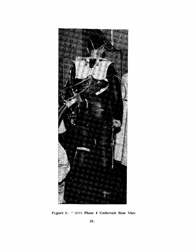
Two vers ions of the undersui t were designed and fabr ica ted f o r the mock-up tes ts described i n Sect ion 8.0. The f i r s t ve r s ion consis ted of a c lose f i t t i n g modified SCUBA d i v e r ’ s “ w e t s u i t ” of c losed- ce l l neo- prene rubber with a l aye r of open-cell polyurethane foam bonded t o the inner su r faces . This Phase I vers ion of the undersu i t i s shown i n Figure 6 .
Addi t ional development of t h e concept based on Phase I mock-up experience indica ted t h a t the neoprene ou te r l aye r of the undersui t should be replaced by a t h i n , low- fr ic t ion m a t e r i a l . It was found t h a t t h e neoprene grabbed a g a i n s t t h e ou te r s u i t m a t e r i a l and reduced the e a s e of opera tor e n t r y and e x i t . It was a l s o determined t h a t t h e ou te r layer should be a l i g h t e r weight m a t e r i a l and t h a t the s u i t should be a r e l a t i v e l y loose f i t . A Phase I1 undersui t was designed and procured based on the experience wi th the Phase I undersu i t . described by the fol lowing t e x t and i l l u s t r a t i o n s .
This undersui t i s
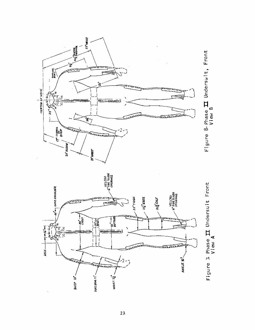
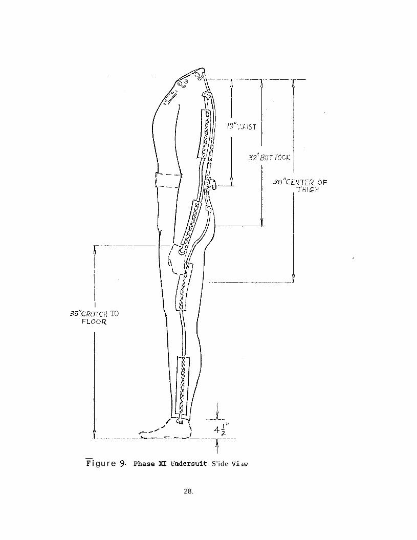
The undergarment i s f u l l length, covering t h e wearer‘s arms t o t h e w r i s t s and legs t o t h e ankles . Figures 7 , 8 , 9 i l l u s t r a t e the o v e r a l l appearance of t h e garment. The dimensions shokm i n these drawings
25.
Fi gure 6 . - BISS Phase I Undersuit Rear
26.
View
3 m
Ci, a, L 3 m LL .-
.c,
3 In L #
W S z)
.-
I 33"CROTCi-! TO
FLooR
- F i gu r e 9. Phase XI U'dersuit S'ide V i s w
28.
r e f l e c t the a c t u a l s i z e of the wea re r , t he re fo re , t he vendor was required t o consider t he thickness of the t r i - l a y e r ma te r i a l i n developing f i n a l s u i t dimensions. I n dimensioning the s u i t , t he vendor was required t o make i t conform t o body shape without being t i g h t on any por t ion o f the body. The th ree l aye r s were bonded together so t h a t a f t e r repeated wearing and cleansing opera t ions , t he s u i t i s s t i l l a un i t a ry garment. The method of bonding the th ree l aye r s of the s u i t together does not block a continuous flow pa th t5rough the foam.
P a r t i c u l a r emphasis was given t o providing good limb mobi l i ty .
The ma te r i a l used f o r the ou te r layer i s Fairprene neoprene shee t s tock, of th ickness 1/64" (nominal) by DuPont. The open c e l l foam layer i s Sco t t foam with 10 pores per l i n e a r inch, 1 /4 inch i n thickness . The inner layer i s nylon laminating s c r i m , 2 /1 leno weave, s t y l e 38016, count 20 x 10 by J. P . Stevens & Co., N.Y. The main zipper on the che r t of the subjec t is a B. F. Goodrich, o r equiva len t , a i r - t i g h t type. S lash openings f o r the wrists a r e s i x inches i n length. For the ankles , these openings a r e nine inches i n length. A l l four s lashopenings a r e closed with Velcro, allowing the inner foam t o mate so t h a t a continu- ous, porous foam layer i s maintained.
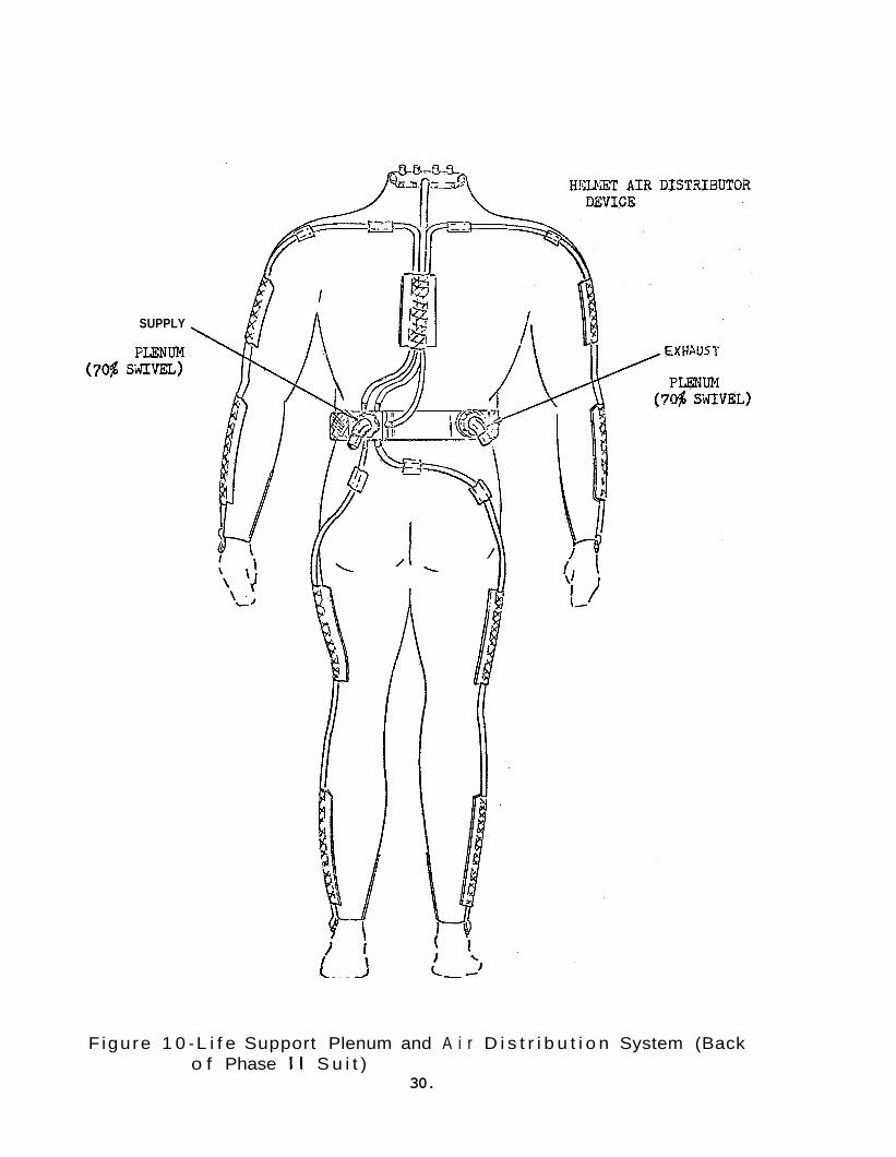
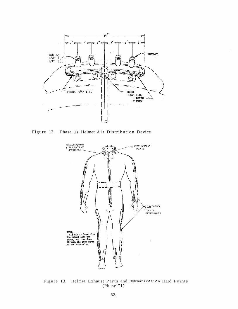
I n add i t i on t o the bas i c garment, the undersu i t provides i n t e r - faces f o r t he l i f e support subsystem. These i n t e r f a c e s a r e shown i n Figure 10. A i r i s brought t o the s u i t from the l i f e support subsystem by a hose which mates with the supply plenum. From the plenum, f i v e tubes lead t o the f e e t , hands, and t o the helmet a i r d i s t r i b u t i o n device. The a i r i s drawn from the hands, f e e t and helmet through the foam l aye r . of the undersu i t t o t heexhaus t plenum, and i s returned t o the l i f e support subsystem. The foam-exhaust plenum i n t e r f a c e i s shown i n Figure 11. Figure 12shows the helmet a i r d i s t r i b u t i o n device, and Figure 13 shows the helmet exhaust p a r t s and communications t ransducer mounting hard poin ts . The a c t u a l undersu i t i s shown i n Figure 14.
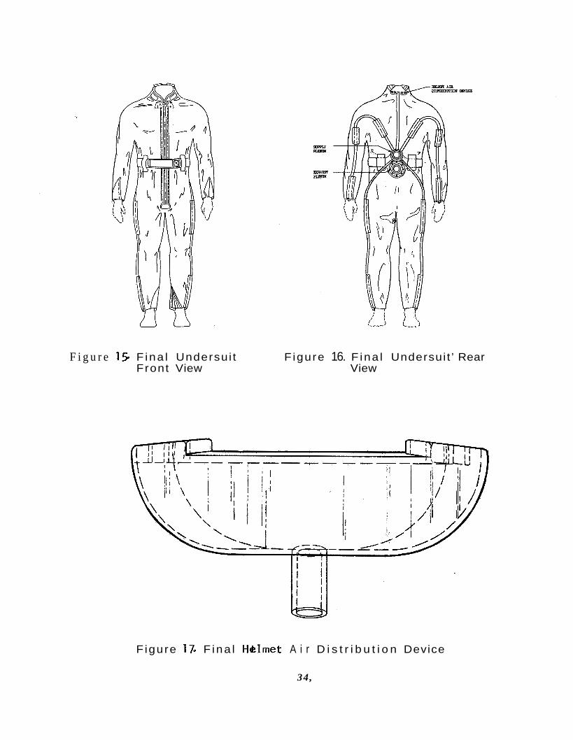
Although good experimental r e s u l t s were obtained with the Phase I1 undersu i t , the experience gained i n opera t ing with t h i s vers ion of the s u i t suggested some f u r t h e r modif icat ions t o optimize the design. These modif icat ions were made i n specifying the f i n a l recommendations f o r an a i r cooled undersu i t a s r e f l e c t e d i n the BISS Undersuit Speci- f i c a t i o n 0230-00-0002 a t tached here to a s Appendix L. For easy r e f e r - ence the i l l u s t r a t i o n s from the s p e c i f i c a t i o n a r e presented here a s Figures 15, 16, and 17.
The major change between the f i n a l undersu i t concept and the gar- ment used i n Phase11 t e s t i n g i s t he change i n the design and loca t ion of the a i r d i s t r i b u t i o n andexhaus t plenums. A s can be seen by examin- ing Figure 16, the plenums a r e now located on top of one another , i n the middle of the lower back. This permits i n t e r f a c i n g with a l a rge r
29 .
SUPPLY
PLENUM SiVEL) (70%
Figure 1 0 - L i f e Support Plenum and A i r D i s t r i b u t i o n System (Back o f Phase I I S u i t )
30.
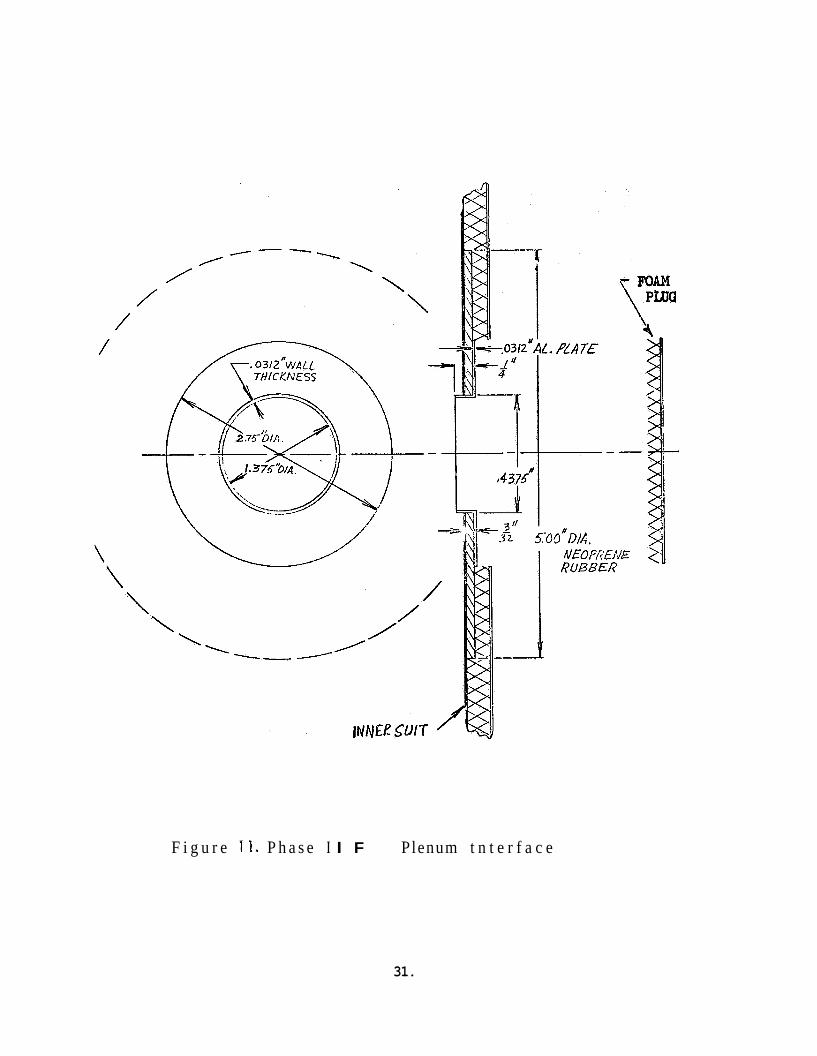
F i g u r e 11. P h a s e I I F Plenum t n t e r f a c e
31.
I
Figure 12. Phase I1 Helmet A i r Dis t r ibu t ion Device
Figure 13. H e l m e t Exhaust P a r t s and Communication Hard Po in t s (Phase 11)
32.
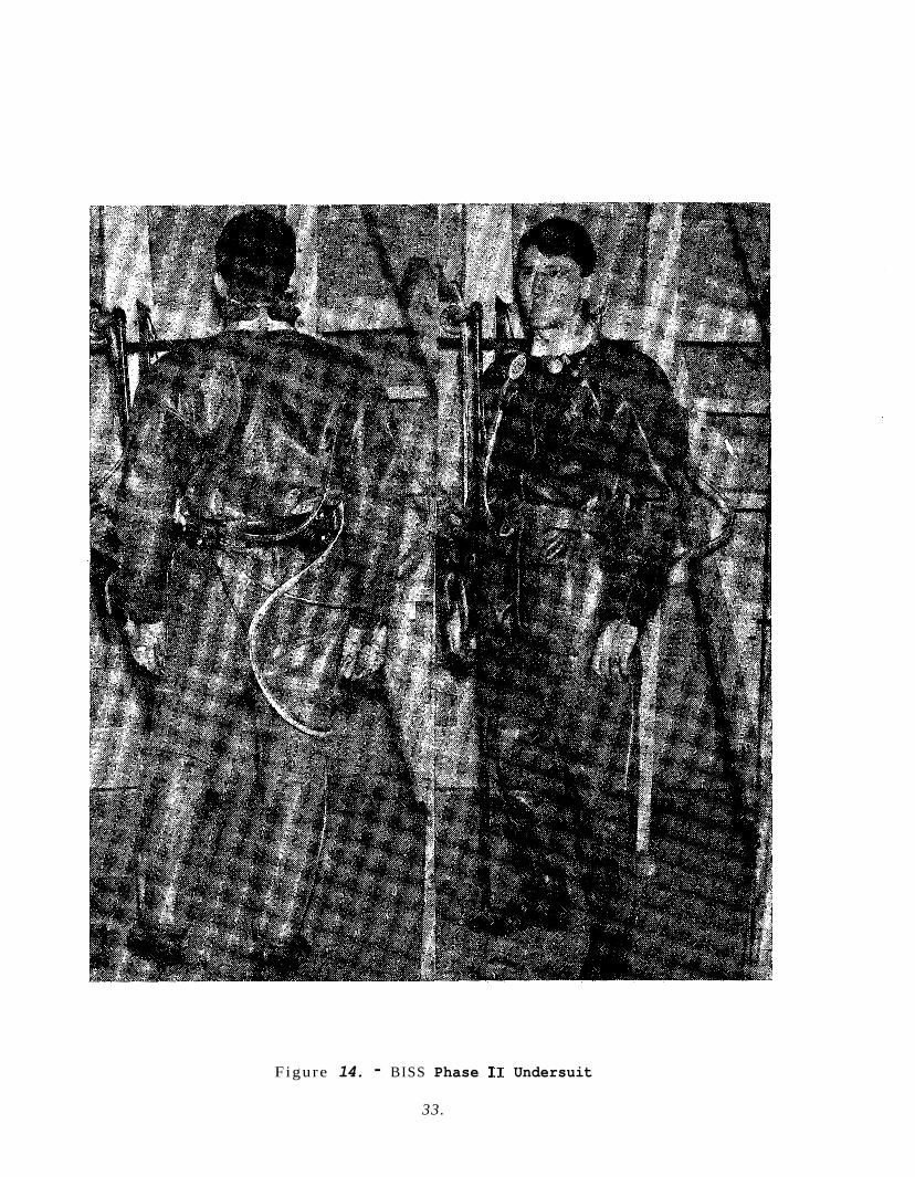
Figure 14. - BISS Phase I1 Undersuit
33.
F i g u r e 15. F ina l Undersui t F igure 16. F ina l Undersui t ’ Rear Front View View
F igure 17. F ina l HClmet A i r D i s t r i b u t i o n Device
34,
area of foam f o r s u i t exhaust than d i d t h e previous approach. It a l s o p e r m i t s t he a i r d i s t r i b u t i o n tubes t o be routed i n a more d i r e c t manner t o the e x t r e m i t i e s w i t h a r e s u l t a n t reduct ion i n the p r o b a b i l i t y of t h e a i r d i s t r i b u t i o n hoses being s t r e s s e d . note a r e t h e des ign of the helmet a i r d i s t r i b u t i o n device, Figure 17 , t he wrist and ankle fas tenings , and the length of t h e zipper. The magnitude of the a i r d i s t r i b u t i o n device redesign can be assessed by a comparison of Figures 12 and 17 . The wrist and ankle fas tenings f o r the f i n a l des ign Velcro f l a p s which a r e sewed down on one s i d e of the s l a s h openings wi th mating Velcro on t h e opposi te s i d e of the I
opening. The zipper has been shortened s ince i t was found t h a t g e t t i n g the Phase I1 undersui t z ipper s t a r t e d when i t terminated between the sub jec t s l egs was d i f f i c u l t . Therefore, t he z ipper now ends on the f r o n t surface of the undersui t .
The o t h e r changes worthy of
4 .1 .3 .1 .2 Oute r su i t
The o u t e r s u i t serves one primary function: i s o l a t i o n of the BISS occupant from the s ter i le environment of the Assembly/Steri l izer main chamber. I n add i t ion , i t serves severa l secondary funct ions such a s physica l p r o t e c t i o n of the occupant 's f e e t and head and contain- ment of a s a f e gas mixture f o r breathing. The o u t e r s u i t c o n s i s t s of severa l in tegra ted elements: s u i t s h e l l (body and limbs), helmet, gloves, and boots. The helmet, gloves, and boots a r e bonded t o the s u i t s h e l l .
A s with t h e undersu i t , the o u t e r s u i t concept has been developed i n th ree s t ages , t he f i r s t two being embodied i n the Phase I and Phase I1 mock-ups and the l a s t s t age r e f l e c t e d i n t h e f i n a l recommen- da t ions .
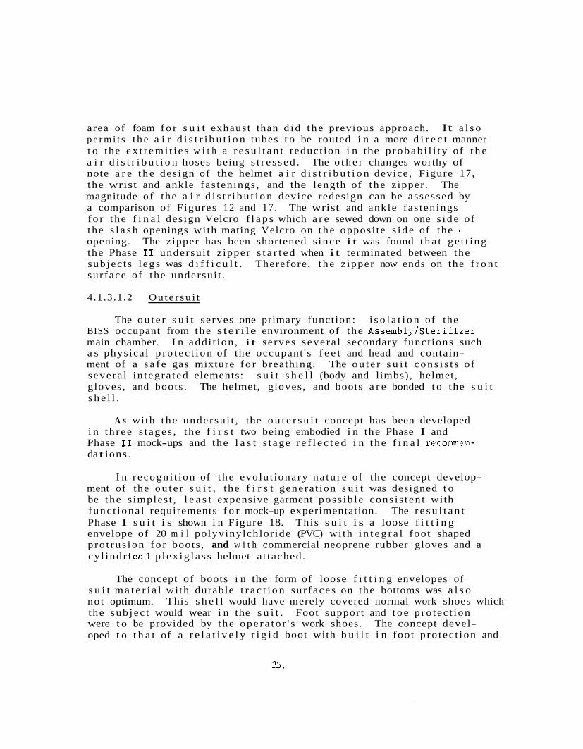
I n r ecogn i t ion of the evolut ionary na tu re of the concept develop- ment of the o u t e r s u i t , the f i r s t genera t ion s u i t was designed t o be the s imples t , l e a s t expensive garment poss ib le cons i s t en t with func t iona l requirements f o r mock-up experimentation. The r e s u l t a n t Phase I s u i t i s shown i n Figure 18. This s u i t i s a loose f i t t i n g envelope of 20 m i l polyvinylchlor ide (PVC) wi th i n t e g r a l foot shaped p ro t rus ion f o r boots, and w i t h commercial neoprene rubber gloves and a cy l indr ica 1 p l e x i g l a s s helmet a t tached.
The concept of boots i n the form of loose f i t t i n g envelopes of s u i t m a t e r i a l wi th durable t r a c t i o n su r faces on the bottoms was a l s o not optimum. the sub jec t would wear i n the s u i t . Foot support and t o e p ro tec t ion were t o be provided by the o p e r a t o r ' s work shoes. The concept devel- oped t o t h a t of a r e l a t i v e l y r i g i d boot with b u i l t i n foot p ro tec t ion and
This s h e l l would have merely covered normal work shoes which
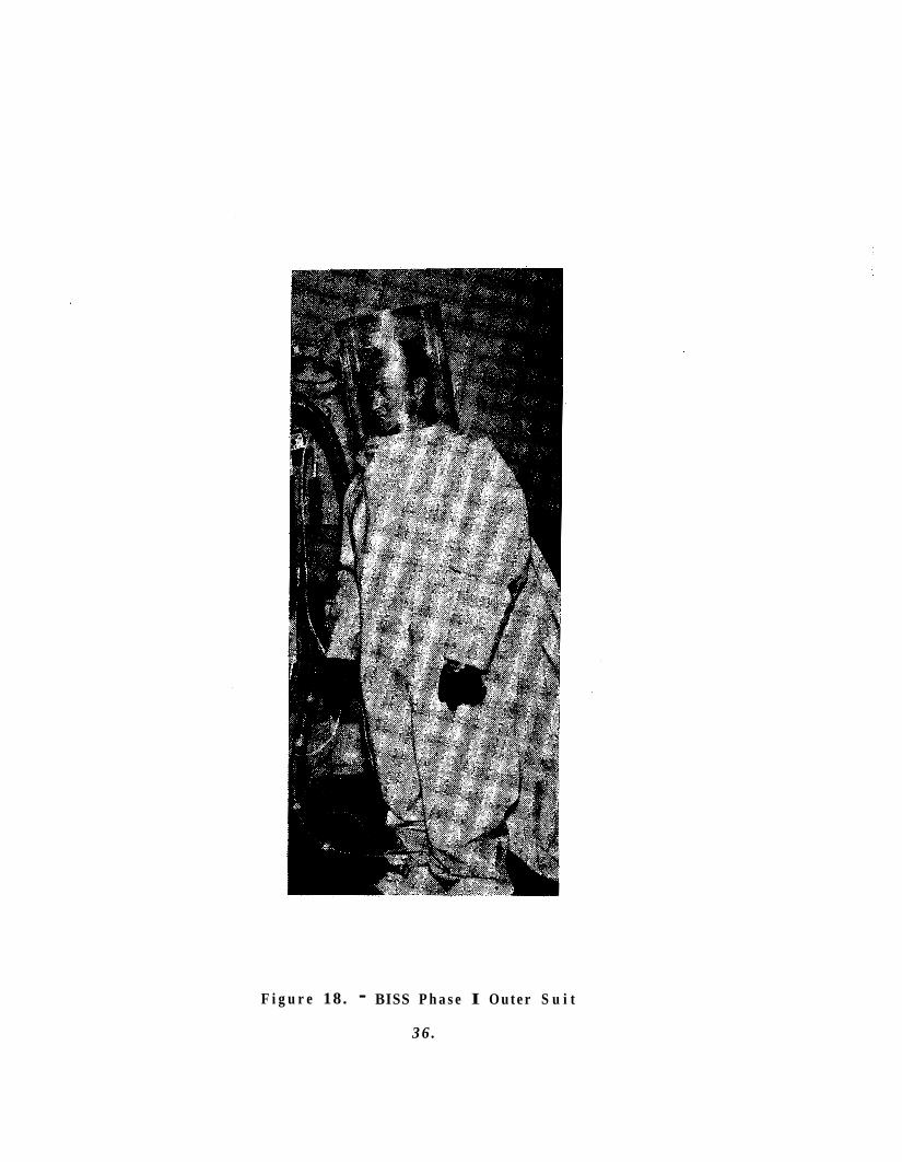
F i g u r e 18. - BISS P h a s e I O u t e r S u i t
3 6 .
support. Since t h e boots a r e not changeable from indiv idual t o i nd iv i- dual , personal inner socks o r s l i p p e r s a r e required f o r each opera tor t o help maintain hygiene and t o accommodate a range of foo t s i z e s . Fireman's boots were adapted t o t h e Phase I s u i t because of t he d e f i - c i enc i e s of the i n t e g r a l "bootie" design.
Experimentation of t he c y l i n d r i c a l helmet and a n Apollo- type hel- m e t s t rong ly suggested the appropriateness of 'a l a rge "fish-bowl" or "bubble" type helmet. This was necessary because t h e helmet does not move with the ope ra to r ' s head, and contouring of the helmet i n a con- vent iona l manner would i n t e r f e r e with the ope ra to r ' s head movement. A co t ton cap w i l l be worn by each opera tor t o avoid smearing the helmet' with h a i r o i l s , e tc . Unlike pressure s u i t helmets which der ive physi- c a l support from the s u i t p ressure , a means must be provided t o support the BISS helmet i n t he overpressure environment. I n t he Phase I s u i t , the helmet was supported- by a modified set of a t h l e t i c shoulder pads. This concept was r e f ined t o the use of a molded shoulder yokewith . e l a s t i c bands which go under the wearer 's armpits . e n t l y a f f ixed t o t h e helmet and i s a p a r t of the ou te r s u i t .
The yoke i s perman-
Surgeon's co t ton s k u l l caps w i l l be worn by BISS opera tors i n s ide the helmet t o prevent contamination of the helmet with h a i r o i l s and t o absorb opera tor pe r sp i r a t ion . These caps w i l l be procured i n the s i z e s required f o r a given Assembly/Ster i l izer opera tor populat ion and w i l l be laundered a f t e r each work sess ion .
A s a r e s u l t o f t he t e s t i n g performed on the Phase I o u t e r s u i t , s eve ra l d e f i c i e n c i e s o r a r eas f o r improvement were r a t ed . The looseness and imprecise f i t of the garment impeded occupant e n t r y and egress under pressure because of fo ld ing and co l lapse of excess s u t t ma te r i a l . I n add i t i on t o the need t o make the ou te r s u i t f i t more p r e c i s e , the s tudy indica ted the need f o r two s t i f f e n i n g r i n g s i n both the arms and legs o f the s u i t . These r i n g s f lank the elbows and th ighs r e spec t ive ly and i n no way hamper opera tor mobi l i ty . I n conjunct ion with two la rge r ings located a t the su i t - tunne l i n t e r f a c e , and a donning rask which supports t he s u i t i n a proper donning a t t i t u d e a t the end of the hatch tube, t he arm and l e g r i n g s g r e a t l y f a c i l i t a t e opera tor e n t r y i n t o the s u i t under the overpressure environment. The r ings accomplish t h i s by c rea t ing d iscernable openings, app ropr i a t e ly pos i t ioned , a t which the opera tor can aim during the e n t r y process . These f ea tu re s a l s o a i d i n e x i t from the s u i t by reducing the amount of s u i t co l lapse on the limbs.
With t h e necessary design improvements def ined, the Phase I1 ou te r s u i t was spec i f i ed . 20, and 21. The s u i t body i s i l l u s t r a t e d i n Figure 19. The garment i s f ab r i ca t ed of AI,-160 by Cooley, Inc . , Pawtucket, R . I . , of weight 16 oz/yd i n accordance wi th t h e dimensions shown.
This vers ion of t he s u i t i s shown i n Figures 19,
The co lor of t h e f a b r i c
37.
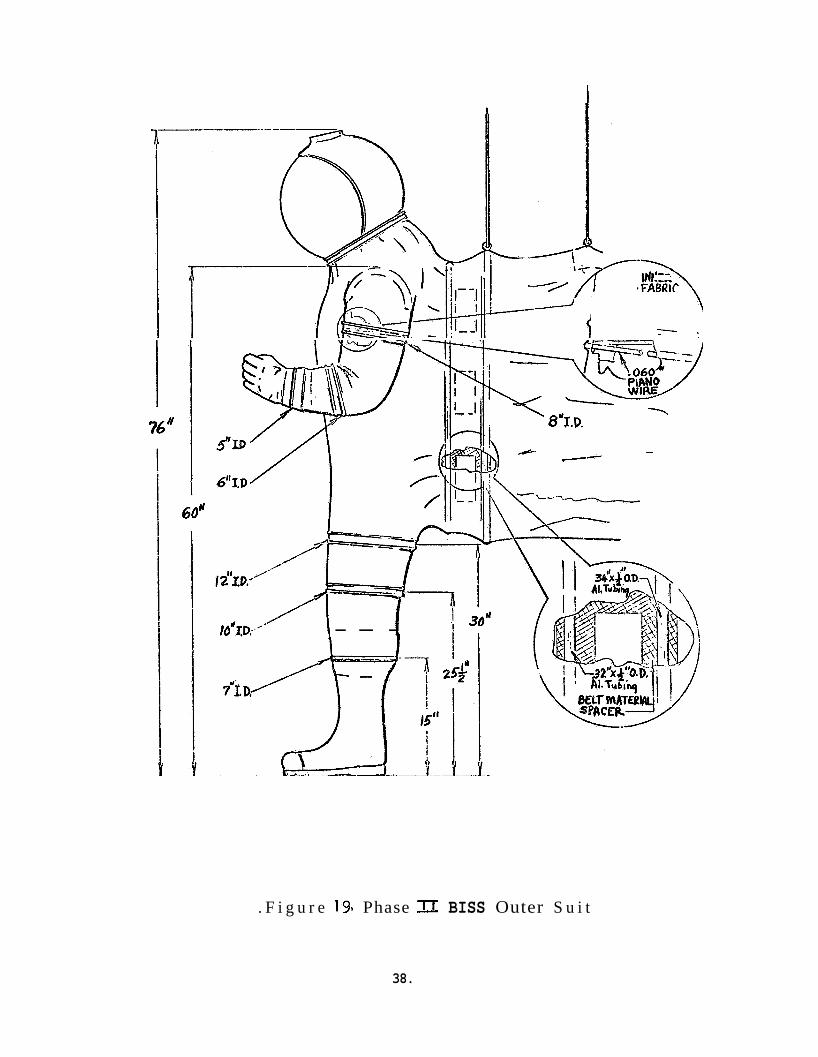
76'
-'
-\
8"T.D.
- - -
. F i g u r e 1 9 Phase - BISS Outer S u i t
38.
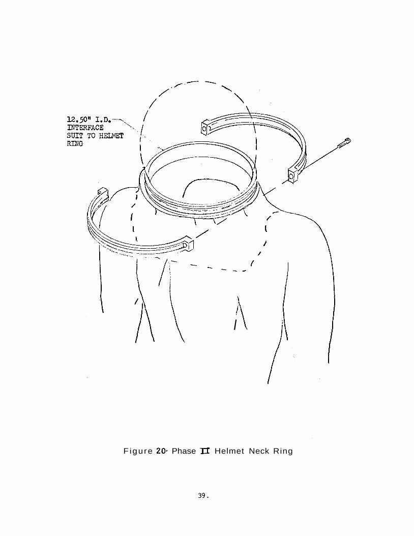
I I
Figure 20. Phase II Helmet Neck Ring
39.
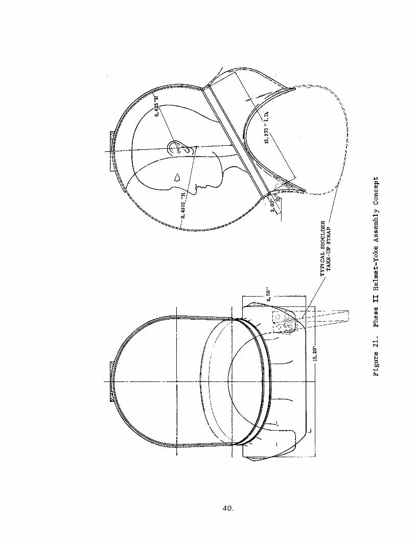
40.
i s black and aluminum, with the aluminum on the e x t e r i o r sur faces . The garment has a 100" circumference opening i n t he back of the s u i t f o r i n t e r f a c e with t h e tunnel . A 12.5" diameter c i r c u l a r opening i s provided f o r i n t e r f a c i n g with the helmet and yoke assembly (See Figure 20 and 21). legs o f the o u t e r s u i t a r e made of ,060 r o l l e d piano w i r e t o the dimen- s ions shown i n Figure 19. i n e n t e r i n g the s u i t under t he overpressure environment, and a r e lam- ina ted t o t he i n t e r i o r of the s u i t ma te r i a l . adjustment s t r a p s on the e x t e r i o r of the s u i t . used t o a d j u s t the s i z i n g i n t h i s a rea f o r d i f f e r e n t subjec ts . two shoulder s t r a p s i n t e r f a c e wi th the helmet support yoke a s shown i n Figures 2 1 and 22.
The support r i ngs incorporated i n the arms and
These r ings a r e necessary t o a s s i s t t he wearer
Figure 22 shows th ree (3) The c ro t ch s t r a p i s
The
The helmet and yoke a r e shown i n Figures 20 and 21. The helmet, manufactured by Air lock, Inc . , was vacuum formed of GE Lexan polycar- bonate. helmet were f ab r i ca t ed of epoxy f i b e r g l a s s and bonded t o t he c l e a r Lexan. polyurethane foam.
The yoke and a p ro t ec t ive s h i e l d over t he r e a r ha l f of the
The yoke and the r e a r of t he helmet were padded in s ide wi th The a c t u a l helmet i s shown i n Figures 23 and 24.
The i n t e r f a c e between t h e s u i t and boots i s shown i n F igure25. The boots used wi th t he s u i t a r e r e l a t i v e l y s t i f f and s ized f o r a person who wears 10% C shoes. a r e s u i t a b l e f o r wearing over heavy socks o r l i g h t boot ies . a r e adapta t ions of commercially-available n a t u r a l rubber boots. Z s d e t a i l s t he i n t e r f a c e between t h e boots and the legs o f the s u i t .
The i n t e r f a c e device provides a hard po in t a t which the s u i t and boot ma te r i a l s may be bonded toge ther . which maintenance personnel can c u t when removing worn boots. a r e rep laceable by c u t t i n g away the o ld boot and bonding on a new one. The h e e l s of t he boots have a cu tout t o mate with t he boot clamp of the donning rack.
These boots provide necessary foo t support and The boots
Figure
It a l s o o f f e r s a sur face aga ins t Boots
The gloves used with t h e s u i t were 30 m i l s i z e 10 butaso l (Charles- ton Rubber Company) gloves a s used success fu l ly i n the AssemblylSteri- l i z e r Analog Program.* The glove i n t e r f a c e wi th t he s u i t i s shown i n Figure 26. i n s i d e and ou t s ide sur faces . Ind iv idual co t ton undergloves a r e worn by the opera tor t o absorb pe r sp i r a t ion . f o r each opera tor .
The gloves have curved f i n g e r s , a r e l ined and have smooth
The co t ton undergloves a r e s ized
* NASA con t r ac t NAS 1-5381, F i n a l Report GE Document 67SD660 24 March 1967.
41.
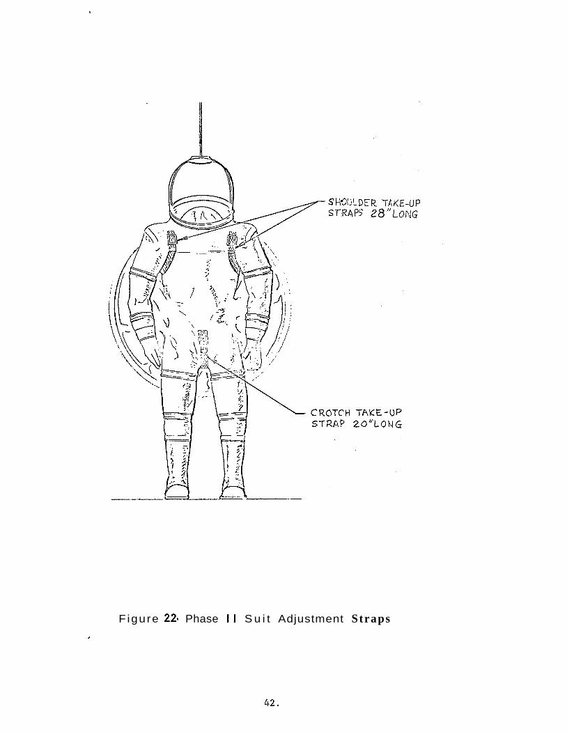
Figure 221 Phase I I S u i t Adjustment Straps I
42.
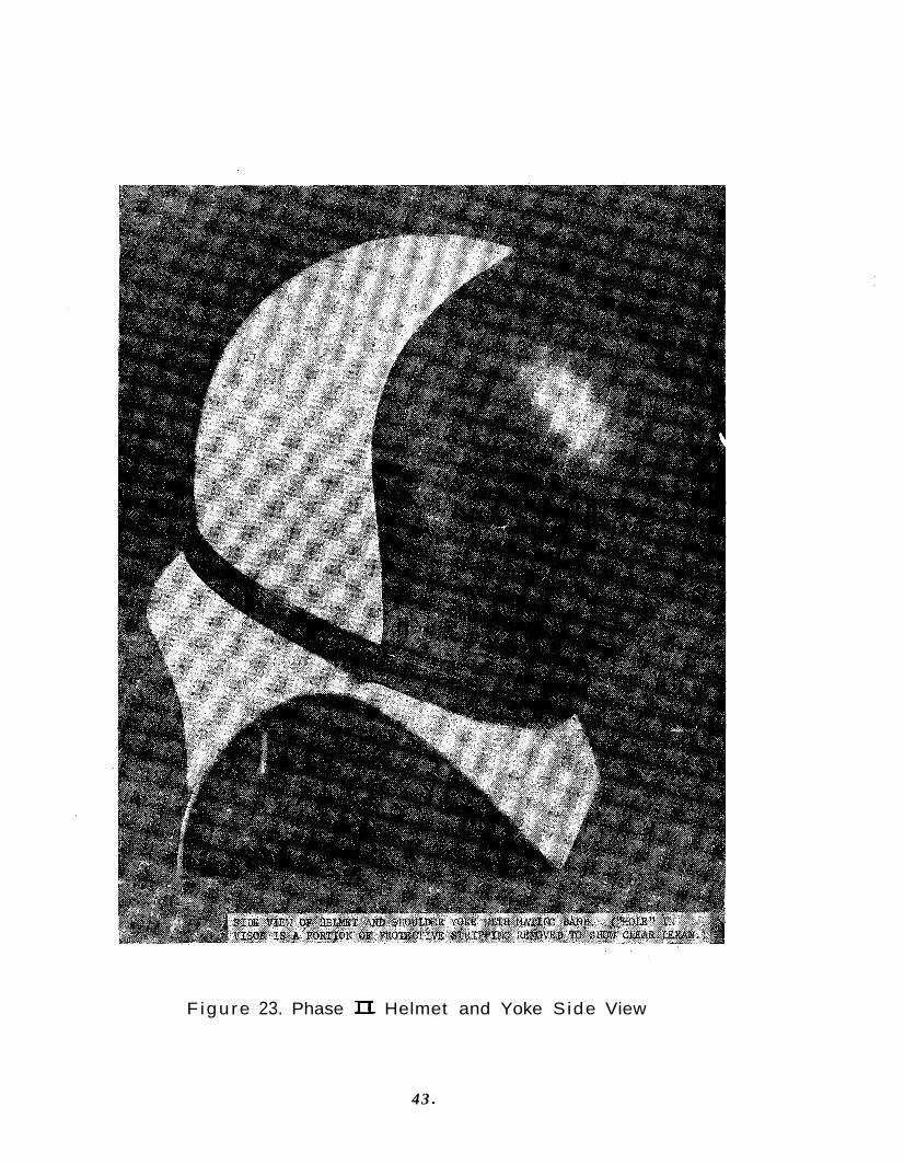
Figure 23. Phase II Helmet and Yoke S ide View
43 e
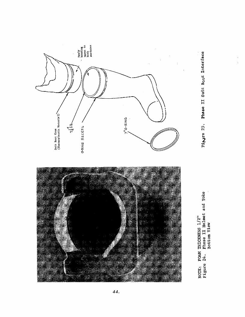
U 0 0 !a
aJ k
.rl F 2
4 4 .
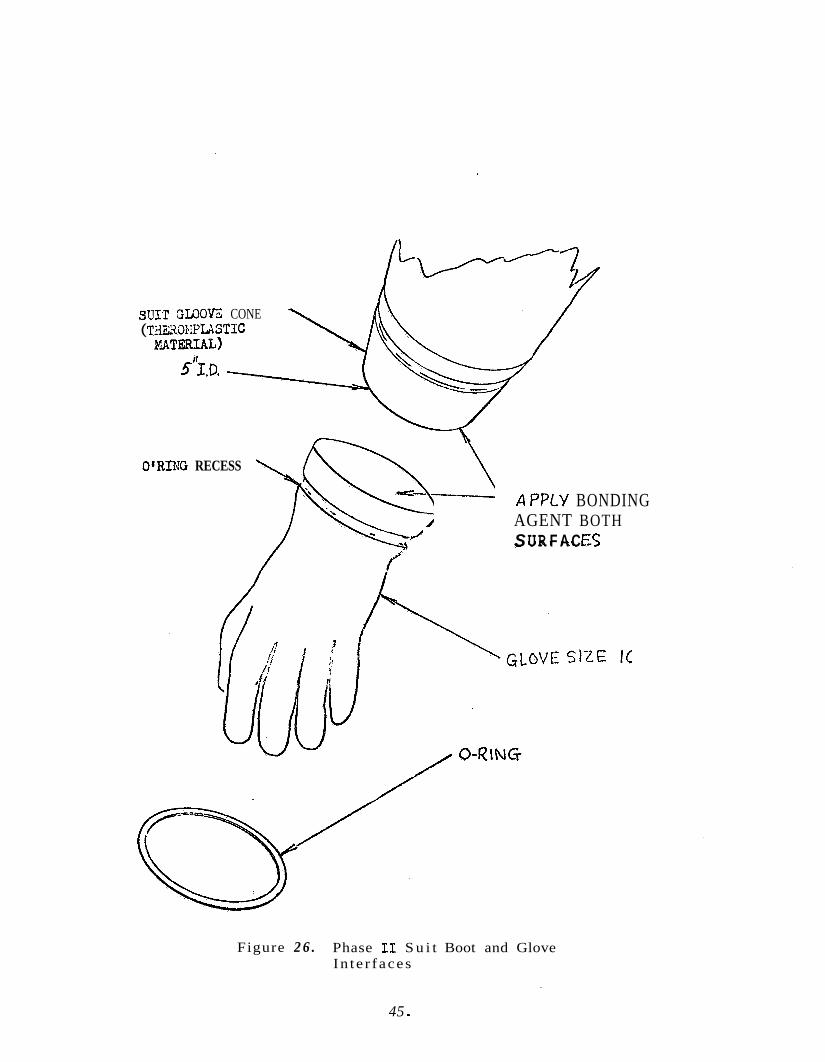
S u m GWOVZ CONE ( T ~ ~ s ~ x P U S T I C
PIATERIAL)
5"z,D.
APPLY BONDING AGENT BOTH S UR F A C €5
O'RIXG RECESS
Figure 2 6 . Phase I1 S u i t Boot and Glove In t e r f aces
45 *
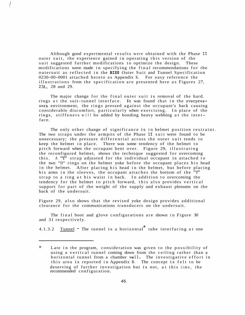
Although good experimental r e s u l t s w e r e obtained with the Phase I1 ou te r s u i t , t he experience gained i n opera t ing t h i s vers ion of the s u i t suggested f u r t h e r modif icat ions t o optimize the design. These modif icat ions were made i n spec i fy ing the f i n a l recommendations f o r the o u t e r s u i t a s r e f l e c t e d i n the BISS Outer S u i t and Tunnel Spec i f i ca t ion 0230-00-0001 a t tached he re to a s Appendix K. For easy re ference the i l l u s t r a t i o n s from the s p e c i f i c a t i o n a r e presented here a s Figures 27, 27A, 28 and 29.
The major change f o r the f i n a l o u t e r s u i t i s removal of the hard. r ings a t the su i t - tunne l i n t e r f a c e . It was found t h a t i n the overpres- smrg environment, the r i n g s pressed a g a i n s t the occupant 's back causing considerable discomfort , p a r t i c u l a r l y when exe rc i s ing . I n place of the r i ngs , s t i f f e n e r s w i l l be added by bonding heavy webbing a t t h e i n t e r - face.
The only o t h e r change of s ign i f i cance i s i n helmet p o s i t i o n r e s t r a i n t . The two s t r a p s under t he armpits of the Phase I1 s u i t were found t o be unnecessary; the pressure d i f f e r e n t i a l across t he ou te r s u i t tends t o keep the helmet i n p lace . There was some tendency of the helmet t o p i t c h forward when the occupant bent over . Figure 29, i l l u s t r a t i n g the reconfigured helmet, shows the technique suggested f o r overcoming t h i s . A "Y" s t r a p ad jus ted f o r the ind iv idua l occupant i s a t t ached t o the two "D" r ings on the helmet yoke before the occupant p laces h i s head i n the helmet. Af t e r p lac ing h i s head i n t he helmet, but before p lac ing h i s arms i n the s leeves , the occupant a t t a c h e s the bottom of t he "Y" s t r a p t o a r i n g a t h i s wais t i n back. I n a d d i t i o n t o overcoming the tendency f o r the helmet t o p i t c h forward, t h i s a l s o provides v e r t i c a l support f o r p a r t of the weight of the supply and exhaust plenums on the back of the undersu i t .
Figure 29, a l s o shows t h a t the rev ised yoke design provides add i t i ona l c learance f o r the communications t ransducers on the undersu i t .
The f i n a l boot and glove conf igura t ions a r e shown i n Figure 30 and 31 r e spec t ive ly .
* 4.1.3.2 Tunnel - The tunnel i s a ho r i zon ta l tube i n t e r f a c i n g a t one
J: Late i n the program, cons idera t ion was given t o the p o s s i b i l i t y of using a v e r t i c a l tunnel coming down from the c e i l i n g r a t h e r than a ho r i zon ta l tunnel from a chamber w a l l . The i n v e s t i g a t i v e e f f o r t i n t h i s a rea i s repor ted i n Appendix B. The concept i s f e l t t o be
deserving of f u r t h e r i nves t iga t ion but i s not , a t t h i s t i m e , the recommended conf igura t ion .
46.
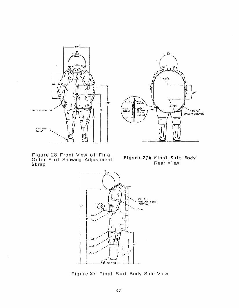
GIBW SIZE NO.
BOOT SIZE #O. lo
Figure 28 Front View o f F ina l Outer S u i t Showing Adjustment S t rap.
F igure 27A F ina l S u i t Body Rear V i ew
F igure 27 F ina l S u i t Body-Side View
47.
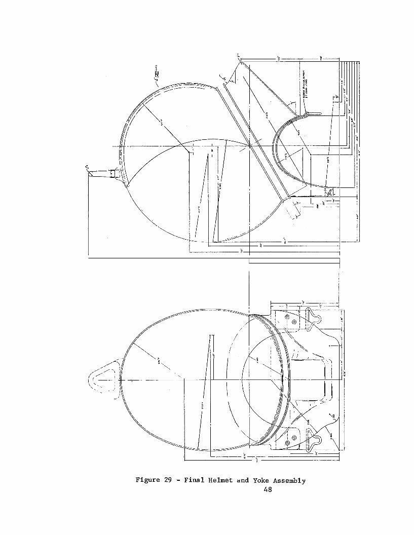
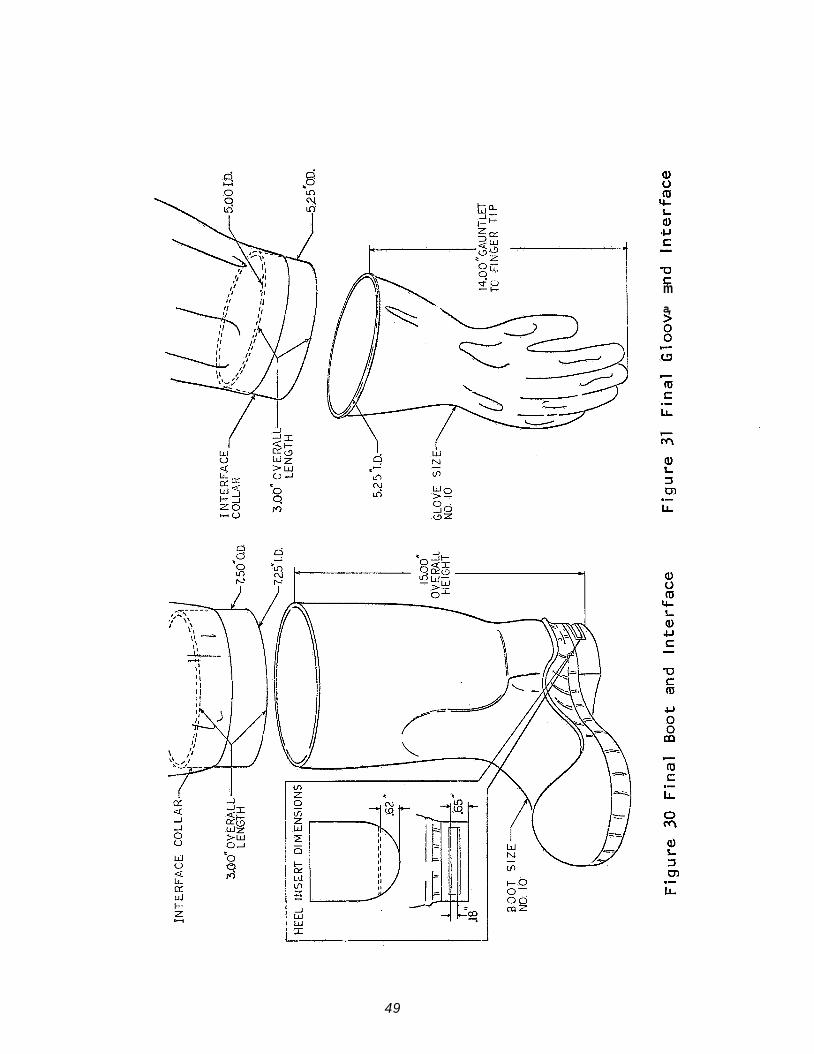
-0 t m a,
2 3 m
c m S
LL .-
.- LL
49
end with the back of the BISS ou te r s u i t and a t t h e o the r end with t he hatch on the Assembly/Ster i l izer wal l . over a r i g i d tube extending i n t o the chamber which i s used f o r r ee f ing . I n t h e t rade- off d iscuss ion of Sec t ion 4.2 .2 , t he s e l e c t i o n of a s o f t tunnel was subs t an t i a t ed . The primary func t iona l requirements of the tunnel a r e :
A t t he wal l end, the tunnel f i t s
0 Permit e n t r y t o , and egress from, t he s u i t .
Maintain an absolu te b a r r i e r aga ins t micro-organisms.
0 Support the l i f e l i n e s and communications l i n e s between the s u i t occupant and the l i f e support and communications subsystems r e spec t ive ly . Minimize c o n s t r a i n t s on s u i t occupant i n moving about t he chamber.
It i s d e s i r a b l e t o minimize tunnel s i z e cons i s t en t with reasonable entry- egress complexity. A tunnel with a nominal circumference of 100 inches was t e n t a t i v e l y se l ec t ed during the e a r l y concept development e f f o r t s i n the program and has been found i n Phase I and Phase I1 of mock-up tes t program, Sec t ion 8.0, t o be s a t i s f a c t o r y .
The Phase I tunnel , l i k e t he Phase I o u t e r s u i t , was designed t o be of the s i m p l e s t , l e a s t expensive form poss ib l e cons i s t en t with func- t i o n a l requirements f o r mock-up experimentation. A s such, i t was a simple tube of 20 m i l polyvinyl chdoride (PVC) zippered t o the back of the s u i t with a 100 inch zipper . Experimentation with t h i s tunnel con- firmed seve ra l design c o n s t r a i n t s an t i c ipa t ed i n the d e f i n i t i o n of t h i s concept :
V e r t i c a l tunnel support i s necessary
A s o f t tunnel i s q u i t e d i f f i c u l t t o r ee f i n an overpressure env i r onmen t
A s o f t tunnel tends t o be pushed back i n t o the open end of the hard tube by the overpressure environment.
These cons t r a in t s a r e r e f l e c t e d i n the requirement f o r a tunnel suppart mechanism, a tunnel r ee f ing mechanism, and a mechanism t o pre- vent t he tunnel from pushing i n t o t he hard tube. a r e discussed i n t he following sec t ions .
These mechanisms
50.
A s a r e s u l t of the tunnel hardness t rade- off and the Phase I t e s t i n g , t he tunnel was conceived a s being made of a r e l a t i v e l y s o f t f a b r i c s i m - i l a r i n composition t o the ou te r s u i t . The tunnel br idges the gap between the ou te r s u i t and the r ee f ing tube through which the opera tor e n t e r s o r leaves t he s u i t when t h e tunnel i s reefed over the tube. The tunnel c a r r i e s the l i f e support and communication l i n e s t o the s u i t occupant and i s i t s e l f supported by s t r i n g e r s t o an overhead boom. As the opera tor moves about i n t he chamber, the boom supports the tunnel and accommodates t h ree dimensional movement, thus p ro t ec t ing the tunnel from abras ion and permi t t ing it t o remain r a d i a l l y col lapsed under the over- pressure." S t i f f e n i n g i s required a t the su i t - tunne l i n t e r f a c e t o f a c i l - i t a t e opera tor e n t r y and e x i t .
.I.
This concept was embodied i n the Phase I1 tunnel . The tunnel i s a 20 foo t long tapered tube of 32" diameter a t the open end and 34" a t t he s u i t i n t e r f ace . The tunnel i s made of the same m a t e r i a l a s t he Phase I1 ou te r s u i t (AL-160 by Cooley, Inc.) and i s sealed t o the opening i n the back of the s u i t . It i s supported a s shown i n Figure 32. This Figureshows the support loops which a r e t o be a t tached t o t he e x t e r i o r
of t he tunnel . S t r i n g e r s from the loops lead t o an over head t r o l l e y l i n e i n the Phase I1 mock-up permi t t ing f u l l longi tudina l movement along the hatch-hard tube a x i s and l imited l a t e r a l movement.
Although good experiment r e s u l t s were obtained with t he Phase I1 tunnel , the experience gained i n opera t ing t h i s vers ion of the tunnel suggested minor modif icat ions t o optimize the design. These modifica- t i o n s w e r e made i n specifying the f i n a l recommendations f o r a tunnel a s r e f l e c t e d i n the BISS Outer S u i t and Tunnel Spec i f i ca t ion 0230-00-001 at tached here to a s Appendix K. For easy re ference , two of the i l l u s t r a - t i o n s from the s p e c i f i c a t i o n a r e combined here a s Figure 33. The changes a r e i n t he tunnel dimensions, hard tube shape, and support loop design.
The f i n a l tunnel w i l l be f ab r i ca t ed from a s i n g l e p iece of s o f t m a t e r i a l compatible with the ou te r s u i t body. The tunnel w i l l be 60 t o 100 f e e t long, with a 104-inch nominal circumference. The seam i n the tunnel w i l l be lengthwise, and bonded i n t o provide a permanent . absolu te b io log ica l s e a l . tube s h a l l be capable of withstanding a d i r e c t p u l l of 700-pounds minimum without damaging s e a l s .
The i n t e r f a c e s a t the s u i t body and hard
F lex ib l e s t r i n g e r s w i l l be a t tached t o t he top of the tunnel spaced e q u i d i s t a n t l y along the e n t i r e tunnel length. They s h a l l be secured
J; See footnote on overpressure e f f e c t s .
51.

NOTE: 'funnel is reefed over a eirculor hard tube. The suit interface rings a r e shaped l i k e a ships hatch.
G ROM 41 ET
SWIVEL EYE
F igure 32- Tunnel f o r Phase - B i s s Mock-up
52.
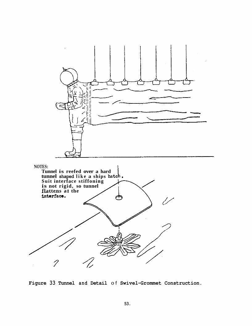
b NOTES: Tunnel is reefed over a hard tunnel shaped l i k e a ships hatc . Sui t interface stiffoning is not rigid, so tunnel flattens a t the
Figure 33 Tunnel and Detail o f Swivel-Grommet Construction.
53.
t o t he tunnel ou te r wal l by a grommet and swivel eye attachment. second s h o r t sp ider s t r i n g e r from the grommet and swivel eye w i l l be adhered t o t he tunnel o u t e r wal l . This s t r i n g e r end w i l l be formed i n such a manner t h a t t h e stress i s d i s t r i b u t e d over a l a rge a r ea . A patch of tunnel m a t e r i a l w i l l cover t he formed s t r i n g e r t o provide a d d i t i o n a l s t r a i n r e l i e f and s e c u r i t y of s t r i n g e r attachment.
A
The hard tube t o be used f o r r ee f ing w i l l be shaped l i k e a s h i p ' s hatch with a circumference of 100 inches maximum. Reefing attachments w i l l be prov.lded on the tunnel t o form the i n t e r f a c e between i t and the r ee f ing mechanism.
4.2 HATCH ASSEMBLY
The func t ion of the ha tch assembly i s t o provide an i n t e r f a c e between the BISS su i t - tunne l , the s t e r i l e Assembly/Ster i l izer Chamber and the n o n- s t e r i l e a r e a s outs ide . The assembly c o n s i s t s of the hatchway, hatch door , and a hard tube used f o r tunnel reef ing . The hatch assembly i s shown i n Figure 34. The hatch and hard tube shape i s a rec tangle with semi- c i rcu lar ends on the top and bottom s ides . This i s the shape of a normal s h i p ' s hatch and provides maximum ease of e n t r y and egress f o r a given circumference.
Although the s h i p ' s hatch shape was envisioned i n the e a r l i e s t v i s u a l i z a t i o n of the BISS hatch; a c i r c u l a r ha tch and c y l i n d r i c a l tube were used f o r the mock-up tests (Sect ion 8.0) t o minimize experimental cos t s . The c i r c u l a r c ross s ec t ion was found adequate, but was not optimum. For a given tunnel circumference a c i r c u l a r c ross s ec t ion r e s u l t s i n s i g n i f i c a n t l y increased d i f f i c u l t y i n ease of e n t r y and eg re s s .
The f i n a l recommendation i s f o r a s h i p ' s hatch c ross s ec t ion f o r the hatch and hard tube with dimensions a s shown i n Figure 34. The length of the hard tube i s a func t ion of tunnel lengths , f r a c t i o n a l length of the reefed tunnel , and tube length a l l o c a t i o n required f o r the r ee f ing mechanism.
The normal mode of opera t ion of the hatch assembly i s wi th the door open when a man i s i n t he s u i t and closed, bu t vented, when the s u i t i s no t occupied. .This mode of opera t ion a s su re s maintenance of a p o s i t i v e inward pressure gradien t aga ins t the s u i t and tunnel ou te r sur faces by maintaining the chamber a t a p o s i t i v e pressure r e l a t i v e t o ambient.
The ha tch door w i l l have four locking bars dr iven by a hand wheel on the cen te r of the door. The door o r hatchway s h a l l have a gas- k e t so t h a t when the door i s closed and the locking bars a r e i n p lace
54.
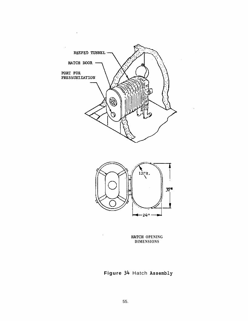
HATCH OPENING DIMENSIONS
Figure 34 Hatch Assembly
55.
the door presents a leak t i g h t b i o l o g i c a l b a r r i e r . use of s te r i l e chamber wi th one o r more s u i t s removed and with t he asso- c i a t ed hatches sealed.
This w i l l permit
The door contains a s ea l ab le p o r t which can be used f o r vent ing the s u i t and tunnel t o maintain pressure grad ien t . t o p re s su r i ze the s u i t with a t r a c e r gas t o make leak checks on the s u i t and tunnel i n a non- s t e r i l e antechamber o r main chamber. Conversely, i f leak de t ec t ion i s t o be performed by "spraying" a t r a c e r gas over t he ou te r sur face of the unoccupied s u i t and tunnel , the po r t can be used f o r sampling the su i t - tunne l gas. (This i s gene ra l ly a low s e n s i t i v i t y leak check scheme).
The po r t a l s o can be used
4 . 3 TUNNEL REEFING MECHANISM
The r ee f ing of the BISS tunnel f o r e n t r y and eg res s and d i s r e e f i n g t o p e r m i t su i t ed worker mobi l i ty present a mechanical design problem of considerable soph i s t i ca t ion . The complexity of tunnel r ee f ing i s a funct ion of t he degree o f tunnel hardness. The tunnel hardness t rade-off i s given i n Sec t ion 4.2 .2 . The r ee f ing aspec t of t h i s t rade- off i s expanded somewhat here.
A r i g i d tunnel composed of a r t i c u l a t e d sec t ions on c a s t e r s o r d o l l i e s does no t p e r m i t r ee f ing . This tunnel conf igura t ion was r e j ec t ed f o r many reasons including mobi l i ty r e s t r i c t i o n s , en t ry- egress d i f f i c u l t y , and d i f f i c u l t y of emergency rescue. A semi- rigid tunnel cons i s t i ng of a s o f t tunnel with r a d i a l support r i ngs would probably be the e a s i e s t t o reef and d i s r e e f s ince i t s f ixed c ros s s ec t ion would prevent it from col laps ing over o r i n t o the hard r ee f ing tube. However t h i s configur- a t i o n presents the d i f f i c u l t y of force-balancing and causes the tunnel r i ngs a t the s u i t i n t e r f a c e t o press aga ins t the back of the s u i t occu- pant. r a d i a l l y , was se lec ted . While i t i s recognized t h a t the s e l e c t i o n of the s o f t tunnel complicated r ee f ing , i t was f e l t t h a t the o the r problems assoc ia ted with t h e semi- rigid conf igura t ion outweighted i t s advantage of e a s i e r r ee f ing .
Thus, t he s o f t tunnel , which al lows the extended tunnel t o co l lapse
Several schemes f o r r ee f ing the s o f t tunnel have been considered. Early mock-up tests ind ica ted t h a t pu l l i ng the tunnel through the hard r ee f ing tube and at tempting t o lap i t back over the hard tube ou t s ide the chamber was no t f e a s i b l e a s a means of reef ing . The in-chamber over- pressure caused the tunnel t o bal loon out through the tube and prevented manual r ee f ing opera t ions . Subsequent in-chamber manual r ee f ing (on the in-chamber p ro j ec t ion of t he hard tube) under two inches of water overpressure ind ica ted t h a t t he amount of force necessary t o overcome the pressure on the f a b r i c is not excessive f o r manual r ee f ing .
Manual reef ing , drawing the tunnel f a b r i c over the ou t s ide of the hard tube, was used throughout t h e mock-up test program. A dome shaped p i s ton was i n s e r t e d i n the tube so t h a t the dome extended out of the end of the tube away from the hatch. This a ided r e e f i n g and d i s r e e f i n g by prevent ing the tunnel from col laps ing back i n t o t o t he tube. This is shown conceptual ly i n t he sketches of Figure 35. Openings a r e l e f t i n the p i s t o n f o r l i f e support and communications l i n e s t o pass through. Even with t he use of the p i s ton , aided d i s r e e f i n g of the tunnel i s necessary. Under two inches of water overpressure, the s u i t occupant i s bare ly ab l e t o p u l l t he tunnel o f f the r ee f ing tube bywalking forward with considerable exe r t i on .
To perform manual r ee f ing , personnel must s tand i n t he chamber ad jacent t o the r ee f ing tube. Thus, manual r ee f ing i s not acceptable f o r rout ine use i n the Assembly/Ster i l izer . A mechanical r ee f ing technique is required. However, manual r ee f ing may be s a t i s f a c t o r y f o r emergency procedures i n the event of malfunction of t he mechanical r ee f ing system. I n f a c t any mchanical r ee f ing system should be compatible with manual r ee f ing by o the r s u i t e d chamber occupants t o a s s i s t i n emergency eg res s i n the event of equipment malfunction.
A mechanical r ee f ing and d i s r e e f i n g mechanism must be ab l e t o grasp the tunnel f a b r i c and e i t h e r push o r p u l l t h e f a b r i c onto the tube and m u s t be a b l e t o reverse t he process. This r equ i r e s a device f o r "grasp- ing" t he tunnel f a b r i c and a device f o r p u l l i n g o r pushing the f a b r i c over the tube e i t h e r continuously o r cyc l i c ly .
The major r ee f ing mechanism requirements a r e t h a t i t must:
Grasp the tunnel f a b r i c . Reef and d i s r e e f the tunnel over a r i g i d tube which i s coaxia l with t he reefed tunnel . . Provide uniform p u l l (o r push) on the tunnel .
Provide uniform displacement around t h e circumference of the tunnel a s i t r e e f s o r d i s r e e f s the tunnel .
0 Be compatible wi th manual emergency r ee f ing .
S a t i s f a c t i o n o f t hese requirements i s complicated by (1) the f a c t t h a t t he extended tunnel requres v e r t i c a l support ( reef ing mechanism and support s t r i n g e r s must no t i n t e r f e r e ) , (2) i t i s des i r ab le t h a t the tunnel sur faces be smooth and s l i c k t o f a c i l i t a t e r ee f ing over the hard tube and t o minimize wear, and (3) t h e over-pressure environment.
57.
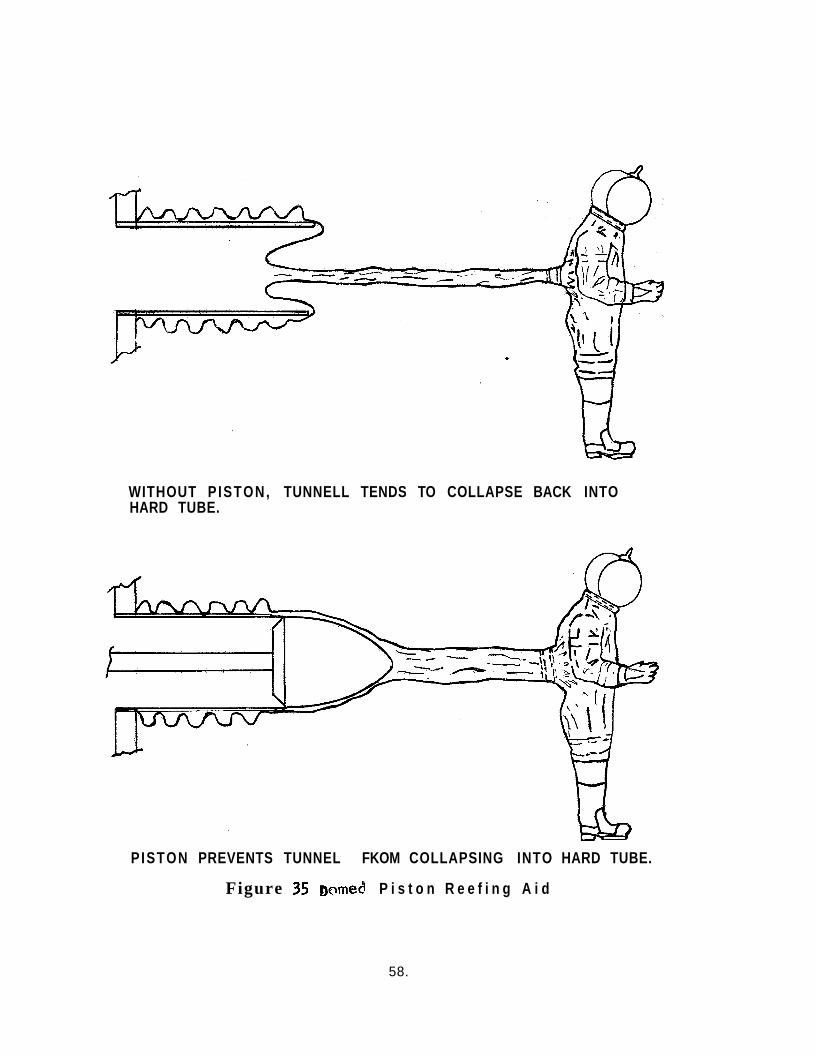
WITHOUT P ISTON, TUNNELL TENDS TO COLLAPSE BACK INTO HARD TUBE.
P ISTON PREVENTS TUNNEL FKOM COLLAPSING INTO HARD TUBE.
Figure 35 Domed P i s t o n R e e f i n g A i d
58.
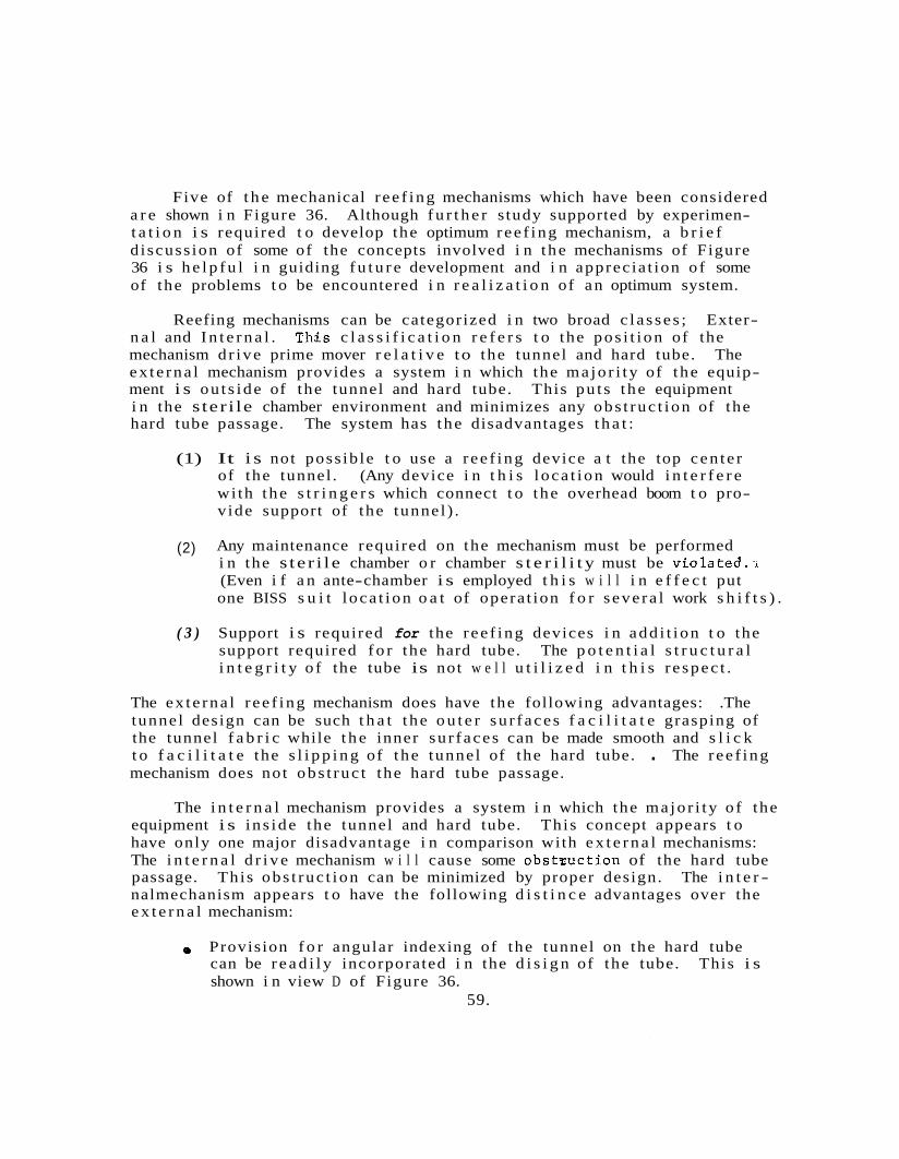
Five of t h e mechanical r ee f ing mechanisms which have been considered a r e shown i n Figure 36. Although f u r t h e r s tudy supported by experimen- t a t i o n i s required t o develop the optimum ree f ing mechanism, a b r i e f d i scuss ion of some of the concepts involved i n t he mechanisms of Figure 36 i s h e l p f u l i n guiding f u t u r e development and i n apprec ia t ion o f some of the problems t o be encountered i n r e a l i z a t i o n of an optimum system.
Reefing mechanisms can be categorized i n two broad c l a s se s ; Exter- n a l and I n t e r n a l . ThJs c l a s s i f i c a t i o n r e f e r s t o the pos i t i on of the mechanism d r ive prime mover r e l a t i v e to the tunnel and hard tube. The ex te rna l mechanism provides a system i n which the ma jo r i ty of t he equip- ment i s ou t s ide of the tunnel and hard tube. This pu t s t he equipment i n the s ter i le chamber environment and minimizes any obs t ruc t ion of the hard tube passage. The system has the disadvantages t h a t :
(1) It i s not poss ib le t o use a r ee f ing device a t the top cen te r of the tunnel . (Any device i n t h i s l oca t ion would i n t e r f e r e wi th t he s t r i n g e r s which connect t o t he overhead boom t o pro- v ide support of the tunnel ) .
(2) Any maintenance required on the mechanism must be performed i n the s te r i l e chamber o r chamber s t e r i l i t y must be v i o l a t e d . & (Even i f a n ante-chamber i s employed t h i s w i l l i n e f f e c t put one BISS s u i t l oca t ion o a t of opera t ion f o r s eve ra l work s h i f t s ) .
( 3 ) Support i s required for the r ee f ing devices i n add i t i on t o the support required f o r the hard tube. The p o t e n t i a l s t r u c t u r a l i n t e g r i t y o f the tube is not w e l l u t i l i z e d i n t h i s r e spec t .
The ex te rna l r ee f ing mechanism does have the following advantages: .The tunnel design can be such t h a t t he o u t e r su r f aces f a c i l i t a t e grasping of the tunnel f a b r i c while t h e inner su r f aces can be made smooth and s l i c k t o f a c i l i t a t e the s l i p p i n g of t he tunnel of the hard tube. . The r ee f ing mechanism does not obs t ruc t the hard tube passage.
The i n t e r n a l mechanism provides a system i n which the ma jo r i ty o f the equipment i s in s ide the tunnel and hard tube. This concept appears t o have only one major disadvantage i n comparison with e x t e r n a l mechanisms: The i n t e r n a l d r i v e mechanism w i l l cause some obs tzuc t ion of the hard tube passage. This obs t ruc t ion can be minimized by proper design. The i n t e r - nalmechanism appears t o have the following d i s t i n c e advantages over the e x t e r n a l mechanism:
e Provision f o r angular indexing of the tunnel on the hard tube can be r e a d i l y incorporated i n the d i s i g n of the tube. This i s shown i n view D of Figure 36.
59.
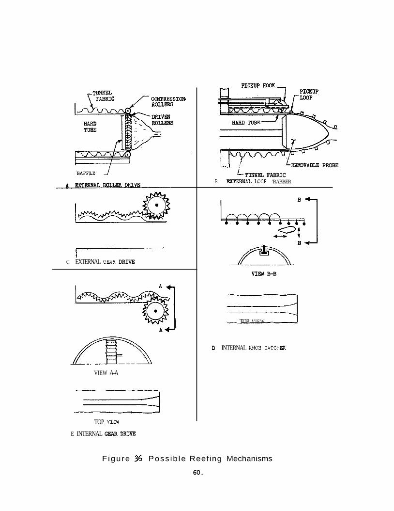
I C EXTERNAL GEAR DRIVE
VIEW A-A
L - /
1
c1
TOP VIW
E INTERNAL GEAR DFUYE
'mvABLE PROBE LTUNNE3, FABRIC
B EX"I'AL LOOF 'RABBER
VIM B-B
3 TOP VIEW
I) INTERNAL KNOB CATCIZR
Figure 36 Poss ib le Reefing Mechanisms
60.

0 The mechanism i s on the n o n- s t e r i l e s i d e of t h e tunnel and can, t h e r e f o r e , be worked on a t any t i m e except dur ing a s t e r i l i z a t i o n cycle. who do not have t o be BISS t r a ined and do not have t o work i n the BISS s u i t s .
This a l s o permits t h e u t i l i z a t i o n of maintenance personnel
0 By using devices such a s long s h a f t s o r rods, the prime movers f o r t h e i n t e r n a l mechanisms can be located on t h e f a r s i d e of the chamber wall near the opening of the hard tube. permit improved access f o r se rv ic ing and minimize obs t ruc t ion of t h e hard tube.
This would
The f i v e devices shown i n Figure 36 represen t both i n t e r n a l and ex te rna l mechanisms and employ th ree b a s i c a l l y d i f f e r e n t concepts of d r iv ing tunnel ma te r i a l . These t h r e e concepts a r e continuous r o l l e r d r i v e , continuous gear d r i v e , and c y c l i c d r i v e through attachments t o the tunnel . Each of the mechariisms i l l u s t r a t e d is a view of only one of s e v e r a l d u p l i c a t e mechanisms t h a t w i l l be simultaneously required around t h e per iphery of the tunnel t o a f f e c t uniform d r i v i n g fo rce and uniform displacement. Some form of mechanical of e l e c t r i c a l syncron- i z i n g w i l l be required t o assure syncronous opera t ion of the mul t ip le mechanisms.
Since t h e r o l l e r d r i v e i s not a p o s i t i v e d r i v e mechanism a r e l a - t i v e l y soph i s t i ca ted feed-back system employing a displacement fol lower would be required f o r each of the mul t ip le mechanisms. examples of displacement fol lowers would be a potentiometer dr iven by a wheel r i d i n g on the moving f a b r i c o r an o p t i c a l sensor counting circum- f e r e n t i a l s t r i p e s painted on the tunnel . The other mechanisms shown i n Figure 36 a r e a l l p o s i t i v e displacement devices and do not r equ i re t h i s type of feed-back t o assure uniform displacement.
Two poss ib le
The i n t e r n a l and e x t e r n a l gear d r i v e mechanisms would employ a f l e x i b l e rack gear molded from a high-temperature mate r i a l such a s Teflon and bonded t o the tunnel su r face . These would requ i re angular indexing of the tunnel ma te r i a l t o assure t h a t t h e d r i v e gear remains i n contact wi th the rack. would be use of Velcro s t r i p s on the tunnel wi th a Velcro covered d r i v e wheel, bu t t h i s does not appear t o o f f e r any advantage over a gear d r ive system.
A poss ib le a l t e r n a t i v e t o the d r i v e gear
The loop grabber mechanism shown i n V i e w B of Figure 36 employs c y c l i c d r i v i n g of t h e tunnel mate r i a l . I n the cycle the mechanism a t t aches t o t h e tunne l , p u l l s i n a length of m a t e r i a l , disengages, r e t u r n s t o t h e extended p rov i s ion and repea t s t h e cycle. ment hook would be designed i n such a manner t h a t it could d is- reef a s w e l l a s r e e f . This mechanism has the disadvantage t h a t t h e required angular indexing n e c e s s i t a t e s provis ion of some indexing f e a t u r e on the tunnel i n add i t ion t o the feed-back loops.
The a t t ach-
61.
The i n t e r n a l knob-catcher mechanism shown i n view D overcomes t h i s d i f f i c u l t y by employing the d r i v e knobs f o r indexing. This p a r t i c u l a r mechanism a l s o has the advantage t h a t the mult i- point attachment o t the hard tube by means of the knobs tends t o make the tunnel fo ld back i n the des i red manner a s i t i s reefed.
Providing t h a t the knob-catcher d r ive mechanism can be made s u f f i - c i e n t l y small t h a t the obs t ruc t ion of the hard tube i s t o l e r a b l e , t h i s mechanism appears t o be super ior t o the o the r four mechanisms shown and t o o f f e r s i g n i f i c a n t p o t e n t i a l f o r fu r the r development. I f t he knob r e t en t ion channels formed i n t o the hard tube can be made s u f f i c i e n t l y smal l , these channels may i n t u rn prove advantageous t o the o v e r a l l BISS system. They can a c t a s r a i l s f o r small wheeled s e a t s which can be used by the worker en t e r ing the BISS s u i t and by maintence personnel ' t o f a c i l i t a t e movement i n the hard tube.
4 .4 TUNNEL SUPPORT BOOM
A boom i s required t o provide v e r t i c a l s;po;t o f ' tbe tunnel when it i s h l l y o r p a r t i a l l y extended. The support w i l l be provided by s t r i n g e r s from the boom t o the tunnel. I n add i t i on t o providing support , the boom must accomodate the movement of the BISS s u i t occupant within the main chamber. The mobi l i ty requirement for the BISS occupant i s f r e e movement throughout a semicylinder with a 60 foo t rad ius and a 20 foot height except fo r a semiconical volume with a 45 degree h a l f angle and a 20 foo t rad ius . This volume i s sketched i n Figure 37.
The mobi l i ty requirement r e s u l t s i n a minimum of th ree dimensional motion. The coordinateg of t h i s motion a r e shown i n view B of Figure 37. The requirement i s fu r the r complicated by the f a c t t h a t a man i n a BISS s u i t i s not an i so l a t ed po in t but i s connected t o the YZ plane by the tunnel with the boom cen te r l i ne above the tunnel cen t e r l i ne .
Figure 38 i s presented t o show the over lap of BISS worker mobi l i ty a reas i n a t y p i c a l i n s t a l l a t i o n i n an Assembly/Ster i l izer main chamber with a f l o o r of approximately 100 x 75 f e e t . The th ree views of t h i s f i gu re show the over lap f o r 60, 80, and 100 f e e t rad ius work volumes. From considerat ion of these f i g u r g , i t i s seen t h a t f o r achievement of the s a f e t y requirement of two men being ab l e t o a s s i s t any disabled opera tor a l a rge number of BISS occupants must be present i n the chamber a t a l l t i m e s o r the work volumes must have very l a rge r a d i i . I n f e r r ed i n t h i s f i gu re , though not shown e x p l i c i t l y , i s the f a c t t h a t i f the tunnel booms a r e of f ixed length, tremendous d i f f i c u l t i e s w i l l r e s u l t from boom in t e r f e r ence a s the s eve ra l occupants move about i n the chamber.
62.

View A - Volume Definition Bottom Surface of Cy1 indrical Section in Plane of Floor. Flat Vertical Surface in P1 ane o f Chamber Wall and (See View B) Coordinate plane xy Coincident with floor, Planeyz coincident with chamber wall.
Z
X
View 6 - Mobility Coordinates.
Figure 37 Required Mobility Volume
6 3 .

Plan View o f Assembly/Ster i l i z e r Main Chamber
NOTES:
1. Numbers i n f l o o r area zones i n d i c a t e t h e number o f BiSJ occupants whose work volumes inc lude t h e i nd i ca ted zones.
L e t t e r s around per iphery designate B135 s u i t . : i n te r faces w i th o u t s i d e w a l l .
2.
3. L e t t e r s i n zones i n d i c a t e B i s s occupants whose work
View A 60 Foot Radius Work Volume -10 Occupants
volumes do n o t inc lude t h e i nd i ca ted zone.
F igure 38 - Overlap O f Working Volumes (Plan View)
6 4 .
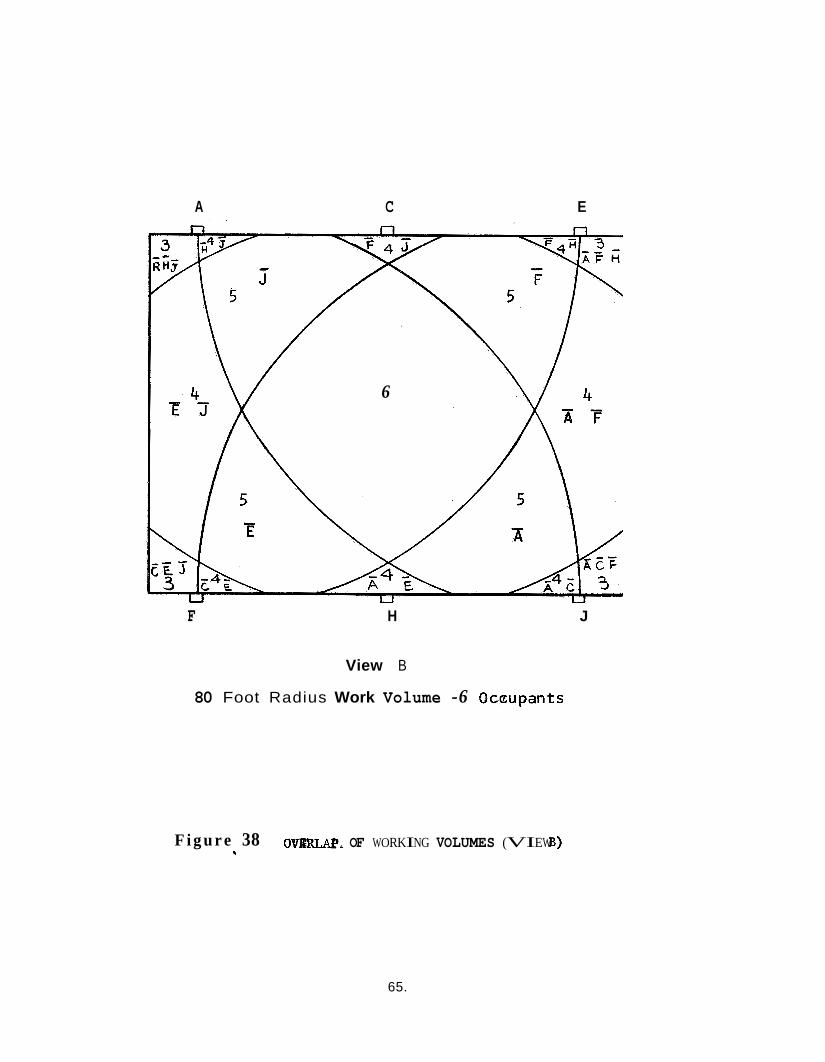
A C E
6
F H J
View B
80 Foot Radius Work Volume -6 Occupants
F i g u r e 38 o w k OF WORKING VOLUMES (VIEW B) *
65.
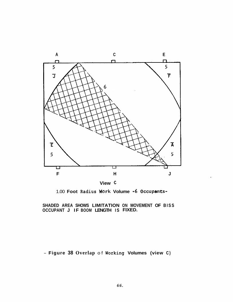
A C E
F H J
View C
1.00 Foot Radius Work Volume ~6 Occupan'ts-
SHADED AREA SHOWS LIMITATION ON MOVEMENT OF B I S S OCCUPANT J I F BOOM LENGTH I S FIXED.
- Figure 38 Overlap o f Working Volumes (view C )
6 6 .
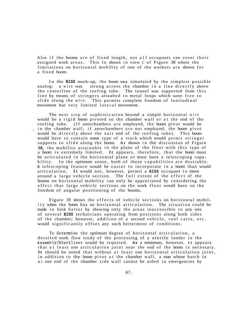
Also i f t h e booms a r e o f f ixed length, no t a l l occupants can cover t h e i r assigned work a r e a s . l i m i t a t i o n s on hor izon ta l mobi l i ty of one of t h e workers a r e shown f o r a f ixed boom.
This i s shown i n view C o f Figure 38 where the
I n the BISS mock-up, t h e boom a a s simulated by the s imples t poss ib le analog: a w i r e was s t rung ac ross the chamber i n a l i n e d i r e c t l y above t h e c e n t e r l i n e of the ree f ing tube. The tunnel was supported from t h i s l i n e by means of s t r i n g e r s a t taahed t o metal loops which were f r e e t o s l i d e along the w i r e . movement but very l imi ted l a t e r a l movement.
This permits complete freedom of l o n i t u d i n a l
The next s t e p o f s o p h i s t i c a t i o n beyond a simple hor izon ta l w i r e would be a r i g i d boom pivoted on the chamber wa l l o r a t t h e end of the ree f ing tube. ( I f antechambers a r e employed, the boom pivot would be i n the chamber wal l ; i f antechambers a r e not employed, the boom p ivo t would be d i r e c t l y above the s u i t end of the r e e f i n g tube) . This boom would have t o con ta in some type of a t r a c k which would p e r m i t s t r i n g e r supports t o s l i d e along t h e boom. A s shown i n the d i scuss ion of Figure 38, t he mobi l i ty a t t a i n a b l e i n the plane of t h e f l o o r wi th t h i s type of a boom i s extremely l imi ted . It appears, the re fo re , t h a t t h e boom must be a r t i c u l a t e d i n t h e hor izon ta l plane o r must have a te lescoping capa- b i l i t y . I n t h e optimum sense, both o f these c a p a b i l i t i e s a r e d e s i r a b l e . A te lescoping f e a t u r e would be e a s i e r t o incorpora te i n a boom than would a r t i c u l a t i o n . It would no t , however, permit a BISS occupant t o move around a l a rge v e h i c l e sec t ion . booms on h o r i z o n t a l mobi l i ty can only be apprecia ted by considering the e f f e c t t h a t l a rge veh ic le sec t ions on t h e work f l o o r would have on the freedom of angular pos i t ion ing of the booms.
Figure 39 shows the e f f e c t s of veh ic le s e c t i o n s on hor izon ta l mobil- i t y when the boom has no hor izon ta l a r t i c u l a t i o n . The s i t u a t i o n could be made t o look b e t t e r by showing only t h e a r e a s inaccess ib le t o any one of severa l BISS technic ians opera t ing from p o s i t i o n s along both s ides of t h e chamber; however, a d d i t i o n of a second v e h i c l e , t o o l c a r t s , e t c . would s i g n i f i c a n t l y o f f s e t any such betterment of condi t ions .
*
The f u l l e x t e n t of the e f f e c t of the
To determine t h e optimum degree of hor izon ta l a r t i c u l a t i o n , a d e t a i l e d work flow s tudy of the processing of a s ter i le lander i n the Assembly/Ster i l izer would be required . A s a minimum, however, i t appears t h a t a t l e a s t one a r t i c u l a t i o n j o i n t near the end of the boom i s necessary. It should be noted t h a t without a t l e a s t one h o r i z o n t a l a r t i c u l a t i o n j o i n t , i n a d d i t i o n t o the boom p i v o t a t the chamber wal l , a man whose hatch is a t one end of the chamber s i d e wa l l cannot be aided i n emergencies by
67.
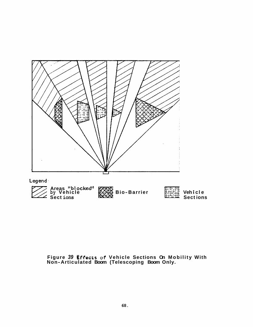
Areas "bl ockedll by Vehic le B io- Barr ier Veh i c l e Sect ions Sect ions
Figure 39 t f f e ~ f s o f Vehic le Sections On M o b i l i t y With Non-Art iculated Boom (Telescoping Boom Only.
68.

more than one man from h i s s i d e o f the chamber.
I n a d d i t i o n t o t he problem o f ho r i zon ta l mobi l i ty , the defined work volume imposes the necess i ty of v e r t i c a l mobi l i ty o f the s u i t occupant. This r equ i r e s e i t h e r v e r t i c a l a r t i c u l a t i o n of the boom o r a system whereby s t r i n g e r s from the tunnel t o the boom a r e ind iv idua l ly cont ro l- l a b l e wi th a ho r i zon ta l boom adds considerable complexity t o v e r t i c a l mobi l i ty c a p a b i l i t y with a ho r i zon ta l boom adds considerable complexity t o t he boom design. Such a concept r equ i r e s i nd iv idua l ly con t ro l l ab l e pos i t i on servos on each of a number of tunnel support s t r i n g e r s . With t h i s approach, the s t r i n g e r s would be shortened a s the BISS worker climbed a work-stand t o work on equipment not acces s ib l e from the f l o o r of the chamber. This i s shown i n Figure 40. Each of the s t r i n g e r s from the boom t o the inc l ined por t ion of the tunnel i s of a d i f f e r e n t length.
Severa l constant force tensioning devices have been considered f o r incorporat ion i n the s t r i n g e r s t o provide the v e r t i c a l movement freedom with a passive (non-servo) system. Examples of such devices a r e weights and pul leys o r constant force spr ings (such a s Negators). However, t he dynamics of motion of t he s u i t occupant w i l l no t r e s u l t i n constant tunnel forces which obvia tes the use o f such devices . Any unbalance of the forces would cause v e r t i c a l "bowing" of t he tunnel and would r e s u l t i n the tunnel dragging on the f l o o r o r bowing upward, wither of which would complicate r ee f ing . Tunnel dragging, of course, would be very undesirable . be p a r t i c u l a r l y disadvantageous because i t would r e s u l t i n a s i g n i f i c a n t increase i n chamber height .*
I n add i t i on t o t h i s problem, a p u l l e y and weight system would
Since a constant force system cannot be employed with a ho r i zon ta l boom, a cont ro l led displacement system (servos) would be required. With a servo d r i v e system on the s t r i n g e r s , the amount of s t r i n g e r shorten- ing and the number of s t r i n g e r s t o be shortened would be a func t ion of the des i r ed v e r t i c a l ascent and the d i s t ance of the des i r ed pos i t i on from the chamber wal l o r r e e f i n g tube end. This would r e s u l t i n a q u i t e soph i s t i ca t ed system.
A s an a l t e r n a t i v e t o s t r i n g e r length adjustment, v e r t i c a l a r t i c u - l a t i o n of the boom can be employed. A s a minimum, t h i s would r equ i r e a 28.3 foo t s e c t i o n of boom which could be e leva ted t o 45' t o provide the 20 foo t ascent c a p a b i l i t y . To minimize undes i rab le i n t e r a c t i o n between ho r i zon ta l and v e r t i c a l a r t i c u l a t i o n and t o optimize worker mobi l i ty , the boom should be a r t i c u l a t e d a t two po in t s i n the v e r t i c a l plane a s w e l l
9: A twenty foo t ascent c a p a b i l i t y with pul ley and weight support would r equ i r e a pu l l ey &eight of about four ty- f ive fee t .
69.
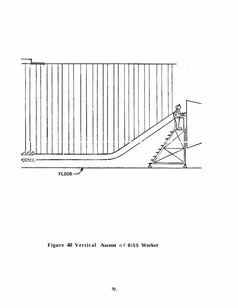
1 I
I
I
Figure 40 Vertical Ascent o f B I S S Worker
70.
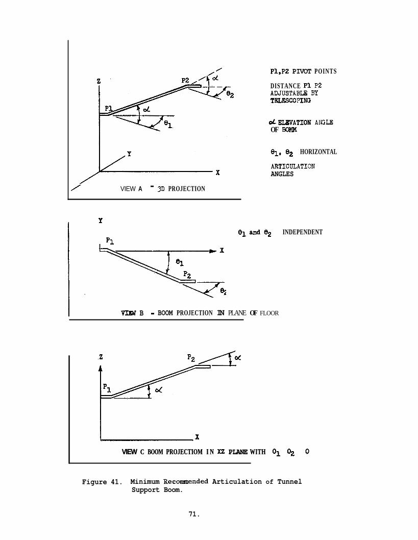
/ VIEW A - 3D PROJECTION
P
P1
Pl,P2 PIVOT POINTS
DISTANCE P I P2 ADJUSTABLG By TELESCO?ING
d E U V A T I O N ANGLE OF BOMM
91, 02 HORIZONTAL
A R T I C ~ T I O N ANGLES
VIW B 0 BOOM PROJECTION IN PLANE OF FLOOR
INDEPENDENT
x VIEW C BOOM PROJECTIOM I N XZ PLANE WITH VIEW C BOOM PROJECTIOM I N XZ PLANE WITH
Figure 41. Minimum Recommended Articulation of Tunnel Support Boom.
71.

a s i n the ho r i zon ta l plane. The two j o i n t a r t i c u l a t i o n i n the v e r t i c a l plane would be coordinated t o keep the ou te r end s e c t i o n of the boom hor izonta l . The ho r i zon ta l a r t i c u l a t i o n angles 01 and 02 would be independent t o maximize mobi l i ty . The conf igura t ion shown here i s the recommended minimum t o permit reason- ab le mob i l i t y of t he BISS occupant.
This combination i s shown i n Figure 41.
I n considering the des i red degree of boom a r t i c u l a t i o n , one f u r t h e r i f the boom does not have two j o i n t system i n t e r a c t i o n should be noted:
ho r i zon ta l a r t i c u l a t i o n , the loca t ion o f the r ee f ing tube has a very s i g n i f i c a n t impact on the useable main chamber volume. This is shown i n Figure 4 2 .
4 . 5 REEFING/BOOM/BISS OCCUPANT INTERACTION
The preceeding d iscuss ions of tunnel r ee f ing and tunnel support i nd ica t e the complexity of the ind iv idua l r ee f ing and boom design problems. These problems a r e f u r t h e r complicated by the need t o coordinate these two major equipment i t e m s with each o the r and wi th t he BISS occupants des i red motions. For example, a s the s u i t occupant moves away from the reef ing tube, the r ee f ing mechanism must play out the tunnel , the boom must extend, and the support s t r i n g e r s m u s t be dr iven out on the boom. These machine funct ions must be accomplished i n a t l e a s t gross synchronism with the forward motion of the s u i t occupant. I n essence the system design problem i s one of a coordinated multidimensional servo system incorpora t ing a human a s a d r iv ing element.
A s a minimum, the system involves 9 degrees of freedom a s de l inea ted be low:
System C r i t e r i a Degrees of Freedom
Tunnel Reefing - displacement 1
Boom - Extension - Elevat ion - Horizontal Motion
S u i t Occupant - Pos i t i on
1 1 2
TOTAL 9
* S u i t occupant pos i t i on involves a s a minimum, X , Y , and Y pos i t i on and angle of body r o t a t i o n about i t s a x i s . This does not include the d i f f e r e n t i a l displacements such a s r e s u l t from bending o r squa t t ing .
7 2 .

CHAMBER FLOOR
dO#K VOLUME
EXTENDS INTO CHAMBER
F igure 42 Loss o f Work Volume i f Reefing Tube Extends i n t o Chamber and Boom Has Only One Hor izon ta l A r t i c u l a t ion J o i n t
73.
To have a workable system, motion i n a l l of these degrees o f freedom must be coordinated and must be i n response t o t he motion des i red by the s u i t occupant. t h a t the system responds t o the d e s i r e s of the s u i t occupant i n t h a t h i s a t tempts t o move a r e sensed and the system automat ica l ly a i d s t h i s motion ( a s i n automotive power s t e e r i n g ) .
For optimum e f f i c i ency , the hardware whould be so designed
It should be noted t h a t the complexity of t he required system i s even g r e a t e r than t h a t suggested above because of two s i g n i f i c a n t f a c t s : (1) the coordinat ion between system degrees of freedom involves non- l i n e a r i t i e s (e.g. tunnel r ee f ing mechanism playout can be a funct ion of the s i n e of a n g l e d ; (2) t he system must be ab l e t o adapt t o d i f f e r e n t modes of opera t ion depending upon the des i red motion of the occupant (e .g . boom e l eva t ion and tunnel r ee f ing a r e coordinated f o r v e r t i c a l a scen t , bu t no e l eva t ion i s involved i n moving about on the f l o o r , though r ee f ing i s involved) .
The design of a madmachine system of t h i s complexity w i l l r equ i r e extensive systems and hardware ana lys i s and design based on d e t a i l e d work flow planning and supported by experimental v e r i f i c a t i o n of the evolving system. Such a design i s beyond the scope of the present con- t r a c t .
4.6 DONNING RACK
A means i s required t o support the BISS ou te r s u i t so t h a t i t holds i t s anthropomorphic shape during donning and dof f ing . i n shape i s a g r e a t a i d t o the man en te r ing o r leaving the s u i t . A donning rack has been designed fo r t h i s purpose.
Holding the s u i t
Early i n the program, a rough wooden donning rack was used f o r the Phase I mock-up e f f o r t and a s an experimental design t o o l f o r evolving a ref ined.meta1 rack. The tubular metal rack which was evolved i s shown i n Figure 4 3 . The rack holds the helmet, boots , and s u i t s leeves while the man dons o r d o f f s the s u i t . The helmet and s u i t s leeves a r e held by hooks, and the boots a r e held by s p e c i a l clamps. The d e t a i l s of the boot clamp a r e shown i n Figures 44 and 45.
The tubular donning rack was used ex tens ive ly i n the Phase I1 mock- up tests and was found s a t i s f a c t o r y . Minor modif icat ions a r e recommended i n the s leeve holding f e a t u r e t o optimize the design.
74.
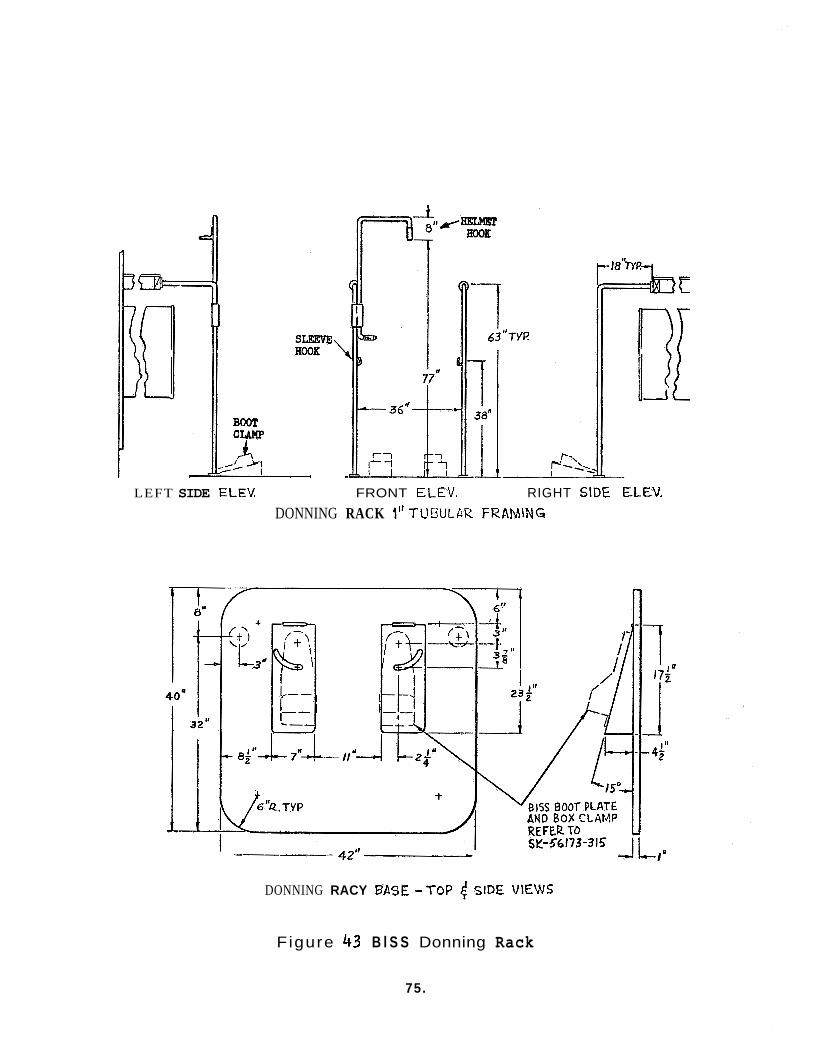
LEFT SIDE ELEV FRONT €LEV. RIGHT SIDE €LEV. DONNING RACK 1'' TUWLAR FRAMlNG
DONNING RACY BASE - T O P 4 SIDE VIELVS
Figure 43 B l S S Donning Rack
75.

I
T
i i
I i”
*m
c V
W c m a, *., m Q c
76
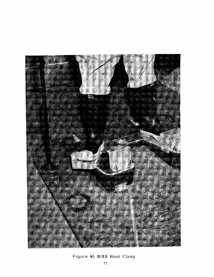
F i g u r e 45 B l S S Boot Clamp 77.
4.7 LIFE SUPPORT
4 .7 .1 Requirements
The l i f e support subsystem includes the equipment necessary t o provide a comfortable, h e a l t h f u l environment wi th in the ou te r s u i t and tunnel , and the equipment necessary t o ensure t h a t the environment i s maintained wi th in reasonable l i m i t s during an opera t ing cycle .
Operator comfort r equ i r e s t h a t body hea t , moisture, and waste gases r e s u l t i n g from the ope ra to r ' s metabolism be removed from the s u i t a t approximately the same r a t e a t which they a r e evolved, and t h a t adequate amounts of oxygen be suppl ied f o r breathing. I n t he case of hea t and water vapor removal, too rap id a removal r a t e would r e s u l t i n overcooling the opera tor ; too slow a r a t e would cause overheat ing, discomfort , and could u l t ima te ly cause p r o s t r a t i o n of the opera tor . F a i l u r e t o remove waste gases would r e s u l t i n a noxious o r even a hazardous atmosphere i n the s u i t . Improper removal r a t e s would thus r e s u l t i n discomfort o r danger t o the opera tor and reduced opera t ing e f f i c i ency .
The oxygen f o r breathing must be i n s u f f i c i e n t quan t i t y and i n t he proper d i l u t i o n t o maintain normal r e s p i r a t i o n a t any given a c t i v i t y l eve l . I n s u f f i c i e n t oxygen o r too low a p a r t i a l p ressure can r e s u l t i n dyspnea, discomfort , reduced work capac i ty , and could a l s o cause eventual p ros t r a t ion . Too high a concentrat ion can r e s u l t i n hypervent i la t ion , apnea and a l k y l o s i s . For opera tor comfort and s a f e t y , sea l e v e l oxygen concentrat ions of 17-36% have been spec i f i ed i n the system c r i t e r i a .
The temperature and r e l a t i v e humidity of t he s u i t atmosphere m u s t be maintained wi th in comfortable l i m i t s . These parameters a r e i n t e r - dependent and comfort l e v e l s vary with the ind iv idua l opera tor . General ly speaking, however, r e l a t i v e humidity less than 39% w i l l r e s u l t i n drying of the mucous membranes of nose and mouth, while r . h . higher than 80% w i l l r e su l t i n discomfort. ab l e while temperatures above 80°F promote pe r sp i r a t ion and discomfort even a t low a c t i v i t y l eve l s . Acceptable ranges were o r i g i n a l l y i d e n t i - f i e d a s 650F t o 75%for temperature and 40% t o 50% f o r r e l a t i v e humidity. I n experimentation-with t he Phase II mock-up system, d r y bulb tempera- tu re of 680F t o 78OF with w e t bulb temperature of 57'F t o 64OF have been shown t o be s a t i s f a c t o r y f o r occupant comfort. This range of condit ions i s shown i n a psychometric c h a r t i n Figure 46. The system should possess s u f f i c i e n t range and accuracy of con t ro l t o permit establ ishment of temperature and humidity condit ions wi th in a r e l a t i v e l y small region wi th in t h i s range t o optimize comfort f o r personal d i f f e rences and d i f f e r - ences i n occupant work load.
Temperatures below 60°F w i l l usua l ly be uncomfort-
78.
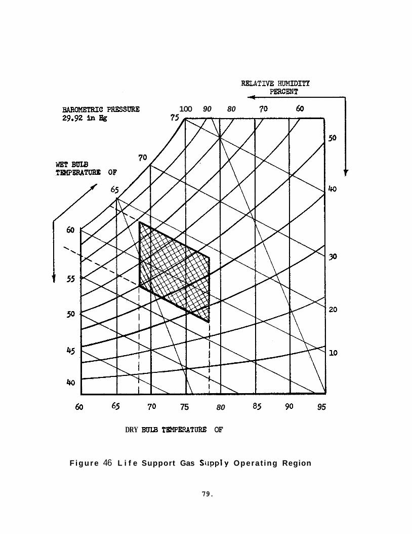
- 100 90 80
60 45 70 75 80 85 90 95
DRY BULB !l'EMPERATURE OF
F i g u r e 46 L i f e Support Gas Siipply Operat ing Region
79.
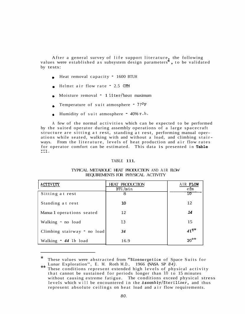
A f t e r a genera l survey of l i f e support l i t e r a t u r e the following 4- values were es tab l i shed a s subsystem design parameters , t o be va l ida ted by tests:
e Heat removal capac i ty - 1600 BTUH
H e l m e t a i r flow r a t e - 2.5 CFM
Moisture removal - 1 l i t e r / h o u r maximum
a Temperature of s u i t atmosphere - 77OF Humidity o f s u i t atmosphere - 40% r . h .
A few of the normal a c t i v i t i e s which can be expected t o be performed by the s u i t e d opera tor dur ing assembly opera t ions of a l a rge spacec ra f t s t r u c t u r e a r e s i t t i n g a t rest , s tanding a t rest , performing manual oper- a t i o n s while sea ted , walking with and without a load, and climbing s t a i r - ways. From the l i t e r a t u r e , l e v e l s of hea t production and a i r flow r a t e s fo r opera tor comfort can be es t imated. 111.
This da ta is presented i n Table
TABLE 111.
TYPICAL METABOLIC HEAT PRODUCTION AND A I R FLOW REQUIREMENTS FOR PHYSICAL ACTIVITY
S i t t i n g a t rest
Standing a t rest
Manua 1 opera t ions sea ted
Walking - no load
Climbing s ta i rway - no load
Walking - 44 l b load
HEAT PRODUCTION BTU /min
8
10
12
13
34
16.9
A I R FLOW C f m v 12
14
15
4 le*
20**
* These values were a b s t r a c t e d from "Bioenergetics of Space S u i t s f o r
** These condi t ions represen t extended high l e v e l s of physica l a c t i v i t y Lunar Exploration", E. M. Roth M.D. , 1966 (NASA SP 8 4 ) .
t h a t cannot be sus ta ined f o r per iods longer than 10 t o 15 minutes without causing extreme fa t igue . l e v e l s which w i l l be encountered i n the Assembly/Ster i l izer , and thus represent abso lu te c e i l i n g s on h e a t load and a i r flow requirements.
The condi t ions exceed physica l stress
80.
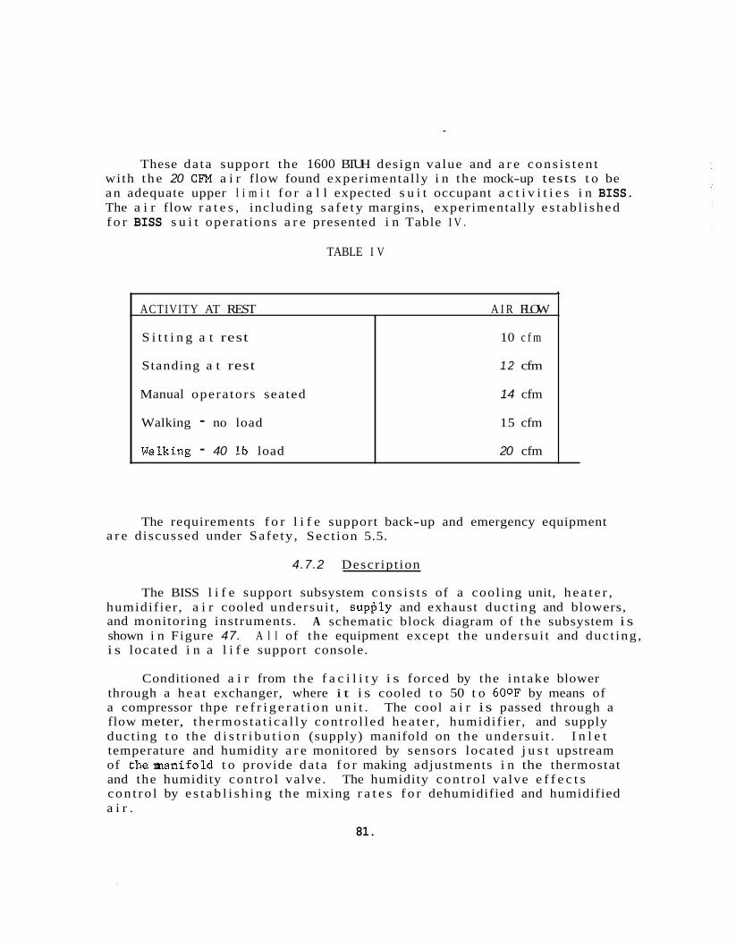
These da ta support the 1600 BTUH design value and a r e cons i s t en t with t he 20 CFM a i r flow found experimental ly i n t he mock-up tests t o be an adequate upper l i m i t f o r a l l expected s u i t occupant a c t i v i t i e s i n BISS. The a i r flow r a t e s , including s a f e t y margins, experimental ly e s t ab l i shed f o r BISS s u i t opera t ions a r e presented i n Table I V .
+
ACTIVITY AT REST A I R FLOW
S i t t i n g a t rest 10 c f m
Standing a t rest 1 2 cfm
Manual opera tors seated 14 cfm
Walking - no load 15 cfm
Walking - 40 l b load 20 cfm
TABLE I V
The requirements f o r l i f e support back-up and emergency equipment a r e discussed under Safe ty , Sec t ion 5.5.
4.7.2 Descript ion
The BISS l i f e support subsystem cons i s t s of a cool ing unit, h e a t e r , humidif ier , a i r cooled undersu i t , supftly and exhaust duc t ing and blowers, and monitoring instruments. shown i n Figure 47. A l l of the equipment except the undersu i t and duc t ing , i s located i n a l i f e support console.
A schematic block diagram of t h e subsystem i s
Conditioned a i r from the f a c i l i t y i s forced by the in take blower through a hea t exchanger, where i t i s cooled t o 50 t o 600F by means of a compressor thpe r e f r i g e r a t i o n u n i t . The cool a i r i s passed through a flow meter, t he rmos ta t i ca l ly cont ro l led hea t e r , humidif ier , and supply duct ing t o the d i s t r i b u t i o n (supply) manifold on the undersu i t . I n l e t temperature and humidity a r e monitored by sensors located j u s t upstream of theman i fo ld t o provide da ta f o r making adjustments i n the thermostat and the humidity con t ro l valve. The humidity con t ro l valve e f f e c t s con t ro l by e s t a b l i s h i n g the mixing r a t e s f o r dehumidified and humidified a i r .
81.
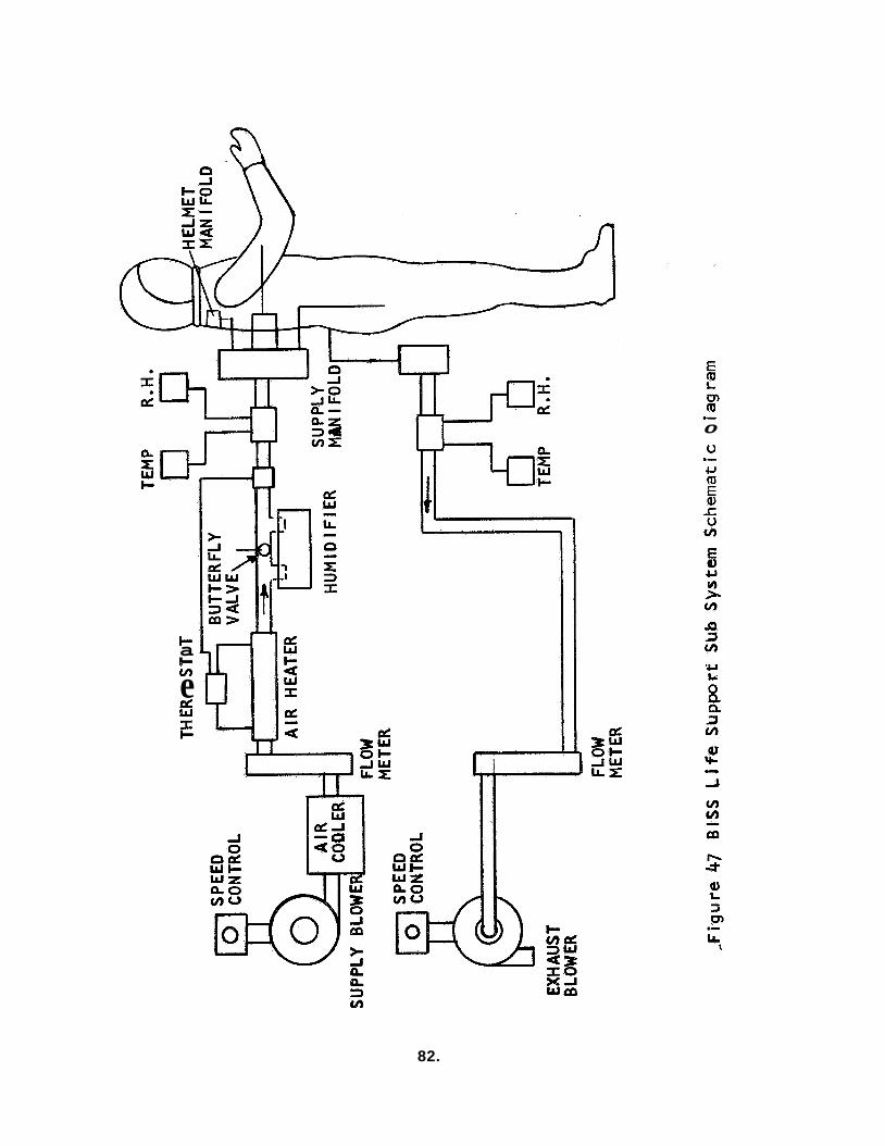
c c v)
a
e 8 I I-
m m .- 0
u .- U
'U L:
82.
Air is distributed from the manifold to the extremities and helmet manifold by means of flexible tubing attached to the life support undersuit. Distributed air is directed into the gloves, boots, and helmet of the outer suit. The gas flow rate is controlled by adjusting the blower speed by means of an autotransformer. flow resistance in the distribution ducting.
Air distribution is controlled by
The supply air to the helmet is directed by the helmet manifold onto the helmet rear inner surface and is then directed down over the operator's face by the helmet configuration. vides a sensation of coolness to the operator, prevents helmet fogging due to expired water vapor, and ensures that supply air will not be diluted by expired air from the operator's lungs. The downward curtain of air also prohibits infringement of noxious by-products of metabolism on the operator's olfactory receptors.
This flow pattern pro-
The air from the extremities is drawn through the open cell foam lining of the undersuit, passing over the body surfaces to the exhaust duct at the rear of the undersuit through which it is carried to a rota- meter, and then to the exhaust blower and vented to atmosphere, The speed of the exhaust blower can be varied by means of an autotransformer to con- trol exhaust flow and suit pressure precisely and to reduce back pressure in the supply lines. Exhaust temperature and relative humidity are monitored .
just downstream of the junction of the exhaust duct and the undersuit to pro- vide data f o r adjustment of supply and exhaust blowers and the humidity control valve.
The selection of the basic subsystem concept is described in the trade-offs discussion which follows. the choice of gas flow meters, temperature indicators, and humidity indi- cators. A number of devices are available for measuring gas flow rates, including Hall effect generators, rotameters, hot wire flowmeters, turbine meters, and pitot tubes. reliability and availability indicate that rotameters are desirable for the pressure and flow rates involved in the BISS life support. temperature monitoring can be accomplished using thermometers, thermis- tors, or thermocouples with remote read-out. Cost factors traded off against reliability and convenience indicate that the thermistors are most desirable. to accomplish. circuit was selected on the basis of sensitivity, availability, and cost.
The inatrument selection required
Trade-offs of cost and complexity versus
Gas
Relative humidity monitoring is somewhat more difficult An electrical resistance type probe mounted as a printed
These instrument selections were biased to some extent by the fact that the life support system had to be realized in hardware for the mock- up test program. program, simplicity and cost of the hardware took precedence over remote read-out and control and extreme accuracy. For example, a rotameter
Consistent with the technical and fiscal scope of the
83.
represen ts an excellent instrument f o r flow rate measurement when l i f e support con t ro l personnel are located w i t h the a i r condi t ioning 2nd con t ro l equipment, bu t would no t be s a t i s f a c t o r y f o r use i n a system where l i f e support con t ro l personnel were located remotely a s may be the case i n a f u l l s c a l e Assembly/Steri l izer.
4.7.3 Design Trade-offs
Trade-off s t ud i e s w e r e performed t o s e l e c t the optimum so lu t ion t o the l i f e support subsystem s u i t temperature and moisture con t ro l design problem. These s tud i e s indicated t h a t the most promising approach i s t o supply breathing and cooling a i r , conditioned by a f a c i l i t y mounted, com- pressor type cooler t o a "semi-closed" l i f e support undersui t separa te from t h e b io- ba r r i e r ou t e r s u i t . The separa te t rade- of fs leading t o t h i s approach a r e presented i n the following subsections.
4.7.3.1 Body Environment Control
I n developing a so lu t i on t o the temperature and moisture con t ro l problem, a t rade-off of t h r ee c l a s se s o f cooling systems was made. The systems which were evaluated were "open" and "closed" systems with a i r a s the cooling medium and a "closed" system with a l i qu id a s the coal ing medium. I n t he closed system, a membrane is interposed between the cool- ing medium and the wearer ' s body. brane was t o be semipermeable and no t suscept ib le t o blockage caused by overpressure compression, thereby allowing the passage of moisture through i t . The membrane f o r the l i qu id cooled s u i t was t o be imper- meable t o the l i qu id . i s provided i n Table V.
For the a i r- cooled system, t h i s mem-
A t rade- of f comparison of these th ree bas ic systems
Based on the comparison of the t h r ee systems, i t was concluded t h a t conditioned a i r was the bes t cooling f l u i d pr imar i ly because of i t s super ior moisture con t ro l p rope r t i e s and the r e l a t i v e s imp l i c i t y of r e l a t e d hardware development. A f u r t h e r conclusion was t o compromise with regard t o the "open" o r "closed" a i r system. The compromise was t o use a permeable membrane t o promote a i r flow under the overpressure environment, but not t o completely s e a l the undersui t o f f a s would be the case i n a t r u l y "closed" system.
Openings were located a t the wrists, ankles and neck of the under- s u i t , which se rve a s e n t r y po r t s f o r input a i r which i s pul led through the s u i t ' s continuous membrane and exhausted from a plenum worn a t the opera tor ' s wais t . Input a i r i s supplied t o the ex t r emi t i e s by means of separa te duct ing located on the e x t e r i o r of the undersui t . decided t h a t the r ead i ly- ava i l ab l e water cooled s u i t of B. Welson, Inc . should be empi r ica l ly compared with the air- cooled s u i t developed by General E l e c t r i c Company.
It was f u r t h e r
a4.
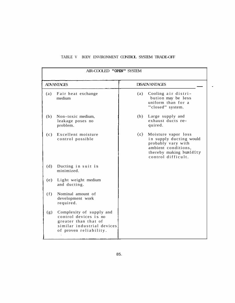
TABLE V BODY ENVIRONMENT CONTROL SYSTEM TRADE-OFF
AIR-COOLED "OPEN" SYSTEM
ADVANTAGES
(a) F a i r hea t exchange medium
(b) Non-toxic medium, leakage poses no problem.
(c) Excel len t moisture con t ro l poss ib le
(d) Ducting i n s u i t i s minimized.
(e) Light weight medium and duct ing.
( f ) Nominal amount of development work required.
(g) Complexity of supply and con t ro l devices i s no g r e a t e r than t h a t of s imi l a r i n d u s t r i a l devices o f proven r e l i a b i l i t y .
- - DISADVANTAGES
(a) Cooling a i r d i s t r i - but ion may be less
uniform than f o r a "closed" system.
(b) Large supply and exhaust duc ts re- quired.
(e) Moisture vapor loss i n supply duc t ing would probably vary with ambient condi t ions , thereby making humidity con t ro l d i f f i c u l t .
85.
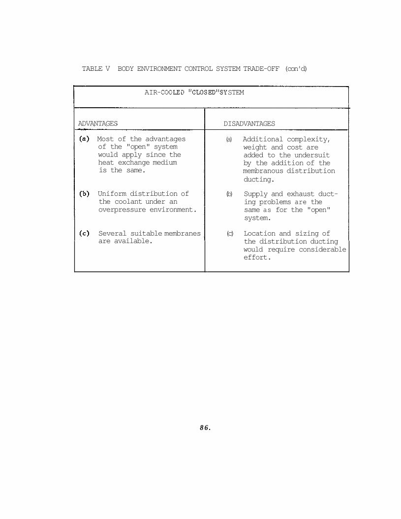
TABLE V BODY ENVIRONMENT CONTROL SYSTEM TRADE-OFF (con'd)
AIR- COOIXD "CLOS ED"SY STEM
ADVANTAGES
Most of the advantages of the "open" system would apply since the heat exchange medium is the same.
Uniform distribution of the coolant under an overpressure environment.
Several suitable membranes are available.
DISADVANTAGES
(a) Additional complexity, weight and cost are added to the undersuit by the addition of the membranous distribution ducting.
(b) Supply and exhaust duct- ing problems are the same as for the "open" system.
(c) Location and sizing of the distribution ducting would require considerable effort.
8 6 .
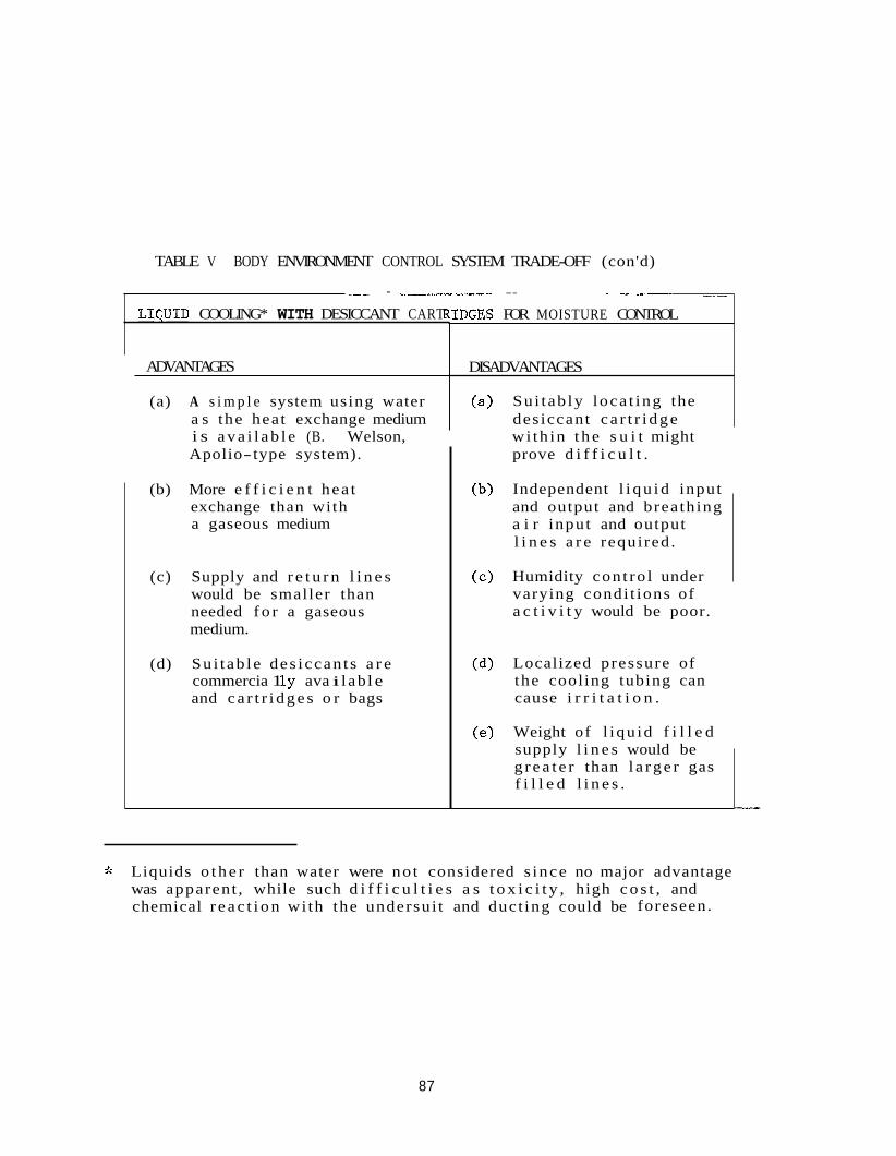
TABLE V BODY ENVIRONMENT CONTROL SYSTEM TRADE-OFF (con'd)
.. _. _.I_ L_._ - -_--c.__ ---- -- -- . ..
L I C U I D COOLING* WITH DESICCANT CART
ADVANTAGES
(a) A s i m p l e system using water a s the heat exchange medium i s a v a i l a b l e (B. Welson, Apolio-type system).
(b) More e f f i c i e n t hea t exchange than with a gaseous medium
(c) Supply and r e t u r n l i n e s would be smaller than needed f o r a gaseous medium.
(d) Su i t ab le des iccan t s a r e commercia 1 l y ava i l ab l e and c a r t r i d g e s o r bags
:DGES FOR MOISTURE CONTROL
DISADVANTAGES
Su i tab ly loca t ing the des iccant c a r t r i d g e wi th in t h e s u i t might prove d i f f i c u l t .
Independent l i q u i d input and output and breathing a i r input and output l i n e s a r e required .
Humidity con t ro l under varying condi t ions of a c t i v i t y would be poor.
Localized pressure of the cooling tubing can cause i r r i t a t i o n .
Weight of l iqu id f i l l e d supply l i n e s would be g r e a t e r than l a r g e r gas f i l l e d l i n e s .
$k Liquids o t h e r than water were no t considered s ince no major advantage was apparent , while such d i f f i c u l t i e s a s t o x i c i t y , high c o s t , and chemical r e a c t i o n wi th the undersui t and duct ing could be foreseen.
87
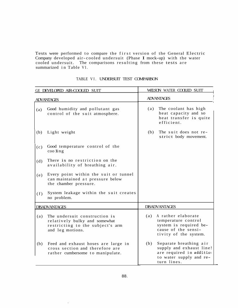
Tests were performed t o compare the f i r s t vers ion of the General Electr ic Company developed air- cooled undersu i t (Phase I mock-up) with the water cooled undersu i t . summarized i n Table V I .
The comparisons r e s u l t i n g from these tests a r e
TABLE V I . UNDERSUIT TEST COMPARISON
GE DEVELOPED AIR-COOLED SUIT
ADVANTAGES
(a) Good humidity and po l lu t an t gas con t ro l o f t he s u i t atmosphere.
(b) Light weight
(c) Good temperature con t ro l of t he coo 1 ing
There is no r e s t r i c t i o n on the a v a i l a b i l i t y of breathing a i r .
Every poin t wi th in the s u i t o r tunnel can maintained a t p ressure below the chamber pressure.
System leakage wi th in the s u i t c r e a t e s no problem.
(d)
(e)
( f )
DISADVANTAGES
(a) The undersu i t cons t ruc t ion i s r e l a t i v e l y bulky and somewhat r e s t r i c t i n g t o the s u b j e c t ' s arm and l eg motions.
(b) Feed and exhaust hoses a r e la rge i n c ros s s e c t i o n and the re fo re a r e r a t h e r cumbersome t o manipulate.
WELSON WATER COOLED SUIT i i
ADVANTAGES I I
(a ) The coolant has high hea t capac i ty and so hea t t r a n s f e r i s q u i t e e f f i c i e n t .
(b) The s u i t does not re- s t r ic t body movement.
DISADVANTAGES
(a) A r a t h e r e l abora t e temperature con t ro l system i s required be- cause of the sens i- t i v i t y o f the system.
(b) Separate breathing a i r supply and exhaust l i ne ! a r e required i n addi t io i t o water supply and re- tu rn l i n e s .
88.
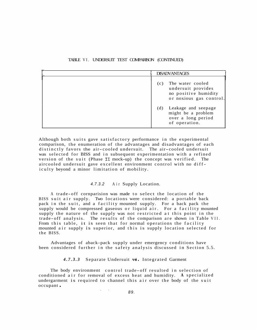
TABLE V I . UNDERSUIT TEST COMPARISON (CONTINUED)
f DISADVANTAGES I
(c) The water cooled undersui t provides no p o s i t i v e humidity o r noxious gas con t ro l .
(d) Leakage and seepage might be a problem over a long per iod of opera t ion .
Although both s u i t s gave s a t i s f a c t o r y performance i n the experimental comparison, t h e enumeration of t h e advantages and disadvantages of each d i s t i n c t l y favors the a i r- cooled undersui t . The air- cooled undersui t was se lec ted f o r BISS and i n subsequent experimentation wi th a r e f ined ve r s ion of the s u i t (Phase I1 mock-up) the concept was v e r i f i e d . The a i rcooled undersui t gave exce l l en t environment c o n t r o l with no d i f f - i c u l t y beyond a minor l i m i t a t i o n of mobi l i ty .
4.7.3.2 A i r Supply Location.
A t rade-off cornparision was made t o select the loca t ion of the BISS s u i t a i r supply. Two loca t ions were considered: a por tab le back pack i n the s u i t , and a f a c i l i t y mounted supply. For a back pack the supply would be compressed gaseous o r l i q u i d a i r . supply t h e nature of the supply was no t r e s t r i c t e d a t t h i s point i n t h e trade-off ana lys i s . From t h i s t a b l e , i t i s seen t h a t f o r normal opera t ions the f a c i l i t y mounted a i r supply i s super ior , and t h i s i s supply loca t ion se lec ted f o r the BISS.
For a f a c i l i t y mounted
The r e s u l t s of t h e comparison a r e shown i n Table V I I .
Advantages of aback-pack supply under emergency condi t ions have been considered f u r t h e r i n the s a f e t y a n a l y s i s discussed i n Sec t ion 5.5.
4 . 7 . 3 . 3 Separa te Undersuit tis. In tegra ted Garment
The body environment c o n t r o l t rade- off r e s u l t e d i n s e l e c t i o n of conditioned a i r f o r removal of excess hea t and humidity. undergarment i s required t o channel t h i s a i r over t h e body of the s u i t occupant .
A spec ia l i zed
. . 89 .
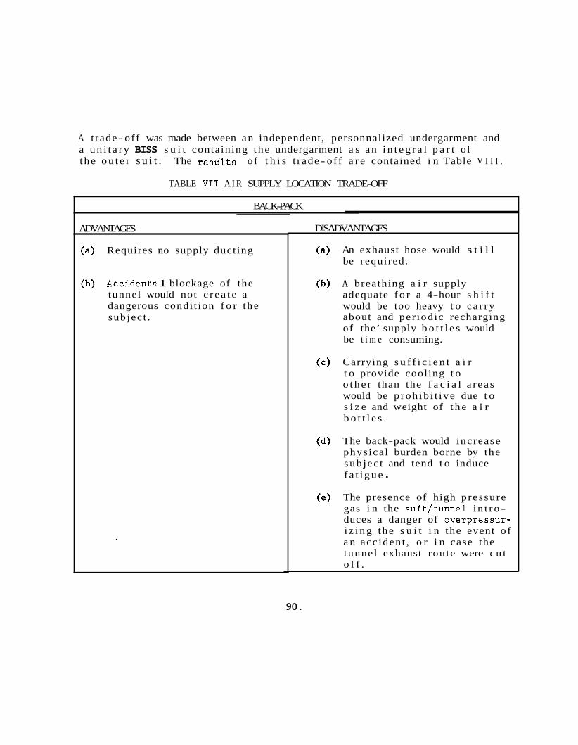
A t rade-off was made between an independent, personnalized undergarment and a u n i t a r y BISS s u i t containing the undergarment a s an i n t e g r a l p a r t of t he o u t e r s u i t . The results of t h i s t rade- off a r e contained i n Table V I I I .
TABLE V I 1 A I R SUPPLY LOCATION TRADE-OFF
BACK-PACK _.
ADVANTAGES
Requires no supply duct ing
Accidenta 1 blockage of the tunnel would not c r e a t e a dangerous condit ion f o r the subjec t .
DISADVANTAGES
An exhaust hose would s t i l l be required.
A breathing a i r supply adequate f o r a 4-hour s h i f t would be too heavy t o ca r ry about and per iodic recharging of the’ supply b o t t l e s would be t i m e consuming.
Carrying s u f f i c i e n t a i r t o provide cool ing t o o t h e r than the f a c i a l a r eas would be p roh ib i t i ve due t o s i z e and weight of t h e a i r b o t t l e s .
The back-pack would increase phys ica l burden borne by the sub jec t and tend t o induce f a t i g u e . The presence of high pressure gas i n the s u i t / t u n n e l i n t r o - duces a danger of overpressur- i z i n g the s u i t i n the event o f a n acc ident , o r i n case the tunnel exhaust rou te were c u t o f f .
90.
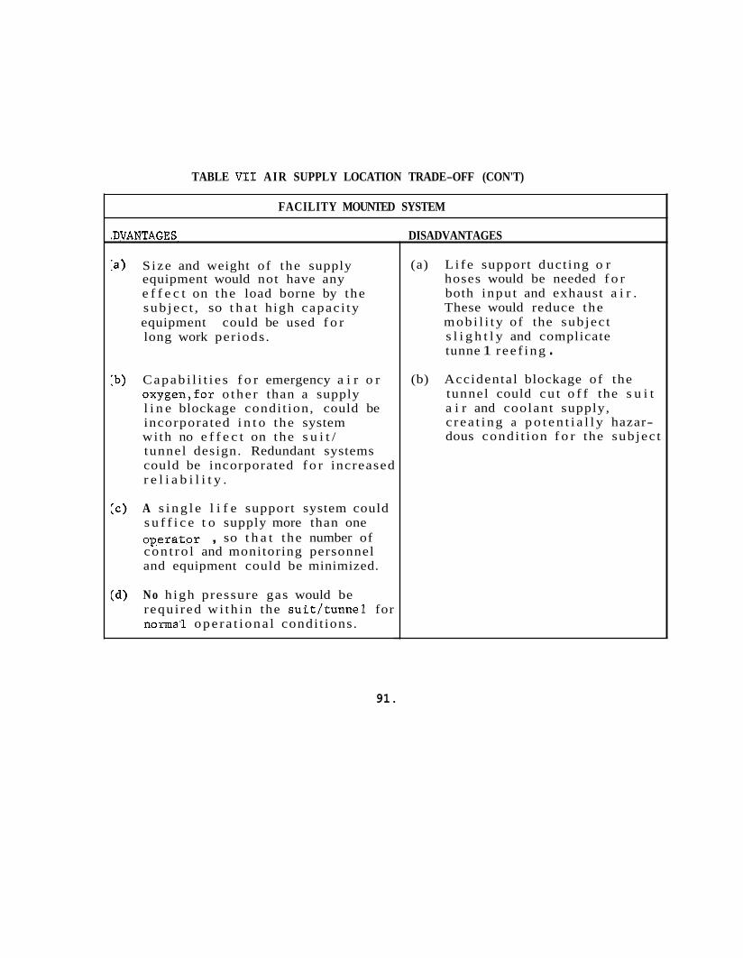
TABLE V I 1 AIR SUPPLY LOCATION TRADE-OFF (CON'T)
FACILITY MOUNTED SYSTEM
LDVANTAGES. DISADVANTAGES
Size and weight of the supply equipment would not have any e f f e c t on the load borne by the sub jec t , so t h a t high capac i ty equipment could be used f o r long work periods.
Capab i l i t i e s f o r emergency a i r o r oxygen,for o the r than a supply l i n e blockage condit ion, could be incorporated i n t o the system with no e f f e c t on the s u i t / tunnel design. Redundant systems could be incorporated f o r increased r e l i a b i l i t y .
A s i n g l e l i f e support system could s u f f i c e t o supply more than one opera tor , so t h a t the number of con t ro l and monitoring personnel and equipment could be minimized.
No high pressure gas would be requi red wi th in the s u i t / t u n n e l for normal ope ra t iona l condi t ions.
(a) L i f e support duct ing o r hoses would be needed f o r both input and exhaust a i r . These would reduce the mob i l i t y of the subjec t s l i g h t l y and complicate tunne 1 ree f ing .
(b) Accidental blockage of the tunnel could cu t o f f the s u i t a i r and coolant supply, c r ea t ing a p o t e n t i a l l y hazar- dous condi t ion f o r the subjec t
91.
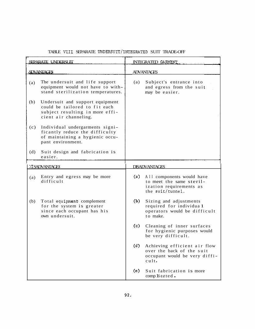
TABLE V I 1 1 SEPARATE UNDERSUIT/INTEGRATED SUIT TRADE-OFF
SEPARATE UNDERSUIT
SDVANTAGES
(a) The undersu i t and l i f e support equipment would not have t o with- stand s t e r i l i z a t i o n temperatures.
(b) Undersuit and support equipment could be t a i l o r e d t o f i t each sub jec t r e s u l t i n g i n more e f f i - c i e n t a i r channeling.
(c) Indiv idual undergarments s ign i- f i c a n t l y reduce the d i f f i c u l t y of maintaining a hygienic occu- pant environment.
(d) S u i t design and f a b r i c a t i o n i s e a s i e r .
11 SADVANTAGE S
(a) Entry and egress may be more d i f f i c u l t
(b) To ta l equipmenh complement f o r the system i s g r e a t e r s ince each occupant has h i s own undersu i t .
INTEGRATED GARMENT-
ADVANTAGES
(a) Subjec t ' s entrance i n t o and egress from the s u i t may be e a s i e r .
DISADVANTAGES
A l l components would have t o meet t he same s ter i l- i z a t i o n requirements a s the s u i t / t u n n e l .
S iz ing and adjustments required f o r individua 1 opera tors would be d i f f i c u l t t o make.
Cleaning of inner su r f aces f o r hygienic purposes would be very d i f f i c u l t .
Achieving e f f i c i e n t a i r flow over the back of the s u i t occupant would be very d i f f i - c u l t
S u i t f a b r i c a t i o n i s more comp 1 i ca t ed .
92.
The t rade- of f comparison very c l e a r l y favors the use of a separa te undersu i t . Subsequent experimentation has shown t h a t the separa te undersui t provides conditioned a i r r e s u l t s i n a comfortable environment f o r the occupant.
good a i r channeling which i n conjunction with proper ly
4.7.3.4 Cool A i r Source
Two bas i c types of equipment were inves t iga ted f o r t h e i r applicad b i l i t y f o r cooling the a i r f o r breathing and body environment con t ro l f o r the BISS occupant. These equipmentswere a conventional compressor r e f r i g e r a t i o n , p l an t and a vortex' tCtbeJc hea t exchanger {ENCON Mfg. Co, , Houston , Tex . )
The two cool a i r sources w e r e evaluated experimentally. The r e s L l t s of the eva lua t ion a r e presented i n t a b l e I X . The compressor a i r con- d i t i o n e r was se lec ted because of l a rge capaci ty , s i l e n t opera t ion , ease of con t ro l , and the f a c t t h a t no p r i o r a i r processing i s required. The vortex tube must be suppl ied by a man-rated a i r compressor.
* This device, a l s o known a s a Hilsh tube, provides simultaneous hot and cold a i r ou tpu ts when supplied with high ambient a i r , r equ i r e s no power o the r than the a i r supply, and has no moving p a r t s .
9 3 .
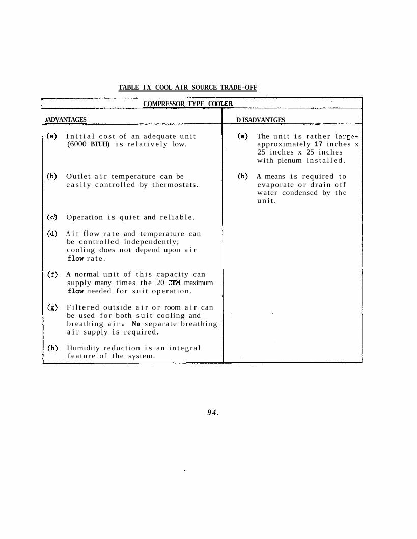
TABLE I X COOL AIR SOURCE TRADE-OFF
COMPRESSOR TYPE COO
ADVANTAGES
I n i t i a l c o s t of an adequate u n i t (6000 BTUH) i s r e l a t i v e l y low.
Out le t a i r temperature can be e a s i l y cont ro l led by thermostats.
Operation i s qu ie t and r e l i a b l e .
A i r flow r a t e and temperature can be cont ro l led independently; cooling does not depend upon a i r flow r a t e .
A normal u n i t of t h i s capaci ty can supply many times the 20 CFM maximum flow needed fo r s u i t opera t ion .
F i l t e r e d ou ts ide a i r o r room a i r can be used f o r both s u i t cooling and breathing a i r . No separa te breathing a i r supply i s required.
Humidity reduct ion i s an i n t e g r a l f ea tu re of the system.
D I SADVANTGE S
The u n i t i s r a t h e r large- approximately 17 inches x 25 inches x 25 inches with plenum i n s t a l l e d .
A means i s required t o evaporate o r d r a i n o f f water condensed by the u n i t .
9 4 .
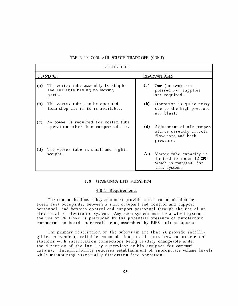
TABLE I X COOL A I R SOURCE TRADE-OFF (CON'T)
VORTEX TUBE
LDVANTAGES
(a) The vor tex tube assembly i s simple and r e l i a b l e having no moving p a r t s .
(b) The vor tex tube can be operated from shop a i r i f i t i s ava i l ab l e .
(c) No power i s required f o r vor tex tube opera t ion o t h e r than compressed a i r .
(d) The vor tex tube i s small and l i g h t - weight.
DISADVANTAGES
One (or two) com- pressed a i r suppl ies a r e required.
Operation i s q u i t e noisy due t o the high pressure a i r b l a s t .
Adjustment of a i r temper. a t u r e s d i r e c t l y a f f e c t s flow r a t e and back pressure .
Vortex tube capac i ty i s l imi ted t o about 12 CFM which i s marginal f o r t h i s system.
4 . 8 COMMUNICATIONS SUBSYSTEM
4.8.1 Requirements
The communications subsystem must provide a u r a l communication be- tween s u i t occupants, between a s u i t occupant and con t ro l and support personnel, and between con t ro l and support personnel through the use of an e l e c t r i c a l o r e l e c t r o n i c system. Any such system must be a wired system - the use of RF l i n k s i s precluded by the p o t e n t i a l presence of pyrotechnic components on-board spacecraf t being assembled by BISS s u i t occupants.
The primary r e s t r i c t i o n on the subsystem a r e t h a t i t provide i n t e l l i - g i b l e , convenient, r e l i a b l e communication a t a l l t i m e s between prese lec ted s t a t i o n s with i n t e r s t a t i o n connections being r e a d i l y changeable under the d i r e c t i o n of the f a c i l i t y supervisor o r h i s designee f o r communi- ca t ions . while maintaining e s s e n t i a l l y d i s t o r t i o n f r e e opera t ion .
I n t e l l i g i b i l i t y r equ i r e s establ ishment of appropr ia te volume levels
95.
Convenience r equ i r e s a t a lk- a t- wi l l c a p a b i l i t y over e s t ab l i shed l inks . R e l i a b i l i t y r equ i r e s the s i m p l e s t system cons i s t en t wi th opera t iona l requirements, employing w e l l proven techniques and equipment.
In a f u l l s c a l e assembly s t e r i l i z e r it i s estimated t h a t upwards of 30 personnel w i l l be involved with the opera t ion , supervis ion, and d i r e c t support of t he assembly s t e r i l i z e r main chamber. Desired communications pa t t e rns between these personnel w i l l be cont inua l ly varying a s work progresses i n the f a c i l i t y . The general requirements f o r the communications system have been in t e rp re t ed a s design cons t r a in t s i n the communications subsystem s p e c i f i c a t i o n S1050-02-0001 i n Appendix M. I n add i t i on t o the performance spec i f i ca t i ons , s eve ra l network design recommendations have been formulated. These a r e l i s t e d below.
Any s u i t occupant s h a l l be ab l e t o communicate with any o the r occupant when necessary. Where there a r e t h r ee o r less s u i t occupants, they s h a l l be interconnected on a connnon talk-at-will net. When the re a r e more than th r ee men i n the chamber, they s h a l l be interconnected on two o r more n e t s a s work assignments i nd i ca t e . ou t s ide the chamber w i l l normally be assoc ia ted with each n e t . The c a p a b i l i t y s h a l l be provided t o connect a l l s u i t occupants on a common n e t when coordinated e f f o r t of the e n t i r e team i s required.
A work supervisor
There s h a l l be a l i f e support communicator and medical monitor assoc ia ted wi th each s u i t occupant n e t . These personnel w i l l normally have only a l i s t e n c a p a b i l i t y on the n e t and w i l l r e l a y information t o the occupants through the assoc ia ted work supervisor . The work sup- perv isor s h a l l be a b l e t o connect these personnel t o the ne t Cor two way communications whenever he deems it advisable . (Note t h a t t o permit e f f i c i e n t opera t ions the l i f e support communicators and medical monitors must be ab l e t o t r a n s f e r con t ro l and observat ion of s u i t occupants t o t h e i r counterpar ts f o r o the r ne t s a s n e t assignments change - the a d v i s a b i l i t y of t h i s break i n cont inu i ty r equ i r e s fu r the r s tudy) .
L is ten only s t a t i o n s s h a l l be provided f o r v i s i t o r s and s h a l l permit switching to a l l cu r r en t ly operat ing n e t s .
A communications supervisor s h a l l oversee the opera t ion of the communications system. He s h a l l be d i r e c t l y responsible t o the operat ions supervisor of t h e f a c i l i t y and s h a l l have complete over- r i d ing con t ro l over a l l communications system operat ion.
96.
4 .8 .2 Design Trade-offs
Ana ly t i ca l comparisons were made i n two a r e a s t o support the develop- ment of the communications concept. A summary of the r e s u l t s of these analyses follows.
4.8.2 .1 BISS Operator ' s Communications Transducer Se lec t ion
The transducer conf igura t ions considered f o r use i n the BISS were:
(a) Headset and t h r o a t microphone
(b) Headset and boom microphone
(c) Single suit-mounted speaker/microphone
(d) Separate suit-mounted speaker and microphone
Approaches (c) and (d) appeared t o have the most promise i n view of the p o t e n t i a l impediment t o s u i t e n t r y and e x i t posed by head mounted transducers. Phase I mock-up experience ru led out (c) because switching i s required and a s i n g l e volume s e t t i n g must be used f o r t ransmit and receive a t both ends of the l ink . It became apparent t h a t no s i n g l e s e t t i n g could be found which was s a t i s f a c t o r y f o r both the BISS opera tor and the tes t conductor. Therefore, t h e concept employed on the present program was a l t e r n a t i v e (d) fo r a sepa ra te , suit-mounted microphone and speaker.
4 .8 .2 .2 BISS Operator ' s Method of Actuating the Communications System
The following a l t e r n a t i v e s were considered:
(a) Push- to- t a lk
(b) Voice-actuated turn-on
(c) Talk when no t r ece iv ing (outs ide switching required)
(d) Talk- at w i l l
A l t e rna t ives (c) and (d) emerged from the a n a l y s i s a s having the g r e a t e s t m e r i t . The r e l a t i v e economy and s i m p l i c i t y o f (c) d i c t a t e d t h a t i t be t r i e d f i r s t . The requirement f o r any switching on the p a r t of e i t h e r the tes t conductor o r the s u i t e d opera tor was found undesi rable , and voice ac tuated switching r e s u l t s i n c l ipp ing of messages and abnormal speech pa t terns.
Fur ther , open l i nks i n both d i r e c t i o n s permit i n s t a n t a l e r t i n g i n e i t h e r d i r e c t i o n i f a hazardous condi t ion should a r i s e . Therefore, a l t e r n a t i v e (d) ( t a lk- a t- wi l l ) i s incorporated i n the concept.
4 . 8 . 3 Descript ion
Def in i t i on of an optimum communications system f o r the f u l l s c a l e Assembly/Ster i l izer must be predicated on a d e t a i l e d work flow descrip- t i o n and t a sk ana lys i s of the f a c i l i t y operation." The system designed on the present program was d i r ec t ed pr imar i ly towards use i n the mock-up o r s imi l a r f a c i l i t i e s , with cons idera t ion of extension t o a f u l l s c a l e f a c i l i t y .
The communications system i s a t a l k - a t - w i l l network between the seve ra l BISS s t a t i o n s . The network a s implemented i n the mock-up test f a c i l i t y i s shown i n Figure 4 8 . A recommended extension of t h i s network i s described i n the communications subsystem s p e c i f i c a t i o n ,50150-02-0001 i n Appendix M. The bas ic concept o f the system i s s i m i l a r t o t h a t of a PBX telephone system with add i t i ona l provision f o r monitoring of l i n e s by se l ec t ed personnel who a r e unable t o speak t o both p a r t i e s on the l i n e . This f e a t u r e was incorporated t o minimize the number of speakers t a lk ing t o the s u i t occupant so t h a t he would rece ive i n s t r u c t i o n s from only one source, t he t e s t d i r e c t o r . ampl i f i e r t o assure adequate audio-power f o r a l l condi t ions and t o permit f l e x i b i l i t y i n adjustment of s i g n a l l eve l s . The t ransducers used i n a l l loca t ions a r e conventional devices used i n a conventional manner except f o r the chamber horn and the t ransducers i n the BISS s u i t .
Each microphone and speaker has an independent
The t ransducers i n the s u i t cons i s t of a small speaker and micro- phone located on the upper ches t of the undersu i t . This loca t ion shown i n Figure 13, was found t o provide adequate communications and provide two advantages: a boom, l i p , o r t h r o a t microphone; and mounting t h e t ransducers on the undersu i t r a t h e r than the ou te r s u i t o r helmet means t h a t they a r e e a s i l y serviced and do not have t o be a b l e t o withstand the severe environment o f the s t e r i l i z a t i o n cycle .
the s u i t occupant was not encumbered by headsets and
The chamber horn used on the present con t r ac t was a standard commer- c i a l u n i t . However, t h i s u n i t remains i n the chamber a t a l l t i m e s and
* F u l l d e f i n i t i o n of a communications system without t h i s da ta would r e s u l t i n the communications system imposing r e s t r i c t i o n s on the work flow and personnel r e l a t ionsh ips r a t h e r than being designed t o optimize the e f f i c i e n c y 0-f t he Assembly/Ster i l izer system operat ion.
98.
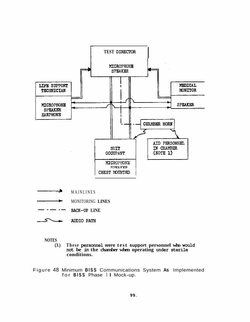
I [ TEST DIRECTOR
MICROPHONE
CHEST ROUEJTED
M A I N L I N E S
MONITORING LINES
--- -- BACK-UP LINE
c\ AUDIO PATH
NOTES (3.) T h e s e personnel were t e s t support personnel who would
not be in the chamber when operating under sterile conditions.
Figure 48 Minimum B l S S Communications System As Implemented f o r B l S S Phase I I Mock-up.
99.
would have t o be redesigned t o withstand decontamination and s t e r i l i z a t i o n f o r use i n a n opera t ing Assembly/Ster i l izer .
Experience with t h i s system i n the mock-up program indica ted t h a t there was room f o r improvement. Two d e f i c i e n c i e s i n the system were noted: ga ins could not be increased t o the des i red levels without causing feedback, and gains were not w e l l matched when s i g n a l s from s e v e r a l persons were feeding a s i n g l e speaker. The g a i n increase can be accomo- dated by a change i n t ransducers and t h e s i g n a l l e v e l matching can be accomodated by a more f l e x i b l e system.
131 t h e system described above most s t a t i o n s used speakers a s receiv- ing t ransducers i n a high ambient noise l eve l . They a l s o employed micro- phones, permit t ing two way t a l k- a t - w i l l t ransmission. A s a r e s u l t , when loop gains were ad jus ted s u f f i c i e n t l y high t o g ive good communications i n the high noise environment, a c o u s t i c feedback caused o s c i l l a t i o n i n the n e t , and gains had t o be reduced t o a less than optimum leve l . This problem w i l l be mi t igated somewhat i n a prime system by the f a c t t h a t the major i ty of personnel can be expected t o be working i n a reas with much lower noise levels than experienced i n the mock-up tes t f a c i l i t y and can be e l iminated by i s o l a t i o n of the receiving and t r ansmi t t ing t r ans- ducers a t each s t a t i o n .
I s o l a t i o n of t ransducers can be achieved phys ica l ly , a c o u s t i c a l l y , o r e l e c t r i c a l l y . The most e f f i c i e n t physica l i s o l a t i o n r e s u l t s from the use of earphones and microphones. This a l s o g r e a t l y reduces the e f f e c t i v e noise l e v e l f o r recept ion. Acoustic i s o l a t i o n can be achieved by us ing highly d i r e c t i o n a l microphones and speakers. This r equ i res e i t h e r t h a t each communicator keep h i s head r e l a t i v e l y s t a t i o n a r y o r t h a t the t r a n s - ducers move wi th h i s head. The former being undesi rable and the l a t t e r leading towards in tegra ted head sets with earphone and microphones. E l e c t r i c a l i s o l a t i o n i s achieved by a push- to- talk f e a t u r e which d i s a b l e s recept ion during transmission. This i s undesi rable because of the inconven- ience and the d i s r u p t i o n of normal speech p a t t e r n s . Thus it appears t h a t in tegra ted headsets f o r each communicator should be given se r ious f u r t h e r considera t ion .
I n t h e t rade- off s tudy f o r t ransducers f o r the s u i t o f the occupant, the in tegra ted head se t was f e l t t o be less d e s i r a b l e than independent ches t mounted t ransducers . This conclusion should be reevaluated. I n p a r t i c u l a r , human f a c t o r s experimentat ion should be performed t o d e t e r & mine the degree of d i f f i c u l t y of s u i t e n t r y and egress r e s u l t i n g from wearing a c lose f i t t i n g headset with earphones and a boom microphone, and t h e s u i t occupant discomfort r e s u l t i n g from extended wearing of the headset .
100.
The problem of ga in matching i s common t o a l l mul t i- s ta t ion phone type networks. This problem i s normally solved by employing s i g n a l mixers a t each receiving s t a t i o n so t h a t the l e v e l of each incoming s i g n a l can be adjus ted t o give a r e l a t i v e l y uniform sound l e v e l from the speaker? o r earphones, r ega rd less of the s i g n a l source. These adjustments a r e done on a pe r iod ic bas i s a t each s t a t i o n by a communications technic ian o r supervisor . Because a l l t he s t a t i o n s i n the Assembly/Ster i l izer com- munication subsystem w i l l be located i n a s i n g l e bui ld ing o r small complex of bui ld ings? a l l amplif ier/mixers should be located i n a s i n g l e loca t ion f o r ease of system set-up; and tone genera tors would be used t o provide gain balancing s i g n a l s . This i s standard communications p r a c t i c e . A receiving ampl i f i e r would be located a t each s t a t i o n with a gain c o n t r o l which would p e r m i t adjustment of the combined s i g n a l t o a comfortable l e v e l f o r the l o c a l communicator ( the communicator would have no c o n t r o l over the gain of h i s microphone ampl i f i e r which would a l s o be located l o c a l l y ) .
The only o the r communications problem f o r the BISS and Assembly/ S t e r i l i z e r system i s t h a t caused by frequent changes i n in terconnect ions and number of s t a t i o n s on m u l t i - s t a t i o n networks. Changes i n connections r e s u l t i n changes i n impedance matching and loading which i n t u r n change loop gains . This phenomenon i s experienced i n telephone systems when more than two p a r t i e s a r e i n the network (e.g. pa r ty l i n e s , extens ions , o r conference c a l l s ) . There a r e severa l ways of minimizing o r e l imina t ing t h i s problem. One such technique i s t o load each ampl i f i e r input o r out- put with mul t ip le dummy loads equivalent t o the loads t h a t would be imposed by the maximum number of input and output connections. When an input o r output i s connected, the respec t ive dummy load i s removed. This main- t a i n s constant loading regard less of the number of connections from none up t o the maximum permiss ib le . A s i m i l a r though somewhat less e f f e c t i v e r e s u l t can be achieved by us ing T pads i n a l l input and output l i n e s on ampl i f i e r s .
4 .9 MEDICAL MONITORING
The BISS places the s u i t occupant i n a uniaue and p o t e n t i a l l y s t r e s s f u l environment. It was determined t h a t i t would be advisable t o provide some means of r e a l t i m e monitoring of the physiological response of the occupant t o t h i s environment, i n a d d i t i o n t o c a r e f u l medical s e l e c t i o n and pe r iod ic medical examinations. The s i n g l e equipment which provides the g r e a t e s t information and l e a s t inconvenience t o the worker i s an electrocardiogram (EKG).
An EKG monitors the h e a r t performance and thus ind ica tes the phs io log ica l response of the s u i t occupant t o t h e phys ica l and non-physical stresses of the environment. Also, changes o r abnormal i t ies i n the EKG record can i n d i c a t e the onset o f pathological condi t ions wi th in a shor t t i m e a f t e r t h e i r occurence so t h a t appropr ia te s a f e t y procedures can be
101.
i n s t i t u t e d with the l e a s t poss ib le delay.
This degree of medical monitoring i s usua l ly on ly experienced i n a laboratory s i t u a t i o n , i n treatment of p a t i e n t s with suspected card iac abnormali t ies , o r i n medical examinations. t i v e runs counter t o t h i s degree of medical monitoring. An exce l l en t example i s the "IN-FAB" f a c i l i t y operated by t h e Universa 1-Cyclops S t e e l Corporation a t Br idgevi l le , Pa . This f a c i l i t y i s an i n e r t atmosphere r o l l i n g m i l l f o r s p e c i a l i t y steel. labor f o r a four hour s h i f t i n a " f r ee s u i t" i n an argon atmosphere and a r e connected t o ex t e rna l l i f e support equipment by hoses, r e s u l t i n g i n an environment simular t o BISS. No medical measurements a r e made on a rou t ine bas i s which these workers a r e on the job.
Most i n d u s t r i a l medical prac-
The workers a r e employed a t hard
Universal-Cyclops has experienced no d i f f i c u l t i e s because of the lack of medicalmoni tor ing. 6
Medical monitoring was employed during the mock-up t e s t i n g on the present program a s discussed i n Sect ion 4 . 9 . The EKG records from t h i s monitoring showed some unexpected responses to the environment. d iscussions with an expert c a rd io log i s t experienced i n medical monitoring of personnel i n unusual environments indicated t h a t responses of the type observed a r e not a t y p i c a l and t h a t they do not appear t o represen t cause f o r concern about the h e a l t h of the s u i t occupants o r the e f f e c t s of the environment on t h e i r hea l th . This sub jec t i s discussed i n more d e t a i l i n Appendix C .
Subsequent
The experience of Universa 1-Cyclops i n the opera t i o n of "IN-FAB'f and proper i n t e r p r e t a t i o n of GE's experience with the mock-up suggest t h a t continued medical monitoring on fu tu re programs employing BISS i s not e s s e n t i a l . However, i t is f e l t t h a t t he p r a c t i c e of monitoring with an FXG should be continued u n t i l a more complete h i s t o r y of physiological response t o the environment i s ava i l ab l e on a wider range of personnel. The information thus obtained i s derived a t r e l a t i v e l y small cos t and o f f e r s s eve ra l p o t e n t i a l bene f i t s : (1) it promises t o be he lp fu l i n s e l ec t i ng personnel, (2) i t may cont r ibu te t o f u r t h e r i nves t i ga t i on of optimum work s h i f t dura t ion , and (3) t he data i t s e l f i s of considerable s c i e n t i f i c i n t e r e s t i n t h a t i t augments the r e l a t i v e l y l imited i n fo r - mation on card iac response t o unusual environments. Thus, i t i s recomb ended t h a t EKG recording be continued i n fu tu re BISS opera t ions u n t i l d e f i n i t e , p red ic tab le pa t t e rns of EKG's a r e developed on a s u f f i c i e n t l y wide base t o i nd i ca t e c l e a r l y t h a t medical monitoring is not needed f o r personnel p ro t ec t i on and thert f u r the r monitoring would be of l i t t l e s c i e n t i f i c value.
* Personal connnunication between D r . W.S. Kip of General E l e c t r i c Company and Mr.C.P. Mueller of Universal Cyclops
102.
On t h e present program EKG's were taken using a Telemedics radio- cardiogram feeding a GE EKG recorder. The r e s u l t was a s i n g l e channel EKG record d i s t o r t e d by s i g n i f i c a n t amounts of e l e c t r i c a l in te r fe rence . I n add i t ion t o the adverse e f f e c t s of the e l e c t r i c a l in te r fe rence , the s i n g l e channel nature of the system made some of t h e r e s u l t a n t records d i f f i c u l t t o i n t e r p r e t . The dynamics of body movements during BISS opera t ion and the dynamics of ca rd iac response t o the environment a r e such t h a t s i n g l e channel data does not g ive an adequate p i c t u r e of ca rd iac performance. It is recommended t h a t EKG;s used f o r f u t u r e medical moni- to r ing i n BISS opera t ions be mult ichannel , o r vec to r , EKG;s and t h a t s i g n a l t ransmission be accomplished by shielded cables .
103.
5.0 SUPPORTING STUDIES
5.1 BIO-INTEGRITY AND LEAK DETECTION
The bio-integrity of the Assembly/Sterilizer is a function of the
It has been shown on a reduced scale analog achievement and maintenance of sterility of the inner surfaces of the chamber and its contents. of the Assembly/Sterilizer system that bio-integrity can be achieved and maintained.* While a logical extension can be made to infer the ability of a full scale facility to achieve and maintain biointegrity, the extension requires considerable support. The BISS suit and tunnel are of central importance in determining the bio-integrity of the Assembly/Sterilizer.*
While the present study does not involve a probabilistic examina- tion of the bio-integrity of the Assembly/Sterilizer or the BISS, a brief review of the associated probabilities is useful to establish the frame- work for the discussion of the BISS bio-integrity. The present official NASA/JPL requirement is that the probability of a single organism on a supposedly sterile spacecraft be less than one in 10,000***. Allowing moderate conservatism, this means that the probability of the Assembly/ Sterilizer maintaining sterility, once established, should be on the order of 3 x 10⁻⁵, and the probability o f the BISS permitting one or more viable organisms to penetrate the "skin" of the suit and tunnel should be on the order of 1 x 10⁻⁵ or less. essentially absolute assurance of the integrity of the BISS suit and tunnel.
In a practical sense this requires
Based on present knowledge, the only way to assure than an organism will not penetrate a barrier is to assure that the barrier has no physi- cal holes large enough to permit passage of an organism under conditions otherwise favorable to such a transfer.%- The studies under the present
* NASA Contract NAS 1-5381
** The other areas of concern in decreasing order of importance are latched closures (e.g. doors), bolted closures (e.g. windows), welded seams, wall plates.
*** *
NASA Position Paper, COSPAR 1966, "A Note on COSPAR Resolution 26.5"
The question of an organism being able to penetrate by consumption of nutrient material is being answered by selection of non-nutrient materials (see fungus growth and mycelial penetration tests in Section 7.3) . The results to be developed under current contracts NAS 1-7277 and NAS1-7166 may show that maintenance of a pressure gradient counter to the intended direction of organism transfer will prohibit such a transfer for some pressure/hole size regimes.
+
104.

contract have concentrated on this aspect of bio-integrity assurance by examining techniques for detection of physical holes in the BISS suit and tunnel.
The hole sizes of concern are 0.2 micron diameter and larger for cylindrical holes. For practical suit and tunnel materials, this means a hole length to diameter ratio on the order of3808 :1 or larger.Je For other holes of simple geometry, the critical dimension is the linear dimension of the minimum cross sectional area of the hole (e.g. the width of a rectangle, the minor axis length of an ellipse, etc.). Better definition of hole dimensions of concern can only be validly based on a detailed study of the mechanics of fadlure of the material and interfaces to be employed in an actual system.
5.1.1 Detection of Holes by Physical Techniques
5.1.1.1 Basic Detection Techniques
Examination of the suit and tunnel for holes by microscoppe* is barred by the very small hole sizes of concern relative to the large total surface area. normal chamber and suit pressure fluctuations would completely mask the infintesimal changes that would result from leaks through a sub-micron hole. Thus any bio-integrity monitoring or checking system must employ a physical detection system using a tracer and a highly sensitive and selective detector.
Pressure leak-down techniques are barred because
The tracer could be gaseous, liquid, or a fine particle solid. Solids have been investigated in the form of fluorescein particles and found to be inapplicable to use in the BISS system. by McDonnell Aircraft for a double-walled asceptic assembly facility wherein an aerosol of micron sized particles of fluorescein is dispensed between the walls in gas at a pressure above both the internal and exter- nal pressures of the chamber. carry the aerosol from the sterile interstice either into the chamber interior or into the room in which the chamber was housed. escaping confinement would be detected by an optical device measuring their fluorescence. The chamber employs double surgical type gloves,
The technique was developed
A leak in either wall would tend to
The particles
- * 0.2 micron = .0078 mil; typical suit thickness = 30 mils;
30 milS/,OO78 mil = 3807
** Any such microscopy would have to be ultraviolet or electron micro- scopy because the limiting resolution of visible light is 0.2 microns.
105.
one sealed into each wall of the interstice. outer wall have external ribbing to maintain an air space between the two gloves. The aerosol then permeates this space so that a leak in either glove can be detected. There is a significant time constant associated with this permeation and it is difficult to maintain an aero- s o l in the space between the two layers.
The gloves attached to the
The significant factors associated with the application of this system to BISS leak deeection are:
Production and maintenance of the aerosol in a large space with one small dimension.
Detectability of the aerosol in very large volumes of gasw
The ability of the aerosol to transgress holes of small diameter.
Because of the large time constant associated with dissemination of the aerosol through spaces with one small dimension, and the hygroscopic nature of the aerosol particles, it appears that establishing and main- taining an aerosol between two layers of outer suit and tunnel material will not be possible. McDonnell extremely difficult to achieve satisfactory aerosol distribution. addition, the aerosol tends to deposit in an orifice and close it to further particle flow, thereby limiting the amount of available agent to be detected. This, coupled with the extremely large chamber volume, would reduce the sensitivity and reliability of this detection system to unaccep- tably low levels.
personnel advised that it would be In
The system is not adaptable to application of the aerosol either to the internal chamber volume or to the suit interior. The former would result in removal of the aerosol by filtration and contamination of hard- ware, and the latter would result in widespread dissemination of the fluorescein to produce high backgrounds and general equipment and facility contamination.
Detectable liquids are employed for leak checking in some industrial applications. liquid for this purpose. this liquid would be used in a manner similar to that described immediately above for fluorescein and would be subject to the same limitations. addition, if any viable organisms were in the interstice, the liquid would encourage organism transfer by capillary action, and sterilizing a liquid in the interstice would present significant design problems. Thus the use of a liquid for leak detection is not felt to be feasible for the BISS .
A t least one manufacturer, Magnaflux, makes a fluorescent For application in the BISS suit and tunnel,
In
106.
Gas tracer leak detection systems are much more sensitive than liquid or solid systems and are recommended for use in the BISS system. possible gas leak detection systems are:
Several
Mass spectrometer - any gas with a distinct ion mass/charge ratio (e .g. , helium)
Halide detector - ionizable halides or hydrocarbons (e.g., dich- lorodifluoromethane - C12F2C-Freon-12) Sonic detector .. any gas Nuclear detector - any radioactive gas (e.g. krypton-85, carbon-14 dioxide)
Gas Chromatograph
Wet Chemis try
Dry Chemistry
Thermal Conductivity - any gas with specific heat significantly different from ambient
Human Nose - any pungent gas (e.g. the mezcaptans) Of these, the mass spectrometer and halide detector are probably the
most commonly used, with the use of radioactive gas detection systems increasing significantly. relatively straight-forward equipment. of the detectors but is less sensitive than the helium or radioactive gas systems.
These systems are quite sensitive and involve The halide detector is the simplest
5.1.1.2 Continuous vs. Periodic Monitoring
It is desirable that leak monitoring be continuous when the Assembly/ Sterilizer - BISS system is in operation (i.e. sterile or decontaminated). Such detection has been called "real time11, and "active". Neglecting the time delay required to accumulate a detectable concentration of tracer gas and the time to transport the gas to the detector, a continuous system may be regarded as real time in that it indicates the existence of a leak as soon as it becomes detectable. of correcting the problem which causes the leak before microbial penetra- tion occurs. is most beneficial when the Assembly/Sterilizer system is active. general, continuous monitoring can be expected to require simultaneous use of multiple fixed sensors to achieve a useful system sensitivity.
This offers the greatest possibility
Continuous detection has been called active since its use In
107.
Periodic monitoring can be employed alone or to augment continuous monitoring. Though by descriptive title periodic monitoring differs from continuous only in the sampling time base, it will in fact be expected to also differ in implementation. For example, periodic monitoring might use a leak detector to probe seams, thereby providing greater sensitivity than would be possible using the same system with a fixed detector probe for continuous monitoring.
A continuous leak detection system for the BISS suit and tunnel would use multiple detectors connected to specially designed detection volumes in the suit and tunnel. ble and the response time and sensitivity would be such as to mitigate strongly against the use of such a system. in detail in Appendix D.
The complexity of the system would be considera-
These problems are discussed
It is recommended that a periodic leak detection system be used for bio-integrity assurance. With a periodic system, leak checks would be performed before and after processing of a vehicle in the main chamber. The suit and tunnel would be inflated with a tracer gas and the outer seams and surfaces would be probed with a detector. If desired, checks could be made while maintaining sterility by using the antechamber for this purpose.
Depending on the decision policy ultimately developed for bio-inte- grity assurance, it may be possible to perform periodic leak checks of the suit and tunnel in the sterile main chamber. One logical decision basis would be: "If a physical leak is detected in the system at any time after sterilization, it will be presumed to indicate a biological violation of the system (i.e. contamination of chamber contents) and the chamber contents will be resterilized."* With such a policy, it should be permissible (and in fact desirable) to inflate the suit and tunnel in the main chamber any time that a leak is suspected, and have a BISS suited technician probe it for leaks. counter to bio-integrity objectives, it is very much in accord with these objectives and can save considerable waste effort.
Although at first reading this sounds
The only reason for not operating the BISS suit and tunnel under positive pressure is to reduce the probability of passage of organisms through a small hole which may develop in the system. However, if the detection of such a hole is regarded as a violation of bio-integrity,
* Data from contracts NAS 1-7277 and NAS 1-7166 may indicate that a less conservative approach is justified if an inward pressure gradient is maintained on the suit and tunnel. cantly alter the arguments of this discussion.
Such a result would signifi-
108.

then the best course of action is one which permits its detection as early as possible so that appropriate action can be taken. Checking the suit and tunnel, as described, as frequently as possible consistent with overall operational efficiency would thus be a desirable course of action and pressurizing the suit and tunnel to do so would not impose a practical threat to the resultant inferred bio-integrity.
The halide detector appears to be particularly applicable to use for sterile in-chamber leak checking. This detector uses a hot cathode diode in air to detect the easily ionized halides and should be compatible with redesign to withstand dry heat sterilization much more readily than any other detector system.
It should be noted that if this absolutist policy is to be implemented its extension to positive pressure operation of the suit and tunnel has a very significant and beneficial effect on design of the BISS system. Reefing, for example, would be much simpler if the suit and tunnel were operated at positive pressure. The overall implications of positive pressure operation affect virtually every area of BISS system design.
5.1.2 Tentative Leak Check Procedures
Periodic leak checking would be done by probing the surfaces and seams of the BISS suit and tunnel with a helium mass spectrometer or a halide detector. The procedures tentatively recommended are:
1) Non-Sterile Check (e.g., At Suit Installation)*
a.
b.
C.
d.
e.
Extend the suit and tunnel its full length into the unsterile Assembly/Sterilizer main chamber.
With the hatch closed, flush and pressurize the suit and tunnel tracer gas.
Examine the entire suit and tunnel surface for leaks.
Flush the tracer gas from the suit and tunnel.
Reef the tunnel and close the antechamber.
* As discussed above, this same procedure may be applicable for a sterile check depending on the decision policy for directed action after detec- ting a leak.
109.

2) Sterile Check (e.g., gross check between shifts of Suit Occupancy)
a. The worker departing from the suit will close the door between the main chamber and the antechamber, then exit from the suit.
Flush and pressurize the antechamber with sterile tracer gas. b.
c. Close the hatch.
d. Sample the atmosphere within the su2t and tunnel periodically and analyze for tracer gas accumulation.
e. Flush the tracer gas from the suit and tunnel.
3) Nonsterile check without violating main chamber sterility (e.g, when a leak in a suit or tunnel is suspected).
a. Reef the suit and tunnel into the antechamber and close the door to the main chamber.
b. Flush and pressurize the suit and tunnel with tracer gas.
c. Enter the antechamber through service doors and examine suit and tunnel surfaces for leaks.
d. Flush tracer gas from suit and tunnel
e. Close antechamber service door, and resterilize antechamber and contents
f. Open door to main chamber.
4 ) Final Leak Check at Termination of Lander Bus Assembly
Procedures (l), (2), or (3) can be employed after final assembly and removal of the assembled lander bus in its bio-barrier.
5.2 HUMAN FACTORS AND MAN-MACHINE ANALYSIS
5.2.1 Entry and Egress
BISS mockup testing has indicated that unaided entry to, and egress from, the BISS suit through a hard tube is feasible for a technician clothed in the BISS undersuit. The technician will have his life support hoses attached to the plenums on the back of his undersuit, and his communications transducers in place on the upper chest of the undersuit,
110.
and will be supported by breathing and cooling air as he passes through the tube. bottom, (i.e., the shape of a commercial water-tight door in a ship) as shown previously in Figure 34.
The tube will have parrallel sides and a semicircular top and
Although not used on the present program, it is recommended that a small dolly be employed in the reefing tube. along the bottom of the reefing tube and would significantly aid the seated operator in moving along the tube. ble reefing mechanism is discussed in Section 4.5 . advantage in normal operations, the use of a dolly in the tube will prove very beneficial in aided egress of an operator under emergency conditions. To further facilitate movement small handholds along the tube should be employed.
Such a dolly would ride
The interface with one possi- In addition to its
The process of entry and egress requires a donning rack at the suit end of the hatchway. for facilitation of entry and egress. ties and the helmet while the tunnel is reefed back on the outer surface of the hatchway. The operator enters the hatchway, and sitting upright, slides along the tube. Arriving at the suit, the operator sits at the lip of the tube and puts his feet into the boots. The operator then puts his hands through the arms into the gloves, simultaneously putting his shoulders into the yoke and his head into the helmet, so that he stands erect. The operator then detaches the a m from the donning rack, then the helmet, and finally the boots,
The donning rack holds the outer suit in position It attaches to the four extreme-
Egress is a reversal of the progress.
5.2.2 work Shift Duration
It would be desirable for a BISS occupant to be able to work a normal 8 hour work shift. However, since the BISS environment is stress- ful, it is not to be expected that this goal is attainable. work shift is considered to be a more reasonable goal,lk with personnel assigned to other duties outside the Assembly/Sterilizer main chamber when not working in the BISS suits. Such an outside assignment might be acting as BISS support personnel. to perform the support functions well.
A four hour
This should result in considerable motivation
The four hour work shift in the BISS suit has been selected as the While it has been demonstrated in mock-up tests that personnel goal.
can work a four hour shift in the BISS suit with appropriate rest periods, further experimentation is required to make a definite recommendation for a prime BISS system. The limited experience gained to date suggests that the optimum work shift may be less than four hours. Several factors which will affect the optimum wbrk shift for a prime system are discussed
- * This is also the work shift duration in the "IN-FAB" facility - Section 4.9 on Medical Monitoring.
111.
below.
see
5.2.2.1 Amount of Chamber Overpressure
As the chamber overpressure goes up, difficulty in chamber opera- tions goes up significantly. movements.
The suit tends to cling and resist body
5.2.2.2 Sophistication of Prime BISS Suit
In-chamber duration of operation will be a function of suit weight and material stiffness, both of which figure prominently in ease of body movement to operational efficiency. Suit fit, while important in a gross sense, is not specifically an inhibitor if the fit is generally adequate. Boot and glove fit appear to be more important than gross body fit, as factors in operational chamber duration.
5.2.2.3 Tunnel Length and Reefing Mechanism and Boom Sophistication
The tunnel length and sophistication of the reefing mechanism and boom directlyaffect the degree of exertion required by the BISS occupant to move about in the Assembly/Sterilizer main chamber and perform his assigned duties. these movements, the duration of his work shift must be correspondingly shortened.
If the occupant must exert significant forces to achieve
5.2.2.4 Work Type Duration
The nature of the work the operator must do will affect his in-chamber duration. Extended requirements for walking, climbing, executing diffi- cult body movements, or working in a cramped position will all tend to decrease in-chamber operational duration. the need for in-chamber tasks to be custom-adapted for BISS operations, rather than to require the suited operator to adapt to the task.
Mockup experience has indicated
5.2.2.5 Planned Rest Cycles
The operator will have to have rest areas in which he can sit for planned periods in relative comfort. Due to the overpressure, the opera- tor needs to shift suit weight and relieve pressure points to relieve muscular tension. It is estimated that for most light in-chamber work, the operator may need as much as a 10 minute break for each half hour of work.
112.
5.2.2.6 Operator Orientation, Training and Physical Condition
The operator must have prior orientation with BISS, and training in overpressure conditions. mined, but it is safe to say that aside from technical in-chamber opera- tions, the operator will require at least twelve hours 6f incremental suited operational training as well as additional hours to acquire inti- mate knowledge of the life support and communication system. This training will serve to orient the operator, determine his personal life support and communication needs, and provide for psychological preparation for extended in-chamber operations.
The extent of training is yet to be deter-
In addition to selecting healthy employees in good physical condition, it is advisable that personnel be motivated to maintain themselves in good condition. cise program will be readily accepted by the workmen, some dietary restric- tions must be imposed (e.g., consumption of large quantities of liquids before a work shift is not compatible with extended isolation in the BISS suit)'and recreational exercise should be encouraged. to the definition of an exercise program would be to examine the program for the astronauts, probably the most rigorous occupational exercise program, and delete from it those elements not felt necessary for the BISS workers.
While it is unlikely that a rigid diet and physical exer-
A reasonable approach
Since the BISS workers will not be able to work a full eight hour shift in the suits, an exercise period may be able to be worked convenient- ly into the work schedule with the strong motivational factor of being paid for the exercise period.
5.2.3 Occupant Comfort
Suit occupant comfort is a function of the degree of inmchamber over- pressure and the design details of the BISS under and outer suits. the outer suit rests mainly on the shoulder yoke, this is the prime area for padding and support. The design of the undersuit plays an important role in occupant confort since it is closest to his body. It is important that the innermost lining fabric of the suit be smooth, "cool" fabric (in the acetate or nylon family) and sufficiently close knit to adequately cover the layer of foam. constriction or chafing spots, but not slack enough to provide for reduced cooling affects or folds which could produce chafing during movement of the wearer. When all of these factors have been adequately accounted for, the primary remaining factor in occupant comfort is net suit and equip- ment weight supported by the suit occupant. large role in decreasing comfort and in-chamber duration time.
Since
The inner suit must be roomy enough to preclude
Increased weight plays a
113.
While sensible air-flow in the helmet was shown in early BISS exper- imentation to be an important factor in psychological comfort, it has been found that as occupants gained additional experience in the suit this factor tended to be reduced in importance.
The helmet should not ordinarily touch the occupant's head while the head is held erect. However, for areas in which head contact is made (rear of helmet) a 1/4 inch of padding suffices for comfort and also pro- vides a degree of sound absorption.
Care must be taken to provide for adequate air flow past the operator's wrists to the hands. Tha gloves must have sufficient gauntlet diameter to accommodate air-flow back to the inner suit for scavenging back to the exhaust hose. Similar$y, the use of cotton undergloves insures comfort for the hands against the llstickyll feeling of elastic gloves.
5.2.4 -- Visibili2
Visaon accommodation in the helmet is dependent upon the quality of
The helmet design shown previously in the material in the visor area, the extent of visor face area, and the degree of curvature of the visor. Figura 21 and 23 gave excellent vision. Care must be taken by the opera- tor, however, to prevent ducking the helmet down close to the work, since mockup testing has shown that with good helmet vision, the operator tends to forget his helmet visor and scrapes the visor against the work object, producing scratches on the visor. If the occupant wears eye- glasses, the frames should be padded at the corners to prevent interior scratches, should the occupants glasses come into contact with the visor.
5.2.5 Mobility and Dexterity
Gross mobility in the Assembly/Sterilizer main chamber is directly dependent on the sophistication of the design of the reefing mechanism and tunnel support boom. This is discussed in detail in Sections 4.3, 4.4, and 4.5.
Operator mobility is promoted by the use of a soft suit with a mini- mum of reinforcement. All reinforcements (e.g., support rings) are located so that they do not restrict joint motion. The main impediment that the operator must contend with is a force of about 26 lbs/in. of water pressure which exists in those periods during which the tunnel is not fully collapsed. This condi- tion occurs briefly during retraction for reefing or extension of the tunnel when the operator walks out into the chamber. brief period is concluded, operator mobility is vastly improved.
The suit design is discussed in Section 4.1.3.1.
However, once this
114.
The BISS suit has been shown experimentally to promote good mobility and is satisfactory for any task requirements the wearer is likely to encounter. not requize the operator to lie on his back, as this is virtually impos- sible due to the life support hoses and tunnel.
Care must be taken that the design of in-chamber work does
5.2.6 Operator Population and Suit Team - Composition
5.2.6.1 Population
Initially, it was intended that the BISS outer suit concept would Subsequ,?nt accomodate the 30th to 80th percentile of male body sizes.
experience in the BISS mockup study has indicated that a suit which would accommodate an 80th percentile man was too large for the 30th percentile man because of overpressure effects. Overpressure folds the excess mater- ial down and requires that the operator pull against the compressed excess of material in moving his arms for work. tions have been narrowed to the following:
Therefore, the sizing restric-
Height : 50th - 80th percentile (69" - 71.4")*
Weight : 20th - 80th percentile (146 lb. - 195 lb.)JC Age : 25 - 34 years Population factors other than size limitations are discusseh under
personnel selection and training.
5.2.6.2 Suit Team Composition
The BISS concept envisions a capability of deploying a maximum of ten operators in the Assembly/Sterilizer. at any one time in the chamber will be a function of the programmed task or tasks. one time is 3 , for reasons of safety. of 2 or 3 men will be deployed simultaneously to accomplish separate tasks in the chamber. will act as task leader. that can work in one area, the leaders will not just Oversee, but will actively contribute to task accomplishment.
The number of operators required
The minimum number of operators who can work in the chamber at It is possible that small groups
For each such group or task, one-of the suited operators Due to the limited number of BISS personnel
JC These ranges refer to American males, (National Center of Health Statistics, U.S. Department of Health, Education, and Welfare, 1960-62 census)
115.
A facility Operations Director will be located outside the Assembly/ Sterilizer chamber and will have visual contact with activities within the chamber. and assuring the proper functioning of all BISS support activities such as operation of the life support and communications systems. Director also will have control of all safety and rescue operations.
He will be responsible for deploying a task-oriented work team
The Operations
The team of BISS operators will consist of mechanical and electronic technicians. ties is required before specific job skill requirements or work teams can be identified, a few general characteristics of the operational BISS team can be hypothesized safely. technician with varied mechanical and electrical skills. assumption that the interplanetary spacecraft which will be assembled and tested in the Assembly/Sterilizer will require system-specific skills, it is possible that each BISS operator will be trained as a specialist in one or more of these specific skills. especially-trained technician can act as team leader for those tasks in which he has received specific instruction. For other operations, he can serve as a worker under the leadership of another specialist. A flexible personnel assignment approach such as this should provide the necessary skills for interplanetary spacecraft assembly and checkout with a minimum number of personnel.
Though more task definition of Assembly/Sterilizer activi-
First, each man will be a highly competent Making the
If this approach is used, the
5.2.7 Personn_ie_LSelection and Training
Observation, measurement, and the subjective reports of the subjects themselves in the mockup test program indicated that operator selection and training will play a very important role in the success of a prime system employing BISS suits.
The prime limitations for selection of the suited-operator population will be in terms of size and age, technical capability, personality varia- bles, and physical condition, in that order. That is, the first deter- mination after size and age will be for appropriate mechanical and electri- cal capability, and from the selected candidates, selection will then be made on the other variables.
BISS suited operators will have to possess, in addition to basic required skills and technical experience, very acceptable personality traits and attitudes. Absence of any discernable phobic traits which would be triggered by the BISS environment must be a basic requirement, . and tolerance to unusual and stressful environments for an extended period of time, while maintaining an interpersonal equilibrium, is parti- cularly necessary.
116.
An indication of appropriate medical and psychological selection criteria can be obtained from the six years of experience of the INFAB facility. following tests.
INFAB selects its chamber operation on the basis of the
A. Mental Testing
1. PTI Verbal Test - (intelligence) 2. Bennett Mechanical Comprehension Test (Mechanical knowledge
and tool use)
3 . Comprehensive testing by a professional testing service
- Guilford-Zimmerman Aptitude survey - General Reasoning Test (intelligence) - Watson - Glaser Critical Thinking Appraisal (intelligence)
- Revised Minnesota Paper Form Board Test ( 3- D test of perception and form)
- Guilford-Zirmnerman Aptitude Survey (perceptual speed) B. Physical Examination (Plant and Hospital)
1. Age ( 2 5 - 40)
2. Weight (150 lb. minimum, 170 lb. maximum)
3 . Height (5'611 to 5'11")
4 .
5.
6.
7.
8.
9.
10.
11.
Vision
Heart
Blood Pressure
Re flexes
Hernia Check
Routine eyes, ears, nose, and throat
Urinanalysis
Chest x-ray (Frontal and side)
117.
12. Blood analysis
13. Electrocardiogram
C. Personality Characteristics (Professional Service used)
1. Depth interview and appraisal
2. Personal history form analysis
3. Guilford-Zimmerman TeaRperament Survey
4. Edwards Personal Preference Schedule
5. Minnesota Multiphasic Personality Inventory
All of the tests above are preceded by an orientation to prepare examinees for the tests, to describe the purpose of testing, and to explain why they may be rejected, if they are so rejected. imply a well-designed selection program, the physical part of which is followed-up every six months. the personality tests may be repeated or supplemented at various intervals, at the recommendation of the program supervisor.
These tests
Although not scheduled, it is probable that
Details of a training program must be based on definition of quali- tative and quantitative personnel requirements, which in-turn require a work flow analysis of chamber operations. However, it is known that in addition to specific technical training on the details of the spacecraft assembly and checkout techniques, the operators will require training in specific use and care of the suit, personal hygiene, safety, chamber operations, and communication rules and regulations. There will have to be team-type instructions, simulated and evaluated team activities, and a developmental training program to observe individual operators for team acceptance and particiaption, as well as technical know-how.
5.2.8 Special Tool Requirements
The need for unique tools for the suited operator is not anticipated. Mockup testing has indicated the need, however,, for hand tools with good gripping detail, i.e., corregated or fluted handles, absence of smooth grips, and more especially, the need for gripping or pincer-type tools if the gloved-suited operator is required to work with very small or fine hardware. Otherwise, it is anticipated that special jigs, fixtures, or tools will only be required for unique assembly tasks which would require similar aids for ungloved operations. The tool sterility study of the Assembly/Sterilizer Analog program, as desired in Appendix D of 67SD604, provides a more detailed discussion of hand tools for use by gloved tech- nicians in the Assembly/Sterilizer.
118.
5.2.9 Work-Team Planning
With the anticipated work limitation not exceeding four hours, it is important that the time period for a given team in a chamber be efficiently utilized. ments for each shift and a detailed break-down of each operator's contri- bution to the shift work goal. Preplanning will minimize necessary deci- sions within the chamber and excessive cross-talk among operators. detailed visual projection of work order process can be made on an in-cham- ber screen or wall. This schedule can be remotely checked off and referred to by all personnel, In like manner, the projection method can be used for detailed schematics and other diagrammatic references.
This criterion suggests the need for pre-determined work seg-
A
5.3 HYGIENE
Provision of a safe, comfortable environment for the BISS occupant includes maintenance of hygienic conditions in the suit. plished by a combination of techniques:
This is accom-
Le Medical selection and screening
Partial isolation of personnel from the microbial flora of others
0 Periodic sanitizing of critical areas in the BISS
0 Insistence on good personal hygiene and appropriate prophylaxis
In addition to selection of personnel whose general medical condition is compatible with the BISS work environment, particular care must be taken to assure freedom from chronic infectious or contagious diseases. Diseases of the respiratory tract or skin are particularly important. The presence of acutesymptoms of minor ailments will not preclude selec- tion of personnel as BISS workers, but will preclude their employment in this capacity until the ailment is cured.
The primary bacteriological hazard to personnel exists in the form of vegetative organisms such as staphlococci, tubercule bacilli, and spores such as trichophyton (athletes foot). The vegetative organisms are common to the respiratory tracts and skin of all personnel. The tubercule bacilli are of significant concern but are not found in healthy persons, although early detection of tubercule diseases is not easy in.a cursory examination. otherwise healthy persons particularly in the feet and crotch and often on the hands.
Spore infections are relatively common in
119.
From a purely hygienic standpoint it is desirable that the BISS suit and tunnel be completely free of any residual flora from the pre- vious occupant when a worker enters the suit. Assurance of such an objec- tive presents significant practical problems. Procedures for sanitizing the suit are discussed in Appendix E.
It has been concluded that routine sanitizing of the BISS suit should be concentrated on the helmet. is the only part of his anatomy which is not isolated from the BISS inner surfaces by personal under-garments in the form of an undersuit, gloves, and socks or booties as described in Section 4.1. These under- garments perform two hygienic functions in addition to their roles in the life support subsystem. They tend to contain the flora released by the body, limbs, hands, and feet of the occupant and to isolate them from any possible residual contamination from the previous occupant. This protection, in conjunction with medical selection and checking of person- nel is felt to be adequate except for the head and respiratory tract.
The head of the BISS occupant
The head and respiratory tract are completely exposed to the environ- ment of the BISS helmet except for the slight protection given by the cotton skull cap worn inside the helmet. contamination of the helmet inner surfaces by the occupant is virtually unavoidable. Consecutive occupancy of the suit without an intermediate sanitizing procedure could result in a health hazard to the second occu- pant. Procedures for sanitizing the helmet between occupants are des- cribed in Appendix E. The tests performed to confirm these procedures have shown them to be effective.
Thus physical and biological
In order for the helmet sanitizing and the partial isolation of personnel by the undersuits tecting BISS personnel from the microbiological flora of each other, additional measures must be instituted. should be performed on a daily basis before the work shift to assure absence of any readily detectable symptons of dlsease or infection. The hands, feet, and respiratory tracts are of particular importance in this examination since these are the areas of the person's system least iso- lated in the BISS suit. The daily medical examinations can be performed by a well trained paramedical technician or nurse* backed up by a doctor who is available to make decisions in questionable cases.
to constitute an effective means for pro-
Cursory medical examinations
* Male technicians or nurses are preferrable for this function. Routine presence of female personnel in the BISS preparation area will adverse- ly affect the freedom of operations in the area. to being regularly examined by a female would be a further and unnec- essary restriction on personnel selection.
Also, indifference
120.
Periodic rigorous physical examinations will be performed by a physician to assure the exclusion of personnel who contract serious ail- ments not readily detected in the daily examination (e.g. tuberculosis).
BISS personnel will prepare for work in the suits in a special prepa- They will doff their street clothes in an outer locker room, ration area,
shower, be subjected to the daily medical examination, dress in BISS undersuits over long underwear, and proceed to their work areas. priate intermediate garments such as robes, shorts, or wrap-around kilts; and slippers or scuffs will be provided to minimize social discomfort and optimize attainment of good hygiene.
Appro-
Freshly laundered towels, wash cloths, and body contact garments shall be provided for BISS occupants daily. fection of the air-cooled undersuit is also required 'bata schedule has not been established. Experience with the mock-up suggests that the undersuit need not be cleaned more often than once per week, but forced air drying of the suit is recommended after each occupancy. Further experience with an operating system is necessary to establish an optimum schedule. undersuits be provided for each occupant. semi-tailored garment. turn around time, it will be necessary to have one garment in use, one in stand-by, and one being laundered.
Regular cleaning and disin-
In this regard, it is recommended that not less than three This.is a personnalized,
Unless the laundering procedure has a very short
The maintenance of good personal hygiene is important to the attain- ment of the overall hygiene objectives for the BISS. expecting personnel to follow normal good personal hygiene practices, the showering and prophylaxis before each shift of work is very important. The showering will consist of a good overall cleansing with Phisohex prior to the medical examination, will dress for BISS occupancy applying liberal quantities of prophylsctic powder such as Desenex or Asterol to the feet and socks or booties to be worn in the BISS as well as intermediate foot covering worn from the preparation area to the BISS hatch. preparation area, the personnel shall again wash their hands with liberal quantities of Phisohex to provide a residual bacteriostatic deposit on the hands. work stations.
In addition to
Following the examination, personnel
Immediately prior to leaving the
Then they will put on cotton gloves and proceed to their
In addition to these medically recommended procedures, it is impor- tant that personnel use body deodorants and an effective deodorizing tooth paste or powder or mouth wash. of good personal hygiene, elimination of offensive body and breath odors is psychologically significant to effective operation of the BISS system. Any given BISS outer suit will be occupied at times by several different personnel. did in fact practice good hygiene, and prevention of offensive odors is directed towards this end. This same observation extends to other matters of personal hygiene or habits.
In addition to being part of a program
Each of these personnel will want to feel that his predecessors
121.
5.4 MAINTENANCE
5.4.1 Maintenance Philosophy
The basic concepts for suit-tunnel maintenance are: total replace- ment of the suit-tunnel with repair of defects in a special maintenance area, or repair or replacement of suit-tunnel elements within ante- chambers.
The following list identifies some of the factors which must be considered in maintenance concept development.
0
0
0
0
0
0
0
0
To
T h e to reactivate work station
Time, man hours, and equipment to perform in-line repairs
Time, man hours, and equipment to perform repairs in special areas
Time, man hours, and equipment to replace a suit-tunnel
Impact on suit-tunnel design
Impact on antechamber design
Number of suit-tunnel subsystems which can support each work station
Number of suit-tunnel subsystems extending from each antechamber
the extent that it is possible to detail a maintenance concept for BISS at the present time, the following information is presented at the subsystem level.
5.4.1.1 Outer Suit and Tunnel Repair
Damage to the outer suit and tunnel will be replaced by patching the defective area or by replacing one or more of the following components:
A. Suit and Tunnel
(1) Repair - Tunnel and suit-shell repair is limited to patching minor defects, such as punctures or tears up to f inch in length.
122.
(2) Replacement - Suit-tunnel replacement is performed if the defect exceeds the repair criteria or when an effective repair cannot be accomplished. from its mounting rings and a replacement is bonded in its place. service life or endurance cycle limits have been reached.
The suit-tunnel is cut
Replacement is also carried out when either the
B. Glove and Boot
(1) Repair - Glove and boot repair is limited to minor defects, such as punctures or tears up to 5 inch in length. glove or boot may be repaired by bonding a patch of like material over the defective area providing it is not in a critical location (i,e., fingers of glove, etc.) where added thickness would adversely affect operator mobility or dexterity.
Replacement - Glove or boot replacement is performed if the defect exceeds the repair criteria or when an effective repair cannot be accomplished. mounting ring and a replacement is bonded in its place.
The
(2)
The item is cut from its
C. Helmet
(1) Repair - Helmet repair is limited to the replacement or resecuring of polyurethane foam padding bonded to the inter- ior of the helmet.
(2) Replacement - Helmet replacement will be performed if the helmet is cracked, destroying its bio-integrity, or if the visor is scarred, thereby degrading its optical qualities. To accomplish helmet replacement, the helmet interface clamp is removed and the suit shell is cut from the helmet mounting ring. A replacement helmet is bonded to the suit shell and the helmet interface clamp is installed.
D, Maintenance Location
The major concept tradeoff in the area of maintenance of the BISS was that of considering the location for repair and/or replacement of BISS items. The competitive areas were:
(1) within the sterile chamber
(2)
(3)
outside of the chamber (i.e. elsewhere in the facility)
within an antechamber to the sterile chamber.
123.
(1) Maintenance Within the Assembly/Sterilizer Main Chamber
Since preliminary maintenance generally occurs within the area of operation, performing maintenance Sterilizer itself was considered as the first possibility. It was concluded that this approach was unacceptable because the rigid checkout testing contemplated to assure the inte- grity of the suit-tunnel subsystem could jeopardize the sterility of the main chamber. Specifically,any tracer gas used to pressurize the subsystem for post repair check- out purposes might leak into the Assembly/Sterilizer and also transport microbes, present in the suit interior, into the sterile chamber.* Further, maintenance in the main chamber would require that the work be performed by BISS suited personnel if sterility is to be maintained.
in the Assembly/
Hahntenance External to the Assembly/Sterilizer Main Chamber
Recognizing that the ideal maintenance location did not lie in the main chamber, the next step was to consider the area immediately outside the main chamber in which supporting subsystems are situated. replacement might be effected indicated that chamber steril- ity would almost certainly be violated by this process when the suit-tunnel subsystem was replaced.
Consideration of how suit-tunnel
(3) Maintenance in an Antechamber
Just as bio-integrity will be maintained between an ante- chamber of the AssemblylSterilizer, bio-integrity can be maintained between an antechamber and the Assembly/Sterilizer main chamber. the antechamber or exterior to it. sterility is lost in the proeess, it may be restored by means of dry heat sterilization. sealed off from the main chamber, required maintenance can be performed, the antechamber and its contents can be resterilized, and then the antechamber can be re-opened to to the main chamber.
Necessary maihtenance can be performed within Although antechamber
Thus the antechamber can be
Je Ths significance of this factor is dependent upon the decision policy for the action upon detection of a leak (see Section 5.1 on Bio-Inte- grity)
124.
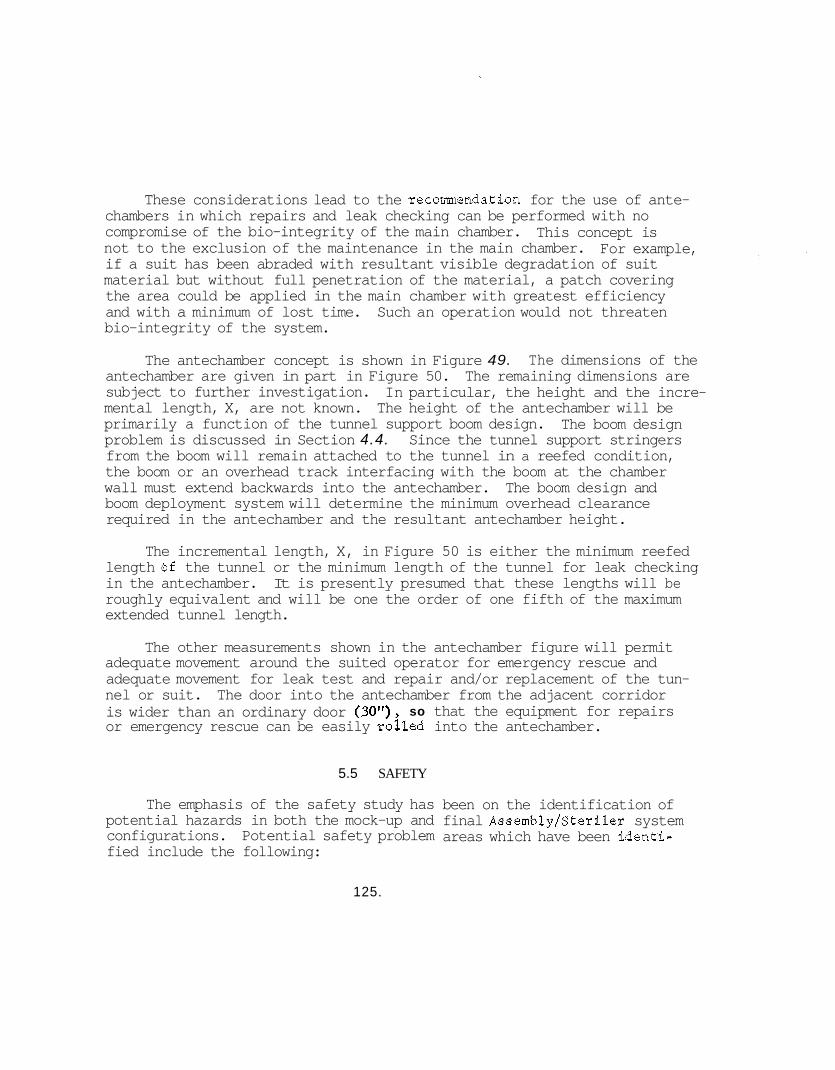
These considerations lead to the recommendation for the use of ante- chambers in which repairs and leak checking can be performed with no compromise of the bio-integrity of the main chamber. This concept is not to the exclusion of the maintenance in the main chamber. if a suit has been abraded with resultant visible degradation of suit material but without full penetration of the material, a patch covering the area could be applied in the main chamber with greatest efficiency and with a minimum of lost time. Such an operation would not threaten bio-integrity of the system.
For example,
The antechamber concept is shown in Figure 49. The dimensions of the antechamber are given in part in Figure 50. subject to further investigation. mental length, X, are not known. primarily a function of the tunnel support boom design. problem is discussed in Section 4.4. from the boom will remain attached to the tunnel in a reefed condition, the boom or an overhead track interfacing with the boom at the chamber wall must extend backwards into the antechamber. The boom design and boom deployment system will determine the minimum overhead clearance required in the antechamber and the resultant antechamber height.
The remaining dimensions are In particular, the height and the incre- The height of the antechamber will be
The boom design Since the tunnel support stringers
The incremental length, X, in Figure 50 is either the minimum reefed length bf the tunnel or the minimum length of the tunnel for leak checking in the antechamber. It is presently presumed that these lengths will be roughly equivalent and will be one the order of one fifth of the maximum extended tunnel length.
The other measurements shown in the antechamber figure will permit adequate movement around the suited operator for emergency rescue and adequate movement for leak test and repair and/or replacement of the tun- nel or suit. is wider than an ordinary door (30"), so that the equipment for repairs or emergency rescue can be easily rozled into the antechamber.
The door into the antechamber from the adjacent corridor
5.5 SAFETY
The emphasis of the safety study has potential hazards in both the mock-up and configurations. Potential safety problem fied include the following:
been on the identification of final Assembly/Sterilcr system areas which have been identi-
125.
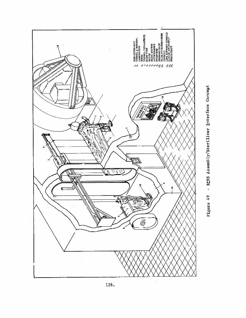
/
U a al u C 0 u al u RI w &I al U C H
&I al N .I4 rl .I4 &I al u m \ h rl P E al rn rn 4 m m H m
I
m d a,
M .rl Fr
:
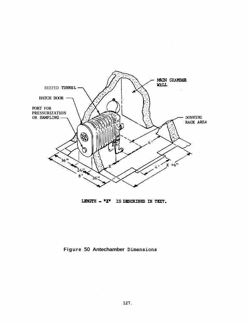
MAIN C W E R REEFED TUNNEL
HATCH DOOR
PORT FOR PRESSURIZATION OR SAMPLING
LENGTH - "X" IS DBSCRIBm IN TXT.
Figure 50 Antechamber Dimensions
127.
Accidental loss of breathing air while working within an opera- ting Assembly/Sterilizer,
Failure to preclude presence of toxic or noxious contaminants from contact with BISS occupant.
Accidental injury of BISS occupant while in the operating Assembly/Sterilizer.
Isolation of BISS occupant from assistance in the event of illness or injury.
In addition to recommending shlutions to these problems, the following discussion notes other recommended safety features which should be incoi.- porated in the AssemblylSterilizer and BISS.
5.5.1 Accidental Loss of Breathing Air
Although the life support system, which will provide the breathing air needed by the BISS occupant in the 100% nitrogen Assembly/Sterilizer environment, will be designed to be highly reliable, the possibility of a failure either within the Life Support System, BISS suit/distribution lines, or a facility power failure exists. the BISS occupant would be in a potentially hazardous condition.
If such an event should occur,
In order to properly evaluate the preferred means for providing suitable safety to minimize this potential BISS occupant hazard, the various possible accident modes and resulting situations were identified. The following classes of accident modes and postulated conditions were established.
(1) Internal equipment failure of the Life Support system precluding the supply of breathing air to a BISS occupant without prior warning or external indication of occurrence. that a change in the operating characteristics of the Life Support Equipment would be noticed by the monitoring personnel. However, the BISS occupant's supply of breathing air could be seriously diminished causing physiological change such as dizzy- ness, and in an extreme case unconsciousness, before the comple- tion of corrective actionon the part of support personnel.
It is expected
128.
(2) Facility power failure during a BISS operation could create a serious safety problem for the BISS occupant. life support systems, lighting, and communications are depen- dent on the primary facility power source, then effective egress from the Assembly/Sterilizer chamber would be extremely diffi- cult for the BISS occupant. Since his breathing air supply would be terminated, he could hot safely remain stationary until the outage was corrected, and any movement within a darkened chamber could be hazardous due to the risk of falling or other injury producing accident.
If all BISS
(3) Breathing air supply line failure due to leakage, kinking, or breaking would create an immediate potential hazard to the BISS occupant which might not be observable to the external moni- tors. The worst case accident situation would be unlikely, but the possibility exists of complete severing of all life support lines leading to the BISS caused by a sharp edged falling object.
Various techniques for minimizing these potential hazards have been It appears that in all three postuxated acci- considered and evaluated.
dent conditions, an emergency back-up supply of air for the BISS occu- pant is essential for use between the period of time when a physiological hazard begins and the occupant is removed to a life supporting environ- ment. described below, together with the appropriate trade-off considerations.
Alternate approaches to provision of a back-up air supply are
(2) Back-up supply provided as part of the life support system equipment. BISS, but operate off of compressed air bottles to be inde- pendent of facility power or life support equipment failure. The back-up would be designed to operate automatically in the event that normal air supply pressure falls below a predeter- mined level.
This would use the normal air supply lines to the
Advantages
Provides no weight or mobi1it.y penalty to BISS occupant.
Economical to design, install and maintain
High expected reliability.
129.
Disadvantages
0 Would not function properly in event of breathing air supply line or undersuit and helmet air distribution failure
(b) Portable emergency air supply carried internally in the BISS, and designed to be operated by either the BISS occupant or from outside the BISS. Ideally this internal supply would be designed to be very compact, and would be incorporated into the BISS design so as to provide minimal penalty on the BISS occupant.
Advantages
Provides a positive emergency supply of breathing air to the BISS occupant under worst case accident modes, inclu- ding failure of supply hose to BISS or intermal BISS dis- tribution system.
Disadvantages
Would require additional design and development effort to prove feasibility.
0 Would provide weight and operability penalty in BISS design.
0 Would provide a potential added safety problem in the event of failure of pressurized system (tubes or regulator) during normal BISS operation.
(e) Portable emergency air supply in Assembly/Sterilizer main cham- ber. This concept envisions the use of sterile, emergency, pressurized breathing air bottles strategically located inside the Assembly/Sterilizer chamber.
These bottles would be equipped with especially designed output- tube fittings which would permit connection into the BISS suit without loss of bio-integrity. valve could be opened, and air injected into the BISS suit to provide emergency breathing air to the occupant.
Once connected, the bottle's
Sufficient numbers of sterilized bottles would be located within an operating Assembly/Sterilizer chamber to allow ready access by any BISS occupant. In the event.of an emergency, the BISS occupant could walk to the closest bottle, make the BISS suit- air bottle connection, and open the valve to allow the air to
130.
enter the suit. The BISS occupant would then be assured of at least 5 minutes of breathing air supply to safely complete his emergency egress from the Assembly/Sterilizer chamber while carrying the emergency air supply bottle with him.
In the event the BISS occupant is immobilized, or otherwise unable to perform this operation himself, it would be possible for another BISS operator to bring an air bottle to the inca- pacitated BISS occupant and connect it to his suit, thereby assuring an adequate breathing air supply during egress.
For this concept, a relatively small air bottle would be pre- ferred to enable ease in carrying and storage.
Advantages
e Does not add any weight penalty to the BISS suit.
Disadvantages-
Permits only a limited supply.
Will require special sterilizable portable air supplies 0
e Will require development of a connection technique which will maintain bio-integrity.
It is recommended that both external back-up supply and the portable emergency air supply in the Assembly/Sterilizer main chamber be incorpor- ated in the BISS operation concept. of safety with minimum potential risk of compromizing the AssemblylSterili- zer main chamber bio-integrity. cut or blocked, the portable supply in the BISS would not be used.
This would provide the maximum degree
Unless the breathing air supply line is
The requirement for a back up life support system was substantiated by failures of’power to life support equipment which occurred during Phase I1 testing. The Occurrence of th&se power failures showed that an occupant could be removed from the chamber wlthin a two minute period in the mock-up system. capable of exiting under his own power.
This was proven in two cases, and the operator was
131.
5.5.2 ISS suit
If the BISS is ET0 decontaminated, it will be necessary to assure that no ET0 permeated into the suit wh5ch could create a potential hazard to the occupant. To minimize this potential hazard, an analysis of the internal suit atmosphere should be made prior to initial occupant entry following a decontamination cycle. The problem of skin contact with ET0 which may have permeated through the suit material does not appear to warrant any further precautionary procedures, since atmospheric analysis should be sensitive enough to detect this.
Continuous monitoring of the internal BISS helmet environment €or toxic or noxious contamination does not appear necessary from a safety standpoint. However, it does appear desirable to provide a capability to monitor the oxygen and carbon dioxide levels in the BISS helmet on a continuous basis to assure maintenance of a safe air mixture. An auto- matic alarm should be incorporated to alert control and support personnel if a proper gas mixture is not maintained.
5.5.3 Accidental Occupant Injury Potential
Although the BISS design concept provides for good visibility and maximum mobility within the constraints imposed by the tunnel design, some limitation is inherent in this system. This tends to increase the potential of injury of the occupant, particularly while working on elevated platforms. An injury sustained while in the BISS would hamper the ability to egress, and first aid would be difficult to administer. For these reasons, the helmet has been designed with hard hat and face shield safety features; and hard boot toes, and non-skid boot soles are incorporated.
5.5.4 Emergency Rescue and Egress Considerations
In considering what type of design and operational features should be incorporated in the BISS concept to facilitate potential emergency rescue and egress, the following possible accident situations were examined :
a. The BISS occupant becomes ill o r injured, but is still capable of unassisted egress.
132.
b. BISS malfunctions significantly reduce breathing air flow to the occupant; however, the condition is noted prior to onset of physiological distress, and bio-integrity is not compromised.
C+ The BISS occupant suffers an incapacitating injury or illness, and cannot exit unaided (bio-integrity not compromised).
d. The BISS air supply fails (bio-integrity not compromised).
e. A catastrophic accident occurs which causes immediate and serious hazard to BISS occupant and bio-integrity has been, or must be compromised.
Under conditions a and b, the BISS occupant should be able to return to the antechamber and close the door within a 5 minute maximum time period. Once in the sealed antechamber, either the occupant can effect a normal egress, or if required, the antechamber can be purged with air and an emergency escape from the BISS can be effected by having the suit cut oren by standby personnel.
Under condition c, the affected BISS occupant must be aided by being carried into the antechamber by other BISS personnel. aiding the injured occupant into the antechamber must leave the antechamber prior to closing the door. stand-by personnel entering the antechamber. fill the antechamber with air or use back-packs.
The personnel
The injured occupant can then be assisted by These personnel can either
Condition d will require the use of an emergency breathing air system provision. back-up air supply will be actuated, allowing the BISS occupant to effect a normal egress from the BISS. If the external back-up air supply is not operable, the emergency air supply in the Assembly/Sterilizer main chamber would be used.
If the air supply lines are operable, the external emergency
Under condition e, any attempt to maintain bio-integrity must be disregarded. .In this case, emergency back-up personnel would put on breathing air back*packs in order to quickly enter the Assembly/Sterilizer chamber to effect the necessary rescue operation.
5.5.5 Warning Lights
The experience gained during mock-up testing showed that it would be desirable to have a facility system of flashing red, steady amber, and steady green lights to indicate safety status. The flashing red light would signify that the BISS operator must be removed imediately. The steady amber light would signify that the BISS operator could complete
133.
a short task of up to 5 minute duration. indicate all systems were normal. by all console operators or to be placed on each console. These lights should be integrated into a warning system compatible with the require- ments of Paragraphs 3.4.4 and 3.4.6 of the system criteria, Appendix A here to.
A steady green light would These lights should either be visible
5.5.6 Rescue Team
Rescue teams should be provided to assist in emergency egress of a suit occupant in the event of disability or system malfunction. members should be trained in all emergency procedures for the facility including administration of first aid. be performed under the direction of the appropriate medical monitor or a physician or nurse on short notice emergency call.
Team
All medical ministrations would '
In the interest of efficiency of personnel utilization, it is recommended that the rescue team be composed of BISS suit workers who are "off duty".* This should enhance the confidence of the suit occupants and provide considerable motivation for close attention to duty by the rescue team personnel.
5.5.7 Redundancy
Wherever possible redundant primary power sources, life support equipment, and lighting should be provided. The life support of the individual BISS occupants must be decoupled from each other and from other facility equipment as much as possible. and interface with the Assembly/Sterilizer must be such that any credible system malfunction or accident can be accomodated without jeopardizing the life and health of suit occupants; and, in particular, must be designed so emergencies. fully defined for the BISS system in the Assembly/Sterilizer, they must be carefully scrutinized to assure that the personnel subsystem possess the degree of redundancy required for system safety. tated by cross-training personnel so that persons-performing routine non-critical jobs can act in an emergency service capacity as required.
The system detail design
that such malfunctions or accidents do not cause multiple concurrent After the work flows and manning requirements have been
This can be facili-
Jr See work shift discussion in Section 5.2.2.
134.
6.0 INTEGRATED TEST PLAN
6 . 1 BACKGROUND
The In tegra ted Tes t P lan was prepared dur ing t h e f i r s t quar te r of the con t rac t period and submitted t o Langley Research Center f o r review i n November 1966. It was issued a s GE Document Number 67SD418 on January 3, 1967 and i s included a s p a r t of t h i s f i n a l r e p o r t a s Appendix F. The p lan , a s o r i g i n a l l y w r i t t e n , covered both the Materials Tes t ing and t h e Mock-up T e s t Program t o be conducted dur ing t h e course of the con t rac t per iod. t i o n s t o the p lan t o incorpora te experience gained i n day t o day mock-up work and mate r i a l s t e s t i n g . i n t e r e s t of g r e a t e r e f f i c i e n c y of t i m e and e f f o r t , while n o t reducing evaluat ion v a l i d i t y .
It was found necessary dur ing the test program t o make modifica-
I n a d d i t i o n , some tests were combined i n the
The changes a r e r e f l e c t e d i n Sections 7.0 and 8.0.
6 .2 BISS TEST AND DEMONSTRATION PLAN
A T e s t and Demonstration P l a s was prepared f o r t h e BISS System and i s d e t a i l e d i n t h i s r e p o r t a s Appendix G. i n which a prime s u i t and i t s subsystems s h a l l be i n t e r f a c e d , t e s t e d , and demonstrated t o s a t i s f y t h e o v e r a l l requirements f o r the var ious environ- mental condit ions under which BISS w i l l be expected t o perform. This p lan , al though i t is not d e t a i l e d t o t h e e x t e n t of t h e In tegra ted T e s t P lan , incorpora tes the experience gained from the mate r i a l s t e s t i n g and mock-up por t ions of the sub jec t c o n t r a c t , and should provide the b a s i s f o r t e s t i n g of engineering models on a subsequent test program.
The p lan desc r ibes the manner
135.
7.0 ANALYSIS OF CANDIDATE MATERIALS
7 .1 GENERAL
The ob jec t ive of t h i s task w a s t o de f ine optimum materials f o r u s e i n t h e BISS ou te r and inner s u i t based on t h e i r a b i l i t y t o withstand t h e thermal, chemical, and mechanical stresses planned f o r t h e assembly s ter i l izer f a c i l i t y .
To provide more accu ra t e r e s u l t s , i t w a s found necessary t o make some s l i g h t a l t e r a t i o n s t o t h e previously submitted In tegra ted T e s t Plan, h e r e i n r e f e r r ed t o as Appendix F. The tests t h a t were modified were:
Fungus Growth T e s t
Mycelial P e n e t r a b i l i t y T e s t
0 Transfer of Microorganisms, Liquids, and Gases Across S u i t Materials T e s t
A more d e t a i l e d explanat ion of t h e reasons which necess i ta ted t h e changes, and t h e r e s u l t s of t h e chemical and b io log ica l tests, appears i n Sect ion 7.3 under t h e appropr ia te headings.
A l i t e r a t u r e search w a s i n i t i a t e d t o e l imina te those materials which obviously could not m e e t t h e q u a l i f i c a t i o n s . r e s u l t s of t h e l i t e r a t u r e search, a l is t of t h e materials which looked most promising w a s compiled and a series of tests w e r e subsequently designed t o assess t h e phys ica l , chemical, microbial , and thermal pro- p e r t i e s of t hese materials.
Based upon t h e
Although it w a s d e s i r a b l e t h a t t h e materials provide a b a r r i e r t o microbial and fungal pene t ra t ion , t h i s requirement w a s deemed a necess i ty only on t h e ou te r s u i t , as t h e inner s u i t could be t r ea t ed pe r iod ica l lv t o des t roy any adhering organisms.
The materials inves t iga ted f o r each po r t ion of t h e system w e r e as follows :
1) S u i t and Tunnel
e Neoprene Rubber Film, XA-3785-2
0 Si l i cone Rubber Film, SE-555
136.
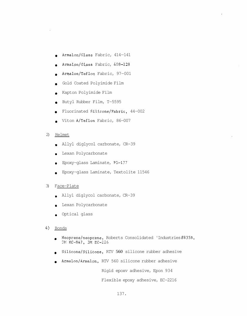
Armalon/Glass Fabric, 414-141
Armalon/Glass Fabric, 408-128
Armalon/Teflon Fabric, 97-001
Gold Coated Polyimide Film
Kapton Polyimide Film
0 Butyl Rubber Film, T-5595
Fluorinated Silicone/Fabric, 44-002
Viton A/Teflon Fabric, 86-007
2) Helmet
Allyl diglycol carbonate, CR-39
0 Lexan Polycarbonate
0 Epoxy-glass Laminate, PD-177
Epoxy-glass Laminate, Textolite 11546
3) Face-Plate
Allyl diglycol carbonate, CR-39
Lexan Polycarbonate
Optical glass
4) Bonds
0 Neoprene/neoprene, Roberts Consolidated 'Industries #835B, 3M EC-847, 3M EC-226
e
Armalon/Armalon, RTV 560 silicone rubber adhesive
Silicone/Silicone, RTV 560 silicone rubber adhesive
Rigid epoxv adhesive, Epon 934
Flexible epoxy adhesive, EC-2216
137.
Based upon t h e q u a n t i t i e s of materials u t i l i z e d i n t h e Phase I1 mock-up, ca l cu la t ed p ro j ec t ions w e r e made concerning t h e t o t a l weights of some of t h e var ious candidate materials l i s t e d above i f they are se l ec t ed f o r t h e f i n a l cons t ruc t ion of t h e BISS. These c a l c u l a t i o n s w e r e based on the test th icknesses of the candidate materials on hand, and a l s o inc lude t h e estimated material th icknesses required f o r f i n a l s u i t , tunnel , and helmet f ab r i ca t ion . This da ta is shown i n Table X.
7.2 PHYSICAL TESTING
A s a r e s u l t of t h e inves t iga t ions conducted on t h e combined e f f e c t s of hea t aging, f l ex ing , and abras ion tests , some d e f i c i e n c i e s i n several of t h e candida te materials were revealed, requi r ing e i t h e r some modifi- c a t i o n of material approach, imposition of u se l i m i t a t i o n s , o r t h e elimin- a t i o n of t h e candida te material from f u r t h e r cons idera t ion f o r t h e BISS system. program appear i n Appendix H. Each one of t h e candidate materials i s discussed i n g r e a t e r d e t a i l below. were made i s contained i n Appendix I.
Some photographs of t h e equipment used during the phys ica l t e s t i n g
The test da t a from whi,h eva lua t ions
7.2.1 Neoprene Rubber, XA-3785-2
The neoprene rubber , o r i g i n a l l y considered as a condidate f o r s u i t and tunnel , and boot and glove app l i ca t ions , embr i t t l e s a f t e r repeated hea t age cyc les t o 15OoC (300°F), as evidenced by an increased abrasion wear index as a func t ion of repeated cyc l ing , a high weight loss (2.57%), and reduced r e s i s t a n c e t o t h e f l ex ib i l i t y- pe rmeab i l i t y prepara t ion method. Of more se r ious concern, however, w a s t h e f a i l u r e of t h e material during fungus eva lua t ions where rap id growth w a s observed.
A s a consequence, neoprene rubber w a s eliminated as a candidate f o r e x t e r i o r u s e i n t h e s u i t and tunnel , o r boot and glove areas, and i t s recommended use confined t o inner s u i t app l i ca t ions only.
Based upon t h e requirements f o r inner s u i t use, t h e eva lua t ion para- meters f o r t h e remaining tests w e r e r ee s t ab l i shed as follows:
e Delet ion of t h e puncture eva lua t ion
N o f u r t h e r permeabil i ty eva lua t ions , and t h e assoc ia ted f l e x i b i l i t y prepara t ion
e N o f u r t h e r heat aging, ETO/Freon, o r d i s i n f e c t a n t eva lua t ions
e Continue tear, de te rgent , abras ion f o r 100 cyc les , and t e n s i l e tests on t h e unaged material only
138.
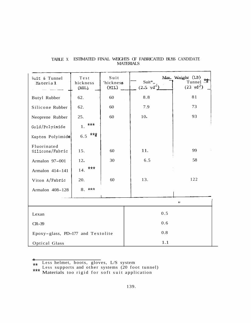
TABLE X ESTIMATED FINAL WEIGHTS OF FABRICATED BUSS CANDIDATE
Lexan
CR-39
Epoxy-glass, PD-177 and T e x t o l i t e
Opt ica l Glass
Suit & Tunnel Ma t er i a 1
Butyl Rubber
S i l i cone Rubber
Neoprene Rubber
Gold/Polyimide
Kapton Polyimide
Fluorinated S i l icone/Fabr ic
Armalon 97-001
Armalon 414-141
Viton A/Fabric
Armalon 408-128
0.5
0.6
0.8
1.1
T e s t hickness
(MIL)
62.
62.
25.
1. *** 6.5 ***
15.
12
14. *** 20.
8. ***
MATERIALS
S u i t 'hickness
(MIL)
60
60
60
60
30
60
Max. Weight (LB) Suit*,, Tunnel **
(2.5 ydL)
8.8
7.9
10 *
11.
6.5
13.
(23 vd')
81
73
93
99
58
1 2 2
I
* ** *** Materials too r i g i d f o r s o f t s u i t app l i ca t ion
L e s s helmet, boots , gloves, L/S system L e s s supports and o the r systems (20 f o o t tunnel)
139.
The t e n s i l e and tear p rope r t i e s of neoprene were unaffected by t h e de tergent t reatment as shown i n Appendix I, and abras ion r e s i s t a n c e in- creased as a r e s u l t of t h e de tergent t reatment . Therefore, neoprene rubber is t h e recommended material f o r inner s u i t use .
7.2.2 Si l i cone Rubber SE-555
Tests on t h i s material were conducted under *worst case exposure condi t ions , and t h e s i l i c o n e rubber successfu l ly passed t h e fungus, hea t aging, microbia l permeabil i ty , abras ion and f l e x i b i l i t y evaluat ions. However, notch s e n s i t i v i t y of t h e non- fabric - re inforced f i lms , and t h e r e l a t i v e l y low assoc ia ted tear s t r eng ths , i n d i c a t e t h a t t h e use of t h i s material should be confined t o high temperature fabric- reinforced types which w i l l tend t o minimize puncture and t e a r . s e n s i t i v i t y . This l a t t e r class of polymeric material i s recommended as t h e p r i m e back-up choice f o r e x t e r i o r s u i t and tunnel , and boot and glove use.
7.2.3 Armalon 414-141 (Glass Fabric)
The Armalon 414-141 (14 m i l th ickness g l a s s f a b r i c material) success- f u l l y passed t h e microbial permeabil i ty evaluat ions; however, t h e material w a s found t o support fungus growth, and on the l a t t e r b a s i s w a s e l iminated from f u r t h e r cons idera t ion . Of secondary importance w a s t h e l ack of f l ex- i b i l i t y and "hand" of t h e coated g l a s s f a b r i c f o r s u i t f a b r i c a t i o n a t p r a c t i c a l thicknesses .
7.2.4 Armalon 408-128 (Glass Fabric)
The Armalon 408-128 (8 m i l th ickness g l a s s f a b r i c material) w a s found t o be r e s i s t a n t t o fungus a t t a c k and subsequent growth. This material, however, w a s found t o be permeable t o microbes, and w a s e l iminated from f u r t h e r cons idera t ion on t h i s bas i s . 414-141 materials, t h e i n s u f f i c i e n t f l e x i b i l i t y and "hand" w a s also deemed unsu i t ab le f o r successfu l f ab r i ca t ion .
Although 6 m i l s th inner than t h e
* This r ep resen t s t h e g r e a t e s t number of hea t (201, abras ion (1000), and f l e x u r e ( 200 ) cycles .
140.
An a d d i t i o n a l observa t ion may a l s o be made regarding t h e two Armalon coated g l a s s f a b r i c s . t h e 14 m i l gauge material w a s not permeable, ind ica ted t h a t t h i s class of material i n excess of 1 2 m i l s w i l l pass t h e i r in-house permeabil i ty tests, while those th inner do not pass , s u b s t a n t i a t i n g t h e r e s u l t s of t h e cu r r en t i nves t iga t ion . A minimum gauge th ickness of 15 m i l s is the re fo re ind ica ted t o provide a s l i g h t margin of s a f e t y , i f judged only on t h e b a s i s of permeabil i ty .
The 8 m i l gauge material was permeable, whereas Vendor con tac t s (DuPont)
7 .2 .5 Armalon 97-001 (Teflon Fabr ic )
Based upon t h e fungus, microbia l permeabil i ty , and hea t age evalua- t i o n s previously conducted on t h e g l a s s f a b r i c Armalon class , and t h e need f o r increased f l e x i b i l i t y and "hand" f o r ease i n f a b r i c a t i o n , t h e Tefloy/ Teflon f a b r i c class of Armalon w a s then considered t o be a prime s u i t and tunnel material candidate . This class of f a b r i c , however, i s not a stand- ard s tock i t e m , as are t h e g l a s s f a b r i c types. The vendor (DuPont) s t a t e d t h a t t h e cu r r en t lead t i m e f o r de l ive ry of t h e material is approximately 4 t o 6 months from r e c e i p t of order , and t h a t no supply w a s c u r r e n t l y on hand f o r de l ive ry .
E f f o r t s were, therefore , expended t o f i nd a converter with an excess of material. With t h e exce l l en t cooperat ion of t h e DuPont Fabr ic Sa les personnel, contac t w a s made wi th M r . Brumbaugh of Fab-Ohio, Inc . Fab-Ohio had received an order of t h e Armalon 97-001, processed f a b r i c a t i o n s f o r t h e i r customer, and had an excess of 5 t o 7 l i n e a l yards of nominal 21 inch wide material ava i l ab l e . and an expedited de l ive ry received FW 10 f o r a f u l l scale evaluat ion.
An order f o r t h i s material w a s processed,
A complete eva lua t ion of t h e Armalon 97-001 material w a s conducted under "worst case" environmental condi t ions, and t h e material success- f u l l y passed fungus and microbial permeabil i ty tests, abrasion, f l exu re , hea t aging, tear, t e n s i l e , and o ther phys ica l proper ty eva lua t ions . This material i s recommended as t h e prime s u i t and tunnel material f o r t h e BISS system.
7 .2 .6 Gold Coated Polyimide Film, Kapton Polyimide Film
Polyimide high temperature r e s i s t a n t f i l m materials, as received and gold vacuum coated, were submitted f o r fungus and microbia l permeabil i ty eva lua t ions . Both materials were r a t ed acceptable f o r u se as judged by these tests; however, t h e f i lms were no t s u f f i c i e n t l v f l e x i b l e f o r s u i t f a b r i c a t i o n , e i t h e r a lone o r f a b r i c supported, and w e r e suscep t ib l e t o tear propagation. A s a r e s u l t , t he se materials were el iminated from f u r t h e r cons idera t ion as s u i t and tunnel candidates .
141.
7.2.7 Butyl Rubber, T ~ 5 5 9 5
Based upon t h e r e s u l t s discussed previously f o r neoprene rubber, an add i t i ona l rubber candida te f o r s u i t and tunnel , and boot and glove app l i ca t ions w a s deemed necessary. t he re fo re , obtained, and w a s evaluated.on a "worst case" environment bas i s .
"Fairprene"* b u t y l rubber f i l m w a s ,
The b u t y l rubber success fu l ly passed t h e fungus, hea t aging, f l exu re , abrasion, gas and microbia l permeabil i ty tests, and d i s i n f e c t a n t and de tergent compa t ib i l i t y eva lua t ions . This material, toge ther with t h e s i l i c o n e rubber, is a l s o considered t o b e a prime back-up candidate f o r s u i t and tunnel use. However, g r e a t e r hea t s t a b i l i t y w a s demonstrated by t h e s i l i c o n e rubber.
7.2.8 A l l y l Diglycol Carbonate, CR-39
CR-39, a l l y l d ig lyco l carbonate w a s eliminated from f u r t h e r con- s i d e r a t i o n as a candidate material. carbonate clear p l a s t i c face- plate candidate material were exposed t o an environment of de te rgent followed by hea t aging. i t e d se r ious stress cracking, and d i sco lo ra t ion ranging from c o l o r l e s s t o a medium amber c o l o r ,
Specimens of t h e a l l y l d ig lyco l
The specimens exhib-
Addit ional labora tory eva lua t ions w e r e conducted t o f u r t h e r d e f i n e t h e f a i l u r e . It w a s found t h a t t h e stress cracking could be el iminated by hea t tempering t h e material, followed by a slow cool-down. However, cons iderable d i s c o l o r a t i o n occurred as a r e s u l t of t h e dry hea t steril i- za t ion time-temperature t reatment , and t h i s material w a s eliminated from f u r t h e r cons idera t ion .
7.2.9 Lexan Polycarbonate
The Lexan polycarbonate p l a s t i c w a s exposed t o t h e fungus, and ETO/ Freon tests, and has been success fu l ly q u a l i f i e d i n t hese environments. Abrasion, o p t i c a l t ransmission, and de tergent and d i s i n f e c t a n t tests were then conducted on t h e v i r g i n material, with no problem areas being ident- i f i e d . Other phys ica l tests, and a d d i t i o n a l o p t i c a l t ransmission measure- ments w e r e a l s o success fu l ly conducted.
Repe t i t i ve hea t cyc l e aging of phys ica l test specimens t o 145OC revealed a p o t e n t i a l problem area. transmission, abrasion, t e n s i l e , impact, and compression tests exhibi ted
F l a t specimens required f o r o p t i c a l
* DuPont t r a d e name 142.
e
var ious degrees of warpage varying from minor abe r ra t ions t o bowing of approximately 1/8 inch on 4" x 4" specimens 1 /4 inch i n th ickness . This d i s t o r t i o n genera l ly occurred a f t e r t h r e e t o f i v e hea t c y c l e t reatments; however s u f f i c i e n t numbers of specimens d i s t o r t e d i n t h e f i r s t t reatment t o cause concern.
Laboratory eva lua t ions w e r e conducted t o determine t h e temperature level a t which d i s t o r t i o n f i r s t occurs. ho r i zon ta l ly and v e r t i c a l l y i n a r e c i r c u l a t i n g a i r oven, and t h e tempera- t u r e w a s slowly increased t o a maximum of 149 C (300'F). D i s to r t i ons c o n s i s t e n t l y occurred i n t h e 135-138OC (275-280'F) temperature range. Imposition of a 3OC (5OF) s a f e t y f a c t o r would thus l i m i t t h e maximum peak temperature t o 132OC (27Q°F), with a corresponding inc rease i n t h e required s t e r i l i z a t i o n t i m e .
Specimens w e r e placed both
E f f o r t s were made t o stress r e l i e v e t h e polycarbonate, f o r sub- sequent hea t age cyc les , by both a rap id and a slow cool-down t o ambient temperatures between t h e p l a t ens . Specimens t r e a t e d i n t h i s fakhion, however, continued t o d i s t o r t i n t h e 135 t o 138OC (275-280'F) range, and contac t with t h e pol ished p l a t ens a t high temperature r e su l t ed i n su r f ace marring, and a l s o i n t h e formation of "pock-marks'' i n t h e sur face , a l l de l e t e r ious t o o p t i c a l transmission. These e f f e c t s are shown i n t h e Figures 51A and B.
It must be concluded, t he re fo re , t h a t although Lexan polycarbonate p l a s t i c o f f e r s many p o t e n t i a l advantages, such as s t a b i l i t y t o t h e chemical environment, relat ive ease i n blow o r vacuum forming, impact r e s i s t a n c e , etc., t h e 1 3 5 O C (275'F) hea t d i s t o r t i o n poin t a t a loading of 264 p s i (ASTM D648) must a l s o be considered as a l i m i t i n g f a c t o r f o r t h e no-load condi t ion as w e l l .
The recommendation, t he re fo re , i s t o l i m i t t h e maximum use tempera- t u r e of Lexan t o 132OC (270°F), as noted above, o r consider t h e use of an o p t i c a l g l a s s face- plate i n a r i g i d , re inforced p l a s t i c helmet.
7.2.10 Epoxy Glass Laminate, PD-177
Epoxy g l a s s laminates (nominal 3/32 inch th ickness) w e r e prepared i n t he labora tory us ing g l a s s c l o t h , Epon 828, and TETA (Triethylenete- tramine) c a t a l y s t . With t h e exception of t h e c a t a l y s t , t h e materials had previously been found t o be non- nutrient per MIL-E-5272, and NIL-F- 8261. The TETA c a t a l y s t i s a l s o non-nutrient per MIL-E-5272.
Fungus tests w e r e conducted on t h e laminate material per MIL-F-8261, and fungus growth w a s observed on t h e as- laminated specimens. Addit ional specimens w e r e then prepared represent ing add i t i ona l post- cure condi t ions
143.
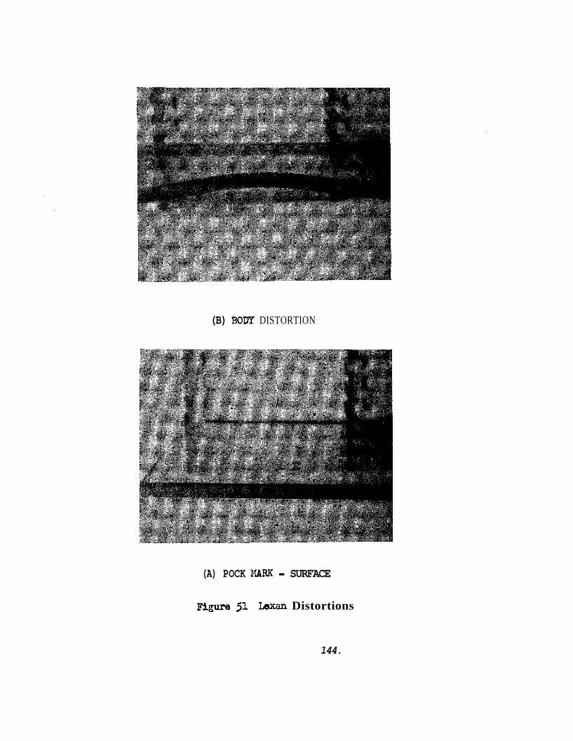
(B) BODY DISTORTION
(A) POCK NARK - SURFACE figure jl rWran Distortions
144.
(5, 10, and 20 heat age cyc les ) and exposed t o t h e fungal environment. It w a s pos tu la ted that t h e a d d i t i o n a l post- cure, i n add i t i on t o f u r t h e r cross- linking the res inous matrix, would a l s o d r i v e o f f low molecular weight r e s i n and c a t a l y s t f r a c t i o n s which might con t r ibu te t o t h e posi- t ive fungus growth, I n genera l , a lesser amount of growth w a s noted as t h e post- cure t i m e a t 15OoC (300°F) w a s increased.; however, a l l test specimens w e r e p o s i t i v e , A s a r e s u l t , t h i s laminate formulation w a s e l iminated from f u r t h e r cons idera t ion .
7.2.11 Epoxy Glass Laminate, T e x t o l i t e 11546
A commercial epoxy g l a s s laminate , General Electr ic T e x t o l i t e Grade 11546, (conforming t o NEMA Grade G-10, and MIL-P-18177 Grade GEE) had previously been q u a l i f i e d as non- nutrient per WIL-E-5272 and MIL-F-8261 This material w a s t he re fo re considered f o r use as t h e RISS helmet, and a sample of t h e material, 3/32 inches t h i ck , w a s obtained f o r evaluat ion.
The laminate has successfu l ly passed t h e fungus and mycel ial Penetra- t i o n tests, ETO/Freon, de te rgent and d i s i n f e c t a n t eva lua t ions , hea t aging, and ab ra t ions , and phys ica l proper ty t e s t i n g . p r i m e candidate f o r t h e BISS helmet.
It i s recommended as t t e
7.2.12 Qptica3 Glass
Due t o t h e d i s t o r t i o n problems out l ined above f o r Lexan, g r e a t e r emphasis w a s placed upon t h e cons idera t ion of g l a s s t o provide a s t a b l e viewing area.
Two approaches may be considered. The f i r s t i s a face- plate incor- porated i n t o a reinforced p l a s t i c helmet, and t h e second i s t h e u s e of a f u l l helmet g l a s s bubble. Several disadvantages are inherent i n t h e f i r s t approach:
e Reduced operator pe r iphe ra l v i s i o n due t o a more l imi ted viewing area
0 Reduced test conductor v i s i b i l i t y of t h e ope ra to r ' s head and f a c e
Increased d i f f i c u l t y i n assur ing a leak- free system, wi th t h e incorpora t ion of t h e add i t i ona l bondinglgasketinqjattach- ment area, and
0 Thermal expansion mismatches during t h e s t e r i l i z a t i o n cvcle
14 5
The second approach must a l s o be c a r e f u l l y analyzed i n v i e w of t h e increased p o s s i b i l i t y of helmet damage, p o t e n t i a l opera tor hazard due t o s c r a t ch and impact propagated f a i l u r e s , and t h e an t i c ipa t ed g r e a t l y in- creased c o s t of an a l l g l a s s helmet,
Of t h e var ious g l a s se s which might be considered, p l a t e , general purpose b o r o s i l i c a t e , and fused s i l ica (quar tz) , quar tz has t he h ighes t o p t i c a l t ransmission i n t he u l t r a- v io l e t and v i s i b l e ranges. is a l s o somewhat more impact and abrasion r e s i s t a n t than the p l a t e o r b o r o s i l i c a t e s , and a l s o has t h e lowest c o e f f i c i e n t of thermal expansion of p o t e n t i a l g l a s s materials. P rope r t i e s of several g l a s se s i n compari- son t o quar tz are shown i n Table I- V I 1 1 of Appendix I and t h e gas perme- a b i l i t y of quar tz a t e levated temperature is shown i n Table I- X I .
Ouartz
7.2.13 \B-<S
After t h e s e l e c t i o n of candidate ma te r i a l s w a s completed, a test program w a s i n i t i a t e d t o eva lua te var ious types of adhesives and t h e i r s u i t a b i l i t y f o r use on the BISS. w e r e measured i n i t i a l l y , and following success fu l completion of these tests, t h e bonded test samples were t e s t ed f o r microbial permeabi l i ty f l exu re , hea t aging, e t c .
Shear s t r eng ths and pee l s t r eng ths
With few exceptions, as noted below, i t w a s pos s ib l e t o produce bonds having shear s t r eng ths of up t o 250 p s i . However, i t w a s found t h a t a l l t h e adhesives w e r e permeable t o microorganisms. The r e s u l t s of t h e microbial permeabi l i ty test are t o be found i n Table I1 of Section 7.3.
7.2.13.1 Neoprene/Neoprene
Several adhesives were evaluated f o r bonding neoprene t o neoprene. These w e r e :
1. Roberts Consolidated Indus t r i e s #835B.
2. 3 M EC-847
3. 3M EC-226
The bonded samples , a f t e r a one week cu re a t room temperature, had shear s t r eng ths of 150-175 p s i and pee l s t r eng ths of 10/12 l b / i n . A l l of t h e above adhesives are s u i t a b l e f o r u se i n t h e BISS and due t o t h e f a c t t h a t t h i s material is recommended f o r inner s u i t use , microbial permeabi l i ty t e s t i n g w a s not considered necessary.
146
7.2.13.2 S i l i cone /S i l i cone
I n i t i a l bonding e f f o r t s w i th the u s e of RTV-560 w e r e no t successfu l , with cured bonds shearing a t 2 t o 30 p s i . that processing a i d s incorporated i n t h e s i l i c o n e rubber gum during com- pounding t o a i d i n ex t rus ion inh ib i t ed t h e cu re of t h e RTV rubber. consu l t a t ion wi th s i l i c o n e compounders, and numerous labora tory t r ia l s , the following bonding procedure proved successfu l :
It w a s determined, however,
Af te r
e Bake s i l i c o n e rubber f o r 1 hour minimum a t 350°F
Glean bond faying su r f aces wi th acetone and t o l u o l e
Wipe faying su r f aces wi th t h e RTV c a t a l y s t and al low t o s tand f o r 10 minutes minimum
Wipe excess c a t a l y s t from sur face , and bond wi th catalyzed RTV-5 60
Af ter a room temperature cure of one week a t ambient, o r 24 hours a t ambient p lus 4 hours a t 350°F, shear bond s t r e n g t h of 200 t o 250 p s i were r ea l i zed .
7-2.13.3 Armalon/Armalon
The Armalon f a b r i c w a s so lvent cleaned, and etched with a me ta l l i c sodium e tchant s o l u t i o n p r i o r t o bond f a b r i c a t i o n i n a l l cases.
7.2.13.3.1 RTV-560
The RTV-560 s i l i c o n e rubber d id not provide s a t i s f a c t o r y bond s t r eng ths , and f a i l u r e s occurred a t 2 t o 30 p s i with pee l s t r e n g t h s i n t h e order of 2 t o 5 l b / i n . Further cons idera t ion of t h e RTV bond w a s e l iminated.
7.2.13.3.2 Rigid Epoxy, Epon 934
Epon 9 3 4 , a hard r i g i d epoxy w a s evaluated i n a l imi ted manner t o determine i f epoxies would b e more s a t i s f a c t o r y . however, t h e epoxy and adhesive w a s too b r i t t l e f o r t h e intended appl ica- t ion.
Bonding w a s exce l l en t ,
7.2.13.3.3 F lex ib i l i zed Epoxy, 3M EC-2216
Bonds produced w i t h EC-2216 have been ,cons i s t en t ly exce l l en t , and have success fu l ly been evaluated i n t h e f l e x i b i l i t y equipment with no
147
f a i l u r e s i n t h e as made, heat aged, and hea t aged p lus ETO/Freon condi- t i o n s . Bonds produced exhib i ted l a p shear s t r eng ths of 200-250 p s i and t h i s adhesive was submitted f o r microbial pene t r a t ion s tud ie s .
Heat s e a l i n g of t h e Armalon f a b r i c has not been experimentally evaluated i n t h e program due t o hea t seal equipment l i m i t a t i o n s . ever, consu l t a t ions with several f a b r i c a t o r s of Teflon items h ighly recommend t h i s method, genera l ly with a double seal t o provide t h e g r e a t e s t r e l i a b i l i t y i n a leak- free system.
How-
7.3 CHEMICAL AND BIOLOGICAL TESTING OF MATERIALS
7.3.1 Fungus Growth T e s t
The fungus Growth T e s t w a s conducted t o determine i f t h e materials under cons idera t ion f o r u se on t h e BISS would support growth of fungus type organisms. i n MIL-STD-810A (USAF) 23 June 1964, were as follows:
The organism's s e l ec t ed , a choice of which is described
. Aspergi l lus n ige r ATCC 9642
0 Asper ig i l l u s f l avus ATCC 10836
Myrothecium ce r ruca r i a ATCC 9095
Penic i l l ium Citrinum ATCC 9849
The test method u t i l i z e d w a s as described i n Procedure I1 of t h e above STD. Performance t e s t i n g of t h e candidate materials w a s done i n accordance with Spec i f i ca t ion MIL-F-8261A. t h e propagation of each of t h e above se l ec t ed organisms w a s as follows:
The c u l t u r e media chosen f o r
e Aspergi l lus n ige r - Enriched Mineral S a l t s o r Potato Dextrose
Aspergi l lus f l avus - Sabouraud Maltose o r Potato Dextrose
Myrothecium s e r r u c a r i a - Mineral S a l t s Cotton
0 Penic i l l ium c i t r i n ium - Sabouraud Maltose
The above s p e c i f i c a t i o n s e s t a b l i s h methods f o r t e s t i n g materials f o r compliance wi th t h e requirements of USAF spec i f i ca t ions , and o the r govern- mental s p e c i f i c a t i o n s , and w e r e prepared t o e l imina te unnecessary and undesirable v a r i a t i o n s i n t e s t i n g procedures.
14 8
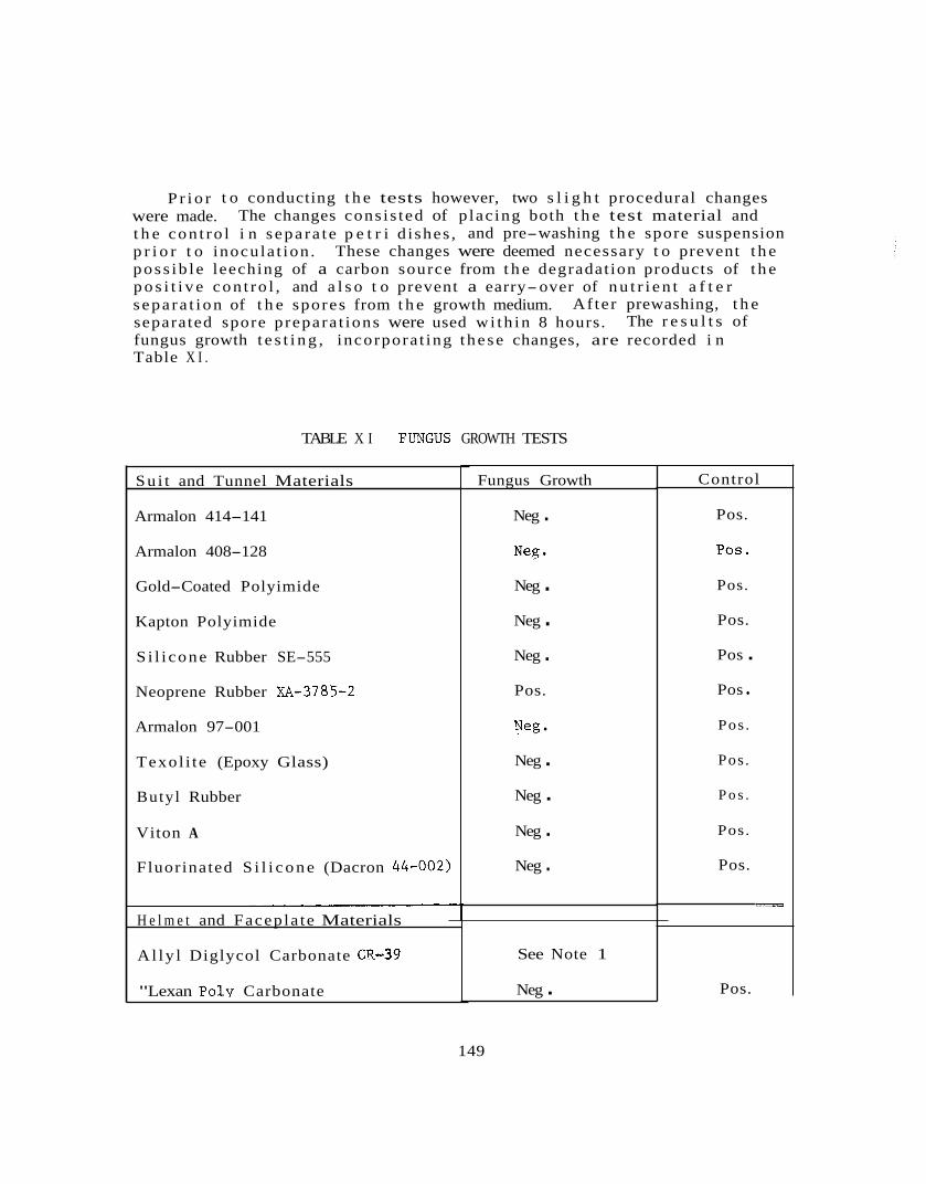
P r i o r t o conducting t h e tests however, two s l i g h t procedural changes were made. t h e con t ro l i n s epa ra t e p e t r i d i shes , and pre-washing t h e spore suspension p r i o r t o inocula t ion . These changes were deemed necessary t o prevent t h e poss ib l e leeching of a carbon source from t h e degradat ion products of t h e p o s i t i v e con t ro l , and a l s o t o prevent a earry-over of n u t r i e n t a f t e r s epa ra t ion of t h e spores from t h e growth medium. separated spore prepara t ions were used wi th in 8 hours. fungus growth t e s t i n g , incorpora t ing these changes, are recorded i n Table X I .
The changes cons is ted of p lac ing both t h e test material and
Af ter prewashing, t h e The r e s u l t s of
TABLE X I FUNGUS GROWTH TESTS
Su i t and Tunnel Materials
Armalon 414-141
Armalon 408-128
Gold-Coated Polyimide
Kapton Polyimide
S i l i cone Rubber SE-555
Neoprene Rubber XA-3785-2
Armalon 97-001
Texol i te (Epoxy Glass)
Butyl Rubber
Viton A
Fluorinated S i l i c o n e (Dacron 44-002)
H e l m e t and Facepla te Materials
Al ly l Diglycol Carbonate CR-39
"Lexan Poly Carbonate
Fungus Growth
Neg .
Neg . Neg . Neg . Pos.
Neg
Neg . Neg . Neg . Neg .
See Note 1
Neg .
Control
Pos.
POS.
Pos.
Pos.
Pos . Pos
Pos .
Pos .
P o s .
Pos.
Pos.
Pos.
149
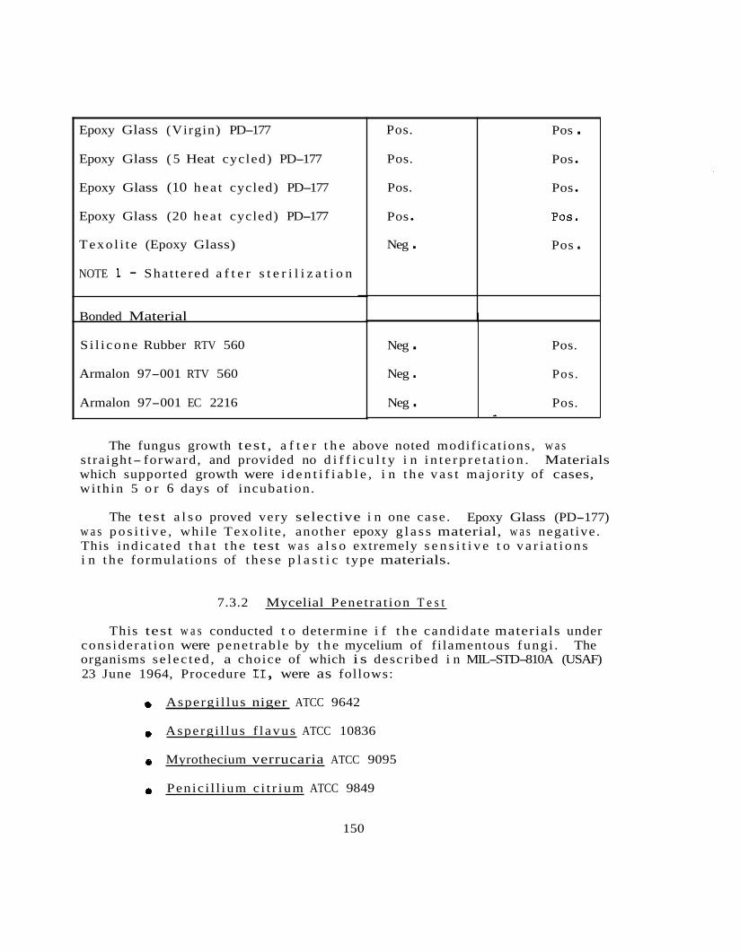
Epoxy Glass (Virgin) PD-177
Epoxy Glass ( 5 Heat cycled) PD-177
Epoxy Glass (10 hea t cycled) PD-177
Epoxy Glass (20 hea t cycled) PD-177
Texo l i t e (Epoxy Glass)
NOTE 1 - Shat te red a f t e r s t e r i l i z a t i o n
Bonded Material
S i l i cone Rubber RTV 560
Armalon 97-001 RTV 560
Armalon 97-001 EC 2216
Neg . Neg . Neg .
Pos.
Pos.
Pos.
Pos
Neg .
Pos.
Pos.
Pos. *
Pos . Pos
Pos
POS.
Pos .
The fungus growth tes t , a f t e r t h e above noted modif icat ions, w a s s t raight- forward, and provided no d i f f i c u l t y i n i n t e r p r e t a t i o n . Materials which supported growth were i d e n t i f i a b l e , i n t h e v a s t major i ty of cases, wi th in 5 o r 6 days of incubat ion.
The test a l s o proved very selective i n one case. Epoxy Glass (PD-177) w a s p o s i t i v e , while Texol i te , another epoxy g l a s s material, w a s negat ive. This ind ica ted t h a t t h e test w a s a l s o extremely s e n s i t i v e t o v a r i a t i o n s i n t h e formulat ions of t hese p l a s t i c type materials.
7.3.2 Mycelial Penet ra t ion T e s t
This test w a s conducted t o determine i f t h e candida te materials under cons idera t ion were penet rab le by t h e mycelium of fi lamentous fungi . organisms se l ec t ed , a choice of which i s described i n MIL-STD-810A (USAF) 23 June 1964, Procedure 11, were as follows:
The
0 Aspergi l lus niger ATCC 9642
0 Aspergi l lus f l avus ATCC 10836
0 Myrothecium verrucaria ATCC 9095
Penic i l l ium c i t r i um ATCC 9849
150
The test method u t i l i z e d w a s a l s o a modif icat ion of t h e above Standard spec i f i ca t ion . i n accordance wi th Spec i f i ca t ion MIL-F-8261AY whi le t h e c u l t u r e media chosen t o propagate each of t h e above se l ec t ed organisms w a s t h e same as t h a t used i n t h e fungus growth tests (Sect ion 7.3.1).
Performance t e s t i n g of t h e uandidate materials w a s done
The modif icat ions t o t h e standard test methods were necess i t a t ed by t h e incidence of spore migrat ion from t h e medium i n t h e base of t h e t e s t i n g p l a t e s , t o t h e medium i n t h e cy l inde r s superimposed on t h e test specimens. I n add i t i on , t h e o r i g i n a l volume of inoculum as prescr ibed w a s too high. The inoculum migrated t o t h e periphery of t h e test specimens and caused an abundant amount of growth i n t h a t area. spores i n t h e p l a t e s , which, upon migrat ion i n t h e condensate formed on t h e l i d s during incubat ion, r e su l t ed i n many f a l s e p o s i t i v e tests i n t h e ind ica t ing cy l inde r s . The test sample and con t ro l were both located i r one 150 mm diameter p e t r i d i s h , as prescr ibed i n t h e test p lan (ADpendix F ) . material w a s a l s o covered.
This produced an excess of
I n those cases where a l a r g e amount of growth was observed, t he test
To remedy these unforeseen circumstances t h e following modif icat ions were made:
1.
2.
3 .
The amount of medium used as a base w a s r a i s ed from 40 m l t o 120 m l . This e f f e c t i v e l y r a i s e d the test cy l inde r s t o t h e l i d of t h e 150 mm diameter p e t r i d i s h when they w e r e superimposed on t h e test specimen. Subsequent tests demonstrated t h a t t h i s d id not e n t i r e l y so lve t h e problem. When t h e con t ro l samples sporulated s u f f i c i e n t l y , spores s t i l l migrated by making use of t h e condensate which formed on t h e l i d s of t h e p e t r i d i shes during incubat ion.
A f i n a l so lu t ion w a s achieved by p lac ing t h e test material on a s i n g l e 100 mm diameter p e t r i d i s h , and t h e con t ro l samples on another . The base medium w a s then reduced i n volume t o 20 m l .
Using a s t e r i l i z e d cork borer , ho les were c u t i n t h e media i n t h e area where t h e test specimens w e r e t o be placed. served t o conta in t h e inoculum and prevented i t s migrat ion t o t h e periphery of t h e test material.
The spore suspension used as t h e inoculum w a s reduced i n volume t o 0.1 m l which a l s o acted as a de t e ren t i n prevent ing t h e migrat ion of inoculum t o t h e periphery of t h e test material.
This
.
The media used i n t h e performance of t h i s test w a s t h e Enriched Mineral S a l t s spec i f i ed i n MIL-F-8261A. g l u c o s e / l i t e r .
The enrichment cons is ted of 20 grams of
15 1
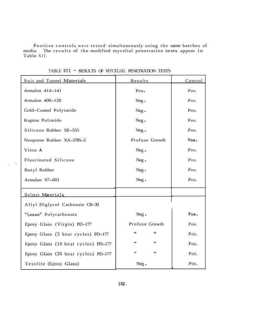
P o s i t i v e c o n t r o l s w e r e t e s t e d simultaneously using t h e same batches of media. The r e s u l t s of t h e modified mycel ial pene t r a t ion tests appear i n Table X I I .
Neg . Profuse Growth
I t 11
I 1 11
11 I 1
Neg .
TABLE XI1 - RESULTS OF MYCELIAL PENETRATION TESTS
POS.
Pos.
Pos.
Pos.
Pos.
Pos. i
S u i t and Tunnel Materials
Armalon 414-141
Armalon 408-128
Gold-Coated Polyimide
Kapton Polimide
S i l i cone Rubber SE-555
Neoprene Rubber XA-3785-2
Viton A
Fluorinated S i l i cone
Butyl Rubber
Armalon 97-001
H e l m e t Mat er i a 1s.
A l l y l Diglycol Carbonate CR-39
"Lexan" Polycarbonate
Epoxy Glass (Virgin) PD-177
Epoxy Glass (5 hea t cyc les ) PD-177
Epoxy Glass (10 h e a t cyc les ) PD-177
Epoxy Glass (20 hea t cyc les ) PD-177
Texo l i t e (Epoxy Glass)
Resul t s
Pos
Neg . Neg . Neg . Neg .
Profuse Growth
Neg . Neg . Neg . Neg .
Control
Pos.
Pos.
Pos.
Pos.
Pos.
Pos *
Pos.
Pos.
Pos.
Pos.
152.
f
' Face P l a t e Materials Resul t s
S i l i cone RTV 560
Armalon 97-001 RTV 560
Control
Neg . Neg .
A l l y l Diglycol Carbonate CR-39
"Lexan" Po 1 y c a rb ona t e
Bonded Materials
Pos .
Pos .
Shattered a f t e r s t e r i l i z a t i o n
Neg . Pos
The test procedures prescr ibed i n MIL-STD-810A (USAF) and MIL-F-8261AY and modified as previously noted, may e a s i l y g ive rise t o misleading re- s u l t s , and f o r t h i s reason, c a r e must be exercised during i n t e r p r e t a t i o n of t he test da t a . For example, Epoxy Glass (PD-177) exhibi ted such pro- fuse growth, t h a t no d e f i n i t e conclusion could be made as t o whether o r no t mycel ial pene t r a t ion had i n f a c t occurred without f u r t h e r study. Microscopic examination showed t h a t t h e cycelium had penetrated i n t o t h e body of t h e material , but not through i t . considered p o s i t i v e f o r Mycelial Penet ra t ion .
The material w a s t he re fo re
I n c o n t r a s t t o t h e Epoxy Glass (PD-177) discussed above, t h e p o s i t i v e ind ica t ion f o r Armalon 414 could not be mis in te rpre ted s ince Armalon 414 does not support fungus growth. b i a l Permeabil i ty , confirmed t h e f a c t t h a t Armalon 414, while no t con- t r i b u t i n g t o t h e support of microorganisms, i s permeable t o t h e organisms themselves.
(See Table X I ) A subsequent t es t , Micro-
7.3.3 Transfer of Microorganisms, Liquids, and Gases Across Su i t Materials
The ob jec t ive of t h e s e tests w a s t o determine whether o r no t materials which had been exposed t o phys ica l and chemical stresses were thereby dam--- aged s u f f i c i e n t l y enough by wear t o enable microorganisms, l i q u i d s , and gases t o pass through them. unt rea ted materials.
Test ing w a s conducted on both t r e a t e d and
I n most ins tances , va lues f o r t h e permeabil i ty of t h e candidate materials exposed t o l i q u i d s and gases , such as water vapor and carbon dioxide, were obtained from t h e a v a i l a b l e l i t e r a t u r e and appear i n Appendix I- X I . For o the r s , t h e va lues were obtained experimentally. Two labora- to ry tests w e r e developed t o measure t h e permeabil i ty of t h e candidate
153
materials t o microorganisms. These were, t h e rad io iso tope test and t h e v i a b l e c u l t u r e Spinner Flask confirming test. Both tests are explained i n g r e a t e r d e t a i l below.
The o the r phys ica l tests performed were a gas permeabil i ty test using helium as t h e test agent and t h e r e t e n t i o n and release of de ter- gents and d i s i n f e c t a n t s tests. The la t ter tests u t i l i z e d two l i q u i d s and one gaseous d i s i n f e c t a n t , each of which required a d i f f e r e n t method of de tec t ion .
7.3.3.1 Transfer of Microorganisms Across Su i t ti Bonded Materials
7.3.3.1.1 t o test chambers, as i l l u s t r a t d i n Figures 52 and 53 which were then f i l l e d with a suspension of C1' l abe led Micrococcus candidus of s p e c i f i c a c t i v i t y (0.12 cpm/bacterium). A background count of t h e material w a s made j u s t p r i o r t o t h e inocula t ion of t h e test organisms, and another background count w a s made immediately a f t e r inocula t ion . The chambers were then pressur ized t o 4" water and held f o r twenty-four hours. Following t h e test per iod, t h e chambers were placed i n t h e gas flow propor t iona l counter (Baird-Atomic Model 146) t o measure t h e radio- a c t i v i t y . A s u f f i c i e n t number of counts were obtained i n a l l cases t o g ive a probable e r r o r of 5%. Any increase i n t h e sample count rate g r e a t e r than 5 counts per minute w a s assumed t o i n d i c a t e t h e permea- b i l i t y of t h e material t o microorganisms. I n a few cases, f a l s e in- d i c a t i o n s of permeabil i ty occurred due t o l eaks i n t h e test chambers. A s a r e s u l t , a s tudy method of t e s t i n g w a s i n i t i a t e d us ing punctured materials conta in ing holes of known dimensions. To accomplish t h i s , samples of gold-coated polyimide f i l m and Armalon 408-128 were t r e a t e d with a focused laser beam t o produce holes averaging 70 microns i n dia- meter. The h o l e s i z e s w e r e measured with an ocular micrometer. The ho le s produced i n t h e Armalon were s l i g h t l y i r r e g u l a r , bu t a l s o averaged 70 microns i n diameter. Two ho le s were produced i n each sample and t h e samples w e r e then f ixed t o test chambers. A background count w a s made of t h e test samples which w e r e then f i l l e d with a suspension of C 14 labe led E. candidus of s p e c i f i c a c t i v i t y (0.12 cpdbacter ium) . Back- ground counts were made aga in with t h e test chambers a t ambient pressure. The chambers were pressurized t o 4" H 2 0 , allowed t o s tand f o r one hour, and then counted again.
Radioisotope Procedure - The candidate materials were at tached
The r e s u l t s are presented i n Table X I I I .
154
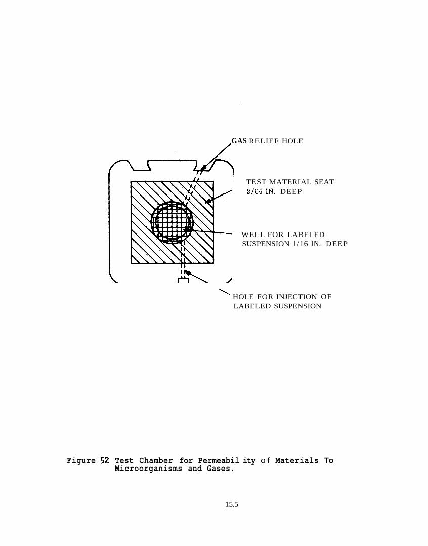
GAS RELIEF HOLE /
TEST MATERIAL SEAT 3/64IN. DEEP
WELL FOR LABELED SUSPENSION 1/16 IN. DEEP
' HOLE FOR INJECTION OF LABELED SUSPENSION
Figure 52 Test Chamber for Permeabil ity o f Materials To Microorganisms and Gases.
15.5
Figure 53 Planchet e s t Chamber Construct ion
156
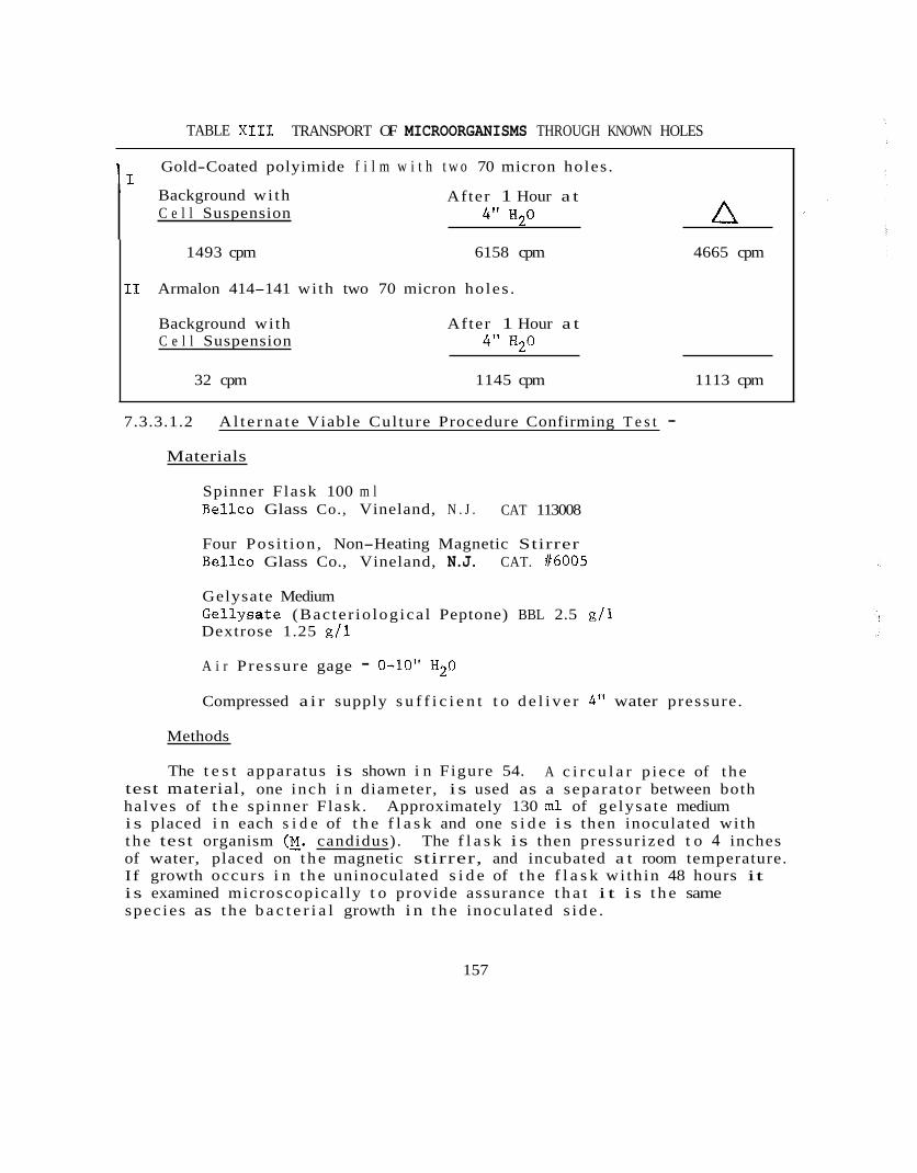
TABLE XI11 TRANSPORT OF MICROORGANISMS THROUGH KNOWN HOLES
11 Gold-Coated polyimide f i l m w i t h t w o 70 micron holes .
Background wi th C e l l Suspension A After 1 Hour a t
4" H20
1493 cpm 6158 cpm 4665 cpm
I1 Armalon 414-141 with two 70 micron ho les .
Background with After 1 Hour a t C e l l Suspension 4" H 2 0
32 cpm 1145 cpm 1113 cpm
7.3.3.1.2 A l t e rna t e Viable Cul ture Procedure Confirming T e s t -
Materials
Spinner Flask 100 m l Bel lco Glass Co., Vineland, N . J . CAT 113008
Four Pos i t ion , Non-Heating Magnetic Stirrer Bellco Glass Co., Vineland, N.J. CAT. f6005
Gelysate Medium Gel lysa te (Bac te r io log ica l Peptone) BBL 2.5 g / 1 Dextrose 1.25 g / 1
A i r P ressure gage - 0-10" H20
Compressed a i r supply s u f f i c i e n t t o d e l i v e r 4" water pressure .
Methods
The t e s t apparatus is shown i n Figure 54. test material, one inch i n diameter, i s used as a separa tor between both halves of t h e spinner Flask. i s placed i n each s i d e of t h e f l a s k and one s i d e i s then inoculated with t h e test organism (E. candidus). of water, placed on t h e magnetic stirrer, and incubated a t room temperature. If growth occurs i n t h e uninoculated s i d e of t h e f l a s k wi th in 48 hours it i s examined microscopical ly t o provide assurance t h a t i t i s t h e same spec ies as t h e b a c t e r i a l growth i n t h e inoculated s ide .
A c i r c u l a r p iece of t he
Approximately 130 m l of ge lysa te medium
The f l a s k i s then pressur ized t o 4 inches
157

v) 3 w m L
IJY Q) I-
?
158
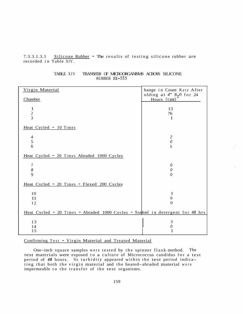
7.3.3.1.3.1 recorded i n Table X I V .
S i l i cone Rubber - The r e s u l t s of t e s t i n g s i l i c o n e rubber are
Heat Cycled - 20 T i m e s - Abraded 1000 Cycles -
TABLE X I V TRANSFER OF MICROORGANISMS ACROSS SILICONE RUBBER SE-555
SoaKed i n de tergent f o r 48 hr s
Virgin Material
Chamber
1 2 3
Heat Cycled - 10 T i m e s
4 5 6
Heat Cycled - 20 T i m e s Abraded 1000 Cycles
7 8 9
Heat Cycled - 20 T i m e s - Flexed 200 Cycles
10 11 12
hange i n Count R a t e Af te r olding a t 4" H 2 0 f o r 24
Hours (cpm)
13 76 1
2 0 1
0 0 0
1 0 0
13 14
3 I 0 15 1 I
Confirming T e s t - Virgin Material and Treated Material
One-inch square samples w e r e t e s t e d by t h e spinner f l a s k method. The
N o t u r b i d i t y appeared wi th in t h e test period indica- test materials were exposed t o a c u l t u r e of Micrococcus candidus f o r a tes t per iod of 48 hours. t i n g t h a t both t h e v i r g i n material and t h e heated-abraded material w e r e impermeable t o t h e t r a n s f e r of t h e test organisms.
159
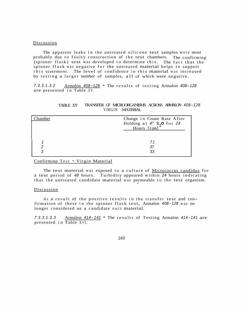
Discussion
The apparent l eaks i n t h e unt rea ted s i l i c o n e test samples w e r e most probably due t o f a u l t y cons t ruc t ion of t h e test chambers. (spinner f l a s k ) test w a s developed t o determine t h i s . spinner f l a s k w a s nega t ive f o r the unt rea ted material he lps t o support t h i s s ta tement . The level of confidence i n t h i s material w a s increased by t e s t i n g a l a r g e r number of samples, a l l of which were negat ive.
The confirming The f a c t that t h e
7.3.3.1.3.2 are presented i n Table X V .
Armalon 408-128 - The r e s u l t s of t e s t i n g Armalon 408-128
TABLE XV TRANSFER OF MICROORGANISMS ACROSS ARMALON 408-128 VIRGIN MATERIAL
Chamber Change i n Count Rate Af ter Holding a t 4" H 2 0 f o r 24
Hours (cpm)
1 7 1 2 37 3 33
Confirminp T e s t - Virgin Material
The test material w a s exposed t o a c u l t u r e of Micrococcus candidus f o r a test period of 48 hours. Turb id i ty appeared wi th in 24 hours i nd ica t ing t h a t t h e unt rea ted candidate material w a s permeable t o t h e test organism. ,
Discussion
A s a r e s u l t of t h e p o s i t i v e r e s u l t s i n t h e t r a n s f e r test and con- f i rmat ion of t hese i n t h e spinner f l a s k test , Armalon 408-128 w a s no longer considered as a candidate s u i t material.
7.3.3.1.3.3 presented i n Table XVI .
Armalon 414-141 - The r e s u l t s of Test ing Armalon 414-141 are
160
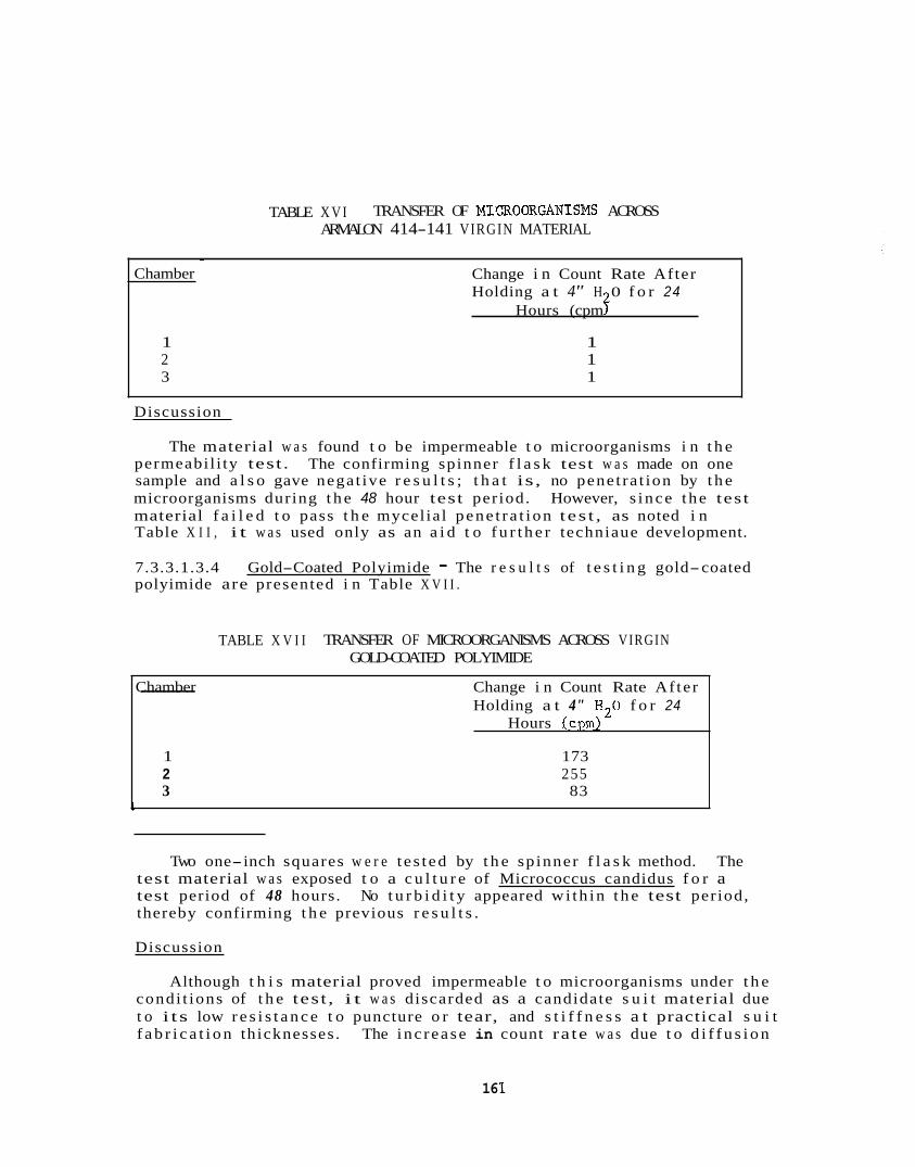
TABLE X V I TRANSFER OF MIrfROORGANISMS ACROSS ARMALON 414-141 VIRGIN MATERIAL
Chamber Change i n Count Rate Af ter -- Holding a t 4" H 2 0 f o r 24
Hours (cpm)
1 173 2 255 3 83
1
~
Chamber Change i n Count Rate After Holding a t 4" H 0 f o r 24
Hours (cpm f 1 1 2 1 3 1
Discussion
The material w a s found t o be impermeable t o microorganisms i n t h e permeabil i ty test . The confirming spinner f l a s k test w a s made on one sample and a l s o gave negat ive r e s u l t s ; t h a t is, no penet ra t ion by t h e microorganisms during t h e 48 hour test per iod. However, s ince the tes t material f a i l e d t o pass t h e mycel ial pene t r a t ion t es t , as noted i n Table X I I , i t w a s used only as an a i d t o f u r t h e r techniaue development.
7.3.3.1.3.4 Gold-Coated Polyimide - The r e s u l t s of t e s t i n g gold-coated polyimide are presented i n Table X V I I .
TABLE X V I I TRANSFER OF MICROORGANISMS ACROSS VIRGIN GOLD-COATED POLYIMIDE
Two one-inch squares w e r e t e s t ed by t h e sp inner f l a s k method. test material w a s exposed t o a c u l t u r e of Micrococcus candidus f o r a test period of 48 hours. thereby confirming t h e previous r e s u l t s .
The
No t u r b i d i t y appeared wi th in t h e test period,
Discussion
Although t h i s material proved impermeable t o microorganisms under t h e condi t ions of t h e tes t , i t w a s discarded as a candidate s u i t material due t o i t s low r e s i s t a n c e t o puncture o r tear, and s t i f f n e s s a t practical s u i t f a b r i c a t i o n thicknesses . The inc rease in count ra te w a s due t o d i f f u s i o n
16 1

of c e l l c o n s t i t u e n t s through t h e membrane. spinner f l a s k test as noted above.
This w a s confirmed by t h e
7.3.3.1.3.5 Armalon 97-001 - The r e s u l t s of t e s t i n g Armalon 97-001 are recorded i n Table XVIII.
TABLE XVIII TRANSFER OF MICROORGANISMS ACROSS ARMALON 97-001
Virgin Material
Chamber
1 2 3
Heat Cycled - 20 T i m e s - Flexed 200 Cycles
4 5 6
Change i n Count Rate After Holding a t 4” H 2 0 f o r 24
Hours (cpm)
1 2 0
1 1 2
Soaked i n Detergent f o r 48 hours - Heat Cycled - 20 T i m e s - Abraded 1000 Cycles
7 2 8 2 9 0
Confirming T e s t - Virgin Material
Two one-inch squares w e r e t e s t e d by t h e spinner f l a s k method. The tes t material w a s exposed t o a c u l t u r e of Mtcrococcus candidus f o r a test per- iod of 48 hours. confirming t h e previous r e s u l t s .
No turb id i tyappenred- w i th in t h e test per iod, therebv
7.3.3.1.3.6 recorded i n Table X I X .
Neoprene Rubber - The r e s u l t s of t e s t i n g neoprene rubber are
16 2
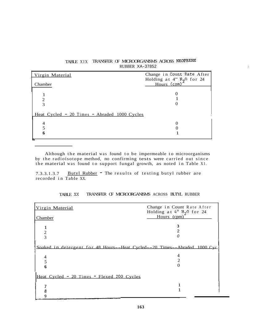
TABLE X I X TRANSFER OF MICROORGANISMS ACROSS NEOPmm RUBBER XA-37852
Virgin Material
Chamber Hours (cpm)
Change i n Count'Rate After Holding a t 4" H20 f o r 24
4 0 5 0 6 1
L
1 2 3
Heat Cycled - 20 T i m e s - Abraded 1000 Cycles
Virgin Material
Chamber
0 1 0
Although t h e material w a s found t o b e impermeable t o microorganisms by t h e rad io iso tope method, no confirming tests were ca r r i ed out s i n c e t h e material w a s found t o support fungal growth, as noted i n Table X I .
7.3.3.1.3.7 recorded i n Table XX.
Butyl Rubber - The r e s u l t s of t e s t i n g b u t y l rubber are
TABLE XX TRANSFER OF MICROORGANISMS ACROSS BUTYL RUBBER
Change i n Count R a t e A f t e r Holding a t 4" H20 f o r 24
Hours (cpm)
1 2 3
3 2 0
I Soaked i n de tergent f o r 48 Hours--Heat Cycled--20 Times--Abraded 1000 Cyc. I 4 5 6
4 2 0
Heat Cycled - 20 T i m e s - Flexed 200 Cycles I 1 1
163

Confirming T e s t - Virgin Material
Two one-inch squares were t e s t e d by t h e spinner f l a s k method. tes t material w a s exposed t o a c u l t u r e of Micrococcus sandidus f o r a test period of 48 hours. thereby confirming t h e previous r e s u l t s .
The
No t u r b i d i t y appeared wi th in t h e test per iod,
7.3.3.2 Transfer of Microorganisms Across Bonding Materials
Two of t h e prime candidate materials, S i l i cone Subber SE-555 and Armalon 97-001, were t e s t ed f o r microbial i n t e g r i t y . s ec t ions were bonded using RTV 560; t h e armalon sec t ions w e r e bonded using EC-2216. d i t i o n , and a l s o fol lowing exposure t o hea t , f l ex ing , and d i s i n f e c t a n t t reatments .
The s i l i c o n e rubber
T e s t s w e r e run on t h e materials i n t h e untreated con-
The test r e s u l t s appear i n Tables XXI and XXTI.
TABLE XXI TRANSFER OF MICROORGANISMS ACROSS BONDED SILICONE RUBBER 53-555
Virgin Material Change i n Count Rate After ' Holding a t 4" H,O f o r 24
Chamber
7 24 10
Vis ib le leak Vi s ib l e leak
Exposed t o Di s in fec t an t f o r 48 hours - f lexed 200 cycles
6 7 8
56 90 7 2
Exposed t o Ethylene Oxide Cycles - Heated 10 Cycles - Flexed 200 Cycles
9 22 10 7 11 29
A confirming test , spinner f l a s k method, w a s not performed on t h i s material.
164
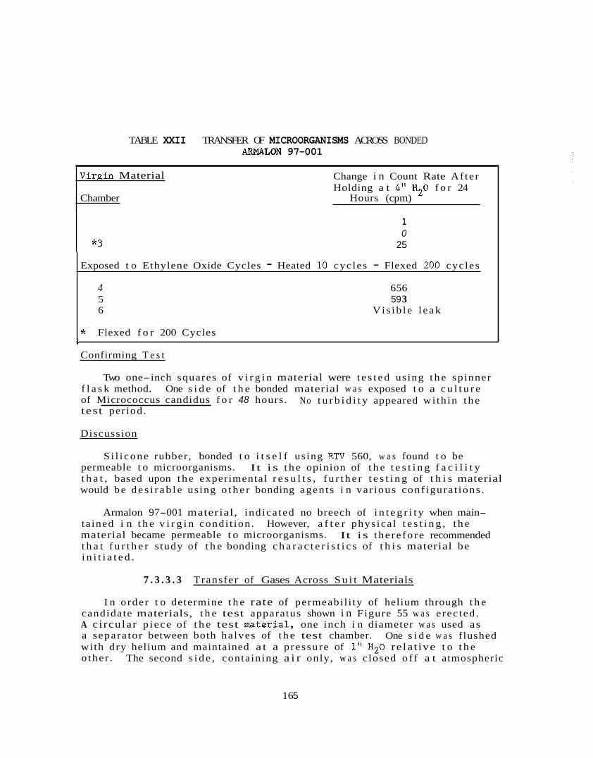
TABLE XXII TRANSFER OF MICROORGANISMS ACROSS BONDED ARMALOM 97-001
Exposed t o Ethylene Oxide Cycles - Heated 10 cyc les - Flexed 200 cycles
4 656 5 59 3 6 Vi s ib l e l eak
* Flexed f o r 200 Cycles 1
Virgin Material
Chamber Hours (cpm)
Change i n Count Rate Af ter Holding a t 4" H20 f o r 24
*3
1 0
25
Confirming T e s t
Two one-inch squares of v i r g i n material were t e s t e d using t h e spinner f l a s k method. One s i d e of t h e bonded material w a s exposed t o a c u l t u r e of Micrococcus candidus f o r 48 hours. No t u r b i d i t y appeared wi th in t h e test per iod.
Discussion
S i l i cone rubber, bonded t o i t s e l f using RTV 560, w a s found t o be permeable t o microorganisms. t h a t , based upon t h e experimental r e s u l t s , f u r t h e r t e s t i n g of t h i s material would b e d e s i r a b l e using o t h e r bonding agents i n var ious conf igura t ions .
It i s t h e opinion of t h e t e s t i n g f a c i l i t y
Armalon 97-001 material, ind ica ted no breech of i n t e g r i t y when main- tained i n t h e v i r g i n condi t ion . However, a f t e r phys ica l t e s t i n g , t h e material became permeable t o microorganisms. t h a t f u r t h e r s tudy of t h e bonding c h a r a c t e r i s t i c s of t h i s material be i n i t i a t e d .
It is the re fo re recommended
7 . 3 . 3 . 3 Transfer of Gases Across S u i t Materials
I n order t o determine t h e rate of permeabil i ty of helium through t h e candidate materials, t h e test apparatus shown i n Figure 55 w a s e rec ted . A circular p i ece of t h e test material, one inch i n diameter w a s used as a separa tor between both ha lves of t h e test chamber. with dry helium and maintained a t a pressure of 1" H 2 0 relative t o t h e o ther .
One s i d e w a s f lushed
The second s i d e , containing a i r only, w a s c losed o f f a t atmospheric
16 5
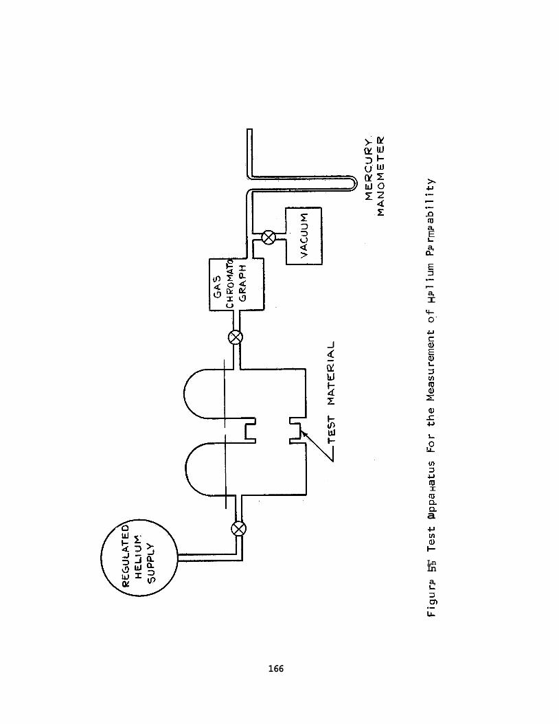
>- 6, .- c .- D m a, E L a, 0,
.- c a, I
3
w ([I I m Q Q a
Ln Ln a, L
166
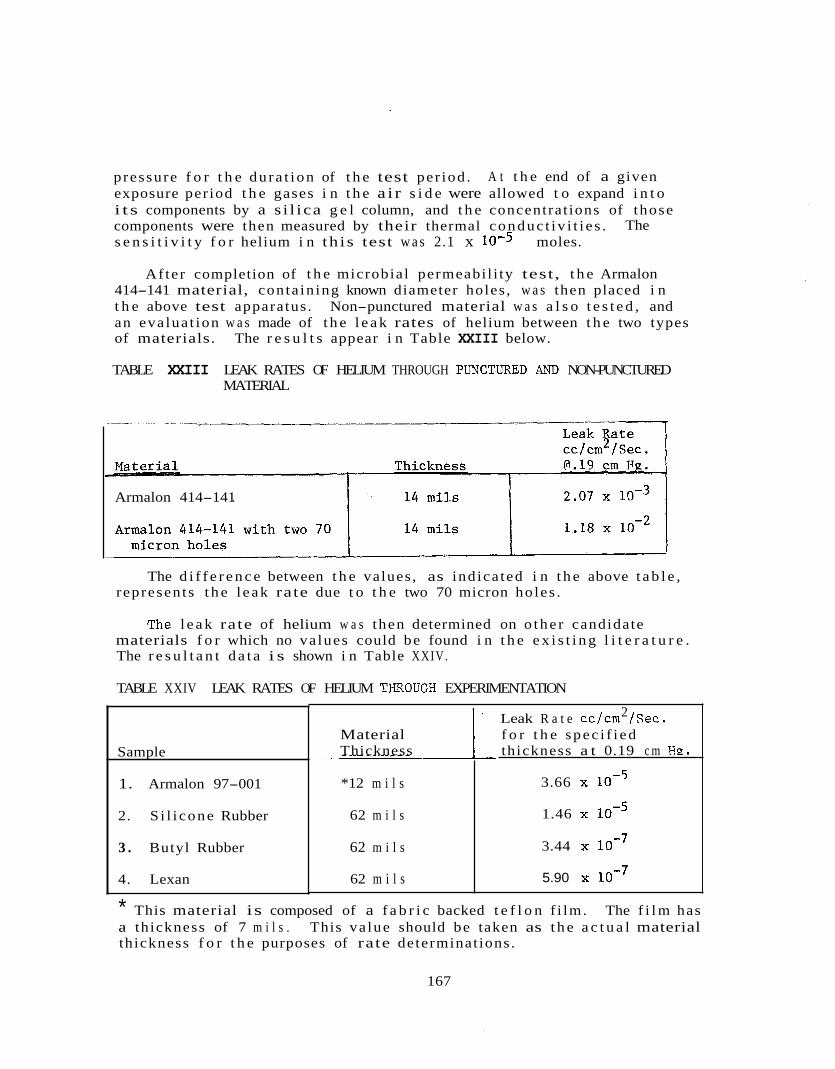
pressure f o r t h e du ra t ion of t h e test per iod . exposure period t h e gases i n t h e a i r s i d e were allowed t o expand i n t o i t s components by a s i l ica g e l column, and t h e concentrat ions of those components were then measured by their thermal conduc t iv i t i e s . s e n s i t i v i t y f o r helium i n th i s test w a s 2.1 x moles.
A t t h e end of a given
The
Af ter completion of t h e microbial permeabil i ty test, t h e Armalon 414-141 material, conta in ing known diameter holes , w a s then placed i n t h e above test apparatus . Non-punctured material w a s a l s o t e s t e d , and an eva lua t ion w a s made of t h e l e a k rates of helium between t h e two types of materials. The r e s u l t s appear i n Table XXIII below.
TABLE XXIII LEAK RATES OF HELIUM THROUGH PLJNCTWD AND NON-PUNCTURED MATERIAL
_I_ _ _ -
Armalon 414-141
The d i f f e r e n c e between t h e values, as ind ica ted i n t h e above t a b l e , represents t h e l eak rate due t o t h e two 70 micron holes .
The l e a k rate of helium w a s then determined on o the r candidate materials f o r which no va lues could be found i n t h e e x i s t i n g l i t e r a t u r e . The r e s u l t a n t d a t a i s shown i n Table XXIV.
TABLE XXIV LEAK RATES OF HELIUM TIPROUGH EXPERIMENTATION
Sample
1. Armalon 97-001
2. S i l i cone Rubber
3 . Butyl Rubber
4. Lexan
2 Leak R a t e cc/cm /Sec. Material f o r t h e spec i f i ed Thickness thickness a t 0.19 c m HP.
*12 m i l s
62 m i l s
62 m i l s
62 m i l s
3.66
1.46
3.44
5.90
* This material is composed of a f a b r i c backed t e f l o n f i lm. The f i l m has a thickness of 7 m i l s . This va lue should be taken as t h e a c t u a l material thickness f o r t h e purposes of rate determinat ions.
167
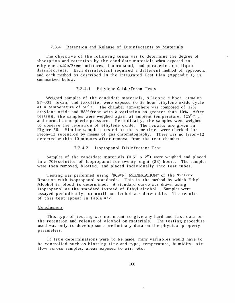
7.3.4 Retent ion and Release of D i s in fec t an t s by Materials
The ob jec t ive of t h e following tests w a s t o determine t h e degree of absorp t ion and r e t e n t i o n by t h e candidate materials when exposed t o ethylene oxide/Freon mixtures, isopropanol, and pe race t i c ac id l i q u i d d i s i n f e c t a n t s . and each method as described i n t h e In tegra ted Test Plan (Appendix I) is summarized below.
Each d i s i n f e c t a n t required a d i f f e r e n t method of approach,
7.3.4.1 Ethylene Oxide/Freon Tests
Weighed samples of t h e candidate materials, s i l i c o n e rubber, armalon 97-001, lexan, and t e x o l i t e , were exposed t o 28 hour ethylene oxide cyc le a t a temperature of 5OoC. The chamber atmosphere w a s composed of 12% ethylene oxide and 88% f reon with a v a r i a t i o n no g rea t e r than 10%. After t e s t i n g , t h e samples were weighed again a t ambient temperature, (25OC) , and normal atmospheric pressure . Pe r iod ica l ly , t h e samples were weighed t o observe t h e r e t e n t i o n of e thylene oxide. Figure 56. Similar samples, t e s t ed a t t h e same t i m e , were checked f o r Freon-12 r e t e n t i o n by means of gas chromatography. de tec ted wi th in 10 minutes a f t e r removal from t h e test chamber.
The r e s u l t s are given i n
There w a s no freon-12
7.3.4.2 Isopropanol Dis infec tan t T e s t
Samples of t h e candidate materials (0.5" x 2") were weighed and placed The samples i n a 70% s o l u t i o n of Isopropanol f o r twenty-eight (28) hours.
were then removed, b l o t t e d , and placed indiv idual ly i n t o test tubes.
Test ing w a s performed using "BOGENS MODIFICATION" of t he Nicloux Reaction with isopropanol s tandards. This i s the method by which Ethyl Alcohol i n blood is determined. A standard curve w a s drawn using isopropanol as t h e s tandard ins tead of Ethyl a lcohol . assayed pe r iod ica l ly , o r u n t i l no a lcohol w a s de t ec t ab le . The r e s u l t s of t h i s test appear i n Table XXV.
Samples were
Conclusions
This type of t e s t i n g w a s no t meant t o g ive any hard and f a s t d a t a on t h e r e t e n t i o n and release of a lcohol on materials. The t e s t i n g procedure used w a s only t o develop some prel iminary da t a on t h e phys ica l property parameters.
I f t r u e determinat ions were t o b e made, many v a r i a b l e s would have t o be cont ro l led such as b l o t t i n g t i m e and type, temperature, humiditv, a i r flow across samples, areas exposed t o a ir , etc.
16 8

F igu re 56 Release o f Ethylene Oxide From Candidate Ma te r i a l s
169
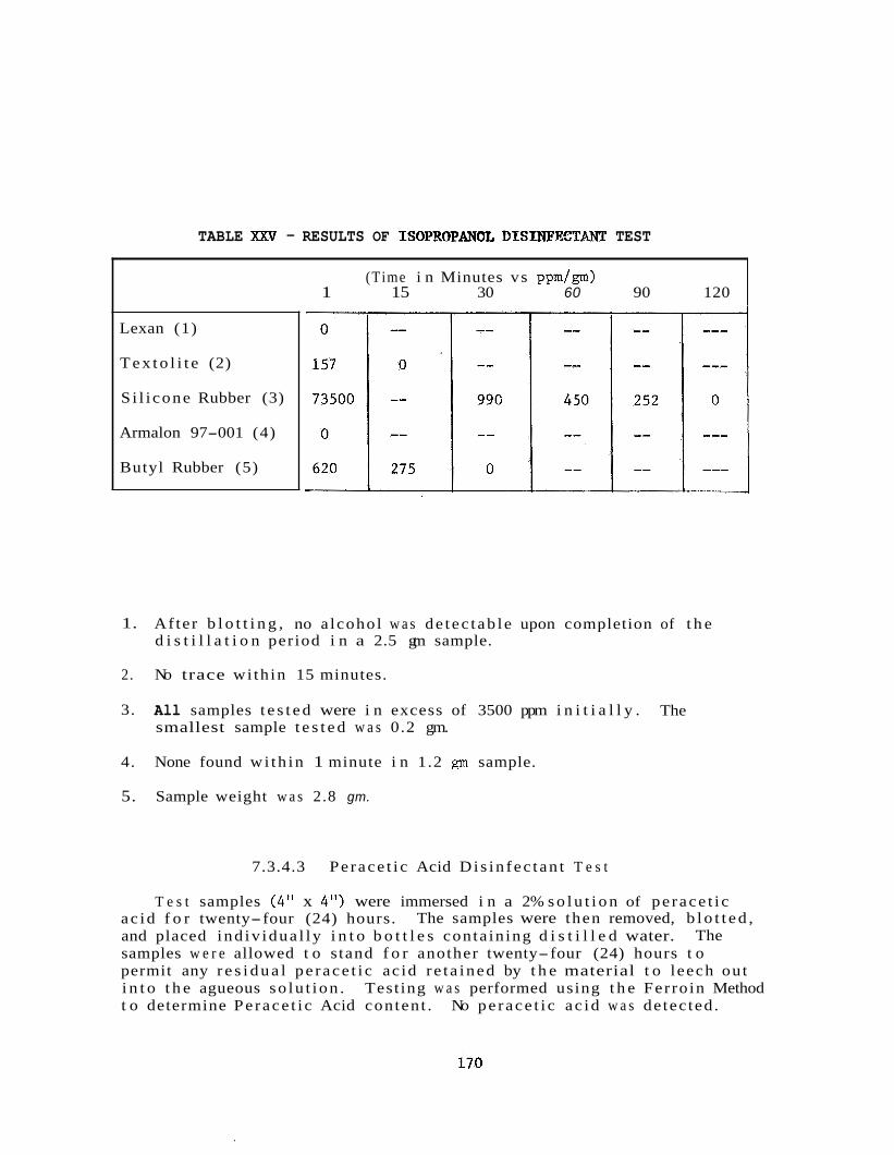
TABLE X X V - RESULTS OF ISOPROFANOL DISINFKTANT TEST
(Time i n Minutes vs ppmlgm) 1 15 30 60 90 120
Lexan (1)
T e x t o l i t e (2)
S i l i cone Rubber (3)
Armalon 97-001 (4)
Butyl Rubber (5)
1. Af ter b l o t t i n g , no a lcohol w a s de t ec t ab le upon completion of t h e d i s t i l l a t i o n period i n a 2.5 gm sample.
2. No trace wi th in 15 minutes.
3. All samples t e s t e d were i n excess of 3500 ppm i n i t i a l l y . smallest sample t e s t e d w a s 0.2 gm.
The
4. None found wi th in 1 minute i n 1.2 p sample.
5. Sample weight w a s 2.8 gm.
7.3.4.3 Pe race t i c Acid Di s in fec t an t T e s t
T e s t samples (4" x 4") were immersed i n a 2% s o l u t i o n of pe race t i c ac id f o r twenty-four (24) hours. and placed ind iv idua l ly i n t o b o t t l e s conta in ing d i s t i l l e d water. samples w e r e allowed t o s tand f o r another twenty-four (24) hours t o permit any r e s i d u a l pe race t i c ac id r e t a ined by t h e material t o leech out i n t o t h e agueous so lu t ion . t o determine Pe race t i c Acid conten t .
The samples were then removed, b l o t t e d , The
Test ing w a s performed using t h e Fer ro in Method No pe race t i c ac id w a s de tec ted .
i70
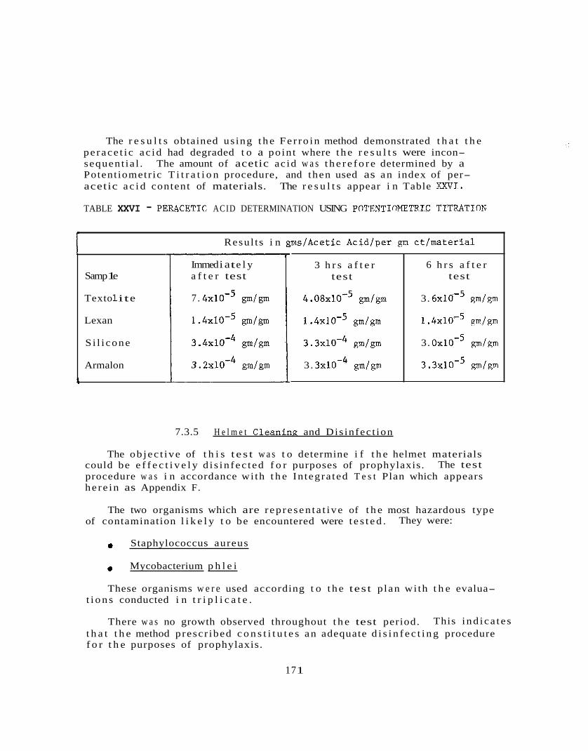
The r e s u l t s obtained us ing t h e Fe r ro in method demonstrated t h a t t h e pe race t i c ac id had degraded t o a poin t where t h e r e s u l t s were incon- sequent ia l . The amount of acetic ac id w a s t h e r e f o r e determined by a Potent iometr ic T i t r a t i o n procedure, and then used as an index of per- acetic a c i d content of materials. The r e s u l t s appear i n Table XXVI.
3 h r s a f t e r test
4 . 0 8 ~ 1 0 - ~ gm/gm
1 . 4 ~ 1 0 - ~ gm/gm
3 . 3 ~ 1 0 - ~ gm/gm
3. 3 x W 4 gm/gm
TABLE XXVI - PEPACETIC ACID DETERMINATION USING POTENTIN'fllTRIC TITRATION
6 h r s a f t e r test
3. 6 x ~ ~ - 5 gm/gm
1 . 4 ~ 1 0 - ~ gm/gm
3. O X ~ O - ~ gm/gm
3 . 3 ~ 1 0 - ~ gm/gm
Samp 1 e
Text o 1 it e
Lexan
S i l i cone
Armalon i
Resul t s i n gms/Acetic Acid/per gm ct/material
Immed i a t e l y a f t e r test
7 . 4 x W 5 gm/gm
1 . 4 ~ 1 0 - ~ gm/gm
3 . 4 ~ 1 0 - ~ gm/gm
3 . 2 x N 4 gm/gm
7.3.5 H e l m e t Cleaninp and Dis infec t ion
The ob jec t ive of t h i s t e s t w a s t o determine i f t h e helmet materials could be e f f e c t i v e l y d i s in fec t ed f o r purposes of prophylaxis. The test procedure w a s i n accordance wi th t h e In tegra ted T e s t Plan which appears he re in as Appendix F.
The two organisms which are r ep resen ta t ive of t h e most hazardous type of contamination l i k e l y t o be encountered were t e s t e d . They were:
Staphylococcus aureus
Mycobacterium p h l e i
These organisms w e r e used according t o t h e tes t p lan wi th t h e evalua- t i o n s conducted i n t r i p l i c a t e .
There w a s no growth observed throughout t h e test period. This i nd ica t e s t h a t t h e method prescr ibed c o n s t i t u t e s an adequate d i s i n f e c t i n g procedure f o r t h e purposes of prophylaxis.
17 1
8.0 MOCK-UP TEST PROGRAM -
8.1 INTRODUCTION
The BISS mock-up study program was intended t o serve two major purposes :
0 Provide an empir ical t e s t i n g t o examine the f e a s i b i l i t y of operat ing i n the environment pecu l i a r t o the BISS concept.
Provide a means f o r experimental examination of developing system concepts t o support concept development t rade- of fs .
The e a r l i e s t dec i s ion i n t he mock-up s tudy was t h a t of approach, t h a t i s : should the s tudy program provide f o r subsystem t e s t s , each developed i n i t s own context , and meeting downstream i n the procure- ment of mock-up equipment; o r should the study program be conducted i n two phases, wi th a l l subsystems i n t eg ra t i ng i n both phases? The deci- s ions was t o use t h e second approach because it was f e l t t h a t while t he r e was considerable information ava i l ab l e about l i f e support and communications systems and p ro t ec t i ve s u i t s a s separa te e n t i t i e s , the major unknown i n t he BISS program was t he i n t eg ra t i on of these subsys- tems i n t o an operat ing system f o r use i n the Assembly/Ster i l izer , Hence, the e a r l i e s t goal was t o ga in experience i n the these subsystems i n a BISS environment, and f o r t h i s purpose i t would be b e s t t o have a rudimentary system ava i l ab l e a s an e n t i t y . mentary system could then be examined i n d e t a i l under the spec i a l BISS condi t ions and a second phase would then serve the purpose of incorpor- a t i n g a l l of t he da ta and experience gained i n the f i r s t phase i n t o a more re f ined system. a prime BISS system and the da ta from tests on t h i s re f ined system would more c lo se ly r e f l e c t u l t imate BISS operat ions . Moreover, t h i s mode of s tudy allowed o ther program developments ( f ab r i c s s tudy, bacter iology, physiology, e t c ) t o develop da ta which could be used i n the second phase and
use of
This rud i-
This second system would then b e t t e r simulate
provide add i t i ona l refinements not poss ib le f o r the f i r s t phase.
The mock-up t e s t s d id not simulate BISS s t e r i l i z a t i o n condi t ions . Ins tead , the mock-up program aimed a t t he s imulat ion of a l l BISS condi- t i ons ou ts ide of s t r i c t s t e r i l e requirements. For t h i s purpose a cham- ber had t o be procured o r modified, and t e s t ed f o r p r e s su r i za t i on . 1 2 x 1 2 x 20-foot Tenney A l t i t ude was used f o r the BISS tests, and was modified t o serve a s a pressure chamber by clamping the main chamber door and i n s t a l l i n g a heavy wooden framework, which supported the hatch assem- b l y i n place of a small door loca ted i n the cen te r of the main door. Also, s ta i rways and an emergency access door were i n s t a l l e d t o make the
A
172
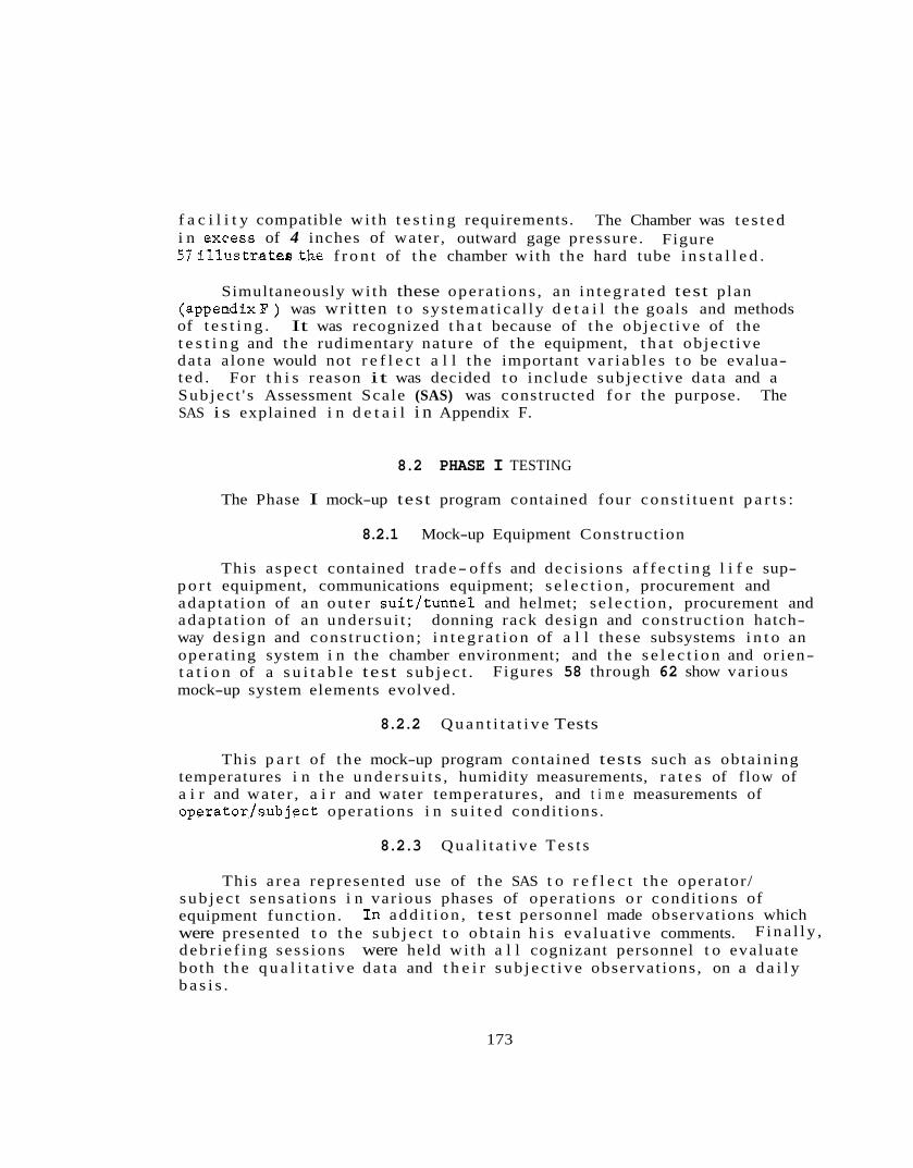
f a c i l i t y compatible wi th t e s t i n g requirements. i n excess of 4 inches of water , outward gage pressure . 5 7 i l l u s t r a t e ~ t h e f r o n t of t he chamber wi th the hard tube i n s t a l l e d .
The Chamber was t e s t ed Figure
Simultaneously wi th these opera t ions , an i n t eg ra t ed test plan (appendixl?) was wri t ten t o sys temat ica l ly d e t a i l t he goals and methods of t e s t i n g . It was recognized t h a t because of t h e ob jec t ive of the t e s t i n g and the rudimentary nature of t he equipment, t h a t ob jec t ive da ta a lone would not r e f l e c t a l l t he important va r i ab l e s t o be evalua- t ed . For t h i s reason it was decided t o include sub jec t ive da ta and a Subjec t ' s Assessment Scale (SAS) was constructed f o r the purpose. The SAS i s explained i n d e t a i l i n Appendix F.
8.2 PHASE I TESTING
The Phase I mock-up test program contained four cons t i tuen t p a r t s :
8.2.1 Mock-up Equipment Construction
This aspec t contained t rade- of fs and dec i s ions a f f e c t i n g l i f e sup- p o r t equipment, communications equipment; s e l e c t i o n , procurement and adap ta t ion of an ou t e r s u i t / t u n n e l and helmet; s e l ec t i on , procurement and adap ta t ion of an undersu i t ; donning rack des ign and const ruct ion hatch- way des ign and cons t ruc t ion ; i n t e g r a t i o n of a l l these subsystems i n t o an operat ing system i n t he chamber environment; and t he s e l e c t i o n and or ien- t a t i o n of a s u i t a b l e t es t sub j ec t . mock-up system elements evolved.
Figures 58 through 62 show var ious
8.2.2 Q u a n t i t a t i v e Tests
This p a r t of t he mock-up program contained tests such a s obta ining temperatures i n t h e unde r su i t s , humidity measurements, r a t e s of f low of a i r and wate r , a i r and water temperatures, and t i m e measurements of opera to r / sub jec t operat ions i n s u i t e d condi t ions .
8.2.3 Qua l i t a t i ve T e s t s
This a rea represented use of t h e SAS t o r e f l e c t t h e operator / sub j ec t sensa t ions i n var ious phases of operat ions o r condi t ions of equipment funct ion. In add i t i on , tes t personnel made observations which were presented t o t he sub j ec t t o ob ta in h i s eva lua t ive comments. deb r i e f i ng sess ions were held wi th a l l cognizant personnel t o evaluate both t h e q u a l i t a t i v e da t a and t h e i r sub j ec t i ve observat ions , on a d a i l y b a s i s .
F ina l l y ,
173
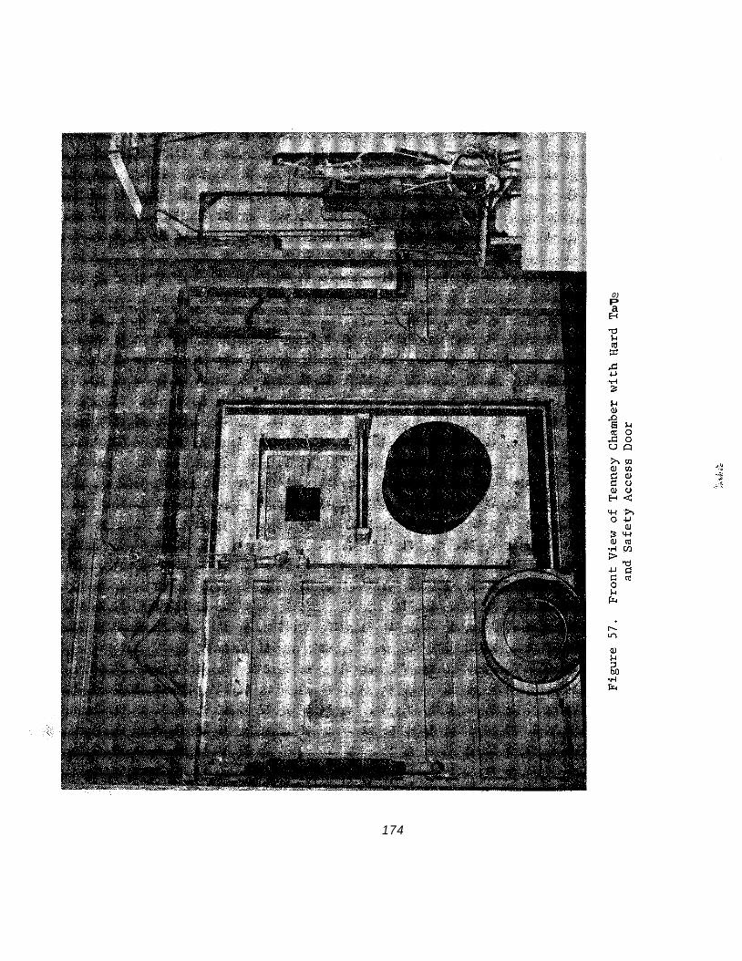
0) P
I3 a
174

a, l-i 0 z V
17 5
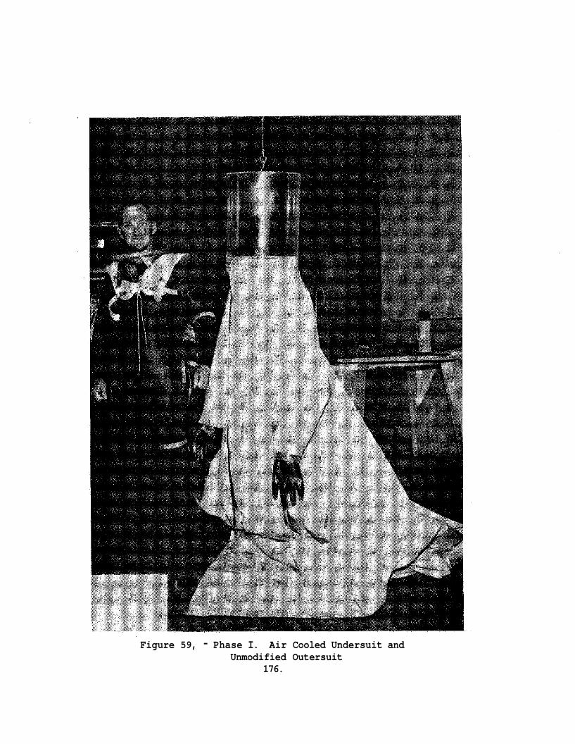
Figure 59, - Phase I. Air Cooled Undersuit and
176. Unmodified Outersuit
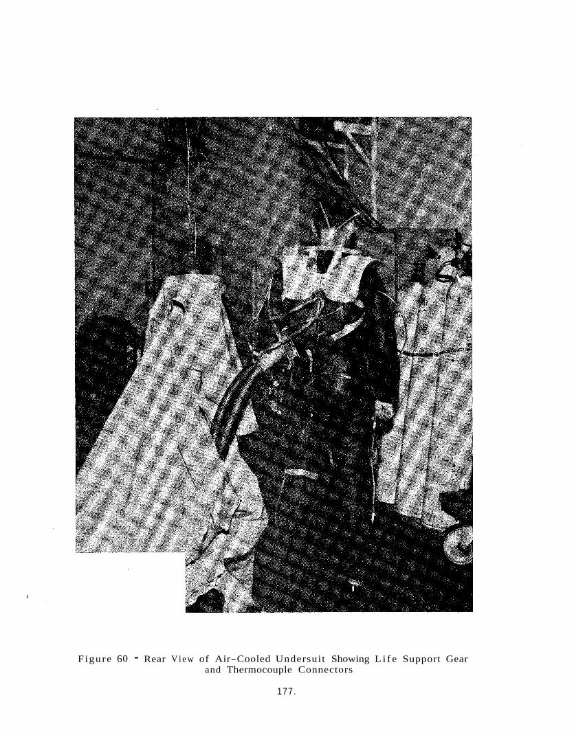
Figure 60 - Rear V i e w of Air-Cooled Undersuit Showing L i f e Support Gear and Thermocouple Connectors
177.
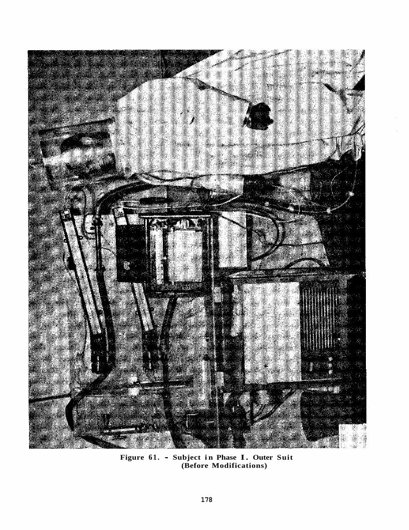
Figure 6 1 . - Subject i n Phase I . Outer Suit (Before Modifications)
178
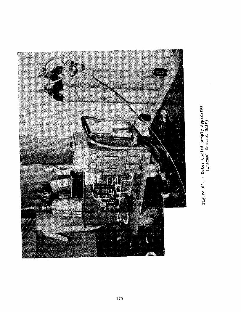
17 9
8.2.4 Mock-up Improvement
By use cJf both the q u a l i t a t i v e and quan t i t a t i ve d a t a , and the d a i l y deb r i e f ing r e s u l t s , immediate mock-up equipment improvements were a f f ec t ed . When requi red , re- runs of Phase I quan t i t a t i ve t e s t s were made a f t e r equipment improvements were incorporated.
I n essence, the Phase I tests were geared t o explora t ion of the BISS environment and the i d e n t i f i c a t i o n of BISS problem areas opera t ive i n , and r e s u l t i n g from,this environment. Fur ther , the implicat ions and dimensions of these Problem a reas f o r BISS design vere explored. Insofar a s hardware i t s e l f was concerned, the focus was developmental and l a r g e l y q u a l i t a t i v e . Overal l , t he primary value of the Phase I e f f o r t l a y i n the guidance value it had f o r the Phase I1 e f f o r t .
The manner i n which t e s t s were conducted during the t e s t program did no t i n a l l cases agree t o t a l l y wi th t he manner spec i f i ed i n the In tegra ted T e s t Plan. Entry- exi t tests were added and performed p r i o r t o sui t- system tests. Reefing tests were conducted only manually s ince no'mechanized r ee f ing device was ava i l ab l e f o r , t e s t i n g .
8.2.5 Tes ts Performed
The tests which were performed a r e l i s t e d below, and a r e presented i n t he same order a s i n the In t eg ra t ed Tes t Plan, wi th the add i t i on of en t ry- ex i t t e s t s , which were c a r r i e d out j u s t before t he sui t- system t e s t s .
1) Component Tes t s
(a)
(b)
Gas flow/temperature t e s t s - Vortex tube cooling system
Gas flow/temperature tests - a i r condi t ioner cool ing system
2) Subsystem Tests
(a) Chamber P re s su r i za t i on
(b) Water cooled undersui t
(c) A i r cooled undersui t
(d)
(e) Helmet a i r supply
S u i t - tunnel l e ak test
180
(f) Visual field test
(g) Outer suit fit
(h) Safety rescue
(i) Communica t ions
(j) Entry-exit
3 ) Suit-system Tests
(a) Comfort
(b) Mobility
(c) Entry-exit
(d) Communications
(e) Subject comments
(f) Reefing
8 . 3 TEST RESULTS
Results of tests are presented in the following sections: Alpha numeric designators following the title correspond to the designators in the preceding section.
Gas flow/temperature tests - Vortex tube cooling system l(a) This tests called for the measurement of flow rates and temperatures
in various parts of the cooling system. collected
For ease of reference, the data has been imposed upon the system schematic, Figure 63 .
Gas flow/temperature tests - Air conditioner cooling system l(b) For the air conditioner cooling system the following, information
was obtained :
e Plenum air temperature - 64OF Blower exhaust temperature - 64'F
181
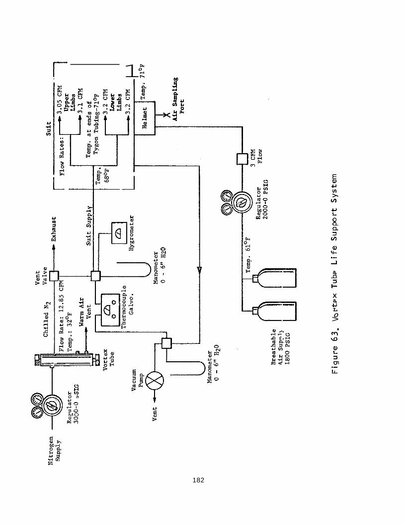
r 1
c3 H L t v 3 O h U (do
4 1 7 0 MO 0 0 drn
Fr 0 rl
a, -c, 3 c X a, CI L 0 > M \D
. 2 3 cn
182
Temperatures i n t h e system leveled o f f a t room temperature s ince the duct ing was not insu la ted .
A i r Conditioner - Vortex Tube Comparison
A maximum a i r flow of 20 cfm was ava i l ab l e from the a i r condi- t i o n e r cool ing system. i n t he tes t p lan while the vor tex tube (12.85 cfm maximum) f e l l s h o r t of t h i s c r i t e r i o n . Other f a c t o r s favoring the a i r condi t ioner were t h a t temperature could be ad jus ted independently of flow which was not poss i- b l e wi th the vor tex tube and t h a t on independent helmet breathing a i r supply was no t required a s it was f o r the vor tex tube.
This exceeded the 16 cfm requirement ind ica ted
These f a c t o r s combined t o i nd i ca t e the s u p e r i o r i t y of the a i r condi- t i o n e r system f o r supporting the BISS a i r cooled undersu i t . recognized t h a t subsequent e d i t i o n s of t he system ( i f t he a i r cooled system w a s chosen over the water cooled system i n the system t e s t s ) , would have t o employ an a i r condi t ioner of g r ea t e r capac i ty and in su l a t ed hosing from the console t o t he opera tor . and the t rade- of fs l i s t e d i n Table IX of Sec t ion 4 .7 , the Encon vortex tube was e l iminated from f u r t h e r considerat ion i n th is study.
It was a l s o
A s a r e s u l t of these tes ts ,
Subsystems Tes t s (2)
Chamber p re s su r i za t i on T e s t 2(a)
The chamber p re s su r i za t i on t e s t es tab l i shed t h a t t h e chamber could be pressur ized and held a t a four inch (H20 gage) pressure . t e s t the hard tube was capped and shop a i r app l ied from a 90 p s i source. The chamber achieved the 4" pressure a t a minute. t h i s l e v e l by an input p ressure of 30-40 p s i f o r a per iod of one hour.
- Undersuit Tests (2(b) and 2(c)
For t h i s
s a t e of approximately 1" pe r Af te r achieving t h e 4" pressure i t was r e a d i l y maintained a t
T e s t s of both t h e a i r cooled and water cooled undersu i t s were con- ducted underunpressur ized chamber condi t ions with the sub jec t c lad i n long underwear and the ou t e r s u i t . The ob jec t ive of the t e s t s was t o determine the c a p a b i l i t y of the undersu i t s t o provide environmental con t ro l f o r t he sub jec t while r e s t i n g and a f t e r exercis ing. Since t he requirement t h a t the undersu i t s cool a sub j ec t while exerc i s ing was more s t r i n g e n t than w h i l e r e s t i n g t he tests f o r the r e s t i n g condi t ions were no t conducted i n a s rSgorous a manner.
18 3
- Resting Subject - Air Cooled Suit Phase I hardware did not provide adequate cooling ability to test
a significant range of inlet temperatures. However, the effect of different rates of air supply was determined.
By varying the input flow rate systematically it was found that the subject, in the air cooled undersuit and outersuit, with the tunnel sealed off, was very comfortable when a flow rate of 8-12 cfm was pro- vided. and the only negative comment was that the humidity of the air conditioner supply was too low (the humidifier became operational later in the tests).
It was not possible to ovescool the subject in this input range
Resting Subject: Water Cooled Suit 0 Inlet water temperature was varied over the range 65-90 F in 5'
increments. of 3 min. Overall comfort was rated as excellent for the inlet temper- ature values of 75O and 80°. quite acceptable, although the subject did report that uncon:fortable at 850. but when taken down to a 650 inlet temperature, the subject reported that the temperature was unsatisfactorily cold and the comfort poor. Humidity posed a minor problem with the water cooled suit in the helmet area since the subject experienced lip-drying due to his breathing of U.S.P. bottled air with virtually no moisture content.
The subject was exposed to each temperature for a period
The 70, 85 and 90 degree values were he felt a little
At 90° he did not feel much different from 85O,
A water inlet temperature of 75O was considered to be ideal. Cooling distribution was reported as being satisfactory throughout the test except for the subject's legs at 85' and 90' inlet temperatures. At these temperatures, the subject sensed the water distribution in his legs as being poor. in the water cooled undersuit was quite acceptable and that the system was not It was also recognized that moisture would have to be introduced into the breathing air supply if it was decided to further explore the water cooled suit in the Phase I1 tests.
Overall, it was concluded that cooling distribution
itaxed in any way, keeping the subject comfortable when resting.
In conclusion, both the air and water cooled undersuits and supply hardware served to provide good overall comfort to a resting subject.
184
For the exerc ised condi t ion , the t e s t i n g was more r igorous . The sub jec t was given a series of 3 minute timed runs on an exercycle (speed constant f o r a l l runs) i n s i d e the chamber, wi th a 0" d i f f e r e n t i a l p ressure . a i r cooled s u i t and i n l e t water temperature f o r the water cooled s u i t ) , and SAS comfort r a t i n g s were taken.
For each t r i a l input parameters were var ied (flow r a t e f o r the
(See attachment A of Appendix F)
Temperature d a t a was recorded by a thermocouple recorder f o r the following po in t s :
-a
:e
e
e
e
0
- 0
0
e
Supply temperature
Exhaust temperature
Ambient
L e f t arm - c u b i t a l reg ion ( Ins ide os5 the forearm)
r i g h t arm - a x i l l a region (Armpit)
l e f t l e g - p o p l i t c a l region (Back p a r t of l e g behind knee j o i n t )
small of back
gro in
ches t
For t h e a i r cooled undersu i t t he re were six 3 minute runs with the a i r f low being r a i s e d from 2 t o 1 2 cfm i n 2 cfm increments. water cooled s u i t t h e i n l e t coolant t e m e r a t u r e was r a i s e d from 70° t o 850 i n 5' increments then lowered t o 65 and, f i n a l l y lowered from 65' t o 55O i n 5' increments. sub jec t and an o v e r a l l SAS average was obtained by averaging t h e SAS r a t i n g s f o r o v e r a l l comfort, temperature, humidity, and the average of the s ix cool ing d i s t r i b u t i o n r a t i n g s . Table XXVII .
For the
g The SAS (comfort) w a s administered t o the
These r a t i n g s a r e shown i n
The air- cooled s u i t received i ts bes t o v e r a l l r a t i n g of 5 . 3 a t an a i r f l o w of 1 2 cfm., exceeding the nea res t competing r a t i n g by 1.4 po in t s . The water cdoled s u i t received i t s b e s t o v e r a l l r a t i n g f o r an i n l e t temperature of 60° a s cont ras ted wi th 75' when the sub jec t was r e s t i n g .
185
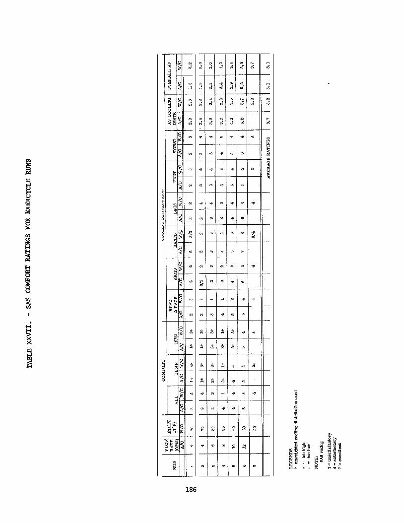
186
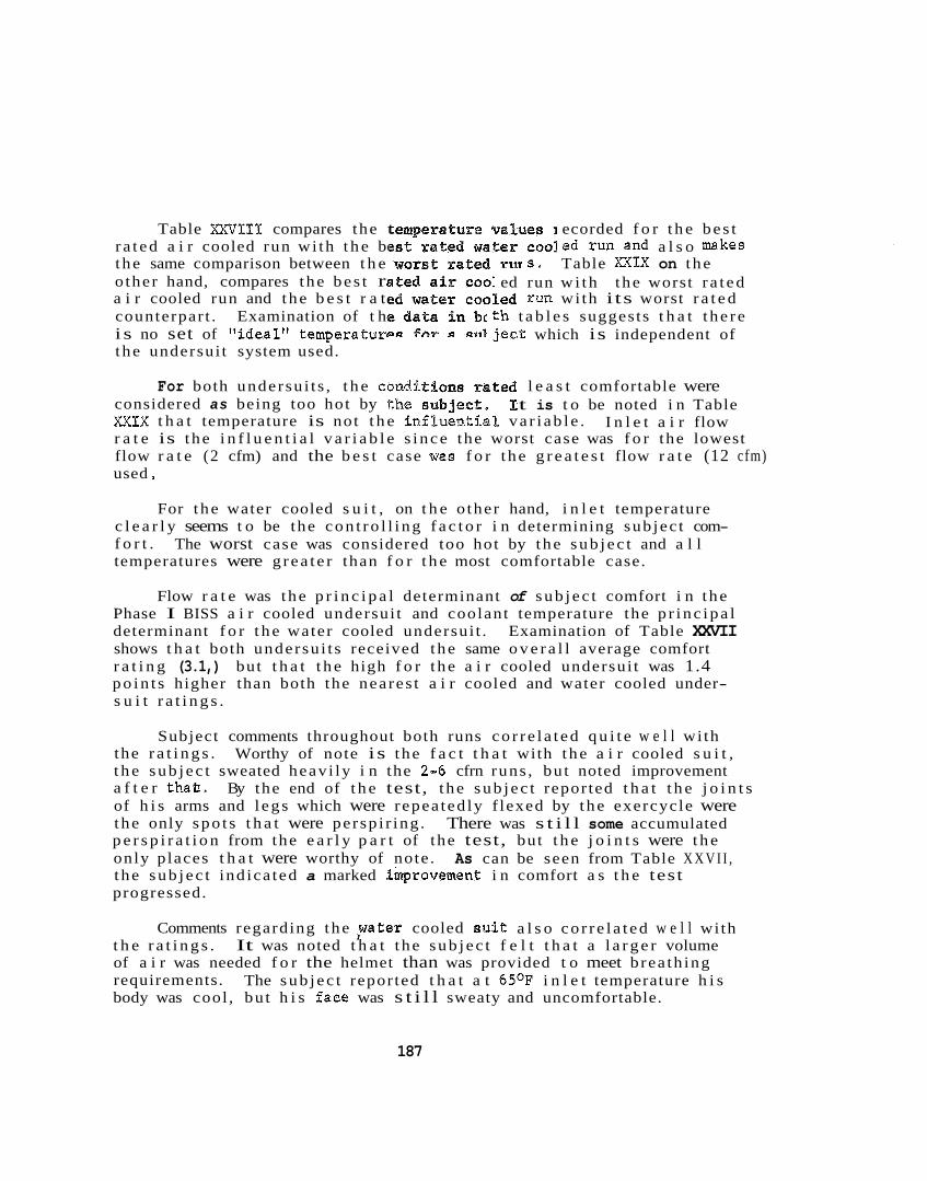
Table XXVIII compares the t ecorded f o r t h e be s t r a t ed a i r cooled run wi th t h e be ed run and a l s o makes t he same comparison between t h e s . Table x X I X on t he o ther hand, compares t he be s t r ed run w i t h t he worst r a t ed a i r cooled run and the b e s t r a t run wi th i ts worst r a t e d counterpar t . Examination of t h t h t a b l e s suggests t h a t t he r e i s no set of "ideal" temperatutr ject which is independent of t he undersui t system used.
For both undersu i t s , t h e condE l e a s t comfortable were considered as being too hot by t h e XXIX t h a t temperature is not t h e i n f l u e ~ ~ i a ~ va r i ab l e . r a t e is the i n f l u e n t i a l v a r i a b l e s i nce the worst case was f o r the lowest flow r a t e (2 cfm) and the b e s t case was f o r t he g r e a t e s t flow r a t e (12 cfm) used
t is t o be noted i n Table I n l e t a i r flow
For t he water cooled s u i t , on t h e o ther hand, i n l e t temperature
The worst case was considered too hot by t he sub j ec t and a l l c l e a r l y seems t o be the con t ro l l i ng f a c t o r i n determining sub jec t com- f o r t . temperatures were g rea t e r than f o r t h e most comfortable case.
Flow r a t e was t he p r i n c i p a l determinant of sub j ec t comfort i n t he Phase I BISS a i r cooled undersui t and coolant temperature the p r i nc ipa l determinant f o r t h e water cooled undersui t . Examination of Table XXVII shows t h a t both undersu i t s received t he same o v e r a l l average comfort r a t i n g (3.1,) but t h a t t h e high f o r t he a i r cooled undersui t was 1.4 po in t s higher than both the neares t a i r cooled and water cooled under- s u i t r a t i n g s .
Subject comments throughout both runs co r r e l a t ed q u i t e w e l l wi th the r a t i n g s . t h e sub j ec t sweated heav i ly i n the 2-6 cfrn runs , bu t noted improvement a f t e r thatr. of h i s arms and l egs which were repea ted ly f lexed by t he exercycle were the only spo t s t h a t were persp i r ing . p e r s p i r a t i o n from the e a r l y p a r t of the test, but t h e j o i n t s were t h e only places t h a t were worthy of note . t he sub j ec t ind ica ted a marked improvement i n comfort a s t h e test progressed.
Worthy of note i s the f a c t t h a t with t he a i r cooled s u i t ,
By the end of t h e test, t he sub j ec t repor ted t h a t t h e j o i n t s
There was s t i l l some accumulated
As can be seen from Table X X V I I ,
Comments regarding t he y a t e r cooled uft a l s o co r r e l a t ed w e l l wi th t h e r a t i n g s . of a i r was needed f o r the helmet than was provided t o meet b rea th ing requirements. body was cool , bu t h i s face was s t i l l sweaty and uncomfortable.
It was noted t h a t t he sub j ec t f e l t t h a t a l a r g e r volume
The sub j ec t repor ted t h a t a t 650F i n l e t temperature h i s
187
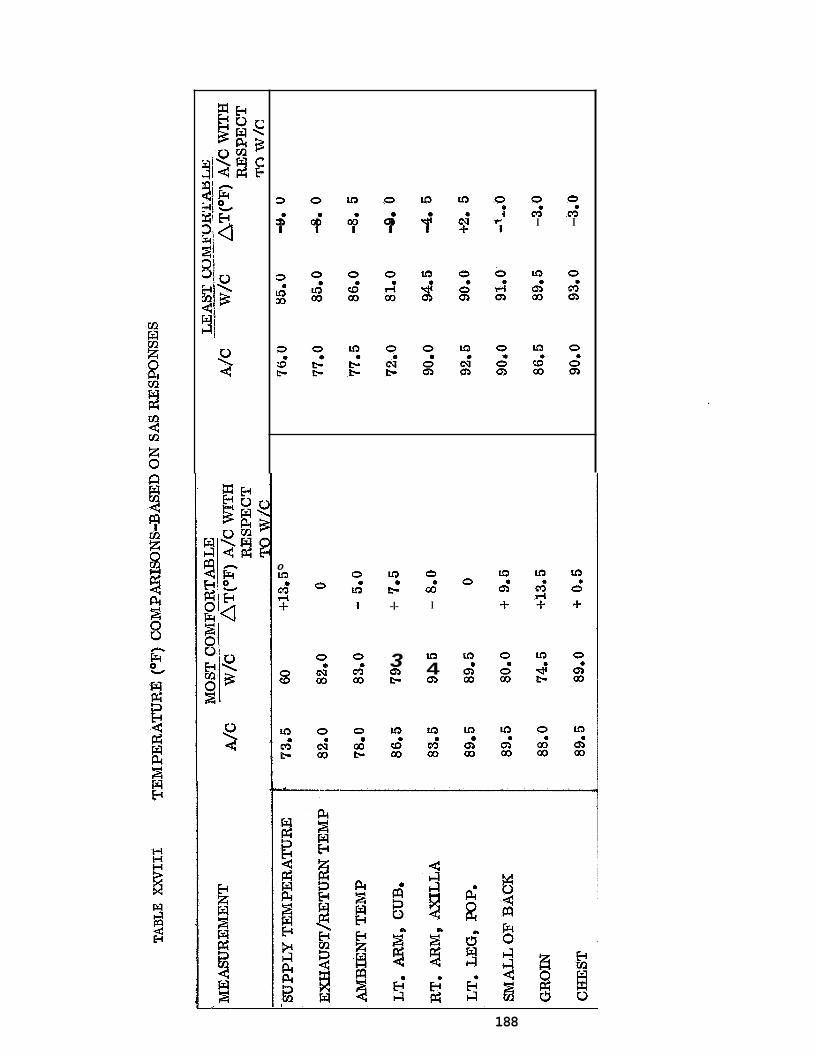
3 0 u 3 0 u 3 u 3 0 0 0 P i c ; c ; ' ; . . ' . p ' $ f $ I I I I I I
0 u3
rl 4- c;
8
u3
b c;
0
0 a
CN 00
0
00 c;
0 a
u3 I
0
00 c;
0 a
00 I?
u3 a I? -I-
3 Q) t-
u3
00 (0'
0 a a3
I
u3
Q) 4
u3
00 c;
0
u3 a
Q) 00
u3 a
Q) 00
u3
Q)
4-
e
0 a 0 00
u3 a
Q) 00
u3 a 0
-I-
0 a
Q) 00
u3
00 a;
188
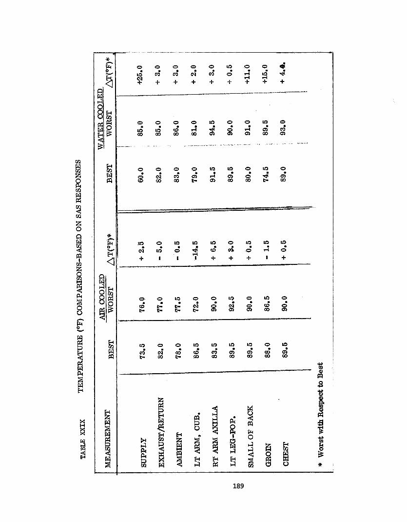
o o o o ~ o m o o o 4 u ; m ' c ; N c 3 ' d f S y + + + + + + + +
I-
189

I n summary, i t was concluded t h a t t h e performance of t he a i r cooled undersui t was super io r t o t h a t of t h e water cooled undersui t i n providing operator environmental con t ro l . Also, it was concluded t h a t t he performance of t he water cooled undersui t was good enough t o warrant a cont inuat ion of t h e undersui t compatisons i n t he system tests.
S u i t Tunnel Leak T e s t - 2(d)
The ou te r s u i t l e ak tes t was run t o determine whether t h e s u i t tunnel combination leaked, and i f s o t o determine t he leakage r a t e . To run t h i s unmanned test, t he s u i t and tunnel were f i r s g i n s t a l l e d i n t he chamber. The hard tube was then capped, t he only opening i n * i t being f o r a manometer. The f i r s t t i m e t he system was pressur ized, the r a t e of p r e s su r i za t i on was poor (near ly 7 min. t o reach 4"AP) and it was obvious t h a t t he r e were leaks .
A s tudy ind ica ted t h a t a b e t t e r gasket was needed f o r t he chamber door and t h a t a b e t t e r s e a l was needed a t the s u i t f t u n n e l i n t e r f a c e . These mat ters were corrected along with miscellaneous small l eaks discov- ered when the s u i t was pressur ized a s a p a r t of t he r e p a i r process. Af te r a l l t he r e p a i r s were completed, t he 4",4 P was achieved i n 3 minutes using an 95 p s i source. with an inpu t pressure of 30-40 p s i . A 2.8 cfm leakage r a t e was measured using t h e manometer and a p i t o t tube. This value was considered accepra- b l e f o r subsequent pressur ized chamber tests.
It was then poss ib le t o maintain t h i s pressure
H e l m e t A i r Supply 2(e)
D i f f i c u l t i e s i n scheduling precluded running t h i s test u n t i l o ther Phase I t e s t i n g had been4completed. Since t h i s was t he case , and ample experience had been gained wi th t he helmet a i r supply throughout a l l the tests of Phase I, i t was f e l t t h a t t he d e t a i l e d tests indicated i n the i n t eg ra t ed t es t p lan were no longer required. It was decided t h a t t he most s i g n i f i c a n t aspec t of the spec i f i ed test a t t h a t po in t i n the program w a s t he gas ana ly s i s .
Since t h e Phase I tests had been concluded and a new exhaust system and helmet device had been designed f o r t h e Phase I1 s u i t , i t was decided t h a t t e s t i n g these devices would be more s i g n i f i c a n t than running t he tests on the a l ready outdated design. The exhaust system change involved t h e add i t i on of sup rac l av i cu l a r . exhaust po r t s t o the Phase I undersui t . The new d i s t r i b u t i o n device was a c o l l a r type manifold. Samples of room a i r , helmet supply and helmet exhaust were a l l taken.
190
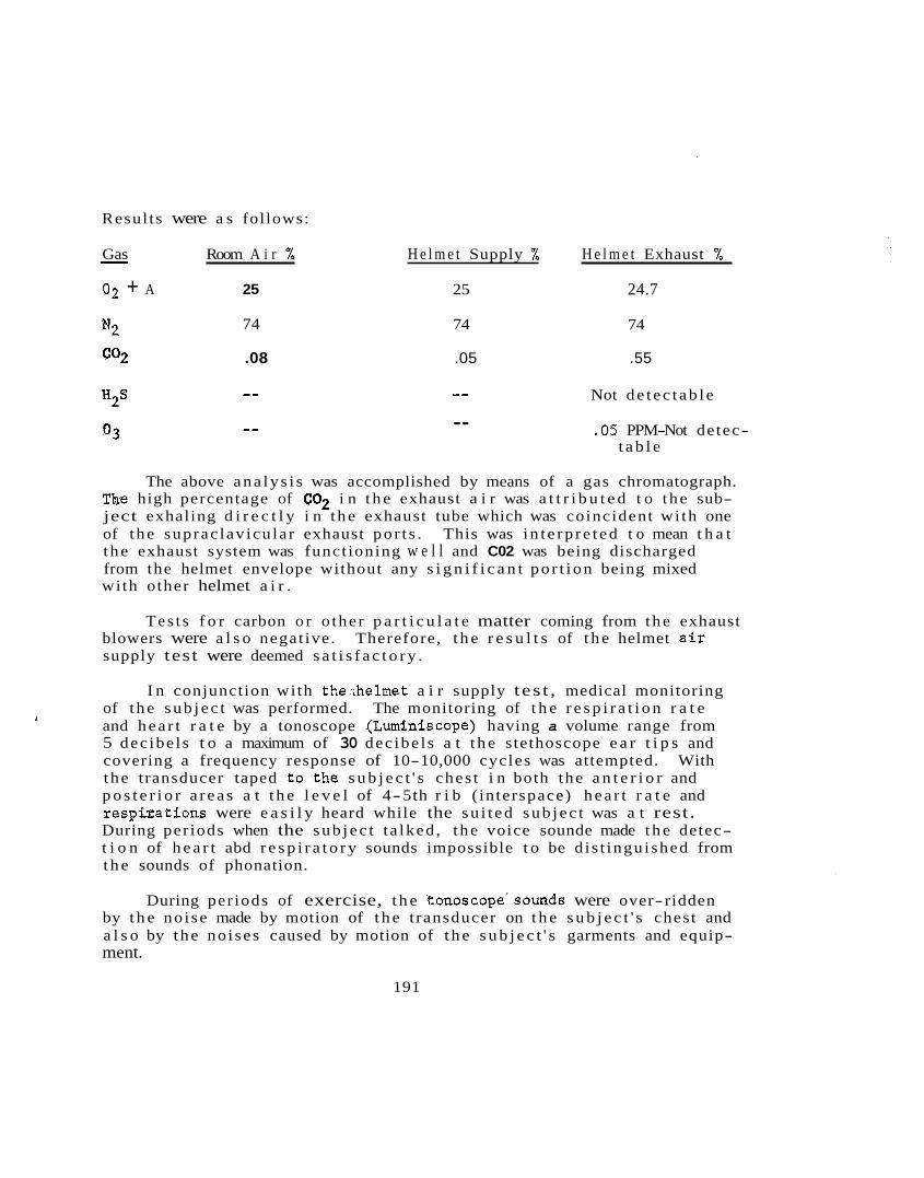
Resul ts were a s follows:
Gas Room A i r % H e l m e t Supply % H e l m e t Exhaust %
02 + A 25 25 24.7
-
N2 74 74 74
co2 .08 .05 .55
Not de t ec t ab l e -- -- H2S
03 -- .05 PPM-Not detec- t a b l e
The above ana ly s i s was accomplished by means of a gas chromatograph. The high percentage of C02 i n t h e exhaust a i r was a t t r i b u t e d t o t he sub- ject exhaling d i r e c t l y i n t he exhaust tube which was coincident wi th one of t he suprac lav icu la r exhaust po r t s . This was i n t e rp r e t ed t o mean t h a t t he exhaust system was funct ioning w e l l and C02 was being discharged from the helmet envelope without any s i g n i f i c a n t po r t i on being mixed wi th other helmet a i r .
T e s t s f o r carbon o r o ther p a r t i c u l a t e matter coming from the exhaust blowers were a l s o negat ive . supply test were deemed s a t i s f a c t o r y .
Therefore, t h e r e s u l t s of t h e helmet a i r
I n conjunction wi th the;helmet a i r supply t es t , medical monitoring of t he sub j ec t was performed. and hea r t r a t e by a tonoscope (Luminiscope) having a volume range from 5 dec ibe l s t o a maximum of 30 dec ibe l s a t t h e stethoscope e a r t i p s and covering a frequency response of 10-10,000 cycles was attempted. With t he transducer taped t o . t h e s u b j e c t ' s ches t i n both the a n t e r i o r and p o s t e r i o r a r ea s a t t h e l e v e l of 4-5th r i b ( in terspace) hea r t r a t e and r e s p b a t i o n s were e a s i l y heard while the su i t ed sub j ec t was a t rest. During per iods when the sub j ec t t a lked , t he voice sounde made t h e detec- t i o n of h e a r t abd r e s p i r a t o r y sounds impossible t o be d i s t ingu ished from t h e sounds of phonation.
The monitoring of t h e r e s p i r a t i o n r a t e
During per iods of exercise, t h e tonoscope'sounds were over- ridden by t h e no i se made by motion of t h e t ransducer on t h e s u b j e c t ' s chest and a l s o by t he no ises caused by motion of t h e s u b j e c t ' s garments and equip- ment.
191
The transducer was placed on t he s u b j e c t ' s neck i n t he a rea of t h e ca ro t i d s i nus . Tests i n t h i s a rea were s imi l a r t o those run when t h e transducer was appl ied t o t h e ches t area .
For t he above reasons , t he use of an e l e c t r o n i c stethoscope f o r t h e BISS System was discarded i n favor of a system composed of a radio-ear- diograph (RKG) t o ob ta in h e a r t r a t e , and a voice communications system has t he a b i l i t y t o t ransmi t r e s p i r a t o r y sounds. exerc i se per iods , the stress was i n s u f f i c i e n t t o produce labored r e sp i r a- t i o n sounds. To test the voice communications system, t he sub j ec t was i n s t ruc t ed t o hyperven t i l a te . These sounds w e s e e a s i l y heard over t he communications system.
During t h e BISS Phase I
On four separa te days, a system composed of an RKG-100 (Telemedics) Radiocardiograph t ransmit ted (l'l x 3kq1 x 4+", weight 10 o z . , range 250 f t . )
Thin f l e x i b l e w i r e s c a r r y the EKG s i g n a l from disposable adhesive type e lec t rodes (lkl ' square wi th m e t a l l i c screen, pas te- rese rvo i r and snap-on fas teners ) t o the t r ansmi t t e r . These e lec t rodes comply wi th the curvature of t h e s k i n and r e t a i n necessary conduct ivi ty f o r extended time per iods . The Telemedic rece iver (14" x 12'' x 8", weight 17 pounds) has a co l l aps ib l e antenna which extends t o a height of 3 f t . This rece iver conta ins sk in r e s i s t ance meter, s tandard iza t ion , and a s e l e c t o r switch f o r channeling t o conventional e lect rocardiographic recording apparatus , osc i l loscope , magnetic t ape recorder , o r a l l t h r ee simultane-
was used.
ous l y . The recharging u n i t f o r t he t r ansmi t t e r i s p a r t of t he rece iver
un i t s For t he tests on Phase I BISS S u i t , t he Telemedics RKG-100 was a t t ached t o a Sanborn Viso-Cordiette e lect rocardiographic recording apparatus .
The e lec t rodes were a t tached t o the s u b j e c t ' s r i g h t and l e f t c l a v i - c u l a r a r e a , so a s t o produce EKG approximating t he standard lead p o s i t i o n
known a s L1. received from the a c t i v e l y exerc i s ing su i t ed sub j ec t from wi th in t h e pres- sur ized chamber. No i n t e r f e r ence was caused by t he metal cons t ruc t ion of t he chamber, t he bu i ld ing o r t he a c t i v i t i e s of such a n c i l l a r y equip- ment a s operat ing pumps, motors, compressors and a i r condi t ioners . The h e a r t r a t e of t h e su i t ed sub j ec t a t rest was 88 beats/min. BISS exe rc i s e s , t h i s h e a r t r a t e went up t o 98 beats/min. wi th in normal range. being normal graphs wi th no s igns of stress.
Elect rocardiographic ' t racings of exce l l en t q u a l i t y were
During t he This i s w e l l
The graphic r e s u l t s were read and repor ted a s
192
Visual F i e ld T e s t 2(f)
The v i s u a l f i e l d test es tab l i shed that t h e sub j ec t could see 79' above h i s l ine of s i g h t (L.O.S.) and 70° below h i s L.O.S. The c r i t e r i o n of 140' t o t a l v e r t i c a l f i e l d was exceeded by t he t o t a l measured f i e l d of 149'., The helmet d i d , however, m i s s t h e 800 below the L.O.S. c r i t e r i o n by 10 . This f a c t was noted f o r considerat ion i n t h e Phase I I ' h e lme t redesign. The c r i t e r i o n of 2200 i n a ho r i zon t a l plane was f a r exceeded by a measured value of 266O, 130' t o t he l e f t and 136' t o the r i g h t .
It was concluded t h a t t h e dimensions of t h e helmet were adequate f o r head r o t a t i o n , but t h a t t he Phase I1 helmet would have t o be recon- f igured t o permit g r ea t e r v e n t r a l f l ex ion .
Outer Su i t F i t 2 ( g )
Outer s u i t f i t could not proper ly be ca l l ed a t e s t , bu t was r a t h e r
This eva lua t ion was ca r r i ed ou t by t he sub jec t and two obser- a c r i t i c a l eva lua t ion of the way the ou te r s u i t f i t t e d the Phase I sub j ec t . ve rs . ve rs ion of t h e Phase I oute r s u i t which would be amenable t o quick r epa i r s . were noted f o r incorpora t ion i n t h e Phase I1 spec i f i c a t i ons .
Its purpose was t o i d e n t i f y gross de f i c t enc i e s i n t he i n i t i a l
Adjustments o r changes t h a t could not be made without redesign
The main observations made underaan ambient p ressure environment were :
Front of ou te r s u i t t o r s o was t o o long; excess mate r ia l should be removed from t h e c ro tch a r ea .
e Improved glove f i t was needed.
.
Greater arm mobi l i ty needed because the sub j ec t could not b r ing h i s arms c lo se r together than t he width of h i s body when h i s hands were extended forward, p a r a l l e l t o t h e f l oo r .
Yoke assembly required reconf igura t ion t o permit sub j ec t t o r a i s e anns upward without having t h e helmet rise,
A s a r e s u l t of these observat ions , a s ix inch tuck was taken i n t h e
Gloves were no t a l t e r e d f o r t he Phase I study, but i t was decided f r o n t of t h e s u i t t o reduce t h e problemof mate r ia l bunching i n t h e c ro tch a r ea . t h a t t he use of a b e t t e r f i t t i n g glove, molded i n a curved f i nge r mold would be b e t t e r f o r Phase I1 usage than t he l a rge , s t ra igh t- f ingered gloves of Phase I.
193
It was not possible to alter the underarm to promote better free- dom of movement of the subject's arms, but this data was noted for appli- cation in the Phase I1 suit specifications. Likewise, yoke modifica- tion was not feasible at the time of the suit fit observations, but yoke redesign was scheduled for Phase I1 as a result of this effort.
Safety-Rescue Test 2(h)
In order to assure the safety of the Phase I BISS subject in the event of an emergency during the test program, it was necessary to assure that the subject rescue criterion (4 minutes) could be met in the modified Tenney Altitude Chamber test facility. The four minute criterion was for the interval from detection of the difficulty to removal of the subject from the chamber. A secondary criterion of 30 sec. for the medical monitor to reach the victim in the chamber was also imposed. Since the only way in which a subject could be removed from the outer suit was to cut him out, it was necessary to simulate cutting operations to avoid ruining the outer suit.
The fully suited subject was told to call for help at his discre- tion and to feign collapse. conductor dispatched two rescuers who were standing in the room outside the chamber. ladder, open the rescue hatch, and descend the inner ladder to reach the subject. This operation took 28 seconds under ambient pressure and 26 seconds under a pressure of 4". criterion. was 49 seconds under ambient pressure and 42 seconds under the 4" pressure. both the pressure times were less than under ambient. required under 4'' pressure for reaching and freeing the subject leaves a balance of nearly 3 minutes for removal of the subject from the cham- ber. This is more than enough time to cut the tunnel away from the end of the hard tube and slide the victim out through the hard tube where he could be placed on a litter by other chamber personnel.
Upon hearing the distress call, the test
It was necessary for these men to ascend the chamber
Both values met the 30 second access The time required to simu2ate cutting and freeing the subject
It was obvious that the 4" pressure posed no problem since The 68 seconds
Throughout the chamber Eests, a knife was located in the chamber and sufficient personnel were available to effect rescue if it had been required. In addition to satisfying the design criterion, plant safety personnel agreed that emergency rescue provisions were satisfactory for the test situation.
194

Cbnnnunications T e s t 2 ( i )
The communication tests f o r Phase I were no t r igorous eva lua t ion tests,r but were geared t o e s t a b l i s h operat ing l e v e l s and t ransducer loca t ions f o r t he Phase I mock-up system. t i o n tests spec i f i ed i n the test p l an were found t o be unnecessary when e a r l y tests ind ica ted t h a t completely s a t i s f a c t o r y r e s u l t s were being obtained wi th t h e speaker and microphone mounted on t h e helmet r i n g d i r e c t l y i n f r o n t of t h e ope ra to r ' s face .
The d e t a i l e d p o s i t i o n loca-
This placement posed no obs t ruc t ion t o operator v i s i o n and did no t impede operator head movement. l i f e support blowers running a t high speed, t he i n t e l l i g i b i l i t y of s i g - n a l s suf fe red . no i se no lbnger posed a problem. It was found t h a t t h e high voulme s e t t i n g on the amp l i f i e r was required t o provide exce l l en t received s i g n a l i n t e l l i g i b i l i t y (SAS r a t i n g of 7) i n the helmet. volume s e t t i n g was more a r e f l e c t i o n of t h e l imi ted gain of t h e intercom type ampl i f i e r than an index of t he loudness of the s i g n a l i n the helmet. fac tory .
It was found t h a t wi th t he noisy, Phase I
When the blowers were running a t a lower speed, t h i s
This high
The sub j ec t s repor ted t h a t t he o v e r a l l e f f e c t was q u i t e s a t i s -
In t h e Phase I communications system t h e l i n k t o the sub j ec t and t o
I n the i n i t i a l ve rs ion of the system, t h e l i n k t o the test t h e chamber speaker from the test conductor was provided by an intercom master u n i t . conductor from the sub j ec t was simply a speaker, connected as a s l ave t o t he intercom master. In add i t i on t o t h e switching from rece ive t o t ransmi t required of t he test conductor, it was found t h a t t he volume con t ro l had t o be ad jus ted each t i m e t he test conductor changed modes, i . e . , when t h e volume s e t t i n g was comfortable f o r t h e su i t ed opera tor , it was too low f o r t he test cpnductor. amp l i f i e r and c r y s t a l microphone were procured f o r t he l i n k from t h e s u i t t o t h e test conductor. volume of t he l i n k i n t o and ou t of t h e s u i t . made, the BISS operator repor ted very s a t i s f a c t o r y r e s u l t s . speaker could be operated i n p a r a l l e l wi th , o r independent o f , the s u i t speaker. Using t h e intercom ampl i f i e r t o d r i v e t he chamber speaker , it was not poss ib le t o achieve a volume l e v e l which permitted t he operator t o adequately h e a r t he chamber speaker throughout t he chamber, poss ib le f o r t he s.ubject t o hear t he ahamber speaker by g e t t i n g near it so t h a t i n t he event of s u i t speaker f a i l u r e , it was poss ib le t o i n s t r u c t t h e sub j ec t via. the chamber speaker, f o r a paging horn type speaker and a much more powerful ampl i f i e r were noted f o r inc lus ion i n t h e Phase I1 system.
For t h i s reason, a separa te
This permit ted independent con t ro l of t he When t h i s modif ica t ion was
The chamber
It was
The obvious requirements
195

The r e a l i n t e n t of the Phase I communications tes t was t o a s c e r t a i n t h a t t he system was adequate f o r maintaining two-way communication with t he sub j ec t s throughout t h e test , and t h i s was done. The o ther matters of concern were those o€ t ransducer placement i n t h e suit- helmet envel- ope and t h e determinat ion of whether t he r e were any reverbera t ion o r echo e f f e c t s i n t he helmet. A s has been prev ious ly mentioned, t he place- ment of the! t ransducer posed no problem.
Entry-Exit T e s t s 2 ( j)
Although these tests were not spec i f i ed f o r Phase I i n t h e In t e- grated T e s t Plan, it was recognized that more experience was required wi th t he s u i t under pressure p r i o r t o the system tests than would have been gained by following the test plan. Therefore, the en t ry- ex i t tests were conceived a s informal developmental tests and were run wi th the expecta t ion of providing a ba s i s f o r f u r t h e r modification t o t he s u i t system before running t he system tests. t h i s test was t o determine t he inf luence of d i f f e r e n t pressure l e v e l s on t he performance of t h e system.
One of t he p r i nc ipa l elements i n
The f i r s t run of t h i s test was made a t a chamber pressure of 1"; the re were a l s o runs of 4", 3", 2", i n t h a t o rder . A t a d i f f e r e n t i a l p ressure of l", e n t r y required 225 sec and 80 sec. by one man i n the chamber during t h i s process. given during these tests was kept t o a minimum, bu t s i nce t h e donning rack was no t r e f i ned , pe r i od i c a s s i s t ance had t o be offered t he sub j ec t .
The sub jec t was aided Generally, the a s s i s t ance
When the pressure was run up t o 4" the sub j ec t could not even g e t h i s f e e t i n t o t h e garment. Also, subsequent runs a t 3" and 2" did not permit sub j ec t e n t r y wi th the p reva i l ing s u i t and donning rack design. Throughout these e f f o r t s and t he suecessful 1" e n t r y and exit t he sub jec t was asked t o i d e n t i f y the d i f f i c u l t i e s he encountered s o t h a t modifications could be made p r i o r t o t h e system tests. following s u i t r e l a t e d conclusions were reached.
Based on these comments, t he
Add s t i f f e n i n g r i ngs a t s u i t terminus of tunnel
Add knee and arm r ings t o provide a t a r g e t f o r t h e man en t e r i ng t h e s u i t .
Reduce f r i c t i o n between undersui t and rubber boots.
Replace s l i p p e r s w i t h heavy socks. impeded operator e n t r y i n t o t h e s u i t .
The bulk of t h e s l i p p e r s
Attach helmet support yoke t o ou te r s u i t so t h a t sub j ec t e n t e r s t h e s u i t wi th no yoke on and comes up underneath t h e yoke, a l ready a f f i xed t o the ou t e r s u i t , a s p a r t of t h e s u i t donning process .
196
These a l t e r a t i o n s were made, incorporated i n the s u i t , and another run scheduled. 2hr1 , and 3" (311 f o r exit only).
The second series was run a t p ressures of ?$I, l", 2",
entry..time was 120 seconds and the exit t i m e 50 seconds. d t o include t h e t i m e required f o r ' t h e sub j ec t t o t r ave r se
on the ou te r s u i t and s t e p away from the donning rack. Exit i s the converse of t h i s process.
It was noted dur ing t h i s run that t h e Velcro used f o r holding t he gloves was i n e f f e c t i v e and it was 'replaced by hooks and eyes f o r t h e subsequent 1" run. f o r en t ry and 78 seconds f o r e x i t . served t h a t t he pos i t ion ing of t h e glove hooking mechanism was poor.
A t a 1" d i f f e r e n t i a l pressure 56 seconds were required During t h i s t r i a l , t h e sub j ec t ob-
A t 2", the sub j ec t required 104 seconds t o enter and 120 seconds t o e x i t t he chamber- reported t h a t it was d i f f i c u l t t o p u l l away from the hard tube. su r e was then r a i s ed t o 3" and the sub j ec t attempted t o e x i t . pressure t h e sub j ec t had g r ea t d i f f i c u l t y . came loose and i t was necessary t o depressur ize t he chamber t o permit exit of t h e sub jec t .
A t 2%", e n t r y required 105 seconds, but t he sub j ec t The pres-
A t t h i s Ul t imate ly both glove r i ngs
This test provided experience and confidence t o t he sub j ec t i n pressur ized operat ions and a l s o indicated t o tes t personnel t h a t it was c l e a r l y not pos s ib l e t o run t he system tests under more than a 211 pressure .
Suit-System Tests 3
The In tegra ted T e s t P lan descr ibed a 6 run tes t comprised of 1 ambient run and 2 pressur ized runs i n each of the undersu i t s . 'he o r i - g i n a l i n t e n t i n having t h e ambient t r i a l s i n t he test w a s t o provide sub j ec t f a m i l i a r i z a t i o n wi th system operat ions , p a r t i c u l a r l y wi th t h e mechanics of e n t r y and exit . t o the Phase I tes t program t o e s t a b l i s h opera t iona l pressure l i m i t s , and t o provide operator experience, and s ince these tes ts&preceded t h e system tests, t he ambient p ressure runs w e r e e l iminated.
Since t he en t ry- ex i t tests had been added
The a i r cooled tests were set up i n i t i a l l y a t inpu t flow r a t e s of These values had 10 t o 12 cfm wi th approximately equal exhaust flows.
been given high comfort r a t i n g s i n t he undersui t tests and the in ten t of t he system tests was t o e s t a b l i s h t h e b e s t poss ib le l i f e support condi- t i o n s f o r t h e sub j ec t and then vary them only--if requested by t h e sub j ec t .
197
Both air cooled trials were run at a differential pressure of 2" H20. The first of the water cooled runs was at a pressure of 1" H20 the second run was at 2" H20 pressure with a short increase to 4" during the course of the trial. to augment the data of the entry-exit tests and the 2" run provided data for comparison with the air cooled runs.
The water cooled trials were run at an inlet cooling f This was between the optimal value indicated
and
The 1" run and the check at 4" served
tempera - the ture of 68'F.
resting and exercising conditions during the undersuit tests. rate of the available cooling unit was approximately one pound per minute.
The flow
The test routine for the system tests was as follows:
1) Subject donned undersuit, entered chamber, and finally donned outer suit.
2) Subject was administered SAS item IV (a) (ENTRY), followed by SAS Section I (COMFORT) via the communications system.
3) Subject was then directed to walk the length of the chamber twice, bend at the waist ten times, climb and descend a ladder three times and perform ten deep knee bends.
4) Subject was then administered SAS Section I1 (MOBILITY), followed by Sections I (COMFORT) and V (c) (COMMUNICATIONS)
A single subject was used for all tests. The subject was a male, in good health, height 69" and approximately 165 lbs. in weight.
Overall, the system tests showed that both undersuits performed sat- isfactorily. The only unsatisfactory ratings (SAS rating = 1) given during the tests regarded the donning rack, background noise level (with water cooled suit), chamber speaker performance, and in one instance, cooling of the head and face.
Comfort 3 (a)
Figures 64 and 65 shows the results of comfort ratings taken during the system tests. For ease of reference the points representing the ratings for each run have been joined by coded lines. the results of the eight sets of comfort ratings taken during the tests.
Figure 64 shows
198
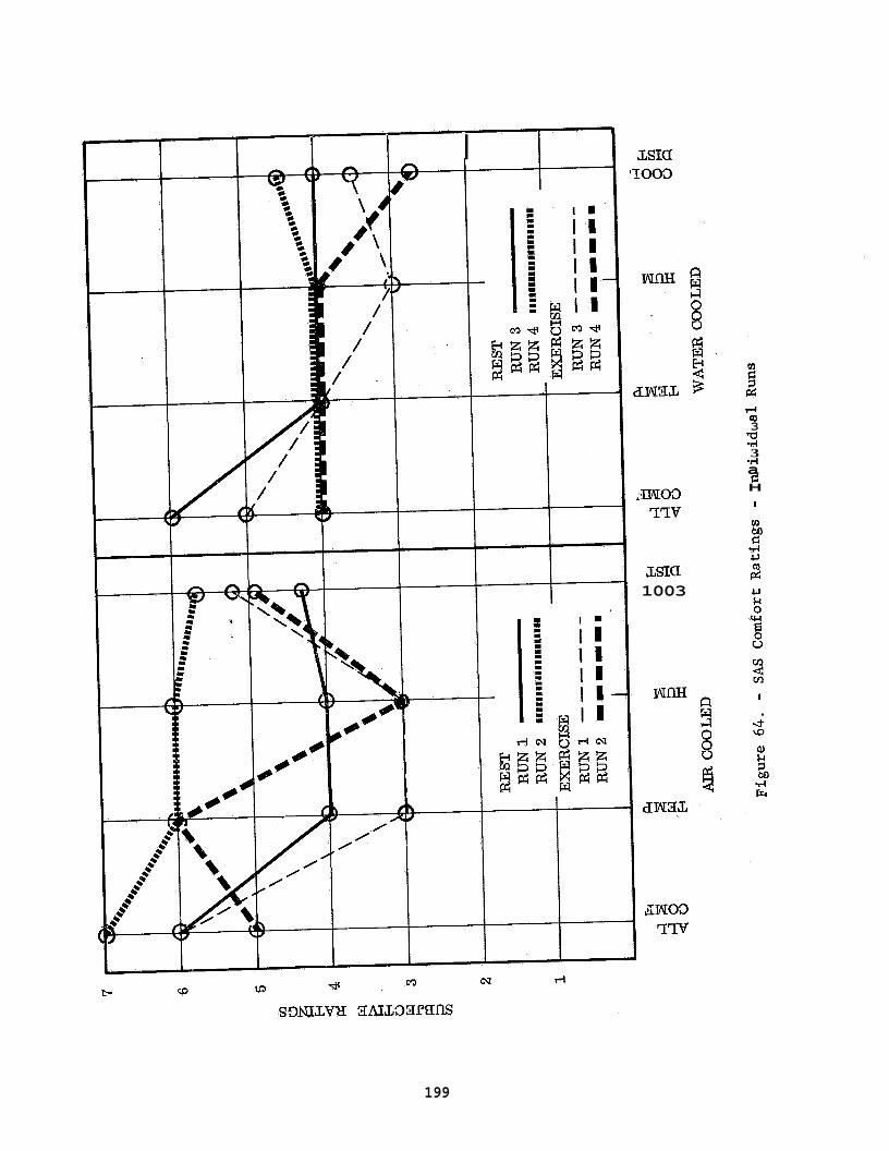
1 1 I m a IO03
3NO3 ??V
LsIa 1003
wm
(0 3
3 .rl a d H
2
1
199
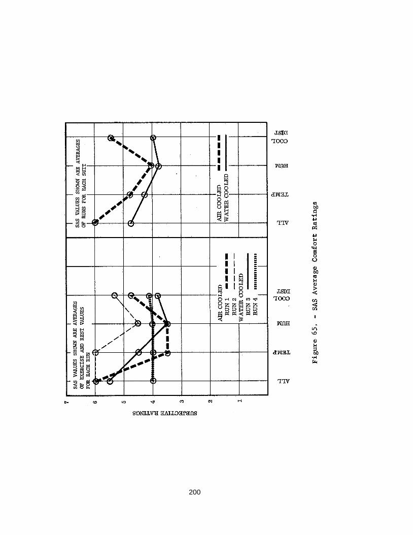
200
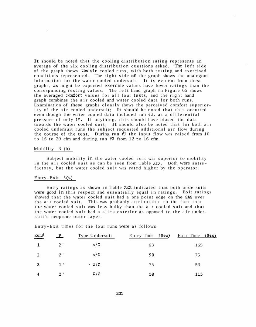
It should be noted t h a t t he cool ing d i s t r i b u t i o n r a t i n g represen ts an average of the six cool ing d i s t r i b u t i o n quest ions asked. The l e f t s i d e of t h e graph shows t h e a i r cooled runs , wi th both r e s t i n g and exercised condi t ions represented. The r i g h t s i d e of t he graph shows the analogous information f o r the water cooled undersuf t . It is ev iden t from these graphs, as might be expected exercise values have lower r a t i n g s than the correspnnding r e s t i n g values . The l e f t hand graph i n Figure 65 shows t h e averaged c o d o r t values f o r a l l four tests, and t h e r i g h t hand graph combines t he a i r cooled and water cooled da ta f o r both runs. Examination of these graphs c l e a r l y shows the perceived comfort super ior- i t y of the a i r cooled undersu i t ; even though the water cooled da t a included run 83, a t a d i f f e r e n t i a l p ressure of only 1". towards the water cooled s u i t , It should a l s o be noted t h a t f o r both a i r cooled undersui t runs the sub j ec t requested add i t i ona l a i r flow during the course of t h e test. t o 16 t o 20 cfm and dur ing run Sf2 from 1 2 to 16 cfm.
It should he noted t h a t t h i s occurred
If anything, t h i s should have biased the da ta
During run #l t h e input flow was r a i s ed from 10
Mobi l i ty 3 (b)
Subject mobi l i ty i n t h e water cooled s u i t was super io r t o mobi l i ty i n the a i r cooled s u i t a s can be seen from Table XXX. Both were s a t i s - f ac to ry , but t h e water cooled s u i t was r a t ed higher by t he opera tor .
Entry-Exit 3(c)
Entry r a t i n g s a s shown i n Table XXX ind ica ted that both undersui ts were good i n t h i s respec t and e s s e n t i a l l y equal i n r a t i n g s . showed t h a t t h e water cooled s u i t had a one po in t edge on the SAS over t h e a i r cooled s u i t . the water cooled s u i t was less bulky than t he a i r cooled s u i t and t h a t t he water cooled s u i t had a s l i c k e x t e r i o r a s opposed t o t he a i r under- s u i t ' s neoprene ou t e r l aye r .
Exit r a t i n g s
This was probably a t t r i b u t a b l e t o the f a c t t h a t
Entry-Exit t i m e s f o r t h e four runs were a s follows:
Run# - P Type Undersuit Entry Time (Sec) E x i t Time (Sec) - 1 21' A f C 63 165
2 2" A f C 90 75
3 1" ' wfc 75 53
4 2" w/c 58 115
201
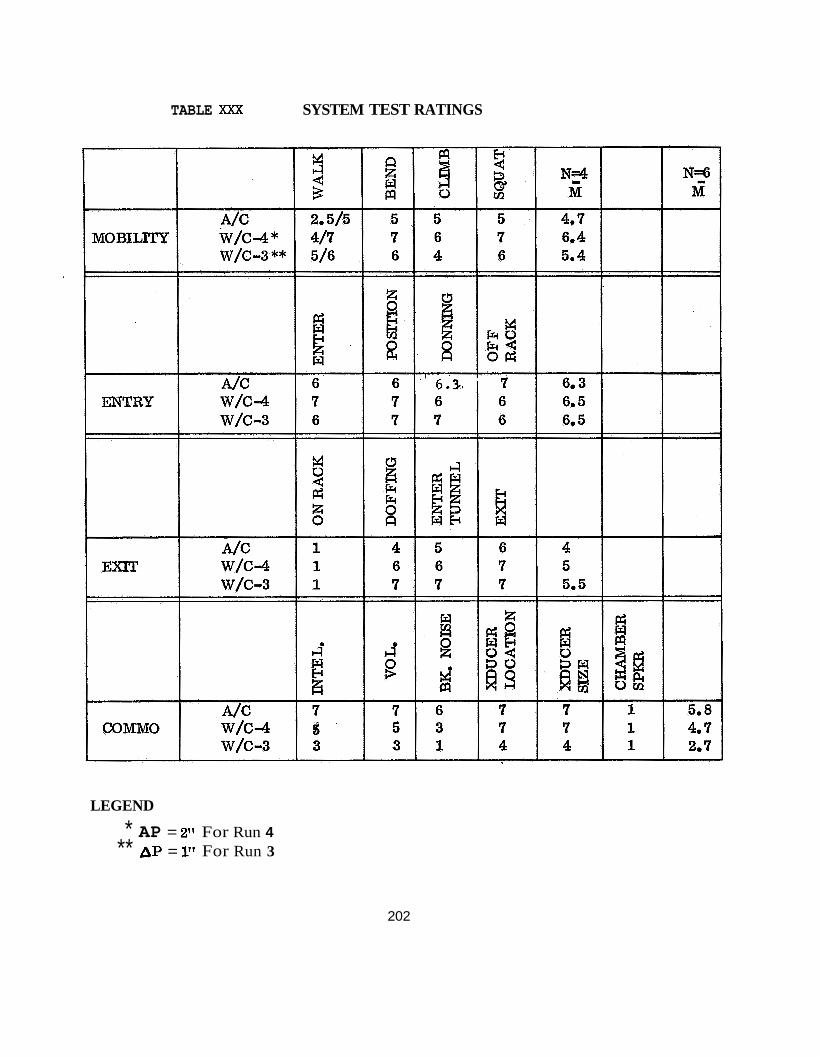
TABLE XXX SYSTEM TEST RATINGS
LEGEND
* AP = 2" For Run 4 ** AP = 1" For Run 3
202
These times suggest t he s u p e r i o r i t y of a water cooled under s u i t over an a i r cooled undersui t i n so fa r a s e n t r y and e x i t a r e concerned. I n add i t ion t o t he f a c t o r s a l ready mentioned, t he f a c t t h a t one of t h e water cooled runs was a t a pressure of l", and that some lea rn ing proba- b ly occurred, which tended t o b i a s t he da t a i n favor of t he water cooled s u i t .
Communications 3 (d)
Communications r a t i n g s favored the a i r cooled undersui t . The reason f o r t h i s was t h a t the sub j ec t requested l a rge r a t e s of helmet a i r when i n t h e water cooled s u i t . The d i f f e r ence i n flow r a t e s was s u f f i c i e n t t o degrade recep t ion i n the helmet due t o high a i r no i se .
The sub j ec t requested f a r more a i r f o r the helmet than was needed N o doubt, t o some e x t e n t ,
I n general , t he sub j ec t expressed a f o r breathing when i n the water cooled s u i t , t h i s a i r aided i n f a c i a l cooling. d e s i r e t o f e e l a i r blowing over h i s face , above and beyond meeting breathing a i r requirements.
Subject Comments 3 (e)
By and l a r g e , sub j ec t comments were compatible wi th t he r a t i n g s given. two values f o r each walking r a t h g . was f o r i n i t i a l condi t ions before t h e tunnel was pu l led away from the hard tube by t he r e e f e r s . walking r a t i n g a f t e r t he tunnel had been pu l led away from the hard tube. This is because once t h e tunnel has been pul led away from the hard tube, the tunnel closed on i t s e l f and the sub j ec t no longer experienced the a x i a l fo rce ( r e l a t i v e t o t h e hard tube) which had previously impeded him.
During a l l runs , as can be seen from Table X X X , the sub j ec t gave The top r a t i n g shown i n t he cha r t
The second, and h igher , value r e f l e c t e d a
It. was noted t h a t dur ing run #3 the sub jec t had some d i f f i c u l t y i n ladder climbing. tended t o impede such movement.
Both t he excess s u i t ma te r i a l , and the supply hoses
The sub j ec t made the observat ion t h a t t he r e was not much d i f f e r ence Over- between experiencing t h e one and two inch pressures environments.
a l l , he f e l t tha t a one inch pressure would provide an i d e a l working environment, but t h a t a 2" pressure was acceptable .
The s h o r t excursion t o a 4" pressure i n t he water cooled undersui t permitted the sub j ec t t o comment t h a t pressure e f f e c t s i n t he a i r cooled and water cooled undersui ts were e s s e n t i a l l y equivalent . ized experience i n t h e a i r cooled s u i t was obtained i n an e a r l i e r i n fo r- m a l test , i n which t he chamber was r a i s ed t o a 4" pressure a f t e r the sub j ec t had entered a t a lower pressure .
The 4" pressur-
20 3
Reefing 3 ( f )
There were no separa te formal r e e f i n g tests a s s p e c i f i e d i n t h e I n t e -
Upon making these observations, an at tempt gra ted T e s t P lan because it was f i r s t necessary t o observe t h e e f f e c t of overpressure on t h e tunnel . was made t o ree f t h e tunnel manually through the hatch hard tube. was found pl ished wi th in t h e chamber. r ee f ing t h e tunnel on the in-chamber p o r t i o n of the hard tube'. required f o r two r e e f e r s t o reef i n the f u l l y extended 20' tunnel under p ressure were recorded as fol lows:
This t o be impossible and indicated t h a t r e e f i n g had t o be accom-
T r i a l s were made cons i s t ing of manually The times
A P = 2": 380 sec; 210 sec M = 295 sec o r 4.9 min.
D P = 1": 160 sec o r 2.7 min.
It was apparerent t h a t t h e d i f f i c u l t y of handling the tunnel ma te r i a l However, the f a c t t h a t t h e and r e e f i n g went up as t h e pressure increased.
material could be success fu l ly reefed manually a t 2-0" pressure supports the idea t h a t a mechanical means of doing t h i s can be devised.
8.4 IMPLICATIONS FOR PHASE I1 BISS
The impl ica t ions f o r Phase I1 BISS were twofold: one, severa l d i s - crete des ign problem a reas were i d e n t i f i e d which required s p e c i a l a t t e n- t i o n i n the Phase I1 design e f f o r t , and secondly, t h e b a s i s was provided f o r making a f i n a l undersui t s e l e c t i o n .
The s p e c i f i c problem a r e a s which were highl ighted f o r Phase I1 were:
0 Inadequacy of the donning rack, p a r t i c u l a r l y wi th regard t o ease of attachment of o u t e r s u i t t o it.
Inadequacy of the chamber speaker system.
Reefing and development of a r e e f i n g mechanism.
The o t h e r f a c e t of t h e system test conclusions was the a i r cooled - water cooled undersui t decis ion. To summarize, the a i r cooled undersui t was super io r wi th respec t t o sub jec t comfort r a t i n g s and communications r a t i n g s . mobi l i ty r a t i n g s . s t rong and weak po in t s . undersui t w a s made l a r g e l y on t h e b a s i s of support equipment considera t ions , i . e . , a less complex device was required t o cool a i r than water and
The water cooled s u i t looked b e t t e r regarding en t ry- ex i t and Both s u i t s performed s a t i s f a c t o r i l y and both had
Therefore, the dec i s ion t o select t h e a i r cooled
204

1
secondzy, an independent brea th ing a i r supply w a s no t required . It was a l s o believed that des ign improvements could be made i n Phase I1 t o t h e a i r cooled undersui t t o enhance sub jec t mobi l i ty .
8.5 PHASE I TEST CONCLUSIONS
A s a r e s u l t of the Phase I t e s t i n g t h e fol lowing equipment-oriented conclusions were developed.
8 .5 .1 Outer S u i t
The o u t e r s u i t must have r e l a t i v e l y s t r a i g h t f i t up and down t h e f r o n t s o t h a t t h e overpressure w i l l not compress excess f a b r i c causing forces which i n h i b i t t h e opera to r ' s limb movements. t h i s i s t h a t the BISS ou te r s u i t cannot be too deviant from a r e l a t i v e l y fo rm- f i t t ing garment and t h a t a n adjustment s t r a p i s required f o r t h e small amount of deviance t h a t may e x i s t between opera to r s . This ad jus t- ment s t r a p should be i n t h e wais t- to- crotch area.. i s t h a t the opera to r s s e l e c t e d f o r t h e u l t ima te BISS system w i l l have t o be r a t h e r homogeneous i n physica l dimensions.
The impl ica t ion of
The f u r t h e r i n p l i c a t i o n
The chamber overpressure compresses t h e ou te r s u i t a s it hangs i n t h e donning rack. -This makes e n t r y very d i f f i c u l t , e s p e c i a l l y the i n i t i a l sea rch f o r t h e l e g s by t h e opera tor . The th igh p o r t i o n of the ou te r s u i t has t o be s t i f f e n e d ( a s was accomplished by r i n g s i n Phase I) i n order t o f a c i l i t a t e s u i t en t ry . I n a d d i t i o n , s t i f f e n i n g r i n g s a r e h e l p f u l i n the arms of t h e o u t e r s u i t , ( a l s o added i n Phase I). F i n a l l y , the i n t e r f a c e of t h e o u t e r s u i t and tunnel r e q u i r e s two r e l a t i v e l y c l o s e s t i f f e n i n g r i n g s t o permit a good tunnel /outer su i t- hard tube i n t e r f a c e f o r e n t r y and e x i t . This w a s a l s o added i n Phase I.
The o r i g i n a l concept had t h e opera tor en te r ing t h e ou te r s u i t while carrying a helmet mating r i n g a t t ached t o h i s shoulder harness (yoke). He had t o mate the r i n g w i t h a matching helmet r i n g f o r p o s i t i v e support of t h e helmet. It w a s found t h a t t h i s mode of opera t ion i n h i b i t e d easy passage of t h e opera to r through t h e hard tube and t h a t the r i n g mating was a d i f f i c u l t t a s k because of t h e to lerance required , t h e compression of ou te r s u i t m a t e r i a l i n t h e r i n g i n t e r f a c e a r e a , and the genera l ly l i m i t e d v i s i b i l i t y afforded i n t h e t a s k , For these reasons t h e helmet, helmet neck r i n g , and shoulder harness should be p a r t of t h e o u t e r s u i t . This r equ i res t h a t t h e opera tor e n t e r t h e shoulder harness and helmet as a u n i t and t h e n a t t a c h adjustment s t r a p s f o r snug f i t . t h e Phase I mock-up confirmed t h i s improvementL
Modificat ion of
205
The shape of t he BISS helmet and i ts mate r ia l w i l l be important t o opera t iona l e f f i c i ency . opera tor , it w i l l provide f o r too much sound reverbera t ion and i f t he helmet possesses too much f l e x i b i l i t y it w i l l add to the no i se l e v e l be- cause t he ma te r i a l tends t o v i b r a t e wi th sound. An eva lua t ion of t he Apollo helmet made of r e l a t i v e l y t h i n Lexan, a s compared t o t he p l ex i - g l a s s tube-shaped helmet, has revealed these f a c t s . Moreover, t he shape of t h e helmet is important i n determining how t h e a i r supply i s channeled about t he i n t e r i o r of the helmet and b a f f l i n g i s required t o d i r e c t t he a i r flow toward the opera to r ' s face (discussed l a t e r i n t h i s s ec t i on ) .
I f t he helmet i s too c lose t o the e a r s of t h e
The use of a properly-designed donning rack i s v i t a l f o r s a t i s f a c - to ry e n t r y Co and e x i t from the BISS ou te r s u i t . Moreover, the manner i n whlch the s u i t 2s held and or ien ted f o r t he operator is c r i t i c a l t o t h e donning opera t ion e f f e c t i v i t y . P o s i t i v e , but quick disconnects a r e required f o r t h e helmet and the four ex t remi t ies . t he tunne l- su i t i n t e r f a c e must f i t proper ly wi th t he hard tube through which t he operator e x i t s and en t e r s .
A t t he same t i m e ,
The d i f f i c u l t i e s of e n t r y and e x i t operat ion a r e very pronounced a s overpressure is r a i s ed i n the chamber. Every chamber-suit operat ion i s p r ac t i c ab l e a t two inches of water p ressure , o r less overpressure, but d i f f i c u l t y of en t ry , e x i t and r ee f ing operat ions goes up sharply a s the pressure i s ra i sed from 2 inches t o 4 inches of water pressure .
The use of a boom f o r support of the tunnel i s necessary. This takes t he load of thetunnel and l i f e support hoses o f f t he su i t ed operator and al lows the tunnel t o co l lapse under overpressure i n a r e l a t i v e l y unif o m manner.
8.5.2 Undersuit
The e x t e r i o r sur face of t h e undersui t must have a low co- e f f i c i en t of f r i c t i o n t o permit easy e n t r y t o t he outer s u i t i n t he ou t e r s u i t / tunnel/donning rack i n t e r f a c e . i n t h a t t he a i r- cooled undersui t must have e l a s t i c i t y , which usua l ly means use of a rubber mate r ia l . high c o e f f i c i e n t of f r i c t i o n , t he use of a talcum powder o r s i l i c o n e spray may be required.
T h i s requirement poses some d i f f i c u l t y
Since rubber general ly has a r e l a t i v e l y
206
The open-cell foam in a life support garment has been shown to be extremely satisfactory. sents the effectiveness of one of the developmental items for BISS, not common to other suit programs. is both comfortable and efficient in life support is especially important to optimization of BISS work cycles and operator work effectiveness.
This fact is emphasized because it repre-
A satisfactory undergarment that
The fit and hygiene aspects of the undersuit imply that the gar- ment must be a personal garment, fitted to the wearer and worn by no other individual. also wear "long john" undeiwear to act as the first absorber of skin slough and sweat, and to act as a skin-comfort layer. The use of this underwear will permit ease of laundering and reduce such requirements on the undersuit. the undersuit over the underwear, the innermost layer of the under- suit must also have a low coefficient of friction.
For the air-cooled undersuit the operator should
I
To accommodate the donning of
The air-cooled undersuit must act as the interface with the life support gear and the communications equipment. with the desire to keep all heat-sensitive gear from being attached into the outer suit, the undersuit should be used to transport the required equipment into and out of the outer suit. This objective is supported by the finding that the life support plenum and the speaker/microphone are best located on the undersuit for efficiency in use. The nature of the undersuit requires direct interface with the life support plenum for maximum efficiency. speaker/microphone in the neck/chin area of the undersuit provides good efficiency, easily accommodates body movements, and does not obstruct vision.
In consonance
Mounting the
The air-cooled undersuit used for the Phase I mock-up was made of 1/16 inch neoprene rubber, to which a very thin layer of dense foam was bonded, with 1/4 inch thick open-cell foam (10 pores per linear inch) on the inner-most surface. the general lines of a SCUBA suit with a long torso zipper and a short zipper at each extremity, to facilitate donning and doffing the suit. close fit of the suit was too restirctive and that while the Phase I1 suit must also be form-fitting, it should be lighter and not as snug fitting. by neoprene as thin as 1/64 inch to retain elasticity while reducing weight.
The suit was fashioned on
The mock-up study demonstrated that the relatively
The 1/16 inch neoprene is too heavy and can be replaced
20 7
8.5.3 Tunnel and Hatch
Simple, manual r e e f i n g through the hard tube i s impossible. More- over , no very simple method of r e e f i n g appears p rac t i cab le . While manual r ee f ing of t h e tunnel onto t h e hard tube i n the chamber has been repeatedly accomplished under a v a r i e t y of overpressures by two men, t h e manner by which t h i s can be accomplished mechanically i s not simple.
A means is required t o prevent the tunnel from being pushed by the overpressure i n t o the hard tube. "piston" i n t o t h e hard tube a f t e r t h e opera tor entered the ou te r s u i t . This c l o s e- f i t t i n g ob jec t is placed a t the chamber end of the hard tube so t h a t t h e tunnel i s not pushed i n t o the tube as t h e operator walks ou t i n t o t h e chamber and the tunnel co l l apses behind him. smooth, rounded su r face of the p i s t o n a l s o provides some spreading e f f e c t a s t h e tunnel i s reefed back onto t h e hard tube.
This was accomplished by p u t t i n g a
The
The hard tube is necessary t o f a c i l i t a t e e n t r y t o and egress from the ou te r s u i t and a c t s a s an i n t e r f a c e wi th the ou te r s u i t a s i t is held i n t h e donning rack. While the mock-up s tudy uses a c i r c u l a r hard tube, the u l t ima te tube should have p a r a l l e l s i d e s wi th s e m i - c i r c u l a r ends, much l i k e a standard wa te r t igh t door i n ships . A t t h e ou t s ide of t h e chamber t h e hard tube can be f l u s h wi th t h e cham- b e r , but on t h e i n s i d e of t h e chamber, the hard tube must be of a l eng th s u f f i c i e n t t o permit r e e f i n g of t h e tunnel . Af ter t h e tunnel co l l apses behind t h e s u i t e d opera tor , mobi l i ty of t h e opera tor i n the chamber is good, r egard less of overpressure.
8.5.4 - L i f e Support
The s u i t e d opera tor must have the sensa t ion of a cooling e f f e c t i n t h e helmet. It is n o t s u f f i c i e n t t h a t t h e opera tor i s simply fed cool ing and breathing a i r i n t h e helmet, he must be a b l e t o f e e l t h i s a i r blow across h i s face. This sensa t ion of a i r flow appears necessary f o r psychological comfort and a sense of "real" cooling. Having t h e knowledge of cooling/breathing a i r being a v a i l a b l e is apparent ly not enough.
Within l i m i t s , t h e undersui t exhaust system appears t o be paramount i n importance. f o r comfort, more so than t h e temperature of t h e cool ing a i r . That i s , changing t h e cooling a i r temperature from 70°F t o 65OF does not appear t o e f f e c t a cooling sensa t ion f o r t h e opera tor a s much a s changing t h e exhaust flow from 5 cfm t o 10 cfm. began t o ask f o r increased exhaust flow r a t h e r than cooler a i r a s work load went up.
This became apparent soon a f t e r t h e f a c t t h a t t h e sub jec t
208
Humidity "control" in the form of a definite humidity range require- ment is necessary to prevent lip drying. use of both the water-cooled and air-conditioner life support systems, (Phase I solved the air conditioner system problem by putting humidity into the air supply).
This was evident in the
8.5.5 Monitoring
Respiration measurement by means of a cardiac microphone placed on the operator's chest is unacceptable. is drowned out by speech and body movements of any sort. is audible only when the operator is standing very still and quiet. Therefore, this method is extremely limited and useless for BISS goals.
The respiration communication The signal
The suited operator's verbal remarks are more useful for life support purposes than is any feedback in the form of displays. remarks reflect real time information while the displays require time to reflect changes in the system. For this reason verbal communication becomes primary as a source of work information, life support information and requests, and safety information.
The verbal
8.5.6 Communications
The original concept of the use of a sfngle channel to and from the in-chamber operator is unacceptable. it has been shown that the sound levels required in the helmet and at the test conductor's console are different, and because a dual channel cuts down on the need to repeat messages while aiding in rapidity of information processing and understanding. communication is not especially necessary for other channels (e.g. test conductor to life support console operator).
This is important because
Duplex
The in-chamber speaker is a satisfactory back-up for regular operator-test conductor communications. of back-up has indicated that the suited operator can use information from such a speaker in the event his primary communication system fails. However, such a back-up is only a temporary measure and requires that the regular communications channel be repaired as soon as possible.
Experience with this form
The shape of the helmet is important to good communications. Helmet shape can affect reverberation and produce poor understanding of information. is important, in that a material that has too much flexibility tends to act as a vibrating membrance and increases reverberation.
Moreover, the material from which the blmet is made
209
8.6 PREPARATION FOR PHASE I1 MOCK-UP TESTING
8.6.1 S u i t Procurement
Using the q u a l i t a t i v e da ta c i t e d i n t h e f i r s t o r a l p resen ta t ion r e p o r t , s e l e c t e d q u a n t i t a t i v e d a t a , and r e l y i n g heavi ly on d e t a i l e d observations and c r i t i q u e s from mock-up s tudy personnel , the procure- ment s p e c i f i c a t i o n s f o r t h e inner s u i t and t h e ou te r s u i t / t u n n e l were w r i t t e n . s p e c i f i c a t i o n , but r a t h e r a s a dimensional and shape requirement. The helmet procurement was handled i n t h i s manner because continuous contact had been maintained wi th Airlock, Inc . , Milford, Conn., and from t h i s contact and samples of t h e i r helmet products , it was poss i- b l e t o procure t h e i r se rv ices and be assured of the q u a l i t y of the end product. helmet procuredc
Figure 23. "bubble". which extends down t o form t h e shoulder yoke. t a i n s two bol ted connectors, al lowing the o u t e r s u i t t o be clamped down a f t e r being bonded t o t h e f ixed por t ion of t h e clamp. The 1/2 inch t h i c k foam which was bonded t o t h e shoulder yoke and a l s o t o t h e inner rear of the helmet has been shown i n Figure 24. The pur- pose of the l a t t e r foam i s t o a c t a s a p r o t e c t i v e pad a s w e l l a s t o a t t e n u a t e reverbera t ion i n t h e helmet.
The helmet requirements were no t w r i t t e n as a formal
The fol lowing i l l u s t r a t i o n s show two aspects of the
The ionermost l a y e r of the helmet is a c t u a l l y a Lexan The s i d e view of the helmet has been shmm i n
The mar p o r t i o n of the bubble i s covered wi th f i b e r g l a s s The mating clamp con-
The con t rac t f o r t h e inner s u i t and t h e ou te r s u i t / t u n n e l was l e t t o B. Welson, I n c . , Hartford, Conn.
Experience gained from Phase I indicated t h a t i t was no t convenient t o suspend t h e a i r supply/exhaust plenum on the inner s u i t . For t h i s reason a be i t ed plenum was procured from Airlock, I n c . , t h e same f i rm which has vended t h e helmet. Figure 66 shows the wa i s t plenum. The p o r t s on e i t h e r s i d e are f o r a i r supply and exhaust , whi le t h e f r o n t b e l t conta ins Velcro and i s pressed together around t h e wais t of t h e wearer t o form a snug f i t . p o r t i o n of the plenum w i l l connect t o the f i v e hoses which supply a i r t o the four ex t remi t i e s f o r cooling and t h e neck manifold f o r breathing. i n t h e w a i s t of t h e undersui t t o insure adequate r e t u r n flow from t h e s u i t .
The a i r supply
The exhaust s i d e of t h e plenum w i l l i n t e r f a c e wi th a cone
2 10
211
8.6.2 Support Equipment
The chamber used f o r BISS mock-up t e s t i n g had t o be refurbished and revised f o r two reasons:
The chamber had t o be vacated between Phase I and I1 ,to allow o the r programs t o run engineering t e s t s , and
The r e s u l t s of Phase I indicated the need f o r more soph i s t i ca ted support equipment f o r -t h e formal runs of Phase 11. '
Figure 67 i l l u s t r a t e s the new support ing equipment necessary f o r The donning rack was improved a s a r e s u l t of running Phase I1 tests.
Phase I experience and t h e support s t r u c t u r e was improved f o r s a f e t y and e f f i c iency .
Specia l a t t e n t i o n was given t o t h e redes ign of the donning rack because of i t s importance t o e f f i c i e n t e n t r y and e x i t t o and from t h e BISS s u i t . Accordingly, t h e s p e c i f i c a t i o n s f o r procurement of the Phase I1 s u i t had provisions i n them f o r e f f i c i e n t i n t e r f a c e with the donning rack requirements.
Other minor rev i s ions were a l s o accomplished. The hard tube was shortened on t h e e x t e r i o r p o r t i o n of t h e hatch t o be f l u s h wi th t h e hatch. The ou t s ide su r face of the in-chamber p a r t of the hard tube bas been made more s l i c k by use of epoxy enamel p a i n t . f a c i l i t a t e r e e f i n g . This process w i l l
Figure 68 i l l u s t r a t e s the Assembly T e s t Object which w a s designed and fabr ica ted t o enable t e s t i n g of hand t o o l work by t h e sui ted/unsui ted opera tor . d i f f e r e n t s i z e s , b o l t s , and screws of va r i ed s i z e s and kinds. The opera- t o r performed represen ta t ive t a sks which enabled a comparison of assem- bly/disassembly e f f i c i e n c y i n both the s u i t e d and unsuited condi t ions .
The ob jec t includes s e v e r a l kinds of e l e c t r i c a l connectors of
8 . 6 . 3 L i f e Support Equipment
The l i f e support subsystem w a s re-designed, procured, assembled and checked-out. This subsystem-incorporated a l l of t h e improvements derived from Phase I; subsystem checkout ind ica ted a more than s a t i s f a c t o r y capa- b i l i t y on t h e p a r t of the equipment t o s a t i s f y the opera to r ' s needs.
2 12
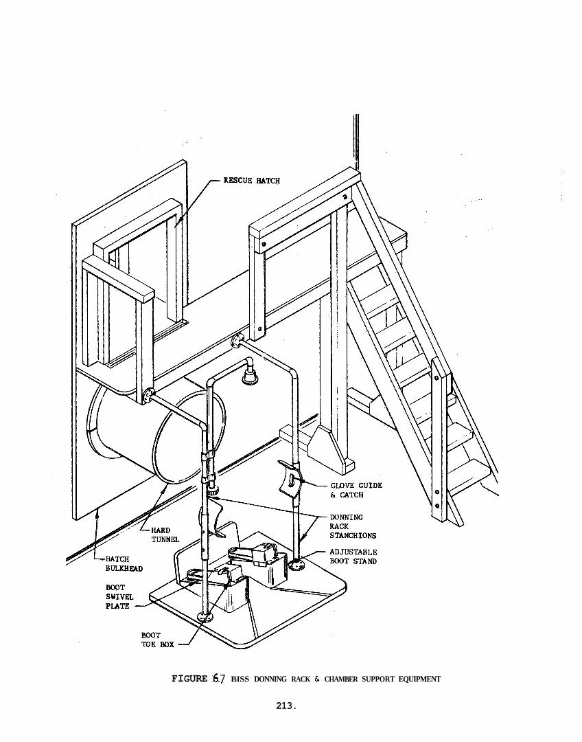
FIGURE .6.7 BISS DONNING RACK 6r CHAMBER SUPPORT EQUIPMENT
213.
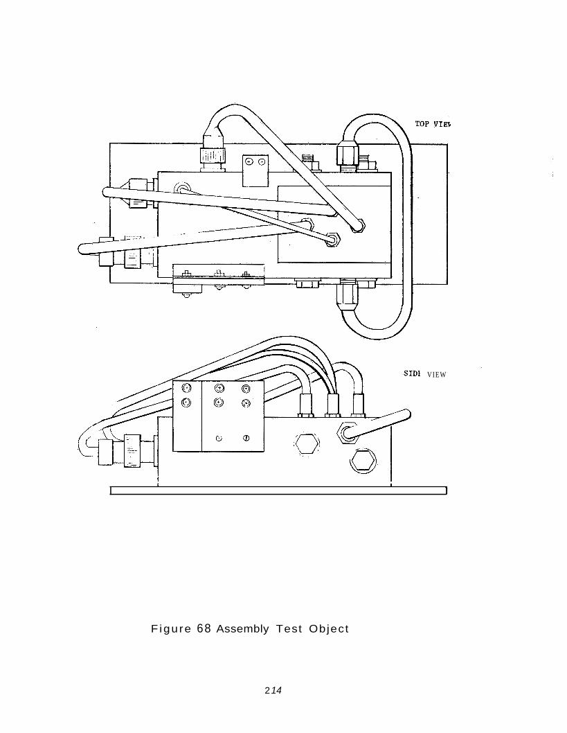
VIEW
I I I
1
F igu re 68 Assembly Test Object
2 14
8 . 6 . 4 Communications
In l i k e manner, the communications subsystem was re-designed and procured. Phase I. Moreover, the s u i t specifications required precise interface hard points which accommodate the operator's equipment i n the s u i t .
The equipment incorporated a l l of the experience gained i n
2 15
8.7 PHASE I1 TESTING
8.7.1 Purpose
The purpose of the Phase I1 mock-up t e s t i n g p r o g r m was t o eva lua te the performance of the second generat ion BISS. t e s t i n g program was almost e n t i r e l y exploratory and developmental i n na ture , a s opposed t o the goal of system eva lua t ion put f o r t h f o r Phase II. Another fundamental d i f f e r ence between the two t e s t i n g e f f o r t s was i n the number of sub jec t s . on one sub jec t , whereas four sub jec t s were used i n the Phase I1 program. Though four sub jec t s i s not a s u f f i c i e n t sample on which t o make f i n e d i sc r imina t ions , some gene ra l i t y can be ascr ibed t o the r e s u l t s obtained, un l ike the case of Phase I where i n most tests only one sub jec t was used.
The f i r s t phase of the
Almost a l l Phase I tests were conducted
The In tegra ted T e s t Plan i d e n t i f i e d s ix e x p l i c i t a r ea s i n the Phase I1 Program. These were: the taking of c e r t a i n anthropometric measure- ments, and the performance of en t ry- ex i t , mobi l i ty , dex t e r i t y , comuni- ca t ions and subjec t endurance tests. Imp l i c i t i n a l l of these tests was the quest ion of sub j ec t Comfort. I n the e a r l y phases of the program when the In tegra ted Test Plan was wr i t t en , i t was proposed t h a t each of the s i x a r ea s would be assessed by the use of independent tests. However, reassessment of the Phase I1 T e s t Plan suggested t h a t more r ea l i s t i c t e s t r e s u l t s would be r ea l i zed by performing the in-chamber t e s t s i n review, with the added advantage of obtaining a more va l id r e f l e c t i o n of sub j ec t endurance.
The p r i n c i p a l eva lua t ive quest ions t o be answered by the Phase I1 t e s t e f f o r t .,were :
e Can a man do use fu l work i n a pressur ized environment, o u t f i t t e d i n the BISS?
e Can a man perform i n t h i s environment f o r a four hour period?
The answers t o these fundamental quest ions and the d i scuss ion of the support ive evidence developed a s a r e s u l t of each of t he s i x a r ea s of i nves t i ga t i on presented i n t h i s sec t ion . Addi t ional ly , f a c e t s o f the design which s t i l l requi re fu r the r development w i l l be i d e n t i f i e d .
5.7.2 Revision of In tegra ted Test: P l a n
It was decided t o consol idate the en t ry- ex i t , mobi l i ty , d e x t e r i t y , and communications t e s t s w i t h the endurance run bu t anthropometric measurements s t i l l had t o be conducted a s a separa te e f f o r t . It was a l s o necessary t o introduce a pressure t ryout test f o r sub jec t f ami l i a r i za t i on with the Phase I1 BISS. This t r you t provided an
2 16
opportunity to completely familiarize the subjects with BISS pressurized operation and to provide data for making a final decision on the pressure level at which to conduct the endurance tests. Since two of the subjects were new and two had been under pressure during Phase I, the tryouts were scheduled so that one experienced man was with each of the inexper- ienced men during these first trials to advise them on such matters as entry techniques. All subjects made at least two pressurized entries and one pressurized exit during the course of the tryouts. to the above, the tryout tests provided necessary information on last minute system modifications and adjustments (e.g., the positioning of the donning rack).
In addition
8.7.3 Endurance Test Sequence
The sequencing of events during the modified endurance test were as follows:
Approx Time (min) Act ivi t y
000 Entry
005 SAS IV a (Entry)
0 10 SAS I (Comfort) & Vc (Communications)
020 Mobility Test
030 SAS I1 (Mobility)
035 Conrmunications (Test Conductor to Subject)
06s SAS I (Comfort)
070
100
110
120
130
140
170
Assembly Test Object disassembly
SAS I11 a , b, c2 (Dexterity)
Rest
Mobility Test
SAS I1 (Mobility) & SAS I (Comfort)
Conrmunications (Subject to Test Conductorj
SAS I (Comfort)
2 17
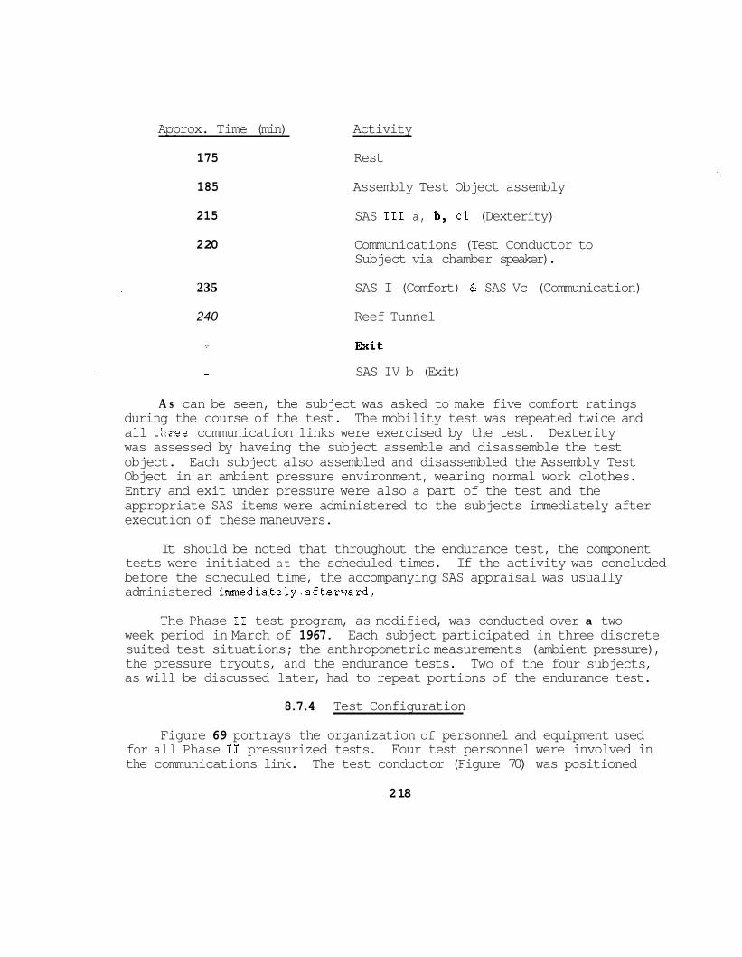
Approx. Time (min) Activity
175 Rest
185
215
2 20
Assembly Test Object assembly
SAS I11 a, b y cl (Dexterity)
Communications (Test Conductor to Subject via chamber speaker).
235 SAS I (Comfort) & SAS Vc (Communication)
240 Reef Tunnel
- SAS IV b (Exit)
A s can be seen, the subject was asked to make five comfort ratings during the course of the test. The mobility test was repeated twice and all thzee communication links were exercised by the test. Dexterity was assessed by haveing the subject assemble and disassemble the test object. Each subject also assembled and disassembled the Assembly Test Object in an ambient pressure environment, wearing normal work clothes. Entry and exit under pressure were also a part of the test and the appropriate SAS items were administered to the subjects immediately after execution of these maneuvers.
It should be noted that throughout the endurance test, the component tests were initiated at the scheduled times. If the activity was concluded before the scheduled time, the accompanying SAS appraisal was usually administered immediately-afterward.
The Phase I1 test program, as modified, was conducted over a two week period in March of 1967. suited test situations; the anthropometric measurements (ambient pressure), the pressure tryouts, and the endurance tests. Two of the four subjects, as will be discussed later, had to repeat portions of the endurance test.
Each subject participated in three discrete
8.7.4 Test Configuration
Figure 69 portrays the organization of personnel and equipment used for all Phase I1 pressurized tests. the communications link. The test conductor (Figure 70) was positioned
Four test personnel were involved in
2 18
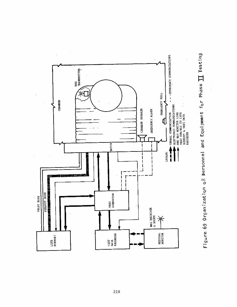
L 0 rc
a, a rc 0 S 0
S m tT, L 0
cn \D
3 w Lr. .-
219
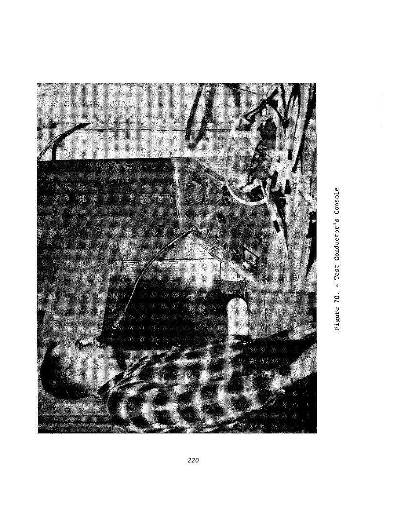
220
a t a window of the modified Tenney A l t i t u d e Chamber and maintained both v i s u a l and audio contact w i t h the subject . The test conductor a l s o had two-way contact with the l i f e support opera tor and the test data recorder who was phys ica l ly co- located with the mddicalmoni tor , and who relayed information t o and from the test conductor. A minimum of two a d d i t i o n a l men were a v a i l a b l e i n the chamber area f o r rescue and ree f ing opera t ions .
A team of 6 men i n assoc ia t ion with the modified Tenney.Alt i tude Chamber, the l i f e support console, and the medical monitoring s t a t i o n , comprised the experimental framework by and i n which the BISS was evaluated. Figure 71 shows the medical moni to r / t e s t da ta recorder s t a t i o n . support console exercised c o n t r o l over the sub jec t s input a i r temperature, input and exhaust flow r a t e s , and input humidity. means of measuring t h e temperature and humidity of t h e exhaust a i r . medical monitor ovserved the cardiograms of the sub jec t s throughout t h e test . Sensors were placed on the subject and t h e s i g n a l t ransmit ted by the small EM t r a n s m i t t e r shown hanging from the s u b j e c t ' s wa i s t , The s i g n a l was received by the u n i t wi th t h e whip antenna and the p a t t e r n was displayed on the osc i l loscope. P e r i o d i c a l l y , o r when the sub jec t showed s igns of stress, the medical monitor made a permanent record of the cardio- gram using a standard paper s t r i p recorder. the t a b l e i n Figure 71 was f o r the communications l i n k .
The l i f e
It a l s o provided a The
The o t h e r equipment shown on
I n opera t ion, the tes t conductor i n s t r u c t e d the sub jec t on a s t e p - by-step b a s i s throughout t h e tests. monitor gave pe r iod ic s t a t u s r e p o r t s t o the test conductor and a l s o advised him immediately of any i r r e g u l a r o r p o t e n t i a l l y dangerous occur- rences. the test conductor evaluated the reques t and passed h i s dec i s ion on t o the l i f e support opera to r .
The medica1 monitor and l i f e support
I f the sub jec t requested a change i n l i f e support parameters,
The tes t conductor recorded event times.and SAS r a t i n g s ; the l i f e support opera tor recorded l i f e support console readings; and the data recorder comments from the subject . The v i s u a l observat ions w e r e recorded by the test conductor s ince he was the only member of the team haveing v i s u a l contact wi th the sub jec t .
The modified Tenney A t t i t u d e Chamber used during the Phase I tests was a l s o used during Phase 11. As noted i n Sect ion 8.6.2. The chamber was refurnished and the donning rack improved t o provide more s o p h i s t i - cated equipment f o r the performance of the Phase I1 tests.
The Phase I1 o u t e r s u i t and undersui t and the donning rack used during t h i s t e s t i n g period a r e shown i n Figures 72 and 73. The BISS o u t f i t occupied by a sub jec t i s shown under no pressure i n Figure 74 and under 2" H20 d i f f e r e n t i a l pressure i n Figure 75.
22 1
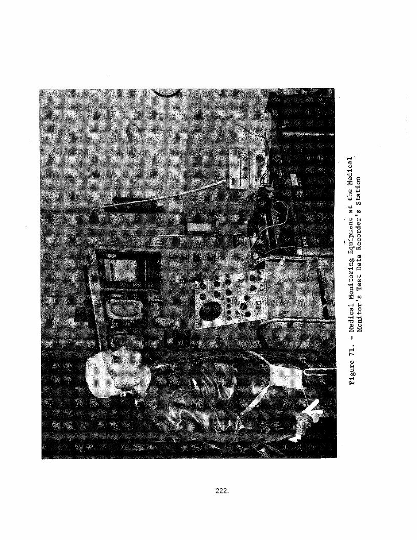
222.
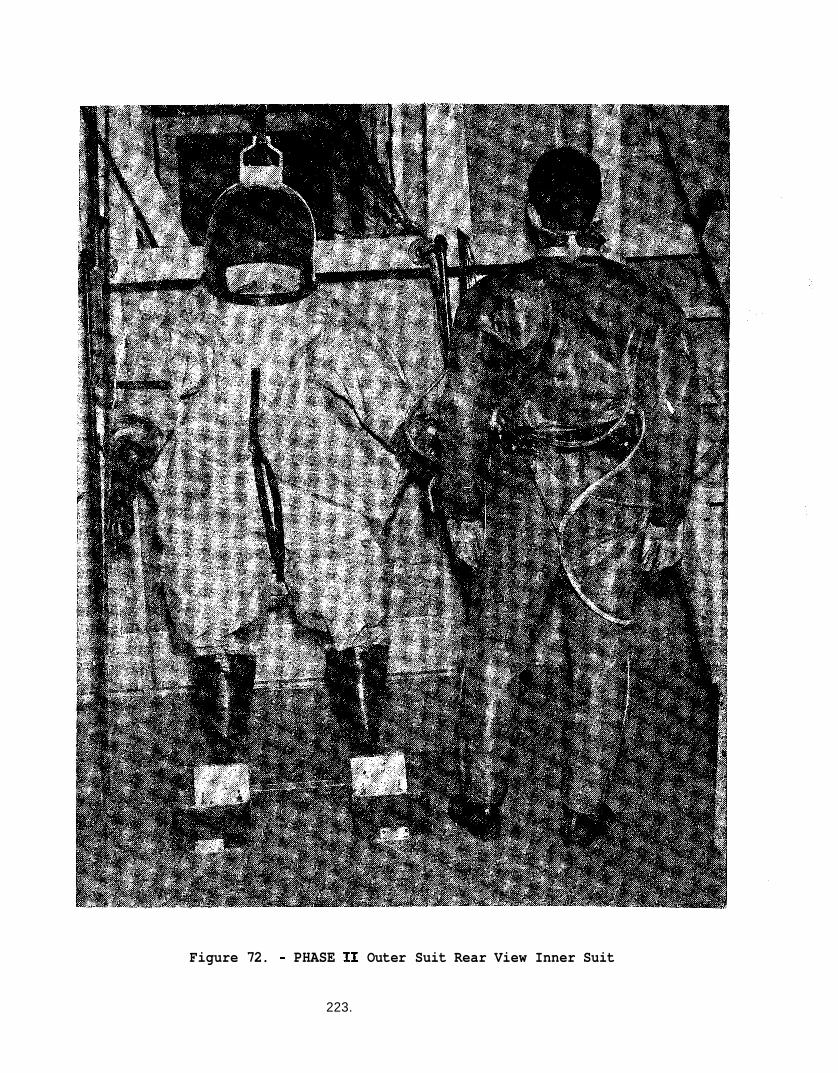
Figure 72. - PHASE I1 Outer Suit Rear View Inner Suit
223.
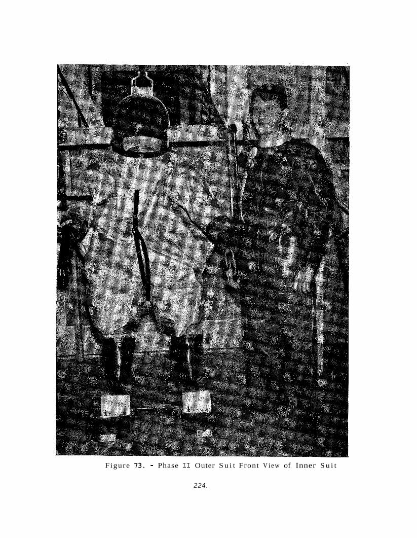
Figure 73. - Phase I1 Outer S u i t Front V i e w of Inner S u i t
224.
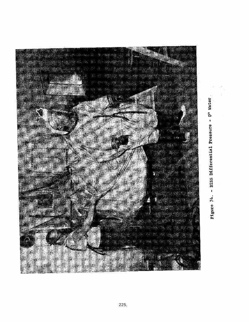
225,
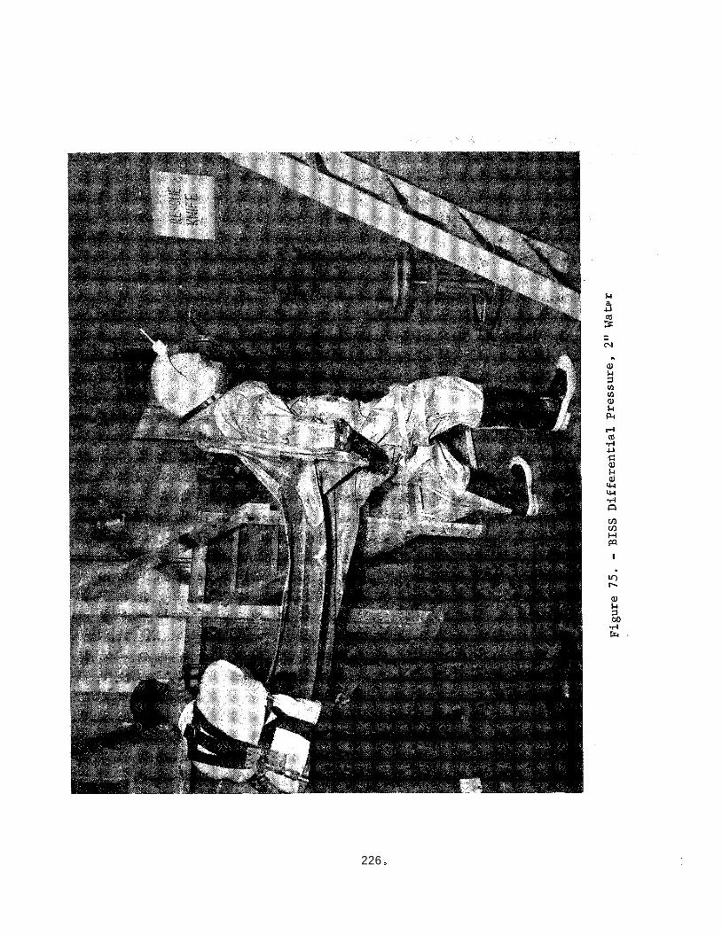
k a, 4J
n
226
8.7.5 Anthropometric Measurements
The o b j e c t i v e of the BISS anthropometric measurements was t o assess the decrement i n mobi l i ty of the arm, hand, wrist and neck of a sub jec t o u t f i t t e d i n a BISS, a s contras ted with the same ind iv idua l garbed i n normal street c lo thes . Guidelines f o r taking these measures were derived from WADC TN 57-311 "A S t a t i s t i c a l Evaluation of J o i n t Range Data" and t h e "Human Engineering Guide to Equipment Design", by Morgan, e t a l . These measurements a l l required the experimenter to measure the angle between a l i n k l i n e o r o the r reference l i n e passing through the bbdy member and a reference plane, usua l ly the v e r t i c a l o r hor izon ta l . (See Figure A 1 Appendix A , Sect ion 3.5.5; note wrist abduction and adduction values a r e reverskd). Since the l i n k l i n e s a r e contained wi th in the envelope of the body member, measurement e r r o r i s poss ib le , even when the movable member i s i n f u l l viiew of the measurer. When the sub jec t i s c lad i n a f a i r l y bulky garment such a s t h e BISS, d e f i n i t i o n of l i n k l i n e loca t ions becomes very d i f f i c u l t . I n add i t ion t o t h i s measure- ment problem, the degree of e x e r t i o n which t h e sub jec t puts f o r t h i n achieving maximum j o i n t o r member r o t a t i o n o r movement i s not ameng3le t o con t ro l by the experimenter.
For these reasons, some negative values w i l l be observed i n t h e percentage d i f fe rence t abu la t ions (Table XXXI) . These negative values imply t h a t the subject had g r e a t e r freedom of movement i n the BISS than i n common work c lo thes . To ta l means f o r sub jec t s and means across sub jec t s exclude these negat ive values.
The data can be summarized a s follows:
Wrist Measurements
a . Flexion A M = 4.8% N*= 3
b. Extension A M = 10.0% N = 3
c. Abduction A M = 44.6% N = 4
d. Adduction A M = 0% N = 2
These measures a r e withinathe design goal of a 10% d i f fe rence wi th the exception of wrist abduction. held s teady on a v e r t i c a l su r face , the sub jec t s tanding and the w r i s t being bent away from t h e body around and imaginary a x i s perpendicular t o the f l a t t e n e d hand. This movement p laces a maximum requirement on garment s leeve length.
The abduction measure i s taken with the hand
Since sub jec t s d id not r e p o r t s l eeve length
* N = Number of data po in t s .
227.
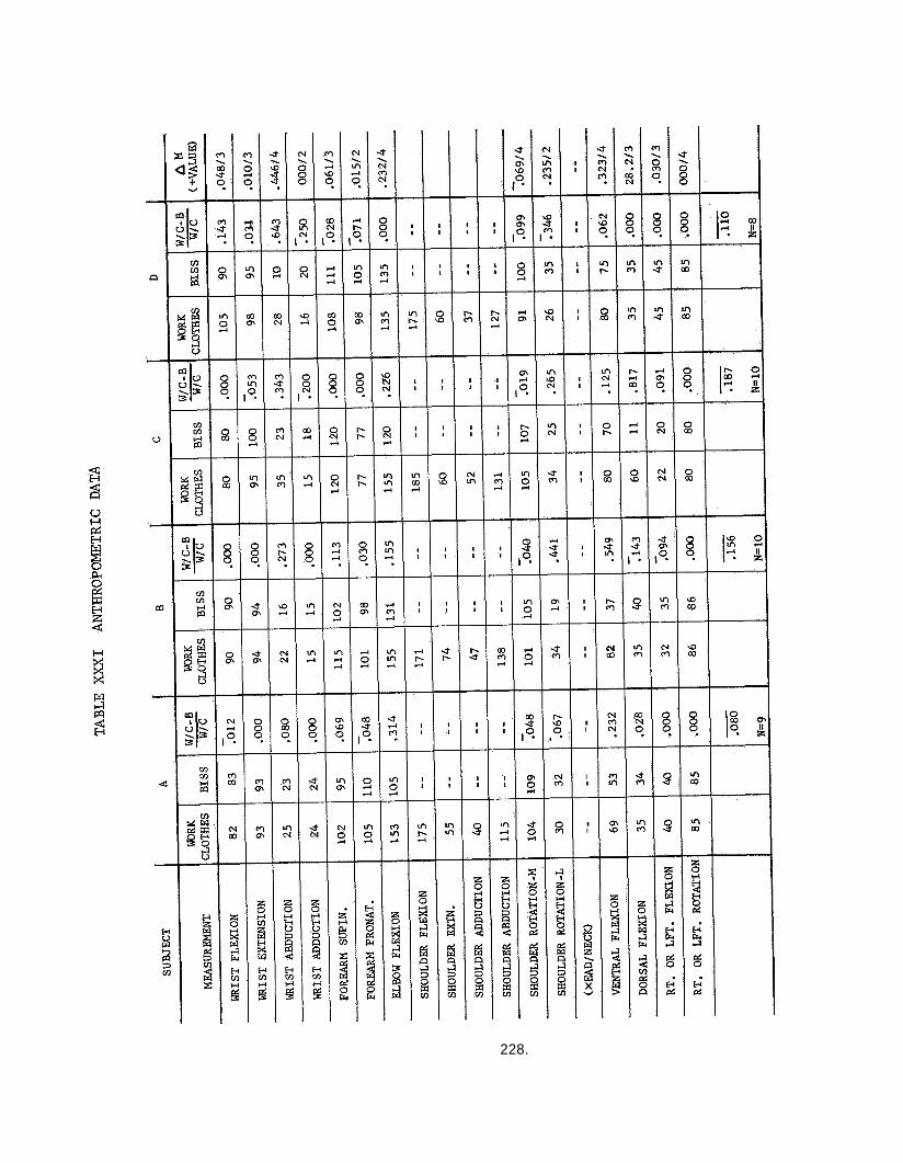
L
I I
- I I
I I
-
I I - I I
-
c
8 P w
2 X "
7- k
228.
aal-,being inadequate a t any time during the test it i s probable t h a t most of the wrist abduction can be ascr ibed t o t h e unnaturalness o f the p o s i t i o n assumed and d i f f f e u l t y i n locat ing the forearm l i n k i n the s u i t e d condit ion. The f a c t t h a t two of the adduction measures were negative i n the s u i t e d condi t ion t r ends t o confirm t h i s hypothesis . It is a l s o c l e a r ' t h a t i f t h e r e were any se r ious impairment t o wrist movement, i t would have been r e f l e c t e d i n the d i x t e r i t y test r e s u l t s , which were good. Figure 76, on the next page i l l u s t r a t e s a phase of t h e measurement process.
Forearm Measurements
a . Supination A M = 6.1% Ne"= 3
b. Pronation A M =: 1.5% N 2
These mean d i f fe rence f o r forearm supinat ion and pronation a r e w e l l within t h e design goal . The negative cases , a l l low percentages, can probably be ascr ibed t o d i f fe rences i n e f f o r t on the p a r t of the sub jec t s under the d i f f e r e n t condit ions.
Elbow Measurements
a . Elbow f l ex ion AM = 23.2% N = 4
Elbow f lex ion was measured with the sub jec t s i t t i n g and t h e arm supported p a r a l l e l t o the surface of a t ab le . The forearm was then maximally f lexed and the angle measured between the p ro jec t ion of the arm l i n k l i n e and the forearm l i n k l i n e . It is understandable t h a t f l ex ing the arm i n t h i s way would be impeding by bunching of the heavy s u i t m a t e r i a l a s the arm closed. Even with t h i s impediment the mean value i s under the design requirement of 25%.
Shoulder Measurements
a . Medial r o t a t i o n A M = 6.9% N = 4
b. L a t e r a l r o t a t i o n AM = 23.5% N = 2
The medial and l a t e r a l r o t a t i o n measures were taken f o r the seated subject with the arm supported a s was done fo r elbow f lexion. suggests t h a t t h e measurer could not accura te ly l o c a t e t h e forearm l i n k l i n e f o r these measurements when the sub jec t was s u i t e d . From a p r a c t i c a l s tandpoint , the shoulder mobi l i ty of sub jec t s was very s a t i s f a c t o r y i n performing t h e assembly and disassembly tasks .
This da ta
229
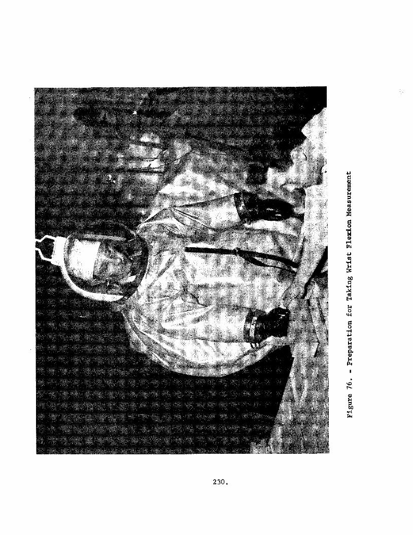
I
230,
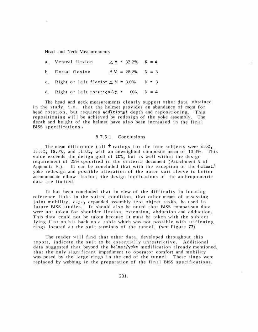
Head and Neck Measurements
a . Ventral f l ex ion A M = 32.2% N = 4
b. Dorsal f l ex ion AM = 28.2% N = 3
c. Right o r l e f t f l e x i o n A M = 3.0% N = 3
d. Right o r l e f t rota t ionAM = 0% N = 4
The head and neck measurements c l e a r l y support o the r da ta obtained i n the s tudy, i .e . , t h a t the helmet provides an abundance of room f o r head r o t a t i o n , but requi res add'i t ional depth and repos i t ion ing . This repos i t ion ing w i l l be achieved by redesign of the yoke assembly. The depth and height of the helmet have a l s o been increased i n the f i n a l BISS spec i f i ca t i ons .
8.7.5.1 Conclusions
The mean d i f f e r ence ( a l l + r a t i n g s f o r the four sub jec t s were 8.0%, 15.6%, 18.7%, and 11.0%, with an unweighted composite mean of 13.3%. This value exceeds the design goal of lo%, but i s wel l wi thin the design requirement of 25% spec i f i ed i n the c r i t e r i a document (Attachment A of Appendix F.) . yoke redesign and poss ib le a l t e r a t i o n of the ou te r s u i t s leeve t o b e t t e r accommodate elbow f l ex ion , t he design implicat ions of the anthropometric data a r e l imited.
It can be concluded t h a t wi th the exception of the helmet/
It has been concluded t h a t i n view of the d i f f i c u l t y i n loca t ing reference l i n k s i n the su i t ed condi t ion, t h a t o the r means of assess ing j o i n t mobi l i ty , e .g . , expanded assembly test ob j ec t t a sks , be used i n fu tu re BISS s tud i e s . It should a l s o be noted t h a t BISS comparison data were not taken f o r shoulder f l ex ion , extension, abduction and adduction. This data could not be taken because i t must be taken with the sub jec t ly ing f l a t on h i s back on a t a b l e which was not poss ib le with s t i f f e n i n g r i ngs located a t the s u i t terminus of the tunnel, (see Figure 77)
The reader w i l l f i nd t h a t o ther da t a , developed throughout t h i s r epo r t , i nd i ca t e the s u i t to be e s s e n t i a l l y u n r e s t r i c t i v e . Addi t ional data suggested t h a t beyond the helmet/yoke modif icat ion a l ready mentioned, t h a t the only s i g n i f i c a n t impediment t o operator comfort and mobi l i ty was posed by the la rge r i ngs i n the end of the tunnel . These r i ngs were replaced by webbing i n the prepara t ion of the f i n a l BISS spec i f i ca t i ons .
231.
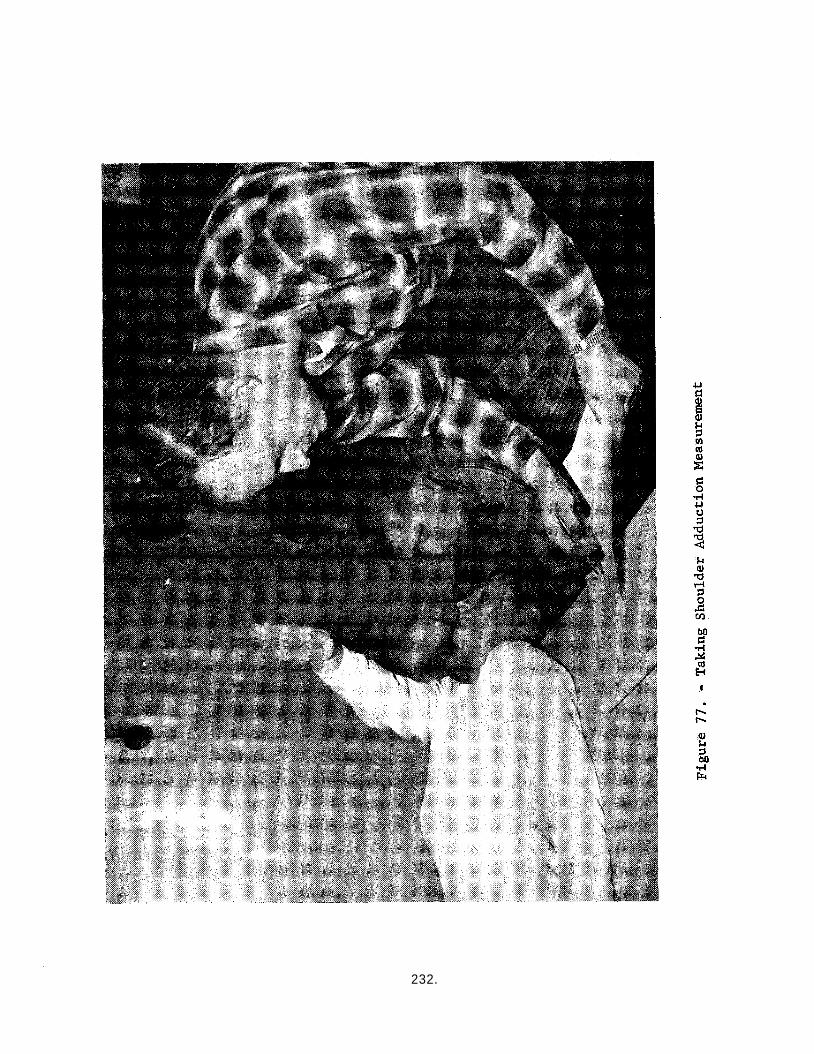
232.
8.7.6 Pressure Tryout Tests
8.7.6.1 Purpose
The goals of the pressure t ryout tests were:
sub jec t f ami l i a r i za t i on with the pressure environment
i d e n t i f i c a t i o n of system problem a reas amenable t o quick modif icat ions
0 determination of a s u i t a b l e pressure level f o r the endurance tests.
Various sub jec t s were run a t each pressure l e v e l from one t o four inches H20. one pressur ized e x i t .
A l l sub jec t s made a minimum of two pressur ized e n t r i e s and Both of the new sub jec t s made two pressur ized e x i t s .
8.7.6.2 Resul ts
8 .7 .6 .2 .1 Hardware
Problem a reas i d e n t i f i e d during the t ryout runs were:
e Donning rack - glove hooks needed repos i t ion ing (accomplished) . Yoke - needed padding o r s t r a p s t o e l eva t e yoke s l i g h t l y (accomp- l i shed)
0 A i r d i s t r i b u t i o n tubing - under pressure , the tubing tended t o par- t i a l l y co l lapse from the a c t i o n of the su i t - tunne l i n t e r f a c e r i ngs on i t (tubing replaced) .
Large su i t - tunne l i n t e r f a c e r i ngs tended t o impede subjec t move- ment and cause some discomfort (no a c t i o n poss ib le ) . . Glove A i r - i n s u f f i c i e n t glove a i r ( l a t e r i n test program repo- s i t i o n i n g of hand a i r d i s t r i b u t i o n tube helped t h i s problem).
;- Compressor - needed modif icat ion t o prevent i c ing i n high R.H. ambients (accomplished).
e Communications transducer package too bulky (modified a f t e r 1st of 4 endurance runs)
233.
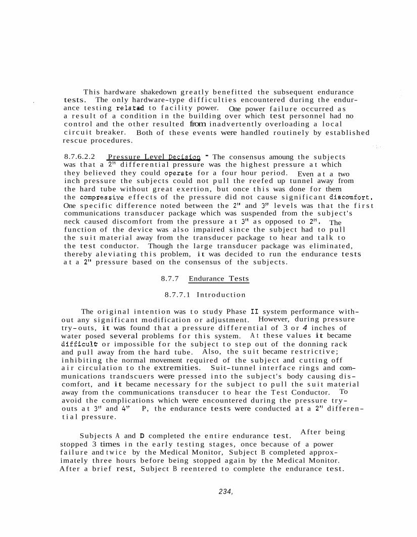
This hardware shakedown g r e a t l y benef i t t ed the subsequent endurance tests. ance t e s t i n g r e l a t a d t o f a c i l i t y power. a r e s u l t of a condi t ion i n the bui ld ing over which test personnel had no c o n t r o l and the o t h e r r esu l t ed from inadver ten t ly overloading a l o c a l c i r c u i t breaker. rescue procedures.
The only hardware-type d i f f i c u l t i e s encountered during the endur- One power f a i l u r e occurred a s
Both of these events were handled rou t ine ly by es tab l i shed
8.7.6.2.2 was t h a t a 2" d i f f e r e n t i a l pressure was the h ighes t pressure a t which they believed they could opesate f o r a four hour period. inch pressure the sub jec t s could not p u l l the reefed up tunnel away from the hard tube without g r e a t exer t ion , but once t h i s was done f o r them the compzessive e f f e c t s of the pressure d id not cause s i g n i f i c a n t discomfort. One s p e c i f i c d i f fe rence noted between the 2" and 3" l eve l s was t h a t the f i r s t communications transducer package which was suspended from the s u b j e c t ' s neck caused discomfort from the pressure a t 3" a s opposed t o 2". funct ion of the device was a l s o impaired s ince the subject had t o p u l l the s u i t m a t e r i a l away from the transducer package t o hear and t a l k t o the test conductor. thereby a l e v i a t i n g t h i s problem, i t was decided t o run the endurance tests a t a 2" pressure based on the consensus of the sub jec t s .
Pressure Level Decisioa - The consensus amoung the sub jec t s
Even a t a two
The
Though t h e large transducer package was e l iminated,
8.7.7 Endurance Tests
8.7.7.1 In t roduc t ion
The o r i g i n a l i n t e n t i o n was t o study Phase I1 system performance with- ou t any s i g n i f i c a n t modif ica t ion o r adjustment. t ry- outs , it was found t h a t a pressure d i f f e r e n t i a l of 3 o r 4 inches of water posed several problems f o r t h i s system. d i f f i c u l t r o r impossible f o r the sub jec t t o s t e p ou t of t h e donning rack and p u l l away from t h e hard tube. i n h i b i t i n g t h e normal movement required of the s u b j e c t and c u t t i n g off a i r c i r c u l a t i o n t o t h e extremities. Sui t- tunnel i n t e r f a c e r i n g s and com- munications t randscuers were pressed i n t o the s u b j e c t ' s body causing d i s - comfort, and it became necessary f o r the sub jec t t o p u l l the s u i t ma te r i a l away from t h e communications transducer t o hear the T e s t Conductor. To avoid the complications which were encountered dur ing the pressure t r y - outs a t 3" and 4" P, t h e endurance tests were conducted a t a 2" d i f f e r e n- t i a l pressure .
However, during pressure
A t these values it became
Also, the s u i t became r e s t r i c t i v e ;
Subjects A and D completed t h e e n t i r e endurance test. Af te r being
stopped 3 times i n the e a r l y t e s t i n g s t ages , once because of a power f a i l u r e and t w i c e by the Medical Monitor, Subject B completed approx- imately th ree hours before being stopped again by the Medical Monitor. Af te r a b r i e f rest, Subject B reentered t o complete the endurance test.
234,
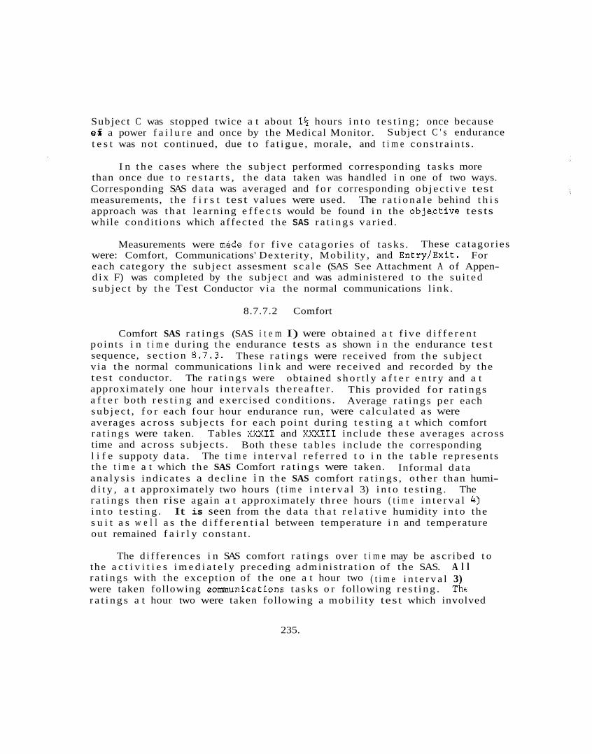
Subject C was stopped twice a t about 1% hours i n t o t e s t i n g ; once because of a power f a i l u r e and once by the Medical Monitor. t e s t was not continued, due t o f a t i g u e , morale, and t i m e cons t ra in t s .
Subject C ' s endurance
I n t h e cases where the subject performed corresponding t asks more than once due t o r e s t a r t s , the data taken was handled i n one of two ways. Corresponding SAS da ta was averaged and f o r corresponding o b j e c t i v e test measurements, the f i r s t test values were used. The r a t i o n a l e behind t h i s approach was t h a t learning e f f e c t s would be found i n the obje.ctive tests while condi t ions which a f fec ted the SAS r a t i n g s va r ied .
Measurements were mgde f o r f i v e ca tagor ies of t a sks . These ca tagor ies were: Comfort, Communications' Dexter i ty , Mobi l i ty , and Entry/Exit . each category the sub jec t assesment s c a l e (SAS See Attachment A of Appen- d i x F) was completed by the sub jec t and was administered t o the s u i t e d sub jec t by t h e Test Conductor v ia the normal communications l ink .
For
8.7.7.2 Comfort
Comfort SAS r a t i n g s (SAS i t e m I) were obtained a t f i v e d i f f e r e n t po in t s i n t i m e dur ing the endurance tests a s shown i n the endurance test sequence, s e c t i o n 8.7.3. v ia the normal communications l i n k and were received and recorded by the test conductor. approximately one hour i n t e r v a l s t h e r e a f t e r . a f t e r both r e s t i n g and exerc ised condi t ions . s u b j e c t , f o r each four hour endurance run, were ca lcu la ted a s were averages ac ross sub jec t s f o r each po in t during t e s t i n g a t which comfort r a t i n g s were taken. Tables X X X I I and XXXIII include these averages across time and across sub jec t s . l i f e suppoty da ta . The t i m e i n t e r v a l r e f e r r e d t o i n the t a b l e represen t s the t i m e a t which t h e SAS Comfort r a t i n g s were taken. a n a l y s i s ind ica tes a dec l ine i n t h e SAS comfort r a t i n g s , o t h e r than humi- d i t y , a t approximately two hours ( t i m e i n t e r v a l 3) i n t o t e s t i n g . The r a t i n g s then rise again a t approximately t h r e e hours ( t i m e i n t e r v a l 4 ) i n t o t e s t i n g . It is seen from the da ta t h a t r e l a t i v e humidity i n t o the s u i t a s w e l l a s t h e d i f f e r e n t i a l between temperature i n and temperature out remained f a i r l y constant .
These r a t i n g s were received from t h e sub jec t
obtained s h o r t l y a f t e r e n t r y and a t This provided f o r r a t i n g s Average r a t i n g s pe r each
The r a t i n g s were
Both these t a b l e s inc lude t h e corresponding
Informal da ta
The d i f fe rences i n SAS comfort r a t i n g s over t i m e may be ascr ibed t o the a c t i v i t i e s i m e d i a t e l y preceding admin i s t ra t ion of the SAS. A l l r a t i n g s with the exception of the one a t hour two ( t i m e i n t e r v a l 3) were taken following aomunica t ions t a s k s o r following r e s t i n g . The r a t i n g s a t hour two were taken following a mobi l i ty test which involved
235.
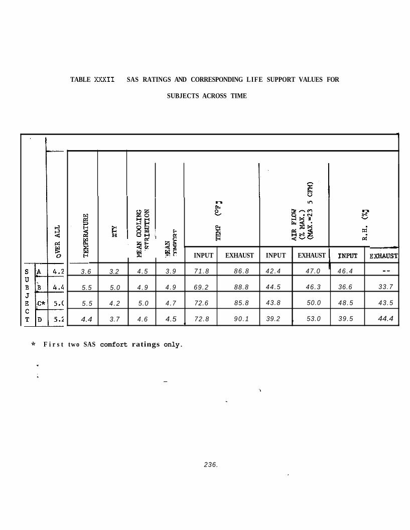
TABLE XXXII SAS RATINGS AND CORRESPONDING LIFE SUPPORT VALUES FOR
SUBJECTS ACROSS TIME
1
3.6
5.5
5 .5
4.4
r: 4
B 0
n In F
n b.-o W
%
a i pi
kz 3s
C 8 2 PI
H V H
INPUT EXHAUST INPUT , EXHAUST 1 INplJT E X I U U G
-_ 3.2 4 .5 3 .9 71 .8 86 .8 42 .4 47.0 ' 4 6 . 4
5.0 4 . 9 4 .9 69 .2 88.8 44 .5 46 .3 36.6 33.7
4 .2 5.0 4 .7 72.6 85.8 43.8 50.0 48 .5 43 .5
3.7 4.6 4.5 72.8 90 .1 39.2 , 53.0 39 .5 44.4 h 4
* F i r s t two SAS comfort ratings only.
236.
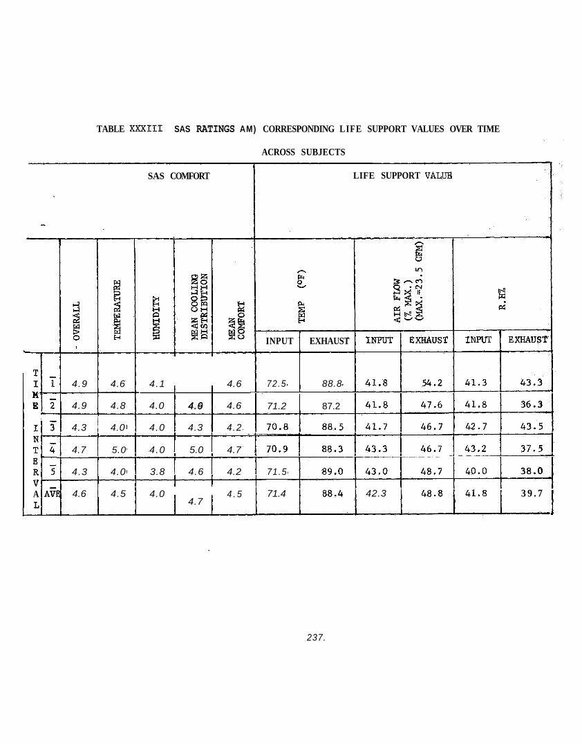
TABLE XXXIII SAS RATINGS AM) CORRESPONDING LIFE SUPPORT VALUES OVER TIME
- I T N- T b E- R 5 V- A A i L
4.9 4.6
4.9 4.8
4.3 4.0
4.7 5.0
4.3 4.0
4.6 4.5
SAS COMFORT
r I I
4.1 4.6 1 4.9 1 4.0 4.6 4.6
4.0 4.3 4.2
4.0 5.0 4.7
3.8 4.6 4.2
4.0 f 4.7 I 4 . 5
ACROSS SUBJECTS
LIFE SUPPORT VALUB
h F %
PI
i! INPUT EXHAUST
72.5 88.8
71.2 1 87.2
71.5
71.4 42.3 3 9 . 7
A
237.

a c e r t a i n amount of exer t ion . Also, following a mobi l i ty test which involved a c e r t a i n amount of exertion.. Also, t h e p a t t e r n followed by a i r flow input r a t e s is s i m i l a r to t h a t of the SAS cooling d i s t r i b u t i o n . General ly, the h igher SAS r a t i n g s , o the r than humidity SAS, were accompanied by the l a r g e s t d i f fe rences between humidity input and exhaust .
The mean comfort and l i f e support data between sub jec t s shows a p e s s i b l e b i a s due t o sub jec t experience. Subjects A and D took p a r t i n Phase I t e s t i n g and were f a r more experienced i n the BISS environment. This might be demonstrated by f a c t t h a t i n a l l cases except o v e r a l l com- f o r t , t h e sub jec t ive r a t i n g s of the two newest sub jec t s were higher than those of t h e more experienced sub jec t s . equivocal ly however, t h a t t h i s was a b i a s e f f e c t s ince the l i f e support parameters d id vary. General ly, the higher input a i r flow r a t e s received higher sub jec t ive r a t i n g s and the h ighes t sub jec t ive r a t i n g s f o r input temperature and input humidity corresponded t o the lowest l i f e support value fog these parameters.
It is impossible t o say un-
To f u r t h e r evaluate t rends , c e r t a i n s t a t i s t i c a l opera t ions w e r e performed. Data was normalized so t h a t a l l va lues could be expressed i n s i m i l a r terms. The average value f o r each SAS s c a l e and each l i f e support parameter was used a s the basel ine f o r i t s own s c a l e o r parameter. Each value wi th in a parameter o r s c a l e was divided by the corresponding value and mul t ip l i ed by 100. The r e s u l t a n t normalized data was the re fo re expressed a s a percent of the average value f o r the values i n i t s own sca le o r parameter.
Once the data had been normalized it was grouped according t o the mean SAS value (Table XXXIV). The mean SAS value was the average of a l l the comfort SAS r a t i n g s c a l e s including temperature, humidity, o v e r a l l comfort and the mean of the cooling d i s t r i b u t i o n sca les . Each d i f f e r e n t mean SAS value was grouped with o the r equal mean SAS values. than one value was contained wi th in a group, corresponding SAS s c a l e s and l i f e support parameters w e r e averaged t o ob ta in one value f o r each s c a l e and parameter. Table XXXIV presents the data a f t e r grouping. Nine groups of data were found. Ranks were then assigned t o the grouped values from 1 (highes t value) t o 9 lowest value) .
When more
The f i n a l s t a t i s t i c a l opera t ion was the c a l a u l a t i o n of c o r r e l a t i o n s between a l l s c a l e s and parameters. r e l a t i o n s h i p s between values. techniques w e r e used f o r t h i s purpose. is :
This was done t o assess poss ib le Spearman Rank Corre la t ion Coef f i c ien t s
The formula f o r t h i s c o e f f i c i e n t
238.
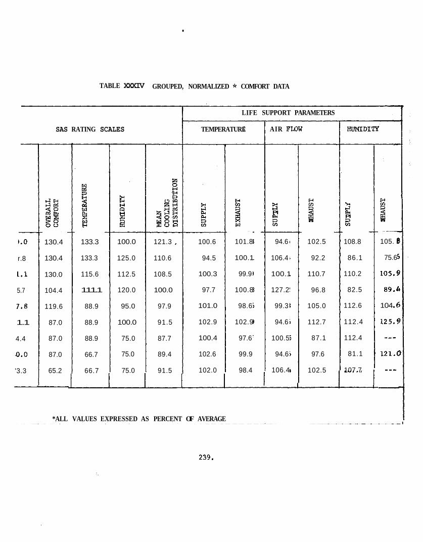
.
TABLE XXXIV GROUPED, NORMALIZED * COMFORT DATA
SAS RATING SCALES
1.0
r.8
1.1
5.7
7.8
1.1
4.4
ro.0
'3.3
4 E - l
3g S O 00
130.4
130.4
130.0
104.4
119.6
87.0
87.0
87.0
65.2
-
133.3
133.3
115.6
111.1
88.9
88.9
88.9
66.7
66.7
100.0
125.0
112.5
120.0
95.0
100.0
75.0
75.0
75.0
121.3 I
110.6
108.5
100.0
97.9
91.5
87.7
89.4
91.5
LIFE SUPPORT PARAMETERS
TEMPERATURE
100.6
94.5
100.3
97.7
101.0
102.9
100.4
102.6
102.0
*ALL VALUES EXPRESSED AS PERCENT OF AVERAGE
101.8
100.1
99.9
100.8
98.6
102.9
97.6
99.9
98.4
AIR FLOW
3 R PI pc
94.6
106.4
100.1
127.2
99.3
94.6
100.5
94.6
106.4
5: rl w
102.5
92.2
110.7
96.8
105.0
112.7
87.1
97.6
102.5
HUMIDITI?
5 4 l.2 pc PI R 108.8
86.1
110.2
82.5
112.6
112.4
112.4
81.1
107.7
5: z w
105. E
75.6
105.5
89.L
104 f
125.5
--- 1 2 1 4
-
239,

where v s equals t h e c o r r e l a t i o n coeff ic ient , N equals the nuniber of groups, and N equals the sum of the squared d i f fe rences between ranks ":
i - 1
of the two parameters o r sca les cor re la ted .
Although no test of s ign i f i cance were attempted, t rends and r e l a t i o n- sh ips between v a r i a b l e s may s t i l l be suggested by the c o r r e l a t i o n values. General ly, f o r an N of 9 (appl icable t o a l l parameters o the r than humidity) a Spearman Rank Cor re la t ion of .600 o r g r e a t e r i s considered s i g n i f i c a n t . A l l c o e f f i c i e n t s found t o be ,500 o r g r e a t e r a r e reported here , however, s ince no at tempt a t determining s ign i f i cance has been made. It should be noted t h a t t h e N f o r c o r r e l a t i o n s involving exhaust humidity have an N o f 7 s ince data were not a v a i l a b l e f o r t h a t parameter i n 2 groups. When c o r r e l a t i n g parameters o r s c a l e s wi th exhaust humidity only the h ighes t 7 values of t h a t s c a l e o r parameter were considered.
Tables XXXV, XXXVI, XXXVII, present values of .SO0 o r g r e a t e r f o r SAS s c a l e i n t e r c o r r e l a t i o n s , l i f e support parame ers i n t e r e o r r e l a t i o n s and c o r r e l a t i o n s of SAS s c a l e s with l i f e support parameters, r e spec t ive ly . A b r i e f d i scuss ion of a r e l a t i o n s h i p s , which the data suggest , follows each t a b l e . D i f f e r e n t i a l va lues included i n Tab e XMVI r e f e r t o exhaust parameters minus supply parameters.
8.7.7.2.1 Discussion - A s might be expected, c e r t a i n d i f f e r e n t i a l parameters show varying degrees of r e l a t i o n s h i p with the supply and exhaust parameters on which they a r e based. a l s o occurs between d the r parameters.% Generally, d i f f e r e n t i a l tempera- t u r e magnitude shows s t rong d i r e c t r e l a t i o n s h i p with d i f f e r e n t i a l a i r flow shows s t rong inverse re la t ionsheps , i .e. a s one parameter increases the o t h e r decreases , with humidity d i f f e r e n t i a l magnitude and d i r e c t i o n . Strong inverse re la t ionsheps a r e a l s o indicated f o r exhause a i r flow with exhaust humidity and f o r supply temperature with supply a i r flow and d i f f e r e n t i a l humidity magnitude and d i r e c t i o n .
Strong r e l a t i o n s h i p s do, however,
240.
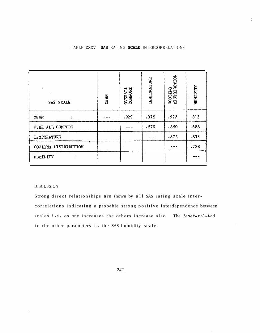
TABLE XXXV SAS RATING SCALE INTERCORRELATIONS
DISCUSSION:
Strong d i r e c t r e l a t i o n s h i p s are shown by a l l SAS r a t i n g scale i n t e r -
c o r r e l a t i o n s i n d i c a t i n g a probable s t rong p o s i t i v e interdependence between
s c a l e s i .e . as one inc reases t h e o t h e r s inc rease a l s o . The l e a s h r e l a t e d
t o t h e o the r parameters i s the SAS humidity scale.
241.
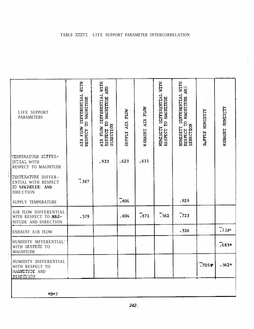
TABLE XXXVI L I F E SUPPORT PARAMETER INTERCORRELATION
L I F E SUPPORT PARAMETERS
CEMPERATURE DIFFER- ZNTIAL WITH RESPECT TO MAGNITUDE
IlEMPERATURE DIFFER- ENTIAL WITH RESPECT
DIRE: CTION ro MAGNITUDE AND
SUPPLY TEMPERATURE
- 567
AIR FLOW DIFFERENTIAL
NITUDE AND DIRECTION
EXHAUST A I R FLOW
HUMIDITY MFFERENTIAL' WITH RESPECT TO MAGNITUDE
HUMIDITY DIFFERENTIAL WITH RESPECT TO MTYITUDE AND D1RE:CTION
WITH RESPECT TO MAG- .579
c
.933 .629
- .804
~
.804
w
.811
- .871
- ,562
.929
- .723
3 F4 F4 3 cn
F H B 9 W
- .7 14*
- .683*
.562*
*N=7
242.
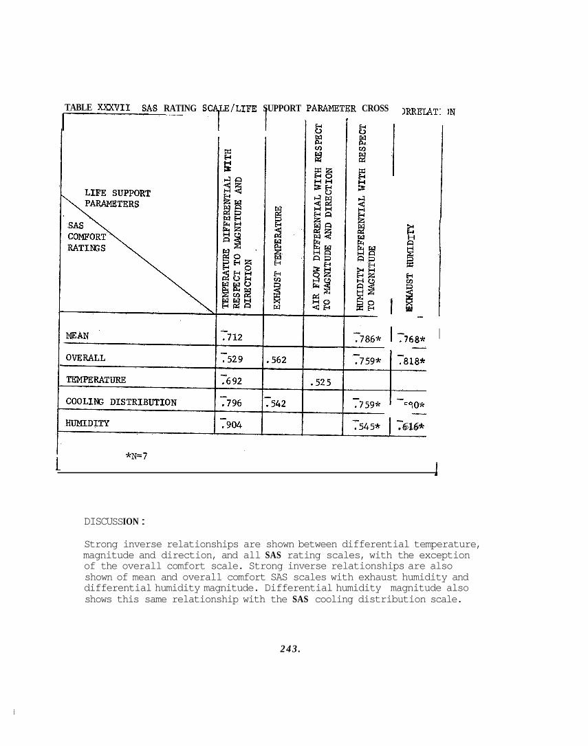
TABLE XXXVII SAS RATING SCALE/LIFE SUPPORT P A W T E R CROSS
I 1 1 r
I! I
*N=7
XRELAT:
c H
1 E-c m
3 x w
.768*
.818*
6 16*
IN
I
1 1
DISCUSS ION :
Strong inverse relationships are shown between differential temperature, magnitude and direction, and all SAS rating scales, with the exception of the overall comfort scale. Strong inverse relationships are also shown of mean and overall comfort SAS scales with exhaust humidity and differential humidity magnitude. Differential humidity magnitude also shows this same relationship with the SAS cooling distribution scale.
243 .
8.7.7.2.2 Comfort Comments - Comments made by the sub jec t s t o the test conductor were recorded. c l a s s e s o r ca tegor ies . These c l a s s e s a r e l i f e support r e l a t e d comments and s u i t j t u n n e l des ign comments. so many of the comments a r e grouped wi th those to which they seemed bes t r e l a t e d . modificat ions t o Phase I1 BISS a r e presented.
8.7.7.3.3.1 - L i f e Support Related Comments:
These comments f a l l genera l ly i n t o two main
These c l a s s e s over lap t o a g r e a t ex ten t , :
Only those comments which had impl ica t ions f o r f u r t h e r des ign
. Cooling was reduced-when sub jec t s a t .
0 A s supply and exhaust a i r flow d i f f e r e n t i a l increases , the pres- sure was f e l t more by the sub jec t s .
e Greater cooling c a p a b i l i t y was needed . A t times genera l discomfort was f e l t but i t was impossible t o l o c a l i z e i t
a No hot spo t s were experienced
0 Independent con t ro l s f o r a i r flow r a t e s i n s u i t and helmet were recommended
0 Subjects tended t o warm up r a p i d l y from only s l i g h t e x e r t i o n
9.7.7.2.2.2 Suit/Tunnel Design Comments:
e Force6 exer ted by the su i t - tunne l i h t e r f a c e r ings became annoying and were.detr imenta1 t o sub jec t comfort i n a l l cases wi th the exception of s tanding i n place.
0 Helmet-uoke assembly s h i f t e d forward, pushing the sub jec t s head forward and causing.genera1 neck and back discomfort.
0 I n a b i l i t y t o move head back (dorsa l f lexion) was hard on the neck
A i r d i s t r i b u t i o n tubes ac ross the back should be harder.
Glove clamps should be fac ing ou t t o avoid snagging the s u i t
0 Weight of tunnel was hard on the small of t h e back
0 Weight of Helmet-Yoke assembly was t i r i n g
244.
8.7.7.2.3 Conclusions - It i s apparent t h a t SAS comfort s c a l e s are not independent. P a r t o f t h i s dependence probably -s tems from the f a c t t h a t c e r t a i n o f t h e l i f e support da ta show s t rong r e l a t i o n s h i p s and t h a t SAS comfort r a t i n g s o f t e n show a high degree of c o r r e l a t i o n wi th s e v e r a l d i f f e r e n t l i f e- suppor t parameters. I n genera l , SAS comfort r a t i n g s show the s t ronges t r e l a t i o n s h i p s wi th d i f f e r e n t i a l temperature magnitude and d i r e c t i o n and wi th the exhaust humidity and d i f f e r e n t i a l humidity magnitude. e f f e c t f o r work versus rest s ince a l l t h r e e parameters can be expected t o increase wi th sub jec t e x e r t i o n and they show inverse r e l a t i o n s h i p s wi th SAS comfort r a t ings . n i tude and d i r e c t i o n show l imi ted d i r e c t r e l a t i o n s h i p s wi th c e r t a i n comfort r a t i n g s .
It would seem t h a t these r e l a t i o n s h i p s show a d e f i n i t e a c t i v i t y
Exhaust temperature and ai-r flow d i f f e r e n t i a l mag-
Although d i f fe rences between sub jec t s , ac ross time, show some r a t i n g s which a r e less than s a t i s f a c t o r y , averages ac ross sub jec t s , over t h e and averages across sub jec t s and t i m e prove t o be s a t i s f a c t o r y .
Hardware impl ica t ions of the above conclusions a r e t h a t wider ranges of temperature c o n t r o l and humidity con t ro l should be incorporated i n t o f u t u r e l i f e support systems and t h a t the a r e a s of s u i t - t u n n e l design ca l l ed i n t o ques t ion by sub jec t comments should be inves t iga ted i n the l i g h t of both the comfort da ta and o the r r e levan t endurance test da ta .
8.7.7.3 Communications
Two types of Communications data were obtained during the endurance test. The Comunicat ions SAS, i t e m Vc, was administered t w i c e , once shor t sy a f t e r e n t r y and once s h o r t l y before e x i t . Harvard P,B. (phonet ica l ly balanced) Word Test was administered t o o b t a i n a more o b j e c t i v e measure of communication system e f fec t iveness . The P.B. word l i s t s were used t o tes t recept ion by both sub jec t and test conductor v ia the normal communications l i n k and by the sub jec t v ia the chamber speaker.
Also, a modified from of the
From the o r i g i n a l P.B. l is ts of 100 words a prescribed number of words was chosen randomly t o be t ransmit ted . The o r i g i n a l l i s t was then used by the person receiving communications. The randomly se lec ted words, 50 f o r normal communications l i n k tests , and 25 f o r chamber speaker com- munications tests w e r e numbered sequen t ia l ly . The randomly se lec ted word list was read by the "Speaker" pausing between words t o al low the "Listener" t o search h i s l ist f o r each word and t o e n t e r the corresponding number beside h i s choice. The "Listener 's" word l ist contained twice a s many words (100 words f o r the normal communications l i n k tests and 50 f o r rhamber speaker tests) a s were t ransmit ted f o r each test . Tables XXXVIII.and XXXIX present sample Speaker's and L i s t e n e r ' s word l ists repec t ive ly .
The f i r s t test involved the sub jec t s a s L i s t eners and the test conductor a s the Speaker. The second test reversed these r o l e s . Both the f i r s t and second tests were normal communications l i n k tests.
245.

TABLE XXXVIII SPEAKER'S WORD LIST
TEST CONDUCTOR TO SUBJECT B
Cloak
ache
neat shout neck
bop bee
oils
pinch
bath
lush
sob
hurl
crave
rut thrash
leave
Mte
hat&
baxb shed
bast
1
2
3
4 5
6
7
8
9
10
I1
l2
13
14
15
16
17
18
19
20
21
22
23
24
25
deck move
dig
dfu sit
heed
Shin
tick
bead
nest
strap
take
gnaw p,eek hiss
raw
fin
new vow
race rack
Path starve W M
hot
246 *
26
27
28
29
30
31
32
33
34
35
36
37
38
39
40
41
42
43
44 45
46
47 48
49
50
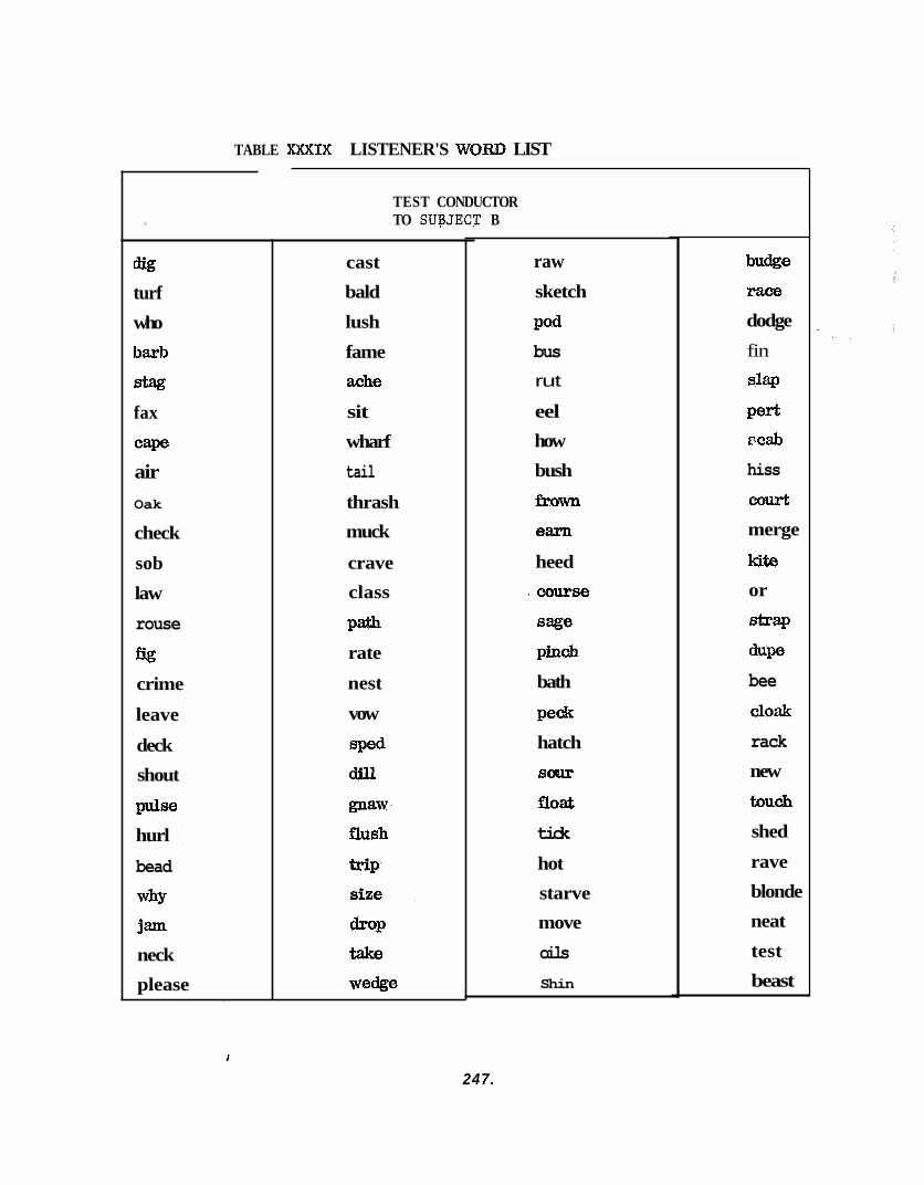
TABLE XXXIX LISTENER'S WORD LIST
tlig turf who
baxb
stag fax
caw air Oak
check
sob
law
rouse
fig crime
leave
deck
shout
pulse hurl
bead
WhY
jam
neck
please
TEST CONDUCTOR TO SUaJECT B
cast
bald
lush
fame ache
sit
wharf
tail thrash muck
crave class
P a rate
nest
vow
raw sketch
pod bus rut
eel how
bush
fhwn
earn
heed
3 course
sage pinch
bath
peck hatch
SOUT
f lO&
tick
hot
starve move
oils Shin
budge race dodge
fin
slap
wd PCab
hiss
court
merge
kite or
s*w duw bee Cloak
rack new
touch
shed
rave
blonde
neat
test
beast
247.
The t h i r d and f i n a l test involved the sub jec t s a s L i s t eners and the test conductor a s the Speaker t o test communications v ia the chamber speaker. I n c o r r e c t answers were those f o r which the word and number d id not corres- pond t o the ones read a s w e l l a s those omitted by the l i s t e n e r .
8.7.7.3.1 Resul ts - 8.7.7.3.1.1 S.A .S . Ratings
Table XL conta ins a l l SAS r a t i n g s f o r communications. A l l para- meters r a t e d by a l l sub jec t s , wi th the exception of Subject D (Transducer s i ze ) were considered a s s a t i s f a c t o r y o r b e t t e r . repackaged before Subjects A; B and C were run and t h i s accounts f o r the d i f fe rence between Subject D and t h e o t h e r s f o r t h i s SAS r a t i n g . o v e r a l l average values show a drop i n SAS r a t i n g s between the f i r s t and second t r i a l s . By not including Subject C ' s va lues ( these values a r e very high f o r t r i a l 1 and s ince t r i a l 2 was never run, no corresponding values e x i s t f o r i t) t h e e f f e c t i s reduced but i s s t i l l present f o r a l l r a t i n g ca tagor ies except t ransducer s i z e . The reasons f o r t h i s e f f e c t a r e unknown and s ince t h e r a t i n g ca tagor ies a r e interdependent i t would be extremely d i f f i c u l t t o determine these reasons.
The transducer was
Generally,
8.7.7.3.1.2 Communications comments
The sub jec t s reported s l i g h t reverbera t ion i n the helmet when t h e i r face was turned t o e i t h e r s ide . The test conductor a l s o p e r i o d i c a l l y noted s l i g h t r everbera t ion e f f e c t s i n the received s igna l .
Though the inf luence of the overpressure environment a c t i n g on the communications transducers was improved g r e a t l y by repackaging, a s l i g h t annoyance was reported by one subject wi th suit/communication transducer i n t e r a c t ion.
Since the volume levels from the test conductor t o a l l personnel w e r e not independent, the b e s t volume l e v e l f o r the subject was uncomfortably loud f o r the monitoring personnel. Independent received volume con t ro l s a r e needed a t the ind iv idua l s t a t i o n s .
8.7.7.3.1.3 Modified Harvard P.B. (Phonet ica l ly Balanced) WORD TEST
% Table XLI presents da ta f o r the th ree types of word l i s t tests. The most no t i cab le e f f e c t i s the very l a rge d i f f e r e n c e found between subject and test conductor reception. Poss ib le causes include feedback problems which required t h a t t h e bass level be kept a t a va lue somewhat higher than optimum while t h e volume level from t h e sub jec t was kept a t a va lue somewhat lower than optimum; high background noise level near the T e s t Conductor's Console and t h e use of speakers r a t h e r than headsets a t t h e test conductor's console.
248.
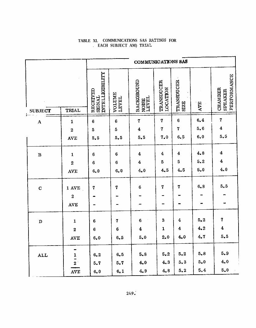
TABLE XL COMMUNICATIONS SAS MTINGS FOR . EACH SUBJECT AM) TRIAL
I COMMUNICATIONS SAS
SUBJECT
A
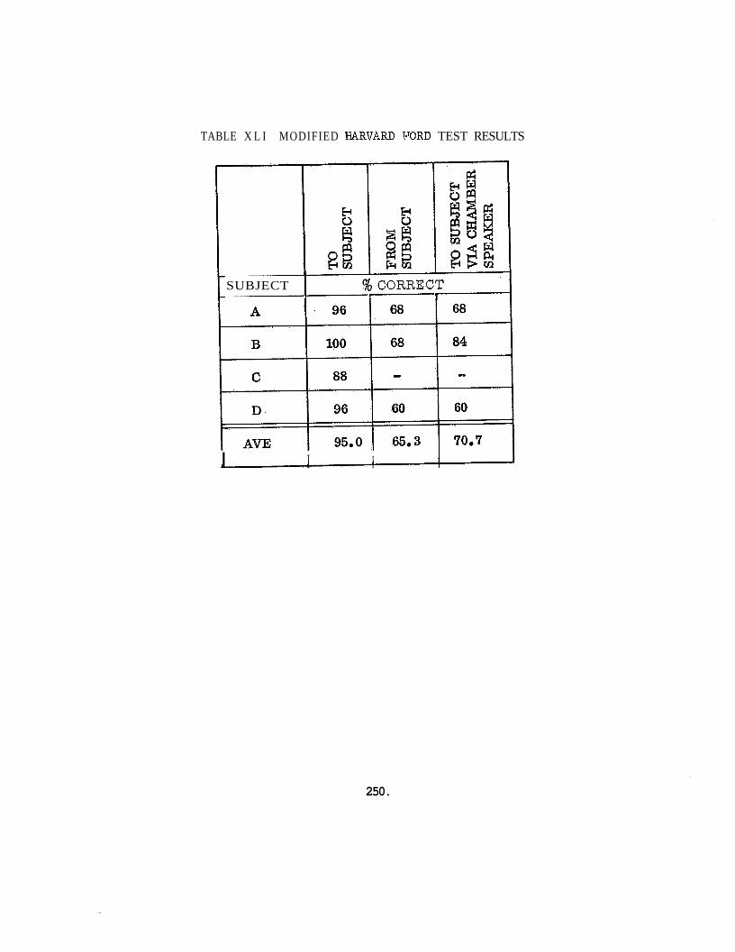
TABLE X L I MODIFIED HARVARD VORD TEST RESULTS
SUBJECT I % CORBECT I I I
I I I 1
250.
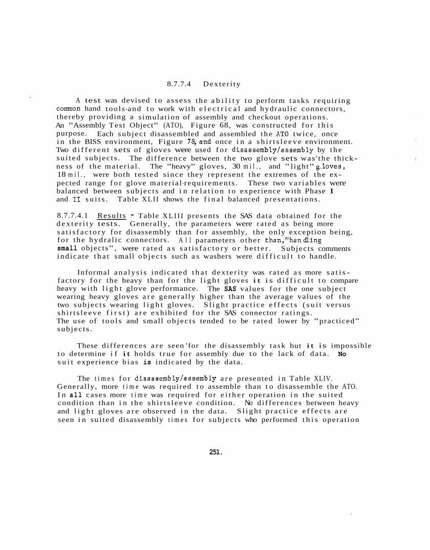
8.7.7.4 Dex te r i ty
A test was devised t o a s s e s s t h e a b i l i t y t o perform tasks requ i r ing common hand too l s -and t o work wi th e l e c t r i c a l and hydraul ic connectors, thereby providing a s imula t ion of assembly and checkout opera t ions . An "Assembly Test Object" (ATO), Figure 68, was constructed f o r t h i s purpose. Each sub jec t disassembled and assembled t h e AT0 twice, once i n the BISS environment, Figure 78,and once i n a s h i r t s l e e v e environment. Two d i f f e r e n t sets of gloves were used f o r disassemblylassembly by t h e s u i t e d sub jec t s . ness of the mate r i a l . The "heavy" gloves, 30 m i l . , and " l ight" g.loves, 18 m i l . , were both t e s t e d s ince they represent t h e extremes of the ex- pected range f o r glove mater ia l -requirements . These two v a r i a b l e s were balanced between sub jec t s and i n r e l a t i o n t o experience with Phase I and I1 s u i t s .
The d i f fe rence between the two glove sets was ' the th ick-
Table XLI I shows the f i n a l balanced p resen ta t ions .
8.7.7.4.1 Resul ts - Table X L I I I presents the SAS data obtained f o r the d e x t e r i t y tests. General ly, the parameters were ra ted a s being more s a t i s f a c t o r y f o r disassembly than f o r assembly, the only exception being, f o r the hydra l i c connectors. A l l parameters o the r than,"han.dling small objects" , were r a t e d a s s a t i s f a c t o r y o r b e t t e r . ind ica te t h a t small o b j e c t s such a s washers were d i f f i c u l t t o handle.
Subjects comments
Informal a n a l y s i s indica ted t h a t d e x t e r i t y was r a t e d a s more s a t i s - fac tory f o r the heavy than f o r the l i g h t gloves i t i s d i f f i c u l t t o compare heavy with l i g h t glove performance. wearing heavy gloves a r e genera l ly higher than the average values of the two sub jec t s wearing l i g h t gloves. S l i g h t p r a c t i c e e f f e c t s ( s u i t versus s h i r t s l e e v e f i r s t ) a r e exhibi ted f o r the SAS connector r a t i n g s . The use of t o o l s and small o b j e c t s tended t o be ra ted lower by "practiced" sub jec t s .
The SAS values f o r the one subject
These d i f fe rences a r e seen 'for the disassembly t a sk but it is impossible t o determine i f it holds t r u e f o r assembly due t o the lack of da ta . s u i t experience b i a s is indica ted by the data .
No
The t i m e s f o r disassembly/assembly a r e presented i n Table XLIV. General ly, more t i m e was required t o assemble than t o disassemble the ATO. I n all cases more t i m e was required f o r e i t h e r opera t ion i n the s u i t e d condit ion than i n t h e s h i r t s l e e v e condit ion. No d i f fe rences between heavy and l i g h t gloves a r e observed i n the data . seen i n su i t ed disassembly t i m e s f o r sub jec t s who performed t h i s opera t ion
S l i g h t p r a c t i c e e f f e c t s a r e
251.
a aJ U 1-I 7 v3
h P
h rl P Ei aJ rn ul aJ v)
.I4 !=l
Iu u aJ 'r)
P 0 4J rn aJ t+ h rl P El aJ rn 9 1
co I-
252.
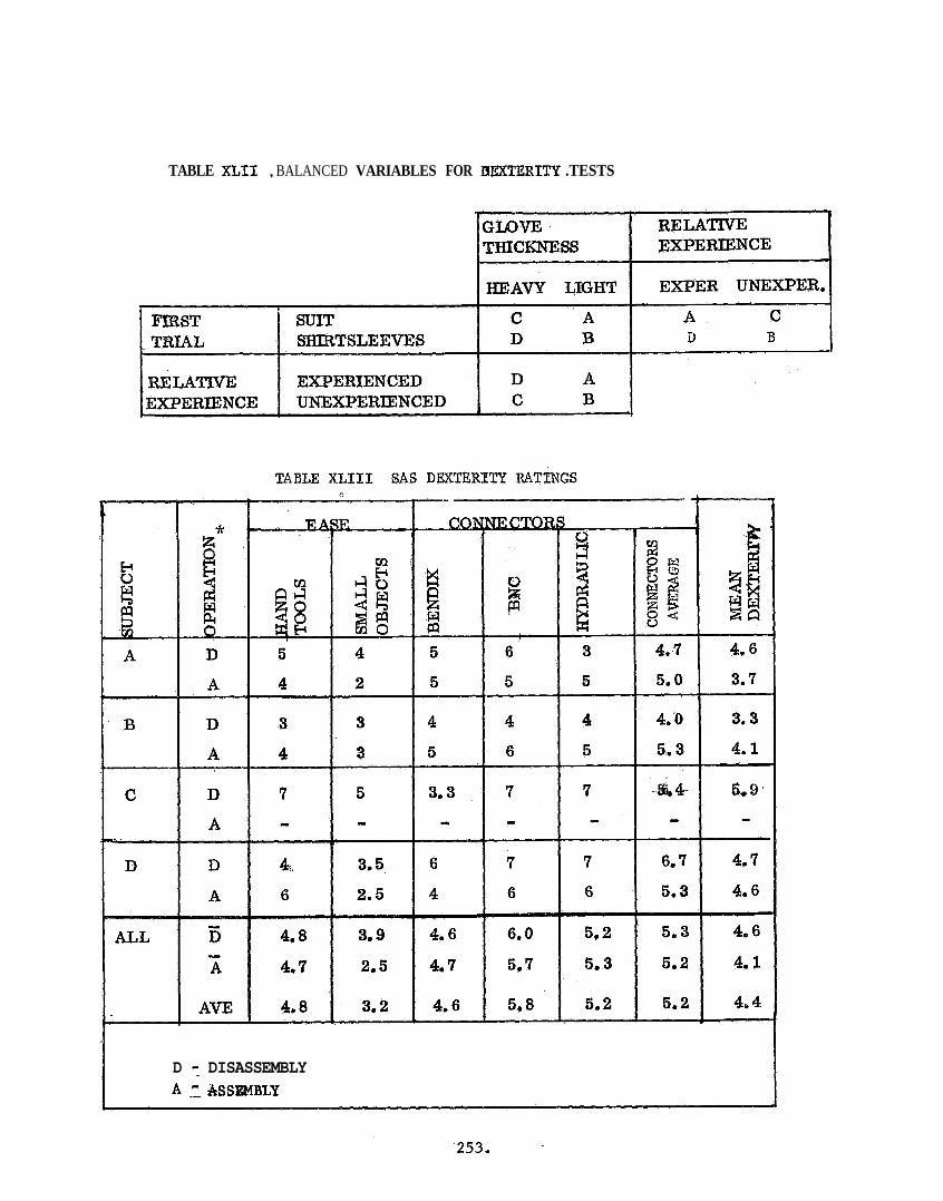
TABLE XLIL , BALANCED VARIABLES FOR FIEXTERITY .TESTS
D 7 DISASSEMBLY A f ASSEMBLY
f i r s t i n the s h i r t s l e e v e conditon. t i v e l y inexperienced subjec ts .
On the average, sub jec t s with r e l a -
No such observat ions may be made concerning assembly however, due t o the lack of assembly data f o r subjec t C .
8.7.7.4.1.1 Dexter i ty Conunents
e Gloves r e s t r i c t e d use -o f screw d r ive r .
e Washers a r e the most d i f f i c u l t p a r t s t o handle.
Access problems become g r e a t e r i n the s u i t .
Smooth gloves made i t d i f f i c u l t t o hold smooth handled wrenches Rough handled too l s would make necessary operat ions e a s i e r .
0 Small p a r t s sometimes became caught i n the fo lds of the l i g h t gloves
9 Specia l t o o l s w i l l probably be necessary t o p ick up the smaller p a r t s
8.7.7.5 Mobility:
Tests were conducted, a s a p a r t of the endurance t e s t , t o a s se s s mobi l i ty a s experienced by the su i t ed subjec t . This tes t was administered twice during each 4-hour endurance run a t 20 minutes i n t o t e s t i n g and a t 2 hours i n t o t e s t i n g . Table XLV presents the Mobi l i ty SAS r a t i n g s and the t i m e s required t o perform the mobi l i ty exerc iese . Subjects were required t o walk forward t o the ex ten t allowed by the tunnel and walk backwards t o the s t a r t i n g pos i t ion . This was performed twice. The sub jec t s were a l s o required t o assnd and decend the f i r s t four steps of a s t e p ladder t h ree times (Figure 79) bend a t t he waist t en times (Figure 80) and do t e n knee bends o r squats (Figure 81)
8.7.7.5.1 Results: SAS data f o r the mobi l i ty t r i a l s shows only one e f f e c t which seems cons is ten t . t i o n of walking, t he re were s l i g h t increases i n sub jec t ive r a t i n g s between t r i a l s one and two. This except ion i s understandable s ince annoyance caused by the su i t - tunne l i n t e r f a c e r i ngs , while walking, increased a s t i m e progressed. The remaining parameter values f o r each subjec t seem t o be sub jec t - spec i f i c and t o depend on s u i t shape and s ize . fu r the r explored with regard t o t h e comments made by the subjec t .
For a l l SAS mobi l i ty parameters, with t h e excep-
This s h a l l be
254,
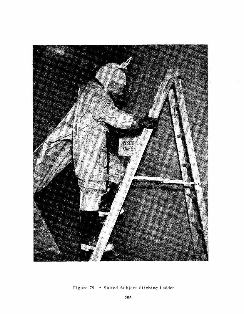
Figure 79. - Sui ted Subject Climbing Ladder
255.
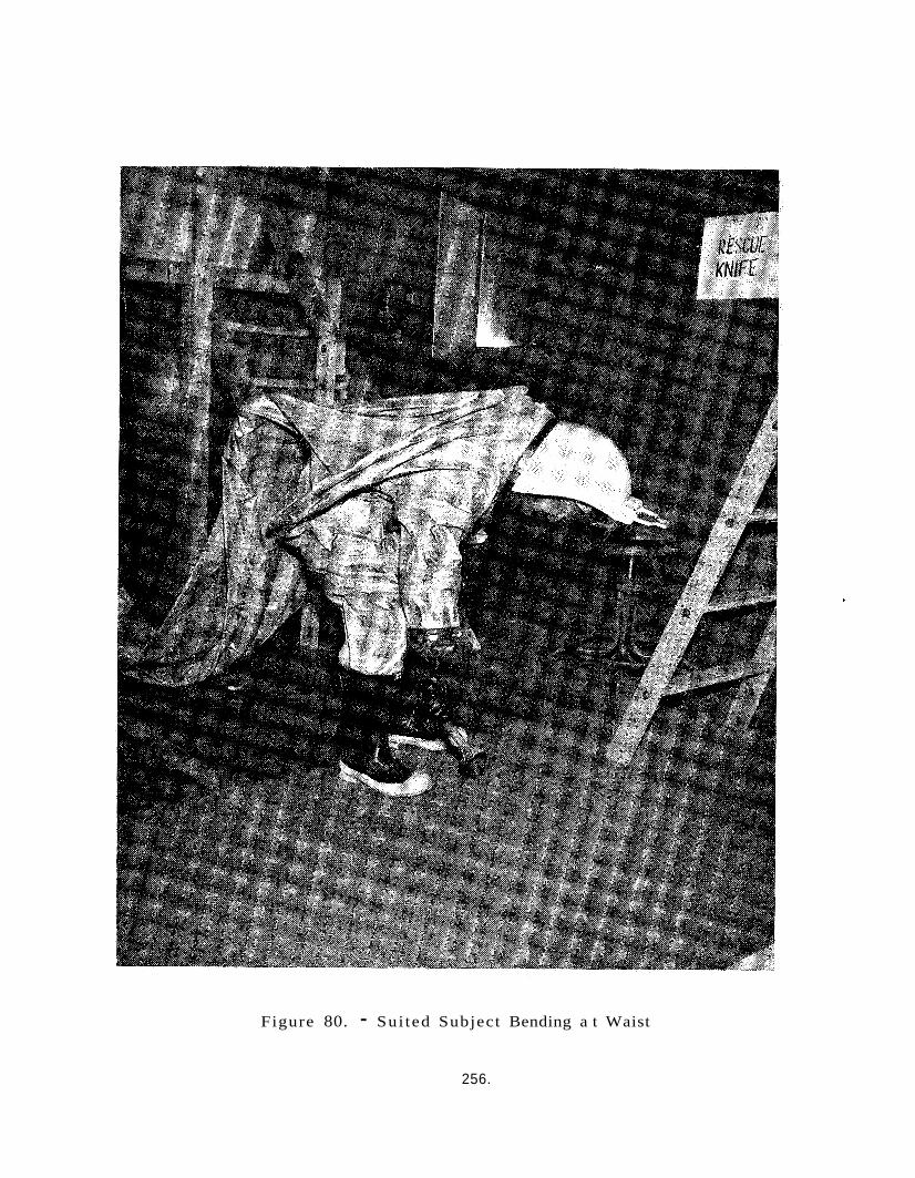
Figure 80. - Sui ted Subject Bending a t Waist
256.
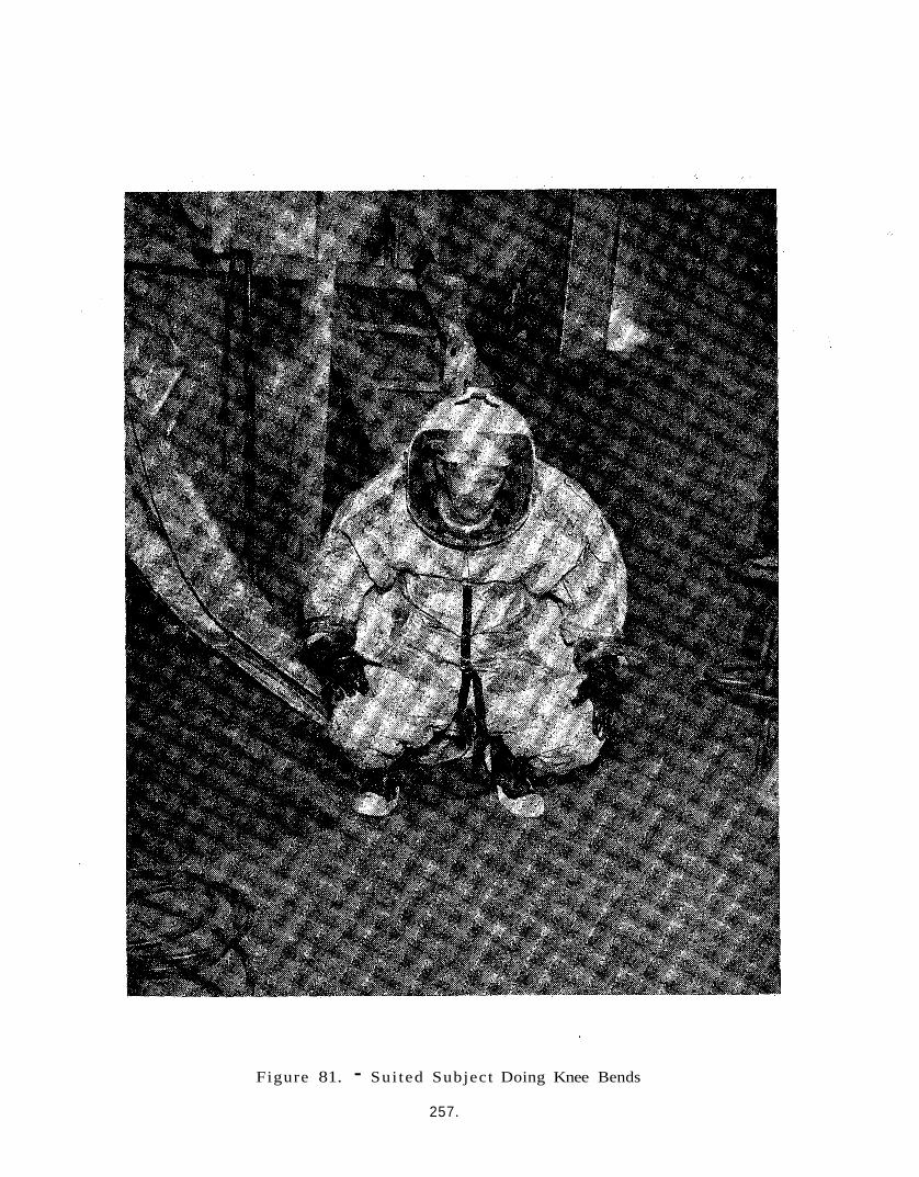
Figure 81. - Sui ted Subject Doing Knee Bends
257.
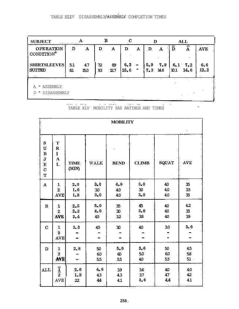
TABLE XLIV DISASSEMBLY /ASS&BLY COMPLETION TIMES
SUBJECT D ALL I CONDITIO^
5.1 4.7 7.2 8.9 8.1 15.0 9.3 12.7 I SHIRTSLEEVES
SUITED I 15.6 - (7.3 14.6 10.1 14.6 1 12.2 I I
A - ASSEMBLY D - DISASSEMBLY
J - - . .. ~. . - - . . - . - _ _ . . - . -
TABLE XLV MOBILITY SAS RATINGS AND TIMES
MOBILITY
I 1
CLIMB
T R I A L TIME
WIN) WALK BEND
3.0 3.0 3.0 A~
AVE 2.4
2.5
4.0 4.0 4.0
4.0 4.0 4.0
3.5 3.5 3.5
4.2 3.5 3.9
3.0 4.0 3.0 4.0 3.0 4.0
5.0 3.5 4.0 3.0 4.5 3.2
-- 4.5 3.0 - - - - 5.0 5.0 6.0 6.0 5.5 5.5
4a6 3.9 4.3 4.3 4.4 4.1
4.5 3.0 3.8
4.0 - - 3.0 - - A I
AVE - 3.0 5.0 4.0
5.0 6.0 5.5
4.5 5.8 5.1
3.6 3.7 3.6
4.0 4.7 4.4
4.0 4.2 4.1
- 2 I 21:: A V E I 2.2
258.

Subject A reported t h a t t h e helmet hook tended t o h i t the ladder rungs and t h a t he tended t o k ick t h e leg r i n g s when climbing t h e ladder. This would account f o r the low SAS r a t i n g s t h i s sub jec t gave t o climbing. The sub jec t s t a t e d t h a t the tunnel hindered walking and t h i s poss ib ly influenced the wa lk ing SAS r a t i n g s .
For sub jec t B y the only c o n s i s t e n t l y low SAS r a t i n g s were those f o r This corresponds t o the s u b j e c t ' s reporo t h a t the bending a t t h e wais t .
s u i t - t u n n e l i n t e r f a c e r ings h i t him i n t h e small of t h e back.
Subject C ' s low SAS r a t i n g f o r bending was probably a l s o r e l a t e d t o h i s r epor t t h a t the r i n g s h i t him i n the back. t h a t when climbing during the f i r s t mobi l i ty t e s t , the plenum was pressed i n t o h i s back. This corresponds t o h i s low SAS r a t i n g f o r climbing.
Subject C a l s o reported
8.7.7.6 Entry-Exit
Table XLVI presents Entry-Exit t i m e s and SAS r a t i n g s . Average o v e r a l l SAS r a t i n g s , wi th the exception of EXIT-"getting i n t o tunnel" r a t i n g s , a r e a l l s a t i s f a c t o r y o r b e t t e r . between sub jec t s i s observed i n the da ta . appear t o be pr imar i ty r e l a t e d t o i n t e r s u b j e c t weight and height d i f f e r - ences. Phase I1 sub jec t s .
A c e r t a i n amount of v a r i a t i o n These i n t e r s u b j e c t d i f fe rences
Table X L V I I presents nude body weight and height data f o r the
Comparing average Entry-Exit SAS values f o r each subject with h i s weight shows a one t o one inverse r e l a t i o n s h i p . This would imply t h a t the heavier the sub jec t , the more d i f f i c u l t y Entry-Exit i s . Simi lar r e l a t i o n - ships e x i s t f o r the ind iv idua l Entry-Exit parameters with weight and/or height .
8.7.8 Helmet A i r Analysis
A second helmet a i r ana lys i s was run during the Phase I1 mock-up tests t o compliment the one run during Phase I. endurance tests, samples of s u i t i n l e t a i r and helmet exhaust a i r was taken on two d i f f e r e n t sub jec t s .
During two of the four
The i n l e t a i r was sampled a t the junct ion of the l i f e support hose and the s u i t plenum. junct ion of t h e s u i t exhaust a i r a t the l e v e l of the plenum'because a t t h i s level the helmet a i r sample would conta in a l a rge volume of a i r t h a t had been i n contact with the body and had not been i n the helmet. There-
The "helmet exhaust a i r " was - not sampled a t t h e
259.
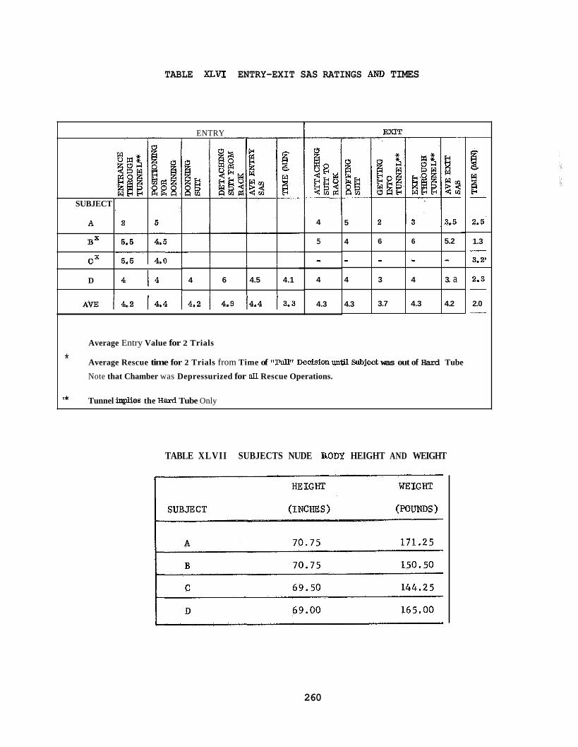
TABLE XLVI ENTRY-EXIT SAS RATINGS AND TIMES
4
- 4
4.3
ENTRY I I i I
6 6 5.2
- - - 3 4 3. a
3.7 4.3 4.2
SUBJECT
4
A.
BX
6 4.5 4.1
CX
D l 4
4
5
4
4.3
EXIT
5 I 2 I 3 13.5
1.3
3.24 -
2.3 - 2.0 -
Average Entry Value for 2 Trials
* Average Rescue time for 2 Trials from Time of llPdllt Decision until Subject was out of Hard Tube
Note that Chamber was Depressurized for a l l Rescue Operations.
Tunnel inplies the Hard Tube Only I*
TABLE XLVII SUBJECTS NUDE UODY HEIGHT AND WEIGHT
260
f o r e a s p e c i a l sample was taken by plac ing the end of a 20 f t . x $'I
diameter Tygon tube i n t o the helmet near the test s u b j e c t ' s r i g h t c l a v i c l e about 2" from h i s mouth. o f a i r from the l i f e support system t o t h e test sub jec t ranged from 10 - 20 cfm. they were a l s o not aware t h a t t h e i r exhaust a i r was being sampled.
Throughout the helmet a i r Zests, t h e flow r a t e
The s u b j e c t s reported t h a t they were comfortable and t h a t
The test was run using gas chromatographic sample tubas a t tached a s explained above on one end and the o t h e r end of the sample tube a t tached t o an e l e c t r i c a l l y dr iven vacuum pump. minutes wi th a guage reading of 1 cfm t h r u 'the l i n e s . The a c t u a l sample was co l l ec ted f o r a f i v e minute period.
This apparatus was run f o r 10
The gas a n a l y s i s was made on a Beckman GC-5 gas chromatograph. Carbon dioxide was separa ted on a Amide) on a Chromosurb P column and detec ted wi th a thermal conduct iv i ty de tec to r . s i eve column and detec ted i n the same manner a s the carbon dioxide. Individual c a l i b r a t i o n curves were prepared f o r each component analyzed.
1/8" x 9' 15% HMPA (Hexyl Methyl Phospho
Oxygen and n i t rogen were separated on a 1/8" x 6 molecular
B e s t & Taylor, "The Physiologica l Basis of Medical Pract ice" , 8 t h Edi t ion , 1966, Chapter 50, s t a t e s t h a t "The mixture of gases i n the a l v e o l i c o n s i s t s of inhaled a i r from which oxygen i s being removed and to which carbon dioxide and water vapor a r e being added. condi t ions each i n h a l a t i o n br ings i n t o the r e s p i r a t o r y system a volume of a i r represent ing less than 10 percent of the t o t a l lung capaci ty , and not a l l of t h i s reaches the a l v e o l i . a i r shows only minor f l u c t u a t i o n s with the r e s p i r a t o r y cycle . The compo- s i t i o n i s not exac t ly the same i n a l l p a r t s of the l i n g , s i n c e there a r e v a r i a t i o n s i n the e f fec t iveness of v e n t i l a t i o n . The average composition, however, is maintained approximately constant by the mechanisms regu la t ing the r e s p i r a t o r y r a t e and volume.
Under r e s t i n g
Hence the composition of the a l v e o l a r
A sample of expired a i r taken near the end of a normal e x p i r a t i o n (end- t idal sample is f a i r l y represen ta t ive of the average composition of a l v e o l a r a i r ."
26 1
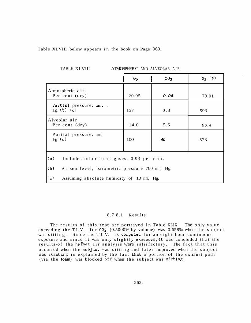
Table XLVIII below appears i n the book on Page 969.
Atmospheric a i r Per cen t (dry)
Partia! pressure, mm. . Hg (b ) ( c )
Alveolar a i r Per cen t (dry)
TABLE XLVIII ATMOSPHERIC AND ALVEOLAR A I R
20.95 0.04
157 0 . 3
14.0 5.6
P a r t i a l pressure, mm. Hg ( c ) 100 40
I 1
(a) Includes o the r i n e r t gases , 0.93 per cen t .
79.01
593
80.4
573
( b ) A t sea l e v e l , barometric pressure 760 mm, Hg.
( c ) Assuming absolu te humidity of 10 mm. Hg.
8.7.8.1 Resul t s
The r e s u l t s of t h i s test a r e portrayed i n Table XLIX. The only value exceeding the T.L.V. f o r 602 (0.5000% by volume) was 0.658% when the sub jec t was s i t t i n g . exposure and s ince it was only s l i g h t l y exceeded , i t was concluded t h a t t h e r e s u l t s -o f t he helinet a i r a n a l y s i s were s a t i s f a c t o r y . The f a c t t h a t t h i s occurred when the subjecbwas s i t t i n g and l a t e r improved when the sub jec t was s tanding i s explained by t h e f a c t that a po r t ion of t he exhaust pa th (via t he foam) was blocked a f f when t h e sub jec t w a s s i t k ing .
Since the T.L.V. i s csmputed f o r an e i g h t hour continuous
262.

TABLE XLIX BISS HE'IIET AIR ANALYSIS
L Sample #
1
2
3
Date - 31 13/67
31 13/67
3/ 131 6 7
31 131 67
31 16/67
3/ 16/67
RESULTS 1
Description . % Volumes 02 1 N7 I co2
r
263.
8.7.9 Helmet Dis in fec t ion Treatment
The detergent* treatment and d i s i n f e c t i o n of the helmet was i n s t i t u t e d 15 minutes p r i o r t o the scheduled ent rance of the opera tor i n t o the s u i t , and consis ted of the following s teps :
1. Disengaging the hook on top of the helmet from i t s attachment. This w i l l drop t h e helmet por t ion down i n t o an inver ted pos i t ion .
Swabbing the helmet with a c l o t h which has been previously dampened wi th a 5 per cent aqueous s o l u t i o n of T r i t o n X-100 t o remove su r face f i l m and sputum which may accumulate during usage.
2.
3. Wipping with a d ry c l o t h t o remove r e s i d u a l moisture.
4 . Swabbing t h e su r face thoroughly with a c l o t h moistened i n a 70 per cent Isopropanol so lu t ion . f o r a t l e a s t f i v e minutes.
The su r face should remain moist
5. Wiping with a dry c l o t h t o remove r e s i d u a l a lcohol .
Following a p p l i c a t i o n of the d i s i n f e c t a n t , the helmet was ae ra ted a t a r a t e of 20 cfm and a f t e r 5 minutes was examined f o r odor r e t e n t i o n . This examination was conducted by two observers , followed by s u i t opera tor who then entered t h e s u i t . A l l concurred t h a t they could not d e t e c t any odor of isopropanol.
~
* S u i t a b l e detergents commercially a v a i l a b l e f o r the helmet treatment a r e :
T r i t o n X- 100 - Rohm & Haas
T e r g i t o l NPX Union Carbide
T e r g i t o l 15-S-7 Union Carbide
The physica l and chemical propert,hs of these surface a c t i v e agents a r e e s s e n t i a l l y the same. b a s i s of c o s t .
T r i t o n X-100 was se lec ted p r imar i ly on the
264.
8.7.10 Medical Monitoring Phase I1 Tes t
A system composed of an RKG-100 (Telemedics) Radiocardiograph t r ans- mitter-Receiver connected t o an Ocil loscope (Tektronix Inc . Type 531) and a Standard Electrocardiograph (G.E. Cardioscribe) was used f o r the Phase I1 mock-up tests. The disposable adhesive- type e lec t rodes (1 l / Y ' square with m e t a l i c screen, pas te r e s e r v o i r , and snap-on fas t ene r s ) were a t tached t o the s u b j e c t ' s ches t b i l a t e r a l l y on the a n t e r i o r a x i l l a r y l i n e a t the l e v e l of the 4 th - 5 t h r i b inner space. X 4 1/2", weight 10 o z . , range 250 f t . ) was worn i n a c l o t h bag t i e d by a cord t o the s u b j e c t ' s waist. Thin f l e x i b l e wires with snap-on f a s t e n e r s c a r r i e d EKG s i g n a l from t h e ches t e l ec t rodes t o t h e t r ansmi t t e r .
The RKG t r a n s m i t t e r (1" X 3 1/2"
The Telemedic Receiver (14'' X 12" X 8" , weight 17 l b s . ) on the ou t s ide of the test chamber contained a s k i n r e s i s t a n c e mover, s tandardiza t ion, and a s e l e c t o r switch f o r channeling t o conventional e lec t rocar idographic recording apparatus, osc i l loscope , magnetic tape recorder , o r a l l t h ree simultaneously.
Elect rocardiographic t r ac ings of f a i r q u a l i t y were received. This
(The t r ac ings show a reduct ion i n q u a l i t y was caused by a 60-cycle i n t e r f e r e n c e from t h e opera- t i o n of the motors i n the l i f e support equipment. 60 cycle in te r fe rence) .
This in te r fe rence d id not present any problem i n reading the EKG t r a c i n g s o r the oc i l loscope f o r the determiat ion of the s u b j e c t ' s h e a r t r a t e . The l a t t e r was the parameter of primary concern. Only two t r a c i n g s , showing anomalies i n the QRS por t ion , a r e a t t r i b u t e d t o s i x t y cycle i n t e r - ference. This anomaly i s not seen when the s u b j e c t ' s h e a r t r a t e i s beyond the frequency response of the e lec t rocardiograph s t y l u s . a r e on ly no ed when the sub jec t s h e a r t r a t e i s slow a t a t i m e i n the test pr0gram.k P k en t h e RKG t r ansmi t t e r has been i n use f o r severa l hours. A t a slow h e a r t r a t e of 100-110 bea t s per minute the s i x t y cycle i n t e r f e r - ence i s wi th in the frequency response of the s t y l u s giving a t r a c i n g of regular 60 cycle v a r i a t i o n s i n i n t e n s i t y impressed on the waves.
The C;RS notches
A series of e i g h t t r i a l runs were made us ing d i f f e r e n t s u b j e c t s . These tests had a dura t ion of 15 t o 45 minutes. The h e a r t r a t e s during e n t r y & e x i t v i a the tunnel ranged between 120 - 180 bea t s per minute. Best & Taylor (The Physiological Basis of Medical P r a c t i c e , Eighth Ed i t ion 1966) s t a t e s t h a t the average r e s t i n g h e a r t r a t e i n a d u l t man i s around 70 bea t s per minute, but the re i s a r a t h e r wide v a r i a t i o n between ind iv idua l s , a r a t e considerably below o r above t h i s average being no t uncommon. Muscular t r a i n i n g tends to reduce the ca rd iac r a t e ; a t h l e t e s not in f requen t ly having a pulse r a t e between 50 - 60. of between 80 - 90 i s sometimes seen i n o the r hea l thy persons.
On t h e o the r hand, a r a t e
265.
A series of 3 tests were made with two d i f f e r e n t sub j ec t s fo r per iods ranging from 1 t o 2 hours i n the test chamber. e x i t r a t e s 120 t o 130. e x i t .
Subject C had en t ry & Subject B had a 160 - 170 hea r t r a t e on e n t r y &
A series of 3 tests were made w i t h two d i f f e r e n t sub j ec t s f o r a test per iod of four hours. Subject A had e n t r y and exi t r a t e s of 130-140. H i s exerc i se r a t e was 130 and h i s r e s t i n g rates i n t he chamber under 2" water p ressure were 85 t o 90. Normal t r ac ings were made before , dur ing and a f t e r t h i s 4 hr . test period. Subject D a l s o was t e s t ed f o r 4 hours and had e s s e n t i a l l y t he same r e s u l t s a s Subject'A, t h e only d i f f e r ence being t h a t sub jec t D had a s h o r t period estimated a t between 30-60 seconds where he had t rouble a t t ach ing l i f e support hoses and h i s r a t e was measured a t 150 bea ts per minute. Subject B (approximately 20 yrs . younger than sub jec t s A & D)had.higher h e a r t r a t e s throughout the 4 hour test per iod. H i s ex i t and e n t r y r a t e s were 150 - 170. During exe rc i s e s , he had a r a t e of 150 and a r e s t i n g r a t e of 95 - 120. For sub j ec t B , a f t e r 3 hours i n the chamber, the graph showed d i r e c t i o n a l changes i n the QRS segment. When o r a l l y qu i r i ed a t t h i s t i m e he answered t h a t he f e l t a " l i t t l e fa t igued." He was asked t o move about, s t r e t c h and a l s o check h i s e l ec- t rodes i n order t o r u l e out hea r t pos i t i ona l changes and e lec t rode f a i l u r e , This d id not change the recorded t r ac ings and even though the sub jec t had been i n the chamber f o r 4 hours , only 3 hours were under overpressure condi t ions , The sub jec t was asked t o take a luncheon break and r e t u r n t o t he t e s t a rea i n one hour. During the one hour r e s t per iod , the t r ansmi t t e r was placed on re-charge. Subject B was re- su i ted and then spent an addi- t i o n a l hour i n the chamber under pressure . t r a c i n g , the graph suddenly showed QRS anomalies which have been a t t r i b u t e d t o the unequal discharge of the b a t t e r i e s i n t he RKG t r ansmi t t e r . The sudden change i n "hear t r a t e " noted a t t h a t t i m e i s caused by the rap id changes i n frequency of the RKG t r ansmi t t e r being beyond the frequency responses of t he EKG s t y l u s which produced a recording t h a t could e a s i l y be misread a s rap id hea r t r a t e . i n any of the graphs.
Af t e r one hour of normal
No abnormal ST segment changes were noted
D r . James A . Roman of NASA/USAF - EDWARDS AFB was most he lp fu l i n the i n t e r p r e t a t i o n of these i n t e r e s t i n g EKG recordings and i n d i s p e l l i n g concern about apparent abnormali t ies noted i n the EKG's physiological response t o the BISS environment did not appear t o present a problem t o fu r the r development of the system.
(See Appendix C ) . The
8.7.11 Conclusions:
The major conclusions reached a s a r e s u l t of the Phase I1 mock-up study a r e presented i n two ca tegor ies . F i r s t , f indings with implicat ions f o r hardware design a r e presented i n a summary manner. Secondly, a b r i e f
266.
discuss ion of the conclusion regarding sub jec t endurance i n t h e BISS environment i s , g i v e n . recommended concept, a n o t a t i o n of incorporated has been indicated beside the recommenda t i o n .
I f the f inding has been incorporated i n the f i n a l
8.7.11.1 Hardware Design Related Conclusions
Each des ign recommendation w i l l be r e l a t e d t o t h e area wi th in the endurance test which yie lded the da ta . The l imi ted f indings of the anthropometric measurement exerc i se were found t o be r e i t e r a t e d by the endurance test r e s u l t s .
8.7.11.2 Comfort
H e l e m t - yoEe redesign i s ' r e q u i r e d t o b e t t e r pos i t ion the assembly on the sub jec t s shoulders , s t a b i l i z e i t and t o permi t g r e a t e r ventra 1 and dorsa 1 f lex ion ; ( incorporated)
Su i t- tunne l i n t e r f a c e r ings requ i re e l imina t ion o r redesign t o remove the discomfort they cause the BISS sub jec t .
0 A h e a t exchanger of s u b s t a n t i a l l y g r e a t e r capaci ty i s required fo r a i r coo l ing. ( incorporated)
An adjustment c a p a b i l i t y for apport ioning a i r t o the helmet and limbs is required. ( incorporated)
Greater humidity c o n t r o l must be exercised by the l i f e support console. ( incorporated)
8.7.11.3 Communications
0 The p o s s i b i l i t y of employing s t i l l smaller communication transducers must be inves t iga ted .
Methods f o r c o n t r o l l i n g helmet r everbera t ion and feedback i n the communications system must be developed.'
Independent adjustment of the volume l e v e l s of the sub jec t s speaker, t o permit p r i v a t e consu l t a t ion between the test condjctor and mon- i t o r i n g personnel .
267.
8.7.11.4 Dexter i ty
e
m
e
e
e
e
e
e
Aids are required f o r handling small hardware (e.g. b o l t s , nu t s , wa s her s)
8.7.11.5 Mobi l i ty
The Su i t- tunne l i n t e r f a c e support r ings must be s tudied i n r e l a t i o n- s h i p t o mobi l i ty impairment a s w e l l a s comfort s ince they tended t o impede the sub jec t s i n bending a t the wais t and climbing and wa lk ing . The leg r ings must be redesigned t o e l iminate i n t e r f e r e n c e when t h e sub jec t i s climbing.
The helmet hook must be made smaller and nea te r t o prevent i t from i n t e r f e r i n g with opera t ions when the s u i t occupant bends forward. ~
8.7.11.6 Entry-Exit
Hard tube must be redesigned t o permit sea ted e n t r y and e x i t .
The por t ion of the donning rack which holds the gloves must be redesigned t o provide a p o s i t i v e locking a c t i o n and t o permit e a s i e r engagement and disengagement by t h e seated opera tor .
8.7.11.7 Misce 1 laneous
Communications cables should be run! ins ide the a i r supply and/or exhaust tubes t o minimize the p o s s i b i l i t y o f cable entanglement.
A monometer sensor must be placed i n t h e s u i t t o measure t o t a l s e n s i b l e pressure s i n c e a d i s p a r i t y i n input and o u t l e t flow r a t e s can r a i s e o r lower t h e t o t a l pressure a c t i n g on the subject .
8.7.11.8 Subject Endurance
Based on t h e Phase I1 BISS mock-up study it is p o s s i b l e . t o p o s i t i v e l y s t a t e that a s u i t a b l y s e l e c t e d man can func t ion i n t h e BISS environment (at a 2" P) f o r four hours. However, s i n c e only two of t h e four s u b j e c t s success fu l ly completed t h e run d e s p i t e t h e f a c t t h a t t h e r e were long rest per iods during t h e tests, i n d i c a t i o n s a r e t h a t t h e four hour period is marginal f o r the Phase I1 BISS system. The s u b j e c t s agreed that a two
268.
hour period would probably be opt imal f o r the present system. f i n a l dec i s ion a s t o opera tor endurance must r e s u l t from a study which sys temat i ca l ly compares sub jec t performance a t d i f f e r e n t pressure l e v e l s with varying work-rest cycles .
However, a
It should a l s o be noted t h a t f o r some tests t h e exhaust a i r flow r a t e s u b s t a n t i a l l y exceeded t h e input flow-rate. pressure experienced by the subjec t was i n excess of the chamber pressure. For t h i s reason, conclusions reached i n t h i s r epor t can be viewed a s conser- v a t i v e s i n c e i n no ins tance was t h e exhaust flow r a t e less than the input a i r flow r a t e .
This implies t h a t t h e sens ib le
269.
9.0 REColMMENDATIONS FOR FUTURE WORK
9.1 BACKGROUNI)
The present program represents the first major step towards the ultimate attainment of a prime BISS system qualified for use in the AssemblylSterilizer facility. ledge that the detail design, fabrication, and testing of the prime system would be accomplished on a subsequent program. providing preliminary design information for the suit and tunnel and life support and communications subsystems, the present program has provided a significant anbunt of detail to be incorporated in the final design, particularly in the areas of the outer suit shell, helmet and undersuit. It has also illuminated two design problems whose magnitude had not previously been fully realized: tunnel reefing and tunnel siip- port.
The program was predicated on the know-
In addition to
Based on the experience from the present contract a follow-on program is outlined below for the completion of the required effort for a prime BISS system. studies, and system fabrication and testing.
This program consists of systems and materials completion of preliminary design, performance of final design,
In performance of the studies and preliminary design, the BISS The Phase I1 Phase I1 mock-up equipment will be an invaluable aid.
suit, tunnel and hatch assembly have been delivered to NASA's Langley Research Center. life support and communications equipment will permit extended mock-up studies. During preliminary design, this system can be adapted to incorporate evolving design details for development design verification.
Use of this equipment, in conjunction with appropriate
9.2 SYSTEMS STUDIES
9.2.1 Tunnel Reefing and Support
The primary systems study area requiring further investigation is the reefing and support of the BISS tunnel. analysis and synthesis of a complex man/machine system. attendant to the major machine elements of the system have been des- cribed in sections 4.3 and 4.4 and the complexity of the integrated system problem is indicated in section 4.5. must run concurrent with the design extension effort on the reefing mechanism and tunnel support boom so that once the system study model or schema has been formulated the preliminary designs for the machine elements of the system can be evaluated and optimized.
This involves a systems The problems
Performance of this study
270.
9 . 2 . 2 Operational Plans
Prior to the employment of a prime BISS system in a.spacecraft sterilization facility, careful plans need to be formulated for opera- tion of the BISS in the system. made at an early date to permit proper reflection of these plans in the final design of the system. tive Standard Operating Procedures. lines and decision policies need to be defined. operations of plans can have on system concepts and equipment designs are given in the discussions on the communications subsystem and bio- integrity and leak detection in Sections 4.8 and 5 , l
. Detailed preliminary plans should be
The plans should be formulated as tenta- As a minimum, full operation guide-
Examples of the impact
The recommended plans or guidelines are a natural outgrowth ai-d extension of the work on the present contract and will be based in large measure on the supporting studies of Section 5.0. plans are:
Some of the required
0 Assembly/Sterilizer organization chart with personnel assign- ments and responsibilities.
Typical BISS work team plans
0 BISS - Assembly/Sterilizer Comunications Plan Bio-Integrity Assurance and Monitoring Plan
Emergency Rescue Plan
BISS personnel utilization plan (accounting for the fact that personnel will work less than 8 hours in the suit in one shift)
9 . 3 MATERIALS STUDIES
Materials investigation is required to select and define physically and biologically acceptable bonds between the several materials of the system. The required bonds are described below:
Suit fabrication -- Armalon t o Armalon
0 Suit- Helmet Interface -- Armalon to Texolite Helmet Fabrication -- Optical glass to Texolite
271.
Suit-glove I n t e r f a c e -- Armalon t o S i l i cone rubber * Suit-Boot I n t e r f a c e -- Armalon t o S i l icone rubber* e
e
a
Tunnel Fabr ica t ion -- Armalon t o Armalon
Tunnel-Suit I n t e r f a c e -- Armalon t o Armalon
Tunnel-Hatch Assembly I n t e r f a c e -- Armalon t o S t a i n l e s s Steel
S u i t o r Tunnel Maintenance -- Armalon t o Armalon e
. Boot o r glove Maintenance -- Si l icone rubber t o S i l icone rubber
The bonds descr ibed a r e based on f a b r i c a t i o n of a BISS using prime candidate ma te r i a l s i d e n t i f i e d on the presen t program. i a l s should no t be disregarded i n the bonding s tud ie s s ince t h e i r use may improve o v e r a l l design by f a c i l i t a t i n g bonding.
Alternate mater-
9.4 DESIGN EXTENSION
I n varying degrees, each of t he elements o r subsystems r equ i r e The ind iv idua l system elements and the primary design add i t i ona l design.
e f f o r t s s t i l l required f o r each a r e i d e n t i f i e d below.
Outer s u i t s h e l l 0- Design f a b r i c j o i n t s and i n t e r f a c e s wi th tunnel , gloves, boots , and helmet, rack i h t e r f a c e t o incorporate a pos i t i ve attachment . Reduce l e g s t i f f e n i n g r i n g diameter. b o t t l e i n t e r f a c e .
Redesign sleeve/donning
Design ex t e rna l emergency a i r
Helmet -- Reconfiguration t o incorporate an o p t i c a l g l a s s face- pla te r a t h e r than a Lexan bubble, and t o incorporate a smal ler helmet hook f o r t he donning rack i n t e r f a c e .
Gloves -- Design of a f a b r i c re inforced s i l i c o n e rubber glove
Boots -0 Design of a f a b r i c re inforced s i l i c o n e rubber boot wi th s a f e t y toe , corregated s o l e s , and donning rack clamp i n t e r f a c e .
- boot
Tunnel -- Incorporate graspable attachment po in t s f o r r e e f i n g mechanism i n t e r f a c e .
* O r Armalon t o Texol i te cuff t o s i l i c o n e rubber
272.
, ..
a
4
0
a
e
a
4
The
Undersuit -- Design supply and exhaust manifolds and flow balancing valve to adjust relative flow to extremities.
Reefing Mechanism, Boom and Hatch Assembly -- Concurrent with the tunnel reefing and support study an integrated reefing and support system for the BISS suit and tunnel. include a large domed piston).
design the elements of
(If required for reefing the hatch assembly will
Life Support -- Reduce life support breadboard to a preliminary sub-system design.
Life Support Back-up -- Design two emergency back-up air supplies for the BISS: through life support subsystem hosing; (2) in-chamber supply bottles. system and the latter suit sheI.1 or helmet.
(1) external automatic supply optrating
The former must be Pntegrated with the life support must be designed to interface with the
Communications -- Design transducers to optimize communications with chest mounted speaker and microphone. After definition of BISS, AssemblylSterilizer communications plan, design a commu- nications network for BISS to integrate BISS communications into a facility communications system. (As noted in .ection-.4.83 the further experimental investigation of an integrated head- set for the BISS occupant should also be performed). communications lines from BISS occupant with life support hoses.
Integrate
Donning Rack -- Design new helmet and suit sleeve attachments. Antechamber -- Design an antechamber for emergency use and maintenance.
9.5 FfNAL DETAILING
final design will result in a prime configuration BISS system. Upon completion of the design extension the final detailing of the BISS system can be performed. design efforts described above will bring the BISS system to the devel- opmental status where the final design effort should consist primarily of detailing the established designs.
With the present status of the system, the
9.6 ENGINEERING MODEL FABRICATION AND TESTING
When the BISS system final detailing has been completed, a prime
The types of testing required are described in the quality system should be fabricated for final verification and type approval testing. Test and Demonstration Plan in Section 6.0 and Appendix G and in the Quality Assurance Provisions of the specifications in Appendices J through N.
274.
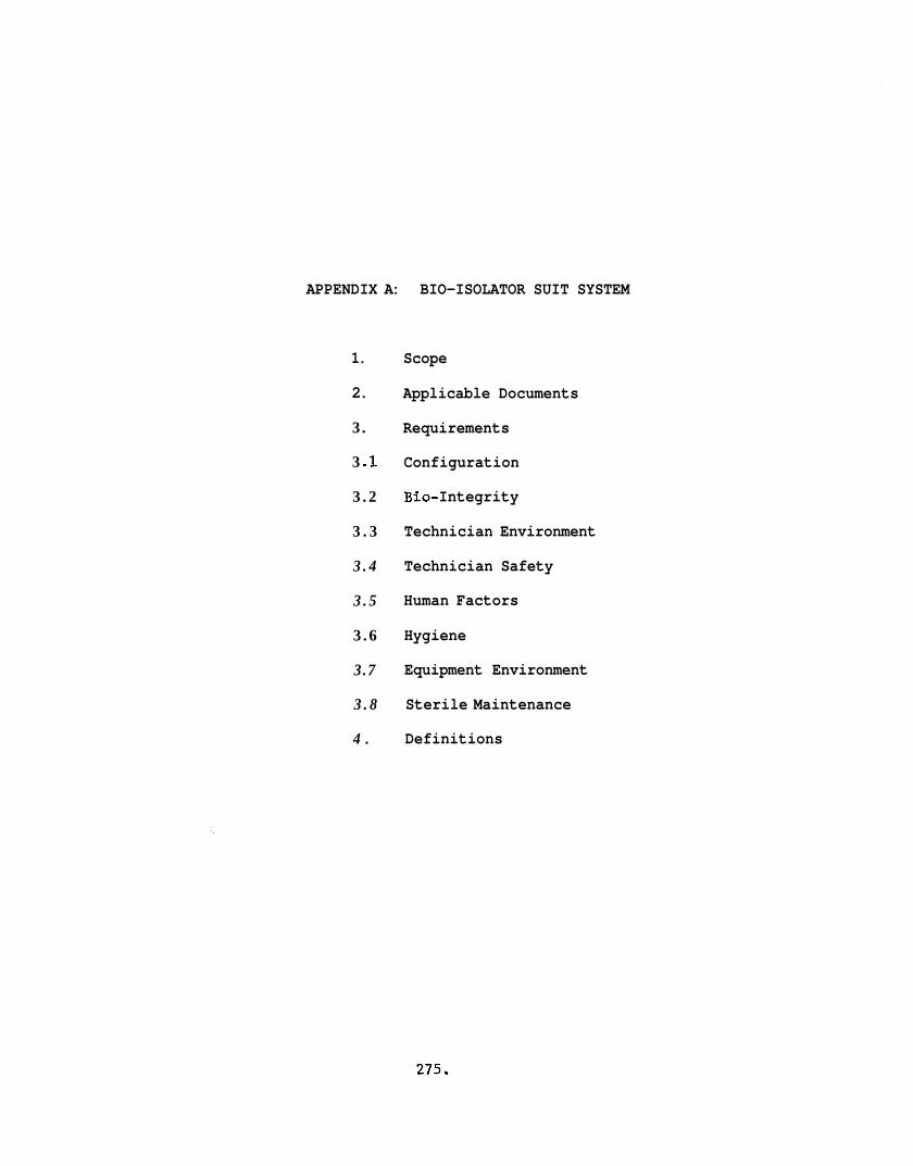
APPENDIX A: BIO-ISOLATOR SUIT SYSTEM
1.
2.
3 .
3 .I
3 . 2
3 . 3
3 . 4
3 . 5
3 . 6
3.7
3 . 8
4 .
Scope
Applicable Documents
Requirements
Configuration
Bi 0- Integrity
Technician Environment
Technician Safety
Human Factors
Hygiene
Equipment Environment
Sterile Maintenance
Definitions
275.
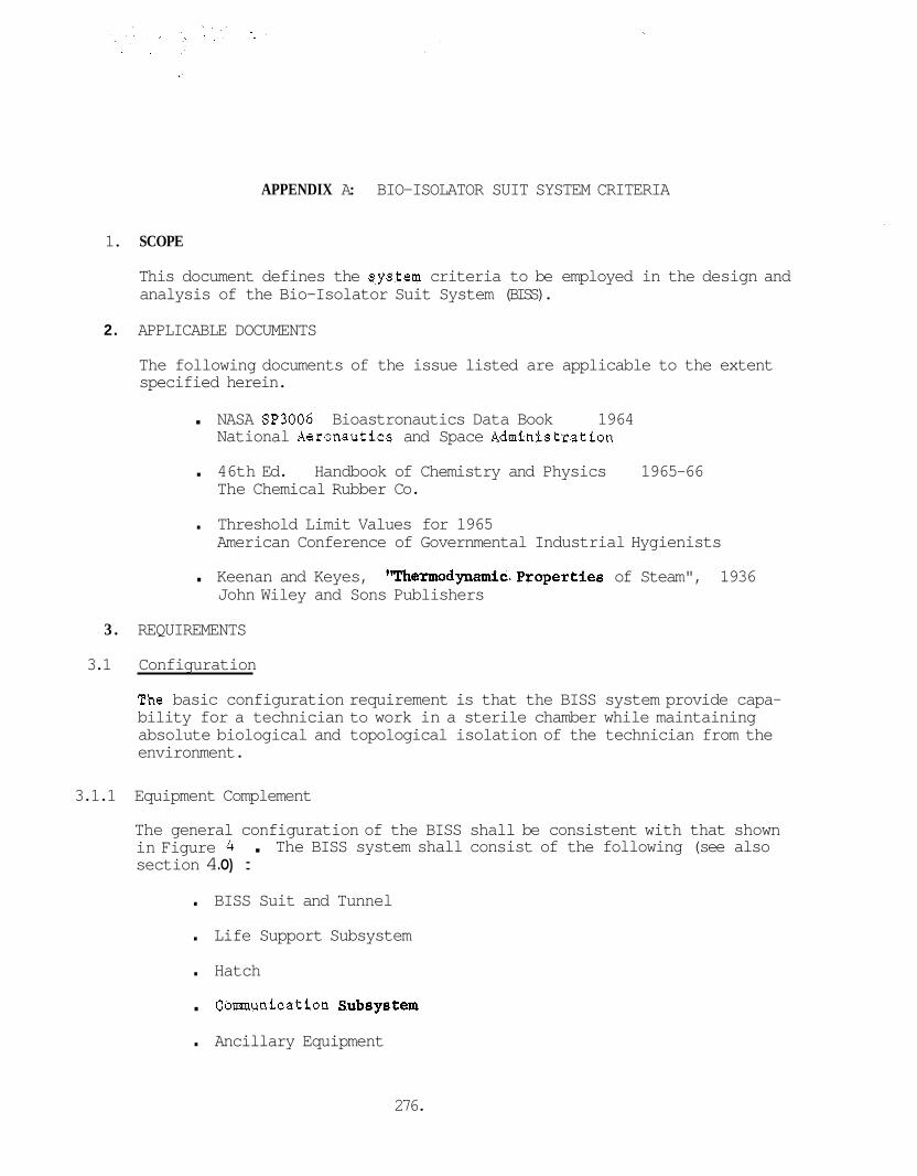
APPENDIX A: BIO-ISOLATOR SUIT SYSTEM CRITERIA
1. SCOPE
This document defines the slystem criteria to be employed in the design and analysis of the Bio-Isolator Suit System (BISS).
2. APPLICABLE DOCUMENTS
The following documents of the issue listed are applicable to the extent specified herein.
. NASA SP3006 Bioastronautics Data Book 1964 National Aeronautics and Space Administration
. 46th Ed. Handbook of Chemistry and Physics 1965-66 The Chemical Rubber Co.
. Threshold Limit Values for 1965 American Conference of Governmental Industrial Hygienists
. Keenan and Keyes, llThermodynamic.Properties of Steam", 1936 John Wiley and Sons Publishers
3 . REQUIREMENTS
3.1 Configuration
3he basic configuration requirement is that the BISS system provide capa- bility for a technician to work in a sterile chamber while maintaining absolute biological and topological isolation of the technician from the environment.
3.1.1 Equipment Complement
The general configuration of the BISS shall be consistent with that shown in Figure 4 . section 4 .O) :
The BISS system shall consist of the following (see also
. BISS Suit and Tunnel
. Life Support Subsystem
. Hatch
. Comnunication SUb8y8tem
. Ancillary Equipment
276.
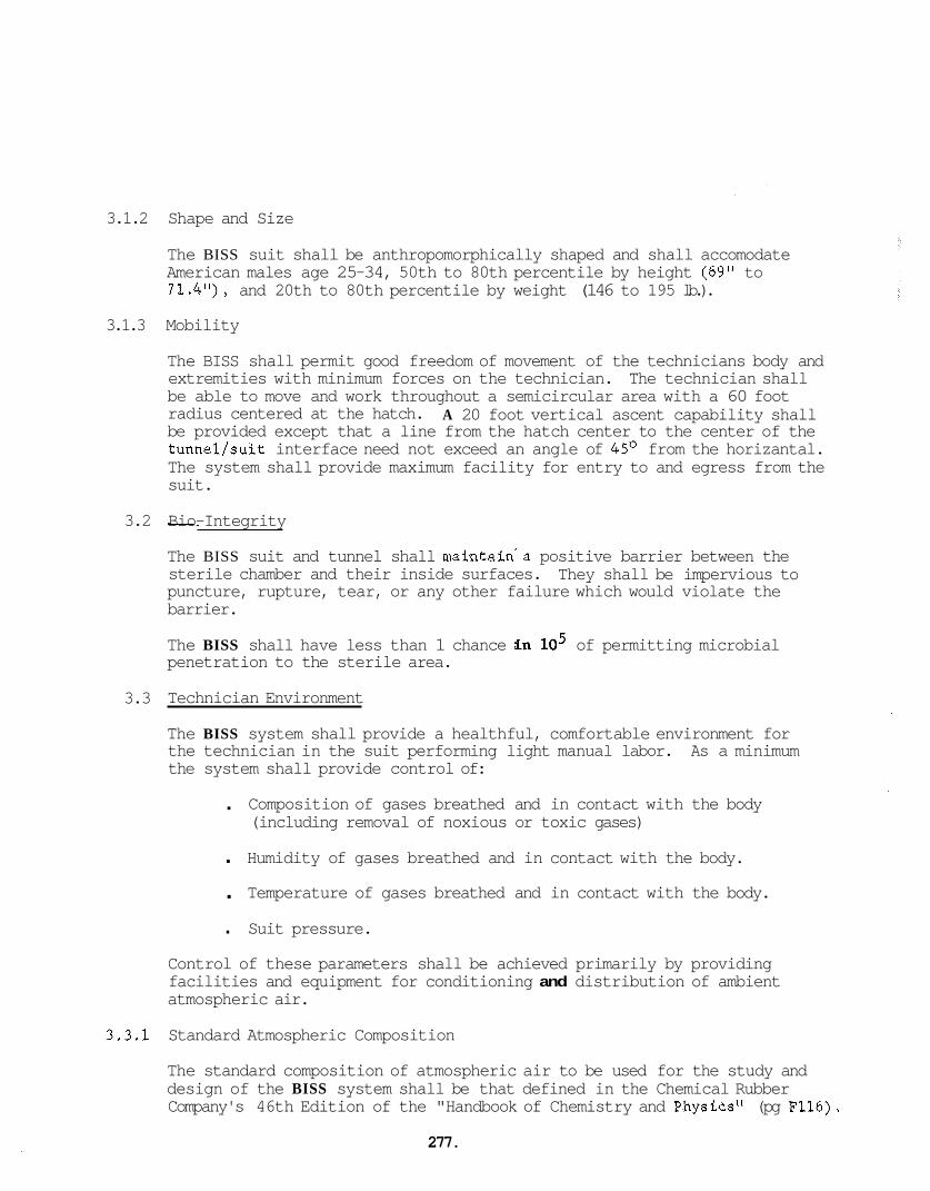
3.1.2
3.1.3
3.2
3.3
3,3.1
Shape and Size
The BISS suit shall be anthropomorphically shaped and shall accomodate American males age 25-34, 50th to 80th percentile by height (69" to 71.4"), and 20th to 80th percentile by weight (146 to 195 lb.).
Mobility
The BISS shall permit good freedom of movement of the technicians body and extremities with minimum forces on the technician. The technician shall be able to move and work throughout a semicircular area with a 60 foot radius centered at the hatch. A 20 foot vertical ascent capability shall be provided except that a line from the hatch center to the center of the tunnel/suit interface need not exceed an angle of 45' from the horizantal. The system shall provide maximum facility for entry to and egress from the suit.
I_i Bio-Integrity
The BISS suit and tunnel shall maintain'a positive barrier between the sterile chamber and their inside surfaces. puncture, rupture, tear, or any other failure which would violate the barrier.
They shall be impervious to
The BISS shall have less than 1 chance .in lo5 of permitting microbial penetration to the sterile area.
Technician Environment
The BISS system shall provide a healthful, comfortable environment for the technician in the suit performing light manual labor. the system shall provide control of:
As a minimum
. Composition of gases breathed and in contact with the body (including removal of noxious or toxic gases)
. Humidity of gases breathed and in contact with the body.
. Temperature of gases breathed and in contact with the body.
. Suit pressure.
Control of these parameters shall be achieved primarily by providing facilities and equipment for conditioning and distribution of ambient atmospheric air.
Standard Atmospheric Composition
The standard composition of atmospheric air to be used for the study and design of the BISS system shall be that defined in the Chemical Rubber Company's 46th Edition of the "Handbook of Chemistry and Physics" (pg F116).
277.
The breakdown of this composition (exclusive of water vapor is given in Table A- I .
The water vapor concentration standard (by volume) for the study and design of the BISS system shall be that defined in Table A - I 1 derived from equation 12 of Keenan and Keyes, "Thermodynamic Properties of Steam," John Wiley and Sons, 1936.
,278.
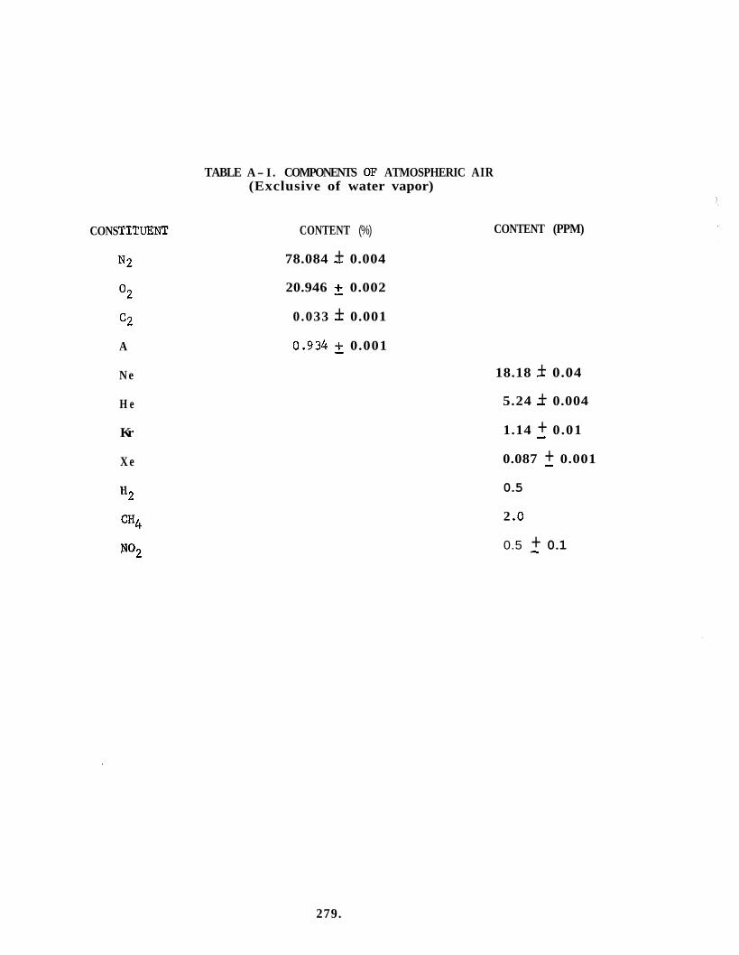
CONS TITUEN"
N 2
O2
c2
A
N e
H e
Kr
X e
*2
cH4
TABLE A- I . COMPONENTS OF ATMOSPHERIC AIR (Exclusive of water vapor)
CONTENT (%)
78.084 - + 0.004
20.946 2 0.002
0.033 + - 0.001
0.934 5 0.001
CONTENT (PPM)
18.18 - + 0.04
5.24 - + 0.004
1.14 + 0.01 - 0.087 + 0.001 - 0.5
2 .o
0.5 + 0.1 -
279.
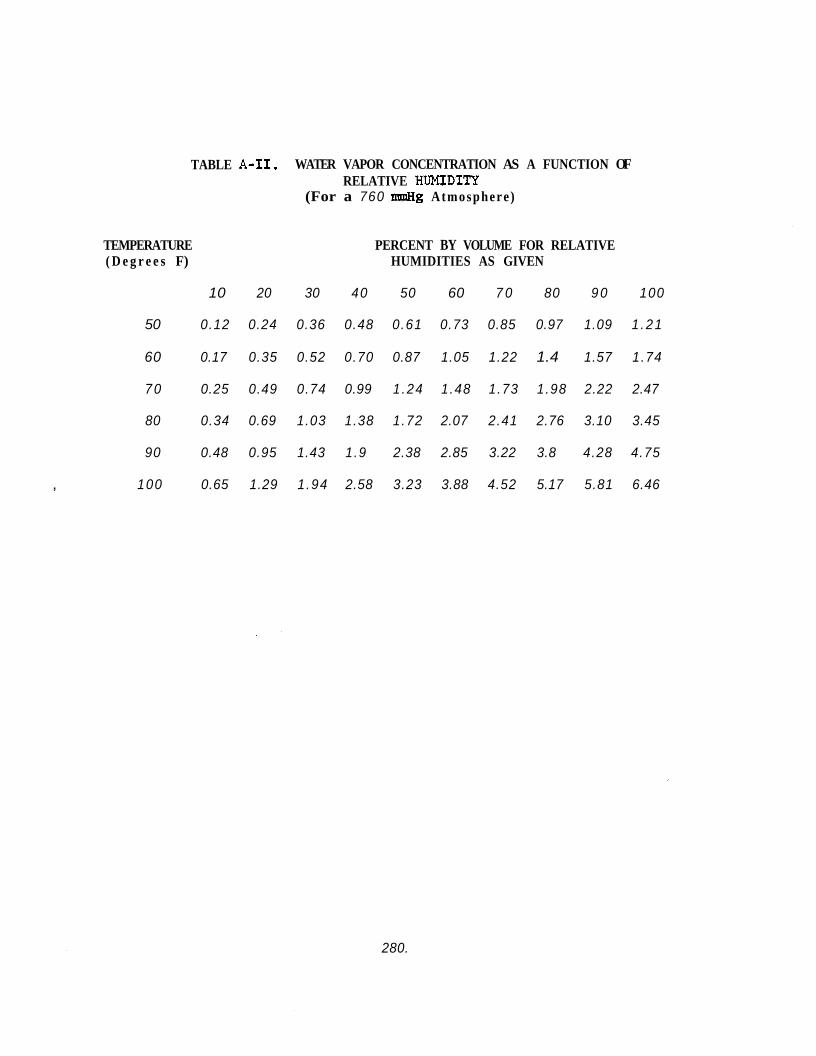
TABLE A-11. WATER VAPOR CONCENTRATION AS A FUNCTION OF RELATIVE HUMIDITY
(For a 760 mmHg Atmosphere )
TEMPERATURE ( D e g r e e s F)
PERCENT BY VOLUME FOR RELATIVE HUMIDITIES AS GIVEN
10 20 30 40 50 60 7 0 80 9 0 100
50 0.12 0.24 0.36 0.48 0.61 0.73 0.85 0.97 1.09 1 .21
60 0.17 0.35 0.52 0.70 0.87 1.05 1.22 1.4 1.57 1.74
7 0 0.25 0.49 0.74 0.99 1 .24 1.48 1.73 1.98 2.22 2.47
80 0.34 0.69 1.03 1.38 1.72 2.07 2.41 2.76 3.10 3.45
90 0.48 0.95 1.43 1.9 2.38 2.85 3.22 3.8 4.28 4.75
, 100 0.65 1.29 1 .94 2.58 3.23 3.88 4.52 5.17 5.81 6.46
280.
3.3.2 Breathing Gas Composition Limits
The standards for gas composition limits for the BISS environment shall be in accordance with the llBIOASTRONAUTICS DATA BOOK", NASA SP-3006, and the Threshold Limit Values published by the American Conference of Governmental Industrial Hygienists.
3.3.2.1 Oxygen. Oxygen concentration shall be between 17 and 36 percent by volume (1.2 of Bioastronautics Data Book (BDB) ) with a nominal objec- tive of 21%.
3.3.2.2 Carbon Dioxide. Carbon Dioxide concentration shall not exceed 0.5% by volume (1.5 of BDB) .
3.3.2.3 Nitrogen and Inert Gases. No absolute limts are established on concen- However, it is the objective trations of nitrogen and the inert gases.
that these gases approximate the standard compositions of Table A-I.
3.3.2.4 Noxious and Toxic Gases. The concentrations of all gases shall be maintained below the noxious or toxic limit, whichever is lower. The toxic limits shall be in accordance with the American Conference of Governmental Industrial Hygienists Threshold Limit Values (TT.,V) where TLV are specified for the gas in question. refer to airborne concentrations of substances and represent limit of may be repeatedly exposed, day after day, without adverse effect.''?; Specific gases which present a potential hazard to be guarded agaPnst in the BISS system are given in Table A-331 along with TLV or comments on concentration.
"The Threshold Limit Values" the upper
conditions under which it is believed that nearly all workers
Jc TLV 1965 p.1
281.

TABLE A-111. GAS CONCENTRATION W A R D LIMITS
TLV PPM -
5000
* 20
*
* 50
50
1000
Comments
Simple Asphyxiant
Hydrogen Sulfide
Toxic Hazard slight. Explosive range 4.1% to 74.2% in air
Methane-similar to H2
Ethene
ET0
Freon 12
* TLV not defined
Noxious gases and vapors shall be maintained at concentrations suffi- ciently low that they are not offensive to the technician in the suit. (No noxious gases or vapors were detected during tests with the BISS mock-up on contract NAS 1-6537).
3.3.3 Body Contact Gas Composition
Any gas mixture supplied for body cooling shall be of the same compos- ition as that used for the supply of breathing gas. any gas mixture safe for breathing presents no cutaneous hazard.
Without exception,
3.3.4 Gas Distribution
Gas supply for breathing shitil be directed to the face or head area and shall not flaw Over body surface areas enroute to the face. breathing and cooling gases may be supplied by a common line to the suit, but must be distributed independently at the suit. purging of the suit and helmet shall be employed to prevent buildup of noxious of toxic gases.
Both
Active
282.
3 . 3 . 5 Skin Contact Materials
All materials employed in the system in contact with the skin of the technicians shall be materials which have histories of acceptable use in contact with the skin without causing irritation. a material be employed which has a history of causing acute or extended irritation in any significant percentage of the population or has caused chronic ailments in otherwise healthy adults. materials used in contact with the skin shall be materials which have been previously approved by the F.D.A. for medical applications for skin contact or body implantation.
In no case shall
Whenever possible,
3 . 3 . 6 Temperature/Humidity
The BISS System shall provide control of the temperature and humidity of the environment. The nominal enviroment inside the suit shall be conditioned air at 70°F and 40% RH. able to give dry bulb supply temperatures from 68'F to 78'F and wet bulb temperatures from 5 7 O to 64OF across this dry bulb temperature range at a flow rate of 20 scfm.
The air supply shall be adjust-
3 . 3 . 7 Gas Flow Rate
The air supply shall be adjustable from 0 to 20 scfm.
3 . 3 . 8 Biological Environment
See Hygiene, Section 3 . 6
3 . 3 . 9 Pressure
The suit system shall be at a nominal pressure of 760 mmHg with a pressure differential across the outer suit and tunnel of up to 4" of water gage ( 7 . 5 mmHg) inward.
3 . 4 Technician Safety
The highest priority in the design of the system shall be given to the safety of the suit occupant. This shall include, as a minimum, relia- bility of the life support equipment, protection of the occupant from physical injury, provision for rapid emergency egress from the suit (aided or unaided), and provisions in the facility operating plans to maximize the protection of the suit occupant.
3.4.1 Life Support Reliability
I
The life support system shall have a probability of not less than .99 of providing a safe operating environment for the operator during any working shift (see also Endurance, Section 3 . 8 ) . shall be that defined in Section 3 . 3 above.
The safe environment
283.
3.4.2
3.4.3
3.4.3.1
3.4.3.2
3.4.4
Life Support Backup
A back-up gas supply shall be provided to maintain a safe breathing environment for the suit occupant in the event of life support system failure. This system shall have sufficient capacity to support the suit occupant for a period of not less than 20 minutes (fifteen min- utes planned maximum plus five minutes reserve).
Physical Protectors
As a minimum, the suit shall provide protection of the head,. face, and feet from sources of injury such as falling objects. In addition, the BISS materials, construction, and operating instructions shall be designed and selected to minimize the potential of rips, tears, punc- tures, or cuts.
Helmet. an industrial safety hat and a safety faceplate providing protection from flying objects equivalent t o the protection provided by safety glasses.
The helmet shall include "hard hat" provisions equivalent to
Boots. arch from dropped objects. non-skid construction to minimize the hazards of slipping or falling.
The boots shall incorporate safety caps to protect the toes and - The outer soles of the boots shall be of
Safety Checking and Monitoring
Checking and monitoring of the environment of the BISS and monitoring of the physiological response of the operator to the environment and working conditions shall be performed to assure operator safety. matic alarms shall be provided to bring attention to hazards or abnormal personnel conditions. and shall. incorporate alarms.
Auto-
The measurements of Table A-IV shall be provided
TABLE A-IV. SAFETY MONITORING
PARAMJ3TER
Toxic gas concentration (notes 1 & 2)
Oxygen Concentration
11
c02 Pulse rate
FREQUENCY ALARM LIMIT
Continuously during TLV (table 3.2) occupancy
11 17% min., 36% max. by volume
11 .5% by volume
I t Further study required (note 3),
NOTES: (1) Gases t o be monitored s h a l l be those t o x i c gases found t o be c h a r a c t e r i s t i c of system performance ( i f any). no such gases have been observed.
To d a t e
(2) ET0 concent ra t ion s h a l l be maeasured a t l e a s t a f t e r each ET0 cycle.
(3) See Sect ion 4.9 on medical monitoring.
3.4.5 Mater ia l Flannnability
The s u i t and tunnel s h a l l be constructed of ma te r i a l which is non- flarmnable o r w i l l n o t support combustion (mater ia l s s h a l l be capable of passing appl icable ASTM standard test or equiva lent ) .
3.4.6 Emergency Procedure
Procedures and/or f a c i l i t i e s s h a l l be provided t o permit rap id egress of a conscious occupant from the s u i t o r rap id removal of an unconscious occupant. with appropr ia te procedural c r i t e r i a .
Three c l a s s e s of emergency condi t ions a r e defined i n Table A-V
TABLE A-V. BISS EMERGENCY CLASSIFICATIONS
Class Conditions Procedural C r i t e r i a
I Loss of breathing gas supply Major system leak Toxic gas exceeds TLV
I1 Loss of temperature con t ro l
I I I ( a ) Operator s u s t a i n s phys ica l i n j u r y
(b) Operator f a i n t o r unconscious Operator h e a r t f a i l u r e Operator r e s p i r a t o r y f a i l u r e Operator s t roke
Act ivate emergency gas supply Operator may complete immediate t a sk Operator s h a l l be c l e a r of the s u i t wi th in 15 minutes
Operator may complete immediate task Operator s h a l l l eave the s u i t i f s u i t temperature goes below 60°F or above 100°F.
Operator s h a l l be removed from the s u i t wi th in 4 minutes and s h a l l then rece ive immediate medical a t t e n t i o n (a r e s p i r a t o r s h a l l be ava i lab le)
Operator s h a l l be removed from the s u i t wi th in 2 minutes (objec t ive - 4 minutes requirement) and s h a l l then rece ive immediate medical a t t e n t i o n (a r e s p i r a t o r s h a l l be ava i l ab le )
28 5.
3.4.7 Electrical Safety
The BISS System design and operating procedures shall be designed to prevent accumulation of static electricity which would cause a discharge between the BISS suit or tunnel and any grounded object in the Assembly/ Sterilizer.
The BISS system shall electrically insulate the occupant from any unpro- tected electrical contacts in the Assembly/Sterilizer .
3.4 .8 Standard Operating Procedures
The operating procedures for the BISS in the Assembly/Sterilizer shall be designed to maximize protection of the BISS suited operator. procedural criteria are:
Specific
. When a man is in the BISS suit, there shall always be at least one other man in the chamber to provide any necessary assistance. Work plans and detailed layout shall be designed so that physical restrictions of mobility do not limit one man from being able to assist his nearest co-worker in the chamber.
. The environment and BISS occupants' response to the environment shall be continuously monitored by personnel trained to interpret the observed data and initiate any immediate corrective action required.
. Personnel shall be available outside the chamber to render any necessary assistance for routine or emergency entry or egress.
. A test director or coordinator shall observe all BISS operations in the Assembly/Sterilizer. He shall be responsible for the direction and coordination of all emergency activity and shall determine when and if system bio-integrity must be broken to rescue a BISS occupant.
. Trained medical personnel shall be on call at all times when personnel are in the BISS suits. to reach any BISS hatch with necessary emergency equipment within two minutes of being called.
These personnel shall be able
. All personnel shall receive a medical examination prior to the start of the work shift.
I
3.5 Human Factors
The system shall be designed to high standards of human engineering practice. will be used as the primary baseline of human factors data,
Where applicable the Bfoastronautics Data Book, NASA SB3006,
3.5.1 Entry and Egress
The des ign s h a l l provide maximum ease of e n t r y t o and egress from the s u i t through the tunnel . The tunnel s h a l l be long i tud ina l ly contracted (or reefed) during e n t r y and egress . Special ized equipment required t o a id e n t r y o r egress s h a l l be considered as p a r t of the BTSS system.
The maximum t i m e s a l l o t e d t o rout ine e n t r y t o , and egress from, the s u i t s h a l l no t exceed 15 rdnu te s with 5 minutes as a design objec t ive . The times f o r emergency egress a r e def ined i n Table A-V.
It is intended t h a t the requirement f o r rout ing e n t r y and egress be s a t i s f i e d with the s u i t occupant unaided by o ther personnel. by personnel in s ide the sterile chamber s h a l l n o t b e employed f o r zoutine e n t r y and egress .
Assistance
Entry and egress t i m e s defined he re in include the time required t o extend o r con t rac t the tunnel .
3.5.2 Work S h i f t Duration
The BISS system s h a l l permit a four hour period without i n t e r r u p t i o n . It i s an ob jec t ive t h a t t he system permit an e i g h t hour work s h i f t i n two four-hour per iods with a break f o r r e s t and ea t ing between per iods . (Further t e s t i n g i s required t o determine whether t h i s is f e a s i b l e ) .
3 .5-3 Occupant Comfort
I n add i t ion t o the provis ion of an environment i n accordance with Sect ion 3.3, t he system design s h a l l provide the maximum poss ib le com- f o r t f o r the occupant. a re : types and loca t ions of padding, s u i t s t i f f n e s s , freedom of movement, magnitude and loca t ion of s u i t weight bearing p o i n t s , unbalanced hydro- s t a t i c p res su res , etc.
S u i t parameters appl icable t o t h i s c r i t e r i a
3.5.4 V i s i b i l i t y
The design s h a l l no t l i m i t t h e v i s i o n of the occupant e i t h e r by obstruc- t i o n of v i s u a l f i e l d o r by abe r ra t ion . The v i s u a l f i e l d with the head upr ight and fac ing forward s h a l l be not less than + l l O o i n the horiz- o n t a l plane and not l e s s than + 600, -80° i n the v e r t i c a l plane. helmet and face p l a t e s h a l l be so designed t h a t t h i s v i s u a l f i e l d r e l a - t i v e t o the head i s maintained when the neck is subjected t o t h e v e n t r a l and d o r s a l f l ex ions and r i g h t and l e f t r o t a t i o n s of Paragraph 3.5.5. Provis ion s h a l l be made t o prevent fogging of t h e fade p l a t e . design s h a l l accommodate t h e wearing of eyeglasses .
The
The
3.5.5 Mobility
The design shall permit maximum mobility of the suit occupant consis- tant with the other system criteria. of movement throughout a semicircular region with a radius of 60 feet, centered at the hatch. also required. limit ascent with the tunnel fully retracted; however, as a minimum, the system distance to the hatch center in a plane parallel to the floor, up to a maximum of 20 feet ascent (i.e, half cylinder of 60 foot radius and 20 foot height with a 450 half cone removed).
The occupant shall be capable
A twenty foot: vertical ascent capability is (Practical limitations of suit and tunnel support may
should provide ascent capability equal to the radial
The BISS system shall provide as a design goal no more than 10% decrement in the joint motions, and as a requirement no more than 25% decrement. A-1. In addition, the following normal neckmotions are defined:
Joint motions for most body joints are defined in Figure
. Ventral flexion 60' Mean 12' S.D.
. Dorsal flexion 61 27
. Right or left flexion 41 7
. Right or left rotation 79 14
The system design shall also specifically provide maximum unrestricted capability for:
. 45' forward bend at the waist
. Squatting
. Scaffold or ladder climbing
. Walking 3.5.6 Manual Dexterity
The BISS system shall provide for maximum technician finger and hand dexterity compatible with overriding criteria such as bio-integrity and safety. Manual tasks to be considered in assessing dexterity are:
. Use of common hand tools
. Fastener starting , Modular assembly operations
. Connector mating and demating operations.
288.
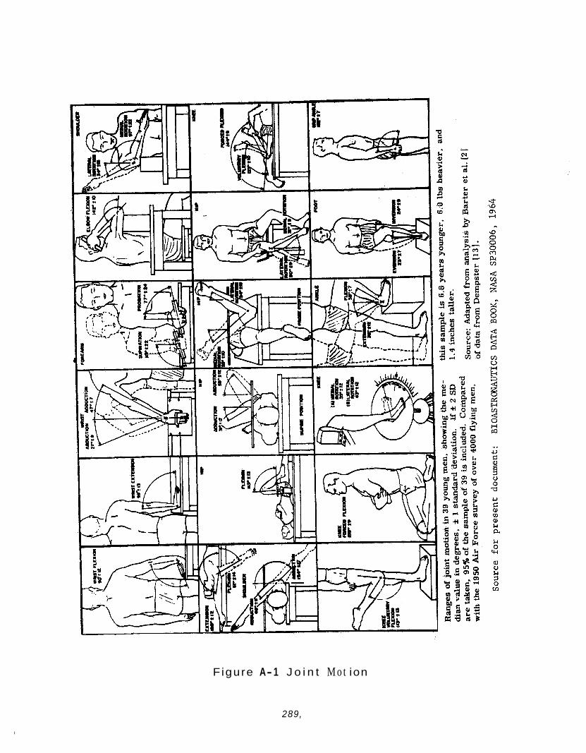
Figure A- 1 J o i n t M o t ion
289,
3.5 .7 Communications
The BISS system shall provide aural communication between suit occu- pants and between a suit occupant and control or support personnel through the use of an electrical or electronic communications system. A system of hand signals can be employed for back-up in the event of communications system failure. However, as a minimum, this shall be augmented by a signalling system incorporating the following:
. A panic button in or on each suit to draw immediate attention of control personnel to a suit occupant who needs assistance or has lost aural communication.
A sounder that can be heard by all suited personnel to draw immediate attention of suit occupants to hand or other visual signals from control personnel.
.
The following additional back-up communications equipment shall also be considered for employment in the Assembly/Sterilizer - BISS:
, A loud speaker system in the Assembly/Sterilizer main chamber with sufficient power capability to create an audible, intel- ligible voice signal in the BISS helmet.
3.5.8 Suit Fit
The BISS suit shall be designed to provide a comfortable fit for the 50th to 80th percentile by height and the 20th to 80th percentiles by weight of American males in the 25-34 year old age group. the suit fit shall be adjustable to accomplish this capability. the maximum extent possible within these limitations, the suit shall be form fitting with a minimum of protruding bulges or folds of suit materials. Folds necessary to accommodate the smallest acceptable occupant in the suit shall be so designed and located as to minimize the hazard of snagging.
If necessary, To
3 .6 Hygiene
The BISS system design and operating procedures shall incorporate provisions for interchange of suit occupants with a minimum of delay without presenting offensive or unhygienic conditions for the second occupant.
The BISS system will employ an appropriate undergarment, or inner- suit, so that an occupant leaving the suit takes with him as large a percentage as possible of the microbial life he produced or liberated during occupancy.
290.
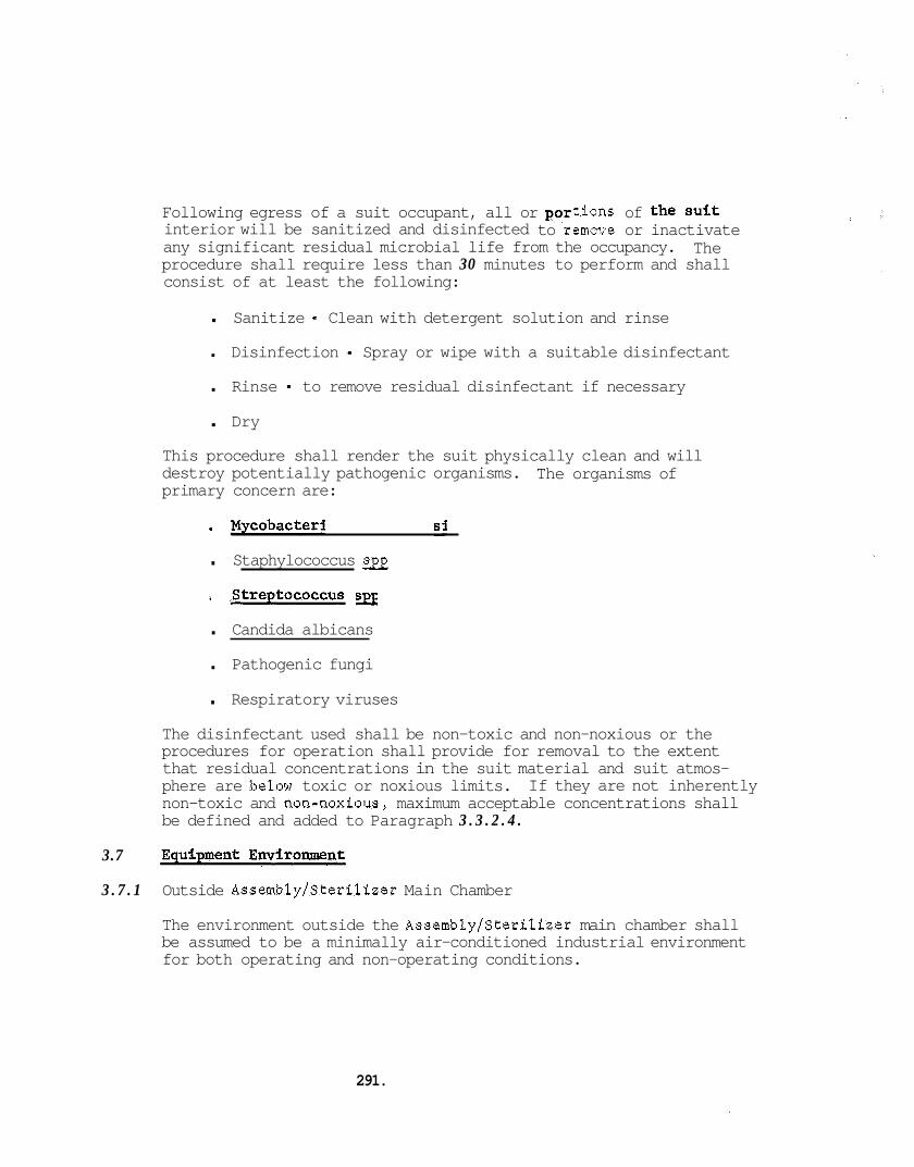
3.7
Following egress of a suit occupant, all or interior will be sanitized and disinfected to remove or inactivate any significant residual microbial life from the occupancy. procedure shall require less than 30 minutes to perform and shall consist of at least the following:
tions of the suit
The
. Sanitize - Clean with detergent solution and rinse
.
. Rinse - to remove residual disinfectant if necessary Disinfection - Spray or wipe with a suitable disinfectant
. Dry This procedure shall render the suit physically clean and will destroy potentially pathogenic organisms. primary concern are:
The organisms of
Mycobacterium tuberculosis
. Staphylococcus SJJ
. Streptococcus SJJ
. Candida albicans
. Pathogenic fungi
. Respiratory viruses The disinfectant used shall be non-toxic and non-noxious or the procedures for operation shall provide for removal to the extent that residual concentrations in the suit material and suit atmos- phere are below toxic or noxious limits. non-toxic and non-noxious, maximum acceptable concentrations shall be defined and added to Paragraph 3 . 3 . 2 . 4 .
If they are not inherently
Equipment Environment
3 . 7 . 1 Outside Assembly/Sterilizer Main Chamber
The environment outside the Assembly/Sterilizer main chamber shall be assumed to be a minimally air-conditioned industrial environment for both operating and non-operating conditions.
291.

3.7.2 Inside Assembly/Sterilizer Main Chamber
In addition to cleaning of the suit and tunnel outer surfaces in the same manner as described in Paragraph 3.6 for inner surfaces, the suit and tunnel will be exposed to the four environmental modes of the Assembly/Sterilizer chambers as described in Table A-VI. The BISS system is operational in Modes A and D and non-operational inModes B and C.
3.7.3 Inside Suit and Tunnel
When the Assembly/Sterilizer system is in Modes A and D and the operator is in the suit, the environment shall be in accordance with technician environment defined in Section 3.3. When the system is in these modes, the suit and tunnel inner surfaces may be exposed to the cleaning procedure described in Section 3.6.
When the system is in Modes B or C or is unoccupied in the modes of A and D, the environment in the suit and tunnel will be air of atmosphere composition at nominally the same temperature as the main chamber gas. If this gas mixture produces degradation of the mater- ials or equipment inside the suit and tunnel at elevated tempera- tures of the modes of B and C, the suit can be filled with nitrogen in these modes.
The pressure inside the suit and tunnel will be at nominally atmos- pheric pressure at all times (€.e.: pressure).
up to 4" H20 below chamber
3 8 Endurance
The BISS shall be designed to operate in accordance with the criteria herein for a period of not less than 360 (objective 1000 hr) hours of continuous trouble free operation without maintenance beyond replacement of filters, and equipment other than the suit and tunnel shall be designed for a total operating life of not less than 20,000 hours with maintenance.
The suit and tunnel of the BISS and all equipment integral thereto shall be capable of withstanding, without violation of any design criteria, 10 cycles each (20 cycles objective) of cleaning of external surfaces, ETO/FREON decontamination, and dry heat sterili- zation and 90 cycles (180 cycles objective) of cleaning of internal surfaces.
The total life of the BISS suit and tunnel or parts thereof shall be up to 24 months from production to end of life. This total shall be composed of a storage life of up to 12 months and a service life of up to 12 months. Consideration may be given to extension of storage life without exceeding a total life of 24 months.
292,
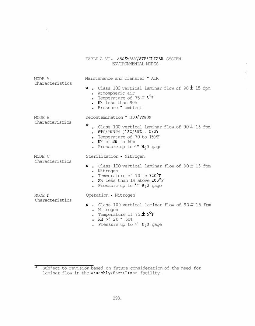
MODE A Characteristics
MODE B Characteristics
MODE C Characteristics
MODE D Characteristics
TABLE A-VI . ASSEMBLY/STERILIZER SYSTEM ENVIRONMENTAL MODES
Maintenance and Transfer - AIR * . . Atmospheric air . . RH less than 90% . Pressure - ambient
Class 100 vertical laminar flow of 90 - + 15 fpm Temperature of 75 - + 5OP
Decontamination - ETO/FREON * .
. . RH of 40 to 60% .
Class 100 vertical laminar flow of 90 - + 15 fpm Temperature of 70 to 150°F
Pressure up to 4" H20 gage
. ETO/FREON (12%/88% - w/w)
Sterilization - Nitrogen * . . Nitrogen . . RH less than 1% above 200°F .
Class 100 vertical laminar flow of 90 - + 15 fpm Temperature of 70 to 320°F
Pressure up to 4" H20 gage
Operation - Nitrogen * . . Nitrogen .
.
Class 100 vertical laminar flow of 90 - + 15 fpm Temperature of 75 - + 5'F Pressure up to 4" H20 gage
. RK Of 20 - 50%
* Subject to revision based on future consideration of the need for laminar flow in the Assembly/Sterilizer facility.
293.
When e i t h e r t h e se rv ice l i f e o r endurance cyc le limits have been reached, the BISS s u i t and tunnel s h a l l be removed from service.
3.9 Sterile Maintenance
The BISS system des ign s h a l l permit a t l e a s t one replacement of the tunnel and s u i t without jeopardizing the s t e r i l i t y of t h e main chamber.
4 .O Defin i t ions
BISS - Bio- Isolator S u i t System
A system which permits a technic ian t o e n t e r and work i n a sterile chamber while being b io log ica l ly and topo log ica l ly i s o l a t e d from the system. below.
- 4.1
The BISS system cons i s t s of the equipment defined
4.1.1 BISS S u i t .. (o r S u i t and Tunnel)
The physical envelop which forms t h e b a r r i e r between t h e technic ian and the s t e r i l e environment of t h e chamber.
4.1.1.1 Outer Su i t . The po r t ion of the BISS S u i t which envelops the tech- n i c i a n and includes t h e following:
. S u i t s h e l l (or ou te r s h e l l ) - covers the occupants body exclusive of head, f e e t , and hands.
. Helmet - covers the occupant 's head.
. Gloves - covers the occupant 's hands.
. Boots - covers the occupant 's f e e t . - 4.1.1.2 Tunnel. The po r t ion of the BISS S u i t which connects t h e back of
the ou te r s u i t t o the hatch, and through which the technic ian e n t e r s and leaves t h e ou te r s u i t .
4.1.1.3 Inner S u i t . The garment worn by t he BISS s u i t occupant t o provide removal of excess body hea t . The garment w i l l be a i r cooled.
4.1.1.4 Personal Under Ga-nts. The garments worn by the BISS s u i t occu- pant t o separa te t h e su r faces of h i s body and ex t r emi t i e s from the inne r su r faces of the ou te r s u i t , i nne r s u i t , gloves, and boots . These garments w i l l c o n s i s t of f a b r i c under wear, l i g h t weight f a b r i c gloves, and socks o r s l i p p e r s .
294.

4.1.2 Life Support Subsystem. provides and maintains a healthful, comfortable, habitable environ- ment for the technician in the BISS suit.
The equip-ent of the BISS system which
4.1.2.1 Gas Supply Equipment. That equipment which provides the conditioned breathing and cooling gas to the BISS suit occupant. air conditioning equipment, distribution hoses, regulators, mani- folds, etc. This includes both normal and back-up gas supply and emergency oxygen enriched breathing supplies.
This includes
4.1.2.2 Gas Scavenging Equipment. That equipment which provides a power exhaust of the BISS suit to remove expired gas, cooling gas, and gases released by the body of the occupant. with the gas supply equipment, provide pressure control of the BISS suit .
This equipment shall,
4.1.3 Communications Subsystem
The equipment and procedures whereby suit occupants communicate with each other and with personnel outside the chamber.
4.1.4 Ancillary Equipment
Equipment needed to make the BISS a working system but not specifi- cally included in the above categories. Examples are:
. Hatch Assembly
. Tunnel support boom
. Tunnel reefing mechanisms and equipment
. Suit donning rack.
4.2 Assembly/Sterilizer
A facility for: the decontamination and sterilization of a spacecraft with subsequent checkout, assembly, and repair in a sterile environ- ment. The BISS system will be part of the Assembly/SteriPizer.
295.
APPENDIX B: VERTICAL BISS TUNNEL INVESTIGATION
1. Introduction
2. Discussion
3. Testing Performed
3.1 Procedures
3.2 Results
3.3 Conclusions and Comments
4 . Recommendation
296.
APPENDIX B: VERTICAL BISS TUNNEL INVESTIGATION
1. INTRODUCTION
2 .
The present BISS Concept employs a horizontal tunnel connecting the back of the suit to the hatch assembly. A vertical tunnel approach has been conceived which offers relief of some of the problems asso- ciated with reefing and support of a horizontal tunnel. tunnel concept is described herein along with a description of limited testing done on a mock-up of the tunnel.
The vertical
DISCUSSION
The tunnel configuration which has received primary consideration for BISS is the horizontal tunnel described in the body of the report. The reefing and tunnel support problems attendant to this configuration suggested the consideration of an alternate tunnel configuration to ease or obviate these problems. from the back of the BISS suit to a hatch in the Assembly/Sterilizer ceiling was developed and subjected to limited investigation. concept is shown schematically in Figure B-1. this concept is that no tunnel support boom is required.
The concept of a vertical tunnel extending
This An important feature of
The BISS worker is lowered into the reefed tunnel and dons the suit in an antechamber above the main chamber, then a hatch to the main chamber is opened and the suit occupant is lowered to the main chamber floor. Once on the main chamber floor, the suit occupant is free to move about and perform his assigned work.
Reefing of the vertical tunnel should be less complex than reefing of the horizontal tunnel because the vertical tunnel appears to be com- patible with a semi-rigid tunnel design (soft tunnel with circumferen- tial supporting rings or a fine pitch helix). Also, the weight of the vertical tunnel does not tend to cause uneven drag of the tunnel mater- ial on the tunnel during reefing.
The advantages and disadvantages of the vertical tunnel compared with the horizontal tunnel are summarized below.
297.
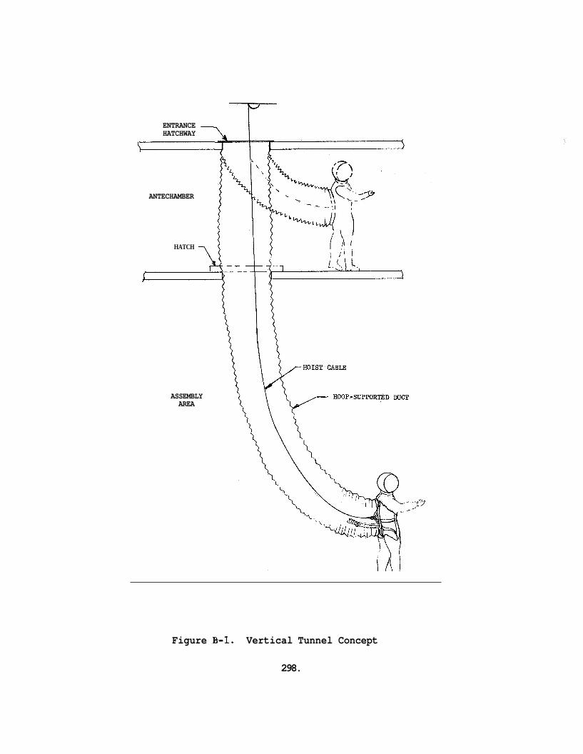
ENTRANCE - HATCHWAY ’
ANTECHAMBER
HATCH 7
ASSEMBLY AREA
Figure €3-1. Vertical Tunnel Concept
298.
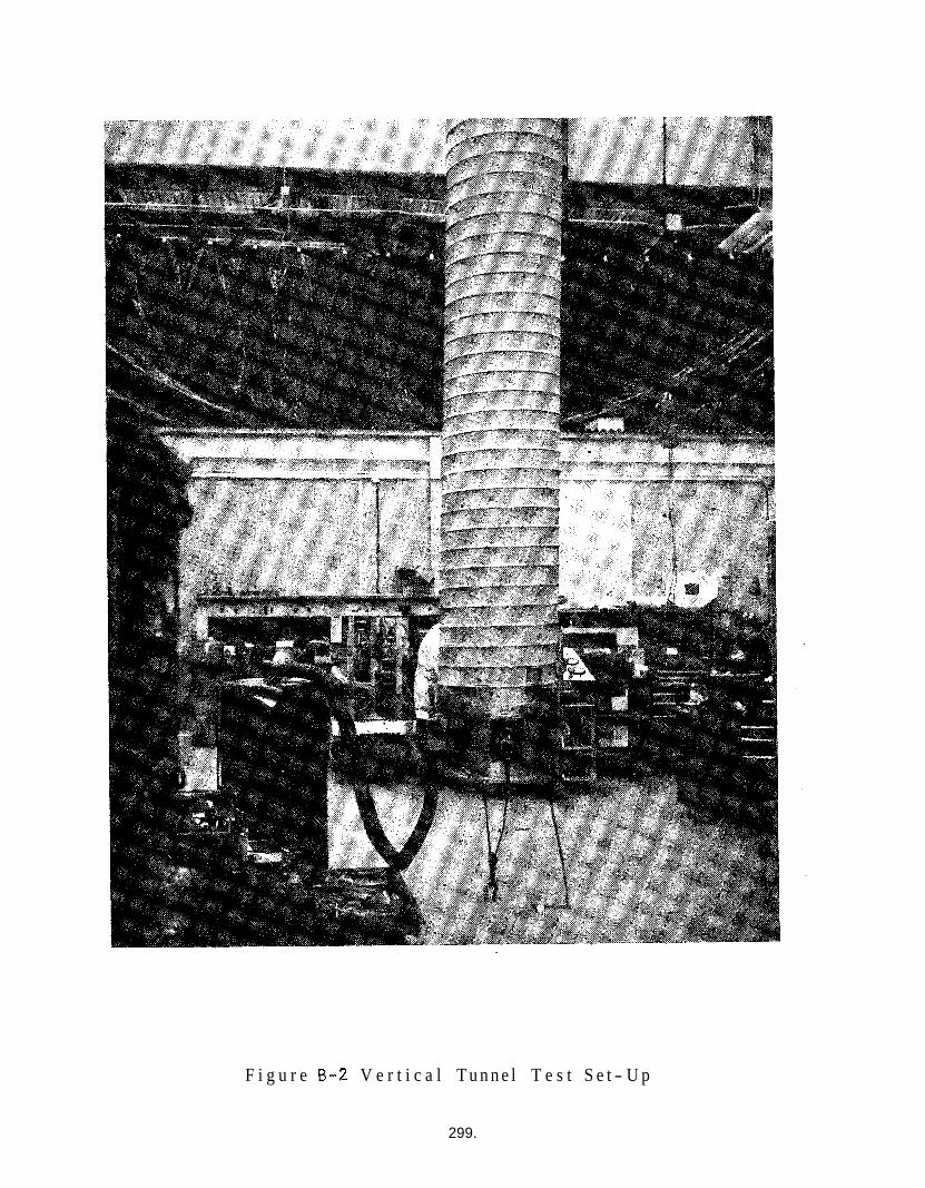
F i g u r e B-2 V e r t i c a l T u n n e l T e s t S e t - U p
299.
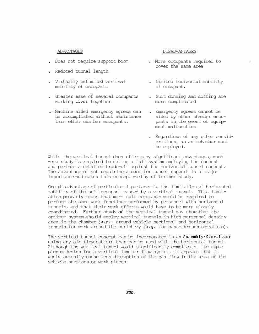
ADVANTAGES
.
. Reduced tunnel length Does not require support boom
DISADVANTAGES
. More occupants required to cover the same area
. Virtually unlimited vertical . Limited horizontal mobility mobility of occupant. of occupant.
. Greater ease of several occupants . Suit donning and doffing are working dose together more complicated
. Machine aided emergency egress can . Emergency egress cannot be be accomplished without assistance aided by other chamber occu- from other chamber occupants. pants in the event of equip-
ment malfunction
. Regardless of any other consid- erations, an antechamber must be employed.
While the vertical tunnel does offer many significant advantages, much mure study is required to define a full system employing the concept and perform a detailed trade-off against the horizontal tunnel concept. The advantage of not requiring a boom for tunnel support is of major importance and makes this concept worthy of further study.
One disadvantage of particular importance is the limitation of horizontal mobility of the suit occupant caused by a vertical tunnel. ation probably means that more suit occupants would be required to perform the same work functions performed by personnel with horizontal tunnels, and that their work efforts would have to be more closely coordinated. optimum system should employ vertical tunnels in high personnel density area in the chamber (e.g., around vehicle sections) and horizontal tunnels for work around the periphery (e.g. for pass-through operations).
This limit-
Further study of the vertical tunnel may show that the
The vertical tunnel concept can be incorporated in an Assembly/Sterilizer using any air flow pattern than can be used with the horizontal tunnel. Although the vertical tunnel would significantly complicate plenum design for a vertical laminar flow system, it appears that it would actually cause less disruption of the gas flow in the area of the vehicle sections or work pieces.
the upper
300.
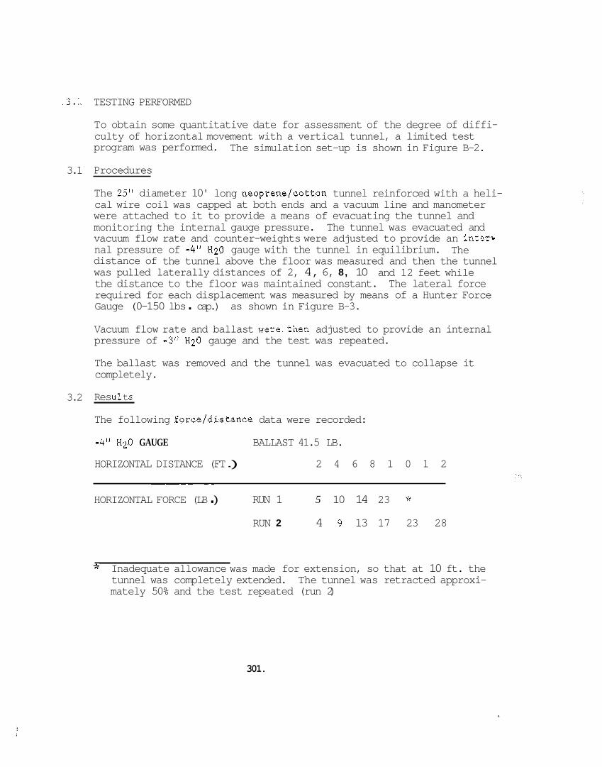
.3.:
3.1
3.2
TESTING PERFORMED
To obtain some quantitative date for assessment of the degree of diffi- culty of horizontal movement with a vertical tunnel, a limited test program was performed. The simulation set-up is shown in Figure B-2.
Procedures
The 25" diameter 10' long neoprene/cotton tunnel reinforced with a heli- cal wire coil was capped at both ends and a vacuum line and manometer were attached to it to provide a means of evacuating the tunnel and monitoring the internal gauge pressure. The tunnel was evacuated and vacuum flow rate and counter-weights were adjusted to provide an inters nal pressure of -4" H20 gauge with the tunnel in equilibrium. distance of the tunnel above the floor was measured and then the tunnel was pulled laterally distances of 2, 4, 6, 8, 10 the distance to the floor was maintained constant. The lateral force required for each displacement was measured by means of a Hunter Force Gauge (0-150 lbs . cap.) as shown in Figure B-3.
The
and 12 feet while
Vacuum flow rate and ballast were.then adjusted to provide an internal pressure of -3" H20 gauge and the test was repeated.
The ballast was removed and the tunnel was evacuated to collapse it completely.
Res ul t s
The following force/distance data were recorded:
-4" H20 GAUGE
HORIZONTAL DISTANCE (FT .) 2 4 6 8 1 0 1 2
BALLAST 41.5 LB.
_ _ _ ~ ~ ~~
HORIZONTAL FORCE (LB . ) RUN 1 5 10 14 23 * RUN 2 4 9 13 17 23 28
Jc Inadequate allowance was made for extension, so that at 10 ft. the tunnel was completely extended. The tunnel was retracted approxi- mately 50% and the test repeated (run 2)
301.
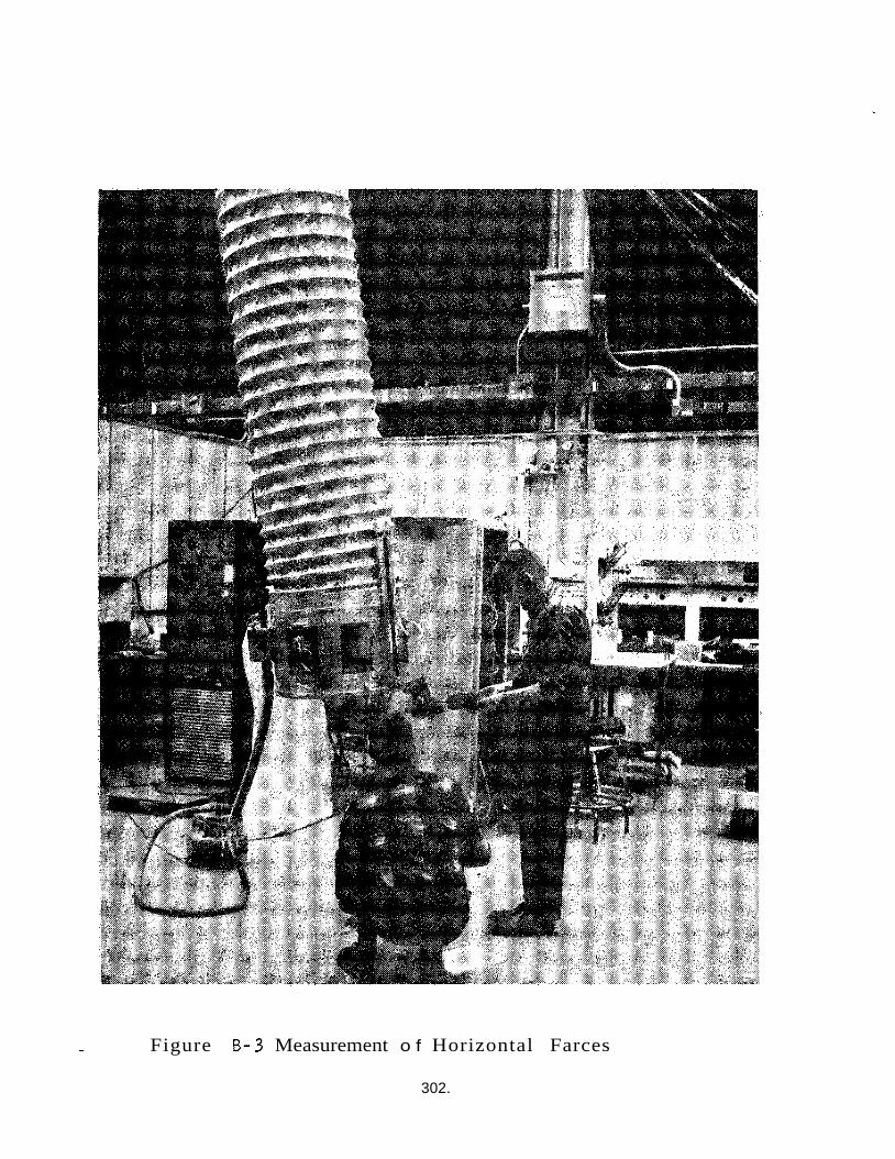
- Figure B-3 Measurement o f Horizontal Farces
302.
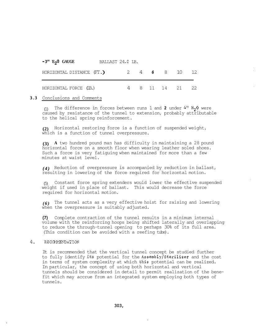
-3" H2O GAUGE BALLAST 24 .O LB.
HORIZONTAL DISTANCE (FT .) 2 4 6 8 10 12
HORIZONTAL FORCE (LB.) 4 8 11 14 21 22
3 . 3 Conclusions and Comments
(1) caused by resistance of the tunnel to extension, probably attributable to the helical spring reinforcement.
The difference in forces between runs 1 and 2 under 4" H20 were
(2) which is a function of tunnel overpressure.
Horizontal restoring force is a function of suspended weight,
(3) horizontal force on a smooth floor when wearing leather soled shoes. Such a force is very fatiguing when maintained for more than a few minutes at waist level.
A two hundred pound man has difficulty in maintaining a 28 pound
( 4 ) resulting in lowering of the force required for horizontal motion.
Reduction of overpressure is accompanied by reduction in ballast,
(5) weight if used in place of ballast. required for horizontal motion.
Constant force spring extenders would lower the effective suspended This would decrease the force
( 6 ) when the overpressure is suitably adjusted.
The tunnel acts as a very effective hoist for raising and lowering
(7) Complete contraction of the tunnel results in a minimum internal volume with the reinforcing hoops being shifted laterally and overlapping to reduce the through-tunnel opening (This condition can be avoided with a reefing tube).
to perhaps 30% of its full area.
4. UCaMMEJYDATION
It is recommended that the vertical tunnel concept be studied further to fully identify its potential for the Assembly/Sterilizer and the cost in terms of system complexity at which thls potential can be realized. In particular, the concept of using both horizontal and vertical tunnels should be considered in detail to permit realization of the bene- fit which may accrue from an integrated system employing both types of tunnels.
303,
APPENDIX C: TRIP REPORT - MEDICAL MONITORING DISCUSS ION
1. Purpose
2. Background
3. Discussion
4 . Conclusions
5. Recommendations
304.
APPENDIX C: TRIP REPORT - MEDICAL MONITORING DISCUSSION
4 April 1967
VISIT TO: Ijr. James A. Roman, Edwards, AFB, Calif.
GE PERSONNEL: J. Crawford, Project Engineer W.S. Kip, D.O.
1. PURPOSE
The purpose of the trip was to discuss BISS Phase I1 mock-u;? EKG's with a NASA/Edwards expert. telemedics RKG. The result of the discussion was to dispel concern about apparent abnormalities in the EKG'S. BISS environment does not appear to present a problem to further devel- opment of the system.
These electrocardiograms were taken ,dth
Physiological response to the
2. BACKGROUND
During test planning for the BISS program, contract NAS 1-6537, it was decided that a one lead electrocardiogram would be taken on the suit occupants to provide a quantitative measure of their physiological response to the environment by recording heart rate. The EKG's were taken using the Telemedics RKG transmittea model R-100, feeding a GE electrocardiograph. Two aspects of the resultant EKG'S were felt to necessitate further investigation: higher than had been expected, and some of the records displayed anomalies (called artifacts by cardiographers) which on cursory exam- ination could be interpreted as indicative of deviant heart performance.
the recorded heart rates were
Arrangements were made through the NASA/LRC technical representative on NAS 1-6537 to discuss the EKG's with Dr. James Roman of NASA Flight Research at Edwards AFB California. experience in monitoring physiological response of personnel to flight environments, and it was felt that this experience would be of consid- erable value in making a proper interpretation of the EKG's from the BISS studies.
Dr. Roman has had extensive
3. DISCUSSION
Dr. Kip and Mr. Crawford visited Dr. Roman at his office on 3/29 to discuss the EKG's. BISS concept and BISS Phase I1 design, Dr. Kip presented the EKG's for discussion ilong with attendant medical observations about the environment and non-quantitative measurements of BISS occupant response to the environment. The EKG'S were then reviewed and discussed in detail with a running discussion of EKG's and personnel response to special environments as measured by EKG.
After a brief presentation by Mr. Crawford on the
305.
Three
1.
2.
3 .
themes recurred throughout t he discussion:
Medical i n t e r p r e t a t i o n of EKG's taken under s p e c i a l environ- ments cannot be proper ly based s o l e l y on experience from measurements made on personnel under standard environmental condi t ions . (e.g., test p i l o t s i n - f l i g h t EKG cannot be reason- ab ly i n t e rp re t ed on the b a s i s of experience from a 94aster 's1 ' test).
I n making i n t e r p r e t a t i o n of EKG's from s p e c i a l environments, p a r t i c u l a r care must be taken t o d i s t i n g u i s h between physical and non-physical s t r e s s . (Heart r a t e s which would be indica- t i v e of i n c i p i e n t co l lapse from exhaustion i f due t o physical s t r e s s have been found t o be r e l a t i v e l y common f o r extended per iods f o r some t e s t p i l o t s ) .
Electrocardiographic recording under s p e c i a l environments i s , i n general , f raught wi th equipment d i f f i c u l t i e s which o f t en manifest themselves i n the EKG'S as a r t i f a c t s which can be i n t e rp re t ed a s hea r t malfunctions i f caut ion i s not exercised t o i s o l a t e t he cause of the a r t i f a c t s .
I n a po in t by po in t review of t he EKG'S which demonstrated s i g n i f i - cant a r t i f a c t s , D r . Roman s a i d t h a t he f e l t t h a t each of these was explainable i n terms of equipment malfunction and he f e l t t h a t t h i s was t h e i r cause, t he nature seen on the EKG's which have been resolved t o be equip- ment performance d e f i c i e n c i e s , no t hea r t malfunctions.
NASA/USAF have repeatedly experienced a r t i f a c t s of
I n f a c t , D r . Roman sa id that assuming t h a t t he observed a r t i f a c t s a r e e l e c t r i c a l of mechanical i n na tu re , t he EKG'S a r e "suspiciously normal . Fur ther , even i f these a r t i f a c t s were not caused by equipment d e f i - cienciers, D r . Roman s a w no g rea t cause f o r concern about t he a r t i f a c t s . Such a r t i f a c t s , which a r e regarded a s cause f o r concern i n conventional cardiography, have been f requent ly encountered dur ing i n - f l i g h t moni- t o r i n g of personnel and have been determined not t o be cause f o r concern i n t h i s s p e c i a l environment. t h a t such a r t i f a c t s , even i f t r u e h e a r t performance a r t i f a c t s , should n o t , i n themselves, be cause f o r concern.
A reasonable extension t o t he BISS suggests
Heart rate i n t e r p r e t a t i o n s r equ i r e some f u r t h e r measure of t he degree of phys ica l stress imposed on the sub jec t dur ing monitoring. While high h e a r t r a t e s due t o physical stress a r e cause f o r a t least caugion, high h e a r t rates due t o non-physical s t r e s s a r e , i n general , not cause f o r concern. experience.
D r . Roman gave seve ra l r e l evan t observations based f l i g h t
306.
1. The " s l o t man'' i n t h e USAF Thunderbirds ae roba t i c team has a h e a r t r a t e of 175 bpm f o r per iods of up t o 4 hours r e g u l a r l y with no adverse e f f e c t s . physical s t r e s s would ind i ca t e i n c i p i e n t co l lapse due t o enhaus- t i o n ) .
During the 1950's i n balloon experiments pulse r a t e s a s high a s 170 bpm with r e s p i r a t i o n r a t e s of 70 were experienced on the ground.
(Such a high h e a r t r a t e due t o
2 .
3 . One of t he lead t e s t p i l o t s a t Edwards ( t h e most experienced p i l o t i n the world) has a h e a r t r a t e of 120 bpm s i t t i n g on the f l i g h t l i n e i n the a i r c r a f t p r i o r t o f l i g h t . h e a r t r a t e goes as high a s 180 bpm. p i l o t starts o f f a t 60 and r a r e l y goes above 90.
During f l i g h t h i s I n c o n t r a s t , a second
4 . NASA/USM - Edwards have no t been ab le t o c o r r e l a t e hea r t r a t e wi th performance qua l i t y . between hea r t r a t e and 'koolness" of p i l o t s .
Nor have they seen any c o r r e l a t i o n
5. A man's verba l comments a r e a f a i r l y r e l i a b l e measure of physical stress. A man under extreme stress i s wel l aware of t he f a c t and w i l l v e rba l ly communicate t h a t he is under s t r e s s .
6. High h e a r t r a t e s due t o non-physical stress should be accom- panied by high blood pressure .
Based on the comments of t he BISS occupants and the observations of t he medical monitor, t he high h e a r t r a t e s observed i n the Phase I1 t e s t i n g cannot be a t t r i b u t e d t o physical stress. When these h e a r t r a t e s a r e a t t r i b u t e d t o non-physical stress, the re i s no cause f o r concern.
One f u r t h e r comment made by D r . Roman is worthy of note . performed seve ra l hundred hours of f l i g h t t e s t i n g without EKG p r i o r t o i n i t i a t i o n of t e s t i n g wi th EKG. on the subsequent i n - f l i g h t EKG's were such t h a t they would have been cause f o r considerable concern i f it were not known t h a t t he p i l o t s involved had performed s a t i s f a c t o r i l y i n the f l i g h t environment wi th no r e s idua l i nd i ca t i on of medical abnormality.
NASA/USAF
The h e a r t r a t e s and a r t i f a c t s observed
4 . CONCLUSIONS
I
The EKG's from the BISS Phase I1 mock-up t e s t i n g should not be i n t e r - preted a s i nd i ca t ing any ca rd io log ica l pathology. The r e s u l t s appear t o be a s would have been expected had w e had s u f f i c i e n t p r i o r exper- ience wi th personnel i n a comparable environment.
307.
5. REC-NDATIONS
Proceed with development of BISS and continue to monitor EKG on BISS occupants to develop a history of physiological response to the environ- ment,
Investigate hardwired EKG to remove the RF link as a possible source of artifacts.
Consider use of vector EKG (or multi-lead EKG) to provide more detailed information on heart behavior of BISS occupants.
Consider investigative testing to provide a quantitative measure of physical stress on the BISS occupant.
308.
APPENDIX D: SENSITIVITY ANALYSIS OF CONTINUOUS LEAK DETECTION SYSTEMS
1. INTRODUCTION
The objective of this analysis is to examine concepts for continuous leak detection systems used to infer bio-integrity of the BISS system. The preliminary results of this analysis were presented in Appendix B of report 67SD483 on the present contract.
2. ANALYSIS*
2.1 Basic Relationships
The relationship between detectable hole size and the other parameters of a detection system are analyzed by modeling the simple system shown schematically in Figure D-1. In this simple model the volume V repre- sents an arbitrary partial suit volume, .bounded by suit surface S and monitored by a single detector. A purge flow is employed to transport any leaked gas to the detector orifice. than V are:
The system parameters other
Q = rate of leak into volume V through a cylindrical hole
q = rate of permeation into volume V
Co = Concentration of tracer gas in the region from which the leak and permeation come
F = purge flow into V
Ci = concentration of tracer in purge stream
C(t) = concentration of tracer gas in volume V and exit stream as a function of time.**
These parameters can be stated in any self-consistent set of units.
* This analysis is based on constant volume systems obeying the perfect gas law and Dalton's law of partial pressures.
** Note that C(0) is not the same as 6,
309.
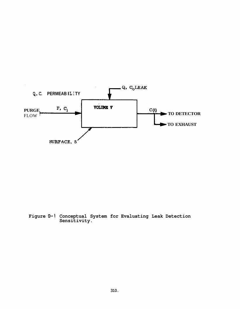
Q, C. PERMEAB I L I TY
PURGE FLOW TO DETECTOR
TO EXHAUST
Figure 0-1 Conceptual System for Evaluating Leak Detection Sensitivity.
310.
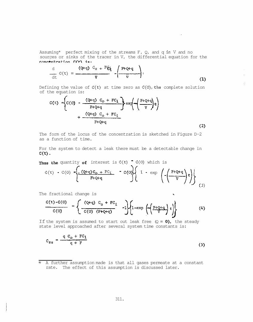
Assuming* perfect mixing of the streams F, Q, and q in V and no sources or sinks of the tracer in V, the differential equation for the
d (Qt4) c, + FCi
v - C(t) = dt
Defining the value of Clt) at time zero as C(O),the complete solution of the equation is:
The form of the locus of the concentration is sketched in Figure D-2 as a function of time.
For the system to detect a leak there must be a detectable change in C(t)
Thus the quantity of interest is C(t) - C(0) which is
C(t) - C(0) =[ (Q+q)Co + FCi - c ( o j { 1 - exp F+Q+q
( 3)
The fractional change is -b
If the system is assumed to start out leak free (Q = 0), the steady state level approached after several system time constants is:
* A further assumption made is that all gases permeate at a constant The effect of this assumption is discussed later. rate.
311.
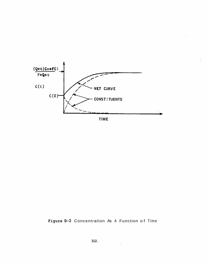
CONST I TUENTS
TIME
Figure 0-2 Concentrat ion As A Funct ion o f T ime
312.
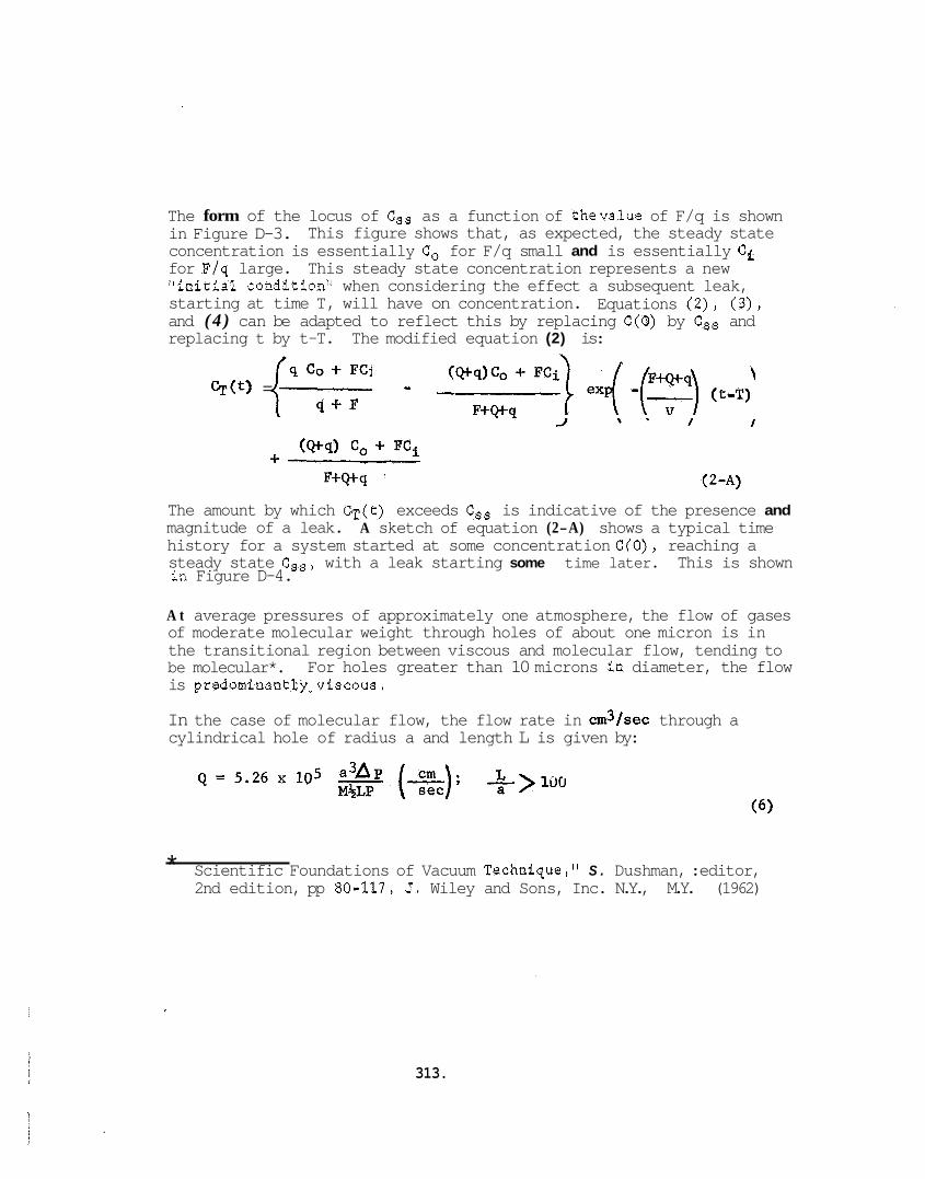
The form of the locus of Css as a function of thevalue of F/q is shown in Figure D-3. concentration is essentially Co for F/q small and is essentially Cg for F/q large. "initial condition" when considering the effect a subsequent leak, starting at time T, will have on concentration. and (4 ) can be adapted to reflect this by replacing C(0) by Css and replacing t by t-T. The modified equation (2) is:
This figure shows that, as expected, the steady state
This steady state concentration represents a new
Equations (2), (3 )J
- F+Wq
%(t) =
The amount by which Q(t) exceeds Css is indicative of the presence and magnitude of a leak. A sketch of equation (2-A) shows a typical time history for a system started at some concentration C(O), reaching a steady state Css, with a leak starting some i n Figure D-4.
time later. This is shown
A t average pressures of approximately one atmosphere, the flow of gases of moderate molecular weight through holes of about one micron is in the transitional region between viscous and molecular flow, tending to be molecular*. is predominantEy_viscous.
In the case of molecular flow, the flow rate in cm3/sec through a cylindrical hole of radius a and length L is given by:
For holes greater than 10 microns in diameter, the flow
* Scientific Foundations of Vacuum Technique," S . Dushman, :editor, 2nd edition, pp 80-117, J. Wiley and Sons, Inc. N.Y., M.Y. (1962)
313.
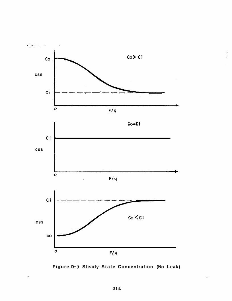
cs s
Co=Ci
t
C i
0
Co) C i
C i
css
C i
css
co
*
Figure 0 - 3 Steady S t a t e Concentration (No Leak).
314.
. .
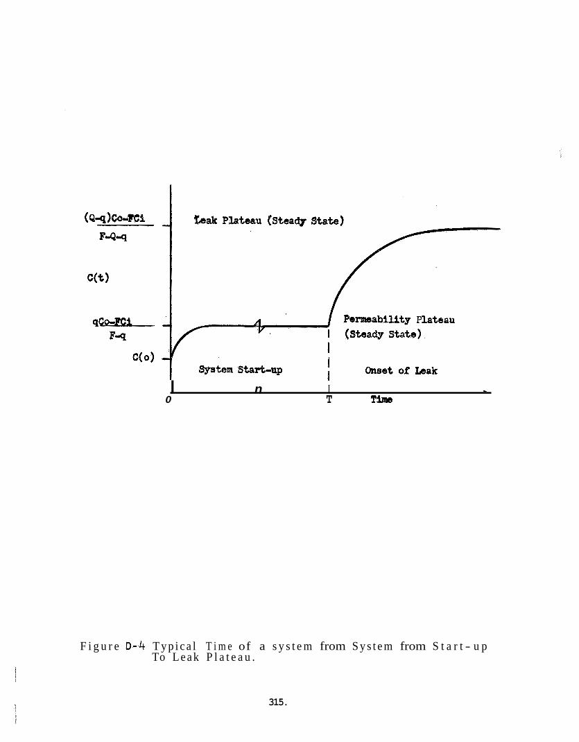
I n I L
0 T Tims
F i g u r e 0-4 T y p i c a l T i m e of a s y s t e m from S y s t e m from S t a r t - u p To Leak P l a t e a u .
315.
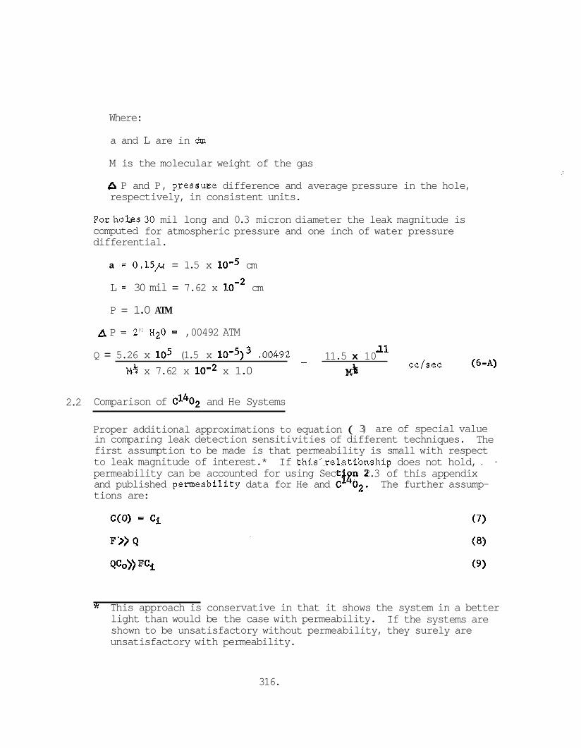
Where:
a and L are in dm
M is the molecular weight of the gas
A P and P, pressme difference and average pressure in the hole, respectively, in consistent units.
Forhobs30 mil long and 0.3 micron diameter the leak magnitude is computed for atmospheric pressure and one inch of water pressure differential.
a = 0.15,~ = 1.5 x loo5 cm
L = 30 mil = 7.62 x cm
P = 1.0 ATM
A P = 2" H20 = ,00492 ATM 1 1 11.5 x 10
cc/sec ( 6 4 - - Q = 5.26 x lo5 (1.5 x 10°5)3 .00492 M% x 7.62 x lom2 x 1.0 M%
2.2 Comparison of d402 and He Systems
Proper additional approximations to equation ( 3) are of special value in comparing leak detection sensitivities of different techniques. first assumption to be made is that permeability is small with respect to leak magnitude of interest.* permeability can be accounted for using Sect and published permeability data for He and C"02. The further assump- tions are:
The
. If thi,s-relatibnship does not hold, . n 2.3 of this appendix
* This approach is conservative in that it shows the system in a better light than would be the case with permeability. shown to be unsatisfactory without permeability, they surely are unsatisfactory with permeability.
If the systems are
316.
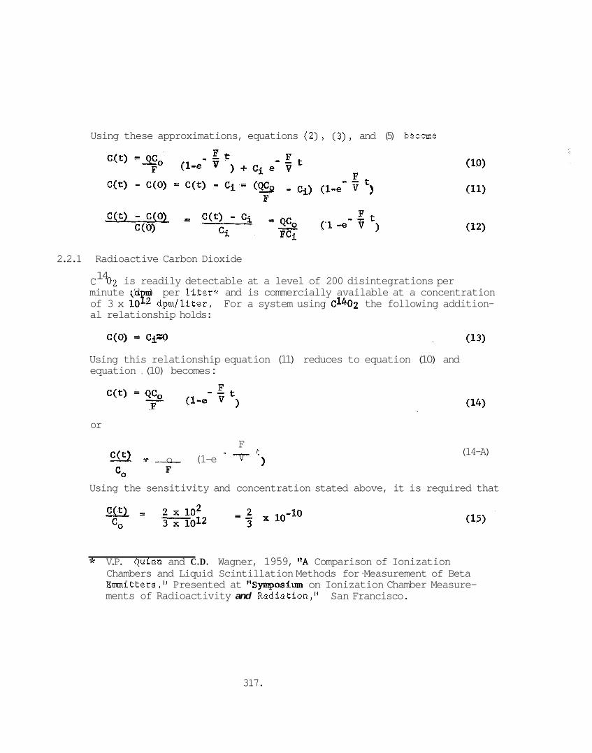
Using these approximations, equations (2), (3) , and (5) becme
2.2.1 Radioactive Carbon Dioxide 14 C
minute (d m) per liter* and is commercially available at a concentration of 3 x lop2 dpm/liter. For a system using 6402 the following addition- al relationship holds:
02 is readily detectable at a level of 200 disintegrations per
Using this relationship equation (11) reduces to equation (10) and equation , (10) becomes :
or
F - - t (14-A) - - _ Q (1-e v C ( t ) -
CO F
Using the sensitivity and concentration stated above, it is required that
* V.P. Quinn and C.D. Wagner, 1959, "A Comparison of Ionization Chambers and Liquid Scintillation Methods for -Measurement of Beta Emitters." Presented at llSymposium on Ionization Chamber Measure- ments of Radioactivity and Radiation," San Francisco.
317.

For a 0.3 micron diameter hole in 30 mil material and a differential pressure of 2" H20 at a nominal ambient pressure, the magnitude of Q is given in equation 6-A. For C1402 the molecular weight is 46. Thus :
u e (46)% liter/sec
1105 lo-'' cc/sec = 1.69 x cc/sec = 1.69 x 10'
(16) Taking this value of Q and assigning Ft/V>2 (such that exp (-FT/V <C 1)> equations (14-A) and 115) can be solved for a maximum value of F.
= 0.0254 cc/sec = 2.43 x liter/sec: < QCo - 1.69 x FL- - (17)
2 x 10⁻¹⁰ 3
Assuming 1000 seconds is required for the concentration of C140
for a single detector is limited to:
to reach the detectable limit (2 time constants), the monitored vo 1 ume
. Ft 4 V c- 2 lo3 =12,7 cc = .0127 liter
2
In this model, the detection of leak rates of the order of cc/sec appears within the state of the art using radioisotopes, but does not appear practical for the BISS system. Utilization of this type of detector for the BISS system would require a multitude of detectors each monitoring a volume of approximately 1/80 of a liter.
2.2.2 Helium
A mass spectrometer can detect a 0.1 ppm (volume) change in helium concentration. Helium is normally present in air at about 5 ppm (table 3-1 of Mpendix A). Thus
(19) -6 C(O) Ci = 5 ppm = 5 x 10
Making the further assumption that Co = 1.0 (%.e,, the gzs leaking into the detection volume is 100% helium) equation (11) becomes
318.
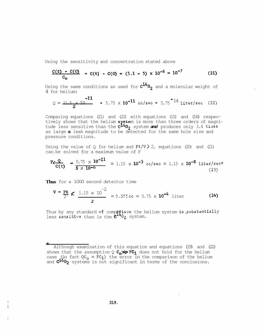
Using the sensitivity and concentration stated above
Using the same conditions as used for CI4O2 and a molecular weight of 4 for helium:
- 14 -11 Q = 11.5 x 10 = 5.75 x 10"'' cc/sec = 5.75 liter/sec (22)
2
Comparing equations (21) and (22) with equations (15) and (16) respec- tively shows that the helium s stem is more than three orders of magni- tude less sensitive than the C1402 system and produces only 3.4 tiaes as large a leak magnitude to be detected for the same hole size and pressure conditions.
Using the value of Q for helium and Ft/V> 2, equations (20) and (21) can be solved for a maximum value of F
= 1.15 x loo5 cc/sec = 1.15 x lom8 liter/sec* F g A = 5.75 x
(23) C(t) 5 x 10-b
Thus for a 1000 second detector time -2 v = E < 1.15 x 10
2' = 0.375~~ = 5.75 x loM4 liter 2
Thus by any standard of comp rison the helium system isgubstantially less sensitrtve than is the e 02 system. f4
* shows that the assumption Q Co>>FCi does not hold for the helium case (in fact QCo = FCi) the error in the comparison of the helium and C14O2 systems is not significant in terms of the conclusions.
Although examination of this equation and equations (19) and (22)
319.
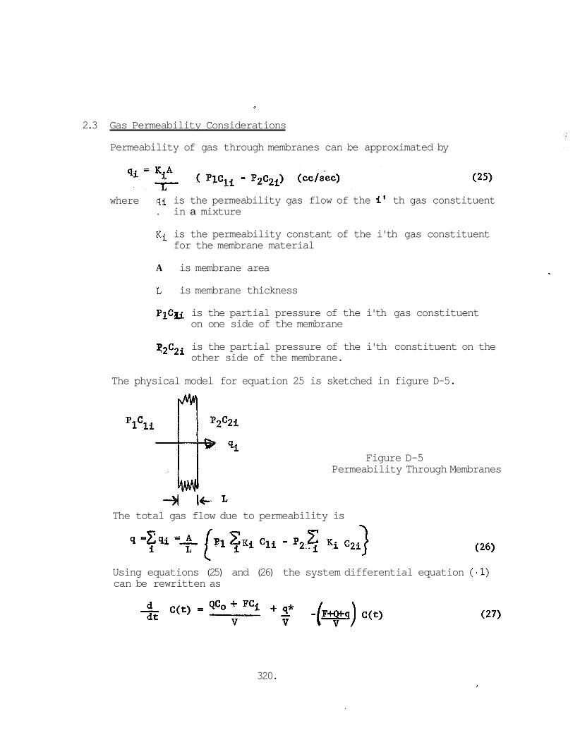
2.3 Gas Permeability Considerations
Permeability of gas through membranes can be / approximated by
where qi is the permeability gas flow of the it th gas constituent . in a mixture
Ki is the permeability constant of the i'th gas constituent for the membrane material
A is membrane area
L is membrane thickness
PICS is the partial pressure of the i'th gas constituent on one side of the membrane
q2C2i is the partial pressure of the i'th constituent on the other side of the membrane.
The physical model for equation 25 is sketched in figure D-5.
Figure D-5 Permeability Through Membranes
4 I+% The total gas flow due to permeability is
Using equations (25) and (26) the system differential equation (-1) can be rewritten as
320.
' where q* is qi from equation (25) for the tracer gas. Co and C(t) , q* is
In terms of
KA L
q* = - where po is the pressure outside the detection volume and P is the pressure inside the detection volume.
Thus the permeability is a function of C(t). Q, is also.
In general, the leak, These effects are minimized and can be neglected if
POCO - PC(t)* POCO
Since in general Po is not significantly greater than P, for equat:.on (29 ) to hold it is necessary that
If the relationships hold then, KA L q*x -
aEd the equations in the section on basic relationships can be corrected by replacing qCo by q*. times, C, will be much greater than C(t) for threshold detection of a leak and the permeability and leak can be assumed constant.
In a sensitive system with reasonable response
3 . DISCUSSION AND CONCEUSIONS
Both of the systems examined have been shown to require very small detection volumes. This means that the suit and tunnel would have to have a double layer wall with a compartmented interstice providing a multitude of detection volumes. Consider, for example, a tunnel of 3 meters circumference and 30 meters n length. area would be 90 square meters or 9 x 10' cm2. Assumlng the inter- stice in 0.5 cm thick, the total detection volume would be 4.5 x lo5 cc. From equation (18) we see that the more sensitive of the two systems examined would require a detection volume of 12.7 cc or less, resulting in not less than 35,433 separate detection volumes and detectors. cost and complexity on the BISS system. An improvement of at least 3 if not 4 orders of magnitude would be required to make the system worthy of further consideration.
The total surface
This, clearly, would impose an unreasonable burden in
In this analysis the two most sensitive candidate detection systems have been examined. ysis, conservatism has been employed, in that the assumptions have
In the assumptions made to permit a simple anal-
321.
made the systems appear to be better than they actually would be. In particular, neglecting permeability has made the systems appear more sensitive than would actually be the case. tivities used for the analysis can be regarded as maxima within the present state of the art.
Also the sensi-
Further practical limitations show continuous leak detection systems for the BISS in even worse light. Filling an Assembly/Sterilizer main chamber with helium would be quite costly; (2) Filling an Assembly/Sterilizer main chamber with C1402 would not be permitted due to the very high total radioactive mass; nor would the dumping of this gas into the atmosphere after each cycle be permitted.
Two of these problems are: (1)
In summary, the use of continuous leak detection systems for hio-ince- grity assurance of the BISS system is not feasible.
322.
APPENDIX E: SANITATION OF THE BISS SUIT
1. Background
2. Methods of Cleansing
3. Methods of Disinfecting
4 .
5. References
Hygienic Practices to be Employed
323.
APPENDIX E: SANITATION OF THE BISS SUIT
1. BACKGROUJ9D
I n use, t he BISS System w i l l be exposed t o a v a r i e t y of microbiological f l o r a native t o t h e i nd iv idua l s i n the s u i t . The use’of a chemical means of -prophylax is and d i s i n f e c t i o n o r s a n i t i z a t i o n of the s u i t , t o p r o t e c t t he se ind iv idua ls from a poss ib le source of i n f e c t i o n , is ind ica ted . t h r ee ca tegor ies :
For t he purposes of d i s i n f e c t i o n , b a c t e r i a f a l l i n t o
. Vegetative - These are the types of microorganisms which are indigenous t o t he sk in and r e s p i r a t o r y system. p l i f i e d by the p i r a t o r y pathogens.
They a r e exem- , Strep tococc i and a v a r i e t y of res-
. Tubercle B a c i l l i - These microorganisms have a waxy capsular material surrounding them. This material provides a b a r r i e r which prevents some d i s i n f e c t i n g agents from gaining access t o the cell and performing i t s funct ion.
. Spores- - Spores are very r e s i s t a n t t o both chemical and hea t s t e r i l i z a t i o n . The t i m e required f o r a d i s i n f e c t a n t t o func- t i o n aga ins t spores is i ncons i s t en t wi th t h a t permitted between s u i t changes. For tuna te ly , t h e few types l i k e l y t o be encoun- t e red i n the s u i t system can be prevented from producing any hazard t o s u i t wearers by prophylact ic means. be thorough f o r s a t i s f a c t o r y d i s i n f e c t i o n t o be obtained.
Cleansing must
2. METHODS OF CLEANSING
The number of materials ava i l ab e f o r a c leans ing opera t ion is numer- ous. i o n i c i n t e r f e r ence wi th the d i s i n f e c t a n t t reatment . t he de te rgen t is t o remove o i l s and f i lms whichcould r e t a i n microbes and s h i e l d them from t h e germicide. ava i l ab l e de te rgents i n tMs category are:
A non- ionic de te rgent is preferab le i n that it w i l l cause no The purpose of
Among the s u i t a b l e connnercially
. Tr i ton x - 100 - R o b & Haas
. Teqgi tol NPX - Union Carbide
. T e r g i t o l 15-s-7 - Union Carbide
These should be used in approximately 5% aqueous so lu t ions . phys ica l and chemical p rope r t i e s of t he se su r f ace a c t i v e agents are e s s e n t i a l l y t he same, T r i t o n x-100 was s e l ec t ed , p r imar i ly on the b a s i s Of c o s t .
Since t h e
324.
3. METHODS OF DISINFECTING
For the purposes of BISS application, the disinfectant used must be tuberculocidal. Since this requirement is much mode stringent than that for any vegetative type cells, it follows that if the treatment is tuberculocidal it will be germicidal to any vegetative cells encountered. The number of materials which can fulfill this criteria is not extensive. They are:
. 70 percent isopropanol
. A solution of 8 percent formaldehyde in 70 percent isopropanol
. A solution of Wescodyne (an iodine donor) at 450 ppm. Other commercially available disinfectants were considered but were not recommended for various reasons. For example:
. e12 Donors - A low PH is needed. constraint on BISS materials due to their inherent corrosive activity .
Their use would place a
. Br & I2 - Acute dermal toxicity
. Chlorophenates - Dermal Toxicity
. Metal Salts - Dermal Toxicity
. Sulfur Compounds - Slow acting - Allergic dermal reactions
. Quaternary Ammonium Compounds - Limited Spectrum of activity Seventy percent isopropanol was selected as a disinfectant because there is no residual chemical; it has tuberculocidal activity; and according to Spaulding, is effective against the Influenza Virus, Entero Viruses, Coxsackie and - Echo Viruses.
Due to the insufficient time between suit changes, this type of treat- ment was considered inadequate for the treatment of possible spores. For example, the organism causing athletes foot (trichophyton) forms a chlamydospore which is a very resistant spore form. In order to insure its destruction the suit would have to be treated a minimum of 3 hours. any organism of this type is by taking prophylactic measures. Any of the commercial preparations such as "Desenex" or flAsterol" should be applied Xiberally to the socks, feet, and shoes if they are used prior to entrance to the suit. Anyone with a ringworm infection of the hair, skin or nails, which are caused by other members of the dermatophytes, should be barred from the use of the suit.
The most feasible method of prevention of infection by
325.
The use of a liquid disinfecting agent on the BISS suit itself was considered. In view of the problems of maintaining the bio-integrity of the suit, a liquid disinfectant would impose unnecessary hazards. If micron size holes in the suit material developed during the normal work cycle, any liquid at the site of the holes might permit organism migration through capillary action against the opposing pressure differential, thereby violating the bio-integrity of the suit. The use of a surface active agent for a cleansing operation would, by lowering the surface tension, increase the likelihood of a capillary migration of contaminants. liquid agent for the suit may be subject to change after further con- sideration df the full bio-integrity ramifications of the system. As discussed under the bio-integrity in section 5.1 , the mere exis- tence of a hole large enough to pe as a violation of bio-integrity if the most conservative approach is used. In such a case, the use of surface active disinfecting agents would be acceptable.
This decision to preclude the use of a
t migration may be interpreted
4. HYGIENIC PRACTICES TO BE EMPLOYED
A prophylactic measure which will consist of a shower using a disinfec- tant detergent such as Phisohex will be mandatory before donning the undergarment. liberal quantities of Phisohex immediately prior to entering the suit. This will provide a residual bacteriostatic deposition on the hands. The use of "undertaker type" worker from possible transfer of infectious microorganisms.
Additionally, personnel should wash their hands with
te gloves will further protect the
The only area of skin which will be exposed to the surface area of the suit is the head. which is the most potential y hazardous area of contamination. liquid disinfectant will be acceptable for this purpose.
Xt will be necessary to disinfect the helmet, A
5. References
Spaulding, G.H., V@mical Disinfection of Medical and Surgical Materials", Antisepeics, Disinfectants, Fungicides and Steriliza- tion; 1961, 619-646, Lea and Febigef.
Dubes, R.J., Bacterial and Mycotic Infections of Man; Second Edition; Philadelphia, J.B. Lippincott Go., 1952.
Spaulding, G.H., on Sterilization, Seton Hall College of Medicine and Dentistry, April 1958.
Whemic 1 Disinfectionf1; Becton, Dickson Lectures
a
326.
APPENDIX F: INTEGRATED TEST PLAN
INTRODUCTION
A. Objective
B. Project Test Phasing
C . Test Configuration
D. Test Procedures
E. BZsB Test and Demonstration Plan
F. Test Plan Schedule
PHASE I. DEVELOPMENTAL TESTS
A. Component Tests
B. Subsystem Tests
C. System Tests
PHASE IT. EVALUATION TESTS
A. Anthropometric Measurements
B. Entry - Exit Tests C. Mobility
D. Dexterity
E. Communications
F. Subject Endurance
G . Hygiene
H. Final Data Analysis
MATERIALS TESTS
Attachinent A Mock-up Tests and Subject's Assessment Scale (SAS)
Attachment B Materials Tests
Attachment C BISS Test Plan Schedule
327.
A . OBJECTIVE
It is the objective of this test plaz to set forth the series of tests which will be used to evaluate the BISS concept. of this program has two primary foci, one being the conduct of a mock-up study to demonstrate that a man can perform useful work in the BISS environment and the other being the selection of suit materials optimally suited to withstand the environmental, biological, and mobility constraints placed upon them.
Much of the content in this plan is directed at the conduct of the mock-up study, i.e. the development and evaluation of the suit, tunnel, reefing mechanism, life support, monitoring system and related support equipment. The materials studies are designed to provide guidance to the mock-up study in the selection of materials, but primarily these studies and tests are geared to providing inputs to the final BISS specification. mock-up study, the materials effort will provide data on the weight and stiffness of candidate suit material since temperature and microbiological characteristics of the final suit will not be simulated. testing effort will evaluate the microbiological and physical characteristics.
The empirical portion
To initiate the
A parallel material
B. PROJECT TEST PHASING
The mock-up test program is divided into two major portions, Phase I develop- mental tests and Phase I1 evaluation tests. Materials tests will span both phases of the mock-up effort.
The Phase I developmental tests will focus on the selection of competing subsystem elements and on design evaluation and modification of the first generation BISS. formance of the system which will result from the Phase I effort.
The Phase I1 tests will be designed to evaluate the per-
Components, subsystems and finally the entire mock-up system will be tested during Phase I. that a significant portion of the developments will emerge from a cut and try approach in response to test results. opment effort, the composite of empirical experience will be reflected in procurement specifications to be written for the second generation BISS system. grated with the test results and will be applied to the Phase I1 BISS procurement specification.
It is expected that this will be an iterative process and
At the end of this Phase I devel-
Results of materials studies completed during Phase I will be inte-
Upon receipt of the Phase I1 hardware, a series of evaluation tests will be
emphasis will shift from discovering faults so that they can be corrected, to evaluating just how the Phase IT system performs without any significant modification or adjustment.
e tests will be more formal than the preceding tests. The
Results of the Phase I1 effort will be care-
* Published as the "Integrated Test Plan for a Research Study to Definitize a BiQ-Isolator Suit System", Document No. 675D418, dated 3 January 1967
328.
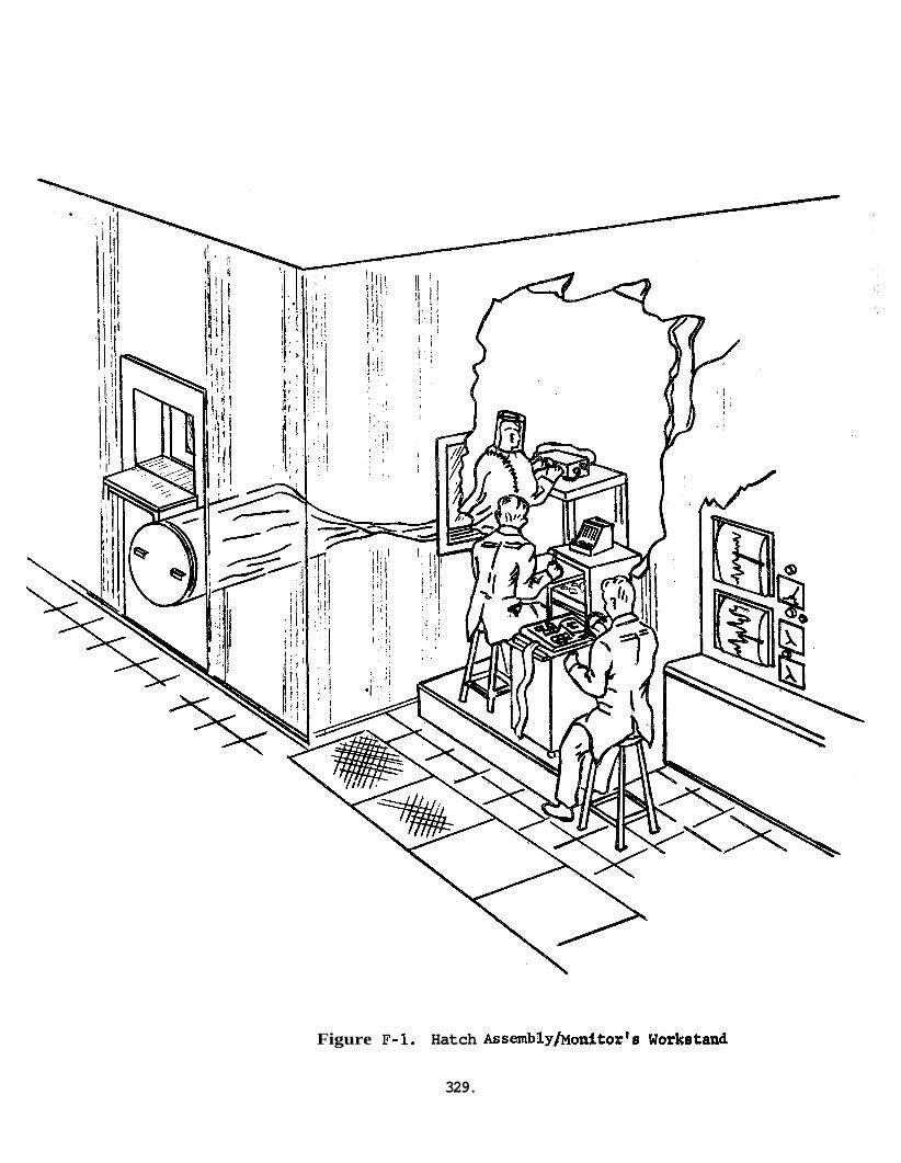
Figure F-1. Hatch Assembly/Monitor's Worketand
329.
fully evaluated and the results fed into both the final BISS system spec- ification and the BISS Test and Demonstration Plan. ials studies will also be integrated into the program end product documents.
Results of all mater-
C. TEST CONFIGURATION
The test configuration for the mock-up tests is discussed in some detail below. as a part of each test plan.
1. Environment
Test configuration for the individual materials tests are discussed
The test facility will have the capability of providing a nominal over- pressure of up to 4 inches of water in which to test the BISS. Chamber temperature will be at normal ambient with the burden for controlling the environment of the subject placed upon the suit life support system, The chamber will be pressurized with shop air which is suitable for breathing for limited periods of time, if the subject's air supply should fail. chamber environment. Therefore, there is no need to take the safety precautions relating to a back-up air supply which will be necessary in a N2 environment.
.
Unzipping a zipper brings the subject in contact with the
2 . Facilities
A Tenney Altitude Chamber, located at the contractor's Chestnut Street facility in Philadelphia, will be modified to serve as a pressure cham- ber for up to 4 inches of H20 pressure. Preliminary tests have already indicated the feasibility of this process. The central door in this chamber will be displaced and a hatch assembly substituted for it. (See FigureF-l.This assembly will provide a proper interface for the suit-tunnel. Included in this hatch assembly are a metal tube (reefing tube) through which the subject enters the chamber and a door for emer- gency entrance and exit. Other special support items which have been fabricated for the tests included a monitor's workstand (See Figure F-L) and a donning rack to assist the subject in getting in and out of the suit.
3 . Test Team
The test team will be made up of a subject, a test conductor, a medical monitor, and a chamber technician. immediately adjacent to a chamber window and will direct all actions of the subject via the communications system. He will collect data from the subject as different tasks are done and will generally direct the test exercises.
The test conductor will be located
At his side, the medical monitor will be monitoring the RKG (Radio Car- diogram) and respiration and collecting gas samples (gas into and out of the helmet) as well as monitoring all test conductor - subject com- munications. to terminate the test or question
At any time the medical monitor feels that there is cause the subject, he will do so. Additions
330.
ally, the medical monitor will watch the gages on the subject's com- pressed air breathing supply (for tests in which this is used), and will be responsible for making any adjustments to this system. Both the test conductor and the medical monitor will note any portion of the subjects performance which is suspect and will question him regarding it at an appropriate time.
The chamber technician is primarily responsible for maintaining the desired pressure level in the chamber. him heavily, he will be able to provide assistance to the test conductor on an as needed basis.
Since this task will not load
4 . Subject Selection
Two subjects have been selected for the Phase I developmental tests. However, it is planned that all Phase I tests will be run on one subject unless illness precludes this. It is believed that the use of the same subject for the developmental tests will permit a consistent evaluation of the BISS in its various states of evolution. The second subject is viewed as a back-up. and one back-up.
The Phase I1 tests will require four subjects
It is recognized that the use of one subject for the Phase I tests will not yield absolute data but rather should provide good relative data. For the purposes of the development tests, the interest of test personnel is in whether the introduction of a given system modification is an improvement over the former condition or not. change is relatively unimportant. comfort, mobility and dexterity for one subject, it is a matter of detailed design as to hoW to do this for a broader segment of thepopulation. Four subjects will be used in the Phase I1 tests which will permit a more accurate interpretation of the data obtained from the evaluation tests.
The absolute value of the If the BISS can be made to provide
Subjects will be selected for similarity in size, a general familiarity with things mechanical, and a willingness to participate in the project. Additionally, all subjects will be given a comprehensive physical prior to acceptance. This physical will include at least a gross audiometric test to assure that communications system test results are not biased by organic deficiencies bf the subjects, diction of the subjects will be made for the same reason.
Also, an assessment of the
5. Safety Ground Rules
a. Subject shall have received Company Physician's approval prior to performing chamber studies.
b. Breathing air supply provisions and emergency procedures shall be reviewed and approved by Company Industrial Safety prior to initia- ting chamber studies.
c. Company Industrial Safety approved breathing air source must be
331.
provided to the subject while performing chamber studies. - NOTE: The pressurized plant air system is not an approved source of breathing air.
d. If a bottled air system is to be utilized for breathing air pur- poses, it shall comply with the following minimum requirements.
(1) Manifold system, regulator and monitoring device system shall conform to Company Safety Requirements.
(2) A min%mum of fifteen minutes of breathing air reserve shall be available at all times during operation, the Medical Monitor shall be responsible for terminating studies when this limit is reached.
(3) Capability for continous monitoring of the quantity of remain- ing air supply shall be provided in a manner which will allow determination of reserve time available.
e. At least one stand-by person, in addition to the test conductor, shall be present at all times that the subject is performing chamber studies. Emergency access into the chamber shall be available at all times so that the stand-by (medical monitor) can reach the subject to administer assistance within thirty seconds from indication of the need for assistance. Visual observation of the subject shall be provided at all times during operation.
Emergency first-aid authority and procedures for stand-by personnel shall be approved by the Company Physician.
Emergency access capability in the mock-up suit shall provide for the following:
f.
g.
(1) In event of breathing air supply termination, chamber atmos- phere shall be made available to subject's breathing zone within fifteen seconds when the subject is conscious, and forty-five seconds when not conscious.
(2) The subject's face shall be available for applying artificial respiration within thirty seconds of reaching the subject. This shall be accomplished without help from the subject.
(3) Removal of the subject from the chamber and outer suit shall be possible within four minutes, wihtout help from the subject.
D. TEST PROCEDURES
Test data will be collected by a combination of objective measurements (e.g. timing entrance and exit) and subjective ratings. The objective measurements which are to be used are self-explanatory, but the Subject's Assessment Scale (SAS)* requires some explanation.
*See Attachment A 332.
Fundamentally the SAS identifies parameters which are salient to the func- tioning of the BISS and asks the subject to rate the performance of these parameters on a seven point scale, , performance while one means unsatisfactory performance, with intermediate numbers representing shadings of good or bad performance. collected in this way cannot represent absolute values, it is an effective technique for gaging relative performance. might have should remain constant over the tests and therefore the impact of the same test conducted under different conditions or the same test before and after some hardware modification should be apparent. multiple subjects' in the Phase I1 tests will permit ascribing more univer- sality to the data collected than to the Phase I data.
A rating of seven implies excellent
While data
Any biases which the subject
Use of
It should also be noted that medical and life support monitoring data will be collected for all fully suited tests in both Phase I and Phase 11. Individual mock-up test plans do not indicate system inlet and outlet temperatures, suit relative humidity, gas flow rate, RKG, respiration and gas composition monitoring (not continous))is being collected since it is constant for all fully suited tests. When a subject is performing test tasks, record of the prevailing medical and life support parameters will be made. Changes in these values will be noted. measurements recorded by the test conductor and medical monitor can readily be correlated with the relevant subject actions, ratings and comments.
that this data (e.g. cooling
Test record sheets will be designed so that the medical/life support
E. BISS TEST AND DEMONSTRATION PLAN
The BISS Test and Demonstration Plan will be completed and incorporated in the Integrated Test Plan as an appendix after the conclusion of the Phase I1 mock-up tests. and both Phases of the mock-up program will be reflected in this plan. The Test and Demonstration Plan will be defined in lesser detail than the mock-up and materials testing plans.
Experience gained in the materials testing program
F. TEST PLAN SCHEDULE
A complete Test Plan Schedule is located in Attachment C .
G . A t t a chmentg
AttachmertA to this document contains the individual test plans for the mock-up tests and a copy of the Subject's Assessment Scale (SAS). test plan inAttachmentA is referrenced by test phase (I or 11) and para- graph number (e.g.X*B.la.) to the appropriate text.AttachmentB contains the detailed materials tests and AttackntCthe Test Plan Schedule.
Each
333.
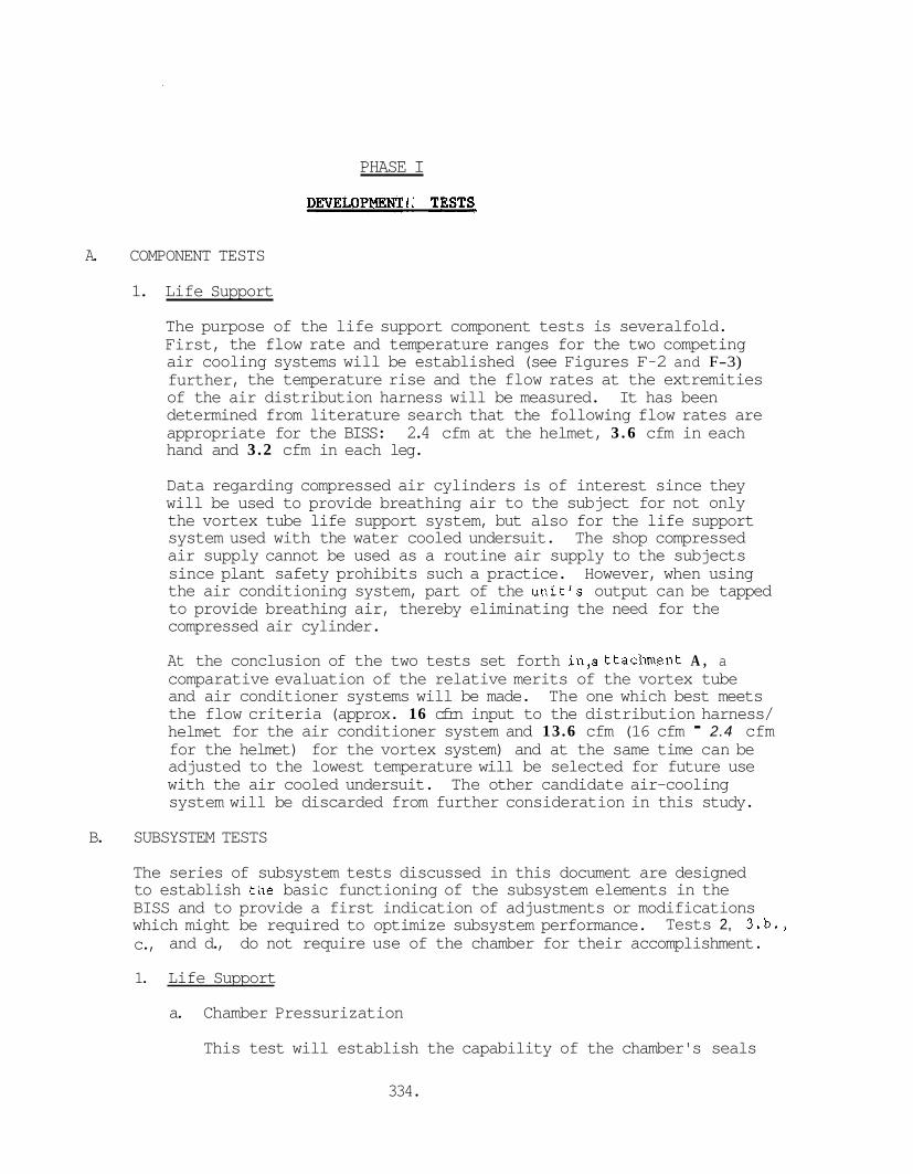
PHASE I
DEVELOPMENTAL TESTS
A. COMPONENT TESTS
1. Life Support
The purpose of the life support component tests is severalfold. First, the flow rate and temperature ranges for the two competing air cooling systems will be established (see Figures F-2 and F-3) further, the temperature rise and the flow rates at the extremities of the air distribution harness will be measured. It has been determined from literature search that the following flow rates are appropriate for the BISS: 2.4 cfm at the helmet, 3 . 6 cfm in each hand and 3.2 cfm in each leg.
Data regarding compressed air cylinders is of interest since they will be used to provide breathing air to the subject for not only the vortex tube life support system, but also for the life support system used with the water cooled undersuit. The shop compressed air supply cannot be used as a routine air supply to the subjects since plant safety prohibits such a practice. However, when using the air conditioning system, part of the unit's output can be tapped to provide breathing air, thereby eliminating the need for the compressed air cylinder.
At the conclusion of the two tests set forth in,attachent A , a comparative evaluation of the relative merits of the vortex tube and air conditioner systems will be made. The one which best meets the flow criteria (approx. 16 cfrn input to the distribution harness/ helmet for the air conditioner system and 13.6 cfm (16 cfm - 2.4 cfm for the helmet) for the vortex system) and at the same time can be adjusted to the lowest temperature will be selected for future use with the air cooled undersuit. The other candidate air-cooling system will be discarded from further consideration in this study.
B. SUBSYSTEM TESTS
The series of subsystem tests discussed in this document are designed to establish tile basic functioning of the subsystem elements in the BISS and to provide a first indication of adjustments or modifications which might be required to optimize subsystem performance. c., and d., do not require use of the chamber for their accomplishment.
Tests 2, 3.b.,
1. Life Support
a. Chamber Pressurization
This test will establish the capability of the chamber's seals
334.
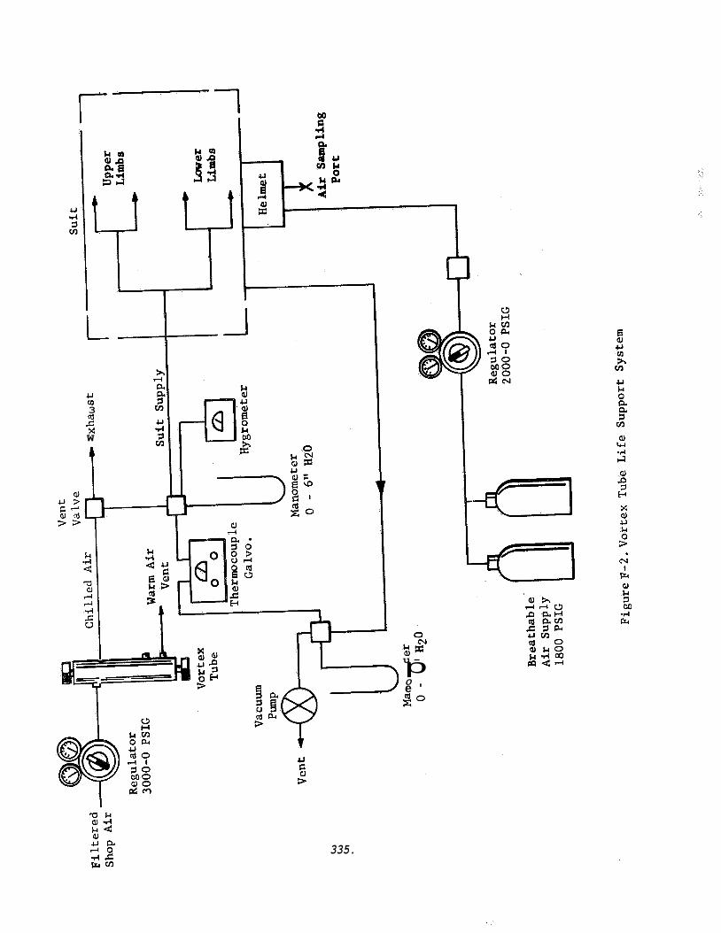
L
U v) 3 (d r: x W
u - p
s o 0 e '
U
3
a
335.

a, u s G."l o n j 3 3
& c) 3
m I
Fr w b 3 bn
0 M C W o x U 0 -
0 G I a c o
G ; o
U
E 3
336.
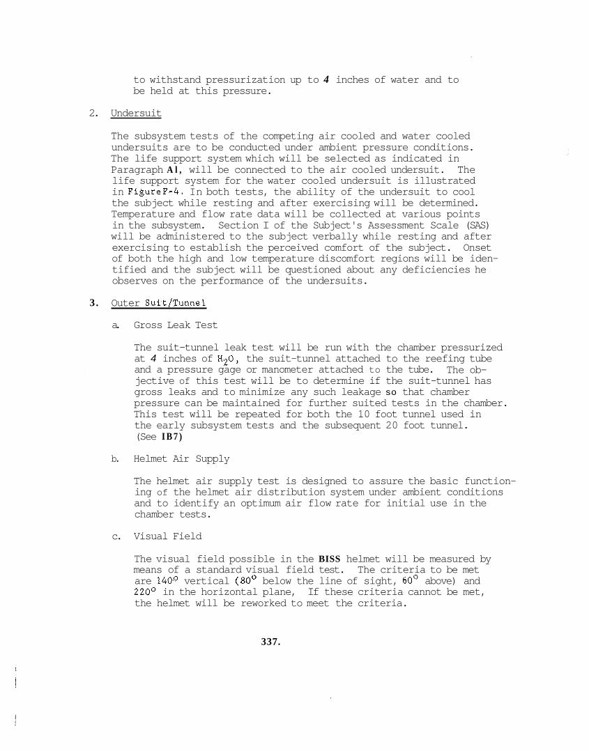
to withstand pressurization up to 4 inches of water and to be held at this pressure.
2. Undersuit
The subsystem tests of the competing air cooled and water cooled undersuits are to be conducted under ambient pressure conditions. The life support system which will be selected as indicated in Paragraph A l , will be connected to the air cooled undersuit. The life support system for the water cooled undersuit is illustrated in FigureF-4. In both tests, the ability of the undersuit to cool the subject while resting and after exercising will be determined. Temperature and flow rate data will be collected at various points in the subsystem. Section I of the Subject's Assessment Scale (SAS) will be administered to the subject verbally while resting and after exercising to establish the perceived comfort of the subject. Onset of both the high and low temperature discomfort regions will be iden- tified and the subject will be questioned about any deficiencies he observes on the performance of the undersuits.
3. Outer Suit/Tunnel
a. Gross Leak Test
The suit-tunnel leak test will be run with the chamber pressurized at 4 inches of H20, the suit-tunnel attached to the reefing tube and a pressure gage or manometer attached to the tube. jective of this test will be to determine if the suit-tunnel has gross leaks and to minimize any such leakage so that chamber pressure can be maintained for further suited tests in the chamber. This test will be repeated for both the 10 foot tunnel used in the early subsystem tests and the subsequent 20 foot tunnel. (See I B 7 )
The ob-
b. Helmet Air Supply
The helmet air supply test is designed to assure the basic function- ing of the helmet air distribution system under ambient conditions and to identify an optimum air flow rate for initial use in the chamber tests.
c. Visual Field
The visual field possible in the BISS helmet will be measured by means of a standard visual field test. The criteria to be met are 140° vertical (80' below the line of sight, 60' above) and 220° in the horizontal plane, the helmet will be reworked to meet the criteria.
If these criteria cannot be met,
337.
i
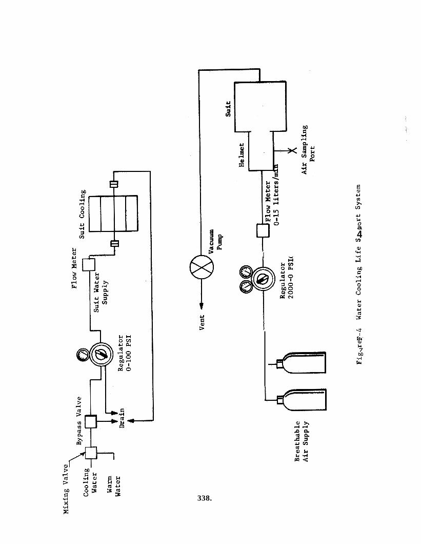
338.
I
0 a 4 m aJ w
s M c -4
I
$4 7 M ..-I Ly
%'
d. Fit
The outer suit will be tried on by the subject over both under- suits in an ambient pressure environment. Fit will be adjusted as necessary to permit optimm freedom of movement for the sub- ject. during this test.
Breathing air and cooling will be supplied to the subject
4 . Monitoring Systems Instrumentation
a. Life Support Monitoring
The instrumentation to be used with the life support systems includes pressure test gages, differential manometers, thermo- couples, a thermocouple recorder, a hygrometer, and an oxygen regulator.
b. Medical Monitoring
Heart rate will be monitored by use of a radio cardiogram (RKG). If a subject's heart exceeds 120 bpm for two minutes or 130 bpm at any time during the testing, the test will be terminated by the medical monitor. Respiration will be monitored by means of the intercom and gas samples will be collected from the gas supply to the helmet and from the helmet's exhaust. The gas samples will be collected, transported, and held for analysis in standard gas sampling bottles. Oxygen, nitrogen, and carbon dioxide con- tent will be determined by means of a gas chromatograph having a thermal conductivity detector.
5. Safety - Rescue The safety - rescue tests are intended to assure that if a mishap should occur during the mock-up tests it is possible to effect a timely rescue of the subject. supply will be needed since the chamber will contain breathable air and the subject's isolation from the chamber environment can be readily broken by use of a zipper in the outer suit. This zipper . is located across the subject's chest. There is also a zipper which attaches the tunnel to the suit, but this is not accessible to the unaided subject.
No back-up air supply or rescue air
Rescue operations will be conducted in the chamber under both ambient and differential pressure conditions. The total time to effect rescue under either condition must be less than four minutes. The chamber's built in "panic button" (klaxon) will be exercised by the subject during this test to assure its proper operation.
6. Communications
The communications subsystems test will be conducted under an ambient pressure environment to assure proper functioning and adjustment of the system and to optimize transducer placement within the helmet.
339.
7. Tunnel Reefing Subsystem
The initial BISS subsystem tests will be conducted with a 10 foot tunnel clamped to the outer surface of chamber side of the reefing tube. reefing to be accomplished, it will be adequate for the subsystem level tests. Concurrent with the conduct of the subsystem tests, an independent tunnel reefing subsystem will be in the final stages of development. As the last element in the subsystem tests, this reefing system (using a 20 foot tunnel) will be tested and mated with the outer suit.
Though this approach permits only a crude form of tunnel
C. SYSTEM TESTS
1. Suit System
The suit system tests are designed to exercise the manned suit system, to assess subject comfort and physiological response to the environment (under both the resting and exercised conditions), mobility, chamberlsuit entry-exit and communications. These tests will first be carried out under ambient pressure conditions and then under a differential pressure environment. will be run under the differential pressure condition.
Both undersuits
The test routine found inattachmeath shows the sequence of tasks which the subject will be directea to accomplish and the way in which the Subject's Assessment Scale (SAS) will be used to obtain evaluative data.
The data collected, plus any observations of the subject relative to difficulties not covered by the SAS, will be reviewed after each test and remedial action will be taken, as appropriate. The tests will be performed with the water cooled and air cooled undersuits. For each suit, the tests will be conducted once under no differential pressure and twice under the differential pressure environment.
Mean ratings for the SAS items will be computed for comparison with comparable data to be obtained from the second generation system. Record will also be made of observed deficiencies and corrective actions for guidance in the preparation of the specifications at the end of the Phase I development effort. The undersuit receiving the poorer overall rating (summation of mean scores on the SAS items) will be eliminated from further consideration in this study.
340.
PHASE I1
EVALUATION TESTS
GENERAL
The evaluation tests of Phase I1 will be applied to the second generation BISS procured as a result of the specifications generated at the conclusion of the Phase I t'esting. It! is assumed that only a minimum amount of initial adjustment will be required by the second generation system. Therefore the tests discussed in the following text reflect only the formal testing effort and do not enumerate any shakedown tests. If the need for any such tests becomes evident during installation, they will be performed on an "as-needed" basis. All Phase I1 tests will be performed on four subjects, completely outfitted in the BISS and under a differential pressure environment.
A. ANTHROPOMETRIC PBASUREMENTS
In order to ascertain more precisely than is possible from the SAS the degree of encumbrance imposed by the BISS on the operator, a series of comparative anthropometric measures of the motions of the head and arms of unsuited versus suited subjects will be made. The list of measure- ments to be taken will be found in the detailed test treatment located inattachment A,Most of the measurements will be taken by the use of a shadow technique illustrated conceptually in FigureF-5. Normal anthro- pometric instruments will be used to take measurements not amenable to the shadow technique.
B. ENTRY-EXIT TESTS
Each of the four subjects will be run through a series of five timed entry-exit tests. Preceding the five timed trials there will be a familiarization trial for each subject. Entry will be defined as the time elapsing from entry of a fully undersuited subject into the exterior opening of the reefing tube until the fully suited man emerges into the chamber. going process. these operations with ten minutes as an upper limit.
The time required for exit will be the converse of the fore- Three minutes is the design objective for either of
C. MOBILITY
The mobility of the subject will be appraised by use of Section I1 of the SAS as was done in the Phase I Development Tests. The subject will be asked to rate each facet of the suit's mobility via the BISS communi- cation system as he completes the relevant action. Walking, climbing, bending at the waist, and squatting will be tested. A path around the perimeter of the chamber will be chalked in, the ladder position indicated and a circle drawn in which the subject will stand while doing the bend- ing exercises. (See Figure F-6.All subjects will go through exactly the same routine to insure comparability of rating data.
341.
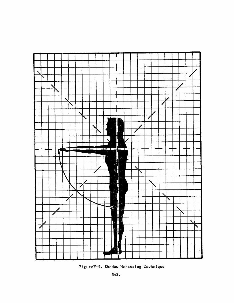
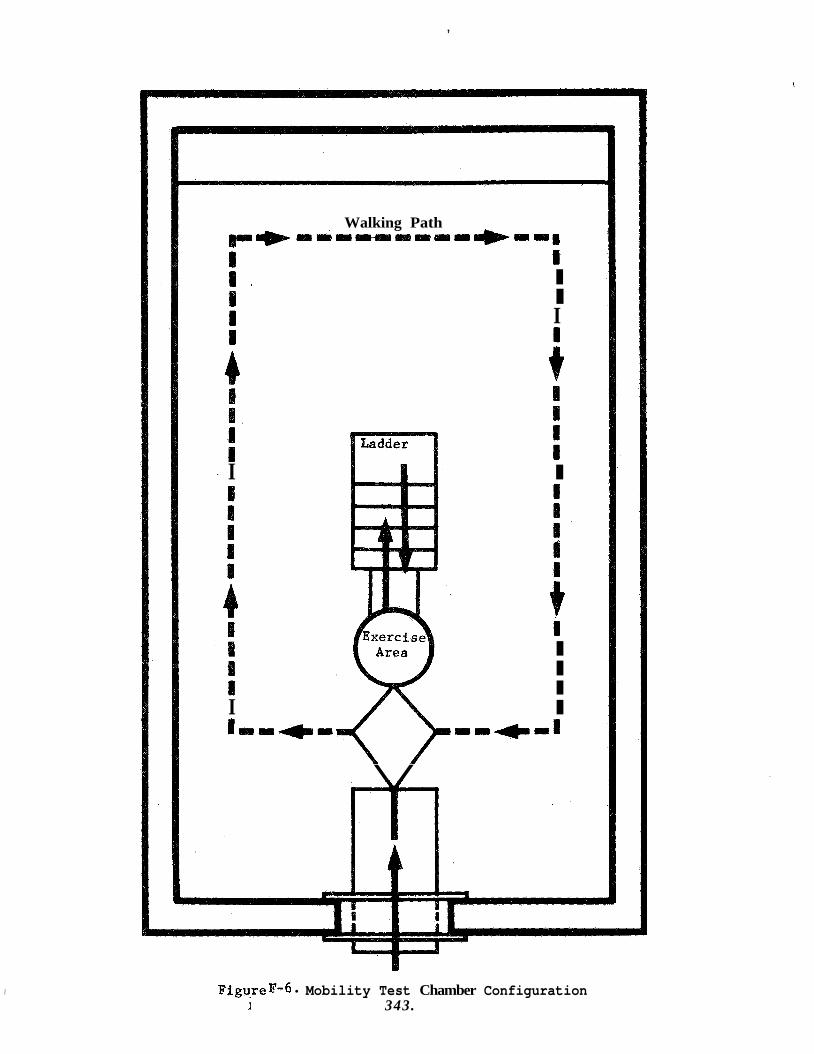
,
I
Walking Path *am- rrr*ll#
I I I I
I I
I I I
I I I,,-- I l + m B I
\ /
FigureF-6 Mobility Test Chamber Configuration I 343.
D. DEXTERITY
It would be possible to use commerically available tests to assess operator dexterity in the suited and unsuited condition, but it is believed that more relevant data can be obtained by the use of an analogue assembly task. The assembly test object is shown in Figure F-7. Its assembly and disassembly will require the use of common hand tools and will also involve the mating and demating of representative electrical and hydraulic connectors.
E. COMMUNICATIONS
Phoenetic nonsense syllables will be used to assess the adequacy of the intercom communications link between the subject and the test con- ductor. Each syllable will have a sequential number associated with it. subject will mark the number next to the syllable received on a printed list containing the fifty syllables to be transmitted intermixed with fifty other syllables.
Each subject will be read a list of fifty such syllables. The
An abbreviated version of another such list (twenty-five syllables to be transmitted, fifty on the list) will be used to assess the chamber speaker's adequacy. The first test (fifty syllables transmitted) will be repeated with the subject transmitting and the test conductor marking the answers.
F. SUBJECT ENDURANCE
The criterion for acceptable endurance of the operator in the BISS environment is four hours. After all other tests have been completed, each of the subjects will be put through a four hour endurance trial. During this period the assembly test object, used for dexterity testing, will be assembled and disassembled several times and movement about the chamber, on an as desired basis by the subject, will be permitted. A stool will be provided on which the subject may rest. Once an hour the entire SAS (less Section IV Entry-Exit and Item V.a and V.b for sub- systems communications test) will be administered over the intercom.
If the subject desires to leave the chamber prior to the expiration of the four hour period, this will be permitted. A test will be promptly terminated on the advice of the medical monitor.
If, however, at the end of the four hour period, both the subject and the medical monitor concur, the test will be extended until either the sub- ject or the medical monitor directs its termination. The purpose of such an extension of the endurance test would be to establish a gross feel for the upper limits of subject endurance in the BISS environment.
G. HYGIENE
Tests of the application of helmet internal disinfection will be per- formed-as indicated in test procedure 9 of attackment B.
1 344.
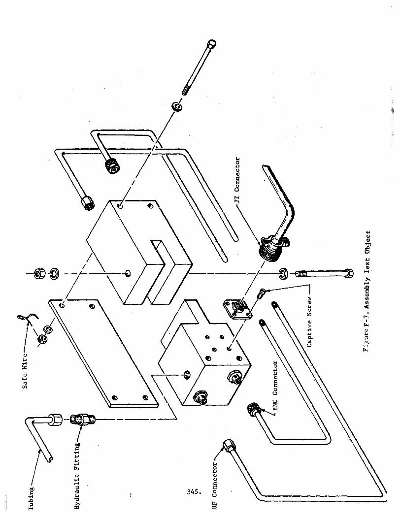
H. FINAL DATA ANALYSIS
At the conclusion of the Phase I1 evaluation tests, the data derived from all the tests will be evaluated. Conclusions resulting from the evaluation will be incorporated in the final BISS specification and the BISS Test and Demonstration Plan. When possible, comparison will be made between the Phase I and Phase I1 data to assess the degree of improvement of the Phase I1 system over the Phase I system. A summary of the results of the final data analysis will be included in the final BISS program. report.
346.
MATERIALS TESTS
The overall objective of the BISS materials testing program is to define optimum materials for use in the BISS outer suit. These materials must withstand the thermal, chemical and mechanical stresses planned for the assembly sterilizer facility and must provide a barrier to microbiological and fungicidal penetration. suit have been recomrnended as a result of early analytical materials study; likewise, the materials of the phase two suit will reflect the requirements of subsequent materials studies and tests. that the materikls used for the mock-up suits simulate the weight and stiffness of the final material, but there is no need that this material possess the thermal, chemical and mechanical tolerances or microbiological impenetrability of the final suit.
The materials used for the Phase I mock-up
It is required
A series of tests designed to assess the physical properties of candidate materials for the outer suit will be run throughout the term of the program. Materials which have been identified as a result of analytical studies will be subjected to competitive evaluations. uation are as follows:
The tests included in this eval-
1.
2.
3 .
4 .
5.
6 .
7.
8.
9.
10.
11.
12.
13.
14.
15.
Fungus Growth Test.
Mycelial Penetrability Test.
Permeability/Flexure
Abrasion
Transfer of Microorganisms and Gases Across Suit Materials
Retention and Release of Disinfectants by Materials
Compatibility With Detergents ti Disinfectants
Evaluation of Disinfectants
Application of Helmet Internal Disinfection
Tensile Test For Rigid, Solid and Laminated Plastics.
Tensile Test of Flexible Plastic Sheeting.
Puncture Resistance
Optical Transmittance
Weight Change
Impact Test for Plastic Materials
347.
16.
17.
18.
19.
20.
Temperature Aging
Tear Resistance
Compressive Properties
Lap Shear
Butt Tensile
All of .the foregoing tests are detailed in attachment B of this document.
Table ~ - 1 . i ~ a matrix showing the materials testing to be performed on the program. For each treatment listed on the left of the table, appropriate tests will be conducted as indicated on the right. of tests indicated reflect the performance of treatments of varying intensity (number of temperature cycles, number of disinfectants, number of abrasion and flexure cycles) in triplicate. number of tests by making use of preliminary data to make early evaluation of materials. If the data is indicative of unfavorable results, further testing of the candidate materials will be discontinued.
The maximum numbers
Attempts will be made to reduce the
348.
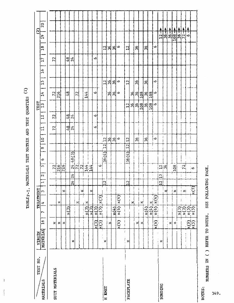
I
i j
I
!I w m
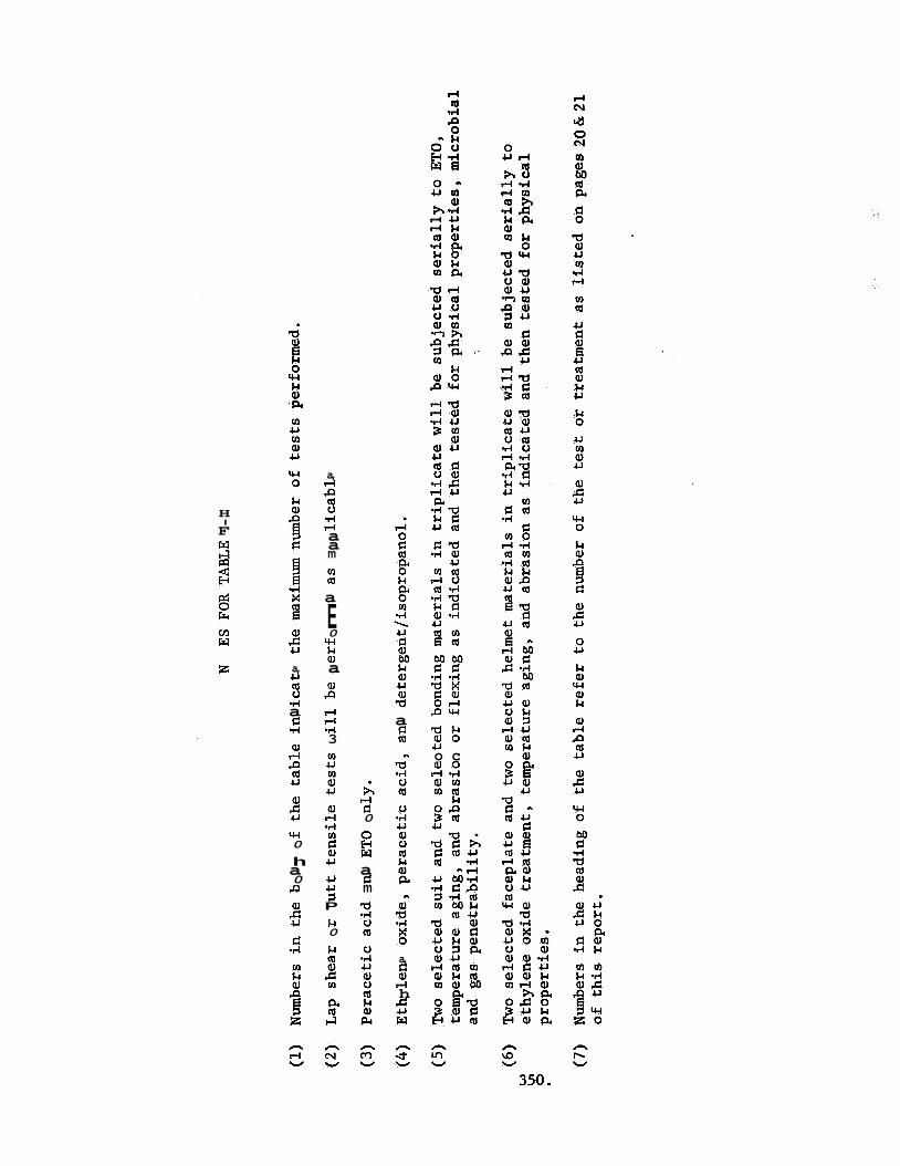
a, d P m o .rl rl a a m m m
H I F
a
E 0
W k a, a
m w
2
aJ 5 a, u m o 1-I a c .d
aJ rl P m U
aJ P rl d .rl 3
a 2 a k a 0
4-l o c m o rl *d c u m r n m
k O P 3 m
A rl c 0
PI
5 W 0
h a 0 P
5 u u u 1 P
a E m
aJ 5 k
0
k m :
c .d
a,
rl 5 5 h
w
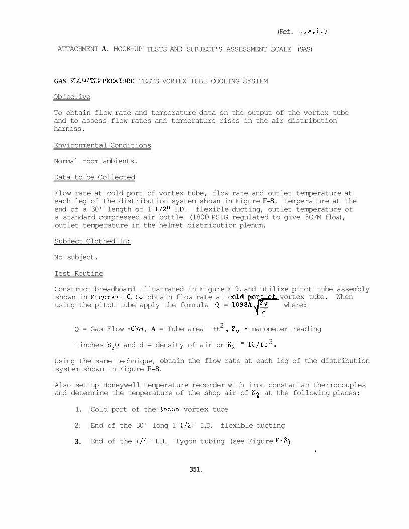
(Ref. I.A.1.)
ATTACHMENT A . MOCK-UP TESTS AND SUBJECT'S ASSESSMENT SCALE (SAS)
GAS FLOW/TEMPERATURE TESTS VORTEX TUBE COOLING SYSTEM
Ob iec t ive
To obtain flow rate and temperature data on the output of the vortex tube and to assess flow rates and temperature rises in the air distribution harness.
Environmental Conditions
Normal room ambients.
Data to be Collected
Flow rate at cold port of vortex tube, flow rate and outlet temperature at each leg of the distribution system shown in Figure F-8., temperature at the end of a 30' length of 1 1/2" I .D. flexible ducting, outlet temperature of a standard compressed air bottle (1800 PSIG regulated to give 3CFM flow), outlet temperature in the helmet distribution plenum.
Subject Clothed In:
No subject.
Test Routine
Construct breadboard illustrated in Figure F-9, and utilize pitot tube assembly shown in FigureF-lO.to obtain flow rate at cold por using the pitot tube apply the formula Q = 1098Af-F where:
vortex tube. When
2 Q = Gas Flow -CFM, A = Tube area -ft , Pv - manometer reading 3 -inches H20 and d = density of air or N2 - lb/ft .
Using the same technique, obtain the flow rate at each leg of the distribution system shown in Figure F-8.
Also set up Honeywell temperature recorder with iron constantan thermocouples and determine the temperature of the shop air of N2 at the following places:
1. Cold port of the Encon vortex tube
2. End of the 30' long 1 1/2" I.D. flexible ducting
3. End of the 1/4" I .D . Tygon tubing (see Figure F-8.)
351.
4 . Outlet of a standard compressed air bottle (1800 PSIG regulated to give 3 CFM flow).
5 . Outlet in the helmet distribution plenum of the compressed gas breathing supply.
Data Analysis
Flow rates at the output of the vortex tube and the extremities will be computed and compared. system will be computed,
C oment s
Also the temperature rises in the distribution
None
352.
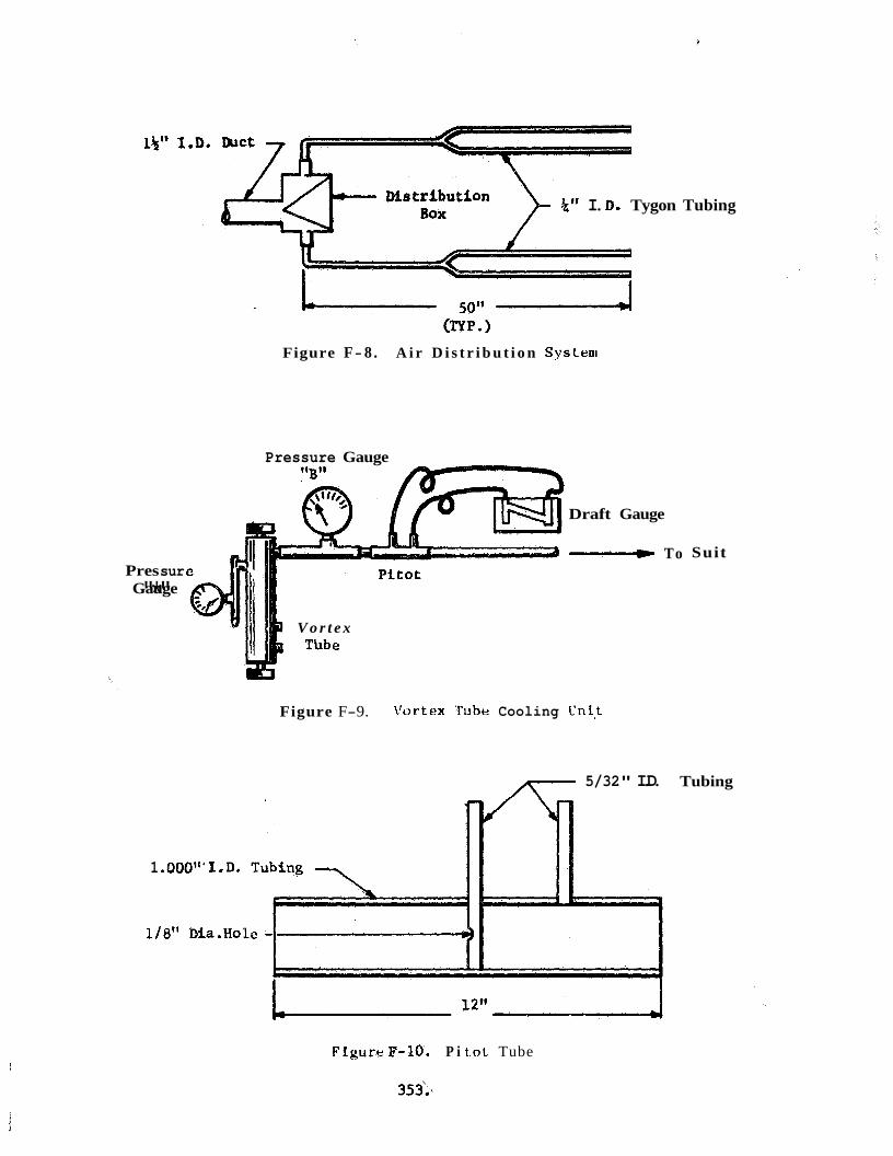
k t t I. D, Tygon Tubing Mstribution
Figure F- 8 . A i r D i s t r i b u t i o n Systeni
Pres sur Gauge "*"
Pressure Gauge
V o r t e x Thbe
1 .OOO"' I. D.
1/8" Dia.Ho
Draft Gauge
____t To
Figure F-9. 1'ortex Tube Cooling L'nL.t
5/32" I.D. A=-
Suit
Tubing
Figure F-10. P i t.ot Tube
353:.
(Ref. I . A . l )
GAS FLOW/TEMPERATURE TeSTS A I R CONDITIONER COOLING SYSTEM
Obiective
To obtain flow and temperature data on a 9000 BTU air conditioner operating in conjunction with a P-400547-13 blower.
Environmental Cohditions
Normal room ambients
Data to be Collected
Plenum air temperature, plenum outlet flow and temperature (no blower), blower exhaust temperature, flow rates and temperatures in the distribution s ys t em.
Subject Clothed In
No subject, unmanned test
Test Routine
Install air conditioner in plenum. Initially, the plenum should be open with no blower installed in its exhaust port. The air conditioner should be operated on the "high" setting with the plenum open for ten minutes. Plenum temperature is taken and recorded. The blower is then installed and the air flow and temperature through the plenum's exhaust opening is taken with the blower not operating (air flow is measured using a draft gage and the pitot tube shown in Test I.A.l. (Vortex Tube Cooling System) Finally, with the blower operating air flow and the temperature of the exhaust air is measured.
Data Analysis
Flow rates will be computed using the technique outlined in Test I.A.1. Temperatures at different points in the system will be compared.
Comments
None
354

(Ref. 1.B.l.a)
CHAMBER PRESSURIZATION TEST
Ob i ec t ive
The objective of the chamber pressurization test is to determine that the chamber can achieve and be held at a pressure of up to 4 inches of water.
Environmental Conditions
Pressure of 4 inches of water inside chamber, ambient chamber temperature.
Subject Clothed In
No subject, chamber unmanned.
Data to be Collected
Chamber pressure (inches of water), input pressure of supply system to chamber and time required to achieve a pressure of 4 inches of water.
Test Routine
The pressure inlet valve will be opened full and the time recorded to achieve a pressure of 4 inches of water in the sealed chamber. For this test the opening for the tunnel will be sealed off. Once this level has been achieved the input pressure required to maintain this pressure for one hour will be recorded. If the leakage rate of the chamber is too high to permit this, adjustments will be made to the seals until the shop air supply can readily maintain the desired pressure at less than maximum inlet pressure for a period of at least one hour.
Data Analysis
No formal data analysis will be required for this test.
Comments
None
355
(Ref. I . B . 2 . )
WATER COOLED UNDERSUIT
Ob j ec t ive
T o determine the water cooled undersuit's capability to provide environ- mental control for the wearer under resting and exercised conditions.
Environmental Conditions
Room ambient temperature and pressure.
Subject Clothed In
Long underwear, water cooled undersuit and outer suit.
Data to be Collected
Inlet fluid temperature; fluid flow rate; subject temperatures (both arms, left leg, chest, groin and small of back); helmet temperature; Section I of the SAS (comfort) and subject's impressions of undersuit design deficiencies.
Test Routine
Inlet water temperature will be varied systematically and the subject queried as to his comfort (Section I of the SAS) in the undersuit under both resting conditions and conditions of exertion (i.e. after the subject has completed timed sessions on an exercycle). Also, under resting conditions, the inlet temperature will be varied to determine the onset of the high and low tempera- ture discomfort zones. Each test will be run once. Finally, the subject will be queried as to any deficiencies he has observed in the design of the suit which was not reflected on the assessment scale,
Data Analysis
Subject comfort assessments will be evaluated in relationship to the tempera- ture measurements.
Comments
This test is intended to provide a gross index of the operational efficacy of the water cooled undersuit. Further, the mock-up staff will gain familiar- ization with the operation and use of this out-of-house developed item.
356
(Ref, I .B .2 . )
AIR COOLED UNDERSUIT
Objective
To determine the air-cooled undersuit's capability to provide environmental control and comfort for the wearer under resting and exercised conditions.
Environmental Condition
Room ambient temperature and pressure.
Subject Clothed In
Long underwear, air cooled undersuit, and outer suit.
Data to be Collected
Subject temperatures (both arms, left leg, chest, groin, and small of back); supply temperature at flow tube; exhaust temperature at flow tube; helmet temperature; inlet and outlet flow rates; Section I of the SAS (comfort) and subject's impressions of undersuit design deficiencies.
Test Routine
Conditioned air source settings (controlling inlet air flow to the undersuit) will be varied systematically and the subject queried (Section I of the SAS) as to comfort under resting and exercised conditions (same exercises as for the water cooled undersuit). to establish the onset of the high and low discomfort zones under resting conditions. identify any design deficiencies he observes during the test.
The conditioned air source will also be adjusted
Each test will be run once. The subject will also be asked to
Data Analysis
Subject comfort assessments will be evaluated in relationship to the tempera- ture measurements.
Comments
This test will serve to provide a gross appraisal of the efficacy of the air cooled undersuit, and to provide data for any required modification.
357,
(Ref. I.B.3.a.)
LEAK TEST
- Objective To determine if the suit-tunnel leaks and if so to minimize the leakage rate to assure maintenance of up to 4" H20 pressure in the pressure chamber.
Environmental Conditions
4" H20 pressure, ambient temperature
Subject Clothed In
No subject, unmanned test
Data to be Collected
Leakage rate, chamber pressure
---
Test Routine
Attach a pressure gage or manometer to the reefing tube after the suit- tunnel has been installed. Seal off the end of the tube and pressurize the chamber to 4" H20. pressures to permit calculation of leakage rates from the suit-tunnel.
Hold at this pressure for 1 / 2 hour and record
Data Analysis
No formal data analysis
Comments
If more than nominal leakage is evident, sources of the leakage will be identified and sealed. The test will then be re-run to assure capability of maintaining pressure in the suit-tunnel chamber combination.
358.
(Ref. I.B.3.b.)
=ET AIR SUPPLY
Objective
The objective of the helmet air distribution test is to empirically determine flow rates of input air required to provide optimum comfort and safety for the subject in the closed suit system.
Environmental Conditions
Ambient room temperature and pressure.
- Subject Clothed In Long underwear and outer suit (including outfitted helmet) with tunnel sealed.
Data to be Collected
Input pressure, respiration, gas composition, heart rate, and Section I, a-c of the SAS.
Test Routine
Compressed air under the control of a pressure regulator will be used to vary the flow of inlet air to the helmet. Limits within which the flow can be varied without presenting any safety hazard to the subject will be prescribed by project medical personnel before testing is initiated. With these limits, respiration and heart rate will be monitored to assure that hyperventilation does not occur as the flow is varied. For different settings within the prescribed limits, the subject's reports as t o comfort and noise will be recorded as well as the physiological indices.
---
Data Analysis L
Formal data analysis will not be required for this test.
Comments - None
359.
(Ref. I.B.3.c.)
VISUAL FIELD
Ob iect ive
To measure the visual field of the Phase I subject in the BISS helmet.
Environmental Conditions
Normal room ambients.
Subject Clothed In
Complete BISS outfit including long-johns, undersuit, helmet support and outer suit/helmet. for this test.
Cooling and breathing air will be supplied the subject
Data to be Collected
Angular displacements from the subject's line of sight vertically and the angular displacement horizontally at which the subject can see a test marker.
Test Routine
This test will be conducted in accordance with conventional visual field measuring techniques. Essentially, the points in a horizontal plane (both to the left and right) and in a vertical plane (both up and down from the subject's line of sight) at which a test marker can be seen will be deter- mined.
Data Analysis
The values obtained from the test will be compared against the criterion values. plane).
(140' vertical, 80' below L.O.S., 60° above and 220' in a horizontal
C omen t s
If the criterion numbers are not met, the helmet will be adjusted accordingly. If this is necessary, the test will be re-run to confirm that the adjustments achieved the desired result.
' 360.
(Ref. I.B.3.d.)
OUTER SUIT FIT
Objective
To assure an optimum fit of the outer suit under ambient pressure conditions.
Environmental Conditions
Normal room ambients
Subject Clothed In
Full BISS outfit including long-underwear, either undersuit and outer suit.
Data to be Collected
Subject's appraisal of fit combined with opinions of test personnel viewing the exterior fit of the suit.
Test Routine
The subject will don the suit and will be asked to move about in it. will be asked to move his various limbs and appraise fit in conjunction with the test personnel who are viewing exterior fit.
He
Data Analysis
No formal data analysis required.
Comen t s
Adjustments will be made to the suit by taking tucks or adding panels as required. that good outer suit fit has been achieved.
If such modications are made, the test will be re-run to assure
361.
(Ref. I.B.5.)
SAFTY RESCUE
Obi ective
The objective of this test is to demonstrate that the subject can be reached in sufficient time to effect emergency assistance and rescue when operating under the criterion of four minutes from detection of the difficulty to having the subject removed from the chamber. into the chamber by the medical monitor can be accomplished within thirty seconds .
It is also to demonstrate that access
Environmental Conditions
Both ambient pressure and temperature, and up to 4 inches water pressure and ambient temperature.
Subiect Clothed In
Long underwear, inner suit, outer suit, boots and helmet.
Data to be Collected
Time required to gain access to the suited subject, time for freeing subject from suit and time to remove subject from the chamber.
Test Routine
Experimental test team personnel will be assembled in an operational con- figuration and the subject will suddenly feign collapse. a stop watch will note the tiUte required for the medical monitor to gain entry to the chamber through the emergency hatch and reach the subject. Also the time required to free the subject's face and body from the suit and to remove the subject through the reefing tube will be recorded. ance to the medical monitor from other chamber personnel in moving the subject through and removing the subject from the reefing tube will be assumed. test will be repeated once under each pressure environment.
An observer with
Assist-
This
Data Analysis
The times for reaching, freeing, and removing the subject will be totaled for both conditions.
Comments
If the various time criteria are not achieved, the routine will be practiced or modified until this is accomplished.
362.
(Ref. I.B.6.)
COMMUNICATIONS
Objective
The objective of the communications tests are to determine helmet loud- speaker position and volume that gives best overall results and volume required for chamber loudspeaker.
Environmental Conditions
Ambient pressure and temperature.
Test Routines
1. Placement of Speaker(s) in Helmet
a. Using the single-transducer (loudspeaker) in the helmet, a series of locations shall be tried for efficacy of reception and trans- mission. The following positions shall be employed (referenced to the head in an erect, facing-forward orientation):
(1) Directly opposite ear
(2) Directly below ear (within helmet limitations)
(3) Directly below chin (within helmet limitations)
( 4 ) Directly below cheek (midway between positions (2) and (3)
(5) Directly overhead
(6) Midway between positions (1) and (5)
(7) Directly in front of forehead (600 up from line of sight)
b. All life-support and monitoring equipment shall be operating at their normal settings.
c. The test conductor shall select three volume settings on his Master Unit. The subject and test conductor shall complete separate copies of SAS item V.a. after each position test.
The Helmet Loudspeaker Positions which have the three best acoustical ratings shall be tested to determine which position offers least physical interference to the operator. ing factors shall be examined:
These settings shall be used for all position tests.
d.
The follow-
363.
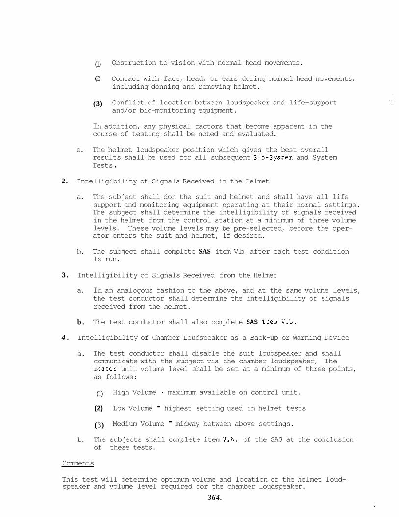
(1) Obstruction to vision with normal head movements.
(2) Contact with face, head, or ears during normal head movements, including donning and removing helmet.
(3) Conflict of location between loudspeaker and life-support and/or bio-monitoring equipment.
In addition, any physical factors that become apparent in the course of testing shall be noted and evaluated.
e. The helmet loudspeaker position which gives the best overall results shall be used for all subsequent Sub-system and System Tests .
2. Intelligibility of Signals Received in the Helmet
a. The subject shall don the suit and helmet and shall have all life support and monitoring equipment operating at their normal settings. The subject shall determine the intelligibility of signals received in the helmet from the control station at a minimum of three volume levels. ator enters the suit and helmet, if desired.
These volume levels may be pre-selected, before the oper-
b. The subject shall complete SAS item V.b after each test condition is run.
3. Intelligibility of Signals Received from the Helmet
a. In an analogous fashion to the above, and at the same volume levels, the test conductor shall determine the intelligibility of signals received from the helmet.
b . The test conductor shall also complete SAS ite.m V.b.
4 . Intelligibility of Chamber Loudspeaker as a Back-up or Warning Device
a. The test conductor shall disable the suit loudspeaker and shall communicate with the subject via the chamber loudspeaker, The mster unit volume level shall be set at a minimum of three points, as follows:
(1)
(2) Low Volume - highest setting used in helmet tests High Volume - maximum available on control unit.
(3) Medium Volume - midway between above settings. b. The subjects shall complete item V.b. of the SAS at the conclusion
of these tests.
Comments
This test will determine optimum volume and location of the helmet loud- speaker and volume level required for the chamber loudspeaker.
364.
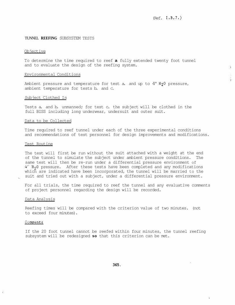
(Ref. I . B . 7 . )
TUNNEL REEFING SUBSYSTEM TESTS
Objective
To determine the time required to reef a fully extended twenty foot tunnel and to evaluate the design of the reefing system.
Environmental Conditions
Ambient pressure and temperature for test a. and up to 4" H20 pressure, ambient temperature for tests b. and C.
Subject Clothed In
Tests a. and b. unmanned; for test c. the subject will be clothed in the full BISS including long underwear, undersuit and outer suit.
Data to be Collected
Time required to reef tunnel under each of the three experimental conditions and recommendations of test personnel for design improvements and modifications.
Test Routine
The test will first be run without the suit attached with a weight at the end of the tunnel to simulate the subject under ambient pressure conditions. The same test will then be re-run under a differential pressure environment of 4" H20 pressure. After these tests have been completed and any modifications which are indicated have been incorporated, the tunnel will be married to the suit and tried out with a subject, under a differential pressure environment.
For all trials, the time required to reef the tunnel and any evaluative comments of project personnel regarding the design will be recorded.
*-
Data Analysis
Reefing times will be compared with the criterion value of two minutes. (not to exceed four minutes).
Comments
365.
If the 20 foot tunnel cannot be reefed within four minutes, the tunnel reefing subsystem will be redesigned so that this criterion can be met.

(Ref. I.C.1.)
SUIT SYSTEM TESTS
Objective
To assess the overall performance of the suit system with regard to subject comfort, mobility, ease of suit/chamber entry-exit and communications. These tests will also provide tradeoff data for selection of either the air-cooled or water-cooled undersuit for use in the Phase I1 tests.
Environmental Conditions
Both ambient pressure and up to 4" H20 pressure, ambient temperature.
Subject Clothed In
Full BISS outfit including long underwear, undersuit and outer suit.
Data to be Collected
SAS items 1V.a. and 1V.b. (chamber/suit entry and exit), Section I (subject comfort), Section I1 (mobility), and item V.C. (communications). Record will also be made of any observations on the part of either the subject or the test team which relate to the design of the suit system and which are not covered by the SAS.
Test Routine
The test routine shown below will be run six times. The first two times will be under an ambient pressure environment using either undersuit, and the last four tests will be in a differential pressure environment (up to 4" H20 pressure) with two being run in the water cooled undersuit and two in the air cooled undersuit. The test routine is as follows:
1. Subject dons suit and enters chamber.
2. Subject is administered SAS item 1V.a. (Entry) via the intercom followed by Section I (Comfort) of the SAS.
3. Subject is then directed to walk around the perimeter of the chamber twice, bend at the waist ten times, climb and descend a ladder three times and perform ten deep knee bends. Figure 6)
(See
4 . Subject is then administered Section I1 (Mobility) of the SAS to obtain his assessment of mobility followed by Section I for comfort under the exercised condition.
5. Subject then exits from chamber through the tunnel.
366.

60 Subject fills out SAS item 1V.b (Exit) for the exit process and SAS Section V.C. relative to communications during the test.
Data Analysis
Comparative analyses of the tests run under the ambient and differential pressure environments will be made. Data from the competitive undersuit tests will be compiled and tradeoffs conducted to eliminate one undersuit from further consideration.
Comments
None
367.
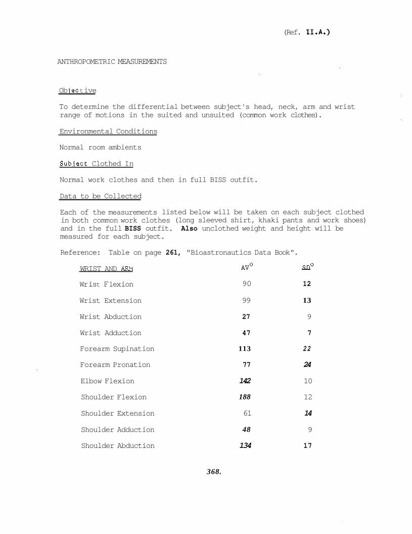
(Ref. 1I.A.)
ANTHROPOMETRIC MEASUREMENTS
Ob iec t ive
To determine the differential between subject's head, neck, arm and wrist range of motions in the suited and unsuited (common work clothes).
Environmental Conditions
Normal room ambients
Subiect Clothed In
Normal work clothes and then in full BISS outfit.
Data to be Collected
Each of the measurements listed below will be taken on each subject clothed in both common work clothes (long sleeved shirt, khaki pants and work shoes) and in the full BISS outfit. Also unclothed weight and height will be measured for each subject.
Reference: Table on page 261, "Bioastronautics Data Book".
WRIST AND ARM
Wr is t F 1 ex ion
AVO - SDo
90 12
Wrist Extension 99 13
Wrist Abduction 27 9
Wrist Adduction 47 7
Forearm Supination 113 22
Forearm Pronation 77 24
Elbow Flexion 142 10
Shoulder Flexion 188 12
Shoulder Extension 61 14
Shoulder Adduction 48 9
Shoulder Abduction 134 17
368.
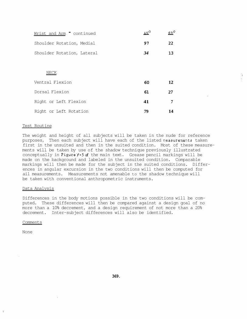
Wrist and Arm - continued Shoulder Rotation, Medial
Shoulder Rotation, Lateral
- AVO - SDo
97 22
34 13
NECK
Ventral Flexion
Dorsal Flexion
Right or Left Flexion
Right or Left Rotation
- 60
61
41
79
12
27
7
14
Test Routine
The weight and height of all subjects will be taken in the nude for reference purposes, Then each subject will have each of the listed measurements taken first in the unsuited and then in the suited condition. Most of these measure- ments will be taken by use of the shadow technique previously illustrated conceptually in FigureF-5d the main text. made on the background and labeled in the unsuited condition. Comparable markings will then be made for the subject in the suited conditions. Differ- ences in angular excursion in the two conditions will then be computed for ail measurements. be taken with conventional anthropometric instruments.
Grease pencil markings will be
Measurements not amenable to the shadow technique will
Data Analysis
Differences in the body motions possible in the two conditions will be com- puted. These differences will then be compared against a design goal of no more than a 10% decrement, and a design requirement of not more than a 20% decrement. Inter-subject differences will also be identified.
Comments
None
369.
(Ref. 1I.B.)
6 ENTRY-EXIT TESTS
Objective
To determine the time required for the subject to enter the chamber (incl- uding suit donning) and to exit from the chamber (including suit removal).
Environmental Conditions
Up to 4" H20 pressure, ambient temperature.
Subject Clothed In
Full BISS outfit including long underwear, undersuit, and outer suit.
Data to be Collected
Time elapsing between entry of a fully undersuited subject into the exterior opening of the reefing tube and emergence of a full suited man into the chamber and the converse exit operation and Section IV (Entry-Exit) of the SAS . Test Routine
Each of the four subjects will be given a familiarization trial and then put through 5 timed trials. The subjects will be given a three minute rest after getting into the chamber before beginning the exit process. A ten minute rest between trials, will be given outside the chamber. Each subject will be given the familiarization trial and the first two timed trials in one session followed by the remaining three timed trials at a subsequent time. This time must be at least three and not more than thirty-six hours later, This tactic will prevent fatigue from bec0ming.a prominent factor in performance and also will preclude loss of skills acquired in the first session. Section IV (Entry-Exit) of the SAS will be administered after each of the 3 test sessions to each subject.
Data Analysis
Mean times for the entry and exit of each subject will be computed for the five timed trials. Entry and exit means for all subjects pooled, also will be computed. Sununary statistics for the Section IV SAS items will be pre- pared. They will show differences for the same subject in session one and two, and mean ratings for all subjects. Entry and exit mean times will be compared with the design objective of three minutes and the upper limit of ten minutes.
Comments
None 370.
(Ref. 1I.C.)
MOBILITY TESTS
Objective
To determine t..e abi ity of the subject to walk, climb and bend at the waist and squatting in the suited condition under a differential pressure environ- ment.
Environmental Conditions
Up to 4" H20 pressure, ambient temperature.
Subject Clothed In
Full BISS outfit, including long underwear, undersuit, and outer suit.
Data to be Collected
Section I1 (Mobility) of the SAS. Individual ratings will be collected on walking, climbing, bending at the waist and squatting (deep knee bends) as the subject completes the relevant action. Instructions to the subject and ratings will be obtained via the BISS communications system.
Test Routine
Each subject will be directed to walk around the perimeter of the room twice, climb and descend the ladder three times, bend at the waist ten times and perform ten deep knee bends. Each subject will perform this test three times with a ten minute rest between trials. Starting and ending points for the walk and the location for other tests will be constant for all subjects.
Data Analysis
Mean ratings for each subject on each type of test will be computed across trials. Mean ratings across subjects for each test will be compared with the criterion mean rating of 4 . Intra-subject data, across trials, will be examined for trends. Inter-subject differences will also be examined and compared with findings from Test 11-A, Anthropometric Measurements.
A mean rating for each test across subjects will also be made.
Comments
None
371.
I
(Ref. 1I.D.)
DEXTERITY
Obi ectlive
TEST
To determine the differential in operator hand and finger dexterity bet- ween the suited and unsuited (work clothes as in 11-A, Anthropometric Measurements) subject.
Environmental Conditions
Up to 4" H20 pressure, ambient temperature.
Subject Clothed In
Full BISS outfit, including long underwear, undersuit, and outer suit.
Data to be Collected
Assembly and disassembly time and Section I11 (Dexterity) of the SAS.
Test Routine
The subjects will be given step by step assembly and disassembly instructions for the Assembly Test Object (FigureF-Z main text) via the intercom. test will be given to each subject in both the suited and the unsuited con- dition. dition first and the other two in the suited condition first. The total assembly and disassembly tests will be timed separately for each subject under both conditions. istered to the subject via the intercom after completion of each major test task (i.e. assembly or disassembly).
The
Two of the four subjects will be given the test in the unsuited con-
Section I11 of the SAS (Dexterity) will be admin-
Data Analysis
Difference scores (suited versus unsuited) will be computed for each individual on both tasks for both the time and SAS rating scores. difference scores across a l l subjects also will be computed.
Mean
Comment s
None
372.

COMMUNICATIONS TESTS
Obi ec t ive
To assess the intelligibility of the communications link used between the subject and the test conductor.
Environmental Conditions
Up to 4" H20 pressure and ambient temperature.
Subject Clothed In
Full BISS outfit including long underwear, undersuit and outer suit.
Data to be Collected
Errors in receiving phoenetic nonsense syllables.
Test Routine
Each subject will be given a list with 100 nonsense syllables on it. The test conductor will clearly enunciate 50 of these syllables once and also give a sequential number associated with each syllable. The subject will scan his list and mark the appropriate number next to the syllable he believes he has received. erent list of 100 syllables with the subject transmitting and the test conductor receiving. This list will be different for each trial so that the test conductor's performance will not be distorted by learning. a third, abbreviated list containing 50 syllables will be used by the test conductor to transmit 25 syllables to the subject over the chamber speaker.
The same routine will be repeated using a diff-
Finally
All subjects will have been given audiometric tests and assessed for clarity of diction as a part of the selection process to eliminate possible dis- tortions in the data.
Data Analysis
Error data will be computed for each subject on both tests and on the test conductor receiving from every subject. across subjects for each test and across trials for the test conductor.
Error data will also be averaged
Comments
None
373.
. .
(Ref. 1I.F.)
SUBJECT ENDURANCE
Ob I ective
To determine if the BISS can support the subject in the differential pres- sure environment for a period of at least four hours and to determine if the subject can function effectively during this period.
Environmental Conditions
Up to 4" H20 pressure, ambient temperature.
Subject Clothed In
Full BISS outfit including long underwear, undersuit and outer suit.
Data to be Collected
Entire SAS less Section IV (entry/exit) and items V.a. and V.b. (for sub- system communications tests) and total time subject remains in chamber. Comments of the subject relating to reasonsofor changes in ratings over time . Test Routine
Each subject will be placed in the chamber for a four hour endurance test. At any time either the subject or the medical monitor may terminate the test. assembly of the test object. about the chamber at will or rest on a stool which will be provided.
Once an hour the subject will be run through the assembly and dis- During other times the subject may move
Also on a once an hour basis, the subject will be administered the entire SAS, less Section IV (entry-exit) and items V.a. and V.b. which related to the subsystems communication test.
Decrements in appraisals will be identified while the subject is in the chamber. The subject will then be interviewed in some detail as to reasons for these changes via the intercom.
Data Analysis
Summary statistics will be prepared contrasting ratings given on the SAS against time in the chamber for each subject. Medical monitoring data records (RKG, respiration and 02 , GO2, and N2 concentrations) will also be correlated with SAS ratings over time in the chamber.
374.
An overall profile will be prepared showing.mean ratings across subjects against time, during the test will be compiled and evaluated,
Reasons for changes in ratings obtained from the subject
Comments
A summary of the subject's comments as to reasons for changes in ratings will be prepared for use in the final data analysis effort,
375.
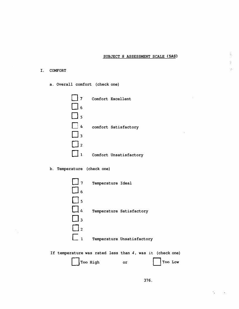
SUBJECT S ASSESSMENT SCALE (SAS)
I. COMFORT
a. Overall comfort (check one)
0 7 Comfort Excellent
0 6
0 5
0 3
0 2
0 1 Comfort Unsatisfactory
4 comfort Satisfactory
b. Temperature (check one)
0 7 Temperature Ideal
0 6
US
0 3
E l 2
a 4 Temperature Satisfactory
1 Temperature Unsatisfactory
If temperature was rated less than 4 , was it (check one)
U T o o High or O T o o Low
376.
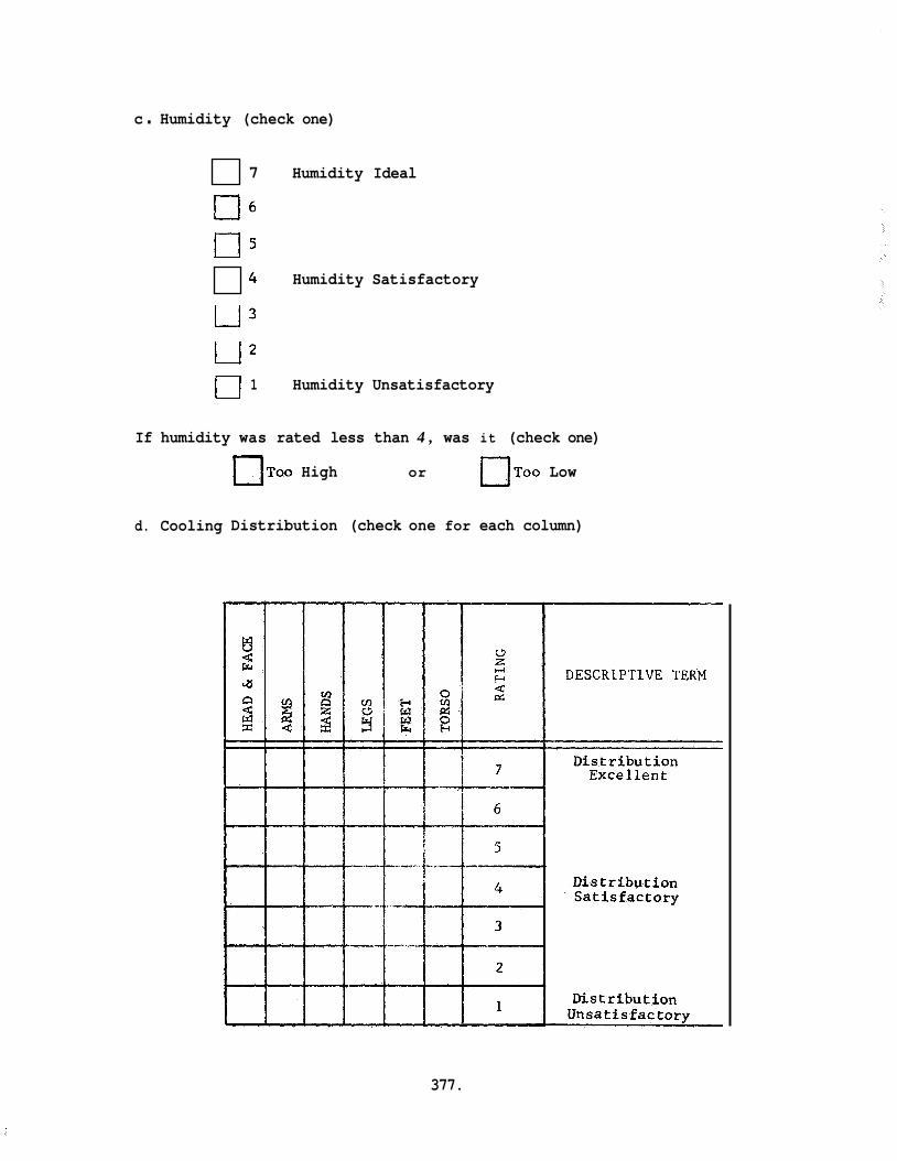
c . Humidity (check one)
7 Humidity Ideal
0 6
E l 5 4 Humidity Satisfactory
u 3 U2 u 1 Humidity Unsatisfactory
If humidity was rated less than 4 , was it (check one)
d. Cooling
TOO High or UT00 Low
Distribution (check one for each column)
377.
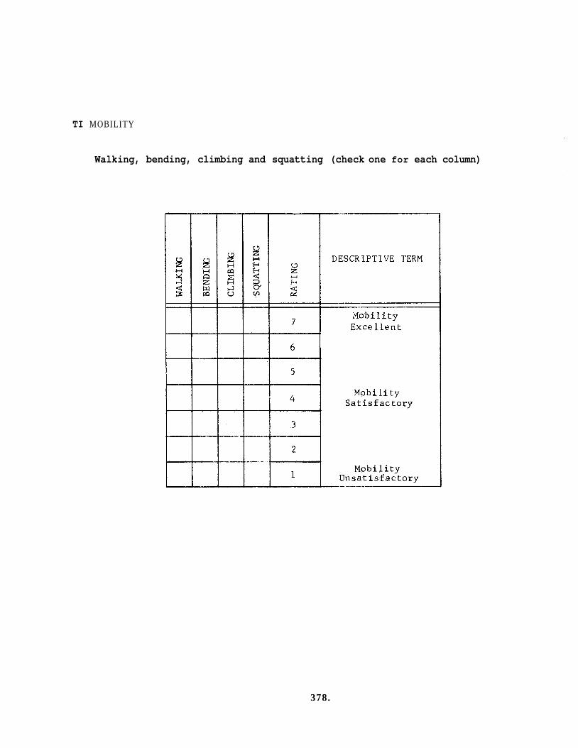
TI MOBILITY
Walking, bending, climbing and squatting (check one for each column)
378.
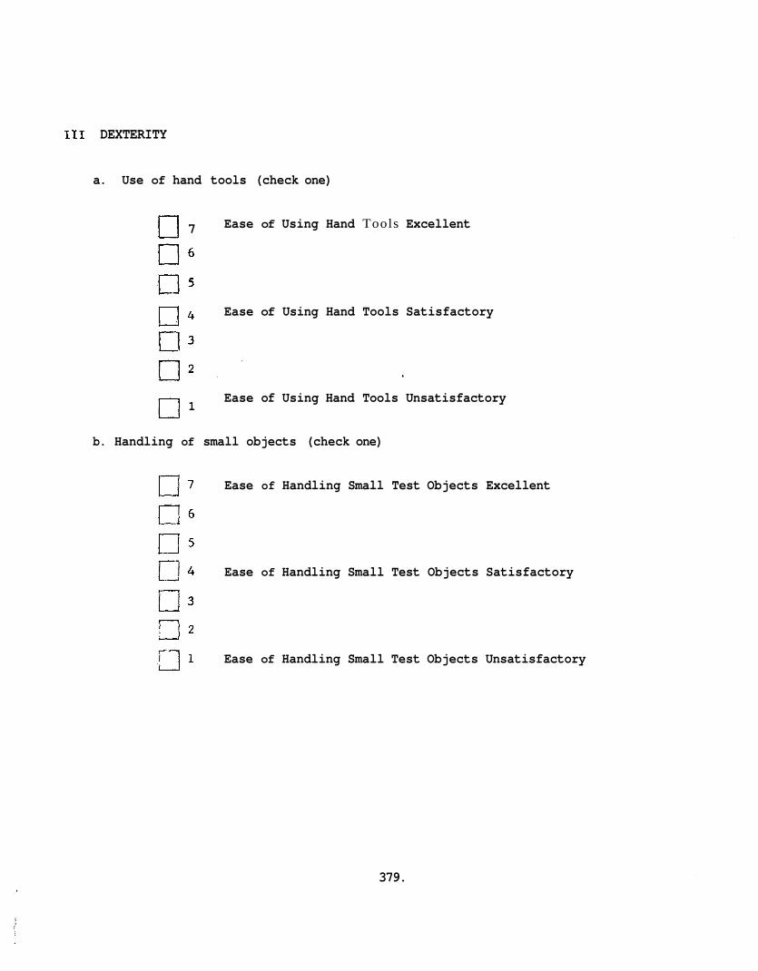
111 DEXTERITY
a. Use of hand tools (check one)
[3 7 Ease of Using Hand Tools Excellent
a 4 Ease of Using Hand Tools Satisfactory
c] 1 Ease of Using Hand Tools Unsatisfactory
b. Handling of small objects (check one)
Ease of Handling Small Test Objects Excellent
Ease of Handling Small Test Objects Satisfactory
Ease of Handling Small Test Objects Unsatisfactory
379.
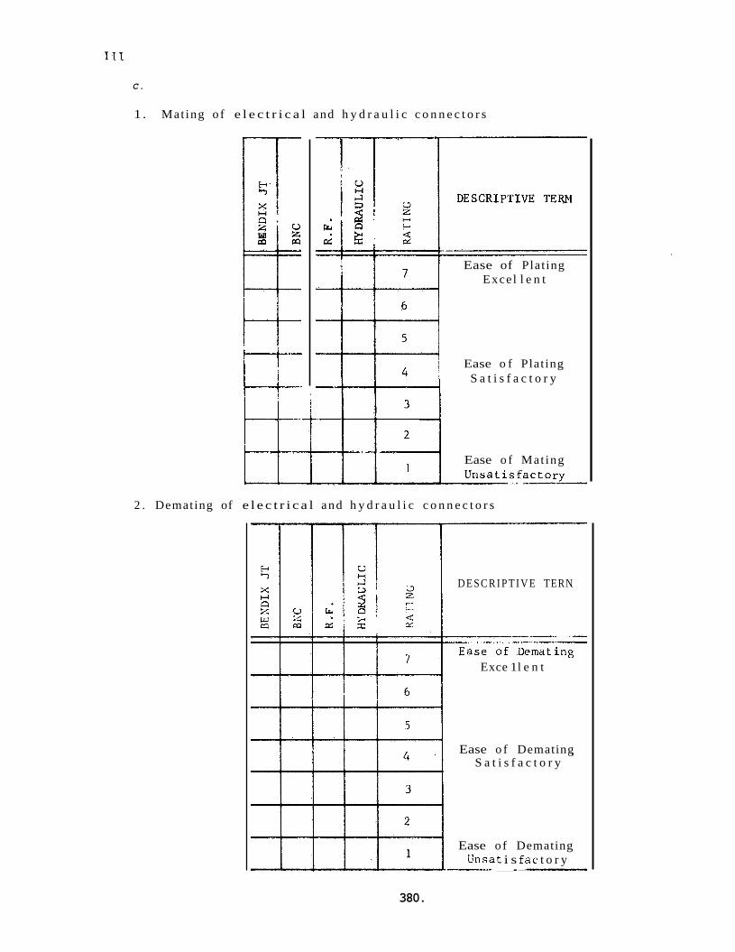
C.
1. Mat ing o f e l e c t r i c a l and h y d r a u l i c c o n n e c t o r s
W
r- +-- -- -- Ease of Plat ing
Excel l e n t
Ease o f Plat ing S a t i s f a c t o r y
Ease o f Mat ing
2 . Demating of e l e c t r i c a l and h y d r a u l i c c o n n e c t o r s
D E S C R I P T I V E TERN
Exce 1 l e n t
Ease o f Demating S a t i s f a c t o r y
Ease o f Demating L'nsat i s f a c t o r y ---- _I-
380.
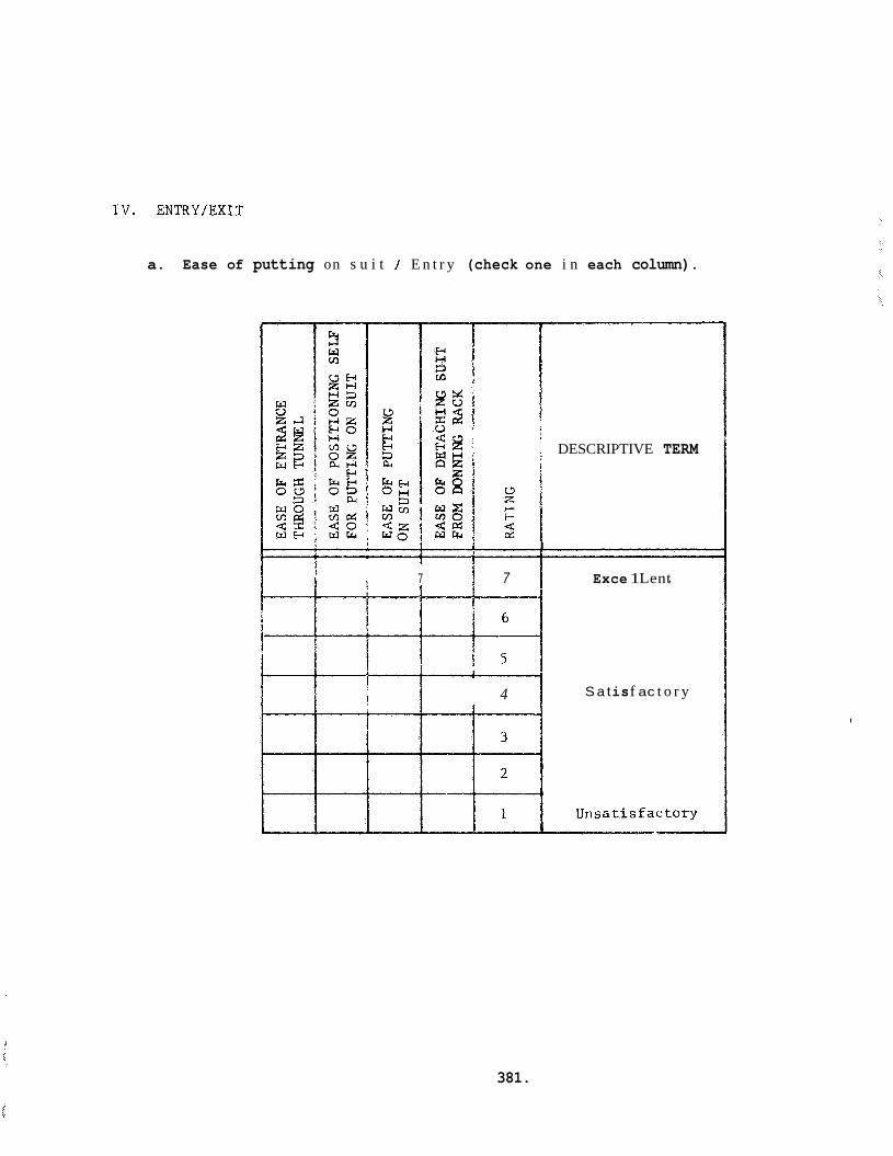
IV. ENTRY/EXIT
a. Ease of putting on s u i t / E n t r y (check one i n each column).
DESCRIPTIVE TERM
I 1
1 I
7 7 Exce 1 Lent
' I
t I I 1 t i i
! I I
4 S a t is f ac t o r y I
381.
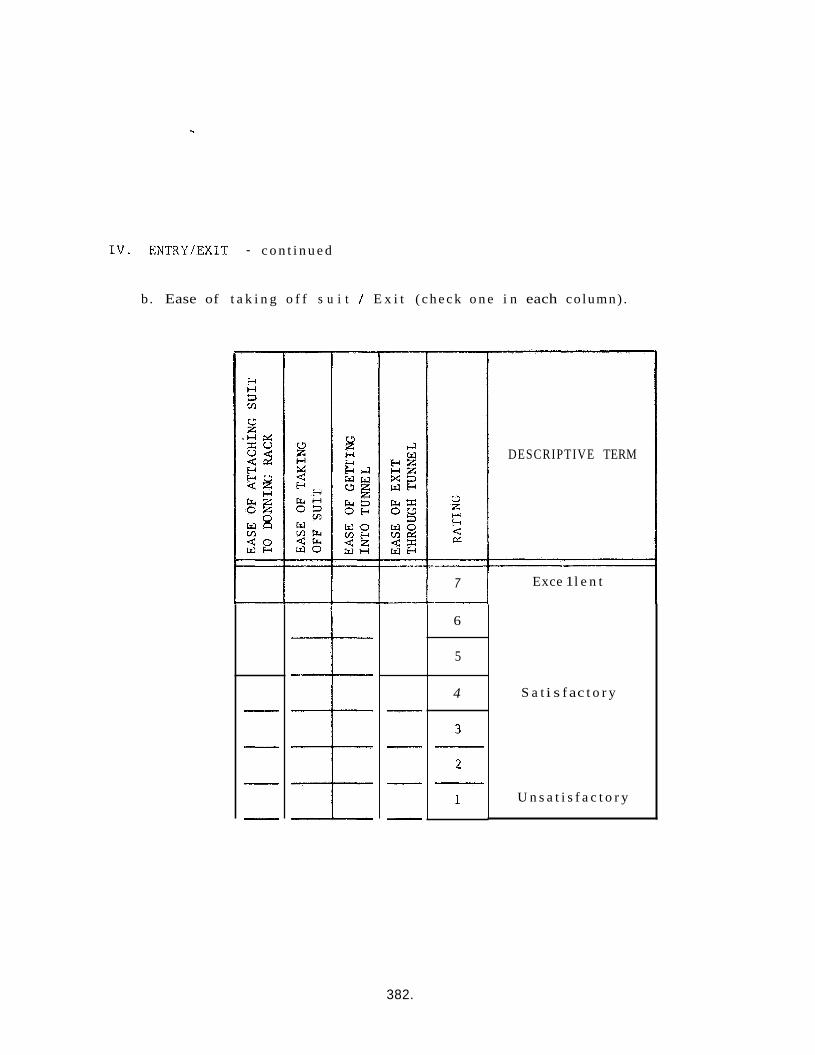
TV. ENTRYIEXIT - c o n t i n u e d
b . Ease of t a k i n g o f f s u i t 1 E x i t ( c h e c k o n e i n each co lumn) .
-__I
7
6
5
--
4
DESCRIPTIVE TERM
Exce 1 l e n t
S a t i s f ac t o r y
U n s a t i s f a c t o r y
382.
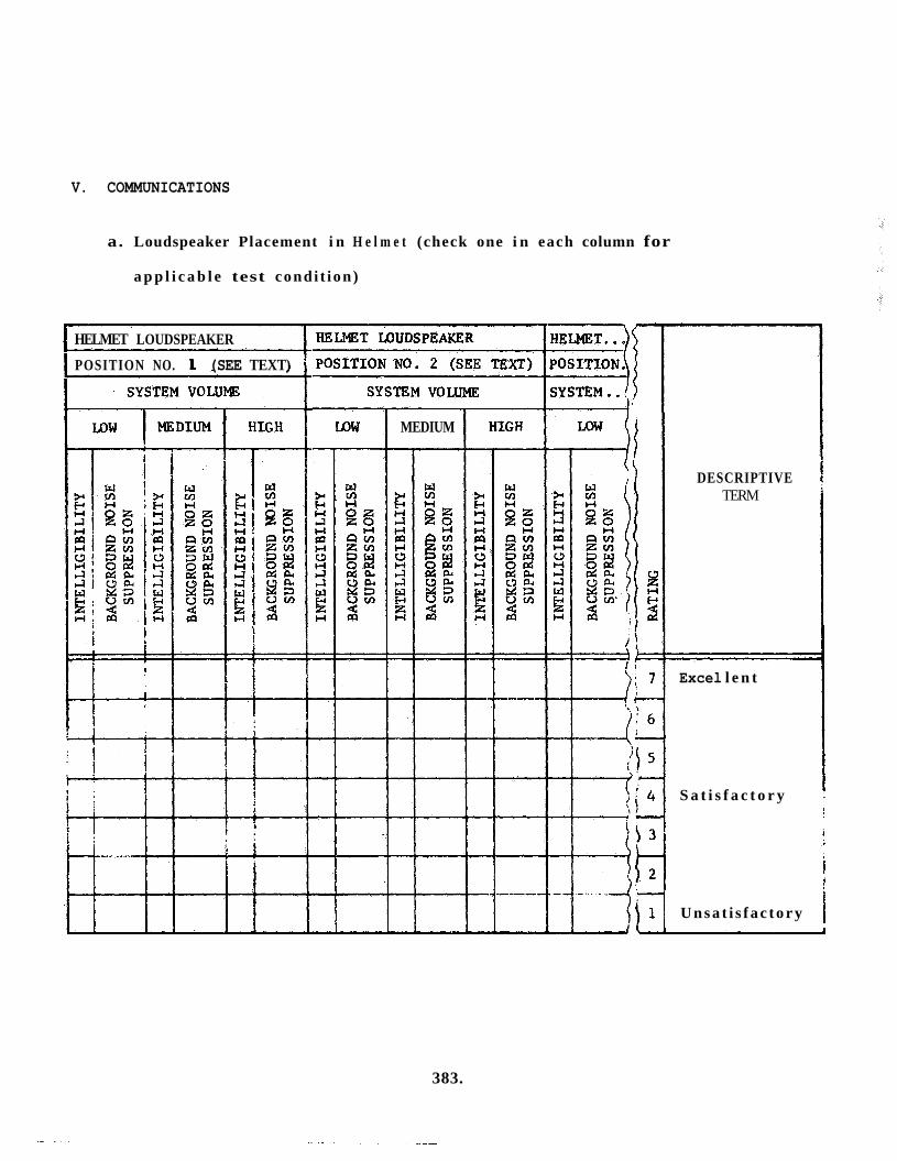
V. COMMUNICATIONS
a. Loudspeaker Placement i n H e l m e t (check one i n each column for
a p p l i c a b l e test condi t ion)
I HELMET LOUDSPEAKER
I POSITION NO. 1 (SEE TEXT)
SYSTEM VOLUME 1 1 POSITION NO. 2 {SEE TEXT) POSITION.
'~~~
LOW
I MEDIUM
DESCRIPTIVE TERM
Excel l e n t
S a t i s f a c t o r y
i U n s a t i s f a c t o r y
383.

V. COMMUNICATIONS - continued
b. Signal Intelligibility (check one in each column for each condition).
MEDIUM I HIGH VOLUME
2 a 2 2
I I
1 I : i
DESCRIPTIVE TERM
384.
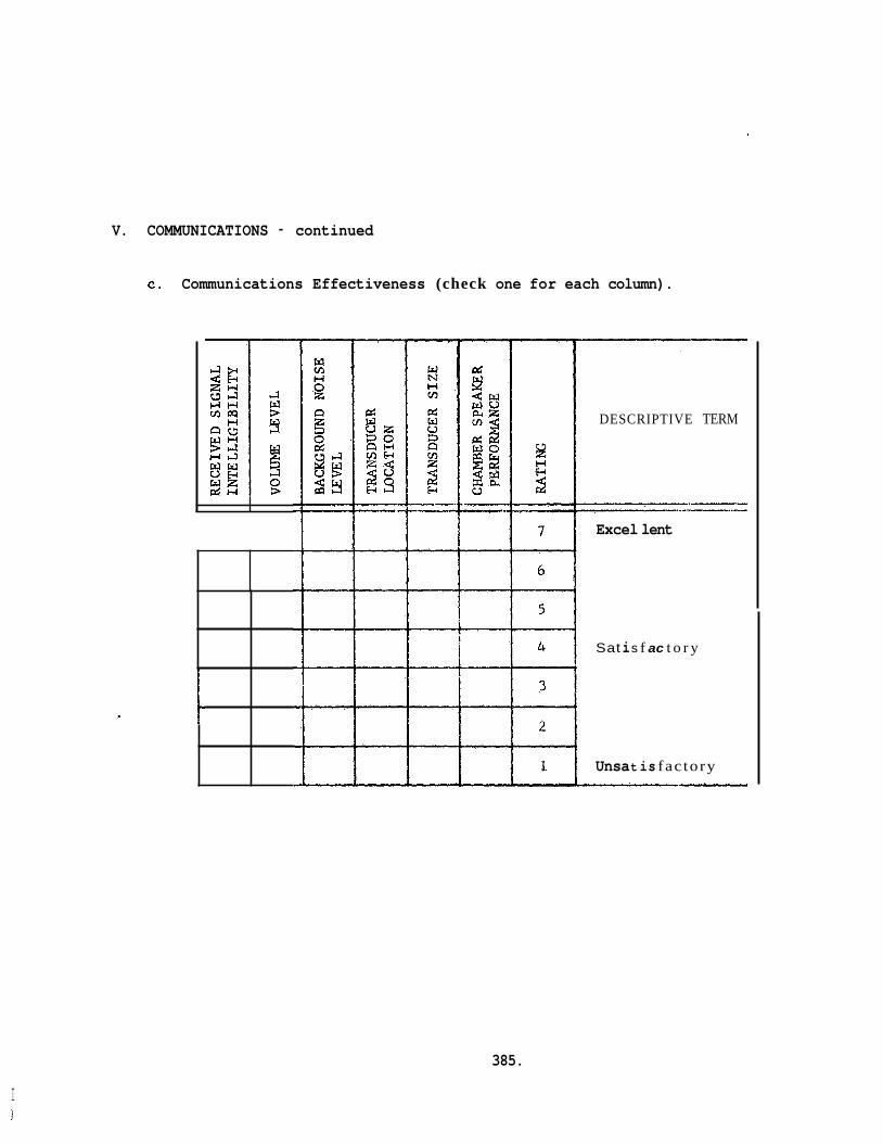
V. COMMUNICATIONS - continued
c. Communications Effectiveness (check one for each column).
DESCRIPTIVE TERM
Excel lent
Sat i s f ac t o r y
Unsa t is fac tory
I
385.
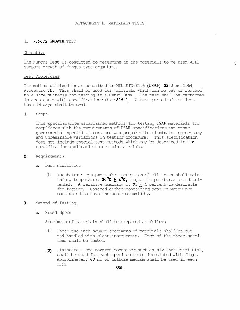
ATTACHMENT B. MATERIALS TESTS
1. FUNGUS GROWTH TEST
Objective
The Fungus Test is conducted to determine if the materials to be used will support growth of fungus type organisms.
Test Procedures
The method utilized is as described in MIL STD-810A (USAF) 23 June 1964, Procedure 11. This shall be used for materials which can be cut or reduced to a size suitable for testing in a Petri Dish. in accordance with Specification MIL-F-8261A. than 14 days shall be used.
The test shall be performed A test period of not less
1.
2.
3.
Scope
This specification establishes methods for testing USAF materials for compliance with the requirements of USAF specifications and other governmental specifications, and was prepared to eliminate unnecessary and undesirable variations in testing procedure. This specification does not include special test methods which may be described in the specification applicable to certain materials.
Requirements
a. Test Facilities
(1) Incubator - equipment for incubation of all tests shall main- 2OC, higher temperatures are detri- tain a temperature 3OoC
mental. A relative humidity of 95 5 percent is desirable for testing. Covered dishes containing agar or water are considered to have the desired humidity.
Method of Testing
a. Mixed Spore
Specimens of materials shall be prepared as follows:
(1) Three two-inch square specimens of materials shall be cut and handled with clean instruments. mens shall be tested.
Each of the three speci-
(2) Glassware - one covered container such as six-inch Petri Dish, shall be used for each specimen to be inoculated with fungi. Approximately 60 ml of culture medium shall be used in each dish.
386.
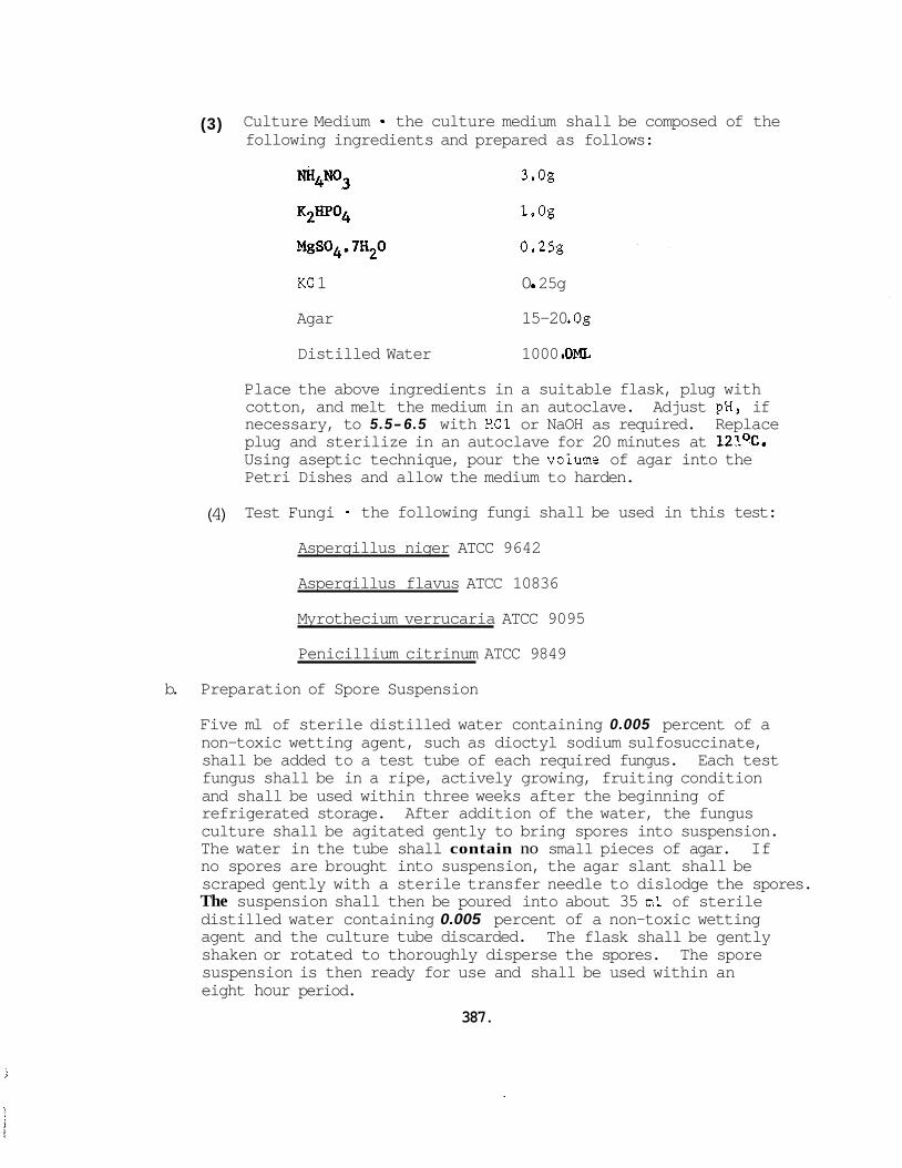
(3) Culture Medium - the culture medium shall be composed of the following ingredients and prepared as follows:
K2HP04
3.og
1.og
MgSO&a7~*0 0.25g
KC 1 0 0 25g
Agar 15-20 .og
Distilled Water 1000 . om Place the above ingredients in a suitable flask, plug with cotton, and melt the medium in an autoclave. Adjust pH, if necessary, to 5.5-6.5 with HC1 or NaOH as required. Replace plug and sterilize in an autoclave for 20 minutes at 121OC. Using aseptic technique, pour the volume of agar into the Petri Dishes and allow the medium to harden.
(4) Test Fungi - the following fungi shall be used in this test: Aspergillus niger ATCC 9642
Aspergillus flavus ATCC 10836
Myrothecium verrucaria ATCC 9095
Penicillium citrinum ATCC 9849
b. Preparation of Spore Suspension
Five ml of sterile distilled water containing 0.005 percent of a non-toxic wetting agent, such as dioctyl sodium sulfosuccinate, shall be added to a test tube of each required fungus. fungus shall be in a ripe, actively growing, fruiting condition and shall be used within three weeks after the beginning of refrigerated storage. After addition of the water, the fungus culture shall be agitated gently to bring spores into suspension. The water in the tube shall contain no small pieces of agar. If no spores are brought into suspension, the agar slant shall be scraped gently with a sterile transfer needle to dislodge the spores. The suspension shall then be poured into about 35 ml of sterile distilled water containing 0.005 percent of a non-toxic wetting agent and the culture tube discarded. shaken or rotated to thoroughly disperse the spores. The spore suspension is then ready for use and shall be used within an eight hour period.
Each test
The flask shall be gently
387.
C.
d.
e.
f.
Viability Control
Several 2-3 inch pieces of heavy untreated cotton cloth shall be cut and placed in a deep covered dish. Tap water and a trace of non-toxic wetting agent, such as dioctyl sodium sulfosuccinate shall be added and the dish shaken vigorously. The pieces shall be separated, replaced in the dish, and sterilized in an autoclave for one hour at 12l0C ( 2 5 0 9 ) . This material shall be inoculated and exposed one inch from the test specimens and shall show heavy growth and complete coverage by the test fungus or the test shall be repeated.
Inoculation
A spore suspension of the test fungus shall be prepared as described in Preparation of Spore.Suspension above, be placed on the center of the hardened agar medium in each dish. About 0.3 ml of the spore suspension shall be used to inoculate each test specimen. A pipette shall be used to measure the required quantity of the spore suspension. buted evenly, lengthwise, and around the edges of the test specimens without flooding the agar medium. In addition the viability control specified in the preceding paragraph shall also be placed on the hardened agar medium one inch from the test specimen and inoculated with 0.3 ml of the spore suspension.
The test specimen shall
The inoculum shall be distri-
Incubation
The period of incubation shall be fourteen days.
Evaluation of Results
At the end of the incubation period, the inoculated and exposed specimens shall be observed for fungus growth with the aid of bright, natural or artificial lighting. Questionable evidence shall be investigated with the aid of a microscope. Specimens shall show no scattered, sparse surface growth nar mycelial bridges between specimen and agar. In addition, the viability control shall show heavy growth and complete coverage, or the test shall be repeated,
Maintenance of Test Fungal Cultures
1. Scope
a. This appendix includes the procedures for maintenance of test fungi cultures for use in fungus - resistance tests of BISS materials.
b. In testing materials for fungus resistance a set of the test fungi aids in the identification of the fungi on the test specimens and
388.
on the viability control. In this manner, observations of fungus growth on test specimens may be standardized for qualitative evaluation of fungus resistance.
2. Requirements
a. When frequent or numerous tests are to be conducted to determine the fungus resistance of materials, cultures shall be maintained as specified herein to provide an adequate source of the test fungi .
b. Culture Maintenance Facilities
(1) Sterilization - equipment for steam sterilization such as an autoclave that shall maintain a temperature of at least 12loC (250%), but no more than 125OC (2579) at 15 lbs pressure. The period of sterilization shall be at the required temperature.
(2) Incubation - equipment for incubation of fungus cultures shall maintain a temperature of 3OoC +, 2OC (86OF & 3.6%). Higher temperatures are detrimental. A relative humidity of 95 5 percent is desired for incubation of fungus cultures.
(3) Refrigeration - equipment for refrigerated storage of culture tubes, test fungus cultures, and stock fungus cultures shall be maintained at 2OC to 5OC (359 to 40°F).
3. Procedures
a. Culture Media for Test Fungi
The following culture media are suggested for maintaining fungus cultures.
Aspergillus flavus - Sabouraud Maltose or Potato Dextrose Aspergillus niger - Enriched Mineral Salts or Potato Dextrose Myrothecium serrucaria - Mineral Salts Cotton Penicillium citrinum - Sabouraud Maltose
4. Mediums
a. Sabouraud Maltose Agar
This agar medium may be obtained from commercial sources such as Difco Laboratories, Inc., Detroit, Michigan. To obtain a satis- factory agar medium for culture tubes, 5 grams of agar shall be added to a liter of the Sabouraud Maltose culture formula.
b. Potato Dextrose Agar
This agar medium may be obtained from commercial sources such as Difco Laboratories, Inc., Detroit, Michigan. To be satisfactory as an agar medium for cultures tubes, 5 grams of agar shall be added to a liter of the Potato Dextrose culture formula.
C. Mineral Salts Agar
This agar medium shall consist of the following ingredients:
3.0 grams
K2HP04 1.0 grams
MgS04.7H20 0.25 grams
KC 1 0.25 grams
NH4N03
Agar 20.0 grams
Distilled Water 1000.0 ml
d. Stock Salt Solutions
Stock salt solutions of the above ingredients may be prepared when frequent testing of numerous specimens is required. These stock solutions shall be refrigerated. The stock salt solutions are not satisfactory after refrigeration for one month. These stock solutions shall be prepared by adding the indicated proportions to the required amount of distilled water. The proportions shall be as follows:
250 ML 1000 ML
NH4N03 75 grams 300 grams
K2HP04 25 grams 100 grams
MgS04.7H 0 6.25 grams 25 grams
KC1 6.25 grams 25 sams 2
e. Enriched Mineral Salts Agar
This agar medium shall consist of the mineral salts agar as described in Mineral Salts Agar above with the addition of 20 grams of dextrose.
(1) Mineral Salts Agar, Cotton Strip .. This agar medium shall consist of the mineral salts agar as d'escribed in Mineral Salts Agar above with the addition of a cotton strip to the
390.
surface of the hardened agar. 1 1/4 inch shall be cut from untreated, 2 to 4 ounce cotton cloth and placed in a deep covered dish. Tap water and a trace of non-toxic wetting agent such as Dioctyl Sodium Sulfosuccinate shall be added and the dish shaken vigorously. The strips shall be rinsed several times with distilled water and then squeezed to remove the excess. be separated and straightened and each strip shall be placed in an individual test tube and plugged. steam sterilized for one hour. Using aseptic technique, one cotton strip shall be transferred onto the surface of each hardened mineral salts agar culture tube before transferring the fungi to the culture tube preceding sterilization of the agar medium. (See above)
The cotton strips, 3/8 by
The strips shall
The tubes shall be
f . Preparation of Culture Media
Stock Salt Solutions .. ten ml of each of the stock salt solutions as described in Stock Salt Solutions above shall be added to 960 ml of distilled water to make a liter. A flask shall be used which is a least 50 percent larger than the volume of the medium. be stirred into the above mixture,
The flask shall be plugged with cotton and the medium heated in an autoclave at 121OC (250OF) for fifteen minutes. The medium shall be removed from the autoclave, allowed to cool slightly, dextrose added if needed, the pH shall be adjusted to 5.6. with HC1 or NaOH.
The required amount of agar shall
Preparation of Culture Tubes - Between 7 and 8 ml of the liquid agar medium is required for each 16 by 150 mm size test tube. The culture tubes shall be plugged and steam sterilized for twenty minutes.
After sterilization the culture tubes shall be slanted at about 15 degrees from the horizontal while cooling resulting in an agar slant. The top level will not extend beyond half the length of the test tube.
The culture tubes shall be refrigerated before use for the transfer of fungi, Culture tubes shall be stored for no more than two or three months. or dessication shall be discarded.
Any tube showing contamination
Transfer of Test Fungi Transfer of any test fungus shall be made from a spore suspension. shall be used to deliver 0,lcc of spore suspension over the surface of the agar slant in an aseptic manner.
A sterile graduated pipette
Preparation of Spore Suspension - The spore suspension shall be made as described in Preparation of Spore Suspension above.
391.
g. Incubation of Transferred Fungi
(1) The following test fungi usually require the indicated incubation period:
Two - Four Days Aspergillus niger
Aspergillus f lavus
Myrothecium verrucaria
Penicillium citrinum
h. Storage of Test Fungi
Fungus cultures shall be refrigerated after incubation
(1) Fungus cultures designated for use in the fungus resistance test of materials shall be refrigerated for no longer than three weeks,
392.
2. MYCELIAL PENETRABILITY TEST
Ob 1 ec t ive
This test is conducted to determine if the materials to be used are pene- trable by the mycelium of filamentous fungi.
Test Procedures
The method used is a modification of MIL-STD-803A (USAF), 23 June 1964 Procedure 11. This shall be used for materials which can be cut or reduced to a size suitable for testing in a Petri Dish. with the mentioned modification in accordance with specification MIL-F-8261A. A test period of not less than 14 days shall be used.
The test shall be performed
1.
2.
3.
Scope
This specification establishes methods for testing USAF materials for compliance with the requirements of US& specifications and other governmental specifications, and was prepared to eliminate unnecessary and undesirable variations in testing procedure. This specification does not include special test methods which may be described in the specification applicable to certain materials.
Requirements
a. Test Facilities
(1) Incubator - equipment for incubation of all tests shall main- tain a temperature 3OoC 5 2OC, higher temperatures are detri- mental. for testing. sidered to have the desired humidity.
A relative humidity of 95 2 5 percent is desirable Covered dishes containing agar or water are con-
Method of Testing
a, Mixed Spore
Specimens of materials shall be prepared as follows:
(1) Three two-inch square specimens of materials shall be cut and handled with clean instruments. shall be tested.
Glassware - one covered container such as a six-inch Petri Dish, shall be used for each specimen to be inoculated with fungi. Approximately 60 ml of culture medium shall be used in each dish.
Each of the three specimens
(2)
I (' 333.
(3) Culture Medium - the culture medium shall be composed of the following ingredients and prepared as follows:
Glucose 20 0 og
NH4N03 3.og
NgS04.7H 0 0.25g
1.og 4 K2W0
2 KC 1 0.25g
Agar 15-20. og
Distilled Water 1000 0 OML
Place the above ingredients in a suitable flask, plug with cotton, and melt the medium in an autoclave. Adjust pH, if necessary, to 5.5-6.5 with HC1 or NaOH as required. Replace plug and sterilize in an autoclave for 20 minutes at 121OC. Using aseptic technique, pour the volume of agar into the Petri Dishes and allow the medium to harden.
(4) Test Fungi - the following fungi shall be used in this test: Aspergillus niaer ATCC 9642
Aspergillus f lavus ATCC 10836
Myrothecium verrucaria ATCC 9095
Penicillium citrinum ATCC 9849
4. Test Methods
a. Preparation of Spore Suspension
Five ml of sterile distilled water containing 0.005 percent of a non-toxic wetting agent, such as dioctyl sodium sulfosuccinate, shall be added to a test tube of each required fungus. fungus shall be in a ripe, actively growing, fruiting condition and shall be used within three weeks after the beginning of refrigerated storage. After addition of the water, the fungus culture shall be agitated gently to bring spores into suspension. The water in the tube shall contain no small pieces of agar. no spores are brought into suspension, the agar slant shall be scraped gently with a sterile transfer needle to dislodge the spores. The suspension shall then be poured into about 35 ml of sterile distilled water containing 0.005 percent of a non-toxic wetting agent and the culture tube discarded. shaken or rotated to thoroughly disperse the spores. The spore suspension is then ready for use and shall be used within an eight hour period.
Each test
If
The flask shall be gently
394.
b. Viability Control
Several 2-3 inch pieces of heavy untreated cotton cloth shall be cut and placed in a deep covered dish. Tap water and a trace of non-toxic wetting agent such as Dioctyl Sodium Sulfosuccinate shall be added and the dish shaken vigorously. The pieces shall be separated, replaced in the dish and sterilized in an autoclave for one hour at 121OC (250"F). positive control to be used with each material tested and shall show heavy growth and coverage by the test fungus or the test shall be repeated.
This material will serve as a
C. Inoculation
A spore suspension of the test fungus shall be prepared as described for Preparation of Spore Suspension above. About 0.3 ml of the spore suspension shall be used to inoculate that portion of the agar upon which the test specimen is to be placed. 0.3 ml of the spore suspension shall be used to inoculate the agar on which the viability control cotton piece ia t o be placed.
The test specimen and viability control pieces will be placed one inch apart.
d. Glass Cylinders with a dimension of one inch outside diameter, and length 0.5 inch shall be washed and autoclaved in a Mason type jar at 121OC (2509) for a period of not less than 20 minutes with the lid unsealed to assure entry of steam. They will subsequently be allowed to cool. ethanol or isopropanol and flaming prior to use. placed centrally on the material to be tested and on the viability control. enriched mineral salts agar which has been previously cooled to 45OC will be placed in the center of the cup, formed by the cylinder and allowed to solidify.
These cylinders may be dried by soaking in They will be
With a sterile graduated pipette 0.75 ml of sterile
e. Incubation
The period of incubation shall be 14 days.
f. Evaluation of Results
At the end of the incubation period, the agar in the cup, both on the material being tested and the viability control, shall be examined for fungus growth with the aid of bright, natural or artificial light. Questionable evidence shall be investigated with the aid of a microscope. agar above the material should be regarded as positive for myceliar penetration. test shall be repeated.
Specimens which show growth in the
The viability control shall show heavy growth or the
Maintenance of Test Fungi Cultures
Same as Fungus Growth Test Plan. 395.
3 . PERMEABILITY/FLEXURE
Obi ective
The test method is not designed to yield flexural properties of plastic materials. and bonded plastics for subsequent evaluation of permeability and tensile properties as shown in Table 1.
It will be employed to prepare flexed specimens of thin film
Test Routine
Test specimens, nominally 1.0 inch by 8.0 inches shall be firmly attached by means of a clamping block to a base plate, passed 180' over a 1/8 inch diameter roller and firmly attached to a spring loaded clamping block which in turn is attached to the base plate. reciprocating action by means of a variac controlled drive motor to re- peatedly flex a 2.0 inch minimum length of the film material over the roller.
The roller shall be imparted a
C oment s
Report data shall include number of flexure cycles and reciprocating speed.
396.
4 . ABRASION
Obiective
This test method covers the procedure for determining the abrasion resistance of plastic films, laminates, and optical materials, by means of the Taber Abraser . Test Routine
1.
2.
3.
4.
5.
Rigid Materials
Test specimens shall be 4 inch by 4 inches nominal dimen ion with a 0.25 inch diameter center hole to allow positioning on the instrument turn-table.
Flexible Materials
Test specimens shall be 4 inches by 4 inches nominal dimension with a 0.25 inch diameter center. turn-table by means of pressure-sensitive adhesive cards, or alternatively, by means of a textile and flexible materials clamping ring.
Specimens shall be mounted on the instrument
Glasses
Glasses shall be abraded by means of C S- 1 7 , H-18, or H-38 wheels with 500 or lOOOgm load, whichever combination is best suited to the material hardness and abrasion rate desired.
Plastic Materials
Rigid plastic materials shall be abraded with the CS- 17 or CS-10 wheels under 1000 grams pressure. utilized where required to extend test duration.
Five hundred (500) grams pressure shall be
This plastic film materials shall be abraded with H-18, H-22, C S- 1 7 , or CS-IO wheels under 500 or 1000 gm pressure, whichever combination is best suited to the material hardness and abrasion rate desired.
Each material will be abraded for 100, 500, and 1000 cycles before and after each environmental test, and weight loss in milligrams recorded as a function of abrasion cycle.
Equipment Required
The instrument utilized for this test routine shall be a Taber Abraser, Model 1 7 4 , with a vacuum dust collection system.
A laboratory analytical balance of 200 gm capacity and sensitivity of 0.lmg shall be used to determine initial and final specimen weight to the nearest 0.lmg.
397.
i
Comments
Specimen data shall be reported as Wear Index (Taber). calculated as follows:
The index shall be
Wear Index (Taber) (Weight Loss Method)
- - mg. weight loss x 1000 cycles actual abrasion cycles
The following data shall also be reported:
1. Wheel identification
2. Abraser head pressure, gm
3. Abrasion cycles
Where applicable, for comparison of specimens of widely differing specific gravity, a volume loss method may be utilized as follows:
mg. weight loss x 1000 cycles - Wear Index (Taber) - (Volume Loss Method) Specific Gravity x Actual abrasion cycles
Reported data are similar to those for the weight loss method.
398.
5. TRANSFER OF MICROORGANISMS, LIOUIDS AND GASES ACROSS SUIT MATERIALS (PART I)
Objective
The purpose of this test is to develop techniques for testing transfer of microorganisms and gases across suit materials. Samples to be tested shall include controls and those that have been previously exposed to the Abrasion testing procedure and to the Permeability/Flexure preparation procedure.
Test Routine - Microorganisms Various suit materials will be exposed to radioactively labeled bacteria in a pressurized system. to the bacteria will be counted in a low level proportional counter in order to determine if the material is permeable to bacteria.
The opposite side of the material from that exposed
1. Method of Testing
The test materials will be prepared as follows:
a.
b.
C.
d.
One inch squares of the material will be fixed to a planchet holder forming a test chamber. This will be leak tested at greater than 12 inches of water of internal pressure.
The background will be counted on these test pieces for 100 minutes on a low level proportional scaler with a counting background of 0.5 - 0.6 counts per minute.
A suspension of radioactively - labeled bacteria of not less than 0.5 disintegrations per minute/bacterium will be injected into the well of the test chamber. The chamber will again be counted for 100 minutes with an internal pressure greater than 4 inches of water . Microorganisms to be used will be selected from the following group on the basis of greatest dpm/bacterium:
Organism Isotope
Micrococcus rubens c14 or ~ 3 2
Micrococcus candidus 32 cL4 or P 32 Bacillus subtilis var. niger ~a~~ or P
j
Bacillus cereus
399.
32 ~a~~ or P
Selection of the isotope will be based on relative uptake by the organism and on its energy.
Test Routine - Gases The suit material samples used in the previous tests will be exposed to a radioactive gas in order to test the transfer of gases through them.
1. Method of Testing
a. The test material will be prepared as described in paragraph 1.a through 1.b above.
C14 carbon dioxide or krypton 85 will be injected into the test chamber at a pressure greater than 4 inches of water.
b.
C. The test chamber will be contained in an ionization chamber and will be counted for periods of up to 8 hours by a means of a vibrating reed electrometer.
Comments
In any case where the background steadily rises it will be taken to indicate that the test material is permeable to the gas tested. The rise must be rapid in order to separate an increase due to diffusion from one caused by leakage. A list of materials which satisfy the BISS criteria of acting as an absolute microbiological barrier will be prepared. Comparisons will be drawn to determine if gas leaks are a reasonable indicator of membrane holes.
400.

5. TRANSFER OF MICROORGANISMS, LIQUIDS AND GASES ACROSS SUIT MATERIALS (PART 11)
Ob i ective
The prupose of this test is to determine the permeability of the suit materials to water vapor and gas as a supplement to data from the litera- ture.
Test Routine
The prospective suit materials will be tested for permeability to water vapor and gas by exposing one side of the material to a given atmosphere and attempting to detect this atmosphere on the other side. In the case of water vapor, the detection will be by means of the Karl-Fisher titration method. In the case of gases, such as ethylene oxide, detection will be gas chromatography.
Comments
None
401.
i
6. RETENTION AND RELEASE OF DISINFECTANTS BY MATERIALS
Objective
The purpose of this test is to determine the degree of absorption and re- tention by the materials when exposed to ethylene oxide/freon mixtures and liquid decontaminants Isopropanol and Peracetic acid.
1. Absorption and Retention of an Ethylene Oxide/Freon Mixture
The candidate material will be cut to a size of 4 inch square. will then be exposed to an atmosphere of ET0 (12%) and freon (88%). After 28 hours exposure to this atmosphere (see procedure for compat- ibility testing) it will be removed and placed in a closed 10 cubic centimeter container. After 0.5 hour equilibration, the atmosphere of the container will be measured by a gas chromatograph. After sampling the container air will be displaced and the container again allowed to equilibrate. The atmosphere will be sampled at suitable intervals until neither ET0 nor freon can be detected. An approxi- mation of the amount of absorbed ET0 can be made by integrating the data from sequential sampling.
It
2. Absorption and Retention of Liquid Decontaminants
The candidate material shall be exposed to liquid solutions of the disinfectants to be used as in 1 above, After exposure, absorption of the disinfectant shall be determined by wet chemical methods. Retention of disinfectants will be determined by analyzing test pieces of the material at intervals after exposure.
Comments
Alternative chemical methods to those referenced may be employed in the event that difficulties arise with the analysis.
Chemical Methods
1. Alcohol (isopropanol) will be determined by wet chemistry (ref. Frankel, S. and Reitman, S. "Gradwahl's Clinical Laboratory Methods and Diagnosis." C. V. Mosby Co. 1963 p. 338.)
2. Peracetic acid will be measured by titration with ceric sulfate. (ref. Greenspan, F. P. and MacKellar, D, G. Analytical Chemistry, Col 20, p. 1061 1948.)
402.
7 , .COMPATIBILITY WITH DETERGENTS AND DISINFECTANTS
Ob 1 ect ive
To determine the resistance of materials to disinfectants and detergents.
Rout ine
Each material shall be submitted to the following compatibility tests:
1. ET0
2. Peracetic Acid
3. Detergent and Isopropanol
ET0 Compatibility Test
The ET0 Compatibility Test shall proceed in the following manner:
1.
2.
3.
4 .
5.
6.
Place the load within the decontamination chamber and close the chamber. Verify that the test chamber temperature is in the range of 20 - 25OC prior to insertion of the load. Induce air to flow through the chamber. Heated, humidified air shall be continuously circulated through the chamber.
When the chamber reference point reaches a temperature reading of 5OoC and the required humidity concentration, stop the circulation of air within the chamber.
Apply sufficient vacuum t o the chamber to produce a vacuum in the range of 60 5 torr within a period of 17 - 20 minutes. Introduce the decontaminating agent through a heat exchanger which is capable of heating the agent to a maximum temperature of 55OC. The nature of the heat exchanger shall be so that when the decontamina- ting agent enters the chamber it shall be at a maximum temperature of 5OoC, reaching an atmospheric concentration 400 mg/liter in 30 minutes. After the stated concentration is reached, close the chamber and hold conditions constant for 28 hours.
Introduce the decontaminating agent at a rate which will permit
After the specified exposure period, apply a vacuum per step 1. During the vacuum cycles, all gases shall be vented to the outside atmosphere in a manner that does not constitute a health hazard.
, 403.
7. Return the chamber to atmospheric pressure within 45 minutes by allowing air at ambient temperature to enter the chamber. Then flush the chamber with ambient air until two air cycles have been accomplished. will be done at ambient pressure. to repeat step 6. and re-flush the chamber to remove the residual decon- taminating agent to a safe level.
Flushing In some instances, it may be necessary
8. Open the chamber and remove the load for testing.
Relative Humidity
The method of achieving and controlling relative humidity (RH) within the chamber shall be one that assures an even distribution of water vapor and an accurate humidity control over the range from 35 to 55 percent RH. method used shall guarantee the required RH within the specified tolerance, and shall be compatible with other requirements and devices for controlling temperature and ET0 concentration.
The
ET0 Decontamination Compatibility Test for Materials
Each item to be tested shall be subjected to six separate cycles (see ET0 Compatibility Test) of ET0 decontamination of a maximum temperature of 5OoC. Performance tests and other evaluation criteria for determining the effects of the environment on the units shall be accomplished with treated and un- treated samples, The decontamination test environment is 88 percent Freon 12 and 12 percent ET0 at 50 percent RH and a concentration of 400 mg of ETO/liter of gaseous atmosphere. ture of 20 - 25OC prior to placement within the ET0 chamber. the decontaminating atmosphere on all principal surfaces of the item is required.
Each item shall be at an initial tempera- Contact of
Peracetic Acid
Each material shall be immersed in a suitable container containing a 2% solution of Peracetic Acid for 48 hours.
Detergent and Isopropanol
Each material shall be immersed in a suitable container in a solution containing 5% Triton X-100 for 48 hours. and immersed in a solution of 70-90% Isopropanol for 48 hours.
The sample will be drained dry
Analysis of Test Results
Degradation of material property parameters shall be reviewed to establish decrement values for each test sufficient to be cause for rejection of the materia 1.
404.

8. EVALUATION OF DISINFECTANTS
Ob i ec t ive
To determine if the helmet materials can be effectively disinfected for purposes of prophylaxis.
Introduction
Since the present concept as evolved holds that the helmet portion of the BISS suit is the only portion of the suit which is to be chemically dis- infected, for sanitary purposes, the helmet materials will be tested.
Two organisms which are representative of the most hazardous type of con- tamination likely to be encountered are to be checked.
1. Staphylococcus aureus
2. Mycobacterium phlei
Method
A loop of a 24 hour culture of both types will be placed on the materials previously sterilized by dry heat. material and then allowed to air dry. following manner:
The inoculum will be spread on the These will then be treated in the
1. Washed with a cotton applicator type swab previously wetted with a 5% solution of non-ionic detergent (Triton X-100).
2. Dried with a cotton applicator type stick.
3. Washed with a cotton swab moistened in 70% Isopropanol and allowed to stand in a moist condition for an appropriate time period.
4 . Dried with another swab.
5. The pieces will then be transferred to a nutrient broth and incubated for 48 hours.
6 , If any growth results Gram stains will be prepared to compare morphology to ascertain if the original type colonies are present.
7. All tests will be performed in triplicate.
Evaluation of Results
Recovery of either organism in a test would constitute an inadequate dis- infecting procedure.
405.
9. APPLICATION OF ?3ETNET INTERNAL DISINFECTION
The suggested method of disinfecting the helmet portion of the suit Will consist of:
1.
2.
3.
4.
5 .
6.
Disengaging the hook on top of the helmet from its attachment. This will drop the helmet portion down into an inverted position.
Swab the helmet with a cloth which has been previously dampened with a 5 percent aqueous solution of Triton X-100 to remove surface film and sputum which may accumulate during usage.
Wipe with a dry cloth to remove residual moisture.
Swab the surface thoroughly with a cloth moistened in a 70 percent Isopropanol solution. The surface should remain moist for at least five minutes.
Wipe with a dry cloth to remove residual alcohol.
To remove the residual alcohol fumes, a hose should be extended into the helmet and air withdrawn from it for a suitable period of time .
Test Routine
The test will consist of evaluating the mechanical application of the above disinfecting technique in the helmet. be evaluated by organoleptic methods.
Aeration of the helmet will
Evaluation of Results
The ease and practicality of the swabbing operation will be determined.
To produce an environment free of objectionable alcohol fumes, the air flow and time required will be determined by a practical application.
406.
10. TENSILE TEST FOR R I G I D , SOLID
Obiective
The tensile property of plastics s (Tensile Properties of Plastics).
Test Routine
AND LAMINATED PLASTICS
\all be determined by ASTM test D-638
The apparatus shall consist of a testing machine of the constant rate-of- cross-head movement type with one grip fixed or essentially stationary, and a movable second grip. from inertia-lag at the specified test rate and shall have an accuracy of
The load indicator shall be essentially free
- + 1%. The test specimens for sheet, plate and molded plastics shall conform to the dimensions as shown in Figure 1 of the ASTM test and may be prepared by machining or prepared as a molded piece. visible flaws, scratches and imperfections.
All surfaces shall be free from
Imperfection marks may be removed using a SO0 or finer abrasive paper or file.
Standard conditioning procedure for conditioning the test specimens shall be followed (ASTM D-618; procedure A) or the applicable criteria test environment and the test shall be conducted in an area maintained at 23 + - l0C (73.4 2 1.8OF) and 50 - + 2% relative humidity.
Speed of testing shall be "Speed B" - or 0.20 to 0.25 inches/min. values are determined at the above speed, with the exception of molded or laminated thermosetting material. The latter materials shall employ a 0.05 inches/min. crosshead speed.
Modulus
Final calculations shall be made to determine tensile strength, percentage of elongation, mean rate of straining, elastic modulus for applicable materials, and average values shall be reported.
Comments
The above method shall be followed for rigid, solid and laminated plastics only. For thin plastic sheeting ASTM D-882 shall be applicable.
407.
11. TENSILE TEST OF FLEXIBLE PLASTIC SHEETING
Objective
The tensile test of flexible plastic sheeting shall be determined by ASTM D-1530-58T. This test method describes the procedure using thin sheeting less than 0.040 inches and is based on the grip separation as a measure of extension. The test has currently been incorporated into test ASTM D-882-64T.
Test Routine
The tensile modulus of elasticity is an index of stiffness of thin plastic sheeting and the absolute values may be greatly affected by specimen dimen- sions, type of gripping system used, and rate of straining.
The testing machine shall have a constant rate of jaw separation and shall be equipped with a weighing head which shall move a maximum distance of not more than 2% of the specimen extension within the test range. The tensile load recorder and separation of grip measurement shall be made with an accuracy of +, 2%. The rate of travel of the power-activated grip shall be uniform and adjustable to produce a strain rate of 10 5 0.5% for the specimen dimension used. uneven stress.
The gripping system shall minimize both slippage and
Thickness measurements of the test specimen shall be made using a pressure on the gage between 23 and 27 psi and measured to a reading of 0.0001 inches or less. inches or less.
The width measuring device must be capable of reading to 0.010
Conditioning specifications for maintaining laboratory atmosphere and con- ditioning of test specimens shall be in accordance to that specified for the tensile test for rigid, solid and laminated plastics, and shall follow ASTM D-618, or the applicable criteria test environment.
The test specimen shall consist of strips of uniform width and thickness at least 2 inches longer than the test separations used. The width shall be greater than 0.19 inches and less than 1.25 inches. ness ratio of at least eight shall be used. Nicks, tears, and imperfections are not allowable.
The width to thick-
Calculation of the elastic modulus shall be made by drawing a tangent to the initial linear portion of the load-extension curve, selecting any point on the tangent, and deviding the nominal tensile stress by the corresponding strain. In applicable cases, a secant modulus may be calculated by the same method using the secant in place of the tangent. in pounds per square inch and to three significant figures.
Results shall be reported
Comments
None 408
12. PUNCTURE RESISTANCE
Ob~i ec t ive
The test method employed t o insure puncture resistance capability of the plastic material shall be performed in accordance with a modified ASTM E 15'4-60'1: (a Puncture Test of Vapor Barriers) adapted for use with the constraints and requirements of the present program.
Test Routine
The equipment shall consist of a pair of wooden or metallic frames with an outside dimension of 10 inches by 10 inches and an opening of 6 inches by 6 inches. Each frame shall be 1 1/4 inches thick. The two frames shall be equipped and held together by thumb screws or bolts. The contact sur- face of each frame shall be surfaced with coarse grit sandpaper to insure that no slippage shall occur. head of a medium-sized screw driver shall be provided, with the edges slightly de-honed.
The test shall be performed in the following manner:
A solid plunger, shaped to conform to the
1. Cut three 10 inch square specimens of the flexible sheet of plastic, conditioned per the applicable environmental test requirement.
2. Sandwich a single sheet of the flexible plastic sheet between the two frames, insuring that no wrinkles or ripples occur, and tighten uni- formly.
3. Place the screw-driver-like plunger in the upper jaw of a constant speed testing machine (parallel to the direction of travel) and place the wooden frame on the bottom platen centered directly under the plunger. surface and zero the load setting. At a constant rate of 0.25 inches per minute, lower the screw-driver plunger into the plastic film until failure occurs. Record the maximum load at failure. Report the aver- age of three tests.
Bring the end surface of the screw-driver down to the film
The failure criteria of this test shall be the ability of the plastic to withstand a constant thrust of 50 pounds using the above plunger.
Comments
None
409.
13. OPTICAL TRANSMITTANCE
Ob j ect ive
Test specimens, 1 inch by 1 inch nominal dimension, shall be measured before and after the applicable criteria environment evaluation, for optical trans- mitfance in the visible range, and reported as percent decrement of trans- mittance. Optical transmittance for the BISS program is defined as trans- mittance of incident energy in the visible wavelength range (0.4 - 0.7 microns).
Test Routine
A Gier-Dunkle Absolute Directional Integrating Sphere Reflectometer capable of spectral measurements in the wave-length region 0.30 to 3.0 microns shall be employed. The system consists of a source and transfer optics unit which generates the spectral energy in the solar spectrum. spectrally by a monochromator which, in turn, directs monochromatic radiation (2% solar spectrum increments) into the integrating sphere reflectometer and onto a specimen suspended at the center of the sphere. and subsequent inter-reflections from the sphere wall (magnesium oxide coated) cause a diffuse irradiation upon detectors which view the entire sphere but not the specimen. The detector signal is calibrated when the incident energy is directed past the specimen to the sphere wall by means of a remote con- trolled rotary mirror in the optical box.
This energy is dispersed
The reflected radiation
The absolute transmittance of non-opaque materials may also be obtained with the Gier-Dunkle integrating sphere. For these determinations, the sample is located to interrupt the monochromatic energy at the entrance of the integrating sphere. The total hemispherical detection of the transmitted energy is then compared to the detected incident energy, yielding the absolute transmittance at discrete wave-lengths. determined for finite wave-length intervals. In this case, the visible range, 0.4 - 0.7 microns.
Transmittance may then be plotted spectrally and
Comments
Optical transmittance shall be reported as percent decrement as a function of the test environment.
410.
14. wEI(GIpT CHANGE
Objective
This test method is designed to determine the change in weight of plastics exposed to the applicable criteria test environments. (See Wompatibility with Detergents and Disinfectants", and "Temperature Aging" .)
Test Routine _L_
Test specimens shall be evaluated before and after the applicable criteria test environment. before and after test, and percent weight change calculated. A laboratory balance, of the single or double pan type, with capacity of ZOOgm., and sensitivity of 0.1 mg. i s required for this test routine.
Test specimens shall be weighed to the nearest 0.1 mg
Comments
Report data shall include the following:
1. Initial specimen weight.
2. Final specimen weight.
3 .
4 . Test environment.
Percent weight increment or decrement.
4 11.
15. IMPACT TEST FOR PLASTIC MATERIALS
- Objective
The impact test f o r p l a s t i c mater ia l s s h a l l be made using a modified Gardner "Coverall" Mandrel Impact Tester.
T e s t Routine
Essen t i a l ly the impact tester i s a two piece u n i t cons is t ing of a rod i m- pacter and a guide tube. ra i sed t o a predetermined height and dropped t o impact upon the test specimen (or assembly) which is positioned d i r e c t l y below the guide tube.
Testing s h a l l be performed t o produce 125 f t . l b s . impact upon the t e s t specimen o r assembly. Thus, modification of the Gardner-unit w i l l require a 12.5 pound weight dropped through 10 f e e t of guide tube t o impact, o r any combination of d is tance times weight t o produce the impact force required.
The rod impacter is placed i n the guide tube,
Fa i lure c r i t e r i a s h a l l be determined v i s u a l l y and s h a l l be c l a s s i f i e d i n the following manner: f a i l u r e - i f cracks o r crazing appear o r a hole is produced. cases, supplementary specimens s h a l l be evaluated t o determine force l eve l required t o produce a discernable f a i l u r e .
passed - i f no cracks a r e apparent i n the p l a s t i c mater ia l ; I n f a i l u r e
None
16. TEMPERATURE AGING
Obi ective
This method, as defined in Fed. Std. 406, Method 1121, is designed t o determine the tear-resistance of flexible plastic film and sheeting ranging in thickness from 0.001 to 0.075 inch.
Test Routine
A die shall be used to cut the single or multiple layer specimens to the dimensions shown in Figure F-11. Dimensions shall not vary more than 0.5% from those shown. Thickness of specimens shall be measured with a micro- meter graduated to 0.0001 inch having a presser foot 0.25 diameter exerting a total force of 3.0 5 0.1 ounce.
The specimens shall be gripped in the clamps of an Instron type testing machine (specimen center-line parallel to the direction of load) and lcad applied at either a rate of 20 inches/minute or 2 pounds/minute per each 0.001 inch of specimen thickness until failure.
0.01 inch in
Comments
Report data shall include the following:
1. Tear Strength, pounds/inch thickness
2. Number of plies
3. Failure mode.
413.
17. TEAR RESISTANCE
Objective
Test *specimens are to undergo temperature aging during this test. Temperature aging is defined as the cyclic elevated temperature exposure of rigid solid or laminated plastic, or plastic sheeting materials.
- Test Routine Test specimens, of a dimension specified by other applicable test methods, will be exposed to 5, 10 and 20 thermal cycles of 16OoC for 3 hours. quent testing will be conducted per the applicable test method for each specimen.
Subse-
Laboratory ovens of the re-circulating type, of suitable dimension to accommo- date all replicate specimens of one test series are required to perform this test routine. Temperature control shall be + 10°F, and shall be programmed to simulate the dry heat sterilization cycle-in temperature rise and decay.
Comments
None.
414.
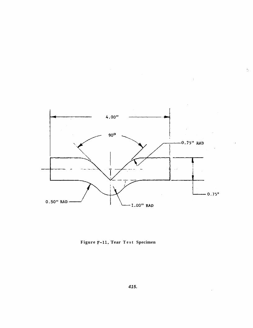
goo \
0.50" RADd
Figure F-12. Tear T e s t Specimen
415.
18. COMPRESSIVE PROPERTIES
Obi ect ive
This method, as defined in Fed. Std. 406, Method 1021, is designed for use in determining the compressive properties of rigid plastics when loaded in compression.
Test Routine
Specimens shall be tested before and after exposure to the applicable cri- teria test environment. Where applicable, standard specimens in the form of a right cylinder or prism whose ends are parallel within 0.005 inch shall be used. or a cylinder 0.5 inch in diameter by 1.0 inch in length is preferred. For rods of less than, or greater than, 0.5 inch, the length/slenderness ratios of Fed. Std. 406, Method 1021, Section 2.5 shall apply. A constant rate of loading, Instron type, compressive testing machine shall be utilized for this test routine.
A prism of square cross-section 0.5 inch by 0.5 inch by 1.0 inch
Comments
Report data shall include the following:
1. Direction, type and rate of loading.
2. Maximum load sustained.
3. Ultimate strength, psi.
4. Failure mode.
5 . Slenderness ratio.
6 . Compressive deformation at maximum load.
416.
19. LAP SNEAR
Obi ect ive
This test method is designed to yield tensile shear strength of adhesive bonded composites.
Test Routine
The test specimen consists of two individual panels, each 1.0 inch by 3.5 inches with suitable holes or grip areas to allow gripping in a tensile machine. trolled thickness of the candidate adhesive. After cure of the adhesive, and after exposure to the applicable criteria test environment, the specimens are tensile stressed to failure. The overlap panels may be of metal such as aluminum, stainless steel, etc. or in the case of rigid plastics bonding, may be constructed of the rigid plastic bonded with the candidate adhesive. A constant rate of loading test machine for the tensile test for rigid solid and laminated plastics (of the Instron type) is required to perform this test routine.
The panels are overlapped 1.0 5 1/64 inch, and bonded with a con-
Comments
Report data shall include the following:
1. Yield strength, psi.
2. Tensile load to failure, psi.
3. Failure mode, ie. adhesive, cohesive.
417.
20. BUTT TENSILE
Ob i ect ive
This test method is designed to yield tensile strength of an adhesive bonded composite. bonded composites.
The method is applicable to rigid and flexible plastic
Test Routine
The butt tensile specimen consists of two blocks of metal (or rigid plastic) 1.0 inch by 1.0 inch by 2.0 inches bonded together at the 1.0 inch by 1.0 inch dimension by a carefully controlled thickness of the candidate adhe- sive, to each face of the tensile blocks. applicable criteria test environment, the specimens are mounted in a test machine and tensile stressed to failure. A constant rate of loading test machine as defined for the tensile test for rigid, solid and laminated plastics (of the Instron type) is required to perform this test routine.
The joint area may also consist of a layer of flexible plastic bonded After adhesive cure and exposure to the
Comments
Report data shall include the following:
1. Yield strength, psi.
2. Ultimate tensile load, psi.
3. Failure mode, i,e. adhesive, cohesive.
418.
ATTACHMENT C: BISS TEST PLAN SCHEDULE
419.

li ).
C c VIII!
420.
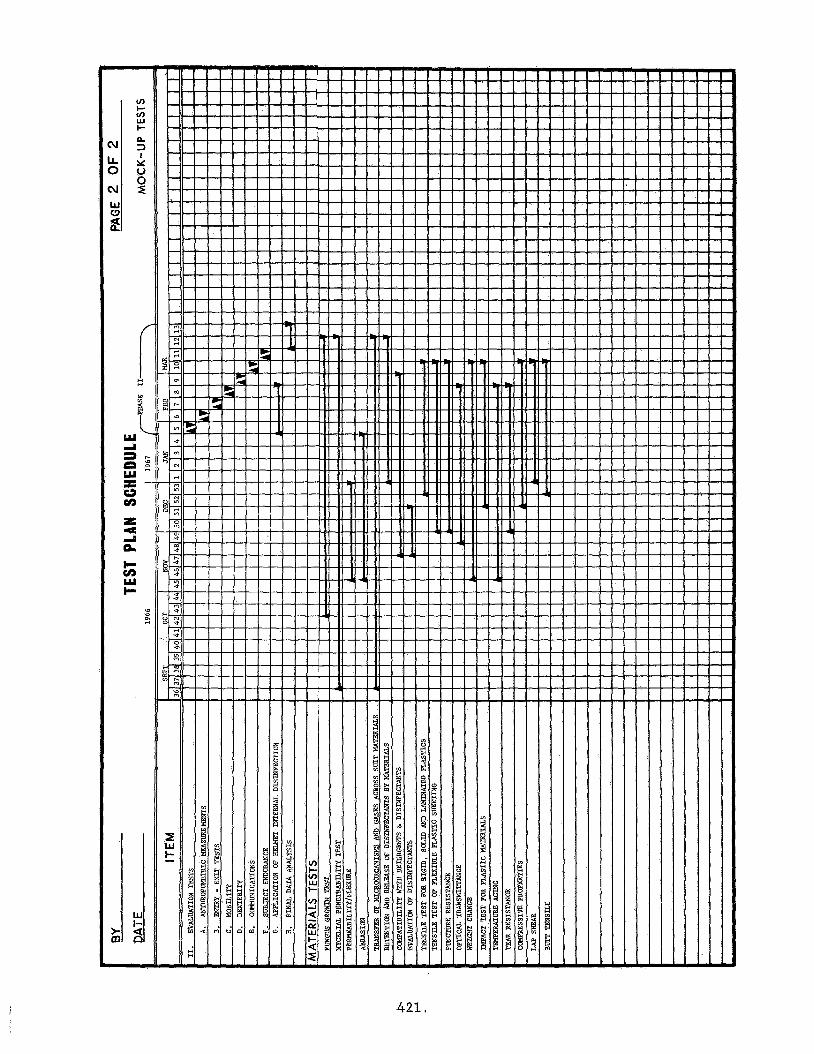
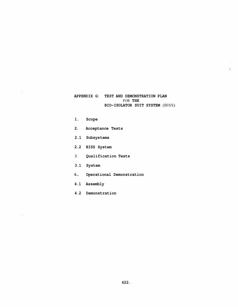
APPENDIX G: TEST AND DEMONSTRATION PLAN FOR THE
BIO-ISOLATOR SUIT SYSTEM (BISS)
1. Scope
2. Acceptance Tests
2.1 Subsys tems
2.2 BISS System
3 . Qualification Tests
3.1 System
4. Operational Demonstration
4.1 Assembly
4.2 Demonstration
422.
1.0 SCOPE - This document def ines t h e t e s t and demonstration plan f o r t he Bio- Isolator Sui t System, here inaf te r refered t o as BISS. BISS subsystems s h a l l be tes ted , interfaced, (assembled), t es ted , and demonstrated as set f o r t h i n t h i s document. The BISS and i ts subsystems are defined i n t h e General Electric Company RSD Specifi- ca t ion ERS 0100-00-0001 (Bio-Isolator Sui t System).
The
2.0 ACCEPTANCE TESTS
2.1 Subsystems - The individual subsystems of t he BISS s h a l l be tes ted i n accordance with t h e acceptance test requirements of Section 4 of t he following specif icat ions:
BISS Undersuit ERS0230-00-0002 BISS Outer Sui t & Tunnel ERS0230-00-0001 L i f e Support Subsystem ERS0210-00-0001 Communications Subsystem ERSO15O-02-0001
2 . 2 BISS System - The BISS system s h a l l be tes ted i n accordance with t h e acceptance test requirements of Section 4 of Specif icat ion ERS0100-00-0001.
3.0 QUALIFICATION TESTS
3.1 System - The BISS system s h a l l be subjected t o the qua l i f i- ca t ion tests as specif ied i n Section 4 of Specif icat ion ERSO100-00-0001.
4.0 OPERATIONAL DEMONSTRATION
4.1 Assembly - The BISS subsystems s h a l l be interfaced (assembled) t o provide t h e complete system f o r operational demonstrations. These subsystems s h a l l be interfaced i n accordance with t he following procedure:
A. In t e r f ace the F a c i l i t y Supervisor's Console with t h e following:
I
1. N e t Control ler ' s Console . 2. Medical Monitor Console 3. Sui t A i r Supply Console
\\ 4 . Assembly/Sterilizer Address Horn 5. Assembly/Sterilizer Warning Horn
4 2 3 .
B. Attach t h e EKG sensors t o t h e technician.
C. A technician s h a l l don the undersuit .
D. In te r face t h e s u i t a i r supply exhaust and supply hoses with t h e undersuit plenum.
NOTE: The s u i t a i r supply may be adjusted a t t h i s point t o provide a low' ra te of flow of cooling a i r t o t h e undersuit .
E. Secure t h e Link transducers t o t he attachment points on t h e undersuit , and in t e r f ace them with t he N e t Control ler ' s Console.
F. Attach t h e "Y" back s t r a p t o the undersuit w a i s t b e l t .
4.2 Demonstration
4.2.1 Environmental Conditions - The BISS demonstration s h a l l be performed i n a chamber capable of maintaining a l l of the environmental conditions required of t he main chamber of t he Assembly S t e r i l i z e r . (i .e. - Temperature - 70°F t o 320°F with RH control led t o less than 1% above 200°F; Pressure - 0 t o 4" H20 gage)
Normal Cycle - With the operator contained within t he undersuit i n a normal room environment, a funct ional check s h a l l be made of t he following:
4.2.2
a ) L i f e support b) Communications c) Medical monitoring
The su i ted technician s h a l l then en te r the outer s u i t and tunnel via the hard tube and s h a l l posi t ion himself i n t he outer s u i t which s h a l l have been mounted on t h e Donning rack and he s h a l l secure t he "Y" back s t r a p t o t h e helmet and yoke D-rings.
NOTE: During the technician's en t ry t o the outer s u i t and tunnel, the s u i t a i r supply hoses and t h e communications cabling s h a l l be carefu l ly fed out down the hard tube.
424.
4.2.2.1 Operational Demonstration - Perform the following functional checks:
A. Check release and engagement of helmet interface loop with donning rack.
Check release and engagement of boots with donning rack base,
Move the outer suit and tunnel clear of the donning rack.
B.
,C.
D. Perform walking, bending, climbing, squat- ting and head movements.
E. Using planned tools and systemlassembly fixtures, perform disassembly, assembly, and check-out functions.
F. Return to donning rack and interface the helmet and boots with the donning rack fix- tures.
G. Perform exit procedures from the outer suit and tunnel.
The above functional demonstration shall be re- peatedvarying the total time the technician is in the chamber up to a maximum of 4 hours. these demonstration cycles, the following times shall be recorded.
During
A. Entrance into the suit
B. Release from the donning rack
C. Re-attachment to the donning rack of the suit for egress from the outer suit and tunnel
The activities of the technician shall be directed by the test conductor via the BISS communication system and the technician's comfort and well being shall be monitored both by oral communication with the test conductor and by observing the real time electrocardiogram recording.
425.
4.2.3 Emergency Cycle #I - The normal cyc le above s h a l l be repeated through Step I) a t which point the technician s h a l l simulate a semi-comatose condition and a second technician i n a second BISS system s h a l l assist him through Steps F & G above. This cyc le s h a l l be per- formed a t various Assembly S t e r i l i z e r pressure con- d i t i o n s ranging from 0 t o 4" H20 gage a d the t i m e from simulation of the comatose condition t o t he f i n a l e x i t s h a l l be recorded.
4.2.4 Emergency Cycle 82 - The procedures of t h e emergency cycle #1 s h a l l be repeated, however, t he technician s h a l l now simulate a condition of complete i n a b i l i t y of physical movement. .
426.
APPENDIX H: ILLUSTRATIONS OF EQUIPMENT USED IN PHYSICAL TESTING
1. Taber Abraser Model 174
2. Gardner Impact Tester
3. Temperature Aging Facility
4. Wolor-Eye" Spectrophotometer
5. Flexibility Apparatus
427.
F i g u r e H - 1 - Taber Abraser Model 1 7 4
F i g u r e H-2 - Gardner Impact T e s t e r
4 2 8 .
429.
Figure H-3 - Temperature Aging F a c i l i t y
Figure H - 4 - "Color-Eye Reflectance Instrument
430.
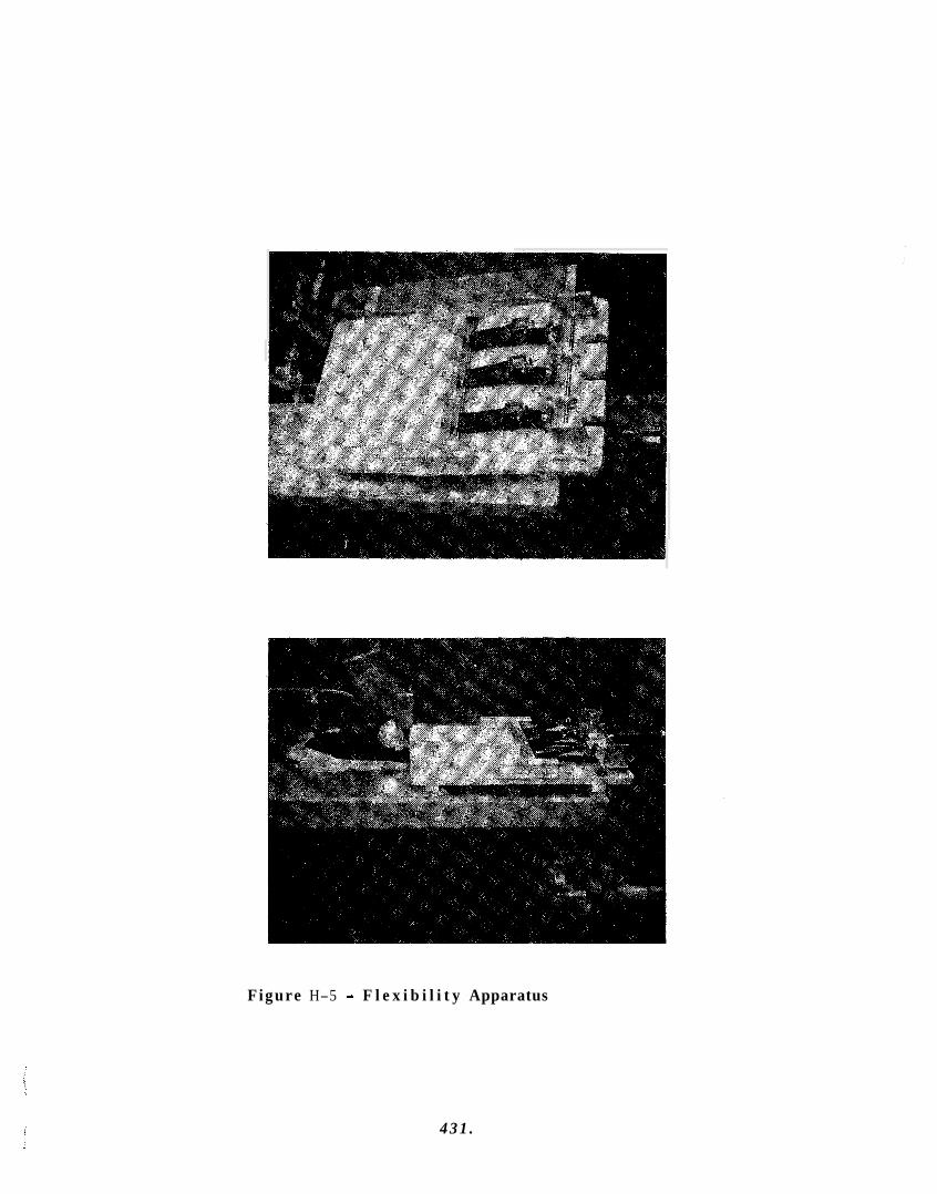
Figure H-5 - F l e x i b i l i t y Apparatus
4 3 1 .
APPENDIX I: MATERIAL PROPERTY DATA SHEETS
1. Introduction
2. optical Transmission
3 . Test Results
4 . References
432.
APPENDIX I: MATERIAL PROPERTY DATA SHEETS
1. INTRODUCTION
This appendix contains the physical test r e s u l t s , t ab l e s , and i l l u s t r a t i o n s from which the f i n a l se lec t ion of candidate mater ia ls was made.
A l i s t of references is included, ind ica t ing the sources of infor- mation which were used f o r the l i t e r a t u r e search during the Phase I candidate mater ia ls se lec t ion .
2. OPTICAL TRANSMISSION
Optical transmission curves were determined by means of the "Color- Eye" Calorimeter and Abridged Spectrophotometer i n the v i s i b l e wave- length range (.4 - .7 microns), using barium s u l f a t e references i n the sample and standard por t s . micron increments over the v i s i b l e range compared t o a i r .
Percent transmission is plo t ted a t 0.02
Lexan specimens, both v i r g i n mater ia l , and environmentally aged were measured, a s w e l l a s a representat ive quartz (Corning #7940) a s shown i n Figures 1-1 and 1-2. No changes were noted i n the quartz a s a function of the environments, therefore , only a v i rg in p l o t i s shown fo r t h i s mater ia l .
Quartz exh ib i t s a 93% plus transmission across the e n t i r e spectrum, whereas Lexan va r i e s from 57% a t the blue region t o 85% a t the yellow- red end of the spectrum.
Small var ia t ions of 1-2% i n transmission a r e noted a s a function of hea t aging, the ETO/Freon treatment and the detergent treatments, however, f o r p rac t i ca l considerations these changes may be considered negl ig ib le .
The g rea t e s t e f f e c t , as might be expected, i s noted i n the cases of abrasion, and abrasion combined with detergent treatment. I n these cases , transmission has degraded t o a.low of 23.5% i n . t h e blue and t o a low value of 43.5% i n the red. It i s therefore obvious t h a t handling abrasion, ora.brasion-induced by chemical cleaning can be most detrimental t o op t i- c a l c l a r i t y .
3 . TEST RESULTS
The test r e s u l t s presented herein were derived from both a l i t e r a - ture search and experimentation. through I-XXV.
The r e s u l t s appear i n Tables 1-1
4 3 3 .
Some observations as indicated below, may be noted as a result of the tensile property evaluations:
. Armalon 97-001, Silicone Rubber SE-555, Lexan,and Textolite 11546 are stable in the environment and exhibit negligible property change.
Neoprene is attacked by the disinfectant and ETO/Freon treat- ments, and is essentially unaffected by the detergent treatment. Heat aging also causes degradation of the neoprene tensile values.
.
. Butly rubber tensile strength is reduced environment:
50% by the heat age
434.
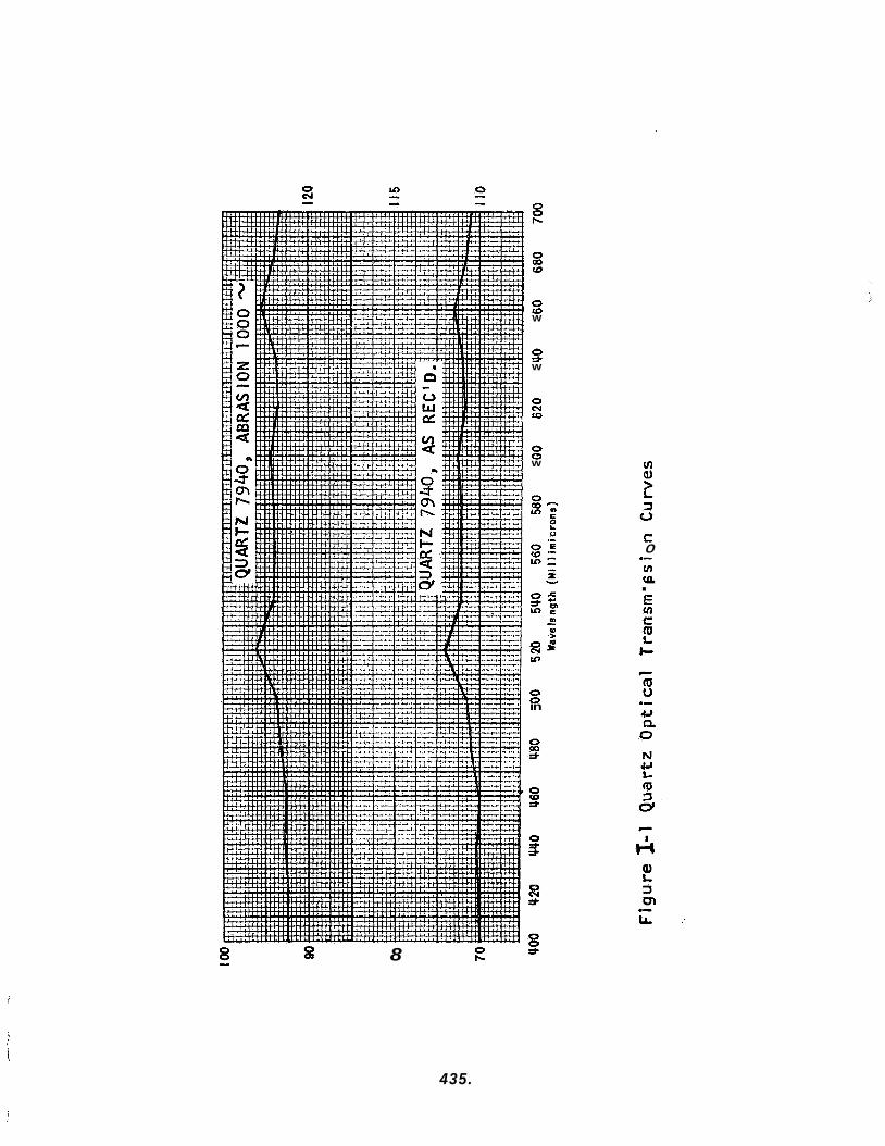
0 (0 W
s W
0 cv (0
0 0 W
8
0 0 in
5: 3
0 3 =f
c 0 .- v) v) .-
435.
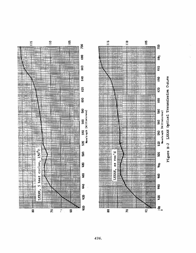
0 00 W
0 W W
0 * W
0 C-J W
0 0 W
0 5:
8 9
8 0 0 O =I- 00 I- W
D aJ 3 id 7 u
N I H
436.
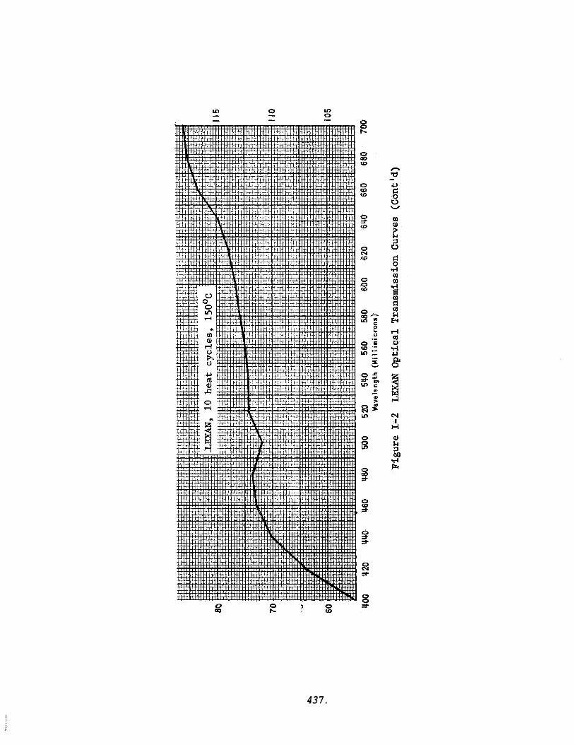
0 OD
437.
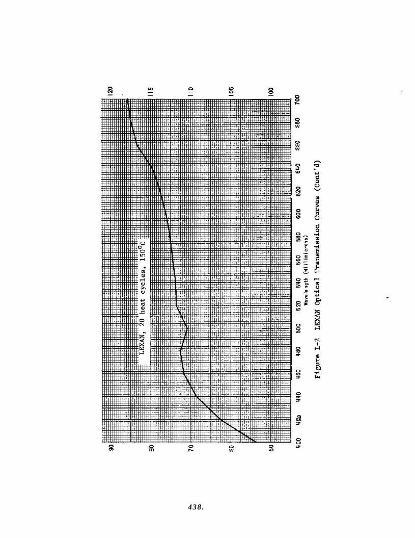
0 0 -
0 m 0 W
0 m W
0 W W
0 j. r,
a r,
0 0 j
f
438.

0 03 W
0 W W
0 =I. (0
0 N W
0 0 W
0 9:
v)
a v)
0 5:
0 OD =I.
v) Q) 3
V s
.- I Y
3 w 4 N
I H
0 Q)
0 OD
0 0
0 9 W
439 .
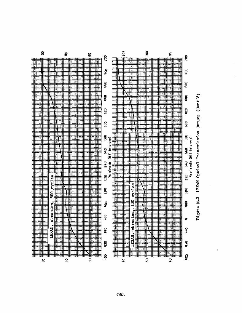
In Q,
0 m 0 m
0 E
8 W
0 W W
3 W
8 W
0 z 0 a 0 ut
0 W u)
s m
a u)
0 5:
8 3
0 s s
F3 s
0 0 s
c * c
u E
e .- .- c - .- x
c + LII
E
0
Y
m c
P
0 0 h
0 OD W
0 W VI
s W
8 W
0
s?
m c
0 >
FSP In
0 5:
.O OD *
*
0 9 s
a s
8 s
La Q) 3 k 1 u
h( I H
440.
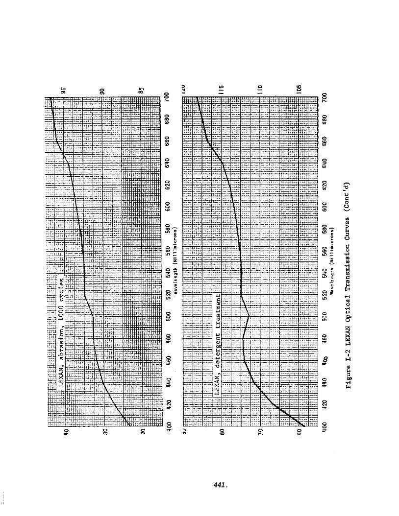
Lo b)
In OQ
m 2
0 =,
0 CD
0 r- 0 W
r-
0 OD W
0 CD W
0 =t W
23 W
0 0 (0
0 s: 0 CD 5-
8 *
0 =t =t
0 0 9
441.
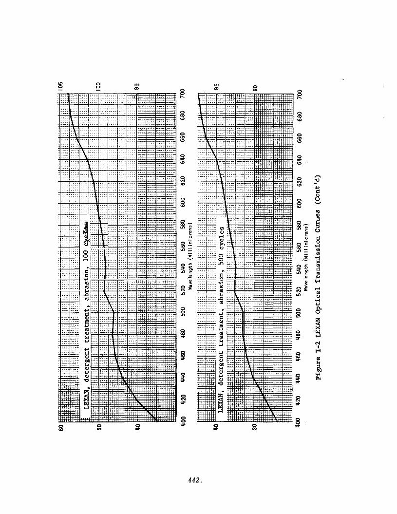
m a,
d:T 3 :::. :::.
M:::: : : : j 0 :::: ::.. . . . . . . . .
rn 01 d c) h 0 0 0 rl
m
rl m nl k
0 (0
m U
5 E! U tu Q) k U
0 u)
0 *
W aJ 3 k 1 u
442.
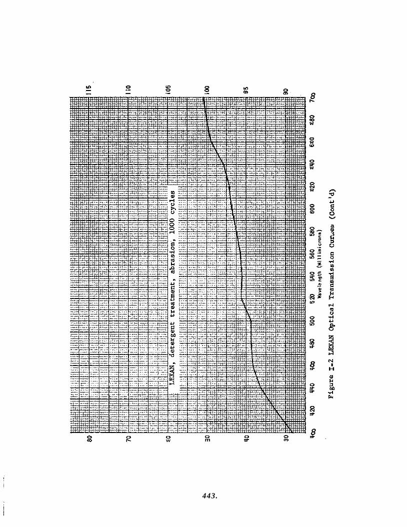
8 b
0 cp W
0 W (0
s W
0 crl W
.lJ
u g W
0 5:
a 9) 3 k 7 u
N I H
8 * Q) i-i
.rl F 7M
8 =t 0 0
m =t 0 0 0 cp b W
443.
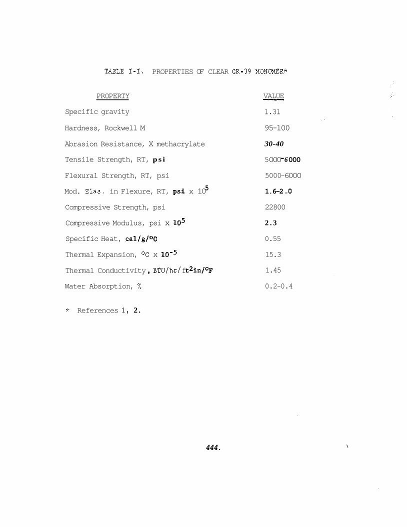
TABLE 1-1. PROPERTIES OF CLEAR CR-39 MONOPER*
PROPERTY
Specific gravity
VALUE - 1.31
Hardness, Rockwell M 95-100
Abrasion Resistance, X methacrylate 30-40
Tensile Strength, RT, p s i 5 000 - 6 000
Flexural Strength, RT, psi 5000 -6000
1.6-2 .O 5 Mod. Elas. in Flexure, RT, psi x 10
Compressive Strength, psi 22800
Compressive Modulus, psi x lo5
Specific Heat, cal/g/OC 0.55
Thermal Expansion, OC x 15.3
Thermal Conductivity , BTU/hr / f t2in/OF 1.45
2 . 3
Water Absorption, % 0.2-0.4
* References 1, 2 .
444. \
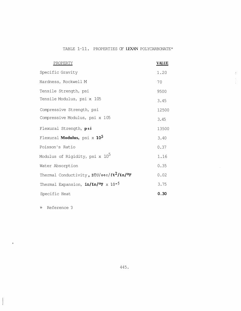
TABLE 1-11. PROPERTIES OF LEXAN POLYCARBONATE*
PROPERTY
Specific Gravity
Hardness, Rockwell M
Tensile Strength, psi
Tensile Modulus, psi x 10 5
Compressive Strength, psi
Compressive Modulus, psi x 10 5
Flexural Strength, p s i
Flexural Modulus, psi x lo5
Poisson's Ratio
Modulus of Rigidity, psi x 10
Water Absorption
Thermal Conductivity , BTU/sec/f t2/in/OF
Thermal Expansion, in/in/OF x 10-5
Specific Heat
5
VALUE
1.20
70
9 500
3.45
12500
3.45
13500
3.40
0.37
1.16
0.35
0.02
3.75
-
0.30
,
* Reference 3
445.
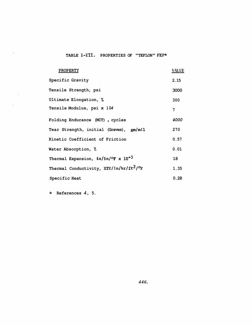
TABLE 1-111. PROPERTIES OF "TEFLON" FEPdr
PROPERTY
Specific Gravity
Tensile Strength, psi
Ultimate Elongation, %
Tensile Modulus, psi x 10 4
VALUE
2.15
-
3000
300
7
Folding Endurance (MIT) , cycles 4000
Tear Strength, initial (Graves), gm/mil 270
Kinetic Coefficient of Friction 0.57
Water Absorption, % 0.01
Thermal Expansion, in/in/OF x 18
Thermal Conductivity, BTU/in/hr/ft2/* 1.35
Specific Heat 0.28
* References 4 , 5.
446.
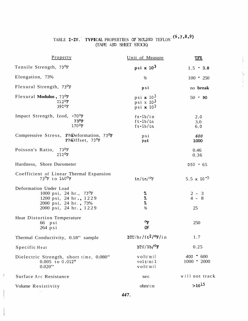
. (6 Y 7 Y 8Y9) TABLE I-IV. TYPICAL PROPERTIES OF'MOLDED TEFLON (TAPE AM, SHEET STOCK)
Property
Tens i l e Strength, 7 3 9
Elongation, 73%
Flexural Strength, 7 3 9
Flexural Modulus , 7 3 9 212OF 3 9 2 9
Impact Strength, Izod, -70- 7 3OF
170-
Compressive S t r e s s , 1% Deformation, 7 3 9 1% Offse t , 7 3 9
Poisson's Ratio, 7 3 9 212-
Hardness, Shore Durometer
Coefficient of Linear Thermal Expansion 7 3 9 t o 140°F
Deformation Under Load 1000 p s i , 24 h r . , 730F 1200 p s i , 24 h r . , 1 2 2 9 2000 p s i , 24 h r . , 73% 2000 p s i , 24 h r . , 1 2 2 9
Heat Dis to r t ion Temperature 66 p s i 264 p s i
Thermal Conductivity, 0.18" sample
Spec i f i c H e a t
D ie lec t r i c Strength, shor t t i m e , 0.080" 0.005 t o 0.012" 0.020"
Surface A r c Resistance I
Volume R e s i s t i v i t y
Unit of Measure
p s i x 103
%
p s i
p s i x 103 p s i x 103 p s i x 103
f t - lb/ i n f t - l b / i n f t - lb / in
p s i P s i
i n / i n / 9
% % % %
OF OF
BTU /hr / f t2/OF / i n
BTU/ lb/OF
v o l t / m i l v o l t / m i 1 v o l t / m i l
se c
ohm/ c m
447.
T X
1.5 - 3.0
100 - 250
no break
50 - 90
2 .o 3.0 6 .O
600 1000
0.46 0.36
D50 - 65
5.5 10-5
2 - 3 4 - 8
25
250
1.7
0.25
400 - 600 1000 - 2000
w i l l no t t r ack
> 1015
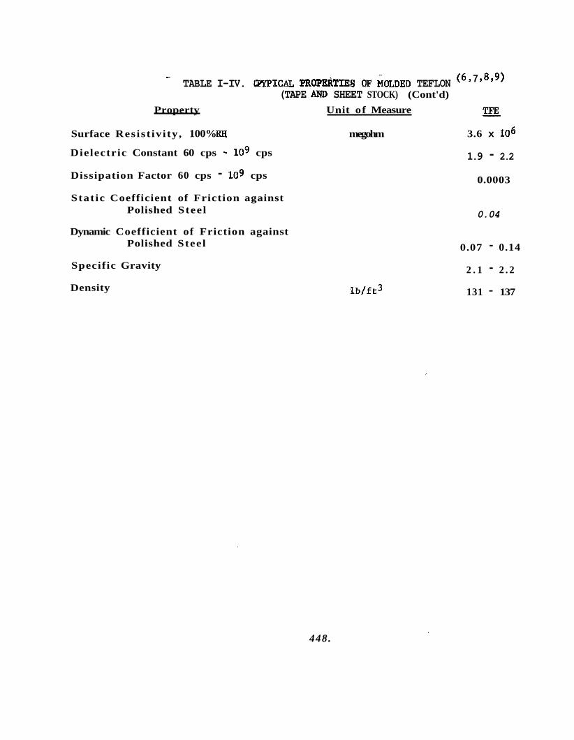
r (6 9 7 $8 $9) TABLE I-IV. ~ I C A L PROPEI~TIES OF MULDED TEFLON
2% (TAPE AND SHEET STOCK) (Cont'd)
Property Unit of Measure
Surface Resist ivi ty , 100% RH megohm 3.6 x IO6
Dielectric Constant 60 cps - IO9 cps
Dissipation Factor 60 cps - lo9 cps
Stat ic Coefficient of Friction against Polished Steel
Dynamic Coefficient of Friction against Polished Steel
Specific Gravity
Density lb/f t3
1.9 - 2.2 0.0003
0.04
0.07 - 0.14
2 . 1 - 2 . 2
131 - 137
448.
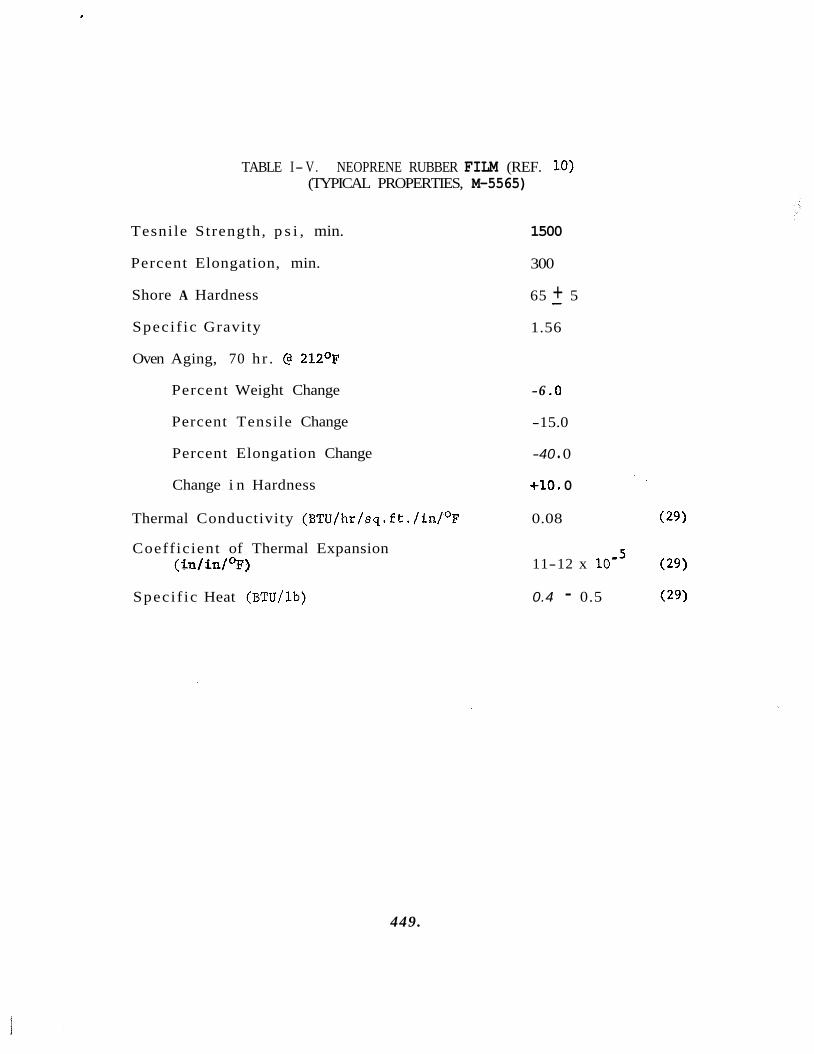
TABLE I- V. NEOPRENE RUBBER FILM (REF. I O ) (TYPICAL PROPERTIES, M-5565)
Tesnile Strength, p s i , min.
Percent Elongation, min.
Shore A Hardness
Speci f ic Gravity
Oven Aging, 70 h r . (3 212OF
Percent Weight Change
Percent Tensile Change
Percent Elongation Change
Change i n Hardness
1500
300
65 + 5 - 1.56
-6 .O
-15.0
-40 0
+lo. 0
Thermal Conductivity (BTU/hr/sq.ft./in/OF 0.08 ( 2 9 )
Coefficient of Thermal Expansion ( Win/* ) ( 2 9 )
5 11-12 x 10-
Speci f ic Heat (BTU/lb) 0.4 - 0.5 ( 2 9 )
449.
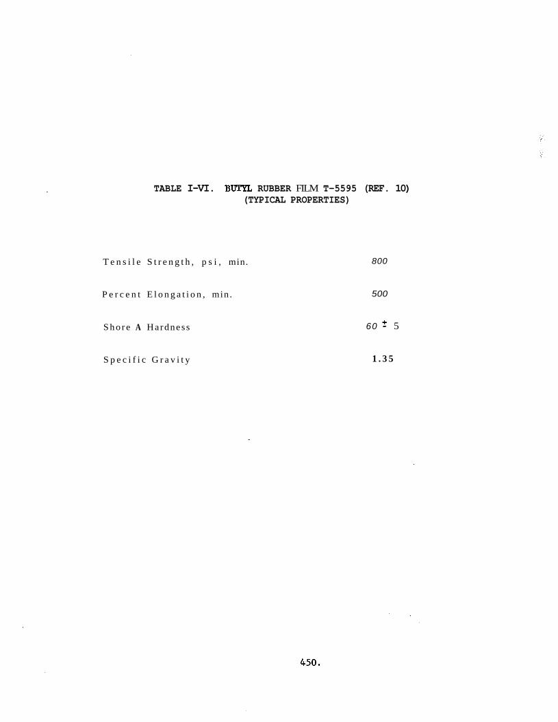
TABLE I-VI. BUTYL RUBBER FILM T-5595 (REF. 10) (TYPICAL PROPERTIES)
T e n s i l e S t r e n g t h , p s i , min.
P e r c e n t E l o n g a t i o n , min.
S h o r e A Hardness
S p e c i f i c G r a v i t y
800
500
60 f 5
1 . 3 5
450.
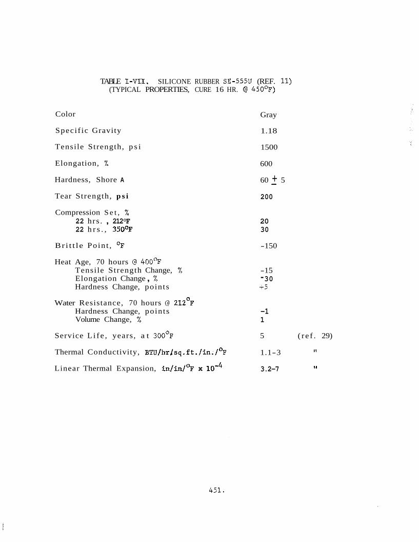
TABLE I-VII. SILICONE RUBBER SE-555U (REF. 11) (TYPICAL PROPERTIES, CURE 16 HR. @ 450OF)
Color
Specif ic Gravity
Tensile Strength, p s i
Elongation, %
Hardness, Shore A
Tear Strength, p s i
Compression S e t , % 22 hrs . , 212°F 22 h r s . , 350°F
Bri t t le Po in t , O F
Heat Age, 70 hours @ 4OO0F Tensile Strength Change, % Elongation Change , % Hardness Change, points
Water Resistance, 70 hours @ 212'F Hardness Change, points Volume Change, %
Service L i f e , years, a t 300°F
Thermal Conductivity, BTTJ/hrlsq.ft./in./°F
Linear Thermal Expansion, in/in/OF x lom4
Gray
1.18
1500
600
60 + 5
200
-
20 30
-150
-15 - 30 +5
-1 1
5 ( r e f . 29)
I 1 1.1-3
11 3.2-7
451.
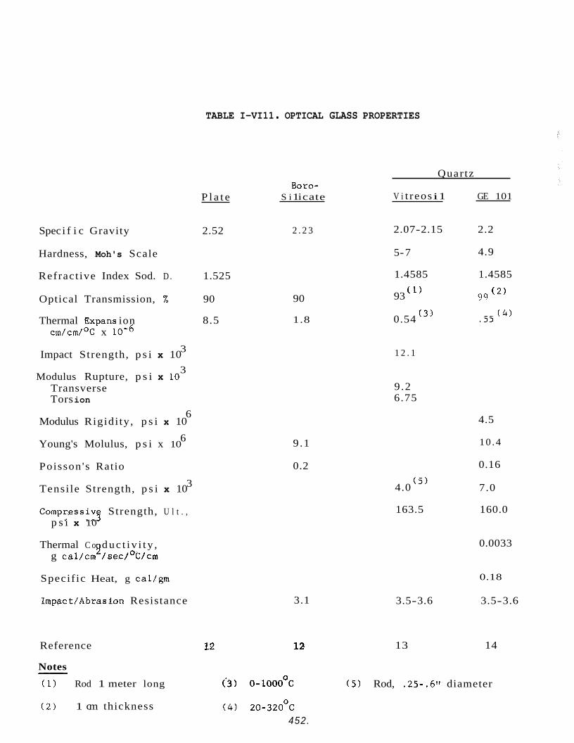
TABLE I-VI11 . OPTICAL GLASS PROPERTIES
Quartz
V i t r eos i 1 GE 101 Boro-
S i 1 icate P l a t e
2.07-2.15 2.2
5- 7 4.9
1.4585 1.4585
93 ( l ) 99 ( 2 )
( 4 ) -55 (3) 0.54
Spec i f i c Gravity 2.52 2 . 2 3
Hardness, Moh's Scale
Refract ive Index Sod. D . 1.525
90
1.8
Optical Transmission, X 90
Thermal Expans ion cm/cm/oC x 10-6
3
3 Impact Strength, p s i x 10
Modulus Rupture, p s i x LO Transverse Tors ion
6 Modulus Rigidi ty , p s i x 10
6 Young's Molulus, p s i x 10
8.5
1 2 . 1
9 .2 6.75
4.5
10 .4
0.16
9 .1
0.2 Poisson 's Ratio
Tensi le Strength, p s i x 10 3 7.0 (5) 4.0
163.5 160.0 Compressivs Strength, U l t . , p s i x 10
Thermal C o duc t i v i t y , g caL/cm / s e c / ° C / c m 9 0.0033
Specif ic Heat, g cal/gm 0.18
3.5-3.6 3.5-3.6 3.1 Impact/Abrasion Resistance
Reference 13 14
Notes
(1 ) Rod 1 meter long -
('3) o-looo°C (5 ) Rod, .25-.6" diameter
(4 ) 20-320°C 452.
( 2 ) 1 cm thickness
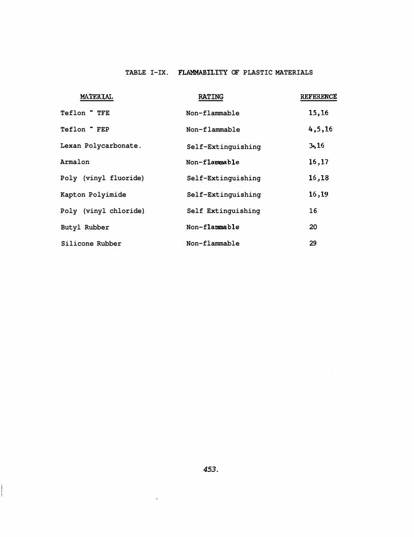
MAT33RIAL
Teflon - TFE Teflon - FEP
TABLE I-IX. J?LAMMABILITY OF PLASTIC MATERIALS
Lexan Polycarbonate
Armalon
Poly (vinyl fluoride)
Kapton Polyimide
Poly (vinyl chloride)
Butyl Rubber
Silicone Rubber
RATING REFERENCE
Non-flammable 15,16
Non-f lammable 4,5,16
Self -Extinguishing 5 16
Non-f lanunable 16,17
Self-Extinguishing 16,18
Self-Extinguishing 16,19
Self Extinguishing 16
Non-f lanunable 20
Non-flammable 29
453.
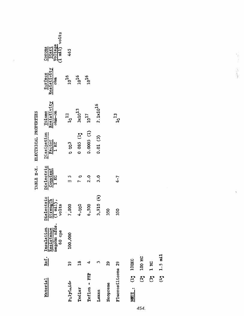
m U rl
4 H
m rl 0 rl
m 0 0 0
m m
m rl 0 rl x m
n rl W
rn m 0
0
0 I-
O 0 0 n
4
cr) 4 0 rl
c n m 4 m m c n r l r l C V N
PI w Fr
a, 3 6 .rl h rl 0 pc
I- t
\o
n n n n r l C V m W W W Z .. PI 2
454.
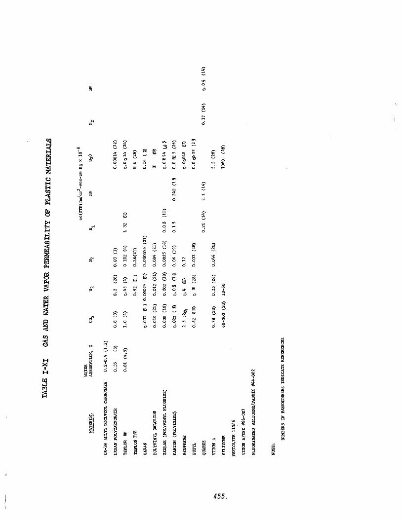
i
b
3 H
H 7
h
3 9 0 0
0
n rl N W
N
d
m
n 5 N
rl
0
m
n 5
9 v)
0
n s 9 rl
h
? s 9 rl
0
L w l4
B
n m c: 10
m
n m N
.j
0
v
?
n m N V
W rl
n Ln
3 zif 9 rl 0
0
h 10 c? m N m 0
0 9
n m
m 4
0
d
N.
n
d m v
u) m L n
0 0 ? ?
N 4
0 9
h F- N v
m 8 9 0
0
n h
c! W
0 0 0
0
m
9
A
rl N W
N
0 0:
n rl N V
8 00 2 h
rl N W
rl m 9 0
n n d c a c ! Z N N d o
0 0 9 9
2 6 3 d
9 9 o m d o
0 0
n m d
9 In d
0
n m rl v
h s 0
n m N v
5 0
6 c! Ln N
m^ N
m rl 0
v
n
01 " N
0
m
?
i
455.
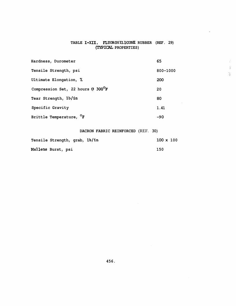
TABLE I-XII. FLUOROSILICONE RUBBER (REF. 29) (TYPICAL PROPERTIES)
Hardness, Durometer
Tensile Strength, psi
Ultimate Elongation, 2,
Compression Set, 22 hours @ 300°F
Tear Strength, lb/in
Specific Gravity
Brittle Temperature, OF
65
800-1000
200
20
80
1.41
-9 0
DACRON FABRIC REINFORCED (REF. 30)
Tensile Strength, grab, lb/in 100 x 100
Mullens Burst, psi 150
456.
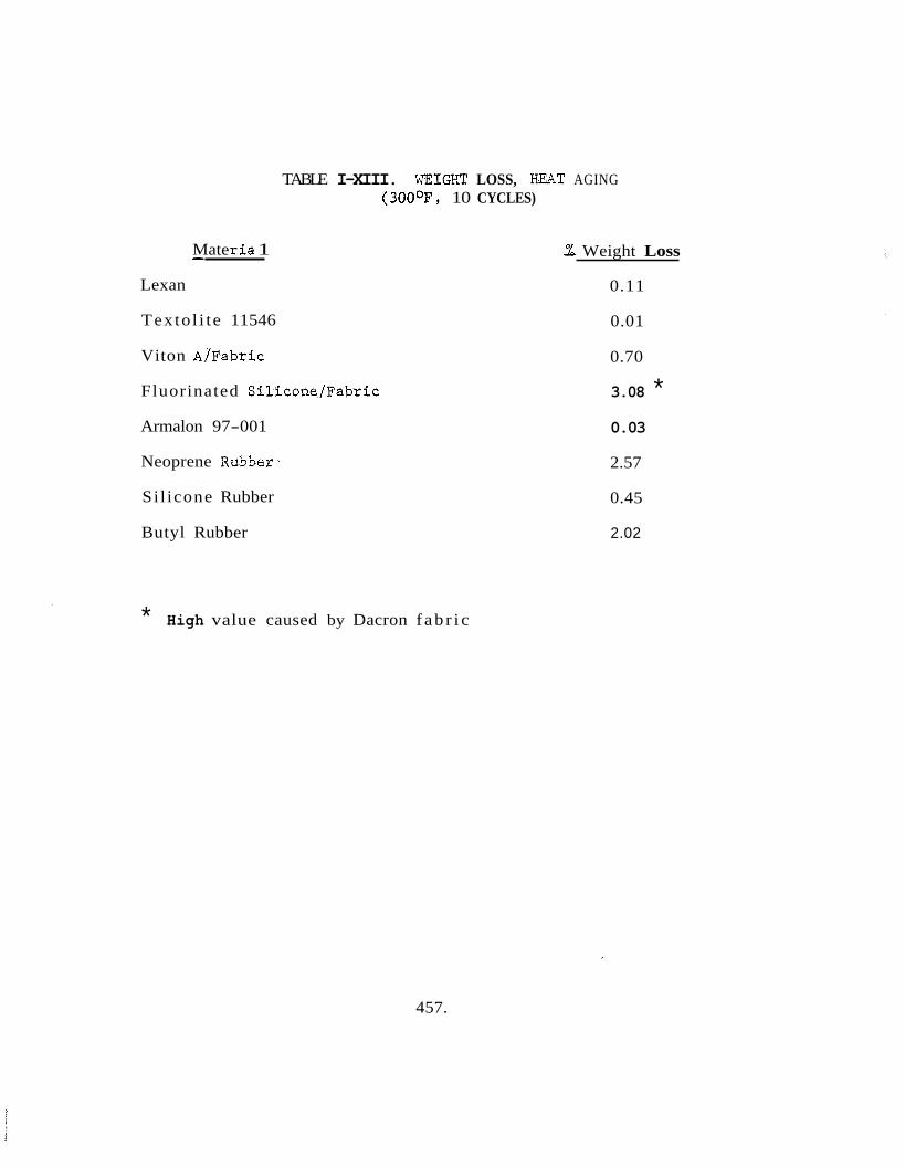
TABLE I-XIII. WEIGHT LOSS, KEAT AGING (300°F, 10 CYCLES)
Mate 1: i a 1 - Lexan
Texto l i te 11546
Viton A/Fabric
Fluorinated Si l icone/Fabric
Armalon 97-001
Neoprene Rubber-
Si l icone Rubber
Butyl Rubber
* High value caused by Dacron f a b r i c
- % Weight Loss
0.11
0.01
0.70
3.08 * 0.03
2.57
0.45
2.02
457.

’ Material
Textolite 11546
Lexan
TABLE I-XIV. IMPACT PROPERTIES
Condition
Vlrgin Material
300°F, 5 cycles
300°F, 10 cycles
300°F, 20 cycles
3009, 10 cycles, plus detergent
Detergent Treatment
300°F, 10 cycles, plus disinfectant
Disinfectant Treatment
300°F, 10 cycles, plus ETO/Freon
Virgin Material
Detergent Treatment
Disinfectant Treatment
ETO/Freon
3OOoF, 5 cycles
P = PASS MF = MINOR FAILURE TF = TOTAL FAILURE
Result
P
P
P
P
P
P
P
MF
TF
TF
458.
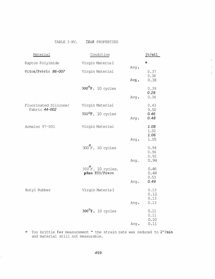
TABLE I-XV. TEaR PROPERTIES
Material
Kapton Polyimide
Viton/Fabric 86-007
Fluorinated Silicone/ Fabric 44-002
Armalon 97-001
Butyl Rubber
Condition
Virgin Materia 1
Virgin Material
300°F, 10 cycles
Virgin Material
300°F, 10 cycles
Virgin Material
0 300 F, 10 cycles
0 300 F, 10 cycles, plus ETO/Freon
Virgin Materia 1
lb/mil -- Jr
Avg . 0.37 0.38
Avg . 0.38
0.39 0.28
Avg . 0.34
0.43 0.50 0.46
Avg . 0.48
1.08 1.02 1.06
Avg . 1.05
0.94 0.96 0.92
Avg. 0.94
0.46 0.48 0.53
Avg . 0.49
0.13 0.12 0.13
Avg . 0.13
300°F, 10 cycles 0.11 0.11 0.10
Avg . 0.11
* Too brittle f o r measurement - the strain rate was reduced to 2"/min and material still not measurable.
459.
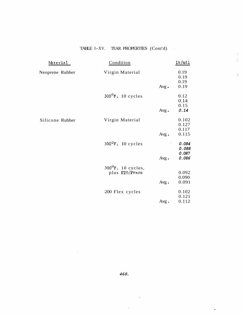
Ma ter i a l
Neoprene Rubber
Sil icone Rubber
TABLE I-XV. TEAR PROPERTIES (Cont'd)
Condition
Virgin Material
300°F, 10 cycles
Virgin Material
300°F, 10 cycles
300°F, 10 cycles, p lus ETO/Freon
-200 Flex cycles
Avg .
Avg .
Avg .
Avg .
Avg .
Avg .
lb/mil
0.19 0.19 0.19 0.19
0.12 0.14 0.15 0.14
0.102 0.127 0.117 0.115
0.084 0.088 0.087 0.086
0.092 0.090 0.091
0.102 0.121 0.112
460.
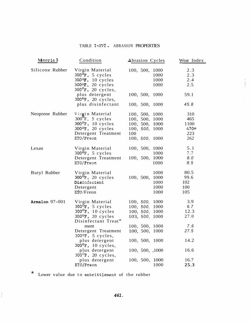
TABLE I-XVI . ABRASION PROPERTIES
Ma t e r ia 1 Condition
Sil icone Rubber Virgin Material 300°F, 5 cycles 3OO0F, 10 cycles 3000F, 20 cycles 300°F, 20 cycles , plus detergent
300°F, 20 cycles, plus d i s i n f ec t an t
- Abrasion Cycles
100, 500, 1000 1000 1000 1000
Wear Index
2 .3 2 .3 2.4 2.5
-
100, 500, 1000 59.1
100, 500, 1000 45.8
Neoprene Rubber V i r i n Material 300 F, 5 cycles 6 300°F, 10 cycles 300°F, 20 cycles Detergent Treatment ETOIFreon
100, 500, 1000 100, 500, 1000 100, 500, 1000 100, 500, 1000 100 100, 500 , 1000
310 465
1100 470* 223 262
Lexan Virgin Material 100, 500, 1000
Detergent Treatment 100, 500, 1000 300°F, 5 cycles 1000
ETO/Freon 1000
5 .1 7 .7 8.0 8.5
Butyl Rubber Virgin Material 1000 300°F, 20 cycles 100, 500, 1000 Dis InSectant 1000 Detergent 1000 ET0 /Freon 1000
80.5 99.6
102 100 105
Armalon 97-001 Virgin Material 300°F, 5 cycles 300°F, 10 cycles 300°F, 20 cycles Dis infectant Treat - Detergent Treatment 3000F, 5 cycles ,
p lus detergent 300°F, 10 cycles,
p lus detergent 300°F, 20 cycles ,
p lus detergent ETO/Freon
ment
100, 500, 1000 100, 500, 1000 100, 500 , 1000 103, 500 , 1000
3.9 6.7
12.3 27.0
100, 500, 1000 100, 500, 1000
7 . 6 27.5
100, 500, 1000 14.2
100, 500, ,1000 16.6
100, 500, 1000 1000
16.7 2 5 . 3
* Lower value due t o embrittlement of the rubber
461.
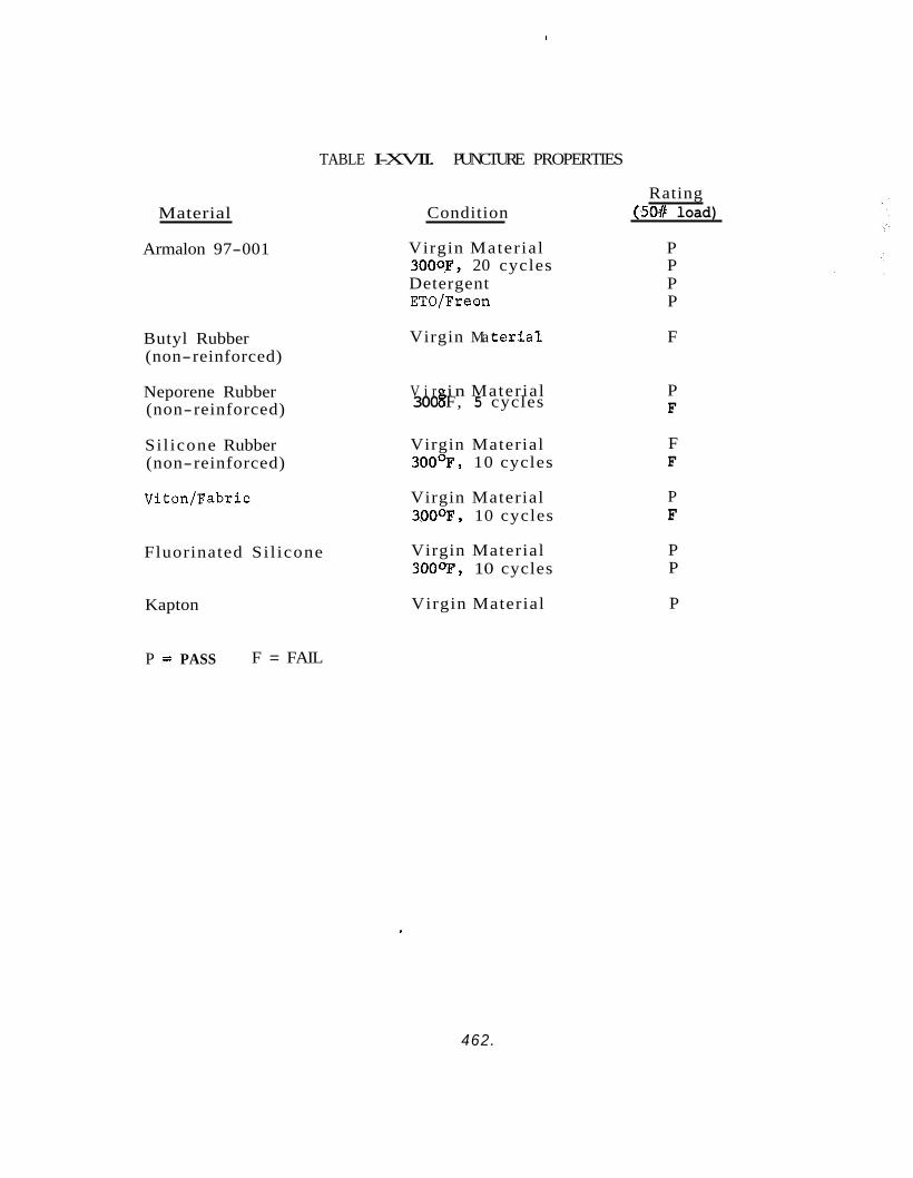
Material
Armalon 97-001
Butyl Rubber (non-reinforced)
Neporene Rubber (non-reinforced)
Si l icone Rubber (non-reinforced)
Viton/Fabric
Fluorinated Si l icone
TABLE I-XVII. PUNCTURE PROPERTIES
Kapton
Condition Rating
(SO# load)
Virgin Mater ia l P 3000F, 20 cycles P Detergent P ETO/Freon P
Virgin Ma t e r i a l F
V i r i n Mater ia l 300 8 F, 5 cycles
Virgin Material 3009, 10 cycles
Virgin Material 300°F, 10 cycles
Virgin Material 3000F, 10 cycles
Virgin Material
P F
F F
P F
P P
P
P = PASS F = FAIL
462.
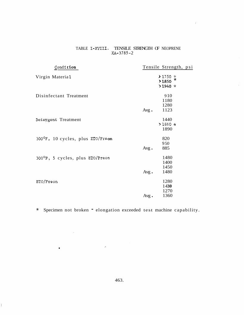
TABLE
Condi t %on - Virgin Materia 1
I-XVIII. TENSILE STRENGTH OF NEOPRENE XA-3785 -2
Tensile Strength, p s i
Disinfectant Treatment
Avg . Detey.gent Treatment
300°F, 10 cycles, plus ET0 /Fre on
Avg . 300°F, S cycles, plus ETO/Freon
ETO/Freon
Avg .
Avg .
>1750 * >la50 * >1940 *
9 10 1180 1280 1123
1440 >1860 *
1890
820 9 50 885
1480 1400 1450 1480
1280 14 30 1270 1360
* Specimen not broken - elongation exceeded test machine capabi l i ty .
.
463.
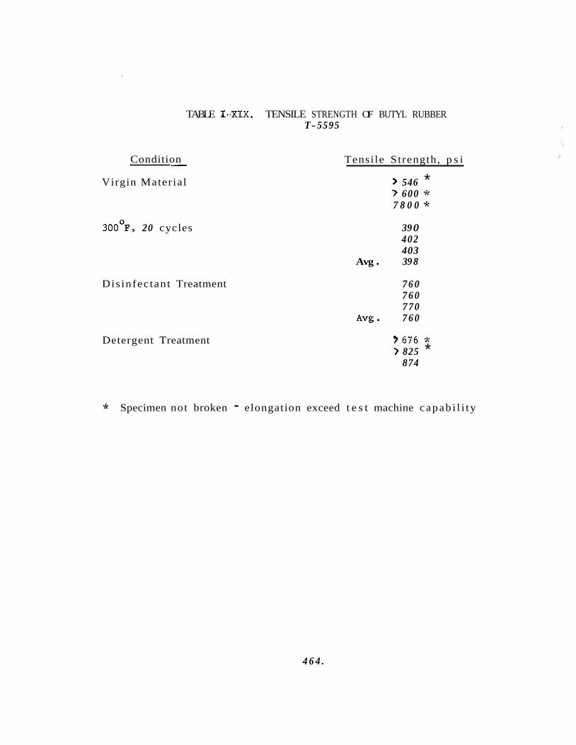
Condition - Virgin Material
3OO0F, 20 cycles
TABLE 1-XIX. TENSILE STRENGTH OF BUTYL RUBBER T-5595
Disinfectant Treatment
Detergent Treatment
Tensile Strength, p s i
Avg .
Avg .
> 546 * 7 600 * 7 8 0 0 *
39 0 402 403 39 8
7 6 0 7 6 0 770 7 6 0
? 6 7 6 * > 825 *
874
* Specimen not broken - elongation exceed t e s t machine capab i l i ty
4 6 4 .
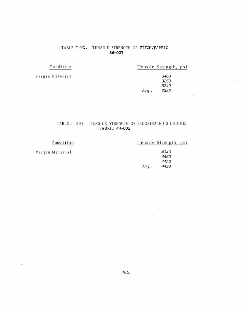
TABLE I-M. T E N S I L E STRENGTH OF VITON/FABRIC 86-007
C o n d i t i o n
V i r g i n M a t e r i a 1
Tensile Strength, p s i
3460 3250 3240
A v g . 3320
TABLE I - X X I . T E N S I L E STRENGTH OF FLUORINATED S I L I C O N E / FABRIC 44-002
C o d it ion
V i r g i n M a t e r i a l
Tens i l e Strength, p s i
4340 4450 447 0
A v g . 4420
465.
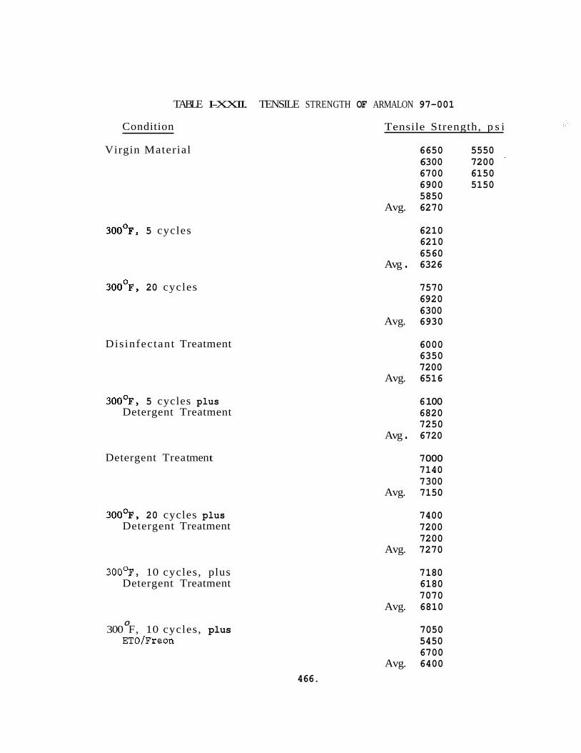
Condition
TABLE I-XXII. TENSILE STRENGTH OF ARMALON 97-001
Virgin Material
300°F, 5 cycles
300°F, 20 cycles
Disinfectant Treatment
300°F, 5 cycles plus Detergent Treatment
Detergent Trea tmen t
300°F, 20 cycles plus Detergent Treatment
300°F, 10 cycles, plus Detergent Treatment
0 300 F, 10 cycles, plus
ETOIFreon
Tensile Strength, p s i
6650 5550 6 300 7200 6700 6150 6900 5150 5850
Avg. 6270
6210 6210 6560
Avg . 6326
7570 69 20 6 300
Avg. 6930
6000 6350 7 200
Avg. 6516
6 100 6820 7250
Avg . 67 20
7 000 7 140 7 300
Avg. 7150
7400 7200 7200
Avg. 7270
7 180 6 180 7070
Avg. 6810
7050 5450 6700
Avg. 6400 466.
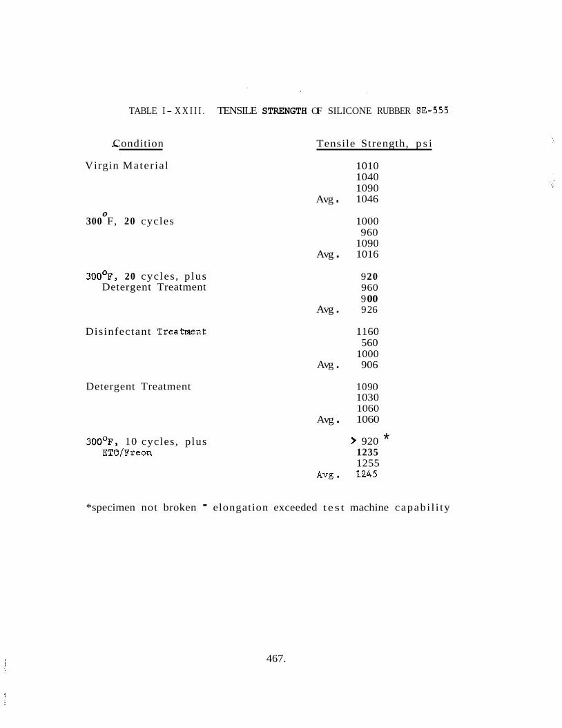
TABLE I - X X I I I . TENSILE STRENGTH OF SILICONE RUBBER 83-555
- Condition Tensile Strength, p s i
Virgin Mater ial
0 300 F, 20 cycles
3OO0F, 20 cycles , plus Detergent Treatment
Disinfectant Treatment
Detergent Treatment
300°F, 10 cycles, plus ETO/Freon
Avg .
Avg .
Avg .
Avg .
Avg .
Avg .
1010 1040 1090 1046
1000 960
1090 1016
9 20 960 9 00 9 26
1160 560
1000 906
109 0 1030 1060 1060
> 920 * 1235 1255 1245
*specimen not broken - elongation exceeded tes t machine capabi l i ty
467.
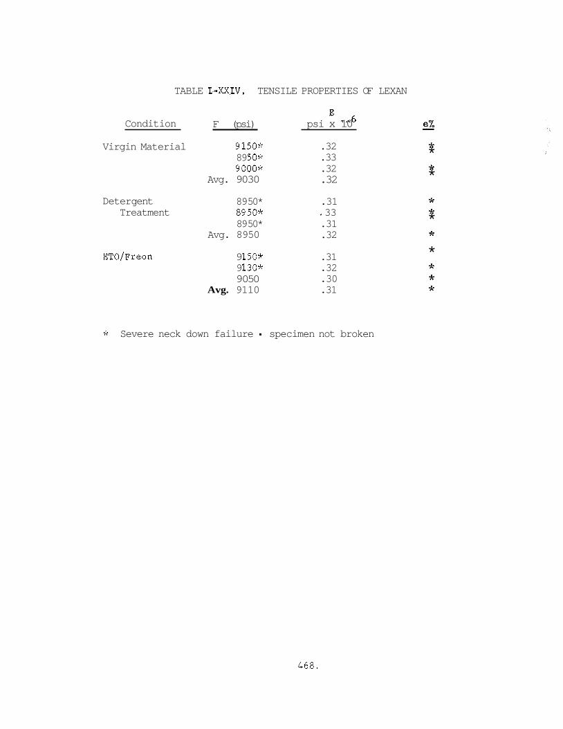
TABLE I-XXIV. TENSILE PROPERTIES OF LEXAN
Condition F (psi)
Virgin Material 9150* 89 50* 9000*
Avg. 9030
Deter gent Treatment
ETO/Freon
89 50* 8950* 89 50*
Avg. 8950
9 150* 9 1306: 9 050
Avg. 9110
' 6 psi x 10
.32
.33
.32
.32
.31 * 33 .31 .32
.31
.32
.30
.31
* * * * * * * * * * * *
* Severe neck down failure - specimen not broken
468.
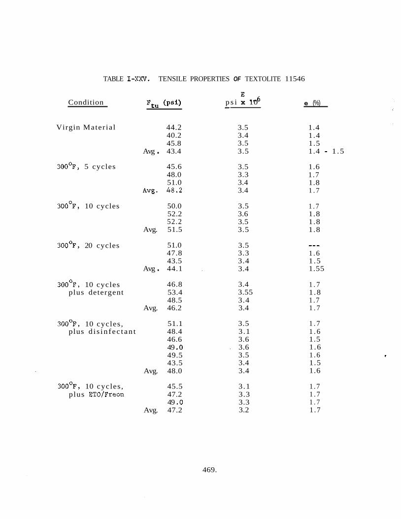
TABLE I-XXV. TENSILE PROPERTIES OF TEXTOLITE 11546
Condition
Virgin Mater ia l
3OO0F, 5 cycles
300°F, 10 cycles
3OO0F, 20 cycles
300°F, 10 cycles plus detergent
300°F, 10 cycles ,
44.2 40.2 45.8
Avg . 43.4
45.6 48.0 51.0
A V ~ . 48.2
50.0 52.2 52.2
Avg. 51.5
51.0 47.8 43.5
Avg . 44.1
46.8 53.4 48.5
Avg. 46.2
51.1 plus d i s in fec t an t 48.4
46.6 49 .O 49.5 43.5
Avg. 48.0
300°F, 10 cycles , 45.5 plus ETO/Freon 47.2
49 .O Avg. 47.2
E 6 p s i x 10 -
3.5 3.4 3.5 3.5
3.5 3.3 3.4 3.4
3.5 3.6 3.5 3.5
3.5 3.3 3.4 3.4
3.4 3.55 3.4 3.4
3.5 3.1 3.6 3.6 3.5 3.4 3.4
3.1 3.3 3.3 3.2
e (%)
1.4 1.4 1.5 1.4 - 1 . 5
1.6 1 .7 1.8 1 . 7
1 . 7 1.8 1.8 1.8
--- 1 .6 1 .5 1.55
1 . 7 1 .8 1 . 7 1 . 7
1 . 7 1 . 6 1.5 1 .6 1 .6 1 .5 1.6
1 . 7 1 . 7 1 . 7 1 . 7
469.
4. REFERENCES
3..
2 .
3.
4 .
5.
6 .
7 .
8.
9 .
10.
11.
12
13.
14.
15.
16.
CR-39 Technical Bul le t in , Pi t tsburgh P l a t e Glass Company
Bul le t in 5, "Homolite 911 (Cast from CR-39 Monomer)", the Homolite Corpora t i on .
Lexan Polycarbonate Sheet, Bul le t ins E- 17, E-18, E-23, t o E-26 General Electric.
Bul le t in T-lC, "Teflon FEP Film", DuPont
Bul le t in T-2BY "Teflon FEP Film", DuPont
Watertown Arsenal WAL TR 397/10, "Thermal Conductivity of Teflon, KEL-F, and Duroid 5600 a t Elevated Temperature", A.W. Schultz and and A.K. Wong.
"Behavior of Teflon Fluorocarbon Resins a t Elevated Temperatures", R.H. Se t t lage and J.C. S ig le , DuPont
"Keeping Cool with Teflon", J . C . Siegle and R.H. Se t t lage , DuPont.
DuPont Design Data fo r Teflon-10
DuPont Product Bul le t in A-28854, "Data Guide f o r DuPont Fairprene Sheet Stocks .It
General Electric Product Bul le t in RBH-4AY "Silicone Rubber Hand- book."
Materials Selector I ssue , "Materials i n Design Engineering," October 1966.
"Vitreosi l Fused Quartz," Product Bul le t in , Thermal American Fused Quartz Company.
"Fused Quartz," Product Bul le t in 410-8-63, General E l e c t r i c Company Lamp Glass Department
Bul le t in A-9819, faTeflon Tetrafluoroethylene DuPont
P l a s t i c s World, Film and Sheeting Chart.
470.
17. Industrial Fabrics Bulletin, "Armalon", DuPont
18. Bulletin TD-lB, "Tedlar PVF Film", DuPont.
19. Bulletin H - 1 , "H-Film, DuPont.
20. "Protective Goa ted Fabrics", Cooley, Inc . 21. Plastics Design and Processing, September 1965.
22. Lexan Polycarbonate Sheet, Bulletins E-17, E-18, E-23, to E-26, General Electric
23. Plastics Design and Processing, September 1965.
24. Bulletin T-lC, "Teflon FEP Film" DuPont.
25. Bulletin TD-lB, "Tedlar PVF Filmf1, DuPont.
26. Bulletin H-1, "H-Film", DuPont . 27. Enjay Product Bulletin, "Enjay Butyl Latex."
28. 'permeability of PQlymers to Gas , Vapors , and Liquids ,I1 Alexander Lebovits, Modern Plastics, March 1966.
29. Mil-Handbook - 149A. 30. DuPont Handbook on Flexible Elastomer Diaphragms, Bulletin A-25196.
471.
472.
APPENDIX J: BIO-ISOLATOR SUIT SYSTEM SPECIFICATIONS
GENERAL EI;ECTRIC COME’ANY Re-entry Systems Department 3198 Chestnut S t r e e t Philadelphia 1, Pennsylvania Code Ident. No. 15226
SPXCIFICATION: ERSOMO-W-OOOL
BIO-ISOLATOR SUIT SYSTEM
(BISS)
1.0 GENERAL
1.1 Scdpe - This spec i f ica t ion defines t h e Bio-Isolator Su i t System, herein referred t o as BISS, used i n the assembly/steril izer. be used t o provide an absolute b io logica l and topological b a r r i e r between a technician and t h e assembly/s ter i l izer environment.
”he BISS s h a l l
1.2 suit and tunnel, l i f e support kubsystem, and a communication subsystem.
System Description - The BISS i s comprised of an undersuit , outer
1.2.1 cated from a f l e x i b l e material. provides t h e wearer with a breatheable and cooling air d i s t r ibu t ion system.
Undersuit - The undersuit is a form contoured +layer garment f a b r i s It is s ized t o f i t individual personnel and
1.2.2 Outer S u i t and Tunnel - The outer s u i t and tunnel is fabr ica ted from a f l e x i b l e material and forms a complete envelope around a technician, which provides an absolute biological and topological b a r r i e r between him and the assembly / st e r i l i zer environment . 102.3 the components and systems necessary t o perform t h e following functions:
Li fe Support Subsystem - The l i f e support subsystem contains a l l of
a. Maintain an adequate supply of f i l t e r e d breathable/cooling air t o t h e BISS undersuit plenum.
b, Provide a means of maintaining tromfortable conditions of! temperature, humidity, pressure, and removal of noxious and tox ic gases f r o n t h e BISS outer s u i t .
1.2.4 Test Conductor’s Console, which includes t h e provisions f o r se lec t ing t h e communication pa t te rns , remote s t a t ions serving t h e L i f e Support and Medical Monitor locat ions, transducer terminals i n t h e individual suits and at t h e net cont ro l le r locat ions, and listen- only provisions f o r v i s t to r s . s t a t i o n equipment may be e i t h e r free-standing or an i n t e g r a l pa r t o f t h e remote equipment with which it is associated. horns are located within the assembly/steril izer “to provide one-way audio contact with t h e BISS operators i n t h e event of f a i l u r e of t h e components located on t h e undersuit.
Communication Subsystem - The comunication subsystem consis ts of a
The remote
Emergency back-up s p p k e r s and warning
473.
SPECIFICATION: ERS0100-00-0001
APPLICABLE DOCUIEBTS
2.1 i ssue speci f ied , form a p a r t of t h i s speci f ica t ion t o t h e extent specifieci herein.
Government Documents - The following government documents of t h e
M i 1 it ary
I V ~ I L - P - ~ ~ ~ D Preservations, Methods of 4 December 1962
14IL-STD- 4 70 21 March 1966 and Equipments
MIL-STD-826A Electromagnetic Interference, T e s t Requirenents 6 June 1966
Maintainabil i ty, Program Requirerents f o r Systems
and Test Methods f o r
MIL-P-7936 19 November 1957 f o r Delivery
P a r t s and Equipment, Aeronautical, Preparation
MS33586 Metals, Defini t ion of Dissimilar 1 October 1952
(Copies of these documents m a y be obtained from t h e Superintendent of Documents, Government Pr in t ing Office, IJashington, D.C. )
2.2 Pion-Government Docments - The following non-government documents of t h e issue i n effect on the date of t h i s speci f ica t ion , forn a par t of t h i s speci f ica t ion t o t h e extent speci f ied herein.
GENERAL ELECTRIC COMPANY, RSD
Specif ic at ions
ERS0230-00-0001
ERS0230-00-0002
ERS02lO-00-0001
E R S O ~ 50-0 2-000 1
S t an dar ds
118~1526
146A9560
Drawings
SK56-173- 316
BISS Outer Su i t and Tunnel
BISS Undersuit
BISS L i f e Support Subsystem
BISS Communication Subsystem
Iden t i f i ca t ion Marking
Preparation for Delivery
BISS-Assembly/Sterilizer In ter face Concept
(Copies of t h e General E l e c t r i c Company documents may be obtained from t h e General E l e c t r i c Company, RSD, 3198 Chestnut S t ree t , Philadelphia, Pennsylvania 19101).
474.
REQUIRUEMTS
3.1 speci f ica t ion and referenced documents t o t h e extent s p e c i f i r d herein. conf l i c t between t h e requirements and anr documents spec i f i ed here in , t h i s speci- f ica t ion s h a l l govern.
General - The BISS (Figure 1) s h a l l meet t h e requirements of t h i s In case of
3.2 Components - The UISS s h a l l consist of t h e following components:
a. Outer Su i t and Tunnel b. Undersuit C. L i f e Support Subsystem ii . e. Hard Tube f , Hatch g. Reefing Mechanism h. Overhead Telescoping Boom i. Donning Rack
Conmuni c a t i on Subsystem
3.2.1 Design Requirements
3.2.1.1 Outer Su i t and Tunnel - The outer s u i t and tunnel s h a l l consist of t h e following subassemblies. GE-RSD Specif icat ion ERS0230-00-0001.
Design of t h e outer s u i t and tunnel shall comply w i t h
3.2.1.1.1 Su i t Body - The s u i t body s h a l l be f l e x i b l e and as l i g h t weight as possible . 3.2.1.1.2 Gloves - The gloves s h a l l be f l e x i b l e and as l i g h t weight as possible. They s h a l l be bonaed t o t h e s u i t body. b io logical seal.
The bonding s h a l l provide an absolute
3.2.1.1.3 Ijoots - The boots s h a l l be semi-rigid and shall be bonded t o t h e suit body.
3.2.1.1.4 and s h a l l be bonded t o t h e sui t body. seaL.
The bonding shall provide an absolute b io logical seal.
IIelmet and Yoke - The helmet and yoke s h a l l be of u n i t construction The bonding s h a l l form an absolute b io logical
3.2.1.1.5 Tunnel - The tunnel s h a l l be flexible and as l i g h t weight as possible. It s h a l l be bonded t o t h e s u i t body. seal.
The bonding shal l form an absolute b io logical
475.

SPECIFICATIOIi: ERS0100-00-0301
3.2.1.2 Undersuit - The undersuit s h a l l be a contour f i t t e d f l e x i b l e garment fabr icated t o f i t individual technicians. The garment s h a l l be a multi- layer fabr ica t ion proviaing an i n t e g r a l a i r d i s t r i bu t ion system t o i n t e r f ace with the l i f e support subsystem. exhausting stale air. an e s sen t i a l l y a i r- t igh t compartment around the wearer. An a i r- t igh t type s l ide fas tener s h a l l be located i n the chest area and quick- release fas teners s h a l l be used f o r leg ends, t o f a c i l i t a t e en t ry and egress. s t r a t e g i c posi t ions , shal l be p a r t of the garment s t ruc tu re and shal l provide t h e attachment points f<jr t h e l i f e support and communication subsystem components. Design of t h e undersuit s h a l l comply with t h e requirements s e t f o r th i n GE-RSD Specif icat ion EHS0230-00-0002 (BISS Undersuit) .
The center l aye r of the garment shall provide a path f o r Seams i n the garment s h a l l be kept t o a minimum t o provide
Hard points , located at
3.2.1.3 Life Support Subsystem - The l i f e support subsystem s h a l l be a s e l f contained system t h a t s h a l l only require f a c i l i t y e l e c t r i c a l power and air f o r operation, and sha l l comply w i t h t h e requirements set fo r th i n GE-HSD Specif icat ion hRS0210-00-0001 (blSS L i f e Support Subsystem). a console. supply, and exhaust blowers, and a system f i l ter . The console s h a l l provide f o r monitoring and cont ro l l ing input and exhaust air flow rates, temperature and humidity . 3.2.1.4 self contained system t h a t s h a l l only require f a c i l i t y power f o r operation, an6 s h a l l comply with t h e requirements set for th i n GE-RSD Specif icat ion ERSOl5O-O% 0001 (BISS Communication Subsystem) . The main system shal l be containea w i t h i n a Fac i l i t y Supervisor's console located outs ide the assembly/s ter i l izer . power supply systems, controls and ind ica tors sha l l be contained within t h e console. Additional communication system components shal l be contained within net con t ro l l e r ' s consoles. Other components shall be located within the l i f e support system console, and t h e medical monitor console. t h e following communication capab i l i t i e s :
The system s h a l l be contained w i t h i n The console shall contain the a i r cooling and humidification components,
Communication Subsystem - The communication subsystem s h a l l be a
Amplifiers,
The system s h a l l have
a.
b.
C.
de
e.
f .
g.
Two-way between the tes t conductor's console and t h e l i f e support system and medical monitor consoles.
One-way only from the test conductor's console t o the l i f e support system and medical monitor consoles.
Two-way between the F a c i l i t y Supervisor console and t h e net con t ro l l e r console.
Two-way between t h e net con t ro l l e r ' s console and the se lec ted group of BISS operators.
One-way between each BISS group and i t s l i f e support system cont ro l and medical monitor s ta t ion .
Two-way between individual BISS occupants.
Monitoring ( l i s t e n i n g ) only capabi l i ty f o r v i s i t o r s .
476.
SPECIFICATIOH: E3SO100-00-0001
3.2.1.5 and a semicircular top and bottom. with t h e tunnel and at the o ther end w i t h t h e assembly/s te r i l izer w a l l (Figure 2 ) . The hard tube shall pass through the w a l l t o the outside of the assembly/ s t e r i l i z e r . Figure 1.
Hard Tube - 'I'he hard tube shall be metal cyl inder with p a r a l l e l sides The hard tube s h a l l i n t e r face at one end
The sea l ing of t h e tunnel t o the assembly/s te r i l izer i s shown i n
3.2.1.6 semicircular top and bottom (Figure 3) . hard tube on t h e e x t e r i o r of the assembly/ster i l izer . supported by hinges, and s h a l l have quick- release locks and a port f o r e i t h e r pressur iza t ion o r gas sampling.
- hatch - The hatch shall be a m e t a l door w i t h a p a r a l l e l sides and a It shall in t e r face wi th t h e enci of t h e
The hatch shal1 .be
3.2.1.7 mechanical device t h a t deploys and r e t r a c t s t h e tunnel material i n a cont ro l led manner. The tunnel material sha l l be fed from and t o t h e outer sur face of t h e hard tube.
Reefing Mechanism - The reef ing mechanism s h a l l be an elec t ro-
3.2.1.8 electro-mechanical device t h a t supports the tunnel mater ia l during operating proceaures. provide support v i a f l e x i b l e s t r i n g e r s which s h a l l be secured t o the tunnel.
Overhead Telescoping Boom - The overhead telescoping boom s h a l l be an
It s h a l l operate i n conjunction w i t h the reef ing mechanism and
3.2.1.9 Donning Rack - The donning rack s h a l l be a metal s t r u c t u r e locateu i n t h e assembly/s te r i l izer (Figure 4). s u i t arms and helmet. Two device shall be loca ted at t h e donning rack base f o r t h e outer s u i t boots (Figure 5). side of t h e donning rack tha t when operated by the UISS occupant;, shall re lease t h e helmet support. tube and s h a l l support the outer s u i t when t h e tunnel i s i n t h e reefed posi t ion.
Supports shall be provided f o r the outer
A quick release device shall be located on one
The aonning rack s h a l l be l oca ted at t h e end of the hard
3.2.2 Materials, P a r t s and Processes - - The materials used i n t h e BISS fabr ica t ion s h a l l be of the highest qua l i ty and s h a l l be se l ec ted on t h e basis of physical o r other e s sen t i a l -p rope r t i e s ,- a v a i l a b i l i t y , adap tab i l i t y t o production processes, and s u i t a b i l i t y t o environment conditions.
3.2.3 design requirements set f o r t h i n GE-RSD Speci f ica t ion ERS0230-00-0002 (BISS Unders-Ji t
Undersuit E4aterials - The undersuit materials shal l comply w i t h the
3.2.3.1 Outer Su i t and Tunnel Material - The outer s u i t and tunnel materials sha l l comply w i t h t h e design requirements set f o r t h i n GE-HSD Speci f ica t ion ERS0230-00-0001 (BISS Outer S u i t and Tunnel): .
3.2.3.2 L i f e Support Subsystem - The materials used shall be of a type, grade, arid qua l i ty which w i l l ensure t h e proper operation of t he l i f e support subsystem. The materials s h a l l conform t o the design requirements se t f o r t h i n GE-RSD Specif icat ion EHS0210-00-0001 ( L i f e Support Subsystem f o r the Bio- Isolator S u i t System ~ p e c i f i c a t i o n ) .
477.
SPBCIFICATIOIJ : kRS0100-00-0001
3.2.3.3 and qua l i t y which w i l l ensure t h e proper operation of t h e communication sub- system. !The materials s h a l l conform t o the design requirements set for th i n GZ-HSL Specif icat ion EHSOl50-02-OOOl ( Communication Subsys t e m fo r t h e Iji 0- I so l a to r Sui t 2.ystern).
Communication Subsystem - The materials s h a l l be of a type, grade,
3.2.4 ensure r e l i a b i l i t y and expedite procurement. Preferred standard p a r t s i n t h e i r oruer of preference are appl icable KASA spec i f ica t ions , I4ilitaw Standgus (HE, Aii, IiAS) , General E lec t r i c Company Standards, and commercial standards standard p a r t s may be used when spec i f i ca l ly authorized by the procuring agency.
Standard. Par t s - Wherever possible , standard parts s h a l l be used t o
lion-
3.2.5 C r i t i c a l ana S t r a t eg i c Platerials - biaterials s h a l l be se lec ted on t h e basis of s u i t a b i l i t y and relative ava i l ab i l i t y . Subject t o s a t i s f ac to ry operation, tile LISS s h a l l incorporate the least c r i t i c a l and s t r a t e g i c materials.
3.2.6 Dissimilar bietals - The use of dissimilar metals, as defined i n F.IZ33580, s h a l l not be used. i n int imate contact unless s u i t a b i l i t y protected against e l e c t r o l y t i c corrosion.
3.2.7 Corrosion Resistance - hlaterials se lec ted s h a l l be corrosion resistant; o r s h a l l be su i t ab ly protected by p la t ing , paint ing, o r o ther surface treatment t h a t i s compatible w i t h t he BISS environment as s e t fo r th i n 3.5.
3.2.8 katerial Bonding Processes - Material bonding processes fo r t h e outer s u i t and tunnel , and undersui t , s h a l l be of the highest i n t e g r i t y proviaing the required absolute b io log ica l b a r r i e r (ou te r s u i t and tunnel on ly) , The bondinf processes s h a l l conform t o t h e requirements set fo r th i n the individual subsystem spec i f ica t ions .
3.2-9 EM1 Considerations - Precautions shall be taken t o minimize e lec t ro- magnetic in te r fe rence both conducted and radiated. The precautions sha l l incluue bonding, grounding, shielding, suppression techniques, and proper choice of components t o minimize the generation of in te r fe rence o r t o suppress it i f it should occur. MIL-STD-826 sha l l be used as a guide.
3.3 Performance - The BISS (Figure 1) s h a l l provide an absolute biolog- i c a l barrier between t h e technician and t h e s te r i le environment of the assembly/ s t e r i l i z e r . It s h a l l allow t h e technician s u f f i c i e n t mobili ty, dex te r i t y , and v i sua l f i e ld t o accomplish spacecraf t assembly and check-out operations w i t h i n the s te r i le pressurized environment. When unoccuppied by a technician, t h e EISS s h a l l withstand an overpressure of up t o 4-inches H20 maximum. When occuppied by a technician it shall withstand an overpressure of up t o 2-inches €120 without causing undue discomfort t o t h e technician o r reducing h i s a c t i v i t i e s . The HISS shall maintain a comfortable and healthful environment within t h e ou te r s u i t and tunnel. Audio contact among BISS technicians within t h e s ter i le environment, and w i t h monitoring personnel outs ide t h e s ter i le environment, s h a l l be maintained at a l l times during BISS operations. Medical and l i f e support s h a l l be monitored at a l l times by personnel s t a t i oned outs ide the assembly/s ter i l izer . support and medical devices s h a l l be monitored by personnel w i t h spec ia l ized t r a i n i n g .
The l i f e
478.
SPLCIFICATIOIi : ERS0100-00-0001
3.3.1 Undersuit - The unaersui t s h a l l be a form- fitt ing garment. It s h a l l d i s t r i b u t e cooling/breathable a i r from t h e l i f e support subsystem t o t h e outer s u i t ' s arms, l egs , and helmet area. t h e stale air from the outer s u i t back t o the l i f e support subsystem. s u i t shall be f l e x i b l e and form- fi t t ing without r e s t r i c t i n g t h e wearer's movements.
3.3 .2 Outer Su i t and Tunnel - The outer s u i t and tunnel s h a l l maintain an absolute b io log ica l anu topological barrier between t h e wearer and the s t e r i l e environment within t h e assembly/s ter i l izer . be f l e x i b l e and sha l l not r e s t r i c t movement of t h e wearer. A reef ing mechanism s h a l l extena and r e t r a c t t h e tunnel t o and from the tunnel/assembly/sterilizer i n t e r f ace t o f a c i l i t a t e bISS ent ry , egress, and operat ing procedures. telescoping boom s h a l l support the tunnel. t h e reef ing mechanism. The overhead te lescoping boom shal l decrease t he tuncel drag on the BISS wearer and assist i n t he reef ing procedures. A donning rack s h a l l be loca ted within t h e nssembly/s ter i l izer and shall support t h e ou te r s u i t body i n t h e v e r t i c a l pos i t ion f o r en t ry and egress procedures Dy the wearer.
It shall a l s o provide a path fo r exhausting The under-
The outer s u i t body and tunnel s h a l l
An overhead It s h a l l operate i n conjunction w i t h
3 .3 .3 L i f e Support Subsystem - The l i f e support subsystem s h a l l supply a n d exhaust cooling ana breathing a i r t o t h e undersuit d i s t r i b u t i o n system. It s h a l l maintain an adequate supply of f i l tered breathable cooling a i r and shall maintain comfortable conditions of temperature, humidity, and pressure w i t h i n t h e outer sui% and helmet. It shall a l s o remove noxious and tox ic gases from the BISS outer s u i t and tunnel.
3 .3 .4 audio contact among personnel within iadividual BISS's and personnel statiwned outside. The audio contact shal l be maintained under a l l conditions which nay e x i s t e i ther in s ide or outside of the assembly/s ter i l izer . communication S U ~ S Y S ~ F ? . ~ by the BISS wearer s h a l l be hands-free, and operation by t h e personae1 outs iue of t h e assembly /s te r i l i zer s h a l l requi re a minimum actuat ion of controls.
Communication Subsystem - The communication subsystem shall Eaintain
Operation of t h e
3.3.5 provide data on t h e physical s t a t u s of t he BISS occupant by means of an EKG. The equipment s h a l l include provisions f o r recording t h e occupants hea r t data, bKG displays shall be monitored only by personnel s t r i c t l y t r a i n e a i n t he in te r- pre ta t ion of such displays.
Medical Monitorinp Equipment - The medical monitoring equipment s h a l l
3.4 In t e r f ace Requirements
3.4.1 mechanical in te r faces .
hIechanical In te r faces - The BISS s h a l l incorporporate t h e following
3.4.1.1 t h e following mechanical in te r faces :
Outersuit and Tunnel - The outer s u i t and tunnel s h a l l incorporate
a. A i r d i s t r i b u t i o n system t o l i f e support subsystem b. Tunnel t o assembly /s te r i l i zer C. Su i t body t o donning rack a. Tunnel t o reef ing mechanism e. Tunnel t o Overhead te lescoping boom
479.
SPECIFICATION: ERS0100500-0001
3.4.1.2 in ter faces :
Unuersuit - ?'he undersuit shall incorporate t h e following mechanical
a. A i r d i s t r i b u t i o n system t o l i f e support subsysten b. Unaersuit t o outer s u i t , tunnel and helmet
3.4.1.3 a mechanicui in t e r face between it and t h e undersuit.
Life Sbpport Subsystem - The l i f e support subsystem s h a l l incorporate
3.4.2 e l e c t r i c a l in ter faces .
L l e c t r i c a l In ter faces - The BISS shall incorporate t h e following
3.4.2.1 between it and t h e communication subsystem.
Undersuit - The undersuit s h a l l incorporate an e l e c t r i c a l in t e r face
3.4.2.2 an e l e c t r i c a l in t e r face between it and t h e communication subsystem.
Li fe Support Subsystem - The l i f e support subsystem s h a l l incorporzte
3.4.2.3 Comraunication Subsystem - The communication subsystem s h a l l incorporate the following e l e c t r i c a l in t e r faces :
a. Coxrmunication subsystem t o undersuit b. Conlmunication subsystem t o l i f e support subsystem console C.
d. Communication subsystem t o emergency back-up speakers and warning Communication subsystem t o medical monitoring
horns within t h e assembly/ster i l izer .
3.5 Environments
3.5.1 a f t e r exposure t o the following environments.
Pion-Operatin6 - The BISS s h a l l meet t h e requirements of 3.2 and 3.3
3.5.1.1 Temperature, Storage - The 3ISS s n a l l be exposed t o a contro l led d x o s - phere f r e e from vapor contaminants at a temperature of 70 2 20°F.
3.5.1.2 'I'emperature, Shipping - The BISS s h a l l be exposed t o -10 t o +120°F.
3.5.1.3 be exposed t o 2 iiinimally air- conditioned i n d u s t r i a l atmosphere with an ambient temperature of 80 2 10°F, dew point of 45 - + 12'F, at ambient pressure.
3.5.1.4 shall be exposed t o 88% Freon 12/12?; ET0 (by weight), a t 405 Ri l , at a concentration of 500 1% of X Y G / l i t r e of gaseous atmosphere f o r 28 hours at 104'F (24 hours s t a b i l i z e d at 104'F).
Temperature, F a c i l i t y (Out8ide t h e kssembly/Steri l izer) - The 51% s h a l l
becontamination - Components located within t h e assernbly/ster i l izer
480.
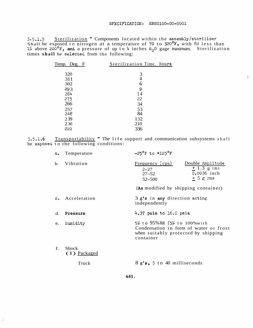
SPECIFICAI’IOI4: ERS0100-00-0001
3.5.1.5 Shall be exposed t o ni trogen a t a temperature of 70 t o 320°E’, with Rii l e s s than l$ above 200°F’, ani a pressure of up t o 4 inches H20 gage maximum. times s h a l l be selecteci from the following:
S t e r i l i z a t i o n - Components located within t h e assembly/s ter i l izer
S t e r i l i z a t i o n
Temp. Deg. F S t e r i l i z a t i o n Time , Eiours
320 311 302 29 3 2 04 275 266 257 24 e 2 39 2 30 221
3 4 G 9
1 4 22 34 53 84
132 210 336
3.5.1.6 be exposeu t o the following conditions:
Transpor tabi l i ty - The l i f e support and communication subsystems s h a l l
a. Temperature - 2 5 O ~ t o +125O~
b. Vibration
c. Acceleration
d. Pressure
e. iiumidity
f. Shock (1) Packaged
Truck
Frequency ( cps ) Double Anplitude + 1.3 g r m s 0.0036 inch + 5 g r m s
2-27 - 27-52 52-500 -
(As modified by shipping conta iner)
3 g’s i n any d i rec t ion ac t in& independently
5$ t o 95% fiH ( 5 $ t o 100% w i t h Condensation i n form of water o r f r o s t when su i t ab ly protec ted by shipping container
8 g‘s, 5 t o 40 milliseconds
481.
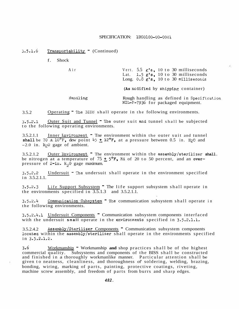
SPECIFICATION: ERS0100-00-0001
5.5.1.6 Transpor tabi l i ty - (Continued)
f . Shock
A i r
iianaling
V e r t . 5.5 e ' s , 10 t o 30 milliseconds Lat . 1.5 e's , 10 t o 30 milliseconds Long. 0.0 &Is, 10 t o 30 milliseconus
(As rrodified by shippinc container)
Rough handling as defined i n Specifi.cat,ion MIL-F-7936 f o r packaged equipment.
3.5.2 Operating - The BISY s h a l l operate i n t h e following environments.
3.5.2.1 t o the following operat ing environments.
Outer Sui t and Tunnel - Tihe outer s u i t and tunnel s h a l l be subjected
3.5.2.1.1 Inner Environnent - Tne environment within t h e outer s u i t and tunnel shall be 70 - + 10°F, dew point 45 2 12OF, a t a pressure between 0.5 i n . 1120 and -2.0 in. I izU gage of ambient.
3.5.2.1.2 be ni trogen at a temperature of 75 2 5'F, RH of 20 t o 50 percent, and an over- pressure of 2-in. H20 gage maximum.
3.5.2.2 Undersuit - Tne undersuit s h a l l operate i n t h e environment speci f ied i n 3.5.2.1.1.
Outer Xnvironment - The environment within t h e assemblyls ter i l izer shall.
3.5.2.3 L i f e Support Subsystem - The l i f e support subsystem s h a l l operate i n the environments spec i f i ed i n 3.5.1.3 and 3.5.2.1.1.
3.5.2.4 t h e following environments.
Commuriication>Subsystem - Tne communication subsystem s h a l l operate i n
3.5.2.4.1 with the undersuit s n a l l operate i n t h e environments speci f ied i n 3.5.2.1.1.
3.5.2.4.2 locatea within t h e assenibly/ster i l izer s h a l l operate i n t h e environments speci f ied i n 3.5.2.1.2.
Undersuit Components - Communication subsystem components in ter faced
Assembly/Sterilizer Components - Communication subsystem components
3.6 Workmanship - Workmanship and shop p rac t i ces s h a l l be of the highest commercial qual i ty. Subsystems and components of t h e BISS s h a l l be constructed and f in ished i n a thoroughly workmanlike manner. P a r t i c u l a r a t t en t ion s h a l l be
bonding, wiring, marking of p a r t s , paint ing, protec t ive coat ings, r ive t ing , machine screw assembly, and freedom of p a r t s from burrs and sha rp edges.
I given t o neatness, c leanl iness , and thoroughness of' soldering, welding, brazing,
482.
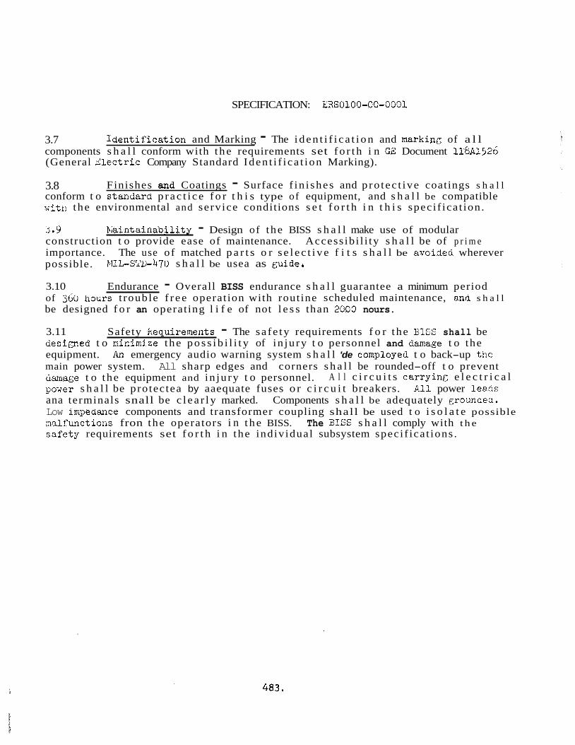
SPECIFICATION: ERS0100-00-0001
3.7 components s h a l l conform with t h e requirements set f o r t h i n GE: Document ll8A1526 (General d l e c t r i c Company Standard Iden t i f i ca t ion Marking).
h e n t i f i e a t i o n and Marking - The i d e n t i f i c a t i o n and marking of a l l
3.8 conform t o standard p r a c t i c e f o r t h i s type of equipment, and s h a l l be compatible
Finishes and Coatings - Surface f in i shes and p ro tec t ive coatings s h a l l
i p l i t l ! t h e environmental and service conditions s e t f o r t h i n t h i s speci f ica t ion .
3.9 La in ta indo i l i ty - Design of the BISS s h a l l make use of modular construction t o provide ease of maintenance. Access ib i l i ty s h a l l be of p r i m e importance. The use of matched p a r t s o r s e l e c t i v e f i t s s h a l l be avoidea wherever possible. EIIL-SW-470 s h a l l be usea as guide.
3.10 Endurance - Overall BISS endurance s h a l l guarantee a minimum period of 360 hours t rouble f r e e operat ion with routine scheduled maintenance, anti s h a l l be designed f o r an operat ing l i f e of not l e s s than 2600 nours.
3.11 Safety kequirements - The sa fe ty requirements f o r the BlSS shall be des imed t o minimize the p o s s i b i l i t y of in ju ry t o personnel and danage t o the equipment. An emergency audio warning system s h a l l 'de comployed t o back-up the main power system. All sharp edges and corners s h a l l be rounded-off t o prevent amage t o the equipment and in ju ry t o personnel. pover s h a l l be protec tea by aaequate fuses o r c i r c u i t breakers. 4-11 power l eacs ana terminals snall be c l e a r l y marked. Components s h a l l be adequately grouncea. Low iapedance components and transformer coupling shall be used t o i s o l a t e possible malfunctions fron the operators i n t h e BISS. The 3ISS s h a l l comply with t h e sa fe ty requirements set f o r t h i n the individual subsystem speci f ica t ions .
A l l c i r c u i t s car ry inc e l e c t r i c a l
4 8 3 .
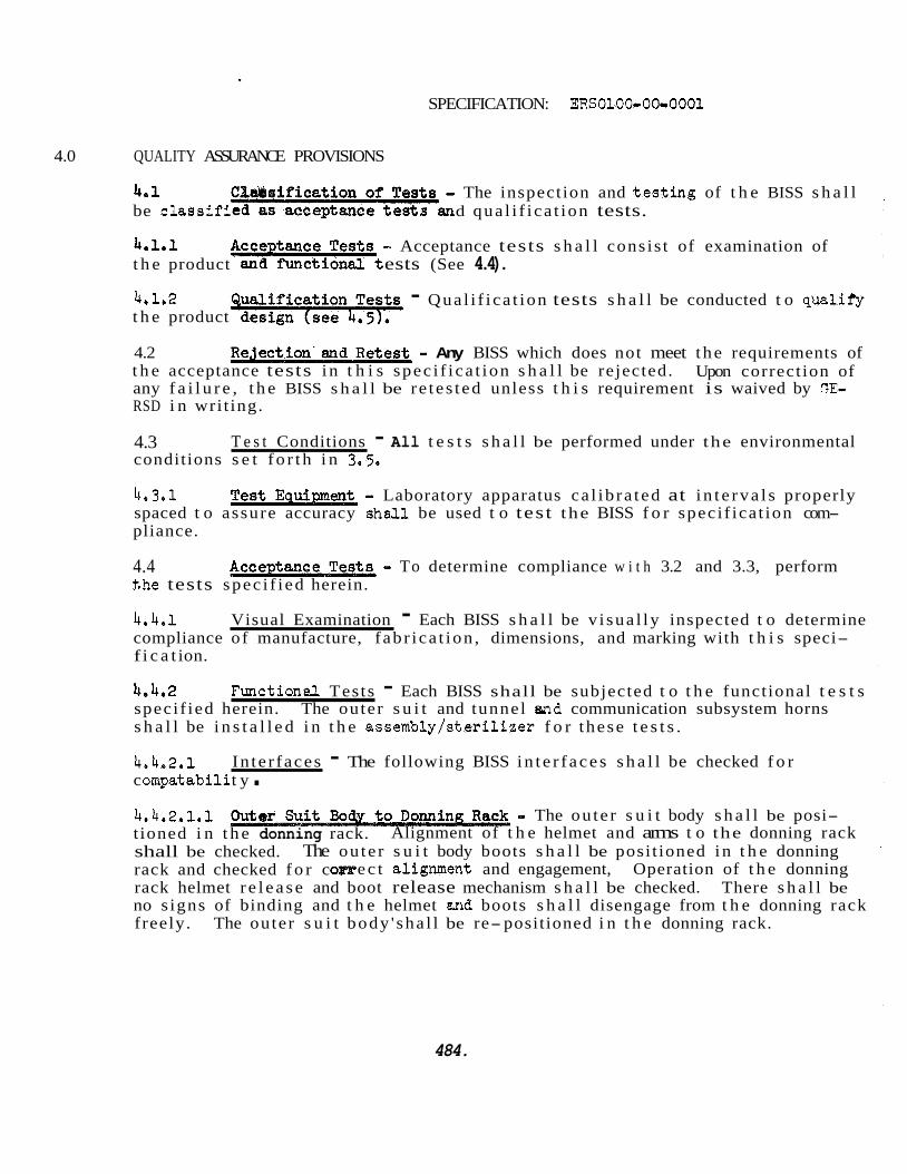
SPECIFICATION: ERS0100-00-0001
4.0 QUALITY ASSURANCE PROVISIONS
4.1 be c l a s s i f i d qua l i f i ca t ion tests.
4.1.1 t h e product ests (See 4.4).
4.1.2 t h e product
4.2 t h e acceptance tests i n t h i s spec i f i ca t ion s h a l l be rejected. any f a i l u r e , t h e BISS s h a l l be re tes ted unless t h i s requirement is waived by GE- RSD i n wri t ing.
4.3 conditions s e t f o r t h i n 3,5.
The inspection and t e s t i n g of t h e BISS s h a l l
- Acceptance tests s h a l l consis t of examination of
- Qual i f i ca t ion tests s h a l l be conducted t o qualif'y
- Any BISS which does not meet t h e requirements of Upon correct ion of
T e s t Conditions - All t e s t s s h a l l be performed under the environmental
4.3.1 spaced t o assure accuracy she31 be used t o test the BISS f o r speci f ica t ion com- pliance.
- Laboratory apparatus ca l ib ra ted at i n t e r v a l s properly
4.4 t,he tests spec i f i ed herein.
- To determine compliance w i t h 3.2 and 3.3, perform
4.4.1 compliance of manufacture, f ab r ica t ion , dimensions, and marking with t h i s speci- f i c a t ion.
Visual Examination - Each BISS s h a l l be v i sua l ly inspected t o determine
4.4.2 speci f ied herein. s h a l l be i n s t a l l e d i n t h e assembly/s ter i l izer f o r these t e s t s .
Function&. Tes ts - Each BISS shall be subjected t o t h e functional t e s t s The outer s u i t and tunnel end communication subsystem horns
4.4.2.1 c ompat a b i l i t y . In te r faces - The following BISS i n t e r f a c e s s h a l l be checked f o r
4.4.2.1.1 t ioned i n t h e donning rack.
.. The ou te r s u i t body s h a l l be posi- Alignment of t h e helmet and arms t o the donning rack
shall be checked. rack and checked f o r c e c t alignment and engagement, Operation of t h e donning rack helmet r e l e a s e and boot release mechanism s h a l l be checked. There s h a l l be no s igns of binding and t h e helmet and boots s h a l l disengage from t h e donning rack freely. The outer s u i t body ' sha l l be re- positioned i n t h e donning rack.
The ou te r s u i t body boots s h a l l be posi t ioned i n t h e donning
484.
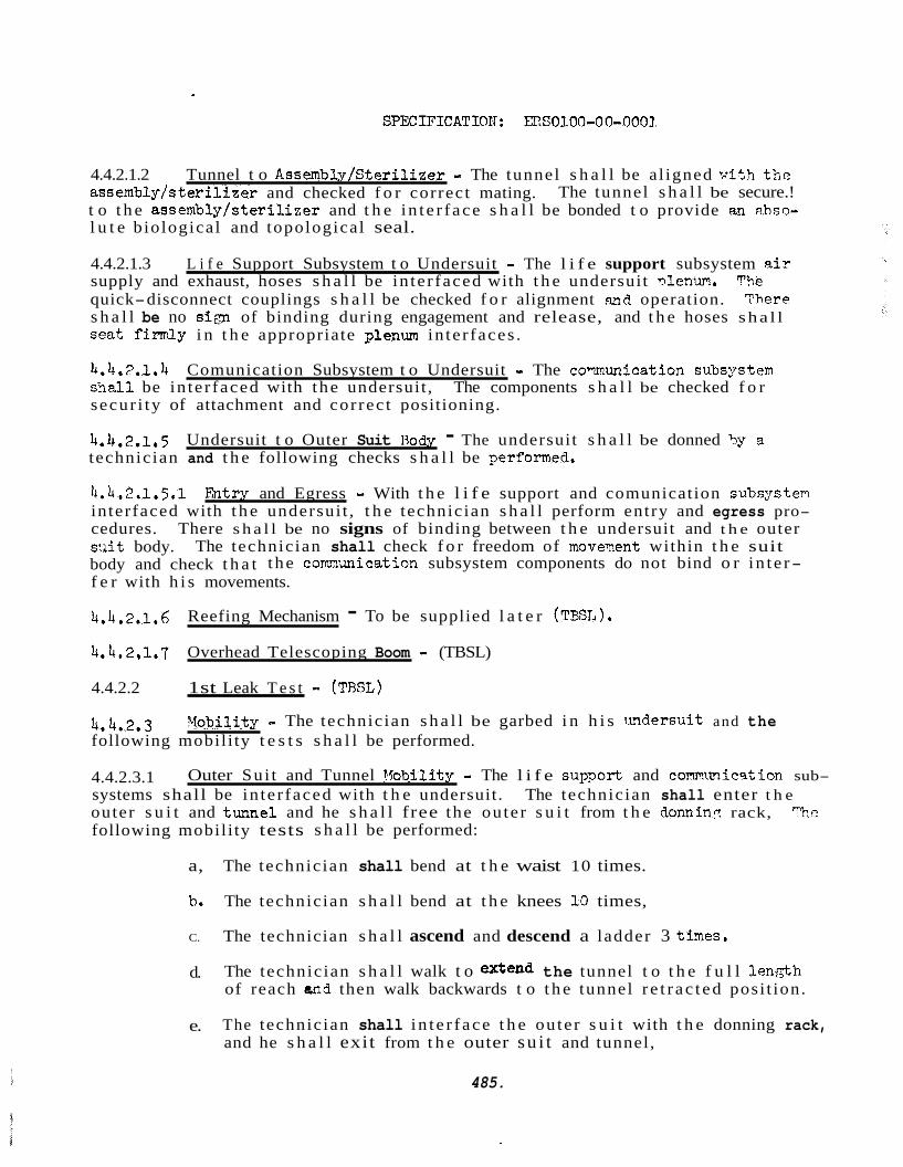
4.4.2.1.2 Tunnel t o Assembly/Steri l izer - The tunnel s h a l l be a l igned v i t h t h e assembly/s ter i l izer and checked f o r correct mating. The tunnel s h a l l be secure.! t o t h e assembly/s ter i l izer and t h e i n t e r f ace s h a l l be bonded t o provide an ahss- l u t e biological and topological seal.
4.4.2.1.3 supply and exhaust, hoses s h a l l be in te r faced with t h e undersuit nlenum. The
L i f e Support Subsystem t o Undersuit - The l i f e support subsystem a i r
quick-disconnect couplings s h a l l be checked f o r alignment and operation. s h a l l be no si:y of binding during engagement and release, and t h e hoses sha l l seat f inr3y i n t h e appropriate ;?lam in te r faces .
4.4.7.1.4 s h a l l be in te r faced with t he undersuit , The components s h a l l be checked f o r secur i ty of attachment and cor rec t positioning.
4.4,2.1,5 technician and t h e following checks s h a l l be performed,
There
Comunication Subsystem t o Undersuit - The comunication subs:wtem
Undersuit t o Outer Suit Rody - The undersuit s h a l l be donned '?y EL
4.4.2.1.5.1 ?&try and Egress - With t h e l i f e support and comunication subs:rstem interfaced with t h e undersui t , t h e technician s h a l l perform entry and egress pro- cedures. There s h a l l be no signs of binding between t h e undersuit and t h e outer s u i t body. body and check t h a t t he comunication subsystem components do not bind o r i n t e r- f e r with h i s movements.
The technician shall check f o r freedom of moveyent within t h e suit
4.4.2.1.6
4.4.2.1.7 Overhead Telescoping Boom - (TBSL)
4.4.2.2 1st Leak T e s t - (TRSL)
Reefing Mechanism - To be supplied l a t e r (TBSL).
4.4.2.3 following mobili ty t e s t s s h a l l be performed.
Yobi l i ty = The technician s h a l l be garbed i n h i s m d e r s u i t and the
4.4.2.3.1 systems shall be in te r faced with t h e undersuit. The technician shall enter t h e
Outer Sui t and Tunnel Vobili ty - The l i f e s u p o r t and com.1ulicqtion sub-
outer s u i t and tunnel and he s h a l l free the ou te r s u i t from t h e donnin? rack, "'he following mobili ty tests s h a l l be performed:
a, The technician shall bend at t h e waist 10 times.
b, The technician s h a l l bend at t h e knees 10 times,
C. The technician s h a l l ascend and descend a ladder 3 tines.
d. The technician s h a l l walk t o extend the tunnel t o t h e f u l l len,gth of reach aad then walk backwards t o t h e tunnel r e t r ac t ed posi t ion.
e. The technician shall i n t e r f ace t h e ou te r s u i t with t h e donning rack, and he s h a l l exit from t h e outer su i t and tunnel,
485.
SPECIFICATION: ERS0100-00-0001
4.4.2.3.1 Outer Suit and Tunnel Mobility - (Continued)
f. All t he mobility tests shall be evaluated. Any s ign i f ican t d i f f i- cu l ty in the execution of the above tests s h a l l be cause for rejec- t i o n of t h e outer s u i t and tunnel..
4.4.2.3.2 Reefing tlechanism Mobility - The reef ing mechanism mobilit:; s h a l l be %ested w i t h t h e technician performing t h e requirements set fo r th i n 4.4.2.3.1, s ign i f ican t d i f f i c u l t y i n t h e execution of the requirements set fo r th i n 4.4.2.3.1 due t o t h e reef ing mechanism shall be cause f o r re ject ion.
Any
4.4.2.3.3 mobility s h a l l be tested w i t h t h e technician performing t h e requirements set forth i n 4,4.2.3.1. ments set f o r t h i n 4.4.2.3.1 and 4.4.2.3.2 due t o the overhead telescoping b o m s h a i l be cause f o r re ject ion,
Overhead Telescoping Boom Mobility - The overhead telescoping boom
Any s ign i f i c an t d i f f i c u l t y in t h e execution of the require-
4.4.2.4 2nd Leak Test - (TBSL)
4.4.2.5 hard tube, a d i r ec t load of 700 lbs. sha l l be applied- t o the s u i t body. A l l
Applied Load T e s t - Vith t h e outer s u i t and tunnel in terfaced with t h e
bonded in te r faces s h a l l be checked f o r failure. sha l l be cause f o r re jec t ion ,
4.4.2.6 Biological Leak Test - (TBSL)
Fai lure i n the bonded in te r faces
486.
SPECIFICATIOH: ERS0100-00-0001
4.5 Qual i f icat ion Tests
4.5.1 specif ied i n 4.2r.l and 4.4.2.1through 4.4.2.6 a f t e r being subjected t o the fol lowiry
lion-Operating Environmental Tests - The UISS s h a l l meet t he requirements
environmental tests. with t h e outer s u i t and tunnel i n t he unmanned condition.
4.5.1.1 t he temperatures spec i f ied therein .
4.5.1.2 Decontamination - To determine compliance with 3.9.1.4 t h e outer s u i t and tunnel , and spec i f ied communic'ation subsystem components s h a l l withstand the conaitions spec i f ied therein.
These tests s h a l l be performed i n t he assembly/s ter i l izer
Temperature - To determine compliance with 3.5 t h e XSS shall withstand
4.5.1.3 and tunnel, and spec i f ied communication subsystem components s h a l l withs-iand the conditions spec i f ied therein .
S t e r i l i z a t i o n i To determine compliance with 3.9.1.5 t h e outer s u i t
4.5.1.4 Vibration - hefer t o G3-RSD Specif icat ions ERS0210-00-0001 (bISS L i f e Support S u b m d ?iRS0150-02-0001 (BISS Communication Subsystem)
4.5.1.5 Life Support Subsystem) and CRS0150-02-0001 (BISS Communication Subsystem).
Acceleration - Refer t o GE-RSD Specif icat ions ERS02lO-00-0001 (BISS
4.5.1.6 Pressure - Refer t o GE-RSD Specif icat ions hRS0210-00-0001 (bISS Life Support Subsystem) and ERS0150-02-0001 (BISS Communication Subsystem).
4.5.1.7 Support Subsystem) and hRS0150-0~-0001 (BISS Communication Subsystem').
4.5.1.6 Support Subsystem) and ERSOl5O-O2-OUOl (UISS Communication Subsystem).
humidity - Refer t o GE-RSD Specif icat ions ERS0210-00-0001 (hISS Life
Shock - Refer t o Gh-RSD Specif icat ions SHSG210-00-0001 (BISS Life
4.5.2 following tests t o determine compliance with 3.3.
Operating Environmental Tests - The BISS s h a l l be subjected t o the
4.5.2.1 s h a l l be performed under t he environmental conditions specif ied i n 3.5.2.
Mobility - The tes t procedures spec i f ied i n 4.4.2.1.5 through 4.4.2.3.1
4.5.2.2 subsystem air flow shall be checked. The air flows s h a l l meet t he requirements specif ied i n GE-HSD Specif icat ion ERS0210-00-0001 (UISS L i f e Support Subsystem).
4.5.2.3 Communication - i)uring t h e tests performed i n k.5.2.l, the comrriunicatioc subsystem transmission and reception from and t o t he outer s u i t and tunnel shall S c checked under t h e environmental conditions specif ied i n 3.5.2. "he transmission and reception snall also be checked with a m a x i m u m supply and exhaust air flow being supplied t o the undersuit.
A i r Flow - Lturing t he tests performed i n 4.5.2.1, the l i f e support
487.
SPECIFICATIOI?: ERS0100-00-0001
4.5.2.3. s t e r i l i z e r s h a l l be actuateu under t h e environmental conditions spec i f i ed i n 3. j .2, w i t h a m a x i m u m supply and exhaust air f l o w being applied t o t ne undersuit. ‘ihe norm s h a l l be audible within the o u t e r . s u i t and tunnel helmet,
Communication Back-up Components - The horns located ,nsiae t h e assemblyi
L1.5.2.4 Biological Leak Test, - TBSL
488.
SPECIFICATION: ERS0100-00-0001
5-0 PREPARATION FOR DELIVERY
5.1 GE/RSD Specif ications :
The BISS shall be stored and shipped as spec i f i ed i n the following
a. ERS0230-00-0001 BISS Outer Sui t and Tunnel
b o ERSO230-00-0002 BISS Undersuit
C. mso210-00-0001 BISS L i f e Support Subsystem
d. ERSO510-02-0001 BISS Communication Subsystem
6.0 NOTES
None
489.
I I
490.
CLAMP RING NUT
FIGURE 2 TUNNEL IfARD TUBE INTERFACE
491.
L 2 4.2 5 0 " 4
H A T C H O P E N I N G DIME NSI ONS
FIGURE 3 HARD TUBE HATCH
492.
/6 7.2, TYP
42"
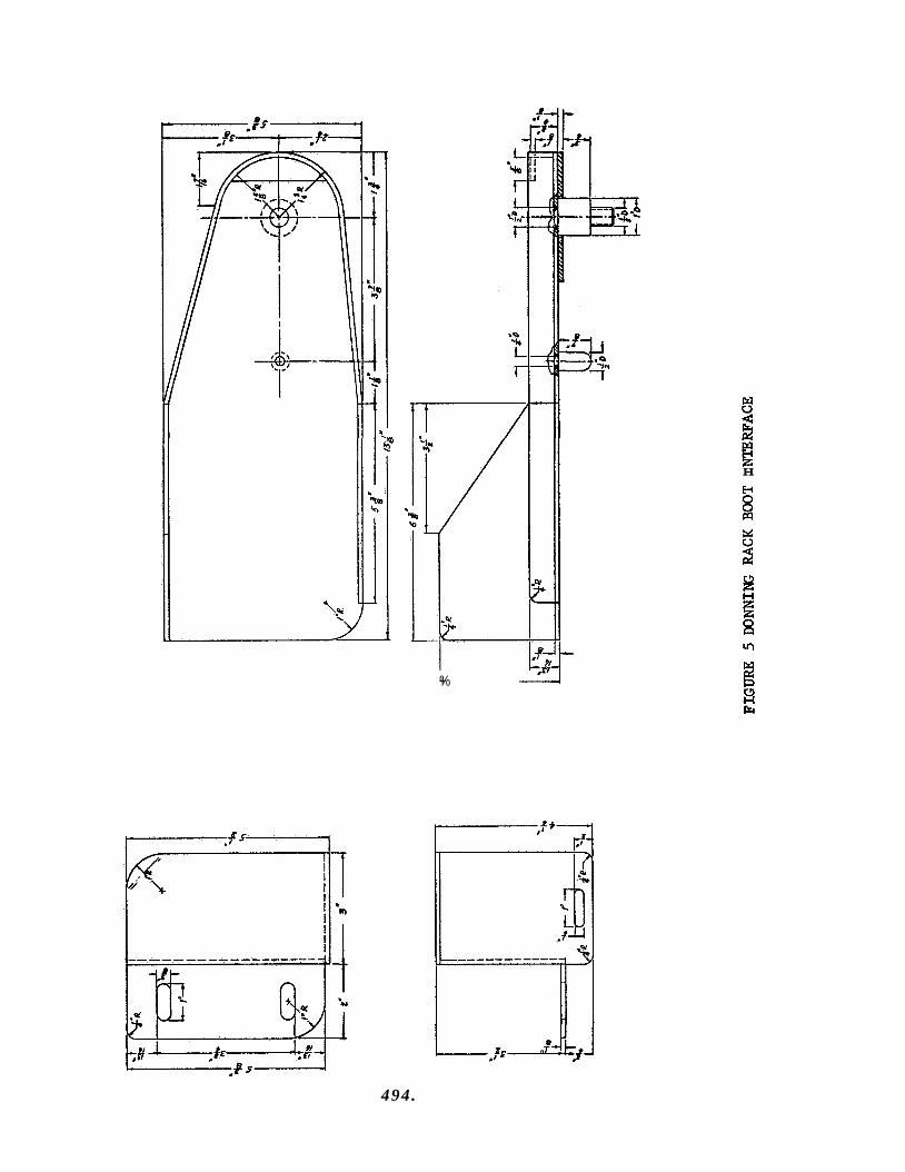
+%
I
H
494.
APPENDIX K: BISS OUTER SUIT AND TUNNEL SPECIFICATIONS
495.
GENERAL EUCTRIC COMPANY Re-entry Systems Department 3198 Chestnut Street Philadelphia, Pennsylvania Code Ident , No. 15226
SPECIFICATION: ERS0230-00-0001
BISS OUTER SUIT AND TUNMEL
1.0 GENrnAL
1.1 Scope = T h i s speci f ica t ion defines t h e outer s u i t and tunnel which i s one of the major subsystems i n the Bio- Isolator Sui t System, here inaf ter r e fe r red t o as BISS, ( G E - E D Speci f ica t ion 50100-00-0001). The outer s u i t and tunnel provide an absolute b io logica l and topological. barrier between a technician and the s t e r i l e environment wi th in t he assembly /s te r i l i z e r . 1.2 Description - The outer s u i t and tunnel shal l contain all the components and systems necessary t o perform the following functions:
a. Allow t h e technician mobility i n a l l d i rec t ions at any point of the tunnel reach.
b. Allow the technician maximum o p t i c a l vision,
C. Retract the tunnel t o the assembly/s ter i l izer in te r- face f o r technician en t ry and egress procedures.
d. Maintain the outer s u i t body i n a semi-rigid v e r t i c a l pos i t ion f o r the technician en t ry and egress procedures.
e. Support the tunnel when it i s extended o r r e t rac ted t o decrease drag on the technician and assist the extending and r e t r a c t i n g mechanism.
1.2.1 following major components:
Components = The outer s u i t and tunnel shall consis t of t he
a. Outer Su i t Body
d. H e l m e t and Yoke
e. Tunnel
f . In ter face Collars
496.
2.0 APPLICABLE W C W T S
2,s issue spec i f ied , form a part of this specif icat ion t o t he extent specif ied
Government Documents - The following government documents of the
herein.
Federal
GGGEb142 c Helmet, Construction Worker*s 18 December 1961.
-
Military
I633586 Metals, Definition of 1 October 1952 Dissimilar
M I ~ ~ 3 8 3 2 5 ~ 23 January 1966
B o o t , Rocket Fuel Handl-ers FWK-&/P22P-L
(Copies of these documents may be obtained from t h e Super- intendent of Documents, Government Pr in t ing Office, Wash- ington, D,C. )
2.2 Non-Government Documents - The following non-government documents of the issue i n e f f e c t on the date of t h i s spec i f ica t ion , form a part of t h i s spec i f ica t ion t o t h e extent spec i f ied herein.
SPEC1 F'I CATIONS
so100-00-0001 Bio- Isolator Su i t System (BISS)
50230-00-0002 BISS Undersuit STANDARDS
~ 8 ~ 1 5 2 6 Ident i f ica t ion Marking
1 4 6A9 5 6 0 Preparation for Delivery
(Copies of t h e General E lec t r i c Company documents are avai lable from: General E lec t r i c Company, RSD, 3198 Chestnut S t r e e t , Philadelphia, Pennsylvania lgU31)
497.
3.0 REQUIREMENTS
3.1 of t h i s spec i f i ca t ion and referenced documents t o the extent speci f ied herein. speci f ied herein, t h i s spec i f i ca t ion s h a l l govern.
General - The outer s u i t and tunnel shall meet the requirements
I n case of c o n f l i c t between the requirements and any documents
3.2 following performance character iskics ,
Performance - The outer s u i t and tunnel sha l l provide t h e
3.2.1 between the wearer and t h e s ter i le environment of t h e assembly/ster i l izer such t h a t t h e probabi l i ty of microbial penetrat ion through any material o r seam is less than and there shall be no a i r leak g rea te r than 1 x 10-Lo cm3/sec..
-LII Leak - It sha l l provide b io logica l and topological barrier
1 x 10⁻⁵
3.2.2 Physical Movement and Vision - It shall allow the wearer t o accomplish spacecraft assembly and checkout operations within the steri le environment such that the following i s provided;
a, Head movements - The helmet, neck r ings and in te r faces between the helmet and s u i t shall allow all normal head movements,
b. Vision and Distort ion - The face p l a t e of the helmet sha l l provide an unobstructed l i n e of v is ion at all normal head movement l i m i t s wi th no v i sua l a i s to r t ion .
C. Fi t lMobil i ty - The outer s u i t and tunnel shall not r e s t r i c t o r evidence d i f f i c u l t y i n manned entry t o o r egress from the s u i t , bending at t he waist, knees, elbows, hips and no binding sha l l occur t h a t w i l l obs t ruct normal air flow t o and from the undersuit .
3.2.3 be capable of withstanding a d i r e c t puU of 700 pounds minimum without breaking the absolute b io logica l and topologica l seal.
Direct Load - In ter fac ing of the s u i t body/tunnel/hard tube shall
3.2.4 tunnels shall meet t h e following requirements (Section 6, Notes
Material Character is t ics - The materials used i n the ou te r s u i t and shal l be used
as a guide i n se lec t ing materials):
a. S t a b i l i t y t o dry heat s t e r i l i z a t i o n under conditions speci f ied i n para. 3.8.1.4,
b. Minimum ETO/Freon permeability/degradation under conditions spec i f i ed i n para. 3.8.1.3.
C. Imperviousness t o micro-organisms as spec i f i ed i n 3,2.1.
498 .
3.2.4 Material Character is t ics - (Continued)
d. Abrasion res i s tance
e. Low coef f ic ien t of f r i c t i o n
f . Resistance t o l i qu id &contaminants
6. Non f lamabi l i ty
h. Minimum s t a t i c e l e c t r i c i t y buildup
3.3 Materials, Parts and Processes
3.3.1 Materials - The materials used i n the outer s u i t and tunnel fabr icat ion shall be of t he highest qua l i ty and se lec ted on the basis of physical or o ther e s s e n t i a l proper t ies , a v a i l a b i l i t y , adap tab i l i ty t o production processes, and s u i t a b i l i t y t o t he envircaunent conditions set fo r th i n 3.8.
3.3.2 Standard Par t s - Wherever possible , standard p a r t s shall be used t o ensure r e l i a b i l i t y and expedite procurenent, pa r t s i n t h e i r order of preference are appl icable NASA Specif icat ions , Mil i tary Standards (MS, AN, NAS), General E l ec t r i c Company Standards, and commercial standards, authorized by the procuring agency.
Preferred standard
Non-standard p a r t s may be used when spec i f i ca l l y
3.3.3 C r i t i c a l and St ra t eg i c Materials - Materials shall be se lec ted on the basis of s u i t a b i l i t y and relative ava i l ab i l i t y , Subject t o satis- factory operation, t h e ou te r s u i t and tunnel s h a l l incorporate the l e a s t c r i t i c a l and s t r a t e g i c materials,
3.3.4 i n 14~33586, s h a l l not be used i n int imate contact unless su i tab ly pro- tec t ed against e l e c t r o l y t i c corrosion.
Dissimilar Metals .I The use of dissimilar metals, as defined
3.3.5 Corrosion Resistance - Materials se lec ted s h a l l be corrosion r e s i s t an t or shall be su i tab ly protected by p l a t i ng , painting, o r other surface treatment that is compatible with the environment t o which the outer s u i t and tunnel i s subjected.
3.3.6 the fabr icat ion of t h e ou te r s u i t and tunnel shall provide bonds of t h e highest i n t e g r i t y providing t h e absolute b io log ica l barrier required. bonding shall meet t h e following requirements:
Materia3 Bonding Processes - Material bonding processes used i n
The
a, Minimum l a p shear of 150 psi .
499. .
i
b, Minimum peel s t rength of LO pounds/inch.
C. Probabi l i ty of microbial penetration as specif ied i n para. 3.2.1.
3.4 highest commercial quali ty. Subassemblies and components of the outer
Workmanship - Workmanship and shop prac t ices sha l l be Of the
s u i t and tunnel s h z l be constructed and f inished i n a thoroughly workmanlike manner. c leanl iness , and thoroughness of welding, brazing, bonding, marking of parts, paint ings , protect ive coatings, r ive t ing , machine screw assembly and freedom of par t s from burrs and sharp edges.
Pa r t i cu l a r a t ten t ion shall be given t o neatness,
3.5 of a l l components s h a l l conform wi th the requirements set fo r th i n GE Document 118Al.526 (General E lec t r ic Company RSD Standard Ident i f ica t ion Markings ) .
Ident i f ica t ion and Marking - The i den t i f i ca t ion and marking
3.6 coatings s h a l l conform t o standard prac t ice f o r t h i s type of equipment, and s h a l l be compatible wi th the environmental and service conditions set fo r th i n t h i s specif icat ion.
Finishes and Coatings - Surface f in i shes and protect ive
3.7 In te r faces
3.7.1 Outer Su i t and Tunnel - The outer s u i t and tunnel s h a l l incor- porate the following in te r faces :
a. b.
a. e. f .
g. he i.
C.
Outer s u i t body t o tunnel Tunnel t o hard tube Outer s u i t body t o helmet Outer s u i t body t o gloves Outer suit body t o boots Helmet and yoke t o undersuit (General E lec t r ic Company RSD Specif icat ion SO230-00-0002) Reefing me chani sm/Tunnel Telescoping Boom/Tunnel Donning rack/Outer s u i t body
3.8 Environment
3.84 t o t h e following non-operating environments :
3.8.1.1 free from vapor contaminants at a temperature of 70 f 200F.
Non-Operatinq = The outer s u i t and tunnel shall be subjected
Storage - The storage environment shall be control led atmosphere
3.8.1.2 Shipping - The shipping environment s h a l l be -lO°F t o +120°F.
500.

SPECIFICATION: ERS0230-00=0001
3.8.1.3 s t e r i l i z e r s h a l l be subjected t o 88% Freon 12/12$ ET0 (by weight), at 40% RH, at a concentration of 500 mg. of ETO/litre of gaseous atmosphere for 28 hours at 10h0F (24 hours s tabl ized at 10k0F),
Recontamination = Components located within the assembly/
3.8.1.4 during s t e r i l i z a t i o n procedures shall be nitrogen at a temperature of T O t o 320°F, w i th RH less than 18 above 200°F, and a pressure of up t o 4 inches H20 gage maximum, S t e r i l i z a t i o n times shall be se lec ted from the following:
S t e r i l i z a t i o n - The environment within the assembly/s ter i l izer
Temp, Deg, F S t e r i l i z a t i o n Time, Hours
320 311 302 293 284 275 266 257 248 239 230 221
3 4 6 9 14 22 34 53 a4 132 210 336
3.8.2 following operating environments.
Operat ing- The outer s u i t and tunnel shall be subjected t o t he
3.8.2.1 Outer Su i t & Tunnel - The environment within t he outer s u i t and tunnel shall be 70°F 3 10°F, d e w point 45 f 12OF at a pressure between 0.5 in. H20 and -2.0 i n , H20 gage.
3.8.2.2 zer during operation procedures shall be nitrogen at a temperature of 75 .I + s0F, RH of 20 t o SO%, and a pressure of 2 inches H20 gage maximum,
3.9 use of modular construction t o provide ease of naintenance. shall be of prime importance. shall be avoided t o the maximum possible extent.
Assenbly/Steri l izer - The environment within the assembly/steri l i-
MaintainabilityI- Design of the outer s u i t and tunnel shall m a k e Accessibi l i ty
The use of matched p a r t s o r s e l ec t ive f i t s
3.10 Endurance = Errdursnce of the outer s u i t and tunnel shall be such as t o permit a minimum period of 360 hours of continuous trouble- free operation without maintenance beyond t h e replacement of boots or gloves, The outer s u i t and t u n d l shall be designed f o r an operating l i fe of not less than 2900 hours with maintenance e
501.
SPECIFICATION t ERS0230-00-0001
3.10.1 i n t e g r a l the re to , sha l l withstand a minimum of 10 cleaning procedures on the e x t e r n a l surfaces, 90 cleaning procedures on the i n t e r n a l sur- faces, 10 cycles of ETO/Freon decontamination and 10 cycles of dry heat s t e r i l i z a t i o n (see 3.8 f o r dry heat s t e r i l i z a t i o n cycles) without v io la t ing t h e bas ic garment construct ion o r t h e design c r i t e r i a . The t o t a l l i f e of t h e outer suit and tunnel and parts thereof s h a l l be up t o 24 months from production t o end of l ife. of up t o 12 months, w i t h the balance of the 24 months being storage t i m e . The design object ive f o r cleaning procedures shall be 20 cleaning gro- cedures on ex te rna l surfaces and 90 cleaning procedures on i n t e r n a l s u r f aces.
Tota l Life - The outer s u i t and tunnel , and all equipment
T h i s t o t a l shall be composed of a service l i f e
3.11 Safe ty Requirements - The outer s u i t and tunnel s h a l l be designed w i t h sncorporation of the following sa fe ty requirements:
a. Minimize t h e p o s s i b i l i t y of in ju ry t o personnel and damage t o the equipment.
b, Remove all sham edges and round-off all Corners.
c. Envelop the wearer and provide an absolute barrier from the ni trogen environment,
d. Minimize the p o s s i b i l i t y of in ju ry t o the wearer from f a l l i n g objects o r accidental f a l l i n g o r s l ipping of the occupant.
e. The h e l m e t and face plate s h a l l provide the equivalent of hard hat and sa fe ty glass protect ion t o the wearer.
The boots sha l l - incorpora te sa fe ty toes and non-skid so les . f ,
g. Adequate grounding shall be provided t o minimize s t a t i c e l e c t r i c i t y build-up.
In ter fac ing of t he s u i t body/tunnel/hard tube shall be capable of withstanding a d i r e c t p u l l as speci f ied i n para. 3.2.3.
b.
3.12 Desim Requirements
3.12.1 Comgonents - The outer s u i t and tunnel shall consis t of the cmponents s e t f o r t h i n 1.2,l.
502.
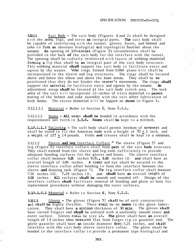
SPECIFICATION: ERS0230-00-0001
3.12.1.1 Sui t Body - The s u i t body [Figures 1 and 2) sha l l be designed w i t h the arms, l egs , and t o r s o as i n t e g r a l parts. be capable of in te r fac ing w i t h t h e tunnel , gloves, boots, and helmet and yoke t o form an absolute b io logica l and topologica l barrier about t h e wearer. provided i n the back of the s u i t body f o r the i n t e r f a c e with the tunnel , The opening shall be r a d i a l l y reinforced w i t h l a y e r s of webbing material fonning a l i p that shall be an i n t e g r a l part of the s u i t body s t ructure . Th i s webbing material shall support t h e s u i t body t o f a c i l i t a t e e n t r y and egress by t h e wearer. incorporated i n the sleeve and l e g s t ructures . above and below the elbow and above the knee areas. posi t ioned t h a t they do not hinder the Werner's movements. support t h e mterial t o f a c i l i t a t e en t ry and egress by t h e wearer. adjustment strap shall be located a t t h e s u i t body crotch area. The neck area of the s u i t w i l l incorporate 22-inches of e x t r a material t o permit mating of t h e helmet and yoke assembly wi th the s u i t after fabr ica t ion of both items.
The s u i t body s h a l l
An opening of lOb=inches (Figure 3) circumference s h a l l be
Wire r ings formed from 0.060 piano w i r e s h a l l be The r ings shall be located
They shall be so The r ings shall
An
The excess material w i l l be lapped as shown i n Figure 4,
3.12.1.1.1 Material - Refer t o Section 6, Note 6.2.1,
3.12.1.1.2 Seams - All seams shall be bonded i n accordance wi th t h e requirements set f o r t h i n 3.3.6, Seam s h a l l be kept t o a min imum,
3.12.1.1.3 T a i l o r i n g - The s u f t body s h a l l permit freedom of movement and s h a l l be sized t o f i t the American male with a height of 70 21 inch, and a weight of 157 f 1 4 pounds.
3.12.1.2 l e g (Figure 6) in te r face c o l l a r s s h a l l form part of the s u i t body s t ructure . They s h a l l extend from the sleeve and leg ends s u f f i c i e n t l y t o provide adequate bonding surfaces f o r the gloves and boots. The s leeve in te r face c o l l a r s h a l l measure 5.25 inches O.D., 5.00 inches I.D. and sha l l have an o v e r a l l length of 3.00 inches. A c l a p and eye shall be secured t o the sleeve in te r face c o l l a r after bonding t o form the in te r face between the sleeve and donning rack (Figure 7) . 7.50 inches O.D., 7'25 inches I.D., and 3.00 inches. All surfaces shall be smooth and rounded off . Design of the in te r face c o l l a r s shall f a c i l i t a t e removal of bonding and glove o r boot f o r replacement procedures without damaging the ou te r surfaces,
Folds and creases sha l l be kept t o a minimum,
Sleeve and k g In ter face Collars - The sleeve (Figure 5) and
The leg i n t e r f a c e c o l l a r sha l l measure shall have an overa l l length of
3.12.1.2.1 Material - Refer t o Section 6 , Note 6.2.2.
3.12.1.3 snd s h a l l be highly f l ex ib le . There she l l be no seams i n t h e glove fabri- cation. The gloves shal l have curved f ingers end shall be unlined with a uniformly smooth inner and outer surface. Gloves shall be s i z e 10. The glove shall have an overa l l length of 1 4 inches when masured f lat from f inger t i p t o gauntlet end, glove gaunt le t s h a l l have an ins ide diameter from 5.25 inches, and s h a l l in ter face with the s u i t body sleeve in te r face co l l a r . The glove shall be bonded t o the in te r face c o l l a r t o provide a permanent type b io log ica l and
Gloves - The gloves (Figure 5) sha l l be of u n i t construct ion
They sha l l have a mfninum thickness of 30 mils.
The
t 503.
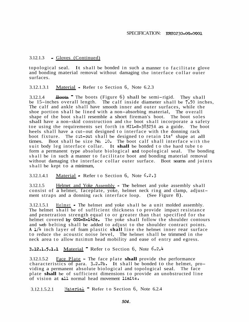
SPECIFICATION: ERSO230=0O=OOOl
3.12.1.3 = Gloves (Continued)
topological seal. It sha l l be bonded i n such and bonding material removal without damaging surfaces.
a manner t o f a c i l i t a t e glove the in te r face c o l l a r outer
3.12.1.3.1 Material - Refer t o Section 6, Note 6.2.3
3.12.1.4 They shall be 15-inches overa l l length. The c a l f ins ide diameter sha l l be 7.50 inches, The ca l f and ankle s h a l l have smooth inner and outer surfaces, while t h e shoe port ion s h a l l be l ined with a non-absorbing material, The overa l l shape of the boot s h a l l resemble a short fireman's boot. The boot so les shall have a non-skid construction and t h e boot s h a l l incorporate a safe ty toe using the requirements set fo r th i n MILE-38325A as a guide. The boot heels s h a l l have a cut-out designed t o in te r face with t h e donning rack boot f ix ture . The cut-out s h a l l be designed t o r e t a i n its' shape at all times. Boot s h a l l be s i ze No. 20 , The boot c a l f s h a l l i n t e r face w i t h t h e s u i t body l e g in te r face col lar . It shall be bonded t o the hard tube t o form a permanent type absolute b io logica l and topological seal. s h a l l be i n such a manner t o f a c i l i t a t e boot and bonding material removal without damaging t h e in te r face c o l l a r outer surface. Boot seams and j o i n t s s h a l l be kept t o a minimum,
- Boots - The boots (Figure 6) shall be semi-rigid.
The bonding
3.12.1.4.1 Material = Refer t o Section 6, Note 6.2.3
3.12.1.5 Helmet and Yoke Assembly - The helmet and yoke assembly shall cons is t of a helmet, facepla te , yoke, helmet neck r ing and clamp, adjust- ment s t r aps and a donning rack in te r face loop. (See Figure 8).
3.12.1.5.1 H e l m e t - The helmet and yoke sha l l be a uni t molded assembly. The helmet s h a l l be of su f f i c i en t thickness t o provide impact res is tance and penetrat ion s t rength equal t o o r g rea te r than t h a t speci f ied f o r the helmet covered by GGG-H-142c. and web be l t ing s h a l l be added t o adjus t t o the shoulder contract points. A 1 / 4 inch l aye r of foam p l a s t i c shal l l i n e the helmet inner rear surface t o reduce the acoust ic noise level, The helmet s h a l l be trimmed i n the neck area t o allow m a x i m u m head mobility and ease of en t ry and egress.
The yoke shall follow t h e shoulder contours
3.12.1.5.1.1 Material - Refer t o Section 6, Note 6.2.4
3.12.1.5.2 Face Pla te - The face p l a t e shall provide the performance cha rac te r i s t i c s of para. 3,2.2b. It s h a l l be bonded t o the helmet, pro- viding a permanent absolute b io logica l and topological seal. p la t e shall be of su f f i c i en t dimensions t o provide an unobstructed l i n e of vision at all normal head movement l i m i t s .
The face
3.12.1.5.2.1 ?.?aterial - Refer t o Section 6, Note 6.2.4
504.

SPECIFICATIOIJ 2 ERS0230-00-0001
3.12.1.5.3 H e l m e t Heck Ring and C l a m p - The neck r i n g s h a l l be of u n i t construction with t h e inner surface so designed t o provide t h e most p r ac t i ca l i n t e r f ace surface between it, t h e helmet, and the ou te r s u i t body. The neck r i ng ou te r surface s h a l l be so designed t o provide t h e most p r ac t i ca l i n t e r f ace surface between it and t h e clamp, s h a l l be fabr icated i n two semi-circular sec t ions with provisions made for securing the ends together, t he neck r i ng t o the bonded helmet and s u i t body. and clamp shall be located at t h e helmet base. faced with t h e s u i t body a permanent-type bonded absolute biological and topological s ea l s h a l l be completed by t h e helmet neck r i ng and elm,
The clamp
When t ightened, t h e clam? s h a l l secure The helmet neck r i ng
When t h e helmet is in t e r-
3.12,1.5.3.1 Material - The helmet neck r i ng and clamp s h a l l be fabr icated from aluminum,
3,12.1,5.4 Adjustment Straps - The adjustment s t r aps s h a l l be secured t o the helmet yoke. with a personal "Y" back s t r a p (Figure 9).
Each s t r a p s h a l l have a D-ring which s h a l l i n t e r f ace The "Y" back s t r a p s h a l l
i n t e r f ace with t h e undersuit fastenings s h a l l be provided individual wearers t o adjust BISS
3.12,1,5,4,1 Material - The Dacron webbing s t r i p s 3/32 x
w a i s t b e l t . Quick-release adJustable on t h e "Y" back s t rap. t h e "Y" back strap before enter ing t h e
This will enable
adjustment s t r aps s h a l l be fabr icated from 2 inches.
3,12,1.5,5 Donning Rack In te r face Loop - The donning rack in t e r f ace loop s h a l l be an i n t e g r a l component of t h e helmet. top of t he helmet i n such a posi t ion t o f a c i l i t a t e alignment with t he support hook on the donning rack.
It s h a l l be located i n t h e
3.12,1,5,5,1 from aluminum.
Material = The donning rack in t e r f ace loop s h a l l be fabr ica ted
3.12.1.6 piece of material. and hard tube. circumference, bonded i n such a manner t o provide a permanent absolute b io log ica l and topological seal. capable of withstanding a d i r ec t pull of 700 pounds minimum without destroying the absolute b io log ica l and topological seals. attached t o t h e top of t h e tunnel and s h a l l be spaced 2 feet apart f o r t h e entire tunnel length. They s h a l l be secured t o t he tunnel outer w a l l by a grommet and swivel eye attachment (Figure If).
Tunnel - The tunnel (Figure 1 0 ) s h a l l be fabr ica ted from a u n i t It s h a l l be capable of in te r fac ing w i t h the s u i t body
The tunnel s h a l l be 20 ft. long, with a 104 inch ins ide The seam i n t h e tunnel s h a l l be lengthwise, and s h a l l be
The in te r faces at t h e s u i t body and hard tube s h a l l be
Flexible s t r i nge r s s h a l l be
505.
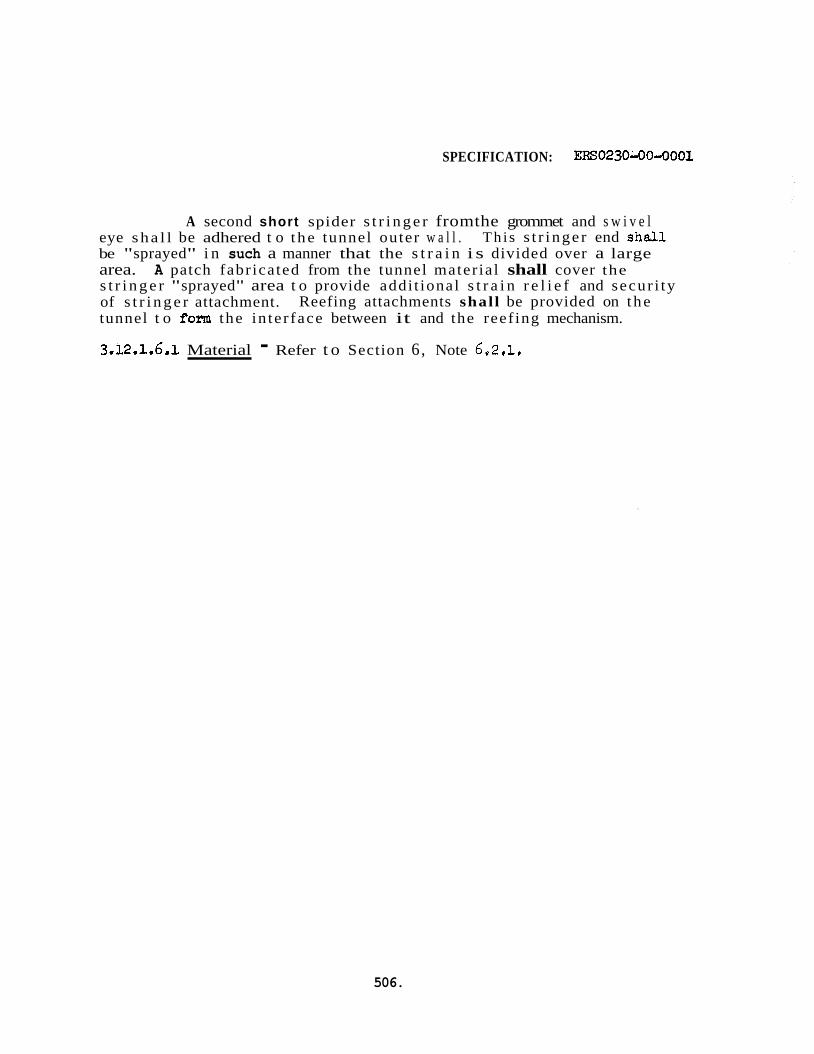
SPECIFICATION: ERS0230-00lo001
A second short spider s t r i n g e r fromthe grommet and s w i v e l eye sha l l be adhered t o t he tunnel outer w a l l . be "sprayed" i n such a manner that the s t r a i n i s divided over a large area. A patch fabr icated from the tunnel mater ia l shall cover the s t r i n g e r "sprayed" area t o provide addi t ional s t r a i n r e l i e f and secur i ty of s t r i n g e r attachment. tunnel t o form the in te r face between it and the reef ing mechanism.
Th i s s t r i nge r end s h a U
Reefing attachments shal l be provided on the
3,~2.1.6.1 Material - Refer t o Section 6 , Note 6.2,~
506.
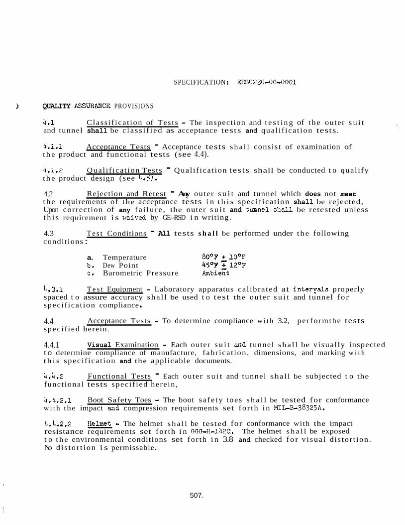
SPECIFICATION : ERSO230-00-0001
QUALITY ASSURNEE PROVISIONS
4.1 and tunnel shall be c l a s s i f i e d as acceptance tests and qual i f ica t ion tests.
Class i f ica t ion of T e s t s - The inspection and t e s t i n g of t he outer s u i t
4.1.1 t h e product and funct ional tests (see 4.4).
Acceptance Tests - Acceptance tests s h a l l consis t of examination of
4.1.2 t h e product design ( see 4.5).
Qual i f ica t ion Tests - Qual i f ica t ion tes ts shall be conducted t o qua l i fy
4.2 t h e requirements of the acceptance tests i n t h i s spec i f ica t ion shall be rejected, Upon correct ion of any f a i l u r e , the outer s u i t and t u n e 1 shaJ.1 be retested unless
Rejection and Retest - Any outer s u i t and tunnel which does not meet
t h i s requirement i s waived
4.3 T e s t Conditions condit ions :
a. Temperature b * Dew Point
by GE-RSD i n writing.
- All tests s h a l l be performed under the following
80°F + 10°F 45OF 7 12OF
C. Barometric Pressure Ambiezt
4.3'1 spaced t o assure accuracy s h a l l be used t o tes t the ou te r s u i t and tunnel f o r spec i f ica t ion compliance
T e s t Equipment - Laboratory apparatus ca l ib ra ted at i n t e rya l s properly
4.4 spec i f ied herein.
Acceptance Tests - To determine compliance w i t h 3.2, per formthe tests
4.4.1 t o determine compliance of manufacture, fabr ica t ion , dimensions, and marking w i t h t h i s spec i f ica t ion and the applicable documents.
4.4.2 funct ional tests spec i f ied herein ,
Visual Examination - Each outer s u i t and tunnel s h a l l be v i sua l ly inspected
Functional Tests - Each outer s u i t and tunnel shall be subjected t o the
4.4.2.1 w i t h the impact and compression requirements set fo r th i n MILB-38325A.
Boot Safety Toes - The boot s a f e ty toes s h a l l be tested for conformance
4.4.2.2 resistance requirements set fo r th i n GGG-H-142C. t o t h e environmental conditions set for th i n 3.8 and checked f o r v i sua l d i s to r t ion . No d i s to r t i on i s permissable.
fIelmet - The helmet sha l l be tested for conformance wi th the impact The helmet s h a l l be exposed
507.
SPECIFICATION: ERS0230=00=0001
4.5 Qual i f ica t ion Tests
4.5.1 N&n-Operating Environmental Tests - The outer suit and tunnel s h a l l meet the requirements spec i f ied i n 4.4.1, 4.1.2.1 and 4.4.2.2 after subjection t o t he following environmental tests.
4.5.1.1
4.5.1.2 the assembly/s ter i l izer hard tube. t o t h e s u i t body, bonded surfaces .
1st Leak T e s t - To be supplied later (TBSL).
Applied Load T e s t - The tunnel s h a l l be in te r faced t o a facimile of A direct load of 700 lbs . s h a l l be applied
There s h a l l be no sign of f a i l u r e of any suit body o r tunnel
4.5.1.3 2nd Leak Test = TBSL
4.5.2 shall be conducted i n conjunction with t he system qua l i f i ca t ion tests spec i f ied i n GE-RSD Specif icat ion ERS0100-00-0001 (Bio- Isolator Su i t System).
Operating Environmental Tests - The operating environmental tests
508.
SPECIFICATION: ERS0230-00-0001
5.0 PREPARATION FOR STORAGE AND TRANSPORTATION
5.1 Storage
5.1.1 Outer S u i t and Tunnel - The outer suit and tunnel shall be s tored i n a clean, cont ro l led environment f r e e from vapor contaminshts at a temperature of 65 t o 75OF. supported by a suitable rack,
5.2 Transportation
5.2'2 overpacked i n a shipping container which shall adequately protec t it during handling and shipping. The shipping container s h a l l meet the minimum requirements of t h e c a r r i e r f o r sa fe t ranspor ta t ion , overpacking shall be placed i n fold areas t o prevent sharp bends, helmet and face p l a t e s h a l l be supported i n the most e f f i c i e n t manner and sha3.1 be overpacked i n t e r n a l l y and external ly. area s h a l l be of t h e highest qua l i ty and shall not degrade t h e o p t i c a l qua l i ty of t h e face p la te , glove and f inger areas t o prevent sharp bends, suit and tunnel s h a l l be shipped at room temperature, temperature i s 55OF o r lower, the shipping container shall be opened at the des t ina t ion and t h e ou te r s u i t and tunnel shal l be allowed suf f fc ien t time t o reach room temperature before removal.
!the outer su i t and tunnel s h a l l be
Outer S u i t and Tunnel - The outer s u i t and tunnel shall be
Additional The
The packaging used i n this
Additional overpacking s h a l l be placed within the e n t i r e Wherever possible the oute r
I f t ranspor ta t ion
5.2.2 All other components used i n t h e ou te r s u i t and tunnel concept s h a l l be overpacked i n shipping containers which shall adequately protec t them during handling and shipping, minimum requirements of t h e c a r r i e r for safe t ranspor ta t ion ,
The shipping containers shall meet t h e
5.3 Marking - Shipping and s torage containers s h a l l be marked with the name and address of t h e consignee and consigner, contract or purchase order number, and i t e m p a r t number, waterproof . A l l markings s h a l l be l e g i b l e and
509.
SPECIFICATION: ~ ~ 0 2 3 0 ~ 0 4 - ~ 0 0 ~
6,o NOTES
6.1 issue, s h a l l be used f o r reference pusposes only and do not form a pa r t of t h i s specification.
Reference Documents - The following documents of t h e latest
General ELectric
165 A4434 128A5469
EPOXY ADHESIVE RUBB, SILICON, MOLDED & EXTRUDED
6.2 Materials - Materials which have demonstrated sa t i s f ac to ry performance t o the requirements of t h i s specif icat ion are as follows:
6.2.1 Sui t Body and Tunnel Material - Armalon, EIDuPont de Nemours.
6.2*2 Sleeve and Leg Interface Collars .I Fabricated f ron Epoxy EC2216, 3M Co (CE-RSD Standard 365A4434)
6.2.3 SE 555 (See GE-RSD Standard 128A5469 f o r rub%r material only)
Gloves and Boots e Fabric reinforced with Si l icone Rubber
6.2.4 Developaent Operation, P i t t s f i e l d , Mass.
Helmet & Fore P la te - Lexan, Ganeral E lec t r i c Co., Chemical
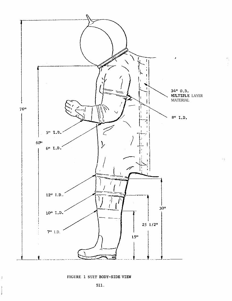
76"
f----
60"
12'1
10"
7"
I . D .
I .D.
L
34" O.D. MLnTIPLE LAYER MATERIAL
8" I . D .
FIGURE 1 SUIT BODY-SIDE VIEW
511.
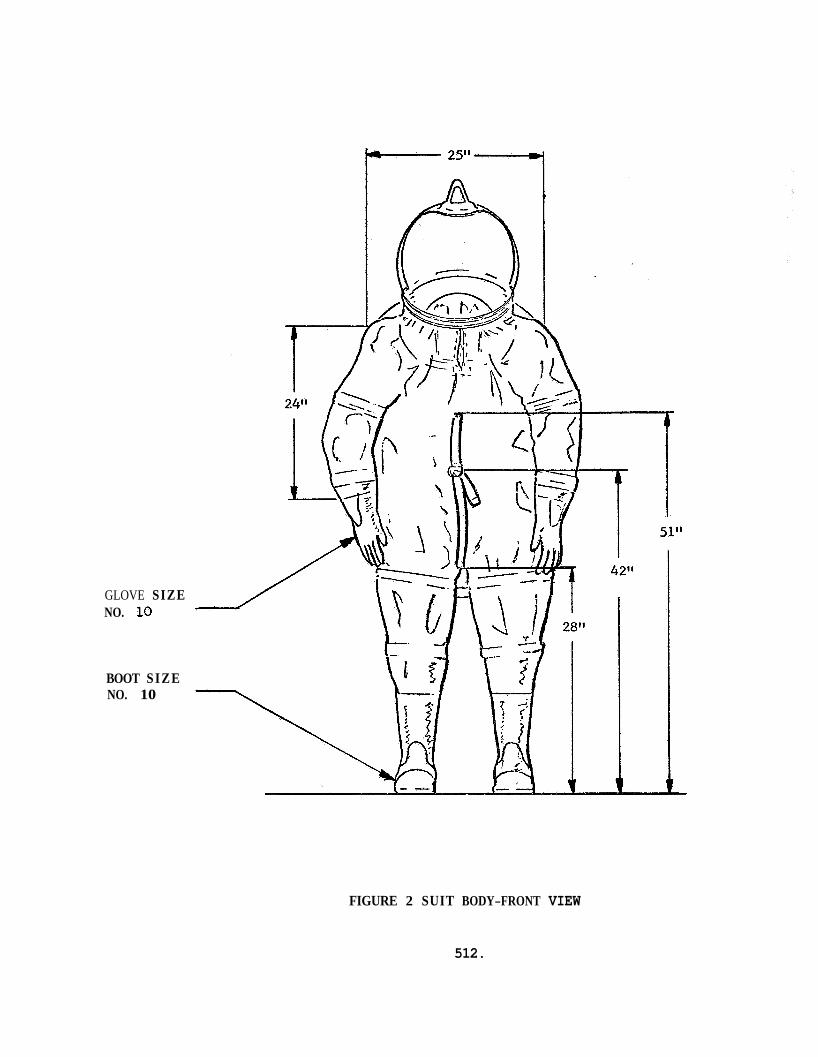
42"
GLOVE SIZE NO. 10
BOOT SIZE NO. 10
FIGURE 2 SUIT BODY-FRONT VIEW
512.
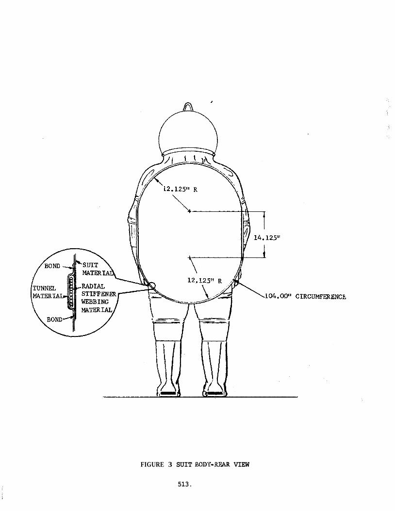
FIGURE 3 SUIT BOD’Y-R?UR VIEW
513.
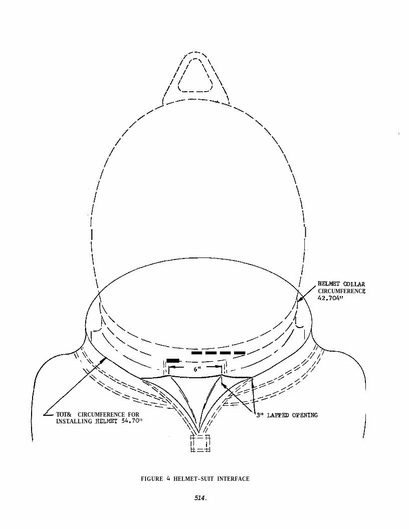
I I I
I
CIRCUMFERENCE
--------- .---- 6 TOT& CIRCUMFERENCE FOR
INSTALLING HELMET 54 70".
I 1 I 1 tt=+-l
FIGURE 4 HELMET-SUIT INTERFACE
514.
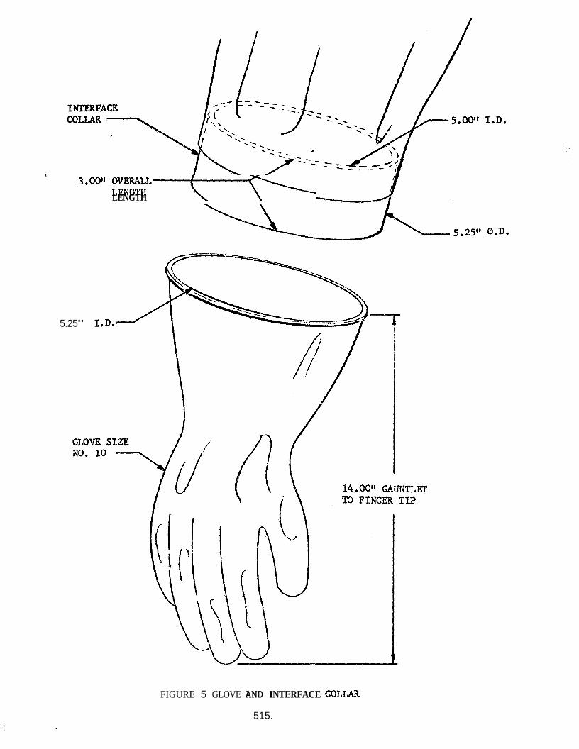
I.D.
0.D.
3*00" O V E M L L M LENGTH
5.25" I
FIGURE 5 GLOVE AND INTERFACE COLLAR
515.
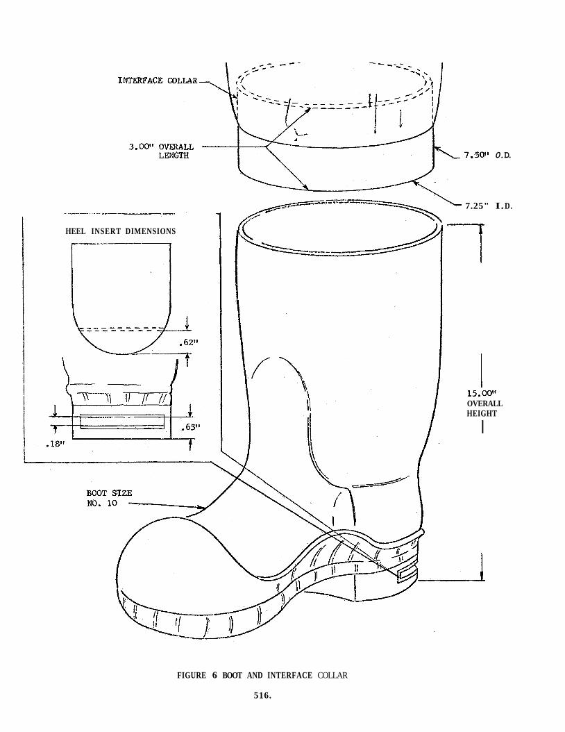
HEEL INSERT DIMENSIONS
7.50" 0. D.
7.25" I. D.
-7
15.00" OVERALL HEIGHT
I
FIGURE 6 BOOT AND INTERFACE COLLAR
516.
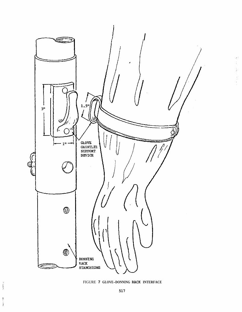
I
FIGURE 7 GLOVE-DONNING RACK INTERFACE
517
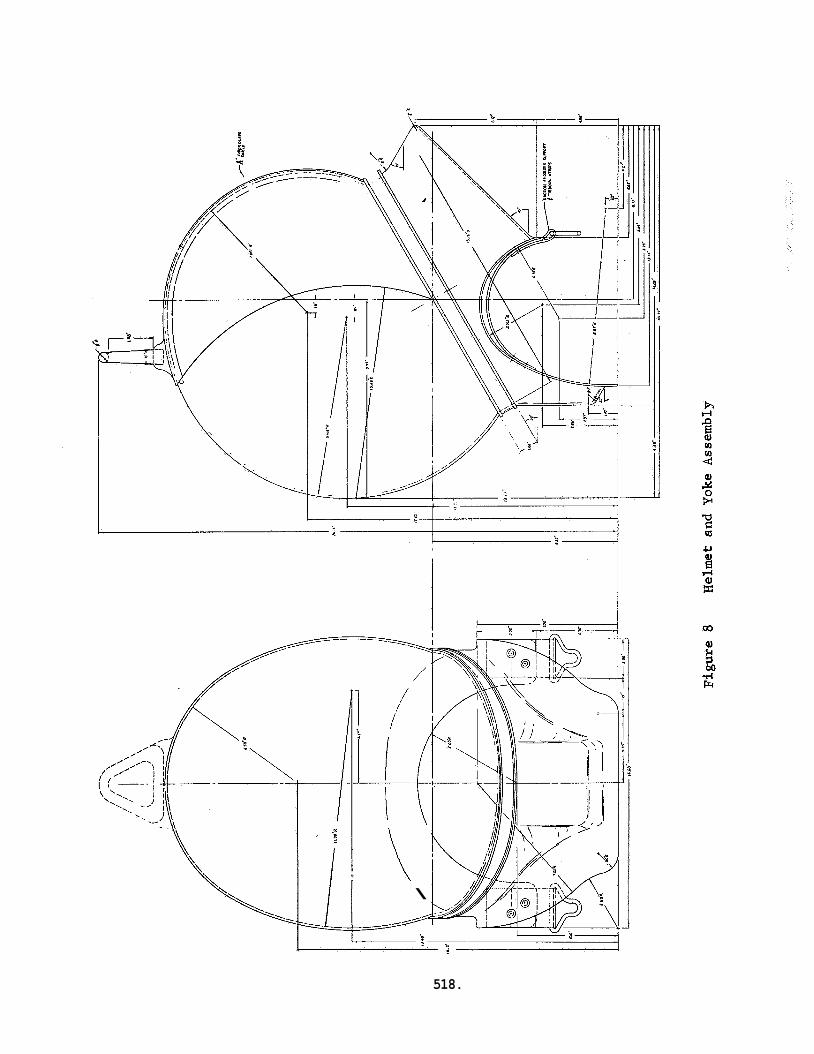
I I '
/ / /
\
518.
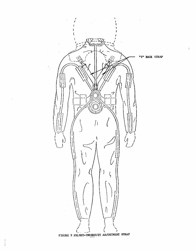
"Y" J3AcK STRAP
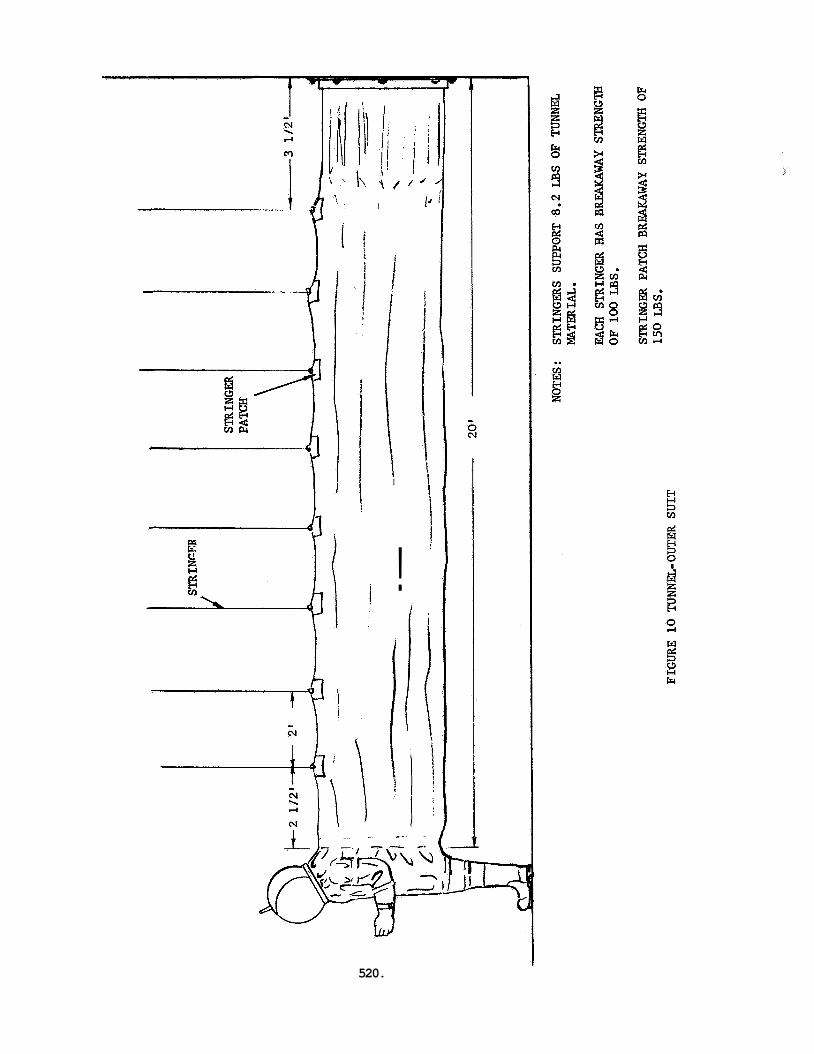
I
i
1 I
!
1 i
j
520.
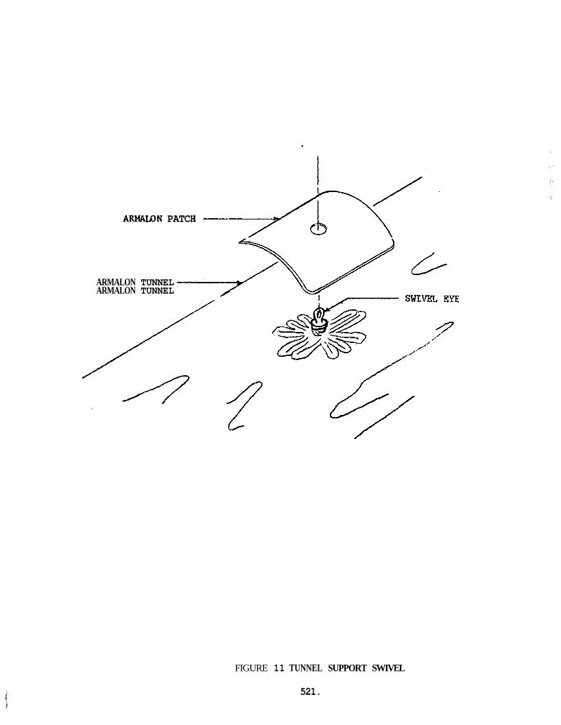
ARMALON TUNNEL 44 L-
ARMAWN PATCH
ARMALON TUNNEL
FIGURE 11 TUNNEL SUPPORT SWIVEL
521.
APPENDIX L : BXSS UMDERSUIT SPECIFICATION
522.
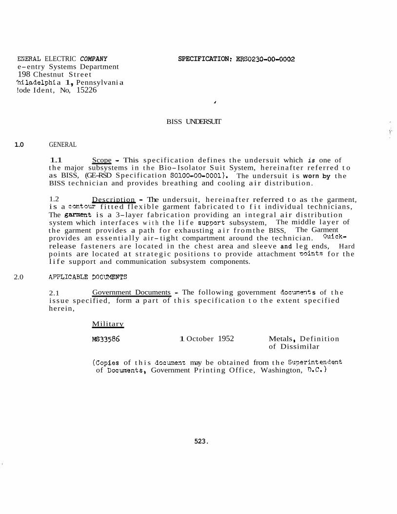
ENEEIAL ELECTRIC COMPANY e-entry Systems Department 198 Chestnut S t ree t ‘hi ladelphi a 1 , Pennsylvani a !ode Ident, No, 15226
SPECIFICATION ERS0230-00-0002
BISS UNDERSUIT
1.0 GENERAL
1.1 t h e major subsystems i n t h e Bio- Isolator Su i t System, here inaf te r re fe r red t o as BISS, (GE-RSD Specif icat ion S0100-00-0001). BISS technician and provides breathing and cooling a i r d i s t r ibu t ion .
Scope - This spec i f ica t ion def ines t he undersuit which is one of
The undersuit i s worn by the
1.2 i s a contour f i t t e d f l e x i b l e garment fabr ica ted t o f i t individual technicians, The gaMlent i s a 3-layer fabr ica t ion providing an i n t e g r a l a i r d i s t r i bu t ion system which in te r faces w i t h t h e l i f e supaort subsystem, the garment provides a path f o r exhausting a i r f r o m t h e BISS, provides an e s s e n t i a l l y a i r- t igh t compartment around the technician. release fas teners a r e located i n the chest area and s leeve and l e g ends, Hard points are located a t s t r a t e g i c pos i t ions t o provide attachment Doints f o r t he l i f e support and communication subsystem components.
Description - The undersuit , he re ina f t e r referred t o as t h e garment,
The middle layer of The Garment
Quick-
2.0 API’LICABLE DOCllMEElTS
2.1 i s sue specif ied, form a pa r t of t h i s spec i f ica t ion t o t h e extent spec i f ied
Government Documents - The following government docunent s of t h e
herein,
Military
MS33586 1 October 1952 Metals Defini t ion of Dissimilar
523.
(CopSes of t h i s document may be obtained from t h e Swerintendent of Documents, Government Pr in t ing Office, Washington, 0.C.
SPECIFICATION: ERSO230-00-0002
2.2 Non-Government Documents - The fol loying non-government documents of t h e i ssue i n effect on t h e da te of t h i s speci f ica t ion , form a p a r t of t h i s speci f ica t ion t o t h e extent speci f ied herein,
GENERAL ELECTRIC COMPARY
, Specif icat ions
so100-00-0001
so210-00-0001
SOl50-02-0001
Standards
118Al526
118~1600
Bio- Isolator Sui t System (BISS)
BISS L i f e Support Subsystem
BISS Communication Subsystem
Ident i f ica t ion Yarking
Finishes and Coatings
147A 18 5 0
165A4429 Flexible Polyurethane Foam Set
(Copies of t h e General E lec t r i c Compmy documents a re avai lable from General E l e c t r i c Company, RSD, 3198 Chestnut S t ree t , Philadelphia, Pennsylvania 19101).
Adhesive Vulcanized Synthetic Elastic
524.
SPECIFICATIOIi : ERS02 30-00-0002
RE2UIREMENTS
3.1 General - The undersuit s h a l l meet t he requirements of t h i s spec i f ica t ion and referenced documents t o the extent spec i f i ed herein. the event of con f l i c t between t h e requirements and any document spec i f i ed herein, t h i s spec i f i ca t ion s h a l l govern.
In
3.2 Materials, Pa r t s , and Processes
3.2.1 Materials - The materials used i n t h e undersuit f ab r i ca t ion s h a l l be of t h e highest qua l i t y ana se l ec t ed on the bas i s of physical o r o ther e s s e n t i a l propert ies , a v a i l e b i l i t y , adap tab i l i t y t o production processes, and s u i t a b i l i t y t o t h e environmental conditions set forth.
3.2.2 Standard Parts - Wherever possible , s tandard p a r t s s h a l l be Lsed to ensure rel iabil i tx and expedite procurement. Preferred standard pa r t s In t h e i r order of preference are appl icable NASA spec i f i ca t ions , Mi l i ta ry Standards (MS, AN, NAS) , General E l e c t r i c Standards, and commercial standards. p a r t s may be used when s p e c i f i c a l l y authorized by t h e procuring agency.
Non-standard
3 2 . 3 C r i t i c a l and S t r a t eg i c Platerials - Materials s h a l l be se lec ted on t h e basis of s u i t a b i l i t y and r e l a t i v e ava i l ab i l i t y . Subject t o s a t i s f a c t o r y operation, t h e garment shal l incorporate t h e l e a s t c r i t i c a l and s t r a t e g i c mater ia ls .
3.2.4 Ms33586, s h a l l not be used i n int imate contact unless su i t ab ly protected against
Dissimilar hletals - The use of d i ss imi la r metals, as defined i n
e l e c t r o l y t i c corrosion.
3.2.5 Corrosion Resistance - Materials se lec ted s h a l l be corrosion r e s i s t a n t o r s h a l l be su i t ab ly protected by p la t ing , paint ing, o r o ther surface treatment t h a t is compatible with t h e environment t o which t h e garment i s subjected.
3.2.6 fabr ica t ion of t h e garment shall provide bonds of t he highest i n t e g r i t y required i n t h e design c r i t e r i a . Bonding s h a l l not r e s t r i c t t he flow of air through t h e
Material Bonding Processes - Material bonding processes used i n t h e
middle and ment s :
3.3 come r c i a1
inner layers of material. The bonding s h a l l meet t he following require-
a. Minimum l a p shear s h a l l be 125 p s i
b. Minimum pee l s t rength s h a l l be 8 pounds/inch
Workmanship - WorkmanshiF and shop prac t ices s h a l l be of t he highest qua l i ty . Subassemblies and components of t h e garment s h a l l be
constructed and f in i shed i n a thoroughly workmanlike manner. ion s h a l l be given t o neatness, c lean l iness , and thoroughness of bonding, marking, of parts, paint ing, p ro tec t ive coatings, r i ve t ing , machine screw assembly, an6 freedom of parts from burrs and sharp edges.
Pa r t i cu l a r a t t en t-
525.
SPECIFICATION: ERS0230-00-0002
3.4 components s h a l l conform with the requirements, set f o r t h i n GX Document; 118A1526 (General E l e c t r i c Company Standard Iden t i f i ca t ion Marking).
Iden t i f i ca t ion ana Marking - The i d e n t i f i c a t i o n and marking of a l l
3.5 s h a l l conform t o t h e General E l e c t r i c Company RSD Standard 118~1600 (Finixhes and Coatings) f o r t h i s type of equipment, and s h a l l be compatible with t h e environmental and service conditions set f o r t h i n t h i s speci f ica t ion .
Finishes and Coatings - Surface f in i sh ing and protec t ive coetings
3.6 Mairitain&bility - Components for t h e a ir d i s t r i b u t i o n sys ten s h a l l be placed and secured i n such a manner t h a t they nay be accessible f o r vaintennnce. The ches t , s leeve and l e g fa s t ings s h a l l be i n s t a l l e d i n such R manner t h a t tk<ey may be repaired o r replaced.
3.7 Endurance - The garment s h a l l withstand a ninirnun of 1000 hours of operat ing l i f e , including minor maintenance and repeated cleansing procedures using a mila detergent . Normal operation s h a l l not cause cracking of t h e garment mater ia l or de te r io ra t ion of the air d i s t r ibu t ion components,
3.8 In te r faces - The garment s h a l l incorporate t h e following in ter faces :
a. L i f e support subsystem a i r supply (GE-RSD Speci f ica t ion S0210-00-00@1)
b. L i f e support subsystem a i r exhaust (GE-RSD Speci f ica t ion SO210-00-0001;
c. Communication subsystem (GE-RSD Speci f ica t ion SOl5O-02-OOOl)
d, 14eeirical monitoring system (GE-RSD Speci f ica t ion SO230-00-0001)
e, Outer s u i t helmet and yoke (GZ-RSD Speci f ica t ion SO230-00-0001)
3.9 Environment
3.9.1 following non-operating environments.
Garment, Non-Operatin& - The garment s h a l l be subjected t o t h e
3.9.1.1 Storage - "lie environment within t h e storage area s h a l l be a contro l led atmosphere f r e e from vapor contaminants at a terrperature of 70 2 20°F.
3.9.1.2 Shippin@; - The shipping environment s h a l l be -lO°F t o +120°F.
3.902 s h a l l be 70°F f 10°F, dew point 45OF - + 12'F at a pressure between 0.5 in. H20 and -2.0 i n . n20 gage.
Garment, Operating - The environment within t h e outer s u i t and tunnel
3.10 Safety Requirements - The sa fe ty requirements for t h e garment s h a l l be designed t o minimize t h e p o s s i b i l i t y of in ju ry t o personnel and damage t o t h e equipment. A l l sharp edges and corners s h a l l be rounded off . L i f e support system in te r faces s h a l l be c l e a r l y iden t i f i ed . The garment s h a l l provide adequate d i s t r i b u t i o n of t h e l i f e sus ta in ing air flow. system shall be posi t ioned t o minimize t h e p o s s i b i l i t y of cut t ing o f f the supply and exhaust flows t o 'ana from t h e wearer.
The garment l i f e sus ta in ing a i r flow d i s t r i b u t i o n
526
SPECIFICATIOB: ERS0230-00-0002
3.11 breathing air t o the ou te r s u i t helmet, and cooling air t o t he ou ter s u i t arm and l e g ex t remi t ies as spec i f ied herein. removal of noxious, t ox i c , ana moisture-laden air from the BISS. i n an overpressure environment of up t o 2 in. Ei20 maximum, and shall be capable of withstanding an overpressure of 4 in . H20 maximum i n t he unmanned condition.
3.11.1 capable of d i s t r i b u t i n g a minimum of 2.5 standard cubic feet per minute (SCFM) of conaitioned breathable a i r t o t h e technician 's helmet i n such a fashion t h a t t h e air f l o w i s down across h i s face at all times. The oxygen content of t h e helmet breathable air s h a l l not be reduced t o less than 178 by volume by d i lu t ion wi th expirea a i r because of turbulence i n t h e helmet o r o ther causes. flow t o t h e extremit ies sha l l be equally d i s t r i bu ted within plus o r minus 10% among a l l four extremit ies . supply of 10 SCFM, +10 SCFM, -0 SCFM applied t o the garment 2-chamber plenum.
Performance - The garment s h a l l d i s t r i b u t e an adequate supply of
Th,e garment shall provide a path fo r t h e It s h a l l function
A i r Dis t r ibu t ion System - The a i r d i s t r i b u t i o n system s h a l l be
The a i r
These conditions s h a l l be provided wi th an a i r
3.11.1.1 up t o 4-inches H20 maxinum, and walking, bending, climbing, and squat t ing motions performed by t h e garment wearer, without collapsing.
Tubin& - The tubing shall withstand an overpressure environment of
3.11.1.2 age of a i r flowing t o t h e helmet d i s t r i bu t ion device and the a r m and l e g extremit,- ies. d i s t r i bu t ion device cannot be shut o f f .
2-4hanber Plenum - The 2-chamber plenum s h a l l regulate t he percent-
It s h a l l regula te t h e a i r flow i n such a manner t h a t t h e flow t o t he helmet
3.11.2 Garment - The garment shal l provide t he requirements spec i f ied he re in .
3.11.2.1 wearer i n such a manner t h a t it f o r m an essentialLy a i r- t igh t envelope around h i m without causing discomfort o r in- h i b i t i n g h i s movenents.
- F i t - The garment s h a l l f i t t h e
3.11.2.2 and squating i n t h e garment, operating i n an overpressure of 2-inches E20 maximum, without any discomfort being caused by t h e garment.
Mobility - The wearer s h a l l be capable of walking, bending, climbir.g,
3.12 and a detachable air d i s t r i bu t ion system f o r the l i f e support subsystem a i r supply and exhaust i n t e r f ac ing hoses.
Components - The garment (Figures 1 and 2) s h a l l consis t of a body
527.
SPECIFICATION: ERS0230-00-0002
3,12,1 t o r s o as i n t e g r a l par t s . It s h a l l be a th ree layer , form contoured garmeht fabr icated from highly f l e x i b l e materials, a i r t i g h t and s h a l l have fas tenings i n t h e f r o n t a l t o r s o area, and s leeve and l e g ends t o f a c i l i t a t e donning and doffing by the wearer, It s h a l l be fabr icated i n such a manner tha t when the th ree layers are bonded together t h e middle and inner l ayer provide an a i r passage f o r exhausting stale air, The middle layer shal l be capable of withstanding an overpressure of up t o 4-inches H20 maximum without r e s t r i c t i n g t h e a i r flow. Hard attachment po in t s f o r t h e communication subsystem and l i f e support subsystem s h a l l be i n t e g r a l p a r t s of t h e s u i t body s t ruc ture , The hard attachment points f o r t h e communication subsystem s h a l l be located i n the f ron t neck area, and the attachment points f o r t h e l i f e s u ~ p o r t subsystem sha l l be i n the rear w a i s t area. Quick-release fas tenings shal l be provided i n t h e r ea r neck area and s h a l l serve as an attachment point fo r an a i r d i s t r i bu t ion device f o r the outer s u i t helmet area. Sui tab le support devices shal l be provided a t c r i t i c a l locat ions of t h e s u i t body f o r the a i r d i s t r i bu t ion system hoses
3.12,2 Material .I The s u i t body s h a l l be manufactured f roq t h e following materials .
- The s u i t body s h a l l be designed w i t h t h e arm, leqs, aqd
The 'suit body shall be e s sen t i a l l v
3,12,2,1 Psirprene Neoprene sheet stock (DuPont o r equivalent) , Standard 147-41850, No, 4769,
- The outer layer s h a l l be fabricated from l /%inch Refer t o GE-SSD
- The middle layer s h a l l be fabr ica ted from polyurethane pore/ l inear inch (Scott Paper Con?any o r equivalent 1.
Refer t o GE-RSD Standard 165A4429,
3,122.3 3 1 /2 t o 4-thousands of an inch th i ck , .
- The inner l aye r shall be fabr ica ted from nylon chiffon,
Seams - A l l seams shall be bonded t o form air t i g h t seals, They s h a l l - 3e12e3 be of t h e highest i n t e g r i t y and made i n t h e most Fract icalmanner , The seam s h a l l be kept t o a minbum and reinforced a t c r i t i c a l stress points. seams shal l be bonded using Bsstik l17T0 A l l seams shall meet t h e requirements set fo r th i n 3.2.6,
Neoprene t o neoyene
3.12.4 t o f i t the individual wearer, The dimensions shown i n Figures 1 and 2 are su i t ab l e f o r an American male with a height of 70 21 - inch and a weight of
- The garment s h a l l be form-contoured and s h a l l be s i zed
157 - + 14-po~1ds.
3.12.5 an air t i g h t ziDper 28 inches long. Fastenings a t the sleeve and l eg ends shal l be Velcro V-folds with a length of &-inches and 6-inches respect ively , release fastenings f o r t h e outer s u i t helmet d i s t r i bu t ion device sha l l be marine type sockets and studs.
Fastener - The s l ide fas tener i n the t o r so ven t r a l area shall be
The quick
528 .
SPECIFICATION : ERS0230-00-0002
3.12.6 of a d i s t r i bu t ion device f o r t h e outer s u i t helmet area, a two-chamber, belt- support detachable plenum, and f l e x i b l e d i s t r i bu t ion tubing,
A i r Dis t r ibut ion System - The air d i s t r i bu t ion system s h a l l cons i s t
3,12.6,1 s h a l l be a contoured plenum which s h a l l have a curvature t h a t conforms t o t h e
Helmet Dis t r ibu t ion Device - The helmet d i s t r i bu t ion device (Pieure 3)
nape of the neck, Two air o u t l e t s located i n t h e plenum s h a l l point-upwards t o t h e helmet area i n t he ou te r s u i t , The helmet d i s t r i bu t ion device s h a l l i n t e r- face with t h e garment d i s t r i bu t ion system by means of a t u b u l a r f i t t i n g nointin? downwards and f l e x i b l e tubing, Movable ba f f l e s s h a l l be contained within t he helmet d i s t r i bu t ion device t o provide a d i r ec t i ona l adjustment t o the a ir
3.12.6.2 wi th an i n s ide diameter of 3/8-inch, the a r m and l e g extremities and t h e d i s t r i bu t ion device f o r t h e helmet area. The tubing s h a l l commence at the detachable 2-chamber plenum, Body movement s h a l l not be res t ra ined by in su f f i c i en t o r excessive tubing.
Tubin& - The tubing shall be fabr ica ted from non-collapsing tubinq The lengths shal l be su f f i c i en t t o reach
3.12.6.3 2-Chamber Plenum - The 2-chamber plenum (Figure 4) shall be fabr ica ted from aluminum, layer for garment exhaust, and t h e other chamber s h a l l i n t e r f ace with t h e distri- bution tubing, a w a i s t belt and t h e garment hard point tie-downs. An air flow adjustnent device shal l be provided in t h e supply chamber i n t e r f ace connection. T h i s adjustment device shall regula te t h e percentage of air flowing t o the helmet d i s t r i bu t ion device cannot be shut off ,
One chamber s h a l l provide an i n t e r f ace w i t h t h e garment middle
The 2-chamber plenum shal l be supported by t h e combination of
529.
E
SPECIFICATION: EBS0230-00-0002
4.0 QUALITY ASSURANCE PROVISIOES 1
4.1 s h a l l be c l a s s i f i e d as acceptance tests and qua l i f i ca t ion tests.
4.1.1 the product and funct ional tests (see 4.4).
Class i f ica t ion of Tests - ?'he inspection and t e s t i n g of t h e garment
AccPptance Tests - Acceptance tests s h a l l cons is t of examination of
4.1.2 t h e product design (see 4.5).
4.2 Rejection ana Retest - Any garment which does not meet t he requirements of the acceptance tests i n t h i s spec i f ica t ion s h a l l be re jected. Upon correct ion of any f a i l u r e , t h e garment s h a l l be r e t e s t ed unless t h i s requirement i s m i v e d by GE-RSD i n writ in6.
Qual i f ica t ion Tests - Qual i f ica t ion t e s t s s h a l l be conducted t o q u a l i f y
4.3 conditions :
T e s t Conditions - A l l tests s h a l l be performed under t h e following
a. Tenperature OO0F 2 10°F b. Dew Point 45OF 2 12OF c. Barometric Pressure Ambient
4.3.1 spaceu t o assure accuracy s h a l l be used t o test t h e garment f o r spec i f ica t ion com- pliance.
Test Equipment - Laboratory apparatus ca l ibra ted at i n t e rva l s properly
4.4 spec i f ied herein.
4.4.1 compliance of manufacture, fabr ica t ion , and marking w i t h t h i s spec i f ica t ion .
Acceptance Tests - To determine compliance with 3.11, perform the t e s t s
Visual Examination - Each garment s h a l l be v i sua l ly inspected t o cietermjne
4.4.2 tests spec i f i ed herein.
Functional Tests - Each garment s h a l l be subjected t o t h e funct ional
4.4.2.1 complies with t h e requirements set f o r t h i n t h i s spec i f ica t ion .
F& - The following functions s h a l l be performed t o ensure t h e garment
4.4.2.1.1 heavy woolen socks. The garment s h a l l be donned and doffed. There s h a l l be no
Donning/Doffing - The technician s h a l l wear long cot ton underwear and
r e s t r i c t i o n o r impedement.
4.4.2.1.2 Quick-Release Fasteners - All quick-release fas teners s h a l l be checked f o r operation. There s h a l l be no s igns of binding o r f a i l u r e t o hold the garment mater ia l i n posi t ion.
530.
SPECIFICATION: ERS0230-00-0002
4.4.2.1.3 Mobility - The technician shall walk forward and backward, bend at t h e w a i s t 10 times, perform 10 knee bends, exten$ arms t o t h e forward, side, and v e r t i c a l pos i t ions 10 times, and climb and descend a ladder 3 t i m e s t o evaluate t h e garment mobility. s h a l l be cause f o r r e j ec t ion of t h e garment.
4.4.2.2 the 2-chamber plenum exhaust por t s h a l l be connected t o an exhaust device capable of providing exhaust flows of 5, 10, 15 and 20 SCFM. exhausted at these flows it s h a l l be checked f o r "hot spots" ( indica t ion of 8 r e s t r i c t e d o r non-existant air flow through t h e gament middle layer) . erhaust device s h a l l be disconnected from t h e 2-chamber plenum. A supply device capable of providing a f l o w of 5 SCFM shall be connected t o t h e &chamber plenun: supply port . With 5 SCFM applied t o t h e garment, all d i s t r i b u t i o n points s h a l l be checked f o r t h e indica t ion o f an a i r flow.
Eiinding or inh ib i t ion of motion t o any discernable degree
A i r Dis t r ibut ion - The garment s h a l l be donned by a technician and
With t h e garment being
The
4.5 Qua l i f i ca t ion Tests
4.5.1 speci f ied i n 4.4.1 and 4.4.2.1 through 4.4.2.2 a f t e r subject ion t o t h e environmntal conditions set f o r t h i n 3.9.
Non-Operating Environmental Tests - The garment shall meet t h e requirenents
4.5.2 Operating Environmental Tests - The operat ing environmental tests shall be conducted i n conjunction with the system qua l i f i ca t ion tests spec i f i ed i n GE-RSD Speci f ica t ion ERS0100-00-0001 (Bio- Isolator Su i t System).
. 531.
SPECIFICATION:ERS0230-00-0002
5.0 PREPARATION FOR STORAGE AVD "iSPORTAT1,ON
5.1 Storage - The garment s h a l l be s to red i n a clean, control led environment free f ron vapor contaminants at a temperature of 65 t o 75'F. The garment s h a l l be supported by a s u i t a b l e rack i n such a manne.r that there are no sharp bends.
5.1.1 L i f e Support System Components - The l i f e sup9ort system components shal l be s tored i n accordance with t h e requirements set f o r t h i n WL-D-166D.
~
Method 1Ae
5.2 Transportation - The garment s h a l l be overpacked i n a shipping container which shall adequately pro tec t it during handling and shipging, The shiyping container s h a l l meet t he min imum requirements of t h e c a r r i e r for safe transgortaion. sharp bends a
Additional overpacking shall be placed i n f o l d areas t o mevent
5.2.1 L i f e Support System Components - The l i f e support system comnonents sha l l be packaged i n accordance with t h e provisions set f o r t h i n C?3 Document 14649560 (General E l ec t r i c Company Standard, Preparation f o r Delivery). The components s h a l l be ove-acked i n shipping containers which shal l adequately Drotect each package during handling and shipping. The containers s h a l l aeet the minimum requirements of t h e carrier f o r safe t ransnor ta t ion ,
5: 3 name and address of t he consignee and consignor, contract o r gurchase order number, and i t e m p a r t number,
Markinq - Shipping and s torage containers sha l l be marked with t h e
A l l markings shall be l eg ib l e and waterproof.
6.0 VOTES
None
532.
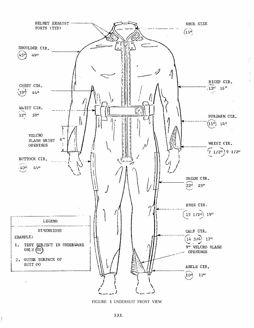
5 3 3 .
FIGURE 1 UNDERSUIT FRONT VIEW
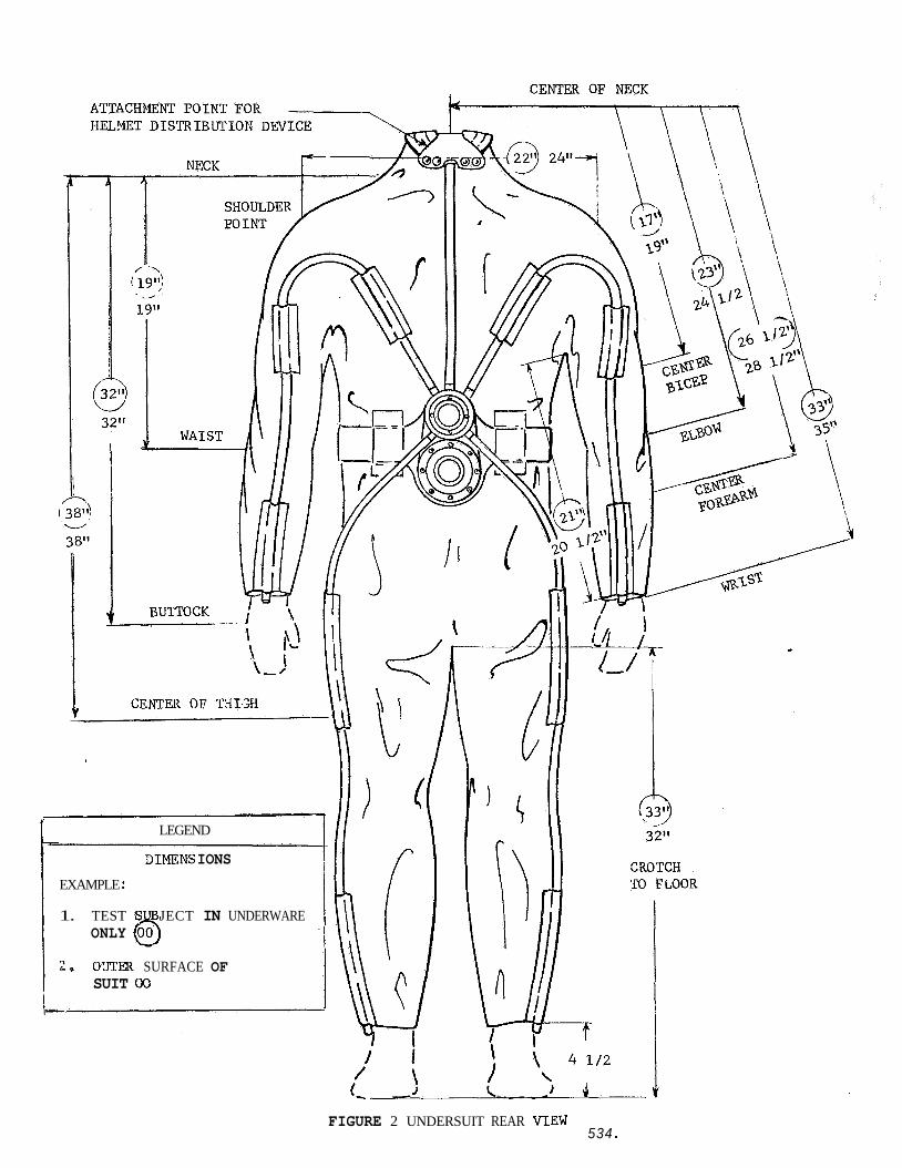
LEGEND
DIMENS IONS
EXAMPLE :
1. TEST S JECT IN UNDERWARE ONLY @J
2. O'JTEX SURFACE OF SUIT 00
FIGURE 2 UNDERSUIT REAR VIEW 534 a
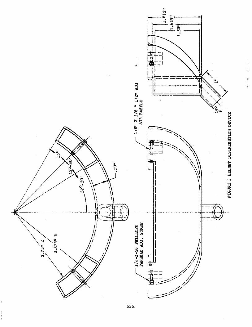
t
535
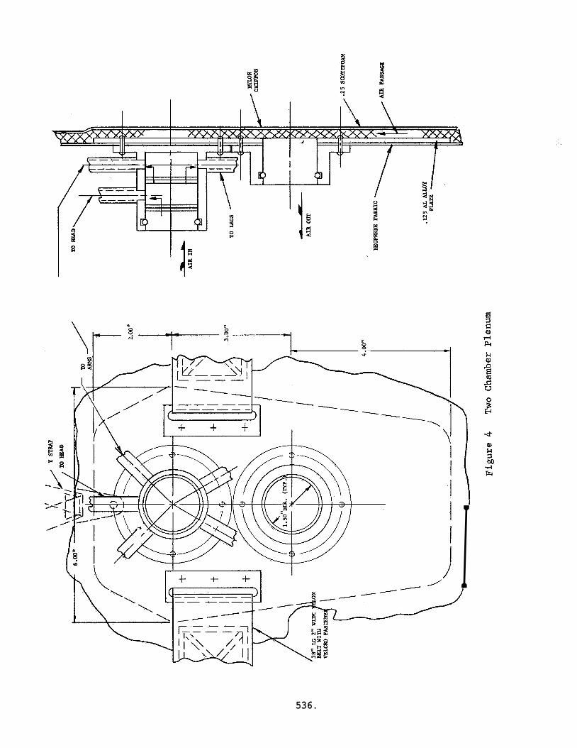
I 536.
APPENDIX M: CCJMMUNICATION SUBSYSTEM FOR BISS SPECIFICATION
537.
GENERAL ELECTRIC COMPANY Re-entry Systems Department 3198 Chestnut S t r ee t Philadelphia, Pennsylvania Code Ident i f ica t ion No, 15226
SPECIFICATION : ERSO150-0 2-0001
COMMUNICATION SUBSYSTEM FOR THE
BIO-ISOLATOR SUIT SYSTEM (BISS)
L O GENERAL
1,l Communication Subsystem f o r the Bio-Isolator Su i t System (GE-RSD Specif icat ion SOlOO-00-0001) , here inaf te r referred t o as BISS, used i n t h e assembly/steri l izer. The Communication Subsystem, here inaf te r ca l led t h e Link, s h a l l permit wired intercommunication among a l l members of t h e assembly/s ter i l izer operating team i n pre- selectable pat terns .
Scope - This spec i f ica t ion defines t h e required performance of t h e
1*2 Descrivtion - The Link cons is t s of a F a c i l i t y Supervisor's Console which includes the provisions for se lec t ing t h e communication pa t te rns , remote s t a t i ons serving t h e Life Support and Medical Monitor locat ion, transducer t e r- minals i n the individual s u i t s , s t a t i ons at the Net Controller locat ions, and l isten- only provisions fo r v i s i t o r s , freestanding o r an i n t eg ra l par t of t he remote equipment with which it is associ- ated. The Net Controllers shal l provide the l i n k between the F a c i l i t y Supervisor and the operators i n t h e BISS's,
The remote s t a t i o n equipment may be e i the r
2,o APPLICABLE DOCUMENTS
2.1 Government Documents - The following government documents of t h e i s sue specif ied, form a par t of th i s specif icat ion t o t h e extent specif ied herein,
Militam
MIL-STD-470 21 March 1966 Maintainabil i ty, Program Fequire- ments f o r Systems and Equipments
MIL-STD-826A 6 June 1966 Electromagnetic Interference, Test Requirements and Test Yethods f o r
FED-STD-595 1 March 1956 Colors
MS 33586 1 O C t * 1952 Metals, Definit ion of Dissimilar
MIL-P-7963 19 NoV. 1957 Par t s and Equipment , Aeronautical, Preparation f o r Delivery
(Copies of these documents may be obtained from the Superintendent of Documents , Government Pr in t ing Office, Washington, D,C. ) *
538.
SPECIFICATION*BRS0150-02-0001
2.2 Non-Government Documents - The following non-government documents of the i s sue i n e f f e c t on t h e date of t h i s spec i f i ca t ion , form a p a r t of t h i s speci- f i c a t i o n t o t h e extent spec i f i ed herein.
GENERAL ELECTRIC COMPANY
1
Specif icat ions
soaoo-00-0001 Bio- Isolator Sui t Systems (BISS)
SO230-00-0002 BISS Undersuit
Standards
118~1526 Iden t i f i ca t ion Marking
118~1600 Finishes and Coatings
149A9 5 60 Preparation f o r Delivery
(Copies of the General E l e c t r i c Company documents may be obtained from t h e General E l e c t r i c Company, RSD, 3198 Chestnut S t r e e t , Philadelphia, Pennsylvania 19101).
539.
3.0 REQUIREMENTS
3.1 and referenced documents to the extent specified herein. between the requirements and any document specified herein, this specification shall take precedence. of safety requirements.
A
General - The Link shall meet the requirements of this specification In the event of conflict
No provision shall be interpreted to mean an abrogation
3.2 Performance - The prime requirement is for reliable, intekligible communications. this prime requirement$
The following detail specifications are imposed to insure
3.2.1 flat from 100 to 4500 Hz t 2 DB.
Bandwidth - The response of a l l audio channels in the Link shall be
3.2.2 shall be sufficient to provide,a minimum of 12 DB signal-to-ambient noise ratio with 5% or less total distortion, when measured at their point of use.
Amplitude - The amplitude available at all loudspeakers and earphones
302.3 Impedance Levels - Impedance levels shall be kept as low as possible, consistent with power-handling requirements. Where many transducers must be fed from a common amplifier, cnnsideration shall be given to using a "cbnstant-volt- age" distribution system. 600 ohms) may be paralleled across a 4-ohm amplifier output in reasonable numbers to provide satisfactory performance.
As an alternative, low-impedance transducer ( 500 or
3.2.4 equipped with exponential, public-address type horns, for one way audio commu- nication, and werning horns, buzzers, howlers, or sirens to signal situation which may, in the opinion:of the Facility Supervisor or other support personnel, constitute a severe personnel hazard. requirement for the assembly/sterilizer speaker shall be measured at the opera- tor's ear inside the helmet. The warning horns shall have a nominal level of 98 DB referred to 0.0002 dynes/cm2 on an axial line 10 feet from the center of each horn front.
Back-up Units - As back-up units, the assembly/sterilizer shall be
The 12 DB signal-to-ambient noise ratio
3.2.5 Controls - Direct communications between any stations shall be obta6n- able by means of illuminated switches or other indicating devices on the Facility Super-sor's Panel. normal communication.
This is in addition to the patching and/or switching for
3.2.6 60-Hertz, single phase power of commercial quality.
Power Requirements - All units of the Link shall operate on 129-volt
540.
SPECIFICATION : ERS0150-02-0001
3.2.7 Functional Performance
3.2.7.1 communication system t o permit:
General - The containment of men witkin BISS s u i t s requires an in te r-
a. Issuing of ins t ruc t ions during various assembly, test and modifi- cation phases of the vehic le i n t h e assembly/ster i l izer . .
b. Reporting of t h e r e s u l t s and completion of these phases.
C. Permitting l imi ted normal conversation of t h e kind t h a t would tran- s p i r e were t h e men not so confined.
d. Conveying information on t h e comfort and s a f e t y of the men t o t h e L i f e Support and Medical Monitor at tendants .
e. Exchange of information between support personnel.
f . Conveying emergency informat ion . Each s t a t i o n ' s microphone o r input t ransducer s h a l l operate an ampli-
f i e r of no more than 5 w a t t s average pover output at a low output impedance (i.e., 4 ohms). This power shal l be s u f f i c i e n t t o d r ive whatever maximum number of loud- speakers or 600-ohms headsets are "on t h e line". have an equivalent impedance of 15 ohms, and at an assumed m a x i m u m power of 20 m i l l i w a t t s per headset s h a l l require less than one w a t t t o t a l f o r sa t i s fac to ry operation). t o s u i t i ts environment, amplif ier with a 600-ohm input) .
(Example: hO&OO-ohm headsets
Each loudspeaker s h a l l have a booster ampl i f ier of s u f f i c i e n t gain (Example: Each chamber horn s h a l l have a 20-watt
3.2.7.2 Basic Operation - The Link s h a l l be arranged t o permit talk- at-wil l by any par ty whose microphone has been energized at t h e F a c i l i t y Supervisor Console. There s h a l l be no manual o r other separa te physical e f f o r t required f o r micro- phone operation i n a normal, pre- selected, mode of operation. muting) switch s h a l l be provided at all external support personnel microphones t o enable temporary s i l enc ing of the individual microphones i f required. A l l speakers and headset earphones s h a l l have l o c a l volume controls , adjustable by t h e l i s t e n e r , except those i n the undersuit which s h a l l be contro l led by t h e F a c i l i t y Supervisor or Net Controller. The s u i t e d operators s h a l l be grouped i n t o "nets" o r operat ing teams of two o r t h r e e persons, with a N e t Control ler f o r each net. Medical Moni- t o r and L i f e Support Communication Operators s h a l l also be provided f o r each net . These l a t t e r may be t h e a c t u a l a t tendants , o r they may be separate talkers with minimal addi t ional functions. Figure 1 shows a t y p i c a l arrangement with two n e t s of two men each and t h e d i rec t ions of communication normally established. tunnel boom operator ( i f required) , may a l s o function as the Net Control ler f o r communication purposes.
A "cough" (manual
The
541.
SPECIFICATION" ERS0150-0~-0001
3.2.8 Performance of Individual Units '
3.2.8.1 F a c i l i t y Supervisor Console - The F a c i l i t y Supervisor Console s h a l l per- m i t t h e F a c i l i t y Supervisor t o v i sua l ly oversee all operations within t h e assembly/ s t e r i l i z e r . d i rec t iona l microphone on a headset. The outgoing voice channel from the F a c i l i t y Supervisor s h a l l normally be received by the TJet Control lers and all L i f e Support/ Medical Monitor communication operators. mute the l i n e s t o the Net Control lers t o permit p r iva te discussion w i t h L i f e Support Medical Monitor personnel olaly. master controls f o r power and s ignal ing and override controls t o permit non-scheduled cross-communication. Establishment of the communication interconnections s h a l l be accomplished by a patch board and/or cross-bar switches located within the F a c i l i t y Supervisor Console.
The F a c i l i t y Supervisor Console shall have one high impedkce , dynamic,
A momentary switch sha l l be provided t o
The control panel on the console s h a l l provide
The F a c i l i t y Supervisor s h a l l be provided w i t h a master clock and task- timing clocks f o r monitoring, and eaah received port ion of t h e Link sha l l be con- s t a n t l y monitored by means of inaudible tones t o determine go-no-go s t a t u s of t he Link. The ind ica to r s f o r the tone-monitoring shal l be located on t h e contro l panel i n a l i g h t matrix, appropriately colored. v i so r s h a l l a l s o be located within the console. Controls s h a l l be provided t o temporarily mute any channel as required.
Amplifiers f o r use by t h e F a c i l i t y Super-
3.2.8.2 be served by e l e c t r i c a l l y similar Line terminals and s h a l l be designated as Re- mote Sta t ions . phone set. i n the net associa ted w i t h the Remote Stat ion. F a c i l i t y Supervisor 's transmission, and t h e microphone s h a l l connect t o speakers a t t h e F a c i l i t y Supervisor 's Consoze. By removing t h e earphone plug, the Remote S ta t ion speaker s h a l l monitor the F a c i l i t y Supervisor's transmission.
Remote Sta t ions - The L i f e Support and Medical Monitor locat ion shall
They s h a l l be equipped w i t h a loudspeaker and an earphone-micro- The loudspeaker s h a l l monitor t h e transmission of t h e s u i t e d operators
The earphones s h a l l monitor t h e
3.2.8.3 mission f r o m t h e F a c i l i t y Supervisor and shall pass t h i s information t o t h e s u i t e d operators i n h i s net. Their transmissions, i n turn , s h a l l be relayed t o the Faci- l i t y Supervisor. equipment t o provide a degree of communication f l e x i b i l i t y . are i n the unique pos i t ion t o i n t e r p r e t d i rec t ions and results and assist the F a c i l i t y Supervisor i n h i s e f f o r t s .
3.2.8.4 t h e s u i t e d operators except talk and l i s t e n . SO230-00-0002) microphone shall be s e n s i t i v e enough t o t ransmit the operator 's voice regardless of h i s head posi t ion , and the speaker s h a l l have s u f f i c i e n t dr ive so that t h e operator may adequately hear i ts output under normal conditions.
N e t Control lers - The Net Control lers s h a l l receive the voice transw
These locat ions sha l l have a small number of audio controls and The N e t Control lers
Undersuit - There shall be no physical communication requirements f o r The undersuit (GE-RSD Specif icat ion
542.
3.3 Materials, Par t s , and Processes
3.3.1 Materials - The mater ia ls used i n the Link fabr ica t ion sha l l conform t o t h e highest q u a l i t i e s on t h e basis of physical .or o ther e s s e n t i a l proper t ies , a v a i l a b i l i t y , adap tab i l i ty t o production processes, and s u i t a b i l i t y t o t h e environ- mental conditions s e t f o r t h i n 3.10. Wherever possible, units s h a l l use sol id- s t a t e ac t ive devices r a t h e r than e lec t ron tubes.
3.3.2 Standard Par t s - Wherever possible, standard parts shall be used t o en- sure r e l i a b i l i t y and expedite procurement. of preference a r e applicable EASA Standards, Military Standards (MS, Am, EAS), General E lec t r i c Company Standards and Commercial Standards. may be used when s p e c i f i c a l l y authorized by t h e procuring agency, items shall be kept t o a minimum.
Preferred standard p a r t s i n thei r order
Eon-Standard p a r t s Re-design of
3.3.3 - Materials s h a l l be se lec ted cn t h e basis of s u i t a b i l i t y and- r e l a t i v e a v a i l a b i l i t y . the Link s h a l l incorporate t h e l e a s t c r i t i c a l and s t r a t e g i c materials.
Subject t o s a t i s f a c t o r y operation,
3.3.4 be used i n int imate contact unless su i t ab ly protected against e l e c t r o l y t i c corrosion.
D i s s i m i l a r Metals - Dissimilar Metals, as defined i n MS33586, s h a l l not
3.305 Corrosion Resistance - Materials se lec ted sha l l be corrosion r e s i s t a n t o r s h a l l be su i t ab ly protected by p la t ing , paint ing, o r o ther sureace treatment t h a t i s compatible w i t h the environment t o which the Link i s subjected.
3.3.6 the Link s h a l l be of the highest i n t e g r i t y required i n the design c r f t e r i a . bonding processes s h a l l be of the type f a c i l i t a t i n g ease of p a r t o r component r epa i r or replacement,
Bonding Processes - Bonding processes required i n t he fabr ica t ion of The
3.3.7 - Like items (headsets , amplif iers , loudspeakers, e t c . ) i n various consoles and cabinets shal l be interchangeable wherever possible. However, due t o the custom nature of t h i s equipment, no s p e c i a l in terchangeabi l i ty s h a l l be imposed.
3.3.8 magnetic in ter ference , both conducted and radiated. include bonding, grounding, sh ie ld ing, suppression techniques, and proper choice of components t o minimize the generation of in ter ference o r t o suppress it if it should occur.
EMI Considerstions - Precautions s h a l l be taken t o minimize e lec t ro- These precautions sha l l
~1~sm-826 shal l be used as a guide.
3.4 commercial quali ty. and f in ished i n a thoroughly workmanlike manner. given t o neatness, c leanl iness , and thoroughness of soldering, welding, brazing, bonding, wiring, marking of p a r t s , paint ing, protec t ive coatings, r ive t ing , machine screw assembly, and freedom of p a r t s from burrs and sharp edges.
- Workmanship and shop p rac t i ces s h a l l be of t h e highest
P a r t i c u l a r a t t en t ion shall be Subassemblies and components of the Link s h a l l be constructed
543.
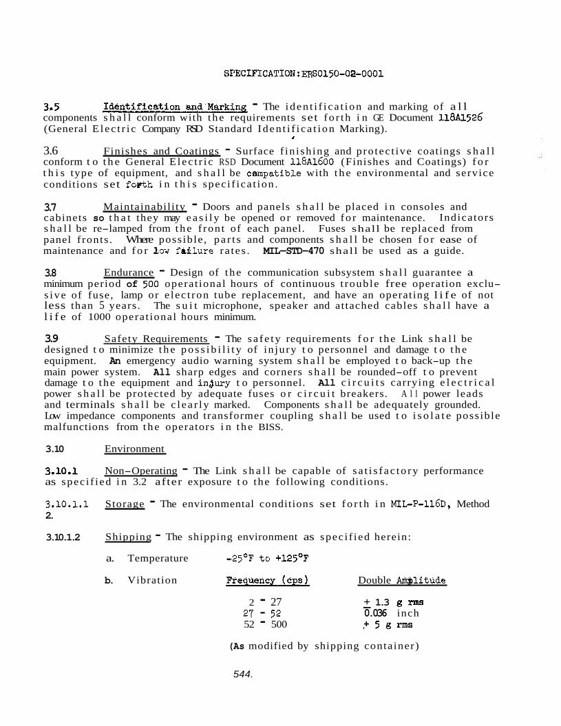
3.5 components s h a l l conform with t he requirements set fo r th i n GE Document 118U526 (General E l ec t r i c Company RSD Standard Iden t i f i ca t i on Marking).
3.6 Finishes and Coatings - Surface f in i sh ing and pro tec t ive coatings s h a l l conform t o t h e General E l ec t r i c RSD Document 118Al.600 (Finishes and Coatings) f o r t h i s type of equipment, and s h a l l be cempatible with t h e environmental and service conditions set foPth i n t h i s spec i f ica t ion .
- The iden t i f i ca t i on and marking of a l l
A
3.7 cabinets so t h a t they may e a s i l y be opened o r removed fo r maintenance. s h a l l be re-lamped from t h e f ron t of each panel. Fuses shall be replaced from panel f ronts . maintenance and f o r &ow f a i l u r e ra tes .
Maintainabil i ty - Doors and panels s h a l l be placed i n consoles and Indicators
Where possible , pa r t s and components s h a l l be chosen f o r ease of MIL-STD-470 shal l be used as a guide.
3.8 minimum period of 500 operat ional hours of continuous t rouble free operation exclu- s ive of fuse, lamp or e lec t ron tube replacement, and have an operating l i f e of not less than 5 years. The s u i t microphone, speaker and attached cables s h a l l have a l i f e of 1000 operat ional hours minimum.
Endurance - Design of t he communication subsystem s h a l l guarantee a
3.9 Safety Requirements - The sa fe ty requirements f o r t he Link s h a l l be designed t o minimize t h e p o s s i b i l i t y of in jury t o personnel and damage t o t h e equipment. An emergency audio warning system s h a l l be employed t o back-up t h e main power system. All sharp edges and corners s h a l l be rounded-off t o prevent damage t o t he equipment and indury t o personnel. power s h a l l be protected by adequate fuses o r c i r c u i t breakers. A l l power leads and terminals s h a l l be c l ea r ly marked. Components s h a l l be adequately grounded. Low impedance components and transformer coupling s h a l l be used t o i s o l a t e possible malfunctions from t h e operators i n t h e BISS.
All c i r c u i t s carrying e l e c t r i c a l
3.10 Environment
3.10.1 as spec i f ied i n 3.2 after exposure t o the following conditions.
Non-Operating - The Link s h a l l be capable of s a t i s f ac to ry performance
3.10.1.1 2.
Storage - The environmental conditions set f o r t h i n M I L P - ~ ~ ~ D , Method
3.10.1.2 Shipping - The shipping environment as spec i f ied herein:
a. Temperature -25'F t o +125'F
b. Vibration Double m l i t u d e
2 - 27
52 - 500 27 - 52
+ 1.3 g rms 0.036 inch - + 5 g m
-
(As modified by shipping container)
544.
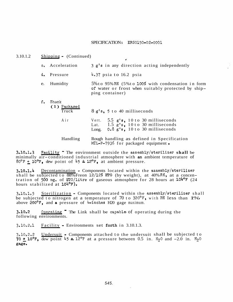
SPECIFICATION : ERS0150-02-0001
3.10.1.2 Shipping - (Continued) 1
c. Acceleration 3 g's i n any d i rec t ion ac t ing independently
d. Pressure 4.37 ps i a t o 16.2 p s i a
e. Humidity 5% t o 95% RH (5% t o 100% with condensation i n form of water o r frost when su i t ab ly protected by ship- ping container)
f. Shock (1) Packaged
Truck 8 g ' s , 5 t o 40 milliseconds
A i r V e r t . 5.5 g's, 1 0 t o 30 mill iseconds 1.5 g's, 1 0 t o 30 mill iseconds 0.8 g's, 10 t o 30 milliseconds
L a t . Long.
Handling Rough handling as defined i n Specif icat ion MIbP-7936 f o r packaged equipment .
3.10.1.3 Fac i l iQ - The environment outs ide the assembly/s ter i l izer sha l l be minimally air- conditioned i n d u s t r i a l atmosphere with an ambient temperature of 8OoF f. 1O0F, dew point of 45 II + 22OF, at ambient pressure.
3.10.1.4 s h a l l be subjected t o 88% Freon 12/12% E20 (by weight), at 40% RH, at a concen- t r a t i o n of 500 mg. of E T O / l i t r e of gaseous atmosphere f o r 28 hours at 10h0F (24 hours s t a b i l i z e d at 104OF).
Decontamination - Components located within the assembly/s ter i l izer
3.10.1.5 be subjected t o nitrogen at a temperature of 70 t o 320°F, w i t h RH less than 1% above 200°F, and 8 pressure of 4-inches H20 gage maximum.
S t e r i l i z a t i o n - Components located within t h e assemblyls ter i l ixer s h a l l
3.10.2 following environments.
Operatins - The Link shall be capable( of operat ing during the
3.10.2.1 F a c i l i t y - Environments set forth i n 3.10.1.3.
3.10.2.2 Undersuit - Components a t tached t o the undersuit shall be subjected t o 70 LIO°F, dew point 45 - + 12OF at a pressure between 0.5 in . H20 and -2.0 in. H20 gage
545.
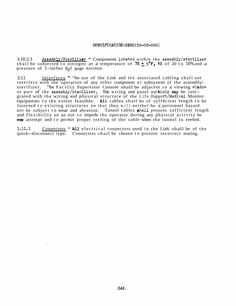
SPECIFICATION:ERS0150-02-0001
3.10.2.3 Assemljly/Sterilizer - Components l o t a t e d within the assembly/ste.rilizer s h a l l be subjected t o nitrogen a t a temperature of 75 2 5OF, RH of 20 t o 50% and a pressure of 2-inches H20 gage maximum.
3.11 i n t e r f e r e with t he operation of any o ther component o r subsystem of the assembly/ s ter i l izer . o r por t of the assembly/s ter i l izer . grated with t h e wiring and physical s t ruc tu re of the L i f e Support/Medical Monitor equipments t o the extent feasible. All cables shal l be of suffdcient length t o be fastened t o ex i s t i ng s t ruc tures so t h a t they w i l l n e i t he r be a personnel hazard nor be subject t o wear and abrasion. and f l e x i b i l i t y so as not t o impede the operator during any physical a c t i v i t y he may attempt and t o permit proper reef ing of the cable when the tunnel is reefed.
In te r faces - "he use of the Link and i ts associated cabling s h a l l not
"he F a c i l i t y Supervisor Console shall be adjacent t o a viewing window The wiring and panel c o n k o l s may be inte-
Tunnel cables p h a l l possess su f f i c i en t length
3.11.1 Connectors - All e l e c t r i c a l connectors used i n the Link shall be of t h e quick-disconnect type. Connectors s h a l l be chosen t o prevent incorrect mating.
546.
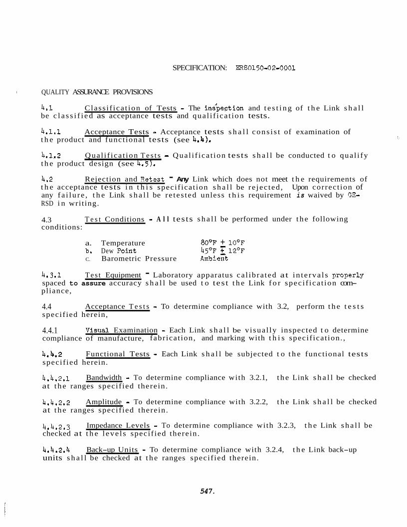
SPECIFICATION: ERS0150=02-0001
QUALITY ASSURANCE PROVISIONS
4.1 be c l a s s i f i e d as acceptance tests and qua l i f i ca t ion tests.
Class i f ica t ion of Tests = The inipect ion and t e s t i n g of t h e Link s h a l l
4.1.1 t h e product and funct ional tests (see 4.4),
4.1.2 t h e product design (see 4.5).
Acceptance Tests = Acceptance tests s h a l l cons i s t of examination of
Qual i f ica t ion T e s t s .I Qual i f ica t ion tests s h a l l be conducted t o qua l i fy
4.2 t h e acceptance tests i n t h i s specif icat ion s h a l l be re jec ted , any f a i l u r e , t h e Link s h a l l be re tes ted unless t h i s requirement is waived by GE- RSD i n writ ing.
Rejection and Iietest - Any Link which does not meet t h e requirements of Upon correct ion of
4.3 conditions:
T e s t Conditions - A l l tes ts s h a l l be performed under t h e following
a. Temperature 80°F + 10°F b, Dew Point 45OF 12OF C. Barometric Pressure Amb i ezt
4.3.1 spaced to assure accuracy s h a l l be used t o tes t t h e Link f o r spec i f ica t ion com- pliance,
Tes t Equipment - Laboratory apparatus ca l ib ra ted at i n t e rva l s proTerly
4.4 specif ied herein,
Acceptance T e s t s - To determine compliance with 3.2, perform t h e t e s t s
4.4.1 compliance of manufacture, fabr icat ion, and marking with t h i s specif icat ion. ,
V i s i i a l Examination - Each Link s h a l l be v i sua l ly inspected t o determine
4,4.2 specif ied herein.
Functional Tests - Each Link s h a l l be subjected t o t h e functional tests
4.4.2.1 at t h e ranges specif ied therein .
Bandwidth = To determine compliance with 3.2.1, t h e Link s h a l l be checked
4.4,2,2 at t h e ranges specif ied therein .
Amplitude - To determine compliance with 3.2.2, t h e Link s h a l l be checked
4.4,2.3 checked at t h e l eve l s specif ied therein .
Impedance Levels - To determine compliance with 3.2.3, t h e Link s h a l l be
4.4.2.4 units s h a l l be checked at t h e ranges specif ied therein.
Back-up Units - To determine compliance with 3.2.4, t h e Link back-up
547.
SPECIFICATION: ERSOl50-02=0001
4.4.2.5 t e d and the controls s h a l l be checked f o r t h e operating requirements specif ied therein .
Controls = To determine compliance, with 3.2.5, t h e Link s h a l l be opera-
4.4.2.6 therein .
Power - To determine compliance with 3.2.6, apply the voltage specif ied
4.4.2,7 s h a l l be operated t o check the requirements specif ied t he re in ,
Functional Performance - To determine compliance with 3,2,7, t h e Link
4.4.2.8 Individual U n i t s - To determine compliance with 3.2,8, t h e Link s h a l l be operated and t h e individual un i t s s h a l l be checked f o r t h e operating require- ments spec i f ied therein .
4.5 gua l i f i ca t i on Tests
4.5.1 specif ied i n 4.4.1 and 4,4,2,1 through 4,4.2,8 after subjection t o t h e following
Non-Operating Ehvironmental Tests - The Link s h a l l meet t h e requirements
environment a1 tests . 4.5.1.1
4.5.1.2 Vibration - (TBSL)
4.5.1.3 Acceleration - (TBSL)
4.5.1.4 Pressure - (TBSL)
4.5.1.5 Humidity - (TBSL)
4.5.1.6 Shock - (TBSL) 4.5.2 shall be conducted i n conjunction with t he system qua l i f i ca t ion tests spec i f ied i n GE-RSD Specif icat ion ERS0100-00-0001 (Bio- Isolator Su i t System) .
Temperature - To be supplied l a t e r (TBSL)
Operating Environmental Tests - The operating environmental tests
548.
SPECIFICATION:ERS0150-02-0001
5.0 PREPARATION FOR DELIVERY
5.1 i n accordance with the provisions set f o r t h i n GE-RSD Standard 146A9560 (Prepara- t i o n f o r Delivery).
5-2 s h a l l adequately pro tec t each package during ordinary handling and shipping and s h a l l meet t h e minimum requirements of t h e c a r r i e r f o r safe t ranspor ta t ion at t h e lowest rate t o t h e point of delivery.
Preservation and Packaging - p e L i n k s h a l l be preserved and packaged
Packing - The L i n k shal l be overpacked i n shipping containers which
5.3 of both consignee and consignor, contract o r purchase order numbers, and the i t e m p a r t number. All markings sha l l be Begible and waterproof.
Marking - Shipping containers shal l be marked wi th t h e name and address
6.0 NOTES
None
-549.
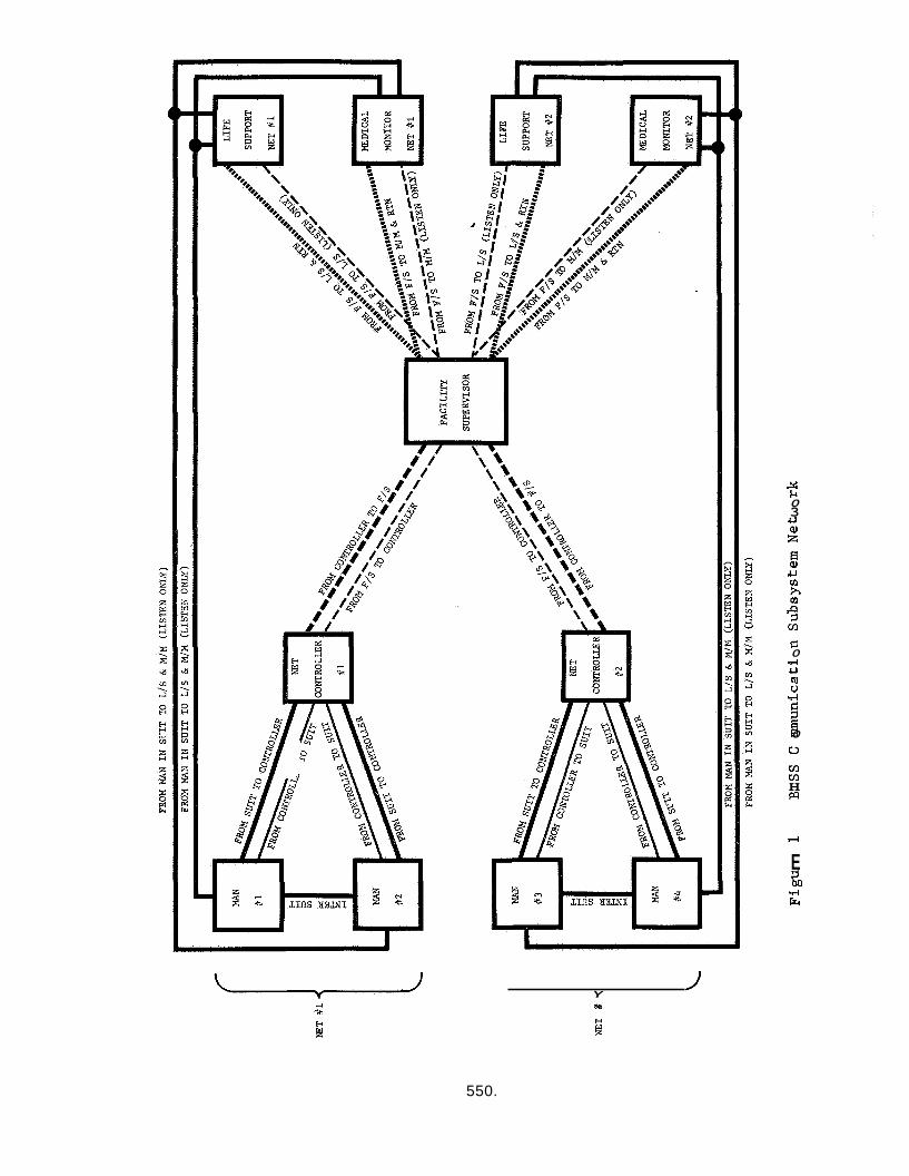
Y N * H P
5 0 3 u al z fi al u v1 h v)
P 1 m G 0 .rl u m c) 4
9 0 u Kl m H !a
4
E 1 M .rl k
550.
APPENDIX N: LIFE SUPPORT SUBSYSTEM FOR BISS SPEC IF ICATI ON
551.
GEXERAL ELECTRIC COMPA?JY ?e-entry Systeas Department 3198 Chestnut S t r ee t Philadelphia 1, Pennsylvania Code Ident , njo. 15226
l a 0 GzNm AL
SPECIFICAT ION *dBSO210-0 0-0001
LIFE SUPPOBT SUBSYSTEM
FOQ THE
BIO-ISr)LATO!'3 SUIT SYSTEM (BISS)
1 0 1 the Bio- Isolator Su i t Sys tern (BISS 1 (GE-RSD Soecif icat ion SO~OO-00-0001 1, her..- i n a f t e r re fe r red t o as the s u i t a i r supgly, The s u i t a i r aupnly s h s l l be used t o provide a l i f e sus ta in ing temTerature and humidity control led cfaseous SLID^^.^ t o t h e occupant within t h e BISS.
Scope - This spec i f ica t ion defines t he l i f e supoort subsystem t o r
1.2 Descriotion - The s u i t a i r supoly s h a l l contain a l l of t h e comonents and systems necessary t o perform the following functions:
a. Maintain an adequate s u p l y of f i l t e r e d breathahle/coolinT a i r t o t h e BISS undersuit plenum.
bo Provide a means of maintaining comfortable conditions of temperature, humidity, pressure, and removal of noxious and tox ic gases from t h e BISS outer s u i t .
1.2.1 ma.) o r components :
Components - The s u i t a i r supply s h a l l cons is t of t h e fol loviny
a.
be
c*
d.
e.
f.
43.
Control Console
Heat Exchanger
Humidifier
Blower Fan
Exhaust Fan
Compressor Unit
Heater Un i t
552.
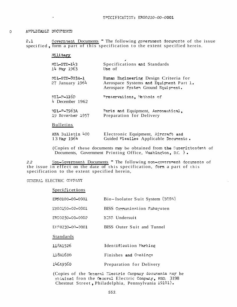
SPEC1 FI CATIOfJ : ERSO 210-00-0 001
APPLICABLE
2.1 spec i f i ed ,
Governqent Documents - The following governmnt docmects of the i ssue form a p a r t of t h i s speci f ica t ion t o the extent spec i f i ed h e r e i n .
I
Speci f ica t ions and Standards use of
1 f l LSTD=803A-l 27 January 1964
Human Fngineering Design Criteria f o r Aerospace Systems an6 Equipyent P a r t 1. Aerospace Fgstei Ground Equipwent,
?.?I E.?-llGP Dreservations, l t t h o d s of 4 December 1962
YIL-D-7963A Perts and Equipment, Aeronautical, 19 Novenber ,1957 Preparation for Delivery
Bul le t ins
A M 3ull .et in 400 13 May 1964
Electronic Equipment, AircrRft and Guided Missiles Applicable Documnts .
(Copies of these documents may be obtained from the SuDerictendent of Documents, Government P r in t ing Office, Washinqton, D.C. 1 .
2.2 Bon-Government Documents - The following non-qovernment docu..ents of the i ssue i n e f f e c t on the date of t h i s spec i f i ca t ion , forn! a p a r t of t h i s speci f ica t ion to the extent speci f ied here in ,
GTYTCRAL ELECTRIC COtlPARY
Spec i f i c et i ons
EPs0100-00-0001 Bio- Isolator S u i t System (315s)
~ ~ ~ 0 1 5 0 - 0 2 - 0 0 0 1 BISS Comrnunic at ion Suhs:;s ten
ER53230-00-0003 3ISS Undersui t
E??? 02 30-On-Cl001 BISS Outer S u i t and Tunnel
Standards
118~1526 I de n t i f i c a t ion t larki ng
118~1Aoo Finishes and Coetings
146A9560 Preparation f o r Delivery
(Copies of the r e n e r d f l lec t r ic Compar,y docurnents zey he oStained f ron the CenerP-l E l e c t r i c Compwy, RSD, 3198 Chestnut S t r e e t , Philadelphia, Pennsylvania 19101)
553.
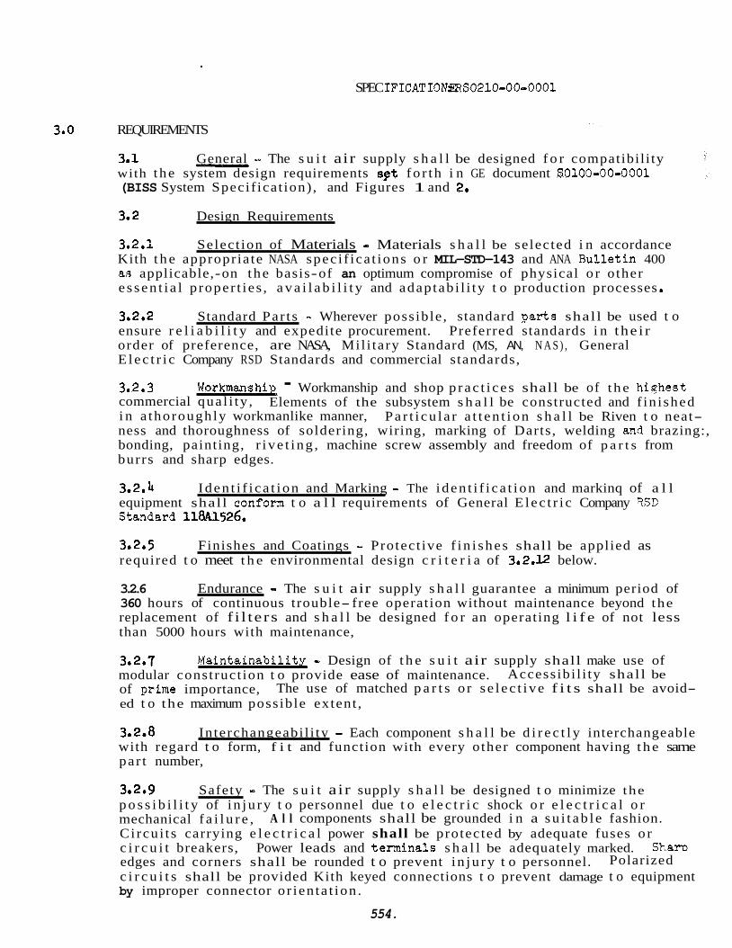
SPEC IFICATIONBS0210-00-0001
REQUIREMENTS
General - The s u i t air supply s h a l l be designed f o r compatibil i ty - 3.1 with t he system design requirements set fo r th i n GE document S0100-00-0001 (BISS System Specif icat ion) , and Figures 1 and 2.
3.2 Design Requirements
3a2.i Select ion of Materials - Materials s h a l l be selected i n accordance Kith t h e appropria te NASA spec i f ica t ions o r MIL-STD-143 and ANA Bul le t in 400 a8 applicable,-on the basis-of an optimum compromise of physical o r other e s sen t i a l p roper t ies , a v a i l a b i l i t y and adaptab i l i ty t o production processes
3.2.2 ensure r e l i a b i l i t y and expedite procurement. order of preference, are NASA, Mil i tary Standard (MS, AN, N A S ) , General E l ec t r i c Company RSD Standards and commercial standards,
Standard Par t s - Wherever possible , standard Darts shall be used t o Preferred standards i n the i r
3e2.3 commercial qua l i ty , i n a thoroughly workmanlike manner, ness and thoroughness of soldering, wiring, marking of Darts, welding &?d brazing:, bonding, painting, r i ve t i ng , machine screw assembly and freedom of p a r t s from burrs and sharp edges.
Workmanshie - Workmanship and shop p rac t i ce s shall be of t he hiqhest Elements of the subsystem s h a l l be constructed and f in i shed
Pa r t i cu l a r a t t en t ion s h a l l be Riven t o neat-
3.2.4 equipment shal l conform t o a l l requirements of General E l ec t r i c Company W D Stmdard 118-41526,
Iden t i f i ca t i on and Marking - The i den t i f i ca t i on and markinq of a l l
3.2.5 Finishes and Coatings - Protect ive f i n i shes shall be applied as required t o meet t h e environmental design c r i t e r i a of 3,2,12 below.
3.2.6 Endurance - The s u i t air supply s h a l l guarantee a minimum period of 360 hours of continuous trouble- free operation without maintenance beyond the replacement of f i l te rs and s h a l l be designed f o r an operating l i f e of not less than 5000 hours with maintenance,
3.2.7 modular construct ion t o provide ease of maintenance. of grime importance, ed t o the maximum possible extent ,
Main ta inab i l i tx - Design of t h e s u i t air supply shall make use of Accessibi l i ty shall be
The use of matched p a r t s o r s e l ec t i ve f i t s shall be avoid-
3.2,8 Interchangeabi l i ty - Each component s h a l l be d i r e c t l y interchangeable with regard t o form, f i t and function with every other component having the same par t number,
3.2.9 Safety - The s u i t a ir supply s h a l l be designed t o minimize the p o s s i b i l i t y of i n ju ry t o personnel due t o e l e c t r i c shock o r e l e c t r i c a l o r mechanical f a i l u r e , Ci rcu i t s carrying e l e c t r i c a l power shall be protected by adequate fuses o r c i r c u i t breakers, Power leads and terminals s h a l l be adequately marked. Sham edges and corners shall be rounded t o prevent i n ju ry t o personnel. c i r c u i t s shall be provided Kith keyed connections t o prevent damage t o equipment by improper connector o r ien ta t ion .
A l l components shall be grounded i n a su i t ab l e fashion.
Polarized
554.

SPECIFICATION : ERSO210-0 0-0 001
3.2.10 required f o r operat ing and monitoring t h e s u i t a i r supply s h a l l he nosit ioned on t h e l i f e supnort subsystem console. The cont ro ls and ind ica tors s h a l l be located so as t o minimize human e r r o r i n operation of t h e system. They s h a l l be located i n accordance with YXL-STD-803A-1. I
3,2011 console shal l be 20-in, wide by 50-in. high by 24-in. deep,
3.2.12 &vi ro nment
3.2,12,1 t h e followinq non-operat ing environments .
Controls and Indica tors - A l l manual controls , switches, and in3 ica tors
Dimensions - The maximum diaensions of t he l i f e s u p ~ o r t subsystem
Non-Operating - The s u i t sir supply s h a l l be designed t o w i t h s t a n d
3.2.12.1,l Yethod IA.
Storage - The environmental Conditions set forth i n I4IL-”-llfjD,
3,2,12,1.2 S h i m i n q - The shipping environments spec i f i ed herein:
9. Tem2erat ure
b, Vibration
c. Acceleration
d. Pressure
e. Humidity
f. Shock (1) Packaged
Truck
A i r
Handling
-25OF t o +12’j°F
Frequency ( CPS ) 2-27
Double -4mplitude - + 1 0 3 4 rmS -
27-52 0.036 inch +. 5 g r m s 52-5 00 -
(As modified by shipping conta iner )
3 g’s i n any di rec t ion act ingindependent ly
. 4.37 p s i s t o 16.2 D s i a
5% t o 95% SH (5% t o loo$ with condensation i n form of water o r f r o s t when su i t ab ly wo tec t eq by shipping container)
6 g’s, 5 t o 40 milliseconds
Vert. 5.5 g’s, 10 t o 30 mill iseconds L a t , 1.5 g’s, 10 t o 30 mill iseconds Long. 0,8 g’s, 10 t o 30 mill iseconds
(As modified by shipping container)
Rough handling as defined i n Specif icat ion MIL-P-7936 f o r packaged equipment .
555.
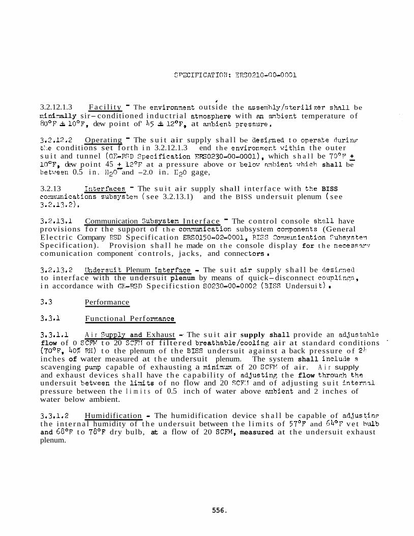
SPECIPICATIO4: ERS0210-00-0001
I
3.2.12.1.3 F a c i l i t y - The environrnent outs ide the assexhly!nterili ze r sh,.tll be z i n i % l l y sir- conditioned induc t r i a l etmosphere with an mbien t temperature o f 80°F - + 10°F, dew point of' 115 - + 12OF, at ambient gressure.
3.2.12.2 t:.e conditions set f o r t h i n 3.2.12.1.3 end t h e environrnent wit!-.in t he ou ter s u i t and tunnel (GZ-FSD Tpecif icat ion ~RS0230-00-0001), which s h a l l be 70°P 2 loop, dew poin t 45 3 12'F at a pressure above o r belov m b i e n t whic?i shall be between 0.5 i n . 1120 and -2.0 in . €120 gage,
Operating - The s u i t air supply s h a l l be d e s i p e d t o operate durinp
3.2.13 comunications subsys tern ( see 3.2.13.1) and the BISS undersui t plenum ( see 3-2.13.2).
In t e r f aces - The s u i t air supply shall in t e r f ace with t h e BISS
3.2.13.1 Communication Subsystez In t e r f ace - The cont ro l console s h d l have provisions f o r t h e support of t h e c m u n i c a t i o c subsystem coflponents (General E lec t r i c Company IISD Specif icat ion ERS0150-02-0001, RISP Comunication Yuhsyste? Specif icat ion) . comunication component ' cont ro ls , jacks, and connec tars . Provision s h a l l he made on t h e console display for t h e necessam
3.2.13,2 [hidersuit Plenum TnterTsce - The s u i t air supply s h a l l be clesisned to in te r face with the undersui t plenum by means of quick-disconnect couplirxn, i n accordance with C,E,-RSJI Spec i f ics t ion SO230-00-0002 (3IES Undersui t ) . 3e3 Performance
3.3.1 Functional Perf ornance
3.3.1,l A i r Suppljj and Exhaust -- The s u i t air supply shall provide an adjustabl-? flow of 0 SCFH t o 20 SCFTI of f i l tered breathable/cooling a ir at standard conditions (7O0F, 401 Wi) t o the plenum of t h e SISS undersui t aga ins t a back pressure o f 21: inches of water measured at t h e undersuit plenum. The system shall inclucie FI
scavenging pump capable of exhausting a minimu9 of 20 SCFP! of air . A i r supply and exhaust devices s h a l l have t h e capab i l i t y of adjustir?p; t h e flow throuqh t h e undersuit betweer, the l inits of no flow and 20 SCFI? and of adjust ing s u i t i n t e r n 2 1 pressure between t h e l i m i t s of 0.5 inch of water above m b i e n t and 2 inches of water below ambient.
3.3,l.z Humidification - The humidification device s h a l l be capable of ad jus t inp t h e i n t e r n a l humidity of t h e undersui t between t h e l i m i t s of 57OF and 6k°F v e t bulb and 68OF t o 78OF dry bulb, at a flow of 20 SCFM, measured at t h e undersui t exhaust plenum.
.
556.
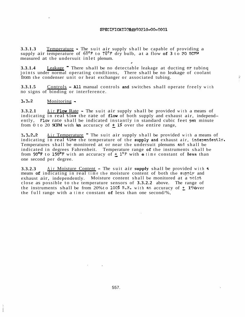
SPECIFICATICN3RS0210-00-0001
3.3.1.3 Temperature - The s u i t a ir supply s h a l l be capable of providing a supply air temperature of 68OF t o 78OF dry bulb, a t a flow of 3 t o 20 SCFV measured at t h e undersuit i n l e t plenum.
3.3.1.4 j o i n t s under normal operating condit ions, from the condenser un i t o r heat exchanger o r associated tubing.
1
Leakage - There shall be no detectable leakage at ducting o.r tubinq There shall be no leakage of coolant
3.3.1.5 Controls - All manual controls and switches shall operate f r e e l y w i t h no s igns of binding or in terference.
3.3. 2 Monitoring - 3.3.2.1 A i r Flow Rate - The s u i t a ir supply shal l be provided w i t h a means of indicat ing i n real t h e the rate of flow of both supply and exhaust air , independ- ent ly , Flaw rate s h a l l be indicated i n s t a n t l y i n standard cubic feet Dei minute from 0 t o 20 SCFM with iSn accuracy of 21% over the entire range,
3.3e2.2 indicat ing i n real t h e t h e temperature of t h e supply and exhaust a i r , independentlv. Temperatures s h a l l be monitored at o r near t h e undersuit plenums and s h a l l be indicated i n degrees Fahrenheit. Temperature range of the instruments s h a l l be from 50°F t o 150°F w i t h an accuracy of f. 1°F with e t i m e constant of less than one second per degree.
3.3.2.3 means of ind ica t ing i n real t i m e t h e moisture content of both the supSv and exhaust air, independently. c lose as possible t o t h e temperature sensors of 3.3.2.2 above. The range of the instruments shall be from 20% t o 100% R.H, w i t h an accuracy of f, 1% over the f u l l range with a t i m e constant of less than one second/%,
A i r Temperature - The s u i t air supply s h a l l be provided w i t h a means of
A i r Moisture Content - The s u i t a ir supply shall be provided w i t h a
Moisture content s h a l l be monitored at a Doint
557.
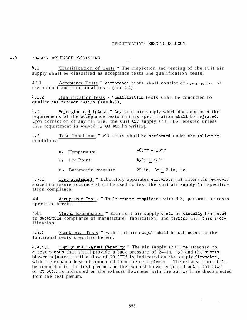
S PECI FI CAT 1911 : El?? i3 210-00-0 09 1
4.0 9,UIU;I TI ASS URAMCE PROV J S I ONS 1
4.1 supply s h a l l be c l a s s i f i e d as acceptance tests and qua l i f i ca t ion tes ts ,
C lass i f i ca t ion of Tests - The inspection and t e s t i n g of t h e s u i t a i r
4.1.1 the product and functional tests ( s e e 4.4).
Acceptance Tests - AcceDtance tests s h a l l cons i s t of exaninF.tion o f
4.1.2 Q u a l i f i c a t i o n Tests - Cwalification t es t s s h a l l be conducted t o qual i fy t h e ?roGuct design (see 4.5) e
40 2 - Fay s u i t a i r supply which does not meet t h e requirements o f t h e acceptance tests i n t h i s spec i f i ca t ion shall be r e jec tea. Upon correct ion of any f a i l u r e , the s u i t air supply s h a l l be retested unless t h i s requirement i s waived by GE-RSD i n writ ing.
4*3 conditions:
Test Conditions - All tes ts s h a l l be perfomed under the follovrirc7:
+ R O O F + 10°F a. Temperature - b, Dew Point 45OF .t 12'F - c . Barometric Pres sure 29 in . HE f, 2 i n , IIg
4.3.1 - Laboratory apparatus ca l ib ra ted at i n t e r v a l s nroner1.r spaced t o assure accuracy s h a l l be used t o t e s t t h e s u i t a i r supply f 9 r speci f ic- a t ion compliance.
4.4 spec i f i ed here in .
4.4.1 Visucll Examination - Each s u i t air supply sh8.U be visually inspected. t o deternine compliance of manufacture, fabr ica t ion, and markinp( wi th t h t s sncc- i f i c a t i o n .
- To de t emine complictnce w i t h 3.3, perform t h e t es t s
4.4.2 functional tests speci f ied herein.
Functional Tests - Each s u i t air suDply shall be suhgected t o t h e
4.4.2.1 a t e s t plenun t h a t s h a l l provide a back pressure of 24-in. H20 and t h e sup?ly blower adjusted u n t i l a flow of 20 SCFN i s indicated on t h e supply flowneter, with t h e exhaust hose disconnected from t h e t e s t plenum. The exhaust l i n e shr.11 be connected t o t h e t e s t plenum and t h e exhaust blower adJusted &?til the flow of 20 SCFII i s indicated on the exhaust flowmeter with t h e supply l i n e disconnected from the test plenum.
- The air supply s h a l l ?le attached t o
558.
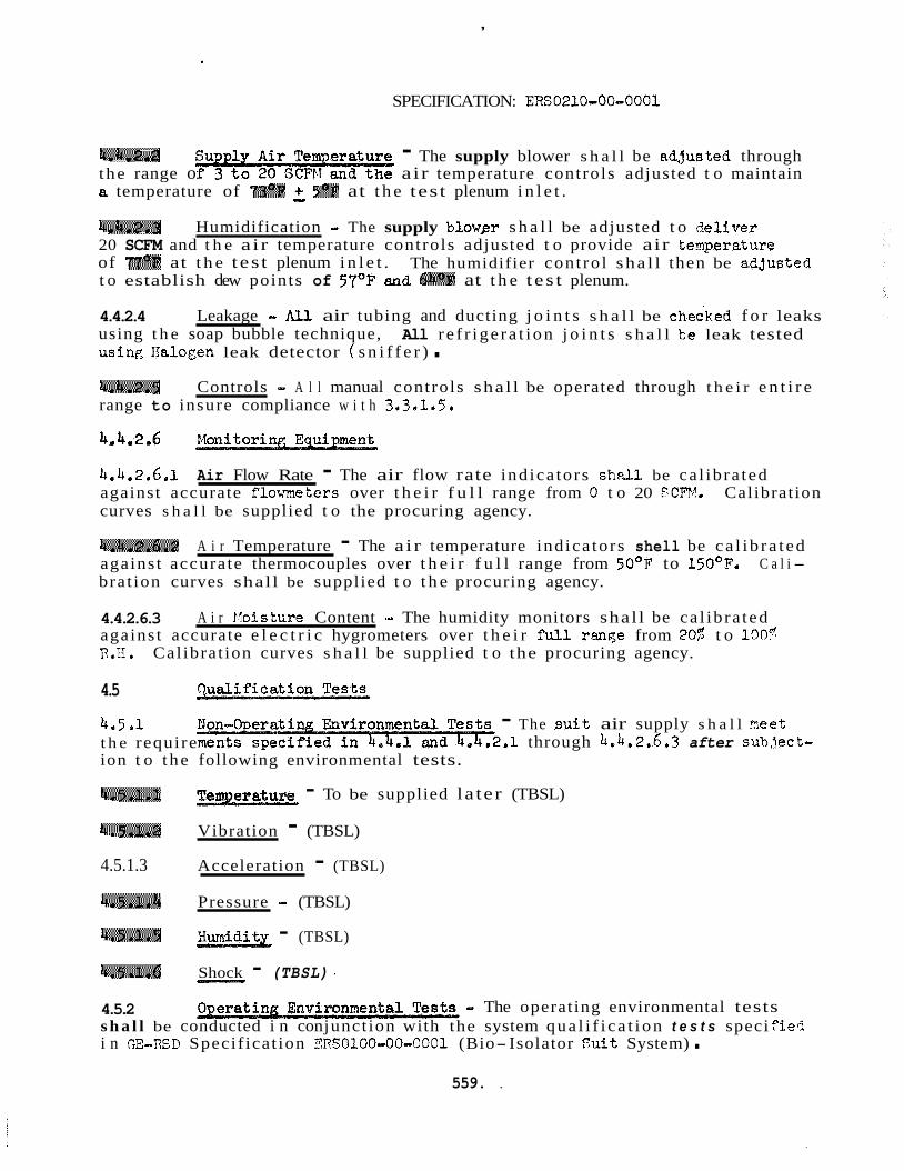
,
SPECIFICATION: ERS0210-00-0001
4.4.2.2 - The supply blower s h a l l be adJusted through the range o air temperature controls adjusted t o maintain a temperature of 73'F f 5OF at t h e test plenum i n l e t .
4.4.2.3 20 SCFM and t h e air temperature controls adjusted t o provide air ternperzture of 77OF at t h e tes t plenum i n l e t . t o establish dew points of 57OF and 54OF at t h e t e s t plenum.
4.4.2.4 using t h e soap bubble technique, using Ilalogen leak detector ( s n i f f e r ) .
Humidification .. The supply blower s h a l l be adjusted t o r?eliver
The humidifier con t ro l sha l l then be a.Cjusted
Leakage - All air tubing and ducting j o i n t s s h a l l be chec-ked f o r leaks All r e f r i ge ra t i on j o i n t s s h a l l ke leak tested
4.4.2.5 range to insure compliance w i t h 3.3.1.5.
Controls - A l l manual controls shal l be operated through t h e i r e n t i r e
4.4.2.6
4.4.2.6.1 against accurate flowmeters over t h e i r f u l l range from 0 t o 20 SCFV. Calibration curves s h a l l be supplied t o the procuring agency.
Air Flow Rate - The air flow rate ind ica tors s h a l l be ca l ib ra ted
4,4.2.6,2 against accurate thermocouples over t h e i r f u l l range from 50°F to 150°F.
A i r Temperature - The a i r temperature ind ica tors shell be ca l i b r a t ed C a l i -
brat ion curves shal l be supplied t o t h e procuring agency.
4.4.2.6.3 against accurate e l e c t r i c hygrometers over t h e i r full range from PO$ t o 1005 R.11. Cal ibrat ion curves s h a l l be supplied t o the procuring agency.
A i r !loisture Content - The humidity monitors shall be ca l ib ra ted
4.5
4 . 5 . J t h e require ion t o t he following environmental tests.
- The , su i t air supply s h a l l 3eet ,1 through 4.4.2.6.3 after subJect-
4.5.1.1
4.5.1.2 Vibration - (TBSL)
4.5.1.3 Acceleration - (TBSL)
4.5.1.4 Pressure - (TBSL)
- To be supplied la te r (TBSL)
4.5.1.5 - (TBSL)
4.5.1.6 Shock - (TBSL) 4
(L..ll
4.5.2 s h a l l be conducted i n con junct ion with the system qua l i f i ca t i on t e s t s speci fiefi i n GE-IISD Specif icat ion ERSOlOO-OO-OOOl (Bio- Isolator S u i t System) .
- The operating environmental tests
559. .
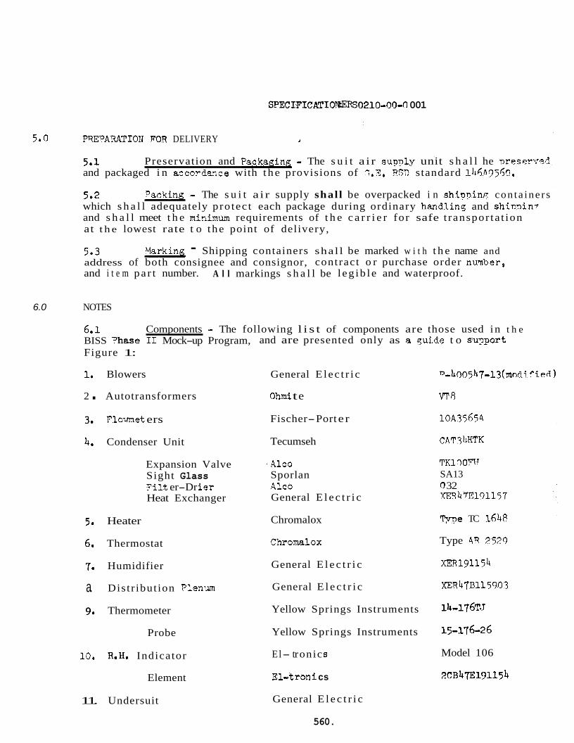
SPECIFICATIOlWRS0210-0b~ 001
5.0 PYEPARATIOTJ FCR DELIVERY 1
5.1 and packaged i n accordmce with t h e provisions of C.E. RSD standard l&fi3j6c?.
5.2 which s h a l l adequately pro tec t each package during ordinary handlins and shinbi n7 and s h a l l meet t h e minimun requirements of t h e c a r r i e r for safe t ranspor ta t ion at t h e lowest rate t o t he point of delivery,
Preservation and Packaaing - The s u i t a i r supnlg unit s h a l l he meserved
Packink - The s u i t a i r supply shal l be overpacked i n shipninp: con ta ine r s
5.3 address of both consignee and consignor, contract o r purchase order nuqber, and i t e m pa r t number.
Varking - Shipping containers shal l be marked w i t h t h e name and
A l l markings s h a l l be l eg ib l e and waterproof.
6.0 NOTES
6.1 BISS =base I1 Mock-up Program, and are presented only as a quide t o su?.oort Figure 1:
1, Blowers General E lec t r i c n-4O9547-13( mndi fie8 )
Components - The following l i s t of components are those used in t h e
2 . Autotransformers Ohmi t e V T R
Flowmet ers Fischer-Port er 10A3565A
CAT3liHTK Condenser Unit Tecumseh
Expansion Valve Sight Glass F i l t er-Dr i e r Heat Exchanger
TKl r) Om1 SA13 0 32 ~ 4 7 E 1 9 1 1 5 7
- Alco Sporlan Alco General E l e c t r i c
me TC 164A Heater Chromalox
Type 4R 9529 6. Chromalox Thermostat
xEIi191154 General E l e c t r i c Humidifier
XER47B115903 a. Distr ibut ion Plenum General E l e c t r i c
14-176T.J Yellow Springs Instruments Thermometer
15-176-26 Yellow Springs Instruments Probe
10. R.H. Indicator
Element
El- t ronic s
El-troni cs
Model 106
2CB47E191154
11. Undersuit General E l e c t r i c
560.
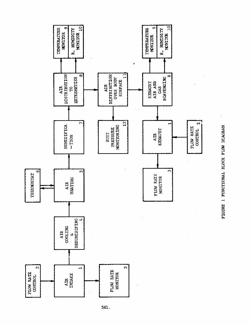
I m
561.
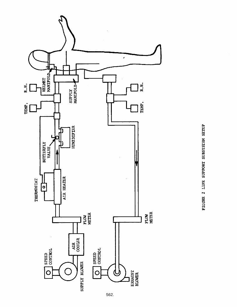
562.