Enhanced Transient Heat Transfer From Arrays of Jets Impinging on a Moving Plate
ISSN: 2180-1053 Vol. 6 No. 2 July-December 2014 1
A NUMERICAL STUDY OF STEADY AND UNSTEADY FLOW AND HEAT TRANSFER FROM A CONFINED SLOT
JET IMPINGING ON A CONSTANT HEAT FLUX WALL
D. U. Lawal1*, A. A. Abubakar2, M. B. Alharbi3, R. Ben-Mansour4
1,2,3,4 Department of Mechanical Engineering, King Fahd University of Petroleum
& Minerals, Dhahran, 31261, Saudi Arabia
ABSTRACT
Impinging jets have been used effectively in several applications including films and foods, rapid cooling and heating processes, tempering of glass and metal, drying of papers, coating, and freezing of tissue. In this work, a numerical simulation of steady and unsteady flow and heat transfer due to a confined 2-D slot jet impinging on constant heat flux plate is presented. Two cases of problem were considered. In the first case, jet-to-plate spacing was varied from 2 to 5 at a fixed jet Reynolds number of 500. In the second case, jet Reynolds number was varied from 200 to 750 at fixed jet-to-plate spacing of 5. In the steady regime, the stagnation Nusselt number was found to increase linearly with increasing Reynolds number, and the distribution of heat transfer in the wall jet region was found to be highly influenced by flow characteristics of the jet. A strong correlation between pressure distribution and Nusselt number was noticed. The critical Reynolds number at which the symmetry of the flow in the formation of vortex sheets is highly disrupted was determined. It was observed that, at the critical Reynolds number, the area-averaged heat transfer coefficient is high and influence the drastic changes of the Nusselt number in the unsteady regime.
KEYWORDS: Jet impingement; Steady flow; Unsteady flow; Heat flux; Critical Reynolds number
1.0 INTRODUCTION
Impinging jets are jets of fluid that are directed on a surface that is required to be dried,
heated or cooled. Due to their high mass and heat transfer rates, impinging jet have received its due attention (Vadiraj & Prabhu, 2008; Vadiraj et al., 2011). Because of their high efficiency and high heat transfer rate, Industries and engineering firms had applied jet
impingement to the applications like freezing of tissue, rapid heating or cooling process, metal and drying of papers. Among numerous advantages of jet impingement is the simplicity
to move the jet to a desired location (Chattopadhyay & Saha, 2002) and the jet ability to remove large amount of heat and mass transfer from the surface of impingement. In electrical and electronics components, jet impingement is used to quench the heat generated in the
components (Guarino & Manno, 2002). Compared to other regions, the impingement region has the largest mass and heat transfer rates (Sergey et al., 2007). Prandtl number, roughness
of the target plate, Reynolds number, target plate inclination, jet-to-plate spacing, nozzle geometry, and many more are the parameters that influence the jet impingement on a surface (Vadiraj et al., 2011).
Chen et al. (2000) carried out numerical and experimental investigation of high Schmidt
number mass transfer in a laminar impinging slot jet flow at Reynolds number ranging from 220 to 690. Their results showed that the point of maximum mass transfer rate is located at
11
2 width from the point of stagnation. Chiriac and Ortega (2002) modelled the laminar fluid

ISSN: 2180-1053 Vol. 6 No. 2 July-December 2014 2
flow and heat transfer associated with impinging slot jets on an isothermal plate. The jet Reynolds number was varied up to the unsteady regime at fixed Prandtl number and jet-to-
plate spacing. The unsteadiness was discovered at Reynolds number between 585 and 610. Contrary to the heat transfer characteristics of the plate under steady state, the unsteady
regime shows an abrupt rise in stagnation Nusselt number and area-averaged heat transfer coefficient. The unsteadiness was also observed to cause the asymmetry of flow fields, lateral jet instability, and formation of shear layer vortices at the jet exit.
Similarly, Sahoo and Sherif (2004) carried out a numerical investigation of the heat transfer
process in the mixed convection-laminar regime due to jet impingement on a constant heat flux surface. The resulting flow fields and isotherms were carefully studied as the Reynolds number, Richardson number, and domain aspect ratio were varied. As expected, the results
shows that the average Nusselt number increases with increasing Reynolds number up to a certain value of Reynolds number and domain aspect ratio, where the average Nusselt
number does not change significantly. They concluded that, buoyancy effects are not very significant on the heat transfer characteristics of laminar-flow slot impingement jets. Chen et al. (2005) also carried out theoretical investigation of laminar flow and heat transfer due to
slot jets impinging on arbitrary-heat-flux surface. Expressions of the heat transfer coefficients of the various regions were determined, which were all found to be in good agreement with
previous experiments. Aldaddagh & Sezai (2002) numerically studied the characteristic of heat transfer and laminar flows of multiple square jet impingements. Several Jets-to-plate spacing ratio were considered. Results revealed that the variation of jet-to-plate spacing
significantly affect the flow structure of jet impingement on the heated plate and had negligible effect on peak Nusselt number.
Heat transfer characteristics due to turbulent flow of an impinging slot jet was also largely studied in the literature. Vadiraj et al. (2011) studied Reynolds number and jet-to-plate
spacing effect on the local heat transfer distribution between smooth flat surface and impinging air jet. Imaging technique was used to capture the flow fields. The surface
temperature at various points was obtained using infra-red radiometry techniques. They obtained correlations for the Nusselt number at various points on the domain, which were all found to be in agreement with experiments. San & Chen (2014) conduct an investigation on
the effects of jet-to-jet spacing and jet height on heat transfer characteristics of an impinging jet array. Nusselt number due to five confined circular air jets impinging on a flat surface
were measured. The jet-to-jet to jet diameter (s/d) ratio and jet height to jet diameter (H/d) ratio were varied at a constant Reynold number of 20,000. Small s/d and H/d ratios were found to result in large Nusselt number due to the jets interaction. However, reduction in
Nusselt number was observed for both intermediate and large ratios due to weaker jets interaction and interference. Caggese et al. (2013) carried out an experimental and numerical
investigation of the heat transfer characteristics of a flat plate under a fully confined impingement jet. The experiments were carried out over a range of Reynolds varying between 16,500 and 41,800. Both experimental and numerical results were found to be in
agreement. Their results revealed that for the target plate, low dependence of the local and average heat transfer level with Z/D was observed.
Mohammadpour et al. (2014) carried out optimization of an impingement system that is composed of both pulsating and steady submerged slot jets using numerical techniques. The
simulation was carried out at varying temperatures, amplitudes, and frequencies of the slot jets. The results show that uniform as well as significantly high Nusselt number can be
obtained using combination of pulsed and steady jets. In view of this, a considerable increase
ISSN: 2180-1053 Vol. 6 No. 2 July-December 2014 3
in convective heat transfer was found at the stagnation point. They also show that a relatively higher heat transfer rate can even be obtained in a system that is composed of both
intermittent-steady jets rather than the sinusoidal-steady ones.
From the foregoing literature review, it can be concluded that no study has investigated the unsteady flow analysis and heat transfer from a confined slot jet impinging on a constant heat flux wall (target). To the best of the author’s knowledge, the nature of the flow fields and
isotherms is not fully exploited during the unsteady regime. Therefore, the objective of present research is to study the effect of geometrical changes and jet inlet velocity on heat
transfer characteristics of impinging plates at at constant heat flux and under laminar flow condition.
2.0 PROBLEM DESCRIPTION
The problem description is illustrated in Figure 1 below. It is a uniform velocity 2-dimensional jet of air entering a nozzle of width (W) located above a channel of height (H)
and length (L). The two cases below further described the problem statement.
Case 1 At a constant Reynolds number of 500 and plate length of 25cm, the jet-to-plate spacing (H/W) was varied from 2 to 5.
Case 2
At a constant jet-to-plate spacing (H/W) of 5 and fixed plate length of 50cm, the Reynolds number was varied from 200 to 750.
In both cases, the upper confining wall is considered to be adiabatic while the lower target wall was kept at constant heat flux of 1000W/m2.
The above problems was solved using commercial Computational Fluid Dynamics package (Fluent 6.2). The entire domain was considered in order to fully detect any unsteadiness and
asymmetry in our analysis.
3.0 MODEL ASSUMPTIONS
Using air of low viscosity as a working fluid, the following assumptions are made:
Flow is incompressible
Unsteady
2-Dimensional modelling
All physical properties are constant

ISSN: 2180-1053 Vol. 6 No. 2 July-December 2014 4
Figure 1. The geometry of a 2-D confined impinging jet
3.1 Governing Equations
With aforementioned assumptions, the continuity, the momentum, and the energy equations
are reduced to Equations (1) - (3) respectively, and are considered to be the basic equations in our analysis:
∇. �̅� = 0 (1)
𝜕𝑢
𝜕𝑡+ �̅� . ∇u̅ = −
1
ρ ∇p + 𝜈∇2u̅ (2)
𝜕T
𝜕𝑡+ �̅� .∇T = α∇2T (3)
3.2 Boundary Conditions (B.C)
The B.C used are as follows:
Top plate:
Left and Right walls, ν = 0, u̅ = 0 and 𝜕𝑇
𝜕𝑦= 0
Jet inlet, ν = Vj, u̅ = 0 and T = 300K
Bottom plate:
Bottom wall, ν = 0, u̅ = 0 and 𝑞 = 1000𝑊/𝑚2
Left and Right outlet: 𝜕𝑢
𝜕𝑥= 0,
𝜕𝑢
𝜕𝑦= 0,
𝜕𝑇
𝜕𝑥= 0, 𝑎𝑛𝑑 𝑃 = 𝑃𝑎𝑡𝑚
In other words, the boundary conditions are,
Top plate is fixed and insulated
Jet flow is Isothermal with constant velocity
Bottom plate is fixed with constant heat dissipation/flux
Left and right outlets are far from the control volume, and considered to be at atmospheric conditions

ISSN: 2180-1053 Vol. 6 No. 2 July-December 2014 5
4.0 MODELING
In solving the above equations using the Computational Fluid Dynamics Code (Fluent 6.2), the main procedure involved are:
In Gambit, create the geometry, mesh the domain, name the boundary conditions and export the output to fluent. In Fluent, the boundary conditions and the material properties are set.
The solver is then used to compute the equations governing the flow. The end result to the problem is achieved when the solution converged.
4.1 Geometry
The geometry of our problem consists of the target wall, outlets (left and right), top walls (left and right), and the jet inlet. The face of the geometry is depicted in Figure 2.
Figure 2. The geometry as drawn in gambit
4.2 Mesh
The domain considered is meshed with quadrilateral elements of aspect ratio 0.98. A mesh of high density was used at regions of steep gradients, i.e. near the jet inlet and the target wall.
This allows more accurate results. The meshed geometry is as shown in Figure 3.
Figure 3. The mesh as built from Gambit
4.3 Material Used and Properties
Air was used as the working medium and its properties is tabulated in Table 1.
ISSN: 2180-1053 Vol. 6 No. 2 July-December 2014 6
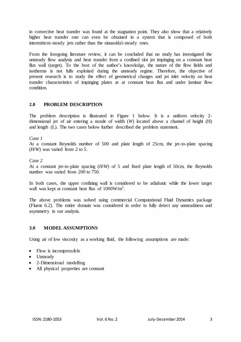
Table 1. The properties of air at 300 K and 101325 Pa
Properties of air at 300 K and 101,325 Pa
Density 1.225 kg/m3
Specific Heat Capacity at constant pressure 1006.43 J/kg-K
Thermal Conductivity 0.0242W/m-K
Viscosity 0.00001789 kg/m-s
4.4 Mesh Independence Test
Six sets of mesh size were used to determine the optimum mesh size. The results are
tabulated in Table 2 according to the decreasing number of grids with S6 having the lowest number of cells. The velocity magnitude of H/W= 5 for different mesh scheme are illustrated
in Fig 4. The plot revealed no clear differences among the six mesh schemes. For compromise between
computational cost and accuracy of results, S4 mesh scheme was selected. Time independent test was then conducted for different H/W ratio (H/W=2, H/W= 3 and H/W= 4).
Table 2. The number of grids in the domain for H/W=5.
Mesh Scheme Number of cells
S1 10,200
S2 9,000
S3 7,500
S4 6,200
S5 4,800
S6 3,900
Figure 4. Plot of velocity for various mesh schemes for H/W=5
0
0.02
0.04
0.06
0.08
0.1
0.12
0.14
0.16
0.18
0.2
0 0.05 0.1 0.15 0.2 0.25
Velo
cit
y (
m/s
)
H/W=5
S1
S2
S3
S4
S5
S6
ISSN: 2180-1053 Vol. 6 No. 2 July-December 2014 7
5.0 RESULTS AND DISCUSSIONS
5.1 Validation
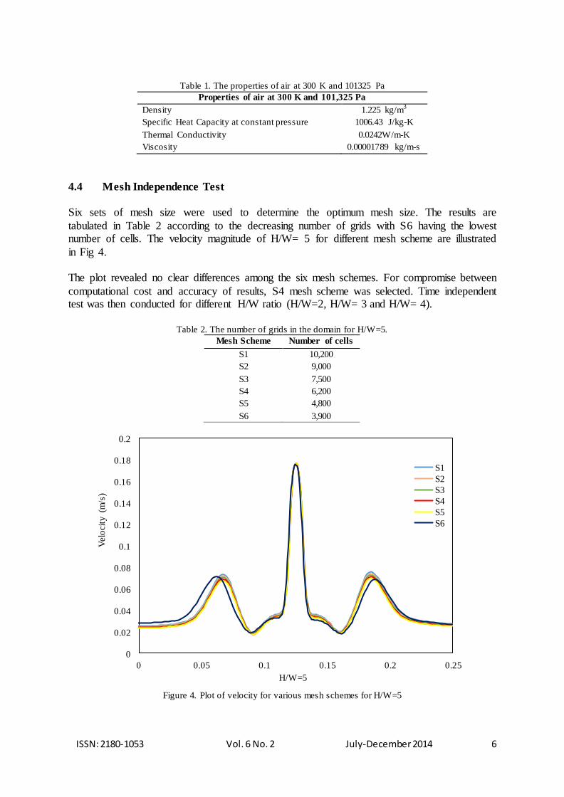
The variation of time-averaged Nusselt number at the point of stagnation for different Reynolds number is depicted in Figure 5. A direct relation between Nusselt number and of
Reynolds number was observed in the steady regime, which is an indication that the rate heat transfer is due to convectional rise in jet inlet velocity. However, a significant departure from
the linear relationship was observed in the unsteady regime. The sudden change in slope of the graph occurred at Re = 600. At this point, Nusselt number was noticed to rise sharply. In unsteady regime, the rate of convective heat transfer is greater at higher Reynolds number
than that at lower Reynolds numbers due to instability (unsteadiness) encountered by the fluid.
Figure 5. Time-averaged Stagnation Nusselt number for H/W=5 and different Reynolds number
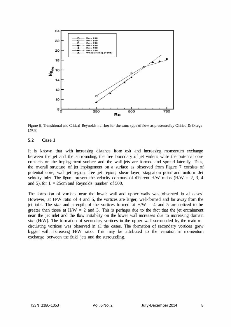
Available for validation is the work of Chiriac & Ortega (2002) which is presented in Figure 6. From their work, the critical Reynolds number was found to be at Re =750. This value was
determined experimentally and numerically. In the current work, the critical Reynolds number was also found to be around Re = 750. However, the Nusselt number obtained in this study is quite higher than those from Chiriac & Ortega (2002). The observed differences may
be attributed to the fact that Chiriac & Ortega (2002) based their analysis on an Isothermal target plate temperature of 300K, whereas our analysis was based on a target plate at constant heat flux of 1000 W/m2.
0
200
400
600
800
1000
1200
1400
0 100 200 300 400 500 600 700 800
Nu
stag
Re
Stagnation Nusselt Number
ISSN: 2180-1053 Vol. 6 No. 2 July-December 2014 8
Figure 6. Transitional and Critical Reynolds number for the same type of flow as presented by Chiriac & Ortega
(2002) 5.2 Case 1
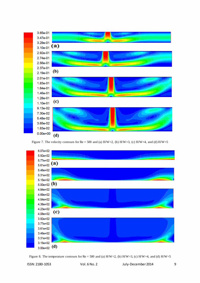
It is known that with increasing distance from exit and increasing momentum exchange
between the jet and the surrounding, the free boundary of jet widens while the potential core contacts on the impingement surface and the wall jets are formed and spread laterally. Thus, the overall structure of jet impingement on a surface as observed from Figure 7 consists of
potential core, wall jet region, free jet region, shear layer, stagnation point and uniform Jet velocity Inlet. The figure present the velocity contours of different H/W ratios (H/W = 2, 3, 4
and 5), for L = 25cm and Reynolds number of 500. The formation of vortices near the lower wall and upper walls was observed in all cases.
However, at H/W ratio of 4 and 5, the vortices are larger, well-formed and far away from the jet inlet. The size and strength of the vortices formed at H/W = 4 and 5 are noticed to be
greater than those at H/W = 2 and 3. This is perhaps due to the fact that the jet entrainment near the jet inlet and the flow instability on the lower wall increases due to increasing domain size (H/W). The formation of secondary vortices in the upper wall surrounded by the main re-
circulating vortices was observed in all the cases. The formation of secondary vortices grew bigger with increasing H/W ratio. This may be attributed to the variation in momentum
exchange between the fluid jets and the surrounding.
ISSN: 2180-1053 Vol. 6 No. 2 July-December 2014 9
Figure 7. The velocity contours for Re = 500 and (a) H/W=2, (b) H/W=3, (c) H/W=4, and (d) H/W=5
Figure 8. The temperature contours for Re = 500 and (a) H/W=2, (b) H/W=3, (c) H/W=4, and (d) H/W=5
ISSN: 2180-1053 Vol. 6 No. 2 July-December 2014 10
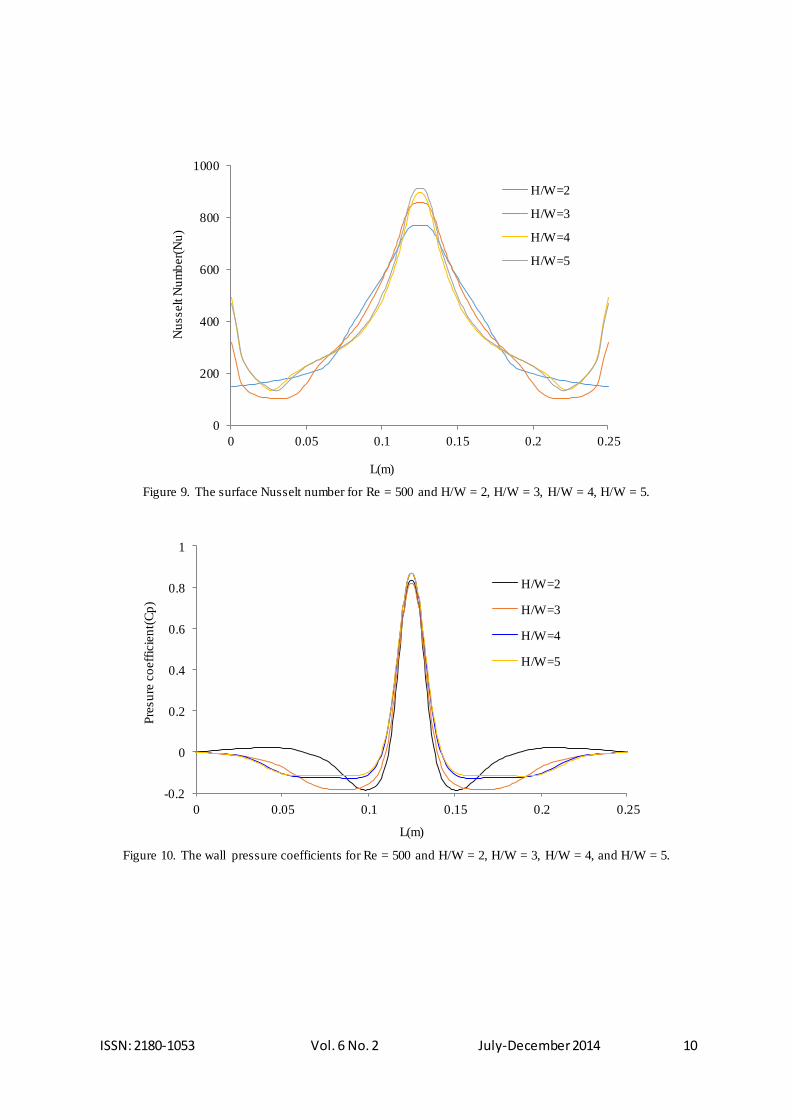
Figure 9. The surface Nusselt number for Re = 500 and H/W = 2, H/W = 3, H/W = 4, H/W = 5.
Figure 10. The wall pressure coefficients for Re = 500 and H/W = 2, H/W = 3, H/W = 4, and H/W = 5.
0
200
400
600
800
1000
0 0.05 0.1 0.15 0.2 0.25
Nu
sselt
Nu
mb
er(
Nu
)
L(m)
H/W=2
H/W=3
H/W=4
H/W=5
-0.2
0
0.2
0.4
0.6
0.8
1
0 0.05 0.1 0.15 0.2 0.25
Pre
su
re c
oeff
icie
nt(
Cp
)
L(m)
H/W=2
H/W=3
H/W=4
H/W=5
ISSN: 2180-1053 Vol. 6 No. 2 July-December 2014 11
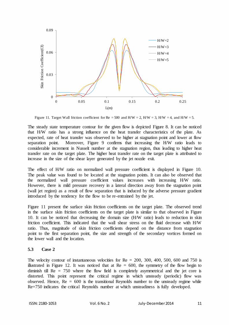
Figure 11. Target Wall friction coefficient for Re = 500 and H/W = 2, H/W = 3, H/W = 4, and H/W = 5.
The steady state temperature contour for the given flow is depicted Figure 8. It can be noticed that H/W ratio has a strong influence on the heat transfer characteristics of the plate. As
expected, rate of heat transfer was observed to be higher at stagnation point and lower at flow separation point. Moreover, Figure 9 confirms that increasing the H/W ratio leads to
considerable increment in Nusselt number at the stagnation region, thus leading to higher heat transfer rate on the target plate. The higher heat transfer rate on the target plate is attributed to increase in the size of the shear layer generated by the jet nozzle exit.
The effect of H/W ratio on normalized wall pressure coefficient is displayed in Figure 10.
The peak value was found to be located at the stagnation points. It can also be observed that the normalized wall pressure coefficient values increases with increasing H/W ratio. However, there is mild pressure recovery in a lateral direction away from the stagnation point
(wall jet region) as a result of flow separation that is induced by the adverse pressure gradient introduced by the tendency for the flow to be re-entrained by the jet.
Figure 11 present the surface skin friction coefficients on the target plate. The observed trend in the surface skin friction coefficients on the target plate is similar to that observed in Figure
10. It can be noticed that decreasing the domain size (H/W ratio) leads to reduction in skin friction coefficient. This indicated that the wall shear stress on the fluid decrease with H/W
ratio. Thus, magnitude of skin friction coefficients depend on the distance from stagnation point to the first separation point, the size and strength of the secondary vortices formed on the lower wall and the location.
5.3 Case 2
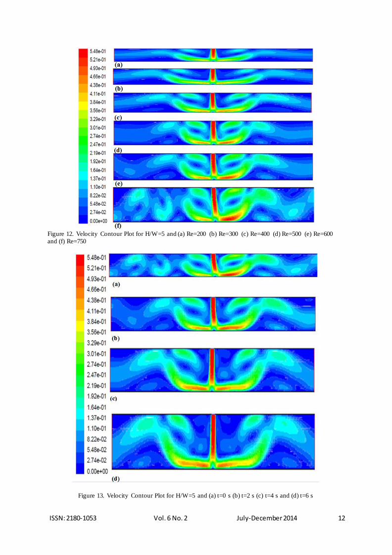
The velocity contour of instantaneous velocities for Re = 200, 300, 400, 500, 600 and 750 is illustrated in Figure 12. It was noticed that at Re = 600, the symmetry of the flow begin to
diminish till Re = 750 where the flow field is completely asymmetrical and the jet core is distorted. This point represent the critical regime in which unsteady (periodic) flow was
observed. Hence, Re = 600 is the transitional Reynolds number to the unsteady regime while Re=750 indicates the critical Reynolds number at which unsteadiness is fully developed.
0
0.03
0.06
0.09
0 0.05 0.1 0.15 0.2 0.25
Skin
Fri
cti
on
Co
eff
icie
nt(
Cf)
L(m)
H/W=2
H/W=3
H/W=4
H/W=5
ISSN: 2180-1053 Vol. 6 No. 2 July-December 2014 12
Figure 12. Velocity Contour Plot for H/W=5 and (a) Re=200 (b) Re=300 (c) Re=400 (d) Re=500 (e) Re=600
and (f) Re=750
Figure 13. Velocity Contour Plot for H/W=5 and (a) t=0 s (b) t=2 s (c) t=4 s and (d) t=6 s

ISSN: 2180-1053 Vol. 6 No. 2 July-December 2014 13
In order to quantify the flow instabilities in the unsteady regime, the velocity contour at the critical Reynolds number were sampled over time as presented in Figure 13. It can be noticed
that the pattern of the velocity field is neither constant nor symmetrical with time, as the pattern of the velocity field is neither symmetrical nor constant with time.
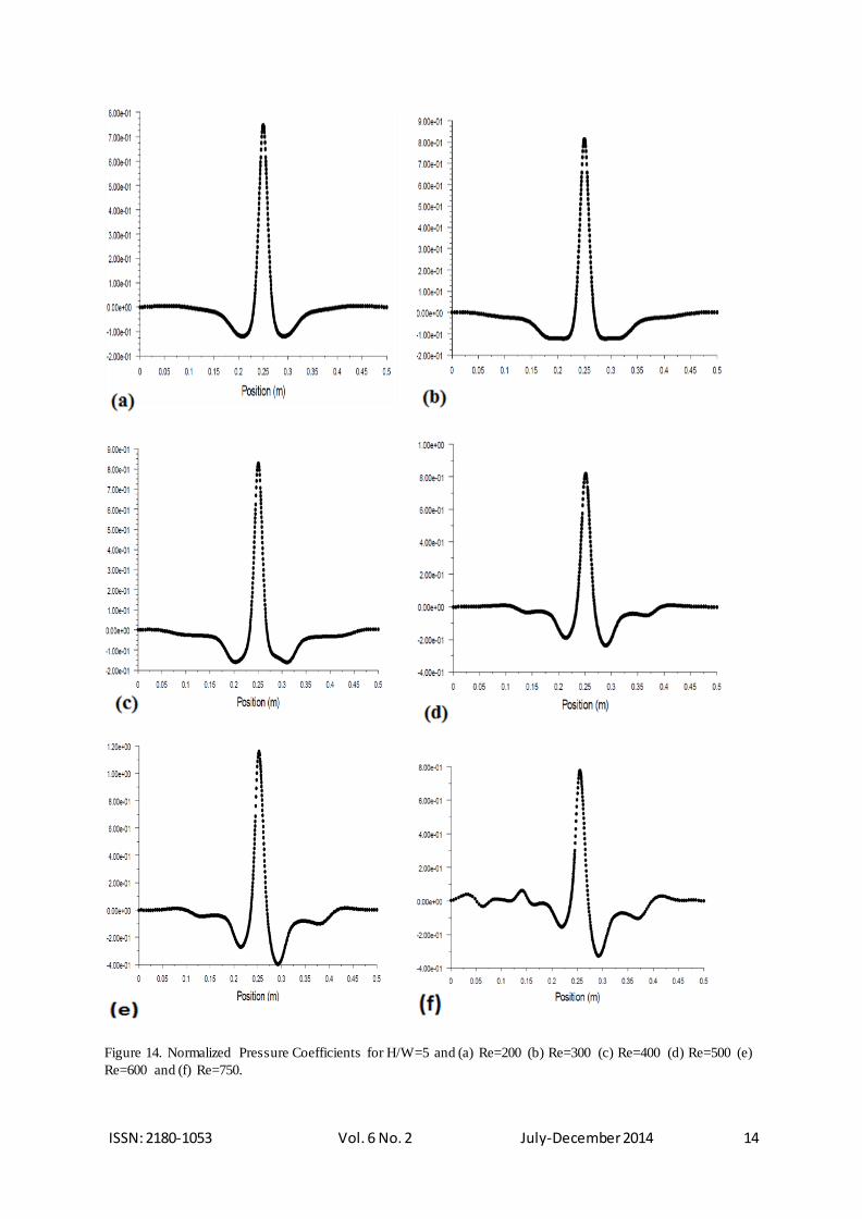
The coefficients of pressure for different Reynolds numbers is depicted in Figure 14. It can be noticed that, as the Reynolds number increases, the symmetry of the flow is disrupted. The
peak point of the coefficient of pressure as expected was found to be situated at the point of stagnation. Careful observation revealed that the wall static pressure drops rapidly as the flow
turns and accelerate. It was noticed that the coefficient of pressure at the point of stagnation increases with increasing Reynolds numbers. This is attributed to the overall increment in the flow velocity due to increment in Reynolds number.
ISSN: 2180-1053 Vol. 6 No. 2 July-December 2014 14
Figure 14. Normalized Pressure Coefficients for H/W=5 and (a) Re=200 (b) Re=300 (c) Re=400 (d) Re=500 (e)
Re=600 and (f) Re=750.
ISSN: 2180-1053 Vol. 6 No. 2 July-December 2014 15
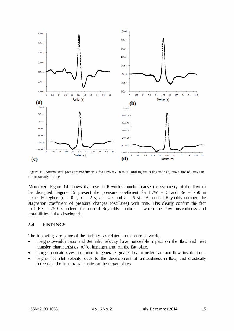
Figure 15. Normalized pressure coefficients for H/W=5, Re=750 and (a) t=0 s (b) t=2 s (c) t=4 s and (d) t=6 s in
the unsteady regime
Moreover, Figure 14 shows that rise in Reynolds number cause the symmetry of the flow to
be disrupted. Figure 15 present the pressure coefficient for H/W = 5 and Re = 750 in unsteady regime (t = 0 s, t = 2 s, t = 4 s and t = 6 s). At critical Reynolds number, the
stagnation coefficient of pressure changes (oscillates) with time. This clearly confirm the fact that Re = 750 is indeed the critical Reynolds number at which the flow unsteadiness and instabilities fully developed.
5.4 FINDINGS
The following are some of the findings as related to the current work,
Height-to-width ratio and Jet inlet velocity have noticeable impact on the flow and heat
transfer characteristics of jet impingement on the flat plate.
Larger domain sizes are found to generate greater heat transfer rate and flow instabilities.
Higher jet inlet velocity leads to the development of unsteadiness in flow, and drastically increases the heat transfer rate on the target plates.

ISSN: 2180-1053 Vol. 6 No. 2 July-December 2014 16
6.0 CONCLUSIONS
The effects height-to-width ratio and jet inlet velocity on the heat and flow characteristics of slot jets impinging on a flat target wall of constant heat flux have been presented. Hence the
following conclusion can be drawn from the study.
Increasing the domain size leads to the formation of vortices (hence, instabilities) in the
flow characteristics of the jet.
The transition and critical Reynolds numbers were found to be 600 and 750 respectively.
At the critical Reynolds number, the unsteadiness of the flow was fully observed and was
found to have major impact on the heat transfer characteristics of the target plates.
Increasing the jet inlet speed triggered the flow transition from steady to unsteady regime.
The heat transfer rate was noticed to be greater at unsteady regimes.
ACKNOWLEDGMENT
The authors would like acknowledge the support received from King Fahd University of Petroleum & Minerals (KFUPM).
NOMENCLATURE
Cf Friction coefficient CP Specific heat [J/kg.K]
h Heat transfer coefficient [W m-2 K-l] H Nozzle–plate spacing (m) k Thermal conductivity [W m-1 K-l]
L Channel length (m) Nu Nusselt number
p Static Pressure [N m-2] q Heat flux at target Wall [W/m2] Re Reynolds number based on hydraulic diameter (2W)
T Temperature of fluid [oC] t Time [s] u Velocity in jet transverse direction (m/s)
v Velocity in jet stream wise direction (m/s) Vj Jet inlet velocity (m/s)
W Jet nozzle width (m) x Jet transverse coordinate (m) y Jet stream wise coordinate (m)
Greek symbols
ρ Density [kg.m-3] ν Kinematic viscosity [m2 s-1] α Thermal diffusivity [m2 s-1]
τw Wall Shear stress [Nm-2]
Subscripts
j Jet stag Stagnation
w Target wall x Local value of parameter on target wall
ISSN: 2180-1053 Vol. 6 No. 2 July-December 2014 17
REFERENCES
Aldabbagh, L. B. Y. & Sezai, I. (2002). Numerical simulation of three-dimensional laminar multiple impinging
square jets. International Journal of Heat and Fluid Flow , 23, 509-518.
Caggese, O., Gnaegi, G., Hannema, G., Terzis, A., & Ott, P. (2013). Experimental and numerical investigation
of a fully confined impingement round jet. International Journal of Heat and Mass Transfer, 65, 873-
882.
Chattopadhyay, H. & Saha, S. K. (2002). Simulation of laminar slot jets impinging on a moving surface.
Journal of Heat Transfer, ASME, 124, 1049-1055.
Chen, Y. C., Ma, C. F., Qin, M., & Li, Y. X. (2005). Theoretical study on impingement heat transfer with
single-phase free-surface slot jets. International Journal of Heat and Mass Transfer, 48(16), 3381-3386.
Chen, M., Chalupa, R., West, A. C. & Modi, V. (2000). High Schmidt mass transfer in a laminar impinging slot
jet flow. International Journal of Heat and Mass Transfer, 43, 3907–3915.
Chiriac, V. A. & Ortega, A. (2002). A numerical study of the unsteady flow and heat transfer in a transitional
confined slot jet impinging on an isothermal surface. International Journal of Heat and Mass Transfer,
45, 1237-1248.
Guarino, J. R. & Manno, V. P. (2002). Characterization of laminar jet impingement cooling in portable
computer applications. IEEE Transactions on Components and Packaging Technologies, 25(3).
Mohammadpour, J., Zolfagharian, M. M., Mujumdar, A. S., Zargarabadi, M. R., & Abdulah zadeh, M. (2014).
Heat transfer under composite arrangement of pulsed and steady turbulent submerged multiple jets
impinging on a flat surface. International Journal of Thermal Sciences, 86, 139-147.
Sahoo, D. & Sharif, M. A. R. (2004). Numerical modeling of slot-jet impingement cooling of a constant heat
flux surface confined by a parallel wall. International Journal of Thermal Sciences, 43(9), 877-887.
San, J. Y. & Chen, J. J. (2014). Effects of jet-to-jet spacing and jet height on heat transfer characteristics of an
impinging jet array. International Journal of Heat and Mass Transfer, 71, 8-17.
Sergey, V. A., Artur, V. B., Vladimir, M., & Dmitriy, M. M. (2007). Experimental Study of an impinging jet
with different swirl rates. Heat and Fluid Flow, 28, 1340-1359.
Vadiraj, K., & Prabhu, S. V. (2008). Experimental study and theoretical analysis of local heat transfer
distribution between smooth flat surface and impinging air jet from circular straight pipe nozzle. Heat
and Mass Transfer, 51, 4480-4495.
Vadiraj, V., Katti, S., & Nagesh, Y. (2011). Local heat transfer distribution between smooth flat surface and
impinging air jet from a circular nozzle at low Reynolds numbers . Heat Mass Transfer, 47, 237-244.
Copyright © 2022 FDOKUMEN