
A novel surface analytical model for cutting linearization error in fast tool/slow slide servo...
12
Precision Engineering 38 (2014) 849–860 Contents lists available at ScienceDirect Precision Engineering jo ur nal ho me p age: www.elsevier.com/locate/precision A novel surface analytical model for cutting linearization error in fast tool/slow slide servo diamond turning Dennis Wee Keong Neo ∗ , A. Senthil Kumar, Mustafizur Rahman Department of Mechanical Engineering, National University of Singapore, 10 Kent Ridge Crescent, 9 Engineering Drive 1, Block EA, Singapore 117576, Singapore a r t i c l e i n f o Article history: Received 14 January 2014 Received in revised form 30 April 2014 Accepted 5 May 2014 Available online 27 May 2014 Keywords: Cutting linearization error Critical machining parameters Fast tool/slow slide servo diamond turning Freeform surfaces a b s t r a c t Fast tool/slow slide servo (FTS/SSS) technology plays an important role in machining freeform surfaces for the modern optics industry. The surface accuracy is a sticking factor that demands the need for a long-standing solution to fabricate ultraprecise freeform surfaces accurately and efficiently. However, the analysis of cutting linearization errors in the cutting direction of surface generation has received little attention. Hence, a novel surface analytical model is developed to evaluate the cutting linearization error of all cutting strategies for surface generation. It also optimizes the number of cutting points to meet accuracy requirements. To validate the theoretical cutting linearization errors, a series of machining experiments on sinusoidal wave grid and micro-lens array surfaces has been conducted. The experimental results demonstrate that these surfaces have successfully achieved the surface accuracy requirement of 1 m with the implementation of the proposed model. These further credit the capability of the surface analytical model as an effective and accurate tool in improving profile accuracies and meeting accuracy requirements. © 2014 Elsevier Inc. All rights reserved. 1. Introduction The new era of ultraprecision machining technologies for freeform optics requires the advancement of design and testing for innovative optical function and improved optical performance [1]. Fast tool/slow slide servo (FTS/SSS) diamond turning [2,3] is one of these technologies which is widely employed for the machining of freeform surfaces. The surface accuracy is a dominant factor for the optical performance of freeform optical surfaces. Much research work has been conducted in the area of surface generation with ultraprecise surface accuracy for freeform optics. Over the past decades, much research has been conducted on the surface generation methods, machine dynamics, error analysis and methodologies of error compensation. In the FTS/SSS processes, there are two different types of surface errors, namely cutting resid- ual and cutting linearization errors. The cutting residual error is the formation of tool marks on the surface along the feed direction [4–8]. Kwok et al. [5] and Yu et al. [8] have studied and success- fully developed their models for predicting this residual error in the FTS/SSS processes. They also conclude that the residual error ∗ Corresponding author. Tel.: +65 90478176. E-mail addresses: [email protected], [email protected] (D.W.K. Neo), [email protected] (A.S. Kumar), [email protected] (M. Rahman). dominates the errors by the tool nose radius and feedrate, and is analogous to surface roughness. Thus, a proper selection of fee- drate and tool nose radius should be optimized for machining accurate freeform surfaces. In contrast, cutting linearization error is the peak-to-valley error (PV err ) between the ideal surface pro- file and the linear tool trajectory in the spiral cutting direction. This PV err depends mainly on the cutting distance between the two corresponding points in the cutting direction. It has been reported that the best profile accuracy results can be achieved by the spline interpolation method in the DiffSys software [9,10]. However, the details for selecting cutting parameters in the spline interpola- tion method were not reported. Zhou et al. [11] have conducted a comparison studies on surface quality of machined surface based on constant-angle and constant arc-length methods. When the constant-angle method is employed, the surface quality of outer regions is worse than that of central regions due to arc-lengths between the corresponding points on outer regions are sparser than those on central regions. Whereas the constant-arc method shares the same number of cutting points as constant-angle ones, the surface quality of machined surface is uniform. Liu et al. [12] explain that the selection of critical incremental arc-lengths plays an important role for achieving ultraprecision surface accuracy of freeform surfaces. Notwithstanding the fact that the constant arc- length method demonstrated its capability for better overall profile accuracy, only sinusoidal wave grid (SWG) profiles were served as http://dx.doi.org/10.1016/j.precisioneng.2014.05.002 0141-6359/© 2014 Elsevier Inc. All rights reserved.
Transcript of A novel surface analytical model for cutting linearization error in fast tool/slow slide servo...

At
DDS
a
ARRAA
KCCFF
1
fiFtfowu
tatut[ft
N
h0
Precision Engineering 38 (2014) 849–860
Contents lists available at ScienceDirect
Precision Engineering
jo ur nal ho me p age: www.elsev ier .com/ locate /prec is ion
novel surface analytical model for cutting linearization error in fastool/slow slide servo diamond turning
ennis Wee Keong Neo ∗, A. Senthil Kumar, Mustafizur Rahmanepartment of Mechanical Engineering, National University of Singapore, 10 Kent Ridge Crescent, 9 Engineering Drive 1, Block EA, Singapore 117576,ingapore
r t i c l e i n f o
rticle history:eceived 14 January 2014eceived in revised form 30 April 2014ccepted 5 May 2014vailable online 27 May 2014
eywords:utting linearization error
a b s t r a c t
Fast tool/slow slide servo (FTS/SSS) technology plays an important role in machining freeform surfacesfor the modern optics industry. The surface accuracy is a sticking factor that demands the need for along-standing solution to fabricate ultraprecise freeform surfaces accurately and efficiently. However,the analysis of cutting linearization errors in the cutting direction of surface generation has receivedlittle attention. Hence, a novel surface analytical model is developed to evaluate the cutting linearizationerror of all cutting strategies for surface generation. It also optimizes the number of cutting points tomeet accuracy requirements. To validate the theoretical cutting linearization errors, a series of machining
ritical machining parametersast tool/slow slide servo diamond turningreeform surfaces
experiments on sinusoidal wave grid and micro-lens array surfaces has been conducted. The experimentalresults demonstrate that these surfaces have successfully achieved the surface accuracy requirement of1 �m with the implementation of the proposed model. These further credit the capability of the surfaceanalytical model as an effective and accurate tool in improving profile accuracies and meeting accuracyrequirements.
© 2014 Elsevier Inc. All rights reserved.
. Introduction
The new era of ultraprecision machining technologies forreeform optics requires the advancement of design and testing fornnovative optical function and improved optical performance [1].ast tool/slow slide servo (FTS/SSS) diamond turning [2,3] is one ofhese technologies which is widely employed for the machining ofreeform surfaces. The surface accuracy is a dominant factor for theptical performance of freeform optical surfaces. Much researchork has been conducted in the area of surface generation withltraprecise surface accuracy for freeform optics.
Over the past decades, much research has been conducted onhe surface generation methods, machine dynamics, error analysisnd methodologies of error compensation. In the FTS/SSS processes,here are two different types of surface errors, namely cutting resid-al and cutting linearization errors. The cutting residual error ishe formation of tool marks on the surface along the feed direction
4–8]. Kwok et al. [5] and Yu et al. [8] have studied and success-ully developed their models for predicting this residual error inhe FTS/SSS processes. They also conclude that the residual error∗ Corresponding author. Tel.: +65 90478176.E-mail addresses: [email protected], [email protected] (D.W.K.
eo), [email protected] (A.S. Kumar), [email protected] (M. Rahman).
ttp://dx.doi.org/10.1016/j.precisioneng.2014.05.002141-6359/© 2014 Elsevier Inc. All rights reserved.
dominates the errors by the tool nose radius and feedrate, and isanalogous to surface roughness. Thus, a proper selection of fee-drate and tool nose radius should be optimized for machiningaccurate freeform surfaces. In contrast, cutting linearization erroris the peak-to-valley error (PVerr) between the ideal surface pro-file and the linear tool trajectory in the spiral cutting direction.This PVerr depends mainly on the cutting distance between the twocorresponding points in the cutting direction. It has been reportedthat the best profile accuracy results can be achieved by the splineinterpolation method in the DiffSys software [9,10]. However, thedetails for selecting cutting parameters in the spline interpola-tion method were not reported. Zhou et al. [11] have conducteda comparison studies on surface quality of machined surface basedon constant-angle and constant arc-length methods. When theconstant-angle method is employed, the surface quality of outerregions is worse than that of central regions due to arc-lengthsbetween the corresponding points on outer regions are sparserthan those on central regions. Whereas the constant-arc methodshares the same number of cutting points as constant-angle ones,the surface quality of machined surface is uniform. Liu et al. [12]explain that the selection of critical incremental arc-lengths plays
an important role for achieving ultraprecision surface accuracy offreeform surfaces. Notwithstanding the fact that the constant arc-length method demonstrated its capability for better overall profileaccuracy, only sinusoidal wave grid (SWG) profiles were served as
850 D.W.K. Neo et al. / Precision Engineering 38 (2014) 849–860
ning (a
cl
fomstose
dawammttugi
2
2
afmsmelt
apaitocbt
Fig. 1. Cutting strategies in FTS/SSS tur
ase studies. It still remains unknown whether the constant arc-ength method is also ideal for other profiles.
Furthermore, it could be seen that most publications mainlyocus on the cutting residual error in the profile accuracy whichften is pre-determined by considering the external factors such asachine dynamics, tool nose radius etc. There is also no analytical
tudy for comprehensively understanding on the cutting lineariza-ion error. Cutting linearization error inherited from the generationf the tool path itself should not be ignored as this inherited errorequentially accumulates those errors from machine dynamics andtc., resulting larger errors or poorer profile accuracy.
This paper shall present a novel surface analytical model toetermine the cutting linearization error for both constant-anglend constant-arc methods. Two surface profiles, namely sinusoidalave grid and microlens array are successfully machined and
chieved accurate surface PVerr with proper evaluation of criticalachining parameters. A hybrid constant-arc and constant-angleethod for surface generation is also derived and successfully fur-
her optimized the FTS/SSS process new higher level. The results ofhe proposed analytical model not only provide a comprehensivenderstanding for the cutting linearization errors in the surfaceeneration, but also enlighten the optimization of surface qualityn the FTS/SSS machining process.
. Surface generation for FTS/SSS diamond turning
.1. Surface analytical model
Surface generation is no longer just a tool path generation, butlso a necessity tool for optimizing the profile accuracy with dif-erent cutting strategies. In the traditional FTS/SSS process, the
achined freeform surface is often evaluated after the machiningtage. This gives a high risk of having a machined surface failing toeet the profile accuracy requirements as the cutting linearization
rror has never been taken into account. Hence, a novel surface ana-ytical model has been derived to address the needs for evaluatinghe cutting linearization error and optimizing the profile accuracy.
Two cutting strategies as described in Fig. 1 are constant-anglend constant-arc, which are commonly employed in the FTS/SSSrocess. The constant-angle method generates the control points in
manner where the number of control points for every revolutions constant. Unfortunately, there is a major setback for employinghis method in which arc lengths between corresponding points at
uter regions are sparser than those of central regions. Dramati-ally, the surface quality at the outer regions of workpiece woulde worse than that of the inner regions. Subsequently, this leads tohe tendency of increasing control points for reducing longer arc) constant-angle, and (b) constant-arc.
lengths to have a better surface quality at outer portion. However,this way of increasing control points is restricted by the bandwidthof FTS/SSS systems [13]. Too many control points not only reducethe spindle speed but also leads to difficulty in cutting ductile mate-rials which requires high cutting speed.
Thus, this longer arc-length issue could be overcome by employ-ing the second method known as constant-arc. This method notonly gives a constant arc length but also leaves a uniform sur-face quality throughout the entire machined surface. Nevertheless,these two cutting strategies shall be validated by the proposed sur-face analytical model for their machining abilities to optimize theprocess. The constant-angle �� and constant-arc �S parameters ofthe cutting strategies are given as:
�� = 360◦/Np (1)
�S = St/(NpNt) (2)
where Np is the number of control points per rotation and St isthe arc-length for the entire spiral tool trajectory. Both �� and �Sparameters play the major role for achieving surface accuracy inFTS/SSS diamond turning. Hence, it is imperative to evaluate thecritical values of these parameters to meet the surface accuracyrequirements.
In the process of surface generation, tool trajectory evolves asan Archimedes spiral which usually proceeds from outer radius tothe centre of workpiece. According to Weisstein [14], the radialposition � of the tool is given by:
� = fr� (3)
where fr is the radial feed per radian. Since the spiral tool trajec-tory begins at the outer radius r, the radial position � of the toolundoubtedly decreases as tool feeds towards the centre and Eq. (3)can be rewritten as:
� = r − fr� (4)
r = fr�t = fr × 2�Nt (5)
Nt = r/2�fr (6)
where �t and Nt are the total angular and the total number of spiralrotations to reach the centre from the outer radius, respectively.

D.W.K. Neo et al. / Precision Engineering 38 (2014) 849–860 851
Sc
s
x
y
z
w�tt
2
u
Fig. 2. Archimedean spiral tool trajectory in FTS/SSS diamond turning.
imilarly, the arc-length S [15] is the length of the arc from theentre of the workpiece to a cutting point P and is given as:
S =∫ √
�2 + (d�/d�)2d �
=√
(r − fr �)2 + fr2d �
= fr
∫ √(2�Nt − �)2 + 1d �
= fr2
[(2�Nt − �)
√(2�Nt − �)2 + 1 + ln |(2�Nt − �) +
√(2�Nt − �)2 + 1|
](7)
Hence, the spiral point P of the tool trajectory in Fig. 2 is repre-ented by polar coordinates as:
= � sin � =(
r − fr�)
sin � (8)
= � cos � =(
r − fr�)
cos � (9)
orW = f(
�, �)
= f (x, y) (10)
here � is the radial distance (mm) from the centre to the point P, is the azimuth angle (radians) from the X-axis to the point P onhe XY-plane, and both z and W axes are the normal heights fromhe XY-plane to the point P in SSS and FTS, respectively.
.2. Cutting linearization error
In the following, the proposed surface analytical model will besed to evaluate the cutting linearization error and to optimize the
Fig. 4. Schematic diagrams for (a) tool path and ideal surface
Fig. 3. Surface generation of tool trajectory should lie within the PV tolerance zone.
FTS/SSS diamond turning process. It will ensure that the tool trajec-tory in the cutting direction lies within the profile tolerance zoneas illustrated in Fig. 3.
Fig. 4 demonstrates that a local PVerr (ıerr) between the ideal pro-file and the actual tool trajectory can be determined by identifyinga maximum deviation ∂Zmax between two corresponding cuttingpoints. ∂Zmax represents the critical point on the ideal curve. ıerr isgiven as:
ıerr = ∂Zmax cos � (11)
where � is the slope of tool trajectory.During the process of evaluating the cutting linearization error,
Newton’s iteration method is employed in the surface analyticalmodel to evaluate ∂� with known ∂S for determining the maximumdeviation ∂Zmax. From Eq. (7), the corresponding arc-length is
f(∂�
)= fr
2[(2�Nt − ∂�)
√(2�Nt − ∂�)2 + 1 + . . . ln|(2�Nt − ∂�)
+√
(2�Nt − ∂�)2 + 1| − ∂S] = 0, (12)
for ∂S ∈ [Si, Si+1] in a subtractive step ≤10−6 mm (Si > Si+1).Then, its derivative is
f ′ (∂�)
= fr
√(2�Nt − ∂�)2 + 1 (13)
The iteration is continued until convergence has been obtained(i.e. ∂�j − ∂�j+1 ≤ 10−9),
∂� = �i −f(∂�
)f ′
(∂�
) (14)
curves, (b) maximum height difference, and (c) PVerr.
852 D.W.K. Neo et al. / Precision Engineering 38 (2014) 849–860
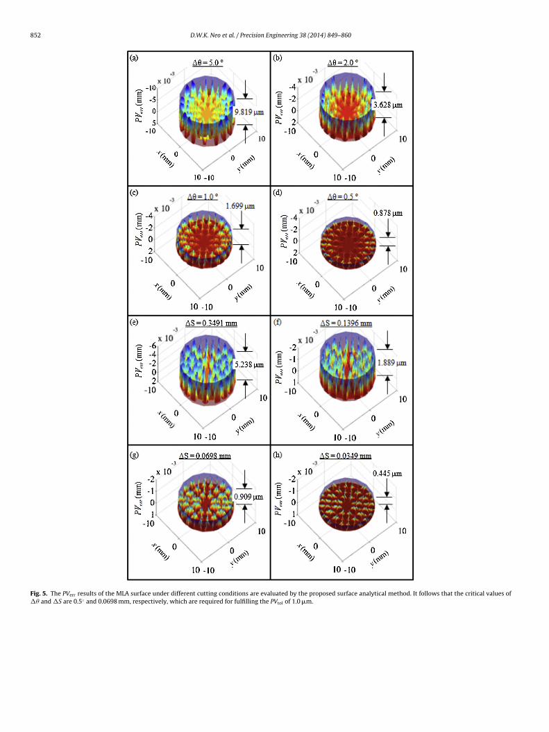
Fig. 5. The PVerr results of the MLA surface under different cutting conditions are evaluated by the proposed surface analytical method. It follows that the critical values of�� and �S are 0.5◦ and 0.0698 mm, respectively, which are required for fulfilling the PVtol of 1.0 �m.

D.W.K. Neo et al. / Precision Engineering 38 (2014) 849–860 853
F , it fol
f
∂
p
∂
ig. 6. From the PVerr results of the SWG surface under different cutting conditions
From Eq. (4), the radial position ∂� corresponded to ∂� can beound as
� = r − fr∂� (15)
From Eq. (10), the ideal surface heights between two controloints are
Zideal = f (∂�, ∂�) (16)
lows that the critical values of �� and �S are 2.0◦ and 0.0698 mm, respectively.
The actual heights of the tool trajectory are
∂Ztool = Zi + ∂SZi+1 − Zi
Si − Si+1(17)
Finally, ∂Zmax is the maximum deviation between ideal surfaceheight and actual height of the tool trajectory
∂Zmax = arg max(∂Zideal − ∂Ztool
)(18)
854 D.W.K. Neo et al. / Precision Engineering 38 (2014) 849–860
F f diffei
cin
3
3
tp
Fr
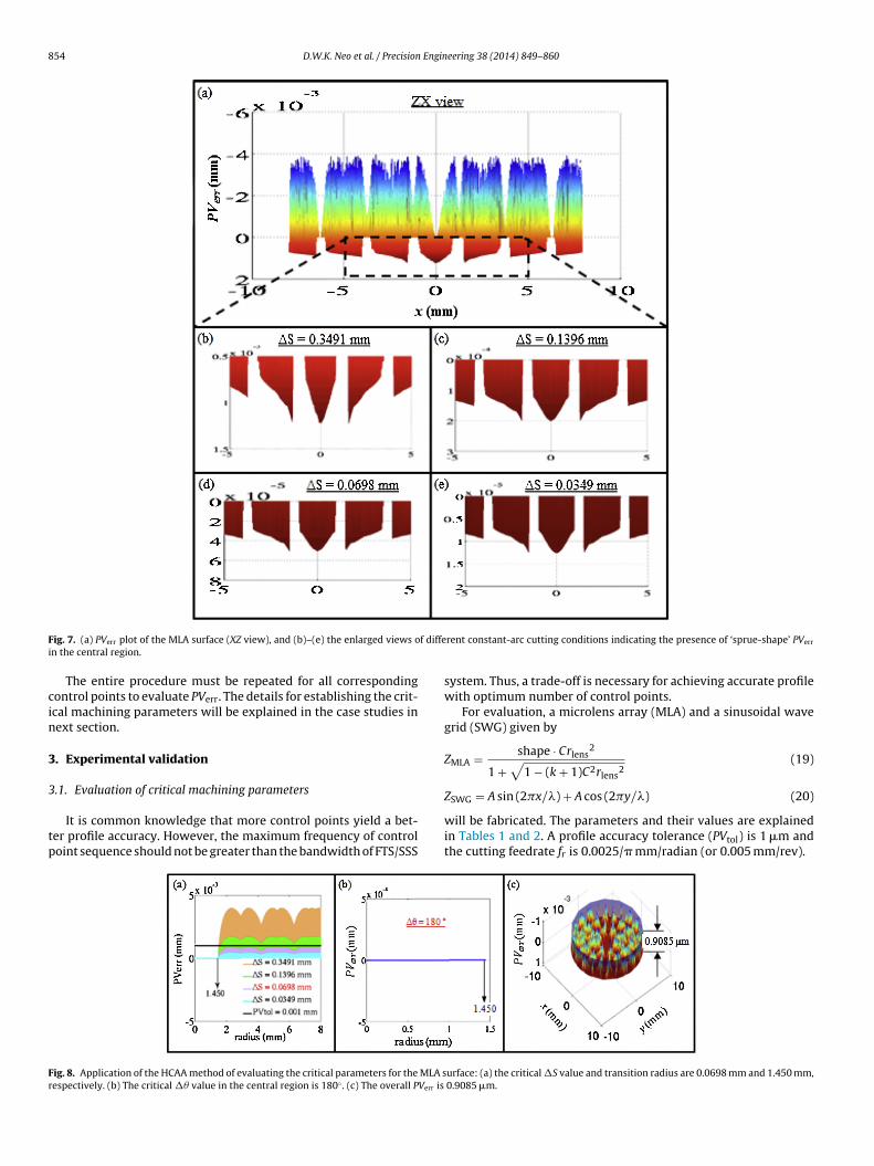
ig. 7. (a) PVerr plot of the MLA surface (XZ view), and (b)–(e) the enlarged views on the central region.
The entire procedure must be repeated for all correspondingontrol points to evaluate PVerr. The details for establishing the crit-cal machining parameters will be explained in the case studies inext section.
. Experimental validation
.1. Evaluation of critical machining parameters
It is common knowledge that more control points yield a bet-er profile accuracy. However, the maximum frequency of controloint sequence should not be greater than the bandwidth of FTS/SSS
ig. 8. Application of the HCAA method of evaluating the critical parameters for the MLA sespectively. (b) The critical �� value in the central region is 180◦ . (c) The overall PVerr is
rent constant-arc cutting conditions indicating the presence of ‘sprue-shape’ PVerr
system. Thus, a trade-off is necessary for achieving accurate profilewith optimum number of control points.
For evaluation, a microlens array (MLA) and a sinusoidal wavegrid (SWG) given by
ZMLA = shape · Crlens2
1 +√
1 − (k + 1)C2rlens2
(19)
ZSWG = A sin (2�x/�) + A cos (2�y/�) (20)
will be fabricated. The parameters and their values are explainedin Tables 1 and 2. A profile accuracy tolerance (PVtol) is 1 �m andthe cutting feedrate fr is 0.0025/� mm/radian (or 0.005 mm/rev).
urface: (a) the critical �S value and transition radius are 0.0698 mm and 1.450 mm, 0.9085 �m.

D.W.K. Neo et al. / Precision Engineering 38 (2014) 849–860 855
Fig. 9. Application of the HCAA method of evaluating the critical parameters for the SWG surface: (a) the critical �S value and transition radius are 0.3491 mm and 0.8195 mm,respectively. (b) The critical �� value in the central region is 24◦ . (c) The overall PVerr is 0.9986 �m.
Table 1Parameters for MLA surface.
Parameters Values Units
Shape (convex or concave) Convex: −1 –Conic coefficient, k Sphere: 0 –
tdoarTSrw
Table 2Parameters for SWG surface.
Parameters Values Units
Amplitude, A 0.00625 mm
Lens curvature, C 1/25 mm−1
Lens radius, rlens 0.5 mmLens-lens pitch 1.5 mm
Figs. 5 and 6 illustrate the 3D plots for the calculated PVerr ofhe MLA and SWG surfaces, respectively, obtained with the twoifferent cutting strategies. The results demonstrate that the PVerr
n the outer radii regions under constant-angle cutting conditionsre generally larger than those of inner regions. In contrast, the PVerr
esults under constant-arc cutting conditions are almost uniform.
he critical values of the �� and �S parameters for the MLA andWG surfaces are 0.5◦ and 0.0698 mm, and 2.0◦ and 0.0698 mm,espectively. If those values are above the critical values, the PVerrill be exceeded the required PVtol of 1 �m.
Fig. 10. Contour error of the SWG surface wi
Wavelength, � 3.0 mm
Notwithstanding the fact that the constant-arc method wouldgive an almost constant surface accuracy, there is a noticeable‘sprue-shape’ PVerr found in the central region under all constant-arc cutting conditions as illustrated in Figs. 6 and 7. Although thistype of PVerr has never been reported in literature, it plays a majorrole in optimizing overall surface accuracy under constant-arc con-ditions. This can be explained by the fact that the arc-length S is afunction of � and the associated angles are larger near the centre of
the part than in outer regions. It also reveals that the PVerr resultsin the outer regions are much lower than PVtol when the critical�S has been defined for reducing this ‘sprue-shape’ PVerr. Thus, ath the constant-angle cutting strategy.

856 D.W.K. Neo et al. / Precision Engineering 38 (2014) 849–860
face w
he
t
Fig. 11. Contour error of the SWG sur
ybrid of constant-arc and constant-angle (HCAA) method has beenmployed for overcoming this ‘sprue-shape’ PVerr problem.
In the HCAA method, the surface analytical model is first usedo evaluate the critical �S at the outer radius of the surface. Then,
Fig. 12. Contour error of the SWG surfac
ith the constant-arc cutting strategy.
a transition radius is identified at a radial location where the PVerr
exceeds the required PVtol. The constant-angle method is appliedfrom the point where the constant-arc method is abandoned. Ascan be seen from the analytical results shown in Figs. 8 and 9,
e with the HCAA cutting strategy.

Engin
tMo0a
gp
D.W.K. Neo et al. / Precision
he transition radius is located at 1.45 mm and 0.8195 mm for theLA and SWG surfaces, respectively. The critical �S values for the
uter regions of the MLA and SWG surfaces are 0.3491 mm and.0698 mm, respectively, and the critical �� for the central regions
re 180◦ and 24◦, respectively.Finally, a comparative study between different cutting strate-ies has been conducted based on their optimum number of cuttingoints. Table 3 reveals that the HCAA method offers the optimum
Fig. 13. Contour error of the MLA surface wi
eering 38 (2014) 849–860 857
number of cutting points, especially only 109,252 cutting pointsfor the SWG surface, which is about 20% of the number neededin conventional constant-arc method. Furthermore, an interest-ing conclusion is that the constant-arc method is not necessarily
superior to the constant-angle method, depending on the typeof freeform surfaces to be machined. For example, the constant-arc method yields a smaller number of cutting points than theconstant-angle method for the MLA surface but more cuttingth the constant-angle cutting strategy.

8 Engin
psp
3
(
58 D.W.K. Neo et al. / Precision
oints than constant-angle method for the SWG surface. Thus, theelection of the cutting strategy should also be optimized for ultra-recision machining of freeform surfaces.
.2. Cutting experiments and results
All the experiments were conducted by a slow slide servoSSS) process using 4-axis ultraprecision machine. Based on
Fig. 14. Contour error of the MLA surface w
eering 38 (2014) 849–860
the novel surface analytical model as described in the previ-ous sections, the number of control points for different cuttingstrategies were optimized and selected in machining both SWGand MLA surfaces to meet the required PV tolerance of 1 �m.
These machined surfaces were measured using an OlympusLEXT OLS4000 3D Measuring Laser Microscope with a confocaloptical system that only captures the in-focus image and elim-inates the flare simultaneously. 3D measured profile data wereith the constant-arc cutting strategy.

Engineering 38 (2014) 849–860 859
ftmett
Table 3Comparison of cutting points between different cutting strategies.
Type of surfaces Optimum number of cutting points
D.W.K. Neo et al. / Precision
urther post-processed for surface characterization. For evalua-ion of the profile errors of the fabricated features, areal error
aps were used along with the characterization method by Yut al. [16]. First, the measured data were extracted as CSV files
o be processed using MATLAB software. Second, a best fit ofhe measured profile was performed for a comparison with theFig. 15. Contour error of the MLA surfac
Constant-angle Constant-arc HCAA
MLA 1,080,001 540,001 521,950SWG 270,001 540,001 109,252
e with the HCAA cutting strategy.

8 Engin
tm
T
c
c
c
0
wtr
sdPardftbtccs
4
ow(piow(e
TeHcwctg
[
[
[
[
[
[
60 D.W.K. Neo et al. / Precision
heoretical surface using a rigid body transformation described theatrix:
(tx, ty, tz, ˛, ˇ, ) =
⎡⎢⎢⎢⎢⎣
cos ̌ cos sin ̨ sin ̌ cos − cos ̨ sin
cos ̌ sin sin ̨ sin ̌ sin + cos ̨ cos
− sin ̌ sin ̨ cos ̌
0 0
here tx, ty and tz are translations in x, y and z-directions respec-ively, and ˛, ˇ, are the rotations about x, y and z-directionsespectively.
Figs. 10–12 demonstrate that the critical cutting parameterselected for the SWG surface in all cutting strategies are vali-ating the PVtol of 1 �m. As can be seen from Figs. 13–15, theVerr results of the MLA surface with the selected parameterslso meet PVtol, if neglecting the fillet effect of the tool noseadius at the edges of lenses. These experimental results vali-ate the credibility of the proposed surface analytical modelor determining the optimal machining conditions for all cut-ing strategies. The model not only improves the profile accuracyut also eliminates the risk of the machined workpiece to misshe accuracy requirements. Furthermore, it is concluded that theonstant-arc cutting strategy is not necessarily be superior than theonstant-angle method, depending on the curvatures of freeformurfaces.
. Conclusion
In the present study, a surface analytical model has been devel-ped to evaluate the cutting linearization error on freeform surfacesith an optimal number of cutting points for the constant-angle
��), constant-arc (�S) and hybrid (HCAA) methods. A gooderformance of the fast tool servo or slow slide servo alone is
nsufficient for producing accurate surfaces; it is also necessary toptimize the tool trajectory. The model developed in this studyas experimentally verified by machining of a sinusoidal wave grid
SWG) and a micro-lens array (MLA) and evaluating the contourrrors.
The profile accuracy requirement for all surfaces could be met.he surface evaluation has demonstrated that the peak-to-valleyrrors (PVerr) were within the specified tolerances. Moreover, theCAA method combines the merits of both the constant-arc andonstant-angle method for producing highly accuracy surfaces
ith an optimum number of control points. Offering a signifi-ant reduction of machining time and increased profile accuracies,he hybrid method is proposed as the new standard in surfaceeneration.
[
eering 38 (2014) 849–860
os ̨ sin ̌ sin + sin ̨ sin tx
os ̨ sin ̌ sin − sin ̨ cos ty
os ̨ cos ̌ tz
1
⎤⎥⎥⎥⎥⎦ (21)
References
[1] Thompson KP, Rolland JP. Freeform optical surfaces: a revolutionin imaging optical design. Opt Photonics News 2012;23(6):30–5,http://dx.doi.org/10.1364/OPN.23.6.000030.
[2] Patterson SR, Magrab EB. Design and testing of a fast tool servo for diamondturning. Precis Eng 1985;7(3):123–8.
[3] Tohme YE, Lowe JA. Machining of freeform optical surfaces by slow slide servomethod, proceedings of the ASPE, annual meetings; 2003.
[4] Kong LB, Cheung CF. Modeling and characterization of surface generation in fasttool servo machining of microlens arrays. Comput Ind Eng 2012;63(4):957–70,http://dx.doi.org/10.1016/j.cie.2012.06.007.
[5] Kwok TC, Cheung CF, Kong LB, To S, Lee WB. Analysis of surface generationin ultra-precision machining with a fast tool servo. Proc IMechE, Part B: J EngManuf 2010;224(9):1351–67, http://dx.doi.org/10.1243/09544054JEM1843.
[6] Yu DP, Hong GS, Wong YS. Profile error compensation in fast tool servodiamond turning of micro-structured surfaces. Int J Mach Tools Manuf2012;52(1):13–23, http://dx.doi.org/10.1016/j.ijmachtools.2011.08.010.
[7] Yin ZQ, Dai YF, Li SY, Guan CL, Tie GP. Fabrication of off-axis aspheric sur-faces using a slow tool servo. Int J Mach Tools Manuf 2011;51(5):404–10,http://dx.doi.org/10.1016/j.ijmachtools.2011.01.008.
[8] Yu DP, Gan SW, Wong YS, Hong GS, Rahman M, Yao J. Optimizedtool path generation for fast tool servo diamond turning of micro-structured surfaces. Int J Adv Manuf Technol 2012;63(9):85–99,http://dx.doi.org/10.1007/s00170-012-3964-z.
[9] Scheiding S, Yi AY, Gebhardt A, Li L, Risse S, Eberhardt R, Tünnermann A.Freeform manufacturing of a micro-optical lens array on a steep curved sub-strate by use of a voice coil fast tool servo. Opt Express 2011;19(24):23938–51,http://dx.doi.org/10.1364/OE.19.023938.
10] Dick L, Risse S, Tünnermann A. Injection molded high precision freeformoptics for high volume applications. Adv Opt Technol 2012;1:39–50,http://dx.doi.org/10.1515/aot-2011-0009.
11] Zhou M, Zhang HJ, Chen SJ. Study on diamond cutting of nonrationallysymmetric microstructured surfaces with fast tool servo. Mater Manuf Proc2010;25(6):488–94, http://dx.doi.org/10.1080/10426910903365836.
12] Liu K, Wu H, Liu P, Shaw KC. Ultra-precision machining of aluminiumalloy surfaces for optical application. Int J Nanomanuf 2011;7(2):116–25,http://dx.doi.org/10.1504/IJNM.2011.040718.
13] Yu DP, Wong YS, Hong GS. Optimal selection of machining parameters forfast tool servo diamond turning. Int J Adv Manuf Technol 2011;57(1):85–99,http://dx.doi.org/10.1007/s00170-011-3280-z.
14] Weisstein EW. Archimedes’ spiral, from MathWorld – a Wolfram web resource,http://mathworld.wolfram.com/ArchimedesSpiral.html
15] Weisstein EW. Arc length, from MathWorld – a Wolfram web resource,
http://mathworld.wolfram.com/ArcLength.html16] Yu DP, Zhong X, Wong YS, Hong GS, Lu WF, Cheng HL. Anautomatic form error evaluation method for characterizingmicro-structured surfaces. Meas Sci Technol 2011;22(1):015105,http://dx.doi.org/10.1088/0957-0233/22/1/015105.