a new vision of software defined radio: from academic ...
134
University of Trento Master Degree Thesis A NEW VISION OF SOFTWARE DEFINED RADIO: FROM ACADEMIC EXPERIMENTATION TO INDUSTRIAL EXPLOITATION Supervisors: Claudio Sacchi and Roberto Passerone (University of Trento) Candidate: Teresa Boncompte Vilaró (Universitat Politècnica de Catalunya) - Thesis in cooperation with ERASMUS Program - July 2012
-
Upload
khangminh22 -
Category
Documents
-
view
6 -
download
0
Transcript of a new vision of software defined radio: from academic ...

University of Trento
Master Degree Thesis
A NEW VISION OF
SOFTWARE DEFINED RADIO:
FROM ACADEMIC EXPERIMENTATION TO
INDUSTRIAL EXPLOITATION
Supervisors:
Claudio Sacchi and Roberto Passerone (University of Trento)
Candidate:
Teresa Boncompte Vilaró (Universitat Politècnica de Catalunya)
- Thesis in cooperation with ERASMUS Program -
July 2012

A new vision of Software Defined Radio: from academic experimentation to industrial exploitation.
2
ACKNOWLEDGEMENTS
First and foremost I offer my sincerest gratitude to my supervisors, Claudio Sacchi and
Roberto Passerone of University of Trento, who have supported me throughout my
thesis with their patience and knowledge.
I would like to thank too Gianluca Gera of Technoaware S.R.L. of Genova for his time
and his appreciated opinion about the topic.
In addition I thank my roommates and my Borino’s friends to be my family during this
Erasmus period and for their support and encouragement during the entire thesis.
Finally, I thank my family for helping me despite the distance.

A new vision of Software Defined Radio: from academic experimentation to industrial exploitation.
3
CONTENTS
1. Summary
2. Evolution of Mobile Communications Systems
2.1. First Generation of mobile communications systems (1G) ................................... 9
2.1.1. Advanced Mobile Phone System (AMPS) ........................................................ 10
2.1.2. Nordic Mobile Telephone (NMT) ..................................................................... 10
2.1.3. Total Access Communication System (TACS) ................................................... 10
2.2. Second Generation of mobile communications systems (2G) ............................ 10
2.2.1. Time Division Multiple Access (TDMA) ............................................................ 11
2.2.2. Code Division Multiple Access (CDMA) ........................................................... 11
2.2.3. Global System for Mobile Communications (GSM) ......................................... 11
2.3. 2.5 Generation of mobile communications systems ........................................... 12
2.4. 2.75 Generation of mobile communications systems ......................................... 12
2.5. Third Generation of mobile communications systems (3G) ............................... 12
2.5.1. CDMA2000 ....................................................................................................... 14
2.5.2. Universal Mobile Telecommunications System (UMTS) ................................. 14
2.6. 3.5 Generation of mobile telecommunications systems .................................... 15
2.7. Four Generation of mobile telecommunications systems (4G) .......................... 15
2.7.1. Wi-Fi ................................................................................................................. 17
2.7.2. WiMAX ............................................................................................................. 18
2.7.3. Long Term Evolution (LTE) ............................................................................... 19
3. Software Defined Radio
3.1. Software Defined Radio Definition ...................................................................... 21
3.2. General aspects of Software Defined Radio ........................................................ 23

A new vision of Software Defined Radio: from academic experimentation to industrial exploitation.
4
3.3. Related Technologies .......................................................................................... 24
3.3.1. Adaptive Radio ................................................................................................. 24
3.3.2. Cognitive Radio ................................................................................................ 24
3.3.3. Intelligent Radio ............................................................................................... 27
3.4. Benefits of Software Defined Radio .................................................................... 28
3.5. Design of Software Defined Radio Architecture ................................................. 30
3.6. Software Communications Architecture (SCA) ................................................... 31
3.7. Architectural challenges ...................................................................................... 33
3.7.1. Reconfigurability .............................................................................................. 33
3.7.2. Portability ......................................................................................................... 35
3.7.3. Common Object Request Broker Architecture (CORBA) ................................. 37
3.8. Multi-Standards User Terminals .......................................................................... 38
3.9. MIMO Technology ............................................................................................... 38
3.9.1. SDR Technology and MIMO systems ............................................................... 41
4. The changing Industry Structure
4.1. Previous Definitions and Knowledge ................................................................... 44
4.2. Classification of Industry Structures .................................................................... 45
4.3. Transition in the Development of Mobile Phones .............................................. 47
4.4. Forces of Moving from one Industry Type to Another ........................................ 51
4.5. Optimal Industry Structure for different Market Segments ............................... 52
4.6. Future prevision ................................................................................................... 53
5. Introduction of SDR in the Commercial Market
5.1. Commercial drivers .............................................................................................. 56
5.1.1. Manufacturer’s perspective............................................................................. 56
5.1.2. A Network Operator’s Perspective .................................................................. 58

A new vision of Software Defined Radio: from academic experimentation to industrial exploitation.
5
5.1.3. A Consumer’s Perspective ............................................................................... 58
5.2. Opportunities in the commercial domain ........................................................... 60
5.2.1. Multiprotocol Multiband Base Stations ........................................................... 60
5.2.2. Mobile Multi-standard Terminals .................................................................... 61
5.2.3. Cognitive Radio ................................................................................................ 61
5.3. Introduction of SDR in a ICT Industry .................................................................. 62
5.3.1. Implementation of Software technology ........................................................ 62
5.3.1.1. Cost ........................................................................................................... 63
5.3.2. Duration ....................................................................................................... 71
5.3.3. Scope ............................................................................................................ 71
5.4. The main idea ................................................................................................... 71
6. Evolution from today's mobile phone to SDR mobile phone
6.1. Open Source SDR ................................................................................................. 74
6.1.1. GNU Radio ........................................................................................................ 74
6.1.1.1. USRP – Hardware platform ....................................................................... 75
6.1.1.2. Hardware components ............................................................................. 77
6.1.1.3. UHD ........................................................................................................... 80
6.1.2. HSPDR .............................................................................................................. 80
6.1.2.1. Hardware block diagram .............................................................................. 81
6.1.2.2. Software block diagram ............................................................................... 82
6.1.2.3. HERMES block diagram I ........................................................................... 82
6.1.3. OSSIE ................................................................................................................ 83
6.1.3.1. Core Framework ........................................................................................... 84
6.1.3.2. Processing Hardware/Operating Systems Supported .................................. 84
6.1.3.3. RF/Data Acquisition Hardware Supported ................................................... 84

A new vision of Software Defined Radio: from academic experimentation to industrial exploitation.
6
6.1.3.4. Waveform Workshop ................................................................................... 85
6.1.3.5. Application Software .................................................................................... 86
6.1.3.6. Waveform Applications Demonstrated ....................................................... 86
6.1.4. ALOE ................................................................................................................. 86
6.1.5. Concepts and functionalities ........................................................................... 86
6.1.6. Architecture and services ................................................................................ 88
6.2. Waveform development ..................................................................................... 90
6.2.1. Preliminary knowledge needed in SDR waveform development .................... 90
6.2.2. The composition of SDR waveform ................................................................. 92
6.2.3. SCA specifications ............................................................................................ 93
6.2.4. The general waveform development flow of SDR ........................................... 98
6.2.4.1. The Early Waveform Development Flow .................................................. 98
6.2.4.2. The General Waveform Development Flow of SDR in IDE ....................... 99
6.2.5. Software Radio Download ............................................................................. 101
6.2.5.1. Software Radio Download Requirements .............................................. 102
6.2.5.2. Differences in download requirements .................................................. 103
6.2.6. Standardization .............................................................................................. 105
6.2.7. Libraries .......................................................................................................... 106
6.3. Key features in new mobile phones design ....................................................... 108
6.3.1. User’s centric methodology ........................................................................... 108
6.3.2. Radio Spectrum Sensing ................................................................................ 111
6.3.3. Front-end challenges ..................................................................................... 114
6.3.4. Power consumption ....................................................................................... 115
6.3.4.1. The Hardware Approach to Reducing Power ......................................... 115
7. Conclusions

A new vision of Software Defined Radio: from academic experimentation to industrial exploitation.
7
8. Abbreviations
9. Appendix
APPENDIX I ................................................................................................................ 128
APPENDIX II ............................................................................................................... 129
APPENDIX III .............................................................................................................. 129
APPENDIX IV .............................................................................................................. 130
10. References

A new vision of Software Defined Radio: from academic experimentation to industrial exploitation.
8
1. SUMMARY
The broad objective of this study is to examine the role of Software Defined Radio in
an industrial field. Basically examines the changes that have to be done to achieve
moving this technology in a commercial domain. It is important to predict the impacts
of the introduction of Software Defined Radio in the telecommunications industry
because it is a real future that is coming.
The project starts with the evolution of mobile telecommunications systems through
the history. Following this, Software Defined Radio is defined and its main features are
commented such as its architecture. Moreover, it wants to predict the changes that
the telecommunications industry will might suffer with the introduction of SDR and
some future structural and organizational variations are suggested. Additionally, it is
discussed the positive and negative aspects of the introduction of SDR in the
commercial domain from different points of view and finally, the future SDR mobile
phone is described with its possible hardware and software.

A new vision of Software Defined Radio: from academic experimentation to industrial exploitation.
9
2. EVOLUTION OF MOBILE
COMMUNICATIONS SYSTEMS
Communications is a vital factor which allows people to connect with each other
around the world. From the very early ages, people thought of having communication
methods to connect with the rest of the world. Early people used symbolic formations,
sounds to express their feelings to others and eventually they started to speak. Then
with the advancement of communications, the languages were formed as formal
communicating methods and people understood the importance of communication
with the rest of the world [1]. So they started to move forward in communications and
thus various techniques were found. From paper based media to electronic media like
telephones, television, radio, the communications was developed rapidly during the
last century. As they are wired media, the use is limited to certain perimeter and soon
people found that it is a great limitation in communication. So people did so many
experiments to have wireless communication, to overcome the limitations of the wired
communications media. As a result of that, the mobile communication was found to
make communication more efficient and effective.
2.1. FIRST GENERATION OF MOBILE COMMUNICATIONS SYSTEMS (1G)
First Generation (1G) cellular mobile telephones were based on the analogue system.
The introduction of cellular systems in the late 1970s was a quantum leap in mobile
communication, especially in terms of capacity and mobility. Semiconductor
technology and microprocessors made smaller, lighter, and more sophisticated mobile
systems a reality. However, these 1G cellular systems still transmitted only analogue
voice information. The prominent ones among 1G systems were Advanced Mobile
Phone System (AMPS), Nordic Mobile Telephone (NMT), and Total Access
Communication System (TACS) [2]. All of these systems offered handover and roaming
capabilities but the cellular networks were unable to interoperate between countries.
This was one of the inevitable disadvantages of first generation mobile networks.

A new vision of Software Defined Radio: from academic experimentation to industrial exploitation.
10
2.1.1. ADVANCED MOBILE PHONE SYSTEM (AMPS)
The AMPS cellular standard used analog FM and full duplex radio channels. The
Frequency Division Multiple Access (FDMA) technique enabled multiple users to share
the same region of spectrum [3]. This standard supported clear communication and
inexpensive mobile telephones, but the transmissions were easy to intercept on a
standard radio receiver and therefore were susceptible to eavesdropping.
2.1.2. NORDIC MOBILE TELEPHONE (NMT)
NMT was developed specially by Ericsson and Nokia to service the rugged terrain that
characterizes the Nordic countries. There are to variants of NMT, NMT - 450 and NMT -
900. The number indicates the frequency band uses. The NMT specifications were free
and open, allowing many companies to produce NMT hardware and pushing the prices
down.
2.1.3. TOTAL ACCESS COMMUNICATION SYSTEM (TACS)
Total Access Communication System (TACS) and ETACS are mostly obsolete variants of
AMPS which were used in some European countries. TACS was also used in Japan
under the name Japanese Total Access Communication (JTAC). ETACS was an extended
version of TACS with more channels.
2.2. SECOND GENERATION OF MOBILE COMMUNICATIONS SYSTEMS
(2G)
Second Generation (2G) mobile systems were introduced in the end of 1980s. Second
Generation mobile telephones used digital technology. Low bit rate data services were
supported as well as the traditional speech service. Compared to first generation
systems, second generation systems use digital multiple access technology, such as
Time Division Multiple Access (TDMA) and Code Division Multiple Access (CDMA).
Consequently, compared with first generation systems, higher spectrum efficiency,
better data services, and more advanced roaming were offered by 2G systems [2]. In
Europe, the Global System for Mobile Communications (GSM) was deployed to provide
a single unified standard. GSM provides voice and limited data services, and uses
digital modulation for improved audio quality.

A new vision of Software Defined Radio: from academic experimentation to industrial exploitation.
11
Today, multiple IG and 2G standards are used in worldwide mobile communications.
2.2.1. TIME DIVISION MULTIPLE ACCESS (TDMA)
TDMA is a multiplexing method that divides network connections into time slices,
where each device on the TDMA network connection gets one or more time slices
during which it can transmit or receive data. TDMA is often used to refer to early
digital mobile phone networks that made use of TDMA multiplexing, such as the
original network implemented by AT&T/Cingular before it moved to GSM, which is it
based on TDMA technology [4].
2.2.2. CODE DIVISION MULTIPLE ACCESS (CDMA)
CDMA is a form of multiplexing which allows numerous signals to occupy a single
transmission channel, optimizing the use of available bandwidth. The technology is
used in Ultra High Frequency (UHF) cellular telephone systems in the 800 MHz and 1.9
GHz bands.
CDMA employs Analog to Digital Conversion (ADC) in combination with spread
spectrum technology. Audio input is first digitized into binary elements. The frequency
of the transmitted signal is then made to vary according to a defined pattern (code), so
it can be intercepted only by a receiver whose frequency response is programmed with
the same code, so it follows exactly along with the transmitter frequency [5]. There are
trillions of possible frequencies sequencing codes, which enhances privacy and makes
cloning difficult.
2.2.3. GLOBAL SYSTEM FOR MOBILE COMMUNICATIONS (GSM)
GSM is a digital mobile telephony system that is widely used in Europe and other parts
of the world. GSM uses a variation of Time Division Multiple Access (TDMA) and is the
most widely used of the three digital wireless telephony technologies (TDMA, GSM,
and CDMA). GSM digitizes and compresses data, then sends it down a channel with
two other streams of user data, each in its own time slot. It operates at either the 900
MHz or 1800 MHz frequency band.

A new vision of Software Defined Radio: from academic experimentation to industrial exploitation.
12
Mobile services based on GSM technology were first launched in Finland in 1991.
Today, more than 690 mobile networks provide GSM services across 213 countries and
GSM represents 82.4% of all global mobile connections.
GSM, together with other technologies, is part of the evolution of wireless mobile
telecommunications that includes High Speed Circuit Switched Data (HSCSD), General
Packet Radio System (GPRS), Enhanced Data GSM Environment (EDGE), and Universal
Mobile Telecommunications Service (UMTS) [6].
2.3. 2.5 GENERATION OF MOBILE COMMUNICATIONS SYSTEMS
2.5 Generation is the 2nd Generation enhanced version of 2G technology. The
enhancement achieved through implementing a packed switched domain in addition
to circuit switched domain. This is to give user better services and access to the
internet. 2.5G gives higher data rates and additional capabilities.
2.4. 2.75 GENERATION OF MOBILE COMMUNICATIONS SYSTEMS
Another enhancement in 2G technology is the 2.75G and it is the head to the 3G
technology. GPRS networks evolved in Enhanced Data Rates for GSM Evolution (EDGE).
EDGE, Enhanced GPRS (EGPRS), or IMT Single Carrier (IMT-SC) is a backward
compatible digital mobile technology and it allows improved data transfer rates.
Higher data rates are achieved by switching to more sophisticated methods of coding
with existing GSM timeslots.
2.5. THIRD GENERATION OF MOBILE COMMUNICATIONS SYSTEMS
(3G)
Third generation (3G) wireless offers the promise of greater bandwidth, basically
bigger data pipes to users, which allow them to send and receive more information. To
become more pervasive there is need to have efficient available bandwidth, long rage
connection, seamless roaming, real time data flow and high speed data rate [7].

A new vision of Software Defined Radio: from academic experimentation to industrial exploitation.
13
The 3G technology adds multimedia facilities to 2G phones by allowing video, audio,
and graphics applications. Over 3G phones, you can watch streaming video or have
video telephony.
Other than mobile telephony other wireless communication system becomes major
part of 3G communication systems such as WLAN. Some of the known WLAN protocols
are Bluetooth, HiperLan, home RF and 802.11 protocol suits. All these systems were
designed independently, targeting different service types, data rates, and users. As
these systems all have their own merits and shortcomings, there is no single system
that is good enough to replace all the other technologies. The idea behind 3G is to
have a single network standard instead of the different types adopted in the US,
Europe, and Asia [2].
3G cellular services, known as Universal Mobile Telecommunications System (UMTS) or
IMT-2000, will sustain higher data rates and open the door to many Internet style
applications. The main characteristics of IMT-2000 3G systems are; a single family of
compatible standards that can be used worldwide for all mobile applications, support
for both packet switched and circuit switched data transmission, data rates up to 2
Mbps (depending on mobility), and high spectrum efficiency.
Figure 1.Evolution of digital cellular standard
Source: From Computer Desktop Encyclopedia [8].

A new vision of Software Defined Radio: from academic experimentation to industrial exploitation.
14
2.5.1. CDMA2000
Code Division Multiple Access 2000 (CDMA-2000) is a third generation (3G) standard
developed by the International Telecommunication Union (ITU). This protocol uses
CDMA access to send voice and data and signals between mobile phone and cell sites.
Enhanced services can be provided to CDMAOne subscribers through CDMA-2000.
Data communications speeds ranging from 114 Kbps to 2 Mbps can be supported by
this standard. This term is also known as IMT-Multi-Carrier or IS-2000.
The main capacity of CDMA-2000 is to deliver a radio interface system that is better
than the second generation systems. SK Telecom (Korea) launched the first commercial
system that used this platform (based on the CDMA 2000 1x technology) in October
2000 [9]. From then, several other versions have been developed. Other technologies
include CDMA2000 1xEV-DO (Evolution Data Optimized) Technologies which further is
comprised of several revisions.
2.5.2. UNIVERSAL MOBILE TELECOMMUNICATIONS SYSTEM (UMTS)
UMTS is a Third Generation (3G) broadband, packet based transmission of text,
digitized voice, video, and multimedia at data rates up to 2 Mbps. UMTS offers a
consistent set of services to mobile computer and phone users, no matter where they
are located in the world. UMTS is based on the Global System for Mobile (GSM)
communication standard. It is also endorsed by major standards bodies and
manufacturers as the planned standard for mobile users around the world. Computer
and phone users can be constantly attached to the Internet wherever they travel.
Users have access through a combination of terrestrial wireless and satellite
transmissions.
Previous cellular telephone systems were mainly circuit switched; meaning
connections were always dependent on circuit availability. A packet switched
connection uses the Internet Protocol (IP), meaning that a virtual connection is always
available to any other end point in the network. UMTS also makes it possible to
provide new services like alternative billing methods or calling plans. For instance,
users can choose to pay per bit, pay per session, flat rate, or asymmetric bandwidth
options. The higher bandwidth of UMTS also enables other new services like video
conferencing or IPTV [10]. UMTS may allow the Virtual Home Environment (VHE) to
fully develop, where a roaming user can have the same services to either at home, in

A new vision of Software Defined Radio: from academic experimentation to industrial exploitation.
15
the office or in the field through a combination of transparent terrestrial and satellite
connections.
2.6. 3.5 GENERATION OF MOBILE TELECOMMUNICATIONS SYSTEMS
3.5G is the next generation in mobile technology which is also called High Speed
Downlink Packet Access (HSDPA). It is a mobile telephony protocol and is a packed
based data service in W-CDMA, downlink with a data transmission up to 8 - 10 Mbit/s
over a 5 MHz bandwidth. HSDPA is enabled with a new transport layer channel which
is called High Speed Downlink Shared Channel (HS-DSCH) to send packets on the
downlink. In HSDPA or 3.5G technology, the data is transmitted together with error
correction bits, thus can be corrected without retransmission. The HS-DSCH channel is
shared between users using channel dependant scheduling to make the best use of
available radio conditions. So the packed scheduling in 3.5G phones is very faster than
other technologies. Adaptive modulation and coding is another significant
improvement in 3.5G technology. As well as improving data rates, it also decreases
latency and so the round trip tie for applications also reduced.
2.7. FOUR GENERATION OF MOBILE TELECOMMUNICATIONS SYSTEMS
(4G)
Researchers are currently developing frameworks for future 4G networks. Different
research programs, such as Mobile VCE, MIRAI, and DoCoMo, have their own visions
on 4G features and implementations. Some key features (mainly from the users’ point
of view) of 4G networks are stated as follows:
• High usability; anytime, anywhere, and with any technology;
• Support for multimedia services at low transmission cost;
• Personalization;
• Integrated services;
First, 4G networks are all IP based heterogeneous networks that allow users to use any
system at anytime and anywhere. Users carrying an integrated terminal can use a wide
range of applications provided by multiple wireless networks.

A new vision of Software Defined Radio: from academic experimentation to industrial exploitation.
16
Second, 4G systems provide not only telecommunications services, but also data and
multimedia services. To support multimedia services, high data rate services with good
system reliability will be provided. At the same time, a low per bit transmission cost
will be maintained.
Third, personalized service will be provided by this new generation network. It is
expected that when 4G services are launched, users in widely different locations,
occupations, and economic classes will use the services. In order to meet the demands
of these diverse users, service providers should design personal and customized
services for them.
Finally, 4G systems also provide facilities for integrated services. Users can use multiple
services from any service provider at the same time [11].
This motivates Software Defined Radio (SDR). SDR are used to implement radio
function such as transmission and reception of signal. The spectrum management for
transmission and reception of signal should be handled effectively. Spectrum is scarce
resource and recent study observes that the static spectrum allocation scheme used in
communication system is not as efficient as it should be. The dynamic allocation
scheme becomes solution for efficient spectrum allocation.
Cognitive radio is one of the approaches to manage spectrum dynamically. Cognitive
radio is a radio that can change its transmitter parameters based on interaction with
the environment in which it operates. The cognitive radio network is one of the
promising technologies for future wireless communication. A cognitive radio is an
unlicensed communication system that is aware of its environment, learns from its
environment, adapts to the statistical variations of its environment and use this to
achieve reliable communication [7].

A new vision of Software Defined Radio: from academic experimentation to industrial exploitation.
17
Figure 2.Evolution of communication system
Source: “Cognitive Radio: Emerging Trend of Next Generation Communication System” [7].
2.7.1. WI-FI
Wi-Fi is the industry name for Wireless Local Area Network (WLAN) communication
technology related to the IEEE 802.11 family of wireless networking standards [12]. It
primarily provides short range wireless high speed data connections between mobile
data devices (such as laptops, PDAs or phones) and nearby Wi-Fi access points (special
hardware connected to a wired network).
There are several variants of 802.11. The most common is 802.11b, which provides
speeds up to 11 Mbps. 802.11g and 802.a are faster versions. Many 802.11g and
802.11a products are backward compatible with the original 802.11b.
Wi-Fi is generally much faster than data technologies operating over the cellular
network like GPRS, EDGE, 1xRTT, HSDPA, and EV-DO. It is much shorter range,
however. Wi-Fi coverage is only provided in small, specific areas called "hot spots".
Other than some corporate or educational campuses, Wi-Fi coverage is not
widespread. Range for a typical Wi-Fi base station (access point) is typically around 100
to 300 feet indoors and up to 2000 feet outdoors.

A new vision of Software Defined Radio: from academic experimentation to industrial exploitation.
18
Most Wi-Fi operates in the 2.4 GHz unlicensed frequency band. This is the same band
as Bluetooth and some cordless phones, although the technologies are designed to
coexist and not interfere. 802.11a operates in the 5 GHz unlicensed frequency band
[13].
Wi-Fi networks can be set up and operated by anyone, with different networks
allowing different kinds of access. A public "hot spot" at an airport or coffee shop
might charge an hourly rate for access. A hotel might offer free Wi-Fi to guests. A
company or university might offer on premises free access for verified
employees/students. Or a home user could set up their own network to which only
they had access.
While most Wi-Fi connections are between a mobile device and an access point, it is
also possible to create an "ad-hoc" network directly among two or more devices,
without an access point.
2.7.2. WIMAX
The name "WiMAX" was created by the WiMAX Forum, which was formed in June
2001 to promote conformity and interoperability of the standard. The forum describes
WiMAX as "a standard based technology enabling the delivery of last mile wireless
broadband access as an alternative to cable and DSL". WiMAX offers data transfer
rates that can be superior to conventional cable modem and DSL connections,
however, the bandwidth must be split among multiple users and thus yields lower
speeds in practice.
WiMAX refers to interoperable implementations of the IEEE 802.16 family of wireless
networks standards ratified by the WiMAX Forum. Similarly, Wi-Fi refers to
interoperable implementations of the IEEE 802.11 Wireless LAN standards certified by
the Wi-Fi Alliance. On the other side, Wi-Fi, the most common wireless technology, has
very limited coverage and it is not always easy to find a Wi-Fi hotspot. WiMAX comes
as a solution: it provides high quality broadband access and has a very high
penetrability, in that the microwaves it emits can be accessed at every nook and
corner of its large coverage area. WiMAX is a type of wireless technology that provides
wireless internet service over longer distances than standard Wi-Fi [14]. IEEE 802.16 is
the standard to state the radio frequency of fixed Broadband Wireless Access. WiMAX
is the trade name of “IEEE 802.16 Standard”.

A new vision of Software Defined Radio: from academic experimentation to industrial exploitation.
19
WiMAX uses fixed and mobile stations to provide users with access to high speed
voice, data, and Internet connectivity. WiMAX technology has not been widely
accepted by the technology community, but its popularity continues to grow as
businesses and consumers seek out better ways to constantly stay connected.
WiMAX can give you connectivity in your desktop computer, laptop and even mobile
device. For a simple scenario, you can connect to the Internet through your WiMAX
connection at home, at work, in the park and even at the seaside, given that your
WiMAX service provider's networks covers all these places. This said, you can even
make cheap and free VoIP phone calls using a WiMAX enabled mobile phone, or simply
your laptop computer [14].
2.7.3. LONG TERM EVOLUTION (LTE)
Long Term Evolution (LTE) is a 4G wireless broadband technology developed by the
Third Generation Partnership Project (3GPP), an industry trade group. 3GPP engineers
named the technology "Long Term Evolution" because it represents the next step (4G)
in a progression from GSM, a 2G standard, to UMTS, the 3G technologies based upon
GSM.
LTE provides significantly increased peak data rates, with the potential for 100 Mbps
downstream and 30 Mbps upstream, reduced latency, scalable bandwidth capacity,
and backwards compatibility with existing GSM and UMTS technology. Future
developments could yield peak throughput on the order of 300 Mbps.
The upper layers of LTE are based upon TCP/IP, which will likely result in an all IP
network similar to the current state of wired communications. LTE will support mixed
data, voice, video and messaging traffic. LTE uses OFDM (Orthogonal Frequency
Division Multiplexing) and, in later releases, MIMO (Multiple Input Multiple Output)
antenna technology similar to that used in the IEEE 802.11n Wireless Local Area
Network (WLAN) standard [15]. The higher Signal to Noise Ratio (SNR) at the receiver
enabled by MIMO, along with OFDM, provides improved coverage and throughput,
especially in dense urban areas.

A new vision of Software Defined Radio: from academic experimentation to industrial exploitation.
20
Figure 3.SDR Capabilities and Services timeline
Source: SDR Forum [16].
Specification Wi-Fi Ultra-
wideband
802.11a/b/g 802.11n Wireless
Broadband
(WiBro)
Mobile
WiMax
(802.16 –
2005)
3G LTE (cellular
WAN)
Digital Video
Broadcasting
- Handheld
Digital Video
Broadcasting
- Terrestrial
Applications High-speed
local
interconnect,
wireless
USB
Medium-speed
LAN
High-speed
LAN
Mobile
wireless
access
Mobile
wireless
access
Mobile
data/voice
Mobile TV Mobile TV
Range 10 m 80 m 50 – 150 m 1 – 5 km 1 – 5 km 1 + km Broadcast Broadcast
Rate 480 Mbps 11 Mbps (b), 54
Mbps (a/g)
100 – 600
Mbps
3 – 50
Mbps
(downlink)
63 Mbps
(downlink)
100 Mbps
(downlink)
384 Kbps 7 Mbps
Frequency 3.1 – 10.6
GHz
2.45/5.8 GHz 2.45/5.8
GHz
2 – 6/2, 3
GHz
2 – 6/2, 3
GHz
1.25/2.2/5/10/20
GHz
0.8 MHz,
1.6GHz
0.8 MHz, 1.6
GHz
Modulation Orthogonal
frequency
division
multiplexing
Direct-sequence
spread
spectrum/
complementary
code keying,
carrier sense
multiple access,
orthogonal
frequency
division
multiplexing
Carrier
sense
multiple
access,
orthogonal
frequency
division
multiplexing
Orthogonal
frequency
division
multiple
access
Orthogonal
frequency
division
multiple
access
Orthogonal
frequency
division multiple
access/single
carrier frequency
division multiple
access
Orthogonal
frequency
division
multiple
multiplexing
Orthogonal
frequency
division
multiple
multiplexing
Table 1.Mobile phone standards
Source: NXP semiconductors [17].

A new vision of Software Defined Radio: from academic experimentation to industrial exploitation.
21
3. SOFTWARE DEFINED RADIO
The idea of implementing radio functions in software rather than hardware had
already been established when, in 1991, Josep Mitola coined the term “Software
Radio”. SDR Technology was originally conceived as a means to facilitate better
communications between the different forces of the US military. SDR was seen as a
technology that could facilitate the interworking of all different radios and radio
systems used within the forces. The aim was to eventually reduce the number of
different radio systems used in the different military services.
3.1. SOFTWARE DEFINED RADIO DEFINITION
Software Defined Radio (SDR) is a radio communication technology that is based on
software communication protocols instead of hardwired implementations [18].
Frequency band, air interface protocol and functionality can be upgraded with
software download and update instead of a complete hardware replacement.
The main idea is how flexibility the radio waveform can be changed through changing
software and without modifying the SDR platform. A SDR is capable of being
reprogrammed or reconfigured to operate with different waveforms and protocols.
These waveforms and protocols can contain a number of different parts, including
modulation techniques, security and performance characteristics defined in software
as part of the waveform itself.
A Software Defined Radio (SDR) is a communications system that performs many of its
required signal processing tasks in a dedicated Digital Signal Processor (DSP) engine
[19]. The SDR’s software reprograms the DSP segment of the radio’s physical layer to
reconfigure the radio system parameters and can thus synthesize multiple radios.
It is important not to confuse SDR with application software and other software not
associated with the radio. SDR describes the software emulating part, or all, of the
signal path. Thus, considering the Open System Interconnection (OSI) reference model,
shown in Figure4, SDR refers in general to functionality within the physical and data
link layers and perhaps parts of the network layer [20]. Functionality in the higher
layers is not specific to SDR and should not therefore be classed as such.

A new vision of Software Defined Radio: from academic experimentation to industrial exploitation.
22
Figure 4.The seven layer OSI reference model
Source: “An Evaluation of Software Defined Radio” [20].
The SDR Forum, a non-profit corporation set up to support the development,
deployment and use of open architectures for advanced wireless systems, have
developed a multi-tiered definition of SDR. The five tier concept is summarised in
Table2.
Tier Name Description
0 Hardware Radio Baseline radio with fixed functionality.
1 Software Controlled
Radio
Radio in which some or all of the physical layer functions are
controlled by software. The radio’s sgnal path is
implemented using application specific hardware.
2 Software Defined Radio Radio in which some or all of the physical layer functions are
Software Defined.
3 Ideal Software Radio Radio that implements much more of the signal path in the
digital domain.
4 Ultimate Software
Radio
Represents the “blu-sky” vision of the SDR. It accepts fully
programmable traffic and control information, supports
operation over a broad ranfe of frequencies and can switch
from one air-interface/application to another in milliseconds.
Table 2.SDR Forum’s tier definitions
Source: “An Evaluation of Software Defined Radio” [20].
The following figure illustrates an abstraction of the five tier definition, where the
length of the arrow indicates the proportion of the software content within the radio.

A new vision of Software Defined Radio: from academic experimentation to industrial exploitation.
23
Figure 5.High level abstraction of the SDR forum tier definition
Source: “An Evaluation of Software Defined Radio” [20].
3.2. GENERAL ASPECTS OF SOFTWARE DEFINED RADIO
There are some characteristics that a SDR has to possess. There are mentioned some
of them in the following list.
Multiband: Most traditional radio architectures operate on a single band or range of
frequencies but there are many applications where multiple frequencies of operations
are desired. Thus multiple radios are used; each designed to operate in one specified
band. A multiband radio has the ability to operate on two or more bands either
sequentially or simultaneously, as in the case of a base station that may be linking
handsets from different bands.
Multicarrier: A multicarrier or multichannel radio has the ability to simultaneously
operate on more than one frequency at a time. This may be within the same band or,
in the case of a multiband radio, in two different bands at the same time. Quite often,
multicarrier applies to a base station that may be servicing many users at once, but it
can also apply to a user terminal that may be processing both voice and data on
different Radio Frequency carriers.

A new vision of Software Defined Radio: from academic experimentation to industrial exploitation.
24
Multimode: Multimode implies the ability to process several different kinds of
standards (AM, FM, GMSK, and CDMA). These modes or standards may be sequential
or simultaneous, in the case of a multicarrier radio.
Multirate: Multirate is closely related to multimode. A multirate radio is one that
either processes different parts of the signal chain at different samples rates, as in a
multirate filter, or one where the radio has the ability to process different modes that
require different data rates.
Variable Bandwidth: A traditional radio determines the channel bandwidth with a fixed
analog filter such as an SAW (Surface Acoustic Wave) or ceramic filter. An SDR,
however, determines the channel bandwidth using digital filters that can be altered.
While a series of switched analog filters could be used to change the channel
bandwidth in a traditional receiver, only a small number would be practical.
Additionally, digital filters have the potential to implement filters not possible in the
analog domain. Lastly, digital filters can be tailored to both adapt around interferers
and compensate for transmission path distortion, both features that analog filters are
hard pressed to accomplish.
3.3. RELATED TECHNOLOGIES
3.3.1. ADAPTIVE RADIO
Adaptive radio is a radio in which communications systems have a means of
monitoring their own performance and modifying their operating parameters to
improve this performance. The use of SDR technologies in an adaptive radio system
enables greater degrees of freedom in adaption, and thus higher levels of performance
and better quality of service in a communications link.
3.3.2. COGNITIVE RADIO
Cognitive radio is a paradigm for wireless communication in which either network or
wireless node itself changes particular transmission or reception parameters to
execute its tasks efficiently. This parameter alteration is based on observations of
several factors from external and internal cognitive radio environment, such as radio
frequency spectrum, user behaviour, and network state.

A new vision of Software Defined Radio: from academic experimentation to industrial exploitation.
25
Cognitive radio will lead to a revolution in wireless communication with significant
impacts on technology as well as regulation of spectrum usage to overcome existing
barriers. Cognitive radio, including SDR as enabling technology, is suggested to realize
a flexible and efficient usage of spectrum. Cognitive radio is an enhancement of SR
which again emerged from SDR. Thus, cognitive radio is the consequent step from a
flexible physical layer to a flexible system as a whole similar to reconfigurable radio.
The term cognitive radio is derived from “cognition”. According to [21] cognition is
referred to as:
Mental processes of an individual, with particular relation;
Mental states such as beliefs, desires and intentions;
Information processing involving learning and knowledge;
Description of the emergent development of knowledge and concepts within a
group;
Resulting from this definition, the cognitive radio is a self-aware communication
system that efficiently uses spectrum in an intelligent way. It autonomously
coordinates the usage of spectrum in identifying unused radio spectrum on the basis of
observing spectrum usage. The classification of spectrum as being unused and the way
it is used involves regulation, as this spectrum might be originally assigned to a
licensed communication system. This secondary usage of spectrum is referred to as
vertical spectrum sharing. To enable transparency to the consumer, cognitive radios
provide besides cognition in radio resource management also cognition in services and
applications.
In observing the environment, the cognitive radio decides about its action. An initial
switching on may lead to an immediate action, while usual operation implies a decision
making based on learning from observation history and the consideration of the actual
state of the environment [22].

A new vision of Software Defined Radio: from academic experimentation to industrial exploitation.
26
Figure 6.Mental processes of a Cognitive Radio based on the cognition.
Source: Wireless World Research Forum, “Cognitive Radio and Management of Spectrum and Radio
Resource” [22].
The Federal Communications Commission (FCC) has identified the following features
that cognitive radios can incorporate to enable a more efficient and flexible usage of
spectrum:
Frequency Agility – The radio is able to change its operating frequency to
optimize its use in adapting to the environment.
Dynamic Frequency Selection (DFS) – The radio senses signals from nearby
transmitters to choose an optimal operation environment.
Adaptive Modulation – The transmission characteristics and waveforms can be
reconfigured to exploit all opportunities for the usage of spectrum.
Transmit Power Control (TPC) – The transmission power is adapted to full
power limits when necessary on the one hand and to lower levels on the other
hand to allow greater sharing of spectrum.
Location Awareness – The radio is able to determine its location and the
location of other devices operating in the same spectrum to optimize
transmission parameters for increasing spectrum reuse.
Negotiated Use – The cognitive radio may have algorithms enabling the sharing
of spectrum in terms of prearranged agreements between a licensee and a
third party or on an ad-hoc/real-time basis.

A new vision of Software Defined Radio: from academic experimentation to industrial exploitation.
27
This understanding of cognitive radios is summarized in the following definition of
cognitive radio from Haykin [23]:
Cognitive radio is an intelligent wireless communication system that is aware of its
surrounding environment (i.e., outside world), and uses the methodology of
understanding-by-building to learn from the environment and adapt its internal states
to statistical variations in the incoming radio frequency stimuli by making
corresponding changes in certain operating parameters (e.g., transmit power; carrier
frequency, and modulation strategy) in real-time, with two primary objectives in mind:
(i.) highly reliable communication whenever and wherever needed and (ii.) efficient
utilization of the radio spectrum.
Figure 7.SDR and Cognitive Radio
Source: “Computing Resource in Software Defined and Cognitive Radio” [24].
3.3.3. INTELLIGENT RADIO
Intelligent radio is cognitive radio that is capable of machine learning. This allows the
cognitive radio to improve the ways in which it adapts to changes in performance and
environments to better serve the needs of the end user.
The following diagram illustrates the relationship between associated advanced
wireless technologies.

A new vision of Software Defined Radio: from academic experimentation to industrial exploitation.
28
Figure 8.Relationship between Advanced Technologies
Source: SDR Forum [16].
3.4. BENEFITS OF SOFTWARE DEFINED RADIO
The benefits of Software Defined Radio can be classified according the following
criteria:
Benefits for radio equipment manufacturers and system integrators
A family of radio products can be implemented using common platform
architecture. The radio waveform can be changed flexible though changing
software and without modifying the SDR platform;
Now features and capabilities can be added to existing infrastructure;
Software reuse;
Reduction of obsolescence;
Reduction of development and manufacturing cost;
SDR allows the implementation of fully reprogrammable and reconfigurable
terminals with reduce size and power consumption;
High performance;
SDR opens up a range of possibilities by making existing types of radio
applications easier to implement, and by allowing new types of applications;
Steady but slower paced progress in the performance and cost of high speed,
high dynamic range ADCs and DACs;
Over the air or other remote reprogramming it allows big fixes to occur while a
radio is in service, thus reducing the time and costs associated with operation
and maintenance;

A new vision of Software Defined Radio: from academic experimentation to industrial exploitation.
29
Benefits for radio service providers
The use of a common radio platform to multiple markets can significantly
reduce logistical support and operating expenditures;
Its radio parameters are reconfigurable under program control. One of the
advantages of a reconfiguration radio is that its supports communications
between a wide range of (currently incompatible) communications systems;
The rapid evolvement of communications standards makes software upgrades
of base stations a more attractive solution than the costly replacement of base
stations;
Benefits for end users
Reduce costs in providing end users with access to ubiquitous wireless
communications, enabling them to communicate with whomever they need,
whenever they need to and in whatever manner is appropriated;
SDR gives the availability of two way communication systems that can interface
with any other two way system;
Remote software downloads, through which capacity can be increased,
capability upgrades can be activated and new revenue generating features can
be inserted;
For the military sector SDR helps to protect investments by prolonging the
useful service life of communication systems. This is facilitated through SDR
allowing the possibility to change the waveforms and/or load new waveforms
on already acquired SDR equipment;
SDR is also beneficial for space applications as it provides the flexibility that will
allow deployed satellite communications equipment to be Software Upgraded
according to advances in algorithms and communications standards.

A new vision of Software Defined Radio: from academic experimentation to industrial exploitation.
30
3.5. DESIGN OF SOFTWARE DEFINED RADIO ARCHITECTURE
The first step in system architecture design is identifying reconfigurable and fixed
system functions. Fixed components include specific interconnect and backplane
technology, power supplies and various physical interface support. All other
electronics require reconfigurability. All digital logic components other than
standalone memory and storage devices can be effectively implemented in either
processors or Field Programmable Gate Arrays (FPGAs).
Next, there is the identification of the different types of operations required and the
optimal processing approach for each. These divide logically into system control and
configuration and signal processing and data path control. System control and
configuration maintain and control the system's state. These control flow intensive
tasks require complex software implementations with little computational load and
generally are performed by control processors. In contrast, signal processing data path
and control operations typically make up the bulk of the processing load. Systems with
light processing demands can be implemented in software, while those with heavier
loads are best implemented in software plus hardware system combining Digital Signal
Processor (DSP) and FPGA based architectures.
Typical SDR architectures will implement the system control, configuration and the
signal processing data path using a combination of microcontrollers, FPGAs and
programmable DSPs. The microcontroller controls the system; the FPGA and DSP
handle the high rate data flow processing.
The partitioning between the FPGA and the DSP depends on system bandwidth. For
example, a DSP can handle all the processing for low bandwidth systems, such as FM
and voice TDMA, while an FPGA will handle the majority of processing in wideband
systems.
A typical programmable narrowband system uses an FPGA to perform the high
computational load filtering and digital download conversions that cannot be handled
by a DSP. In most narrowband systems, the majority of the processing capability is
consumed by filtering operations. These operations can be computed much more
efficiently on dedicated hardware coprocessors, while the light load baseband
processing is generally handled by the DSP.
In the typical wideband system, on the other hand, the FPGA performs the majority of
the physical layer processing, leaving only the symbol processing to the DSP. The signal

A new vision of Software Defined Radio: from academic experimentation to industrial exploitation.
31
processing requirements of such systems can be delivered at least 10 times more
efficiently with an FPGA as opposed to a DSP.
Although many commercial radio applications implement these same wideband
systems in ASICs, the trend has been to move back to FPGAs as the wideband
standards continue to evolve and the costs of designing and maintaining ASIC-based
systems continue to rise exponentially [25].
3.6. SOFTWARE COMMUNICATIONS ARCHITECTURE (SCA)
The most widely used software architecture for SDR is the Software Communications
Architecture (SCA) [26]. The SCA is an open architecture that wants to standardize the
development of software defined radio, improve communications systems
interoperability, and reduce development and deployment cost [27].
The SCA is a distributed system architecture, allowing the various parts of applications
to run on different processing elements [26]. The communication between the
components, and between components and devices, is based on using the Common
Object Request Broker Architecture (CORBA) middleware.
The Common Object Request Broker Architecture (CORBA) is the backbone of the
software architecture. The SCA dictates the use of minimum CORBA to provide
transparent exchange of information across components. It was chosen due to its
simplicity, openness, and platform independence. CORBA provides the SCA with the
ability to distribute applications seamlessly. It creates a flexible software bus to
support modular, reconfigurable platforms. For a given application, different
components can be deployed on different processors, boards, computers, or networks
and yet appear as if they were collocated.
The main SCA goals are:
Cost effective utilization of Commercial off-the-shelf (COTS) technology: the
SCA relies on COTS components, standard interfaces, and well known design
patterns to provide an operational environment to manage and operate SDR
applications, deliver platform independence, and improve intellectual property;
Waveform portability: to facilitate waveform portability, the SCA was
developed as a scalable architecture supporting platforms with widely different
capacities, from fixed communications hubs to handheld devices;

A new vision of Software Defined Radio: from academic experimentation to industrial exploitation.
32
Software reuse;
Interoperability;
Technology insertion;
Hardware abstraction;
SCA only describes the behaviour expected from components, waveforms, and
operational environments; it does not provide implementation details.
One common misconception is that the SCA is SDR. While the SCA is the most
complete and robust open SDR architecture developed so far, following it is not a
requirement to implement SDR technology [27]. SDR can be developed without
following the SCA, and the SCA can be used to implement applications other than SDR.
There are many components involved in the development and deployment of Software
Communication Architecture (SCA) based Software Defined Radio (SDR) systems; from
the multiple target software components that make up the SCA Operating
Environment (OE) to the tools that enable design, deployment, debug and optimization
of individual waveforms and the complete system.
Figure 9.Operating environment for and SCA enabled radio.
Source: “The Green Hills Platform for SDR provides a complete operating
environment compliant with the latest POSIX and SCA standards [28]”

A new vision of Software Defined Radio: from academic experimentation to industrial exploitation.
33
The limitations with the SCA are linked to the fact that it was developed for the
military sector and the dynamics of a military market are different from the
commercial market. Some of the differences are showed in the following table.
Defense Commercial
Architecture must ensure long life for the
system without too many revisions
Architecture not geared towards ensuring
long life
Low maintenance costs Low development costs
Architecture must ensure error free operation Errors should be minimized
Modular/Distributed Processor architecture Centralized Processor Architecture
Architecture supports rigid interfaces without
concern for development time or costs.
Architecture needs to support flexible
interfaces to minimize development time
and costs
Table 3.Defense vs. Commercial implementation architecture
Source: ”Software Defined Radio: The transition from defense to commercial markets” [29].
To solve this differences the Object Management Group (OMG) standards body has
developed a commercial version of the SCA called the OMG SWRADIO specification.
This is now complete and mature for commercial use, it is much more flexible than SCA
and it provides the platform independence required for third party software providers.
3.7. ARCHITECTURAL CHALLENGES
3.7.1. RECONFIGURABILITY
A Software Defined Radio (SDR) design must meet today's reconfigurability
requirements and adapt to emerging standards, as well as accommodate cost, power
and performance demands.
Reconfigurability challenges a number of areas ranging from user, business and
regulatory aspects to radio resource/spectrum and system level interactions.
The technological challenges for the reconfiguration are not only on enabling
technologies necessary for the development of reconfigurable terminals and base
stations but also on network and equipment architectures (HW/SW) supporting

A new vision of Software Defined Radio: from academic experimentation to industrial exploitation.
34
reconfiguration, on interactions between terminals and networks, on mode switching
negotiation and vertical handovers, on reconfiguration management, etc.
While open programmable and configurable hardware platforms are the basis for
reconfigurable communications equipment, suitable software architectures and
mechanisms to facilitate reliable, secure and trustworthy reconfiguration on the
equipment are essential [30]. Thereby, suitable system and software architectures
capable to implement any possible radio configuration on an open programmable
platform have to be specified.
Few years ago there were some reasons to consider the SDR like “partial software
upgradeability”. These reasons were:
Reconfigurability was limited to a particular family of standards and didn’t
allow “cross-standards” upgrades.
The cost of enabling “partial software upgradeability” was especially at the RF
front end due to the need for separate “RF chains” to support different
protocols and frequency bands.
The time to develop software upgradeable base station was high due to lengthy
hardware design cycles. This has a direct impact on the time to market, a
critical factor in the commercial world.
The economies of scale that the SDR market needs can only come from
handsets. SDR had unable to make inroads into the wireless handset market.
Until now, multimode handsets have been using “hard-coded” ASICs with
partitions and separate RF chains, which lead to lengthy and complicated
design cycles and high developments costs. The absence of soft transceivers
and reconfigurable baseband modems for multimode handsets has been due to
particular technological bottlenecks in SDR.
The limitations and bottlenecks of “partial software upgradeability” are now being
overcome with the provision of MPMB reconfigurability.

A new vision of Software Defined Radio: from academic experimentation to industrial exploitation.
35
Figure 10.Regulatory influence on SDR deployment roadmap
Source: “Evaluation of Software Defined Radio Technology” [36].
3.7.2. PORTABILITY
The idea of portability is rather simple. The developer takes a waveform
implementation from one SDR platform and ports it to another platform. Absolute
portability implicates that no effort is necessary for this porting step. However, such
absolute portability typically does not exist. Thus portability cannot be defined as a
binary property with the values portable or not portable. The porting effort depends
on different factors such as the differences of the hardware platform, the selected
implementation level, the waveform development tools, etc. Since these factors are
highly multidimensional, the definition of portability cannot be given by a single
equation.
SCA contributes portability by providing a standard for deployment and management
of SCA based applications. It also standardizes the interconnection and
intercommunication both between the components of the application, and between
components and system devices. SCA also standardizes the minimum subset of
operating system capabilities that must be available for the applications, and hence
the limited subset that applications may use.

A new vision of Software Defined Radio: from academic experimentation to industrial exploitation.
36
The SCA compliance of an application is not sufficient to cover all aspects of portability.
Significant pieces that are not standardized by the SCA itself are the APIs to the
services and devices of the system platform. Since these are linked to the actual
implementation of the system platform, they are supposed to be standardized per
system or domain. Another related portability issue is the various alternatives for
transport mechanisms for the communication with components deployed on DSPs and
FPGAs.
Lastly, portability obviously requires that the component code is interpreted correctly
on the platform. This again has two aspects, language compatibility issues and target
processor functionality compatibility. Since SCA is based on CORBA which has support
for several programming languages, using different code languages will be possible as
long as the appropriate compilers and libraries are available. However, different
processing elements, in particular different types of DSPs and FPGAs, support different
functionalities and features. This either requires several component implementations,
one for each family of processing elements, resulting in an overhead of work-hours
used. The other approach is to have the component functionality defined in a high-
level language, which is compiled to create a correct code image for the actual
processing element to be used. Obviously such a compiler may become very
complicated. The resulting target code or image may also become less optimal than a
target code written specifically for the target processor [26].
Portability Aspects Standardized through SCA?
Environment and protocol for the installation, instantiation, control, connection and
intercommunication of application components...
Yes. (But SCA Security requirements not public)
Defined allowed Operating System Access Yes, through AEP
APIs to system units (devices) and system services
No. (SCA states is to be handled per domain)
Communications (message transport) with specializes processors (DSPs, FPGAs)
No. Multiple solutions available
ORB SCA specifies CORBA. There are however some minor differences between ORB
implementations
Programming Language No, but this merely presumes availability of compilers, libraries, …
Target processor compatibility of the code No. Different DSPs and FPGAs may support different features
Table 4.A summary of Portability issues for SCA based applications
Source:” Software Defined Radio: Challenges and Opportunities” [26].

A new vision of Software Defined Radio: from academic experimentation to industrial exploitation.
37
3.7.3. COMMON OBJECT REQUEST BROKER ARCHITECTURE (CORBA)
Common Object Request Broker Architecture (CORBA) is an architecture and
specification for creating, distributing, and managing distributed program objects in a
network. It allows programs at different locations and developed by different vendors
to communicate in a network through an "interface broker."
CORBA enables separate pieces of software written in different languages and running
on different computers to work with each other like a single application or set of
services. More specifically, CORBA is a mechanism in software for normalizing the
method-call semantics between application objects residing either in the same address
space (application) or remote address space (same host, or remote host on a network).
The essential concept in CORBA is the Object Request Broker (ORB). ORB support in a
network of clients and servers on different computers means that a client program
(which may itself be an object) can request services from a server program or object
without having to understand where the server is in a distributed network or what the
interface to the server program looks like [31]. To make requests or return replies
between the ORBs, programs use the General Inter-ORB Protocol (GIOP) and, for the
Internet, it is Internet Inter-ORB Protocol (IIOP). IIOP maps GIOP requests and replies
to the Internet's Transmission Control Protocol (TCP) layer in each computer.
The CORBA is the backbone of the software architecture. The SCA dictates the use of
CORBA to provide transparent exchange of information across components. It was
chosen due to its simplicity, openness, and platform independence.
CORBA provides the SCA with the ability to distribute applications seamlessly. It
creates a flexible software bus to support modular, reconfigurable platforms. For a
given application, different components can be deployed on different processors,
boards, computers, or networks and year appear as if they were collocated.
There have been concerns about latency overhead introduced by CORBA. While
CORBA adds a layer of complexity, and when not used efficiently it can become a
burden for SDR, the benefits in terms of consistent and interoperable distributed
application development outweigh the added overhead in many situations. It is
important to mention that CORBA delays are mostly due to transport mechanisms.
This is because the standard transport protocol distributed with CORBA
implementations is the Internet Inter-ORB Protocol (IIOP), which relies in TCP/IP,
thereby causing long and non-deterministic delays. In order to avoid this dependency

A new vision of Software Defined Radio: from academic experimentation to industrial exploitation.
38
on IIOP, ORB developers provide the ability to plug in custom optimized transport
mechanisms. When used adequately, CORBA delays represent only a small fraction of
the total processing delays and can be tolerated, allowing its inclusion in several SDR
implementations.
3.8. MULTI-STANDARDS USER TERMINALS
One of the main challenges posed by 4G wireless communication systems is achieving
flexible, programmable multi-standard radio transceivers with maximum hardware
share amongst different standards at minimum power consumption.
SDR provides an efficient and relatively inexpensive solution to the design of multi-
mode, multi-band, multi-functional wireless devices that can be enhanced using
software upgrades only. Another advantage of the SDR template is the possibility to
implement real adaptive systems.
The optimal way of realizing a multi-standards terminal is to identify the common
functions and operators between standards. This yields generic architectures
depending on a set of parameters, characterizing the function or operator associated
with a specific standard [32].
Multimode user terminals are essential as they can adapt to different wireless
networks by reconfiguring themselves. This eliminates the need to use multiple
terminals (or multiple hardware components in a terminal).
3.9. MIMO TECHNOLOGY
Multiple Input Multiple Output (MIMO) techniques for wireless channels, involving the
use of multi-element antenna arrays at both the transmitter and receiver, have been
identified in the past few years as a means of dramatically increasing the capacity of
wireless communication systems and networks.
The fundamental basis of MIMO techniques is to exploit multi path propagation in the
radio channel. Multi-path is an effect (that has traditionally been regarded as
deleterious rather than advantageous), which arises when the radio signal travels from

A new vision of Software Defined Radio: from academic experimentation to industrial exploitation.
39
transmitter to receiver via multiple paths rather than a single, dominant line of sight
path. The multiple paths (or simply multi-paths) occur due to reflection and scattering
from objects such as buildings, trees and the general geographic features (or indoors
from wall, furniture, etc.), as shown in Figure11. The paths interfere at the receiver to
cause Rayleigh fading; if the multiple antenna elements are sufficiently separated, the
fading at different elements may be largely uncorrelated, allowing diversity reception.
Figure 11.Illustration of multi-path propagation
Source: “An Evaluation of Software Defined Radio” [20].
The MIMO channel is generally modelled as a matrix. Apart from the capacity
enhancement, the MIMO channel, in principle, also provides a diversity advantage. The
elements of the channel matrix each can potentially provide a signal, and hence,
provided they each fade independently; the available diversity order is related to the
size of the matrix.
Clearly the performance of MIMO systems, both in terms of capacity and diversity,
depends strongly on the propagation environment. In some cases, where there is a
strong line of sight and very little multi-path, MIMO gives no advantage because there
is no spatial diversity available. It has been traditional to evaluate the performance of
MIMO systems assuming uncorrelated Rayleigh fading between each pair of
transmit/receive antennas, but this, in effect, assumes an infinitely rich multipath
environment.

A new vision of Software Defined Radio: from academic experimentation to industrial exploitation.
40
MIMO has the ability to significantly increase raw data throughput in spectrally limited
environments, while at the same time providing immunity to the multipath effects
common in urban settings. Therefore MIMO architecture is proposed for SDR [33].
The methods available to increase the capacity of a wireless link in a traditional Single
Input, Single Output (SISO) wireless system are fairly limited. The problem of these
techniques is that any increase in power or bandwidth can negatively impact other
communications systems operating in adjacent spectral channels or within a given
geographic area. As such, bandwidth and power for a given communications system
are generally well regulated, limiting the ability of the system to support any increase
in capacity or performance.
MIMO technologies overcome the deficiencies of these traditional methods through
the use of spatial diversity. Data in a MIMO system is transmitted over T transmit
antennas through what is referred to as a "MIMO channel" to R receive antennas
supported by the receiver terminal.
Space-Time diversity coding
In space-time diversity coding, each modulated symbol is encoded and transmitted
from each of the transmit antennas. This maximizes the total available spatial diversity
from the MIMO channel, on a per symbol basis, offering a significant increase in bit
error rate performance over an equivalent SISO channel operating at the same
transmit power.
This scheme is a simple example of a space-time trellis code (STTC), and is typically
decoded through the use of a fairly complex maximum likelihood sequence estimator
in the front-end of the receiver. One of the more popular schemes for space-time
diversity coding is the Alamouti scheme. This scheme utilizes a simple space-time block
code (STBC) that encodes two modulated symbols into a matrix that is two rows by
two columns in size.
Spatial Multiplexing
Spatial multiplexing maximizes the link capacity that is sent over a given bandwidth by
transmitting a different symbol on each antenna during each symbol period. Thus the
number of symbols transmitted per symbol period is equal to the number of transmit
antennas.

A new vision of Software Defined Radio: from academic experimentation to industrial exploitation.
41
For spatial multiplexing to work, the number of receive antennas must be greater than
or equal to the number of transmit antennas. The space-time code in a spatial
multiplexing scheme is inherent in the multiplexing function.
The predominant encoding schemes associated with spatial multiplexing break into
two types: horizontal encoding and vertical encoding. In horizontal encoding, the bit
stream to be transmitted is demultiplexed into T separate data streams. Each of these
data streams is then temporally encoded, interleaved and converted to transmission
symbols, with different modulation schemes allowed on each transmit channel. In
contrast, in vertical encoding, the bit stream to be transmitted is encoded using a
space-time block code and then converted into transmission symbols. The
transmission symbols are then demultiplexed into T bit streams and transmitted.
Vertical encoding offers improved diversity gain over horizontal encoding because
each data bit can be spread across all of the transmit antennas. However horizontal
encoding accrues an advantage in receiver complexity in that the individual data
streams are decoded separately, typically using a relatively simple linear receiver.
3.9.1. SDR TECHNOLOGY AND MIMO SYSTEMS
With careful design, support for MIMO technology can be inherent in the SDR
architecture with little or no impact on per unit cost. Thus through the use of SDR
technology, MIMO can be supported in an economical manner, allowing a system to
be fielded today with MIMO capabilities added as a future software upgrade [33].
A number of architectural elements are required in realizing a conceptual model for
SDR architecture system that can support a future MIMO upgrade.
First, a processing engine must be established to act as a minimum unit of scalability
within the overall modem architecture. This "modem-processing engine" would
generically incorporate the number and types of processing devices required in
supporting a single modem channel following the traditional radio model.
These processing devices would be selected to provide additional capacity over what is
necessary to meet contemporary waveform requirements, effectively future proofing
the system by allow the addition of new features and capabilities over time, including
the addition of MIMO technology.

A new vision of Software Defined Radio: from academic experimentation to industrial exploitation.
42
Once the modem-processing engine is defined, a communications infrastructure must
be created to support the required connectivity within the overall processing
architecture. This infrastructure must provide "any-to-any" connectivity between the
processing devices of the modem processing engines to facilitate distribution of data
on a per channel basis to and from common space-time processing elements.
This requirement is best addressed through the creation of a data plane based on a
high speed switched fabric interconnect such as RapidIO. In this type of architecture,
data is routed between processing devices based on a destination address embedded
in each transmitted packet, with the switched fabric providing a transport layer
capable of end-to-end routing and multiple links.
As such, switched fabric technologies provide efficient support of the logical channels
necessary to interconnect the waveform components associated with each
instantiated waveform application across multiple disparate processing elements
throughout the overall radio architecture.
Support for the deterministic latency through the switched fabric interconnect
required for data plane communications implies a need to allocate fabric capacity on a
per channel basis as a part of the overall setup of each waveform. Properties that must
be allocated include both sustained bandwidth and end-to-end transmission latency.
A number of switched fabric architectures provide support for these features. For
example, RapidIO offers extensions to its base protocol stack to include flow control
and data streaming to provide for traffic management and predictable latency.
The use of a switched fabric to support data plane communications, however, requires
additional consideration is given to the issues associated with multi-channel
synchronization necessary in MIMO processing. Switched fabric interconnects
generally operate asynchronous to the sample clock, and as such have no inherent
mechanism for temporally aligning samples received from multiple channels at the
space-time processor.
This issue can be addressed by tagging the transported samples with a "sample count"
that is maintained on both sides of the asynchronous fabric and can be used by the
waveform processing components to associate samples from multiple channels
coherently in time.
It should be noted that the proposed use of a switched fabric between the RF and
modem-processing function has the added benefit of allowing these two subsystems
to be hosted in geographically disparate locations. If necessary, for example, the RF

A new vision of Software Defined Radio: from academic experimentation to industrial exploitation.
43
subsystem could be placed on a communications tower with the modem processing
for multiple towers, interconnected via the switched fabric, centrally located in a
common "base station hotel", reducing the overall operating expense on a per channel
basis.

A new vision of Software Defined Radio: from academic experimentation to industrial exploitation.
44
4. THE CHANGING INDUSTRY
STRUCTURE
During the last decade the structure of the consumer electronics industry has been
changing profoundly passing through a number of structural types. This part of the
project wants to analyse the transition in the consumer electronics industry using the
case of mobile phones because it is thought that the industry transition follows a
similar evolution.
The main reasons to choose the development of mobile phones are the significant
amount of software that they contain, the mobile phones are considered “young” and
have gone through a rapid evolution in a short time, they have different features set
and business model, and a lot of information is available.
In the beginning, the industry for consumer electronics was dominated by a small
group of consumer electronics companies that were responsible for the complete
design of its products and developed many of the product components. In that
moment the cost of designing a product was negligible compared with the material
and manufacturing costs. However, as the functionality increased the relative design
cost became a significant factor.
4.1. PREVIOUS DEFINITIONS AND KNOWLEDGE
Here there are list some key definitions useful in the following parts of the project [34]:
Value chain: describes the activities needed to make a product and the value
that each of activities created for the end product.
Value system: analyses value chains in an inter-organizational context,
including the activities of upstream and downstream participants in a supply
chain.
Supply chain: “A network that starts with raw material, transforms them into
intermediate goods, and then into final product delivered to customers. Each
participant consumes logical and/or physical products from one or more

A new vision of Software Defined Radio: from academic experimentation to industrial exploitation.
45
upstream suppliers, adds value, usually by incorporating them into more
complex products, and suppliers the results downstream consumers.” (Lee and
Billington, 1994) [35]. In a supply chain, each of the participants uses
components containing variability, combines them in-house developed
components, and delivers specialized components containing variability to its
customers.
Software Supply Networks: software architecture created based on products
and services from others parties in the network.
4.2. CLASSIFICATION OF INDUSTRY STRUCTURES
To start with the analysis first it is proposed a classification of different kinds of
industry structures. These structures are presented from the perspectives of software
architecture and industry structure.
Figure 12.Model of industry structure types, visualized
Source: “The changing industry structure of software development for consumer electronics and its
consequences for oftware architectures” [34].
Vertically Integrated Firms
Suppliers and Integrators
Supply ChainClosed
EcosystemOpen
Ecosystem

A new vision of Software Defined Radio: from academic experimentation to industrial exploitation.
46
Vertically
integrated firms
This kind of industry develops their entire product and delivers it to
the market. It has the complete control over the specifications,
architecture, and develops the software based on its customers’
needs. All functionality has to be developed by one company.
System
integrators and
specialized
suppliers
The system integrators are responsible for the end solution. The
system integrator has complete control over the overall
architecture and has close contact with the final customer. They are
responsible for the requirements of the product and the high level
software architecture. They use components from specialized
suppliers to reduce their own development effort or when the
knowledge is not available to develop that part of the product.
Supply chains
The product is developed by a group of companies, each with their
own specialty. In this type the system integrator does not own the
product architecture. Instead, the product architecture is shared by
the players and might not be defined through rigorous industry
wide standards. The software is developed using supply chains,
where the supplied software has to be tailored for each customer
and integration maybe done in stages. The software integration
accounts for a substantial proportion of the development effort.
The participants share control over the architecture and the
functionality is developed by several parties where each party
delivers specialized variants of products to the next party in the
chain.
Closed
ecosystem
In an ecosystem, the product is developed by a group of companies
and the product architecture is defined through standards. In a
closed ecosystem the ecosystem is formed around one specific
vendor. This vendor opens up their platform so that other parties
can add functionality for their own use. Other parties could be the
customers, the end-users or third party software vendors. The
advantage for the vendor is that it can offer a wider product line
with less development effort and the customers or third parties can
add functionality more easily. Control over the architecture is
owned by the party that develops the platform. Third parties and
customers can add functionality, based on close contact with the
final customer.

A new vision of Software Defined Radio: from academic experimentation to industrial exploitation.
47
Open ecosystem
In an open ecosystem the architecture is rigorously defined through
industry standards and the several components are
interchangeable. The standards are open, meaning that they are
available for anybody to implement. Open standards allow
competition at the subsystem level, since suppliers can create
competitive components. Hence the likelihood of one firm
becoming dominant is reduced. The “openness” of an ecosystem is
not an absolute because some of these properties can be relaxed
making the standard less open but still not closed or proprietary.
The architecture is defined through open industry standards. The
integrator has close contact with the final customer and can create
a product by combining interchangeable components. All parts of
the system can developed by alternative parties and are
interchangeable. Tailor-made solutions can be made by several
parties for specific customer needs.
Table 5.Classification of industries structure
4.3. TRANSITION IN THE DEVELOPMENT OF MOBILE PHONES
Initially mobile phones were developed by a small group of vertically integrated
companies that developed the entire product and sold these to their customers,
usually through the mobile network operators. The functionality was limited to that of
voice calls and SMS.
The move from analog to digital technology drove the need for a Digital Signal
Processor (DSP) core to be added to the architecture. The first manufacturers of
mobile phones, e.g. Nokia, Ericsson, Motorola and Siemens, were large, vertically
integrated companies that owned the entire development, manufacturing and sales
process. During the 1990s end users and mobile network operators were willing to pay
for enhanced functionality and usability. To meet these demands, products were made
with customized components since standardized components could not meet the high
performance requirements. Hence a vertically integrated firm was the most suited
industry structure because only large companies could make these investments. These
companies also developed their own software. Different products were made to serve
different standards and market segments. When the amount software grew, product

A new vision of Software Defined Radio: from academic experimentation to industrial exploitation.
48
line engineering was applied to reduce development effort for creating variants of the
products.
Around 1996 new functionality was introduced to mobile phones, such as cameras,
downloadable ringtones and MP3 playback. The vertically integrated companies used
specialized suppliers for these components, mostly originating from consumer
electronics firms, and integrated these components into their products.
In 2002 functionality that was originally used in Personal Digital Assistants (PDAs) was
incorporated into mobile phones. This introduced the need for dedicated application
processors and operating systems. Separate hardware and software platform suppliers
were created, often through spin-offs of the vertically integrated companies. The
overall software architecture was now controlled by a combination of the mobile
phone manufacturers, the operating system vendors and the platform suppliers.
With the introduction of data and multimedia services, a mobile phone must interface
with E-mail systems, the Internet and be able to handle a wide range of non-voice
content, such as music, videos and games. As a result, several new technologies must
be incorporated, such as GPS, e-mail clients, web browsers, etc. This development was
encouraged by the mobile network operators, who offered phones at low price with a
subscription, because the new functionality required large amounts of data transfer
which was a major source of revenue.
The development investments became significantly higher, both for hardware and
software, and the vertically integrated companies needed to decide where they could
excel and choose their own focus in this value chain. Separate platform suppliers were
created through spin-offs of the vertically integrated companies and specialized IC
vendors. For instance, Qualcomm focused on being hardware and software platform
supplier, Motorola spun off Freescale that focuses on delivering a hardware platform
with software drivers, leaving integration to third parties. Ericcson Mobile Platform
focuses on using hardware and software components from other suppliers and so does
MediaTek. As a result, the industry transitioned and the suppliers, who defined part of
the product architecture, determined a significant part of the functionality.
It is necessary to pay more attention to companies like Qualcomm. Qualcomm
Incorporated is a wireless communications company dedicated to the creation of
innovative mobile phone systems. Qualcomm started out providing contract research
and development services, with limited product manufacturing for the wireless
telecommunications market. Then, it patented Code Division Multiple Access (CDMA)
technology that is used by telecommunications companies across the globe and has

A new vision of Software Defined Radio: from academic experimentation to industrial exploitation.
49
played an integral role in the development of a single international standard for
wireless communications. This company was born of an idea and the owners of the
idea achieved to develop it thank a more horizontal structure. Another company to be
mentioned is The MITRE Corporation. MITRE is a not-for-profit company that provides
systems engineering, research and development, and information technology support
to the government. It operates federally funded research and development centers for
the Department of Defense, the Federal Aviation Administration, and the Internal
Revenue Service, with principal locations in Bedford, Mass., and McLean, Va. When Joe
Mitola created some of the first SDRs for the military in the early 1990s, he was a
consulting scientist of MITRE and the corporation was very supportive of his efforts to
consolidate his research in software designed radio. It is the same concept as before,
he had the idea and with the help of MITRE he could developed it.
The industry structure that was established around 2005 made it possible for new
handset manufacturers to enter the market since components for mobile devices
became commodities and hardware platforms became available.
The availability of third generation (3G) technology made it possible for faster
connection to the Internet. An API was created that enabled third parties to develop
applications that the end user could download and purchase through the Internet,
thus forming an ecosystem. This situation emerged around 2008 and still exists today.
In this way, the handset makers can offer more functionality to their end users without
making the development effort themselves.
Handset manufactures such as RIM and Apple use this business model with their
proprietary platforms, as did the open source platforms, such as Android and Symbian.
The rapid commercial success of the Apple iPhone can be explained because it made
use of two existing supply chains, namely that of the handset and the supply chain
through their existing iTunes store. The industry structure for the majority of mobile
phone industry is now a combination of two different structures: the structure for
third party applications and the industry structure for the mobile devices.
Several attempts for industry standardization have been made since the year 2000 in
order to create a modular architecture, allowing for easier product integration and
multiple parties to contribute more easily.
For wireless telecommunication standards, there is a broad adoption since that
enables a mobile device to function in a network, but does not dictate software
architectures. For the standardization of the hardware and software there are a

A new vision of Software Defined Radio: from academic experimentation to industrial exploitation.
50
number of different strategies of the different players but several reasons exist for the
lack of standardization:
The fear that a dominant firm takes most of the revenue;
The convergence of additional functionality from other consumer products can
be expected and therefore the speed of innovation will hinder the definition of
stable interfaces;
A high degree of modularity cannot be achieved because this would cause
inefficiency and optimal use of resources remains an important design
objective;
All this transition took place in several small steps. The initial phase of de-
verticalization started when functionality outside the traditional domain was
introduced for which specialized suppliers where used. Furthermore, the fast growth
of the amount of software started when functionality was shifted from being
implemented in hardware towards software. Product manufacturers had to focus their
investments and spun out their IC business. Also, software integrators, middleware
suppliers and operating systems vendors emerged. The overall software architecture
was now controlled by several parties. Consequently products are created through a
supply chain where each customer receives specialized components from its suppliers.
Standardization attempts for creating a modular architecture across the industry have
failed due to different viewpoints of the involved parties and rapid changes of the
technology. For the development of downloadable applications, ecosystems have been
created, currently mainly for mobile phones.

A new vision of Software Defined Radio: from academic experimentation to industrial exploitation.
51
4.4. FORCES OF MOVING FROM ONE INDUSTRY TYPE TO ANOTHER
Figure13 shows the forces that help or restrain the evolution from the vertically
integrated structure to the more ecosystem-centric structure.
Vertically
Integrated Firms
Suppliers and
Integrators
Supply Chain Closed
Ecosystems
Open Ecosystems
Integrators view
1 2 3 4 5
Figure 13.Forces of moving from one industry type to another
Source: “The changing industry structure of Software development for consumer electronics and its
consequences for software architectures” [34].
Advantages of staying or moving to a more vertically integrated approach
Modular and layering introduces inefficiency in the implementation. In a
vertically integrated approach, direct control of the hardware is possible, thus
allowing for better resource utilization;
In a supply chain or ecosystem centric approach there are few possibilities to
change the system architecture and APIs since the industry structure depends
on its stability. This may constrain innovation and impose the requirements for
backwards compatibility;
The overall product quality depends on the combination of software from
different vendors and failures often occur because of component interaction,
unclearly documented APIs or unknown use of the system. A more vertically
integrated company has control over the architecture and its constituent
components and can therefore guarantee the product quality more easily;
Driving forces
Lower development cost and shorter time to
market;
More variability can be offered;
Restraining forces
Increasing time for integration;
Increased cost of interacting with suppliers;
A dominant firm may emerge;
Driving forces
More efficient use of
resources;
More freedom to innovate;
Better control over product
quality;

A new vision of Software Defined Radio: from academic experimentation to industrial exploitation.
52
Advantages of moving to a more ecosystem-centric approach
Specialized firms are used to develop part of the system. In this way the total
development cost are reduced because an individual firm does not have to
invest in developing the entire software stack;
Variability can be offered more easily to the customers by using components
from different suppliers or by enabling third parties and customers to develop
the functionality they need;
Disadvantages, or consequences, of moving to a more ecosystem-centric approach
Increased uncertainty and time needed for system integration. This is especially
the case in the Supply Chain, in which heterogeneous architectures have to be
combined;
Co-operating with suppliers leads to additional interaction costs;
When the industry adopts an ecosystem centric approach, some firm may be
able to take a dominant position and create a monopoly. This is often possible
for a firm that develops the middleware or the spanning layer.
4.5. OPTIMAL INDUSTRY STRUCTURE FOR DIFFERENT MARKET
SEGMENTS
Some authors have discussed whether a more vertically integrated or a more
horizontal structure would be most suitable for the mobile phone industry. Using this
model of industry structures and the forces, these strategic choices can easily be
verified.
Anderson identified that for the entry-levels devices, which contain little variability,
vertically integrate firms offers better possibilities to obtain the lowest costs because
increased resource efficiency [37].
Andserson and Constrantinou argued that a more integrated approach might be more
suited for high-end and new-to-market products [34]. For this product range, bringing
novel functionality to the market is more important than the higher development costs
since the sales price is much higher than the manufacturing costs. As a small case of
study, considers Apple’s mobile products. Initially, Apple and Motorola co-developed
the ROKR, a mobile phone with MP3 playback and iTunes connectivity. The resulting

A new vision of Software Defined Radio: from academic experimentation to industrial exploitation.
53
device lacked sufficient innovative features to attract many customers. The Apple
developed the iPhone, now keeping control of the hardware architecture, although
based on a combination of existing hardware components from various suppliers.
Moreover, Apple providing the software, derived from the Macintosh OS X. This
degree of control enabled Apple to create very innovative product and immediately
attracted many customers. The development cost could be amortized because of the
large market share that Apple has obtained and a huge margin on the manufacturing
costs. Furthermore additional revenues are generated by selling additional applications
developed by third parties. Note that for the handset, Apple’s range contains very little
variability, with the amount of internal memory being the principal variation point.
Although Apple has become an Integrator that uses specialized suppliers, they
continue to rely heavily on the close ecosystem approach for downloads applications.
4.6. FUTURE PREVISION
With software becoming the key component of MPMB products and with hardware
equipment being treated as a naked platform upon which various waveforms can be
ported, a new business model and disruptive value chain is likely to emerge. There is
the possibility of a new entrant in the value chain, known as the third party software
provider, who will provide the functional software, which is the key to any SDR radio.
With the introduction of SDR in the market there are bounds to be changed in the
business model that operate in the wireless space. This includes the possibility of a
handset service upgrade model which is capable of replacing the current handset
replacement model. This essentially means that the end user can benefit by purchasing
a naked handset and upload the necessary protocols that would suit his particular
needs. In this case, the wireless operator would also need to adapt the current
subsidized handset model and suit it to providing protocols and services rather than
locking the end user to a particular phone or wireless protocol.
However, as expected, there is a large amount of opposition from OEMs and wireless
operators in adopting handset service upgrade model, which directly affects handset
volumes, which in turn drives the current replacement hardware model. However it is
quite likely that wireless operators will play a prominent role in provisioning of the
software due to the security and piracy concerns associated with software. Therefore,
in the long run it is more likely that the third party software providers will get
consolidated in the value chain rather than remain as independent identities.

A new vision of Software Defined Radio: from academic experimentation to industrial exploitation.
54
The benefits and anticipated opportunities for SDR technology are having a significant
impact on the wireless industry’s value chain. This chain consists of product based and
service based providers, with value added at each stage, ultimately resulting in SDR
end products and services that meet the needs of the end users and subscribers.
The first impacts or changes that industry suffer are that new features and capabilities
are to be added to existing infrastructure, the use of a common radio platform to
multiple markets significantly reduce the logistical support and the operational
expenditures and the remote software downloads, through which capacity can be
increased, capability upgrades can be activated and new revenue generating features
can be inserted.
Component
Providers
Boards/
Subsystems
Providers
Application
Software
Providers
Radio
Manufacturers and
System Integrators
Operators/
Service
Providers
End Users
Subscribers Development Tools
and Middleware
Providers
Engineering
Service/
Consultants
Research
Laboratories
Industry
Standards
Bodies
Investors Test and Verification Regulation
and Policy
Educational
Institutions
Figure 14.SDR Value Chain: product and service based providers and supporting organizations
Source: SDR Forum [16].
Companies may represent more than one category in the value chain. Equally most
component providers also provide development tools.
Hence, an ecosystem-centric approach can offer variability more easily to the
customers by using components from different suppliers or by enabling third parties
and customers to develop the functionality they need.
Standardization is needed to make possible for a system integrator to integrate
software and hardware from different suppliers easily but as it is said before, there are
several reasons for the lack of standardization.
On the other hand, modular and layering introduces inefficiency in the
implementation. In a supply chain or ecosystem centric approach there are few
possibilities to change the system architecture and APIs since the industry structure
depends on its stability. This may constrain innovation and impose the requirements
for backwards compatibility.

A new vision of Software Defined Radio: from academic experimentation to industrial exploitation.
55
Furthermore, in case of different evolving hardware configurations, compatibility of
applications may easily be broken and could easily become a major source of
inefficiency, which is a major concern for embedded devices. Thus, a company that
uses a more vertically integrated approach has control over the architecture and its
constituent components and can therefore guarantee the product quality more easily;
it has the freedom to innovate more freely.

A new vision of Software Defined Radio: from academic experimentation to industrial exploitation.
56
5. INTRODUCTION OF SDR IN THE
COMMERCIAL MARKET
Until now Software Defined Radio has been seen as a military technology with a
limited market in the commercial application, but with the recent innovations in
technology SDR can move to a commercial market success.
One of the main markets for commercial SDR is the wireless infrastructure and devices
market [29]. The inability to provide software reconfigurability and wideband capacity
at the RF front end has been a major reason for the lack of interest from commercial
wireless vendors. Due to the technological bottlenecks, SDR has been viewed as a
technology that simply enables “partial software upgradeability”.
However, the technological innovations are now beginning to bring out a change in the
perception of SDR. SDR is now being viewed as an enabler for Multiprotocol Multiband
(MPMB) support. MPMB SDR is being seen as the solution an ever increasing complex
world of rival standards like GSM, CDMA and OFDMA, which are being promoted by
competing vendor factions.
5.1. COMMERCIAL DRIVERS
In this part it is examined the key factors that can drive the introduction of SDR in the
commercial area. It is analysed the commercial drivers that are likely to define the
progress that will be made in this area in the years to come. There are considered the
commercial drivers from a range of different perspectives.
5.1.1. MANUFACTURER’S PERSPECTIVE
A range of different manufacturers are involved in the design, development and
production of radio equipment. The reasons for adopting SDR are:

A new vision of Software Defined Radio: from academic experimentation to industrial exploitation.
57
Infrastructure Vendors
Cost is one of the main aspects in the development and production of
telecommunications infrastructure equipment, but in recent years its importance has
increased significantly such that it is perhaps the single, dominant factor on which
infrastructure vendors compete for business.
With the introduction of SDR the cost can be impacted with the following ways:
• Decreased equipment development cost;
• Decreased hardware platform cost;
• Faster time to market;
• Ability to track changing wireless standards;
• Post manufacturer bug fixes;
Terminal Manufacturers
In large scale mobile radio networks, the business of designing, manufacturing and
selling terminal is quite different to the business of designing, manufacturing and
selling infrastructure equipment. The end customers are quite different; hence, they
have different requirements and priorities. These two key aspects of the terminal
business may affect the uptake of SDR techniques within these devices:
• End user requirements;
• Volume sales;
Semiconductor Houses
Digital semiconductor devices used within radio equipment appear to fall into three
main categories, namely general programmable devices, wireless specific
programmable devices and technology specific devices.

A new vision of Software Defined Radio: from academic experimentation to industrial exploitation.
58
Test Equipment Manufacturers
It is also important to consider the test equipment manufacturer. The SDR approach
has a number of benefits from the perspective of a test equipment manufacturer,
including the following:
• Lower development cost;
• Increased customer loyalty;
Software Houses
SDR presents an opportunity for companies to develop and sell software to run on SDR
platforms. It seems that there are two main types of software product opportunities
within the SDR market. Firstly we have IP blocks, which are software modules or device
configuration files that can be used to implement parts of a radio system on a
programmable device, and the second type of software providers are those
organisations who develop complete software applications to run on an SDR platform.
5.1.2. A NETWORK OPERATOR’S PERSPECTIVE
Consider the commercial drivers for the use of SDR within network operators, i.e.
organisations which deploy and operate large scale public access or private radio
systems (e.g., cellular network operators, public safety network operators, fixed
wireless access network operators). These drivers can be divided into two broad
categories. The one category of drivers relies on the use of programmable devices in
the equipment and these do not require the equipment to be reconfigurable after
manufacture. The other category relies on the use of programmable devices in the
equipment and the ability to reconfigure the equipment once it has entered operation,
i.e. post manufacture.
5.1.3. A CONSUMER’S PERSPECTIVE
It appears that the key factors in the consumer’s purchasing decisions are the cosmetic
appearance of the product, the size, weight and battery life and the number of
features supported.

A new vision of Software Defined Radio: from academic experimentation to industrial exploitation.
59
Clearly the cosmetic appearance has little to do with whether or not the product
makes use of SDR techniques. As far as the size, weight and battery life of the product
are concerned, they will tend to drive users away from devices based on SDR
hardware, since these will tend to lead to bulkier, more power hungry devices.
Therefore, it seems that the key driver towards the adoption of SDR from the
perspective of the consumer is the ability of the product to support more and more
features. If devices based on an SDR platform can support more features than non SDR
devices, then this may encourage their uptake within the cellular subscriber base.
However, given the price sensitive nature of the consumer market, the cost associated
with adding this SDR flexibility to the product must be kept to a minimum and this may
prove to be a barrier to its adoption.
SDR Technology
Advantages Disadvantages
User
Portability Complexity increase
Flexibility Restriction to basic control
Compatibility Security vulnerability
“AAA” (anything, anyplace, anytime) service Complex billing
Interoperability Problems in provision of services
Openness to configure as wanted
Increased service availability
Operators (Network and Service Provider)
Better control of systems Additional provision of services
Easy problem fixes Possible diversification of client roles
Mass upgrade
Utilisation of the network efficiently
Manufacturer (Network and Terminal Equipment Provider
Easy to maintain the equipment More competition from 3rd party software
providers when using open architectures Easy to develop and support systems
Concentration on the software side
Single platform
Table 6.SDR Technology: deployment advantages-disadvantages Source: “Evaluation of Software Defined Radio Technology” [36].

A new vision of Software Defined Radio: from academic experimentation to industrial exploitation.
60
5.2. OPPORTUNITIES IN THE COMMERCIAL DOMAIN
5.2.1. MULTIPROTOCOL MULTIBAND BASE STATIONS
SDR provides an opportunity to switch from conventionally designed cellular base
stations to Software Defined Multiprotocol Multiband (MPMB) base stations.
SDR MPMBs allow standardization of hardware platforms, which reduces the amount
of capital tied up in hardware inventory. Since the total lifetime cost of the system is
more important than the initial cost, the SDR solution may be preferred even if the
initial cost of the SDR platform is higher [26].
The reasons why MPMB is expected to drive commercial SDR are the following:
A single Common RF Head/RF Chain reduces hardware components and lowers
costs of equipment for supporting MPMB.
A Common reconfigurable platform for multiband along with multiprotocol
reduces the development time, and shortens time to market. This advantage
holds true in both infrastructures products like base stations as well as devices
like handsets and handhelds.
Supporting multiple protocols in different bands is the major advantage for the
end user, whether it is a cellular operator or a handset user. Cellular operators
can use a single platform and upgrade across different protocols, eliminating
the need to choose a specific wireless standard. It also allows a handset
manufacturer and the end user to use a dingle handset and enable operability
in different regions with disparate protocols and frequencies.
Simultaneous protocol supports is only possible with MPMB. This allows for
rural operators to take advantage of roaming revenues using MPMB base
station and also allows a handset to simultaneously provide support for cellular
protocols like GSM, CDMA and wireless broadband protocols like Wi-Fi and
WiMAX. This functionality can be provided using a single modem chip and a
common RF frond end. This drastically reduces de BOM (Bill of Material) cost
and development cost for multimode handsets when compared to current
hardware approaches.

A new vision of Software Defined Radio: from academic experimentation to industrial exploitation.
61
5.2.2. MOBILE MULTI-STANDARD TERMINALS
Mobile Multi-standard Terminals (MMTs) represent another large market opportunity
for SDR [26]. As the number of standards needing to be served by the MMT grows, SDR
will at some point provide a cost advantage relative to a conventionally designed
MMT. Further it provides opportunities for future mobile wireless users to change and
personalize their units by installing additional pieces of waveform software, and
upgrade their units as new standards emerge or as standards are updated. More
importantly, with the future reconfigurable and cognitive radio networks it will be a
necessity for the units to be able to add waveform applications or components
dynamically.
MMTs presently are also characterized by a relatively small amount of dominant
manufacturers having a high degree of vertical integration and proprietary solutions.
There are, however, some signs of interfaces being opened up and value chain
restructuring. An obvious observation is the trend of employing third party operating
systems allowing third party user applications to be loaded. This has an effect in
making end users accustomed to adding SW applications to their units.
5.2.3. COGNITIVE RADIO
The projected evolution into CR capable MPMBs and MMTs represents a large future
market opportunity and driver for SDR technology. CRs may both provide context
aware services for the user and improve spectrum utilization through dynamic
spectrum access [26]. In order to continuously take advantage of spectrum
opportunities and adapt to the specific context, CR requires platforms that have fast
dynamic reconfiguration abilities.

A new vision of Software Defined Radio: from academic experimentation to industrial exploitation.
62
The following table shows some services and applications that SDR can offer.
Military Commercial Public Safety
Secure, encrypted
communications
Mission flexibility
Options to select
communications
channel by
availability
Real-time flexibility
Portable command
post
Integrated radio,
router, and computer
International
connectivity to
prevailing networks
International
connectivity
Location awareness
Multimedia
applications
Virtual private
networks – Closed
user groups
Media distribution
Combined delivery of
e-mail, voice mail,
messages and faxes
Browser capability
Nationwide portable
station for response
crisis management
Improved emergency
communications by
the use of one device
that can operate on
multiple systems
Closed user groups
Database access
International
connectivity
(especially for
Federal use and
search and rescue
operations)
Table 7.Potential services and applications
5.3. INTRODUCTION OF SDR IN A ICT INDUSTRY
Nowadays the telecommunication companies that dedicate its efforts in software
technology are specialized in applications aspects or in mathematic tools. There are
not so much known companies that apply the software technology in the commercial
market.
5.3.1. IMPLEMENTATION OF SOFTWARE TECHNOLOGY
When a telecommunications company wants to implement the SDR its organization
structure undergoes many changes. First of all it needs a big number of people working
on the software design and time to create all the aspects that involve the software.
This means an increment of wages and a large expenditure of money.
Following it is analysed the tree main aspects that includes a design project; the cost,
time and scope.

A new vision of Software Defined Radio: from academic experimentation to industrial exploitation.
63
5.3.1.1. COST
It is not easy to estimate the cost of the software design because it involves a lot of
aspects. There are different methods of estimating software development costs, also
known as software metrics. The vast majority of these methods are based on
measuring the number of Source Lines of Code (SLOC) which contains the
development (excluding comments and blank lines from the sources).
One of the methods is the COCOMO (Constructive Cost Model). A method for
estimating development cost is only a mathematical relationship between the effort
and time required to develop a product or a project. The model uses a basic regression
formula with parameters that are derived from historical project data and current
project characteristics.
First of all it is need a classification about the kind of project:
Organic: relatively simple projects. A small group of experienced programmers
develop software in a familiar environment. The software size varies from a few
thousand lines (small) to tens of thousands of lines (middle).
Semidetached: Projects intermediate in complexity and size. In this type, the
project has strong restrictions, which may be related to the processor and
interface hardware. The problem to solve is unique and is difficult to rely on
experience, since it cannot any.
Embedded: quite complex projects without experience. They fall into a place of
great technical innovation. Moreover, they work with very stringent
requirements and high volatility.
Now, on the other hand, there are defined the different COCOMO models: Basic
Model, Intermediate Model and Advanced Model.
Basic Model
Basic COCOMO computes software development effort (and cost) as a function of
program size. Program size is expressed in estimated thousands of Source Lines of
Code (SLOC). The basic COCOMO equations take the form:

A new vision of Software Defined Radio: from academic experimentation to industrial exploitation.
64
( ) ( ) [ ] [ ]
( ) ( ) [ ] [ ]
( )
[ ] [ ]
Where, KLOC is the estimated number of delivered lines (expressed in thousands) of
code for project. The coefficients ab, bb, cb and db are given in the following table:
Software project ab bb cb db
Organic 2.4 1.05 2.5 0.38
Semi-detached 3.0 1.12 2.5 0.35
Embedded 3.6 1.20 2.5 0.32
Table 8.Coefficients
Source: Wikipedia [38].
The effort estimation is expressed in units of person-months (PM). It is the area under
the person-month plot as shown in figure below. It should be carefully noted that an
effort of 100 PM does not imply that 100 persons should work for 1 month nor does it
imply that 1 person should be employed for 100 months, but it denotes the area under
the person-month curve.
Figure 15.Person-month curve
Source: [39].
Number of Persons
working on a project
Time

A new vision of Software Defined Radio: from academic experimentation to industrial exploitation.
65
From the following figure which shows a plot of estimated effort versus product size it
is observed that the effort is somewhat superlinear in the size of the software product.
Thus, the effort required to develop a product increases very rapidly with project size.
Figure 16.Effort versus Product size
Source: [39].
Now the following figure plots the development time versus the product size in KLOC.
Can be observed that the development time is a sublinear function of the size of the
product, i.e. when the size of the product increases by two times, the time to develop
the product does not double but rises moderately.
Figure 17.Development time versus Size
Source: [39].

A new vision of Software Defined Radio: from academic experimentation to industrial exploitation.
66
It is to be noted that the effort and the duration estimations obtained using the
COCOMO model are called as nominal effort estimate and nominal duration estimate.
Basic COCOMO is good for quick estimate of software costs. However it does not
account for differences in hardware constraints, personnel quality and experience, use
of modern tools and techniques, and so on.
Intermediate Model
Intermediate COCOMO computes software development effort as function of program
size and a set of "cost drivers" that include subjective assessment of product,
hardware, personnel and project attributes. This extension considers a set of four "cost
drivers", each with a number of subsidiary attributes:
Cost Drivers Ratings
Very
Low
Low Nominal High Very
High
Extra
High
Product attributes
Required software reliability 0.75 0.88 1.00 1.15 1.40
Size of application database 0.94 1.00 1.08 1.16
Complexity of the product 0.70 0.85 1.00 1.15 1.30 1.65
Hardware attributes
Run-time performance constraints 1.00 1.11 1.30 1.66
Memory constraints 1.00 1.06 1.21 1.56
Volatility of the virtual machine environment 0.87 1.00 1.15 1.30
Required turnabout time 0.87 1.00 1.07 1.15
Personnel attributes
Analyst capability 1.46 1.19 1.00 0.86 0.71
Applications experience 1.29 1.13 1.00 0.91 0.82
Software engineer capability 1.42 1.17 1.00 0.86 0.70
Virtual machine experience 1.21 1.10 1.00 0.90
Programming language experience 1.14 1.07 1.00 0.95
Project attributes
Application of software engineering methods 1.24 1.10 1.00 0.91 0.82
Use of software tools 1.24 1.10 1.00 0.91 0.83
Required development schedule 1.23 1.08 1.00 1.04 1.10
Table 9.Attributes and ratings
Source: Wikipedia [38].

A new vision of Software Defined Radio: from academic experimentation to industrial exploitation.
67
Each of the 15 attributes receives a rating on a six point scale that ranges from "very
low" to "extra high" (in importance or value). An effort multiplier from the table below
applies to the rating. The product of all effort multipliers results in an Effort
Adjustment Factor (EAF). Typical values for EAF range from 0.9 to 1.4.
The Intermediate COCOMO formula now takes the form:
( ) [ ]
Where E is the effort applied in person-months, KLoC is the estimated number of
thousands of delivered lines of code for the project, and EAF is the factor calculated
above. The coefficient ai and the exponent bi are given in the next table.
Software Project ai bi
Organic 3.2 1.05
Semi-detached 3.0 1.12
Embedded 2.8 1.20
Table 10.Coefficients
Source: Wikipedia [38].
The Development time D calculation uses E in the same way as in the Basic COCOMO.
Advanced Model
Detailed COCOMO incorporates all characteristics of the intermediate version with an
assessment of the cost driver's impact on each step (analysis, design, etc.) of the
software engineering process.
The detailed model uses different effort multipliers for each cost driver attribute.
These Phase Sensitive effort multipliers are each to determine the amount of effort
required to complete each phase.
In detailed COCOMO, the effort is calculated as function of program size and a set of
cost drivers given according to each phase of software life cycle. A Detailed project
schedule is never static.

A new vision of Software Defined Radio: from academic experimentation to industrial exploitation.
68
The five phases of detailed COCOMO are:
1. Plan and requirement;
2. System design;
3. Detailed design;
4. Module code and test;
5. Integration and test;
At this point it is good to remember that these models are oriented to the magnitude
of the final product, measuring the size of the project in lines of code. By the fact that
is based on the number of lines of code, it is measured the product and its size but not
is measured the productivity.
Category Programmers Duration Lines of Code Example
Trivial 1 0 – 4 weeks < 1k Utility
Management
Small 1 1 – 6 weeks 1k – 3k Function Library
Medium 2 - 5 0.5 – 2 years 3k – 50k C Compiler
Big 5 – 20 2 – 3 years 50k – 100k Small SO
Very big 100 – 1000 4 – 5 years 100k – 1M Big SO
Giant 1000 – 5000 5 – 10 years > 1M Distribution
System
Table 11.Project difficulty according to their lines of code
Source: “Costes del Desarrollo de software” [40].
Estimation Cost of our Software Development Project
To make a first estimation about the software development cost it is utilized the Basic
Model.
The software development project can be considered as an “embedded project”
because it is a complex project without previous experience. Hence, the coefficients
are:

A new vision of Software Defined Radio: from academic experimentation to industrial exploitation.
69
If it is considered the GNU Radio project the Lines of Code are 268310. This value is
obtained from the addition of Header, Phynton and FPGA; *.h, *.cc, *.py and *.v.
Hence:
( ) ( ) [ ] [ ]
( ) ( ) [ ] [ ]
( )
[ ] [ ]
If it is considered a Basic Model that follows the curve of the Figure15, it is possible to
make an estimation comparing both areas under the curve. It is a qualitative
evaluation.
It can be believed that the Lines of Code increases in a software project like this, so:
( ) ( ) [ ] [ ]
( ) ( ) [ ] [ ]
( )
[ ] [ ]
Hence, the area under the curve increases. A possible plot of the effort can be:
Figure 18.Person-Months curve comparison
Number of Persons working
on a project
Time

A new vision of Software Defined Radio: from academic experimentation to industrial exploitation.
70
If the estimation is done with the Intermediate Model the values of the attributes in
this can of project can be:
Cost Drivers Ratings
Very
Low
Low Nominal High Very
High
Extra
High
Product attributes
Required software reliability 0.75 0.88 1.00 1.15 1.40
Size of application database 0.94 1.00 1.08 1.16
Complexity of the product 0.70 0.85 1.00 1.15 1.30 1.65
Hardware attributes
Run-time performance constraints 1.00 1.11 1.30 1. 66
Memory constraints 1.00 1.06 1.21 1.56
Volatility of the virtual machine environment 0.87 1.00 1.15 1.30
Required turnabout time 0.87 1.00 1.07 1.15
Personnel attributes
Analyst capability 1.46 1.19 1.00 0.86 0.71
Applications experience 1.29 1.13 1.00 0.91 0.82
Software engineer capability 1.42 1.17 1.00 0.86 0.70
Virtual machine experience 1.21 1.10 1.00 0.90
Programming language experience 1.14 1.07 1.00 0.95
Project attributes
Application of software engineering methods 1.24 1.10 1.00 0.91 0.82
Use of software tools 1.24 1.10 1.00 0.91 0.83
Required development schedule 1.23 1.08 1.00 1.04 1.10
Table 12.Project difficulty according to their lines of code
Source: “Costes del Desarrollo de software” [40].
The product of all effort multipliers is:
( )
And the coefficients are:

A new vision of Software Defined Radio: from academic experimentation to industrial exploitation.
71
Hence,
( ) ( ) [ ] [ ]
( ) ( ) [ ] [ ]
( )
[ ] [ ]
Using this model of estimation it can be said that a project with this kind of dimensions
can take more than three years with more than a centenary of workers.
5.3.2. DURATION
One the other hand it is basic to estimate correctly the duration of the project. To
make a good estimation is necessary to have the programming of the tasks well
defined and specified. To successfully complete a project, the time constraint should
be comprised of a schedule. If the duration of the project is lengthened without
conscience the costs of the project can increase substantially.
5.3.3. SCOPE
The third constraint of project management is scope. Scope can be defined as the tools
and resources that are needed to achieve the end objective of the team. Perhaps one
of the most important aspects of the scope is the quality of the end product or service
that is produced. How much time the team puts into the project is directly connected
to its quality. Some projects will require a longer period of time in order to be
completed properly.
5.4. THE MAIN IDEA
As it is said before there are no so many companies that dedicate its efforts in
software radio and less in software radio for the commercial domain. If a
telecommunication company wants to work with software radio first need to develop
the software and it means a big inversion of money and time in the beginning of the
project. Once the company has the software designed and implemented the positive
think is that the software does not need a huge effort in maintenance or management

A new vision of Software Defined Radio: from academic experimentation to industrial exploitation.
72
costs. Hence, in the beginning the company needs to involve a lot of money and time
designing the software but it is realistic to think that in the future it will back the
inversion and the company will have benefits.
It is necessary to talk about the hardware too. It is known that the software design is
always ahead of hardware. Because of this, a lot of money is invested to adapt the
software to the hardware existent. As a result of this it can be said that one company
that wants to implement SDR cannot use the actual hardware and needs to design new
one to assemble with the new software.
The telecommunications companies that would be able to implement the software
technology would be the “small ones”. In a “big company” the software is designed by
specialized third parties but in a small company is this one that produces all the steps
to develop the product or system.
Hence, it is supposed that the companies that would be able to introduce the software
technology would be the small ones or the specialized in software development.

A new vision of Software Defined Radio: from academic experimentation to industrial exploitation.
73
6. EVOLUTION FROM TODAY’S MOBILE PHONE TO
SDR MOBILE PHONE
With all the sophistication that characterizes mobile phones today, it is easy to forget
that the handset, at heart, is a radio. Put simply, the mobile phone’s basic function is
to send and receive radio signals carrying voice or data information. These signals
travel on different frequencies, utilizing various waveforms. However, the growing
base of mobile subscribers worldwide, along with the increasing sophistication of
devices and the uptake of richer mobile applications, is leading to an increasing
demand for additional waveforms and new frequency bands.
Traditionally, radios have been implemented entirely in hardware, with new
waveforms added by integrating new hardware. However, jump forward three years
and it is foreseeable that handsets sold into developed markets will need to support
the following wireless standards: GSM, GPRS, EDGE, WCDMA, HSDPA, Long Term
Evolution (LTE), GPS, mobile TV, Wi-Fi, Bluetooth and UWB. Add WiMAX to the mix, as
well as multimode handsets able to work across GSM and CDMA networks, and the
number of waveforms to be supported is considerable.
Integrating additional radio hardware into a device is impractical beyond a point
because it increases handset size, complexity and cost. The attraction of Software
Defined Radio (SDR) is its ability to support multiple waveforms by re-using the same
hardware while changing its parameters in software. This has enormous benefits for
handset size, cost, development cycle, upgrade and interoperability.

A new vision of Software Defined Radio: from academic experimentation to industrial exploitation.
74
Figure 19.Future SDR mobile phone
Source: Bitware Semiconductor [41].
6.1. OPEN SOURCE SDR
6.1.1. GNU RADIO
GNU Radio is a free and open source software development toolkit that provides signal
processing blocks to implement software defined radio systems. It can be used with
readily available low cost external RF hardware to create software defined radios, or
without hardware in a simulation like environment. It is widely used in hobbyist,
academic and commercial environments to support both wireless communications
research and real world radio systems.
GNU Radio applications are primarily written using the Python programming language,
while the supplied performance critical signal processing path is implemented in C++
using processor floating point extensions, where available. Thus, the developer is able
to implement real time, high throughput radio systems in a simple to use, rapid
application development environment. While not primarily a simulation tool, GNU
Radio does support development of signal processing algorithms using pre-recorded or
generated data, avoiding the need for actual RF hardware.

A new vision of Software Defined Radio: from academic experimentation to industrial exploitation.
75
GNU Radio is a signal processing package, which is distributed under the terms of the
GNU General Public License. All of the code is copyright of the Free Software
Foundation. The goal is to give ordinary software people the ability to 'hack' the
electromagnetic spectrum, that is, to understand the radio spectrum and think of
clever ways to use it.
As with all software defined radio systems, reconfigurability is the key feature. Instead
of purchasing multiple expensive radios, a single more generic radio is purchased,
which feeds into powerful signal processing software. Currently only a few forms of
radio are duplicated in GNU Radio, but if one understands the math of a radio
transmission system, one can reconfigure GNU Radio to receive it.
The GNU Radio project utilizes the Universal Software Radio Peripheral (USRP) which is
a computer-based transceiver containing four 64 mega sample per second (MS/s) 12
bit analog to digital (A to D) converters, four 128 MS/s 14 bit digital to analog (D to A)
converters, and support circuitry for the interface to the host computer. Depending on
the model, the host to USRP interface is either USB 2.0 or Gigabit Ethernet. The USRP
can process signals up to 25 MHz wide, depending on the model. Several transmitter
and receiver plug in daughter boards are available covering various bands between 0
and 5.9 GHz. The USRP was developed by Matt Ettus.
6.1.1.1. USRP – HARDWARE PLATFORM
The USRP product family is intended to be a comparatively inexpensive hardware
platform for software radio. USRPs connect to a host computer through a high speed
USB or Gigabit Ethernet link, which the host based software uses to control the USRP
hardware and transmit/receive data. Some USRP models also integrate the general
functionality of a host computer with an embedded processor that allows the USRP
Embedded Series to operate in a standalone fashion.
The USRP family was designed for accessibility, and many of the products are open
source. The board schematics for select USRP models are freely available for
download; all USRP products are controlled with the open source UHD driver. USRPs
are commonly used with the GNU Radio software suite to create complex software
defined radio systems.
The USRP product family includes a variety of models that use a similar architecture. A
motherboard provides the following subsystems: clock generation and
synchronization, FPGA, ADCs, DACs, host processor interface, and power regulation. A

A new vision of Software Defined Radio: from academic experimentation to industrial exploitation.
76
modular front end, called a daughterboard, is used for analog operations such as
up/down conversion, filtering, and other signal conditioning. This modularity permits
the USRP to serve applications that operate between DC and 6 GHz.
In stock configuration the FPGA performs several DSP operations, which ultimately
provide translation from real signals in the analog domain to lower rate, complex,
baseband signals in the digital domain. In most use cases, these complex samples are
transferred to/from applications running on a host processor, which perform DSP
operations. The code for the FPGA is open source and can be modified to allow high
speed, low latency operations to occur in the FPGA.
Basically, the USRP is an integrated board which incorporates Analog to Digital
Converters (ADC) and Digital to Analog Converters (DAC), some forms of RF front end,
and an FPGA which does some important but computationally expensive pre-
processing of the input signal. The USRP is low cost and high speed, which is the best
choice for a GNU Radio user to implement some real time applications. You can
purchase the USRP boards from Ettus Research. A USRP board consists of one mother
board and up to four daughter boards. The price for the mother board is $700 and
daughter boards cost anyware between $75 and $275 each. Figure20 shows the
picture of a USRP board equipped with four daughter boards (2 for RX and 2 for TX).
Figure 20.USRP board
Source: [42].

A new vision of Software Defined Radio: from academic experimentation to industrial exploitation.
77
6.1.1.2. HARDWARE COMPONENTS
This section introduces the hardware components on the USRP board. A typical setup
of the USRP board consists of one mother board and up to four daughter boards, as
shown in Figure21.
Figure 21.Typical setup of USRP board
Source: [42].
On the mother board, there is the DC power input and the USB 2.0 interface. At this
stage, USB 1.x is not supported at all.
ADCs / DACs
There are 4 high speed 12 bit ADCs. The sampling rate is 64 M samples per second. In
principle, it could digitize a band as wide as 32MHz. The ADCs can band pass sample
signals of up to about 150 MHz, though. If it is sampled a signal with the IF larger than
32 MHz, it is introduced aliasing and actually the band of the signal of interest is
mapped to some places between - 32 MHz and 32 MHz. Sometimes this can be useful,
for example, someone can listen to the FM stations without any RF front end. The
higher the frequency of the sampled signal, the more the SNR will be degraded by
jitter. 100 MHz is the recommended upper limit.
The full range on the ADCs is 2V peak to peak, and the input is 50 ohms differential.
This is 40 mW, or 16 dBm. There is a Programmable Gain Amplifier (PGA) before the
ADCs to amplify the input signal to utilize the entire input range of the ADCs, in case
the signal is weak. The PGA can be set from 0 dB up to 20 dB. Note that it can be used

A new vision of Software Defined Radio: from academic experimentation to industrial exploitation.
78
other sampling rates if desired. The available rates are all submultiples of 128 MHz,
such as 64 MS/s, 42.66 MS/s, 32 MS/s, 25.6 MS/s and 21.33 MS/s.
At the transmitting path, there are also 4 high speed 14 bit DACs. The DAC clock
frequency is 128 MS/s, so the Nyquist frequency is 64 MHz. However, someone will
probably want to stay below about 50MHz or so to make filtering easier. So a useful
output frequency range is DC to about 50 MHz. The DACs can supply 1V peak to a 50
ohm differential load, or 10 mW (10dBm). There is also a PGA used after the DAC,
again providing up to 20 dB of gain. Note that the PGAs on both RX and TX paths are
programmable.
So in principle, it has 4 input and 4 output channels if it is used real samplings.
However, it has more flexibility (and bandwidth) if it use complex (IQ) sampling.
The Daughter Boards
On the mother board there are four slots, where can be plugged in up to 2 RX daughter
boards and 2 TX daughter boards. The daughter boards are used to hold the RF
receiver interface or tuner and the RF transmitter.
There are slots for 2 TX daughter boards, labeled TXA and TXB, and 2 corresponding RX
daughter boards, RXA and RXB. Each daughter board slot has access to 2 of the 4 high
speed ADCs / DACs (DAC outputs for TX, ADC inputs for RX). This allows each daughter
board which uses real (not IQ) sampling to have 2 independent RF sections and 2
antennas (4 total for the system). If complex IQ sampling is used, each board can
support a single RF section, for a total of 2 for the whole system. There numerous
daughter boards available are:
BasicTX/
BasicRX
$75
Nothing fancy on it. Two SMA connectors are used to connect external tuners
or signal generators. It can be treated as an entrance to the ADC or an exit
from the DAC for the signal without affecting it. Some form of external RF
front end is required.
LXTX/ LFRX
$75
Very similar to the BasicTX / BasicRX but they use differential amplifiers,
allowing signals to be received at DC.
TVRX
$100
Equipped with the Microtune 4937 Cable Modem tuner. This is a receive only
daughter board that converts the VHF and UHF TV bands. The RF frequency
ranges from 50 MHz to 800 MHz, with an IF bandwidth of 6 MHz. Useful for
the reception of TV and FM signals, but it can also fulfill any receive only
function in this frequency band.

A new vision of Software Defined Radio: from academic experimentation to industrial exploitation.
79
DBSRX
$150
Similar to the TVRX boards, this board receive only. The RF frequency ranges
from 800 MHz to 2.4 GHz and has a channel filter tunable between 1 MHz and
60 MHz.
RFX
Transceiver
Series
$275
Transceiver boards that are the choice for doing most two-way
communication, whether analog or digital. There are a number of versions for
operating in different frequency bands from 400 MHz up to 2.9 GHz.
Table 13.Daughter boards available
Source: [42].
The FPGA
Probably the most important aspect for the GNU Radio user to understand about the
USRP is what transpires in the FPGA. As shown in Figure21, all the ADCs and DACs are
connected to the FPGA. It plays a key role in the GNU Radio system. Basically, it
performs high bandwidth math to reduce the data rates to something you can
manageably transfer over the USB2.0 link. The FPGA connects to the Cypress FX2,
which implements the USB interface. Everything (FPGA circuitry and USB
Microcontroller) is programmable over the USB2 bus.
Our standard FPGA configuration includes Digital down Converters (DDC) implemented
with Cascaded Integrator-Comb (CIC) filters. CIC filters are very high performance
filters that use only adds and delays. The FPGA implements 4 digital down converters
(DDC), allowing 1, 2 or 4 separate RX channels. On the RX path, we have 4 ADCs and 4
DDCs, each of which has two inputs, I and Q. Each of the 4 ADCs can be routed to
either the I or Q input of any of the 4 DDCs. This allows for selection of multiple
channels out of the same ADC sample stream.
The Digital up Converters (DUCs) on the transmit side are actually contained in the
AD9862 CODEC chips, not in the FPGA. The only transmit signal processing blocks in
the FPGA are the interpolators. The interpolator outputs can be routed to any of the 4
CODEC inputs.
The multiple RX channels (1, 2, or 4) must all be the same data rate (i.e. same
decimation ratio). The same applies to the 1, 2, or 4 TX channels, which each must be
at the same data rate (which may differ from the RX rate). Figure22 shows the block
diagram of the USRP's receive path and the diagram of the digital down converter.

A new vision of Software Defined Radio: from academic experimentation to industrial exploitation.
80
Figure 22.The block diagram of the USRP receive path
Source: [42].
6.1.1.3. UHD
UHD is the "Universal Software Radio Peripheral" (USRP) Hardware Driver. It works on
all major platforms (Linux, Windows, and Mac); and can be built with GCC, Clang, and
MSVC compilers. Several frameworks including GNU Radio, LabVIEW, MATLAB and
Simulink use UHD. The functionality provided by UHD can also be accessed directly
with the UHD API, which provides native support for C++. Any other language that can
import C++ functions can also use UHD.
The goal of UHD is to provide a host driver and API for current and future Ettus
Research products. Users will be able to use the UHD driver standalone or with third-
party applications. UHD provides portability across the USRP product family.
Applications developed for a specific USRP model will support other USRP models if
proper consideration is given to sample rates and other parameters.
6.1.2. HSPDR
The HPSDR is an open source (GNU type) hardware and software project intended as a
"next generation" Software Defined Radio (SDR) for use by Radio Amateurs ("hams")
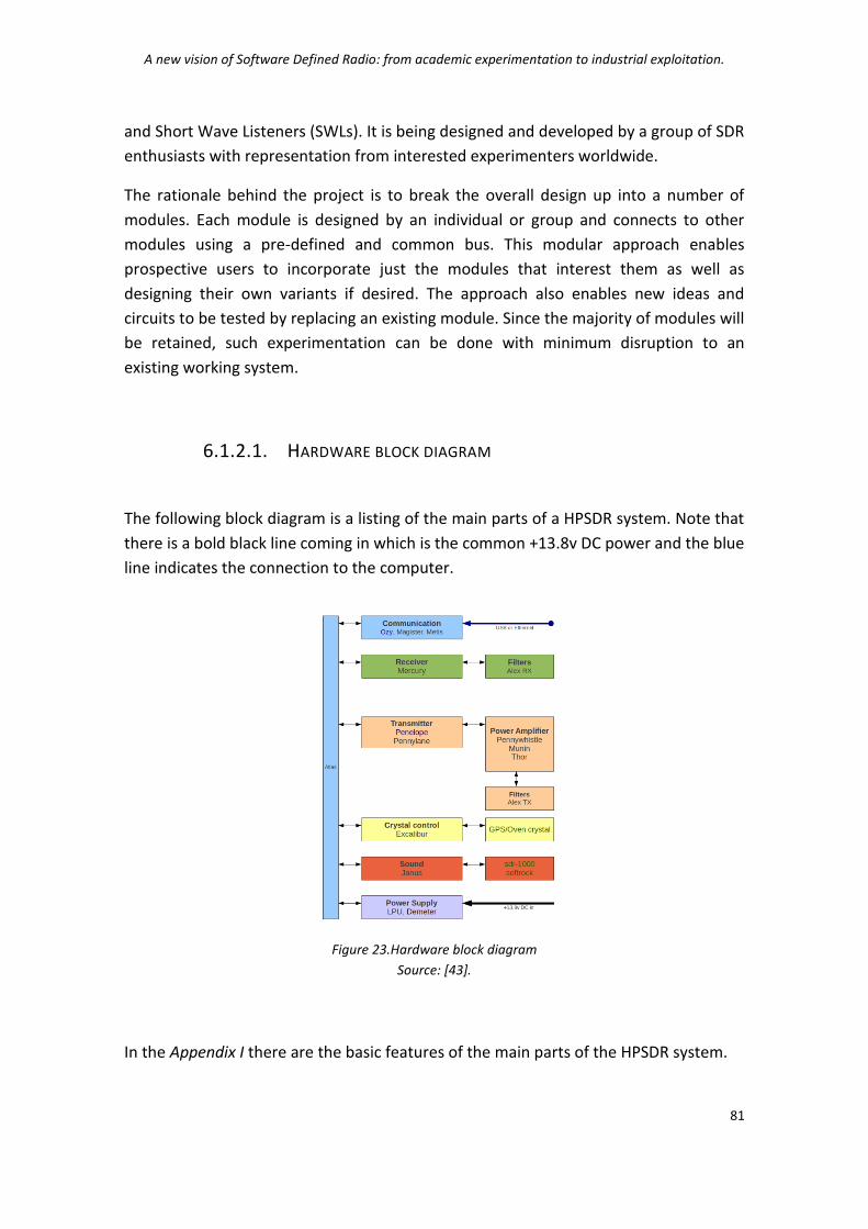
A new vision of Software Defined Radio: from academic experimentation to industrial exploitation.
81
and Short Wave Listeners (SWLs). It is being designed and developed by a group of SDR
enthusiasts with representation from interested experimenters worldwide.
The rationale behind the project is to break the overall design up into a number of
modules. Each module is designed by an individual or group and connects to other
modules using a pre-defined and common bus. This modular approach enables
prospective users to incorporate just the modules that interest them as well as
designing their own variants if desired. The approach also enables new ideas and
circuits to be tested by replacing an existing module. Since the majority of modules will
be retained, such experimentation can be done with minimum disruption to an
existing working system.
6.1.2.1. HARDWARE BLOCK DIAGRAM
The following block diagram is a listing of the main parts of a HPSDR system. Note that
there is a bold black line coming in which is the common +13.8v DC power and the blue
line indicates the connection to the computer.
Figure 23.Hardware block diagram
Source: [43].
In the Appendix I there are the basic features of the main parts of the HPSDR system.

A new vision of Software Defined Radio: from academic experimentation to industrial exploitation.
82
6.1.2.2. SOFTWARE BLOCK DIAGRAM
The following block diagram list the software currently available as open source to
operate the HPSDR hardware. The blue line indicates the connection to the hardware.
There are other programs that can work with HPSDR hardware. Some these include
WinRad, WinRadHD, CWSkimmer to name a few.
Figure 24.Software block diagram
Source: [43].
For more information about the software see Appendix II.
6.1.2.3. HERMES BLOCK DIAGRAM I
The following is a block diagram for the Hermes project. The Hermes project uses
technology developed in the HPSDR boards but combines them in to two boards that
fit in a Euro style box. This radio might be for those that wish to go mobile with their
SDR or do not wish to use the modular approach used in the development of the other
boards.

A new vision of Software Defined Radio: from academic experimentation to industrial exploitation.
83
Figure 25.Hermes block diagram
Source: [43].
Hermes is a single board Digital Up and Down Conversion (DUC/DDC) full duplex HF +
6m multi-mode transceiver. It is basically the Mercury, Penelope, Metis and Excalibur
boards rolled into one PCB. The board communicates to an associated PC via
100T/1000T Ethernet. Appendix III shows the Hermes hardware block diagram.
Apollo is to be a companion 15W PA and Low Pass Filter for Hermes. The idea is to
build a self-contained HPSDR Transceiver into a box similar to the one used for the two
Alex boards.
6.1.3. OSSIE
OSSIE is an open source Software Defined Radio (SDR) development effort based at
Wireless@Virginia Tech. The project's primary goals are to enable research and
education in SDR and wireless communications. The software package includes: an SDR
core framework based on the JTRS Software Communications Architecture (SCA); the
Waveform Workshop, a set of tools for rapid development of SDR components and
waveforms applications; and an evolving library of pre-built components and
waveform applications. In addition, free laboratory exercises for SDR education and
training are being developed in cooperation with the Naval Postgraduate School. OSSIE
is distributed under the GNU General Public License 2.0 or later (signal processing
components and tools) and GNU Lesser General Public License 2.1 (core framework)
[44].

A new vision of Software Defined Radio: from academic experimentation to industrial exploitation.
84
6.1.3.1. CORE FRAMEWORK
The OSSIE project is written in C++ using the omniORB CORBA ORB, which is openly
available. Current development is primarily focused on the Linux operating system,
however they welcome reports from people trying to build on other operating
systems, such as BSD, OSX, Windows, QNX and Integrity.
OSSIE implements key elements of the SCA specification. Backward compatibility will
remain a priority as changes are made that enhance SCA compatibility. The 0.7.4
release runs on Intel and AMD based PCs. A release that includes enhanced support for
embedded as well as PC-based applications is planned for fall 2009. Instructions will be
provided detailing any changes needed for porting components to the new release.
6.1.3.2. PROCESSING HARDWARE/OPERATING SYSTEMS SUPPORTED
OSSIE 0.7.4 runs on the general purpose processor of most PCs using a recent version
of Linux such as Fedora Core 10 or Ubuntu 9.04. A release that includes enhanced
support for embedded processors is planned for fall 2009.
Experimental embedded versions have been ported to the following platforms:
TI 320C6416 DSP (Lyrtech SignalMaster Quad);
ARM 9 (OMAP Starter Kit and Lyrtech small form factor SDR board);
Marvell PXA270 (Gumstix Verdex XL6P);
PowerPC (Efika board);
PowerPC 405 (Xilinx ML403 board);
6.1.3.3. RF/DATA ACQUISITION HARDWARE SUPPORTED
Universal Software Radio Peripheral (USRP) and current daughter boards (Basic
RX, Basic TX, DBSRX, RFX 400, RFX 900, RFX 2400, RFX 1200 and RFX 1800);
Tektronix Test Equipment (loadable device wrappers for some equipment exist
for OSSIE version C);

A new vision of Software Defined Radio: from academic experimentation to industrial exploitation.
85
6.1.3.4. WAVEFORM WORKSHOP
This set of rapid prototyping tools allows users to create, run, observe, and control
OSSIE signal processing components and waveform applications. The tools in the
Waveform Workshop include:
The OSSIE Eclipse Feature (OEF): This tool leverages the Eclipse open-source
integrated development environment to provide a simple drag-and-drop
interface for creating new waveform applications. It also provides GUI-based
creation of signal processing components and autogeneration of skeletal code
for interfacing with OSSIE and CORBA. In addition, OEF allows launching most
OSSIE tools and applications from a GUI environment;
The OSSIE Waveform Developer (OWD): This legacy tool provided much of the
current functionality of OEF with a menu-based interface. OWD allows users to
specify available devices on a given platform and to create the appropriate
Device Manager profiles, and will be phased out once this capability is
integrated into OEF;
ALF, visualization and debugging environment for OSSIE waveform applications.
ALF allows users to launch waveform applications, display them in block
diagram form, and inject and/or monitor signals at various points in the
application. ALF can be used for remote execution and monitoring of
applications. Multiple instances of applications or multiple applications can run
simultaneously, resources permitting. ALF also provides the capability to
package and launch OSSIE signal processing components as self-contained
applications, and to interconnect components that are running as part of the
same application or in separate applications;
The Waveform Dashboard (WaveDash) uses the SCA query and configures
methods to allow users to interactively configure waveform applications at run
time, from an easily customized GUI. This combined with the monitoring
capabilities of ALF provides real-time feedback to students and researchers.
WaveDash also eliminates the need to invest time in GUI development for
prototype applications. Users can interactively specify which components and
properties are visible, and select the appropriate type of control (text box,
slider, etc.) for each property.

A new vision of Software Defined Radio: from academic experimentation to industrial exploitation.
86
6.1.3.5. APPLICATION SOFTWARE
Components currently distributed with OSSIE include those necessary to build
narrowband AM and narrowband or wideband FM receivers. The USRP is assumed as
the RF front end, but the applications can be adapted to other hardware. In addition, a
demonstration transmitter that generates a predefined QPSK signal, a component that
simulates an AWGN channel with phase offset and a QPSK receiver that counts bit
errors are packaged with OSSIE. Additional digital components are included beginning
with version 0.7.3.
6.1.3.6. WAVEFORM APPLICATIONS DEMONSTRATED
• AM Receiver;
• Narrowband FM transmitter and receiver;
• Wideband FM receiver;
• BPSK/CVSD Voice transmitter and receiver;
• CIREN cognitive radio with BPSK/QPSK/16-QAM modulated packetized data
transmitter and receiver;
6.1.4. ALOE
The Abstraction Layer and Operating Environment (ALOE) is an open source execution
environment for software defined radios [45]. It is essentially based on a hardware
abstraction layer, lightweight and time driven software architecture, and a simple
interface format. ALOE accounts for heterogeneous multiprocessor platforms. Its
cognitive computing source management capabilities enable flexible and dynamic
management of SDR platforms and applications for distributed real time execution of
applications and dynamic reconfiguration of platforms.
6.1.5. CONCEPTS AND FUNCTIONALITIES
ALOE supports heterogeneous multiprocessor platforms, where a single silicon device
may encapsulate several Processing Elements (PEs). A PE here abstracts any bounded

A new vision of Software Defined Radio: from academic experimentation to industrial exploitation.
87
silicon area-static logic (GPP, DSP, ASIC) or a Dynamically Reconfigurable Area (DRA).
PEs with multitasking operating systems access the ALOE services through an
Application Programming Interface (API). PEs without operating system (e.g., DRAs or
ASICs) access the middleware services through a static logic interface.
ALOE abstracts the platform’s physical network interfaces. The PE network (mesh, star,
shared bus, or any other) has implications on the processing throughput and latency.
The task of ALOE is to deal with these network characteristics while providing inter-PE
communication capabilities as a service.
Figure 26.The ALOE layers
Source: “ALOE: An Open Source SDR execution environment with cognitive computing resource management capabilities” [45].
Figure26 illustrates the ALOE layers. The hardware layer at the bottom shows a cluster
of PEs and their physical interconnection. The abstract application layer at the top
consists of graphs that model the application tasks and their data flow dependencies.
At the real application layer these tasks are treated as individual modules, which use
the ALOE services for assembling the waveform. The platform layer provides a pseudo-
homogeneous and virtual execution environment, where all tasks see the same
abstract platform, the ALOE platform. It enables:
• Real time execution;
• Waveform execution control;
• Synchronized distributed computing;

A new vision of Software Defined Radio: from academic experimentation to industrial exploitation.
88
• Packet-oriented data flows;
• Cognitive computing resource management;
• External configuration and management;
6.1.6. ARCHITECTURE AND SERVICES
The ALOE architecture encompasses several components that enable hardware
independent access to ALOE services. The ALOE services are implemented as isolated
modules (software daemons), which run as background processes on the PEs. An
application module interacts with the system through the software API (SW API).
The SW API enables a seamless access to the ALOE software library, which interacts
with the software daemons via the hardware API (HW API). This ensures the portability
of all layers above the HW API. Hence, only the ALOE hardware library is platform
specific.
The ALOE hardware library abstracts the hardware specific management functions,
including task or process creation and management, variable management, and
interfacing and timing issues. Each PE implements these functions in a different
manner. The HW API provides a standard interface for accessing the PE-specific
hardware library. The ALOE software library, on the other hand, implements the
services that are required by the application modules. It can be considered a link
between the application and the ALOE software daemons, providing functions for the
creation of data flows, statistics, and log files, among others. The application
programmer uses the SW API for accessing these functions.

A new vision of Software Defined Radio: from academic experimentation to industrial exploitation.
89
ALOE SCA GNU Radio
Program model Multiprocessor One process per module Time-driven
Multiprocessor One process per module Event-driven
Single processor One process per core Event driven
Application range
Digital signal processing (DAGs)
Any Any
Hardware support
GPPs, TI DSPs, FPGAs GPPs, TI DSPs, FPGAs GPPs
Software requirements
RT POSIX or DSP BIOS RT POSIX or DSP BIOS + ORB middleware
Linux + Python
Data interfaces FIFO-like, message-based Remote/local procedure calls. CORBA-IDL
Local procedure calls
Interface latency Fixed, packet size and location independent Internal: 1 time slot External: 1 time slot
Medium-high Internal: 9.1 µs/kbyte External (over RapidIO): 45 µs/kbyte
Low Internal: 0.41 µs/kbyte External not allowed
Processing overhead
2.1 % N/A 6 %
Test waveform throughput
1.28 Mb/s 0.72 Mb/s 0.59 Mb/s
Size overhead GPP: 16 MB + 260 KB/module DSP: 208 kB + 21 kB/module FPGA: 4%
GPP: 32 – 64 MB DSP: < 1MB FPGA: 11%
GPP: 32 – 64 MB DSP: N/A FPGA: N/A
Computing resource
Computing resource awareness (plug-and-play), resource monitoring
None None
Task mapping and scheduling
Automatic mapping at runtime, pipelined scheduling
Manual mapping at design time, operating system scheduling
Single processor, best effort scheduling
Dynamic reconfiguration
Supported: well defined execution status enables a pipelined loading, initialization and replacement of components
Partially supported: application definition must be reparsed and interfaces recompiled
Supported, but must be implemented in Python
Table 14.Comparision between ALOE, SCA and GNU Radio
Source: “ALOE: An Open Source SDR execution environment with cognitive computing resource management capabilities” [45].
Table13 compares ALOE with the SCA and GNU Radio. The simplicity of the ALOE
implementation, providing specific services for digital signal processing applications,
explains the low memory and area overheads. ALOE guarantees deterministic interface
delays, which are data and location independent.

A new vision of Software Defined Radio: from academic experimentation to industrial exploitation.
90
Although the SCA and GNU Radio have both been designed for SDRs, they can be
applied to other computing contexts as well. This increases their scope but decreases
the performance of digital signal processing applications and resource-constrained
platforms. The abstraction layer and operating environment (ALOE) is an alternative
SDR framework. It targets multiprocessor platforms and embedded systems with tight
resource constraints. ALOE is a lightweight, open source SDR framework with cognitive
computing resource management capabilities. It is not SCA-compliant and uses a
specific message passing scheme instead of CORBA.
6.2. WAVEFORM DEVELOPMENT
The waveform in software defined radio (SDR) is the important application software
which fulfills the function of communication [46]. The waveform development is one
of the most important aspects in the industry of SDR. In order to improve its portability
and reusability, the waveform software should be developed according to a special
flow. In some sense the design and development of communication systems based on
SDR is turning to the development of waveform software.
6.2.1. PRELIMINARY KNOWLEDGE NEEDED IN SDR WAVEFORM DEVELOPMENT
The Software Communication Architecture (SCA) specification specifies the hardware
architecture, software architecture, security architecture and application program
interface (API). The SCA specification is built on the existing commercial infrastructures
and is independent from bottom hardware. The goals of SCA specification includes
reducing the development expense through adopting existing commercial standards
and reducing the development time through reusing existing components. The final
idea is to guarantee the portability of software and the reconfigurability of hardware
platform.
The essential of the SCA specification is an open and universal architecture which
provides a standard, open and interoperational communication software platform for
radio. Through this software platform, the bottom hardware is isolated from the

A new vision of Software Defined Radio: from academic experimentation to industrial exploitation.
91
software which implements the waveform function. Accordingly those characteristics
such as portability, reconfigurability, scalability and reusability can be realized.
The software infrastructure in SCA specification is shown in Figure27. Apparently it is a
layered architecture and those layers are respectively device driver, operating system,
CORBA middleware, application environment profile, framework control service
interface and waveform application from the top down. The layer of waveform
application component shown in Figure27 is called application layer. It mainly finishes
the user’s communication function such as digital signal processing in MODEM level,
protocol processing in data link and network level, routing in internet, security
processing and embedded application, etc.
Figure 27.Layered software architecture in SCA specification
Source: “The general waveform development flow of Software Defined Radio” [46].
By all appearances the waveform of SDR is a kind of application. The SCA specification
doesn’t specify particular means and process about the detailed realization, but this
doesn’t mean that there is no any requirement about waveform development. In fact
the SCA specification clearly specifies how the waveform application interacts and
interfaces with operating environment. And it also specifies that the waveform
application should use the interface and service provided by the Core Framework (CF).
The direct access to operating system is limited within the services defined by the SCA
POSIX, too.

A new vision of Software Defined Radio: from academic experimentation to industrial exploitation.
92
6.2.2. THE COMPOSITION OF SDR WAVEFORM
Following it is identified the features required to support a component based on
software radio application that can run on a modular, reconfigurable platform. This
helps in understanding some of the design decisions in the SCA.
In the SCA context any radio application is known as a waveform. Let us start the
requirements identification by considering the two general waveforms, W1 and W2,
shown in Figure28.
Ci,j : is a standalone entity that performs some sort of signal processing or control
functionality required by the waveform.
Components can have multiple implementations, each one targeted to a specific
processing device D, while preserving their functionality and interfaces. In Figure28,
C2,1 is depicted as having three different implementations.
Figure 28.Block diagrams of sample SDR waveforms and platforms.
Source: “Understanding the Software Communications Architecture” [27].
Both waveforms are supposed to run on the two platforms, P1 and P2. These platforms
have different reprogrammable processing devices, Dm,n, and while the nature of them
is inconsequential, let assume that at least one of them is a digital processor. Consider
P1 a single board platform, where no new elements can be added. P2, on the other
hand, is modular, and extra processing elements can be added.

A new vision of Software Defined Radio: from academic experimentation to industrial exploitation.
93
Component Model
Defines the semantics of components, the interfaces that are expected from them, and the protocols to manage and exchange information with other components.
Operational Environment
The decision of which waveform is to be deployed on which platform is made at runtime. Therefore, it is need to develop waveforms independent of their final deployment configuration. It guarantees the independence of the waveform.
Applications Factory
Launch waveforms. This artefact must find the waveforms in memory and perform all the required tasks to deploy them on the selected platform.
Assembly Instructions
Launching a waveform requires, at minimum, finding, loading, and instantiating each individual component on the appropriate device in the platform, connecting the components, and performing any initialization tasks necessary to have the waveform running properly. It is needed to pass in the Application factory all these Assembly Instructions for our waveforms.
File System Memory. It is a way store, organize, and access memory.
Middleware Guarantees the communication mechanism between components. Each waveform should be able to be deployed on both platforms without changing its logic and granularity. Given the modular nature of P2, we need a communication mechanism to exchange information and data across different nodes on the platform.
Manager Mechanism that control and keep track of all the available hardware and software resources, and to interface with the user.
Proxies for Physical Devices
It is a way to interact with different hardware components. This will give the ability to configure them, and to Exchange data and control information with them.
Capacity model Describe the available resources and requirements. Different platforms will have different physical capacities which may be reconfigurable and unknown at development time. Similarly, different waveforms will have different resource requirements. It is necessary to validate that the hosting platform has enough capacity for the waveform at hand.
Table 15.SCA CF Interfaces.
Source: “Understanding the Software Communications Architecture” [24].
6.2.3. SCA SPECIFICATIONS
The SCA defines in the CF a core set of interfaces that rule the deployment and
management of waveforms and their components. These interfaces define the
architecture and other tedious low level details of the system, allowing developers to
focus only on applications. The SCA CF includes base application interfaces, base
device interfaces, framework control interfaces, framework services interfaces and
domain profile. The SCA CF interfaces are defined in CORBA’s Interface Description
Language (IDL). A simplified diagram of their relationships is shown in the following
figure.

A new vision of Software Defined Radio: from academic experimentation to industrial exploitation.
94
Figure 29.Simplified SCA CF IDL Rrelationship
Source: “Understanding the Software Communications Architecture” [27].
Base Application Interfaces
In the SCA, all waveform components are required to implement the base application interfaces. At the highest level of these interfaces is the Resource interface, which provides a common interface for the control and configuration of software components. This interface enables component control and inherits from the following base interfaces.
LifeCycle Is used to initialize or release the resource.
TestableObject Provides resources with built-in test capabilities.
PropertySet Provides operations to configure and query resource properties.
PortSupplier Provides an operation to get a port object reference.
Port Is used to connect Resource components. Enables components to exchange data. Ports are classified into Uses ports (clients) and Provides ports (servers). The Port interface also provides components with the connect and disconnect functionalities necessary to assemble waveforms.
ResourceFactory Optional interface modelled after the Factory design pattern, and used to create and tear down resources.
Base Device Interfaces
The device-related interfaces allow interaction with physical hardware devices by providing a
proxy to the rest of the framework. This abstraction allows non- CORBA-enabled elements to
interact with other components and the rest of the framework. Device-related interfaces
include:
Device Provides a logical representation of hardware devices. It inherits from the
Resource interface, extending it to provide status and capacity
management (allocate and deallocate capacities). An ASIC or a dedicated
piece of hardware is a typical example of physical hardware represented
by this interface.
LoadableDevice Extends the functionality of Device. It adds loading and unloading
capabilities that modify the runtime behaviour of the physical device.
FPGAs and DSPs are typical examples of hardware components
represented with this interface.

A new vision of Software Defined Radio: from academic experimentation to industrial exploitation.
95
ExecutableDevice Extends the LoadableDevice interface by allowing it to execute and
terminate resources. A typical example of a device represented by this
interface is a GPP, although any processor with multithread capabilities
can be represented by this interface.
AggregateDevice Is used to represent composite devices, which can be made of multiple
logical devices but display a single interface to the domain.
Framework Control Interfaces
These interfaces provide management and control capability to the CF over the whole radio
domain. These interfaces allow consistent deployment, configuration, and management of
waveforms and platforms.
ApplicationFactory Used to create instances of a specific waveform. It obtains assembly
instructions from the Domain Profile. These instructions include a list of
the components that make up a waveform, their location, and their
respective connections. It finds suitable Devices based on available
capacity, launches the components, establishes the respective
connections, and performs initial configuration and initialization
Application After creating an application, ApplicationFactory returns an instance of
the Application interface. This interface provides a container for all
resources in a waveform, enabling waveform configuration and status
inquiries in a single interface. This interface is also in charge of
terminating the application, releasing all the resources used and
returning the allocated capacities to host devices.
DeviceManager Used to manage a set of logical devices and services. Usually, this
interface is used to represent a CORBA-enabled board. When
instantiated, DeviceManager creates a file system for the board it
represents and launches all of the logical devices under its control.
DeviceManager also obtains the location of DomainManager and
registers itself as part of the radio domain.
DomainManager The DomainManager interface controls and maintains the overall state
of the radio. It creates a FileManager that will contain the FileSystem(s)
of every DeviceManager registered under its domain. At instantiation,
DomainManager also sets up the naming context for the radio in the
CORBA naming service. DomainManager provides registration interfaces
for DeviceManagers, Devices, Applications, and Services, manages access
to registered device managers and installed applications, and provides
the user interface.
Figure30 provides a graphical description of the simplified operation of
ApplicationFactory.

A new vision of Software Defined Radio: from academic experimentation to industrial exploitation.
96
Figure 30.Application Factory behaviour
Source: “Understanding the Software Communications Architecture” [27].
Framework Services Interfaces
These interfaces are used to perform all file-related operations. These interfaces allow files to
be accessed across distributed SCA platforms.
File Provides access to individual files and their basic operations (e.g., read, write,
close) within the radio’s domain.
FileSystem Allows remote access to physical file systems, and the creation, deletion,
copying, and so on of files. Typically, a FileSystem is limited to one piece of
hardware or a single OS.
FileManager Allows the management of multiple distributed FileSystems. It can be seen as a
root file system that mounts and unmounts other file systems.
Domain Profile
Includes in a set of files all the information concerning applications and platforms within the
SCA. These files describe the interfaces, capacity models, properties, inter-dependencies,
interconnections, and logical location of each and every component within the domain. These
descriptions are provided in Extensible Markup Language (XML).
A visual description of the relationships among Domain Profile descriptors is shown in
the following figure.

A new vision of Software Defined Radio: from academic experimentation to industrial exploitation.
97
Figure 31.XML Domain Profile Relationship
Source: “Understanding the Software Communications Architecture” [27].
Software Package Descriptor (SPD) files describes software components and their
implementations. The interfaces provided and used by each component are described
in the Software Component Descriptor (SCD), and a reference to this file is included in
the SPD. The particular properties of each component are described in the PRF. A
property is the representation of any physical or logical characteristic.
Waveforms are described by a Software Assembly Descriptor (SAD) file, which includes
a list of the components, specific deployment requirements and configurations, and
connections between them. The SAD file references an SPD for each of the
components in the waveform.
Platform characteristics are described by the Device Package Descriptor (DPD) and
Device Configuration Descriptor (DCD); both are also known as the Device Profile. Each
hardware component is described by a DPD and an SPD addressing its hardware and
logical representations, respectively. The DPD also references a PRF, which describes
the properties of the device being deployed such as serial number, processor type, and
allocation capacities. The DCD contains a list of the devices initially deployed at start-
up by the DeviceManager and the required information to locate the DomainManager.

A new vision of Software Defined Radio: from academic experimentation to industrial exploitation.
98
6.2.4. THE GENERAL WAVEFORM DEVELOPMENT FLOW OF SDR
The guiding principle in designing the SDR is as follow: “develop once, run anywhere”
[46].
This is different from the traditional method in which all development must start anew
each time the function changes. In order to obey the aforementioned rules and
improve the portability and reusability of waveform software, a special flow should be
followed when one develops the waveform application.
6.2.4.1. THE EARLY WAVEFORM DEVELOPMENT FLOW
Before the appearance of visual integrated development environment (IDE), the
development of SDR waveform which conforms to the SCA specification is finished
through writing different kinds of code manually. The detailed flow is shown as
Figure32 and we can see every step involves writing code manually. This flow requires
a thorough mastery on the SCA specification and is very complicated and fallible.
Because of the appearance of IDE for waveform development, this flow is outdated
now.
Figure 32.The flow of manual developing the SDR waveform
Source: “The general Waveform Development Flow of Software Defined Radio” [39].

A new vision of Software Defined Radio: from academic experimentation to industrial exploitation.
99
6.2.4.2. THE GENERAL WAVEFORM DEVELOPMENT FLOW OF SDR IN IDE
Aiming at those shortcomings in the traditional flow and in order to satisfy the
requirements on portability, the Object Management Group (OMG) proposed a new
method for waveform development. This method is the famous Model Driven
Architecture (MDA).
These IDEs can automatically generate many skeleton and code which were written
manually before. This is helpful for reducing mistake, improving the efficiency of
waveform development and improving the compatibility with SCA specification. The
general waveform development flow of SDR based on IDE is shown in Figure33.
Figure 33.The general waveform development flow of SDR in IDE
Source: “The general Waveform Development Flow of Software Defined Radio” [46].
As shown in Figure33, the general waveform development flow based on IDE can
automatically generate all kinds of files defined in the Domain Profile and the skeleton
code of the waveform application. The remainder work is adding the necessary code
which performs digital processing manually. The every step in Figure33 is explained as
follow.
SDR waveform components mapping to SDR platform
The mapping from SDR waveform components to SDR platform means the assignment
of waveform components on the processing elements in the SDR platform according to
function requirement and computation burden. The processing elements in SDR
platform include four categories: GPP, DSP, FPGA and ASIC. Generally speaking, the

A new vision of Software Defined Radio: from academic experimentation to industrial exploitation.
100
high speed waveform components will be arranged on the FPGA or ASIC, and the low
speed components could be arranged on the GPP.
SDR waveform component modelling
Those components such as Resource, Device, Adapter, DeviceManager and
AssemblyController are the basic elements composing the SDR waveform. The concept
of component modelling in IDE means the determination of input/output port and
their types and the accession of corresponding properties and description. The sketch
map of component modelling is shown in Figure34.
Figure 34.SDR Waveform component modelling in IDE
Source: “The general Waveform Development Flow of Software Defined Radio” [46].
When creating the Resource or Device component, we should use as little granularity
as possible to model them and this is helpful for the reuse and portability of waveform.
At the same time we must notice that the property and port modelling is different
from the component modelling. Some property, port and interface can be created
through reusing ComponentTypes, but others need be imported using the interfaces
defined using CORBA IDL.
The skeleton code generation, arithmetic integration and compilation of SDR
waveform component
The next step after component modelling is the skeleton code generation using the
function provided by IDE. The code can deal with the problem of lifecycle in
CORBA/SCA and it needs no incorporation when the model is modified or the code is
regenerated. Because these skeletons are empty, the code fulfilling the signal
processing function should be added (called arithmetic integration) and compiled
according to the prospective operating environment.

A new vision of Software Defined Radio: from academic experimentation to industrial exploitation.
101
The assembly of SDR waveform application and node
As mentioned before, the waveform application of SDR is the combination of different
components which implement different function. So the SCA application or node is
defined as the assembly of separate components. The model of assembly provides the
following information: the types of components which are used in the assembly, the
number of component instantiation of each type and the instantiation of
interconnection between ports of specified component, etc. In IDE the assembly of a
waveform application or node only needs a simple paradigm blocking plan. The
components can be dragged into an assemble placement. This method can realize
reengineering and verify the existent assembly to indicate or resolve the possible
problems. It also provides the real-time model verification and a packaging property to
create a document from all SCA production.
The installation, deployment and test of the application
The waveform application must be installed before it can be used. Similar to the
Personal Computer (PC) world, the installation of an application means the copy of all
files into target platform. In order to use an application, we must deploy it onto the
hardware platform. Through deployment the independent components will be loaded
on the appropriate devices and then be instantiated. The connection will be
established and the application will be configured to the default state. Once an
application is expanded, we can monitor and control it through user interface. In the
IDE such as SCARI Suite, we can install, deploy and control an application through
RadioManager. After the installation and deployment, the system should be tested to
determine whether it can implement the desired function.
6.2.5. SOFTWARE RADIO DOWNLOAD
The increased amount of software installed in wireless devices includes both
application software and operational software, such as radio software used to
implement software defined radio capabilities [47].
Application software is the software that resides at and deals with the highest layer in
the communications protocol stack. Application software is usually directly executable
by the device user to satisfy a specific need.
The operational software is all the software other than application software. It includes
the operating system, drivers, radio software and middleware. All the software needs
to support the applications on the wireless device.

A new vision of Software Defined Radio: from academic experimentation to industrial exploitation.
102
Radio software is the primary software within a wireless device; it is coupled with the
radio hardware to derive the overall radio functionality. Ancillary software (e.g.,
control) that may be needed as a consequence of the primary software is an inherent
part of this definition. Radio software includes reconfiguration data and
reconfiguration executable code.
Figure 35.Software/Firmware categories in commercial wireless terminals
Source: “Radio Software Download for Commercial Wireless Reconfigurable Devices” [47].
6.2.5.1. SOFTWARE RADIO DOWNLOAD REQUIREMENTS
The requirements for radio software download can be broadly divided into general
requirements, requirements related to each individual step in the download process,
SDR device requirements, and requirements for the network that supports radio
software downloads. A critical general requirement is that any downloaded radio
software installed on an SDR device must not malfunction or cause the SDR device to
emit undesirable radio frequency waves. It is also required that billing, licensing,
ownership, and maintenance agreements be in place between the SDR device user and
the service provider, network operator, equipment and software manufacturer, and
software vendor prior to the download and installation of a radio software module.
The process of downloading radio software to an SDR device can be broken down into
several individual steps such as discovery of the need for download, initiation of
download, download setup, mutual authentication, authorization, capability exchange,
download acceptance exchange, protection (encryption), software download,
installation, in situ testing, nonrepudiation, reset and recovery, and termination.

A new vision of Software Defined Radio: from academic experimentation to industrial exploitation.
103
Appendix IV illustrates the download process steps and outlines the major
requirements.
A crucial requirement for reconfigurable SDR devices that support radio software
download is a Reconfiguration Manager (RM) that oversees the processes of radio
software download, installation, reconfiguration, in situ testing, and recovery. Such an
RM is required to reside on the SDR device in a secure software area that is not subject
to reconfiguration, and is responsible for enabling full or partial reconfiguration of all
protocol stack layers of the SDR device, controlling and managing reconfiguration
processes at the SDR device, ensuring that the anticipated configuration adheres to
the given radio access system standards, and communicating with any RM entities
residing on the network side to coordinate radio software download and
reconfiguration.
SDR devices are required to perform mode monitoring and service discovery to seek
alternative modes of operation and services, and select the most appropriate mode of
operation for the desired service, including software radio download. SDR devices also
need to be equipped with sufficient additional memory space beyond that required for
normal modes of operation to support all of the above-mentioned functions.
Additional memory is no longer considered to be an impediment to the
implementation of SDR capabilities. A network supporting radio software downloads
needs to meet certain specific requirements. The architecture of such a network needs
to also support reconfiguration management (RM) functionalities. These network RM
functionalities are responsible for maintaining a database of current configurations
and capabilities of SDR devices in the network, scheduling radio software downloads to
SDR devices, supporting efficient downloads to a large number of SDR devices,
maintaining and coordinating access to software repositories of third-party vendor and
original equipment manufacturer (OEM) software modules, communicating with local
RMs residing on each SDR device to coordinate radio software download,
reconfiguration, mode identification, mode monitoring, mode negotiation, and mode
switching. An operator needs to forecast and provision sufficient network and radio
resources to support radio-software-download-related traffic in addition to regular
user traffic.
6.2.5.2. DIFFERENCES IN DOWNLOAD REQUIREMENTS
A major difference, between radio software download and other downloads is that a
Regulatory Agency (RA) might impose certain obligations on the process of radio
software download to address specific radio-related concerns.

A new vision of Software Defined Radio: from academic experimentation to industrial exploitation.
104
For example, it is a regulatory requirement that in general the device must provide
some means of indicating its current “type approval” or “conformance acceptance,”
often a physical label attached to the device [47]. However, the specific need with SDR
is that the indications must be associated with the radio configuration that is
downloaded. This is because the radio characteristic of the device is changed after a
download and reconfiguration. Consequently, the currently accepted practice of a
physical label becomes untenable. Therefore, download and device management may
need to include how an electronic variant (proposed in some regulatory jurisdictions)
of this labeling might be accommodated and how the device could provide information
as to its current version/variants. This criterion is beyond that typically needed in the
application download regime.
Another RA-related requirement is that the radio must not be able to operate with an
unapproved configuration. Therefore, a security mechanism must be built into the
radio to prevent malicious or accidental reconfiguration.
Figure 36.Download to a terminal device
Source: “Radio Software Download for Commercial Wireless Reconfigurable Devices” [40].
There are other differences, although lesser ones. For example, in radio software
download, stronger authentication may be required. Verification of a downloaded
module may need different techniques than other downloads. Further to the point,
referring to Figure36 is a difference in philosophy that provides an overarching
difference between application and radio software downloads. In the application
arena, the failure of the application (e.g., a game) may result in disappointment of the
customer with no additional harm done. In the radio software arena, failure of the

A new vision of Software Defined Radio: from academic experimentation to industrial exploitation.
105
radio software (e.g., frequency selection and modulation) may result in a customer
having a non-functional radio device or, worse, a device that functions inappropriately
and disturbs other users or radio services. The mechanisms to download may be the
same; the specifics and scope can vary to satisfy the imposed criteria.
6.2.6. STANDARDIZATION
It is essential to analyse which are the appropriate elements to be standardized and
which industry for are the relevant parties to address these aspects. Is it the
architecture, protocol, interfaces, management? For operational software download,
particularly in an OTA environment, it is evident that certain elements should be
standardized. The released standards and ongoing work on the download of
applications certainly provides guidance for the download of operational software,
including radio software. As has been pointed out, operational software is a close
relative of application software, and consequently can and should build on the
foundation work done on applications software.
It is desirable that any OTA download be independent of the radio interface
technology and the core network to the greatest extent possible.
Figure 37.Which part should be standardized and which not?
Source: Panasonic Technologies [47].

A new vision of Software Defined Radio: from academic experimentation to industrial exploitation.
106
Sufficient standardization is required to ensure adherence to the protocols and
procedures, perhaps down to the level of a standardized “sandbox” (partitioned
memory/code) in a device where the transition takes place between the standardized
world and the internal proprietary regime.
Figure 38.Possible SDR download hardware and software stack
Source: Panasonic Technologies [47].
6.2.7. LIBRARIES
The reusability of software is one of the main targets of SDR. The SDR software
framework can be shared by different system. But the software modules for different
standard are different [48]. The new air-interface standards typically rely on well-
understood protocols of predecessor systems. Cost intensive re-engineering of
software can be avoided and software can be re-used if designed in a suitable way.
Modular software design entails several advantages. On the one hand, portability of
dedicated functionality is supported. Using well defined interfaces, the same module
can operate within different systems. On the other hand software-upgrades are easily
facilitated, as the respective modules can be changed individually.
In the multi-standard SDR BB, the reusability of protocol software is reached through
library definition.

A new vision of Software Defined Radio: from academic experimentation to industrial exploitation.
107
Through identification of commonalities and difference of different standards,
protocol libraries can be defined as common library, dedicated library. For BB part, the
software modules mainly focuses on the development of base band signal processing
which basically performs chip- and symbol- rate processing in both downlink and
uplink, as well as frame protocol terminations, and so on. The comprehensive software
modules for base band signal processing, which will be used in multi-standard
environment, have to be clarified into three libraries (pools), as depicted in Figure39,
in whatever downlink and uplink:
Dedicated system libraries
These libraries consist of the unique functions in the specific air interface environment,
identified by different standards, for example, UMTS-FDD and HSDPA, e.g. 16QAM
modulation scheme for HSDPA, and 1st interleaving function for UMTS-FDD, etc. They
have to be downloaded immediately to the unique hardware accordingly. Making the
connections of the specific building blocks is necessary before the radio link in the air
interface protocol required is really set up.
Common system libraries
When different standards are operated simultaneously, the components in these
libraries will help to build up the common functional blocks in the processing chain, for
example HSDPA and UMTS-FDD, which includes CRC attachment, spreading, QPSK,
TPC, TFCI, Pilot bits, etc. All these elements will be downloaded during the radio link
setup procedure.
Common algorithm libraries
Generally, they consist of basic functions that are widely used in scientific and Telecom
areas, such as Filtering function, Complex/Real FTT, function, Matrix function,
Windowing function, Logical functions, Simple functions, Vector Math functions, etc.,
particularly for DSP implementations.

A new vision of Software Defined Radio: from academic experimentation to industrial exploitation.
108
Figure 39.Hirarchical SDR Library Concept
Source:”A multi-standard SDR Base Band Platform [48]”
6.3. KEY FEATURES IN NEW MOBILE PHONES DESIGN
6.3.1. USER’S CENTRIC METHODOLOGY
User’s perspective refers taking the user as its departing point. Users are the main
actors on the stage of the wireless world and are unaware of and indifferent about the
technology to use in order to obtain a desired service.
The user centric approach can result in a beneficial method for identifying innovation
topics at “all” the different protocols layers and avoiding a potential mismatch in terms
of service provisioning and user expectations.
If it is considered the users requirements as secondary with respect to the
technological issues, the risk is to face an unanticipated failure. Thus, it becomes
crucial to understand the users and their expectations and needs, and to consider
them as the cornerstone in the design of new services in order to turn the new
technology into a big success. Besides, it has also to be taken in consideration that
novel technologies may have a significant impact on the user’s behaviour and,
consequently, their usage may change the emerging product. So, understanding users
in general means understanding how they change as the society around them changes
and, specifically, how they change through the interaction with the products that are
introduced. In particular, if technological developers start from understanding human’s
needs, they are more likely to accelerate the evolutionary development of useful
technology.

A new vision of Software Defined Radio: from academic experimentation to industrial exploitation.
109
The methodology proposed in [49] is a top down approach that focuses on a user-
centric vision of the wireless world and consists of the following four steps. First of all
it is necessary to consider the user as a socio-cultural person with subjective
preferences and motivations, cultural background, customs and habits. This leads to
the identification of the user’s functional needs and expectations in terms of series and
products. Then it is necessary to make a reflection about the functional needs and
expectations derived from the previous step in everyday life situations, where new
services are significant assets for the user. In this way, fundamental but exemplary
user scenarios are derived from sketches of people’s everyday life. Following it can be
extrapolated the key features of new services from the user scenarios. Finally comes
the identification of the real technical step-up of new services with respect to old ones
by mapping the key features described in the previous step into advanced in terms of
system designs, services, and devices.
Figure 40.The user centric system
Source: “Defining 4G Technology from the User’s Perspective” [49].
As shows the Figure40 the user is located on the center of the system and the different
key features defining new services rotate around him on orbits with a distance
dependent on a user-sensitive scale.
Therefore, the further the planet is from the center of the system, the less sensitive to
it the user is. The decrease of user-sensitivity leads to a translation towards the

A new vision of Software Defined Radio: from academic experimentation to industrial exploitation.
110
“techno-centric” system, where network heterogeneity has a much stronger impact
than user friendliness. Furthermore, this kind of representation also shows the
independency between key features, for example, service personalization is a satellite
of terminal heterogeneity. The “user-centric” system demonstrates that it is
mandatory in the design of 4G to focus on the upper layers (maximum user-sensitivity)
before improving or developing the lower ones. If a device is not user friendly, for
example, the user cannot exploit it and have access to other features, such as user
personalization.
Some important traits are:
User friendliness and user personalization
User friendliness exemplifies and minimizes the interaction between applications and
users thanks to a well-designed transparency that allows the users and the terminals
to naturally interact.
User personalization refers to the way users can configure the operational mode of
their device and preselect the content of the services chosen according to their
preferences. Since every new technology is designed keeping in mind the principal aim
to penetrate the mass market and to have a strongly impact on people’s life, the new
concepts introduced are based on the assumption that each user wants to be
considered as a distinct, valued customer who demands special treatment for his or
her exclusive needs.
Terminal heterogeneity and network heterogeneity
Terminal heterogeneity refers to the different types of terminals in terms of display
size, energy consumption, portability/weight, complexity, and so forth.
Network heterogeneity is related to the increasing heterogeneity of wireless networks
due to the proliferation in the number of access technologies available. These
heterogeneous wireless access networks typically differ in terms of coverage, data
rate, latency, and loss rate. Therefore, each of them is practically designed to support a
different set of specific services and devices. Hence, new technologies will encompass
various types of terminals, which may have to provide common services independently
of their capabilities. Therefore, tailoring content for end-user devices will be necessary
in order to optimize the services presentation.

A new vision of Software Defined Radio: from academic experimentation to industrial exploitation.
111
6.3.2. RADIO SPECTRUM SENSING
Radio spectrum is a scarce resource and is regulated under the responsibility of local
administration. Today’s technology can only operate on certain frequencies.
Frequencies are classified under licensed band or unlicensed band. Spectrum usage is
one of the key issues in communication system challenges [7]. It is observed by
empirical study that good quality spectrum is even underutilized. Hence the problem is
more a spectrum management policy issue than a physical scarcity. The static
allocation of spectrum results in deficiency of spectrum utilization. The spectrum
efficiency can be improved with idea of dynamic spectrum allocation. The technology
which promises to implement dynamic spectrum allocation is cognitive radio network.
The idea of cognitive radio is based on effective spectrum utilization. The spectrum is
allocated to primary user or licensed user. When primary user is not utilizing the
allocated band, secondary user can claim for the band without interfering to primary
user. The cognitive radio should sense the spectrum and allocate it to secondary use
when it is empty. So basically, cognitive radio has to deal with spectrum sensing,
spectrum management, spectrum mobility, and spectrum sharing. Cognitive radio
technology integrates radio technology and network technology.
The dynamic spectrum allocation is achieved through spectrum sensing. One of the
primary requirements of cognitive radio networks is their ability to scan the entire
spectral band for the presence/absence of primary users. This process is called
spectrum sensing and is performed either locally by a secondary user or collectively by
a group of secondary users. The spectrum sensing is challenging goal in cognitive radio.
In wireless communication spectrum is occupied in multidimensions, in form of time
domain allocation, frequency domain allocation and code spectrum allocation.
Spectrum sensing can be achieved in two flavors: Horizontal spectrum sensing and
Vertical spectrum sensing. Horizontal spectrum sensing assigns equal regulatory status
to all users (both primary and secondary). Vertical sensing distinguishes between rights
of primary user and secondary users. Secondary user will access the spectrum without
affecting to primary users. Cognitive radio follows principle of vertical sharing. The
requirement of vertical sharing is that secondary user should not interfere with
primary user. This interference analysis is one of the design parameter of cognitive
radio. This is done with respect to power control, modulation strategy, higher layer
protocol etc. Practically interference is handled in two ways: interference control and
interference avoidance. Interference avoidance is worst case design issue. Interference
control means controlling the transmitted power from secondary user below
threshold. This threshold is selected such that it should not affect primary user. But
this approach fails with incorrect threshold value selection. The shadowing effect on

A new vision of Software Defined Radio: from academic experimentation to industrial exploitation.
112
primary user can result into interference with secondary user. The SNR required for
estimating threshold should be carefully chosen. But low SNR could cause interference
from secondary user. Interference avoidance approach allows secondary user to share
the band only if primary user is not utilizing it. As soon as primary user want to utilize
band, secondary user should vacant it. This requires continuous sensing of spectrum
from secondary user to detect presence/absence of primary user. Sensing accuracy
and reliability is limited due by electromagnetic signal attenuation which is result of
path loss and fading. Commonly consider spectrum sensing metrics are bandwidth,
resolution, real time capability.
Individual Sensing
There are lots of sensing algorithms studied in literature for cognitive radio. The broad
classification of these algorithms based on prior information is knowledge of
transmitted signal and noise, knowledge of environmental noise, and without prior
knowledge of signal and noise.
The spectrum sensing techniques are energy detection, matched filter, cyclostationary,
wavelet matching, eigenvalue based and other multiple approaches. Out of which
energy detection tech is adapted in many of research environment due to its simplicity
and ease in design.
The mentioned approaches are individual sensing approach followed by secondary
user. The secondary user can share their information among themselves and can take
decision about spectrum utilization. This is known as cooperative sensing. The
cooperative sensing overcomes problem of individual sensing such as hidden user
terminal, low SNR detection. Tradeoff for selecting spectrum sensing method based on
characteristic of primary user, accuracy, sensing duration requirement, computational
complexity and network requirements [7]. The characteristic of primary user is based
on use of technology. The technology may be fixed frequency and spread spectrum.
Primary users that use spread spectrum are difficult to detect. The issues to be
considered while spectrum sensing is as follows: Measuring which frequencies are
being used, when they are used, determine location of transmitter and receiver and
determining signal modulation.
In energy detection algorithm, also known as radiometry signal is detected by
comparing output of energy detector with threshold. It performs non coherent
detection. Match filter is optimum method for detection of primary user when

A new vision of Software Defined Radio: from academic experimentation to industrial exploitation.
113
transmitted signal is known. Cyclostationary stationary detection method is
augmented with energy detection. The cyclostationary method makes use of
periodicity characteristic of modulated signal. This periodicity of modulated signal
results from sine wave carriers, pulse trains, repeated spreading sequence.
Cyclostationary analysis estimate relation between widely dispersed spectral
components due to spectral redundancy cause caused by periodicity. The other
category of sensing algorithm which mainly concentrates on noise information covers
Eigen value algorithm, correlation function algorithm [7]. Most of the above
mentioned techniques suffer from noise uncertainty and channel fading variation, for
this blind spectrum sensing technique is solution.
Cooperative sensing
The cooperative sensing technique come up with idea of sharing information among
the secondary users and takes decision based on collective information. Cooperative
sensing relies on variability of signal strength at various locations. The cooperative
sensing address question like how secondary user of cognitive radio should cooperate
and what is overhead associated with cooperation. Cooperative sensing techniques
follows one of the two approach centralized network or distributed approach. This is
also known as data fusion or decision fusion respectively. In centralized network on in
data fusion each secondary user obtains information about spectrum and sends it to
access point which act as central unit. This raw data from every secondary user is
processed at access point and based on that decision will be taken. The drawback of
this approach is costly set up for transmission of raw data from individual secondary
user to access point. In distributed or decision fusion technique, secondary user
processed data at his terminal and then processed data is send to access point. Access
point has to take decision based on fusion rules. Cooperative sensing reduces
probability of misdetection and false alarm consideration and also reduces sensing
time. Cooperative sensing address issues like hidden user problem, noise uncertainty,
fading and shadowing. There are issues need to be addressed with reference to
cooperative sensing like how to combine results of various secondary users which may
have different sensing time and sensitivities. To resolve this issue there is need to have
separate control channel. But this dedicated channel shares bandwidth when multiple
cognitive radio groups are active simultaneously.
The design requirements for cognitive radio uses mathematical formulation which
either follows artificial intelligence approach or machine learning approach.

A new vision of Software Defined Radio: from academic experimentation to industrial exploitation.
114
6.3.3. FRONT-END CHALLENGES
It is necessary to take into account the front-end design of such a system. From the
technical point of view, the front-end also is part of an SDR solution, even if it is not
software. Radio or communication standards operate in different frequency bands and
require dedicated input frequencies and bandwidths to the front-end. The vision is to
have a wideband front-end and sample the complete bandwidth of several tenths of
MHz with one ADC, and perform all post processing like channel selection and filtering
in DSP engines. Within commercial boundaries this is simply not suitable because
sampling of a broad signal bandwidth requires higher interface bandwidth, and the
processing workload may exceed the platform capability.
A second more realistic approach is to build front ends, which can be switched to
different input frequencies. This is possible, and there are several front-end
architectures that can be configured in a wide range.
The other aspect is the sampling frequency. It has to be high enough to fulfill the
Nyquist Criteria. The tendency to build wideband front-ends can be seen through
modern technologies, which allow for a bandwidth increase of multiple tens of MHz
for commercial applications. Commercial applications in this context means that the
chipset has to be at a competitive price point for high volume production, and the
power consumption has to be as low as possible.
For mobile applications, the power is one of the key parameters. As the power
consumption of an ADC is directly related to the sampling frequency and resolution,
the wideband system architecture needs to be compared with narrow band
architectures. If the ADC is not on the same silicon as the digital baseband processing,
an interface with enough bandwidth must exist to send the data from the ADC to the
processing unit. In the case of commercial standard components, the input interface
could easily be the bottleneck of the overall system. The conclusion of this challenge is
that the components of the overall system architecture with tuner, ADC and baseband
processing, must fit together. There are several chipsets existing on the market that
fulfill the requirements of such a multi-standard terminal, but the components cannot
be mixed arbitrarily.

A new vision of Software Defined Radio: from academic experimentation to industrial exploitation.
115
6.3.4. POWER CONSUMPTION
Power is a major consideration in the design of every subsystem of an SDR, especially
since they tend to consume more power than hardware radios. As an example, the
Radio Frequency (RF) front end must have sufficient transmit power for the radio’s
intended range, typically in the order of 5-10 km, depending on the link. Also, for
radios running on batteries, the power consumption of the RF front end, modem and
the crypto processing subsystems directly impacts the operational lifetime of the
radio. In addition, the ability to dissipate the heat generated by the modem has a
direct impact on the radio lifetime, and even potentially on the number of channels
that can be processed concurrently in a chassis.
Hence, reducing the power of an SDR has numerous benefits that can even include
reduced operational expenses from having to purchase fewer spare batteries. Here,
the focus will be on a holistic approach to reducing the power consumption of the
modem of an SDR in order to capture some of those benefits.
6.3.4.1. THE HARDWARE APPROACH TO REDUCING POWER
The first place most people look to reduce power consumption in the modem is in the
processing hardware, which is typically comprised of a Field-programmable Gate Array
(FPGA), Digital Signal Processor (DSP) and General-purpose Processor (GPP). It is
important to distinguish between two sources of power consumption in any hardware
device, static and dynamic. Static power consumption is the inherent power consumed
by a device that is on but not active, and it is dominated by the current leakage of the
transistors. Dynamic power, on the other hand, is the power consumed by active usage
of the device, which is affected by a number of variables including supply voltages,
number of accesses to external memory, data bandwidth, etc. It is important to
monitor both types of power consumption, particularly in the case of a radio that has a
duty cycle that typically involves more receiving than transmitting. In the case of GPPs
and even DSPs, power management features such as frequency scaling, voltage scaling
and power down modes have become increasingly common.

A new vision of Software Defined Radio: from academic experimentation to industrial exploitation.
116
Static Power Triple Oxide
Power Gating
Power Gating Floorplanning
Partial Reconfiguration
Dynamic Power Processor Integration
Dedicated IP Blocks
Clock Gating
Low Frequency Operation
Parallelization
Clock Gating Floorplanning
Table 16.A holistic approach to reducing power in SDRs would ideally multiple techniques from each
quadrant
Source: [50].
There are numerous methods that can be used to reduce static or dynamic power
consumption in an FPGA, many of which are not mutually exclusive. Some methods of
reducing static power consumption include triple oxide and power gating.
With triple oxide, silicon vendors coat transistors with an oxide to reduce leakage; the
thicker the coating, the less leakage. The trade-off is performance. It has been
common to use thin oxide in the core where performance is required, and use thick
oxide for the I/Os to drive higher voltages. The addition of a medium oxide can
significantly reduce leakage where maximum performance is not required, such as
configuration SRAMs.
Figure 41.Model-based design flow with power measurements can simplify waveform partitioning
decisions.
Source: [50].

A new vision of Software Defined Radio: from academic experimentation to industrial exploitation.
117
Power gating involves the usage of transistors to reduce standby leakage when an
FPGA block is not being utilized. An example of this technique can be seen in low-
power sleep modes. For example, if all the blocks in an FPGA are power gated, the
device consumes very little static power. The trade-off, in this case, is a loss of the
configuration of the FPGA such that the device has to be completely reconfigured
during the wake-up process, which can take milliseconds. On the other hand, if all
blocks are power gated except those with configurations (i.e., configuration
memories), then the state of the FPGA is retained. Although the wake-up time is
significantly decreased, the power saving is not as significant as when all blocks are
power gated.
Dynamic power consumption is the other part of the power equation. Methods of
reducing dynamic power consumption include processor integration, dedicated IP
blocks and clock gating.
Processor integration is a classic value proposition for platform FPGAs with embedded
GPPs and DSP engines. By using an embedded GPP, rather than a discrete GPP, power
savings are derived by not having to drive data from the FPGA to the GPP across
external I/O lines, which can typically consume a significant amount of power.
Having dedicated IP blocks to perform certain common functions can significantly
reduce dynamic power without a major impact on flexibility. An example is having a
dedicated DSP engine in an FPGA to perform multiply-accumulates. This dedicated IP
block can perform that function at much higher performance and up to 85% lower
power than logic.
The clock gating technique uses circuitry to disable clocks of FPGA blocks that are not
in use, thereby reducing the power consumption in that block to the amount of
leakage current.
Since it is important to reduce both static and dynamic power, the most powerful
approaches to lowering power from a hardware perspective impact both. One of the
best examples is lowering the core voltage. Processing devices tend to benefit from
lower voltages as they move to the next process node (i.e., from 90 to 65 nanometers).
As an example, the core voltage of a 65 nm Virtex-5 FPGA is 1.0V, 17% lower than the
90 nm Virtex-4 FPGA at 1.2V and 33% lower than the 130 nm Virtex-II FPGA at 1.5V.
This is one benefit to using the most current devices. Lower core voltage has a
significant impact on both static and dynamic power, since leakage scales
exponentially with voltage and dynamic power scales quadratically. As a result, Virtex-
5 devices average over 30% lower static and dynamic power than Virtex-4 FPGAs.

A new vision of Software Defined Radio: from academic experimentation to industrial exploitation.
118
To truly optimize SDRs for power consumption one needs to take a more holistic
approach, combining both hardware and programming techniques. An inefficiently
implemented waveform can have a tremendous negative impact on an SDR’s power
consumption regardless of how well the hardware is designed. There are many
techniques that one can use to implement a waveform more efficiently in an FPGA,
including parallelizing the algorithm, low frequency operation, floorplanning for power
and partial reconfiguration.
With parallelizing the algorithm, it is well documented that the parallelism offered by
FPGAs allows for much higher performance signal processing than is possible from
sequential processors such as DSPs or GPPs. Since parallel processing can perform
tasks at much lower clock frequencies than required by sequential processors, FPGAs
can actually be more energy efficient than processors when parallelizing the algorithm.
With low frequency operation, many military waveforms can benefit from running at
lower frequency to reduce power consumption. It is common for waveforms to be
running in an FPGA at less than 200 MHz, well below the maximum frequency.
Some of the techniques described above, such as clock gating, can be much more
effective with some careful floorplanning of the design. For example, to truly take
advantage of clock gating, one would want the portions of a design utilizing the same
clock that could be gated located in the same area, perhaps in a quadrant of the
device. Commercially available tools such as the Xilinx PlanAhead design and analysis
tool significantly ease floorplanning with a Graphical User Interface (GUI).
Partial Reconfiguration (PR) allows a designer to time multiplex the resources within an
FPGA. Without PR, one would have to reload the entire FPGA to support a new
waveform mode, thereby temporarily losing the comms link, or have all modes loaded
concurrently in a large FPGA even though only one mode is being used at a time. PR
allows support for multi-mode waveforms without having all the modes loaded into
the FPGA concurrently, thus enabling the same functionality with a smaller, lower
power FPGA. Efficiently using PR also benefits from floorplanning. Similar to low core
voltage, PR can impact both static and dynamic power, whereas the techniques above
only affect dynamic power.
Given the numerous approaches to reducing power in an SDR, many of which can be
combined, it would seem that there could be little chance to determine the ideal
power-optimized waveform implementation. Add to the mix that many waveform
components like Forward Error Correction (FEC) can often be efficiently implemented
in either an FPGA or DSP. It is often not clear how best to partition a waveform
between hardware and software to maximize energy efficiency. While there is no

A new vision of Software Defined Radio: from academic experimentation to industrial exploitation.
119
magic bullet, no tool that can assess all the various options and permutations to
definitively identify the optimal solution, there must be a better way than sheer
guesswork by using published datasheet numbers and spreadsheet-based power
estimators.
A far superior approach would be to have access to an SDR that could serve as a
testbed for power-optimized designs. Having such a testbed would allow a designer or
system architect to empirically test and weigh the trade-offs associated with a specific
hardware and software design for power. The designer could not only compare the
relative merits of some of the techniques discussed above, but could also iteratively
develop and partition a waveform between an FPGA and DSP/GPP with relative ease,
while taking power measurements on each modem processing device.
Such an SDR testbed with power monitoring is available today through the
collaboration between Xilinx, Texas Instruments and Lyrtech. The Small Form Factor
SDR Development Platform combines a Virtex-4 FPGA with a DM6446 DSP/GPP to
empower designing for low power.

A new vision of Software Defined Radio: from academic experimentation to industrial exploitation.
120
CONCLUSIONS
In the last few years the mobile and wireless networks have made an incredible
growth. First generation mobile telephones were developed around the world using
different incompatible analog technologies. Second generation used digital technology
and it was still primary meant for voice communications, not data. Then, third
generations appeared and allowed high speeds of transmission and were particularly
useful for data services. During the evolution from 2G to 3G, a range of wireless
systems were developed. The increasing growth of user demand, the limitations of the
third generation and the emergence of new mobile broadband technologies on the
market have brought researchers and industries to a thorough reflection on the fourth
generation. This technology give users faster access to the Internet than most previous
third generation networks, and it also offers new user options such as the ability to
access high-definition (HD) video, high-quality voice, and high-data-rate wireless
channels via mobile devices. With a higher data rate and broader bandwidth
capability, the increasing complexities of mobile terminals and a desire to generate
multiple versions with increasing features for handsets have led to the consideration of
Software Defined Radio based approach in the wireless industry.
The term "Software Defined Radio" was coined in 1991 by Joseph Mitola, who
published the first paper on the topic in 1992. Software Defined Radios have their
origins in the defense sector and one of the first public software radio initiatives was a
U.S. military project. A Software Defined Radio is a radio communication system where
components that have been typically implemented in hardware are instead
implemented by means of software on an embedded computing device.
The most widely used software architecture for SDR is the Software Communications
Architecture (SCA). The SCA is an open architecture framework that tells designers
how elements of hardware and software are to operate in harmony within a software
defined radio. The SCA is a distributed system architecture, allowing the various parts
of applications to run on different processing elements. The communication between
the components, and between components and devices, is based on using the
Common Object Request Broker Architecture (CORBA) middleware.
SDR is a rapidly evolving technology that is receiving widespread popularity in the
commercial wireless communication industry. It facilitates implementation of multi-
band and multi-standard wireless communications systems. Mobile operators,
manufacturers and subscribers will all benefit from the vastly improved
communications available through SDR.

A new vision of Software Defined Radio: from academic experimentation to industrial exploitation.
121
With the SDR technology, mobile operators will be able to upgrade their network
systems to the latest version without any hardware change, hence decreasing total
cost of ownership. They can roll out new services tailored to the various tiers of users
on a common hardware platform. The deployment of SDR equipment can help
operators transit from "network providers" to "service providers", which will create a
substantial new source of revenue. Moreover, the SDR equipment offers improved
time to market, significantly reducing the operators' investment risks.
From the manufacturers' perspective, the SDR technology is adopted to remove the
development gap among different technologies, which can lower the R&D cost and
shorten the time to market for new products and services. As the SDR-based air
interfaces and frequency bands accommodate multiple and evolving technical
standards, the SDR platform addresses a wide range of market requirements. The SDR
products are modularized and enable "soft" update of new services, features and
security mechanisms. With the SDR technology, the manufacturers can enhance
product integrity, continuity and stability.
For subscribers, the SDR terminal means a single platform for multiple technical
standards that allows customization and access to a variety of new features and
services with an easy upgrade path. Subscribers can use the SDR terminals to
seamlessly roam across operator boundaries and achieve true mobility. The SDR
technology increases the lifetime of a terminal investment and provides insurance
against obsolescence.
The next step after SDR is Cognitive Radio (CR). The main advantage for using CR would
be because spectrum is over-allocated but under-utilized. There are lots of white
spaces in the spectrum that could be utilized by devices intelligently of their own.
Cognitive Radios are defines as a radio that can autonomously change its parameters
based on interaction with, and possibly learning of, the environment in which
operates. Through appropriate radio resource management, such a cognitive radio
should make flexible and efficient use of network/spectrum resources.
Following the changes of mobile and wireless networks, the software development of
consumer electronics industry also has gone through a substantial transition in the last
15 years. In the beginning the industry used to have a vertically structure but with the
introduction of more functionalities, the structure of consumer electronics industry
started to change and more de-verticalization structures appeared.
Initially the size of the software was limited, so it could be developed by vertically
integrated companies, and enabled them to use the system resources most efficiently.
With the introduction of feature phones, the players used components from other

A new vision of Software Defined Radio: from academic experimentation to industrial exploitation.
122
consumer electronics firms but no major architectural changes were required. A major
shift occurred when functionality from PDAs was incorporated, thereby requiring
general purpose operating systems, which required large development investments.
Several software platforms entered the market with the aim to create an ecosystem
for the mobile phone handset. However, none of these attempts have gained industry
wide option and no high degree of modularization was attained. This led to the
challenge to use different suppliers while assuring optimal resource utilization and,
furthermore, an increase in the time needed for software integration was noted.
The supply chain is the dominant industry structure at this moment in the time,
although some players use a more vertically integrated approach. The need to ensure
optimal resource utilization, the ability to serve multiple customers and the lack of
industry-wide standards prevents the development of handsets from becoming more
ecosystem-centric. The supply chain industry structure is likely to remain the dominant
structure since no industry wide standardization may be expected due to the speed of
innovation and the fear that a dominant player may take most of the revenues. For the
development of downloadable applications, close ecosystems have been created
because this functionality has no hard performance requirements nor does optimal
resource utilization need to be guaranteed.
In a vertically integrated structure there are more control and better resource
utilization. Thus, a company that uses a more vertically approach has control over the
architecture and its constituent components and can guarantee the product quality
more easily. Moreover, it has the freedom to innovate more freely. Anderson
identified that for the entry-levels devices, which contain little variability, vertically
integrate firms offers better possibilities to obtain the lowest costs because increased
resource efficiency. Andserson and Constrantinou argued that a more integrated
approach might be more suited for high-end and new-to-market products. For this
product range, bringing novel functionality to the market is more important than the
higher development costs since the sales price is much higher than the manufacturing
costs.
In a supply chain or ecosystem centric approach it is more difficult to change the
system architecture. Modular and layering introduces inefficiency in the
implementation, constrain innovation and impose the requirements backwards
compatibility.
Specialized firms are used to develop part of the system. In this way the total
development cost are reduced because an individual firm does not have to invest in
developing the entire software stack. Hence, the customers can have more variability
using components from different suppliers or by enabling third parties and customers

A new vision of Software Defined Radio: from academic experimentation to industrial exploitation.
123
to develop the functionality they need. On the other hand, the time to achieve the
system integration is higher and the cooperation with suppliers leads to additional
interaction costs. It is not so easy to innovate and there is the fear that some firms may
be able to take a dominant position and create a monopoly. This is often possible for a
firm that develops the middleware or the spanning layer.
Actually, there are no so many companies that dedicate its efforts in software radio
and less in software radio for the commercial domain. If a telecommunications
company decides that it wants to work with this kind of software it has to take into
account some of the arguments discussed before. First of all the company need to
develop the software and this means a big inversion of money and time in the
beginning. Once the software is developed is necessary to adapt it to the hardware
because, as it is known, software design is always ahead of hardware. The good point
is that when the software is developed this doesn’t need any effort in maintenance or
management. It can be said that the telecommunications companies that would be
able to implement the software technology would be the “small ones”. In a “big
company” the software is designed by specialized third parties but in a small company
is this one that produces all the steps to develop the product or system.
What about mobile phones? Can you imagine keeping the same cell phone as you
switch from one service provider to another to take advantage of deals and new phone
service options? Software Defined Radio can make that possible.
Traditional radio chips are hard wired to communicate using one specific protocol. For
example, a typical cell phone has several different chips to handle a variety of radio
communications: one to talk to cell phone towers, another to contact WiFi base
stations, a third to receive GPS signals, and a fourth to communicate with Bluetooth
devices. In contrast, SDR hardware works with raw electromagnetic signals, relying on
software to implement specific applications.
This makes software defined radio devices tremendously versatile. With the right
software, a single software defined radio chip could perform the functions of all of
those special purpose radio chips in your cell phone and many others besides. It could
record FM radio and digital television signals, read EFID chips, track ship locations, or
do radio astronomy. In principle it could perform all of these functions simultaneously.
Software defined radio hardware also enables rapid prototyping of new
communications protocols.
Software defined radio will make it possible to use the electromagnetic spectrum in
fundamentally new ways. Most radio standards today are designed to use a fixed,
narrow frequency band. In contrast, SDR devices can tune into many different

A new vision of Software Defined Radio: from academic experimentation to industrial exploitation.
124
frequencies simultaneously, making possible communications schemes that wouldn't
be feasible with conventional radio gear. Most significantly, the widespread adoption
of SDR hardware could undermine the FCC's control over the electromagnetic
spectrum itself. Right now, the FCC largely focuses on limiting the transmission
frequencies of radio hardware. But this regulatory approach is likely to work poorly for
SDR devices that aren't confined to any specific frequency.
A fundamental challenge with SDR is how to achieve sufficient computational capacity,
in particular for processing wide-band high bit rate waveforms, within acceptable size
and weight factors, within unit cost, and acceptable power consumption. The power
consumption must be below certain limits to keep the battery discharge time within
acceptable limits, and with the smallest handheld units it will also be an issue of not
causing the surface temperature of the device to become unpleasantly high for the
user. Although traditionally the focus has been on reducing the power consumption of
the SDR hardware, it is clear that software also has a major impact on power
consumption. As such, a holistic approach to reducing the power of SDRs is required.
To make a good design of software defined radio devices it is important to keep in
mind a user’s perspective. The user centric approach can result in a beneficial method
for identifying innovation topics at all the different protocols layers and avoiding a
potential mismatch in terms of service provisioning and user expectations.
It is necessary to take into account the front end design of such a system. From the
technical point of view, the front-end also is part of an SDR solution, even if it is not
software. Radio or communication standards operate in different frequency bands and
require dedicated input frequencies and widths to the front-end.
Nowadays there are some organizations that focus their efforts in the design and
implementation of SDR. GNU Radio, Virginia Tech OSSIE and High Performance SDR
are some of them.
To finish just say that expects envision a future in which every home has a software
defined radio device. Right now, most people probably could not imagine why they’d
want software defined radio hardware in their homes. But people said the same thing
about microcomputers in the 1970s.

A new vision of Software Defined Radio: from academic experimentation to industrial exploitation.
125
ABBREVIATIONS
1G First Generation 2G Second Generation 2.5G 2.5 Generation 2.75G 2.75 Generation 3G Third Generation 3GPP Third Generation Partnership Project 3.5G 3.5 Generation 4G Fourth Generation ADC Analog to Digital Converters ALOE Abstraction Layer and Operating Environment AMPS Advanced Mobile Phone System API Applications Program Interface BOM Bill of Material CDMA Code Division Multiple Access CF Core Framework CIC Cascaded Integrator-Comb COCOMO Constructive Cost Model CORBA Common Object Request Broker Architecture COTS Commercial Of-The-Shelf CR Cognitive Radio DAC Digital to Analog Converters DCD Device Configuration Descriptor DDC Digital Down Converters DFS Dynamic Frequency Selection DPD Device Package Descriptor DRA Dynamically Reconfigurable Area DSP Digital Signal Processors DUC Digital Up Converters EDGE Enhanced Data GSM Environment EGPRS Enhanced GPRS FCC Federal Communications Commission FDMA Frequency Division Multiple Access FEC Forward Error Correction FPGA Field Programmable Gate Array GIOP General Inter-ORB Protocol GSM Global System for Mobile Communications GPP General Purpose Processor GPRS General Packet Radio Service GUI Graphical User Interface HSCSD High Speed Circuit Switched Data HSDPA High Speed Downlink Packet Access HS – DSCH High Speed Downlink Shared Channel

A new vision of Software Defined Radio: from academic experimentation to industrial exploitation.
126
IDE Integrated Development Environment IDL Interface Description Language IIOP Internet Inter-ORB Protocol IMT-SC IMT Single Carrier IP Internet Protocol ITU International Telecommunication Union JTAC Japanese Total Access Communication LTE Long Term Evolution MDA Model Driven Architecture MIMO Multiple Input Multiple Output MMT Mobile Multi-Standard Terminals MPMB Multiprotocol Multiband NMT Nordic Mobile Telephone OE Operating Environment OEF OSSIE Eclipse Feature OFDM Orthogonal Frequency Division Multiplexing OMG Object Management Group ORB Object Request Broker OSI Open System Interconnection OWD OSSIE Waveform Developer PC Personal Computer PDA Personal Digital Assistant PE Processing Elements PGA Programmable Gain Amplifier PR Partial Reconfiguration RA Regulatory Agency RAT Radio Access Technology RF Radio Frequency RM Reconfiguration Manager SAD Software Assembly Descriptor SAW Surface Acoustic Wave SCA Software Communications Architecture SCD Software Component Descriptor SDR Software Defined Radio SE Software Engineering SISO Single Input Single Output SLOC Source Lines of Code SNR Signal to Noise Ratio SPD Software Package Descriptor SSN Software Supply Networks SWL Short Wave Listeners TACS Total Access Communication System TCP Transmission Control Protocol TDMA Time division Multiple Access TPC Transmit Power Controls UHF Ultra High Frequency

A new vision of Software Defined Radio: from academic experimentation to industrial exploitation.
127
UMTS Universal Mobile Telecommunications System USR Ultimate Software Radio USRP Universal Software Radio Peripheral VHE Virtual Home Environment WLAN Wireless Local Area Network XML Extensible Markup Language

A new vision of Software Defined Radio: from academic experimentation to industrial exploitation.
128
APPENDIX
APPENDIX I
ATLAS
The Atlas is a passive backplane that all other modules plug into. The circuit board has provision for up to six DIN41612 connectors at 0.8 inch spacing. An ATX 20 pin power connector is fitted to the board so that 12v, 5v, 3.3v etc. supplies from a standard PC power supply can be used for power. Since such power supplies are in plentiful supply, both new and surplus, this neatly solves the power supply requirements. The DIN connector spacing and board size have been chosen such that the backplane can fit into a standard PC enclosure.
MAGISTER
Magister is an FPGA based interface controller card that provides a high-speed USB 2.0 interface for the Atlas bus, as well as limited additional I/O lines intended for radio control. The USB interface uses a Cypress FX2 chip, supporting full duplex USB communications at > 30MB/s.
MERCURY
Perhaps the most exciting of all the modules, the Mercury board enables direct sampling of the 0-65MHz spectrum. Based on a Linear Technology LTC2208 130MSPS 16-bit A/D converter the board downsamples in its own Altera Cyclone III FPGA to 250 kSPS or less for transfer over the Atlas bus to the USB interface on the OZY board.
FILTERS
ALEXIARES is a combination RF Preselector for use with Mercury or any other SDR, as well as a transmitter low pass filter bank for a transmitter such as Penelope, and optionally, with an associated RF power amplifier up to 100 watts peak. As a receiver preselector, the purpose of ALEX is to reduce the level of out-of-band signals at the input of a receiver, and importantly, to suppress any signals at the sampling image or alias frequencies. See Anie for ideas on a tunable preselector. As a transmitter low pass filter, ALEX will suppress the harmonic energy typically generated by an RF power amplifier, as well as the images or aliases that appear at the sampling clock frequency (122.8 MHz) plus/minus the operating frequency. The transmit low pass filters will also be used for additional MERCURY receiver input band limiting.
PENELOPE
The Penelope digital up converter (DUC) is a 1/2-watt transmitter/exciter board. It makes a good companion to the Mercury HF direct sampling receiver board. When connected to the Atlas (bus) it will process the I and Q signal from the personal computer.
POWER
AMPLIFIER
PennyWhistle is a compact RF power amplifier stage that can be used with Penelope and Alex to make a complete 16 to 20 Watt transmitter. Since any higher power HPSDR amplifier does not appear to be close in time, this amplifier can quickly and inexpensively be used to get an HPSDR on the air, either barefoot, or as a driver for a larger linear. It covers the same 160 Meter through 6 Meter bands as the rest of HPSDR.
CRYSTAL
CONTROL
Excalibur is a small accessory card for the Atlas bus that enables the use of an external 10 MHz frequency reference for locking the frequency of an HPSDR radio to the same accuracy of the standard, or GPS disciplined oscillator. It also provides an optional TCXO frequency reference for the HPSDR, that is much better than the on board 10 MHz oscillators, although not as good as an external standard or GPS-DO.
SOUND
The Janus module is a very high performance, dual, full duplex, audio frequency A/D and D/A converter board (soundcard). The A/D sample rate options are 48, 96 or 192kHz and the D/As are fixed at 48kHz. While the M-Audio Delta 44 has become the de-facto standard for A/D sound cards for use with a SDR, there are a number of advantages to rolling your own. These include having complete control of any software drivers needed to communicate with the A/D chips as well as optimization of sampling rates and bit depths for individual signals. It's also possible to cost effectively develop a board which approaches the performance of professional high end sound cards.
POWER SUPPLY
"LPU" is the project-name for a simple HPSDR power supply. Although power supplies are widely available,
the LPU will provide a convenient low-noise solution until the more complex Demeter power supply is
completed. The LPU (as well as Demeter) are specifically designed for the HPSDR project. With the
approaching release of Mercury, this is the last hardware part of a basic functional HPSDR transceiver.
Table 17.Basic features of the main parts of the HPSDR system
Source: [43].

A new vision of Software Defined Radio: from academic experimentation to industrial exploitation.
129
APPENDIX II
WINDOWS
PowerSDR is the Microsoft Windows based client software created by Flexradio to operate their
software defined radios. It has been adapted (primarily by Bill Tracey, KD5TFD and Doug Wigley,
W5WC) to work with the HPSDR Mercury, Penelope, Ozy, Magister, and Excalibur boards. Features
of the software also support the Antenna Switch, Alexiares, and the Hercules 100 Watt Amplifier.
MACINTOSH
Heterodyne is a native Mac implementation of a receiver for OpenHPSDR hardware by Jeremy
McDermond (NH6Z).
LINUX
GHPSDR is a software defined radio client written specifically for HPSDR by John Melton,
G0ORX/N6LYT. The software is being developed on the Ubuntu version of Linux (specifically version
9.04). This code has been compiled and runs on MacOS as well.
SVN
The software is available from SVN and includes a precompiled executable in the bin directory.
There are now a compiled version of the 64-bit Linux version, 32-bit Linux version and the MacOS
version.
Table 18.HPSDR Software
Source: [43].
APPENDIX III
Figure 42. Hermes hardware block diagram
Source: [43].

A new vision of Software Defined Radio: from academic experimentation to industrial exploitation.
130
APPENDIX IV
Figure 43.Download process steps
Source: “Radio Software Download for Commercial Wireless Reconfigurable Devices” [47].

A new vision of Software Defined Radio: from academic experimentation to industrial exploitation.
131
REFERENCES [1] Iroshan Priyanta, “Evolution of Mobile Communications”, Scribd doc 34376105,
July 2010.
[2] L.S. Ashiho, “Mobile Technology: Evolution from 1G to 4G”, Electronics for you,
June 2003.
[3] National Research Council (U.S.), Committee on Evolution of Untethered
Communications, “The Evolution of Untethered Communications”.
[4] Michael F. Oryl Jr., Mobile Burn,
Available: http://www.mobileburn.com/definition.jsp?term=TDMA, April 2012.
[5] Margaret Rouse, TechTarget, SearchTelecom, “CDMA (Code-Division Multiple
Access)”, 2009.
[6] Margaret Rouse, TechTarget, SearchMobileComputing, “GSM (Global System
for Mobile Communications), 2007.
[7] Ashwini Dalvi, Pamu Kumar Swamy, B. B. Meshram, “Cognitive Radio: Emerging
Trend of Next Generation Communication System”, IEEE, 2011.
[8] Computer Desktop Encyclopedia,
Available: http://www.computerlanguage.com/, April 2012.
[9] Techopedia, “Code Division Multople Access 2000”,
Available: http://www.techopedia.com/definition/2929/code-division-multiple-
access-2000-cdma-2000, April 2012.
[10] Search Mobile Computing, TechTarget, “UMTS”,
Available: http://searchmobilecomputing.techtarget.com/definition/UMTS,
April 2012.
[11] Suk Hui and Kai Hau Yeung, City University of Hong Kong, “Challenges in the
Migration to 4G Mobile Systems”, IEEE Communications Magazine, pp. 54 – 59,
December 2003.
[12] About.com, “Wi-Fi- Fidelity”, Available:
http://compnetworking.about.com/cs/wireless80211/g/bldef_wifi.htm,
April 2012.
[13] PhoneScoop, “Wi-Fi”, Available:
http://www.phonescoop.com/glossary/term.php?gid=430, April 2012.
[14] About.com, “WiMax”, Available:
http://voip.about.com/od/mobilevoip/g/WiMaxGlossary.htm, April 2012.
[15] Search Mobile Computing, TechTarget, “LTE”,
Available: http://searchmobilecomputing.techtarget.com/definition/Long-
Term-Evolution-LTE, April 2012.

A new vision of Software Defined Radio: from academic experimentation to industrial exploitation.
132
[16] SDR Forum Version 2.0, Wireless Innovation Forum, Available:
http://www.wirelessinnovation.org/, May 2012.
[17] Ulrich Ramacher, Infineon Technologies AG, “Software-Defined Radio Prospects
for Multistandard Mobile Phones”, IEEE Computer Society, 2007.
[18] Texas Instruments, “Software Defined Radio”, Available:
http://www.ti.com/solution/software-defined-radio-sdr-diagram, May 2012.
[19] Fred Harris and Wade Lowdermilk, “Software Defined Radio”, Part 22 in a Series
of Tutorials on Instrumentation and Measurement, 2010.
[20] Dr. Taj A. Sturman, QinetiQ/D&TS/COM/PUB0603670/Version 1.0, “An
Evaluation of Software Defined Radio – Main Document”, 2006.
[21] Wikipedia, “Cognition”, http://www.wikipedia.org, June 2005.
[22] Wireless World Research Forum, Working Group 6 White Paper, “Cognitive
Radio and Management of Spectrum and Radio Resources”, 2005.
[23] S. Haykin, "Cognitive Radio: Brain-Empowered Wireless Communications," IEEE
Journal on Selected Areas in Communications, vol. 23, no. 2, pp. 201-220,
February 2005.
[24] Vuk Marojevik, “Computing Resource in Software – Defined and Cognitive
Radio”, Barcelona, July 2009.
[25] EE Times, “Keys to reconfigurable DSR design”, Available:
http://www.eetimes.com/design/programmable-logic/4009238/Keys-to-
reconfigurable-SDR-system-design, May 2012.
[26] Tore Ulversoy, Member, “Software Defined Radio: Challenges and
Opportunities”, IEEE Communications Surveys & Tutorials, Vol.12, No.4 , Fourth
Quarter 2010.
[27] Carlos R. Aguayo González, Carl B. Dietrich, and Jeffrey H. Reed, “Understanding
the Software Communications Architecture”, Topics in Radio Communications,
IEEE Communications Magazine, September 2009.
[28] Green Hills Software, “The Green Hills Platform for SDR”, Available:
http://www.ghs.com/products/SDR.html, May 2012.
[29] Aditya Kaul, “Software Defined Radio: The transition from defense to the
commercial markets”, 2007.
[30] Klaus Moessner, Didier Bourse, Dieter Greifendorf, Joerg Stammen, Elsevier,
“Software radio and reconfiguration management”, Computer
communications, pp. 26 – 35, 2003.
[31] SearchSQLServer, “CORBA”, Available:
http://searchsqlserver.techtarget.com/definition/CORBA
[32] Sufi Tabassum Gul, Christophe Moy, Jacques Palicot, “Graphical Approach for
Multi-standards Radio Design Formalization and Global Optimization”, IEEE 2ND
International Workshop on Cognitive Information Processing, pp. 116 – 121,
2010.

A new vision of Software Defined Radio: from academic experimentation to industrial exploitation.
133
[33] EE Times, “Tutorial: SDR meets MIMO or, all you need to know about designing
MIMO with a software-defined radio”, Available:
http://www.eetimes.com/design/automotive-design/4012612/Tutorial-SDR-
meets-MIMO-or-all-you-need-to-know-about-designing-MIMO-with-a-
software-defined-radio?pageNumber=1, July 2012.
[34] Herman Hartmann, Tim Trew, Jan Bosch, “The changing industry structure of
Software development for consumer electronics and its consequences for
software architectures”, The Journal of Systems and Software 85 (2012) 178 –
192.
[35] Lee,H., Billington, C., “Designing products and processes for postponement”,
In: Dasu, S., Eastman, C., (Eds.), Management of Design: Engineering and
Management Perspectives. Kluver, 1994.
[36] Stoytcho Gultchev, Klaus Moessner, Duminda Thilakawardana, Terence
Dodgson, Rahim Tafazolli, “Evaluation of Software Defined Radio Technology”,
Centre of Communications System Research, University of Surrey, February
2006.
[37] Anderson, J., Jonsson, M., “The mobile handset Industry in Transition: The PC
Industry Revisited?” European School of Management and Technology, Berlin,
2006.
[38] Wikipedia, “COCOMO Model”, Available:
http://es.wikipedia.org/wiki/COCOMO, May 2012.
[39] C#Corner, “COCOMO1/COCOMO’81: Constructive Cost Estimation Model”,
Available:http://www.c-sharpcorner.com/uploadfile/nipuntomar/cocomo-1-
cocomo81-constructive-cost-estimation-model/, May 2012.
[40] Tufunción, “Costes del desarrollo del software”, Available:
http://www.tufuncion.com/desarrollo-software, May 2012.
[41] 3G and 4G wireless blog, “SDR: Today and Future”, Available:
http://3g4g.blogspot.it/2008/11/sdr-today-and-future.html, June 2012.
[42] Radioware, Available: http://Radioware.nd.edu, June 2012.
[43] High Performance Software Defined Radio, An Open Source Design, Project
Description, Available: http://openhpsdr.org/, June 2012.
[44] OSSIE, SCA-Based Open Source Software Defined Radio, Available:
http://ossie.wireless.vt.edu/, June 2012.
[45] Ismael Gomez, Vuk Marojevic, and Antoni Gelonch, Universitat Politècnica de
Catalunya, “ALOE: An Open-Source SDR Execution Envirnment with Cognitive
Computing Resource Management Capabilities”, IEEE Communications
Magazine, September 2011.
[46] Guan Jianxin Ye Xiaohui Gao Jun Liu Quan, “The General Waveform
Development Flow of Software Defined Radio”, IEEE, 2011.

A new vision of Software Defined Radio: from academic experimentation to industrial exploitation.
134
[47] Jim Hoffmeyer, Il-Pyung Park, Panasonic, “Radio Software Download for
Commercial Wireless Reconfigurable Devices”, IEEE Radio Communications, pp.
26 – 32, March 2004.
[48] Luo Zhigang, Li Wei, Zhang Yan, Guan Wei, “A Multi-standard SDR Base Band
Platform”, IEEE Computer Society, 2003.
[49] Simone Frattasi, Hanane Fathi, Frank H.P Fitzek, and Ramjee Prasad, Aalborg
University Marcos D. Katz, Samsung Electronics, “Defining 4G Technology from
the User’s Perspective”, IEEE Networks, pp. 35 – 41, January/February 2006.
[50] Cots Journal, “The Power of Software Defined Radio: A Holistic Approach to
Designing SDRs for Power”, Available:
http://www.cotsjournalonline.com/articles/view/100611, June 2012.