
A New Method to Control Fuel-Saving Eco-Motorbike at the ...
9
International Journal of Engineering Research and Technology. ISSN 0974-3154, Volume 12, Number 7 (2019), pp. 977-985 © International Research Publication House. http://www.irphouse.com 977 A New Method to Control Fuel-Saving Eco-Motorbike at the Competition “Honda 2018 Fuel-Saving Eco-Motorbike Driving” Trịnh Lương Miên 1 , Trương Mạnh Hùng 2 1,2 PhD, University of transport and communications, Hanoi, Vietnam. Abstract The article presents a new method to control UTC fuel-saving eco-motorbike, that is combining the 3-time-opening-driving engineering on each lap and controlling forced operating engine in present modes on the race by using the electronic device adjusting input variables of electronic fuel injection. This electronic device is made based on STM32 microcontroller-SIM800 module-GPSL70 module, allows to create signals equivalent to the measured signals of ECU input variables, can adjust these values in local or remote through Wi-Fi network on the supervisory control interface on smartphone. The experimental results show that the proposed new solution ensures eco-motorcycle stability, safety, efficient operation engine, reducing 10% fuel, reducing operations for driver. Keywords: fuel saving, efficiency-fuel driving, eco-driving, eco-engine, electronic fuel injection. I. INTRODUCTION Fuel economy is very important not only for users but also for automobile and motorcycle manufacturers due to the exhaustion of traditional fossil energy sources [7]. In order to have fuel-saving solution, automobile and motorbike manufacturers in the world have constantly researched and improved technology and organized contests to seek initiatives to save fuel. Honda manufacturer has organized the contest "Fuel-efficient eco-driving" in Vietnam and ASEAN region every year. University of Transport and Communications (UTC) participated actively in this competition and won 02 first prizes in Vietnam in 2014, 2015 with effective technical improvement to UTC eco-motorbike. Articles in the world and Vietnam [2-12] on technology for motorbike operation and fuel economy showed that in addition to the driver's experience, the optimal operation mode of the engine on the racetrack will determine primarily the fuel consumption of the vehicle. Mark Archer and Greg Bell [6] presented PI (Port Injection), SePI (Synerject electronic Port Injection) methods to interfere with the electronic fuel injection system (EFI) applied to 4-period engines to reduce fuel consumption. and reduce emissions. Mohd et al. [8] present simulation results and experiment with PI method for 4-period engine. Hayakawa [9], Ujiie [10], Nakamura [11] Tamaki [12], presented methods of interfering with electronic fuel injection systems to reduce emissions of pollution and reduce fuel. In general, these studies have achieved certain success, but technology and solutions are either implemented or kept confidential or very expensive. From the above studies, the UTC authors have come up with a new solution presented in this paper, which is to combine the driving technique of opening the engine three times on each lap and using electronic assistive devices. driver Electronic equipment is researched and manufactured by the author group, allowing direct intervention in electronic fuel injection system to force the operation mode of the engine on the eco-car, in accordance with the driving mode on the road. Racing pre- installed. The structure of this article includes the following sections: part 1 issues, part 2 presents an overview of UTC eco- cars and an improved electronic fuel injection system for Honda 110cc engine on UTC eco vehicles, Part 3 designs the manufacture of electronic devices that directly interfere with the electronic fuel injection system on UTC eco-vehicles, part 4 is the test results, finally the conclusions. II. UTC ECO-MOTORBIKE II.1. Characteristics of UTC eco-motorbike UTC eco-motorbike is a self-made racing motorbike at the laboratory at the University of Transport and Communications, used to participate in the contest "Honda 2018 fuel-saving eco- motorbike driving". UTC eco-motorbike are designed and manufactured to meet the requirements of Honda [3], with the following basic technical features: + Dimension LxWxH: 3500 x 2500 x 1800mm + Weight: 45kg + Average speed: 25km/h + Motorbike with 3 wheels 2 compartments (driver, engine) + Motorbike uses 4-period Honda wave 110cc engine + Motorbike is equipped with two separate brakes controlled independently. + Motorbike is equipped with fuel tank and standard carburetor; auxiliary start system, 12V-5A battery. Fig.1. UTC eco- motorbike
-
Upload
khangminh22 -
Category
Documents
-
view
4 -
download
0
Transcript of A New Method to Control Fuel-Saving Eco-Motorbike at the ...
International Journal of Engineering Research and Technology. ISSN 0974-3154, Volume 12, Number 7 (2019), pp. 977-985
© International Research Publication House. http://www.irphouse.com
977
A New Method to Control Fuel-Saving Eco-Motorbike at the Competition “Honda 2018
Fuel-Saving Eco-Motorbike Driving”
Trịnh Lương Miên1, Trương Mạnh Hùng2
1,2 PhD, University of transport and communications, Hanoi, Vietnam.
Abstract
The article presents a new method to control UTC fuel-saving
eco-motorbike, that is combining the 3-time-opening-driving
engineering on each lap and controlling forced operating
engine in present modes on the race by using the electronic
device adjusting input variables of electronic fuel injection.
This electronic device is made based on STM32
microcontroller-SIM800 module-GPSL70 module, allows to
create signals equivalent to the measured signals of ECU input
variables, can adjust these values in local or remote through
Wi-Fi network on the supervisory control interface on
smartphone. The experimental results show that the proposed
new solution ensures eco-motorcycle stability, safety, efficient
operation engine, reducing 10% fuel, reducing operations for
driver.
Keywords: fuel saving, efficiency-fuel driving, eco-driving,
eco-engine, electronic fuel injection.
I. INTRODUCTION
Fuel economy is very important not only for users but also for
automobile and motorcycle manufacturers due to the
exhaustion of traditional fossil energy sources [7]. In order to
have fuel-saving solution, automobile and motorbike
manufacturers in the world have constantly researched and
improved technology and organized contests to seek initiatives
to save fuel. Honda manufacturer has organized the contest
"Fuel-efficient eco-driving" in Vietnam and ASEAN region
every year. University of Transport and Communications (UTC)
participated actively in this competition and won 02 first prizes
in Vietnam in 2014, 2015 with effective technical improvement
to UTC eco-motorbike.
Articles in the world and Vietnam [2-12] on technology for
motorbike operation and fuel economy showed that in addition
to the driver's experience, the optimal operation mode of the
engine on the racetrack will determine primarily the fuel
consumption of the vehicle. Mark Archer and Greg Bell [6]
presented PI (Port Injection), SePI (Synerject electronic Port
Injection) methods to interfere with the electronic fuel injection
system (EFI) applied to 4-period engines to reduce fuel
consumption. and reduce emissions. Mohd et al. [8] present
simulation results and experiment with PI method for 4-period
engine. Hayakawa [9], Ujiie [10], Nakamura [11] Tamaki [12],
presented methods of interfering with electronic fuel injection
systems to reduce emissions of pollution and reduce fuel. In
general, these studies have achieved certain success, but
technology and solutions are either implemented or kept
confidential or very expensive.
From the above studies, the UTC authors have come up with a
new solution presented in this paper, which is to combine the
driving technique of opening the engine three times on each lap
and using electronic assistive devices. driver Electronic
equipment is researched and manufactured by the author group,
allowing direct intervention in electronic fuel injection system
to force the operation mode of the engine on the eco-car, in
accordance with the driving mode on the road. Racing pre-
installed. The structure of this article includes the following
sections: part 1 issues, part 2 presents an overview of UTC eco-
cars and an improved electronic fuel injection system for
Honda 110cc engine on UTC eco vehicles, Part 3 designs the
manufacture of electronic devices that directly interfere with
the electronic fuel injection system on UTC eco-vehicles, part
4 is the test results, finally the conclusions.
II. UTC ECO-MOTORBIKE
II.1. Characteristics of UTC eco-motorbike
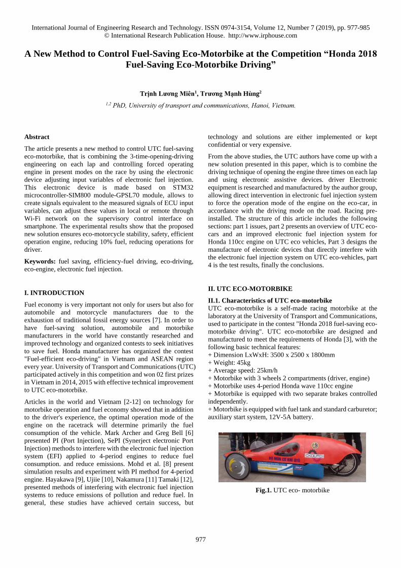
UTC eco-motorbike is a self-made racing motorbike at the
laboratory at the University of Transport and Communications,
used to participate in the contest "Honda 2018 fuel-saving eco-
motorbike driving". UTC eco-motorbike are designed and
manufactured to meet the requirements of Honda [3], with the
following basic technical features:
+ Dimension LxWxH: 3500 x 2500 x 1800mm
+ Weight: 45kg
+ Average speed: 25km/h
+ Motorbike with 3 wheels 2 compartments (driver, engine)
+ Motorbike uses 4-period Honda wave 110cc engine
+ Motorbike is equipped with two separate brakes controlled
independently.
+ Motorbike is equipped with fuel tank and standard carburetor;
auxiliary start system, 12V-5A battery.
Fig.1. UTC eco- motorbike
International Journal of Engineering Research and Technology. ISSN 0974-3154, Volume 12, Number 7 (2019), pp. 977-985
© International Research Publication House. http://www.irphouse.com
978
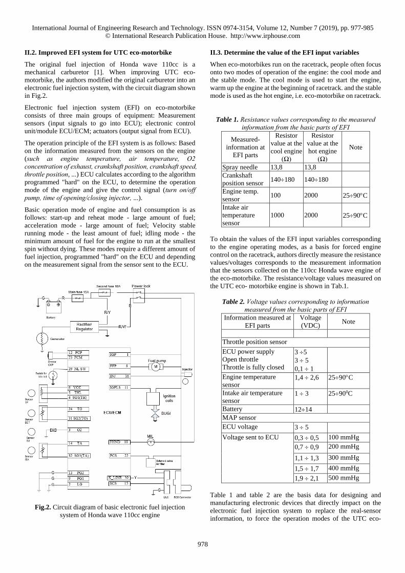
II.2. Improved EFI system for UTC eco-motorbike
The original fuel injection of Honda wave 110cc is a
mechanical carburetor [1]. When improving UTC eco-
motorbike, the authors modified the original carburetor into an
electronic fuel injection system, with the circuit diagram shown
in Fig.2.
Electronic fuel injection system (EFI) on eco-motorbike
consists of three main groups of equipment: Measurement
sensors (input signals to go into ECU); electronic control
unit/module ECU/ECM; actuators (output signal from ECU).
The operation principle of the EFI system is as follows: Based
on the information measured from the sensors on the engine
(such as engine temperature, air temperature, O2 concentration of exhaust, crankshaft position, crankshaft speed, throttle position, ...) ECU calculates according to the algorithm
programmed "hard" on the ECU, to determine the operation
mode of the engine and give the control signal (turn on/off pump, time of opening/closing injector, ...).
Basic operation mode of engine and fuel consumption is as
follows: start-up and reheat mode - large amount of fuel;
acceleration mode - large amount of fuel; Velocity stable
running mode - the least amount of fuel; idling mode - the
minimum amount of fuel for the engine to run at the smallest
spin without dying. These modes require a different amount of
fuel injection, programmed "hard" on the ECU and depending
on the measurement signal from the sensor sent to the ECU.
Fig.2. Circuit diagram of basic electronic fuel injection
system of Honda wave 110cc engine
II.3. Determine the value of the EFI input variables
When eco-motorbikes run on the racetrack, people often focus
onto two modes of operation of the engine: the cool mode and
the stable mode. The cool mode is used to start the engine,
warm up the engine at the beginning of racetrack. and the stable
mode is used as the hot engine, i.e. eco-motorbike on racetrack.
Table 1. Resistance values corresponding to the measured information from the basic parts of EFI
Measured-
information at
EFI parts
Resistor
value at the
cool engine
(Ω)
Resistor
value at the
hot engine
(Ω)
Note
Spray needle 13,8 13,8
Crankshaft
position sensor 140180 140180
Engine temp.
sensor 100 2000 2590C
Intake air
temperature
sensor
1000 2000 2590C
To obtain the values of the EFI input variables corresponding
to the engine operating modes, as a basis for forced engine
control on the racetrack, authors directly measure the resistance
values/voltages corresponds to the measurement information
that the sensors collected on the 110cc Honda wave engine of
the eco-motorbike. The resistance/voltage values measured on
the UTC eco- motorbike engine is shown in Tab.1.
Table 2. Voltage values corresponding to information measured from the basic parts of EFI
Information measured at
EFI parts
Voltage
(VDC) Note
Throttle position sensor
ECU power supply
Open throttle
Throttle is fully closed
3 5
3 5
0,1 1
Engine temperature
sensor 1,4 2,6 2590C
Intake air temperature
sensor 1 3 25900C
Battery 1214
MAP sensor
ECU voltage 3 5
Voltage sent to ECU 0,3 0,5 100 mmHg
0,7 0,9 200 mmHg
1,1 1,3 300 mmHg
1,5 1,7 400 mmHg
1,9 2,1 500 mmHg
Table 1 and table 2 are the basis data for designing and
manufacturing electronic devices that directly impact on the
electronic fuel injection system to replace the real-sensor
information, to force the operation modes of the UTC eco-
International Journal of Engineering Research and Technology. ISSN 0974-3154, Volume 12, Number 7 (2019), pp. 977-985
© International Research Publication House. http://www.irphouse.com
979
motorbike’s engine, suitable for driving on the racetrack, to
save fuel, is detailed in part 4.
III. NEW METHOD FOR FUEL-SAVING ECO-
MOTORBIKE DRIVING
III.1. Characteristic of the racing road in 2018
The racing-road in 2018 is shown in Fig.3, consisting of
straight, curved and folded sections connecting each other to
form a closed racetrack with a circumference of 1200 m/lap.
Each participating vehicle must run 8 laps with a total length of
racetrack 9600m.
Fig.3. Honda racing-road in 2018
III.2. Proposing new method for the fuel-saving eco-
motorbike driving
With a minimum speed of 25 km/h, after the calculation and
test-run, the authors propose the operation plan of UTC eco-car
as follows: Each lap (1200m) the driver just needs to start
engine 3-times. The first-time opened-engine, from the starting
position, the eco-motorbike accelerates from 0 (only for the first lap) or 20km/h (for the next lap) to a stable-speed of about
50 km/h then the eco-motorbike runs according to inertia,
decreases the speed of about 20 km/h. The second-time
opened-engine, the eco-motorbike continuously runs from
20km/h to 50 km/h, then the vehicle follows the inertial and
decreases speed of 20km/h. The 3-time opened-engine, the eco-
motorbike is on 20km/h only needs to accelerate to about 35
km/h to bring the vehicle back to the starting position of the
new racetrack.
Fig.4. Three-time opened-engine on lap 1200m
From the eco-driving operation graph in Fig.4, it shows that the
UTC eco-motorbike’s engine does not operate continuously
(run only 3 to 5 seconds) so if it is not “force” controlled, the
engine will always be in start-up mode and speed up when
driver accelerates or hit the pedal, therefore the engine
consumes a lot of fuel. To overcome this problem, in order to
save fuel consumption, the authors propose a new method,
which is to combine the operation of the vehicle with 3-times
opened-engine and to control “force” the operation of the
engine by using the electronic device. This electronic device
directly impacts on the EFI system (called iEFI device), as
follows:
+ The iEFI device will give the equivalent electrical signals to
the measuring signals of the ECU input variable, so that to feed
forced into the ECU, so that the engine operates according to
the desired mode (cool mode to start the engine, hot mode when the car runs on the racetrack, combined with the fuel pump control on the nozzle).
+ Before starting the engine, set the resistor values on the iEFI
device of the ECU input variables corresponding to the variable
values: engine temperature and the intake air temperature in the
cooling mode as shown in Table 1.
+ When the eco-motorbike runs on the racetrack in the hot
mode, we set the resistance values on the iEFI device of the
ECU input variables corresponding to the variable values:
engine temperature and the intake air temperature in the hot
mode as shown in the Table 1.
IV. MANUFACTURING THE ELECTRONIC DEVICE
iEFI TO ADJUST EFI INPUT VARIABLES
IV.1. Requirements of the iEFI device
With the minimum fuel consumption criterion on the racetrack
Fig.3, the driver must take advantage of the vehicle’s inertia by
turning on/off the engine on the racetrack with the least number
of times. However, turning on/off the engine, to operate in the
desired mode, only succeeds when ECU is properly provided
with the values of the ECU input variables. The value of the
ECU input variables will usually be transmitted from actual
measurement sensors installed on the Honda wave110cc engine
on UTC eco-motorbike.
In this article, the authors fabricate the electronic device that
directly impacts on EFI system (called iEFI device) to generate
electrical signals equivalent to the measured signals of the ECU
input variables, in order to force the engine working in the
desired mode. In other words, the iEFI electronic device
impacts on the EFI system, having the following basic
requirements:
+ Generate an electrical signal equivalent to the engine
temperature signal, measured by the engine temperature sensor,
and then to be forced into the ECU.
+ Generate an electrical signal equivalent to the intake air
temperature signal, measured by the intake air temperature
sensor, and then to be forced into the ECU.

International Journal of Engineering Research and Technology. ISSN 0974-3154, Volume 12, Number 7 (2019), pp. 977-985
© International Research Publication House. http://www.irphouse.com
980
+ Generate an electrical signal equivalent to the oxygen
concentration signal in the exhaust gas, measured by the
oxygen concentration sensor, and then to be forced into the
ECU.
+ Give an electrical signal to forcedly control the cyclic
injector/nozzle with the suitable opening/closing time to reduce
fuel consumption.
IV.2. Adding iEFI device to EFI system
UTC eco-motorbike operates in two basic modes: start-up
mode (cool engine) and acceleration mode (hot engine). In
order to fuel-saving, in this paper, the author has created an
additional iEFI electronic device to add in the EFI system. The
iEFI device creates the forced input signals for ECU, to force
the ECU selecting the pre-set operation mode of engine,
calculating the fuel injection time required on the racetrack.
The block diagram of the EFI control system is complemented
with the iEFI typical device to force the operation of the 110cc
Honda wave engine, as shown in Fig.5.
Fig.5. iEFI device added to the EFI system
In this diagram, ECU continuously updates and processes
information of input variables, then determines the driving
mode on the racetrack, calculates the time of opening/closing
the injector to spray fuel into the nozzle. Information of ECU
input variables or collected from sensors installed on Honda
wave110cc engine, or taken from iEFI device. The iEFI device
generates a forced input signal for the ECU (equivalent to the
measurement signal of the ECU input variables in the
corresponding mode), to force the ECU to select the operating
mode of the desired engine and calculate timing of fuel
injection required on the racetrack. The process of opening and
closing injectors is interrupted. The time to open the injector
depends on the control pulse output from the ECU and PWM
block. The pulse width varies depending on the engine's
operation mode. To ensure safety in case of equipment
malfunction, the driver can switch the switch so that the engine
runs in the original mode.
IV.3. The iEFI device structure block diagram
The diagram block of the iEFI device is fabricated and added
to the EFI system as shown in Fig.6.
Fig.6. iEFI device structure block diagram
The iEFI device includes the following main function blocks:
source block; central microcontroller block using ARM Cortex
STM32F 32-bit microcontroller; The electrical signal
generation block (resistance value) is equivalent to the engine
temperature/intake air temperature, to be forced into the ECU;
The electrical signal generation block (resistor value) is
equivalent to the crankshaft position/injector position, to be
forced into the ECU; The PWM block sends out the suitable
signal to force the injector/nozzle cycle with the appropriate
opening/closing time to save fuel; GPRS SIM800/Wi-Fi
Esp8266 communication block allows setting the resistance
values equivalent to the signal of engine temperature/intake air
temperature remotely via Wi-Fi/GPRS network on the
smartphone, to force the engine to run according to the demand
regime; GPS-L70 position module, to update the eco-
motorbike's journey on Google Map in real time.
IV.4. Principle circuit diagram of the iEFI device
The principle circuit diagram of the iEFI device is presented in
Fig.7.
The mimic electrical signal generation block uses IC
MCP42010 of Microchip. This block works to mimic the ECU
input sensor signals, acting as the variable resistors.
The resolution of the input variables is as follows:
R_adj=10000/28=39.0625 Ohm
Thus, it is possible to adjust 256 levels of resistance value with
each step of 39.0625Ohm, maximum of 10KOhm to put on the
ECU.
RPOT1 and RPOT2 are resistor outputs, to be included in ECU.
MCP42010 communicates with microcontroller STM32 via
SPI standard.

International Journal of Engineering Research and Technology. ISSN 0974-3154, Volume 12, Number 7 (2019), pp. 977-985
© International Research Publication House. http://www.irphouse.com
981
Fig.7. Principle circuit of iEFI device: source block; central microcontroller block; signal generation block; PWM block
Fig.8. Principle circuit of iEFI device: communication block; position module
International Journal of Engineering Research and Technology. ISSN 0974-3154, Volume 12, Number 7 (2019), pp. 977-985
© International Research Publication House. http://www.irphouse.com
982
The PWM block uses FET IRF640 with 12VDC, 1Mhz. it is
necessary to have the signal switch circuit: from 3.3V to 12V.
This block controls the injector from the output signal of
STM32F to save fuel.
The GPRS SIM800/Wi-Fi Esp8266 communication block
handle communication between the STM32F and cloud for
monitoring and control purposes.
The GPS-L70 position block is connected to the
microcontroller's STM32 UART, with the removable antenna
1575.42Mhz ensuring accurate positioning.
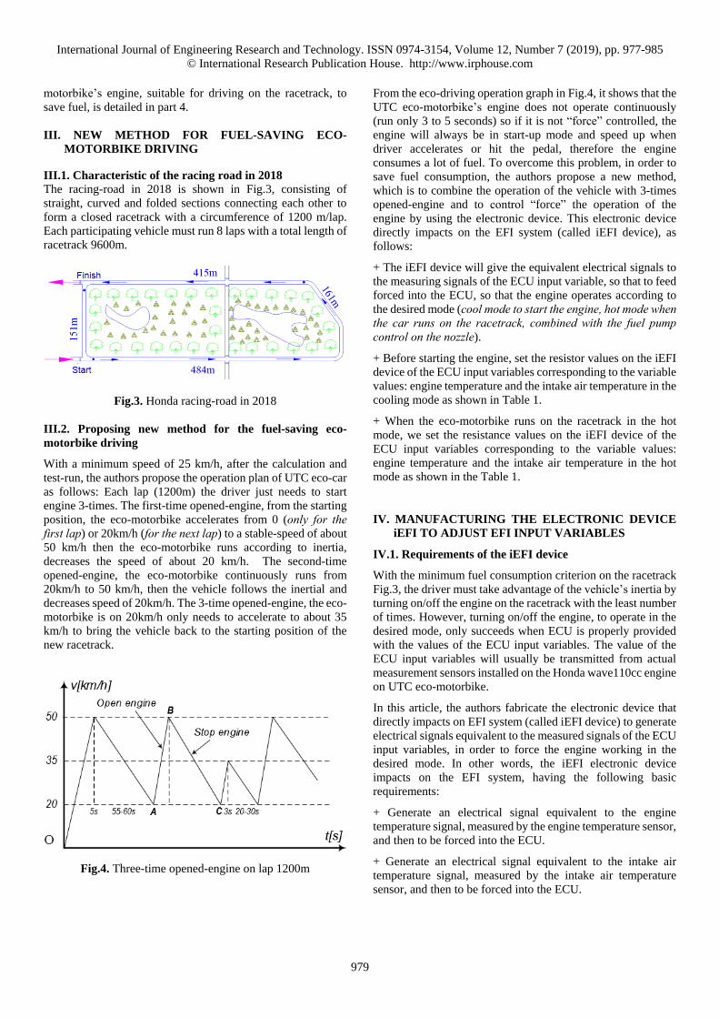
IV.5. Printed circuit diagram of iEFI device
The printed circuit diagram is shown in Fig.9.
Fig.9. Printed circuit of iEFI device
Hardware product image after assembling the event as Fig.10.
The iEFI device connects to phones and/or computers via Wi-
Fi. Resistance value (or voltage value), equivalent to the signal
measured from sensors mounted on a Honda wave110cc engine,
forcing into ECU, adjusted directly on the smartphone, while
displaying eco-motorbike’s journey on Google Map.
Fig.10. The hardware real-image of the iEFI device
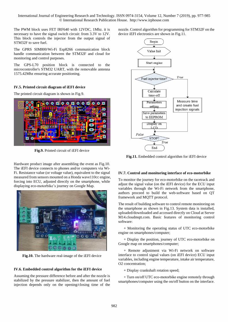
IV.6. Embedded control algorithm for the iEFI device
Assuming the pressure difference before and after the nozzle is
stabilized by the pressure stabilizer, then the amount of fuel
injection depends only on the opening/closing time of the
nozzle. Control algorithm for programming for STM32F on the
device iEFI electronics are shown in Fig.11.
Fig.11. Embedded control algorithm for iEFI device
IV.7. Control and monitoring interface of eco-motorbike
To monitor the journey for eco-motorbike on the racetrack and
adjust the signal value (on the iEFI device) for the ECU input
variables through the Wi-Fi network from the smartphone,
authors proceed to build the web-software based on QT
framework and MQTT protocol.
The result of building software to control remote monitoring on
the smartphone as shown in Fig.13. System data is installed,
uploaded/downloaded and accessed directly on Cloud at Server
M14.cloudmqtt.com. Basic features of monitoring control
software:
+ Monitoring the operating status of UTC eco-motorbike
engine on smartphones/computer;
+ Display the position, journey of UTC eco-motorbike on
Google map on smartphones/computer;
+ Remote adjustment via Wi-Fi network on software
interface to control signal values (on iEFI device) ECU input
variables, including engine temperature, intake air temperature,
O2 concentration;
+ Display crankshaft rotation speed;
+ Turn on/off UTC eco-motorbike engine remotely through
smartphones/computer using the on/off button on the interface.

International Journal of Engineering Research and Technology. ISSN 0974-3154, Volume 12, Number 7 (2019), pp. 977-985
© International Research Publication House. http://www.irphouse.com
983
V. TESTING iEFI DEVICE ON UTC ECO-MOTORBIKE
V.1. Installing the iEFI device on UTC eco-motorbike
Carry out the installation of iEFI device on UTC eco-motorbike
as shown in Fig.12.
Fig.12. Installation the iEFI device on UTC eco-motorbike
V.2. Tested results of the iEFI devices on eco-motorbike on
the racetrack
Table 3. The first time tested results
The IEF’s part
getting
measurement
signal
Without iEFI With iEFI Note
Environment
temp. 30oC
Cool
mode
Hot
mode
Engine
temperature
sensor (Ω)
1500 150 1500
Intake air
temperature
sensor (Ω)
1500 1200 1500
Driving time
(min) 24 24 9.6km
Fuel
consumption (cc) 22,9 21,6 5,7%
Running UTC eco-motorbike by opening the engine three times
at each lap, when do not and using iEFI device, then use MST-
100P standard measurement device, supplied by Honda, to
synthesize the data on each test of the racetrack, the tested
results are shown in Table 3, Table 4, Table 5.
Table 4. The second time tested results
The IEF’s part
getting
measurement
signal
Without iEFI With iEFI Note
Environment
temp. 30oC
Cool
mode
Hot
mode
Engine
temperature
sensor (Ω)
1500 150 1500
Intake air
temperature
sensor (Ω)
1500 1500 1500
Driving time
(min) 24 24 9.6km
Fuel
consumption (cc) 22,9 20,8 9,2%
Table 5. The third time tested results
The IEF’s part
getting
measurement
signal
Without iEFI With iEFI Note
Environment
temp. 30oC
Cool
mode
Hot
mode
Engine
temperature
sensor (Ω)
1500 150 1500
Intake air
temperature
sensor (Ω)
1500 1500 1500
Driving time
(min) 24 24 9.6km
Fuel
consumption (cc) 22,9 20,6 10,0%
Based on the data tables of UTC eco-driving tested results on
the racetrack, it shows that when applying the UTC eco-driving
method by opening the engine three times on each lap and using
iEFI device, the eco-motorbike runs smoothly, save fuel up to
10% (corresponding to 20% fuel injection pulse reduction time).
Controlling eco-motorbike on web-software installed on
smartphone via Wi-Fi network, we obtained some results
images displaying and adjusting values (on the iEFI device) on
the interface software corresponding to the ECU input variables
and the journey on the racetrack as shown in Fig.13, Fig.14.
International Journal of Engineering Research and Technology. ISSN 0974-3154, Volume 12, Number 7 (2019), pp. 977-985
© International Research Publication House. http://www.irphouse.com
984
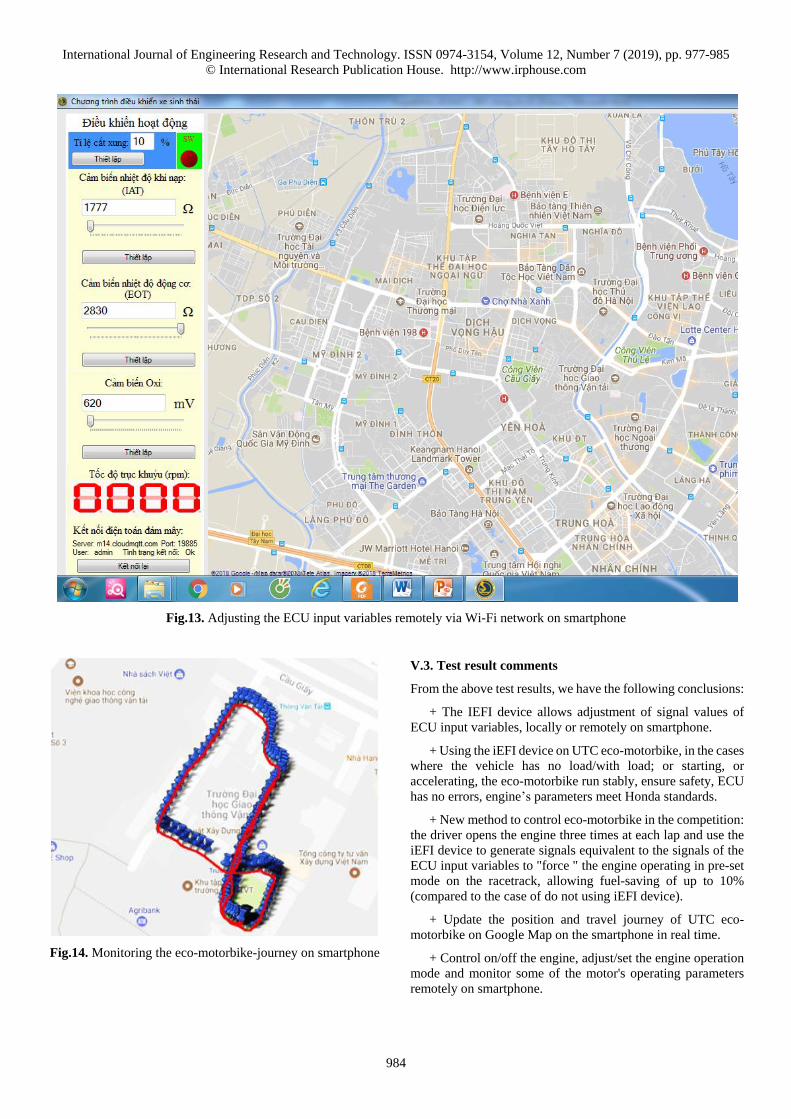
Fig.13. Adjusting the ECU input variables remotely via Wi-Fi network on smartphone
Fig.14. Monitoring the eco-motorbike-journey on smartphone
V.3. Test result comments
From the above test results, we have the following conclusions:
+ The IEFI device allows adjustment of signal values of
ECU input variables, locally or remotely on smartphone.
+ Using the iEFI device on UTC eco-motorbike, in the cases
where the vehicle has no load/with load; or starting, or
accelerating, the eco-motorbike run stably, ensure safety, ECU
has no errors, engine’s parameters meet Honda standards.
+ New method to control eco-motorbike in the competition:
the driver opens the engine three times at each lap and use the
iEFI device to generate signals equivalent to the signals of the
ECU input variables to "force " the engine operating in pre-set
mode on the racetrack, allowing fuel-saving of up to 10%
(compared to the case of do not using iEFI device).
+ Update the position and travel journey of UTC eco-
motorbike on Google Map on the smartphone in real time.
+ Control on/off the engine, adjust/set the engine operation
mode and monitor some of the motor's operating parameters
remotely on smartphone.

International Journal of Engineering Research and Technology. ISSN 0974-3154, Volume 12, Number 7 (2019), pp. 977-985
© International Research Publication House. http://www.irphouse.com
985
VI. CONCLUSION
The article presents a new method to control the UTC eco-
motorbike on the racetrack in order to save fuel, which is
driving the eco-motorbike by opening the engine three times in
each lap combined using iEFI device to generate electrical
signals, equivalent to the engine temperature signal, intake air
temperature signal, exhaust’s oxygen concentration signal of
the ECU input variables. Based on these mimic signals, the
engine is forced to operate in the pre-set mode on the racetrack
(the engine does not operate following the "hard" programme
about fuel injection level of Honda EFI system). The iEFI
device is built using STM32F microcontroller, SIM800/Wi-Fi
Esp8266 module, GPS L70 position module, which allows to
adjust the value of ECU input variables, locally or remotely on
the smartphone’s screen.
The new eco-driving method by opening the engine three times
on each lap using iEFI device to ensure stalely and safely,
meeting Honda's technical requirements and 10% reduction in
fuel. UTC eco-motorbike journey is updated on Google Map
on smartphone in real-time.
The success of this research allows to continue the research on
improving quality of the control system of electronic fuel
injection system, electronic ignition system for 2-period/4-
period gasoline engines to reduce fuel consumption.
REFERENCES
[1] Truong Manh Hung (2018), Research, design,
manufacture equipment to adjust input parameters of
electronic fuel injection system for vehicle participating
in the contest "Fuel-saving eco-driving environment
protection" organized by Honda Vietnam, University of
transport and communications.
[2] Pham Minh Tuan (2003), Internal combustion engine,
Science and Technology Publisher.
[3] Honda (2018), Guide to fuel-saving eco-motorbike
driving in Vietnam, Honda Vietnam.
[4] Roland S.Burns (2001), Advanced Control Engineering,
Department of Mechanical and Marine Engineering
University of Plymouth, UK.
[5] AllanW.M. Bonnick (2001), Automotive Computer
Controlled Systems, Butterworth-Heinemann, UK.
[6] Mark Archer, Greg Bell (2001), Advanced Electronic
Fuel Injection Systems – An Emissions Solution for both
2- and 4-stroke Small Vehicle Engines, SIAT26.doc –
MDA/GBB.
[7] Jiun-Horng Tsai, et al. (2018), Fuel Economy and
Volatile Organic Compound Exhaust Emission for
Motorcycles with Various Running Mileages, Aerosol
and Air Quality Research, 18, 2018.
[8] Mohd Faisal Hushim and el. (2014), Port-Fuel Injection
System for Small 4-Stroke Single Cylinder Engine: An
Experimental Framework, Automotive Research Group.
[9] Hayakawa, K., et al. (2004), 125cc Small Engine Fuel
Injection System with Low Emissions Solutions. SAE
Technical Paper, No.2004-32
[10] Ujiie, T., et al. (2005). Development of Fuel Injector and
Fuel Pump for a Fuel Injection System to Use in Small
Motorcycles. SAE Technical Paper, No.2005-01-0047.
[11] Nakamura, M., et al. (2003). Fuel Injection System for
Small Motorcycles. SAE Technical Paper, No.2003-32-
0084.
[12] Tamaki, K., et al. (2004). Control Device of
Electronically Controlled Fuel Injection System of Air-
cooled Engines for Small Motorcycles. SAE Technical
Paper, No.2004-01-0901.