
Solving interoperability and performance challenges over ...

A model-driven ontology approach for manufacturing system interoperability and knowledge sharing
Nitishal Chungoora1, Robert Young1, George Gunendran2, Claire Palmer1, Zahid Usman1, Najam Anjum1, Anne-Françoise Cutting-Decelle3, Jennifer Harding1, Keith Case1
1Wolfson School of Mechanical and Manufacturing Engineering, Loughborough University, Loughborough, Leicestershire, LE11 3TU, UK
2Control Techniques Ltd., The Gro, Newtown, Powys, SY16 3BE, UK
3CODATA France, F-75016 Paris, France; Université Lille Nord de France, F-59000 Lille, France; LM2O, Ecole Centrale de Lille, Cité Scientifique, BP 48, 59651 Villeneuve d’Ascq, France
Abstract. The requirements for the interoperability of semantics and knowledge have become increasingly important in Product Lifecycle Management (PLM), in the drive towards knowledge-driven decision support in the manufacturing industry. This article presents a novel concept, based on the Model Driven Architecture (MDA). The concept has been implemented under the Interoperable Manufacturing Knowledge Systems (IMKS) project in order to understand the extent to which manufacturing system interoperability can be supported using radically new methods of knowledge sharing. The concept exploits the capabilities of semantically well-defined core concepts formalised in a Common Logic-based ontology language. The core semantics can be specialised to configure multiple application-specific knowledge bases, as well as product and manufacturing information platforms. Furthermore, the utilisation of the expressive ontology language and the generic nature of core concepts help support the specification of system mechanisms to enable the verification of knowledge across multiple platforms. An experimental demonstration, using a test case based on the design and manufacture of an aerospace part, has been realised. This has led to the identification of several benefits of the approach, its current limitations as well as areas to be considered for further work.
Keywords: ontologies, model driven architecture, product lifecycle management, knowledge sharing

1 Introduction The traditional approach towards information sharing across the product lifecycle has been based on the utilisation of a single common schema, or product master model [1], which prescribes a rigid information structure for use across several engineering functions. However, is has been recognised that this approach remains problematic as engineers are interested in different lifecycle viewpoints, terms, definitions and representations [2]. These factors inevitably have repercussions in the ability to achieve system interoperability and knowledge sharing. It has been shown, e.g., that the lack of interoperability is very costly to globally distributed industries in the manufacturing sector [3]. This issue is also prevalent across other fields such as services, healthcare and business-to-business e-commerce amongst others and, therefore, the issue of knowledge sharing still remains to be addressed.
Several resourceful efforts have been fostered to progress towards improved system configurations and interoperability following the Model Driven Architecture (MDA) [4], Model Driven Interoperability (MDI) and ontology development methods [5-11]. Related works such as Djuric et al. [12] also indicate that there is a tendency to exploit the combined use of MDA with Semantic Web ontology languages. However, while Semantic Web ontology languages like the Web Ontology Language (OWL) [13]can prove suitable for certain model-driven systems [9, 12, 14], these ontology languages fall short of meeting the rich and verifiable semantics and structures that are required by product lifecycle systems. It is also evident that current work does not entirely address the practical deployment and testing side of MDA, MDI and ontology-driven system development applied to industrial test cases across the product lifecycle.
This article identifies a concept based on MDA, MDI and ontology-driven specifications as contribution towards the understanding of novel model-driven methods for achieving manufacturing system interoperability and knowledge sharing across multiple platforms in the product lifecycle. More specifically, this work targets the combined exploitation of model-driven and ontology-driven system development using the expressive power of the Extended Common Logic Interchange Format (ECLIF) as ontology language. The model-driven concept has been explored and tested as part of the Interoperable Manufacturing Knowledge Systems (IMKS) research project [15]. The concept builds on the ideas of extensible generic or core ontologies of manufacturing [16-20] as well as knowledge verification methods [21-23]. The understanding and results from the completed IMKS project are being presented in the context of MDA and MDI.
The methodology applied in this work has comprised of an initial industrial exploration of the design and manufacture of aerospace parts. This has aided the specification of the key requirements and concepts that are relevant to supporting multiple system development and knowledge verification across the design and manufacture phases of the product lifecycle. A Manufacturing Core Ontology has been proposed to provide an extensible set of formally-defined core concepts from which application-specific systems can be developed [24]. Essential mechanisms for enabling knowledge verification across systems have also been researched. Altogether, the IMKS experimental system has been designed and implemented with the intention of testing the resulting ideas.
This article is structured as follows: section 2 identifies the proposed ontology-based model-driven concept, leading to a description of the key elements in the development of the approach in section 3. Section 4 documents an industrial test case which exploits the configuration provided by the IMKS

experimental system to validate the applicability of the model-driven concept. A discussion of the findings from this work is elaborated in section 5 followed by the relevant conclusions in section 6.
2 IMKS model-driven concept
2.1 Overview Figure 1 depicts the IMKS model-driven concept in relationship to the hierarchy of models within MDA. MDA is an approach to IT system specification that divides up the specification of system functionalities from the intended technology-specific implementation platform [6]. The architecture defines three viewpoints and their corresponding models notably: the Computation Independent Model (CIM), the Platform Independent Model (PIM) and the Platform Specific Model (PSM), whose interactions involve transformations for converting one model to another on the same system. The implications of the different levels within MDA and their respective models applied to IMKS are next explained.
Figure 1. The IMKS model-driven concept
2.2 Specification models and their transformations
2.2.1 Computation independent models The CIM specifies the high-level requirements that should be fulfilled by the models to be developed at the PIM level. Some examples of generic requirements, identified in Figure 1, for enabling the specification of the Manufacturing Core Ontology consist of (1) the ability to capture product lifecycle core concepts, (2) the requirement for accommodating domain concepts via specialisation

mechanisms and (3) the need to support mechanisms for knowledge verification amongst others. A more detailed view of requirements defined at the CIM level is presented in section 3.
2.2.2 Platform independent models The PIM, on the other hand, defines a model at a relatively high level of abstraction, where the model is used to describe the software solution using a technology independent view [25]. In Figure 1, at the heart of the PIM level is the Manufacturing Core Ontology. The methodology for specifying this ontology comprises the initial capture of a lightweight, platform-independent, UML class model. This lightweight representation is then formalised as heavyweight ontology encoded in the Extended Common Logic Interchange Format (ECLIF) [26]. The latter is an extended version of the Common Logic Interchange Format which, as a recommendation from ISO/IEC 24707 [27], supports a logic framework for the exchange and transmission of information.
The Manufacturing Core Ontology can be specialised into multiple domain-specific PIMs, in order to address the semantic requirements of different domains in the product lifecycle such as design and manufacture, as shown in Figure 1. These domain-specific PIMs are also formalised in ECLIF and are, therefore, platform-independent as far as the semantics of their structures are concerned.
2.2.3 Platform specific models The PSM is targeted at the deployment of models that derive from suitable PIMs, in the chosen execution platforms. Examples of platform-specific implementations relevant to our needs are: design and manufacturing knowledge environments, product information and manufacturing information platforms such as PLM suites. Overall, fundamentally speaking, the IMKS concept adopts a combination of model-driven and ontology-driven development methods towards the deployment of systems at the PSM level, which is considered a promising perspective [11]. PSM-level systems may be regarded as those that end users, such as engineers, interact directly with in order to support decision making during the product lifecycle.
2.2.4 Model transformations In MDA there are a number of model transformations that can take place between and within the CIM, PIM and PSM levels [8, 9]. In our work, the first transformation is concerned with taking the general CIM requirements for the Manufacturing Core Ontology into its lightweight and heavyweight specification models at the PIM level. Based on Figure 1, e.g., for a particular design domain under construction, new sets of CIM requirements (such as domain and user requirements) would be defined which are transformed into the design domain PIM.
This second transformation also requires building the design domain as an integrally-defined extension of the Manufacturing Core Ontology. Mechanisms such as ontology specialisation are used for that purpose [20]. The design domain PIM can then be transformed into several design application-specific PSMs for developing systems such as design knowledge bases, design methods and product information platforms. The latter transformations are largely dependent on the system implementation requirements and may be manual in nature. The same understanding applies for the specification of manufacturing domains and the development of manufacturing systems.
2.2.5 Model interoperability The fundamental basis of sharing a reusable set of semantics, as prescribed by the Manufacturing Core Ontology, supports the ability to evaluate and verify specialised domain knowledge. Knowledge
verification methods are planned and specified at the PIM level in ECLIF. In other words, following our approach, model interoperability does not directly take place at the PSM level but instead an interoperability specification in ECLIF is captured at the PIM level which is then transformed into a PSM execution of the specification. This concept is analogous to PIM-level interoperability models used in MDI [7, 10, 25]. The PIM representation of the knowledge verification specification can then be deployed at the PSM level for driving knowledge sharing across real applications, e.g., across actual product and manufacturing information platforms to support feedback of manufacturing knowledge to product designers.
3 Development of the IMKS model-driven concept
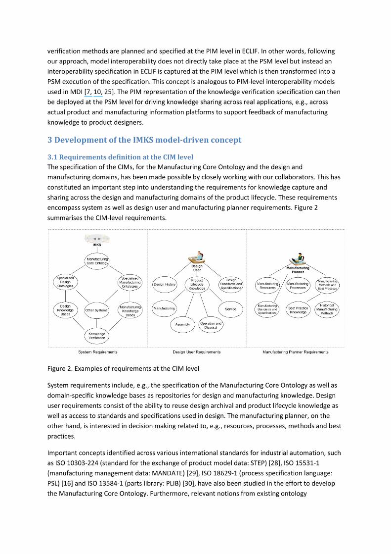
3.1 Requirements definition at the CIM level The specification of the CIMs, for the Manufacturing Core Ontology and the design and manufacturing domains, has been made possible by closely working with our collaborators. This has constituted an important step into understanding the requirements for knowledge capture and sharing across the design and manufacturing domains of the product lifecycle. These requirements encompass system as well as design user and manufacturing planner requirements. Figure 2 summarises the CIM-level requirements.
Figure 2. Examples of requirements at the CIM level
System requirements include, e.g., the specification of the Manufacturing Core Ontology as well as domain-specific knowledge bases as repositories for design and manufacturing knowledge. Design user requirements consist of the ability to reuse design archival and product lifecycle knowledge as well as access to standards and specifications used in design. The manufacturing planner, on the other hand, is interested in decision making related to, e.g., resources, processes, methods and best practices.
Important concepts identified across various international standards for industrial automation, such as ISO 10303-224 (standard for the exchange of product model data: STEP) [28], ISO 15531-1 (manufacturing management data: MANDATE) [29], ISO 18629-1 (process specification language: PSL) [16] and ISO 13584-1 (parts library: PLIB) [30], have also been studied in the effort to develop the Manufacturing Core Ontology. Furthermore, relevant notions from existing ontology

development methodologies have been tailored to address the needs of the IMKS model-driven concept.
3.2 Ontologies at the PIM level
3.2.1 Lightweight representation of concepts and relations Figure 3 depicts a lightweight UML class model for a majority of concepts specified in the Manufacturing Core Ontology as exploited for the demonstration of the model-driven concept. The figure illustrates the core classes of concepts and the existing relations to help build the vocabulary of the ontology. It is to be noted that for our purpose, UML has here been exploited purely as a tool to design ontologies to be later formalised in ECLIF.
Figure 3. Lightweight UML representation of classes and relations
The various concepts acknowledged in the ontology relate to the notions that need to be covered in the CIM-level requirements previously identified in Figure 2. Some examples are: DesignPartFamily, DesignFeature and DesignFunction to capture design archival knowledge; ManufacturingPartFamily, ManufacturingFeature and ManufacturingMethod to capture methods and best practices for manufacturing planning. Overall, the UML representation captures important silos of product lifecycle information, e.g., part planning using part families and features, manufacturing methods and processes, manufacturing resources, manufacturing facilities and information from the physical realisation of parts.

3.2.2 UML to ECLIF A detailed discussion of the mappings from UML to ECLIF falls outside the current scope of this article. However, we have investigated that UML can be accurately exploited to represent the exclusively lightweight structures of ECLIF, where it is not intended to express ECLIF logical axioms. Table 1 depicts the necessary mappings for transforming the Manufacturing Core Ontology from its UML representation to the corresponding ECLIF lightweight representation.
Table 1. Summary of mappings from UML to ECLIF lightweight structures
UML Element ECLIF Element Class Type Generalisation sup (i.e., has super-type relation) Binary association with directionality BinaryRel (i.e., binary relation) n-ary association with argument positions n-ary relation (e.g., TernaryRel, QuaternaryRel,
QuinaryRel) Attribute of type Boolean UnaryRel Stereotype n-ary function (e.g., UnaryFun, BinaryFun) Powertype Metaproperty (i.e., meta-type)
3.2.3 Formalisation in ECLIF The lightweight representation of the Manufacturing Core Ontology serves as a basis for formalising the ontology in ECLIF. Types, relations and functions are defined using the ECLIF syntax which follows the CLIF syntax [27]. Two ontology assertions are shown as examples of an ECLIF Type and BinaryRel relating to the entities PartFamily and hasFeature respectively (see Figure 3). Notice that contextFor is a binary relation used to associate an identifier (i.e., namespace), in this case MLO (stands for Middle Level Ontology), to some particular ontology entity, while argProp is used to define the signature of relations.
(Type PartFamily) (sup PartFamily Object) (contextFor PartFamily MLO) (BinaryRel hasFeature) (argProp hasFeature 1 PartFamily) (argProp hasFeature 2 Feature) (contextFor hasFeature MLO) Of particular relevance is how semantic constraints are declared using ECLIF logical axioms in order to capture formal meaning. The ECLIF expression shown next identifies an example of a semantic constraint in the Manufacturing Core Ontology. Semantic constraints prescribe the conditions necessary to ensure the integrity of the ontology. In ECLIF, integrity constraints capture semantic restrictions and hold information about their severity and their required informal interpretation. In this case, the constraint catches the notion that the definition of a type of PartFamily requires the existence of some associated type(s) of Feature(s).
(integrityConstraint (=> (supTC ?pf PartFamily)

(exists (?f) (and (supTC ?f Feature) (hasFeature ?pf ?f)))) HardIC "Every type of PartFamily has some associated type of Feature.")
3.2.4 Specialisation An important consideration made during the development of the Manufacturing Core Ontology has been to develop the model so that it can be extended to accommodate the semantics of domain-specific design and manufacturing PIMs. This is achievable through the support of specialisation mechanisms. In addition to the common specialisation mechanisms such as subsumption and instantiation, the Manufacturing Core Ontology adopts a distinctive approach to specialisation via constraints. This enables the tailoring of semantic constraints at the PIM level leading to the ability to capture knowledge at the PSM level.
Figure 4 illustrates an example based on the progressive specialisation of constraints originating from the definition of Feature individuals. The figure shows one semantic constraint declared at the generic level of the ontology. This constraint is then specialised at the product lifecycle level of the ontology to capture the compulsory definition of DesignFeature individuals. At the domain level, the constraint route from Feature to DesignFeature is then exploited to capture some domain-specific constraint for LocatingHole individuals.
Figure 4. Specialisation of semantic constraints
Finally, the overall semantics described in ECLIF at the PIM level can be used, e.g., to instantiate domain-specific knowledge in some chosen knowledge environment. It is to be noted that the various levels of specialisation of semantics are also enabled through the use of second-order

relations across ECLIF meta-properties, types and individuals. This constitutes a powerful aspect of the ECLIF ontology language. In this way, the Manufacturing Core Ontology built on top of ECLIF imparts the ability to address specialisations into multiple viewpoint platform-independent domain models, which themselves can be transformed into multiple PSMs.
3.3 Knowledge verification and sharing The IMKS model-driven concept argues the basis of having a common semantic foundation, built on top of a provable expressive ontology language as prerequisite towards knowledge verification and sharing across multiple systems. In our investigation, the Manufacturing Core Ontology fosters the semantic foundation and ECLIF supports the requirements as a provable logic-based language.
To enable interoperability and knowledge sharing across multiple PSMs, appropriate knowledge verification mechanisms are planned and specified in ECLIF at the PIM level. This makes it possible to, e.g., support reasoning ability across individually developed PSMs that originate from suitable design and manufacturing PIMs. The ECLIF expression shown in this section depicts one example of a knowledge verification mechanism, in the form of a constraint. The constraint formalises notions associated with a design feature, critical from a manufacturing perspective and establishes a conclusion (i.e., consequent) based on some known premise (i.e., antecedent), which can be checked across PIMs.
In the example, the logical structure prescribed by the ontology contributes to the ability to reference classes of concepts, such as LocatingHole and Diameter (relevant to the design PIM) and StandardDrillingTool (relevant to the manufacturing PIM), in the knowledge verification constraint. Relations such as hasDimension and hasFeatureAttribute, defined in the Manufacturing Core Ontology, can simply be reused in the constraint.
(integrityConstraint (=> (and (LocatingHole ?hole) (Diameter ?dia1) (hasFeatureAttribute ?hole ?dia1) (hasDimension ?dia1 ?dim1)) (exists (?tool ?dia2 ?dim2) (and (StandardDrillingTool ?tool) (available ?tool) (Diameter ?dia2) (hasFeatureAttribute ?tool ?dia2) (hasDimension ?dia2 ?dim2) (measureLTE ?dim2 ?dim1)))) SoftIC "The nominal value of a locating hole diameter may not be less than the available minimum standard drill size. Since the selected hole diameter value is below the available minimum standard drill size, standard tooling and standard machining methods cannot be used.") This knowledge verification constraint can, e.g., be used to warn the designer of a potential issue, from a manufacturing point of view, related to the selected diameter of a LocatingHole if during design, the diameter of the hole is asserted as being less than the available minimum standard drill

size. The constraint presents one way in which an interoperability specification is declared in order to share manufacturing knowledge into design realisation. Other investigated methods for reasoning about knowledge sharing across systems are through suitable inference rules and the assertion of mappings at the PIM level. Below is an ECLIF assertion of a possible mapping between two types of hole features held in the design and manufacturing PIMs respectively. The binary relation mapsTo is irreflexive, transitive and symmetric in nature.
(mapsTo LocatingHole DrilledHole)
It is important to note that the knowledge verification mechanisms at the PIM level do not actually handle any specific knowledge themselves because the knowledge is captured as individuals, i.e., instantiated information, at the PSM level. Specific knowledge can, e.g., be in the form of instantiated facts, values, dimensions, actual design functions and actual cutting tool information. Hence, knowledge verification mechanisms are declared to provide the ‘schemas’ for referring to the actual knowledge residing at the PSM level and may be present in multiple knowledge based platforms and product lifecycle systems.
4 Sharing manufacturing knowledge with design users: a demonstration to validate the IMKS model-driven concept
4.1 Overview An experimental system has been designed and implemented in order to validate the IMKS model-driven approach. The demonstration system is identified in Figure 5. For the purpose of the demonstration the test case has consisted of specialising, from the Manufacturing Core Ontology, the design and manufacturing ontologies of an aerospace compressor disc.
Figure 5. IMKS experimental demonstration system

In Figure 5 each PIM-level ontology has been deployed, at the PSM level, as an eXtensible Knowledge Server (XKS) [31] in the Highfleet Integrated Ontology Development Environment (IODE) [32] in order to develop the required knowledge bases. The disc design and manufacturing PIMs have been transformed from their description in ECLIF into the Knowledge Frame Language (KFL) format [33]. The latter is the formalisation language used for the deployment of XKSs in IODE. The required transformation is a fairly straight forward one as KFL is both frame and Common Logic-based. The knowledge verification specification at the PIM level is also transformed into KFL format to be handled in IODE.
On the other hand, the disc design and manufacturing PIMs have also been utilised to configure a Computer Aided Design (CAD) and Product Lifecycle Management (PLM) system for handling product model and manufacturing information under an integrated platform. NX CAD [34] and Teamcenter PLM [35] are at the PSM level and hold the geometrical modelling and organisation of disc part families and features, respectively. The transformation process from the disc design and manufacturing PIMs into the CAD/PLM information structures is partly manual in nature. Furthermore, it is a requirement that relevant taxonomies of classes and terms, such as those for part families and features, from the domain-specific PIMs be reproduced into the code description of the CAD/PLM software environment. This procedure is made possible and enhanced, in the first place, through the existence of the ECLIF description for the disc design and manufacturing PIMs.
4.2 Example of an implemented knowledge verification constraint Another important task has been to test the ability of the approach to drive knowledge verification and sharing. The scenario has been based on supporting design users, interacting with the CAD/PLM platform, with feedback on manufacturing-critical design features present on the compressor disc. To achieve this, suitable knowledge verification mechanisms have been applied at the PIM level in order to map across the disc design and manufacturing PIMs.
The ECLIF expression next depicts one example of a knowledge verification constraint to warn the design user about machining issues occurring as a result of the unsuitability of available standard tools, due to their tool life, to machine particular design features on a disc. This ECLIF interoperability specification has been utilised at the PSM level to drive the feedback of knowledge from the manufacturing domain to the design domain and made visible to the design user.
(integrityConstraint (=> (and (HPCDiscPF ?disc) (spiralCuttingLength WebProfile ?disc ?sclweb)) (exists (?ct ?scltool ?cs) (and (Length ?scltool) (CuttingSpeed ?cs) (hasAchievableSCLforCuttingSpeed ?ct ?scltool ?cs) (not (measureLT ?scltool ?sclweb))))) SoftIC "There are currently no standard cutting tool inserts capable of finish machining, in a single pass, the web profile described by the Cob, Cob-Diaphragm Transition Feature, Diaphragm, Diaphragm-Rim Transition Feature and Rim. This is due to the relatively short tool life of standard cutting tool inserts. Proceeding with the selected
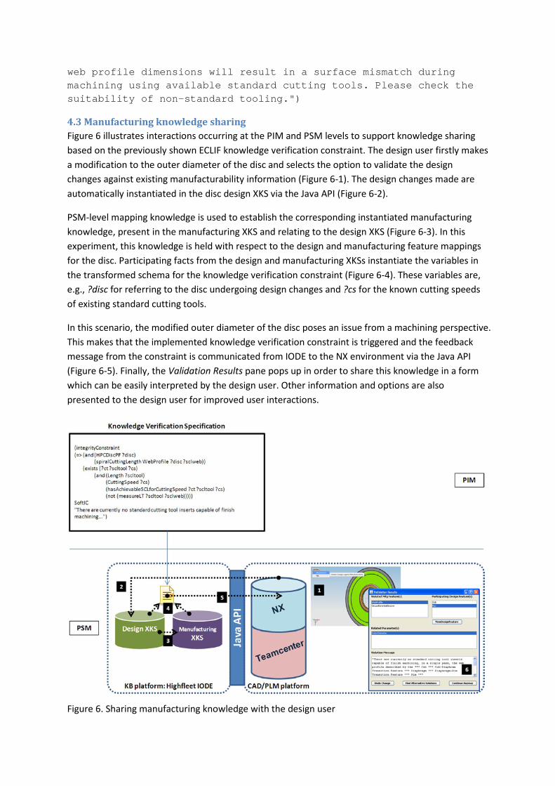
web profile dimensions will result in a surface mismatch during machining using available standard cutting tools. Please check the suitability of non-standard tooling.")
4.3 Manufacturing knowledge sharing Figure 6 illustrates interactions occurring at the PIM and PSM levels to support knowledge sharing based on the previously shown ECLIF knowledge verification constraint. The design user firstly makes a modification to the outer diameter of the disc and selects the option to validate the design changes against existing manufacturability information (Figure 6-1). The design changes made are automatically instantiated in the disc design XKS via the Java API (Figure 6-2).
PSM-level mapping knowledge is used to establish the corresponding instantiated manufacturing knowledge, present in the manufacturing XKS and relating to the design XKS (Figure 6-3). In this experiment, this knowledge is held with respect to the design and manufacturing feature mappings for the disc. Participating facts from the design and manufacturing XKSs instantiate the variables in the transformed schema for the knowledge verification constraint (Figure 6-4). These variables are, e.g., ?disc for referring to the disc undergoing design changes and ?cs for the known cutting speeds of existing standard cutting tools.
In this scenario, the modified outer diameter of the disc poses an issue from a machining perspective. This makes that the implemented knowledge verification constraint is triggered and the feedback message from the constraint is communicated from IODE to the NX environment via the Java API (Figure 6-5). Finally, the Validation Results pane pops up in order to share this knowledge in a form which can be easily interpreted by the design user. Other information and options are also presented to the design user for improved user interactions.
Figure 6. Sharing manufacturing knowledge with the design user

5 Discussion and conclusions The results from the experimental investigation of the IMKS model-driven concept are showing promise in facilitating interoperation across systems for improved knowledge sharing. Two important ideas have been tested in the effort towards combined model-driven and ontology-driven system development for product lifecycle applications. Firstly it has been demonstrated that the specification of a manufacturing ontology of core concepts at the PIM level enables the development of domain-specific PIMs which can capture the semantics of product lifecycle stages, such as design and manufacture, for particular product ranges.
Secondly, using the basis of the Manufacturing Core Ontology and the expressive ECLIF language on which it is built, it has been possible to explore and test knowledge verification and sharing mechanisms. ECLIF benefits from the rigorousness and expressivity of first and second order semantics, thereby implying that more comprehensively-defined structures can be captured and reasoned with, for improved decision making during product design and production.
However, it is necessary to point out that, at the PSM level, our demonstration has been limited to the creation of two knowledge bases deployed under the same environment, i.e., design and manufacturing XKSs in IODE. Moreover, the product and manufacturing information platforms are integrated into a single CAD/PLM environment. A future challenge, therefore, would be to understand the implications of developing and interoperating across different types of knowledge environments and product lifecycle systems.
For example, given that PIM-level Common Logic-based domain ontologies are used to develop separate object-oriented databases and triple stores, it would be required to understand the extent to which these fundamentally different repositories can interoperate. Another potential issue with the investigated approach lies in the manual model transformations that are sometimes required from one MDA level to the next, particularly between the PIM and PSM levels. This can be labour intensive and time consuming, thereby, implying the need for further research into the automation of model transformations in the context of the IMKS model-driven concept.
On the other hand, it would be required to extend the Manufacturing Core Ontology into a reference ontology model for capturing product lifecycle knowledge with increasing complexity. Such an ontology should be able to accommodate concepts central to, e.g., machine control levels and discrete manufacturing timescales, operational timescales needed for inter-machine configurations, longer term product configurations and product service-systems [36]. Furthermore, in order to apply the model-driven concept within other spheres of knowledge, the notion of foundation ontologies would need to be exploited so as to leverage interoperability.
Acknowledgement This work has been funded by the EPSRC through the Loughborough University Innovative Manufacturing and Construction Research Centre (IMCRC) project 253: Interoperable Manufacturing Knowledge Systems (IMKS). We also wish to acknowledge our gratitude and appreciation to all our collaborators for their involvement in the IMKS project.

References 1. C.M. Hoffman, R. Joan-Arinyo, CAD and the product master model, Computer-Aided Design, 30
(11) (1998) 905–918. 2. P. Kugathasan, C.A. McMahon, Multiple viewpoint design models for automotive body-in-white
design, International Journal of Production Research, 39 (8) (2001) 1689–1705. 3. S.B. Brunnermeier, S.A. Martin, Interoperability costs in the U.S. automotive supply chain, Supply
Chain Management–an International Journal, 7 (2) (2002) 71–82. 4. Model Driven Architecture, Object Management Group, Available on-line as
http://www.omg.org/mda/, 2011. 5. V. Rajsiri, J.-P. Lorré, F. Bénaban, H. Pingaud, Knowledge-based system for collaborative process
specification, Computers in Industry, 60 (2) (2010) 161–175. 6. J.P. Almeida, R. Dijkman, M.V. Sinderen, L.S. Pires, Platform-independent modelling in MDA–
supporting abstract platforms, in: Model Driven Architecture–European MDA workshop (MDAFA), Linköping, Sweden, 2004 June 10-11.
7. A.-F. Cutting-Decelle, J.-P. Bourey, R. Grangel, R.I.M. Young, Ontology based communications through model driven tools–the MDA approach feasibility of the approach in urban engineering projects, in: J. Teller, R. John, C. Roussey (eds), Ontologies for Urban Development, Studies in Computational Intelligence, 61, 2007, pp. 181–196.
8. S. Ou, N. Georgalas, M. Azmoodeh, K. Yang, X. Sun, A model-driven integration architecture for ontology-based context modelling and context-aware application development, in: A. Rensink, J. Warmer (eds), Proceedings of the 2nd European Conference on Model Driven Architecture–Foundations and Applications, Bilbao, Spain, 2006 June 10-16, pp. 188–197.
9. S. Cranefield, J. Pan, Bridging the gap between the model-driven architecture and ontology engineering, International Journal of Human-Computer Studies, 65 (7) (2007) 595–609.
10. N. Moalla, Y. Ouzrout, G. Neubert, A. Bouras, Model-driven interoperability to enhance product data quality, in: Proceedings of the 1st International Workshop on Model Driven Interoperability for Sustainable Information Systems in conjunction with the CAiSE’08 conference, Montpellier, France, 2008, pp. 121–133.
11. A. Soylu, P. De Causmaecker, Merging model driven and ontology driven system development approaches–pervasive computing perspective, in: 24th International Symposium on Computer and Information Sciences, Güzelyurt, Turkey, 2009 September 14-16, pp. 730–735.
12. D. Djuric, D. Gasevic, V. Devedzic, Ontology modeling and MDA, Journal of Object Technology, 4 (1) (2005) 109–128.
13. Web Ontology Language (OWL), OWL Web Ontology Language overview, Available on-line as http://www.w3.org/TR/owl-features/, 2011.
14. G.C. Gannod, J.T.E. Timm, R.J. Brodie, Facilitating the specification of semantic web services using model-driven development, International Journal of Web Services Research, 3 (3) (2006) 61–81.
15. Interoperable Manufacturing Knowledge Systems, Available on-line as http://www.lboro.ac.uk/departments/mm/research/product-realisation/imks/, 2011.
16. ISO 18629-1, Industrial automation systems and integration–process specification language–part 1–overview and basic principles, International Organisation for Standardisation (ISO), Geneva, Switzerland, 2004.
17. S.J. Fenves, S. Foufou, C. Bock, R.D. Sriram, CPM2–a core model for product data, Journal of Computing and Information Science in Engineering, 8 (1) (2008) 014501.

18. S. Lemaignan, A. Siadat, J.-Y. Dantan, A. Semenenko, MASON–a proposal for an ontology of manufacturing domain, in: Proceedings of the IEEE Workshop on Distributed Intelligent Systems–Collective Intelligence and its Applications, Prague, Czech Republic, 2006 June 15-16, pp. 195–200.
19. S. Borgo, P. Leitão, Foundations for a core ontology of manufacturing, in: R. Sharman, R. Kishore, R. Ramesh (eds.), Ontologies–a handbook of principles, concepts and applications in information systems, Springer, New York, 2008, pp. 751–776.
20. N. Chungoora, R.I.M. Young, The configuration of design and manufacture knowledge models from a heavyweight ontological foundation, International Journal of Production Research, 49 (15) (2011) 4701–4725.
21. S.D. Cochrane, Manufacturing knowledge verification in design support system, PhD Thesis, Wolfson School of Mechanical and Manufacturing Engineering, Loughborough University, Loughborough, UK, 2006.
22. N.A. Anjum, J.A. Harding, R.I.M. Young, Cross domain knowledge verification–verifying knowledge in foundation based domain ontologies, in: Proceedings of the International Conference on Knowledge Engineering and Ontology Development (KEOD), Valencia, Spain, 2010 October 25-28.
23. L. Toussaint, F. Demoly, N. Lebaal, S. Gomes, PLM-based approach for design verification and validation using manufacturing process knowledge, Journal of Systemics, Cybernetics and Informatics, 8 (1) (2010) 1-7.
24. Z. Usman, R.I.M, Young, N. Chungoora, C. Palmer, K. Case, J.A. Harding, A manufacturing core concepts ontology for product lifecycle interoperability, in: M. van Sinderen, P. Johnson (eds), Enterprise interoperability–Proceedings of the 3rd International IFIP Working Conference on Enterprise Interoperability, Stockholm, Sweden, 2010 March 23-24, pp. 5–18.
25. J.-P. Bourey, Model driven interoperability and service-oriented architecture, Presentation, IMS Seminar, Zurich, Switzerland, Available on-line as ftp://ftp.cordis.europa.eu/pub/ims/docs/2-6-bourey.pdf, 2007.
26. Extended Common Logic Interchange Format (ECLIF) reference, in: Document supplied with Highfleet Integrated Ontology Development Environment (IODE), 2010.
27. ISO/IEC 24707, Information technology–common logic–a framework for a family of logic-based languages, International Organisation for Standardisation (ISO), Geneva, Switzerland, 2007.
28. ISO 10303-224, Industrial automation systems and integration–product data representation and exchange–part 224–application protocol–mechanical product definition for process planning using machining features, International Organisation for Standardisation (ISO), Geneva, Switzerland, 2006.
29. ISO 15531-1, Industrial automation systems and integration–industrial manufacturing management data–part 1–general overview. International Organisation for Standardisation (ISO), Geneva, Switzerland, 2004.
30. ISO 13584, Industrial automation systems and integration–parts library, International Organization for Standardization (ISO), Geneva, Switzerland, 2001.
31. eXtensible Knowledge Server (XKS), Available on-line as http://www.highfleet.com/xks-servers.html, 2011.
32. Highfleet Integrated Ontology Development Environment (IODE), Available at: http://www.highfleet.com/iode.html, 2011.

33. Knowledge Frame Language (KFL) reference, in: Document supplied with Highfleet Integrated Ontology Development Environment (IODE), 2010.
34. Siemens NX, Available on-line as http://www.plm.automation.siemens.com/en_us/products/nx/, 2011.
35. Siemens Teamcenter, Available on-line as http://www.plm.automation.siemens.com/en_us/products/teamcenter/, 2011.
36. T.S. Baines, H. Lightfoot, E. Steve, A. Neely, R. Greenough, J. Peppard, R. Roy, E. Shehab, A. Braganza, A. Tiwari, J. Alcock, J. Angus, M. Bastl, A. Cousens, P.Irving, M. Johnson, J. Kingston, H. Lockett, V. Martinez, P. Michele, D. Tranfield, I. Walton, H. Wilson, State-of-the-art in product service-systems. Proceedings of the IMechE Part B: Journal of Engineering Manufacture, 221 (10) (2007) 1543-1552.
Copyright © 2022 FDOKUMEN