A MODEL BASED FRAMEWORK FOR SEMANTIC ...
298
A MODEL BASED FRAMEWORK FOR SEMANTIC INTERPRETATION OF ARCHITECTURAL CONSTRUCTION DRAWINGS A Dissertation Presented to The Academic Faculty By Olubi Oluyomi Babalola In Partial Fulfillment Of the Requirements for the Degree Doctor of Philosophy in the College of Architecture Georgia Institute of Technology May, 2012 Copyright © Olubi O. Babalola, 2012
-
Upload
khangminh22 -
Category
Documents
-
view
2 -
download
0
Transcript of A MODEL BASED FRAMEWORK FOR SEMANTIC ...
A MODEL BASED FRAMEWORK FOR SEMANTIC INTERPRETATION OF ARCHITECTURAL
CONSTRUCTION DRAWINGS
A Dissertation Presented to
The Academic Faculty
By
Olubi Oluyomi Babalola
In Partial Fulfillment Of the Requirements for the Degree
Doctor of Philosophy in the College of Architecture
Georgia Institute of Technology May, 2012
Copyright © Olubi O. Babalola, 2012
A MODEL BASED FRAMEWORK FOR SEMANTIC INTERPRETATION OF ARCHITECTURAL
CONSTRUCTION DRAWINGS
Approved by: Professor Charles M. Eastman (Advisor) College of Architecture Georgia Institute of Technology Professor Godfried Augenbroe College of Architecture Georgia Institute of Technology Asst. Professor Ioannis Brilakis College of Engineering Georgia Institute of Technology
Professor N Hari Narayanan Computer Science & Software Engineering Department Auburn University Dr. Ronald W Ferguson SAIC Advanced System & Concepts Division
Date Approved ____01/13/2012_____
iii
Table of Contents
DEDICATION ………….……………………………………………………………………………… .. vi
ACKNOWLEDGEMENTS ………………………………………………………………...………… .. vii
LIST OF TABLES ……………………………………………………………………………………… viii
LIST OF FIGURES ……………………………………………………………………………………..… ix
SUMMARY..……………………………………………………………………………………………... .xi
CHAPTER 1. ................................................................................................................................................... 1 1.1 Research Motivation ......................................................................................................................... 1 1.2 Architectural Drawings ..................................................................................................................... 9
1.2.1 Architectural Construction Drawings .................................................................................... 11 1.3 Understanding and Architectural Drawings .................................................................................... 14
1.3.1 Drafting Interpretation as Inferential Construction ................................................................ 15 1.3.2 Levels of Meaning and Interpretation .................................................................................... 16
1.4 Research Objectives ........................................................................................................................ 18 1.4.2 Scope and Limitations .......................................................................................................... 20
1.5 Summary of Research Contributions .............................................................................................. 21 1.6 Thesis Organization ........................................................................................................................ 22
CHAPTER 2. ................................................................................................................................................. 25 2.1 Overview ......................................................................................................................................... 25 2.2 Language, Drawings, and Structure ................................................................................................ 25
2.2.1 Pictorial Languages ............................................................................................................... 27 2.2.2 Emergent Visual Languages .................................................................................................. 28 2.2.3 Formal Structure in Language. .............................................................................................. 28 2.2.4 Diagrammatic Analysis and Specification ............................................................................. 30
2.3 Task v/s Model Oriented Recognition and Interpretation ............................................................... 32 2.3.1 Task Oriented Recognition .................................................................................................... 33 2.3.2 Model Oriented Interpretation ............................................................................................... 41 2.3.3 Coordinate Systems and Composition Structure ................................................................... 42
2.4 Architecture Drawing Interpretation Systems ................................................................................. 44 2.5 Diagrammatic Inference and Knowledge Representation ............................................................... 48
2.5.1 Knowledge Structures and Meaning ...................................................................................... 48 2.5.2 Building Information Models ................................................................................................ 54
2.6 Summary ......................................................................................................................................... 56
CHAPTER 3. ................................................................................................................................................. 57 3.1 Overview ......................................................................................................................................... 57 3.2 Defining Model Scope and Structure .............................................................................................. 61
3.2.1 Model Scope and Translation Context .................................................................................. 61 3.2.2 Identifying Symbols and Defining Semantics ....................................................................... 63 3.2.3 Drafting Symbol Relationships ............................................................................................. 68
3.3 Drafting Interpretation as Inferential Construction ......................................................................... 71 3.3.1 Drafting Interpretation Exercises .................................................................................................. 73 3.3.2 Model to BIM Translation ..................................................................................................... 78
3.4 Evaluating the Model ...................................................................................................................... 79
iv
3.4.1 Test Data and Drawing .......................................................................................................... 80 3.5 Summary ......................................................................................................................................... 80
CHAPTER 4. ................................................................................................................................................. 82 4.1 Architectural Drafting as Symbol System ....................................................................................... 82 4.2 Some Theoretical Background ........................................................................................................ 83 4.3 Context Sensitivity in Drafting ....................................................................................................... 85 4.4 Levels of Meaning .......................................................................................................................... 89 4.5 Architectural Drafting Symbols: A Functional Typology ............................................................... 90
4.5.1 Meta Symbols: ....................................................................................................................... 90 4.5.2 Building Components: ........................................................................................................... 91 4.5.3 Building Component Descriptors: ......................................................................................... 92 4.5.4 CAD Data .............................................................................................................................. 95
4.6 Domain Symbols and Syntax .......................................................................................................... 96 4.7 Parts, Relationships, and Structure ................................................................................................ 100
4.7.1 Formalizing the Concept of Object-Spatial Framework Relationships ............................... 101 4.7.2 Formalizing the Concept of Object-Object Spatial Relationship ......................................... 102 4.7.3 Formalizing the Concept of Object-Object Logical Relationship ....................................... 104 4.7.4 Ambiguity and Relational Precedence ................................................................................. 108
4.8 Summary ....................................................................................................................................... 111
CHAPTER 5. ............................................................................................................................................... 113 5.1 Knowledge Representation and Information Modeling ................................................................ 113 5.2 Core Layer Overview .................................................................................................................... 118
5.2.1 Semantic Network (Physical) View ..................................................................................... 118 5.2 Logical Schema Overview ....................................................................................................... 120
5.4 Symbol Classes: Syntactic and Semantic Symbols ....................................................................... 125 5.4.1 Syntactic .............................................................................................................................. 126 5.4.2 Semantic .............................................................................................................................. 129
5.5 Defining Syntactic and Semantic Symbols ................................................................................... 130 5.5.1 Defining Syntactic Symbols: ............................................................................................... 130 5.5.2 Defining Semantic Symbols: ............................................................................................... 132 5.5.3 Model View Definition Process .......................................................................................... 137 5.5.4 Representation, Translation and Instantiation ..................................................................... 141
5.6 Relationship Classes ..................................................................................................................... 142 5.6.1 Spatial Relationships and Spatial Reasoning ....................................................................... 143 5.6.2 Logical Relationships .......................................................................................................... 146
5.7 Collector Classes ........................................................................................................................... 148 5.8 Summary ....................................................................................................................................... 152
CHAPTER 6. ............................................................................................................................................... 154 6.1 Implementation Platform .............................................................................................................. 156 6.2 View Segmentation and Classification ......................................................................................... 158 6.3 Matching Plans to Elevation ......................................................................................................... 163 6.4 Recognizing Walls in Plan View .................................................................................................. 168
6.4.1 Instantiating Walls in the BIM. ........................................................................................... 174 6.5 Identifying and Validating Door Symbols .................................................................................... 175 6.6 Exploiting Prior Information: Identifying Elevation Doors or Windows ...................................... 179 6.7 Spatial and Logical Structure of Information across Views .......................................................... 181 6.8 Summary ....................................................................................................................................... 183
CHAPTER 7. ............................................................................................................................................... 185 7.1 Contributions ................................................................................................................................. 187 7.2 Limitations and Further Research ................................................................................................. 189
v
Appendix A…………….…………………………………………………………………………………. 194
Appendix B…………….……………………………………………………………………………….… 200
Appendix C…………….…………………………………………………………………………….…… 203
Appendix D…………….…………………………………………………………………………….…… 205
Appendix E…………….…………………….…………………………………………………………… 210
Appendix F…………….…………………….…………………………………………………………… 211
Appendix G…………….…………………………………………………………………………….…… 213
Appendix H…………….…………………………………………………………………………………. 230 Appendix I…………….…………………………………………………………………………………. 244 Appendix J…………….…………………………………………………………………………………. 246 Appendix H…………….…………………………………………………………………………………. 247
References .…………….…………….…………………………………………………………………… 273

vi
Dedication
To my mother, Bolanle, who only got to see me begin this work, my father, Abayomi
who urged me along, the good Lord who saw me through it, and my dear wife Melanie,
the best in the world.
vii
Acknowledgements
I would like to thank my advisor, Professor Charles Eastman for his support motivation
and patience through my studies. The combination of his breadth of knowledge and
tirelessness represent ideals to which I aspire. I also wish to thank Dr. Janet Kolodner, my
minor adviser, whose introduction on the subject of computational models of meaning
provided an important springboard for the research. My appreciation also goes to Mr.
Arol Wolford, who provided an initial grant for a study that led to my research, and Dr.
Tolek Lesnewski, Director of the Imagine Lab, whose kindness I will always remember.
Finally, I would like to thank my wife and friend Melanie, whose patience has been
unbelievable, as well as my father and siblings, whose constant support and
encouragement I am eternally grateful for.
viii
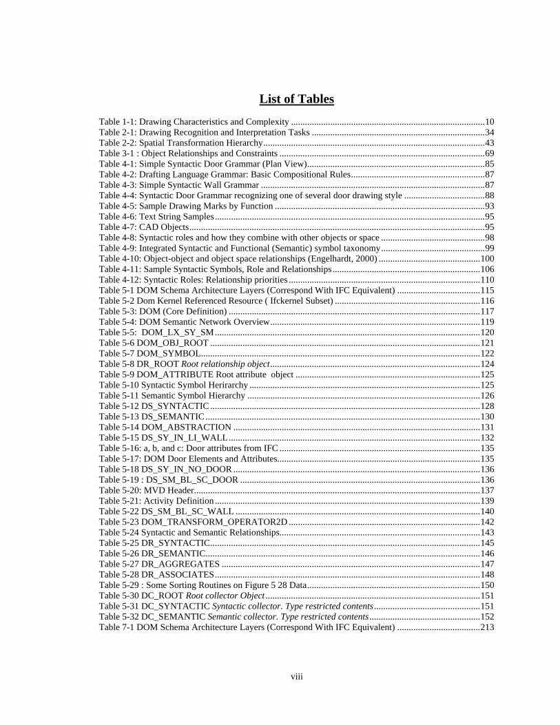
List of Tables Table 1-1: Drawing Characteristics and Complexity .................................................................................... 10 Table 2-1: Drawing Recognition and Interpretation Tasks ........................................................................... 34 Table 2-2: Spatial Transformation Hierarchy ................................................................................................ 43 Table 3-1 : Object Relationships and Constraints ......................................................................................... 69 Table 4-1: Simple Syntactic Door Grammar (Plan View) ............................................................................. 85 Table 4-2: Drafting Language Grammar: Basic Compositional Rules .......................................................... 87 Table 4-3: Simple Syntactic Wall Grammar ................................................................................................. 87 Table 4-4: Syntactic Door Grammar recognizing one of several door drawing style ................................... 88 Table 4-5: Sample Drawing Marks by Function ........................................................................................... 93 Table 4-6: Text String Samples ..................................................................................................................... 95 Table 4-7: CAD Objects ................................................................................................................................ 95 Table 4-8: Syntactic roles and how they combine with other objects or space ............................................. 98 Table 4-9: Integrated Syntactic and Functional (Semantic) symbol taxonomy ............................................. 99 Table 4-10: Object-object and object space relationships (Engelhardt, 2000) ............................................ 100 Table 4-11: Sample Syntactic Symbols, Role and Relationships ................................................................ 106 Table 4-12: Syntactic Roles: Relationship priorities ................................................................................... 110 Table 5-1 DOM Schema Architecture Layers (Correspond With IFC Equivalent) .................................... 115 Table 5-2 Dom Kernel Referenced Resource ( Ifckernel Subset) ............................................................... 116 Table 5-3: DOM (Core Definition) ............................................................................................................. 117 Table 5-4: DOM Semantic Network Overview ........................................................................................... 119 Table 5-5: DOM_LX_SY_SM ................................................................................................................... 120 Table 5-6 DOM_OBJ_ROOT ..................................................................................................................... 121 Table 5-7 DOM_SYMBOL ......................................................................................................................... 122 Table 5-8 DR_ROOT Root relationship object ........................................................................................... 124 Table 5-9 DOM_ATTRIBUTE Root attribute object ................................................................................ 125 Table 5-10 Syntactic Symbol Herirarchy .................................................................................................... 125 Table 5-11 Semantic Symbol Hierarchy ..................................................................................................... 126 Table 5-12 DS_SYNTACTIC ..................................................................................................................... 128 Table 5-13 DS_SEMANTIC ....................................................................................................................... 130 Table 5-14 DOM_ABSTRACTION ........................................................................................................... 131 Table 5-15 DS_SY_IN_LI_WALL ............................................................................................................. 132 Table 5-16: a, b, and c: Door attributes from IFC ....................................................................................... 135 Table 5-17: DOM Door Elements and Attributes........................................................................................ 135 Table 5-18 DS_SY_IN_NO_DOOR ........................................................................................................... 136 Table 5-19 : DS_SM_BL_SC_DOOR ........................................................................................................ 136 Table 5-20: MVD Header ............................................................................................................................ 137 Table 5-21: Activity Definition ................................................................................................................... 139 Table 5-22 DS_SM_BL_SC_WALL .......................................................................................................... 140 Table 5-23 DOM_TRANSFORM_OPERATOR2D ................................................................................... 142 Table 5-24 Syntactic and Semantic Relationships....................................................................................... 143 Table 5-25 DR_SYNTACTIC ..................................................................................................................... 145 Table 5-26 DR_SEMANTIC ....................................................................................................................... 146 Table 5-27 DR_AGGREGATES ................................................................................................................ 147 Table 5-28 DR_ASSOCIATES ................................................................................................................... 148 Table 5-29 : Some Sorting Routines on Figure 5 28 Data ........................................................................... 150 Table 5-30 DC_ROOT Root collector Object ............................................................................................. 151 Table 5-31 DC_SYNTACTIC Syntactic collector. Type restricted contents .............................................. 151 Table 5-32 DC_SEMANTIC Semantic collector. Type restricted contents ................................................ 152 Table 7-1 DOM Schema Architecture Layers (Correspond With IFC Equivalent) .................................... 213
ix
List of Figures
Figure 1-1: Drafting Interpretation Complexity ............................................................................................ 10 Figure 1-2 Mechanical Drawing – Parallel Projections & Composition Conventions .................................. 12 Figure 1-3: Sample architectural construction drawing sheet ....................................................................... 14 Figure 2-1: Two Equivalent Sentences in a Pictorial Language - Boy and Girl ............................................ 27 Figure 2-2: Drawing Interpretation Activity Overview (from Prahbu, B. Pandhe, S. 1999}) ...................... 33 Figure 2-3; Descriptive Geometry - Orthographic Projection ....................................................................... 38 Figure 3-1: Translation Architecture and Drafting Model Role .................................................................... 62 Figure 3-2: Syntactic Symbol: Graphical Representation vs Abstraction ..................................................... 65 Figure 3-3: Multiple (Symbol) Views for Same Object ................................................................................ 67 Figure 3-4: View relationships as distorted metric space .............................................................................. 70 Figure 4-1: Context-Free Door Pattern Specification .................................................................................... 85 Figure 4-2: Context Sensitivity in Drafting Language .................................................................................. 86 Figure 4-3: Semantic Ambiguity from Syntactic Description ....................................................................... 88 Figure 4-4: Semantic Parse Structures for True and False Door samples ..................................................... 89 Figure 4-5: Sample Meta Symbols ................................................................................................................ 90 Figure 4-6: Scaled Symbol Examples ........................................................................................................... 91 Figure 4-7: Abstract (Iconic) Symbol Examples ........................................................................................... 92 Figure 4-8: Sample Descriptor Symbols (Labeled annotator, dimension, datum) ......................................... 92 Figure 4-9: Three Views of a Window .......................................................................................................... 94 Figure 4-10: Connectivity (vertex-edge ,edge-edge or vertex-edge) relation .............................................. 102 Figure 4-11: Examples of Containment Relation ........................................................................................ 103 Figure 4-12: Examples of Overlap Relation ................................................................................................ 103 Figure 4-13: Aggregation and Ambiguity ................................................................................................... 108 Figure 4-14: Syntactic Relationships and Precedence ................................................................................. 109 Figure 4-15: Symbol Aggregation and Attribution ..................................................................................... 111 Figure 5-1: Physical (Network) View of DOM ( Lists) .............................................................................. 119 Figure 5-2: Inter-List Relationships ............................................................................................................ 120 Figure 5-3 DOM Object and DOM Symbol Overviews .............................................................................. 121 Figure 5-4: DOM Root Object Class (based on IFC root) ........................................................................... 122 Figure 5-5: DOM Syntactic and Semantic Symbol Overview (some examples) ........................................ 123 Figure 5-6: Example connection (Spatial) Relationship between Syntactic Door and Wall ....................... 124 Figure 5-7: Symbol Variation ...................................................................................................................... 127 Figure 5-8 Syntactic Symbol Schema ......................................................................................................... 127 Figure 5-9 Semantic Object Schema ........................................................................................................... 129 Figure 5-10: Syntactic Abstraction .............................................................................................................. 131 Figure 5-11: Symbol Variation - Abstracting for Consistency .................................................................... 131 Figure 5-12: Abstraction and graphic may not necessarily ‘touch’. ............................................................ 132 Figure 5-13: Syntactic Wall (Truncated. See Appendix-E for full) ............................................................. 132 Figure 5-14: Syntactic Door Schema (Truncated. See Appendix-E for Full) .............................................. 136 Figure 5-15: Semantic Door Schema (Truncated. See Appendix-E for full) ............................................... 136 Figure 5-16: DOM to BIM Use Case (Process Map Subset) ....................................................................... 138 Figure 5-17 Semantic Wall Schema (Truncated) See Appendix-E for full ................................................ 140 Figure 5-18 : Sample Binding - Wall (With Opening) ................................................................................ 141 Figure 5-19: DOM transform (3D transform is similar) .............................................................................. 142 Figure 5-20: Root Level DOM Relationship Schema ................................................................................. 143 Figure 5-21: Spatial Relationships (General Derivation) ............................................................................ 144 Figure 5-22: Logical Relationship .............................................................................................................. 146 Figure 5-23: Aggregation ............................................................................................................................ 147 Figure 5-24: Association ............................................................................................................................. 148 Figure 5-25 Collector Schema and Required Methods ................................................................................ 149 Figure 5-26: Spatial (Perceptual) Modeling - Examples ............................................................................. 150 Figure 6-1: DOM Framework and Application Load .................................................................................. 156 Figure 6-2: Loaded and Empty Building Framework Browser ................................................................... 156
x
Figure 6-3: Save/Load (Fly-out Menu) ....................................................................................................... 158 Figure 6-4: Quad-Tree ................................................................................................................................. 158 Figure 6-5: Segmented Regions .................................................................................................................. 159 Figure 6-6: Possible view/label relationship after segmentation ................................................................. 160 Figure 6-7: Sample Text - Geometry Ratios for Various Floor-plans ......................................................... 161 Figure 6-8: Syntactic views and attribute subset in framework browsers ................................................... 162 Figure 6-9: Plan and Elevation Point Set Generation .................................................................................. 164 Figure 6-10: Sorting and Filtration Methods Dialog ................................................................................... 164 Figure 6-11: Some Vertex Occlusion Conditions (looking from below -x in +y direction) ........................ 166 Figure 6-12: Plan and Elevation Point-Set Matching .................................................................................. 166 Figure 6-13: Elevation-Plan alignment (elevation is returned to position but the transform is stored) ....... 167 Figure 6-14: Parallel line spacing for wall width determination ................................................................. 170 Figure 6-15: Wall End Conditions .............................................................................................................. 171 Figure 6-16: Wall Recognition Implementation Process Flow ................................................................... 171 Figure 6-17: Instantiated Syntactic Wall in Framework Browser ............................................................... 172 Figure 6-18: Wall end condition centerline and graph ................................................................................ 172 Figure 6-19 Semantic Wall Instances in Dom Browser .............................................................................. 173 Figure 6-20: Error Conditions. Gaps and False walls .................................................................................. 174 Figure 6-21: Extruded v/s correct wall geometries ...................................................................................... 175 Figure 6-22: Wall search region .................................................................................................................. 176 Figure 6-23: Wall Opening and Door Search Region ................................................................................. 177 Figure 6-24: Syntactic doors in framework browser ................................................................................... 177 Figure 6-25: Views and sub-views .............................................................................................................. 179 Figure 6-26: Transformation management within and across views ........................................................... 183
xi
Summary
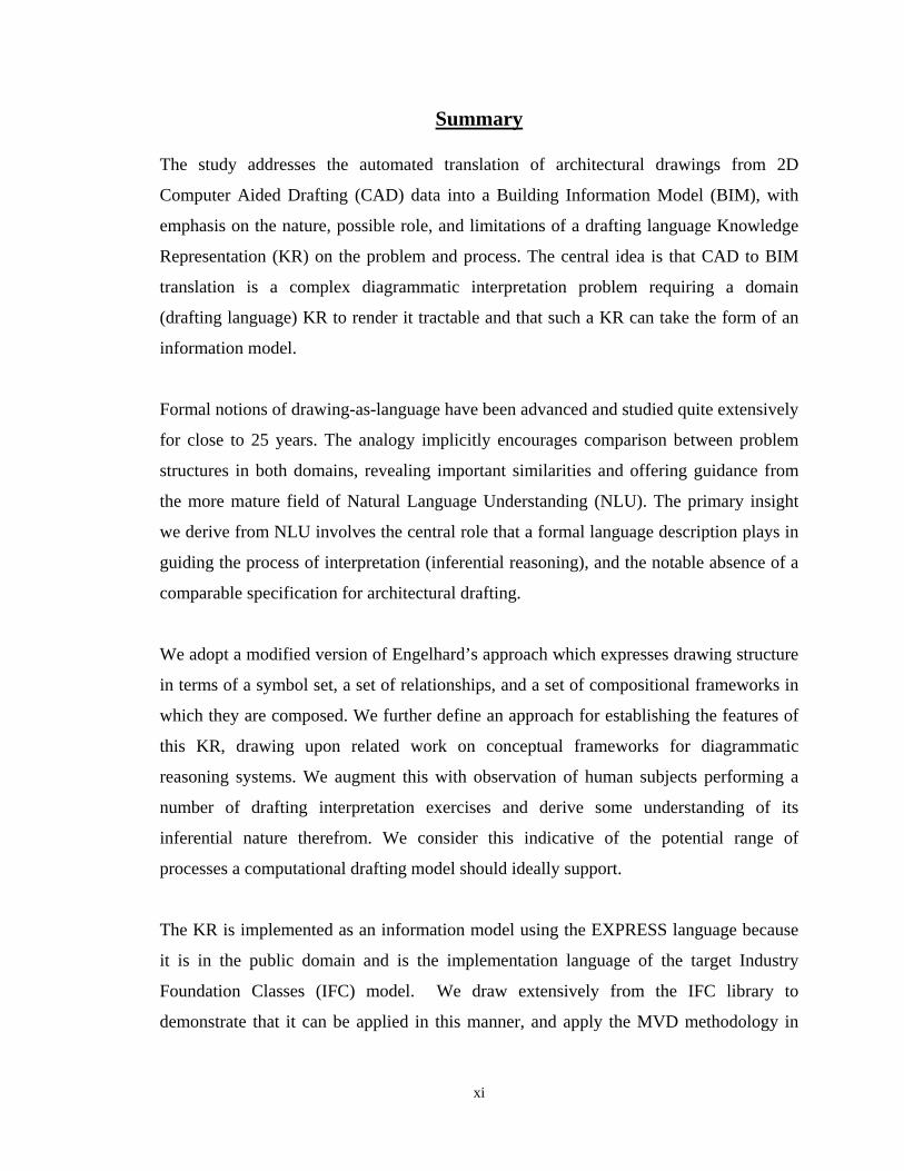
The study addresses the automated translation of architectural drawings from 2D
Computer Aided Drafting (CAD) data into a Building Information Model (BIM), with
emphasis on the nature, possible role, and limitations of a drafting language Knowledge
Representation (KR) on the problem and process. The central idea is that CAD to BIM
translation is a complex diagrammatic interpretation problem requiring a domain
(drafting language) KR to render it tractable and that such a KR can take the form of an
information model.
Formal notions of drawing-as-language have been advanced and studied quite extensively
for close to 25 years. The analogy implicitly encourages comparison between problem
structures in both domains, revealing important similarities and offering guidance from
the more mature field of Natural Language Understanding (NLU). The primary insight
we derive from NLU involves the central role that a formal language description plays in
guiding the process of interpretation (inferential reasoning), and the notable absence of a
comparable specification for architectural drafting.
We adopt a modified version of Engelhard’s approach which expresses drawing structure
in terms of a symbol set, a set of relationships, and a set of compositional frameworks in
which they are composed. We further define an approach for establishing the features of
this KR, drawing upon related work on conceptual frameworks for diagrammatic
reasoning systems. We augment this with observation of human subjects performing a
number of drafting interpretation exercises and derive some understanding of its
inferential nature therefrom. We consider this indicative of the potential range of
processes a computational drafting model should ideally support.
The KR is implemented as an information model using the EXPRESS language because
it is in the public domain and is the implementation language of the target Industry
Foundation Classes (IFC) model. We draw extensively from the IFC library to
demonstrate that it can be applied in this manner, and apply the MVD methodology in
xii
defining the scope and interface of the DOM and IFC. This simplifies the IFC translation
process significantly and minimizes the need for mapping.
We conclude on the basis of selective implementations that a model reflecting the
principles and features we define can indeed provide needed and otherwise unavailable
support in drafting interpretation and other problems involving reasoning with this class
of diagrammatic representations.
1
CHAPTER 1.
INTRODUCTION
1.1 Research Motivation
illions of active1 drawings of existing buildings remain paper based or in older
‘dumb’ CAD formats2 (http://en.wikipedia.org/wiki/AutoCAD). There are
currently no automated means for converting them into model-based representations,
leaving manual effort as the only option for translating this data. A building model /
building information model (BIM) is a proprietary or public domain standard for
representing useful information about a building, which is defined as a composition of
objects at different levels of aggregation. It is a conceptualization that emphasizes
building elements and activities in terms of geometry, non-geometric attributes, relations
and processes from a range of actor perspectives. Given the large repository of active
legacy CAD files, the man hour costs that would be expended in converting them all are
considerable, with online bureau services currently offering rates between $100 and $525
per sheet for offshore services on a 4 to 30 day turnaround and even higher rates with
local services. These drawings contain a lot of information that is important beyond the
construction phase, yet only a small number of large projects are converted each year,
typically within the context of sufficiently extensive and costly renovation work. There
1 Active drawings are of existing buildings. The drawings are still called upon periodically for maintenance or modification purposes. 2 Dumb CAD formats consist of geometric description, without associated object semantics. There is no semantic distinction between geometric representations for a wall and a floor slab, for example.
M
2
are consequently many smaller projects including single family residences and
commercial buildings that are effectively excluded from conversion because of cost and
effort considerations. Renovation or extension work requires some of the information
contained in these older drawings which if translated, could then support the various data
exchange, collaboration, budgetary, and other capabilities offered by the newer BIM
applications. While new projects are increasingly being produced with intelligent tools,
the issue of an existing and unutilized or underutilized building information repository
will persist for a considerable while. Widespread use of the technologies that produced
the legacy data began less than 25 years ago (Weisberg, David E, 2008), yet (even small)
buildings in North America can be expected to have a 50 year life-span, and often exceed
100 years of operation with proper maintenance (CSA S478, 1995; Sjöström, C.,
Jernberg, P., 2001).
Post-occupancy needs like building management (space, safety, energy, movable assets,
etc.) stand to benefit significantly from a shared building model database. For example,
energy savings in the range of 12-20% have been reported from the use of energy
management systems in commercial buildings (Johnson Controls, 2010), and we assume
savings (even within the lower end) of this range can be achieved for single family
homes. As of 1995, there were approximately 58 million single family residences
accounting for approximately 19.5% of total US energy consumption and another 2.4
million small commercial buildings consuming an additional 8%. The potential savings
for the consumer and overall energy policy impact alone should provide sufficient
motivation for post facto adoption of energy management systems (Diamond, R. C. 2001,
Intermediate Energy Infobook, 2008), and when integrated with home security, fire safety
3
and home automation in more comprehensive systems, the benefits are easy to sell and
are only constrained by cost considerations.
The role of a BIM model in this context is two-fold. The first involves its utility as an
intelligent graphical interface for the system. At the application and interface level, there
are many building automation solutions currently available for the I-pad on the
application website www.apshopper.com, Apple Inc., recently filed a patent for a ‘Smart
Home Energy Management System’ (application: 20100013309, 20100205528A1), and
Intel’s Home Dashboard Concept also targets Home Automation. In many cases, the
interfaces incorporate vector representations of the building floor plans, typically in 2D
format. The second is the role of an open BIM standard in integrating disparate
proprietary and closed building automation and management systems, many of which
currently do not communicate. Some efforts at integrating BIM and building automation
sensor network standards like the BACnet ISO 16484-5 and ZigBee IEEE 802.15.4-2003
standards are currently under investigation. The goal is to marry and standardize
automation device communication protocols and building information data exchange
standards (Karavan A. et. al, 2005; Bozany, A., 2003), marrying building geometry and
topology with sensor capabilities.
While the cost of hardware and networking continue to fall (Mainardi et al, 2005), the
cost of producing adequate as-built BIM models for these applications will likely remain
relatively high if manually produced. One approach currently under development for
automating the production of as-built BIM models involves the use of laser scanning and
various software post-processing operations on the data (Brilakis, I, 2010) . 3D object

4
geometry is generated from the resulting scanner point cloud, camera acquired texture
maps are applied onto the faces, and a combination of textural and planar changes are
employed in decomposing the model into intelligent (BIM) building components.
Automatic interpretation from 2D drawings as we propose in this study could offer an
alternative model generation approach, and circumvents the need for expensive
equipment and physical measurement, since drawing files could be submitted to and
received electronically from a modeling service upon translation. Either approach or in
conjunction could provide enough cost savings to catalyze the demand and use of as-built
BIM models, driving greater migration of legacy CAD drawings from older formats into
BIM representations.
The required level of detail and resolution in the BIM varies, with fabrication oriented
applications requiring more detail and accuracy than the building automation applications
mentioned earlier or a fire safety application. Laser scanned BIM models offer the
potential for a high degree of detail and resolution if properly carried out, and accurately
represents the as built structure at a given point in time. The resolution of BIM translated
CAD drawings remains open and the correspondence between the drawings and built
structure is dependent upon how up to date the drawing version is.
Finally, beyond its foreseeable practical benefits, we also have a fundamental and
theoretical interest in the question of symbolic structure in the (drafting) domain, driven
by our presumption that a domain schemata of this sort capturing some notion of meaning
and semantics provides the framework for a broad array of inferential operations targeted
at this class of representations. For example, a semantic 2D drawing interpretation
5
capability operating behind the process in the design stage could play a significant role in
what Goel, Schon and others in design studies describe as an ‘iterative dialog’ between
designer and representation’ {Goel, V. 1996, Schon, D. A., 1982} and could function
within a design advisory system in a number of ways, either at a low level similar to the
grammar checking capabilities incorporated in many word processing applications, or at a
higher level employing morphological or structural properties of the design under
progress in retrieving relevant examples and providing other forms of advice that could
inform the design process {Terzidis, K. 1994, Pearce, M. et. al., 1992}. Some benefits
may only become obvious over time much like similar work in computational models of
natural language that established the foundation for many of the translation systems that
are only now becoming popular. There is reasonable basis for enthusiasm about similar
unanticipated applications of a drafting specification.
The study builds on a substantive but disjointed body of work in diagrammatic
interpretation and reasoning, focusing principally on contributions by Cherneff (1996)
and Noack (2001) in Architectural Drawing Recognition, Engelhardt’s (2004) work in
Diagrammatic Language specification, along with broader efforts in Visual languages
(Marriot & Kim, 2000; Narayanan, 2000) and geometric / feature based reconstruction
from mechanical drawings (Prahbu, B, & Pande, S. 2000; Lafue, G 1976). In terms of
scope, we are concerned not just with reconstruction of 3D building geometry from 2D
views like much of the work in Mechanical Drawing recognition, but are also interested
in identifying component objects in a building assemblage from their various symbolic
2D views and defining them in a manner compatible with the translation or instantiation
of their geometry and topologies in an open BIM standard.
6
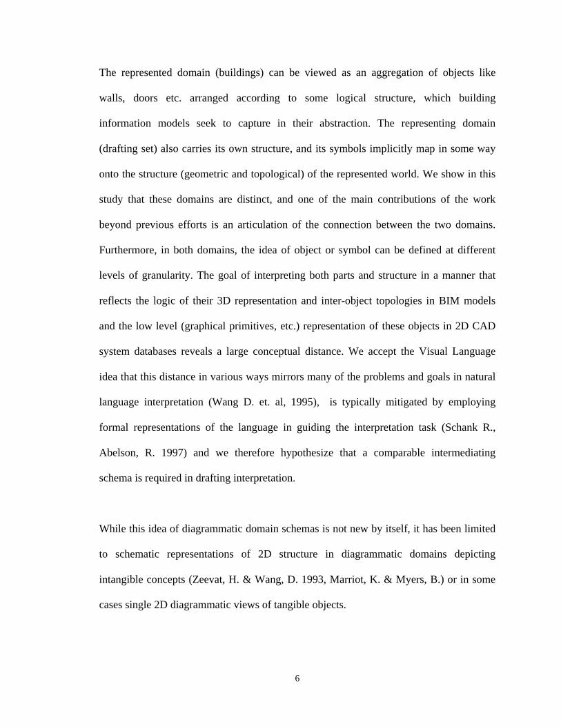
The represented domain (buildings) can be viewed as an aggregation of objects like
walls, doors etc. arranged according to some logical structure, which building
information models seek to capture in their abstraction. The representing domain
(drafting set) also carries its own structure, and its symbols implicitly map in some way
onto the structure (geometric and topological) of the represented world. We show in this
study that these domains are distinct, and one of the main contributions of the work
beyond previous efforts is an articulation of the connection between the two domains.
Furthermore, in both domains, the idea of object or symbol can be defined at different
levels of granularity. The goal of interpreting both parts and structure in a manner that
reflects the logic of their 3D representation and inter-object topologies in BIM models
and the low level (graphical primitives, etc.) representation of these objects in 2D CAD
system databases reveals a large conceptual distance. We accept the Visual Language
idea that this distance in various ways mirrors many of the problems and goals in natural
language interpretation (Wang D. et. al, 1995), is typically mitigated by employing
formal representations of the language in guiding the interpretation task (Schank R.,
Abelson, R. 1997) and we therefore hypothesize that a comparable intermediating
schema is required in drafting interpretation.
While this idea of diagrammatic domain schemas is not new by itself, it has been limited
to schematic representations of 2D structure in diagrammatic domains depicting
intangible concepts (Zeevat, H. & Wang, D. 1993, Marriot, K. & Myers, B.) or in some
cases single 2D diagrammatic views of tangible objects.
7
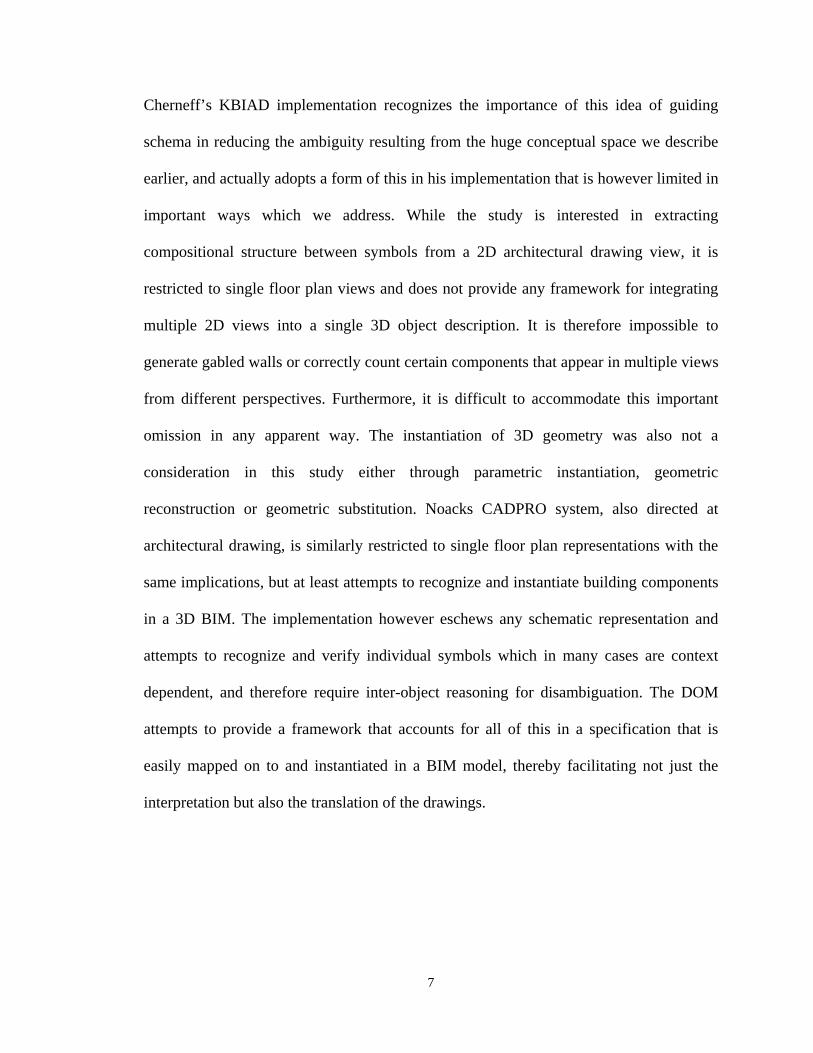
Cherneff’s KBIAD implementation recognizes the importance of this idea of guiding
schema in reducing the ambiguity resulting from the huge conceptual space we describe
earlier, and actually adopts a form of this in his implementation that is however limited in
important ways which we address. While the study is interested in extracting
compositional structure between symbols from a 2D architectural drawing view, it is
restricted to single floor plan views and does not provide any framework for integrating
multiple 2D views into a single 3D object description. It is therefore impossible to
generate gabled walls or correctly count certain components that appear in multiple views
from different perspectives. Furthermore, it is difficult to accommodate this important
omission in any apparent way. The instantiation of 3D geometry was also not a
consideration in this study either through parametric instantiation, geometric
reconstruction or geometric substitution. Noacks CADPRO system, also directed at
architectural drawing, is similarly restricted to single floor plan representations with the
same implications, but at least attempts to recognize and instantiate building components
in a 3D BIM. The implementation however eschews any schematic representation and
attempts to recognize and verify individual symbols which in many cases are context
dependent, and therefore require inter-object reasoning for disambiguation. The DOM
attempts to provide a framework that accounts for all of this in a specification that is
easily mapped on to and instantiated in a BIM model, thereby facilitating not just the
interpretation but also the translation of the drawings.
8
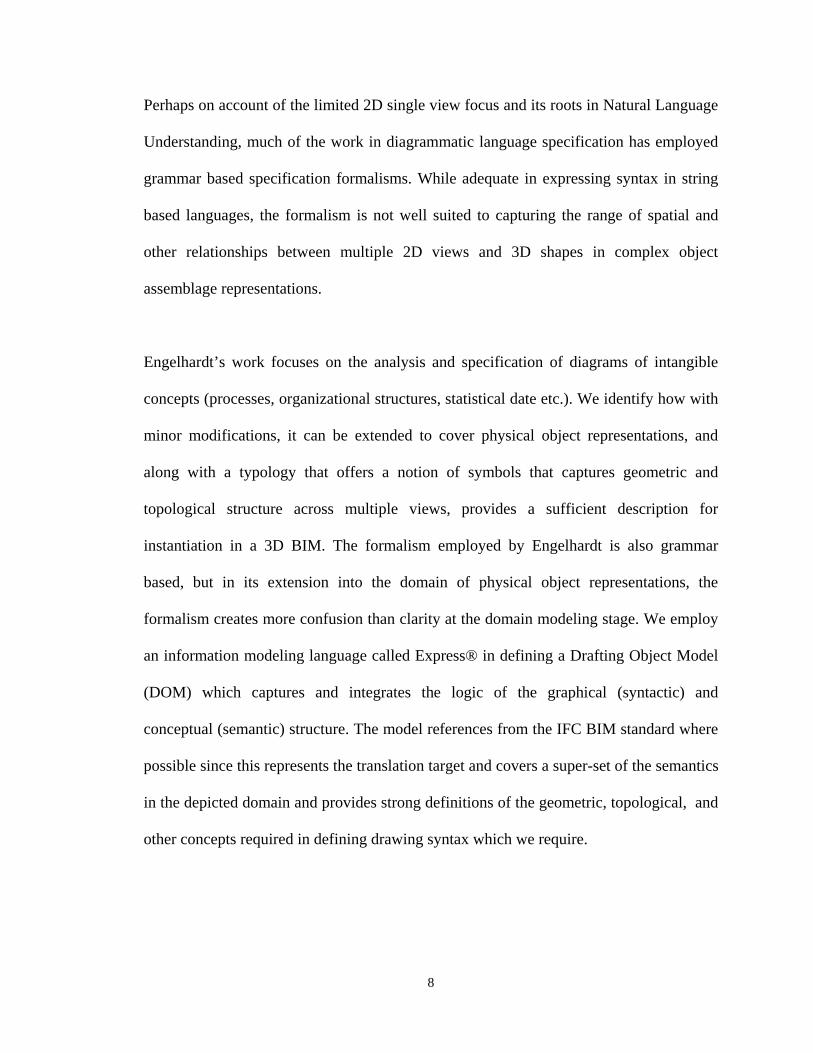
Perhaps on account of the limited 2D single view focus and its roots in Natural Language
Understanding, much of the work in diagrammatic language specification has employed
grammar based specification formalisms. While adequate in expressing syntax in string
based languages, the formalism is not well suited to capturing the range of spatial and
other relationships between multiple 2D views and 3D shapes in complex object
assemblage representations.
Engelhardt’s work focuses on the analysis and specification of diagrams of intangible
concepts (processes, organizational structures, statistical date etc.). We identify how with
minor modifications, it can be extended to cover physical object representations, and
along with a typology that offers a notion of symbols that captures geometric and
topological structure across multiple views, provides a sufficient description for
instantiation in a 3D BIM. The formalism employed by Engelhardt is also grammar
based, but in its extension into the domain of physical object representations, the
formalism creates more confusion than clarity at the domain modeling stage. We employ
an information modeling language called Express® in defining a Drafting Object Model
(DOM) which captures and integrates the logic of the graphical (syntactic) and
conceptual (semantic) structure. The model references from the IFC BIM standard where
possible since this represents the translation target and covers a super-set of the semantics
in the depicted domain and provides strong definitions of the geometric, topological, and
other concepts required in defining drawing syntax which we require.
9
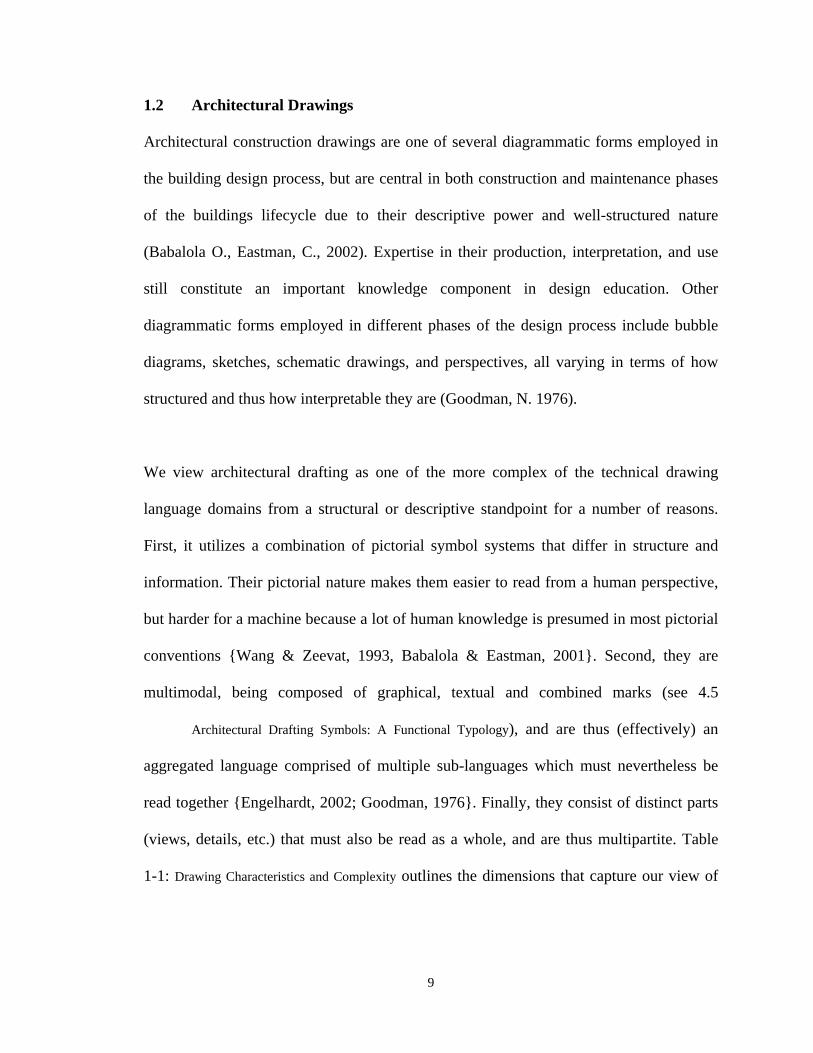
1.2 Architectural Drawings
Architectural construction drawings are one of several diagrammatic forms employed in
the building design process, but are central in both construction and maintenance phases
of the buildings lifecycle due to their descriptive power and well-structured nature
(Babalola O., Eastman, C., 2002). Expertise in their production, interpretation, and use
still constitute an important knowledge component in design education. Other
diagrammatic forms employed in different phases of the design process include bubble
diagrams, sketches, schematic drawings, and perspectives, all varying in terms of how
structured and thus how interpretable they are (Goodman, N. 1976).
We view architectural drafting as one of the more complex of the technical drawing
language domains from a structural or descriptive standpoint for a number of reasons.
First, it utilizes a combination of pictorial symbol systems that differ in structure and
information. Their pictorial nature makes them easier to read from a human perspective,
but harder for a machine because a lot of human knowledge is presumed in most pictorial
conventions {Wang & Zeevat, 1993, Babalola & Eastman, 2001}. Second, they are
multimodal, being composed of graphical, textual and combined marks (see 4.5
Architectural Drafting Symbols: A Functional Typology), and are thus (effectively) an
aggregated language comprised of multiple sub-languages which must nevertheless be
read together {Engelhardt, 2002; Goodman, 1976}. Finally, they consist of distinct parts
(views, details, etc.) that must also be read as a whole, and are thus multipartite. Table
1-1: Drawing Characteristics and Complexity outlines the dimensions that capture our view of

10
drawing complexity in this study. The columns represent different aspects, and the rows
generally reflect increasing complexity lower down each column.
Table 1-1: Drawing Characteristics and Complexity
Complexity encompasses a diverse range of criteria such as the graphical characteristics
of the constituent symbols in a representational system, the nature of the relationship
between symbolic representation and depicted concept, and the degree of
interdependence between symbols and their compositional context. A drawing
convention like architectural drafting may simultaneously employ multiple kinds of
representations from the Symbol Type column. Collectively, these problems intersect and
propagate through the process and collectively widen the conceptual distance between
drawing and meaning as earlier described.
Figure 1-1: Drafting Interpretation Complexity
11
1.2.1 Architectural Construction Drawings
2D CAD and/or paper based drawings have long served as the central descriptive
component in architectural contract documentation alongside material bills, specifications
etc., and remain a primary means for the exchange of design information between actors
in the construction industry in spite of a growing interest in the versatility and power of
intelligent building information model (BIM) based representations3. Architectural
drafting evolved over centuries and the conventions guiding its generation and
interpretation are widely if implicitly understood within the industry4. A core aspect
involves its use of descriptive geometry. Although the idea of mathematically governed
drawing production rules predate Brunelleschi’s discovery of perspective in the 15th
century (as evidenced by the scaled tablet representing a palace built by Gudea dating
back Circa 2140 B.C.), his work is generally considered a starting point for the
application of formalized rules in generating and interpreting physical object
representations. This was advanced by Leonardo DaVinci, who combined earlier
contributions by Pythagoras and Samos in producing some examples of partially
coordinated drawings based on parallel projection. All of this earlier thinking was
integrated and formalized by the French mathematician Gaspard Monge, who is credited
with the invention of descriptive geometry in the 18th century {Heilbron, J.L., 1997}. The
convention has its basis in the principles of parallel projection and idea that 2D
representation of 3D geometry generally requires multiple views in order to adequately
describe objects. In order to abbreviate the potentially limitless number of incrementally
3 This includes 2 dimensional traditional paper based drawings and 2 dimensional CAD based drawings 4 The largely implicit nature of this knowledge can be attributed to the fact that the required skill set is transferred though an apprenticeship tradition that emphasizes “learning by doing” {Goel V. 1996}
12
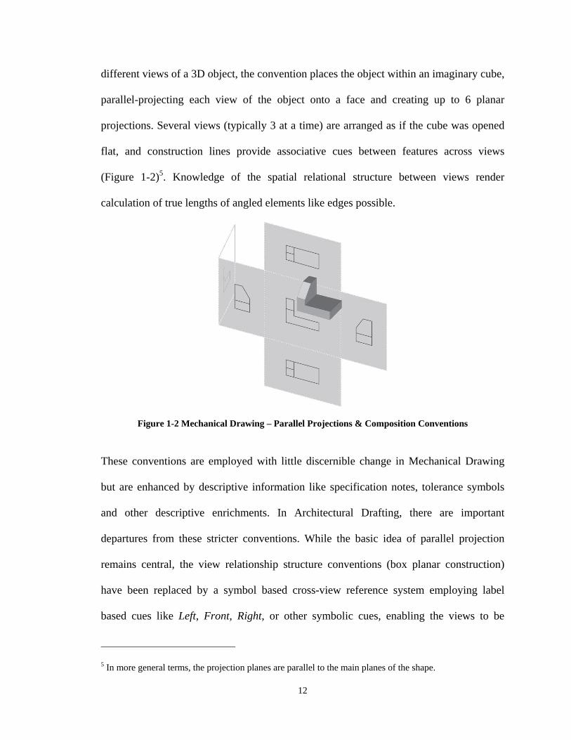
different views of a 3D object, the convention places the object within an imaginary cube,
parallel-projecting each view of the object onto a face and creating up to 6 planar
projections. Several views (typically 3 at a time) are arranged as if the cube was opened
flat, and construction lines provide associative cues between features across views
(Figure 1-2)5. Knowledge of the spatial relational structure between views render
calculation of true lengths of angled elements like edges possible.
Figure 1-2 Mechanical Drawing – Parallel Projections & Composition Conventions
These conventions are employed with little discernible change in Mechanical Drawing
but are enhanced by descriptive information like specification notes, tolerance symbols
and other descriptive enrichments. In Architectural Drafting, there are important
departures from these stricter conventions. While the basic idea of parallel projection
remains central, the view relationship structure conventions (box planar construction)
have been replaced by a symbol based cross-view reference system employing label
based cues like Left, Front, Right, or other symbolic cues, enabling the views to be
5 In more general terms, the projection planes are parallel to the main planes of the shape.
13
arranged in more random order on the drawing sheet. This assumes a reader is able to
correctly interpret the meta-language underlying the view label/relation notations which
requires both natural language and spatial interpretation capabilities. Furthermore, the
construction lines linking features from one view to another are no longer available,
presenting an additional burden of figuring out the precise geometric correspondence
between views6 even where the planar relationships between them is determined from the
labeling language. While these are routinely handled by a human being with some
occasional error, they present a significant challenge for a machine. Furthermore, there is
an additional problem whereby not all graphical elements in the representational system
depict physical building components, and even amongst these, not all are generated by
orthographic projection7. For example, bathroom fixtures, kitchen appliance and some
other symbols are iconic pictorial representations of the component class they depict (see
chapter 4 for discussion of symbol taxonomy), and it is not uncommon to represent 2
substantially different instances of the class with the same symbol, distinguishing them
by annotation or tag references to separate documents. Finally, sub-regions of drawings
are sometimes drawn at different scales and level of detail, and cross referenced through
some means, sometimes with such details representing a typical case with multiple
occurrences8.
6 In addition to understanding which side of a plan an elevation corresponds with, it is necessary to determine the matching geometrical features in each view 7 Even orthogonal projection produces ambiguous representation of curved surfaces because it only depicts profiles of a shape. 8 A typical floor plan, which we also consider a higher symbolic aggregation may represent several floors, which also creates a counting mismatch between floor plans and floor levels, unless the multi reference note is understood by the interpreting system
14
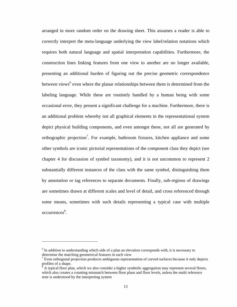
Figure 1-3: Sample architectural construction drawing sheet 1.3 Understanding and Architectural Drawings
Drawing recognition and interpretation are presented in this study as distinct concepts.
Recognition involves targeted search, while interpretation is focused on extracting
underlying structural descriptions of physical or conceptual arrangements {Babalola O.,
Eastman C., 2001; Dori D. 2000}. Consequently, while wall or door tokens can be
recognized, the overall (semantic) structure of a drawing must be interpreted.
Word processors offer intelligent capabilities like spelling and grammar checkers, and
web search technologies increasingly respond to the problem of navigating and
presenting relevant results from vast quantities of unstructured data by incorporating
strategies that utilize knowledge-level descriptions of content {Berners-Lee, 1998 ; Lu,
2002}. Computer Aided Design (CAD) tools are also responding via a shift in underlying
15
representation. Traditional geometry-based CAD systems are being enhanced by
integrated semantic models, opening up a new range of possibilities in CAD tool
functionality9 {Eastman, 1999}. The newer (BIM) tools substitute geometric primitives
with building-object-level instantiation and editing operations, allowing for more
intuitive design interaction, closer integration between consultants stemming from the use
of a shared product database, as well as analytical capabilities derived from a commonly
defined semantic representation10.
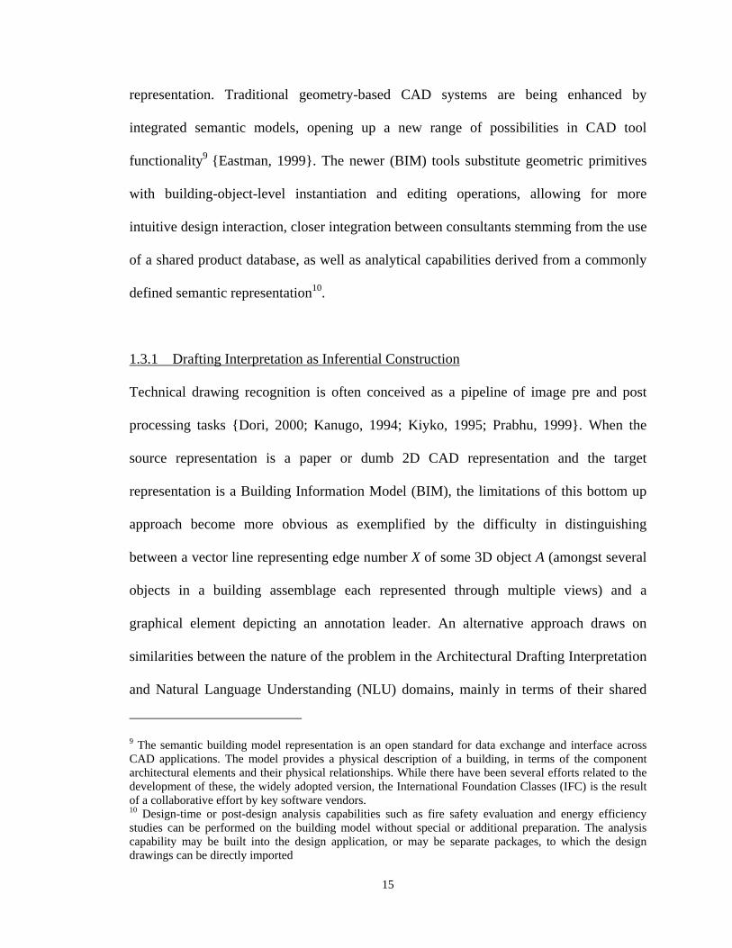
1.3.1 Drafting Interpretation as Inferential Construction
Technical drawing recognition is often conceived as a pipeline of image pre and post
processing tasks {Dori, 2000; Kanugo, 1994; Kiyko, 1995; Prabhu, 1999}. When the
source representation is a paper or dumb 2D CAD representation and the target
representation is a Building Information Model (BIM), the limitations of this bottom up
approach become more obvious as exemplified by the difficulty in distinguishing
between a vector line representing edge number X of some 3D object A (amongst several
objects in a building assemblage each represented through multiple views) and a
graphical element depicting an annotation leader. An alternative approach draws on
similarities between the nature of the problem in the Architectural Drafting Interpretation
and Natural Language Understanding (NLU) domains, mainly in terms of their shared
9 The semantic building model representation is an open standard for data exchange and interface across CAD applications. The model provides a physical description of a building, in terms of the component architectural elements and their physical relationships. While there have been several efforts related to the development of these, the widely adopted version, the International Foundation Classes (IFC) is the result of a collaborative effort by key software vendors. 10 Design-time or post-design analysis capabilities such as fire safety evaluation and energy efficiency studies can be performed on the building model without special or additional preparation. The analysis capability may be built into the design application, or may be separate packages, to which the design drawings can be directly imported
16
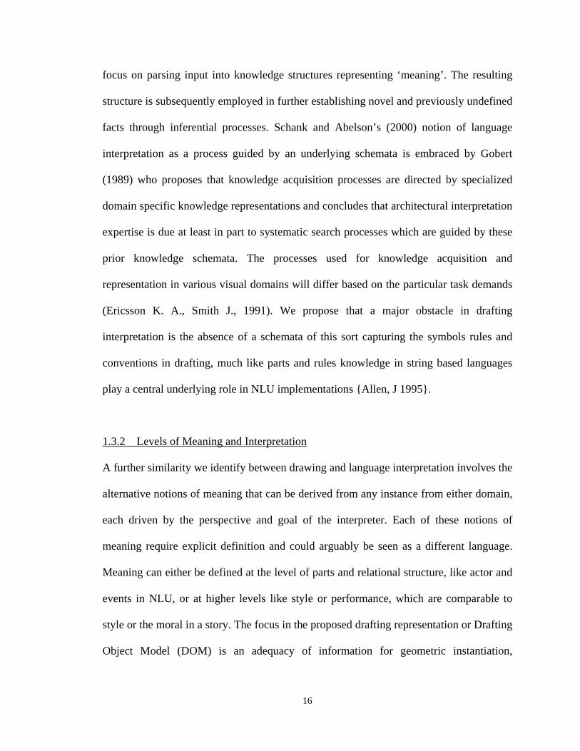
focus on parsing input into knowledge structures representing ‘meaning’. The resulting
structure is subsequently employed in further establishing novel and previously undefined
facts through inferential processes. Schank and Abelson’s (2000) notion of language
interpretation as a process guided by an underlying schemata is embraced by Gobert
(1989) who proposes that knowledge acquisition processes are directed by specialized
domain specific knowledge representations and concludes that architectural interpretation
expertise is due at least in part to systematic search processes which are guided by these
prior knowledge schemata. The processes used for knowledge acquisition and
representation in various visual domains will differ based on the particular task demands
(Ericsson K. A., Smith J., 1991). We propose that a major obstacle in drafting
interpretation is the absence of a schemata of this sort capturing the symbols rules and
conventions in drafting, much like parts and rules knowledge in string based languages
play a central underlying role in NLU implementations {Allen, J 1995}.
1.3.2 Levels of Meaning and Interpretation
A further similarity we identify between drawing and language interpretation involves the
alternative notions of meaning that can be derived from any instance from either domain,
each driven by the perspective and goal of the interpreter. Each of these notions of
meaning require explicit definition and could arguably be seen as a different language.
Meaning can either be defined at the level of parts and relational structure, like actor and
events in NLU, or at higher levels like style or performance, which are comparable to
style or the moral in a story. The focus in the proposed drafting representation or Drafting
Object Model (DOM) is an adequacy of information for geometric instantiation,
17
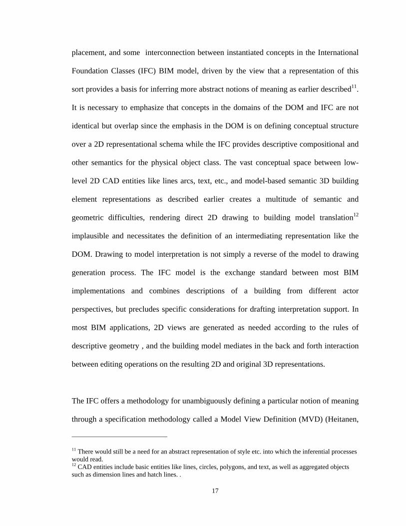
placement, and some interconnection between instantiated concepts in the International
Foundation Classes (IFC) BIM model, driven by the view that a representation of this
sort provides a basis for inferring more abstract notions of meaning as earlier described11.
It is necessary to emphasize that concepts in the domains of the DOM and IFC are not
identical but overlap since the emphasis in the DOM is on defining conceptual structure
over a 2D representational schema while the IFC provides descriptive compositional and
other semantics for the physical object class. The vast conceptual space between low-
level 2D CAD entities like lines arcs, text, etc., and model-based semantic 3D building
element representations as described earlier creates a multitude of semantic and
geometric difficulties, rendering direct 2D drawing to building model translation12
implausible and necessitates the definition of an intermediating representation like the
DOM. Drawing to model interpretation is not simply a reverse of the model to drawing
generation process. The IFC model is the exchange standard between most BIM
implementations and combines descriptions of a building from different actor
perspectives, but precludes specific considerations for drafting interpretation support. In
most BIM applications, 2D views are generated as needed according to the rules of
descriptive geometry , and the building model mediates in the back and forth interaction
between editing operations on the resulting 2D and original 3D representations.
The IFC offers a methodology for unambiguously defining a particular notion of meaning
through a specification methodology called a Model View Definition (MVD) (Heitanen,
11 There would still be a need for an abstract representation of style etc. into which the inferential processes would read. 12 CAD entities include basic entities like lines, circles, polygons, and text, as well as aggregated objects such as dimension lines and hatch lines. .
18
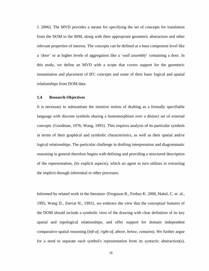
J. 2006). The MVD provides a means for specifying the set of concepts for translation
from the DOM to the BIM, along with their appropriate geometric abstraction and other
relevant properties of interest. The concepts can be defined at a base component level like
a ‘door’ or at higher levels of aggregation like a ‘wall assembly’ containing a door. In
this study, we define an MVD with a scope that covers support for the geometric
instantiation and placement of IFC concepts and some of their basic logical and spatial
relationships from DOM data.
1.4 Research Objectives
It is necessary to substantiate the intuitive notion of drafting as a formally specifiable
language with discrete symbols sharing a homomorphism over a distinct set of external
concepts {Goodman, 1976; Wang, 1993}. This requires analysis of its particular symbols
in terms of their graphical and symbolic characteristics, as well as their spatial and/or
logical relationships. The particular challenge in drafting interpretation and diagrammatic
reasoning in general therefore begins with defining and providing a structured description
of the representation, (its explicit aspects), which an agent in turn utilizes in extracting
the implicit through inferential or other processes.
Informed by related work in the literature {Ferguson R., Forbus K. 2000, Habel, C. et. al.,
1995, Wang D., Zeevat H., 1993}, we embrace the view that the conceptual features of
the DOM should include a symbolic view of the drawing with clear definition of its key
spatial and topological relationships, and offer support for domain independent
comparative spatial reasoning (left-of, right-of, above, below, contains). We further argue
for a need to separate each symbol's representation from its syntactic abstraction(s),
19
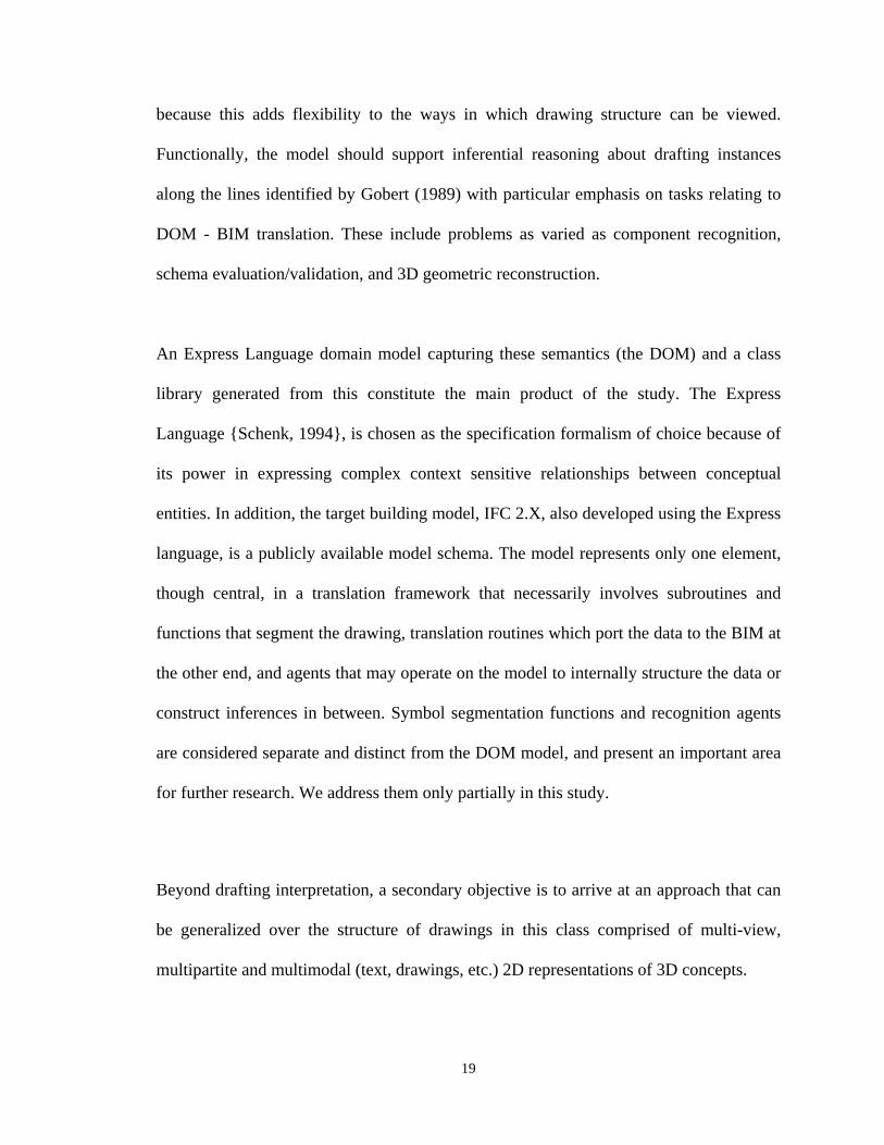
because this adds flexibility to the ways in which drawing structure can be viewed.
Functionally, the model should support inferential reasoning about drafting instances
along the lines identified by Gobert (1989) with particular emphasis on tasks relating to
DOM - BIM translation. These include problems as varied as component recognition,
schema evaluation/validation, and 3D geometric reconstruction.
An Express Language domain model capturing these semantics (the DOM) and a class
library generated from this constitute the main product of the study. The Express
Language {Schenk, 1994}, is chosen as the specification formalism of choice because of
its power in expressing complex context sensitive relationships between conceptual
entities. In addition, the target building model, IFC 2.X, also developed using the Express
language, is a publicly available model schema. The model represents only one element,
though central, in a translation framework that necessarily involves subroutines and
functions that segment the drawing, translation routines which port the data to the BIM at
the other end, and agents that may operate on the model to internally structure the data or
construct inferences in between. Symbol segmentation functions and recognition agents
are considered separate and distinct from the DOM model, and present an important area
for further research. We address them only partially in this study.
Beyond drafting interpretation, a secondary objective is to arrive at an approach that can
be generalized over the structure of drawings in this class comprised of multi-view,
multipartite and multimodal (text, drawings, etc.) 2D representations of 3D concepts.
20
1.4.2 Scope and Limitations
The primary focus of the study is on defining a structured representation of architectural
drafting that provides an adequate framework for 2D - 3D semantic interpretation in
particular and drafting inference in general. We propose that it is more flexible and useful
than an application oriented model and its population mechanisms are less important than
the structure itself because the latter constitutes a stable and transferable model of
‘meaning’ while the former is pragmatic and interchangeable {Schank, R., Abelson, R.,
1997}. The processes or agents that operate on the model are therefore addressed only to
the extent that they reflect commitments in its underlying assumptions, or are
implemented in testing or establishing its fulfillment of a particular inferential capability.
In such cases, this should be seen as one of several possible process hypotheses, of which
one was simply selected for either pragmatic or other reasons because an important
argument in this approach involves supporting alternative inferential paths to the same
end state.
The full richness of a drawing set is also not addressed. For example, we do not consider
specification notes, which are part of standard contract documentation alongside the
drawing set even though they may be referred to by annotation and comments in the
drawings. Furthermore, full understanding of a drawing set would require a natural
language understanding capability for handling notes and comments, and this lies beyond
the goals in this study. It may be possible for instance to recognize a room label and a
floor finish specification note as instances of textual annotation associated with the room,
but impossible without textual language understanding capabilities to determine which is
21
which. Drawing detail views and other differentially scaled sub-view information is not
fully integrated in the model, though consideration was given to this issue, and the model
is able to represent these as special cases of ‘view’ with a scaling in addition to a
translation and/or rotation. Section views were also not sufficiently mined for their
information content nor detailed out in the schema, though this is more an issue of time
constraints than the models ability to express these semantics. The overall model, being
potentially quite sizeable, is not defined in every detail. Rather, a framework is
established and selected concepts and structures are defined in a manner that informs the
extension of similar effort to its undefined aspects.
1.5 Summary of Research Contributions
The contributions of the study are both practical and theoretical. The practical benefits
center on its applicability in the areas of drafting interpretation (the primary motivation)
and other potential diagrammatic reasoning application areas like consistency checking
and other diagrammatic reasoning applications, along with a possible role in the
facilitation of extended design interaction capabilities.
Theoretically, the work provides a specification strategy for multimodal and multipartite
pictorial languages, integrating diagrammatic symbol analysis and abstraction
methodologies, and a model-based language specification framework {Engelhardt, 2002;
Pineda, 1997; Pineda, 1988; Cherneff, 1990; Stückelberg, 2000}. The proposed
framework outlines the key aspects of the language formalization task.
22
1.6 Thesis Organization
Chapter One We establish the motivation for the work and identify some important
benefits of drafting interpretation with our primary emphasis on its importance in 2D
CAD to 3D BIM data conversion processes, and some discussion of its role in
consistency checking or broader design interaction paradigms. We argue that
interpretation of the drafting language, much like Natural Language Understanding
requires a formal representation or framework to guide and facilitate the processes of
diagrammatic inference that characterize the interpretation process, and propose an
information model as a candidate representation.
Chapter Two We review the relevant literature in the related areas of Natural Language
Understanding, Visual Languages and Diagrammatic Reasoning, as well as document,
graphics, and architectural drawing recognition. The similarities between drafting
interpretation and Natural Language Understanding are significant and provide a
foundation for our approach both directly and indirectly, an assumption shared in the
field of Visual Languages and Diagrammatic Reasoning.
Chapter Three We outline a methodology that includes a symbol analysis and
specification approach drawn in part from Engelhardt’s work on diagrammatic
specification of conceptual space, a number of observed exercises for substantiating the
kind of inferential constructions involved in the interpretation process, an abstraction
strategy for defining semantic concepts based upon the IFC model view definition
(MVD) methodology (Heitanen, J, 2006a), and an evaluation strategy based on selective
23
implementation testing the product of this hypothetical framework against a subset of its
intended functionality. Methodological discussions/descriptions are elaborated in
appropriate sections for contextual benefit.
Chapter Four We examine key issues underlying the development of a drawing language
specification and provide conceptual underpinnings for our notion of symbol, informed in
large part by Yuri Engelhardt’s drawing symbol classification approach. The
spatial/dimensional characteristics of the representation and its relationship with the
(physical) depicted object require some extension on Engelhardt’s view on syntax and
inter-symbol relationships, which we also address. The principles and criteria for
analyzing and specifying a drafting symbol component schema are outlined, along with
definitions of tokens, symbols, and the relationships / constraints guiding the composition
of the (language) parts. The resulting analysis culminates in a symbol system typology
that forms the basis for the inheritance structure we later develop in the model.
Chapter Five discusses assumptions goals and criteria adopted in the development of the
model, and describe its general architecture and key elements along with guidelines for
its extension and modification. The model reflects several views and capabilities
proposed in earlier chapters as essential attributes of a drafting inference model,
reflecting typological, partonomical, as well as granular views, in addition to providing
support for perceptual modeling and propositional reasoning.
24
Chapter Six explores the functionality of a model derived from the proposed conceptual
underpinnings through a number of implementations illustrating its utility, practicability.
An important aspect in the implementation is an interactive tool for manual population
and browsing the models instances and structure. The tool is employed in evaluating
various aspects of its semantics and remains useful through the course of its extension.
The manual population process augments automatic processes for syntactic tokenization
and semantic validation of the model by allowing the user to manually establish the state
preceding a task of particular interest in the recognition process then implement a
solution to particular problem without investing considerable energies in implementing
the many procedures leading to the state.
Chapter Seven presents a summary of the work, along with its conclusions and outlines
directions for further work.
25
CHAPTER 2.
LITERATURE REVIEW
2.1 Overview
ranslation of drawing information from digital data to a structured (semantic)
representation involves more than graphics or image recognition. Although this
may form a sub-goal, interpretation includes other problems more commonly
encountered in the fields of natural and visual language understanding {Cherneff, J.
1990}. The following chapter reviews literature on formal efforts directed at the drawing-
as-language assumption, the role of formal representations in describing diagrammatic
versus natural languages, the notion of language interpretation as inferential construction,
the question of what representation best serves the purposes of capturing the conceptual
/topological semantics of drafting symbols, and the question of what characteristics or
features are key in a specification for this purpose.
2.2 Language, Drawings, and Structure
Diagrammatic or Visual languages are amongst the oldest documentary forms, dating as
far back as early cave paintings or the subsequent and more structured and sophisticated
T
26
pictographic systems in Egyptian hieroglyphics13. Diagrammatic languages like technical
drawings have also evolved over time but unlike hieroglyphics, have a syntactic and
semantic structure that relies on 2D spatial relationships between implicit tokens, rather
than the sequential order that defines string based languages. This offers little guidance
on where reading begins and the order in which it proceeds {Marriot & Myers,, K.,
Meyer, B., 1996}.
We define Artificial Visual Languages (AVL) as those consciously developed for
particular purposes like product/process specification or visual programming, are
products of focus and rigor, and reflect a high level of consensus in their conventions.
Contrastingly, Emergent Visual Languages (EVL) evolved in a more organic manner
{MacWhinney, 1998}. The development of standardized conventions for representing
physical objects by Brunelleschi, DaVinci, and Monge have evolved to their current state
whereby technical drawings often reflect a level of formalization comparable with
Artificial Visual Languages14, and should therefore be re-classified accordingly.
Emergent Visual Languages are powerful and effective communication systems,
notwithstanding the absence of any declarative or formal understanding of their rules.
The growing role of visual representation in digital computation and the interest in
computer systems that better support visual communication call for better understanding
of both Artificial and Emergent Visual Language symbol systems {Wang, 1995}.
13 Egyptian hieroglyphics, though pictorial, is arguably closer to a string based language because of its iconographic nature and sequential order, and could therefore be considered a 1dimensional pictorial language. Chinese kanji characters are somewhat similar in this regard. 14 ISO TCIO standards
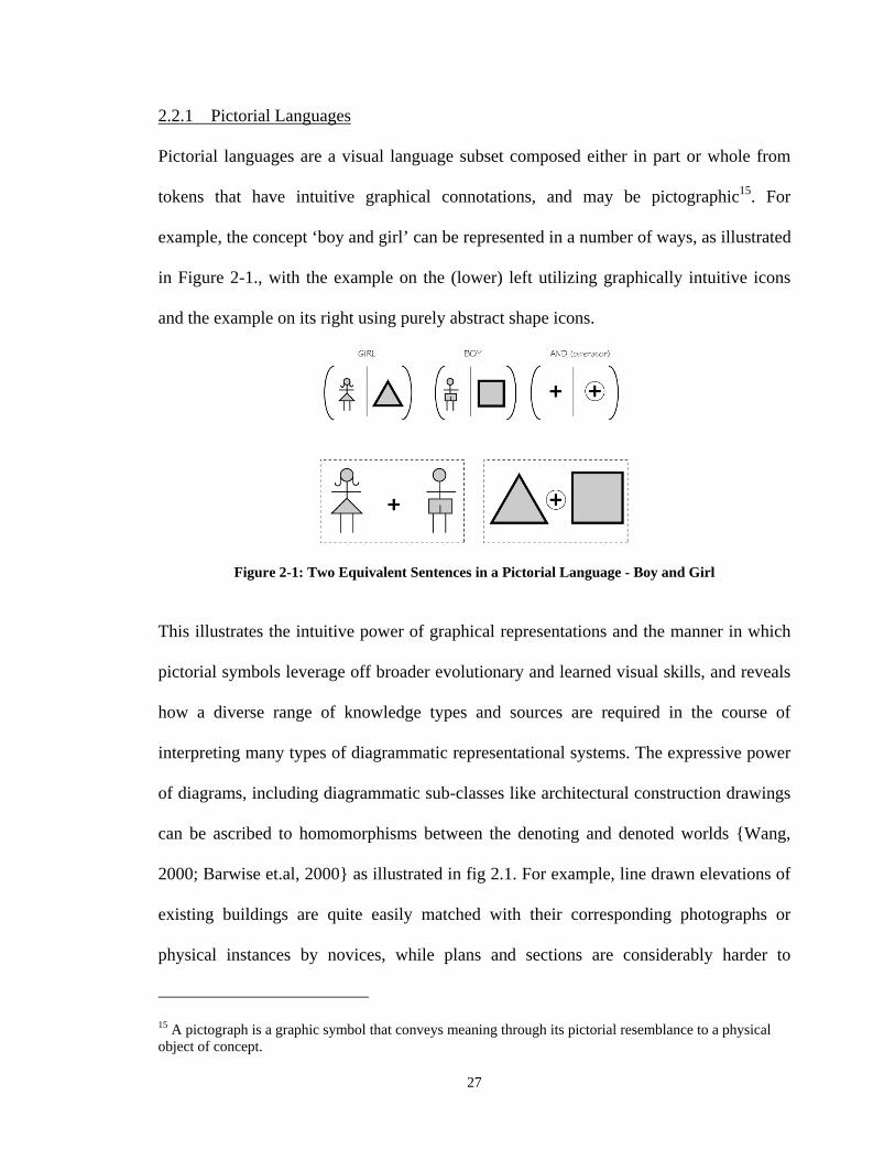
27
2.2.1 Pictorial Languages
Pictorial languages are a visual language subset composed either in part or whole from
tokens that have intuitive graphical connotations, and may be pictographic15. For
example, the concept ‘boy and girl’ can be represented in a number of ways, as illustrated
in Figure 2-1., with the example on the (lower) left utilizing graphically intuitive icons
and the example on its right using purely abstract shape icons.
Figure 2-1: Two Equivalent Sentences in a Pictorial Language - Boy and Girl
This illustrates the intuitive power of graphical representations and the manner in which
pictorial symbols leverage off broader evolutionary and learned visual skills, and reveals
how a diverse range of knowledge types and sources are required in the course of
interpreting many types of diagrammatic representational systems. The expressive power
of diagrams, including diagrammatic sub-classes like architectural construction drawings
can be ascribed to homomorphisms between the denoting and denoted worlds {Wang,
2000; Barwise et.al, 2000} as illustrated in fig 2.1. For example, line drawn elevations of
existing buildings are quite easily matched with their corresponding photographs or
physical instances by novices, while plans and sections are considerably harder to
15 A pictograph is a graphic symbol that conveys meaning through its pictorial resemblance to a physical object of concept.
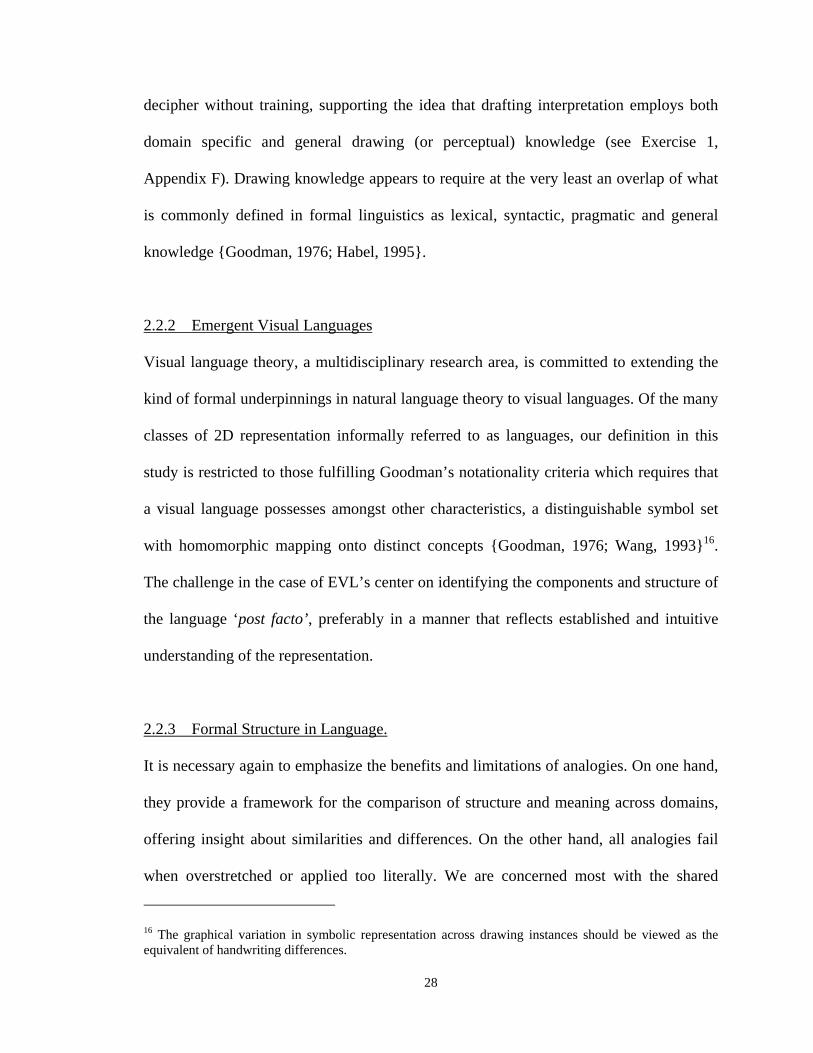
28
decipher without training, supporting the idea that drafting interpretation employs both
domain specific and general drawing (or perceptual) knowledge (see Exercise 1,
Appendix F). Drawing knowledge appears to require at the very least an overlap of what
is commonly defined in formal linguistics as lexical, syntactic, pragmatic and general
knowledge {Goodman, 1976; Habel, 1995}.
2.2.2 Emergent Visual Languages
Visual language theory, a multidisciplinary research area, is committed to extending the
kind of formal underpinnings in natural language theory to visual languages. Of the many
classes of 2D representation informally referred to as languages, our definition in this
study is restricted to those fulfilling Goodman’s notationality criteria which requires that
a visual language possesses amongst other characteristics, a distinguishable symbol set
with homomorphic mapping onto distinct concepts {Goodman, 1976; Wang, 1993}16.
The challenge in the case of EVL’s center on identifying the components and structure of
the language ‘post facto’, preferably in a manner that reflects established and intuitive
understanding of the representation.
2.2.3 Formal Structure in Language.
It is necessary again to emphasize the benefits and limitations of analogies. On one hand,
they provide a framework for the comparison of structure and meaning across domains,
offering insight about similarities and differences. On the other hand, all analogies fail
when overstretched or applied too literally. We are concerned most with the shared
16 The graphical variation in symbolic representation across drawing instances should be viewed as the equivalent of handwriting differences.
29
context sensitivity of Drafting and NLU, as defined by Chomsky for Natural Languages
{Goodman, 1976}, or Barton for drawings {Barton and Berrywick, 1987}, along with
their respective views of parts and structure, and the multi-layered nature of meaning in
both domains. Schank & Abelson (1997) examine these ideas in natural language,
observing that interpretation of textual passages may focus on actor-even relationships
and sequences or higher level notions like the ‘moral’ or ‘style’ of a story.
From Chomsky’s work, a formal grammar G, is a 4-tuple G = {V, , P, S} where V = set
of non-terminal symbols, = set of terminal symbols /constants, P = set of production
rules and S = a starting symbol that is in the set N. The parts that form the terminal and
non-terminals along with the rules guiding their composition are well understood in
Natural Language from extensive work in linguistics but are not formally defined in
drafting. In string language specifications, structure is often defined in terms of symbols
and production rules. In the case of drawings, we find it more useful to think of domain
structure in terms of symbolic concepts and relational constraints between them.
Chomsky defines a hierarchical order of grammars comprised of type 0 or context free,
type 1 or context sensitive and type 2 or unrestricted. We proceed on strong evidence that
that the (specifiable) structure in drafting is either context free or context sensitive
(Cherneff, J. 1999). Context free productions apply a rewriting rule to a single non-
terminal regardless of the context in which the symbol is found and are of the form A
BC or A , where A, B, C V, and , meaning whenever a non-terminal string A
is encountered, it can be re-written as BC or . This would apply to bottom-up structural
30
descriptions of unverified candidate symbols. Alternatively, a language is context
sensitive if we have productions of the form A where A V and,, ,
meaning that whenever the non-terminal A is surrounded by sub-strings and then it
can be rewritten as some 17. It is clear from looking at drawing samples that some
patterns are repeated in different contexts and mean different things in each (see Figure
4-2). This would occur in the case of a line and arc pattern which in context of a wall
opening, represent a door symbol. Context sensitive languages are typically difficult to
parse {Allen, 1995; Kozen, 1997} and heuristic or other techniques are often required to
overcome the problem of context sensitivity, some of which we shall address as they
apply to drafting interpretation in later discussions.
2.2.4 Diagrammatic Analysis and Specification
The general task outline for drafting specification involves carving up the drawing world
into symbols using an appropriate methodology then identifying the relationships that
constrain the composition of symbols. The resulting schema must then be subject to
evaluation according to some defined criteria. While some work has been carried out on
methodologies for visual language design using pictographic and graph based formalisms
{Andreis, Engels, Rekers 1998; Wang & Zeevat, 1993; Wang 1995; Haarslev, 1998},
there has been less work on methodologies for analyzing and formally specifying the
structure of an existing language, particularly in the case of multi-modal and multi-partite
17 Note that there is a single symbol, non-terminal on the left-hand side of the transition arrow in the context free grammar while there is more than one symbol on the left hand of the context sensitive production rule.
31
pictorial representations18 like architectural drawings {Goodman 1976, Barwise, J. &
Etchemendy, J. 1996}. Much of what has been undertaken necessarily draws from
Natural Language Understanding and Goodman’s work in Computational Linguistics.
Developing formal specifications of Emergent Visual Languages like architectural
drafting is beneficial for all of the reasons outlined in Chapter 1, establishing a
framework upon which domain-specific model-based intelligent diagrammatic
applications such as an interpretation system can be built.
Goodman provides some useful if limited guidance in defining a typological
classification of visual languages, but leaves out serious discussion of their symbolic
character and the process of symbolic decomposition. Mariott offers a rigorous
classification system based on a Copy Constrained Multiset Grammar (CCMG) hierarchy
as a visual language parallel to Chomsky’s hierarchy {Marriot, K. Meyers, B 1996}, but
appears more interested in AVLs. The CCMG hierarchy is based on the constraint
multiset grammar formalism, and Marriot et. al. show that many visual language
specification formalisms can be mapped into constraint multiset grammars, illustrating
that a large class of visual languages are inherently context-sensitive, hence the core of
the hierarchy is built around different forms of context-sensitivity.
Wang et. al. offer a grammar based specification methodology suited to AVL definition
or some pictographic EVL representations. The method employs an order sorted
signature comprised of a discrete set of symbol classes, a set of functions over the
18 Englehards work provides one of the few examples of this line of work
32
symbols, a set of (relationship) predicates, and a partial order (hierarchical classification)
of the symbol classes {Wang, D., Zeevat, H., 1993; Wang. Lee, Zeevat, 2000}. The
principal targets for the methodology are iconic diagrammatic representations of non-
physical concepts.
While much of the related work is directed at the design of artificial languages (AVLs),
Engelhardt focuses on the analysis and specification of existing or emergent
diagrammatic representations (EVL’s), offering a generalized methodology that defines
visual languages as notational schemas comprised of component and compositional
schemas {Engelhardt, 2002}. According to Engelhardt, a component schema is defined
as the set of symbolic parts comprising the representation, while the compositional
schema is defined as the framework in which a set of symbolic parts are composed.
Engelhardt’s principal interest is in conceptual representations of non-physical ‘spaces’
(e.g. process flowcharts, organizational graphs, etc.) and abstracts out most geometric or
spatial attributes beyond iconic shape and relative symbolic placement.
2.3 Task v/s Model Oriented Recognition and Interpretation
There is a broad literature framing the drawing recognition problem in terms of
sequential tasks (see Prabhu, B., Pande, S., 1999, Mumcu, H Kocabiçak, Ü. 2006, Dori,
D, Tombre, K. 1995 for surveys). The objectives can be grouped into those generating
vector geometry from scanned, vectorized and post-processed paper input, those
accepting the same input but advancing the conversion process to include structured
symbols like CAD entities or drawing symbols mainly through syntactic means, and
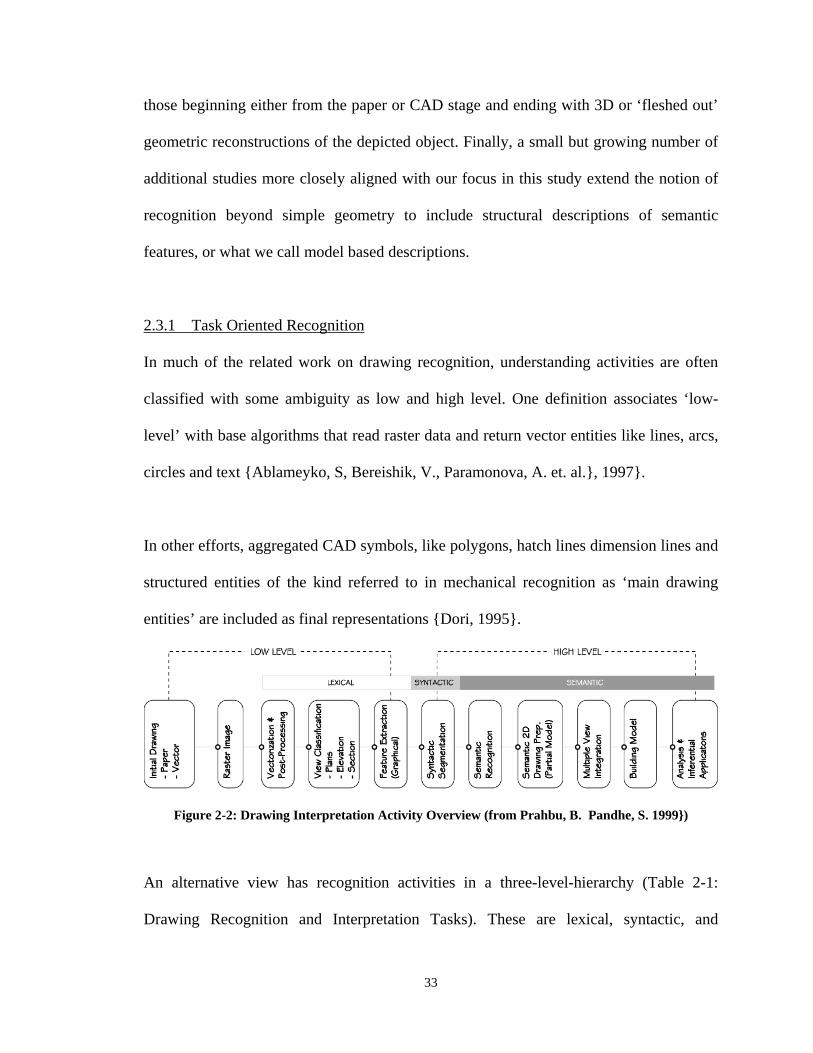
33
those beginning either from the paper or CAD stage and ending with 3D or ‘fleshed out’
geometric reconstructions of the depicted object. Finally, a small but growing number of
additional studies more closely aligned with our focus in this study extend the notion of
recognition beyond simple geometry to include structural descriptions of semantic
features, or what we call model based descriptions.
2.3.1 Task Oriented Recognition
In much of the related work on drawing recognition, understanding activities are often
classified with some ambiguity as low and high level. One definition associates ‘low-
level’ with base algorithms that read raster data and return vector entities like lines, arcs,
circles and text {Ablameyko, S, Bereishik, V., Paramonova, A. et. al.}, 1997}.
In other efforts, aggregated CAD symbols, like polygons, hatch lines dimension lines and
structured entities of the kind referred to in mechanical recognition as ‘main drawing
entities’ are included as final representations {Dori, 1995}.
Figure 2-2: Drawing Interpretation Activity Overview (from Prahbu, B. Pandhe, S. 1999})
An alternative view has recognition activities in a three-level-hierarchy (Table 2-1:
Drawing Recognition and Interpretation Tasks). These are lexical, syntactic, and
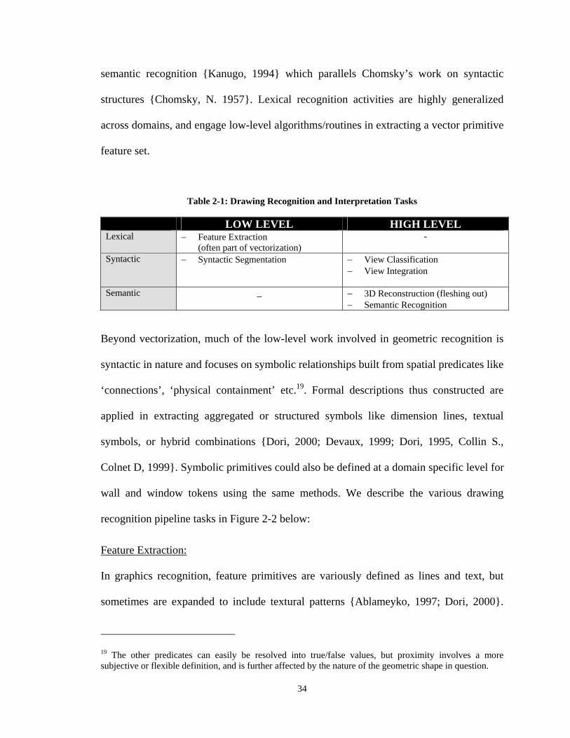
34
semantic recognition {Kanugo, 1994} which parallels Chomsky’s work on syntactic
structures {Chomsky, N. 1957}. Lexical recognition activities are highly generalized
across domains, and engage low-level algorithms/routines in extracting a vector primitive
feature set.
Table 2-1: Drawing Recognition and Interpretation Tasks
LOW LEVEL HIGH LEVEL Lexical Feature Extraction
(often part of vectorization) -
Syntactic Syntactic Segmentation View Classification View Integration
Semantic _ 3D Reconstruction (fleshing out) Semantic Recognition
Beyond vectorization, much of the low-level work involved in geometric recognition is
syntactic in nature and focuses on symbolic relationships built from spatial predicates like
‘connections’, ‘physical containment’ etc.19. Formal descriptions thus constructed are
applied in extracting aggregated or structured symbols like dimension lines, textual
symbols, or hybrid combinations {Dori, 2000; Devaux, 1999; Dori, 1995, Collin S.,
Colnet D, 1999}. Symbolic primitives could also be defined at a domain specific level for
wall and window tokens using the same methods. We describe the various drawing
recognition pipeline tasks in Figure 2-2 below:
Feature Extraction:
In graphics recognition, feature primitives are variously defined as lines and text, but
sometimes are expanded to include textural patterns {Ablameyko, 1997; Dori, 2000}.
19 The other predicates can easily be resolved into true/false values, but proximity involves a more subjective or flexible definition, and is further affected by the nature of the geometric shape in question.
35
Preliminary activities in raster-sourced drawing recognition systems emphasize extraction
of such primitive features followed by their post-processing into editable CAD entities,
which represented the final goal in several early engineering drawing recognition systems
{Tudhope, 1983}. Typical problems in the vectorization process include noise, gaps,
breaks and similar discontinuities.
Several publications describe implementations and algorithms for the extraction of vector
lines from bitmap raster images. These follow one of 2 main approaches, either
employing a thinning or skeletonization approach, followed by vectorization, or through
computation of a vector centerline by tracing the outer contours of a drawing
stroke{Tombre, 1998}. The drawbacks of skeletonization are its inefficiency, and
inability to distinguish line weights, an important graphical cue.
The output from both algorithms are point sets or short vector lines, which are
subsequently converted into continuous lines, circles, and arcs in post-processing
operations which may or may not be merged with the vectorization operation {Dori,
2000}.
Broken line-types are often recognized as multiple segments in the simplest algorithms,
and a number of line-pattern recognition algorithms have emerged in response. Most
employ Hough Transforms {Duda, R. et. al., 2000} which transform the x-y line
description into slope - intercept space, so that collinear line segments share the same
36
description and are thus easily aggregated. Other approaches convert the aggregated
segments into a single object in other post-processing operations.
The development of vectorization algorithms remains an open research area, with current
algorithms performing quite fast and accurately, though results are still highly dependent
upon image quality and resolution {Kong et. al., 1996}.
Syntactic Recognition
Vectorization operations are mainly of importance in cases where the translation input
consists of paper or raster data. Well documented limitations regarding the performance
of the different vectorization algorithms inform our choice of CAD input data in this
study, since this eliminates many of the problems associated with the quality of
vectorized raster data. CAD objects are also vector-based representations, though of a
somewhat higher order than vector primitives, and range from simple geometric entities,
such as lines and circles, to more complex aggregations of geometry and text in
structured association like engineering dimension lines. Variations in scale and rotation
within and across drawing sets render template matching techniques ill-suited for
architectural symbol segmentation. Template definitions typically consist of a library of
symbol-class instances at fixed resolution, from which a feature vector is derived, mainly
by (Boolean) assessment of each pixel’s color. The template is systematically traversed
across the image, and a distance function measures the correspondence between the
template and target region and a classification function establishes the likeliest kind of
symbol the target represents. Template matching approaches are very susceptible to scale
37
and rotational changes though a number of implementations address these limitations. In
contrast, these problems are easily handled by structural (syntactic) description, a
common approach in most drawing symbol recognition implementations.
Symbol Segmentation
Structural definitions are typically expressed using string, web and higher-order
grammar-based methods {Gessima E., 1986}20 as illustrated by Colin & Colnet in their
PLEX grammar based method for engineering dimension line recognition {Collin, S.,
Colnet, D.1999}. Textured patterns, such as wall hatching in floor plans, brick or other
material representations are also considered aggregated objects. Texture segmentation
strategies are primarily encountered in image recognition, and are mostly based on a
number of statistical approaches. Architectural texture and hatch patterns are often linear
primitives composed in some kind of structured arrangement, and a number of syntactic
techniques have been proven successful in segmenting line-based textural patterns from
base-level vector data input {Ablameyko, S. et al, 1997}.
Geometric Reconstruction:
Complete systems are defined by Dori as incorporating all or most of the recognition
pipeline activities in a single implementation that spans the entire paper to solid model
reconstruction reprocess {Dori, 2000}. There is a substantial literature on the subject of
3D geometric reconstruction from 2D views, mainly in Mechanical Engineering Drawing
20 Structural recognition does not necessarily equate to semantic recognition of symbols. Structural descriptions should be seen as tokenization or segmentation strategies, the results of which are then subject to semantic disambiguation.
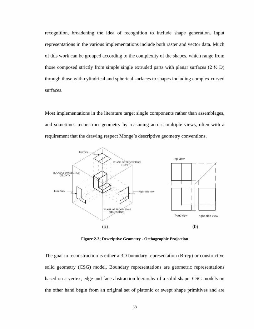
38
recognition, broadening the idea of recognition to include shape generation. Input
representations in the various implementations include both raster and vector data. Much
of this work can be grouped according to the complexity of the shapes, which range from
those composed strictly from simple single extruded parts with planar surfaces (2 ½ D)
through those with cylindrical and spherical surfaces to shapes including complex curved
surfaces.
Most implementations in the literature target single components rather than assemblages,
and sometimes reconstruct geometry by reasoning across multiple views, often with a
requirement that the drawing respect Monge’s descriptive geometry conventions.
Figure 2-3; Descriptive Geometry - Orthographic Projection
The goal in reconstruction is either a 3D boundary representation (B-rep) or constructive
solid geometry (CSG) model. Boundary representations are geometric representations
based on a vertex, edge and face abstraction hierarchy of a solid shape. CSG models on
the other hand begin from an original set of platonic or swept shape primitives and are
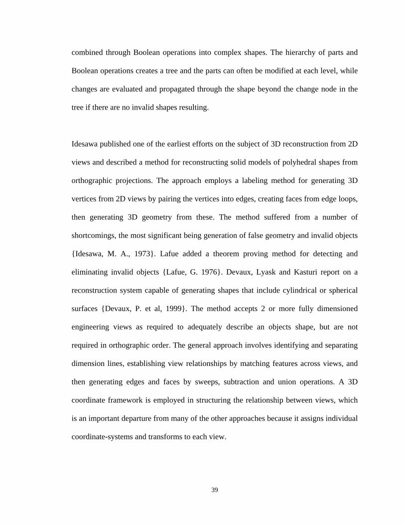
39
combined through Boolean operations into complex shapes. The hierarchy of parts and
Boolean operations creates a tree and the parts can often be modified at each level, while
changes are evaluated and propagated through the shape beyond the change node in the
tree if there are no invalid shapes resulting.
Idesawa published one of the earliest efforts on the subject of 3D reconstruction from 2D
views and described a method for reconstructing solid models of polyhedral shapes from
orthographic projections. The approach employs a labeling method for generating 3D
vertices from 2D views by pairing the vertices into edges, creating faces from edge loops,
then generating 3D geometry from these. The method suffered from a number of
shortcomings, the most significant being generation of false geometry and invalid objects
{Idesawa, M. A., 1973}. Lafue added a theorem proving method for detecting and
eliminating invalid objects {Lafue, G. 1976}. Devaux, Lyask and Kasturi report on a
reconstruction system capable of generating shapes that include cylindrical or spherical
surfaces {Devaux, P. et al, 1999}. The method accepts 2 or more fully dimensioned
engineering views as required to adequately describe an objects shape, but are not
required in orthographic order. The general approach involves identifying and separating
dimension lines, establishing view relationships by matching features across views, and
then generating edges and faces by sweeps, subtraction and union operations. A 3D
coordinate framework is employed in structuring the relationship between views, which
is an important departure from many of the other approaches because it assigns individual
coordinate-systems and transforms to each view.
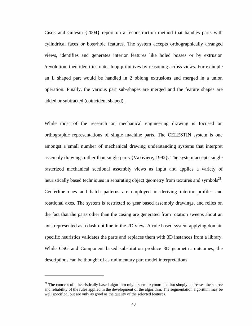
40
Cisek and Gulesin {2004} report on a reconstruction method that handles parts with
cylindrical faces or boss/hole features. The system accepts orthographically arranged
views, identifies and generates interior features like holed bosses or by extrusion
/revolution, then identifies outer loop primitives by reasoning across views. For example
an L shaped part would be handled in 2 oblong extrusions and merged in a union
operation. Finally, the various part sub-shapes are merged and the feature shapes are
added or subtracted (coincident shaped).
While most of the research on mechanical engineering drawing is focused on
orthographic representations of single machine parts, The CELESTIN system is one
amongst a small number of mechanical drawing understanding systems that interpret
assembly drawings rather than single parts {Vaxiviere, 1992}. The system accepts single
rasterized mechanical sectional assembly views as input and applies a variety of
heuristically based techniques in separating object geometry from textures and symbols21.
Centerline cues and hatch patterns are employed in deriving interior profiles and
rotational axes. The system is restricted to gear based assembly drawings, and relies on
the fact that the parts other than the casing are generated from rotation sweeps about an
axis represented as a dash-dot line in the 2D view. A rule based system applying domain
specific heuristics validates the parts and replaces them with 3D instances from a library.
While CSG and Component based substitution produce 3D geometric outcomes, the
descriptions can be thought of as rudimentary part model interpretations.
21 The concept of a heuristically based algorithm might seem oxymoronic, but simply addresses the source and reliability of the rules applied in the development of the algorithm. The segmentation algorithm may be well specified, but are only as good as the quality of the selected features.
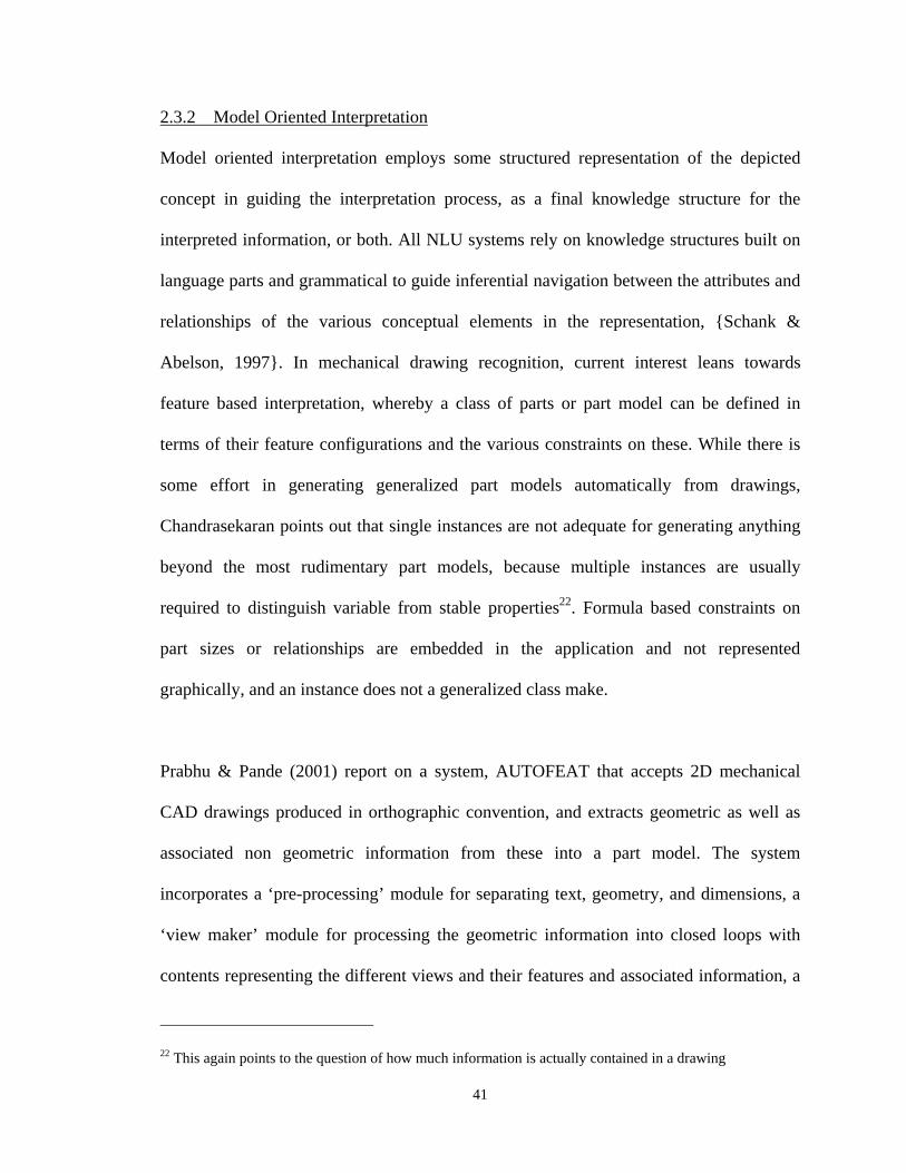
41
2.3.2 Model Oriented Interpretation
Model oriented interpretation employs some structured representation of the depicted
concept in guiding the interpretation process, as a final knowledge structure for the
interpreted information, or both. All NLU systems rely on knowledge structures built on
language parts and grammatical to guide inferential navigation between the attributes and
relationships of the various conceptual elements in the representation, {Schank &
Abelson, 1997}. In mechanical drawing recognition, current interest leans towards
feature based interpretation, whereby a class of parts or part model can be defined in
terms of their feature configurations and the various constraints on these. While there is
some effort in generating generalized part models automatically from drawings,
Chandrasekaran points out that single instances are not adequate for generating anything
beyond the most rudimentary part models, because multiple instances are usually
required to distinguish variable from stable properties22. Formula based constraints on
part sizes or relationships are embedded in the application and not represented
graphically, and an instance does not a generalized class make.
Prabhu & Pande (2001) report on a system, AUTOFEAT that accepts 2D mechanical
CAD drawings produced in orthographic convention, and extracts geometric as well as
associated non geometric information from these into a part model. The system
incorporates a ‘pre-processing’ module for separating text, geometry, and dimensions, a
‘view maker’ module for processing the geometric information into closed loops with
contents representing the different views and their features and associated information, a
22 This again points to the question of how much information is actually contained in a drawing
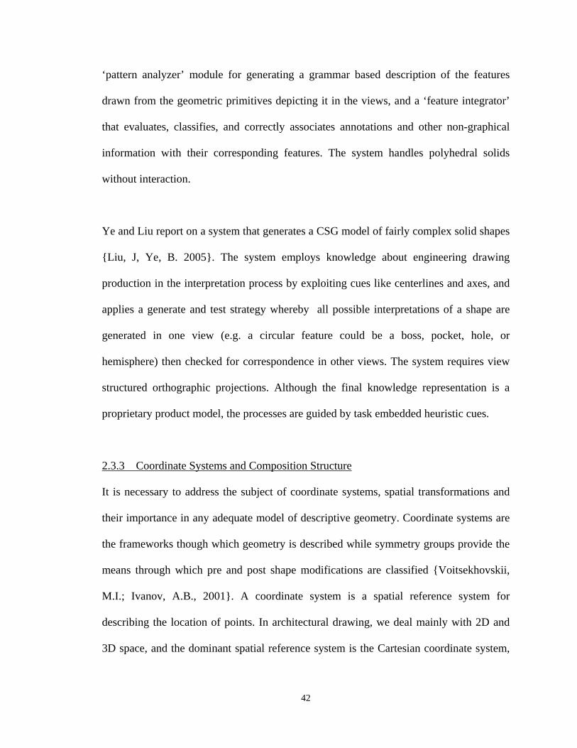
42
‘pattern analyzer’ module for generating a grammar based description of the features
drawn from the geometric primitives depicting it in the views, and a ‘feature integrator’
that evaluates, classifies, and correctly associates annotations and other non-graphical
information with their corresponding features. The system handles polyhedral solids
without interaction.
Ye and Liu report on a system that generates a CSG model of fairly complex solid shapes
{Liu, J, Ye, B. 2005}. The system employs knowledge about engineering drawing
production in the interpretation process by exploiting cues like centerlines and axes, and
applies a generate and test strategy whereby all possible interpretations of a shape are
generated in one view (e.g. a circular feature could be a boss, pocket, hole, or
hemisphere) then checked for correspondence in other views. The system requires view
structured orthographic projections. Although the final knowledge representation is a
proprietary product model, the processes are guided by task embedded heuristic cues.
2.3.3 Coordinate Systems and Composition Structure
It is necessary to address the subject of coordinate systems, spatial transformations and
their importance in any adequate model of descriptive geometry. Coordinate systems are
the frameworks though which geometry is described while symmetry groups provide the
means through which pre and post shape modifications are classified {Voitsekhovskii,
M.I.; Ivanov, A.B., 2001}. A coordinate system is a spatial reference system for
describing the location of points. In architectural drawing, we deal mainly with 2D and
3D space, and the dominant spatial reference system is the Cartesian coordinate system,
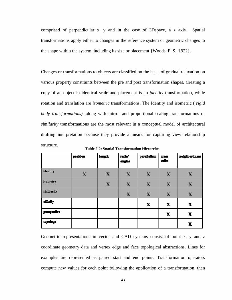
43
comprised of perpendicular x, y and in the case of 3Dspace, a z axis . Spatial
transformations apply either to changes in the reference system or geometric changes to
the shape within the system, including its size or placement {Woods, F. S., 1922}.
Changes or transformations to objects are classified on the basis of gradual relaxation on
various property constraints between the pre and post transformation shapes. Creating a
copy of an object in identical scale and placement is an identity transformation, while
rotation and translation are isometric transformations. The Identity and isometric ( rigid
body transformations), along with mirror and proportional scaling transformations or
similarity transformations are the most relevant in a conceptual model of architectural
drafting interpretation because they provide a means for capturing view relationship
structure.
Geometric representations in vector and CAD systems consist of point x, y and z
coordinate geometry data and vertex edge and face topological abstractions. Lines for
examples are represented as paired start and end points. Transformation operators
compute new values for each point following the application of a transformation, then
Table 2-2: Spatial Transformation Hierarchy

44
regenerate the geometry based on proper topological relations {Mantyla, M., 1988}. The
same process applies to more complex graphical aggregations like a view or detail, in
which case a view associated transformation that places one view in matching alignment
and orientation with another view would effectively capture the structure of the
relationship between these views.
It is possible to define the x, y and z coordinates of a point relative to any reference point
or origin. In addition to a global reference point, it is also possible to consider one objects
location relative to another, in which case the one objects position is defined within the
coordinate system of the other. This is important when reasoning about symbol
relationships within rather than across views as earlier described, and a conversion can
also be computed for switching between the vertex coordinate values in the global
coordinate and reference object coordinate systems. In chapter 4, we make the case for
individual drawing views as distinct 2D coordinate spaces, but composed within a global
3D coordinate framework.
2.4 Architecture Drawing Interpretation Systems
A number of efforts similar to those in mechanical drawing are directed at architectural
drawings, mostly focused on 3D geometric reconstruction. A system named “Building
Model Generator” (BMG), was developed at Berkeley, and creates extruded B-rep walls
from 2D vector floor plans with minimal intervention {R. Lewis, 1998}. The system
accepts 2D CAD floor plan input, and applies a number of pre-processing operations on
the wall geometry prior to perpendicular extrusion into 3D walls. Human intervention is
45
required at various points like stacking of floors in multi-story units, or creating arched
openings in walls. The result is a fairly accurate 3D geometric model. The system is only
capable of handling slab-type roofs.
Dosch, Tombre et. al . (2000) report on a system for 3D generation of architectural
models from 2D raster images. The system integrates various aspects of work in the
engineering drawing recognition field, combining them into what Dori refers to as a
“Complete System” handling both low level vectorization/post processing and higher
level reasoning about symbol classes and shape generation. The system is mostly
automated and operates on multiple floor plan drawings, producing multistory floor plan
assemblies. Heuristic domain knowledge is embodied in algorithms that handle problems
like floor plan stacking (the focus is on ‘robust’ cues like stairs and load bearing walls).
One obvious problem with the system and approach in general is that it makes no use of
elevations for example, and is therefore unable to represent gabled walls, determine
correct window shapes and heights, etc. because the 3D geometry is created by extrusion.
Furthermore, the absence of any semantic representation of 2D drawing structure or
resulting 3D geometric product in terms of symbolic or topological associations which is
required for the model to be actually useful beyond its 3D depiction.
Cherneff’s work on the KBIAD system (1996) is a principal influence in this study. The
input representations are schematic level architectural floor plan drawings and the result
is a 2D structured building component level model. The system architecture includes a
perceptual modeling component that reduces search through various structuring and
46
scoping methods, an interpretation hierarchy which provides a model of semantic
interdependency and process coherence, a symbolic decomposition of the drawing class
captured in a formal grammar along with context sensitive rules for their composition,
and a query process knowledge model mechanism for managing the application of
grammar rules throughout the process. While the system offers some interesting results,
there are a number of fundamental shortcomings that preclude its extension over the full
CAD to BIM translation process. First, while the idea of a conceptual model as process
driver and final outcome is crucial, the structure employed is improperly defined at a
fundamental level, possibly stemming from the focus of the study on a single view.
Drawing interpretation involves navigation between views for a number of different
reasons that include an inability to sufficiently describe most 3D objects using a single
2D view {Boyer, C. B., 1991}. Furthermore, it is necessary in any model of drafting
understanding to associate a plan and elevation views of the same concept under a
common instance, otherwise counting of building components for example becomes
impossible. In addition, there is no distinction between concept, representation and
abstraction, hence assuming the problem of multiple views is resolved by some grouping
mechanism, the result would be 2 views of the same symbol potentially carrying different
values for the same set of attributes relating to the depicted concept. Also if there is no
distinction between the syntactic description and the representation, then downstream
analysis and similar functionality which often require different abstractions may require a
whole new grammar. Finally, the system does not address the issue of generation of 3D
geometry from 2D views and the associated operations like spatial matching of views
required to enable this.
47
The CADPRO system (2001) was developed as a proof of concept investigation of the
prospects for automatic recognition and translation of layer-structured 2D CAD drawings
into an IFC based building model. The drawing input is prepared according to an
established layering standard. Like KBIAD, the system is limited to floor plans, and does
not draw upon a structured representation to guide the process. The approach consists
largely of extracting and instantiating graphical/geometric components in a bottom up
manner. While the system demonstrated some success in extracting doors and walls, the
exclusive focus on plans views precludes the recognition of gabled walls for example.
The major limitation in both systems can be summarized in their focus on individual floor
plans and the related inability to establish and utilize relational structure between views.
This also creates a broader set of problems associated with representation of individual
symbols and component representation across views, which can sometimes be
asymmetrical in their relationship cardinality23.
A few systems have been implemented in the area of Architectural Morphology and
Space Syntax for analyzing topological, formal, and perceptual properties of floor plan
designs. Terzidis {1994} reported on a system AELI that employs a variety of graphics
based recognition techniques in extracting and drawing features and applying them in
different low and high level analysis of the representation. These include measures like
symmetry. Space Syntax studies are focused on identifying metric predictors for a variety
of architectural buildings properties ranging from performance characteristics like way
23 A floor plan representation of a door may cross reference to 2 elevations views of the same instance.
48
finding {Nenci, A. Troffa, R. 2006} to relationships between spatial organization and
building function {Peponis, 1997}. One of the earliest drawing recognition systems was
an analysis application for fire safety compliance evaluation, which was implemented as
a rule based system built on a CAD application {Ozel, 1993}. The system accepted 2D
CAD input and operated on individual floor plans, relied upon a rule base derived from a
fire safety code assessment worksheet, and was implemented as a production rule system
with geometric operations on a small set of relevant predefined conceptual objects like
rooms, walls and doors.
2.5 Diagrammatic Inference and Knowledge Representation
Much of the preceding literature review has focused on shape recognition with the
exception of our discussion on model based interpretation. This view over simplifies the
problem because drawings depict an aggregated object with interrelated parts using a
convention which is context sensitive and produces ambiguity. The process of
disambiguation involves analyzing not just the symbol itself but its relationships with
other symbols, and there has to be a capability within the interpretation system to support
such inferential navigation between symbols, views etc.
2.5.1 Knowledge Structures and Meaning
Schank and Abelson make a strong case that understanding and memory are inextricably
intertwined, and understanding should be viewed in terms of knowledge structures and
the kinds of inferential conclusions that can be built from them {Schank & Abelson,
1997}. This is reflected in the architecture of their various implementations, which tend
49
to separate the knowledge representation (or information structure) from the processes
that operate on them. A similar distinction is found in Expert Systems and the notion of
underlying generalized knowledge bases which can be exploited in multiple applications.
In practical terms, knowledge structures reflect application specific commitments. The
view adopted in this study is that a conceptual representation of a diagram which focuses
on the logical and spatial structure of symbolic tokens is a base level conceptualization
atop which higher level conceptualizations can be constructed through inferential
processes. A representation of this sort should adequately support symbol-level part
structure and spatial inferencing, such as ‘How many doors are on the first floor?’ or ‘Is
plan-view door number x represented in elevation, and if so, in which elevation?’. This is
equivalent to an NLU knowledge structure that supports actor and event inferencing of
the sort ‘Who threw the ball?’ or ‘How many times did Mary call out John's name?’
These types of inferences are constructed without recourse to higher level
conceptualizations that represent higher notions of meaning like the ‘moral of a story’ in
NLU or ‘style of building’ in drafting, whereby the notion of a moral or style must be
explicitly defined a-priori as higher level knowledge structures. The view here is that in
the drafting domain, logical and spatial structure between symbolic concepts one degree
removed often provides an adequate framework upon which higher level meaning can be
inferentially derived, otherwise each symbol can be viewed as having some sort of
relationship with every other symbol. In this case one degree removed implies explicit
representation of the association between a window and its containing wall and the
various representations of the instance at the very least. The relationship between the
50
window and room symbols could thence be derived through its relationship with the wall
and the walls relationship with the room. If the window-room symbol relationship is
frequently of interest, then explicit associations in the symbol definitions could be carried
as a pragmatic decision and we propose that such pragmatic extensions are an important
element of such inferential drafting knowledge representations.
Schank and Abelson’s conclude from their work in NLU that knowledge about ‘what’
and knowledge about ‘how’ require fundamentally different forms of representation
{Newell, 1982; Winograd, 71; Minsky, 68, 70}. They adopt an episodic view with
“memory built around personal experience and episodes rather than abstract semantic
categories”. Word level meaning is implemented in this approach as data structures with
type restricted slots emphasizing the conceptualization of verbs and nouns, while
scenarios or the procedural aspects are implemented as scripts or common patterns (e.g.
buying and paying for goods, watching the television, etc.). The script is also considered
a (procedural) knowledge structure, and in order to interpret different kinds of textual
description like visiting a restaurant versus taking an exam, distinct scripts would be
required. Furthermore, if the goal of the interpreter in the restaurant case is an ability to
respond to actor event type queries, it would differ even from a knowledge representation
designed to distinguish between pleasant and disastrous restaurant visits. A number of
implementations were predicated on this line of work, including SAM (Script Applier
Mechanism) {Schank, R. C., Riesbeck, 1981} which was designed to understand script
based stories, FRUMP (Fast Reading and Understanding Memory Program) {Dejong, G.,
1979}, which was designed to summarize newspaper articles. Both systems are
51
considered Case Based Expert Systems which are a class of Knowledge Based Systems
(KBS) that attempt to approximate aspects of human domain expertise. Knowledge Based
Systems employ representations of domain knowledge in problem solving. {Giarratano,
J.C, Riley, G., 2005}
A number of other researchers {Habbel & Pribbenow 2000, Glasgow & Pappadias
2000}, reach similar conclusions regarding the basic characteristics of representational
schemes designed to support efficient reasoning about the perceptual and conceptual
properties of diagrams. Both studies conclude that any effective scheme must include
distinct spatial and visual representation components, must provide for hierarchical
granular structuring of the representation (graphical) in addition to offering relative
spatial reasoning capabilities. A logical structure should also define topologies and
constraints between parts and provide the means for part-structure logical navigation,
embodying domain specific knowledge.
Gobert et.al. {1989} sought to characterize the knowledge acquisition process employed
in abstracting information from architectural plans and evaluate the subject’s conceptual
understanding of the representation and depicted concept. The study implicitly accepts
the notion that the interpreter carries a conceptual framework or abstraction which is
incrementally populated through the process of reading the drawing input, analogous to
the structured representation which the DOM seeks to capture. The methodology in the
study involved observed studies of expert and novice subjects engaged in reading
architectural blue print samples while verbalizing their internal processes, and the results
52
were analyzed under 2 sets of protocols. The information was encoded for systematic
versus haphazard moves, while the second protocol focused on frequency of 3
dimensional moves. Systematic moves are these considered to reflect a continuous line of
inquiry such as identifying a space function then following its connection to an adjacent
space, while haphazard moves appear to reflect the discontinuation of one line of thought
and attention shift to some other aspect of the drawing such as commenting on a space,
followed by how all the windows are small. 4 comprehension measures were employed,
which included 2 dimension comprehension, 3 dimensional comprehension, building
comprehension, and design comprehension. Of particular relevance in our study were the
2D/3D comprehension tests and the building comprehension test.
A set of important points are noted from the study.
1. Since graphical information is simultaneous rather than linearly structured
(Thorndyke P., Satz, C. 1980), graphical interpretation requires additional search
processes to guide the acquisition of information (Larkin, J. A & Simon, H.A
1987)
2. Drawing information parsed in different spatial order can be shown to produce
equivalent representations of the depicted building.
3. The processes used for knowledge acquisition and representation in different
visual domains will differ depending on the task demands of the particular
domain (Ericsson K.A., Smith, J., 1991).
53
4. 8 kinds of semantic information are identified as used by interpreters to encode a
building from its plans (Object Identification | Object Description | Object
Geometry | Object function | Object Location | Part Structure | Support Structure
| Circulation) and correspond to the propositional (2nd) level of representation.
The study concludes that knowledge acquisition processes are directed by specialized
domain specific schemata, and that architectural interpretation expertise is due at least in
part to systematic search processes which are guided by prior knowledge schemata.
Ferguson and Forbus reported on a system called GeoRep, {Ferguson, R. Forbus, K.
2000} principally developed as a tool for defining the structure of diagrammatic
representations and as an investigatory tool directed at the cognitive aspects of
diagrammatic inference. The underlying system architecture implicitly commits to the
view that perceptual and conceptual structures in a diagrammatic representation can and
should be distinctly defined, notwithstanding their close interaction in applications.
Perceptual structures like parallelism or containment relationships are domain
independent, while relationships between conceptual symbols are governed by the
semantics of the domain. Collectively, they provide a powerful and flexible framework
for diagrammatic inferencing on structured representations.
Barwise and Etchemendy argue that heterogeneous and multimodal diagrammatic
systems incorporating multiple representational forms do not require an underlying
interlingua or dedicated diagrammatic specification to mediate between the various forms
of representation, proposing that the semantic mappings that link each of the
54
representational systems to a common target domain is adequate for this intermediation
{Barwise, et. al., 2000}. It is worth emphasizing that structured representations of parts
and relationships themselves can be viewed as an explicit representation that minimize
the amount of computation required in the process of mediation between representations
{Shank &Schank, R. Abelson, R. 1997}, a position adopted in this study.
Cherneff’s KBIAD system which employs structured representations both in guiding the
process and storing the results reflects our thinking on the subject of perceptual v/s
conceptual support, as well as the idea of an abstraction based on a set of symbols and
relationships. The perceptual (spatial) model provides some domain independent
reasoning capabilities, while the inheritance hierarchy or logical model provides the
means for navigating from one building concept to another. The system is not intended to
produce 3D geometric representations and consequently does not account for multiple
representations of the same concept or geometric issues like the compositional structure
of the multiple views in the resulting model. The CADPRO system offers even less in
this regard and only employs a model as final representation, relying on a more
traditional task based approach in the process of extracting the various components;
hence there is no articulation of what is conceptually important in a drafting
interpretation or other diagrammatic reasoning system.
2.5.2 Building Information Models
A Building Model is an open standard for representing useful information about a
building, defined as a composition of objects at different levels of aggregation {Eastman,
55
1999}. The objects are described in terms of their geometry, materials, processes, and
relations. Building information modeling was initially motivated by data exchange
requirements. The models attempt to capture a rich description of buildings as a general
class of objects, including their 3D geometry, material properties and some implicit
functional characteristics. The model considers buildings from the perspective of the
various professional involved with the product through the building lifecycle, including
Cost Management, Engineering (Structures, M&E,) Architectural, and Facility
Management to name a few. An abstraction of the domain focusing on the important
features from each of the various domains constitutes the end view. CAD developers
have increasingly adopted these as underlying representation, and the Public Standard,
IAI-IFC model was developed as a normative representation with the goal of providing
interoperability between these proprietary models. The representation provides intelligent
components like walls windows doors and columns that are constrained in manners
consistent with the actual objects configurations in the physical world, rather than the
linear or mass geometry that characterize traditional 2D and 3D drawings. In ‘Building
Product Models’ and ‘BIM Handbook’ C. M. Eastman et al review progress in the field,
identifying challenges in their development and possible applications of the technology
{Eastman, 1999, Eastman et al, 2008}.
Brilakis et. al (2010) report on an alternative approach for generating BIM geometry. The
goals overlap with those in CAD to BIM translation in terms of generating BIM models
without undertaking the manual task of BIM modeling. The approach employs laser
scanning and photography, applying texture analysis and segmentation methods on both
56
raster and vector images in order to segment the planes in the raster image and apply
these onto corresponding object surfaces onto 3D geometry generated from a 3D point
cloud produced by the scanner.
2.6 Summary
Drafting interpretation involves inferential as much as it does geometric reasoning, and
requires a structured representation to support its underlying inferential knowledge
building processes. Language interpretation of this kind, regardless of input modality or
domain specificity requires formal definition of parts and compositional structure. This
provides a necessary framework for the development of routines or agents to exploit in
the process of interpretation. Context sensitive languages like drafting in particular can
benefit from the wealth of knowledge provided from the literature in computational
linguistics, diagrammatic reasoning and visual language theory. Taken together, they
address many of the problems associated with the semantic interpretation of visual
language. Most significantly, they represent a core body of knowledge that defines a
hitherto unarticulated field of research. Of the few efforts directed at architectural
drafting interpretation, the richness and complexity of the representation has not been
adequately considered, even where an implementation reflects some understanding of the
(inferential) nature of the interpretation challenge. The resulting outcome are approaches
that are fundamentally unable to address the range of problems involved like integrating
disparate drawing views, identifying building components and their multiple symbolic
representations, establishing relationships between component instances and the syntax of
the relationships, and generating the kind of rich 3D descriptions in a building model.
57
CHAPTER 3.
METHODOLOGY
3.1 Overview
ike grammar based Natural Language (NL) specifications, we view the drafting
model as a (conceptual) language representation, a necessary intermediary
between input data and a structured interpretation thereof. It is meant to play a variety of
roles in the transformation from graphical ‘data’ into meaningful and usable form which
can then be applied in supporting search across diverse aspects of a representation or
mitigating and resolving the various forms of ambiguity and inconsistencies that arise in
the course of architectural drafting interpretation. We pursue a number of approaches in
defining the model’s conceptual structure, symbolic elements, and functionality, drawn
from work in the related areas of NLU, Diagrammatic Reasoning, and cognitive studies
on human subjects engaged in drafting interpretation tasks.
We begin by establishing the models contextual, semantic and inferential scope. The
contextual scope defines its role within a broader interpretation and translation
framework, the semantic scope defines which concepts and aspects we target for
interpretation, while the inferential scope establishes what kind of processes or operations
the model is intended to support. The contextual framework implicitly assumes that an
L
58
appropriate representation can facilitate the otherwise complex problem of translation
from 2D CAD data to a 3D BIM representation based on the idea that Drafting
interpretation, like Natural Language Understanding (NLU) and other inferential
processing, requires a structured language representation to guide or otherwise render it
tractable {Schank, R., Abelson R., 1997, Cherneff, J. 1990; Babalola, O. 2002}. In
natural language, long standing knowledge of the parts and rules of speech from
traditional and computational linguistics provide the underpinnings for grammar based
specifications. These ideas have influenced much of the work in diagrammatic reasoning,
particularly in the area of Artificial Visual Languages (AVL), where the parts (symbols)
are defined in tandem with the process of language specification.
In pictorial representations, part definition has either been at a domain independent
graphical level focusing on geometric primitives or combinations of these into, angles,
polygons, circles etc. Where the specification involves definition of its parts and
structure, implementations have relied on ad-hoc rather than on well-defined domain
symbols. For drafting interpretation, we derive our part and structure definition through
analysis of drawing samples, guided by Engelhardt’s work on diagrammatic analysis
(1996). This part structure description is captured in a model called the DOM, one of
many possible expressions of its semantic structure. We define the DOM as “a model-
based conceptualization of the symbols and structure in architectural drafting that
supports spatial and logical reasoning about both the depiction and the depicted”.
Reasoning in this context is viewed as inferential construction, which we further define as
59
“the generation of information previously unrepresented from that which is explicitly
represented”24.
We define interpretation as the symbolic transformation from geometric CAD data into
the structuring (DOM) model, while translation refers to the porting of the recognized
information to some other representation like a BIM. We define the scope of DOM to
BIM translation using the IFC Model View Definition (MVD) methodology (Heitanen, J.
2006a). The methodology provides a means for explicating the requirements for inter-
schema object translation based on information needs in the target application, which in
the case of DOM-BIM, center on data exchange requirements for instantiating symbol
geometry and some basic inter-object topologies, which are defined independently for
each symbol. Practical constraints on the recognizable subset of overall information about
each symbol impose some limits on the resulting DOM information. The translation stage
from DOM to BIM also requires clear definition of the objects and properties to be
exchanged, and various factors like missing attributes in the DOM may preclude its
instantiation in the BIM, thus some interpreted symbols may be unsuitable for translation.
Architectural drawings are not as rigidly formal in convention as mechanical drawings
(see section 2.2 Language, Drawings, and Structure) and the process of analyzing
the symbols, structure, and conventions that govern its production and use is crucial. For
this purpose, we adopt Engelhardt’s diagrammatic language specification methodology
with some minor but necessary extension. Engelhardt’s method focuses on representation
24 This informs the thinking that guides our scope of understanding and semantics in this study
60
of intangible concepts (processes, organizational structures, etc.). In order for this to
adequately capture representations of physical concepts, we modify the approach to allow
for the expression of conceptual associations across multiple views25 and also combine
his definition of symbol with domain semantics from architectural drafting. The resulting
class and relationship structure is implemented in the Express Language information
language in which also common to the translation target IFC model.
Because full implementation of the model and an interpretation system are beyond the
means of a single researcher within a reasonable time frame, we demonstrate the role and
utility of this approach through selective implementations addressing a number of
interpretation and translation tasks directed at both routine and more challenging aspects
of the problem. The implementation focuses on illustrating the role of the model in what
we consider to be key aspects of the problem like symbolic reasoning within and across
views, and the notion that continual refinement of the interpreted information is both a
crucial and pragmatic requirement for resolving the broader problem. Implicit in this is
the notion that demonstrable support for these kinds of problems offer validation for the
models basic structure and our underlying assumptions. The purpose of the
implementation is to demonstrate one approach amongst what we argue are various
process paths through which the model can be employed in drafting interpretation, and
our emphasis lies more on the resulting representation and its correspondence with what
we define as a fundamental (part structure) level of meaning in a drafting set. We further
develop a tool for manually populating aspects of the model and pre-defining
25 Descriptive geometry provides the basis for most 2D conventions for representing 3D objects, and relies on the use of multiple projections or views.
61
assumptions for testing interpretation and translation process hypotheses. The tool
provides useful support in furtherance of the models development, allowing developers to
focus on a particular aspect of the interpretation problem and bypass the tasks preceding
the particular point of interest.
3.2 Defining Model Scope and Structure
While this study is influenced by related work in Natural Language Understanding
(NLU), there are notable differences, the most obvious being dimensionality. Marriot et
al {1996}suggest that the (2) dimensionality of drawings render its syntax more difficult
to define and complex to parse than NLU because of the broader range of relationships,
even though NLU presents semantic disambiguation challenges not encountered in
drafting.
3.2.1 Model Scope and Translation Context
Many current product modeling efforts employ ISO-10303 (STEP) languages and
methods. The procedure begins with process modeling of the domain through an
Application Activity Model (AAM) which helps establish its scope. An Application
Requirements Model (ARM) which captures the desired view of the information is then
defined using one of several modeling formalisms (including EXPRESS-G), and is
ultimately refined into an Application Interpreted Model (AIM) in the EXPRESS
language (Eastman et. al 2008,.Lee, G. et. al, 2007). Scoping is critical to avoiding an
open ended modeling process.
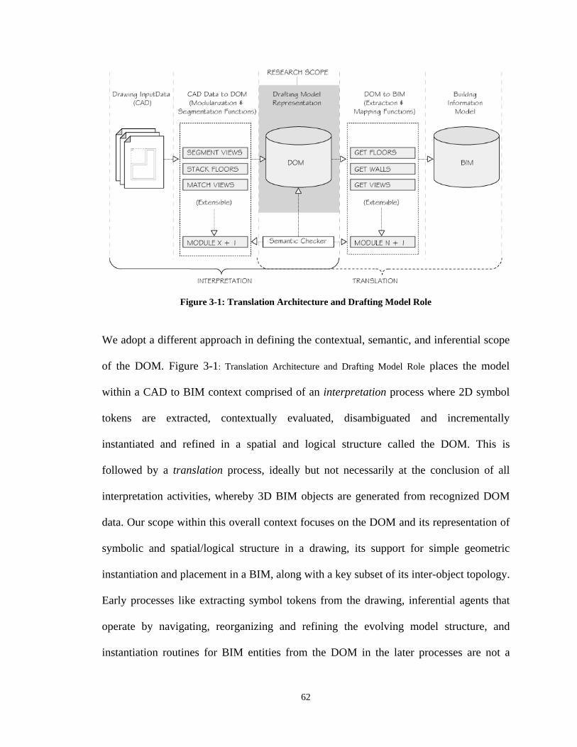
62
Figure 3-1: Translation Architecture and Drafting Model Role
We adopt a different approach in defining the contextual, semantic, and inferential scope
of the DOM. Figure 3-1: Translation Architecture and Drafting Model Role places the model
within a CAD to BIM context comprised of an interpretation process where 2D symbol
tokens are extracted, contextually evaluated, disambiguated and incrementally
instantiated and refined in a spatial and logical structure called the DOM. This is
followed by a translation process, ideally but not necessarily at the conclusion of all
interpretation activities, whereby 3D BIM objects are generated from recognized DOM
data. Our scope within this overall context focuses on the DOM and its representation of
symbolic and spatial/logical structure in a drawing, its support for simple geometric
instantiation and placement in a BIM, along with a key subset of its inter-object topology.
Early processes like extracting symbol tokens from the drawing, inferential agents that
operate by navigating, reorganizing and refining the evolving model structure, and
instantiation routines for BIM entities from the DOM in the later processes are not a
63
primary focus in this study, but merit consideration in so far as they impact the modeling
task.
3.2.2 Identifying Symbols and Defining Semantics
Certain graphical symbols are specific to architectural drafting. Drawing views are
composed from many such concepts organized according to various rules or constraints.
The properties and attribute definitions of each symbol limit the possible meanings that
can be expressed by a language composed from the symbol set (Chomsky N., 1957;
Schank R, Riesbeck C., 1981; Schank R, Abelson R., 1997).
Like other researchers in diagrammatic reasoning (Cherneff, Habel et al, Gobert, etc.) we
adopt a 3-tier framework that identifies lexical symbols combined through a set of
propositional (syntactic) rules that find expression through a situational ’ (semantic)
models as representative of the levels of meaning in sentences (Shank et al, 1997, Van
Dijk & Kintsch 1983). We propose that these respectively correspond to unverified
(lexical) symbol tokens, the (semantic) DOM schema comprising the various syntactic
and semantic definitions of concepts in the drafting domain, and an instantiated DOM
model reflecting a given configuration of these respectively.
We review a glossary of architectural drafting texts for relevant concepts (see Appendix
G, : Huth, M, 1996; Cullinan J., 1993). The glossary provides a broad range of drafting
and related terms that are representative of the kinds of conceptual structures employed in
structuring drafting information through the reading process. This is coupled with a
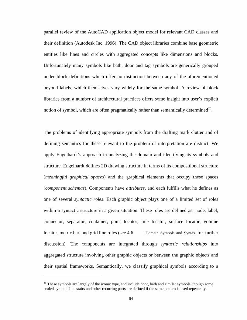
64
parallel review of the AutoCAD application object model for relevant CAD classes and
their definition (Autodesk Inc. 1996). The CAD object libraries combine base geometric
entities like lines and circles with aggregated concepts like dimensions and blocks.
Unfortunately many symbols like bath, door and tag symbols are generically grouped
under block definitions which offer no distinction between any of the aforementioned
beyond labels, which themselves vary widely for the same symbol. A review of block
libraries from a number of architectural practices offers some insight into user’s explicit
notion of symbol, which are often pragmatically rather than semantically determined26.
The problems of identifying appropriate symbols from the drafting mark clutter and of
defining semantics for these relevant to the problem of interpretation are distinct. We
apply Engelhardt’s approach in analyzing the domain and identifying its symbols and
structure. Engelhardt defines 2D drawing structure in terms of its compositional structure
(meaningful graphical spaces) and the graphical elements that occupy these spaces
(component schemas). Components have attributes, and each fulfills what he defines as
one of several syntactic roles. Each graphic object plays one of a limited set of roles
within a syntactic structure in a given situation. These roles are defined as: node, label,
connector, separator, container, point locator, line locator, surface locator, volume
locator, metric bar, and grid line roles (see 4.6 Domain Symbols and Syntax for further
discussion). The components are integrated through syntactic relationships into
aggregated structure involving other graphic objects or between the graphic objects and
their spatial frameworks. Semantically, we classify graphical symbols according to a
26 These symbols are largely of the iconic type, and include door, bath and similar symbols, though some scaled symbols like stairs and other recurring parts are defined if the same pattern is used repeatedly.
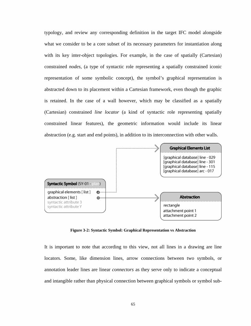
65
typology, and review any corresponding definition in the target IFC model alongside
what we consider to be a core subset of its necessary parameters for instantiation along
with its key inter-object topologies. For example, in the case of spatially (Cartesian)
constrained nodes, (a type of syntactic role representing a spatially constrained iconic
representation of some symbolic concept), the symbol’s graphical representation is
abstracted down to its placement within a Cartesian framework, even though the graphic
is retained. In the case of a wall however, which may be classified as a spatially
(Cartesian) constrained line locator (a kind of syntactic role representing spatially
constrained linear features), the geometric information would include its linear
abstraction (e.g. start and end points), in addition to its interconnection with other walls.
Figure 3-2: Syntactic Symbol: Graphical Representation vs Abstraction
It is important to note that according to this view, not all lines in a drawing are line
locators. Some, like dimension lines, arrow connections between two symbols, or
annotation leader lines are linear connectors as they serve only to indicate a conceptual
and intangible rather than physical connection between graphical symbols or symbol sub-
66
parts, and are not spatially constrained in the way physical object representations are27.
For example an annotation in a space with a leader line pointing to a column X can be
moved around within the space or even placed outside the space without changing the
information communicated by the drawing as long as the column X and the note remain
connected by the line. On the other hand, pointing the leader to some door Y for example
even without moving the text changes meaning in the drawing is for instance the
containing space of the instance and thus its possible association changes. In this manner,
we differentiate between the graphical representations of a symbol, its syntactic
abstraction derived from its syntactic role, and its (key) properties and its constraints in
relation to other symbols in the drawing space, and define the geometries that are
employed in the construction of relationships between symbols and drawing space (see
4.5 Architectural Drafting Symbols: A Functional Typology, 4.6 Domain Symbols and Syntax).
In architectural drafting, the problem is further compounded in several ways. First, many
drafting symbols are more than simple denotational referents but are pictographic, which
also map on to additional information like geometry, and material in the depicted object.
This relationship between representation and concept is unique to the pictorial mode
because the representation is not only a pointer to the concept, but may also share some
geometric and other correspondence (Goel V., 1996). Second, in representing 3D objects
using multiple 2D projections, the different views of a component must be understood as
belonging to the same 3D instance otherwise component counts would be incorrect
27 They are ultimately constrained in some manner, just not in some absolute sense by Cartesian space, as there is some ability to move them within certain limits without altering meaning in the drawing. These constraint relationships can be connectivity, or containment amongst others.
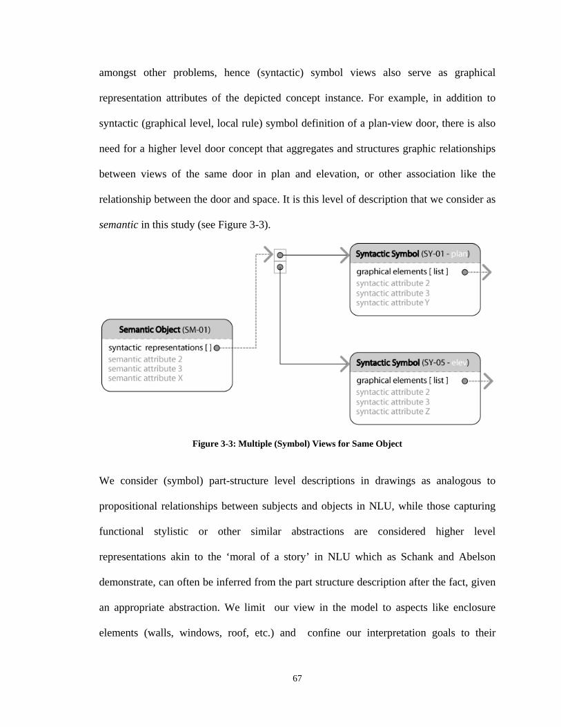
67
amongst other problems, hence (syntactic) symbol views also serve as graphical
representation attributes of the depicted concept instance. For example, in addition to
syntactic (graphical level, local rule) symbol definition of a plan-view door, there is also
need for a higher level door concept that aggregates and structures graphic relationships
between views of the same door in plan and elevation, or other association like the
relationship between the door and space. It is this level of description that we consider as
semantic in this study (see Figure 3-3).
Figure 3-3: Multiple (Symbol) Views for Same Object
We consider (symbol) part-structure level descriptions in drawings as analogous to
propositional relationships between subjects and objects in NLU, while those capturing
functional stylistic or other similar abstractions are considered higher level
representations akin to the ‘moral of a story’ in NLU which as Schank and Abelson
demonstrate, can often be inferred from the part structure description after the fact, given
an appropriate abstraction. We limit our view in the model to aspects like enclosure
elements (walls, windows, roof, etc.) and confine our interpretation goals to their
68
geometry and a subset of their spatial and aggregation relationships based on the view
that other kinds of ‘meaning’ can be inferred from this starting point. Finally, when
reading a drawing, studies indicate that an overlap exists between knowledge of symbols
and their use vs. knowledge about the physical concepts they depicted (see sections 2.8.0,
3.2.6) so careful consideration is necessary when defining the semantics of symbol
classes in the DOM.
Third, the DOM is subject to constraints imposed on it by the target representation on one
hand, and those stemming from the drawing source on the other. For example, a BIM
model of a window includes type information in addition to cost or geometric
descriptions of frame, mullion, sill, etc. However, some of this information is difficult to
accurately extract from a drawing, and may be completely omitted altogether. We limit
our interest to a subset of this geometric information like overall door unit dimension,
placement, and swing direction. Furthermore, because some of these (building
components) symbols are iconic rather than scaled pictorial representations, fine-grained
geometric associations like relationships between a line in a plan view window and edge
in the elevation are therefore impractical.
3.2.3 Drafting Symbol Relationships
Engelhardt, defines a variety of spatial frameworks that include basic metric spaces or
distorted metric spaces. Basic metric spaces include metric axis like timelines or integral
metric spaces like 2D/3D Cartesian or Polar coordinate systems. Distorted metric spaces
are less constrained, preserving order and approximate directions, but not the ratios of
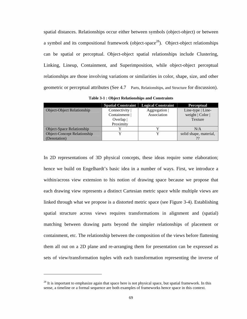
69
spatial distances. Relationships occur either between symbols (object-object) or between
a symbol and its compositional framework (object-space28). Object-object relationships
can be spatial or perceptual. Object-object spatial relationships include Clustering,
Linking, Lineup, Containment, and Superimposition, while object-object perceptual
relationships are those involving variations or similarities in color, shape, size, and other
geometric or perceptual attributes (See 4.7 Parts, Relationships, and Structure for discussion).
Table 3-1 : Object Relationships and Constraints
Spatial Constraint Logical Constraint Perceptual Object-Object Relationship Connectivity |
Containment | Overlap | Proximity
Aggregation | Association
Line-type | Line-weight | Color |
Texture
Object-Space Relationship Y Y N/A Object-Concept Relationship (Denotation)
Y Y solid shape, material, ??
In 2D representations of 3D physical concepts, these ideas require some elaboration;
hence we build on Engelhardt’s basic idea in a number of ways. First, we introduce a
within/across view extension to his notion of drawing space because we propose that
each drawing view represents a distinct Cartesian metric space while multiple views are
linked through what we propose is a distorted metric space (see Figure 3-4). Establishing
spatial structure across views requires transformations in alignment and (spatial)
matching between drawing parts beyond the simpler relationships of placement or
containment, etc. The relationship between the composition of the views before flattening
them all out on a 2D plane and re-arranging them for presentation can be expressed as
sets of view/transformation tuples with each transformation representing the inverse of
28 It is important to emphasize again that space here is not physical space, but spatial framework. In this sense, a timeline or a formal sequence are both examples of frameworks hence space in this context.
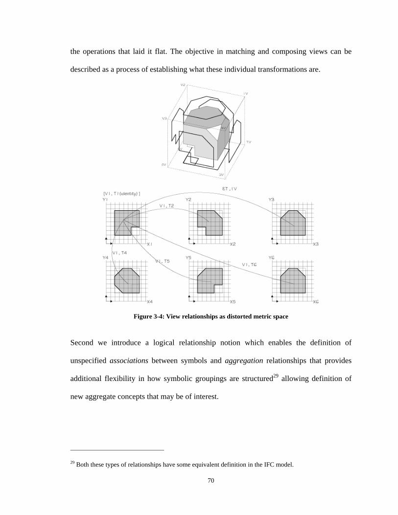
70
the operations that laid it flat. The objective in matching and composing views can be
described as a process of establishing what these individual transformations are.
Figure 3-4: View relationships as distorted metric space
Second we introduce a logical relationship notion which enables the definition of
unspecified associations between symbols and aggregation relationships that provides
additional flexibility in how symbolic groupings are structured29 allowing definition of
new aggregate concepts that may be of interest.
29 Both these types of relationships have some equivalent definition in the IFC model.

71
Perceptual relationships between symbols are domain independent and generic. In
cognition, they are considered to be low-level operations and facilitate the process of
inferential construction rather than represent persistent categories or structures (Schank,
R. Abelson, R. 1997). In this regard they are similar to the low level operations in human
vision, and for this reason along with other practical considerations, we implement these
as methods within the model (see 5.7 Collector Classes), and illustrate their possible role in
the interpretation process (see wall and window matching implementation sections in
chapter 7). Together, these guide our approach in identifying and defining the symbols in
the architectural drafting domain along with their compositional structure.
3.3 Drafting Interpretation as Inferential Construction
Having assumed the view of Gobert, Cherneff, Habel, and others on drawing
interpretation as inferential process, we broadly characterize the kinds of inferential tasks
in the drafting interpretation process as “spatial/geometric and logical reasoning about
parts and part-structure relationships within and across views” and attempt to identify
particular kinds of inferential that define their use. Of particular interest are the role of
perceptual and inferential reasoning in the integration of multiple drawing views, the
purpose of geometric versus symbolic reasoning, how inconsistencies within and between
views are detected, the implications of spatial constraints between and within views as
indicators of the kinds of relationships between the respective metric spaces, and the role
of a defined structure in guiding the interpretation process via knowledge driven heuristic
strategies. Gobert accepts that human drafting interpretation draws on spatial abilities
(French, J. et.al, 1963) that we propose are also relevant in a drafting interpretation
model. Of particular relevance are:
72
1. Visual memory – The ability to remember the configuration, location, and orientation
of figural material
2. Spatial Visualization – The ability to transform the image of spatial patterns into
other arrangements
3. Spatial Orientation – The ability to perceive spatial patterns or to maintain
orientation with respect to objects in space
Other associated factors which are also relevant in defining a conceptual representation of
drafting that supports our notion of meaning and inference are:
4. Flexibility of Closure – The ability to hold a given visual percept or configuration in
mind so as to disembed it from other well defined perceptual material
5. Logical Reasoning – The ability to select and organize relevant information for the
solution of a problem
6. Induction – The kinds of reasoning involved in forming and trying out hypothesis that
will fit a set of data
7. Integrative Processes – The ability to keep in mind simultaneously or to combine
several conditional premises or rules in order to produce a correct response)
There are a number of important limitations between the Gobert et. al. study and our
purposes. First, is important to note that verbalizations in the protocols focus almost
exclusively on concepts (rooms, walls, doors, etc.) rather than their representations.
Topological and other inter-object navigation occur at and are verbalized at a topological
rather than a symbolic level. For example, there are few verbal references to ‘door tag’ or
73
‘door symbol’. Given that our interest is in symbolic structure, this presents some
limitations in the usefulness of the verbalizations, though one possible remedy is to omit
key symbols in certain tasks thereby forcing the interpreter to consciously attend to and
perhaps verbalize about them. Second, The lack of access to Gobert’s data prompted the
need for some examination of these assertions by directly observing subjects in the
process of solving interpretation tasks in a set of simple exercises focused on problems
like navigating the logical and spatial structure of the drawing (see 3.2.7 for summary,
and Appendix D). The goal was to identify some characteristic inferential activities
involved in interpretation with a view towards incorporating support for them within the
model. The tasks centered on how subjects navigate the physical and logical structure of
the representation in the process of constructing a coherent model of the depicted
concept, and how this serves in reviewing or revising the conceptual and relational
definitions in the model as it evolves.
3.3.1 Drafting Interpretation Exercises
In the first exercise, we examine the notion that perceptual reasoning is an integral low-
level aspect of how drafting information is processed, and that the cognitive facilities that
underlie this are implicit and domain independent. Similar views are held by Ferguson
et.al. (2000) and Habel and Pribbenow (1995), both of whom view perceptual operation
as somewhat different from domain specific part structure reasoning.
The second exercise examines the proposition that drawing information is graphically
and conceptually processed at different levels of granularity, determined by the level of
74
detail required for a given task. We look at how reasoning is expedited by managing the
level of perceptual detail of symbolic representations. In diagrammatic reasoning,
semantic structure is built through spatial and logical relationships between symbols,
which at some low-level involves geometric testing. The simpler the geometries being
tested, the more efficient the determination, hence our interest is in establishing that
drafting information actually is represented at various levels of detail for purposes of
efficient reasoning. The purpose of the exercise was to establish evidence of this strategy
in drafting prior to accounting for it in our abstraction of symbols in the model.
The third exercise sought to examine how interpreters reason across multiple views, with
particular interest in the role of geometric and non-geometric information in the
accomplishment of this task. The tasks involved reasoning across view with and without
the aid of cross-reference or compositional symbol schemas (textual, iconic, tags, section
symbols, etc.) The purpose of the exercise was to derive a better understanding of the
complementary role of symbolic information in the construction of coherent geometric
representations from multiple views.
The fourth exercise sought to directly identify some of the various types of inferential
reasoning problems that interpreters face in the use or interpretation of architectural
construction drawings. Of particular interest was how subjects navigated a multipartite
representation in the course of constructing a mental model of the depicted object, and
involves mapping symbols on to conceptual instances, spatial transformation and
75
reconstruction of (spatial) relationships, in addition to construction and navigation of
logical and other temporary structures.
A fifth exercise sought to demonstrate the differences between constraints on
relationships within and across views, driven by the hypothesis that subjects overcome
spatial order by transforming entire views in the course of their integration, lending
support to the view that spatial layout of views represent a distorted metric space, while
single views represent a cartesian metric space. The exercise also examines the ability of
subjects to transform sub-view symbolic components and identify inconsistencies
between these, which again relates to the tendency of interpreters to engage the
representation at coarse and fine levels of details even in the course of fundamental tasks.
The tasks involved multiple sets of floor plans and elevations with different spatial
arrangements of the views in each instance, and some sets including minor
inconsistencies or irregularities like omitted or displaced windows.
The verbalization protocols under which the exercises are conducted presented an
opportunity to glean additional insights into the use of drawings and the process of their
interpretation. The exercises also offer the additional benefit of substantiating or
challenging our initial assumptions regarding the required conceptual characteristics of
diagrammatic inference systems, hence implicit in each of the experiments is an interest
in whether any of the assumptions relevant to a given task is irreconcilably contradicted.
76
From the exercises we identify the following characteristics, which though not
necessarily comprehensive, reflect common and recurring problems and operations
through the process of interpretation, and if accounted for in a drafting interpretation
model should enable the level of interpretation we are interested in. These specifically
include:
1. Symbol Recognition:
The ability to recognize symbolic shapes corresponds with the Flexibility of Closure
factor (Gobert J. Frederiksen, C 1989, Ekstrom, R. B et. al 1976) In our contextual
framework we consider this an external function input source to the model.
2. Propositional (Spatial) Reasoning on Geometry
Domain independent thinking of the sort Left-of, Right-of, Greater-than Smaller-than.
Comparative spatial logical reasoning with symbols or primitives is considered key in
flexible and intuitive diagrammatic inference. This represents a domain independent
low level process and is called with sufficient frequency that we propose its
integration within the model as methods.
3. Mapping Representations to Depiction
In all symbol classes depicting physical building components, 3D objects are
depicted using 1 or more views. It is important to be able to recognize that several of
these views correspond to the same depicted object. In other words, the KR
distinguishes between a conceptual symbol instance and its 2D symbolic depiction,
often across views. Again, the interest in the model lies more in the ability to support
77
this structured multi-view definition of concepts than in routines that populate the
representation.
4. Creating Conceptual and Pragmatic Assemblages
While some logical aggregations e.g. a view or pragmatic aggregations like a door
schedule may be so commonly employed in diagrammatic reasoning with drafting
that they are worth defining, others like ‘wall assembly’ or ‘all circular windows on
the north face’ may be more usefully constructed ad hoc, and this ability to create
these either temporary or application specific categories appears necessary.
5. Navigating Conceptual and Pragmatic Aggregations
Navigation of inter-concept topology and pragmatic aggregations constructed on the
basis of common features or attributes via their connections (in this case objectified
relationships) provide the mechanisms through which actual inferential reasoning
occurs.
6. Spatial Transformation
The reconstruction of spatial relationships between views, interpreting differentially
scaled details and a host of other problems involve a mapping process that seems to
indicate need for spatial transformation operations These all correspond with the
Spatial Visualization factor (Gobert J. Frederiksen, C 1989, Ekstrom, R. B et. al
1976).
7. Geometric Testing/Comparison
Unlike propositional reasoning which though spatial and resolves to a single logical
decision, testing of actual shapes involves more detailed geometric comparisons and
a broader set of overall knowledge and low/high level reasoning rules than
78
propositional reasoning. The resulting understanding between the 2 shapes is richer
and may include vertex to vertex mapping, transformational relationships, and
others. This again corresponds with the Spatial Visualization Factor.
8. Geometric Construction
Generation of geometry in the course of drafting interpretation is often an important
aspect of the hypothesis generation and testing process involved in interpretation as
inferential construction. Consider a front elevation with a gabled pediment and 2
columns. The interpreter realizes that this represents either a portico projecting or
the building face or a free standing structure in the foreground, the side view must
reflect a solution that corresponds to one of the two solutions.
3.3.2 Model to BIM Translation
Finally, in establishing semantics for DOM to BIM translation, we apply the IFC Model
View Definition methodology (MVD) (Heitanen J. 2006a). The methodology offers a
means for precisely defining which of the many aspects in a schema, including its
geometric representation and attributes are of importance in a given translation context. A
document called an Information Delivery Manual (IDM) which details the various
information exchanges in a given process establishes the functional expectations or scope
in an exchange (Translator, Interpreter, etc). The purpose of the MVD on the other hand
is to provide a specification that ensures support for this functionality at implementation.
Modularity and reusability are important considerations in the methodology. The
modules are built from elements called concepts. For each concept requiring translation,
it is necessary to consider at least minimally its functional semantics and its pertinent
79
relationships in order to guarantee they carry enough information to support the required
functionality in the receiving application.
3.4 Evaluating the Model
The evaluation strategy addresses the role of perceptual modeling and propositional
reasoning, how geometric and part structure inference can be supported by the model and
how the relationships we define in section 3.2.4 facilitate this. We also illustrate the
importance of incremental processes like structuring view relationships in simplifying
various other recognition processes, and examine how the relational structures in the
model enable logical and spatial inference and the knowledge driven heuristic approach
that constitutes the main strength of a model of this sort. The relationship between the
DOM and BIM in a translation context is also partly examined, with emphasis on the
importance of information structure across views and the attributes required in
instantiating Building Model information from the DOM. Finally, the model
implementation includes the definition of a framework comprised of symbols relationship
and property set schemas that collectively capture the interrelated and multilayered nature
of drafting symbol systems. Schemas for syntactic and semantic symbols and their
inheritance structure are clearly defined in order to provide a template for the
unimplemented symbol schemas. The symbol implementations in the study focus on wall
door and window schemas. These are chosen for a number of reasons. First, wall
recognition is important because it is crucial in defining spaces. Furthermore, in order to
recognize a wall, both the plan and elevation views should be ideally matched and
orientated in order to extract geometric information from both views relevant to the 3D
80
instantiation as illustrated by the case of gabled walls. The need for spatial transforms in
each symbol for spatial matching as in the case of views becomes clear. In addition, walls
and doors or windows form assemblages that share both syntactic and semantic
interconnectedness and we show through implementation how these can be interpreted
individually and structured in the model, then translated to the IFC. Doors and windows
often have multiple representations, and the implemented schemas show how such cases
are addressed.
3.4.1 Test Data and Drawing
The drawings used in the limited testing consist of 3 single story orthogonal AutoCAD
drawings. The geometric entities in the sample range between 1,000 and 2,000 entities
when block symbols and attributes are reduced to CAD primitives (exploded). The
drawings include some of the inaccuracies encountered in normal drafting samples,
including imperfect use of layering. The level of detail in the drawings is representative
of a typical production set but excludes detail views and component schedules.
3.5 Summary
The interpretation of aggregated 3D objects from 2D views requires knowledge of the
symbols and conventions in the language, in addition to conceptual knowledge about
depicted objects. This knowledge framework can guide an agent’s processes of
understanding. Drafting instances include several sub-language schemas like a
measurement language schema, a meta-language schema for integrating views, and
various textual and graphical abstraction languages serving a variety of purposes. These
81
are read collectively, and their relationships require definition along various logical and
spatial dimensions. In order to understand the kinds of inferential tasks involved in
diagrammatic reasoning as a prerequisite to providing support for these in the model, we
refer to the work of Gobert et. al. (1989), which we substantiate through a number of
simple implementations in order to examine some of the positions advanced. The DOM
model which we develop on the basis of these arguments is subsequently tested through
selective implementation for its support vis-à-vis the design criteria. A means for further
testing, development and revision of the model is offered through a manual instantiation
tool capable of simulate a starting point for the development or evaluation of a process
hypothesis.
82
CHAPTER 4.
ARCHITECTURAL DRAFTING SYMBOL STRUCTURE
4.1 Architectural Drafting as Symbol System
he ability to effectively exchange building information between actors with
minimal ambiguity lends credence to the notion of construction drawing as
‘language’, defined here as “a system of signs, symbols, gestures, or rules used in
communicating {The American Heritage® Dictionary of the English Language}. We
view drawings in this study as symbolic compositions serving a communicative purpose,
or more specifically, as “a composition of semantic symbol systems, which though varied
and distinct, must be read as a whole” {Goodman, N, 1976}. The drafting language
notion is also supported by the demonstrable ability of expert interpreters trained in one
drafting standard to easily read drawings produced in different conventions in spite of
observable differences between these, implying that the mode of communication is
comprised of both superficial variability as well as more stable (deep) characteristics.
Newell & Simon [1982] introduced the symbol-system paradigm in “Computer Science
as Empirical Inquiry: Symbols and Search”. The premise states that the intelligent
machine is a symbol system, and makes further assertions about the general nature and
T
83
structure of symbol systems30. A symbol system is defined as being comprised of a
symbol set standing as abstract representations of tangible or intangible concepts, and a
set of rules for their combination or manipulation.
4.2 Some Theoretical Background
Goodman extends an idea previously applied in specifying string based languages to
different representational systems utilized in artistic creation. This generalized notion of
symbol which embraces domains as diverse as the visual arts, music, and dance, holds
that textual, audio, and graphical elements are all potentially legitimate symbols, and can
be abstracted in manners independent of medium or mode. Goodman broadly divides
symbol systems into three classes which he categorizes as notational, discursive, and non-
notational symbol systems respectively. Notational and discursive systems are those with
definable parts and rules, being therefore (potentially) specifiable and interpretable
{Goodman, 1976}. Consequently, it is important to determine where a given
representational scheme falls within this spectrum. Goodman offers a set of principles in
this regard. Two Syntactic principles impose constraints on how the symbolic domain is
carved up and represented, while 3 semantic principles address the relationship between
the structure of symbols and concepts in the representing and represented worlds. The
symbolic and depicted worlds are distinct, with each having defined but interrelated
structures connected by what he defines as exemplification whereby the connection
between symbol and depicted concept is not merely denotational, but embodies property
30 This notion has since been adopted by the cognitive science community, and is simultaneously applied in discussions about human and machine intelligence. The information-processing model of Newell provided the bridge between computation and psychology, and remains the dominant paradigm to date.
84
subsets of the depicted concept rather than being a simple abstract stand-in. An example
would be a descriptive system that employs a red circle standing as a symbolic
abstraction of a red football (color, shape), rather than a white triangle for example. This
kind of relationship is limited in textual representations to properties like color and
possible relative size of text and concept, but for drawings, some geometric aspects of the
depicted are also captured in the representation. In the case of architecture, we define the
building and drawing world are our two independent but interrelated domains. There is
however further distinction within the depicting (pictorial, textual) world in the
relationship between a symbol and its graphical representation, much like fonts
representing a letter and the actual letter as an ‘aggregator of all its valid graphical
instances’. Stated otherwise, the symbol is the class while the various representations are
tokens in that class, of which each class can have multiple tokens.
The syntactic principle of disjointness requires interchangeability between any two
tokens that represent the same concept without consequence. In addition, no token in a
given symbol set should refer to anything another token in the same set does not equally
represent31. Syntactic differentiability on the other hand requires that for any two tokens
classes, it should be possible to determine which if any of 2 classes a given token
instance with an exclusive membership belongs to. The concept of compliance
(denotation) as the connection between a symbol (representation class), and the (external)
concept to which it refers is more appropriately captured in pictorial representations by
31 Practically speaking, it is not likely that multiple token representations of a given symbol will be used arbitrarily. In textual passages, italicization and use of different fonts usually carry some semantic connotation, such as the introduction of new terminology, or as labels and headings.
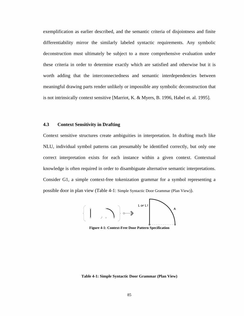
85
exemplification as earlier described, and the semantic criteria of disjointness and finite
differentiability mirror the similarly labeled syntactic requirements. Any symbolic
deconstruction must ultimately be subject to a more comprehensive evaluation under
these criteria in order to determine exactly which are satisfied and otherwise but it is
worth adding that the interconnectedness and semantic interdependencies between
meaningful drawing parts render unlikely or impossible any symbolic deconstruction that
is not intrinsically context sensitive [Marriot, K. & Myers, B. 1996, Habel et. al. 1995].
4.3 Context Sensitivity in Drafting
Context sensitive structures create ambiguities in interpretation. In drafting much like
NLU, individual symbol patterns can presumably be identified correctly, but only one
correct interpretation exists for each instance within a given context. Contextual
knowledge is often required in order to disambiguate alternative semantic interpretations.
Consider G1, a simple context-free tokenization grammar for a symbol representing a
possible door in plan view (Table 4-1: Simple Syntactic Door Grammar (Plan View)).
Figure 4-1: Context-Free Door Pattern Specification
Table 4-1: Simple Syntactic Door Grammar (Plan View)
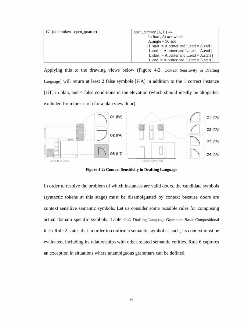
86
G1 (door token - open_quarter) open_quarter (A, L) L: line , A: arc where A.angle = 90 and {L.start = A.center and L.end = A.end | L.end = A.center and L.start = A.end | L.start = A.center and L.end = A.start | L.end = A.center and L.start = A.start }
Applying this to the drawing views below (Figure 4-2: Context Sensitivity in Drafting
Language) will return at least 2 false symbols [F/A] in addition to the 1 correct instance
[HT] in plan, and 4 false conditions in the elevation (which should ideally be altogether
excluded from the search for a plan view door).
Figure 4-2: Context Sensitivity in Drafting Language
In order to resolve the problem of which instances are valid doors, the candidate symbols
(syntactic tokens at this stage) must be disambiguated by context because doors are
context sensitive semantic symbols. Let us consider some possible rules for composing
actual domain specific symbols. Table 4-2: Drafting Language Grammar: Basic Compositional
Rules Rule 2 states that in order to confirm a semantic symbol as such, its context must be
evaluated, including its relationships with other related semantic entities. Rule 6 captures
an exception in situations where unambiguous grammars can be defined.
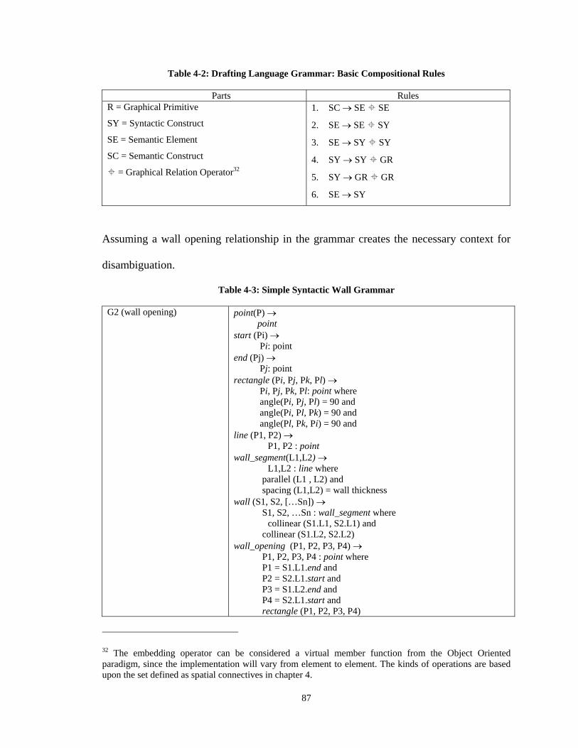
87
Table 4-2: Drafting Language Grammar: Basic Compositional Rules
Parts Rules R = Graphical Primitive
SY = Syntactic Construct
SE = Semantic Element
SC = Semantic Construct
= Graphical Relation Operator32
1. SC SE SE
2. SE SE SY
3. SE SY SY
4. SY SY GR
5. SY GR GR
6. SE SY
Assuming a wall opening relationship in the grammar creates the necessary context for
disambiguation.
Table 4-3: Simple Syntactic Wall Grammar
G2 (wall opening) point(P) point start (Pi) Pi: point end (Pj) Pj: point rectangle (Pi, Pj, Pk, Pl) Pi, Pj, Pk, Pl: point where angle(Pi, Pj, Pl) = 90 and angle(Pi, Pl, Pk) = 90 and angle(Pl, Pk, Pi) = 90 and line (P1, P2) P1, P2 : point wall_segment(L1,L2) L1,L2 : line where parallel (L1 , L2) and spacing (L1,L2) = wall thickness wall (S1, S2, […Sn]) S1, S2, …Sn : wall_segment where collinear (S1.L1, S2.L1) and collinear (S1.L2, S2.L2) wall_opening (P1, P2, P3, P4) P1, P2, P3, P4 : point where P1 = S1.L1.end and P2 = S2.L1.start and P3 = S1.L2.end and P4 = S2.L1.start and rectangle (P1, P2, P3, P4)
32 The embedding operator can be considered a virtual member function from the Object Oriented paradigm, since the implementation will vary from element to element. The kinds of operations are based upon the set defined as spatial connectives in chapter 4.
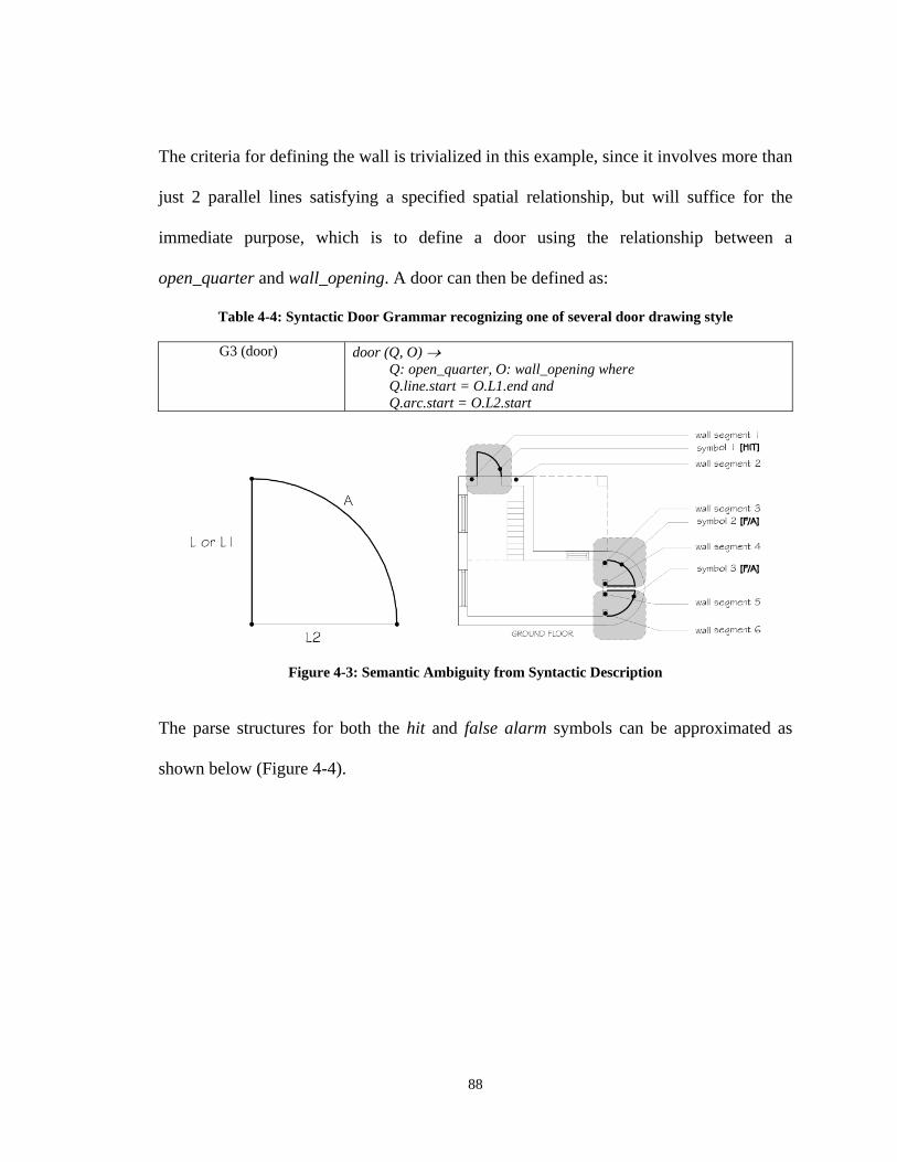
88
The criteria for defining the wall is trivialized in this example, since it involves more than
just 2 parallel lines satisfying a specified spatial relationship, but will suffice for the
immediate purpose, which is to define a door using the relationship between a
open_quarter and wall_opening. A door can then be defined as:
Table 4-4: Syntactic Door Grammar recognizing one of several door drawing style
G3 (door) door (Q, O) Q: open_quarter, O: wall_opening where Q.line.start = O.L1.end and Q.arc.start = O.L2.start
Figure 4-3: Semantic Ambiguity from Syntactic Description
The parse structures for both the hit and false alarm symbols can be approximated as
shown below (Figure 4-4).
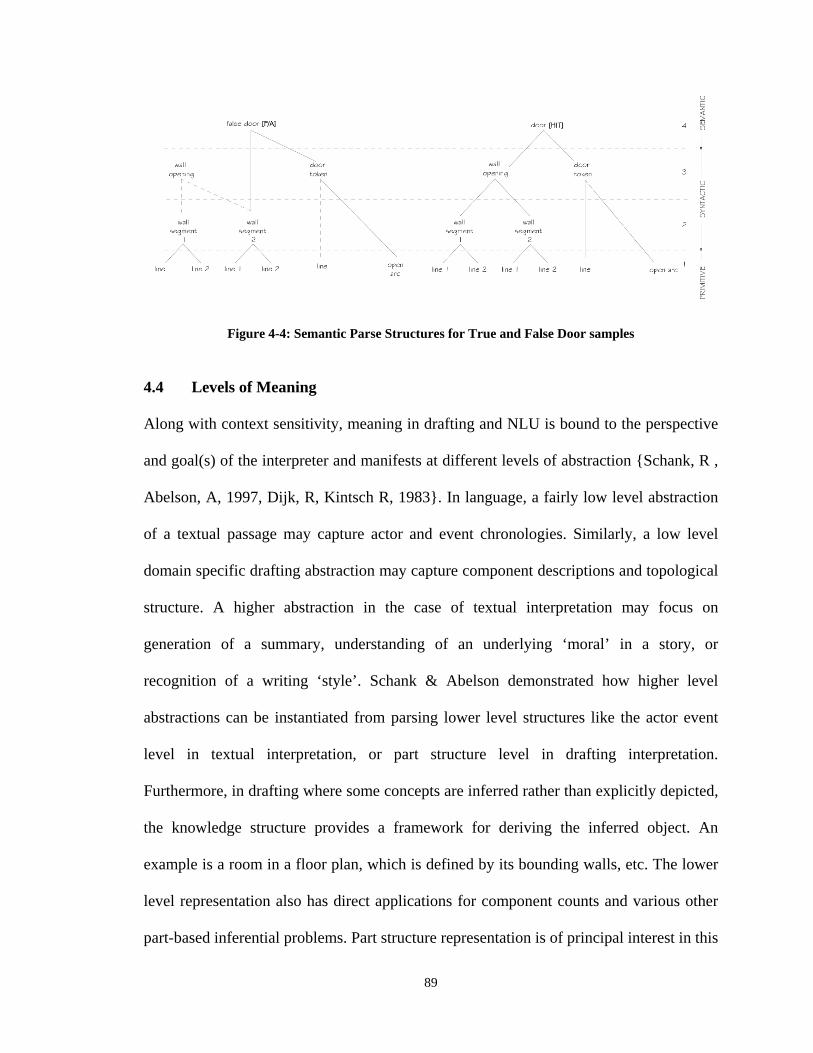
89
Figure 4-4: Semantic Parse Structures for True and False Door samples 4.4 Levels of Meaning
Along with context sensitivity, meaning in drafting and NLU is bound to the perspective
and goal(s) of the interpreter and manifests at different levels of abstraction {Schank, R ,
Abelson, A, 1997, Dijk, R, Kintsch R, 1983}. In language, a fairly low level abstraction
of a textual passage may capture actor and event chronologies. Similarly, a low level
domain specific drafting abstraction may capture component descriptions and topological
structure. A higher abstraction in the case of textual interpretation may focus on
generation of a summary, understanding of an underlying ‘moral’ in a story, or
recognition of a writing ‘style’. Schank & Abelson demonstrated how higher level
abstractions can be instantiated from parsing lower level structures like the actor event
level in textual interpretation, or part structure level in drafting interpretation.
Furthermore, in drafting where some concepts are inferred rather than explicitly depicted,
the knowledge structure provides a framework for deriving the inferred object. An
example is a room in a floor plan, which is defined by its bounding walls, etc. The lower
level representation also has direct applications for component counts and various other
part-based inferential problems. Part structure representation is of principal interest in this
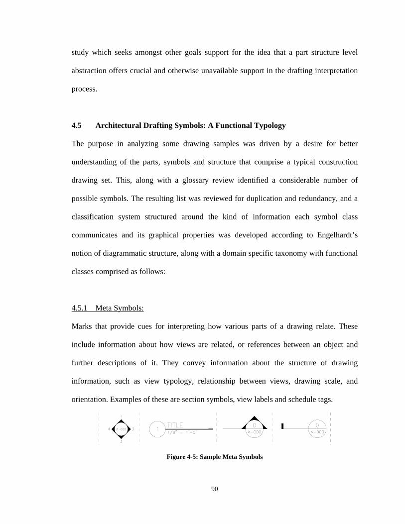
90
study which seeks amongst other goals support for the idea that a part structure level
abstraction offers crucial and otherwise unavailable support in the drafting interpretation
process.
4.5 Architectural Drafting Symbols: A Functional Typology
The purpose in analyzing some drawing samples was driven by a desire for better
understanding of the parts, symbols and structure that comprise a typical construction
drawing set. This, along with a glossary review identified a considerable number of
possible symbols. The resulting list was reviewed for duplication and redundancy, and a
classification system structured around the kind of information each symbol class
communicates and its graphical properties was developed according to Engelhardt’s
notion of diagrammatic structure, along with a domain specific taxonomy with functional
classes comprised as follows:
4.5.1 Meta Symbols:
Marks that provide cues for interpreting how various parts of a drawing relate. These
include information about how views are related, or references between an object and
further descriptions of it. They convey information about the structure of drawing
information, such as view typology, relationship between views, drawing scale, and
orientation. Examples of these are section symbols, view labels and schedule tags.
Figure 4-5: Sample Meta Symbols
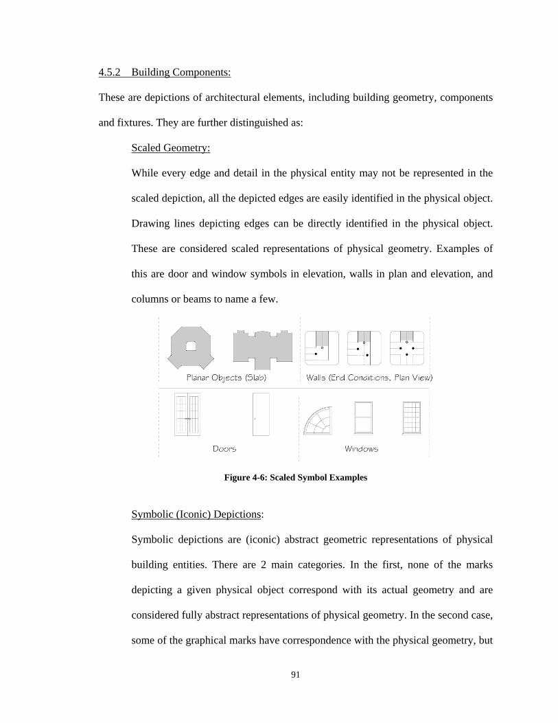
91
4.5.2 Building Components:
These are depictions of architectural elements, including building geometry, components
and fixtures. They are further distinguished as:
Scaled Geometry:
While every edge and detail in the physical entity may not be represented in the
scaled depiction, all the depicted edges are easily identified in the physical object.
Drawing lines depicting edges can be directly identified in the physical object.
These are considered scaled representations of physical geometry. Examples of
this are door and window symbols in elevation, walls in plan and elevation, and
columns or beams to name a few.
Figure 4-6: Scaled Symbol Examples
Symbolic (Iconic) Depictions:
Symbolic depictions are (iconic) abstract geometric representations of physical
building entities. There are 2 main categories. In the first, none of the marks
depicting a given physical object correspond with its actual geometry and are
considered fully abstract representations of physical geometry. In the second case,
some of the graphical marks have correspondence with the physical geometry, but
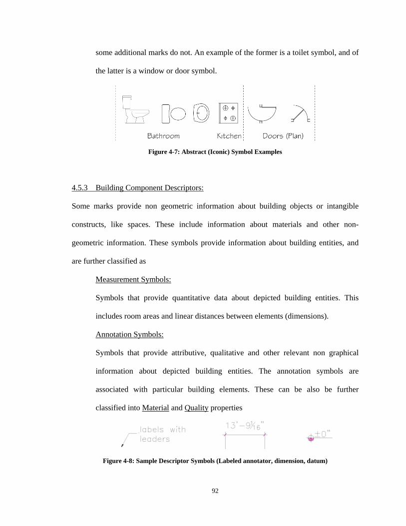
92
some additional marks do not. An example of the former is a toilet symbol, and of
the latter is a window or door symbol.
Figure 4-7: Abstract (Iconic) Symbol Examples 4.5.3 Building Component Descriptors:
Some marks provide non geometric information about building objects or intangible
constructs, like spaces. These include information about materials and other non-
geometric information. These symbols provide information about building entities, and
are further classified as
Measurement Symbols:
Symbols that provide quantitative data about depicted building entities. This
includes room areas and linear distances between elements (dimensions).
Annotation Symbols:
Symbols that provide attributive, qualitative and other relevant non graphical
information about depicted building entities. The annotation symbols are
associated with particular building elements. These can be also be further
classified into Material and Quality properties
Figure 4-8: Sample Descriptor Symbols (Labeled annotator, dimension, datum)
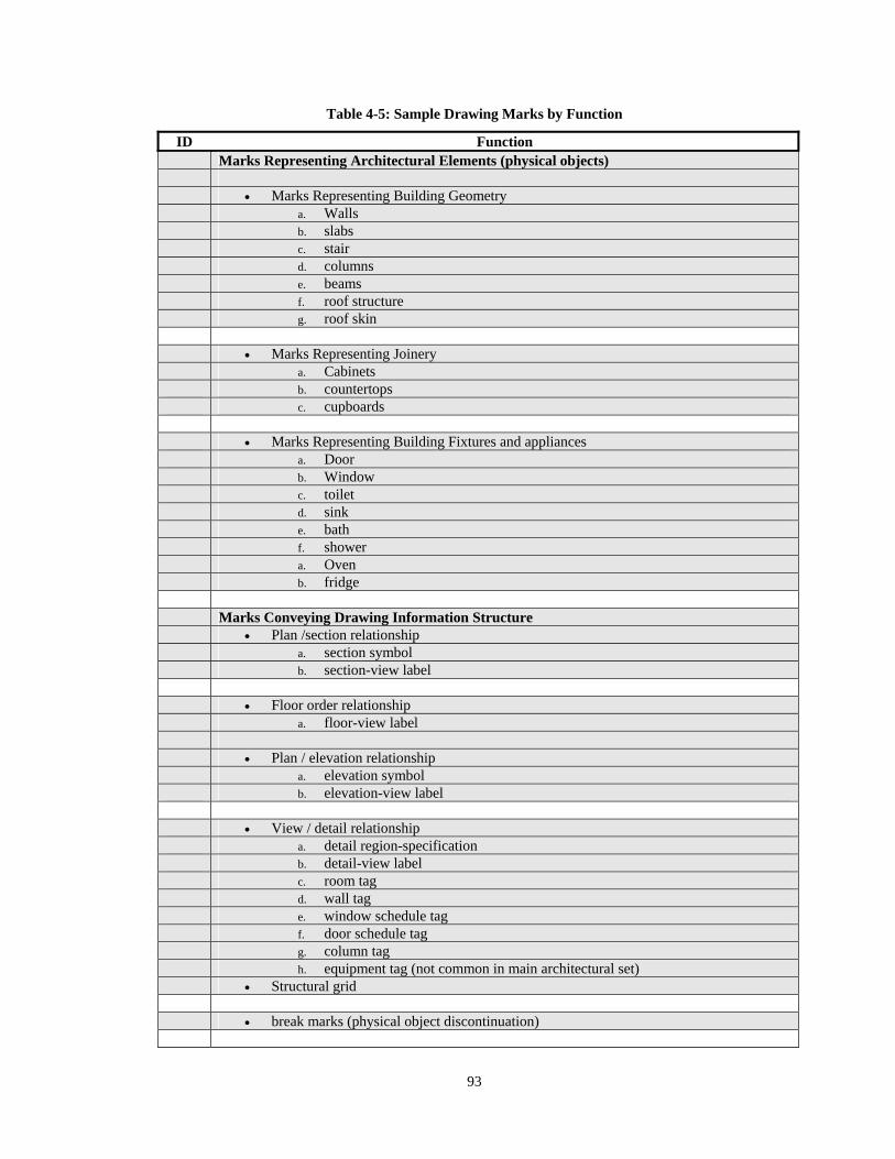
93
Table 4-5: Sample Drawing Marks by Function
ID Function Marks Representing Architectural Elements (physical objects) Marks Representing Building Geometry a. Walls b. slabs c. stair d. columns e. beams f. roof structure g. roof skin Marks Representing Joinery a. Cabinets b. countertops c. cupboards Marks Representing Building Fixtures and appliances a. Door b. Window c. toilet d. sink e. bath f. shower a. Oven b. fridge Marks Conveying Drawing Information Structure Plan /section relationship a. section symbol b. section-view label Floor order relationship a. floor-view label Plan / elevation relationship a. elevation symbol b. elevation-view label View / detail relationship a. detail region-specification b. detail-view label c. room tag d. wall tag e. window schedule tag f. door schedule tag g. column tag h. equipment tag (not common in main architectural set) Structural grid break marks (physical object discontinuation)
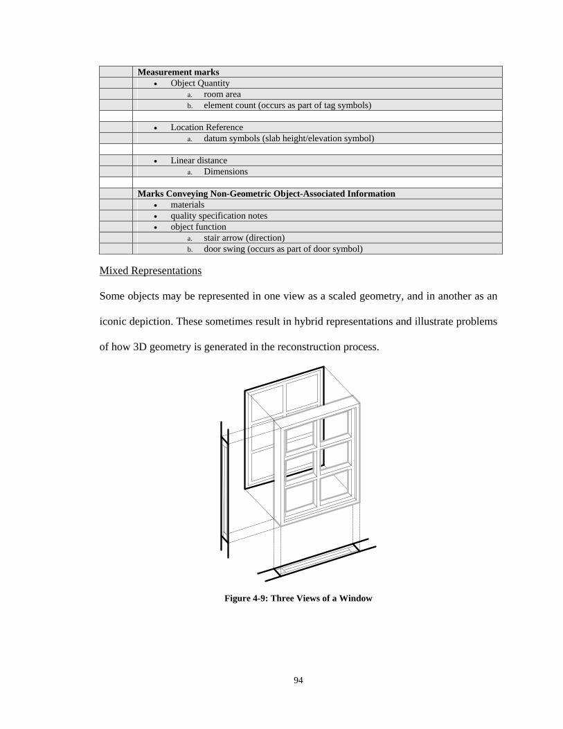
94
Measurement marks Object Quantity a. room area b. element count (occurs as part of tag symbols) Location Reference a. datum symbols (slab height/elevation symbol) Linear distance a. Dimensions Marks Conveying Non-Geometric Object-Associated Information materials quality specification notes object function a. stair arrow (direction) b. door swing (occurs as part of door symbol)
Mixed Representations
Some objects may be represented in one view as a scaled geometry, and in another as an
iconic depiction. These sometimes result in hybrid representations and illustrate problems
of how 3D geometry is generated in the reconstruction process.
Figure 4-9: Three Views of a Window
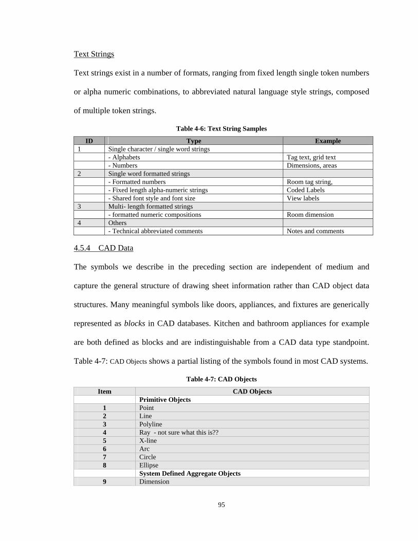
95
Text Strings
Text strings exist in a number of formats, ranging from fixed length single token numbers
or alpha numeric combinations, to abbreviated natural language style strings, composed
of multiple token strings.
Table 4-6: Text String Samples
ID Type Example 1 Single character / single word strings - Alphabets Tag text, grid text - Numbers Dimensions, areas 2 Single word formatted strings - Formatted numbers Room tag string, - Fixed length alpha-numeric strings Coded Labels - Shared font style and font size View labels 3 Multi- length formatted strings - formatted numeric compositions Room dimension 4 Others - Technical abbreviated comments Notes and comments
4.5.4 CAD Data
The symbols we describe in the preceding section are independent of medium and
capture the general structure of drawing sheet information rather than CAD object data
structures. Many meaningful symbols like doors, appliances, and fixtures are generically
represented as blocks in CAD databases. Kitchen and bathroom appliances for example
are both defined as blocks and are indistinguishable from a CAD data type standpoint.
Table 4-7: CAD Objects shows a partial listing of the symbols found in most CAD systems.
Table 4-7: CAD Objects
Item CAD Objects Primitive Objects
1 Point 2 Line 3 Polyline 4 Ray - not sure what this is?? 5 X-line 6 Arc 7 Circle 8 Ellipse
System Defined Aggregate Objects 9 Dimension
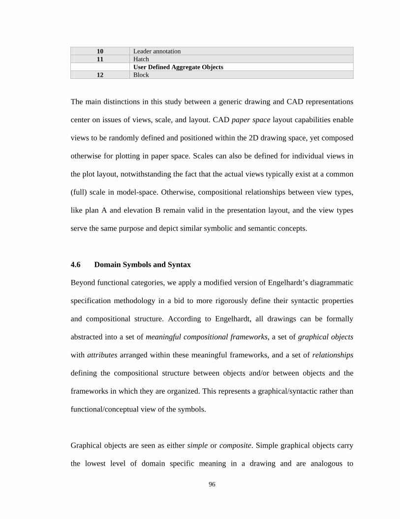
96
10 Leader annotation 11 Hatch
User Defined Aggregate Objects 12 Block
The main distinctions in this study between a generic drawing and CAD representations
center on issues of views, scale, and layout. CAD paper space layout capabilities enable
views to be randomly defined and positioned within the 2D drawing space, yet composed
otherwise for plotting in paper space. Scales can also be defined for individual views in
the plot layout, notwithstanding the fact that the actual views typically exist at a common
(full) scale in model-space. Otherwise, compositional relationships between view types,
like plan A and elevation B remain valid in the presentation layout, and the view types
serve the same purpose and depict similar symbolic and semantic concepts.
4.6 Domain Symbols and Syntax
Beyond functional categories, we apply a modified version of Engelhardt’s diagrammatic
specification methodology in a bid to more rigorously define their syntactic properties
and compositional structure. According to Engelhardt, all drawings can be formally
abstracted into a set of meaningful compositional frameworks, a set of graphical objects
with attributes arranged within these meaningful frameworks, and a set of relationships
defining the compositional structure between objects and/or between objects and the
frameworks in which they are organized. This represents a graphical/syntactic rather than
functional/conceptual view of the symbols.
Graphical objects are seen as either simple or composite. Simple graphical objects carry
the lowest level of domain specific meaning in a drawing and are analogous to
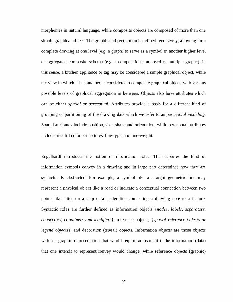
97
morphemes in natural language, while composite objects are composed of more than one
simple graphical object. The graphical object notion is defined recursively, allowing for a
complete drawing at one level (e.g. a graph) to serve as a symbol in another higher level
or aggregated composite schema (e.g. a composition composed of multiple graphs). In
this sense, a kitchen appliance or tag may be considered a simple graphical object, while
the view in which it is contained is considered a composite graphical object, with various
possible levels of graphical aggregation in between. Objects also have attributes which
can be either spatial or perceptual. Attributes provide a basis for a different kind of
grouping or partitioning of the drawing data which we refer to as perceptual modeling.
Spatial attributes include position, size, shape and orientation, while perceptual attributes
include area fill colors or textures, line-type, and line-weight.
Engelhardt introduces the notion of information roles. This captures the kind of
information symbols convey in a drawing and in large part determines how they are
syntactically abstracted. For example, a symbol like a straight geometric line may
represent a physical object like a road or indicate a conceptual connection between two
points like cities on a map or a leader line connecting a drawing note to a feature.
Syntactic roles are further defined as information objects {nodes, labels, separators,
connectors, containers and modifiers}, reference objects, {spatial reference objects or
legend objects}, and decoration (trivial) objects. Information objects are those objects
within a graphic representation that would require adjustment if the information (data)
that one intends to represent/convey would change, while reference objects (graphic)
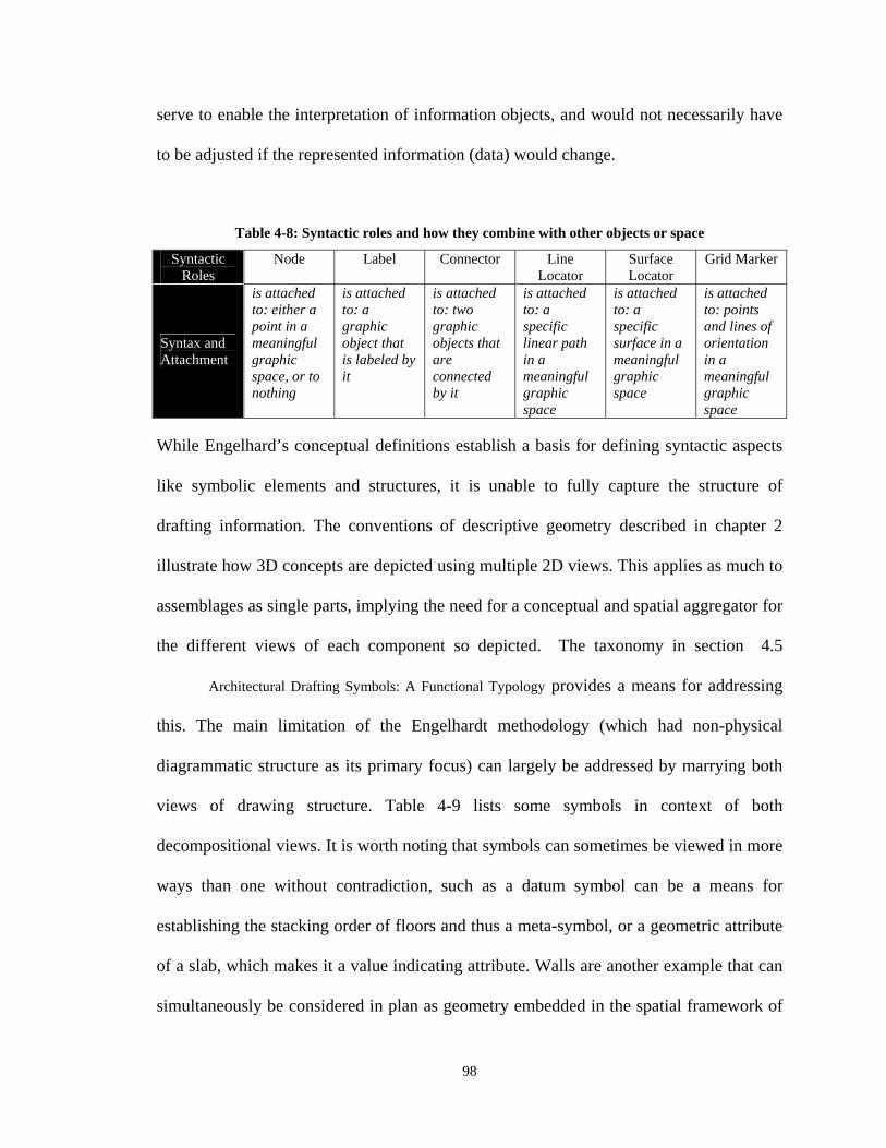
98
serve to enable the interpretation of information objects, and would not necessarily have
to be adjusted if the represented information (data) would change.
Table 4-8: Syntactic roles and how they combine with other objects or space
Syntactic Roles
Node Label Connector Line Locator
Surface Locator
Grid Marker
Syntax and Attachment
is attached to: either a point in a meaningful graphic space, or to nothing
is attached to: a graphic object that is labeled by it
is attached to: two graphic objects that are connected by it
is attached to: a specific linear path in a meaningful graphic space
is attached to: a specific surface in a meaningful graphic space
is attached to: points and lines of orientation in a meaningful graphic space
While Engelhard’s conceptual definitions establish a basis for defining syntactic aspects
like symbolic elements and structures, it is unable to fully capture the structure of
drafting information. The conventions of descriptive geometry described in chapter 2
illustrate how 3D concepts are depicted using multiple 2D views. This applies as much to
assemblages as single parts, implying the need for a conceptual and spatial aggregator for
the different views of each component so depicted. The taxonomy in section 4.5
Architectural Drafting Symbols: A Functional Typology provides a means for addressing
this. The main limitation of the Engelhardt methodology (which had non-physical
diagrammatic structure as its primary focus) can largely be addressed by marrying both
views of drawing structure. Table 4-9 lists some symbols in context of both
decompositional views. It is worth noting that symbols can sometimes be viewed in more
ways than one without contradiction, such as a datum symbol can be a means for
establishing the stacking order of floors and thus a meta-symbol, or a geometric attribute
of a slab, which makes it a value indicating attribute. Walls are another example that can
simultaneously be considered in plan as geometry embedded in the spatial framework of
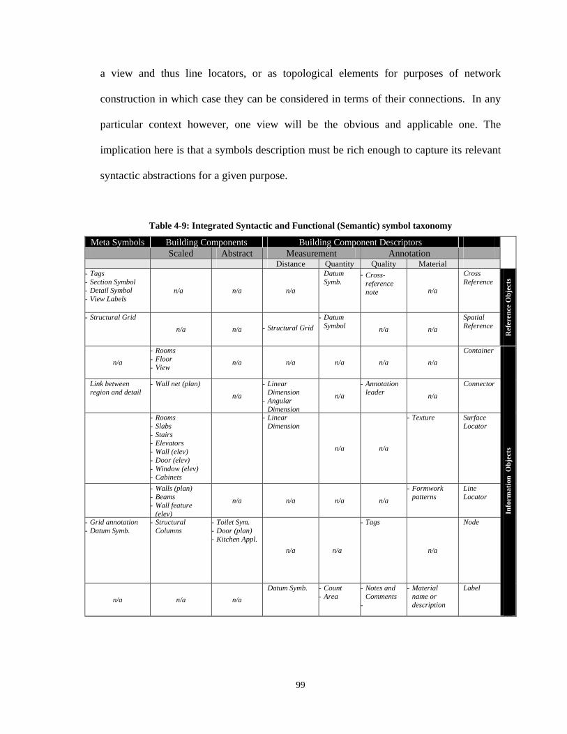
99
a view and thus line locators, or as topological elements for purposes of network
construction in which case they can be considered in terms of their connections. In any
particular context however, one view will be the obvious and applicable one. The
implication here is that a symbols description must be rich enough to capture its relevant
syntactic abstractions for a given purpose.
Table 4-9: Integrated Syntactic and Functional (Semantic) symbol taxonomy
Meta Symbols Building Components Building Component Descriptors Scaled Abstract Measurement Annotation
Distance Quantity Quality Material - Tags - Section Symbol - Detail Symbol - View Labels
n/a n/a n/a
Datum Symb.
- Cross-reference note n/a
Cross Reference
Ref
eren
ce O
bje
cts
- Structural Grid
n/a n/a
- Structural Grid
- Datum Symbol n/a n/a
Spatial Reference
n/a
- Rooms - Floor - View
n/a n/a n/a n/a n/a
Container
Info
rmat
ion
Ob
ject
s
Link between region and detail
- Wall net (plan) n/a
- Linear Dimension
- Angular Dimension
n/a
- Annotation leader n/a
Connector
- Rooms - Slabs - Stairs - Elevators - Wall (elev) - Door (elev) - Window (elev) - Cabinets
- Linear Dimension
n/a n/a
- Texture
Surface Locator
- Walls (plan) - Beams - Wall feature
(elev)
n/a n/a n/a n/a
- Formwork patterns
Line Locator
- Grid annotation - Datum Symb.
- Structural Columns
- Toilet Sym. - Door (plan) - Kitchen Appl.
n/a n/a
- Tags
n/a
Node
n/a n/a n/a
Datum Symb. - Count - Area
- Notes and Comments
-
- Material name or description
Label
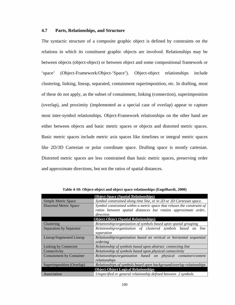
100
4.7 Parts, Relationships, and Structure
The syntactic structure of a composite graphic object is defined by constraints on the
relations in which its constituent graphic objects are involved. Relationships may be
between objects (object-object) or between object and some compositional framework or
‘space’ (Object-Framework/Object-‘Space’). Object-object relationships include
clustering, linking, lineup, separated, containment superimposition, etc. In drafting, most
of these do not apply, as the subset of containment, linking (connection), superimposition
(overlap), and proximity (implemented as a special case of overlap) appear to capture
most inter-symbol relationships. Object-Framework relationships on the other hand are
either between objects and basic metric spaces or objects and distorted metric spaces.
Basic metric spaces include metric axis spaces like timelines or integral metric spaces
like 2D/3D Cartesian or polar coordinate space. Drafting space is mostly cartesian.
Distorted metric spaces are less constrained than basic metric spaces, preserving order
and approximate directions, but not the ratios of spatial distances.
Table 4-10: Object-object and object space relationships (Engelhardt, 2000)
Object-Space (Spatial Relationships) Simple Metric Space Symbol constrained along time line, or in 2D or 3D Cartesian space. Distorted Metric Space Symbol constrained within a metric space that relaxes the constraint of
ratios between spatial distances but retains approximate order, direction
Object-Object (Spatial Relationships) Clustering Relationship/organization of symbols based upon spatial grouping Separation by Separator Relationship/organization of clustered symbols based on line
separation Lineup/Segmented Lineup Relationship/organization based on vertical or horizontal sequential
ordering Linking by Connector Relationship of symbols based upon abstract connecting line Connectivity Relationship of symbols based upon physical connectivity Containment by Container Relationships/organization based on physical container/content
relationships Superimposition (Overlap) Relationships of symbols based upon background/overlap relationships
Object-Object Logical Relationships Association Unspecified or general relationship defined between 2 symbols
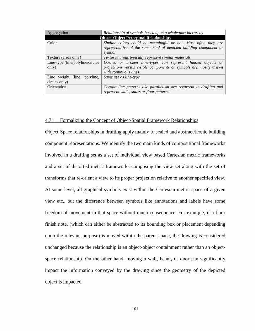
101
Aggregation Relationship of symbols based upon a whole/part hierarchy Object-Object Perceptual Relationships
Color Similar colors could be meaningful or not. Most often they are representative of the same kind of depicted building component or symbol
Texture (areas only) Textured areas typically represent similar materials Line-type (line/polyline/circles only)
Dashed or broken Line-types can represent hidden objects or projections versus visible components or symbols are mostly drawn with continuous lines
Line weight (line, polyline, circles only)
Same use as line-type
Orientation Certain line patterns like parallelism are recurrent in drafting and represent walls, stairs or floor patterns
4.7.1 Formalizing the Concept of Object-Spatial Framework Relationships
Object-Space relationships in drafting apply mainly to scaled and abstract/iconic building
component representations. We identify the two main kinds of compositional frameworks
involved in a drafting set as a set of individual view based Cartesian metric frameworks
and a set of distorted metric frameworks composing the view set along with the set of
transforms that re-orient a view to its proper projection relative to another specified view.
At some level, all graphical symbols exist within the Cartesian metric space of a given
view etc., but the difference between symbols like annotations and labels have some
freedom of movement in that space without much consequence. For example, if a floor
finish note, (which can either be abstracted to its bounding box or placement depending
upon the relevant purpose) is moved within the parent space, the drawing is considered
unchanged because the relationship is an object-object containment rather than an object-
space relationship. On the other hand, moving a wall, beam, or door can significantly
impact the information conveyed by the drawing since the geometry of the depicted
object is impacted.
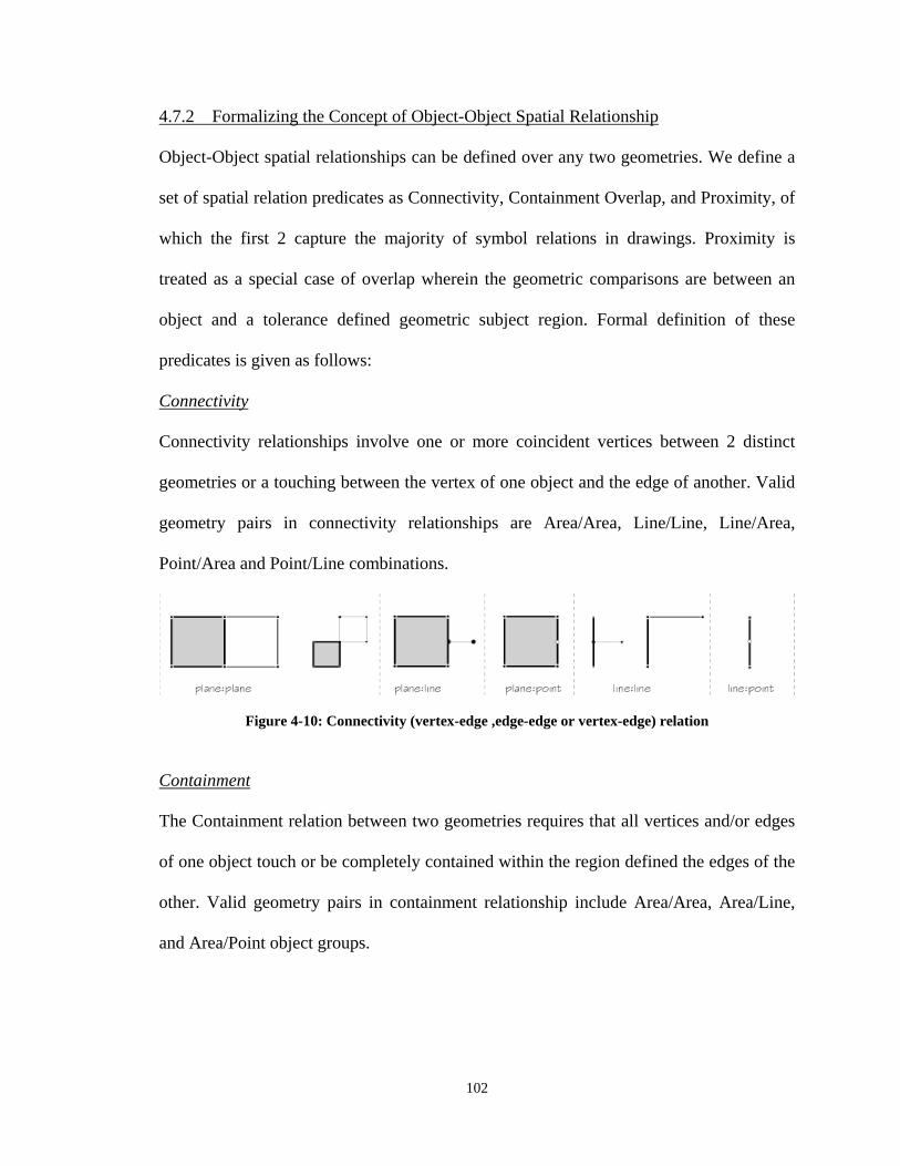
102
4.7.2 Formalizing the Concept of Object-Object Spatial Relationship
Object-Object spatial relationships can be defined over any two geometries. We define a
set of spatial relation predicates as Connectivity, Containment Overlap, and Proximity, of
which the first 2 capture the majority of symbol relations in drawings. Proximity is
treated as a special case of overlap wherein the geometric comparisons are between an
object and a tolerance defined geometric subject region. Formal definition of these
predicates is given as follows:
Connectivity
Connectivity relationships involve one or more coincident vertices between 2 distinct
geometries or a touching between the vertex of one object and the edge of another. Valid
geometry pairs in connectivity relationships are Area/Area, Line/Line, Line/Area,
Point/Area and Point/Line combinations.
Figure 4-10: Connectivity (vertex-edge ,edge-edge or vertex-edge) relation
Containment
The Containment relation between two geometries requires that all vertices and/or edges
of one object touch or be completely contained within the region defined the edges of the
other. Valid geometry pairs in containment relationship include Area/Area, Area/Line,
and Area/Point object groups.

103
Figure 4-11: Examples of Containment Relation
Overlap
The Overlap relation applies to L/L, L/A, A/A. An overlap relationship between a and b,
in the case of areas has some vertices of one area within the boundary of the other. For a
line and area, an overlap requires that one vertex of the line is contained within the
boundary of the area while the other is outside. In the case of two linear elements, we
define it somewhat differently. In this case from a conceptual standpoint, the lines are
abstracted into regions based upon a tolerance value offsetting each line on both sides,
and the resulting rectangles are tested for overlap in a manner similar to the area-area
case:
Figure 4-12: Examples of Overlap Relation Proximity
The proximity relation applies to all pairs of geometry classes (P, L, A) and is determined
by if the distance between two defined reference points (e.g. nearest point or centroid) is
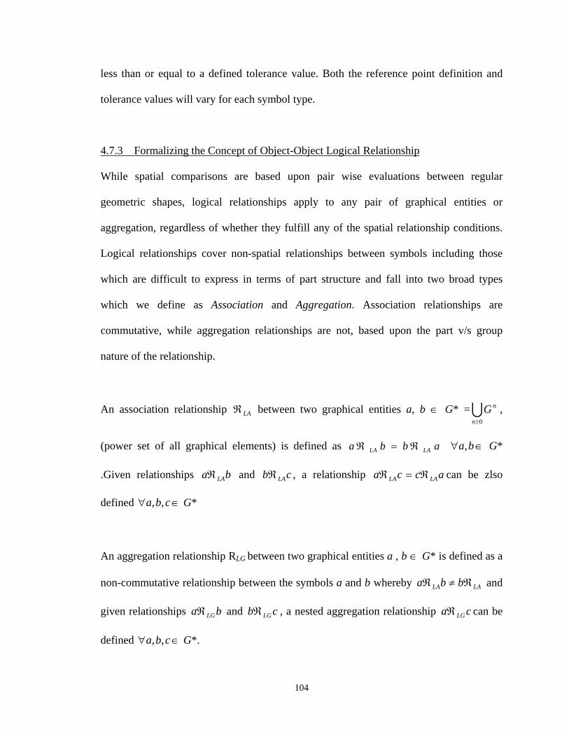
104
less than or equal to a defined tolerance value. Both the reference point definition and
tolerance values will vary for each symbol type.
4.7.3 Formalizing the Concept of Object-Object Logical Relationship
While spatial comparisons are based upon pair wise evaluations between regular
geometric shapes, logical relationships apply to any pair of graphical entities or
aggregation, regardless of whether they fulfill any of the spatial relationship conditions.
Logical relationships cover non-spatial relationships between symbols including those
which are difficult to express in terms of part structure and fall into two broad types
which we define as Association and Aggregation. Association relationships are
commutative, while aggregation relationships are not, based upon the part v/s group
nature of the relationship.
An association relationship LA between two graphical entities a, b G* =0n
nG ,
(power set of all graphical elements) is defined as abba LALA ba, G*
.Given relationships ba LA and cb LA , a relationship ca LA ac LA can be zlso
defined cba ,, G*
An aggregation relationship RLG between two graphical entities a , b G* is defined as a
non-commutative relationship between the symbols a and b whereby LALA bba and
given relationships ba LG and cb LG , a nested aggregation relationship ca LG can be
defined cba ,, G*.
105
Table 4-9 provides examples of drafting symbols in the DOM taxonomy along with their
spatial context (compositional framework), syntactic role, and the kinds of syntactic
relationships in which they are composed. It is important to note that a given symbol can
be represented in different views, each playing a different syntactic role with different
kinds of syntactic relationships.
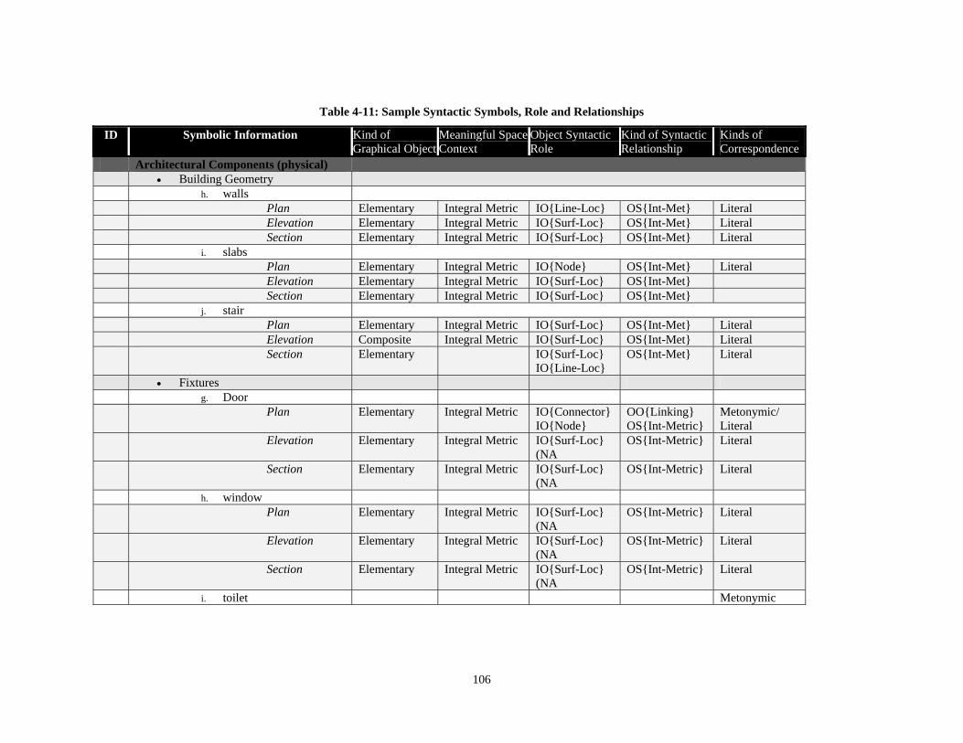
106
Table 4-11: Sample Syntactic Symbols, Role and Relationships
ID Symbolic Information Kind of Graphical Object
Meaningful Space Context
Object Syntactic Role
Kind of Syntactic Relationship
Kinds of Correspondence
Architectural Components (physical) Building Geometry h. walls Plan Elementary Integral Metric IO{Line-Loc} OS{Int-Met} Literal Elevation Elementary Integral Metric IO{Surf-Loc} OS{Int-Met} Literal Section Elementary Integral Metric IO{Surf-Loc} OS{Int-Met} Literal i. slabs Plan Elementary Integral Metric IO{Node} OS{Int-Met} Literal Elevation Elementary Integral Metric IO{Surf-Loc} OS{Int-Met} Section Elementary Integral Metric IO{Surf-Loc} OS{Int-Met} j. stair Plan Elementary Integral Metric IO{Surf-Loc} OS{Int-Met} Literal Elevation Composite Integral Metric IO{Surf-Loc} OS{Int-Met} Literal Section Elementary IO{Surf-Loc}
IO{Line-Loc} OS{Int-Met} Literal
Fixtures g. Door Plan Elementary Integral Metric IO{Connector}
IO{Node} OO{Linking} OS{Int-Metric}
Metonymic/ Literal
Elevation Elementary Integral Metric IO{Surf-Loc} (NA
OS{Int-Metric} Literal
Section Elementary Integral Metric IO{Surf-Loc} (NA
OS{Int-Metric} Literal
h. window Plan Elementary Integral Metric IO{Surf-Loc}
(NA OS{Int-Metric} Literal
Elevation Elementary Integral Metric IO{Surf-Loc} (NA
OS{Int-Metric} Literal
Section Elementary Integral Metric IO{Surf-Loc} (NA
OS{Int-Metric} Literal
i. toilet Metonymic
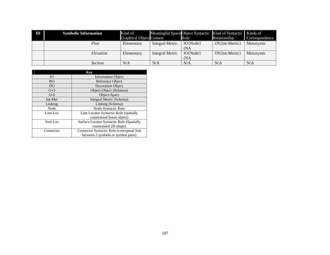
107
ID Symbolic Information Kind of Graphical Object
Meaningful Space Context
Object Syntactic Role
Kind of Syntactic Relationship
Kinds of Correspondence
Plan Elementary Integral Metric IO{Node} (NA
OS{Int-Metric} Metonymic
Elevation Elementary Integral Metric IO{Node} (NA
OS{Int-Metric} Metonymic
Section N/A N/A N/A N/A N/A
Key IO Information Object RO Reference Object DO Decoration Object O-O Object-Object (Relation) O-S Object-Space
Int-Met Integral Metric (Schema) Linking Linking (Schema) Node Node Syntactic Role
Line-Loc Line Locator Syntactic Role (spatially constrained linear object)
Surf-Loc Surface Locator Syntactic Role (Spatially constrained 2D shape)
Connector Connector Syntactic Role (conceptual link between 2 symbols or symbol parts)

108
4.7.4 Ambiguity and Relational Precedence
Most symbols are involved in more than one relationship with another or various other
objects simultaneously. A symbol may be contained within a space and connected to
another symbol in object-object relationships while simultaneously embedded in a
Cartesian metric Object-Framework.
Figure 4-13: Aggregation and Ambiguity
Another example would be a toilet symbol in a bathroom having an annotated leader or
tag. In the case of textual attribute information, human experts often resolve such
conflicts through semantic cues derived from the text itself. Given the amount of
variation in drafting jargon and phraseology, it seems likely that a full and accurate
interpretation of most drawings would require some NLU capabilities in the drawing
interpretation system. It is however possible that lexical heuristic cues within the
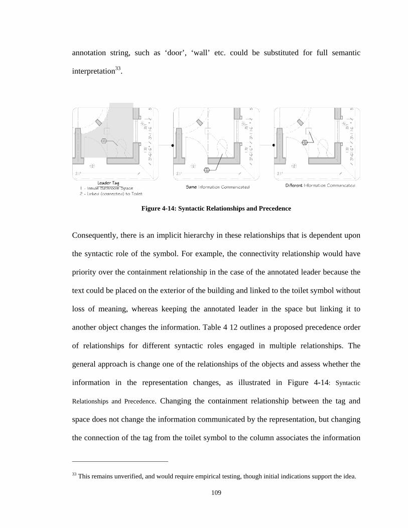
109
annotation string, such as ‘door’, ‘wall’ etc. could be substituted for full semantic
interpretation33.
Figure 4-14: Syntactic Relationships and Precedence
Consequently, there is an implicit hierarchy in these relationships that is dependent upon
the syntactic role of the symbol. For example, the connectivity relationship would have
priority over the containment relationship in the case of the annotated leader because the
text could be placed on the exterior of the building and linked to the toilet symbol without
loss of meaning, whereas keeping the annotated leader in the space but linking it to
another object changes the information. Table 4 12 outlines a proposed precedence order
of relationships for different syntactic roles engaged in multiple relationships. The
general approach is change one of the relationships of the objects and assess whether the
information in the representation changes, as illustrated in Figure 4-14: Syntactic
Relationships and Precedence. Changing the containment relationship between the tag and
space does not change the information communicated by the representation, but changing
the connection of the tag from the toilet symbol to the column associates the information
33 This remains unverified, and would require empirical testing, though initial indications support the idea.
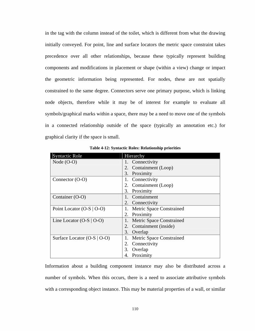
110
in the tag with the column instead of the toilet, which is different from what the drawing
initially conveyed. For point, line and surface locators the metric space constraint takes
precedence over all other relationships, because these typically represent building
components and modifications in placement or shape (within a view) change or impact
the geometric information being represented. For nodes, these are not spatially
constrained to the same degree. Connectors serve one primary purpose, which is linking
node objects, therefore while it may be of interest for example to evaluate all
symbols/graphical marks within a space, there may be a need to move one of the symbols
in a connected relationship outside of the space (typically an annotation etc.) for
graphical clarity if the space is small.
Table 4-12: Syntactic Roles: Relationship priorities
Syntactic Role Hierarchy Node (O-O) 1. Connectivity
2. Containment (Loop) 3. Proximity
Connector (O-O) 1. Connectivity 2. Containment (Loop) 3. Proximity
Container (O-O) 1. Containment 2. Connectivity
Point Locator (O-S | O-O) 1. Metric Space Constrained 2. Proximity
Line Locator (O-S | O-O) 1. Metric Space Constrained 2. Containment (inside) 3. Overlap
Surface Locator (O-S | O-O) 1. Metric Space Constrained 2. Connectivity 3. Overlap 4. Proximity
Information about a building component instance may also be distributed across a
number of symbols. When this occurs, there is a need to associate attributive symbols
with a corresponding object instance. This may be material properties of a wall, or similar
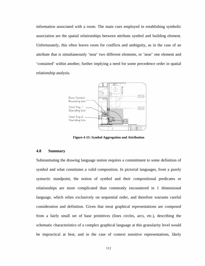
111
information associated with a room. The main cues employed in establishing symbolic
association are the spatial relationships between attribute symbol and building element.
Unfortunately, this often leaves room for conflicts and ambiguity, as in the case of an
attribute that is simultaneously ‘near’ two different elements, or ‘near’ one element and
‘contained’ within another, further implying a need for some precedence order in spatial
relationship analysis.
Figure 4-15: Symbol Aggregation and Attribution
4.8 Summary
Substantiating the drawing language notion requires a commitment to some definition of
symbol and what constitutes a valid composition. In pictorial languages, from a purely
syntactic standpoint, the notion of symbol and their compositional predicates or
relationships are more complicated than commonly encountered in 1 dimensional
language, which relies exclusively on sequential order, and therefore warrants careful
consideration and definition. Given that most graphical representations are composed
from a fairly small set of base primitives (lines circles, arcs, etc.), describing the
schematic characteristics of a complex graphical language at this granularity level would
be impractical at best, and in the case of context sensitive representations, likely
112
impossible due to conceptual distance and ambiguities resulting therefrom. The adopted
strategy was to define symbolic classes in the language on the basis of the information
conveyed by a given type of symbol represented by a structured group of graphical
primitives. The kinds of information range from shape descriptions through material or
other attribute information, to symbols providing compositional cues for multipartite
representations. It is conceivable that symbols conveying different kinds of information
like drawing structure and object material properties could be represented in a common
modality, like textual strings describing material finishes and textural patterns
representing these. The information conveyed by the graphical and textual modes are
considered semantically equivalent even if they differ syntactically.
In terms of semantics, the scope of what constitutes the semantics expressed by the
representational schema and the external concept are potentially open ended and must be
narrowly defined, and is therefore limited in this study to the description of a subset of
the geometric and other superficial characteristics of the represented domain expressed
by the graphical language.
113
CHAPTER 5.
MODEL OVERVIEW
he Drafting Model (DOM) draws upon a combination of native and IFC based or
derived schemas in order to capture various aspects of the domain semantics as
defined in the previous chapter. This also ensures that it interfaces more closely with the
IFC which is the translation target. The following sections are intended to provide an
introduction to the underlying modeling philosophy, structure, and key aspects. It is not
intended to detail every individual entity, attribute and type. Appendix G provides more
information in this regard, and should be read along with the IFC schema, particularly for
a full and detailed description of the referenced aspects.
5.1 Knowledge Representation and Information Modeling
The DOM focuses on physical characteristics of drafting symbols (mainly geometric) and
key topological and spatial relationships occurring between them34. The model is
important because it offers a framework for inferential reasoning atop which
interpretation agents or functions can be constructed. The model provides domain
knowledge to the interpretation processes by simple virtue of its meaningful and thus
34 We are mainly concerned with a subset that will enable instantiation of the symbol in a BIM. Depending upon the kind of symbol, this could be as simple as a profile placement and extrusion path/direction (e.g. columns) a b-rep generated from the various projections ( roof from plan and elevations) or as simple as a placement and orientation which will be used for locating a retrieved 3D object from a library (e.g. fixtures, appliances, etc.).
T
114
logically intuitive structure. The underlying idea is that if the model reflects conventional
understanding about drafting symbols in terms of their interconnectivity and other key
relationships within and across views etc., it provides a means for reasoning about a
drafting set and the various building components depicted within it.
While conceptually distinct in purpose, we base the DOM substantially on the
architecture and library provided by the IFC 2x3 Model. An IFC entity based
specification offers 3 main advantages and one notable disadvantage. First, it provides
efficiency in the modeling task by offering many predefined entities and concepts of
relevance to the DOM. Second, employing a subset of the entities and types in the target
model minimizes the difficulties of mapping between the DOM and IFC domains. Third,
we benefit from tested and stable definitions and utilities especially at the resource level
where the semantics of geometric representation, relationship, constraints are very well
defined and reviewed. The main disadvantage noted in this approach so far is that the
resulting model ends up somewhat larger than it could (perhaps should) be, and a
definition from scratch would produce a more parsimonious model.
The DOM architecture reflects the following set of basic goals and principles:
a. To provide a modular structure to the model. b. To enable information modelers to reuse model components c. To provide a framework for storing and interconnecting instantiated symbol instances
and to enable navigation of these interconnections in search for additional instances. d. To provide a simple mapping into an open BIM standard for instantiation of the
recognized instances in applications. e. To articulate the distinction and interconnection between symbolic structure in the
graphical domain and conceptual structure in the domain of the depicted object.
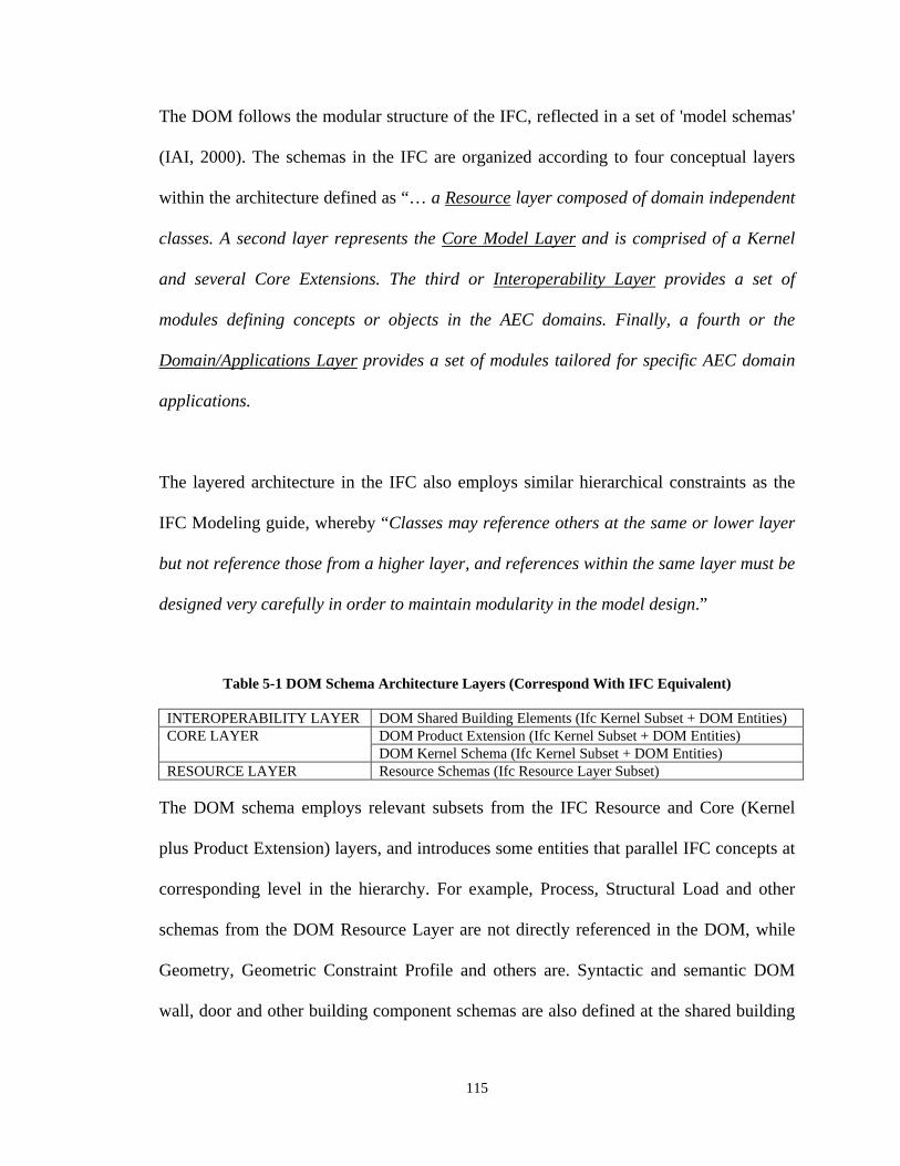
115
The DOM follows the modular structure of the IFC, reflected in a set of 'model schemas'
(IAI, 2000). The schemas in the IFC are organized according to four conceptual layers
within the architecture defined as “… a Resource layer composed of domain independent
classes. A second layer represents the Core Model Layer and is comprised of a Kernel
and several Core Extensions. The third or Interoperability Layer provides a set of
modules defining concepts or objects in the AEC domains. Finally, a fourth or the
Domain/Applications Layer provides a set of modules tailored for specific AEC domain
applications.
The layered architecture in the IFC also employs similar hierarchical constraints as the
IFC Modeling guide, whereby “Classes may reference others at the same or lower layer
but not reference those from a higher layer, and references within the same layer must be
designed very carefully in order to maintain modularity in the model design.”
Table 5-1 DOM Schema Architecture Layers (Correspond With IFC Equivalent)
INTEROPERABILITY LAYER DOM Shared Building Elements (Ifc Kernel Subset + DOM Entities) CORE LAYER DOM Product Extension (Ifc Kernel Subset + DOM Entities)
DOM Kernel Schema (Ifc Kernel Subset + DOM Entities) RESOURCE LAYER Resource Schemas (Ifc Resource Layer Subset)
The DOM schema employs relevant subsets from the IFC Resource and Core (Kernel
plus Product Extension) layers, and introduces some entities that parallel IFC concepts at
corresponding level in the hierarchy. For example, Process, Structural Load and other
schemas from the DOM Resource Layer are not directly referenced in the DOM, while
Geometry, Geometric Constraint Profile and others are. Syntactic and semantic DOM
wall, door and other building component schemas are also defined at the shared building
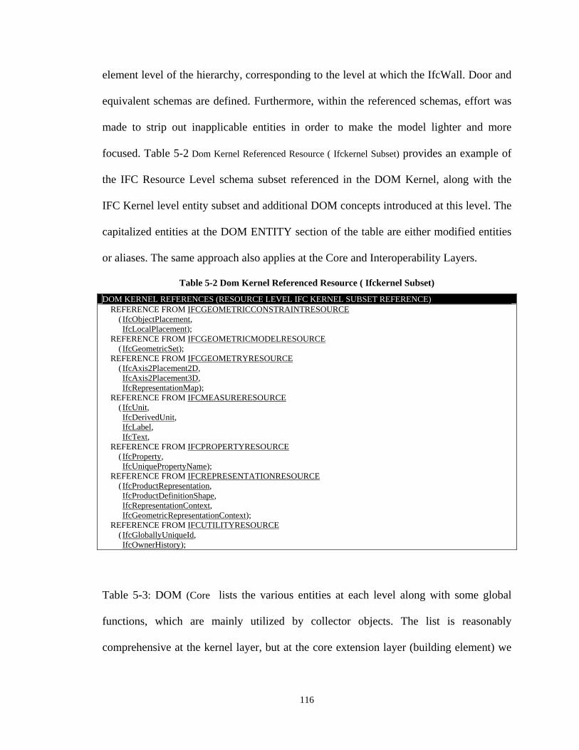
116
element level of the hierarchy, corresponding to the level at which the IfcWall. Door and
equivalent schemas are defined. Furthermore, within the referenced schemas, effort was
made to strip out inapplicable entities in order to make the model lighter and more
focused. Table 5-2 Dom Kernel Referenced Resource ( Ifckernel Subset) provides an example of
the IFC Resource Level schema subset referenced in the DOM Kernel, along with the
IFC Kernel level entity subset and additional DOM concepts introduced at this level. The
capitalized entities at the DOM ENTITY section of the table are either modified entities
or aliases. The same approach also applies at the Core and Interoperability Layers.
Table 5-2 Dom Kernel Referenced Resource ( Ifckernel Subset)
DOM KERNEL REFERENCES (RESOURCE LEVEL IFC KERNEL SUBSET REFERENCE) REFERENCE FROM IFCGEOMETRICCONSTRAINTRESOURCE
( IfcObjectPlacement, IfcLocalPlacement);
REFERENCE FROM IFCGEOMETRICMODELRESOURCE ( IfcGeometricSet);
REFERENCE FROM IFCGEOMETRYRESOURCE ( IfcAxis2Placement2D,
IfcAxis2Placement3D, IfcRepresentationMap);
REFERENCE FROM IFCMEASURERESOURCE ( IfcUnit,
IfcDerivedUnit, IfcLabel, IfcText,
REFERENCE FROM IFCPROPERTYRESOURCE ( IfcProperty,
IfcUniquePropertyName);
REFERENCE FROM IFCREPRESENTATIONRESOURCE ( IfcProductRepresentation,
IfcProductDefinitionShape, IfcRepresentationContext, IfcGeometricRepresentationContext);
REFERENCE FROM IFCUTILITYRESOURCE ( IfcGloballyUniqueId,
IfcOwnerHistory);
Table 5-3: DOM (Core lists the various entities at each level along with some global
functions, which are mainly utilized by collector objects. The list is reasonably
comprehensive at the kernel layer, but at the core extension layer (building element) we
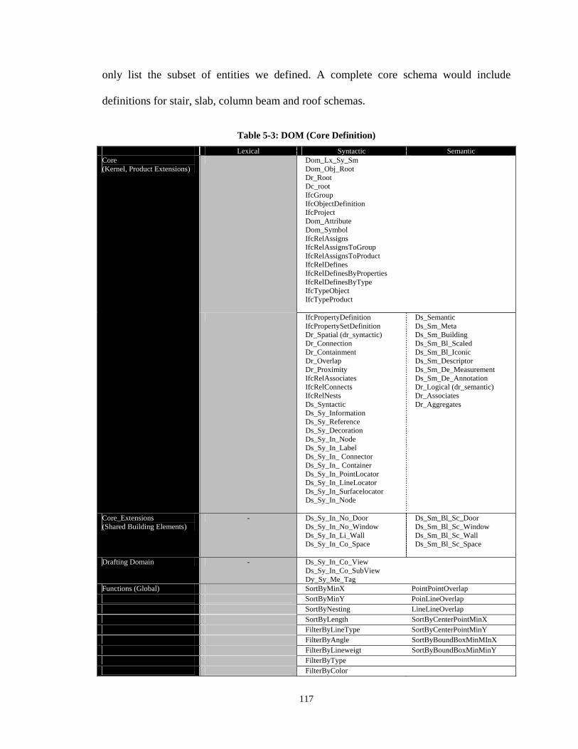
117
only list the subset of entities we defined. A complete core schema would include
definitions for stair, slab, column beam and roof schemas.
Table 5-3: DOM (Core Definition)
Lexical Syntactic Semantic Core (Kernel, Product Extensions)
Dom_Lx_Sy_Sm Dom_Obj_Root Dr_Root Dc_root IfcGroup IfcObjectDefinition IfcProject Dom_Attribute Dom_Symbol IfcRelAssigns IfcRelAssignsToGroup IfcRelAssignsToProduct IfcRelDefines IfcRelDefinesByProperties IfcRelDefinesByType IfcTypeObject IfcTypeProduct
IfcPropertyDefinition IfcPropertySetDefinition Dr_Spatial (dr_syntactic) Dr_Connection Dr_Containment Dr_Overlap Dr_Proximity IfcRelAssociates IfcRelConnects IfcRelNests Ds_Syntactic Ds_Sy_Information Ds_Sy_Reference Ds_Sy_Decoration Ds_Sy_In_Node Ds_Sy_In_Label Ds_Sy_In_ Connector Ds_Sy_In_ Container Ds_Sy_In_PointLocator Ds_Sy_In_LineLocator Ds_Sy_In_Surfacelocator Ds_Sy_In_Node
Ds_Semantic Ds_Sm_Meta Ds_Sm_Building Ds_Sm_Bl_Scaled Ds_Sm_Bl_Iconic Ds_Sm_Descriptor Ds_Sm_De_Measurement Ds_Sm_De_Annotation Dr_Logical (dr_semantic) Dr_Associates Dr_Aggregates
Core_Extensions (Shared Building Elements)
- Ds_Sy_In_No_Door Ds_Sy_In_No_Window Ds_Sy_In_Li_Wall Ds_Sy_In_Co_Space
Ds_Sm_Bl_Sc_Door Ds_Sm_Bl_Sc_Window Ds_Sm_Bl_Sc_Wall Ds_Sm_Bl_Sc_Space
Drafting Domain - Ds_Sy_In_Co_View Ds_Sy_In_Co_SubView Dy_Sy_Me_Tag
Functions (Global) SortByMinX PointPointOverlap SortByMinY PoinLineOverlap SortByNesting LineLineOverlap SortByLength SortByCenterPointMinX FilterByLineType SortByCenterPointMinY FilterByAngle SortByBoundBoxMinMInX FilterByLineweigt SortByBoundBoxMinMinY FilterByType FilterByColor
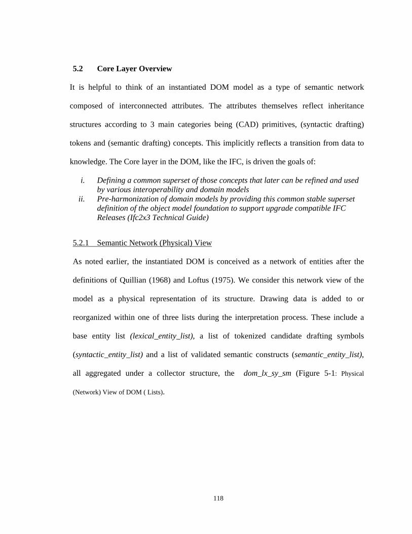
118
5.2 Core Layer Overview
It is helpful to think of an instantiated DOM model as a type of semantic network
composed of interconnected attributes. The attributes themselves reflect inheritance
structures according to 3 main categories being (CAD) primitives, (syntactic drafting)
tokens and (semantic drafting) concepts. This implicitly reflects a transition from data to
knowledge. The Core layer in the DOM, like the IFC, is driven the goals of:
i. Defining a common superset of those concepts that later can be refined and used by various interoperability and domain models
ii. Pre-harmonization of domain models by providing this common stable superset definition of the object model foundation to support upgrade compatible IFC Releases (Ifc2x3 Technical Guide)
5.2.1 Semantic Network (Physical) View
As noted earlier, the instantiated DOM is conceived as a network of entities after the
definitions of Quillian (1968) and Loftus (1975). We consider this network view of the
model as a physical representation of its structure. Drawing data is added to or
reorganized within one of three lists during the interpretation process. These include a
base entity list (lexical_entity_list), a list of tokenized candidate drafting symbols
(syntactic_entity_list) and a list of validated semantic constructs (semantic_entity_list),
all aggregated under a collector structure, the dom_lx_sy_sm (Figure 5-1: Physical
(Network) View of DOM ( Lists).
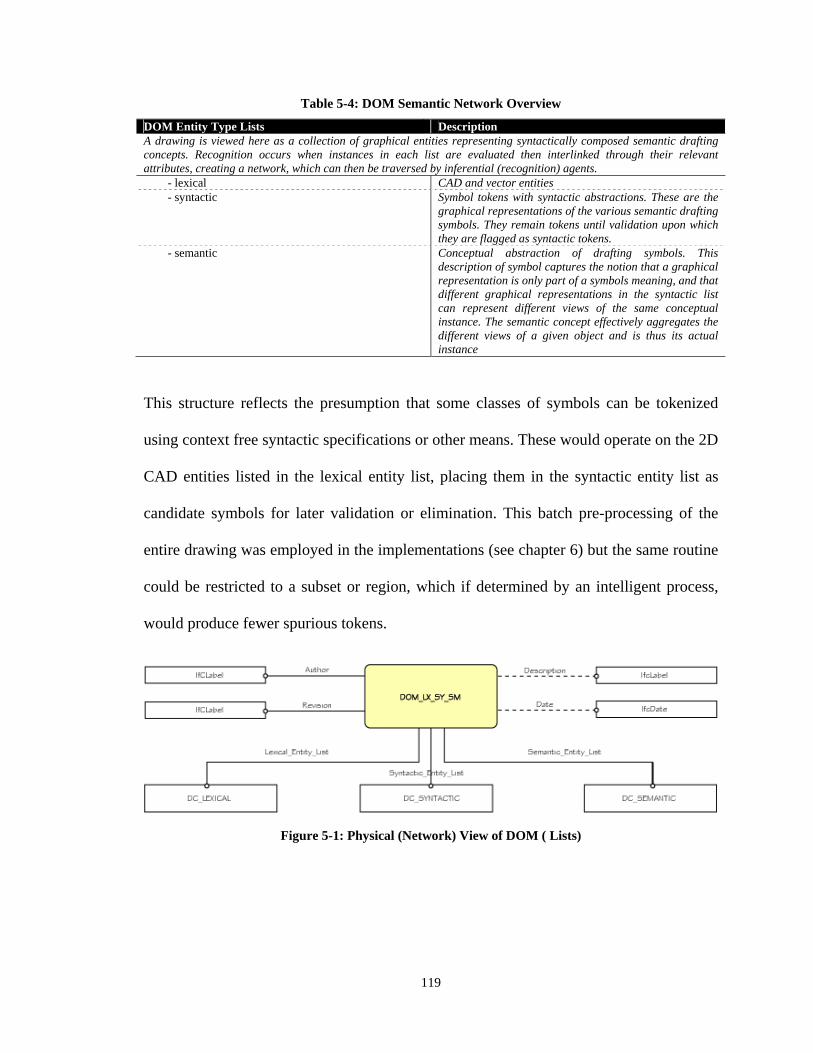
119
Table 5-4: DOM Semantic Network Overview
DOM Entity Type Lists Description A drawing is viewed here as a collection of graphical entities representing syntactically composed semantic drafting concepts. Recognition occurs when instances in each list are evaluated then interlinked through their relevant attributes, creating a network, which can then be traversed by inferential (recognition) agents. - lexical CAD and vector entities - syntactic Symbol tokens with syntactic abstractions. These are the
graphical representations of the various semantic drafting symbols. They remain tokens until validation upon which they are flagged as syntactic tokens.
- semantic Conceptual abstraction of drafting symbols. This description of symbol captures the notion that a graphical representation is only part of a symbols meaning, and that different graphical representations in the syntactic list can represent different views of the same conceptual instance. The semantic concept effectively aggregates the different views of a given object and is thus its actual instance
This structure reflects the presumption that some classes of symbols can be tokenized
using context free syntactic specifications or other means. These would operate on the 2D
CAD entities listed in the lexical entity list, placing them in the syntactic entity list as
candidate symbols for later validation or elimination. This batch pre-processing of the
entire drawing was employed in the implementations (see chapter 6) but the same routine
could be restricted to a subset or region, which if determined by an intelligent process,
would produce fewer spurious tokens.
Figure 5-1: Physical (Network) View of DOM ( Lists)
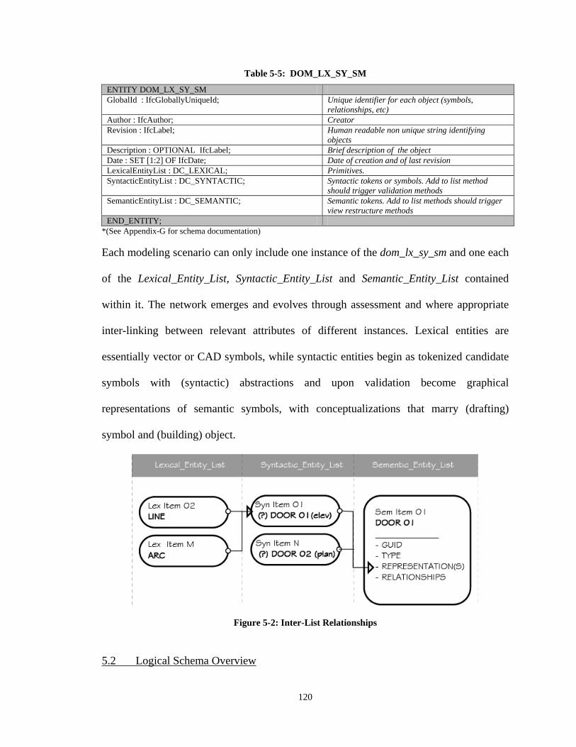
120
Table 5-5: DOM_LX_SY_SM
ENTITY DOM_LX_SY_SM GlobalId : IfcGloballyUniqueId; Unique identifier for each object (symbols,
relationships, etc) Author : IfcAuthor; Creator Revision : IfcLabel; Human readable non unique string identifying
objects Description : OPTIONAL IfcLabel; Brief description of the object Date : SET [1:2] OF IfcDate; Date of creation and of last revision LexicalEntityList : DC_LEXICAL; Primitives. SyntacticEntityList : DC_SYNTACTIC; Syntactic tokens or symbols. Add to list method
should trigger validation methods SemanticEntityList : DC_SEMANTIC; Semantic tokens. Add to list methods should trigger
view restructure methods END_ENTITY;
*(See Appendix-G for schema documentation)
Each modeling scenario can only include one instance of the dom_lx_sy_sm and one each
of the Lexical_Entity_List, Syntactic_Entity_List and Semantic_Entity_List contained
within it. The network emerges and evolves through assessment and where appropriate
inter-linking between relevant attributes of different instances. Lexical entities are
essentially vector or CAD symbols, while syntactic entities begin as tokenized candidate
symbols with (syntactic) abstractions and upon validation become graphical
representations of semantic symbols, with conceptualizations that marry (drafting)
symbol and (building) object.
Figure 5-2: Inter-List Relationships
5.2 Logical Schema Overview
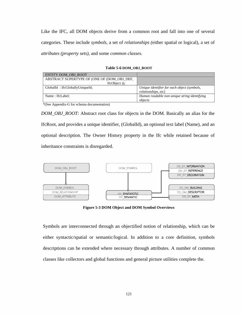
121
Like the IFC, all DOM objects derive from a common root and fall into one of several
categories. These include symbols, a set of relationships (either spatial or logical), a set of
attributes (property sets), and some common classes.
Table 5-6 DOM_OBJ_ROOT
ENTITY DOM_OBJ_ROOT ABSTRACT SUPERTYPE OF (ONE OF (DOM_OBJ_DEF,
IfcObject ));
GlobalId : IfcGloballyUniqueId; Unique identifier for each object (symbols, relationships, etc)
Name : IfcLabel; Human readable non unique string identifying objects
*(See Appendix-G for schema documentation)
DOM_OBJ_ROOT: Abstract root class for objects in the DOM. Basically an alias for the
IfcRoot, and provides a unique identifier, (GlobalId), an optional text label (Name), and an
optional description. The Owner History property in the Ifc while retained because of
inheritance constraints is disregarded.
Figure 5-3 DOM Object and DOM Symbol Overviews Symbols are interconnected through an objectified notion of relationship, which can be
either syntactic/spatial or semantic/logical. In addition to a core definition, symbols
descriptions can be extended where necessary through attributes. A number of common
classes like collectors and global functions and general picture utilities complete the.
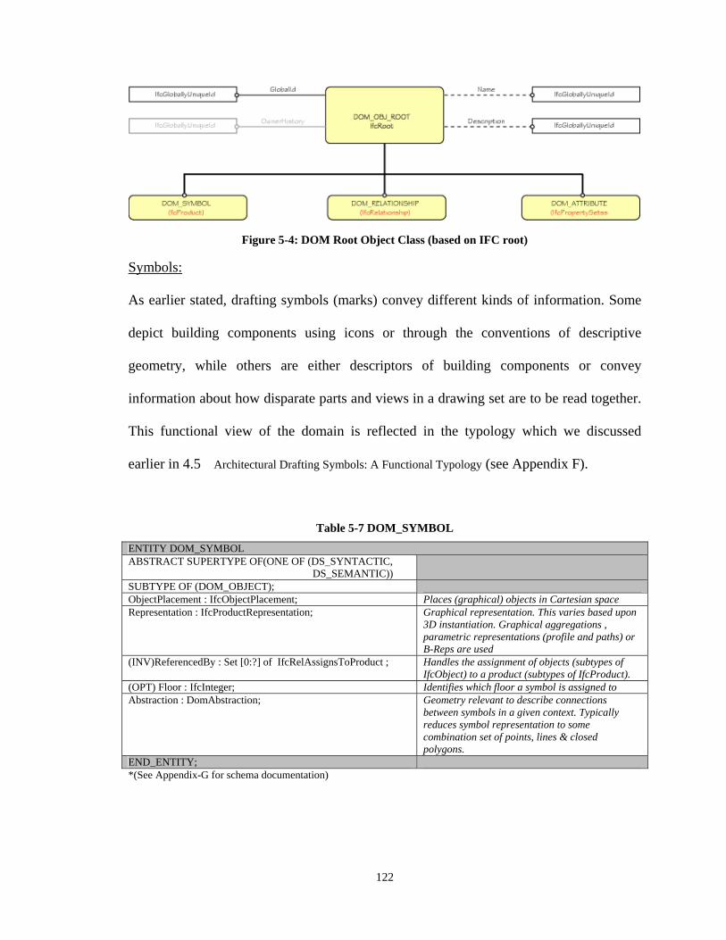
122
Figure 5-4: DOM Root Object Class (based on IFC root)
Symbols:
As earlier stated, drafting symbols (marks) convey different kinds of information. Some
depict building components using icons or through the conventions of descriptive
geometry, while others are either descriptors of building components or convey
information about how disparate parts and views in a drawing set are to be read together.
This functional view of the domain is reflected in the typology which we discussed
earlier in 4.5 Architectural Drafting Symbols: A Functional Typology (see Appendix F).
Table 5-7 DOM_SYMBOL
ENTITY DOM_SYMBOL ABSTRACT SUPERTYPE OF(ONE OF (DS_SYNTACTIC, DS_SEMANTIC))
SUBTYPE OF (DOM_OBJECT); ObjectPlacement : IfcObjectPlacement; Places (graphical) objects in Cartesian space Representation : IfcProductRepresentation; Graphical representation. This varies based upon
3D instantiation. Graphical aggregations , parametric representations (profile and paths) or B-Reps are used
(INV)ReferencedBy : Set [0:?] of IfcRelAssignsToProduct ; Handles the assignment of objects (subtypes of IfcObject) to a product (subtypes of IfcProduct).
(OPT) Floor : IfcInteger; Identifies which floor a symbol is assigned to Abstraction : DomAbstraction; Geometry relevant to describe connections
between symbols in a given context. Typically reduces symbol representation to some combination set of points, lines & closed polygons.
END_ENTITY; *(See Appendix-G for schema documentation)
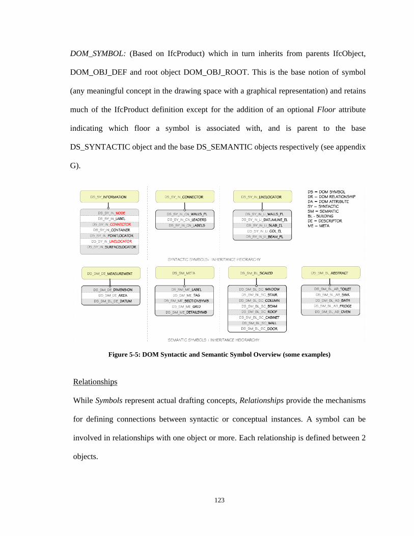
123
DOM_SYMBOL: (Based on IfcProduct) which in turn inherits from parents IfcObject,
DOM_OBJ_DEF and root object DOM_OBJ_ROOT. This is the base notion of symbol
(any meaningful concept in the drawing space with a graphical representation) and retains
much of the IfcProduct definition except for the addition of an optional Floor attribute
indicating which floor a symbol is associated with, and is parent to the base
DS_SYNTACTIC object and the base DS_SEMANTIC objects respectively (see appendix
G).
Figure 5-5: DOM Syntactic and Semantic Symbol Overview (some examples)
Relationships
While Symbols represent actual drafting concepts, Relationships provide the mechanisms
for defining connections between syntactic or conceptual instances. A symbol can be
involved in relationships with one object or more. Each relationship is defined between 2
objects.
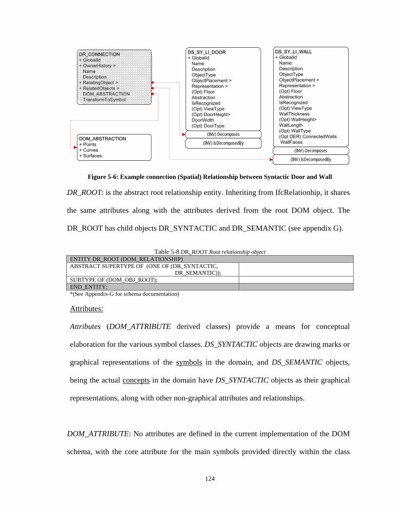
124
DS_SY_LI_WALL+ GlobalId Name Description ObjectType ObjectPlacement > Representation > (Opt) Floor Abstraction IsRecognized (Opt) ViewType WallThickness (Opt) WallHeight> WallLength (Opt) WallType (Opt DER) ConnectedWalls WallFaces
DOM_ABSTRACTION+ Points+ Curves+ Surfaces
(INV) Decomposes
(INV) IsDecomposedBy
DR_CONNECTION+ GlobalId+ OwnerHistory > Name Description+ RelatingObject >+ RelatedObjects > DOM_ABSTRACTION TransformToSymbol
DS_SY_LI_DOOR+ GlobalId Name Description ObjectType ObjectPlacement > Representation > (Opt) Floor Abstraction IsRecognized (Opt) ViewType (Opt) DoorHeight> DoorWidth (Opt) DoorType
(INV) Decomposes
(INV) IsDecomposedBy
Figure 5-6: Example connection (Spatial) Relationship between Syntactic Door and Wall
DR_ROOT: is the abstract root relationship entity. Inheriting from IfcRelationhip, it shares
the same attributes along with the attributes derived from the root DOM object. The
DR_ROOT has child objects DR_SYNTACTIC and DR_SEMANTIC (see appendix G).
Table 5-8 DR_ROOT Root relationship object ENTITY DR_ROOT (DOM_RELATIONSHIP) ABSTRACT SUPERTYPE OF (ONE OF (DR_SYNTACTIC, DR_SEMANTIC));
SUBTYPE OF (DOM_OBJ_ROOT); END_ENTITY; *(See Appendix-G for schema documentation)
Attributes:
Attributes (DOM_ATTRIBUTE derived classes) provide a means for conceptual
elaboration for the various symbol classes. DS_SYNTACTIC objects are drawing marks or
graphical representations of the symbols in the domain, and DS_SEMANTIC objects,
being the actual concepts in the domain have DS_SYNTACTIC objects as their graphical
representations, along with other non-graphical attributes and relationships.
DOM_ATTRIBUTE: No attributes are defined in the current implementation of the DOM
schema, with the core attribute for the main symbols provided directly within the class
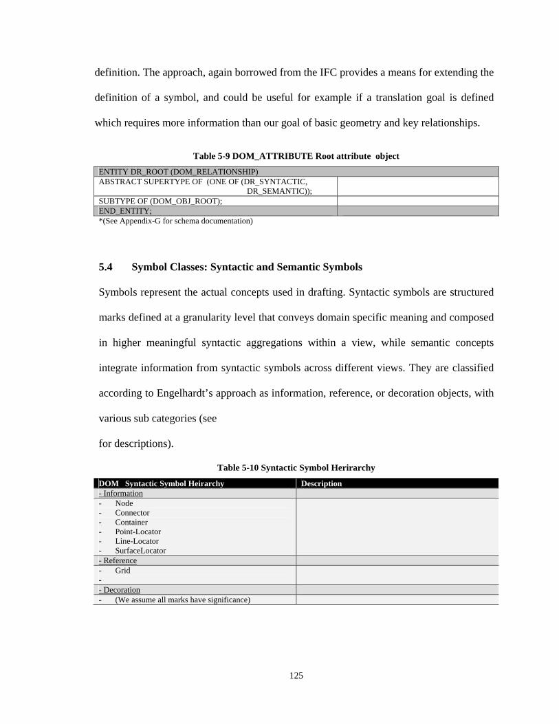
125
definition. The approach, again borrowed from the IFC provides a means for extending the
definition of a symbol, and could be useful for example if a translation goal is defined
which requires more information than our goal of basic geometry and key relationships.
Table 5-9 DOM_ATTRIBUTE Root attribute object
ENTITY DR_ROOT (DOM_RELATIONSHIP) ABSTRACT SUPERTYPE OF (ONE OF (DR_SYNTACTIC, DR_SEMANTIC));
SUBTYPE OF (DOM_OBJ_ROOT); END_ENTITY; *(See Appendix-G for schema documentation)
5.4 Symbol Classes: Syntactic and Semantic Symbols
Symbols represent the actual concepts used in drafting. Syntactic symbols are structured
marks defined at a granularity level that conveys domain specific meaning and composed
in higher meaningful syntactic aggregations within a view, while semantic concepts
integrate information from syntactic symbols across different views. They are classified
according to Engelhardt’s approach as information, reference, or decoration objects, with
various sub categories (see
for descriptions).
Table 5-10 Syntactic Symbol Herirarchy
DOM Syntactic Symbol Heirarchy Description - Information - Node - Connector - Container - Point-Locator - Line-Locator - SurfaceLocator
- Reference - Grid -
- Decoration - (We assume all marks have significance)
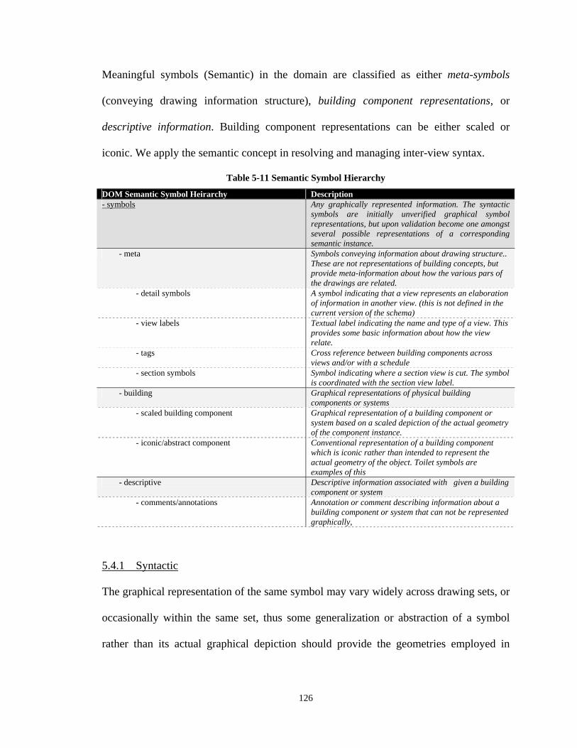
126
Meaningful symbols (Semantic) in the domain are classified as either meta-symbols
(conveying drawing information structure), building component representations, or
descriptive information. Building component representations can be either scaled or
iconic. We apply the semantic concept in resolving and managing inter-view syntax.
Table 5-11 Semantic Symbol Hierarchy
DOM Semantic Symbol Heirarchy Description - symbols Any graphically represented information. The syntactic
symbols are initially unverified graphical symbol representations, but upon validation become one amongst several possible representations of a corresponding semantic instance.
- meta Symbols conveying information about drawing structure.. These are not representations of building concepts, but provide meta-information about how the various pars of the drawings are related.
- detail symbols A symbol indicating that a view represents an elaboration of information in another view. (this is not defined in the current version of the schema)
- view labels Textual label indicating the name and type of a view. This provides some basic information about how the view relate.
- tags Cross reference between building components across views and/or with a schedule
- section symbols Symbol indicating where a section view is cut. The symbol is coordinated with the section view label.
- building Graphical representations of physical building components or systems
- scaled building component Graphical representation of a building component or system based on a scaled depiction of the actual geometry of the component instance.
- iconic/abstract component Conventional representation of a building component which is iconic rather than intended to represent the actual geometry of the object. Toilet symbols are examples of this
- descriptive Descriptive information associated with given a building component or system
- comments/annotations Annotation or comment describing information about a building component or system that can not be represented graphically,
5.4.1 Syntactic
The graphical representation of the same symbol may vary widely across drawing sets, or
occasionally within the same set, thus some generalization or abstraction of a symbol
rather than its actual graphical depiction should provide the geometries employed in
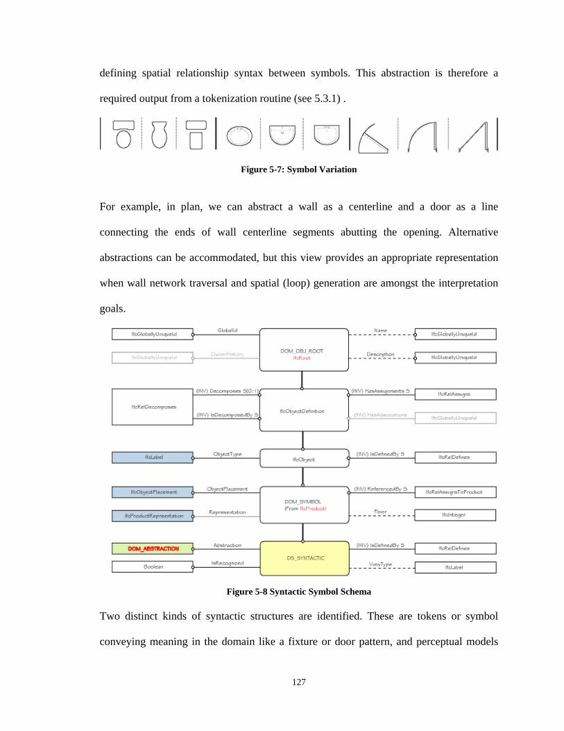
127
defining spatial relationship syntax between symbols. This abstraction is therefore a
required output from a tokenization routine (see 5.3.1) .
Figure 5-7: Symbol Variation
For example, in plan, we can abstract a wall as a centerline and a door as a line
connecting the ends of wall centerline segments abutting the opening. Alternative
abstractions can be accommodated, but this view provides an appropriate representation
when wall network traversal and spatial (loop) generation are amongst the interpretation
goals.
Figure 5-8 Syntactic Symbol Schema Two distinct kinds of syntactic structures are identified. These are tokens or symbol
conveying meaning in the domain like a fixture or door pattern, and perceptual models
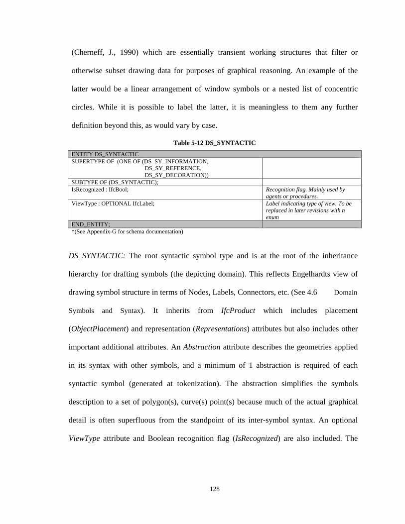
128
(Cherneff, J., 1990) which are essentially transient working structures that filter or
otherwise subset drawing data for purposes of graphical reasoning. An example of the
latter would be a linear arrangement of window symbols or a nested list of concentric
circles. While it is possible to label the latter, it is meaningless to them any further
definition beyond this, as would vary by case.
Table 5-12 DS_SYNTACTIC
ENTITY DS_SYNTACTIC SUPERTYPE OF (ONE OF (DS_SY_INFORMATION, DS_SY_REFERENCE, DS_SY_DECORATION))
SUBTYPE OF (DS_SYNTACTIC); IsRecognized : IfcBool; Recognition flag. Mainly used by
agents or procedures. ViewType : OPTIONAL IfcLabel; Label indicating type of view. To be
replaced in later revisions with n enum
END_ENTITY; *(See Appendix-G for schema documentation)
DS_SYNTACTIC: The root syntactic symbol type and is at the root of the inheritance
hierarchy for drafting symbols (the depicting domain). This reflects Engelhardts view of
drawing symbol structure in terms of Nodes, Labels, Connectors, etc. (See 4.6 Domain
Symbols and Syntax). It inherits from IfcProduct which includes placement
(ObjectPlacement) and representation (Representations) attributes but also includes other
important additional attributes. An Abstraction attribute describes the geometries applied
in its syntax with other symbols, and a minimum of 1 abstraction is required of each
syntactic symbol (generated at tokenization). The abstraction simplifies the symbols
description to a set of polygon(s), curve(s) point(s) because much of the actual graphical
detail is often superfluous from the standpoint of its inter-symbol syntax. An optional
ViewType attribute and Boolean recognition flag (IsRecognized) are also included. The
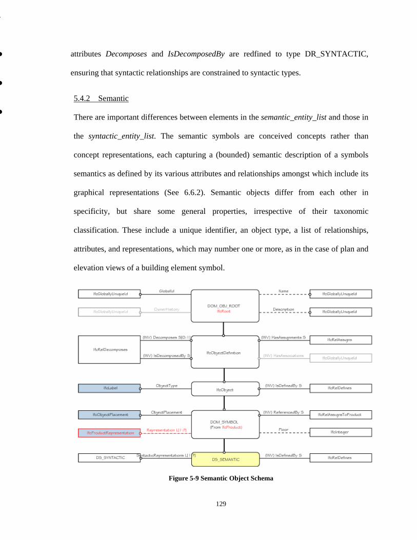
129
attributes Decomposes and IsDecomposedBy are redfined to type DR_SYNTACTIC,
ensuring that syntactic relationships are constrained to syntactic types.
5.4.2 Semantic
There are important differences between elements in the semantic_entity_list and those in
the syntactic_entity_list. The semantic symbols are conceived concepts rather than
concept representations, each capturing a (bounded) semantic description of a symbols
semantics as defined by its various attributes and relationships amongst which include its
graphical representations (See 6.6.2). Semantic objects differ from each other in
specificity, but share some general properties, irrespective of their taxonomic
classification. These include a unique identifier, an object type, a list of relationships,
attributes, and representations, which may number one or more, as in the case of plan and
elevation views of a building element symbol.
Figure 5-9 Semantic Object Schema
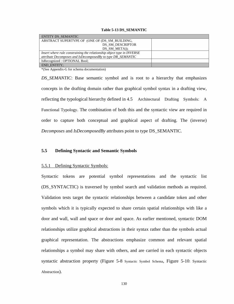
130
Table 5-13 DS_SEMANTIC
ENTITY DS_SEMANTIC ABSTRACT SUPERTYPE OF (ONE OF (DS_SM_BUILDING, DS_SM_DESCRIPTOR DS_SM_META));
Insert where rule constraining the relationship object type in INVERSE attribute Decomposes and IsDecomposedBy to type DR_SEMANTIC
IsRecognized : OPTIONAL Bool; END_ENTITY; *(See Appendix-G for schema documentation)
DS_SEMANTIC: Base semantic symbol and is root to a hierarchy that emphasizes
concepts in the drafting domain rather than graphical symbol syntax in a drafting view,
reflecting the typological hierarchy defined in 4.5 Architectural Drafting Symbols: A
Functional Typology. The combination of both this and the syntactic view are required in
order to capture both conceptual and graphical aspect of drafting. The (inverse)
Decomposes and IsDecomposedBy attributes point to type DS_SEMANTIC.
5.5 Defining Syntactic and Semantic Symbols
5.5.1 Defining Syntactic Symbols:
Syntactic tokens are potential symbol representations and the syntactic list
(DS_SYNTACTIC) is traversed by symbol search and validation methods as required.
Validation tests target the syntactic relationships between a candidate token and other
symbols which it is typically expected to share certain spatial relationships with like a
door and wall, wall and space or door and space. As earlier mentioned, syntactic DOM
relationships utilize graphical abstractions in their syntax rather than the symbols actual
graphical representation. The abstractions emphasize common and relevant spatial
relationships a symbol may share with others, and are carried in each syntactic objects
syntactic abstraction property (Figure 5-8 Syntactic Symbol Schema, Figure 5-10: Syntactic
Abstraction).
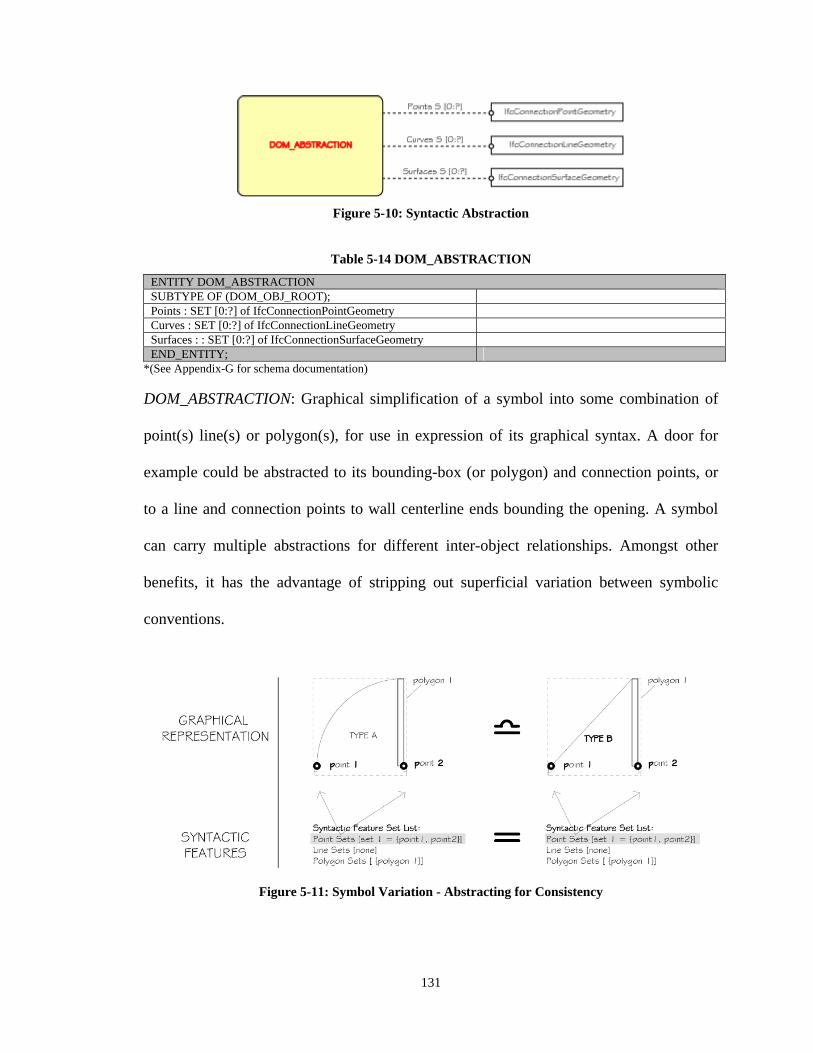
131
Figure 5-10: Syntactic Abstraction
Table 5-14 DOM_ABSTRACTION
ENTITY DOM_ABSTRACTION SUBTYPE OF (DOM_OBJ_ROOT); Points : SET [0:?] of IfcConnectionPointGeometry Curves : SET [0:?] of IfcConnectionLineGeometry Surfaces : : SET [0:?] of IfcConnectionSurfaceGeometry END_ENTITY;
*(See Appendix-G for schema documentation)
DOM_ABSTRACTION: Graphical simplification of a symbol into some combination of
point(s) line(s) or polygon(s), for use in expression of its graphical syntax. A door for
example could be abstracted to its bounding-box (or polygon) and connection points, or
to a line and connection points to wall centerline ends bounding the opening. A symbol
can carry multiple abstractions for different inter-object relationships. Amongst other
benefits, it has the advantage of stripping out superficial variation between symbolic
conventions.
Figure 5-11: Symbol Variation - Abstracting for Consistency
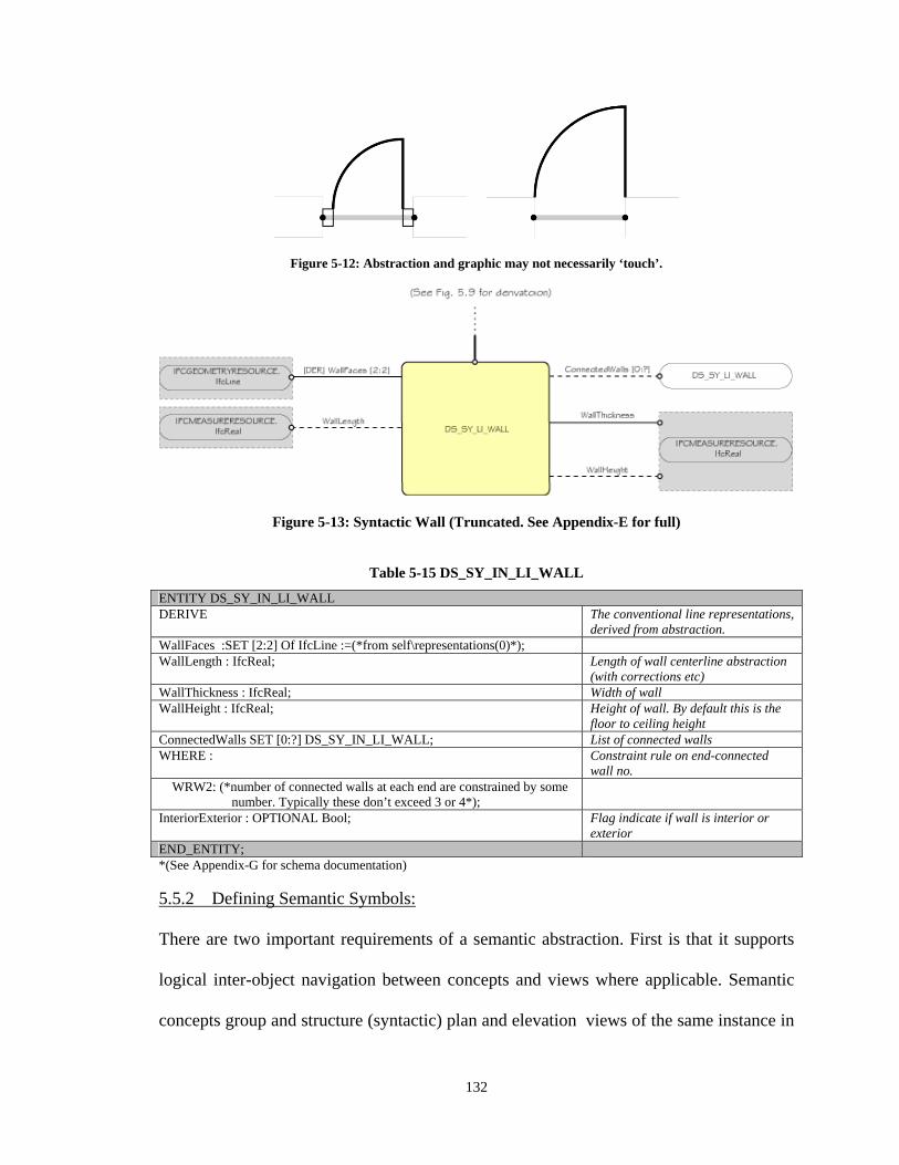
132
Figure 5-12: Abstraction and graphic may not necessarily ‘touch’.
Figure 5-13: Syntactic Wall (Truncated. See Appendix-E for full)
Table 5-15 DS_SY_IN_LI_WALL
ENTITY DS_SY_IN_LI_WALL DERIVE The conventional line representations,
derived from abstraction. WallFaces :SET [2:2] Of IfcLine :=(*from self\representations(0)*); WallLength : IfcReal; Length of wall centerline abstraction
(with corrections etc) WallThickness : IfcReal; Width of wall WallHeight : IfcReal; Height of wall. By default this is the
floor to ceiling height ConnectedWalls SET [0:?] DS_SY_IN_LI_WALL; List of connected walls WHERE : Constraint rule on end-connected
wall no. WRW2: (*number of connected walls at each end are constrained by some
number. Typically these don’t exceed 3 or 4*);
InteriorExterior : OPTIONAL Bool; Flag indicate if wall is interior or exterior
END_ENTITY; *(See Appendix-G for schema documentation)
5.5.2 Defining Semantic Symbols:
There are two important requirements of a semantic abstraction. First is that it supports
logical inter-object navigation between concepts and views where applicable. Semantic
concepts group and structure (syntactic) plan and elevation views of the same instance in
133
both spatial and logical terms. In this regard, DOM concepts are somewhat akin to
models of the depicted object, but its representations are principally 2D syntactic views35.
This allows us for example to begin with an elevation view of a window, navigate
through its semantic definition to any of its other representations (e.g. a plan view) via
the relationship attributes of this syntactic representation to its parent wall, to other
windows in adjacent walls.
In order to ensure support for the anticipated exchanges and instantiation between views,
it is necessary to have methodologies for defining the scope of information exchange
which should be practicable. For this, we apply the IFC Model View Definition
methodology (MVD) which is driven by the information requirements of a client
application. The requirements are typically defined in a document called an Information
Delivery Manual (IDM), which is the current approach for capturing exchange
requirements between applications in the ISO 10303 standards. Hietanen, J. (2006) and
Eastman et al (2009) outline how this document provides a clear set of expectations and
functional scope for an exchange application, but does not provide adequate detail at the
implementation level to ensure these objectives are met. The MVD fills the gap between
the requirements analysis and implementation stages, eliminating the ambiguity and
potential conflicts in representation, etc. resulting from the broader and less focused
objectives of the full IFC model. The idea is to identify the specific concepts and
exchange requirements between actors during different phases of interest in a project,
including class attributes, important relationships and representational description. For
35 There are other possible representations like bounding boxes, etc. that provide different levels of detail and address the issue of granularity.
134
example, a structural load calculation may require a linear abstraction of a column while
an MEP model may require a surface representation for interference checking. In the
MVD, concepts are hierarchically defined in a View Definition Diagram, with aggregated
or variable concepts at the root branching down to elementary or static concepts and
relevant properties at the leaves. They may be variable or static. In a full specification, it
is also necessary to establish the binding of the concepts to a standard model like a
particular IFC release. The MVD can be viewed as an intermediating mapping of shared
concepts between proprietary BIM implementations defined in such a manned and level
of detail as to clarify its relationship to the exporting or importing application models.
The same thinking is directly applicable in CAD-DOM-BIM interpretation and
translation. Because the final target is a BIM model, the concepts and class descriptions
in the DOM should incorporate as much information for instantiation of the object in the
BIM as can be practicably recognized from the CAD. Consider a door concept and its
IFC 2.X3 definition comprised of several parts, namely the DoorStyle, which represents
the general class definition, and the DoorLining, and DoorPanel, which carry the instance
attribute definitions. The IFC 2.X3 definition, as earlier stated, is considerably richer in
information than the drawing. Consequently, it is necessary to identify which of these
many properties can be recognized from the drawing. This process must be carried out
for each concept common to both DOM and IFC 2.X models.
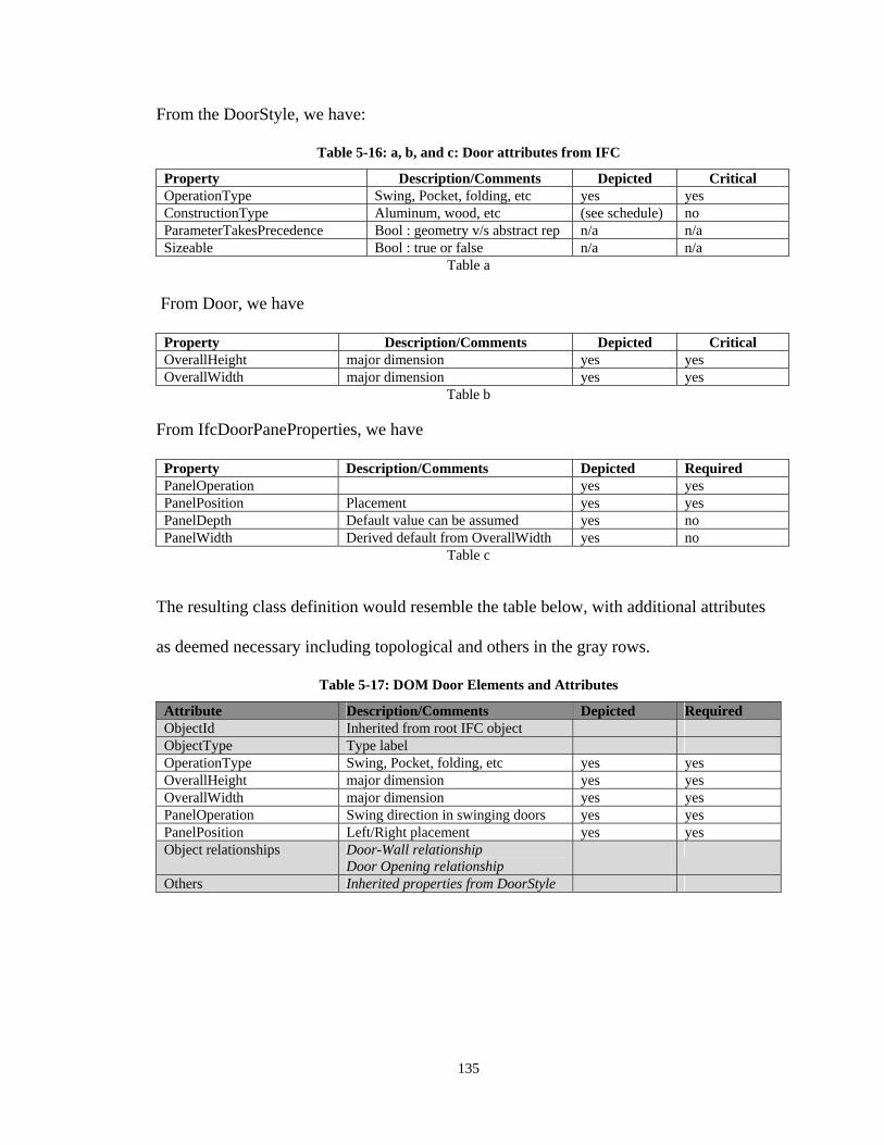
135
From the DoorStyle, we have:
Table 5-16: a, b, and c: Door attributes from IFC
Property Description/Comments Depicted Critical OperationType Swing, Pocket, folding, etc yes yes ConstructionType Aluminum, wood, etc (see schedule) no ParameterTakesPrecedence Bool : geometry v/s abstract rep n/a n/a Sizeable Bool : true or false n/a n/a
Table a From Door, we have
Property Description/Comments Depicted Critical OverallHeight major dimension yes yes OverallWidth major dimension yes yes
Table b
From IfcDoorPaneProperties, we have
Property Description/Comments Depicted Required PanelOperation yes yes PanelPosition Placement yes yes PanelDepth Default value can be assumed yes no PanelWidth Derived default from OverallWidth yes no
Table c
The resulting class definition would resemble the table below, with additional attributes
as deemed necessary including topological and others in the gray rows.
Table 5-17: DOM Door Elements and Attributes
Attribute Description/Comments Depicted Required ObjectId Inherited from root IFC object ObjectType Type label OperationType Swing, Pocket, folding, etc yes yes OverallHeight major dimension yes yes OverallWidth major dimension yes yes PanelOperation Swing direction in swinging doors yes yes PanelPosition Left/Right placement yes yes Object relationships Door-Wall relationship
Door Opening relationship
Others Inherited properties from DoorStyle
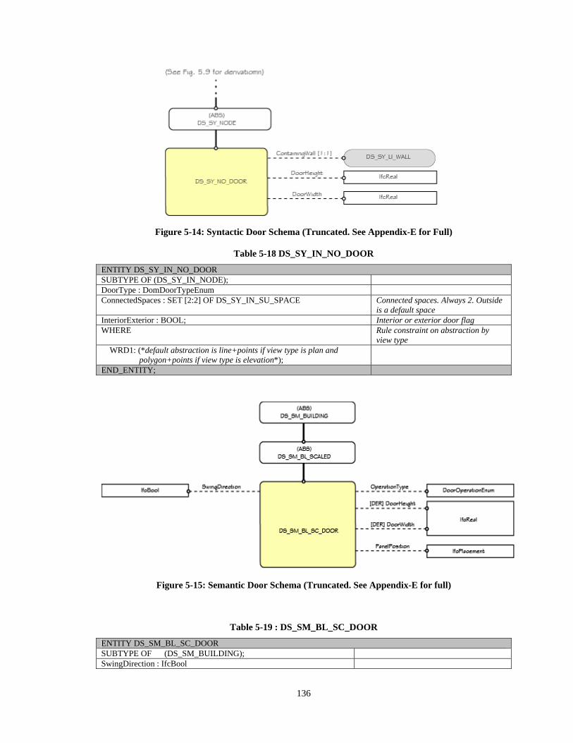
136
Figure 5-14: Syntactic Door Schema (Truncated. See Appendix-E for Full)
Table 5-18 DS_SY_IN_NO_DOOR
ENTITY DS_SY_IN_NO_DOOR SUBTYPE OF (DS_SY_IN_NODE); DoorType : DomDoorTypeEnum ConnectedSpaces : SET [2:2] OF DS_SY_IN_SU_SPACE Connected spaces. Always 2. Outside
is a default space InteriorExterior : BOOL; Interior or exterior door flag WHERE Rule constraint on abstraction by
view type WRD1: (*default abstraction is line+points if view type is plan and
polygon+points if view type is elevation*);
END_ENTITY;
Figure 5-15: Semantic Door Schema (Truncated. See Appendix-E for full)
Table 5-19 : DS_SM_BL_SC_DOOR
ENTITY DS_SM_BL_SC_DOOR SUBTYPE OF (DS_SM_BUILDING); SwingDirection : IfcBool
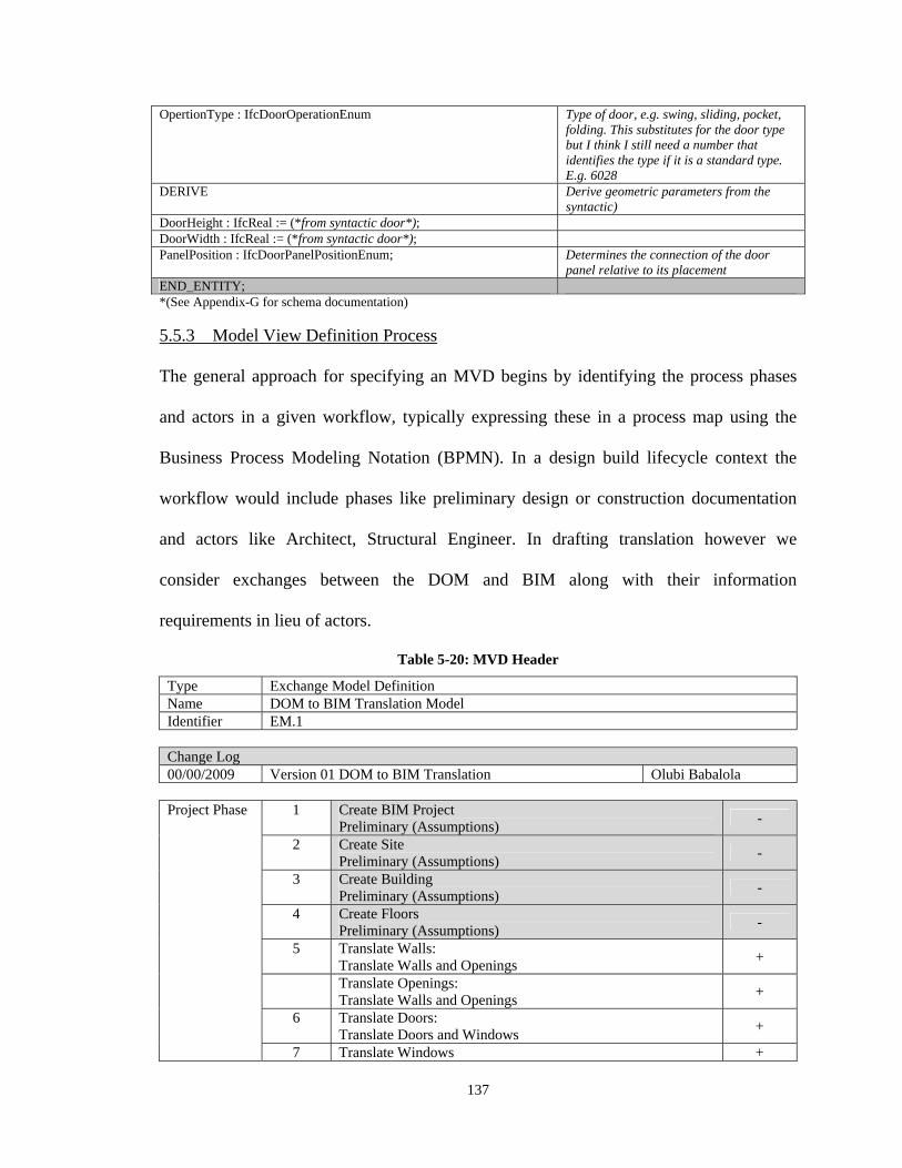
137
OpertionType : IfcDoorOperationEnum Type of door, e.g. swing, sliding, pocket, folding. This substitutes for the door type but I think I still need a number that identifies the type if it is a standard type. E.g. 6028
DERIVE Derive geometric parameters from the syntactic)
DoorHeight : IfcReal := (*from syntactic door*); DoorWidth : IfcReal := (*from syntactic door*); PanelPosition : IfcDoorPanelPositionEnum; Determines the connection of the door
panel relative to its placement END_ENTITY; *(See Appendix-G for schema documentation)
5.5.3 Model View Definition Process
The general approach for specifying an MVD begins by identifying the process phases
and actors in a given workflow, typically expressing these in a process map using the
Business Process Modeling Notation (BPMN). In a design build lifecycle context the
workflow would include phases like preliminary design or construction documentation
and actors like Architect, Structural Engineer. In drafting translation however we
consider exchanges between the DOM and BIM along with their information
requirements in lieu of actors.
Table 5-20: MVD Header
Type Exchange Model Definition Name DOM to BIM Translation Model Identifier EM.1 Change Log 00/00/2009 Version 01 DOM to BIM Translation Olubi Babalola Project Phase 1 Create BIM Project
Preliminary (Assumptions) -
2 Create Site Preliminary (Assumptions)
-
3 Create Building Preliminary (Assumptions)
-
4 Create Floors Preliminary (Assumptions)
-
5 Translate Walls: Translate Walls and Openings
+
Translate Openings: Translate Walls and Openings
+
6 Translate Doors: Translate Doors and Windows
+
7 Translate Windows +
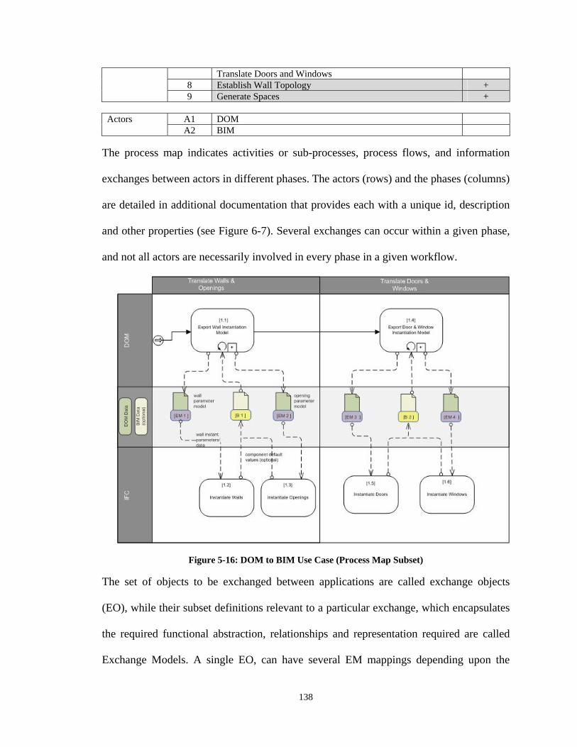
138
Translate Doors and Windows 8 Establish Wall Topology + 9 Generate Spaces +
Actors A1 DOM
A2 BIM
The process map indicates activities or sub-processes, process flows, and information
exchanges between actors in different phases. The actors (rows) and the phases (columns)
are detailed in additional documentation that provides each with a unique id, description
and other properties (see Figure 6-7). Several exchanges can occur within a given phase,
and not all actors are necessarily involved in every phase in a given workflow.
Figure 5-16: DOM to BIM Use Case (Process Map Subset)
The set of objects to be exchanged between applications are called exchange objects
(EO), while their subset definitions relevant to a particular exchange, which encapsulates
the required functional abstraction, relationships and representation required are called
Exchange Models. A single EO, can have several EM mappings depending upon the
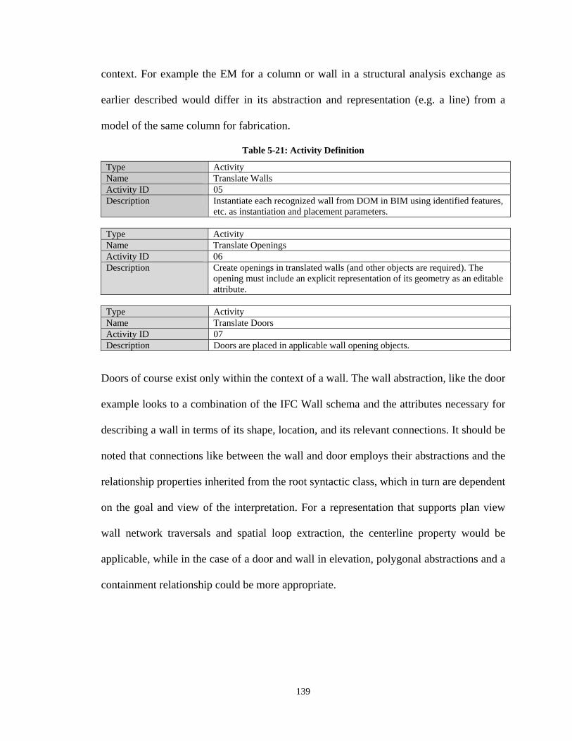
139
context. For example the EM for a column or wall in a structural analysis exchange as
earlier described would differ in its abstraction and representation (e.g. a line) from a
model of the same column for fabrication.
Table 5-21: Activity Definition
Type Activity Name Translate Walls Activity ID 05 Description Instantiate each recognized wall from DOM in BIM using identified features,
etc. as instantiation and placement parameters.
Type Activity Name Translate Openings Activity ID 06 Description Create openings in translated walls (and other objects are required). The
opening must include an explicit representation of its geometry as an editable attribute.
Type Activity Name Translate Doors Activity ID 07 Description Doors are placed in applicable wall opening objects.
Doors of course exist only within the context of a wall. The wall abstraction, like the door
example looks to a combination of the IFC Wall schema and the attributes necessary for
describing a wall in terms of its shape, location, and its relevant connections. It should be
noted that connections like between the wall and door employs their abstractions and the
relationship properties inherited from the root syntactic class, which in turn are dependent
on the goal and view of the interpretation. For a representation that supports plan view
wall network traversals and spatial loop extraction, the centerline property would be
applicable, while in the case of a door and wall in elevation, polygonal abstractions and a
containment relationship could be more appropriate.
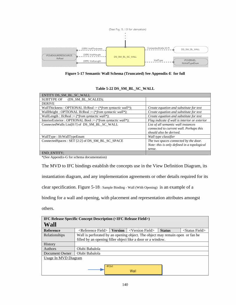
140
Figure 5-17 Semantic Wall Schema (Truncated) See Appendix-E for full
Table 5-22 DS_SM_BL_SC_WALL
ENTITY DS_SM_BL_SC_WALL SUBTYPE OF (DS_SM_BL_SCALED); DERIVE WallThickness : OPTIONAL IfcReal := (*from syntactic wall*); Create equation and substitute for text WallHeight : OPTIONAL IfcReal := (*from syntactic wall*); Create equation and substitute for text WallLength : IfcReal := (*from syntactic wall*); Create equation and substitute for text InteriorExterior : OPTIONAL Bool := (*from syntactic wall*); Flag indicate if wall is interior or exterior ConnectedWalls List[0:?] of DS_SM_BL_SC_WALL List of all semantic wall instances
connected to current wall. Perhaps this should also be derived.
WallType : IfcWallTypeEnum Wall type classifier ConnectedSpaces : SET [2:2] of DS_SM_BL_SC_SPACE The two spaces connected by the door.
Note: this is only defined in a topological sense.
END_ENTITY; *(See Appendix-G for schema documentation)
The MVD to IFC bindings establish the concepts use in the View Definition Diagram, its
instantiation diagram, and any implementation agreements or other details required for its
clear specification. Figure 5-18 : Sample Binding - Wall (With Opening) is an example of a
binding for a wall and opening, with placement and representation attributes amongst
others.
IFC Release Specific Concept Description (<IFC Release Field>)
Wall Reference <Reference Field> Version <Version Field> Status <Status Field> Relationships Wall is perforated by an opening object. The object may remain open or fan be
filled by an opening filler object like a door or a window. History Authors Olubi Babalola Document Owner Olubi Babalola Usage In MVD Diagram
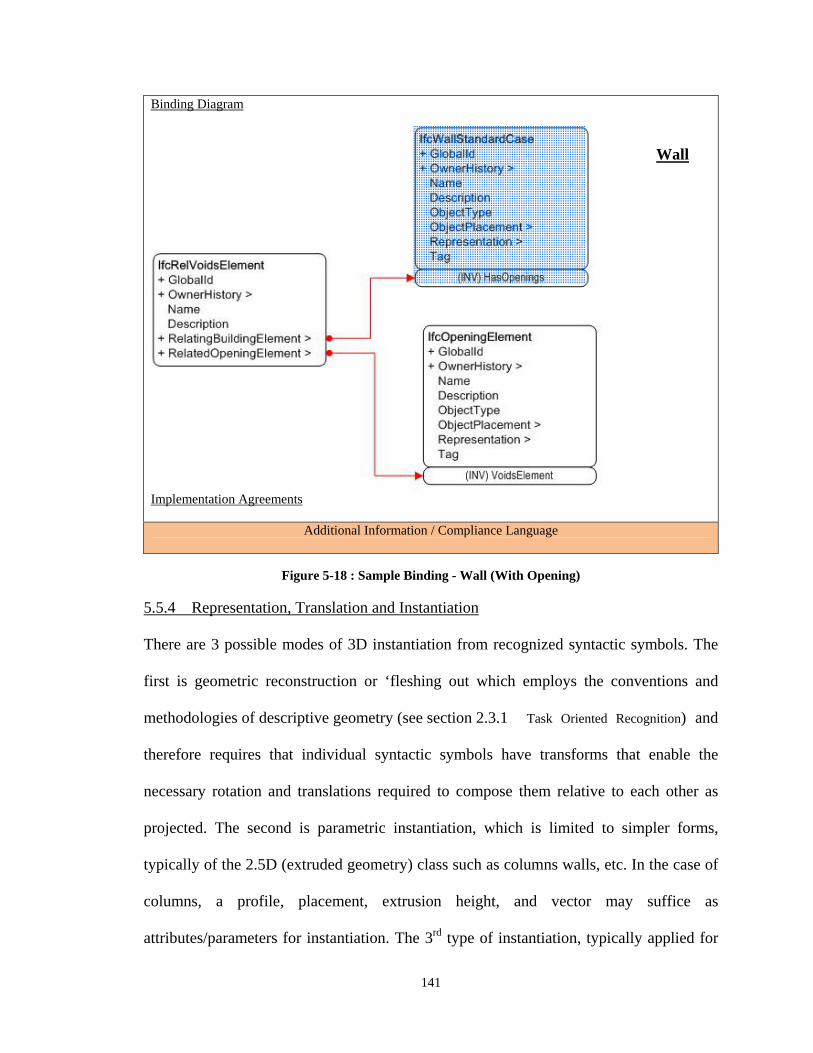
141
Binding Diagram
Implementation Agreements
Additional Information / Compliance Language
Figure 5-18 : Sample Binding - Wall (With Opening)
5.5.4 Representation, Translation and Instantiation
There are 3 possible modes of 3D instantiation from recognized syntactic symbols. The
first is geometric reconstruction or ‘fleshing out which employs the conventions and
methodologies of descriptive geometry (see section 2.3.1 Task Oriented Recognition) and
therefore requires that individual syntactic symbols have transforms that enable the
necessary rotation and translations required to compose them relative to each other as
projected. The second is parametric instantiation, which is limited to simpler forms,
typically of the 2.5D (extruded geometry) class such as columns walls, etc. In the case of
columns, a profile, placement, extrusion height, and vector may suffice as
attributes/parameters for instantiation. The 3rd type of instantiation, typically applied for
Wall
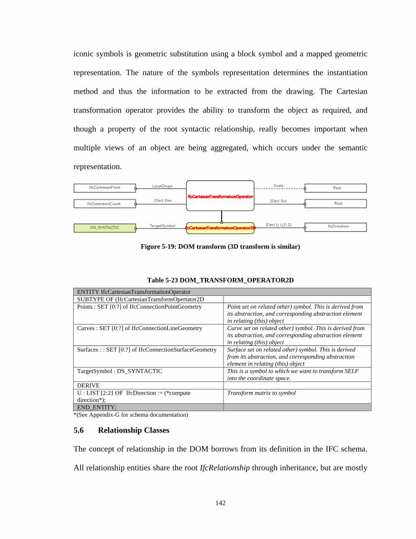
142
iconic symbols is geometric substitution using a block symbol and a mapped geometric
representation. The nature of the symbols representation determines the instantiation
method and thus the information to be extracted from the drawing. The Cartesian
transformation operator provides the ability to transform the object as required, and
though a property of the root syntactic relationship, really becomes important when
multiple views of an object are being aggregated, which occurs under the semantic
representation.
Figure 5-19: DOM transform (3D transform is similar)
Table 5-23 DOM_TRANSFORM_OPERATOR2D
ENTITY IfcCartesianTransformationOperator SUBTYPE OF (IfcCartesianTransformOpertator2D Points : SET [0:?] of IfcConnectionPointGeometry Point set on related other) symbol. This is derived from
its abstraction, and corresponding abstraction element in relating (this) object
Curves : SET [0:?] of IfcConnectionLineGeometry Curve set on related other) symbol. This is derived from its abstraction, and corresponding abstraction element in relating (this) object
Surfaces : : SET [0:?] of IfcConnectionSurfaceGeometry Surface set on related other) symbol. This is derived from its abstraction, and corresponding abstraction element in relating (this) object
TargetSymbol : DS_SYNTACTIC This is a symbol to which we want to transform SELF into the coordinate space.
DERIVE U : LIST [2:2} OF IfcDirection := (*compute direction*);
Transform matrix to symbol
END_ENTITY; *(See Appendix-G for schema documentation)
5.6 Relationship Classes
The concept of relationship in the DOM borrows from its definition in the IFC schema.
All relationship entities share the root IfcRelationship through inheritance, but are mostly
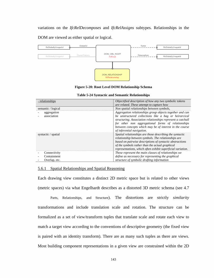
143
variations on the IfcRelDecomposes and IfcRelAssigns subtypes. Relationships in the
DOM are viewed as either spatial or logical.
Figure 5-20: Root Level DOM Relationship Schema
Table 5-24 Syntactic and Semantic Relationships
- relationships Objectified description of how any two symbolic tokens are related. These attempt to capture how
semantic / logical Non spatial relationships between symbols, - aggregation - association
Aggregation relationships group objects together and can be unstructured collections like a bag or heirarcical structuring. Association relationships represent a catchall for other non aggregational forms of relationships between concepts which may be of interest in the course of inferential navigation.
syntactic / spatial Spatial relationships are those describing the syntactic relationship between symbols. The relationships are based on pairwise descriptions of syntactic abstractions of the symbols rather than the actual graphical representations, which often exhibit superficial variation.
- Connectivity - Containment - Overlap, etc.
These represent the main classes of relationships we define as necessary for representing the graphical structure of symbolic drafting information
5.6.1 Spatial Relationships and Spatial Reasoning
Each drawing view constitutes a distinct 2D metric space but is related to other views
(metric spaces) via what Engelhardt describes as a distorted 3D metric schema (see 4.7
Parts, Relationships, and Structure). The distortions are strictly similarity
transformations and include translation scale and rotation. The structure can be
formalized as a set of view/transform tuples that translate scale and rotate each view to
match a target view according to the conventions of descriptive geometry (the fixed view
is paired with an identity transform). There are as many such tuples as there are views.
Most building component representations in a given view are constrained within the 2D
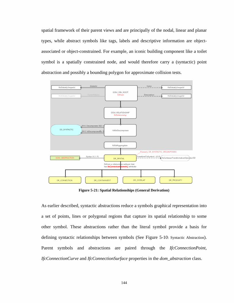
144
spatial framework of their parent views and are principally of the nodal, linear and planar
types, while abstract symbols like tags, labels and descriptive information are object-
associated or object-constrained. For example, an iconic building component like a toilet
symbol is a spatially constrained node, and would therefore carry a (syntactic) point
abstraction and possibly a bounding polygon for approximate collision tests.
Figure 5-21: Spatial Relationships (General Derivation)
As earlier described, syntactic abstractions reduce a symbols graphical representation into
a set of points, lines or polygonal regions that capture its spatial relationship to some
other symbol. These abstractions rather than the literal symbol provide a basis for
defining syntactic relationships between symbols (See Figure 5-10: Syntactic Abstraction).
Parent symbols and abstractions are paired through the IfcConnectionPoint,
IfcConnectionCurve and IfcConnectionSurface properties in the dom_abstraction class.
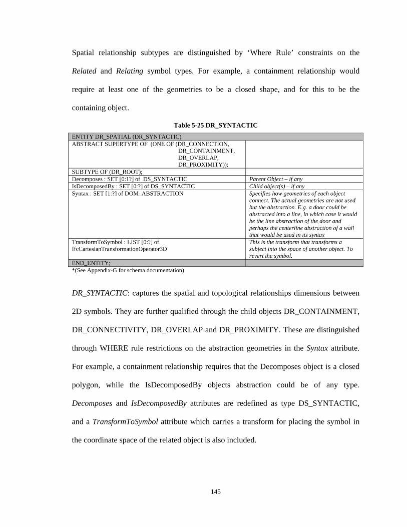
145
Spatial relationship subtypes are distinguished by ‘Where Rule’ constraints on the
Related and Relating symbol types. For example, a containment relationship would
require at least one of the geometries to be a closed shape, and for this to be the
containing object.
Table 5-25 DR_SYNTACTIC
ENTITY DR_SPATIAL (DR_SYNTACTIC) ABSTRACT SUPERTYPE OF (ONE OF (DR_CONNECTION, DR_CONTAINMENT, DR_OVERLAP, DR_PROXIMITY));
SUBTYPE OF (DR_ROOT); Decomposes : SET [0:1?] of DS_SYNTACTIC Parent Object – if any IsDecomposedBy : SET [0:?] of DS_SYNTACTIC Child object(s) – if any Syntax : SET [1:?] of DOM_ABSTRACTION Specifies how geometries of each object
connect. The actual geometries are not used but the abstraction. E.g. a door could be abstracted into a line, in which case it would be the line abstraction of the door and perhaps the centerline abstraction of a wall that would be used in its syntax
TransformToSymbol : LIST [0:?] of IfcCartesianTransformationOperator3D
This is the transform that transforms a subject into the space of another object. To revert the symbol.
END_ENTITY; *(See Appendix-G for schema documentation)
DR_SYNTACTIC: captures the spatial and topological relationships dimensions between
2D symbols. They are further qualified through the child objects DR_CONTAINMENT,
DR_CONNECTIVITY, DR_OVERLAP and DR_PROXIMITY. These are distinguished
through WHERE rule restrictions on the abstraction geometries in the Syntax attribute.
For example, a containment relationship requires that the Decomposes object is a closed
polygon, while the IsDecomposedBy objects abstraction could be of any type.
Decomposes and IsDecomposedBy attributes are redefined as type DS_SYNTACTIC,
and a TransformToSymbol attribute which carries a transform for placing the symbol in
the coordinate space of the related object is also included.
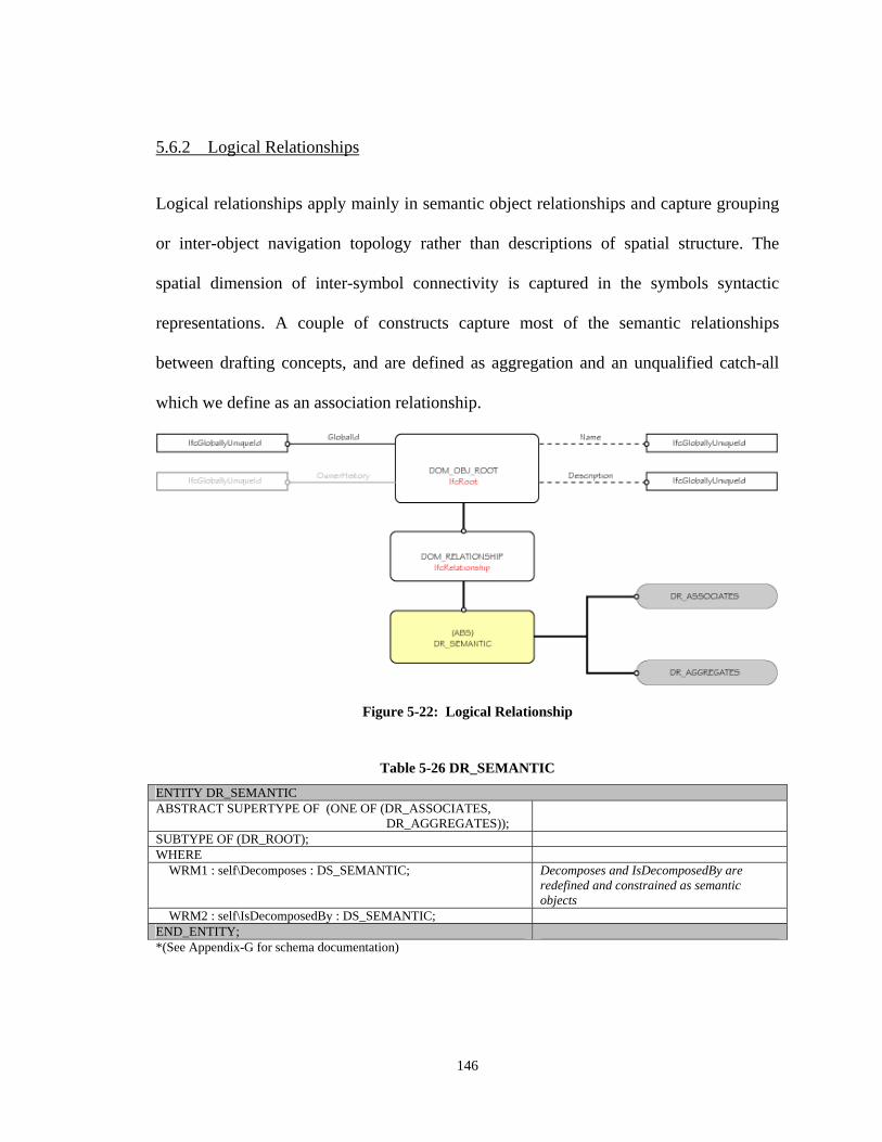
146
5.6.2 Logical Relationships
Logical relationships apply mainly in semantic object relationships and capture grouping
or inter-object navigation topology rather than descriptions of spatial structure. The
spatial dimension of inter-symbol connectivity is captured in the symbols syntactic
representations. A couple of constructs capture most of the semantic relationships
between drafting concepts, and are defined as aggregation and an unqualified catch-all
which we define as an association relationship.
Figure 5-22: Logical Relationship
Table 5-26 DR_SEMANTIC
ENTITY DR_SEMANTIC ABSTRACT SUPERTYPE OF (ONE OF (DR_ASSOCIATES, DR_AGGREGATES));
SUBTYPE OF (DR_ROOT); WHERE WRM1 : self\Decomposes : DS_SEMANTIC; Decomposes and IsDecomposedBy are
redefined and constrained as semantic objects
WRM2 : self\IsDecomposedBy : DS_SEMANTIC; END_ENTITY; *(See Appendix-G for schema documentation)
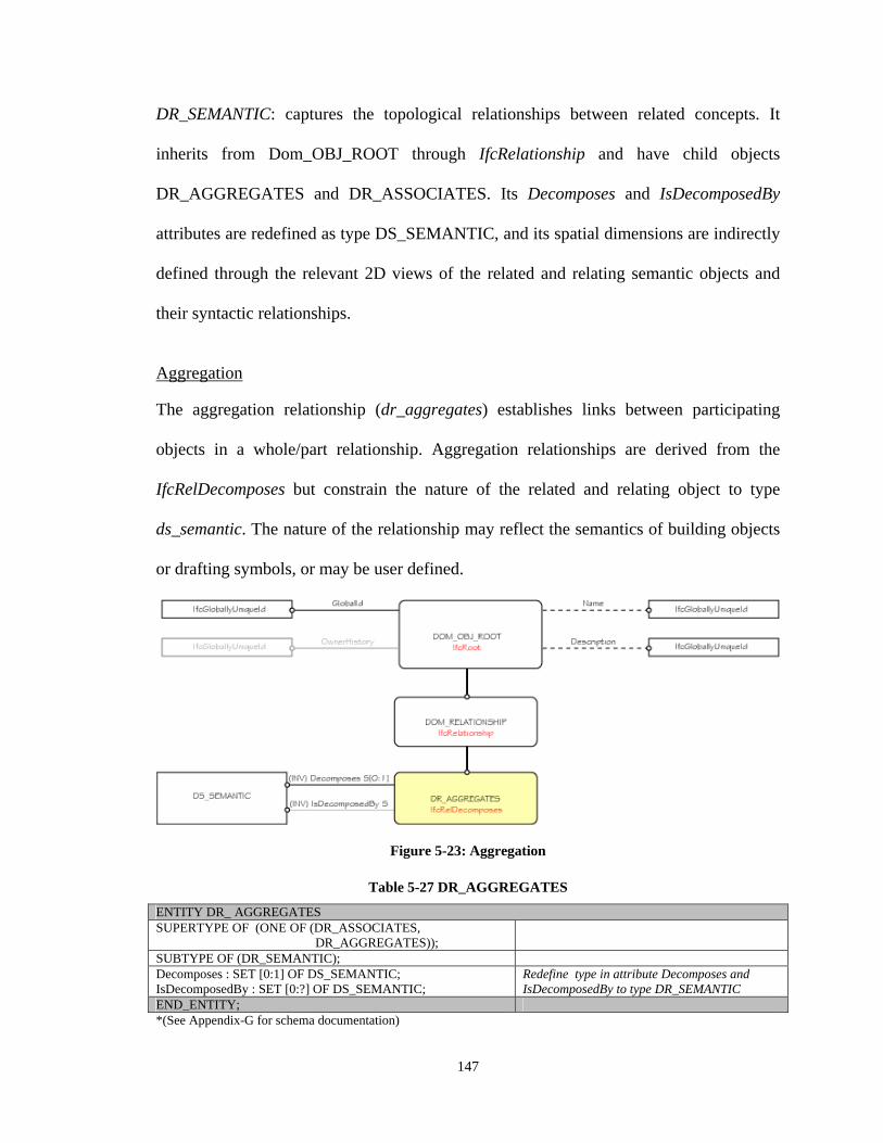
147
DR_SEMANTIC: captures the topological relationships between related concepts. It
inherits from Dom_OBJ_ROOT through IfcRelationship and have child objects
DR_AGGREGATES and DR_ASSOCIATES. Its Decomposes and IsDecomposedBy
attributes are redefined as type DS_SEMANTIC, and its spatial dimensions are indirectly
defined through the relevant 2D views of the related and relating semantic objects and
their syntactic relationships.
Aggregation The aggregation relationship (dr_aggregates) establishes links between participating
objects in a whole/part relationship. Aggregation relationships are derived from the
IfcRelDecomposes but constrain the nature of the related and relating object to type
ds_semantic. The nature of the relationship may reflect the semantics of building objects
or drafting symbols, or may be user defined.
Figure 5-23: Aggregation
Table 5-27 DR_AGGREGATES
ENTITY DR_ AGGREGATES SUPERTYPE OF (ONE OF (DR_ASSOCIATES, DR_AGGREGATES));
SUBTYPE OF (DR_SEMANTIC); Decomposes : SET [0:1] OF DS_SEMANTIC; IsDecomposedBy : SET [0:?] OF DS_SEMANTIC;
Redefine type in attribute Decomposes and IsDecomposedBy to type DR_SEMANTIC
END_ENTITY; *(See Appendix-G for schema documentation)
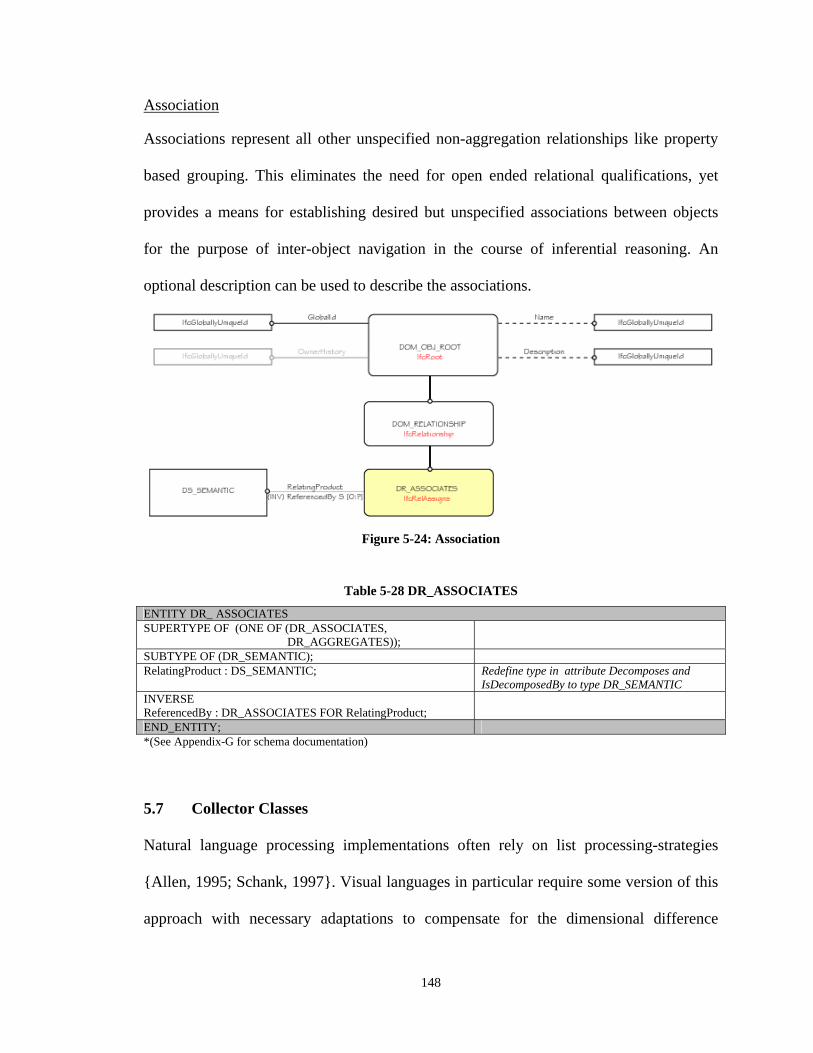
148
Association Associations represent all other unspecified non-aggregation relationships like property
based grouping. This eliminates the need for open ended relational qualifications, yet
provides a means for establishing desired but unspecified associations between objects
for the purpose of inter-object navigation in the course of inferential reasoning. An
optional description can be used to describe the associations.
Figure 5-24: Association
Table 5-28 DR_ASSOCIATES
ENTITY DR_ ASSOCIATES SUPERTYPE OF (ONE OF (DR_ASSOCIATES, DR_AGGREGATES));
SUBTYPE OF (DR_SEMANTIC); RelatingProduct : DS_SEMANTIC; Redefine type in attribute Decomposes and
IsDecomposedBy to type DR_SEMANTIC INVERSE ReferencedBy : DR_ASSOCIATES FOR RelatingProduct;
END_ENTITY; *(See Appendix-G for schema documentation)
5.7 Collector Classes
Natural language processing implementations often rely on list processing-strategies
{Allen, 1995; Schank, 1997}. Visual languages in particular require some version of this
approach with necessary adaptations to compensate for the dimensional difference
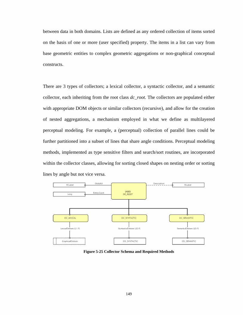
149
between data in both domains. Lists are defined as any ordered collection of items sorted
on the basis of one or more (user specified) property. The items in a list can vary from
base geometric entities to complex geometric aggregations or non-graphical conceptual
constructs.
There are 3 types of collectors; a lexical collector, a syntactic collector, and a semantic
collector, each inheriting from the root class dc_root. The collectors are populated either
with appropriate DOM objects or similar collectors (recursive), and allow for the creation
of nested aggregations, a mechanism employed in what we define as multilayered
perceptual modeling. For example, a (perceptual) collection of parallel lines could be
further partitioned into a subset of lines that share angle conditions. Perceptual modeling
methods, implemented as type sensitive filters and search/sort routines, are incorporated
within the collector classes, allowing for sorting closed shapes on nesting order or sorting
lines by angle but not vice versa.
Figure 5-25 Collector Schema and Required Methods
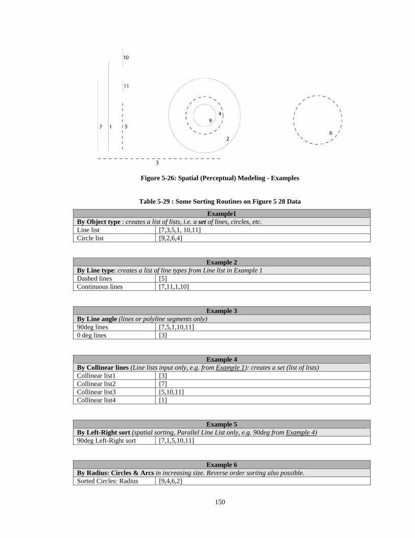
150
Figure 5-26: Spatial (Perceptual) Modeling - Examples
Table 5-29 : Some Sorting Routines on Figure 5 28 Data
Example1 By Object type : creates a list of lists, i.e. a set of lines, circles, etc. Line list [7,3,5,1, 10,11] Circle list [9,2,6,4]
Example 2 By Line type: creates a list of line types from Line list in Example 1 Dashed lines [5] Continuous lines [7,11,1,10]
Example 3 By Line angle (lines or polyline segments only) 90deg lines [7,5,1,10,11] 0 deg lines [3]
Example 4 By Collinear lines (Line lists input only, e.g. from Example 1): creates a set (list of lists) Collinear list1 [3] Collinear list2 [7] Collinear list3 [5,10,11] Collinear list4 [1]
Example 5 By Left-Right sort (spatial sorting, Parallel Line List only, e.g. 90deg from Example 4) 90deg Left-Right sort [7,1,5,10,11]
Example 6 By Radius: Circles & Arcs in increasing size. Reverse order sorting also possible. Sorted Circles: Radius [9,4,6,2]
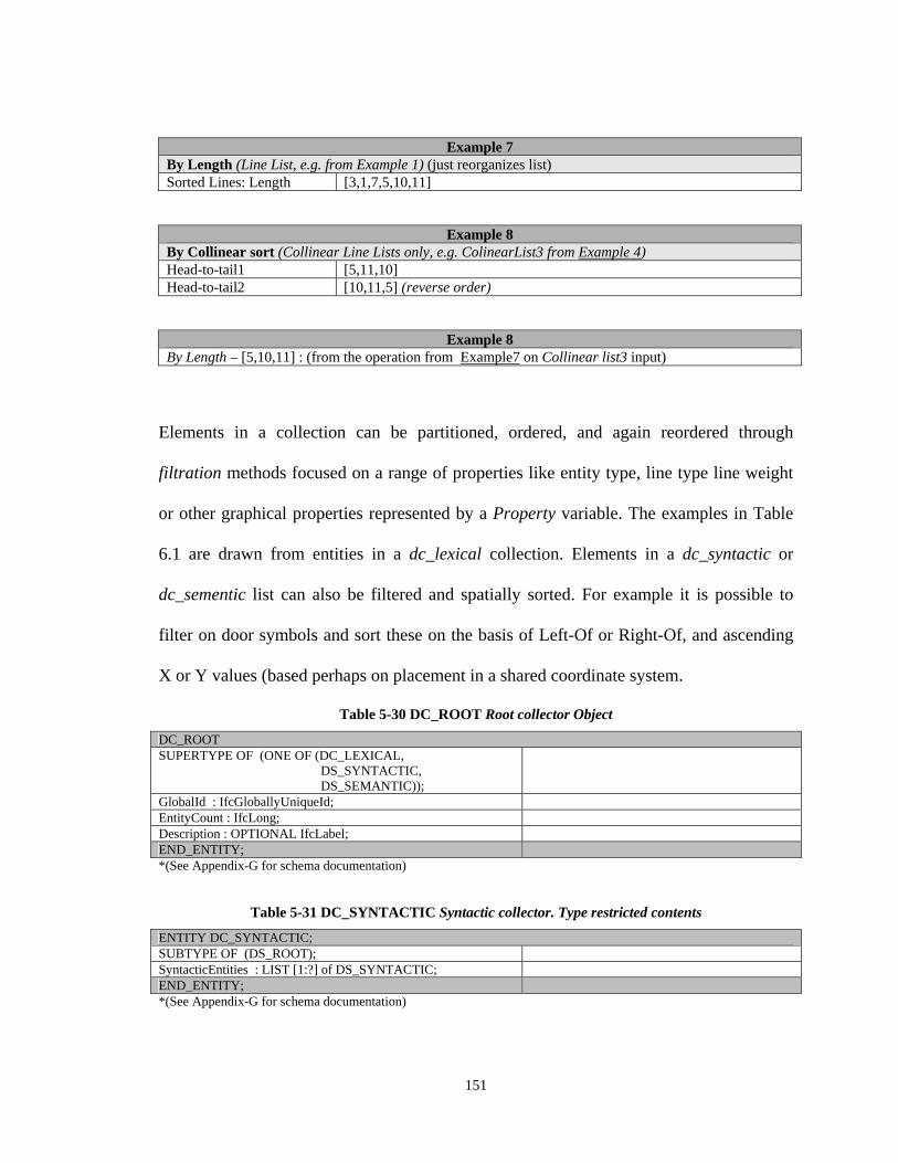
151
Example 7 By Length (Line List, e.g. from Example 1) (just reorganizes list) Sorted Lines: Length [3,1,7,5,10,11]
Example 8 By Collinear sort (Collinear Line Lists only, e.g. ColinearList3 from Example 4) Head-to-tail1 [5,11,10] Head-to-tail2 [10,11,5] (reverse order)
Example 8 By Length – [5,10,11] : (from the operation from Example7 on Collinear list3 input)
Elements in a collection can be partitioned, ordered, and again reordered through
filtration methods focused on a range of properties like entity type, line type line weight
or other graphical properties represented by a Property variable. The examples in Table
6.1 are drawn from entities in a dc_lexical collection. Elements in a dc_syntactic or
dc_sementic list can also be filtered and spatially sorted. For example it is possible to
filter on door symbols and sort these on the basis of Left-Of or Right-Of, and ascending
X or Y values (based perhaps on placement in a shared coordinate system.
Table 5-30 DC_ROOT Root collector Object
DC_ROOT SUPERTYPE OF (ONE OF (DC_LEXICAL, DS_SYNTACTIC, DS_SEMANTIC));
GlobalId : IfcGloballyUniqueId; EntityCount : IfcLong; Description : OPTIONAL IfcLabel; END_ENTITY; *(See Appendix-G for schema documentation)
Table 5-31 DC_SYNTACTIC Syntactic collector. Type restricted contents
ENTITY DC_SYNTACTIC; SUBTYPE OF (DS_ROOT); SyntacticEntities : LIST [1:?] of DS_SYNTACTIC; END_ENTITY; *(See Appendix-G for schema documentation)
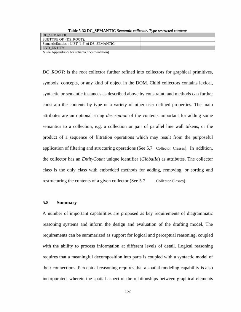
152
Table 5-32 DC_SEMANTIC Semantic collector. Type restricted contents DC_SEMANTIC SUBTYPE OF (DS_ROOT); SemanticEntities : LIST [1:?] of DS_SEMANTIC; END_ENTITY; *(See Appendix-G for schema documentation)
DC_ROOT: is the root collector further refined into collectors for graphical primitives,
symbols, concepts, or any kind of object in the DOM. Child collectors contains lexical,
syntactic or semantic instances as described above by constraint, and methods can further
constrain the contents by type or a variety of other user defined properties. The main
attributes are an optional string description of the contents important for adding some
semantics to a collection, e.g. a collection or pair of parallel line wall tokens, or the
product of a sequence of filtration operations which may result from the purposeful
application of filtering and structuring operations (See 5.7 Collector Classes). In addition,
the collector has an EntityCount unique identifier (GlobalId) as attributes. The collector
class is the only class with embedded methods for adding, removing, or sorting and
restructuring the contents of a given collector (See 5.7 Collector Classes).
5.8 Summary
A number of important capabilities are proposed as key requirements of diagrammatic
reasoning systems and inform the design and evaluation of the drafting model. The
requirements can be summarized as support for logical and perceptual reasoning, coupled
with the ability to process information at different levels of detail. Logical reasoning
requires that a meaningful decomposition into parts is coupled with a syntactic model of
their connections. Perceptual reasoning requires that a spatial modeling capability is also
incorporated, wherein the spatial aspect of the relationships between graphical elements
153
can be expressed. A number of additional characteristics are peculiar to architectural
drawings, most significant of which concern the multimodality of the representation, the
graphical complexity and the employment of multiple views. These imply a need for
capabilities unaccounted for in related implementations in architectural or other
diagrammatic domains. A representation addressing the various issues as we propose
should enable and facilitate both spatial and semantic reasoning about aggregated parts.
154
CHAPTER 6.
APPLYING THE MODEL
n this chapter, we examine some of the models key structures, and their practical role
in the drafting interpretation process. The translation context (Figure 3-1: Translation
Architecture and Drafting Model Role) includes an initial data component A, a collection of
tokenization and interpretation functions B, the structure C representing drafting domain
semantics, a collection of translation functions from the DOM into a Building Model D,
and the final Building Model representation E. The goal is to illustrate their
interrelationships, including how conceptual definitions and relational structures in the
DOM facilitate inter-object navigation and reasoning within / across views, and how the
combination of (drafting) domain knowledge and prior information enable subsequent
and more detailed analysis and recognition. Stated otherwise, we examine component C
through selective implementations in components B and C, along with the interrelation
between C and its mapping to D.
The interpretation process can be viewed as one involving the transformation of data into
information, thus many of the sub-processes involve reclassification or enrichment of
existing data within the model itself and transforming unstructured geometric information
into known symbols in structured relationships that support logically intuitive navigation
I
155
between symbol instance and building components. We cover a number of issues central
to the drafting interpretation problem that include segmentation and classification of
multiple views, recognition of walls from a floor plan, which we then employ in
identifying door symbols in plan and polygonal representations of exterior walls in
elevation. These address (domain independent) perceptual modeling in the process of
wall identification and knowledge driven search within and across views. We also
illustrate how spatial and logical structure between floor plans and elevations can be
established and captured in the model which is essential in the reconstruction of shape
representation using descriptive geometry, an important aspect of the drafting convention.
As we noted earlier, the structure of the DOM implicitly constitutes an expression of
drafting domain part-structure semantics, which even when incomplete, can inform and
simplify the search for additional information. Even partial reconstruction of these
relationships can provide important guidance in various stages of the interpretation
process. We therefore follow the recognition process through translation and instantiation
of 3D BIM walls, doors and windows, illustrating how an incremental knowledge
building strategy that exploits existing knowledge can continually refine the information
in the model. The resulting DOM wall and door representations are instantiated in a BIM
that captures some of the part structure semantics of a wall and its opening and filler
objects.
Given the considerable scope of the effort required in overall translation of drafting
information and our selective focus, are limited to describing how the model can be
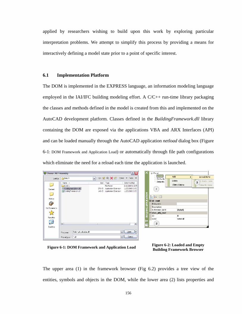
156
applied by researchers wishing to build upon this work by exploring particular
interpretation problems. We attempt to simplify this process by providing a means for
interactively defining a model state prior to a point of specific interest.
6.1 Implementation Platform
The DOM is implemented in the EXPRESS language, an information modeling language
employed in the IAI/IFC building modeling effort. A C/C++ run-time library packaging
the classes and methods defined in the model is created from this and implemented on the
AutoCAD development platform. Classes defined in the BuildingFramework.dll library
containing the DOM are exposed via the applications VBA and ARX Interfaces (API)
and can be loaded manually through the AutoCAD application netload dialog box (Figure
6-1: DOM Framework and Application Load) or automatically through file path configurations
which eliminate the need for a reload each time the application is launched.
Figure 6-1: DOM Framework and Application Load
Figure 6-2: Loaded and Empty Building Framework Browser
The upper area (1) in the framework browser (Fig 6.2) provides a tree view of the
entities, symbols and objects in the DOM, while the lower area (2) lists properties and
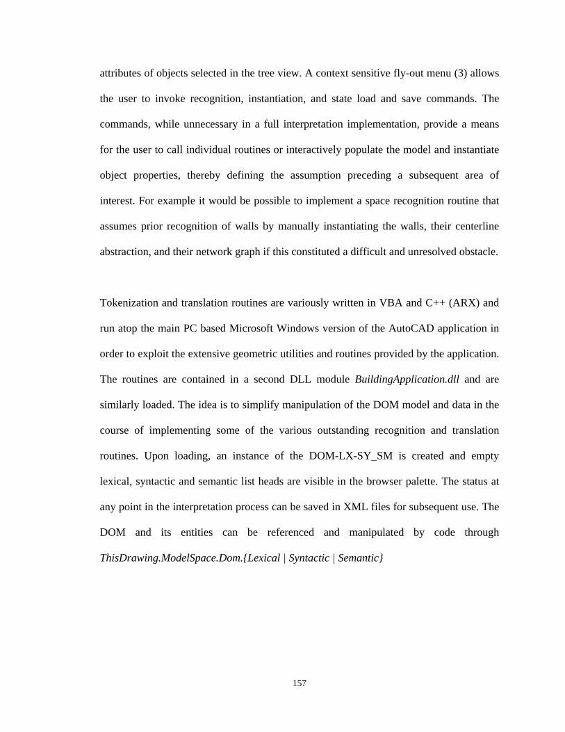
157
attributes of objects selected in the tree view. A context sensitive fly-out menu (3) allows
the user to invoke recognition, instantiation, and state load and save commands. The
commands, while unnecessary in a full interpretation implementation, provide a means
for the user to call individual routines or interactively populate the model and instantiate
object properties, thereby defining the assumption preceding a subsequent area of
interest. For example it would be possible to implement a space recognition routine that
assumes prior recognition of walls by manually instantiating the walls, their centerline
abstraction, and their network graph if this constituted a difficult and unresolved obstacle.
Tokenization and translation routines are variously written in VBA and C++ (ARX) and
run atop the main PC based Microsoft Windows version of the AutoCAD application in
order to exploit the extensive geometric utilities and routines provided by the application.
The routines are contained in a second DLL module BuildingApplication.dll and are
similarly loaded. The idea is to simplify manipulation of the DOM model and data in the
course of implementing some of the various outstanding recognition and translation
routines. Upon loading, an instance of the DOM-LX-SY_SM is created and empty
lexical, syntactic and semantic list heads are visible in the browser palette. The status at
any point in the interpretation process can be saved in XML files for subsequent use. The
DOM and its entities can be referenced and manipulated by code through
ThisDrawing.ModelSpace.Dom.{Lexical | Syntactic | Semantic}
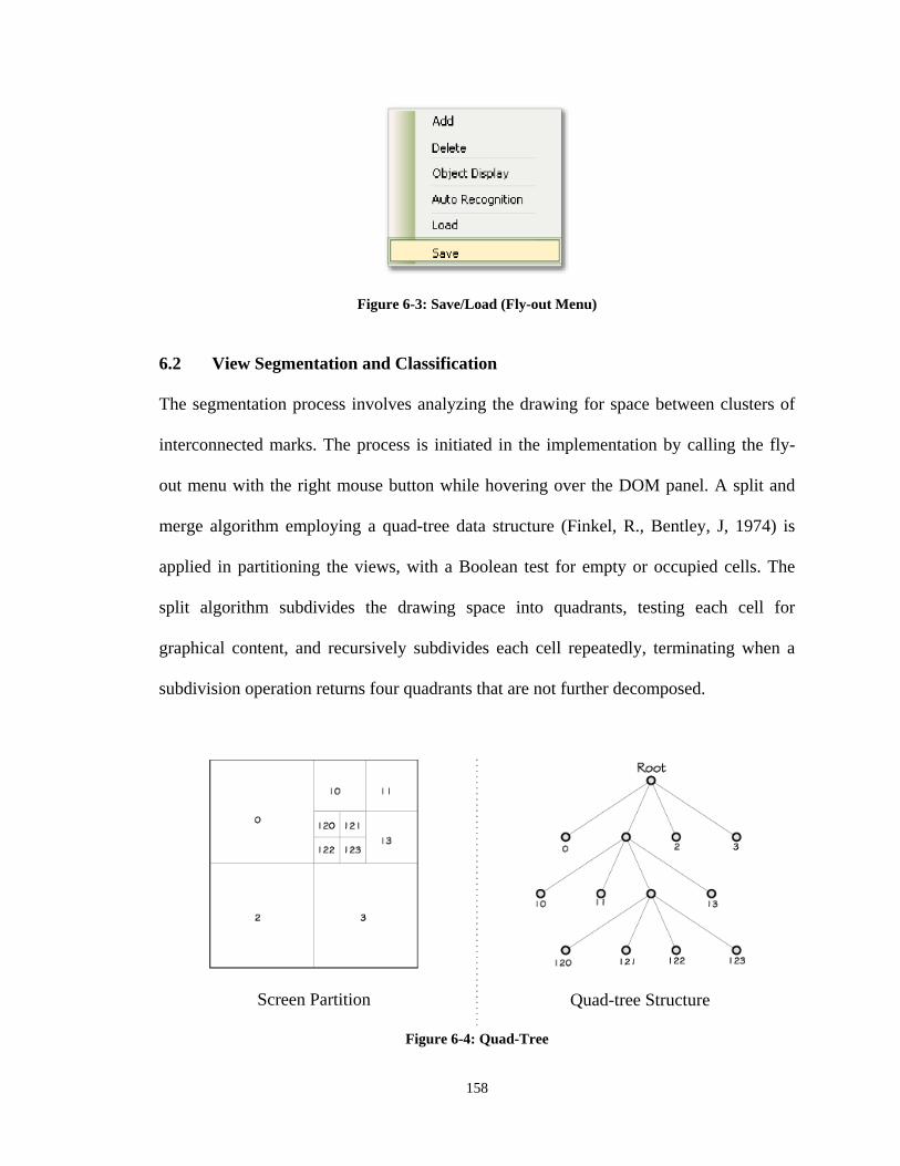
158
Figure 6-3: Save/Load (Fly-out Menu) 6.2 View Segmentation and Classification
The segmentation process involves analyzing the drawing for space between clusters of
interconnected marks. The process is initiated in the implementation by calling the fly-
out menu with the right mouse button while hovering over the DOM panel. A split and
merge algorithm employing a quad-tree data structure (Finkel, R., Bentley, J, 1974) is
applied in partitioning the views, with a Boolean test for empty or occupied cells. The
split algorithm subdivides the drawing space into quadrants, testing each cell for
graphical content, and recursively subdivides each cell repeatedly, terminating when a
subdivision operation returns four quadrants that are not further decomposed.
Screen Partition
Quad-tree Structure
Figure 6-4: Quad-Tree
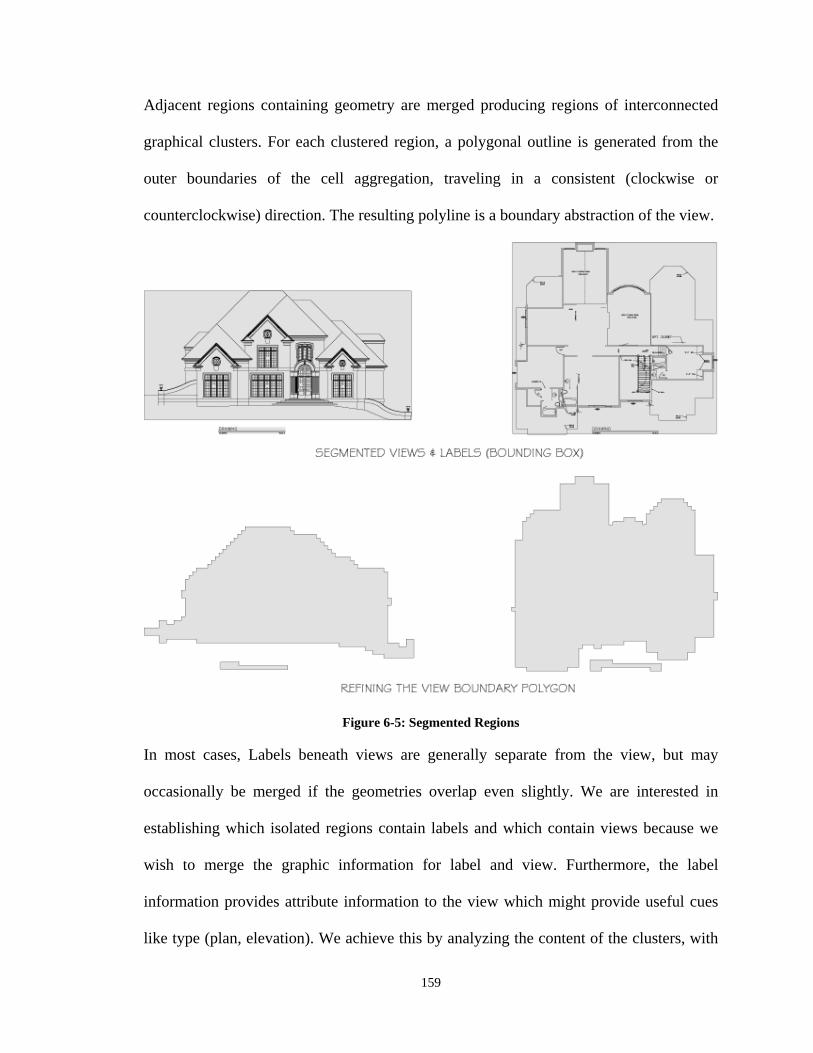
159
Adjacent regions containing geometry are merged producing regions of interconnected
graphical clusters. For each clustered region, a polygonal outline is generated from the
outer boundaries of the cell aggregation, traveling in a consistent (clockwise or
counterclockwise) direction. The resulting polyline is a boundary abstraction of the view.
Figure 6-5: Segmented Regions In most cases, Labels beneath views are generally separate from the view, but may
occasionally be merged if the geometries overlap even slightly. We are interested in
establishing which isolated regions contain labels and which contain views because we
wish to merge the graphic information for label and view. Furthermore, the label
information provides attribute information to the view which might provide useful cues
like type (plan, elevation). We achieve this by analyzing the content of the clusters, with
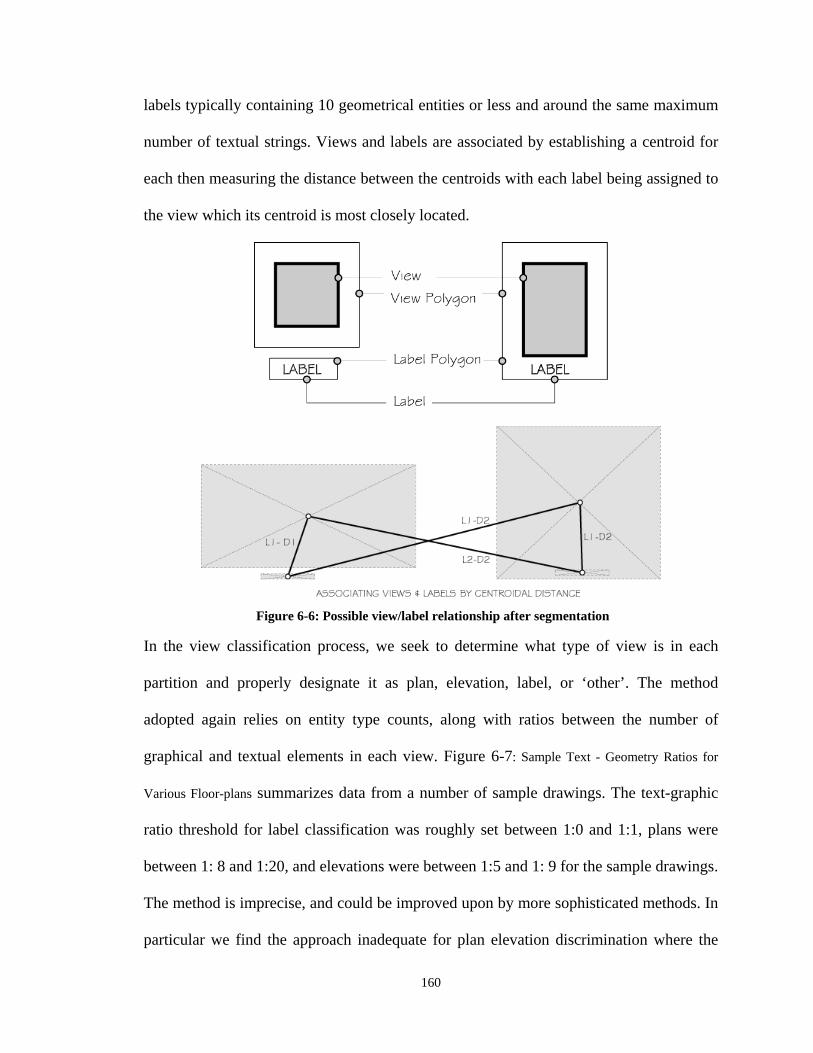
160
labels typically containing 10 geometrical entities or less and around the same maximum
number of textual strings. Views and labels are associated by establishing a centroid for
each then measuring the distance between the centroids with each label being assigned to
the view which its centroid is most closely located.
In the view classification process, we seek to determine what type of view is in each
partition and properly designate it as plan, elevation, label, or ‘other’. The method
adopted again relies on entity type counts, along with ratios between the number of
graphical and textual elements in each view. Figure 6-7: Sample Text - Geometry Ratios for
Various Floor-plans summarizes data from a number of sample drawings. The text-graphic
ratio threshold for label classification was roughly set between 1:0 and 1:1, plans were
between 1: 8 and 1:20, and elevations were between 1:5 and 1: 9 for the sample drawings.
The method is imprecise, and could be improved upon by more sophisticated methods. In
particular we find the approach inadequate for plan elevation discrimination where the
Figure 6-6: Possible view/label relationship after segmentation
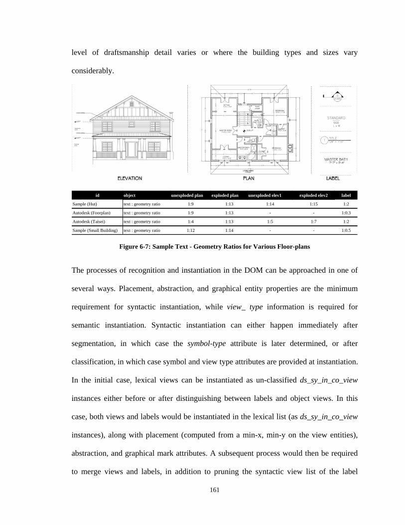
161
level of draftsmanship detail varies or where the building types and sizes vary
considerably.
id object unexploded plan exploded plan unexploded elev1 exploded elev2 label
Sample (Hut) text : geometry ratio 1:9 1:13 1:14 1:15 1:2
Autodesk (Foorplan) text : geometry ratio 1:9 1:13 - - 1:0.3
Autodesk (Taisei) text : geometry ratio 1:4 1:13 1:5 1:7 1:2
Sample (Small Building) text : geometry ratio 1:12 1:14 - - 1:0.5
Figure 6-7: Sample Text - Geometry Ratios for Various Floor-plans The processes of recognition and instantiation in the DOM can be approached in one of
several ways. Placement, abstraction, and graphical entity properties are the minimum
requirement for syntactic instantiation, while view_ type information is required for
semantic instantiation. Syntactic instantiation can either happen immediately after
segmentation, in which case the symbol-type attribute is later determined, or after
classification, in which case symbol and view type attributes are provided at instantiation.
In the initial case, lexical views can be instantiated as un-classified ds_sy_in_co_view
instances either before or after distinguishing between labels and object views. In this
case, both views and labels would be instantiated in the lexical list (as ds_sy_in_co_view
instances), along with placement (computed from a min-x, min-y on the view entities),
abstraction, and graphical mark attributes. A subsequent process would then be required
to merge views and labels, in addition to pruning the syntactic view list of the label
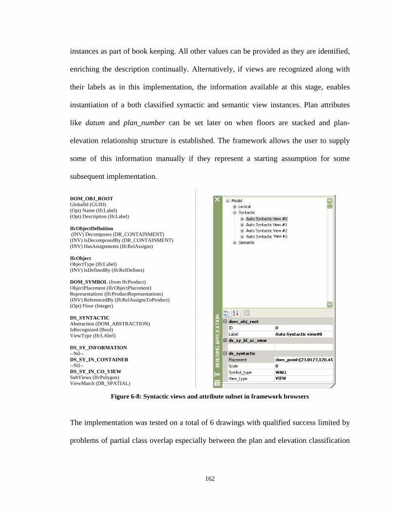
162
instances as part of book keeping. All other values can be provided as they are identified,
enriching the description continually. Alternatively, if views are recognized along with
their labels as in this implementation, the information available at this stage, enables
instantiation of a both classified syntactic and semantic view instances. Plan attributes
like datum and plan_number can be set later on when floors are stacked and plan-
elevation relationship structure is established. The framework allows the user to supply
some of this information manually if they represent a starting assumption for some
subsequent implementation.
DOM_OBJ_ROOT GlobalId (GUID) (Opt) Name (IfcLabel) (Opt) Description (IfcLabel) IfcObjectDefinition (INV) Decomposes (DR_CONTAINMENT) (INV) IsDecomposedBy (DR_CONTAINMENT) (INV) HasAssignments (IfcRelAssigns) IfcObject ObjectType (IfcLabel) (INV) IsDefinedBy (IfcRelDefines) DOM_SYMBOL (from IfcProduct) ObjectPlacement (IfcObjectPlacement) Representations (IfcProductRepresentations) (INV) ReferencedBy (IfcRelAssignsToProduct) (Opt) Floor (Integer) DS_SYNTACTIC Abstraction (DOM_ABSTRACTION) IsRecognized (Bool) ViewType (IfcLAbel) DS_SY_INFORMATION --Nil-- DS_SY_IN_CONTAINER --Nil-- DS_SY_IN_CO_VIEW SubViews (IfcPolygon) ViewMatch (DR_SPATIAL)
Figure 6-8: Syntactic views and attribute subset in framework browsers
The implementation was tested on a total of 6 drawings with qualified success limited by
problems of partial class overlap especially between the plan and elevation classification
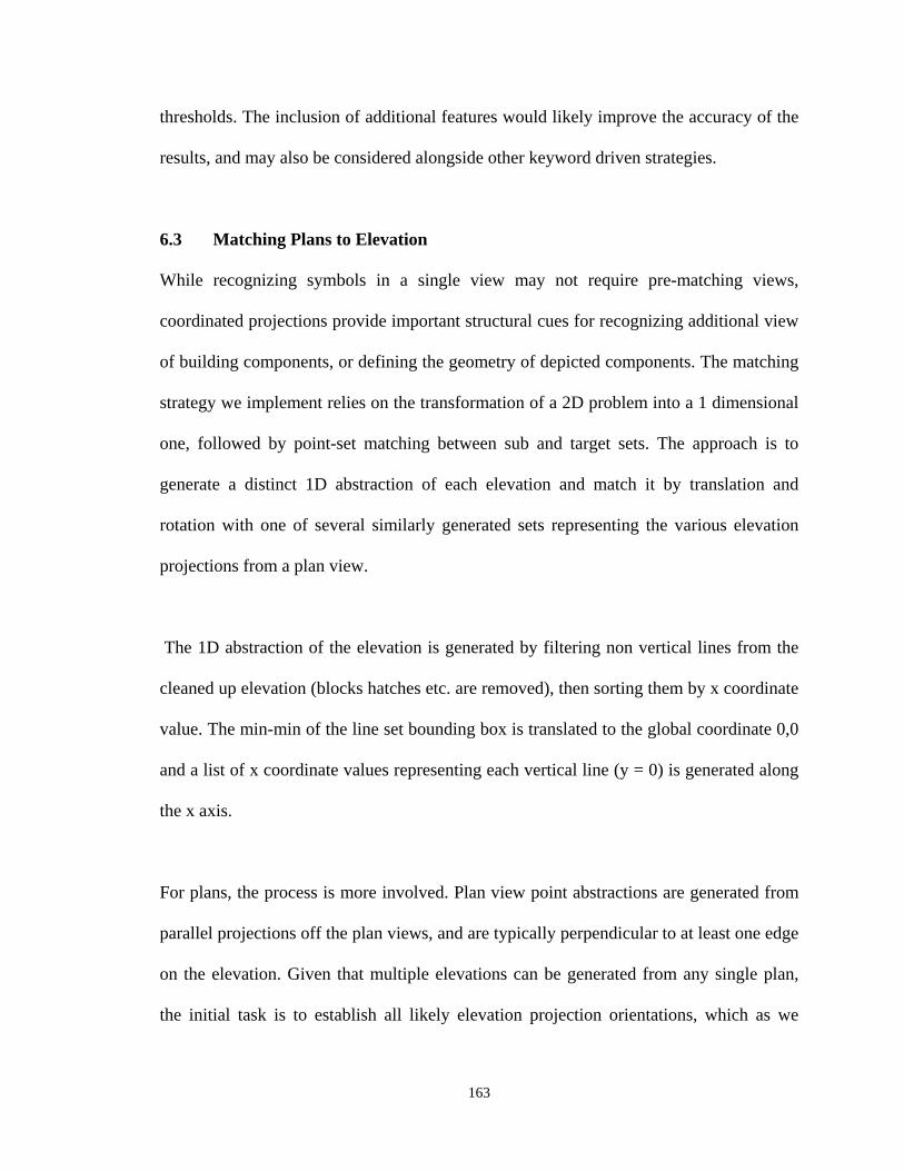
163
thresholds. The inclusion of additional features would likely improve the accuracy of the
results, and may also be considered alongside other keyword driven strategies.
6.3 Matching Plans to Elevation
While recognizing symbols in a single view may not require pre-matching views,
coordinated projections provide important structural cues for recognizing additional view
of building components, or defining the geometry of depicted components. The matching
strategy we implement relies on the transformation of a 2D problem into a 1 dimensional
one, followed by point-set matching between sub and target sets. The approach is to
generate a distinct 1D abstraction of each elevation and match it by translation and
rotation with one of several similarly generated sets representing the various elevation
projections from a plan view.
The 1D abstraction of the elevation is generated by filtering non vertical lines from the
cleaned up elevation (blocks hatches etc. are removed), then sorting them by x coordinate
value. The min-min of the line set bounding box is translated to the global coordinate 0,0
and a list of x coordinate values representing each vertical line (y = 0) is generated along
the x axis.
For plans, the process is more involved. Plan view point abstractions are generated from
parallel projections off the plan views, and are typically perpendicular to at least one edge
on the elevation. Given that multiple elevations can be generated from any single plan,
the initial task is to establish all likely elevation projection orientations, which as we
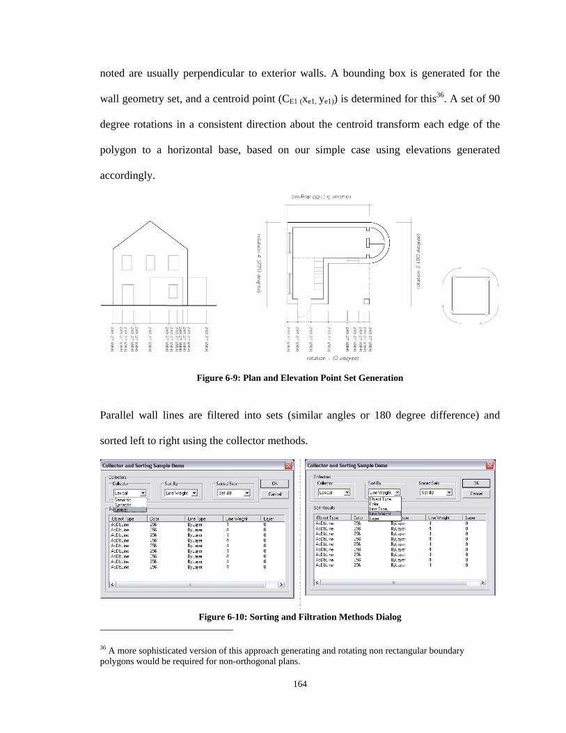
164
noted are usually perpendicular to exterior walls. A bounding box is generated for the
wall geometry set, and a centroid point (CE1 (xe1, ye1)) is determined for this36. A set of 90
degree rotations in a consistent direction about the centroid transform each edge of the
polygon to a horizontal base, based on our simple case using elevations generated
accordingly.
Figure 6-9: Plan and Elevation Point Set Generation
Parallel wall lines are filtered into sets (similar angles or 180 degree difference) and
sorted left to right using the collector methods.
Figure 6-10: Sorting and Filtration Methods Dialog 36 A more sophisticated version of this approach generating and rotating non rectangular boundary polygons would be required for non-orthogonal plans.
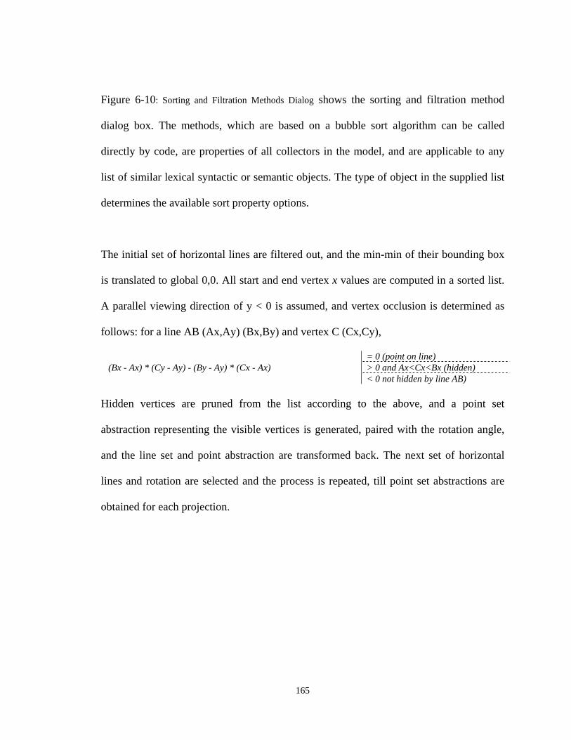
165
Figure 6-10: Sorting and Filtration Methods Dialog shows the sorting and filtration method
dialog box. The methods, which are based on a bubble sort algorithm can be called
directly by code, are properties of all collectors in the model, and are applicable to any
list of similar lexical syntactic or semantic objects. The type of object in the supplied list
determines the available sort property options.
The initial set of horizontal lines are filtered out, and the min-min of their bounding box
is translated to global 0,0. All start and end vertex x values are computed in a sorted list.
A parallel viewing direction of y < 0 is assumed, and vertex occlusion is determined as
follows: for a line AB (Ax,Ay) (Bx,By) and vertex C (Cx,Cy),
(Bx - Ax) * (Cy - Ay) - (By - Ay) * (Cx - Ax) = 0 (point on line) > 0 and Ax<Cx<Bx (hidden) < 0 not hidden by line AB)
Hidden vertices are pruned from the list according to the above, and a point set
abstraction representing the visible vertices is generated, paired with the rotation angle,
and the line set and point abstraction are transformed back. The next set of horizontal
lines and rotation are selected and the process is repeated, till point set abstractions are
obtained for each projection.
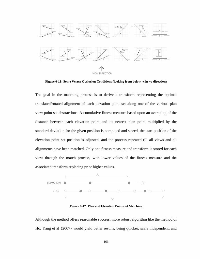
166
Figure 6-11: Some Vertex Occlusion Conditions (looking from below -x in +y direction)
The goal in the matching process is to derive a transform representing the optimal
translated/rotated alignment of each elevation point set along one of the various plan
view point set abstractions. A cumulative fitness measure based upon an averaging of the
distance between each elevation point and its nearest plan point multiplied by the
standard deviation for the given position is computed and stored, the start position of the
elevation point set position is adjusted, and the process repeated till all views and all
alignments have been matched. Only one fitness measure and transform is stored for each
view through the match process, with lower values of the fitness measure and the
associated transform replacing prior higher values.
Figure 6-12: Plan and Elevation Point-Set Matching
Although the method offers reasonable success, more robust algorithm like the method of
Ho, Yang et al {2007} would yield better results, being quicker, scale independent, and
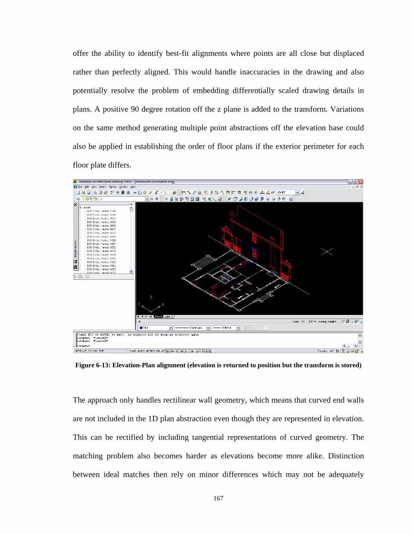
167
offer the ability to identify best-fit alignments where points are all close but displaced
rather than perfectly aligned. This would handle inaccuracies in the drawing and also
potentially resolve the problem of embedding differentially scaled drawing details in
plans. A positive 90 degree rotation off the z plane is added to the transform. Variations
on the same method generating multiple point abstractions off the elevation base could
also be applied in establishing the order of floor plans if the exterior perimeter for each
floor plate differs.
Figure 6-13: Elevation-Plan alignment (elevation is returned to position but the transform is stored)
The approach only handles rectilinear wall geometry, which means that curved end walls
are not included in the 1D plan abstraction even though they are represented in elevation.
This can be rectified by including tangential representations of curved geometry. The
matching problem also becomes harder as elevations become more alike. Distinction
between ideal matches then rely on minor differences which may not be adequately
168
captured in 1D string abstraction. A third issue is that the classification process as
implemented simply relies on ranking match probabilities for the views, hence even
completely unrelated plan and elevation views from separate drawings will yield
probabilities. Some additional measure based upon averaging or measuring the variance
of match distances will be required and a threshold empirically determined for
inapplicable relationships.
The computed transforms are stored in the ViewMatch relationship property linking
subject and target views (See Figure 6-8: Syntactic views and attribute subset in framework
browsers). Floor plans are spatially related by stacking order and elevations are related to 1
or more plans by projection. The implementation also allows for manually matching the
views through navigation to the transform attribute in the relationship either in the tree or
property browser, then interactively manipulating the views to match. The transform is
computed from these translations and rotations, and is updated and stored in the instance.
Semantic view instances currently do not differ much from syntactic views except that
the syntactic view is an instance of the semantic views representations. When a syntactic
view is classified by type, a semantic instance can simultaneously be created in the DOM,
and the syntactic views IsRecognized Boolean flag can be set to True.
6.4 Recognizing Walls in Plan View
From our analysis, we conclude that floor plans are central representations because more
building components and information are depicted in them than any other single view
169
type (see Appendix F). We propose that the wall recognition process unlike many other
symbols, can circumvent the circularity arising when relationships may ultimately point
back to the original object.
The wall recognition implementation integrates three main processes. The first attempts
to establish the wall width. The second process applies this width in filtering out likely
walls using the sorting and filtration capabilities implemented in the collector classes,
thereby reducing the data set for testing. The final process attempts to validate likely
walls by testing local properties of the walls like end conditions or connections, based
upon the approach implemented by Noack (2001). While there is an understanding that
global properties like characteristics of the resulting network should also be tested, this
was not addressed in our approach.
The wall width definition process begins by filtering sorted lists of parallel lines from a
floor plan, and then again by line-type and line-width. If necessary, the lines are
transformed and orientated perpendicular to the x axis and sorted by increasing values of
x (left to right). A string of numeric values A denoting the spacing (e.g. (x+1) – x)
between successive linear elements in the sequence is generated for each sub list. A
pruning operation eliminates lists comprised of repetitive spacing with more than 2
occurrences in immediate succession, being likelier representations of stair treads,
gridlines, and other noise. The ranking of width values after pruning prioritizes the
likeliest wall width candidate. Other high ranking substring patterns are also considered
as possible wall with intermediate window or other geometry and the sum of the sub-
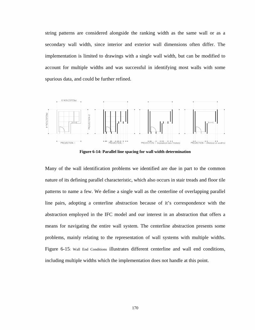
170
string patterns are considered alongside the ranking width as the same wall or as a
secondary wall width, since interior and exterior wall dimensions often differ. The
implementation is limited to drawings with a single wall width, but can be modified to
account for multiple widths and was successful in identifying most walls with some
spurious data, and could be further refined.
Figure 6-14: Parallel line spacing for wall width determination
Many of the wall identification problems we identified are due in part to the common
nature of its defining parallel characteristic, which also occurs in stair treads and floor tile
patterns to name a few. We define a single wall as the centerline of overlapping parallel
line pairs, adopting a centerline abstraction because of it’s correspondence with the
abstraction employed in the IFC model and our interest in an abstraction that offers a
means for navigating the entire wall system. The centerline abstraction presents some
problems, mainly relating to the representation of wall systems with multiple widths.
Figure 6-15: Wall End Conditions illustrates different centerline and wall end conditions,
including multiple widths which the implementation does not handle at this point.
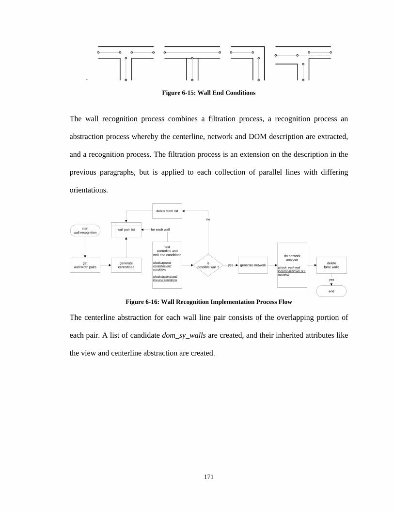
171
-
Figure 6-15: Wall End Conditions
The wall recognition process combines a filtration process, a recognition process an
abstraction process whereby the centerline, network and DOM description are extracted,
and a recognition process. The filtration process is an extension on the description in the
previous paragraphs, but is applied to each collection of parallel lines with differing
orientations.
startwall recognition
getwall width pairs
generatecenterlines
testcenterline and
wall end conditions
check againstcenterline endconditions
check fagainst wallline end conditions
wall pair list
generate networkis
possible wall ?yes
no
do networkanalysis
(check each wallloop for minimum of 1opening)
end
yes
deletefalse walls
delete from list
for each wall
Figure 6-16: Wall Recognition Implementation Process Flow
The centerline abstraction for each wall line pair consists of the overlapping portion of
each pair. A list of candidate dom_sy_walls are created, and their inherited attributes like
the view and centerline abstraction are created.
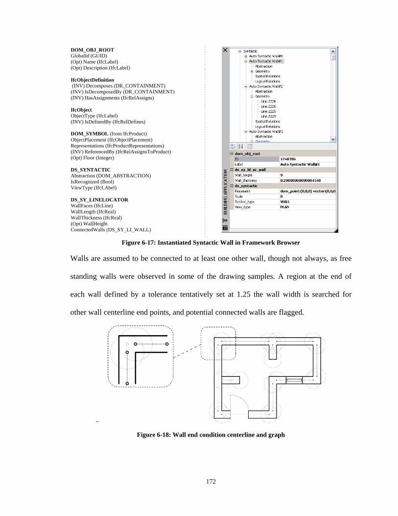
172
DOM_OBJ_ROOT GlobalId (GUID) (Opt) Name (IfcLabel) (Opt) Description (IfcLabel) IfcObjectDefinition (INV) Decomposes (DR_CONTAINMENT) (INV) IsDecomposedBy (DR_CONTAINMENT) (INV) HasAssignments (IfcRelAssigns) IfcObject ObjectType (IfcLabel) (INV) IsDefinedBy (IfcRelDefines) DOM_SYMBOL (from IfcProduct) ObjectPlacement (IfcObjectPlacement) Representations (IfcProductRepresentations) (INV) ReferencedBy (IfcRelAssignsToProduct) (Opt) Floor (Integer) DS_SYNTACTIC Abstraction (DOM_ABSTRACTION) IsRecognized (Bool) ViewType (IfcLAbel) DS_SY_LINELOCATOR WallFaces (IfcLine) WallLength (IfcReal) WallThickness (IfcReal) (Opt) WallHeight ConnectedWalls (DS_SY_LI_WALL)
Figure 6-17: Instantiated Syntactic Wall in Framework Browser Walls are assumed to be connected to at least one other wall, though not always, as free
standing walls were observed in some of the drawing samples. A region at the end of
each wall defined by a tolerance tentatively set at 1.25 the wall width is searched for
other wall centerline end points, and potential connected walls are flagged.
-
Figure 6-18: Wall end condition centerline and graph
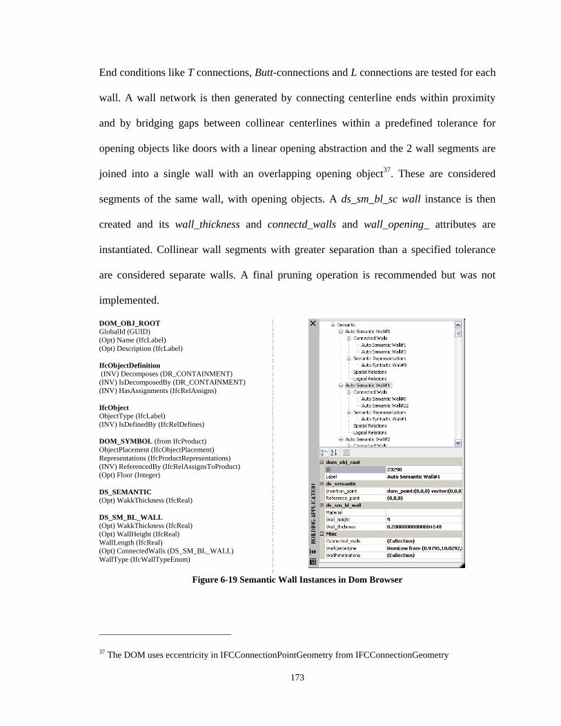
173
End conditions like T connections, Butt-connections and L connections are tested for each
wall. A wall network is then generated by connecting centerline ends within proximity
and by bridging gaps between collinear centerlines within a predefined tolerance for
opening objects like doors with a linear opening abstraction and the 2 wall segments are
joined into a single wall with an overlapping opening object37. These are considered
segments of the same wall, with opening objects. A ds_sm_bl_sc wall instance is then
created and its wall_thickness and connectd_walls and wall_opening_ attributes are
instantiated. Collinear wall segments with greater separation than a specified tolerance
are considered separate walls. A final pruning operation is recommended but was not
implemented.
DOM_OBJ_ROOT GlobalId (GUID) (Opt) Name (IfcLabel) (Opt) Description (IfcLabel) IfcObjectDefinition (INV) Decomposes (DR_CONTAINMENT) (INV) IsDecomposedBy (DR_CONTAINMENT) (INV) HasAssignments (IfcRelAssigns) IfcObject ObjectType (IfcLabel) (INV) IsDefinedBy (IfcRelDefines) DOM_SYMBOL (from IfcProduct) ObjectPlacement (IfcObjectPlacement) Representations (IfcProductRepresentations) (INV) ReferencedBy (IfcRelAssignsToProduct) (Opt) Floor (Integer) DS_SEMANTIC (Opt) WakkThickness (IfcReal) DS_SM_BL_WALL (Opt) WakkThickness (IfcReal) (Opt) WallHeight (IfcReal) WallLength (IfcReal) (Opt) ConnectedWalls (DS_SM_BL_WALL) WallType (IfcWallTypeEnum)
Figure 6-19 Semantic Wall Instances in Dom Browser
37 The DOM uses eccentricity in IFCConnectionPointGeometry from IFCConnectionGeometry
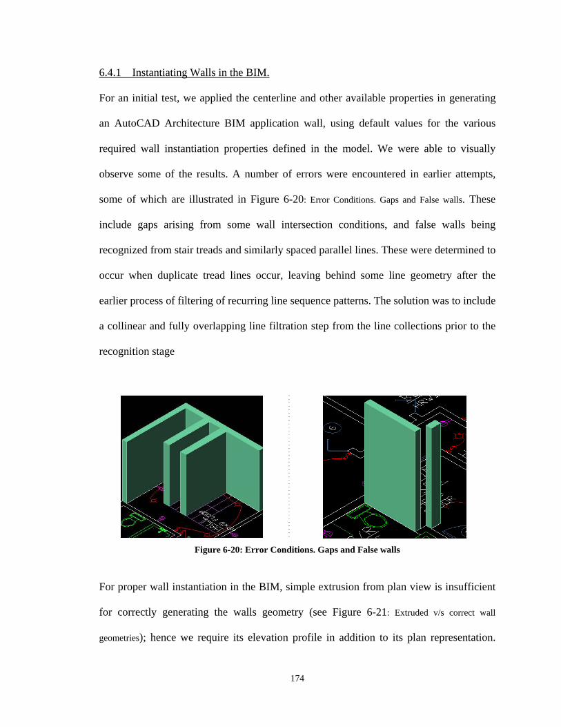
174
6.4.1 Instantiating Walls in the BIM.
For an initial test, we applied the centerline and other available properties in generating
an AutoCAD Architecture BIM application wall, using default values for the various
required wall instantiation properties defined in the model. We were able to visually
observe some of the results. A number of errors were encountered in earlier attempts,
some of which are illustrated in Figure 6-20: Error Conditions. Gaps and False walls. These
include gaps arising from some wall intersection conditions, and false walls being
recognized from stair treads and similarly spaced parallel lines. These were determined to
occur when duplicate tread lines occur, leaving behind some line geometry after the
earlier process of filtering of recurring line sequence patterns. The solution was to include
a collinear and fully overlapping line filtration step from the line collections prior to the
recognition stage
Figure 6-20: Error Conditions. Gaps and False walls
For proper wall instantiation in the BIM, simple extrusion from plan view is insufficient
for correctly generating the walls geometry (see Figure 6-21: Extruded v/s correct wall
geometries); hence we require its elevation profile in addition to its plan representation.
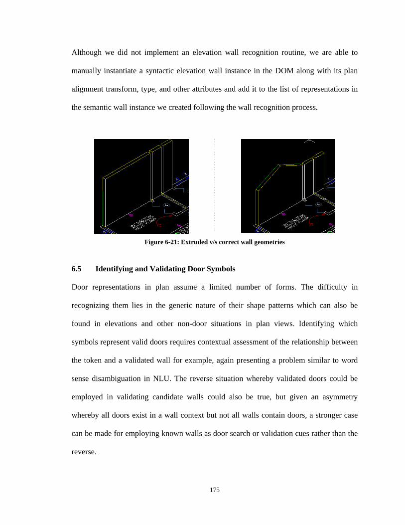
175
Although we did not implement an elevation wall recognition routine, we are able to
manually instantiate a syntactic elevation wall instance in the DOM along with its plan
alignment transform, type, and other attributes and add it to the list of representations in
the semantic wall instance we created following the wall recognition process.
Figure 6-21: Extruded v/s correct wall geometries
6.5 Identifying and Validating Door Symbols
Door representations in plan assume a limited number of forms. The difficulty in
recognizing them lies in the generic nature of their shape patterns which can also be
found in elevations and other non-door situations in plan views. Identifying which
symbols represent valid doors requires contextual assessment of the relationship between
the token and a validated wall for example, again presenting a problem similar to word
sense disambiguation in NLU. The reverse situation whereby validated doors could be
employed in validating candidate walls could also be true, but given an asymmetry
whereby all doors exist in a wall context but not all walls contain doors, a stronger case
can be made for employing known walls as door search or validation cues rather than the
reverse.
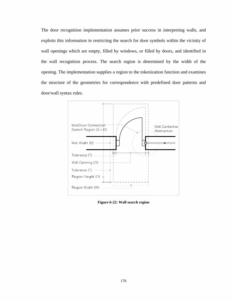
176
The door recognition implementation assumes prior success in interpreting walls, and
exploits this information in restricting the search for door symbols within the vicinity of
wall openings which are empty, filled by windows, or filled by doors, and identified in
the wall recognition process. The search region is determined by the width of the
opening. The implementation supplies a region to the tokenization function and examines
the structure of the geometries for correspondence with predefined door patterns and
door/wall syntax rules.
Figure 6-22: Wall search region
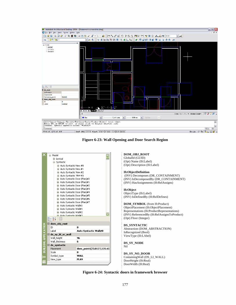
177
Figure 6-23: Wall Opening and Door Search Region
DOM_OBJ_ROOT GlobalId (GUID) (Opt) Name (IfcLabel) (Opt) Description (IfcLabel) IfcObjectDefinition (INV) Decomposes (DR_CONTAINMENT) (INV) IsDecomposedBy (DR_CONTAINMENT) (INV) HasAssignments (IfcRelAssigns) IfcObject ObjectType (IfcLabel) (INV) IsDefinedBy (IfcRelDefines) DOM_SYMBOL (from IfcProduct) ObjectPlacement (IfcObjectPlacement) Representations (IfcProductRepresentations) (INV) ReferencedBy (IfcRelAssignsToProduct) (Opt) Floor (Integer) DS_SYNTACTIC Abstraction (DOM_ABSTRACTION) IsRecognized (Bool) ViewType (IfcLAbel) DS_SY_NODE Nil DS_SY_NO_DOOR ContainingWall (DS_LI_WALL) DoorHeight (IfcReal) DoorWidth (IfcReal)
Figure 6-24: Syntactic doors in framework browser
178
A syntactic door symbol is then instantiated from the recognized token, along with its
abstraction which is defined as a part of the symbol hypothesis, a back pointer to its
parent view defined by its Decomposes attribute, and its placement location with
transform relative to its local coordinate system and an additional transform that places it
in the view coordinate system. An abstraction of the syntactic door is also instantiated,
which in this case we define as a line connecting the wall centerlines opposite the
opening with a relationship to its containing wall because this closes the graph
representation of the wall structure. The syntactic abstraction rather than its graphical
representation provides the geometry that is used in defining syntactic relationships
between symbols. A ds_sm_bl_door (semantic) is also instantiated because the
knowledge driven routine which guides the process by expectation effectively addresses
what would otherwise be a downstream disambiguation process and test it’s the distance
of its connecting ends to vertices in the wall abstraction within a defined region heuristic
(2 x D in the implementation) using defined tolerances, hence both door_operation
derived from the shape characteristics and panel_width attributes derived from the wall
opening size are assigned, while the door height attribute must await the recognition of its
elevation representation.
The routine which was tested on 2 floor plans appears quite successful, recognizing most
doors, but initially missed a number of doors. The problem was later determined to result
from the tolerance settings and the variation between door symbol representations, some
of which included frames while others did not. The implementation only considered
symbols with frames (door ::- line + arc + rectangle frames and the simpler door::- line +
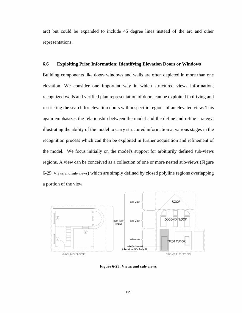
179
arc) but could be expanded to include 45 degree lines instead of the arc and other
representations.
6.6 Exploiting Prior Information: Identifying Elevation Doors or Windows
Building components like doors windows and walls are often depicted in more than one
elevation. We consider one important way in which structured views information,
recognized walls and verified plan representation of doors can be exploited in driving and
restricting the search for elevation doors within specific regions of an elevated view. This
again emphasizes the relationship between the model and the define and refine strategy,
illustrating the ability of the model to carry structured information at various stages in the
recognition process which can then be exploited in further acquisition and refinement of
the model. We focus initially on the model's support for arbitrarily defined sub-views
regions. A view can be conceived as a collection of one or more nested sub-views (Figure
6-25: Views and sub-views) which are simply defined by closed polyline regions overlapping
a portion of the view.
Figure 6-25: Views and sub-views
180
The regions are typically driven by some conceptual notion like floor sub-sections in an
elevation, or may simply be representative of the portion of an elevation defined by the
lower and upper bounds of a floor and the width + tolerance of a door or window derived
from the plan elevation.
When an elevation and plan are matched, the transform that places the elevation in
alignment to the plan is computed and stored as described in section 6.3 Matching Plans
to Elevation. Even though the emphasis in the implementation was only focused on
transforming to match a plan and elevation in a plane. The plan door width x-Pdoor1, and
xPdoor2 values are multiplied by the inverse of the matrix that transforms the elevation to
plan, providing the x-Edoor1/x-Edoor2 and y-Edoor1, y-Edoor2 region values. The z
values are computed from a height value for the floor, which is derived in the stacking
process and which we assume for the purposes of this discussion was earlier resolved,
and supplied with a tolerance as a search region parameter in the elevation space for
elevation door patterns. The recognized elevation view is then included in the
representation attributes of the original window.
The real benefit of the models role in this approach derive from the fact that the search
region only requires a door width value matched floor height in order to focus the search.
The second benefit derived from the ability to refine the structure of the data in the
model. By default, all views consist of a single sub-view which is the same as the full
view. The data and information can be refined by restructuring it into nested partitions,
181
hence it is possible at one stage in the process to identify a view, and at a later point
refine it into a collection of floor sub-views.
This also addressed an important element of the inferential tasks earlier mentioned,
specifically regarding the ability to process graphical information at multiple levels of
granularity. The implementation was subjected to limited testing, with some success. The
ambiguity of the rectangular shape of doors or windows in elevation is mitigated in large
part by the expectation that guides and limits the search. Errors arise however if
rectangular shapes like smaller shapes or decorative patterns on the façade are not
successfully filtered out in earlier stages.
6.7 Spatial and Logical Structure of Information across Views
The implementation offers an illustration of how the conceptual (logical and spatial )
structure of symbolic information across views is carried and employs callback methods
in an object manager to maintain the structure of drawing information once it has been
established. This demonstrates how spatial relationships between views and between
symbols within views interact across views, since they are all related. The idea is to
demonstrate how different spatial arrangement of views can produce the same consistent
representation of meaning and illustrates how the transformation of views relative to each
other should propagate the transformation through to its constituent symbols independent
of the structures that logically aggregates and spatially structures multiple representations
of the same symbol by demonstrating that even after a translation and rotation operation
182
on a view, transforming a component symbol representation like a door in one view can
be coherently reflected in the transformation of its representation in another view.
Semantic symbols (ds_semantic) from which semantic doors, windows, and walls inherit
carry symbolic views in a list of symbol_representations composed of ds_syntactic
instances. Based upon our recursive definition, both the view and its constituent symbols
are considered symbols, and therefore each carry a transform attribute inherited from its
parent ds_syntactic and optionally in its ds_semantic object. The transforms represent a
list whereby the first element represents its identity matrix, and the second item
represents a transform for computing its placement in its parent objects coordinate space,
which in the case of a view is its alignment transform for matching to a plan. When
transforming views, the transformation operations propagate through its component
symbols, updating their parent coordinate transform matrices and placements as
appropriate. The processes for transformation and book keeping for view transformation
and symbol transformation within views is illustrated below in Figure 6-26: Transformation
management within and across views
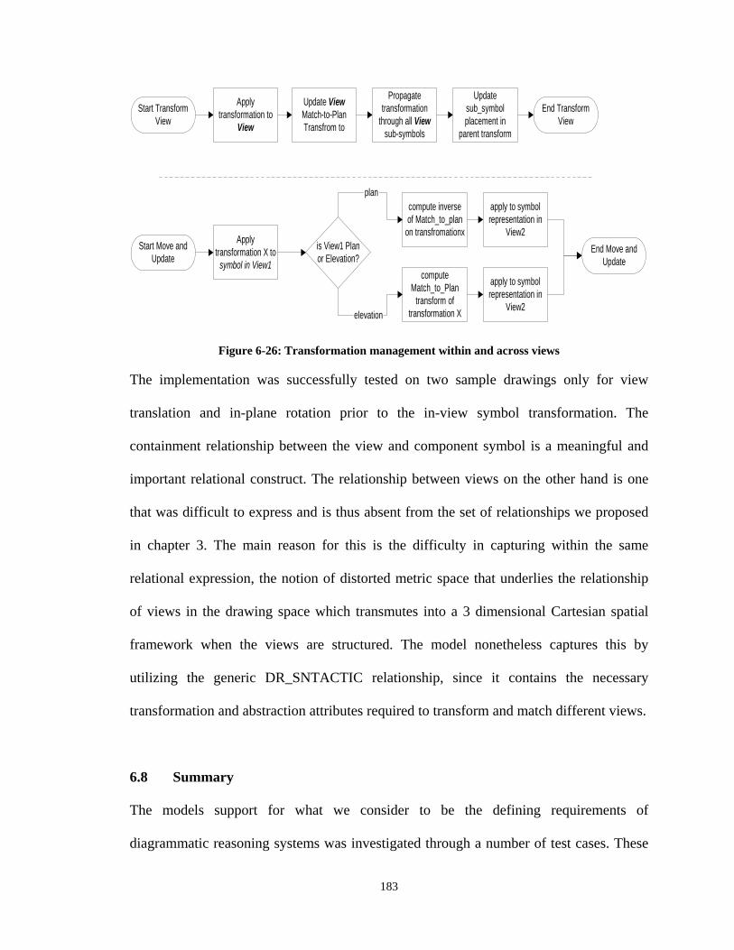
183
Start TransformView
Applytransformation to
View
Update ViewMatch-to-PlanTransfrom to
Propagatetransformation
through all Viewsub-symbols
Updatesub_symbolplacement in
parent transform
End TransformView
Start Move andUpdate
Applytransformation X to
symbol in View1
compute inverseof Match_to_plan
on transfromationx
apply to symbolrepresentation in
View2is View1 Planor Elevation?
plan
elevation
computeMatch_to_Plan
transform oftransformation X
apply to symbolrepresentation in
View2
End Move andUpdate
Figure 6-26: Transformation management within and across views The implementation was successfully tested on two sample drawings only for view
translation and in-plane rotation prior to the in-view symbol transformation. The
containment relationship between the view and component symbol is a meaningful and
important relational construct. The relationship between views on the other hand is one
that was difficult to express and is thus absent from the set of relationships we proposed
in chapter 3. The main reason for this is the difficulty in capturing within the same
relational expression, the notion of distorted metric space that underlies the relationship
of views in the drawing space which transmutes into a 3 dimensional Cartesian spatial
framework when the views are structured. The model nonetheless captures this by
utilizing the generic DR_SNTACTIC relationship, since it contains the necessary
transformation and abstraction attributes required to transform and match different views.
6.8 Summary
The models support for what we consider to be the defining requirements of
diagrammatic reasoning systems was investigated through a number of test cases. These
184
addressed its support for logical and spatial reasoning at different levels of detail. We
also acknowledge the need for a broader evaluation of the model in order to establishing
the extent of it support for the range of inferential manipulations implicit in drafting
understanding and use. The framework browsers support for manually instantiation
circumvents current unknowns, and provides a means through which these can be
systematically investigated.
185
CHAPTER 7.
CONCLUSION & FURTHER RESEARCH
rafting interpretation as an area has received limited attention, much of this has
been focused on problems of geometry extraction and 3D reconstruction,
embracing a very limited view of what recognition means in this domain. The differences
between the various formulations and our adopted view translate into significantly
different concerns and therefore challenges. Our view is of recognition as the
instantiation/population of a semantic model, which implies the existence of a pre-
defined conceptualization of the object class.
Architectural drafting can be considered a ‘natural’ visual language because of its
informal history and evolution, which accounts for the dearth in formal understanding of
the structural properties of the language. We conclude from the study that formal drafting
symbol structure indeed exists and can be specified in an information model. We
demonstrate that a formalized (semantic) drafting specification is both definable and
important in resolving many challenging aspects of drafting interpretation and go a
significant way in defining its core features and elements, along with a descriptive subset
of its component schemas, illustrating its role in diagrammatic reasoning problems like
drafting interpretation. Of importance, the model captures our distinction between
D
186
symbolic structure in the representational (drawing) domain, conceptual structure in the
depicted (object) domain and their intersection. The amount of geometric, relational, and
other information carried both implicitly and explicitly in a drawing set as identified in
chapters 4 and 5 as ‘conceptual distance’ render it difficult to conceive of a solution
without some kind of intermediating representation
Automatic conversion of 2D construction drawings into 3D building models represents
one of its many possible applications and would serve an important role in data migration
between generations of CAD applications with different underlying representations.
Automating the translation of old CAD drawings into BIM models could reduce some of
the cost barrier impeding wider adoption in the growing market for home automation
systems. This could be seen as a complementary approach to ongoing work on as-built
laser scanning BIM creation (Brilakis, I. 2010). Laser scanning offers advantage in its
potential for generating a higher level of geometric detail and guarantee that the
generated model actually represents the finished built work. Conversely, CAD based
instantiation offers advantages in lack of specialized equipment and expertise, no need
for physical presence and the resulting ability to carry out the translation process through
file exchanges. Furthermore, many target applications often don’t require the level of
modeling detail required for remodeling or fabrication, like the home automation
graphical interface earlier described, with topological and other semantic information
well within the capabilities of an automatic interpreter being adequate for these purposes.
Aspects of both methods could be integrated for example as a redundancy for semantic
validation. A crude representation (bounding box etc.) produced from a drafting
187
interpretation system could be employed in checking its overlap with the components
extracted and instantiated through a laser scanning process.
A variety of other benefits are anticipated like the development of drafting consistency
checking tools capable of verifying the completeness and consistency of information in a
(2D) drafting set, and the interpretation input for CAD to DOM can also be less detailed
schematic drawings rather than the richer construction drawings we emphasized through
much of the study. In addition, various kinds of analysis could be automatically
performed on the geometric and component topologies from the limited information
provided in schematic drawings, with potential for later integrating this semantic floor
layout information (space, wall, floor topologies defined) with 2D elevations and
ultimately generating a 3D BIM model that would be required for proper energy
simulation or circulation and egress in a multi-level residence.
7.1 Contributions
The study provides a strategic and methodological approach for analysis, definition and
formal specification of this family of technical drawing languages, which we define as
‘representational systems composed of various sub-languages composed from multi-
modal symbols using multiple views depicting assemblages’ (See 4.0) and further informs
our understanding of the structural and functional properties of graphical languages in
general.. The distinction and articulation of structures (symbolic, conceptual) in the
depicted and depicting worlds and their intersection also seem valid beyond the
188
architectural drafting domain and applicable in any technical drawing domain that
employs the conventions of descriptive geometry at its core.
In broad terms, the study represents an initial contribution towards the goal of drafting
language formalization, which is a key requirement for developing new drawing
production and analysis tools that extend the functionality of existing tools. We define
this in an information model/framework called the DOM, which captures geometric and
topological structure in the domain. Description of ‘hard’ semantic characteristics like
functionality metrics, or ‘soft’ characteristics like aesthetics could also conceivably be
formalized and layered atop the foundational description provided by the model.
The framework also provides a means for developing and testing various aspects of the
models semantics relevant to a specified objective. The static (data oriented) nature of the
representation allows for the investigator to define a set of assumption through manual or
other means before testing an interpretation task process hypothesis, circumventing
difficult or unresolved stages and allowing for limited testing of specific aspects.
We examine the notion of drawing interpretation as inferential construction through test
implementations, specifically regarding the requirements for and nature of reasoning
across multiple views. The sample implementations attempted to simultaneously examine
the models success in supporting some of the key requirements of logical spatial and
granular decomposition as underpinnings of diagrammatic reasoning systems, as well as
189
the process of inference building as a mechanism though which logical drawing
representations can be instantiated and manipulated. This required some knowledge of
the underlying inferential reasoning tasks involved in drafting interpretation, leading us to
hypothesize that many of these processes are fairly general for single views, and common
for representation that employ multiple views. We conclude that a generalizable
abstraction capable of supporting inferential construction in an application independent
manner lies at the core of the semantic drafting model, which can then be elaborated for
specific purposes and domains.
7.2 Limitations and Further Research
While additional work is required in order to develop a prototype capable of interpreting
the full range of symbols in full architectural drafting, we conclude that it is both feasible
and worthwhile. The major outstanding challenges lie mainly in the areas of further
schema entity definition and control system design. The study provides a framework and
subset of the overall range of drafting language entities (See Appendix J – Drafting
Symbol – Full Range), but additional effort is required in establishing both syntactic and
semantic descriptions for various drafting concepts like stairs, beams, elevators, roof
form, and structure in terms of their various 2D views as described in
5.5.1 Defining Syntactic Symbols:. Even though these require examination in terms of
different syntactic views and conceptual properties, the task should not require
unreasonable effort, given that some of these definitions share some overlap. For
example, syntactic dishwashers and washing machines are only differentiated by type
definitions, sharing the same nodal abstraction and other attributes. Similarly, columns
190
walls, and beams also share similarities in how their representation and inter-object
topologies are defined.
The accompanying task of developing routines for segmenting/tokenizing the various
symbols from the graphical clutter may require more effort. The symbolic patterns are for
discrete (isolated) symbols like appliances or tag marks are easily defined, but roof
geometry or stairs in elevation can vary significantly. Much of the outstanding work on
symbols falls within this area. One approach to simplifying the problem of developing
syntactic expressions for highly varied geometry with underlying patterns, is in
employing statistical descriptions either to vector or an integrated raster/vector
representation of the drawing space (the vector is rasterized and the raster is mapped onto
the vector space). These can extract a description of certain classes of structured patterns
automatically or through training, and could provide a polygonal outline for these to the
underlying CAD drawing.
Automating the instantiation of a full drawing requires a control system built on a process
hypothesis that deals with the numerous practical issues surrounding the management of
ambiguity and inconsistencies arising largely from the context sensitivity of the inter-
symbol relationships and the conceptual distance between graphical primitives and
features on the depicted object. A process control mechanism that defined where symbol
search begin and how it proceeds and halts must be defined atop the current static model.
Although the model emphasizes a static view of drawing structure, the connection
between process and data knowledge require some articulation. The model can be viewed
as a description of what is true (and for our purposes adequate) about the world of
191
drafting symbols. It does not include rules for transforming the interpretation space from
one state to another. The question of search strategy remains open because the search
space structure itself has not been investigated in detail, and this represents an important
area for further research. We know drafting has context sensitive symbolic aspects (wall
validates door, space requires walls, etc.), but don’t know if a deep or shallow heuristic
search will prove most effective in reaching the many sub-goals (symbol validation) as
well as the overall end goal. We presume of course that heuristic search strategies will
feature in any efficient approach to the problem given the potentially large size of the
search space and the ability to heuristically reduce this ambiguity and search space size.
Given the inferential nature of the constructions (If walls exist and in certain
configurations, then we can infer space) and desirable as it may be, it is not clear at this
point if the control system should support backtracking, error recovery and even learning,
or if should we pursue strategies that minimize this from the outset. For example, the test
implementations buttress our support for control strategies that emphasize coarse
solutions followed by refinement, which implies batch preprocessing e.g. for all wall
tokens, which are added to the syntactic entity list for validation in a following step (a
flag in the symbol is set upon validation). Similarly, classifying views (tokenized view ->
classified view) reduces the search space for certain kinds of symbols whose pattern rules
may even produce false tokens in invalid views, and organizing them in relation to each
other to reflect their projections simplifies the task of coordinating multiple views of a
symbol. Search strategy and control mechanism cannot really be separated from KR, and
the model reflects certain commitments to this strategy of define-and-refinement with the
DOM_LX_SY_SM structure and its interconnected lists of lexical syntactic and semantic
192
items. The validation trigger for a symbol can be built into the syntactic add() method and
defined uniquely defined for each symbol type.
Validation rules must be defined possibly within each symbol class (as we did in the
implementation) which may be invoked in order, with three possible outcomes being (a)
pruning of a token from the syntactic or semantic token list if it falls below some
threshold, (b) placing it in some paused status pending new information (e.g. addition of
a new instance of a symbol) or (c) determine with some measure of certainty that the
token is a symbol in the class. The set of validation rules for each symbol should have
some measure of certainty attached. [e.g. 1-P(x) for each rule, compounded as each rule
is applied, with lower numbers reflecting reduced uncertainty/ambiguity]. There are
questions about how we determine the threshold for the elimination of a potential symbol
and how we establish our probabilistic rule measures. It would seem that extracting them
from drawing samples should be ideal. For example, if a set of drawings with known
walls are analyzed for a set of features (number of end connected walls, openings, filler
objects like doors windows, etc.), the proportion of them carrying each of the test features
should provide a measure of the prevalence and reliability of the feature in predicting a
wall for example. This would produce recognition with some measure of certainty. It
would also help identify the areas where uncertainty is greatest.
An entirely different approach to the define and refine which the model also supports is
deeper in its path and would focus on a single symbol, e.g. a door, then invoking other
validation methods for related object in a nested fashion. For example, the door symbol
involves amongst its various validation tests, its contextual relation to walls. This would
then test the end regions for validated wall segments, and in the absence of these would
193
invoke a wall validation method on geometries adjacent to the door ends, and the nested
wall validation method would similarly invoke its own methodsi. Halting would occur
upon failure of any of these nested tests, exiting to the outer routine, ultimately exiting to
the outermost routine and eliminating the initial token from the list if the test is a pivotal
one. Given the benefits of classified and structure views, preprocessing at least of the
views seems inevitable in this approach. Another important area for additional work
would be the development of a set of high level spatial reasoning routines that would
allow very simple queries about relative positioning of symbols, perhaps as part of a
broader high level interface that would simplify the process of developing routines. This
would reduce the considerable effort required in achieving enough familiarity with the
model as currently implemented (and the IFC) and may encourage involvement from
other researchers on the subject.
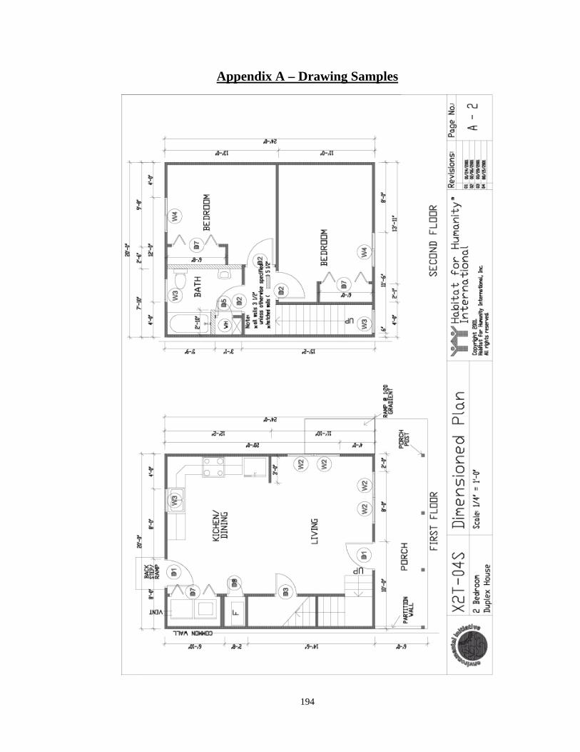
194
Appendix A – Drawing Samples
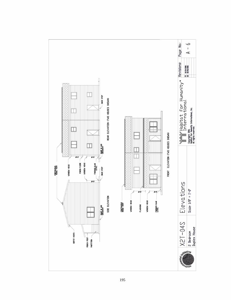
195
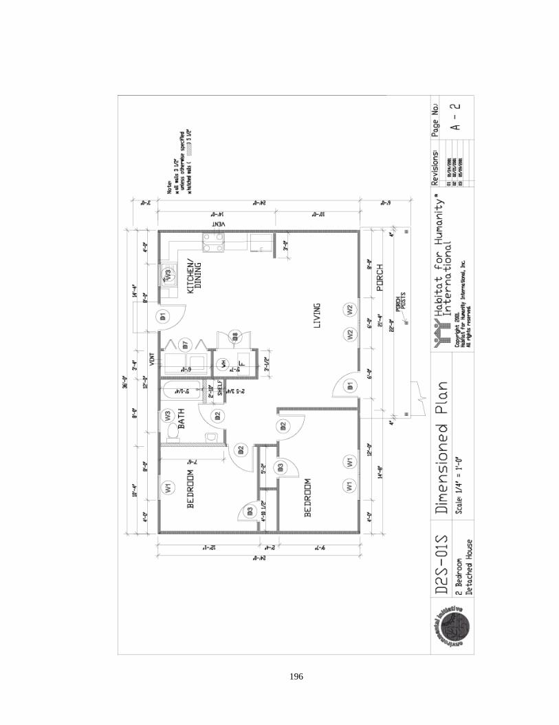
196
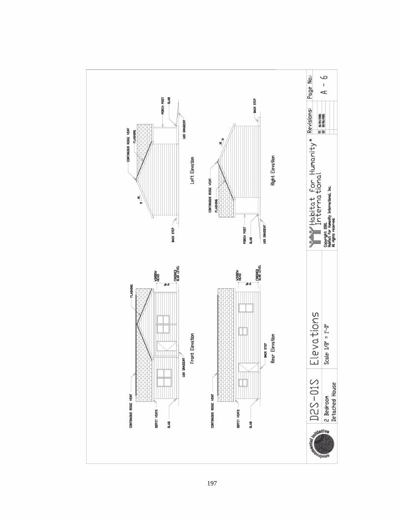
197
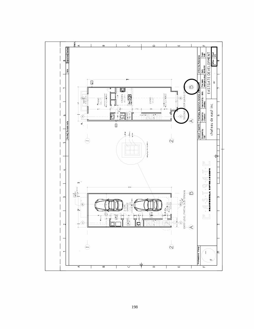
198
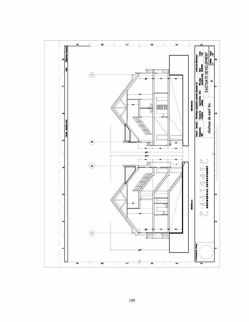
199
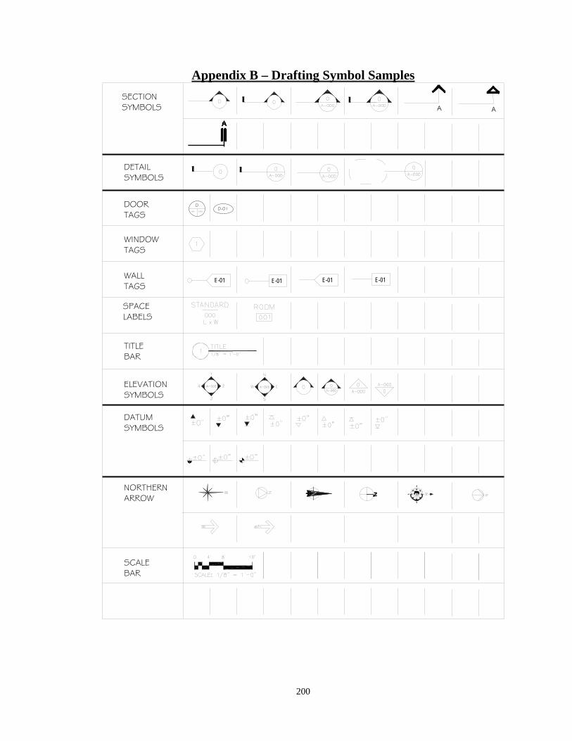
200
Appendix B – Drafting Symbol Samples
SECTIONSYMBOLS
DETAILSYMBOLS
DOORTAGS
WINDOWTAGS
WALLTAGS
SCALEBAR
TITLEBAR
NORTHERNARROW
ELEVATIONSYMBOLS
DATUMSYMBOLS
AA
DA01 A 03
D-01
E-01 E-01 E-01 E-01
SPACELABELS
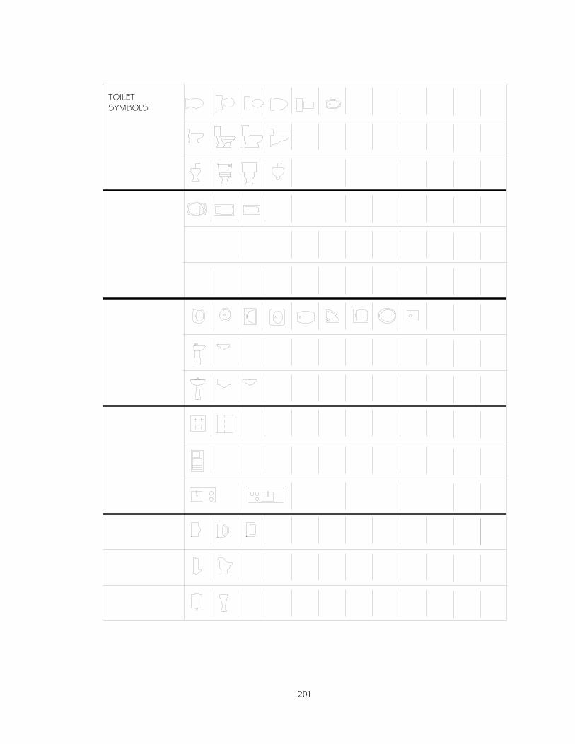
201
TOILETSYMBOLS
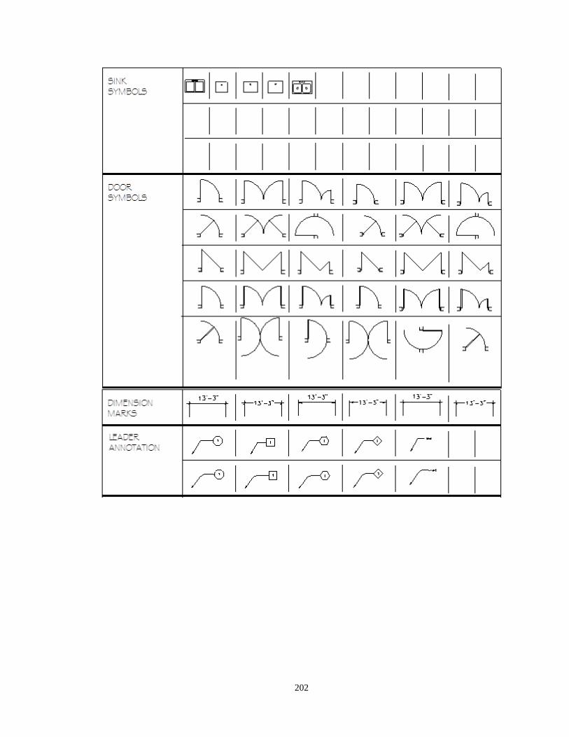
202
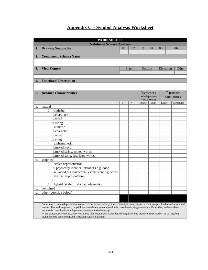
203
Appendix C – Symbol Analysis Worksheet
WORKSHEET 1 Notational Schema Analysis
1. Drawing Sample Set 01 02 03 04 05 06
2. Component Schema Name 3. View Context Plan Section Elevation Other
4. Functional Description 5. Instance Characteristics *Sentences
-- independent -- occurrences
** Instance Similarities
Y N Single Multi Exact Structural
a. textual 2. alphabet
i.character ii.word
iii.string 3. numeric
i.character ii.word
iii.sting 4. alphanumeric
i.mixed word ii.mixed string, mixed words
iii.mixed sting, restricted words b. graphical
5. scaled representation i. physically identical instances e.g. door ii. varied but syntactically consistent e.g. walls
6. abstract representation i.
7. hybrid (scaled + abstract elements) c. combined d. other (describe below)
*A sentence is an independent unconnected occurrence of a symbol. If multiple components interact in a predictable and structured manner, like wall segments, or gridlines then the entire composition is considered a single sentence. Otherwise, each unrelated instance is considered an independent sentence in the language. ** An exact occurrence excludes variations like a numerical value that distinguishes one instance from another, as in tags, but includes some basic consistent structural/syntactic pattern
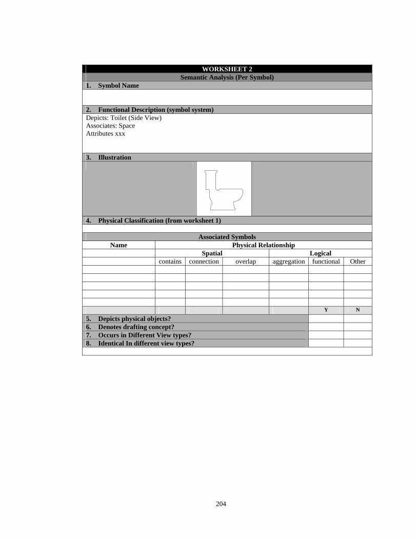
204
WORKSHEET 2 Semantic Analysis (Per Symbol)
1. Symbol Name 2. Functional Description (symbol system) Depicts: Toilet (Side View) Associates: Space Attributes xxx 3. Illustration
4. Physical Classification (from worksheet 1)
Associated Symbols Name Physical Relationship
Spatial Logical contains connection overlap aggregation functional Other Y N
5. Depicts physical objects? 6. Denotes drafting concept? 7. Occurs in Different View types? 8. Identical In different view types?
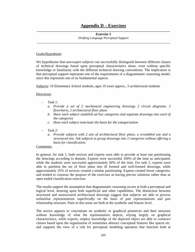
205
Appendix D – Exercises ____________________________________________________________________________
Exercise 1 Drafting Language Perceptual Support
____________________________________________________________________________
Goals/Hypothesis:
We hypothesize that non-expert subjects can successfully distinguish between different classes of technical drawings based upon perceptual characteristics alone, even without specific knowledge or familiarity with the different technical drawing conventions. The implication is that perceptual support represents one of the requirements of a diagrammatic reasoning model, since this represents one of its fundamental aspects. Subjects: 10 Elementary School students, ages 10 years approx., 5 architectural students Directions:
- Task 1: a. Provide a set of 2 mechanical engineering drawings 2 circuit diagrams, 2
flowcharts, 2 architectural floor plans b. Have each subject establish ad hoc categories and separate drawings into each of
the categories c. Have each subject note/state the basis for the categorization
- Task 2:
a. Provide subjects with 2 sets of architectural floor plans; a scrambled one and a structured one. Ask subjects to group drawings into 2 categories without offering a basis for classification.
Comments:
In general, for task 1, both novices and experts were able to provide at least one partitioning the drawings according to domain. Experts were successful 100% of the time as anticipated, while the students were successful approximately 60% of the time. For task 2, experts were able to partition the set of floor plans into ill formed and well-formed drawings, while approximately 35% of novices created a similar partitioning. Experts created fewer categories, and tended to construe the purpose of the exercises as having precise solutions rather than as open ended classification exercises. The results support the assumption that diagrammatic reasoning occurs at both a perceptual and logical level, drawing upon both superficial and other capabilities. The distinction between structured and unstructured architectural drawings suggest that subjects are able to process unfamiliar representations superficially on the basis of part representations and part relationship structure. Parts in this sense are both at the symbolic and feature level. The novice appears to concentrate on symbolic or graphical primitives and their structure without knowledge of what the representation depicts, relying largely on graphical characteristics, while experts, employ knowledge of the depicted object are able to construct classes based upon the organization of sometimes abstract conceptual features like spaces etc. and supports the view of a role for perceptual modeling operators that function both at
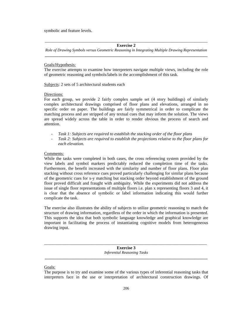
206
symbolic and feature levels. ____________________________________________________________________________
Exercise 2 Role of Drawing Symbols versus Geometric Reasoning in Integrating Multiple Drawing Representation ____________________________________________________________________________
Goals/Hypothesis: The exercise attempts to examine how interpreters navigate multiple views, including the role of geometric reasoning and symbols/labels in the accomplishment of this task. Subjects: 2 sets of 5 architectural students each Directions: For each group, we provide 2 fairly complex sample set (4 story buildings) of similarly complex architectural drawings comprised of floor plans and elevations, arranged in no specific order on paper. The buildings are fairly symmetrical in order to complicate the matching process and are stripped of any textual cues that may inform the solution. The views are spread widely across the table in order to render obvious the process of search and attention.
- Task 1: Subjects are required to establish the stacking order of the floor plans - Task 2: Subjects are required to establish the projections relative to the floor plans for
each elevation. Comments: While the tasks were completed in both cases, the cross referencing system provided by the view labels and symbol markers predictably reduced the completion time of the tasks. Furthermore, the benefit increased with the similarity and number of floor plans. Floor plan stacking without cross reference cues proved particularly challenging for similar plans because of the geometric cues for x-y matching but stacking order beyond establishment of the ground floor proved difficult and fraught with ambiguity. While the experiments did not address the issue of single floor representations of multiple floors i.e. plan x representing floors 3 and 4, it is clear that the absence of symbolic or label information indicating this would further complicate the task. The exercise also illustrates the ability of subjects to utilize geometric reasoning to match the structure of drawing information, regardless of the order in which the information is presented. This supports the idea that both symbolic language knowledge and graphical knowledge are important in facilitating the process of instantiating cognitive models from heterogeneous drawing input.
____________________________________________________________________________
Exercise 3 Inferential Reasoning Tasks
____________________________________________________________________________
Goals: The purpose is to try and examine some of the various types of inferential reasoning tasks that interpreters face in the use or interpretation of architectural construction drawings. Of
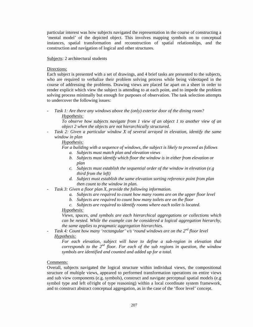
207
particular interest was how subjects navigated the representation in the course of constructing a ‘mental model’ of the depicted object. This involves mapping symbols on to conceptual instances, spatial transformation and reconstruction of spatial relationships, and the construction and navigation of logical and other structures. Subjects: 2 architectural students Directions: Each subject is presented with a set of drawings, and 4 brief tasks are presented to the subjects, who are required to verbalize their problem solving process while being videotaped in the course of addressing the problems. Drawing views are placed far apart on a sheet in order to render explicit which view the subject is attending to at each point, and to impede the problem solving process minimally but enough for purposes of observation. The task selection attempts to undercover the following issues: - Task 1: Are there any windows above the (only) exterior door of the dining room?
Hypothesis: To observe how subjects navigate from 1 view of an object 1 to another view of an object 2 when the objects are not hierarchically structured.
- Task 2: Given a particular window X of several arrayed in elevation, identify the same window in plan
Hypothesis: For a building with a sequence of windows, the subject is likely to proceed as follows
a. Subjects must match plan and elevation views b. Subjects must identify which floor the window is in either from elevation or
plan c. Subjects must establish the sequential order of the window in elevation (e.g
third from the left) d. Subject must establish the same elevation sorting reference point from plan
then count to the window in plan. - Task 3: Given a floor plan X, provide the following information.
a. Subjects are required to count how many rooms are on the upper floor level b. Subjects are required to count how many toilets are on the floor c. Subjects are required to identify rooms where each toilet is located.
Hypothesis: Views, spaces, and symbols are each hierarchical aggregations or collections which can be nested. While the example can be considered a logical aggregation hierarchy, the same applies to pragmatic aggregation hierarchies.
- Task 4: Count how many ‘rectangular’ v/s ‘round windows are on the 2nd floor level Hypothesis:
For each elevation, subject will have to define a sub-region in elevation that corresponds to the 2nd floor. For each of the sub regions in question, the window symbols are identified and counted and added up for a total.
Comments: Overall, subjects navigated the logical structure within individual views, the compositional structure of multiple views, appeared to performed transformation operations on entire views and sub view components (e.g. symbols), construct and navigate perceptual spatial models (e.g symbol type and left of/right of type reasoning) within a local coordinate system framework, and to construct abstract conceptual aggregation, as in the case of the ‘floor level’ concept.
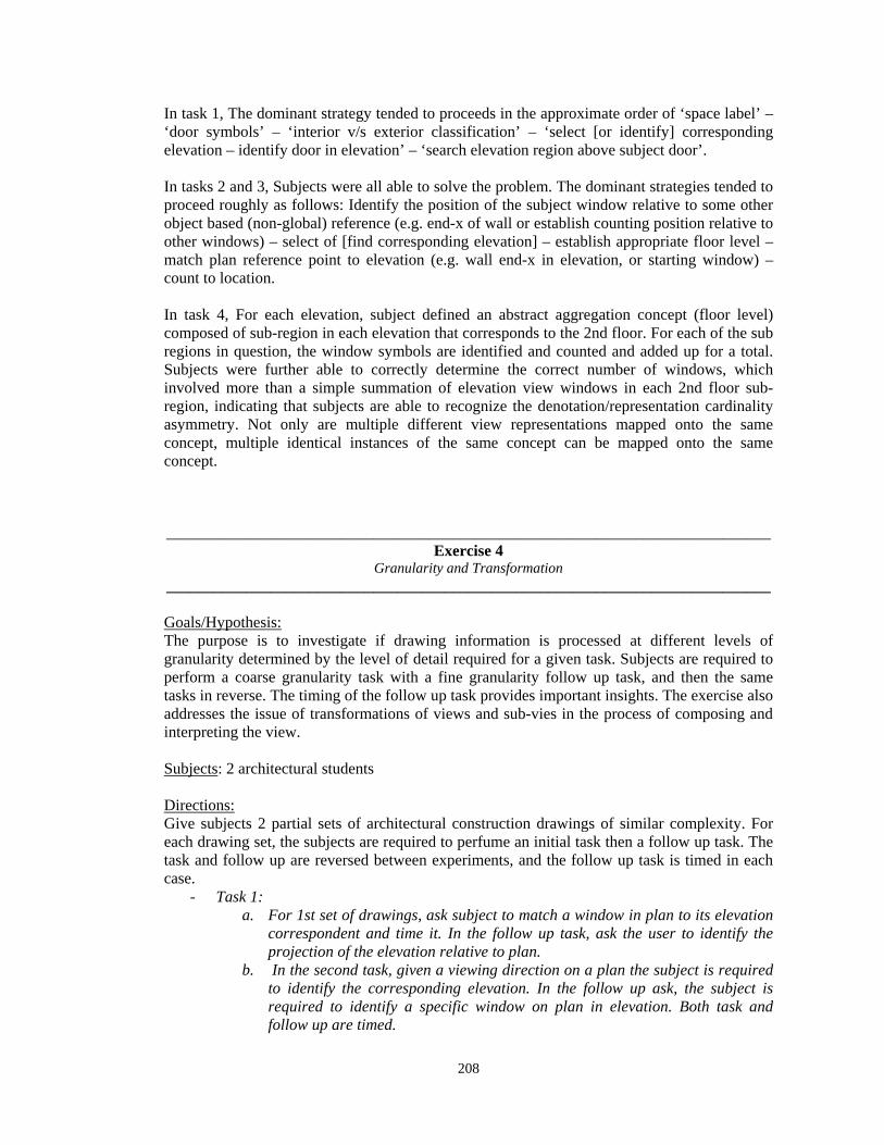
208
In task 1, The dominant strategy tended to proceeds in the approximate order of ‘space label’ – ‘door symbols’ – ‘interior v/s exterior classification’ – ‘select [or identify] corresponding elevation – identify door in elevation’ – ‘search elevation region above subject door’. In tasks 2 and 3, Subjects were all able to solve the problem. The dominant strategies tended to proceed roughly as follows: Identify the position of the subject window relative to some other object based (non-global) reference (e.g. end-x of wall or establish counting position relative to other windows) – select of [find corresponding elevation] – establish appropriate floor level – match plan reference point to elevation (e.g. wall end-x in elevation, or starting window) – count to location. In task 4, For each elevation, subject defined an abstract aggregation concept (floor level) composed of sub-region in each elevation that corresponds to the 2nd floor. For each of the sub regions in question, the window symbols are identified and counted and added up for a total. Subjects were further able to correctly determine the correct number of windows, which involved more than a simple summation of elevation view windows in each 2nd floor sub-region, indicating that subjects are able to recognize the denotation/representation cardinality asymmetry. Not only are multiple different view representations mapped onto the same concept, multiple identical instances of the same concept can be mapped onto the same concept.
____________________________________________________________________________
Exercise 4 Granularity and Transformation
____________________________________________________________________________
Goals/Hypothesis: The purpose is to investigate if drawing information is processed at different levels of granularity determined by the level of detail required for a given task. Subjects are required to perform a coarse granularity task with a fine granularity follow up task, and then the same tasks in reverse. The timing of the follow up task provides important insights. The exercise also addresses the issue of transformations of views and sub-vies in the process of composing and interpreting the view. Subjects: 2 architectural students Directions: Give subjects 2 partial sets of architectural construction drawings of similar complexity. For each drawing set, the subjects are required to perfume an initial task then a follow up task. The task and follow up are reversed between experiments, and the follow up task is timed in each case.
- Task 1: a. For 1st set of drawings, ask subject to match a window in plan to its elevation
correspondent and time it. In the follow up task, ask the user to identify the projection of the elevation relative to plan.
b. In the second task, given a viewing direction on a plan the subject is required to identify the corresponding elevation. In the follow up ask, the subject is required to identify a specific window on plan in elevation. Both task and follow up are timed.
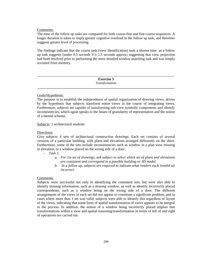
209
Comments: The time of the follow up tasks are compared for both coarse-fine and fine-coarse sequences. A longer duration is taken to imply greater cognitive overload in the follow up task, and therefore suggests greater level of processing. The findings indicate that the coarse task (view identification) took a shorter time as a follow up task suggests (under 0.5 seconds V/s 2.5 seconds approx) suggesting that view projection had been resolved prior to performing the more detailed window matching task and was simply revisited from memory.
____________________________________________________________________________ Exercise 5
Transformation ____________________________________________________________________________
Goals/Hypothesis: The purpose is to establish the independence of spatial organization of drawing views, driven by the hypothesis that subjects transform entire views in the course of integrating views. Furthermore, subjects are capable of transforming sub-view symbolic components and identify inconsistencies, which again speaks to the issues of granularity of representation and the notion of a mental schema. Subjects: 2 architectural students Directions: Give subjects 4 sets of architectural construction drawings. Each set consists of several versions of a particular building, with plans and elevations arranged differently on the sheet. Furthermore, some of the sets include inconsistencies such as window in a plan view missing in elevation, or a window placed on the wrong side of a door.
- Task 1: a. For 1st set of drawings, ask subject to select which set of plans and elevations
are consistent and correspond to a possible building or 3D model. b. In a follow up, subjects are required to indicate what renders each invalid set
incorrect. Comments: Subjects were successful not only in identifying the consistent sets, but were also able to identify missing information, such as a missing window, as well as identify incorrectly placed correspondents, such as a window being on the wrong side of a door. The different arrangements of the views in each set did not appear to constitute a significant problem, and in cases where more than 1 set was valid, subjects were able to identify this regardless of layout of the views, indicating that some form of spatial transformation of views appears to be integral in the process. In addition, the notion of a window being incorrectly placed implies that transformations within a view and spatial reasoning/transformation in terms of left of and right of operations are carried out.
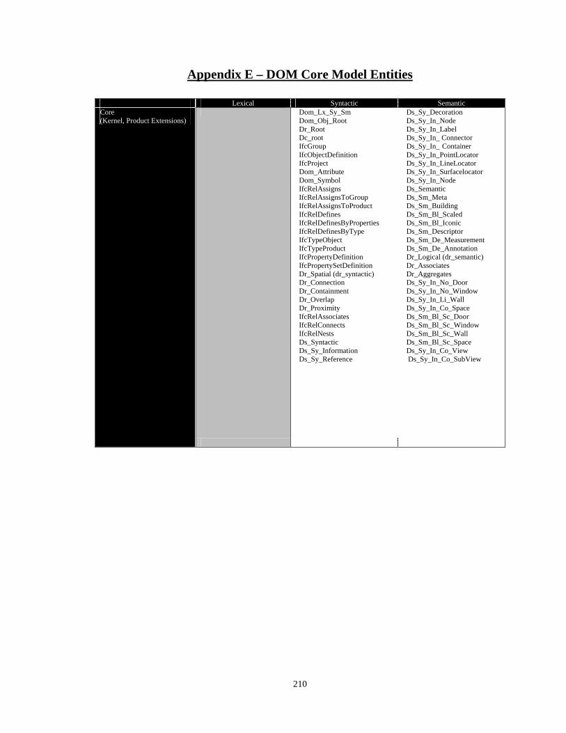
210
Appendix E – DOM Core Model Entities Lexical Syntactic Semantic Core (Kernel, Product Extensions)
Dom_Lx_Sy_Sm Dom_Obj_Root Dr_Root Dc_root IfcGroup IfcObjectDefinition IfcProject Dom_Attribute Dom_Symbol IfcRelAssigns IfcRelAssignsToGroup IfcRelAssignsToProduct IfcRelDefines IfcRelDefinesByProperties IfcRelDefinesByType IfcTypeObject IfcTypeProduct IfcPropertyDefinition IfcPropertySetDefinition Dr_Spatial (dr_syntactic) Dr_Connection Dr_Containment Dr_Overlap Dr_Proximity IfcRelAssociates IfcRelConnects IfcRelNests Ds_Syntactic Ds_Sy_Information Ds_Sy_Reference
Ds_Sy_Decoration Ds_Sy_In_Node Ds_Sy_In_Label Ds_Sy_In_ Connector Ds_Sy_In_ Container Ds_Sy_In_PointLocator Ds_Sy_In_LineLocator Ds_Sy_In_Surfacelocator Ds_Sy_In_Node Ds_Semantic Ds_Sm_Meta Ds_Sm_Building Ds_Sm_Bl_Scaled Ds_Sm_Bl_Iconic Ds_Sm_Descriptor Ds_Sm_De_Measurement Ds_Sm_De_Annotation Dr_Logical (dr_semantic) Dr_Associates Dr_Aggregates Ds_Sy_In_No_Door Ds_Sy_In_No_Window Ds_Sy_In_Li_Wall Ds_Sy_In_Co_Space Ds_Sm_Bl_Sc_Door Ds_Sm_Bl_Sc_Window Ds_Sm_Bl_Sc_Wall Ds_Sm_Bl_Sc_Space Ds_Sy_In_Co_View Ds_Sy_In_Co_SubView
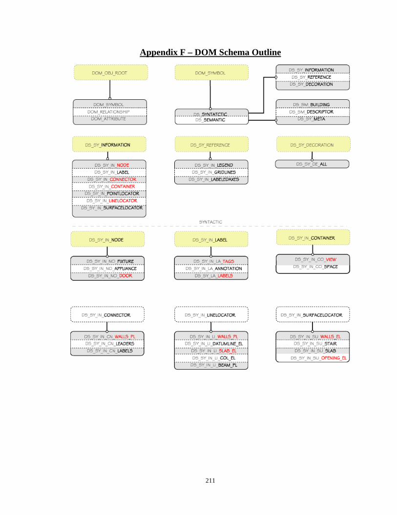
211
Appendix F – DOM Schema Outline
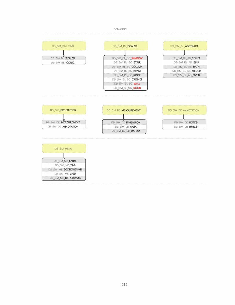
212
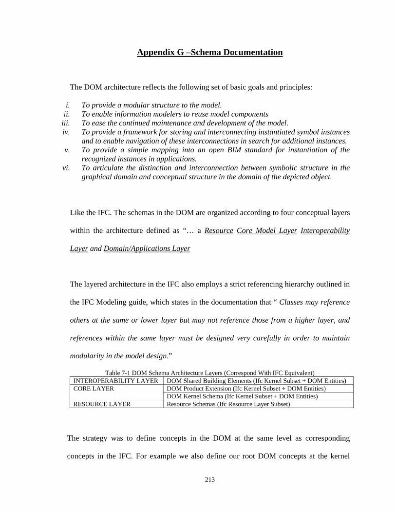
213
Appendix G –Schema Documentation
The DOM architecture reflects the following set of basic goals and principles:
i. To provide a modular structure to the model. ii. To enable information modelers to reuse model components
iii. To ease the continued maintenance and development of the model. iv. To provide a framework for storing and interconnecting instantiated symbol instances
and to enable navigation of these interconnections in search for additional instances. v. To provide a simple mapping into an open BIM standard for instantiation of the
recognized instances in applications. vi. To articulate the distinction and interconnection between symbolic structure in the
graphical domain and conceptual structure in the domain of the depicted object.
Like the IFC. The schemas in the DOM are organized according to four conceptual layers
within the architecture defined as “… a Resource Core Model Layer Interoperability
Layer and Domain/Applications Layer
The layered architecture in the IFC also employs a strict referencing hierarchy outlined in
the IFC Modeling guide, which states in the documentation that “ Classes may reference
others at the same or lower layer but may not reference those from a higher layer, and
references within the same layer must be designed very carefully in order to maintain
modularity in the model design.”
Table 7-1 DOM Schema Architecture Layers (Correspond With IFC Equivalent) INTEROPERABILITY LAYER DOM Shared Building Elements (Ifc Kernel Subset + DOM Entities) CORE LAYER DOM Product Extension (Ifc Kernel Subset + DOM Entities)
DOM Kernel Schema (Ifc Kernel Subset + DOM Entities) RESOURCE LAYER Resource Schemas (Ifc Resource Layer Subset)
The strategy was to define concepts in the DOM at the same level as corresponding
concepts in the IFC. For example we also define our root DOM concepts at the kernel
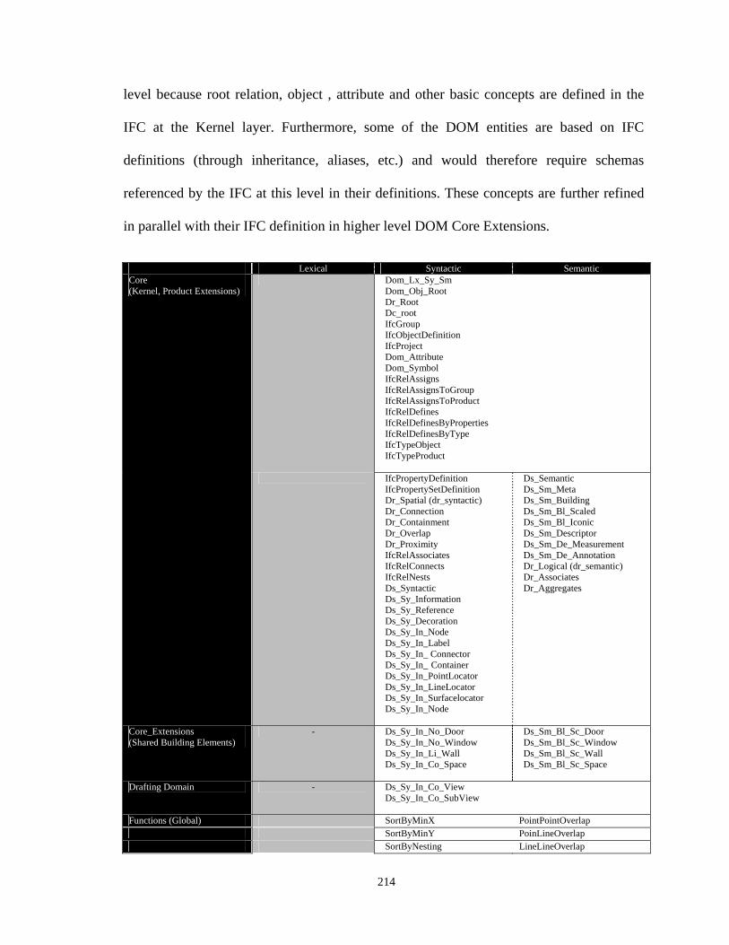
214
level because root relation, object , attribute and other basic concepts are defined in the
IFC at the Kernel layer. Furthermore, some of the DOM entities are based on IFC
definitions (through inheritance, aliases, etc.) and would therefore require schemas
referenced by the IFC at this level in their definitions. These concepts are further refined
in parallel with their IFC definition in higher level DOM Core Extensions.
Lexical Syntactic Semantic Core (Kernel, Product Extensions)
Dom_Lx_Sy_Sm Dom_Obj_Root Dr_Root Dc_root IfcGroup IfcObjectDefinition IfcProject Dom_Attribute Dom_Symbol IfcRelAssigns IfcRelAssignsToGroup IfcRelAssignsToProduct IfcRelDefines IfcRelDefinesByProperties IfcRelDefinesByType IfcTypeObject IfcTypeProduct
IfcPropertyDefinition IfcPropertySetDefinition Dr_Spatial (dr_syntactic) Dr_Connection Dr_Containment Dr_Overlap Dr_Proximity IfcRelAssociates IfcRelConnects IfcRelNests Ds_Syntactic Ds_Sy_Information Ds_Sy_Reference Ds_Sy_Decoration Ds_Sy_In_Node Ds_Sy_In_Label Ds_Sy_In_ Connector Ds_Sy_In_ Container Ds_Sy_In_PointLocator Ds_Sy_In_LineLocator Ds_Sy_In_Surfacelocator Ds_Sy_In_Node
Ds_Semantic Ds_Sm_Meta Ds_Sm_Building Ds_Sm_Bl_Scaled Ds_Sm_Bl_Iconic Ds_Sm_Descriptor Ds_Sm_De_Measurement Ds_Sm_De_Annotation Dr_Logical (dr_semantic) Dr_Associates Dr_Aggregates
Core_Extensions (Shared Building Elements)
- Ds_Sy_In_No_Door Ds_Sy_In_No_Window Ds_Sy_In_Li_Wall Ds_Sy_In_Co_Space
Ds_Sm_Bl_Sc_Door Ds_Sm_Bl_Sc_Window Ds_Sm_Bl_Sc_Wall Ds_Sm_Bl_Sc_Space
Drafting Domain - Ds_Sy_In_Co_View Ds_Sy_In_Co_SubView
Functions (Global) SortByMinX PointPointOverlap SortByMinY PoinLineOverlap SortByNesting LineLineOverlap
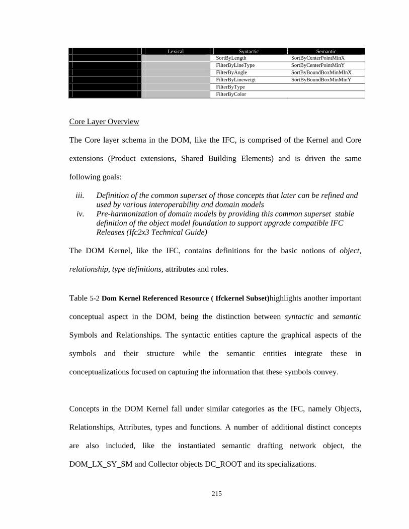
215
Lexical Syntactic Semantic SortByLength SortByCenterPointMinX FilterByLineType SortByCenterPointMinY FilterByAngle SortByBoundBoxMinMInX FilterByLineweigt SortByBoundBoxMinMinY FilterByType FilterByColor
Core Layer Overview
The Core layer schema in the DOM, like the IFC, is comprised of the Kernel and Core
extensions (Product extensions, Shared Building Elements) and is driven the same
following goals:
iii. Definition of the common superset of those concepts that later can be refined and used by various interoperability and domain models
iv. Pre-harmonization of domain models by providing this common superset stable definition of the object model foundation to support upgrade compatible IFC Releases (Ifc2x3 Technical Guide)
The DOM Kernel, like the IFC, contains definitions for the basic notions of object,
relationship, type definitions, attributes and roles.
Table 5-2 Dom Kernel Referenced Resource ( Ifckernel Subset)highlights another important
conceptual aspect in the DOM, being the distinction between syntactic and semantic
Symbols and Relationships. The syntactic entities capture the graphical aspects of the
symbols and their structure while the semantic entities integrate these in
conceptualizations focused on capturing the information that these symbols convey.
Concepts in the DOM Kernel fall under similar categories as the IFC, namely Objects,
Relationships, Attributes, types and functions. A number of additional distinct concepts
are also included, like the instantiated semantic drafting network object, the
DOM_LX_SY_SM and Collector objects DC_ROOT and its specializations.
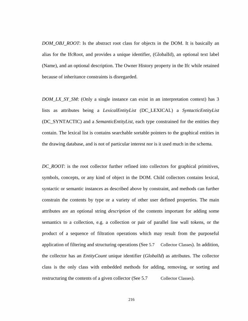
216
DOM_OBJ_ROOT: Is the abstract root class for objects in the DOM. It is basically an
alias for the IfcRoot, and provides a unique identifier, (GlobalId), an optional text label
(Name), and an optional description. The Owner History property in the Ifc while retained
because of inheritance constraints is disregarded.
DOM_LX_SY_SM: (Only a single instance can exist in an interpretation context) has 3
lists as attributes being a LexicalEntityList (DC_LEXICAL) a SyntacticEntityList
(DC_SYNTACTIC) and a SemanticEntityList, each type constrained for the entities they
contain. The lexical list is contains searchable sortable pointers to the graphical entities in
the drawing database, and is not of particular interest nor is it used much in the schema.
DC_ROOT: is the root collector further refined into collectors for graphical primitives,
symbols, concepts, or any kind of object in the DOM. Child collectors contains lexical,
syntactic or semantic instances as described above by constraint, and methods can further
constrain the contents by type or a variety of other user defined properties. The main
attributes are an optional string description of the contents important for adding some
semantics to a collection, e.g. a collection or pair of parallel line wall tokens, or the
product of a sequence of filtration operations which may result from the purposeful
application of filtering and structuring operations (See 5.7 Collector Classes). In addition,
the collector has an EntityCount unique identifier (GlobalId) as attributes. The collector
class is the only class with embedded methods for adding, removing, or sorting and
restructuring the contents of a given collector (See 5.7 Collector Classes).
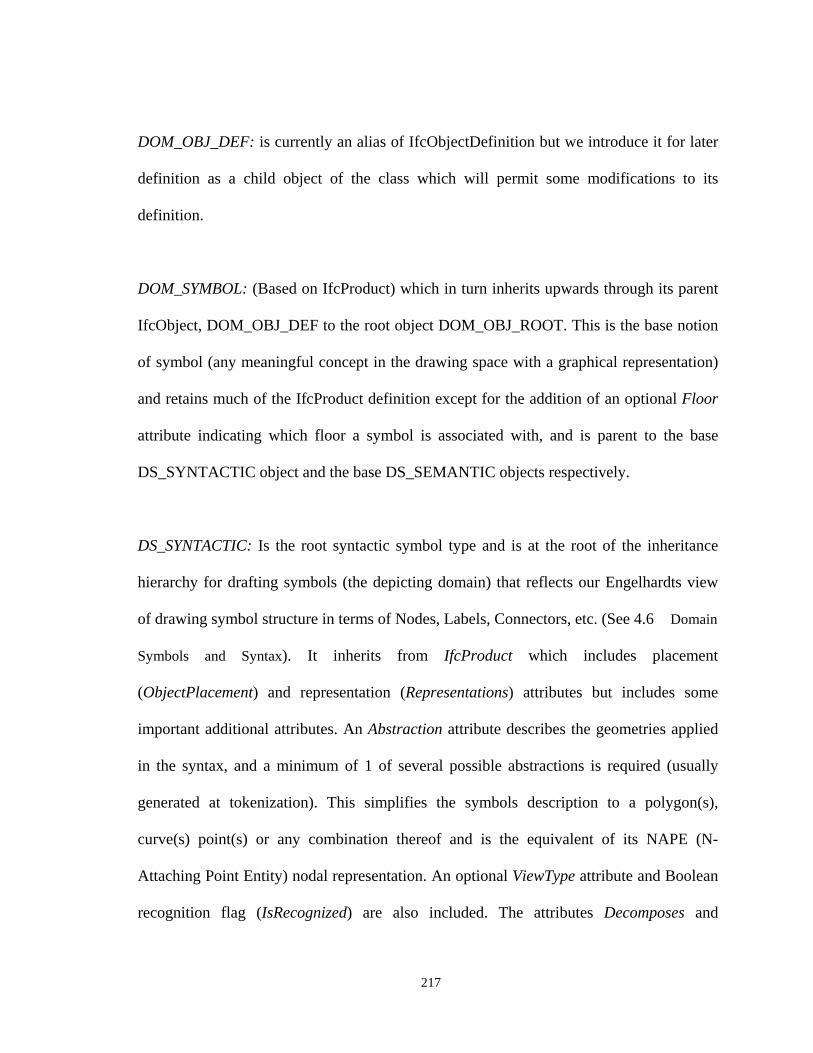
217
DOM_OBJ_DEF: is currently an alias of IfcObjectDefinition but we introduce it for later
definition as a child object of the class which will permit some modifications to its
definition.
DOM_SYMBOL: (Based on IfcProduct) which in turn inherits upwards through its parent
IfcObject, DOM_OBJ_DEF to the root object DOM_OBJ_ROOT. This is the base notion
of symbol (any meaningful concept in the drawing space with a graphical representation)
and retains much of the IfcProduct definition except for the addition of an optional Floor
attribute indicating which floor a symbol is associated with, and is parent to the base
DS_SYNTACTIC object and the base DS_SEMANTIC objects respectively.
DS_SYNTACTIC: Is the root syntactic symbol type and is at the root of the inheritance
hierarchy for drafting symbols (the depicting domain) that reflects our Engelhardts view
of drawing symbol structure in terms of Nodes, Labels, Connectors, etc. (See 4.6 Domain
Symbols and Syntax). It inherits from IfcProduct which includes placement
(ObjectPlacement) and representation (Representations) attributes but includes some
important additional attributes. An Abstraction attribute describes the geometries applied
in the syntax, and a minimum of 1 of several possible abstractions is required (usually
generated at tokenization). This simplifies the symbols description to a polygon(s),
curve(s) point(s) or any combination thereof and is the equivalent of its NAPE (N-
Attaching Point Entity) nodal representation. An optional ViewType attribute and Boolean
recognition flag (IsRecognized) are also included. The attributes Decomposes and
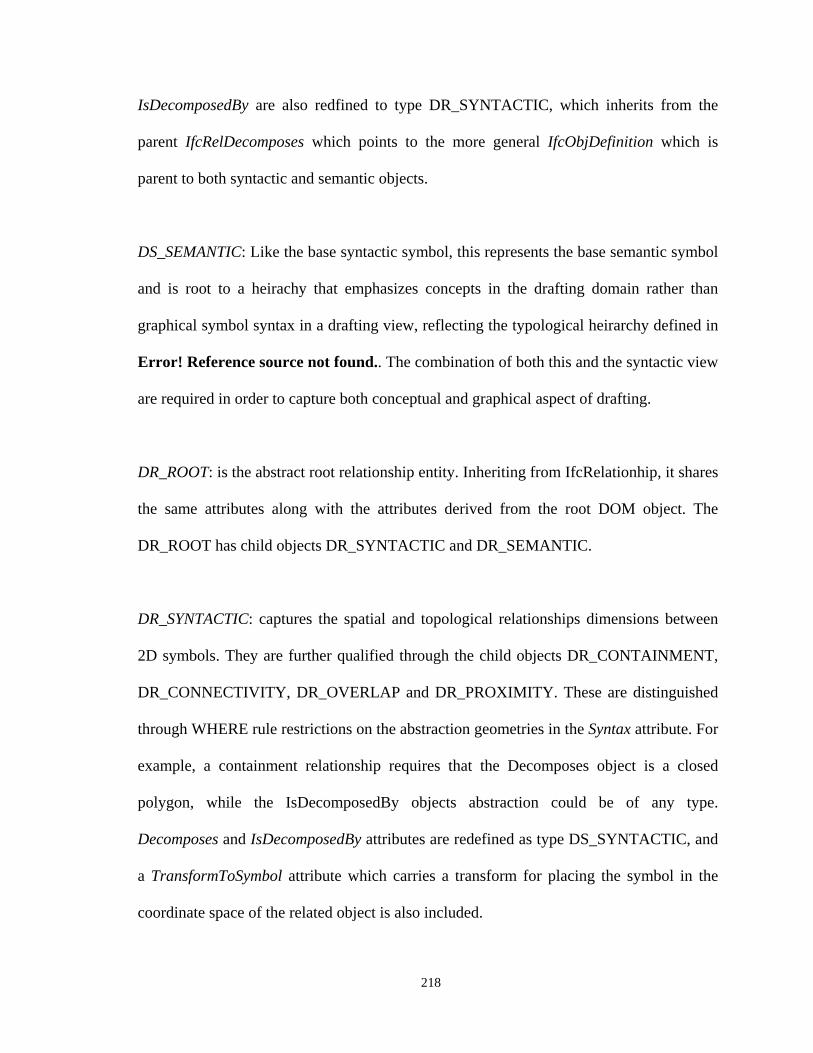
218
IsDecomposedBy are also redfined to type DR_SYNTACTIC, which inherits from the
parent IfcRelDecomposes which points to the more general IfcObjDefinition which is
parent to both syntactic and semantic objects.
DS_SEMANTIC: Like the base syntactic symbol, this represents the base semantic symbol
and is root to a heirachy that emphasizes concepts in the drafting domain rather than
graphical symbol syntax in a drafting view, reflecting the typological heirarchy defined in
Error! Reference source not found.. The combination of both this and the syntactic view
are required in order to capture both conceptual and graphical aspect of drafting.
DR_ROOT: is the abstract root relationship entity. Inheriting from IfcRelationhip, it shares
the same attributes along with the attributes derived from the root DOM object. The
DR_ROOT has child objects DR_SYNTACTIC and DR_SEMANTIC.
DR_SYNTACTIC: captures the spatial and topological relationships dimensions between
2D symbols. They are further qualified through the child objects DR_CONTAINMENT,
DR_CONNECTIVITY, DR_OVERLAP and DR_PROXIMITY. These are distinguished
through WHERE rule restrictions on the abstraction geometries in the Syntax attribute. For
example, a containment relationship requires that the Decomposes object is a closed
polygon, while the IsDecomposedBy objects abstraction could be of any type.
Decomposes and IsDecomposedBy attributes are redefined as type DS_SYNTACTIC, and
a TransformToSymbol attribute which carries a transform for placing the symbol in the
coordinate space of the related object is also included.
219
DR_SEMANTIC: captures the topological relationships between related concepts. It
inherits from DOM_OBJ_ROOT through IfcRelationship and has child objects
DR_AGGREGATES and DR_ASSOCIATES. Its Decomposes and IsDecomposedBy
attributes are redefined as type DS_SEMANTIC, and its spatial dimensions are indirectly
defined through the relevant 2D views of the related and relating semantic objects and
their syntactic relationships.
DS_SY_INFORMATION: is an abstract super-type representing the syntactic role of any
symbol which conveys information in a drawing. Subtypes are (DS_SY_IN_NODE),
(DS_SY_IN_LABEL), (DS_SY_IN_LINELOCATOR), (DS_SY_IN_CONNECTOR),
(DS_SY_IN_CONSTAINER), etc. (See 4.6 Domain Symbols and Syntax). An (inferred)
space would be a type of container (DS_SY_IN_CO_SPACE) with container attributes
(syntactic Contents) while a wall in plan may be a LINELOCATOR.
DS_SY_IN_NODE: is important because it is equivalent to an N-Attachment Point Entity,
which provides the graph theoretical basis for parsing of 2D symbolic structure within a
view. It is a topological generalization of any 2D symbol with tight inter-object constraints
but more flexible object space constraints, and is applicable where a symbols syntactic
role cannot be more specifically defined. A drawing view is considered a constraint space,
and spatially constrained symbols are those from which 3D building geometry might be
extracted through geometric reconstruction. Changing the relationship of the symbol
(location, shape, scale) changes the meaning of the representation (See )
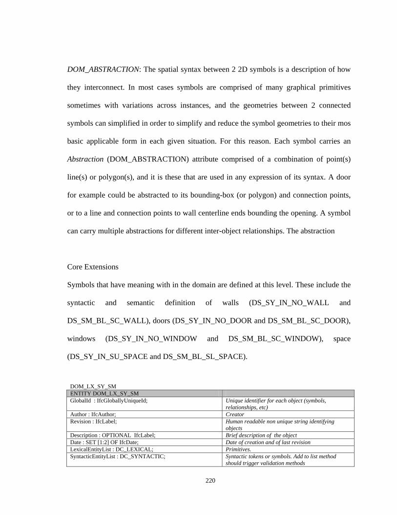
220
DOM_ABSTRACTION: The spatial syntax between 2 2D symbols is a description of how
they interconnect. In most cases symbols are comprised of many graphical primitives
sometimes with variations across instances, and the geometries between 2 connected
symbols can simplified in order to simplify and reduce the symbol geometries to their mos
basic applicable form in each given situation. For this reason. Each symbol carries an
Abstraction (DOM_ABSTRACTION) attribute comprised of a combination of point(s)
line(s) or polygon(s), and it is these that are used in any expression of its syntax. A door
for example could be abstracted to its bounding-box (or polygon) and connection points,
or to a line and connection points to wall centerline ends bounding the opening. A symbol
can carry multiple abstractions for different inter-object relationships. The abstraction
Core Extensions
Symbols that have meaning with in the domain are defined at this level. These include the
syntactic and semantic definition of walls (DS_SY_IN_NO_WALL and
DS_SM_BL_SC_WALL), doors (DS_SY_IN_NO_DOOR and DS_SM_BL_SC_DOOR),
windows (DS_SY_IN_NO_WINDOW and DS_SM_BL_SC_WINDOW), space
(DS_SY_IN_SU_SPACE and DS_SM_BL_SL_SPACE).
DOM_LX_SY_SM ENTITY DOM_LX_SY_SM GlobalId : IfcGloballyUniqueId; Unique identifier for each object (symbols,
relationships, etc) Author : IfcAuthor; Creator Revision : IfcLabel; Human readable non unique string identifying
objects Description : OPTIONAL IfcLabel; Brief description of the object Date : SET [1:2] OF IfcDate; Date of creation and of last revision LexicalEntityList : DC_LEXICAL; Primitives. SyntacticEntityList : DC_SYNTACTIC; Syntactic tokens or symbols. Add to list method
should trigger validation methods
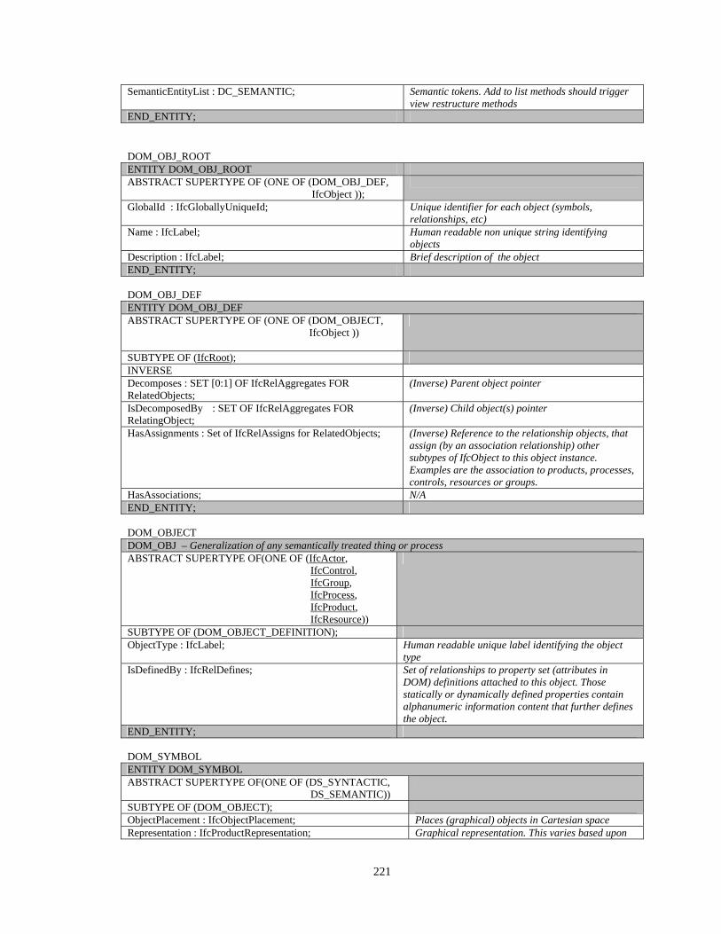
221
SemanticEntityList : DC_SEMANTIC; Semantic tokens. Add to list methods should trigger view restructure methods
END_ENTITY; DOM_OBJ_ROOT ENTITY DOM_OBJ_ROOT ABSTRACT SUPERTYPE OF (ONE OF (DOM_OBJ_DEF,
IfcObject ));
GlobalId : IfcGloballyUniqueId; Unique identifier for each object (symbols, relationships, etc)
Name : IfcLabel; Human readable non unique string identifying objects
Description : IfcLabel; Brief description of the object END_ENTITY; DOM_OBJ_DEF ENTITY DOM_OBJ_DEF ABSTRACT SUPERTYPE OF (ONE OF (DOM_OBJECT,
IfcObject ))
SUBTYPE OF ( IfcRoot);
INVERSE Decomposes : SET [0:1] OF IfcRelAggregates FOR RelatedObjects;
(Inverse) Parent object pointer
IsDecomposedBy : SET OF IfcRelAggregates FOR RelatingObject;
(Inverse) Child object(s) pointer
HasAssignments : Set of IfcRelAssigns for RelatedObjects; (Inverse) Reference to the relationship objects, that assign (by an association relationship) other subtypes of IfcObject to this object instance. Examples are the association to products, processes, controls, resources or groups.
HasAssociations; N/A END_ENTITY; DOM_OBJECT DOM_OBJ – Generalization of any semantically treated thing or process ABSTRACT SUPERTYPE OF(ONE OF (IfcActor, IfcControl, IfcGroup, IfcProcess, IfcProduct, IfcResource))
SUBTYPE OF (DOM_OBJECT_DEFINITION); ObjectType : IfcLabel; Human readable unique label identifying the object
type IsDefinedBy : IfcRelDefines; Set of relationships to property set (attributes in
DOM) definitions attached to this object. Those statically or dynamically defined properties contain alphanumeric information content that further defines the object.
END_ENTITY; DOM_SYMBOL ENTITY DOM_SYMBOL ABSTRACT SUPERTYPE OF(ONE OF (DS_SYNTACTIC, DS_SEMANTIC))
SUBTYPE OF (DOM_OBJECT); ObjectPlacement : IfcObjectPlacement; Places (graphical) objects in Cartesian space Representation : IfcProductRepresentation; Graphical representation. This varies based upon
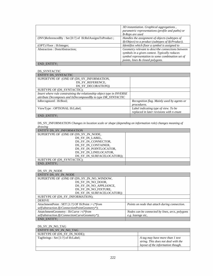
222
3D instantiation. Graphical aggregations , parametric representations (profile and paths) or B-Reps are used
(INV)ReferencedBy : Set [0:?] of IfcRelAssignsToProduct ; Handles the assignment of objects (subtypes of IfcObject) to a product (subtypes of IfcProduct).
(OPT) Floor : IfcInteger; Identifies which floor a symbol is assigned to Abstraction : DomAbstraction; Geometry relevant to describe connections between
symbols in a given context. Typically reduces symbol representation to some combination set of points, lines & closed polygons.
END_ENTITY; DS_SYNTACTIC ENTITY DS_SYNTACTIC SUPERTYPE OF (ONE OF (DS_SY_INFORMATION, DS_SY_REFERENCE, DS_SY_DECORATION))
SUBTYPE OF (DS_SYNTACTIC); Insert where rule constraining the relationship object type in INVERSE attribute Decomposes and IsDecomposedBy to type DR_SYNTACTIC
IsRecognized : IfcBool; Recognition flag. Mainly used by agents or procedures.
ViewType : OPTIONAL IfcLabel; Label indicating type of view. To be replaced in later revisions with n enum
END_ENTITY; DS_SY_INFORMATION Changes in location scale or shape (depending on information role) changes meaning of drawing ENTITY DS_SY_INFORMATION SUPERTYPE OF (ONE OF (DS_SY_IN_NODE, DS_SY_IN_LABEL, DS_SY_IN_CONNECTOR, DS_SY_IN_CONTAINER, DS_SY_IN_POINTLOCATOR, DS_SY_IN_LINELOCATOR, DS_SY_IN_SURFACELOCATOR));
SUBTYPE OF (DS_SYNTACTIC); END_ENTITY; DS_SY_IN_NODE ENTITY DS_SY_IN_NODE SUPERTYPE OF (ONE OF (DS_SY_IN_NO_WINDOW, DS_SY_IN_NO_DOOR, DS_SY_IN_NO_APPLIANCE, DS_SY_IN_NO_FIXTURE, DS_SY_IN_SURFACELOCATOR))
SUBTYPE OF (DS_SY_INFORMATION); DERIVE AttachmentPoint : SET [1:?] OF IfcPoint := (*from self\abstraction.IfcConnectionPointGeometry*);
Points on node that attach during connection.
AttatchmentGeometry : IfcCurve :=(*from self\abstraction.IfcConnectionCurveGeometry*);
Nodes can be connected by lines, arcs, polygons e.g. lozenge etc,
END_ENTITY; DS_SY_IN_NO_TAG ENTITY DS_SY_IN_NO_TAG SUBTYPE OF (DS_SY_IN_NODE); TagStrings : Set [1:?] of IfcLabel; A tag may have more than 1 text
string. This does not deal with the layout of the information though.
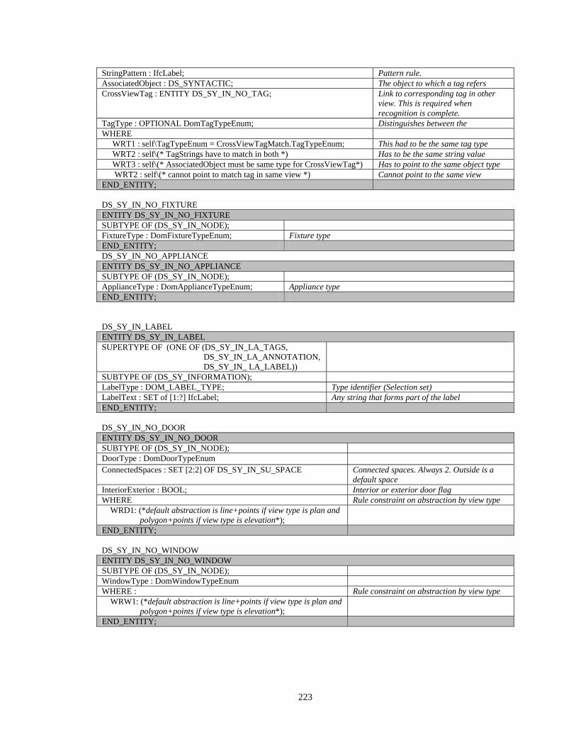
223
StringPattern : IfcLabel; Pattern rule. AssociatedObject : DS_SYNTACTIC; The object to which a tag refers CrossViewTag : ENTITY DS_SY_IN_NO_TAG; Link to corresponding tag in other
view. This is required when recognition is complete.
TagType : OPTIONAL DomTagTypeEnum; Distinguishes between the WHERE
WRT1 : self\TagTypeEnum = CrossViewTagMatch.TagTypeEnum; This had to be the same tag type WRT2 : self\(* TagStrings have to match in both *) Has to be the same string value WRT3 : self\(* AssociatedObject must be same type for CrossViewTag*) Has to point to the same object type WRT2 : self\(* cannot point to match tag in same view *) Cannot point to the same view END_ENTITY; DS_SY_IN_NO_FIXTURE ENTITY DS_SY_IN_NO_FIXTURE SUBTYPE OF (DS_SY_IN_NODE); FixtureType : DomFixtureTypeEnum; Fixture type END_ENTITY; DS_SY_IN_NO_APPLIANCE ENTITY DS_SY_IN_NO_APPLIANCE SUBTYPE OF (DS_SY_IN_NODE); ApplianceType : DomApplianceTypeEnum; Appliance type END_ENTITY; DS_SY_IN_LABEL ENTITY DS_SY_IN_LABEL SUPERTYPE OF (ONE OF (DS_SY_IN_LA_TAGS, DS_SY_IN_LA_ANNOTATION, DS_SY_IN_ LA_LABEL))
SUBTYPE OF (DS_SY_INFORMATION); LabelType : DOM_LABEL_TYPE; Type identifier (Selection set) LabelText : SET of [1:?] IfcLabel; Any string that forms part of the label END_ENTITY; DS_SY_IN_NO_DOOR ENTITY DS_SY_IN_NO_DOOR SUBTYPE OF (DS_SY_IN_NODE); DoorType : DomDoorTypeEnum ConnectedSpaces : SET [2:2] OF DS_SY_IN_SU_SPACE Connected spaces. Always 2. Outside is a
default space InteriorExterior : BOOL; Interior or exterior door flag WHERE Rule constraint on abstraction by view type
WRD1: (*default abstraction is line+points if view type is plan and polygon+points if view type is elevation*);
END_ENTITY; DS_SY_IN_NO_WINDOW ENTITY DS_SY_IN_NO_WINDOW SUBTYPE OF (DS_SY_IN_NODE); WindowType : DomWindowTypeEnum WHERE : Rule constraint on abstraction by view type
WRW1: (*default abstraction is line+points if view type is plan and polygon+points if view type is elevation*);
END_ENTITY;
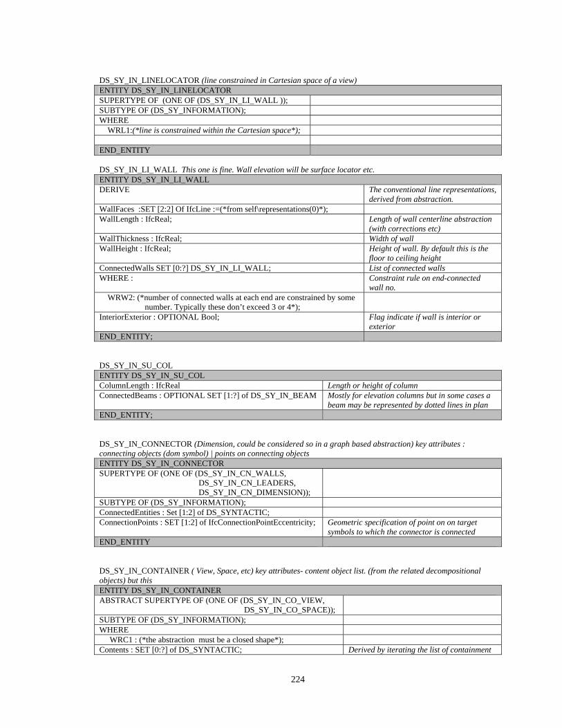
224
DS_SY_IN_LINELOCATOR (line constrained in Cartesian space of a view) ENTITY DS_SY_IN_LINELOCATOR SUPERTYPE OF (ONE OF (DS_SY_IN_LI_WALL )); SUBTYPE OF (DS_SY_INFORMATION); WHERE
WRL1:(*line is constrained within the Cartesian space*);
END_ENTITY DS_SY_IN_LI_WALL This one is fine. Wall elevation will be surface locator etc. ENTITY DS_SY_IN_LI_WALL DERIVE The conventional line representations,
derived from abstraction. WallFaces :SET [2:2] Of IfcLine :=(*from self\representations(0)*); WallLength : IfcReal; Length of wall centerline abstraction
(with corrections etc) WallThickness : IfcReal; Width of wall WallHeight : IfcReal; Height of wall. By default this is the
floor to ceiling height ConnectedWalls SET [0:?] DS_SY_IN_LI_WALL; List of connected walls WHERE : Constraint rule on end-connected
wall no. WRW2: (*number of connected walls at each end are constrained by some
number. Typically these don’t exceed 3 or 4*);
InteriorExterior : OPTIONAL Bool; Flag indicate if wall is interior or exterior
END_ENTITY; DS_SY_IN_SU_COL ENTITY DS_SY_IN_SU_COL ColumnLength : IfcReal Length or height of column ConnectedBeams : OPTIONAL SET [1:?] of DS_SY_IN_BEAM Mostly for elevation columns but in some cases a
beam may be represented by dotted lines in plan END_ENTITY; DS_SY_IN_CONNECTOR (Dimension, could be considered so in a graph based abstraction) key attributes : connecting objects (dom symbol) | points on connecting objects ENTITY DS_SY_IN_CONNECTOR SUPERTYPE OF (ONE OF (DS_SY_IN_CN_WALLS, DS_SY_IN_CN_LEADERS, DS_SY_IN_CN_DIMENSION));
SUBTYPE OF (DS_SY_INFORMATION); ConnectedEntities : Set [1:2] of DS_SYNTACTIC; ConnectionPoints : SET [1:2] of IfcConnectionPointEccentricity; Geometric specification of point on on target
symbols to which the connector is connected END_ENTITY DS_SY_IN_CONTAINER ( View, Space, etc) key attributes- content object list. (from the related decompositional objects) but this ENTITY DS_SY_IN_CONTAINER ABSTRACT SUPERTYPE OF (ONE OF (DS_SY_IN_CO_VIEW, DS_SY_IN_CO_SPACE));
SUBTYPE OF (DS_SY_INFORMATION); WHERE WRC1 : (*the abstraction must be a closed shape*); Contents : SET [0:?] of DS_SYNTACTIC; Derived by iterating the list of containment
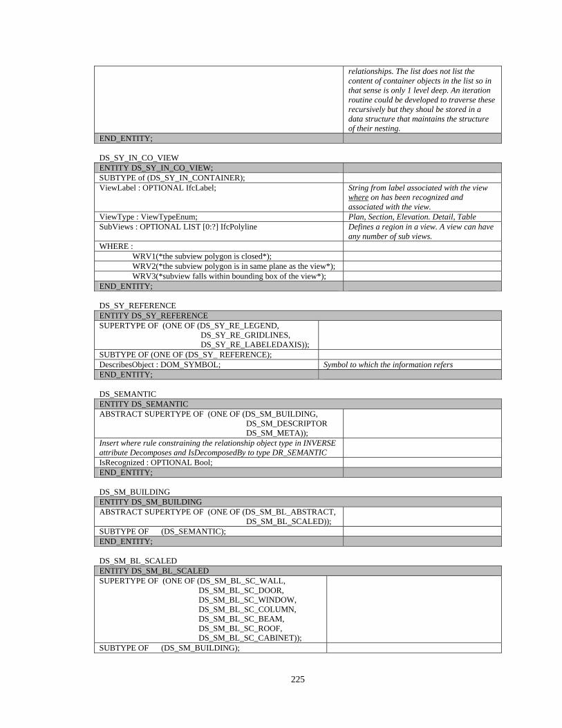
225
relationships. The list does not list the content of container objects in the list so in that sense is only 1 level deep. An iteration routine could be developed to traverse these recursively but they shoul be stored in a data structure that maintains the structure of their nesting.
END_ENTITY; DS_SY_IN_CO_VIEW ENTITY DS_SY_IN_CO_VIEW; SUBTYPE of (DS_SY_IN_CONTAINER); ViewLabel : OPTIONAL IfcLabel; String from label associated with the view
where on has been recognized and associated with the view.
ViewType : ViewTypeEnum; Plan, Section, Elevation. Detail, Table SubViews : OPTIONAL LIST [0:?] IfcPolyline Defines a region in a view. A view can have
any number of sub views. WHERE :
WRV1(*the subview polygon is closed*); WRV2(*the subview polygon is in same plane as the view*); WRV3(*subview falls within bounding box of the view*);
END_ENTITY; DS_SY_REFERENCE ENTITY DS_SY_REFERENCE SUPERTYPE OF (ONE OF (DS_SY_RE_LEGEND, DS_SY_RE_GRIDLINES, DS_SY_RE_LABELEDAXIS));
SUBTYPE OF (ONE OF (DS_SY_ REFERENCE); DescribesObject : DOM_SYMBOL; Symbol to which the information refers END_ENTITY; DS_SEMANTIC ENTITY DS_SEMANTIC ABSTRACT SUPERTYPE OF (ONE OF (DS_SM_BUILDING, DS_SM_DESCRIPTOR DS_SM_META));
Insert where rule constraining the relationship object type in INVERSE attribute Decomposes and IsDecomposedBy to type DR_SEMANTIC
IsRecognized : OPTIONAL Bool; END_ENTITY; DS_SM_BUILDING ENTITY DS_SM_BUILDING ABSTRACT SUPERTYPE OF (ONE OF (DS_SM_BL_ABSTRACT, DS_SM_BL_SCALED));
SUBTYPE OF (DS_SEMANTIC); END_ENTITY; DS_SM_BL_SCALED ENTITY DS_SM_BL_SCALED SUPERTYPE OF (ONE OF (DS_SM_BL_SC_WALL, DS_SM_BL_SC_DOOR, DS_SM_BL_SC_WINDOW, DS_SM_BL_SC_COLUMN, DS_SM_BL_SC_BEAM, DS_SM_BL_SC_ROOF, DS_SM_BL_SC_CABINET));
SUBTYPE OF (DS_SM_BUILDING);
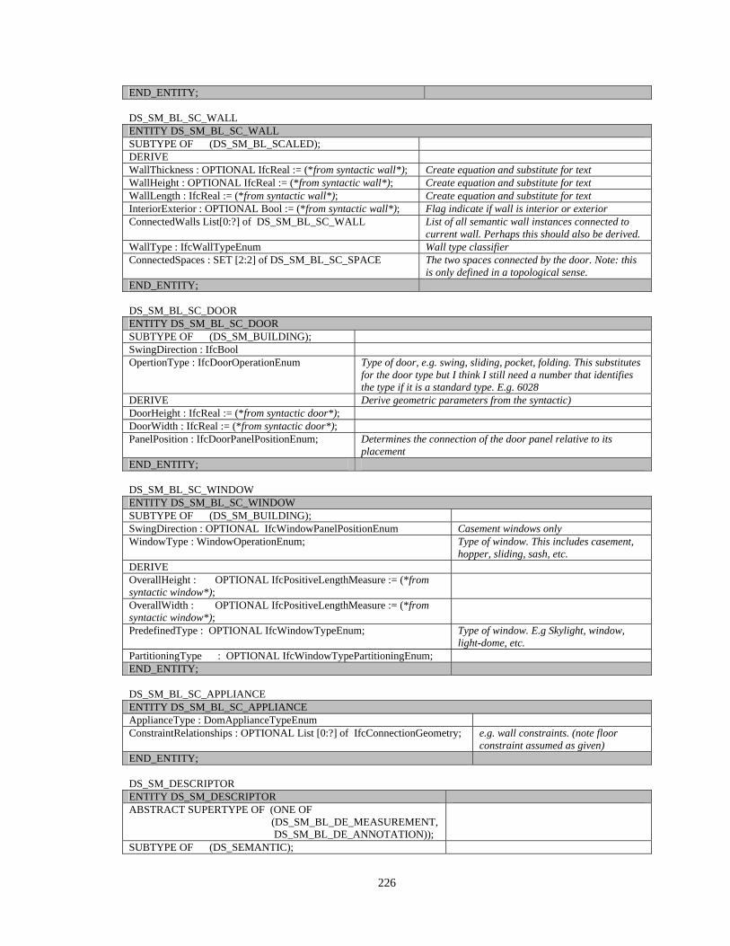
226
END_ENTITY; DS_SM_BL_SC_WALL ENTITY DS_SM_BL_SC_WALL SUBTYPE OF (DS_SM_BL_SCALED); DERIVE WallThickness : OPTIONAL IfcReal := (*from syntactic wall*); Create equation and substitute for text WallHeight : OPTIONAL IfcReal := (*from syntactic wall*); Create equation and substitute for text WallLength : IfcReal := (*from syntactic wall*); Create equation and substitute for text InteriorExterior : OPTIONAL Bool := (*from syntactic wall*); Flag indicate if wall is interior or exterior ConnectedWalls List[0:?] of DS_SM_BL_SC_WALL List of all semantic wall instances connected to
current wall. Perhaps this should also be derived. WallType : IfcWallTypeEnum Wall type classifier ConnectedSpaces : SET [2:2] of DS_SM_BL_SC_SPACE The two spaces connected by the door. Note: this
is only defined in a topological sense. END_ENTITY; DS_SM_BL_SC_DOOR ENTITY DS_SM_BL_SC_DOOR SUBTYPE OF (DS_SM_BUILDING); SwingDirection : IfcBool OpertionType : IfcDoorOperationEnum Type of door, e.g. swing, sliding, pocket, folding. This substitutes
for the door type but I think I still need a number that identifies the type if it is a standard type. E.g. 6028
DERIVE Derive geometric parameters from the syntactic) DoorHeight : IfcReal := (*from syntactic door*); DoorWidth : IfcReal := (*from syntactic door*); PanelPosition : IfcDoorPanelPositionEnum; Determines the connection of the door panel relative to its
placement END_ENTITY; DS_SM_BL_SC_WINDOW ENTITY DS_SM_BL_SC_WINDOW SUBTYPE OF (DS_SM_BUILDING); SwingDirection : OPTIONAL IfcWindowPanelPositionEnum Casement windows only WindowType : WindowOperationEnum; Type of window. This includes casement,
hopper, sliding, sash, etc. DERIVE OverallHeight : OPTIONAL IfcPositiveLengthMeasure := (*from syntactic window*);
OverallWidth : OPTIONAL IfcPositiveLengthMeasure := (*from syntactic window*);
PredefinedType : OPTIONAL IfcWindowTypeEnum; Type of window. E.g Skylight, window, light-dome, etc.
PartitioningType : OPTIONAL IfcWindowTypePartitioningEnum; END_ENTITY; DS_SM_BL_SC_APPLIANCE ENTITY DS_SM_BL_SC_APPLIANCE ApplianceType : DomApplianceTypeEnum ConstraintRelationships : OPTIONAL List [0:?] of IfcConnectionGeometry; e.g. wall constraints. (note floor
constraint assumed as given) END_ENTITY; DS_SM_DESCRIPTOR ENTITY DS_SM_DESCRIPTOR ABSTRACT SUPERTYPE OF (ONE OF (DS_SM_BL_DE_MEASUREMENT, DS_SM_BL_DE_ANNOTATION));
SUBTYPE OF (DS_SEMANTIC);
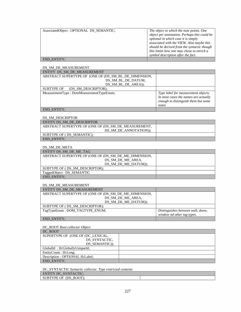
227
AssociatedObject : OPTIONAL DS_SEMANTIC; The object to which the note points. One object per annotation. Perhaps this could be optional in which case it is simply associated with the VIEW. Also maybe this should be derived from the syntactic though this limits how one may chose to enrich a symbol description after the fact.
END_ENTITY; DS_SM_DE_MEASUREMENT ENTITY DS_SM_DE_MEASUREMENT ABSTRACT SUPERTYPE OF (ONE OF (DS_SM_BL_DE_DIMENSION, DS_SM_BL_DE_DATUM, DS_SM_BL_DE_AREA));
SUBTYPE OF (DS_SM_DESCRIPTOR); MeasurementType : DomMeasurementTypeEnum; Type label for measurement objects.
In most cases the names are actually enough to distinguish them but some notes
END_ENTITY; DS_SM_DESCRIPTOR ENTITY DS_SM_DE_DESCRIPTOR ABSTRACT SUPERTYPE OF (ONE OF (DS_SM_DE_MEASUREMENT, DS_SM_DE_ANNOTATION));
SUBTYPE OF ( DS_SEMANTIC); END_ENTITY; DS_SM_DE_META ENTITY DS_SM_DE_ME_TAG ABSTRACT SUPERTYPE OF (ONE OF (DS_SM_DE_ME_DIMENSION, DS_SM_DE_ME_AREA, DS_SM_DE_ME_DATUM));
SUBTYPE OF ( DS_SM_DESCRIPTOR); TaggedObject : DS_SEMANTIC END_ENTITY; DS_SM_DE_MEASUREMENT ENTITY DS_SM_DE_MEASUREMENT ABSTRACT SUPERTYPE OF (ONE OF (DS_SM_DE_ME_DIMENSION, DS_SM_DE_ME_AREA, DS_SM_DE_ME_DATUM));
SUBTYPE OF ( DS_SM_DESCRIPTOR); TagTypeEnum : DOM_TAGTYPE_ENUM; Distinguishes between wall, doow,
window nd other tag types. END_ENTITY; DC_ROOT Root collector Object DC_ROOT SUPERTYPE OF (ONE OF (DC_LEXICAL, DS_SYNTACTIC, DS_SEMANTIC));
GlobalId : IfcGloballyUniqueId; EntityCount : IfcLong; Description : OPTIONAL IfcLabel; END_ENTITY; DC_SYNTACTIC Syntactic collector. Type restricted contents ENTITY DC_SYNTACTIC; SUBTYPE OF (DS_ROOT);
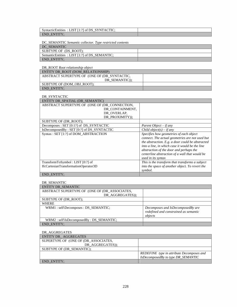
228
SyntacticEntities : LIST [1:?] of DS_SYNTACTIC; END_ENTITY; DC_SEMANTIC Semantic collector. Type restricted contents DC_SEMANTIC SUBTYPE OF (DS_ROOT); SemanticEntities : LIST [1:?] of DS_SEMANTIC; END_ENTITY; DR_ROOT Root relationship object ENTITY DR_ROOT (DOM_RELATIONSHIP) ABSTRACT SUPERTYPE OF (ONE OF (DR_SYNTACTIC, DR_SEMANTIC));
SUBTYPE OF (DOM_OBJ_ROOT); END_ENTITY; DR_SYNTACTIC ENTITY DR_SPATIAL (DR_SEMANTIC) ABSTRACT SUPERTYPE OF (ONE OF (DR_CONNECTION, DR_CONTAINMENT, DR_OVERLAP, DR_PROXIMITY));
SUBTYPE OF (DR_ROOT); Decomposes : SET [0:1?] of DS_SYNTACTIC Parent Object – if any IsDecomposedBy : SET [0:?] of DS_SYNTACTIC Child object(s) – if any Syntax : SET [1:?] of DOM_ABSTRACTION Specifies how geometries of each object
connect. The actual geometries are not used but the abstraction. E.g. a door could be abstracted into a line, in which case it would be the line abstraction of the door and perhaps the centerline abstraction of a wall that would be used in its syntax
TransformToSymbol : LIST [0:?] of IfcCartesianTransformationOperator3D
This is the transform that transforms a subject into the space of another object. To revert the symbol.
END_ENTITY; DR_SEMANTIC ENTITY DR_SEMANTIC ABSTRACT SUPERTYPE OF (ONE OF (DR_ASSOCIATES, DR_AGGREGATES));
SUBTYPE OF (DR_ROOT); WHERE WRM1 : self\Decomposes : DS_SEMANTIC; Decomposes and IsDecomposedBy are
redefined and constrained as semantic objects
WRM2 : self\IsDecomposedBy : DS_SEMANTIC; END_ENTITY; DR_AGGREGATES ENTITY DR_ AGGREGATES SUPERTYPE OF (ONE OF (DR_ASSOCIATES, DR_AGGREGATES));
SUBTYPE OF (DR_SEMANTIC); REDEFINE type in attribute Decomposes and
IsDecomposedBy to type DR_SEMANTIC END_ENTITY;
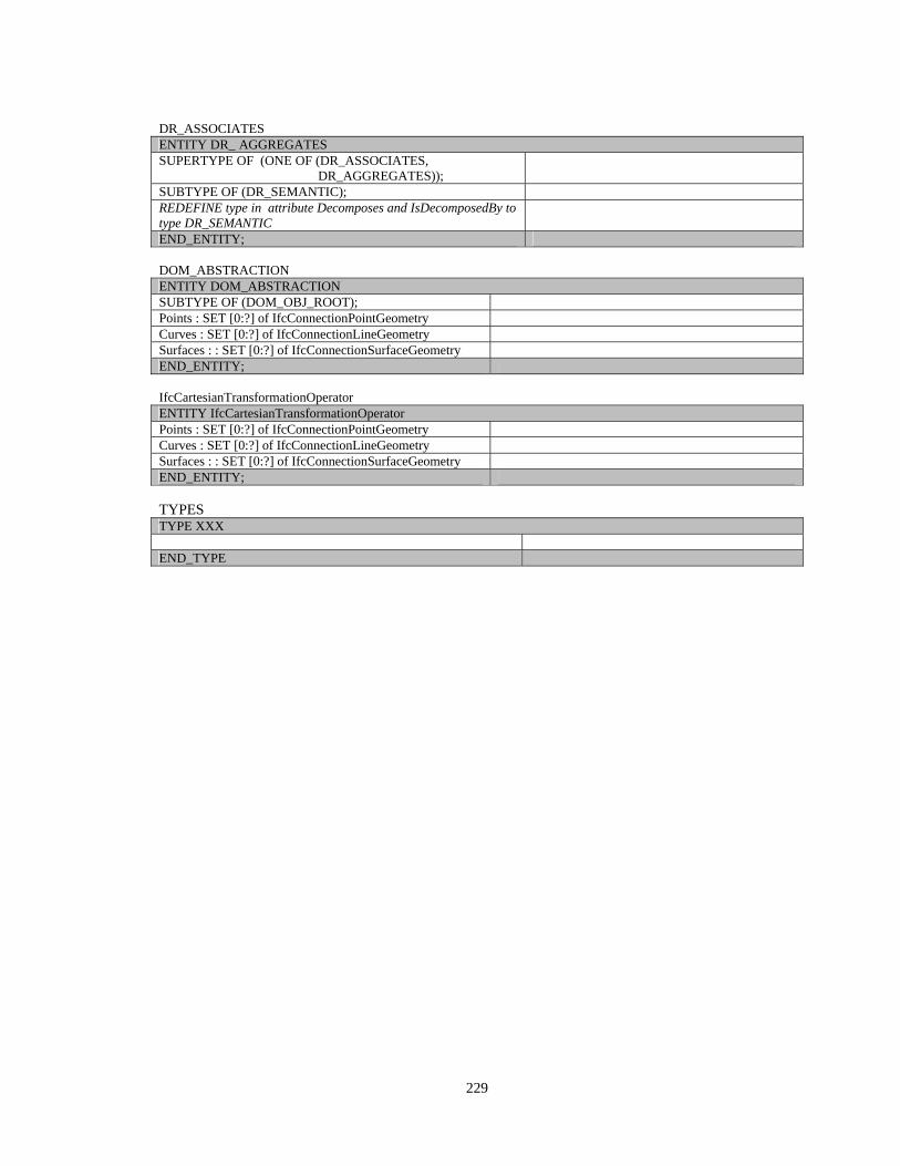
229
DR_ASSOCIATES ENTITY DR_ AGGREGATES SUPERTYPE OF (ONE OF (DR_ASSOCIATES, DR_AGGREGATES));
SUBTYPE OF (DR_SEMANTIC); REDEFINE type in attribute Decomposes and IsDecomposedBy to type DR_SEMANTIC
END_ENTITY; DOM_ABSTRACTION ENTITY DOM_ABSTRACTION SUBTYPE OF (DOM_OBJ_ROOT); Points : SET [0:?] of IfcConnectionPointGeometry Curves : SET [0:?] of IfcConnectionLineGeometry Surfaces : : SET [0:?] of IfcConnectionSurfaceGeometry END_ENTITY; IfcCartesianTransformationOperator ENTITY IfcCartesianTransformationOperator Points : SET [0:?] of IfcConnectionPointGeometry Curves : SET [0:?] of IfcConnectionLineGeometry Surfaces : : SET [0:?] of IfcConnectionSurfaceGeometry END_ENTITY; TYPES TYPE XXX END_TYPE
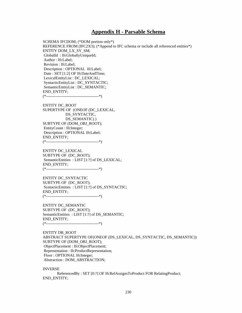
230
Appendix H - Parsable Schema SCHEMA IFCDOM; (*DOM portion only*) REFERENCE FROM (IFC2X3); (*Append to IFC schema or include all referenced entities*) ENTITY DOM_LX_SY_SM; GlobalId : IfcGloballyUniqueId; Author : IfcLabel; Revision : IfcLabel; Description : OPTIONAL IfcLabel; Date : SET [1:2] OF IfcDateAndTime; LexicalEntityList : DC_LEXICAL; SyntacticEntityList : DC_SYNTACTIC; SemanticEntityList : DC_SEMANTIC; END_ENTITY; (*----------------------------------------*) ENTITY DC_ROOT SUPERTYPE OF (ONEOF (DC_LEXICAL, DS_SYNTACTIC, DS_SEMANTIC) ) SUBTYPE OF (DOM_OBJ_ROOT); EntityCount : IfcInteger; Description : OPTIONAL IfcLabel; END_ENTITY; (*----------------------------------------*) ENTITY DC_LEXICAL SUBTYPE OF (DC_ROOT); SemanticEntities : LIST [1:?] of DS_LEXICAL; END_ENTITY; (*----------------------------------------*) ENTITY DC_SYNTACTIC SUBTYPE OF (DC_ROOT); SyntacticEntities : LIST [1:?] of DS_SYNTACTIC; END_ENTITY; (*----------------------------------------*) ENTITY DC_SEMANTIC SUBTYPE OF (DC_ROOT); SemanticEntities : LIST [1:?] of DS_SEMANTIC; END_ENTITY; (*----------------------------------------*) ENTITY DR_ROOT ABSTRACT SUPERTYPE OF(ONEOF (DS_LEXICAL, DS_SYNTACTIC, DS_SEMANTIC)) SUBTYPE OF (DOM_OBJ_ROOT); ObjectPlacement : IfcObjectPlacement; Representation : IfcProductRepresentation; Floor : OPTIONAL IfcInteger; Abstraction : DOM_ABSTRACTION; INVERSE ReferencedBy : SET [0:?] OF IfcRelAssignsToProduct FOR RelatingProduct; END_ENTITY;
231
(*----------------------------------------*) ENTITY DOM_OBJ_ROOT SUPERTYPE OF (ONEOF (DS_ROOT, DR_ROOT)) SUBTYPE OF (IfcRoot); END_ENTITY; (*----------------------------------------*) ENTITY DS_ROOT ABSTRACT SUPERTYPE OF(ONEOF (DS_SYNTACTIC, DS_SEMANTIC)) SUBTYPE OF (IfcObject); ObjectPlacement : IfcObjectPlacement; Representation : IfcProductRepresentation; Floor : OPTIONAL IfcInteger; Abstraction : DOM_ABSTRACTION; INVERSE ReferencedBy : SET[0:?] OF IfcRelAssignsToProduct FOR RelatingProduct; END_ENTITY; (*----------------------------------------*) ENTITY DS_LEXICAL SUBTYPE OF (IfcGeometricRepresentationItem); END_ENTITY; (*----------------------------------------*) ENTITY DS_SYNTACTIC SUPERTYPE OF (ONEOF (DS_SY_INFORMATION, DS_SY_REFERENCE, DS_SY_DECORATION) ) SUBTYPE OF (DS_ROOT); IsRecognized : IfcBoolean; ViewType : OPTIONAL IfcLabel; END_ENTITY; (*----------------------------------------*) ENTITY DS_SY_INFORMATION SUPERTYPE OF (ONEOF (DS_SY_IN_NODE, DS_SY_IN_LABEL, DS_SY_IN_CONNECTOR, DS_SY_IN_CONTAINER, DS_SY_IN_POINTLOCATOR, DS_SY_IN_LINELOCATOR, DS_SY_IN_SURFACELOCATOR) ) SUBTYPE OF (DS_SYNTACTIC); END_ENTITY; (*----------------------------------------*)
232
ENTITY DS_SY_IN_NODE SUPERTYPE OF (ONEOF (DS_SY_IN_NO_WINDOW, DS_SY_IN_NO_DOOR, DS_SY_IN_NO_APPLIANCE, DS_SY_IN_NO_FIXTURE)) SUBTYPE OF (DS_SY_INFORMATION); DERIVE AttachmentPoint : SET [1:?] OF IfcPoint := (*from self\abstraction.IfcConnectionPointGeometry*);; AttatchmentGeometry : IfcCurve :=(*from self\abstraction.IfcConnectionCurveGeometry*);; END_ENTITY; (*----------------------------------------*) ENTITY DS_SY_IN_LINELOCATOR SUPERTYPE OF (ONEOF (DS_SY_IN_LI_WALL)) SUBTYPE OF (DS_SY_INFORMATION); WHERE (*WRL1 : line is constrained within the Cartesian space*);; END_ENTITY; (*----------------------------------------*) ENTITY DS_SY_IN_LI_WALL SUBTYPE OF (DS_SY_IN_LINELOCATOR); InteriorExterior : OPTIONAL IfcBoolean; WallLength : IfcReal; WallThickness : IfcReal; WallHeight : IfcReal; ConnectedWalls : SET [0:?] OF DS_SY_IN_LI_WALL; DERIVE WallFaces : DOM_TYPE_PARALLEL_LINES := (*derive parallel line entities from self\representations*);; WHERE (*WRW2 : connected walls at each end constrained by number. Typically 3 or 4*);; END_ENTITY; (*----------------------------------------*) TYPE DOM_TYPE_PARALLEL_LINES = SET [2:2] OF IfcLine; END_TYPE; ENTITY DS_SY_IN_NO_TAG SUBTYPE OF (DS_SY_IN_NODE); TagStrings : SET [1:?] OF IfcLabel; StringPattern : IfcLabel; AssociatedObject : DS_SYNTACTIC; CrossViewTag : DS_SY_IN_NO_TAG; TagType : OPTIONAL DOM_ENUM_TAGTYPE; WHERE (*WRT1 : self\DomTagTypeEnum = CrossViewTagMatch.DOM_ENUM_TAGTYPE*); (*WRT2 : self\TagStrings have to match in both *);
233
(*WRT3 : self\AssociatedObject must be same type for CrossViewTag*); (*WRT2 : self\ cannot point to match tag in same view *); END_ENTITY; (*----------------------------------------*) TYPE DOM_ENUM_TAGTYPE = ENUMERATION OF (DOORTAG, WINOWTAG, WALLTAG, APPLIANCETAG, FIXTURETAG); END_TYPE; (*---------------------------------------------*) ENTITY DS_SY_IN_NO_WINDOW SUBTYPE OF (DS_SY_IN_NODE); WindowType : IfcWindowStyleOperationEnum; WHERE (*WRW1: default abstraction is line+points if plan and polygon+points if elevation*);; END_ENTITY; (*----------------------------------------*) ENTITY DS_SY_IN_NO_DOOR SUBTYPE OF (DS_SY_IN_NODE); DoorType : IfcDoorStyleOperationEnum; ConnectedSpaces : SET [2:2] OF DS_SY_IN_SU_SPACE; (*change to select type to include DS_SY_IN_CO_SPACE*) InteriorExterior : IfcBoolean; WHERE (*WRD1: default abstraction is line+points if plan and polygon+points if elevation*);; END_ENTITY; (*----------------------------------------*) ENTITY DS_SY_IN_SU_SPACE SUBTYPE OF (DS_SY_IN_SURFACELOCATOR); END_ENTITY; (*----------------------------------------*) ENTITY DS_SY_IN_CO_SPACE (*alternative representation that allow aggregation of spatial contents*) SUBTYPE OF (DS_SY_IN_CONTAINER); END_ENTITY; (*----------------------------------------*) ENTITY DS_SY_IN_NO_APPLIANCE SUBTYPE OF (DS_SY_IN_NODE); ApplianceType : DOM_ENUM_APPLIANCE; END_ENTITY; (*----------------------------------------*)
234
TYPE DOM_ENUM_APPLIANCE = ENUMERATION OF (Range, Dishwasher, Microwave, Fridge, Washer, Dryer); END_TYPE; (*----------------------------------------*) ENTITY DS_SY_IN_NO_FIXTURE SUBTYPE OF (DS_SY_IN_NODE); FixtureType : DOM_ENUM_FIXTURE; END_ENTITY; (*----------------------------------------*) TYPE DOM_ENUM_FIXTURE = ENUMERATION OF (Sink, Tub, Shower); END_TYPE; (*----------------------------------------*) ENTITY DS_SY_IN_LABEL SUPERTYPE OF (ONEOF (DS_SY_IN_LA_TAG, DS_SY_IN_LA_ANNOTATION, DS_SY_IN_LA_LABEL)) SUBTYPE OF (DS_SY_INFORMATION); LabelType : DOM_ENUM_LABEL; LabelText : SET [1:?] OF IfcLabel; END_ENTITY; (*----------------------------------------*) TYPE DOM_SELECT_LABEL = SELECT (DS_SY_IN_LA_TAGS, DS_SY_IN_LA_LABEL); END_TYPE; (*----------------------------------------*) TYPE DOM_ENUM_LABEL = ENUMERATION OF (Tag, Annotation, Label); END_TYPE; (*----------------------------------------*) ENTITY DS_SY_IN_NO_TAG SUBTYPE OF (DS_SY_IN_NODE); TagStrings : Set [1:?] OF IfcLabel; StringPattern : IfcLabel; AssociatedObject : DS_SYNTACTIC; CrossViewTag : DS_SY_IN_NO_TAG; TagType : OPTIONAL DOM_ENUM_TAGTYPE; WHERE (*WRT1 : self\DOM_ENUM_TAGTYPE = same as tagtype in cross view tag*);; (*WRT2 : self\TagStrings have to match in both *);; (*WRT3 : self\AssociatedObject must be same type for CrossViewTag*);; (*WRT2 : self\cannot point to match tag in same view *);; END_ENTITY; (*----------------------------------------*)

235
ENTITY DS_SY_IN_LA_ANNOTATION SUBTYPE OF (DS_SY_IN_LABEL); END_ENTITY; (*----------------------------------------*) ENTITY DS_SY_IN_LA_LABEL SUBTYPE OF (DS_SY_IN_LABEL); END_ENTITY; (*----------------------------------------*) ENTITY DS_SY_IN_CONNECTOR SUPERTYPE OF (ONEOF (DS_SY_IN_CN_WALL, DS_SY_IN_CN_LEADER, DS_SY_IN_CN_DIMENSION) ) SUBTYPE OF (DS_SY_INFORMATION); ConnectedEntities : Set [1:2] OF DS_SYNTACTIC; ConnectionPoints : SET [1:2] OF IfcConnectionPointEccentricity; END_ENTITY; (*----------------------------------------*) ENTITY DS_SY_CN_WALL SUBTYPE OF (DS_SY_IN_CONNECTOR); END_ENTITY; (*----------------------------------------*) ENTITY DS_SY_CN_LEADERS SUBTYPE OF (DS_SY_IN_CONNECTOR); END_ENTITY; (*----------------------------------------*) ENTITY DS_SY_CN_DIMENSIONS SUBTYPE OF (DS_SY_IN_CONNECTOR); END_ENTITY; (*--------------------------------------*) ENTITY DS_SY_IN_CONTAINER ABSTRACT SUPERTYPE OF (ONEOF (DS_SY_IN_CO_VIEW, DS_SY_IN_CO_SPACE)) SUBTYPE OF (DS_SY_INFORMATION); Contents : SET [0:?] of DS_SYNTACTIC; WHERE (*WRC1 : the abstraction must be a closed shape*);; END_ENTITY; (*----------------------------------------*) ENTITY DS_SY_IN_POINTLOCATOR SUBTYPE OF (DS_SY_INFORMATION);
236
END_ENTITY; (*----------------------------------------*) ENTITY DS_SY_IN_CO_VIEW SUBTYPE of (DS_SY_IN_CONTAINER); ViewLabel : OPTIONAL IfcLabel; ViewType : IfcGeometricProjectionEnum; SubViews : OPTIONAL LIST [0:?] OF IfcPolyline; WHERE (*WRV1 : the subview polygon is closed*);; (*WRV2 : the subview polygon is in same plane as the view*);; (*WRV3 : subview falls within bounding box of the view*);; END_ENTITY; (*----------------------------------------*) ENTITY DS_SY_IN_LINELOCATOR SUPERTYPE OF (ONEOF (DS_SY_IN_LI_WALL )) SUBTYPE OF (DS_SY_INFORMATION); WHERE (*WRL1:line is constrained within the views cartesian space*);; (*WRL2:the abstraction is a line*);; END_ENTITY; (*----------------------------------------*) ENTITY DS_SY_IN_SURFACELOCATOR SUPERTYPE OF (ONEOF (DS_SY_IN_SU_SPACE, DS_SY_IN_SU_WALL, DS_SY_IN_SU_STAIRS, DS_SY_IN_SU_SLAB, DS_SY_IN_SU_OPENING)) SUBTYPE OF (DS_SY_INFORMATION); WHERE (*WRS1: surface is constrained within the views cartesian space*);; (*WRL2:the abstraction is a closed polyline*);; END_ENTITY; (*----------------------------------------*) ENTITY DS_SY_IN_SU_WALL SUBTYPE OF (DS_SY_IN_SURFACELOCATOR); (*attributes: not yet defined*) (*WRSW1 : constrained to elevation view wall representations*) END_ENTITY; (*----------------------------------------*) ENTITY DS_SY_IN_SU_STAIR SUBTYPE OF (DS_SY_IN_SURFACELOCATOR); (*attributes: not yet defined*) (*WRSW1 : constrained to plan view stair representations*) END_ENTITY; (*----------------------------------------*)
237
ENTITY DS_SY_IN_SU_SLAB SUBTYPE OF (DS_SY_IN_SURFACELOCATOR); (*attributes: not yet defined*) (*WRSW1 : constrained to plan view slab representations*) END_ENTITY; (*----------------------------------------*) ENTITY DS_SY_IN_SU_OPENING SUBTYPE OF (DS_SY_IN_SURFACELOCATOR); (*attributes: not yet defined*) (*WRSW1 : applies to both plan and levation view opening representations*) END_ENTITY; (*----------------------------------------*) ENTITY DS_SY_REFERENCE SUBTYPE OF (DS_SYNTACTIC); (*not defined. cant immediately think of any symbols under this category*) END_ENTITY; (*----------------------------------------*) ENTITY DS_SY_DECORATION SUBTYPE OF (DS_SYNTACTIC); (*not defined. these are symbols that do not add to the information in any way and can be changed moved or deleted altogether. I cant immediately think of any symbols under this category*) END_ENTITY; (*----------------------------------------*) ENTITY DS_SEMANTIC ABSTRACT SUPERTYPE OF (ONEOF (DS_SM_BUILDING, DS_SM_DESCRIPTOR, DS_SM_META)) SUBTYPE OF (DS_ROOT); IsRecognized : OPTIONAL Boolean; (*inherits placement and representation from IfcProdct*) (*representation is constrained by rule to DS_SYNTACTIC*) END_ENTITY; (*----------------------------------------*) ENTITY DS_SM_BL_SC_APPLIANCE SUBTYPE OF (DS_SM_BL_SCALED); ApplianceType : DOM_ENUM_APPLIANCE; ConstraintRelationships : OPTIONAL List [0:?] of IfcConnectionGeometry; END_ENTITY; (*----------------------------------------*) ENTITY DS_SM_BL_SC_FIXTURE SUBTYPE OF (DS_SM_BL_SCALED); FixtureType : DOM_ENUM_FIXTURE; ConstraintRelationships : OPTIONAL List [0:?] of IfcConnectionGeometry; END_ENTITY; (*----------------------------------------*)
238
ENTITY DS_SM_BUILDING ABSTRACT SUPERTYPE OF (ONEOF (DS_SM_BL_ABSTRACT, DS_SM_BL_SCALED)) SUBTYPE OF (DS_SEMANTIC); END_ENTITY; (*----------------------------------------*) ENTITY DS_SM_BL_SCALED SUPERTYPE OF (ONEOF (DS_SM_BL_SC_WALL, DS_SM_BL_SC_DOOR, DS_SM_BL_SC_WINDOW, DS_SM_BL_SC_COLUMN, DS_SM_BL_SC_BEAM, DS_SM_BL_SC_ROOF, DS_SM_BL_SC_CABINET, DS_SM_BL_SC_SPACE)) SUBTYPE OF (DS_SM_BUILDING); END_ENTITY; (*----------------------------------------*) ENTITY DS_SM_BL_SC_WALL SUBTYPE OF (DS_SM_BL_SCALED); WallType : IfcWallTypeEnum; ConnectedSpaces : SET [2:2] OF DS_SM_BL_SC_SPACE; ConnectedWalls : LIST [0:?] OF DS_SM_BL_SC_WALL; DERIVE WallThickness : IfcReal := (*from syntactic wall*);;(*should be OPTIONAL*) WallHeight : IfcReal := (*from syntactic wall*);;(*should be OPTIONAL*) WallLength : IfcReal := (*from syntactic wall*);; InteriorExterior : Boolean := (*from syntactic wall*);;(*should be OPTIONAL*) END_ENTITY; (*----------------------------------------*) ENTITY DS_SM_BL_SC_SPACE SUBTYPE of (DS_SM_BL_SCALED); (*not yet defined*) (*include connected spaces, bounding walls, bounding slabs, access objects i.e. doors and openings, windows*) (*basically cull the relevant subset from IfcSpace definition*) END_ENTITY; (*----------------------------------------*) ENTITY DS_SM_BL_SC_DOOR SUBTYPE OF (DS_SM_BL_SCALED); SwingDirection : IfcBoolean; OperationType : IfcDoorStyleOperationEnum; DERIVE DoorHeight : IfcReal := (*from syntactic door. should be OPTIONAL*);; DoorWidth : IfcReal := (*from syntactic door. should be OPTIONAL*);;
239
PanelPosition : IfcDoorPanelPositionEnum := (*from syntactic door. should be OPTIONAL*);; END_ENTITY; (*----------------------------------------*) ENTITY DS_SM_BL_SC_WINDOW SUBTYPE OF (DS_SM_BUILDING); SwingDirection : OPTIONAL IfcWindowPanelPositionEnum; WindowType : IfcWindowStyleOperationEnum; DERIVE OverallHeight : IfcPositiveLengthMeasure := (*from syntactic window. should be OPTIONAL*);; OverallWidth : IfcPositiveLengthMeasure := (*from syntactic window. should be OPTIONAL*);; (*should add attribute for window partition since this can be recognized from the drawings*) END_ENTITY; (*----------------------------------------*) ENTITY DS_SM_BL_SC_COLUMN SUBTYPE OF (DS_SM_BL_SCALED); (* not yet defined. see IfcColumn Schema for guidance. key attributes only *) END_ENTITY; (*----------------------------------------*) ENTITY DS_SM_BL_SC_BEAM SUBTYPE OF (DS_SM_BL_SCALED); (* not yet defined. see IfcBeam Schema for guidance. key attributes only *) END_ENTITY; (*----------------------------------------*) ENTITY DS_SM_BL_SC_STAIR SUBTYPE OF (DS_SM_BL_SCALED); (* not yet defined. see IfcStair Schema for guidance. see flights, landings and railings *) END_ENTITY; (*----------------------------------------*) ENTITY DS_SM_BL_SC_ROOF SUBTYPE OF (DS_SM_BL_SCALED); (* not yet defined. see IfcRoof Schema for guidance. exterior form only *) END_ENTITY; (*----------------------------------------*) ENTITY DS_SM_BL_ABSTRACT SUBTYPE OF (DS_SM_BUILDING); END_ENTITY; (*----------------------------------------*) ENTITY DS_SM_DESCRIPTOR ABSTRACT SUPERTYPE OF (ONEOF (DS_SM_DE_MEASUREMENT, DS_SM_DE_ANNOTATION)) SUBTYPE OF (DS_SEMANTIC); AssociatedObject : OPTIONAL DS_SEMANTIC; END_ENTITY; (*----------------------------------------*) ENTITY DS_SM_DE_MEASUREMENT
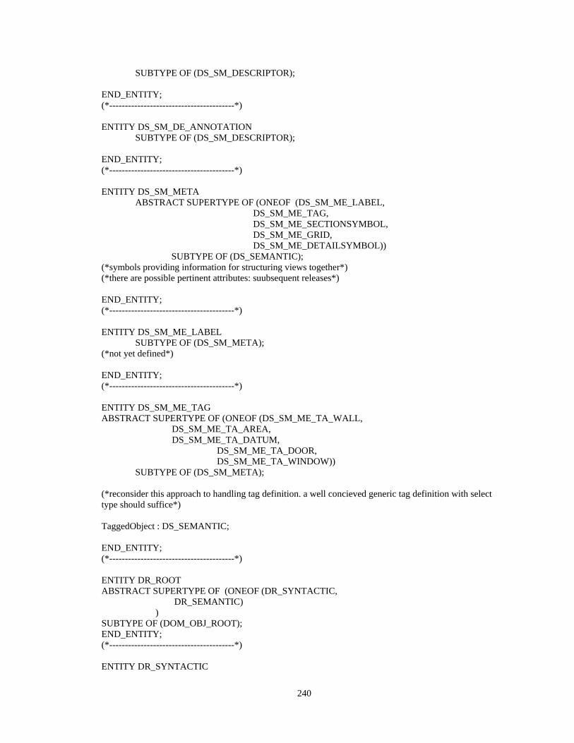
240
SUBTYPE OF (DS_SM_DESCRIPTOR); END_ENTITY; (*----------------------------------------*) ENTITY DS_SM_DE_ANNOTATION SUBTYPE OF (DS_SM_DESCRIPTOR); END_ENTITY; (*----------------------------------------*) ENTITY DS_SM_META ABSTRACT SUPERTYPE OF (ONEOF (DS_SM_ME_LABEL, DS_SM_ME_TAG, DS_SM_ME_SECTIONSYMBOL, DS_SM_ME_GRID, DS_SM_ME_DETAILSYMBOL)) SUBTYPE OF (DS_SEMANTIC); (*symbols providing information for structuring views together*) (*there are possible pertinent attributes: suubsequent releases*) END_ENTITY; (*----------------------------------------*) ENTITY DS_SM_ME_LABEL SUBTYPE OF (DS_SM_META); (*not yet defined*) END_ENTITY; (*----------------------------------------*) ENTITY DS_SM_ME_TAG ABSTRACT SUPERTYPE OF (ONEOF (DS_SM_ME_TA_WALL, DS_SM_ME_TA_AREA, DS_SM_ME_TA_DATUM, DS_SM_ME_TA_DOOR, DS_SM_ME_TA_WINDOW)) SUBTYPE OF (DS_SM_META); (*reconsider this approach to handling tag definition. a well concieved generic tag definition with select type should suffice*) TaggedObject : DS_SEMANTIC; END_ENTITY; (*----------------------------------------*) ENTITY DR_ROOT ABSTRACT SUPERTYPE OF (ONEOF (DR_SYNTACTIC, DR_SEMANTIC) ) SUBTYPE OF (DOM_OBJ_ROOT); END_ENTITY; (*----------------------------------------*) ENTITY DR_SYNTACTIC
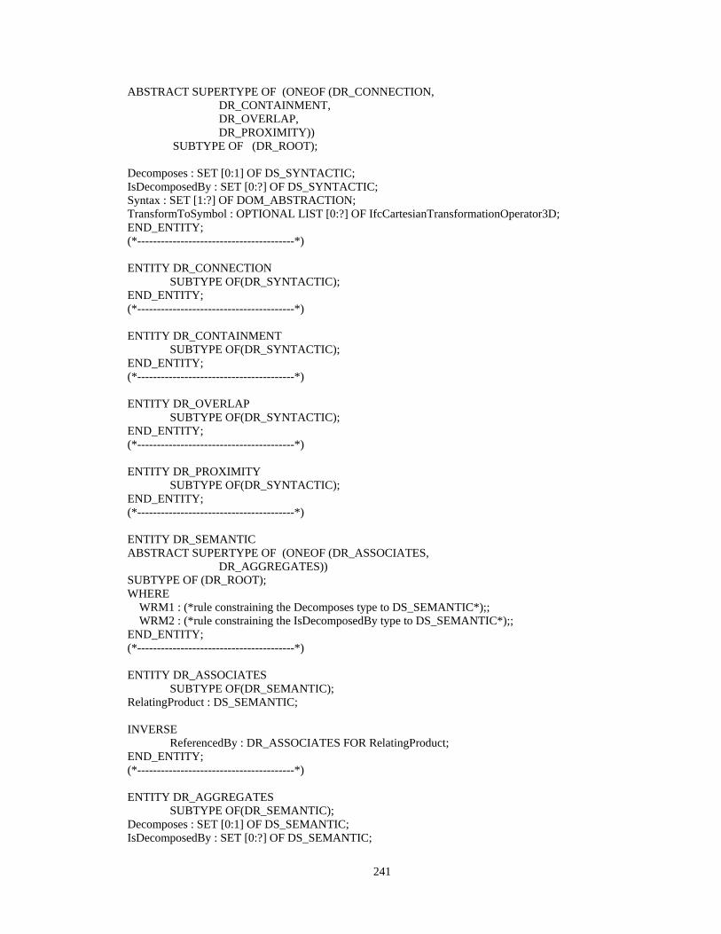
241
ABSTRACT SUPERTYPE OF (ONEOF (DR_CONNECTION, DR_CONTAINMENT, DR_OVERLAP, DR_PROXIMITY)) SUBTYPE OF (DR_ROOT); Decomposes : SET [0:1] OF DS_SYNTACTIC; IsDecomposedBy : SET [0:?] OF DS_SYNTACTIC; Syntax : SET [1:?] OF DOM_ABSTRACTION; TransformToSymbol : OPTIONAL LIST [0:?] OF IfcCartesianTransformationOperator3D; END_ENTITY; (*----------------------------------------*) ENTITY DR_CONNECTION SUBTYPE OF(DR_SYNTACTIC); END_ENTITY; (*----------------------------------------*) ENTITY DR_CONTAINMENT SUBTYPE OF(DR_SYNTACTIC); END_ENTITY; (*----------------------------------------*) ENTITY DR_OVERLAP SUBTYPE OF(DR_SYNTACTIC); END_ENTITY; (*----------------------------------------*) ENTITY DR_PROXIMITY SUBTYPE OF(DR_SYNTACTIC); END_ENTITY; (*----------------------------------------*) ENTITY DR_SEMANTIC ABSTRACT SUPERTYPE OF (ONEOF (DR_ASSOCIATES, DR_AGGREGATES)) SUBTYPE OF (DR_ROOT); WHERE WRM1 : (*rule constraining the Decomposes type to DS_SEMANTIC*);; WRM2 : (*rule constraining the IsDecomposedBy type to DS_SEMANTIC*);; END_ENTITY; (*----------------------------------------*) ENTITY DR_ASSOCIATES SUBTYPE OF(DR_SEMANTIC); RelatingProduct : DS_SEMANTIC; INVERSE ReferencedBy : DR_ASSOCIATES FOR RelatingProduct; END_ENTITY; (*----------------------------------------*) ENTITY DR_AGGREGATES SUBTYPE OF(DR_SEMANTIC); Decomposes : SET [0:1] OF DS_SEMANTIC; IsDecomposedBy : SET [0:?] OF DS_SEMANTIC;
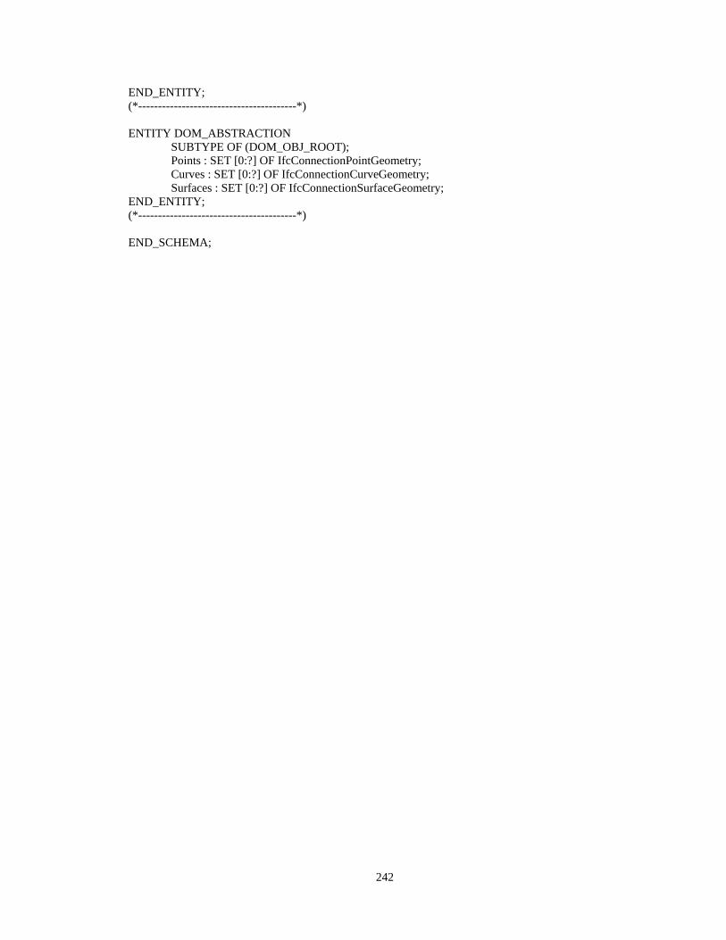
242
END_ENTITY; (*----------------------------------------*) ENTITY DOM_ABSTRACTION SUBTYPE OF (DOM_OBJ_ROOT); Points : SET [0:?] OF IfcConnectionPointGeometry; Curves : SET [0:?] OF IfcConnectionCurveGeometry; Surfaces : SET [0:?] OF IfcConnectionSurfaceGeometry; END_ENTITY; (*----------------------------------------*) END_SCHEMA;

243
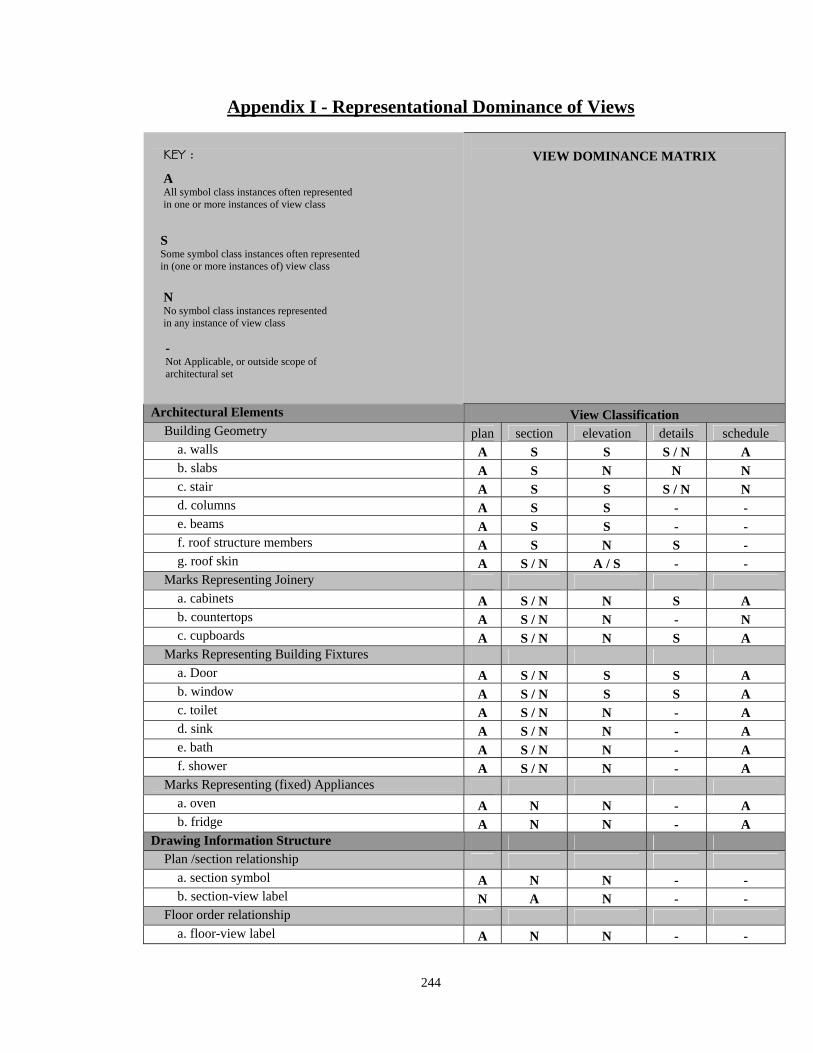
244
Appendix I - Representational Dominance of Views
VIEW DOMINANCE MATRIX
Architectural Elements View Classification Building Geometry plan section elevation details schedule
a. walls A S S S / N A b. slabs A S N N N c. stair A S S S / N N d. columns A S S - - e. beams A S S - - f. roof structure members A S N S - g. roof skin A S / N A / S - -
Marks Representing Joinery a. cabinets A S / N N S A b. countertops A S / N N - N c. cupboards A S / N N S A
Marks Representing Building Fixtures a. Door A S / N S S A b. window A S / N S S A c. toilet A S / N N - A d. sink A S / N N - A e. bath A S / N N - A f. shower A S / N N - A
Marks Representing (fixed) Appliances a. oven A N N - A b. fridge A N N - A
Drawing Information Structure Plan /section relationship
a. section symbol A N N - - b. section-view label N A N - -
Floor order relationship a. floor-view label A N N - -
A All symbol class instances often represented in one or more instances of view class
S Some symbol class instances often represented in (one or more instances of) view class
N No symbol class instances represented in any instance of view class
KEY :
- Not Applicable, or outside scope of architectural set
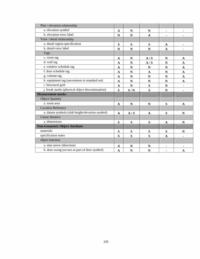
245
Plan / elevation relationship a. elevation symbol A N N - - b. elevation-view label N N A - -
View / detail relationship a. detail region-specification S S S A - b. detail-view label N N N A - Tags c. room tag A N A / S N A d. wall tag A N A / S N A e. window schedule tag A N N N A f. door schedule tag A N A N A g. column tag A N N N A h. equipment tag (uncommon in standard set) A N N N A
i. Structural grid A N S N - j. break marks (physical object discontinuation) S S / N S N -
Measurement marks Object Quantity
a. room area A N N S A Location Reference
a. datum symbols (slab height/elevation symbol) A A / S A S N Linear distance
a. dimensions S S S A N Non-Geometric Object Attribute
materials S S S S N specification notes S S S A - object function
a. stair arrow (direction) A N N - - b. door swing (occurs as part of door symbol) A N N - A
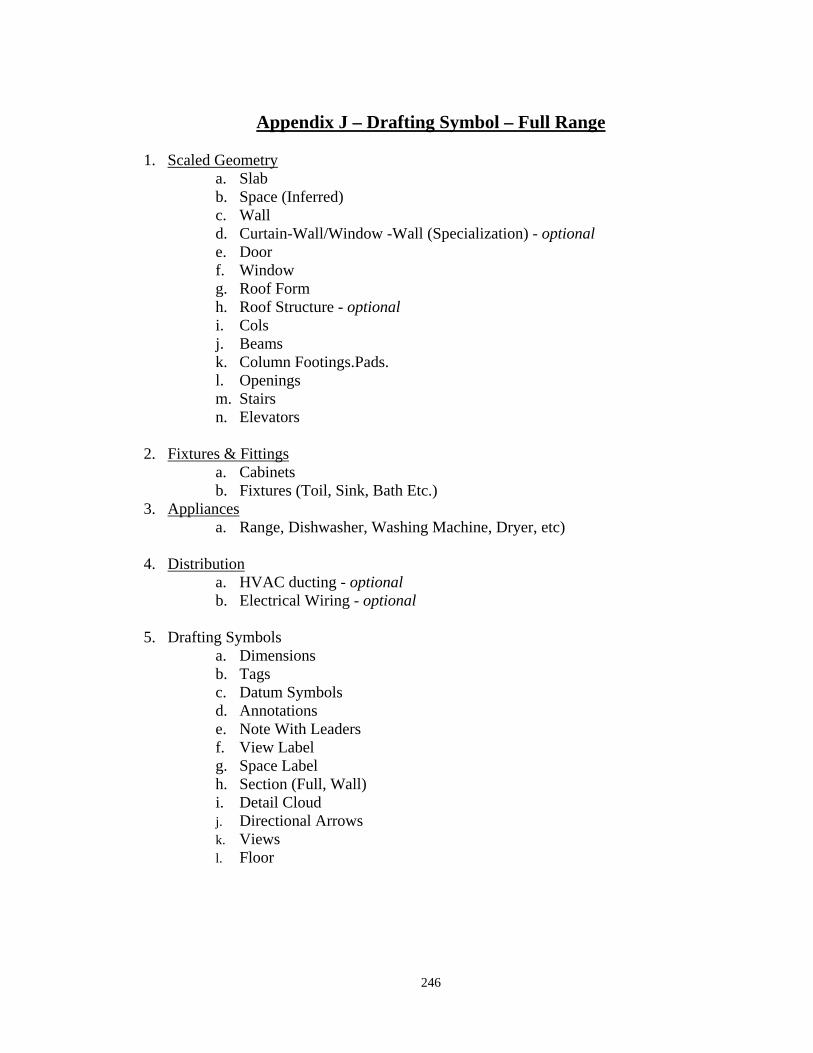
246
Appendix J – Drafting Symbol – Full Range 1. Scaled Geometry
a. Slab b. Space (Inferred) c. Wall d. Curtain-Wall/Window -Wall (Specialization) - optional e. Door f. Window g. Roof Form h. Roof Structure - optional i. Cols j. Beams k. Column Footings.Pads. l. Openings m. Stairs n. Elevators
2. Fixtures & Fittings
a. Cabinets b. Fixtures (Toil, Sink, Bath Etc.)
3. Appliances a. Range, Dishwasher, Washing Machine, Dryer, etc)
4. Distribution
a. HVAC ducting - optional b. Electrical Wiring - optional
5. Drafting Symbols
a. Dimensions b. Tags c. Datum Symbols d. Annotations e. Note With Leaders f. View Label g. Space Label h. Section (Full, Wall) i. Detail Cloud j. Directional Arrows k. Views l. Floor
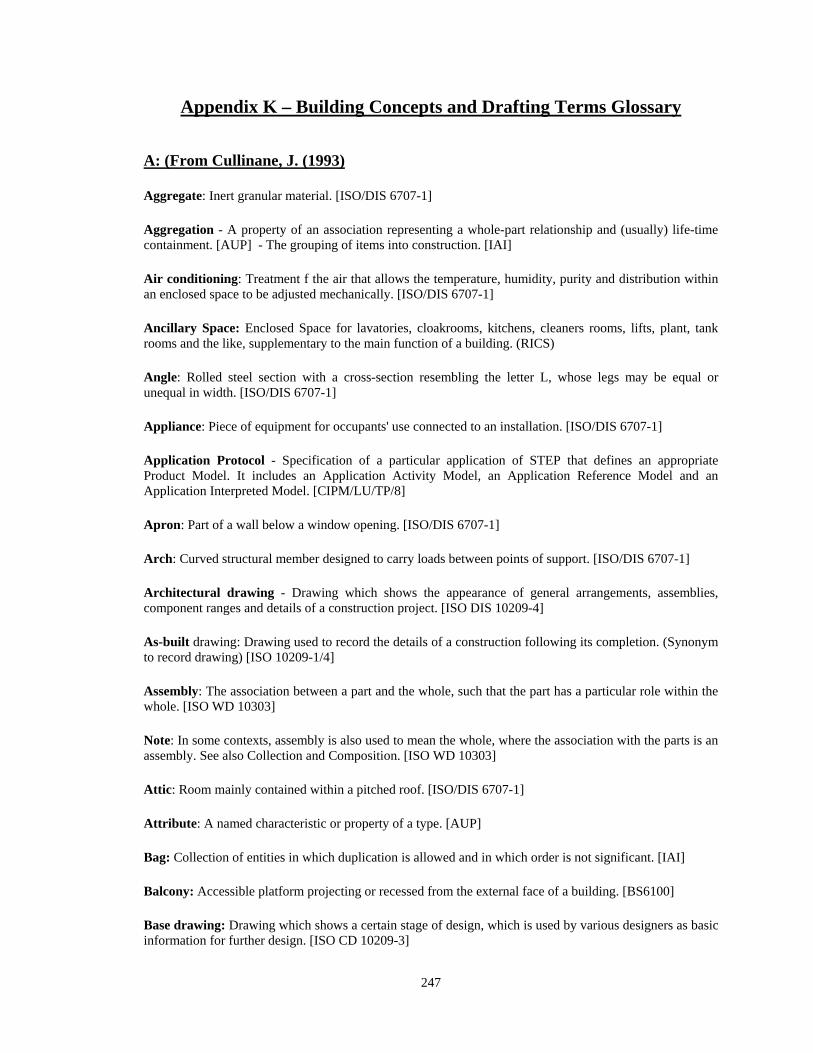
247
Appendix K – Building Concepts and Drafting Terms Glossary
A: (From Cullinane, J. (1993)
Aggregate: Inert granular material. [ISO/DIS 6707-1]
Aggregation - A property of an association representing a whole-part relationship and (usually) life-time containment. [AUP] - The grouping of items into construction. [IAI]
Air conditioning: Treatment f the air that allows the temperature, humidity, purity and distribution within an enclosed space to be adjusted mechanically. [ISO/DIS 6707-1]
Ancillary Space: Enclosed Space for lavatories, cloakrooms, kitchens, cleaners rooms, lifts, plant, tank rooms and the like, supplementary to the main function of a building. (RICS)
Angle: Rolled steel section with a cross-section resembling the letter L, whose legs may be equal or unequal in width. [ISO/DIS 6707-1]
Appliance: Piece of equipment for occupants' use connected to an installation. [ISO/DIS 6707-1]
Application Protocol - Specification of a particular application of STEP that defines an appropriate Product Model. It includes an Application Activity Model, an Application Reference Model and an Application Interpreted Model. [CIPM/LU/TP/8]
Apron: Part of a wall below a window opening. [ISO/DIS 6707-1]
Arch: Curved structural member designed to carry loads between points of support. [ISO/DIS 6707-1]
Architectural drawing - Drawing which shows the appearance of general arrangements, assemblies, component ranges and details of a construction project. [ISO DIS 10209-4]
As-built drawing: Drawing used to record the details of a construction following its completion. (Synonym to record drawing) [ISO 10209-1/4]
Assembly: The association between a part and the whole, such that the part has a particular role within the whole. [ISO WD 10303]
Note: In some contexts, assembly is also used to mean the whole, where the association with the parts is an assembly. See also Collection and Composition. [ISO WD 10303]
Attic: Room mainly contained within a pitched roof. [ISO/DIS 6707-1]
Attribute: A named characteristic or property of a type. [AUP]
Bag: Collection of entities in which duplication is allowed and in which order is not significant. [IAI]
Balcony: Accessible platform projecting or recessed from the external face of a building. [BS6100]
Base drawing: Drawing which shows a certain stage of design, which is used by various designers as basic information for further design. [ISO CD 10209-3]
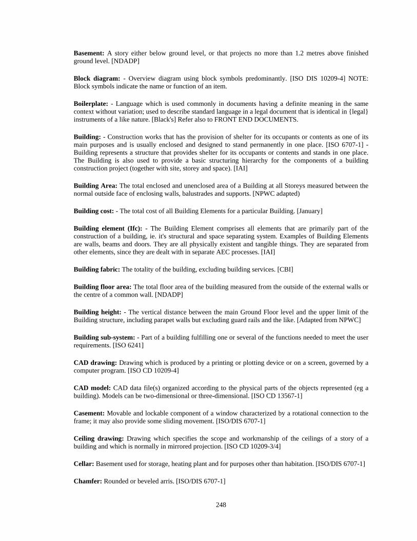
248
Basement: A story either below ground level, or that projects no more than 1.2 metres above finished ground level. [NDADP]
Block diagram: - Overview diagram using block symbols predominantly. [ISO DIS 10209-4] NOTE: Block symbols indicate the name or function of an item.
Boilerplate: - Language which is used commonly in documents having a definite meaning in the same context without variation; used to describe standard language in a legal document that is identical in {legal} instruments of a like nature. [Black's] Refer also to FRONT END DOCUMENTS.
Building: - Construction works that has the provision of shelter for its occupants or contents as one of its main purposes and is usually enclosed and designed to stand permanently in one place. [ISO 6707-1] - Building represents a structure that provides shelter for its occupants or contents and stands in one place. The Building is also used to provide a basic structuring hierarchy for the components of a building construction project (together with site, storey and space). [IAI]
Building Area: The total enclosed and unenclosed area of a Building at all Storeys measured between the normal outside face of enclosing walls, balustrades and supports. [NPWC adapted)
Building cost: - The total cost of all Building Elements for a particular Building. [January]
Building element (Ifc): - The Building Element comprises all elements that are primarily part of the construction of a building, ie. it's structural and space separating system. Examples of Building Elements are walls, beams and doors. They are all physically existent and tangible things. They are separated from other elements, since they are dealt with in separate AEC processes. [IAI]
Building fabric: The totality of the building, excluding building services. [CBI]
Building floor area: The total floor area of the building measured from the outside of the external walls or the centre of a common wall. [NDADP]
Building height: - The vertical distance between the main Ground Floor level and the upper limit of the Building structure, including parapet walls but excluding guard rails and the like. [Adapted from NPWC]
Building sub-system: - Part of a building fulfilling one or several of the functions needed to meet the user requirements. [ISO 6241]
CAD drawing: Drawing which is produced by a printing or plotting device or on a screen, governed by a computer program. [ISO CD 10209-4]
CAD model: CAD data file(s) organized according to the physical parts of the objects represented (eg a building). Models can be two-dimensional or three-dimensional. [ISO CD 13567-1]
Casement: Movable and lockable component of a window characterized by a rotational connection to the frame; it may also provide some sliding movement. [ISO/DIS 6707-1]
Ceiling drawing: Drawing which specifies the scope and workmanship of the ceilings of a story of a building and which is normally in mirrored projection. [ISO CD 10209-3/4]
Cellar: Basement used for storage, heating plant and for purposes other than habitation. [ISO/DIS 6707-1]
Chamfer: Rounded or beveled arris. [ISO/DIS 6707-1]
249
Channel section: Rolled steel section with a cross-section resembling the letter U. [ISO/DIS 6707-1]
Chase: Recess cut into an existing construction to accommodate services. [ISO/DIS 6707-1]
Chimney shaft: Chimney that is of substantial height and usually contains a flue of large cross-section. [ISO/DIS 6707-1]
Chimney stack: Part of a chimney that projects above a roof. [ISO/DIS 6707-1]
Circulation: Space linking together individual rooms or spaces within a single Functional Area. It includes the area occupied by internal walls and columns. [NPWC adapted]
Cladding: The non-loadbearing external surfacing of a building designed to provide a weather-proof enclosure, fixed to framing.
Class hierarchy: A description of the inheritance relations between classes. [AUP]
Class method: A method that defines the behavior of the class itself, as opposed to the behavior of its instances. [AUP]
Classification: Classification defines a relationship between a type and its instances. The classification mapping identities the extension of a type. [AUP]
Component: A product manufactured as a distinct unit to serve a specific function (or functions). [ISO 6240, ISO/DIS 6707-1]
Composition: The association between a part and the whole. [ISO WD 10303] Note: In some contexts, composition is also used to mean the whole. See also Assembly and Collection. [ISO WD 10303]
Concept: A unit of thought constituted through abstraction on the basis of properties common to a set of objects. [ISO 1087]
Connection diagram: Diagram that shows the electrical connections of an installation or equipment. [ISO CD 10209-3/4]
Constraint: A restriction or condition on an element. [AUP]
Construction: Assembled or complete part of construction works that result from work on site. [ISO/DIS 6707-1]
Construction drawing: Drawing which specifies construction information. NOTE 1: Construction information includes information on architectural, structural engineering, heating, ventilation, sanitation, water supply, sewerage, ground and earth works and electrical construction. NOTE 2: Not to be confused with ‘for construction drawing’. [ISO CD 10209-4]
Construction information: Information used to support one or more construction process. [ISO/DIS 12006-2]
Construction manager: A party having a contract to perform construction management services. [W2]
250
Construction process: Process which transforms construction resources into construction results. [ISO/DIS 12006-2]
Construction Specification: Specification for the Production Process of a particular Project. [Adapted from USNBS]
Construction Work: The partial or complete Results of the Production Process. [Adapted from BS6100 that contains undefined term]
Consultant: A person (or organization) with an area of expertise or professional training who contracts to perform a service. [Means]
Continuous beam: Beam that spans three or more supports. [ISO/DIS 6707-1]
Contract documents: Includes the Agreement, Definitions, General Conditions of the Contract, Supplementary Conditions, Division 1 - General Requirements, specifications, drawings, addenda, Bid Revisions and modifications subsequent to execution of the Contract. [W2] (The above definition expands on the definition in CCDC 2, 3, or 4.]
Contractor: The Contractor is the person or entity identified as such in the Agreement. The term Contractor means the Contractor or the Contractor's authorized representative as designated to the Owner in writing. [CCDC 2 1994]
Co-ordination drawing: Base drawing that is used for coordination among the designers on a project. [ISO CD 10209-3]
Corridor: Narrow enclosed circulation space that gives access to rooms or other spaces. [ISO/DIS 6707-1]
Cost (Ifc): Amount to be paid for acquisition, installation, or assembly; associated with a product, process, or resource. [IAI]
Coupling: A dependency between elements (usually types, class and subsystems), typically resulting from collaboration between the elements to provide a service. [AUP]
Courtyard: External space bounded by buildings, walls or fences. [ISO/DIS 6707-1]
Cross-section: Section which shows a cut that is perpendicular to the longitudinal direction of the object. [ISO CD 10209-3]
Cut: View of the features of an object lying on a plane passing though it, showing in addition features in front of or behind that plane. [BS 1192]
Cut: material excavated in bulk. [ISO/DIS 6707-1]
Cut and fill: earthwork technique to lessen a variation in ground level by using material excavated from higher ground to raise the level of lower ground. [ISO/DIS 6707-1]
Decomposition: The breaking down of a whole into parts. [IAI]
Deferred Maintenance: Maintenance which is known to be required but which has been deferred deliberately to a later date; eg. because of a shortage of funds or unavailability of parts. [NCRB]
251
Demolition: Process entailed by the planned physical destruction of the construction works. [ISO/TC59/SC13/N75]
Derivation: The process of defining a new class by reference to an existing class and then adding attributes and methods. The existing class is the superclass; the new class is referred to as the subclass or derived class. [AUP]
Design: A process that uses the products of analysis to produce a specification for implementing a system. A logical description of how a system will work. [AUP]
Design Process: The Activities entailed by the further conceptual elaboration of the desired Facility (brief), prior to the Production Process. [ISO TR 14177]. See also Creation Process and Design.
Design Specification: Specifications for the evaluation of engineering or architectural design. [USNBS]
Detail drawing: Drawing showing parts of a construction or a component, generally enlarged, and including any specific information about the form and construction or about the assembly and joints. [ISO 10209-1/4]
Diagram: Drawing in which graphical symbols are used to indicate the form and/or function of the components of a system and their relationships. [ISO 10209-1/4]
Dimensional drawing: Drawing which specifies dimensions necessary for construction or production. [ISO DIS 10209-4]
Distribution Element (Ifc): Elements in a building services system that facilitate the distribution of matter, such as air or water. [IAI]
Document: Recorded information that can be treated as a unit in a documentation process. [ISO 5127-1, ISO DIS 10209-4]
Domain: A formal boundary that defines a particular subject or area of interest. [AUP]
Door schedule: Component range drawing of doors and their hardware, and which may contain information in the form of a table. [ISO DIS 10209-4]
Draft drawing: Drawing serving as a basis for the choice of a final solution and/or discussion between involved parties (synonym = preliminary drawing). [ISO 10209-1/4]
Draftsperson: A person that prepares drawings under the supervision of an architect or engineer. [January]
Drawings (Product): Graphic representations showing the geometry and dimensions of the elements of a project in sufficient detail to execute the work. [CMAA]
Electrical drawing: Drawing which comprises installations for power supply, lighting, electric heating, motor operation, telecommunication, voltage adjustment, etc. [Adapted from ISO CD 10209-4]
Element (Building): Major functional part of a building. Note: Examples are foundation, floor, and roof, and wall, services. [ISO 6707-1]
Element (Ifc): Generalization of all components that make up an AEC product. Those elements can be located logically by an element container in a structuring hierarchy (here: building), described by calculated
252
quantities and assigned with one or many performed functions. The latter copes with multifunctional elements. See also Discrete Element and Distribution Element. [IAI]
Elevation drawing: Drawing which shows a view on a vertical plane. [ISO DIS 10209-4]
Entity: A physical object that can be defined by a set of Attributes. [Woestenenk]
Environmental Performance: The ability of the whole or parts of a Facility to meet the communal or individual needs of the occupants and conversely, of their impact on them. [Adapted from NCRB]
Equipment (Ifc): An apparatus used to perform work, energy conversion or heat transfer. [IAI]
Estimate: The anticipated sum for which some future builder – usually unknown – will agree to execute at some future date – often indeterminate – certain works which are frequently only partially defined at the time the estimate is made. [H. Wexler – The Building Economist - Feb 1969]
Evacuation drawing: Drawing which shows ways of evacuation and how the fire brigade and other emergency services are called and gain access. [ISO 10209-4]
Fabricator: A person, firm, or corporation who shapes, assembles, or finishes product. [W2]
Facade drawing: Elevation drawing which shows the external view of a building. [ISO DIS 10209-4]
Facility: A physical structure or installation, including related External Works, serving one or more main purpose. [Adapted from ISO TR 14177]. See also Construction complex.
File drawing: As-built drawing which complies with certain demands for archive durability. [ISO CD 10209-3/4]
Finished ground level: The finished level of a site. [NDADP]
Fixture (Ifc): Permanently attached appendage, appliance, or device that is connected to a building system (eg plumbing and electrical fixtures). [IAI]
Floor area (of a building): The total floor area of the building measured from te outside of the external walls or the centre of a common wall. [NDADP]
Footing beam (Ground Beam): A beam spanning between piles, pile caps, pads or other beams and acting as a footing. [CCS]
Framework: A set of collaborating abstract and concrete classes that may be used as a template to solve a related family of problems. It is usually extended via subclassing for application-specific behaviour. [AUP]
Functional decomposition: The process of refining a problem solution by repeatedly decomposing a problem into smaller and smaller functional steps. [AUP]
Furnishing plan: Drawing which specifies the scope and location of furniture and equipment. [ISO CD 10209-4]
Furniture (Ifc): A piece of equipment for occupants use, not usually fixed to the building. [IAI]
253
General assembly drawing: Assembly drawing showing all groups and parts of a complete product. [ISO 10209-1/4]
Generic Relation: Hierarchical relation that is based on the partial identity of the intensions of generic, specific and coordinate concepts. [ISO 1087]
Glazing: The use of clear and translucent glass and/or glazing plastics.[CBI]
Graph: Drawing which expresses the relationship between two or more variable quantities, and which is usually arranged within a coordinate system (synonym = chart). [ISO 10209-1]
Gross Floor Area: Total of all enclosed spaces fulfilling the functional requirements of the building measured to the internal structural face of the enclosing walls. Includes areas occupied by partitions, columns, chimney breasts, internal structural or party walls, stairwells, lift wells, and the like. Includes lift, plant, tank rooms and the like above the main roof slab. Sloping surfaces such as staircases, galleries, tiered terraces and the like should be measured flat on plan. Excludes any spaces fulfilling the functional requirements of the building which are not enclosed spaces (eg open ground floors, open covered ways and the like). Excludes private balconies and private verandahs. [BCIS Jul 1971]
Ground floor: The floor which is nearest the level of the outside ground. [BCIS July 1971}
Ground level (finished): The finished level of a site. [NDADP]
Ground level (natural): The natural level of a site. [NDADP]
Group Element: (UniFormat) - See Element.
Habitable room: Any room used for normal domestic activities other than a bathroom, toilet, pantry, walk-in wardrobe, corridor, lobby, photographic dark room, clothes drying room, and other spaces of a specialised nature occupied neither frequently not for extended periods. [NDADP]
Heating, ventilation and airconditioning (HVAC) drawing: Drawing which shows systems of cooling and heating pump, heating, air conditioning, etc. and which are normally drawn by a designer of such installations. [ISO DIS 10209-4]
Hierarchical Relation: Relation between concepts that is established by division of a superordinate concept into subordinate concepts forming one or more levels, or by the reverse process. [based on ISO 1087]
Hole: A void formed by cutting through work already constructed. [CBI]
Information: Message used to represent a factor or a concept within a communication process in order to increase knowledge. [ISO 5127/1]
Inheritance: A feature of object-oriented programming languages by which classes may be specialized from more general superclasses. Attributes and method definitions from superclasses are automatically acquired by the subclass. [AUP]
Inspect: To look carefully into or to view closely and critically ... - [Oxford Short]
Installation diagram: Diagram showing the location of components of an electrical installation and the connections between them. [ISO DIS 10209-4]
254
Instantiation: The creation of an instance of a type or class. [AUP]
Integer: A value which has a whole number component only eg 1,2 22, 6348 etc. [IAI]
Interconnection diagram: Diagram showing the electrical or communications connections among different constructional elements. [ISO CD 10209-4]
Interior decoration drawing: Drawing which shows furnishing plans, assembly, component range and details for loose and fixed fittings and which is normally drawn by an interior designer. [ISO CD 10209-3/4]
Item list: Drawing which completely list the items constituting and assembly (or a sub-assembly), or of detailed parts, according to agreed rules, eg requirements of ISO 7573-1983. [ISO 7573]
Landscape drawing: Drawing which shows the composition and processing of the ground for roads, planted areas, external installations, etc. [ISO 11091, ISO DIS 10209-4]
Layer: An organisational attribute of entities in a CAD data file used to separate data in order to manage and communicate that data and to control visibility on the computer screen and on plotted drawings. [ISO CD 13567-1]
Layout drawing: Drawing showing the location of sites, structure, buildings, spaces, elements, assemblies or components (synonym = location drawing). [ISO 10209-1]
Layout plan: Plan that shows the use of a site plan or area. [ISO CD 10209-3]
Leveling drawing: Drawing which records the level of points that have been leveled. [ISO CD 10209-3/4]
Lighting drawing: Drawing which specifies the type and location of lighting, lighting equipment and lighting system circuitry. [ISO DIS 10209-4]
Linings: Substrate sheet linings is the term used for sheet linings, used internally, fixed to framing, which require a surface finish such as paint, wallpaper, etc. Examples are plasterboard, fibre cement sheeting, etc. Prefinished sheet linings is the term used for sheet linings, used internally, fixed to framing, which require either no surface finish or only a clear finish. Examples are plastics laminate, wood panelling, etc. [CBI]
List: A collection of entities in which no duplication is allowed and in which order is significant. [IAI]
Location drawing: Drawing showing the location of sites, structures, buildings, spaces, elements, assemblies or components, eg for prefabricated structures (ref ISO 4172-1991). (Synonym = layout drawing). [ISO 10209-1/4]
Longitudinal section: Section in which the cutting plane is situated in the longitudinal direction of the object. [ISO CD 10209-3]
Maintainability: A characteristic of design and installation, expressed as the probability that an item will be retained in or restored to a specified condition within a given period of time, provided that the maintenance is performed in accordance with prescribed procedures and Resources. [NCRB]
Major Element Group: (UniFormat) See Element Group.
255
Manufacturing drawing: Drawing which provides all necessary information for production. [ISO CD 10209-3/4]
Mark Up: The sum added to an estimate or a rate in respect of head office overheads and profit. [AIB]
Massing: The exterior shape of a building. A volumetric view of the building. [Ifc ver. 2.0]
Master schedule: An executive summary-level schedule highlighting the major components of a project. The schedule can be in the form of a network or milestone chart. [CMAA]
Match existing: Provide new materials to match the existing in place material in all aspects as closely as possible. Existing materials are those which are visible in whole or in part in the facility. [Haney]
Material: Substance that can be used to form Products. [Adapted from BS6100]
Materials: Any substances specified for incorporation in the completed project. [AASHTO]
Medium: Material on which information is recorded, eg paper, microfilm, magnetic or optical disc. [ISO DIS 10209/4]
Metal angle: Metal sections shaped like the letter L made up with legs of equal or unequal length. Structural angles are used in arch bars and built-up work. [CCS]
Metamodel: A model that defines other models. The UML metamodel defines the element types of the UML, such as Type and Operation. [AUP]
Model: A formal statement of classes, properties and behaviours which can be used to inform software implementation and set out requirements for structuring of information exchange and sharing. [IAI]
Name: Designation of an object by a linguistic expression. [ISO 1087]
Natural ground level: The natural level of a site. [NDADP]
Net floor area: Area measured within the structural face of the enclosing walls defined as "Usable", "Circulation" and "Ancillary". Areas occupied by partitions, columns, chimney breasts, internal structural or party walls are excluded from these groups, and are shown separately under "Internal Divisions". [BCIS Jul 1971]
Net habitable floor area: (residential buildings only) Total area of all enclosed spaces forming the dwelling measured within the structural internal face of the enclosing walls. Includes areas occupied by partitions, columns, chimney breasts and the like. Excludes balconies, public access spaces, communal laundries, drying rooms, lift, plant and tank rooms and the like. [BCIS Jul 1971]
Network diagram: Overview diagram that shows the connections between different kinds of installations, telecommunications, power lines, equipment, etc. [ISO CD 10209-4]
Object: In the UML, an instance of a class that encapsulates state and behaviour. More informally, an example of a thing. [AUP]
Object (Ifc): The generalization of any semantically treated things and processes within IFC. Examples for IfcObject include physically tangible items, such as wall, beam or covering, physically existent items, such
256
as spaces, or conceptually items, such as grids or virtual boundaries. It also stands for processes, such as work tasks, controls, documents, etc. [IAI]
Object: An instance of a class which has a unique identity and which has values assigned to attributes so that its state may be determined. [IAI]
Object: Any part of the perceivable or conceivable world. [ISO 1087] [ISO/DIS 12006-2] Note: Objects may be material (eg engine) or immaterial (eg magnetism).
Object model: A representation of information and behaviour in the real world to some acceptable level of detail. [IAI]
Object-oriented analysis: The investigation of a problem domain or system in terms of domain concepts, such as object types, associations and state changes. [AUP]
Object-oriented design: The specification of a logical software solution in terms of software objects, such as their classes, attributes, methods and collaborations. [AUP]
Object-oriented programming language: A programming language that supports the concepts of encapsulation, inheritance and polymorphism. [AUP]
Opening: A void formed or constructed during the work. [CBI] See also Hole.
Operable partitions/doors: There can be misunderstandings in regard to the distinction between operable partitions and sliding/folding doors/partitions. An appropriate distinction is that operable partitions and operable walls rest on the floor or are sealed to the floor when not in motion; sliding/folding doors/partitions are always clear of the floor, whether or not they are in motion. [CBI]
Part: Similar to MATERIAL for classification purposes. [W2]
Part drawing: Drawing depicting a single part (which cannot be further disassembled) and which includes all necessary information required for the definition of that part. [ISO 10209-1]
Partitions: Non-loadbearing units, extending from floor to ceiling, subdividing space.[CBI]
Pattern: A pattern is a named description of a problem, solution, when to apply the solution and how to apply the solution in new contexts. [AUP]
Performance: The way in which something reacts under certain conditions or fulfils the purpose for which it was intended. [Macquarie Dictionary 1985]
Performance Requirement: User requirement expressed in terms of the performance of a product. [ISO 6241]
Performance specification: States the results which are to be achieved, giving the contractor total freedom in the choice of materials and methods. [CSC Semester Level 1 Session 11] [CSC HSC Level 1 Chapter 5]
Persistence: The enduring storage of the state of an object. [AUP]
Persistent object: An object that can survive the process or thread that created it. A persistent object exists until it is explicitly deleted. [AUP]
257
Perspective drawing: Drawing which shows a three-dimensional view of a project in which one or more groups of projectors converge on their respective vanishing points. [ISO DIS 10209-4]
Plan: View, section or cut, in a horizontal plane, seen from above. [ISO 10209-1]
Plan detail: Drawing which to a large scale shows a part of a plan. [ISO CD 10209-3]
Plans: Approved Contract drawings showing the location, type, dimensions, and details of Contract work to be performed. [AASHTO]
Plant: (1) Machinery and heavy equipment installed for the operation of a service, eg. heating and ventilating service. [BS6100]
Plastic: An ability to continue to change shape under applied pressure (Adjective). [CBI]
Polymorphic operation: The same operation implemented differently by two or more types. [AUP]
Polymorphism: The concept that two or more types of objects can respond to the same message in different ways using polymorphic operations. Also, the ability to define polymorphic operations. [AUP]
Pragmatic Relation: Relation between concepts that can be established on the basis of thematic connections. [ISO 1087]
Pre-condition: A constraint that must hold true before an operation is requested. [AUP]
Preliminary drawing: Drawing of a designer's concept of a project and which is expected to be modified. [ISO DIS 10209-4]
Priced bill of quantities: Bill of quantities that contains the contractor’s rates extended and totalled to give tender sum. [ISO 6707-2, BS 1192, ISO DIS 10209-4]
Process (Ifc): An action taking place in building construction with the intent of acquiring or conducting products. Processes are placed in sequence (including overlapping for parallel tasks) in time. [IAI]
Process model: A representation of processes which occur in the real world to some acceptable level of detail. [IAI Release 2.0]
Product (Ifc): Any object, manufactured, supplied or created for incorporation into an AEC/FM project. This also includes objects that are created indirectly by other products, as spaces are defined by bounding elements. Products can be designated for, permanent use or temporary use; an example for the latter is formwork. [IAI]
Product Model: The way engineering information is held to facilitate the unambiguous transfer of such information between computer systems and how it can be coherently represented to facilitate information sharing. [CIPM/LU/TP/8]
Production drawing: Drawing, generally established on the basis of the design data, giving all the information required for the production. [ISO 10209-1/4]
Program: A sequence of executable instructions to a computer. [IAI Release 2.0]
Programme: A schedule of actions. [IAI Release 2.0]
258
Project (Ifc): The undertaking of some engineering activities leading towards a product. It acts as the top container for all objects defining a project. The Project also holds the units used for certain measures throughout the project, and the central registry, currently for only team members and applications. The IfcProject establishes the World Coordinate System, WCS. [IAI]
Projection: Additional or alternative data that is used to produce different projections from the same CAD model. [ISO CD 13567-1]
Real: A value that has a whole number component and a decimal component. [IAI Release 2.0]
Reinforcement drawing: Drawing which shows the position and designation of rods, bars, wires and cables embedded in a reinforced concrete structure. [ISO CD 10209-4]
Relation: A fact that exists between classes. [IAI Release 2.0]
Roof plan elevation: Drawing which specifies in detail the roof seen from above. [ISO CD 10209-3]
Roof plan: Drawing which specifies in detail the roof seen from above. [ISO DIS 10209-4]
Room: An identifiable physical space bounded actually or theoretically. It may not be completely enclosed by walls, ceiling and floor but it should have some of these physical limitations. [January] - based on ISO CD 4157-2
Room relation drawing: Drawing which shows the disposition of rooms in accordance with the brief as regards the relative position of rooms and their relations to others. [ISO CD 10209-3/4]
Technical drawing: Technical information, given on an information carrier, graphically presented in accordance with agreed rules and usually to scale. (synonym = drawing). [ISO 10209-1]
Technical specification: A term sometimes used to identify the specification sections within Divisions 2 to 16 inclusive.
Unit of Measurement: The basis for uniformly quantifying units of material, work and effort either separately or in combination. [NPWC]
Upper floors: All floors above the Ground floor.
Usable Floor Area: The sum of the floor areas of a facility measured at floor level from the general inside face of external walls of all interior or covered spaces related to the primary function of the building. Note: This will normally be computed by calculating the "Gross Floor Area" (GFA) and deducting all of the following areas supplementary to the primary function of the facility:
(a) Common Use Areas
All floored areas for circulation and standard facilities provided for the common use of all occupiers, tenants and/or the public such as lobbies and foyers to entrances; stairways, lifts, landings and fire escapes; corridors and passages; toilets and common amenities; cleaner's rooms, stores and cupboards.
(b) Service Areas
259
All areas set aside for plant supplying services and facilities for the use of occupants, tenants and/or the public, such as mechanical plant rooms; electrical equipment and switch rooms; refuse collection areas; loading bays; car parks and access thereto.
(c) Non-habitable Areas All non-habitable areas such as those occupied by internal columns and other structural supports, internal walls and permanent partitions, lift shafts, service ducts and the like. [adapted from NPWC]
Usable floor area: Total area of all enclosed spaces fulfilling the main functional requirements of the building (eg office space, shop space, public house drinking area, etc.) [BCIS Jul 1971]
Use case: A narrative, textual description of the sequence of events and actions that occur when a user participates in a dialog with a system during a meaningful process. [AUP]
View: Orthogonal projection showing the visible part of an object and also, if necessary, its hidden outlines. [ISO 10209-1]
Wall to Floor Ratio: A measure of plan efficiency computed by dividing the face area of the external surfaces of a Building (excluding gable walls, parapet walls and walls below lowest floor finished level) by the Fully Enclosed Covered Area and expressing the result as a ratio to 1. [NPWC]
Walls: Vertical assemblies which are load-bearing. [CBI]
Window schedule: Component range drawing of windows and window doors including their hardware, and which may contain information in the form of a table. [ISO DIS 10209-4]
Windows: Glazed openings in partitions, walls and cladding. [CBI]
Work group (Ifc): A grouping of work tasks into a designated group. [IAI]
Work task (Ifc): An identifiable unit of work to be carried out independently of any other units of work. [IAI]
Working Drawings: A set of drawings issued for construction, showing the detailed architectural, structural, mechanical, electrical, hydraulic, landscaping or other design solutions and details for a project. [GBT]
B: (From Huth, M, 1993)
AlA: Abbreviation for the American Institute 01 Architects, 1735 New York Avenue, NW, Washington, DC 20006. When following the name of an architect, this abbreviation indicates that the architect is a corporate member of the institute. An individual can be an architect without being a member of the AlA, but cannot use the letters AlA without being an architect.
Air-duct: A pipe or tube (round, square or rectangular) for conducting air in a ventilation system.
Atrium: A large open hallway or lobby with galleries at each floor level on three or more sides.
Backing Brick: Brick used on the inner part of a brick wall usually of lesser quality than a face brick.
Baluster: An upright support for a stair or balcony railing.
260
Batten: A batten is generally used on the exterior of buildings in wood frame construction. It is a wood strip that covers the vertical joint of siding in "board and batten" construction.
Batt Insulation (Batts): Typically, a pre-sized blanket of mineral-fiber insulation placed between wall, floor, ceiling, or roof framing members.
Bay Window: A window, of any' shape, projecting out from a building and forming a recess in the building interior.
Bead: Generally found in detailed work, a bead is a round or semicircular molding.
Beam: A structural framing member used to support loads over an opening. Beams can be made up of many different materials--steel, wood, timber, concrete, or a combination of materials.
Brick Veneer: A brick facing applied to the surface of a frame, or other type, structure.
Btu: British thermal unit is the amount of heat required to raise the temperature of one pound of water one degree
Fahrenheit. Almost all heat references on plans and in specifications will be in Btu.
Built-up Roof: A roofing system composed of a series of layers of waterproof materials.
Bungalow: A one-story house with low sweeping lines and a wide veranda. Occasionally, the attic space will be finished, but a bungalow is always a Single story. Popular in the early part of the 20th century, the style evolved into 1-1 /2- and 2-story versions referred to as "bungaloids."
Caisson (pile): A type of foundation pile which is surrounded with concrete. A caisson pile is usually larger than two feet in diameter. A smaller pile is referred to as a pier.
Cant (strip): When noted on plans, a cant is a sloping piece of lumber used on roofs as a transition from vertical to horizontal surfaces.
Capital: The upper part of a column or pilaster. The most common classical column capitals are from Greek architecture -- Corinthian, Doric, and Ionic. Roman architecture added two additional styles -- Tuscan and Composite.
Chase: A chase is a vertical groove or channel designed to receive pipes, ducts, or conduits. A horizontal channel for the same purpose is referred to as a raceway.
Cleanout: Usually found on plumbing plans, this term refers to a removable plate or plug providing access to a drainage pipe to allow cleaning. On plans, this will generally be noted just by the letters "CO."
Cleat: A strip of wood or metal used for supporting some object.
Clerestory: The portion of a multistory room extending above an adjacent lower room. The c1erestorv space generally contains windows to admit light and ventilation into the taller space.
Coffer: When referenced on plans, a coffer is usually an ornamental, recessed panel on a ceiling or soffit. On structural drawings, a coffer would refer to a structural pan system.
Colonnade: A series of columns at regular intervals.
261
Column: A perpendicular structural member, usually circular,square, or rectangular in shape.
Concrete Block: A hollow or solid precast concrete masonry unit (CMU).
Crown Molding: The molding at the top of the cornice, immediately beneath the roof or ceiling.
Curtain Wall: A thin wall applied to a steel or concrete building frame. datum point A point of elevation used as a reference by which levels and distances are measured. This would appear on a benchmark on a site plan.
Deflection: In structural terms, a deflection is the bending of a beam or any part of a structure under an applied load.
Divided Light: A window divided into small panes of glass.
Door Jamb: The side frame upon which a door hinges or latches. The door head will generally appear the same in detail as the jambs.
Door Schedule: On architectural plans, a listing which identifies all doors in a building, providing location, type, size, operation, and finish.
Door Sill: The detail at the bottom of a door opening upon which a door stops. Also known as the threshold.
Expansion Joint: In structural systems, an expansion joint is a flexible connection bCh'Veen two portions of a structure.
Exposed aggregate: A concrete finish where the coarse aggregate is exposed on the surface.
Façade: The entire exterior surface of a building, especially the front.
Face Brick: Historically, a better quality brick used on the public face of a building. At times, the face brick would be different sizes, shapes, or patterns. face putty The glazing putty that is placed in the angle of the sash after the glass is laid .
Fascia: A long, flat member in the entablature, or at the edge of a beam, used as a finish, nonstructural, element.
Feathering: When noted on plans or in specifications, this refers to flattening out the edges of a material to blend it with new material, such as feathering the edges of existing paint to blend with new paint.
Fenestration: The arrangement of openings in a facade.
Fillet: As a structural reference, a fillet is the concave junction formed when two structural members meet. It is normally used as a welding term.
Finish Floor: This notation can be found on plans as an elevation reference. On floor plans, sections, elevations, and details, the term will be noted "fin fl" and usually be the point from which something is measured, such as 36" above Fin fl. This means that the object would be located 36 inches above the final floor elevation.
262
Finish Grade: This refers to the final surface elevation of elements outside of the structure, such as planted areas, roadways, and sidewalks.
Fire Barriers: On architectural plans, this would refer to any obstruction to prevent the spread of fire, such as a fire door or stair enclosure.
Firebrick: A type of brick that is made especially for use in highheat locations, such as fireplaces. It is made of a c1ifferent material than standard construction brick.
Fire Door: A door that is made of fire-resistant material. A fire door will be rated by Underwriters Laboratory to resist burning for a specified period of time 3 / 4 of an hour, 1 hour, 2 hours, 4 hours.
Furring: The process of leveling a portion of a floor, wall, or ceiling.
Furring Strips: Flat pieces of wood used to level uneven framing or placed against a masonry wall to facilitate the placement of a finished wall material.
Gingerbread: Ornate detailing used on houses during the later part of the 19th century and early 20th century.
Glass Block: A hollow, non-structural glass form.
Glaze: The process of installing glass in openings, such as in windows or doors.
Grading: The process of filling in around a structure with earth.
Groin: On plans, this would refer to the intersection of two vaults.
Grout: A fluid cement mixture used to fill crevices.
Gutter: A horizontal channel of wood, metal, or plastic designed to carry off water from a roof area.
Gypsum Wallboard: See "drywall."
Hardboard: A pressed-wood panel.
Lanai: A covered walkway; Hawaiian for "porch."
Lean-to: Generally a small structure built as an addition to a larger building and having a single-sloped roof whose roof rafters "lean" against the other building.
Lintel: A structural member, made up of wood or metal, placed horizontally across the top of an opening, such as a window or door. The lintel will generally be at least four inches longer than the width of the opening.
Louver: A slatted opening, designed to provide ventilation.
Mansard Roof: A roof form developed for use in France and used extensively by the architect Francois Mansart (1598 -1666). It is a roof with two slopes, the uppermost, almost flat, and the lower slope, very steep. It was deve1oped originally to house an additional floor in a building without appearing to be another story higher.
263
Masonry: A generic term applied to anything constructed of stone, brick, tile, concrete, or other similar materials.
Metal Ties: This is a term used for any type of lightweight steel ties used to join or bond separate elements of masonry wall construction.
Penthouse: This is a reference to a room located on the roof of a building. A penthouse can house a living space, such as an apartment, or can contain mechanical equipment, such as air conditioners or elevator machinery.
Pergola: A structure open to the sky, with its roof constructed of open rafters. Perspective An illustration of an object on a plane surface so it will have the same appearance as when it is viewed from a particular location. A perspective drawing of a building or a structure basically shows the building as it would look in real life. There are one-point perspectives, where all the horizontal lines spring from a Single point. Generally, one point perspectives are used on drawings of interiors. There are two-point perspectives, with two vanishing points. This technique is used on most exterior renderings of buildings. And, there are three-point perspectives, not often used and quite complicated.
Piazza: An enclosed courtyard, arcade, or colonnade of a building.
Pilaster: A round, square, or rectangular column attached to a wall.
Pile: A wood, steel, precast or pre-stressed concrete shaft driven into the ground for support of a structure.
Pitch: In architectural terms, pitch refers to the slope of roof rafters, expressed as a ratio of rise to run. On drawings, it will either be noted as slope per inch on roof plans, or illustrated as a small triangle on elevation drawings. In plumbing, pitch is the slope of a surface to a drain.
Plate: On architectural drawings the word "plate" can refer to the topmost, horizontal wood member in a frame wall. It can also reference the wood member placed at the top of a foundation wall onto which the floor framing members are attached.
Plenum: Plenum is a term found on mechanical drawings, referring to a pressurized chamber connecting two or more air-distribution ducts.
Purlins: These are secondary structural members installed as horizontal beams in roof construction.
PVC: Polyvinyl Chloride. It is a material used in the manufacturing of piping used in mechanical and electrical work.
Queen Post: Vertical ties in a roof truss.
Quoins: Quoins, which can most often be found in Georgian architecture, are large stones, or simulated s tones, at the outside corners of masonry buildings.
Rabbet: This is a term used in woodworking which refers to a groove cut in the surface or edge of a piece of wood to receive another board.
Rafter: A structural member in roof framing which extends from the ridge of the roof to the eaves.
Rain water leader: A pipe which conveys water from the roof to the ground. Also referred to as a "downspout."
264
Raked Joint: In masonry construction, a joint in which the mortar is "raked" out to a specific depth.
Raking: The construction method of stepping masonry up and in to the building wall. This detail is most often found at the base of Victorian period structures.
Rebar: Slang for reinforcement bar.
Receptacle: On electrical plans and in specifications, this refers to the de vice, such as a wall plug, placed in an outlet box.
Roof: The exterior, structural, overhead covering of a building.
Roofing: The material covering a roof.
Roof pitch: A roof pitch is the slope of the roof surface. On drawings, this will be shown as a fraction representing the rise of the roof over its span.
Roof sheathing: Plywood or wood boards nailed to roof rafters to form a solid, flat surface over which roofing is placed
Roof truss: A structural element made up of light wood or steel members assembled to form a roof support.
Rough coat: The first coat of plaster applied to a wall or ceiling surface.
Rubble: In masonry construction, rubble is broken stones or brick used to fill walls.
Running bond: A course of brick laid on its bottom.
Sandstone: Used extensil'e1y in the la te 19th and early 20th centuries, sandstone is a relatively soft stone composed of fine grains of sand bonded with silica, oxide of iron, or carbonate of lime.
Sash: The frame in which window panes are placed.
Screed: In concrete or plasterwork, a screed is the wood or metal edge used to strike the level of a slab or wall.
Sill: A term which can be used in many different locations on a set of drawings. It will usually refer to the lowest member under a window or door. It can also reference the lowest member supporting a frame structure.
Skim coat: This is a thin, finishing coat of plaster
Skylight: On plans and in specifications, a skylight will refer to a window or covering fitting into or over an opening in a roof for admitting daylight.
Slab: This is a structural term referring to a flat area of concrete. A slab may be placed directly on earth or can be part of a larger structural system, such as columns, beams, and slab.
Sleeper: Generally, the term sleeper will be found on architectural drawings and refer to strips of wood laid over a rough slab to which a finished wood floor is attached.
265
Slipforrn: This is a method of construction where the concrete form moves continuously. It is not a very common method of construction because of the precision required.
Slope: Slope can be used in reference to many different building systems on a project, but will always refer to the incline of an object, such as a roof, floor, or site.
Soffit: The underside of any subordinate member in a structure, such as an arch, cornice, eaves, or stair.
Spackle: The miracle material for building repairs. Spackle is a flexible plaster used for patching walls and ceilings.
Stilted arch: An arch having its spring line above the apparent impost.
Stoop: A raised platform leading into a building.
Storm window: A second window placed on the outside or inside of the primary window, designed to conserve energy by creating a dead air space, and to protect the window.
Stretcher: In brickwork, a stretcher is brick laid lengthwise.
Stringer: This term will be found primarily on architectural plans as a reference to the inclined member in a stair designed to support the risers and treads.
Structural day tile (SCT): Hollow masonry units made of clay or shale.
Structure: Generally, the term "structure" will be inclusive defining an edifice constructed of parts arranged and fitted together.
Strut: A structural term used for any piece of material designed and placed to keep two pieces apart, absorbing pressure or stress, such as in a truss.
Stucco: Generally, a rough plaste r used for exterior coverings on walls.
Stud: In a building, a stud is a vertical member used in the framework of a wall. A stud can be made of wood or metal. Unless noted otherwise, on architectural plans a wood stud will be a 2 x 4, measuring 1-9 / 16" x 3-1 / 2".
Subcontractor: Construction of a building will usually be undertaken by a general contractor. This individual will hire a series of subcontractors to execute specific pa rts of the project, such as site work, electrical, mechanical, roofing, etc.
Subfloor: On architectural plans and in specifications, sub floor refers to the rough boards or plywood placed between the building's structural support (floor joists) and finished floor. It acts as a base for the finished floor and a stiffener for the structure.
Sump: A pit or hole in a building where water is allowed to accumulate. These are generally found in buildings where an interior floor elevation is below' the level of a sewer or adjacent ground water.
Sump pump: A pump used to remove the water allowed to accumulate in the sump.
Toenailing: This toenailing is the driving of a nail or brad in a slanted manner. It is most evident in laying tongue- and-groove wood floors:
266
Tongue and groove: A joint made by two pieces of lumber with a corresponding tongue and groove.
Toothing: Allowing alternate courses of brick to project tooth like and fitting corresponding courses into the voids. Instructions in most specifications will prohibit toothing for fear that a full layer of mortar will not be obtainable at the top of the fitted brick.
Transom: A small window over a door or another window.
Truss: A structural member made up of a combination of elements arranged in triangular units to form a rigid frame. Trusses come in a variety of d esigns, sizes, and materials.
Valley: The depressed angle formed by the intersection at the bottom of two inclined sides of a roof.
Vault: An arched structural form that forms a ceiling.
Vent pipe: A pipe or flue designed to exhaust gases or fumes from building fixtures, such as a water closet, to a vent stack.
Angle: On plans and in specifications, the reference to an angle could refer to either the inclination of one straight line to another, the space between two straight lines, or a structural member, generally made of metal used to support some element of a structure. When referring to a metal angle, the terms "angle iron" or "angle cleat" may be used.
Apse: The projecting portion of a building, usually semicircular in plan.
Arch: A term used to describe a curved, pointed, or flat structural member supported at its sides or ends and used to span an opening.
Area: When used on plans, the word "area" can refer to a function, such as living area, or it can refer to the square footage of a space, such as 120 sf in area.
Ashlar: As generally used, ashlar refers to sawed, dressed, tooled, or quarry-faced stone.
ASTM: The letters ASTM stand for the American Society for Testing and Materials. This reference will be found most often in specifications where a material or (building) system must meet a minimum standard of quality or operation. The letters ASTM will generally be followed by a series of numbers and characters representing the specific standard.
Bifolds: Doors, generally light in weight and used on closets.
Bleaching: A process used for whitening wood , not cloths.
Blueprint: Blueprinting is a process typically used to produce construction drawings. A blueprint has a dark blue background and white lines. Other, more common printing techniques produce black-line and blue-line prints, where the background is white and the lines are black or blue.
Board & batten: See "batten."
Box girder: A structural form in the shape of a box and made up of metal, wood, or concrete.
Box gutter: A gutter built into the edge of a roof, usually lined with galvanized metal, tin, or copper.
267
Breezeway: A covered passageway between two structures that is open at each end, or one which passes through a building.
Brick: A clay or clay mixture molded into blocks, which are then hardened by baking in a kiln. Brick can be made in a number of earth tones, surface finishes, and shapes. A Standard size brick is 2-1/ 4" x 3-1/ 2" x 7 -1 / 2". Other common bricks sizes, Roman and Norman, are larger.
Cased opening: An opening finished with trim, but without a window or door.
Casement (window): A window that is hinged from the side edge.
Cast-in-place (CIP): This is a term most often used in reference to concrete. It means that the concrete is allowed to harden where it is placed, as opposed to precast concrete.
Caulk (n): a mastic substance used to seal exterior joints or edges, such as around windows or doors.
Cavity wall: Although this does not mean that the wall needs dental work, it does indicate that there is a void in the wall. This term is generally used when referring to a brick wall made lip of two independent columns tied together with metal or brick.
Chamfer: A bevel edge formed by cutting away the corner or edge of wood or masonry
Conduit: On plans and in specifications, a conduit is a stiff tube or pipe designed to carry electrical wires.
Construction joint: A rigid joint where two sections of a structure are joined to form a continuous plane or mass.
Cooling tower: This refers to a device used for cooling water used in air-conditioning condensers, A cooling tower will generally be located outside -- adjacent to a structure or, most often, on the roof of a building.
Coping: This is the cap or top course of a masonry wall,
Cornice: A cornice can take many forms. It is the construction where the roof and side walls meet, or the top course of a wall when treated as a crowning member.
Course: A course is a continuous level row of brick or stone.
Crawl space: The space under a building between the first floor and the ground surface,
Cricket: A small elevated part of a roof designed to act as a watershed,
Crown: The uppermost member of the cornice, or the high point in sidewalk or road construction.
Dormer (window): A vertical projection built out from a sloping roof or an extension of the exterior wall above a roof line. A dormer usually contains a window, thus dormer window.
Double-hung window: A window that has an upper and a lower sash which both slide up and down. In a single-hung window, just one sash (usually the lower) operates.
Drywall: Sheets of gypsum board used as an interior finish, also referred to as wallboard.
268
Ducts: Pipes or tubes, round or rectangular, designed to distribute air in a heating, ventilating or air-conditioning system.
Dutch door: A door that is divided horizontally, allowing the lower portion to be closed while the upper portion remains open.
Dutchman: An odd piece of woodwork inserted to fill an opening or to correct a defect.
Eaves: The portion of roof that extends OVeT the exteTior wall.
English bond: A brick bond in which one COUTse is made up entirely of headers, and the next course entirely of stretchers. The header and stretcher courses alternate throughout the wall
Entablature: That portion of a building that rests horizontally on columns and consists of a cornice, frieze, and architrave.
Evaporative cooler: An air-conditioning system which draws cooler air through moisture and then circulates it through a building. This system is used extensively in low-humidity regions.
Fire escape: Usually, an exterior-applied steel or wood ladder designed to provide a means of escape from a building during a fire.
Fire wall: A wall built to restrict or contain lire, preventing it from spreading to other parts of a building or to another structure.
Flashing: Metal or plastic strips of film installed to prevent water penetration through joints, such as over windows and doors and between exterior walls and roofing.
Floor plan: A graphic representation of the floor pattern of a building. On drawings, a floor plan is a view looking downward from five feet above the floor. A set of drawings would normally have a separate floor plan for each level of a structure. (See 'The Drawings" chapter of this book)
Flue: On plans and in specifications, a flue is an enclosed passageway. round or rectangular, such as a pipe or chimney, designed to carry off fumes or smoke.
Footing: Eliminate the word "footer" from your vocabulary: it is a "footing." A structural term meaning a form used to spread or distribute the load of a wall over a wide area.It is sometimes referred to as a "spread footing" when it extends along the length of the wall. When it is located directly under a free-standing column, it might be referredto as a "pad."
Foundation: That portion of a structure upon which the superstructure is erected. The foundation can consist of footings, foundation walls, piling, and other support elements below the ground.
Foundation wall: Any structural wall below the first floor joists or beams.
Framing: The skeleton parts of a building, such as wood floor and roof joists and stud walls.
French door: Doors with glazed panels extending the full length of the door, usually hung in pairs.
Header: Header has a number of possible meanings when used on plans and in specifications. In brick construction, it isa brick laid so its small side faces outward and it extends back into the wa ll. As a
269
structural member, a header is usually a built-up beam designed to transfer joist or rafter loads. In wall framing, headers are used over window and door openings to support the walls above the openings.
Insulation: Any material designed to prevent heat transmission. Insulation can come in the form of blankets, batts, boards, or loose material. Also, insulation can refer to the protective coating over electrical wire.
Isometric drawing: A drawing where all horizontal lines are drawn at 30°, all vertical lines are drawn vertically. and all dimensions are accurate on the 30o-angle lines and the vertical lines.
Jack arch: An arch which is flat instead of curved. rounded, or pointed.
Joist: The wood structural member designed to support floors or ceiling finishes (floor joists. ceiling joists).
Keystone: A structural wedge-shaped piece of material at the center of an arch which serves to lock all of the arch pieces together.
Mortar: In historic buildings, a pasty material composed of sand and lime. In contemporary construction, a mixture of cement, sand, and water. (Contemporary mortar should not be used in historic buildings and vice-versa.)
Mortar joints: The joints between masonry units filled with mortar. Mortar joints can be finished in different shapes. (flush, struck, concave, V, beaded, etc.).
Offset: This is a reference on plans referring to a change in the plane of a surface.
Ogee arch: An arch which has a compound curve, part concave and part convex.
Open-web steel joists: This generally refers to a composite structural element made up of light steel members.
Pan floor: A flooring system made up of a series of interconnecting concrete beams joined together at the top with a thin concrete slab.
Parapet wall: The portion of an exterior building wall, party wall, or fire wall, which extends above the roof line.
Partition: Usually an interior wall used to separate spaces of a building. These can be constructed of any material, be permanent or temporary, stationary or portable.
Pediment: In classical architecture, a pediment is a triangular element, resembling a gable end of a roof, crowning the entrance of a structure, doorway, or window.
Plinth: The square base of a column, wall or frame.
Plywood: A widely used building material which is made up of two or more thin sheets of wood glued together wi th the grain of adjacent layers at right angles to each other.
Pointing: On plans and in specifications, this refers to finishing the joints in brick and s tone walls.
Porch: A covered entrance or extension to a building, a type of enclosed veranda.
270
Precast concrete: Both architectural and structural elements that usually are cast off-site, shipped to the construction site, and erected. Precast concrete units can be columns, beams, sections of walls, or roofs.
Prefabricated: In construction this can refer to building components, such as walls or roof sections, constructed in a factory and brought to the site. It may also reference interior finish elements like cabinet work or "pre-hung" doors.
Reinforced concrete: Concrete in which steel reinforcing bars are embedded to provide tensile strength.
Reinforcing: The steel bars used to reinforce concrete.
Rendering: This is a term used to describe a delineation of a building plan, elevation, or perspective that simulates real settings, textures, and landscape.
Retaining wall: A structural element designed to hold back, or retain, earth or other lateral pressure.
Reveal: In architectural drawings and woodworking, a reveal refers to a recessed space between building materials.
Ridge ventilator: A horizontal raised section of a roof ridge used to exhaust heated air.
Right-hand door Door swings have been a mystery to most architects and non-architects for years. There are four possible swings -right-hand, right-hand reverse, left-hand, and lefthand reverse. The way you determine which is to look at the door from what would be the outside. If the door hinges are on the right side of the door, it's a right-hand door. Then imagine yourself standing with your back against the hinge side. If a right-hand door swings to the left, it is a right-hand re\•erse door. If it swings to the right it is a right-hand door. The same system can be used on left-hand doors. If the door swings to the left, it is a left-hand door, if to the right, it is a left-hand reverse.
Rise: The vertical distance between a roof plate and the ridge, or the height of a stair.
Riser: The vertical face under a stair tread.
Sealant: On drawings and in specifications, this will usually refer to a dear coating applied to wood, masonry, or concrete to prevent moisture penetration.
Section: On drawings, a section generally refers to a vertical cut through a building or site illustrating all or a portion of that element.
Segmented arch: A masonry arch 'where the arc is less than a semicircle.
Septic tank: A concrete tank used to hold sewage during the process of disintegration by bacteria.
Shaft: On plans and in specifications, the word "shaft" can have two meanings. On architectural drawings, it will refer to the center portion of a column, that section extending from the base to the capital. On mechanical drawings, a shaft is a vertical opening through which air-distribution ducts will run.
Shear wall: A structural element designed to withstand shear forces caused by wind or earthquakes.
Sheathing: Sheathing is usually a wood membrane applied as a covering for roofs, exterior walls, and floors.
271
Shed roof: A roof form having one slope.
Shingle: A thin piece of wood, stone, or composition material used as a roof or wall covering. Shingles can be manufactured in any number of forms and shapes. Hand-split wood shingles are referred to as "shakes."
Spandrel beam: A horizontal structural member on an exterior wall that forms a spandrel.
Specifications: Specifications for a project are part of the contract and construction documents. They are the written instructions to the contractor on the scope of work to be done, the material to be used, and the method by whichthe work is to be carried out.
Spiral stairs: A staircase, circular in plan, made up entirely of winders (wedge-shaped steps).
Spread footings: In contemporary terms, a spread footing is one that spreads the weight of a building across a large area of earth.
Spring line: A line across the span of an arch passing through the points where the arch is tangent to the vertical plane.
Sprinkler system: On mechanical drawings and in specifications for mechanical: work, a sprinkler system is a series of water lines inside a building that are designed to release a spray of water through sprinkler heads to extinguish afire. On site plans, a sprinkler system would refer to an irrigation system.
Stair (stairway): A series of horizontal and vertical elements assembled in a manner to connect one floor or area with another above or below.
Stair tread: The horizontal surface connecting risers in a stair.
Survey: An accurate measure of the physical properties of a building and/ or building site. In a set of drawings there could be a number of different surveys individually shown or combined onto one drawing. There may be a boundary survey showing the property lines and setback requirements; a topographical survey showing the land contours; and, a landscape survey showing all plant material on the site.
Suspended ceiling: A ceiling suspended from a structural ceiling above. Contemporary usage generally defines a suspended ceiling as one made up of acoustic-tile panels. The term is correctly used for suspended ceilings of any material-plaster. wood, wallboard, glass, or acoustic panels.
Tail cut: The cut on the lower end of a rafter, sometimes to give a decorative effect.
Thermostat: An electric or electronic instrument used to measure and regulate air temperature.
Three-way switch: On electrical drawings this term, or corresponding symbol, will refer to a switch which allow a circuit to be activated from two different locations.
Threshold: A plate under a door.
Tile: As used on architectural plans and in specifications, this term refers to a fired clay, stone, concrete, or glass material used as a finish floor, wall, or ceiling covering. Tile comes in many different sizes, shapes, colors, and patterns.
Vestibule: On architectural plans, a vestibule is usually a small room used as an entrance to a building.
272
Wainscot: A wall covering on the lower portion of an interior wall. Wainscoting may be wood, fabric, tile, or any other material.
Weep hole: An opening through mortar joints in unit masonry walls, or through concrete retaining walls, to allow drainage of condensed moisture or ground water.
Winders: Stair treads used when stairs are circular, or are carried around curves or angles. Winders are 'wider at one end than the other.
Window schedule: On architectural plans, a listing which identifies all windows in a building, providing location, type, size, operation, and finish.
Wythe: In masonry construction, a single vertical wall of brick.
Working drawing: A finished drawing containing al1 necessary information to complete all, or a portion, of a project
273
References Ablameyko, S., Bereishik, V. (1997). "Recognizing Engineering Drawing Entities: Technology And Results." IEEE Conference Publication (443): 15-17. Ablameyko, S., Bereishik, V., Frantskevich, O., Homenko, M., and Paramonova, N. 1997. Algorithms for Recognition of the Main Engineering Drawing Entities. In Proceedings of the 4th international Conference on Document Analysis and Recognition (August 18 - 20, 1997). ICDAR. IEEE Computer Society, Washington, DC, 776-779. Akin, O.: 1979, Models of architectural knowledge: An information-processing view of design. Dissertation Abstracts International, 41,3, p. 833A. (University Microfilms No. 72-8621.) Alexander, C., Ishikawa, S., Silverstein, M., Jacobson, M., Fiksdahl-King, I., Angel, S. (1977). A pattern language: Towns, buildings, construction. New York, Oxford University Press. Allen, J. (1995). Natural Language Understanding. Redwood California, Benjamin, Cummins Book Publishers Inc. Amir, A., Landau, G. M., Vishkin, U (1990). Efficient Pattern Matching with Scaling. 1st Annual ACM-SIAM Symposium On Discrete Algorithms (SODA), San Francisco, CA. Angele, J., Studer, R (1997). Requirements Specification and Model-based Knowledge Engineering. Softwaretechnik, Braunschweig. Autodesk Inc. (2007) BIM and Facilities Management http://images.autodesk.com/adsk/files/bim_and_fm_jan07_1_.pdf Babalola, O., Eastman, C. (2001). Semantic Modeling of Architectural Drawings. In Proceedings of 2Oth ACADIA Conference, Buffalo NY. Ballard, D. H., Brown, C. M. (1982). Computer Vision. Prentice Hall. Barton, G. E., Berrywick, R.C., Ristad, E.S (1987). Computational Complexity and Natural Language, MIT Press, Cambridge MA. Barwise, J. E., Etchemendy, J. (1996). Heterogenous Logic. Diagrammatic Reasoning, Cognitive and Computational Perspectives, IAAA Press. Bechtel, W., Graham, G. (1998). A Companion to Cognitive Science. Oxford, Basil Blackwell.
274
Belongie, S., Carson, C., Greenspan, H., Malik J (1998). Color and Texture-Based Image Segmentation Using EM and Its Application to Content-Based Image Retrieval. Sixth International Conference on Computer Vision (ICCV'98), Bombay, India, Narosa Publishing House. Berners-Lee, T. (1998). "Semantic Web Road map." IW3C Design Issues. Cambridge, MA : W3C. Available at http://www.w3.org/DesignIssues/Semantic.html September 1998 [site visited 08.11.2010] Blackwell, A., Marriot, K., Shimojima, A., Ed. (2004). Diagrammatic Representation and Inference. Third International Conference, Diagrams 2004. Cambridge, UK, Springer. Booch, G., Martin, R. Newkirk, J (1999). Object-Oriented Analysis And Design With Applications, Addison-Wesley. Bower, G. H. (1972). Mental Imagery and Associative Learning. Cognition, Learning and Memory. D. G. Bobrow, Collins, A., New York Academic Press: 1-34. Boyle R.D. & Thomas R.C. (1988) Computer Vision: A First Course. Oxford: Blackwell Scientific. Bozany, A. (2003). Integration of Building Automation Systems and Facility Information Systems. Hungarian Electronic Journal of Sciences, HU ISSN 1418-7108 Brilakis, I, Lourakis,M, Sacks, R., Savarese, R., Christodoulou, S., Teizer J.and Makhmalbaf, A. (2010) Toward automated generation of parametric BIMs based on hybrid video and laser scanning data. In Journal of Advanced Engineering Informatics, 24(4) 456-465 Chatzis, V., Pitas, J. (1997). "Fuzzy Cell Hough Transform for Curve Detection." Pattern Recognition 12(30): 2031-2042. Cherneff, J. (1990). Knowledge Based Interpretation of Architectural Drawings. Department of Civil Engineering. Cambridge, MA, Massachusetts Institute of Technology. Ph.D Thesis. Chira, O. (2003). Ontologies, Intelligent Agent Based Collaborative Design Information Management and Support Tools (IDIMS) Project. Chomsky, N. (1957). Syntactic Structures. The Hague, Mouton. Ciriello, M. (2002). Architectural Design Graphics, McGraw-Hill. Clancey, W. J. (1989). "The Knowledge Level Reinterpreted: Modeling how Systems Interact." Machine Learning 4: 285-291.
275
Claus, B., Eyferth, K. Gips, C., Hörnig, R., Schmid,U., Wiebrock, S., and Wysotzki, F (1998) Reference Frames for Spatial Inference in Text Understanding in Series Lecture Notes in Computer Science pp. 241-266 Springer Berlin / Heidelberg Collin, S., Colnet, D. (1999). "Syntactic Analysis of Technical Drawing Dimensions." International Journal of Pattern Recognition and Artificial Intelligence (IJPRAI) 8 (5): 1131-1148. Collins, A. M., Loftus, E.F. (1975). "A Spreading-Activation Theory of Semantic Processing." Psychological Review (82): 407-429. Cortelazzo, G., Guerra, G., (2004) Model-based and image-based 3D scene representation for interactive visualization Computer Vision and Image Understanding Volume 96, Issue 3 Elsevier Science, New York CSA S478-1995 (1995), Guideline on Durability in Buildings, Canadian Standards Association (2001). Cullinane, J. J. (1993). Understanding architectural drawings: a guide for non-architects. Washington, D.C.: Preservation Press, National Trust for Historic Preservation. De Jonq, G. (1979) Skimming Stories in Real Time: An Experiment in Integrated Understanding. Yale University, Dep. of Compo Sc., Research Report 158 Defense Technical Information Center, Publishers. Devaux, P., Lysak, B., Kasturi, R. (1999). "A Complete System for the Intelligent Interpretation of Engineering Drawings." International Journal on Document Analysis and Engineering 2: 120-131. Dori, D. (2000). Syntactic and Semantic Graphics recognition: The role of the Object-Process Methodology. GREC'99, Heidelberg, Springer-Verlag. Dori, D., Tombre, K (2000). "A Complete System For The Analysis Of Architectural Drawings." International Journal On Document Analysis and Recognition 3 (2): 102-116. Dori, D., Tombre, K. (1995). "From Engineering Drawings to 3D CAD Models: Are We Ready Now?" Computer-Aided Design 27(4): 243-254. Dosch, P., Tombre K., Ah-Soon C., and Masini, G (2000). A Complete System For Analysis Of Architectural Drawings. International Journal on Document Analysis and Recognition, 3(2):102--116, Duda, R., Hart, P., Stork, D (2000). Pattern Classification, Second Edition, John Wiley and Sons.
276
Eastman, C. Jeong, Y. Sacks, R. and Kaner, I (2009) Exchange Model and Exchange Object Concepts for Implementation of National BIM Standards (White Paper) Eastman, C. Teicholz, P. Sacks, R. and Liston, K. (2008) BIM Handbook: A Guide to Building Information Modeling for Owners, Managers, Designers, Engineers and Contractors. John Wiley & Sons, Inc, New Jersey Eastman, C. (1999). Building Product Models: Computer Environments Supporting Design. Boca Raton, FL, CRC Press. Eastman, C. M. (1970). On the analysis of intuitive design processes. Emerging Methods in Environmental Design and Planning. G. T. Moore. Cambridge, MIT Press: 21-37. Edelman, S., Weinshall, D., (1990) A Self-Organizing Multiple-View Representation of 3D Objects Biological Cybernetics, Volume 64, 209-219 Springer Berlin / Heidelberg Egenhofer, M. J., Herring, J. A. (1990). A Mathematical Framework for the Definition of Topological Relationships. Fourth International Conference on Spatial Data Handling, Columbus, Ohio. Engelhardt, Y. (2002). The Language of Graphics. A Framework for the Analysis of Syntax and Meaning in Maps,Charts and Diagrams. Published by the Institute for Logic, Language and Computation. Amsterdam, University of Amsterdam. Ph.D. Ericsson, K.A., and Simon, H. (1984) Protocol Analysis: Verbal Reports as Data, Bradford Books, MIT Press, Cambridge, MA. Ericsson, K.A., and Smith, J.: 1991, Prospects and limits of the empirical study of expertise: An introduction, in K.A. Ericsson and J. Smith, (eds.), Toward a general theory of expertise: Prospects and Limits. MIT Press, Cambridge, MA. Evans, G. W. (1980). "Environmental Cognition in Psychological Bulletin." 259-285. Ferguson, R. W., & Forbus, K. D. (2000). GeoRep: A Flexible Tool for Spatial Representation of Line Drawings, Proceedings of the 18th National Conference on Artificial Intelligence. Austin, Texas: AAAI Press. Finkel, R., Bentley, J.L. (1974). "Quad Trees: A Data Structure for Retrieval on Composite Keys". Acta Informatica 4 (1): 1–9. French, J., Ekstrom, R., Price, L. (1963). Kit of Reference Tests for Cognitive Factors. Princeton: Educational Testing Service. Frydman, C., Torres, L., Giambiasi, N. (1996). Building Executable Models from Expert Conceptual Models. 1996 Simulation Multiconference - Simulators International XIII, New Orleans, LA.
277
Funt, B. (1987). Problem-Solving with Diagramatic Representations. Diagrammatic Reasoning, Cognitive and Computational Perspectives, IAAA Press. Geng, W., Wang, J., (2002), Embedding Visual Cognition in 3D Reconstruction from Multi-View Engineering Drawing, Computer Aided Design, 34, 321-336. Gessima E., K., L (1986). Computer Aided Analysis of Schematic Drawings. Pattern Recognition In Practice II. Gips, J., Stiny, G. (1980). "Production Systems and Grammars: A Uniform Characterization." Environment and Planning B 7: 399-408. Glassgow, J., Narayanan, H, Chandrashekaren, B. (1995). Introduction. Diagrammatic Reasoning, Cognitive and Computational Perspectives. J. Glassgow, Narayanan, H, Chandrashekaren, B. Menlo Park, IAAA Press. Glassgow, J., Narayanan, H., Chandrashekaren, B., Ed. (1995). Introduction to Diagrammatic Reasoning, Cognitive and Computational Perspectives, IAAA Press. Glassgow, J., Papadias, D (1992). Computational Imagery. Cognitive Science. 16: 355-394. Gobert, J., and Frederiksen, C. (1989) Expert And Novice Semantic Interpretation of Architectural Drawings, Paper presented at the Annual Meeting of the American Educational Research Association, March, San Francisco, CA. Goel, V. (1996). Sketches of Thought. Cambridge, MA, MIT Press. Gomis, J. M., Compay, P., Gil, M. A. (1999) Vectorization in Recovering Engineering Drawings. WSCG 99, 2 361-368 Gonzalez, R., Thomason, M. (1978). Syntactic Pattern Recognition: An Introduction, Addison Wesley Publishing. Goodman, N. (1976). Languages of art: An approach to a theory of symbols. Bobbs-Merrill, Indianapolis/New York Groen, F. C. A., Van Munster, R.J. (1986). Computer Aided Analysis of Schematic Diagrams. B.V. North Holland, Elsevier Science Publishers. Guarino, N. (1995). "Formal Ontology, Conceptual Analysis and Knowledge Representation." International Journal of Human Computer Studies.
278
Guarino, N. (1997). ""Understanding, Building and Using Ontologies: A Commentary to "Using Explicit Ontologies in KBS Development."" International Journal of Human and Computer Studies 46: 293-310. Giarratano, J. C., Riley, G (2005) Expert Systems, Principles and Programming. PWS Publishing Co. Boston, MA, USA Habel, C., Pribbenow, S. Simmons, G. (1995). Partonomies and Depiction. Diagrammatic reasoning, cognitive and computational perspectives, IAAA Press: 205-210. Haralick, R. M., Queeny, D. (1982). "Understanding Engineering Drawings." Computer graphics and image processing 20: 244-258. Haugeland, J. (1985). Artificial Intelligence: The very idea. Cambridge, MA, MIT Press. Hayes, P. (1995). Theoretical Foundations. Diagrammatic reasoning, cognitive and computational perspectives, IAAA Press: 397-40. Healey, P. G., Swoboda, N., Umata, I., Katagiri, Y. (2000). "Graphical Interaction and the Emergence of Abstraction." First InternationalWorkshop on Interactive Graphical Communication. Hebb, D. O. (1949). Organization of Behavior. New York, Wiley. Hegarty, M., Meyer, B., Narayanan, N. H., Ed. (2002). Diagramatic representation and reasoning. 2nd International Conference, Diagrams 2002. Callaway Gardens, GA, Springer. Helibron, J. L (1997) Geometry Civilized: History, Culture, Technique. Oxford University Press. ISBN 0-19-850078-5. 2000 paperback: ISBN 0-198-50690-2.) Hietanen, J. (2006a) IFC Model View Definition Format, International Alliance for Interoperability Hietanen, J. (2006b) Information Delivery Manual Guide to Component and Development Methods, BuildSMART, Norway, March 2006 Hillier, B. (1984). The social logic of space. Cambridge, Cambridge University Press. Hirschtick, J., Gossard, D. (1996). Geometric Reasoning for Design Advisory Systems. American Society of Mechanical Engineers Computers in Engineering Conference and Exhibition, Chicago, IL. Ho,J., Yang, M., Rangarajan, A., Vemuri, B. (2007) A New Affine Registration Algorithm for Matching 2D Point Sets, Proceedings of the Eighth IEEE Workshop on Applications of Computer Vision, p.25, February 21-22, 2007
279
Hofer-Alfeis, J. (1986). Automated Conversion of Existing Mechanical Drawings to CAD Data Structures: State of the Art. Computer Applications in Production and Engineering, CAPE’86, North-Holland Amsterdam. Hopcroft, J., Ullman, J. D. (1979). Introduction to automata theory, languages, and computation (2nd edition). Reading, MA, AddisonWesley. Huth, M. W. (1996). Understanding construction drawings. 2nd ed. Albany: Delmar Publishers. IAI (2000). IFC Technical Guide Industry Foundation Classes - Release 2x, International Allliance for Interoperability. Idesawa, M. A. (1973). "A System To Generate A Solid Figure From Three Views." Bulletin Of Japan Society Of Mechanical Engineering 1973 16: 582-596. Indurkhya (1992). Metaphor and cognition: An interactionist Approach. Dordrecht, Kluwer Academic Publishers. ISO (2003). Technical drawings - General Principles of Presentation. T. S. I. Standards, International Standards Organisation. Iwaki, O. (1986). Document Recognition System for Office Automation. 8th International Conference on Pattern Recognition, Paris, International Association for Pattern Recognition. Iwasaki, Y. (1995). Problem Solving With Diagrams. Diagrammatic Reasoning: Cognitive and Computational Perspectives. J. Glassgow, Narayanan, H., Chandrashekaren, B. Palo Alto, AAAI Press: 657-667. Jackson, P. (1985). Introduction to Artificial Intelligence. Johnson Controls 2010 Case Study Colony Park, Jackson Mississippi CSST-10-124 (8/10) www.johnsoncontrols.com Joseph, S. H. (1989). "Processing of Engineering Drawings for Automatic input to CAD." Pattern Recognition 22: 1-11. Joseph, S. H., Pridimore, T.P. (1992). "Knowledge-Directed Interpretation of Mechanical Engineering Drawings." IEEE Transactions on Pattern Analysis and Machine Intelligence 14 (9): 922-940. Kanugo, T., Haralick, R., Dori, D. (1994). Understanding Engineering Drawings: A Survey., Intelligent Systems Laboratory Department of Electrical Engineering University of Washington.
280
Karavan, A.; Neugebauer, M.; Kabitzsch, K.(2005) : Integration of Building Automation Network Design and 3D Construction Tools by IFC Standard. Proceedings, 6th IFAC International Conference on Fieldbus Systems and their Applications, Puebla, Mexico pp. 247 – 254 Kimura, A., Watanabe, T. (1998). "Fast Generalized Hough Transforms - Rotation, Scale and Translation Invariant Detection of Arbitrary shapes." IEICE Journal J81-D-II, No.4: 726-734. Kiyko, V. (1995). Recognition of Objects In Images of Paper Based Line Drawings. IEEE Journal: 970-973. Kolodner, J. (1983). "Maintaining organization in a dynamic long-term memory." Cognitive Science 7: 243-280. Kolodner, J. (1983). "Reconstructive memory, a computer model." Cognitive Science 7: 281-328. Kolodner, J. (1993). Case-Based Reasoning. San Mateo, CA, Morgan Kaufmann. Kong, B., Phillips,I. T., Haralick, R. M., Prasad, A. Kasturi, R. (1996). A Benchmark: Performance Evaluation of Dashed-Line Detection Algorithms. Graphics Recognition - Methods and Applications (Lecture Notes in Computer Science). T. Kasturi R, K. Berlin, Springer. 1072: 270-285. Kozen, D. (1997). Automata and Computability. Heidelberg, Springer. Lafue, G. (1976). Recognition of three-dimensional objects from orthographic views. In Proceeding SIGGRAPH '76 Proceedings of the 3rd annual conference on Computer graphics and interactive techniques. 10, 2, 103-108. Lai, C., Kasturi, R (1997). Detection Of Dashed Lines In Engineering Drawings And Maps. In Proceedings 1st International Conference On Document Analysis and Recognition. St. Malo, France, pp. 507-515 Lank, E. H. (2003). A Retargetable Framework for Interactive Diagram Recognition. Proceedings of the seventh international conference on document analysis and recognition (ICDAR 2003), Edinburgh, Scotland, IEEE. Larkin, J. H., & Simon, H. A. (1987). Why a Diagram is (Sometimes) Worth Ten Thousand Words. Cognitive Science, 11(1), 65-100. Elsevier. Lawson, B. R., Riley J.P. (1982). A Technique for the Automatic Interpretation of Spaces from Draw Building Floor Plans. CAD 82: 5th International Conference and Exhibition on Computers in Design Engineering, Butterworths, Guildford.
281
Lee, G. Eastman, C., Sacks, R. (2007) Eliciting Information For Product Modeling Using Process Modeling Data & Knowledge Engineering Archive Volume 62 , Issue 2 (August 2007) Pages 292-307 Year of Publication: 2007 Elsevier Science Publishers B. V. Amsterdam, The Netherlands, The Netherlands Lennox, J. E., (1993) Conceptual Model for Spatial Reasoning and Understanding in a GIS System Proc. SPIE Vol. 1819, p. 133-143, Digital Image Processing and Visual Communications Technologies in the Earth and Atmospheric Sciences II, Mark J. Carlotto; Ed. Lewis, R., Séquin, C. H. (1998). "Generation of Three-Dimensional Building Models from Two-Dimensional Architectural Plans." Computer-Aided Design 30(10): 765-779. Lindsey, R. (1995). Images and Inference in Diagrammatic Reasoning, Cognitive and Computational Perspectives, IAAA Press. Lopez, F. M. (2001). Overview of Methodologies for Building Ontologies. IJCAI-99 Workshop on Ontologies and Problem-Solving Methods: Lessons Learned and Future Trends. 17(2), 2002 Lu, S., Dong, M., et. al. (2002). "The Semantic Web: opportunities and challenges for next-generation Web applications." Information Research 7(4). MacKay, D. J. C. (1992). "A Practical Baysian Framework for Backpropagation Networks." Neural Compu 4: 448-472. MacWhinney, B. (1998). "Models of the Emergence of Language." Annual Review of Psychology 49: 199-227. Mäntylä, M. (1988). An Introduction to Solid Modeling. Rockville, Md.: Computer Science Press, 1988. Marriott, K., Meyer, B. Editors (1996). Visual Language Theory. Workshop on Theory of Visual Languages, Gubbio. Marriott, K., Meyer, B., Wittenburg, K. (1998). A Survey of Visual Language Specification and Recognition. Visual Laguage Theory. K. Marriott, Meyer. New York, Berlin, Heidelberg, Springer-Verlag: 5-70. Martin, J., Odell, J. (1995). Object-Oriented Methods: A Foundation. Englewood Cliffs, NJ, Prentice-Hall. Masini, G., Mohr, R (1983) Mirabelle, A System for Structural Analysis of Architectural Drawings. Pattern Recogition, Vol 16, No. 4, pp 363 -372. Pergamon Press.
282
McCartney, J., Hayes, P. (1969). Some Phillosophical Problems From the Standpoint of Artificial Intelligence. Machine Intelligence. B. Melzer, Michie, D. Edinburgh, Edinburgh University Press. 4. Medin, D. L., Schaffer, M. M. (1978). "Context Theory of Classification Learning." Psychological Review 85: 207–238. Medin, D. L., Schwanenflugel, P. J. (1981). Linear Separability in Classification Learning. Journal of Experimental Psychology: Human Learning and Memory 7: 355–368. Miclet, L. (1986). Structural Methods in Pattern Recognition. London, North Oxford Academic. Minas, M. (2000). Creating Semantic Representation of Diagrams. International Workshop on Applications of Graph Transformations with Industrial Relevance, Monastery Rolduc, NL, Springer. Minda, P. J., Smith, D. (2002). "Comparing Prototype-Based and Exemplar-Based Accounts of Category Learning and Attentional Allocation." American Journal of Experimental Psychlogy 28(2): 275-292. Minsky, M. L. (1974). A Framework for Representing Knowledge. Boston, MA, MIT-AI Laboratory. Mitchell, W. (1987). The logic of Architecture. Cambridge, MA, MIT Press. Mitchell, W., McCullough, M. (1997). Digital design media, Wiley, John & Sons. Mitchell, W. S., J., Ligett, R. (1976). "Synthesis And Optimization of Small Rectangular Floor Plans." Environment and Planning B 3: 37-70. Monk, K. (1991). "Underlying Assumptions of Knowledge Acquisition as a Process of Mode Refinement." Knowledge Acquisition 2.1: 21-49. Neches, R., R. Fikes, T. Finin, T. Gruber, R. Patil, T. Senator, W. R. Swartout (1991). "Enabling Technology For Knowledge Sharing." AI Magazine 12(36-56). Need Project, (2008) Intermediate Energy Infobook, Energy Consumption, 2008, http://www.need.org/ [Downloaded 03.19.2009] Newell, A. (1982). "The Knowledge Level." Artificial Intelligence 18(1): 87-127. Newell, A., and Simon, H. A. (1972). Human problem solving. Englewood Cliffs, NJ, Prentice Hall.
283
Noack, R. (2001). Converting CAD Drawings to Product Models, Royal Institute of Technology, Sweden.- Licentiate Theses. Ozel, F. (1993). A Computerized Fire Safety Evaluation System for Business Occupancies. CAAD Futures ‘93, Pittsburgh. Paivio (1971). Imagery and Verbal Process. New York, Holt. Pearce, M, Goel A.K., Kolodner J. L., Zimring C, Sentosa L, Billington R., (1992) "Case-Based Design Support: A Case Study in Architectural Design," IEEE Intelligent Systems, vol. 7, no. 5, pp. 14, 18-20, Oct. 1992, doi:10.1109/64.163668 Peponis, J., Wineman, J., Rashid, M., Kim, S. H., Bafna, S. (1997). "The description of shape and spatial configuration inside buildings: convex partitions and their properties." Environment and Planning B 24: 761-781. Phillips, I., Liang, J., Chhabra, A., Haralick, R. (1998). A Performance Evaluation Protocol for Graphics Recognition Systems, Springer. Pineda, L., Garza, G. (1997). A Model for Multimodal Representation and Inference. Workshop on Referring Phenomena in a Multimedia Context and Their Computational Treatment ACL-SIGMEDIA, Somerset, NJ, Association for Computational Linguistics. Pineda, L., Lee, J. R. (1992). Logical Representation in Drafting and CAD systems, EdCADD and Centre for Cognitive Sciences, University of Edinburgh, U.K. Poole, D. "Logic, Knowledge representation and Baysian Decision theory." Posener, M. I., Keele, S.W (1967). "Decay of Visual Information From a Single Letter." Science 158: 137-139. Prabhu, B., Pande, S. (1999). "Intelligent Interpretation of CADD Drawings." Computer and Graphics 23: 25-44. Prieto-Diaz, R. (1990). "Domain Analysis: An Introduction." ACM SIGSoft Software Engineering Notes 15(2): 47-54. Quillian, M. R. (1968). Semantic Memory. Semantic Information Processing. M. Minsky. Cambridge, MA, MIT Press. Lewis, R., Sequin, C. H. (1998). Generation of Three-Dimensional Building Models from Two-Dimensional Architectural Plans. Computer-Aided Design 30(10): 765-779. Raphael, B. (1971). The Frame Problem in Problem Solving Systems. Artificial Intelligence and Heuristic Programming. N. V. Findler, Meltzer, B.
284
Roediger, H. L., Goff, L. M. (1998). Memory. A Companion to Cognitive Science. W. Bechtel, Graham, G. Oxford, Blackwell: 250-264. Rotman, Joseph (1995). An Introduction to the Theory of Groups. Graduate Texts in Mathematics 148 ((4th ed.) ed.). Springer-Verlag. ISBN 0-387-94285-8. Rumbaugh, J. R., Blaha, M., Eddy, F. (1990). "Object-Oriented Modeling and Design." Sakurai, H., Gossard, D. (1983). "Solid Model Input Through Orthographic Views." Computer Graphics 17(3). Schank, R., Abelson, R. (1997). Scripts, Plans, Goals, and Understanding: An Inquiry into Human Knowledge Structures, Lawrence Erlbaum Associates. Schank, R. C., Riesbeck, C. K. (1981). Inside Computer Understanding. Hillsdale, NJ: Erlbaum. Schenck, D. A., Wilson, P. R., Latham, P. M. (1994). Information Modeling: The Express Way. Oxford, Oxford University Press. Schon, D. A., (1982) The reflective practitioner: How professionals think in action London, Temple Spring Schreiber, A. T., Wielinga, B. J. (1992). Differentiating problem solving methods in: Current Developments in Knowledge Acquisition. EKAW'92, Berlin, Springer Verlag. Sjöström, C. and Jernberg, P., International Standards for Design Life of Constructed Assets, CIB World Building Congress, Paper No. 192 (April 2001). Sloman, A. (1971). Interactions Between Philosophy and AI: The Role of Intuition and Non-logical Reasoning in Intelligence. Second International Joint Conference on Artificial Intelligence, San Francisco, Morgan Kaufmann. Sloman, A. (1995). Musings on the Roles of Logical and Nonlogical Representations in Intelligence. Diagrammatic Reasoning, Cognitive and Computational Perspectives, IAAA Press. Sowa, J. F. (2000). Knowledge Representation: Logical, Philosophical, and Computational Foundations. Pacific Grove, CA, Brooks Cole Publishing Co. Stenning, K., Inder, R. (1995). Applying Semantic Concepts to Analyzing Media and Modalities. Diagrammatic Reasoning, Cognitive and Computational Perspectives, IAAA Press. Stenning, K. A. (1995). "Cognitive Theory of Graphical and Linguistic Reasoning: Logic and Implementation." Cognitive Science 19(1): 97-140.
285
Stückelberg, M. V., Doermann, D. (2000). Model-Based Graphics Recognition. Lecture Notes in Computer Science. A. K. Chhabra, Dori, D. Berlin, Heidelberg, Springer. 1941: 121-132. Sun, M., Schindler, G., Kang, S. B., and Dellaert, F. (2007). 4D View Synthesis: Navigating Through Time and Space. In ACM SIGGRAPH 2007 Posters (San Diego, California, August 05 - 09, 2007). SIGGRAPH '07. ACM, New York, NY, 194. Teller, S., Wehowsky, A. (2001). Procedural Generation of a 3D model of MIT campus, MIT Graphics Lab. Terzidis, K. (1994). Computer-Aided extraction of Morphological Information from Architectural Construction Drawings. Architecture. Michigan, University of Michigan. - Ph.D Thesis. Thorndyke, P., Stasz, C. (1980) Individual differences in procedures for knowledge acquisition from maps, Cognitive Psychology, 12, 137-175. Tombre, K., Ah-Soon, C., Dosch, P., Habed, A., Masini, G. (1998). Stable, Robust and Off-the-Shelf Methods for Graphics Recognition. In Proceedings of 14th International Conference on Pattern Recognition. 11--17 Tsai, D. H., Shaw, D. (1993). Syntactic Pattern Recognition and Aided System for Mechanical Drawing Diagnosis. In Proceedings of American Society of Mechanical Engineers Winter Annual Meeting, New Orleans, LA, ASME, New York, NY. Tudhope, D., Oldfield, J. (1983). A High Level Recognizer for Schematic Diagrams. IEEE Computer Graphics & Applications 3(3): 33-40. Van Dijk, T., and Kintsch, W. (1983) Strategies of Discourse Comprehension, Academic Press, New York. Van Sommers, P. (1984). Drawing and Cognition. New York, Cambridge University Press. Vaxiviere, P., Tombre, K. (1992). "Celestin: CAD Conversion of Mechanical Drawings." IEEE Computer 25(7): 46-54. Verstijnen, I. M. (1997). Sketches of Creative Discoveries: A psychological Inquiry into the role of Imagery and Sketching in creative Discovery, Technische Universiteit Delft. -Ph.D. Thesis. Voitsekhovskii, M.I.; Ivanov, A.B. (2001), "Coordinates", in Hazewinkel, Michiel, Encyclopaedia of Mathematics, Springer
286
Waltz, D. (1975). Understanding Line drawings of Scenes with Shadows. The Psychology of Computer Vision. P. Winston. New York, McGraw-Hill Book Company. Waltz, D. (1995). Cognitive and Computational Models In Diagrammatic Reasoning, Cognitive and Computational Perspectives, IAAA Press: 205-210. Wang, D. (1995). Studied on the Formal Semantics of Pictures. Institute of Logic, Language and Computation. Amsterdam, University of Amsterdam. Ph.D. Wang, D., Lee, J. Zeevat, H. (1993). "Reasoning with Diagrammatic Representations." Journal of Visual Languages and Computing 4: 327-394. Waskan, J. A. (2003). Intrinsic Cognitive models. In : Cognitive Science: A Multidisciplinary Journal 27(2): 259-283. Weiss-Cohen, M. (2007) 3D Reconstruction of Solid Models from Engineering Orthographic Views Using Variational Geometry and Composite Graphs. In: Proceedings of the International Multi-Conference of Engineers and Computer Scientists IMECS March 21-23, 2007, Hong Kong, China Sio Iong Ao, Castillo,O., Douglas,C., Feng, D., Lee, J. eds. pp 1949-1954 Wenhua, J., Xiaoping, L., et al (1997). Automatic Feature Contour Recognition of Components on Piping Design, CAD System CAD Lab, Institute of Computing Technology, The Chinese Academy of Sciences, Beijing China. Wielinga, J. B., Schreiber, A. T. H., Breuker, J. W. (1992). "KADS: a modeling approach to knowledge engineering." Knowledge Acquisition 4(1): 5 -53. Woods, F. S. (1922). Higher Geometry. Ginn and Co.. pp. 1ff. Yu, Y., Samal, A., Seth, C. (1979) A System for Recognizing a Large Class of Engineering Drawings, IEEE Transactions on Pattern Analysis and Machine Intelligence, vol. 19, no. 8, pp. 868-890 Yourdon, E., Coad, P. (1991). Object Oriented Analysis. Englewood Cliffs, NJ, Prentice-Hall. Zhi G.S., L., S.M., Fang, Z., (2003). "A Graph-Based Algorithm for Extracting Units and Loops from Architectural Floor Plans for a Building Evacuation Model." Computer-Aided Design 35: 1-14. i A pausing state could be included where further additions to the token list may continue the execution of a validation procedure