A Level Physics A Exemplar Candidate Work - H556/03 ... - OCR
42
H556 For first teaching in 2015 PHYSICS A H556/03 Summer 2017 examination series Version 1 Qualification Accredited www.ocr.org.uk/physics A LEVEL Exemplar Candidate Work
-
Upload
khangminh22 -
Category
Documents
-
view
1 -
download
0
Transcript of A Level Physics A Exemplar Candidate Work - H556/03 ... - OCR

H556For first teaching in 2015
PHYSICS A
H556/03 Summer 2017 examination seriesVersion 1
QualificationAccredited
www.ocr.org.uk/physics
A LEVEL
Exemplar Candidate Work

Exemplar Candidate Work
2
A Level Physics A
© OCR 2017
ContentsIntroduction 3
Question 1(a) 4
Commentary 4
Question 1(b) 5
Commentary 6
Question 1(c) 7
Commentary 7
Question 2(a) 8
Commentary 9
Question 2(b)(i) and (ii) 10
Commentary 10
Question 2(c)(i) and (ii) 11
Commentary 12
Question 3(a) 13
Commentary 14
Question 3(b)(iii) 15
Commentary 17
Question 3(c) 18
Commentar 18
Question 4(a) 19
Commentary 24
Question 4(b) 25
Commentary 27
Question 5(a)(i) 28
Commentary 29
Question 5(a)(ii) 30
Commentary 30
Question 5(b) 31
Commentary 34
Question 6(a) 35
Commentary 36
Question 6(b)(i) 37
Commentary 37
Question 6(b)(ii) 38
Commentary 38
Question 6(c) 39
Commentary 40
Question 6(d) 41
Commentary 41

Exemplar Candidate Work
3
A Level Physics A
© OCR 2017
IntroductionThese exemplar answers have been chosen from the summer 2017 examination series.
OCR is open to a wide variety of approaches and all answers are considered on their merits. These exemplars, therefore, should not be seen as the only way to answer questions but do illustrate how the mark scheme has been applied.
Please always refer to the specification (http://www.ocr.org.uk/qualifications/as-a-level-gce-physics-a-h156-h556-from-2015/) for full details of the assessment for this qualification. These exemplar answers should also be read in conjunction with the sample assessment materials and the June 2017 Examiners’ Report to Centres available on the OCR website http://www.ocr.org.uk/qualifications/.
The question paper, mark scheme and any resource booklet(s) will be available on the OCR website from summer 2018. Until then, they are available on OCR Interchange (school exams officers will have a login for this).
It is important to note that approaches to question setting and marking will remain consistent. At the same time OCR reviews all its qualifications annually and may make small adjustments to improve the performance of its assessments. We will let you know of any substantive changes.

Exemplar Candidate Work
4
A Level Physics A
© OCR 2017
Question 1(a)
[2]
Mark(s): Exemplar 1 – 2/2 and Exemplar 2 – 2/2
1
2
Examiner commentaryAlmost all of the candidates made a good start to the paper writing one of the two correct equations for the nuclear decay shown above.

Exemplar Candidate Work
5
A Level Physics A
© OCR 2017
Question 1(b)
kinetic energy = ................................................. MeV [4]
Mark(s): Exemplar 1 – 4/4 and Exemplar 2 – 4/4
1
2

Exemplar Candidate Work
6
A Level Physics A
© OCR 2017
Examiner commentaryOne mark in this question was reserved for converting any given answer from units of joule into mega electron volt. This was the only mark awarded to half of the candidates. Few recognised this to be an isolated system, applying the conservation of momentum to Newtonian ‘billiard ball’ particles to solve the problem. The first example shows the expected solution Many failed to realise that the mass of an alpha particle is given in the Data, Formulae, and Relationships Booklet, often improvising as shown in the second example above. The data in the question was only given to 2 significant figures so any such approximation was acceptable.
The most common incorrect approach was to use the data given in the question in the formula E = ½mv2 obtaining 0.072 MeV, that is, attempting to equate the kinetic energies of the thorium nucleus and alpha particle.
Another common approach was to use the formula E = mc2 to obtain 2.25 x 10⁵ MeV. Candidates may have been thinking of the alternative approach to find the KE:
Suppose the mass of the thorium nucleus had been given in the stem of the question with the mass data to more SFs then it would have been possible to solve for the KE by equating energies as follows:
MU – MTh – Mα = mass defect = Δm
KETh +KEα = c2 Δm = change in binding energy
KETh is negligible so change in binding energy = KEα = 4.3 MeV

Exemplar Candidate Work
7
A Level Physics A
© OCR 2017
Question 1(c)
[3]
Mark(s): 2/3
Examiner commentaryA significant number of candidates had no idea where to start and left the page blank. Of the rest most managed to decide on 8 alpha particles. A minority worked initially with the proton number rather than the nucleon number incorrectly choosing 5 alpha particles.
The explanations about the choice of 6 beta particles were often just restricted to equating the numbers correctly rather than giving any description of the transformation of neutrons into protons, that is, indicating that the nucleon number could remain unchanged whilst the charge changed.
As the number of particles was given in the stem of the question the candidate had to justify to the examiner that 6 beta particles were not chosen because 14 – 8 = 6. The example above is acceptable for the second mark but does not contain sufficient detail to be awarded the quality mark.
Some candidates referred to electrons rather than beta particles, perhaps just by using the symbol e instead of β if writing an equation. This is not acceptable as these are different particles. A β-particle coming from the nucleus with an energy of the order of 1 MeV obeys relativistic mechanics. An electron in or near an atom has an energy of only a few eV.
All candidates appeared to understand that the number 14 referred to particles having a finite mass so there were no references to antineutrinos and gamma ray photons which would also have been emitted in the decay chain.

Exemplar Candidate Work
8
A Level Physics A
© OCR 2017
Question 2(a)
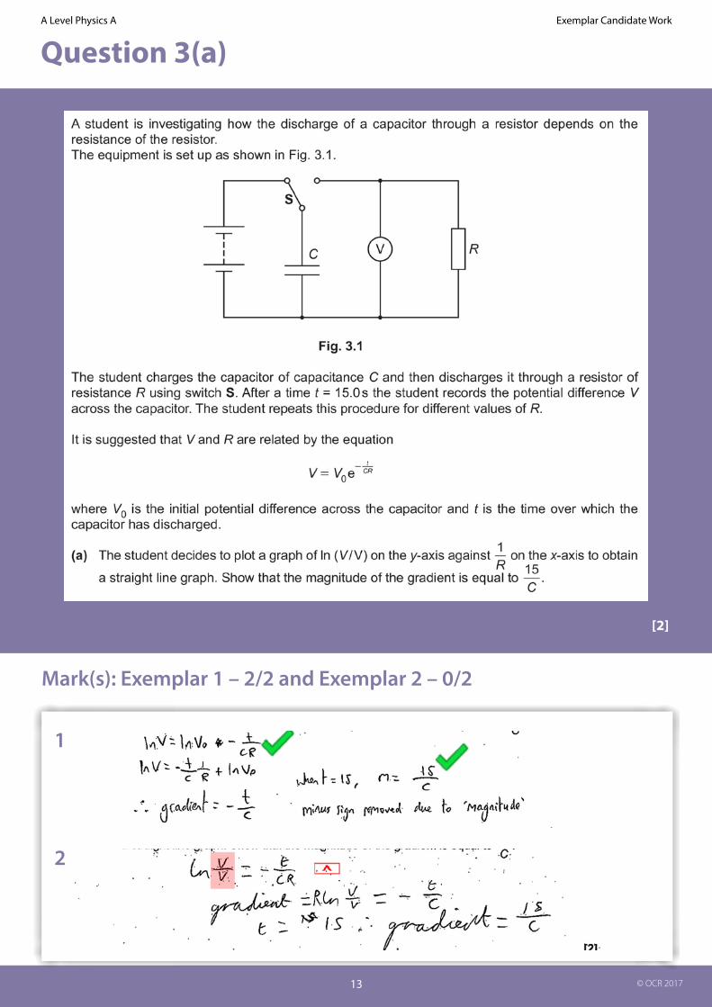
A small thin rectangular slice of semiconducting material has width a and thickness b and carries a current I. The current is due to the movement of electrons. Each electron has charge – e and mean drift velocity v. A uniform magnetic field of flux density B is perpendicular to the direction of the current and the top face of the slice as shown in Fig. 2.1.
(a) As soon as the current is switched on, the moving electrons in the current are forced towards the shaded rear face of the slice where they are stored. This causes the shaded faces to act like charged parallel plates. Each electron in the current now experiences both electric and magnetic forces. The resultant force on each electron is now zero.
Write the expressions for the electric and magnetic forces acting on each electron and use these to show that the magnitude of the potential difference V between the shaded faces is given by
V = Bva.
[3]
Mark(s): 2/3

Exemplar Candidate Work
9
A Level Physics A
© OCR 2017
Examiner commentaryThis was an exercise in writing basic definitions in algebraic form and then using them to derive a given equation. More than half of the candidates managed to gain full marks with less than one third scoring zero. The presentation was sometimes difficult to follow with the inclusion of unnecessary equations and deletions and the substitution of d for a not being made until the last line. Some stated F = BIl and I = nAev but were unable to derive F = Bev and so were limited to a maximum of 1 mark for the potential gradient equation
In the stem of the question candidates were asked to start by writing expressions for the electric and magnetic forces on an electron. The example given above has failed to include the fundamental equation F = eE and so fails to gain the first marking point. The force is related to the potential gradient and so scores the second point with the substitution and rearrangement given the third mark.

Exemplar Candidate Work
10
A Level Physics A
© OCR 2017
Question 2(b)(i) and (ii)
Here are some data for the slice in a particular experiment.
number of conducting electrons per cubic metre, n = 1.2 × 10²³ m–3
a = 5.0 mmb = 0.20 mmI = 60 mAB = 0.080 T
Use this data to calculate
(i) the mean drift velocity v of electrons within the semiconductor
v = ................................................ m s–1 [3]
(ii) the potential difference V between the shaded faces of the slice.
V = ...................................................... V [1]
Mark(s): 3/3; 1/1
Examiner commentaryThese exercises of choosing and substituting values with correct units into a formula and then evaluating were done well. About three quarters of the candidates gained full marks. A typical example of both parts is shown here.
A small number of candidates misunderstood the value of n in the formula for current and multiplied it ab. The resulting
incorrect answer to the second part could still be awarded the mark by ECF making the maximum mark possible 2/4. Another misunderstanding was to substitute the area A for a in the second part.

Exemplar Candidate Work
11
A Level Physics A
© OCR 2017
Question 2(c)(i) and (ii)
The slice is mounted and used as a measuring instrument called a Hall probe. A cell is connected to provide the current in the slice. The potential difference across the slice is measured by a separate voltmeter.
A student wants to measure the magnetic flux density between the poles of two magnets mounted on a steel yoke as shown in Fig. 2.2. The magnitude of the flux density is between 0.02 T and 0.04 T.
(i) Suggest one reason why this Hall probe is not a suitable instrument to measure the magnetic flux density for the arrangement shown in Fig. 2.2. [1]
(ii) Another method of measuring the magnetic flux density for the arrangement shown in Fig. 2.2 is to insert a current-carrying wire between the poles of the magnet. Explain how the magnetic flux density can be determined using this method and discuss which measurement in the experiment leads to the greatest uncertainty in the value for the magnetic flux density. [4]
Mark(s): 1/1; 4/4

Exemplar Candidate Work
12
A Level Physics A
© OCR 2017
Examiner commentaryThe first part proved to be too difficult for more than 90% of the candidates who did not appreciate that the potential difference across the Hall probe would be very small making the probe an unsuitable instrument for measuring the magnetic flux density, B. However almost all were familiar with the experiment where the magnets are mounted on a top pan balance with a fixed wire carrying the current. More than half of the candidates gained at least half marks here, the formula mark being most common and then the measurement of force mark.
The example above shows an excellent answer covering all of the points. Only a small number of candidates varied the current and plotted a graph to obtain a more accurate value of B. Too many appear to be content with taking a single measurement when describing an experiment. Candidates should try to imagine themselves in the laboratory and then describe what they have seen or done.
Few appreciated that the edges of the magnetic field spread out making the length of wire in the field the least reliable measurement. An answer in terms of the percentage uncertainty in the length measurement was accepted as an alternative response.
Exemplar Candidate Work
13
A Level Physics A
© OCR 2017
Question 3(a)
[2]
Mark(s): Exemplar 1 – 2/2 and Exemplar 2 – 0/2
1
2

Exemplar Candidate Work
14
A Level Physics A
© OCR 2017
Examiner commentaryThe whole question produced a full range of marks and discriminated well. About 70% gained more than half marks.
It was expected that candidates would write the equation in the expanded form lnV = - t/RC + lnV0 as shown in the first example. However the expression ln(V/V) in the stem appears to have encouraged a majority of the candidates to state the equation in the form ln(V/V0) = - t/RC. This was allowed as an acceptable answer. However those who omitted the subscript on V0 to copy the stem of the question were not awarded any marks as V here is the unit volt, not the initial value of V. The second script is an example of this. If the candidate had written V0 then the answer would have been awarded two marks.
The mark scheme for this answer is M1 A1 which means that the second mark cannot be given unless the first mark has already been awarded. This scheme is used here because part of the answer appears in the stem. The MA pattern is often used in ‘show that’ questions.

Exemplar Candidate Work
15
A Level Physics A
© OCR 2017
Question 3(b)(iii)
Values of R and V at t = 15.0 s are given in the table below.
(iii) Use the graph to determine a value for C. Include the absolute uncertainty and an appropriate unit in your answer.
C = .................. ± ............... unit ............. [4]

Exemplar Candidate Work
16
A Level Physics A
© OCR 2017
Mark(s): Exemplar 1 – 4/4 and Exemplar 2 – 3/4
1

Exemplar Candidate Work
17
A Level Physics A
© OCR 2017
Examiner commentaryThere was one mark for completing the table in part bi. 60% of candidates did this successfully.
In part bii there was one mark for plotting two points with error bars and one mark for drawing the best straight line on the graph. About 80% of candidates completed this successfully.
Many candidates failed to draw the worst straight line automatically forfeiting two possible marks in part biii.
Two competent answers are shown here. However nearly all candidates including these two used too many significant figures for each number.
Many forgot the power of 10-6 in the unit on the x-axis when finding the gradient of the lines.
The normal requirement that the final value for the capacitance C should to be given to 2 significant figures (SF) and the absolute uncertainty to 1 SF, e.g. 230 ± 20 μF, was waived. However the absolute uncertainty had to be stated to the same number of decimal places as the calculated value of C to gain the mark. This is why the second example does not gain the fourth mark.
2
Exemplar Candidate Work
18
A Level Physics A
© OCR 2017
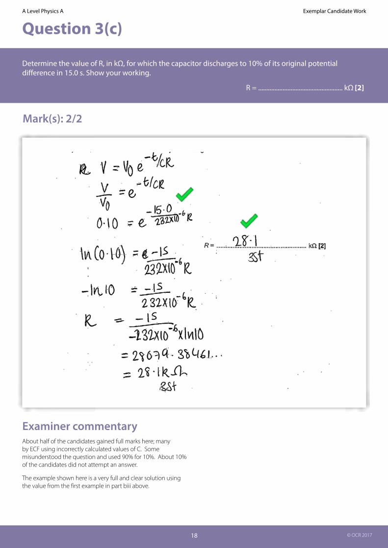
Question 3(c)
Determine the value of R, in kΩ, for which the capacitor discharges to 10% of its original potential difference in 15.0 s. Show your working.
R = .................................................... kΩ [2]
Mark(s): 2/2
Examiner commentaryAbout half of the candidates gained full marks here; many by ECF using incorrectly calculated values of C. Some misunderstood the question and used 90% for 10%. About 10% of the candidates did not attempt an answer.
The example shown here is a very full and clear solution using the value from the first example in part biii above.

Exemplar Candidate Work
19
A Level Physics A
© OCR 2017
Question 4(a)
You are given an unmarked sealed square box which has four identical terminals at each corner.
Fig 4.1 shows the circuit diagram for the contents of the box with the four terminals labelled A, B, C and D.
One of the resistors in the box has resistance 220 Ω. The other resistor has resistance 470 Ω. Two of the terminals are connected by a wire.
The four terminals on your unmarked sealed box are not labelled.
You are given a 6.0 V d.c. supply, a 100 Ω resistor (labelled R) and a digital ammeter.
Plan an experiment to determine the arrangement of the components and identify which
terminal of your unmarked sealed box is A, B, C and D.
A space has been left for you to draw circuit diagrams to illustrate your answer.
[6]
Mark(s): Exemplar 1 – 6/6, Exemplar 2 – 4/6, Exemplar 3 – 4/6 and Exemplar 4 – 4/6
1

Exemplar Candidate Work
20
A Level Physics A
© OCR 2017

Exemplar Candidate Work
21
A Level Physics A
© OCR 2017
2
3

Exemplar Candidate Work
22
A Level Physics A
© OCR 2017
3

Exemplar Candidate Work
23
A Level Physics A
© OCR 2017
4

Exemplar Candidate Work
24
A Level Physics A
© OCR 2017
Examiner commentaryThis Level of Response (LoR) question had two strands – planning how to determine the positioning of two resistors inside an unlabelled four terminal box and then verifying the values of their resistances.
Some candidates concentrated on determining the labelling of the terminals; others assumed the positions and explained how the resistances could be determined.
Many candidates made the task more difficult than necessary. For example it was intended that once terminals C and D had been identified, C could only be lower left and not lower right. and hence the positions of A and B were also identified.
A very common circuit used to determine the resistances placed the supply between A and C with the given resistor R between B and D, leading to calculations requiring combinations of resistors in series and parallel. Many ignored the limiting resistor R and probed the box without it, a few stating that the current between C and D would be zero with the supply across CD.
Some answers lacked any circuit diagram and some 15% failed to attempt the question. Weaker candidates were confused as to when the resistors were connected in series or in parallel. Generally, the responses were clearer in terms of planning than identifying. Comments such as and then you can work out the arrangement of the resistors were common without showing how this could be done. A small number of candidates introduced a voltmeter and others wanted to position the ammeter ‘inside’ the box.
The four examples of answers given here illustrate many of the above points. Full marks were awarded to the first example. The second example was written by someone who obviously has a full understanding but is too cryptic and so would only be awarded a very good L2. The third example would also be L2 as it has no current readings or comparison of current readings. The explanation with the unusual circuit in the fourth example deserves credit except for the error when the supply is connected across CD.

Exemplar Candidate Work
25
A Level Physics A
© OCR 2017
Question 4(b)
A light-dependent resistor (LDR) is connected between points X and Y in the circuit of Fig. 4.2. The circuit is used to switch on a lamp during the hours of darkness.
(i) Draw the symbol for an LDR on Fig. 4.2 between X and Y. [1]
(ii) Fig. 4.3 shows how the resistance of the LDR varies with light intensity. The electronic switch closes when V across XY is 4.0 V and opens when V across XY is 2.4 V. The electronic switch draws a negligible current.
Calculate
1 the resistance R of the resistor for the lamp to switch on at a light intensity of 0.80 W m–2
R = ...................................................... Ω [3]
2 the light intensity of the surroundings at which the lamp switches off.
light intensity = ............................................... W m–2 [2]
Mark(s): Exemplar 1 – 5/5 and Exemplar 2 – 3/5

Exemplar Candidate Work
26
A Level Physics A
© OCR 2017
1

Exemplar Candidate Work
27
A Level Physics A
© OCR 2017
2
Examiner commentaryIn part 1 more than half of the candidates knew the correct circuit symbol for an LDR. The most common error was to draw a variation of an LED symbol.
In part 2 it was more common for candidates to use a potential divider approach to solve the problem than to calculate the current in the circuit. The first example shows a script initially calculating the current whereas the second example uses a potential divider approach.
A small minority misinterpreted the question and reversed the voltages required to switch the lamp on and off. In cases such as the second example where all of the physics is correct except for the exchange of the two voltage conditions the candidates could be awarded a maximum of 3/5.
In part 2 about 25% of the candidates were only able to read the graph correctly to be credited with the first mark. However about the same number gained full marks.’ showing that this question discriminated well.

Exemplar Candidate Work
28
A Level Physics A
© OCR 2017
Question 5(a)(i)
A loudspeaker mounted on a bench is emitting sound of frequency 1.7 kHz to a microphone. Fig. 5.1 shows an illustration of the bulk movement of the air at one instant of time.
The maximum displacement of the air particles from their mean positions is 2.0 × 10⁻⁶ m.
The speed of sound in air at 17 °C is 340 m s–1.
(i) On Fig. 5.2, sketch the sinusoidal variation of the displacement of the air with distance between C and R.
1 Label the axes and include sensible scales.
2 On Fig. 5.2, mark one point where air particles are moving at maximum speed. Label it X.
3 On Fig. 5.2, mark one point where air particles are moving at maximum speed but travelling in the opposite direction to the air particles in 2. Label it Y.
[4]
Mark(s): Exemplar 1 – 4/4 and Exemplar 2 – 2/4

Exemplar Candidate Work
29
A Level Physics A
© OCR 2017
1
2
Examiner commentaryMost candidates drew a sinusoidal graph, correctly labelling the scale on the displacement axis. The points X and Y where the air particles were moving the fastest were also marked correctly along the x-axis. Fewer labelled distance on the x-axis; many incorrectly writing time. Only the better candidates marked the correct scale on this axis and very few indicated that there were 1.5 wavelengths between the points C and R.
The first example shows a clear and accurate answer given by only 5% whilst the second is typical of some 40% of candidates. Three quarters of a wavelength was a common choice for the distance between C and R.
The labelling of time on the x-axis by so many indicates the lack of ability to read the question correctly which clearly states with distance. There is no mention of time in the stem of part ai.

Exemplar Candidate Work
30
A Level Physics A
© OCR 2017
Question 5(a)(ii)
(ii) Calculate
1 the maximum speed vmax of the oscillating particles in the sound wave
vmax = .................................................m s–1 [2]
2 the root mean square speed cr.m.s. of the air molecules in the room.
The molar mass of air is 2.9 × 10⁻² kg mol–1.
cr.m.s. = .................................................m s–1 [2]
Mark(s): Exemplar 1 – 3/4 and Exemplar 2 – 2/4
1
2
Examiner commentaryTwo common mistakes in the first part were to use frequency rather than angular frequency or only to give the answer to one significant figure.
Most knew the correct formula on an atomic scale to calculate the mean square speed and used the kelvin scale
of temperature. However they then mixed R/M with k/m to produce k/M resulting in a rather small value of crms.
The first example shows two of these faults, whilst the second illustrates another common fault, namely to give the answer as the mean square speed and not the root mean square speed.

Exemplar Candidate Work
31
A Level Physics A
© OCR 2017
Question 5(b)
Students are given the equipment in Fig. 5.1 together with a metre rule. They are also given a second loudspeaker connected to the same signal generator at 1.7 kHz. They are asked to design an experiment where they would need to take just one measurement and be able to determine the value of the speed of sound.
They set up the experiment in two different ways as shown in Fig. 5.3(a) and (b).
In method (a) the microphone is fixed and one loudspeaker is moved to the left as shown in Fig. 5.3(a).
In method (b) the microphone is moved to the left or to the right with the loudspeakers fixed a certain distance apart as shown in Fig. 5.3(b).
Describe and explain how both methods can be used to accurately determine the speed of sound. In your description, discuss how the uncertainty in the value for the speed of sound can be minimised in one of the methods, without using any other apparatus. [6]
Mark(s): Exemplar 1 – 5/6 and Exemplar 2 – 0/6

Exemplar Candidate Work
32
A Level Physics A
© OCR 2017
1

Exemplar Candidate Work
33
A Level Physics A
© OCR 2017
2

Exemplar Candidate Work
34
A Level Physics A
© OCR 2017
Examiner commentaryAnswers were generally well structured into two sections, one for each experiment. A few candidates thought they could measure the wavelength on the oscilloscope screen. In experiment (a) most understood that the phase difference between the two oscillations at the microphone changed as one speaker was moved away. Explanations often muddled path and phase difference or referred to nodes and antinodes detected by the microphone. The distance between maximum amplitude signals was often stated to be λ/2. Some candidates misinterpreted the experiment moving the microphone to detect interference fringes, then used the double slits formula to find the wavelength. Others thought that the Doppler shift was applicable.
For experiment (b) many candidates used maxima and minima in place of antinodes and nodes although most recognised this to be a standing wave situation.
Many candidates ignored the instruction about suggesting how to reduce the uncertainty. The best candidates suggested reducing the frequency to reduce the percentage uncertainty in the wavelength measurement.
The first example shows a very good answer which is L3 standard. It was only given 5 marks but some examiners may well give it full marks. In LoR questions the first reading should determine whether the answer is in the L1, 2 or 3 band. At the second reading it is decided whether the answer is in the upper or lower level of the band.
The second example goes to the other extreme and illustrates how two pages can be written including some of the key words but constructed in such a way that the answer does not deserve any credit.

Exemplar Candidate Work
35
A Level Physics A
© OCR 2017
Question 6(a)
This question is about the motion of a ball suspended by an elastic string above a bench. The mass of the string is negligible compared to that of the ball. Ignore air resistance.
In Fig. 6.1 the ball of weight 1.2 N hangs vertically at rest from a point P. The extension of the string is 0.050 m. The string obeys Hooke’s law.
In Fig. 6.2 the ball is moving in a horizontal circle of radius 0.045 m around a vertical axis through P with a period of 0.67 s. The string is at an angle θ to the vertical. The tension in the string is T.
(a) On Fig. 6.2 draw and label one other force acting on the ball. [1]
Mark(s): Exemplar 1 – 1/1 and Exemplar 2 – 1 or 0/1
1

Exemplar Candidate Work
36
A Level Physics A
© OCR 2017
2
Examiner commentaryThe first example shows a clear correctly labelled answer. The second example shows a carelessly drawn arrow not through the centre of mass of the ball. A generous examiner might award the mark but a more critical one would not.
Note the instruction in the guidance section of the MS not to award the mark when other arrows are present on the diagram. Some candidates drew arrows resolving T into vertical and horizontal components on Fig. 6.1 rather than drawing a separate sketch in the answer space for part (b).

Exemplar Candidate Work
37
A Level Physics A
© OCR 2017
Question 6(b)(i)
(i) Resolve the tension T horizontally and vertically and show that the angle θ is 22°.
[2]
Mark(s): Exemplar 1 – 2/2 and Exemplar 2 – 2/2
1
2
Examiner commentaryIt is possible to work back from the given angle of 22o to write T sin θ = 0.48. The MS was constructed to try to avoid this by giving an M mark for showing the resolution of T into components either by equations of a vector diagram.
The full explanation in the first example is the perfect answer. The second answer is definitely acceptable as the value of the centripetal force is given to 3 figures, namely, 0.484 which is only possible if the candidate had completed the correct calculation. So both answers gain full marks.

Exemplar Candidate Work
38
A Level Physics A
© OCR 2017
Question 6(b)(ii)
(ii) Calculate the extension x of the string shown in Fig. 6.2.
x = ...................................................... m [3]
Mark(s): Exemplar 1 – 3/3 and Exemplar 2 – 1/3
1
2
Examiner commentaryNeither of these answers follows the answer column in the MS which was the most common way of writing the solution. Many weaker candidates were able to gain one of the three marks correctly calculating the force constant of the string.
The error in the second method is more than a simple arithmetic error so neither of the last two marks can be awarded. This candidate should have realised that the answer was smaller than the original extension so had to be incorrect. Questioning whether the answer to a calculation is plausible is a useful habit to cultivate.

Exemplar Candidate Work
39
A Level Physics A
© OCR 2017
Question 6(c)
Whilst rotating in the horizontal plane the ball suddenly becomes detached from the string. The bottom of the ball is 0.18 m above the bench at this instant. The ball falls as a projectile towards the bench beneath. Fig. 6.3 shows the view from above.
Calculate the horizontal distance R from the point on the bench vertically below the point P to the point where the ball lands on the bench.
R = ...................................................... m [4]
Mark(s): Exemplar 1 – 4/4 and Exemplar 2 – 3/4
1

Exemplar Candidate Work
40
A Level Physics A
© OCR 2017
Examiner commentaryAbout half of the candidates calculated the time for the ball to fall to the bench. Both of the examples show clearly the separation of horizontal and vertical motion. The first also illustrates another good practice of listing the symbols and known values of quantities to be used in the calculations. The second example is typical for about one quarter of all candidates who considered the horizontal distance from the point of release to be the final answer. The last mark was not included as a deliberate hurdle for the candidates but to mirror a practical situation where the point of reference for real measurements is the centre of rotation of the conical pendulum.
2

Exemplar Candidate Work
41
A Level Physics A
© OCR 2017
Question 6(d)
Returning to the situation shown in Fig. 6.2, state and explain what happens when the rate of rotation of the ball is increased. [2]
Mark(s): Exemplar 1 – 2/2 and Exemplar 2 – 1/2
1
2
Examiner commentaryAbout half of the candidates gave an answer similar to the second example here, stating what happens. The first example gave the correct explanation that a larger force is required provide by the increased tension. Many answers gave the impression that the centripetal force is a real force rather than its provision by a real force in the system being necessary for the ball to follow a circular path.

The
smal
l pri
nt
We’d like to know your view on the resources we produce. By clicking on the ‘Like’ or ‘Dislike’ button you can help us to ensure that our resources work for you. When the email template pops up please add additional comments if you wish and then just click ‘Send’. Thank you.
Whether you already offer OCR qualifications, are new to OCR, or are considering switching from your current provider/awarding organisation, you can request more information by completing the Expression of Interest form which can be found here: www.ocr.org.uk/expression-of-interest
OCR Resources: the small printOCR’s resources are provided to support the delivery of OCR qualifications, but in no way constitute an endorsed teaching method that is required by OCR. Whilst every effort is made to ensure the accuracy of the content, OCR cannot be held responsible for any errors or omissions within these resources. We update our resources on a regular basis, so please check the OCR website to ensure you have the most up to date version.
This resource may be freely copied and distributed, as long as the OCR logo and this small print remain intact and OCR is acknowledged as the originator of this work.
OCR acknowledges the use of the following content:Square down and Square up: alexwhite/Shutterstock.com
Please get in touch if you want to discuss the accessibility of resources we offer to support delivery of our qualifications: [email protected]
OCR is part of Cambridge Assessment, a department of the University of Cambridge. For staff training purposes and as part of our quality assurance programme your call may be recorded or monitored.
© OCR 2017 Oxford Cambridge and RSA Examinations is a Company Limited by Guarantee. Registered in England. Registered office 1 Hills Road, Cambridge CB1 2EU. Registered company number 3484466. OCR is an exempt charity.
General qualificationsTelephone 01223 553998Facsimile 01223 552627Email [email protected]
Looking for a resource?There is now a quick and easy search tool to help find free resources for your qualification:
www.ocr.org.uk/i-want-to/find-resources/
www.ocr.org.uk/alevelreform
OCR Customer Contact Centre