A Hybrid Finite-Element/Finite- Difference Scheme for Solving the 3-D Energy Equation in Transient...
17
This article was downloaded by: [University of Malaya] On: 29 May 2015, At: 21:40 Publisher: Taylor & Francis Informa Ltd Registered in England and Wales Registered Number: 1072954 Registered office: Mortimer House, 37-41 Mortimer Street, London W1T 3JH, UK Click for updates Numerical Heat Transfer, Part B: Fundamentals: An International Journal of Computation and Methodology Publication details, including instructions for authors and subscription information: http://www.tandfonline.com/loi/unhb20 A Hybrid Finite-Element/Finite- Difference Scheme for Solving the 3-D Energy Equation in Transient Nonisothermal Fluid Flow over a Staggered Tube Bank Seyyed Mahmood Aboulhasan Alavi a , Mohammad Reza Safaei b , Omid Mahian b , Marjan Goodarzi b , Hooman Yarmand c , Mahidzal Dahari c & Somchai Wongwises d a Department of Mechanical Engineering, Mashhad Branch, Islamic Azad University, Mashhad, Iran b Department of Mechanical Engineering, Ferdowsi University of Mashhad, Mashhad, Iran c Department of Mechanical Engineering, Faculty of Engineering, University of Malaya, Kuala Lumpur, Malaysia d Fluid Mechanics, Thermal Engineering and Multiphase Flow Research Laboratory (FUTURE), Department of Mechanical Engineering, Faculty of Engineering, King Mongkut’s University of Technology Thonburi, Bangmod, Bangkok, Thailand Published online: 29 May 2015. To cite this article: Seyyed Mahmood Aboulhasan Alavi, Mohammad Reza Safaei, Omid Mahian, Marjan Goodarzi, Hooman Yarmand, Mahidzal Dahari & Somchai Wongwises (2015) A Hybrid Finite-Element/ Finite-Difference Scheme for Solving the 3-D Energy Equation in Transient Nonisothermal Fluid Flow over a Staggered Tube Bank, Numerical Heat Transfer, Part B: Fundamentals: An International Journal of Computation and Methodology, 68:2, 169-183, DOI: 10.1080/10407790.2015.1012440 To link to this article: http://dx.doi.org/10.1080/10407790.2015.1012440 PLEASE SCROLL DOWN FOR ARTICLE Taylor & Francis makes every effort to ensure the accuracy of all the information (the “Content”) contained in the publications on our platform. However, Taylor & Francis, our agents, and our licensors make no representations or warranties whatsoever as to
Transcript of A Hybrid Finite-Element/Finite- Difference Scheme for Solving the 3-D Energy Equation in Transient...

This article was downloaded by: [University of Malaya]On: 29 May 2015, At: 21:40Publisher: Taylor & FrancisInforma Ltd Registered in England and Wales Registered Number: 1072954 Registeredoffice: Mortimer House, 37-41 Mortimer Street, London W1T 3JH, UK
Click for updates
Numerical Heat Transfer, Part B:Fundamentals: An International Journalof Computation and MethodologyPublication details, including instructions for authors andsubscription information:http://www.tandfonline.com/loi/unhb20
A Hybrid Finite-Element/Finite-Difference Scheme for Solving the3-D Energy Equation in TransientNonisothermal Fluid Flow over aStaggered Tube BankSeyyed Mahmood Aboulhasan Alavia, Mohammad Reza Safaeib, OmidMahianb, Marjan Goodarzib, Hooman Yarmandc, Mahidzal Daharic &Somchai Wongwisesd
a Department of Mechanical Engineering, Mashhad Branch, IslamicAzad University, Mashhad, Iranb Department of Mechanical Engineering, Ferdowsi University ofMashhad, Mashhad, Iranc Department of Mechanical Engineering, Faculty of Engineering,University of Malaya, Kuala Lumpur, Malaysiad Fluid Mechanics, Thermal Engineering and Multiphase FlowResearch Laboratory (FUTURE), Department of MechanicalEngineering, Faculty of Engineering, King Mongkut’s University ofTechnology Thonburi, Bangmod, Bangkok, ThailandPublished online: 29 May 2015.
To cite this article: Seyyed Mahmood Aboulhasan Alavi, Mohammad Reza Safaei, Omid Mahian, MarjanGoodarzi, Hooman Yarmand, Mahidzal Dahari & Somchai Wongwises (2015) A Hybrid Finite-Element/Finite-Difference Scheme for Solving the 3-D Energy Equation in Transient Nonisothermal Fluid Flowover a Staggered Tube Bank, Numerical Heat Transfer, Part B: Fundamentals: An International Journalof Computation and Methodology, 68:2, 169-183, DOI: 10.1080/10407790.2015.1012440
To link to this article: http://dx.doi.org/10.1080/10407790.2015.1012440
PLEASE SCROLL DOWN FOR ARTICLE
Taylor & Francis makes every effort to ensure the accuracy of all the information (the“Content”) contained in the publications on our platform. However, Taylor & Francis,our agents, and our licensors make no representations or warranties whatsoever as to

the accuracy, completeness, or suitability for any purpose of the Content. Any opinionsand views expressed in this publication are the opinions and views of the authors,and are not the views of or endorsed by Taylor & Francis. The accuracy of the Contentshould not be relied upon and should be independently verified with primary sourcesof information. Taylor and Francis shall not be liable for any losses, actions, claims,proceedings, demands, costs, expenses, damages, and other liabilities whatsoever orhowsoever caused arising directly or indirectly in connection with, in relation to or arisingout of the use of the Content.
This article may be used for research, teaching, and private study purposes. Anysubstantial or systematic reproduction, redistribution, reselling, loan, sub-licensing,systematic supply, or distribution in any form to anyone is expressly forbidden. Terms &Conditions of access and use can be found at http://www.tandfonline.com/page/terms-and-conditions
Dow
nloa
ded
by [
Uni
vers
ity o
f M
alay
a] a
t 21:
40 2
9 M
ay 2
015

Numerical Heat Transfer, Part B, 68: 169–183, 2015Copyright # Taylor & Francis Group, LLCISSN: 1040-7790 print/1521-0626 onlineDOI: 10.1080/10407790.2015.1012440
A HYBRID FINITE-ELEMENT=FINITE-DIFFERENCESCHEME FOR SOLVING THE 3-D ENERGY EQUATIONIN TRANSIENT NONISOTHERMAL FLUID FLOW OVERA STAGGERED TUBE BANK
Seyyed Mahmood Aboulhasan Alavi1, Mohammad RezaSafaei2, Omid Mahian2, Marjan Goodarzi2, HoomanYarmand3, Mahidzal Dahari3, and Somchai Wongwises41Department of Mechanical Engineering, Mashhad Branch,Islamic Azad University, Mashhad, Iran2Department of Mechanical Engineering, Ferdowsi University of Mashhad,Mashhad, Iran3Department of Mechanical Engineering, Faculty of Engineering, Universityof Malaya, Kuala Lumpur, Malaysia4Fluid Mechanics, Thermal Engineering and Multiphase Flow ResearchLaboratory (FUTURE), Department of Mechanical Engineering, Faculty ofEngineering, King Mongkut’s University of Technology Thonburi, Bangmod,Bangkok, Thailand
This article presents a hybrid finite-element=finite-difference approach. The approachsolves the 3-D unsteady energy equation in nonisothermal fluid flow over a staggeredtube bank with five tubes in the flow direction. The investigation used Reynolds numbersof 100 and 300, Prandtl number of 0.7, and pitch-to-diameter ratio of 1.5. An equilateraltriangle (ET) tube pattern is considered for the staggered tube bank. The proposedhybrid method employs a 2-D Taylor-Galerkin finite-element method, and the energyequation perpendicular to the tube axis is discretized. On the other hand, the finite-difference technique discretizes the derivatives toward the tube axis. Weighting the 3-D,transient, convection-diffusion equation for a cube verifies the numerical results. The L2
norm of the error between numerical and exact solutions is also presented for threedifferent hybrid meshes. A grid independence study for the energy equation preceded thefinal mesh. The outcome is found to be in acceptable concurrence with those from theprevious studies. After the temperature field is attained, the local Nusselt number iscomputed for the tubes in the bundle at different times. The isotherms are also obtainedat different times until a steady-state solution is reached. The numerical results convergeto the exact results through refining the mesh. The implemented hybrid scheme requiresless computation time compared with the conventional 3-D finite-element method,requiring less program coding.
Received 2 October 2014; accepted 6 December 2014.Address correspondence to Mohammad Reza Safaei, Department of Mechanical Engineering,
Ferdowsi University of Mashhad, Mashhad, Iran. E-mail: [email protected]
169
Dow
nloa
ded
by [
Uni
vers
ity o
f M
alay
a] a
t 21:
40 2
9 M
ay 2
015

1. INTRODUCTION
Heat transfer and fluid flow analysis over tube banks is of great importance invarious design applications such as cooling towers [1], boilers [2], various heatexchangers [3–5], chemical filtration [6], and nuclear reactors [7]. Heat exchangerdesign depends on such parameters as the number of pipes of various lengths anddiameters, geometric dimensions, arrangement of tubes, and fluids that carry heat[8, 9]. There have been numerous experimental and 2-D numerical studies on theflow over tube banks, but Le Feuvre [10] and later Launder and Massey [11] werethe ones who developed numerical applications for fluid flow and heat transfer intube banks. Alavi and Goshayeshi [12] and Alavi [13] used a finite-element (FE)method to assess the laminar forced convection of air past an in-line and staggeredtube bank. Recently, Wu and Che [14] employed a finite-volume (FV) method toexamine turbulent forced-convection heat transfer of vapor=air mixture flow pasta staggered tube bank. They studied a wide range of tube rows (from 2 to 7), tubediameters, vapor concentration, wall temperature, and gas velocity for an equilateraltriangle of tube banks.
However, 2-D analysis is not always sufficient, and a full 3-D analysis isrequired in some circumstances for more accuracy [15], especially of transfer in heatexchangers [16–18].
There have been a number of 3-D numerical studies on the heat transfer andfluid flow over tube banks. Fan, Ding, He, and Tao [19] developed a code accordingto nonorthogonal curvilinear coordinates, using the finite-volume method to solve3-D fluid flow and heat transfer equations around a dimpled fin-and-tube structure.Yusuf, Halvorsen, and Melaaen [20] have studied 3-D turbulent forced-convectionheat transfer in a cylindrical pin-fin channel with a staggered and aligned arrange-ment, using a finite-element commercial code, ANSYS CFX 11. Afgan [15] employedthe commercial CFD code STAR-CD to examine the turbulent forced convection ofan incompressible Newtonian fluid in a square in-line tube bank. His results showedthe 2-D simulations could not capture the complete flow physics. More recently,Iacovides, Launder, Laurence, and West [21] and Iacovides, Launder, and West
NOMENCLATURE
K matrixM mass matrixP dimensionless pressure�P Pressure, PaPe Peclet numberPr Prandtl numberRe Reynolds numbert dimensionless time�t time, sT temperature, KU velocity, m=s�V velocity vectorV¼ (u, v, w) dimensionless velocity vectorX dimensionless coordinate vector
�X coordinate vectorh dimensionless temperaturem dynamic viscosity Pa s
Subscripts and Superscriptsa advectionbd balancing diffusiond diffusion(e) elementnp total number of nodes in each
perpendicular planew wall1 free-stream
170 S. M. A. ALAVI ET AL.
Dow
nloa
ded
by [
Uni
vers
ity o
f M
alay
a] a
t 21:
40 2
9 M
ay 2
015

[22, 23] examined the turbulent forced-convection heat transfer of a Newtonian fluidaround in-line tube banks, using the large-eddy simulation (LES) and unsteadyReynolds-averaged Navier-Stokes (URANS) models in the finite-volume code,Code Saturne.
Recently, the hybrid scheme has helped overcome the difficulties in generating3-D meshes. Dai and Nassar [24] studied the heat conduction equation in a double-layered 3-D thin film using a hybrid finite-difference=finite-element method. Theirmodel predictions were in good agreement with earlier finite-difference numericalstudies. Chaabane, Askri, and Ben Nasrallah [25] employed the lattice Boltzmannmethod (LBM) to solve the transient conduction–radiation heat transfer equationin a cylindrical enclosure. In that work, the radiation was solved through a hybridfinite-element=control-volume (CVFEM) approach. Wang, Han, and Sun [26] useda hybrid finite-difference=finite-element scheme to model 1-D and 2-D nonclassical-conduction heat transfer and its related thermal stresses in various configurations.Arefmanesh and Alavi [27] solved the unsteady energy equation in 3-D heat transferand fluid flow crossing over a circular tube using a hybrid finite-element=finite-difference method.
The aforementioned simulation approaches have proven applicable to 3-Dproblems. However, complex cases requiring both high computational time andverification of results require a new method. For this article, the hybrid finite-element=finite-difference method, using an in-house FORTRAN code, has numericallyanalyzed unsteady 3-D, nonisothermal heat transfer and fluid flow past a staggeredtube bank. The flow regime’s simulation results contrasted with the exact solutionresults in the literature. Attention focused on computation time and program codingcomplexity of the proposed method, compared to the 3-D finite-element method.
2. METHODOLOGY
This study solved a 3-D transient energy equation for a nonisothermal fluidflow passing over a staggered tube bank inserted in a channel. To do this, weintroduced a hybrid finite-element=finite-difference technique. In this scheme, thefinite-difference method discretizes the energy equation along with the tube axis,whereas the finite-element method handles the perpendicular direction. Appointingequally spaced grid points (mþ 1) along the tube length (H) divides it into identicalparts (m). A normal plane with respect to the tube axis is plotted at each point, withDz the distance between any two sequential planes, as shown in Figure 1 (perpendi-cular planes). Eventually, symmetry creates an identical 2-D finite-element meshincluding triangular elements of three nodes on each of the planes. Thereafter,aligned lines, in parallel with the tube axis, connect the nodes of homologicalelements in adjacent planes. This creates a hybrid 3-D mesh, as shown in Figure 1.
The following steps create the hybrid finite-element=finite-difference scheme.First, a Navier-Stokes equation solver based on the finite-element method helpscalculate the temperature distribution of the flow field. After the velocity distributionis obtained, a 2-D Taylor-Galerkin finite-element scheme helps discretize the energyequation over each perpendicular plane. Finally, finite-difference equations replaceresulting derivatives in the obtained semidiscretized equations, which are in thedirection of the tube axis (z coordinate).
HYBRID FE=FD FOR FLOW OVER A TUBE BANK 171
Dow
nloa
ded
by [
Uni
vers
ity o
f M
alay
a] a
t 21:
40 2
9 M
ay 2
015

Dimensionless transient equations of continuity, momentum, and energy for3-D, incompressible flow of a Newtonian fluid in laminar regime are presented asfollows:
r � V ¼ 0 ð1ÞDVDt
¼ �rPþ 1Re
r2V ð2Þ
DhDt
¼ 1Pe
r2h ð3Þ
where the dimensionless variables can be expressed as
Pe ¼ qCpU1Dk
Re ¼ qU1Dm
P ¼�P
qU21
X ¼�XD
t ¼ �tU1D
h ¼ T � T1Tw � T1
V ¼�VU1
ð4Þ
A physical model of 2-D flow around a staggered tube bank with five tubes inthe flow direction is shown in Figure 2a. The axis of the first tube is positioned in theupstream at a distance from the input plane equivalent to 3D (Lus). The computa-tional domain should be long enough on the x axis to fully develop boundaryconditions at the outlet plane. Therefore, this length was selected at 12D, which isup to the fifth tube axis in the downstream (Lds). All the above lengths were chosenaccording to Tezduyar and Shih [28] and Arefmanesh and Alavi [29]. Variousarrangements can be chosen for the tubes in a staggered tube bank. The equilateraltriangle (ET) [30, 31] is a tube arrangement used in this work, and its graphicaldefinition is given in Figure 2b.
Figure 3 shows the computational domain of the studied problem and itsrelated boundary conditions. The tubes are between two upper and bottom walls
Figure 1. The hybrid 3-D mesh used in the present study.
172 S. M. A. ALAVI ET AL.
Dow
nloa
ded
by [
Uni
vers
ity o
f M
alay
a] a
t 21:
40 2
9 M
ay 2
015
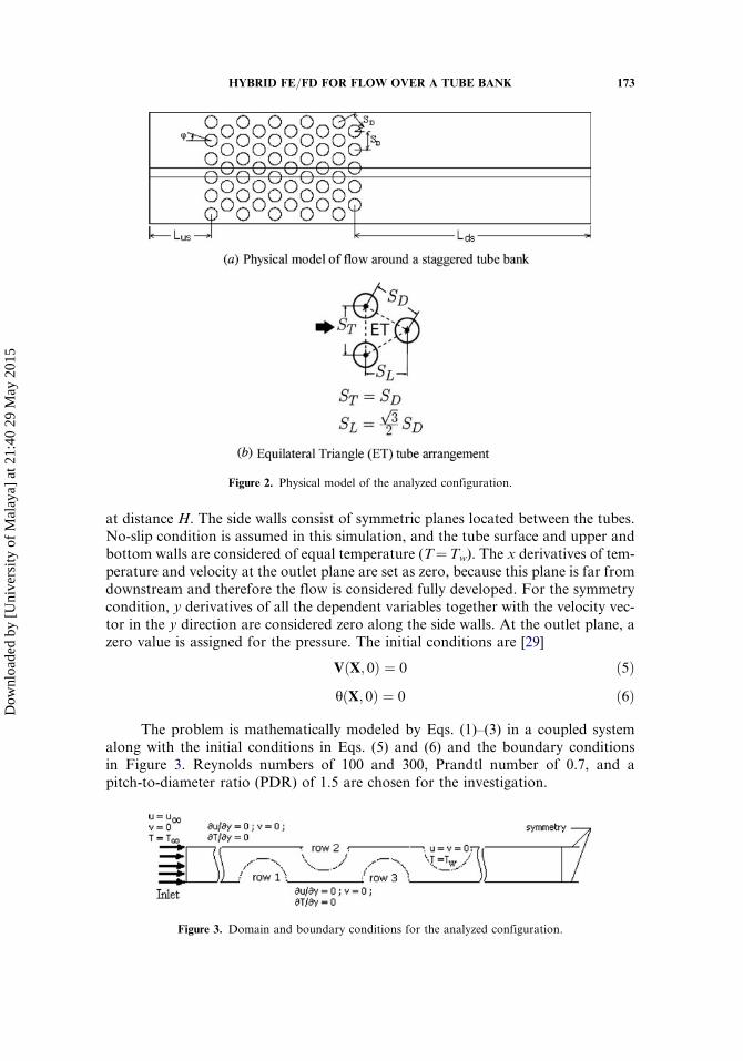
at distance H. The side walls consist of symmetric planes located between the tubes.No-slip condition is assumed in this simulation, and the tube surface and upper andbottom walls are considered of equal temperature (T¼Tw). The x derivatives of tem-perature and velocity at the outlet plane are set as zero, because this plane is far fromdownstream and therefore the flow is considered fully developed. For the symmetrycondition, y derivatives of all the dependent variables together with the velocity vec-tor in the y direction are considered zero along the side walls. At the outlet plane, azero value is assigned for the pressure. The initial conditions are [29]
VðX; 0Þ ¼ 0 ð5ÞhðX; 0Þ ¼ 0 ð6Þ
The problem is mathematically modeled by Eqs. (1)–(3) in a coupled systemalong with the initial conditions in Eqs. (5) and (6) and the boundary conditionsin Figure 3. Reynolds numbers of 100 and 300, Prandtl number of 0.7, and apitch-to-diameter ratio (PDR) of 1.5 are chosen for the investigation.
Figure 2. Physical model of the analyzed configuration.
Figure 3. Domain and boundary conditions for the analyzed configuration.
HYBRID FE=FD FOR FLOW OVER A TUBE BANK 173
Dow
nloa
ded
by [
Uni
vers
ity o
f M
alay
a] a
t 21:
40 2
9 M
ay 2
015

3. NUMERICAL MODELING
The flow field needs to be generated before solving the energy equation. ANavier-Stokes equation solver based on the finite-element technique does this. A lin-ear shape function helps solve the velocity field within tetrahedral elements with fournodes, and the pressure is assumed unchanged in each segment within the elements(piecewise constant pressure) [32]. These approximations are substituted in thePetrov-Galerkin weighted-residual weak form of the Navier-Stokes equations [33]and the time derivatives are discretized. The result is nonlinear algebraic equationsin a coupled system for the unknown pressure and velocity components in the nodes[28]. Solution of this system of equations at each time step gives the distributions ofvelocity and pressure in the computational domain.
The proposed hybrid method is applied to discretize the energy equation[Eq. (3)]. The equation is discretized in the normal planes with respect to thetube axis (x–y planes), as shown in Figure 1. This is done with a 2-D finite-elementscheme and 3-noded triangular elements. Thereafter, the finite-difference methoddiscretizes the obtained semidiscretized ODEs in the direction of the tube axis(z direction).
We used the Taylor-Galerkin technique, a proper choice in transient cases, topresent the dimensionless form of temperature with respect to time in a second-order-accurate truncated Taylor series in the following equation:
hnþ1 ¼ hn þ Dtqhn
qtþ Dt2
2q2hn
qt2ð7Þ
where n and nþ 1 denote sequential time steps. Using Eq. (3), the tem-peraturederivatives of first and second orders with respect to time are given as follows:
qhn
qt¼ �V � rhn þ 1
Per2hn
q2hn
qt2¼ � qVn
qt� rhn � ðVn � rÞ qh
n
qtþ 1Pe
r2 qhn
qt
� �ð8Þ
Substituting the expressions of Eq. (8) into Eq. (7), and replacing qhn=qt byhnþ1 � hn=Dt in the ensuing equation, we get a time-discretized form of the energyequation:
1Dt
� 12 Pe
r2
� �hnþ1 ¼ 1
Dtþ 12 Pe
r2 � Vnþ1=2 � r þ Dt2ðVn � rÞðVn � rÞ
� �hn ð9Þ
The Galerkin finite-element method discretizes Eq. (9) is in the x–y planes.To do so, the following linear interpolation is used to estimate the dimensionlesstemperature in a typical 3-noded triangular element, Xe, within the 2-D mesh(Figure 1):
�hðeÞðx; y; z; tÞ ¼
X3i¼1
NðeÞi ðx; yÞhðeÞi ðz; tÞ ð10Þ
where �hðeÞ
is the linear approximation of the temperature in the dimensionless form,
NðeÞi is the usual linear shape functions, and hðeÞi is the value of the dimensionless
temperature at the nodes, both for i¼ 1–3.
174 S. M. A. ALAVI ET AL.
Dow
nloa
ded
by [
Uni
vers
ity o
f M
alay
a] a
t 21:
40 2
9 M
ay 2
015

The Galerkin weighted residual formulation of the problem can be achieved bymultiplying Eq. (9) by the shape functions and the integral of the obtained formulaover the elements and setting the formula to zero:
ZXe
1Dt � 1
2 Per2� �
hnþ1�1Dt þ 1
2 Per2 � Vnþ1=2 � rþ Dt
2 ðVn � rÞðVn � rÞ� �
hn
8><>:
9>=>;Nj dx dy ¼ 0 ð11Þ
Using Gauss’s theorem and substituting the linear approximations for hn andhnþ 1 from Eq. (10) results in the following system of ordinary differential equationsODEs for the typical element:
MðeÞ
DtþKðeÞ
d
2 Pe
!hðeÞn onþ1
�MðeÞ
2 Pe
d2 hðeÞn onþ1
dz2¼ MðeÞ
Dt�KðeÞ
d
2 Pe� ðKðeÞ
a þKðeÞbd Þ
!hðeÞn on
þ 12 Pe
þ Dt2w2
� �MðeÞ
d2 hðeÞn on
dz2� wnþ1=2MðeÞ � wDtKðeÞ
a
� d hðeÞn on
dzð12Þ
where {h(e)}, for i¼ 1–3, is the vector of nodal unknowns. Local node numbers areused to express the elements of the matrices in the following form:
MðeÞij ¼
ZXe
NðeÞi NðeÞ
j dx dy
KðeÞdij
¼ZXe
ðNðeÞi;x N
ðeÞj;x þ NðeÞ
i;y NðeÞj;y Þ dx dy
KðeÞaij ¼
ZXe
ðunþ1=2NðeÞj;x N
ðeÞi þ vnþ1=2NðeÞ
j;y NðeÞi Þ dx dy
KðeÞbdij
¼ Dt2
ZXe
ðu2NðeÞi;x N
ðeÞj;x þ v2NðeÞ
i;y NðeÞj;y þ uvNðeÞ
i;x NðeÞj;y
þ uvNðeÞi;y N
ðeÞj;x Þ dx dy
for i; j ¼ 1� 3 ð13Þ
Discretization of the system of ODEs [Eq. (12)] along with the z axis is thenext step of solving the energy equation, done with the finite-difference method.The vector of nodal unknowns in each element is presented according to the globalnode number:
hðeÞn o‘
¼hIhJhK
8<:
9=;
‘
for ‘ ¼ n; nþ 1 ð14Þ
where I, J, and K denote the global node numbers in each element (Figure 1). Theseglobal node numbers can be used to rewrite the difference quotients for the first andsecond derivatives with regard to the z axis. Therefore, the dimensionless form of thetemperature in Eq. (12) can be given as
HYBRID FE=FD FOR FLOW OVER A TUBE BANK 175
Dow
nloa
ded
by [
Uni
vers
ity o
f M
alay
a] a
t 21:
40 2
9 M
ay 2
015

dh‘idz
¼ h‘iþnp � h‘i�np
2Dzi ¼ I; J;K ð15Þ
d2h‘idz2
¼ h‘i�np � 2h‘i þ h‘iþnp
Dz2‘ ¼ n; nþ 1 ð16Þ
where z is the distance between successive planes (Figure 1). Replacing Eq. (12) withEqs. (15) and (16) yields a fully discretized form of the energy equation for the element:
MðeÞ
DtþKðeÞ
d
2 Pe
!hif gnþ1�MðeÞ
2 Pe
hi�np � 2hi þ hiþnp �nþ1
Dz2
¼ MðeÞ
Dt�KðeÞ
d
2 Pe� ðKðeÞ
a þKðeÞbd Þ
!hif gn
þ 12 Pe
þ Dtw2
2
� �MðeÞ hi�np � 2hi þ hiþnp
�nDz2
� wnþ1=2MðeÞ � wDtKðeÞa
� hiþnp � hi�np �n
2Dzð17Þ
Eventually, Eq. (17) is the result for the elements in the hybrid mesh. Applying thenecessary boundary conditions for the temperature, the obtained algebraic equationsare solved and, for each time step, the temperature values are obtained at all nodes.
4. RESULTS AND DISCUSSION
This work considered transient, 3-D, and nonisothermal fluid flow passing over astaggered tube bank. It solved the relevant energy equation using a proposed hybridfinite-difference=finite-element technique. In this technique, a 2-D finite-elementmethod discretizes in the x–y planes, and the finite-difference method approximatesthe derivatives in the direction of the z axis. The Taylor-Galerkin method ensured astable discretization at high Peclet numbers. As a test case, D¼ 0.01m, Tw¼ 400K,and T1¼ 300K are considered, leading to the discussion that follows.
4.1. Validity of the Method
The performance of the introduced scheme was evaluated by implementing themethod on a 3-D transient, convection–diffusion flow in a unit cube:
qTqt
þ aqTqx
þ bqTqy
þ cqTqz
¼ mq2Tqx2
þ q2Tqy2
þ q2Tqz2
� �ð18Þ
The exact, steady-state solution of Eq. (18) for the following boundaryconditions,
Tð0; y; z; tÞ ¼ 1� exp½ðy� 1Þb=m�1� expð�b=mÞ
� 1� exp½ðz� 1Þc=m�1� expð�c=mÞ
� Tð1; y; z; tÞ ¼ 0 ð19aÞ
176 S. M. A. ALAVI ET AL.
Dow
nloa
ded
by [
Uni
vers
ity o
f M
alay
a] a
t 21:
40 2
9 M
ay 2
015

Tðx; 0; z; tÞ ¼ 1� exp½ðx� 1Þa=m�1� expð�a=mÞ
� 1� exp½ðz� 1Þc=m�1� expð�c=mÞ
� Tðx; 1; z; tÞ ¼ 0 ð19bÞ
Tðx; y; 0; tÞ ¼ 1� exp½ðx� 1Þa=m�1� expð�a=mÞ
� 1� exp½ðy� 1Þb=m�1� expð�b=mÞ
� Tðx; y; 1; tÞ ¼ 0 ð19cÞ
and the initial condition
Tðx; y; z; 0Þ ¼ 0 ð20Þ
are defined by [27]
Taðx; y; z; tÞ ¼ 1� exp½ðx� 1Þa=m�1� expð�a=mÞ
� 1� exp½ðy� 1Þb=m�1� expð�b=mÞ
� 1� exp½ðz� 1Þc=m�1� expð�c=mÞ
� ð21Þ
In the present study, the coefficients a, b, c, and m in Eq. (18) were consideredequal to unity and the equation was solved for the said boundary and initialconditions. The solution was based on the discussed hybrid scheme, employing three
different meshes. The L2 norm of the error ( ek k0 ¼RX ðTa � TÞ2dX
h i0:5, ¼ {0� x, y,
z� 1}) between the exact solution and numerical simulation of Eq. (18) wereobtained in the steady-state condition and are demonstrated in Figure 4, consideringthe number of nodes.
It is apparent from the figure that by refining the mesh, the result of thenumerical simulation converges to the exact solution. This shows the strength ofthe proposed scheme in solving 3-D problems.
We used an Intel Pentium 4A to compare the time of calculation of the pro-posed scheme to that of the 3-D finite-element method. The time recorded for thefinest applied hybrid mesh, having 1,331 nodes, was 2,800 s for 100 time steps. How-ever, the time for the same number of time steps and nodes was 8,400 s for the 3-Dfinite-element scheme with tetrahedral elements of four nodes.
Lower connectivity between the nodes in the hybrid scheme is the main reasonwhy its time of computation is lower. However, the codes the authors used for bothcases were in-house research versions rather than optimized ones. Nevertheless,based on previous research, optimization of the methods is believed to decreasecalculation time [34, 35].
4.2. Mesh-Independent Study
Mesh-independent tests were carried out before adopting the final mesh. There-fore, three grid distributions were tested to assure that the computational resultswere grid-independent. These were a coarse mesh with the number 6,869, a mediumone with the number 12,684, and a fine mesh with the number 21,679. These types ofmesh were used in the computations consisting of 2-D elements in the planesperpendicular to the tube axis until the mesh was optimized and results remainedthe same even with numbers greater than these. In the third dimension, the
HYBRID FE=FD FOR FLOW OVER A TUBE BANK 177
Dow
nloa
ded
by [
Uni
vers
ity o
f M
alay
a] a
t 21:
40 2
9 M
ay 2
015

derivatives parallel to the tube axis were set at 10 parts in all tests [29]. The grid ismore refined in the vicinity of tube walls, where significant temperature and velocitygradients occur.
Figure 5 illustrates the local Nusselt number at different angles for differentgrids. Based on the presented results, a 12,684� 10 grid was selected for all modelingcases.
Figure 4. Alteration of the L2 norm of the error for Equation (18).
Figure 5. Grid independence tests for the present study by comparison of local Nusselt numbers in variousmesh concentration.
178 S. M. A. ALAVI ET AL.
Dow
nloa
ded
by [
Uni
vers
ity o
f M
alay
a] a
t 21:
40 2
9 M
ay 2
015

4.3. Isotherms
The isotherms for flow over a staggered tube bank with five tubes in the flowdirection with Reynolds numbers 100 and 300, at different times until steady stateare shown in Figure 6. It is possible to predict the amount of heat at different timesand at the various points of the tube bank.
It is obvious that in places where the isotherms are closer to each other, thetemperature gradient is greater and heat transfer is higher. In Figure 6a, the iso-therms at �t ¼ 0:1 are drawn symmetrically over all the tubes. This symmetry tendsto vanish over time due to the recirculation happening between the tubes(Fig. 6b). Figure 6c demonstrates that, in the steady state, the isotherms are swarmedon the front half of the first tube and with less intensity over the front half of thesecond tube, which indicates a high radial heat flux.
Figure 6. Isotherms in the staggered tube bank in mid-plane.
HYBRID FE=FD FOR FLOW OVER A TUBE BANK 179
Dow
nloa
ded
by [
Uni
vers
ity o
f M
alay
a] a
t 21:
40 2
9 M
ay 2
015

4.4. Nusselt number
Figure 7 shows the distribution of the local Nusselt number around the tubes atthe steady-state condition, in comparison with the result of Wang, Penner, and Ormis-ton [36]. The local Nusselt number and the bulk temperature are defined as [36, 37]
Nu ¼ � DðTw � TbÞ
qTqn
����w
� �¼ � 1
1� hb
qhq�n
����w
� �ð22Þ
Tb ¼R SD=2D=2 quT dy
qðSD=2ÞU1ð23Þ
Figure 7 shows that the fluid has the same local Nusselt number over all the tubesin the initial phase. The intense temperature gradient around these tubes increases itand normalizes it. As time passes, it decreases and differs among tubes. The first tubein the steady state has the highest Nusselt number, almost the same, at angles between0� and 80�. For the third tube, the maximumNusselt number is at the front stagnationpoint, and with the growth of the boundary-layer flow, decreases.
For the first and third tubes, the minimum Nusselt number occurs in the wakeflow behind the tube.
5. CONCLUSION
This work studied a nonisothermal fluid flow passing over a staggered tubebank in a channel. To solve the related 3-D transient energy equation, we proposedand implemented a hybrid finite-difference=finite-element method. This method sawdiscretization performed with a 2-D finite-element scheme for the perpendicular
Figure 7. The local Nusselt number at the steady state in the mid-plane.
180 S. M. A. ALAVI ET AL.
Dow
nloa
ded
by [
Uni
vers
ity o
f M
alay
a] a
t 21:
40 2
9 M
ay 2
015

planes and the finite-difference technique for the derivatives in the direction of thetube axis. To achieve stable solutions at high Peclet numbers, the Taylor-Galerkinmethod was used for the finite-element scheme.
The time of computation for the introduced hybrid schemewas evaluated by com-parison with the calculation time for a 3-D finite-element method. Simulations for thetest case were performed by the two methods with the same computer and for the sametime steps and nodes. The results found the computational time of the finite-elementmethod to be about three times greater than that for the hybrid scheme, due to thehybrid scheme’s lower nodal connectivity. This is the advantage of this scheme inmassive simulations of 3-D problems, where calculation time is a determining factor.Then, the present method was thoroughly benchmarked against an exact solution inthe literature and was found to be in very good agreement, especially in fine meshes.
After that, the method was applied for the simulation of 3-D convection heattransfer in a nonisothermal fluid flow passing over a staggered tube bank in achannel at the conditions of Re¼ 100 and 300 and Pr¼ 0.7. The related mesh-independent evaluations were also performed.
The results showed that the isotherms were symmetrically crowded over all of thetubes at the first stage. However, the recirculation between the tubes destroys this sym-metry over time. At the steady state, the isotherms huddle over the front half of thefirst tube and with less intensity over the front half of the second tube, indicating a highradial heat flux. At steady state, the maximumNusselt number for the first tube occursbetween the angles of 0� and 80�. However, Nusselt number for the third tube is high-est at the front stagnation point, and it decreases as the flow boundary layer grows.The Nusselt number has the lowest value at the wake flow region behind the tube.
FUNDING
The authors gratefully acknowledge High Impact Research Grant UM.C=HIR=MOHE=ENG=23, UMRG Grant RP012C-13AET, and the Faculty ofEngineering, University of Malaya, Malaysia, for support in conducting thisresearch work. The seventh author would like to thank the “Research Chair Grant”National Science and Technology Development Agency (NSTDA), the ThailandResearch Fund (IRG5780005), and the National Research University Project fortheir support.
REFERENCES
1. D.-S. Zhu, W.-Y. Zheng, G.-Y. Zhou, J.-F. Wu, and Y.-Y. Shi, Computational Analysisof Closed Wet Cooling Towers, Numer. Heat Transfer A, vol. 63, pp. 396–409, 2013.
2. F. Gutiérrez Ortiz, Modeling of Fire-Tube Boilers, Appl. Thermal Eng., vol. 31, pp. 3463–3478, 2011.
3. P. Pongsoi, S. Pikulkajorn, and S. Wongwises, Heat Transfer and Flow Characteristicsof Spiral Fin-and-Tube Heat Exchangers: A Review, Int. J. Heat Mass Transfer,vol. 79, pp. 417–431, 2014.
4. A. A. Gholami, M. A. Wahid, and H. A. Mohammed, Heat Transfer Enhancement andPressure Drop for Fin-and-Tube Compact Heat Exchangers with Wavy RectangularWinglet-Type Vortex Generators, Int. Commun. Heat Mass Transfer, vol. 54, pp. 132–140, 2014.
HYBRID FE=FD FOR FLOW OVER A TUBE BANK 181
Dow
nloa
ded
by [
Uni
vers
ity o
f M
alay
a] a
t 21:
40 2
9 M
ay 2
015

5. D. H. Lee, J. M. Jung, J. H. Ha, and Y. I. Cho, Improvement of Heat Transfer withPerforated Circular Holes in Finned Tubes of Air-Cooled Heat Exchanger, Int. Commun.Heat Mass Transfer, vol. 39, pp. 161–166, 2012.
6. B. W. Floan and E. M. Sparrow, Fluid Flow in Heat Exchangers Whose Flow PassagesContain Periodically Deployed Tubes, Numer. Heat Transfer A, vol. 62, pp. 81–94, 2012.
7. J.-F. Sigrist and D. Broc, Dynamic Analysis of a Tube Bundle with Fluid–StructureInteraction Modelling Using a Homogenisation Method, Comput. Meth. Appl. Mech.Eng., vol. 197, pp. 1080–1099, 2008.
8. M. R. H. Nobari and A. Malvandi, Torsion and Curvature Effects on Fluid Flow in aHelical Annulus, Int. J. Non-Linear Mech., vol. 57, pp. 90–101, 2013.
9. T. A. Tahseen, M. Ishak, and M. M. Rahman, Performance Predictions of LaminarHeat Transfer and Pressure Drop in an In-line Flat Tube Bundle Using an AdaptiveNeuro-fuzzy Inference System (ANFIS) Model, Int. Commun. Heat Mass Transfer,vol. 50, pp. 85–97, 2014.
10. R. F. Le Feuvre, Laminar and Turbulent Forced Convection Processes through In-lineTube Banks, Ph.D. thesis, Imperial College London, 1973.
11. B. Launder and T. Massey, The Numerical Prediction of Viscous Flow and Heat Transferin Tube Banks, J. Heat Transfer, vol. 100, pp. 565–571, 1978.
12. M. A. Alavi and H. R. Goshayeshi, Analysis of Non-isothermal Fluid Flow past anIn-line Tube Bank, in C. A. Brebbia and G. M. Carlomagno, Computational Methodsand Experimental Measurements XIV, WIT Press, 2009.
13. S. M. A. Alavi, Finite Element Simulation of Non-isothermal Fluid Flow past aStaggered Tube Bank,ASME 2010 10th Biennial Conference on Engineering Systems Designand Analysis, pp. 171–180, American Society of Mechanical Engineers, Istanbul, Turkey,2010.
14. X. Wu and D. Che, A Numerical Study of High Moisture Flue Gas in Tube Banks,Numer. Heat Transfer A, vol. 65, pp. 357–377, 2014.
15. I. Afgan, Large Eddy Simulation of Flow over Cylindrical Bodies Using UnstructuredFinite Volume Methods, Ph.D. thesis, The University of Manchester, Manchester, UK,2007.
16. M. Yataghene and J. Legrand, A 3D-CFD Model Thermal Analysis within a ScrapedSurface Heat Exchanger, Comput. Fluids, vol. 71, pp. 380–399, 2013.
17. B. Lotfi, M. Zeng, B. Sundén, and Q. Wang, 3D Numerical Investigation of Flow andHeat Transfer Characteristics in Smooth Wavy Fin-and-Elliptical Tube Heat ExchangersUsing New Type Vortex Generators, Energy, vol. 73, pp. 233–257, 2014.
18. C. Pierre, J. Bouyssier, F. de Gournay, and F. Plouraboué, Numerical Computation of 3DHeat Transfer in Complex Parallel Heat Exchangers Using Generalized Graetz Modes,J. Comput. Phys., vol. 268, pp. 84–105, 2014.
19. J. Fan, W. Ding, Y. He, and W. Tao, Three-Dimensional Numerical Study of Fluid andHeat Transfer Characteristics of Dimpled Fin Surfaces, Numer. Heat Transfer A, vol. 62,pp. 271–294, 2012.
20. R. Yusuf, B. Halvorsen, and M. C. Melaaen, Eulerian–Eulerian Simulation of HeatTransfer between a Gas–Solid Fluidized Bed and an Immersed Tube-Bank with Horizon-tal Tubes, Chem. Eng. Sci., vol. 66, pp. 1550–1564, 2011.
21. H. Iacovides, B. Launder, D. Laurence, and A. West, Alternative Strategies for ModellingFlow over In-line Tube Banks, International Symposium on Turbulence and Shear FlowPhenomena (TSFP-8), Poitiers, France, 2013.
22. H. Iacovides, B. Launder, and A. West, A Comparison and Assessment of Approachesfor Modelling Flow over In-line Tube Banks, Int. J. Heat Fluid Flow, vol. 49, pp. 69–79, 2014.
182 S. M. A. ALAVI ET AL.
Dow
nloa
ded
by [
Uni
vers
ity o
f M
alay
a] a
t 21:
40 2
9 M
ay 2
015

23. H. Iacovides, B. Launder, and A. West, Modelling Turbulent Flow within Nuclear HeatExchangers, in E. O~nate J. Oliver, and A. Huerta, (eds.), 11th. World Congress on Com-putational Mechanics (WCCM XI), 5th. European Conference on ComputationalMechanics (ECCM V) and 6th. European Conference on Computational Fluid Dynamics(ECFD VI) pp. 1–12, International Association for Computational Mechanics (IACM)and the European Community on Computational Methods in Applied Sciences(ECCOMAS), Barcelona, Spain, 2014.
24. W. E. Dai and R. Nassar, A Hybrid Finite Element-Finite Difference Method forSolving Three-Dimensional Heat Transport Equations in a Double-Layered ThinFilm with Microscale Thickness, Numer. Heat Transfer A, vol. 38, pp. 573–588,2000.
25. R. Chaabane, F. Askri, and S. Ben Nasrallah, Application of the Lattice BoltzmannMethod to Transient Conduction and Radiation Heat Transfer in Cylindrical Media,J. Quant. Spectrosc. Radiat. Transfer, vol. 112, pp. 2013–2027, 2011.
26. B. L. Wang, J. C. Han, and Y. G. Sun, A Finite Element=Finite Difference Scheme for theNon-classical Heat Conduction and Associated Thermal Stresses, Finite Elem. Anal.Design, vol. 50, pp. 201–206, 2012.
27. A. Arefmanesh and M. A. Alavi, A Hybrid Finite Difference-Finite Element method forSolving the 3D Energy Equation in Non-isothermal Flow past over a Tube, Int. J. Numer.Meth. Heat Fluid Flow, vol. 18, pp. 50–66, 2008.
28. T. Tezduyar and R. Shih, Numerical Experiments on Downstream Boundary of Flow pastCylinder, J. Eng. Mech., vol. 117, pp. 854–871, 1991.
29. A. Arefmanesh and M. Alavi, A Hybrid Finite Difference-Finite Element Method forSolving the 3D Energy Equation in Non-isothermal Flow past over a Tube, Int. J. Numer.Meth. Heat Fluid Flow, vol. 18, pp. 50–66, 2008.
30. Y. Bao, D. Zhou, and C. Huang, Numerical Simulation of Flow over Three CircularCylinders in Equilateral Arrangements at Low Reynolds Number by a Second-OrderCharacteristic-Based Split Finite Element Method, Comput. Fluids, vol. 39, pp. 882–899, 2010.
31. M. Ozgoren, Flow Structures around an Equilateral Triangle Arrangement of ThreeSpheres, Int. J. Multiphase Flow, vol. 53, pp. 54–64, 2013.
32. Y. He and J. Li, A Stabilized Finite Element Method Based on Local Polynomial PressureProjection for the Stationary Navier–Stokes Equations, Appl. Numer. Math., vol. 58,pp. 1503–1514, 2008.
33. T. J. Hughes, The Finite Element Method: Linear Static and Dynamic Finite Element Ana-lysis, Courier Dover Publications, 2012.
34. M. Goodarzi, M. R. Safaei, A. Karimipour, K. Hooman, M. Dahari, S. N. Kazi, andE. Sadeghinezhad, Comparison of the Finite Volume, and Lattice Boltzmann Methodsfor Solving Natural Convection Heat Transfer Problems inside Cavities, and Enclosures,Abstr. Appl. Anal., vol. 2014, Article ID 762184, 15 pages, 2014, doi:10.1155=2014=762184.
35. M. R. Safaei, H. Togun, K. Vafai, S. N. Kazi, and A. Badarudin, Investigation of HeatTransfer Enhancement in a Forward-Facing Contracting Channel Using FMWCNTNanofluids, Numer. Heat Transfer A, vol. 66, pp. 1321–1340, 2014.
36. Y. Q. Wang, L. Penner, and S. Ormiston, Analysis of Laminar Forced Convection of Airfor Crossflow in Banks of Staggered Tubes, Numer. Heat Transfer A, vol. 38, pp. 819–845,2000.
37. D. Lo and D.-T. Su, An Embedding Finite Element Analysis of Heat Transfer on the Sur-face of Circular Cylinders in Flow, Int. J. Heat Mass Transfer, vol. 55, pp. 6916–6926,2012.
HYBRID FE=FD FOR FLOW OVER A TUBE BANK 183
Dow
nloa
ded
by [
Uni
vers
ity o
f M
alay
a] a
t 21:
40 2
9 M
ay 2
015