A HYBRID APPROACH OF STRETCHING AND FILTERING FOR ENHANCING UNDERWATER GRAY SCALE IMAGE
10
International Journal in Foundations of Computer Science & Technology (IJFCST), Vol.4, No.5, September 2014 DOI:10.5121/ijfcst.2014.4503 25 A HYBRID APPROACH OF STRETCHING AND FILTERING FOR ENHANCING UNDERWATER GRAY SCALE IMAGE Rekha Rani 1 , Ashish Verma 2 , Shiv Kumar Verma 1 and Upma Bansal 1 1 Department of CSE, Chandigarh University, Punjab, India and 2 Department of CSE/IT ,SSIET, Dera Bassi, Punjab, India, ABSTRACT The picture quality of an underwater image affected by several factors, e.g. light absorption, turbidity, structure less environment and scattering effects etc. The quality enhancements of underwater images were previously performed by using contrast and filtering method separately. In this paper, stretching and filtering both techniques are applied to improve the quality of underwater images. This approach significantly improved the quality of underwater images and the results of subjective and objective predefined parameters of test images are compared with proposed and other available methods. KEYWORDS Underwater Images Enhancement, Contrast Stretching, Bilateral Filter, Homomorphic Filter. 1. INTRODUCTION Underwater images are taken inside the water using special cameras. These collected images are used to provide information about water species, underwater archaeology, marine pipelining, underwater mining, underwater building (underwater tunnels), shipping (to identify ice rocks) etc. Underwater perception is an experimental field for researchers and marine engineers. The visual quality of underwater images is usually very poor due to several factors, such as light attenuation, scattering, refraction, non-uniform lighting, blurring, and noise etc. Capturing of photograph from high sensitive camera is still affected by visibility inside water, which depends upon the amount of light reaching at that depth of water (that depend on the salinity of water, reflection and scattering of light). Thus, these factors of visibility can be considered as transmission loss of light or as attenuation of light. Light Attenuation (Transmission loss): It is defined as the reduction in intensity of the light beam with respect to distance travelled through a transmission medium. ) ( ) ( log * 10 ) ( 10 w Intensity Output w Intensity Input db n Attenuatio (1) Increase in distances cause increase in light attenuation, also at depth most of the colours are absorbed by water.
-
Upload
independent -
Category
Documents
-
view
3 -
download
0
Transcript of A HYBRID APPROACH OF STRETCHING AND FILTERING FOR ENHANCING UNDERWATER GRAY SCALE IMAGE
International Journal in Foundations of Computer Science & Technology (IJFCST), Vol.4, No.5, September 2014
DOI:10.5121/ijfcst.2014.4503 25
A HYBRID APPROACH OF STRETCHING AND
FILTERING FOR ENHANCING UNDERWATER GRAY SCALE IMAGE
Rekha Rani1, Ashish Verma2, Shiv Kumar Verma1 and Upma Bansal1
1Department of CSE, Chandigarh University, Punjab, India and 2Department of CSE/IT ,SSIET, Dera Bassi, Punjab, India,
ABSTRACT The picture quality of an underwater image affected by several factors, e.g. light absorption, turbidity, structure less environment and scattering effects etc. The quality enhancements of underwater images were previously performed by using contrast and filtering method separately. In this paper, stretching and filtering both techniques are applied to improve the quality of underwater images. This approach significantly improved the quality of underwater images and the results of subjective and objective predefined parameters of test images are compared with proposed and other available methods. KEYWORDS Underwater Images Enhancement, Contrast Stretching, Bilateral Filter, Homomorphic Filter. 1. INTRODUCTION Underwater images are taken inside the water using special cameras. These collected images are used to provide information about water species, underwater archaeology, marine pipelining, underwater mining, underwater building (underwater tunnels), shipping (to identify ice rocks) etc. Underwater perception is an experimental field for researchers and marine engineers. The visual quality of underwater images is usually very poor due to several factors, such as light attenuation, scattering, refraction, non-uniform lighting, blurring, and noise etc. Capturing of photograph from high sensitive camera is still affected by visibility inside water, which depends upon the amount of light reaching at that depth of water (that depend on the salinity of water, reflection and scattering of light). Thus, these factors of visibility can be considered as transmission loss of light or as attenuation of light. Light Attenuation (Transmission loss): It is defined as the reduction in intensity of the light beam with respect to distance travelled through a transmission medium.
)()(log*10)( 10 wIntensityOutput
wIntensityInputdbnAttenuatio (1)
Increase in distances cause increase in light attenuation, also at depth most of the colours are absorbed by water.
International Journal in Foundations of Computer Science & Technology (IJFCST), Vol.4, No.5, September 2014
26
Table 1. Colour absorption and average wavelength in depth of water.
Colour Average Wavelength Colour Absorption at Approximate Depth
Infra-Red 800nm 3m Red 685nm 5m Orange 600nm 20m Ultra-Violet 300nm 25m Yellow 575nm 50m Violet 400nm 100m Green 525nm 110m Blue 475nm 275m
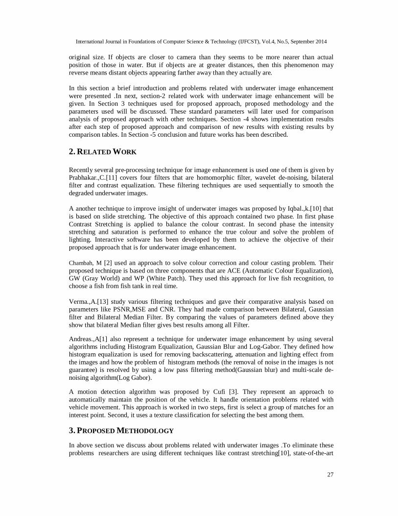
Table 1 described the details of colour absorption at various depth of water. Light colour absorption also affected by quality of water. For crystal clear water, light colour absorption is less as compared to saline, turbid or polluted or some dissolved particles of water. The result of these dissolved organics particles, colours of some coastal areas are appears as green and colours of all time running water, i.e. rivers water look like red-brown. From table 1 it is also mentioned that the colour absorption is also depends on the wavelengths of different colours. Blue colour travel long distance in water and red absorbed after few distance this is better represented in figure 1. It is clear that colours are more visible up to 200m in open ocean water due to less quantity of dissolved organics. In fifty meters coastal water that has highly dissolved materials.
Figure 1: Light penetration of different colours in clear (Open Ocean) and dirty water (coastal water).
Scattering means amount of light diverted back when passes through a medium. Strength of scattering measured by loss of energy in light signals as it passes through a medium. Scattering also occurs in air but it cause greater concern in water as most of the light beams are diverted due to molecules of water itself and due to dissolved organics. Scattering is of two type forward and backward. Forward scattering cause blur the image features while backscattering cause reduction in contrast of images. Refraction also causes problems in underwater imaging. The light waves are turned when they traverse from mediums of different density. In underwater photography the refraction occurs at the interface between the air and the water. Output of refraction is object appears larger than its
International Journal in Foundations of Computer Science & Technology (IJFCST), Vol.4, No.5, September 2014
27
original size. If objects are closer to camera than they seems to be more nearer than actual position of those in water. But if objects are at greater distances, then this phenomenon may reverse means distant objects appearing farther away than they actually are. In this section a brief introduction and problems related with underwater image enhancement were presented .In next, section-2 related work with underwater image enhancement will be given. In Section 3 techniques used for proposed approach, proposed methodology and the parameters used will be discussed. These standard parameters will later used for comparison analysis of proposed approach with other techniques. Section -4 shows implementation results after each step of proposed approach and comparison of new results with existing results by comparison tables. In Section -5 conclusion and future works has been described. 2. RELATED WORK Recently several pre-processing technique for image enhancement is used one of them is given by Prabhakar.,C.[11] covers four filters that are homomorphic filter, wavelet de-noising, bilateral filter and contrast equalization. These filtering techniques are used sequentially to smooth the degraded underwater images. A another technique to improve insight of underwater images was proposed by Iqbal.,k.[10] that is based on slide stretching. The objective of this approach contained two phase. In first phase Contrast Stretching is applied to balance the colour contrast. In second phase the intensity stretching and saturation is performed to enhance the true colour and solve the problem of lighting. Interactive software has been developed by them to achieve the objective of their proposed approach that is for underwater image enhancement. Chambah, M [2] used an approach to solve colour correction and colour casting problem. Their proposed technique is based on three components that are ACE (Automatic Colour Equalization), GW (Gray World) and WP (White Patch). They used this approach for live fish recognition, to choose a fish from fish tank in real time. Verma.,A.[13] study various filtering techniques and gave their comparative analysis based on parameters like PSNR,MSE and CNR. They had made comparison between Bilateral, Gaussian filter and Bilateral Median Filter. By comparing the values of parameters defined above they show that bilateral Median filter gives best results among all Filter. Andreas.,A[1] also represent a technique for underwater image enhancement by using several algorithms including Histogram Equalization, Gaussian Blur and Log-Gabor. They defined how histogram equalization is used for removing backscattering, attenuation and lighting effect from the images and how the problem of histogram methods (the removal of noise in the images is not guarantee) is resolved by using a low pass filtering method(Gaussian blur) and multi-scale de-noising algorithm(Log Gabor). A motion detection algorithm was proposed by Cufi [3]. They represent an approach to automatically maintain the position of the vehicle. It handle orientation problems related with vehicle movement. This approach is worked in two steps, first is select a group of matches for an interest point. Second, it uses a texture classification for selecting the best among them.
3. PROPOSED METHODOLOGY In above section we discuss about problems related with underwater images .To eliminate these problems researchers are using different techniques like contrast stretching[10], state-of-the-art
International Journal in Foundations of Computer Science & Technology (IJFCST), Vol.4, No.5, September 2014
28
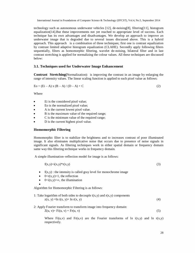
technology such as autonomous underwater vehicles [12], de-noising[8], filtering[11], histogram equalization[14].But these improvements not yet reached to appropriate level of success. Each technique has its own advantages and disadvantages. We develop an approach to improve an underwater image that is degraded due to several issues discussed above. This is a hybrid approach. This approach is a combination of three techniques; first one is contrast equalization by contrast limited adaptive histogram equalization (CLAHE). Secondly apply following filters sequentially, filters as homomorphic filtering, wavelet de-noising, bilateral filter and in last contrast stretching is applied for normalizing the colour values. All these techniques are discussed below: 3.1. Techniques used for Underwater Image Enhancement Contrast Stretching(Normalization): is improving the contrast in an image by enlarging the range of intensity values. The linear scaling function is applied to each pixel value as follows: Eo = (Ei – A) x (B – A) / (D – A) + C (2) Where Ei is the considered pixel value; Eo is the normalized pixel value; A is the current lowest pixel value. B is the maximum value of the required range; C is the minimum value of the required range; D is the current highest pixel value. Homomorphic Filtering Homomorphic filter is to stabilize the brightness and to increases contrast of poor illuminated image. It also eliminates multiplicative noise that occurs due to presence of noise signals in significant signals. As filtering techniques work in either spatial domain or frequency domain same way this filtering technique works in frequency domain. A simple illumination–reflection model for image is as follows: f(x,y)=i(x,y)*r(x,y) (3)
f(x,y) : the intensity is called gray level for monochrome image 0<r(x,y)<1, the reflection 0<i(x,y)<∞, the illumination
Algorithm for Homomorphic Filtering is as follows: 1: Take logarithm of both sides to decouple i(x,y) and r(x,y) components z(x, y) =ln i(x, y)+ ln r(x, y) (4) 2: Apply Fourier transform to transform image into frequency domain:
Z(u, v)= Fi(u, v) + Fr(u, v) (5)
Where Fi(u,v) and Fr(u,v) are the Fourier transforms of ln i(x,y) and ln r(x,y) respectively.
International Journal in Foundations of Computer Science & Technology (IJFCST), Vol.4, No.5, September 2014
29
3: High pass the Z(u,v) by a filter function H(u,v) in frequency domain and obtain a filtered version S(u,v) as the following:
S(u,v) = H(u,v)Z(u,v) S(u,v) =H(u,v)Fi (u,v)+ H(u,v)Fr (u,v) (6)
4: Take an inverse Fourier transform to get above the filtered image in the spatial domain: s(x,y) = F-1{S(u,v)} = F-1{H(u,v)Fi (u,v)+ H(u,v)Fr (u,v) } (7)
5: Now the resultant enhanced image g(x,y) obtained by appling exponent function on s(x,y): g(x, y) =exp(s(x, y)) (8)
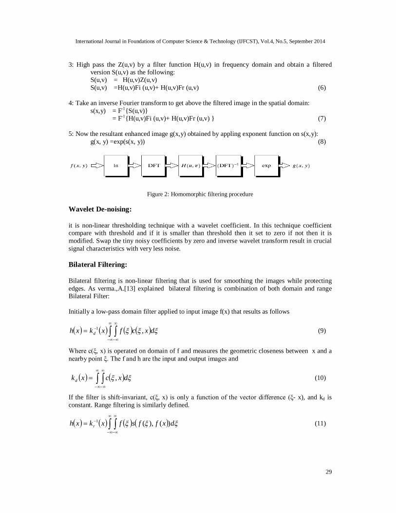
Figure 2: Homomorphic filtering procedure
Wavelet De-noising:
it is non-linear thresholding technique with a wavelet coefficient. In this technique coefficient compare with threshold and if it is smaller than threshold then it set to zero if not then it is modified. Swap the tiny noisy coefficients by zero and inverse wavelet transform result in crucial signal characteristics with very less noise. Bilateral Filtering: Bilateral filtering is non-linear filtering that is used for smoothing the images while protecting edges. As verma.,A.[13] explained bilateral filtering is combination of both domain and range Bilateral Filter: Initially a low-pass domain filter applied to input image f(x) that results as follows
dxcfxkxh d ,1 (9)
Where c(ξ, x) is operated on domain of f and measures the geometric closeness between x and a nearby point ξ. The f and h are the input and output images and
dxcxkd , (10)
If the filter is shift-invariant, c(ξ, x) is only a function of the vector difference (ξ- x), and kd is constant. Range filtering is similarly defined.
dxffsfxkxh r )(),(1 (11)

International Journal in Foundations of Computer Science & Technology (IJFCST), Vol.4, No.5, September 2014
30
Here s(f(ξ),f(x)) measures the photometric similarity between the pixel at the neighbourhood centre x and that of a nearby point ξ. Function s operates in the range of f. The normalized constant for range filter is as follows:
dxffsxk r )(),( (12)
Both geometric and photometric locality is achieved by combined filtering as given below:
dxffsxcfxkxh )(),(),(1 (13)
With the normalization
dxffsxcxk )(),(),( (14)
Bilateral filtering replaces the pixel value at x with an average of similar and nearby pixel values.
Where 2
21 ,),(
d
xdexc (15)
||||, xxdxd (16)
Similarity function s is perfectly analogous to c.
221 (),(),(
rxffexs
(17)
||||),( xxx difference between the two intensity values and f. (18)
3.2. Methodology for Proposed Underwater Image Enhancement Approach
Figure 3: Proposed Underwater Image Enhancement process
Following steps explain how all above discussed techniques used for proposed underwater enhancement method.
1. A contrast equalization system is used to reject backscattering, attenuation and lighting inequalities. Local contrast equalization method is applied to resolve non-uniform lighting problem that occur due to backscattering, and the output is shown in fig. 4 (b).
Input Image
Contrast Equalization
Homomorphic Filtering Wavelet
Denoising
Bilateral filtering
Contrast Stretching
Output Image
International Journal in Foundations of Computer Science & Technology (IJFCST), Vol.4, No.5, September 2014
31
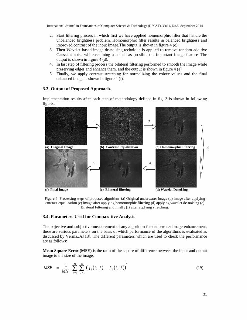
2. Start filtering process in which first we have applied homomorphic filter that handle the unbalanced brightness problem. Homomorphic filter results in balanced brightness and improved contrast of the input image.The output is shown in figure 4 (c).
3. Then Wavelet based image de-noising technique is applied to remove random additive Gaussian noise while retaining as much as possible the important image features.The output is shown in figure 4 (d).
4. In last step of filtering process the bilateral filtering performed to smooth the image while preserving edges and enhance them, and the output is shown in figure 4 (e).
5. Finally, we apply contrast stretching for normalizing the colour values and the final enhanced image is shown in figure 4 (f).
3.3. Output of Proposed Approach. Implementation results after each step of methodology defined in fig. 3 is shown in following figures.
Figure 4: Processing steps of proposed algorithm (a) Original underwater Image (b) image after applying contrast equalization (c) image after applying homomorphic filtering (d) applying wavelet de-noising (e)
Bilateral Filtering and finally (f) after applying stretching.
3.4. Parameters Used for Comparative Analysis The objective and subjective measurement of any algorithm for underwater image enhancement, there are various parameters on the basis of which performance of the algorithms is evaluated as discussed by Verma.,A.[13]. The different parameters which are used to check the performance are as follows: Mean Square Error (MSE) is the ratio of the square of difference between the input and output image to the size of the image.
2
1 121 ,,1
M
i
N
jjifjif
MNMSE (19)
(a) Original Image (b). Contrast Equalization (c) Homomorphic Filtering
(f) Final Image (e) Bilateral filtering (d) Wavelet Denoising
1 2
4 5
3
International Journal in Foundations of Computer Science & Technology (IJFCST), Vol.4, No.5, September 2014
32
Here f1, f2 are the input and output images respectively. M and N are the sizes of the images. The MSE should be less, which means that the pixel intensity of the input and output image should be as close as possible. Peak Signal to Noise ratio (PSNR) is the logarithmic value of the ratio of size of the image and the mean square error of the image.
MSELOGPSNR
225510 (20)
PSNR should be as large as possible which means that the content of signal in the output is large and the noise is less. Signal to noise ratio (SNR) should be as large as possible which means that the content of signal in the output is large and the noise is less.
0BA SSSNR
(21)
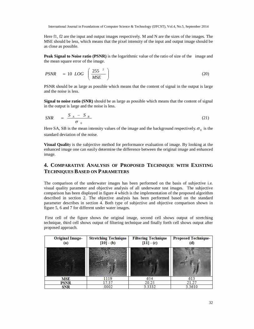
Here SA, SB is the mean intensity values of the image and the background respectively. 0 is the standard deviation of the noise. Visual Quality is the subjective method for performance evaluation of image. By looking at the enhanced image one can easily determine the difference between the original image and enhanced image. 4. COMPARATIVE ANALYSIS OF PROPOSED TECHNIQUE WITH EXISTING TECHNIQUES BASED ON PARAMETERS The comparison of the underwater images has been performed on the basis of subjective i.e. visual quality parameter and objective analysis of all underwater test images. The subjective comparison has been displayed in figure 4 which is the implementation of the proposed algorithm described in section 2. The objective analysis has been performed based on the standard parameter describes in section 4. Both type of subjective and objective comparison shown in figure 5, 6 and 7 for different under water images. First cell of the figure shows the original image, second cell shows output of stretching technique, third cell shows output of filtering technique and finally forth cell shows output after proposed approach.
International Journal in Foundations of Computer Science & Technology (IJFCST), Vol.4, No.5, September 2014
33
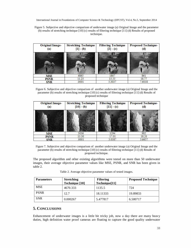
Figure 5. Subjective and objective comparison of underwater image (a) Original Image and the parameter (b) results of stretching technique [10] (c) results of filtering technique [11] (d) Results of proposed
technique.
Figure 6. Subjective and objective comparison of another underwater image (a) Original Image and the parameter (b) results of stretching technique [10] (c) results of filtering technique [11] (d) Results of
proposed technique
Figure 7. Subjective and objective comparison of another underwater image (a) Original Image and the parameter (b) results of stretching technique [10] (c) results of filtering technique [11] (d) Results of
proposed technique.
The proposed algorithm and other existing algorithms were tested on more than 50 underwater images, their average objective parameter values like MSE, PSNR, and SNR has been given in table 2.
Table 2. Average objective parameter values of tested images.
Parameters Stretching Technique [10]
Filtering Technique[11]
Proposed Technique
MSE 4670.333 1135.5 724 PSNR 12.7 18.11333 19.89833 SNR 0.000267 5.477817 6.500717
5. CONCLUSIONS Enhancement of underwater images is a little bit tricky job, now a day there are many heavy duties, high definition water proof cameras are floating to capture the good quality underwater
International Journal in Foundations of Computer Science & Technology (IJFCST), Vol.4, No.5, September 2014
34
images. The processing of captured underwater video and image is still a challenging problem for the researchers. In the present paper it has been shown that the available techniques for enhancement of underwater images can be improved much better. The proposed hybrid technique consisting of existing techniques given as stretching [10] and filtering [11] improved the quality of underwater images more efficiently as shown in table 2. In future, the proposed approach can be used for colour underwater image enhancement purpose; more parameters are used for performance evaluation of enhanced images. Optimization of various techniques can be done to reduce the complexity as much as possible. REFERENCES [1] Andreas,A.,and illes,.K,(2005) “Towards a model-free denoising of underwater optical images”, In
IEEE Conference on Oceans. [2] Chambah, M., Semani,D., Renouf, A., Courtellemont,P. and Rizzi ,A.(2004) “Underwater Color
Constancy :Enhancement of Automatic Live Fish Recognition”, vol. 5293 of Proceedings of SPIE, 157-168, San jose, Calif, USA.
[3] Cufí, X., Garcia,R., and Ridao,P. ,(2002) “An Approach To Vision-Based Station Keeping For An Unmanned Underwater Vehicle”. Available via: IEEE/RSJ International Conference on Intelligent Robots and Systems (IROS).
[4] Dudek,G.,Jenkin, M., Prahacs,C., Hogue,A., Sattar, J., Giguere,P., German,A., Liu,H., Saunderson,S., Ripsman,A., Simhon, S., Torres,L., Milios,E., Zhang,P., and Rekletis,I,(2005) “A Visually Guided Swimming Robot'', IEEE/RSJ International Conference on Intelligent Robots and Systems.
[5] Fairweather,A.J.R., Hodgetts,M.A.,and Greig,A.R.,(1997) “Robust scene interpretation of underwater image sequences”, In 6th International Conference on Image Processing and its Applications, pp. 660 -664.
[6] Garcia, R., Nicosevici, T., and Cufí, X.,(2002) “On The Way to Solve Lighting Problems in Underwater Imaging”, Proceedings of the IEEE OCEANS Conference (OCEANS), pp. 1018-1024.
[7] Gasparini, F and Schettini, R ,(2003) “Colour Correction for Digital Photographs”, Proceedings of the 12th International Conference on Image Analysis and Processing (ICIAP’03), IEEE Press.
[8] Grace Chang, S., Bin Yu and Vetterli,M.,(2000) “Adaptive wavelet thresholding for image denoising and compression” IEEE Transactions on Image Processing, vol. 9(9), 1532-1546.
[9] Elyasi and S. Zarmehi,“Elimination Noise by Adaptive Wavelet Threshold,(2009)“ World Academy of Science, Engineering and Technology, Vol. 56, pp. 462-466.
[10] Iqbal, K.,Salam, R.A., Osman, A, and Talib, A.Z.,(2007) “Underwater image enhancement using an integrated colour model”, IAENG, pp. 529-534,.
[11] Prabhakar, C.J. and Praveen.K.,(2011) “An image based technique for enhancement of underwater images”, IJMI,VOL-3(4), pp 217-224.
[12] Schettini,R. and Corchs,S.,(2010) “Underwater Image Processing: State of the art of Restoration and Image Enhancement methods”, EURASIP JASP, doi:10.1155/2010/746052.
[13] Verma,A. and Sharma,B. ,(2010) “Comparative Analysis in Medical Imaging”, IJCA, Vol. 1- No. 13. [14] Singh, B., Mishra, R.S. and Gour, P.,(2012) “Analysis of Contrast Enhancement Techniques for
Underwater Images”, IJCTEE,vol.-1,issue-2, ISSN 2249-6343. [15] Schechner,Y and Karpel, N.,(2004) “Clear Underwater Vision”. Proceedings of the IEEE CVPR, Vol.
1, pp. 536-543. [16] Tomasi .,C. and Manduchi .,R.,(1998) “Bilateral Filtering for Gray and Colour Images” in
Proceedings of the sixth International Conference on Computer Vision, 839 - 846. [17] White, E.M., Partridge, U.C., Church, S.C,(2003) “Ultraviolet dermal reflection and mate choice in
the guppy”, pp. 693-700. [18] Delac.,K., Grgic.,M. and Kos.,T.,(2006), “ Sub-Image Homomorphic Filtering Technique for
Improving Facial Identification under Difficult Illumination Conditions”, International Conference on Systems, Signals and Image Processing (IWSSIP’06).