A Formal Modeling Scheme for Analyzing a Software System ...
Upload
khangminh22Category
view
0download
0
A Formal Framework for Software Process Modellingand Verification: A Behavior Engineering and OntologyApproach
Author
Kabaale, Edward
Published
2018-12
Thesis Type
Thesis (PhD Doctorate)
School
School of Info & Comm Tech
DOI
https://doi.org/10.25904/1912/2453
Copyright Statement
The author owns the copyright in this thesis, unless stated otherwise.
Downloaded from
http://hdl.handle.net/10072/384794
Griffith Research Online
https://research-repository.griffith.edu.au
A Formal Framework for Software Process
Modelling and Verification: A Behavior
Engineering and Ontology Approach
Edward Kabaale
Bachelor of Business Computing, MSc. Information Systems
School of Information and Communication Technology
Griffith University
Submitted in fulfillment of the requirements of the
degree of
Doctor of Philosophy
December 2018
i
Abstract
The main objective of software development is to produce software that addresses
user needs appropriately. As such, success in its realisation is highly dependent on
an explicit software process that aims at describing precisely and unambiguously
all activities and tasks undertaken to develop the required software. Software
Engineering (SE) standards and reference models provide a set of process life cycle
activities and best practices to guide the engineering and production of software
products with the right quality within budget and schedule. However, these are
usually diverse and described in natural language.
While specifying software processes in natural language is straightforward and
guarantees a wider understanding, it is difficult to consistently, systematically and
automatically monitor and verify if they have been fully implemented and adhered
too in a given software project. Besides the process of defining and documenting
the necessary evidence to comply with SE standard requirements is often subjec-
tive, manual and time consuming. With the quick development and diversity of
SE standards and reference models for different domains, systematic methods of
modelling and verification of software processes are crucial for process analysis,
understanding and evolution. Although there is substantial literature on software
process formalisation, the existing approaches have some limitations that we ad-
dress in this thesis, namely: (i) there is hardly any systematic and repeatable
approach for translation of natural language software processes to formal presen-
tations; (ii) the current approaches don’t accommodate diverse software processes
in a unified way during formalisation process; (iii) the current approaches do not
provide a comprehensive formal framework for reasoning on the consistency, com-
pleteness and verification of software process descriptions.
Following a design science research methodology, we develop and evaluate a frame-
work for a systematic, repeatable and consistent approach for formalisation and
automated verification of software processes that are usually written in natural
language and published in formal documents such as SE standards and reference
models. Our approach utilises the potential offered by a synergistic representation

ii
model based on a graphical and logical formalism. While logical approaches offer
mathematically rigorous specification and verification, graphical approaches on the
other hand, encapsulate the use of logical techniques with familiar concepts and
notions of the domain, making the approach simple and intuitive for stakeholders
to use in software development.
Our contribution has four main aspects : 1) A customised metamodel to underpin
systematic and faithful formalisation of heterogeneous software processes from
diverse SE standards and reference process models; 2) A formalisation approach
to consistently and repeatedly formalise software processes ; 3) A Software Process
Knowledge Base that integrates the various semantic process models that form the
nucleus of our approach; and 4) A set of application scenarios that demonstrate
and evaluate the quality, utility and efficacy of our approach.
iii
Statement of Originality
This work has not previously been submitted for a degree or diploma in any
university. To the best of my knowledge and belief, the thesis contains no material
previously published or written by another person except where due reference is
made in the thesis itself.
Edward Kabaale

iv
List of Publications
The main contributions of this study have been published in various conferences
and others are in preparation for submission to reputed journals in the field.
• Kabaale E., Wen L., Wang Z., Rout T. (2016) Representing Software Process
in Description Logics: An Ontology Approach for Software Process Reason-
ing and Verification. In: Clarke P., O’Connor R., Rout T., Dorling A. (eds)
Software Process Improvement and Capability Determination. SPICE 2016.
Communications in Computer and Information Science, vol 609. Springer,
Cham
• Kabaale E., Wen L., Wang Z., Rout T. (2017) An Axiom Based Metamodel
for Software Process Formalisation: An Ontology Approach. In: Mas A.,
Mesquida A., O’Connor R., Rout T., Dorling A. (eds) Software Process
Improvement and Capability Determination. SPICE 2017. Communications
in Computer and Information Science, vol 770. Springer, Cham
• Kabaale E., Wen L., Wang Z., Rout T. (2018) Ensuring Conformance to Pro-
cess Standards Through Formal Verification. In: Stamelos I., O’Connor R.,
Rout T., Dorling A. (eds) Software Process Improvement and Capability De-
termination. SPICE 2018. Communications in Computer and Information
Science, vol 918. Springer, Cham
• Nonoyama, T., Kabaale, E., Wen, L., Tuffley, D. and Wang, Z., 2018,
September. Integrating Culture Awareness and Formalisation in Software
Process Assessment and Improvement for Very Small Entities (VSEs). In Eu-
ropean Conference on Software Process Improvement (pp. 123-135). Springer,
Cham.
Papers to be Submitted
• A Formal Framework for Software Process Modelling and Verification
• An Integrated Metamodeling Framework for Process Standardisation

v
• Formalising Process Assessment and Capability Determination: An Ontol-
ogy Approach
vi
Acknowledgement
The Intellectual journey that has produced this thesis is seldom, if ever was a
solitary effort. The completion of a Ph.D. thesis is never an accomplishment for
the student alone, but for the many individuals who, behind the scene, support the
student’s efforts throughout the Ph.D. candidature. Uppermost in my mind are
several great people who have helped me along the way stimulating and guiding the
results reported in this thesis. To begin with I thank The Almighty for bringing
me this far with profound love, care and guidance.
Most of all I wish in an exceptional way to thank my principal supervisor Dr. Lian
Wen for his invaluable support and guidance throughout my Ph.D. candidature.
My associate supervisor Dr. Zhe Wang introduced me to logics and ontologies
and continuously supported and kept me in the right direction. Our weekly meet-
ings yielded outstanding ideas for the research presented in this thesis, and always
inspired me to get things done. A thank you also goes to my second associate
supervisor Associate Professor Terry Rout for his expert advice on the SE stan-
dards and reference models that are used in this research as well as our SPICE
conference presentations. There are no words to thank you all for the supervision,
guidance and support rendered to me throughout my Ph.D. candidature. In addi-
tion I would like to thank my co-author; Nonoyama Tatsuya for our collaboration
paper and friendship.
A special acknowledgement is due to the head of the Artificial Intelligence and
Semantic Technologies (AIST) lab: Professor Kewen Wang for his involvement,
support and guidance during my early candidature days. Am also indebted to
all the members of the AIST lab for the conducive environment, weekly seminar
discussions and support rendered to me during my stay in the lab.
I would like to acknowledge the generous financial assistance from Griffith Uni-
versity and the school of ICT, without which this work would not have been
possible. Special thanks also go to my employer back home, Makerere Univer-
sity Business School (MUBS) for granting me the study leave that enabled me to
take up my Ph.D. candidature at Griffith University. Special thanks also go to

vii
Professor Moya Musa, Dean of computing and informatics faculty, Dr. Kyeyune
Robert, Dr. Joseph Bada and Dr. Kituyi Mayoka for mentoring and supporting
me through out my academic career. I also extend my appreciation to all the
colleagues in the computing and informatics faculty especially Abima Boniface for
keeping up the friendship despite the distance. I also acknowledge the support and
guidance of Professor Josephine Nabukenya at Makerere University, my master’s
thesis supervisor for laying the research foundation upon which i continue to build.
Alongside the people encountered in the academic world, they are many other
people whose support can’t be missed. I have great respect for friends and col-
leagues with whom I have had the privilege to walk this journey: Joy Galaige at
Griffith University, Mathew Kalubanga at Newcastle University, John Paul Kasse
at Bournemouth University and Louis Amwine in South Korea thank you so much
for the various discussions and encouragement.
My Family has been supporting me both morally and financial through all these
years of my studies, my gratitude to them is endless for all the love and support.
To my kids who have missed my presence at home, i will be coming home soon.
To you Mum, there are no words, I can use to express my appreciation for all
the support and love you have given me and the family while I was away. Thank
you so much. Finally, my wife, Diana, thank you so much for accompanying and
supporting me through out this journey, Diana was always expressly supportive
of my efforts. To Diana, I also offer a sincere thank you.
Edward Kabaale
December 2018
Contents
1 Introduction 1
1.1 Background . . . . . . . . . . . . . . . . . . . . . . . . . . . . . . . 2
1.1.1 Key Term Definitions . . . . . . . . . . . . . . . . . . . . . . 3
1.2 Motivation . . . . . . . . . . . . . . . . . . . . . . . . . . . . . . . . 4
1.2.1 Limitations of existing Approaches . . . . . . . . . . . . . . 10
1.3 Aims and Objectives . . . . . . . . . . . . . . . . . . . . . . . . . . 12
1.4 Proposed Approach . . . . . . . . . . . . . . . . . . . . . . . . . . . 13
1.5 Overview of the Contributions . . . . . . . . . . . . . . . . . . . . . 16
1.6 Research Scope . . . . . . . . . . . . . . . . . . . . . . . . . . . . . 17
1.7 A brief Justification of used tools and techniques . . . . . . . . . . . 17
1.7.1 ISO/IEC 330xx (SPICE) . . . . . . . . . . . . . . . . . . . . 18
1.7.2 Composition Trees (CT) . . . . . . . . . . . . . . . . . . . . 18
1.7.3 Description Logics (DLs) . . . . . . . . . . . . . . . . . . . . 19
1.8 Outline . . . . . . . . . . . . . . . . . . . . . . . . . . . . . . . . . . 20
1.9 Summary . . . . . . . . . . . . . . . . . . . . . . . . . . . . . . . . 21
2 Preliminaries 23
2.1 Introduction . . . . . . . . . . . . . . . . . . . . . . . . . . . . . . . 23
2.2 Software Process Management . . . . . . . . . . . . . . . . . . . . . 23
2.2.1 Software Process . . . . . . . . . . . . . . . . . . . . . . . . 24
2.2.2 Software Process Modelling . . . . . . . . . . . . . . . . . . 25
2.2.3 Process Modelling Languages . . . . . . . . . . . . . . . . . 26
2.2.3.1 Process centred Software Engineering Environments(PSEEs) . . . . . . . . . . . . . . . . . . . . . . . . 31
2.2.4 Process Reference Models (PRMs) . . . . . . . . . . . . . . 33
2.2.4.1 ISO/IEC TR 24774 . . . . . . . . . . . . . . . . . . 33
2.2.4.2 ISO/IEC 12207 . . . . . . . . . . . . . . . . . . . . 34
2.2.4.3 ISO/IEC 29110 . . . . . . . . . . . . . . . . . . . . 36
2.2.5 Process Conformance and Verification . . . . . . . . . . . . . 38
2.2.6 Process Assessment . . . . . . . . . . . . . . . . . . . . . . . 39
2.2.6.1 PAM Process Dimension . . . . . . . . . . . . . . . 42
2.2.6.2 PAM Capability Dimension . . . . . . . . . . . . . 44
2.2.6.3 The Rating Scheme in ISO/IEC 33020 . . . . . . . 47
2.2.6.4 VSE Process Assessment . . . . . . . . . . . . . . . 49
2.3 Process metamodeling . . . . . . . . . . . . . . . . . . . . . . . . . 51
viii
Contents ix
2.3.1 Software Process Engineering Metamodel (SPEM) . . . . . . 53
2.3.2 Powertype based metamodeling framework . . . . . . . . . . 55
2.3.3 Summary . . . . . . . . . . . . . . . . . . . . . . . . . . . . 58
2.4 Behavior Engineering . . . . . . . . . . . . . . . . . . . . . . . . . . 59
2.4.1 Behavior Engineering Philosophy . . . . . . . . . . . . . . . 59
2.4.2 Behavior Trees Notation (BTN) . . . . . . . . . . . . . . . . 62
2.4.3 Composition Trees Notation (CTN) . . . . . . . . . . . . . . 63
2.4.3.1 Using Composition Trees to model Software Pro-cesses . . . . . . . . . . . . . . . . . . . . . . . . . 64
2.5 Ontologies . . . . . . . . . . . . . . . . . . . . . . . . . . . . . . . . 68
2.5.1 Ontology Classification . . . . . . . . . . . . . . . . . . . . . 69
2.5.2 Description Logics . . . . . . . . . . . . . . . . . . . . . . . 71
2.5.3 Web Ontology Language (OWL) . . . . . . . . . . . . . . . 75
2.5.4 Ontology Reasoning Services . . . . . . . . . . . . . . . . . . 78
2.5.5 Semantic Web Rule Language (SWRL) . . . . . . . . . . . . 81
2.5.6 Metamodeling support in OWL Standard . . . . . . . . . . . 82
2.6 Summary . . . . . . . . . . . . . . . . . . . . . . . . . . . . . . . . 85
3 Literature Review 86
3.1 Introduction . . . . . . . . . . . . . . . . . . . . . . . . . . . . . . . 86
3.2 Ontology and DL based Approaches . . . . . . . . . . . . . . . . . . 87
3.3 Logical and Process algebra based Approaches . . . . . . . . . . . . 93
3.4 Petri nets based Approaches . . . . . . . . . . . . . . . . . . . . . . 96
3.5 UML and Graphical based Approaches . . . . . . . . . . . . . . . . 98
3.6 Process mining and Pattern based Approaches . . . . . . . . . . . . 100
3.7 Literature Findings and Research Direction . . . . . . . . . . . . . . 102
3.8 Summary . . . . . . . . . . . . . . . . . . . . . . . . . . . . . . . . 103
4 Methodology 105
4.1 Introduction . . . . . . . . . . . . . . . . . . . . . . . . . . . . . . . 105
4.2 Design Science Research Approach . . . . . . . . . . . . . . . . . . 106
4.3 Design Science Research Methodology . . . . . . . . . . . . . . . . . 108
4.3.1 Activity 1: Problem identification and motivation . . . . . . 111
4.3.2 Activity 2: Define objectives of a solution . . . . . . . . . . 112
4.3.3 Activity 3: Design and development . . . . . . . . . . . . . . 112
4.3.3.1 software process normalisation through a unifiedprocess model (Metamodel) . . . . . . . . . . . . . 113
4.3.3.2 Translation of software process from natural lan-guage to Composition Tree . . . . . . . . . . . . . 114
Composition Tree Translation process . . . . . . . . . 115
4.3.3.3 Translation of Composition Trees to DL TBox (on-tology) . . . . . . . . . . . . . . . . . . . . . . . . . 116
4.3.4 Activity 4: Demonstration . . . . . . . . . . . . . . . . . . . 118
4.3.5 Activity 5: Evaluation . . . . . . . . . . . . . . . . . . . . . 119
4.3.5.1 Use of Competency Questions in Evaluation . . . . 120
Contents x
4.3.6 Activity 6: Communication . . . . . . . . . . . . . . . . . . 121
4.4 Summary . . . . . . . . . . . . . . . . . . . . . . . . . . . . . . . . 122
5 Metamodel 123
5.1 Introduction . . . . . . . . . . . . . . . . . . . . . . . . . . . . . . . 123
5.2 Axiom based Metamodel . . . . . . . . . . . . . . . . . . . . . . . . 124
5.2.1 Achievable Axiom . . . . . . . . . . . . . . . . . . . . . . . . 125
5.2.2 Doable Axiom . . . . . . . . . . . . . . . . . . . . . . . . . . 127
5.2.3 Tangible Axiom . . . . . . . . . . . . . . . . . . . . . . . . . 128
5.2.4 Assessable Axiom . . . . . . . . . . . . . . . . . . . . . . . . 129
5.3 Formalising the Axiom based Metamodel . . . . . . . . . . . . . . . 130
5.3.1 Formalising and Clarifying Relations in Metamodels . . . . . 133
5.4 Summary . . . . . . . . . . . . . . . . . . . . . . . . . . . . . . . . 135
6 Translation 136
6.1 Introduction . . . . . . . . . . . . . . . . . . . . . . . . . . . . . . . 136
6.2 Using Composition Tree (CT) to model Software Processes . . . . . 139
6.3 The Software Process Knowledge Base . . . . . . . . . . . . . . . . 141
6.3.1 The PRM Ontology (PRMO) . . . . . . . . . . . . . . . . . 142
6.3.1.1 Translating CT Diagrams to DL TBoxes . . . . . . 144
6.3.1.2 Translating HRM CT process model to DL . . . . 146
6.3.1.3 Formal Process Verification . . . . . . . . . . . . . 147
6.3.2 The PAM Ontology (PAMO) . . . . . . . . . . . . . . . . . 149
6.3.2.1 Representing Process requirements as Mapping Ax-ioms . . . . . . . . . . . . . . . . . . . . . . . . . . 153
Process Outcome Rating . . . . . . . . . . . . . . . . 156
6.3.3 Measurement Framework Ontology (MF Ontology) . . . . . 159
6.3.3.1 Process Attributes (PAs) Achievement . . . . . . . 160
PA2.1 Performance Management Attribute Achieve-ment . . . . . . . . . . . . . . . . . . . . . 160
PA2.2 Work Product Management Attribute Achieve-ment . . . . . . . . . . . . . . . . . . . . . 163
6.3.3.2 Capability Level Determination . . . . . . . . . . . 167
6.4 Summary . . . . . . . . . . . . . . . . . . . . . . . . . . . . . . . . 168
7 Applications 169
7.1 Introduction . . . . . . . . . . . . . . . . . . . . . . . . . . . . . . . 169
7.1.1 The Process Instance (ABox) . . . . . . . . . . . . . . . . . 169
7.2 Ensuring Conformance to HRM process through formal verification 170
7.2.0.1 Implementation in Protege . . . . . . . . . . . . . . 172
7.3 Verification of Open Source Software Development Processes: AnE-Learning Case Study . . . . . . . . . . . . . . . . . . . . . . . . . 174
7.3.1 Moodle SRA Process Verification . . . . . . . . . . . . . . . 176
7.4 Formalised Process Assessment and Capability Determination . . . 181
7.4.1 Case Study Evaluation . . . . . . . . . . . . . . . . . . . . . 184
Contents xi
7.4.1.1 Towards automated Capability level Determination 188
7.5 Formalisation of Culture Impact on Software Assessment (CISA)Framework . . . . . . . . . . . . . . . . . . . . . . . . . . . . . . . . 190
7.6 Summary . . . . . . . . . . . . . . . . . . . . . . . . . . . . . . . . 194
8 Conclusion 195
8.1 Introduction . . . . . . . . . . . . . . . . . . . . . . . . . . . . . . . 195
8.2 Contributions and Achievements . . . . . . . . . . . . . . . . . . . . 195
8.3 Research limitations . . . . . . . . . . . . . . . . . . . . . . . . . . 200
8.4 Future Directions . . . . . . . . . . . . . . . . . . . . . . . . . . . . 202
Bibliography 204
List of Figures
1.1 Use of formal methods to remove ambiguity from PRMs (Wen etal., 2011) . . . . . . . . . . . . . . . . . . . . . . . . . . . . . . . . . 8
1.2 Proposed Approach . . . . . . . . . . . . . . . . . . . . . . . . . . . 15
2.1 ISO/IEC 29110 Basic Profile Processes and Activities (Laporte etal., 2008) . . . . . . . . . . . . . . . . . . . . . . . . . . . . . . . . . 37
2.2 Correspondence between ISO/IEC 15504 and ISO/IEC 330xx (Routet al., 2017) . . . . . . . . . . . . . . . . . . . . . . . . . . . . . . . 41
2.3 Process assessment model relationships - ISO/IEC 33001 . . . . . . 42
2.4 Capability levels and Process Attributes of ISO/IEC 15504-5 . . . . 45
2.5 Formative model for capability level rating (Jung et al., 2013) . . . 48
2.6 Elements of VSE process assessment (ISO/IEC DTR 29110-3) . . . 49
2.7 Process model abstractions (Weiss et al., 2009) . . . . . . . . . . . . 52
2.8 SPEM hierarchy and MOF Layers (Rodrigues et al., 2010) . . . . . 54
2.9 Power type for Bird Species . . . . . . . . . . . . . . . . . . . . . . 56
2.10 Task powertype adapted from (Henderson et al., 2005) . . . . . . . 57
2.11 Behavior Engineering Approach to Complexity (Dromey, 2003) . . . 60
2.12 Behavior Engineering Process (Yatapanage et al., 2010) . . . . . . . 61
2.13 Overview of BE . . . . . . . . . . . . . . . . . . . . . . . . . . . . . 62
2.14 CT model for configuration management process purpose (Wen etal., 2011) . . . . . . . . . . . . . . . . . . . . . . . . . . . . . . . . . 65
2.15 The complete CT for the configuration management process (Wenet al., 2011) . . . . . . . . . . . . . . . . . . . . . . . . . . . . . . . 66
2.16 Ontology Classification according to the level of generality (Guarinoet al., 1998 . . . . . . . . . . . . . . . . . . . . . . . . . . . . . . . . 69
2.17 Description Logic components (Keet 2018) . . . . . . . . . . . . . . 73
2.18 Eagle context . . . . . . . . . . . . . . . . . . . . . . . . . . . . . . 83
2.19 contextual semantics model (Motik et al., 2007) . . . . . . . . . . . 84
3.1 Challenges of software process formalisation . . . . . . . . . . . . . 103
4.1 Design Science Research Methodology Process model (Peffers et al.2008) . . . . . . . . . . . . . . . . . . . . . . . . . . . . . . . . . . . 110
4.2 Composition Tree translation Process . . . . . . . . . . . . . . . . . 115
4.3 Top down ontology development approach (Calvanese, 2008) . . . . 117
5.1 Relationship between metamodel concepts . . . . . . . . . . . . . . 126
xii
List of Figures xiii
5.2 Achievable Axiom showing process purpose, objectives and outcomes127
5.3 Doable Axiom showing software implementation process example . 128
5.4 Tangible Axiom showing work products . . . . . . . . . . . . . . . . 129
5.5 Ontology based process metamodeling architecture . . . . . . . . . 132
6.1 Overview of the Translation Approach . . . . . . . . . . . . . . . . 138
6.2 Human Resource Process CT model . . . . . . . . . . . . . . . . . . 140
6.3 Software Process Knowledge Base Architecture . . . . . . . . . . . . 143
6.4 Study program CT model . . . . . . . . . . . . . . . . . . . . . . . 146
6.5 Process Verification Architecture . . . . . . . . . . . . . . . . . . . 148
6.6 A conceptual model for PAM Ontology . . . . . . . . . . . . . . . . 150
6.7 Process Assessment Indicators . . . . . . . . . . . . . . . . . . . . . 151
6.8 Process Attributes . . . . . . . . . . . . . . . . . . . . . . . . . . . 152
6.9 Asserted capability levels . . . . . . . . . . . . . . . . . . . . . . . . 152
6.10 Inferred process capability levels . . . . . . . . . . . . . . . . . . . . 153
6.11 Some classes in the PAM ontology . . . . . . . . . . . . . . . . . . . 153
6.12 PAM ontology metrics . . . . . . . . . . . . . . . . . . . . . . . . . 154
6.13 Mapping axioms for ProcessOutcomes and Indicators . . . . . . . . 157
6.14 PA2.2 Achievement Axiomatization in Protege . . . . . . . . . . . . 165
7.1 HRM process implemented in Protege . . . . . . . . . . . . . . . . . 171
7.2 Process P not entailed by HRM Process . . . . . . . . . . . . . . . 172
7.3 DL query showing Process P entailed as an instance of HRM . . . . 173
7.4 Process outcomes achieved by mSRAprocess . . . . . . . . . . . . . 179
7.5 mSRAProcess rated as largely achieved . . . . . . . . . . . . . . . . 180
7.6 mSRAProcess inferred at capability level one . . . . . . . . . . . . . 180
7.7 Inferred SRA Process Outcomes achieved by SRA001 . . . . . . . . 187
7.8 Inferred justification for SRA001 achievement of PO1 . . . . . . . . 187
7.9 SRA001 rated as Fully achieved . . . . . . . . . . . . . . . . . . . . 188
7.10 PA outcomes achieved by PA2.1s and PA2.2s . . . . . . . . . . . . . 189
7.11 Ratings for PA2.1 and PA2.2 . . . . . . . . . . . . . . . . . . . . . . 189
7.12 SRA001 classified at Capability Level Two . . . . . . . . . . . . . . 190
7.13 CISA Architecture (Nonoyama et al., 2018) . . . . . . . . . . . . . . 191
7.14 Excerpt of Onto-CISA in Protege . . . . . . . . . . . . . . . . . . . 193
List of Tables
2.1 SRA process base practices from ISO/IEC 15504-5 . . . . . . . . . 44
2.2 SRA Process process work products from ISO/IEC 15504-5 . . . . . 44
2.3 PA2.1 Performance Management Attribute . . . . . . . . . . . . . . 46
2.4 PA2.1 Generic practices . . . . . . . . . . . . . . . . . . . . . . . . 46
2.5 PA2.1 Generic work products . . . . . . . . . . . . . . . . . . . . . 46
2.6 PA2.1 Generic Resources . . . . . . . . . . . . . . . . . . . . . . . . 47
2.7 PA2.2 Work product management attribute . . . . . . . . . . . . . 47
2.8 PA2.2 Generic practices . . . . . . . . . . . . . . . . . . . . . . . . 47
2.9 PA2.2 Generic work products . . . . . . . . . . . . . . . . . . . . . 47
2.10 PA2.2 Generic Resources . . . . . . . . . . . . . . . . . . . . . . . . 48
2.11 The rating scale of Process Outcomes/Attributes . . . . . . . . . . 48
2.12 Base practices - ISO/IEC 15504-5 to achieve SI.02 Objective . . . . 50
2.13 Syntax and semantics of some DL constructors . . . . . . . . . . . . 72
2.14 Syntax and semantics of some TBox and ABox axioms . . . . . . . 74
4.1 Set of activities of DSRM process mapped with the thesis chapters . 122
6.1 CT to DL Translation . . . . . . . . . . . . . . . . . . . . . . . . . 145
6.2 CT to DL translation Example . . . . . . . . . . . . . . . . . . . . 146
6.3 Process Outcome Rating scheme . . . . . . . . . . . . . . . . . . . . 158
6.4 PA2.1 Performance Management Attribute Rating Scheme . . . . . 163
6.5 PA2.2 Work Product Management Attribute Rating Scheme . . . . 165
7.1 ABox fragment for Process P . . . . . . . . . . . . . . . . . . . . . 171
7.2 Moodle SRA Process Terminology . . . . . . . . . . . . . . . . . . . 176
7.3 Moodle SRA Process Evidence . . . . . . . . . . . . . . . . . . . . . 176
7.4 Moodle Process Instance (ABox) . . . . . . . . . . . . . . . . . . . 177
7.5 Competency Questions for moodle SRA Process . . . . . . . . . . . 178
7.6 Summary of SwiftCom SRA Process Terminology . . . . . . . . . . 183
7.7 Summary of SwiftCom SRA Process Evidence . . . . . . . . . . . . 183
7.8 Summary of SwiftCom SRA Process Evidence for PA2.1 . . . . . . 184
7.9 Summary of SwiftCom SRA Process Evidence for PA2.2 . . . . . . 184
7.10 SwiftCom ABox for SRA Process Outcomes Achievement . . . . . . 185
7.11 SwiftCom ABox for SRA PA2.1 and PA2.2 outcomes achievement . 186
7.12 Competency Questions for SwiftCom SRA Process . . . . . . . . . . 187
7.13 Characteristics Comparison between Individualist and Collectivist . 192
xiv
Chapter 1
Introduction
This chapter gives an introduction to the context of the work presented in this
thesis, namely, the software process formalisation approach. Motivated by the
challenges of verifying software processes specified in natural language, our main
objective in this work is to provide a formalisation approach that can support
consistent and repeatable formalisation process that is amenable to formal veri-
fication. This helps to eliminate errors and flaws early in software development
process and can improve the quality of the software product produced. This thesis
shows how the above objective is achieved by the main contributions of the work:
a holistic approach for software process formalisation and verification.
The remainder of this chapter is organised as follows. In Section 1.1 we introduce
the background to the study, followed by the research motivation in Section 1.2.
In Section 1.3 we discuss the research aims and objectives, while in Section 1.4 we
introduce the approach used to achieve the research aims and objectives. In Sec-
tions 1.5 and 1.6 we discuss our research main contributions and set the boundaries
of our study respectively. A brief justification for the tools and techniques used in
this research is described in Section 1.7 and finally in Section 1.8 we conclude the
chapter with the outline of this thesis.
1
Chapter 1. Introduction 2
1.1 Background
Software systems are pervasive in our society today. More and more systems are
increasingly reliant on the correct functioning of software [1]. Software now drives
applications in virtually all areas of human endeavours in critical roles [2]. Due to
these critical roles, it is important that software performs correctly and predictably
in all domains where it is relied upon. This imposes more challenges and demands
on the process through which software is developed and maintained [3].
Software Engineering (SE)1 focuses on sound processes and methods for quality
and professional software development within budget and time frame [1]. Over
the last couple of decades, the process dimension of SE has received increased
attention from both researchers and practitioners [5] and is regarded as one of the
foundational pillars of SE [6]. One of the main objectives of this dimension is to
enhance the software product quality through formal definition and improvement
of the process by which software is developed and maintained [7]. The process
perspective to software development is premised on the manufacturing principle
that product quality is influenced and evolved by the process used to produce it [8].
Where a process is a set of interrelated or interacting activities which transforms
inputs into outputs [9], and a software process is a set of activities, methods, and
practices that are used in the production and evolution of software [10].
Software process as a means to deliver better quality software and increased effi-
ciency is assuming an eminent role in SE than ever before [3, 11]. However, soft-
ware development is a complex, challenging and knowledge intensive endeavour
[12, 13], defining a software process that can produce quality software on schedule
and within budget is still a challenge to many software developing organisations
[14, 15]. Reports of unsuccessful projects and poor quality in delivered software
products are widely documented [16, 17]. Therefore, to ensure that software is pro-
duced with the right quality, within budget and timeline, it is important to have
1The establishment and use of sound engineering principles in order to obtain economicallysoftware that is reliable and works efficiently on real machines [4]
Chapter 1. Introduction 3
an explicit process that is structured in a way that makes software development
systematic and consistent [11].
1.1.1 Key Term Definitions
In this section, we present definitions of fundamental terms and concepts used in
this research. This is needed because there are various software process definitions
and related terms used in different contexts [18]. To eliminate ambiguity and
uncertainty of term usage, we provide definitions of terms and examples that are
used in the context of this thesis. These terms are largely drawn from ISO/IEC
33001 [19].
Software process: refers to a set of activities, methods, and practices that are
used in the production and evolution of software [10]. In this study, we refer to a
software process as prescribed by ISO/IEC 24774 and ISO/IEC 33004; a process
is expressed in terms of a purpose and a set of outcomes that are necessary and
sufficient to achieve the purpose.
Standard Process: refers to a set of software process definitions used to guide
software processes definitions in an organisation [19]. These can be supplemented
by the organisational software process life cycle models, adopted standards and
organisational culture [20].
Process instance: refers to a single specific and identifiable execution of a soft-
ware process within a given project [19]. Such an instance is instantiated from the
organisational standard process and takes into consideration the project peculiar-
ities [21].
Process Assessment: refers to a disciplined evaluation of the organisational
processes against a set of criteria defined in a process assessment model (PAM)
such as ISO/IEC 15504-5 (ISO/IEC 33061) to determine the capability of the
organisational processes to perform within the constraints of quality, cost and
schedule [22]. Process assessment is designed to evaluate the performance and
capability of the undertaken software process to achieve business objectives.
Chapter 1. Introduction 4
Process Assessment Model (PAM): refers to a model such as ISO/IEC 15504-
5 (ISO/IEC 33061) suitable for the purpose of assessing software capability to
achieve business objectives, based on one or more process reference models such as
ISO/IEC 12207. ISO/IEC 33004 constrains the PAM definition and its suitability
for process assessment with various PRMs.
Process Reference Model (PRM): refers to a model such as ISO/IEC 12207,
ISO/IEC 29110 comprising of software processes described in terms of purpose and
outcomes, together with the description of the relationship between the software
processes [19, 22]. ISO/IEC 33004 constrains process descriptions in a PRM in
terms of purpose and outcomes and provides compliance requirements with process
assessment models such as ISO/IEC 15504-5 (ISO/IEC 33061).
Process Measurement Framework: refers to a schema such as ISO/IEC 33020
for measuring and characterising a process capability of an implemented process
to achieve business objectives [19]. ISO/IEC 33003 provides requirements for the
definition of process measurement frameworks for use in process assessment.
Process Modelling Language: refers to a notation either formal such as Petri
nets or non formal such as UML used to represent a software process [11] through
a modelling process. The output of such a process is a process model that can be
analysed and enacted [23].
In the next sections we introduce the motivation dealt with throughout the whole
study, we establish the boundaries of our work and present its main contributions.
1.2 Motivation
The description of software processes with the help of software process models is a
way to understand and analyse such processes. Where process models are gener-
alized solution specifications that can be instantiated to perform specific software
project concrete activities [3]. While processes are conduits for solving problems
and achieving software development goals, process models are specifications on
Chapter 1. Introduction 5
how this should be done [24]. Once processes are represented in process models,
they become an important asset of the organisation that can be used to instantiate
processes for specific software projects. Such process models can then be used to
reason about processes, to test and improve them in order to answer to quality
and cost organisational expectations [25].
To ensure a degree of soundness, consistency, repeatability and systematise soft-
ware development, SE standards and reference process models such as ISO/IEC
12207 [9], ISO/IEC 29110 [26], ISO/IEC 330xx [27], CMMI [28] among others
are considered as a source of universally accepted best practices and guidelines to
support the design, implementation and improvement of software processes [29].
These state a minimum set of requirements that a sound process should fulfil.
Conformance to such requirements is always considered a best practice to ensure
successful completion of software development projects and certification is usu-
ally awarded for such compliance [30]. Significant benefits have been shown to
accrue from the application of SE standards and reference process models [31, 32]
in software development. It is also common for some software acquirers to require
demonstration of some degree of implementation of standardised processes as part
of supplier capability evaluation and selection [22, 33].
However, it has also been reported that the industry has still failed to embrace and
adopt the best practices prescribed in these reference process models in their daily
software development operations due to various reasons [34–37]. SE standards and
reference process models are usually described in natural language (NL) and tar-
geted at general users such as developers, managers, suppliers, acquirers and any
other actor taking part in the development process [38]. While specifying software
processes in natural language is straightforward and guarantees a wider under-
standing, it is difficult to consistently, systematically and automatically monitor
and verify if they have been fully implemented and adhered too in a given software
project [39, 40]. Furthermore, the ambiguity and lack of precision in natural lan-
guage hampers definitive process analysis and verification of such processes [7, 41].
Natural language based software process specifications pose numerous challenges
for implementation and verification [29, 42]:
Chapter 1. Introduction 6
• Natural language software process descriptions are always prone to
inconsistency, ambiguity and incompleteness due to the fallible way people
use natural language.
• Natural language software process descriptions are always lengthy and
intricate making process knowledge retrieval difficult to understand and
manage.
• They can not be used for automated analysis. They are not suitable to
serve as input for automated verification.
• They are difficult to compare and merge for better process understanding,
improvement and selection [39]. It makes it difficult to rigorous analyse
and compare information from the many different versions of the same
process model.
• They are seldom implemented and followed exactly as they are typically
large and complex multi-paper documents [27, 38]. As such, software
developers often need to collect data by questionnaires to validate their
organizational processes against the process models. This leads to
problems of ambiguity, subjectivity, inconsistency and inaccuracy in
process implementation and validation [43, 44].
Furthermore, the software process domain according to ISO/IEC 330xx framework
and requirements [27], involves various interrelated reference models like the pro-
cess reference models (PRM) such as ISO/IEC 12207, ISO/IEC 29110 to provide
process descriptions and their relationships as a basis for assessment. The process
assessment models (PAM) such as ISO/IEC 15504-5 (ISO/IEC 33061) to provide
assessment indicators to evaluate process performance in organisations, and the
measurement models such as ISO/IEC 33020 [45] to evaluate the capability of
organisational processes to achieve business objectives effectively and efficiently
[22]. These models are interrelated and should work amicably together through
complete, clear and unambiguous mappings to improve organisational processes.
The need for a less ambiguous and clear PRM is well emphasised in literature
Chapter 1. Introduction 7
[46, 47] as it provides a foundation for process assessment and improvement. On
the other hand, the PAM must contain assessment indicators that explicitly ad-
dress the process purposes and outcomes as defined in a selected PRM and at the
same time embed the measurement model through explicit mappings [48].
However, due to the ambiguity in natural language, maintaining explicit mappings
between the different process models is made difficult and complex [49, 50]. Instead
inconsistencies and misinterpretations are always cited in such mappings making
process definition and improvement error prone and laborious [42, 51]. With re-
spect to a specific software system under development, manually extracting the
relevant requirements and development activities out of the extensive reference
models and maintaining their mapping to the source PRM can be error-prone
and time-consuming [44, 46, 52, 53]. The same challenge faces process assessment
where software developers use questionnaires and interviews to collect data for
process conformance and capability determination [44, 53, 54]. This requires in-
tensive manual efforts and domain expertise that are costly [22] and unaffordable
to some entities such as VSEs [55]. Consequently, the results are often incom-
plete and inaccurate because of the complexity of multi-dimensional dependencies
among process elements in the different reference models [56]. Notwithstanding
some efforts making software standards more applicable and accessible even to very
small entities (VSE): for example ISO/IEC 29110 with deployment packages,2 still
considerable time and resources are needed to understand, implement and verify
their conformance [55, 57].
To overcome the above challenges, formal process specification has been actively
explored in SE [1, 7, 58, 59]. A formal process specification refers to any activities
that rely on mathematical representations of software process including formal
system specification, specification analysis and proof, and program verification [1].
A formal software process specification is a specification expressed in a language
whose vocabulary, syntax and semantics are formally defined and well understood
[58].
2http://profs.etsmtl.ca/claporte/english/vse/vse-packages.html
Chapter 1. Introduction 8
A formal process representation improves process understanding and communica-
tion among the team members [11, 24]. Moreover, representing a process using a
formal executable notation lends it to formal reasoning, automation and to pro-
vide guidance and support to users during process execution [7, 14, 60]. This
can help to detect any inconsistencies, flaws and ambiguities in the process so
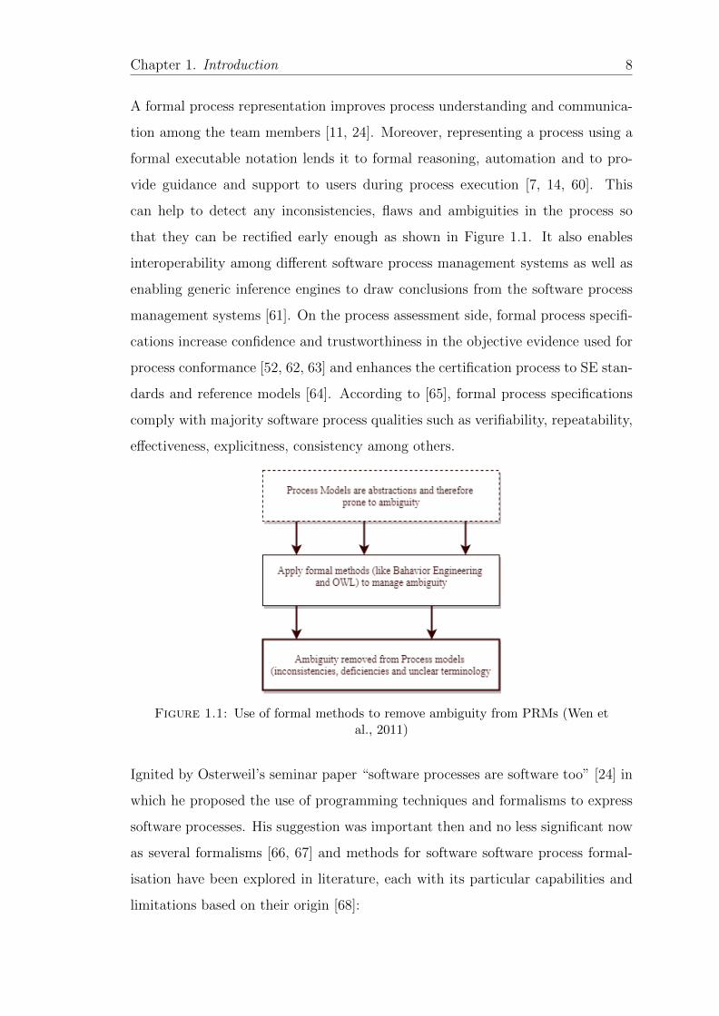
that they can be rectified early enough as shown in Figure 1.1. It also enables
interoperability among different software process management systems as well as
enabling generic inference engines to draw conclusions from the software process
management systems [61]. On the process assessment side, formal process specifi-
cations increase confidence and trustworthiness in the objective evidence used for
process conformance [52, 62, 63] and enhances the certification process to SE stan-
dards and reference models [64]. According to [65], formal process specifications
comply with majority software process qualities such as verifiability, repeatability,
effectiveness, explicitness, consistency among others.
Figure 1.1: Use of formal methods to remove ambiguity from PRMs (Wen etal., 2011)
Ignited by Osterweil’s seminar paper “software processes are software too” [24] in
which he proposed the use of programming techniques and formalisms to express
software processes. His suggestion was important then and no less significant now
as several formalisms [66, 67] and methods for software software process formal-
isation have been explored in literature, each with its particular capabilities and
limitations based on their origin [68]:
Chapter 1. Introduction 9
• Petri net based approaches: these have been consistently used in process
modelling (both business and software) since the first generation process
modelling languages for example SoftPM [69]. They are mainly considered
because of their graphical representation and powerful means to represent
the static and dynamic aspects of the process [70, 71]. They enhance pro-
cess analysis in a simple and intuitive way that underpins the various Petri
net based process verification approaches [72]. While Petri net based ap-
proaches have a graphical representation that provides some easiness in pro-
cess modelling, it usually becomes extremely complex when detailed software
processes activities are modelled [69]. Even then Petri nets can only solve
purely syntactic composition problems, they lack formal semantics [11, 73].
• Graphical based approaches: such as UML approaches [74], composition trees
(CT) [39], BPMN approaches [38, 75, 76]. These convey an intuitive visual
process impression, however, they usually can’t support precise and reliable
process reasoning due to their underlying shallow and weak semantics [11].
Besides there are currently no mature reasoning tools for such formalisms.
Therefore, when broad categories of powerful, precise and reliable reasoning
is required, stronger and broader semantics are essential in a formalism [11].
• Logical based approaches: these are based on rigorous mathematical founda-
tions such as First order logic (FOL) inspired formalisms for representing and
verifying software processes [40, 56, 62]. For instance in [52], a methodology
for managing standards compliant software development is provided. FOL
is a proven and necessary expressive formal approach. However, its major
drawback is undecidability that makes such formalisms inefficient in terms
of computational costs and acceptance in the industry. Generally Logical
approaches are difficult to understand by the ordinary users and have a low
acceptance rate in industry.
• Algebraic based approaches: have also been considered for software process
representation and assessment [77, 78]. Generally, process algebras are used
to model systems consisting of multiple processes that run in parallel and
Chapter 1. Introduction 10
may communicate via channels. Process algebras are a very formal, math-
ematical approach that was mainly developed to model the behaviour of
operating systems and can form a basis for analysis and comparison of soft-
ware process models, as well as tool support [77–79]. Even though, algebraic
approaches provide a wide range of operators and theories for determining
equivalence of process specifications such as bisimulation, they are a less
convenient approach for process verification [80]. Process algebras are rarely
used in the context of software process modelling in general due to their
rigorous formality and certainly not adequate to be used by humans [79].
Moreover, the industry uptake of process algebra approaches in software
process management is still very low [81].
• Ontology based approaches: are a promising approach to formalising soft-
ware process [46, 82]. Particularly, the use of Description Logics (DLs) [83]
ontologies is the most established approach for representing in a machine
processable way the software process knowledge, providing formal definitions
for the basic entities involved in a process, such as sub processes, activities,
tasks and the relations between them [42, 84, 85]. One of the key bene-
fits of using ontologies is that they can be used to effectively support the
aspects of formal representation for automated verification while retaining
the appropriate levels of abstraction for human comprehension. Moreover,
using ontologies, formal rules can be defined and automated processing and
verification can be made using inference engines readily available off shelf
[46, 86]. However, existing studies on formalising software processes using
DLs ontologies [42, 84, 85, 87] have mainly focused on clearing terminology
confusion in the software process domain.
1.2.1 Limitations of existing Approaches
Current approaches to software process formalisation are limited to supporting
either humans or machines but not both. For example, while the widely popular
graphical based methods such as UML-based approaches [88], composition trees
Chapter 1. Introduction 11
and BPMN based approaches can support a visual conceptualization of software
process, they lack the automated reasoning support for automated analysis and
verification. Yet typical formal specification based approaches such as FOL ap-
proaches [52] on the other hand, extremely lack the means of effective human com-
prehension. While the application of these approaches is indisputably important
for developing reliable software process specifications [78], their usage within the
software process engineering community, in practice, is quite still limited [1, 81].
The main drawback of using these approaches is the formal nature of their rep-
resentation which often makes the formal process specification inexplicable for
most people. Moreover, there is a glaring gap between formal process specifica-
tions for the technical people and graphical models that needs to be narrowed
[38, 74, 89, 90]. There are still several open issues regarding the formalisation
process [80] in the software process domain:
1. There is hardly any systematic and repeatable approach for translation of
natural language software processes to formal presentations that is; i) easy
and simple to understand by all stakeholders involved in software process
[38, 69]; ii) verifiable; and iii) consistent and transparent. Instead, most of
the available approaches are ad-hoc and simple independent solution pro-
posals in form of taxonomies and mappings of concepts within the software
process domain without clear translation methodology. According to [89, 90]
ad-hoc formalisation methods may be prone to errors due to various domain
interpretations that can be done. Moreover, maintaining the equivalence
between the formal process model and the original natural language process
specification may be complicated. Therefore there is need for a simple, con-
sistent and repeatable translation approach from natural language processes
to formal representations [81, 91].
2. The current approaches don’t accommodate diverse software processes in a
unified way during formalisation process. Different SE standards and refer-
ence models use different terminologies [92], for instance, process outcomes
in ISO/IEC 12207 and process objectives in ISO/IEC 29110 referring to the
Chapter 1. Introduction 12
same thing. They also use different granularity levels during process descrip-
tion. For example, what is considered a process, activity and task varies in
ISO/IEC 12207 and ISO/IEC 29110 [92] respectively. Therefore there is need
for a unified conceptual foundation to eliminate structural and conceptual
inconsistencies during the formalisation process.
3. The current approaches do not provide a comprehensive formal framework
for reasoning on the consistency, completeness and verification of software
process descriptions, instead some approaches employ ad-hoc methods for
checking process consistency [38, 87].
An approach that overcomes these shortcomings in the current approaches would
allow the processes to be formalised in a systematic and consistent way that is
verifiable and understandable by all the stakeholders involved in software devel-
opment. It is also much more helpful to represent software processes in easier
but unambiguous ways, while preserving their formality beneath [69]. This in
return would enable formal verification and automation of the software process
[11, 53]. Such an approach would make it easier to understand the development
of processes over time and would also promote reusability of such processes in a
more systematic manner [74]. In this thesis, we present a novel formal approach
that responds to these shortcomings. Formalisation of software process presents a
significant improvement towards developing process modelling tools that offer an
automated reasoning support in process modelling and assessment activities. In
the next section we describe the main objectives of the research work presented in
this thesis.
1.3 Aims and Objectives
As motivated in the previous section, our main research aim is to provide a formal
approach and related techniques and guidelines for software process formalisation
to enable process verification and automation. In service of our main research aim,
the following specific objectives are at the core of this study:
Chapter 1. Introduction 13
1. To develop a translation approach from natural language software process
to formal presentations.
2. To demonstrate that the developed translation approach is able to
integrate heterogeneous software processes into a unified model.
3. To demonstrate that the developed translation approach is; i) systematic;
ii) easy to use and understandable by all the stakeholders.
4. To demonstrate that the developed translation approach has reasoning
capability that can facilitate:
• automated process analysis and verification;
• check process compliance to the reference process;
• enable automated process capability determination and checking.
1.4 Proposed Approach
Software processes are diverse and often prescribed in natural language in SE stan-
dards and reference models for a broader understanding and flexibility. This may
lead to various interpretations and perceptions due to the fallible way people use
natural language. This leads to ambiguities or implicit information and misinter-
pretations by various actors. Therefore, if processes and their implementations
have to be analysed and verified, then it requires such processes to be represented
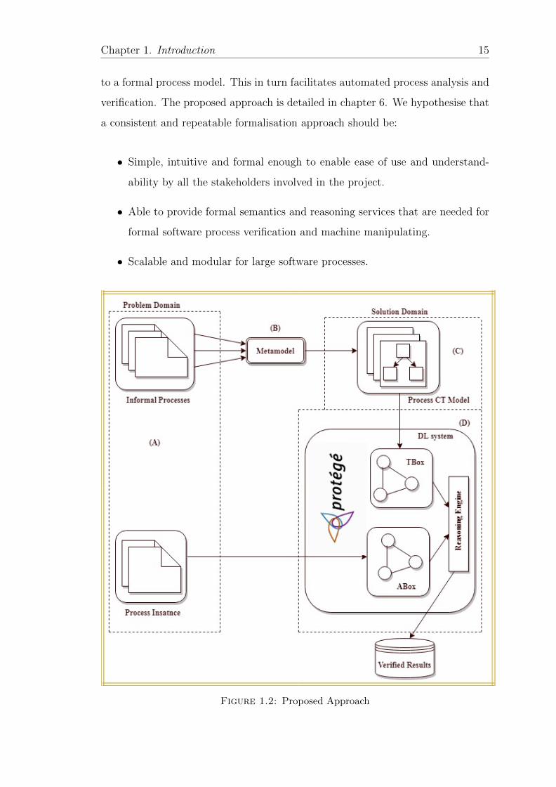
in a formal language underpinned by a metamodel. The proposed approach in-
volves the following steps, as visualised in Figure 1.2:
• Normalisation of process terminologies through use of a metamodel to un-
derpin diverse software processes formalisation.
• Translation of software processes from natural language to composition trees.
• Translation of composition tree software process models to DL TBox (On-
tology).
Chapter 1. Introduction 14
• Translation of organisational processes (process instances) to DL ABox.
• Software process verification using DL reasoning engines.
To systematically and faithfully formalise diverse and heterogeneous processes
from diverse standards and process models, there is need to normalise different
process terminologies used by different PRMs into a unified way [93]. To this
effect, we developed an axiom based metamodel described in details in Chapter 5
as a formal conceptual framework to underpin homogeneous process formalisation.
A direct translation of natural language processes into formal specifications is usu-
ally costly, difficult and can be error prone [38, 89], therefore it necessitates an
intermediate representation to reduce the gap between the two formalisms. We
employ Composition Trees (CT), a Behavior Engineering (BE) formal graphical
modelling notation as an intermediate representation to reduce the gap between
the two formalisms to translate and model software process from natural language
to a formal model. Composition Trees (CT) are a BE graphical modelling nota-
tion for capturing and formalising static system behaviour described in natural
language [39]. CTs are used to translate and formalise natural language software
processes to a more intuitive, simple and verifiable models by domain experts who
may not have the necessary formal methods skills. However, there are no mature
reasoning tools for CT to automatically check and verify the modelled software
processes [94].
On the other hand, Description Logics (DL) [83], an ontology modelling language
with well understood semantics provide means by which models can be understood
by machines and therefore inference engines can be used to automatically verify
and reason the consistency, completeness and conformance of the software process.
DL is made up of the TBox (class level) and ABox (instance level). DL is well
supported by most ontology editors and reasoners. Ontology reasoners can be used
for automated process verification (i.e., checking process consistency, compliance
and capability determination). Combining the two approaches, i.e., CT and DL
provides a formal path and traceability from natural language software processes
Chapter 1. Introduction 15
to a formal process model. This in turn facilitates automated process analysis and
verification. The proposed approach is detailed in chapter 6. We hypothesise that
a consistent and repeatable formalisation approach should be:
• Simple, intuitive and formal enough to enable ease of use and understand-
ability by all the stakeholders involved in the project.
• Able to provide formal semantics and reasoning services that are needed for
formal software process verification and machine manipulating.
• Scalable and modular for large software processes.
Figure 1.2: Proposed Approach
Chapter 1. Introduction 16
1.5 Overview of the Contributions
The main contribution of this study is a formal approach by which software pro-
cesses specified in natural language such as those in SE standards and reference
models can be consistently and repeatedly translated into formal representations.
Such a formal process representation can then be leveraged for automated process
verification and automation. As a consequence of achieving the research aims and
objectives, the following contributions have been made:
1. An axiom based metamodel has been developed to underpin and enhance
homogeneous software process formalisation. This contribution is published
in [93] and detailed in Chapter 5.
2. A systematic and repeatable formalisation approach for software process has
been developed utilising composition trees as a graphical notation and DL
as a formal notation. This contribution is published in [94] and detailed
in Chapter 6. While throughout this thesis, software process examples are
used, the applicability of the developed approach is beyond boundaries of
any specific domain.
3. A Software Process Knowledge Base (SPKB) has also been developed inte-
grating various software process modules: (i) A PRM ontology that provides
process concepts and their relationships, (ii) A PAM ontology that pro-
vides assessment indicator information as well as mapping axioms to both
the PRM ontology and the measurement framework ontology, and (iii) the
Measurement Framework ontology that provides the metrics to measure the
process capability of organisational processes in achieving the business objec-
tives. Part of this contribution is disseminated to peers in [95] and detailed
in Chapter 6.
4. A set of application scenarios (process instances) have also been developed to
demonstrate and evaluate the quality, utility and efficacy of the formalisation
approach developed in this thesis. Results of application scenarios include
Chapter 1. Introduction 17
ensuring process conformance and automated capability determination. This
contribution is published in [95] and detailed in Chapter 7.
1.6 Research Scope
While there are many ways of describing software processes by various process
models, the terms and descriptions used in such process models vary in format,
content and level prescription [18], in this study, we focus on describing software
processes in terms of purpose and outcomes as prescribed in ISO/IEC 33004 [96]
and ISO/IEC TR 24774 [18]. This is an innovation that evolved within the con-
finements of ISO/IEC 15504 series of standards [22]. We don’t claim that it is the
only way of process description but one that has been successful in process defini-
tions and assessments [22]. Notwithstanding this way of process description, there
are various process models such as ISO/IEC 12207 and ISO/IEC 29110 within
the confinements of ISO/IEC 33004 and ISO/IEC TR 24774 that use varying
terms, abstraction levels and granularity that need to be unified during process
formalisation [92].
1.7 A brief Justification of used tools and tech-
niques
In our formal process formalisation approach, certain tools, languages, and tech-
niques are used. In this section, we briefly describe the reasons which made them
suitable to demonstrate our contributions. We justify the use of Composition
Trees, DLs, and SE standards such as ISO/IEC 330xx, ISO/IEC 12207, ISO/IEC
29110 among others.
Chapter 1. Introduction 18
1.7.1 ISO/IEC 330xx (SPICE)
SE standards are widely considered as a source of universally accepted best prac-
tices and guidelines to support the design, implementation and improvement of
software processes by encapsulating a coverage of process life cycle activities and
their improvement. By novelty and process coverage, the emerging ISO/IEC 330xx
[27] family of standards provides the most generic and a comprehensive set of re-
lated documents for assessing process quality characteristics (PQC) intended to
replace the ISO/IEC 15504 series of standards that was only assessing process
capability. The new family of standards comes at a higher abstract level, gener-
alisation and wider potential for process assessment and in ISO/IEC 33004 [96]
provides requirements for the definition of other interrelated reference models such
as:
• PRM such as ISO/IEC 12207, ISO/IEC 29110: to provide process descrip-
tions and their relationships as a basis for assessment. These should be
defined in terms of their purposes and outcomes;
• PAM such as ISO/IEC 15504-5 (ISO/IEC 33061): to provide assessment
indicators to evaluate process performance in organisations;
• Measurement models such as ISO/IEC 33020: to evaluate the capability of
organisational processes to achieve business objectives effectively and effi-
ciently.
1.7.2 Composition Trees (CT)
The CT notation is a Behavior Engineering (BE) approach that has been success-
fully used to formalize, compare and verify software processes [39]. CTs similar
to UML class diagrams, model static system aspects in terms of entities, rela-
tionships, attributes and component states [39] and are constructed through a
careful step wise approach and later integrated into one complete tree like graph-
ical model. The created models are more intuitive, less ambiguous and easier to
Chapter 1. Introduction 19
read and verify than the original natural language processes [39]. The benefit of
modelling a software process in a CT is that the graph gives an overall view of the
process and it is less ambiguous and intuitive. Moreover, it is very easy to trace
back the software process to its natural language specifications given the careful
process translation of one a time procedure. Formal verification such as compar-
ing two processes can be performed by using automated tools [39]. Compared to
other graphical models like UML, it produces few and easy models to comprehend.
However, reasoning of processes modelled in CT is not possible because they are
no mature reasoning tools for CT models currently. This has propelled us to look
at knowledge representation languages where DLs can be used to model and reason
processes efficiently there by enabling automated process analysis and verification.
1.7.3 Description Logics (DLs)
The choice of DLs [83] for our study is not surprising as it provides a rich and
flexible modelling language that is well suited for addressing the challenges posed
by natural language ambiguity in SE [97]. DLs as a decidable fragment of FOL
provide a standardised semantics with a wide range of tools and infrastructure
for modelling, storage, reasoning and query answering [98]. In recent years, DLs
have been widely accepted as an important means for representing and formalising
knowledge in different domains including software process engineering [82]. DLs
also underpin the Web Ontology Language (OWL)3; a W3C standard for develop-
ing ontologies in the semantic web. Using a standardised modelling language can
ease the adoption of the supported approach. Moreover, DLs are supported by a
variety of optimised inference engines 4 that can be utilised to support both consis-
tent process implementation and querying the process space by logical expressions
[99].
3https://www.w3.org/OWL/4http://owl.cs.manchester.ac.uk/tools/list-of-reasoners/

Chapter 1. Introduction 20
Ontology development in DLs is also supported by a variety of ontology edit-
ing tools such as Swoop5, TopBraid composer6 and Protege [100] among others.
These serve as a bridge between the syntax of an ontology and its semantics di-
rectly dealing with reasoners to determine consequences of ontology axioms and
present them in an easy way to end users [98]. Coupled with the above tools for
ontology editing and reasoning, is the availability of OWL APIs [101] for parsing
and rendering ontologies in various different standards and providing a standard
interface to ontology reasoners for different applications [98]. OWL 2 also provides
a milder metamodeling technique called Punning7 that is based on contextual se-
mantics of DL [102] defined in SHOIQ. We use punning technique to formalise
the customised metamodel developed as part of the approach proposed in this
study. Over all, the formalisation of software processes in DL provides us with a
rigorous formal framework for representing and automatically reasoning on soft-
ware process specifications.
1.8 Outline
Following this introductory chapter, the rest of the thesis is organised in a number
of related chapters:
• Chapter 2 overviews the research preliminaries, providing basic concepts
and terminologies related to software processes, software process modelling,
process assessment and process metamodelling. In addition, it also provides
concepts and definitions on Behaviour Engineering and Description Logics
formalism used in the design of the formal approach.
• Chapter 3 presents the state of the art to the work presented in this study.
Discussions and comparisons are made with other works in literature.
5http://swoogle.umbc.edu/2006/6https://franz.com/agraph/tbc/7https://www.w3.org/2007/OWL/wiki/Punning
Chapter 1. Introduction 21
• Chapter 4 discusses in details the research methodology employed and its
justification to achieve the research objectives undertaken in this research.
Comparisons with other approaches are made and benefits of the proposed
approach are elaborated in achieving our research objectives.
• Chapter 5 is part of our main contribution in this study, this chapter dis-
cusses the justification and development of a customised metamodel based
on powertype and OWL 2 punning techniques to underpin homogeneous
software process formalisation.
• Chapter 6 presents and discusses our main contribution in this study. The
formal approach for software process formalisation. This chapter also in-
cludes the development of the Software Process Knowledge Base (SPKB)
that forms the formal foundation of the formal approach presented in this
thesis.
• Chapter 7 provides a discussion of application scenarios to demonstrate and
evaluate the quality, utility and efficacy of the developed formal approach
in providing intelligent support in software process formalisation. These
include process conformance verification and capability determination.
• Chapter 8 finally this chapter presents a summary of the work done in this
thesis, the research limitations and outlines some future directions to extend
this work and concludes the thesis.
1.9 Summary
This chapter has laid the foundations for the study in this thesis. The research
background and motivation were presented in Sections 1.1 and 1.2 respectively
for an overall understanding of the research context. Then the research aims and
objectives were identified in Section 1.3. In order to achieve the aims and objectives
of this research the proposed approach was introduced in Section 1.4. Our main
research contributions are outlined in Section 1.5 while the research boundaries

Chapter 1. Introduction 22
are set in Section 1.6. A brief justification of the tools and techniques used in this
research was made in Section 1.7. Finally, the outline of the rest of the thesis is
described in Section 1.8. In the next Chapter, we present preliminaries that are
used through out the research work presented in this study.
Chapter 2
Preliminaries
2.1 Introduction
In the previous chapter, we laid the foundation for the work presented in this
thesis. In the current chapter we present the preliminaries about the essential
concepts and terminologies that underpin the work presented in this study. It ex-
amines works related to software process management in Section 2.2 and process
metamodeling in Section 2.3. Behavior Engineering concepts and notations are de-
scribed in Section 2.4 while DLs and ontology modelling languages are discussed
in Section 2.5. Finally this chapter is concluded with a summary statement in
Section 2.6. It is important to note that this chapter does not aim to give an ex-
haustive study about these topics, but rather a brief introduction that is adequate
to comprehend the work presented in this thesis.
2.2 Software Process Management
Software process management is a systematic and continuous endeavour to define,
assess and improve processes that are used to produce quality software products
and services within the constraints of time, budget and schedule [8]. It is the use
of process engineering concepts, techniques, and practices to explicitly monitor,
23
Chapter 2. Preliminaries 24
control, and improve the software process [8]. The objective of software process
management is to enable an organization to produce software products according
to a plan while simultaneously improving the quality of its products [8].
2.2.1 Software Process
The process perceptive to software development is premised on the manufacturing
principle that product quality is influenced and evolved by the process used to
produce it [8]. Where a process is a set of interrelated or interacting activities
which transforms inputs into outputs [9]. Processes for software development have
been proposed with the goal to standardise development in order to make projects
reach their target within a specific time frame, in budget and with a certain func-
tionality [24]. Due to the plenitude of software systems in demand, the necessity
of manageable and repeatable software development is of great importance [24].
Software development is accomplished through a set of activities that are con-
currently carried out by interacting agents with different backgrounds and skill
set. The aggregation of these activities is commonly referred to as a software pro-
cess [24]. The software process is a common framework that enables the software
development stakeholders to interact during software development process.
Feiler [10] defines a software process as a set of activities, methods, and practices
that are used in the production and evolution of software. Sometimes the term
software process is used synonymously with software development process however,
software process includes activities that are not directly related to software devel-
opment like quality, configuration among others. Although differences of opinion
still exist, there appears to be some agreement about a software process being a set
or order of activities (sometimes as a workflow), methods and practices concerned
with the design, development and maintenance of software products. Its main
aim is to manage and transform user needs into a software product that meets
these needs within budget and time [23]. Ultimately, a software process provides
a roadmap for the development of high quality software products that meet the
needs of its stakeholders within a balanced schedule and budget [103].
Chapter 2. Preliminaries 25
According to [23] software process definition normally specifies the actors, roles and
the artefacts produced. Even though there is no ‘ideal’ and fit all software process
for all environments and projects, all software processes must include the major
activities that are fundamental to software engineering as; software specification,
software design and implementation, software validation and software evolution
[1]. The overall goal of a software process is to provide a framework for managing
these software development activities that can easily get out of control [5].
Software Process Engineering on the other hand, refers to the principles and tech-
niques used in modelling, evaluation and improvement of software process towards
greater productivity and quality in software development [10]. It is the application
of scientific methods and guidelines dedicated to handling of activities of software
development process [104]. The output of which is a software process description.
Software process description is a representation of a software process created to
facilitate process enactment and evaluation, and to serve as a medium of commu-
nication for software process information [24, 105]. Process descriptions should
be update, well structured, consistent in presentation style and tailorable [105].
Importantly these descriptions can drive process enactments. Software process
descriptions can be described in various ways using for example natural language,
text, pictures, graphics, mathematical models or a combination of any these ways
through software process modelling [105].
2.2.2 Software Process Modelling
Software process modelling (SPM) refers to the activities in creating abstract rep-
resentations of the methodology, design or definition of the software process [23].
SPM incorporates a representation approach and comprehensive analysis capabil-
ities (a range of tests in the areas of consistency, completeness, and correctness).
The goals of SPM are to abstract and organize software process information into
well-defined models, analyse the inter-relationships among model elements and
attributes, and predict the outcome of software process [23]. Process models are
Chapter 2. Preliminaries 26
used to represent processes at an abstract level and it has been suggested that
any process representation can be considered a process model [24, 39]. Process
models can be analysed, validated and simulated [23, 25] and if represented by a
formal language with clear semantics like DL then they can also be reasoned on
for consistency [11].
The resulting software process models from SPM can be descriptive or prescriptive
[23]. Prescriptive process modelling defines how software development processes
should be performed, including methodologies, rules, guidelines, and behaviour
patterns that would lead to the desired process performance. Prescriptive process
models are used as guidelines or frameworks to organize and structure how soft-
ware development activities should be performed, and in what order [23]. Thus,
prescriptive process models can also be referred to as process reference models
(PRM), some examples in SE are ISO/IEC 12207 [9], ISO/IEC 29110 [26] among
others. These process models describe a set of essential, but unordered activities,
which have to be completed to obtain a software product. They do not prescribe
a specific life cycle [39]. Each organization that uses the process model must
instantiate the prescribed process as a specific or tailored process.
2.2.3 Process Modelling Languages
A software process model is developed, analysed, refined, and transformed within
a Process Modelling Language (PML) [106]. Thus, any software process model has
to meet the software process modelling objectives and these imply requirements for
the PML by which a process model is defined. These requirements often influence
the choice of a PML. The need to rigorously express software processes and exploit
the computing power in their execution led to the application of programming
techniques and formalisms to be used to express process descriptions in what was
termed as process programming [24]. This notion led to the sprung of various
PMLs in literature [11, 67], however, defining a successful and semantically rich
PML is still a challenge [67].

Chapter 2. Preliminaries 27
PMLs provide important support for describing and managing processes. Various
PMLs have been developed over the years to model and support the software
process features and facts in a precise and comprehensive way [11, 67]. Choice
of these greatly depends on the modelling objectives, process elements and the
structure of the process [5]. A PML supports the description of several concepts
that characterize a software process, such as: Activities which are the process
steps used to produce and maintain artefacts. Artefacts are the input and output
of activities. Roles these describe the rights and responsibilities of the agents
(human and tools) in charge of activities. Notwithstanding the various PMLs
available in literature, the main challenge for organisations is choosing the most
suitable process formalism to meet the organisational process requirements [68].
There are various features and quality factors that characterise PMLs [7, 68, 88].
Here we highlight some necessary features for a software process formalisation
approach.
• Formality ; a process may be represented in an informal or formal nota-
tion. Formal notations have defined syntax and semantics that can enable
automated analysis through reasoning. Ostrweil [24] observes that most
graphical notations such as UML are based on shallow semantics that may
not support reliable process reasoning. On the other hand, formal notations
like knowledge graphs [107, 108] and DL can be reasoned on for consistency
[7, 109]. These can support various automate process analysis due to their
formal semantics. Formal notations describe processes in a precise and com-
prehensive way that makes its understanding easy through communication
among the different stakeholders [24]. This helps to avoid any ambiguity
and misunderstanding among the stakeholders [39].
• Expressiveness ; the process formalism should be expressive enough to model
the various process elements. For software process description, ISO/IEC
24774 [18] specifies the process elements that can be used uniformly to de-
scribe processes as the title, purpose, outcomes, activities and tasks.
Chapter 2. Preliminaries 28
• Understandability ; the approach should be easy and simple to use while
retaining sufficient formality for process analysis. It is more helpful to rep-
resent software processes in easier but unambiguous ways, while preserving
their formality beneath [69].
• Supporting tools ; for example in automating a process, the approach should
be supported by readily available tools or specific developed tools. Such
tools enhance the automation and adoption of the approach.
• Abstraction and modularization. the approach should be able to support a
certain level of abstraction and modularization. Different process models
can be aligned and compared.
• Conformity to standards ; the approach should be in conformity to various
standards within the software process domain. For example, ISO/IEC 24774
provides the various process elements to describe software processes in a
uniform way.
• Granularity ; the approach should take care of software processes defined at
various granularity levels through harmonising them in a unified way. Use of
a metamodel can provide a conceptual foundation to such process definitions.
There are still arguments over the foundation choice for PMLs: different PMLs
have been developed from different sources without clear trend for selection of their
foundations. However, it seems modelling, expressivity and the level of formality
objectives induced most PMLs foundations [24, 67]. According to [7] a perfect
PML may never be developed and perhaps this explains the huge number of avail-
able PMLs in literature. A detailed discussion of the different PMLs is beyond the
scope of this study, however, surveys for first generation PMLs can be found in
[110]. According to [67] these PMLs were complex, extremely sophisticated and
strongly oriented toward detailed modelling which hindered their usage and up-
take by academic and industry. These PMLs adopted a Closed World Assumption
(CWA) where the user couldn’t modify a predefined process during enactment. A
lot of emphasis was placed on process completeness and process automation. This
Chapter 2. Preliminaries 29
required a lot of specification to include all the details in the process for automa-
tion increasing its complexity. Shortcomings of these PMLs are well documented
elsewhere in [110].
Classification of PMLs and their founding technologies has not been clearly agreed
upon [67]. However, some PMLs have been classified according to generations. For
example, first generation involves Petri net based languages, rule based languages
and programming languages [110]. The main aim of these languages was on process
execution and formality. Whilst this was achieved in most of the languages cited
above, it rendered them complex, inflexible and difficult to understand and use
[67]. The second generation languages saw the emergency of UML as a standard
language for modelling in software engineering and therefore formed a basis of
many PMLs in this generation [88].
The second way to classify PMLs is the creation of taxonomy for PMLs based on
their founding technologies [66, 67]. In this classification PMLs are categorised in
three groups:
• Grammar based languages: these include a collection of programming lan-
guages, graph theory, Petri nets and rule languages. Their main advantage
lays in providing precise syntax and semantics however, they are difficult
to use in modelling software process, lack of executable semantics, they
don’t support distributed processes as well as lack of global function and
behavioural view of process models.
• Petri net based languages which have been consistently used in process mod-
eling (both business and software) since the first generation languages for
example SoftPM, among others. They are mainly considered because of
their graphical representation and powerful means to represent the static
and dynamic aspects of the process. They enhance process analysis in a
simple and intuitive way.
• Metamodel based Languages: These are mainly based on SPEM 1.1, SPEM
2.0 and ISO/IEC 24744. In some cases these are like extensions of UML, for
Chapter 2. Preliminaries 30
example eSPEM, VSPEM [67]. SPEM has also be extended using OWL and
SWRL for formality and constraints verification [86]. The main advantage of
PMLs in this group is the separation between general process modelling prin-
ciples from domain specific languages as well as having modelling patterns
that are implementable [67].
• UML based Languages: a large number of PMLs is based on UML [88] such
as PROMENADE [106]. UML is a very popular and attractive modelling
language to software engineers. It is widely used because it has an intuitive
graphical representation, extensibility, support by many tools, different views
for process presentation and object constraint language (OCL) support for
model verification [67]. From the above discussion, and given the fact that
UML is a standard modelling language in software engineering, it is not a
coincidence that it has been extensively used as a base technology for many
PMLs in the second generation. Undeniably though, UML and its associated
PMLs lack formal semantics [88].
Recently other modelling alternatives are being used to model software processes
such as Business Process Modelling and Notation (BPMN)[111]. BPMN is a graph-
ical notation that is devoted to representing business processes in a graphical and
easy way for humans to understand as it is main objective. BPMN has been used
to model software processes [38, 75, 76]. However, it remains informal and more
oriented towards the general business process modelling than the specificity of
software processes [76]. Composition Tree (CT) approach has also been used and
proven to be useful in formalizing, modelling and comparing software processes
[39]. Composition Trees (CT) are a BE graphical modelling notation for captur-
ing and formalising static system behaviour described in natural language [39].
CTs are used to translate and formalise natural language software processes to
more intuitive and simple models. However, there are no reasoning tools for CT
to automatically check and verify the modelled software processes [94].
Chapter 2. Preliminaries 31
2.2.3.1 Process centred Software Engineering Environments (PSEEs)
Software process models represent a precise specification of a software process
through an appropriate PML. Process models can be analysed and enacted within
a Software Engineering Environment (SEE). Emerging from the notion of Process
programming [24], SEE that later came to be known as Process Centered Software
Engineering Environments (PSEEs) are used to enact software process models.
The enacted software processes can provide guidance, automation and enforcement
of the software engineering practices that are embodied in the process model [112,
113]. PSEEs support the engineering process used to conceive, design, develop,
and evolve a software product through an explicit process model [112]. PSEEs
also support software development control and management as well as integrating
developers with the software process and the supporting technology [24, 112].
The PSEE centres on the process model that specifies how to carry out software
development activities, the roles and tasks of software developers, and how to use
and control software development tools [24]. A process model is therefore a conduit
to better understand and communicate the process [24]. And if it is expressed in
a formal notation, it can be used to support a variety of activities such as process
analysis, process enactment, process verification and reasoning within the PSEE
[24]. PSEEs are characterized by the underlying PML. The PML is used to define
the process model that is analysed and enacted by the environment. PSEE’s key
idea is to use a process model as its parameter in effecting its enactment [114].
To fully appreciate the services provided by PSEEs, we recall the Dowson’s concep-
tual and terminological framework that divides the software process into three do-
mains: process model domain, process enactment domain and process performance
domain [115]. The process model domain includes the defining and maintaining
the software process models which are defined by a PML. The process enactment
domain puts the process model into effect or use while the process performance
domain encompasses the actual activities and tasks carried out by human and
non-human agents during the software development process [112]. Process model
domain interlinks process enactment domain and process performance domain
Chapter 2. Preliminaries 32
through providing process models that can be enacted by the enactment domain.
There are continuous links between process enactment and performance domains
through performance feedback and assistance and support for performance [115].
They are various roles provided by PSEEs depending on the specific environment
and purpose of development however, in general they are generic roles that PSEEs
should play in any environment, in some cases these are called features of PSEEs
[112, 114, 116]:
1. Support process enactment: any PSEE should be able to support the def-
inition, initiation and control of software processes within a development
environment. To realise this role an appropriate PML is required to define
software process models that can easily be enacted by the environment [113].
2. Support software team communication and coordination at all levels. It can
be organisational or project level. Human agent’s involvement is crucial for
the suitability of the process and therefore coordination amongst the team
should be ensured by the PSEE.
3. Managing consistency of the software process as well as the software products
due to various changes that take place while software development is ongoing.
4. Process flexibility and evolution: Flexibility according to [112] is the ability
to modify software process activities dynamically during software perfor-
mance while evolution is taking into consideration the changes that occur to
the process for example through performance feedback changes that can be
initiated for process improvement. There could be process deviations from
the standard process. Such deviations should be taken into consideration
and supported by the PSEE.
5. PSEE should support process reasoning to check for its consistence, com-
pleteness and correctness. Knowledge management is another aspect that
PSEEs should enable and include a query mechanism to check the status of
a modelled software process and enable knowledge retrieval from the knowl-
edge base within the PSEE [24].
Chapter 2. Preliminaries 33
While the earlier SEE tried to focus on the implementation of a single tool, the
subsequent SEEs advocated for more integration. This propelled the desire to
use knowledge management techniques to efficiently integrate the different tools,
knowledge and processes within the environments [87]. By providing a shared
conceptualization and understanding, formal notations enable seamlessly integra-
tion as well as communication not only between human agents but also among
computer agents within PSEE [87]. By employing a formal process model to be
enacted by PSEE, the environment lends its self to efficient and effectiveness in
process enactment.
2.2.4 Process Reference Models (PRMs)
In software engineering, there are various PRMs through out the software devel-
opment life cycle providing basic activities, roles, work products that can be used
in quality software development. The PRMs presented in the next subsections
are intended for process assessment as identified in the process assessment frame-
work provided in ISO/IEC 330xx family of standards and constrained within the
confinements of ISO/IEC 33004. These PRMs are intended to provide the de-
scriptions of the process entities to be assessed in the process dimension of the
process assessment model ISO/IEC 15504-5 (ISO/IEC 33061). For other purposes
interested readers can refer to the full process models in [9, 26].
2.2.4.1 ISO/IEC TR 24774
There is no one way to specify a process for all contexts, however, any software
process in a given context should possess the basic process elements such as ac-
tivities, tasks, roles [117] among others. ISO/IEC TR 24774 [18] is one important
example of prescriptive process reference models that defines a general format for
any process reference model without specifying a specific life cycle. Any organi-
zation that uses the standard must instantiate their own specific process based
Chapter 2. Preliminaries 34
on the guidelines provided by the standard. This general purpose standard out-
lines the elements used to describe a software process [18] as: the title, purpose,
outcomes, activities and tasks.
• The purpose identifies the aim or goal of undertaking a process. The process
purpose is expressed as a high level goal for performing the process, mainly
stated in a single sentence. The implementation of the process should provide
positive results and demonstrated through the expected outcomes.
• The outcomes express the tangible results from process performance. Pro-
cess outcomes are demonstrated through positive results. Process outcomes
can also be referred to as process objectives [26]. A set of process outcomes
is necessary and sufficient to demonstrate the achievement of a process pur-
pose. Process outcomes normally address the process purpose and their
achievement help to build capability level one of any assessed process in-
stance [22, 48].
• The activities are a set of specific actions that are undertaken to achieve the
stated process outcomes. Activities may further be broken down into specific
tasks to achieve specific outcomes and related activities can be grouped
within a given process.
• The tasks are specific steps and recommendations undertaken to achieve an
activity. Various related actions can be grouped within an activity to achieve
a given process.
2.2.4.2 ISO/IEC 12207
ISO/IEC 12207 [9] is an international standard for software and system engineering
that prescribes a set of life cycle processes, activities and tasks for developing and
maintaining software. ISO/IEC 12207 provides a common framework for software
life cycle processes to be used by the software industry during software devel-
opment, supply, operation, maintenance and disposal of software products and
Chapter 2. Preliminaries 35
services. It provides a common terminology to facilitate communication among
acquirers, suppliers and other stakeholders in the life cycle of a software product
[9].
ISO/IEC 12207 is organised into two major subdivisions that is system context
processes and Software specific processes. These are further categorised in seven
process groups with forty three processes, one hundred and twenty one activities
and four hundred and six individual tasks [118]. Processes represent a collection
of sub processes or activities. Activities are a set of cohesive tasks of a process
while a task is a requirement, recommendation, or permissible action, intended to
contribute to the achievement of one or more outcomes of a process [118].
ISO/IEC 12207 meets the requirements of a process reference model by ISO/IEC
33004 to be suitable for process assessment with ISO/IEC 330xx family of stan-
dards. To this end, ISO/IEC 12207 provides process descriptions for the process
assessment model in ISO/IEC 15504-5 (ISO/IEC 33061). Where such process
descriptions incorporate a unique process name, purpose statement and outcome
statements. An example of software requirements analysis process description is
given in section 2.2.6.1 and used though out the thesis. It should be noted that
process descriptions provided in the PRM such as ISO/IEC 12207 are not detailed
enough for process assessment. Therefore in the process assessment model pro-
vided in ISO/IEC 15504-5 (ISO/IEC 33061), they are supplemented with base
practices and work products.
Despite the fact that ISO/IEC 12207 is a well-structured and detailed technical
text on a complex subject. Many organisations and projects are not fully utilising
it to define and improve their software processes [35, 36]. It needs a comprehensive
review to apprehend. Moreover, its description in natural language doesn’t help
matters either. In [105] it is argued that the demand for usable software process
descriptions is high however, in practice, process descriptions suffer from complex-
ity and inflexibility because of their structures and styles of description. ISO/ IEC
12207 in its current form is not very user friendly and this causes difficulties for
process engineers wanting to find required information quickly [119].
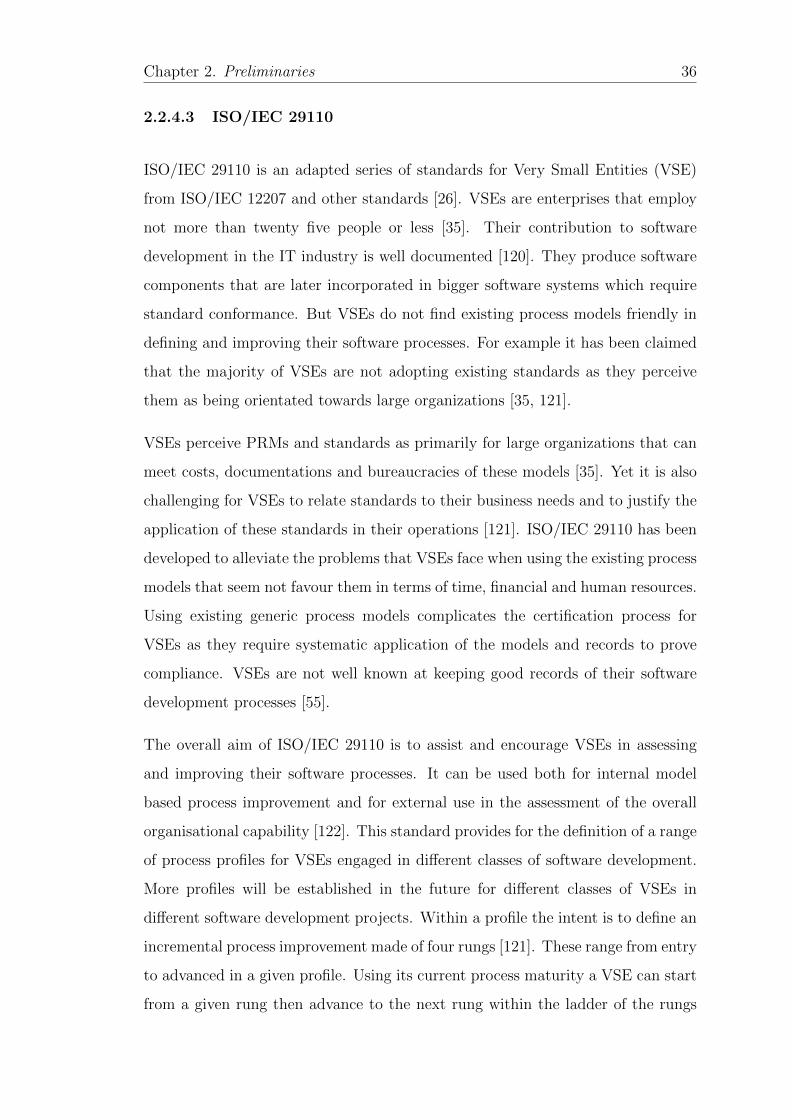
Chapter 2. Preliminaries 36
2.2.4.3 ISO/IEC 29110
ISO/IEC 29110 is an adapted series of standards for Very Small Entities (VSE)
from ISO/IEC 12207 and other standards [26]. VSEs are enterprises that employ
not more than twenty five people or less [35]. Their contribution to software
development in the IT industry is well documented [120]. They produce software
components that are later incorporated in bigger software systems which require
standard conformance. But VSEs do not find existing process models friendly in
defining and improving their software processes. For example it has been claimed
that the majority of VSEs are not adopting existing standards as they perceive
them as being orientated towards large organizations [35, 121].
VSEs perceive PRMs and standards as primarily for large organizations that can
meet costs, documentations and bureaucracies of these models [35]. Yet it is also
challenging for VSEs to relate standards to their business needs and to justify the
application of these standards in their operations [121]. ISO/IEC 29110 has been
developed to alleviate the problems that VSEs face when using the existing process
models that seem not favour them in terms of time, financial and human resources.
Using existing generic process models complicates the certification process for
VSEs as they require systematic application of the models and records to prove
compliance. VSEs are not well known at keeping good records of their software
development processes [55].
The overall aim of ISO/IEC 29110 is to assist and encourage VSEs in assessing
and improving their software processes. It can be used both for internal model
based process improvement and for external use in the assessment of the overall
organisational capability [122]. This standard provides for the definition of a range
of process profiles for VSEs engaged in different classes of software development.
More profiles will be established in the future for different classes of VSEs in
different software development projects. Within a profile the intent is to define an
incremental process improvement made of four rungs [121]. These range from entry
to advanced in a given profile. Using its current process maturity a VSE can start
from a given rung then advance to the next rung within the ladder of the rungs
Chapter 2. Preliminaries 37
[121]. The entry and basic profiles of ISO/IEC 29110 are made up of two processes;
Project Management (PM) with five activities and Software Implementation (SI)
with six activities as shown in Figure 2.1. Being compliant and suitable for process
Figure 2.1: ISO/IEC 29110 Basic Profile Processes and Activities (Laporte etal., 2008)
assessment by ISO/IEC 15504-5 was among the factors that influenced the design
of ISO/IEC 29110 [123]. This led to the development of ISO/IEC 29110 part 3
that provides guidelines for using and tailoring ISO/IEC 15504 to assess software
development following the ISO/IEC 29110 standard. Various authors [48, 124]
have also provided different ways to make ISO/IEC 29110 a compliant PRM for
process assessment with ISO/IEC 15504-5 (ISO/IEC 33061).
However, despite the efforts to make this standard easier for VSEs to implement
through availing the deployment packages which are additional documentations
to improve process understanding and comprehension, the standard still needs to
be tailored to the specific needs of the VSEs [55]. The standard is described in
natural language which makes it complex and inflexible for VSEs to implement
and verify [21, 55, 57].
Chapter 2. Preliminaries 38
2.2.5 Process Conformance and Verification
An important difference between software processes and other business processes is
the intangibility nature of the software product [12]. Where as other products can
be tested on their physical appearance, software products on the other hand, can
only be checked on their functionality when used to fulfil the intended purposes
for which they are developed. It is therefore vital to convince potential customers
that the software produced will perform as intended. Therefore the quality of the
software product in part can be estimated by checking if the process used to provide
it is in compliance with PRMs such as ISO/IEC 12207. However, most PRMs are
always abstract specifications and never specify any particular methodology for
their implementation given the fact that there is no one size fits all process [125].
Therefore there is always a big gap between the PRMs and the actual software
process used to produce software products.
The compliance of software processes with PRMs plays a vital role in convincing
the potential customers that the software will result in the quality specified [125].
The process of verifying the extent to which the implemented process is in con-
formance with a PRM is referred to as process compliance [62] and accomplished
through process assessment or auditing [22]. Conformance assessment is where or-
ganisational processes are checked for the fulfilment of, and adherence to a PRM’s
requirements [48, 126].
On the other hand, verification is defined in [127] as a means to check whether
an artefact and/ or its creation comply with a set of given requirements. Verifica-
tion focuses more on the internal aspects of what is being checked in contrast to
validation which focuses on ensuring that the artefact is eligible for the intended
purpose [99]. PAMs such as ISO/IEC 15504-5 proposes the use of objective evi-
dence to verify process implementations against PRMs requirements [128]. This
kind of verification is based on conventional methods where collected evidence is
manually compared to the PRM requirements. However, conventional methods
have proven to be expensive and error prone [43, 44].
Chapter 2. Preliminaries 39
On the other hand, automated verification can be utilised to ease the verifica-
tion process [129]. A first step towards such verification is the representation of
the software process in a formal language such as DL. A number of verification
approaches based on DL have been discussed in literature [99, 125, 130, 131].
2.2.6 Process Assessment
While the software process prescribes the actions the software developers should
undertake during software development, process assessment on the other hand, is
designed to judge the execution or performance of the undertaken software process
to produce the required software product. Processes are an inherent part of SE,
so is process assessment as a foundation step for process improvement [46]. Pro-
cess assessment is a broadly used method by organisations to evaluate and change
their processes in light of achieving business objectives and support process confor-
mance to standard processes [48]. Process assessment is a disciplined evaluation
of the organisational processes against a set of criteria defined in a process as-
sessment model (PAM) such as ISO/IEC 15504-5 to determine the capability of
the organisational processes to perform within the constraints of quality, cost and
schedule [22]. The main aspect of process assessment is the comparison of the
actual organisational process performance to some form of a structured process
(such as processes described in the PRM) that serves as a benchmark for process
improvement and capability determination [22]. During process assessment, the
emphasis is placed on two measures[22, 48]:
• Organisational process conformance to the PRM through conformance as-
sessment approach. Under this approach, PRM can be utilised in evaluating
the achievement of the process outcomes and studying the fulfilment of a
standard’s requirements [45, 48]. Therefore, process assessment provides a
way to verify conformance to a standard like ISO/IEC 29110, if such a stan-
dard is considered as a set of requirements [48]. Schmidt [125] identifies such
requirements for service process conformance/compliance.
Chapter 2. Preliminaries 40
• The effectiveness of the organisational processes (process capability) to achieve
organisational business objectives. The process capability assessment stud-
ies individual processes and their attributes that form the capability level of
the assessed process through combining PRM and a measurement scale into
a PAM.
By novelty and genericity, the emerging ISO/IEC 330xx [27] family of standards
provides the most generic and a comprehensive set of related documents for assess-
ing process quality characteristics (PQC) intended to replace the ISO/IEC 15504
series of standards that was specifically assessing process capability. The main
umbrella term in the new standard is the definition of process quality characteris-
tics in ISO/IEC 33001 [27], that has influence on all other parts of the ISO/IEC
330xx family. The new set of standards comes at a higher abstract level and wider
potential for process assessment geared towards:
• Establishing unified requirements for full consistency and harmony across
the ISO/IEC 15504 set and all other JTCI/SC7 standards.
• Establishing a more rigorous approach to performing process assessments for
process quality characteristics other than process capability. Other process
characteristics include security, sustainability, agility and process value.
• ISO/IEC 33020 provides a revised measurement framework for process ca-
pability similar to the one in ISO/IEC 15504-2.
Also ISO/IEC 330xx family, in ISO/IEC 33004, defines requirements for the defi-
nition of other interrelated reference models such as:
• PRM such as ISO/IEC 12207, ISO/IEC 29110: to provide process descrip-
tions and their relationships as a basis for assessment. These should be
defined in terms of purposes and outcomes.
• PAM such as ISO/IEC 15504-5 (ISO/IEC 33061): to provide assessment in-
dicators to evaluate process performance in organisations. It also emphasises
the use of objective evidence to prove conformance to the defined criteria
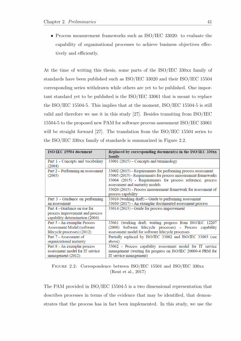
Chapter 2. Preliminaries 41
• Process measurement frameworks such as ISO/IEC 33020: to evaluate the
capability of organisational processes to achieve business objectives effec-
tively and efficiently.
At the time of writing this thesis, some parts of the ISO/IEC 330xx family of
standards have been published such as ISO/IEC 33020 and their ISO/IEC 15504
corresponding series withdrawn while others are yet to be published. One impor-
tant standard yet to be published is the ISO/IEC 33061 that is meant to replace
the ISO/IEC 15504-5. This implies that at the moment, ISO/IEC 15504-5 is still
valid and therefore we use it in this study [27]. Besides transiting from ISO/IEC
15504-5 to the proposed new PAM for software process assessment ISO/IEC 33061
will be straight forward [27]. The translation from the ISO/IEC 15504 series to
the ISO/IEC 330xx family of standards is summarized in Figure 2.2.
Figure 2.2: Correspondence between ISO/IEC 15504 and ISO/IEC 330xx(Rout et al., 2017)
The PAM provided in ISO/IEC 15504-5 is a two dimensional representation that
describes processes in terms of the evidence that may be identified, that demon-
strates that the process has in fact been implemented. In this study, we use the

Chapter 2. Preliminaries 42
ISO/IEC 15504-5, because it is the most popular PAM for software process as-
sessment [132]. Generally the PAM comprise sets of practices and descriptions
of work products that serve as assessment indicators of process performance and
process capability. See Figure 2.3 for the PAM dimensions and their relationships.
Figure 2.3: Process assessment model relationships - ISO/IEC 33001
2.2.6.1 PAM Process Dimension
The process dimension of a PAM describes processes drawn from one or more
PRMs, In SE, these processes can be drawn from ISO/IEC 12207 or ISO/IEC
29110 for VSEs. This dimension forms the process performance capability level
with only one process attribute. The process performance attribute is a measure of
the extent to which the process purpose is being achieved. PRM provides a list of
processes to be evaluated and their descriptions with a common terminology and
scope for process assessments [50]. In the process dimension, processes are drawn
from a PRM described in terms of purpose and outcomes. The process outcomes
are necessary and sufficient to achieve the process purpose [133]. For example the
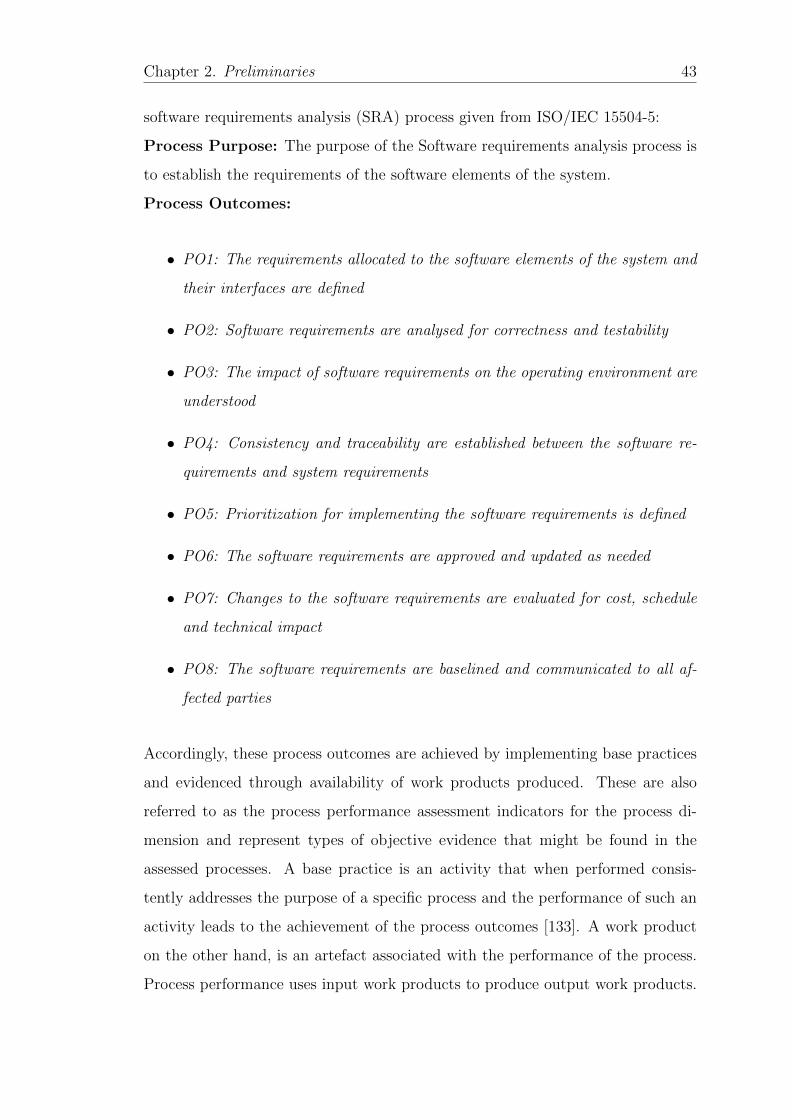
Chapter 2. Preliminaries 43
software requirements analysis (SRA) process given from ISO/IEC 15504-5:
Process Purpose: The purpose of the Software requirements analysis process is
to establish the requirements of the software elements of the system.
Process Outcomes:
• PO1: The requirements allocated to the software elements of the system and
their interfaces are defined
• PO2: Software requirements are analysed for correctness and testability
• PO3: The impact of software requirements on the operating environment are
understood
• PO4: Consistency and traceability are established between the software re-
quirements and system requirements
• PO5: Prioritization for implementing the software requirements is defined
• PO6: The software requirements are approved and updated as needed
• PO7: Changes to the software requirements are evaluated for cost, schedule
and technical impact
• PO8: The software requirements are baselined and communicated to all af-
fected parties
Accordingly, these process outcomes are achieved by implementing base practices
and evidenced through availability of work products produced. These are also
referred to as the process performance assessment indicators for the process di-
mension and represent types of objective evidence that might be found in the
assessed processes. A base practice is an activity that when performed consis-
tently addresses the purpose of a specific process and the performance of such an
activity leads to the achievement of the process outcomes [133]. A work product
on the other hand, is an artefact associated with the performance of the process.
Process performance uses input work products to produce output work products.
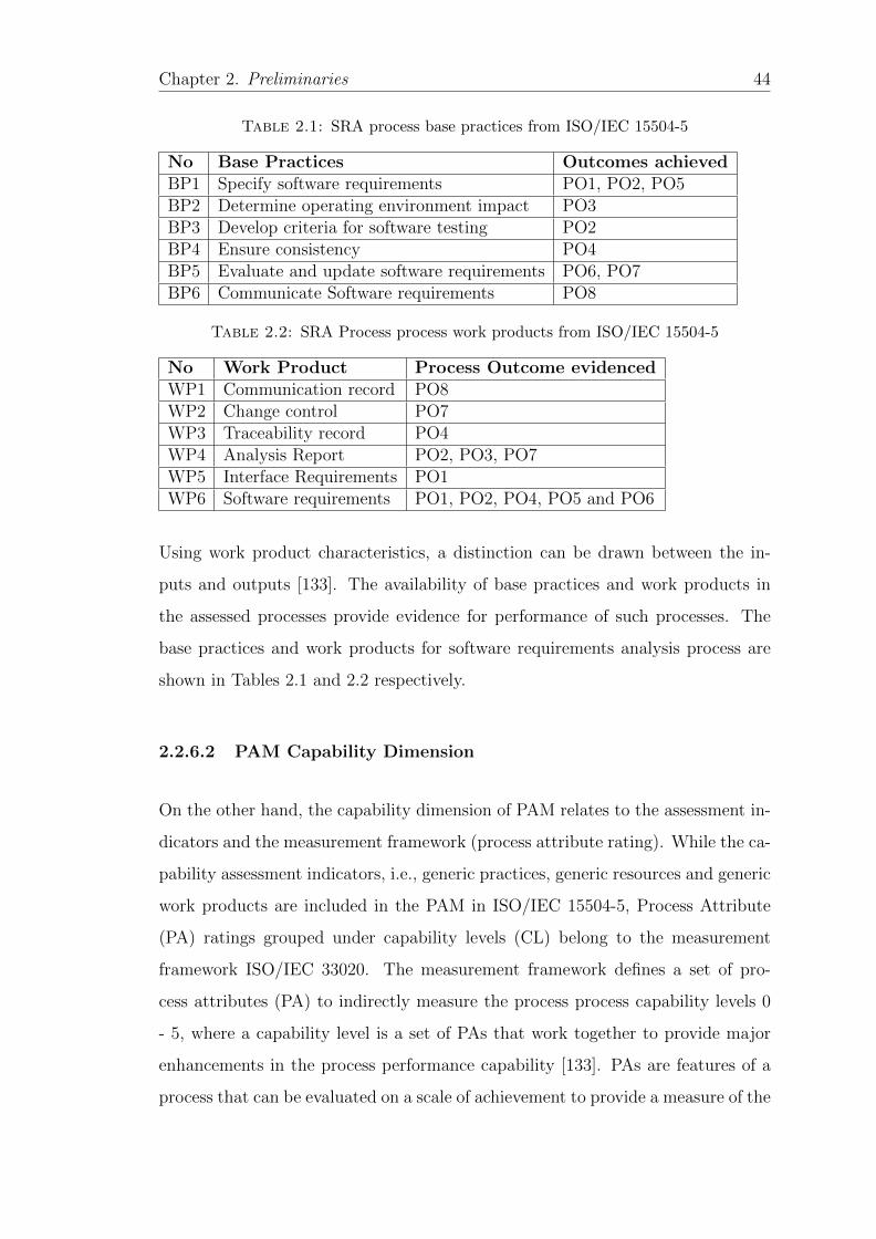
Chapter 2. Preliminaries 44
Table 2.1: SRA process base practices from ISO/IEC 15504-5
No Base Practices Outcomes achievedBP1 Specify software requirements PO1, PO2, PO5BP2 Determine operating environment impact PO3BP3 Develop criteria for software testing PO2BP4 Ensure consistency PO4BP5 Evaluate and update software requirements PO6, PO7BP6 Communicate Software requirements PO8
Table 2.2: SRA Process process work products from ISO/IEC 15504-5
No Work Product Process Outcome evidencedWP1 Communication record PO8WP2 Change control PO7WP3 Traceability record PO4WP4 Analysis Report PO2, PO3, PO7WP5 Interface Requirements PO1WP6 Software requirements PO1, PO2, PO4, PO5 and PO6
Using work product characteristics, a distinction can be drawn between the in-
puts and outputs [133]. The availability of base practices and work products in
the assessed processes provide evidence for performance of such processes. The
base practices and work products for software requirements analysis process are
shown in Tables 2.1 and 2.2 respectively.
2.2.6.2 PAM Capability Dimension
On the other hand, the capability dimension of PAM relates to the assessment in-
dicators and the measurement framework (process attribute rating). While the ca-
pability assessment indicators, i.e., generic practices, generic resources and generic
work products are included in the PAM in ISO/IEC 15504-5, Process Attribute
(PA) ratings grouped under capability levels (CL) belong to the measurement
framework ISO/IEC 33020. The measurement framework defines a set of pro-
cess attributes (PA) to indirectly measure the process process capability levels 0
- 5, where a capability level is a set of PAs that work together to provide major
enhancements in the process performance capability [133]. PAs are features of a
process that can be evaluated on a scale of achievement to provide a measure of the
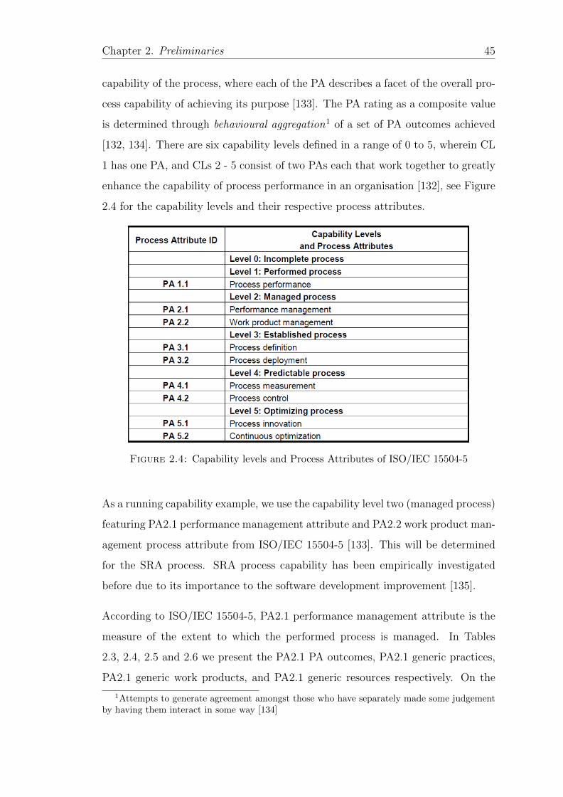
Chapter 2. Preliminaries 45
capability of the process, where each of the PA describes a facet of the overall pro-
cess capability of achieving its purpose [133]. The PA rating as a composite value
is determined through behavioural aggregation1 of a set of PA outcomes achieved
[132, 134]. There are six capability levels defined in a range of 0 to 5, wherein CL
1 has one PA, and CLs 2 - 5 consist of two PAs each that work together to greatly
enhance the capability of process performance in an organisation [132], see Figure
2.4 for the capability levels and their respective process attributes.
Figure 2.4: Capability levels and Process Attributes of ISO/IEC 15504-5
As a running capability example, we use the capability level two (managed process)
featuring PA2.1 performance management attribute and PA2.2 work product man-
agement process attribute from ISO/IEC 15504-5 [133]. This will be determined
for the SRA process. SRA process capability has been empirically investigated
before due to its importance to the software development improvement [135].
According to ISO/IEC 15504-5, PA2.1 performance management attribute is the
measure of the extent to which the performed process is managed. In Tables
2.3, 2.4, 2.5 and 2.6 we present the PA2.1 PA outcomes, PA2.1 generic practices,
PA2.1 generic work products, and PA2.1 generic resources respectively. On the
1Attempts to generate agreement amongst those who have separately made some judgementby having them interact in some way [134]
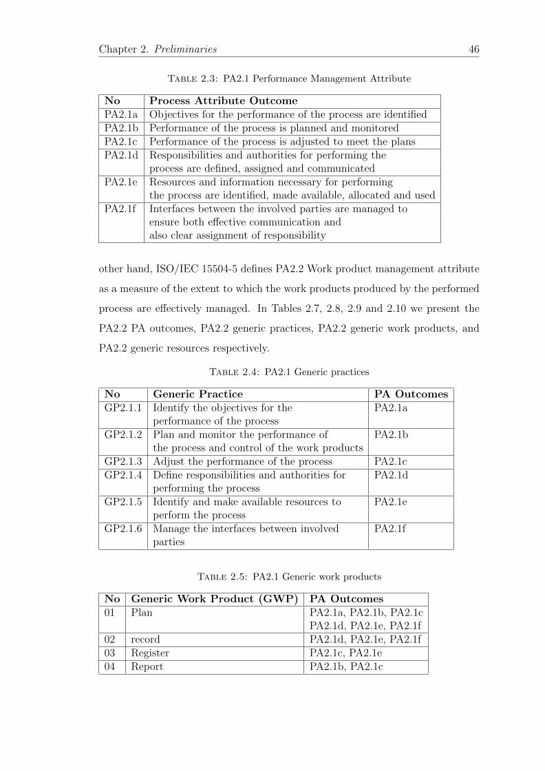
Chapter 2. Preliminaries 46
Table 2.3: PA2.1 Performance Management Attribute
No Process Attribute OutcomePA2.1a Objectives for the performance of the process are identifiedPA2.1b Performance of the process is planned and monitoredPA2.1c Performance of the process is adjusted to meet the plansPA2.1d Responsibilities and authorities for performing the
process are defined, assigned and communicatedPA2.1e Resources and information necessary for performing
the process are identified, made available, allocated and usedPA2.1f Interfaces between the involved parties are managed to
ensure both effective communication andalso clear assignment of responsibility
other hand, ISO/IEC 15504-5 defines PA2.2 Work product management attribute
as a measure of the extent to which the work products produced by the performed
process are effectively managed. In Tables 2.7, 2.8, 2.9 and 2.10 we present the
PA2.2 PA outcomes, PA2.2 generic practices, PA2.2 generic work products, and
PA2.2 generic resources respectively.
Table 2.4: PA2.1 Generic practices
No Generic Practice PA OutcomesGP2.1.1 Identify the objectives for the PA2.1a
performance of the processGP2.1.2 Plan and monitor the performance of PA2.1b
the process and control of the work productsGP2.1.3 Adjust the performance of the process PA2.1cGP2.1.4 Define responsibilities and authorities for PA2.1d
performing the processGP2.1.5 Identify and make available resources to PA2.1e
perform the processGP2.1.6 Manage the interfaces between involved PA2.1f
parties
Table 2.5: PA2.1 Generic work products
No Generic Work Product (GWP) PA Outcomes01 Plan PA2.1a, PA2.1b, PA2.1c
PA2.1d, PA2.1e, PA2.1f02 record PA2.1d, PA2.1e, PA2.1f03 Register PA2.1c, PA2.1e04 Report PA2.1b, PA2.1c
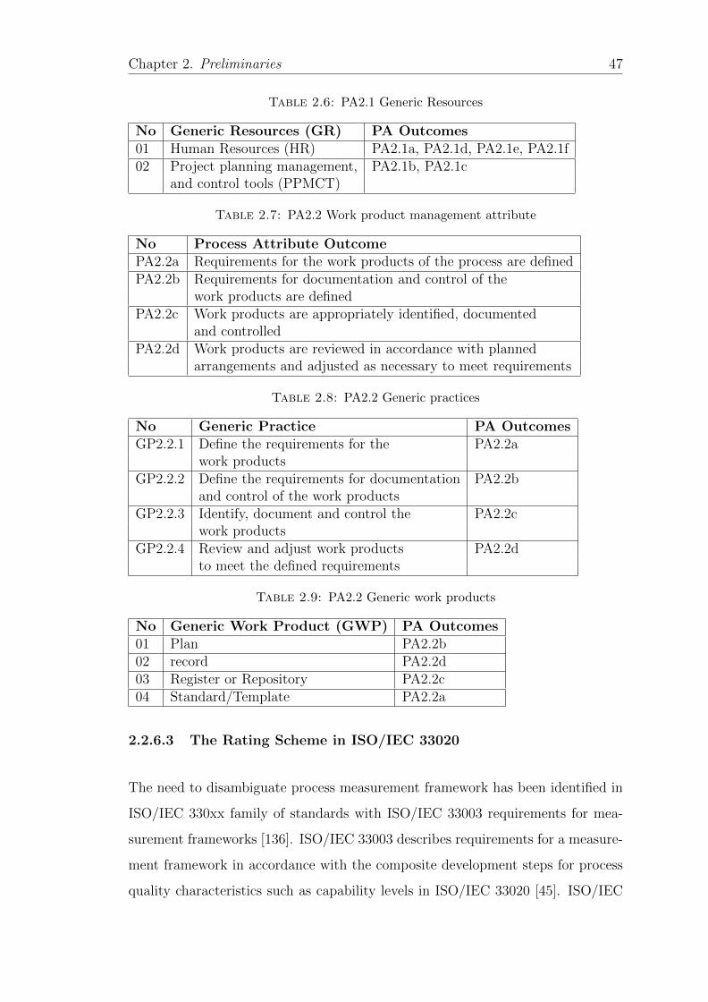
Chapter 2. Preliminaries 47
Table 2.6: PA2.1 Generic Resources
No Generic Resources (GR) PA Outcomes01 Human Resources (HR) PA2.1a, PA2.1d, PA2.1e, PA2.1f02 Project planning management, PA2.1b, PA2.1c
and control tools (PPMCT)
Table 2.7: PA2.2 Work product management attribute
No Process Attribute OutcomePA2.2a Requirements for the work products of the process are definedPA2.2b Requirements for documentation and control of the
work products are definedPA2.2c Work products are appropriately identified, documented
and controlledPA2.2d Work products are reviewed in accordance with planned
arrangements and adjusted as necessary to meet requirements
Table 2.8: PA2.2 Generic practices
No Generic Practice PA OutcomesGP2.2.1 Define the requirements for the PA2.2a
work productsGP2.2.2 Define the requirements for documentation PA2.2b
and control of the work productsGP2.2.3 Identify, document and control the PA2.2c
work productsGP2.2.4 Review and adjust work products PA2.2d
to meet the defined requirements
Table 2.9: PA2.2 Generic work products
No Generic Work Product (GWP) PA Outcomes01 Plan PA2.2b02 record PA2.2d03 Register or Repository PA2.2c04 Standard/Template PA2.2a
2.2.6.3 The Rating Scheme in ISO/IEC 33020
The need to disambiguate process measurement framework has been identified in
ISO/IEC 330xx family of standards with ISO/IEC 33003 requirements for mea-
surement frameworks [136]. ISO/IEC 33003 describes requirements for a measure-
ment framework in accordance with the composite development steps for process
quality characteristics such as capability levels in ISO/IEC 33020 [45]. ISO/IEC

Chapter 2. Preliminaries 48
Table 2.10: PA2.2 Generic Resources
No Generic Resources (GR) PA Outcome achieved01 Requirements management PA2.2a, PA2.2b, PA2.2c
method (RMM)02 Problem and issue management PA2.2d
mechanisms (PMM)
Table 2.11: The rating scale of Process Outcomes/Attributes
Acronym Achievement of the defined Outcome % AchievementNot achieved (N) There is little or no evidence of 0− ≤ 15%
achievement of the defined outcome in theassessed process
Partially achieved (P) There is some evidence of the approach to, > 15%− ≤ 50%and some achievement of, the definedattribute in the assessed process
Largely achieved (L) There is evidence of a systematic approach > 50%− ≤ 85%to, and significant achievement of, the definedoutcomes in the assessed process. Some weaknessrelated to this attribute may existin the assessed process
Fully achieved (F) There is evidence of a complete and > 85%− ≤ 100%systematic approach to, and full achievementof, the defined outcome in the assessed processNo significant weaknesses related to theoutcome exist in the assessed process
33020 defines an ordinal scale for the evaluation of process capability based upon
six defined capability levels. It characterises the extent to which the process (at-
tribute) outcomes are achieved, see Table 2.11 for details.
However, ISO/IEC 33020, doesn’t provide a method on characterising the extent to
which process outcomes are achieved [132]. There are various methods suggested
in literature [132] for aggregating process level outcomes through the formative
measurement model as shown in Figure 2.5 where aggregation propagates from
the lowest class upto the most abstract class.
Figure 2.5: Formative model for capability level rating (Jung et al., 2013)
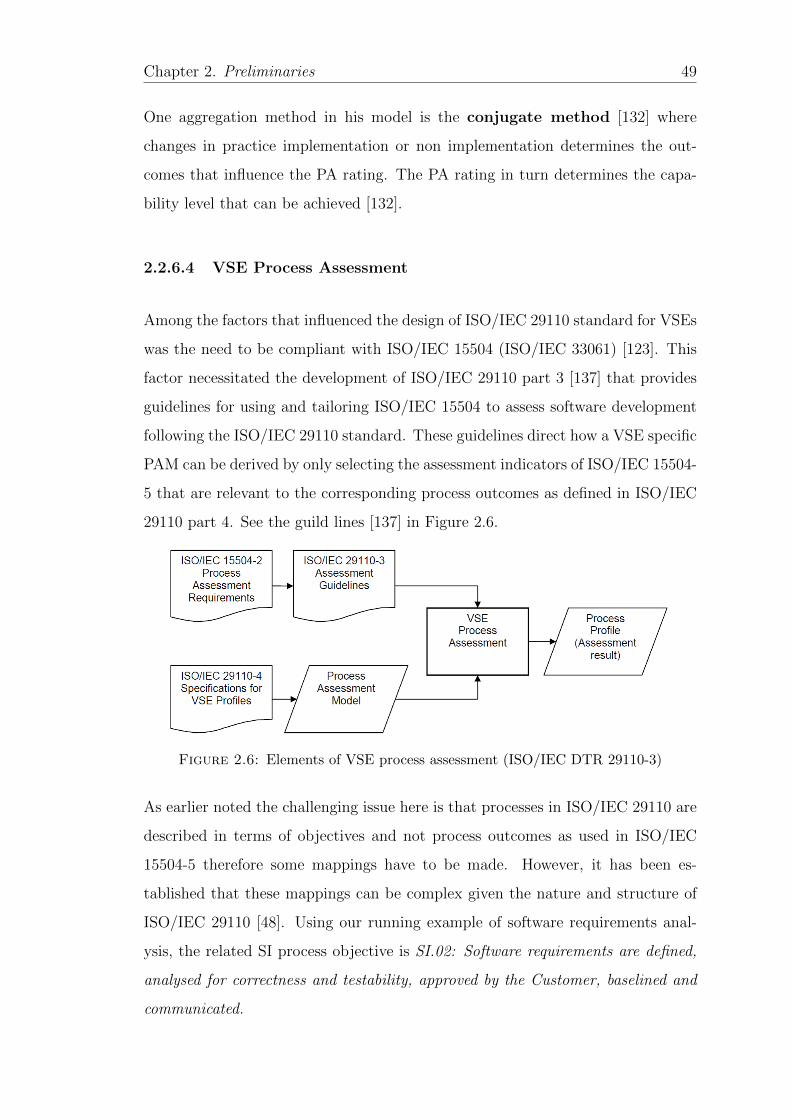
Chapter 2. Preliminaries 49
One aggregation method in his model is the conjugate method [132] where
changes in practice implementation or non implementation determines the out-
comes that influence the PA rating. The PA rating in turn determines the capa-
bility level that can be achieved [132].
2.2.6.4 VSE Process Assessment
Among the factors that influenced the design of ISO/IEC 29110 standard for VSEs
was the need to be compliant with ISO/IEC 15504 (ISO/IEC 33061) [123]. This
factor necessitated the development of ISO/IEC 29110 part 3 [137] that provides
guidelines for using and tailoring ISO/IEC 15504 to assess software development
following the ISO/IEC 29110 standard. These guidelines direct how a VSE specific
PAM can be derived by only selecting the assessment indicators of ISO/IEC 15504-
5 that are relevant to the corresponding process outcomes as defined in ISO/IEC
29110 part 4. See the guild lines [137] in Figure 2.6.
Figure 2.6: Elements of VSE process assessment (ISO/IEC DTR 29110-3)
As earlier noted the challenging issue here is that processes in ISO/IEC 29110 are
described in terms of objectives and not process outcomes as used in ISO/IEC
15504-5 therefore some mappings have to be made. However, it has been es-
tablished that these mappings can be complex given the nature and structure of
ISO/IEC 29110 [48]. Using our running example of software requirements anal-
ysis, the related SI process objective is SI.02: Software requirements are defined,
analysed for correctness and testability, approved by the Customer, baselined and
communicated.
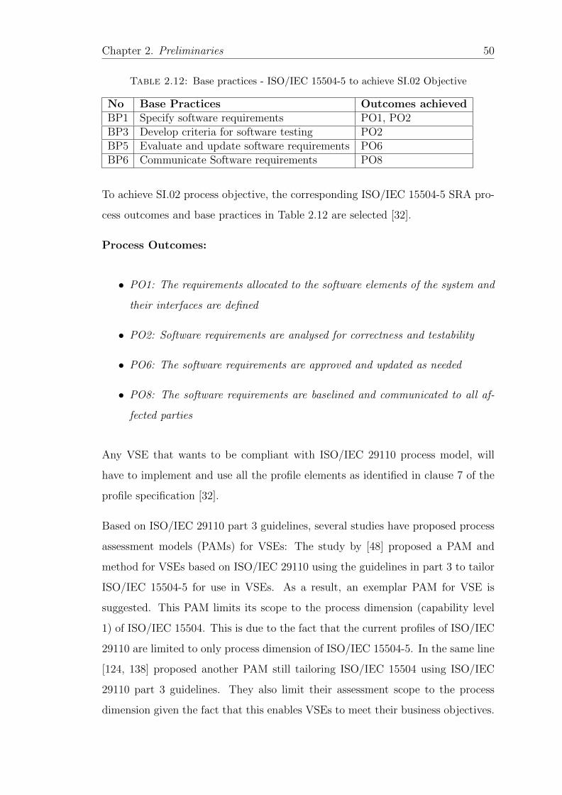
Chapter 2. Preliminaries 50
Table 2.12: Base practices - ISO/IEC 15504-5 to achieve SI.02 Objective
No Base Practices Outcomes achievedBP1 Specify software requirements PO1, PO2BP3 Develop criteria for software testing PO2BP5 Evaluate and update software requirements PO6BP6 Communicate Software requirements PO8
To achieve SI.02 process objective, the corresponding ISO/IEC 15504-5 SRA pro-
cess outcomes and base practices in Table 2.12 are selected [32].
Process Outcomes:
• PO1: The requirements allocated to the software elements of the system and
their interfaces are defined
• PO2: Software requirements are analysed for correctness and testability
• PO6: The software requirements are approved and updated as needed
• PO8: The software requirements are baselined and communicated to all af-
fected parties
Any VSE that wants to be compliant with ISO/IEC 29110 process model, will
have to implement and use all the profile elements as identified in clause 7 of the
profile specification [32].
Based on ISO/IEC 29110 part 3 guidelines, several studies have proposed process
assessment models (PAMs) for VSEs: The study by [48] proposed a PAM and
method for VSEs based on ISO/IEC 29110 using the guidelines in part 3 to tailor
ISO/IEC 15504-5 for use in VSEs. As a result, an exemplar PAM for VSE is
suggested. This PAM limits its scope to the process dimension (capability level
1) of ISO/IEC 15504. This is due to the fact that the current profiles of ISO/IEC
29110 are limited to only process dimension of ISO/IEC 15504-5. In the same line
[124, 138] proposed another PAM still tailoring ISO/IEC 15504 using ISO/IEC
29110 part 3 guidelines. They also limit their assessment scope to the process
dimension given the fact that this enables VSEs to meet their business objectives.
Chapter 2. Preliminaries 51
For the higher capability levels, they substitute them with human resource com-
petency [138]. They build their PAM based on work products and base practices
identified from DPs2.
Even though ISO/IEC 15504 provides clear guidelines and process for process as-
sessment, for effective process assessment to take place, there is a need to maintain
clear mappings between the PRM processes and the organisational processes as
well as process attributes in the measurement framework [46, 50]. However, the
assessment process is currently made cumbersome where all the process models
are described in natural language and computers can’t be used to verify such
processes [51, 139]. It therefore becomes necessary to explore ways of increasing
the process assessment rigour and enable at least semi automation for some func-
tions within the process assessment process such as determining PA rating and
capability determination [46, 51].
2.3 Process metamodeling
While metamodels were originally used to formulate modelling languages such as
UML, they have also been used to provide a conceptual foundation for process
modelling [140]. Metamodels have been proposed as a way of increasing process
modelling rigour and formality for automation [140]. These metamodels lay a
foundation in terms of concepts, rules and conceptual relationships among concepts
used in process modelling [141]. So processes grounded in metamodels offer a
higher degree of formalisation and better support for consistent extensions and
modification [140]. Moreover, they impose well formedness rules on process models
and process instances instantiated from them. These help in maintaining process
consistency and completeness [56].
2http://profs.etsmtl.ca/claporte/english/vse/vse-packages.html
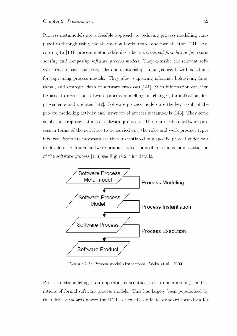
Chapter 2. Preliminaries 52
Process metamodels are a feasible approach to reducing process modelling com-
plexities through rising the abstraction levels, reuse, and formalisation [141]. Ac-
cording to [104] process metamodels describe a conceptual foundation for repre-
senting and composing software process models. They describe the relevant soft-
ware process basic concepts, rules and relationships among concepts with notations
for expressing process models. They allow capturing informal, behaviour, func-
tional, and strategic views of software processes [141]. Such information can then
be used to reason on software process modelling for changes, formalisation, im-
provements and updates [142]. Software process models are the key result of the
process modelling activity and instances of process metamodels [143]. They serve
as abstract representations of software processes. These prescribe a software pro-
cess in terms of the activities to be carried out, the roles and work product types
involved. Software processes are then instantiated in a specific project endeavour
to develop the desired software product, which in itself is seen as an instantiation
of the software process [143] see Figure 2.7 for details.
Figure 2.7: Process model abstractions (Weiss et al., 2009)
Process metamodeling is an important conceptual tool in underpinning the defi-
nitions of formal software process models. This has largely been popularised by
the OMG standards where the UML is now the de facto standard formalism for
Chapter 2. Preliminaries 53
software modelling. The modelling layers in UML metamodel are defined based
on a strict metamodeling architecture that only allows instanceOf relations be-
tween adjacent layers, i.e., variables defined at level Mn can only be realised at
Mn−1. This is termed as shallow instantiation where attributes and constraints
are defined at the class level and only realised at the instance level [144]. One ma-
jor process metamodel based on the OMG modelling architecture is the Software
Process Engineering Metamodel (SPEM) [145].
2.3.1 Software Process Engineering Metamodel (SPEM)
SPEM 2.0 [145] provides a metamodel to design software processes by providing
building blocks needed to represent in a standard way process models, life cycles,
roles, activities, tasks and work products used in software engineering [146]. Us-
ing SPEM for process definition enables to utilise the model driven architecture
(MDA) facilities in process modelling, where MDA promotes the definition and
use of systematic models at different levels of abstraction [146]. SPEM 2.0 is de-
fined at the meta object facility (MOF) 2 model and reuses some key classes from
the UML 2 infrastructure. The MOF specification defines a modelling architec-
ture based on 4 layers through strict instantiation relationship. See Figure 2.8 for
details where SPEM 2 is defined at M2 of MOF abstraction architecture [86].
The SPEM specification defines largely two major types of concepts: (i) The
method concept that is used to define basic elements such as roles, tasks and work
products, and (ii) the process concept to build on the previously method content in
a dynamic structure. This kind of separation enables reusability of processes and
their adaptation to different software process life cycles through the extensibility
mechanism called the method-plugin [145]. These main concepts are organised and
detailed in seven packages. Any organisation intending to use SPEM for process
definition may choose to use some packages according to their needs given the fact
that SPEM is a general process metamodel that can be used for process tailoring
[146]. SPEM as a general process metamodel has been a subject of different
applications and extensions in software process management. For instance SPEM
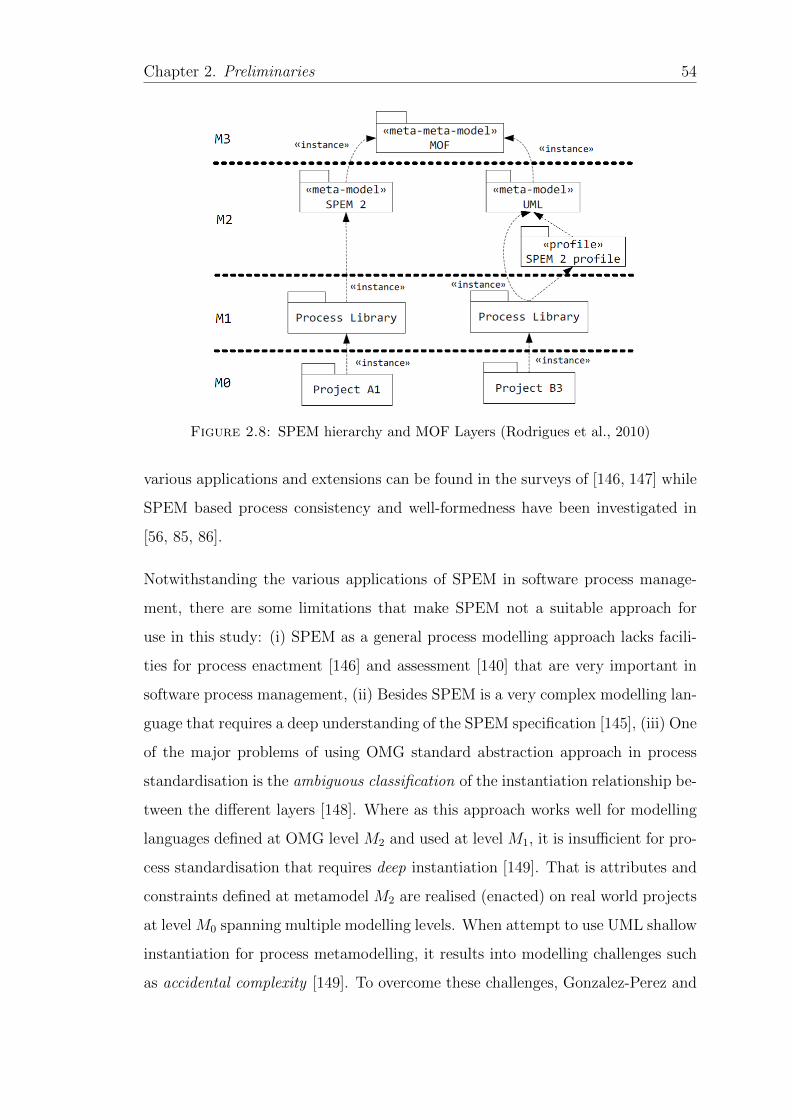
Chapter 2. Preliminaries 54
Figure 2.8: SPEM hierarchy and MOF Layers (Rodrigues et al., 2010)
various applications and extensions can be found in the surveys of [146, 147] while
SPEM based process consistency and well-formedness have been investigated in
[56, 85, 86].
Notwithstanding the various applications of SPEM in software process manage-
ment, there are some limitations that make SPEM not a suitable approach for
use in this study: (i) SPEM as a general process modelling approach lacks facili-
ties for process enactment [146] and assessment [140] that are very important in
software process management, (ii) Besides SPEM is a very complex modelling lan-
guage that requires a deep understanding of the SPEM specification [145], (iii) One
of the major problems of using OMG standard abstraction approach in process
standardisation is the ambiguous classification of the instantiation relationship be-
tween the different layers [148]. Where as this approach works well for modelling
languages defined at OMG level M2 and used at level M1, it is insufficient for pro-
cess standardisation that requires deep instantiation [149]. That is attributes and
constraints defined at metamodel M2 are realised (enacted) on real world projects
at level M0 spanning multiple modelling levels. When attempt to use UML shallow
instantiation for process metamodelling, it results into modelling challenges such
as accidental complexity [149]. To overcome these challenges, Gonzalez-Perez and
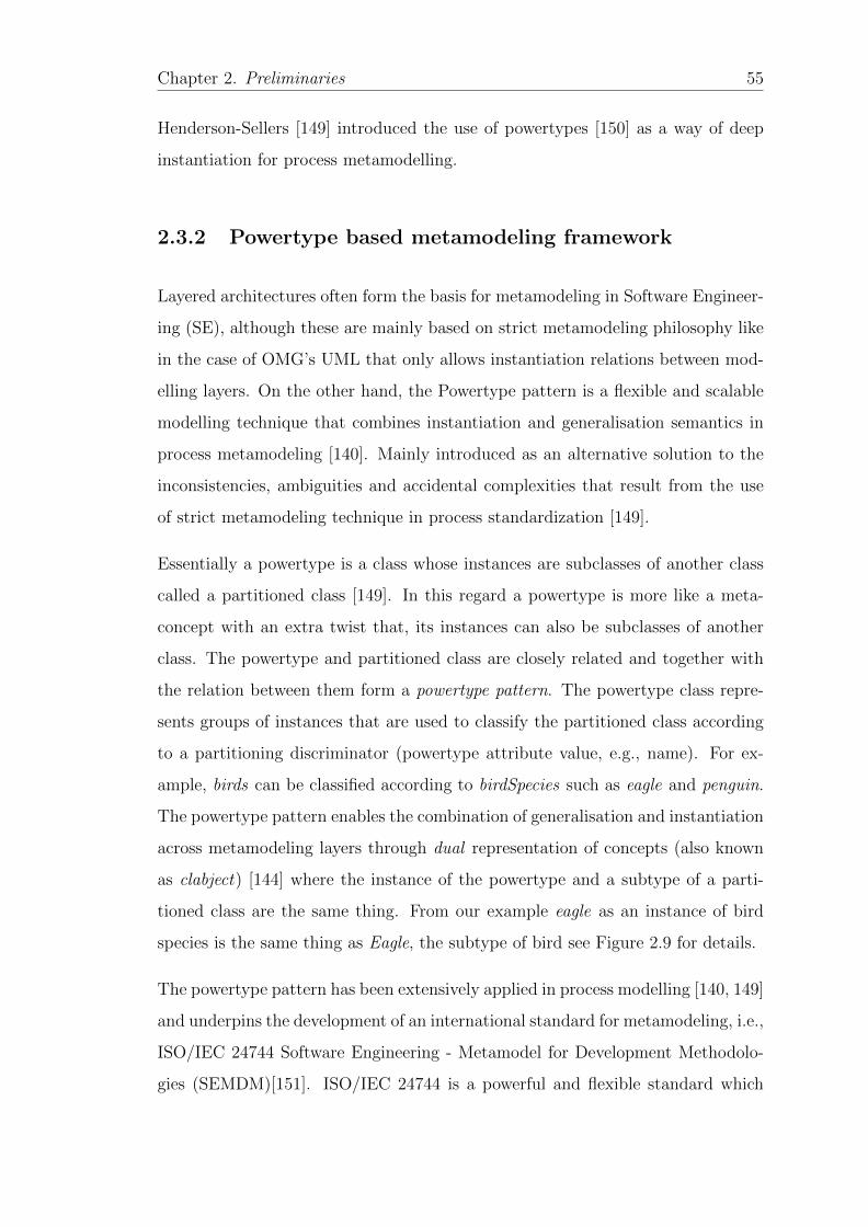
Chapter 2. Preliminaries 55
Henderson-Sellers [149] introduced the use of powertypes [150] as a way of deep
instantiation for process metamodelling.
2.3.2 Powertype based metamodeling framework
Layered architectures often form the basis for metamodeling in Software Engineer-
ing (SE), although these are mainly based on strict metamodeling philosophy like
in the case of OMG’s UML that only allows instantiation relations between mod-
elling layers. On the other hand, the Powertype pattern is a flexible and scalable
modelling technique that combines instantiation and generalisation semantics in
process metamodeling [140]. Mainly introduced as an alternative solution to the
inconsistencies, ambiguities and accidental complexities that result from the use
of strict metamodeling technique in process standardization [149].
Essentially a powertype is a class whose instances are subclasses of another class
called a partitioned class [149]. In this regard a powertype is more like a meta-
concept with an extra twist that, its instances can also be subclasses of another
class. The powertype and partitioned class are closely related and together with
the relation between them form a powertype pattern. The powertype class repre-
sents groups of instances that are used to classify the partitioned class according
to a partitioning discriminator (powertype attribute value, e.g., name). For ex-
ample, birds can be classified according to birdSpecies such as eagle and penguin.
The powertype pattern enables the combination of generalisation and instantiation
across metamodeling layers through dual representation of concepts (also known
as clabject) [144] where the instance of the powertype and a subtype of a parti-
tioned class are the same thing. From our example eagle as an instance of bird
species is the same thing as Eagle, the subtype of bird see Figure 2.9 for details.
The powertype pattern has been extensively applied in process modelling [140, 149]
and underpins the development of an international standard for metamodeling, i.e.,
ISO/IEC 24744 Software Engineering - Metamodel for Development Methodolo-
gies (SEMDM)[151]. ISO/IEC 24744 is a powerful and flexible standard which
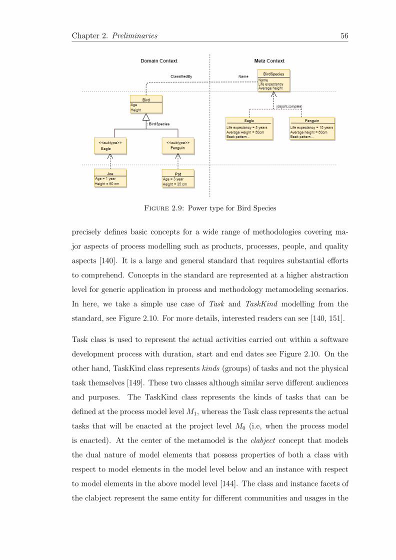
Chapter 2. Preliminaries 56
Figure 2.9: Power type for Bird Species
precisely defines basic concepts for a wide range of methodologies covering ma-
jor aspects of process modelling such as products, processes, people, and quality
aspects [140]. It is a large and general standard that requires substantial efforts
to comprehend. Concepts in the standard are represented at a higher abstraction
level for generic application in process and methodology metamodeling scenarios.
In here, we take a simple use case of Task and TaskKind modelling from the
standard, see Figure 2.10. For more details, interested readers can see [140, 151].
Task class is used to represent the actual activities carried out within a software
development process with duration, start and end dates see Figure 2.10. On the
other hand, TaskKind class represents kinds (groups) of tasks and not the physical
task themselves [149]. These two classes although similar serve different audiences
and purposes. The TaskKind class represents the kinds of tasks that can be
defined at the process model level M1, whereas the Task class represents the actual
tasks that will be enacted at the project level M0 (i.e, when the process model
is enacted). At the center of the metamodel is the clabject concept that models
the dual nature of model elements that possess properties of both a class with
respect to model elements in the model level below and an instance with respect
to model elements in the above model level [144]. The class and instance facets of
the clabject represent the same entity for different communities and usages in the
Chapter 2. Preliminaries 57
Figure 2.10: Task powertype adapted from (Henderson et al., 2005)
software development process. For example, The class facet of the clabject, e.g
ValidateRequirementsTask is a subtype of Task class in the powertype pattern and
is useful for the software developer to instantiate instance level objects from, while
the instance facet, e.g validateRequirementsTask is an instance of the Taskkind
class and is useful for the process engineer [149]. Process engineers deal with
process templates at the model layer M1 and therefore interested in properties and
features of groups of tasks that can be later instantiated at the project level such
as the minimal capability levels of a group of tasks. While in strict metamodeling
a metamodel can’t exert control on how the instance layer M0 will be organised,
powertype based metamodeling approach on the other hand, models the dual
representation where process model M1 layer entities and instance M0 layer entities
are defined in the metamodel layer [149]. Attributes of these two modelling layers
can be defined in the Metamodel layer and transmitted down the specialisation
and instantiation hierarchies, thus achieving a greater control over both class and
instance layers [149]. The powertype pattern can also be extended through adding
Chapter 2. Preliminaries 58
attributes at the process model level (See, e.g., NeedsSignOff attribute at the
model layer in Figure 2.10, this kind of scalability and flexibility scenario may not
be possible in other modelling approaches where the attribute values are frozen at
the metamodel for once during the metamodel construction [149].
SEMDM supports the actual enactment of the process through its endeavour layer
and as such, can be used for process performance or compliance checking [79].
Therefore, in this study we utilise it to underpin modelling and tailoring of software
process formalisation to specific software project contexts through the developed
metamodel. However, metamodels only deal with the syntactical structures but
not the formal semantics of process models and therefore, the need to ground the
metamodels in an ontology [152].
2.3.3 Summary
In this subsection, we have presented the need for process metamodels in process
modelling as well as the major available metamodels for process meatmodeling.
While SPEM is a popular metamodel for process modelling and backed up by the
use of UML as a modelling language, it was established that SPEM suffers from
the ambiguous classification problem that affects most of the modelling languages
that use MOF strict metamodeling. Moreover it has also been established that
SPEM doesn’t support process enactment and assessment, two important concepts
in software process management. On the other hand, powertype based metamod-
eling as implemented in ISO/IEC 24744 standard, is the only metamodeling tech-
nique that supports process enactment and process capability level determination
[140]. Powertypes also support dynamic and flexible process modelling that com-
bines instantiation and generalisation simultaneously enabling process tailoring
and adaptability. It is these features that have motivated us to use powertypes
as an underlying conceptual foundation for the metamodel we develop in Chapter
5 to provide uniform concepts that underpin the software process formalisation
approach detailed in Chapter 6.

Chapter 2. Preliminaries 59
2.4 Behavior Engineering
Behavior Engineering (BE) [153] is a general high level and integrated formal
graphical approach that supports the engineering of large scale and dependable
software intensive systems. BE uses a formally grounded graphical notation with a
capacity to model a wide range of system behaviours in an unambiguous ways [39].
Originally founded as genetic software engineering in 2001 [154], BE notation has
gone through evolutions and refinements to its current state. For example in [142]
it was extended with a metamodel for further understanding and clarity especially
to the object oriented community. Its formal semantics have been defined in [155].
While in [156] non monotonic reasoning was incorporated in BE notation. In [157]
it was incorporated with semantic networks to support interactive requirements
engineering process. To enhance its reliability, performance and other dependabil-
ity properties it has been extended with probabilistic theory [158]. BE notation is
well documented, explained and discussed in different formulas, with supporting
tools and industry successful case studies3.
2.4.1 Behavior Engineering Philosophy
Despite the advances made in SE since 1968, software complexity, deficient require-
ments and a need to satisfy a set of requirements by the developed software still
threaten software quality [153, 154]. This situation is exacerbated by conventional
SE methods that try to build software systems that should satisfy their require-
ments. Such SE methods are not only complicated but also fail to consistently
deliver quality software within schedule and budget [154].
On the other hand, BE provides an alternative strategy to overcome software com-
plexity and deficient requirements by building a system out of its requirements
[153, 154]. This is made possible through a rigorous translation of functional re-
quirements expressed in natural language (NL) one at a time to a formal model,
3http://www.beworld.org/BE/

Chapter 2. Preliminaries 60
thereby breaking up the complex tasks into their respective functional require-
ments. During functional requirements translations, requirements defects, incom-
pleteness and missing requirements are identified and discussed, and resolved with
the client [154]. The translated functional requirements into individual Behavior
Figure 2.11: Behavior Engineering Approach to Complexity (Dromey, 2003)
Trees (BTs) are then integrated into a Design Behavior Tree (DBT) that pro-
vides an integrated view of the requirements where the Composition Trees (CTs)
indicate the static components and their attributes.
The BE process starts with functional requirements expressed in NL are rigorous
translated one at a time to a behavior tree [154]. Each requirement is first trans-
lated to an individual behavior tree by identifying the components and behaviors
described in natural language. In the next step all the individual behavior trees are
integrated into the integrated behavior tree (IBT) which can later be transformed
into the design bahevior tree (DBT). During the integration of the behavior trees,
precondition and interaction axioms are utilised. In practise however, the integra-
tion can simply be done through locating a root node of one the behavior tree that
occurs in another behavior tree and the integration can be done through such a
node [154]. The design behavior tree can also be translated to other analysis tools
for further verification such as simulation, model checking [159] and description
logic for reasoning [94]. Following this process, BE provides a clear, simple and
systematic path from a set of functional requirements in natural language to a
design that will satisfy those requirements [154] as summarised by [159] in Figure
2.12.
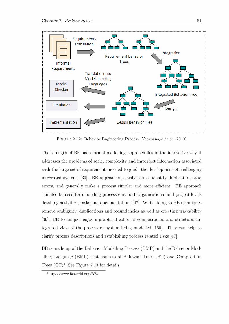
Chapter 2. Preliminaries 61
Figure 2.12: Behavior Engineering Process (Yatapanage et al., 2010)
The strength of BE, as a formal modelling approach lies in the innovative way it
addresses the problems of scale, complexity and imperfect information associated
with the large set of requirements needed to guide the development of challenging
integrated systems [39]. BE approaches clarify terms, identify duplications and
errors, and generally make a process simpler and more efficient. BE approach
can also be used for modelling processes at both organisational and project levels
detailing activities, tasks and documentations [47]. While doing so BE techniques
remove ambiguity, duplications and redundancies as well as effecting traceability
[39]. BE techniques enjoy a graphical coherent compositional and structural in-
tegrated view of the process or system being modelled [160]. They can help to
clarify process descriptions and establishing process related risks [47].
BE is made up of the Bahavior Modelling Process (BMP) and the Behavior Mod-
elling Language (BML) that consists of Bahavior Trees (BT) and Composition
Trees (CT)4. See Figure 2.13 for details.
4http://www.beworld.org/BE/
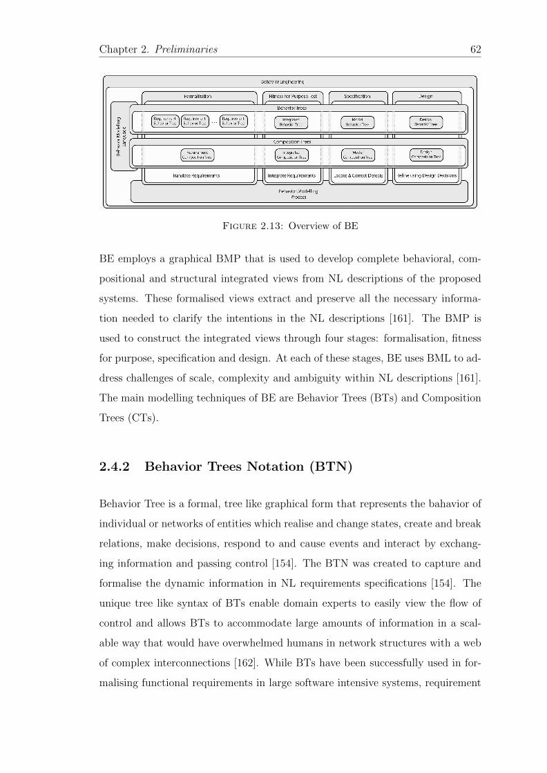
Chapter 2. Preliminaries 62
Figure 2.13: Overview of BE
BE employs a graphical BMP that is used to develop complete behavioral, com-
positional and structural integrated views from NL descriptions of the proposed
systems. These formalised views extract and preserve all the necessary informa-
tion needed to clarify the intentions in the NL descriptions [161]. The BMP is
used to construct the integrated views through four stages: formalisation, fitness
for purpose, specification and design. At each of these stages, BE uses BML to ad-
dress challenges of scale, complexity and ambiguity within NL descriptions [161].
The main modelling techniques of BE are Behavior Trees (BTs) and Composition
Trees (CTs).
2.4.2 Behavior Trees Notation (BTN)
Behavior Tree is a formal, tree like graphical form that represents the bahavior of
individual or networks of entities which realise and change states, create and break
relations, make decisions, respond to and cause events and interact by exchang-
ing information and passing control [154]. The BTN was created to capture and
formalise the dynamic information in NL requirements specifications [154]. The
unique tree like syntax of BTs enable domain experts to easily view the flow of
control and allows BTs to accommodate large amounts of information in a scal-
able way that would have overwhelmed humans in network structures with a web
of complex interconnections [162]. While BTs have been successfully used in for-
malising functional requirements in large software intensive systems, requirement
Chapter 2. Preliminaries 63
specifications are not the only artefacts in software engineering that needs to be
unambiguous, defect free and precise. Software processes and process models too,
need to be unambiguous and precise. Indeed BTs have been used to verify soft-
ware process reference models. For example, OOSPICE and CMMI were verified
using BTs and many defects were identified and corrected [47] as well as verifying
a leadership process model [163].
2.4.3 Composition Trees Notation (CTN)
Composition Tree approach is a formal graphical notation originally for modelling
component based systems [160], CTs similar to UML class diagrams, model static
system aspects in terms of entities, relationships, attributes and component states
[39]. CT just like BT is constructed through a careful step wise approach and
later integrated into one complete tree like graphical model. Individual CTs are
later integrated into an Integrated Composition Tree (ICT) more like a UML
class diagram to encapsulate a structured view of the complete system vocabulary.
BE in general and CT in particular has proven to be successfully in modelling,
analysing and comparing software processes [39, 47, 122, 164], verifying processes
[165] and, process management and assessment in the cloud [161]. CT technique
has also been found to be very useful in comparing and contrasting software process
models [166].
Compared to other modelling notations like UML with teens of diagrams to con-
tend with, the created CT models are more intuitive, less ambiguous and easier
to read and verify than the original natural language processes [39]. The CT
flowchart-styled graphic notation, a soft and casual modelling can easily be un-
derstood by non-experts. The notation has been found to be easier to trace back
and preserve the intentions of the natural language processes than other modelling
notations [39].
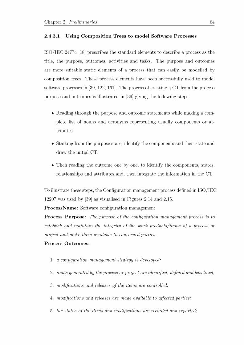
Chapter 2. Preliminaries 64
2.4.3.1 Using Composition Trees to model Software Processes
ISO/IEC 24774 [18] prescribes the standard elements to describe a process as the
title, the purpose, outcomes, activities and tasks. The purpose and outcomes
are more suitable static elements of a process that can easily be modelled by
composition trees. These process elements have been successfully used to model
software processes in [39, 122, 161]. The process of creating a CT from the process
purpose and outcomes is illustrated in [39] giving the following steps;
• Reading through the purpose and outcome statements while making a com-
plete list of nouns and acronyms representing usually components or at-
tributes.
• Starting from the purpose state, identify the components and their state and
draw the initial CT.
• Then reading the outcome one by one, to identify the components, states,
relationships and attributes and, then integrate the information in the CT.
To illustrate these steps, the Configuration management process defined in ISO/IEC
12207 was used by [39] as visualised in Figures 2.14 and 2.15.
ProcessName: Software configuration management
Process Purpose: The purpose of the configuration management process is to
establish and maintain the integrity of the work products/items of a process or
project and make them available to concerned parties.
Process Outcomes:
1. a configuration management strategy is developed;
2. items generated by the process or project are identified, defined and baselined;
3. modifications and releases of the items are controlled;
4. modifications and releases are made available to affected parties;
5. the status of the items and modifications are recorded and reported;
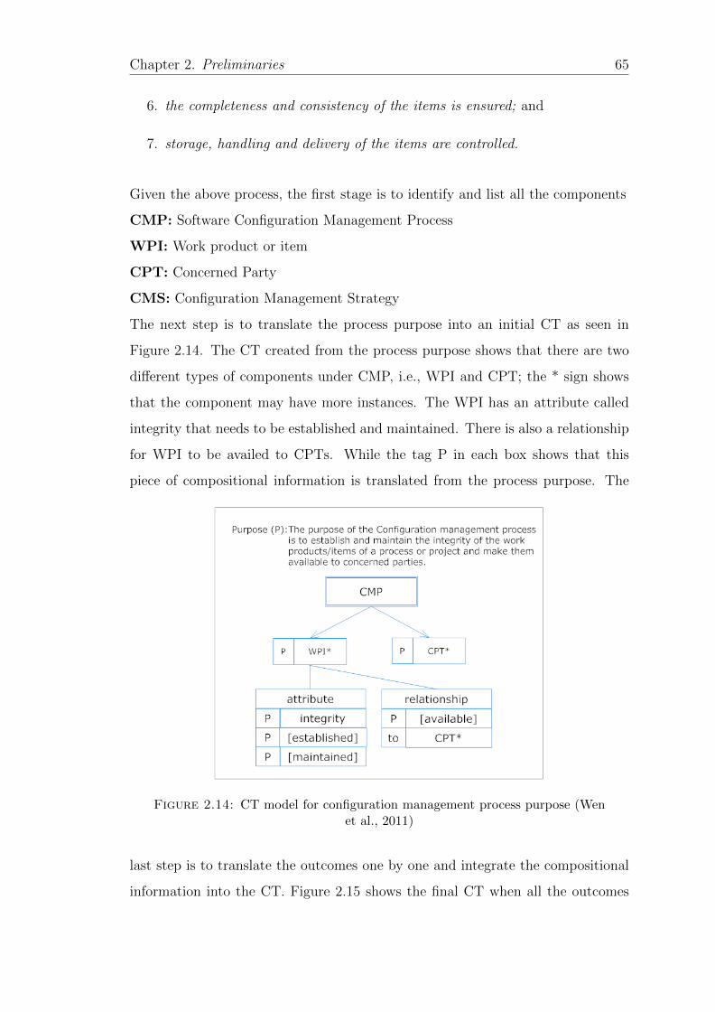
Chapter 2. Preliminaries 65
6. the completeness and consistency of the items is ensured; and
7. storage, handling and delivery of the items are controlled.
Given the above process, the first stage is to identify and list all the components
CMP: Software Configuration Management Process
WPI: Work product or item
CPT: Concerned Party
CMS: Configuration Management Strategy
The next step is to translate the process purpose into an initial CT as seen in
Figure 2.14. The CT created from the process purpose shows that there are two
different types of components under CMP, i.e., WPI and CPT; the * sign shows
that the component may have more instances. The WPI has an attribute called
integrity that needs to be established and maintained. There is also a relationship
for WPI to be availed to CPTs. While the tag P in each box shows that this
piece of compositional information is translated from the process purpose. The
Figure 2.14: CT model for configuration management process purpose (Wenet al., 2011)
last step is to translate the outcomes one by one and integrate the compositional
information into the CT. Figure 2.15 shows the final CT when all the outcomes
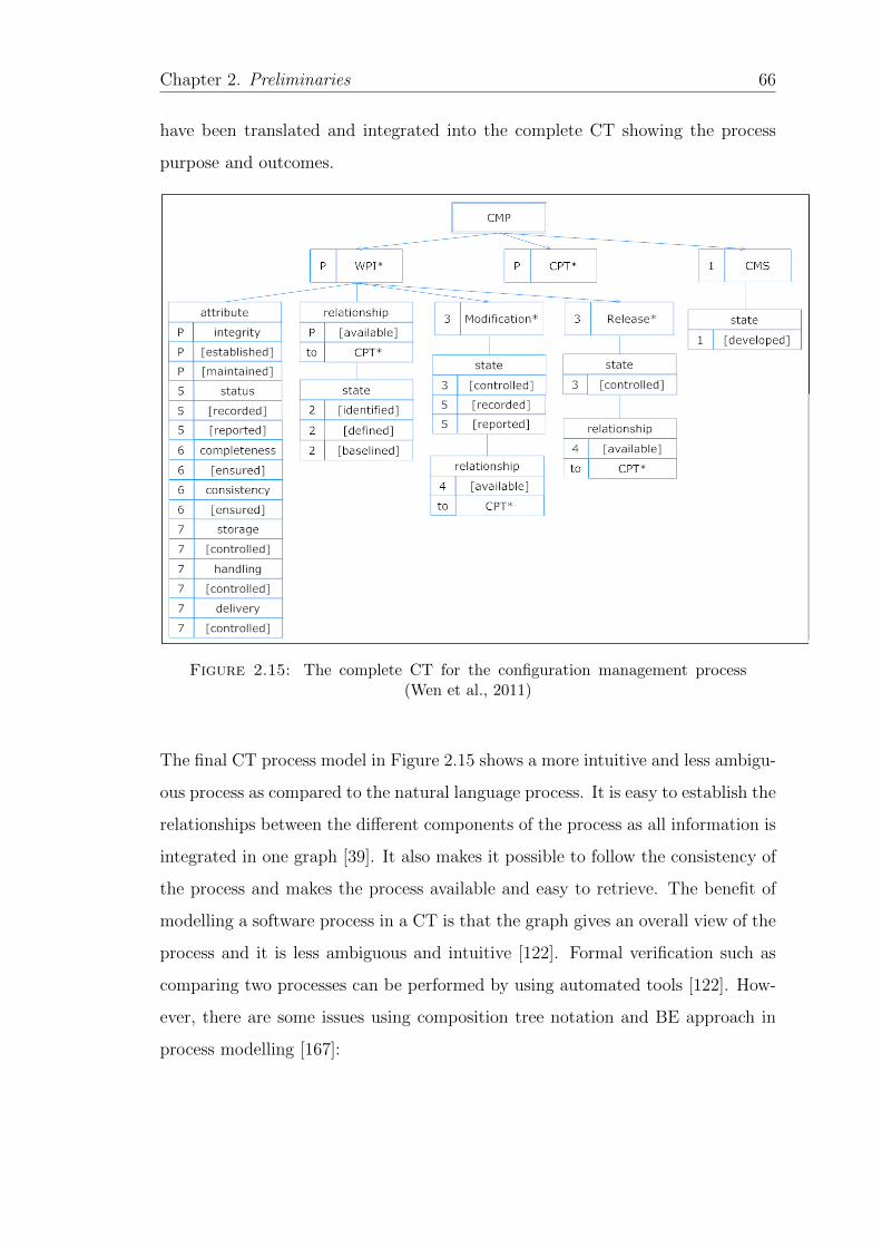
Chapter 2. Preliminaries 66
have been translated and integrated into the complete CT showing the process
purpose and outcomes.
Figure 2.15: The complete CT for the configuration management process(Wen et al., 2011)
The final CT process model in Figure 2.15 shows a more intuitive and less ambigu-
ous process as compared to the natural language process. It is easy to establish the
relationships between the different components of the process as all information is
integrated in one graph [39]. It also makes it possible to follow the consistency of
the process and makes the process available and easy to retrieve. The benefit of
modelling a software process in a CT is that the graph gives an overall view of the
process and it is less ambiguous and intuitive [122]. Formal verification such as
comparing two processes can be performed by using automated tools [122]. How-
ever, there are some issues using composition tree notation and BE approach in
process modelling [167]:

Chapter 2. Preliminaries 67
• Reasoning of processes modelled in CT is not possible because they are no
mature reasoning tools for CT models currently. A major drawback of for-
mal non logical formalism like CT is the lack of standard representation and
formats as well as mature reasoning systems to aid in automated process
analysis [94]. Available DL reasoners can be considered as domain indepen-
dent problem solving engines that can be used in an arbitrary application
domain provided the domain knowledge is coded in OWL DL. Therefore
to utilise DL reasoning services we need to translate the domain specific
problem solving process to a format supported by DL reasoners [168].
• Currently there is need for a human expert to use the CT modelling guide-
lines during process modelling and derive the CT process model manually.
Therefore, for large-scale processes, deriving process models is a time con-
suming, laborious and error-prone manual process. Although some tools
[169] have been developed to aid in this process, they only support Behavior
Trees design.
• The modelling language CT itself is an informal graphical model. Therefore,
there is no formal connection between the CT notational symbols used in
modelling and their formal meaning. The relationship that exists between
the CT nodes is only defined as syntactic matching between nodes. Osterweil
in [7] alludes to the fact that most graphical modelling notations are based on
shallow semantics and therefore they should not be relied up for meaningful
reasoning, BE notations are not any different in this case.
• Integration and comparison of CT models is performed manually [39, 122]
and therefore can be erroneous and time consuming for comparing large
software process models.
• CT models can grow big and this presents a problem to software engineers
to analyse and verify such process models due to human memory lapse and
state explosion [159].
Chapter 2. Preliminaries 68
• The language for logic tests is limited subsequently no reasoners currently
can be used to automatically verify and reason the consistency and complete-
ness of software process models produced. Query answering for information
retrieval is out of question with the current CT models.
We believe the simple created CT models can easily be translated to DL and rea-
soned on using DL reasoners for consistence, completeness and conformance. Next,
we review ontologies and DL as a formal notation for software process modelling.
2.5 Ontologies
An ontology in computer science is defined as an explicit, formal specification of
a shared conceptualisation [170]. In which “conceptualisation” means an abstract
model of some reality in the world. Ontologies are formal abstract and simpli-
fied representations of the domain of discourse. In SE, information systems and
databases, ontologies can also be referred to as conceptual schemas [170]. In an
ontology, relevant concepts of the aspects and the relationship between them in
the universe of discourse are defined, For example, if we are concerned with an or-
ganisational ontology then, relevant concepts can be employees and departments,
then the relationship between them can be like worksFor or belongsTo. Ontologies
avail a common understanding of a domain that can be communicated between
people and application systems. Ontologies are supported by a backbone that
consists of a generalization hierarchy of concepts, i.e., taxonomy [170]. The W3C
recommends the web ontology language (OWL) underpinned by description logic
as a standard language for ontology modelling on the semantic web.
Essentially ontology approaches are an application of formal methods in the se-
mantic web where web resources are formally specified using logical notations and
rigorously verified using ontology reasoning engines [171]. In recent years, DL
based ontologies have been widely accepted as an important means for represent-
ing and formalising knowledge in different domains including software process (See,
e.g., [84, 85, 172]).
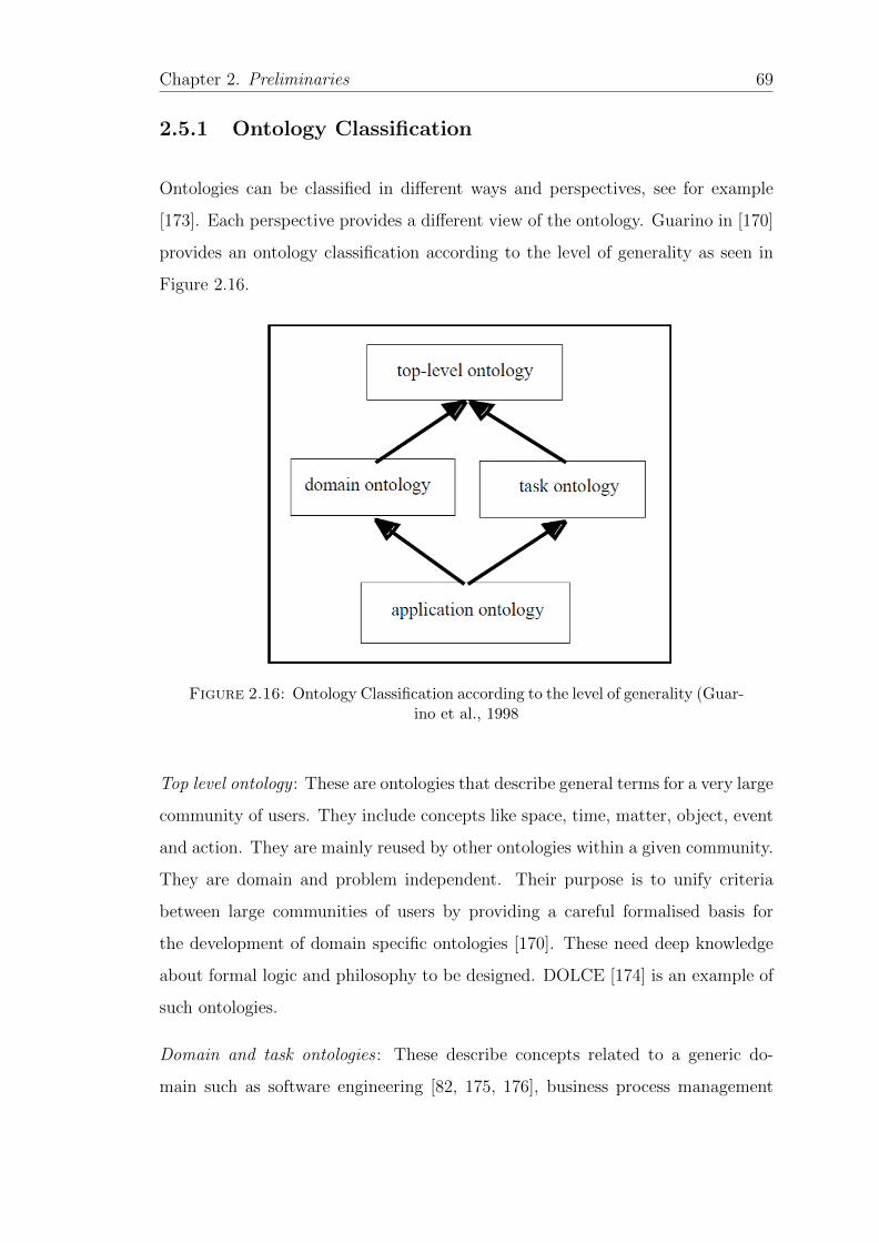
Chapter 2. Preliminaries 69
2.5.1 Ontology Classification
Ontologies can be classified in different ways and perspectives, see for example
[173]. Each perspective provides a different view of the ontology. Guarino in [170]
provides an ontology classification according to the level of generality as seen in
Figure 2.16.
Figure 2.16: Ontology Classification according to the level of generality (Guar-ino et al., 1998
Top level ontology : These are ontologies that describe general terms for a very large
community of users. They include concepts like space, time, matter, object, event
and action. They are mainly reused by other ontologies within a given community.
They are domain and problem independent. Their purpose is to unify criteria
between large communities of users by providing a careful formalised basis for
the development of domain specific ontologies [170]. These need deep knowledge
about formal logic and philosophy to be designed. DOLCE [174] is an example of
such ontologies.
Domain and task ontologies : These describe concepts related to a generic do-
main such as software engineering [82, 175, 176], business process management
Chapter 2. Preliminaries 70
[73] among others. They reuse terms and concepts introduced by the top level
ontologies.
Application ontologies : These describe terms and concepts based on both a par-
ticular domain and task. They are often specialization of both the related ontolo-
gies. They are always designed with some sort of computational application and
expressed in languages of some computationally tractable sub logic e.g., OWL DL
[177]. In [178] a distinction is made between application ontologies and reference
ontologies. Reference (core) ontologies are in between upper ontologies and do-
main ontologies. They cover extensions or specialization of top level ontologies
that take a global view of multiple domains. Reference ontologies are meant to be
reused by application ontologies within a given domain of discourse and are used
to reduce terminological ambiguity among members of a community. For exam-
ple, the ontology developed by Sellers et al. [175] for ISO standards. They are
broad and deep within a given community. They are also designed according to
strict ontological principles [178]. They provide a precise definition of structural
knowledge in a specific field that spans across different application domains [179].
Reference ontologies are used as a basis to integrate and derive different applica-
tion ontologies developed in a given domain [178]. However, for this to happen
reference ontologies should be found and reused by application ontologies within
a given domain.
Another ontology classification is by [180] where ontologies are classified as heavy-
weight and lightweight ontologies. This classification is based on the axiom amount
and features included in the ontology as well as the expressiveness of the formalism
used to model the ontology. Lightweight ontologies are defined with concept and
property definitions as well as simple concept taxonomies supporting simple taxo-
nomic inferences [177]. These ontologies are always developed in RDF schema or
OWL lite [177]. Such ontologies include UML class diagrams, ERDs among oth-
ers. On the other hand, heavyweight ontologies in addition to the constructs in
lightweight ontologies also include other types of restrictions and axioms that en-
able richer inferences with underlying data. These according to [177] demonstrate
Chapter 2. Preliminaries 71
a deep understanding of the domain being modelled and are always developed in
OWL with high expressivity.
Other ontology classifications can be found in [181] and[170] where an ontology
spectrum is provided. In [173] a classification based on the language expressivity
is provided moving along an ontology continuum from informal ontologies repre-
sented in natural language to highly formal languages like FOL and DL. It should
be noted that modelling an ontology with reasoning purposes in mind differs from
modelling an ontology for example taxonomy or glossary purposes. In the fol-
lowing subsections we review DLs, OWL and ontology reasoning services and the
related tools used in this thesis.
2.5.2 Description Logics
Description Logics (DLs) [83] are a family of logics specifically designed to rep-
resent and reason on structured knowledge. DLs are descendants of semantic
networks and frames equipped with tarski-style semantics. DLs are a collection of
logics that are less expressive than for example first order logic (FOL) but highly
structured with improved computational complexity [182]. DLs are a class based
representation formalism that represent aspects of the domain of interest in terms
of:
• Concepts (unary predicate) these are also called classes in OWL context,
represent sets of objects such as Employees, Students. Usually NC is used to
denote the set of atomic concepts. This set usually includes the Top concept
> (OWL:Thing) and the Bottom concept ⊥ (OWL:Nothing);
• Roles (binary predicate) these are also called property in OWL context,
represent the relationship between individuals and concepts in the domain
of interest. Usually NR is used to denote the set of role names, such as
worksFor, marriedTo;
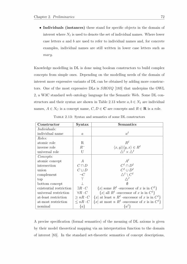
Chapter 2. Preliminaries 72
• Individuals (instances) these stand for specific objects in the domain of
interest where NI is used to denote the set of individual names. Where lower
case letters a and b are used to refer to individual names and, for concrete
examples, individual names are still written in lower case letters such as
mary.
Knowledge modelling in DL is done using boolean constructors to build complex
concepts from simple ones. Depending on the modelling needs of the domain of
interest more expressive variants of DL can be obtained by adding more construc-
tors. One of the most expressive DLs is SROIQ [183] that underpins the OWL
2, a W3C standard web ontology language for the Semantic Web. Some DL con-
structors and their syntax are shown in Table 2.13 where a, b ∈ NI are individual
names, A ∈ NC is a concept name, C,D ∈ C are concepts and R ∈ R is a role.
Table 2.13: Syntax and semantics of some DL constructors
Constructor Syntax SemanticsIndividuals:individual name a aI
Roles:atomic role R RI
inverse role R− 〈x, y〉|〈y, x〉 ∈ RI
universal role U 4I ×4I
Concepts:atomic concept A AI
intersection C uD CI ∩DI
union C tD CI ∪DI
complement ¬C 4I \ CI
top > 4I
bottom concept ⊥ ∅existential restriction ∃R · C {x| some RI -successor of x is in CI}universal restriction ∀R · C {x| all RI -successor of x is in CI}at-least restriction ≥ nR · C {x| at least n RI -successor of x is in CI}at-most restriction ≤ nR · C {x| at most n RI -successor of x is in CI}nominal {a} {aI}
A precise specification (formal semantics) of the meaning of DL axioms is given
by their model theoretical mapping via an interpretation function to the domain
of interest [83]. In the standard set-theoretic semantics of concept descriptions,
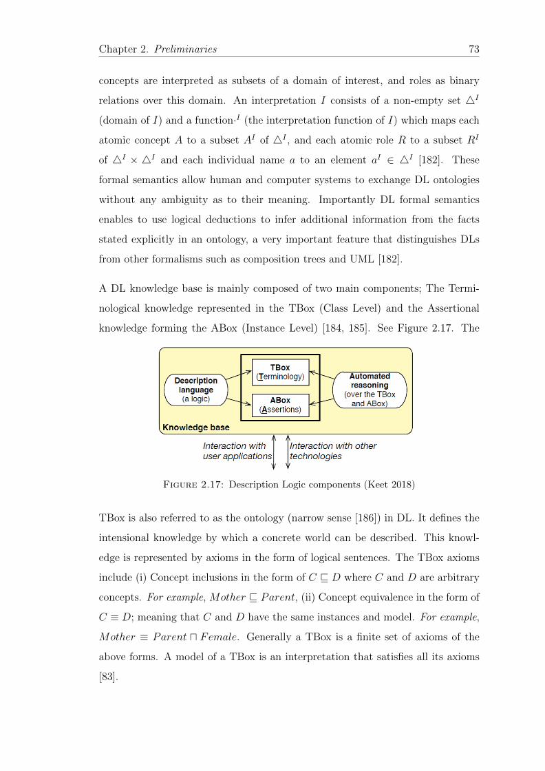
Chapter 2. Preliminaries 73
concepts are interpreted as subsets of a domain of interest, and roles as binary
relations over this domain. An interpretation I consists of a non-empty set 4I
(domain of I) and a function·I (the interpretation function of I) which maps each
atomic concept A to a subset AI of 4I , and each atomic role R to a subset RI
of 4I × 4I and each individual name a to an element aI ∈ 4I [182]. These
formal semantics allow human and computer systems to exchange DL ontologies
without any ambiguity as to their meaning. Importantly DL formal semantics
enables to use logical deductions to infer additional information from the facts
stated explicitly in an ontology, a very important feature that distinguishes DLs
from other formalisms such as composition trees and UML [182].
A DL knowledge base is mainly composed of two main components; The Termi-
nological knowledge represented in the TBox (Class Level) and the Assertional
knowledge forming the ABox (Instance Level) [184, 185]. See Figure 2.17. The
Figure 2.17: Description Logic components (Keet 2018)
TBox is also referred to as the ontology (narrow sense [186]) in DL. It defines the
intensional knowledge by which a concrete world can be described. This knowl-
edge is represented by axioms in the form of logical sentences. The TBox axioms
include (i) Concept inclusions in the form of C v D where C and D are arbitrary
concepts. For example, Mother v Parent, (ii) Concept equivalence in the form of
C ≡ D; meaning that C and D have the same instances and model. For example,
Mother ≡ Parent u Female. Generally a TBox is a finite set of axioms of the
above forms. A model of a TBox is an interpretation that satisfies all its axioms
[83].
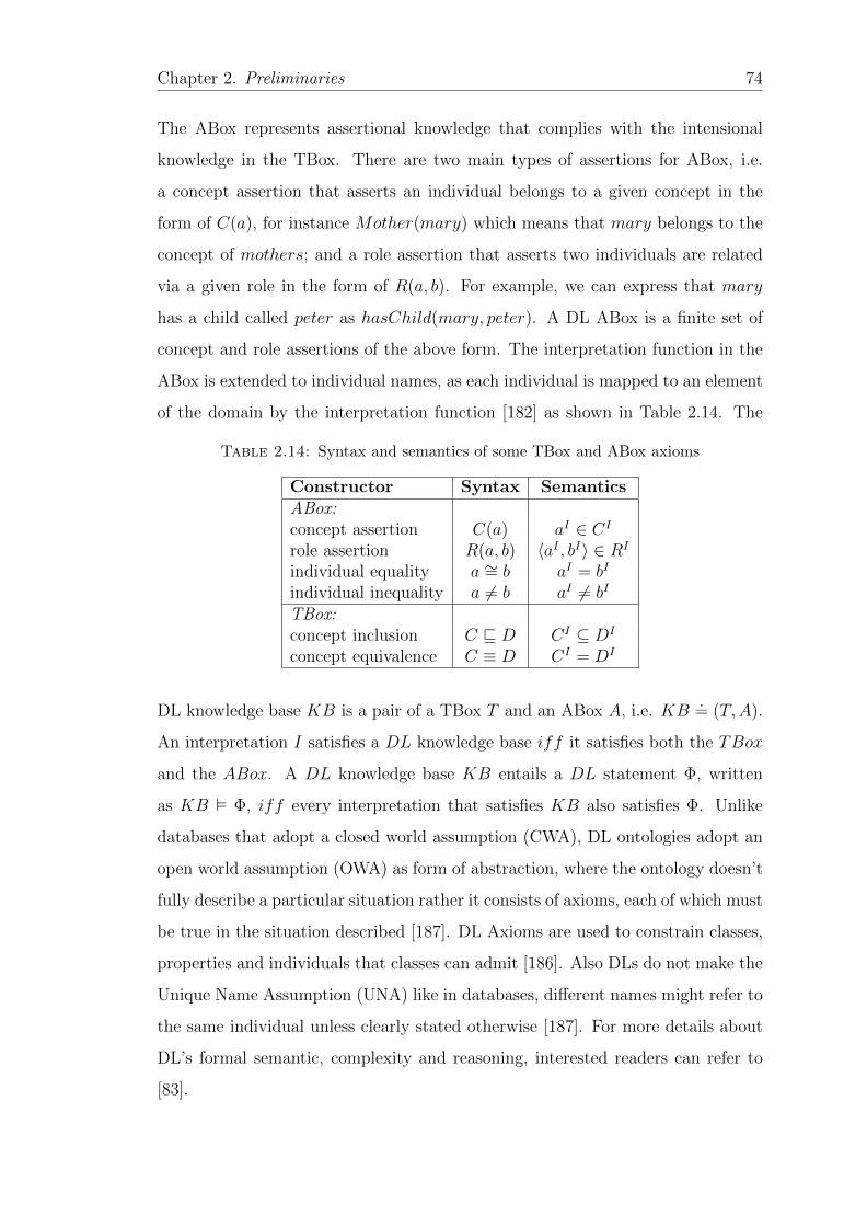
Chapter 2. Preliminaries 74
The ABox represents assertional knowledge that complies with the intensional
knowledge in the TBox. There are two main types of assertions for ABox, i.e.
a concept assertion that asserts an individual belongs to a given concept in the
form of C(a), for instance Mother(mary) which means that mary belongs to the
concept of mothers; and a role assertion that asserts two individuals are related
via a given role in the form of R(a, b). For example, we can express that mary
has a child called peter as hasChild(mary, peter). A DL ABox is a finite set of
concept and role assertions of the above form. The interpretation function in the
ABox is extended to individual names, as each individual is mapped to an element
of the domain by the interpretation function [182] as shown in Table 2.14. The
Table 2.14: Syntax and semantics of some TBox and ABox axioms
Constructor Syntax SemanticsABox:concept assertion C(a) aI ∈ CI
role assertion R(a, b) 〈aI , bI〉 ∈ RI
individual equality a ∼= b aI = bI
individual inequality a 6= b aI 6= bI
TBox:concept inclusion C v D CI ⊆ DI
concept equivalence C ≡ D CI = DI
DL knowledge base KB is a pair of a TBox T and an ABox A, i.e. KB.= (T,A).
An interpretation I satisfies a DL knowledge base iff it satisfies both the TBox
and the ABox. A DL knowledge base KB entails a DL statement Φ, written
as KB � Φ, iff every interpretation that satisfies KB also satisfies Φ. Unlike
databases that adopt a closed world assumption (CWA), DL ontologies adopt an
open world assumption (OWA) as form of abstraction, where the ontology doesn’t
fully describe a particular situation rather it consists of axioms, each of which must
be true in the situation described [187]. DL Axioms are used to constrain classes,
properties and individuals that classes can admit [186]. Also DLs do not make the
Unique Name Assumption (UNA) like in databases, different names might refer to
the same individual unless clearly stated otherwise [187]. For more details about
DL’s formal semantic, complexity and reasoning, interested readers can refer to
[83].
Chapter 2. Preliminaries 75
DL systems have been used to model different domains of interest such as con-
ceptual modelling [188], databases [189], software process [85] and above all onto-
logical modelling for the semantic web [190]. DLs underpin the logical foundation
of Web Ontology Language (OWL) which is now a W3C standard for ontology
modelling on the Semantic Web [183]. Generally DLs can be used to model any-
thing that can be modelled by a directed graph [191]. Starting with the design of
a TBox in a top down fashion is a popular approach in developing DL complex
ontologies, however, there is little discussion on practical ways of dealing with
real world challenges that must be overcome to build, refine and maintain TBox
models [192]. Nevertheless it provides the basic structure of the ontology to be
developed and it is here where the conceptualization of the domain under study
is enumerated. While it is possible to split the TBox and ABox in modelling DL
knowledge bases for various reasons and benefits [192], in this study we adopt a
methodology [192] that allows the knowledge base structure to be constructed first
as a TBox and later complimented with ABox at run time. This approach enables
TBox maximum reasoning capabilities.
2.5.3 Web Ontology Language (OWL)
The increasing importance of ontologies and their processing in computers has led
to the development of many ontology modelling languages such as SHOE, OIL,
DAML+OIL, RDF, RDF(S) and OWL [98]. Web Ontology Language5 (OWL) is
a consolidation of its preceding languages with influence from Description Log-
ics, frames paradigm and RDF. Its main representation and logical framework
including syntax and semantics are based on Description Logics [98]. The surface
structure (abstract syntax) of OWL is influenced by the frame paradigm yet the
RDF/XML exchange syntax was influenced by a requirement for upward compati-
bility with RDF [193]. An ontology language is a vehicle to specify at abstract level
what is necessarily true in the domain of interest. It should be able to express
5https://www.w3.org/OWL/

Chapter 2. Preliminaries 76
constraints which declare what should necessarily hold in any possible concrete
instantiation of the domain.
The Web Ontology Language (OWL) is a semantic web language designed and
standardised by W3C to model rich and complex knowledge about things, groups
of things, and relations between things [194]. OWL is a knowledge representation
language that enables expressed knowledge to be reasoned on by human and arti-
ficial agents for consistency and inferring implicit knowledge from the explicit one.
OWL representations commonly referred to as ontologies [195], can be published
and stored in the world wide web. It describes the domain of discourse in terms of
individuals, classes, properties, datatypes and values. OWL models primitive and
defined classes and can organise them in a class hierarchy, it also models properties
between classes and organise them in a hierarchy as well defining their range and
domains [195]. These properties can be functional, symmetric and inverse [193].
It also models class and property equivalences, disjointness as well as equality or
inequality of individuals. OWL extends the RDFS datatypes for different prop-
erties for a given class [193]. Because OWL is given formal semantics based on
first order logic (FOL), they can be seen as a fragment of FOL either directly or
through description logics [193].
Since its standardisation in 2004 by W3C, OWL has undergone transformations
from the original OWL to OWL 1.1 and currently OWL 2 standardised in 2009
with improved expressivity, property features, punning and supporting extended
datatypes and keys [194]. OWL 2 also introduced more several convenience fea-
tures such as improved specification in both BNF and UML formats, validated
XML syntax and the use of the user friendly Manchester syntax [98]. Because
OWL is based on SHOIN(D) a very expressive and difficult DL to reason with,
making standard inference problems such as ontology consistency, class expression
satisfiability, class expression subsumption and instance checking is 2NExpTime
complex [98]. To overcome this situation three profiles that have desirable com-
putational properties for different situations have been devised [98, 194]:

Chapter 2. Preliminaries 77
• EL Profile; for which standard reasoning can be performed in polynomial
time. This is desirable in applications that contain very large numbers of
classes and properties for example in life science.
• DL Lite Profile; for which reasoning problems can be reduced to SQL query
answering and can be performed in LOGSPACE with respect to the size
of the data. This is desirable in applications that use very large volumes of
instance data and where query answering is the most important reasoning
task needed.
• DLP Profile; a DL based on rule techniques. It aims for applications where
scalable reasoning is required without sacrificing too much expressive power.
Details of these profiles can be found in [194].
OWL is part of the W3C’s semantic web technology stack, which includes RDF
and SPARQL [194]. Although OWL is closer to DL, the use of RDF datatypes
and URI references as names places it firmly in the semantic web stack. OWL DL
entailment is compatible with RDF(S) entailment [193]. OWL has various syntaxes
for different purposes. The Functional-Style syntax [194] is designed to be easier
for specification purposes and to provide a foundation for the implementation of
OWL 2 tools such as APIs and reasoners. The RDF/ XML syntax is the standard
syntax for the semantic web that all OWL implementation tools should support;
however, its very verbose and hard to read for humans. The Manchester syntax is
used for precision and in formal documents [194]. It is also designed to be easier for
non-logicians to read. The OWL XML syntax is XML syntax for integration with
other tools. The Turtle syntax is an optional OWL syntax and easy to read/write
RDF triples. Tools can be used translate between the different syntaxes for OWL
[194].
To retain upward compatibility with existing web language OWL includes features
of class and property as already used by RDF and RDFS [193]. Because of all the
influences on OWL and compatibility issues with other semantic web languages;
Chapter 2. Preliminaries 78
• OWL uses URI references as names just like RDF uses them. It also usual
in OWL to use qualified names such as OWL: Thing
• OWL represents information into ontologies which are stored as web
documents written in RDF/XML.
• OWL allows RDF annotation properties to be used to attach information
to classes, properties and ontologies.
• OWL uses RDF datatypes and XML schema datatypes to provides
datatypes and data values.
Semantically the formal specification of OWL is provided via DL model theory se-
mantics [83] and DL reasoners therefore can be used to check ontology consistency
and entailment and other reasoning services on the developed ontology. OWL uses
DL style model theory to formalise the meaning of the language [193]. The decid-
ability and complexity of the current DLs is well understood [98]. This averts the
danger of supporting software tools having unpredictable performance. In partic-
ular the risk of non termination in OWL ontologies is avoided [98]. In this study,
we emphasise OWL DL style because we need an expressive ontology language yet
retaining its decidability. The choice of OWL DL is justified for reasons of brevity
as the XML syntax is too verbose for human readability and understanding [98].
OWL DL is also used in the ontology modelling tools like protege [195].
2.5.4 Ontology Reasoning Services
In the last decades, ontologies and ontology reasoning services have been heav-
ily deployed in many applications [196]. DL systems provide users with various
reasoning services that deduce implicit knowledge from the explicitly represented
knowledge [182]. Ontology reasoning has been found to be sound, complete and
terminating [196]. This guarantees that applications based on it are predictable
and reliable. Moreover, they are efficient and practical in terms of implementa-
tion. Automated reasoning can help to make software process models explicit and
Chapter 2. Preliminaries 79
thus allows to evaluate the process correctness without depending on concrete test
cases that are very expensive and hard to get [197].
A reasoner or inference engine is a software tool that infers logical consequences
from a set of explicitly asserted facts or axioms and typically offers automated
support for reasoning tasks such as classification, instantiation, query answering
among others [198]. There are a variety of reasoners that support ontology devel-
opment in protege such as HermiT [199], Pellet [200] among others. Importantly
reasoners are used to validate the quality and correctness of the ontology by eval-
uating its consistency and certainty through various reasoning services [201].
The basic reasoning service in DL systems is to test for satisfiability of a concept
or a TBox. That is to test whether the conceptualization specified in the TBox
has a contradiction or not. In an unsatisfiable TBox any consequence can flow
logically but this will be without meaning. Testing for satisfiability is often a
first step in checking whether a TBox models anything meaningful. Let C be a
concept description and T a TBox. The concept C is satisfiable w.r.t. T iff there
is a model of T in which C can be interpreted as nonempty, i.e. there exists an
interpretation I such that CI 6= ∅. A TBox is satisfiable iff it has a model.
Another reasoning service is concept subsumption that consists of computing in-
ferred subset or subclass relationships. Checking whether all individuals that
are instances of a subconcept are also instances of its superconcept. Given two
concepts C and D w.r.t KB. The concept D subsumes concept C w.r.t KB
(KB |= C v D) if C′ ⊆ D′ holds for all models I of KB. Concepts C, D are
equivalent if they subsume each other w.r.t KB. Based on concept subsumption
all named concepts of a KB can be automatically organized in a taxonomy or sub-
sumption hierarchy. This is what is also often called KB classification. Similar
to subsumption, we can also infer equivalence or disjointness between concepts.
Concept checking and subsumption are important techniques during ontology de-
signing as they provide important feedback about the modelling errors that might
occur during the modelling process [201].
Chapter 2. Preliminaries 80
The second set of reasoning services concerns with instance descriptions. These can
be checked for consistency, membership and retrieval with respect to the TBox:
Instance checking: An individual a is an instance of a concept C w.r.t a knowledge
base KB, iff KB |= C(a). Instance checking denotes the task of testing whether a
given individual is an instance of a given concept, i.e., whether KB |= C(a) holds.
Instance checking is the central reasoning service for information and instance re-
trieval from knowledge bases. Instance checking can also be used to verify whether
an individual can be classified into some defined DL concepts in the knowledge
base.
ABox realization: Realization of an individual, in turn denotes the retrieval of all
named concepts from the knowledge base that a given individual is an instance of.
This reasoning service is also central in automated verification of organizational
process models.
Ontology reasoning services can therefore be utilised in a variety of application
domains concerned with representation and reasoning about knowledge [196]. For
example in SE and in Software process, specifically DL reasoning services are cen-
tral in our approach for software process consistence, completeness, conformance
checking, and capability and maturity determination [139]. Our motivation for
adoption of DL reasoning services in software process modelling is coupled with
huge amount of DL reasoners available off shelf for this purpose. For example we
intend to use satisfiability checking to check the coherence and consistency of our
software process descriptions. We shall also use instance description reasoning to
check the instance consistency in respect with the TBox. As mentioned earlier, the
ABox comes from logged processes, i.e. instances of a process. Just like for con-
sistency of a TBox, we can also test for (i) contradictions in the ABox and (ii) At
run time, we can check whether the ABox is consistent with the conceptualization
in the TBox.
Chapter 2. Preliminaries 81
2.5.5 Semantic Web Rule Language (SWRL)
Even though, OWL is an expressive ontology modelling language for the semantic
web, it has some limitations especially when it comes to property representations
[202]. In order to extend OWL expressiveness, horn clause rules have been added
to OWL forming the Semantic Web Rule Language (SWRL) [202]. SWRL enables
the use of rules expressed in terms of OWL classes and properties to reason about
OWL individuals and it can be used to infer new knowledge from existing OWL
knowledge bases [203]. Rules are represented in the form of an implication between
the antecedent (body) and consequent (head), which implies that whenever the
conditions in the antecedent hold, then conditions in the consequent must also
hold [202]. The antecedent and consequent are made up of zero or more atoms,
where multiple atoms in the body are treated as conjunctions while those in the
head are treated as separate consequences [202]. These atoms are statements that
can take one of the following forms:
• C(x), where individual x is an instance of OWL class C.
• P (x, y), where individuals x and y are related by OWL property P .
• P (x, z), where the value of OWL datatype OWL P for individual x is z.
• sameAs(x, y), where x is interpreted as the same object as y.
• differentFrom(x, y), where x is interpreted as a different object from y.
Where atoms in the antecedent and consequent may refer to individuals, data
literals, individuals, variables or data variables. For safety reasons, only variables
that occur in the antecedent of the rule may appear in the consequent [202]. The
general structure of a rule is simply as: antecentent → consequent where both
the body and the head are conjunctions of atoms in the form of: ai ∧ ... ∧ an in
which the variables are indicated using the question mark (?x). For example the
hasUncle relationship can be represented as:
hasParent(?a, ?b) ∧ hasBrother(?b, ?c)→ hasUncle(?a, ?c)
Chapter 2. Preliminaries 82
Informally, if Edward has parent Mary and Mary has a brother Peter, then Edward
has uncle Peter.
The protege SWRL editor [203] incorporated in Protege can be used to create,
edit and store rules as part of an OWL ontology and it fully supports all the lan-
guage features outlined in the SWRL specification6. SWRL also supports a range
of built-in predicates which greatly extends its expressiveness such as comparison
operations, mathematical, strings, dates, lists and many more others7 where all
SWRL built-ins must be proceeded by the namespace qualifier ′swrlb′. Accord-
ing to [203], most processes, compliance monitoring and process control are best
modelled using declarative approaches.
2.5.6 Metamodeling support in OWL Standard
Metamodeling has become a common issue in the ontology engineering community.
In [204], the authors point out the usefulness of metamodeling in applications
that need to express situations in which classes can also be seen as instances,
such as interchanging models that are described in different languages, ontology
mapping, ontology evolution, model validation and verification, ontology network,
meta query answering as well as using metamodeling to check for modelling errors
and to examine the quality properties of the models [205, 206].
OWL is a family of knowledge representation languages standardized by W3C to
enable resource annotation on the semantic web. Three variants, i.e., OWL Lite,
OWL DL and OWL Full with varying expressivity have been developed. OWL
lite and OWL DL are underpinned by DLs that define their formal semantics.
The complexity of the DL subsets, i.e., SHIF (D) and SHOIN(D) that underpin
OWL lite and OWL DL respectively are well understood with decision proce-
dures implemented in practical and optimised reasoners such as PELLET [200],
FACT++ [207] that are readily available off shelf. On the other hand, OWL Full
6https://www.w3.org/Submission/SWRL/7https://www.w3.org/Submission/SWRL/issuesList.html
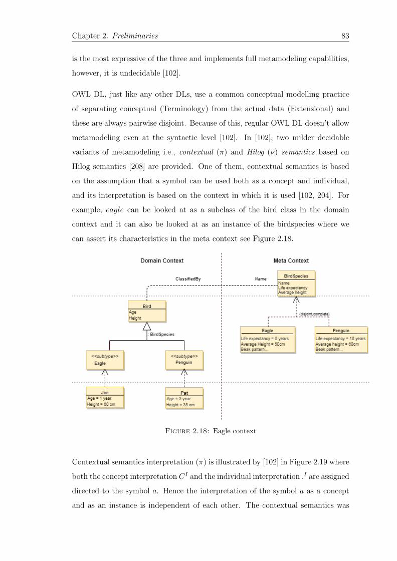
Chapter 2. Preliminaries 83
is the most expressive of the three and implements full metamodeling capabilities,
however, it is undecidable [102].
OWL DL, just like any other DLs, use a common conceptual modelling practice
of separating conceptual (Terminology) from the actual data (Extensional) and
these are always pairwise disjoint. Because of this, regular OWL DL doesn’t allow
metamodeling even at the syntactic level [102]. In [102], two milder decidable
variants of metamodeling i.e., contextual (π) and Hilog (ν) semantics based on
Hilog semantics [208] are provided. One of them, contextual semantics is based
on the assumption that a symbol can be used both as a concept and individual,
and its interpretation is based on the context in which it is used [102, 204]. For
example, eagle can be looked at as a subclass of the bird class in the domain
context and it can also be looked at as an instance of the birdspecies where we
can assert its characteristics in the meta context see Figure 2.18.
Figure 2.18: Eagle context
Contextual semantics interpretation (π) is illustrated by [102] in Figure 2.19 where
both the concept interpretation CI and the individual interpretation .I are assigned
directed to the symbol a. Hence the interpretation of the symbol a as a concept
and as an instance is independent of each other. The contextual semantics was
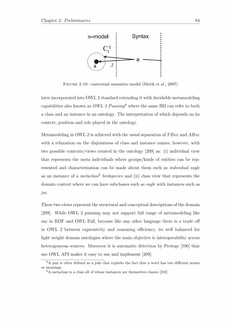
Chapter 2. Preliminaries 84
Figure 2.19: contextual semantics model (Motik et al., 2007)
later incorporated into OWL 2 standard extending it with decidable metamodeling
capabilities also known as OWL 2 Punning8 where the same IRI can refer to both
a class and an instance in an ontology. The interpretation of which depends on its
context, position and role played in the ontology.
Metamodeling in OWL 2 is achieved with the usual separation of TBox and ABox
with a relaxation on the disjointness of class and instance names, however, with
two possible contexts/views created in the ontology [209] as: (i) individual view
that represents the meta individuals where groups/kinds of entities can be rep-
resented and characterisation can be made about them such as individual eagle
as an instance of a metaclass9 birdspecies and (ii) class view that represents the
domain context where we can have subclasses such as eagle with instances such as
joe.
These two views represent the structural and conceptual descriptions of the domain
[209]. While OWL 2 punning may not support full range of metamodeling like
say in RDF and OWL Full, because like any other language there is a trade off
in OWL 2 between expressivity and reasoning efficiency, its well balanced for
light weight domain ontologies where the main objective is interoperability across
heterogeneous sources. Moreover it is automatic detection by Protege [100] that
use OWL API makes it easy to use and implement [209].
8A pun is often defined as a joke that exploits the fact that a word has two different sensesor meanings
9A metaclass is a class all of whose instances are themselves classes [210]
Chapter 2. Preliminaries 85
It is common place in conceptual and ontology engineering to classify entities
either as classes or instances depending on their context [204], given the fact that
there is no clear cut borderline between classes and instance classification. In fact
some entities are classified as classes in higher abstraction levels and instances in
lower abstraction levels making the borderline blurred [211]. The two contexts are
integrated through a shared vocabulary (punning)such as eagle or metamodeling
hierarchy [211].
As an ontology modelling language that underpins the OWL that is used to de-
velop ontologies for the semantic web, DLs have a number of attractive features for
our software process formalisation approach. Firstly, DLs are expressive enough to
allow formalization of the software process knowledge in an ontology with famil-
iar semantics of the FOL. Secondly, it is supported by various efficient inference
engines and modelling tools that we can utilise in developing our approach. Fi-
nally, DLs are extensively used in supporting the development of ontologies for
the semantic web and related applications. This comes with a lot of related se-
mantic web tools and APIs that we can use for our approach in software process
formalisation.
2.6 Summary
In this chapter, the basic concepts, notions and tools used in this thesis are intro-
duced. This chapter reviews the basic software process modelling concepts, process
assessment and verification. We have also reviewed the composition tree technique,
a behavior engineering tool for modelling and comparing software processes. On-
tologies and ontology languages have also been reviewed with the emphasis on DLs
and OWL that can be used to model and verify software processes. In the next
chapter, we discuss how the concepts and terminologies explored in this chapter
have been used in software process modelling and verification in the state of the
art.
Chapter 3
Literature Review
3.1 Introduction
Chapter 1 introduced the research problem: there is lack of a systematic and
repeatable approach for software process formalisation that is; i) easy and simple
to use and understand by all stakeholders involved in software process. In this
chapter, a detailed understanding of the current state of affairs in software process
formalisation is sought from which a theoretical foundation is built by reviewing
the relevant literature to justify the research problem. As an outcome of this
chapter, research limitations that are not addressed by previous researchers are
identified and conceptualised.
Describing and managing activities, resources, and constraints of software devel-
opment is a challenging goal for many software developing organizations [88]. The
idea to represent software processes explicitly and formally is not new. In fact it
dates back to the days of the software crisis meetings [4] where the idea of using
mathematical ways to represent software process was first mottled [7]. Subse-
quently, many PMLs (see subsection 2.2.2 in Chapter 2 for PML analysis) were
developed to represent software processes in a precise and formal way. The main
aim of these PMLs was to completely automate the software process in a closed
world assumption (CWA). However, this made these PMLs very complicated and
86
Chapter 3. Literature Review 87
complex to be used in practice and many didn’t go beyond the labs where they
were developed [67, 110].
In response, lightweight approaches have been developed overtime to represent
and verify software processes in a formal way. Most of the formal approaches to
software process modelling can be categorised according to their base formalisms
where they derive their modelling and analysis capabilities [88]. In this chapter
we review the most related approaches to the work presented in this study based
on their base formalism. In section 3.2, we discuss the various ontology and DL
based approaches to software process representation and verification. In Section
3.3 we discuss other logical formalism that are used to formalise and verify soft-
ware processes yet in Section 3.4 we highlight approaches based on Petri nets and
in Section 3.5 we discussed the graphical based approaches for software process
representation and verification. In Section 3.6 we review process mining based
approaches and we finally conclude the chapter with the literature findings and
research direction in Section 3.7 and a summary in Section 3.8.
3.2 Ontology and DL based Approaches
Since the emergence of the semantic web [190], there has been a momentous in-
terest in ontologies which offer possibilities for formally representing, organising
and reasoning over the domain of discourse. The semantic web helps to publish
and share ontologies via the web. Ontology based approaches have been mak-
ing progress in formalizing software processes [46, 172, 181, 212]. Moreover, an
ontology is a useful resource to give a better view and identification of the pro-
cess architecture [213]. Subsequently, a number of ontology based approaches for
formalising software processes have been suggested in literature.
Sellers et al. [175] have developed an ontology for ISO software engineering stan-
dards to be a single underpinning for all software process standards, current and
the future ones. The main aim of this ontology is to clear ambiguity and termi-
nological confusion in the different standards developed by ISO by having a single
Chapter 3. Literature Review 88
definition elements ontology (DEO). When developing an individual standard,
only a subset of DEO is required which can be configured to derive configurable
definitional ontology (CDO). These two can form a basis for the development of
a domain specific ontology (SDO) acting as a foundational and reference ontology
for the SDO. Software processes in standards developed this way can be of high
quality and easily interoperable with other processes developed using the same
basis. Ruy et al. [212] proposed to use ontology pattern language for harmonizing
software process related ISO standards. They argue that the basic set of DEO
and CDO should be represented as core ontologies on software process but not
like foundational ontologies as earlier suggested by Sellers et al. The point here
is to clear ambiguity and terminological confusions as identified in the standards
produced by the same ISO committee SC7 [214] making the developed ontology a
reference ontology than foundational ontology [178].
In [87], a process ontology is developed to establish a common vocabulary for soft-
ware organizations to understand software process in clear terms. The aim of the
ontology is to provide an ontorigua for communication purposes to clear ambiguity
for people involved in software development. A mapping is proposed between the
concepts presented in the ontology and the process standard concepts in ISO/IEC
12207. In [215] another SE ontology is developed for multi-site software develop-
ment. Its aim is to represent software engineering knowledge based on a software
engineering book [1] and SWEBOK1. It provides a communication framework for
the multi-site software developers to share knowledge about software development
purposes. The ontologies provided by these authors are mainly reference ontolo-
gies whose main aim is to clear ambiguity and provide clear terminologies when
talking about software process development activities among software develop-
ers. According to [178] reference ontologies are mainly for reference purposes and
therefore their application is limited. For example they can never be taken like
computational ontologies where computational inference is used for various roles
such as process analysis and verification. However, reference ontologies provide a
1https://www.computer.org/web/swebok
Chapter 3. Literature Review 89
foundation for clear concepts, terminologies and relations among them to build on
for computational ontologies [175].
An Ontology based approach for software process model tailoring is presented in
[21]. The approach is divided in three layers; the core layer is based on a software
engineering standard for VSEs [26]. The standard provides the main elements,
classes and properties of the ontology. The corporate/organisational layer is based
on the core layer through tailoring. Project layer is the instantiation of the cor-
porate layer in the specific project where all the tailored processes are executed.
A semantic media wiki tool is proposed for publication and reuse of the resulting
process adaptations. However, the semantic wiki tool is not yet publicly available.
The tailoring approach as mentioned and executed in the approach seems to be
ad-hoc and manual. Moreover, the tailoring process is left to the process engi-
neer or project manager without any automated support which may not provide
reliable tailoring in case the process engineer is not experienced. Importantly the
approach doesn’t consider verification of the tailored process with the standard
process to confirm its compliance with the standard process [216]. According to
[9] tailoring is not complete until verification between the tailored process and the
standard process is done to maintain process compliance.
An ontology approach for software engineering process automation is developed in
[171]. The ontology is developed to enhance process automation and adherence.
The ontology is based on RUP process supported by a conceptual model based on
SPEM. The study proposes formal specification of the process in order to enhance
its automation and adherence using OWL. The developed ontology can be used
for automated process definition, execution, evaluation and improvement though
no guidelines are provided on how best to go about this. The enactment of the
automated process can be done through three levels as project initiation, execution
and closure. Process improvement is suggested at the closure of the project. This
means the approach doesn’t allow any process improvement while the project is
ongoing. This may lead to more rework as any defects in the process are checked
at the closure of the project. The software process ontology (SPO) is presented
by [42]. The ontology expresses the software process at the conceptual level. The
Chapter 3. Literature Review 90
SPO can be extended to generate ontologies for specific process models such as
CMMI and ISO/IEC 15504. A web prototype based process assessment tool based
on SPO is developed as a concept of proof. The ontology developed here doesn’t
take into consideration the use of computational inference.
An approach for software process analysis and verification is developed by Ro-
driguez [86]. In this approach, an ontology based on SPEM is developed and
enriched with rules using SWRL [202]. As part of the approach, SCRUM ontol-
ogy is developed to illustrate the importance of rules in constraints verification.
The main aim of this approach is actually to check and verify constraints that are
defined as part of a SPEM process model. It shows an approach where rules and
OWL are combined for better management of software process projects. On the
other hand, a project assets ontology (PAO) is developed in [217, 218] to describe
work products of a software project that conforms to typical work products that
can be used as objective evidence for CMMI practices and goals. This ontology is
used to underpin a gap analysis tool that can be used for preliminary assessment
[218]. Similarly, an ontology based verification approach for checking process com-
pliance with standards requirements is presented in [125] where the service PRM
is translated to a TBox and process instance translated to the ABox. To perform
compliance verification, membership to a TBox class is not only defined by instan-
tiation, but also declaratively checks the necessary and required conditions of a
class. All process instances in the ABox associated to the TBox are checked if
they fulfil the necessary and required conditions of the classes in the TBox. This
idea is also called realization in ontology reasoning [200].
In [84] an approach to formalise SE practitioner’s tacit knowledge is presented.
The approach is based on KUALI-BEH [219], a normative kernel extension of the
ESSENCE formal specification and the approach involves three components: An
ontology to represent common knowledge concepts and the relationships between
them. A situational method engineering algebra to formalise well defined method
properties and operations, and DL representation of the ontology and the algebra.
The main objective of the formalisation approach in this study is to improve com-
munication between humans and machines, computational inferences and reuse
Chapter 3. Literature Review 91
of knowledge among the software practitioners [84]. The lack of reasoning mech-
anism for the current metamodels such as SPEM and ESSENCE itself further
motivated the need for DL formalisation of the approach as well as providing soft-
ware practitioners a mechanism with which they can reason about the knowledge
they accumulate during software projects. KUALI-BEH is a language extension
of ESSENCE that allows software practitioners to express and transform their
tacit knowledge into explicit knowledge as well as providing a framework for au-
thoring SE methods [220]. The approach is validated with a proof of concept in
form of a case study. From the case study results, it was established that the ap-
proach was able to solve some SPEM incompleteness and inconsistencies that were
identified in [85]. It was also claimed in [84] that the approach supports a com-
prehensive representation of knowledge and permits to reason about the created
methods. Where as the main objective of the formalisation approach in [84] is to
enable communication and reuse of practitioners knowledge through formalising
the KUALI-BEH terminology [220], we aim in our study to provide a simple, re-
peatable and consistency approach that can be used to formalise and reason about
heterogeneous software processes. We believe our approach can be complimentary
to this approach as we focus on improving processes and practices that form the
way of working for software practitioners in the endeavour concern of ESSENCE
standard [84].
More in line with our objectives, is the formalisation approach presented in [85]
where SPEM metamodel is represented in DL ontology based on two mappings.
SPEM and object constraint language (OCL) are mapped to DL so that process
analysis techniques such as reasoning, consistency checks can benefit from DL
based mature reasoning tools. In this approach SPEM metamodel is mapped to
the DL TBox and model instances are mapped to the DL ABox. This enables
reasoning to be done on both models (metamodel and model instances) to find
any inconsistencies and problematic steps that may exist between the metamodel
and its instances. From The SPEM formal model, it was established that SPEM
metamodel had some incompletenesses and inconsistencies as identified in the
case study used. This work shares the same spirit with the work presented in

Chapter 3. Literature Review 92
our approach, although their conceptualisation was only limited to SPEM and
therefore doesn’t suffice in our context.
In the same line, is the approach of Soto and Munch [54] where software process
model versions based on SE standards are used to isolate changes between the
new and old model versions. When the changes are identified, they are checked
to see if they have broken the compliance between the software process and the
old model version. In the approach, a knowledge representation language, i.e.,
Resource Description Framework2 (RDF) is used to formalise both the process
standards and its instances in the form of subject, predicates and objects. The
created models are queried using SPARQL query language3. It is reported that the
approach is effective in helping organisations identify model areas that needed to
keep the processes compliant with a given standard. However, while the approach
may work well with small model changes, it may not be expressive enough given
the limited expressivity of RDF as a modelling language. Moreover, SPARQL
queries may not be in position to express all patterns of model changes that can
happen [54].
Similarly in [51], an approach for traceable maturity assessment methodology is
presented. The methodology is based on Enterprise Architecture (EA) modelling
and SPARQL queries. The main aim of the approach is to overcome the short-
comings of the main stream process assessment methods i.e., SPICE and SCAMPI
[221]. Maturity and capability level determination is done through the use of
SPARQL queries where they are posed on an OWL ontology translated from the
EA models. The use of queries is intended to reduce on the over reliance on expen-
sive assessors and ensure objectivity based on collected and formalised evidence.
It is claimed that this approach is beneficial over other assessment methods in
different ways such as; being applicable across different domains, low barrier to
adoption, simple and minimalism approach, its also modular and rigorous because
it is based on the rigours of design science [222]. All these benefits are achieved
2https://www.w3.org/RDF/3https://www.w3.org/TR/rdf-sparql-query/
Chapter 3. Literature Review 93
through the use of EA modelling and separation of concerns as well as determin-
ing maturity and capability levels through formalising evidence by using SPAQRL
queries. However, the approach is mostly manual using conventional data col-
lection techniques like interviews that can carry inherent subjectivity that was
intended to be minimised. It is also not expressive enough to align with expert
judgement [51]. While the approach is claimed to be applicable across different
domains, it was only applied on a specific case study in digital preservation. It is
not yet known how well the approach can scale if applied to other process intensive
domains such as software engineering.
An ISO/IEC 15504-5 Ontology is developed by [139] with the main intention of
deriving process capability levels automatically using generic inference engines.
This approach is based on an earlier formalisation approach for CMMI developed
in [61]. The Ontology is based on a PAM in ISO/IEC 15504-5 and has been con-
sidered a reference ontology that can be extended for specific purposes. While the
authors acknowledge that PAM describes relationships between practices, work
products, generic resources and outcomes, the outcome aspect was not fully mod-
elled in the ontology. However, process outcomes are very important for both
process definition and assessment [22]. Besides one of the major innovations of
the SPICE project and the ISO/IEC 15504 series of standards has been the defi-
nition of processes in terms of their purpose and outcomes; where a set of process
outcomes is necessary and sufficient to achieve a process purpose [22]. Secondly,
the approach assumes that an organisation has in place the appropriate process
attribute ratings from which to derive process capability levels automatically [139].
3.3 Logical and Process algebra based Approaches
Logical approaches provide a mathematical foundation upon which software pro-
cesses can be formally specified and verified using inference tools [1]. Not only does
decidable logics give a precise and unambiguous process representation, they also
Chapter 3. Literature Review 94
allow the development of reasoning algorithms that can be used to answer ques-
tions about the process formalisation. It has also been established that logical
approaches increase the confidence [63] and trustworthiness [51] in the objective
evidence used to claim conformance to SE standards. Consequently a number of
logical approaches are proposed in literature for software process formalisation.
In [52], an approach for managing standard’s compliance is developed. In this
approach the best practices provided by the standards are treated as constraints
that should hold for the documents produced during software development such
as software requirements specification. The constraints are formalised using First
Order Logic (FOL) and UML classes. This approach was later incorporated in the
Doors environment [52]. The main focus of the approach is enhancing compliance
to software engineering standards. In contrast, the approach presented in this
thesis is a general approach for software process formalisation and compliance is
embedded within the verification process. Similarly in [56] a set of well-formedness
rules that improve the consistency of SPEM based software processes is developed.
The rules are defined in FOL and UML multiplicities. Process specifications inter-
connect very many process elements that may result into process inconsistencies.
Several SPEM constraints are specified in natural language that may result into
inconsistencies due to the inherent ambiguities in natural language. This ap-
proach only focuses on the consistency of roles, work products, tasks and their
relationships, while in our case we provide a general formalisation approach that
can be used to consistently and repeatable formalise software processes including
process constraints represented as DL axioms. While FOL is a proven and neces-
sary expressive formalism, its major drawback is the undecidability that leads to
inefficiency in terms of computational costs [131].
More in line with our objectives, is the compliance approach presented in [223]. In
this approach, standard requirements are formalised into a rule set using Formal
Contract Logic (FCL) and their fulfilment is checked by Regorous [224]. Regorous
is an FCL based reasoning methodology and tool for business process compliance
checking. In this approach, they model standard requirements via three EFP com-
poser plug-ins starting with requirements, process elements and process activity
Chapter 3. Literature Review 95
diagram that are checked by Regorous for compliance. The approach generates
compliance reports about the process compliance status i.e., whether a process is
compliant or not and provides sources of any rule violations if any detected for
non compliance. It is suggested that this information increases the efficiency and
confidence in process compliance since it permits the process engineer to focus on
specific process elements that causes rule violation and non compliance [223]. This
is similar to DL justification [225] where violations are detected and pinpointed for
the ontology modeller to re-examine the sources of such violations [131]. There-
fore our approach enhances the belief that logical based approaches increase the
efficiency and confidence in the evidence used for process compliance and assess-
ment [63]. However, our approach is different from the approach presented in
[223], whereas their main focus is on the process behaviour through accumulating
compliance effects that may trigger new effects [223], in our approach we are more
concerned with process performance and efficiency (process capability) in achiev-
ing organisational goals and objectives. Therefore in terms of process compliance
our approach can be complimentary.
On the other hand, Process algebras have also been used to formalise and model
software processes consisting of multiple processes that run in parallel and may
communicate via channels [79]. Process algebras are a very formal, mathematical
approach that was mainly developed to model the behaviour of operating systems
and can form a basis for analysis and comparison of software process models, as
well as tool support [77–79].
The use of CSP-CASL, a type of process algebra in CMMI implementation is
proposed by Mishra [78]. In their approach, it is shown that formal specifications
can help to achieve specific CMMI goals and improve software product quality.
CSP-CASL (Communicating Sequential Process - Common Algebraic Specification
Language) is a new process algebraic specification language that includes means for
both structural and behavioural properties [78]. Relatedly El-Saber [77] presents
an algebraic automated approach to formally check the compliance of business
processes with a set of best practices described by CMMI. In this approach business
process models are formalised in Maude and Maude model checking tools are used
Chapter 3. Literature Review 96
for compliance verification. Business process compliance checking with CMMI
requirements that are formalised in Linear Temporal Logic (LTL) is treated as a
model checking problem. However, the use of model checking techniques has its
own challenges that may affect the results of the compliance verification process
[77, 159].
More in the same line, is the approach proposed in [40]. An algebraic approach for
formal specification is presented for formalising standards requirements. The ben-
efits of a formal process specification over natural language process specifications
are highly emphasised. It is also stated that the uptake of formal methods in SE
is still low and a preserve of high critical systems. The authors argue that benefits
of formal methods in the long run outweigh the costs involved in their adoption.
However, they did not suggest any specific approach for the formalisation process
like we do in this study. Notwithstanding the benefits of algebraic approaches,
such as providing a wide range of operators and theories for determining equiv-
alence of process specifications such as bisimulation, they are a less convenient
approach for process verification [80]. Process algebras are rarely used in the con-
text of software process modelling in general due to their rigorous formality and
certainly not adequate to be used by humans [79].
3.4 Petri nets based Approaches
Petri nets is a disciplined formal approach with inherent modelling constructs such
as transitions, places, arcs and tokens that can be used to model both static and
dynamic properties of a software process [69]. Petri nets based approaches provide
flexibility, ease of integration, significant level of automation and easy to analyse.
Moreover, Petri nets obey operational semantics that facilitate composition, sim-
ulation and validation of processes. Consequently a number of Petri net based
process modelling approaches are suggested in literature:
Chapter 3. Literature Review 97
In [41, 69] a formal approach to process modelling and analysis based on high
level Petri nets is proposed in form of a process centred software engineering en-
vironment. To ease the use and adoption of the approach, a multi level modelling
strategy for software process representation is adopted. One of the layers is used
as an interface for process modelling without getting in touch with the core Petri
net formalism. Similarly a Petri net based approach is presented in [226] for locat-
ing delaying activities within a software process. Delaying activities tend to cause
software projects to be late and out of schedule.
A unified based approach for software process representation and analysis based
on Petri nets and UML is presented in [74]. The approach provides benefits from
both object oriented modelling and Petri nets in process modelling. While UML
provides advantages of graphical abstraction, high level of understanding and man-
ageable representation of software process classes and instances, Petri nets on the
other hand, provides formal semantics for verifying process properties as well as
applying managerial analysis [74]. In this approach, UML models are mechani-
cally transformed into high level timed Petri nets for process analysis using various
Petri net based analysis techniques such as simulation, reachability analysis and
model checking. The approach is intended for integrated software process mod-
elling and detecting of any process modelling errors in the process specification
before the process is put into formal use. This approach shares the same spirit of
providing an approach to software process formalisation like in our case, however,
the limitations of UML and Petri nets in process modelling are well documented
in literature [79, 80, 88].
Simon and Stoffel [70] present a formal approach based on state machines and
Petri nets to formally represent the dynamic aspects of software process in the
systems life cycle management. The aim is to reduce on the big gap that exists
between the informal software development methodologies and the formal methods
that can be used to validate and verify such methodologies. The software process
is first represented by a state machine and later translated directly to Petri nets
for automated analysis. The formalised process is much simpler and easier to
verify than the informal ones. Where as this approach shares the same spirit of
Chapter 3. Literature Review 98
providing a simple and easy approach for process formalisation, they only consider
the dynamic aspects of the process, while in our approach, we consider the static
process aspects. Therefore our approaches can be complimentary to each other.
While Petri net based approaches have a graphical representation that provides
some easiness in process modelling, it remains a formal expression and may not be
easily understood by ordinary users [69]. Moreover, it usually becomes extremely
complex when detailed software processes activities are modelled [69]. Even then
Petri nets can only solve purely syntactic composition problems, they lack formal
semantics [73]. Petri nets are also less expressive than for instance BPMN process
models and UMLs and rarely used directly for process modelling, but if any auto-
mated analysis of the process is required, then graphical notations such as BPMN
diagrams or UML are usually translated into Petri nets first. This leads to some
information loss (e.g. in the case of BPMN most event information is lost) but
the core activity flow can be translated without problems [79].
3.5 UML and Graphical based Approaches
Various graphical formalisms for creating process definitions and representations
have been suggested in literature to aid in presenting complex software processes
in a comprehensive way. Graphical formalism represent software processes in an
intuitive visual way preferred by many ordinary modellers [64]. In a recent survey
about process description usage in industry, practitioners used more than one
notation for software process representation and in all cases, a common notation
was a graphical one [64].
In [106], a UML based approach PROMENADE is presented to model the static
aspects of software process using UML class and object diagrams. Similarly in
[227], UML class and object diagrams are used for scenario testing. On the other
hand, in the context of software process compliance or conformance, several UML
approaches have been introduced in order to ensure cost effectiveness of imple-
mented/organisational processes against the processes defined in PRMs. In [14],
Chapter 3. Literature Review 99
A UML based approach is proposed for process definition, verification and valida-
tion of organisational processes to meet the CMMI requirements. In this approach
software processes are modelled using UML and checked using Object constraint
language to see if they compile with CMMI requirements. The process models are
later transformed into the SimSE process simulation environment for process vali-
dation. Simulation affords the stakeholders an opportunity to validate the process
before it is put to actual use [14]. The main aim of the approach is to help the
organisation attain CMMI level 3. In contrast our approach is a general approach
for software process formalisation without limiting to any maturity or capability
levels.
A model driven approach for continue process compliance is presented in [228]. In
this approach, two levels of process abstraction are modelled where the standard
process is translated to the abstract layer and the user process is translated at
the concrete layer. Mappings are then established between these layers to verify
compliance between the standard processes at the abstract layer and the user
process at the concrete layer. The methodology covers compliance across the
process life cycle from design to enactment. This approach is similar to the work
presented in this study in such a way that two levels of process abstraction are
modelled and used for process compliance checking. However, the two approaches
differ on the way how the relationship is established between the two layers of
process abstraction. Where as in their approach they establish the relationship
between the abstract and concrete activities through Design by contract notion, in
this study, we utilise the classical instantiation relationship that underpins most
object oriented modelling approaches such as UML. The limitation of the approach
suggested in [228], is that combining of the two levels in the same model makes the
approach heavier and complex [228]. We don’t experience such a problem in our
case, since DL is based on an object oriented approach involving two levels i.e.,
classes and instances. Even when we use metaclasses as discussed in Chapter 5, we
can easily use decidable ontology metamodeling techniques [102] to formalise such
concepts. Moreover, our approach is supported by off the shelf inference tools that
Chapter 3. Literature Review 100
can determine instantiation relationships and consistency between the two layers
automatically as discussed in Chapter 5.
There are several problems that arise when using UML as a process modelling lan-
guage. Since a process model will probably need to be represented using several
different kinds of UML diagrams, it might be problematic to ensure the complete-
ness and consistency of the overall model [229]. In addition, the formal semantics of
the UML models is not yet well defined [88]. Moreover, in general, most graphical
notations are based upon weak and shallow semantics which makes it impossi-
ble and unsafe to reason about software process descriptions they represent [230].
Besides there are currently no mature reasoning tools for such formalisms. Even
though their process descriptions may convey an intuitive impression, they usually
can’t support precise and reliable reasoning due to their underlying shallow and
weak semantics [230].
3.6 Process mining and Pattern based Approaches
Process mining is a kind of process management technique that lies between data
mining and machine learning [231]. It is based on the events logs that are kept in
organisational information systems where it performs; (i) process discovery (e.g.,
[232]), (ii) process verification (e.g., [128]). Process mining based techniques have
been considered for improving and modelling software processes. For example in
[232], an approach for extracting objective evidence and information for process
appraisal is suggested. Likewise in [233] suggests a conformance checking approach
based on process mining. Valle et al. [231] propose a process mining extension to
SCAMPI appraisal method that aims at reducing the limitations of conventional
manual assessment methods such as those used in SCAMPI and SPICE frame-
works. In their approach, process mining is used for evidence collection necessary
for software process appraisal. During the process appraisal, process mining com-
pares actual running processes against the way they are supposed to run. Various
Chapter 3. Literature Review 101
process mining algorithms are used in this process for process discovery, infor-
mation extraction among other things [232]. However, process mining techniques
are based on the premise that mature companies have been effective in collect-
ing, organising and storing process data about their daily operations in modern
information systems such as process configuration management systems [232]. In
reality, however, not very many companies have their data stored in event logs on
a daily basis. Besides small software companies such as VSEs are known for not
keeping proper records about their daily operations and therefore process mining
techniques may not be the most appropriate technique for companies that do not
use event logs to keep their process data. Process mining techniques at the mo-
ment also requires process mining competencies and tools by the assessors to be
able to use the approach in process appraisal [231]. Process mining is often used
when there is no other formal approaches to be used.
A process pattern based approach for automatic approach software process com-
pliance checking is presented in [234] where process patterns are used to record
process constraints. Checking the results indicate where and which constraints
are violated in terms of absent, skipped or reverse order of the implemented tasks.
To overcome the ambiguities and inexact expressions of natural language process
specifications, a formal process pattern description language is used in this study
to formalise and avail solutions for a certain recurring process problem in a certain
context. A process pattern has three main elements: problem, context and solu-
tion, details of these can be found in [234]. The solution is described as a set of
constraints with which a high quality process should comply and a process model
is compliant with a process pattern if and only if all the constraints in a pattern
are not violated or else it is incompliant [234]. While this approach looks at auto-
mated process compliance checking during process implementation, our approach
looks at process formalisation and compliance against a PRM during process as-
sessment. Therefore, our approach can be complementary to each other during
the software process life cycle.
Chapter 3. Literature Review 102
3.7 Literature Findings and Research Direction
In this chapter the state of the art on software process formalisation was studied
and analysed. The literature review reveals that there has been an increasing
interest in developing formal representations of software processes and that it is
commonly believed that ontologies would greatly facilitate software process anal-
ysis and verification [46]. However, no associated formal approach exists in the
literature addressing: (i) easy and simple translation of software process from
natural language to formal representations; ii) verifiable; and iii) consistent and
transparent. Taking the above into consideration, this research aims at addressing
the following gaps, which arise from reviewing the relevant literature conceptu-
alised in Figure 3.1:
• Lack of a systematic and and repeatable approach for software process for-
malisation.
• Lack of a unified process model during software process formalisation.
• Lack of a comprehensive formal framework for reasoning on the software
process formalisation
In Chapter 2, we reviewed various well established formalisms that can be used
to offer a solution to the limitations in the current approaches. Therefore, it is
considered reasonable to use these formalisms in a formal framework for software
process formalisation as conceptualised in Figure 3.1:
• We use composition tree notation to translate natural languages processes
to a formal representation. CTN is a formal notation that produces simple,
easy and traceable process models.
• A unified process model is needed during process formalisation to provide
consistent terminologies. To provide this we develop an axiom based meta-
model that is founded on power type patterns for easy customisation.
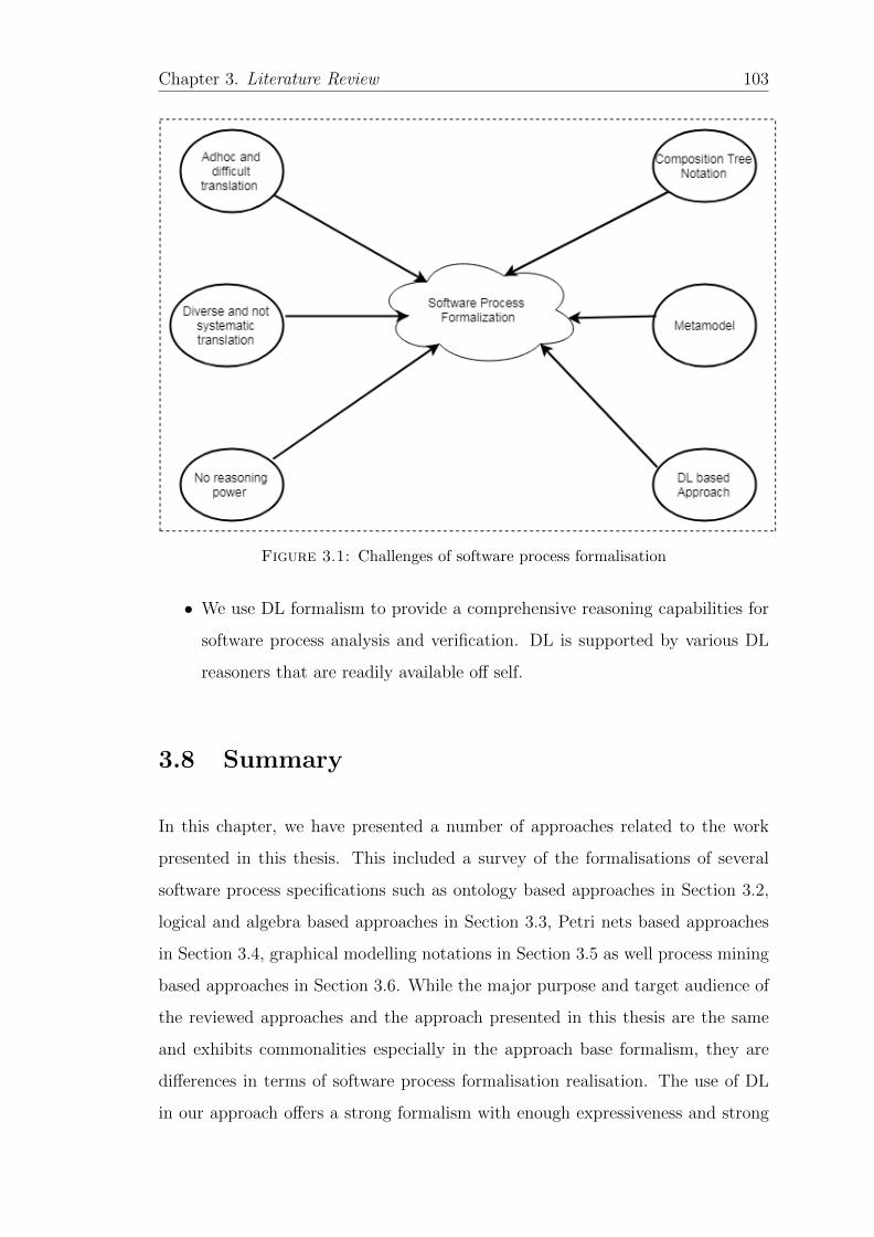
Chapter 3. Literature Review 103
Figure 3.1: Challenges of software process formalisation
• We use DL formalism to provide a comprehensive reasoning capabilities for
software process analysis and verification. DL is supported by various DL
reasoners that are readily available off self.
3.8 Summary
In this chapter, we have presented a number of approaches related to the work
presented in this thesis. This included a survey of the formalisations of several
software process specifications such as ontology based approaches in Section 3.2,
logical and algebra based approaches in Section 3.3, Petri nets based approaches
in Section 3.4, graphical modelling notations in Section 3.5 as well process mining
based approaches in Section 3.6. While the major purpose and target audience of
the reviewed approaches and the approach presented in this thesis are the same
and exhibits commonalities especially in the approach base formalism, they are
differences in terms of software process formalisation realisation. The use of DL
in our approach offers a strong formalism with enough expressiveness and strong

Chapter 3. Literature Review 104
reasoning capabilities needed for process verification. Moreover, DL provides for-
mal semantics to the standardised web ontology language. Using a standardised
language improves the adoption rate of the developed approach in industry. To
ease the use of our approach, we incorporated CT models that are easy and simple
for the stakeholders to work with and validate.
Having provided the research limitations in this chapter, in Chapter 4, we elaborate
upon the methodology employed to achieve the research aims and objectives of
this study, and briefly review the methods and techniques that are used to achieve
them. Two contribution chapters (5 and 6) then follow, which describe our solution
in details.
Chapter 4
Methodology
4.1 Introduction
In the previous chapter, related works in literature were reviewed. From the litera-
ture review, several issues in the current software process formalisation approaches
were identified and represented in a conceptual framework in Figure 3.1.
In this chapter, we present the research methodology adopted to achieve the re-
search objectives set out in Chapter 1. A research methodology involves a com-
bination of processes, methods and tools that are used in conducting research in
a given research domain [235]. The selection of a research methodology depends
upon how closely the research method relates to the research objectives that are
guiding the research [236, 237]. Software Engineering requires research method-
ologies that involve building, analysing and improving various aspects of software
development [237, 238]. Crucial for quality research is not only the selection of
an interesting and relevant problem, but also the choice of an appropriate and
rigorous research methodology to achieve the research objectives. As the overall
objective of this research consists of developing and evaluating a consistent and re-
peatable approach for software process formalisation, the Design Science Research
(DSR) approach is adopted and justified in Section 4.2, while Section 4.3 describes
105
Chapter 4. Methodology 106
the design science research methodology process model that is used to structure
the research process in this thesis and Section 4.4 concludes the chapter.
4.2 Design Science Research Approach
Research in the computing domain is largely characterised by two paradigms,
namely behavioural science and design science [222]. Behavioural science has its
roots in the natural science with quantitative, qualitative and mixed methodolo-
gies [239] rooted in data collection and empirical analysis techniques that seek
to develop and test hypothesises, and theories (i.e., principles and laws) [240].
The natural science research methods are indoctrinated in positivism and inter-
pretivism philosophical stances and are suited to studying naturally existing or
emergent phenomena but are not sufficient to develop novel artefacts that solve
wicked organisational problems and challenges [222].
On the other hand, Design Science Research (DSR) approach is a prominent re-
search method that emerged as a response to increasing the practical relevance of
research to the practitioners community. It emphasises practical relevance through
artefact development as an essential research goal and, thereby accomplishing util-
ity [222]. DSR emerged as a paradigm shift to supporting research when developing
novel, innovative solutions to problems faced by organizations [222]. The design
science paradigm is rooted in engineering and the Science of the Artificial [241].
It seeks to develop and evaluate innovative artefacts that can be used to solve
real world problems [222]. Computational and mathematical methods are mainly
utilised in developing and evaluating the utility and functionality of the DSR arte-
facts [222]. DSR primary objective is to solve problems through rigorously arte-
fact development and evaluation, a feature that distinguishes it from behavioural
research. On the contrary behavioural science is concerned with exploring and
understanding unexplained phenomena: Through developing and testing theories,
behavioural research seeks for truth as opposed to utility. However, while pursuing
distinct goals, the two paradigms are complementary in nature [222, 242].
Chapter 4. Methodology 107
DSR creates and evaluates innovative artefacts aimed at solving important un-
solved problems or solving such problems in an efficient and effective way [222],
while appropriately applying the existing body of knowledge (i.e. theoretical foun-
dations and methodologies) [243]. This distinguishes DSR from mere design ac-
tivities practised in engineering and computer science for routine activities [222].
While several authors attempt to define various artefacts produced by DSR, March
and Smith [240] differentiate between four types of computing artefacts:
• Constructs are the conceptual vocabulary and symbols of a domain. They
provide a language through which the problem and the solution are commu-
nicated.
• Models on the other hand, use constructs to help in the understanding of
the problem and the solution. Through abstractions, models represent the
design problem and its solution space [241].
• Methods (algorithms and practices) define processes and guidelines on how to
solve the designated problem. They range from formal to informal, textual
descriptions of best practices approaches on how to solve problems, i.e.,
searching the solution space.
• Instantiation operationalize the constructs, models and methods in a work-
ing system or prototype. They demonstrate quality, utility and efficacy of
an artefact suitability to its intended purpose.
In this study, as an artefact, we develop and evaluate an approach (a method
in DSR terms) for software process formalisation. Software processes are mainly
described in natural language as a set of best practices and guidelines for effective
software development. However, such informal process descriptions are difficult
to verify if they have been fully implemented and adhered to in a given software
development project. As part of the formal approach, we also develop a customised
metamodel and software process knowledge base to support automated process
analysis.
Chapter 4. Methodology 108
Our aim in this study, is the development and evaluation of a formalisation ap-
proach (an artefact) for software processes making DSR an appropriate paradigm
and methodology [240, 244] for our study. Since this is a practical problem and
the solution to this problem includes the development and evaluation of several
artefacts (formalisation approach, metamodel and a knowledge base), then DSR
approach emerges intuitively as an appropriate approach for this study. The DSR
approach is a problem solving paradigm that emphasises the rigorous development
and evaluation of artefacts intended to solve identified organisational problems in
effective and efficient ways [222]. Moreover, the DSR approach is increasingly
being used in the software engineering as evidenced by its usage in technology ori-
ented research institutions such as MIT’s media lab, Carnegie-Mellon’s Software
Engineering Institute, Xerox’s PARC among others [242]. Furthermore, the DSR
approach is now an established research methodology that is suited to the wicked
problems [12] in SE [244] and specifically in developing and evaluating software
process models [48, 163, 245–247].
4.3 Design Science Research Methodology
At the heart of any research endeavour; be it design science or behavioural science,
stands the research process [235, 248]. It encompasses a sequence of steps in which
one or more research methods are applied. Various authors have contributed to
developing a DSR process and guidelines for its conduct [222, 235, 242]. While
these DSR process models are useful as high level frameworks and guidelines for
conducting DSR, they lack sufficient details in their application. To overcome
this challenge, prior DSR process models were synthesised into the design science
research methodology (DSRM) by Peffers et al. [248], whose main objective was to
develop a template and mental model for conducting consistent DSR. According
to Geerts [249], DSRM aims at improving the conduct and evaluation of DSR
while being consistent with the principles and guidelines of DSR established in
earlier research such as [222]. DSRM provides the most comprehensive rigorous
DSR process that:
Chapter 4. Methodology 109
• provides a nominal design science research process with a template for con-
ducting applicable and precise design science research with six clear steps.
DSRM provides a useful synthesised systematic process model for conducting
and evaluating DSR.
• builds upon the strengths of prior research that proposed various guidelines
and frameworks for conducting design science research such as [222, 235, 242].
• provides a mental model for characteristics of design science research output.
The DSRM incorporates principles, practices, and procedures required to carry
out design science research with six clear activities as shown Figure 4.1 [248]:
1. Problem identification and motivation: The research process starts
with identifying and defining a specific research problem that needs a arte-
factual solution to be provided by carrying out design science research.
2. Objectives of a solution: After problem definition then solution objectives
are set from the research problem.
3. Design and development: The solution objectives are transformed into
the artefact functionality through developing the artefactual solution. This
is based on the knowledge obtained from literature review as well as from
other sources like practitioners, case studies among others [250].
4. Demonstration: Demonstration of the artefact utility, efficacy and quality
to check whether the artefact can solve the problem for which it was created.
This can be done through various DSR evaluation strategies [222, 240, 251].
5. Evaluation: This phase enhances the demonstration results through mon-
itoring the performance of the artefact in solving the problem for which it
was created. This can be done by comparing the objectives of the arte-
fact solution and the actual observed results from use of the artefact in the
demonstration. Various evaluation metrics can be applied as well as empir-
ical studies in selected case studies [222].
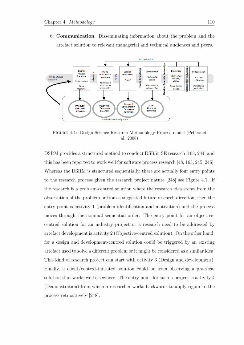
Chapter 4. Methodology 110
6. Communication: Disseminating information about the problem and the
artefact solution to relevant managerial and technical audiences and peers.
Figure 4.1: Design Science Research Methodology Process model (Peffers etal. 2008)
DSRM provides a structured method to conduct DSR in SE research [163, 244] and
this has been reported to work well for software process research [48, 163, 245, 246].
Whereas the DSRM is structured sequentially, there are actually four entry points
to the research process given the research project nature [248] see Figure 4.1. If
the research is a problem-centred solution where the research idea stems from the
observation of the problem or from a suggested future research direction, then the
entry point is activity 1 (problem identification and motivation) and the process
moves through the nominal sequential order. The entry point for an objective-
centred solution for an industry project or a research need to be addressed by
artefact development is activity 2 (Objective-centred solution). On the other hand,
for a design and development-centred solution could be triggered by an existing
artefact used to solve a different problem or it might be considered as a similar idea.
This kind of research project can start with activity 3 (Design and development).
Finally, a client/context-initiated solution could be from observing a practical
solution that works well elsewhere. The entry point for such a project is activity 4
(Demonstration) from which a researcher works backwards to apply rigour to the
process retroactively [248].
Chapter 4. Methodology 111
In this study, the entry point is activity 1 (Problem-centred initiation) given the
fact that the idea comes from the observation of the problem in literature (see
Chapter 3). The lack of a formal framework for a systematic, repeatable and
consistent approach for software process formalisation could hinder software pro-
cess automation and verification. Therefore, there is need for a framework that
is systematic, repeatable and consistent for software process formalisation and
automation. Therefore, the entry point for this research is activity 1 (problem
identification and motivation) and five other activities follow sequentially as dis-
cussed next:
4.3.1 Activity 1: Problem identification and motivation
Software processes are always represented in natural language, for example soft-
ware processes represented in software engineering standards such as ISO/IEC
12207, ISO/IEC 29110 among others are described in natural language. However
natural language lacks the computational semantics needed to enable automated
analysis of such processes [85]. The need for software process formalisation is well
emphasised in literature, and various formalisation approaches have been sug-
gested in literature [38, 74, 77, 78, 220] however, the current approaches are: (i)
adhoc and too technical to be used by ordinary process engineers [38], (ii) such
approaches don’t accommodate diverse software processes in a unified way dur-
ing the formalisation process, and (iii) they don’t provide a comprehensive formal
reasoning framework for software process automated analysis and verification. In
response to these challenges, we develop a formal approach and related techniques
and guidelines for software process formalisation to enable process verification and
automation. Figure 3.1 highlights the challenges in the current software process
formalisation approaches identified in Chapters 1 and 3, and how we address each
one of them in Chapters 5 and 6.

Chapter 4. Methodology 112
4.3.2 Activity 2: Define objectives of a solution
The main objective of this thesis is to develop a formal approach and related
techniques and guidelines for software process formalisation to enable process ver-
ification and automation. In service of our main research objective, the following
specific objectives are at the core of this study:
1. To develop a translation approach from natural language software process
to formal presentations. This is addressed in Chapter 6.
2. To demonstrate that the developed translation approach is able to
integrate heterogeneous software processes into a unified model. This is
addressed in Chapter 5
3. To demonstrate that the developed translation approach is; i) systematic;
ii) easy to use and understandable by all the stakeholders. This is
addressed in Chapter 6
4. To demonstrate that the developed translation approach has reasoning
capability that can facilitate (Chapter 7);
• automated process analysis and verification
• check process compliance to the reference process
• enable automated process capability determination and checking
4.3.3 Activity 3: Design and development
During the design and development process, the objectives of the proposed so-
lutions are transformed to determine the artefacts functionality and its architec-
ture. In this thesis, the design and development of the formalisation approach is
described in Chapter 6, while the design and development of the metamodel is
presented in Chapter 5. In here, we discuss the methodologies and steps used to
develop the formalisation approach and the metamodel.
Chapter 4. Methodology 113
We have analysed related literature in Chapters 2 and 3 to gather requirements for
the development of the formalisation approach. This is consistent with findings by
Ostrowski and Helfert [250] who established that most design science researchers
gathered relevant information for constructing artefacts from literature. During
this process, the contributions from previous researchers in the literature review
served as the theoretical foundation for the development of the formalisation ap-
proach see Figure 3.1. For the design and development of the formalisation ap-
proach, we took a 4-step approach involving: (i) software process normalisation
through use of a customised metamodel; (ii) translation of software processes from
natural language to composition trees; (iii) translation of composition trees to DL
TBox (ontology); (iv) translation of software process instance to DL ABox (This
forms the basis of the demonstration and evaluation activity in Chapter 7)
4.3.3.1 software process normalisation through a unified process model
(Metamodel)
Every software process has some common basic elements such as activity, work
products and roles [117]. However, different PRMs represent them differently in
terms of name, granularity, formality and abstraction. For example, ISO/IEC
12207 represents the positive benefits of performing a software process as process
outcomes and the same is represented as objectives in ISO/IEC 29110 and yet
their mapping may not be straight forward [48]. To enhance homogeneous and
systematic software process formalisation, process modelling needs to be supported
by a very high level of abstraction [14] to take into consideration the varying con-
ceptual differences. In service of our research objective (RO2) we have developed
a customised metamodel to provide a conceptual foundation that integrates het-
erogeneous software processes into a unified model for process formalisation. The
metamodel is discussed in details in Chapter 5 and published in [93].
To develop this metamodel, we have used axioms [252] to determine the metamodel
basic constituents. Axioms are statements which are accepted as true and their ac-
curacy doesn’t need to be proven and can therefore be used as a basis for argument
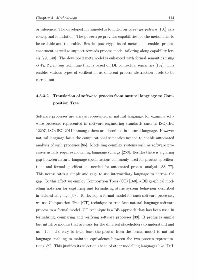
Chapter 4. Methodology 114
or inference. The developed metamodel is founded on powerype pattern [150] as a
conceptual foundation. The powertype provides capabilities for the metamodel to
be scalable and tailorable. Besides powertype based metamodel enables process
enactment as well as support towards process model tailoring along capability lev-
els [79, 140]. The developed metamodel is enhanced with formal semantics using
OWL 2 punning technique that is based on DL contextual semantics [102]. This
enables various types of verification at different process abstraction levels to be
carried out.
4.3.3.2 Translation of software process from natural language to Com-
position Tree
Software processes are always represented in natural language, for example soft-
ware processes represented in software engineering standards such as ISO/IEC
12207, ISO/IEC 29110 among others are described in natural language. However
natural language lacks the computational semantics needed to enable automated
analysis of such processes [85]. Modelling complex systems such as software pro-
cesses usually requires modelling language synergy [253]. Besides there is a glaring
gap between natural language specifications commonly used for process specifica-
tions and formal specifications needed for automated process analysis [38, 77].
This necessitates a simple and easy to use intermediary language to narrow the
gap. To this effect we employ Composition Trees (CT) [160], a BE graphical mod-
elling notation for capturing and formalising static system behaviour described
in natural language [39]. To develop a formal model for such software processes,
we use Composition Tree (CT) technique to translate natural language software
process to a formal model. CT technique is a BE approach that has been used in
formalising, comparing and verifying software processes [39]. It produces simple
but intuitive models that are easy for the different stakeholders to understand and
use. It is also easy to trace back the process from the formal model to natural
language enabling to maintain equivalence between the two process representa-
tions [89]. This justifies its selection ahead of other modelling languages like UML
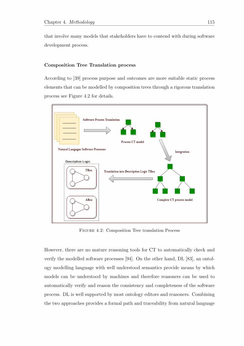
Chapter 4. Methodology 115
that involve many models that stakeholders have to contend with during software
development process.
Composition Tree Translation process
According to [39] process purpose and outcomes are more suitable static process
elements that can be modelled by composition trees through a rigorous translation
process see Figure 4.2 for details.
Figure 4.2: Composition Tree translation Process
However, there are no mature reasoning tools for CT to automatically check and
verify the modelled software processes [94]. On the other hand, DL [83], an ontol-
ogy modelling language with well understood semantics provide means by which
models can be understood by machines and therefore reasoners can be used to
automatically verify and reason the consistency and completeness of the software
process. DL is well supported by most ontology editors and reasoners. Combining
the two approaches provides a formal path and traceability from natural language

Chapter 4. Methodology 116
software processes to a formal process model. This in turn facilitates automated
process analysis and verification.
4.3.3.3 Translation of Composition Trees to DL TBox (ontology)
Since CT models cannot be reasoned on using available DL reasoners, we then
translate the CT process models to DL TBox (ontology). Formal ontologies pro-
vide a logical formalism or model theory for automated process analysis, consis-
tency checking and verification [85]. Moreover, ontologies allow more convenient
and powerful query answering for knowledge retrieval, reduces process ambiguity,
promote integration and interoperability between different software processes [61].
DL has well understood semantics by which software process models can be under-
stood and shared by machines and therefore reasoners can be used to automatically
verify and reason the consistency and completeness of the software process. Highly
optimized and efficient DL reasoners such as PELLET [200], FACT++ [207] and
HERMIT [199] are readily available off shelf for such purposes.
Specifically we follow a two layered development approach commonly used in on-
tology development [254], to represent the different levels of software process ab-
straction. i.e., standard process description modelled as a TBox (Class Level) and
instance level processes modelled as an ABox (Instance Level). We follow a top
down approach developing the TBox first then instantiating it with the instances
of the ABox [184], See Figure 4.3 for details [255]. The development process is
based on ontology development methodologies in [254, 256] with the following
steps:
1. Design the TBox for the knowledge base. The CT process model developed
in 4.3.3.2 provides the input to this step.
• Classify entities as concept or role.
• Add concepts to TBox.
• Add roles to TBox.
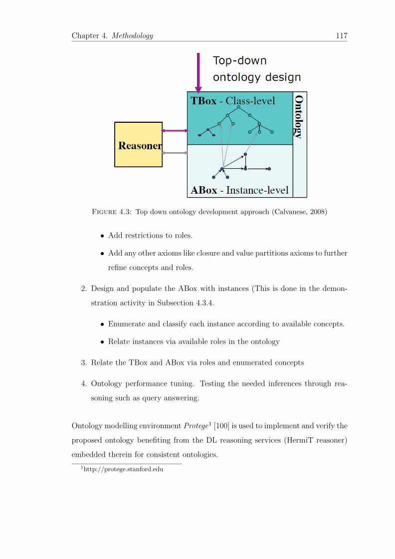
Chapter 4. Methodology 117
Figure 4.3: Top down ontology development approach (Calvanese, 2008)
• Add restrictions to roles.
• Add any other axioms like closure and value partitions axioms to further
refine concepts and roles.
2. Design and populate the ABox with instances (This is done in the demon-
stration activity in Subsection 4.3.4.
• Enumerate and classify each instance according to available concepts.
• Relate instances via available roles in the ontology
3. Relate the TBox and ABox via roles and enumerated concepts
4. Ontology performance tuning. Testing the needed inferences through rea-
soning such as query answering.
Ontology modelling environment Protege1 [100] is used to implement and verify the
proposed ontology benefiting from the DL reasoning services (HermiT reasoner)
embedded therein for consistent ontologies.
1http://protege.stanford.edu
Chapter 4. Methodology 118
4.3.4 Activity 4: Demonstration
According to Venables et al. [251] artefact evaluation is a central and essential
activity in conducting rigorous DSR. Towards this, Hevner et al. [222] identified
quality, utility and efficacy as the artefact attributes to be evaluated. They urge
that the selection of evaluation methods must be matched appropriately with
the designed artefacts. To achieve this, they provide various types of artefact
evaluation methods. Among which is descriptive evaluation method that is based
on informed arguments and scenarios defined to develop a convincing argument
of the utility of the solutions proposed. They further suggest that descriptive
evaluation (scenarios) can be adopted where other evaluation methods may not
be usable. In our case due to time constraints, we leave other evaluation methods
such as empirical evaluations for future work.
To demonstrate the feasibility of the proposed approach to solve one or more
instances of the problem, the developed formalisation approach is demonstrated
through various application scenarios to demonstrate reasoning capabilities of the
approach. The application scenarios are translated into a DL ABox to enable
automated verification with the DL TBox that holds the standard process infor-
mation as discussed in Chapter 6. Together the DL TBox and ABox implemented
in protege can facilitate:
• automated analysis and verification
• check process compliance to the reference process
• enable automated process capability determination and checking
The application scenarios and the approach reasoning capabilities are demon-
strated and discussed in details in chapter 7.
Chapter 4. Methodology 119
4.3.5 Activity 5: Evaluation
In this activity, we observe and measure how well the proposed approach can pro-
vide solutions for the research issues raised in Chapters 1 and 3. The outcome of
this research effort is a software process formalisation approach, which is a method
in DSR terms. Methods (Approach) just like any other engineering artefacts need
to be evaluated to assess their quality, utility, efficacy and relevance for the in-
tended purposes. To this end, March and Smith [240] provide a set of criteria for
evaluating DSR methods as completeness, ease of use, consistency, operationality
(the ability to perform the intended task such as software process capability deter-
mination), efficiency, generality, effectiveness and quality of result. This criteria
is consistent with the evaluation of software process quality characteristics [65] to
the extent they apply. Since our approach is ontology based, we also take into
consideration ontology evaluation criteria [201]:
• Accuracy; checks whether the ontology captures and represents correctly the
aspects of the world being modelled. This is similar to operationality seen
above.
• Adaptability; checks whether the ontology can be extended and specialised
monotonically especially where the ontology is developed without its actual
use in mind.
• Clarity; checks whether the ontology communicates effectively the intended
meaning of the defined terms and properties and if the the users can under-
stand the ontology with ease.
• Completeness; does the ontology cover a domain of interest appropriately.
Does it include all relevant concepts and their lexical representations.
• Computational efficiency; can the available reasoners process the ontology
in a fast and efficient way in terms of the common reasoning problems.
• Conciseness; does the ontology include irrelevance axioms with regards to
the domain of interest.
Chapter 4. Methodology 120
• Consistency/coherence; are there any contradictions in the axioms repre-
sented in the ontology. Are the informal and formal description of the on-
tology consistent. For example the ontology documentation and the explicit
conceptualisation.
4.3.5.1 Use of Competency Questions in Evaluation
Ontology validation is an important part of measuring the quality of an ontology,
and the best way to assert the accuracy of the knowledge encoded in the ontology
[257]. Competency questions (CQs) [258] are widely used in authoring [259] and
evaluating ontologies [254, 260]. CQs are natural language questions that represent
ontology requirements and needs, and are expected to be answered by the ontology
[259] only if and only if the ontology has the information required to answer them.
Given the different granularity levels of informal CQs, different technologies can be
used to formalise them, such as SPARQL2 [257], and DL queries [261]. In this study
we use DL queries to answer the CQs. DL query language functions by collecting
all necessary information about a particular class, relationship or instance. DL
queries are able to retrieve superclasses, equivalent, subclasses and instances from
the ontology. CQs support the ontology evaluation through providing developers
with simple ways to verify requirements satisfiability through either information
retrieval or entailment on its axioms and answers [260]. In [257] steps are provided
for working with CQs in evaluating ontologies including:
• Identifying CQs categories according to expected answers and these can be.
definition questions, boolean questions, factual or list questions among oth-
ers.
• Determining the expected answer.
• Formalising the informal CQs into DL query as seen above.
2https://www.w3.org/TR/rdf-sparql-query/

Chapter 4. Methodology 121
Therefore in this thesis, we evaluate our formalisation approach in terms of the
evaluation criteria highlighted above in the application scenarios set out in Chap-
ter 7. We have implemented the approach in Protege [100]. Protege is a free
open source ontology building tool from Stanford university and is widely used
in ontology building for both academic and commercial purposes. Importantly
its embedded with reasoning services provided by FaaCT++ and Hermit reason-
ers. DL facilitates different reasoning services both at the class and instance level
which we employ in evaluating various aspects of the approach. We have also
formalised our competency questions in DL queries and utilised them in evaluat-
ing the functionality, completeness and usability of the approach. We found this
evaluation strategy more efficient and time saving than the empirical evaluation
strategy adopted by Kabaale et al.[262] in evaluating requirements engineering
process improvement approach. We also thought to compare results from the
formal approach with earlier manual approaches [139, 263] for consistency. While
substantial demonstration and evaluation of the artefact capabilities and function-
alities have been shown in Chapter 7, empirical evaluation of the artefact’s utility,
quality and efficacy in the industry is left as future work due to time constraints.
4.3.6 Activity 6: Communication
In order to disseminate the information about the problem and the artefact solu-
tion to relevant audiences, various parts of this research have been communicated
to peers through presentations at several international conferences and have been
published in the conference proceedings throughout the research process. This
thesis is the main means of communication of the research results and is intended
for academic audiences. In Table 4.1, we map the thesis chapters and the cor-
responding set of activities of the design science research methodology process
model.
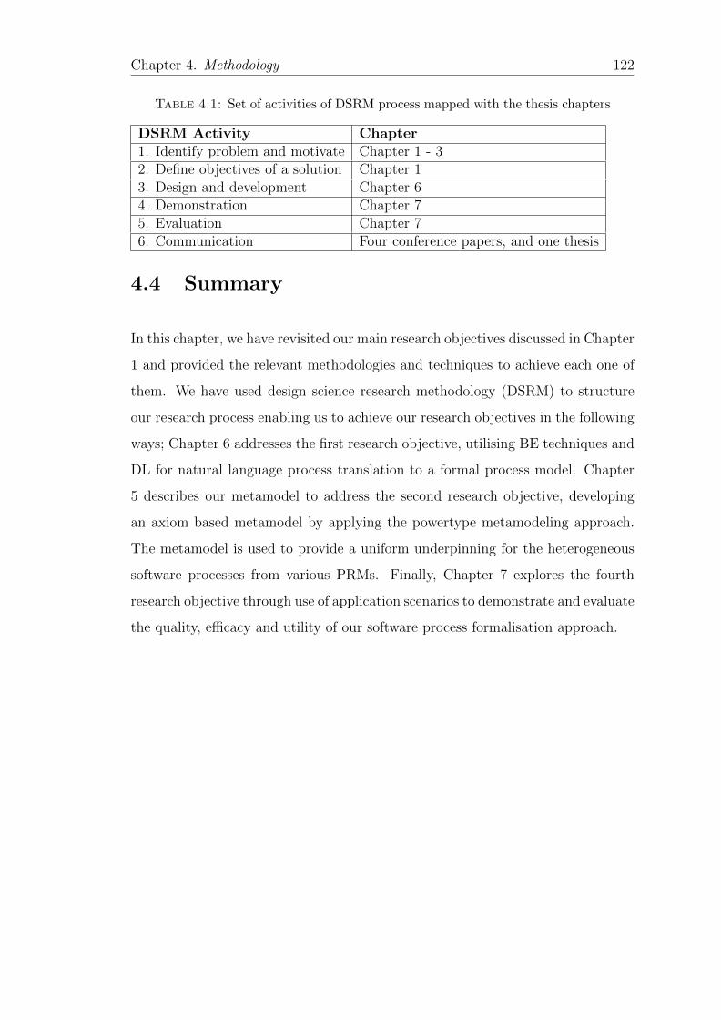
Chapter 4. Methodology 122
Table 4.1: Set of activities of DSRM process mapped with the thesis chapters
DSRM Activity Chapter1. Identify problem and motivate Chapter 1 - 32. Define objectives of a solution Chapter 13. Design and development Chapter 64. Demonstration Chapter 75. Evaluation Chapter 76. Communication Four conference papers, and one thesis
4.4 Summary
In this chapter, we have revisited our main research objectives discussed in Chapter
1 and provided the relevant methodologies and techniques to achieve each one of
them. We have used design science research methodology (DSRM) to structure
our research process enabling us to achieve our research objectives in the following
ways; Chapter 6 addresses the first research objective, utilising BE techniques and
DL for natural language process translation to a formal process model. Chapter
5 describes our metamodel to address the second research objective, developing
an axiom based metamodel by applying the powertype metamodeling approach.
The metamodel is used to provide a uniform underpinning for the heterogeneous
software processes from various PRMs. Finally, Chapter 7 explores the fourth
research objective through use of application scenarios to demonstrate and evaluate
the quality, efficacy and utility of our software process formalisation approach.

Chapter 5
Metamodel
5.1 Introduction
The complexity and diversity of modern software systems demands a variety of
metamodel-based modelling languages for software development [264]. PRMs such
as ISO/IEC 12207, ISO/IEC 29110 provide process life cycle activities and prac-
tices for effective software development, however, these are diverse in the termi-
nologies they use for the same concepts at different abstraction and granularity
levels leading to ambiguities and misinterpretations [92]. For example ISO/IEC
12207 uses process outcomes to represent positive results of process performance,
while ISO/IEC 29110 a tailored version of ISO/IEC 12207 for VSEs uses pro-
cess objectives to refer to the same outcomes. The mapping between the process
outcomes of ISO/IEC 12207 and ISO/IEC 29910 objectives are complicated and
tiresome [48]. Moreover, these PRMs are not directly underpinned by any meta-
model [265].
Therefore when processes from these PRMs are compared and formalised together
on the same project, there are likely to be inconsistent [122]. This rises a need for
a uniform conceptual foundation in terms of a metamodel to underpin software
process formalisation. But then, the available process metamodels such as SPEM
123
Chapter 5. Metamodel 124
and SEDM are too generic and complex to be used for software process formalisa-
tion [84, 141, 266]. It is against this background that in this chapter, we present
an axiom based metamodel developed in Section 5.2 utilising powertype patterns
as a conceptual framework to underpin homogeneous process formalisation. The
advantage of an axiomatic and powertype based metamodel approach lies in its
potential to determine the metamodel basic constituents and formalism as well
as its extensibility and adaptability. We formalise the metamodel using OWL 2
punning in Section 5.3 and Section 5.4 concludes the chapter.
5.2 Axiom based Metamodel
Metamodels have been proposed as a way of increasing process modelling rigour
and formality for automation [140]. These metamodels lay a foundation in terms
of concepts, rules and conceptual relationships among concepts used in process
modelling [141]. So processes grounded in metamodels offer a higher degree of
formalisation and better support for consistent extensions and modification [140].
Moreover, metamodels impose well-formedness rules on process models and process
instances instantiated from them. These help in maintaining process consistency
and completeness [56]. However, the existing process metamodels in literature
such as SPEM [145] and SEMDM [151] are too generic and complex to guide
software process formalisation [141]. For example, SEMDM was intended to be
a general methodology metamodel and cover not only process modelling but also
other areas like computer supported collaborative work (CSCW) [140]. Indeed
such genericity and complexity hinders their comprehension that would be of great
help to software process formalisation. Therefore, there is a need for a customised
and simple metamodel tailored for homogeneous software process formalisation.
To develop this metamodel, we utilise the powertype technique [150] as introduced
in process metamodeling by [149]. The powertype pattern enables tailoring of
software process formalisation to specific project requirements and contexts.
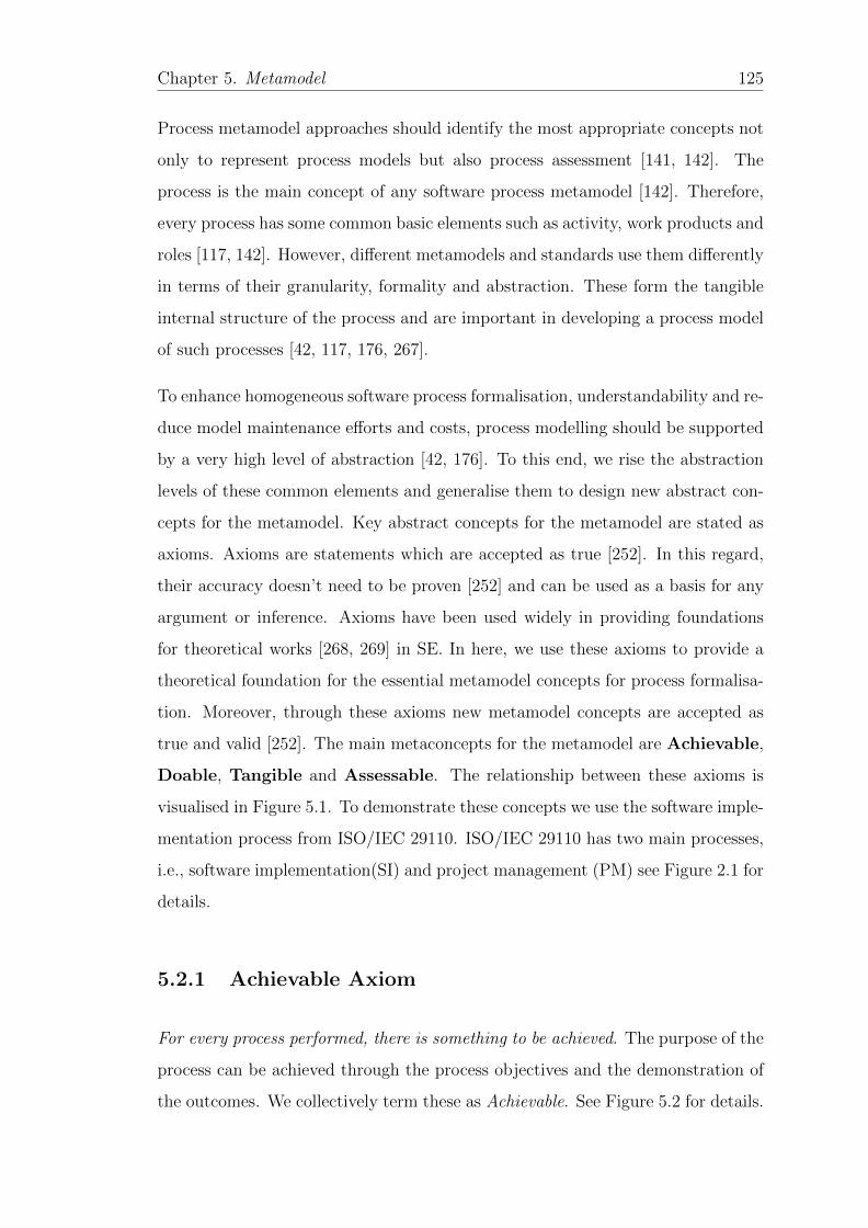
Chapter 5. Metamodel 125
Process metamodel approaches should identify the most appropriate concepts not
only to represent process models but also process assessment [141, 142]. The
process is the main concept of any software process metamodel [142]. Therefore,
every process has some common basic elements such as activity, work products and
roles [117, 142]. However, different metamodels and standards use them differently
in terms of their granularity, formality and abstraction. These form the tangible
internal structure of the process and are important in developing a process model
of such processes [42, 117, 176, 267].
To enhance homogeneous software process formalisation, understandability and re-
duce model maintenance efforts and costs, process modelling should be supported
by a very high level of abstraction [42, 176]. To this end, we rise the abstraction
levels of these common elements and generalise them to design new abstract con-
cepts for the metamodel. Key abstract concepts for the metamodel are stated as
axioms. Axioms are statements which are accepted as true [252]. In this regard,
their accuracy doesn’t need to be proven [252] and can be used as a basis for any
argument or inference. Axioms have been used widely in providing foundations
for theoretical works [268, 269] in SE. In here, we use these axioms to provide a
theoretical foundation for the essential metamodel concepts for process formalisa-
tion. Moreover, through these axioms new metamodel concepts are accepted as
true and valid [252]. The main metaconcepts for the metamodel are Achievable,
Doable, Tangible and Assessable. The relationship between these axioms is
visualised in Figure 5.1. To demonstrate these concepts we use the software imple-
mentation process from ISO/IEC 29110. ISO/IEC 29110 has two main processes,
i.e., software implementation(SI) and project management (PM) see Figure 2.1 for
details.
5.2.1 Achievable Axiom
For every process performed, there is something to be achieved. The purpose of the
process can be achieved through the process objectives and the demonstration of
the outcomes. We collectively term these as Achievable. See Figure 5.2 for details.
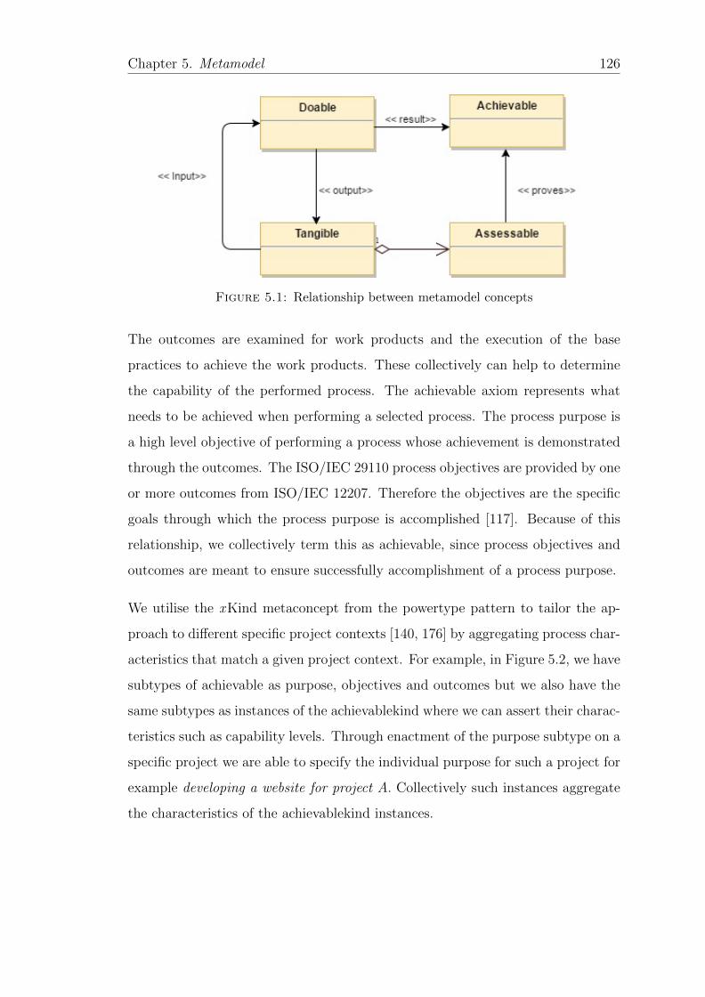
Chapter 5. Metamodel 126
Figure 5.1: Relationship between metamodel concepts
The outcomes are examined for work products and the execution of the base
practices to achieve the work products. These collectively can help to determine
the capability of the performed process. The achievable axiom represents what
needs to be achieved when performing a selected process. The process purpose is
a high level objective of performing a process whose achievement is demonstrated
through the outcomes. The ISO/IEC 29110 process objectives are provided by one
or more outcomes from ISO/IEC 12207. Therefore the objectives are the specific
goals through which the process purpose is accomplished [117]. Because of this
relationship, we collectively term this as achievable, since process objectives and
outcomes are meant to ensure successfully accomplishment of a process purpose.
We utilise the xKind metaconcept from the powertype pattern to tailor the ap-
proach to different specific project contexts [140, 176] by aggregating process char-
acteristics that match a given project context. For example, in Figure 5.2, we have
subtypes of achievable as purpose, objectives and outcomes but we also have the
same subtypes as instances of the achievablekind where we can assert their charac-
teristics such as capability levels. Through enactment of the purpose subtype on a
specific project we are able to specify the individual purpose for such a project for
example developing a website for project A. Collectively such instances aggregate
the characteristics of the achievablekind instances.
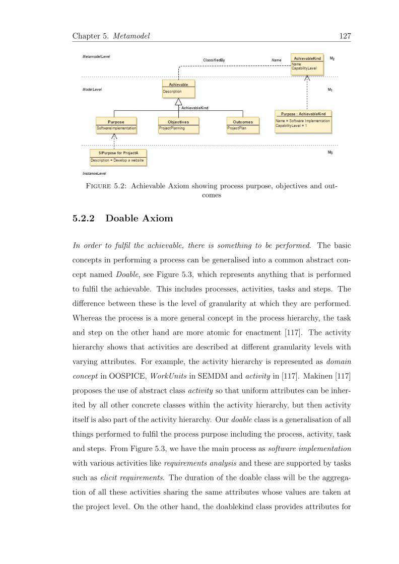
Chapter 5. Metamodel 127
Figure 5.2: Achievable Axiom showing process purpose, objectives and out-comes
5.2.2 Doable Axiom
In order to fulfil the achievable, there is something to be performed. The basic
concepts in performing a process can be generalised into a common abstract con-
cept named Doable, see Figure 5.3, which represents anything that is performed
to fulfil the achievable. This includes processes, activities, tasks and steps. The
difference between these is the level of granularity at which they are performed.
Whereas the process is a more general concept in the process hierarchy, the task
and step on the other hand are more atomic for enactment [117]. The activity
hierarchy shows that activities are described at different granularity levels with
varying attributes. For example, the activity hierarchy is represented as domain
concept in OOSPICE, WorkUnits in SEMDM and activity in [117]. Makinen [117]
proposes the use of abstract class activity so that uniform attributes can be inher-
ited by all other concrete classes within the activity hierarchy, but then activity
itself is also part of the activity hierarchy. Our doable class is a generalisation of all
things performed to fulfil the process purpose including the process, activity, task
and steps. From Figure 5.3, we have the main process as software implementation
with various activities like requirements analysis and these are supported by tasks
such as elicit requirements. The duration of the doable class will be the aggrega-
tion of all these activities sharing the same attributes whose values are taken at
the project level. On the other hand, the doablekind class provides attributes for
Chapter 5. Metamodel 128
the process model level describing the characteristics of all the kinds of processes,
activities and tasks.
Figure 5.3: Doable Axiom showing software implementation process example
5.2.3 Tangible Axiom
In order to perform the doable, it requires something as input to produce the desired
output. The main purpose of performing a process is to produce outputs. Tangible
are the inputs and outputs of performing the doable see Figure 5.4. The tangible
within ISO/IEC 29110 at the abstract level are input, internal or output prod-
ucts. When they are outputs, they are always associated with a destination. This
destination can either be another process for example project plan from project
management process to software implementation process [26] or just going outside
of the process, for example acceptance document goes outside of the implementa-
tion process to the customer. The tangible can also be inputs to the doable for
example a project plan is an input to the software implementation process. Other
times the tangible can be internal work products such as ChangeRequest from
within the process [26].
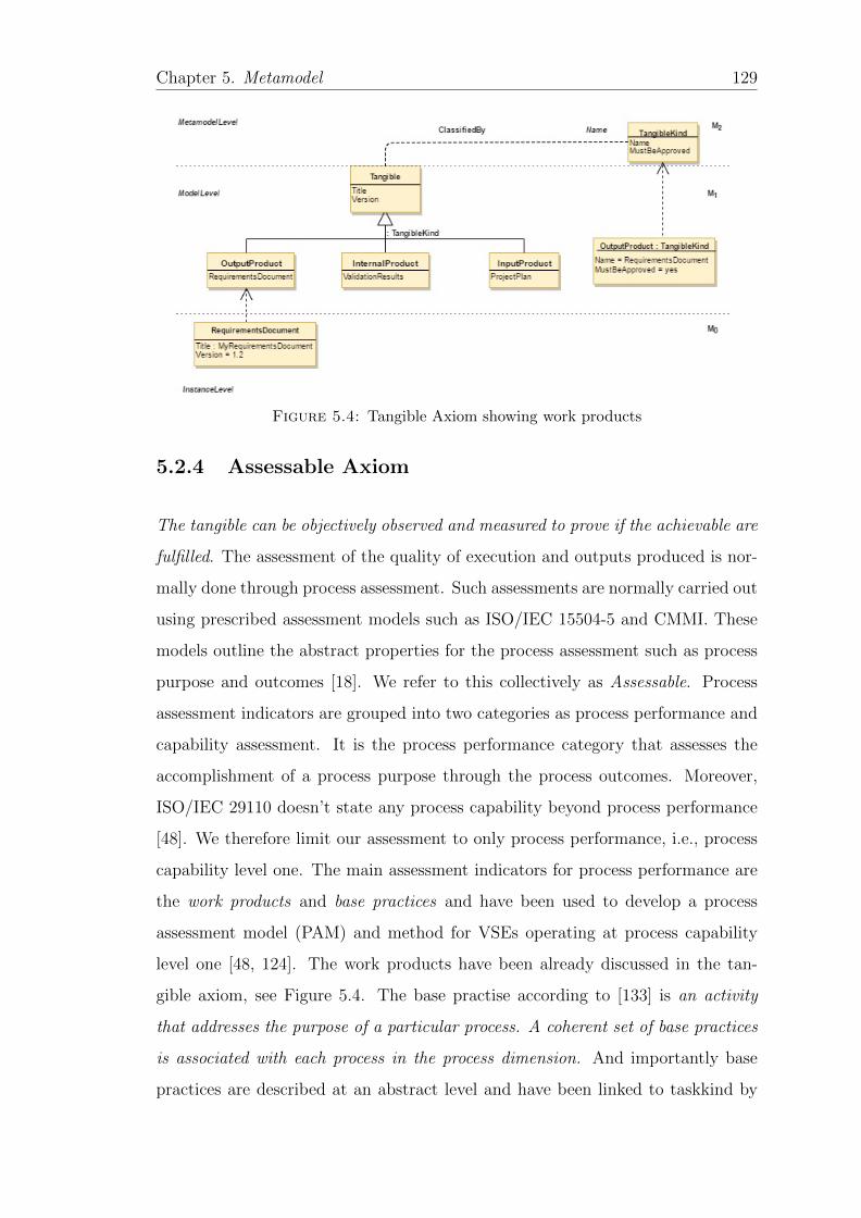
Chapter 5. Metamodel 129
Figure 5.4: Tangible Axiom showing work products
5.2.4 Assessable Axiom
The tangible can be objectively observed and measured to prove if the achievable are
fulfilled. The assessment of the quality of execution and outputs produced is nor-
mally done through process assessment. Such assessments are normally carried out
using prescribed assessment models such as ISO/IEC 15504-5 and CMMI. These
models outline the abstract properties for the process assessment such as process
purpose and outcomes [18]. We refer to this collectively as Assessable. Process
assessment indicators are grouped into two categories as process performance and
capability assessment. It is the process performance category that assesses the
accomplishment of a process purpose through the process outcomes. Moreover,
ISO/IEC 29110 doesn’t state any process capability beyond process performance
[48]. We therefore limit our assessment to only process performance, i.e., process
capability level one. The main assessment indicators for process performance are
the work products and base practices and have been used to develop a process
assessment model (PAM) and method for VSEs operating at process capability
level one [48, 124]. The work products have been already discussed in the tan-
gible axiom, see Figure 5.4. The base practise according to [133] is an activity
that addresses the purpose of a particular process. A coherent set of base practices
is associated with each process in the process dimension. And importantly base
practices are described at an abstract level and have been linked to taskkind by
Chapter 5. Metamodel 130
[176]. The taskind classes that represent base practices have also been discussed
in the doable axiom see Figure 5.3.
According to [142] a metamodel that directly supports the concept of capability
levels enhances the definitions of process models that are dynamically tailorable
along their capability levels. It should be noted, however, that from the Doable
axiom, it is only the process that is assessable because its associated with a purpose
and outcomes while others are not [142]. An assessable process metamodel is one
that incorporates the necessary formal properties for assessment so that no external
process reference model is needed [142]. A good metamodel should address the
different aspects of a process model such as the process hierachy (Doable), work
products (Tangible), objectives (Achievable) as well as the assessment (Assessable)
of the entire process [142].
Even though, metamodels provide a rigorous underpinning and consistent ter-
minology to various aspects of SE, they only deal with conceptual definitions,
standardisations and syntax of process models necessitating the need for formal
semantics and reasoning of such conceptual definitions [152, 270]. We therefore
formalise the developed metamodel using ontologies. Ontologies constitute formal
models that define formal semantics and inference services for a shared conceptu-
alisation. These can be used to draw interesting logical conclusions through for
example (meta)model checking, model enrichment, dynamic classification, infor-
mation retrieval and querying of software process models across the metamodel
hierarchy thus improving software engineering processes [253].
5.3 Formalising the Axiom based Metamodel
The need to fix formal semantics for metamodels and their instantiated process
models has long been highlighted by different authors [253, 270–272]. Metamodel
formal semantics are needed for satisfiability checking at the process model layers
as well as checking the consistency of the instantiated process models [253]. The
current approaches [253] emphasise fixing formal semantics for metamodels and
Chapter 5. Metamodel 131
the corresponding process models helping to maintain consistency between meta-
models and their instantiated process models [270]. For example in [253], both the
metamodel and process models are transformed to ontologies where the metamodel
is transformed to the OWL DL TBox and the process model is transformed to the
OWL DL ABox. In [270] domain ontologies are used to define formal semantics
for process models while meta-ontologies or foundational ontologies are used to
define formal semantics for metamodels. A reference ontology for the domain of
software engineering standards has been developed by [176] where a common and
unambiguous terminology is sought for all (current and future) software engineer-
ing standards developed by ISO/IEC JTC1’s SC7. Software engineering standard
harmonization ontologies [92, 267] have also been developed to harmonise concepts
and term usage across different process models and references models in software
engineering domain. All these studies lay a theoretical foundation for the work
presented in this section.
The semantics and consistency of the instantiated processes at M0 in respect to
the metamodel at M2 are largely undefined in the current approaches. In [94], we
have shown how the semantics of the instantiated process can be used for process
reasoning, verification and conformance to the process model. This provides our
motivation for the current section by extending the semantic mapping from the
metamodel further to the process instances. This can guarantee the semantic
consistency right from the metamodel upto the instantiated process. Hence, we
map the metamodel at M2 to a OWL DL TBox, the clabject (dual entity) at M1 to
OWL DL TBox/ABox (OWL punning) and the instantiated process M0 to OWL
DL ABox. See Figure 5.5 for details. With such a mapping, we are able to utilise
ontology reasoning support across the metamodeling layers such as satisfiability
checking between metamodels and process models, process models and process
instances as well as process metamodels and process instances. Moreover, we can
enforce and check the well-formedness constraints [56] that the metamodel imposes
on the process models and process instances respectively.
To illustrate our approach, we take the Tangible metaconcept for an example as
shown by Figure 5.5. At level M2, we have the TangibleKind class(Powertype)
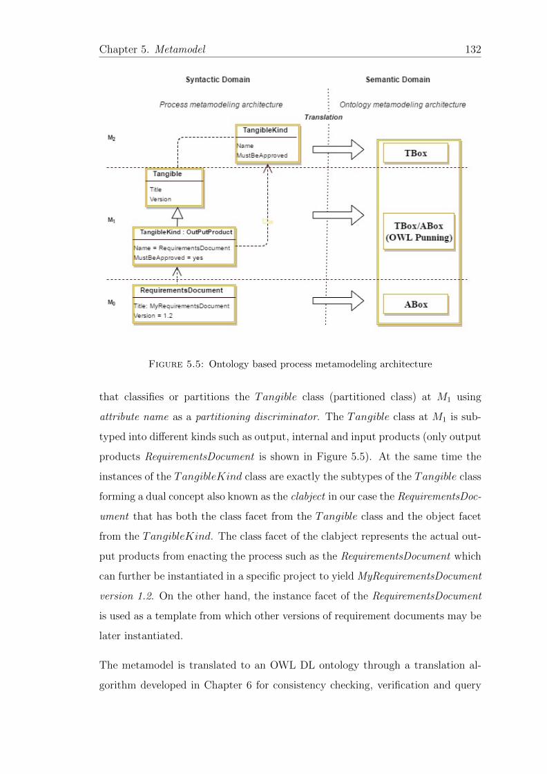
Chapter 5. Metamodel 132
Figure 5.5: Ontology based process metamodeling architecture
that classifies or partitions the Tangible class (partitioned class) at M1 using
attribute name as a partitioning discriminator. The Tangible class at M1 is sub-
typed into different kinds such as output, internal and input products (only output
products RequirementsDocument is shown in Figure 5.5). At the same time the
instances of the TangibleKind class are exactly the subtypes of the Tangible class
forming a dual concept also known as the clabject in our case the RequirementsDoc-
ument that has both the class facet from the Tangible class and the object facet
from the TangibleKind. The class facet of the clabject represents the actual out-
put products from enacting the process such as the RequirementsDocument which
can further be instantiated in a specific project to yield MyRequirementsDocument
version 1.2. On the other hand, the instance facet of the RequirementsDocument
is used as a template from which other versions of requirement documents may be
later instantiated.
The metamodel is translated to an OWL DL ontology through a translation al-
gorithm developed in Chapter 6 for consistency checking, verification and query
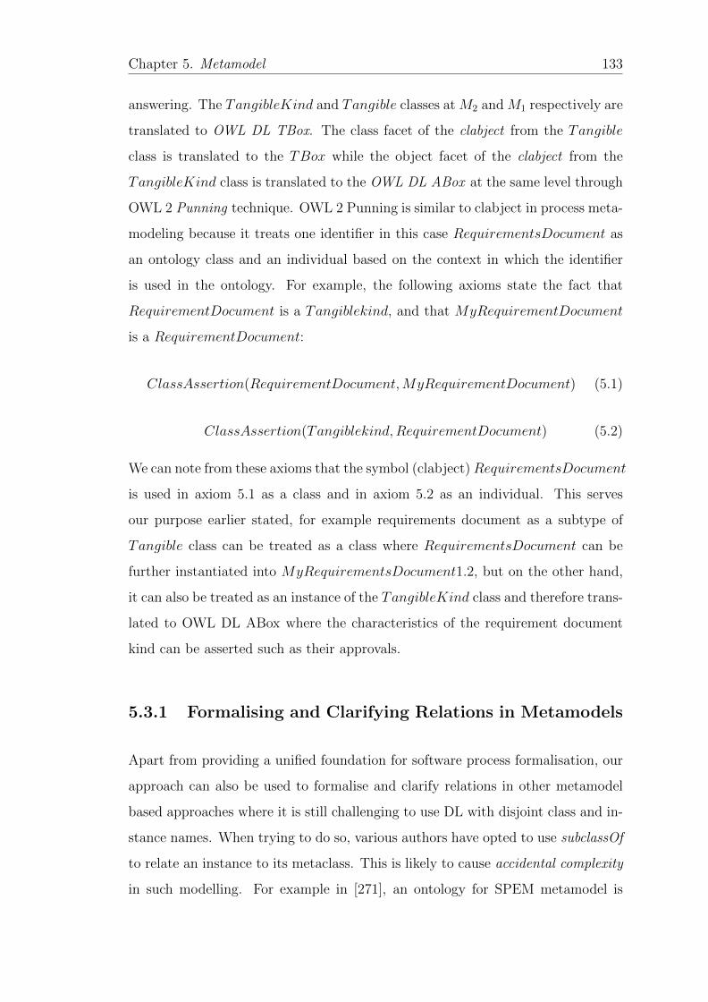
Chapter 5. Metamodel 133
answering. The TangibleKind and Tangible classes at M2 and M1 respectively are
translated to OWL DL TBox. The class facet of the clabject from the Tangible
class is translated to the TBox while the object facet of the clabject from the
TangibleKind class is translated to the OWL DL ABox at the same level through
OWL 2 Punning technique. OWL 2 Punning is similar to clabject in process meta-
modeling because it treats one identifier in this case RequirementsDocument as
an ontology class and an individual based on the context in which the identifier
is used in the ontology. For example, the following axioms state the fact that
RequirementDocument is a Tangiblekind, and that MyRequirementDocument
is a RequirementDocument:
ClassAssertion(RequirementDocument,MyRequirementDocument) (5.1)
ClassAssertion(Tangiblekind,RequirementDocument) (5.2)
We can note from these axioms that the symbol (clabject)RequirementsDocument
is used in axiom 5.1 as a class and in axiom 5.2 as an individual. This serves
our purpose earlier stated, for example requirements document as a subtype of
Tangible class can be treated as a class where RequirementsDocument can be
further instantiated into MyRequirementsDocument1.2, but on the other hand,
it can also be treated as an instance of the TangibleKind class and therefore trans-
lated to OWL DL ABox where the characteristics of the requirement document
kind can be asserted such as their approvals.
5.3.1 Formalising and Clarifying Relations in Metamodels
Apart from providing a unified foundation for software process formalisation, our
approach can also be used to formalise and clarify relations in other metamodel
based approaches where it is still challenging to use DL with disjoint class and in-
stance names. When trying to do so, various authors have opted to use subclassOf
to relate an instance to its metaclass. This is likely to cause accidental complexity
in such modelling. For example in [271], an ontology for SPEM metamodel is
Chapter 5. Metamodel 134
developed using OWL DL, and to remain within the decidability boundaries of
OWL DL, subclassOf relation is used instead of instanceOf to relate an instance
to its metaclass. Similarly in [273] an ontology based on ISO/IEC 24744 standard
is developed, however, the powertype and clabject elements were not modelled in
the ontology. In this ontology, all xKind entities are modelled as classes with has-
SubclassOf relation to their instances. While this works fine within the ontology
module used, it may have undesirable consequences if such an ontology is to be
shared with other ontologies over the web. Moreover, such misrepresentation has
been shown to be non intuitive and causes accidental complexity [274].
The xKind metatypes are classes whose instances are classes themselves [210] and
therefore should be related via instanceOf relation and not subclassOf. Because
their instances are also subtypes of the partitioned class such as Task they form
a dual facet entity also known as clabject meaning an entity with both class and
object facets. In OWL 2 such an entity is modelled using OWL 2 punning1 where
one symbol is used to refer to an ontology class and an individual at the same
time based on the context in which each is used. With OWL 2 punning, the
restriction of having the instances and class names being disjoint is relaxed and
therefore ontology reasoners can be used to check ontology consistency without
causing any contradictions. This is possible because OWL 2 punning is based
on contextual semantics [102] where the symbol interpretation is independently
based on the context and the role played by the symbol in an ontology. In our
metamodel, there are two contexts in which the clabject is interpreted; first at
the process model level M1 where a group of processes, tasks, work products
are discussed and their features identified. At this level, the clabject instance
facet is used as a template from which other processes can be instantiated for a
specific project at the instance level M0. On the other, the same clabject, but
this time its class facet as a subtype of the partitioned class yields the physical
tasks to be implemented on a particular project at M0. This illustration helps to
improve the process model comprehension and flexibility and adaptability. Using
1https://www.w3.org/2007/OWL/wiki/Punning

Chapter 5. Metamodel 135
this integrated metamodeling approach, existing ontology approaches in literature
such as [271, 273, 275] can greatly be enhanced.
5.4 Summary
In this section, we have presented an axiom based metamodel towards systematic
and faithfully software process formalisation for software process automation and
verification. The main aim of the metamodel is to provide uniform formal con-
cepts at an abstract level that may be utilised to formalise heterogeneous software
processes from diverse process reference models. The main meta-concepts of the
metamodel as stated as axioms: achievable, doable, tangible and assessable.
The powertype pattern was utilised to develop the metamodel with the view of en-
abling process model extensibility and flexibility with the ability to model process
enactment and verification. Powertypes also enable tailoring of process models to
different specific projects through the use of xKind and clabject concepts. This
helps to create different hierarchical views/contexts for the modeled process, a
limitation identified with UML strict metamodeling in Chapter 2.
Finally the metamodel is then formalised into a formal ontology using OWL pun-
ning technique. This enables various types of verification at different metamodel
conceptual levels to be carried. For example, ontology reasoning can be used across
the metamodeling layers such as satisfiability checking between process models and
metamodels, process models and process instances as well as process metamodels
and process instances. Having laid the conceptual foundation for software pro-
cess formalisation in form of a metamodel in this chapter, in the next Chapter 6,
we tackle the translation approach from natural language processes to a formal
representation.
Chapter 6
Translation
6.1 Introduction
Software process plays an important role in managing software development com-
plexity by providing an infrastructure to coordinate and manage the various de-
velopment activities, roles and work products, and sequencing them in the correct
order to ensure consistent outputs [165]. However, software processes described
in software engineering standards and reference models such as ISO/IEC 12207,
ISO/IEC 330xx among others are specified in natural language (NL). Due to the
inherent linguistic ambiguities of natural language, such processes are likely to
be inconsistent, incomplete, ambiguous and error prone [40]. As a result, these
software process specifications are hardly suitable for any formal analysis and
verification. This hinders the application of automated rigorous process analysis
techniques to ensure process correctness, completeness and conformance. Software
process specified using natural language should, therefore, be formalized to enable
formal process analysis and automation [53].
Subsequently, formal process specification techniques have been utilised to for-
malise software processes in literature [1, 7, 85]. These are discussed in details in
Chapter 3 where the main aim of such process formalisations is to attain [40]: (i)
136
Chapter 6. Translation 137
an improved understanding of the process by all the stakeholders involved in soft-
ware development, (ii) an enforced certain level of precision into software process
specification, and (iii) more importantly to provide extended process analysis ca-
pabilities such as consistency, completeness and conformance checking [7, 73, 85].
However, there is hardly any simple and consistent process formalisation approach
[91] that can produce repeatable and consistent process formalisation results as
pointed out in Chapter 1.
The main aim of the current chapter is to close this glaring gap by providing
a translation method that can be used to consistently and repeatedly translate
diverse NL processes to formal representation so that automated analysis tech-
niques can be applied on such software processes [85] and provide a foundation for
their automation [53]. Therefore, to leverage formal representations for software
process definition and assessment, both the PRMs and PAMs, and the process
instances (organisational processes) need to be specified in a formal language [46].
This then provides a foundation for automated process analysis techniques such as
query answering to be applied on the process [85]. However, most formal methods
are not easily comprehensible to many software developers [40], hence necessitat-
ing an intermediary interface and a simple translation methodology from natural
language processes to formal process representations.
Upon this motivation, our approach involves firstly translating NL processes un-
derpinned by a unified model discussed in Chapter 5 to composition trees (CT).
The unified model (metamodel) provides a conceptual foundation for software pro-
cesses from different software engineering standards with diverse terminology into
uniform concepts for easy translation to the CT model [93]. In the second step we
translate the created CT process models to DL TBox (ontology) and in the third
step we translate organisational processes (process instances) to DL ABox. Using
ontology reasoning engines such as HermiT [199], we carry out automated analy-
sis such as verifying organisational process conformance in the ABox against the
standard processes in the TBox, i.e., verification by instantiation [125]. Verified
results in form of conformance or non conformance and process profiles can then
be checked by the domain user for equivalence with the original NL processes.
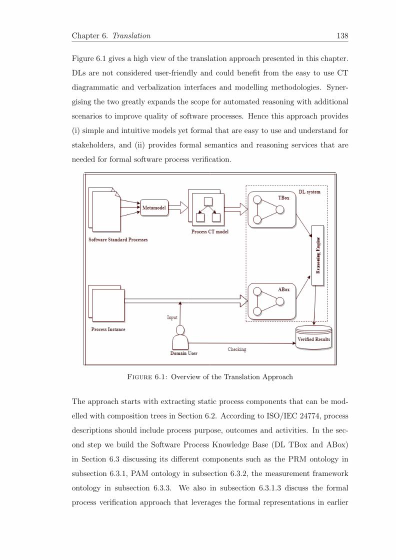
Chapter 6. Translation 138
Figure 6.1 gives a high view of the translation approach presented in this chapter.
DLs are not considered user-friendly and could benefit from the easy to use CT
diagrammatic and verbalization interfaces and modelling methodologies. Syner-
gising the two greatly expands the scope for automated reasoning with additional
scenarios to improve quality of software processes. Hence this approach provides
(i) simple and intuitive models yet formal that are easy to use and understand for
stakeholders, and (ii) provides formal semantics and reasoning services that are
needed for formal software process verification.
Figure 6.1: Overview of the Translation Approach
The approach starts with extracting static process components that can be mod-
elled with composition trees in Section 6.2. According to ISO/IEC 24774, process
descriptions should include process purpose, outcomes and activities. In the sec-
ond step we build the Software Process Knowledge Base (DL TBox and ABox)
in Section 6.3 discussing its different components such as the PRM ontology in
subsection 6.3.1, PAM ontology in subsection 6.3.2, the measurement framework
ontology in subsection 6.3.3. We also in subsection 6.3.1.3 discuss the formal
process verification approach that leverages the formal representations in earlier
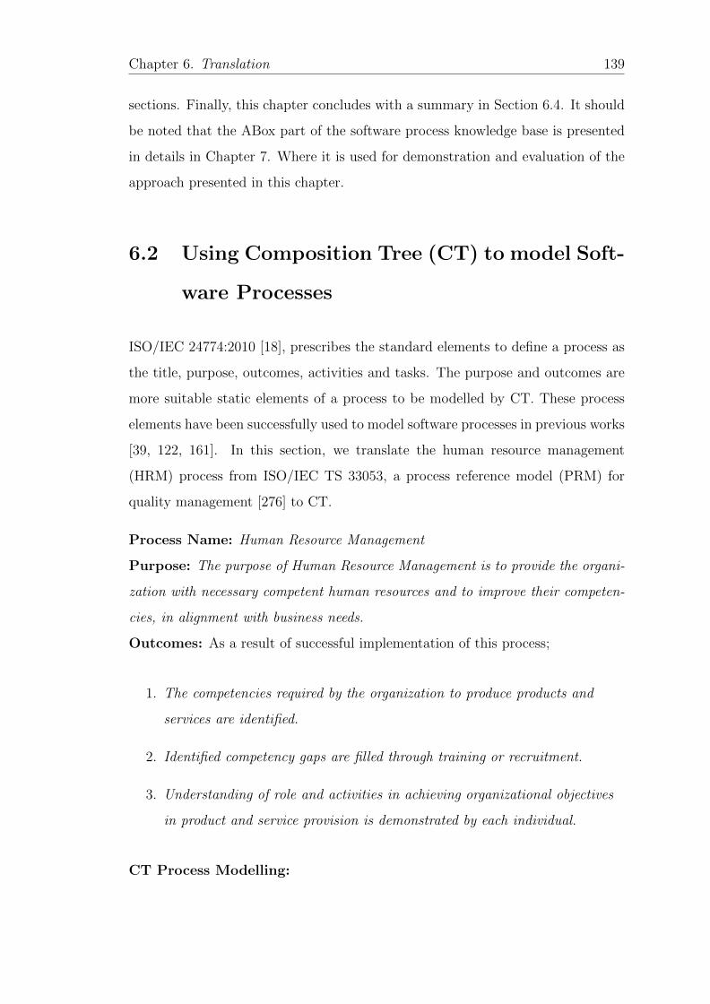
Chapter 6. Translation 139
sections. Finally, this chapter concludes with a summary in Section 6.4. It should
be noted that the ABox part of the software process knowledge base is presented
in details in Chapter 7. Where it is used for demonstration and evaluation of the
approach presented in this chapter.
6.2 Using Composition Tree (CT) to model Soft-
ware Processes
ISO/IEC 24774:2010 [18], prescribes the standard elements to define a process as
the title, purpose, outcomes, activities and tasks. The purpose and outcomes are
more suitable static elements of a process to be modelled by CT. These process
elements have been successfully used to model software processes in previous works
[39, 122, 161]. In this section, we translate the human resource management
(HRM) process from ISO/IEC TS 33053, a process reference model (PRM) for
quality management [276] to CT.
Process Name: Human Resource Management
Purpose: The purpose of Human Resource Management is to provide the organi-
zation with necessary competent human resources and to improve their competen-
cies, in alignment with business needs.
Outcomes: As a result of successful implementation of this process;
1. The competencies required by the organization to produce products and
services are identified.
2. Identified competency gaps are filled through training or recruitment.
3. Understanding of role and activities in achieving organizational objectives
in product and service provision is demonstrated by each individual.
CT Process Modelling:
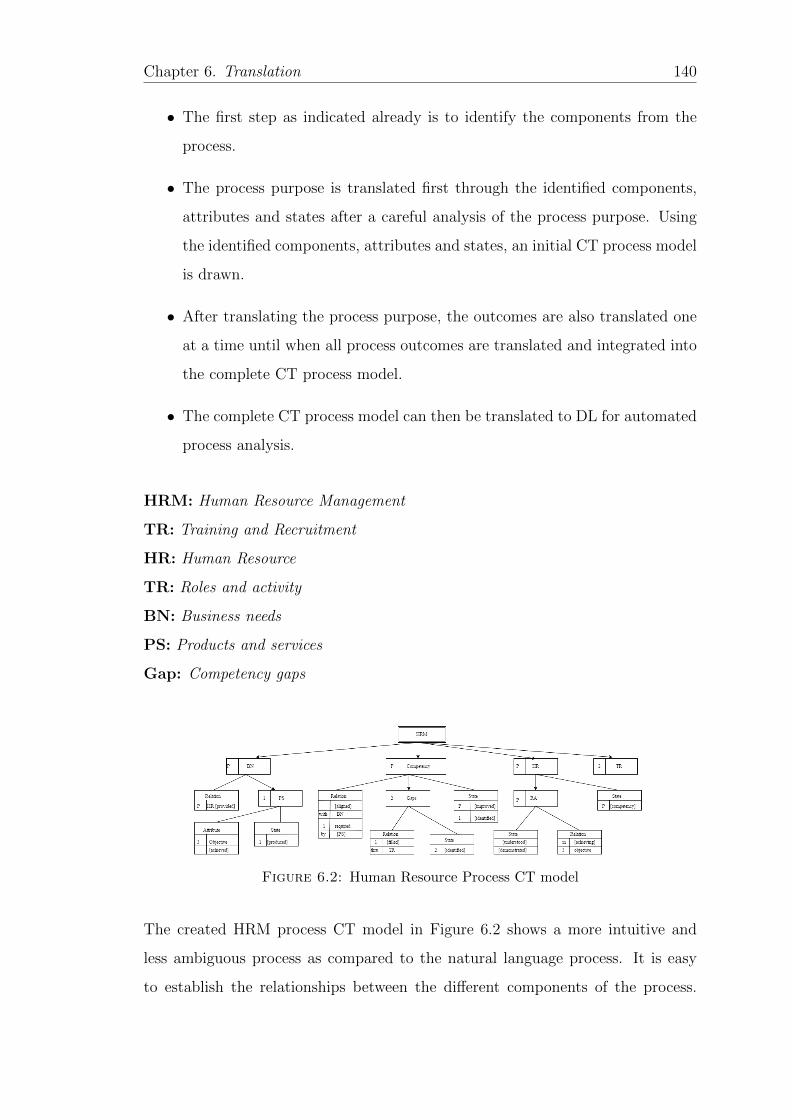
Chapter 6. Translation 140
• The first step as indicated already is to identify the components from the
process.
• The process purpose is translated first through the identified components,
attributes and states after a careful analysis of the process purpose. Using
the identified components, attributes and states, an initial CT process model
is drawn.
• After translating the process purpose, the outcomes are also translated one
at a time until when all process outcomes are translated and integrated into
the complete CT process model.
• The complete CT process model can then be translated to DL for automated
process analysis.
HRM: Human Resource Management
TR: Training and Recruitment
HR: Human Resource
TR: Roles and activity
BN: Business needs
PS: Products and services
Gap: Competency gaps
Figure 6.2: Human Resource Process CT model
The created HRM process CT model in Figure 6.2 shows a more intuitive and
less ambiguous process as compared to the natural language process. It is easy
to establish the relationships between the different components of the process.
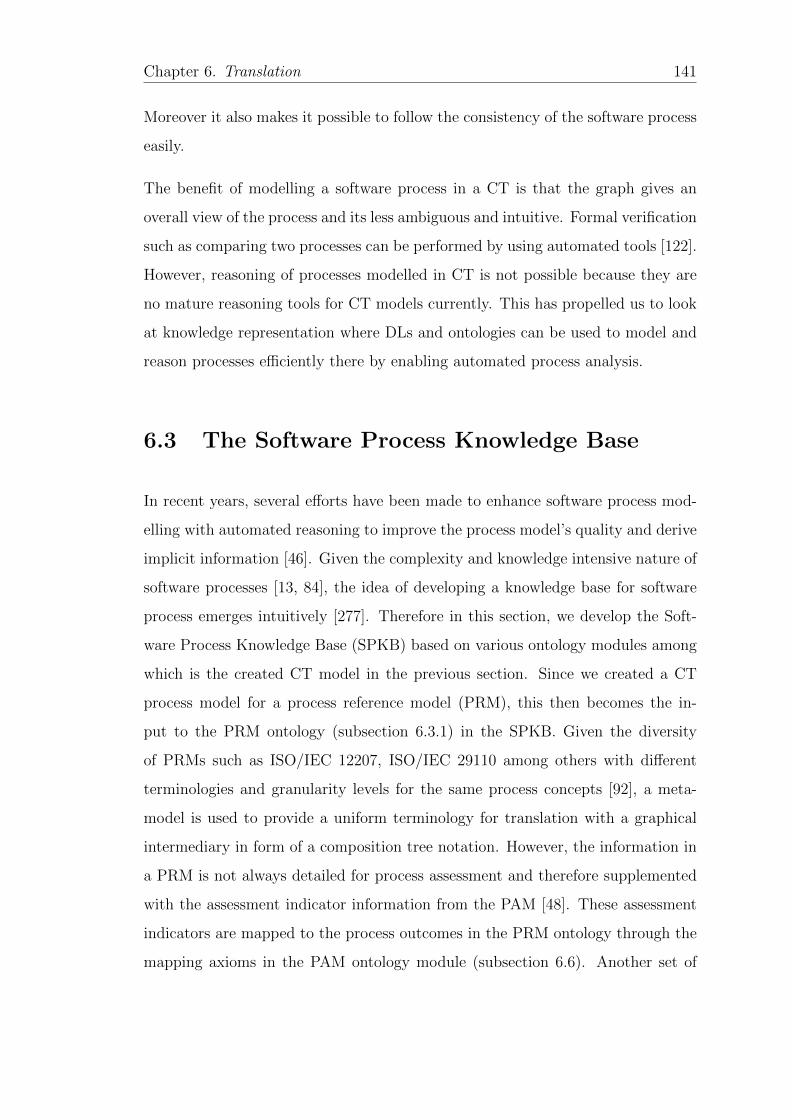
Chapter 6. Translation 141
Moreover it also makes it possible to follow the consistency of the software process
easily.
The benefit of modelling a software process in a CT is that the graph gives an
overall view of the process and its less ambiguous and intuitive. Formal verification
such as comparing two processes can be performed by using automated tools [122].
However, reasoning of processes modelled in CT is not possible because they are
no mature reasoning tools for CT models currently. This has propelled us to look
at knowledge representation where DLs and ontologies can be used to model and
reason processes efficiently there by enabling automated process analysis.
6.3 The Software Process Knowledge Base
In recent years, several efforts have been made to enhance software process mod-
elling with automated reasoning to improve the process model’s quality and derive
implicit information [46]. Given the complexity and knowledge intensive nature of
software processes [13, 84], the idea of developing a knowledge base for software
process emerges intuitively [277]. Therefore in this section, we develop the Soft-
ware Process Knowledge Base (SPKB) based on various ontology modules among
which is the created CT model in the previous section. Since we created a CT
process model for a process reference model (PRM), this then becomes the in-
put to the PRM ontology (subsection 6.3.1) in the SPKB. Given the diversity
of PRMs such as ISO/IEC 12207, ISO/IEC 29110 among others with different
terminologies and granularity levels for the same process concepts [92], a meta-
model is used to provide a uniform terminology for translation with a graphical
intermediary in form of a composition tree notation. However, the information in
a PRM is not always detailed for process assessment and therefore supplemented
with the assessment indicator information from the PAM [48]. These assessment
indicators are mapped to the process outcomes in the PRM ontology through the
mapping axioms in the PAM ontology module (subsection 6.6). Another set of
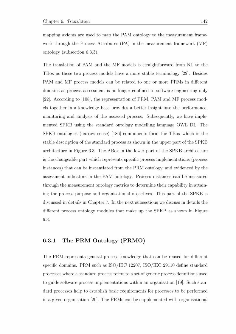
Chapter 6. Translation 142
mapping axioms are used to map the PAM ontology to the measurement frame-
work through the Process Attributes (PA) in the measurement framework (MF)
ontology (subsection 6.3.3).
The translation of PAM and the MF models is straightforward from NL to the
TBox as these two process models have a more stable terminology [22]. Besides
PAM and MF process models can be related to one or more PRMs in different
domains as process assessment is no longer confined to software engineering only
[22]. According to [108], the representation of PRM, PAM and MF process mod-
els together in a knowledge base provides a better insight into the performance,
monitoring and analysis of the assessed process. Subsequently, we have imple-
mented SPKB using the standard ontology modelling language OWL DL. The
SPKB ontologies (narrow sense) [186] components form the TBox which is the
stable description of the standard process as shown in the upper part of the SPKB
architecture in Figure 6.3. The ABox in the lower part of the SPKB architecture
is the changeable part which represents specific process implementations (process
instances) that can be instantiated from the PRM ontology, and evidenced by the
assessment indicators in the PAM ontology. Process instances can be measured
through the measurement ontology metrics to determine their capability in attain-
ing the process purpose and organisational objectives. This part of the SPKB is
discussed in details in Chapter 7. In the next subsections we discuss in details the
different process ontology modules that make up the SPKB as shown in Figure
6.3.
6.3.1 The PRM Ontology (PRMO)
The PRM represents general process knowledge that can be reused for different
specific domains. PRM such as ISO/IEC 12207, ISO/IEC 29110 define standard
processes where a standard process refers to a set of generic process definitions used
to guide software process implementations within an organisation [19]. Such stan-
dard processes help to establish basic requirements for processes to be performed
in a given organisation [20]. The PRMs can be supplemented with organisational
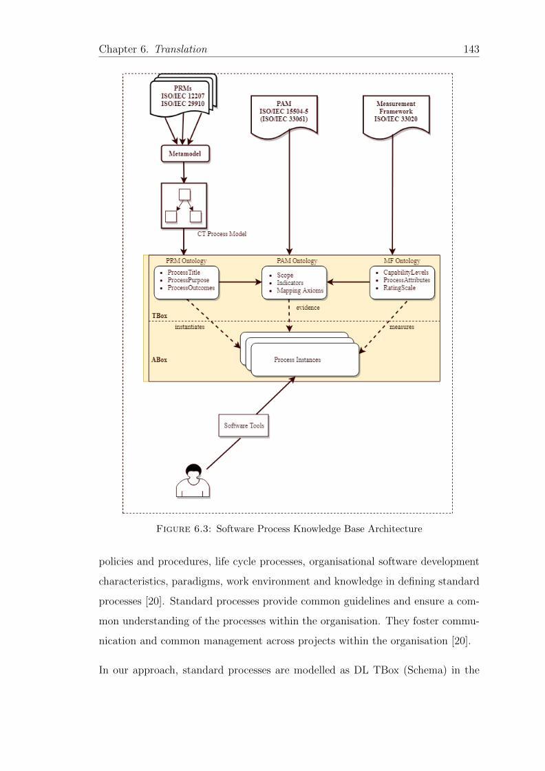
Chapter 6. Translation 143
Figure 6.3: Software Process Knowledge Base Architecture
policies and procedures, life cycle processes, organisational software development
characteristics, paradigms, work environment and knowledge in defining standard
processes [20]. Standard processes provide common guidelines and ensure a com-
mon understanding of the processes within the organisation. They foster commu-
nication and common management across projects within the organisation [20].
In our approach, standard processes are modelled as DL TBox (Schema) in the

Chapter 6. Translation 144
SPKB. In here we model the generic concepts of the standard processes includ-
ing process title, process purpose and outcomes. This works as an organisational
process template or schema from which project specific processes can be obtained
through instantiation. The PRM ontology provides a basis for automated process
assessment where PRMs and organisational processes are mapped and continu-
ously tracked [46]. To enrich our PRM ontology we have reused some concepts and
properties defined in some existing PRM ontologies in literature such as the Soft-
ware Lifecycle Ontology1 and Software Implementation Process ontology - based
on ISO/IEC 12207 developed for the ALIGNED project2.
6.3.1.1 Translating CT Diagrams to DL TBoxes
In this approach, a natural language software process is translated to a CT model
first (see section 6.2 for using Composition Trees to model software process) and
later to DL TBox with formal semantics for automated verification and reasoning
purposes. Here we describe how a CT model can be translated to a DL TBox. In
addition, using DL ABox we can enumerate the instances and properties of the
components. The goal of such translation is that the resulting knowledge base
(both the TBox translated from the CT model and the additional ABox) can
be used for process verification through automated reasoning. The use of DL in
modelling processes enables DL reasoning tools to be used for process analysis. For
instance, using the resulting knowledge base we can verify organizational processes
through instance checking see Figure 6.5.
Our translation process is based on the Composition Tree Axioms in Table 6.1,
which aims at maximally preserving the structure of the CT. Our translation is
different from the approaches in [97, 191] but shares the same spirit. In particular,
we formalize the CT process model into a DL TBox (ontology) as follows:
• Each component is represented by an Atomic concept.
1http://aligned.cs.ox.ac.uk/ont/slo.html2http://aksw.org/Projects/ALIGNED.html

Chapter 6. Translation 145
• Each component is associated with its subcomponent through a universal
role hasSubComponent.
• Each state is represented by an atomic concept and each component is
associated with its states through a universal role hasState.
• Each attribute is represented by a role and each value type is represented by
an atomic concept.
• Each relation is represented by a role.
Table 6.1: CT to DL Translation
CT Statements DL AxiomsA component C has a C v ∃hasSubComponent · Ci
subcomponent Ci
A component C has an attribute C v ∃ai · Tiai with value type TiA component C has relation R C v ∃R · C′with another component C′A component C has a state S C v ∃hasState · STwo components C1 and C2 C1 v ¬C2
are disjointA component C is constituted C ≡ ∃hasSubComponent · C1 u ...from all its properties (incl. u∃hasSubComponent · Cn
subcomponents attributes, relations u∃a1 · T1 u ... u ∃am · Tm u ∃R1 · C′1to other components, and states u... u ∃Ri · C′i u ∃hasState · S1 u ...
u∃hasState.Sk
Note that the final axiom provides a definition of the component. This assumes
the CT model provide complete information about each component. Such axioms
are useful for process verification as we shall discuss later in the following section.
Next we present a simple example in Figure 6.4 and Table 6.2 to illustrate our
translation rules as stated in Table 6.1. This example is about a study program
offered in a given university school. The study program has a name and offered
by a given school with course units as its main subcomponent. We represent this
information using a simple CT and later translate each component of CT one by
one to DL TBox.
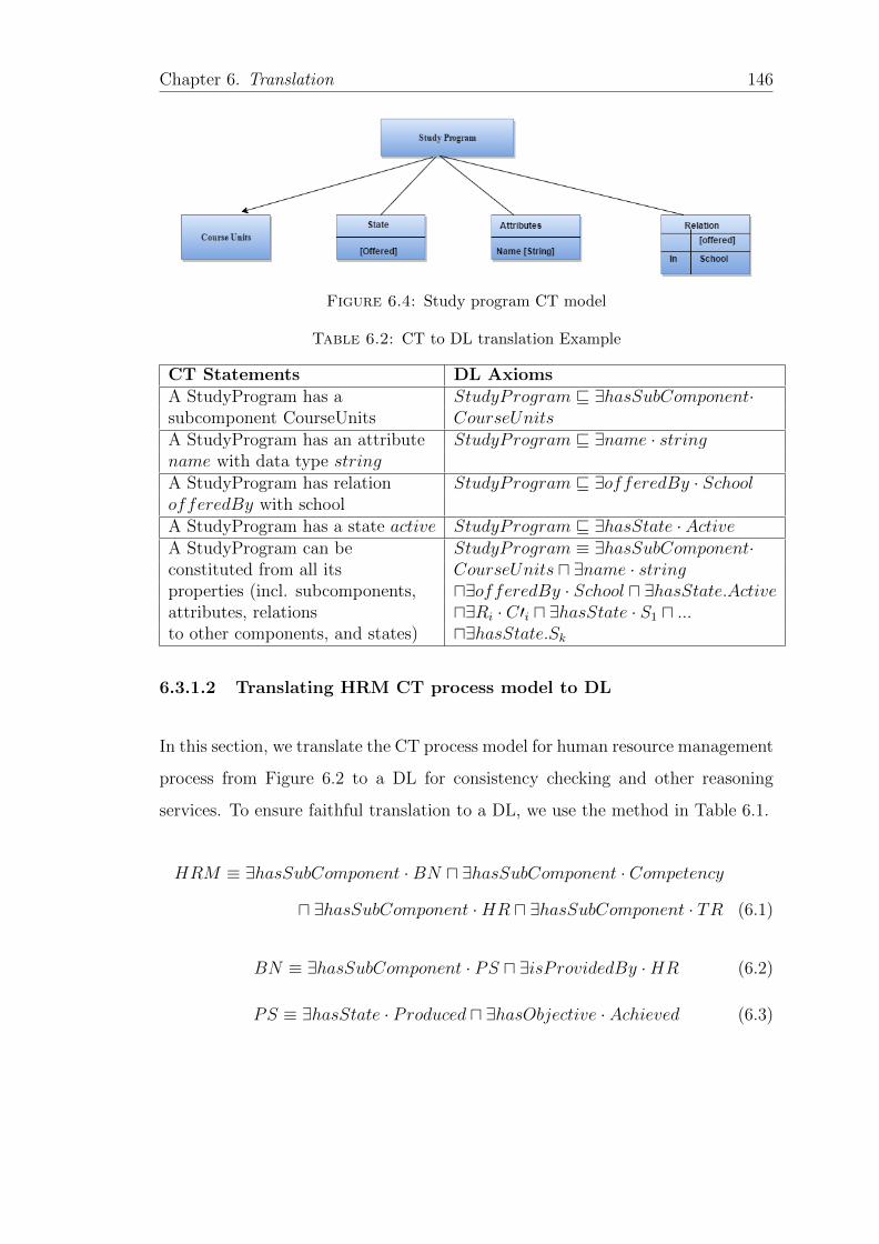
Chapter 6. Translation 146
Figure 6.4: Study program CT model
Table 6.2: CT to DL translation Example
CT Statements DL AxiomsA StudyProgram has a StudyProgram v ∃hasSubComponent·subcomponent CourseUnits CourseUnitsA StudyProgram has an attribute StudyProgram v ∃name · stringname with data type stringA StudyProgram has relation StudyProgram v ∃offeredBy · SchoolofferedBy with schoolA StudyProgram has a state active StudyProgram v ∃hasState · ActiveA StudyProgram can be StudyProgram ≡ ∃hasSubComponent·constituted from all its CourseUnits u ∃name · stringproperties (incl. subcomponents, u∃offeredBy · School u ∃hasState.Activeattributes, relations u∃Ri · C′i u ∃hasState · S1 u ...to other components, and states) u∃hasState.Sk
6.3.1.2 Translating HRM CT process model to DL
In this section, we translate the CT process model for human resource management
process from Figure 6.2 to a DL for consistency checking and other reasoning
services. To ensure faithful translation to a DL, we use the method in Table 6.1.
HRM ≡ ∃hasSubComponent ·BN u ∃hasSubComponent · Competency
u ∃hasSubComponent ·HR u ∃hasSubComponent · TR (6.1)
BN ≡ ∃hasSubComponent · PS u ∃isProvidedBy ·HR (6.2)
PS ≡ ∃hasState · Produced u ∃hasObjective · Achieved (6.3)
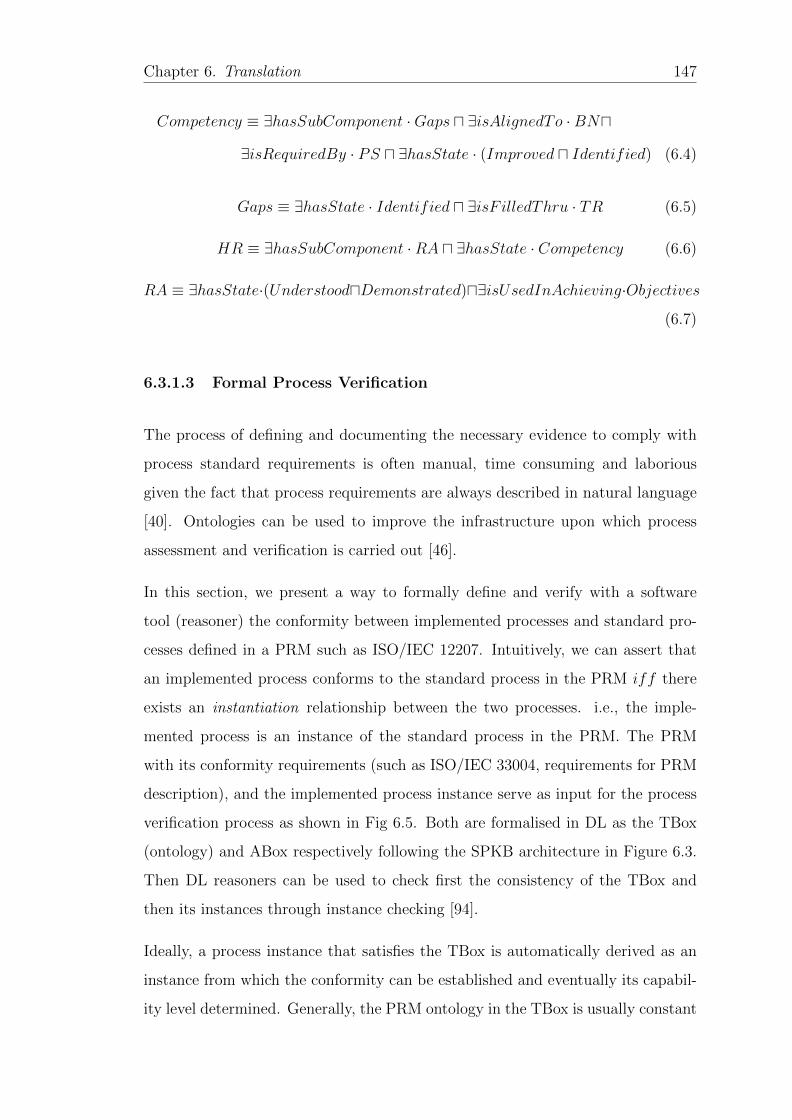
Chapter 6. Translation 147
Competency ≡ ∃hasSubComponent ·Gaps u ∃isAlignedTo ·BNu
∃isRequiredBy · PS u ∃hasState · (Improved u Identified) (6.4)
Gaps ≡ ∃hasState · Identified u ∃isF illedThru · TR (6.5)
HR ≡ ∃hasSubComponent ·RA u ∃hasState · Competency (6.6)
RA ≡ ∃hasState·(UnderstooduDemonstrated)u∃isUsedInAchieving·Objectives
(6.7)
6.3.1.3 Formal Process Verification
The process of defining and documenting the necessary evidence to comply with
process standard requirements is often manual, time consuming and laborious
given the fact that process requirements are always described in natural language
[40]. Ontologies can be used to improve the infrastructure upon which process
assessment and verification is carried out [46].
In this section, we present a way to formally define and verify with a software
tool (reasoner) the conformity between implemented processes and standard pro-
cesses defined in a PRM such as ISO/IEC 12207. Intuitively, we can assert that
an implemented process conforms to the standard process in the PRM iff there
exists an instantiation relationship between the two processes. i.e., the imple-
mented process is an instance of the standard process in the PRM. The PRM
with its conformity requirements (such as ISO/IEC 33004, requirements for PRM
description), and the implemented process instance serve as input for the process
verification process as shown in Fig 6.5. Both are formalised in DL as the TBox
(ontology) and ABox respectively following the SPKB architecture in Figure 6.3.
Then DL reasoners can be used to check first the consistency of the TBox and
then its instances through instance checking [94].
Ideally, a process instance that satisfies the TBox is automatically derived as an
instance from which the conformity can be established and eventually its capabil-
ity level determined. Generally, the PRM ontology in the TBox is usually constant
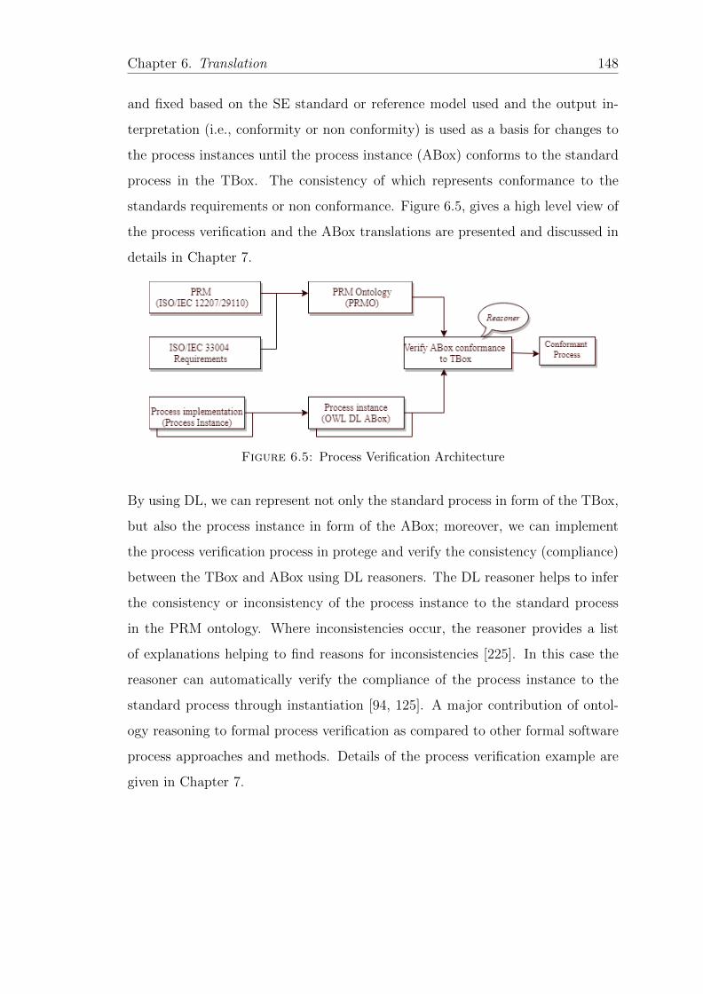
Chapter 6. Translation 148
and fixed based on the SE standard or reference model used and the output in-
terpretation (i.e., conformity or non conformity) is used as a basis for changes to
the process instances until the process instance (ABox) conforms to the standard
process in the TBox. The consistency of which represents conformance to the
standards requirements or non conformance. Figure 6.5, gives a high level view of
the process verification and the ABox translations are presented and discussed in
details in Chapter 7.
Figure 6.5: Process Verification Architecture
By using DL, we can represent not only the standard process in form of the TBox,
but also the process instance in form of the ABox; moreover, we can implement
the process verification process in protege and verify the consistency (compliance)
between the TBox and ABox using DL reasoners. The DL reasoner helps to infer
the consistency or inconsistency of the process instance to the standard process
in the PRM ontology. Where inconsistencies occur, the reasoner provides a list
of explanations helping to find reasons for inconsistencies [225]. In this case the
reasoner can automatically verify the compliance of the process instance to the
standard process through instantiation [94, 125]. A major contribution of ontol-
ogy reasoning to formal process verification as compared to other formal software
process approaches and methods. Details of the process verification example are
given in Chapter 7.
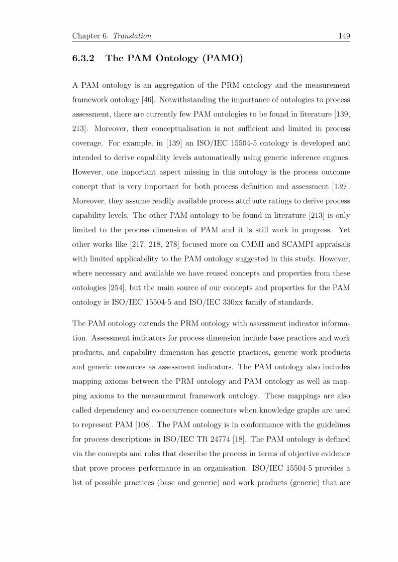
Chapter 6. Translation 149
6.3.2 The PAM Ontology (PAMO)
A PAM ontology is an aggregation of the PRM ontology and the measurement
framework ontology [46]. Notwithstanding the importance of ontologies to process
assessment, there are currently few PAM ontologies to be found in literature [139,
213]. Moreover, their conceptualisation is not sufficient and limited in process
coverage. For example, in [139] an ISO/IEC 15504-5 ontology is developed and
intended to derive capability levels automatically using generic inference engines.
However, one important aspect missing in this ontology is the process outcome
concept that is very important for both process definition and assessment [139].
Moreover, they assume readily available process attribute ratings to derive process
capability levels. The other PAM ontology to be found in literature [213] is only
limited to the process dimension of PAM and it is still work in progress. Yet
other works like [217, 218, 278] focused more on CMMI and SCAMPI appraisals
with limited applicability to the PAM ontology suggested in this study. However,
where necessary and available we have reused concepts and properties from these
ontologies [254], but the main source of our concepts and properties for the PAM
ontology is ISO/IEC 15504-5 and ISO/IEC 330xx family of standards.
The PAM ontology extends the PRM ontology with assessment indicator informa-
tion. Assessment indicators for process dimension include base practices and work
products, and capability dimension has generic practices, generic work products
and generic resources as assessment indicators. The PAM ontology also includes
mapping axioms between the PRM ontology and PAM ontology as well as map-
ping axioms to the measurement framework ontology. These mappings are also
called dependency and co-occurrence connectors when knowledge graphs are used
to represent PAM [108]. The PAM ontology is in conformance with the guidelines
for process descriptions in ISO/IEC TR 24774 [18]. The PAM ontology is defined
via the concepts and roles that describe the process in terms of objective evidence
that prove process performance in an organisation. ISO/IEC 15504-5 provides a
list of possible practices (base and generic) and work products (generic) that are
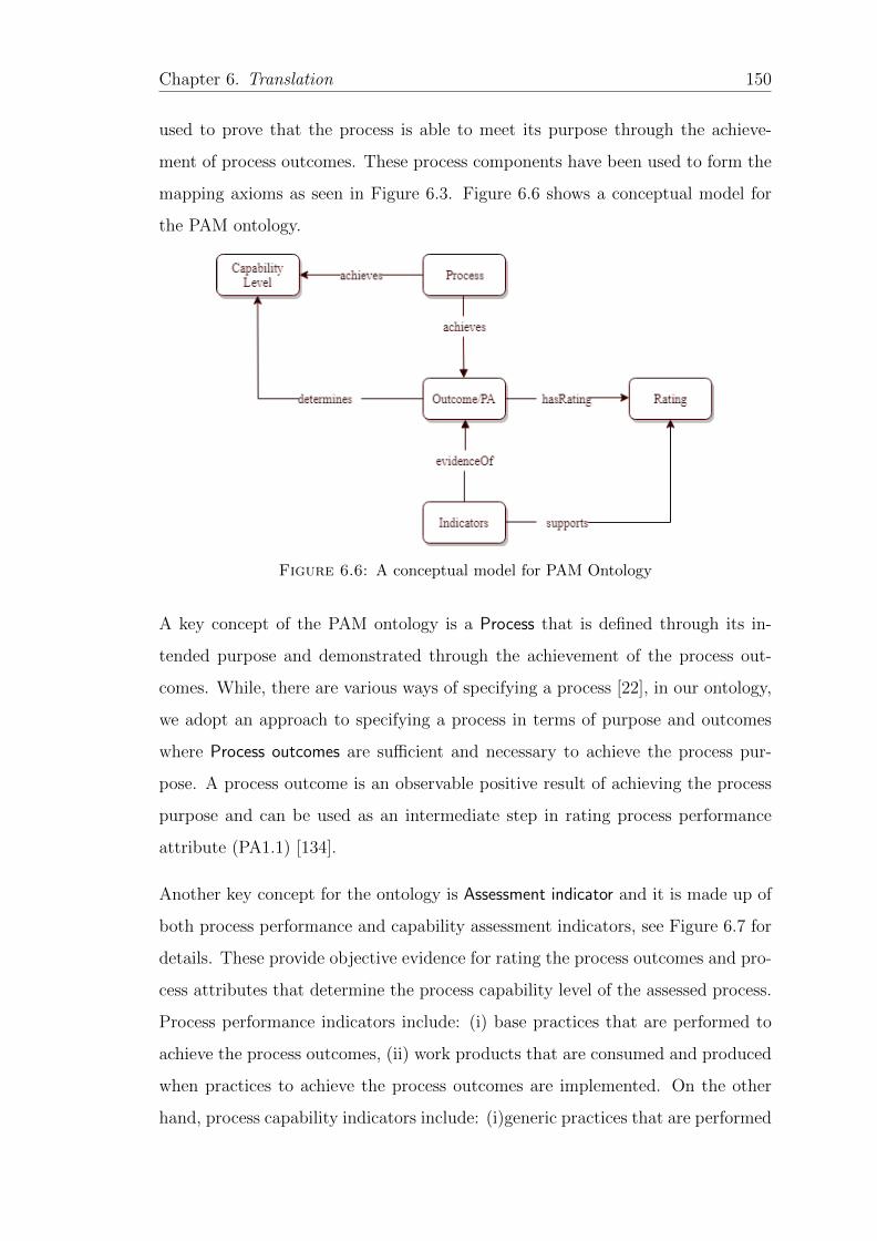
Chapter 6. Translation 150
used to prove that the process is able to meet its purpose through the achieve-
ment of process outcomes. These process components have been used to form the
mapping axioms as seen in Figure 6.3. Figure 6.6 shows a conceptual model for
the PAM ontology.
Figure 6.6: A conceptual model for PAM Ontology
A key concept of the PAM ontology is a Process that is defined through its in-
tended purpose and demonstrated through the achievement of the process out-
comes. While, there are various ways of specifying a process [22], in our ontology,
we adopt an approach to specifying a process in terms of purpose and outcomes
where Process outcomes are sufficient and necessary to achieve the process pur-
pose. A process outcome is an observable positive result of achieving the process
purpose and can be used as an intermediate step in rating process performance
attribute (PA1.1) [134].
Another key concept for the ontology is Assessment indicator and it is made up of
both process performance and capability assessment indicators, see Figure 6.7 for
details. These provide objective evidence for rating the process outcomes and pro-
cess attributes that determine the process capability level of the assessed process.
Process performance indicators include: (i) base practices that are performed to
achieve the process outcomes, (ii) work products that are consumed and produced
when practices to achieve the process outcomes are implemented. On the other
hand, process capability indicators include: (i)generic practices that are performed
Chapter 6. Translation 151
to achieve a specified process attribute, (ii) generic work product these are char-
acteristics that differentiate between the needed work product inputs and outputs
to achieve a specified process attribute and (iii) generic resources that are used
during the process execution. The main source of evidence for the process capa-
bility dimension is generic practices and they be should monitored to ensure their
proper implementation [133]. We have also used the indicators in the mapping
axioms between the process outcomes in the PRM ontology and PAM ontology
and between the MF ontology and PAM ontology as shown in Figure 6.3.
Figure 6.7: Process Assessment Indicators
While the process outcomes are very important in achieving the process purpose in
the process dimension, Process Attributes (PAs) are equally important as measur-
able characteristics of capability levels and they can be characterised as an inter-
mediate step to providing a process attribute rating [45]. There are nine process
attributes in general with capability level one only having one process attribute
and the remaining capability levels 2 - 5, each having two process attributes.
Rating is another major concept of our ontology derived from the objective evidence
provided by the indicators. Rating of process attributes shows a judgement of
the degree of achievement of the process attribute for the assessed process. In
our ontology, we have used ratings for both the process outcomes to determine
the process achievement of the process purpose (capability level one) and process
attributes to determine the capability levels 2 - 5 of the assessed process.
Capability Level is characterised by the process attribute rating derived from the
adduced objective evidence and affirmations from the process performers. In our
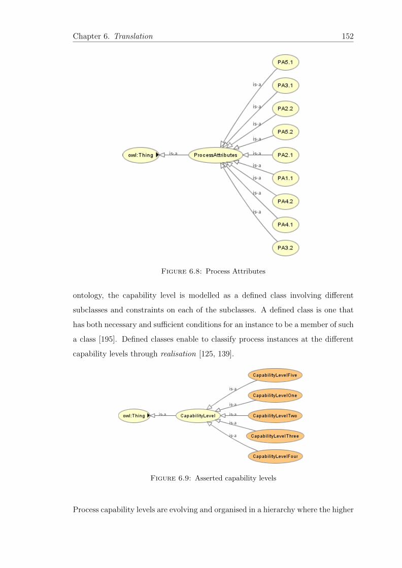
Chapter 6. Translation 152
Figure 6.8: Process Attributes
ontology, the capability level is modelled as a defined class involving different
subclasses and constraints on each of the subclasses. A defined class is one that
has both necessary and sufficient conditions for an instance to be a member of such
a class [195]. Defined classes enable to classify process instances at the different
capability levels through realisation [125, 139].
Figure 6.9: Asserted capability levels
Process capability levels are evolving and organised in a hierarchy where the higher
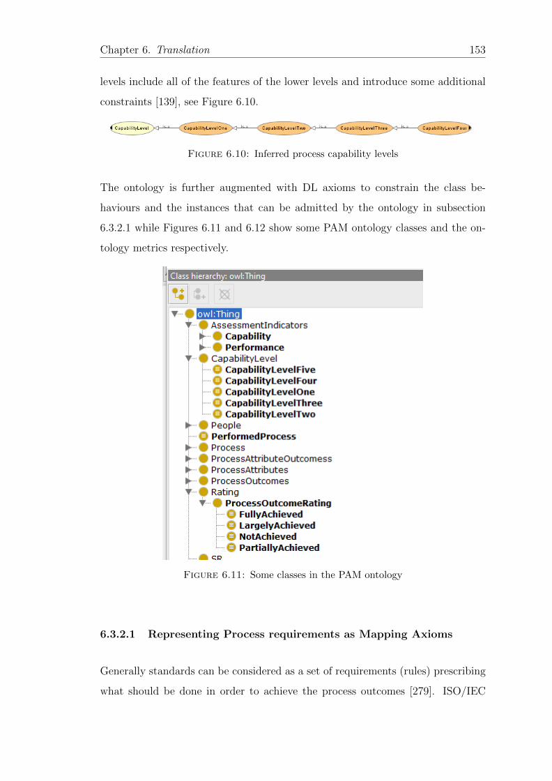
Chapter 6. Translation 153
levels include all of the features of the lower levels and introduce some additional
constraints [139], see Figure 6.10.
Figure 6.10: Inferred process capability levels
The ontology is further augmented with DL axioms to constrain the class be-
haviours and the instances that can be admitted by the ontology in subsection
6.3.2.1 while Figures 6.11 and 6.12 show some PAM ontology classes and the on-
tology metrics respectively.
Figure 6.11: Some classes in the PAM ontology
6.3.2.1 Representing Process requirements as Mapping Axioms
Generally standards can be considered as a set of requirements (rules) prescribing
what should be done in order to achieve the process outcomes [279]. ISO/IEC
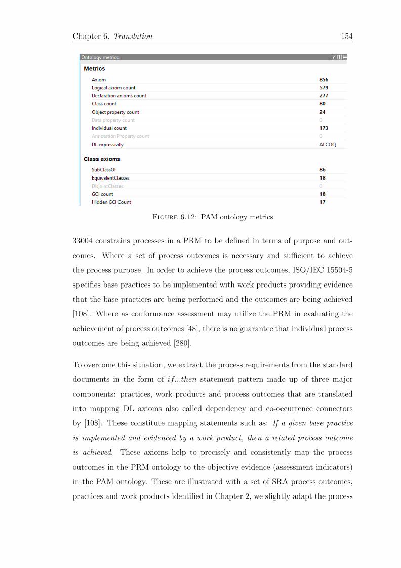
Chapter 6. Translation 154
Figure 6.12: PAM ontology metrics
33004 constrains processes in a PRM to be defined in terms of purpose and out-
comes. Where a set of process outcomes is necessary and sufficient to achieve
the process purpose. In order to achieve the process outcomes, ISO/IEC 15504-5
specifies base practices to be implemented with work products providing evidence
that the base practices are being performed and the outcomes are being achieved
[108]. Where as conformance assessment may utilize the PRM in evaluating the
achievement of process outcomes [48], there is no guarantee that individual process
outcomes are being achieved [280].
To overcome this situation, we extract the process requirements from the standard
documents in the form of if...then statement pattern made up of three major
components: practices, work products and process outcomes that are translated
into mapping DL axioms also called dependency and co-occurrence connectors
by [108]. These constitute mapping statements such as: If a given base practice
is implemented and evidenced by a work product, then a related process outcome
is achieved. These axioms help to precisely and consistently map the process
outcomes in the PRM ontology to the objective evidence (assessment indicators)
in the PAM ontology. These are illustrated with a set of SRA process outcomes,
practices and work products identified in Chapter 2, we slightly adapt the process
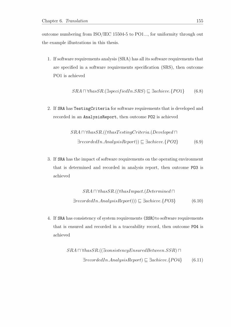
Chapter 6. Translation 155
outcome numbering from ISO/IEC 15504-5 to PO1..., for uniformity through out
the example illustrations in this thesis.
1. If software requirements analysis (SRA) has all its software requirements that
are specified in a software requirements specification (SRS), then outcome
PO1 is achieved
SRA u ∀hasSR.(∃specifiedIn.SRS) v ∃achieve.{PO1} (6.8)
2. If SRA has TestingCriteria for software requirements that is developed and
recorded in an AnalysisReport, then outcome PO2 is achieved
SRA u ∀hasSR.((∀hasTestingCriteria.(Developed u
∃recordedIn.AnalysisReport)) v ∃achieve.{PO2} (6.9)
3. If SRA has the impact of software requirements on the operating environment
that is determined and recorded in analysis report, then outcome PO3 is
achieved
SRA u ∀hasSR.((∀hasImpact.(Determined u
∃recordedIn.AnalysisReport))) v ∃achieve.{PO3} (6.10)
4. If SRA has consistency of system requirements (SSR)to software requirements
that is ensured and recorded in a traceability record, then outcome PO4 is
achieved
SRA u ∀hasSR.((∃consistencyEnsuredBetween.SSR) u
∃recordedIn.AnalysisReport) v ∃achieve.{PO4} (6.11)
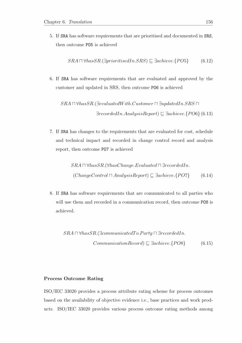
Chapter 6. Translation 156
5. If SRA has software requirements that are prioritised and documented in SRS,
then outcome PO5 is achieved
SRA u ∀hasSR.(∃prioritisedIn.SRS) v ∃achieve.{PO5} (6.12)
6. If SRA has software requirements that are evaluated and approved by the
customer and updated in SRS, then outcome PO6 is achieved
SRA u ∀hasSR.(∃evaluatedWith.Customer u ∃updatedIn.SRS u
∃recordedIn.AnalysisReport) v ∃achieve.{PO6} (6.13)
7. If SRA has changes to the requirements that are evaluated for cost, schedule
and technical impact and recorded in change control record and analysis
report, then outcome PO7 is achieved
SRA u ∀hasSR.(∀hasChange.Evaluated u ∃recordedIn.
(ChangeControl u AnalysisReport) v ∃achieve.{PO7} (6.14)
8. If SRA has software requirements that are communicated to all parties who
will use them and recorded in a communication record, then outcome PO8 is
achieved.
SRA u ∀hasSR.(∃communicatedTo.Party u ∃recordedIn.
CommunicationRecord) v ∃achieve.{PO8} (6.15)
Process Outcome Rating
ISO/IEC 33020 provides a process attribute rating scheme for process outcomes
based on the availability of objective evidence i.e., base practices and work prod-
ucts. ISO/IEC 33020 provides various process outcome rating methods among
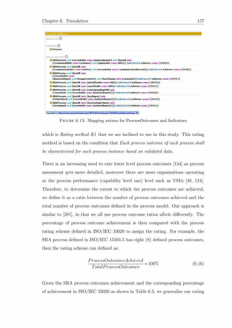
Chapter 6. Translation 157
Figure 6.13: Mapping axioms for ProcessOutcomes and Indicators
which is Rating method R1 that we are inclined to use in this study. This rating
method is based on the condition that Each process outcome of each process shall
be characterised for each process instance based on validated data.
There is an increasing need to rate lower level process outcomes [134] as process
assessment gets more detailed, moreover there are more organisations operating
at the process performance (capability level one) level such as VSEs [48, 124].
Therefore, to determine the extent to which the process outcomes are achieved,
we define it as a ratio between the number of process outcomes achieved and the
total number of process outcomes defined in the process model. Our approach is
similar to [281], in that we all use process outcome ratios albeit differently. The
percentage of process outcome achievement is then compared with the process
rating scheme defined in ISO/IEC 33020 to assign the rating. For example, the
SRA process defined in ISO/IEC 15504-5 has eight (8) defined process outcomes,
then the rating scheme can defined as:
ProcessOutcomesAchieved
TotalProcessOutcomes∗ 100% (6.16)
Given the SRA process outcomes achievement and the corresponding percentage
of achievement in ISO/IEC 33020 as shown in Table 6.3, we generalise our rating
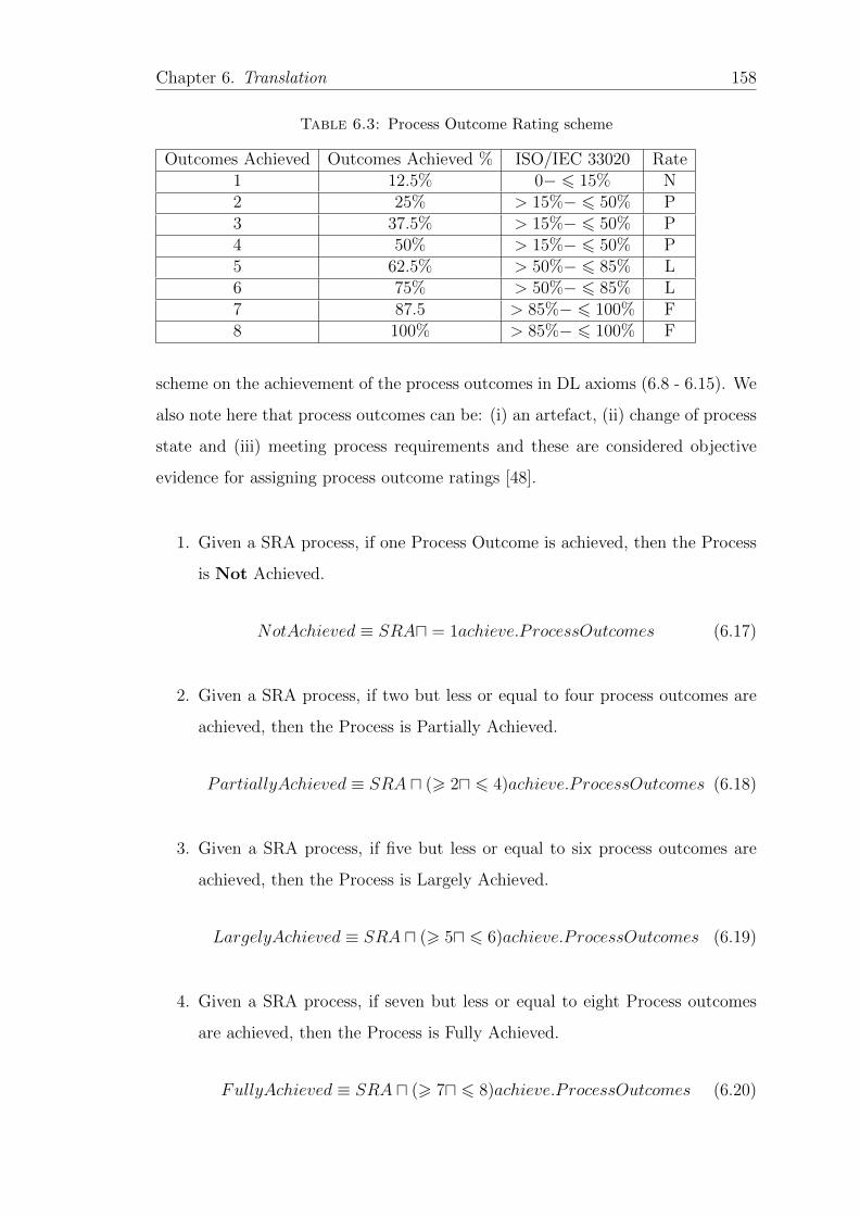
Chapter 6. Translation 158
Table 6.3: Process Outcome Rating scheme
Outcomes Achieved Outcomes Achieved % ISO/IEC 33020 Rate1 12.5% 0− 6 15% N2 25% > 15%− 6 50% P3 37.5% > 15%− 6 50% P4 50% > 15%− 6 50% P5 62.5% > 50%− 6 85% L6 75% > 50%− 6 85% L7 87.5 > 85%− 6 100% F8 100% > 85%− 6 100% F
scheme on the achievement of the process outcomes in DL axioms (6.8 - 6.15). We
also note here that process outcomes can be: (i) an artefact, (ii) change of process
state and (iii) meeting process requirements and these are considered objective
evidence for assigning process outcome ratings [48].
1. Given a SRA process, if one Process Outcome is achieved, then the Process
is Not Achieved.
NotAchieved ≡ SRAu = 1achieve.ProcessOutcomes (6.17)
2. Given a SRA process, if two but less or equal to four process outcomes are
achieved, then the Process is Partially Achieved.
PartiallyAchieved ≡ SRA u (> 2u 6 4)achieve.ProcessOutcomes (6.18)
3. Given a SRA process, if five but less or equal to six process outcomes are
achieved, then the Process is Largely Achieved.
LargelyAchieved ≡ SRA u (> 5u 6 6)achieve.ProcessOutcomes (6.19)
4. Given a SRA process, if seven but less or equal to eight Process outcomes
are achieved, then the Process is Fully Achieved.
FullyAchieved ≡ SRA u (> 7u 6 8)achieve.ProcessOutcomes (6.20)
Chapter 6. Translation 159
Achieving process outcomes to the level of Largely or Fully achieved status (see
Table 6.3, shows a performed process i.e., a process that is able to achieve its
purpose through outcome achievement. This helps to build process performance
attribute (PA1.1) that forms capability level one of the assessed process. Details
of PA rating are discussed in the measurement framework ontology next.
6.3.3 Measurement Framework Ontology (MF Ontology)
In the capability dimension, each Capability Level is composed of Process At-
tributes (PA). Capability level one is composed of one attribute, i.e., process
performance attribute (PA1.1) as a measure of the extent to which the process
achieves its purpose through process outcomes demonstration [133]. On the other
hand, capability levels 2 to 5 are made up of two process attributes see Figure
2.4. A capability level is derived from the rating of its process attributes and the
process attribute rating is derived formally from the achievement of the process
attribute outcomes. The achievement of the process attribute outcomes depends
on the model practices implemented by the organisation and availability of work
products. The formative aggregation method [132] is one method where changes in
practice implementation or non implementation determines the process outcomes
that influence the PA rating. The PA rating in turn determines the capability level
that can be achieved. In other words, aggregation propagates from the achieve-
ment of PA outcomes to the derived process capability level as shown in Figure
2.5.
Objective evidence evaluates the degree of implementation of the practices and
achievement of process attributes based on the assessment indicators [22]. ISO/IEC
15504-5 provides three types of process capability indicators as generic practice
(GP), generic resource (GR) and generic work product (GWP). These collectively
enable the achievement of the PA outcomes and are transformed into the PA
ratings that determine a given capability level of an assessed process instance.
From the generic practices, generic work products, generic resources and process
attribute outcomes we derive the following if ... then pattern statements. These
Chapter 6. Translation 160
map the PAM ontology via the generic practices, resources and work products
to the measurement framework ontology. Process Attribute rating as shown in
Tables 6.4 and 6.5, is a composite value that is determined by aggregating a set
of process attribute outcomes achieved [132]. We use capability level II (managed
process) in a minimalist way in the next section to demonstrate the achievement
of its process attributes.
6.3.3.1 Process Attributes (PAs) Achievement
Capability Level II deals with managing a performed process in a planned way
with its work products well established, controlled and maintained [133]. It has
two PAs i.,e Performance management attribute (PA2.1) and Work product man-
agement attribute (PA2.2) that once achieved demonstrates the achievement of
this capability level.
PA2.1 Performance Management Attribute Achievement
In order to achieve the performance management attribute (PA2.1), the following
PA outcome characterisations are defined.
1. If the objectives for the performance of the process are identified and assigned
to human resources (HR) and recorded in a plan and, then process attribute
outcome (PA 2.1a) is achieved.
PA2.1 u ∀hasProcessPerformance.∀hasObjectives.(Identified
u∃recordedIn.P lan u ∃assignedTo.HR) v ∃achieve.{PA2.1a} (6.21)
2. If the performance of the process is planned and monitored, assigned to
project planning management and control tools (PPMCT) and recorded in
Chapter 6. Translation 161
a plan, then process attribute outcome (PA2.1b) is achieved.
PA2.1 u ∀hasProcessPerformance.(Planned uMonitored
u∃recordedIn.P lan u ∃assignedTo.PPMCT ) v ∃achieve.{PA2.1b}
(6.22)
3. If the performance of the process is adjusted and assigned to project plan-
ning management and control tools (PPMCT) and recorded in a plan, then
process attribute outcome (PA 2.1c) is achieved.
PA2.1 u ∀hasProcessPerformance.(Adjusted u ∃recordedIn.Register
u∃assignedTo.PPMCT ) v ∃achieve.{PA2.1c}
(6.23)
4. If the responsibilities for performing the process are defined, assigned and
communicated to human resources (HR) and recorded in a plan, then process
attribute outcome(PA 2.1d) is achieved.
PA2.1 u ∀hasProcessPerformance.∀hasResponsibilities.(Defined
u∃recordedIn.P lan u ∃assignedTo.HR) v ∃achieve.{PA2.1d}
(6.24)
5. If the resources necessary for performing the process are defined and assigned
to human resource (HR) and communicated to stakeholders and recorded in
a plan, then process attribute outcome(PA 2.1e) is achieved.
PA2.1 u ∀hasProcessPerformance.∀hasResources.(Defined
u∃recordedIn.P lan u ∃assignedTo.HR
u∃communicatedTo.Stakeholders) v ∃achieve.{PA2.1e} (6.25)
6. If the interfaces between the involved parties are managed to ensure both
Chapter 6. Translation 162
communication and also clear assignment of responsibility to human re-
sources/workflow management system and recorded in a plan/record, then
process attribute outcome(PA 2.1f) is achieved.
PA2.1 u ∀hasInterface.Managed
u∃recordedIn.P lan u ∃assignedTo.HR v ∃achieve.{PA2.1f} (6.26)
ISO/IEC 33020 provides various Process attribute rating methods among which is
Rating method R1 that we adopt in this study. This rating method is based on
the condition that Each process attribute outcome of each PA shall be characterised
for each process instance based on validated data.
In ISO/IEC 33020, each PA is comprised of PA outcomes, where they represent
generic work products, generic resources and generic practices [132]. Process At-
tribute rating as a composite value is determined by aggregating a set of process
attribute outcome value characterisations [132]. Therefore, to determine the ex-
tent to which the PA is achieved, we define it as a ratio between the number
of PA outcomes achieved and the total number of PA outcomes defined in the
Measurement Framework ISO/IEC 33020. The percentage of achievement is then
compared with the process rating scheme defined in ISO/IEC 33020 to assign the
PA rating, see Table 6.4 for details . For example, Performance management at-
tribute (PA 2.1) has six (6) PA outcomes, then the rating scheme can be defined
as:
PAOutcomesAchieved
TotalPAOutcomes∗ 100% (6.27)
1. Given a PA 2.1, if zero PA Outcome is achieved, then the PA is Not
Achieved.
PA21 NotAchieved ≡ PA2.1u = 0achieve.PAOutcomes (6.28)
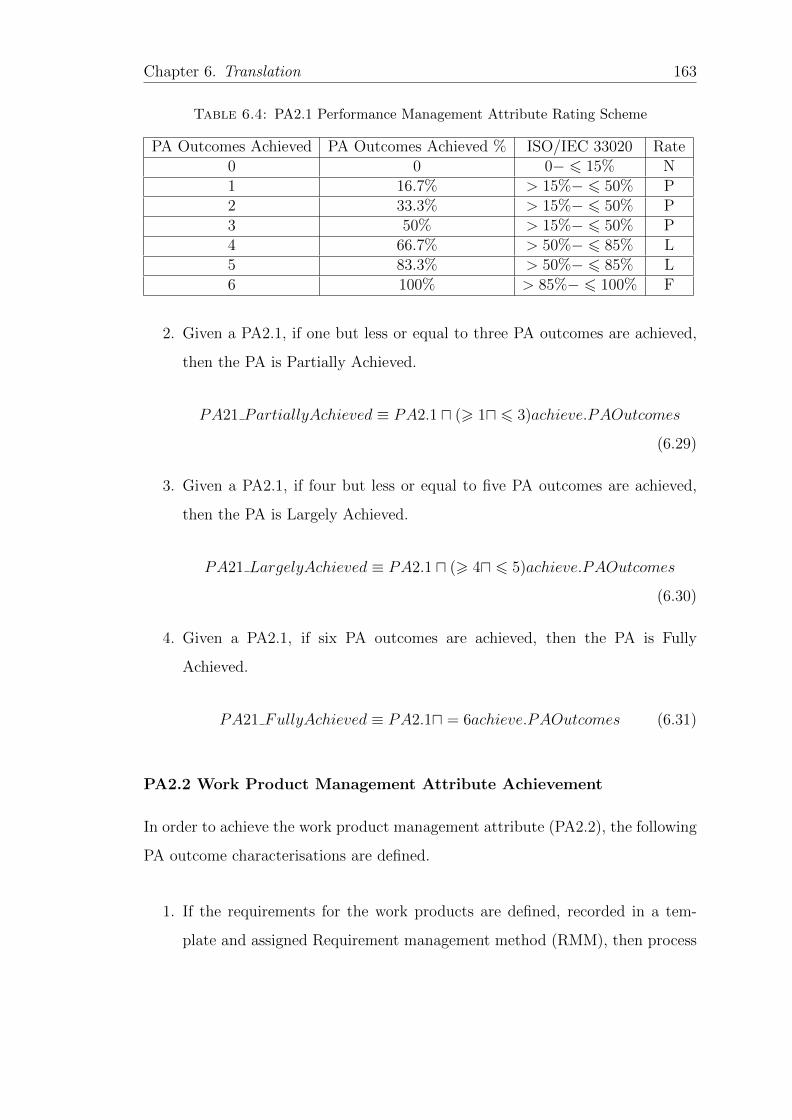
Chapter 6. Translation 163
Table 6.4: PA2.1 Performance Management Attribute Rating Scheme
PA Outcomes Achieved PA Outcomes Achieved % ISO/IEC 33020 Rate0 0 0− 6 15% N1 16.7% > 15%− 6 50% P2 33.3% > 15%− 6 50% P3 50% > 15%− 6 50% P4 66.7% > 50%− 6 85% L5 83.3% > 50%− 6 85% L6 100% > 85%− 6 100% F
2. Given a PA2.1, if one but less or equal to three PA outcomes are achieved,
then the PA is Partially Achieved.
PA21 PartiallyAchieved ≡ PA2.1 u (> 1u 6 3)achieve.PAOutcomes
(6.29)
3. Given a PA2.1, if four but less or equal to five PA outcomes are achieved,
then the PA is Largely Achieved.
PA21 LargelyAchieved ≡ PA2.1 u (> 4u 6 5)achieve.PAOutcomes
(6.30)
4. Given a PA2.1, if six PA outcomes are achieved, then the PA is Fully
Achieved.
PA21 FullyAchieved ≡ PA2.1u = 6achieve.PAOutcomes (6.31)
PA2.2 Work Product Management Attribute Achievement
In order to achieve the work product management attribute (PA2.2), the following
PA outcome characterisations are defined.
1. If the requirements for the work products are defined, recorded in a tem-
plate and assigned Requirement management method (RMM), then process
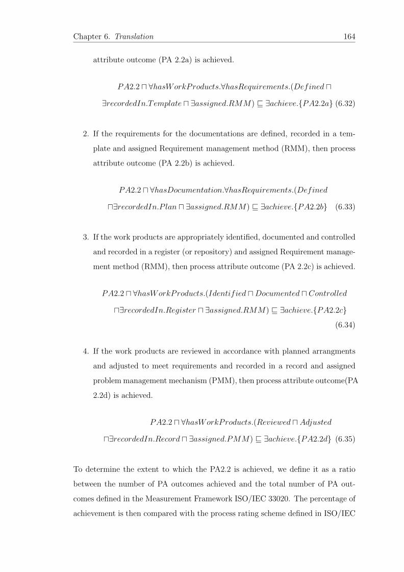
Chapter 6. Translation 164
attribute outcome (PA 2.2a) is achieved.
PA2.2 u ∀hasWorkProducts.∀hasRequirements.(Defined u
∃recordedIn.Template u ∃assigned.RMM) v ∃achieve.{PA2.2a} (6.32)
2. If the requirements for the documentations are defined, recorded in a tem-
plate and assigned Requirement management method (RMM), then process
attribute outcome (PA 2.2b) is achieved.
PA2.2 u ∀hasDocumentation.∀hasRequirements.(Defined
u∃recordedIn.P lan u ∃assigned.RMM) v ∃achieve.{PA2.2b} (6.33)
3. If the work products are appropriately identified, documented and controlled
and recorded in a register (or repository) and assigned Requirement manage-
ment method (RMM), then process attribute outcome (PA 2.2c) is achieved.
PA2.2 u ∀hasWorkProducts.(Identified uDocumented u Controlled
u∃recordedIn.Register u ∃assigned.RMM) v ∃achieve.{PA2.2c}
(6.34)
4. If the work products are reviewed in accordance with planned arrangments
and adjusted to meet requirements and recorded in a record and assigned
problem management mechanism (PMM), then process attribute outcome(PA
2.2d) is achieved.
PA2.2 u ∀hasWorkProducts.(Reviewed u Adjusted
u∃recordedIn.Record u ∃assigned.PMM) v ∃achieve.{PA2.2d} (6.35)
To determine the extent to which the PA2.2 is achieved, we define it as a ratio
between the number of PA outcomes achieved and the total number of PA out-
comes defined in the Measurement Framework ISO/IEC 33020. The percentage of
achievement is then compared with the process rating scheme defined in ISO/IEC
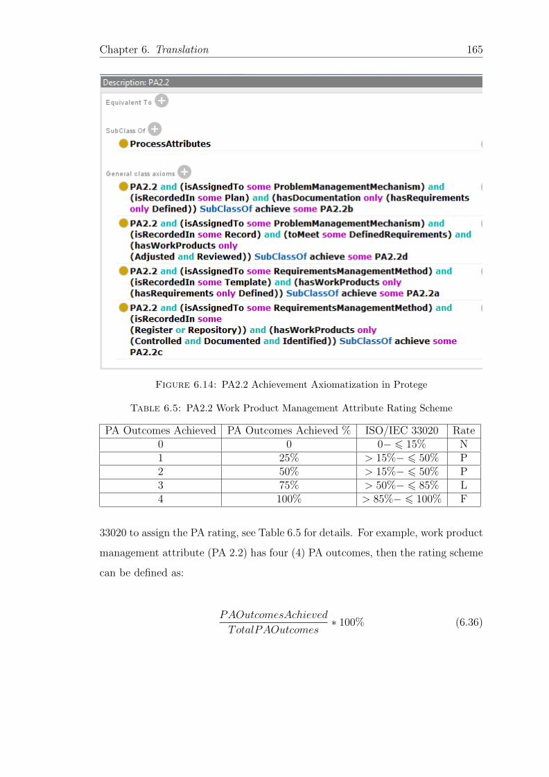
Chapter 6. Translation 165
Figure 6.14: PA2.2 Achievement Axiomatization in Protege
Table 6.5: PA2.2 Work Product Management Attribute Rating Scheme
PA Outcomes Achieved PA Outcomes Achieved % ISO/IEC 33020 Rate0 0 0− 6 15% N1 25% > 15%− 6 50% P2 50% > 15%− 6 50% P3 75% > 50%− 6 85% L4 100% > 85%− 6 100% F
33020 to assign the PA rating, see Table 6.5 for details. For example, work product
management attribute (PA 2.2) has four (4) PA outcomes, then the rating scheme
can be defined as:
PAOutcomesAchieved
TotalPAOutcomes∗ 100% (6.36)
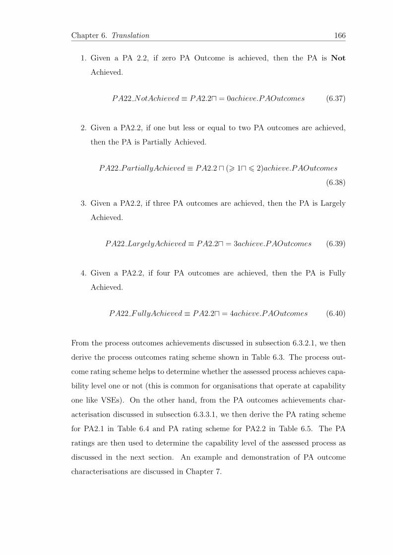
Chapter 6. Translation 166
1. Given a PA 2.2, if zero PA Outcome is achieved, then the PA is Not
Achieved.
PA22 NotAchieved ≡ PA2.2u = 0achieve.PAOutcomes (6.37)
2. Given a PA2.2, if one but less or equal to two PA outcomes are achieved,
then the PA is Partially Achieved.
PA22 PartiallyAchieved ≡ PA2.2 u (> 1u 6 2)achieve.PAOutcomes
(6.38)
3. Given a PA2.2, if three PA outcomes are achieved, then the PA is Largely
Achieved.
PA22 LargelyAchieved ≡ PA2.2u = 3achieve.PAOutcomes (6.39)
4. Given a PA2.2, if four PA outcomes are achieved, then the PA is Fully
Achieved.
PA22 FullyAchieved ≡ PA2.2u = 4achieve.PAOutcomes (6.40)
From the process outcomes achievements discussed in subsection 6.3.2.1, we then
derive the process outcomes rating scheme shown in Table 6.3. The process out-
come rating scheme helps to determine whether the assessed process achieves capa-
bility level one or not (this is common for organisations that operate at capability
one like VSEs). On the other hand, from the PA outcomes achievements char-
acterisation discussed in subsection 6.3.3.1, we then derive the PA rating scheme
for PA2.1 in Table 6.4 and PA rating scheme for PA2.2 in Table 6.5. The PA
ratings are then used to determine the capability level of the assessed process as
discussed in the next section. An example and demonstration of PA outcome
characterisations are discussed in Chapter 7.
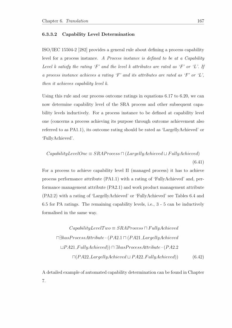
Chapter 6. Translation 167
6.3.3.2 Capability Level Determination
ISO/IEC 15504-2 [282] provides a general rule about defining a process capability
level for a process instance. A Process instance is defined to be at a Capability
Level k satisfy the rating ‘F’ and the level k attributes are rated as ‘F’ or ‘L’. If
a process instance achieves a rating ‘F’ and its attributes are rated as ‘F’ or ‘L’,
then it achieves capability level k.
Using this rule and our process outcome ratings in equations 6.17 to 6.20, we can
now determine capability level of the SRA process and other subsequent capa-
bility levels inductively. For a process instance to be defined at capability level
one (concerns a process achieving its purpose through outcome achievement also
referred to as PA1.1), its outcome rating should be rated as ‘LargellyAchieved’ or
‘FullyAchieved’.
CapabilityLevelOne ≡ SRAProcess u (LargellyAchieved t FullyAchieved)
(6.41)
For a process to achieve capability level II (managed process) it has to achieve
process performance attribute (PA1.1) with a rating of ‘FullyAchieved’ and, per-
formance management attribute (PA2.1) and work product management attribute
(PA2.2) with a rating of ‘LargellyAchieved’ or ‘FullyAchieved’ see Tables 6.4 and
6.5 for PA ratings. The remaining capability levels, i.e., 3 - 5 can be inductively
formalised in the same way.
CapabilityLevelTwo ≡ SRAProcess u FullyAchieved
u∃hasProcessAttribute · (PA2.1 u (PA21 LargellyAchieved
tPA21 FullyAchieved)) u ∃hasProcessAttribute · (PA2.2
u(PA22 LargellyAchieved t PA22 FullyAchieved)) (6.42)
A detailed example of automated capability determination can be found in Chapter
7.
Chapter 6. Translation 168
6.4 Summary
In this chapter, we have presented a formal systematic, consistent and repeatable
approach for software process formalisation. Our approach leverages on estab-
lished formal languages for software process representation. The composition tree
notation helps to create simple and easy process models that stakeholders can work
with and validate. On the other side, DL, a knowledge representation language
that underpins OWL, standard language for ontology modelling in the semantic
web provides the formalism to capture process models in a machine-readable and
understandable form so that they can be formally reasoned and verified using on-
tology reasoners, thereby automating the conformance approach through formal
verification. In doing so, we have represented software process standard best prac-
tices as ontology axioms mapping PRMs, PAM and MF in an unambiguous and
formal way. Together with the organisational processes (process instance) dis-
cussed in Chapter 7 form the Software Process Knowledge Base (SPKB) discussed
in Section 6.3 as a major component of our formalisation approach. It should be
noted that different PRMs can now be mapped to a standard PAM given the fact,
process assessment is no longer limited to process capability alone [22].
Using ontology reasoners we are able to automatically perform confirmatory ver-
ification and capability determination of process implementations. Ontology rea-
soners enable the process to be automated improving the efficiency, effectiveness
and reduce on human errors in process assessments and improvement. The main
benefits of DL based ontologies as a formalisation approach is its capability to:
(i) provide formal specification using its various constructors and, (ii) formal ver-
ification through their underlining reasoning algorithms and tools that can be
effectively used to perform large scale automated reasoning on the schema and
instance levels with greater scalability and efficiency [82]. The resulting approach
is a general formalisation approach that transcends boundaries of any specific do-
main. In the next chapter, we present the application scenarios that demonstrate
and evaluate the quality, utility and efficacy of the formal approach developed in
this chapter.
Chapter 7
Applications
7.1 Introduction
This chapter presents the applications of our process formalisation approach pre-
sented in Chapter 6 forming the ABox part of the software process knowledge base
(SPKB) in Figure 6.3. The main objective of this chapter is to demonstrate and
evaluate the quality, utility and efficacy of our approach in different application
scenarios using the evaluation criteria set out in Chapter 4. Section 7.2 discusses a
case study about process conformance verification, while in Section 7.3, we apply
our approach to the analysis and verification of open source software development
process in e-learning systems using a case of Moodle e-learning software require-
ments analysis process (mSRAProcess). Next in Section 7.4 we use our approach
to assess and determine the capability of an ISO/IEC 29110 compliant website
development project (SwiftCom). Finally in Section 7.5 we discuss the role of
formalisation in developing a new cultural aware process assessment framework
for Very Small Entities (VSEs) and we conclude the chapter in Section 7.6.
7.1.1 The Process Instance (ABox)
In this chapter, we describe project specific processes that can be performed or
enacted as instances of the standard processes in the TBox in Chapter 6. A
169
Chapter 7. Applications 170
process instance (PI) is defined to be a singular instantiation of a process that is
uniquely identifiable and about which information can be gathered in a repeatable
manner [9]. Process instances are identified for specific projects considering the
particularity of the project. Implemented processes at this level are instances
of the standard processes at the organisational level but specialised to meet the
specific needs of a particular project [21]. It is always a requirement that processes
implemented at the project level are compliant to the standard processes at the
organisation level [9]. Processes at the instance level also provide evidence for
organisational process capability/maturity determination [20].
7.2 Ensuring Conformance to HRM process through
formal verification
In Chapter 6, we developed a PRM ontology using the human resource manage-
ment process example (see subsection 6.3.1). In this section, we provide a process
instance example that we verify for conformance through formal verification.
A Process P is recorded for an organization that has a business need of developing
an accounting software system in Java platform following the human resource pro-
cess as defined in the Process reference model for quality management as modelled
in Chapter 6. It has a human resource (individual) Peter who has competency in
C programming. The organizational objective is to develop an accounting software
system in Java platform. This means that, there is a competency gap in the orga-
nization that can be filled through training or recruitment. This shows that Peter
needs training in Java in order to meet the organizational object of developing
the software system. This will help to align the human resource competency with
the business needs. This information can be modelled as an ABox in Table 7.1
and instance checking reasoning service can be used to check if Process P is HRM
process compliant as described previous.
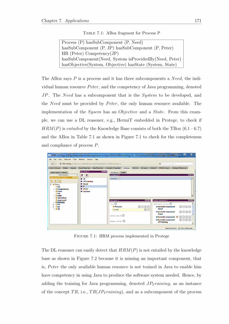
Chapter 7. Applications 171
Table 7.1: ABox fragment for Process P
Process (P) hasSubComponent (P, Need)hasSubComponent (P, JP) hasSubComponent (P, Peter)HR (Peter) Competency(JP)hasSubComponent(Need, System isProvidedBy(Need, Peter)hasObjective(System, Objective) hasState (System, State)
The ABox says P is a process and it has three subcomponents a Need, the indi-
vidual human resource Peter, and the competency of Java programming, denoted
JP . The Need has a subcomponent that is the System to be developed, and
the Need must be provided by Peter, the only human resource available. The
implementation of the Sysem has an Objective and a State. From this exam-
ple, we can use a DL reasoner, e.g., HermiT embedded in Protege, to check if
HRM(P ) is entailed by the Knowledge Base consists of both the TBox (6.1 - 6.7)
and the ABox in Table 7.1 as shown in Figure 7.1 to check for the completeness
and compliance of process P .
Figure 7.1: HRM process implemented in Protege
The DL reasoner can easily detect that HRM(P ) is not entailed by the knowledge
base as shown in Figure 7.2 because it is missing an important component, that
is, Peter the only available human resource is not trained in Java to enable him
have competency in using Java to produce the software system needed. Hence, by
adding the training for Java programming, denoted JPT raining, as an instance
of the concept TR, i.e., TR(JPT raining), and as a subcomponent of the process
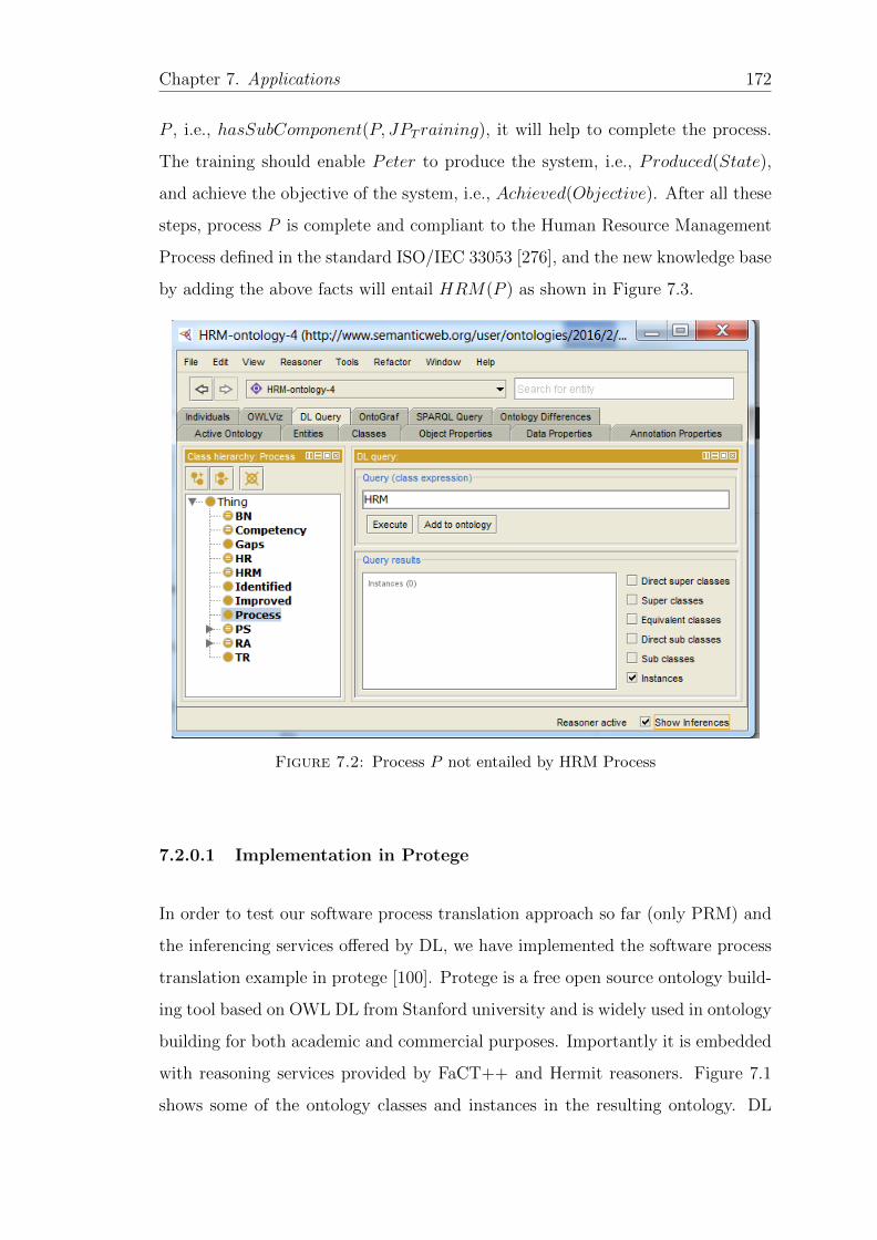
Chapter 7. Applications 172
P , i.e., hasSubComponent(P, JPT raining), it will help to complete the process.
The training should enable Peter to produce the system, i.e., Produced(State),
and achieve the objective of the system, i.e., Achieved(Objective). After all these
steps, process P is complete and compliant to the Human Resource Management
Process defined in the standard ISO/IEC 33053 [276], and the new knowledge base
by adding the above facts will entail HRM(P ) as shown in Figure 7.3.
Figure 7.2: Process P not entailed by HRM Process
7.2.0.1 Implementation in Protege
In order to test our software process translation approach so far (only PRM) and
the inferencing services offered by DL, we have implemented the software process
translation example in protege [100]. Protege is a free open source ontology build-
ing tool based on OWL DL from Stanford university and is widely used in ontology
building for both academic and commercial purposes. Importantly it is embedded
with reasoning services provided by FaCT++ and Hermit reasoners. Figure 7.1
shows some of the ontology classes and instances in the resulting ontology. DL
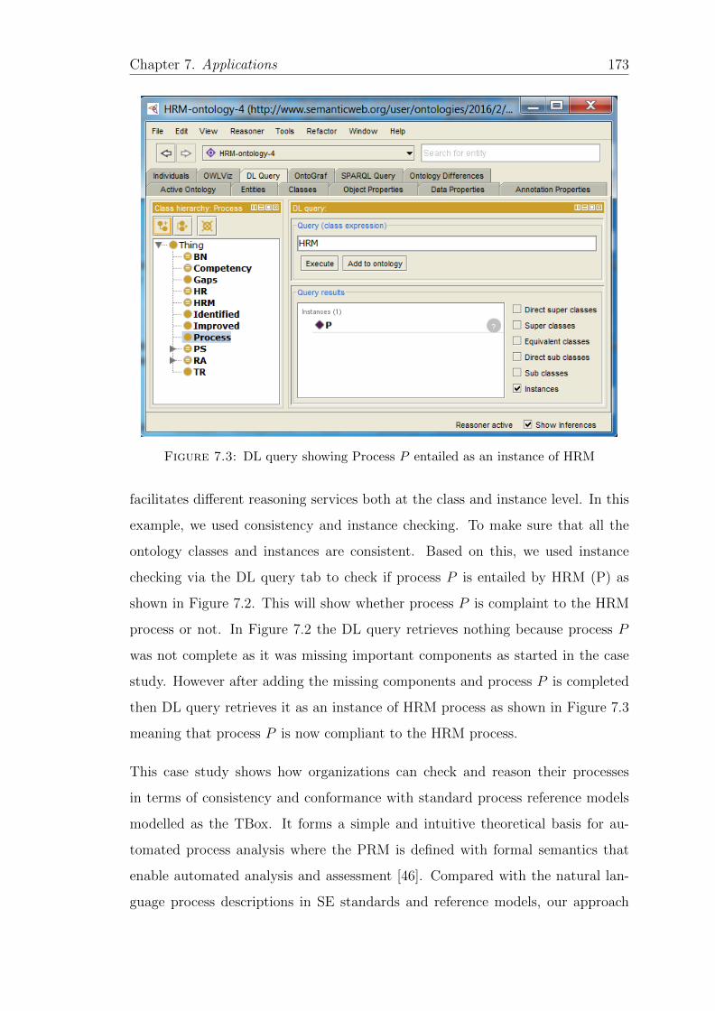
Chapter 7. Applications 173
Figure 7.3: DL query showing Process P entailed as an instance of HRM
facilitates different reasoning services both at the class and instance level. In this
example, we used consistency and instance checking. To make sure that all the
ontology classes and instances are consistent. Based on this, we used instance
checking via the DL query tab to check if process P is entailed by HRM (P) as
shown in Figure 7.2. This will show whether process P is complaint to the HRM
process or not. In Figure 7.2 the DL query retrieves nothing because process P
was not complete as it was missing important components as started in the case
study. However after adding the missing components and process P is completed
then DL query retrieves it as an instance of HRM process as shown in Figure 7.3
meaning that process P is now compliant to the HRM process.
This case study shows how organizations can check and reason their processes
in terms of consistency and conformance with standard process reference models
modelled as the TBox. It forms a simple and intuitive theoretical basis for au-
tomated process analysis where the PRM is defined with formal semantics that
enable automated analysis and assessment [46]. Compared with the natural lan-
guage process descriptions in SE standards and reference models, our approach
Chapter 7. Applications 174
provides a benefit of modelling and verifying a software process in a very intuitive
and simple formal way. This gives an overall view of the process both in graphical
and formal notation and yet less ambiguous, precise and intuitive. Formal verifi-
cation and reasoning can be performed using ontology readily available off shelf
engines.
7.3 Verification of Open Source Software Devel-
opment Processes: An E-Learning Case Study
Open source software development is gaining attention recently with reliable prod-
ucts such as Moodle, Apache, Linux among others. However, open source software
development lacks a well defined software development process [281]. In response;
Krishnamurthy and O’Connor [281] used DEMO models and ISO/IEC 12207 to
analyse the Moodle e-learning systems development process life cycle. The anal-
ysis provided a deep understanding of the development process used in Moodle
software development process. To further their findings, we give a more detailed
analysis and verification of the Moodle e-learning system requirements analysis
against ISO/IEC 15504-5 software requirements analysis (SRA) process outcomes
in this section.
Given the very nature of open-source software development (OSSD) projects, there
are assumptions that such projects do not have requirements and a requirement
process. However, it is shown in literature [283] that OSSD projects do actually
have requirements and a requirements process. Even though, these requirements
are mainly informal lacking a clear, formal organization in well-structured docu-
ments and have to be inferred from open source social communications such as
change requests, bug fixes requests, forums, blogs, email exchanges, and other
types of electronic communication between open source participants. The lack of
standardization exhibited by requirements processes and requirements representa-
tion in open-source calls for a further standard analysis [281]. Consequently, the
aim of this case study is to formalise the objective evidence of moodle e-learning
Chapter 7. Applications 175
systems development SRA process and verify it against ISO/IEC 15504-5 SRA
process outcomes. The results of the analysis have been presented and discussed
in [95]. A process that is able to achieve its purpose through outcome demonstra-
tion operates at capability level one of the measurement framework in ISO/IEC
33020 [45].
As an implementation process instance, we adapt and give a detailed analysis and
verification of the moodle e-learning system software requirements analysis process
suggested in [281]. In this case study, we only highlight and summarise activities
related to moodle SRA process as shown in Table 7.2, for other software implemen-
tation processes, interested readers can refer to [281]. In a moodle SRA process, a
moodle community starts by communicating with the core team for performing a
feature voting activity. The features could be about functional requirements (req1 )
or performance requirements (req2 ). In Moodle, there are four activities to be exe-
cuted in order to vote and select a feature and develop a requirement specification
for the selected feature(s). They are feature voting activity, road map development,
developing the requirements specifications and suggestions, discussions and agree-
ments about the requirements specification. At each end of a successful execution
of these activities, a work product is produced. For example the roadmap list is
developed after successful completion of voting process for selecting and prioritiz-
ing the features with the highest number of votes. The roadmap is used to guide
the implementation of selected features. In Moodle, software requirements speci-
fication (SRS) documents are to be created for each of the feature added to the
roadmap. The final work product in moodle SRA process are the suggestions and
discussion on the SRS document that the entire community provides and agrees
to, based on the specification released earlier.
In Table 7.2 we summarise the moodle terminology used and Table 7.3 analyses
the moodle evidence against the SRA process outcomes where its noticed that
moodle process doesn’t achieve the SRA process outcome PO4: Consistency and
traceability are established between the software requirements and system require-
ments. The moodle process evidence for DL TBox axioms 6.8 - 6.15 in Chapter 6
is then summarised in form of a DL ABox in Table 7.4.
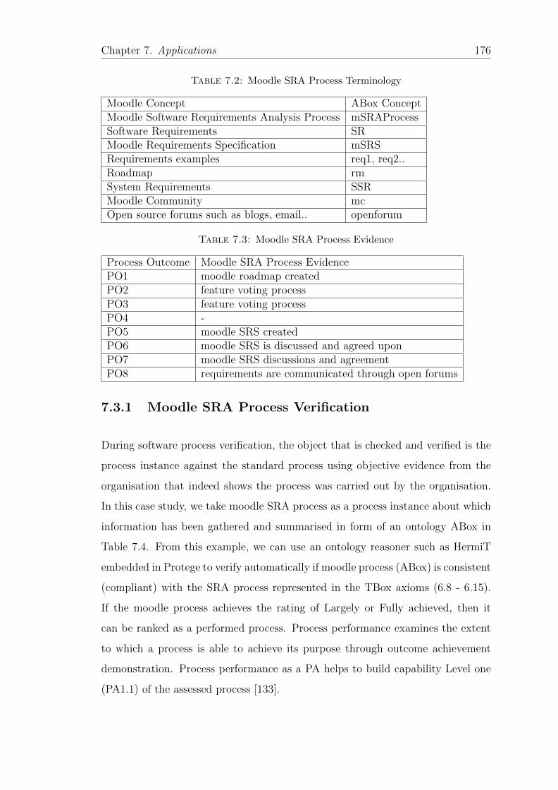
Chapter 7. Applications 176
Table 7.2: Moodle SRA Process Terminology
Moodle Concept ABox ConceptMoodle Software Requirements Analysis Process mSRAProcessSoftware Requirements SRMoodle Requirements Specification mSRSRequirements examples req1, req2..Roadmap rmSystem Requirements SSRMoodle Community mcOpen source forums such as blogs, email.. openforum
Table 7.3: Moodle SRA Process Evidence
Process Outcome Moodle SRA Process EvidencePO1 moodle roadmap createdPO2 feature voting processPO3 feature voting processPO4 -PO5 moodle SRS createdPO6 moodle SRS is discussed and agreed uponPO7 moodle SRS discussions and agreementPO8 requirements are communicated through open forums
7.3.1 Moodle SRA Process Verification
During software process verification, the object that is checked and verified is the
process instance against the standard process using objective evidence from the
organisation that indeed shows the process was carried out by the organisation.
In this case study, we take moodle SRA process as a process instance about which
information has been gathered and summarised in form of an ontology ABox in
Table 7.4. From this example, we can use an ontology reasoner such as HermiT
embedded in Protege to verify automatically if moodle process (ABox) is consistent
(compliant) with the SRA process represented in the TBox axioms (6.8 - 6.15).
If the moodle process achieves the rating of Largely or Fully achieved, then it
can be ranked as a performed process. Process performance examines the extent
to which a process is able to achieve its purpose through outcome achievement
demonstration. Process performance as a PA helps to build capability Level one
(PA1.1) of the assessed process [133].
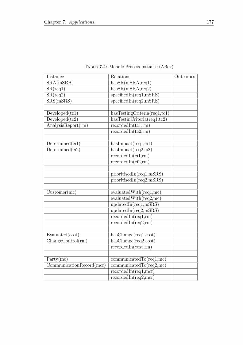
Chapter 7. Applications 177
Table 7.4: Moodle Process Instance (ABox)
Instance Relations OutcomesSRA(mSRA) hasSR(mSRA,req1)SR(req1) hasSR(mSRA,req2)SR(req2) specifiedIn(req1,mSRS)SRS(mSRS) specifiedIn(req2,mSRS)
Developed(tc1) hasTestingCriteria(req1,tc1)Developed(tc2) hasTestinCriteria(req1,tc2)AnalysisReport(rm) recordedIn(tc1,rm)
recordedIn(tc2,rm)
Determined(ei1) hasImpact(req1,ei1)Determined(ei2) hasImpact(req2,ei2)
recordedIn(ei1,rm)recordedIn(ei2,rm)
prioritisedIn(req1,mSRS)prioritisedIn(req2,mSRS)
Customer(mc) evaluatedWith(req1,mc)evaluatedWith(req2,mc)updatedIn(req1,mSRS)updatedIn(req2,mSRS)recordedIn(req1,rm)recordedIn(req2,rm)
Evaluated(cost) hasChange(req1,cost)ChangeControl(rm) hasChange(req2,cost)
recordedIn(cost,rm)
Party(mc) communicatedTo(req1,mc)CommunicationRecord(mcr) communicatedTo(req2,mc)
recordedIn(req1,mcr)recordedIn(req2,mcr)
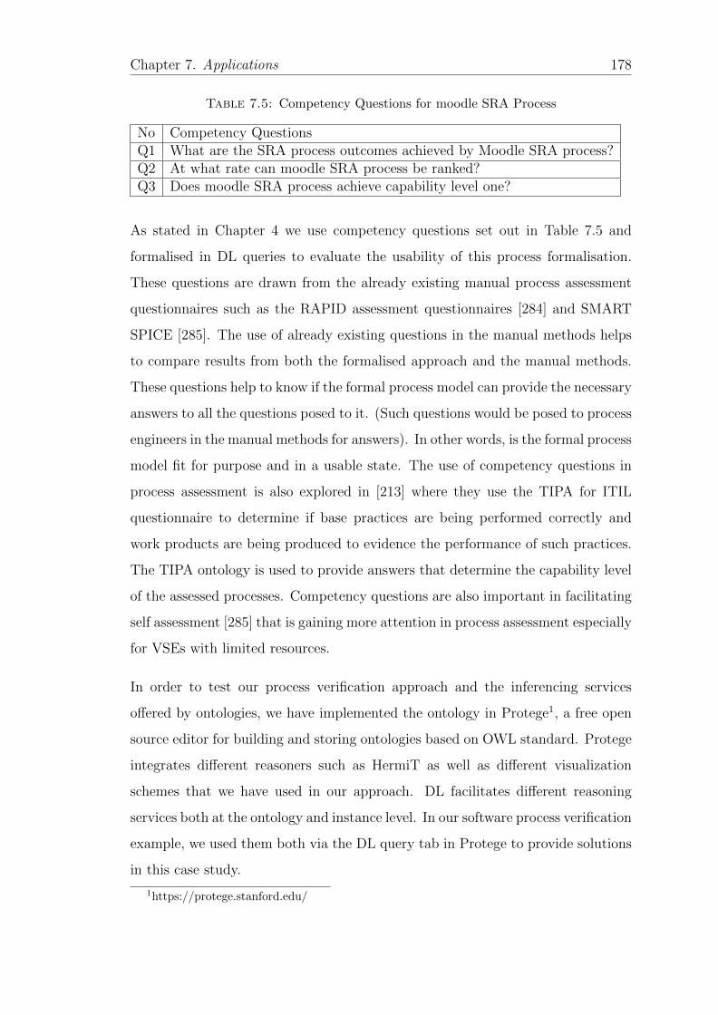
Chapter 7. Applications 178
Table 7.5: Competency Questions for moodle SRA Process
No Competency QuestionsQ1 What are the SRA process outcomes achieved by Moodle SRA process?Q2 At what rate can moodle SRA process be ranked?Q3 Does moodle SRA process achieve capability level one?
As stated in Chapter 4 we use competency questions set out in Table 7.5 and
formalised in DL queries to evaluate the usability of this process formalisation.
These questions are drawn from the already existing manual process assessment
questionnaires such as the RAPID assessment questionnaires [284] and SMART
SPICE [285]. The use of already existing questions in the manual methods helps
to compare results from both the formalised approach and the manual methods.
These questions help to know if the formal process model can provide the necessary
answers to all the questions posed to it. (Such questions would be posed to process
engineers in the manual methods for answers). In other words, is the formal process
model fit for purpose and in a usable state. The use of competency questions in
process assessment is also explored in [213] where they use the TIPA for ITIL
questionnaire to determine if base practices are being performed correctly and
work products are being produced to evidence the performance of such practices.
The TIPA ontology is used to provide answers that determine the capability level
of the assessed processes. Competency questions are also important in facilitating
self assessment [285] that is gaining more attention in process assessment especially
for VSEs with limited resources.
In order to test our process verification approach and the inferencing services
offered by ontologies, we have implemented the ontology in Protege1, a free open
source editor for building and storing ontologies based on OWL standard. Protege
integrates different reasoners such as HermiT as well as different visualization
schemes that we have used in our approach. DL facilitates different reasoning
services both at the ontology and instance level. In our software process verification
example, we used them both via the DL query tab in Protege to provide solutions
in this case study.
1https://protege.stanford.edu/

Chapter 7. Applications 179
To answer Q1, using the ABox in Table 7.4 and the axioms in equations 6.8 to
6.15 for SRA process outcomes in Chapter 6, we invoke the reasoner to derive the
SRA process outcomes achieved by the Moodel SRA process (mSRAProcess) as
shown in the query in Figure 7.4.
Figure 7.4: Process outcomes achieved by mSRAprocess
To answer the second question Q2, based on the number of distinct process out-
comes achieved in Figure 7.4, a rating can be assigned as defined in the process
outcome rating scheme in Table 6.3 and DL axioms in equations 6.17 to 6.20 in
Chapter 6. In Figure 7.5 the reasoner is able to rate the moodle SRA process
(mSRAprocess) as largely achieved.
In the process dimension, the main aim is for the process to achieve its purpose
through outcome achievement demonstration. A process that is able to achieve
its purpose through outcome achievement demonstration operates at capability
one. Based on the moodle SRA process rating in Figure 7.5, it can be classified
as operating at capability level one as shown in Figure 7.6.
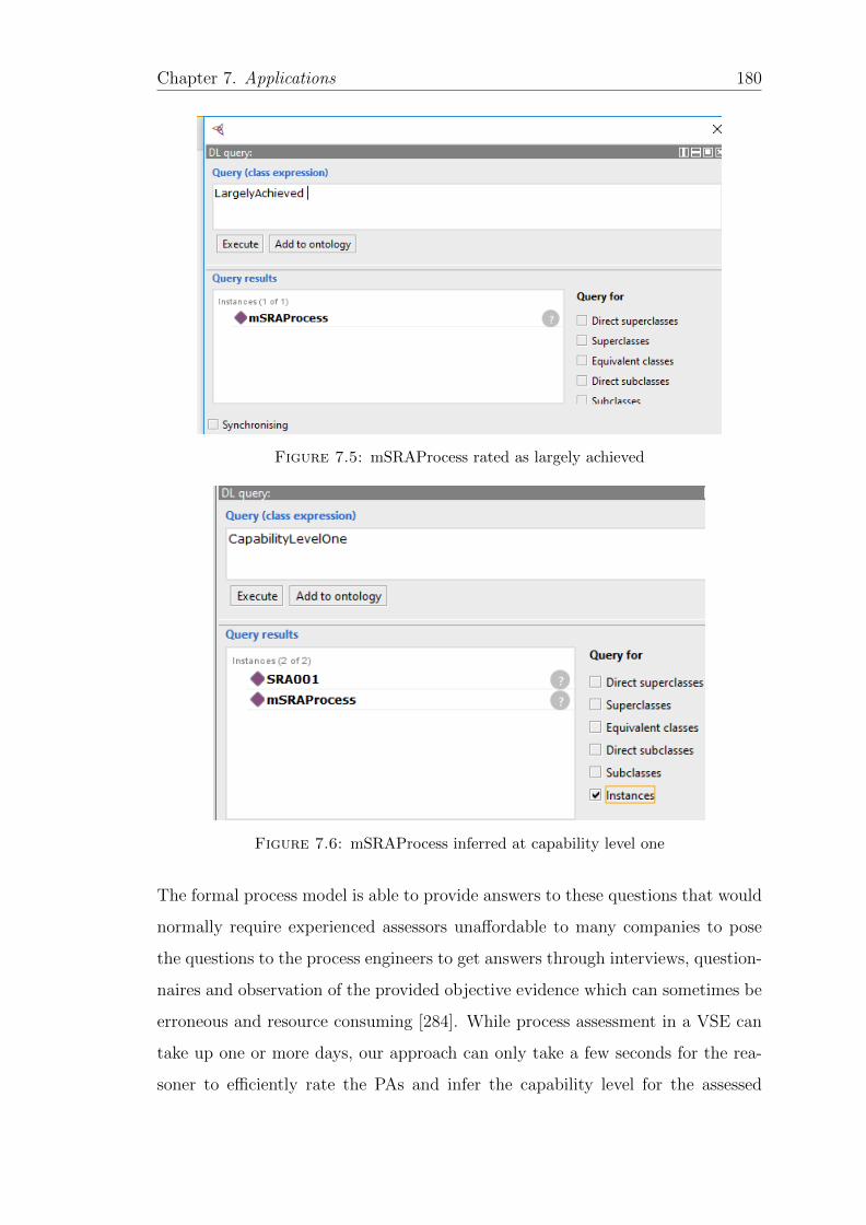
Chapter 7. Applications 180
Figure 7.5: mSRAProcess rated as largely achieved
Figure 7.6: mSRAProcess inferred at capability level one
The formal process model is able to provide answers to these questions that would
normally require experienced assessors unaffordable to many companies to pose
the questions to the process engineers to get answers through interviews, question-
naires and observation of the provided objective evidence which can sometimes be
erroneous and resource consuming [284]. While process assessment in a VSE can
take up one or more days, our approach can only take a few seconds for the rea-
soner to efficiently rate the PAs and infer the capability level for the assessed
Chapter 7. Applications 181
software process.
7.4 Formalised Process Assessment and Capa-
bility Determination
This software development project case study is about ISO/IEC 29110 compliant
website development and adapted from [286]. The project was carried out by a
2-person start up enterprise. This set up follows within the definition of VSE
according to ISO/IEC 29110 standard. The main objective of the project was to
develop a social networking website for travellers, SwiftCom. While the project
follows the two main processes specified in ISO/IEC 29110 standard [26], i.e.,
project management (PM) and software implementation (SI) process, here we only
analyse the software requirements analysis (SRA) process as one of the software
implementation processes, however, our approach is general and can be extended
to any other process. Improving the SRA process can greatly improve the success
of a project [135]. While various roles and responsibilities were divided between
the two persons in the project and documented, here we only look at the SRA
process roles and responsibilities [286].
According to ISO/IEC 29110, the statement of work (SOW) is the input to the
software requirements analysis process and this was developed using friends of
the developers as there were no formal clients to develop the SOW. In SOW high
level features of the system were identified such as (i) adding a user to the system
(req1), (ii) modifying a user on the system (req2) among others. Prioritising of the
features listed in the SOW was done by the development team where some features
were revised and others dropped. After prioritising and ranking of the features
they were converted into a set of requirements and documented in a software
requirements specification (SRS).
A set of requirements describes all the requirements that have been agreed upon
by both the development team and the customer. The SRS was reviewed using
Chapter 7. Applications 182
desk check for several rounds before it could be accepted and its various versions
were managed using an open source software tool SVN. The SRS was captured
using a template developed by the team. The requirements were analysed during
discussions that led to some initial requirements being dropped and others being
replaced with simple ones. During the discussions it was also established that some
requirements were not identified in the SOW which were added during the process.
The analysis activity was found to be very useful especially during the monthly
project reviews where some requirements would be replaced with others. After the
analysis phase, the final SRS was produced. The SRS was also verified, validated
and baselined to ensure accuracy and testability as well as their consistency with
the product description [286].
Based on the a final SRS, a traceability matrix was also developed to connect
the defined requirements in SRS with other software components in software ar-
chitecture phase. Testing plans and reports were developed to verify the site’s
features as documented in the SRS. There was interaction between SRA and the
software architecture process as SRA is the input process to the architecture pro-
cess, some recommendations come from SAD to improve SRS such as developing
the traceability matrix between requirements and other software components.
In this case study, we formally assess and determine the capability level that the
SwitfCom SRA process can achieve using our formalisation approach developed
in Chapter 6. While ISO/IEC 15504-5 SRA process has seven process outcomes,
it is stated in [137] that a VSE wishing to assess its processes using ISO/IEC
15504-5 can select only the relevant artefacts needed at a particular moment.
In response, various methodologies have been developed with varying assessment
levels [32, 287] to sufficiently assess the software process objectives as identified
in ISO/IEC 29110. Various authors acknowledge that the highest capability level
that can be reached by any VSE is capability level three [124].
In Table 7.6 we summarise the SwiftCom SRA process terminologies that we use
through out the case study. We also present the various SwiftCom SRA process
evidence summarised from the case study in Tables 7.6 to 7.9, while in Tables 7.10
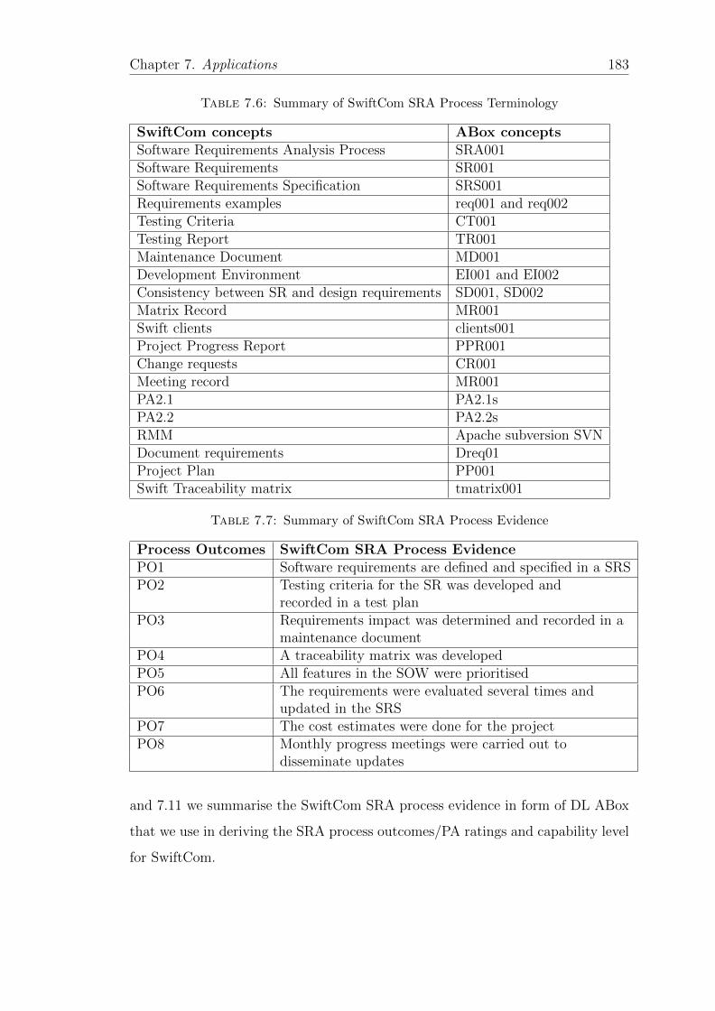
Chapter 7. Applications 183
Table 7.6: Summary of SwiftCom SRA Process Terminology
SwiftCom concepts ABox conceptsSoftware Requirements Analysis Process SRA001Software Requirements SR001Software Requirements Specification SRS001Requirements examples req001 and req002Testing Criteria CT001Testing Report TR001Maintenance Document MD001Development Environment EI001 and EI002Consistency between SR and design requirements SD001, SD002Matrix Record MR001Swift clients clients001Project Progress Report PPR001Change requests CR001Meeting record MR001PA2.1 PA2.1sPA2.2 PA2.2sRMM Apache subversion SVNDocument requirements Dreq01Project Plan PP001Swift Traceability matrix tmatrix001
Table 7.7: Summary of SwiftCom SRA Process Evidence
Process Outcomes SwiftCom SRA Process EvidencePO1 Software requirements are defined and specified in a SRSPO2 Testing criteria for the SR was developed and
recorded in a test planPO3 Requirements impact was determined and recorded in a
maintenance documentPO4 A traceability matrix was developedPO5 All features in the SOW were prioritisedPO6 The requirements were evaluated several times and
updated in the SRSPO7 The cost estimates were done for the projectPO8 Monthly progress meetings were carried out to
disseminate updates
and 7.11 we summarise the SwiftCom SRA process evidence in form of DL ABox
that we use in deriving the SRA process outcomes/PA ratings and capability level
for SwiftCom.
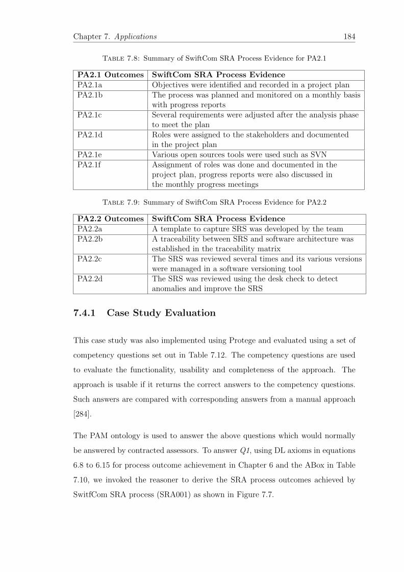
Chapter 7. Applications 184
Table 7.8: Summary of SwiftCom SRA Process Evidence for PA2.1
PA2.1 Outcomes SwiftCom SRA Process EvidencePA2.1a Objectives were identified and recorded in a project planPA2.1b The process was planned and monitored on a monthly basis
with progress reportsPA2.1c Several requirements were adjusted after the analysis phase
to meet the planPA2.1d Roles were assigned to the stakeholders and documented
in the project planPA2.1e Various open sources tools were used such as SVNPA2.1f Assignment of roles was done and documented in the
project plan, progress reports were also discussed inthe monthly progress meetings
Table 7.9: Summary of SwiftCom SRA Process Evidence for PA2.2
PA2.2 Outcomes SwiftCom SRA Process EvidencePA2.2a A template to capture SRS was developed by the teamPA2.2b A traceability between SRS and software architecture was
established in the traceability matrixPA2.2c The SRS was reviewed several times and its various versions
were managed in a software versioning toolPA2.2d The SRS was reviewed using the desk check to detect
anomalies and improve the SRS
7.4.1 Case Study Evaluation
This case study was also implemented using Protege and evaluated using a set of
competency questions set out in Table 7.12. The competency questions are used
to evaluate the functionality, usability and completeness of the approach. The
approach is usable if it returns the correct answers to the competency questions.
Such answers are compared with corresponding answers from a manual approach
[284].
The PAM ontology is used to answer the above questions which would normally
be answered by contracted assessors. To answer Q1, using DL axioms in equations
6.8 to 6.15 for process outcome achievement in Chapter 6 and the ABox in Table
7.10, we invoked the reasoner to derive the SRA process outcomes achieved by
SwitfCom SRA process (SRA001) as shown in Figure 7.7.
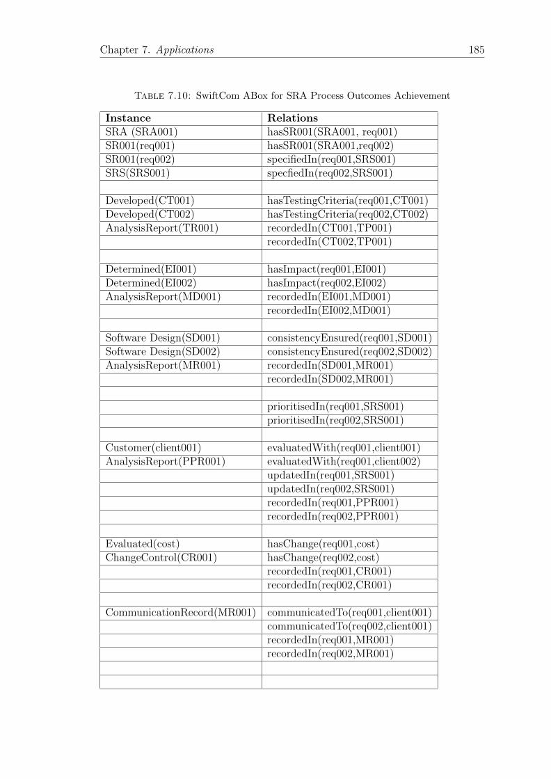
Chapter 7. Applications 185
Table 7.10: SwiftCom ABox for SRA Process Outcomes Achievement
Instance RelationsSRA (SRA001) hasSR001(SRA001, req001)SR001(req001) hasSR001(SRA001,req002)SR001(req002) specifiedIn(req001,SRS001)SRS(SRS001) specfiedIn(req002,SRS001)
Developed(CT001) hasTestingCriteria(req001,CT001)Developed(CT002) hasTestingCriteria(req002,CT002)AnalysisReport(TR001) recordedIn(CT001,TP001)
recordedIn(CT002,TP001)
Determined(EI001) hasImpact(req001,EI001)Determined(EI002) hasImpact(req002,EI002)AnalysisReport(MD001) recordedIn(EI001,MD001)
recordedIn(EI002,MD001)
Software Design(SD001) consistencyEnsured(req001,SD001)Software Design(SD002) consistencyEnsured(req002,SD002)AnalysisReport(MR001) recordedIn(SD001,MR001)
recordedIn(SD002,MR001)
prioritisedIn(req001,SRS001)prioritisedIn(req002,SRS001)
Customer(client001) evaluatedWith(req001,client001)AnalysisReport(PPR001) evaluatedWith(req001,client002)
updatedIn(req001,SRS001)updatedIn(req002,SRS001)recordedIn(req001,PPR001)recordedIn(req002,PPR001)
Evaluated(cost) hasChange(req001,cost)ChangeControl(CR001) hasChange(req002,cost)
recordedIn(req001,CR001)recordedIn(req002,CR001)
CommunicationRecord(MR001) communicatedTo(req001,client001)communicatedTo(req002,client001)recordedIn(req001,MR001)recordedIn(req002,MR001)
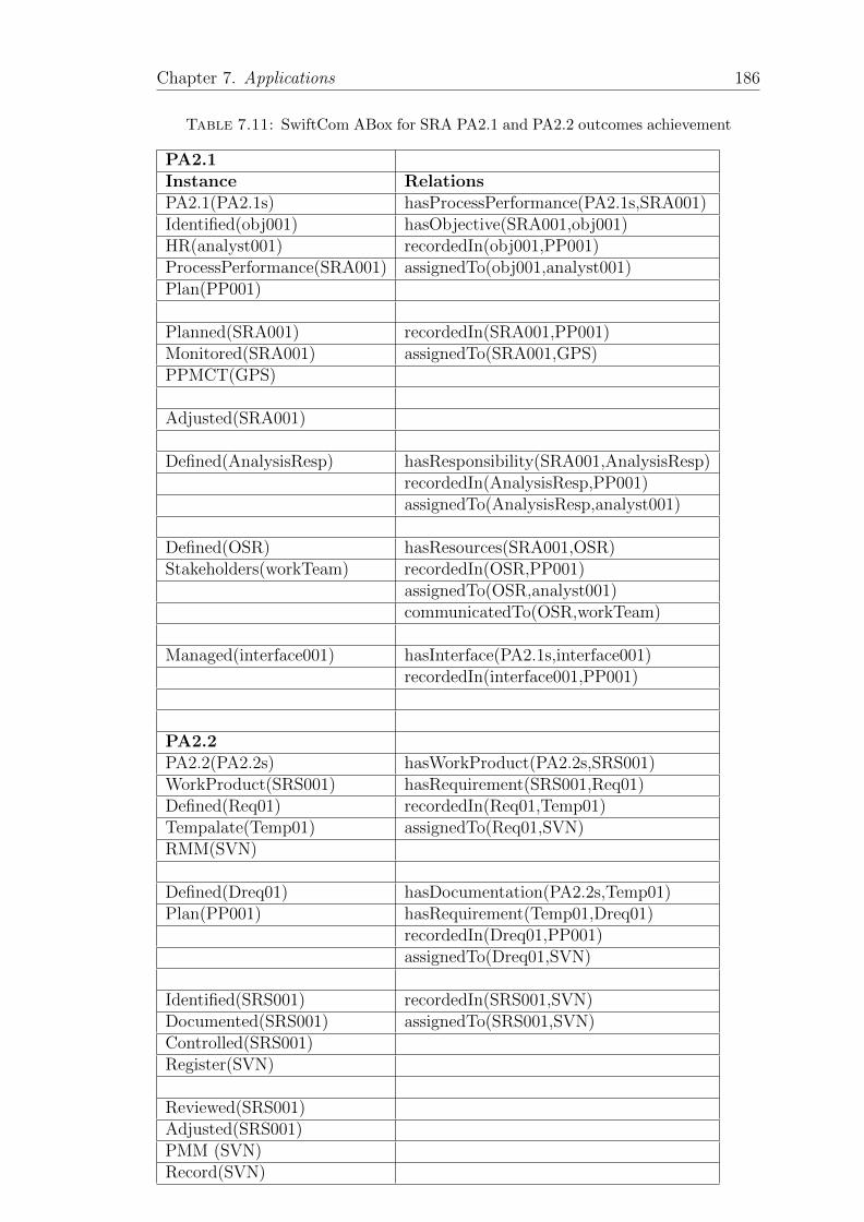
Chapter 7. Applications 186
Table 7.11: SwiftCom ABox for SRA PA2.1 and PA2.2 outcomes achievement
PA2.1Instance RelationsPA2.1(PA2.1s) hasProcessPerformance(PA2.1s,SRA001)Identified(obj001) hasObjective(SRA001,obj001)HR(analyst001) recordedIn(obj001,PP001)ProcessPerformance(SRA001) assignedTo(obj001,analyst001)Plan(PP001)
Planned(SRA001) recordedIn(SRA001,PP001)Monitored(SRA001) assignedTo(SRA001,GPS)PPMCT(GPS)
Adjusted(SRA001)
Defined(AnalysisResp) hasResponsibility(SRA001,AnalysisResp)recordedIn(AnalysisResp,PP001)assignedTo(AnalysisResp,analyst001)
Defined(OSR) hasResources(SRA001,OSR)Stakeholders(workTeam) recordedIn(OSR,PP001)
assignedTo(OSR,analyst001)communicatedTo(OSR,workTeam)
Managed(interface001) hasInterface(PA2.1s,interface001)recordedIn(interface001,PP001)
PA2.2PA2.2(PA2.2s) hasWorkProduct(PA2.2s,SRS001)WorkProduct(SRS001) hasRequirement(SRS001,Req01)Defined(Req01) recordedIn(Req01,Temp01)Tempalate(Temp01) assignedTo(Req01,SVN)RMM(SVN)
Defined(Dreq01) hasDocumentation(PA2.2s,Temp01)Plan(PP001) hasRequirement(Temp01,Dreq01)
recordedIn(Dreq01,PP001)assignedTo(Dreq01,SVN)
Identified(SRS001) recordedIn(SRS001,SVN)Documented(SRS001) assignedTo(SRS001,SVN)Controlled(SRS001)Register(SVN)
Reviewed(SRS001)Adjusted(SRS001)PMM (SVN)Record(SVN)
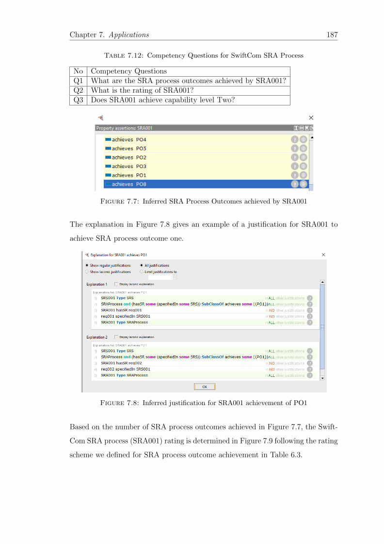
Chapter 7. Applications 187
Table 7.12: Competency Questions for SwiftCom SRA Process
No Competency QuestionsQ1 What are the SRA process outcomes achieved by SRA001?Q2 What is the rating of SRA001?Q3 Does SRA001 achieve capability level Two?
Figure 7.7: Inferred SRA Process Outcomes achieved by SRA001
The explanation in Figure 7.8 gives an example of a justification for SRA001 to
achieve SRA process outcome one.
Figure 7.8: Inferred justification for SRA001 achievement of PO1
Based on the number of SRA process outcomes achieved in Figure 7.7, the Swift-
Com SRA process (SRA001) rating is determined in Figure 7.9 following the rating
scheme we defined for SRA process outcome achievement in Table 6.3.
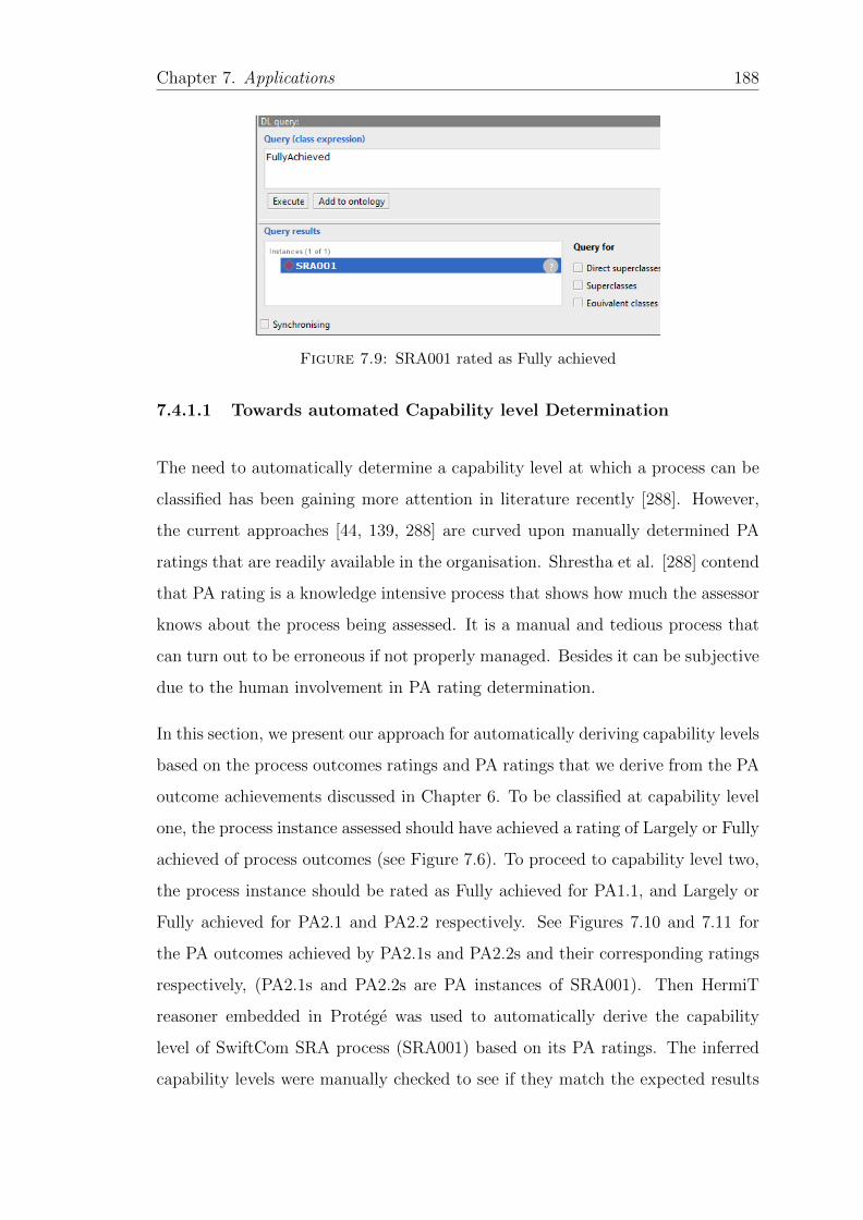
Chapter 7. Applications 188
Figure 7.9: SRA001 rated as Fully achieved
7.4.1.1 Towards automated Capability level Determination
The need to automatically determine a capability level at which a process can be
classified has been gaining more attention in literature recently [288]. However,
the current approaches [44, 139, 288] are curved upon manually determined PA
ratings that are readily available in the organisation. Shrestha et al. [288] contend
that PA rating is a knowledge intensive process that shows how much the assessor
knows about the process being assessed. It is a manual and tedious process that
can turn out to be erroneous if not properly managed. Besides it can be subjective
due to the human involvement in PA rating determination.
In this section, we present our approach for automatically deriving capability levels
based on the process outcomes ratings and PA ratings that we derive from the PA
outcome achievements discussed in Chapter 6. To be classified at capability level
one, the process instance assessed should have achieved a rating of Largely or Fully
achieved of process outcomes (see Figure 7.6). To proceed to capability level two,
the process instance should be rated as Fully achieved for PA1.1, and Largely or
Fully achieved for PA2.1 and PA2.2 respectively. See Figures 7.10 and 7.11 for
the PA outcomes achieved by PA2.1s and PA2.2s and their corresponding ratings
respectively, (PA2.1s and PA2.2s are PA instances of SRA001). Then HermiT
reasoner embedded in Protege was used to automatically derive the capability
level of SwiftCom SRA process (SRA001) based on its PA ratings. The inferred
capability levels were manually checked to see if they match the expected results
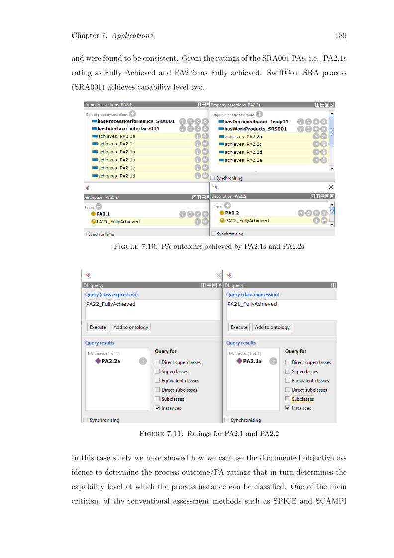
Chapter 7. Applications 189
and were found to be consistent. Given the ratings of the SRA001 PAs, i.e., PA2.1s
rating as Fully Achieved and PA2.2s as Fully achieved. SwiftCom SRA process
(SRA001) achieves capability level two.
Figure 7.10: PA outcomes achieved by PA2.1s and PA2.2s
Figure 7.11: Ratings for PA2.1 and PA2.2
In this case study we have showed how we can use the documented objective ev-
idence to determine the process outcome/PA ratings that in turn determines the
capability level at which the process instance can be classified. One of the main
criticism of the conventional assessment methods such as SPICE and SCAMPI
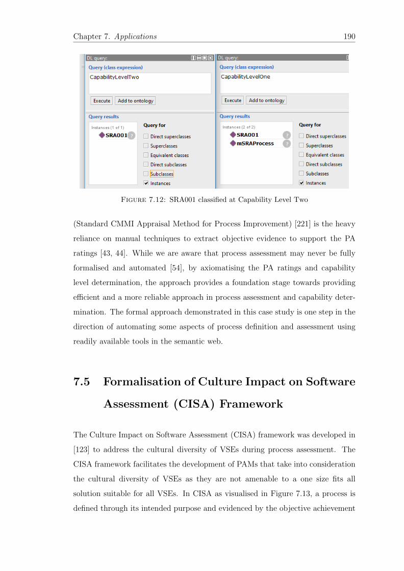
Chapter 7. Applications 190
Figure 7.12: SRA001 classified at Capability Level Two
(Standard CMMI Appraisal Method for Process Improvement) [221] is the heavy
reliance on manual techniques to extract objective evidence to support the PA
ratings [43, 44]. While we are aware that process assessment may never be fully
formalised and automated [54], by axiomatising the PA ratings and capability
level determination, the approach provides a foundation stage towards providing
efficient and a more reliable approach in process assessment and capability deter-
mination. The formal approach demonstrated in this case study is one step in the
direction of automating some aspects of process definition and assessment using
readily available tools in the semantic web.
7.5 Formalisation of Culture Impact on Software
Assessment (CISA) Framework
The Culture Impact on Software Assessment (CISA) framework was developed in
[123] to address the cultural diversity of VSEs during process assessment. The
CISA framework facilitates the development of PAMs that take into consideration
the cultural diversity of VSEs as they are not amenable to a one size fits all
solution suitable for all VSEs. In CISA as visualised in Figure 7.13, a process is
defined through its intended purpose and evidenced by the objective achievement
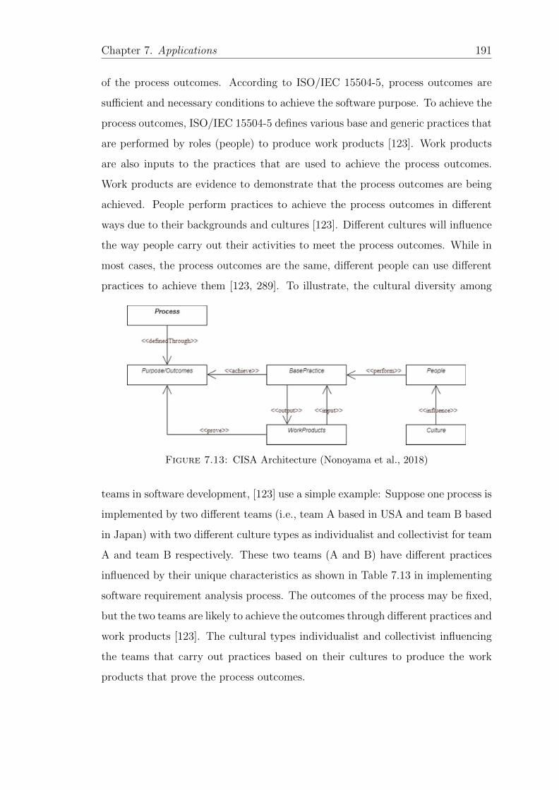
Chapter 7. Applications 191
of the process outcomes. According to ISO/IEC 15504-5, process outcomes are
sufficient and necessary conditions to achieve the software purpose. To achieve the
process outcomes, ISO/IEC 15504-5 defines various base and generic practices that
are performed by roles (people) to produce work products [123]. Work products
are also inputs to the practices that are used to achieve the process outcomes.
Work products are evidence to demonstrate that the process outcomes are being
achieved. People perform practices to achieve the process outcomes in different
ways due to their backgrounds and cultures [123]. Different cultures will influence
the way people carry out their activities to meet the process outcomes. While in
most cases, the process outcomes are the same, different people can use different
practices to achieve them [123, 289]. To illustrate, the cultural diversity among
Figure 7.13: CISA Architecture (Nonoyama et al., 2018)
teams in software development, [123] use a simple example: Suppose one process is
implemented by two different teams (i.e., team A based in USA and team B based
in Japan) with two different culture types as individualist and collectivist for team
A and team B respectively. These two teams (A and B) have different practices
influenced by their unique characteristics as shown in Table 7.13 in implementing
software requirement analysis process. The outcomes of the process may be fixed,
but the two teams are likely to achieve the outcomes through different practices and
work products [123]. The cultural types individualist and collectivist influencing
the teams that carry out practices based on their cultures to produce the work
products that prove the process outcomes.
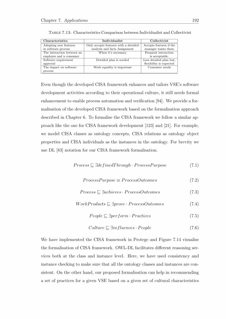
Chapter 7. Applications 192
Table 7.13: Characteristics Comparison between Individualist and Collectivist
Characteristics Individualist Collectivist
Adopting new features Only accepts features with a detailed Accepts features if thein software process analysis and facts Assignment manager wants themThe interaction between an When it’s necessary Frequent interactionemployee and a consumer is acceptable.Software requirement Detailed plan is needed Less detailed plan but,approval flexibility is expectedThe impact on software Work equality is important Consumer needsprocess
Even though the developed CISA framework enhances and tailors VSE’s software
development activities according to their operational culture, it still needs formal
enhancement to enable process automation and verification [94]. We provide a for-
malisation of the developed CISA framework based on the formalisation approach
described in Chapter 6. To formalise the CISA framework we follow a similar ap-
proach like the one for CISA framework development [123] and [21]. For example,
we model CISA classes as ontology concepts, CISA relations as ontology object
properties and CISA individuals as the instances in the ontology. For brevity we
use DL [83] notation for our CISA framework formalisation.
Process v ∃definedThrough · ProcessPurpose (7.1)
ProcessPurpose ≡ ProcessOutcomes (7.2)
Process v ∃achieves · ProcessOutcomes (7.3)
WorkProducts v ∃prove · ProcessOutcomes (7.4)
People v ∃perform · Practices (7.5)
Culture v ∃influences · People (7.6)
We have implemented the CISA framework in Protege and Figure 7.14 visualise
the formalisation of CISA framework. OWL-DL facilitates different reasoning ser-
vices both at the class and instance level. Here, we have used consistency and
instance checking to make sure that all the ontology classes and instances are con-
sistent. On the other hand, our proposed formalisation can help in recommending
a set of practices for a given VSE based on a given set of cultural characteristics
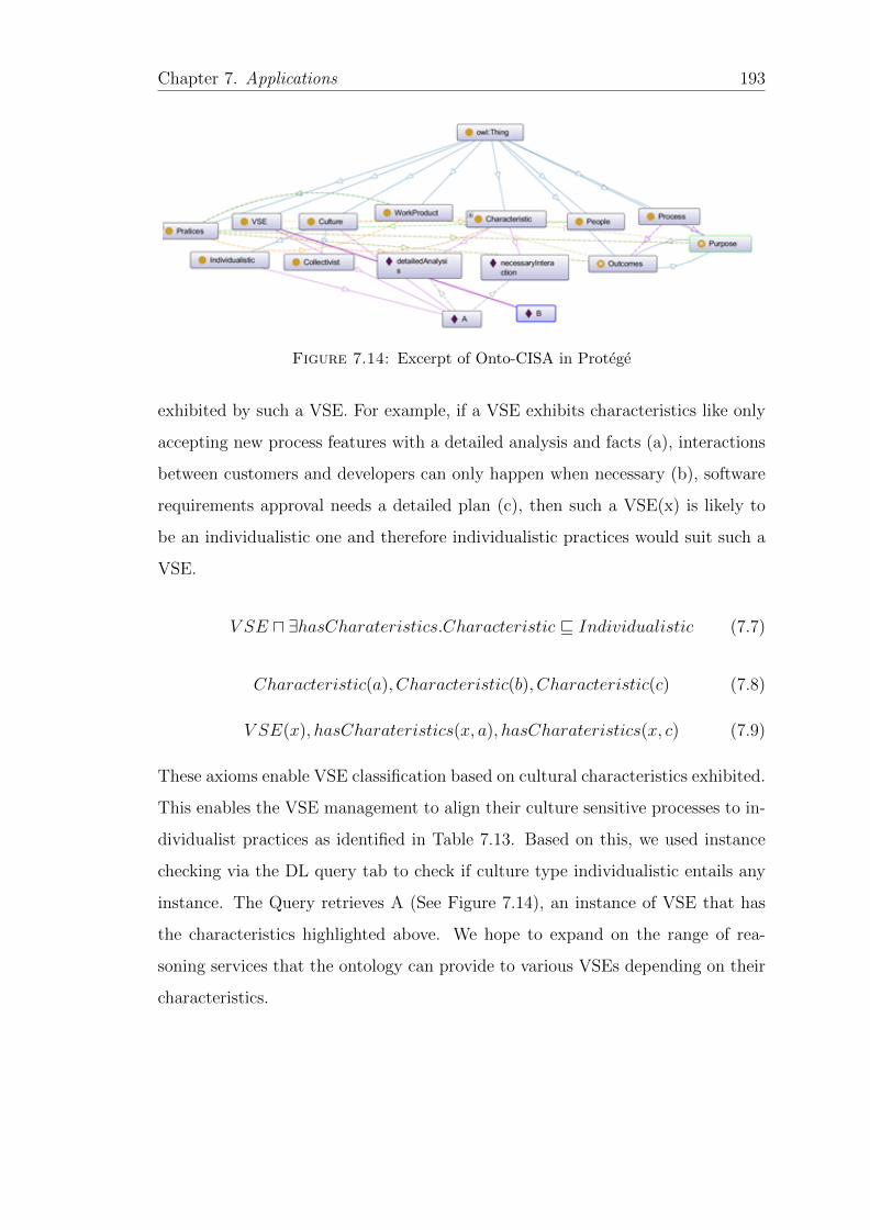
Chapter 7. Applications 193
Figure 7.14: Excerpt of Onto-CISA in Protege
exhibited by such a VSE. For example, if a VSE exhibits characteristics like only
accepting new process features with a detailed analysis and facts (a), interactions
between customers and developers can only happen when necessary (b), software
requirements approval needs a detailed plan (c), then such a VSE(x) is likely to
be an individualistic one and therefore individualistic practices would suit such a
VSE.
V SE u ∃hasCharateristics.Characteristic v Individualistic (7.7)
Characteristic(a), Characteristic(b), Characteristic(c) (7.8)
V SE(x), hasCharateristics(x, a), hasCharateristics(x, c) (7.9)
These axioms enable VSE classification based on cultural characteristics exhibited.
This enables the VSE management to align their culture sensitive processes to in-
dividualist practices as identified in Table 7.13. Based on this, we used instance
checking via the DL query tab to check if culture type individualistic entails any
instance. The Query retrieves A (See Figure 7.14), an instance of VSE that has
the characteristics highlighted above. We hope to expand on the range of rea-
soning services that the ontology can provide to various VSEs depending on their
characteristics.

Chapter 7. Applications 194
7.6 Summary
In this chapter we presented application scenarios that demonstrated and eval-
uated the quality, utility and efficacy of the formalisation approach described in
Chapter 6 in providing a formal and graphical approach to producing formal pro-
cess models that are easy to use for the practitioners [64]. It also highlights the
benefits of formal process specification to process definition and assessment as
less ambiguous process measurements and PA ratings have been advocated for in
ISO/IEC 3003. To this end, our approach provides a formal basis for formally and
automatically deriving PA ratings from the available objective evidence expressed
in form of DL axioms, in turn the PA ratings determine the capability level at
which a process instance can be classified.
While taking a minimalistic approach, our application scenarios may not be ex-
haustive, but they serve as representative examples to provide a proof of concept
of the design, implementation and evaluation of our approach discussed in Chapter
6. While, we have not considered PA ratings beyond capability level two, these
can be formalised and derived automatically in the same way, provided the nec-
essary PA outcomes and assessment indicators are represented using the pattern
described in Chapter 6. For each capability level determination, the ABox for each
PA has to be generated as described in this chapter and verified with the mapping
axioms in the TBox formed by PA outcomes and assessment indicators to derive
the PA ratings which in turn determine the capability level of the assessed process
instance.

Chapter 8
Conclusion
8.1 Introduction
This chapter summarizes the research outcomes of the study undertaken in this
thesis. It concludes the thesis by providing an overview of the thesis, a summary
of the contributions in Section 8.2, research limitations in Section 8.3 and a brief
look at some insights into future research opportunities in Section 8.4.
8.2 Contributions and Achievements
Software Engineering (SE) standards and reference models are by necessity be-
ing increasingly adopted by the software industry [123] as a source of universally
accepted best practices and guidelines to support the definition, implementation
and improvement of software processes. Significant benefits have been shown to
accrue from their adoption [31] and it is also common for some software acquirers
to require demonstration of some degree of implementation of standardised pro-
cesses as part of supplier capability evaluation [22]. But then, software process
standards and models are mainly described in natural language [39] with no for-
mal semantics that impedes the automated analysis of such processes making it
195
Chapter 8. Conclusion 196
difficult to verify if they have been fully implemented and adhered too in a given
software project [290].
Analysis of the current approaches to this challenge in literature revealed several
shortcomings that we addressed in this research following our objectives restated
here from Chapter 1. Our overarching research goal was to build a formal approach
for software process formalisation that fulfils three critical features including being
consistent and repeatable, easy to use and understandable, and to use a semanti-
cally computable formalism to facilitate effective and efficient process verification
through reasoning.
To achieve the overarching research goal, four objectives were formulated. Ob-
jective 1 was to develop a translation approach from natural language software
process to formal presentations (see Chapter 6). Objective 2 was to demonstrate
that the developed translation approach is able to integrate heterogeneous software
processes into a unified model during software process formalisation (see Chapter
5). Objective 3 was to demonstrate that the developed translation approach is; i)
systematic; ii) easy to use and understandable by all the stakeholders, and Objec-
tive 4 was to demonstrate that the developed translation approach has reasoning
capabilities that can facilitate: (i) automated analysis and verification, (ii) check
process compliance to the reference process and (iii) enable automated process
conformance checking and capability determination (see Chapter 7). In order to
achieve these objectives, a design science research methodology was adopted in
Chapter 4 to structure the research process in this thesis.
In service of these objectives, the main contribution of this study is a formal
approach by which software processes specified in natural language such as those
in SE standards and reference process models can be consistently and repeatedly
translated into formal representations for verification. The formal approach is
consistent with the requirements and quality characteristics of process formalisms
[7, 68, 88] to the extent they apply. Consequently the following contributions have
been made:
Chapter 8. Conclusion 197
1. An axiom based metamodel was developed to underpin and enhance homo-
geneous software process formalisation. The main aim of the metamodel is
to provide uniform formal concepts at an abstract level that may be utilised
to formalise heterogeneous software processes from diverse process reference
models and standards. The powertype pattern was utilised to develop the
metamodel with the view of enabling process model extensibility and flexibil-
ity with the ability to model process enactment and verification. Powertypes
also enable tailoring of process models to different specific projects through
the use of xKind and clabject concepts. This helps to create different hierar-
chical views/contexts of the modelled software process. The metamodel was
also formalised into a formal ontology using OWL punning technique. This
contribution is published in [93] and detailed in Chapter 5.
2. A systematic and repeatable formalisation approach for software process
was developed utilising Composition Trees (CT) as a graphical notation and
DL, a knowledge representation language as a formal notation. A fruitful
combination of formal methods and graphical notation in process modelling
and verification. The proposed approach takes advantages of both formal
methods and graphical notation to provide a more efficient and effective ap-
proach for software process formalisation. While DL offers expressivity and
reasoning capabilities to deliver a software process knowledge base (SPKB),
CT encapsulates the complex mathematical foundation of DL, make it more
accessible for end-users and prevents human errors. Furthermore, this ap-
proach provides an easy path from natural language processes to CT process
models, then DL representation. The approach establishes a basis for a hy-
brid environment preserving the value of each representation while at the
same time allowing users to express the software process information intu-
itively [186]. While throughout this thesis, software process examples are
used, the applicability of the developed approach is beyond boundaries of
any specific domain. This contribution is disseminated to peers in [94] and
detailed in Chapter 6.

Chapter 8. Conclusion 198
3. A Software Process Knowledge Base (SPKB) was developed to integrate the
different semantic process models that make up our formalisation approach.
These semantic models include the process reference model (PRM) ontol-
ogy, process assessment model (PAM) ontology and measurement framework
(MF) ontology that are integrated through mapping axioms: (i) The PRM
ontology represents in a formal and an unambiguous way the software pro-
cess definitions and their relationships as represented in the various PRMs
such as ISO/IEC 12207, ISO/IEC 29110 among others. These form the basis
of formal process assessment. (ii) The PAM ontology represents the assess-
ment indicators and provides mappings between the PRM ontology and the
MF ontology. (iii) The MF ontology that represents the process attribute
(PA) ratings that are used to derive the capability levels (See Figure 6.3 for
details). The SPKB forms the nucleus of our formalisation approach. Using
the SPKB, a software process can be formalised and verified for consistency
and compliance to a relevant PRM as well as determining its capability level
in achieving the organisational business objectives see Chapter 7 for details.
4. A set of application scenarios were developed to provide a proof of concept to
demonstrate and evaluate the quality, utility and efficacy of the formalisation
approach developed in this thesis. Results of application scenarios include
ensuring process conformance and automated capability determination. This
contribution is published in [95] and detailed in Chapter 7.
Within the broader context of software process definition and assessment, the
implications of our thesis are: 1) it can promote a systematic approach to rep-
resenting software processes in a machine-processable artefact and enable process
compliance; 2) it enables automated PA ratings that are used to derive capabil-
ity levels automatically through the use of inference engines; 3) it can be used
to conduct self assessment and evaluations of implemented processes. VSEs can
use the process dimension of our approach to evaluate and rate the achievement of
process outcomes in preparation for certification similar to [30, 291]. On the other,
other organisations can use both the process dimension and capability dimension
Chapter 8. Conclusion 199
of our approach to evaluate and rate the various process attributes achieved by
the organisation. Guide to process outcome/PA rating and automated capabil-
ity determination is demonstrated in Chapter 7; 4) it can be used for automated
pre-assessments to align organisational processes for formal large scale process
assessments.
Our formal approach has been demonstrated and evaluated in Chapter 7 and found
to be of quality, usable and efficient. We also found it to be consistent with the
various process formalism requirements in literature [7, 68, 88]:
• Formality ; the approach utilities DL and CT formalism to represent software
process in a formal and graphical way. DL provides the formal semantics that
enable process reasoning while CT provides easy and simple process models
for the stakeholders to use and validate during software process formalisation.
• Expressiveness ; the approach relies on the expressivity of DL to model the
various process elements according to ISO/IEC 24774 that specifies the pro-
cess elements that can be used uniformly to describe processes as discussed
in Chapter 6 .
• Understandability ; the approach uses CT notation to present the process
information in easy and simple ways while retaining sufficient formality for
process analysis. It is more helpful to represent software processes in easier
but unambiguous ways, while preserving their formality beneath [69].
• Supporting tools ; the approach is supported by readily available DL tools
such as reasoners, modelling tools like protege and various APIs. These
tools enable the formalisation and automation of process definitions and
assessments as discussed in Chapter 7.
• Abstraction and modularization; the approach is based on various ontology
modules such as PRM ontology, PAM ontology and measurement frame-
work ontology modules that make up the software process knowledge base
as discussed in Chapter 6.
Chapter 8. Conclusion 200
• Conformity to standards ; the approach is in conformity with ISO/IEC 24774
that provides the various process elements to describe software processes in
a uniform way. It is also consistent with the requirements of ISO/IEC 33004
for PRM and PAM description. Moreover, the approach is based on other
several standards such as ISO/IEC 330xx, ISO/IEC 12207, ISO/IEC 29110
and the OWL (Semantic web standard ontology language) among others.
• Granularity ; the approach takes care of software processes defined at various
granularity levels through harmonising them in an axiom based metamodel
described in Chapter 5.
• Rigour ; the approach is rigorously designed based on design science research
methodology [248]. Rigour is necessary during software process formalisation
[51].
While, the research undertaken in this thesis produced various contributions as
discussed above, there were some limitations as discussed next.
8.3 Research limitations
In conducting this research, every effort has been taken to ensure that the software
process reference frameworks for the investigation are comprehensive and fit-for-
purpose. We specifically followed ISO/IEC 24774 guidelines on describing software
processes in terms of purpose and outcomes for process definition and assessment
[22]. In this regard, ISO/IEC 330xx family of standards was the chosen reference
model. Moreover in ISO/IEC 33004, it specifies requirements for description of
PRMs and PAMs. In SE, PRMs such as ISO/IEC 12207 and ISO/EC 29110 pro-
vide process descriptions and their relationships for large entities and VSEs. Such
process descriptions provide a basis for process assessment with in the ISO/IEC
330xx family of standards. Even though these chosen process reference frameworks
for the study are comprehensive and generic in process definition and assessment,
no single framework can claim to be absolutely complete. For example, ISO/IEC

Chapter 8. Conclusion 201
330xx is still evolving with some parts already published like ISO/IEC 33020 and
others like ISO/IEC 33061 yet to be published. While we assume that the change
over from ISO/IEC 15504-5 to ISO/IEC 33061 will be straight forward. So far, we
couldn’t establish any practical reports to indicate practical aspects of the already
published parts to draw inspiration from. However, the annual release by the re-
sponsible ISO committee [27] about the same can be relied upon once ISO/IEC
33061 and others are finally published.
In this study, we only considered process reference models within the confinement
of the ISO/IEC 33004 and ISO/IEC 24774, see the research scope section 1.6.
This restriction may also limit the applicability of our approach. To expand our
horizon, the approach can be extended to other software process descriptions such
as those in CMMI and agile through the readily available harmonisation schemes
such as [50, 267]. However, at the moment no efforts have been made for such
extensions.
In our formal approach, we exploit the expressivity and reasoning capabilities of
DL to derive SPKB that forms a nucleus of our approach, however, one well known
limitation of DL is its consideration of open world assumption (OWA) yet pro-
cess models are considered to be following closed world assumption (CWA). DL’s
OWA restricts some reasoning abilities and may give confusing reasoning results
to people who are not experts at it [131]. In the OWA, something can’t be deter-
mined not to exist until explicitly stated [187]. This is a big departure from CWA
that assumes a complete knowledge about something widely adopted in database
modelling [187] and process modelling [253]. Moreover, the approach requires the
use of specific OWL DL tools such reasoners. For example DL reasoners only work
with ontologies represented in logical formalisms [168]. In our approach, it requires
that both the process models and organisational processes (process instance) be
formalised in a logical decidable formalism.
Our approach is only limited to formalising the software process static elements
where we have used DL and CT techniques. The dynamic aspects of software
process during implementation were omitted. To formalise the dynamic aspects
Chapter 8. Conclusion 202
of software process will require to use other tools such as Behavior Trees [47, 165]
and any temporal related DL to represent such aspects.
8.4 Future Directions
SE standards are large, complex and interrelated multi-part documents [27]. Man-
ually extracting and translating process requirements and practices from them is
a difficult and laborious task. It has been widely reported that translating of
standard requirements into formal representations is not a trivial task [40]. Yet
at the moment this is done manually in our approach, it means carefully reading
and identifying the requirements from the standard and translating them one by
one [52]. Given the sheer size of standards such as ISO/IEC 12207 and ISO/IEC
330xx; such work is very tiresome. Moreover, there is likely to be different inter-
pretations by different people given the inherent ambiguity of natural language.
The re-usability of the modelled processes, gives hope that such processes can be
used on other projects in future, although, we also acknowledge the fact that each
software project is unique and one size fits all doesn’t suffice in most situations.
In future we intend to use natural language processing (NLP) techniques to assist
in the translation. Automating the process parsing software process requirements
from textual descriptions (natural language standards) into DL axioms is hoped
to greatly improve the approach efficiency.
In our approach, the ABox can grow very big as seen in chapter 7, we need to
devise means of automating the generation of the ABox that corresponds to the
given TBox as given in Chapter 6.
While in this study, ISO/IEC 330xx was considered over other process assessment
models, we realise that, there are no currently standard benchmarks for SPICE
like it is the case for CMMI with SCAMPI. This makes benchmarking of the
results problematic. In future, we intend to benchmark with SCAMPI through
the available mappings between SPICE and CMMI [50].
Chapter 8. Conclusion 203
The approach is not fully automated, however, the core functionality of the DL
based formalization is fully provided. That is, the models can be verified to be
well-formed, and therefore process instances can be checked against the PRM
automatically and their capability determined. Other possible automation points
are left as future work.
Finally, the implementation of a software tool that automates the process elab-
orated in this thesis is the next step of action. The software process knowledge
base will form the base for the development of an intelligent process definition and
assessment tool. This tool will also incorporate the features highlighted in [46].
Our approach was only evaluated with academic examples. Therefore, we plan
to further evaluate the approach with more complex cases, i.e., industrial cases.
Applying the approach to a real life scenario in the industry was not possible
during the development of this approach. However, results were presented in the
Software Process Improvement and Capability Determination (SPICE) conference
where experts in the field gave us some comments that we used to improve the
approach. The application of the approach with a real scenario in industry is
planned as one of the essential future work to enhance the approach and place it
to match the real industry scenarios.
Bibliography
[1] I Sommerville. Software engineering, boston, massachusetts: Pearson edu-
cation, 2011.
[2] Leon J Osterweil. A future for software engineering? In 2007 Future of
Software Engineering, pages 1–11. IEEE Computer Society, 2007.
[3] Jurgen Munch, Ove Armbrust, Martin Kowalczyk, and Martin Soto. Soft-
ware process definition and management. Springer Science & Business Media,
2012.
[4] Peter Naur and Brian Randell. Software engineering: Report on a conference
sponsored by the nato science committee, garmisch, germany, 7th to 11th
october 1968. Nato, 1969.
[5] A Fuggetta. Software process: A roadmap. 22nd int. In Conf. on Soft-
ware Engineering (ICSE’2000), Future of Software Engineering Track, June,
pages 4–11, 2000.
[6] Anthony I Wasserman. Toward a discipline of software engineering. IEEE
software, (6):23–31, 1996.
[7] Leon J Osterweil. Formalisms to support the definition of processes. Journal
of Computer Science and Technology, 24(2):198–211, 2009.
[8] David H Kitson and Watts S Humphrey. The role of assessment in soft-
ware process improvement. Technical report, CARNEGIE-MELLON UNIV
PITTSBURGH PA SOFTWARE ENGINEERING INST, 1989.
204
Bibliography 205
[9] ISO ISO. Iec 12207 systems and software engineering-software life cycle pro-
cesses. International Organization for Standardization, Geneva, Switzerland,
2008.
[10] Peter H Feiler and Watts S Humphrey. Software process development and
enactment: Concepts and definitions. In Software Process, 1993. Continu-
ous Software Process Improvement, Second International Conference on the,
pages 28–40. IEEE, 1993.
[11] Leon J Osterweil. Software processes are software too, revisited. In Engi-
neering of Software, pages 345–359. Springer, 2011.
[12] F Brooks and HJ Kugler. No silver bullet. April, 1987.
[13] Paul Clarke, Rory V O’Connor, and Brian Leavy. A complexity theory
viewpoint on the software development process and situational context. In
Proceedings of the International Conference on Software and Systems Pro-
cess, pages 86–90. ACM, 2016.
[14] Nien-Lin Hsueh, Wen-Hsiang Shen, Zhi-Wei Yang, and Don-Lin Yang. Ap-
plying uml and software simulation for process definition, verification, and
validation. Information and Software Technology, 50(9-10):897–911, 2008.
[15] Pablo Ruiz, Alcides Quispe, Marıa Cecilia Bastarrica, and Julio Ariel Hur-
tado Alegrıa. Formalizing the software process in small companies. 8CCC,
Colombia (August 2013), 2012.
[16] T STANDISH GROUP et al. The chaos manifesto. Think Big, Act Small,
Boston: The Standish Group, 2013.
[17] Huma Hayat Khan and Muhammad Noman Malik. Software standards and
software failures: A review with the perspective of varying situational con-
texts. IEEE Access, 5:17501–17513, 2017.
[18] ISO ISO. Iso/iec tr 24774:2010. software and systems engineering – life cycle
management – guidelines for process description. International Organization
for Standardization, Geneva, Switzerland, 2007.
Bibliography 206
[19] ISO ISO. Iso/iec 33001: Information technology – process assessment –
concepts and terminology (2015). International Organization for Standard-
ization, Geneva, Switzerland, 2015.
[20] Mariano Montoni, Gleison Santos, Ana Regina Rocha, Savio Figueiredo,
Reinaldo Cabral, Rafael Barcellos, Ahilton Barreto, Andrea Soares, Cristina
Cerdeiral, and Peter Lupo. Taba workstation: Supporting software process
deployment based on cmmi and mr-mps. br. In International Conference on
Product Focused Software Process Improvement, pages 249–262. Springer,
2006.
[21] Ricardo Eito-Brun. Ontology-based tailoring of software process models. In
Terminology and Knowledge Engineering 2014, pages 10–p, 2014.
[22] Terence P Rout, Khaled El Emam, Mario Fusani, Dennis Goldenson, and
Ho-Won Jung. Spice in retrospect: Developing a standard for process as-
sessment. Journal of Systems and Software, 80(9):1483–1493, 2007.
[23] Silvia T Acuna, Natalia Juristo, Ana Maria Moreno, and Alicia Mon. A
Software Process Model Handbook for Incorporating People’s Capabilities.
Springer Science & Business Media, 2006.
[24] Leon Osterweil. Software processes are software too. In Proceedings of the 9th
international conference on Software Engineering, pages 2–13. IEEE Com-
puter Society Press, 1987.
[25] Walt Scacchi. Process models in software engineering. Encyclopedia of soft-
ware engineering, 2002.
[26] ISO ISO. Iso/iec tr 29110-5-1-2:2011, software engineering – lifecycle profiles
for very small entities (vses): Management and engineering guide: Generic
profile group: Basic profile. International Organization for Standardization,
Geneva, Switzerland, 2011.
[27] Terry Rout, Alastair Walker, and Alec Dorling. Adopting the new standard
for process assessment. Software Quality Professional, 19(3):4, 2017.
Bibliography 207
[28] CMMI Product Team. Cmmi for development, version 1.2. 2006.
[29] Martin Verlage and Jiirgen Munch. Formalizing software engineering stan-
dards. In Software Engineering Standards Symposium and Forum, 1997.
Emerging International Standards. ISESS 97., Third IEEE International,
pages 196–206. IEEE, 1997.
[30] Patricia Rodrıguez-Dapena and Miguel Francisco Buitrago-Botero. How to
certify the very small entity software processes using iso/iec 29110. In Inter-
national Conference on Software Process Improvement and Capability De-
termination, pages 245–252. Springer, 2015.
[31] William G Tuohey. Benefits and effective application of software engineering
standards. Software Quality Journal, 10(1):47–68, 2002.
[32] Philippe Saliou and Vincent Ribaud. Iso-standardized requirements activi-
ties for very small entities. In RESC 2010-REFSQ 2010, pages 16–28, 2010.
[33] Watts S Humphrey and WL Sweet. A method for assessing the software
engineering capability of contractors: preliminary version. Technical re-
port, CARNEGIE-MELLON UNIV PITTSBURGH PA SOFTWARE EN-
GINEERING INST, 1987.
[34] Rory V O’connor and Gerry Coleman. Ignoring” best practice”: Why irish
software smes are rejecting cmmi and iso 9000. Australasian Journal of
Information Systems, 16(1), 2009.
[35] Claude Y Laporte, Simon Alexandre, and Rory V O’Connor. A software
engineering lifecycle standard for very small enterprises. In European Con-
ference on Software Process Improvement, pages 129–141. Springer, 2008.
[36] Gerry Coleman and Rory O’Connor. Investigating software process in prac-
tice: A grounded theory perspective. Journal of Systems and Software, 81
(5):772–784, 2008.
Bibliography 208
[37] Mark Staples, Mahmood Niazi, Ross Jeffery, Alan Abrahams, Paul Byatt,
and Russell Murphy. An exploratory study of why organizations do not
adopt cmmi. Journal of systems and software, 80(6):883–895, 2007.
[38] Eric Simon. Towards bridging the gap between reprensentation and formal-
ism in the context of systems life cycle management processes. PhD thesis,
Universite de Neuchatel, 2013.
[39] Lian Wen, David Tuffley, and Terry Rout. Using composition trees to model
and compare software process. In International Conference on Software
Process Improvement and Capability Determination, pages 1–15. Springer,
2011.
[40] Konstantinos Barlas, Eleni Berki, Petros Stefaneas, and George Koletsos.
Towards formal open standards: formalizing a standard’s requirements. In-
novations in Systems and Software Engineering, 13(1):51–66, 2017.
[41] Sang-Yoon Min, Ik-Joo Han, Wei-Jin Park, and Doo-Hwan Bae. An ap-
proach to software process management based on formal process modeling
and analysis. In Software Engineering Conference, 1997. Asia Pacific... and
International Computer Science Conference 1997. APSEC’97 and ICSC’97.
Proceedings, pages 292–301. IEEE, 1997.
[42] Li Liao, Yuzhong Qu, and H Leung. A software process ontology and its
application. In ISWC2005 Workshop on Semantic Web Enabled Software
Engineering, pages 6–10, 2005.
[43] Ning Chen, Steven CH Hoi, and Xiaokui Xiao. Software process evaluation:
A machine learning approach. In Proceedings of the 2011 26th IEEE/ACM
International Conference on Automated Software Engineering, pages 333–
342. IEEE Computer Society, 2011.
[44] Gregor Grambow, Roy Oberhauser, and Manfred Reichert. Automated soft-
ware engineering process assessment: supporting diverse models using an
ontology. Int’l Journal on Advances in Software, 6(1 & 2):213–224, 2013.
Bibliography 209
[45] ISO ISO. Iso/iec 33020: Information technology – process assessment –
process measurement framework for assessment of process capability (2014).
International Organization for Standardization, Geneva, Switzerland, 2014.
[46] Ayca Tarhan and Gorkem Giray. On the use of ontologies in software process
assessment: a systematic literature review. In Proceedings of the 21st Inter-
national Conference on Evaluation and Assessment in Software Engineering,
pages 2–11. ACM, 2017.
[47] David Tuffley and Terry Rout. Applying behavior engineering to process
modeling. In Proceedings of the 1st Improving Systems and Software Engi-
neering Conference (ISSEC), National Convention Centre, Canberra, Aus-
tralia, pages 10–12, 2009.
[48] Timo Varkoi and Timo Makinen. A process assessment model for very small
software entities. In Process Improvement and Capability Determination in
Software, Systems Engineering and Service Management. Proceedings of 10th
International SPICE Conference, 2010.
[49] Cesar Gonzalez-Perez and Brian Henderson-Sellers. An ontology for software
development methodologies and endeavours. In Ontologies for Software En-
gineering and Software Technology, pages 123–151. Springer, 2006.
[50] Terence P Rout and Angela Tuffley. Harmonizing iso/iec 15504 and cmmi.
Software Process: Improvement and Practice, 12(4):361–371, 2007.
[51] Ricardo Vieira, Elsa Cardoso, and Christoph Becker. A traceable matu-
rity assessment method based on enterprise architecture modelling. In 2014
IEEE 18th International Enterprise Distributed Object Computing Con-
ference Workshops and Demonstrations (EDOCW), pages 245–253. IEEE,
2014.
[52] Wolfgang Emmerich, Anthony Finkelstein, Carlo Montangero, Stefano An-
tonelli, Stephen Armitage, and Richard Stevens. Managing standards com-
pliance. IEEE Transactions on Software Engineering, 25(6):836–851, 1999.
Bibliography 210
[53] Suppasit Roongsangjan, Thanwadee Sunetnanta, and Pattanasak Mongkol-
wat. Using fca implication to determine the compliance of model practice
implementation for software process. In Proceedings of the 2017 Interna-
tional Conference on Management Engineering, Software Engineering and
Service Sciences, pages 64–70. ACM, 2017.
[54] Martın Soto and Jurgen Munch. Using model comparison to maintain model-
to-standard compliance. In Proceedings of the 2008 international workshop
on Comparison and versioning of software models, pages 35–40. ACM, 2008.
[55] Quentin Boucher, Gilles Perrouin, Jean-Christophe Deprez, and Patrick
Heymans. Towards configurable iso/iec 29110-compliant software develop-
ment processes for very small entities. In European Conference on Software
Process Improvement, pages 169–180. Springer, 2012.
[56] Eliana Beatriz Pereira, Ricardo Melo Bastos, Michael da Costa Mora, and
Toacy Cavalcante de Oliveira. Improving the consistency of spem-based
software processes. In ICEIS (3), pages 76–86, 2011.
[57] Alena Buchalcevova. Using archimate to model iso/iec 29110 standard for
very small entities. Computer Standards & Interfaces, 2019.
[58] Anne E Haxthausen. An introduction to formal methods for the develop-
ment of safety-critical applications. DTU Informatics Technical University
of Denmark, 2010.
[59] Axel van Lamsweerde. Formal specification: a roadmap. In Proceedings of
the Conference on the Future of Software Engineering, pages 147–159. ACM,
2000.
[60] Alfred Brockers and Volker Gruhn. Computer-aided verification of software
process model properties. In International Conference on Advanced Infor-
mation Systems Engineering, pages 521–546. Springer, 1993.
Bibliography 211
[61] Gokhan Halit Soydan and Mieczyslaw M Kokar. A partial formalization
of the cmmi-dev—a capability maturity model for development. Journal of
Software Engineering and Applications, 5(10):777, 2012.
[62] Wolfgang Emmerich, Anthony Finkelstein, Carlo Montangero, and Richard
Stevens. Standards compliant software development. 1997.
[63] Julieth Patricia Castellanos Ardila and Barbara Gallina. Towards increased
efficiency and confidence in process compliance. In European Conference on
Software Process Improvement, pages 162–174. Springer, 2017.
[64] Philipp Diebold and Simon Andre Scherr. Software process models vs de-
scriptions: What do practitioners use and need? Journal of Software: Evo-
lution and Process, 29(11):e1879, 2017.
[65] Trent A Kroeger, Neil J Davidson, and Stephen C Cook. Understanding
the characteristics of quality for software engineering processes: A grounded
theory investigation. Information and Software Technology, 56(2):252–271,
2014.
[66] Kamal Z Zamli and Peter A Lee. Taxonomy of process modeling languages.
In Computer Systems and Applications, ACS/IEEE International Confer-
ence on. 2001, pages 435–437. IEEE, 2001.
[67] Laura Garcıa-Borgonon, MA Barcelona, JA Garcıa-Garcıa, M Alba, and
Marıa Jose Escalona. Software process modeling languages: A systematic lit-
erature review. Information and Software Technology, 56(2):103–116, 2014.
[68] JA Garcıa-Garcıa, JG Enrıquez, and FJ Domınguez-Mayo. Characterizing
and evaluating the quality of software process modeling language: Compar-
ison of ten representative model-based languages. Computer Standards &
Interfaces, 63:52–66, 2019.
[69] S-Y Min, H-D Lee, and D-H Bae. Softpm: a software process management
system reconciling formalism with easiness. Information and Software Tech-
nology, 42(1):1–16, 2000.
Bibliography 212
[70] Eric Simon and Kilian Stoffel. State machines and petri nets as a formal
representation for systems life cycle management. 2009.
[71] Eric Simon, Christophe Kunzi, and Kilian Stoffel. Scalable social proto-
cols to formalize systems development life cycles. In Proceedings of IADIS
International Conference e-Society, pages 177–184, 2007.
[72] John Paul Kasse, Lai Xu, and Paul de Vrieze. A comparative assessment of
collaborative business process verification approaches. In Working Confer-
ence on Virtual Enterprises, pages 355–367. Springer, 2017.
[73] Agnes Koschmider and Andreas Oberweis. Ontology based business process
description. In EMOI-INTEROP, pages 321–333, 2005.
[74] Vassilis C Gerogiannis, George Kakarontzas, Ioannis Stamelos, et al. A uni-
fied approach for software process representation and analysis. In ICSOFT
(2), pages 127–132, 2006.
[75] Andre LN Campos and Toacy Oliveira. Software processes with bpmn: an
empirical analysis. In International Conference on Product Focused Software
Process Improvement, pages 338–341. Springer, 2013.
[76] Laura Garcıa-Borgonon, JA Garcıa-Garcıa, M Alba, and M Jose Escalona.
Software process management: A model-based approach. In Building Sus-
tainable Information Systems, pages 167–178. Springer, 2013.
[77] Nissreen AS El-Saber. CMMI-CM compliance checking of formal BPMN
models using Maude. PhD thesis, Department of Computer Science, 2015.
[78] Satish Mishra. Software product and process quality improvement using
formal methods. 2015.
[79] Ralf Kneuper. Software process assessment and improvement. In Software
Processes and Life Cycle Models, pages 211–260. Springer, 2018.
[80] Arthur HM ter Hofstede and Henderik Alex Proper. How to formalize it?:
Formalization principles for information system development methods. In-
formation and Software Technology, 40(10):519–540, 1998.
Bibliography 213
[81] Carlos Alberto Fernandez-y Fernandez. Integrating formal methods into
traditional practices for software development: an overview. arXiv preprint
arXiv:1412.3504, 2014.
[82] Jeff Z Pan, Steffen Staab, Uwe Aßmann, Jurgen Ebert, and Yuting Zhao.
Ontology-driven software development. Springer Science & Business Media,
2012.
[83] Franz Baader, Diego Calvanese, Deborah McGuinness, Peter Patel-
Schneider, and Daniele Nardi. The description logic handbook: Theory,
implementation and applications. Cambridge university press, 2003.
[84] Miguel Morales-Trujillo, Hanna Oktaba, Francisco Hernandez-Quiroz, and
Boris Escalante-Ramırez. Towards a formalization of a framework to express
and reason about software engineering methods. Computing & Informatics,
37(1), 2018.
[85] Shengjun Wang, Longfei Jin, and Chengzhi Jin. Represent software process
engineering metamodel in description logic. self, 10:16, 2006.
[86] Daniel Rodrıguez, Elena Garcia, Salvador Sanchez, and Carlos Rodrıguez-
Solano Nuzzi. Defining software process model constraints with rules using
owl and swrl. International Journal of Software Engineering and Knowledge
Engineering, 20(04):533–548, 2010.
[87] Ricardo de Almeida Falbo and Gleidson Bertollo. Establishing a common vo-
cabulary for software organizations understand software processes. In EDOC
International Workshop on Vocabularies, Ontologies and Rules for The En-
terprise, VORTE.
[88] Reda Bendraou, Jean-Marc Jezequel, Marie-Pierre Gervais, and Xavier
Blanc. A comparison of six uml-based languages for software process mod-
eling. IEEE Transactions on Software Engineering, 36(5):662–675, 2010.
Bibliography 214
[89] S Staab, V Svatek, Ruud Stegers, Annette ten Teije, Frank van Harmelen,
S Staab, and V Svatek. From natural language to formal proof goal: Struc-
tured goal formalisation applied to medical guidelines. In EKAW, volume 1.
Springer, 2006.
[90] Matt Selway, Georg Grossmann, Wolfgang Mayer, and Markus Stumptner.
Formalising natural language specifications using a cognitive linguistic/con-
figuration based approach. Information Systems, 54:191–208, 2015.
[91] Michael Rathmair, Ralph Hoch, Hermann Kaindl, and Roman Popp. Con-
sistently formalizing a business process and its properties for verification:
A case study. In IFIP Working Conference on The Practice of Enterprise
Modeling, pages 126–140. Springer, 2015.
[92] Fabiano B Ruy, Erica F Souza, Ricardo A Falbo, and Monalessa P Barcellos.
Software testing processes in iso standards: How to harmonize them?
[93] Edward Kabaale, Lian Wen, Zhe Wang, and Terry Rout. An axiom based
metamodel for software process formalisation: An ontology approach. In
International Conference on Software Process Improvement and Capability
Determination, pages 226–240. Springer, 2017.
[94] Edward Kabaale, Lian Wen, Zhe Wang, and Terry Rout. Representing soft-
ware process in description logics: n ontology pproach for software process
reasoning and verification. In International Conference on Software Process
Improvement and Capability Determination, pages 362–376. Springer, 2016.
[95] Edward Kabaale, Lian Wen, Zhe Wang, and Terry Rout. Ensuring con-
formance to process standards through formal verification. In International
Conference on Software Process Improvement and Capability Determination,
pages 248–262. Springer, 2018.
[96] ISO ISO. Iso/iec 33004: Information technology – process assessment – re-
quirements for process reference, process assessment and maturity models
(2015). International Organization for Standardization, Geneva, Switzer-
land, 2015.
Bibliography 215
[97] Andrea Calı, Diego Calvanese, Giuseppe De Giacomo, and Maurizio Lenz-
erini. Reasoning on uml class diagrams in description logics. In Proc. of
IJCAR Workshop on Precise Modelling and Deduction for Object-oriented
Software Development (PMD 2001), pages 77–86, 2001.
[98] Ian Horrocks and Peter F Patel-Schneider. Kr and reasoning on the semantic
web: Owl. In Handbook of Semantic Web Technologies, pages 365–398.
Springer, 2011.
[99] Michael Fellmann, Frank Hogrebe, Oliver Thomas, Markus Nuttgens,
and Fachgebiet Informationsmanagement und Wirtschaftsinformatik. An
ontology-driven approach to support semantic verification in business pro-
cess modeling. In MobIS, pages 99–110, 2010.
[100] Mark A Musen. The protege project: a look back and a look forward. AI
matters, 1(4):4–12, 2015.
[101] Matthew Horridge and Sean Bechhofer. The owl api: a java api for working
with owl 2 ontologies. In Proceedings of the 6th International Conference
on OWL: Experiences and Directions-Volume 529, pages 49–58. CEUR-WS.
org, 2009.
[102] Boris Motik. On the properties of metamodeling in owl. Journal of Logic
and Computation, 17(4):617–637, 2007.
[103] Alfonso Fuggetta and Elisabetta Di Nitto. Software process. In Proceedings
of the on Future of Software Engineering, pages 1–12. ACM, 2014.
[104] Jacques Lonchamp. A structured conceptual and terminological framework
for software process engineering. In Software Process, 1993. Continuous Soft-
ware Process Improvement, Second International Conference on the, pages
41–53. IEEE, 1993.
[105] Mohd Naz’ri Mahrin, David Carrington, and Paul Strooper. Investigating
factors affecting the usability of software process descriptions. In Interna-
tional Conference on Software Process, pages 222–233. Springer, 2008.
Bibliography 216
[106] Xavier Franch and Josep M Ribo. Using uml for modelling the static part
of a software process. In International Conference on the Unified Modeling
Language, pages 292–307. Springer, 1999.
[107] Aldo De Moor and Harry Delugach. Software process validation: comparing
process and practice models. Eleventh Intl. Wkshop on Exploring Modeling
Methods in Systems Analysis and Design (EMMSAD’06), 2006.
[108] Alvaro Fernandez Del Carpio. Visualizing composition and behavior of the
iso/iec 33000 assessment framework through a multi-layer model. Computer
Standards & Interfaces, 2018.
[109] Peiwei Mi and Walt Scacchi. A knowledge-based environment for model-
ing and simulating software engineering processes. IEEE Transactions on
Knowledge and Data Engineering, 2(3):283–289, 1990.
[110] Kamal Zuhairi Zamli and Nor Ashidi Mat Isa. A survey and analysis of
process modeling languages. Malaysian Journal of Computer Science, 17
(2):68–89, 2004.
[111] Object Management Group et al. Business process model and notation
(bpmn). Object management group, 2010.
[112] Reza Matinnejad and Raman Ramsin. An analytical review of process-
centered software engineering environments. In 2012 IEEE 19th Interna-
tional Conference and Workshops on Engineering of Computer-Based Sys-
tems, pages 64–73. IEEE, 2012.
[113] Alan M Christie. A practical guide to the technology and adoption of soft-
ware process automation. Technical report, CARNEGIE-MELLON UNIV
PITTSBURGH PA SOFTWARE ENGINEERING INST, 1994.
[114] Volker Gruhn. Process-centered software engineering environments, a brief
history and future challenges. Annals of Software Engineering, 14(1-4):363–
382, 2002.
Bibliography 217
[115] Mark Dowson. Consistency maintenance in process sensitive environments.
In Proc. Process Sensitive Software Eng. Environments Architectures Work-
shop, 1992.
[116] Gianpaolo Cugola and Carlo Ghezzi. Software processes: a retrospective
and a path to the future. Software Process: Improvement and Practice, 4
(3):101–123, 1998.
[117] Timo Makinen and Timo Varkoi. Analyzing a process profile for very small
software enterprises. In Proceedings of SPICE, 2008.
[118] Paul Clarke and Rory O’Connor. Harnessing iso/iec 12207 to examine the
extent of spi activity in an organisation. In European Conference on Software
Process Improvement, pages 25–36. Springer, 2010.
[119] Ufuk Aydan, Murat Yilmaz, and Rory V O’Connor. Towards a serious
game to teach iso/iec 12207 software lifecycle process: an interactive learning
approach. In International Conference on Software Process Improvement and
Capability Determination, pages 217–229. Springer, 2015.
[120] Claude Y Laporte, Normand Seguin, Gisele Villas Boas, and Sanyakorn
Buasung. Small tech firms: Seizing the benefits of software and systems
engineering standards. ISO Focus+, 4(2):32–36, 2013.
[121] Rory V O’connor and Claude Y Laporte. Using iso/iec 29110 to harness
process improvement in very small entities. In European Conference on
Software Process Improvement, pages 225–235. Springer, 2011.
[122] Lian Wen and Terry Rout. Using composition trees to validate an entry pro-
file of software engineering lifecycle profiles for very small entities (vses). In
International Conference on Software Process Improvement and Capability
Determination, pages 38–50. Springer, 2012.
[123] Tatsuya Nonoyama, Edward Kabaale, Lian Wen, David Tuffley, and Zhe
Wang. Integrating culture awareness and formalisation in software process

Bibliography 218
assessment and improvement for very small entities (vses). In European Con-
ference on Software Process Improvement, pages 123–135. Springer, 2018.
[124] Vincent Ribaud and Philippe Saliou. Process assessment issues of the iso/iec
29110 emerging standard. In Proceedings of the 11th International Confer-
ence on Product Focused Software, pages 24–27. ACM, 2010.
[125] Rainer Schmidt, Christian Bartsch, and Roy Oberhauser. Ontology-based
representation of compliance requirements for service processes. In SBPM,
2007.
[126] ISO ISO. Iso/iec 17000. conformity assessment – vocabulary and general
principles (2004). International Organization for Standardization, Geneva,
Switzerland, 2004.
[127] IEEE. ) ieee 1012-1998 : Ieee standard for software verification and valida-
tion. Institute of Electrical and Electronics Engineers, 1998.
[128] Tugba Gurgen, Ayca Tarhan, and N Alpay Karagoz. An integrated infras-
tructure using process mining techniques for software process verification.
In Computer Systems and Software Engineering: Concepts, Methodologies,
Tools, and Applications, pages 1503–1522. IGI Global, 2018.
[129] Volker Gruhn. Validation and verification of software process models. In
Software Development Environments and CASE Technology, pages 271–286.
Springer, 1991.
[130] Frederick Yip, Nandan Parameswaran, and Pradeep Ray. Rules and ontology
in compliance management. In Enterprise Distributed Object Computing
Conference, 2007. EDOC 2007. 11th IEEE International, pages 435–435.
IEEE, 2007.
[131] Sandra Schroder and Matthias Riebisch. Architecture conformance checking
with description logics. In Proceedings of the 11th European Conference on
Software Architecture: Companion Proceedings, pages 166–172. ACM, 2017.
Bibliography 219
[132] Ho-Won Jung. Investigating measurement scales and aggregation methods
in spice assessment method. Information and Software Technology, 55(8):
1450–1461, 2013.
[133] ISO. Iso/iec 15504-5:2012, information technology - process assessment – an
exemplar process assessment model, 2012.
[134] Tom McBride and Timo Varkoi. A method for aggregating ordinal process
assessment measures. Journal of Software: Evolution and Process, 26(12):
1267–1279, 2014.
[135] Khaled El Emam and Andreas Birk. Validating the iso/iec 15504 measure
of software requirements analysis process capability. IEEE transactions on
Software Engineering, 26(6):541–566, 2000.
[136] Ho-Won Jung, Timo Varkoi, and Tom McBride. Constructing process mea-
surement scales using the iso/iec 330xx family of standards. In International
Conference on Software Process Improvement and Capability Determination,
pages 1–11. Springer, 2014.
[137] Iso: Iso/iec dtr 29110-3 software engineering - lifecycle profiles for very small
entities (vses) – part 3: Assessment guide. iso, geneva (2010). International
Organization for Standardization, Geneva, Switzerland, 2010.
[138] Vincent Ribaud and Rory V O’Connor. Blending process assessment and
employees competencies assessment in very small entities. In European Con-
ference on Software Process Improvement, pages 206–219. Springer, 2015.
[139] Diogo Proenca and Jose Borbinha. Formalizing iso/iec 15504-5 and sei cmmi
v1. 3–enabling automatic inference of maturity and capability levels. Com-
puter Standards & Interfaces, 2018.
[140] Brian Henderson-Sellers and Cesar Gonzalez-Perez. A comparison of four
process metamodels and the creation of a new generic standard. Information
and software technology, 47(1):49–65, 2005.
Bibliography 220
[141] Paula Ventura Martins and Alberto Rodrigues da Silva. Pit-processm: a
software process improvement meta-model. In Quality of Information and
Communications Technology (QUATIC), 2010 Seventh International Con-
ference on the, pages 453–458. IEEE, 2010.
[142] Cesar Gonzalez-Perez, Brian Henderson-Sellers, and Geoff Dromey. A meta-
model for the behavior trees modelling technique. In Information Technol-
ogy and Applications, 2005. ICITA 2005. Third International Conference
on, volume 1, pages 35–39. IEEE, 2005.
[143] Gerhard Weiß, Gustav Pomberger, Wolfgang Beer, Georg Buchgeher, Bern-
hard Dorninger, Josef Pichler, Herbert Prahofer, Rudolf Ramler, Fritz
Stallinger, and Rainer Weinreich. Software engineering–processes and tools.
In Hagenberg Research, pages 157–235. Springer, 2009.
[144] Colin Atkinson and Thomas Kuhne. The essence of multilevel metamodeling.
In International Conference on the Unified Modeling Language, pages 19–33.
Springer, 2001.
[145] SPEM OMG and OMG Notation. Software & systems process engineering
meta-model specification. OMG Std., Rev, 2:18–71, 2008.
[146] Ivan Ruiz-Rube, Juan Manuel Dodero, Manuel Palomo-Duarte, Mercedes
Ruiz, and David Gawn. Uses and applications of spem process models. a
systematic mapping study. Journal of Software Maintenance and Evolution:
Research and Practice, 1(32):999–1025, 2012.
[147] Ragna Steenweg, Marco Kuhrmann, and Daniel Mendez Fernandez. Software
engineering process metamodels. 2012.
[148] Fahad R Golra and Fabien Dagnat. The lazy initialization multilayered
modeling framework (nier track). In Proceedings of the 33rd International
Conference on Software Engineering, pages 924–927. ACM, 2011.
[149] Cesar Gonzalez-Perez and Brian Henderson-Sellers. A powertype-based
metamodelling framework. Software & Systems Modeling, 5(1):72–90, 2006.
Bibliography 221
[150] James Odell. Power types. JOOP, 7(2):8–12, 1994.
[151] ISO ISO. Iso/iec, 2007. iso/iec 24744. software engineering – metamodel for
development methodologies. International Organization for Standardization,
Geneva, Switzerland, 2007.
[152] Brian Henderson-Sellers. Bridging metamodels and ontologies in software
engineering. Journal of Systems and Software, 84(2):301–313, 2011.
[153] R Geoff Dromey. Climbing over the” no silver bullet” brick wall. IEEE
Software, 23(2):120–119, 2006.
[154] R Geoff Dromey. From requirements to design: Formalizing the key steps.
In Software Engineering and Formal Methods, 2003. Proceedings. First In-
ternational Conference on, pages 2–11. IEEE, 2003.
[155] Robert Colvin and Ian J Hayes. A semantics for behavior trees. Technical
report, 2010.
[156] Lin Wah Chan, Rene Hexel, and Lian Wen. Integrating non-monotonic
reasoning into high level component-based modelling using behavior trees.
In SoMeT, pages 21–40, 2012.
[157] Kushal Ahmed, Lian Wen, and Abdul Sattar. ire: A semantic network based
interactive requirements engineering framework. In Proceedings of 2nd World
Conference on Complex Systems, 2014.
[158] Robert Colvin, Lars Grunske, and Kirsten Winter. Probabilistic timed be-
havior trees. In International Conference on Integrated Formal Methods,
pages 156–175. Springer, 2007.
[159] Nisansala Yatapanage, Kirsten Winter, and Saad Zafar. Slicing behavior
tree models for verification. In IFIP International Conference on Theoretical
Computer Science, pages 125–139. Springer, 2010.
[160] R Geoff Dromey. System composition: Constructive support for the analysis
and design of large systems. In SETE-2005, Systems Engineering/Test and
Evaluation Conference, Brisbane, Australia, 2005.
Bibliography 222
[161] Jeremy Cade, Lian Wen, and Terry Rout. Issues in applying model based
process improvement in the cloud computing domain. In International Con-
ference on Software Process Improvement and Capability Determination,
pages 238–249. Springer, 2014.
[162] Toby Myers. The Foundation for a Scaleable Methodology for Systems De-
sign. PhD thesis, Griffith University, 2010.
[163] David John Tuffley. A Design Research approach to developing a Process
Reference Model for leadership of integrated teams in virtual environments.
Griffith University, 2010.
[164] Sajid Anwer, Lian Wen, Terry Rout, and Zhe Wang. Introducing require-
ments change management process into iso/iec 12207. In International
Conference on Software Process Improvement and Capability Determination,
pages 185–199. Springer, 2018.
[165] David Tuffley and Terry Rout. Behavior engineering as process model verifi-
cation tool. In The proceedings of the 10th International SPICE conference,
2010.
[166] Christian Cano, Andres Melgar, Abraham Davila, and Marcelo Pessoa. Com-
parison of software process models. a systematic literature review. In Com-
puting Conference (CLEI), 2015 Latin American, pages 1–6. IEEE, 2015.
[167] Kushal Ahmed. iRE: An Interactive Requirements Engineering Framework.
PhD thesis, Griffith University, Brisbane, Australia, 2015.
[168] Katy Wolstencroft, Robert Stevens, and Volker Haarslev. Applying owl
reasoning to genomic data. In Semantic Web, pages 225–248. Springer,
2007.
[169] Lian Wen, Robert Colvin, Kai Lin, John Seagrott, Nisansala Yatapanage,
and Geoff Dromey. “integrare”, a collaborative environment for behavior-
oriented design. In International Conference on Cooperative Design, Visu-
alization and Engineering, pages 122–131. Springer, 2007.
Bibliography 223
[170] Nicola Guarino. Formal ontology in information systems: Proceedings of the
first international conference (FOIS’98), June 6-8, Trento, Italy, volume 46.
IOS press, 1998.
[171] S Thaddeus and SV Kasmir Raja. Ontology-driven model for knowledge-
based software engineering. In SEKE, pages 337–342, 2006.
[172] Yajing Zhao, Jing Dong, and Tu Peng. Ontology classification for semantic-
web-based software engineering. IEEE Transactions on Services Computing,
2(4):303–317, 2009.
[173] Ora Lassila and Deborah McGuinness. The role of frame-based representa-
tion on the semantic web. Linkoping Electronic Articles in Computer and
Information Science, 6(5):2001, 2001.
[174] Claudio Masolo, Stefano Borgo, Aldo Gangemi, Nicola Guarino, and
Alessandro Oltramari. Ontology library (wonder-web deliverable d18). URL:
http://www. loa-cnr. it/Papers D, 18:36, 2003.
[175] Brian Henderson-Sellers, Cesar Gonzalez-Perez, Tom Mcbride, and Graham
Low. An ontology for iso software engineering standards: 1) creating the
infrastructure. Computer Standards & Interfaces, 36(3):563–576, 2014.
[176] Cesar Gonzalez-Perez, Brian Henderson-Sellers, Tom McBride, Graham C
Low, and Xabier Larrucea. An ontology for iso software engineering stan-
dards: 2) proof of concept and application. Computer Standards & Inter-
faces, 48:112–123, 2016.
[177] Oscar Corcho, Marıa Poveda-Villalon, and Asuncion Gomez-Perez. Ontol-
ogy engineering in the era of linked data. Bulletin of the Association for
Information Science and Technology, 41(4):13–17, 2015.
[178] James F Brinkley, Dan Suciu, Landon T Detwiler, John H Gennari, Cor-
nelius Rosse, and Structural Informatics Group. A framework for using
reference ontologies as a foundation for the semantic web. In AMIA Annual
Bibliography 224
Symposium Proceedings, volume 2006, page 96. American Medical Informat-
ics Association, 2006.
[179] Stefano Borgo. How formal ontology can help civil engineers. In Ontologies
for urban development, pages 37–45. Springer, 2007.
[180] Gertjan Van Heijst, A Th Schreiber, and Bob J Wielinga. Using explicit
ontologies in kbs development. International journal of human-computer
studies, 46(2-3):183–292, 1997.
[181] Francisco Ruiz and Jose R Hilera. Using ontologies in software engineering
and technology. In Ontologies for software engineering and software technol-
ogy, pages 49–102. Springer, 2006.
[182] Markus Krotzsch, Frantisek Simancik, and Ian Horrocks. A description logic
primer. arXiv preprint arXiv:1201.4089, 2012.
[183] Ian Horrocks, Oliver Kutz, and Ulrike Sattler. The even more irresistible
sroiq. Kr, 6:57–67, 2006.
[184] Giuseppe De Giacomo and Maurizio Lenzerini. Tbox and abox reasoning in
expressive description logics. KR, 96(316-327):10, 1996.
[185] C Maria Keet. An introduction to ontology engineering, 2018.
[186] Alan Rector. Axioms & templates: distinctions & transformationsamongst
ontologies, frames, & information models. In Proceedings of the seventh
international conference on Knowledge capture, pages 73–80. ACM, 2013.
[187] Boris Motik, Ian Horrocks, and Ulrike Sattler. Bridging the gap between
owl and relational databases. Web Semantics: Science, Services and Agents
on the World Wide Web, 7(2):74–89, 2009.
[188] Diego Calvanese, Maurizio Lenzerini, and Daniele Nardi. Description log-
ics for conceptual data modeling. In Logics for databases and information
systems, pages 229–263. Springer, 1998.
Bibliography 225
[189] Alex Borgida, Maurizio Lenzerini, and Riccardo Rosati. Description logics
for databases. In The description logic handbook, pages 462–484. Cambridge
University Press, 2003.
[190] Tim Berners-Lee, James Hendler, and Ora Lassila. The semantic web. Sci-
entific american, 284(5):34–43, 2001.
[191] Daniela Berardi, Diego Calvanese, and Giuseppe De Giacomo. Reasoning
on uml class diagrams. Artificial intelligence, 168(1-2):70–118, 2005.
[192] Mike Bergman. The fundamental importance of keeping an abox and tbox
split. AI3 Adaptive Information, Sunday, 2009.
[193] Ian Horrocks, Peter F Patel-Schneider, and Frank Van Harmelen. From shiq
and rdf to owl: The making of a web ontology language. Web semantics:
science, services and agents on the World Wide Web, 1(1):7–26, 2003.
[194] Pascal Hitzler, Markus Krotzsch, Bijan Parsia, Peter F Patel-Schneider, and
Sebastian Rudolph. Owl 2 web ontology language primer. W3C recommen-
dation, 27(1):123, 2009.
[195] Matthew Horridge, Simon Jupp, Georgina Moulton, Alan Rector, and
Robert Stevens. A practical guide to building owl ontologies using protege
4 and co-ode tools edition1. 3. The University of Manchester, 178, 2011.
[196] Ian Horrocks. What are ontologies good for? In Evolution of Semantic
Systems, pages 175–188. Springer, 2013.
[197] Carsten Lutz, Franz Baader, Enrico Franconi, Domenico Lembo, Ralf
Moller, Riccardo Rosati, Ulrike Sattler, Boontawee Suntisrivaraporn, and
Sergio Tessaris. Reasoning support for ontology design. In OWLED, 2006.
[198] Sunitha Abburu. A survey on ontology reasoners and comparison. Interna-
tional Journal of Computer Applications, 57(17), 2012.
[199] Rob Shearer, Boris Motik, and Ian Horrocks. Hermit: A highly-efficient owl
reasoner. In OWLED, volume 432, page 91, 2008.
Bibliography 226
[200] Evren Sirin and Bijan Parsia. Pellet system description. In 2006 Interna-
tional Workshop on Description Logics DL’06, page 255, 2006.
[201] Denny Vrandecic. Ontology evaluation. In Handbook on ontologies, pages
293–313. Springer, 2009.
[202] Ian Horrocks, Peter F Patel-Schneider, Harold Boley, Said Tabet, Benjamin
Grosof, Mike Dean, et al. Swrl: A semantic web rule language combining
owl and ruleml. W3C Member submission, 21:79, 2004.
[203] Martin O’connor, Holger Knublauch, Samson Tu, Benjamin Grosof, Mike
Dean, William Grosso, and Mark Musen. Supporting rule system interop-
erability on the semantic web with swrl. In International Semantic Web
Conference, pages 974–986. Springer, 2005.
[204] Christopher A Welty and David A Ferrucci. What’s in an instance. Technical
report, Technical report, RPI Computer Science, 1994.
[205] Birte Glimm, Sebastian Rudolph, and Johanna Volker. Integrated meta-
modeling and diagnosis in owl 2. In International Semantic Web Conference,
pages 257–272. Springer, 2010.
[206] Vojtech Svatek, Martin Homola, Jan Kluka, and Miroslav Vacura.
Metamodeling-based coherence checking of owl vocabulary background mod-
els. In OWLED, 2013.
[207] Dmitry Tsarkov and Ian Horrocks. Fact++ description logic reasoner: Sys-
tem description. In International Joint Conference on Automated Reasoning,
pages 292–297. Springer, 2006.
[208] Weidong Chen, Michael Kifer, and David S Warren. Hilog: A foundation
for higher-order logic programming. The Journal of Logic Programming, 15
(3):187–230, 1993.
[209] Mike Bergman. Metamodeling in domain ontologies. AI3 Adaptive Infor-
mation, September 2010.
Bibliography 227
[210] Douglas Foxvog. Instances of instances modeled via higher-order classes. In
Proceedings of the Workshop on Foundational Aspects of Ontologies (FOnt
2005), 28th German Conference on Artificial Intelligence, Koblenz, Ger-
many, pages 46–54, 2005.
[211] Regina Motz, Edelweis Rohrer, and Paula Severi. Applying description logics
extended with meta-modelling to snomed-ct.
[212] Fabiano B Ruy, Ricardo A Falbo, Monalessa P Barcellos, and Giancarlo
Guizzardi. Towards an ontology pattern language for harmonizing software
process related iso standards. In Proceedings of the 30th Annual ACM Sym-
posium on Applied Computing, pages 388–395. ACM, 2015.
[213] Rafael Almeida, Ines Percheiro, Cesar Pardo, and Miguel Mira da Silva.
An ontology-based model for itil process assessment using tipa for itil. In
International Conference on Software Process Improvement and Capability
Determination, pages 104–118. Springer, 2018.
[214] Terry Rout. Consistency and conflict in terminology in software engineering
standards. In isess, page 67. IEEE, 1999.
[215] Pornpit Wongthongtham, Elizabeth Chang, Tharam Dillon, and Ian Som-
merville. Development of a software engineering ontology for multisite soft-
ware development. IEEE Transactions on Knowledge and Data Engineering,
21(8):1205–1217, 2009.
[216] Il-Chul Yoon, Sang-Yoon Min, and Doo-Hwan Bae. Tailoring and verifying
software process. In Software Engineering Conference, 2001. APSEC 2001.
Eighth Asia-Pacific, pages 202–209. IEEE, 2001.
[217] Suwanit Rungratri and Sasiporn Usanavasin. Project assets ontology (pao)
to support gap analysis for organization process improvement based on
cmmi v. 1.2. In International Conference on Software Process, pages 76–
87. Springer, 2008.
Bibliography 228
[218] Suwanit Rungratri and Sasiporn Usanavasin. Semantic based approach sup-
porting cmmi gap analysis process. Journal of Convergence Information
Technology, 7(20), 2012.
[219] Hanna J Oktaba, Miguel Ehecatl Morales, and Magdalena Davila. Kuali-
beh: Software project common concepts, 2012.
[220] Miguel Ehecatl Morales-Trujillo, Hanna Oktaba, and Mario Piattini. The
making of an omg standard. Computer Standards & Interfaces, 42:84–94,
2015.
[221] SCAMPI Upgrade Team. Standard cmmi appraisal method for process im-
provement (scampi) a, version 1.3: Method definition document. 2011.
[222] R Hevner Von Alan, Salvatore T March, Jinsoo Park, and Sudha Ram.
Design science in information systems research. MIS quarterly, 28(1):75–
105, 2004.
[223] Julieth Patricia Castellanos Ardila, Barbara Gallina, and Faiz Ul Muram.
Transforming spem 2.0-compatible process models into models checkable for
compliance. In International Conference on Software Process Improvement
and Capability Determination, pages 233–247. Springer, 2018.
[224] Guido Governatori. The regorous approach to process compliance. In Enter-
prise Distributed Object Computing Workshop (EDOCW), 2015 IEEE 19th
International, pages 33–40. IEEE, 2015.
[225] Aditya Kalyanpur, Bijan Parsia, Matthew Horridge, and Evren Sirin. Find-
ing all justifications of owl dl entailments. In The Semantic Web, pages
267–280. Springer, 2007.
[226] Yun-Zhi Jin, Hua Zhou, Hong-Ji Yang, Si-Jing Zhang, and Ji-Dong Ge. An
approach to locating delayed activities in software processes. International
Journal of Automation and Computing, 15(1):115–124, 2018.
[227] Hendrina Francina Harmse. Scenario Testing Using OWL. PhD thesis,
University of KwaZulu-Natal, Durban, 2015.
Bibliography 229
[228] Fahad Rafique Golra, Fabien Dagnat, Reda Bendraou, and Antoine Beug-
nard. Continuous process compliance using model driven engineering. In
International Conference on Model and Data Engineering, pages 42–56.
Springer, 2017.
[229] Ali Hanzala Khan et al. Consistency of uml based designs using ontology
reasoners. 2013.
[230] LJ Osterweil. Software processes are software too, revisited: An invited talk
on the most influental paper of icse 9. In Proc. 19th Int’l Conf. Software
Engineering (ICSE), 1997.
[231] Arthur M Valle, Eduardo AP Santos, and Eduardo R Loures. Applying
process mining techniques in software process appraisals. Information and
software technology, 87:19–31, 2017.
[232] J Samalikova. Process mining application in software process assessment.
2012.
[233] Artini M Lemos, Caio C Sabino, Ricardo Massa Ferreira Lima, and Cesar AL
Oliveira. Conformance checking of software development processes through
process mining. In SEKE, pages 654–659, 2011.
[234] Xiaoyang He, Jingang Guo, Yasha Wang, and Ying Guo. An automatic com-
pliance checking approach for software processes. In Software Engineering
Conference, 2009. APSEC’09. Asia-Pacific, pages 467–474. IEEE, 2009.
[235] Jay F Nunamaker Jr, Minder Chen, and Titus DM Purdin. Systems develop-
ment in information systems research. Journal of management information
systems, 7(3):89–106, 1990.
[236] Claes Wohlin and Aybuke Aurum. Towards a decision-making structure
for selecting a research design in empirical software engineering. Empirical
Software Engineering, 20(6):1427–1455, 2015.
[237] Mary Shaw. What makes good research in software engineering? Interna-
tional Journal on Software Tools for Technology Transfer, 4(1):1–7, 2002.
Bibliography 230
[238] Victor R Basili. The experimental paradigm in software engineering. In
Experimental Software Engineering Issues: Critical Assessment and Future
Directions, pages 1–12. Springer, 1993.
[239] John W Creswell and Vicki L Plano Clark. Designing and conducting mixed
methods research. Sage publications, 2017.
[240] Salvatore T March and Gerald F Smith. Design and natural science research
on information technology. Decision support systems, 15(4):251–266, 1995.
[241] Herbert A Simon. The sciences of the artificial. MIT press, 1996.
[242] Vijay Vaishnavi and William Kuechler. Design research in information sys-
tems. 2004/2017.
[243] Anne Cleven, Philipp Gubler, and Kai M Huner. Design alternatives for
the evaluation of design science research artifacts. In Proceedings of the
4th International Conference on Design Science Research in Information
Systems and Technology, page 19. ACM, 2009.
[244] Roelf J. Wieringa. Design science methodology for information systems and
software engineering. Springer, Germany, 2014. ISBN 978-3-662-43838-1.
doi: 10.1007/978-3-662-43839-8. 10.1007/978-3-662-43839-8.
[245] Anup Shrestha, Aileen Cater-Steel, Mark Toleman, and Wui-Gee Tan. Build-
ing a software tool for transparent and efficient process assessments in it ser-
vice management. In International Conference on Design Science Research
in Information Systems, pages 241–256. Springer, 2014.
[246] Hannes Gobel, Stefan Cronholm, and Ulf Seigerroth. Towards an agile
method for itsm self-assessment: A design science research approach. In
Proceedings of the International Conference on Management, Leadership and
Governance (ICMLG2013), pages 135–142, 2013.

Bibliography 231
[247] Edward Kabaale and Josephine Nabukenya. A systematic approach to re-
quirements engineering process improvement in small and medium enter-
prises: an exploratory study. In International Conference on Product Fo-
cused Software Process Improvement, pages 262–275. Springer, 2011.
[248] Ken Peffers, Tuure Tuunanen, Marcus A Rothenberger, and Samir Chatter-
jee. A design science research methodology for information systems research.
Journal of management information systems, 24(3):45–77, 2007.
[249] Guido L Geerts. A design science research methodology and its applica-
tion to accounting information systems research. International Journal of
Accounting Information Systems, 12(2):142–151, 2011.
[250] Lukasz Ostrowski and Markus Helfert. Commonality in various design sci-
ence methodologies. In 2011 Federated Conference on Computer Science and
Information Systems (FedCSIS), pages 317–320. IEEE, 2011.
[251] John Venable, Jan Pries-Heje, and Richard Baskerville. A comprehensive
framework for evaluation in design science research. In International Con-
ference on Design Science Research in Information Systems, pages 423–438.
Springer, 2012.
[252] Nam P Suh. Axiomatic design: Advances and applications (the oxford series
on advanced manufacturing). 2001.
[253] Steffen Staab, Tobias Walter, Gerd Groner, and Fernando Silva Parreiras.
Model driven engineering with ontology technologies. In Reasoning web.
semantic technologies for software engineering, pages 62–98. Springer, 2010.
[254] Natalya F Noy, Deborah L McGuinness, et al. Ontology development 101:
A guide to creating your first ontology, 2001.
[255] Diego Calvanese and Giuseppe De Giacomo. Reasoning for ontology engi-
neering and usage. Tutorial at ISWC, 2008.
[256] S Farrar and DT Langendoen. An owl-dl implementation of gold: An on-
tology for the semantic web. linguistic modeling of information and markup
Bibliography 232
languages: Contributions to language technology. aw witt and d. metzing,
2010.
[257] Leila Zemmouchi-Ghomari and Abdessamed Reda Ghomari. Translating
natural language competency questions into sparqlqueries: a case study. In
The First International Conference on Building and Exploring Web Based
Environments, pages 81–86, 2013.
[258] Michael Gruninger and Mark S Fox. Methodology for the design and evalu-
ation of ontologies. 1995.
[259] Y. Ren, A. Parvizi, C. Mellish, J. Z. Pan, K. V. Deemter, and R. Stevens.
Towards competency question-driven ontology authoring. In Presutti V.,
d’Amato C., Gandon F., d’Aquin M., Staab S., Tordai A. (eds) The Se-
mantic Web: Trends and Challenges. ESWC 2014. Lecture Notes in Com-
puter Science, volume 8465, pages 752–767. Springer, Cham, 2014. doi:
10.1007/978-3-319-07443-6 50.
[260] C. Bezerra, F. Freitas, and F. Santana. Evaluating ontologies with compe-
tency questions. In 2013 IEEE/WIC/ACM International Joint Conferences
on Web Intelligence (WI) and Intelligent Agent Technologies (IAT), vol-
ume 03, page 284–285. IEEE, 2013.
[261] Yuri Malheiros, Fred Freitas, and Rio Tinto-PB-Brazil. A method to develop
description logic ontologies iteratively based on competency questions: an
implementation. In ONTOBRAS, pages 142–153, 2013.
[262] Edward Kabaale, Christine Amulen, and Geoffrey Mayoka Kituyi. Validation
of a systematic approach to requirements engineering process improvement
in smes in a design science framework. 2014.
[263] Anup Shrestha, Aileen Cater-Steel, Mark Toleman, and Terry Rout. Evalua-
tion of software mediated process assessments for it service management. In
International Conference on Software Process Improvement and Capability
Determination, pages 72–84. Springer, 2015.
Bibliography 233
[264] Brian Henderson-Sellers, Cesar Gonzalez-Perez, Owen Eriksson, Par J
Agerfalk, and Greg Walkerden. Software modelling languages: a wish list.
In 2015 IEEE/ACM 7th International Workshop on Modeling in Software
Engineering, pages 72–77. IEEE, 2015.
[265] Brian Henderson-Sellers and Cesar Gonzalez-Perez. Granularity in concep-
tual modelling: application to metamodels. In International Conference on
Conceptual Modeling, pages 219–232. Springer, 2010.
[266] Mehdi Mohamed Hamri and Sidi Mohamed Benslimane. Building an on-
tology for the metamodel iso/iec24744 using mda process. International
Journal of Modern Education and Computer Science, 7(8):48, 2015.
[267] Cesar Jesus Pardo-Calvache, Felix Oscar Garcıa-Rubio, Mario Piattini-
Velthuis, Francisco Jose Pino-Correa, and Marıa Teresa Baldassarre. A ref-
erence ontology for harmonizing process-reference models. Revista Facultad
de Ingenierıa Universidad de Antioquia, (73):29–42, 2014.
[268] S-J Kim, Nam P Suh, and S-G Kim. Design of software system based on
axiomatic design. CIRP Annals-Manufacturing Technology, 40(1):165–170,
1991.
[269] Jbid Arsenyan and Gulcin Buyukozkan. Modelling collaborative software de-
velopment using axiomatic design principles. IAENG International Journal
of Computer Science, 36(3):234–239, 2009.
[270] Motoshi Saeki and Haruhiko Kaiya. On relationships among models, meta
models and ontologies. In Proceedings of the Proceedings of the 6th OOPSLA
Workshop on Domain-Specific Modeling (DSM 2006), 2006.
[271] Miroslav Lıska and Pavol Navrat. Spem ontology as the semantic notation for
method and process definition in the context of swebok. Computer Science
and Information Systems, 8(2):299–315, 2011.
Bibliography 234
[272] Bernd Neumayr and Michael Schrefl. Multi-level conceptual modeling and
owl. In International Conference on Conceptual Modeling, pages 189–199.
Springer, 2009.
[273] Peter Butka. Knowledge-based representation for modeling of selected soft-
ware development methodology.
[274] Colin Atkinson and Thomas Kuhne. Reducing accidental complexity in
domain models. Software & Systems Modeling, 7(3):345–359, 2008.
[275] Ricardo Eito-Brun and Antonio Amescua. Dealing with software process
requirements complexity: an information access proposal based on semantic
technologies. Requirements Engineering, 22(4):527–542, 2017.
[276] ISO ISO. Iso/iec 33053 pdts1 information technology — process assessment
— process reference model for quality management. International Organi-
zation for Standardization, Geneva, Switzerland, 2016.
[277] Jan Kozusznik and Svatopluk Stolfa. Knowledge based approach to soft-
ware development process modeling. In International Conference on Digital
Information Processing and Communications, pages 16–28. Springer, 2011.
[278] Eda Gulcin Ciflikli and Ahmet Coskuncay. An ontology to support tmmi-
based test process assessment. In International Conference on Software Pro-
cess Improvement and Capability Determination, pages 345–354. Springer,
2018.
[279] Ulisses Telemaco, Renata Mesquita, Toacy Oliveira, Glaucia Melo, and
Paulo Alencar. A catalog of software development rules for agile methods.
[280] HSS Mishra and H Schlingloff. Using formal specifications in the imple-
mentation of cmmi. 16th int. In Conf on Concurrency, Specification and
Programming, Lagow, Poland, 2007.
[281] Aarthy Krishnamurthy and Rory V O’Connor. Using iso/iec 12207 to ana-
lyze open source software development processes: an e-learning case study.
Bibliography 235
In International Conference on Software Process Improvement and Capabil-
ity Determination, pages 107–119. Springer, 2013.
[282] ISO ISO. Iso/iec 15504: Information technology process assessment - part 1
to 5. International Organization for Standardization, Geneva, Switzerland,
2005.
[283] Radu E Vlas and Cristina Vlas. A requirements-based analysis of success in
open-source software development projects. In AMCIS, 2011.
[284] TP Rout, Angela Tuffley, Brent Cahill, and Bruce Hodgen. The rapid as-
sessment of software process capability. In First International Conference on
Software Process Improvement and Capability Determination, pages 47–56,
2000.
[285] Sharmistha Kar, Satyabrata Das, Amiya Kumar Rath, and Subrata Kumar
Kar. Self-assessment model and review technique for spice: Smart spice. In
International Conference on Software Process Improvement and Capability
Determination, pages 222–232. Springer, 2012.
[286] Claude Y Laporte, Charles Hebert, and Christian Mineau. Development
of a social network website using the new iso/iec 29110 standard developed
specifically for very small entities. Software Quality Professional, 16(4):4–25,
2014.
[287] Francisco J Pino, Cesar Pardo, Felix Garcıa, and Mario Piattini. Assess-
ment methodology for software process improvement in small organizations.
Information and Software Technology, 52(10):1044–1061, 2010.
[288] Anup Shrestha, Aileen Cater-Steel, and Mark Toleman. Virtualising process
assessments to facilitate continual service improvement in it service manage-
ment. arXiv preprint arXiv:1606.02483, 2016.
Bibliography 236
[289] Tatsuya Nonoyama, Lian Wen, Terry Rout, and David Tuffley. Cultural
issues and impacts of software process in very small entities (vses). In Inter-
national Conference on Software Process Improvement and Capability De-
termination, pages 70–81. Springer, 2017.
[290] Djamel-Eddine Khelladi, Reda Bendraou, Souheib Baarir, Yoann Laurent,
and Marie-Pierre Gervais. A framework to formally verify conformance of a
software process to a software method. In Proceedings of the 30th Annual
ACM Symposium on Applied Computing, pages 1518–1525. ACM, 2015.
[291] Philippe Lohier and Patricia Rodrıguez-Dapena. Self-assessment as a path
to improvement and recognition for small entities. In European Conference
on Software Process Improvement, pages 514–526. Springer, 2018.
Copyright © 2022 FDOKUMEN