
Towards a Holistic Conceptual Modelling-Based Software Development Process
14
This is a pre-publication draft of the following paper: España, S., Panach, J. I., Pederiva, I. and Pastor, Ó. (2006). Towards a holistic conceptual modelling-based software development process. 25th International Con- ference on Conceptual Modeling (ER2006), Tucson, Arizona, USA, Springer. Towards a Holistic Conceptual Modelling-based Software Development Process Sergio España, José Ignacio Panach, Inés Pederiva, Óscar Pastor Department of Information Systems and Computation Valencia University of Technology Camino de Vera s/n, 46022 Valencia, España {sergio.espana, jpanach, ipederiva, opastor}@dsic.upv.es Phone: +34 96 387 7000, Fax: +34 96 3877359 Abstract. Traditionally, the Conceptual Modelling (CM) community has been interested in defining methods to model Information Systems by specifying their data and behaviour, disregarding user interaction. On the other hand, the Human-Computer Interaction (HCI) community has defined techniques ori- ented to the modelling of the interaction between the user and the system, pro- posing a user-centred software construction, but leaving out details on system data and behaviour. This paper aspires to reconcile both visions by integrating task modelling techniques using a sound, conceptual model-based software de- velopment process in a HCI context. The system is considered on its three axis (data, functionality and interaction), as a whole. The use of CTT (Concurrent Task Trees) embedded in a model-based approach makes it possible to establish mapping rules between task structure patterns that describe interaction and the elements of the abstract interface model. By defining such structural patterns, the CTT notation is much more manageable and productive; therefore, this HCI technique can be easily integrated in a well-established conceptual modelling approach. This proposal is underpinned by the MDA-based technology Oli- vaNova Method Execution, which allows real automatic software generation, while still taking user interface into account at an early requirements elicitation stage. 1. Introduction For several decades, computer science students have become aware of the Crisis of Software concept. It is related to the apparently unavoidable fact that producing an In- formation System is costly (it uses expensive resources over extended periods of time); it is much too slow for modern business conditions; it is very risky (it is hard to control and has a high failure rate); and it is highly unreliable (because it introduces hidden failure points). The Conceptual Model community continues to claim that programming is still the basic task when software engineers speak in terms of the expected final software product and this fault justifies the historical failure when it is attempted to meet soft-
Transcript of Towards a Holistic Conceptual Modelling-Based Software Development Process

This is a pre-publication draft of the following paper: España, S., Panach, J. I., Pederiva, I. and Pastor, Ó. (2006). Towards a holistic
conceptual modelling-based software development process. 25th International Con-ference on Conceptual Modeling (ER2006), Tucson, Arizona, USA, Springer.
Towards a Holistic Conceptual Modelling-based
Software Development Process
Sergio España, José Ignacio Panach, Inés Pederiva, Óscar Pastor
Department of Information Systems and Computation Valencia University of Technology
Camino de Vera s/n, 46022 Valencia, España {sergio.espana, jpanach, ipederiva, opastor}@dsic.upv.es
Phone: +34 96 387 7000, Fax: +34 96 3877359
Abstract. Traditionally, the Conceptual Modelling (CM) community has been interested in defining methods to model Information Systems by specifying their data and behaviour, disregarding user interaction. On the other hand, the Human-Computer Interaction (HCI) community has defined techniques ori-ented to the modelling of the interaction between the user and the system, pro-posing a user-centred software construction, but leaving out details on system data and behaviour. This paper aspires to reconcile both visions by integrating task modelling techniques using a sound, conceptual model-based software de-velopment process in a HCI context. The system is considered on its three axis (data, functionality and interaction), as a whole. The use of CTT (Concurrent Task Trees) embedded in a model-based approach makes it possible to establish mapping rules between task structure patterns that describe interaction and the elements of the abstract interface model. By defining such structural patterns, the CTT notation is much more manageable and productive; therefore, this HCI technique can be easily integrated in a well-established conceptual modelling approach. This proposal is underpinned by the MDA-based technology Oli-vaNova Method Execution, which allows real automatic software generation, while still taking user interface into account at an early requirements elicitation stage.
1. Introduction
For several decades, computer science students have become aware of the Crisis of Software concept. It is related to the apparently unavoidable fact that producing an In-formation System is costly (it uses expensive resources over extended periods of time); it is much too slow for modern business conditions; it is very risky (it is hard to control and has a high failure rate); and it is highly unreliable (because it introduces hidden failure points).
The Conceptual Model community continues to claim that programming is still the basic task when software engineers speak in terms of the expected final software product and this fault justifies the historical failure when it is attempted to meet soft-
ware system needs. From a Conceptual Modelling perspective, the development proc-ess has not changed much over the past 40 years. Even if it is strongly argued that Model-Based Code Generation can provide a reliable alternative to those conven-tional programming-based software production environments, in most projects, the design, programming and testing activities still require substantial manual effort. Thus, the potential that modelling offers is not being taken advantage of.
After many attempts, it seems that, for the first time, the idea of transforming the model into code is an affordable dream, instead of having the code as the only real model. Many specific proposals have been presented: Extreme-Non-Programming (XNP) [18], Model Driven Architecture (MDA) [23], Conceptual-Schema Centric Development [22], Model Transformation Technologies, etc. Even tools that imple-ment Conceptual Model Compilers have started to appear in industry.
In this challenging context, it is interesting to realize that modelling an Information System is traditionally seen as a process where there is a data-oriented component and a process-oriented component as the two basic axes. They represent the static system view and the dynamic system view, respectively. Accordingly, a lot of methods and techniques have been provided in the past to solve this specification problem, includ-ing well-known data modelling techniques (the Entity-Relationship Model [4] and its extensions) and process modelling approaches (Structured Analysis with its Data Flow Diagrams). In the nineties Object-Oriented Modelling was seen as the way to encapsulate statics (data) and dynamics (behaviour) under the common notion of ob-ject, so new methods [2][32] and languages (UML [24]) have been proposed under this unified paradigm. The focus is commonly placed on those data and functional system aspects at the modelling stage, while one very important issue is normally left aside until the design stage: the user interaction with the system.
This is the main issue that we confront in this work and several questions arise. If user interaction is a basic component of a system specification, why is interaction modelling not considered at the same level as data and behaviour modelling in the vast majority of software production methods? Isn’t interaction an essential part of the world description, as system data and functionality are? Why isn’t there a widely ac-cepted model when talking about user interaction modelling, as there is when talking about data modelling (i.e. the ER model)? A possible explanation for this situation is that the interaction modelling problem has been treated separately by a parallel com-munity, the Human Computer Interaction community (HCI), where specific tech-niques are proposed as potential solutions. However, these proposals normally ignore the required link of interaction modelling with data and process modelling.
In order to provide proper bridges between the Conceptual Modelling (CM) and the HCI communities, we assume that CM is considered to be strong in modelling data and functional requirements, while HCI is centred on defining user interaction at the appropriate level of abstraction. We want to define a conceptual model-based software production environment where system data, functionality and interaction are specified all together, in a precise way. We argue that if any of these aspects is not properly dealt with, the software production process will fail because, as a whole, the reality to be modelled is an inseparable mix of data, functionality and interaction.,
The purpose of this paper is to provide the basis for building a holistic software production process, with two basic principles in mind:
• To use Model Transformation as the basic strategy to automate the conversion of the Requirements Model into the Conceptual Model, and then to convert this Conceptual Model into the final software product. A model compiler imple-ments the corresponding mappings.
• To assume that each modelling step has to provide the appropriate methods to deal properly with the specification of structural, functional, and interaction properties.
We present an approach that introduces the following original aspects: • The combination of two well-known techniques that come from different fields:
a sound functional specification (Use Cases [10], widely used in CM contexts) that is enriched by an interaction model (CTT Model from HCI [26])
• Then a set of mappings allows the derivation of the Conceptual Schema. The approach presented here is currently being successfully implemented in Oli-
vaNova Model Execution (ONME)[3], an MDA-based tool which generates a soft-ware product that corresponds to the source Conceptual Schema. Without going into detail on the technical aspects of the model compilation, we intend to demonstrate that conceptual modelling is more powerful when user interaction and system behav-iour are modelled within a unified view at the early stage of requirements elicitation.
The paper is structured as follows. Section 2 presents an overview of model-based user interface development environments proposed in the literature. Section 3 intro-duces a software production process that combines model-based and task-based ap-proaches. This process is explained with a case study using an application generated with ONME. Finally, section 4 presents the conclusions derived from the process ap-plication, and future work.
2. Related work
From an HCI point of view, there are a number of model-based user interface devel-opment environments (MB-UIDEs) reported in the literature. In da Silva’s survey [5], several MB-UIDEs are reviewed, distinguishing two generations of tools. The aim of the first generation was to provide a run-time environment for user interface models; some examples are COUSIN [9], HUMANOID [29] and UIDE [12]. The second gen-eration aimed to provide support for interface modelling at a high level of abstraction. Examples of these environments include ADEPT [15], FUSE [14], GENIUS [11], MASTERMIND [30], MECANO [27], MOBI-D [28], TADEUS [7], and TRIDENT [1]. Many of the second-generation MB-UIDEs rely on a domain model. This model is often a description of the domain entities and the relationships among them, which are represented as a declarative data model (as in MECANO and MOBI-D), an entity-relationship data model (as in GENIUS), or an object-oriented data model (as in FUSE). Some MB-UIDEs like ADEPT, FUSE, TADEUS, TRIDENT, and USIXML propose task models as a primary abstract interaction modelling, from which the ab-stract interface models (or their equivalent dialogue models) are later derived. It is important to remark that USIXML [31] is an XML-based interface description lan-guage that is supported by a suite of tools, ranging from creating User Interface (UI)
sketches to generating the final UI. Therefore, we will consider USIXML as an MB-UIDE for the purposes of this review.
Moreover, there are several UML-based approaches. WISDOM [21] is a UML-based software engineering method that proposes a use-case-based and evolutive method in which the software system is iteratively developed by incremental proto-types until the final product is obtained. The UML notation has been enriched with the necessary stereotypes, labelled values, and icons to allow user-centred develop-ment and a detailed user interface design. Three of its models are concerned with in-teraction modelling at different stages: the Interaction Model, at the analysis stage; and the Dialog Model and the Presentation Model during the design stage, as refine-ments of the Interaction Model. Another important proposal is UMLi [6]. It is a set of user interface models that extends UML to provide greater support for UI design. UMLi introduces a new diagram: User Interface Diagram; it is the first reliable pro-posal of UML to capture the user interface formally. However, the models are so de-tailed that the modelling turns out to be very difficult. Middle-sized problems are very hard to specify, that maybe the reason why UMLi has not been adopted in industrial environments.
Table 1 shows a comparison between some of the reviewed MB-UIDEs. In general terms, there is poor lifecycle support, lack of integration between models to provide a full software production process, and lack of functionality specification leading to no functionality generation. In addition, some of the reviewed MB-UIDEs do not allow the automatic generation of the final UI.
Table 1. Review of several approaches
Approach Whole
life-cycle support
Model in-tegration
Functionality specification / generation
Interface generation
Conceptual domain model
Mobi-D Yes Yes No / No Guided Declarative Mastermind No Yes No / No Yes Declarative
Adept Yes Yes No / No Yes In Task model
Genius No Yes No / No Yes Entity rela-tionship
Fuse No Yes Partial/No Yes Object model
Tadeus Yes Yes No / No Yes Object model
Trident Yes Yes No / No Yes Enhanced data models
Usixml No Yes No / No Yes Class dia-gram
Wisdom Yes Yes No / No No UML class diagram
UMLi No Yes No/No Yes Class dia-gram

The result is that the application being modelled cannot be completely generated. For example, USIXML has properly mapped the elements of a task model to the ele-ments of domain and interface models by defining a Transformation Model and the corresponding support tools [13][17]. Although there are tools that deal with the final user interface generation, no business layer is generated due to the lack of a functional model.
From a software engineering point of view, some development methods and envi-ronments have been proposed. They normally use a class-diagram-like model to cap-ture the system structure and a process model to fix the functionality that the system is supposed to provide. In addition, in recent years, some CASE tools (Together, Ra-tional Rose, Poseidon, etc.) have been proposed with the objective of providing some kind of automation to manage these models. However, interaction modelling is not a key issue when requirements and conceptual modelling is represented in a software production process.
3. The role of conceptual modelling in OlivaNova Model Execution
In this section, we present a complete software production process that combines functional requirements specification, analytical conceptual modelling (including user interaction design), and implementation. It is defined on the basis of OlivaNova Model Execution (ONME) [3], a model-based environment for software development that complies with the MDA paradigm [23] by defining models of a different abstrac-tion level. Figure 1 shows the correspondence between the models proposed by MDA and the models dealt with in OO-Method [25], which is the methodology underlying ONME.
As we are about to see, the main strategy behind OO-Method is the modelling of the real world in terms of abstract concepts which are well defined. In other words, a specific syntax is given to create the models and an unambiguous semantics is con-ferred to the conceptual constructs. These semantically precise notations will allow us to automatically transform the Conceptual Model into the final application, thus es-tablishing a powerful framework for software production.
At the most abstract level, a Computation-Independent Model (CIM) describes the Information System (IS) without considering whether or not it will be supported by any software application. In OO-Method, this description is called the Functional Re-quirements Model. As we have identified a lack of interaction requirements elicitation in these early stages of the software production process, we advocate the adoption of a task model to help to establish the user needs concerning interaction. Figure 1 gives a graphical description of the approach.
The Platform-Independent Model (PIM) describes the system in an abstract way, keeping in mind that the system will somehow be computerized but without determin-ing the underlying computer platform. This is called the Conceptual Model in OO-Method.

SOURCE CODE
INTERFACE LAYER
BUSINESS LAYER
PERSISTENCE LAYER
2) SYSTEM ANALYSIS
FUNCTIONAL REQUIREMENTS MODEL
USE CASES
FUNCTION REFIN. TREE
SYSTEM MISSION
1.1) FUNCTIONAL REQUIREMENTS
ELICITATION
1.2) INTERACTION REQUIREMENTS
ELICITATION
CONCEPTUAL MODEL
OBJECT MODEL
DYNAMIC MODEL
FUNCTIONAL MODEL
INTERACTION MODEL
3) MODEL COMPILATIONAPPLICATION
MODEL
INTERACTION REQ.
CONCUR TASK TREES
Start
End
Activity
Precedence
Alternative
Production/Consumption
Product
LEGEND
Fig. 1. OO-Method software development as an MDA-compliant process
ONME implements an automatic transformation of the Conceptual Model into the source code of the final user application. This is done by a Model Compilation proc-ess that has implicit knowledge about the target platform. This implied and tacit knowledge, which is equivalent to the Platform Specific Model (PSM) defined by MDA, is projected onto the mappings between the concepts of the PIM and their im-plementation on a specific programming language and platform (the Code Model, CM).
In the following, we explain the main steps of our software production process in more detail, illustrating the argumentation with examples from a real case study.
3.1 Functional requirements extraction
The first step in building the conceptual modelling is the capture of requirements. In our software production process, this is done through the definition of a Requirements Model [10]. This model contains a description of the objectives and the external be-haviour of the system, that is, what the system must do without describing how to do it.
The Requirements Model is defined using three elements: the Mission Statement, the Functions Refinement Tree (FRT), and the Use-Case Model.

The Mission Statement is a high-level description of the nature and purpose of the system. This element describes what the system will and will not do. The FRT repre-sents the hierarchical decomposition of the business functions of a system, independ-ently of the current system structure. Each tree’s leaf is a function of the system. The leaves are grouped into internal tree nodes that group related business functions.
Once we have defined the FRT, the next step is to create the Use-Case Model. A use case is an interaction between the system and an external entity. The leaf nodes of the FRT, which are the elemental functions, are considered to be primary use cases; they represent the most important functions of the system.
In order to explain our proposal, we use an example taken from a real system from the OlivaNova Model Execution portfolio: the Bullent Water application. This system is used in a company that delivers water to homes. The main functions of the system are: to read the customer’s meter, to emit an invoice, to register the use of some mate-rial in a repair, and to maintain the stock in the warehouses. For the sake of simplicity, we have centred our attention on only one task of this system: the task to add a meter reading in the system.
In Figure 2, we show part of the FRT of our case study. The figure shows the func-tional groups, e.g. Meter; this group includes all the functions related to the meters, including the studied task (remarked).
Fig. 2. Functions Refinement Tree for the Bullent Water system
Each use case is described in a template that is a specification of this use case. It consists of a use-case description, the actors who can invoke it, the conditions needed to execute it, and the list of events which compose it. Table 2 contains the specifica-tion of the studied task.
Table 2. Use-case specification
Identification: Add meter reading Description: It creates a new meter reading in the system.
Actor: Administrator Precondition: Meter must previously exist
Event flow:
1.Click on new meter reading 2.Select the meter that has been read 3.Insert the date of the reading 4.Insert the measurement (in cubic metres) 6.The entered information is saved

3.2 Modelling interaction requirements with CTT
We have proposed the Concur Task Trees (CTT) notation [26] in order to document interaction requirements. Although this notation from the HCI community has a for-mal background and is well-known among HCI practitioners, its inclusion in an in-dustrial software production process entails some problems like: 1. The granularity of the task decomposition (when to stop refining the task model). 2. The burden of repeatedly modelling frequent and structurally similar interactions; 3. The intractability of the task models for large business management information
systems, even with the aid of available tools [19][20]. 4. The notorious but frequently overlooked difference between modelling an itinerary
across the interface and modelling the interface itself. 5. The difficulty of defining how this task model should derive later models of the
system. Some of the problems have been addressed in the previous works that were men-
tioned in Section 2. That is the case of the mappings between CTT elements and ele-ments of the abstract interface model [13]; those mappings solve problem #5 in the UsiXML framework.
In order to try to overcome the aforementioned problems, we propose the follow-ing: 1. To clear up the uncertainty of the granularity issue, we have defined that the basic
data elements must be reached during the task decomposition. 2. Even though the former requirement seems to worsen the task model size, we pro-
pose the identification of structural task patterns that are common in the interaction of a user and an information system.
3. Thus, we conceive of a tool that supports this workstyle by allowing the reuse of these structural task patterns and their adjustment to each usage (that is to say, each instantiation).
4. We consider the task model to be an assemblage of task patterns, thus, by adding some recurrent-building rules, we are defining a grammar that allows both model-ling user interaction in a very economic way and modelling the interface, since the task model will represent the itinerary through the whole interface.
5. Several correspondences have been defined to map elements of the Task Model (CIM) to elements of the Interaction Model (PIM), allowing a model-to-model transformation. Our approach to the problem is similar to that taken with the use of UML notations
in some of the diagrams of the Conceptual Model in OO-Method. The proposal of a pattern-oriented solution where concise semantic values are given to the elements of the model is already being applied to the definition of the business domain and the modelling of the abstract interface. This strategy simplifies the work of the analyst and makes code generation possible.
Meter reading
Enter reading data Process reading[ ]>>
Date Cubic metres
|||
[ ]>>
Add meter reading
Select meter
Showmeters
List meters
[ ]>>
Select filter
[ ]>>
Customer Model
|||
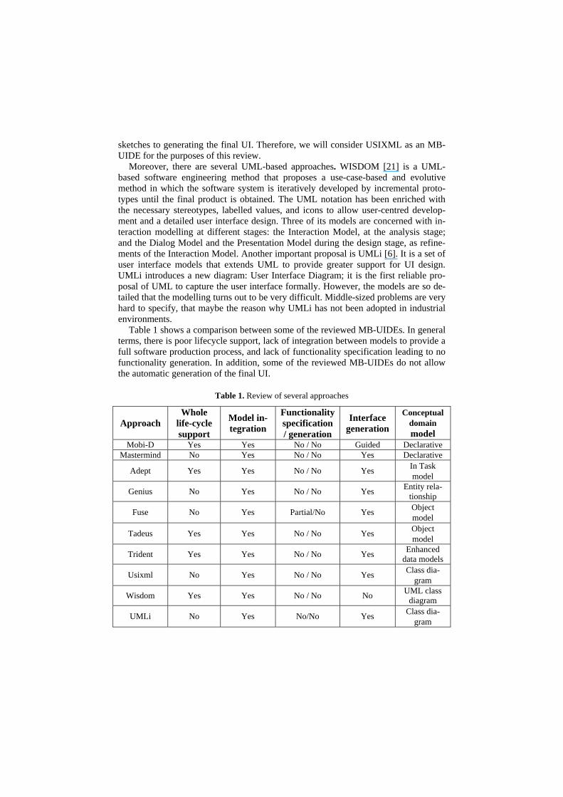
Fig. 3. CTT for the Add meter reading use case
To build the task model we proceed as follows. The Functional Requirements Model is taken as input and a task tree is built for each leaf of the FRT (that is, each use case). A precise mapping is defined between lines of the use case specification and elements of the task model. The steps of the use case involving elemental data manipulation appear as basic tasks of the task tree. For example, the introduction or selection of a piece of data being described in the use-case specification (i.e. step 3 of Table 2) results in an interaction task of the lowest granularity, which consists of the user introducing or selecting that data in the interface (i.e. the Date interactive task in the tree of Figure 3). Note that step 6 of the use-case description corresponds to the Process reading system task.
Since the task model not only reflects the interaction of use cases one-at-a-time, the interaction modelling involves the restructuring of the functional requirements repre-sented in the FRT. Therefore, the example CTT also includes the “List meters” use case, as the selection of a meter is prior to the introduction of a new meter reading (this is stated in step 2 of the use case description).
To deal with how the initial access to the system’s functionality is presented to the user, we propose building a taxonomical task tree that models this fact, taking advan-tage of task decomposition in order to follow the gradual approach principle.
The CIM level is fulfilled with the interaction requirements. The next section ex-plains the Conceptual Modelling step, which is the real basis of the OO-Method ap-proach and the cornerstone of the ONME code generation technology.
3.3 Conceptual Modelling the three problem axes in ONME
In order to model what has been elicited in the Requirements Model, OO-Method [25] defines four complementary models that should be used to define the data, the behaviour, and the interaction of the system which; all together make up the Concep-tual Model.
The Object Model is designed with a classic class diagram similar to UML and represents the data that the system will manipulate. The interaction and the sequences of events that occur among those objects are modelled in the Dynamic Model, while

the changes of their states are modelled by the Functional Model. Together the Dy-namic and Functional Model define the entire behaviour of the system.
The fourth and last model is called the Presentation Model. It is based on abstract ways of interaction and defines three levels of interaction patterns [16]. The first level is called Hierarchical Action Tree (HAT) and organizes the way the user can access the functionality of the system. The second level is called Interaction Units (IU) and represents the interface units that the user is going to interact with. These units are called Service IU, Instance IU, Population IU, and Master/Detail IU. The third level is called Elementary Patterns and constitutes the building blocks of the IUs.
Figure 4.a graphically represents part of the system in the first two levels. Figure 4.b describes the three levels of the case study in greater detail. These patterns are de-rived by applying transformation rules to the CTT and these transformations are ex-plained elsewhere [8].
(b)
Subscriber
HAT
Meters
AArguments:Id_meterSerial numberDateCubic meters
Services:Create_instanceDelete_instanceModify_instanceAdd_reading
(a)
Subscriber
HAT
Articles
Rates
Subscribers
House type
Invoice Type
Article supplying
Rate
Meters
Category
Article
Invoice
...
Fig. 4. Presentation Model
3.4 Automatic code generation
After the Functional Requirements Model and the Conceptual Model are speci-fied, the Conceptual Model can be transformed into code by applying specific trans-formation rules. ONME implements these transformations for Visual Basic, C #, ASP. NET, Cold Fusion and Java, in a Model View Controller way, obtaining a full soft-ware system using SQL-Server, ORACLE, or DB2 database in the persistence tier.
As an example, Table 3 presents the transformation between the abstract patterns from the Presentation Model and the concrete widgets of the Visual Basic program-ming language.

Table 3. Some Transformation Patterns
Presentation model VB component Hierarchical action tree (HAT) Application menu Interaction unit MDI child form Service IU MDI child form with entry controls Simple type service argument Entry control Object-valued service argument OIDSelector Generic control Filter Filter control Filter variable Entry control Actions Button panel Action item Button Service throw “Accept” button and code to validate and invoke
the service Cancellation “Cancel” button and code to close the form Services invocation Code for linking business logical layer with ser-
vice invocation Data presentation Code for formatting and data recovery Navigation Button panel Navigation Item Button Figure 5 shows the generated interface. Table 4 shows the mapping used for the
transformation presented in Figure 5.
Fig. 5. Add meter reading window

Table 4. Mapping between Presentation Model and Final Interface
Presentation Model Final Interface Hierarchical action tree (HAT) Service IU
The whole window
Service throw and Cancellation
Simple type service argument
Introduction pattern for a date field Code for validating date format Navigation
Filter
There is a back and forth traceability through the entire software process. The final
interface was designed in the early steps of the software project and the corresponding transformation model is defined in each level of abstraction of OO-Method.
4. Conclusions and future work
Model-Based Software Production Methods need to integrate system functionality, behaviour, and user interaction from the early stages of the system lifecycle. As inter-action modelling is rarely considered at the same level as data and process modelling, methods to model user interaction need to be properly embedded in such a Model-Based strategy. Consequently, HCI techniques must be adapted to specify user inter-action, fixing which conceptual primitives must be taken into account when system interaction is to be modelled. In this paper, we have presented a software production process that starts from requirements elicitation and adds the use of the CTT (HCI-based technique) to model user interaction.
The original semantics of CTT are simplified in order to adapt it to the proposed model-based development approach. As a consequence, the user interface is designed by taking into account the way in which the user interacts with the system, and a full final software product can be obtained through the use of Model Transformation techniques. The practical application of these new ideas is the extension of ONME (an MDA-based tool that generates a software product corresponding to the source Conceptual Schema).
Future work will include the application of this approach to new case studies, as well as the study of sketching techniques, to be used in combination with the defined task models.
References
[1] Bodart, F., Hennebert, A., Leheureux, J., Provot, I., and Vanderdonckt, J.. (1994) A Model-Based Approach to Presentation: A Continuum from Task Analysis to Prototype. In Pro-ceedings of DSV-IS'94, pp. 25-39, Bocca di Magra.
[2] Booch, G. (1993). Object-oriented Analysis and Design with Applications, 2nd ed. Red-wood City: Benjamin Cummings.
[3] Care Technologies: http://www.care-t.com Last visit: June-2006 [4] Chen, P. P. (1976) The Entity Relationship Model - Toward a Unified View of Data. ACM
Transactions Database Systems, 1 (1), pp. 9-36. 103 [5] da Silva, P. P. (2001) ”User interface declarative models and development environments: A
survey”. Interactive Systems. Design, Specification, and Verification, 8th International Workshop, DSV-IS 2001, Glasgow, Scotland, Springer-Verlag Berlin.
[6] da Silva, P. P. d. and N. W. Paton (2003). "User Interface Modelling in UMLi " IEEE Softw. 20 (4 ). pp. 62-69
[7] Elwert, T. and Schlungbaum, E. (1995) Modelling and Generation of Graphical User Inter-faces in the TADEUS Approach. In Designing, Specification and Verification of Interac-tive Systems, pp. 193-208, Vienna, Springer.
[8] España, S., Pederiva, I., Panach, I., Pastor, O. (2006). Integrating Model-Based and Task Based Approaches to User Interface Generation. 6th Int. Conf on Computer-Aided Design of User Interfaces (CADUI 2006). Springer.pp. 255-262.
[9] Hayes, P., Szekely, P. and Lerner, R. (1985) Design Alternatives for User Interface Man-agement Systems Based on Experience with COUSIN. Proc. of SIGCHI'85, pp. 169-175. Addison-Wesley.
[10] Insfrán, E., Pastor, O., Wieringa, R. (2002). Requirements Engineering-Based Conceptual Modelling. Requirements Engineering, Vol. 7, Issue 2, p. 61-72. Springer-Verlag.
[11] Janssen, C., A. Weisbecker, et al. (1993). Generating user interfaces from data models and dialogue net specifications. Proceedings of the SIGCHI conference on Human factors in computing systems Amsterdam, The Netherlands ACM Press: 418-423
[12] Kim, W. and Foley, J. (1990) DON: User Interface Presentation Design Assistant. In Pro-ceedings of UIST'90, pp. 10-20. ACM Press.
[13] Limbourg, Q. and J. Vanderdonckt (2004). Addressing the mapping problem in user inter-face design with UsiXML Proceedings of the 3rd annual conference on Task models and diagrams Prague, Czech Republic ACM Press: 155-163.
[14] Lonczewski, F. and Schreiber, S. (1996) The FUSE-System: an Integrated User Interface Desgin Environment. Computer-Aided Design of User Interfaces, pp. 37-56, Namur, Bel-gium, Namur University Press.
[15] Markopoulos, P., Pycock, J., Wilson, S. and Johnson, P. (1992) Adept - A task based de-sign environment. Proceedings of the 25th Hawaii International Conference on System Sciences, pp. 587-596. IEEE Computer Society Press.
[16] Molina P. 2003. User interface specification: from requirements to automatic generation, , PhD Thesis, DSIC, Universidad Politécnica de Valencia. (in Spanish) .
[17] Montero, F., V. López-Jaquero, et al. (2005). Solving the mapping problem in user inter-face design by seamless integration in IdealXML. Proc. of DSV-IS'05, Newcastle upon Tyne, United Kingdom, Springer-Verlag.
[18] Morgan,T. "Business Rules and Information Systems – Aligning IT with Business Goals", Addison-Wesley, 2002
[19] Mori G., Paternò F., Santoro C. (2002) "CTTE: Support for Developing and Analyzing Task Models for Interactive System Design" IEEE Trans. on Software Engin.; pp.797-813
[20] Mori G., Paternò F., Santoro C. (2004) "Design and Development of Multidevice User In-terfaces through Multiple LogicalDescriptions" IEEE Transactions on Software Engineer-ing; pp.507-520
[21] Nunes, N. J. y J. F. e. Cunha (2000). "Wisdom: a software engineering method for small software development companies." Software, IEEE 17(5): 113-119.
[22] Olive, A. (2005). Conceptual Schema-Centric Development: A Grand Challenge for In-formation Systems Research. Proceedings of the 16th Conference on Advanced Informa-tion Systems Engineering, Oscar Pastor, João Falcão e Cunha (Ed.), Lecture Notes in
Computer Science, Springer-Verlag, Porto, Portugal, Lecture Notes in Computer Science, Vol. 3520, ISBN 3-540-26095-1.pp. 1-15.
[23] OMG (2003) MDA Guide Version 1.0.1: http://www.omg.org/docs/omg/03-06-01.pdf Last visit: June-2006
[24] OMG (2003) Unified Modelling Language v1.5: http://www.omg.org/cgi-bin/doc?formal/03-03-01 Last visit: June-2006.
[25] Pastor, O., J. Gómez, et al. (2001). "The OO-method approach for information systems Modelling: from object-oriented conceptual Modelling to automated programming." In-formation Systems 26(7): 507-534.
[26] Paternò, F., C. Mancini, et al. (1997). ConcurTaskTrees: A Diagrammatic Notation for Specifying Task Models. Proceedings of the IFIP TC13 International Conference on Hu-man-Computer Interaction, Chapman & Hall, Ltd.: 362-369.
[27] Puerta, A. (1996). The Mecano Project: Comprehensive and Integrated Support for Model-Based Interface Development. Computer-Aided Design of User Interfaces CADUI'96 , pp. 19-36, Namur, Belgium, Namur University Press.
[28] Puerta, A. and Maulsby, D. (1997) Management of Interface Design Knowledge with MODI-D. In Proceedings of IUI'97, pp. 249-252, Orlando, FL, USA.
[29] Szekely, P. (1990) Template-Based Mapping of Application Data to Interactive Displays. Proceedings of UIST'90, pp. 1-9. ACM Press.
[30] Szekely, P., Sukaviriya, P., Castells, P., Muthukumarasamy, J., and Salcher, E. (1996) De-clarative Interface Models for User Interface Construction Tools: the MASTERMIND Ap-proach. In Engineering for HCI, pp. 120-150, London, UK, Chapman & Hall.
[31] Vanderdonckt, J., Q. Limbourg, et al. (2004). USIXML: a User Interface Description Lan-guage for Specifying Multimodal User Interfaces. Proceedings of W3C Workshop on Mul-timodal Interaction WMI'2004, Sophia Antipolis, Greece.
[32] Yourdon, E. (1994). Object-Oriented Systems Design an Integrated Approach, Yourdon Press.