A few notes from the sanitary engineering field - Scholars' Mine
78
Scholars' Mine Scholars' Mine Professional Degree Theses Student Theses and Dissertations 1928 A few notes from the sanitary engineering field A few notes from the sanitary engineering field Ronald Davies Ward Follow this and additional works at: https://scholarsmine.mst.edu/professional_theses Part of the Civil Engineering Commons Department: Department: Recommended Citation Recommended Citation Ward, Ronald Davies, "A few notes from the sanitary engineering field" (1928). Professional Degree Theses. 109. https://scholarsmine.mst.edu/professional_theses/109 This Thesis - Open Access is brought to you for free and open access by Scholars' Mine. It has been accepted for inclusion in Professional Degree Theses by an authorized administrator of Scholars' Mine. This work is protected by U. S. Copyright Law. Unauthorized use including reproduction for redistribution requires the permission of the copyright holder. For more information, please contact [email protected].
-
Upload
khangminh22 -
Category
Documents
-
view
1 -
download
0
Transcript of A few notes from the sanitary engineering field - Scholars' Mine

Scholars' Mine Scholars' Mine
Professional Degree Theses Student Theses and Dissertations
1928
A few notes from the sanitary engineering field A few notes from the sanitary engineering field
Ronald Davies Ward
Follow this and additional works at: https://scholarsmine.mst.edu/professional_theses
Part of the Civil Engineering Commons
Department: Department:
Recommended Citation Recommended Citation Ward, Ronald Davies, "A few notes from the sanitary engineering field" (1928). Professional Degree Theses. 109. https://scholarsmine.mst.edu/professional_theses/109
This Thesis - Open Access is brought to you for free and open access by Scholars' Mine. It has been accepted for inclusion in Professional Degree Theses by an authorized administrator of Scholars' Mine. This work is protected by U. S. Copyright Law. Unauthorized use including reproduction for redistribution requires the permission of the copyright holder. For more information, please contact [email protected].

THE LIBRARY
MISSOURI SCHOOL OF MINES

itA FEW NOTES FROM THE SANITARY ENGINEERING FIEID"
BY
RONALD DAVIES WARD
A
THESIS
submitted to the faculty of the
SCHOOL OF MINES AND MErALLURGY OF TEE UNIVERSITY OF MISSOURI
in partial fulfillment of the work required for the
Degree of
CIVIL ENGINEER
Rolla, Mo.
1928
Approved by _
Proressor of Civil Engineering
TABLE OF CONTENTS
Synopsis - - - - - - - - - - - - - - - Pa.ge 1
I. A Few Observations on Promotion Pa.ge 3
II. Co-operation with State
and Other Institutions
III. Notes on Waterworks Design
Page 8
Page 18
IV. Notes on Sanitary Sewerage System Design Page 53
- ---
LIST OF ILLUSTRATIONS
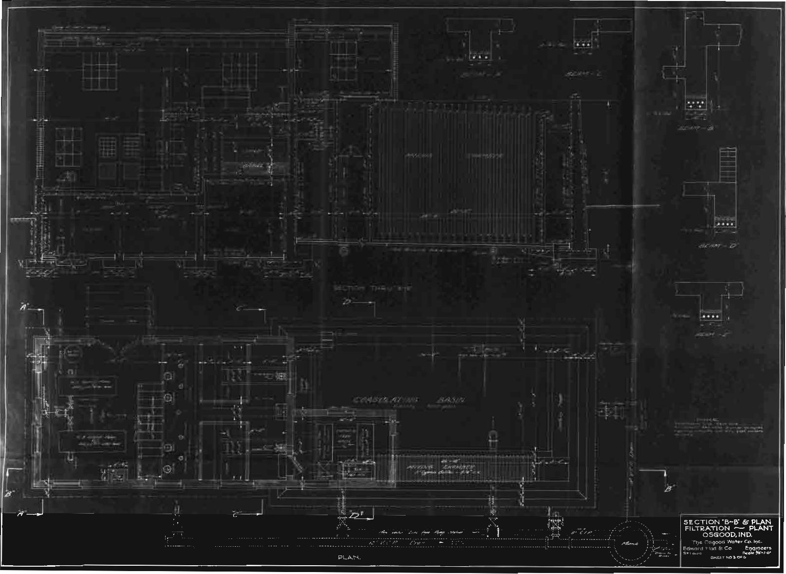
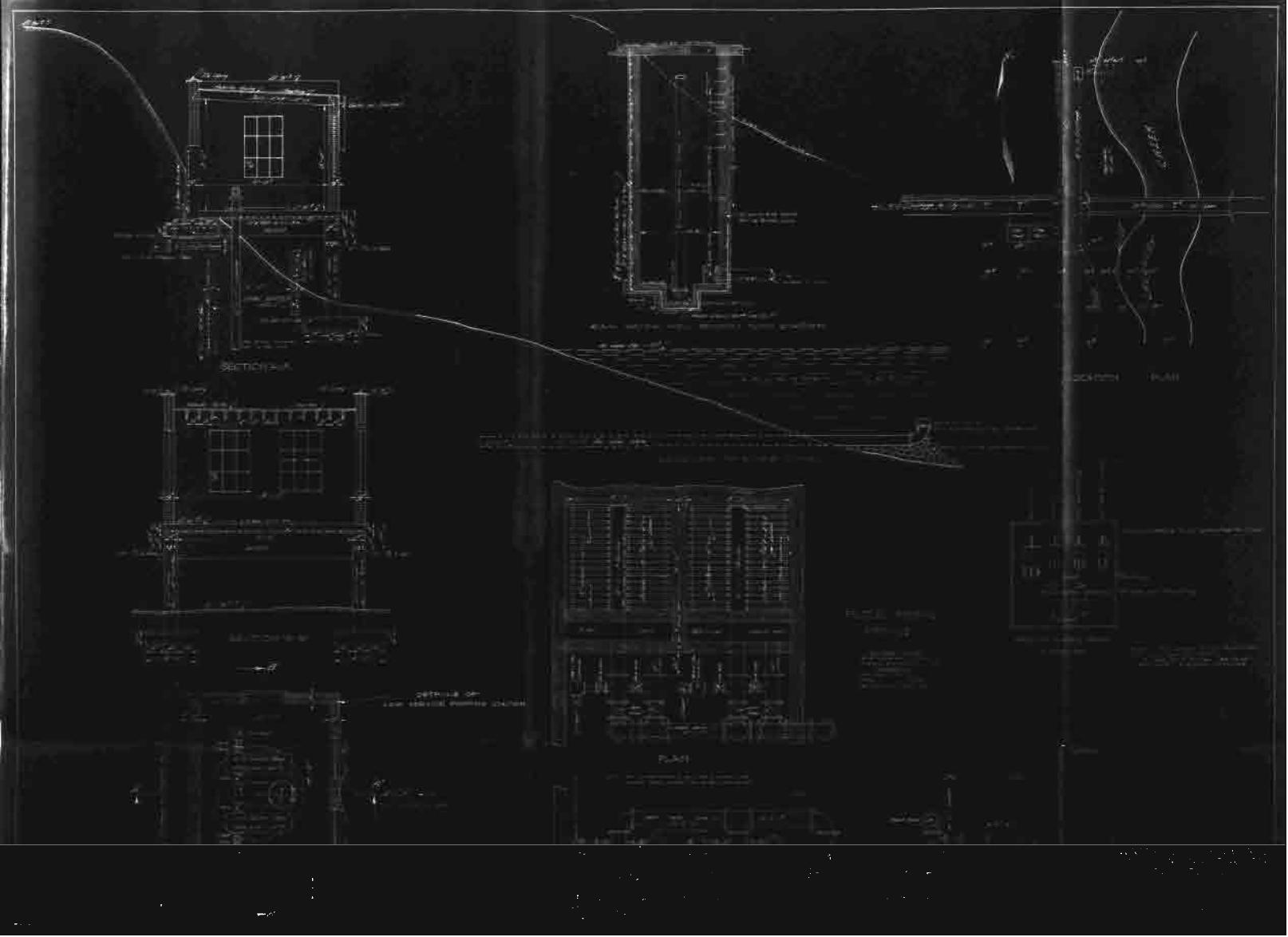
- To face page -Plate I. Plan and Sections of Filtration
Plant 18
Plate II. Filter Piping Details and
Pump House - - - - - 18
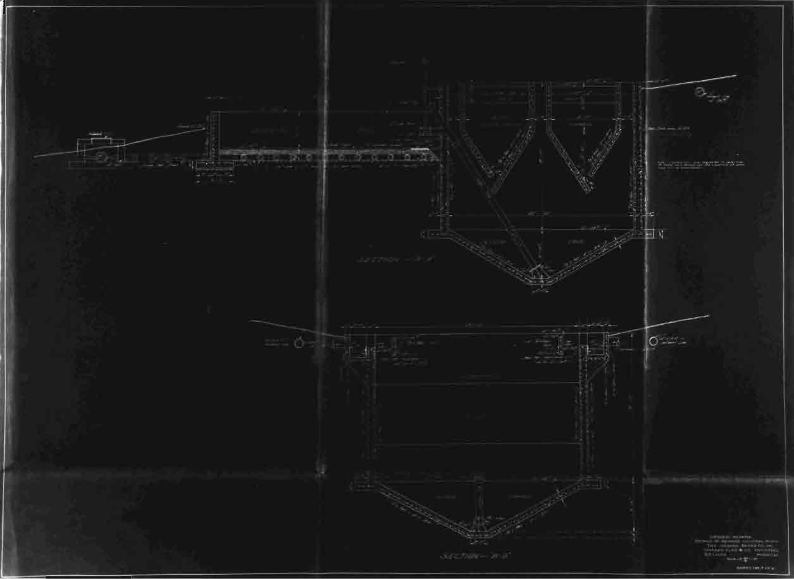
Plate III. Plan of Sewage Disposal Plant - - - - 53
Plate IV. Sections of Sewage Disposal
Plant - - - - 53
- - ~ - - - - - - ~ -
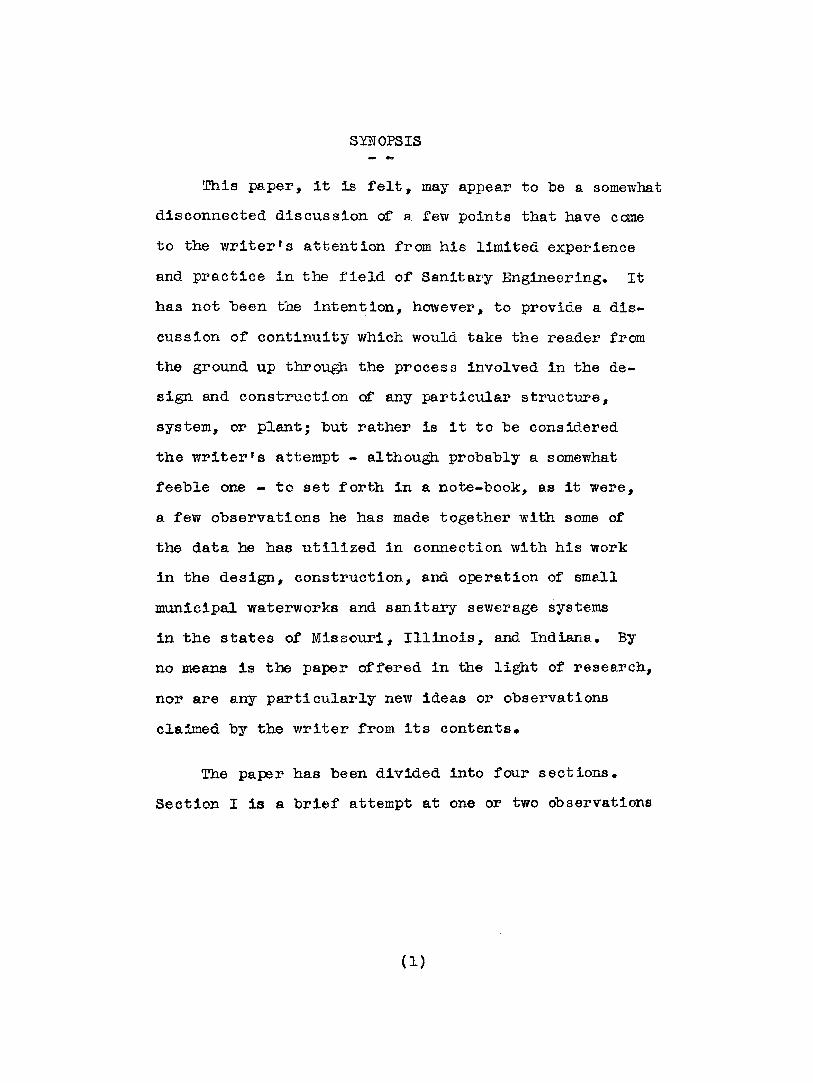
SYNOPSIS
This paper, it is felt, may appear to be a somewhat
disconnected discussion of a few points that have come
to the writer's attention from his limited experience
and practice in the field of Sanitary Engineering. It
has not been tbe intention, however, to provide a dis
cussion of continuity which would take the reader from
the ground up through the process involved in the de
sign and construction of any particular structure,
system, or plant; but rather is it to be considered
the writer's attempt - although probably a somewhat
feeble one - to set forth in a note-book, as it were,
a few observations he has made together with some of
the data be has utilized in connection with his work
in the design, construction, and operation of small
municipal waterworks and sanitary sewerage systems
in the states of Missouri, Illinois, and Indiana. By
no means is the paper offered in the light of research,
nor are any particularly new ideas or observations
claimed by the writer from its contents.
The paper has been divided into four sections.
Section I is a brief attempt at one or two Observations
(l)
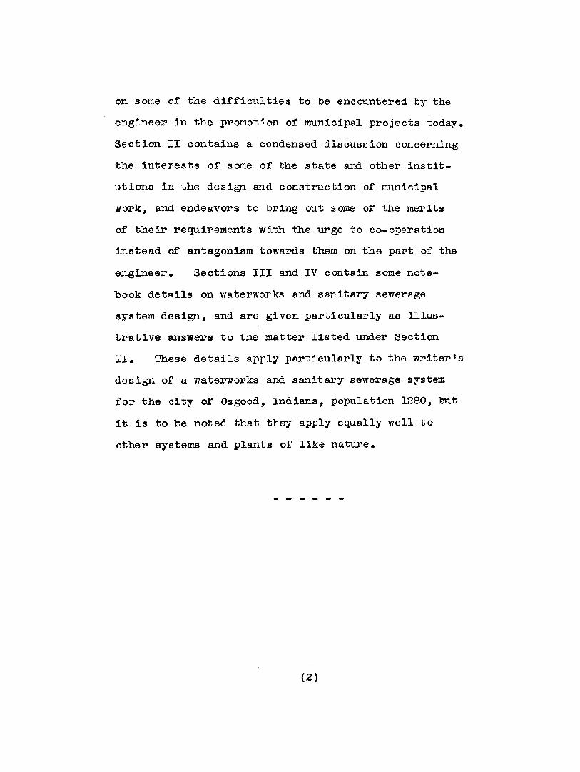
on some or the di£ficulties to be encountered by the
engineer in the promotion of municipal projects today.
Section II contains a condensed discussion concerning
the interests of some of the state and other instit
utions in the design and construction of municipal
work, and endeavors to bring out some of the merits
of their requirements with the urge to co-operation
instead of antagonism towards them on the part of the
engineer. Sections III and IV contain some note
book details on waterworks and sanitary sewerage
system design, and are given particUlarly as illus
trative answers to the matter listed under Section
II. These details apply particularly to the writer's
design of a waterworks and sanitary sewerage system
for the city of Osgood, Indiana, population 1280, but
it is to be noted that they apply equally well to
other systems and plants of like nature.
(2)
I. A PEW OBSEl.~VATIONS ON PROIEOTION
It would seem to the writer that the problems the
engineer of to-day must encounter as he endeavors to
secure a contract for tne englneering of a contemplated
small mun:lcipal project must indeed d:Lf.fer vastly from
those of "days of old ". That whereas formerly the main
problems of the engineer in promotj.o~l work consisted of
the education of the connnuni t~T to its needs for the better
and more hygienic standard of living to be attained through
the media of a pure wa.ter supply and sanitary method of
sewage disposal, the satisfactory recognition of his
ability as an engineer, and the intelligent advising of
the community in matters of municipa.l finance, in order
to stand a reasonable chance of securing a contract for
his services, such are far from the main obstacles to
be encountered to-day. Few, indeed, but the engineer
devoting much time and effort in the field of promotion
probably realize the ad<5,itior:al factors to be confronted.
To assert that many of' the ethics of tb,e profession of
former days are fastly disappearing would, the writer
believes, be no exaggeration; and, sad to say, in most
cases there may be some necessity for it.
In the first place, whereas formerly the field of
sanitary engineering was comparatively limited, to-day a
(3 )
dozen or more engineers are to be found at a gather
ing in some community of probably not more than
a thousand population each endeavoring to obtain
the s~e engineering contract~ and it indeed may be
considered a "survival of the fittest" as to whom
the contract will eventually be awarded. Each of
the twelve being given his chance in turn to appear
before the city council to present his qualifications
and terms for engineering service, it often happens
that the man with the most flowery language~ promises,
and lowest price wins out and is awarded the job.
Engineering ability may count for 11ttle~ far copious
letters of recommendation always appear from some
where for each applicant. Many city councils could be
told that water ordinarily flows up grade without dis
puting the matter, and often do not take too kindly to
the engineer of well-educated bearing and speech who
appears before them, but prefer the uengineer" of the
practical workman type. In the state of Indiana, and
undoubtedly in other states where registration of
qualified professional engineers is compulsory, part of
the above situation has probably been somewhat improved#
although by no means altogether due to laxness in the
registration requirements themselves. Nevertheless the
prevalent practice to-day of the engineer bidding in
(4)
h18 services to a considerable extent cannot be denied,insofar has it been tl~ writer's observation on
municipal projects, in each instance of which
engineering firms both large and small were represented.
Secondly, the influence "material" rnen have been
able to exert o,Tor the members of the city council, often
long before the arrival of the engineer who is endeavor ing
to secure a contract for professional services, must be
mentioned. It would seem that there are few companies
to-day, who may be selling anything fIlom a. screw bolt
on up to a steam shovel, who have not representatives
traveling continually from one tovm to another endeavoring
to promote some phase of municipal improvement in which
their particular product may be used. Such endeavors
are, for the most part, undoubtedly commendable, inasmuch
as interest in municipal betterment is often thus created
in communities where the engineer might never have
prospected. The drawback, however, often is that whether
the material man's particular apparatus or material should
be used in any resulting municipal project from an
engineering standpoint matters not, as he is out to sell
his wares regardless of methods to be resorted to to do
so.
From this it can be seen that much friction between
the engineer, who has finally obtained a contract for his
(5)
services, and the city COlU1Cil, who hai)"o been pJ'eV:LOl.isly
"wincel and dined" by the me.. terit"3.l man, may at; times
reSlllt. Inasmuch as most m.ate:r>ial men also possess
some technical kno"Vvlec1ge as applied to the u.se of their.-
Oi,;vn particular product, this, in combin.ation \vi th the
above good fellowship stunt, has often served to exert
undue influence over at least several members of the
city council, and the engineer in such cases has no
course but to yield to the wishes and dictat.es of the
city officials over his ovm opinions and recmmnendations
for the use of materials if he would hold his job. ~[,his
must not be taken as general practice, however, but it
would seem to occur far too frequently for the benefit
of the profession.
On the other hand, quite frequently mater'ial men
deserve far more credit than they obtain for their
efforts and expense for municipal promotion before an
engineer is engaged. Many have succeeded in creating
a feeling for municipal improvements where none had
ever existed before, and probably never would have
existed were.it not for their efforts. Many do play
the game s~~arely, and if they find the engineer averse
to the use o.f their product for reasons quite explainab1e
and apparent, they withdraw taking their losses without
murmur. These men, the writer believes, deserve the
utmost consideration from the engineer who has obtained
(6)
his contract primarily tIl-rough their efforts, if he finds
it at all possible that he can approve their materials,
and at the S8.me time in his ovm judgement serve the
interests of the community to the utmost advantage.
Such are a few instances only of many positions
in which the engineer may find himself situated. VV11ether
there may be a remedy wherehjr the ethj.cs of the engineering
profession of old may be recovered and at the same time
insure the bona-fide engineer a living commensurate with
that of other professional men the writer is at a loss
to say, but it is his frank opinion that a few more
efforts for the welfaJ."e and uplifting of the profession as a whole
by the several national engineerinG societies could well
be exerted, coupled vvith so:ne system of nat ional 01'
state registration free from polities.
- ....... - ... - ...
(7)

II. CO-OPERATION WITH STATE AND OTHER INSTITUTIONS
- - ~ -It would seem worth while that a brief mention
be made concerning the part that state and other
institutions wish to take in the design of municipa.l
waterworks and sanitary sewerage systems. Hardly need
it be said that it is to the advantage of every engin
eer - end should be his earnest desire also - to meet
the requirements of these institutions, and to solicit
their co-operation whenever possible. In some cases
such co-operation 1s necessitated by state law, yet
in any event the writer, in his work in the three
states of Missouri, Illinois, and Indiana, has yet to
encounter any recommendations or requirements of these
institutions that were not in accord with best engin
eering practice, whether the matter concern features
of design, construction, ~ operation. The engineer
should further bear in mind that every community is
proud of the state in which it is located, and with
the knowledge that its municipal improvements are
being made with full approval of interested depart
ments of state, its confidence and trust in his
ability become great from the very beginning.
Briefly, these institutions, with their interests
and jurisdiction, are as follow.
(8)

STATE BOARD OF HEALTH
The interests of this department of state are, of
course, primarily concerned with the safeguard of public
health through safety and sanitation in accordance wi th
common practices of medical hygiene. Some of these
have been intelligently extended to influence- certain
details of design of municipal waterworks and sanitary
sewerage systems, and it is fram this point of view
that the state board of' health requires that all plans
and specifications be first submitted f'or their
approval in order that none of these details may have
been overlooked, and that maximum sanitary operation
of the finished system or plant may be anticipated fram
the design. The engineer, in most cases, 1s further
asked to submit a report embodying the following details
in so far as may be possible.
Waterworks
1. Source of Supply
(a) Surface Supply -
A full discussion of the nature and extent
of the watershed, with special reference to its sanitary
condition, together with any proposed methods of regulation
of pollution, should be g1ven. storage capacity, average
depth, width, rate of flow, nature and area of reservoir,
if any, character of' raw water, ete. should also be
(9)
Discussed. If a river supply is under consideration,
the course above stream wi thin five miles of the
proposed intake ahould be Shown, together with a list
of all cities on the watershed.
(b) Ground Supply -
If the water supply is to be taken from
wells or infiltration galleries, the number, depth,
size, and proposed method or construction of these
should be given, together with any geological features
of the region in which the well is to be drilled; the
type of strainers to be used, probable capacity of the
wells, and size of pumps should also be specified.
2. Purification Plant
If purification of the supply is proposed,
information should be given showing the arrangement,
size and construction of sedimentation basins, together
with the method of introducing and mixing chemicals
for coagulation, and the method of sterilization. If
filters are propos ed, details should be g1ven showing
size, type, arrangement, and capacity of units,
together wi th methods of control and operation. Details
o:f any provisions for laboratory control and testing
of water are essential.
(10)
Sanitary Sewerage Systems
1. System -
Adequate information, from the basis of
design, is asked on the following: population to
be served, both present and future, estimated for
twenty five years; estimated daily flow of sewage per
capita, and total estimated daily flow; allowance
for ground water infiltration; probable character of
sewage; minimum and maximum grades of' sewers of each
size; provisions for fluShing sewers.
2. Disposal Plant -
The following informa.tion is requested:
location of plant, together wi th character and flow
of stream receiving effluent, and nearest location of
water supplies being taken from stream above and below
plant outlet, if' any; general method of disposal
proposed, and basis ot design upon which plant is
expected to operate; method of disposal ot sludge;
provisions for secondary treatment of effluent, if any.
STATE PUBLIC SERVICE COMMISSION
The interests and jurisdiction of this second
department of state in the matter or municipal
waterworks and sanitary sewerage system construction
varies in intensity in each of the three states
(11)
heretofore mentioned, being probably most intense of
"the three in the State of Indiana.
The chief concerns of this department may be said
to be that the interests of the community are properly
taken care of in the awarding of the construction
contract. To attain this end~ all plans and specif
ications are gone over to see that no manufacturer's
products have been unjustly discriminated against in
the requirements of the engineer. By so doing, it is
hoped that competitive bidding as unlimited as possible
may be assured at the letting, thereby encouraging the
fairest price possible to the community. It must not
be understood from this that the engineer 1s prevented
in any way from specifying the type s of' materials and
apparatus he wishes to use, but that the practice of
helping to swing the job for some particular manufac
turer alone is to some extent thereby prevented. Such
practice, the writer regrets to say, has at times seemed
far too apparent to him on the part of a few ttwould-be"
members of the profession. In addition, the engineer's
estimate of materials and quantities for the job is
also requested, as an aid in the checking up of bids
submitted and the possible detecting of any "frame-up"
of bids on the part of the contractors, and to insure
that the contract may have been truly awarded to the
lowest responsible bidder.
(12)

STATE INSPECTION BUREAU
An inspection bureau. whose business it is to see
that the requirements of the National Board of Fire
Insurance Underwriters are met ~or adequate fire
protection of a community contemplating the installation
of a waterworks system, is maintained by the fire
insurance companies in each of the three states here
tofore mentioned. Naturally the maximum poss ible fire
protection and reduction in eXisting insurgnce rates is
one of the biggest "talking points" and objectives for
any canmunity endeavoring to obtain the approval of its
citizens for ~1nancing the cost of a proposed water
works installation. Needless to say, therefore, it is
to the interest of the engineer to co-operate wi th this
bureau in its requirements in every way possible.
The requirements of this bureau being considerably
more de~inite than those of other interested instit
utions the following are given in detail for the
obtaining of a very desirable fire insurance rating,
!mown as a "Class 4-1/2 (N.B. 8)" rating in the state
~ Missouri. It may be remarked that it has been the
writer's practice to meet these requirements in design
with equal rigidity in the States of Illinois and
Indiana.
(13)
Waterworks
1. Source of Supply -
The source of" supply shall be adequate
and reliable at all times.
2. Capacity of" Supply Works -
The total capacity, in excess of the maximum
daily domestic consumption rate, shall be able to deliver
a fire flow of not less than the following rate and
duration, and at the pressures specified under Item 3,
"Pressure", below.
PopUlation
Up to 750750 to 15001500 to 25002500 to 3500
Fire Flow (Gals. per min.) Duration
- - - 400 - - - - - - - 2 hours- - - - - 400 - :3 hours- - - 400 - - - 4 hours- - - 500 - - - 5 hours
For places larger than 3500 and up to
10,000 population, a fire flow of 600 gallons per minute
for a 6 to 10 hour perioo is required, in excess of the
maximum daily domestic consumption rate.
3. Pressure -
The flows specified under "Capacity ot
Supply Works" are to be maintained at not less than 50
pounds flowing pressure from fire hydrants in business
and manufacturing sections in towns of less than 2500
population. In towns of more then 2500 population, the
fire flows in these sections are to be maintained at
not less than 60 pounds flO'Ning pressure. In residential
(14)
seetions of single family dwellings~ half' the above flows
are to be maintained at 50 pounds flowing pressure.
Where a fire engine pumper is provided in the fire
deptrtment~ having a capae1ty of at least 300 gallons
per minute in towns up to 5,000 population, and at
least 500 gallons per minute capacity in towns over
5000 and up to 10,000 population, these flowing press
ures may be reduced to 40 pounds in all cases.
4. Power -
To be adequate to operate all pumps at
all times; transformers serving pump motors to be equal
to total combined motor capacities, and to serve pump
motors only.
5. Pump Hous e -
To be constructed of brick or tile, with
fire-proof roof covering.
S. Pipe Distribution System -
The pipes are to be adequate to deliver
the flows at pressures above specified, but must be
6 inches or larger to supply fire hydrants 1n business
and manufacturing sections, and not less then 4 inches
in dwelling sections. In general, 4 inch dead-end mains
should not exceed 600· teet in length, or 4 inch single
loops exceed 1500 feet in length. If such adverse
conditions obtdn generally over town, at least a 300
(15)
gallon per minute fire engine pumper must be provided
in the fire department. Gate valves shall be sUitably
located tbrmghout the system so that parts of the
system may be blocked off at any time.
7. Fire Hydrants -
All hydrants must have at least two
2-1/2 inch nozzles, threaded to the "National Standard"
gauge; 4 inch or large r foot valves; 6 inch pipe
connections to 6 inch or larger mains, and 4 inch
connections to 4 inch mains. Fire hydrants shall be
located not to exceed 300 feet apart in business and
manu£acturlng sections, and not to exceed 600 feet
apart in residential sections.
STATE GEOLOGICAL SURVEY
The interests of this department concern the
obtaining of accurate log records for the purpose of
compiling geological correlation of the underlying
strata from all wells or test holes drilled wi thin the
state. As a result of the records so accumulated by
the State Geological Survey of Missouri, much information
1s often at hand to guide the engineer as to the
possibilities or obtaining a municipal well water supply
of sufficient quantity and desirable quality in the
particular location in WhiCh he may be interested within
the state of Missouri. This service is freely and
(16

cheerfully given, and the engineer should reciprocate
whenever possible by forvlarding accurate and detailed
drilling log records and cutting samples to this
department whenever he may be in contact with such work.
This department eo-operates with the state board of
health in its endeavors to insure all water supplies
as free from contamination as possible, and it is well
that its specifications covering the drilling, casing,
and sealing of wells, and the testing of water be
adopted whenever a well supply is under contemplation.
-.-. .. _----.
(17 )

III. NOTES ON \tVATER\VORKS DESIGN
General
On August 29th, 1927, Edward Flad & Company,
Consulting Engineers, st. Louis, Mo., received a con
tract rrom the Osgood Water Company for the complete
engineering work comprising investigations, surveys,
design, and supervision incidental to the construct
ion of a complete waterworks system for the City of
Osgood, Indiana. The writer, as associate engineer
with the above company of engineers, had charge of the
design, and submits herewith in brief, from his note-
book as it were, some o£ the features upon which the
design was based; with particular reference, however,
to those conforming with the requirements of the
various interested institutions 'discussed in Section
II or this paper, "Co-operation with state and other
Institutions". By no means are the notes which roll~
ow submitted as representing particularly original or
out of the ordmary points of design, the intent being
merely to present the basis and data utilized in a
particular instance which met the approval of the above
mentioned interested institutions.
The City or Osgood, a community of some 1280
inhabitants, is located in the £arming region of south
eastern Indiana. Through it runs the main eastern line

of the Baltimore and Ohio Railroa.d from St. Louis, and
in addition to its farming interests, a wooden plug
factory in its midst gives additional employment to
many of its citizens. The topography of the city
itself is generally flat, although located in the
highest part of the surrounding cwntry with the area
dropping away sharply to the northeast where it soon
becomes quite hilly. The top soil, consisting of a
glacial sandy clay averaging some nine feet in depth,
overlies a hard limestone formation which 1s approx
imately fi.fteen feet thick in this area.. Underlying
this, in layers averaging from four to six feet in
thickness each, limestone strata alternating with a
hard argillaceous shale, locally termed "Bluestone If,
are to be encountered.
Cost
The cost of the entire waterworks project, includ
ing all incidentals, amounted to apprOXimately $75,000.
Part of this amount was obtained from a wa.terworks fund
already in existence through proceeds from the sale of
a former light and power plant, the balance being raised
through the sale of stock in the Osgood Water Company,
a specially created municipal corporation, in accordance
with the provisions therefor of the state laws of Ind
iana.
(19)
Source of Supply
It was decided that a surface supply could be
utilized and be obtained from Laughery Creek, a
stream located approximately two miles northeast of
the city limits and flowing in a general direction
from north to south. The sources of' the creek are
a natural watershed extending some twenty miles
north of the located point of intake at Osgood,
while from here the stream flows some twenty miles
further due south6 thence turning sharply to the
east for another twenty miles discharges directly
into the Ohio River.
The discharge of Laughery Creek in the vicinity
of Osgood. varies considerably. It 1s reported that
in one very unusual perial of drought the flow
dropped to some probable fifteen second feet as a
minimum, but that the average is many times greater
than this, being some five thousand second feet to
many times more during certain periods of the rainy
season. There being no other communities located
near the creek for at least ten miles in either dir
ection from Osgood, possible pollution from sewage
discharge into the streem eould therefore be placed
at a probable absolute minimum. A very low degree of
turbidity o~ the water in this vicinity was also
reported.
(20)
Puri~lcation Plant
General
The general operation of this plant provides
for coagulation, sedimentation, filtration, and
sterilization of the raw water. This is supplied to
the plant from a low service pump house, located on
the bank of Laughery Creek some 400 feet distant,
by either of two centrifugal pumping units, haVing a
capacity each of 250 gallons per minute, which takes
the raw water directly from a "wet well tt beneath the
pump house, being fed through a ten inch cast iron
pipe gravity line from the creek intake. Design and
equipment of the low service pump house will be
discussed later.
Capacity of Plant
The plant was designed for a maximum capacity
of 300,000 gallons ~ r 24 hour period, or 209 gallons
per minute, under theoretical conditions of ideal
operation. That this capacity could be increased to
250 gallons per minute without particularly affecting
'the quality of thetreated water will be brought out below.
As may readily be seen, these capacity amounts are con
siderably in excess of any conceivable daily domestic
consumption rate for a city the size of Osgood, even
were a future population of 2000 inhabitants with a
(21)

Mixing Chamber
The raw water, upon reaching the plant from
the low service pump house, is discharged upward through
a small rectangular compartment where it receives a
properly proportioned dose of lime and alum from dry
feed machines above, and from here is passed through the
mixing chamber. A discussion on the proportioning of
these chemicals will be found later.
The mixing chamber consists of' a series of
cypress wood vertical baffles, two inches in thickness,
so spaced and designed as to allow the desired quantity
of water to flow and be mixed by passing between them
over one baf~le and under the next - in a vertical
direction. The design of the mixing chamber itself
(22)
and o:f the spacing of the ba:ffles was made in
accordance with the following provisions:
1. Retention period for passing through chamber
to be 15 minutes
2. Velocity in passing through chamber to be
between 30 and 40 feet per minute
3. Maxlnmm quantity to be designed for to be
250 gallons per minute
(8.) Number of Baffles Required
Maximum length of path of travel, from above,
40 x 15 600 lineal feet
The depth of the chamber averaging 17.7 feet,
(from design of coagulating ba.sin), and the minimum
length of vertical path of flow between baffles being
15.0 feet, the minimum number of baffles required is
600 plus 1--m 41 ba:ffles
(b) Spacing between Baffles
The width of the baffles being 3.0 feet (arbitrar
ily used), and assuming a passage of 250 gallons per
minute, or 33.5 cubic feet, between baffles, the allow
ance per foot width of baffle becomes 11.2 cubic feet
~r minute.
From Q::: av, with Q::. 11.2, v: 40, a -=8 r 1
spacing necessary, s' = 4~1~21 ; 0.28 feet.
(23)
The baffles were actually spaced 3-1/4 inches apart in
construction, or on 5-1/4 inch centers.
Coagulating or Sedimentation Basin
From the mixing chamber the treated water is
allowed to spill qUietly over a weir, 13.25 £eet in
length, at the extreme end of an open sedimentation
basin or reservoir. This basin, 34.0 feet long by
13.25 feet wide by 17.8 feet average depth, allows a
maximum quantity of 50,000 gallons of treated water to
undergo sedimentation. This capacity is based on the
allowance of a minimum retention period of 4 hours for
the total plant capacity of 300,000 gallons per 24
hours. The correctness of such an assumption from the
point of design may, of course, be somewhat open to
question, owing to such variable factors as the poss
1bility of short circuits and currents through the
basin due to shape of basin, non-tmiform weir flows,
different specific gravity at various depths, and other
factors impossible of determination. However, with the
possibility of the plant operating to capacity being
confined to rare occasions only, it is probable that
the size of the basin as designed would provide a general
retention period considerably ~ excess of the-desired
4 hours. The basin in this case, however, was designed,
and the weir from the mixing chamber so located, that
(24)
a minimum amotUlt of short circuiting is anticipated,
a point very essential from the standpoint ofhighly
successful operation.
Filter Units
From the coagulating or sedimentation basin
the treated water passes over a second weir into a
trough at the other extremity of the basin from which
the water may flow by gravity through two separate
valve intakes into the wash troughs of two independent
rapid sand filter units. These units may be operated
one at a time or both together I depending upon necess
ity; the intention being, however, that as a general
rule one unit at a time only should be used.
(a) Size of Filter Units
The min~ desirable size of the units
was obtained from en allowance of 2 gallons of filtered
water per minute per square foot of filter area, plus
a small allowance for wash water, or a total assumption
of 365 square feet of filter area per million gallons
of water filtered per 24 hours. Allowing each unit to
be capable of filtering half the maximum plant capacity,
or 150,000 gallons per 24 hours, the minimum area
required per unit becomes 52.5 square feet. Inasmuch as
it appears that there is a limit to the desirable min~
size for the construction of a .filter unit, mainly from the
(25)

sta.ndpoints of providing adequate working space for
cleaning operations and other manipulations, it was
decided to construct eaCh unit 8 feet square; thus
providing a r11ter area of 64.0 square feet per unit,
which, of course, was well on the side of safety.
(b) Sand and Gravel
A depth of filter sand of 30
inches covering a layer of graded gravel 18 inches in
depth was specified for ea.ch unit.
Specifications covering the sand
provided that it be a hard, resistant, quartz sand,
having not more than 2% of foreign material by weight.
The effective grain size was limited between 0.35 and
0.45 millimeters, with no grain size over 0.45 milli
meters being allowed, and a uniformity coefficient of
less than 1.6 was specified. The effective size being
that size which 1s coarser than 10% of the sand grains
by weight; the uniformity coefficient being the ratio
between the size such that 60% of the sand is finer
then it and the effective size.
Specifications covering gravel
provided that it be free from tine material and uniform
in size to avoid disturbance in the washing process, and
that it be caref'ully graded and laid in strict accord
ance with the following:
(26)

Bottom layer - 6 inches deep - gravel size 1 to 2 inches
Second " - 3It It It It 1/2 to 1 It
Third f1- :3
tt If It It 1/4 to 1/2 "Fourth It
- 3n tt n ft 1/8 to 1/4 rr
Top tt- :3 It ft U rt 1/8 tf
(c) Wash Troughs
One wash trough, having a cross
section 20 inches wide by 12 inches deep with an add-
itional 3 inch depth of grooved channel, constructed of
reinforced concrete, was provided for each filter unit;
so suspended that the spillway edge was exactly 24 inches
above the top of the sand. Allowing a maximum wash
water rate of 15 gallons per minute per square foot of
filter area, this would produce a crest 1-1/2 inches
in depth of wash water over each of the two spillway
edges ot each trough. The maximum horizontal path of
travel tor any particle of waSh water being one half the
filter width less one half the width of the wash trough,
or 3.22 feet in this case, the maximum recommended
allowance of 3.5 feet was not exceeded, which has been
so suggested in order to aid in counteracting the
formation of mud balls in washing as much as possible.
Cd) Filter Underdraw System
Beneath the gravel layer the
f'iltered water is collected by a system of. underdra1ns
consisting of a series of perforated east iron pipes,
or "orificed laterals", spaced on 6 inch centers, which
connect to "Tee rt projections similarly spaced on each
side of a larger central cast iron pipe, or collecting
manifold, running parallel to and directly beneath the
wash trough above, the whole resting horizontally on
the concrete bottom of each unit. The design of this
underdraln system 1s based on the following factors:
1. Number of Laterals Required
An arbitrary spacing of 6
inches between each lateral was taken. There being
one lateral on each side of the manifold for each
6 inch spacing, and the length of each unit being
8.0 feet, the total number of laterals required far
each filter unit becomes 8 x 2 :;: 320.5
2. Length of Laterals
Assuming a 12 inch diameter
mani.fold, the calculations .for which are shown below I
and allowing for pipe thickness and lateral clearance,
a length per lateral of 3.25 feet was specified.
3. Number and Size of Lateral Orifices
It seems general practice
now that the total orifice area per unit be taken as
from 0.20% to 0.30% of the filter area, and from this
a factor of 0.25% was chosen:
(28)
0.25% of 64.0 sq. ft. 0.16 sq. ft.
~ 23.04 sq. ins.
The total orifice area per single lateral then becomes
23.04 :;;: 0.72 sq. ins.32
19 orifices, spaced on 2 inch centers, each 7/32 inches
in diameter, giving a total area of 0.718 square inches,
were, therefore, specified for each lateral.
4. Size of Laterals
General practice rec
ommends that the area of each lateral be at least
3 times the area of it s orifices J
3 x 0.718 ; an area of 2.154 square inches per lateral.
The nearest theoretical size would, therefore, be a
1-11/16 inch diameter cast iron pipe, whose area equals
2.237 square inches. Inasmuch as this is not a
standard size in cast iron pipe, it was decided to use
a 2 inch diameter pipe, area.: 3.14 square inches, which,
of course, would be well an the side of safety.
5. Size of Manifold
The recommended size for
a filter manifold 1s that it be at least 1.5 times the
total theoretical area of the laterals in the unit.
In this case this would be -
2.154 x 32 x 1.5 c 103.2 square inches
A 12 inch diameter cast iron pipe manifold was, theretore,
(29)
specified, the area being 113.1 square inches.
Pipe Gallery
From the filters the water passes out through
the manifolds into the pipe gallery, where it runs
through rate of flow controllers to the inverted
double elbow discharge pipes into the clear water
well underlying the main body of the fil tar plant,
the well having a total storage capacity for 28,400
gallons of filtered water. A detailed description
of the piping and valve arrangements of the gallery
will not be attempted, but the following accessories
may be noted:
1. Rate of Flow Controllers
A ra.te of flow controller of the Venturi
type, with l~its between 100,000 and 200,000 gallons
per 24 hours and set at 150,000 gallons, was provided
for each unit.
2. Loss of Head Gauges
A manometer type loss of head gauge, reading
from 0 to 10 feet, far determining the limiting 10s8
of head in the passage of the water through the filters
before washing becomes necessary was installed far
each unit.
3. Depth Gause
A depth gauge far indicating the depth of
filtered water in the clear water well at all t~es was
also installed.
(30)

Provisions £or Washing
For reversing the flow through the filters in
order to remove the accumulated silt and other roreign
matter out o£ ea.ch filter, no special wash water pump
was deemed necessary in this case. It was decided
instead to wash directly from connection to the 8 inch
city service main running from the plant, operating
at the same time the 500 g.p.m. high service pumping
unit. In this way adequate capacity and pressure
for washing could be assured at any time.
Assuming a maximum wash water requirement at the
rate of 15 gallons per square .foot of filter area per
minute, or a total of 960 gallons per minute per unit
- which would give the desirable vertical velocity of
2 feet per minute through each filter - it was
estimated that this total flow could be thus obtained
from the main at a pressure as high as 100 pounds per
square inch if necessary. Such a pressure is, of
course, far too excessive for filter washing, but it
is evident that the source is satisfactory, and by
means of careful valve manipulation could be limited
very satisfactorily to the desired quantity and pressure.
Adequate provisions were made, of course, for the
removal of wash water from each unit through a special
pipe drain emptying into a lower part of LaUghery Creek.
(31)
Laboratory Control and Testing of Water
Explanatory
. By no means is the following to be con
sidered an attempt on the writer's part to set forth
the many methods of analysis and theory for the
proper treatment or water with chemicals in filtration
plant operation. The few tests and tables which
follow have been compiled in part by the writer, and
have been successfully used by him in the field where
the use of the chemicals, alum, lime, and chlorine
alone was concerned.
General
By treatment of the raw water as it
enters the plant wi th the chemicals lime and alum, a
way is found to collect together by coagulation the
particles of sand, clay I and organic matter which
render the raw water muddy or turbid. The above par
ticles, being for the most part in a state of suspen
sion, are collected together in the process to form
masses or larger particles of such size that they will
readily settle to the bottom of the sedimentation
basin during the given detention period of four hours.
To remove the finest of these suspended particles,
the chemicals are further responsible for the presence
of agelatlnou8 covering and mass on and within the sand
(32)
filters themselves which prevents the passage of these
particles through the filters and further aids in the
production of a clear grade of water.
Notes on Theory of Coagulation
A12 (S04)3 +- 3Ca(OH)2 ~
Alum Lime
A12 ( OH)S + 3CaS04
"Floc tf
A full explanation of the factors influencing the pro
per coagulation of the suspended matter in raw water
by the introduction of lime and alum would require
a lengthy discussion involving much chemical theory,
and will not be attempted here. The following may
give a fair idea of the reactions involved, however.
When aluminum sulphate, commonly termed
"alumfl, is added to water having a. sufficient degree of
alkalinity, a jelly-like invisible mass or precipitate
is formed. By means of thorough mixing and agitating,
this mass may be broken up into fine "pin-headn flakes
constituting a coagulum or "rloc tt • This tfrloc n has
the property of causing small particles of clay, silt,
organic matter, ete., with which it may come in contact
in the raw water, to coagulate or collect together, and
precipitate or settle. The max~ precipitation poss
ible or these particles in the sedimentation basin before
the raw water reaches the sand filters is the end to be
(33)
constantly sought a.fter for the successful operation of
any filtration plant, and the final obtaining of a good
clear water. The eventual presence of the "floc ff in
the sand of the sand filters 1s also highly essential,
as expla~ed above, and the success of the operation of
the filters depends almost entirely upon this presence.
Tests
In the attempt to obtain the above mentioned
maximum possible "floc", it is of course necessary that
certain tests be made from time to time to determine
the character and certain constituents of the raw
water which will influence the proportioning of the
lime and alum quantities. The following tests have
been used by the writer, and are obtained from "standard Methods of Water Analysis", 1925 edition, American
Public Health Association.
1. Degree of Turbidity
This is determined by me ana C5£ a
turbid~eter, and is expressed in parts per million, as
fUlly described on page 6, "Standard Methods of Water
Analysis".
2. Degree of Alkalinitz
This is determined by titrating 100
c.c. of the sample water with N/50 sulphuric acid, using
(34)
4 drops of methyl orange as an indicator; the indicated
alkalinity being equal to the number of c.c. of the
acid multiplied by 10, expressing the result in parts
pe r million. The procedure is fully described on page
33, "Standard Methods of Water Analysis ff.
(Note: Titration, using phenolphthalein as
an indicator, was omitted by the writer inasmuch
the presence of bicarbonates only was indicated
in the raw water on each occasion of his experience.)
3. Free Carbon Dioxide Content
This 1s determined by titrating 100 C.C.
of the sample raw water with N/44 sodium hydroxide,
using 10 drops of phenolphthalein as an indicator; the
indicated free C02 being equal to the number or c.o. of
sodium hydroxide multiplied, expressing the result in
parts per million. The ~rocedure is fully described on
page 36, "Standard Methods of Water Analysis n.
Chemicals
l.~
The amoo.nt of alum to be used depends
almost entirely upon the degree of turbidity of the raw
water, and it is very essential that a turbidity test
of the raw water trom the low service pump discharge be
taken at least daily to determine this desired amount.
:Not only is the daily regulation of the amount of alum
(35)
being used necessary f'rom the standpoint of proper
filter operation, and the obtaining of a good grade of
water, but it will be found to have considerable bear
ing on the economic cost of plant operation. The table
given later shows the suggested amounts of alum to be
used for water of varying degrees of turbidity. It may
be noted here, that the amounts suggested in this table
may seem considerably in excess of' those suggested by
the various text book authors, but it is the writer's
opinion that they are far from excessive for a plant of'
this nature, and in this opinion be has the approval of
others, amongst whom might be mentioned Mr. E. S. Clark,
Chief Chemist and Bacteriologist of the state Board of
Health of Illinois.
2.~
The success of the amount of alum being
used to produce the maximum possible "floo Jt depends
also to a considerable extent upon the degree of alkal
inity of the raw water. It may be estimated that for
each grain of alum per gallon, an alkalinity of 10 parts
per million is necessary. Should the second chemical
test above, the alkalinity test, show that the raw water
is deficient in alkalinity content, lime must be added
to the water to make up this deficiency. The amount of
(36)
lime to be added 1s given in the tables belC1H for various
amounts of alurn and alkal1nity content.
The presence of free carbon dioxide (C02 )
in the raw water is particularly objectionable inasmuch
as not only does it affect the process of coagulation
but it is responsible for considerable corrosive action
within the service pipes. Free C02 can be eliminated
by the add!t ion of an add!t1onal smount of lime. Having
determined the amount of: free C02 present, by neans of
the third chemical test given above, the additional
quantity of lime to be added may also be determined
from the tables below.
Chemical Feed Machines
In the installation at Osgood two
chemical feed machines of the dry feed type were used;
one machine for feeding alum" another for feeding lime.
The chemical from each machine being then automatically
put into solution with pure water is carried through a
small pipe to the mixing chamber, where it encounters
the incoming raw water as previously described. The
feeding from these machines is automatically and acc
urately controlled in each case through regulation of
the speed of revolution of a small cog wheel. The wheel
being actuated by a pawl for a definite number of times
each minute ~ the number of cogs or "not ches II on the wheel
(37)
over which the pawl is allowed to climb for each actuation
determines its speed of revolution. Assuming, therefore,
an increase in the setting of the machine of one "notch" I
this would mean that the length of travel for each
actuation has been increased by the space of one cog,
resulting in an increase of travel of the wheel during
one minute equal to the number of actuations per minute
times one notch. Most machines having from ten to fif
teen actuations per minute, an increase of one notch would
represent an additional space of travel .for the wheel of
from ten to .fifteen notches per minute.
The above explanation is given in detail
to show that the fineness of regulation of chemicals with
these machine s is by no means all that may be desirable,
an increase in the setting or one notch in each case
being responsible for an increase of more than one grain
of chemical per gallon of water. It was necessary, there
fore I in the writer r s preparation of the following tables
for use at Osgood to specify settings of the machines in
each instance which would at least insure the use of the
minimum desirable amount of chemical. For instance, it
will be noted in the alum table that for raw water with a
turbidity of 200, a setting of the machine at 3 notches 1s
specified, Whereby a dose of 3.70 grains of alum ~r gallon
(38)
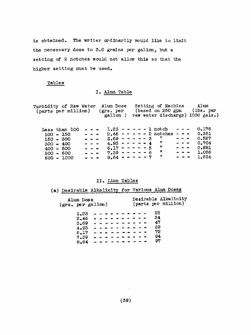
is obtained. The writer ordinarily would like to limit
the necessary dose to 3.0 grains per gallon, but a
setting of 2 notches would not allow this So that the
higher setting must be used.
Tables
I. Alum Table
Turbidity of Raw Water(parts per million)
Alum Dose(grs. per
gallon )
Setting of Machine Alum(based on 250 gpm (lba. per
raw water discharge) 1000 gals.)
Less than 100 - - - 1.23 - - - - - 1 notch - - - 0.176100 - 150 - - - 2.4:6 - - - 2 notches - - - 0.351150 - 300 - - - 3.69 - - - - - 3 ff 0.527300 - 400 - - - 4.93 - - - 4 tt - - - 0.704400 500 - - 6.17 - - - - - 5 tt - - - 0.881- -500 600 - - 7.39 - 6 It - - - 1.056- -600 1000 - - 8.64 - - - - - '7 ff - -- 1.234- -
II. Lime Tables
(a) Desirable Alkalinity for Various Alum Doses
Alum. Dose(grs. per ga.llon)
Desirable Alkalinity(parts per million)
1.23 - - - - - -- - - - 222.46 - - - - - - 343.69 - - - - - - - - 4'74.93 - - - - - - 596.1'7 - - - - - - '727.39 - - - - - - 848.64 - - - - - - - -- - 97
(39)
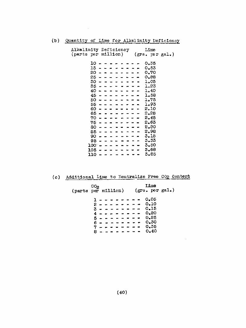
(b ) Quantity o:f Lime :for Alkal in!ty Def1clencl
Alkalinity Deficiency Lime(parts per million) (grs. pe r gal.)
10 - - - - - - - - 0.3515 - - - - 0.5320 - - - - 0.7025 - - - - 0.8830 - - - - 1.0535 - - - - 1.2340 - - - - - - 1.4045 - - - - - - - - 1.5850 - - - - - - - - 1.7555 - - - - - - 1.9360 - - - - - - 2.1065 - - - - 2.2870 - - - - - - - - 2.4575 - - - - 2.6380 - - - - - - 2.8085 - - - - 2.9890 - - - - - - - - 3.1595 - - - - - - 3.33
100: - - - - - - - - 3.50105 - - - - 3.68110 - - - - - - - - 3.85
(0) Additiona.l Lime to Neutralize Free CO2 Content
c~(parts per million)
Lime(grs. per gal.)
1 - - - - - - - - 0.052 - - - - 0.103 - - - - 0.154 - - - - - -- - 0.205 - - - - 0.256 - - - - - - - - 0.30'7 - - - - - - 0.358 - - - - - - 0.40
(40)

( d) Set ting of Lime Machine
Setting of Machine(based on 250 g.p.m.raw water discharge)
Lime Used(grs. per ga.1.)
Lime Used(lbs. per 1000 gal.)
1 notch - - - 1.055 - - - - 0.1502 notches - 2.095 - - - - - - 0.2993
oft - - - 3.150 - 0.450-4 If - - - 4.185 - 0.598- -5 " - - - 5.250 0.750-6 tf - - 6.300 0.9000- - - -7 ft - - - 7.340 - - 1.0488 n - - - 8.400 - - - - - - 1.200
Example in Use of Tables
Assum~ng water analysis as rollows:
Turbidity
Alkalinity
400 p.p.m.
25 p.p.m.
Free C02 - - - 5 p.p.m.
what should be the setting of the dry feed machines?
Alum Machine
Table I, Alum Table, shows -
'turbidity 400..~ alum dose 6.1'1 grains per gallon;
set maChine at 5 notches
Lime Machine
Under Table II, find -
alum dose, 6.l? grains per gallon requires
alkalinity of 72
(41.)
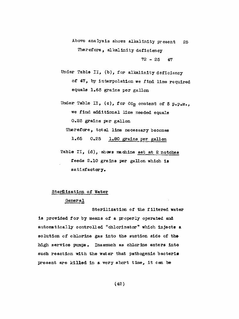
Above analysis shows alkalinity present 25
Theref'ore, al kal1nity deficiency
72 - 25 47
Under Table III (b), for alkalinity deficiency
of 47 I by interpolation we find lime required
equals 1.65 grains per gallon
Under Table II, (c), for C02 content of 5 p.p.m.,
we find additional lime needed equals
0.25 grains per gallon
Therefore, total lime necessary becomes
1.65 0.25 1.80 grains per gallon
Table II, (d) I shORS machine set at 2 notches
f'eeds 2.10 grains per gallon which is
sati sfactory.
Ste~1zat1on of Water
General
Sterilization of the filtered water
1s provided for by means of a properly operated and
automatically controlled tfchlorinator" which injects a
solution of' chlorine gas into the suction side of the
high service pumps. Inasmuch as chlorine enters into
such reaction with the water that pathogenic bacteri8
present are killed in 8. very short time, it can be
(42 )
applied to the mains very shortly before the water
reaches the consumer.
Quantity of Chlorine Necessary
The amount of chlorine necessary
for sterilization depends upon the character of the wa.ter.
However, in general, it must be said that not less than
0.22 parts per million is required to ins~e safe end
satis:factory sterilization at all times. This 121
equivalent to .00184 Ibs. per 1000 gallons, or .0127
grains per gallon.
Assuming 250 gallons per minute are
being pumped into the mains, the chlorinator pulsations
should be adjusted by the chart to be delivering
250 x .0127 = 3.175 grains of chlorine per minute.
Determination of Chlorine Content
The proper application of chlorine
for sterilization of water 1s far more essential than any
other operation at the plant and it is very advisable to
add to the three chemical tests already mentioned one
more, which 1s exceedingly simple, for the determination
of the amount of chlorine being injected into the service
mains. In this way a check is obtained on the action of
the chlorinator.
To 100 e.e. of filtered water obtained
from the laboratory faucet add 1 c.c. of ortho-to11dine
(43)

solution; let stand for 5 minutes and then compare the
resulting color of the water wi th the standard bottled
chlorine comparator colored solutions. The bottles are
la.beled rt .15", ft .2", rt .25 rt, tt .3 ff , If .4", It .5", and these
numbers represent residual chlorine content in parts per
million.
Supposing the above 100 c.c. sample
when 1 c.c. of ortho-tolidine is added shows a yellowish
color exactly the same as tba t in the bottle labeled
ff .25", tbat would mean e. r es1dual chlor:1ne content of
.25 parts per million was present. The above dose of
.00184 lbs. of chlorine ~ r thousand gallons, or .22
parts per million, should compare between the bottles
marked tt .2 ft and u .2511 in the compara.tor set.
Pumping Equipment
General
Four electrically driven centrifugal
pump units, mare particularly described below, were
installed in connection with the filtration plant.
Two of these are for "low service n use, supplying raw
water from the intake "wet" well to the head of the
mixing chamber; two for ffhigh service" usa, taking
filtered water out of the clear water well beneath
the filtration plant far the distribution system supply.
(44)

Before proceeding further, the writer is
taking the liberty of a slight digression with the
following remarks concerning the selection of the
pump units in this particular case. That many very
estimable makes of centrifugal pumps are to be found
on the market these days is a fact that cannot be
disputed; and assuming adequacy as to capacity, size,
and reliability of operation, the final selection as
far as the engineer is concerned simmers down to the
question of greatest economy of operation under the
given conditions of operation. In this latter
respect, no two manufacturer's pumps are to be fOUnd
entirely alike; one bettering the other under certain
conditions of capacity and head, and vice versa under
those slightly different. Nevertheless it is regret
table that selections are made far too often on the
basis of first cost and the personal elements involved,
Dather than from the viewpoint of maximum efficiency
of operation, assuming there is no choice as far as
the mechanical construction of the pump is concerned.
That such influences prevailed in the
rinal selection of the pump units for Osgood was very
much apparent, inasmuch as personal motives only against
the manufacturer whose units showed the highest guar
anteed ef£lc1enc1es £or the required conditions of
operation were responsible ror the rejection of his
(45)
equipment by the Osgood Water Company, all efforts and
advice of their engineers being to the contrary and of
no avail. The efficiencies of the pump units finally
selected were particularly low, being on the average
s orne thirteen pe r cent lower than thos e of the equip
ment recommended.
Pump Units
Low Service
Duplicate units each consisting of
a 250 g.p.m. single stage centrifugal pump, operating
against a maximum total head of 52.? feet with a
guaranteed efficiency of 72% overall at full load,
having a 3 inch discharge, directly connected to a
7.5 R.P. squirrel cage motor operating at a speed
of 1750 R.P.M. under alternating current character
istics of 440 volts, 60 cycles, 3 phase, with magnetic
SWitch push button starters, were installed. These
units were housed in a small pump house, 10.0 feet by
14.0 feet floor space, of brick and concrete construct
ion, located some 300 feet fran the filtration plant
on the bank of Laughery Creek, and took their supply
from a reinforced concrete "wet" well, 6.0 feet in
diameter, located directly beneath, Which was fed by
gravity from a cast iron pipe, 10 inches in diameter,
extending some 50 feet out tmough rock to the river.
(46)

High Service
One unit consisting or a 500 g.
p.m., 5 inch discharge, double stage, centrifugal
pump, operating against a total max~um head of 390
feet 247 feet static, 133 feet friction, 10 feet
suction having a guaranteed overall efficiency
at full load ot 62%, and being directly connected to
a 100 R.P. squirrel cage motor operating at a speed
of 1750 R.P.M. under alternating current character
istics of 440 volts, 60 cycles, 3 phase, with manual
control compensator, was installed to meet fire
protection requirements and as an auxiliary unit to
the one below upon certain occasions only.
A second unit consisting of a
250 g.p.m., 3 inch discharge, triple stage, centrif
ugal pump, operating against a total maximum head
of 296 feet 247 feet static, 39 feet friction,
10 feet suction - having a guaranteed overall eff
iciency at full load of 55%, and being directly
connected to a 40 H.P. squirrel cage motor operating
at a speed of 1750 R.P.M. under alternating current
characteristics of 440 volts, 60 cycles, 3 phase, with
manual control compensator, was installed for everyday
domestic consumption requirements.
(47)
It should be noted here that the
system was designed for the operation of' the high
service pumps as separate units only, and upon no
occasion whatever were they to be operated together.
Power
Power, obtained from the local public utilities
company, was supplied to the plant at 2300 volts,
where it was stepped down through three 37.5 K.V.A.
transformers to 440 volts--; this transformer ca.pacity
being adequate to take care of' the maximum combination
load, based upon the following data:
Two 250 g.p.m. L.S. pumps, B.R.P. 5.'7 each
One 250 g.p.m. H.S. pump, B.H.P. 34.0
One 500 g.p.m. H.B. pump, B.H.P. 79.4
Two dry feed machine motors, 0.25 B.li.P. each
Three 3000 watt coil heaters, 220 volts
Eleven 60 watt, 110 volts, lamps
(48)
Distribution System
General
From the filtration plant an 8 inch cast iron
pipe service main was run to the northeast corner of' the
city 1imits~ a distance of 12,700 feet, where it was
connected to a network or tfgridiron" distribution system
of 6 inch and 4 inch cast iron pipe serving the entire
city. The sys tem was laid out in strict accordance with
the suggestions of' the National Board of Underwriters,
previously discussed under Section II of this paper.
Additional loops of 2 inch cast iron pipe for domestic
supply oonnections only were provided far those consumers
located within fire protection limits but at some slight
distance from the mains. Pressure was maintained and a
source of supply prOVided by means of a 75,000 gallon
hemispherical bottom. steel tank, elevated on a steel tower
100 feet above ground to the balcony surrounding the tank
a height of 116 feet above ground to the top of the tank
the base of the tower being located on the highest ground
elevation within the city, and approximately in the center
of the d1 atribution sys tam. Fire hydrants were located
and conformed in detail of construction to the specifications
of the National Board of Underwriters mentioned above.
Valves were provided throughout the s1Btem so that any part
(49)
of the network cOlld be cut off separately at any time.
The system as laid out provided for service of the
entire city with the exception of approxixm.tely 12
residences widely scattered along extreme boundaries
of the city limits.
Pipe Lines
All pipe lines were of cast iron pipe with
bell and s p1got ends having pre-caulked lead joints,
and consisted of 8 inch, 6 inch, 4 inch and 2 inch sizes.
A working pressure of 150 Ibs. on all pipe was guaranteed
by the manufacturers, with the exception of 10,000 feet
of 8 inch pipe from the filtration plant which was of
heavier construction and guaranteed to withstand a
working pressure of 250 1bs.
Throughout the system four "dead end" lines
only were laid, each of tre se being a 4 inch line
terminating at a fire hydrant, the lengths being 450,
350, 310 and 300 feet respectively from the main.
!:i.re Hydrants
Fire hydrants were located not to exceed 300
feet apart in business sections and not to exceed 600
feet in residence sections.
The following two hydrants were estimated as
giving minimum pressure conditions, under the assumption
of water supply from the elevated tank only.
(50)
1. Business District
A fir e hydrant fed from a 6 inch
main located at the intersection of Ripley and Buckeye
Streets and being by chance the "business distrlet tt
hydrant most remote from the elevated tank, was
estimated to have a flowing pressure of 48.5 Ibs. for
a flow of 400 gallons per minute at the hydrant. A
friction head loss between tank and hydrant of 9.5 feet
was included for a supply to be obtained in both north
and south directions from the tank through all
intermed1a te lines and loops available.
2. Residence District
A f 1r e hydrant tidead-ended" from a
4 inch main located the farthest east on Ripley street,
and being by chance the "residence district" hydrant
most remote from the elevated tank, was estimated to have
a flOWing pressure of 48.2 lbs. for a flow of 200 gallons
per minute at the hydrant. A friction head loss of 20
teet was mcluded for a supply to be obtained in both
north and south directions from the tank through all
intermediate lines and loops available.
Elevatlo~
It might be of some interest that the following
few ground elevations, from an assumed datum, be noted
herewith.
(51)

Normal water in Laughery Creek - Elevation 70.7
Raw water intake in Laughery Creek " 63.0
Ground at filtration plant, average tf 98.5
Ground at tank and tower sit e in c1 ty - " 225.0
Ground at above "business district tt
hydrant tl 220.0
Ground at above "residence district"
hydrant If 210.0
(52)

IV • NOTES ON SANITARY _SEVVERAGE SYS'EM DESIGN
- ... -- ~--
General
In December, 1927, Edward Flad & Canpany received
a contract from the Osgood Sewer Company, a second
municipal corporation for this city specially created
under the provisions of the state laws of Indiana
therefor, for the complete engineering work comprising
investigations, surveys, design, and supervision
incidental to the construction of a complete sanitary
sewerage sys tem for the 01 ty of Osgood, Indiana. The
writer had charge of the design, and it is hoped tb8.t
the following brief notes sub.nitted in connection there
with may not seem to be entirely too elementary as to
prove uninteresting. It might be mentioned th~t many
of these notes were incorporated in the writerts report
to the state Board of Heal th of Indiana upon completion
of the design, and that the whole received full approval
of the board. The system as a whole may be considered
as representing a simple problem in sanitary sewerage
s'YBtem design with no particularly canplieated methoda
of sewage discharge <:r disposal involved.
(53)
Cost-The cost of the entire sanitary sewerage system
Rroject, including all incidentals, is estimated at
$40,000.00. This has been raised through the sale
or stock in the Osgood Sewer Company.
Design of Sewers
Population to be Served
The present population of Osgood 1s estimated
at 1280 inhabitants. The system has been designed
to be capable of serving a population of 2000 to 2500
inhabitants if necessary.
Estimated per Capita daily Flow of Sewase
The per capita daily flow of sewage was
assumed as a maximum possibility equal to a maximum
daily discharge of 75 gallons per day. Such an assump
tion is undoubtedly extremely high for a c1ty of this
size.
Est~ated Flow of Sewage ror Desisn
It' 1s undoubtedly apparent that were the total
estimated daily flow of sewage from the entire area
under consideration reduced to gallons per minute or
cubic feet per second without taking into consideration
additional factors such as maximum periods of fluc-
(54)
tuation or sewage discharge, or allowance for ground
water inriltration, much error in design or size of
sewers might easily result. Considerable speculation
and formulae as to the possible limits or these fac
tors have been advanced by various authors for the
purpose of safe design, resulting in a great var
iance of suggestions for the guidance of the engineer.
It may be noted here that inasmuch as the waterworks
for Osgood were not completed at this time no ob
servations on periods of maximum water consumption,
which might have been used to adventa.ge in estimating
possible maximum sewage discharge, were possible.
In view of such possible variations in the
periods of maximum sewage discharge, the writer presents
with some timidity the following table he has prepared
for use in design and which to him has seemed reasonably
well on the side of safety from all observations he
has been able to make. By no means, however I 1s this
table intended as a substitution for more accurate
da.ta to be obtained from actual observations in the
field whenever possible.
(55)
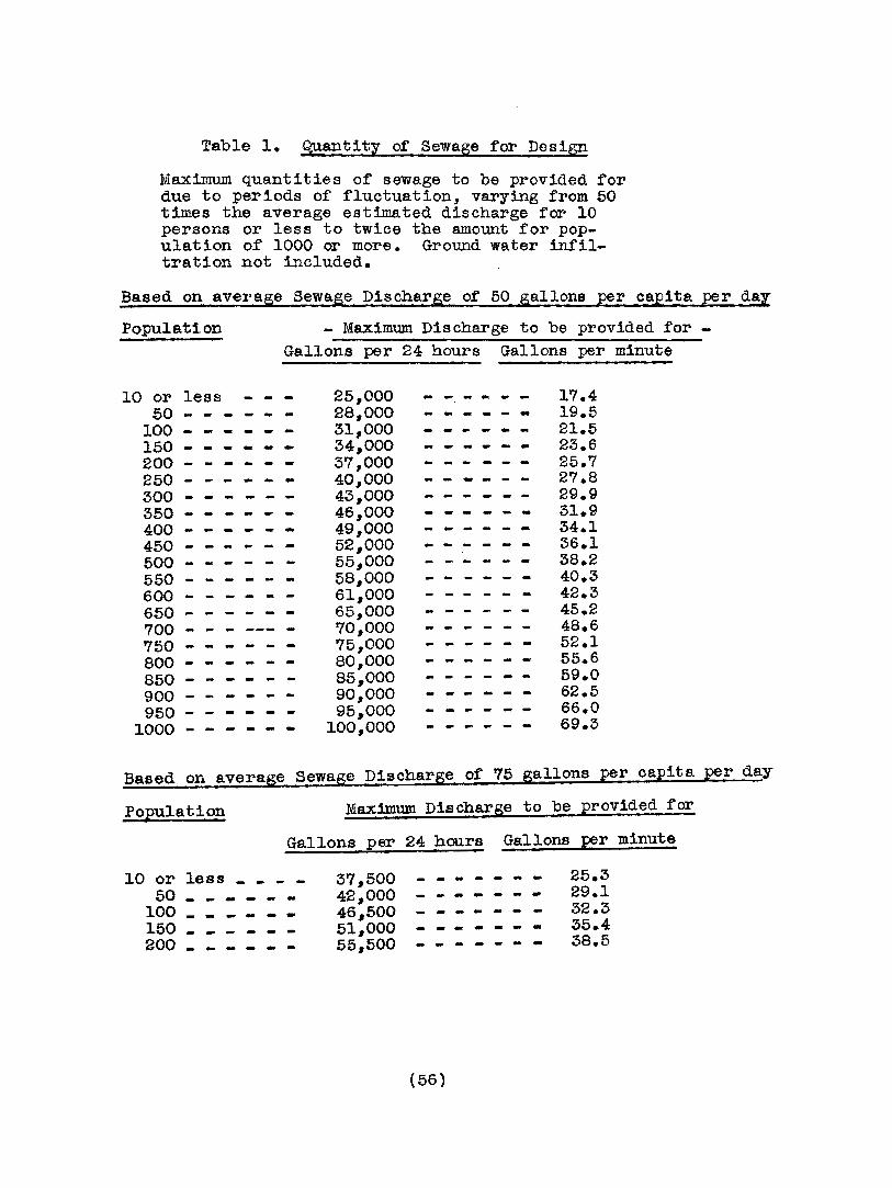
Table 1. Quantity or Sewage for Design
Maximum quantities of sewage to be provided fordue to periods of fluctuation, varying from 50times the average estimated discharge far 10persons or less to twice the amount for population of 1000 or more. Ground water infiltration not included.
Based on average Sewage Discharge of 50 gallons per capita per daz
Population - Maximum Discharge to be provided for Gallons per 24 hours Gallons per minute
10 or less - - - 25,000 - - - - 1'7.450 - - - - 28,000 - - - - 19.5
100 - - - - - - 31,0.00 - - - - 21.5150 - - - - 34,000 - - - - 23.6200 - - - - 37,000 - - - - 25.7250 - - - - 40,000 - - - - - - 2'7.8300 - - - - - - 43,000 - - - - - - 29.9350 46,000 - - - - - - 31.9400 - - - - 49,000 - - - - 34.1450 - - - - 52,000 - - - - - - 36.1500 - - - - - - 55,000 - - - - - - 38.2550 - - - - 58,000 40.3600 61,000 - - - - - - 42.3650 - - - - 65,000 45.2700 - - - --- - 70,000 - - - - 48.6750 75,000 - - - - 52.1800 80,000 - - - - 55.6850 85,000 59.0900 90,000 - - - - -- 62.5950 - - 95,000 66.0
1000 - - - - 100,000 - - - - 69.3
Based on averase Sewage Discharge of 75 gallons per capita per day
Population Maximum Discharge to be provided for
Gallons per 24 hours Gallons per minute
10 or less - - 37,500 - - - - - 25.350 - - - - 42~OOO - -- - - - - 29.1
100 - - 46 6 500 - - - - - - - 32.3150 - - - - - - 51~OOO - - - - -- - 35.4200 - - -- 55~500 - - - - - 38.5
(56)
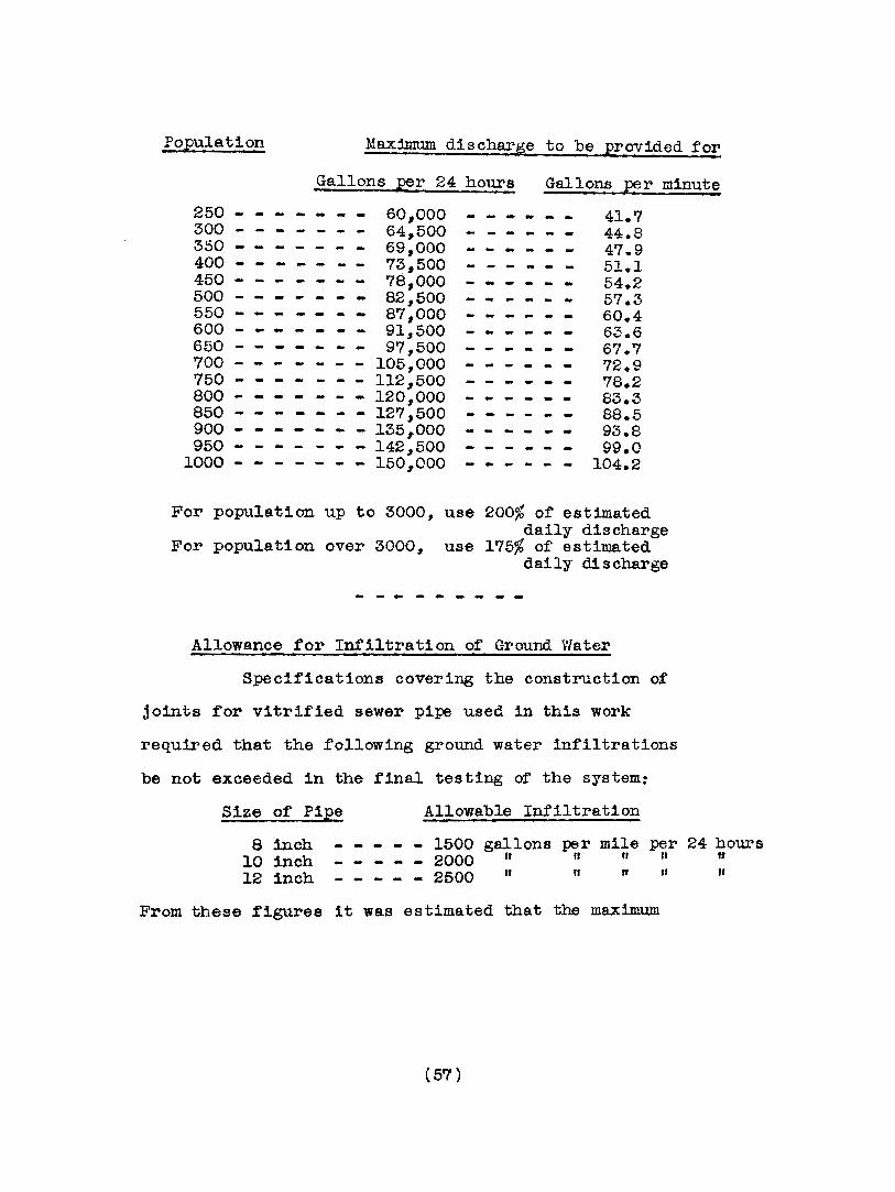
Population Max:1mum discharge to be provided for
Gallons per 24 hours Gallons j?!Jr minute
41.744.847.951.154.257.360.463.667.772.978.283.388.593.899.0
104.2
60,00064,50069,00073,50078,00082,50087,00091,50097,500
105,000- - - 112,500
- 120,000- - 127,500- - 135,000
- 142,500- - 150,000
250 -300 - - - - - - -350 - - -400 - - -450 -500 - - 550 - - 600 - - -650 - - -700 - - 750 - - - 800 - - - 850 - - 900 -950
1000 -
For population up to 3000, use 200% of estimateddaily discharge
For population over 3000, use 175% of estimateddaily discharge
Allowance for Infiltration of Ground Water
Specifications covering the construction of
joints for vitrified sewer pipe used in this work
required that the following ground water infiltrations
be not exceeded in the final testing of the system:
Size of Pipe
8 inch - - 10 inch12 inch
Allowable Infiltration
1500 gallons per mile per 24 hours_ 2000 It n ft n "_ 2500" " "n n
From these figures it was estimated that the maximum
(5'7 )
allowable flow due to ground water infiltration over
the entire system as designed for Osgood should not
exceed 5.09 gallons per minute.
It is realized, however, that the ground
water infiltration after a few years service may be
increased to many times the initial allowable amount,
and in view or this an assumption of a probable
increase to 10 times the above amount, or 51 gallons
per minute, was used. Whereas it is quite possible
that th:1s assumption of 10 times the initial allowable
amoont may be greatly exoeeded at some future date~
however~ it would seem that some limit from the stand
point of design should be drawn somewhere.
The writer would venture to express an
opinion of his own here that the imposs ib1l1ty of
attempting to apply mathematical formulae for the
infiltration of ground water into sewer joints cannot
be overstated. The many factors involved, particularly
the topographic, geologie, and climatic coOO1tiona ot
the area, together wi th nethods of joint construction6 and
materials used, are undoubtedly variable beyond any
mathematical comprehension. Nevertheless 6 the wr1tar has
noted several 1nstance8~ one anongst the engineers of a
state board of health in part1cular 6 in which the above
(58)
factors were considered to be of minor importance, and
ground water inf'iltra.tion deemed to be in proportion
of the number of inhabitants served. He can see little
or no reason whatever for such a basis for design, and
believes that in view of the importance of the four
factors already mentioned, the only sensible basis seems
to be that of infiltration in terms of length and size
of the sewer line itself.
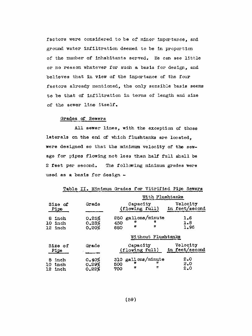
Grades or Sewers
All sewer lines, with the exception of those
laterals on the end of which f~ushta.nks are located,
were designed so that the minLmwm velocity of the sew
age for pipes flowing not less than half full shall be
2 feet per second. The following minimum grades were
used as a basis for design -
Grade
Table II. Minimum Grades -ror Vitrified Pipe Sewers
With FlushtanksCapacity Velocity
(flow~ full) in teet/secondSize of
Pipe
8 inch10 inch12 inch
250 gal~ons/minute450 If U
680 If "
Wi.thout Fluahtanks
Size ofPipe
8 inch10 inch12 inch
Grade
0.40%0.29%0.22%
Capacity(flow:tng full)
310 gallons/minute500 rr If
700" ff
Velocityin feet/second
2.02.02.0
(59)
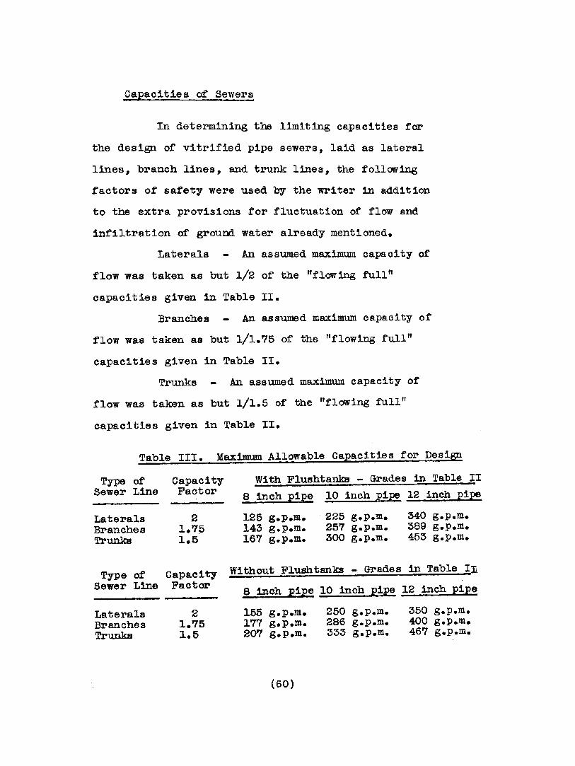
Capacities of Sewers
In determining the limiting capacities for
the design of vitrified pipe sewers, laid as lateral
lines, branch lines, and trunk lines, the following
factors of safety were used by the writer in addition
to the extra provisions for fluctuation of flow and
infiltration of ground water already mentioned.
Laterals An assumed maximum capacity of
flow was taken as but 1/2 of the nflow 1ng fu.ll"
capacities given in Table II.
Branches An assumed maximum capacity of
flow was taken as but 1/1.75 of: the ttflowlng full"
capacities given 1n Table II.
Trunks An assumed maximum capacity of
flow was taken as but 1/1.5 of the "flowing full"
capacities given in Table II.
Table III. Maximum Allowable Capacities for Design
Type of Capacity With F1ushtanks - Grades in Table IISewer Line Factor
8 inch pipe 10 inch pipe 12 inch pipe
Laterals 2 125 g.p.m. 225 g.p.m. 340 g.p.m.Branches 1.75 143 g.p.m. 257 g.p.m. 389 g.p.m.Trunks 1.5 167 g.p.m. 300 g.p.m. 453 g.p.m.
Type of Capacity Without F1ushtanks - Grades in Table I:nSewer Line Factor
8 inch pipe 10 inch pill! 12 inch pipe
Laterals 2 155 g.p.m. 250 g.p.m. 350 g.p.m.Branches 1.75 177 g.p.m. 286 g.p.m. 400 g.p.m.Trunks J..5 20'7 g.p.m. 333 g.p.m. 467 g.p.m.
(60)
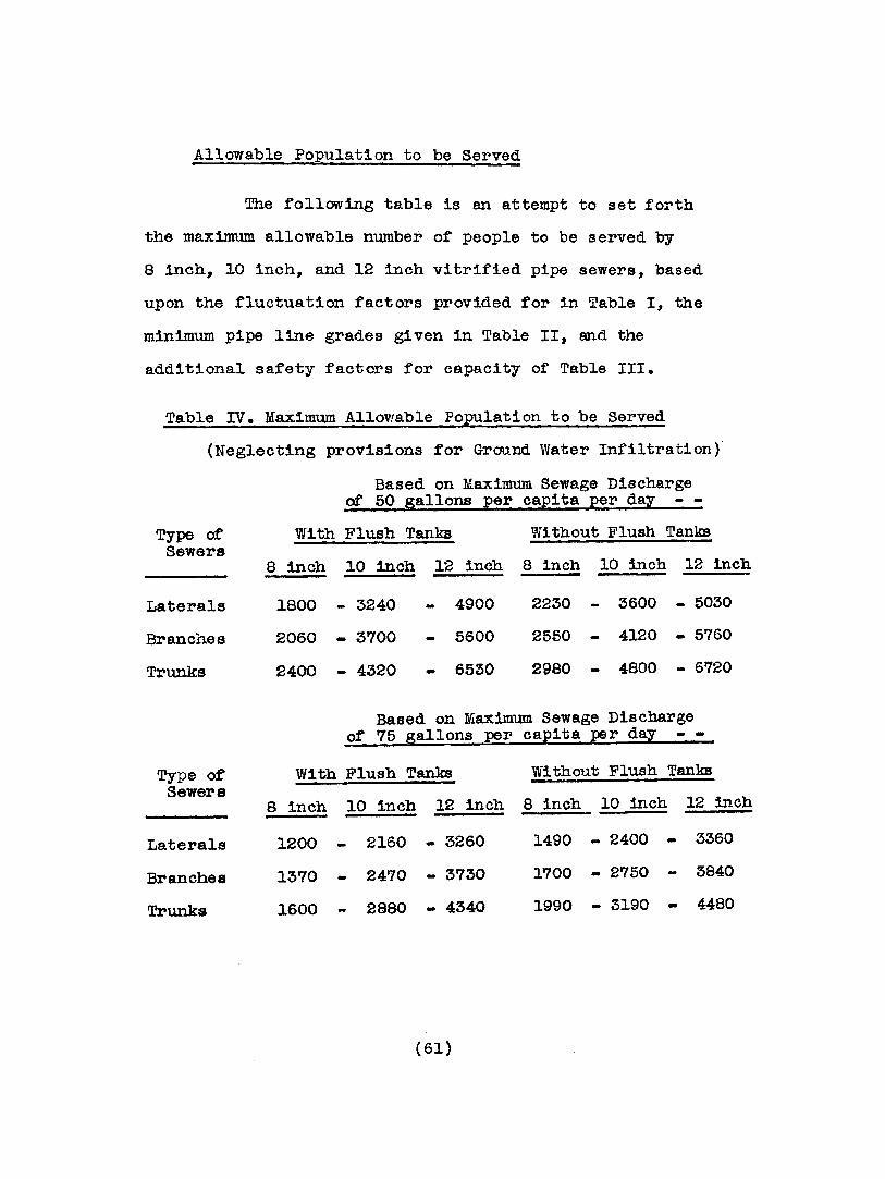
Allowable Population to be Served
The .following table is an attempt to set forth
the max~um allowable number of people to be served by
8 inch l 10 inch, and 12 inch vitrified pipe sewers, based
upon the fluctuation factors provided for in Table I, the
minimum pipe line grades given in Table II, and the
additional safety factors for capacity of Table III.
Table IV. Maximum Allowable Population to be Served
(Neglecting prOVisions for Ground Water Infiltration)
Based on Maximum Sewage Dischargeof 50 gallons per capita per day
Type ~Sewers
With Flush Tanks Without Flush Tanks
Laterals
Branches
Trunks
8 inch 10 inch 12 inch 8 inch 10 inch 12 inch
1800 - 3240 4900 2230 - 3600 - 5030
2060 - 3700 5600 2550 - 4120 - 5760
2400 - 4320 6530 2980 - 4800 - 6720
Based on Maximum Sewage Dischargeof 75 gallons per capita per day
Type of With Flush Tanks Without Flush TanksSewers
8 inch 10 inch 12 inch 8 inch 10 inch 12 inch
Laterals 1200 2160 - 3260 1490 - 2400 - 3360
Branches 13'70 2470 - 3730 1700 - 2750 - 3840
Trunks 1600 2880 - 4340 1990 - 3190 - 4480
(61)
Method of Flushing Sewers
Automatic siphon flushtanks were located on
the extremities of lateral sewers wherever it was found
necessary to lower the percentage of line grade below
the minimum for a velocity of 2 feet per second.
Lampholes, Manholes
Lampholes were provided at the dead ends of
all lateral sewers where flushtanks were not necessary.
Manholes were provided at the junction points of all
sewers, and spaced not more than 400 feet apart along
all lines throughout the system.
Charact~r of Sewage
The sewage is to be considered as that resulting
fran domestic sources entirely.
Disposal Plant
General
The sewage disposal plant designed for Osgood
provides for primary treatment of sewage only, and con
sists of an Imhoff tank with sludge bed, the effluent
from the tank being discharged directly into a small
creek. It may be noted, however, that the plant was so
located and arranged as to allow for the construction of
(62)
sprinkling £ilters and additional sedimentation, or humus,
tank as an addition thereto for secondary treatment at
a future date if necessary.
The disposal plant consists essentially of a
double sedimentation chamber Imhof'f tank, designed for
reversal of flow operation, and a connecting sludge bed
for the removal of sludge.
Data for Design of Imhoff Tank
Capacity
The tank was designed to serve an ultimate
population of 2000.
CaEaclty of Sludge Chamber
Of three formulae commonly used for
calculation of sludge chamber capacity, namely the Im
hoff formula, the Allen formula, and the Metcalf' and
Eddy formula, the writer chose the last named. Whereas
the second and third of these give results reasonably
close to one another, the Imhoff formula seems to be
considered to give results entirely too low for American
practice. In fact it is suggested by numerous authors
that if the Imhoff formula be considered, an additional
50% of the result should be added £or safety.
(a) Imhoff Formula -
This provides for the capacity
(63)

v=
of the sludge chamber equal to a volume of sludge that
would accumula.te over a period of 6 months at the rate
or 0.0035 cubic reet per capita per day.
{b) Allen formula -
(This formula is based on sludge
having an average moisture content of 80% )
V ::;:;; 5.25 PD
V -= volume of sludge chamber in cubic feet
p .:; population to be provided for, in thousands
D :;:: number of days storage to be provided for
(0) Metcalf and. Eddy formula -
(This formula is based on sludge
having an average moisture content of 85%~ and assumes a
volume of sludge of' 2.48 cubic yards per million gallons
of domestic sewage. It is considered to be a formula
very much on the side or safety for American practice)
2.48 x 27 x P x G x D
1 1 °00,000
V :: volume or sludge chamber in cubic feet
G ::' as sumed sewage flow per capita per day
P = population to be provided for, actual number
D ~ number of days storage to be provided for
(64)
In the use of the above formula for
Osgood, the following figures were used:
P -:; 2000 G ~ 75 D::: 210
resulting in a required sludge chamber capacity of
2117 cubic feet.
Additional Miscellaneous Data upon which
Design of Imhoff Tank was based
1. Detention period for passage through
sedimentation chambers to be from 2 to 3 hours. Length
to be sufficient to limit velocity to 25 feet per hour,
where possible.
2. Gas vent area to be 17% of the total
area of' the tank.
3. Minimum velocity for effluent channels
after passage through sedimentation chambers to be
2.5 feet per second.
4. Stilling baffles to be provided at
entrance to sedimentation chamber; scum boards to be
provided in front of sedimentation ch~ber weir out-
lets.
5. Slope for sedimentation baffles to
be 1.5 vertical to 1 horizontal. Slot at bottom of
chamber between baffles to be from 6 to 12 inches wide.
Horizontal overlap of baffles below slot to be at least
8 inches.
(65)

6. Sur·face of sludge in sludge tank
to be at least 18 inches from slot in sedimentation
cha.mber when sludge tank is filled to capa.. city.
7. Depth of sludge tank to be not less
than from 16 to 20 feet.
8. Use sludge pipe at least 8 inches in
diameter for removal of sludge, the pipe outlet to
sludge bed to be at least 4 to 6 feet below sewage
level in sedimentation chamber.
Data. fo!~ D!sigrl. of' Sludge Bed
1. Sludge bed to be porous and well
underdrained at a depth of from 24 to 30 inches with
from 4 to 6 inch open joint tile.
2. Area of sludge bed to be calculated
on the ba.sis of 3 persons per square foot of area. The
writer would like to remark here that there seems to be
a growing opinion that the above heretofore generally
accepted allowance for sludge bed area 1s too small and
that the basis should be changed to not more than 1 per
son per square foot of area.
(66)
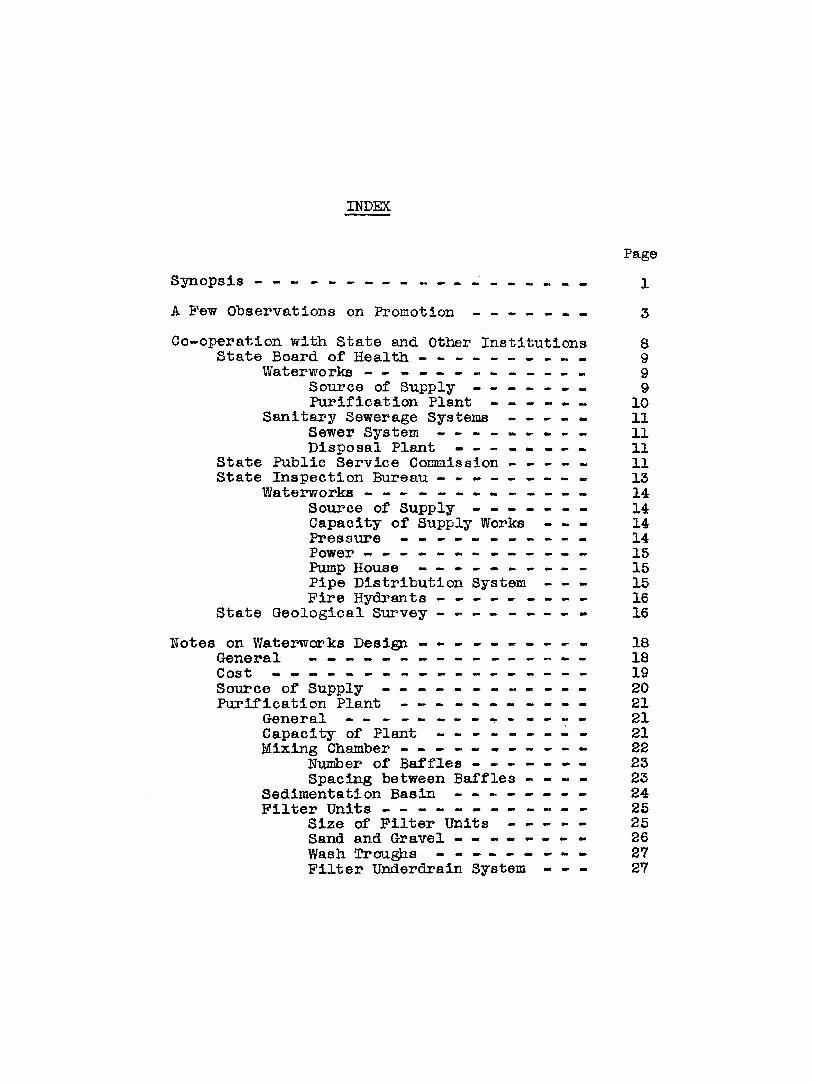
INDEX
Page
Synopsis - - - - - - - - - - - - -
A Few Observations on Promotion
1
3
Co-operation with State and Other Institutions 8State Board of Health - - - - - - - - - - 9
Waterworks - - - - - - - - - - - 9Source of Supply - - - - - 9Purification Plant - - - - 10
Sanitary Sewerage Systems - - - 11Sewer System - - - - - - - 11Disposal Plant - - - - - - 11
State Public Service Commission - - - - - 11State Inspection Bureau - - - - - - - - - 13
Waterworks - - - - - - - - - - - 14Source of Supply - - - - - - - 14Capacity of Supply Works - - - 14Pressure - - - - - - - - - - - 14Power - - - - - - - - - - - - - 15Pump House - - - - - - - - - - 15Pipe Distribution System - - - 15Fire Hydrants - - - - - - - - - 16
State Geological Survey - - - - - - - 16
Notes on Waterworks Design - - - - - - 18General - - - - - - 18Cost - - - - - - - - - - - - - - 19Source of Supply - - - - - - - - - - 20Purification Plant - - - - - - - 21
General - - - - - - 21Capacity of Plant - - - - - - - - - 21Mixing Chamber - - - - - ... - - - - - 22
Number of Baffles - 23Spacing between Baffles - - - - 23
Sedimentation Basin - - - - - - - - 24Filter Units - - - - - - - - 25
Size of Filter Units - - - 25Sand and Gravel - - - - - - 26Wash Troughs - - - - - - - 27Filter Underdrain System - - - 27
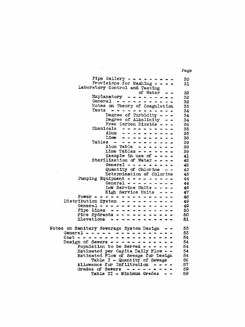
Page
Pipe Gallery - - - - - - - 30Provisions for WaShing - - - - 31
Laboratory Control and Testingof Water 32
Explanatory - - - - - - - - - 32General - - - - - - - - - - - 32Notes on Theory of Coagulation 33Tests - - - - - - - - - - - - 34
Degree of Turbidity - 34Degree of Alkalinity 34Free Carbon Dioxide - - - 35
Chemicals - - - - - - 35Alum. - - - - - - - - - - 35LiIne - - - - - - - - 36
Tables - - - - - - - - - - 39Alum Table - - - - - - - 39Lime Tables - - - 39Example in use of - - - - 41
Sterilization of Water 42General - - - - - 42Quantity of Chlorine 43Determination of Chlorine 43
Pumping Equipment - - - - - - - - - 44General - - - - - - - - - 44Low Service Units - - - - 46High Service Units - - - 47
Power - - - - - - - - - - - 48Distribution System - - - - - - 49
General - - - - - - - - - - - - 49Pipe Lines - - - - - - 50Fire Hydrants - - - - - - - - - 50Elevations - - - - - - 51
Notes on Sanitary Sewerage System Design 53General - - - - - - - - - - - - - - 53Cost ~ ~ ~ ~ - - ~ - - - - ~ - - - - - - 54Design of Sewers - - - - - - - - - - - - 54
Population to be Served - - - - - - 54Estimated per Capita Daily Flow - - 54Estimated Flow of Sewage far Design 54
Table I - Quantity of Sewage 56Allowance for Infiltration - - - - 57Grades of Sewers - - - - - - - 59
Table II - Minimum Grades 59
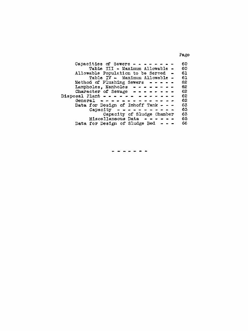
Page
Capacities of Sewers - - - - - - - - 60Table III - Maximum Allowable - 60
Allowable Population to be Served - 61Table IV - Maximum Allowable - 61
Method of Flushing Sewers - - - 62Lampholes, Manholes - - - - - - 62Character of Sewage - - - - - - - - 62
Disposal Plant - - - - - - - - - 62General - - - - - - - - - - - - - - 62Data for Design of Imhoff Tank - - - 63
Capacity - - - - - - - - - - - 63Capacity of Sludge Chwnber 63
Miscellaneous Data - - - - - - 65Data for Design of Sludge Bed - - - 66