
A data-base for IC mask making
10
:6-2692/83/1405-0043 $5.00/0 data-base for IC mask making FN. N. Kundu, S. N. Gupta, A. K. Bagchl, D. R. Nagpai, A. V. Ramani and I. S. Khokle .=ntral Electronics Engineering Research Institute, Pilani- 333031 (Rajasthan), India hotomasks are very important in the manufacturing of integrated circuits and aould be of very high quality with low defect density and very good edge efinition. A photomask fabrication process involves various photo-imaging, rocossing, measurement and quality control steps. The complexity and aphisticetion of the process requires that either the operator be extremely killed and conversant with all the process steps involved as per requirements of given set of masks or that the entire process be computerised. CEERI has developed a data-bese for the complete processing of emulsion and ard surface masks. This has been generated using the IMAGE 1000 software of a IP 1000 computer system and describes each process step such as, exposing ~ith pattern generator, image repeater and contact printer. Several mask ,rocessing procedures, critical dimension measurements and quality contro! taps have also been included. In fact, depending on the job requirements, the ,perator can simply enter all parameters through the query system of the lata-base, which can be conveniently listed either on hard copy or on a terminal or setting up various work stations and process steps of mask making. In this roper, this data-base has been described with its advantages and )racticel usage. I. Introduction ~reater complexity and diminishing dimensions of LSI have been putting more stringent requirements before.the mask-maker. This has lead to greater automation in all the processes 3f mask making. Pattern generators are becoming more complex with considerably enhanced software. 2. Mask making Apart from automation of single process steps in mask making such as reticle preparation, step-and-repeat operation etc., there has been considerable interest in the computerisation of the complete mask-making facility itself. Bringsfield and Oardee t developed a mask information system which was part of Bell Labs. mask-making facility as described by Howland and Poole. 2 This facility was based on automatic rubylith pattern generator with subsequent step-and-repeat operation. The job flow through various operations of mask making was also monitored with appropriate routing and priority assignment. Thus, the flow of jobs through the whole facility was simulated using a data base with ring and linked list structure. This approach takes care of job queries at each machine very well. Yield of masks has also been very important in a production environment. Dey and Harrison 3, have used interactive process control to model the parameters that affect the quality of the photomasks. A computerised analysis on inspection data of measurements on critical dimensions (CD) of MICROELECTRONICS JOURNAL Vo114 No 5 1983 Benn Electronics Publications Ltd, Luton 43
-
Upload
independent -
Category
Documents
-
view
1 -
download
0
Transcript of A data-base for IC mask making

:6-2692/83/1405-0043 $5.00/0
data-base for IC mask making
F N. N. Kundu, S. N. Gupta, A. K. Bagchl, D. R. Nagpai, A. V. Ramani and I. S. Khokle .=ntral Electronics Engineer ing Research Institute, Pi lani- 333031 (Rajasthan), India
hotomasks are very important in the manufacturing of integrated circuits and aould be of very high quality with low defect density and very good edge efinition. A photomask fabrication process involves various photo-imaging, rocossing, measurement and quality control steps. The complexity and aphisticetion of the process requires that either the operator be extremely killed and conversant with all the process steps involved as per requirements of given set of masks or that the entire process be computerised. CEERI has developed a data-bese for the complete processing of emulsion and
ard surface masks. This has been generated using the IMAGE 1000 software of a IP 1000 computer system and describes each process step such as, exposing ~ith pattern generator, image repeater and contact printer. Several mask ,rocessing procedures, critical dimension measurements and quality contro! taps have also been included. In fact, depending on the job requirements, the ,perator can simply enter all parameters through the query system of the lata-base, which can be conveniently listed either on hard copy or on a terminal or setting up various work stations and process steps of mask making. In this roper, this data-base has been described with its advantages and )racticel usage.
I. Introduction ~reater complexity and diminishing dimensions of LSI have been putting more stringent requirements before.the mask-maker. This has lead to greater automation in all the processes 3f mask making. Pattern generators are becoming more complex with considerably enhanced software.
2. Mask making Apart from automation of single process steps in mask making such as reticle preparation, step-and-repeat operation etc., there has been considerable interest in the computerisation of the complete mask-making facility itself. Bringsfield and Oardee t developed a mask information system which was part of Bell Labs. mask-making facility as described by Howland and Poole. 2 This facility was based on automatic rubylith pattern generator with subsequent step-and-repeat operation. The job flow through various operations of mask making was also monitored with appropriate routing and priority assignment. Thus, the flow of jobs through the whole facility was simulated using a data base with ring and linked list structure. This approach takes care of job queries at each machine very well. Yield of masks has also been very important in a production environment. Dey and Harrison 3, have used interactive process control to model the parameters that affect the quality of the photomasks. A computerised analysis on inspection data of measurements on critical dimensions (CD) of
MICROELECTRONICS JOURNAL Vo114 No 5 �9 1983 Benn Electronics Publications Ltd, Luton 43

A data-base for IC mask making cont/nued from page 43
Edge ~~ l - ~ l
I
~og, Tope Nlth ~ ~ask dot~
I Pattern generotlon
lOX reticle ~Process
inspection ~ verlflcatlon
Good reticle t 4 I
]c0nt0ct printing I setPrepored Reticle ~-- Pr0cess 11
1 gaster ~losk ~-~Process
Inspection
Reticle defect J dato
[Reoo,r Go~ ~oster
l r printing
~skSUbmaster working ~---Process
~g. 1 Maskmakingflowcha~.
hard surface masks is performed. This analysis is used to vary input parameters to control mask quality and thus improveyield. A slightly different approach is used by Stapper et al ~ for improvement of yield in wafer processing. The chosen model constants are modified with new inspection data and thus yield prediction is informed.
3. Pattern generation Apart from modelling for yield through inspection data, specific aspects of detailed processes such as pattern generation itself have been considered for improvement in mask quality. Le Carpentier s has proposed partitioning of reticles with a very large number of flashes into smaller reticles with less number of flashes in order to reduce the probability of error in reticle exposure. Furthermore, several features required by the mask maker such as polarity, orientation and background have been taken care of by considering the control tape of a pattern generator as a programmable step. The software so developed relieves both the designer and the mask maker of many details. In the present paper, we describe the use of an existing data base management system in order to describe a complete mask-making facility. This is utilised to generate reports for operators of different machines. This approach has certain advantages which will be discussed during the course of this paper. We will first look at the mask-making fabrication procedure and then the development of the data base for it.
4. Procedure of mask making Mask making is quite a complex process. The fabrication procedure for photomasks used in integrated circuits involves several steps. There are several major steps in mask making which
44

PLATE -
(~anual ~s te r Set)
, pLTyp i PLTID I PLSZ I
Plate ID No.
KFGR
EXPDT
- - ~ DTUSED
- - [ THICK
- ~ FLAT
Type of plate E~UL/CROM
Plate size
P~nufacturer
Expiry dote
Dote of use
Plate thickness
Plate flatness
TYPE Em, u]slon type
Fig. 2 PLATE. master file.
n vary slightly depending on each mask-making house. Figure 1 shows the flow chart of a ,od mask-making facility. All mask-making houses do not necessarily use the same flow tart. The reticle does not necessarily have to be 10X although the reduction is generally ~ed. If pattern generator is E-beam, reticle contact printing may not necessarily be used and ticle repair might become very important. Reticle contact printing is normally used to )tain a reticle of correct polarity. This contact printing can involve any combination of nulsion and chrome. In fact, there are a large number of details that can also vary depending I mask complexity and minimum feature size, etc. However, there are some major �9 ocesses that a good mask-making house should be able to provide. These are:
(1) Reticle preparation (2) Step-and-repeat operation (3) Mask processing (4) Critiealdimension (CD) measurement (5) Mask inspection
(6) Mask duplication (contact printing) (7) Mask repair (8) Storage and classification
Each of these major processes could have different methods of realisation. Let us take for tample, reticle exposure. It could be done through rubylith eoordinatography and first step duction camera or an optical pattern generator or an E-beam pattern generator. For .'vices such as power transistors, rubylith/first step reduction camera method might be ifficient. However, for IC work optical pattern generation is by far the most widely used ethod at present. If we look at the reticle exposure process by an optical pattern generator, e find that there are several steps before one can prepare a reticle. As mentioned earlier, each of the eight mask-making processes contains several steps in it.
ee have considered all the steps except the mask repair step which has not been implemented :t in our facility. Let us see what are the details required in each of these seven tasks.
1 Reticle preparation s is also evident from the flow chart of Fig. 1, what we mean by a prepared reticle is a reticle
45

A data-base for IC mask making continued from page 45
(Automatic Master Set)
DTAPE (Manual Master Set)
PTGEN @ (Detail Data Set) PLATE
(P~nual ~ster Set)
SGPG (Manual Master Set)
~ Feduclo1-YES/NO
_ . ~ ' ~ R e t i c l e contact YES/NO
- - F ~ F o c u s value
- ~ E x p o s u r e value
- - ~ M i r r o r i n g - Y E S / N O
~ Boundary width
~ No, of flashes
~ TotaI flash time
- - ~ S y m b o l generator
Fig. 3 Pattern generator file.
1 (Automatic Master Set)
PLATE
(Manual Master Set)
SGIR
(~onual Master Set)
EDGMS (Manual Master Set}
--•Arroy size
- - ~ A r r a y shape
~ Arroy dlamater
- ~ D l e size
- ~ E x p o s u r e value
~ Focus value
- - ~ N o . of flashes
- ' ~ T o t a l flash time
~ - - I B l o n k location
~ Edge master no,
D k ~ ~ D o t e of Job done
Fig. 4 Image repeater file. 46

ready to be mounted on a step-and-repeat camera. The steps necessary to obtain a prepared reticle are as follows:
(a) Pattern generator set-up: for which one needs to know the format, etc., of the data tape, pattern generator calibration factors, etc.
(b) Plate development and processing: for which we need to know whether it is hard surface/emulsion plate, which developer/etchant is to be used at what ambient conditions, etc.
(c) Inspection and verification: for which we need to compare the image on the reticle against the data tape or a checkplot of the image. Defects have to be classified and if there are fatal or killer defects which cannot be repaired, the reticle is to be remade.
(d) Contact printing: to obtain reticles of both polarities (dark field/bright field), contact printing is used. One may use contact printing from emulsion to chrome or emulsion to emulsion%Iso.
4.2 Step-and-repeat operation The array of images of a die is normally exposed through automatic optical step-and- repeaters. The prepared reticle is edge masked, either manually or automatically and aligned on the step-and:repeater camera.
Following are the principal steps in step-and-repeat operation:
(a) Fiducial alignment: normally there are two dissimilar fiducial marks on the reticle that have to be aligned to the camera. Orientation of the fiducials is important for proper image rotation.
(b) Step-and-repeat camera set-up: the matrix size, stepping distances, blank or test pattern locations, type and size of plate, exposure and focus values, etc., have to be normally specified to the controller of the machine before running a job.
(c) Plate development and processing: the exposed plates have to be subsequently processed. This step has same considerations as in reticle preparation.
(d) Mask inspection: defects are classified from die to die either normally or on automatic mask inspection systems. Defect density will ultimately decide the yield of the process.
7.3 Mask processing Exposed mask blanks have to be developed. Mask blanks are normally exposed either at PG, ~tep-and-repeat or contact printing stations. Both emulsion and hard surface plates are used ['or mask making. The development procedure for both of them is different. The procedures ['or processing for these plates in general have steps as given below:
~.3. 1 Emulsion process Emulsion process is also of two kinds, one is for negative development and the other is ~eversal development. Both of these involve different steps, which are as follows:
~egative development has following steps:
(a) Image development (b) Fixing (c) DI water rinse (d) Ultrasonic cleaning (e) Drying.
Reversal development has following steps:
(a) Image development (b) Bleaching (c) Re-exposure
47

A data-base for IC mask making continued from page 47
I VASKI)
VASKCD (Automatic Master Set)
DEVCD
(Automatic ~ster Set)
JOB No.
(Manuel Master Set)
DIAPE
(~bnuaI Master Set)
~ Form of Input NGTP/Ruby
~ Sub master or working mask
~ Type of plate emul/crom.
~ Plate size 2,5"/3" etc,
~ Totol no, of levels
~ Scrlbe line width
~ Dle slze In X dlrectlon
- - ~ - ~ ~ D l e slze In Y direction
~ M l n feature slze In PG
~ M l n feature slze In IR
-~R--~SP]Array shape RND/SOR
-~Whether test structure Is there?
(d) (e) (f) (g)
Hard of the
(a) (b) (e) (d) (e)
Fig. 5 Maskdata file.
Fixing DI water rinse Ultrasonic cleaning Drying.
surface process. This process is essentially a photolithographic process. It consists following steps:
Photoresist development DI water rinsing Metal (chrome, iron oxide, etc.) etching Resist removal Scrubbing and cleaning.
There are thus several parameters that go in mask processing and should be kept track of for good quality control.
4.4 Cr i t ical d i m e n s i o n (CD) m e a s u r e m e n t
In order to ensure the final accuracy of the feature sizes in the mask set, measurements on CD should be made both on reticle and the master. The steps in this process would simply be:
(a) Measurement of CD on reticle. (b) Measurement of CD on master mask.
48
1
~ AUT OY.AT I C VASTER SET
DETA' ' DATA SET Y, ANUAL Y.ASTER SET
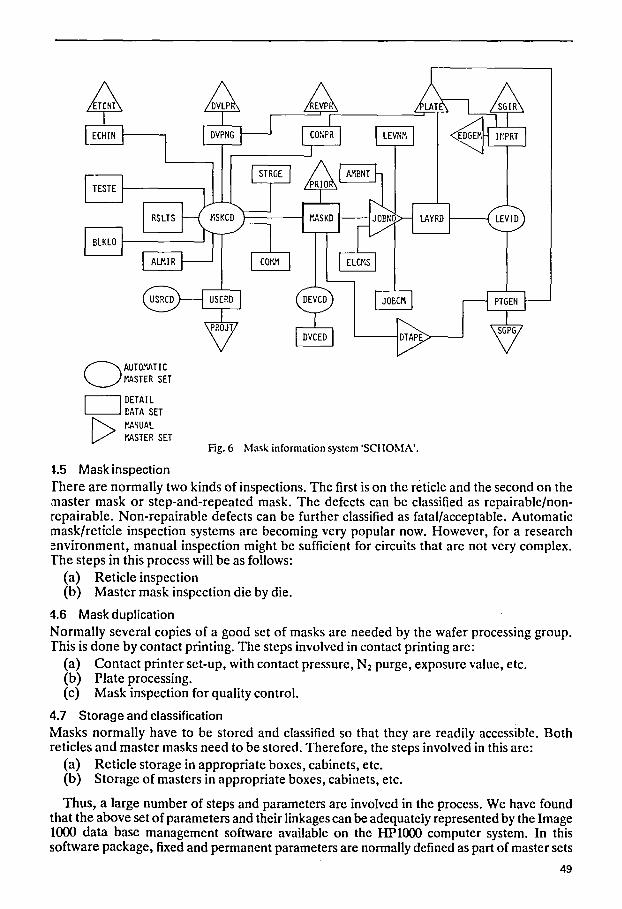
Fig. 6 Mask information system 'SCHOMA'.
7
~,.5 Mask inspection there are normally two kinds of inspections. The first is on the reticle and the second on the master mask or step-and-repeated mask. The defects can be classified as repairable/non- repairable. Non-repairable defects can be further classified as fatal/acceptable. Automatic mask/reticle inspection systems are becoming very popular now. However, for a research .~nvironment, manual inspection might be sufficient for circuits that are not very complex. The steps in this process will be as follows:
(a) Reticle inspection (b) Master mask inspection die by die.
4.6 Mask duplication Normally several copies of a good set of masks are needed by the wafer processing group. This is done by contact printing. The steps involved in contact printing are:
(a) Contact printer set-up, with contact pressure, N2 purge, exposure value, etc. (b) Plate processing. (c) Mask inspection for quality control.
4.7 Storage and classification Masks normally have to be stored and classified so that they are readily accessible. Both reticles and master masks need to be stored. Therefore, the steps involved in this are:
(a) Reticle storage in appropriate boxes, cabinets, etc. (b) Storage of masters in appropriate boxes, cabinets, etc.
Thus, a large number of steps and parameters are involved in the process. We have found that the above set of parameters and their linkages can be adequately represented by the Image 1000 data base management software available on the HP1000 computer system. In this software package, fixed and permanent parameters are normally defined as part of master sets
49

A d a t a - b a s e f o r IC m a s k m a k i n g continued from page 49
LLI
I---
OCt;
,3 ~.-~,3 ~l-,.-h ~- ,~ ,: ,.-~ ,.~ ,.~ ,,D ,~
-.,- .... i.'~ "~!" ,'~1 ..,---~ -OJ I D -'~)~'-I'9,.'~I . . . . . I ~ -
"TLU 0
_J,~ ,~ ,."~ IO ,:d ,;0 L~., .~ ~ .,~ r.. ,7", ,-, ,~ -.~'~ OJ '-~J """~ '.~ "" ~'" LU
F- ~.
'-~ '---' ' ~ U], I 0 " - , ' ~ ' - " - - ' ,-~ ':::,
�9 ~I-" ,:3,.~,:3~--.,-, , ':~'.'~l,':J'~ hJ ,", ~ . . . . . . . . . .
L-, i.~ LTJ ;-~
LU I - -
--~----' ............. ILl F-
0 " ~ : IJJ iv" Q I.l._-".- ~,'_q W
E l - - . X i , i .'7" ,~ ~,~ !_?- ,~
-~ "f~ L~ ~..~ D UJ r.r: LIJ ,-~ , = , , ~ ,.~ ,-~ ,--, ,:3 , - , , ~ , : , ,.~ ,~ ,_~ ~ - LU ~--Z ~.1 ::3 I1") Lr.i i i3 l/-.i LI') I~.l I j3 Ll-j i1") I~.l t 0 LI".t i j" ) "O I--" -J
E LL _-~-- ,~n
�9 4s LUI-- I--E ~ -ILl j r . . ) . ~ 0 ' r l - - i ' j . ~ .T_.LL LL E l - " I"I-- '~I~h~ ~ ~,:-~ 0,~ b~ W,~I~ ~ ,:,
31:L I.U 0 IJ._ 0 I-'-.
E t . ~ IJ.I ~ . 111
LL LL ~ 0".'
;'~ F'- C', -.-J . . ' ILL T I ~ r n ,"~ .- p'; I0 ~r~ r,. ,~, ~- ,?d .,.. ,?d i~; ~ i0 .-j: Z,-, E E ) .T_. ,--, , :3 ,..~ , ~ ,.~ , ~ ,=, - - . - . p,~ r , ) pr; F.,/~') ..~
i~. 3-- . . . . ~-" h l r f ) I.~ I~. r~, E,
h l 13- ILl M I LJ F" ~ n," "~,', "fr'~"fr _JH "7"
O. .,- I - - , ' 3 ~ "~r'~" ~ I "~ " ~I" Lr) I 0 P - P - ~ p - r , - , : , r - 'T ,=, :E:: ,=,
,.-.,
. .J - o W o ~-- r~ I|') ' .9 ['.- kYJ - - Cd ~ L"~ rr ~l ~ ll') , : ,
LU ,--, . .J
0
"6
E b
Z
v %
l'O. ro '.9 ~ oJ I0 ,.Jr, r~
,:L r'- ,'~.~ r'-,:o u'~ :E 1.0 .--_, I..- Z:,..T_ ~-~ CL ~
�9 ,--H L~ ..~ 0:) Cq i I I-'L-:" ..J C~ --H-- ~ "F" I-- ,..ID ~ ~"I--I.~ -~_J Ll.lr'q--n."LLl i~ ;~"
I j _ , - , _ I r O P - I - - ' ~ _ J I.-L ~01-- : E L L r j I--- 0
/',':0 n ,.'00):E "r I I I IIII,".Q QZ~ ",- r UJ I.I.I I.U LU IJJ LIJ LU Ld ~ n~
,.'0 I-- 0~, ~- I-- L'O ~":- ~--'- ~ ~--- Z:-- ~ ~- ~ ,-4 I~
I-- EO I-- ,'n EEl I-- i]_ I.'L I-- I-- I-- I-- P- I-- F- I-- ~ ,-, :~.rj ,'r; Crj,.rj ,'r., CO O) ,.r; f.rj ~.C, r,) r~ r,-., r,~. p~
,m
�9 , - l~.I b7 ' .9 P - l:O " , - Cd ~ OJ r".r'4" E., '..0 P- CO ~ r [ 0 .-~, b:~ ,:q ,=, , : , ,--, , - , ,:.:, ,.--, ~ ~ C-:J OJ C,J ,:',.~ r r C~ OJ r,:, P'.~ FO F,-J P.~
50
l h l - ~ L ~
O ( , 0 '.,D I '~ r~.~ ,.,~'~- ,.~ ~ - E . - 3 ,.D "~- r ~ - , - r~- 1/3 ,=, .,-- I ' - 0 113 ~ , '~) ' ,0 " , - ' .0 ".-' ' ,0 "tl" 0", 0 r.~ iv.~ Iv., 1,0 '~" -'~
I1 OJ I~i,J i ' l l I:hi I ~ I.'~11"l) i"~ i"l i i.'%1 r~) .i-. i ~ i~) i~) i~l i~-~ 3< I11
~ - 113 r o I D r ~ H ~ E , i ~ 113113 I~1 iv) lrH-._ p . i ~ p . i,.. _
i ~ ~'~ ..q" - ~ -Q: , 2 : - ~ -,3: . ~ . ~ . ~ . ~ .2: ~1: .~: .~: .0: . ~ . ~
i'JO ILl ,:~ ,-~, ,:D ,..--, , 3 " , '::~ '4:i '= ' '----" Q ~ '~ ' ,-7 ,:::~ ,=, ' 3 (_..i ".~ : E ' ,0 ' ~ I ~ C~I li ') ~ " '.'0 ~ " '-~ " , - '~I ' .~ "~" " , - ' ~ " , - '-~ "3: . J H ,:3 - l V ) ~ - I ~ - ~ - . ~ C 9 ~ , ~ 1 ~ 3 , . % 1 , : ~ Q. I L l - - "~D " " -'--~- - , ;~ I ,~ . . . . . . . .
.~ IF~ ,.~J Is ,:~I ,.~J I~) Cd U'~ h-~ ,.TJ C~I LF) ,:d ,:d C,I r:~l ,;~] O.J I~- ~s r.- ,.D ,~ r,- ,.9 r.- r,- ,.D ',D P- '~ '-,', '-.~ '-D '-9
LL>
ILl
CO::) ',D ,.~ ,.r, ,L.,,,D ;,', O . J 0_-,.I: X > IJJ
~ ~ E E I Z ~ E ~ Z ~ i Z ~ I Z
: ) - Is r - . b') r-- r . . if.~ r . . iF.ql-) r . - r . . E ) ,.-I-, ,.-I-, ,:i-, ,.-i-, i.-lh �9 2 : L U . . . . . . . . .
I .d I - - ..-,]:
I .d I :L IJJ I 'E
IJJ
I 'M
W O i - - I .L
~ _ l l l . J W, ' , ,.'3. I--- LIJ I:~
- . 4 -
I-I~1 L iJ I]r.l
, 3 -"7" - ~ I.L ,-_l ~ O
I - - I - - ..'I""i'~" .-;.:: .T__ ,.~ W L~LL [-- 0
r t , ~ !13 r~. I f3 I~. i~. L~ i~. U3 l!3 i ~ i ~ !13 -r~ ~ ~ ~ . ~ LL . . J ~GI: C0 . . . . .~- . . . . . . . . , - ~-- . - - ~ - - , - L~ . -'~ ,:3
ILl ~-~ [33 r.0 ,--, �9 ~ O h ~ . 3 - : E Z M i-i-) t;0
I . J ...'~ L U g " 1~'3 Lr) b'.~ Lr~ Is ~'3 I1'3 Lr.Hs Lf) Lr~ IJ") '..0 '.s ' .~ '.D ' ~ - ~ "71=.!. t ~ 1.1.,I "-~ O C l V , ~ I I I t -
C0 ,-~ J iz l ,:3
( ~ I H Q ,=, ,::) ,::, , 3 0-~ , 3 ,=, ,::, Q o o I '9 l','j r,') I~., I " ) E LU
Z
h i ~ -
I - - , ;d
1 , % ,-~
. j o LU " , - ' , - i f ) F~ b') U'~,-Z) ',D r-- P - o~ o'.; ~ Cd F-3 ~I- b') P- ~ > , 3 ILl ,~, ,.~
0
~3 .E
o
LE
- ~ h3'-D - p',
I_L EL I - - t ~ . ~ "~ C.J 1"3 ~ " b3 ,.r, s ,'r, H ~_ _~ LLI ~'::
, .rl IJ~ ,.r, " : - -%. - - - ~ "--. - - - "--- ~ -
" ; - 1'~9 : l :)'- - " l I - - I - - I - - I - - I - - 1-- i " - I - - i 'ri i'l'l i ~ L'I:.H~3 I . L H 0.: l s - -d- ' -
, :0
5 1

A data-base for IC mask making continued from pago 51
or files. Each master file has a unique identification number which is associated with a key item. This key item can be used by other detailed files whenever they need to associate with the contents of the particular master file; e.g. P L A T E is a master file which contains information on all the plates being used by the mask-making facility. This file is structured as illustrated in Fig. 2.
Thus, if at pattern generation, one has used 2.5-inch emulsion plate, one just has to specify that plate ID 02 has been used for this particular set of mask. A detailed file can be associated with up to five key items or identification codes of master files. The main detail files are for pat tern generator and image repeater. These files are illustrated in Figs 3 and 4.
It is clear from Figs 3 and 4 that each of these files has four key items which associate them with four master files. For a set of masks, different levels are identified through automatic master file LEVCD.
The type of plate actually used is found out through master file PLATE, the kind of codes format , etc., used for data formation is accessed through the master file DATPE, and the string of symbols written on each reticle is accessed through the master file SGPG. In addit ion, there are twelve more detailed parameters such as contact printing of the reticle, kind of fiducials, boundary width, etc., are stored as separate items. The step-and-repeater file I M R P T has a similar structure. The average environmental conditions under which these masks have been made are stored in file A M B N T . The calibration details for the mask set are s tored in a file called EICMS.
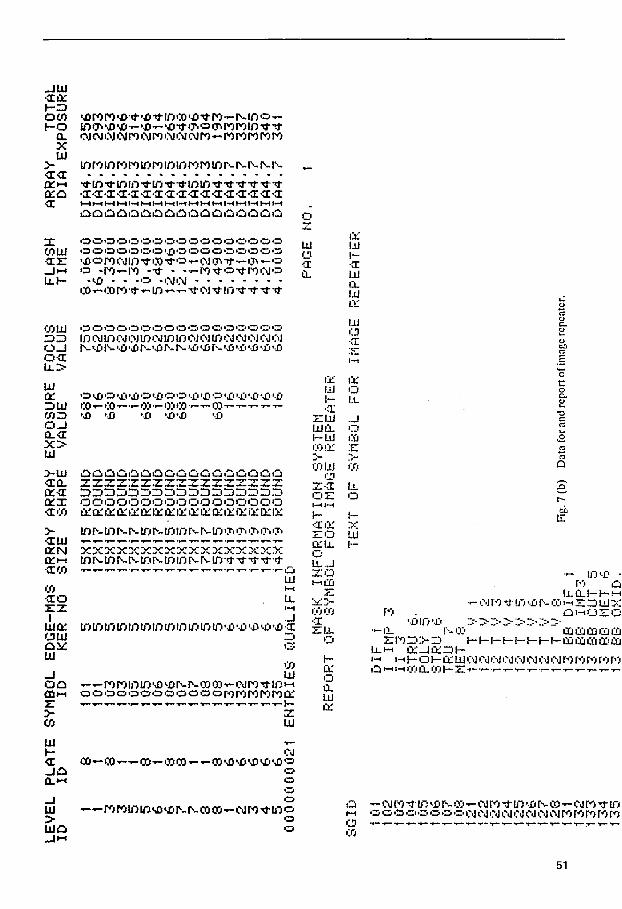
Final mask details are stored in a detail file called MASKD which is shown in Fig. 5. This is linked through four key items to masters storing information on mask and device identi- fications, job numbers and magnetic data tape identification with its formatting parameters. The complete linkages and files are shown in Fig. 6. In Fig. 7 we show some of the reports genera ted using this software, for some of the steps needed in mask making, e.g. a report file IS genera ted for a complete set of parameters for pattern generator and step-and-repeat stations including the symbols to be written on each plate identified by the job number. This is available to the operator on a terminal connected to the HP1000 computer or through a print-out.
In smaller mask-making facilities such as normally found in research institutions, com- plicated yield statistics, etc., on masks are not as important, Report generation for a particular set of masks is quite sufficient to decide on which kind o f processes at what conditions and with what parameters to use. This makes it very convenient for an operator to set up each station and prepare a set of masks. The probability of making errors at any process stage goes down. It also helps to streamline a facility where mask sets of different kinds of devices are being made.
5. Acknowledgment The authors wish to thank CEERI computer centre for providing excellent support for this work.
6. References [1] Bringsfield, J. G., and Oardee, S., "Mask information system", BSTJ, 49(9), 2203-20 (Nov. 1970). [2] Howland, 17. L., and Poole, K. M., "An overview of the New Mask making system", BSTJ, 49(9),
1997-7009 (Nov. 1970). [3] Dey, J., and Harrison, K., "Process control in the production of hard surface photomasks", Proc.
SPIE Developments in Semiconductor Microlithography II, 100, 4-11 (April 4-5, 1977). [4] Stapper, C. H., Castrucci, P. P., et aL, "Evolution and accomplishments of VLSI yield manage-
ment at IBM, IBMJ. R & D, 26(5), 524-644 (Sept. 1982). [5] Le Carpentier, J., "Computer optimised mask making", SPIE Proc. Development in Semi-
conductor Microlithography II, 100, 4-11 (April 4-5, 1977). [6] Bagchi, A. K., Gupta, S. N., etaL, "On mask making using reticle contact method", presented at
Symp. on Elect. & Comm. for 80s, I.I.T. Bombay (Feb. 11-14, 1983). [7] Henrilesen, G. M., "Reticles by Automatic pattern generation", SPIE Proe., Developments in
Semiconductor Microlithography II, 100, 4-11 (April 4-5, 1977).
52