A Control and Automation System for Medicine Preparation using Reconfigurable Architectures
9
A Control and Automation System for Medicine Preparation using Reconfigurable Architectures Egon Guterres Dept. Eng. Mecânica, Universidade de Brasília e-mail: [email protected] Carlos Humberto Llanos Dept. Eng. Mecânica, Universidade de Brasília e-mail: [email protected] Ângelo Pelli Júnior Dept. Eng. Mecânica, Universidade de Brasília e-mail: [email protected] Ricardo P. Jacobi Dept. Ciência da Computação, Universidade de Brasília e-mail: [email protected] Guilherme Caribe de Carvalho Dept. Eng. Mecânica, Universidade de Brasília e-mail: [email protected] Abstract. Medicine preparation requires an accurate control of variables such as the temperature, the quantity of each component in the mixture and the speed in which the components are mixed together. In order to automate this process, a medicine preparation system was developed. It is composed of two main modules: a digital temperature controller and a manufacturing automation system. Reconfigurable architectures are composed of standard general-purpose processors (GPP), such as a microcontroller, that work concurrently with Programmable Logic Devices (PLDs). Among a variety of PLDs available in the market, the FPGAs (Field Programmable Gate Arrays) are the most important. These devices provide the possibility of hardware reconfiguration by software means. This characteristic turns them into very flexible devices for the implementation of different hardware architectures. Such flexibility opens a wide range of architectural alternatives to implement control and/or automation solutions directly in hardware instead of software (e.g. using microcontrollers). This paper explores the implementations of an automation and control system for medicine preparation using a FPGA and a microcontroller. The possibility of implementing the digital control and the automation system using both technologies is also studied. The results of the implementations are compared in order to determine the advantages and limitations of each one, contributing to the evaluation of which technology presents the most appropriate characteristics for solving the two different problems (control and automation). Also, the suitability of using both technologies together is analysed based on a hardware/software co-design. Keywords: PI Controller, ON-OFF Controller, FPGA, Microcontroller. 1. Introduction This paper describes an automation and control system developed for Medicine preparation process. This kind of system requires an accurate control of variables such as the temperature, the quantity of each component in the mixture and the speed in which the components are mixed together. The system is basically composed of two main modules: a digital temperature controller and a manufacturing automation system. Lately, microcontrollers have been used more frequently for the implementation of techniques of automation (for example, using Programmable Logic Controllers - PLCs), as well as classic control techniques. In the last decades, the Programmable Logic Devices (PLDs) arouse, among them the Field Programmable Gate Arrays (FPGAs) being the most important. The possibility of reconfiguring the FPGAs by software means makes possible the implementation of different hardware architectures. Therefore, these devices are a good solution to implementing both control and automation techniques. The FPGA flexibility opens a wide range of architectural alternatives that allow the implementation of these techniques directly in hardware. Nowadays, FPGA devices are widely used in the automotive sector, in home appliances and in the toys industry, among others (Muller- Glaser, et al., 2004). These devices achieve satisfactory realization of complex systems, with good performance and flexibility, accomplishing the requirements of every process or products in a customized way. The fabrication of medicines requires the application of automation and control principles. Generally, it is necessary to use a thermo-controlled mixer that enables the automation process. Creams, lotions, syrups and some active principles used in other medicines are produced by using processes that involve the mixing and methodical addition of components in a thermo-controlled environment. The Acetyl Salicylic Acid (AAS) is an excellent example of this.
-
Upload
independent -
Category
Documents
-
view
8 -
download
0
Transcript of A Control and Automation System for Medicine Preparation using Reconfigurable Architectures

A Control and Automation System for MedicinePreparation using Reconfigurable Architectures
Egon GuterresDept. Eng. Mecânica, Universidade de Brasíliae-mail: [email protected] Humberto LlanosDept. Eng. Mecânica, Universidade de Brasíliae-mail: [email protected]Ângelo Pelli JúniorDept. Eng. Mecânica, Universidade de Brasíliae-mail: [email protected] P. JacobiDept. Ciência da Computação, Universidade de Brasíliae-mail: [email protected] Caribe de CarvalhoDept. Eng. Mecânica, Universidade de Brasíliae-mail: [email protected]
Abstract. Medicine preparation requires an accurate control of variables such as the temperature, the quantity of each component in the mixture and the speed in which the components are mixed together. In order to automate this process, a medicine preparation system was developed. It is composed of two main modules: a digital temperature controller and a manufacturing automation system. Reconfigurable architectures are composed of standard general-purpose processors (GPP), such as a microcontroller, that work concurrently with Programmable Logic Devices (PLDs). Among a variety of PLDs available in the market, the FPGAs (Field Programmable Gate Arrays) are the most important. These devices provide the possibility of hardware reconfiguration by software means. This characteristic turns them into very flexible devices for the implementation of different hardware architectures. Such flexibility opens a wide range of architectural alternatives to implement control and/or automation solutions directly in hardware instead of software (e.g. using microcontrollers).This paper explores the implementations of an automation and control system for medicine preparation using a FPGA and a microcontroller. The possibility of implementing the digital control and the automation system using both technologies is also studied. The results of the implementations are compared in order to determine the advantages and limitations of each one, contributing to the evaluation of which technology presents the most appropriate characteristics for solving the two different problems (control and automation). Also, the suitability of using both technologies together is analysed based on a hardware/software co-design.
Keywords: PI Controller, ON-OFF Controller, FPGA, Microcontroller.
1. Introduction
This paper describes an automation and control system developed for Medicine preparation process. This kind of system requires an accurate control of variables such as the temperature, the quantity of each component in the mixture and the speed in which the components are mixed together. The system is basically composed of two main modules: a digital temperature controller and a manufacturing automation system.
Lately, microcontrollers have been used more frequently for the implementation of techniques of automation (for example, using Programmable Logic Controllers - PLCs), as well as classic control techniques. In the last decades, the Programmable Logic Devices (PLDs) arouse, among them the Field Programmable Gate Arrays (FPGAs) being the most important. The possibility of reconfiguring the FPGAs by software means makes possible the implementation of different hardware architectures. Therefore, these devices are a good solution to implementing both control and automation techniques. The FPGA flexibility opens a wide range of architectural alternatives that allow the implementation of these techniques directly in hardware. Nowadays, FPGA devices are widely used in the automotive sector, in home appliances and in the toys industry, among others (Muller-Glaser, et al., 2004). These devices achieve satisfactory realization of complex systems, with good performance and flexibility, accomplishing the requirements of every process or products in a customized way.
The fabrication of medicines requires the application of automation and control principles. Generally, it is necessary to use a thermo-controlled mixer that enables the automation process. Creams, lotions, syrups and some active principles used in other medicines are produced by using processes that involve the mixing and methodical addition of components in a thermo-controlled environment. The Acetyl Salicylic Acid (AAS) is an excellent example of this.
jokamoto
ABCM Symposium Series in Mechatronics - Vol. 2 - pp.51-59 Copyright © 2006 by ABCM

In this work the automation module is composed of a heater reservoir, a mixer peel, two reservoirs for liquids/oils and a container for solid components. In this case, the implementation of the same automation module was developed using both the microcontroller and the FPGA approaches. The control module, which controls the water temperature, was implemented using two different technological solutions. In the first one, a PI controller was implemented using a Programmable Interrupt Controller (PIC) (Microchip Inc., 2005). The second implementation using ON-OFF control with hysteresis was implemented in a FPGA. Finally, an implementation using both methodologies (microcontroller and FPGA) was developed using a hardware-software co-design approach (Kumar S., 1996). In the hardware implementation of the control and automation modules, a Spartan3 FPGA development board was used (Xilinx Corporation, 2005; Diligent Inc., 2005).
This paper is divided as follows: Section 2 presents an introduction to the basic concepts of the implemented system. Section 3 discusses a microcontroller-based approach. Section 4 shows the implementation of the proposed system using FPGAs. Section 5 describes the implementation using both a FPGA and a microcontroller. Several results are discussed in section 6. Finally, section 7 outlines the conclusions.
Figure 1 - Built system schematic2. System Specification
The equipment was divided in independent modules in order to operate all control and automation aspects. In this case, the automation system was designed for scheduling the different process tasks and was implemented in two units. Additionally, the control system was implemented in one module in order to operate the heater resistance (see figure 1).
The system’s automation module groups together both the unit that drives the mixture peels and the unit that schedules the addition of the components. The first one has an actuator that activates two sets of diametrically opposed phases of a stepper motor. For instance, one can stop the mixing (using the pause button/command) to avoid that the mixing recipient overflows during the addition of components.
The second unit, which implements the automation of the component addition, releases an electromechanical lock at predetermined times (in the two reservoirs for liquids/oils and in the single reservoir for solids). The process depends on the medicine’s formula and this determines the process scheduling. The user can program the system via keyboard according to a predetermined scheduling.
For the implementation of the heater control module one sensor monitors the water temperature and is allocated in a strategic point. Moreover, the temperature signal is digitalized and is used to activate a warmer driver. Two classic control methods were used for temperature: PI and on/off with hysteresis. The two control systems were implemented in a microcontroller and in a FPGA, respectively, in order to drive the heater resistance (see sections 3 and 4). All of automation units were implemented in both: microcontroller and FPGA.
Finally, an interface module that allows the user to send data using a keyboard and provides the tools to following up the control and the automation processes via a display was implemented.
3. The microcontroller approach
A 16-bit microcontroller (18F452 PIC, from Microchip) (Microchip Inc., 2005) was selected for implementing the control and the automation modules for this process. This microcontroller has many useful resources such as analogue-to-digital (A/D) conversion channels, PWM (Pulse Width Modulation) output, RS 232 serial communication, timers, watchdog and many digital input/output (I/O) ports. It is a cheap solution but requires a board to operate (with TTL logic level source) and a circuit programmer, which is not included.
The control and the automation processes were implemented using the internal timer and software interruption systems. In every interruption work cycle (programmed to happen every one second), the system scans the user’s inputs (on the keyboard) and measures the signals coming from the sensor as well. Furthermore,
tanks
sensor
warmer
displaymixture module
heater module
tank module
mixer
references &user commands
Con
trol &
dat
a A
cqui
sitio
n

the system schedules the function calls in order to control each module. An input channel with an analogue-to-digital converter (A/D converter) is used to collect information from the temperature sensor.
In the case of the implementation of the temperature control module, the A/D data and the reference temperature, which is provided by the user, are transferred to a Proportional-Integral (PI) controller. This controller in turn tunes the duty cycle for the PWM output. Unfortunately, the internal PWM generator of this microcontroller, which has a 20MHz crystal clock, cannot generate a PWM within a one-second period, and therefore, it had to be implemented in software.
The functions of the tank’s automation module control the supply of the components. It has an internal time reference used to activate the three reservoirs by means of digital outputs, which are connected to the drivers of the tank’s control that operate the valve actuators. Additionally, the mixer unit works over the stepper-motor where a sequence of input signals produces the mixing movement. The microcontroller digital outputs are used to guide the motor’s power driver.
A numeric keyboard allows the user to input commands such as changing the reference points of the temperature, starting and stopping the process, and programming details about the medicine formula. A LCD display provides process monitoring information. Both keyboard and LCD display use the microcontroller I/O ports.
In this implementation, it is important that the controller’s clock should be many times quicker than the process time constants. In this case a 20 MHz clock was used – far quicker than the time the process takes to be completed – to prevent computational problems of von Neumann based architectures such as pipeline limitations for calculating the PI controller equation, scanning the user keyboard keys, making the A/D conversion, writing on LCD, etc, in every second. On the other hand, it is important to have some type of isolation between the microcontroller and the actuators, such as photo isolators and buffers.
3.1. Obtaining the PI discrete controller
In this approach, the thermal control module was implemented with a proportional-integral (PI) discrete controller. First of all, the system was mathematically modelled and then a dynamic continuous controller was designed. Afterwards, the continuous controller was discretized and the resulting difference equation was implemented on the microcontroller.
In order to obtain a mathematical model, a simple step input was applied and data from the temperature sensor’s output were collected. Usually this is a good approximation providing three important characteristics about the studied system: time constant, gain and initial time delay (also known as transport delay or dead time). This information was obtained directly from the experimental graph. Afterwards, the corresponding first order model was plotted together with the original experimental response in order to verify the similitude. Figure 2 shows the first 2000 seconds of a comparison between the experimental results (blue) and the first order mathematical model obtained (green) for an 80°C reference temperature.
The values are (by visual inspection, trial and error):• Gain K = 0.46• Time constant T = 860 seconds• Initial time delay τ = 20 seconds (approximately)
0 200 400 600 800 1000 1200 1400 1600 1800 200020
30
40
50
60
70
80
90
100Experimental results and mathematical model (80°C reference; first 2000 seconds)
Experimental results
First OrderMathematical model
Figure 2 – Comparison between experimental and theoretical results
Tem
pera
ture
(Cel
sius
)
Time (seconds)

The theoretical model obtained with the experimental data is shown in equation 1 and the operational transfer function in the Laplace domain is shown in equation 2 (Phillips, C. L. and Nagle, H. T., 1995).
−⋅=⇒
−⋅=
−−
−−
86020
146.0)(1)(t
Tt
etyeKtyτ
(1)
186046.0
1)(
1)()()(
20
+⋅=
+⋅=⇒
+⋅=∆=
−−−
se
TsKesG
TsKe
sUssG
sss
ττθ
(2)
- 6 - 5 - 4 - 3 - 2 - 1 0 1
x 1 0- 3
- 1 0
- 8
- 6
- 4
- 2
0
2
4
6
8
x 1 0- 3 R o o t L o c u s
R e a l A x i s
Ima
g A
xis
- 7 0
- 6 0
- 5 0
- 4 0
- 3 0
- 2 0
- 1 0
0
G . M . : I n fF r e q : I n fS t a b l e l o o p
O p e n - L o o p B o d e D i a g r a m
Ma
gn
itud
e (
dB
)
1 0- 4
1 0- 3
1 0- 2
1 0- 1
- 1 8 0
- 1 3 5
- 9 0
- 4 5
0
P . M . : I n fF r e q : N a N
F r e q u e n c y ( r a d / s e c )
Ph
ase
(d
eg
)
Then a dynamic continuous controller was designed. Many design techniques can be employed such as Root Locus, State Space, Nyquist, Ziegler Nichols, Neural Networks and Fuzzy Logic (Phillips, C. L. and Nagle, H. T., 1995). In this case, the root locus technique was chosen due to its objectivity and simplicity. With the addiction of one pole to the system its response became quicker. Afterwards, the system’s module was readjusted to its original value with the correct controller gain resulting in a second order system (see Figure 3).
The final step is to transform the continuous controller model into a difference equation and, afterwards, to apply the Z-transform. The new model is then ready to be implemented on the microcontroller. The final result was simulated on MatLab’s Simulink (Math Works Inc., 2005) and is shown in Figure 4.
Figure 4 – Simulation in MatLab’s Simulink
Controller System
Delay
Step
Init Temp
Figure 3 – Root locus changes system type to second order

4. The FPGA approach
4.1 The FPGA technology and reconfigurable systemsFPGAs (Field Programmable Gate Arrays) are Programmable Logic Devices (PLDs) that provide the
possibility of hardware reconfiguration controlled by software. This characteristic makes the FPGA a very flexible device for implementing different hardware architectures.
Figure 5 shows the internal structure of a RAM-based FPGA. The small boxes represent the logic cells and the larger blocks (with the letter S) are programmable switch boxes. An FPGA can have its behaviour redefined in such a way that it can implement completely different digital systems on the same chip. Fine grain FPGAs allow the user to define a circuit at gate level, working with bit wide operators. This kind of architecture provides a lot of flexibility, but takes more time to reconfigure than coarse grain reconfigurable platforms (rDPAs: reconfigurable data path arrays: arrays of rDPUs) (Becker, J. and Hartenstein, R. W., 2003). In those ones, the user does not provide details at gate level but specify the configuration in terms of word wide operations, i.e., a functional unit is configured to operate over n-bit data, and the configuration just specify one among a set of available operations. The amount of configuration bits in this case is much less than in the fine grain FPGAs.
Configuration of the FPGA can be done by several design/synthesis tools provided by companies such as Altera (Altera® Corporation, 2005) and Xilinx (Xilinx Corporation 2005). The circuit can be described using a high-level description language as VHDL or Verilog (Becker, J. and Hartenstein, R. W., 2003). Software tools make the synthesis of the description file producing a binary configuration file (bitstream file). This file is used to configure the FPGA device.
FPGAs permit to implement algorithms directly in hardware instead of in software (for instance, using microcontrollers). Implementation in software has limitations due to the sequential nature of von Newmann architectures that run the software model. In contrast, in FPGA implementations the potential of parallelism of the hardware can be explored in order to improve the performance of the system. Moreover, the flexibility of these devices permits to configure (reconfiguration operation) the system even in real time.
Figure 5: FPGA architecture
Reconfigurable systems are usually based on a microcontroller and a FPGA working jointly. In this case one part of the system can be running in software (in the microcontroller) whereas the other part can be implemented in hardware (in the FPGA). In general, reconfigurable systems can be designed using hardware-software co-design approach (Kumar S., 1996), which specifies methodologies in order to determine the system parts being implemented in software and in hardware. This partitioning can be made taking into account a function cost that tries to optimize some circuit characteristic such as area, performance and system’s power consumption. 4.2 The FPGA implementation
To obtain this solution a Spartan-3 FPGA, from Xilinx (Xilinx Corporation 2005) system board was used. The FPGA based board Digilent S-3 System Board (Digilent Inc., 2005) provides several features such as a 200K equivalent gates Xilinx Spartan-3 FPGA, buttons, switches, leds, display, flash memory and two large memory chips, among other useful resources (see figure 6). In contrast with microcontroller case, the FPGA based board comes ready to use and it does not need additional interfaces, programmers, cables, etc. Otherwise, FPGA based board does not have internal A/D converter and, therefore, it must be implemented with discrete components.
Figure 7 shows a structural representation of the system and how this parallelism works. A central macro-block is configured with the responsibility of gathering external information and the distribution of the clock
S S
S S
L
L L
LL
L
L LL

synchronization signals. Thus, every module (implementing the automation and control parts of the system) runs independently and concurrently with the others. Each module was independently described in a VHDL file, following a structured design approach.
Figure 6 – Features of S-3 board.
The implementation of the user interface is accomplished through the resources of the board. As the microcontroller-based approach, the outputs operate over to the actuators and drives through the photo isolator devices.
Figure 7 – VHDL components integration
4.3. ON/OFF with hysteresis thermal controller module
In the FPGA approach, it was necessary to choose a control technique that is suitable to be easily implemented in hardware. The technique chosen was the ON/OF with hysteresis given its simplicity and suitability to be implemented in hardware. To design the controller module, it is only necessary to implement some conditional jumps. In this case, the set point, the upper and lower limits of the hysteresis are determined. When the input signal goes down the low limit the controller activates the control output. The control output remains active until the input signal returns into the hysteresis limits.
The most relevant advantage in this method is its simplicity, which consists of selecting an appropriate hysteresis interval and, afterwards, the control system is ready to use. It is not necessary to monitor step inputs, calculate mathematical models and implement discretized equations.
Additional quality adjustments can be obtained with a non-symmetrical hysteresis interval. In this system, in which warming up is much quicker than cooling down, it is an interesting option.

4.4. The automation module
The automation module was described through two VHDL files. The first one describes the tank unit whereas the second one describes the motor unit (see figure 7). A clock generation module was added in order to provide the necessary clock signals to the control and automation modules. Additionally, the VHDL files related to user interfaces were also included in the project (figure 7).
5. The Hybrid implementation
The first implemented solution using a microcontroller was suitable for dealing with analogue elements (internal A/D conversion), direct operation of actuator (PWM output signal), communication (serial RS232 was used to implement PC communication) and man-machine interface (LCD display, keyboard). On the other hand, the pipeline limitations and sequential processing are its weak points (see section 4.1).
With the FPGA approach was the opposite: it was appropriate for controlling the logic modules, but had problems with real world interaction. It is evident that a third solution, combining the benefits of each design, would be the best approach.
In this final implementation, a hybrid system was constructed. The hardware-software co-design methodology that was used took the advantages of the microcontroller and the FPGA implementations. In this new approach, the microcontroller, which provides good interfaces with the external world, was responsible for data acquisition and actuators’ signals. On the other hand, the FPGA, with its flexibility and parallelism capabilities, took care of the temperature control module (using the ON-OFF with hysteresis controller) and all automation tasks. The control module implementation using ON-OFF with hysteresis was chosen due to its simplicity and the excellent results obtained with this technique (see section 6).
6. Results
All implementations satisfied the automation and control requirements. Concerning the thermal control problem, the first option, PI controller, allowed a finer control (see Figure 4). However, due to the necessity of further development steps, such as obtaining the step input response and the mathematical modeling, apart from the simulation, implementation and verification times, it was far more expensive in terms of development cost. In contrast, the second implementation of the controller (ON/OFF with hysteresis) satisfactorily solved the problem using a very short developing time. Figures 8 and 9 show the two results for both controller implementations. One can see that the results in both cases are very similar. The PI controller was implemented in a PIC-microcontroller with a 20 MHz clock.
Thermal control with PI controller
200 400 600 800 1000 12000
10
20
30
40
50
60
70
80
90
100
Figure 8– Microcontroller implementation: thermal control with PI controllerTime (seconds)
Tem
pera
ture
(Cel
sius
)
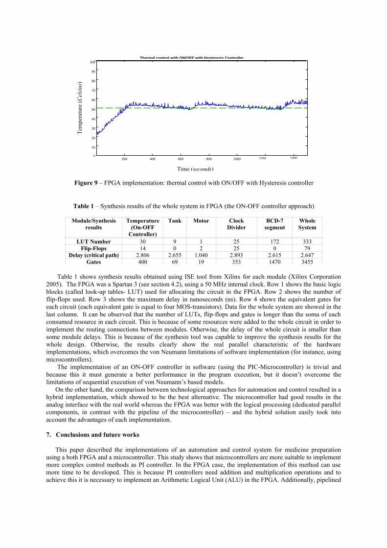
Table 1 – Synthesis results of the whole system in FPGA (the ON-OFF controller approach)
Module/Synthesisresults
Temperature(On-OFF
Controller)
Tank Motor Clock Divider
BCD-7 segment
Whole System
LUT Number 30 9 1 25 172 333Flip-Flops 14 0 2 25 0 79
Delay (critical path) 2.806 2.655 1.040 2.893 2.615 2.647Gates 400 69 19 353 1470 3455
Table 1 shows synthesis results obtained using ISE tool from Xilinx for each module (Xilinx Corporation 2005). The FPGA was a Spartan 3 (see section 4.2), using a 50 MHz internal clock. Row 1 shows the basic logic blocks (called look-up tables- LUT) used for allocating the circuit in the FPGA. Row 2 shows the number of flip-flops used. Row 3 shows the maximum delay in nanoseconds (ns). Row 4 shows the equivalent gates for each circuit (each equivalent gate is equal to four MOS-transistors). Data for the whole system are showed in the last column. It can be observed that the number of LUTs, flip-flops and gates is longer than the soma of each consumed resource in each circuit. This is because of some resources were added to the whole circuit in order to implement the routing connections between modules. Otherwise, the delay of the whole circuit is smaller than some module delays. This is because of the synthesis tool was capable to improve the synthesis results for the whole design. Otherwise, the results clearly show the real parallel characteristic of the hardware implementations, which overcomes the von Neumann limitations of software implementation (for instance, using microcontrollers).
The implementation of an ON-OFF controller in software (using the PIC-Microcontroller) is trivial and because this it must generate a better performance in the program execution, but it doesn’t overcome the limitations of sequential execution of von Neumann’s based models.
On the other hand, the comparison between technological approaches for automation and control resulted in a hybrid implementation, which showed to be the best alternative. The microcontroller had good results in the analog interface with the real world whereas the FPGA was better with the logical processing (dedicated parallel components, in contrast with the pipeline of the microcontroller) – and the hybrid solution easily took into account the advantages of each implementation.
7. Conclusions and future works
This paper described the implementations of an automation and control system for medicine preparation using a both FPGA and a microcontroller. This study shows that microcontrollers are more suitable to implement more complex control methods as PI controller. In the FPGA case, the implementation of this method can use more time to be developed. This is because PI controllers need addition and multiplication operations and to achieve this it is necessary to implement an Arithmetic Logical Unit (ALU) in the FPGA. Additionally, pipelined
200 400 600 800 1000 1200 14000
10
20
30
40
50
60
70
80
90
100Thermal control with ON/OFF with Hysteresis Controller
Time (seconds)
Tem
pera
ture
(Cel
sius
)
Figure 9 – FPGA implementation: thermal control with ON/OFF with Hysteresis controller

data-path architecture must be implemented in order to execute the classical equations of digital control techniques.
On the other hand, the results obtained using ON-OFF with hysteresis technique (using FPGAs), were very similar to the ones obtained using a more sophisticated method such as PI. The trade-off between performance, flexibility and suitability to implement user interfaces can be obtained using a hardware-software co-design approach as was discussed in sections 5 and 6.
In this work the implementation of the automation module allowed the direct comparison between the microcontroller and the FPGA, given that the same module structure was implemented in both approaches. In this case the FPGA implementation allowed the exploration of all parallelism implicit in this technology.
Given that FPGA-based boards are becoming cheaper and cheaper, their use in automation and control applications is increasing (Muller-Glaser, et al, 2004). Future works consist of developing techniques for quick-prototyping of PI/PID controllers in FPGAs. In this case the implementation of all type of controllers would be possible in FPGAs and the microcontroller would be used only to implement supervisory systems or to take advantage of some special hardware resources and flexibility of procedural programming.
8. ReferencesAltera® Corporation, 2005, “Quartus II User Guide”, available at http://www.altera.com, accessed in June 2005. Becker, J. and Hartenstein , R. W., 2003, “Configware and Morphware going mainstream”, Journal of Systems Architecture, Vol. 49, pp. 127-142.Digilent Inc., 2005, ”Spartan 3 board”, available at http:// www.digilentinc.com, accessed in June 2005.Kumar S., 1996, “The co-design of embedded systems: a unified hardware software representation”, Ed. Kluwer Academic Publishers, 1996.Math Works Inc., 2005, “Home-Page of Math Works”, available at http:// www.mathworks.com, accessed in June 2005.Microchip Inc., 2005, “Home-Page of Microchip”, available at http:// www.microchip.com, accessed in June 2005. Muller-Glaser, K. D., Frick, G., Sax, E. and Kuhl, M., 2004, “Mutiparadigm Modeling in Embedded System Design”, IEEE Transaction on Control, Systems Technology, vol. 12, No. 2.Phillips, C. L. and Nagle, H. T., 1995, “Digital Control System Analysis and Design”, Ed. Prentice Hall, third edition. Xilinx Corporation 2005, “ISE User Guide”, available at http://www.xlinx.com, accessed in June 2005. 9. Responsibility notice
The authors are the only responsible for the printed material included in this paper.