A COMPARISON OF SCANNING TECHNOLOGIES FOR ARCHIVAL MOTION PICTURE FILM
27
HAUSARBEIT DIGITALISIERUNG VON KULTURGUT: A COMPARISON OF SCANNING TECHNOLOGIES FOR ARCHIVAL MOTION PICTURE FILM Zu Händen: Dr. Gerard Maier Landesarchiv Baden-Württemberg Michelle S. Carlos Master-Studiengang »Konservierung Neuer Medien und Digitaler Information« 02. August, 2013
-
Upload
abk-stuttgart -
Category
Documents
-
view
1 -
download
0
Transcript of A COMPARISON OF SCANNING TECHNOLOGIES FOR ARCHIVAL MOTION PICTURE FILM

HAUSARBEIT DIGITALISIERUNG VON KULTURGUT:
A COMPARISON OF SCANNING TECHNOLOGIES FOR ARCHIVAL MOTION PICTURE FILM
Zu Händen:
Dr. Gerard Maier
Landesarchiv Baden-Württemberg
Michelle S. Carlos
Master-Studiengang »Konservierung Neuer Medien und Digitaler Information«
02. August, 2013
2
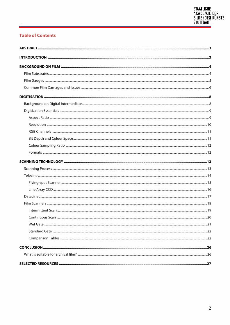
Table of Contents
ABSTRACT .......................................................................................................................................................................... 3
INTRODUCTION ................................................................................................................................................................ 3
BACKGROUND ON FILM ................................................................................................................................................... 4
Film Substrates ....................................................................................................................................................................................................... 4
Film Gauges ............................................................................................................................................................................................................. 5
Common Film Damages and Issues ................................................................................................................................................................ 6
DIGITISATION .................................................................................................................................................................... 8
Background on Digital Intermediate .............................................................................................................................................................. 8
Digitization Essentials .......................................................................................................................................................................................... 9
Aspect Ratio ...................................................................................................................................................................................................... 9
Resolution ........................................................................................................................................................................................................ 10
RGB Channels ................................................................................................................................................................................................. 11
Bit Depth and Colour Space ....................................................................................................................................................................... 11
Colour Sampling Ratio ................................................................................................................................................................................ 12
Formats ............................................................................................................................................................................................................. 12
SCANNING TECHNOLOGY .............................................................................................................................................. 13
Scanning Process ................................................................................................................................................................................................. 13
Telecine ................................................................................................................................................................................................................... 14
Flying-spot Scanner ...................................................................................................................................................................................... 15
Line Array CCD ................................................................................................................................................................................................ 16
Datacine .................................................................................................................................................................................................................. 17
Film Scanners ........................................................................................................................................................................................................ 18
Intermittent Scan ........................................................................................................................................................................................... 19
Continuous Scan ............................................................................................................................................................................................ 20
Wet Gate ............................................................................................................................................................................................................ 21
Standard Gate ................................................................................................................................................................................................. 22
Comparison Tables ........................................................................................................................................................................................ 22
CONCLUSION ................................................................................................................................................................... 26
What is suitable for archival film? ................................................................................................................................................................. 26
SELECTED RESOURCES ................................................................................................................................................... 27
3
1. ABSTRACT
In the past couple of decades technology in the scanning of film has developed rapidly and opened doors to the
digitisation of archival films. The century old motion picture films can now be resurrected in their former glory but
with this wide array of options available, users are in constant inevitable dilemma: which scanner technology to
use? What is a telecine and a film scanner?
This paper will present the different scanning technologies, its benefits and limitations as a crucial process in the
digitisation of motion picture film. Some history on the development of the technology and essential technical
specifications will also be explained to aid in selecting the best technology in archival film scanning as well as some
film basics to fully understand the medium used for this process.
2. INTRODUCTION
Scanning is an important step in the digitisation of archival film—it is the first step that allows the media to be
ingested into the digitisation workflow. It is the process of capturing the image using a device, which converts the
images into video signals as in the case of telecines and into data with the use of film scanners in high quality and
high resolutions for use in various digital processes such as restoration, colour correction, remastering or simply
duplication.
As with any digitisation projects, the purpose of scanning is to enable access of the media in digital form with
preservation as a natural by-product. With archives all over the world racing against time to save their film
collections, it’s also a race among developers in the post-production industry to come up with the best solution in
archiving, digitizing and restoring motion picture films. There is a wildfire movement among film archives to get
their precious film collections digitized, provided there is appropriated funding, of course. This is enforced by the
development of new products that will meet every requirement in preserving film in digital formats.
Naturally many questions arise in the proper scanning of a valuable and fragile cultural medium such as film. A
basic question will be, which hardware to use? How does this hardware handle the film? How do we go about with
the process? And finally, how much is it?
Protection of the original object is always a concern among archivists and conservators. Therefore minimum
requirements for scanning are often set to ensure the safety of the original object and quality of the digitized copy.
In 1999, while advocating a “preservation mindset”, the Colorado Digitization Program suggested general
guidelines for scanning at a minimum level for their digitisation projects. These guidelines may also be true and
applicable even up to now:
• Scanning at the highest resolution appropriate to the informational content of the originals
• Scanning at an appropriate level of quality to avoid rescanning and re-handling of the originals in the
future—scan once
• Creating and storing a master image file that can be used to produce derivative image files and serve a

4
variety of current and future user needs
• Using system components that are nonproprietary
• Using image file formats and compression techniques that conform to industry standards
• Creating backup copies of all files on a stable medium
• Creating meaningful metadata for image files or collections
• Storing media in an appropriate environment
• Monitoring and recopying data as necessary
• Outlining a migration strategy for transferring data across generations of technology
• Anticipating and planning for future technological developments
Digitisation is expensive and always dependent on many decision factors. More than 20 years ago, archives and
producers alike were still struggling on which technology would meet their needs for the digitisation and archiving
of their precious film collections. In this day and age, that concern is already blurring as more and more options are
becoming available in the market. Even more facilities are offering services that will best suit such requirements
and deliver the best possible results. The only question now is which system to use and if it is worth the cost.
3. BACKGROUND ON FILM
3.1. Film Substrates
3.1.1. Nitrate
For the growing motion picture industry, the increase in the usage of plastic based film took a leap only after
1889. This type of material was used in still cameras in the form of roll film or sheet film. At that time the only
available material was cellulose nitrate, which was already used in photographic processes as in collodion
binders. The chemical properties of this product are similar to that of guncotton. Although extremely
flammable, it is not explosive because it is not heavily nitrated. It does however constitute a fire hazard in large
quantities. Once ignited it will continue to burn and therefore cannot be extinguished until it burned itself out.
Because of its chemical instability and high combustibility that caused many disastrous fire incidents, the
usage of cellulose nitrate was banned and eventually the manufacture was stopped in the 1950s. Particularly
on motion picture film reels, strict prohibitions for the usage, transport and storage were implemented.
Nitrate films are also known to self-destruct even in proper storage conditions. The decomposition is inevitable
and irreversible.
3.1.2. Acetate
Because it does not have combustible properties, “safety film” or cellulose triacetate, which was acetate-based
had phased-out cellulose nitrates and was commonly used in 1951. Most 16mm and almost all 8mm films used
for home movies and amateur industrial or educational filmmaking are acetate. Kodak was the first company
to introduce celluloid acetate film in 1925.

5
Acetate films are always entwined with its disease, “vinegar syndrome.” This has the characteristic odor of
vinegar due to the off-gassing acidic fumes as the material decomposes. This decomposition happens at a very
rapid state, which can easily spread and affect other acetate films. This material also becomes brittle and
shrinks over time.
3.1.3. Polyester
Polyester is a much stronger film base and cannot be torn unlike acetate. It has far better chemical stability
than its predecessors. Its strength has also been taken as a disadvantage because of its resistance to breakage.
Splicing with cement is impossible and it also has the tendency to break the film equipment should a jam or
extra tension occur1, therefore it was not used as the original negative for shooting movies. Also known as
Mylar or Estar, it was introduced in the 1950s and has been the preferred film base until now. It is humidity and
heat tolerant and it is estimated that newer films are expected to last up to 500 years.
3.2. Film Gauges
The most common film gauge standards (35mm, 16mm, 8mm and Super 8mm)
3.2.1. 35 mm
Using the film stock that George Eastman supplied, William Dickinson with Thomas Edison first used the 35
mm width film in 1892 for Edison’s Kinetoscope, the predecessor of film projectors. In 1909 the 35 mm with 4
perforations became the international standard for film gauges and has since remained the dominant format.
Despite its relative high cost, 35 mm was still preferred because of the quality of the image captured.
Advancing technology coupled with declining prices of digital movie cameras is slowly phasing out the use of
film.
1 Wikipedia 2 The measurements given here have been taken from the ASA and ISO Standards. Restoration of Motion Picture Film, 2000 3 National Television Systems Committee, used in the US, South America and parts of Asia 4 Phase Alternating Line, used in Europe and parts of Asia 5 Sequentiel Couleur avec Mémoire, used in France, Russia and parts of Africa

6
3.2.2. 16 mm
16 mm film became popular in the 1950s for amateur filmmakers because of its cheaper cost and chemical
stability, which makes it perfect for home movie making. Eastman Kodak introduced this format in 1923 to
reach a broader commercial market. It was also meant to replace nitrate films. It was extensively used in
television broadcasting until it was eventually replaced by video. Super 16 is still used until today in some low
cost production.
3.2.3. 8 mm
As the 16 mm grew into a professional film format, Kodak launched the 8 mm or Standard 8 in 1933 for use in
home movies and was quickly adopted by the amateur filmmaker. The film has an 8 mm wide picture area with
sprocket holes on one side as it was manufactured from the 16 mm film stock. It has other variants: Super 8
(1965, Kodak), Single 8 (1965, Fuji), Straight 8 (Kodak, Agfa and Svema as reversal film) and UltraPan 8 (2011 for
modified Bolex cameras).
3.2.4. Uncommon gauges
The 70 mm film gauge with 6 magnetic soundtracks has become a standard format not until the 1960s. From
these negatives smaller prints for movies shot in anamorphic 35 mm were possible to make.
Middle pef (left) and Lumier perf (right)
There are many other uncommon film gauges that were produced during the age of film—from 8 mm to 86
mm and with variations in sprocket hole shapes and placements, which did not follow the dictated norm from
the conventions held in 1934 and 1936. Some manufacturers customized the perforations as requested by
clients or simply used in experiments. As a result, sprocket holes can be found in the middle, irregularly on the
sides or none at all. Films with 4 Super 8 mm images in one 35 mm gauge were also found in collections. These
non-standard formats have been an enigma to archivists, conservators and likewise to hardware
manufacturers.
3.3. Common Film Damages and Issues
3.3.1. Dust
Dirt and dust on the film surface is one of the most common problems of the physical film medium regardless

7
of age. This becomes even more of a problem once enlarged; therefore film handling should be done in a dust-
free environment.
Even though more and more high-end systems are dedicated to the digital removal of dust, it can still be quite
laborious and expensive. Hours are spent only for digital dust busting.
3.3.2. Scratch
Scratches are mechanical damages on the film emulsion due to mishandling. For a vertical scratch to be
repaired digitally, algorithms must rely on the pixels from both sides of the scratch to conceal or re-create the
missing information. This can be achieved automatically or semi-automatically with good results. However
depending on the image background and the sophistication of the tool the result sometimes can be
substandard. Alternative analog solutions were adapted from older techniques to remove the scratches such
as wet gate scanning.
Scratch removal using (Digital Vision Optics) DVO Scratch tool
3.3.3. Damaged Perforations
Old and brittle films are prone to mechanical damages. Torn perforations due to mishandling and tensions in
the film transport are not uncommon occurrences. There are ways to physically mend these tears but may not
guarantee its durability. Some conservators would rather leave the damaged film as it is and proceed with the
scanning provided that the machine is capable of non-contact or sprocketless film transport.
3.3.4. Grain
8
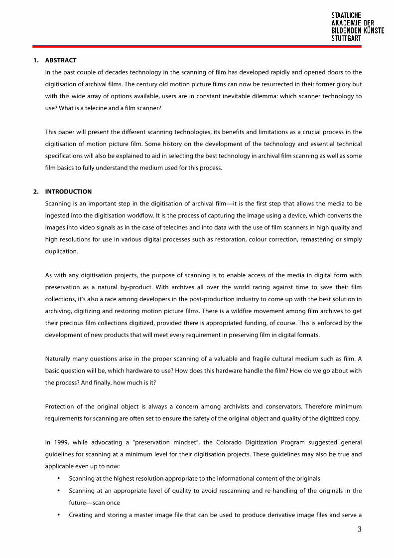
Film grain or granularity is one characteristic of film that is always debated upon—whether it should be
retained, removed or tweaked digitally. The grain on film is formed from the micro particles of metallic silver or
dye clouds developed from silver halides that have been exposed, which then results to an optical effect that
when enlarged, depending on the film stock can become quite noticeable.
Grain removal using (Digital Vision Optics) DVO Grain tool
There are various high-end image-processing software and hardware specifically designed to automatically
and semi-automatically manipulate this optical texture or noise.
3.3.5. Shrunken Film and Instability
Shrunken films that can no longer be cured, buckle when scanned and produce warped images, which cause
instability during playback of the sequential frames. Unsteady pictures can also originate from film scanning or
camera shakes during capture. Stabilizing algorithms are designed to correct this. Some film scanners will have
this feature mechanically or algorithmically built-in or as an optional tool in many image-processing programs.
4. DIGITISATION
4.1. Background on Digital Intermediate
Digital Intermediate or DI, in general is a process that describes the digitisation of the film medium from scanning
to recording back to film. The process also includes digitally manipulating the colour and other characteristics of
the image for correction and enhancement and, in some cases, with the addition of computer generated visual
effects. The final stage is where the manipulated, cleaned and composited data is digitally mastered for various
distribution formats.
The process began in the 1990s in conjunction to the series of technological developments and then rapidly
caught on in the mid-2000s as the demand to produce high-quality scanning and colour adjustments increased for
digital cinemas.

9
A typical digital intermediate workflow would be:
Original source à
(Film)
Scanning à SAN Storage
ß Digital Image Processing Delivery to multiple output
formats
Film, DVD, BD, DCP ß Color Correction
ß Digital Mastering à
4.2. Digitisation Essentials
Digitisation project requirements normally dictate the image quality. With respect to the film medium, the size of
the digital image file limits the quality and depends on the size and quality of the original and the following
essential image-capture elements:
4.2.1. Aspect Ratio
Aspect ratio is the area of the image on the film. It is defined by the measurement of the width in relation to
the height of the frame. The filmed area is almost always larger than the image screened to avoid showing the
unwanted edges, which is normally done by cropping or using letterboxes or pillarboxes as masks. As a
response to the growing popularity of the television, movie studios then incorporated several methods to
have that wide screen viewing experience such as squishing the image using an anamorphic lens
(Cinemascope) or flipping the film sideways and shooting the image horizontally (Vistavision) and even
creating a bigger film gauge, the 70 mm. The table2 and diagram below demonstrates the many aspect ratios
that came into being throughout the history of filmmaking.
FORMAT AND NOMINAL ASPECT RATIO CAMERA SCREENING
Surface area of image filmed (mm) Surface area of image screened (mm) Aspect ratio: 1
35 mm
Silent 1,33 18,00/24,00 17,25/23,00 1,33
Normal (Academy) 1,37 16,03/22,05 15,25/20,96 1,37
35 mm (wide screen)
1,85** (*)/21,95 11,33/20,96 1,85
1,85*** (*)/22,05 11,33/21,11 1,86
Vistavision 1,75 22,10/37,52 21,31/37,29 1,75
Cinerama 2,71 - 27,64/75,06 2,71
Cinemascope ** 2,55 18,67/23,80 18,16/23,16 2,55
‘Scope’ *** 2,35 18,60/21,95 18,21/21,29 2,34
Technirama 2,34 23,80/37,15 18,16/21,31 2,34
Techniscope 2,34 9,34/22,10 18,16/21,31 2,34
16 mm
1,33** 7,49/10,26 7,21/9,65 1,33
S16 mm 1,66 7,42/12,52 - -
70 mm
65 mm *** 2,20 23,00/52,50 - -
70 mm ** 2,20 23,00/52,60 22,00/48,60 2,21
2 The measurements given here have been taken from the ASA and ISO Standards. Restoration of Motion Picture Film, 2000

10
70 mm *** 2,20 23,00/52,50 22,10/48,59 2,20
*Dimension never standardized for negative. ** ASA *** ISO
The 16:9 or 1.78:1 is a SMPTE “compromise” aspect ratio to integrate both 4:3 and 2.35 in one format. This
became the default aspect ratio in all High Definition digital videos.
4.2.2. Resolution
Standard Definition (SD) refers to the broadcast video standard format with aspect ratio 4:3, which also traces
its origin to the first silent film 35 mm format with the same aspect ratio. It has the dimensions of 720 x 486 for
NTSC3 and 768 x 576 for PAL4 and SECAM5 systems6.
A much higher resolution than SD is High Definition (HD), which is used in all digital videos and HDTVs with
various formats 720p (1280 x 720p) or 1080i or 1080p (1080 x1920). The letter “i” stands for interlaced and the
“p” is for progressive scan.
Development in digital camera technology and increase in storage capacities enabled much higher resolutions
to be generated and used. This changed the way motion pictures are projected on cinemas, now aptly called
Digital Cinema, and TV programs are broadcasted on digital television. The pixel resolution of 2K (2048x1080)
is now becoming the norm both in digital cinematography and digital television. Ultra High Definition pixel
resolutions 4K (4096x2160) and 8K (7680x4320) are also finding its way to the commercial scene. It is only
expected that in a few years bigger resolutions from 6K up to 16K will be well adopted.
Even before the digital television revolution, the 2K and 4K resolutions already exist in post-production, as
professional equipment particularly scanners are capable of reproducing these resolutions. For better image
3 National Television Systems Committee, used in the US, South America and parts of Asia 4 Phase Alternating Line, used in Europe and parts of Asia 5 Sequentiel Couleur avec Mémoire, used in France, Russia and parts of Africa 6 Colour systems adopted in analog video and television broadcasting systems
11
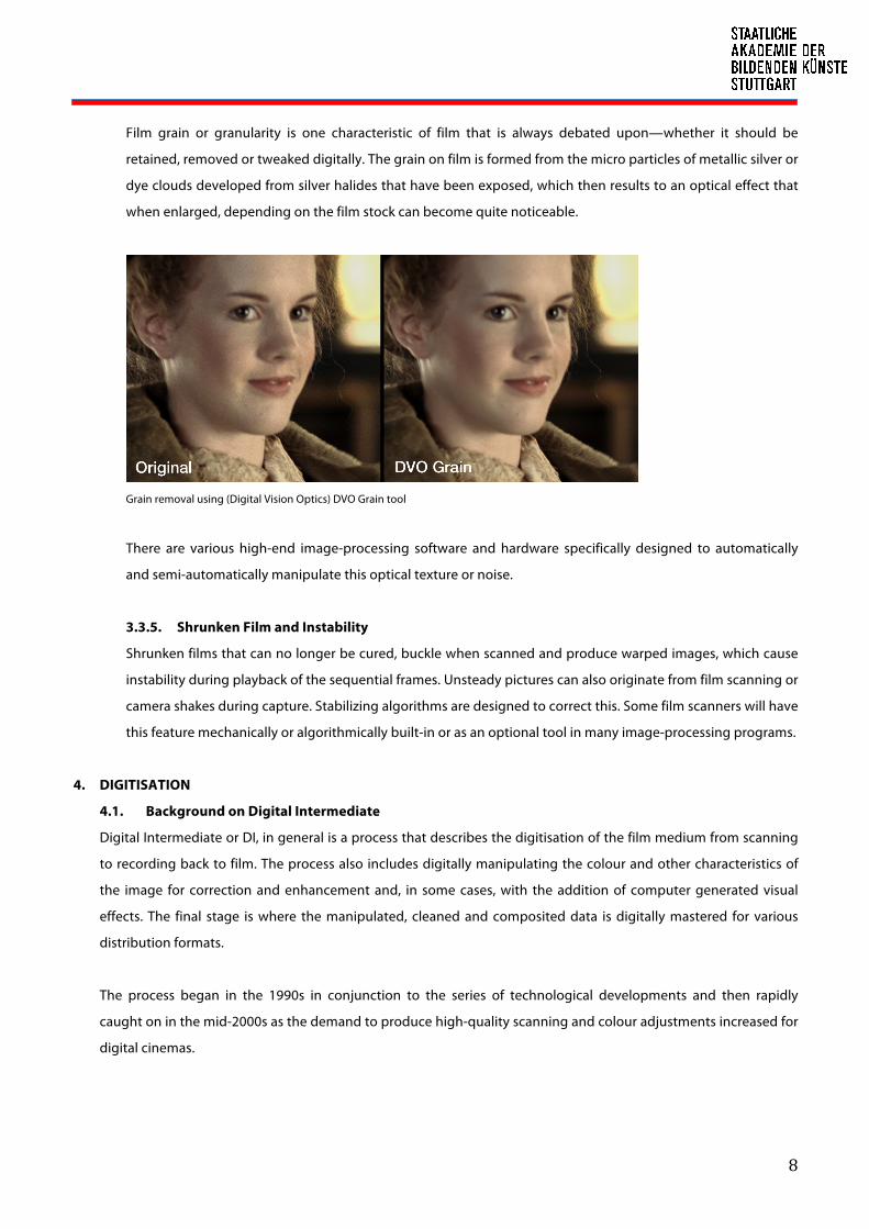
quality, films are normally scanned for example, in 2K and then downsized depending on the final delivery
output. However film’s real pixel resolution is a much-debated topic. After conducting some experiments,
Eastman Kodak recommends a 4000 horizontal pixel resolution for 35 mm Academy color negative film.7
Archivists also generally agree that 4k scanning of 35mm is more than adequate for archival purposes.
4.2.3. RGB Channels
RGB Channels is a group of three primary color channels, red, green and blue, which generally compose digital
images. These represent a single pixel on an RGB device such as a computer monitor or a digital camera. Basically
all the scanning works will be performed in RGB mode as scanners work in RGB mode.
4.2.4. Bit Depth and Colour Space
Bit depth determines the amount of memory per image pixel and colour channel, and thus the accuracy with
which the colour information is stored. The greater the bit depth, the greater is the number of gray scale or
colour tones that can be represented and the larger the file size. Most digital video formats use a minimum 8-bits
per colour channel, still images use 16-bit, while videos use 8 or 10 bits per RGB channel.
Scanning specifications will always combine the bit depth and colour space values (i.e. 10-bit log, 16-bit linear).
The log or “logarithmic” colour space is used in certain film-specific file formats because this provides better
response in the darker spectrum; each gradation in the gray scale will have the same values. Whereas a linear
colour space will have values incremented in certain ways. This means that the darker portions will have very
course increments and the highs will have very fine increments—simply saying that more details and finer
gradation is seen in a logarithmic image than in a linear image. Because the human eye is a lot more sensitive to
7 Restoration of Motion Picture Film, page 221

12
luminance than to chrominance and because analog film has a bigger density range, an image rendered in log
space is ideal in scanning.
4.2.5. Colour Sample Ratio
Colour sample ratio pertains to the ratio of luminance (Y’) samples in reference to each colour difference sample
(Cb and Cr)8. 4:4:4, which is used in most high-end scanners, means each RGB channel, or Y’, Cb and Cr channel, is
sampled at the same rate, therefore maximum colour detail is captured. Another sample ratio commonly
encountered in professional video formats are 4:2:2, wherein for every four pixels of Y’, there are only two Cb
samples and two Cr samples. Other sample ratios are 4:1:1 or 4:2:0.
4.3. Supported Formats
4.3.1. DPX (Digital Moving-Picture Exchange or Digital Picture Exchange)
A by-product of Eastman Kodak’s Cineon format from their proprietary telecine of the same name, Digital
Moving-Picture Exchange (DPX) has become an open-source industry standard moving image digital format
used in many digital intermediate and visual effects work. DPX is developed by the Society of Motion Picture
and Television Engineers (SMPTE), a member of the American National Standards Institute (ANSI) and is used
for motion picture scanning since 2004. It is well supported in several film scanners and is also an output
format in some digital cameras.
By design DPX is not playable, which means the files are rendered as single sequential raster still images, and
does not meet the requirements of broadcasters because it does not contain sound data. Professional
equipment is needed to assemble the frames for playback. The file format however is capable in representing
the density of each colour channel of a scanned negative film in an uncompressed "logarithmic" image where
the gamma of the original camera negative is preserved as taken by a film scanner. DPX provides, in fact, a
great deal of flexibility in storing colour information, colour spaces and colour planes for exchange between
production facilities.9
The DPX SMPTE Specification allow for a wide variety of metadata to further clarify information stored (and
storable) within each file. In addition to picture data DPX files contain three sections: (1) generic file
information including data format, (2) motion picture and television industry specific information such as film
perforation edge number or video timecode information, and (3) user-defined information which may include
ASCII data.10
4.3.2. TIFF (Tagged Image File Format)
TIFF (Tagged Image File Format) is a standard non-proprietary archival format initially developed by Aldus
Corporation in 1986 and now under the control of Adobe Systems since 2009. It is a file format for lossless
8 Cb (blue-difference) Cr (red-difference) 9 Wikipedia 10 Digital Moving Picture Exchange (DPX), Version 2.0, Sustainability of Digital Formats Planning for Library of Congress Collections

13
storage of image files. It holds all the spatial (resolution), color, tone, metadata and preservation information
required to create a digital master of the original.11 It is therefore particularly suitable as the basis for digital
image processing and is compatible to most programs.
The format is also adopted by some motion picture film scanner systems because of its ability to store color
information as raw data. Similar to DPX, the images are individually rendered. Although self-documenting, TIFF
does not contain motion picture and industry specific information. Nevertheless, it is a well-recommended
format for digital preservation.
4.3.3. Cineon
Eastman Kodak designed the film scanner Cineon and was released in 1993. The proprietary format used in the
system that bears the same name. Although the system is no longer in production, the Cineon file format (.cin)
is still widely used and adopted by many visual effects and colour grading systems. It was specifically designed
to represent scanned film images and has some characteristics, which make it different from TIFF. The Cineon
data is rendered in log format and each RGB channel is 10 bits that provides 1024 levels of color as opposed to
256 levels of color in 8 bits per pixel color space. It is similar to the ANSI/SMPTE DPX file format, which was a
derivative format of Cineon. Both have variable header lengths and the same format for the image data.
However, the format of the headers is different. The DPX file headers are flexible, allowing variable image
headers to accommodate the needs of different industries. The Cineon file format is more directed to digital
film.12
Cineon was used in the restoration of Disney’s Snow White and the Seven Dwarfs, which became the first film to
be entirely digitally scanned, manipulated and recorded back to film—a process that will later be known as
Digital Intermediate. The film was scanned in 4K resolution and 10-bit color depth.
5. SCANNING TECHNOLOGY
5.1. Scanning Process
Scanning is a process of capturing images whether by optical, electronic or digital methods. The process of
scanning motion picture film can either be electronic where the images are converted into video signals or digital
where the image transforms into data. The devices used to capture film images are the telecine, film scanner plus a
hybrid of both machines called the datacine.
To begin scanning, the operator, usually the colourist loads the already exposed and developed film print
(negative or positive) onto the film spool and plate and then laces it through the series of rollers, capstans, the film
gate block and finally to the receiving reel. The film gate will correspond to the print’s gauge and perforations. As
the film is run through at a pre-programed speed, this will then be exposed using a light source (CRT13, xenon,
11 http://cool.conservation-us.org/coolaic/sg/emg/library/pdf/vitale/2007-07-vitale-digital_image_file_formats.pdf 12 http://www.cineon.com/ff_draft.php 13 Cathode-ray Tube

14
halogen or LED) and then captured ‘per line’ or ‘frame-by-frame’ by a digital camera with charge-coupled device
(CCD) or a Contact Image Sensor (CIS) as the image sensor within seconds. The scanner is either directly controlled
by a local control panel or the integrated scanner software with a PC interface or remotely controlled by another
system, usually a colour grading system. The captured image, which is an uncompressed RGB image can then be
stored on a tape as with telecines or as data in a centralised storage as with film scanners and can be accessed by
the next user in the DI workflow.
DFT Scanity film transport
5.2. Telecine
Because of the popularity of the television in the 1950s there was an immediate need to access the films made for
the cinema and recorded television programming for broadcasting. Thus a process as well as a machine was
invented to achieve this goal. Telecine is the process of transferring motion picture film into electronic signals,
which then can be viewed with standard video equipment, such as televisions, video cassette decks or computers.
The term “telecine” is a combination of the words “television” and “cinema.” Problems arose pertaining to the
frame rate differences between film (24 frames/s) and television (30 or 25 frames/s), which resulted to “flickering.”
This was resolved by turning every second frame of the film into three fields of video for a smoother display.
However, the resulting images were still not suitable for recording back into film for theatrical distribution and
even for archiving, hence the process remained for the initial part only in broadcasting and not in film post-
production. Migration of films for archiving would then have to wait.
Telecine is also the video machine used in this process. Since this device was developed before the digital boom,
this has no ‘data’ capability. Basically, most telecines function with a light that is projected through the film onto a
pick-up device that translates the image into an electronic video signal, which will then be processed and altered
using a colour correction system. Its rudimentary features are:
• Real time capability (24/25/30 frames per second)
• Mostly standard definition video (625/525) outputs
• Some have high definition video (e.g. 1080) outputs
• Needs a remote control desk (daVinci, Pandora, Tangent, ARCAS, AMIGO)
• Will normally have internal colour correction (Primary and Secondary)

15
• May have internal image manipulation (Zooms, Pans etc.)
• Usually coupled with a downstream colour corrector (daVinci or Pandora)
Examples of telecines are: Cintel: MKIII, URSA and ADS1/2, BTS/Philips: FDL/Quadra, Sony: Vialta
BTS-Philips Quadra (left) and Thomson-Philips Spirit (right) telecine
5.2.1. Flying-spot Scanner
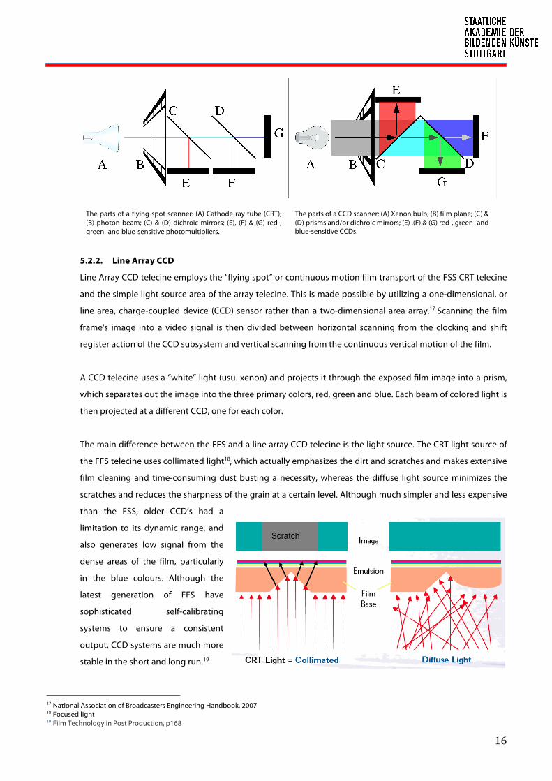
Invented in 1930 by Manfred von Ardenne using the same technology based from the primitive live action
studio cameras in the early beginnings of television in the twenties, the flying-spot scanner (FSS) is a telecine
that uses a monochrome CRT as the light source. As the electron beam is drawn across the face of the CRT, it
creates a scan that has the correct number of lines and aspect ratio for the format of the signal. The image of
this scan is focused with a lens onto the film frame. Its light passes through the image being scanned and is
converted to a proportional electrical signal by Photomultiplier tube(s), one for each colour (Red, Green, Blue)
that detect the variations in intensity of the beam spot as it scans across the film, and are converted to
proportional electrical signals, on for each of the colour channels.14
Colour analysis is also done after scanning avoiding registration errors, which can be prevalent with systems
that separate colours before scanning. Another plus point of the FSS is that both its transport and image-
sensing sections are much simpler than those of the area array CCD15. It is also quite flexible in adapting to
different film formats. On the other hand, the CRT light source is considered to be a much more complex
subsystem where the light spot must be very bright for good signal-to-noise yet remain tightly focused16 to
produce good resolution. The geometry of the scan for each patch can be quite difficult. The CRT also has a
short operational life; each replacement requires precise realignment of the telecine scanning section.
Nowadays this type of light source is considered to be obsolete.
14 http://www.digitalmonalisa.com/newsite/tecnical.pdf 15 An area array telecine is a colour television camera that looks at film frames one at a time. It has the similar intermittent motion of film projectors. 16 National Association of Broadcasters Engineering Handbook, 2007
16
5.2.2. Line Array CCD
Line Array CCD telecine employs the “flying spot” or continuous motion film transport of the FSS CRT telecine
and the simple light source area of the array telecine. This is made possible by utilizing a one-dimensional, or
line area, charge-coupled device (CCD) sensor rather than a two-dimensional area array.17 Scanning the film
frame's image into a video signal is then divided between horizontal scanning from the clocking and shift
register action of the CCD subsystem and vertical scanning from the continuous vertical motion of the film.
A CCD telecine uses a “white” light (usu. xenon) and projects it through the exposed film image into a prism,
which separates out the image into the three primary colors, red, green and blue. Each beam of colored light is
then projected at a different CCD, one for each color.
The main difference between the FFS and a line array CCD telecine is the light source. The CRT light source of
the FFS telecine uses collimated light18, which actually emphasizes the dirt and scratches and makes extensive
film cleaning and time-consuming dust busting a necessity, whereas the diffuse light source minimizes the
scratches and reduces the sharpness of the grain at a certain level. Although much simpler and less expensive
than the FSS, older CCD’s had a
limitation to its dynamic range, and
also generates low signal from the
dense areas of the film, particularly
in the blue colours. Although the
latest generation of FFS have
sophisticated self-calibrating
systems to ensure a consistent
output, CCD systems are much more
stable in the short and long run.19
17 National Association of Broadcasters Engineering Handbook, 2007 18 Focused light 19 Film Technology in Post Production, p168
The parts of a flying-spot scanner: (A) Cathode-ray tube (CRT); (B) photon beam; (C) & (D) dichroic mirrors; (E), (F) & (G) red-, green- and blue-sensitive photomultipliers.
The parts of a CCD scanner: (A) Xenon bulb; (B) film plane; (C) & (D) prisms and/or dichroic mirrors; (E) ,(F) & (G) red-, green- and blue-sensitive CCDs.
17
5.3. Datacine
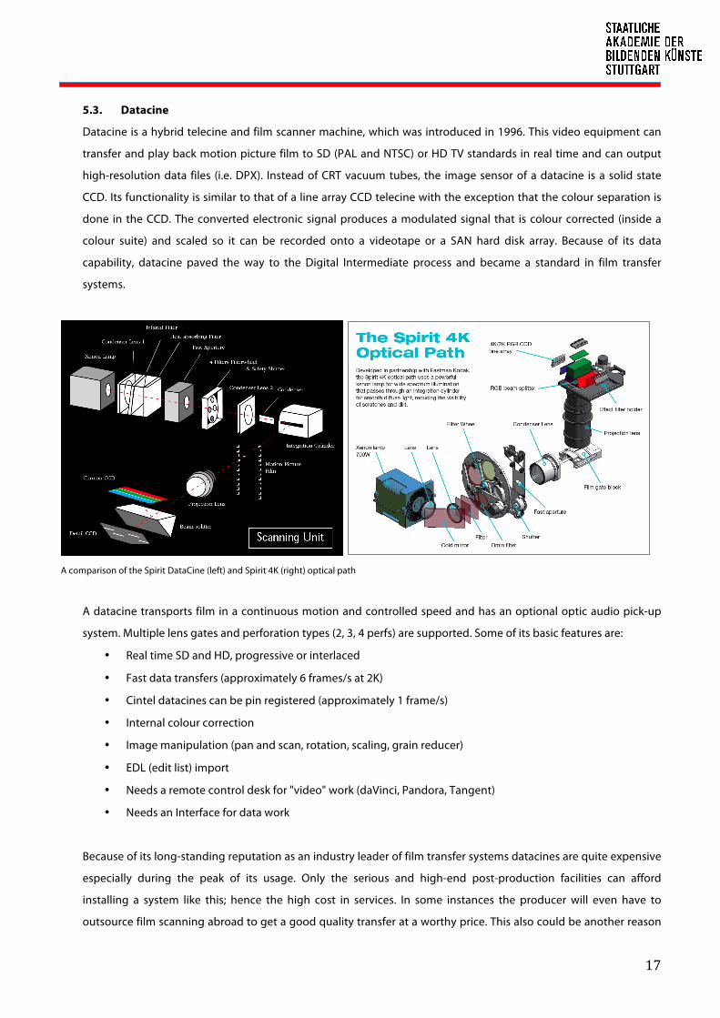
Datacine is a hybrid telecine and film scanner machine, which was introduced in 1996. This video equipment can
transfer and play back motion picture film to SD (PAL and NTSC) or HD TV standards in real time and can output
high-resolution data files (i.e. DPX). Instead of CRT vacuum tubes, the image sensor of a datacine is a solid state
CCD. Its functionality is similar to that of a line array CCD telecine with the exception that the colour separation is
done in the CCD. The converted electronic signal produces a modulated signal that is colour corrected (inside a
colour suite) and scaled so it can be recorded onto a videotape or a SAN hard disk array. Because of its data
capability, datacine paved the way to the Digital Intermediate process and became a standard in film transfer
systems.
A comparison of the Spirit DataCine (left) and Spirit 4K (right) optical path
A datacine transports film in a continuous motion and controlled speed and has an optional optic audio pick-up
system. Multiple lens gates and perforation types (2, 3, 4 perfs) are supported. Some of its basic features are:
• Real time SD and HD, progressive or interlaced
• Fast data transfers (approximately 6 frames/s at 2K)
• Cintel datacines can be pin registered (approximately 1 frame/s)
• Internal colour correction
• Image manipulation (pan and scan, rotation, scaling, grain reducer)
• EDL (edit list) import
• Needs a remote control desk for "video" work (daVinci, Pandora, Tangent)
• Needs an Interface for data work
Because of its long-standing reputation as an industry leader of film transfer systems datacines are quite expensive
especially during the peak of its usage. Only the serious and high-end post-production facilities can afford
installing a system like this; hence the high cost in services. In some instances the producer will even have to
outsource film scanning abroad to get a good quality transfer at a worthy price. This also could be another reason

18
for filmmakers to opt for digital camera shoots rather than using film. Today used datacine and telecine can also be
found in online auction and shopping websites at discounted rates usually from facilities that have refurbished
their systems or closed down.20
Examples of datacines are: Cintel: C-Reality/DSX and Millennium2, Philips/Thomson: Spirit/Spirit2K/Spirit4K,
Thomson: Shadow
5.4. Film Scanner
To differentiate it from the telecine, a motion picture film scanner is a ‘data’ machine, with no ‘video’ capability. The
original film is scanned and the images captured are high-resolution digital intermediate files. It is capable of
scanning a variety of original film stocks (negative, positive and reversal/IP), using multiple interchangeable
gauges from 8 mm to 70 mm with resolutions ranging from 2K, 4K to 8K digital video. Each film frame is scanned as
a still image file with metadata and raw RGB colour information and stored as a sequence using powerful data
storage devices. Basic features include:
• No ‘video’ output
• Data resolution: SD, HD, 2K, 4K etc.
• Not real time but faster scan speed (up to 25 frames/s for 2K)
• Image manipulation (scaling, aspect ratio, letterbox, dust and noise reduction)
• No remote control desk needed but usually requires a PC interface for scanner software
• Should have pin registration or optical registration capability
• EDL (edit list) import and export for batch recording
• Will interface direct to data storage or network
• Colour management (Primaries, Dmin, Dmax)
• Keycode and optical sound decoding
• A Cineon calibrated LOG output
• Optional colour panel control
• Dry gate or wet gate scan
• Customizable gates
• Image stabilizers
• “Perf to perf” scan
Similar to a datacine, the imaging system may either be a CCD or a complementary metal-oxide-semiconductor
(CMOS). A xenon or halogen lamp and until recently, LED is used as light source and the light that is separated into
RGB colour values and then outputted to DPX files through the network for later use.
The advantage of a film scanner is that one step in the DI process is eliminated, which is the conversion of the
scanned video signal into digital. Capture from a video tape deck is no longer necessary making the playback and
20 http://www.usedtelecine.com/

19
access of the data files faster and non-linear. Any workstation (editing, vfx, compositing or digital restoration) that
will be using the files can immediately grab the sequences anytime within the workflow process. Although, there is
still the issue of non-real time capture, which means there will be a waiting period until the whole reel of film is
finished scanning. Colour grading, unlike with a datacine is done after the scanned data are already ingested into
the centralized storage. This however is being resolved through faster scan speeds and data transfer rates.
In the earlier days of telecine and also datacine, transfer in real time speed was a requirement. But in those days a
lot, specifically image quality had to be sacrificed for speed because of the limitations of the real time video
channel. Compared to a film scanner, the images captured from a telecine are noisier and highly unstable. But
there is a reason why the real time speed was given up from the many capabilities of a film scanner; that is to
produce better quality images, which are low in noise and extremely stable.
A lot of research and effort in terms of design were also done to improve the physical make of film scanners. Gone
are the “walk-in refrigerator” types that take up room space and weigh tons. Some film scanners are purposely built
to be compact desktop machines for ease of use and portability especially for onsite projects. This avoids
transporting of delicate and even highly classified film materials from the climate-controlled storage facility.
Examples of film scanners are: Cintel: diTTo, dataMill and Klone, Filmlight: Northlight, Imagica: ImagerXE and HSX,
Arri: Arriscan, Digital Vision: GoldenEye II and III
Cintel diTTo (left) and Digital Vision GoldenEye III (right) film scanner
5.4.1. Intermittent pull-down
Some film scanner systems are intermittent pull-down types, which device an intermittent mechanism by
which the film is scanned, with the film perforations locked down by a pin-registered (sprockets) film gate,
where each frame is captured individually. Each frame takes roughly a second to capture.
20
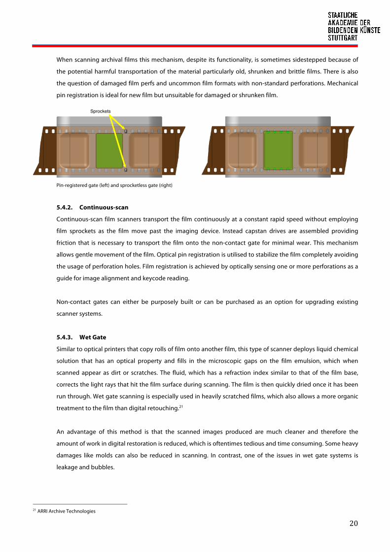
When scanning archival films this mechanism, despite its functionality, is sometimes sidestepped because of
the potential harmful transportation of the material particularly old, shrunken and brittle films. There is also
the question of damaged film perfs and uncommon film formats with non-standard perforations. Mechanical
pin registration is ideal for new film but unsuitable for damaged or shrunken film.
Pin-registered gate (left) and sprocketless gate (right)
5.4.2. Continuous-scan
Continuous-scan film scanners transport the film continuously at a constant rapid speed without employing
film sprockets as the film move past the imaging device. Instead capstan drives are assembled providing
friction that is necessary to transport the film onto the non-contact gate for minimal wear. This mechanism
allows gentle movement of the film. Optical pin registration is utilised to stabilize the film completely avoiding
the usage of perforation holes. Film registration is achieved by optically sensing one or more perforations as a
guide for image alignment and keycode reading.
Non-contact gates can either be purposely built or can be purchased as an option for upgrading existing
scanner systems.
5.4.3. Wet Gate
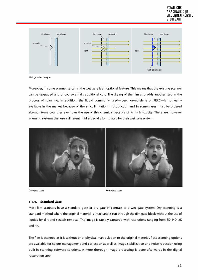
Similar to optical printers that copy rolls of film onto another film, this type of scanner deploys liquid chemical
solution that has an optical property and fills in the microscopic gaps on the film emulsion, which when
scanned appear as dirt or scratches. The fluid, which has a refraction index similar to that of the film base,
corrects the light rays that hit the film surface during scanning. The film is then quickly dried once it has been
run through. Wet gate scanning is especially used in heavily scratched films, which also allows a more organic
treatment to the film than digital retouching.21
An advantage of this method is that the scanned images produced are much cleaner and therefore the
amount of work in digital restoration is reduced, which is oftentimes tedious and time consuming. Some heavy
damages like molds can also be reduced in scanning. In contrast, one of the issues in wet gate systems is
leakage and bubbles.
21 ARRI Archive Technologies
Sprockets
21
Wet gate technique
Moreover, in some scanner systems, the wet gate is an optional feature. This means that the existing scanner
can be upgraded and of course entails additional cost. The drying of the film also adds another step in the
process of scanning. In addition, the liquid commonly used—perchloroethylene or PERC—is not easily
available in the market because of the strict limitation in production and in some cases must be ordered
abroad. Some countries even ban the use of this chemical because of its high toxicity. There are, however
scanning systems that use a different fluid especially formulated for their wet gate system.
Dry gate scan Wet gate scan
5.4.4. Standard Gate
Most film scanners have a standard gate or dry gate in contrast to a wet gate system. Dry scanning is a
standard method where the original material is intact and is run through the film gate block without the use of
liquids for dirt and scratch removal. The image is rapidly captured with resolutions ranging from SD, HD, 2K
and 4K.
The film is scanned as it is without prior physical manipulation to the original material. Post-scanning options
are available for colour management and correction as well as image stabilization and noise reduction using
built-in scanning software solutions. A more thorough image processing is done afterwards in the digital
restoration step.

22
The scanner hardware is normally a single unit system and can even be installed on a tabletop. This makes the
scanner space, production and cost efficient.
ARRIScan Standard Gate (left) ARRIScan Wet Gate (right)—The tiny holes around deploy the liquid.
5.4.5. Comparison Tables
Overview of telecine types
TELECINE
TYPE
Light
Source Image sensor
Film
Formats Resolution
Scanning
Motion Output Models
Flying Spot
Scanner
CRT,
collimated
light
Photomultiplier
tubes 35 mm SD
Real time,
continuous, line
by line
Analog
video
Cintel MK series,
URSA series
Line Array CCD
Xenon or
halogen
diffused
light
CCD 35 mm SD, HD Real time, per
line, per frame
Analog
video
Bosch FDL-60,
Philips-BTS FDL
90/Quadra,
Rank Cintel
ADS-1, Marconi
B3410, Sony
Vialta,

23
Overview of datacine models
Manufacturer22
Cintel DFT DFT DFT Philips-
Thomson Thomson
Model Millenium II 4K Spirit HD Spirit 2K Spirit 4K Shadow Spirit DataCine
Sensor - Linear CCD Linear CCD Linear CCD Multi-linear
CCD CCD
Light source CRT Xenon Xenon Xenon LED Xenon
Resolution HD/2K/4K HD 2K 4K 2K 2K
Scan process N/A continuous continuous continuous continuous continuous
Scan speed ** 15 fps 30 fps
variable 30 fps variable 7.5 fps variable
2-57 fps
variable
4-57 fps
variable
Sprocketless no yes yes yes yes yes
Audio pick-up N/A N/A N/A N/A optical and
magnetic N/A
Archive mode N/A N/A N/A N/A yes yes
Film Formats 8/16/35/70mm 16/35mm 16/35mm 16/35mm 16/35mm 8/16/35mm
Film Types Print, Neg, IP Print, Neg, IP Print, Neg, IP Print, Neg, IP Print, Neg, IP Print, Neg, IP
Data Output DPX DPX DPX 10-bit log DPX 10-bit log DPX DPX
Video Output
(Analog/Digita
l)
PAL/NTSC
4:2:2, 4:4:4
PAL/NTSC,
SD/HD,
2:1 interlace
4:2:2, 4:4:4,
8:4:4
PAL/NTSC,
SD/HD,
2:1 interlace,
progressive
4:2:2, 4:4:4,
8:4:4
PAL/NTSC, SD/HD,
2:1 interlace,
progressive
4:2:2, 4:4:4, 8:4:4
PAL/NTSC
1080P at 4:4:4
PAL/NTSC
4:2:2, 4:4:4
** based on 35mm film gauge
22 Cintel, founded in 1958 became Rank Cintel in 1977 and then acquired by Blackmagic Design (2012); Philips worked with Kodak and introduced Spirit DataCine (1996); Philips worked with Thomson for the Shadow (2000) and then Thomson’s Grass Valley for the Spirit 2K (2005); Now all the Spirit DataCine line are under DFT
24
Manufacturer ARRI Cintel Cintel DFT Digital Vision Digital Vision Filmlight Filmlight
Model ARRIScan diTTo DataMill SCANITY Golden Eye II Golden Eye III Northlight I Northlight II
Sensor Flat CMOS Area Array CCDPhotomultiplier tubes
Multi-linear TDI Multi-linear CCD Multi-linear CCD Multi-linear CCD Multi-linear CCD
Light source LED LED CRT LED Halogen LED Halogen Halogen
Resolution HD/2K/4K 2K/4K/6K 2K/3K/4K 2K/4K 2K/4K 2K/4K 2K/4K/8K 2K/4K/8K
Scan process progressive progressive continuous continuous continuous continuous progressive progressive
Scan speed (2K) 8 frames/s 5 frames/s 15 frames/s 25 frames/s 15 frames/s 15 frames/s 2.6 frames/s 0.5 frames/s
Scan speed (4K) 8 frames/s N/A 3.5 frames/s 15 frames/s 4 frames/s frames/s 4.7 frames/s 0.8 frames/s
Archive mode optional optional - yes yes yes optional optional
Wetgate optional - optional - - - - -
Infrared optional Optional, D/SCO optional, Oscar optional - - optional optional
Sprocketless optional optional no yes yes yes no optional
Sound decoder N/A N/A N/A optical & magnetic optical optical N/A N/A
Film Formats 16/35/65mm 16/35mm 8/16/35/70mm 16/35mm 8/16/35/70 mm 8/16/35/70 mm 16/35mm 16/35mm
Film TypesB/W & Colour prints and negatives
B/W & Colour prints and negatives
B/W & Colour prints and negatives
B/W & Colour prints and negatives, IP
B/W & Colour prints and negatives
B/W & Colour prints and negatives
B/W & Colour prints and negatives
B/W & Colour prints and negatives
Data Output DPX, TIFF DPX, Cineon DPX, Cineon DPX, TIFFDPX, TIFF, QT, WMV, AVI
DPX, TIFF, QT, WMV, AVI
DPX, Cineon DPX, Cineon
Bit Depth10-bit log, 16-bit linear
10-bit log 10-bit log/linear10-bit log, 16-bit linear
8/10/16 bit log/linear
10bit, 8/16 bit 10/16-bit log 10/16-bit log
Operating System
N/A Windows Linux & Windows Linux Windows Windows N/A N/A
Price* USD 468K** USD 212K** USD 300K**
Manufacturer Imagica Lasergraphics MWA Nova OXBERRY OXBERRY P+S Technik Walde Walde
Model Imager EX Director Flashtransfer vario OXSCAN CINESCAN Steadyframe FilmStar MoPic 44K FilmStar 20K Pro
Sensor Multi-linear CCD Multi-linear CCD variable CCD Array CCD Array CCD Array CCD Array CCD Array
Light source Xenon LED LED LED LED LED Xenon, Halogen DC
Resolution 4K SD/HD/2K/4K sensor-dependent 2K/3K 2K/4K 2K 2K/4K 2K/4K
Scan process progressive progressive continuous - - continuous continuous -
Scan speed (2K) 1.3 frames/s 6.8 frames/s Sensor dependent 2 frames/s 2 frames/s 4.5 frames/s 11 frames/s 24 frames/s
Scan speed (4K) 1.9 frames/s 1 frames/s Sensor dependent 6 frames/s - 5.5 frames/s 3 frames/s
Archive mode - optional yes N/A N/A yes yes -
Wetgate optional - - optional optional - - -
Infrared - optional - - - - yes -
Sprocketless no optional no no yes optional N/A
Sound decoder N/A optional optical & magnetic N/A N/A - N/A N/A
Film Formats 16/35mm 16/35mm 16/35mm 16/35/65mm 16/35/65mm 16/35mm 16/35/65mm 8/16/35mm
Film TypesB/W & Colour prints and negatives
B/W & Colour prints and negatives, IP
N/A N/A N/AB/W & Colour prints and negatives
B/W & Colour prints and negatives
B/W & Colour prints and negatives
Data OutputDPX, TIFF, SGI, Cineon
DPX, TIFF, QT, WAV N/A N/A N/ADPX, TIFF, CineForm
DPX, TIFF, Cineon, QT
JPG, JPG 2000, BMP
Bit Depth10-bit log, 8/16-bit linear
10-bit log, 16-bit linear
N/A N/A N/A 10bit, 8/16 bit10/12/16 log/linear
N/A
Operating System
Linux & Windows Windows N/A Windows Windows Linux & Windows Windows Windows
Price* USD 250K USD 206K** USD 290K**
* Estimate ** Not updated
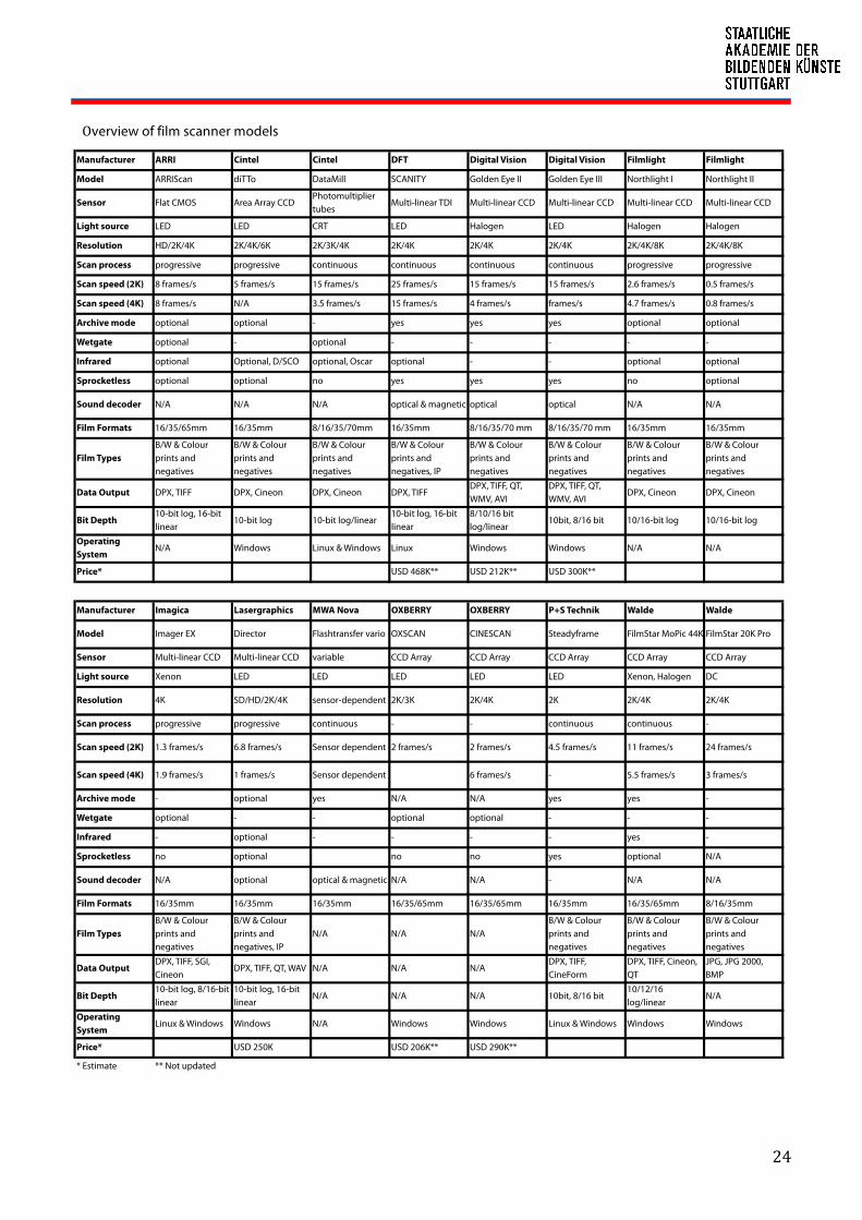
Overview of film scanner models

25
Comparison of Scanner Types
Scanner Type Telecine Datacine Film Scanner
Film Substrates
Nitrate √
Acetate √ √
Polyester √ √ √
Film Gauges
35 mm √ √ √√
16 mm √ √√
8 mm √ √√
70 mm √ √√
Others ?
Film Types
Negative √ √ √
Positive √ √ √
Intermediate √ √ √
Film Issues
Dust √ √√
Scratch √ √√
Damaged Perfs √ √√
Grain √√
Shrunken Film √√
Image Stability √ √√
Scanner Functionality
Hi-res Digital Output √ √√
Uncompressed Formats √√ √√
Image Quality √ √√
Light Source Quality √ √√
Sensor Capability √ √√
Film Handling √ √√
Speed √ √
Portability √
DI Workflow √
Value of Cost √
√ = able and good in handling √√ = able and very good in handling ? = possible

26
6. CONCLUSION: What is suitable for archival film?
Digitisation of motion picture film has come a long way from transferring film into analog video signals into
conversion to high-resolution digital formats and this is all because of the never-ending drive to come up with
better solutions. At this point, the process of film scanning is becoming less difficult to accomplish, whereby at the
beginning of the 21st century a lot of film archivists and conservators were still pessimistic on what could be
achieved.
This doubt was driven by the fact that current systems at that time were still not at par to the goal quality that
archivists required in stark contrast to the high cost of services it entailed. Digitisation of one whole film, let alone
an entire collection was still very impractical. An expensive machine like a telecine could only output SMPTE
standard video (SD, HD) that was recorded to tape—a quality and medium that is by no means acceptable for
archiving not even in recording back to film.
For a significant period of that time, telecine transfer was an acceptable solution, if not a standard, in post-
production but not in digital restoration of motion picture films. Photochemical restoration was still preferred. And
then commercial filmmaking wanted and demanded for the best quality digital outputs sans the usage of analog
film. It was only natural that developers should respond. Owing to the explosive growth in computing power and
storage capacity, much higher resolutions of image capture are now attainable. Real time transfer is becoming less
imperative as scanning speed rates increase by the second—from real time scanning of 1 frame per second to 25
frames per second at 4K resolutions. Telecines were replaced by datacines and hybrid datacines is competing with
all-digital film scanners. Solutions for image stabilization, dust busting, scratch removal, grain and noise reduction
and of course, colour correction are increasingly improving to achieve the so-called “film look.” Along with this is
the drop in prices of certain systems and services because of the tight competition among service-providers, for
example colour grading and visual effects tools and services, but that is another story. The point is, development in
technology is not only catering to and affecting the mainstream media but also the film archiving community. As a
ricocheting effect, film archivists and conservators’ enthusiasm in digitisation is revived.
Given the many possibilities in processes and varieties of capable systems, it is always a matter of deciding on
which one will suit the digitisation requirement. What is right for a digitisation project depends on the budget and
desired workflow. What is suitable for archival film is a system that will protect the original material and reproduce
something that will resemble the original presentation as close as possible.
27
7. SELECTED RESOURCES
A Broadcast Engineering Tutorial for Non-Engineers, 2005, Graham A. Jones Changing the Shape of Cinema: History of Aspect Ratio, FilmmakerIQ.com Chemicals In The Environment: Perchloroethylene, Office Of Pollution Prevention And Toxics U.S. Environmental Protection Agency, 1994 Cinematography: Third Edition, 2005, Kris Malkiewicz, M. David Mullen Digital Moving Picture Exchange (DPX), Version 2.0, Sustainability of Digital Formats Planning for Library of Congress Collections Digitalisierungsfibel, Leitfaden für audiovisuelle Archive, 2012, transfermedia Film Technology in Post Production, Second Edition, 2001, Dominic Case http://cool.conservation-us.org/coolaic/sg/emg/library/pdf/vitale/2007-07-vitale-digital_image_file_formats.pdf http://www.digital-intermediate.co.uk/DIindex.htm Kevin Shaw White Papers, www.finalcolor.com National Association of Broadcasters Engineering Handbook, 10th Edition, 2007, Graham A. Jones, David H. Layer, Thomas G. Osenkowsky Restoration of Motion Picture Film, 2000, Paul Read & Mark-Paul Meyer Wikipedia: http://en.wikipedia.org/wiki/Aspect_ratio_(image) http://en.wikipedia.org/wiki/Datacine http://en.wikipedia.org/wiki/Digital_cinema http://en.wikipedia.org/wiki/Digital_intermediate http://en.wikipedia.org/wiki/Motion_picture_film_scanner http://en.wikipedia.org/wiki/NTSC http://en.wikipedia.org/wiki/PAL http://en.wikipedia.org/wiki/Secam http://en.wikipedia.org/wiki/Telecine Manufacturers: ARRI, www.arri.com Cintel, www.cintel.co.uk DFT, ww.dft-film.com Digital Vision, www.digitalvison.se FilmLight, www.filmlight.ltd.uk Imagica, www.rti-us.com Lasergraphics, www.lasergraphics.com MWA Nova, www.mwa-nova.com Oxberry, www.oxberry.com P+S Technik, www.pstechnik.de Thomson, www.thomsonbroadcast.com Walde, www.walde.com