Chapter 9, Non-functional Requirements Organizational Requirements Engineering
Upload
independentCategory
view
0download
0
A Case-Based Approach for Elaboration of Design Requirements
Paulo Gomes1,2
1 ISEC - Instituto Superior de Engenharia de Coimbra
Quinta da Nora, 3030 Coimbra [email protected]
Carlos Bento2
2 CISUC - Centro de Informática e Sistemas da Universidade de Coimbra
Polo II - Universidade de Coimbra, 3030 Coimbra
{pgomes|bento}@eden.dei.uc.pt Abstract
The process of Case-Based Creative Design comprises: problem specification, problem elaboration, case retrieval, case adaptation, and verification. Problem specification and elaboration are crucial stages in the design process. Notwithstanding most of the current systems do not address this phase, assuming that the problem is well defined and complete, which is not a valid assumption for most of the situations.
In this paper we propose a case-based method for problem elaboration. Old design episodes are used for problem specification and elaboration. Through the use of a graphical editor the user explores a set of alternative problem specifications. This helps the user in the problem specification task. If the problem still remains ill or incompletely defined, a problem elaboration method is used to complete the problem specification based on a library of cases and domain knowledge.
1. Introduction Design is a complex activity that is generally ill-structured and requires a great amount of different types of knowledge (Reich 1991). It comprises creation of a structure complying with a set of functional specifications and constraints (Tong & Sriram 1992).
Design can be divided into routine and non-routine design (Gero 1994). We use the term routine design when the designer is a priori acquainted with the necessary knowledge. In this way routine design comprises parametric variations of old designs. Non-routine design involves two sub-classes: (1) innovative and (2) creative design. In innovative design a new artefact is generated from a known class of designs, but differs from previous class artefacts in some substantive way. This can occur, for instance, in terms of value(s) assigned to the design variables which are specific to the new solution. In creative design the space of possible design alternatives is expanded through the use of new design variables. This takes place when the space of potential designs is extensive and is not entirely defined by the knowledge available to the user. In creative design the process of specifying the design requirements is also viewed as an important phase (Tong & Sriram 1992 , Kolodner & Wills 1993).
In this paper we present the problem specification and problem elaboration phases in CREATOR, which is a case-based reasoning shell for creative design. In the problem specification phase a graphical editor is used to help the user identifying the desired design functionalities. CREATOR uses its memory structure to perform problem elaboration in order to complete the design requirements. Two types of

knowledge represented in the memory structure are used for problem elaboration: a hierarchy of functionalities and the problem descriptions of cases in memory.
In the next section we present the case representation we adopted in CREATOR. Section three shows the memory structure that supports the whole process. Section 4 presents how the graphic editor assists the user to carry out the problem specification. We describe the algorithm for problem elaboration, and show how CREATOR uses cases for problem elaboration. In section 5 we give an example in the domain of specification of room configuration. Section 6 describes related work. In section 7 we present some conclusions and future work directions.
2. Case Representation Within our framework design episodes are represented in the form of SBF models (Goel 1992, Stroulia et al. 1992). These models are based on the component-substance ontology developed by Bylander and Chandrasekaran (Bylander and Chandrasekaran 1985). A case comprises three different parts:
• Problem Specification (Function). • Explanation (Behavior). • Design Solution (Structure).
The problem specification comprises a set of high level functionalities (HLF) and functional specifications (FS) that must be exhibit by the design. The explanation is in the form of a causal structure, representing the design behavior. The case solution describes the design structures that accomplish the desired functionalities described in the target problem.
A design problem is represented by a tree of functionalities, where leaves are FSs and the high levels in the tree represent HLFs. HLFs are abstract functionalities, used to help the user in specifying the design problem. Each leaf in the tree represents a FS in a schema comprising the following slots:
• Given: The initial behavior state. • Makes: The final behavior state. • By-Behavior: Behavior constraints. • Stimulus: External stimulus to the design. • Provided: Structural constraints.
Figure 1b specifies functionalities associated with the bedroom sketched in figure 1a. The abstract goal is to design a bedroom. This HLF comprises two FSs: Sleeping1 and Resting1, meaning that the bedroom must allow people to sleep and rest. For example, functionality Sleeping1 comprises the final behavioral and initial behavioral states (Makes and Given slots). The Makes slot describes that exist a Person, located in Bed1, laid, and with mental state asleep. The Given slot defines the initial conditions, which comprise the existence of a Person with awake mental state.
The design solution is in the form of a hierarchy of device structures. Each structure can be viewed as a set of device structures where substances can flow through. The structure schema is as follows:
• Is-a-part-of: the super structure of the structure. • Consists-of: the sub-structures of the structure. • Is-a: the class of the structure. • Relations: structural relations with other structures.
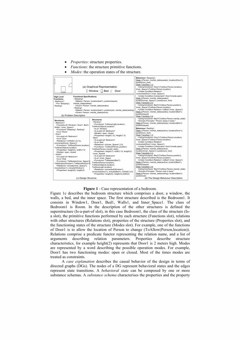
• Properties: structure properties. • Functions: the structure primitive functions. • Modes: the operation states of the structure.
High LevelFunctions:- Bedroom1 <Fs> Sleeping1, Resting1
(b) Problem Description
Structures:- Bedroom1 <Consists-of> Window1, Door1, Bed1,Walls1, Inner_Space1 <Functions> Sleeping1, Resting1 <Is-a> Room- Door1 <Is-a-part-of> Bedroom1 <Is-a> Door <Relations> in(Walls1,0,2.5),connected(Inner_Space1) <Functions> ToAllow(Person,location)ToAllow(Objects,location) <Properties> height(2), width(1.5) <Modes> open, closed- Walls1 <Is-a-part-of> Bedroom1 <Is-a> Wall <Functions> ToMantain(Inner_Space1)ToMaintain(Window1) ToMaintain(Door1) <Relations> include(Inner_Space1),Include(Door1), include(Window1) <Properties> length(5), heigth(3)
(c) Design Structure
Behaviour: Sleeping1State 1:Person; mental_state(awake); location(Door1);position(on_foot)State Transition 1-2 <Using-functions> Door1(ToAllow,Person,location),Inner_Space1(ToAllow,Person,location) <Under-Condition-Relation>connected(Door1,Inner_Space1) <Under-Condition-Component> Door1(mode,open)State 2:Person; mental_state(awake);location(Inner_Space1); position(on_foot)State Transition 2-3 <Using-functions> Bed1(ToAllow,Person,position),Inner_Space1(ToAllow,Person,location) <Under-Condition-Relation> in(Bed1,Inner_Space1)State 3:Person; mental_state(awake); location(Bed1);position(layed)State Transition 3-4 <Using-functions> Bed1(ToAllow,Person,mental_state) <Domain-Principle> "Person sleep in beds."State 4:Person; mental_state(asleep); location(Bed1);position(layed)
(d) The Design Behaviour Description
(a) Graphical RepresentationWindow Bed Door
Functional Specifications:- Sleeping1 <Makes> Person: location(bed1), position(layed),mental_state(asleep) <Given> Person: mental_state(awake);- Resting1 <Makes> Person: location(bed1), position(sit), mental_state(resting) <Given> Person: mental_state(active);
Structures:- Window1 <Functions> ToAllow(Ligth,location),ToAllow(Objects,location) <Is-a> Window <Is-a-part-of> Bedroom1 <Modes> open, closed <Properties> length(1.5), Heigth(1.5)- Bed1 <Is-a-part-of> Bedroom1 <Is-a> Bed <Relations> in(Inner_Space1,2,0) <Functions> ToAllow(Person,position)ToAllow(Person,mental_state) <Properties> height(1), width(1.5), length(2)- Inner_Space1 <Is-a-part-of> Bedroom1 <Is-a> Inner_Space <Functions> ToMantain(Bed1)ToAllow(Person,location),ToAllow(Objects,location),ToAllow(Ligth,location) <Relations> connected(Window1),connected(Door1), include(Bed1), in(Wall1,0,0) <Properties> length(5), heigth(3),width(5)
Behaviour: Resting1State 1:Person; mental_state(active); location(Door1);position(on_foot)State Transition 1-2 <Using-functions> Door1(ToAllow,Person,location),Inner_Space1(ToAllow,Person,location) <Under-Condition-Relation>connected(Door1,Inner_Space1) <Under-Condition-Component> Door1(mode,open)State 2:Person; mental_state(active);location(Inner_Space1); position(on_foot)State Transition 2-3 <Using-functions> Bed1(ToAllow,Person,position),Inner_Space1(ToAllow,Person,location) <Under-Condition-Relation> in(Bed1,Inner_Space1)State 3:Person; mental_state(active); location(Bed1);position(layed)State Transition 3-4 <Using-functions> Bed1(ToAllow,Person,mental_state) <Domain-Principle> "Person rest in beds."State 4:Person; mental_state(resting); location(Bed1);position(sit)
Figure 1 - Case representation of a bedroom. Figure 1c describes the bedroom structure which comprises a door, a window, the walls, a bed, and the inner space. The first structure described is the Bedroom1. It consists in Window1, Door1, Bed1, Walls1, and Inner_Space1. The class of Bedroom1 is Room. In the description of the other structures is defined the superstructure (Is-a-part-of slot), in this case Bedroom1, the class of the structure (Is-a slot), the primitive functions performed by each structure (Functions slot), relations with other structures (Relations slot), properties of the structure (Properties slot), and the functioning states of the structure (Modes slot). For example, one of the functions of Door1 is to allow the location of Person to change (ToAllow(Person,location)). Relations comprise a predicate functor representing the relation name, and a list of arguments describing relation parameters. Properties describe structure characteristics, for example height(2) represents that Door1 is 2 meters high. Modes are represented by a word describing the possible operation modes. For example, Door1 has two functioning modes: open or closed. Most of the times modes are treated as constraints.
A case explanation describes the causal behavior of the design in terms of directed graphs (DGs). The nodes of a DG represent behavioral states and the edges represent state transitions. A behavioral state can be composed by one or more substance schemas. A substance schema characterises the properties and the property

values of a substance. A state transition represents the conditions under which the transition between behavioral states occurs. A state transition is represented by a schema with the following slots: • Using-functions: The primitive component’s functions that allow the state
transition. • Under-condition-relation: structural relations needed to make the state transition. • Domain-principle: domain principles or laws responsible for the state transition. • Under-condition-component: component conditions that must be met. • Under-condition-substance: substance conditions that must be met. • Under-condition-transition: other state transitions that are influential to the state
transition. Figure 1d presents the Sleeping1 and Resting1 behaviors. For example in figure 1 there is one substance schemas representing the properties of Person, in State1. It is a substance Person, located in Door1, with position on_foot, and with mental state awake. State Transition 1-2 says that the transformation from State1 to State2 is due to the primitive functions of Door1 and Inner_Space1, that allow Person to change location. It also states that the transition is constrained by the relation that represents the existence of a connection between Door1 and Inner_Space1 (connected(Door1,Inner_Space1)), and that the door must be open. The rest of the description is analogous.
3. Memory Structure The memory structure comprises two interconnected substructures: a tree of HLFs and FSs, and a graph of cases. The tree of HLFs and FSs is used in two ways. One is in providing help for the problem specification and elaboration phase. The other role is in retrieving the starting cases. The starting cases are all the cases with at least one FSs in common with the new problem. These cases are used as starting points in the graph of cases for exploration of the episode memory, making possible for the searching mechanism to incrementally retrieve neighbor cases.
WC1Experiment1
Washing1
HLF class HLF instance CaseList of HLFs and FSs
Room
HouseRoom Laboratory Classroom
Bedroom Kitchen
Bedroom2Bedroom1 Kitchen1 ComputerLab1
ElectronicLab1 Classroom1
Ako Ako
Ako Ako
Isa Isa Isa
Isa Isa
Ako
Isa
Ako
Isa IsaAko
IsaIsa
Sleeping1Resting1
Sleeping1Resting1Writing1
Coocking1Eating1
Coocking1Eating1
Washing1
Computing1Teaching1
Teaching1Experiment1 Teaching1 Teaching1
Comp Comp Comp Comp Comp Comp Comp Comp
......
...
...
......
Case1 Case2 Case3 Case5 Case5 Case7Differences1-2 Differences2-3 Differences5-6 Differences6-7
Comp
Case4Differences3-4
Laboratory1
Isa
Figure 2 - Example of a memory structure in the domain of room configuration.
The tree of HLFs and FSs comprises three different types of nodes and three types of links (see figure 2). Nodes are of type: HLF class, HLF instance, and LF node (a LF node comprises a list of HLFs and/or FSs). Connections between nodes are of type: hlf_ako, hlf_isa, and lfs_comp links. A hlf_ako link represents that a HLF class is a kind of a HLF superclass. A hlf_isa link represents that a HLF instance is a HLF class. A lfs_comp link connect a list of functionalities (HLFs and/or FSs) to a HLF instance. This kind of connection represents a partonomic relation between a HLF instance and the list of HLFs and FSs in the LF node.
In the graph of cases nodes represent episodes, and edges represent functional differences between cases. In figure 2 Case1 is connected to Case2 by the link Differences1-2. This link represents the functional differences between Case1 and Case2 problem descriptions.
A difference link is created only when the cases that it connects have at least one FS in common. A difference link connecting two cases, comprises three parts: • The set of FSs that belong to the first case but do not belong to the second one. • The set of FSs that belong to the second one but do not belong to the first one. • The set of differences in the FSs common to both cases. Case links are automatically generated, when a new case is stored in the case library.
4. Problem Elaboration Design specifications are often ill-defined or incomplete. This is particularly common in creative design. The process of problem elaboration tries to create a full description of the design requirements. Kolodner & Wills (Kolodner & Wills 1993) call it the process of “designing the design specification”. Defining the design problem takes place in two phases. The first step is done by the designer, and the second one is performed by the system.
4.1 Helping the user specifying the problem In our system the first step comprises the definition by the designer of the HLFs and FSs in the new problem. She/he makes use of the graphical editor which shows the relevant part of the memory structure for the elaboration process. The memory structure presented to the user is a hierarchy of HLFs and LF nodes, like in figure 2, with the difference that it does not show cases and connections between them (see figure 3).

Figure 3 - CREATOR’s graphic editor with the problem description selected by a
decorator.
The user can perform several operations on the nodes and each type of node has associated a set of available operations.
HLF classes can be expanded (e.g. subclasses and/or instances are displayed), collapsed (e.g. subclasses and instances are hidden), and new HLF instances can be linked to a class.
HLF instances can be expanded (e.g. LF nodes are displayed), collapsed (e.g. LF nodes are hidden), new LF nodes can be linked to it, and it can be added to the new problem specification.
LFs can be added to the new problem specification, and can have its contents modified. When a user selects a LF node the lfs_comp link and HLF instance associated to it are automatically added to the new problem specification. The problem specification phase results into a set of HLF instances, LF nodes, and lfs_comp links. At the beginning, the graphical editor shows only the root node.
As we denoted before a problem specification may be incomplete. A HLF instance belonging to the problem specification is said to be incomplete if: (a) does not have any lfs_comp link connecting it to a LF node; or (b) occurs in a LF node, and does not have any corresponding complete HLF
instance in the problem (a complete HLF has at least one non-empty LF node). As an example, Problem1 in figure 4 is incomplete because the HLF Bedroom1 matches condition (a). Problem2 is also incomplete because WC1 respects condition (b). Problem3 is complete because all the HLF instances and HLFs in LF nodes are completely specified.

WC1Experiment1
Kitchen1 Kitchen1Bedroom1 Laboratory1 Kitchen1 Laboratory1
Eating1Cooking1
comp
Eating1Cooking1
comp
Eating1Cooking1
compcomp
Kitchen1Experiment1
comp
(a) Problem1 (b) Problem2 (c) Problem3 Figure 4 - (a) and (b) incomplete problem specifications, (c) a complete problem
specification.
The problem specification can be more general or more specific depending on the number of complete HLFs it comprises. The more complete HLFs incorporated in the new problem, the more specific the problem description becomes. On the opposite side, selecting a higher number of incomplete HLFs results into a more general problem. This defines a relation between the number of incomplete HLFs and the number of alternative solutions for the problem. In this way when the problem is completely defined the system generates solutions for a single problem. On the other hand, when the specification is incomplete, the system creates solutions for a class of problems. In the framework of creative design incomplete specifications result into a richer set of alternative solutions with the drawback of increasing the computational demands of the system. In the next section we describe the elaboration process that takes place when the problem is not completely specified.
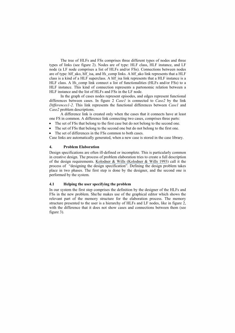
4.2 Algorithm for problem elaboration When the problem specification comprises incomplete HLFs the system uses the algorithm described in figure 5 for problem elaboration.
The system will try to elaborate all the problems in List_of_Problems (step 1 of figure 5). A problem is elaborated until it comprises only complete HLFs (step 2). If a HLF is incomplete, the algorithm searches for the respective node in the memory structure (step 3 and 4). If the node has lfs_comp links (step 5), the system creates a new copy of the problem specification for each link (step 7) and adds the LF node (that one the lfs_comp link connects) to each problem copy (step 8). Each new problem is added to List_of_Problems (step 9). If lfs_comp links are not found in memory (step 11), the algorithm searches for subclasses of the Incomplete_HLF. If subclasses are found (step 12), the system creates a new copy of the problem for each subclass (step 14) and replaces in each copy the Incomplete_HLF by the subclass in memory (step 15). The new problems created are appended to List_of_Problems (step 16). If no subclasses are found (step19), the superclass of the Incomplete_HLF replaces it in the problem (step 20). After all HLF instances are complete, several design problem alternatives are generated by the system.
1. FOR EACH Problem in List_of_Problems DO 2. WHILE there are incomplete HLFs in Problem DO 3. SELECT an incomplete HLF (Incomplete_HLF) 4. Search the memory structure for (by preference order): 1st Lfs_comp links from Incomplete_HLF 2nd Subclasses of Incomplete_HLF 3rd Superclasse of Incomplete_HLF 5. IF Lfs_comp links were found THEN 6. FOR EACH Lfs_comp link DO 7. Make a copy of the Problem 8. Complete the Incomplete_HLF using the list of HLFs and list of FSs in the LF node connected by the lfs_comp link 9. Add New_Problem to List_of_Problems 10. END FOR 11. ELSE 12. IF subclasses were found THEN 13. FOR EACH subclass DO 14. Make a copy of the Problem 15. Replace the Incomplete_HLF by the subclass 16. Add New_Problem to List_of_Problems 17. END FOR 18. ELSE 19. IF superclass was found THEN 20. Replace the Incomplete_HLF by the superclass 21. END IF 22. END IF 23. END IF 24. END WHILE 25. END FOR
Figure 5 - Algorithm for Problem Elaboration.
5. Example CREATOR evolved from IM-RECIDE (Gomes et. Al. 1996), an independent domain reasoning shell. The domain chosen for tests, was the building/room configuration. The case library has 36 cases describing various buildings comprising various rooms. Like schools, restaurants, etc. We present an example in CREATOR from the beginning of the problem specification till the alternative problem specifications produced by the system.
We consider a decorator who wants to design the displacement of furniture in an apartment. So, She/he uses CREATOR’s graphic editor to help her/him in the problem specification task. After using the graphic editors she/he establishes the problem specification (see figure 3). Note that in the figure it is not possible to distinguish the kinds of nodes. This happens because in the editor types of nodes are drawn using different colours.
The problem specification comprises three HLF instance nodes, and three LF nodes. HLF instance nodes are: Apartment T0, Kitchen1, and WC1. LF nodes are:
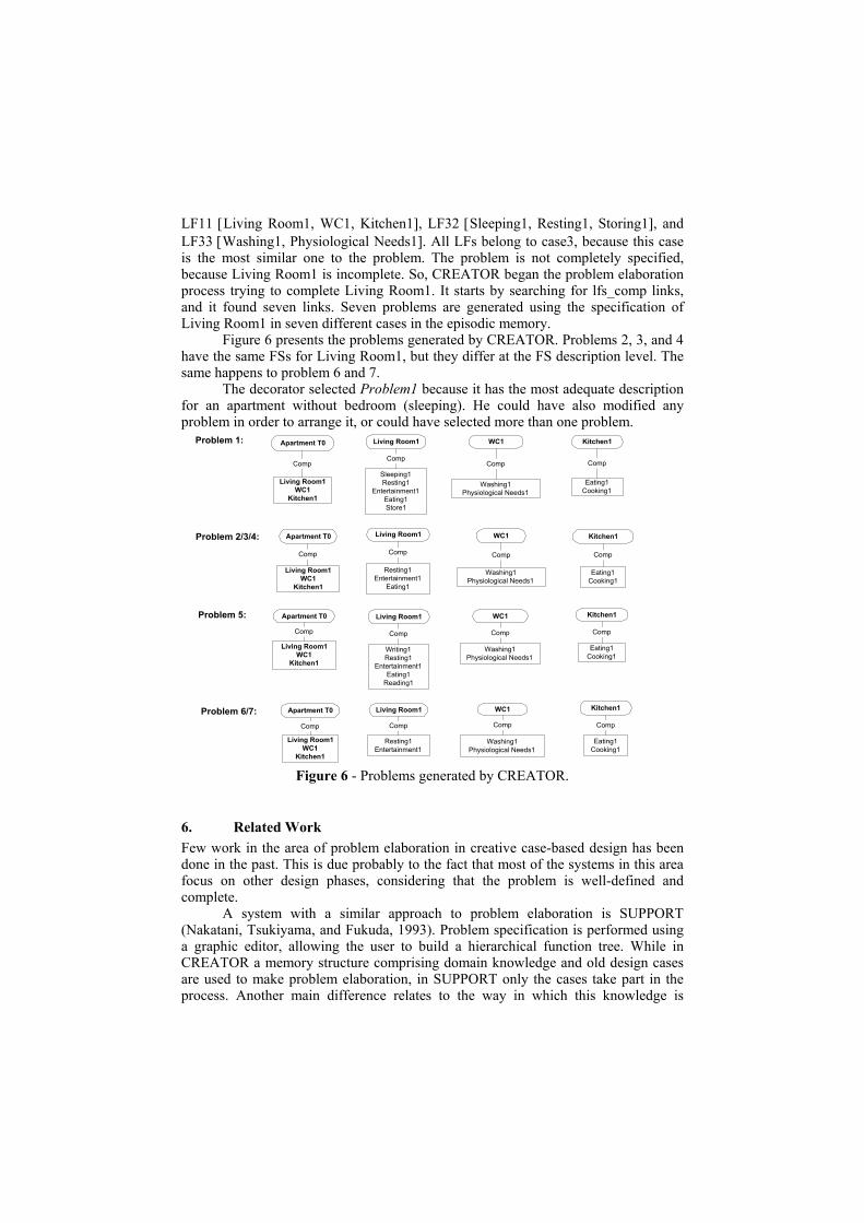
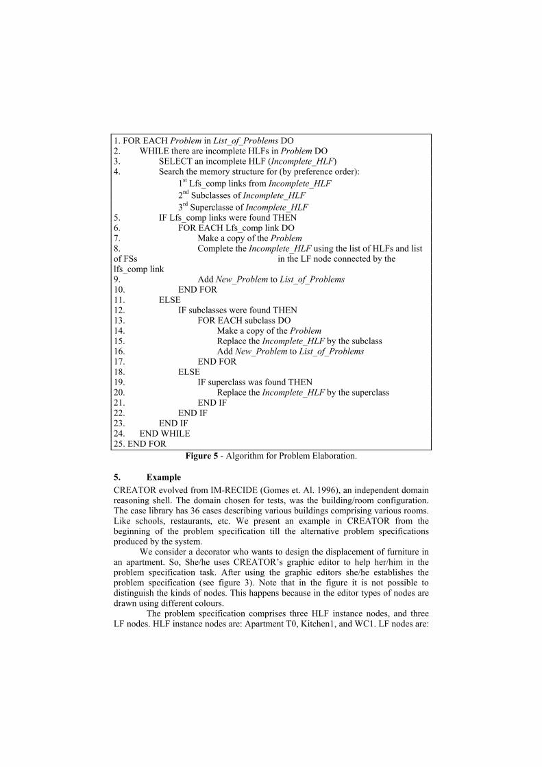
LF11 [Living Room1, WC1, Kitchen1], LF32 [Sleeping1, Resting1, Storing1], and LF33 [Washing1, Physiological Needs1]. All LFs belong to case3, because this case is the most similar one to the problem. The problem is not completely specified, because Living Room1 is incomplete. So, CREATOR began the problem elaboration process trying to complete Living Room1. It starts by searching for lfs_comp links, and it found seven links. Seven problems are generated using the specification of Living Room1 in seven different cases in the episodic memory.
Figure 6 presents the problems generated by CREATOR. Problems 2, 3, and 4 have the same FSs for Living Room1, but they differ at the FS description level. The same happens to problem 6 and 7.
The decorator selected Problem1 because it has the most adequate description for an apartment without bedroom (sleeping). He could have also modified any problem in order to arrange it, or could have selected more than one problem.
Problem 1: Apartment T0
Problem 2/3/4:
Living Room1 WC1 Kitchen1
Sleeping1Resting1
Entertainment1Eating1Store1
Washing1Physiological Needs1
Eating1Cooking1
CompCompComp
Living Room1WC1
Kitchen1
Comp
Apartment T0 Living Room1 WC1 Kitchen1
Resting1Entertainment1
Eating1
Washing1Physiological Needs1
Eating1Cooking1
Comp CompComp
Living Room1WC1
Kitchen1
Comp
Problem 5: Apartment T0
Problem 6/7:
Living Room1 WC1 Kitchen1
Writing1Resting1
Entertainment1Eating1
Reading1
Washing1Physiological Needs1
Eating1Cooking1
Comp CompComp
Living Room1WC1
Kitchen1
Comp
Apartment T0 Living Room1 WC1 Kitchen1
Resting1Entertainment1
Washing1Physiological Needs1
Eating1Cooking1
Comp CompComp
Living Room1WC1
Kitchen1
Comp
Figure 6 - Problems generated by CREATOR.
6. Related Work Few work in the area of problem elaboration in creative case-based design has been done in the past. This is due probably to the fact that most of the systems in this area focus on other design phases, considering that the problem is well-defined and complete.
A system with a similar approach to problem elaboration is SUPPORT (Nakatani, Tsukiyama, and Fukuda, 1993). Problem specification is performed using a graphic editor, allowing the user to build a hierarchical function tree. While in CREATOR a memory structure comprising domain knowledge and old design cases are used to make problem elaboration, in SUPPORT only the cases take part in the process. Another main difference relates to the way in which this knowledge is

applied. Our system uses an algorithm for the problem elaboration. SUPPORT suggests related problems and specifications to the user, but is the user’s responsibility to select which specifications are relevant for the current problem. CREATOR can deal with simultaneous problems which is another difference from SUPPORT which only works with a single problem.
7. Conclusions and Future Work In this paper we address the problem specification and problem elaboration phases of the design process. We present a case-based approach for problem elaboration. In the basis of our work is the SBF model representation of cases, and the memory structure used in CREATOR. We have also presented an example of the problem elaboration process.
We defend that ill and incomplete defined problems have a strong link with creative design. This happens because these types of designs specifications give the chance for the system to explore rich sets of alternatives in the problem specification. This makes also possible the search for design alternatives, transforming the usual CBR retrieval of the best case, in the retrieval of several cases for adaptation in order to generate new solutions.
So far CREATOR’s evaluation lead us to the conclusion that the problem elaboration algorithm saves work to designers in the task of detailing design specifications. An important issue in this process is that if the problem specified by the designer is too abstract (e.g. too many incomplete HLFs) the number of alternative problem specifications can be enormous, depending also on the number of cases in memory, and on which HLFs are incomplete.
In the future we are going to implement an adaptation module and a verification/validation algorithm.
8. Acknowledgments This research was partially supported by a MSc. grant to the first author from JNICT (PRAXIS XXI BM 6563 95).
9. References (Bylander and Chandrasekaran 1985) Bylander,T., and Chandrasekaran, B. 1985.
Understanding Behavior Using Consolidation. In Proceedings of the Ninth International Joint Conference on Artificial Intelligence.
(Gero 1994) Gero, J. 1994. Computational Models of Creative Design Processes. In T. Dartnall (ed.), AI in Creativity. Kluwer, Dordrecht, pp. 269-281.
(Goel 1992) Goel, A. 1992. Representation of Design Functions in Experience-Based Design. Intelligent Computer Aided Design. D. Brown, M. Waldron, and H. Yoshikawa (eds.). Elsevier Science Publishers.
(Gomes et al. 1996) Gomes, P., Bento, C., Gago, P., and Costa, E. 1996. Towards a Case-Based Model for Creative Processes. In Proceedings of the 12th European Conference on Artificial Intelligence. John Willey & Sons.
(Kolodner and Wills 1993) Kolodner, K., and Wills, L. 1993. Case-Based Creative Design. In AAAI Spring Symposium on AI+Creativity, Stanford, CA.
(Nakatani, Tsukiyama and Fukuda 1993) Nakatani, Y., Tsukiyama, M., and Fukuda, T. 1993. Reuse of Conceptual Designs for an Engineering Design Group. In
Reuse of Designs: an interdisciplinary cognitive approach. De. Willemien Visser. Proceedings of the Workshop of the 13th International Joint Conference on Artificial Intelligence, France.
(Reich 1991) Reich, Y. 1991. Design Knowledge Acquisition: Task Analysis and a Partial Implementation. Knowledge Acquisition: An International Journal of Knowledge Acquisition for Knowledge-Based System 3(3):234-254.
(Stroulia et al. 1992) Stroulia, E., Shankar, M., Goel, A., and Penberthy, L. 1992. A Model-Based Approach to Blame Assignment in Design. In Proceedings of the 2nd International Conference on AI in Design.
(Tong and Sriram 1992) Tong, C., and Sriram, D. eds. 1992. Artificial Intelligence in Engineering Design, Vol. I. Academic Press.
Copyright © 2022 FDOKUMEN