95% BIDDING DOCUMENT PHASE - VA Vendor Portal
473
Department of Veterans Affairs Issue for Bid Contract No. –VA69D-P-0645 VA Project No. – 556-12-118 Order Date January 18,2012 BE Task Order #3 BE Project No. 1115-11-02 HVAC Upgrade for Pharmacy FHCC at North Chicago VAMC BY: ARCHITECT Bailey Edward Design 35 E Wacker Drive Tower Floor 28 Chicago, IL 60601 312-440-2300 DATE: May 15, 2012
-
Upload
khangminh22 -
Category
Documents
-
view
2 -
download
0
Transcript of 95% BIDDING DOCUMENT PHASE - VA Vendor Portal

Department of Veterans Affairs
Issue for Bid Contract No. –VA69D-P-0645 VA Project No. – 556-12-118 Order Date January 18,2012 BE Task Order #3 BE Project No. 1115-11-02
HVAC Upgrade for Pharmacy FHCC at North Chicago VAMC BY: ARCHITECT Bailey Edward Design
35 E Wacker Drive Tower Floor 28
Chicago, IL 60601 312-440-2300
DATE: May 15, 2012

HVAC Upgrade for Pharmacy
03-01-12
00 01 10-1
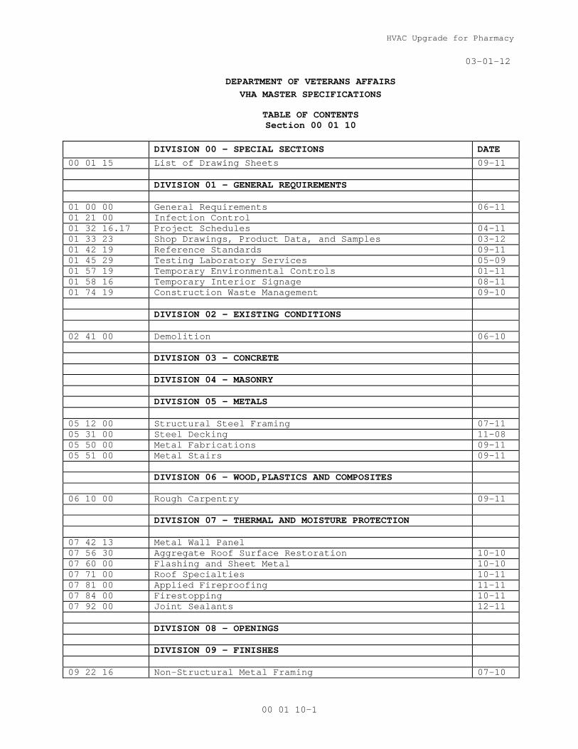
DEPARTMENT OF VETERANS AFFAIRS VHA MASTER SPECIFICATIONS TABLE OF CONTENTS
Section 00 01 10
DIVISION 00 - SPECIAL SECTIONS DATE 00 01 15 List of Drawing Sheets 09-11 DIVISION 01 - GENERAL REQUIREMENTS 01 00 00 General Requirements 06-11 01 21 00 Infection Control 01 32 16.17 Project Schedules 04-11 01 33 23 Shop Drawings, Product Data, and Samples 03-12 01 42 19 Reference Standards 09-11 01 45 29 Testing Laboratory Services 05-09 01 57 19 Temporary Environmental Controls 01-11 01 58 16 Temporary Interior Signage 08-11 01 74 19 Construction Waste Management 09-10 DIVISION 02 – EXISTING CONDITIONS 02 41 00 Demolition 06-10 DIVISION 03 – CONCRETE DIVISION 04 – MASONRY DIVISION 05 – METALS 05 12 00 Structural Steel Framing 07-11 05 31 00 Steel Decking 11-08 05 50 00 Metal Fabrications 09-11 05 51 00 Metal Stairs 09-11 DIVISION 06 – WOOD,PLASTICS AND COMPOSITES 06 10 00 Rough Carpentry 09-11 DIVISION 07 - THERMAL AND MOISTURE PROTECTION 07 42 13 Metal Wall Panel 07 56 30 Aggregate Roof Surface Restoration 10-10 07 60 00 Flashing and Sheet Metal 10-10 07 71 00 Roof Specialties 10-11 07 81 00 Applied Fireproofing 11-11 07 84 00 Firestopping 10-11 07 92 00 Joint Sealants 12-11 DIVISION 08 - OPENINGS DIVISION 09 – FINISHES 09 22 16 Non-Structural Metal Framing 07-10

HVAC Upgrade for Pharmacy
03-01-12
00 01 10-2
09 29 00 Gypsum Board 02-12 09 51 00 Acoustical Ceilings 10-10 09 91 00 Painting 04-09 DIVISION 21- FIRE SUPPRESSION 21 05 00 Common Work Results for Fire Suppression 11-09 DIVISION 22 – PLUMBING 22 05 00 Common Work Results for Plumbing 08-08M DIVISION 23 – HEATING, VENTILATING, AND AIR
CONDITIONING (HVAC)
23 05 00 Common Work Results for HVAC 11-10 23 05 12 General Motor Requirements for HVAC and Steam
Generation Equipment 11-10
23 05 93 Testing, Adjusting, and Balancing for HVAC 05-11
23 07 11 HVAC And Boiler Plant Insulation 23 08 00 Commissioning of HVAC 07-10 23 09 23 Direct-Digital Control System for HVAC 09-11 23 21 13 Hydronic Piping 03-10 23 22 13 Steam and Condensate Heating Piping 03-10 23 31 00 HVAC Ducts and Casing 23 31 13 23 33 00 Air ducts Accessories 23 34 00 HVAC Fans 11-09 23 36 00 Air Terminal Units 03-10 23 37 00 Air Outlets and Inlets 11-09 23 64 00 Packaged Water Chillers 04-11 23 74 13 Packaged, Outdoor, Central-Station Air-Handling Units 04-11 23 82 16 Air Coils 04-11 23 84 00 Humidity Control Equipment 05-11 DIVISION 25 – INTEGRATED AUTOMATION DIVISION 26 – ELECTRICAL 26 05 11 Requirements for Electrical Installations 03-12 26 05 21 Low-Voltage Electrical Power Conductors and Cables (600
Volts and Below) 03-12
26 05 33 Raceway and Boxes for Electrical Systems 03-12 26 29 21 Disconnect Switches 03-12 DIVISION 27 – COMMUNICATIONS DIVISION 28 – ELECTRONIC SAFETY AND SECURITY

HVAC Upgrade for Pharmacy
00 01 15 - 1
SECTION 00 01 15 LIST OF DRAWING SHEETS
The drawings listed below accompanying this specification form a part of
the contract.
GENERAL
GI-000 COVER GI-001 GENERAL INFORMATION GI-002 SITE LOCATION PLAN GI-003 PHASING PLAN GR-001 PHOTOGRAPHS OF EXISTING CONDITIONS GR-002 PHOTOGRAPHS OF EXISTING CONDITIONS STRUCTURAL
S001 STRUCTURAL GENERAL NOTES S100 LOADING DOCK ROOF FRAMING S200 SECTIONS AND DETAILS
ARCHITECTURAL AD-100 PARTIAL FIRST FLOOR DEMOLITION PLANS AS-100 PARTIAL FIRST FLOOR AND REFLECTED CEILING PLANS AS-700 CONSTRUCTION DETAILS
FIRE PROTECTION & PLUMBING
PFP1.00 PLUMBING AND FIRE PROTECTION PARTIAL FIRST FLOOR PLAN - DEMO PFP2.00 PLUMBING AND FIRE PROTECTION PARTIAL FIRST FLOOR PLAN
MECHANICAL
M0.00 MECHANICAL NOTES, SYMBOLS, AND ABBREVIATION M1.00 MECHANICAL PARTIAL FIRST FLOOR PLAN – DEMO M1.01 MECHANICAL PARTIAL FIRST FLOOR PLAN PIPING – DEMO M1.02 MECHANICAL DEMO RISER DIAGRAMS M2.00 MECHANICAL PARTIAL FIRST FLOOR PLAN DUCTWORK M2.01 MECHANICAL PARTIAL FIRST FLOOR PLAN PIPING M4.00 MECHANICAL NEW AIR FLOW RISER DIAGRAMS M5.00 MECHANICAL SCHEDULES M5.01 MECHANICAL SCHEDULES M6.00 MECHANICAL DETAILS M6.01 MECHANICAL DETAILS M6.02 MECHANICAL DETAILS M7.00 MECHANICAL TEMPERATURE CONTROL DIAGRAM M7.01 MECHANICAL TEMPERATURE CONTROL DIAGRAM
ELECTRICAL
E0.00 ELECTRICAL, SYMBOLS, AND ABBREVIATIONS E1.00 ELECTRICAL PARTIAL FIRST FLOOR PLAN – ELECTRICAL DEMOLITION E2.00 ELECTRICAL PARTIAL FIRST FLOOR PLAN ELECTRICAL NEW WORK E2.01 ELECTRICAL PARTIAL FIRST FLOOR LIGHTING PLAN E5.00 ELECTRICAL SCHEDULES
- - - END - - -


HVAC Upgrade for Pharmacy
01 00 00 - 1
SECTION 01 00 00 General Requirements
Medical Center Construction Policies & Procedures 1.1 GENERAL INTENTION
A. Contractor shall completely prepare site for construction
operations, including demolition and removal of existing
structures and materials, and furnish labor and materials to
perform work for buildings at the VA Federal Health Care Center
in North Chicago as required by drawings and specifications.
B. Visits to the site by Bidders may be made only by appointment
with the Project Manager
C. Offices of Bailey Edward Architecture, as Architect, will render
certain technical services during construction. Such services
shall be considered as advisory to the Government and shall not
be construed as expressing or implying a contractual act of the
Government without affirmations by Contracting Officer or his
duly authorized representative.
E. All employees of general contractor and subcontractors shall
comply with VA security management program and obtain permission
of the VA police, be identified by project and employer, consent
to photo identification, and be restricted from unauthorized
access.
1.2 STATEMENT OF BID ITEM(S)
A. ITEM I, GENERAL CONSTRUCTION: Work at Buildings #133 is included
in the base contract: Work includes general construction of
roofing, interior construction and finishes, structural, and
mechanical, plumbing, fire protection, electrical work, and
necessary removal of existing structures temporary facilities and
construction and certain other items.
B. ALTERNATES: There are no alternates in this bid.
Medical Center Policy: All construction personnel shall be orientated and trained on hospital safety, rules and procedures before starting work and periodically throughout the project duration. The general contractor and subcontractors’ field supervisors/foremen shall be thoroughly familiar with Specification Section 01010 “General Requirements” and those items covered in the “Field Supervisors/Foremen Agreement” below.
HVAC Upgrade for Pharmacy
01 00 00 - 2
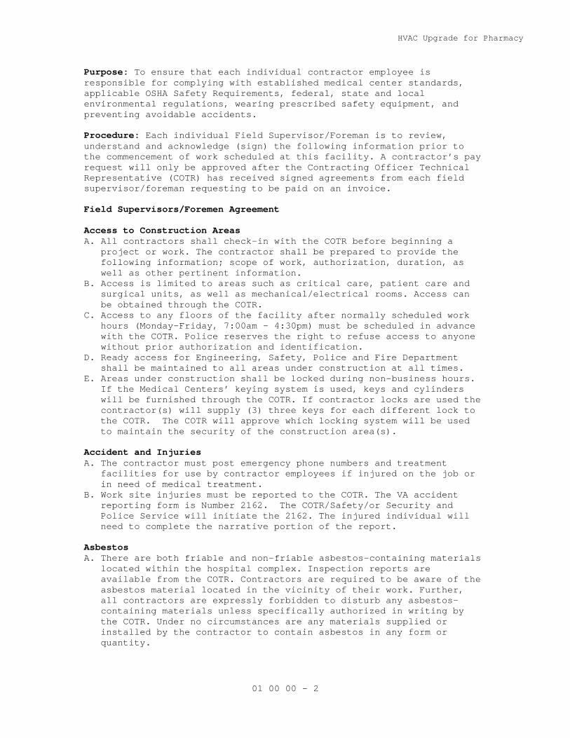
Purpose: To ensure that each individual contractor employee is responsible for complying with established medical center standards, applicable OSHA Safety Requirements, federal, state and local environmental regulations, wearing prescribed safety equipment, and preventing avoidable accidents. Procedure: Each individual Field Supervisor/Foreman is to review, understand and acknowledge (sign) the following information prior to the commencement of work scheduled at this facility. A contractor’s pay request will only be approved after the Contracting Officer Technical Representative (COTR) has received signed agreements from each field supervisor/foreman requesting to be paid on an invoice. Field Supervisors/Foremen Agreement Access to Construction Areas A. All contractors shall check-in with the COTR before beginning a
project or work. The contractor shall be prepared to provide the following information; scope of work, authorization, duration, as well as other pertinent information.
B. Access is limited to areas such as critical care, patient care and surgical units, as well as mechanical/electrical rooms. Access can be obtained through the COTR.
C. Access to any floors of the facility after normally scheduled work hours (Monday-Friday, 7:00am – 4:30pm) must be scheduled in advance with the COTR. Police reserves the right to refuse access to anyone without prior authorization and identification.
D. Ready access for Engineering, Safety, Police and Fire Department shall be maintained to all areas under construction at all times.
E. Areas under construction shall be locked during non-business hours. If the Medical Centers’ keying system is used, keys and cylinders will be furnished through the COTR. If contractor locks are used the contractor(s) will supply (3) three keys for each different lock to the COTR. The COTR will approve which locking system will be used to maintain the security of the construction area(s).
Accident and Injuries A. The contractor must post emergency phone numbers and treatment
facilities for use by contractor employees if injured on the job or in need of medical treatment.
B. Work site injuries must be reported to the COTR. The VA accident reporting form is Number 2162. The COTR/Safety/or Security and Police Service will initiate the 2162. The injured individual will need to complete the narrative portion of the report.
Asbestos A. There are both friable and non-friable asbestos-containing materials
located within the hospital complex. Inspection reports are available from the COTR. Contractors are required to be aware of the asbestos material located in the vicinity of their work. Further, all contractors are expressly forbidden to disturb any asbestos-containing materials unless specifically authorized in writing by the COTR. Under no circumstances are any materials supplied or installed by the contractor to contain asbestos in any form or quantity.

HVAC Upgrade for Pharmacy
01 00 00 - 3
B. Asbestos removal contractors will be trained and licensed, and will follow OSHA, VA Specifications, state and local regulations from notification to disposal.
C. A VA Representative will verify the adequacy of the barriers and ventilation before any asbestos removal work is conducted.
D. The contractor(s) is responsible for monitoring their employees’ exposure to asbestos.
E. Additional asbestos removal specifications will apply. Clean-up A. All work activities within occupied portions of the facility shall
be immediately cleaned and restored to its original finished condition upon completion of the activity. If the activity continues into the next workday, the area shall be left safe, clean, and presentable.
B. Public restrooms are not to be used for cleaning tools or equipment. Janitor’s slop sinks are available for this purpose. If janitor’s closets are used they must be cleaned.
C. Trash, combustible waste, and excess construction materials must be removed daily to prevent accumulation. Contractors must arrange for the removal of their debris and waste.
D. All work for an area must be confined within that space. Public corridors, stairwells, equipment rooms, and vacant floors are not to be used for the storage of materials or as a workshop. Tracking of construction dirt into the public corridors or stairwells must be prevented. The contractor will provide tack pads at all entrances and exits from the construction space.
E. If smoke detectors are covered during dust-producing activities, they must be uncovered at the end of each day.
F. All contractors working above the ceiling are required to reset all disturbed ceiling tiles by the end of the day.
Compressed Gas Cylinders A. Compressed gas cylinders are very dangerous if not treated properly. B. Employees who work with compressed gas cylinders must have specific
training in that area. C. Make sure that they are secured properly when in storage. D. Always keep the caps on the cylinders when they are not in use. E. Hot work permit(s) are required. Confined Space A. Consult with the COTR before entering sewers, manholes, and
underground vaults. Identify which require confined space permits. The contractor must submit in writing a confined space entry plan prior to any confined space entry activity. The Safety Manager of the Medical Center will review the plan. Confined space entry can commence once approval is obtained from the Safety Manager.
B. All construction personnel that require entry into a confined space must abide by the Confined Space Program procedure. NO ONE will be allowed to enter these areas without the proper qualifications, equipment and training.
C. It is the sole responsibility of the contractor to coordinate entry into any confined space. The contractor shall notify the COTR prior to entering a confined space.
D. Anyone entering a permit-required confine space must follow OSHA regulations, 29 CFR 1910.120.
HVAC Upgrade for Pharmacy
01 00 00 - 4
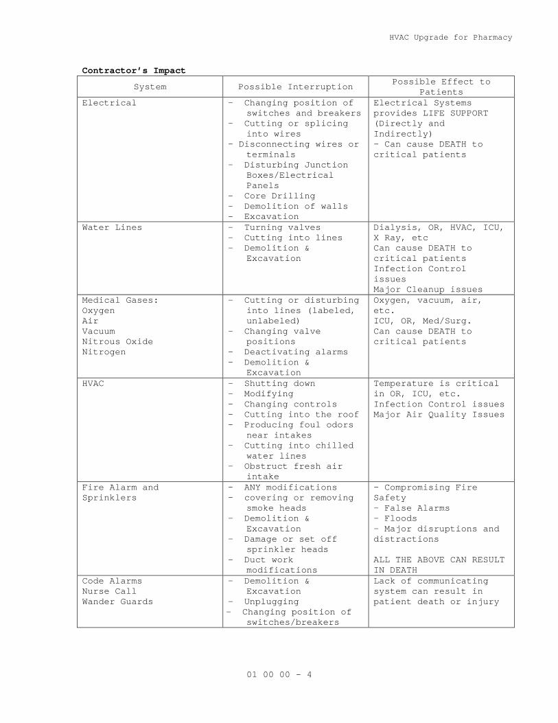
Contractor’s Impact
System Possible Interruption Possible Effect to Patients
Electrical - Changing position of switches and breakers
- Cutting or splicing into wires
- Disconnecting wires or terminals
- Disturbing Junction Boxes/Electrical Panels
- Core Drilling - Demolition of walls - Excavation
Electrical Systems provides LIFE SUPPORT (Directly and Indirectly) - Can cause DEATH to critical patients
Water Lines - Turning valves - Cutting into lines - Demolition &
Excavation
Dialysis, OR, HVAC, ICU, X Ray, etc Can cause DEATH to critical patients Infection Control issues Major Cleanup issues
Medical Gases: Oxygen Air Vacuum Nitrous Oxide Nitrogen
- Cutting or disturbing into lines (labeled, unlabeled)
- Changing valve positions
- Deactivating alarms - Demolition &
Excavation
Oxygen, vacuum, air, etc. ICU, OR, Med/Surg. Can cause DEATH to critical patients
HVAC - Shutting down - Modifying - Changing controls - Cutting into the roof - Producing foul odors
near intakes - Cutting into chilled
water lines - Obstruct fresh air
intake
Temperature is critical in OR, ICU, etc. Infection Control issues Major Air Quality Issues
Fire Alarm and Sprinklers
- ANY modifications - covering or removing
smoke heads - Demolition &
Excavation - Damage or set off
sprinkler heads - Duct work
modifications
- Compromising Fire Safety - False Alarms - Floods - Major disruptions and distractions ALL THE ABOVE CAN RESULT IN DEATH
Code Alarms Nurse Call Wander Guards
- Demolition & Excavation
- Unplugging - Changing position of
switches/breakers
Lack of communicating system can result in patient death or injury

HVAC Upgrade for Pharmacy
01 00 00 - 5
Contractor Room/Space A. Materials will be kept on the job site in the contractors’ room or
in storage space provided for the contractor by the COTR. B. Any shared space within the storage room(s) must be accessible to
the COTR, Police, and Fire Department. C. Corridors are not to be used for storage. D. Contractors will manage the signed space and assure the site is kept
clean and safe. Refer to OSHA standards. E. Any disputes or concerns will be directed to the COTR. Damage by Contractors A. Any damage caused by the contractor’s employees is to be reported to
the COTR immediately. Deliveries A. All material deliveries at the loading dock must be coordinated with
the COTR. Deliveries of material and equipment are to be made at times when the contractor or subcontractor is available to accept them. The VA will not be responsible for receiving or storing items, and warehouse personnel will not allow deliveries to be unloaded.
B. In order to minimize delays and interferences, large deliveries must occur Monday through Friday after 7:30 a.m. and before 2:30 p.m. Weekend and after hours deliveries need to be prearranged with the COTR.
Dress Code A. All personnel must be appropriately dressed for their work. T-shirts
or garments with obscene or suggestive messages are not permitted. Personnel found improperly dressed will be asked to leave the facility.
Dust Barriers and Ventilation Requirements A. All dust barriers will be coordinated with the COTR before
installation. B. Dust barriers are needed to protect occupied areas on any portion of
the construction project that has the potential to generate dust. C. The barriers must be smoke resistive and non-combustible. When
barriers are part of a smoke or fire barrier, the construction barriers must be equivalent.
D. Refer to specification section 012100, Infection Control, for complete requirements for the control of environmental conditions.
Emergency Preparedness Notification A. Contractors are to post the “VA Emergency Guidebook” in a
conspicuous spot for all construction personnel to review. Contractor personnel are to be trained on the postings prior to beginning work and as the project progresses.
B. The guidebook lists all emergency phone number and explains what to do in the case of an emergency. Such as; bomb threat, workplace injuries, emergency preparedness, hazardous materials & spills, tornado procedures, fire plan, and utility & equipment failures. A copy of the guidebook is available from the COTR.
Elevator Usage A. Contractors shall not hold or block from use any public elevators in
any building unless authorized by the COTR.
HVAC Upgrade for Pharmacy
01 00 00 - 6
B. The COTR will define which elevators shall be used and the times for moving materials and waste to and from the site(s).
Equipment Safety A. Ladders are not to be left unattended in public areas during breaks,
lunch hours and off-duty hours. Ladders shall be laid down and placed out of the traffic areas during these periods.
B. No tools, carts, ladders or other equipment are to be left unattended outside a secured area.
C. Yellow safety barricades must be used when working in public areas. D. Use of hospital equipment is not permitted. Equipment and Supplies A. Caution must be used with all flammable materials, i.e., adhesives,
thinners, varnishes, etc. B. All paint shall be low odor latex paint. The contractor will use
odor reducing agents in all paints and solvents. Ventilation will be required if toxic or foul smelling materials have to be applied.
C. Only a one-day supply of paints, materials and gas cylinders is permitted outside an approved storage area.
Fire Alarm System A. Care must be exercised to prevent the accidental tripping of smoke
detectors and fire alarms. B. Notify the COTR of your activities and location while performing
work in the medical center. C. Cover and protect the smoke alarms when raising dust or creating
smoke. Remove plastic bags around smoke detectors upon completion of the work and at the end of each workday.
D. Notify the COTR immediately if the alarm is tripped. Hazardous Materials and Waste A. A listing of all hazardous materials that will be used on the job
and their material safety data sheets (MSDS) will be available on site for COTR review.
B. Any excess or used chemicals will be removed from the medical center promptly and properly disposed of by the contractor in accordance with federal, state and local regulations.
C. Do not store excessive amounts of flammable or combustible materials on the job site.
Heavy Lifting A. Hoisting heavy materials/items require prior review by the COTR. Hospital Fire Plan R-A-C-E A. Fire Plan - There is no difference between a fire drill and an
actual fire. B. Make sure you know where the pull stations are in the areas you are
working. C. If you are in the area of the fire:
1. Rescue anyone from the area if necessary 2. Pull the nearest Pull Station 3. Contain the fire by closing all doors in the area 4. Extinguish if possible or Evacuate the area immediately
D. If you are NOT in the immediate area of the fire but within the building in alarm:

HVAC Upgrade for Pharmacy
01 00 00 - 7
Construction Workers are to cease activities, exit the building. DO NOT move through the hospital. DO NOT use the elevators or stairwells.
Housekeeping A. Housekeeping in public areas of the hospital will be maintained at
the highest level, even while work is on going. B. In secured areas, housekeeping will be performed as needed, but at a
minimum at the end of each day. Hot Work Permits A. Before any cutting, soldering, grinding, welding, etc., is
conducted, the contractor or sub-contractor shall obtain permission through a hot work permit. The contractor shall be responsible for obtaining the hot work permits from the COTR.
B. Gas and oxygen canisters shall be properly chained and protected and two 10 – pound fire extinguishers shall be present.
C. The contractor shall maintain a fire watch during the hot work operations, and 30 minutes after the hot work is completed.
Identification Badges A. The construction personnel will be required to wear identification
badges. Infection Control (also refer to specification section 01 21 00, Infection Control) A. Prior to all construction activities, infection control procedures
must be reviewed and approved by the COTR. B. The construction personnel are to read and follow the directions
listed on any Infection Control Precaution sheet posted outside a patient’s room. Generally this means permission must be obtained from the nursing staff before entry.
C. Temporary walls or dust barriers are required to enclose areas under construction.
D. Under some conditions it may be necessary to block return and supply ducts. There shall be no re-circulation of air from a construction areas that will generate dust, smoke or odors to other parts of the hospital.
E. Tack pads must be located entrances and exits to the construction area.
F. Contractor shall promptly remove any dust tracked outside of construction barriers.
G. As a standard precaution assume that any person may carry contagious disease. In order to protect you from these diseases always assume blood; non-intact skin, mucous membranes and other body fluids and excretions are infectious. Do not touch any such materials and contact the COTR immediately. Needle container boxes are provided for the disposal of syringes and other sharps used in the medical center. These must be properly removed and disposed of by hospital personnel.
Interim Life Safety A. The hospital will document whether and to what extent Interim Life
Safety Measures (ILSM) will be implemented for each project. B. Any life safety code violations incurred during construction or
renovation will result in close coordination with COTR to implement

HVAC Upgrade for Pharmacy
01 00 00 - 8
the hospital’s Interim Life Safety Measures. JCAHO and NFPA require these measures.
C. The Contractor in cooperation with the COTR will ensure ILSMs are employed to temporarily compensate for hazards posed by existing Life Safety Code (LSC) deficiencies or construction activities.
D. ILSMs apply to both construction and medical center employees. E. ILSMs will require increased walkthrough inspections by the
superintendent/foreman, COTR and Safety Manager. F. Training of construction workers and hospital staff will always be a
significant part of any ILSM procedure. The contractor, COTR and Safety Manager all share responsibility to make sure everyone under increased risk is made aware of the risk and compensating ILSMs.
Life Safety A. Temporary construction partitions of non-combustible materials shall
be installed as required to provide a smoke tight separation between the areas undergoing renovation and/or construction and adjoining areas that are occupied by the facility.
B. Exits for occupied areas of the building including rooms, suites, corridors and floors shall not be blocked by the construction or by construction materials. Exit may be blocked temporarily if it is unavoidable and adequate alternative measures are provided, such as signage, instructions to occupants and approved by the COTR.
C. Existing fire protection systems including fire alarm systems, smoke detection systems, and sprinkler systems shall not be altered except as required for the alteration and/or renovation project. Any alteration to the system shall be coordinated with COTR
D. It is the responsibility of each contractor to know exactly where the fire extinguishers and pull stations are in the work area.
E. Fire hazard inspections shall be conducted daily by the contractor once construction starts and until the work is turned back over to the facility.
F. All temporary electrical wiring and equipment used for construction shall be installed and used in accordance with pertinent provisions of NFPA 70 and National Electrical Code.
G. Maintain construction site to permit access to fire department as necessary. Clear building construction areas of obstructions so that all portions are accessible for fire department apparatus and permit emergency egress of patients and other personnel.
Lockout/Tag out A. Lock Out/Tag Out - No contract workers are allowed to change the
status/position of ANY switch, valve or any other energy source without prior approval from the COTR. All Lock out/Tag out activities need prior approval before implementation. Any activity requiring a Lockout/Tag out process must comply with the medical center policy.
B. All contractors shall comply with OSHA Regulation 29 CFR 1910.147 on Lockout/Tag out procedures.
C. Only VA personnel are authorized to shutdown medical center equipment or utilities unless permission is specifically granted.
Material Safety Data Sheets (MSDS) A. MSDS must be provided for any hazardous materials that will be used
on VA property. B. MSDS are available for all materials used in the medical center.
Contact the COTR for all medical center MSDSs.

HVAC Upgrade for Pharmacy
01 00 00 - 9
Noise A. All core drilling, chipping and hole drilling shall be done at a
time and day determined by the COTR in consultation with occupants of the space and adjacent areas.
B. Patients, visitors and staff deserve consideration and the quiet enjoyment of their premises. Anyone found being loud, rude or otherwise annoying to the patients, their guests or hospital staff would be asked to leave the medical center.
C. All work activity within occupied portions of the medical center shall be accomplished with minimal disruption to the patients, physicians, visitors and staff.
D. Playing of radios, tapes and CD players is not permitted in any occupied areas. “Walkman” radios/tapes and CD players are not permitted anywhere in the medical center.
E. The playing of radios, tapes and CD players are permitted in vacant areas but shall not be heard outside the vacant area.
OSHA Compliance A. All contractors are subject to Occupational Safety and Health
Administration (OSHA) regulations. The contractor is expected to enforce and comply with these standards in the performance of their work. OSHA regulations can be found in Chapter 29 of the Code of Federal Regulations (CFR). Failure on the part of any contractor or their employee to comply with these standards and/or conduct their work in a safe fashion will result in an interruption in the work schedule for which the contractor will be solely responsible. A. OSHA Training:
1. Beginning January 1, 2005, all employees of general contractor
of subcontractors shall have the 10 hour OSHA certified Construction Safety course or other relevant competency training, as determined by VA CP with input from the ICRA team
2. Submit training records of all such employees for approval
before the start of work. Parking A. COTR will designate contractor employee parking areas. Contractors
may not block fire lanes or other roadways. B. Contractor to coordinate parking with the COTR. Patient/Visitor Privacy A. No construction personnel are allowed to review, acknowledge or move
any patient information or records. Personal Protective Equipment A. There are many situations that require specific personal protective
equipment for worker safety according to OSHA. It is the responsibility of the individual contractor to know when it is to be used and is responsible to wear them.
Posting and Training A. The field superintendents/foremen are to post the following hospital
specific documents for all construction employees are to read; Construction Commandments, VA Emergency Guidebook and medical center Smoking Policy.
HVAC Upgrade for Pharmacy
01 00 00 - 10
B. Each field superintendent/foreman is responsible for construction personnel working under his/her supervision. This person shall make sure each employee working on the site has been trained on the Construction Commandments; the Smoking Policy; as well as, other posted information.
Restroom Usage A. Construction personnel shall use the public restrooms and shall not
use restrooms in occupied areas. Request for Information A. All requests for assistance, coordination and information shall be
done through the COTR. B. Address:
COTR (Facility Management) VA Medical Center 3001 Green Bay Road North Chicago, IL. 60064 Phone No. 847.688.1900 ext. 83562 Fax No. 847.578.3733
Safety Regulations A. Contractors are expected to comply with all Occupational Safety and
Health Administration (OSHA) regulation, 29 CFR 1926 and 19100. B. Appropriate job signs and barriers are to be in place to prevent
occupants from straying into the construction area. C. Stairwell doors can not be propped open or blocked at any time.
Equipment cannot be stored in the stairwells. D. All contractors shall close doors to construction area. All doors
shall be locked when not under contractor direct supervision. E. All contractors are encouraged to frequently review these guidelines
with their employees and subcontractors on site. F. All contractors and their subcontractors are responsible for
complying with these guidelines, specification section 010100, and OSHA rules and regulations.
Shutdowns/Connections to Utilities and Building Systems A. All connections, tie-ins, or alterations to the building life safety
components and utility systems must be performed with COTR coordination and approval at least one week prior to the date requested.
Smoking A. The Smoking policy of the hospital is no smoking with 50 feet of the
building and only in areas designated for smoking. All construction employees must comply with this policy. Any construction employee not complying with this policy will be asked to leave the facility grounds for the duration of the project.
B. Construction superintendents/foremen are expected to enforce this smoking policy at all times.
Stop Work A. The hospital safety officer and the COTR have the Director’s
authorization to stop work whenever conditions pose an imminent threat to life and health or threaten damage to equipment or buildings.
HVAC Upgrade for Pharmacy
01 00 00 - 11
Subcontractors A. The general contractor is responsible for obtaining and submitting
signed “Field Supervisors/Foremen Agreement” from each of subcontractors working in the medical center. A subcontractor will not be paid until the COTR has received the signed agreements.
B. The COTR reserves the right to reject any subcontractor proposed to work on a project for just cause.
C. An on-site construction employee must be designated “In Charge” at all times the contractor is on site.
Traffic Control A. Contractor shall provide trained personnel and equipment, signage,
barricades, etc., to regulate traffic whenever construction operations affect traffic patterns.
Trenching and Digging A. OSHA regulations must be followed during trenching operations. Waste A. Trash, combustible waste and excess construction materials must be
removed daily to prevent accumulation. Contractors must arrange for the removal of their debris and waste with the COTR.
B. Contractor shall use their Dumpster. Coordinate dumpster location with the COTR.
C. The contractor is encouraged to contact and utilize the medical center’s recycling program for the disposal of recyclable.
D. The contractor is expected to comply with all environmental regulations.
Wall and Floor Penetrations A. Prior to making any penetrations in walls, floors or ceilings, it is
the contractor’s responsibility to identify fire and smoke rated systems.
B. The contractor shall have the COTR inspect and approve all floor and wall penetration.
C. All wall and floor penetrations must be located, marked and sealed by the contractor responsible for the penetration.
D. All repaired penetrations on rated systems must be completed using a fire rated material matching the rating of the system and must be inspected by the COTR before ceiling tiles are replaced or area is concealed.

HVAC Upgrade for Pharmacy
01 00 00 - 12
IF THERE IS ANY QUESTION REGARDING ANY OF THE INFORMATION ON THIS DOCUMENT, IMMEDIATELY CONTACT THE COTR TO RESOLVE ISSUES PRIOR TO WORK COMMENCEMENT. Project Title:_________________________________________________________ Contract No. ______________________ Company: Receipt Acknowledged: (print name) Signature: Date:
HVAC Upgrade for Pharmacy
01 21 00 - 1
SECTION 01 21 00 INFECTION CONTROL
DESCRIPTION:
A. This section specifies the control of environmental infection control and
risk assessment that the Contractor must consider for construction & renovation projects in the medical facility. It includes precautionary management of, inspections and non-invasive activities, small scale, short duration activities, that creates minimal dust. Major demolition and construction projects that generates a moderate to high levels of dust. Movement of materials and equipment, and resources that are encountered or generated by the Contractor. The Contractor is obligated to consider the specified control measures with the costs included within the various contract items of work.
B. Infection Control risk and damage is defined as the presence of chemical, physical, or biological elements or agents which:
1. Adversely effect human health or welfare,
2. Unfavorably alter ecological balances of importance to human
life,
POLICY: A. A Project Risk Assessment form must be completed at the Pre-Construction
meeting. Signatures of all parties shall be obtained. The Notice To
Proceed will not be issued until this form is completed.
PROCEDURES: A. Match the Construction Type (A, B, C) with the appropriate Risk Area
(Low, Moderate, High) to establish the Class Project (I, II, III).
Follow the appropriate Infection Control measures established by the
Class Project.

HVAC Upgrade for Pharmacy
01 21 00 - 2
Project Title:
HVAC Upgrades for Pharmacy Project #: # 556-12-118
Location: Bldg #133, FHCC at North Chicago Project Coord: Kurt Schild Start Date:
Phone: (224) 610-3527 PRE-CONSTRUCTION RISK ASSESSMENT YES N/A Off Tour Construction Necessary? X Permit Required Confined Space (PCRS) Entry Necessary? X Cutting, Burning, Or Welding Necessary? X Asbestos/Lead Or Other Hazardous Abatement Necessary? X
Lock-Out/Tag-Out Of Any Of The Following Systems Will Be Necessary
x Domestic Water x Electrical Systems x HVAC Systems
Medical Gases x Steam Systems Security Alarms The Following Disciplines/Shops Will Be Involved In This Project
x
Infection Control x
Construction
Paint Shop x
Engineering Biomed
x Safety
Patient Safety
Carpenter
IRM Other
This Project Will Require Infection Control Measures If Any Of The Following Are Checked Yes YES NO
TYPE A -- Will generate a minimal amount of dust, fumes/odors, noise, or vibration
TYPE B -- Will generate a moderate amount of dust, fumes/odors, noise, or vibration
TYPE C -- Will generate a major amount of dust, fumes/odors, noise, or vibration
x
I. LOW Risk Area (affects one or more of the following areas):
Office Areas/Shops Locker Rooms
Mech Equip Rooms
Non Public Access Areas
Equip Store Rooms Boiler/Chiller Plants Other:
II. MODERATE Risk Area (affects one or more of the following areas):
Medical Inpatient Units
Outpatient Clinics
Canteen, Kitchen Areas
PT Psych Inpatient Other:
III. HIGH RISK AREA (affects one or more of the following areas):
Cardiology
Resp Therapy
ER
Endoscopy
Echo-Cardiograph
Cardiac Cath Lab
Radiology/MRI/CT
Sterile Supply Nuc Med
Laboratoires
Outpatient Surg x Pharmacy
Surgical Inpatient Area
ICUs
Oncology
Operating Rooms
SPD
Surg Recov. Unit
Immuno-compromised patient areas or negative pressure Isolation Rooms

HVAC Upgrade for Pharmacy
01 21 00 - 3
USING THE FOLLOWING TABLE, IDENTIFY THE CLASS PROJECT
A B C
LOW Risk Area I II II MODERATE Risk Area I II III HIGH Risk Area II III III
CLASS PROJECT (I,II OR III) III(HIGH RISK AREA)
INFECTION CONTROL MEASURES REQUIRED FOR THIS PROJECT (SEE ATTACHED): X YES NO
THIS PROJECT WILL REQUIRE INTERIM LIFE SAFETY MEASURES IF ANY OF THE FOLLOWING ARE CHECKED YES YES NO
Approved exits/means of egress passages will be obstructed x Emergency access ways will be obstructed x Fire alarm/detection/suppression system(s) will be impaired longer than 4 hrs x Smoke barrier or vertical shaft way will be compromised x Removal of any corridor or more than 5% of a rooms ceiling tiles x Floor or ceilings will be penetrated during construction x Significant renovation of an occupied floor x
ILSM MEASURES ARE REQUIRED FOR THIS PROJECT X YES NO
DURING ALL CONSTRUCTION PROJECTS YES
Negative pressure exhaust will be in place, unused doors sealed with duct tape, air supply/exhaust vents are to be sealed off x
“Sticky” dust mats & carpeting remnants will be installed at all construction entrances & exits to reduce dust
x
Contractors to thoroughly sweep & mop construction & entrance/exit areas daily x
Area is broom-cleaned at end of the day, no trash is left on site (to prevent vermin) x
Project coordinator to check site daily & log in project folder x
Appropriate safety and project signage will be posted x
All doors into area are smoke tight, self closing and self locking x
Temporary partitions separating construction from occupied area’s will be smoke tight, all penetrations will be maintained in a smoke tight condition by the use of approved/rated materials
x
Firefighting equipment will be in place & accessible x
Ceiling tiles are replaced as soon as possible so as not to impair sprinklers x
All power equipment is UL listed, outlets are GFCI, equipment is properly grounded, extension cords & wiring is protected, open conductors are secured at 10 foot intervals, and temporary lighting, heating or electrical devices are in accordance with NEC standards
x
Flammable & combustible liquids/gases/solids shall be used/stored properly x
No smoking policy will be enforce x
Smoke detectors will be covered to prevent dust contamination -- covers to be x
HVAC Upgrade for Pharmacy
01 21 00 - 4
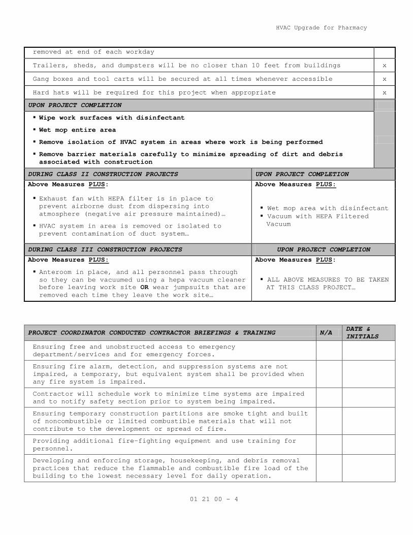
removed at end of each workday
Trailers, sheds, and dumpsters will be no closer than 10 feet from buildings x
Gang boxes and tool carts will be secured at all times whenever accessible x
Hard hats will be required for this project when appropriate x
UPON PROJECT COMPLETION
Wipe work surfaces with disinfectant
Wet mop entire area
Remove isolation of HVAC system in areas where work is being performed
Remove barrier materials carefully to minimize spreading of dirt and debris associated with construction
DURING CLASS II CONSTRUCTION PROJECTS UPON PROJECT COMPLETION
Above Measures PLUS: Above Measures PLUS:
Exhaust fan with HEPA filter is in place to prevent airborne dust from dispersing into atmosphere (negative air pressure maintained)…
HVAC system in area is removed or isolated to prevent contamination of duct system…
Wet mop area with disinfectant Vacuum with HEPA Filtered Vacuum
DURING CLASS III CONSTRUCTION PROJECTS UPON PROJECT COMPLETION
Above Measures PLUS: Above Measures PLUS:
Anteroom in place, and all personnel pass through so they can be vacuumed using a hepa vacuum cleaner before leaving work site OR wear jumpsuits that are removed each time they leave the work site…
ALL ABOVE MEASURES TO BE TAKEN AT THIS CLASS PROJECT…
PROJECT COORDINATOR CONDUCTED CONTRACTOR BRIEFINGS & TRAINING N/A DATE & INITIALS
Ensuring free and unobstructed access to emergency department/services and for emergency forces.
Ensuring fire alarm, detection, and suppression systems are not impaired, a temporary, but equivalent system shall be provided when any fire system is impaired.
Contractor will schedule work to minimize time systems are impaired and to notify safety section prior to system being impaired.
Ensuring temporary construction partitions are smoke tight and built of noncombustible or limited combustible materials that will not contribute to the development or spread of fire.
Providing additional fire-fighting equipment and use training for personnel.
Developing and enforcing storage, housekeeping, and debris removal practices that reduce the flammable and combustible fire load of the building to the lowest necessary level for daily operation.
HVAC Upgrade for Pharmacy
01 21 00 - 5
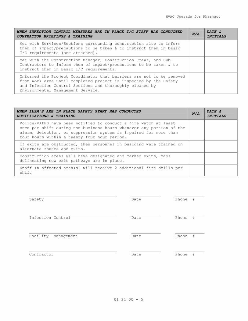
WHEN INFECTION CONTROL MEASURES ARE IN PLACE I/C STAFF HAS CONDUCTED CONTRACTOR BRIEFINGS & TRAINING N/A DATE &
INITIALS
Met with Services/Sections surrounding construction site to inform them of impact/precautions to be taken & to instruct them in basic I/C requirements (see attached).
Met with the Construction Manager, Construction Crews, and Sub-Contractors to inform them of impact/precautions to be taken & to instruct them in Basic I/C requirements.
Informed the Project Coordinator that barriers are not to be removed from work area until completed project is inspected by the Safety and Infection Control Sections and thoroughly cleaned by Environmental Management Service.
WHEN ILSM’S ARE IN PLACE SAFETY STAFF HAS CONDUCTED NOTIFICATIONS & TRAINING N/A DATE &
INITIALS
Police/VAfFD have been notified to conduct a fire watch at least once per shift during non-business hours whenever any portion of the alarm, detection, or suppression system is impaired for more than four hours within a twenty-four hour period.
If exits are obstructed, then personnel in building were trained on alternate routes and exits.
Construction areas will have designated and marked exits, maps delineating new exit pathways are in place.
Staff In affected area(s) will receive 2 additional fire drills per shift
Safety Date Phone # Infection Control Date Phone # Facility Management Date Phone # Contractor Date Phone #


HVAC Upgrade for Pharmacy
04-10M
01 32 16.17 - 1
SECTION 01 32 16.17 PROJECT SCHEDULES
(SMALL PROJECTS – DESIGN/BID/BUILD)
PART 1- GENERAL
1.1 DESCRIPTION:
A. The Contractor shall develop a Critical Path Method (CPM) plan and
schedule demonstrating fulfillment of the contract requirements (Project
Schedule), and shall keep the Project Schedule up-to-date in accordance
with the requirements of this section and shall utilize the plan for
scheduling, coordinating and monitoring work under this contract
(including all activities of subcontractors, equipment vendors and
suppliers). Conventional Critical Path Method (CPM) technique shall be
utilized to satisfy both time and cost applications.
1.2 CONTRACTOR'S REPRESENTATIVE:
A. The Contractor shall designate an authorized representative responsible
for the Project Schedule including preparation, review and progress
reporting with and to the Contracting Officer's Representative (COTR).
B. The Contractor's representative shall have direct project control and
complete authority to act on behalf of the Contractor in fulfilling the
requirements of this specification section.
C. The Contractor’s representative shall have the option of developing the
project schedule within their organization or to engage the services of
an outside consultant. If an outside scheduling consultant is utilized,
Section 1.3 of this specification will apply.
1.3 CONTRACTOR'S CONSULTANT:
A. The Contractor shall submit a qualification proposal to the COTR, within
10 days of bid acceptance. The qualification proposal shall include:
1. The name and address of the proposed consultant.
2. Information to show that the proposed consultant has the
qualifications to meet the requirements specified in the preceding
paragraph.
3. A representative sample of prior construction projects, which the
proposed consultant has performed complete project scheduling
services. These representative samples shall be of similar size and
scope.
B. The Contracting Officer has the right to approve or disapprove the
proposed consultant, and will notify the Contractor of the VA decision
within seven calendar days from receipt of the qualification proposal.
In case of disapproval, the Contractor shall resubmit another consultant
within 10 calendar days for renewed consideration. The Contractor shall

HVAC Upgrade for Pharmacy
04-10M
01 32 16.17 - 2
have their scheduling consultant approved prior to submitting any
schedule for approval.
1.4 COMPUTER PRODUCED SCHEDULES
A. The contractor shall provide monthly, to the Department of Veterans
Affairs (VA), all computer-produced time/cost schedules and reports
generated from monthly project updates. This monthly computer service
will include: three copies of up to five different reports (inclusive of
all pages) available within the user defined reports of the scheduling
software approved by the Contracting Officer; a hard copy listing of all
project schedule changes, and associated data, made at the update and an
electronic file of this data; and the resulting monthly updated schedule
in PDM format. These must be submitted with and substantively support
the contractor’s monthly payment request and the signed look ahead
report. The COTR shall identify the five different report formats that
the contractor shall provide.
B. The contractor shall be responsible for the correctness and timeliness
of the computer-produced reports. The Contractor shall also responsible
for the accurate and timely submittal of the updated project schedule
and all CPM data necessary to produce the computer reports and payment
request that is specified.
C. The VA will report errors in computer-produced reports to the
Contractor’s representative within ten calendar days from receipt of
reports. The Contractor shall reprocess the computer-produced reports
and associated diskette(s), when requested by the Contracting Officer’s
representative, to correct errors which affect the payment and schedule
for the project.
1.5 THE COMPLETE PROJECT SCHEDULE SUBMITTAL
A. Within 45 calendar days after receipt of Notice to Proceed, the
Contractor shall submit for the Contracting Officer's review; three blue
line copies of the interim schedule on sheets of paper 765 x 1070 mm (30
x 42 inches) and an electronic file in the previously approved CPM
schedule program. The submittal shall also include three copies of a
computer-produced activity/event ID schedule showing project duration;
phase completion dates; and other data, including event cost. Each
activity/event on the computer-produced schedule shall contain as a
minimum, but not limited to, activity/event ID, activity/event
description, duration, budget amount, early start date, early finish
date, late start date, late finish date and total float. Work
activity/event relationships shall be restricted to finish-to-start or
start-to-start without lead or lag constraints. Activity/event date
constraints, not required by the contract, will not be accepted unless

HVAC Upgrade for Pharmacy
04-10M
01 32 16.17 - 3
submitted to and approved by the Contracting Officer. The contractor
shall make a separate written detailed request to the Contracting
Officer identifying these date constraints and secure the Contracting
Officer’s written approval before incorporating them into the network
diagram. The Contracting Officer’s separate approval of the Project
Schedule shall not excuse the contractor of this requirement. Logic
events (non-work) will be permitted where necessary to reflect proper
logic among work events, but must have zero duration. The complete
working schedule shall reflect the Contractor's approach to scheduling
the complete project. The final Project Schedule in its original form
shall contain no contract changes or delays which may have been incurred
during the final network diagram development period and shall reflect
the entire contract duration as defined in the bid documents. These
changes/delays shall be entered at the first update after the final
Project Schedule has been approved. The Contractor should provide their
requests for time and supporting time extension analysis for contract
time as a result of contract changes/delays, after this update, and in
accordance with Article, ADJUSTMENT OF CONTRACT COMPLETION.
D. Within 30 calendar days after receipt of the complete project interim
Project Schedule and the complete final Project Schedule, the
Contracting Officer or his representative, will do one or both of the
following:
1. Notify the Contractor concerning his actions, opinions, and
objections.
2. A meeting with the Contractor at or near the job site for joint
review, correction or adjustment of the proposed plan will be
scheduled if required. Within 14 calendar days after the joint
review, the Contractor shall revise and shall submit three blue line
copies of the revised Project Schedule, three copies of the revised
computer-produced activity/event ID schedule and a revised electronic
file as specified by the Contracting Officer. The revised submission
will be reviewed by the Contracting Officer and, if found to be as
previously agreed upon, will be approved.
E. The approved baseline schedule and the computer-produced schedule(s)
generated there from shall constitute the approved baseline schedule
until subsequently revised in accordance with the requirements of this
section.
F. The Complete Project Schedule shall contain minimally 35 work
activities/events.

HVAC Upgrade for Pharmacy
04-10M
01 32 16.17 - 4
1.6 WORK ACTIVITY/EVENT COST DATA
A. The Contractor shall cost load all work activities/events except
procurement activities. The cumulative amount of all cost loaded work
activities/events (including alternates) shall equal the total contract
price. Prorate overhead, profit and general conditions on all work
activities/events for the entire project length. The contractor shall
generate from this information cash flow curves indicating graphically
the total percentage of work activity/event dollar value scheduled to be
in place on early finish, late finish. These cash flow curves will be
used by the Contracting Officer to assist him in determining approval or
disapproval of the cost loading. Negative work activity/event cost data
will not be acceptable, except on VA issued contract changes.
B. The Contractor shall cost load work activities/events test, balance and
adjust various systems in accordance with the provisions in Article, FAR
52.232 – 5 (PAYMENT UNDER FIXED-PRICE CONSTRUCTION CONTRACTS) and VAAR
852.236 – 83 (PAYMENT UNDER FIXED-PRICE CONSTRUCTION CONTRACTS).
C. In accordance with FAR 52.236 – 1 (PERFORMANCE OF WORK BY THE
CONTRACTOR) and VAAR 852.236 – 72 (PERFORMANCE OF WORK BY THE
CONTRACTOR), the Contractor shall submit, simultaneously with the cost
per work activity/event of the construction schedule required by this
Section, a responsibility code for all activities/events of the project
for which the Contractor's forces will perform the work.
D. The Contractor shall cost load work activities/events for all BID ITEMS
including ASBESTOS ABATEMENT. The sum of each BID ITEM work shall equal
the value of the bid item in the Contractors' bid.
1.7 PROJECT SCHEDULE REQUIREMENTS
A. Show on the project schedule the sequence of work activities/events
required for complete performance of all items of work. The Contractor
Shall:
1. Show activities/events as:
a. Contractor's time required for submittal of shop drawings,
templates, fabrication, delivery and similar pre-construction
work.
b. Contracting Officer's and Architect-Engineer's review and approval
of shop drawings, equipment schedules, samples, template, or
similar items.
c. Interruption of VA Facilities utilities, delivery of Government
furnished equipment, and rough-in drawings, project phasing and
any other specification requirements.

HVAC Upgrade for Pharmacy
04-10M
01 32 16.17 - 5
d. Test, balance and adjust various systems and pieces of equipment,
maintenance and operation manuals, instructions and preventive
maintenance tasks.
e. VA inspection and acceptance activity/event with a minimum
duration of five work days at the end of each phase and
immediately preceding any VA move activity/event required by the
contract phasing for that phase.
2. Show not only the activities/events for actual construction work for
each trade category of the project, but also trade relationships to
indicate the movement of trades from one area, floor, or building, to
another area, floor, or building, for at least five trades who are
performing major work under this contract.
3. Break up the work into activities/events of a duration no longer than
20 work days each or one reporting period, except as to
non-construction activities/events (i.e., procurement of materials,
delivery of equipment, concrete and asphalt curing) and any other
activities/events for which the COTR may approve the showing of a
longer duration. The duration for VA approval of any required
submittal, shop drawing, or other submittals will not be less than 20
work days.
4. Describe work activities/events clearly, so the work is readily
identifiable for assessment of completion. Activities/events labeled
"start," "continue," or "completion," are not specific and will not
be allowed. Lead and lag time activities will not be acceptable.
5. The schedule shall be generally numbered in such a way to reflect
either discipline, phase or location of the work.
B. The Contractor shall submit the following supporting data in addition to
the project schedule:
1. The appropriate project calendar including working days and holidays.
2. The planned number of shifts per day.
3. The number of hours per shift.
Failure of the Contractor to include this data shall delay the review of
the submittal until the Contracting Officer is in receipt of the missing
data.
C. To the extent that the Project Schedule or any revised Project Schedule
shows anything not jointly agreed upon, it shall not be deemed to have
been approved by the COTR. Failure to include any element of work
required for the performance of this contract shall not excuse the
Contractor from completing all work required within any applicable
completion date of each phase regardless of the COTR’s approval of the
Project Schedule.
HVAC Upgrade for Pharmacy
04-10M
01 32 16.17 - 6
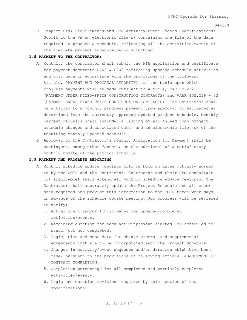
D. Compact Disk Requirements and CPM Activity/Event Record Specifications:
Submit to the VA an electronic file(s) containing one file of the data
required to produce a schedule, reflecting all the activities/events of
the complete project schedule being submitted.
1.8 PAYMENT TO THE CONTRACTOR:
A. Monthly, the contractor shall submit the AIA application and certificate
for payment documents G702 & G703 reflecting updated schedule activities
and cost data in accordance with the provisions of the following
Article, PAYMENT AND PROGRESS REPORTING, as the basis upon which
progress payments will be made pursuant to Article, FAR 52.232 – 5
(PAYMENT UNDER FIXED-PRICE CONSTRUCTION CONTRACTS) and VAAR 852.236 – 83
(PAYMENT UNDER FIXED-PRICE CONSTRUCTION CONTRACTS). The Contractor shall
be entitled to a monthly progress payment upon approval of estimates as
determined from the currently approved updated project schedule. Monthly
payment requests shall include: a listing of all agreed upon project
schedule changes and associated data; and an electronic file (s) of the
resulting monthly updated schedule.
B. Approval of the Contractor’s monthly Application for Payment shall be
contingent, among other factors, on the submittal of a satisfactory
monthly update of the project schedule.
1.9 PAYMENT AND PROGRESS REPORTING
A. Monthly schedule update meetings will be held on dates mutually agreed
to by the COTR and the Contractor. Contractor and their CPM consultant
(if applicable) shall attend all monthly schedule update meetings. The
Contractor shall accurately update the Project Schedule and all other
data required and provide this information to the COTR three work days
in advance of the schedule update meeting. Job progress will be reviewed
to verify:
1. Actual start and/or finish dates for updated/completed
activities/events.
2. Remaining duration for each activity/event started, or scheduled to
start, but not completed.
3. Logic, time and cost data for change orders, and supplemental
agreements that are to be incorporated into the Project Schedule.
4. Changes in activity/event sequence and/or duration which have been
made, pursuant to the provisions of following Article, ADJUSTMENT OF
CONTRACT COMPLETION.
5. Completion percentage for all completed and partially completed
activities/events.
6. Logic and duration revisions required by this section of the
specifications.

HVAC Upgrade for Pharmacy
04-10M
01 32 16.17 - 7
7. Activity/event duration and percent complete shall be updated
independently.
B. After completion of the joint review, the contractor shall generate an
updated computer-produced calendar-dated schedule and supply the
Contracting Officer’s representative with reports in accordance with the
Article, COMPUTER PRODUCED SCHEDULES, specified.
C. After completing the monthly schedule update, the contractor’s
representative or scheduling consultant shall rerun all current period
contract change(s) against the prior approved monthly project schedule.
The analysis shall only include original workday durations and schedule
logic agreed upon by the contractor and resident engineer for the
contract change(s). When there is a disagreement on logic and/or
durations, the Contractor shall use the schedule logic and/or durations
provided and approved by the resident engineer. After each rerun update,
the resulting electronic project schedule data file shall be
appropriately identified and submitted to the VA in accordance to the
requirements listed in articles 1.4 and 1.7. This electronic submission
is separate from the regular monthly project schedule update
requirements and shall be submitted to the resident engineer within
fourteen (14) calendar days of completing the regular schedule update.
Before inserting the contract changes durations, care must be taken to
ensure that only the original durations will be used for the analysis,
not the reported durations after progress. In addition, once the final
network diagram is approved, the contractor must recreate all manual
progress payment updates on this approved network diagram and associated
reruns for contract changes in each of these update periods as outlined
above for regular update periods. This will require detailed record
keeping for each of the manual progress payment updates.
D. Following approval of the CPM schedule, the VA, the General Contractor,
its approved CPM Consultant, RE office representatives, and all
subcontractors needed, as determined by the SRE, shall meet to discuss
the monthly updated schedule. The main emphasis shall be to address work
activities to avoid slippage of project schedule and to identify any
necessary actions required to maintain project schedule during the
reporting period. The Government representatives and the Contractor
should conclude the meeting with a clear understanding of those work and
administrative actions necessary to maintain project schedule status
during the reporting period. This schedule coordination meeting will
occur after each monthly project schedule update meeting utilizing the
resulting schedule reports from that schedule update. If the project is

HVAC Upgrade for Pharmacy
04-10M
01 32 16.17 - 8
behind schedule, discussions should include ways to prevent further
slippage as well as ways to improve the project schedule status, when
appropriate.
1.10 RESPONSIBILITY FOR COMPLETION
A. If it becomes apparent from the current revised monthly progress
schedule that phasing or contract completion dates will not be met, the
Contractor shall execute some or all of the following remedial actions:
1. Increase construction manpower in such quantities and crafts as
necessary to eliminate the backlog of work.
2. Increase the number of working hours per shift, shifts per working
day, working days per week, the amount of construction equipment, or
any combination of the foregoing to eliminate the backlog of work.
3. Reschedule the work in conformance with the specification
requirements.
B. Prior to proceeding with any of the above actions, the Contractor shall
notify and obtain approval from the COTR for the proposed schedule
changes. If such actions are approved, the representative schedule
revisions shall be incorporated by the Contractor into the Project
Schedule before the next update, at no additional cost to the
Government.
1.11 CHANGES TO THE SCHEDULE
A. Within 30 calendar days after VA acceptance and approval of any updated
project schedule, the Contractor shall submit a revised electronic file
(s) and a list of any activity/event changes including predecessors and
successors for any of the following reasons:
1. Delay in completion of any activity/event or group of
activities/events, which may be involved with contract changes,
strikes, unusual weather, and other delays will not relieve the
Contractor from the requirements specified unless the conditions are
shown on the CPM as the direct cause for delaying the project beyond
the acceptable limits.
2. Delays in submittals, or deliveries, or work stoppage are encountered
which make rescheduling of the work necessary.
3. The schedule does not represent the actual prosecution and progress
of the project.
4. When there is, or has been, a substantial revision to the
activity/event costs regardless of the cause for these revisions.
B. CPM revisions made under this paragraph which affect the previously
approved computer-produced schedules for Government furnished equipment,
vacating of areas by the VA Facility, contract phase(s) and sub
phase(s), utilities furnished by the Government to the Contractor, or
HVAC Upgrade for Pharmacy
04-10M
01 32 16.17 - 9
any other previously contracted item, shall be furnished in writing to
the Contracting Officer for approval.
C. Contracting Officer's approval for the revised project schedule and all
relevant data is contingent upon compliance with all other paragraphs of
this section and any other previous agreements by the Contracting
Officer or the VA representative.
D. The cost of revisions to the project schedule resulting from contract
changes will be included in the proposal for changes in work as
specified in FAR 52.243 – 4 (Changes) and VAAR 852.236 – 88 (Changes –
Supplemental), and will be based on the complexity of the revision or
contract change, man hours expended in analyzing the change, and the
total cost of the change.
E. The cost of revisions to the Project Schedule not resulting from
contract changes is the responsibility of the Contractor.
1.12 ADJUSTMENT OF CONTRACT COMPLETION
A. The contract completion time will be adjusted only for causes specified
in this contract. Request for an extension of the contract completion
date by the Contractor shall be supported with a justification, CPM data
and supporting evidence as the COTR may deem necessary for determination
as to whether or not the Contractor is entitled to an extension of time
under the provisions of the contract. Submission of proof based on
revised activity/event logic, durations (in work days) and costs is
obligatory to any approvals. The schedule must clearly display that the
Contractor has used, in full, all the float time available for the work
involved in this request. The Contracting Officer's determination as to
the total number of days of contract extension will be based upon the
current computer-produced calendar-dated schedule for the time period in
question and all other relevant information.
B. Actual delays in activities/events which, according to the computer-
produced calendar-dated schedule, do not affect the extended and
predicted contract completion dates shown by the critical path in the
network, will not be the basis for a change to the contract completion
date. The Contracting Officer will within a reasonable time after
receipt of such justification and supporting evidence, review the facts
and advise the Contractor in writing of the Contracting Officer's
decision.
C. The Contractor shall submit each request for a change in the contract
completion date to the Contracting Officer in accordance with the
provisions specified under FAR 52.243 – 4 (Changes) and VAAR 852.236 –
88 (Changes – Supplemental). The Contractor shall include, as a part of
each change order proposal, a sketch showing all CPM logic revisions,

HVAC Upgrade for Pharmacy
04-10M
01 32 16.17 - 10
duration (in work days) changes, and cost changes, for work in question
and its relationship to other activities on the approved network
diagram.
D. All delays due to non-work activities/events such as RFI’s, WEATHER,
STRIKES, and similar non-work activities/events shall be analyzed on a
month by month basis.
- - - E N D - - -

HVAC Upgrade for Pharmacy
11-08M
01 33 23 - 1
SECTION 01 33 23 SHOP DRAWINGS, PRODUCT DATA, AND SAMPLES
PART 1- GENERAL
1.1 Refer to Articles titled SPECIFICATIONS AND DRAWINGS FOR CONSTRUCTION
(FAR 52.236-21) and, SPECIAL NOTES (VAAR 852.236-91), in GENERAL
CONDITIONS.
1.2 For the purposes of this contract, samples, test reports, certificates,
and manufacturers' literature and data shall also be subject to the
previously referenced requirements. The following text refers to all
items collectively as SUBMITTALS.
1.3 Submit for approval, all of the items specifically mentioned under the
separate sections of the specification, with information sufficient to
evidence full compliance with contract requirements. Materials,
fabricated articles and the like to be installed in permanent work shall
equal those of approved submittals. After an item has been approved, no
change in brand or make will be permitted unless:
A. Satisfactory written evidence is presented to, and approved by
Contracting Officer, that manufacturer cannot make scheduled
delivery of approved item or;
B. Item delivered has been rejected and substitution of a suitable
item is an urgent necessity or;
C. Other conditions become apparent which indicates approval of such
substitute item to be in best interest of the Government.
1.4 Forward submittals in sufficient time to permit proper consideration and
approval action by Government. Time submission to assure adequate lead
time for procurement of contract - required items. Delays attributable
to untimely and rejected submittals will not serve as a basis for
extending contract time for completion.
1.5 Submittals will be reviewed for compliance with contract requirements by
Architect-Engineer, and action thereon will be taken by Resident
Engineer on behalf of the Contracting Officer.
1.6 Upon receipt of submittals, Architect-Engineer will assign a file number
thereto. Contractor, in any subsequent correspondence, shall refer to
this file and identification number to expedite replies relative to
previously approved or disapproved submittals.
1.7 The Government reserves the right to require additional submittals,
whether or not particularly mentioned in this contract. If additional
submittals beyond those required by the contract are furnished pursuant
to request therefor by Contracting Officer, adjustment in contract price
and time will be made in accordance with Articles titled CHANGES (FAR

HVAC Upgrade for Pharmacy
11-08M
01 33 23 - 2
52.243-4) and CHANGES - SUPPLEMENT (VAAR 852.236-88) of the GENERAL
CONDITIONS.
1.8 Schedules called for in specifications and shown on shop drawings shall
be submitted for use and information of Department of Veterans Affairs
and Architect-Engineer. However, the Contractor shall assume
responsibility for coordinating and verifying schedules. The Contracting
Officer and Architect- Engineer assumes no responsibility for checking
schedules or layout drawings for exact sizes, exact numbers and detailed
positioning of items.
1.9 Submittals must be submitted by Contractor only and shipped prepaid.
Contracting Officer assumes no responsibility for checking quantities or
exact numbers included in such submittals.
A. Submit samples in duplicate units unless otherwise specified.
Submit shop drawings, schedules, manufacturers' literature and
data, and certificates in quadruplicate, except where a greater
number is specified.
B. Submittals will receive consideration only when covered by a
transmittal letter signed by Contractor. Letter shall be sent via
first class mail and shall contain the list of items, name of
Medical Center, name of Contractor, contract number, applicable
specification paragraph numbers, applicable drawing numbers (and
other information required for exact identification of location for
each item), manufacturer and brand, ASTM or Federal Specification
Number (if any) and such additional information as may be required
by specifications for particular item being furnished. In addition,
catalogs shall be marked to indicate specific items submitted for
approval.
1. A copy of letter must be enclosed with items, and any items
received without identification letter will be considered
"unclaimed goods" and held for a limited time only.
2. Each sample, certificate, manufacturers' literature and data
shall be labeled to indicate the name and location of the
Medical Center name of Contractor, manufacturer, brand,
contract number and ASTM or Federal Specification Number as
applicable and location(s) on project.
3. Required certificates shall be signed by an authorized
representative of manufacturer or supplier of material, and by
Contractor.
C. If submittal samples have been disapproved, resubmit new samples as
soon as possible after notification of disapproval. Such new
HVAC Upgrade for Pharmacy
11-08M
01 33 23 - 3
samples shall be marked "Resubmitted Sample" in addition to
containing other previously specified information required on label
and in transmittal letter.
D. Approved samples will be kept on file by the Resident Engineer at
the site until completion of contract, at which time such samples
will be delivered to Contractor as Contractor's property. Where
noted in technical sections of specifications, approved samples in
good condition may be used in their proper locations in contract
work. At completion of contract, samples that are not approved will
be returned to Contractor only upon request and at Contractor's
expense. Such request should be made prior to completion of the
contract. Disapproved samples that are not requested for return by
Contractor will be discarded after completion of contract.
E. Submittal drawings (shop, erection or setting drawings) and
schedules, required for work of various trades, shall be checked
before submission by technically qualified employees of Contractor
for accuracy, completeness and compliance with contract
requirements. These drawings and schedules shall be stamped and
signed by Contractor certifying to such check.
1. For each drawing required, submit one legible photographic
paper or vellum reproducible.
2. Reproducible shall be full size.
3. Each drawing shall have marked thereon, proper descriptive
title, including Medical Center location, project number,
manufacturer's number, reference to contract drawing number,
detail Section Number, and Specification Section Number.
4. A space 120 mm by 125 mm (4-3/4 by 5 inches) shall be reserved
on each drawing to accommodate approval or disapproval stamp.
5. Submit drawings, ROLLED WITHIN A MAILING TUBE, fully protected
for shipment.
6. One reproducible print of approved or disapproved shop drawings
will be forwarded to Contractor.
7. When work is directly related and involves more than one trade,
shop drawings shall be submitted to Architect-Engineer under
one cover.
1.10 Samples, shop drawings, test reports, certificates and manufacturers'
literature and data, shall be submitted for approval to
Bailey Edward Architecture (Architect-Engineer)
35 E Wacker Drive, Suite 2800, Chicago, Illinois, 60601

HVAC Upgrade for Pharmacy
11-08M
01 33 23 - 4
1.11 At the time of transmittal to the Architect-Engineer, the Contractor
shall also send a copy of the complete submittal directly to the
Resident Engineer.
- - - E N D - - -
HVAC Upgrade for Pharmacy
09-11
01 42 19 - 1
SECTION 01 42 19 REFERENCE STANDARDS
PART 1 - GENERAL
1.1 DESCRIPTION
This section specifies the availability and source of references and
standards specified in the project manual under paragraphs APPLICABLE
PUBLICATIONS and/or shown on the drawings.
1.2 AVAILABILITY OF SPECIFICATIONS LISTED IN THE GSA INDEX OF FEDERAL SPECIFICATIONS, STANDARDS AND COMMERCIAL ITEM DESCRIPTIONS FPMR PART 101-29 (FAR 52.211-1) (AUG 1998)
A. The GSA Index of Federal Specifications, Standards and Commercial Item
Descriptions, FPMR Part 101-29 and copies of specifications, standards,
and commercial item descriptions cited in the solicitation may be
obtained for a fee by submitting a request to – GSA Federal Supply
Service, Specifications Section, Suite 8100, 470 East L’Enfant Plaza,
SW, Washington, DC 20407, Telephone (202) 619-8925, Facsimile (202) 619-
8978.
B. If the General Services Administration, Department of Agriculture, or
Department of Veterans Affairs issued this solicitation, a single copy
of specifications, standards, and commercial item descriptions cited in
this solicitation may be obtained free of charge by submitting a request
to the addressee in paragraph (a) of this provision. Additional copies
will be issued for a fee.
1.3 AVAILABILITY FOR EXAMINATION OF SPECIFICATIONS NOT LISTED IN THE GSA INDEX OF FEDERAL SPECIFICATIONS, STANDARDS AND COMMERCIAL ITEM DESCRIPTIONS (FAR 52.211-4) (JUN 1988)
The specifications and standards cited in this solicitation can be
examined at the following location:
DEPARMENT OF VETERANS AFFAIRS
Office of Construction & Facilities Management
Facilities Quality Service (00CFM1A)
425 Eye Street N.W, (sixth floor)
Washington, DC 20001
Telephone Numbers: (202) 632-5249 or (202) 632-5178
Between 9:00 AM - 3:00 PM
HVAC Upgrade for Pharmacy
09-11
01 42 19 - 2
1.4 AVAILABILITY OF SPECIFICATIONS NOT LISTED IN THE GSA INDEX OF FEDERAL SPECIFICATIONS, STANDARDS AND COMMERCIAL ITEM DESCRIPTIONS (FAR 52.211-3) (JUN 1988)
The specifications cited in this solicitation may be obtained from the
associations or organizations listed below.
AA Aluminum Association Inc.
AABC Associated Air Balance Council
http://www.aluminum.org
AAMA American Architectural Manufacturer's Association
http://www.aabchq.com
ACGIH American Conference of Governmental Industrial Hygienists
http://www.aamanet.org
ACI American Concrete Institute
http://www.acgih.org
ADC Air Diffusion Council
http://www.aci-int.net
AGA American Gas Association
http://flexibleduct.org
AGC Associated General Contractors of America
http://www.aga.org
AISC American Institute of Steel Construction
http://www.agc.org
AISI American Iron and Steel Institute
http://www.aisc.org
AMCA Air Movement and Control Association, Inc.
http://www.steel.org
ANSI American National Standards Institute, Inc.
http://www.amca.org
ARI Air-Conditioning and Refrigeration Institute
http://www.ansi.org
http://www.ari.org
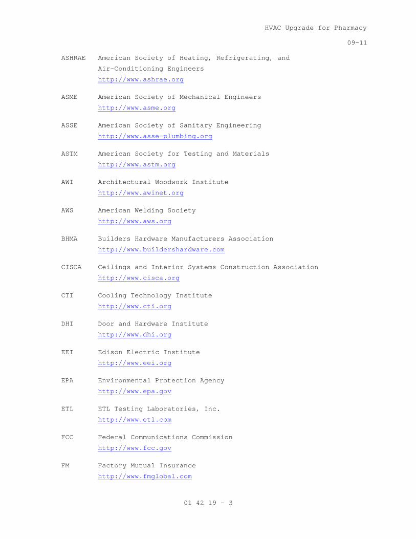
HVAC Upgrade for Pharmacy
09-11
01 42 19 - 3
ASHRAE American Society of Heating, Refrigerating, and
Air-Conditioning Engineers
ASME American Society of Mechanical Engineers
http://www.ashrae.org
ASSE American Society of Sanitary Engineering
http://www.asme.org
ASTM American Society for Testing and Materials
http://www.asse-plumbing.org
AWI Architectural Woodwork Institute
http://www.astm.org
AWS American Welding Society
http://www.awinet.org
BHMA Builders Hardware Manufacturers Association
http://www.aws.org
CISCA Ceilings and Interior Systems Construction Association
http://www.buildershardware.com
CTI Cooling Technology Institute
http://www.cisca.org
DHI Door and Hardware Institute
http://www.cti.org
EEI Edison Electric Institute
http://www.dhi.org
EPA Environmental Protection Agency
http://www.eei.org
ETL ETL Testing Laboratories, Inc.
http://www.epa.gov
FCC Federal Communications Commission
http://www.et1.com
FM Factory Mutual Insurance
http://www.fcc.gov
http://www.fmglobal.com

HVAC Upgrade for Pharmacy
09-11
01 42 19 - 4
GA Gypsum Association
GSA General Services Administration
http://www.gypsum.org
HI Hydraulic Institute
http://www.gsa.gov
IBC International Building Code
http://www.pumps.org
www.iccsafe.org ICC International Code Council www.iccsafe.org ICEA Insulated Cable Engineers Association Inc.
ICAC Institute of Clean Air Companies
http://www.icea.net
IEEE Institute of Electrical and Electronics Engineers
http://www.icac.com
IPCEA Insulated Power Cable Engineers Association
http://www.ieee.org\
MSS Manufacturers Standardization Society of the Valve and Fittings
Industry Inc.
NAAMM National Association of Architectural Metal Manufacturers
http://www.mss-hq.com
NAPHCC Plumbing-Heating-Cooling Contractors Association
http://www.naamm.org
NBS National Bureau of Standards
See - NIST
http://www.phccweb.org.org
NEC National Electric Code
See - NFPA National Fire Protection Association
NEMA National Electrical Manufacturers Association
http://www.nema.org

HVAC Upgrade for Pharmacy
09-11
01 42 19 - 5
NFPA National Fire Protection Association
NIH National Institute of Health
http://www.nfpa.org
NIST National Institute of Standards and Technology
http://www.nih.gov
NSF National Sanitation Foundation
http://www.nist.gov
NWWDA Window and Door Manufacturers Association
http://www.nsf.org
OSHA Occupational Safety and Health Administration
Department of Labor
http://www.nwwda.org
PPI The Plastic Pipe Institute
http://www.osha.gov
SDI Steel Deck Institute
http://www.plasticpipe.org
www.sdi.org
SJI Steel Joist Institute
SMACNA Sheet Metal and Air-Conditioning Contractors
National Association, Inc.
http://www.steeljoist.org
SSPC The Society for Protective Coatings
http://www.smacna.org
TEMA Tubular Exchange Manufacturers Association
http://www.sspc.org
UL Underwriters' Laboratories Incorporated
http://www.tema.org
- - - E N D - - -
http://www.ul.com


HVAC Upgrade for Pharmacy
05-09M
01 45 29 - 1
SECTION 01 45 29 TESTING LABORATORY SERVICES
PART 1 - GENERAL
1.1 DESCRIPTION:
This section specifies materials testing activities and inspection
services required during project construction to be provided by a
Testing Laboratory retained and paid for by Contractor.
1.2 APPLICABLE PUBLICATIONS:
A. The publications listed below form a part of this specification to the
extent referenced. The publications are referred to in the text by the
basic designation only.
B. American Society for Testing and Materials (ASTM):
A325-06.................Structural Bolts, Steel, Heat Treated, 120/105
ksi Minimum Tensile Strength
A370-07.................Definitions for Mechanical Testing of Steel
Products
C31/C31M-06.............Making and Curing Concrete Test Specimens in the
Field
C33-03..................Concrete Aggregates
C39/C39M-05.............Compressive Strength of Cylindrical Concrete
Specimens
C109/C109M-05...........Compressive Strength of Hydraulic Cement Mortars
C138-07.................Unit Weight, Yield, and Air Content
(Gravimetric) of Concrete
C140-07.................Sampling and Testing Concrete Masonry Units and
Related Units
C143/C143M-05...........Slump of Hydraulic Cement Concrete
C172-07.................Sampling Freshly Mixed Concrete
C173-07.................Air Content of freshly Mixed Concrete by the
Volumetric Method
C330-05.................Lightweight Aggregates for Structural Concrete
C567-05.................Density Structural Lightweight Concrete
C780-07.................Pre-construction and Construction Evaluation of
Mortars for Plain and Reinforced Unit Masonry
C1019-08................Sampling and Testing Grout
C1064/C1064M-05.........Freshly Mixed Portland Cement Concrete
C1077-06................Laboratories Testing Concrete and Concrete
Aggregates for Use in Construction and Criteria
for Laboratory Evaluation
C1314-07................Compressive Strength of Masonry Prisms
D698-07.................Laboratory Compaction Characteristics of Soil
Using Standard Effort
HVAC Upgrade for Pharmacy
05-09M
01 45 29 - 2
D2166-06................Unconfined Compressive Strength of Cohesive Soil
E329-07.................Agencies Engaged in Construction Inspection
and/or Testing
E543-06.................Agencies Performing Non-Destructive Testing
E605-93(R2006)..........Thickness and Density of Sprayed Fire-Resistive
Material (SFRM) Applied to Structural Members
E709-(2001).............Guide for Magnetic Particle Examination
E1155-96(R2008).........Determining FF Floor Flatness and FL Floor
Levelness Numbers
E. American Welding Society (AWS):
D1.1-07.................Structural Welding Code-Steel
1.3 REQUIREMENTS:
A. Accreditation Requirements: Construction materials testing laboratories
must be accredited by a laboratory accreditation authority and will be
required to submit a copy of the Certificate of Accreditation and Scope
of Accreditation. The laboratory’s scope of accreditation must include
the appropriate ASTM standards (i.e.; E 329, C 1077, D 3666, D3740, A
880, E 543) listed in the technical sections of the specifications.
Laboratories engaged in Hazardous Materials Testing shall meet the
requirements of OSHA and EPA. The policy applies to the specific
laboratory performing the actual testing, not just the “Corporate
Office.”
B. Inspection and Testing: Testing laboratory shall inspect materials and
workmanship and perform tests described herein and additional tests
requested by Resident Engineer. When it appears materials furnished, or
work performed by Contractor fail to meet construction contract
requirements, Testing Laboratory shall direct attention of Resident
Engineer to such failure.
C. Written Reports: Testing laboratory shall submit test reports to
Resident Engineer, Contractor, unless other arrangements are agreed to
in writing by the Resident Engineer. Submit reports of tests that fail
to meet construction contract requirements on colored paper.
D. Verbal Reports: Give verbal notification to Resident Engineer
immediately of any irregularity.
1.4 SUBMITTALS:
A. Submit testing agency credential for review and acceptance.
PART 2 - PRODUCTS (NOT USED)

HVAC Upgrade for Pharmacy
05-09M
01 45 29 - 3
PART 3 - EXECUTION
3.1 STRUCTURAL STEEL:
A. General: Provide shop and field inspection and testing services to
certify structural steel work is done in accordance with contract
documents. Welding shall conform to AWS D1.1 Structural Welding Code.
B. Prefabrication Inspection:
1. Review design and shop detail drawings for size, length, type and
location of all welds to be made.
2. Approve welding procedure qualifications either by pre-qualification
or by witnessing qualifications tests.
3. Approve welder qualifications by certification or retesting.
4. Approve procedure for control of distortion and shrinkage stresses.
5. Approve procedures for welding in accordance with applicable sections
of AWS D1.1.
C. Fabrication and Erection:
1. Weld Inspection:
a. Inspect welding equipment for capacity, maintenance and working
condition.
b. Verify specified electrodes and handling and storage of electrodes
in accordance with AWS D1.1.
c. Inspect preparation and assembly of materials to be welded for
conformance with AWS D1.1.
d. Inspect preheating and interpass temperatures for conformance with
AWS D1.1.
e. Measure 25 percent of fillet welds.
f. Verify that correction of rejected welds are made in accordance
with AWS D1.1.
g. Testing and inspection do not relieve the Contractor of the
responsibility for providing materials and fabrication procedures
in compliance with the specified requirements.
2. Bolt Inspection:
a. Inspect high-strength bolted connections in accordance AISC
Specifications for Structural Joints Using ASTM A325 or A490
Bolts.
b. Slip-Critical Connections: Inspect 10 percent of bolts, but not
less than 2 bolts, selected at random in each connection in
accordance with AISC Specifications for Structural Joints Using
ASTM A325 or A490 Bolts. Inspect all bolts in connection when one
or more are rejected.
c. Bolts installed by turn-of-nut tightening may be inspected with
calibrated wrench when visual inspection was not performed during
tightening.

HVAC Upgrade for Pharmacy
05-09M
01 45 29 - 4
d. Snug Tight Connections: Inspect 10 percent of connections
verifying that plies of connected elements have been brought into
snug contact.
e. Inspect field erected assemblies; verify locations of structural
steel for plumbness, level, and alignment.
D. Submit inspection reports, record of welders and their certification,
and identification, and instances of noncompliance to Resident Engineer.
3.2 STEEL DECKING:
A. Provide field inspection of welds of metal deck to the supporting steel,
and testing services to insure steel decking has been installed in
accordance with contract documents and manufacturer’s requirements.
B. Qualification of Field Welding: Qualify welding processes and welding
operators in accordance with “Welder Qualification” procedures of AWS
D1.1. Refer to the “Plug Weld Qualification Procedure” in Part 3 “Field
Quality Control.”
C. Submit inspection reports, certification, and instances of noncompliance
to Resident Engineer.
3.3 SPRAYED-ON FIREPROOFING:
A. Provide field inspection and testing services to certify sprayed-on
fireproofing has been applied in accordance with contract documents.
B. Obtain a copy of approved submittals from Resident Engineer.
C. Use approved installation in test areas as criteria for inspection of
work.
D. Test sprayed-on fireproofing for thickness and density in accordance
with ASTM E605.
1. Thickness gauge specified in ASTM E605 may be modified for pole
extension so that overhead sprayed material can be reached from
floor.
E. Location of test areas for field tests as follows:
1. Thickness: Select one bay. Take thickness determinations from each of
following locations: Metal deck, and beam.
2. Density: Take density determinations from each floor, or roof. From
each of the following areas: Underside of metal deck, beam flanges,
and beam web.
F. Submit inspection reports, certification, and instances of noncompliance
to Resident Engineer.
- - - E N D - - -
HVAC Upgrade for Pharmacy
01-11
01 57 19- 1
SECTION 01 57 19 TEMPORARY ENVIRONMENTAL CONTROLS
PART 1 - GENERAL
1.1 DESCRIPTION
A. This section specifies the control of environmental pollution and damage
that the Contractor must consider for air, water, and land resources. It
includes management of visual aesthetics, noise, solid waste, radiant
energy, and radioactive materials, as well as other pollutants and
resources encountered or generated by the Contractor. The Contractor is
obligated to consider specified control measures with the costs included
within the various contract items of work.
B. Environmental pollution and damage is defined as the presence of
chemical, physical, or biological elements or agents which:
1. Adversely effect human health or welfare,
2. Unfavorably alter ecological balances of importance to human life,
3. Effect other species of importance to humankind, or;
4. Degrade the utility of the environment for aesthetic, cultural, and
historical purposes.
C. Definitions of Pollutants:
1. Chemical Waste: Petroleum products, bituminous materials, salts,
acids, alkalis, herbicides, pesticides, organic chemicals, and
inorganic wastes.
2. Debris: Combustible and noncombustible wastes, such as leaves, tree
trimmings, ashes, and waste materials resulting from construction or
maintenance and repair work.
3. Sediment: Soil and other debris that has been eroded and transported
by runoff water.
4. Solid Waste: Rubbish, debris, garbage, and other discarded solid
materials resulting from industrial, commercial, and agricultural
operations and from community activities.
5. Surface Discharge: The term "Surface Discharge" implies that the
water is discharged with possible sheeting action and subsequent soil
erosion may occur. Waters that are surface discharged may terminate
in drainage ditches, storm sewers, creeks, and/or "water of the
United States" and would require a permit to discharge water from the
governing agency.
6. Rubbish: Combustible and noncombustible wastes such as paper, boxes,
glass and crockery, metal and lumber scrap, tin cans, and bones.
HVAC Upgrade for Pharmacy
01-11
01 57 19- 2
7. Sanitary Wastes:
a. Sewage: Domestic sanitary sewage and human and animal waste.
b. Garbage: Refuse and scraps resulting from preparation, cooking,
dispensing, and consumption of food.
1.2 QUALITY CONTROL
A. Establish and maintain quality control for the environmental protection
of all items set forth herein.
B. Record on daily reports any problems in complying with laws,
regulations, and ordinances. Note any corrective action taken.
1.3 REFERENCES
A. The publications listed below form a part of this specification to the
extent referenced. The publications are referred to in the text by basic
designation only.
B. U.S. National Archives and Records Administration (NARA):
33 CFR 328..............Definitions
1.4 SUBMITTALS
A. In accordance with Section, 01 33 23, SHOP DRAWINGS, PRODUCT DATA, AND
SAMPLES, furnish the following:
1. Environmental Protection Plan: After the contract is awarded and
prior to the commencement of the work, the Contractor shall meet with
the Resident Engineer to discuss the proposed Environmental
Protection Plan and to develop mutual understanding relative to
details of environmental protection. Not more than 20 days after the
meeting, the Contractor shall prepare and submit to the COTR for
approval, a written and/or graphic Environmental Protection Plan
including, but not limited to, the following:
a. Name(s) of person(s) within the Contractor's organization who is
(are) responsible for ensuring adherence to the Environmental
Protection Plan.
b. Name(s) and qualifications of person(s) responsible for
manifesting hazardous waste to be removed from the site.
c. Name(s) and qualifications of person(s) responsible for training
the Contractor's environmental protection personnel.
d. Description of the Contractor's environmental protection personnel
training program.
e. A list of Federal, State, and local laws, regulations, and permits
concerning environmental protection, pollution control, noise
control and abatement that are applicable to the Contractor's
proposed operations and the requirements imposed by those laws,
regulations, and permits.
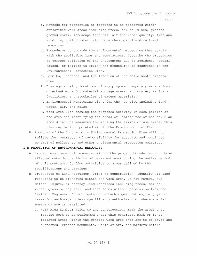
HVAC Upgrade for Pharmacy
01-11
01 57 19- 3
f. Methods for protection of features to be preserved within
authorized work areas including trees, shrubs, vines, grasses,
ground cover, landscape features, air and water quality, fish and
wildlife, soil, historical, and archeological and cultural
resources.
g. Procedures to provide the environmental protection that comply
with the applicable laws and regulations. Describe the procedures
to correct pollution of the environment due to accident, natural
causes, or failure to follow the procedures as described in the
Environmental Protection Plan.
h. Permits, licenses, and the location of the solid waste disposal
area.
i. Drawings showing locations of any proposed temporary excavations
or embankments for material storage areas, structures, sanitary
facilities, and stockpiles of excess materials.
j. Environmental Monitoring Plans for the job site including land,
water, air, and noise.
k. Work Area Plan showing the proposed activity in each portion of
the area and identifying the areas of limited use or nonuse. Plan
should include measures for marking the limits of use areas. This
plan may be incorporated within the Erosion Control Plan.
B. Approval of the Contractor's Environmental Protection Plan will not
relieve the Contractor of responsibility for adequate and continued
control of pollutants and other environmental protection measures.
1.5 PROTECTION OF ENVIRONMENTAL RESOURCES
A. Protect environmental resources within the project boundaries and those
affected outside the limits of permanent work during the entire period
of this contract. Confine activities to areas defined by the
specifications and drawings.
B. Protection of Land Resources: Prior to construction, identify all land
resources to be preserved within the work area. Do not remove, cut,
deface, injure, or destroy land resources including trees, shrubs,
vines, grasses, top soil, and land forms without permission from the
Resident Engineer. Do not fasten or attach ropes, cables, or guys to
trees for anchorage unless specifically authorized, or where special
emergency use is permitted.
1. Work Area Limits: Prior to any construction, mark the areas that
require work to be performed under this contract. Mark or fence
isolated areas within the general work area that are to be saved and
protected. Protect monuments, works of art, and markers before
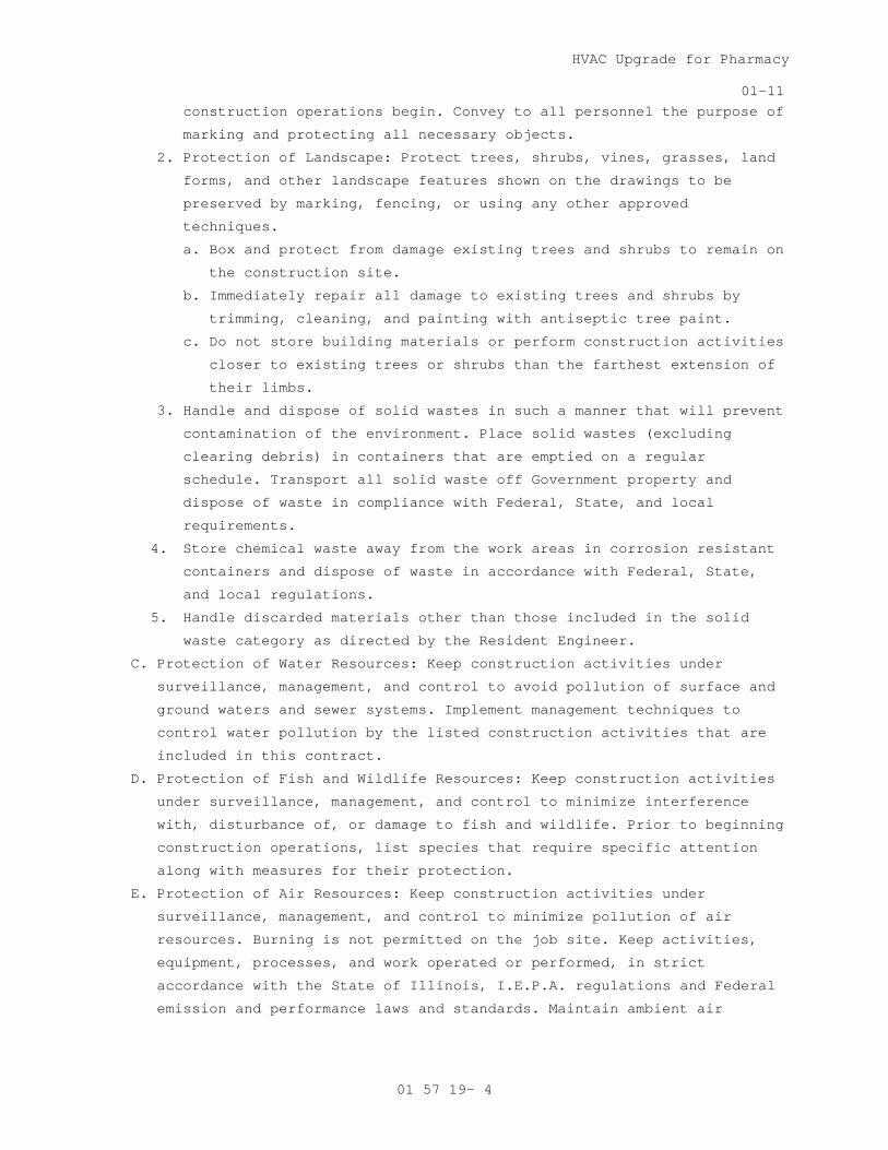
HVAC Upgrade for Pharmacy
01-11
01 57 19- 4
construction operations begin. Convey to all personnel the purpose of
marking and protecting all necessary objects.
2. Protection of Landscape: Protect trees, shrubs, vines, grasses, land
forms, and other landscape features shown on the drawings to be
preserved by marking, fencing, or using any other approved
techniques.
a. Box and protect from damage existing trees and shrubs to remain on
the construction site.
b. Immediately repair all damage to existing trees and shrubs by
trimming, cleaning, and painting with antiseptic tree paint.
c. Do not store building materials or perform construction activities
closer to existing trees or shrubs than the farthest extension of
their limbs.
3. Handle and dispose of solid wastes in such a manner that will prevent
contamination of the environment. Place solid wastes (excluding
clearing debris) in containers that are emptied on a regular
schedule. Transport all solid waste off Government property and
dispose of waste in compliance with Federal, State, and local
requirements.
4. Store chemical waste away from the work areas in corrosion resistant
containers and dispose of waste in accordance with Federal, State,
and local regulations.
5. Handle discarded materials other than those included in the solid
waste category as directed by the Resident Engineer.
C. Protection of Water Resources: Keep construction activities under
surveillance, management, and control to avoid pollution of surface and
ground waters and sewer systems. Implement management techniques to
control water pollution by the listed construction activities that are
included in this contract.
D. Protection of Fish and Wildlife Resources: Keep construction activities
under surveillance, management, and control to minimize interference
with, disturbance of, or damage to fish and wildlife. Prior to beginning
construction operations, list species that require specific attention
along with measures for their protection.
E. Protection of Air Resources: Keep construction activities under
surveillance, management, and control to minimize pollution of air
resources. Burning is not permitted on the job site. Keep activities,
equipment, processes, and work operated or performed, in strict
accordance with the State of Illinois, I.E.P.A. regulations and Federal
emission and performance laws and standards. Maintain ambient air
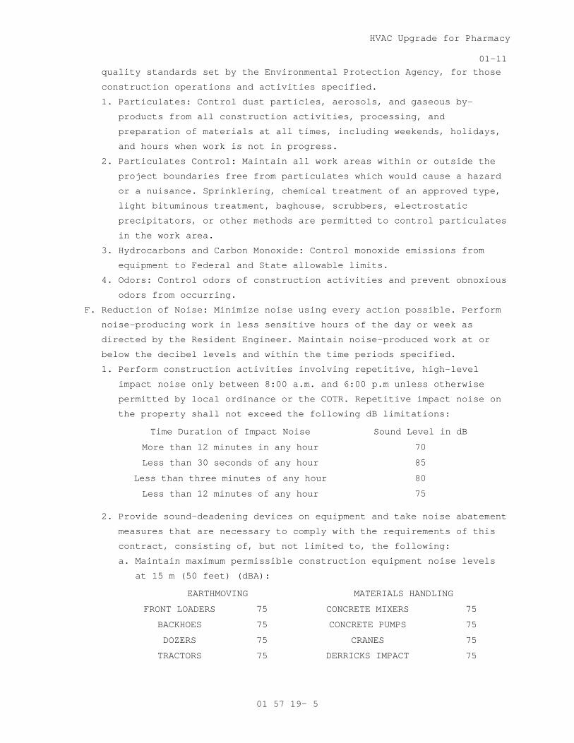
HVAC Upgrade for Pharmacy
01-11
01 57 19- 5
quality standards set by the Environmental Protection Agency, for those
construction operations and activities specified.
1. Particulates: Control dust particles, aerosols, and gaseous by-
products from all construction activities, processing, and
preparation of materials at all times, including weekends, holidays,
and hours when work is not in progress.
2. Particulates Control: Maintain all work areas within or outside the
project boundaries free from particulates which would cause a hazard
or a nuisance. Sprinklering, chemical treatment of an approved type,
light bituminous treatment, baghouse, scrubbers, electrostatic
precipitators, or other methods are permitted to control particulates
in the work area.
3. Hydrocarbons and Carbon Monoxide: Control monoxide emissions from
equipment to Federal and State allowable limits.
4. Odors: Control odors of construction activities and prevent obnoxious
odors from occurring.
F. Reduction of Noise: Minimize noise using every action possible. Perform
noise-producing work in less sensitive hours of the day or week as
directed by the Resident Engineer. Maintain noise-produced work at or
below the decibel levels and within the time periods specified.
1. Perform construction activities involving repetitive, high-level
impact noise only between 8:00 a.m. and 6:00 p.m unless otherwise
permitted by local ordinance or the COTR. Repetitive impact noise on
the property shall not exceed the following dB limitations:
Time Duration of Impact Noise Sound Level in dB
More than 12 minutes in any hour 70
Less than 30 seconds of any hour 85
Less than three minutes of any hour 80
Less than 12 minutes of any hour 75
2. Provide sound-deadening devices on equipment and take noise abatement
measures that are necessary to comply with the requirements of this
contract, consisting of, but not limited to, the following:
a. Maintain maximum permissible construction equipment noise levels
at 15 m (50 feet) (dBA):
EARTHMOVING MATERIALS HANDLING
FRONT LOADERS 75 CONCRETE MIXERS 75
BACKHOES 75 CONCRETE PUMPS 75
DOZERS 75 CRANES 75
TRACTORS 75 DERRICKS IMPACT 75

HVAC Upgrade for Pharmacy
01-11
01 57 19- 6
SCAPERS 80 PILE DRIVERS 95
GRADERS 75 JACK HAMMERS 75
TRUCKS 75 ROCK DRILLS 80
PAVERS, STATIONARY
80 PNEUMATIC TOOLS 80
PUMPS 75 BLASTING 75
GENERATORS 75 SAWS 75
COMPRESSORS 75 VIBRATORS 75
b. Use shields or other physical barriers to restrict noise
transmission.
c. Provide soundproof housings or enclosures for noise-producing
machinery.
d. Use efficient silencers on equipment air intakes.
e. Use efficient intake and exhaust mufflers on internal combustion
engines that are maintained so equipment performs below noise
levels specified.
f. Line hoppers and storage bins with sound deadening material.
g. Conduct truck loading, unloading, and hauling operations so that
noise is kept to a minimum.
3. Measure sound level for noise exposure due to the construction at
least once every five successive working days while work is being
performed above 55 dB(A) noise level. Measure noise exposure at the
property line or 15 m (50 feet) from the noise source, whichever is
greater. Measure the sound levels on the A weighing network of a
General Purpose sound level meter at slow response. To minimize the
effect of reflective sound waves at buildings, take measurements at
900 to 1800 mm (three to six feet) in front of any building face.
Submit the recorded information to the Resident Engineer noting any
problems and the alternatives for mitigating actions.
G. Restoration of Damaged Property: If any direct or indirect damage is
done to public or private property resulting from any act, omission,
neglect, or misconduct, the Contractor shall restore the damaged
property to a condition equal to that existing before the damage at no
additional cost to the Government. Repair, rebuild, or restore property
as directed or make good such damage in an acceptable manner.
H. Final Clean-up: On completion of project and after removal of all
debris, rubbish, and temporary construction, Contractor shall leave the
construction area in a clean condition satisfactory to the Resident
Engineer. Cleaning shall include off the station disposal of all items

HVAC Upgrade for Pharmacy
01-11
01 57 19- 7
and materials not required to be salvaged, as well as all debris and
rubbish resulting from demolition and new work operations.
- - - E N D - - -


HVAC Upgrade for Pharmacy
08-11
01 58 16 - 1
SECTION 01 58 16 TEMPORARY INTERIOR SIGNAGE
PART 1 GENERAL
DESCRIPTION
This section specifies temporary interior signs.
PART 2 PRODUCTS
2.1 TEMPORARY SIGNS
A. Fabricate from 50 Kg (110 pound) mat finish white paper.
B. Cut to 100 mm (4-inch) wide by 300 mm (12 inch) long size tag.
C. Punch 3 mm (1/8-inch) diameter hole centered on 100 mm (4-inch)
dimension of tag. Edge of Hole spaced approximately 13 mm (1/2-inch)
from one end on tag.
D. Reinforce hole on both sides with gummed cloth washer or other suitable
material capable of preventing tie pulling through paper edge.
E. Ties: Steel wire 0.3 mm (0.0120-inch) thick, attach to tag with twist
tie, leaving 150 mm (6-inch) long free ends.
PART 3 EXECUTION
3.1 INSTALLATION
A. Install temporary signs attached to room door frame or room door knob,
lever, or pull for doors on corridor openings.
B. Mark on signs with felt tip marker having approximately 3 mm (1/8-inch)
wide stroke for clearly legible numbers or letters.
C. Identify room with numbers as designated on floor plans.
3.2 LOCATION
A. Install at areas as determined by the VA’s COTR.
B. Replace missing, damaged, or illegible signs.
- - - E N D - - -


HVAC Upgrade for Pharmacy
09-10
01 74 19 - 1
SECTION 01 74 19 CONSTRUCTION WASTE MANAGEMENT
PART 1 – GENERAL
1.1 DESCRIPTION
A. This section specifies the requirements for the management of non-
hazardous building construction and demolition waste.
B. Waste disposal in landfills shall be minimized to the greatest extent
possible. Of the inevitable waste that is generated, as much of the
waste material as economically feasible shall be salvaged, recycled or
reused.
C. Contractor shall use all reasonable means to divert construction and
demolition waste from landfills and incinerators, and facilitate their
salvage and recycle not limited to the following:
1. Waste Management Plan development and implementation.
2. Techniques to minimize waste generation.
3. Sorting and separating of waste materials.
4. Salvage of existing materials and items for reuse or resale.
5. Recycling of materials that cannot be reused or sold.
D. At a minimum the following waste categories shall be diverted from
landfills:
1. Inerts (eg, concrete, masonry and asphalt).
2. Clean dimensional wood and palette wood.
3. Green waste (biodegradable landscaping materials).
4. Engineered wood products (plywood, particle board and I-joists,
etc).
5. Metal products (eg, steel, wire, beverage containers, copper, etc).
6. Cardboard, paper and packaging.
7. Bitumen roofing materials.
8. Plastics (eg, ABS, PVC).
9. Carpet and/or pad.
10. Gypsum board.
11. Insulation.
12. Paint.
13. Fluorescent lamps.
1.2 RELATED WORK
A. Section 02 41 00, DEMOLITION.
B. Section 01 00 00, GENERAL REQUIREMENTS.
C. Lead Paint: Section 02 83 33.13, LEAD BASED PAINT REMOVAL AND DISPOSAL.
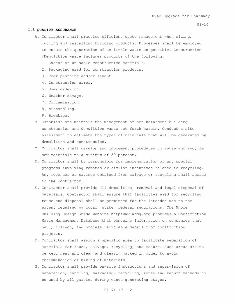
HVAC Upgrade for Pharmacy
09-10
01 74 19 - 2
1.3 QUALITY ASSURANCE
A. Contractor shall practice efficient waste management when sizing,
cutting and installing building products. Processes shall be employed
to ensure the generation of as little waste as possible. Construction
/Demolition waste includes products of the following:
1. Excess or unusable construction materials.
2. Packaging used for construction products.
3. Poor planning and/or layout.
4. Construction error.
5. Over ordering.
6. Weather damage.
7. Contamination.
8. Mishandling.
9. Breakage.
B. Establish and maintain the management of non-hazardous building
construction and demolition waste set forth herein. Conduct a site
assessment to estimate the types of materials that will be generated by
demolition and construction.
C. Contractor shall develop and implement procedures to reuse and recycle
new materials to a minimum of 50 percent.
D. Contractor shall be responsible for implementation of any special
programs involving rebates or similar incentives related to recycling.
Any revenues or savings obtained from salvage or recycling shall accrue
to the contractor.
E. Contractor shall provide all demolition, removal and legal disposal of
materials. Contractor shall ensure that facilities used for recycling,
reuse and disposal shall be permitted for the intended use to the
extent required by local, state, federal regulations. The Whole
Building Design Guide website http:www.wbdg.org provides a Construction
Waste Management Database that contains information on companies that
haul, collect, and process recyclable debris from construction
projects.
F. Contractor shall assign a specific area to facilitate separation of
materials for reuse, salvage, recycling, and return. Such areas are to
be kept neat and clean and clearly marked in order to avoid
contamination or mixing of materials.
G. Contractor shall provide on-site instructions and supervision of
separation, handling, salvaging, recycling, reuse and return methods to
be used by all parties during waste generating stages.

HVAC Upgrade for Pharmacy
09-10
01 74 19 - 3
H. Record on daily reports any problems in complying with laws,
regulations and ordinances with corrective action taken.
1.4 TERMINOLOGY
A. Class III Landfill: A landfill that accepts non-hazardous resources
such as household, commercial and industrial waste resulting from
construction, remodeling, repair and demolition operations.
B. Clean: Untreated and unpainted; uncontaminated with adhesives, oils,
solvents, mastics and like products.
C. Construction and Demolition Waste: Includes all non-hazardous resources
resulting from construction, remodeling, alterations, repair and
demolition operations.
D. Dismantle: The process of parting out a building in such a way as to
preserve the usefulness of its materials and components.
E. Disposal: Acceptance of solid wastes at a legally operating facility
for the purpose of land filling (includes Class III landfills and inert
fills).
F. Inert Backfill Site: A location, other than inert fill or other
disposal facility, to which inert materials are taken for the purpose
of filling an excavation, shoring or other soil engineering operation.
G. Inert Fill: A facility that can legally accept inert waste, such as
asphalt and concrete exclusively for the purpose of disposal.
H. Inert Solids/Inert Waste: Non-liquid solid resources including, but not
limited to, soil and concrete that does not contain hazardous waste or
soluble pollutants at concentrations in excess of water-quality
objectives established by a regional water board, and does not contain
significant quantities of decomposable solid resources.
I. Mixed Debris: Loads that include commingled recyclable and non-
recyclable materials generated at the construction site.
J. Mixed Debris Recycling Facility: A solid resource processing facility
that accepts loads of mixed construction and demolition debris for the
purpose of recovering re-usable and recyclable materials and disposing
non-recyclable materials.
K. Permitted Waste Hauler: A company that holds a valid permit to collect
and transport solid wastes from individuals or businesses for the
purpose of recycling or disposal.
L. Recycling: The process of sorting, cleansing, treating, and
reconstituting materials for the purpose of using the altered form in
the manufacture of a new product. Recycling does not include burning,
incinerating or thermally destroying solid waste.

HVAC Upgrade for Pharmacy
09-10
01 74 19 - 4
1. On-site Recycling – Materials that are sorted and processed on site
for use in an altered state in the work, i.e. concrete crushed for
use as a sub-base in paving.
2. Off-site Recycling – Materials hauled to a location and used in an
altered form in the manufacture of new products.
M. Recycling Facility: An operation that can legally accept materials for
the purpose of processing the materials into an altered form for the
manufacture of new products. Depending on the types of materials
accepted and operating procedures, a recycling facility may or may not
be required to have a solid waste facilities permit or be regulated by
the local enforcement agency.
N. Reuse: Materials that are recovered for use in the same form, on-site
or off-site.
O. Return: To give back reusable items or unused products to vendors for
credit.
P. Salvage: To remove waste materials from the site for resale or re-use
by a third party.
Q. Source-Separated Materials: Materials that are sorted by type at the
site for the purpose of reuse and recycling.
R. Solid Waste: Materials that have been designated as non-recyclable and
are discarded for the purposes of disposal.
S. Transfer Station: A facility that can legally accept solid waste for
the purpose of temporarily storing the materials for re-loading onto
other trucks and transporting them to a landfill for disposal, or
recovering some materials for re-use or recycling.
1.5 SUBMITTALS
A. In accordance with Section 01 33 23, SHOP DRAWINGS, PRODUCT DATA, and
SAMPLES, furnish the following:
B. Prepare and submit to the Resident Engineer a written demolition debris
management plan. The plan shall include, but not be limited to, the
following information:
1. Procedures to be used for debris management.
2. Techniques to be used to minimize waste generation.
3. Analysis of the estimated job site waste to be generated:
a. List of each material and quantity to be salvaged, reused,
recycled.
b. List of each material and quantity proposed to be taken to a
landfill.

HVAC Upgrade for Pharmacy
09-10
01 74 19 - 5
4. Detailed description of the Means/Methods to be used for material
handling.
a. On site: Material separation, storage, protection where
applicable.
b. Off site: Transportation means and destination. Include list of
materials.
1) Description of materials to be site-separated and self-hauled
to designated facilities.
2) Description of mixed materials to be collected by designated
waste haulers and removed from the site.
c. The names and locations of mixed debris reuse and recycling
facilities or sites.
d. The names and locations of trash disposal landfill facilities or
sites.
e. Documentation that the facilities or sites are approved to
receive the materials.
C. Designated Manager responsible for instructing personnel, supervising,
documenting and administer over meetings relevant to the Waste
Management Plan.
D. Monthly summary of construction and demolition debris diversion and
disposal, quantifying all materials generated at the work site and
disposed of or diverted from disposal through recycling.
1.6 APPLICABLE PUBLICATIONS
A Publications listed below form a part of this specification to the
extent referenced. Publications are referenced by the basic designation
only. In the event that criteria requirements conflict, the most
stringent requirements shall be met.
B. U.S. Green Building Council (USGBC):
LEED Green Building Rating System for New Construction
1.7 RECORDS
Maintain records to document the quantity of waste generated; the
quantity of waste diverted through sale, reuse, or recycling; and the
quantity of waste disposed by landfill or incineration. Records shall
be kept in accordance with the LEED Reference Guide and LEED Template.
PART 2 - PRODUCTS
2.1 MATERIALS
A. List of each material and quantity to be salvaged, recycled, reused.
B. List of each material and quantity proposed to be taken to a landfill.

HVAC Upgrade for Pharmacy
09-10
01 74 19 - 6
C. Material tracking data: Receiving parties, dates removed,
transportation costs, weight tickets, tipping fees, manifests,
invoices, net total costs or savings.
PART 3 - EXECUTION
3.1 COLLECTION
A. Provide all necessary containers, bins and storage areas to facilitate
effective waste management.
B. Clearly identify containers, bins and storage areas so that recyclable
materials are separated from trash and can be transported to respective
recycling facility for processing.
C. Hazardous wastes shall be separated, stored, disposed of according to
local, state, federal regulations.
3.2 DISPOSAL
A. Contractor shall be responsible for transporting and disposing of
materials that cannot be delivered to a source-separated or mixed
materials recycling facility to a transfer station or disposal facility
that can accept the materials in accordance with state and federal
regulations.
B. Construction or demolition materials with no practical reuse or that
cannot be salvaged or recycled shall be disposed of at a landfill or
incinerator.
3.3 REPORT
A. With each application for progress payment, submit a summary of
construction and demolition debris diversion and disposal including
beginning and ending dates of period covered.
B. Quantify all materials diverted from landfill disposal through salvage
or recycling during the period with the receiving parties, dates
removed, transportation costs, weight tickets, manifests, invoices.
Include the net total costs or savings for each salvaged or recycled
material.
C. Quantify all materials disposed of during the period with the receiving
parties, dates removed, transportation costs, weight tickets, tipping
fees, manifests, invoices. Include the net total costs for each
disposal.
- - - E N D - - -
HVAC Upgrade for Pharmacy
06-10
02 41 00 - 1
SECTION 02 41 00 DEMOLITION
PART 1 - GENERAL
1.1 DESCRIPTION
This section specifies demolition and removal of portions of buildings,
utilities, other structures and debris from trash dumps shown.
1.2 RELATED WORK
A. Safety Requirements: GENERAL CONDITIONS Article, ACCIDENT PREVENTION.
B. Disconnecting utility services prior to demolition: Section 01 00 00,
GENERAL REQUIREMENTS.
C. Environmental Protection: Section 01 57 19, TEMPORARY ENVIRONMENTAL
CONTROLS.
D. Construction Waste Management: Section 017419 CONSTRUCTION WASTE
MANAGEMENT.
E. Infectious Control: Section 01 00 00, GENERAL REQUIREMENTS, Article 1.7,
INFECTION PREVENTION MEASURES.
1.3 PROTECTION
A. Perform demolition in such manner as to eliminate hazards to persons and
property; to minimize interference with use of adjacent areas, utilities
and structures or interruption of use of such utilities; and to provide
free passage to and from such adjacent areas of structures. Comply with
requirements of GENERAL CONDITIONS Article, ACCIDENT PREVENTION.
B. Provide safeguards, including warning signs, barricades, temporary
fences, warning lights, and other similar items that are required for
protection of all personnel during demolition and removal operations.
Comply with requirements of Section 01 00 00, GENERAL REQUIREMENTS,
Article PROTECTION OF EXISTING VEGETATION, STRUCTURES, EQUIPMENT,
UTILITIES AND IMPROVEMENTS.
C. Provide enclosed dust chutes with control gates from each floor to carry
debris to truck beds and govern flow of material into truck. Provide
overhead bridges of tight board or prefabricated metal construction at
dust chutes to protect persons and property from falling debris.
D. Prevent spread of flying particles and dust. Sprinkle rubbish and debris
with water to keep dust to a minimum. Do not use water if it results in
hazardous or objectionable condition such as, but not limited to; ice,
flooding, or pollution. Vacuum and dust the work area daily.
E. In addition to previously listed fire and safety rules to be observed in
performance of work, include following:

HVAC Upgrade for Pharmacy
06-10
02 41 00 - 2
1. No wall or part of wall shall be permitted to fall outwardly from
structures.
2. Wherever a cutting torch or other equipment that might cause a fire
is used, provide and maintain fire extinguishers nearby ready for
immediate use. Instruct all possible users in use of fire
extinguishers.
3. Keep hydrants clear and accessible at all times. Prohibit debris from
accumulating within a radius of 4500 mm (15 feet) of fire hydrants.
F. Before beginning any demolition work, the Contractor shall survey the
site and examine the drawings and specifications to determine the extent
of the work. The contractor shall take necessary precautions to avoid
damages to existing items to remain in place, to be reused, or to remain
the property of the Medical Center; any damaged items shall be repaired
or replaced as approved by the Resident Engineer. The Contractor shall
coordinate the work of this section with all other work and shall
construct and maintain shoring, bracing, and supports as required. The
Contractor shall ensure that structural elements are not overloaded and
shall be responsible for increasing structural supports or adding new
supports as may be required as a result of any cutting, removal, or
demolition work performed under this contract. Do not overload
structural elements. Provide new supports and reinforcement for existing
construction weakened by demolition or removal works. Repairs,
reinforcement, or structural replacement must have Resident Engineer’s
approval.
G. The work shall comply with the requirements of Section 01 57 19,
TEMPORARY ENVIRONMENTAL CONTROLS.
H. The work shall comply with the requirements of Section 01 00 00, GENERAL
REQUIREMENTS, Article 1.7 INFECTION PREVENTION MEASURES.
1.4 UTILITY SERVICES
A. Demolish and remove outside utility service lines shown to be removed.
B. Remove abandoned outside utility lines that would interfere with
installation of new utility lines and new construction.
PART 2 - PRODUCTS (NOT USED)
PART 3 – EXECUTION
3.1 DEMOLITION
A. Completely demolish and remove existing construction and structures,
including all appurtenances related or connected thereto, as noted
below:
1. As required for installation of new utilities.

HVAC Upgrade for Pharmacy
06-10
02 41 00 - 3
B. Debris, including brick, concrete, stone, metals and similar materials
shall become property of Contractor and shall be disposed of by him
daily, off the Medical Center to avoid accumulation at the demolition
site. Materials that cannot be removed daily shall be stored in areas
specified by the Resident Engineer. Break up concrete slabs below grade
that do not require removal from present location into pieces not
exceeding 600 mm (24 inches) square to permit drainage. Contractor shall
dispose debris in compliance with applicable federal, state or local
permits, rules and/or regulations.
C. Remove and legally dispose of all materials, from any trash dumps shown.
Materials removed shall become property of contractor and shall be
disposed of in compliance with applicable federal, state or local
permits, rules and/or regulations
3.2 CLEAN-UP
On completion of work of this section and after removal of all debris,
leave site in clean condition satisfactory to the COTR. Clean-up shall
include off the Medical Center disposal of all items and materials not
required to remain property of the Government as well as all debris and
rubbish resulting from demolition operations.
- - - E N D - - -

HVAC Upgrade for Pharmacy
07-11
05 12 00 - 1
SECTION 05 12 00 STRUCTURAL STEEL FRAMING
PART 1 - GENERAL
1.1 DESCRIPTION:
A. This section specifies structural steel shown and classified by Section
2, Code of Standard Practice for Steel Buildings and Bridges.
1.2 RELATED WORK:
A. Materials testing and inspection during construction: Section 01 45 29,
TESTING LABORATORY SERVICES.
B. Steel Decking: Section 05 31 00, STEEL DECKING.
C. Painting: Section 09 91 00, PAINTING.
D. Fireproofing: Section 07 81 00, APPLIED FIREPROOFING.
1.3 QUALITY ASSURANCE:
A. Fabricator and erector shall maintain a program of quality assurance in
conformance with Section 8, Code of Standard Practice for Steel
Buildings and Bridges. Work shall be fabricated in an AISC certified
Category fabrication plant.
B. Before authorizing the commencement of steel erection, the controlling
contractor shall ensure that the steel erector is provided with the
written notification required by 29 CFR 1926.752. Provide copy of this
notification to the Architect of Record.
1.4 TOLERANCES:
A. Fabrication tolerances for structural steel shall be held within limits
established by ASTM A6, by Section 7, Code of Standard Practice for
Buildings and Bridges, and by Standard Mill Practice - General
Information except as follows:
1. Elevation tolerance for column splice points at time member is
erected is 3/8 inch.
2. Elevation tolerance for top surface of steel beams and girders at
connections to columns at time floor is erected is 1/2 inch.
3. Elevation tolerance for closure plates at the building perimeter and
at slab openings prior to concrete placement is 1/4 inch.
1.5 DESIGN:
A. Connections: Design and detail all connections for each member size,
steel grade and connection type to resist the loads and reactions
indicated on the drawings or specified herein. Use details consistent
with the details shown on the Drawings, supplementing where necessary.
The details shown on the Drawings are conceptual and do not indicate the
required weld sizes or number of bolts unless specifically noted. Use

HVAC Upgrade for Pharmacy
07-11
05 12 00 - 2
rational engineering design and standard practice in detailing,
accounting for all loads and eccentricities in both the connection and
the members. Promptly notify the Engineer of any location where the
connection design criteria is not clearly indicated. The design of all
connections is subject to the review and acceptance of the Engineer.
Submit structural calculations prepared and sealed by a qualified
engineer registered in the state where the project is located. Submit
calculations for review before preparation of detail drawings.
1.6 REGULATORY REQUIREMENTS:
A. AISC: Specification for Structural Steel, latest edition.
B. AISC: Code of Standard Practice for Steel Buildings and Bridges, latest
edition.
1.7 SUBMITTALS:
A. Submit in accordance with Section 01 33 23, SHOP DRAWINGS, PRODUCT DATA,
AND SAMPLES.
B. Shop and Erection Drawings: Complete
C. Certificates:
1. Structural steel.
2. Steel for all connections.
3. Welding materials.
4. Shop coat primer paint.
D. Test Reports:
1. Welders' qualifying tests.
E. Design Calculations and Drawings:
1. Connection calculations, if required.
F. Record Surveys.
1.8 APPLICABLE PUBLICATIONS:
A. Publications listed below form a part of this specification to extent
referenced. Publications are referenced in text by basic designation
only.
B. American Institute of Steel Construction (AISC):
1. Specification for Structural Steel Buildings - Allowable Stress
Design and Plastic Design, latest edition.
2. Load and Resistance Factor Design Specification for Structural Steel
Buildings, latest edition.
3. Code of Standard Practice for Steel Buildings and Bridges, latest
edition.
C. American National Standards Institute (ANSI):
B18.22.1-65(R2008)......Plain Washers
D. American Society for Testing and Materials (ASTM):

HVAC Upgrade for Pharmacy
07-11
05 12 00 - 3
A6-09...................Standard Specification for General Requirements
for Rolled Structural Steel Bars, Plates,
Shapes, and Sheet Piling
A36-08..................Standard Specification for Carbon Structural
Steel
A53-10..................Standard Specification for Pipe, Steel, Black
and Hot-Dipped, Zinc-Coated Welded and Seamless
A123-09.................Standard Specification for Zinc (Hot-Dip
Galvanized) Coatings on Iron and Steel Products
A242-04.................Standard Specification for High-Strength Low-
Alloy Structural Steel
A283-03.................Standard Specification for Low and Intermediate
Tensile Strength Carbon Steel Plates
A307-10.................Standard Specification for Carbon Steel Bolts
and Studs, 60,000 psi Tensile Strength
A325-10.................Standard Specification for Structural Bolts,
Steel, Heat Treated, 120/105 ksi Minimum Tensile
Strength
A490-10.................Standard Specification for Heat-Treated Steel
Structural Bolts 150 ksi Minimum Tensile
Strength
A500-10.................Standard Specification for Cold Formed Welded
and Seamless Carbon Steel Structural Tubing in
Rounds and Shapes
A501-07.................Standard Specification for Hot-Formed Welded and
Seamless Carbon Steel Structural Tubing
A572-07.................Standard Specification for High-Strength
Low-Alloy Columbium-Vanadium Structural Steel
A992-06.................Standard Specification for Structural Steel
Shapes
E. American Welding Society (AWS):
D1.1....................Structural Welding Code-Steel
F. Research Council on Structural Connections (RCSC) of the Engineering
Foundation:
Specification for Structural Joints Using ASTM A325 or A490 Bolts
G. Military Specifications (Mil. Spec.):
MIL-P-21035.............Paint, High Zinc Dust Content, Galvanizing,
Repair
H. Occupational Safety and Health Administration (OSHA):
29 CFR Part 1926-2001...Safety Standards for Steel Erection
HVAC Upgrade for Pharmacy
07-11
05 12 00 - 4
PART 2 - PRODUCTS
2.1 MATERIALS:
A. Structural Steel: ASTM A992 unless noted otherwise.
B. Structural Tubing: ASTM A500, Grade B.
C. Steel Pipe: ASTM A53, Grade B.
D. Steel Plates, Channels, Angles, Miscellaneous Material – ASTM A36
E. Bolts, Nuts and Washers:
1. High-strength bolts, including nuts and washers: ASTM A325.
2. Bolts and nuts, other than high-strength: ASTM A307, Grade A.
3. Plain washers, other than those in contact with high-strength bolt
heads and nuts: ANSI Standard B18.22.1.
F. Zinc Coating: ASTM A123.
G. Galvanizing Repair Paint: Mil. Spec. MIL-P-21035.
PART 3 - EXECUTION
3.1 CONNECTIONS (SHOP AND FIELD):
A. Welding: Welding in accordance with AWS D1.1. Welds shall be made only
by welders and welding operators who have been previously qualified by
tests as prescribed in AWS D1.1 to perform type of work required.
B. High-Strength Bolts: High-strength bolts tightened to a bolt tension not
less than proof load given in Specification for Structural Joints Using
ASTM A325 or A490 Bolts. Tightening is to done with properly calibrated
wrenches, by turn-of-nut method or by use of direct tension indicators
(bolts or washers). Tighten bolts in connections identified as slip-
critical using Direct Tension Indicators or the turn-of-the-nut method.
Twist-off torque bolts are not an acceptable alternate fastener for slip
critical connections.
3.2 FABRICATION:
A. Fabrication of structural steel framing in accordance with Chapter M,
Specification for Steel Buildings, latest edition.
3.3 SHOP PAINTING:
A. General: Shop paint steel with primer in accordance with Section 6, Code
of Standard Practice for Steel Buildings and Bridges.
B. Shop paint for steel surfaces is specified in Section 09 91 00,
PAINTING.
C. Do not apply paint to following:
1. Surfaces within 2 inches of joints to be welded in field.
2. Surfaces which will be encased in concrete.
3. Surfaces which will receive sprayed on fireproofing.
4. Top flange of members which will have shear connector studs applied.

HVAC Upgrade for Pharmacy
07-11
05 12 00 - 5
D. Zinc Coated (Hot Dip Galvanized) per ASTM A123 (after fabrication):
Touch-up after erection: Clean and wire brush any abraded and other
spots worn through zinc coating, including threaded portions of bolts
and welds and touch-up with galvanizing repair paint.
3.4 ERECTION:
A. General: Erection in accordance with Section 7, Code of Standard
Practice for Steel Buildings and Bridges, latest edition.
B. Temporary Supports: Temporary support of structural steel frames during
erection in accordance with Section 7, Code of Standard Practice for
Steel Buildings and Bridges, latest edition.
3.5 FIELD PAINTING:
A. After erection, touch-up steel surfaces specified to be shop painted.
After welding is completed, clean and prime areas not painted due to
field welding.
B. Finish painting of steel surfaces is specified in Section 09 91 00,
PAINTING.
- - - E N D - - -


HVAC Upgrade for Pharmacy
09-11
05 50 00- 1
SECTION 05 50 00 METAL FABRICATIONS
PART 1 - GENERAL
1.1 DESCRIPTION
A. This section specifies items and assemblies fabricated from structural
steel shapes and other materials as shown and specified.
B. Items specified.
1. Railings: (10)
2. Catwalks and Platforms and grating.
1.2 RELATED WORK
A. Railings attached to steel stairs: Section 05 51 00, METAL STAIRS.
1.3 SUBMITTALS
A. Submit in accordance with Section 01 33 23, SHOP DRAWINGS, PRODUCT DATA,
AND SAMPLES.
B. Manufacturer's Literature and Data:
C. Shop Drawings:
1. Each item specified, showing complete detail, location in the
project, material and size of components, method of joining various
components and assemblies, finish, and location, size and type of
anchors.
2. Mark items requiring field assembly for erection identification and
furnish erection drawings and instructions.
3. Provide templates and rough-in measurements as required.
D. Manufacturer's Certificates:
1. Live load designs as specified.
E. Design Calculations for specified live loads including dead loads.
F. Furnish setting drawings and instructions for installation of anchors to
be preset into concrete and masonry work, and for the positioning of
items having anchors to be built into concrete or masonry construction.
1.4 QUALITY ASSURANCE
A. Each manufactured product shall meet, as a minimum, the requirements
specified, and shall be a standard commercial product of a manufacturer
regularly presently manufacturing items of type specified.
B. Each product type shall be the same and be made by the same
manufacturer.
C. Assembled product to the greatest extent possible before delivery to the
site.
D. Include additional features, which are not specifically prohibited by
this specification, but which are a part of the manufacturer's standard
commercial product.
HVAC Upgrade for Pharmacy
09-11
05 50 00- 2
1.5 APPLICABLE PUBLICATIONS
A. The publications listed below form a part of this specification to the
extent referenced. The publications are referenced in the text by the
basic designation only.
B. American Society of Mechanical Engineers (ASME):
B18.6.1-97..............Wood Screws
B18.2.2-87(R2005).......Square and Hex Nuts
C. American Society for Testing and Materials (ASTM):
A36/A36M-08.............Structural Steel
A53-10..................Pipe, Steel, Black and Hot-Dipped, Zinc-Coated
Welded and Seamless
A123-09.................Zinc (Hot-Dip Galvanized) Coatings on Iron and
Steel Products
A167-99(R2009)..........Stainless and Heat-Resisting Chromium-Nickel
Steel Plate, Sheet and Strip
A269-10.................Seamless and Welded Austenitic Stainless Steel
Tubing for General Service
A307-10.................Carbon Steel Bolts and Studs, 60,000 PSI Tensile
Strength
A312/A312M-09...........Seamless, Welded, and Heavily Cold Worked
Austenitic Stainless Steel Pipes
A391/A391M-07...........Grade 80 Alloy Steel Chain
A653/A653M-10...........Steel Sheet, Zinc Coated (Galvanized) or Zinc-
Iron Alloy Coated (Galvannealed) by the Hot-Dip
Process
A786/A786M-09...........Rolled Steel Floor Plate
B221-08.................Aluminum and Aluminum-Alloy Extruded Bars, Rods,
Wire, Shapes, and Tubes
C1107-08................Packaged Dry, Hydraulic-Cement Grout (Nonshrink)
F436-10.................Hardened Steel Washers
F468-10.................Nonferrous Bolts, Hex Cap Screws, and Studs for
General Use
F593-02(R2008)..........Stainless Steel Bolts, Hex Cap Screws, and Studs
F1667-11................Driven Fasteners: Nails, Spikes and Staples
D. American Welding Society (AWS):
D1.1-10.................Structural Welding Code Steel
D1.3-08.................Structural Welding Code Sheet Steel
E. National Association of Architectural Metal Manufacturers (NAAMM)
AMP 521-01..............Pipe Railing Manual
AMP 500-06..............Metal Finishes Manual
MBG 531-09..............Metal Bar Grating Manual

HVAC Upgrade for Pharmacy
09-11
05 50 00- 3
MBG 532-09..............Heavy Duty Metal Bar Grating Manual
F. Structural Steel Painting Council (SSPC)/Society of Protective Coatings:
SP 1-04.................No. 1, Solvent Cleaning
SP 2-04.................No. 2, Hand Tool Cleaning
SP 3-04.................No. 3, Power Tool Cleaning
G. Federal Specifications (Fed. Spec):
RR-T-650E...............Treads, Metallic and Nonmetallic, Nonskid
PART 2 - PRODUCTS
2.1 DESIGN CRITERIA
A. In addition to the dead loads, design fabrications to support the
following live loads unless otherwise specified.
B. Ladders and Rungs: 300 pounds (135 kg)
C. Railings and Handrails: 50 lb/ft (750 N/m) line load or 200 pounds(900
N)point load, whichever is greater, in any direction at any point.
D. Floor Plates, Gratings, Catwalks, and Platforms: 500 kg/m2
2.2 MATERIALS
(100 pounds
per square foot). Use 300 pounds (135 kg)for concentrated loads.
reference sheet S001.
A. Structural Steel: ASTM A36.
B. Steel Pipe: ASTM A53.
1. Galvanized for exterior locations, G90 coating.
2. Type S, Grade A unless specified otherwise.
3. NPS (inside diameter) as shown.
2.3 HARDWARE
A. Rough Hardware:
1. Furnish rough hardware with a standard plating, applied after
punching, forming and assembly of parts; galvanized, cadmium plated,
or zinc-coated by electro-galvanizing process. Galvanized G-90 where
specified.
2. Use G90 galvanized coating on ferrous metal for exterior work unless
non-ferrous metal or stainless is used.
B. Fasteners:
1. Bolts with Nuts:
a. ASME B18.2.2.
b. ASTM A307 for 415 MPa (60,000 psi) tensile strength bolts.
c. ASTM F593 for stainless steel.
2. Screws: ASME B18.6.1.
3. Washers: ASTM F436, type to suit material and anchorage.
4. Nails: ASTM F1667, Type I, style 6 or 14 for finish work.
2.4 FABRICATION GENERAL
A. Material

HVAC Upgrade for Pharmacy
09-11
05 50 00- 4
1. Use material as specified. Use material of commercial quality and
suitable for intended purpose for material that is not named or its
standard of quality not specified.
2. Use material free of defects which could affect the appearance or
service ability of the finished product.
B. Size:
1. Size and thickness of members as shown.
2. When size and thickness is not specified or shown for an individual
part, use size and thickness not less than that used for the same
component on similar standard commercial items or in accordance with
established shop methods.
C. Connections
1. Except as otherwise specified, connections may be made by welding,
riveting or bolting.
2. Field riveting will not be approved.
3. Design size, number and placement of fasteners, to develop a joint
strength of not less than the design value.
4. Holes, for rivets and bolts: Accurately punched or drilled and burrs
removed.
5. Size and shape welds to develop the full design strength of the parts
connected by welds and to transmit imposed stresses without permanent
deformation or failure when subject to service loadings.
6. Use Rivets and bolts of material selected to prevent corrosion
(electrolysis) at bimetallic contacts. Plated or coated material will
not be approved.
7. Use stainless steel connectors for removable members machine screws
or bolts.
D. Fasteners and Anchors
1. Use methods for fastening or anchoring metal fabrications to building
construction as shown or specified.
2. Where fasteners and anchors are not shown, design the type, size,
location and spacing to resist the loads imposed without deformation
of the members or causing failure of the anchor or fastener, and suit
the sequence of installation.
3. Use material and finish of the fasteners compatible with the kinds of
materials which are fastened together and their location in the
finished work.
4. Fasteners for securing metal fabrications to new construction only,
may be by use of threaded or wedge type inserts or by anchors for
welding to the metal fabrication for installation before the concrete
is placed or as masonry is laid.

HVAC Upgrade for Pharmacy
09-11
05 50 00- 5
E. Workmanship
1. General:
a. Fabricate items to design shown.
b. Furnish members in longest lengths commercially available within
the limits shown and specified.
c. Fabricate straight, true, free from warp and twist, and where
applicable square and in same plane.
d. Provide holes, sinkages and reinforcement shown and required for
fasteners and anchorage items.
e. Prepare members for the installation and fitting of hardware.
f. Cut openings in gratings and floor plates for the passage of
ducts, sumps, pipes, conduits and similar items. Provide
reinforcement to support cut edges.
g. Fabricate surfaces and edges free from sharp edges, burrs and
projections which may cause injury.
2. Welding:
a. Weld in accordance with AWS.
b. Welds shall show good fusion, be free from cracks and porosity and
accomplish secure and rigid joints in proper alignment.
c. Where exposed in the finished work, continuous weld for the full
length of the members joined and have depressed areas filled and
protruding welds finished smooth and flush with adjacent surfaces.
d. Finish welded joints to match finish of adjacent surface.
3. Joining:
a. Miter or butt members at corners.
b. Where frames members are butted at corners, cut leg of frame
member perpendicular to surface, as required for clearance.
4. Anchors:
a. Where metal fabrications are shown to be preset in concrete, weld
32 x 3 mm (1-1/4 by 1/8 inch) steel strap anchors, 150 mm (6
inches) long with 25 mm (one inch) hooked end, to back of member
at 600 mm (2 feet) on center, unless otherwise shown.
b. Where metal fabrications are shown to be built into masonry use 32
x 3 mm (1-1/4 by 1/8 inch) steel strap anchors, 250 mm (10 inches)
long with 50 mm (2 inch) hooked end, welded to back of member at
600 mm (2 feet) on center, unless otherwise shown.
5. Cutting and Fitting:
a. Accurately cut, machine and fit joints, corners, copes, and
miters.
b. Fit removable members to be easily removed.
HVAC Upgrade for Pharmacy
09-11
05 50 00- 6
c. Design and construct field connections in the most practical place
for appearance and ease of installation.
d. Fit pieces together as required.
e. Fabricate connections for ease of assembly and disassembly without
use of special tools.
f. Joints firm when assembled.
g. Conceal joining, fitting and welding on exposed work as far as
practical.
h. Do not show rivets and screws prominently on the exposed face.
i. The fit of components and the alignment of holes shall eliminate
the need to modify component or to use exceptional force in the
assembly of item and eliminate the need to use other than common
tools.
F. Finish:
1. Finish exposed surfaces in accordance with NAAMM Metal Finishes
Manual.
2. Steel and Iron: NAAMM AMP 504.
a. Zinc coated (Galvanized): ASTM A123, G90 unless noted otherwise,
all materials, this section unless stainless steel is used.
b. Surfaces exposed in the finished work:
1) Finish smooth rough surfaces and remove projections.
2) Fill holes, dents and similar voids and depressions with epoxy
type patching compound.
3) Galvanized touch-up paint to match galvanized surfaces.
2.5 RAILINGS
A. In addition to the dead load design railing assembly to support live
load specified.
B. Fabrication General:
1. Provide continuous welded joints, dressed smooth and flush.
2. Standard flush fittings, designed to be welded, may be used.
3. Exposed threads will not be approved.
4. Form handrail brackets to size and design shown.
5. Exterior Post Anchors.
a. Fabricate tube or pipe sleeves with closed ends or plates as
shown.
C. Handrails:
1. Close free ends of rail with flush metal caps welded in place except
where flanges for securing to walls with bolts are shown.
2. Make provisions for attaching handrail brackets to wall, posts, and
handrail as shown.
D. Steel Pipe Railings:
HVAC Upgrade for Pharmacy
09-11
05 50 00- 7
1. Fabricate of steel pipe with welded joints.
2. Number and space of rails as shown, are a minimum, meet load
requirements
3. Space posts for railings not over (5 feet) on centers between end
posts.
2.6 CATWALKS AND PLATFORMS
A. Fabricate catwalks including platforms, railings, ladders, supports and
hangers, and arrangement of members as shown on drawings.
B. Fabricate stairs as specified in Section 05 51 00, METAL STAIRS.
C. Fabricate steel pipe railings as specified under paragraph RAILINGS.
D. Catwalk and platforms floor surfaces as shown.
1. Steel gratings as specified under paragraph gratings, bar or type.
2.7 GRATINGS
A. Fabricate gratings to support live loads specified and a concentrated
load as noted on sheet S001.
B. Provide clearance at all sides to permit easy removal of grating.
C. Make cutouts in gratings with 6 mm (1/4 inch) minimum to 25 mm (one
inch) maximum clearance for penetrations or passage of pipes and ducts.
Edge band cutouts.
D. Fabricate in sections not to exceed 2.3 m2
E. Fabricate sections of grating with end-banding bars.
(25 square feet) in area and
90 kg (200 pounds) in weight.
F. Fabricate angle frames and supports, including anchorage as shown.
1. Fabricate intermediate supporting members from "T's" or angles.
2. Locate intermediate supports to support grating section edges.
3. Fabricate frame to finish flush with top of grating.
4. Locate anchors at ends and not over 600 mm (24 inches) o.c.
5. Butt or miter, and weld angle frame at corners.
G. Steel Bar Gratings:
1. Fabricate grating using steel bars, frames, supports and other
members shown in accordance with Metal Bar Grating Manual.
2. Galvanize steel members after fabrication in accordance with ASTM
A123, G-90 for all gratings..
3. Use serrated bars for all exterior gratings.
PART 3 - EXECUTION
3.1 INSTALLATION, GENERAL
A. Set work accurately, in alignment and where shown, plumb, level, free of
rack and twist, and set parallel or perpendicular as required to line
and plane of surface.
B. Field weld in accordance with AWS.
1. Design and finish as specified for shop welding.

HVAC Upgrade for Pharmacy
09-11
05 50 00- 8
2. Use continuous weld unless specified otherwise.
C. Install anchoring devices and fasteners as shown and as necessary for
securing metal fabrications to building construction as specified.
D. Spot prime all abraded welds and damaged areas of zinc coating as
specified and all abraded and damaged areas of shop prime coat with
galvanized touch-up paint.
3.2 INSTALLATION OF SUPPORTS
A. Anchorage to structure.
1. Secure angles or channels and clips to structural steel by continuous
welding unless bolting is shown.
3.3 CATWALK AND PLATFORMS
A. Bolt or weld structural components together including ladders and stairs
to support system.
B. Weld railings to structural framing.
C. Bolt or weld walk surface to structural framing.
D. Smooth field welds and spot prime damaged prime paint surface.
E. Fasten removable members with stainless steel fasteners.
3.4 CLEAN AND ADJUSTING
A. Adjust movable parts including hardware to operate as designed without
binding or deformation of the members centered in the opening or frame
and, where applicable, contact surfaces fit tight and even without
forcing or warping the components.
B. Clean after installation exposed prefinished and plated items and items
fabricated from stainless steel, aluminum and copper alloys, as
recommended by the metal manufacture and protected from damage until
completion of the project.
3.5 GRATINGS
A. Set grating flush with adjacent floor levels. Set frame so that
horizontal leg of angle frame is flush with face of wall except when
frame is installed on face of wall.
B. Secure removable supporting members in place with stainless steel bolts.
C. Bolt gratings to supports.
- - - E N D - - -

HVAC Upgrade for Pharmacy 09-11
05 51 00 - 1
SECTION 05 51 00 METAL STAIRS
PART 1 - GENERAL
1.1 DESCRIPTION
A. Section specifies steel stairs with railings.
B. Types:
1. Industrial stairs: Closed and open riser stairs.
1.2 RELATED WORK
A. Structural Framing: Section 05 12 00 STRUCTURAL STEEL FRAMING.
B. Roofing: Section 07 56 30 AGGREGATE ROOF SURFACES RESTORATION.
C. Flashing: Section 07 60 00 FLASHING AND SHEET METAL.
D. Air Handling Unit: Division 23, HVAC.
1.3 SUBMITTALS
A. Submit in accordance with Section 01 33 23, SHOP DRAWINGS, PRODUCT DATA,
AND SAMPLES.
B. Shop Drawings: Show design, fabrication details, installation,
connections, material, and size of members. Plans & sections at ¼” = 1’-
0” scale minimum, Details at 3” = 1’-0” minimum.
1.4 APPLICATION PUBLICATIONS
A. The publications listed below form a part of this specification to the
extent referenced. The publications are referenced in the text by basic
designation.
B. American Society for Testing and Materials (ASTM):
A36/A36M-08.............Structural Steel
A53-10..................Pipe, Steel, Black and Hot-Dipped Zinc-Coated
Welded and Seamless
A307-10.................Carbon Steel Bolts and Studs, 60000 psi Tensile
Strength
A653/653M-10............Steel Sheet, Zinc Coated (Galvanized) or Zinc
Alloy Coated (Galvannealed) by the Hot-Dip
Process
A563-07.................Carbon and Alloy Steel Nuts
A1008-10................Steel, Sheet, Cold-Rolled, Carbon, Structural,
High-Strength, Low-Alloy
A1011-10................Steel, Sheet and Strip, Strip, Hot-Rolled
Carbon, Structural, High-Strength, Low-Alloy
C. American Welding Society (AWS):
D1.1-10.................Structural Welding Code-Steel
D1.3-08.................Structural Welding Code-Sheet Steel
HVAC Upgrade for Pharmacy 09-11
05 51 00 - 2
D. The National Association of Architectural Metal Manufactures (NAAMM)
Manuals:
Metal Bar Gratings (ANSI/NAAMM MBG 531-09)
AMP521-01...............Pipe Railing Manual, Including Round Tube
E. American Iron and Steel Institute (AISI):
2001....................Design of Cold-Formed Steel Structural Members
PART 2 - PRODUCTS
2.1 DESIGN CRITERIA
A. Design stairs to support a live load of 500 kg/m2
B. Structural design, fabrication and assembly in accordance with
requirements of NAAMM Metal Stairs Manual, except as otherwise specified
or shown.
(100 pounds per square
foot), minimum.
C. Design Grating treads in accordance with NAAMM Metal Bar Grating Manual.
D. Design pipe railings in accordance with NAAMM Pipe Railing Manual for
900 N (200 pounds) in any direction at any point, minimum.
2.2 MATERIALS
A. Steel Pipe: ASTM A53, Standard Weight, zinc coated.
B. Steel Grating: Metal bar type grating NAAMM BG.
C. Sheet Steel: ASTM A1008.
D. Structural Steel: ASTM A36.
E. Steel Plate: ASTM A1011.
2.3 FABRICATION GENERAL
A. Fasteners:
1. Conceal bolts and screws wherever possible.
2. Use countersunk heads on exposed bolts and screws with ends of bolts
and screws dressed flush after nuts are set.
3. Fasteners to be non-magnetic stainless steel only.
B. Welding:
1. Structural steel, AWS D1.1 and sheet steel, AWS D1.3.
2. Where possible, locate welds on unexposed side.
3. Grind exposed welds smooth and true to contour of welded member.
4. Remove welding splatter.
C. Remove sharp edges and burrs.
D. Fit stringers to head channel and close ends with steel plates welded in
place where shown.
E. Fit face stringer to newel post by tenoning into newel post, or by
notching and fitting face stringer to side of newel where shown.

HVAC Upgrade for Pharmacy 09-11
05 51 00 - 3
F. All components and materials to be hot-dipped galvanized, 90 coated
typical.
2.4 RAILINGS
A. Fabricate railings, including handrails, from steel pipe with flush.
1. Connections may be standard fittings designed for welding, or coped
or mitered pipe with full welds.
B. Return ends of handrail to wall and close free end.
C. Provide standard terminal castings where fastened to newel.
D. Space intermediate posts not over five feet on center between end posts
or intermediate posts.
E. Fabricate handrail brackets from cast malleable iron.
F. Provide standard terminal fittings at ends of post and rails for loads &
conditions as required.
2.5 INDUSTRIAL STAIRS
A. Provide treads, platforms, railings, stringers and other supporting
members as shown, and as required for the structural loads and field
conditions.
B. Treads and platforms of steel grating:
1. Fabricate steel grating treads and platforms in accordance with
requirements of NAAMM Metal Bar Grating Manuals.
2. Provide end banding bars, except where carrier angle are used at
tread ends.
3. Support treads by use of carrier plates or carrier angle. Use carrier
plate end banding bars on exterior stairs.
4. Provide abrasive nosing on treads and edge of platforms at head of
stairs.
5. Provide toe plates on platforms.
PART 3 - EXECUTION
3.1 STAIR INSTALLATION
A. Provide hangers and struts required to support the loads imposed.
B. Perform job site welding and bolting as specified for shop fabrication.
C. Set stairs and other members in position and secure to structure as
shown.
D. Install stairs plumb, level and true to line.
E. Provide steel closure plate to fill any gap between the stringer and
surrounding shaft wall. Weld and finish with prime and paint finish of
adjoining steel.
3.2 RAILING INSTALLATION
A. Install standard terminal fittings at ends of posts and rails.
HVAC Upgrade for Pharmacy 09-11
05 51 00 - 4
B. Secure brackets, posts and rails to steel by welds.
C. Set rails horizontal or parallel to rake of stairs to within 3 mm in
3650 mm (1/8-inch in 12 feet).
D. Set posts plumb and aligned to within 3 mm in 3650 mm (1/8-inch in 12
feet).
E. Provide typical rail sections to fill-in gaps between rail posts and
mechanical units; maintain a 5 inch gap, maximum.
3.3 FIELD PRIME PAINTING
A. When installation is complete, clean field welds and surrounding areas
to bright metal, and coat with galvanized touch-up paint.
B. Touch-up abraded areas with galvanized touch-up paint.
- - - E N D - - -

HVAC Upgrade for Pharmacy
10-07M
06 10 00 - 1
SECTION 06 10 00 ROUGH CARPENTRY
PART 1 - GENERAL
1.1 DESCRIPTION:
Section specifies wood blocking, framing, furring, nailers, sub-
flooring, rough hardware, and curbs.
1.2 RELATED WORK:
A. Roofing: Section 07 52 00 Modified Bituminous Membrane Roofing – Torch
Application
1.3 SUMBITTALS:
A. Submit in accordance with Section 01 33 23, SHOP DRAWINGS, PRODUCT DATA,
AND SAMPLES.
B. Shop Drawings showing framing connection details, fasteners, connections
and dimensions.
1.4 PRODUCT DELIVERY, STORAGE AND HANDLING:
A. Protect lumber and other products from dampness both during and after
delivery at site.
B. Pile lumber in stacks in such manner as to provide air circulation
around surfaces of each piece.
C. Stack board products so as to prevent warping.
D. Locate stacks on well drained areas, supported at least 6 inches above
grade and cover with well ventilated sheds having firmly constructed
over hanging roof with sufficient end wall to protect lumber from
driving rain.
1.5 APPLICABLE PUBLICATIONS:
A. Publications listed below form a part of this specification to extent
referenced. Publications are referenced in the text by basic designation
only.
B. American Forest and Paper Association (AFPA):
National Design Specification for Wood Construction
NDS-05..................Conventional Wood Frame Construction
C. American Institute of Timber Construction (AITC):
A190.1-02...............Structural Glued Laminated Timber
D. American Society of Mechanical Engineers (ASME):
B18.2.1A-96(R2005)......Square and Hex Bolts and Screws
B18.2.2-87(R2005).......Square and Hex Nuts
B18.6.1-81 (R97)........Wood Screws
B18.6.4-98(R2005).......Thread Forming and Thread Cutting Tapping Screws
and Metallic Drive Screws

HVAC Upgrade for Pharmacy
10-07M
06 10 00 - 2
E. American Society for Testing And Materials (ASTM):
A653/A653M-07...........Steel Sheet Zinc-Coated (Galvanized) or Zinc-
Iron Alloy Coated (Galvannealed) by the Hot Dip
Process
C954-04.................Steel Drill Screws for the Application of Gypsum
Board or Metal Plaster Bases to Steel Studs from
(2.24 mm)0.033 inch to (2.84mm)0.112-inch in
thickness
D143-94(R2004)..........Small Clear Specimens of Timber, Method of
Testing
D1760-01................Pressure Treatment of Timber Products
F844-07.................Washers, Steel, Plan (Flat) Unhardened for
General Use
F1667-05................Nails, Spikes, and Staples
F. Federal Specifications (Fed. Spec.):
MM-L-736C...............Lumber; Hardwood
G. Commercial Item Description (CID):
A-A-55615...............Shield, Expansion (Wood Screw and Lag Bolt Self
Threading Anchors)
H. U.S. Department of Commerce Product Standard (PS)
PS 20-05................American Softwood Lumber Standard
PART 2 - PRODUCTS
2.1 LUMBER:
A. Unless otherwise specified, each piece of lumber bear grade mark, stamp,
or other identifying marks indicating grades of material, and rules or
standards under which produced.
1. Identifying marks in accordance with rule or standard under which
material is produced, including requirements for qualifications and
authority of the inspection organization, usage of authorized
identification, and information included in the identification.
2. Inspection agency for lumber approved by the Board of Review,
American Lumber Standards Committee, to grade species used.
B. Lumber Other Than Structural:
1. Unless otherwise specified, species graded under the grading rules of
an inspection agency approved by Board of Review, American Lumber
Standards Committee.
2. Framing lumber: Minimum extreme fiber stress in bending of 1100.
3. Furring, blocking, nailers and similar items 4 inches and narrower
Standard Grade; and, members 6 inches and wider, Number 2 Grade.

HVAC Upgrade for Pharmacy
10-07M
06 10 00 - 3
C. Sizes:
1. Conforming to Prod. Std., PS20.
2. Size references are nominal sizes, unless otherwise specified, actual
sizes within manufacturing tolerances allowed by standard under which
produced.
D. Moisture Content:
1. At time of delivery and maintained at the site.
2. Boards and lumber 2 inches and less in thickness: 19 percent or less.
3. Lumber over 2 inches thick: 25 percent or less.
E. Preservative Treatment:
1. Do not treat Heart Redwood and Western Red Cedar.
2. Do not use treated lumber in roofing systems unless using stainless
steel fasteners.
3. Treat wood members located on roofs, exposed to weather or in contact
with plaster, masonry or concrete, including framing of open roofed
structures; sills, sole plates, furring, and sleepers that are less
than 24 inches from ground; nailers, edge strips, blocking, crickets,
curbs, cant and other members used in connection with roofing and
flashing materials.
3. Treat other members specified as preservative treated (PT).
4. Preservative treat by the pressure method complying with ASTM D1760,
except any process involving the use of Chromated Copper arsenate
(CCA) for pressure treating wood is not permitted.
F. Blocking Nailers, and Furring:
1. Install furring, blocking, nailers, and grounds where shown.
2. Use longest lengths practicable.
3. Use fire retardant treated wood blocking where shown at openings and
where shown or specified.
4. Layers of Blocking or Plates:
a. Stagger end joints between upper and lower pieces.
b. Nail at ends and not over 600 mm (24 inches) between ends.
c. Stagger nails from side to side of wood member over 125 mm (5
inches) in width.
PART 3 - EXECUTION
3.1 INSTALLATION OF FRAMING AND MISCELLANEOUS WOOD MEMBERS:
A. Conform to applicable requirements of the following:
1. AFPA National Design Specification for Wood Construction for timber
connectors.
B. Fasteners:
1. Nails.

HVAC Upgrade for Pharmacy
10-07M
06 10 00 - 4
a. Nail in accordance with the Recommended Nailing Schedule as
specified in AFPA Manual for House Framing where detailed nailing
requirements are not specified in nailing schedule. Select nail
size and nail spacing sufficient to develop adequate strength for
the connection without splitting the members.
b. Use eight penny or larger nails for nailing through 1 inch thick
lumber and for toe nailing 2 inch thick lumber.
c. Use 16 penny or larger nails for nailing through 2 inch thick
lumber.
3. Drill Screws to steel less than 0.112 inch thick.
a. ASTM C1002 for steel less than 0.033 inch thick.
b. ASTM C 954 for steel over 0.033 inch thick.
4. Do not anchor to wood plugs or nailing blocks in masonry or concrete.
Use metal plugs, inserts or similar fastening.
5. Screws to Join Wood:
a. Where shown or option to nails.
b. ASTM C1002, sized to provide not less than 1 inch penetration into
anchorage member.
c. Spaced same as nails.
C. Cut notch, or bore in accordance with NFPA Manual for House-Framing for
passage of ducts wires, bolts, pipes, conduits and to accommodate other
work. Repair or replace miscut, misfit or damaged work.
D. Blocking Nailers, and Furring:
1. Install furring, blocking, nailers, and grounds where shown.
2. Use longest lengths practicable.
3. Layers of Blocking or Plates:
a. Stagger end joints between upper and lower pieces.
b. Nail at ends and not over 24 inches between ends.
c. Stagger nails from side to side of wood member over 5 inches in
width.
3.2. ROUGH HARDWARE AND ADHESIVES:
A. Anchor Bolts:
1. ASME B18.2.1 and ANSI B18.2.2 galvanized, 1/2 inch unless shown
otherwise.
2. Extend at least 8 inches into masonry or concrete with ends bent 2
inches.
B. Miscellaneous Bolts: Expansion Bolts: C1D, A-A-55615; lag bolt, long
enough to extend at least 2-1/2 inches into masonry or concrete. Use 1/2
inch bolt unless shown otherwise.
C. Washers

HVAC Upgrade for Pharmacy
10-07M
06 10 00 - 5
1. ASTM F844.
2. Use zinc or cadmium coated steel or cast iron for washers exposed to
weather.
D. Screws:
1. Wood to Wood: ANSI B18.6.1 or ASTM C1002.
2. Wood to Steel: ASTM C954, or ASTM C1002.
E. Nails:
1. Size and type best suited for purpose unless noted otherwise. Use
plated nails, or zinc-coated nails, for nailing wood work exposed to
weather and on roof blocking.
2. Use stainless steel fasteners where wood is preservative treated.
3. ASTM F1667:
a. Common: Type I, Style 10.
b. Barbed: Type I, Style 26.
c. Masonry: Type I, Style 27.
d. Use special nails designed for use with ties, strap anchors,
framing connectors, joists hangers, and similar items. Nails not
less than 1-1/4 inches long, 8d and deformed or annular ring
shank.
- - - E N D - - -


HVAC Upgrade for Pharmacy
07 42 13 - 1
SECTION METAL WALL PANELS
07 42 13
PART 1 - GENERAL
1.1 SUMMARY
A. Laminated steel, insulated metal wall panels. Panels are to be custom
fabricated for the application indicated from standard materials and
components. Integral installation with windows is required.
B. Accessories including fasteners and perimeter trim
C. Related Sections
1. Division 07, Section ‘Joint Sealants’ for sealants in panels
2. Division 07, Section ‘Sheet Metal Flashing and Trim’ for flashed
openings in panels
3. Division 23, Section ‘Heating Ventilation and Air Conditioning
(HVAC)’ for duct penetrations.
1.2 REFERENCES
A. American Architectural Manufacturers Association (AAMA)
1. AAMA 501.1: Standard Test Method for Metal Curtain Walls for
water penetration using Dynamic Pressure
2. AAMA 501.2: Quality Assurance and Diagnostic Water Leakage Field
Check of Installed Storefronts, Curtain Walls and Sloped Glazing
Systems
3. AAMA 620: Voluntary Specification for High Performance Organic
Coatings on Coil Coated Architectural Aluminum Substrates
4. AAMA 621: Voluntary Specification for High Performance Organic
Coatings on Coil Coated Architectural Hot Dipped Galvanized (HDG)
and Zinc-Aluminum Coated Steel Substrates
B. ASTM International
1. ASTM A653: Standard Specification for Steel Sheet, Zinc-Coated
(Galvanized) or Zinc-Iron Alloy-Coated (Galvannealed) by the Hot-
Dip Process
2. ASTM A755: Standard Specification for Steel Sheet, Metallic
Coated by the Hot-Dip Process and Prepainted by the Coil-Coating
Process for Exterior Exposed Building Products
3. ASTM A792: Standard Specification for Steel Sheet, 55 percent
Aluminum-Zinc Alloy-Coated by the Hot–Dip Process
4. ASTM A924: Standard Specification for General Requirements for
Steel Sheet, Metallic-Coated by the Hot-Dip Process
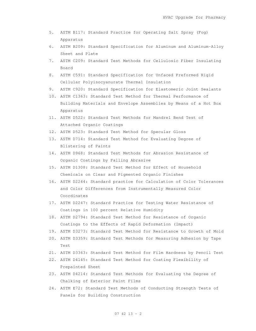
HVAC Upgrade for Pharmacy
07 42 13 - 2
5. ASTM B117: Standard Practice for Operating Salt Spray (Fog)
Apparatus
6. ASTM B209: Standard Specification for Aluminum and Aluminum-Alloy
Sheet and Plate
7. ASTM C209: Standard Test Methods for Cellulosic Fiber Insulating
Board
8. ASTM C591: Standard Specification for Unfaced Preformed Rigid
Cellular Polyisocyanurate Thermal Insulation
9. ASTM C920: Standard Specification for Elastomeric Joint Sealants
10. ASTM C1363: Standard Test Method for Thermal Performance of
Building Materials and Envelope Assemblies by Means of a Hot Box
Apparatus
11. ASTM D522: Standard Test Methods for Mandrel Bend Test of
Attached Organic Coatings
12. ASTM D523: Standard Test Method for Specular Gloss
13. ASTM D714: Standard Test Method for Evaluating Degree of
Blistering of Paints
14. ASTM D968: Standard Test Methods for Abrasion Resistance of
Organic Coatings by Falling Abrasive
15. ASTM D1308: Standard Test Method for Effect of Household
Chemicals on Clear and Pigmented Organic Finishes
16. ASTM D2244: Standard practice for Calculation of Color Tolerances
and Color Differences from Instrumentally Measured Color
Coordinates
17. ASTM D2247: Standard Practice for Testing Water Resistance of
Coatings in 100 percent Relative Humidity
18. ASTM D2794: Standard Test Method for Resistance of Organic
Coatings to the Effects of Rapid Deformation (Impact)
19. ASTM D3273: Standard Test Method for Resistance to Growth of Mold
20. ASTM D3359: Standard Test Methods for Measuring Adhesion by Tape
Test
21. ASTM D3363: Standard Test Method for Film Hardness by Pencil Test
22. ASTM D4145: Standard Test Method for Coating Flexibility of
Prepainted Sheet
23. ASTM D4214: Standard Test Methods for Evaluating the Degree of
Chalking of Exterior Paint Films
24. ASTM E72: Standard Test Methods of Conducting Strength Tests of
Panels for Building Construction
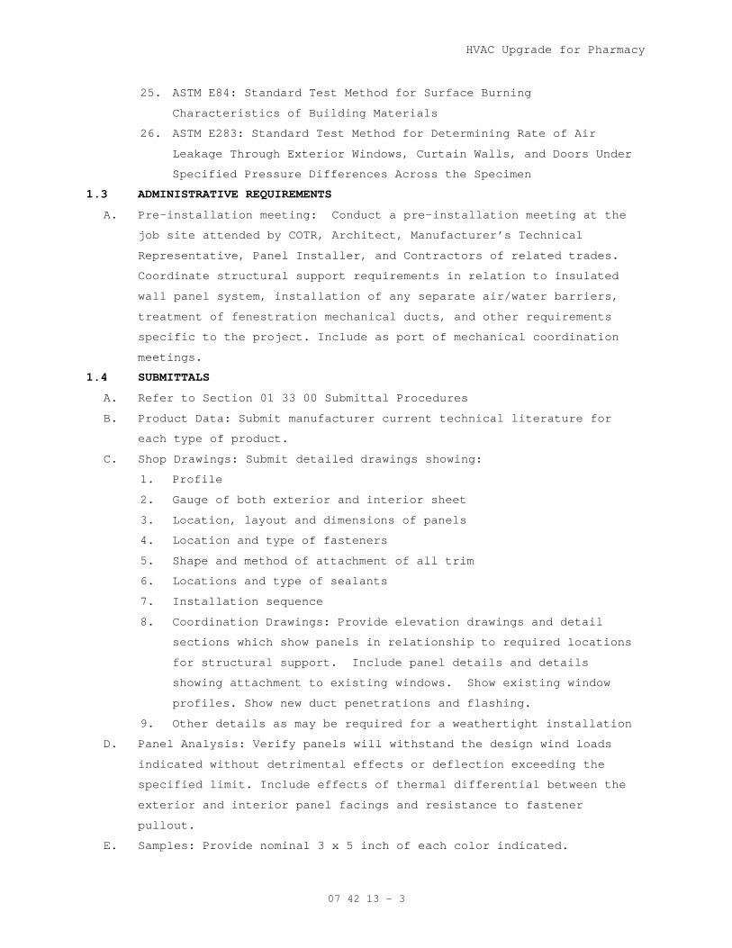
HVAC Upgrade for Pharmacy
07 42 13 - 3
25. ASTM E84: Standard Test Method for Surface Burning
Characteristics of Building Materials
26. ASTM E283: Standard Test Method for Determining Rate of Air
Leakage Through Exterior Windows, Curtain Walls, and Doors Under
Specified Pressure Differences Across the Specimen
1.3 ADMINISTRATIVE REQUIREMENTS
A. Pre-installation meeting: Conduct a pre-installation meeting at the
job site attended by COTR, Architect, Manufacturer’s Technical
Representative, Panel Installer, and Contractors of related trades.
Coordinate structural support requirements in relation to insulated
wall panel system, installation of any separate air/water barriers,
treatment of fenestration mechanical ducts, and other requirements
specific to the project. Include as port of mechanical coordination
meetings.
1.4 SUBMITTALS
A. Refer to Section 01 33 00 Submittal Procedures
B. Product Data: Submit manufacturer current technical literature for
each type of product.
C. Shop Drawings: Submit detailed drawings showing:
1. Profile
2. Gauge of both exterior and interior sheet
3. Location, layout and dimensions of panels
4. Location and type of fasteners
5. Shape and method of attachment of all trim
6. Locations and type of sealants
7. Installation sequence
8. Coordination Drawings: Provide elevation drawings and detail
sections which show panels in relationship to required locations
for structural support. Include panel details and details
showing attachment to existing windows. Show existing window
profiles. Show new duct penetrations and flashing.
9. Other details as may be required for a weathertight installation
D. Panel Analysis: Verify panels will withstand the design wind loads
indicated without detrimental effects or deflection exceeding the
specified limit. Include effects of thermal differential between the
exterior and interior panel facings and resistance to fastener
pullout.
E. Samples: Provide nominal 3 x 5 inch of each color indicated.
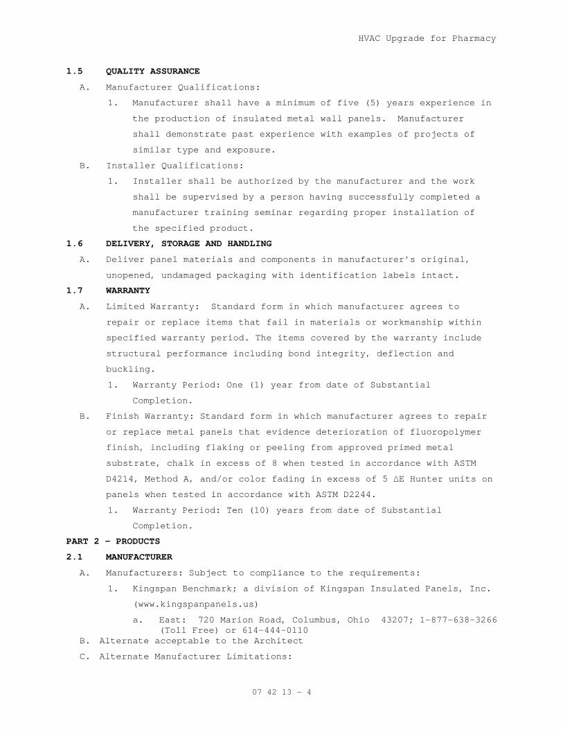
HVAC Upgrade for Pharmacy
07 42 13 - 4
1.5 QUALITY ASSURANCE
A. Manufacturer Qualifications:
1. Manufacturer shall have a minimum of five (5) years experience in
the production of insulated metal wall panels. Manufacturer
shall demonstrate past experience with examples of projects of
similar type and exposure.
B. Installer Qualifications:
1. Installer shall be authorized by the manufacturer and the work
shall be supervised by a person having successfully completed a
manufacturer training seminar regarding proper installation of
the specified product.
1.6 DELIVERY, STORAGE AND HANDLING
A. Deliver panel materials and components in manufacturer’s original,
unopened, undamaged packaging with identification labels intact.
1.7 WARRANTY
A. Limited Warranty: Standard form in which manufacturer agrees to
repair or replace items that fail in materials or workmanship within
specified warranty period. The items covered by the warranty include
structural performance including bond integrity, deflection and
buckling.
1. Warranty Period: One (1) year from date of Substantial
Completion.
B. Finish Warranty: Standard form in which manufacturer agrees to repair
or replace metal panels that evidence deterioration of fluoropolymer
finish, including flaking or peeling from approved primed metal
substrate, chalk in excess of 8 when tested in accordance with ASTM
D4214, Method A, and/or color fading in excess of 5 ∆E Hunter units on
panels when tested in accordance with ASTM D2244.
1. Warranty Period: Ten (10) years from date of Substantial
Completion.
PART 2 - PRODUCTS
2.1 MANUFACTURER
A. Manufacturers: Subject to compliance to the requirements:
1. Kingspan Benchmark; a division of Kingspan Insulated Panels, Inc.
(www.kingspanpanels.us)
a. East: 720 Marion Road, Columbus, Ohio 43207; 1-877-638-3266 (Toll Free) or 614-444-0110
B. Alternate acceptable to the Architect
C. Alternate Manufacturer Limitations:
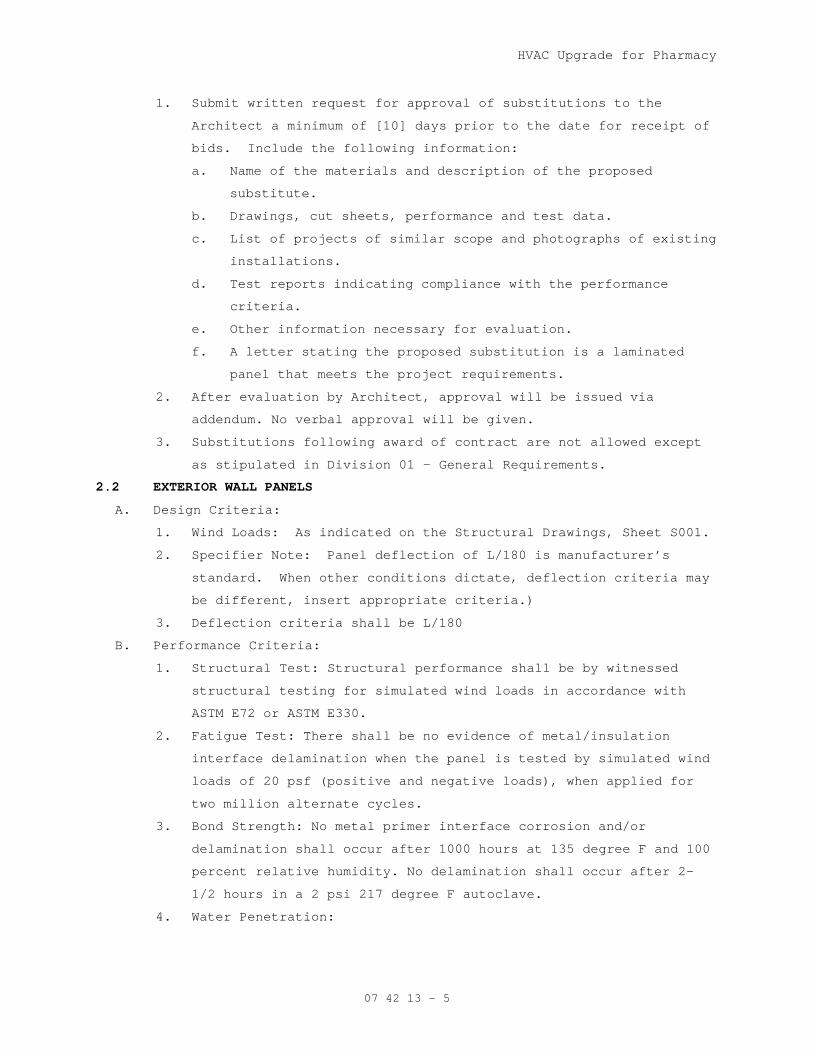
HVAC Upgrade for Pharmacy
07 42 13 - 5
1. Submit written request for approval of substitutions to the
Architect a minimum of [10] days prior to the date for receipt of
bids. Include the following information:
a. Name of the materials and description of the proposed
substitute.
b. Drawings, cut sheets, performance and test data.
c. List of projects of similar scope and photographs of existing
installations.
d. Test reports indicating compliance with the performance
criteria.
e. Other information necessary for evaluation.
f. A letter stating the proposed substitution is a laminated
panel that meets the project requirements.
2. After evaluation by Architect, approval will be issued via
addendum. No verbal approval will be given.
3. Substitutions following award of contract are not allowed except
as stipulated in Division 01 – General Requirements.
2.2 EXTERIOR WALL PANELS
A. Design Criteria:
1. Wind Loads: As indicated on the Structural Drawings, Sheet S001.
2. Specifier Note: Panel deflection of L/180 is manufacturer’s
standard. When other conditions dictate, deflection criteria may
be different, insert appropriate criteria.)
3. Deflection criteria shall be L/180
B. Performance Criteria:
1. Structural Test: Structural performance shall be by witnessed
structural testing for simulated wind loads in accordance with
ASTM E72 or ASTM E330.
2. Fatigue Test: There shall be no evidence of metal/insulation
interface delamination when the panel is tested by simulated wind
loads of 20 psf (positive and negative loads), when applied for
two million alternate cycles.
3. Bond Strength: No metal primer interface corrosion and/or
delamination shall occur after 1000 hours at 135 degree F and 100
percent relative humidity. No delamination shall occur after 2-
1/2 hours in a 2 psi 217 degree F autoclave.
4. Water Penetration:

HVAC Upgrade for Pharmacy
07 42 13 - 6
a. Dynamic: There shall be no uncontrolled water leakage when
tested in accordance with AAMA 501.1 at a pressure
differential of 15 psf. Test shall be conducted with the
liner side seal broken.
b. Static: No uncontrolled water leakage, when tested in
accordance with ASTM E331 at a [6.24 psf] [20 psf] pressure
differential.
c. Static – 2 hour duration: Panel system shall demonstrate no
water penetration when tested in accordance with ASTM E331 at
6.24 psf pressure differential for a two (2) hour duration to
satisfy International Building Code, Section 1403.2.
5. Air Infiltration: Air infiltration through the panel shall not
exceed 0.01 cfm/sf at [6.24 psf] [20 psf] air pressure
differential when tested in accordance with ASTM E283.
6. Water Absorption: There shall be no more than 0.127 percent
water absorption by volume when a 12 x 12 inch laminated
insulated metal wall panel sample is subjected to a 24-hour full
water submersion in accordance with ASTM C209.
7. Thermal Performance: Polyisocyanurate (ISO) core panels shall
provide the following R-Values as tested in accordance with ASTM
C1363:
a. 2 inch thick Flat: R-14
C. Insulating Core: Polyisocyanurate (ISO) core, ASTM C591 Type IV, CFC
and HCFC free, compliant with Montreal Protocol and Clean Air Act,
with the following minimum physical properties:
1. Density Nominal: 2.1 pcf
2. Shear Strength: 27 psi
3. Compressive Strength: 26 psi
4. Tensile Strength: 33 psi
5. Closed Cell Content: 95 percent minimum
6. FM Global approvals: Class 1 per FM 4880
7. Surface burning characteristics of unfaced foam core when tested
in accordance with ASTM E84:
a. Flame Spread: less than 25
b. Smoke Developed: less than 195

HVAC Upgrade for Pharmacy
07 42 13 - 7
D. Exterior Paint Finish Characteristics for Panels meeting the
requirements of AAMA 621 for G90 galvanized steel or AZ50 Galvalume®:
1. Gloss: 15 ± 5 measured at 60 degree angle tested in accordance
with ASTM D523.
2. Pencil Hardness: HB-H minimum tested in accordance with ASTM
D3363.
3. Flexibility, T-Bend: 1-2T bend with no adhesion loss when tested
in accordance with ASTM D4145.
4. Flexibility, Mandrel: No cracking when bent 180 degrees around a
1/8 mandrel as tested in accordance with ASTM D522.
5. Adhesion: No adhesion loss tested in accordance with ASTM D3359.
6. Reverse Impact: No cracking or adhesion loss when impacted 3000 x
inches of metal thickness (lb-in), tested in accordance with ASTM
D2794.
7. Abrasion Resistance: Nominal 65 liters of falling sand to expose
5/32 inch diameter of metal substrate when tested in accordance
with ASTM D968.
8. Graffiti Resistance: Minimal effect.
9. Humidity Resistance: Passes 1500 hours at 100 percent relative
humidity and 95 degrees F, with a test rating of 10 when tested
in accordance with ASTM D2247 and D714.
10. Color Retention: Passes 5000 hours when tested in accordance with
ASTM G153 and G154.
11. Chalk Resistance: Maximum chalk is a rating of 8 when tested in
accordance with ASTM D4214, Method A.
12. Color Tolerances: Maximum of 5∆E Hunter units on panels when
tested in accordance with ASTM D2244.
E. Panel Assembly:
1. Panel thickness: 1 inches thick.
2. Panel width, Flat Panels
3. Panel joints shall consist of fasteners and attachment clip
completely concealed within the joint. Panel joint shall have two
distinct lines of defense against water infiltration.
4. Exterior Face of Panel:
a. Material:
1) Coil material shall be in accordance with ASTM A755
Grade 33, G90 galvanized steel in accordance with ASTM

HVAC Upgrade for Pharmacy
07 42 13 - 8
A653 and A924 or AZ50 Galvalume® / Zincalume® in
accordance with ASTM A792.
2) Gauge: 22 (steel)
b. Profile: Flat
1) Flat profile to have no flutes, planking, or mild
profiling of any type.
c. Texture: Smooth or Non-directional embossed
d. Exterior Paint Finish Color:
1) To match window frames, from manufacturer’s standard
colors.
2) Finish System:
a) 1.0 mil. Fluropolymer (PVDF) Two Coat system: 0.2
mil primer with 0.8 mil Kynar 500 (70 percent)
SOLID color coat.
5. Interior Face of Panel:
a. Material:
1) Coil material shall be Grade 33, G90 galvanized steel in
accordance with ASTM A653 and A924 or AZ50 Galvalume® /
Zincalume® in accordance with ASTM A792 (contact
Kingspan for project specific availability).
2) Gauge: 24 (steel)
b. Profile: Standard flat, non-profiled
c. Texture: Smooth
d. Interior Finish: Modified polyester finish with a total
minimum dry film thickness of 0.9 to 1.1 mil including
primer.
1) Color: Standard USDA Imperial White.
6. Insulating Core: Precured, profiled, sanded flat prior to
lamination. Core material shall be polyisocyanurate (ISO).
7. Structural Adhesive: Type II Class 2 Structural Urethane
Adhesive, 100 percent solids and 100 percent solvent free,
evaluated and listed for sandwich panel construction by ICC
Evaluation Service or other recognized agency.
2.3 ACCESSORIES
A. Fasteners: Fasteners as recommended by manufacturer.
B. Clips: Shall be zinc-plated C1050 annealed spring steel, heat-treated
to nominal 150 ksi yield strength.
C. Perimeter Trim:
HVAC Upgrade for Pharmacy
07 42 13 - 9
1. Fabricated perimeter trim and metal flashing: Shall be same
gauge, material and coating color as exterior face of insulated
metal wall panel.
2. Extruded perimeter trim: Shall be extruded aluminum 6063-T5 alloy
with spray applied PVF coating in same color as exterior face of
insulated metal wall panel.
D. Butyl Weather Barrier Sealant: Non-skinning butyl tube sealant per
panel manufacturer’s recommendations compliant with AAMA 809.2.
E. Sealants at exposed joints: Neutral cure silicone sealant compliant
with ASTM C920.
PART 3 - EXECUTION
3.1 EXAMINATION
A. Provide field measurements to manufacturer as required to achieve
proper fit of the preformed wall panel envelope. Measurements shall
be provided in a timely manner so that there is no impact to
construction or manufacturing schedule.
B. Examine individual panels upon removing from the bundle; notify
manufacturer of panel defects. Do not install defective panels.
3.2 PANEL INSTALLATION
A. Installation shall be in accordance with manufacturer’s installation
guidelines and recommendations. Panel installation shall be integral
with windows.
B. Install panels plumb, level, and true-to-line to dimensions and layout
indicated on approved shop drawings.
C. Cut panels prior to installing, where indicated on shop drawings,
using a power circular saw with fine tooth carbide tip blade per
manufacturer’s instructions.
D. Butyl Weather Barrier Sealant:
1. Apply non-skinning butyl sealant as shown on shop drawings and
manufacturer’s installation instructions as necessary to
establish the vapor barrier for the panels.
2. Use non-skinning butyl tube sealant only for tight metal-to-metal
contact.
3. Do not use non-skinning butyl tube sealant to bridge gaps.
E. Glaze panels into window units. Place panel fasteners through pre-
punched holes in attachment clips, concealed within the joint of the
panel. Secure units to the structural supports. Space clips as
HVAC Upgrade for Pharmacy
07 42 13 - 10
recommended by manufacturer or otherwise indicated on the approved
shop drawings.
3.3 TRIM INSTALLATION
A. Place trim and trim fasteners only as indicated per details on the
approved shop drawings.
B. Field drill weep holes where appropriate in horizontal trim; minimum
1/4 inch diameter at 24 inches on center.
C. Place a continuous strip of butyl tape or butyl tube sealant on
closure trims for the length of the panel to be covered by trim.
3.4 SEALANT INSTALLATION FOR EXPOSED JOINTS
A. Clean and prime surfaces to receive exterior exposed sealants in
accordance with sealant manufacturer’s recommendations.
B. Follow sealant manufacturer’s recommendations for joint width-to-depth
ratio, application temperature range, size and type of backer rod, and
compatibility of materials for adhesion.
C. Direct contact between butyl and silicone sealants shall not be
permitted.
3.5 CLEANING AND PROTECTION
A. Remove protective film immediately after installation.
B. Touch-up, repair or replace metal panels and trim that have been
damaged.
C. After metal wall panel installation, clear weep holes and drainage
channels of obstructions, dirt, and sealant.
- - - E N D - - -
HVAC Upgrade for Pharmacy
10-10
07 56 30 - 1
SECTION 07 56 30 AGGREGATE ROOFING SURFACE RESTORATION
PART 1 — GENERAL 1.1 RELATED DOCUMENTS
A. Drawings and general provisions of the Contract, including the Conditions of
the Contract and Division 01 Specification Sections apply to this Section.
1.2 SUMMARY A. Restoration system of Bldg 134 as indicated on drawings:
1. Clean debris and gravel surfacing off of current roof system. 2. Repair any additional issues at flashing around perimeter and penetrations
indicated on drawings. 3. Remove current perimeter and penetration flashings in preparation for roof
restoration. 4. Install 2xPlies HPR Torch Base as a base flashing ply at all projections
and perimeter. Extend base flashing ply 6” onto the field of roof. 5. Install Stressply IV FR Mineral modified flashing ply at all projections
and perimeter. Extend modified flashing ply 9” onto field of roof. 6. Three-course all flashing lap seams with SilverFlash and Garmesh. 7. Seal top of flashing at perimeter (gravel stop/metal edge) with GarlaFlex
(cartridges). 8. Apply Energizer K FR cold process polymer modified flood coat at a rate of
3.5 gal. per 100 sq.ft. 9. Immediately embed Grip Poly Soft fiberglass mesh into Energizer K FR
restoration coating. 10. Apply Energizer K FR cold process polymer modified flood coat at a rate
of 3.5 gal. per 100 sq.ft. 11. Immediately embed No. 5 pea gravel in cold process flood coat. 12. Seal all pitch pans with 2-part pitch pan filler.
B. Related Sections:
1. Section 07 01 00 - Common Work Results for Thermal and Moisture Protection.
2. Section 07 62 00 - Section Sheet Metal Flashing and Trim. 3. Section 07 71 00 - Manufactured Roof Specialties.
1.3 REFERENCES A. American Society for Testing and Materials (ASTM):
1. ASTM D41 Standard Specification for Asphalt Primer Used in Roofing, Dampproofing and Waterproofing.
2. ASTM D451 Standard Test Method for Sieve Analysis of Granular Mineral Surfacing For Asphalt Roofing Products.
3. ASTM D1079 Terminology Relating to Roofing and Waterproofing. 4. ASTM D1227 Standard Specification for Emulsified Asphalt Used as a
Protective Coating for Roofing. 5. ASTM D1863 Standard Specification for Mineral Aggregate Used on Built-Up
Roofs. 6. ASTM D4586 Standard Specification for Asphalt Roof Cement. 7. ASTM D2824 Standard Specification for Aluminum-Pigmented Asphalt Roof
Coatings, Nonfibered, Asbestos Fibered, and Fibered without Asbestos 8. ASTM D4601 Standard Specification for Asphalt-Coated Glass Fiber Base
Sheet Used in Roofing. 9. ASTM D5147 Standard Test Methods for Sampling and Testing Modified
Bituminous Sheet Material.

HVAC Upgrade for Pharmacy
10-10
07 56 30 - 2
10. ASTM D6162 Standard Specification for Styrene Butadiene Styrene (SBS) Modified Bituminous Sheet Materials Using a Combination of Polyester and Glass Fiber Reinforcements.
11. ASTM D6163 Standard Specification for Styrene Butadiene Styrene (SBS) Modified Bituminous Sheet Materials Using Glass Fiber Reinforcements.
12. ASTM E108 Standard Test Methods for Fire Tests of Roof Coverings. B. National Roofing Contractors Association (NRCA):
1. Roofing and Waterproofing Manual. C. Underwriters Laboratories, Inc. (UL):
1. Fire Hazard Classifications. 1.4 SUBMITTALS FOR REVIEW-N/A 1.5 CONTRACT CLOSEOUT SUBMITTALS
A. General: Comply with Requirements of Division 01 Section - Closeout
Submittals.
B. Special Project Warranty: Provide specified warranty for the Project,
executed by the authorized agent of the Manufacturer.
C. Roofing Maintenance Instructions. Provide a manual of manufacturer's
recommendations for maintenance of installed roofing systems.
D. Insurance Certification: Assist Owner in preparation and submittal of roof
installation acceptance certification as may be necessary in connection with
fire and extended coverage insurance on roofing and associated work.
E. Demonstration and Training Schedule: Provide a schedule of proposed dates and
times for instruction of Owner's personnel in the maintenance requirements
for completed roofing work. Refer to Part 3 for additional requirements.
1.6 QUALITY ASSURANCE A. Manufacturer Qualifications: Company specializing in manufacturing the
products specified in this Section with not less than 12 years documented
experience.
B. Installer Qualifications: Company specializing in modified bituminous roofing
installation with not less than 5 years experience and authorized by roofing
system manufacturer as qualified to install manufacturer's roofing materials.
C. Installer's Field Supervision: Maintain a full-time Supervisor/Foreman on job
site during all phases of roofing work while roofing work is in progress.
Maintain proper supervision of workmen.
D. Maintain a copy of the Contract Documents in the possession of the
Supervisor/Foreman and on the roof at all times.
E. Source Limitations: Obtain all components of roof system from a single
manufacturer. Secondary products that are required shall be recommended and
approved in writing by the roofing system Manufacturer.
1. Upon request of the Architect or Owner, submit Manufacturer's written approval of secondary components in list form, signed by an authorized agent of the Manufacturer.

HVAC Upgrade for Pharmacy
10-10
07 56 30 - 3
F. Source Quality Control: Manufacturer shall have in place a documented,
standardized quality control program such as ISO-9001.
1.7 PRE-INSTALLATION CONFERENCE A. Pre-Installation Roofing Conference: Convene a pre-roofing conference
approximately two (2) weeks before scheduled commencement of modified
bituminous roofing system installation and associated work.
B. Require attendance of installer of each component of associated work,
installers of deck or substrate construction to receive roofing work,
installers of rooftop units and other work in and around roofing that must
precede or follow roofing work (including mechanical work if any), Architect,
Owner, roofing system manufacturer's representative, and other
representatives directly concerned with performance of the Work, including
(where applicable) Owner's insurers, testing agencies and governing
authorities. Objectives of conference include:
1. Review foreseeable methods and procedures related to roofing work, including set up and mobilization areas for stored material and work area.
2. Tour representative areas of roofing substrates (decks), inspect and discuss condition of substrate, roof drains, curbs, penetrations and other preparatory work performed by others.
3. Review structural loading limitations of deck and inspect deck for loss of flatness and for required attachment.
4. Review roofing system requirements (drawings, specifications and other contract documents).
5. Review required submittals both completed and yet to be completed. 6. Review and finalize construction schedule related to roofing work and
verify availability of materials, installer's personnel, equipment and facilities needed to make progress and avoid delays.
7. Review required inspection, testing, certifying and material usage accounting procedures.
8. Review weather and forecasted weather conditions and procedures for coping with unfavorable conditions, including possibility of temporary roofing (if not mandatory requirement).
9. Record discussion of conference including decisions and agreements (or disagreements) reached and furnish copy of record to each party attending. If substantial disagreements exist at conclusion of conference, determine how disagreements will be resolved and set date for reconvening conference.
10. Review notification procedures for weather or non-working days. C. The Owner's Representative will designate one of the conference participants
to record the proceedings and promptly distribute them to the participants
for record.
D. The intent of the conference is to resolve issues affecting the installation
and performance of roofing work. Do not proceed with roofing work until such
issues are resolved to the satisfaction of the Owner and [Architect or
Engineer] of Record. This shall not be construed as interference with the

HVAC Upgrade for Pharmacy
10-10
07 56 30 - 4
progress of Work on the part of the Owner or [Architect or Engineer] of
Record.
1.8 DELIVERY, STORAGE AND HANDLING A. Deliver products to site with seals and labels intact, in manufacturer's
original containers, dry and undamaged.
B. Store and handle roofing sheets in a dry, well-ventilated, weather-tight
place to prevent moisture exposure. Store rolls of felt and other sheet
materials on pallets or other raised surface. Stand all roll materials on
end. Cover roll goods with a canvas tarpaulin or other breathable material
(not polyethylene).
C. Do not leave unused materials on the roof overnight or when roofing work is
not in progress unless protected from weather and other moisture sources.
D. Secure all material and equipment on the job site. If any material or
equipment is stored on the roof, assure that the integrity of the deck is not
compromised at any time. Damage to the deck caused by the Contractor's
actions will be the sole responsibility of the Contractor, and the deck will
be repaired or replaced at his expense.
1.9 MANUFACTURER'S INSPECTIONS A. When the Project is in progress, the roofing system manufacturer will provide
the following:
1. Report progress and quality of the work as observed. 2. Provide periodic job site inspections a minimum of 3 times per week. 3. Report to the Architect in writing any failure or refusal of the
Contractor to correct unacceptable practices called to the Contractor's attention.
4. Confirm after completion that manufacturer has observed no application procedures in conflict with the specifications other than those that may have been previously reported and corrected.
1.10 PROJECT CONDITIONS A. Proceed with roofing work only when existing and forecasted weather
conditions will permit a unit of work to be installed in accordance with
manufacturer's recommendations and warranty requirements.
B. Do not apply roofing insulation or membrane to damp deck surface.
C. Do not expose materials subject to water or solar damage in quantities
greater than can be weatherproofed during same day.
D. All slopes greater than 2:12 require back-nailing to prevent slippage of the
ply sheets. Use ring or spiral-shank one (1) inch cap nails, or screws and
plates at a rate of one (1) fastener per ply (including the membrane) at each
insulation stop. Place insulation stops at 16 ft o.c. for slopes less than
3:12 and four (4) ft o.c. for slopes greater than 3:12. On non-insulated
systems, nail each ply directly into the deck at the rate specified above.
HVAC Upgrade for Pharmacy
10-10
07 56 30 - 5
When slope exceeds 2:12, install all plies parallel to the slope (strapping)
to facilitate backnailing. Install four (4) additional fasteners at the upper
edge of the membrane when strapping the plies.
1.11 SEQUENCING AND SCHEDULING A. Sequence installation of roofing with related units of work specified in
other Sections to ensure that roof assemblies, including roof accessories,
flashing, trim and joint sealers, are protected against damage from effects
of weather, corrosion and adjacent construction activity.
B. Complete all roofing field assembly work each day. Phased construction will
not be accepted.
1.12 WARRANTY A. Upon completion of installation, and acceptance by the Owner and Architect,
the Manufacturer will supply to the Owner the 15-year warranty.
B. Installer will submit a two (2)-year warranty to the membrane manufacturer
with a copy directly to Owner.
PART 2 — PRODUCTS 2.1 ACCEPTABLE MANUFACTURERS
A. The design is based upon roofing systems engineered and manufactured by:
The Garland Company 3800 East 91st Street Cleveland, Ohio 44105 Telephone: (800) 762-8225 Website: www.garlandco.com
2.2 DESCRIPTION A. Maintenance work including but not limited to:
1. Energizer K Plus FR: A liquid applied membrane with Kevlar fibers for restoration of smooth or granulated asphalt or modified membrane surfaces. Used in slopes up to 3:12 inches.
B. Reinforcement including but not limited to:
1. Grip Poly Soft C. Base Flashing Ply:
1. Base Flashing Ply: Two (2) plies of HPR Torch Base, SBS torch-applied base flashing ply covered by an additional layer of modified bitumen membrane and set in bitumen.
a. Modified Flashing Ply: 1. Modified Membrane: STRESSPLY IV FR MINERAL; 160 mil SBS (Styrene-
Butadiene-Styrene) mineral surfaced, rubber modified, torch-applied roofing membrane with dual fiberglass reinforced scrim and superior low temperature capabilities.
2.3 BITUMINOUS MATERIALS A. Asphalt Primer: V.O.C. compliant, ASTM D41.
B. Asphalt Roofing Mastic: V.O.C. compliant, ASTM D4586, Type II
2.4 SHEET MATERIALS A. Base Ply:
1. Polyester-Fiberglass-Polyester Base Sheet: ASTM D-2523
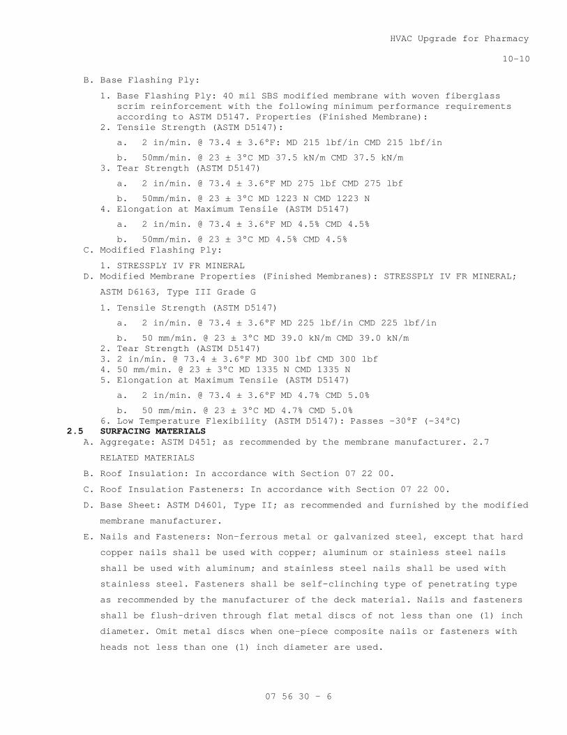
HVAC Upgrade for Pharmacy
10-10
07 56 30 - 6
B. Base Flashing Ply:
1. Base Flashing Ply: 40 mil SBS modified membrane with woven fiberglass scrim reinforcement with the following minimum performance requirements according to ASTM D5147. Properties (Finished Membrane):
2. Tensile Strength (ASTM D5147):
a. 2 in/min. @ 73.4 ± 3.6°F: MD 215 lbf/in CMD 215 lbf/in
b. 50mm/min. @ 23 ± 3°C MD 37.5 kN/m CMD 37.5 kN/m 3. Tear Strength (ASTM D5147)
a. 2 in/min. @ 73.4 ± 3.6°F MD 275 lbf CMD 275 lbf
b. 50mm/min. @ 23 ± 3°C MD 1223 N CMD 1223 N 4. Elongation at Maximum Tensile (ASTM D5147)
a. 2 in/min. @ 73.4 ± 3.6°F MD 4.5% CMD 4.5%
b. 50mm/min. @ 23 ± 3°C MD 4.5% CMD 4.5% C. Modified Flashing Ply:
1. STRESSPLY IV FR MINERAL D. Modified Membrane Properties (Finished Membranes): STRESSPLY IV FR MINERAL;
ASTM D6163, Type III Grade G
1. Tensile Strength (ASTM D5147)
a. 2 in/min. @ 73.4 ± 3.6°F MD 225 lbf/in CMD 225 lbf/in
b. 50 mm/min. @ 23 ± 3°C MD 39.0 kN/m CMD 39.0 kN/m 2. Tear Strength (ASTM D5147) 3. 2 in/min. @ 73.4 ± 3.6°F MD 300 lbf CMD 300 lbf 4. 50 mm/min. @ 23 ± 3°C MD 1335 N CMD 1335 N 5. Elongation at Maximum Tensile (ASTM D5147)
a. 2 in/min. @ 73.4 ± 3.6°F MD 4.7% CMD 5.0%
b. 50 mm/min. @ 23 ± 3°C MD 4.7% CMD 5.0% 6. Low Temperature Flexibility (ASTM D5147): Passes -30°F (-34°C)
2.5 SURFACING MATERIALS A. Aggregate: ASTM D451; as recommended by the membrane manufacturer. 2.7
RELATED MATERIALS
B. Roof Insulation: In accordance with Section 07 22 00.
C. Roof Insulation Fasteners: In accordance with Section 07 22 00.
D. Base Sheet: ASTM D4601, Type II; as recommended and furnished by the modified
membrane manufacturer.
E. Nails and Fasteners: Non-ferrous metal or galvanized steel, except that hard
copper nails shall be used with copper; aluminum or stainless steel nails
shall be used with aluminum; and stainless steel nails shall be used with
stainless steel. Fasteners shall be self-clinching type of penetrating type
as recommended by the manufacturer of the deck material. Nails and fasteners
shall be flush-driven through flat metal discs of not less than one (1) inch
diameter. Omit metal discs when one-piece composite nails or fasteners with
heads not less than one (1) inch diameter are used.
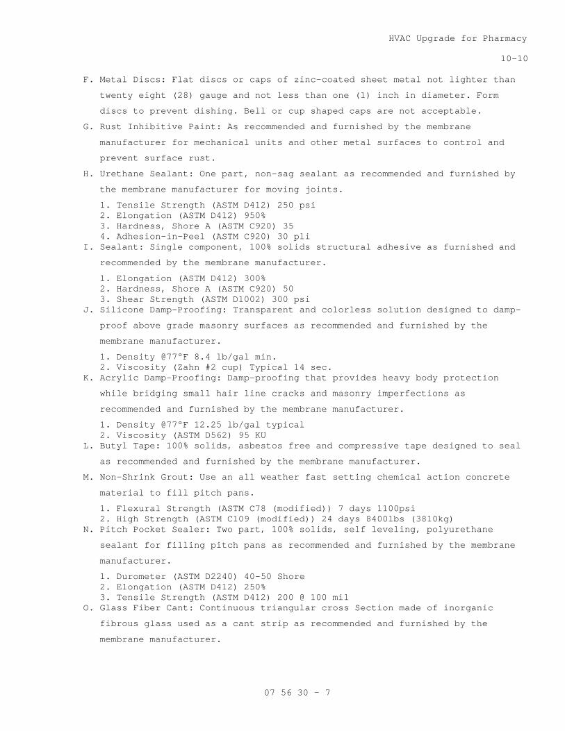
HVAC Upgrade for Pharmacy
10-10
07 56 30 - 7
F. Metal Discs: Flat discs or caps of zinc-coated sheet metal not lighter than
twenty eight (28) gauge and not less than one (1) inch in diameter. Form
discs to prevent dishing. Bell or cup shaped caps are not acceptable.
G. Rust Inhibitive Paint: As recommended and furnished by the membrane
manufacturer for mechanical units and other metal surfaces to control and
prevent surface rust.
H. Urethane Sealant: One part, non-sag sealant as recommended and furnished by
the membrane manufacturer for moving joints.
1. Tensile Strength (ASTM D412) 250 psi 2. Elongation (ASTM D412) 950% 3. Hardness, Shore A (ASTM C920) 35 4. Adhesion-in-Peel (ASTM C920) 30 pli
I. Sealant: Single component, 100% solids structural adhesive as furnished and
recommended by the membrane manufacturer.
1. Elongation (ASTM D412) 300% 2. Hardness, Shore A (ASTM C920) 50 3. Shear Strength (ASTM D1002) 300 psi
J. Silicone Damp-Proofing: Transparent and colorless solution designed to damp-
proof above grade masonry surfaces as recommended and furnished by the
membrane manufacturer.
1. Density @77°F 8.4 lb/gal min. 2. Viscosity (Zahn #2 cup) Typical 14 sec.
K. Acrylic Damp-Proofing: Damp-proofing that provides heavy body protection
while bridging small hair line cracks and masonry imperfections as
recommended and furnished by the membrane manufacturer.
1. Density @77°F 12.25 lb/gal typical 2. Viscosity (ASTM D562) 95 KU
L. Butyl Tape: 100% solids, asbestos free and compressive tape designed to seal
as recommended and furnished by the membrane manufacturer.
M. Non-Shrink Grout: Use an all weather fast setting chemical action concrete
material to fill pitch pans.
1. Flexural Strength (ASTM C78 (modified)) 7 days 1100psi 2. High Strength (ASTM C109 (modified)) 24 days 8400lbs (3810kg)
N. Pitch Pocket Sealer: Two part, 100% solids, self leveling, polyurethane
sealant for filling pitch pans as recommended and furnished by the membrane
manufacturer.
1. Durometer (ASTM D2240) 40-50 Shore 2. Elongation (ASTM D412) 250% 3. Tensile Strength (ASTM D412) 200 @ 100 mil
O. Glass Fiber Cant: Continuous triangular cross Section made of inorganic
fibrous glass used as a cant strip as recommended and furnished by the
membrane manufacturer.
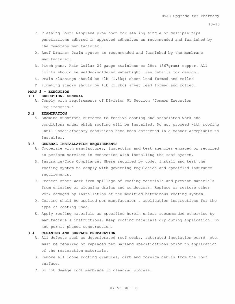
HVAC Upgrade for Pharmacy
10-10
07 56 30 - 8
P. Flashing Boot: Neoprene pipe boot for sealing single or multiple pipe
penetrations adhered in approved adhesives as recommended and furnished by
the membrane manufacturer.
Q. Roof Drains: Drain system as recommended and furnished by the membrane
manufacturer.
R. Pitch pans, Rain Collar 24 gauge stainless or 20oz (567gram) copper. All
joints should be welded/soldered watertight. See details for design.
S. Drain Flashings should be 4lb (1.8kg) sheet lead formed and rolled
T. Plumbing stacks should be 4lb (1.8kg) sheet lead formed and rolled.
PART 3 — EXECUTION 3.1 EXECUTION, GENERAL
A. Comply with requirements of Division 01 Section "Common Execution
Requirements."
3.2 EXAMINATION A. Examine substrate surfaces to receive coating and associated work and
conditions under which roofing will be installed. Do not proceed with roofing
until unsatisfactory conditions have been corrected in a manner acceptable to
Installer.
3.3 GENERAL INSTALLATION REQUIREMENTS A. Cooperate with manufacturer, inspection and test agencies engaged or required
to perform services in connection with installing the roof system.
B. Insurance/Code Compliance: Where required by code, install and test the
roofing system to comply with governing regulation and specified insurance
requirements.
C. Protect other work from spillage of roofing materials and prevent materials
from entering or clogging drains and conductors. Replace or restore other
work damaged by installation of the modified bituminous roofing system.
D. Coating shall be applied per manufacturer's application instructions for the
type of coating used.
E. Apply roofing materials as specified herein unless recommended otherwise by
manufacture's instructions. Keep roofing materials dry during application. Do
not permit phased construction.
3.4 CLEANING AND SURFACE PREPARATION A. All defects such as deteriorated roof decks, saturated insulation board, etc.
must be repaired or replaced per Garland specifications prior to application
of the restoration materials.
B. Remove all loose roofing granules, dirt and foreign debris from the roof
surface.
C. Do not damage roof membrane in cleaning process.

HVAC Upgrade for Pharmacy
10-10
07 56 30 - 9
D. All surface defects (cracks, blisters, tears) must be repaired:
E. Blister Repair
1. Clean and prime the area. 2. All blisters must be cut and opened down to the solidly adhered plies of
the existing roof system. Use a roofer's knife to open the blister with an "X" or "H" cut. Fold the flaps and remove any existing moisture. Permit the area to dry before applying repair materials.
3. Apply a liberal coating of bituminous material into the blister. Firmly press the flaps into the bituminous material and trim the edges to ensure proper fit.
4. Apply a coating of bituminous material over the repaired area extending a minimum of eight (8) inches beyond the cuts. Embed a strip of fabric into the bituminous material and brush or roll firmly. Apply a second coat of bituminous material over the fabric and onto the roof surface.
F. Edge Detail Repair
1. Remove all loose dirt and debris along the edge detail and prime with an asphalt primer.
2. Secure all loose metal to the wood nailer. 3. Install a bond breaker at moving joints. 4. Apply a liberal coat of mastic over the prepared area and embed fabric
into the mastic. 5. Apply a liberal coat of mastic over the fabric. Sufficiently cover the
fabric to obliterate the weave from sight. 6. Apply surfacing to the repair.
G. Pitch Pocket Repair
1. Fill the pitch pocket with a 2-part pitch pan filler. Taper the filler to ensure water run-off.
2. Clean and prime the area with an asphalt primer. 3. Apply a liberal coating of mastic around the pitch pocket extending a
minimum of twelve (12) inches onto the horizontal roofing surface. 4. Cut four (4) strips of fabric. Each strip should be twelve (12) inches
wide and be of sufficient length so as to extend a minimum of twelve (12) inches beyond the pitch pan.
5. Embed a strip into the mastic along each side of the pitch pocket. Brush or roll the fabric into place to ensure proper embedment.
6. Top dress the area with mastic. 7. Install rain bonnet, draw band and caulk.
3.5 FLASHING INSTALLATION A. Prepare all walls, penetrations and expansion joints to be flashed and where
shown on the drawings, with asphalt primer at the rate of one hundred (100)
square feet per gallon. Allow primer to dry tack free.
B. All plies will be adhered with one of the following:
C. With brush grade flashing adhesive.
D. The entire sheet of flashing membrane must be solidly adhered to the
substrate and nailed off using a termination bar.
E. Seal all vertical laps of flashing membrane with a three-course application
of Flashing Bond and fiberglass mesh and aluminize.
F. Seal junction of flashing membrane and roof with a three-course application
of Flashing Bond and mesh.

HVAC Upgrade for Pharmacy
10-10
07 56 30 - 10
G. Counterflashing, cap flashings, expansion joints and similar work to be
coordinated with roofing work are specified in other sections.
H. Roof accessories, miscellaneous sheet metal accessory items, including piping
vents and other devices to be coordinate with the roofing work are in other
sections.
3.6 COATING APPLICATION A. Brush, spray or squeegee the coating onto the roof surface at a rate of:
1. Three and one-half (3.5) gallons of Energizer K Plus FR per one hundred (100) square feet.
B. Install polyester beginning at the low end of the roof. Embed a full roll of
the polyester fabric into the wet resurfacer and brush firmly into place. All
wrinkles should be broomed out immediately.
C. Apply a second coat of the coating at a rate of:
1. Three and one-half (3.5) gallons of Energizer K Plus FR one hundred (100) square feet.
D. Continue across the roof in similar fashion lapping each successive full
width roll of polyester a minimum of four (4) inches on sides and six (6)
inches at ends.
E. Allow the system to cure a minimum of thirty (30) days until it is tack free
and will support foot traffic without deformation.
F. Apply selected surfacing:
1. Embed No. 5 pea gravel into the restoration coating immediately after applying second 3.5 gallon/100 square foot coating.
3.7 FIELD QUALITY CONTROL A. Perform field inspection and as required.
B. Correct defects or irregularities discovered during field inspection.
C. Require attendance of roofing materials manufacturers' representatives at
site during installation of the roofing system.
3.8 CLEANING A. Remove bitumen adhesive drippings from all walls, windows, floors, ladders
and finished surfaces.
B. In areas where finished surfaces are soiled by asphalt or any other sources
of soiling caused by work of this section, consult manufacturer of surfaces
for cleaning instructions and conform to their instructions.
C. Repair or replace defaced or disfigured finishes caused by work of this
section.
3.9 FINAL INSPECTION A. At completion of roofing installation and associated work, meet with Owner,
roofing system manufacturer's representative, and other representatives
directly concerned with performance of roofing system.

HVAC Upgrade for Pharmacy
10-10
07 56 30 - 11
B. Walk roof surface areas of the building, inspect perimeter building edges as
well as flashing of roof penetrations, walls, curbs and other equipment. List
all items requiring correction or completion and furnish copy of list to each
party in attendance.
C. The roofing system manufacturer reserves the right to request a thermographic
scan of the roof during final inspection to determine if any damp or wet
materials have been installed. The thermographic scan shall be provided by
the Roofing Contractor.
D. If core cuts verify the presence of damp or wet materials, the Roofing
Contractor shall be required to replace the damaged areas at his own expense.
E. Repair or replace deteriorated or defective work found at time above
inspection as required to a produce an installation which is free of damage
and deterioration at time of Substantial Completion and according to warranty
requirements.
F. Notify the Owner upon completion of corrections.
G. Following the final inspection, provide written notice of acceptance of the
installation from the roofing system manufacturer.
- - - E N D - - -

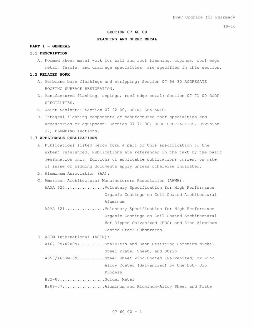
HVAC Upgrade for Pharmacy
10-10
07 60 00 - 1
SECTION 07 60 00
FLASHING AND SHEET METAL
PART 1 - GENERAL
1.1 DESCRIPTION
A. Formed sheet metal work for wall and roof flashing, copings, roof edge
metal, fascia, and drainage specialties, are specified in this section.
1.2 RELATED WORK
A. Membrane base flashings and stripping: Section 07 56 30 AGGREGATE
ROOFING SURFACE RESTORATION.
B. Manufactured flashing, copings, roof edge metal: Section 07 71 00 ROOF
SPECIALTIES.
C. Joint Sealants: Section 07 92 00, JOINT SEALANTS.
D. Integral flashing components of manufactured roof specialties and
accessories or equipment: Section 07 71 00, ROOF SPECIALTIES, Division
22, PLUMBING sections.
1.3 APPLICABLE PUBLICATIONS
A. Publications listed below form a part of this specification to the
extent referenced. Publications are referenced in the text by the basic
designation only. Editions of applicable publications current on date
of issue of bidding documents apply unless otherwise indicated.
B. Aluminum Association (AA):
C. American Architectural Manufacturers Association (AAMA):
AAMA 620................Voluntary Specification for High Performance
Organic Coatings on Coil Coated Architectural
Aluminum
AAMA 621................Voluntary Specification for High Performance
Organic Coatings on Coil Coated Architectural
Hot Dipped Galvanized (HDG) and Zinc-Aluminum
Coated Steel Substrates
D. ASTM International (ASTM):
A167-99(R2009)..........Stainless and Heat-Resisting Chromium-Nickel
Steel Plate, Sheet, and Strip
A653/A653M-09...........Steel Sheet Zinc-Coated (Galvanized) or Zinc
Alloy Coated (Galvanized) by the Hot- Dip
Process
B32-08..................Solder Metal
B209-07.................Aluminum and Aluminum-Alloy Sheet and Plate
HVAC Upgrade for Pharmacy
10-10
07 60 00 - 2
B370-09.................Copper Sheet and Strip for Building
Construction
D173-03.................Bitumen-Saturated Cotton Fabrics Used in
Roofing and Waterproofing
D412-06.................Vulcanized Rubber and Thermoplastic Elastomers-
Tension
D1187-97(R2002).........Asphalt Base Emulsions for Use as Protective
Coatings for Metal
D4586-07................Asphalt Roof Cement, Asbestos Free
E. Sheet Metal and Air Conditioning Contractors National Association
(SMACNA): Architectural Sheet Metal Manual.
F. National Association of Architectural Metal Manufacturers (NAAMM):
AMP 500-06..............Metal Finishes Manual
G. Federal Specification (Fed. Spec):
A-A-1925A...............Shield, Expansion; (Nail Anchors)
UU-B-790A...............Building Paper, Vegetable Fiber
H. International Code Commission (ICC): International Building Code,
Current Edition
1.4 PERFORMANCE REQUIREMENTS
A. IBC categorizes this site as 90 mph wind (table 1609), surface
roughness B (1609 4.2) exposure category east boundary of over site
within 5,000 feet of Lake Michigan, should be exposure category “D”.
(1609.4.3) and wind velocity pressure of 26.5 psf (table 1609.6.2 (1)).
1. Determine applicable wind uplift pressures in accordance with
ASCE 7.
2. Wind Uplift Forces: Resist the forces per FM Approvals 1-49.
B. Wind Design Standard: Fabricate and install roof-edge flashings tested
per ANSI/SPRI ES-1 to resist design pressure.
1.5 SUBMITTALS
A. Submit in accordance with Section 01 33 23, SHOP DRAWINGS, PRODUCT
DATA, AND SAMPLES.
B. Shop Drawings: For all specified items, including:
1. Flashings and counter flashings, two-piece counterflashing.
2. Copings
C. Manufacturer's Literature and Data: For all specified items, including:
1. Flashings and counter flashings, Two-piece counterflashing
2. Copings
D. Color Samples
HVAC Upgrade for Pharmacy
10-10
07 60 00 - 3
E. Certificates: Indicating compliance with specified finishing
requirements, from applicator and contractor.
PART 2 - PRODUCTS
2.1 FLASHING AND SHEET METAL MATERIALS
A. Stainless Steel: ASTM A167, Type 302B, dead soft temper.
B. Aluminum Sheet: ASTM B209, alloy 3003-H14 except alloy used for color
anodized aluminum shall be as required to produce specified color.
Alloy required to produce specified color shall have the same
structural properties as alloy 3003-H14.
2.2 FLASHING ACCESSORIES
A. Solder: ASTM B32; flux type and alloy composition as required for use
with metals to be soldered.
B. Rosin Paper: Fed-Spec. UU-B-790, Type I, Grade D, Style 1b, Rosin-sized
sheathing paper, weighing approximately 6 lbs/100 sf.
C. Fasteners:
1. Use only stainless steel.
2. Nails:
a. Minimum diameter for stainless steel nails: 0.095 inch and
annular threaded.
d. Length to provide not less than 7/8 inch penetration into
anchorage.
3. Rivets: Not less than 1/8 inch diameter.
4. Expansion Shields: Fed Spec A-A-1925A.
E. Sealant: As specified in Section 07 92 00, JOINT SEALANTS for exterior
locations.
F. Roof Cement: ASTM D4586.
2.3 SHEET METAL THICKNESS
A. Except as otherwise shown or specified use thickness or weight of sheet
metal as follows:
B. Concealed Locations (Built into Construction):
1. Stainless steel: 0.010 inch thick.
C. Exposed Locations:
1. Stainless steel: 0.015 inch.
D. Thickness of aluminum or galvanized steel is specified with each item.
2.4 FABRICATION, GENERAL
A. Jointing:
1. In general, stainless steel, except expansion and contraction
joints, shall be locked and soldered.
HVAC Upgrade for Pharmacy
10-10
07 60 00 - 4
2. Jointing of stainless steel over 0.018 inch thick shall be done by
lapping, riveting and soldering.
3. Joints shall conform to following requirements:
a. Flat-lock joints shall finish not less than 3/4 inch wide.
b. Lap joints subject to stress shall finish not less than one inch
wide and shall be soldered and riveted.
c. Unsoldered lap joints shall finish not less than 4 inches wide.
4. Flat and lap joints shall be made in direction of flow.
5. Soldering:
a. Pre tin both mating surfaces with solder for a width not less
than 1 1/2 inches of uncoated copper and stainless steel.
b. Treat in accordance with metal producers recommendations other
sheet metal required to be soldered.
c. Completely remove acid and flux after soldering is completed.
B. Cleats:
1. Fabricate cleats to secure flashings and sheet metal work over 12
inches wide and where specified.
2. Provide cleats for maximum spacing of 12 inch centers unless
specified otherwise.
3. Form cleats of same metal and weights or thickness as the sheet
metal being installed unless specified otherwise.
4. Fabricate cleats from 2 inch wide strip. Form end with not less than
3/4 inch wide loose lock to item for anchorage. Form other end of
length to receive nails free of item to be anchored and end edge to
be folded over and cover nail heads.
C. Edge Strips or Continuous Cleats:
1. Fabricate continuous edge strips where shown and specified to secure
loose edges of the sheet metal work.
2. Except as otherwise specified, fabricate edge strips of 0.024 inch
thick stainless steel or 0.050 inch thick aluminum.
3. Use material compatible with sheet metal to be secured by the edge
strip.
4. Fabricate in 10 feet maximum lengths with not less than 3/4 inch
loose lock into metal secured by edge strip.
5. Fabricate Strips for fascia anchorage to extend below the supporting
wood construction to form a drip and to allow the flashing to be
hooked over the lower edge at least 3/4-inch.

HVAC Upgrade for Pharmacy
10-10
07 60 00 - 5
6. Fabricate anchor edge maximum width of 3 inches or of sufficient
width to provide adequate bearing area to insure a rigid
installation using 0.0625 inch thick aluminum.
D. Drips:
1. Form drips at lower edge of sheet metal counter-flashings (cap
flashings), fascias, gravel stops, wall copings, by folding edge
back 1/2 inch and bending out 45 degrees from vertical to carry
water away from the wall.
2. Form drip to provide hook to engage cleat or edge strip for
fastening for not less than 3/4 inch loose lock where shown.
E. Edges:
1. Edges of flashings concealed in masonry joints opposite drain side
shall be turned up 1/4 inch to form dam, unless otherwise specified
or shown otherwise.
2. Finish exposed edges of flashing with a 1/4 inch hem formed by
folding edge of flashing back on itself when not hooked to edge
strip or cleat. Use 1/4 inch minimum penetration beyond wall face
with drip for through-wall flashing exposed edge.
3. All metal roof edges shall meet requirements of IBC, current
edition.
F. Metal Options:
1. Where options are permitted for different metals use only one metal
throughout.
2. Stainless steel may be used in concealed locations for fasteners of
other metals exposed to view.
2.5 FINISHES
A. Use same finish on adjacent metal or components and exposed metal
surfaces unless specified or shown otherwise.
B. In accordance with NAAMM Metal Finishes Manual AMP 500, unless
otherwise specified.
C. Finish exposed metal surfaces as follows, unless specified otherwise:
1. Stainless Steel: Finish No. 2B or 2D.
2. Aluminum:
a. Fluorocarbon Finish: AAMA 621, high performance organic coating.
2.6 BASE FLASHING
A. Use metal base flashing at vertical surfaces intersecting built-up
roofing without cant strips and where shown on drawings.
1. Use stainless steel, thickness specified unless specified otherwise.
HVAC Upgrade for Pharmacy
10-10
07 60 00 - 6
2. When flashing is over 10 inches in vertical height or horizontal
width use 0.018 inch stainless steel.
3. Use stainless steel at aluminum roof curbs where flashing contacts
the aluminum.
4. Use either stainless steel at pipe flashings.
B. Fabricate metal base flashing up vertical surfaces not less than 8 inch
nor more than 16 inch.
C. Fabricate roof flange not less than 4 inches wide unless shown
otherwise. When base flashing length exceeds 8 feet form flange edge
with 1/2 inch hem to receive cleats.
D. Form base flashing bent from strip except pipe flashing. Fabricate ends
for riveted soldered lap seam joints. Fabricate expansion joint ends as
specified.
E. Pipe Flashing: (Other than engine exhaust or flue stack)
1. Use sheet lead flashing
2. Fabricate roof flange not less than 4 inches beyond sleeve on all
sides.
3. Extend sleeve up and around pipe and flange out at bottom not less
than 1/2 inch and solder to flange and sleeve seam to make
watertight.
4. At low pipes 8 inch to 18 inch above roof:
a. Form top of sleeve to turn down into the pipe at least one inch.
b. Allow for loose fit around and into the pipe.
5. At high pipes and pipes with goosenecks or other obstructions which
would prevent turning the flashing down into the pipe:
a. Extend sleeve up not less than 12 inch above roofing.
b. Allow for loose fit around pipe;
2.7 COUNTERFLASHING (CAP FLASHING OR HOODS)
A. Stainless steel.
B. Fabricate to lap base flashing a minimum of 100 mm (4 inches) with
drip:
1. Form lock seams for outside corners. Allow for lap joints at ends
and inside corners.
2. In general, form flashing in lengths not less than 2400 mm (8 feet)
and not more than 3000 mm (10 feet).
3. Two-piece, lock in type flashing may be used in-lieu-of one piece
counter-flashing.
4. Manufactured assemblies may be used.
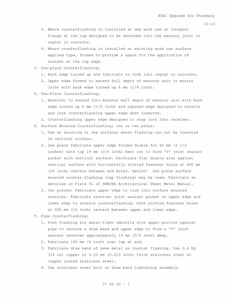
HVAC Upgrade for Pharmacy
10-10
07 60 00 - 7
5. Where counterflashing is installed at new work use an integral
flange at the top designed to be extended into the masonry joint or
reglet in concrete.
6. Where counterflashing is installed at existing work use surface
applied type, formed to provide a space for the application of
sealant at the top edge.
C. One-piece Counterflashing:
1. Back edge turned up and fabricate to lock into reglet in concrete.
2. Upper edge formed to extend full depth of masonry unit in mortar
joint with back edge turned up 6 mm (1/4 inch).
D. Two-Piece Counterflashing:
1. Receiver to extend into masonry wall depth of masonry unit with back
edge turned up 6 mm (1/4 inch) and exposed edge designed to receive
and lock counterflashing upper edge when inserted.
2. Counterflashing upper edge designed to snap lock into receiver.
E. Surface Mounted Counterflashing; one or two piece:
1. Use at existing or new surfaces where flashing can not be inserted
in vertical surface.
2. One piece fabricate upper edge folded double for 65 mm (2 1/2
inches) with top 19 mm (3/4 inch) bent out to form "V" joint sealant
pocket with vertical surface. Perforate flat double area against
vertical surface with horizontally slotted fastener holes at 400 mm
(16 inch) centers between end holes. Option: One piece surface
mounted counter-flashing (cap flashing) may be used. Fabricate as
detailed on Plate 51 of SMACNA Architectural Sheet Metal Manual.
3. Two pieces: Fabricate upper edge to lock into surface mounted
receiver. Fabricate receiver joint sealant pocket on upper edge and
lower edge to receive counterflashing, with slotted fastener holes
at 400 mm (16 inch) centers between upper and lower edge.
F. Pipe Counterflashing:
1. Form flashing for water-tight umbrella with upper portion against
pipe to receive a draw band and upper edge to form a "V" joint
sealant receiver approximately 19 mm (3/4 inch) deep.
2. Fabricate 100 mm (4 inch) over lap at end.
3. Fabricate draw band of same metal as counter flashing. Use 0.6 Kg
(24 oz) copper or 0.33 mm (0.013 inch) thick stainless steel or
copper coated stainless steel.
4. Use stainless steel bolt on draw band tightening assembly.

HVAC Upgrade for Pharmacy
10-10
07 60 00 - 8
5. Vent pipe counter flashing may be fabricated to omit draw band and
turn down 25 mm (one inch) inside vent pipe.
G. Where vented edge decks intersect vertical surfaces, form in one piece,
shape to slope down to a point level with and in front of edge-set
notched plank; then, down vertically, overlapping base flashing.
2.8 COPINGS
A. General:
1. Fabricate in lengths not less than 2400 mm (8 feet) long and maximum
of 3000 mm (10 feet).
2. Fabricate internal and external corners as one-piece with legs not
less than 600 mm (2 feet) or more than 1200 mm (4 feet) long.
3. Fabricate roof flange not less than 100 mm (4 inches) wide.
4. Fabricate lower edge outward at an angle of 45 degrees to form drip
and as fascia or as counter flashing as shown:
a. Fabricate of one-piece material of suitable width for fascia
height of 250 mm (10 inch) maximum or counterflashing lap of not
less than 100 mm (4 inch) over base flashing.
b. Fabricate bottom edge of formed fascia to receive edge strip.
c. When fascia bottom edge forms counter flashing over roofing lap
roofing not less than 150 mm (6 inches).
B. Formed Flat Sheet Metal Copings:
1. Fabricate as shown of (0.050 inch) thick aluminum.
2. When fascia exceeds 150 mm (6 inches) in depth, form one or more
horizontal stops not less than 13 mm (1/2 inch) high in the fascia.
3. Fabricate as two-piece fascia when fascia depth exceeds 250 mm (10
inches).
4. At joint between ends of sheets, provide a concealed clip soldered
or welded near one end of each sheet to hold the adjoining sheet in
lapped position. The clip shall be approximately 100 mm (4 inches)
wide and shall be the full depth of the fascia less 25 mm (one inch)
at top and bottom. Clip shall be of the same thickness as the
fascia.
5. Provide edge strip as specified with lower hooked edge bent outward
at an angle of 45 degrees.
C. Formed (Corrugated Sheet) Sheet Metal Gravel Stops and Fascia:
1. Fabricate as shown of //0.4 mm (0.015 inch) thick stainless steel//
//0.5 Kg (16 ounce) copper// //0.8 mm (0.032 inch) thick aluminum//.
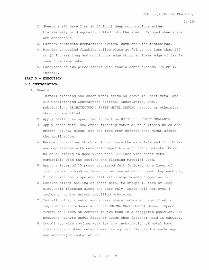
HVAC Upgrade for Pharmacy
10-10
07 60 00 - 9
2. Sheets shall have 2 mm (1/16 inch) deep corrugations either
transversely or diagonally rolled into the sheet. Crimped sheets are
not acceptable.
3. Factory fabricate prepackaged system, complete with fastenings.
4. Provide concealed flashing splice plate at joints not less than 150
mm (6 inches) long and continuous edge strip at lower edge of fascia
made from same metal.
5. Fabricate as two-piece fascia when fascia depth exceeds 175 mm (7
inches).
PART 3 - EXECUTION
3.1 INSTALLATION
A. General:
1. Install flashing and sheet metal items as shown in Sheet Metal and
Air Conditioning Contractors National Association, Inc.,
publication, ARCHITECTURAL SHEET METAL MANUAL, except as otherwise
shown or specified.
2. Apply Sealant as specified in Section 07 92 00, JOINT SEALANTS.
3. Apply sheet metal and other flashing material to surfaces which are
smooth, sound, clean, dry and free from defects that might affect
the application.
4. Remove projections which would puncture the materials and fill holes
and depressions with material compatible with the substrate. Cover
holes or cracks in wood wider than 1/4 inch with sheet metal
compatible with the roofing and flashing material used.
5. Apply a layer of 15 pound saturated felt followed by a layer of
rosin paper to wood surfaces to be covered with copper. Lap each ply
2 inch with the slope and nail with large headed copper nails.
6. Confine direct nailing of sheet metal to strips 12 inch or less
wide. Nail flashing along one edge only. Space nail not over 4
inches on center unless specified otherwise.
7. Install bolts, rivets, and screws where indicated, specified, or
required in accordance with the SMACNA Sheet Metal Manual. Space
rivets at 3 inch on centers in two rows in a staggered position. Use
neoprene washers under fastener heads when fastener head is exposed.
8. Coordinate with roofing work for the installation of metal base
flashings and other metal items having roof flanges for anchorage
and watertight installation.
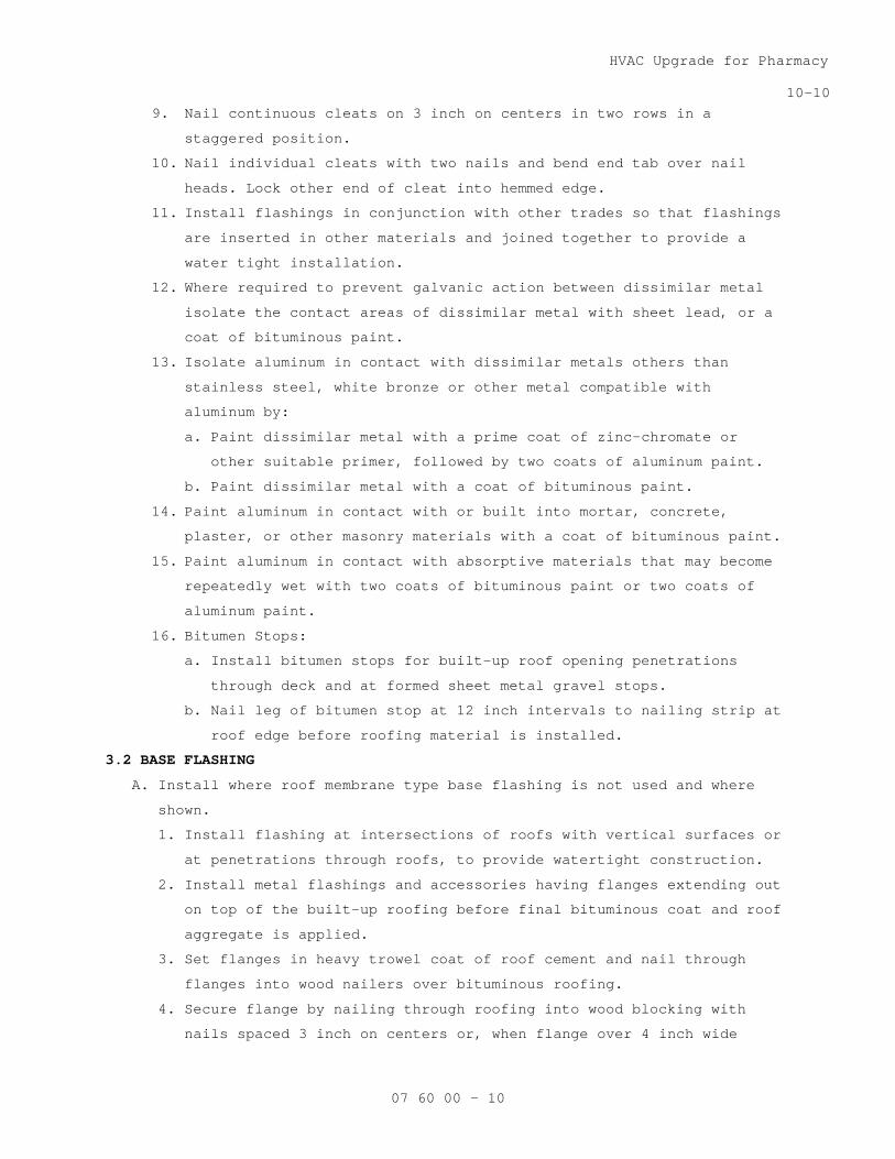
HVAC Upgrade for Pharmacy
10-10
07 60 00 - 10
9. Nail continuous cleats on 3 inch on centers in two rows in a
staggered position.
10. Nail individual cleats with two nails and bend end tab over nail
heads. Lock other end of cleat into hemmed edge.
11. Install flashings in conjunction with other trades so that flashings
are inserted in other materials and joined together to provide a
water tight installation.
12. Where required to prevent galvanic action between dissimilar metal
isolate the contact areas of dissimilar metal with sheet lead, or a
coat of bituminous paint.
13. Isolate aluminum in contact with dissimilar metals others than
stainless steel, white bronze or other metal compatible with
aluminum by:
a. Paint dissimilar metal with a prime coat of zinc-chromate or
other suitable primer, followed by two coats of aluminum paint.
b. Paint dissimilar metal with a coat of bituminous paint.
14. Paint aluminum in contact with or built into mortar, concrete,
plaster, or other masonry materials with a coat of bituminous paint.
15. Paint aluminum in contact with absorptive materials that may become
repeatedly wet with two coats of bituminous paint or two coats of
aluminum paint.
16. Bitumen Stops:
a. Install bitumen stops for built-up roof opening penetrations
through deck and at formed sheet metal gravel stops.
b. Nail leg of bitumen stop at 12 inch intervals to nailing strip at
roof edge before roofing material is installed.
3.2 BASE FLASHING
A. Install where roof membrane type base flashing is not used and where
shown.
1. Install flashing at intersections of roofs with vertical surfaces or
at penetrations through roofs, to provide watertight construction.
2. Install metal flashings and accessories having flanges extending out
on top of the built-up roofing before final bituminous coat and roof
aggregate is applied.
3. Set flanges in heavy trowel coat of roof cement and nail through
flanges into wood nailers over bituminous roofing.
4. Secure flange by nailing through roofing into wood blocking with
nails spaced 3 inch on centers or, when flange over 4 inch wide
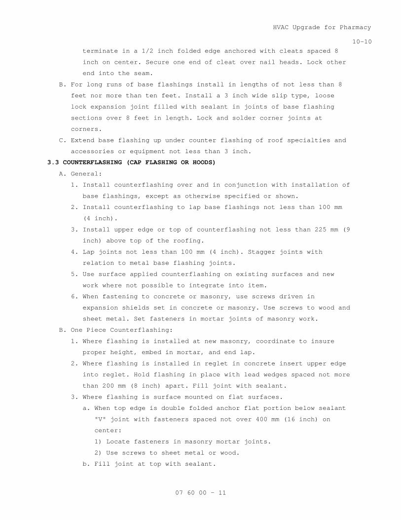
HVAC Upgrade for Pharmacy
10-10
07 60 00 - 11
terminate in a 1/2 inch folded edge anchored with cleats spaced 8
inch on center. Secure one end of cleat over nail heads. Lock other
end into the seam.
B. For long runs of base flashings install in lengths of not less than 8
feet nor more than ten feet. Install a 3 inch wide slip type, loose
lock expansion joint filled with sealant in joints of base flashing
sections over 8 feet in length. Lock and solder corner joints at
corners.
C. Extend base flashing up under counter flashing of roof specialties and
accessories or equipment not less than 3 inch.
3.3 COUNTERFLASHING (CAP FLASHING OR HOODS)
A. General:
1. Install counterflashing over and in conjunction with installation of
base flashings, except as otherwise specified or shown.
2. Install counterflashing to lap base flashings not less than 100 mm
(4 inch).
3. Install upper edge or top of counterflashing not less than 225 mm (9
inch) above top of the roofing.
4. Lap joints not less than 100 mm (4 inch). Stagger joints with
relation to metal base flashing joints.
5. Use surface applied counterflashing on existing surfaces and new
work where not possible to integrate into item.
6. When fastening to concrete or masonry, use screws driven in
expansion shields set in concrete or masonry. Use screws to wood and
sheet metal. Set fasteners in mortar joints of masonry work.
B. One Piece Counterflashing:
1. Where flashing is installed at new masonry, coordinate to insure
proper height, embed in mortar, and end lap.
2. Where flashing is installed in reglet in concrete insert upper edge
into reglet. Hold flashing in place with lead wedges spaced not more
than 200 mm (8 inch) apart. Fill joint with sealant.
3. Where flashing is surface mounted on flat surfaces.
a. When top edge is double folded anchor flat portion below sealant
"V" joint with fasteners spaced not over 400 mm (16 inch) on
center:
1) Locate fasteners in masonry mortar joints.
2) Use screws to sheet metal or wood.
b. Fill joint at top with sealant.
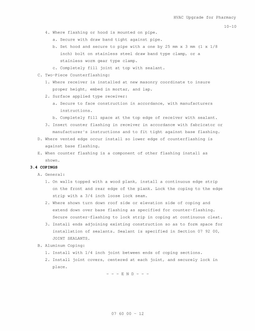
HVAC Upgrade for Pharmacy
10-10
07 60 00 - 12
4. Where flashing or hood is mounted on pipe.
a. Secure with draw band tight against pipe.
b. Set hood and secure to pipe with a one by 25 mm x 3 mm (1 x 1/8
inch) bolt on stainless steel draw band type clamp, or a
stainless worm gear type clamp.
c. Completely fill joint at top with sealant.
C. Two-Piece Counterflashing:
1. Where receiver is installed at new masonry coordinate to insure
proper height, embed in mortar, and lap.
2. Surface applied type receiver:
a. Secure to face construction in accordance, with manufacturers
instructions.
b. Completely fill space at the top edge of receiver with sealant.
3. Insert counter flashing in receiver in accordance with fabricator or
manufacturer's instructions and to fit tight against base flashing.
D. Where vented edge occur install so lower edge of counterflashing is
against base flashing.
E. When counter flashing is a component of other flashing install as
shown.
3.4 COPINGS
A. General:
1. On walls topped with a wood plank, install a continuous edge strip
on the front and rear edge of the plank. Lock the coping to the edge
strip with a 3/4 inch loose lock seam.
2. Where shown turn down roof side or elevation side of coping and
extend down over base flashing as specified for counter-flashing.
Secure counter-flashing to lock strip in coping at continuous cleat.
3. Install ends adjoining existing construction so as to form space for
installation of sealants. Sealant is specified in Section 07 92 00,
JOINT SEALANTS.
B. Aluminum Coping:
1. Install with 1/4 inch joint between ends of coping sections.
2. Install joint covers, centered at each joint, and securely lock in
place.
- - - E N D - - -
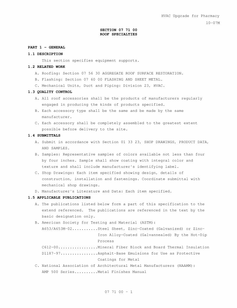
HVAC Upgrade for Pharmacy
10-07M
07 71 00 - 1
SECTION 07 71 00 ROOF SPECIALTIES
PART 1 - GENERAL
1.1 DESCRIPTION
This section specifies equipment supports.
1.2 RELATED WORK
A. Roofing: Section 07 56 30 AGGREGATE ROOF SURFACE RESTORATION.
B. Flashing: Section 07 60 00 FLASHING AND SHEET METAL.
C. Mechanical Units, Duct and Piping: Division 23, HVAC.
1.3 QUALITY CONTROL
A. All roof accessories shall be the products of manufacturers regularly
engaged in producing the kinds of products specified.
B. Each accessory type shall be the same and be made by the same
manufacturer.
C. Each accessory shall be completely assembled to the greatest extent
possible before delivery to the site.
1.4 SUBMITTALS
A. Submit in accordance with Section 01 33 23, SHOP DRAWINGS, PRODUCT DATA,
AND SAMPLES.
B. Samples: Representative samples of colors available not less than four
by four inches. Sample shall show coating with integral color and
texture and shall include manufacturer's identifying label.
C. Shop Drawings: Each item specified showing design, details of
construction, installation and fastenings. Coordinate submittal with
mechanical shop drawings.
D. Manufacturer's Literature and Data: Each item specified.
1.5 APPLICABLE PUBLICATIONS
A. The publications listed below form a part of this specification to the
extend referenced. The publications are referenced in the text by the
basic designation only.
B. American Society for Testing and Material (ASTM):
A653/A653M-02...........Steel Sheet, Zinc-Coated (Galvanized) or Zinc-
Iron Alloy-Coated (Galvannealed) By the Hot-Dip
Process
C612-00.................Mineral Fiber Block and Board Thermal Insulation
D1187-97................Asphalt-Base Emulsions for Use as Protective
Coatings for Metal
C. National Association of Architectural Metal Manufacturers (NAAMM):
AMP 500 Series..........Metal Finishes Manual

HVAC Upgrade for Pharmacy
10-07M
07 71 00 - 2
PART 2 - PRODUCTS
2.1 MATERIALS
A. Galvanized Sheet Steel: ASTM A526/A526M; G-90 coating.
2.2 EQUIPMENT SUPPORTS
A. Fabricate equipment supports from 0.0516 inch thick galvanized steel.
B. Form exterior curb with integral base, and deck closures for curbs
installed on steel decking.
C. Use galvanized steel liners for curbs having inside dimension over 12
inches.
D. Fabricate curb with a minimum height of 8 inches above roof surface.
E. Attach preservative treated wood nailers to top of curb. Use 2 inch by 2
inch minimum nominal size on curb with openings and 2 inch thick, width
of curb up to 12 inches on equipment support curbs.
F. Make size of supports suit size of equipment furnished, with height as
shown on drawings, but not less than 8 inches above roof flashing
height.
2.3 FINISH
A. In accordance with NAAMM Amp 500 Series.
PART 3 - EXECUTION
3.1 INSTALLATION
A. Install roof specialties where shown, and as required to support
mechanical equipment, ducts and piping.
B. Secure with fasteners in accordance with manufacture's printed
installation instructions and approved shop drawings unless shown
otherwise.
C. Coordinate with existing roof and insulation patching work.
D. Comply with section 07 92 00, JOINT SEALANTS to install sealants where
manufactures installation instructions require sealant.
E. Coordinate with roofing work for installation of items in sequence to
prevent water infiltration.
a. After completion of base flashing bend down cap flashing flange
and secure to blocking with screws.
b. Install cover plates with formed aluminum flashing concealed and
centered on joint. Flashing to lap cover not less than 100 mm (4
inches).
F. Equipment Supports: Do not anchor to insulating concrete or metal deck.
Anchor only to building structure as per manufacturer’s recommendations.
Field verify existing equipment support structure, and size curbs
accordingly.

HVAC Upgrade for Pharmacy
10-07M
07 71 00 - 3
3.2 PROTECTION
Protect roof accessories from damage during installation and after
completion of the work from subsequent construction.
- - - E N D - - -


HVAC Upgrade for Pharmacy
11-11
07 81 00 - 1
SECTION 07 81 00 APPLIED FIREPROOFING
PART 1 - GENERAL
1.1 DESCRIPTION
This section specifies mineral fiber and cementitious coverings to
provide fire resistance to interior structural steel members shown.
1.2 SUBMITTALS
A. Submit in accordance with Section 01 33 23, SHOP DRAWINGS, PRODUCT
DATA, AND SAMPLES.
B. Manufacturer's Literature and Data:
1. Manufacturer's complete and detailed application instructions and
specifications.
2. Manufacturer's repair and patching instructions.
C. Certificates:
1. Certificate from testing laboratory attesting fireproofing material
and application method meet the specified fire ratings.
a. List thickness and density of material required to meet fire
ratings.
b. Accompanied by complete test report and test record.
2. Manufacturer's certificate indicating sprayed-on fireproofing
material supplied under the Contract is same within manufacturing
tolerance as fireproofing material tested.
D. Miscellaneous:
1. Manufacturer's written approval of the applicators of fireproofing
material.
1.3 PRODUCT DELIVERY, STORAGE AND HANDLING
A. Deliver to job-site in sealed containers marked and labeled to show
manufacturer's name and brand and certification of compliance with the
specified requirements.
B. Remove damaged containers from the site.
C. Store the materials off the ground, under cover, away from damp
surfaces.
D. Keep dry until ready for use.
E. Remove materials that have been exposed to water before installation
from the site.

HVAC Upgrade for Pharmacy
11-11
07 81 00 - 2
1.4 QUALITY CONTROL
A. Test for fire endurance in accordance with ASTM E119, for fire rating
specified, in a nationally recognized laboratory.
B. Pre-Application Test Area.
1. Apply a test area consisting of a typical overhead fireproofing
installation, including not less than 4.5 m (15 feet) of beam and
deck.
a. Apply for the hourly ratings used.
2. Install in location selected by the VA COTR.
3. Do not proceed in other areas until installation of test area has
been completed and approved.
4. Keep approved installation area open for observation as criteria for
sprayed-on fireproofing.
1.5 APPLICABLE PUBLICATIONS
A. Publications listed below form a part of this specification to the
extent referenced. Publications are referenced in the text by the basic
designation only.
B. American Society for Testing and Materials (ASTM):
E84-10..................Surface Burning Characteristics of Building
Materials
E119-10.................Fire Tests of Building Construction and
Materials
E605-93(R2006)..........Thickness and Density of Sprayed Fire-Resistive
Materials Applied to Structural Members
E736-00(R2006)..........Cohesion/Adhesion of Sprayed Fire-Resistive
Materials Applied to Structural Members
E759-92(R2005)..........The Effect of Deflection on Sprayed Fire-
Resistive Material Applied to Structural
Members
E760-92(R2005)..........Impact on Bonding of Sprayed Fire-Resistive
Material Applied to Structural Members
E761-92(R2005)..........Compressive Strength of Fire-Resistive Material
Applied to Structural Members
E859-93(R2006)..........Air Erosion of Sprayed Fire-Resistive Materials
Applied to Structural Members
E937-93(R2005)..........Corrosion of Steel by Sprayed Fire-Resistive
Material Applied to Structural Members

HVAC Upgrade for Pharmacy
11-11
07 81 00 - 3
G21-09..................Determining Resistance of Synthetic Polymeric
Materials to Fungi
C. Underwriters Laboratories, Inc. (UL):
Fire Resistance Directory...Latest Edition including Supplements
D. Warnock Hersey (WH):
Certification Listings..Latest Edition
E. Factory Mutual System (FM):
Approval Guide..........Latest Edition including Supplements
PART 2 - PRODUCTS
2.1 SPRAYED-ON FIREPROOFING
A. ASTM E1042, Class (a), Category A.
1. Type I, factory mixed cementitious materials with approved
aggregate.
2. Type II, factory mixed mineral fiber with integral inorganic binders
minimum 240 kg/m3 (15 1b/ft3
B. Materials containing asbestos are not permitted.
) density per ASTM E605 test unless
specified otherwise. Use in areas that are completely encased.
C. Fireproofing characteristics when applied in the thickness and density
required to achieve the fire-rating specified.
Characteristic Test Results
1. Deflection ASTM E759 No cracking, spalling, or delamination when backing to which it is applied has a deflection up to 1/120 in 3m (10 ft.)
2. Corrosion-Resistance ASTM E937 No promotion of corrosion of steel.
3. Bond Impact ASTM E760 No cracking, spalling, or delamination.
4. Cohesion/Adhesion
(Bond Strength)
ASTM E736 Minimum cohesive/adhesive strength of 9.57 kPa (200 lbf/ft2) for protected areas. 19.15 kPa (400 lbf/ft2
5.
) for exposed areas.
Air Erosion ASTM E859 Maximum gain weight of the collecting filter 0.27gm/m2 (0.025 gm/ft2
6.
).
Compressive Strength ASTM E761 Minimum compressive strength 48 kPa (1000psf).
7. Surface Burning Characteristics with adhesive and sealer
ASTM E84 Flame spread 25 or less smoke developed 50 or less
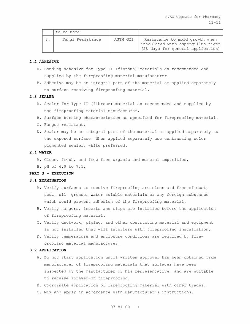
HVAC Upgrade for Pharmacy
11-11
07 81 00 - 4
to be used
8. Fungi Resistance ASTM G21 Resistance to mold growth when inoculated with aspergillus niger (28 days for general application)
2.2 ADHESIVE
A. Bonding adhesive for Type II (fibrous) materials as recommended and
supplied by the fireproofing material manufacturer.
B. Adhesive may be an integral part of the material or applied separately
to surface receiving fireproofing material.
2.3 SEALER
A. Sealer for Type II (fibrous) material as recommended and supplied by
the fireproofing material manufacturer.
B. Surface burning characteristics as specified for fireproofing material.
C. Fungus resistant.
D. Sealer may be an integral part of the material or applied separately to
the exposed surface. When applied separately use contrasting color
pigmented sealer, white preferred.
2.4 WATER
A. Clean, fresh, and free from organic and mineral impurities.
B. pH of 6.9 to 7.1.
PART 3 - EXECUTION
3.1 EXAMINATION
A. Verify surfaces to receive fireproofing are clean and free of dust,
soot, oil, grease, water soluble materials or any foreign substance
which would prevent adhesion of the fireproofing material.
B. Verify hangers, inserts and clips are installed before the application
of fireproofing material.
C. Verify ductwork, piping, and other obstructing material and equipment
is not installed that will interfere with fireproofing installation.
D. Verify temperature and enclosure conditions are required by fire-
proofing material manufacturer.
3.2 APPLICATION
A. Do not start application until written approval has been obtained from
manufacturer of fireproofing materials that surfaces have been
inspected by the manufacturer or his representative, and are suitable
to receive sprayed-on fireproofing.
B. Coordinate application of fireproofing material with other trades.
C. Mix and apply in accordance with manufacturer's instructions.
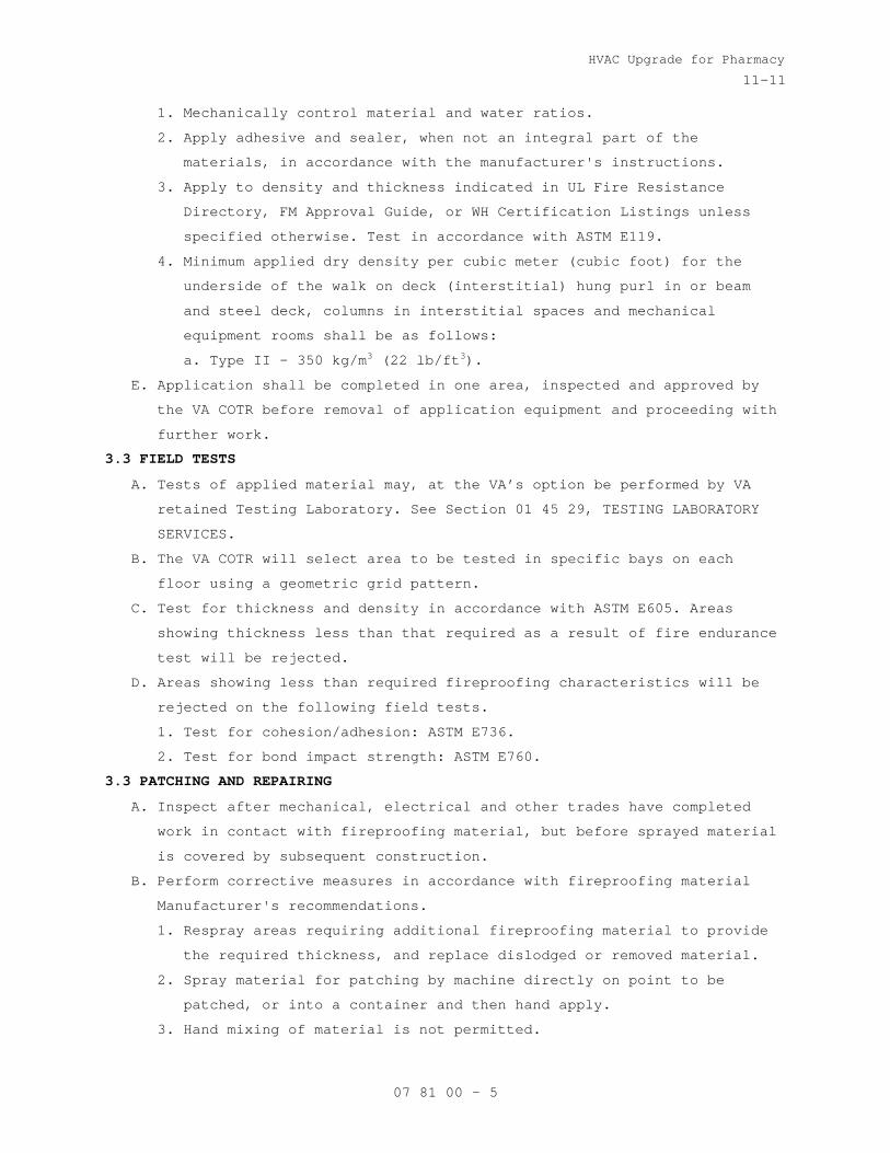
HVAC Upgrade for Pharmacy
11-11
07 81 00 - 5
1. Mechanically control material and water ratios.
2. Apply adhesive and sealer, when not an integral part of the
materials, in accordance with the manufacturer's instructions.
3. Apply to density and thickness indicated in UL Fire Resistance
Directory, FM Approval Guide, or WH Certification Listings unless
specified otherwise. Test in accordance with ASTM E119.
4. Minimum applied dry density per cubic meter (cubic foot) for the
underside of the walk on deck (interstitial) hung purl in or beam
and steel deck, columns in interstitial spaces and mechanical
equipment rooms shall be as follows:
a. Type II - 350 kg/m3 (22 lb/ft3
E. Application shall be completed in one area, inspected and approved by
the VA COTR before removal of application equipment and proceeding with
further work.
).
3.3 FIELD TESTS
A. Tests of applied material may, at the VA’s option be performed by VA
retained Testing Laboratory. See Section 01 45 29, TESTING LABORATORY
SERVICES.
B. The VA COTR will select area to be tested in specific bays on each
floor using a geometric grid pattern.
C. Test for thickness and density in accordance with ASTM E605. Areas
showing thickness less than that required as a result of fire endurance
test will be rejected.
D. Areas showing less than required fireproofing characteristics will be
rejected on the following field tests.
1. Test for cohesion/adhesion: ASTM E736.
2. Test for bond impact strength: ASTM E760.
3.3 PATCHING AND REPAIRING
A. Inspect after mechanical, electrical and other trades have completed
work in contact with fireproofing material, but before sprayed material
is covered by subsequent construction.
B. Perform corrective measures in accordance with fireproofing material
Manufacturer's recommendations.
1. Respray areas requiring additional fireproofing material to provide
the required thickness, and replace dislodged or removed material.
2. Spray material for patching by machine directly on point to be
patched, or into a container and then hand apply.
3. Hand mixing of material is not permitted.
HVAC Upgrade for Pharmacy
11-11
07 81 00 - 6
C. Repair:
1. Respray all test and rejected areas.
2. Patch fireproofing material which is removed or disturbed after
approval.
D. Perform final inspection of sprayed areas after patching and repair.
3.5 SCHEDULE
A. Apply fireproofing material in interior structural steel members and on
underside of interior steel floor and roof decks. Apply to new members
added to the existing roof structure as indicated. Refer to both the
Structural and Architectural drawings.
B. Type II:
1. Two hour fire rating, assumed for scope of work, this project.
- - - E N D - - -
HVAC Upgrade for Pharmacy
10-11
07 84 00 - 1
SECTION 07 84 00 FIRESTOPPING
PART 1 GENERAL
1.1 DESCRIPTION
A. Closures of openings in walls, floors, and roof decks against
penetration of flame, heat, and smoke or gases in fire resistant rated
construction.
1.2 RELATED WORK
A. Spray applied fireproofing: Section 07 81 00, APPLIED FIREPROOFING
B. Sealants and application: Section 07 92 00, JOINT SEALANTS.
1.3 SUBMITTALS
A. Submit in accordance with Section 01 33 23, SHOP DRAWINGS, PRODUCT
DATA, AND SAMPLES.
B. Manufacturers literature, data, and installation instructions for types
of firestopping and smoke stopping used.
C. List of FM, UL, or WH classification number of systems installed.
D. Certified laboratory test reports for ASTM E814 tests for systems not
listed by FM, UL, or WH proposed for use.
1.4 DELIVERY AND STORAGE
A. Deliver materials in their original unopened containers with
manufacturer’s name and product identification.
B. Store in a location providing protection from damage and exposure to
the elements.
1.5 WARRANTY
A. Firestopping work subject to the terms of the Article “Warranty of
Construction”, FAR clause 52.246-21, except extend the warranty period
to five years.
1.6 QUALITY ASSURANCE
A. FM, UL, or WH or other approved laboratory tested products will be
acceptable.
1.7 APPLICABLE PUBLICATIONS
A. Publications listed below form a part of this specification to the
extent referenced. Publications are referenced in the text by the basic
designation only.
B. American Society for Testing and Materials (ASTM):
E84-10..................Surface Burning Characteristics of Building
Materials
HVAC Upgrade for Pharmacy
10-11
07 84 00 - 2
E814-11.................Fire Tests of Through-Penetration Fire Stops
C. Factory Mutual Engineering and Research Corporation (FM):
Annual Issue Approval Guide Building Materials
D. Underwriters Laboratories, Inc. (UL):
Annual Issue Building Materials Directory
Annual Issue Fire Resistance Directory
1479-10.................Fire Tests of Through-Penetration Firestops
E. Warnock Hersey (WH):
Annual Issue Certification Listings
PART 2 - PRODUCTS
2.1 FIRESTOP SYSTEMS
A. Use either factory built (Firestop Devices) or field erected (through-
Penetration Firestop Systems) to form a specific building system
maintaining required integrity of the fire barrier and stop the passage
of gases or smoke.
B. Through-penetration firestop systems and firestop devices tested in
accordance with ASTM E814 or UL 1479 using the "F" or "T" rating to
maintain the same rating and integrity as the fire barrier being
sealed. "T" ratings are not required for penetrations smaller than or
equal to 100 mm (4 in) nominal pipe or 0.01 m2
C. Products requiring heat activation to seal an opening by its
intumescence shall exhibit a demonstrated ability to function as
designed to maintain the fire barrier.
(16 sq. in.) in overall
cross sectional area.
D. Firestop sealants used for firestopping or smoke sealing shall have
following properties:
1. Contain no flammable or toxic solvents.
2. Have no dangerous or flammable out gassing during the drying or
curing of products.
3. Water-resistant after drying or curing and unaffected by high
humidity, condensation or transient water exposure.
4. When used in exposed areas, shall be capable of being sanded and
finished with similar surface treatments as used on the surrounding
wall or floor surface.
E. Firestopping system or devices used for penetrations by glass pipe,
plastic pipe or conduits, unenclosed cables, or other non-metallic
materials shall have following properties:

HVAC Upgrade for Pharmacy
10-11
07 84 00 - 3
1. Classified for use with the particular type of penetrating material
used.
2. Penetrations containing loose electrical cables, computer data
cables, and communications cables protected using firestopping
systems that allow unrestricted cable changes without damage to the
seal.
3. Intumescent products which would expand to seal the opening and act
as fire, smoke, toxic fumes, and, water sealant.
F. Maximum flame spread of 25 and smoke development of 50 when tested in
accordance with ASTM E84.
G. FM, UL, or WH rated or tested by an approved laboratory in accordance
with ASTM E814.
H. Materials to be asbestos free.
PART 3 - EXECUTION
3.1 EXAMINATION
A. Submit product data and installation instructions, as required by
article, submittals, after an on site examination of areas to receive
firestopping.
3.2 PREPARATION
A. Remove dirt, grease, oil, loose materials, or other substances that
prevent adherence and bonding or application of the firestopping or
smoke stopping materials.
B. Remove insulation on insulated pipe for a distance of 150 mm (six
inches) on either side of the fire rated assembly prior to applying the
firestopping materials unless the firestopping materials are tested and
approved for use on insulated pipes.
3.3 INSTALLATION
A. Do not begin work until the specified material data and installation
instructions of the proposed firestopping systems have been submitted
and approved.
B. Install firestopping systems with smoke stopping in accordance with FM,
UL, WH, or other approved system details and installation instructions.
C. Install smoke stopping seals in smoke partitions.
3.4 CLEAN-UP AND ACCEPTANCE OF WORK
A. As work on each floor is completed, remove materials, litter, and
debris.

HVAC Upgrade for Pharmacy
10-11
07 84 00 - 4
B. Do not move materials and equipment to the next-scheduled work area
until completed work is inspected and accepted by the Resident
Engineer.
C. Clean up spills of liquid type materials.
- - - E N D - - -

HVAC Upgrade for Pharmacy
02-11
07 92 00 - 1
SECTION 07 92 00 JOINT SEALANTS
PART 1 - GENERAL
1.1 DESCRIPTION:
A. Section covers all sealant and caulking materials and their
application, wherever required for complete installation of building
materials or systems.
1.2 RELATED WORK:
A. Firestopping penetrations: Section 07 84 00, FIRESTOPPING.
B. Exterior wall panel: Section 074213 METAL WALL PANEL.
C. Flashing: Section 076000, FLASHING AND SHEET METAL.
D. Gypsum partitions: Section 09 29 00, GYPSUM BOARD.
E. Mechanical Work: Section 21 05 11, COMMON WORK RESULTS FOR FIRE
SUPPRESSION, COMMON WORK RESULTS FOR HVAC AND STEAM GENERATION.
1.3 QUALITY CONTROL:
A. Installer Qualifications: An experienced installer who has specialized
in installing joint sealants similar in material, design, and extent to
those indicated for this Project and whose work has resulted in joint-
sealant installations with a record of successful in-service
performance.
B. Source Limitations: Obtain each type of joint sealant through one
source from a single manufacturer.
C. Product Testing: Obtain test results from a qualified testing agency
based on testing current sealant formulations within a 12-month period.
1. Testing Agency Qualifications: An independent testing agency
qualified according to ASTM C1021.
2. Test elastomeric joint sealants for compliance with requirements
specified by reference to ASTM C920, and where applicable, to other
standard test methods.
3. Test elastomeric joint sealants according to SWRI’s Sealant
Validation Program for compliance with requirements specified by
reference to ASTM C920 for adhesion and cohesion under cyclic
movement, adhesion-in peel, and indentation hardness.
4. Test other joint sealants for compliance with requirements indicated
by referencing standard specifications and test methods.
D. VOC: Acrylic latex and Silicon sealants shall have less than 50g/l VOC
content.
HVAC Upgrade for Pharmacy
02-11
07 92 00 - 2
1.4 SUBMITTALS:
A. Submit in accordance with Section 01 33 23, SHOP DRAWINGS, PRODUCT
DATA, AND SAMPLES.
B. Manufacturer's installation instructions for each product used.
C. Cured samples of exposed sealants for each color where required to
match adjacent material.
D. Manufacturer's Literature and Data:
1. Sealant
2. Primers
3. Sealing compound, each type, including compatibility when different
sealants are in contact with each other.
1.5 PROJECT CONDITIONS:
A. Environmental Limitations:
1. Do not proceed with installation of joint sealants under following
conditions:
a. When ambient and substrate temperature conditions are outside
limits permitted by joint sealant manufacturer or are below 40 °F.
b. When joint substrates are wet.
B. Joint-Width Conditions:
1. Do not proceed with installation of joint sealants where joint
widths are less than those allowed by joint sealant manufacturer for
applications indicated.
C. Joint-Substrate Conditions:
1. Do not proceed with installation of joint sealants until
contaminants capable of interfering with adhesion are removed from
joint substrates.
1.6 DELIVERY, HANDLING, AND STORAGE:
A. Deliver materials in manufacturers' original unopened containers, with
brand names, date of manufacture, shelf life, and material designation
clearly marked thereon.
B. Carefully handle and store to prevent inclusion of foreign materials.
C. Do not subject to sustained temperatures exceeding 90° F or less than
40° F.
1.7 DEFINITIONS:
A. Definitions of terms in accordance with ASTM C717 and as specified.
B. Back-up Rod: A type of sealant backing.
C. Bond Breakers: A type of sealant backing.
D. Filler: A sealant backing used behind a back-up rod.

HVAC Upgrade for Pharmacy
02-11
07 92 00 - 3
1.8 WARRANTY:
A. Warranty exterior sealing against leaks, adhesion, and cohesive
failure, and subject to terms of "Warranty of Construction", FAR clause
52.246-21, except that warranty period shall be extended to two years.
B. General Warranty: Special warranty specified in this Article shall not
deprive Government of other rights Government may have under other
provisions of Contract Documents and shall be in addition to, and run
concurrent with, other warranties made by Contractor under requirements
of Contract Documents.
1.9 APPLICABLE PUBLICATIONS:
A. Publications listed below form a part of this specification to extent
referenced. Publications are referenced in text by basic designation
only.
B. American Society for Testing and Materials (ASTM):
C509-06.................Elastomeric Cellular Preformed Gasket and
Sealing Material.
C717-10.................Standard Terminology of Building Seals and
Sealants.
C919-08.................Use of Sealants in Acoustical Applications.
C920-10.................Elastomeric Joint Sealants.
C1021-08................Laboratories Engaged in Testing of Building
Sealants.
C1193-09................Standard Guide for Use of Joint Sealants.
C1330-02 (R2007)........Cylindrical Sealant Backing for Use with Cold
Liquid Applied Sealants.
D1056-07................Specification for Flexible Cellular Materials—
Sponge or Expanded Rubber.
E84-09..................Surface Burning Characteristics of Building
Materials.
C. Sealant, Waterproofing and Restoration Institute (SWRI).
The Professionals’ Guide
PART 2 - PRODUCTS
2.1 SEALANTS:
A. S-6:
1. ASTM C920, silicone, neutral cure.
2. Type S.
3. Class: Joint movement range of plus 100 percent to minus 50 percent.
4. Grade NS.

HVAC Upgrade for Pharmacy
02-11
07 92 00 - 4
5. Shore A hardness of 15-20.
6. Minimum elongation of 1200 percent.
B. S-9:
1. ASTM C920 silicone.
2. Type S.
3. Class 25.
4. Grade NS.
5. Shore A hardness of 25-30.
6. Non-yellowing, mildew resistant.
2.2 CAULKING COMPOUND:
A. C-1: ASTM C834, acrylic latex.
B. C-2: One component acoustical caulking, non drying, non hardening,
synthetic rubber.
2.3 COLOR:
A. Color of sealants for other locations shall be as selected by
Architect.
B. Caulking shall be light gray or white, unless specified otherwise.
2.4 JOINT SEALANT BACKING:
A. General: Provide sealant backings of material and type that are
nonstaining; are compatible with joint substrates, sealants, primers,
and other joint fillers; and are approved for applications indicated by
sealant manufacturer based on field experience and laboratory testing.
B. Cylindrical Sealant Backings: ASTM C1330, of type indicated below and
of size and density to control sealant depth and otherwise contribute
to producing optimum sealant performance:
1. Type C: Closed-cell material with a surface skin.
C. Bond-Breaker Tape: Polyethylene tape or other plastic tape recommended
by sealant manufacturer for preventing sealant from adhering to rigid,
inflexible joint-filler materials or joint surfaces at back of joint
where such adhesion would result in sealant failure. Provide self-
adhesive tape where applicable.
2.5 FILLER:
A. Mineral fiber board: ASTM C612, Class 1.
B. Thickness same as joint width.
C. Depth to fill void completely behind back-up rod.
2.6 PRIMER:
A. As recommended by manufacturer of caulking or sealant material.
B. Stain free type.

HVAC Upgrade for Pharmacy
02-11
07 92 00 - 5
2.7 CLEANERS-NON POROUS SURFACES:
Chemical cleaners acceptable to manufacturer of sealants and sealant
backing material, free of oily residues and other substances capable of
staining or harming joint substrates and adjacent non-porous surfaces
and formulated to promote adhesion of sealant and substrates.
PART 3 - EXECUTION
3.1 INSPECTION:
A. Inspect substrate surface for bond breaker contamination and unsound
materials at adherent faces of sealant.
B. Coordinate for repair and resolution of unsound substrate materials.
C. Inspect for uniform joint widths and that dimensions are within
tolerance established by sealant manufacturer.
3.2 PREPARATIONS:
A. Prepare joints in accordance with manufacturer's instructions and SWRI.
B. Clean surfaces of joint to receive caulking or sealants leaving joint
dry to the touch, free from frost, moisture, grease, oil, wax, lacquer
paint, or other foreign matter that would tend to destroy or impair
adhesion.
1. Clean porous joint substrate surfaces by brushing, grinding, blast
cleaning, mechanical abrading, or a combination of these methods to
produce a clean, sound substrate capable of developing optimum bond
with joint sealants.
2. Remove loose particles remaining from above cleaning operations by
vacuuming or blowing out joints with oil-free compressed air. Porous
joint surfaces include the following:
a. Concrete.
b. Masonry.
3. Remove laitance and form-release agents from concrete.
4. Clean nonporous surfaces with chemical cleaners or other means that
do not stain, harm substrates, or leave residues capable of
interfering with adhesion of joint sealants.
a. Metal.
b. Glass.
C. Do not cut or damage joint edges.
D. Apply masking tape to face of surfaces adjacent to joints before
applying primers, caulking, or sealing compounds.
1. Do not leave gaps between ends of sealant backings.
2. Do not stretch, twist, puncture, or tear sealant backings.
HVAC Upgrade for Pharmacy
02-11
07 92 00 - 6
3. Remove absorbent sealant backings that have become wet before
sealant application and replace them with dry materials.
E. Apply primer to sides of joints wherever required by compound
manufacturer's printed instructions.
1. Apply primer prior to installation of back-up rod or bond breaker
tape.
2. Use brush or other approved means that will reach all parts of
joints.
F. Take all necessary steps to prevent three sided adhesion of sealants.
3.3 BACKING INSTALLATION:
A. Install back-up material, to form joints enclosed on three sides as
required for specified depth of sealant.
B. Where deep joints occur, install filler to fill space behind the back-
up rod and position the rod at proper depth.
C. Cut fillers installed by others to proper depth for installation of
back-up rod and sealants.
D. Install back-up rod, without puncturing the material, to a uniform
depth, within plus or minus 1/8 inch for sealant depths specified.
E. Where space for back-up rod does not exist, install bond breaker tape
strip at bottom (or back) of joint so sealant bonds only to two
opposing surfaces.
F. Take all necessary steps to prevent three sided adhesion of sealants.
3.4 SEALANT DEPTHS AND GEOMETRY:
A. At widths up to 1/4 inch, sealant depth equal to width.
B. At widths over 1/4 inch, sealant depth 1/2 of width up to 1/2 inch
maximum depth at center of joint with sealant thickness at center of
joint approximately 1/2 of depth at adhesion surface.
3.5 INSTALLATION:
A. General:
1. Apply sealants and caulking only when ambient temperature is between
40° and 100° F.
2. Do not use sealant type listed by manufacture as not suitable for
use in locations specified.
3. Apply sealing compound in accordance with manufacturer's printed
instructions.
4. Avoid dropping or smearing compound on adjacent surfaces.
5. Fill joints solidly with compound and finish compound smooth.

HVAC Upgrade for Pharmacy
02-11
07 92 00 - 7
6. Tool joints to concave surface unless shown or specified otherwise.
7. Apply compounds with nozzle size to fit joint width.
8. Test sealants for compatibility with each other and substrate. Use
only compatible sealant.
B. For application of sealants, follow requirements of ASTM C1193 unless
specified otherwise.
3.6 CLEANING:
A. Fresh compound accidentally smeared on adjoining surfaces: Scrape off
immediately and rub clean with a solvent as recommended by the caulking
or sealant manufacturer.
B. After filling and finishing joints, remove masking tape.
C. Leave adjacent surfaces in a clean and unstained condition.
3.7 LOCATIONS:
A. Exterior Building Joints, Horizontal and Vertical:
1. Metal to Metal: Type S-6
2. Metal to Masonry or Stone: Type S-6
3. Wood to Masonry: Type S-6
B. Metal Reglets and Flashings:
1. Flashings to Wall: Type S-6
2. Metal to Metal: Type S-6
C. Sanitary Joints:
1. Pipe Penetrations: Type S-9
2. Other Piping: Type S-9 (U.N.O).
D. Interior Caulking:
1. Typical Narrow Joint 6 mm, (1/4 inch) or less at Walls and Adjacent
Components: Types C-1 and C-2.
2. Joints at Top of Full Height Walls: Types C-1 and C-2.
3. Joints at Partitions Type C-2.
4. Concealed Acoustic Sealant Types C-1 and C-2.
5. Wall Mounted fixtures and devices: Types C-1 and C-2.
- - - E N D - - -

HVAC Upgrade for Pharmacy
07-10M
09 22 16 - 1
SECTION 09 22 16 NON-STRUCTURAL METAL FRAMING
PART 1 - GENERAL
1.1 DESCRIPTION
A. This section specifies steel studs wall systems, ceiling or soffit
suspended or furred framing, wall furring, fasteners, and accessories
for the screw attachment of gypsum board, plaster bases or other
building boards.
1.2 RELATED WORK
A. Ceiling suspension and wall partition systems: Section 09 51 00,
ACOUSTICAL CEILINGS Section 09 29 00, GYPSUM BOARD.
1.3 TERMINOLOGY
A. Description of terms shall be in accordance with ASTM C754, ASTM C11,
ASTM C841 and as specified.
B. Thickness of steel specified is the minimum bare (uncoated) steel
thickness.
1.4 SUBMITTALS
A. Submit in accordance with Section 01 33 23, SHOP DRAWINGS, PRODUCT DATA,
AND SAMPLES.
B. Manufacturer's Literature and Data:
1. Studs, runners and accessories.
2. Channels.
3. Furring channels.
4. Screws, clips and other fasteners.
1.5 DELIVERY, IDENTIFICATION, HANDLING AND STORAGE
A. In accordance with the requirements of ASTM C754.
1.6 APPLICABLE PUBLICATIONS
A. The publications listed below form a part of this specification to the
extent referenced. The publications are referenced in the text by the
basic designation only.
B. American Society For Testing And Materials (ASTM)
A123-09.................Zinc (Hot-dip Galvanized) Coatings on Iron and
Steel Products
A653/A653M-09...........Steel Sheet, Zinc-Coated (Galvanized) or Zinc-
Iron Alloy Coated (Galvannealed) by the Hot-Dip
Process
A641-09.................Zinc-Coated (Galvanized) Carbon Steel Wire
C11-10..................Terminology Relating to Gypsum and Related
Building Materials and Systems
HVAC Upgrade for Pharmacy
07-10M
09 22 16 - 2
C635-07.................Manufacture, Performance, and Testing of Metal
Suspension System for Acoustical Tile and Lay-in
Panel Ceilings
C645-09.................Non-Structural Steel Framing Members
C754-09.................Installation of Steel Framing Members to Receive
Screw-Attached Gypsum Panel Products
C1002-07................Steel Self-Piercing Tapping Screws for the
Application of Gypsum Panel Products or Metal
Plaster Bases to Wood Studs or Steel Studs
PART 2 - PRODUCTS
2.1 PROTECTIVE COATING
A. Galvanize steel studs, runners (track), rigid (hat section) furring
channels, "Z" shaped furring channels, and resilient furring channels,
with coating designation of G-60 minimum, per ASTM 123.
2.2 STEEL STUDS AND RUNNERS (TRACK)
A. ASTM C645, modified for thickness specified and sizes as shown.
1. Use ASTM A525 steel, 0.8 mm (0.0329-inch) thick bare metal (33 mil).
2. Runners same thickness as studs.
B. Provide not less than two cutouts in web of each stud, approximately 300
mm (12 inches) from each end, and intermediate cutouts on approximately
600 mm (24-inch) centers.
C. Doubled studs for openings and studs for supporting concrete
backer-board.
D. Studs 3600 mm (12 feet) or less in length shall be in one piece.
2.3 FURRING CHANNELS
A. Rigid furring channels (hat shape): ASTM C645.
2.4 FASTENERS, CLIPS, AND OTHER METAL ACCESSORIES
A. ASTM C754, except as otherwise specified.
B. Fasteners for steel studs thicker than 0.84 mm (0.033-inch) thick. Use
ASTM C954 steel drill screws of size and type recommended by the
manufacturer of the material being fastened.
C. Clips: ASTM C841 (paragraph 6.11), manufacturer’s standard items. Clips
used in lieu of tie wire shall have holding power equivalent to that
provided by the tie wire for the specific application.
F. Tie Wire and Hanger Wire:
1. ASTM A641, soft temper, Class 1 coating.
2. Gage (diameter) as specified in ASTM C754 or ASTM C841.
E. Attachments for Wall Furring:
1. Manufacturers standard items fabricated from zinc-coated (galvanized)
steel sheet.

HVAC Upgrade for Pharmacy
07-10M
09 22 16 - 3
F. Power Actuated Fasteners: Type and size as recommended by the
manufacturer of the material being fastened.
PART 3 - EXECUTION
3.1 INSTALLING STUDS
A. Install studs in accordance with ASTM C754, except as otherwise shown or
specified.
B. Space studs not more than 610 mm (24 inches) on center.
C. Cut studs 6 mm to 9 mm (1/4 to 3/8-inch) less than floor to underside of
structure overhead when extended to underside of structure overhead.
D. Extend studs to underside of structure.
E. Openings:
1. Frame jambs of openings in stud partitions and furring with two studs
placed back to back or as shown.
2. Fasten back to back studs together with 9 mm (3/8-inch) long Type S
pan head screws at not less than 600 mm (two feet) on center,
staggered along webs.
3. Studs fastened flange to flange shall have splice plates on both
sides approximately 50 X 75 mm (2 by 3 inches) screwed to each stud
with two screws in each stud. Locate splice plates at 600 mm (24
inches) on center between runner tracks.
F. Fastening Studs:
1. Fasten studs located adjacent to partition intersections, corners and
studs at jambs of openings to flange of runner tracks with two screws
through each end of each stud and flange of runner.
2. Do not fasten studs to top runner track when studs extend to
underside of structure overhead.
3.2 INSTALLING WALL FURRING FOR FINISH APPLIED TO ONE SIDE ONLY
A. In accordance with ASTM C754, or ASTM C841 except as otherwise specified
or shown.
B. Wall furring-Stud System:
1. Framed with 63 mm (2-1/2 inch) or narrower studs, 600 mm (24 inches)
on center.
2. Brace as specified in ASTM C754 for Wall Furring-Stud System or brace
with sections or runners or studs placed horizontally at not less
than three foot vertical intervals on side without finish.
3. Securely fasten braces to each stud with two Type S pan head screws
at each bearing.
C. Direct attachment to masonry or concrete; rigid channels or "Z"
channels:

HVAC Upgrade for Pharmacy
07-10M
09 22 16 - 4
1. Install rigid (hat section) furring channels at 600 mm (24 inches) on
center, horizontally or vertically.
2. Install "Z" furring channels vertically spaced not more than 600 mm
(24 inches) on center.
3. At corners where rigid furring channels are positioned horizontally,
provide mitered joints in furring channels.
4. Ends of spliced furring channels shall be nested not less than 200 mm
(8 inches).
5. Fasten furring channels to walls with power-actuated drive pins or
hardened steel concrete nails. Where channels are spliced, provide
two fasteners in each flange.
6. Locate furring channels at interior and exterior corners in
accordance with wall finish material manufacturers printed erection
3.3 INSTALLING SUPPORTS REQUIRED BY OTHER TRADES
A. Provide for attachment and support of electrical outlets, fixtures, wall
bumpers, and other items like auto door buttons and auto door operators
supported by stud construction.
B. Provide additional studs where required. Install metal backing plates,
or special metal shapes as required, securely fastened to metal studs.
3.4 INSTALLING FURRED AND SUSPENDED CEILINGS OR SOFFITS
A. Install furred and suspended ceilings or soffits in accordance with ASTM
C754 or ASTM C841 except as otherwise specified or shown for screw
attached gypsum board ceilings and for plaster ceilings or soffits.
1. Space framing at 400 mm (16-inch) centers for metal lath anchorage.
2. Space framing at 600 mm (24-inch) centers for gypsum board anchorage.
B. Where bar joists or beams are more than 1200 mm (48 inches) apart,
provide intermediate hangers so that spacing between supports does not
exceed 1200 mm (48 inches). Use clips, bolts, or wire ties for direct
attachment to steel framing.
C. Existing concrete construction exposed or concrete on steel decking:
1. Use power actuated fasteners either eye pin, threaded studs or drive
pins for type of hanger attachment required.
2. Install fasteners at approximate mid height of concrete beams or
joists. Do not install in bottom of beams or joists.
3.7 TOLERANCES
A. Fastening surface for application of subsequent materials shall not vary
more than 3 mm (1/8-inch) from the layout line.
B. Plumb and align vertical members within 3 mm (1/8-inch.)
C. Level or align ceilings within 3 mm (1/8-inch.)
- - - E N D - - -
HVAC Upgrade for Pharmacy
02-01-12
09 29 00 - 1
SECTION 09 29 00 GYPSUM BOARD
PART 1 - GENERAL
1.1 DESCRIPTION
A. This section specifies installation and finishing of gypsum board.
1.2 RELATED WORK
A. Installation of steel framing members for walls, partitions, furring,
soffits, and ceilings: Section 09 22 16, NON-STRUCTURAL METAL FRAMING.
B. Acoustical Sealants: Section 07 92 00, JOINT SEALANTS.
C. Lay in gypsum board ceiling panels: Section 09 51 00, ACOUSTICAL
CEILING.
1.3 TERMINOLOGY
A. Definitions and description of terms shall be in accordance with ASTM
C11, C840, and as specified.
1.4 SUBMITTALS
A. Submit in accordance with Section 01 33 23, SHOP DRAWINGS, PRODUCT DATA,
AND SAMPLES.
B. Manufacturer's Literature and Data:
1. Cornerbead and edge trim.
2. Finishing materials.
3. Gypsum board, each type.
1.5 DELIVERY, IDENTIFICATION, HANDLING AND STORAGE
A. In accordance with the requirements of ASTM C840.
1.6 ENVIRONMENTAL CONDITIONS
A. In accordance with the requirements of ASTM C840.
1.7 APPLICABLE PUBLICATIONS
A. The publications listed below form a part of this specification to the
extent referenced. The publications are referenced in the text by the
basic designation only.
B. American Society for Testing And Materials (ASTM):
C11-08..................Terminology Relating to Gypsum and Related
Building Materials and Systems
C475-02.................Joint Compound and Joint Tape for Finishing
Gypsum Board
C840-08.................Application and Finishing of Gypsum Board
C919-08.................Sealants in Acoustical Applications
C954-07.................Steel Drill Screws for the Application of Gypsum
Board or Metal Plaster Bases to Steel Stud from
0.033 in. (0.84mm) to 0.112 in. (2.84mm) in
thickness

HVAC Upgrade for Pharmacy
02-01-12
09 29 00 - 2
C1002-07................Steel Self-Piercing Tapping Screws for the
Application of Gypsum Panel Products or Metal
Plaster Bases to Wood Studs or Steel Studs
C1047-05................Accessories for Gypsum Wallboard and Gypsum
Veneer Base
C1658-06................Glass Mat Gypsum Panels
C1396-06................Gypsum Board
E84-08..................Surface Burning Characteristics of Building
Materials
C. Underwriters Laboratories Inc. (UL):
Latest Edition..........Fire Resistance Directory
D. Inchcape Testing Services (ITS):
Latest Editions.........Certification Listings
PART 2 - PRODUCTS
2.1 GYPSUM BOARD
A. Gypsum Board: ASTM C1396, Type X, 16 mm (5/8 inch) thick unless shown
otherwise. Shall contain a minimum of 20 percent recycled gypsum.
B. Gypsum cores shall contain a minimum of 95 percent post industrial
recycled gypsum content. Paper facings shall contain 100 percent post-
consumer recycled paper content.
2.2 ACCESSORIES
A. ASTM C1047, except form of 0.39 mm (0.015 inch) thick zinc coated steel
sheet or rigid PVC plastic.
B. Flanges not less than 22 mm (7/8 inch) wide with punchouts or
deformations as required to provide compound bond.
2.3 FASTENERS
A. ASTM C1002 and ASTM C840, except as otherwise specified.
B. ASTM C954, for steel studs thicker than 0.04 mm (0.33 inch).
C. Select screws of size and type recommended by the manufacturer of the
material being fastened.
D. Clips: Zinc-coated (galvanized) steel; gypsum board manufacturer's
standard items.
2.4 FINISHING MATERIALS AND LAMINATING ADHESIVE
A. ASTM C475 and ASTM C840. Free of antifreeze, vinyl adhesives,
preservatives, biocides and other VOC. Adhesive shall contain a maximum
VOC content of 50 g/l.
PART 3 - EXECUTION
3.1 GYPSUM BOARD HEIGHTS
A. Extend all layers of gypsum board from floor to underside of structure
overhead.

HVAC Upgrade for Pharmacy
02-01-12
09 29 00 - 3
3.2 INSTALLING GYPSUM BOARD
A. Coordinate installation of gypsum board with other trades and related
work.
B. Install gypsum board in accordance with ASTM C840, except as otherwise
specified.
C. Use gypsum boards in maximum practical lengths to minimize number of end
joints.
D. Bring gypsum board into contact, but do not force into place.
E. Ceilings:
1. For single-ply construction, use perpendicular application.
F. Walls (Except Shaft Walls):
1. When gypsum board is installed parallel to framing members, space
fasteners 300 mm (12 inches) on center in field of the board, and 200
mm (8 inches) on center along edges.
2. When gypsum board is installed perpendicular to framing members,
space fasteners 300 mm (12 inches) on center in field and along
edges.
3. Stagger screws on abutting edges or ends.
4. For single-ply construction, apply gypsum board with long dimension
either parallel or perpendicular to framing members as required to
minimize number of joints except gypsum board shall be applied
vertically over "Z" furring channels.
5. Control Joints ASTM C840 and as follows:
a. Not required for wall lengths less than 9000 mm (30 feet).
b. Extend control joints the full height of the wall or length of
soffit/ceiling membrane.
H. Electrical and Telecommunications Boxes:
1. Seal annular spaces between electrical and telecommunications
receptacle boxes and gypsum board partitions.
I. Accessories:
1. Set accessories plumb, level and true to line, neatly mitered at
corners and intersections, and securely attach to supporting surfaces
as specified.
2. Install in one piece, without the limits of the longest commercially
available lengths.
3. Corner Beads:
a. Install at all vertical and horizontal external corners and where
shown.
b. Use screws only. Do not use crimping tool.
4. Edge Trim (casings Beads):

HVAC Upgrade for Pharmacy
02-01-12
09 29 00 - 4
a. Where gypsum board terminates against dissimilar materials and at
perimeter of openings, except where covered by flanges, casings or
permanently built-in equipment.
b. Where gypsum board surfaces of non-load bearing assemblies abut
load bearing members.
c. Where shown.
3.3 FINISHING OF GYPSUM BOARD
A. Finish joints, edges, corners, and fastener heads in accordance with
ASTM C840. Use Level 4 finish for al finished areas open to public view.
B. Before proceeding with installation of finishing materials, assure the
following:
1. Gypsum board is fastened and held close to framing or furring.
2. Fastening heads in gypsum board are slightly below surface in dimple
formed by driving tool.
C. Finish joints, fasteners, and all openings, including openings around
penetrations, on that part of the gypsum board extending above suspended
ceilings to seal surface of gypsum board construction. After the
installation of hanger rods, hanger wires, supports, equipment,
conduits, piping and similar work, seal remaining openings and maintain
the integrity of the construction Sanding is not required of non
decorated surfaces.
3.4 REPAIRS
A. After taping and finishing has been completed, and before decoration,
repair all damaged and defective work, including nondecorated surfaces.
B. Patch holes or openings 13 mm (1/2 inch) or less in diameter, or
equivalent size, with a setting type finishing compound or patching
plaster.
C. Repair holes or openings over 13 mm (1/2 inch) diameter, or equivalent
size, with 16 mm (5/8 inch) thick gypsum board secured in such a manner
as to provide solid substrate equivalent to undamaged surface.
D. Tape and refinish scratched, abraded or damaged finish surfaces
including cracks and joints in non decorated surfaces.
- - - E N D - - -

HVAC Upgrade for Pharmacy
10-10
09 51 00 - 1
SECTION 09 51 00 ACOUSTICAL CEILINGS
PART 1- GENERAL
1.1 DESCRIPTION
A. Metal ceiling suspension system for acoustical ceilings.
B. Acoustical units.
1.2 RELATED WORK
A. MEP Systems above ceiling: Divisions 21, 23, 26 and 28.
1.3 SUBMITTAL
A. Submit in accordance with Section 01 33 23, SHOP DRAWINGS, PRODUCT DATA,
AND SAMPLES.
B. Samples:
1. Acoustical units, each type, with label indicating conformance to
specification requirements.
2. Colored markers for units providing access.
C. Manufacturer's Literature and Data:
1. Ceiling suspension system, each type, showing complete details of
installation.
2. Acoustical units, each type
D. Manufacturer's Certificates: Acoustical units, each type, in accordance
with specification requirements.
1.4 DEFINITIONS
A. Standard definitions as defined in ASTM C634.
B. Terminology as defined in ASTM E1264.
1.5 APPLICABLE PUBLICATIONS
A. Publications listed below form a part of this specification to extent
referenced. Publications are referenced in the text by basic
designation only.
B. American Society for Testing and Materials (ASTM):
A641/A641M-03...........Zinc-coated (Galvanized) Carbon Steel Wire
A653/A653M-07...........Steel Sheet, Zinc-Coated (Galvanized) or Zinc-
Iron Alloy-coated (Galvannealed) by the Hot-Dip
Process
C423-07.................Sound Absorption and Sound Absorption
Coefficients by the Reverberation Room Method
C634-02 (E2007).........Standard Terminology Relating to Environmental
Acoustics
C635-04.................Metal Suspension Systems for Acoustical Tile and
Lay-in Panel Ceilings
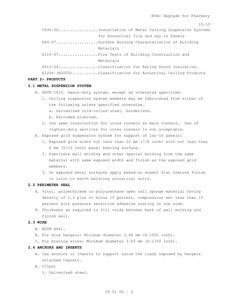
HVAC Upgrade for Pharmacy
10-10
09 51 00 - 2
C636-06.................Installation of Metal Ceiling Suspension Systems
for Acoustical Tile and Lay-in Panels
E84-07..................Surface Burning Characteristics of Building
Materials
E119-07.................Fire Tests of Building Construction and
Materials
E413-04.................Classification for Rating Sound Insulation.
E1264-(R2005)...........Classification for Acoustical Ceiling Products
PART 2- PRODUCTS
2.1 METAL SUSPENSION SYSTEM
A. ASTM C635, heavy-duty system, except as otherwise specified.
1. Ceiling suspension system members may be fabricated from either of
the following unless specified otherwise.
a. Galvanized cold-rolled steel, bonderized.
b. Extruded aluminum.
2. Use same construction for cross runners as main runners. Use of
lighter-duty sections for cross runners is not acceptable.
B. Exposed grid suspension system for support of lay-in panels:
1. Exposed grid width not less than 22 mm (7/8 inch) with not less than
8 mm (5/16 inch) panel bearing surface.
2. Fabricate wall molding and other special molding from the same
material with same exposed width and finish as the exposed grid
members.
3. On exposed metal surfaces apply baked-on enamel flat texture finish
in color to match existing acoustical units.
2.2 PERIMETER SEAL
A. Vinyl, polyethylene or polyurethane open cell sponge material having
density of 1.3 plus or minus 10 percent, compression set less than 10
percent with pressure sensitive adhesive coating on one side.
B. Thickness as required to fill voids between back of wall molding and
finish wall.
2.3 WIRE
A. ASTM A641.
B. For wire hangers: Minimum diameter 2.68 mm (0.1055 inch).
C. For bracing wires: Minimum diameter 3.43 mm (0.1350 inch).
2.4 ANCHORS AND INSERTS
A. Use anchors or inserts to support twice the loads imposed by hangers
attached thereto.
B. Clips:
1. Galvanized steel.

HVAC Upgrade for Pharmacy
10-10
09 51 00 - 3
2. Designed to clamp to steel beam or bar joists, or secure framing
member together.
3. Designed to rigidly secure framing members together.
4. Designed to sustain twice the loads imposed by hangers or items
supported.
2.5 CARRYING CHANNELS FOR SECONDARY FRAMING
A. Fabricate from cold-rolled or hot-rolled steel, black asphaltic paint
finish, free of rust.
B. Weighing not less than the following, per 300 m (per thousand linear
feet):
Size mm Size Inches
Cold-rolled
Kg Pound
Hot-rolled Kg Pound
38 1 1/2 215.4 475 508 1120
50 2 267.6 590 571.5 1260
2.6 ACOUSTICAL UNITS
A. General:
1. Ceiling Tile shall meet minimum 37% bio-based content in accordance
with USDA Bio-Preferred Product requirements.
2. ASTM E1264, weighing 3.6 kg/m2
3. Class A Flame Spread: ASTM 84
(3/4 psf) minimum for mineral fiber
panels or tile.
4. Minimum NRC (Noise Reduction Coefficient): 0.55 unless specified
otherwise: ASTM C423.
5. Minimum CAC (Ceiling Attenuation Class): 40-44 range unless specified
otherwise: ASTM E413.
6. Manufacturers standard finish, minimum Light Reflectance (LR)
coefficient of 0.75 on the exposed surfaces.
7. Lay-in panels: Sizes as shown, with square edges.
B. Type III Units - Mineral base with water-based painted finish less than
10 g/l VOC, Form 2 - Water felted, minimum 16 mm (5/8 inch) thick.
Mineral base to contain minimum 65 percent recycled content.
C. Type IV Units - Mineral base with membrane-faced overlay, Form 2 - Water
felted, minimum 16 mm (5/8 inch) thick. Apply over the paint coat on
the face of the unit a poly (vinyl) chloride overspray having a flame
spread index of 25 or less when tested in accordance with ASTM E84.
2.7 ACCESS IDENTIFICATION
A. Markers:
1. Use colored markers with pressure sensitive adhesive on one side.

HVAC Upgrade for Pharmacy
10-10
09 51 00 - 4
2. Make colored markers of paper of plastic, 6 to 9 mm (1/4 to 3/8 inch)
in diameter.
B. Use markers of the same diameter throughout building.
C. Color Code: Use following color markers for service identification:
Color...................Service
Red.....................Sprinkler System: Valves and Controls
Green...................Domestic Water: Valves and Controls
Yellow..................Chilled Water and Heating Water
Orange..................Ductwork: Fire Dampers
Blue....................Ductwork: Dampers and Controls
Black...................Gas: Laboratory, Medical, Air and Vacuum
PART 3 EXECUTION
3.1 CEILING TREATMENT
A. Treatment of ceilings shall include sides and soffits of ceiling beams,
furred work 600 mm (24 inches) wide and over, and vertical surfaces at
changes in ceiling heights unless otherwise shown. Install acoustic
tiles after wet finishes have been installed and solvents have cured.
B. Lay out acoustical units symmetrically about center lines of each room
or space unless shown otherwise on reflected ceiling plan.
C. Moldings:
1. Install metal wall molding at perimeter of room, column, or edge at
vertical surfaces.
2. Install special shaped molding at changes in ceiling heights and at
other breaks in ceiling construction to support acoustical units and
to conceal their edges.
D. Perimeter Seal:
1. Install perimeter seal between vertical leg of wall molding and
finish wall, partition, and other vertical surfaces.
2. Install perimeter seal to finish flush with exposed faces of
horizontal legs of wall molding.
3.2 CEILING SUSPENSION SYSTEM INSTALLATION
A. General:
1. Install metal suspension system for acoustical tile and lay-in panels
in accordance with ASTM C636, except as specified otherwise.
2. Use direct or indirect hung suspension system or combination thereof
as defined in ASTM C635.
3. Support a maximum area of 1.48 m2
4. Prevent deflection in excess of 1/360 of span of cross runner and
main runner.
(16 sf) of ceiling per hanger.

HVAC Upgrade for Pharmacy
10-10
09 51 00 - 5
5. Provide extra hangers, minimum of one hanger at each corner of each
item of mechanical, electrical and miscellaneous equipment supported
by ceiling suspension system not having separate support or hangers.
6. Provide not less than 100 mm (4 inch) clearance from the exposed face
of the acoustical units to the underside of ducts, pipe, conduit,
secondary suspension channels, concrete beams or joists; and steel
beam or bar joist unless furred system is shown,
7. Use main runners not less than 1200 mm (48 inches) in length.
8. Install hanger wires vertically. Angled wires are not acceptable
except for seismic restraint bracing wires.
B. Anchorage to Structure:
1. Steel:
a. When steel framing does not permit installation of hanger wires at
spacing required, install carrying channels for attachment of
hanger wires.
(1) Size and space carrying channels to insure that the maximum
deflection specified will not be exceeded.
(2) Attach hangers to steel carrying channels, spaced four feet on
center, unless area supported or deflection exceeds the amount
specified.
b. Attach carrying channels to the bottom flange of steel beams
spaced not 1200 mm (4 feet) on center before fire proofing is
installed. Weld or use steel clips to attach to beam to develop
full strength of carrying channel.
C. Direct Hung Suspension System:
1. As illustrated in ASTM C635.
2. Support main runners by hanger wires attached directly to the
structure overhead.
3. Maximum spacing of hangers, 1200 mm (4 feet) on centers unless
interference occurs by mechanical systems. Use indirect hung
suspension system where not possible to maintain hanger spacing.
D. Indirect Hung Suspension System:
1. As illustrated in ASTM C635.
2. Space carrying channels for indirect hung suspension system not more
than 1200 mm (4 feet) on center. Space hangers for carrying channels
not more than 2400 mm (8 feet) on center or for carrying channels
less than 1200 mm (4 feet) or center so as to insure that specified
requirements are not exceeded.
3. Support main runners by specially designed clips attached to carrying
channels.

HVAC Upgrade for Pharmacy
10-10
09 51 00 - 6
3.3 ACOUSTICAL UNIT INSTALLATION
A. Cut acoustic units for perimeter borders and penetrations to fit tight
against penetration for joint not concealed by molding.
B. Install lay-in acoustic panels in exposed grid with not less than 6 mm
(1/4 inch) bearing at edges on supports.
1. Install tile to lay level and in full contact with exposed grid.
2. Replace cracked, broken, stained, dirty, or tile not cut for minimum
bearing.
C. Install hold–down clips at grid at top of acoustic tile above ceiling,
four clips per tile at systems indicated throughout.
D. Markers:
1. Install markers of color code specified to identify the various
concealed piping, mechanical, and plumbing systems.
2. Attach colored markers to exposed grid on opposite sides of the units
providing access.
3. Attach marker on exposed ceiling surface of upward access acoustical
unit.
3.5 CLEAN-UP AND COMPLETION
A. Replace damaged, discolored, dirty, cracked and broken acoustical units.
B. Leave finished work free from defects.
- - - E N D - - -

HVAC Upgrade for Pharmacy 04-09M
09 91 00 - 1
SECTION 09 91 00 PAINTING
PART 1-GENERAL
1.1 DESCRIPTION
A. Section specifies field painting.
B. Section specifies prime coats which may be applied in shop under other
sections.
C. Painting includes coatings specified, and striping or markers and identity
markings.
1.2 RELATED WORK
A. Shop prime painting of steel and ferrous metals: Division 05 - METALS,
Division 21 – FIRE SUPPRESSION, Division 22 - PLUMBING, Division 23 –
HEATING, VENTILATION AND AIR-CONDITIONING, Division 26 - ELECTRICAL,
1.3 SUBMITTALS
A. Submit in accordance with Section 01 33 23, SHOP DRAWINGS, PRODUCT DATA,
AND SAMPLES.
B. Manufacturer's Literature and Data:
Before work is started, or sample panels are prepared, submit
manufacturer's literature, the current Master Painters Institute (MPI)
"Approved Product List" indicating brand label, product name and product
code as of the date of contract award, will be used to determine
compliance with the submittal requirements of this specification. The
Contractor may choose to use subsequent MPI "Approved Product List",
however, only one list may be used for the entire contract and each
coating system is to be from a single manufacturer. All coats on a
particular substrate must be from a single manufacturer. No variation from
the MPI "Approved Product List" where applicable is acceptable.
C. Sample Panels:
1. After painters' materials have been approved and before work is started
submit sample panels showing each type of finish and color specified.
2. Panels to show color: Composition board, 100 by 250 by 3 mm (4 inch by
10 inch by 1/8 inch).
3. Attach labels to panel stating the following:
a. Federal Specification Number or manufacturers name and product
number of paints used.
b. Specification code number specified in Section 09 06 00, SCHEDULE
FOR FINISHES.
c. Product type and color.
d. Name of project.

HVAC Upgrade for Pharmacy 04-09M
09 91 00 - 2
4. Strips showing not less than 50 mm (2 inch) wide strips of undercoats
and 100 mm (4 inch) wide strip of finish coat.
D. Sample of identity markers if used.
E. Manufacturers' Certificates indicating compliance with specified
requirements:
1. Manufacturer's paint substituted for Federal Specification paints meets
or exceeds performance of paint specified.
2. High temperature aluminum paint.
3. Epoxy coating.
1.4 DELIVERY AND STORAGE
A. Deliver materials to site in manufacturer's sealed container marked to
show following:
1. Name of manufacturer.
2. Product type.
3. Batch number.
4. Instructions for use.
5. Safety precautions.
B. In addition to manufacturer's label, provide a label legibly printed as
following:
1. Federal Specification Number, where applicable, and name of material.
2. Surface upon which material is to be applied.
3. If paint or other coating, state coat types; prime, body or finish.
C. Maintain space for storage, and handling of painting materials and
equipment in a neat and orderly condition to prevent spontaneous
combustion from occurring or igniting adjacent items.
D. Store materials at site at least 24 hours before using, at a temperature
between 18 and 30 degrees C (65 and 85 degrees F).
1.5 MOCK-UP PANEL
A. Before starting application of water paint mixtures, apply paint as
specified to an area, not to exceed 9 m2 (100 ft2
B. Finish and texture approved by Resident Engineer will be used as a
standard of quality for remainder of work.
), selected by the VA
COTR.
1.6 APPLICABLE PUBLICATIONS
A. Publications listed below form a part of this specification to the extent
referenced. Publications are referenced in the text by basic designation
only.
B. American Conference of Governmental Industrial Hygienists (ACGIH):
ACGIH TLV-BKLT-2008.....Threshold Limit Values (TLV) for Chemical
Substances and Physical Agents and Biological
Exposure Indices (BEIs)

HVAC Upgrade for Pharmacy 04-09M
09 91 00 - 3
ACGIH TLV-DOC-2008......Documentation of Threshold Limit Values and
Biological Exposure Indices, (Seventh Edition)
C. American National Standards Institute (ANSI):
A13.1-07................Scheme for the Identification of Piping Systems
D. Master Painters Institute (MPI):
No. 1-07................Aluminum Paint (AP)
No. 18-07...............Organic Zinc Rich Primer
No. 45-07...............Interior Primer Sealer
No. 79-07...............Marine Alkyd Metal Primer
No. 115.................Interior Water-Based Epoxy(Eggshell) MPI Gloss
Level 3.
No. 143.................Interior Institutional Low Odor/VOC Latex (Flat)
MPI Gloss Level 1.
No. 145.................Interior Institutional Low Odor/VOC Latex
(Eggshell) MPI Gloss Level 3.
E. Steel Structures Painting Council (SSPC):
SSPC SP 11..............Power Tool Cleaning To Bare Metal
PART 2 - PRODUCTS
2.1 MATERIALS
A. Identity markers options:
1. Pressure sensitive vinyl markers.
2. Snap-on coil plastic markers.
B. Aluminum Paint (AP): MPI 1.
C. Organic Zinc rich Coating (HR): MPI 22.
D. Interior Primer Sealer: MPI 45.
E. Marine Alkyd Metal primer: MPI 79.
F. Interior Water-Based Epoxy(Eggshell) MPI #115, MPI Gloss Level 3.
G. Interior Institutional Low Odor/VOC Latex (Flat) MPI #143, MPI Gloss
Level 1.
H. Interior Institutional Low Odor/VOC Latex (Eggshell)MPI #145, MPI Gloss
Level 3.
2.2 PAINT PROPERTIES
A. Use ready-mixed (including colors), except two component epoxies,
polyurethanes, polyesters, paints having metallic powders packaged
separately and paints requiring specified additives.
B. Where no requirements are given in the referenced specifications for
primers, use primers with pigment and vehicle, compatible with substrate
and finish coats specified.
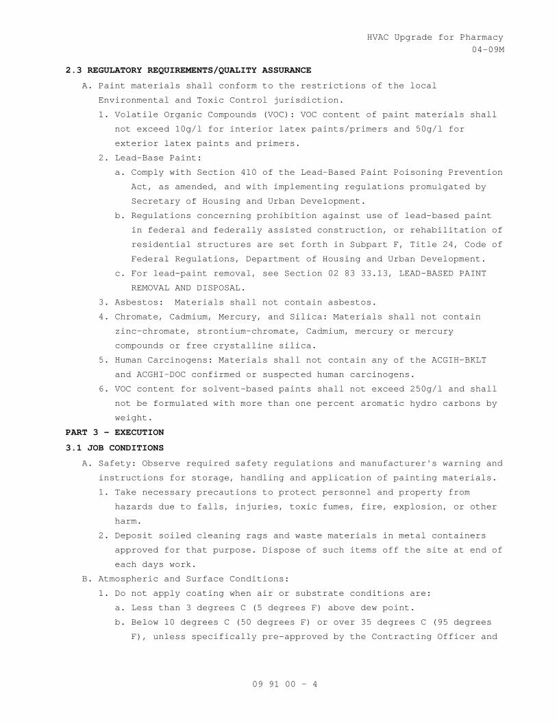
HVAC Upgrade for Pharmacy 04-09M
09 91 00 - 4
2.3 REGULATORY REQUIREMENTS/QUALITY ASSURANCE
A. Paint materials shall conform to the restrictions of the local
Environmental and Toxic Control jurisdiction.
1. Volatile Organic Compounds (VOC): VOC content of paint materials shall
not exceed 10g/l for interior latex paints/primers and 50g/l for
exterior latex paints and primers.
2. Lead-Base Paint:
a. Comply with Section 410 of the Lead-Based Paint Poisoning Prevention
Act, as amended, and with implementing regulations promulgated by
Secretary of Housing and Urban Development.
b. Regulations concerning prohibition against use of lead-based paint
in federal and federally assisted construction, or rehabilitation of
residential structures are set forth in Subpart F, Title 24, Code of
Federal Regulations, Department of Housing and Urban Development.
c. For lead-paint removal, see Section 02 83 33.13, LEAD-BASED PAINT
REMOVAL AND DISPOSAL.
3. Asbestos: Materials shall not contain asbestos.
4. Chromate, Cadmium, Mercury, and Silica: Materials shall not contain
zinc-chromate, strontium-chromate, Cadmium, mercury or mercury
compounds or free crystalline silica.
5. Human Carcinogens: Materials shall not contain any of the ACGIH-BKLT
and ACGHI-DOC confirmed or suspected human carcinogens.
6. VOC content for solvent-based paints shall not exceed 250g/l and shall
not be formulated with more than one percent aromatic hydro carbons by
weight.
PART 3 - EXECUTION
3.1 JOB CONDITIONS
A. Safety: Observe required safety regulations and manufacturer's warning and
instructions for storage, handling and application of painting materials.
1. Take necessary precautions to protect personnel and property from
hazards due to falls, injuries, toxic fumes, fire, explosion, or other
harm.
2. Deposit soiled cleaning rags and waste materials in metal containers
approved for that purpose. Dispose of such items off the site at end of
each days work.
B. Atmospheric and Surface Conditions:
1. Do not apply coating when air or substrate conditions are:
a. Less than 3 degrees C (5 degrees F) above dew point.
b. Below 10 degrees C (50 degrees F) or over 35 degrees C (95 degrees
F), unless specifically pre-approved by the Contracting Officer and

HVAC Upgrade for Pharmacy 04-09M
09 91 00 - 5
the product manufacturer. Under no circumstances shall application
conditions exceed manufacturer recommendations.
2. Maintain interior temperatures until paint dries hard.
3. Do no exterior painting when it is windy and dusty.
4. Do not paint in direct sunlight or on surfaces that the sun will soon
warm.
5. Apply only on clean, dry and frost free surfaces.
3.2 SURFACE PREPARATION
A. Method of surface preparation is optional, provided results of finish
painting produce solid even color and texture specified with no overlays.
B. General:
1. Remove prefinished items not to be painted such as lighting fixtures,
escutcheon plates, hardware, trim, and similar items for reinstallation
after paint is dried.
2. Remove items for reinstallation and complete painting of such items and
adjacent areas when item or adjacent surface is not accessible or
finish is different.
3. See other sections of specifications for specified surface conditions
and prime coat.
4. Clean surfaces for painting with materials and methods compatible with
substrate and specified finish. Remove any residue remaining from
cleaning agents used. Do not use solvents, acid, or steam on concrete
and masonry.
C. Ferrous Metals:
1. Remove loose mill scale, rust, and paint to bare metal, by power tool
cleaning, as defined in SSPC-SP 11 (Power Tool Cleaning to Bare Metal).
2. In addition, remove oil, grease, soil, drawing and cutting compounds,
flux and other detrimental foreign matter in accordance with SSPC-SP 1
(Solvent Cleaning).
3. Prime all metal, including exposed bare metal with the specified primer
the same day as the cleaning noted above. Do not leave bare metal
exposed.
D. Zinc-Coated (Galvanized) Metal touch-up paint:
1. Clean surfaces to remove grease, oil and other deterrents to paint
adhesion in accordance with SSPC-SP 1 (Solvent Cleaning).
2. Spot coat abraded and damaged areas of zinc-coating which expose base
metal on hot-dip zinc-coated items and spot coat all welds with MPI 18
(Organic Zinc Rich Coating).

HVAC Upgrade for Pharmacy 04-09M
09 91 00 - 6
E. Gypsum Plaster and Gypsum Board:
1. Remove efflorescence, loose and chalking plaster or finishing
materials.
2. Remove dust, dirt, and other deterrents to paint adhesion.
3. Fill holes, cracks, and other depressions with CID-A-A-1272A [Plaster,
Gypsum (Spackling Compound) finished flush with adjacent surface, with
texture to match texture of adjacent surface. Patch holes over 25 mm
(1-inch) in diameter as specified in Section for plaster or gypsum
board.
3.3 PAINT PREPARATION
A. Thoroughly mix painting materials to ensure uniformity of color, complete
dispersion of pigment and uniform composition.
B. Do not thin unless necessary for application and when finish paint is used
for body and prime coats. Use materials and quantities for thinning as
specified in manufacturer's printed instructions.
C. Remove paint skins, then strain paint through commercial paint strainer to
remove lumps and other particles.
D. Mix two component and two part paint and those requiring additives in such
a manner as to uniformly blend as specified in manufacturer's printed
instructions unless specified otherwise.
E. For tinting required to produce exact shades specified, use color pigment
recommended by the paint manufacturer.
3.4 APPLICATION
A. Start of surface preparation or painting will be construed as acceptance
of the surface as satisfactory for the application of materials.
B. Unless otherwise specified, apply paint in three coats; prime, body, and
finish. When two coats applied to prime coat are the same, first coat
applied over primer is body coat and second coat is finish coat.
C. Apply each coat evenly and cover substrate completely.
D. Allow not less than 48 hours between application of succeeding coats,
except as allowed by manufacturer's printed instructions, and approved by
the VA COTR.
E. Finish surfaces to show solid even color, free from runs, lumps,
brushmarks, laps, holidays, or other defects.
F. Apply by brush or roller.
G. Do not spray paint in existing occupied spaces.
I. Do not paint in closed position operable items such as access doors and
panels, and similar items.
3.5 PRIME PAINTING
A. After surface preparation prime surfaces before application of body and
finish coats, except as otherwise specified.
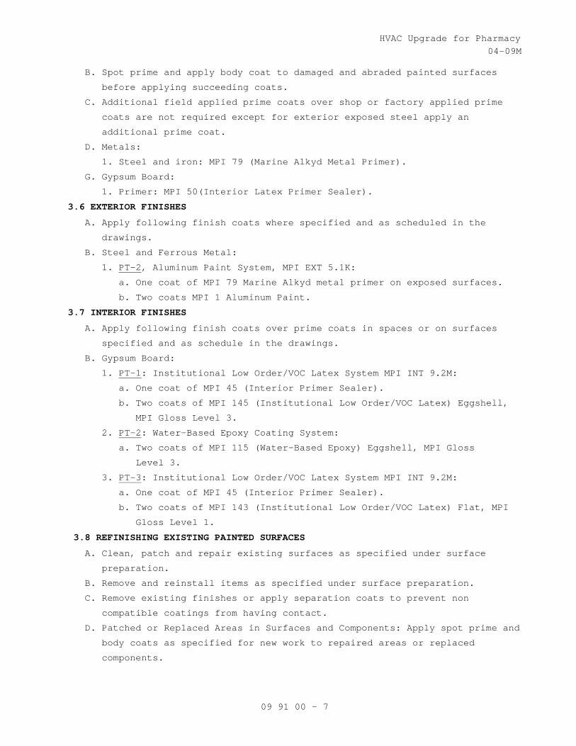
HVAC Upgrade for Pharmacy 04-09M
09 91 00 - 7
B. Spot prime and apply body coat to damaged and abraded painted surfaces
before applying succeeding coats.
C. Additional field applied prime coats over shop or factory applied prime
coats are not required except for exterior exposed steel apply an
additional prime coat.
D. Metals:
1. Steel and iron: MPI 79 (Marine Alkyd Metal Primer).
G. Gypsum Board:
1. Primer: MPI 50(Interior Latex Primer Sealer).
3.6 EXTERIOR FINISHES
A. Apply following finish coats where specified and as scheduled in the
drawings.
B. Steel and Ferrous Metal:
1. PT-2
a. One coat of MPI 79 Marine Alkyd metal primer on exposed surfaces.
, Aluminum Paint System, MPI EXT 5.1K:
b. Two coats MPI 1 Aluminum Paint.
3.7 INTERIOR FINISHES
A. Apply following finish coats over prime coats in spaces or on surfaces
specified and as schedule in the drawings.
B. Gypsum Board:
1. PT-1
a. One coat of MPI 45 (Interior Primer Sealer).
: Institutional Low Order/VOC Latex System MPI INT 9.2M:
b. Two coats of MPI 145 (Institutional Low Order/VOC Latex) Eggshell,
MPI Gloss Level 3.
2. PT-2
a. Two coats of MPI 115 (Water-Based Epoxy) Eggshell, MPI Gloss
Level 3.
: Water-Based Epoxy Coating System:
3. PT-3
a. One coat of MPI 45 (Interior Primer Sealer).
: Institutional Low Order/VOC Latex System MPI INT 9.2M:
b. Two coats of MPI 143 (Institutional Low Order/VOC Latex) Flat, MPI
Gloss Level 1.
3.8 REFINISHING EXISTING PAINTED SURFACES
A. Clean, patch and repair existing surfaces as specified under surface
preparation.
B. Remove and reinstall items as specified under surface preparation.
C. Remove existing finishes or apply separation coats to prevent non
compatible coatings from having contact.
D. Patched or Replaced Areas in Surfaces and Components: Apply spot prime and
body coats as specified for new work to repaired areas or replaced
components.

HVAC Upgrade for Pharmacy 04-09M
09 91 00 - 8
E. Except where scheduled for complete painting apply finish coat over plane
surface to nearest break in plane, such as corner, reveal, or frame.
F. Refinish areas as specified for new work to match adjoining work unless
specified or scheduled otherwise.
H. Sand or dull glossy surfaces prior to painting.
J. Sand existing coatings to a feather edge so that transition between new
and existing finish will not show in finished work.
K. Prepare exterior ferrous metals as noted in Section 3.2 surface.
3.9 PAINT COLOR
A. Color and gloss of finish coats is scheduled in the drawings.
B. For additional requirements regarding color see Articles, REFINISHING
EXISTING PAINTED SURFACE and MECHANICAL AND ELECTRICAL FIELD PAINTING
SCHEDULE.
C. Coat Colors:
1. Color of priming coat: Lighter than body coat.
2. Color of body coat: Lighter than finish coat.
3. Color prime and body coats to not show through the finish coat and to
mask surface imperfections or contrasts.
3.10 MECHANICAL AND ELECTRICAL WORK FIELD PAINTING SCHEDULE
A. Field painting of mechanical and electrical consists of cleaning,
touching-up abraded shop prime coats, and applying prime, body and finish
coats to materials and equipment if not factory finished in space
scheduled to be finished.
B. Paint various systems specified in Division 23 – HEATING, VENTILATION AND
AIR-CONDITIONING, and Division 26 - ELECTRICAL.
C. Paint after tests have been completed.
D. Omit prime coat from factory prime-coated items.
E. Finish painting of mechanical and electrical equipment is not required
when located in interstitial spaces, above suspended ceilings, in
concealed areas such as pipe and electric closets, pipe basements, pipe
tunnels, trenches, attics, roof spaces, shafts and furred spaces except on
electrical conduit containing feeders 600 volts or more.
F. Color: As selected by the Architect.
G. Apply paint systems on properly prepared and primed surface as follows:
1. Exterior Locations:
a. Apply two coats of MPI 9 (Exterior Alkyd Enamel (EO)to the following
ferrous metal items:
Vent and exhaust pipes with temperatures under 94 degrees C
(200 degrees F), roof drains, fire hydrants, post indicators, yard
hydrants, exposed piping and similar items.

HVAC Upgrade for Pharmacy 04-09M
09 91 00 - 9
b. Apply two coats of MPI 119 (Exterior Latex, High Gloss (acrylic)
(AE)) to the following metal items:
Galvanized and zinc-copper alloy metal.
3.11 IDENTITY PAINTING SCHEDULE
A. Identify designated service in accordance with ANSI A13.1, unless
specified otherwise, on exposed piping, piping above removable ceilings,
piping in accessible pipe spaces, interstitial spaces, and piping behind
access panels.
1. Legend may be identified using 2.1 G options or by stencil
applications.
2. Apply legends adjacent to changes in direction, on branches, where
pipes pass through walls or floors, adjacent to operating accessories
such as valves, regulators, strainers and cleanouts a minimum of 12 000
mm (40 feet) apart on straight runs of piping. Identification next to
plumbing fixtures is not required.
3. Locate Legends clearly visible from operating position.
4. Use arrow to indicate direction of flow.
5. Identify pipe contents with sufficient additional details such as
temperature, pressure, and contents to identify possible hazard. Insert
working pressure shown on drawings where asterisk appears for High,
Medium, and Low Pressure designations as follows:
a. High Pressure - 414 kPa (60 psig) and above.
b. Medium Pressure - 104 to 413 kPa (15 to 59 psig).
c. Low Pressure - 103 kPa (14 psig) and below.
d. Add Fuel oil grade numbers.
6. Legend name in full or in abbreviated form as follows:
COLOR OF COLOR OF COLOR OF LEGEND
PIPING EXPOSED PIPING BACKGROUND LETTERS BBREVIATIONS
A/C Condenser Water Supply Green White A/C Cond Wtr Sup
A/C Condenser Water Return Green White A/C Cond Wtr Ret
Chilled Water Supply Green White Ch. Wtr Sup
Chilled Water Return Green White Ch. Wtr Ret
Drain Line Green White Drain
High Pressure Steam Yellow Black H.P. ______*
High Pressure Condensate Return Yellow Black H.P. Ret ____*
Medium Pressure Steam Yellow Black M. P. Stm ____*
Medium Pressure Condensate Return Yellow Black M.P. Ret _____*
Low Pressure Steam Yellow Black L.P. Stm _____*
Low Pressure Condensate Return Yellow Black L.P. Ret _____*
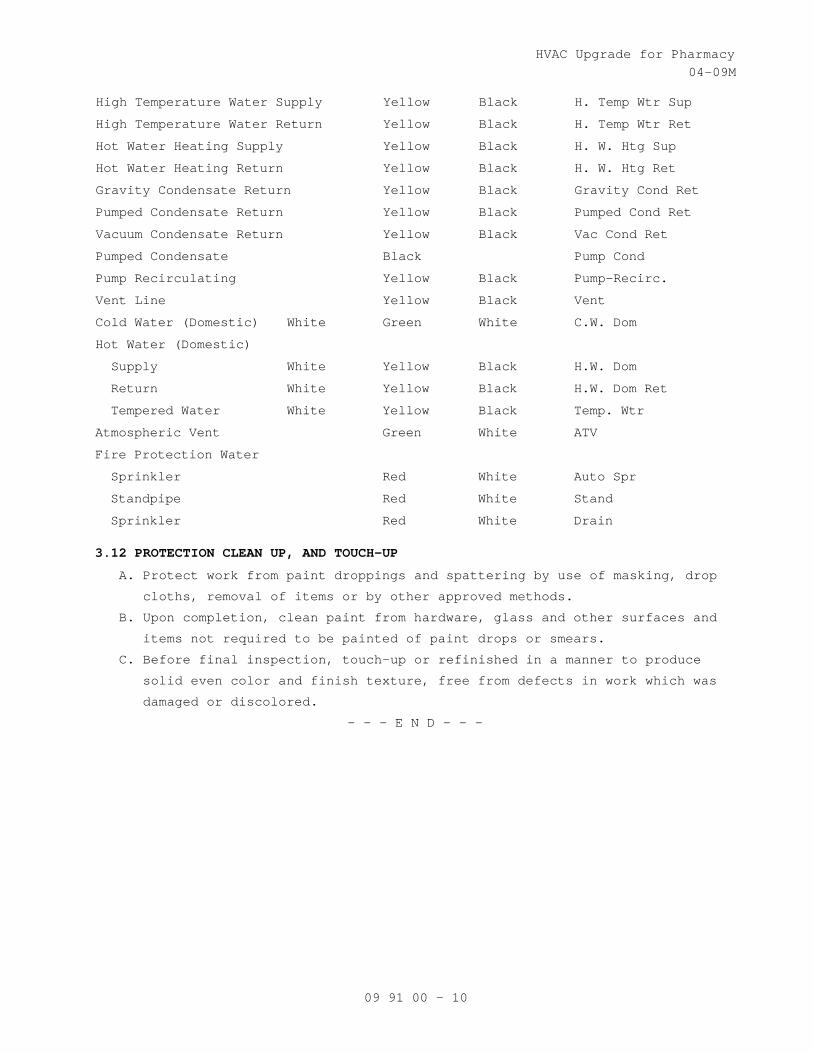
HVAC Upgrade for Pharmacy 04-09M
09 91 00 - 10
High Temperature Water Supply Yellow Black H. Temp Wtr Sup
High Temperature Water Return Yellow Black H. Temp Wtr Ret
Hot Water Heating Supply Yellow Black H. W. Htg Sup
Hot Water Heating Return Yellow Black H. W. Htg Ret
Gravity Condensate Return Yellow Black Gravity Cond Ret
Pumped Condensate Return Yellow Black Pumped Cond Ret
Vacuum Condensate Return Yellow Black Vac Cond Ret
Pumped Condensate Black Pump Cond
Pump Recirculating Yellow Black Pump-Recirc.
Vent Line Yellow Black Vent
Cold Water (Domestic) White Green White C.W. Dom
Hot Water (Domestic)
Supply White Yellow Black H.W. Dom
Return White Yellow Black H.W. Dom Ret
Tempered Water White Yellow Black Temp. Wtr
Atmospheric Vent Green White ATV
Fire Protection Water
Sprinkler Red White Auto Spr
Standpipe Red White Stand
Sprinkler Red White Drain 3.12 PROTECTION CLEAN UP, AND TOUCH-UP
A. Protect work from paint droppings and spattering by use of masking, drop
cloths, removal of items or by other approved methods.
B. Upon completion, clean paint from hardware, glass and other surfaces and
items not required to be painted of paint drops or smears.
C. Before final inspection, touch-up or refinished in a manner to produce
solid even color and finish texture, free from defects in work which was
damaged or discolored.
- - - E N D - - -

HVAC Upgrade for Pharmacy 11-09
21 05 11 - 1
SECTION 21 05 00 COMMON WORK RESULTS FOR FIRE SUPPRESSION
PART 1 - GENERAL
1.1 DESCRIPTION
A. The requirements of this Section apply to all sections of Division 21.
B. Definitions:
1. Exposed: Piping and equipment exposed to view in finished rooms.
2. Option or optional: Contractor's choice of an alternate material or
method.
1.2 RELATED WORK
A. Section 01 00 00, GENERAL REQUIREMENTS. B. Section 01 33 23, SHOP DRAWINGS, PRODUCT DATA, AND SAMPLES. D. Concrete and Grout: Section 03 30 00, CAST-IN-PLACE CONCRETE.
E. Building Components for Attachment of Hangers: Section 05 31 00, STEEL
DECKING. Section 05 36 00, COMPOSITE METAL DECKING.
F. Section 05 50 00, METAL FABRICATIONS.
G. Section 07 84 00, FIRESTOPPING.
H. Flashing for Wall and Roof Penetrations: Section 07 60 00, FLASHING AND
SHEET METAL.
I. Section 07 92 00, JOINT SEALANTS.
J. Section 09 91 00, PAINTING.
K. Section 13 05 41, SEISMIC RESTRAINT REQUIREMENTS FOR NON-STRUCTURAL
COMPONENTS
1.3 QUALITY ASSURANCE
A. Products Criteria:
1. Standard Products: Material and equipment shall be the standard
products of a manufacturer regularly engaged in the manufacture of
the products for at least 3 years. See other specification sections
for any exceptions.
2. Equipment Service: Products shall be supported by a service
organization which maintains a complete inventory of repair parts and
is located reasonably close to the site.
3. Multiple Units: When two or more units of materials or equipment of
the same type or class are required, these units shall be products of
one manufacturer.
4. Assembled Units: Manufacturers of equipment assemblies, which use
components made by others, assume complete responsibility for the
final assembled product.

HVAC Upgrade for Pharmacy 11-09
21 05 11 - 2
5. Nameplates: Nameplate bearing manufacturer's name or identifiable
trademark shall be securely affixed in a conspicuous place on
equipment, or name or trademark cast integrally with equipment,
stamped or otherwise permanently marked on each item of equipment.
6. Asbestos products or equipment or materials containing asbestos shall
not be used.
B. Manufacturer's Recommendations: Where installation procedures or any
part thereof are required to be in accordance with the recommendations
of the manufacturer of the material being installed, printed copies of
these recommendations shall be furnished to the Resident Engineer prior
to installation. Installation of the item will not be allowed to proceed
until the recommendations are received. Failure to furnish these
recommendations can be cause for rejection of the material.
C. Guaranty: In GENERAL CONDITIONS.
D. Extended Guarantee Period Services:
1. Qualifications: All service technicians assigned to perform work
under this contract shall be qualified and factory trained by the
Original Equipment Manufacturer (O.E.M.). Each technician shall have
at least three years experience of working on comparable systems and
shall be a full time employee of the contractor. The contractor shall
furnish, for the Department of Veterans Affairs (VA) review and
approval, resumes of all service technicians scheduled to service the
equipment and systems. The resume shall include details of
experience, training, and educational qualifications and performance
evaluations.
2. Replacement Parts: The contractor shall be equipped with all
replacement parts of all equipment and systems to be serviced and the
manufacturer's standard service and repair procedures. All
replacement parts shall be brand new and of current design. The
replacement parts shall be O.E.M. items. Obsolete or refurbished
parts are unacceptable. "Approved Equal" parts must have prior
approval of the Contracting Officer. Contractor shall furnish
evidence of guaranteed supply of parts for the life of the system.
3. Service Supplies: The services shall include, without any additional
cost to the government, all replacement parts, special tools and
equipment, and consumable materials, that is, lubrication oil,
grease, and cleaning materials, as required. The requirement of UL
listing, where applicable, shall not be voided by any replacement

HVAC Upgrade for Pharmacy 11-09
21 05 11 - 3
parts, components, software, or modifications provided by the
contractor.
4. Scheduled and Emergency Call Service: The service shall include a
scheduled monthly visit to perform systematic examination of
equipment and/or systems and a 7 day, 24 hours call back service for
emergency service. The emergency service is defined as a situation
created by a breakdown or malfunction of any equipment or system
warranting urgent attention. A qualified service representative shall
respond to the VA request for emergency service within two hours and
assess the problem either by telephone or remote diagnostic
capability. If the emergency situation cannot be rectified by the VA
personnel, on site emergency service shall be provided by sending a
qualified service representative within 24 hours. For the rural
locations of the VA medical centers, situated over 200 miles from the
contractor's established service depot, the maximum response time of
48 hours shall be acceptable. The emergency service shall be limited
to adjustments and repairs specifically required to protect the
safety of the equipment for which the emergency service was required
to be performed.
5. Licensing: The contractor shall be licensed to perform the contracted
services. The contractor shall furnish details of all applicable
local and state licensing requirements to VA as a part of the
qualification requirements. The licenses shall be current, valid
through the term of the contract and in the name of the contractor.
6. Documentation Requirements: The contractor shall maintain a separate
log for each item of equipment and each system covered under the
extended guarantee period service contract with the VA Medical Center
(VAMC) Engineering Service. The log shall list dates and times of all
scheduled and emergency calls. Each emergency call shall be described
with details of the nature and causes of emergency, steps taken to
rectify the situations, and specific recommendations to avoid such
conditions in the future.
7. Reports: The contractor shall provide a quarterly report for the
first year and twice a year for the remainder of the guarantee period
for all equipment and systems serviced under the extended guarantee
period contract. The report shall clearly and concisely describe the
services rendered, parts replaced, and repairs performed. The report
shall prescribe anticipated future needs of the equipment and systems
for preventive and predictive maintenance.

HVAC Upgrade for Pharmacy 11-09
21 05 11 - 4
8. Quality Program: The contractor shall provide a description of the
quality management and control program. The description shall include
a tangible proof the existence of such program, names of at least
three customers who have participated in the program, and specific
information showing the applicability of program to the project.
9. Training: During each scheduled service visit, the contractor shall
actively involve the VAMC maintenance personnel in performing
scheduled service and associated activities. The practical training
during the scheduled service visits shall include parting oral and
written instructions, for each specific task of the servicing
contract, to the VAMC maintenance personnel who shall operate the
hardware and software in accordance with the intent of the design and
under direct supervision of the service contractor's qualified
service technician. At the end of the first year of the service
contract, the contractor shall obtain a certificate from the VAMC
Engineering Service confirming completion of training to the
authorized VA representatives.
10. Classroom Training: Provide list and costs of available classroom
training courses offered by contractor or O.E.M.
E. Supports for sprinkler piping shall be in conformance with NFPA 13.
F. Supports for standpipe shall be in conformance with NFPA 14.
1.4 SUBMITTALS
A. Submit in accordance with Section 01 33 23, SHOP DRAWINGS, PRODUCT DATA,
AND SAMPLES.
B. Manufacturer's Literature and Data: Submit under the pertinent section
rather than under this section.
1. Equipment and materials identification.
2. Fire-stopping materials.
3. Hangers, inserts, supports and bracing. Provide load calculations for
variable spring and constant support hangers.
4. Wall, floor, and ceiling plates.
C. Coordination Drawings: Provide detailed layout drawings of all piping
systems. Provide details of the following.
1. Mechanical equipment rooms.
2. Interstitial space.
3. Hangers, inserts, supports, and bracing.
4. Pipe sleeves.
5. Equipment penetrations of floors, walls, ceilings, or roofs.
D. Maintenance Data and Operating Instructions:
HVAC Upgrade for Pharmacy 11-09
21 05 11 - 5
1. Maintenance and operating manuals in accordance with Section 01 00
00, GENERAL REQUIREMENTS, Article, INSTRUCTIONS, for systems and
equipment.
2. Provide a listing of recommended replacement parts for keeping in
stock supply, including sources of supply, for equipment. Include in
the listing belts for equipment.
1.5 APPLICABLE PUBLICATIONS
A. The publications listed below form a part of this specification to the
extent referenced. The publications are referenced in the text by the
basic designation only.
B. American Society for Testing and Materials (ASTM):
A36/A36M-2001...........Carbon Structural Steel
A575-96.................Steel Bars, Carbon, Merchant Quality, M-Grades R
(2002)
E84-2003................Standard Test Method for Burning Characteristics
of Building Materials
E119-2000...............Standard Test Method for Fire Tests of Building
Construction and Materials
C. National Fire Protection Association (NFPA):
90A-96..................Installation of Air Conditioning and Ventilating
Systems
101-97..................Life Safety Code
PART 2 - PRODUCTS
2.1 LIFTING ATTACHMENTS
Provide equipment with suitable lifting attachments to enable equipment
to be lifted in its normal position. Lifting attachments shall withstand
any handling conditions that might be encountered, without bending or
distortion of shape, such as rapid lowering and braking of load.
2.5 FIRESTOPPING
Section 07 84 00, FIRESTOPPING specifies an effective barrier against
the spread of fire, smoke and gases where penetrations occur for piping.
2.6 GALVANIZED REPAIR COMPOUND
Mil. Spec. DOD-P-21035B, paint form.
2.7 PIPE PENETRATIONS
A. Install sleeves during construction for other than blocked out floor
openings for risers in mechanical bays.
B. To prevent accidental liquid spills from passing to a lower level,
provide the following:

HVAC Upgrade for Pharmacy 11-09
21 05 11 - 6
1. For sleeves: Extend sleeve 25 mm (one inch) above finished floor and
provide sealant for watertight joint.
2. For blocked out floor openings: Provide 40 mm (1-1/2 inch) angle set
in silicone adhesive around opening.
3. For drilled penetrations: Provide 40 mm (1-1/2 inch) angle ring or
square set in silicone adhesive around penetration.
C. Penetrations are not allowed through beams or ribs, but may be installed
in concrete beam flanges. Any deviation from this requirement must
receive prior approval of Resident Engineer.
D. Sheet Metal, Plastic, or Moisture-resistant Fiber Sleeves: Provide for
pipe passing through floors, interior walls, and partitions, unless
brass or steel pipe sleeves are specifically called for below.
E. Cast Iron or Zinc Coated Pipe Sleeves: Provide for pipe passing through
exterior walls below grade. Make space between sleeve and pipe
watertight with a modular or link rubber seal. Seal shall be applied at
both ends of sleeve.
F. Galvanized Steel or an alternate Black Iron Pipe with asphalt coating
Sleeves: Provide for pipe passing through concrete beam flanges, except
where brass pipe sleeves are called for. Provide sleeve for pipe passing
through floor of mechanical rooms, laundry work rooms, and animal rooms
above basement. Except in mechanical rooms, connect sleeve with floor
plate.
G. Brass Pipe Sleeves: Provide for pipe passing through quarry tile,
terrazzo or ceramic tile floors. Connect sleeve with floor plate.
H. Sleeves are not required for wall hydrants for fire department
connections or in drywall construction.
I. Sleeve Clearance: Sleeve through floors, walls, partitions, and beam
flanges shall be one inch greater in diameter than external diameter of
pipe. Sleeve for pipe with insulation shall be large enough to
accommodate the insulation. Interior openings shall be caulked tight
with fire stopping material and sealant to prevent the spread of fire,
smoke, and gases.
J. Sealant and Adhesives: Shall be as specified in Section 07 92 00, JOINT
SEALANTS.
2.8 TOOLS AND LUBRICANTS
A. Furnish, and turn over to the Resident Engineer, special tools not
readily available commercially, that are required for disassembly or
adjustment of equipment and machinery furnished.
B. Grease Guns with Attachments for Applicable Fittings: One for each type
of grease required for each motor or other equipment.
HVAC Upgrade for Pharmacy 11-09
21 05 11 - 7
C. Tool Containers: Hardwood or metal, permanently identified for in tended
service and mounted, or located, where directed by the Resident
Engineer.
D. Lubricants: A minimum of 0.95 L (one quart) of oil, and 0.45 kg (one
pound) of grease, of equipment manufacturer's recommended grade and
type, in unopened containers and properly identified as to use for each
different application.
2.9 WALL, FLOOR AND CEILING PLATES
A. Material and Type: Chrome plated brass or chrome plated steel, one piece
or split type with concealed hinge, with set screw for fastening to
pipe, or sleeve. Use plates that fit tight around pipes, cover openings
around pipes and cover the entire pipe sleeve projection.
B. Thickness: Not less than 2.4 mm (3/32-inch) for floor plates. For wall
and ceiling plates, not less than 0.64 mm (0.025-inch) for up to 80 mm
(3-inch pipe), 0.89 mm (0.035-inch) for larger pipe.
C. Locations: Use where pipe penetrates floors, walls and ceilings in
exposed locations, in finished areas only. Use also where insulation
ends on exposed water supply pipe drop from overhead. Provide a
watertight joint in spaces where brass or steel pipe sleeves are
specified.
PART 3 - EXECUTION
3.1 INSTALLATION
A. Coordinate location of piping, sleeves, inserts, hangers, and equipment.
Locate piping, sleeves, inserts, hangers, and equipment clear of
windows, doors, openings, light outlets, and other services and
utilities. Follow manufacturer's published recommendations for
installation methods not otherwise specified.
B. Protection and Cleaning:
1. Equipment and materials shall be carefully handled, properly stored,
and adequately protected to prevent damage before and during
installation, in accordance with the manufacturer's recommendations
and as approved by the Resident Engineer. Damaged or defective items
in the opinion of the Resident Engineer, shall be replaced.
2. Protect all finished parts of equipment, such as shafts and bearings
where accessible, from rust prior to operation by means of protective
grease coating and wrapping. Close pipe openings with caps or plugs
during installation. Tightly cover and protect equipment against
dirt, water chemical, or mechanical injury. At completion of all work
thoroughly exposed materials and equipment.

HVAC Upgrade for Pharmacy 11-09
21 05 11 - 8
C. Concrete and Grout: Use concrete and shrink compensating grout 25 MPa
(3000 psi) minimum, specified in Section 03 30 00, CAST-IN-PLACE
CONCRETE.
D. Install gages, valves, and other devices with due regard for ease in
reading or operating and maintaining said devices. Locate and position
gages to be easily read by operator or staff standing on floor or
walkway provided. Servicing shall not require dismantling adjacent
equipment or pipe work.
E. Work in Existing Building:
1. Perform as specified in Article, OPERATIONS AND STORAGE AREAS,
Article, ALTERATIONS, and Article, RESTORATION of the Section 01 00
00, GENERAL REQUIREMENTS for relocation of existing equipment,
alterations and restoration of existing building(s).
2. As specified in Section 01 00 00, GENERAL REQUIREMENTS, Article,
OPERATIONS AND STORAGE AREAS, make alterations to existing service
piping at times that will least interfere with normal operation of
the facility.
3. Cut required openings through existing masonry and reinforced
concrete using diamond core drills. Use of pneumatic hammer type
drills, impact type electric drills, and hand or manual hammer type
drills, will be permitted only with approval of the Resident
Engineer. Locate openings that will least effect structural slabs,
columns, ribs or beams. Refer to the Resident Engineer for
determination of proper design for openings through structural
sections and opening layouts approval, prior to cutting or drilling
into structure. After Resident Engineer's approval, carefully cut
opening through construction no larger than absolutely necessary for
the required installation.
G. Switchgear Drip Protection: Every effort shall be made to eliminate the
installation of pipe above electrical and telephone switchgear. If this
is not possible, encase pipe in a second pipe with a minimum of joints.
H. Inaccessible Equipment:
1. Where the Government determines that the Contractor has installed
equipment not conveniently accessible for operation and maintenance,
equipment shall be removed and reinstalled or remedial action
performed as directed at no additional cost to the Government.
2. The term "conveniently accessible" is defined as capable of being
reached without the use of ladders, or without climbing or crawling
under or over obstacles such as motors, fans, pumps, belt guards,
transformers, high voltage lines, piping, and ductwork.
HVAC Upgrade for Pharmacy 11-09
21 05 11 - 9
3.6 INSTRUCTIONS TO VA PERSONNEL
Provide in accordance with Article, INSTRUCTIONS, of Section 01 00 00,
GENERAL REQUIREMENTS.
- - - E N D - - -

HVAC Upgrade for Pharmacy 04-11
22 05 00 - 1
SECTION 22 05 00 COMMON WORK RESULTS FOR PLUMBING
PART 1 - GENERAL
1.1 DESCRIPTION
A. The requirements of this Section shall apply to all sections of
Division 22.
B. Definitions:
1. Exposed: Piping and equipment exposed to view in finished rooms.
2. Option or optional: Contractor's choice of an alternate material or
method.
1.2 RELATED WORK
A. Section 01 00 00, GENERAL REQUIREMENTS.
B. Section 01 33 23, SHOP DRAWINGS, PRODUCT DATA, AND SAMPLES.
C. Section 07 60 00, FLASHING AND SHEET METAL: Flashing for Wall and Roof
Penetrations.
D. Section 07 92 00, JOINT SEALANTS.
E. Section 09 91 00, PAINTING.
1.3 QUALITY ASSURANCE
A. Products Criteria:
1. Standard Products: Material and equipment shall be the standard
products of a manufacturer regularly engaged in the manufacture of
the products for at least 3 years. However, digital electronics
devices, software and systems such as controls, instruments,
computer work station, shall be the current generation of technology
and basic design that has a proven satisfactory service record of at
least three years.
2. Equipment Service: There shall be permanent service organizations,
authorized and trained by manufacturers of the equipment supplied,
located within 160 km (100 miles) of the project. These
organizations shall come to the site and provide acceptable service
to restore operations within four hours of receipt of notification
by phone, e-mail or fax in event of an emergency, such as the shut-
down of equipment; or within 24 hours in a non-emergency. Names,
mail and e-mail addresses and phone numbers of service organizations
providing service under these conditions for (as applicable to the
project): pumps, critical instrumentation, computer workstation and

HVAC Upgrade for Pharmacy 04-11
22 05 00 - 2
programming shall be submitted for project record and inserted into
the operations and maintenance manual.
3. All items furnished shall be free from defects that would adversely
affect the performance, maintainability and appearance of individual
components and overall assembly.
4. The products and execution of work specified in Division 22 shall
conform to the referenced codes and standards as required by the
specifications. Local codes and amendments enforced by the local
code official shall be enforced, if required by local authorities
such as the natural gas supplier. If the local codes are more
stringent, then the local code shall apply. Any conflicts shall be
brought to the attention of the Resident Engineer (RE)/Contracting
Officers Technical Representative (COTR).
5. Multiple Units: When two or more units of materials or equipment of
the same type or class are required, these units shall be products
of one manufacturer.
6. Assembled Units: Manufacturers of equipment assemblies, which use
components made by others, assume complete responsibility for the
final assembled product.
7. Nameplates: Nameplate bearing manufacturer's name or identifiable
trademark shall be securely affixed in a conspicuous place on
equipment, or name or trademark cast integrally with equipment,
stamped or otherwise permanently marked on each item of equipment.
8. Asbestos products or equipment or materials containing asbestos
shall not be used.
B. Manufacturer's Recommendations: Where installation procedures or any
part thereof are required to be in accordance with the recommendations
of the manufacturer of the material being installed, printed copies of
these recommendations shall be furnished to the Resident Engineer prior
to installation. Installation of the item will not be allowed to
proceed until the recommendations are received. Failure to furnish
these recommendations can be cause for rejection of the material.
C. Execution (Installation, Construction) Quality:
1. All items shall be applied and installed in accordance with
manufacturer's written instructions. Conflicts between the
manufacturer's instructions and the contract drawings and
specifications shall be referred to the RE/COTR for resolution.
Written hard copies or computer files of manufacturer’s installation

HVAC Upgrade for Pharmacy 04-11
22 05 00 - 3
instructions shall be provided to the RE/COTR at least two weeks
prior to commencing installation of any item.
2. Complete layout drawings shall be required by Paragraph, SUBMITTALS.
Construction work shall not start on any system until the layout
drawings have been approved.
D. Guaranty: Warranty of Construction, FAR clause 52.246-21.
E. Plumbing Systems: IPC, International Plumbing Code.
1.4 SUBMITTALS
A. Submittals shall be submitted in accordance with Section 01 33 23, SHOP
DRAWINGS, PRODUCT DATA, and SAMPLES.
B. Information and material submitted under this section shall be marked
"SUBMITTED UNDER SECTION 22 05 11, COMNON WORK RESULTS FOR PLUMBING",
with applicable paragraph identification.
C. Contractor shall make all necessary field measurements and
investigations to assure that the equipment and assemblies will meet
contract requirements.
D. If equipment is submitted which differs in arrangement from that shown,
provide drawings that show the rearrangement of all associated systems.
Approval will be given only if all features of the equipment and
associated systems, including accessibility, are equivalent to that
required by the contract.
E. Prior to submitting shop drawings for approval, contractor shall
certify in writing that manufacturers of all major items of equipment
have each reviewed drawings and specifications, and have jointly
coordinated and properly integrated their equipment and controls to
provide a complete and efficient installation.
F. Upon request by Government, lists of previous installations for
selected items of equipment shall be provided. Contact persons who
will serve as references, with telephone numbers and e-mail addresses
shall be submitted with the references.
G. Manufacturer's Literature and Data: Manufacturer’s literature shall be
submitted under the pertinent section rather than under this section.
1. Electric motor data and variable speed drive data shall be submitted
with the driven equipment.
2. Equipment and materials identification.
3. Fire stopping materials.
4. Hangers, inserts, supports and bracing. Provide load calculations
for variable spring and constant support hangers.
HVAC Upgrade for Pharmacy 04-11
22 05 00 - 4
5. Wall, floor, and ceiling plates.
H. Coordination Drawings: Complete consolidated and coordinated layout
drawings shall be submitted for all new systems, and for existing
systems that are in the same areas. The drawings shall include plan
views, elevations and sections of all systems and shall be on a scale
of not less than 1:32 (3/8-inch equal to one foot). Clearly identify
and dimension the proposed locations of the principal items of
equipment. The drawings shall clearly show the proposed location and
adequate clearance for all equipment, piping, pumps, valves and other
items. All valves, trap primer valves, water hammer arrestors,
strainers, and equipment requiring service shall be provided with an
access door sized for the complete removal of plumbing device,
component, or equipment. Equipment foundations shall not be installed
until equipment or piping until layout drawings have been approved.
Detailed layout drawings shall be provided for all piping systems. In
addition, details of the following shall be provided.
1. Mechanical equipment rooms.
2. Interstitial space.
3. Hangers, inserts, supports, and bracing.
4. Pipe sleeves.
5. Equipment penetrations of floors, walls, ceilings, or roofs.
I. Maintenance Data and Operating Instructions:
1. Maintenance and operating manuals in accordance with Section 01 00
00, GENERAL REQUIREMENTS, Article, INSTRUCTIONS, for systems and
equipment.
2. Listing of recommended replacement parts for keeping in stock
supply, including sources of supply, for equipment shall be
provided.
3. The listing shall include belts for equipment: Belt manufacturer,
model number, size and style, and distinguished whether of multiple
belt sets.
1.5 DELIVERY, STORAGE AND HANDLING
A. Protection of Equipment:
1. Equipment and material placed on the job site shall remain in the
custody of the Contractor until phased acceptance, whether or not
the Government has reimbursed the Contractor for the equipment and
material. The Contractor is solely responsible for the protection of
such equipment and material against any damage.

HVAC Upgrade for Pharmacy 04-11
22 05 00 - 5
2. Damaged equipment shall be replaced with an identical unit as
determined and directed by the RE/COTR. Such replacement shall be at
no additional cost to the Government.
3. Interiors of new equipment and piping systems shall be protected
against entry of foreign matter. Both inside and outside shall be
cleaned before painting or placing equipment in operation.
4. Existing equipment and piping being worked on by the Contractor
shall be under the custody and responsibility of the Contractor and
shall be protected as required for new work.
B. Cleanliness of Piping and Equipment Systems:
1. Care shall be exercised in the storage and handling of equipment and
piping material to be incorporated in the work. Debris arising from
cutting, threading and welding of piping shall be removed.
2. Piping systems shall be flushed, blown or pigged as necessary to
deliver clean systems.
3. The interior of all tanks shall be cleaned prior to delivery and
beneficial use by the Government. All piping shall be tested in
accordance with the specifications and the International Plumbing
Code (IPC), latest edition. All filters, strainers, fixture faucets
shall be flushed of debris prior to final acceptance.
4. Contractor shall be fully responsible for all costs, damage, and
delay arising from failure to provide clean systems.
1.6 APPLICABLE PUBLICATIONS
A. The publications listed below shall form a part of this specification
to the extent referenced. The publications are referenced in the text
by the basic designation only.
B. American Society of Mechanical Engineers (ASME):
C. American Society for Testing and Materials (ASTM):
A36/A36M-2008...........Standard Specification for Carbon Structural
Steel
A575-96 (R 2007)........Standard Specification for Steel Bars, Carbon,
Merchant Quality, M-Grades R (2002)
E84-2005................Standard Test Method for Surface Burning
Characteristics of Building Materials
E119-2008a..............Standard Test Methods for Fire Tests of
Building Construction and Materials

HVAC Upgrade for Pharmacy 04-11
22 05 00 - 6
D. Manufacturers Standardization Society (MSS) of the Valve and Fittings
Industry, Inc:
SP-58-02................Pipe Hangers and Supports-Materials, Design and
Manufacture
SP 69-2003 (R 2004).....Pipe Hangers and Supports-Selection and
Application
E. National Electrical Manufacturers Association (NEMA):
MG1-2003, Rev. 1-2007...Motors and Generators
F. International Code Council, (ICC):
IBC-06, (R 2007)........International Building Code
IPC-06, (R 2007)........International Plumbing Code
PART 2 - PRODUCTS
2.1 FACTORY-ASSEMBLED PRODUCTS
A. STANDARDIZATION OF COMPONENTS SHALL BE MAXIMIZED TO REDUCE SPARE PART
requirements.
B. Manufacturers of equipment assemblies that include components made by
others shall assume complete responsibility for final assembled unit.
1. All components of an assembled unit need not be products of same
manufacturer.
2. Constituent parts that are alike shall be products of a single
manufacturer.
3. Components shall be compatible with each other and with the total
assembly for intended service.
4. Contractor shall guarantee performance of assemblies of components,
and shall repair or replace elements of the assemblies as required
to deliver specified performance of the complete assembly.
C. Components of equipment shall bear manufacturer's name and trademark,
model number, serial number and performance data on a name plate
securely affixed in a conspicuous place, or cast integral with, stamped
or otherwise permanently marked upon the components of the equipment.
D. Major items of equipment, which serve the same function, shall be the
same make and model
2.2 COMPATIBILITY OF RELATED EQUIPMENT
A. Equipment and materials installed shall be compatible in all respects
with other items being furnished and with existing items so that the
result will be a complete and fully operational system that conforms to
contract requirements.

HVAC Upgrade for Pharmacy 04-11
22 05 00 - 7
2.3 SAFETY GUARDS
A. Pump shafts and couplings shall be fully guarded by a sheet steel
guard, covering coupling and shaft but not bearings. Material shall be
minimum 16-gage sheet steel; ends shall be braked and drilled and
attached to pump base with minimum of four 6 mm (1/4-inch) bolts.
Reinforce guard as necessary to prevent side play forcing guard onto
couplings.
B. All Equipment shall have moving parts protected from personal injury.
2.4 PIPE AND EQUIPMENT SUPPORTS AND RESTRAINTS
A. In lieu of the paragraph which follows, suspended equipment support and
restraints may be designed and installed in accordance with the
International Building Code (IBC), latest edition, and SECTION 13 05
41, SEISMIC RESTRAINT REQUIREMENTS FOR NON-STRUCTURAL COMPONENTS.
Submittals based on the International Building Code (IBC), latest
edition, SECTION 13 05 41 requirements, or the following paragraphs of
this Section shall be stamped and signed by a professional engineer
registered in a state where the project is located. The Support system
of suspended equipment over 227 kg (500 pounds) shall be submitted for
approval of the Resident Engineer in all cases. See these
specifications for lateral force design requirements.
B. Type Numbers Specified: MSS SP-58. For selection and application refer
to MSS SP-69. Refer to Section 05 50 00, METAL FABRICATIONS, for
miscellaneous metal support materials and prime coat painting.
C. For Attachment to Concrete Construction:
1. Concrete insert: Type 18, MSS SP-58.
2. Self-drilling expansion shields and machine bolt expansion anchors:
Permitted in concrete not less than 102 mm (4 inches) thick when
approved by the Resident Engineer for each job condition.
3. Power-driven fasteners: Permitted in existing concrete or masonry
not less than 102 mm (4 inches) thick when approved by the Resident
Engineer for each job condition.
D. For Attachment to Steel Construction: MSS SP-58.
1. Welded attachment: Type 22.
2. Beam clamps: Types 20, 21, 28 or 29. Type 23 C-clamp may be used for
individual copper tubing up to 23 mm (7/8-inch) outside diameter.
E. Attachment to Metal Pan or Deck: As required for materials specified in
Section 05 31 00, STEEL DECKING.
F. For Attachment to Wood Construction: Wood screws or lag bolts.
HVAC Upgrade for Pharmacy 04-11
22 05 00 - 8
G. Hanger Rods: Hot-rolled steel, ASTM A36 or A575 for allowable load
listed in MSS SP-58. For piping, provide adjustment means for
controlling level or slope. Types 13 or 15 turn-buckles shall provide
38 mm (1-1/2 inches) minimum of adjustment and incorporate locknuts.
All-thread rods are acceptable.
H. Multiple (Trapeze) Hangers: Galvanized, cold formed, lipped steel
channel horizontal member, not less than 41 mm by 41 mm (1-5/8 inches
by 1-5/8 inches), 2.7 mm (No. 12 gage), designed to accept special
spring held, hardened steel nuts. Trapeze hangers are not permitted for
steam supply and condensate piping.
1. Allowable hanger load: Manufacturers rating less 91kg (200 pounds).
2. Guide individual pipes on the horizontal member of every other
trapeze hanger with 6 mm (1/4-inch) U-bolt fabricated from steel
rod. Provide Type 40 insulation shield, secured by two 13 mm
(1/2-inch) galvanized steel bands, or insulated calcium silicate
shield for insulated piping at each hanger.
I. Pipe Hangers and Supports: (MSS SP-58), use hangers sized to encircle
insulation on insulated piping. Refer to Section 23 07 11, HVAC,
PLUMBING, and BOILER PLANT INSULATION for insulation thickness. To
protect insulation, provide Type 39 saddles for roller type supports or
insulated calcium silicate shields. Provide Type 40 insulation shield
or insulated calcium silicate shield at all other types of supports and
hangers including those for insulated piping.
1. General Types (MSS SP-58):
a. Standard clevis hanger: Type 1; provide locknut.
b. Riser clamps: Type 8.
c. Wall brackets: Types 31, 32 or 33.
d. Roller supports: Type 41, 43, 44 and 46.
e. Saddle support: Type 36, 37 or 38.
f. Turnbuckle: Types 13 or 15.
g. U-bolt clamp: Type 24.
h. Copper Tube:
1) Hangers, clamps and other support material in contact with
tubing shall be painted with copper colored epoxy paint,
plastic coated or taped with isolation tape to prevent
electrolysis.
2) For vertical runs use epoxy painted or plastic coated riser
clamps.
HVAC Upgrade for Pharmacy 04-11
22 05 00 - 9
3) For supporting tube to strut: Provide epoxy painted pipe
straps for copper tube or plastic inserted vibration isolation
clamps.
4) Insulated Lines: Provide pre-insulated calcium silicate
shields sized for copper tube.
2. Plumbing Piping (Other Than General Types):
a. Horizontal piping: Type 1, 5, 7, 9, and 10.
b. Chrome plated piping: Chrome plated supports.
c. Hangers and supports in pipe chase: Prefabricated system ABS
self-extinguishing material, not subject to electrolytic action,
to hold piping, prevent vibration and compensate for all static
and operational conditions.
d. Blocking, stays and bracing: Angle iron or preformed metal
channel shapes, 1.3 mm (18 gage) minimum.
J. Pre-insulated Calcium Silicate Shields:
1. Provide 360 degree water resistant high density 965 kPa (140 psi)
compressive strength calcium silicate shields encased in galvanized
metal.
2. Pre-insulated calcium silicate shields to be installed at the point
of support during erection.
3. Shield thickness shall match the pipe insulation.
4. The type of shield is selected by the temperature of the pipe, the
load it must carry, and the type of support it will be used with.
a. Shields for supporting cold water shall have insulation that
extends a minimum of one inch past the sheet metal.
b. The insulated calcium silicate shield shall support the maximum
allowable water filled span as indicated in MSS-SP 69. To support
the load, the shields shall have one or more of the following
features: structural inserts 4138 kPa (600 psi) compressive
strength, an extra bottom metal shield, or formed structural
steel (ASTM A36) wear plates welded to the bottom sheet metal
jacket.
5. Shields may be used on steel clevis hanger type supports, roller
supports or flat surfaces.
K. Seismic Restraint of Piping: Refer to Section 13 05 41, SEISMIC
RESTRAINT REQUIREMENTS FOR NON-STRUCTURAL COMPONENTS.

HVAC Upgrade for Pharmacy 04-11
22 05 00 - 10
2.5 ASBESTOS
Materials containing asbestos are not permitted.
PART 3 - EXECUTION
3.1 ARRANGEMENT AND INSTALLATION OF EQUIPMENT AND PIPING
A. Location of piping, sleeves, inserts, hangers, and equipment, access
provisions shall be coordinated with the work of all trades. Piping,
sleeves, inserts, hangers, and equipment shall be located clear of
windows, doors, openings, light outlets, and other services and
utilities. Equipment layout drawings shall be prepared to coordinate
proper location and personnel access of all facilities. The drawings
shall be submitted for review.
Manufacturer's published recommendations shall be followed for
installation methods not otherwise specified.
B. Operating Personnel Access and Observation Provisions: All equipment
and systems shall be arranged to provide clear view and easy access,
without use of portable ladders, for maintenance and operation of all
devices including, but not limited to: all equipment items, valves,
filters, strainers, transmitters, sensors, control devices. All gages
and indicators shall be clearly visible by personnel standing on the
floor or on permanent platforms. Maintenance and operating space and
access provisions that are shown on the drawings shall not be changed
nor reduced.
C. Structural systems necessary for pipe and equipment support shall be
coordinated to permit proper installation.
D. Protection and Cleaning:
1. Equipment and materials shall be carefully handled, properly stored,
and adequately protected to prevent damage before and during
installation, in accordance with the manufacturer's recommendations
and as approved by the Resident Engineer. Damaged or defective items
in the opinion of the Resident Engineer, shall be replaced.
2. Protect all finished parts of equipment, such as shafts and bearings
where accessible, from rust prior to operation by means of
protective grease coating and wrapping. Close pipe openings with
caps or plugs during installation. Pipe openings, equipment, and
plumbing fixtures shall be tightly covered against dirt or
mechanical injury. At completion of all work thoroughly clean
fixtures, exposed materials and equipment.
E. Work in Existing Building:
HVAC Upgrade for Pharmacy 04-11
22 05 00 - 11
1. Perform as specified in Article, OPERATIONS AND STORAGE AREAS,
Article, ALTERATIONS, and Article, RESTORATION of the Section 01 00
00, GENERAL REQUIREMENTS for relocation of existing equipment,
alterations and restoration of existing building(s).
2. As specified in Section 01 00 00, GENERAL REQUIREMENTS, Article,
OPERATIONS AND STORAGE AREAS, make alterations to existing service
piping at times that will cause the least interfere with normal
operation of the facility.
3.2 PIPE AND EQUIPMENT SUPPORTS
A. Where hanger spacing does not correspond with joist or rib spacing, use
structural steel channels secured directly to joist and rib structure
that will correspond to the required hanger spacing, and then suspend
the equipment and piping from the channels. Holes shall be drilled or
burned in structural steel ONLY with the prior written approval of the
Resident Engineer.
B. The use of chain pipe supports, wire or strap hangers; wood for
blocking, stays and bracing, or hangers suspended from piping above
shall not be permitted. Rusty products shall be replaced.
C. Hanger rods shall be used that are straight and vertical. Turnbuckles
for vertical adjustments may be omitted where limited space prevents
use. A minimum of 15 mm (1/2-inch) clearance between pipe or piping
covering and adjacent work shall be provided.
D. For horizontal and vertical plumbing pipe supports, refer to the
International Plumbing Code (IPC), latest edition, and these
specifications.
E. Overhead Supports:
1. The basic structural system of the building is designed to sustain
the loads imposed by equipment and piping to be supported overhead.
2. Provide steel structural members, in addition to those shown, of
adequate capability to support the imposed loads, located in
accordance with the final approved layout of equipment and piping.
3. Tubing and capillary systems shall be supported in channel troughs.
3.3 PLUMBING SYSTEMS DEMOLITION
A. Rigging access, other than indicated on the drawings, shall be provided
after approval for structural integrity by the RE/COTR. Such access
shall be provided without additional cost or time to the Government.
Where work is in an operating plant, approved protection from dust and

HVAC Upgrade for Pharmacy 04-11
22 05 00 - 12
debris shall be provided at all times for the safety of plant personnel
and maintenance of plant operation and environment of the plant.
B. In an operating plant, cleanliness and safety shall be maintained. The
plant shall be kept in an operating condition. Government personnel
will be carrying on their normal duties of operating, cleaning and
maintaining equipment and plant operation. Work shall be confined to
the immediate area concerned; maintain cleanliness and wet down
demolished materials to eliminate dust. Dust and debris shall not be
permitted to accumulate in the area to the detriment of plant
operation. All flame cutting shall be performed to maintain the fire
safety integrity of this plant. Adequate fire extinguishing facilities
shall be available at all times. All work shall be performed in
accordance with recognized fire protection standards. Inspections will
be made by personnel of the VA Medical Center, and the Contractor shall
follow all directives of the RE or COTR with regard to rigging, safety,
fire safety, and maintenance of operations.
C. Unless specified otherwise, all piping, wiring, conduit, and other
devices associated with the equipment not re-used in the new work shall
be completely removed from Government property. This includes all
concrete equipment pads, pipe, valves, fittings, insulation, and all
hangers including the top connection and any fastenings to building
structural systems. All openings shall be sealed after removal of
equipment, pipes, ducts, and other penetrations in roof, walls, floors,
in an approved manner and in accordance with plans and specifications
where specifically covered. Structural integrity of the building system
shall be maintained. Reference shall also be made to the drawings and
specifications of the other disciplines in the project for additional
facilities to be demolished or handled.
3.4 CLEANING AND PAINTING
A. Prior to final inspection and acceptance of the plant and facilities
for beneficial use by the Government, the plant facilities, equipment
and systems shall be thoroughly cleaned and painted. Refer to Section
09 91 00, PAINTING.
B. In addition, the following special conditions apply:
1. Cleaning shall be thorough. Solvents, cleaning materials and methods
recommended by the manufacturers shall be used for the specific
tasks. All rust shall be removed prior to painting and from surfaces
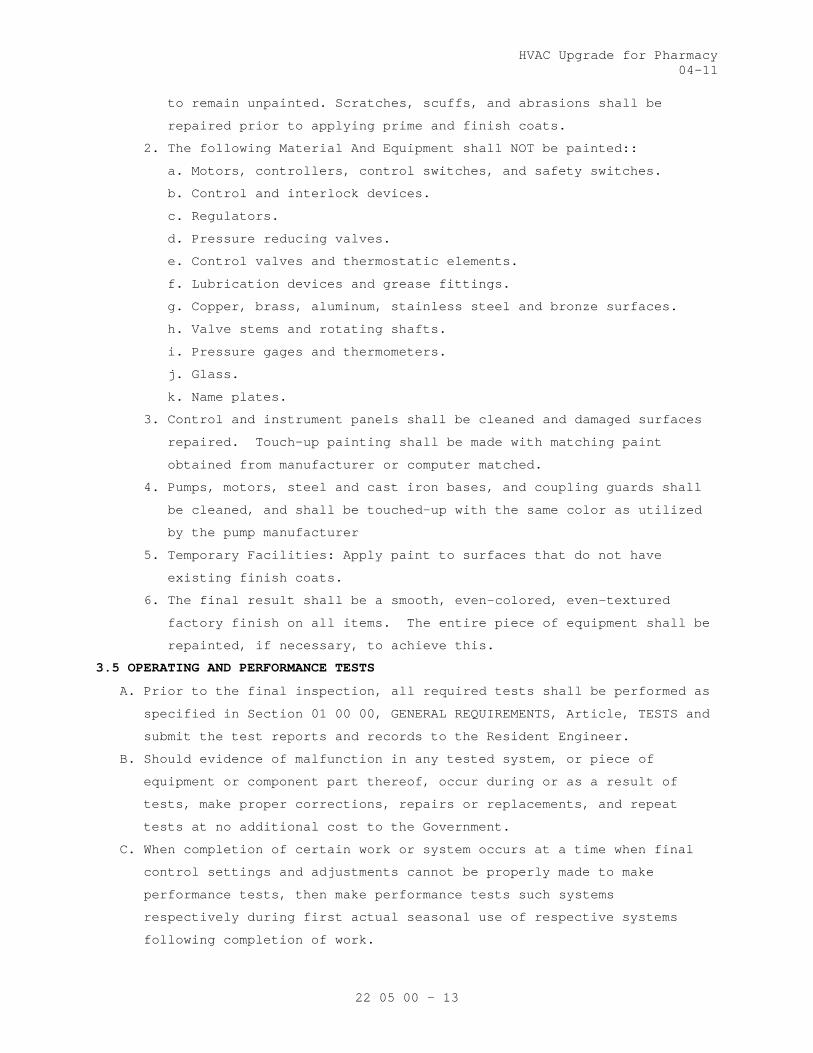
HVAC Upgrade for Pharmacy 04-11
22 05 00 - 13
to remain unpainted. Scratches, scuffs, and abrasions shall be
repaired prior to applying prime and finish coats.
2. The following Material And Equipment shall NOT be painted::
a. Motors, controllers, control switches, and safety switches.
b. Control and interlock devices.
c. Regulators.
d. Pressure reducing valves.
e. Control valves and thermostatic elements.
f. Lubrication devices and grease fittings.
g. Copper, brass, aluminum, stainless steel and bronze surfaces.
h. Valve stems and rotating shafts.
i. Pressure gages and thermometers.
j. Glass.
k. Name plates.
3. Control and instrument panels shall be cleaned and damaged surfaces
repaired. Touch-up painting shall be made with matching paint
obtained from manufacturer or computer matched.
4. Pumps, motors, steel and cast iron bases, and coupling guards shall
be cleaned, and shall be touched-up with the same color as utilized
by the pump manufacturer
5. Temporary Facilities: Apply paint to surfaces that do not have
existing finish coats.
6. The final result shall be a smooth, even-colored, even-textured
factory finish on all items. The entire piece of equipment shall be
repainted, if necessary, to achieve this.
3.5 OPERATING AND PERFORMANCE TESTS
A. Prior to the final inspection, all required tests shall be performed as
specified in Section 01 00 00, GENERAL REQUIREMENTS, Article, TESTS and
submit the test reports and records to the Resident Engineer.
B. Should evidence of malfunction in any tested system, or piece of
equipment or component part thereof, occur during or as a result of
tests, make proper corrections, repairs or replacements, and repeat
tests at no additional cost to the Government.
C. When completion of certain work or system occurs at a time when final
control settings and adjustments cannot be properly made to make
performance tests, then make performance tests such systems
respectively during first actual seasonal use of respective systems
following completion of work.
HVAC Upgrade for Pharmacy 04-11
22 05 00 - 14
3.6 OPERATION AND MAINTENANCE MANUALS
A. Manufacturer’s installation, maintenance, repair, and operation
instructions for each device shall be included. Assembly drawings and
parts lists shall also be included. A summary of operating precautions
and reasons for precautions shall be included in the Operations and
Maintenance Manual.
- - - E N D - - -

HVAC Upgrade for Pharmacy 11-10
23 05 00 - 1
SECTION 23 05 00 COMMON WORK RESULTS FOR HVAC
PART 1 - GENERAL
1.1 DESCRIPTION
A. The requirements of this Section apply to all sections of Division 23.
B. Definitions:
1. Exposed: Piping, ductwork, and equipment exposed to view in finished
rooms.
2. Option or optional: Contractor's choice of an alternate material or
method.
3. RE: Resident Engineer
4. COTR: Contracting Officer’s Technical Representative.
1.2 RELATED WORK
A. Section 00 72 00, GENERAL CONDITIONS
B. Section 01 00 00, GENERAL REQUIREMENTS
C. Section 01 33 23, SHOP DRAWINGS, PRODUCT DATA, and SAMPLES
D. Section 23 05 12, GENERAL MOTOR REQUIREMENTS FOR HVAC and STEAM
GENERATION
E. Section 23 05 93, TESTING, ADJUSTING, and BALANCING FOR HVAC
F. Section 23 09 23, DIRECT-DIGITAL CONTROL SYSTEM FOR HVAC
G. Section 23 21 13, HYDRONIC PIPING
H. Section 23 22 13, STEAM and CONDENSATE HEATING PIPING
I. Section 23 34 00, HVAC FANS
J. Section 23 36 00, AIR TERMINAL UNITS
K. Section 23 37 00, AIR OUTLETS and INLETS
L. Section 23 64 00, PACKAGED WATER CHILLERS
M. Section 23 74 13, PACKAGED, OUTDOOR, CENTRAL-STATION AIR-HANDLING UNITS
N. Section 23 82 16, AIR COILS
O. Section 23 84 00, HUMIDITY CONTROL EQUIPMENT
P. Section 23 08 00, COMMISSIONING OF HVAC SYSTEMS: Requirements for
commissioning, systems readiness checklists, and training
1.3 QUALITY ASSURANCE
A. Mechanical, electrical and associated systems shall be safe, reliable,
efficient, durable, easily and safely operable and maintainable, easily
and safely accessible, and in compliance with applicable codes as
specified. The systems shall be comprised of high quality institutional-
class and industrial-class products of manufacturers that are
experienced specialists in the required product lines. All construction
firms and personnel shall be experienced and qualified specialists in
industrial and institutional HVAC

HVAC Upgrade for Pharmacy 11-10
23 05 00 - 2
B. Flow Rate Tolerance for HVAC Equipment: Section 23 05 93, TESTING,
ADJUSTING, AND BALANCING FOR HVAC.
C. Equipment Vibration Tolerance:
1. Refer to Section 23 05 41, NOISE AND VIBRATION CONTROL FOR HVAC
PIPING and EQUIPMENT. Equipment shall be factory-balanced to this
tolerance and re-balanced on site, as necessary.
2. After HVAC air balance work is completed and permanent drive sheaves
are in place, perform field mechanical balancing and adjustments
required to meet the specified vibration tolerance.
D. Products Criteria:
1. Standard Products: Material and equipment shall be the standard
products of a manufacturer regularly engaged in the manufacture of
the products for at least 3 years (or longer as specified elsewhere).
The design, model and size of each item shall have been in
satisfactory and efficient operation on at least three installations
for approximately three years. However, digital electronics devices,
software and systems such as controls, instruments, computer work
station, shall be the current generation of technology and basic
design that has a proven satisfactory service record of at least
three years. See other specification sections for any exceptions
and/or additional requirements.
2. All items furnished shall be free from defects that would adversely
affect the performance, maintainability and appearance of individual
components and overall assembly.
3. Conform to codes and standards as required by the specifications.
Conform to local codes, if required by local authorities such as the
natural gas supplier, if the local codes are more stringent then
those specified. Refer any conflicts to the Resident Engineer.
4. Multiple Units: When two or more units of materials or equipment of
the same type or class are required, these units shall be products of
one manufacturer.
5. Assembled Units: Manufacturers of equipment assemblies, which use
components made by others, assume complete responsibility for the
final assembled product.
6. Nameplates: Nameplate bearing manufacturer's name or identifiable
trademark shall be securely affixed in a conspicuous place on
equipment, or name or trademark cast integrally with equipment,
stamped or otherwise permanently marked on each item of equipment.
7. Asbestos products or equipment or materials containing asbestos shall
not be used.
E. Equipment Service Organizations:

HVAC Upgrade for Pharmacy 11-10
23 05 00 - 3
1. HVAC: Products and systems shall be supported by service
organizations that maintain a complete inventory of repair parts and
are located within 50 miles to the site.
F. HVAC Mechanical Systems Welding: Before any welding is performed,
contractor shall submit a certificate certifying that welders comply
with the following requirements:
1. Qualify welding processes and operators for piping according to ASME
"Boiler and Pressure Vessel Code", Section IX, "Welding and Brazing
Qualifications".
2. Comply with provisions of ASME B31 series "Code for Pressure Piping".
3. Certify that each welder has passed American Welding Society (AWS)
qualification tests for the welding processes involved, and that
certification is current.
G. Execution (Installation, Construction) Quality:
1. Apply and install all items in accordance with manufacturer's written
instructions. Refer conflicts between the manufacturer's instructions
and the contract drawings and specifications to the Resident Engineer
for resolution. Provide written hard copies or computer files of
manufacturer’s installation instructions to the Resident Engineer at
least two weeks prior to commencing installation of any item.
Installation of the item will not be allowed to proceed until the
recommendations are received. Failure to furnish these
recommendations is a cause for rejection of the material.
2. Provide complete layout drawings required by Paragraph, SUBMITTALS.
Do not commence construction work on any system until the layout
drawings have been approved.
H. Upon request by Government, provide lists of previous installations for
selected items of equipment. Include contact persons who will serve as
references, with telephone numbers and e-mail addresses.
1.4 SUBMITTALS
A. Submit in accordance with Section 01 33 23, SHOP DRAWINGS, PRODUCT DATA,
AND SAMPLES, and with requirements in the individual specification
sections.
B. Contractor shall make all necessary field measurements and
investigations to assure that the equipment and assemblies will meet
contract requirements.
C. If equipment is submitted which differs in arrangement from that shown,
provide drawings that show the rearrangement of all associated systems.
Approval will be given only if all features of the equipment and
associated systems, including accessibility, are equivalent to that
required by the contract.
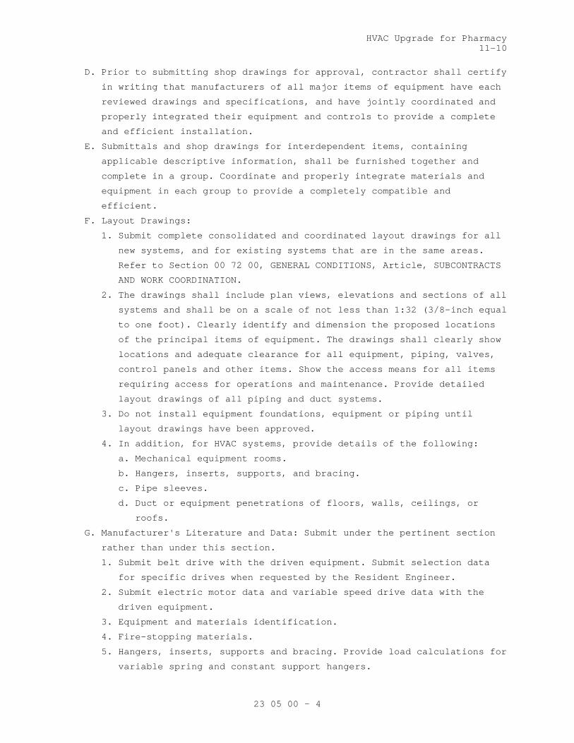
HVAC Upgrade for Pharmacy 11-10
23 05 00 - 4
D. Prior to submitting shop drawings for approval, contractor shall certify
in writing that manufacturers of all major items of equipment have each
reviewed drawings and specifications, and have jointly coordinated and
properly integrated their equipment and controls to provide a complete
and efficient installation.
E. Submittals and shop drawings for interdependent items, containing
applicable descriptive information, shall be furnished together and
complete in a group. Coordinate and properly integrate materials and
equipment in each group to provide a completely compatible and
efficient.
F. Layout Drawings:
1. Submit complete consolidated and coordinated layout drawings for all
new systems, and for existing systems that are in the same areas.
Refer to Section 00 72 00, GENERAL CONDITIONS, Article, SUBCONTRACTS
AND WORK COORDINATION.
2. The drawings shall include plan views, elevations and sections of all
systems and shall be on a scale of not less than 1:32 (3/8-inch equal
to one foot). Clearly identify and dimension the proposed locations
of the principal items of equipment. The drawings shall clearly show
locations and adequate clearance for all equipment, piping, valves,
control panels and other items. Show the access means for all items
requiring access for operations and maintenance. Provide detailed
layout drawings of all piping and duct systems.
3. Do not install equipment foundations, equipment or piping until
layout drawings have been approved.
4. In addition, for HVAC systems, provide details of the following:
a. Mechanical equipment rooms.
b. Hangers, inserts, supports, and bracing.
c. Pipe sleeves.
d. Duct or equipment penetrations of floors, walls, ceilings, or
roofs.
G. Manufacturer's Literature and Data: Submit under the pertinent section
rather than under this section.
1. Submit belt drive with the driven equipment. Submit selection data
for specific drives when requested by the Resident Engineer.
2. Submit electric motor data and variable speed drive data with the
driven equipment.
3. Equipment and materials identification.
4. Fire-stopping materials.
5. Hangers, inserts, supports and bracing. Provide load calculations for
variable spring and constant support hangers.

HVAC Upgrade for Pharmacy 11-10
23 05 00 - 5
6. Wall, floor, and ceiling plates.
H. HVAC Maintenance Data and Operating Instructions:
1. Maintenance and operating manuals in accordance with Section 01 00
00, GENERAL REQUIREMENTS, Article, INSTRUCTIONS, for systems and
equipment.
2. Provide a listing of recommended replacement parts for keeping in
stock supply, including sources of supply, for equipment. Include in
the listing belts for equipment: Belt manufacturer, model number,
size and style, and distinguished whether of multiple belt sets.
I. Provide copies of approved HVAC equipment submittals to the Testing,
Adjusting and Balancing Subcontractor.
1.5 APPLICABLE PUBLICATIONS
A. The publications listed below form a part of this specification to the
extent referenced. The publications are referenced in the text by the
basic designation only.
B. Air Conditioning, Heating and Refrigeration Institute (AHRI):
430-2009................Central Station Air-Handling Units
C. American National Standard Institute (ANSI):
B31.1-2007..............Power Piping
D. Rubber Manufacturers Association (ANSI/RMA):
IP-20-2007..............Specifications for Drives Using Classical
V-Belts and Sheaves
IP-21-2009..............Specifications for Drives Using Double-V
(Hexagonal) Belts
IP-22-2007..............Specifications for Drives Using Narrow V-Belts
and Sheaves
E. Air Movement and Control Association (AMCA):
410-96..................Recommended Safety Practices for Air Moving
Devices
F. American Society of Mechanical Engineers (ASME):
Boiler and Pressure Vessel Code (BPVC):
Section I-2007..........Power Boilers
Section IX-2007.........Welding and Brazing Qualifications
Code for Pressure Piping:
B31.1-2007..............Power Piping
G. American Society for Testing and Materials (ASTM):
A36/A36M-08.............Standard Specification for Carbon Structural
Steel
A575-96(2007)...........Standard Specification for Steel Bars, Carbon,
Merchant Quality, M-Grades
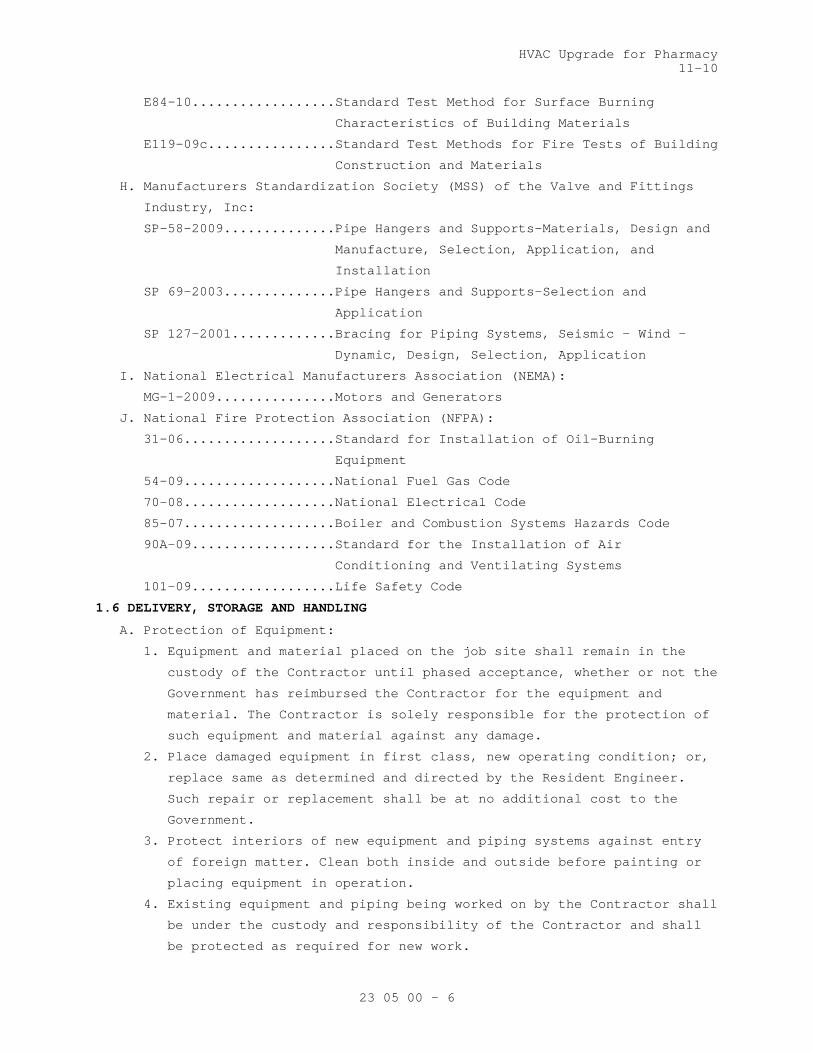
HVAC Upgrade for Pharmacy 11-10
23 05 00 - 6
E84-10..................Standard Test Method for Surface Burning
Characteristics of Building Materials
E119-09c................Standard Test Methods for Fire Tests of Building
Construction and Materials
H. Manufacturers Standardization Society (MSS) of the Valve and Fittings
Industry, Inc:
SP-58-2009..............Pipe Hangers and Supports-Materials, Design and
Manufacture, Selection, Application, and
Installation
SP 69-2003..............Pipe Hangers and Supports-Selection and
Application
SP 127-2001.............Bracing for Piping Systems, Seismic – Wind –
Dynamic, Design, Selection, Application
I. National Electrical Manufacturers Association (NEMA):
MG-1-2009...............Motors and Generators
J. National Fire Protection Association (NFPA):
31-06...................Standard for Installation of Oil-Burning
Equipment
54-09...................National Fuel Gas Code
70-08...................National Electrical Code
85-07...................Boiler and Combustion Systems Hazards Code
90A-09..................Standard for the Installation of Air
Conditioning and Ventilating Systems
101-09..................Life Safety Code
1.6 DELIVERY, STORAGE AND HANDLING
A. Protection of Equipment:
1. Equipment and material placed on the job site shall remain in the
custody of the Contractor until phased acceptance, whether or not the
Government has reimbursed the Contractor for the equipment and
material. The Contractor is solely responsible for the protection of
such equipment and material against any damage.
2. Place damaged equipment in first class, new operating condition; or,
replace same as determined and directed by the Resident Engineer.
Such repair or replacement shall be at no additional cost to the
Government.
3. Protect interiors of new equipment and piping systems against entry
of foreign matter. Clean both inside and outside before painting or
placing equipment in operation.
4. Existing equipment and piping being worked on by the Contractor shall
be under the custody and responsibility of the Contractor and shall
be protected as required for new work.
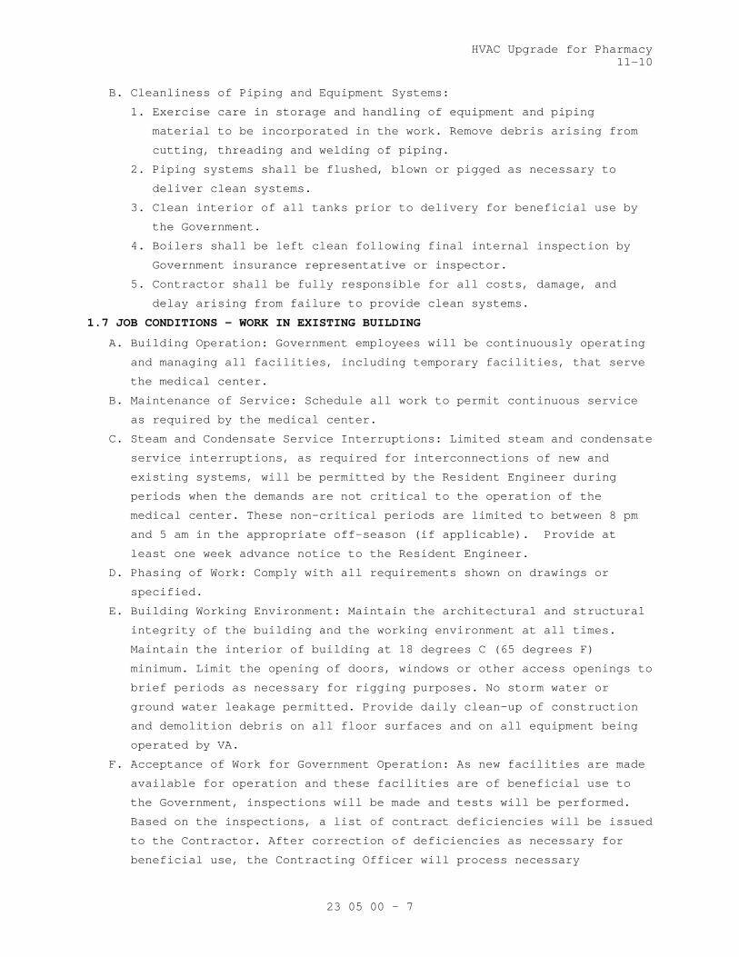
HVAC Upgrade for Pharmacy 11-10
23 05 00 - 7
B. Cleanliness of Piping and Equipment Systems:
1. Exercise care in storage and handling of equipment and piping
material to be incorporated in the work. Remove debris arising from
cutting, threading and welding of piping.
2. Piping systems shall be flushed, blown or pigged as necessary to
deliver clean systems.
3. Clean interior of all tanks prior to delivery for beneficial use by
the Government.
4. Boilers shall be left clean following final internal inspection by
Government insurance representative or inspector.
5. Contractor shall be fully responsible for all costs, damage, and
delay arising from failure to provide clean systems.
1.7 JOB CONDITIONS – WORK IN EXISTING BUILDING
A. Building Operation: Government employees will be continuously operating
and managing all facilities, including temporary facilities, that serve
the medical center.
B. Maintenance of Service: Schedule all work to permit continuous service
as required by the medical center.
C. Steam and Condensate Service Interruptions: Limited steam and condensate
service interruptions, as required for interconnections of new and
existing systems, will be permitted by the Resident Engineer during
periods when the demands are not critical to the operation of the
medical center. These non-critical periods are limited to between 8 pm
and 5 am in the appropriate off-season (if applicable). Provide at
least one week advance notice to the Resident Engineer.
D. Phasing of Work: Comply with all requirements shown on drawings or
specified.
E. Building Working Environment: Maintain the architectural and structural
integrity of the building and the working environment at all times.
Maintain the interior of building at 18 degrees C (65 degrees F)
minimum. Limit the opening of doors, windows or other access openings to
brief periods as necessary for rigging purposes. No storm water or
ground water leakage permitted. Provide daily clean-up of construction
and demolition debris on all floor surfaces and on all equipment being
operated by VA.
F. Acceptance of Work for Government Operation: As new facilities are made
available for operation and these facilities are of beneficial use to
the Government, inspections will be made and tests will be performed.
Based on the inspections, a list of contract deficiencies will be issued
to the Contractor. After correction of deficiencies as necessary for
beneficial use, the Contracting Officer will process necessary

HVAC Upgrade for Pharmacy 11-10
23 05 00 - 8
acceptance and the equipment will then be under the control and
operation of Government personnel.
PART 2 - PRODUCTS
2.1 FACTORY-ASSEMBLED PRODUCTS
A. Provide maximum standardization of components to reduce spare part
requirements.
B. Manufacturers of equipment assemblies that include components made by
others shall assume complete responsibility for final assembled unit.
1. All components of an assembled unit need not be products of same
manufacturer.
2. Constituent parts that are alike shall be products of a single
manufacturer.
3. Components shall be compatible with each other and with the total
assembly for intended service.
4. Contractor shall guarantee performance of assemblies of components,
and shall repair or replace elements of the assemblies as required to
deliver specified performance of the complete assembly.
C. Components of equipment shall bear manufacturer's name and trademark,
model number, serial number and performance data on a name plate
securely affixed in a conspicuous place, or cast integral with, stamped
or otherwise permanently marked upon the components of the equipment.
D. Major items of equipment, which serve the same function, must be the
same make and model. Exceptions will be permitted if performance
requirements cannot be met.
2.2 COMPATIBILITY OF RELATED EQUIPMENT
A. Equipment and materials installed shall be compatible in all respects
with other items being furnished and with existing items so that the
result will be a complete and fully operational plant that conforms to
contract requirements.
2.3 BELT DRIVES
A. Type: ANSI/RMA standard V-belts with proper motor pulley and driven
sheave. Belts shall be constructed of reinforced cord and rubber.
B. Dimensions, rating and selection standards: ANSI/RMA IP-20 and IP-21.
C. Minimum Horsepower Rating: Motor horsepower plus recommended ANSI/RMA
service factor (not less than 20 percent) in addition to the ANSI/RMA
allowances for pitch diameter, center distance, and arc of contact.
D. Maximum Speed: 25 m/s (5000 feet per minute).
E. Adjustment Provisions: For alignment and ANSI/RMA standard allowances
for installation and take-up.
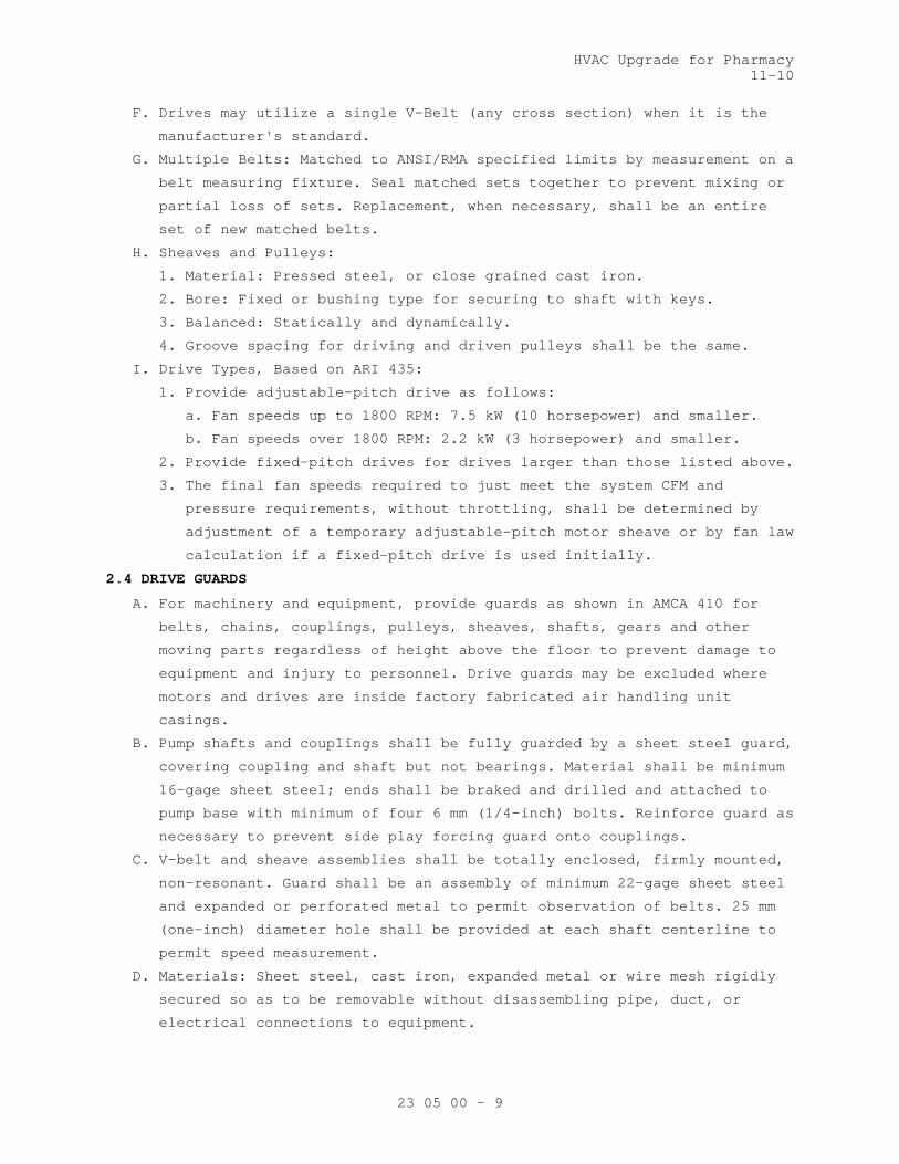
HVAC Upgrade for Pharmacy 11-10
23 05 00 - 9
F. Drives may utilize a single V-Belt (any cross section) when it is the
manufacturer's standard.
G. Multiple Belts: Matched to ANSI/RMA specified limits by measurement on a
belt measuring fixture. Seal matched sets together to prevent mixing or
partial loss of sets. Replacement, when necessary, shall be an entire
set of new matched belts.
H. Sheaves and Pulleys:
1. Material: Pressed steel, or close grained cast iron.
2. Bore: Fixed or bushing type for securing to shaft with keys.
3. Balanced: Statically and dynamically.
4. Groove spacing for driving and driven pulleys shall be the same.
I. Drive Types, Based on ARI 435:
1. Provide adjustable-pitch drive as follows:
a. Fan speeds up to 1800 RPM: 7.5 kW (10 horsepower) and smaller.
b. Fan speeds over 1800 RPM: 2.2 kW (3 horsepower) and smaller.
2. Provide fixed-pitch drives for drives larger than those listed above.
3. The final fan speeds required to just meet the system CFM and
pressure requirements, without throttling, shall be determined by
adjustment of a temporary adjustable-pitch motor sheave or by fan law
calculation if a fixed-pitch drive is used initially.
2.4 DRIVE GUARDS
A. For machinery and equipment, provide guards as shown in AMCA 410 for
belts, chains, couplings, pulleys, sheaves, shafts, gears and other
moving parts regardless of height above the floor to prevent damage to
equipment and injury to personnel. Drive guards may be excluded where
motors and drives are inside factory fabricated air handling unit
casings.
B. Pump shafts and couplings shall be fully guarded by a sheet steel guard,
covering coupling and shaft but not bearings. Material shall be minimum
16-gage sheet steel; ends shall be braked and drilled and attached to
pump base with minimum of four 6 mm (1/4-inch) bolts. Reinforce guard as
necessary to prevent side play forcing guard onto couplings.
C. V-belt and sheave assemblies shall be totally enclosed, firmly mounted,
non-resonant. Guard shall be an assembly of minimum 22-gage sheet steel
and expanded or perforated metal to permit observation of belts. 25 mm
(one-inch) diameter hole shall be provided at each shaft centerline to
permit speed measurement.
D. Materials: Sheet steel, cast iron, expanded metal or wire mesh rigidly
secured so as to be removable without disassembling pipe, duct, or
electrical connections to equipment.
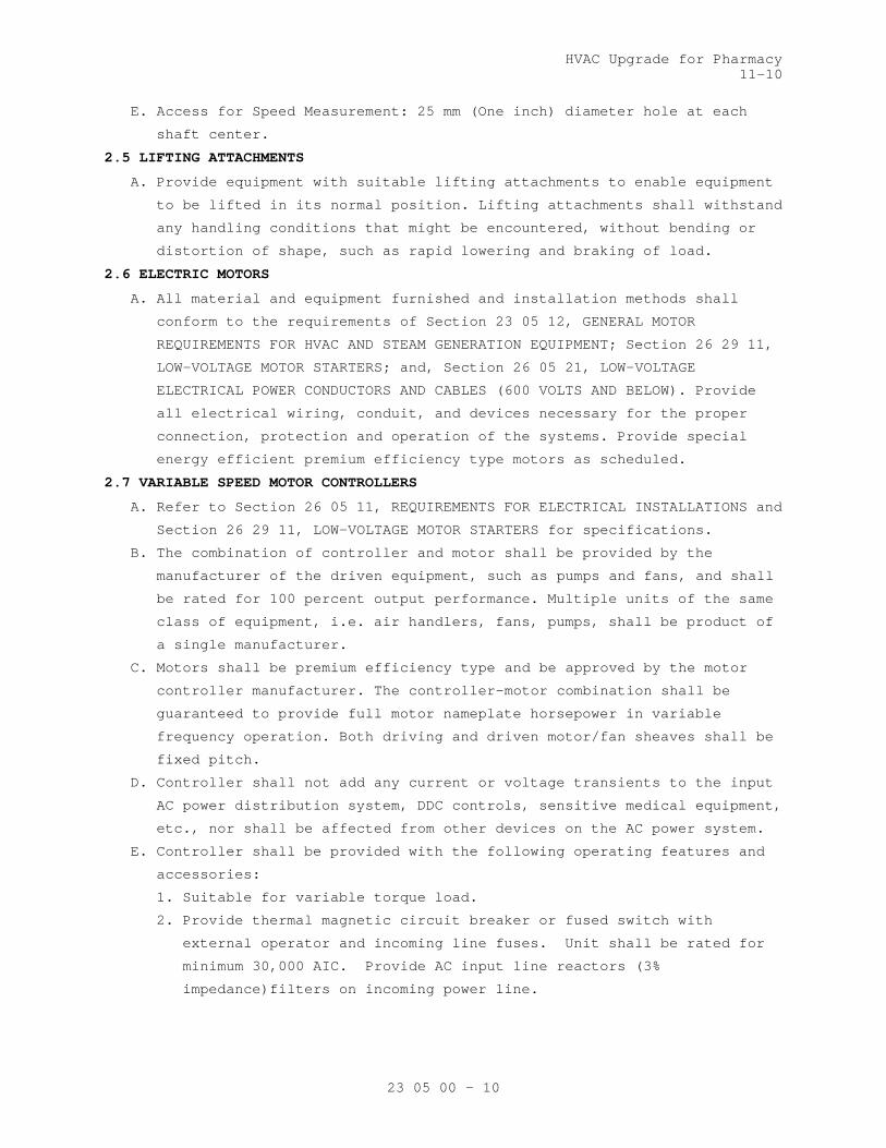
HVAC Upgrade for Pharmacy 11-10
23 05 00 - 10
E. Access for Speed Measurement: 25 mm (One inch) diameter hole at each
shaft center.
2.5 LIFTING ATTACHMENTS
A. Provide equipment with suitable lifting attachments to enable equipment
to be lifted in its normal position. Lifting attachments shall withstand
any handling conditions that might be encountered, without bending or
distortion of shape, such as rapid lowering and braking of load.
2.6 ELECTRIC MOTORS
A. All material and equipment furnished and installation methods shall
conform to the requirements of Section 23 05 12, GENERAL MOTOR
REQUIREMENTS FOR HVAC AND STEAM GENERATION EQUIPMENT; Section 26 29 11,
LOW-VOLTAGE MOTOR STARTERS; and, Section 26 05 21, LOW-VOLTAGE
ELECTRICAL POWER CONDUCTORS AND CABLES (600 VOLTS AND BELOW). Provide
all electrical wiring, conduit, and devices necessary for the proper
connection, protection and operation of the systems. Provide special
energy efficient premium efficiency type motors as scheduled.
2.7 VARIABLE SPEED MOTOR CONTROLLERS
A. Refer to Section 26 05 11, REQUIREMENTS FOR ELECTRICAL INSTALLATIONS and
Section 26 29 11, LOW-VOLTAGE MOTOR STARTERS for specifications.
B. The combination of controller and motor shall be provided by the
manufacturer of the driven equipment, such as pumps and fans, and shall
be rated for 100 percent output performance. Multiple units of the same
class of equipment, i.e. air handlers, fans, pumps, shall be product of
a single manufacturer.
C. Motors shall be premium efficiency type and be approved by the motor
controller manufacturer. The controller-motor combination shall be
guaranteed to provide full motor nameplate horsepower in variable
frequency operation. Both driving and driven motor/fan sheaves shall be
fixed pitch.
D. Controller shall not add any current or voltage transients to the input
AC power distribution system, DDC controls, sensitive medical equipment,
etc., nor shall be affected from other devices on the AC power system.
E. Controller shall be provided with the following operating features and
accessories:
1. Suitable for variable torque load.
2. Provide thermal magnetic circuit breaker or fused switch with
external operator and incoming line fuses. Unit shall be rated for
minimum 30,000 AIC. Provide AC input line reactors (3%
impedance)filters on incoming power line.

HVAC Upgrade for Pharmacy 11-10
23 05 00 - 11
2.8 EQUIPMENT AND MATERIALS IDENTIFICATION
A. Use symbols, nomenclature and equipment numbers specified, shown on the
drawings and shown in the maintenance manuals. In addition, provide bar
code identification nameplate for all equipment which will allow the
equipment identification code to be scanned into the system for
maintenance and inventory tracking. Identification for piping is
specified in Section 09 91 00, PAINTING.
B. Interior (Indoor) Equipment: Engraved nameplates, with letters not less
than 48 mm (3/16-inch) high of brass with black-filled letters, or rigid
black plastic with white letters specified in Section 09 91 00, PAINTING
permanently fastened to the equipment. Identify unit components such as
coils, filters, fans, etc.
C. Exterior (Outdoor) Equipment: Brass nameplates, with engraved black
filled letters, not less than 48 mm (3/16-inch) high riveted or bolted
to the equipment.
D. Control Items: Label all temperature and humidity sensors, controllers
and control dampers. Identify and label each item as they appear on the
control diagrams.
E. Valve Tags and Lists:
1. HVAC and Boiler Plant: Provide for all valves other than for
equipment in Section 23 82 00, CONVECTION HEATING AND COOLING UNITS.
2. Valve tags: Engraved black filled numbers and letters not less than
13 mm (1/2-inch) high for number designation, and not less than 6.4
mm(1/4-inch) for service designation on 19 gage 38 mm (1-1/2 inches)
round brass disc, attached with brass "S" hook or brass chain.
3. Valve lists: Typed or printed plastic coated card(s), sized 216
mm(8-1/2 inches) by 280 mm (11 inches) showing tag number, valve
function and area of control, for each service or system. Punch
sheets for a 3-ring notebook.
4. Provide detailed plan for each floor of the building indicating the
location and valve number for each valve. Identify location of each
valve with a color coded thumb tack in ceiling.
2.9 FIRESTOPPING
A. Section 07 84 00, FIRESTOPPING specifies an effective barrier against
the spread of fire, smoke and gases where penetrations occur for piping
and ductwork. Refer to Section 23 07 11, HVAC, PLUMBING, AND BOILER
PLANT INSULATION, for firestop pipe and duct insulation.
2.10 GALVANIZED REPAIR COMPOUND
A. Mil. Spec. DOD-P-21035B, paint form.
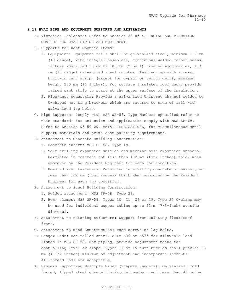
HVAC Upgrade for Pharmacy 11-10
23 05 00 - 12
2.11 HVAC PIPE AND EQUIPMENT SUPPORTS AND RESTRAINTS
A. Vibration Isolators: Refer to Section 23 05 41, NOISE AND VIBRATION
CONTROL FOR HVAC PIPING AND EQUIPMENT.
B. Supports for Roof Mounted Items:
1. Equipment: Equipment rails shall be galvanized steel, minimum 1.3 mm
(18 gauge), with integral baseplate, continuous welded corner seams,
factory installed 50 mm by 100 mm (2 by 4) treated wood nailer, 1.3
mm (18 gauge) galvanized steel counter flashing cap with screws,
built-in cant strip, (except for gypsum or tectum deck), minimum
height 280 mm (11 inches). For surface insulated roof deck, provide
raised cant strip to start at the upper surface of the insulation.
2. Pipe/duct pedestals: Provide a galvanized Unistrut channel welded to
U-shaped mounting brackets which are secured to side of rail with
galvanized lag bolts.
C. Pipe Supports: Comply with MSS SP-58. Type Numbers specified refer to
this standard. For selection and application comply with MSS SP-69.
Refer to Section 05 50 00, METAL FABRICATIONS, for miscellaneous metal
support materials and prime coat painting requirements.
D. Attachment to Concrete Building Construction:
1. Concrete insert: MSS SP-58, Type 18.
2. Self-drilling expansion shields and machine bolt expansion anchors:
Permitted in concrete not less than 102 mm (four inches) thick when
approved by the Resident Engineer for each job condition.
3. Power-driven fasteners: Permitted in existing concrete or masonry not
less than 102 mm (four inches) thick when approved by the Resident
Engineer for each job condition.
E. Attachment to Steel Building Construction:
1. Welded attachment: MSS SP-58, Type 22.
2. Beam clamps: MSS SP-58, Types 20, 21, 28 or 29. Type 23 C-clamp may
be used for individual copper tubing up to 23mm (7/8-inch) outside
diameter.
F. Attachment to existing structure: Support from existing floor/roof
frame.
G. Attachment to Wood Construction: Wood screws or lag bolts.
H. Hanger Rods: Hot-rolled steel, ASTM A36 or A575 for allowable load
listed in MSS SP-58. For piping, provide adjustment means for
controlling level or slope. Types 13 or 15 turn-buckles shall provide 38
mm (1-1/2 inches) minimum of adjustment and incorporate locknuts.
All-thread rods are acceptable.
I. Hangers Supporting Multiple Pipes (Trapeze Hangers): Galvanized, cold
formed, lipped steel channel horizontal member, not less than 41 mm by

HVAC Upgrade for Pharmacy 11-10
23 05 00 - 13
41 mm (1-5/8 inches by 1-5/8 inches), 2.7 mm (No. 12 gage), designed to
accept special spring held, hardened steel nuts. Not permitted for steam
supply and condensate piping.
1. Allowable hanger load: Manufacturers rating less 91kg (200 pounds).
2. Guide individual pipes on the horizontal member of every other
trapeze hanger with 6 mm (1/4-inch) U-bolt fabricated from steel rod.
Provide Type 40 insulation shield, secured by two 13mm (1/2-inch)
galvanized steel bands, or preinsulated calcium silicate shield for
insulated piping at each hanger.
J. Supports for Piping Systems:
1. Select hangers sized to encircle insulation on insulated piping.
Refer to Section 23 07 11, HVAC, PLUMBING, AND BOILER PLANT
INSULATION for insulation thickness. To protect insulation, provide
Type 39 saddles for roller type supports or preinsulated calcium
silicate shields. Provide Type 40 insulation shield or preinsulated
calcium silicate shield at all other types of supports and hangers
including those for preinsulated piping.
2. Piping Systems except High and Medium Pressure Steam (MSS SP-58):
a. Standard clevis hanger: Type 1; provide locknut.
b. Riser clamps: Type 8.
c. Wall brackets: Types 31, 32 or 33.
d. Roller supports: Type 41, 43, 44 and 46.
e. Saddle support: Type 36, 37 or 38.
f. Turnbuckle: Types 13 or 15. Preinsulate.
g. U-bolt clamp: Type 24.
h. Copper Tube:
1) Hangers, clamps and other support material in contact with
tubing shall be painted with copper colored epoxy paint,
plastic coated or taped with non adhesive isolation tape to
prevent electrolysis.
2) For vertical runs use epoxy painted or plastic coated riser
clamps.
3) For supporting tube to strut: Provide epoxy painted pipe straps
for copper tube or plastic inserted vibration isolation clamps.
4) Insulated Lines: Provide pre-insulated calcium silicate shields
sized for copper tube.
i. Supports for plastic or glass piping: As recommended by the pipe
manufacturer with black rubber tape extending one inch beyond
steel support or clamp.
3. High and Medium Pressure Steam (MSS SP-58):
a. Provide eye rod or Type 17 eye nut near the upper attachment.

HVAC Upgrade for Pharmacy 11-10
23 05 00 - 14
b. Piping 50 mm (2 inches) and larger: Type 43 roller hanger. For
roller hangers requiring seismic bracing provide a Type 1 clevis
hanger with Type 41 roller attached by flat side bars.
c. Piping with Vertical Expansion and Contraction:
1) Movement up to 20 mm (3/4-inch): Type 51 or 52 variable spring
unit with integral turn buckle and load indicator.
2) Movement more than 20 mm (3/4-inch): Type 54 or 55 constant
support unit with integral adjusting nut, turn buckle and
travel position indicator.
4. Convertor and Expansion Tank Hangers: May be Type 1 sized for the
shell diameter. Insulation where required will cover the hangers.
K. Pre-insulated Calcium Silicate Shields:
1. Provide 360 degree water resistant high density 965 kPa (140 psi)
compressive strength calcium silicate shields encased in galvanized
metal.
2. Pre-insulated calcium silicate shields to be installed at the point
of support during erection.
3. Shield thickness shall match the pipe insulation.
4. The type of shield is selected by the temperature of the pipe, the
load it must carry, and the type of support it will be used with.
a. Shields for supporting chilled or cold water shall have insulation
that extends a minimum of 1 inch past the sheet metal. Provide for
an adequate vapor barrier in chilled lines.
b. The pre-insulated calcium silicate shield shall support the
maximum allowable water filled span as indicated in MSS-SP 69. To
support the load, the shields may have one or more of the
following features: structural inserts 4138 kPa (600 psi)
compressive strength, an extra bottom metal shield, or formed
structural steel (ASTM A36) wear plates welded to the bottom sheet
metal jacket.
5. Shields may be used on steel clevis hanger type supports, roller
supports or flat surfaces
2.12 PIPE PENETRATIONS
A. Install sleeves during construction for other than blocked out floor
openings for risers in mechanical bays.
B. To prevent accidental liquid spills from passing to a lower level,
provide the following:
1. For sleeves: Extend sleeve 25 mm (one inch) above finished floor and
provide sealant for watertight joint.
2. For blocked out floor openings: Provide 40 mm (1-1/2 inch) angle set
in silicone adhesive around opening.

HVAC Upgrade for Pharmacy 11-10
23 05 00 - 15
3. For drilled penetrations: Provide 40 mm (1-1/2 inch) angle ring or
square set in silicone adhesive around penetration.
C. Penetrations are not allowed through beams or ribs, but may be installed
in concrete beam flanges. Any deviation from these requirements must
receive prior approval of Resident Engineer.
D. Sheet Metal, Plastic, or Moisture-resistant Fiber Sleeves: Provide for
pipe passing through floors, interior walls, and partitions, unless
brass or steel pipe sleeves are specifically called for below.
E. Cast Iron or Zinc Coated Pipe Sleeves: Provide for pipe passing through
exterior walls below grade. Make space between sleeve and pipe
watertight with a modular or link rubber seal. Seal shall be applied at
both ends of sleeve.
F. Galvanized Steel or an alternate Black Iron Pipe with asphalt coating
Sleeves: Provide for pipe passing through concrete beam flanges, except
where brass pipe sleeves are called for. Provide sleeve for pipe passing
through floor of mechanical rooms, laundry work rooms, and animal rooms
above basement. Except in mechanical rooms, connect sleeve with floor
plate.
G. Brass Pipe Sleeves: Provide for pipe passing through quarry tile,
terrazzo or ceramic tile floors. Connect sleeve with floor plate.
H. Sleeves are not required for wall hydrants for fire department
connections or in drywall construction.
I. Sleeve Clearance: Sleeve through floors, walls, partitions, and beam
flanges shall be one inch greater in diameter than external diameter of
pipe. Sleeve for pipe with insulation shall be large enough to
accommodate the insulation. Interior openings shall be caulked tight
with fire stopping material and sealant to prevent the spread of fire,
smoke, and gases.
J. Sealant and Adhesives: Shall be as specified in Section 07 92 00, JOINT
SEALANTS.
2.13 DUCT PENETRATIONS
A. Provide curbs for roof mounted piping, ductwork and equipment. Curbs
shall be 18 inches high with continuously welded seams, built-in cant
strip, interior baffle with acoustic insulation, curb bottom, hinged
curb adapter.
B. Provide firestopping for openings through fire and smoke barriers,
maintaining minimum required rating of floor, ceiling or wall assembly.
See section 07 84 00, FIRESTOPPING.
HVAC Upgrade for Pharmacy 11-10
23 05 00 - 16
2.14 SPECIAL TOOLS AND LUBRICANTS
A. Furnish, and turn over to the Resident Engineer, tools not readily
available commercially, that are required for disassembly or adjustment
of equipment and machinery furnished.
B. Grease Guns with Attachments for Applicable Fittings: One for each type
of grease required for each motor or other equipment.
C. Refrigerant Tools: Provide system charging/Evacuation equipment, gauges,
fittings, and tools required for maintenance of furnished equipment.
D. Tool Containers: Hardwood or metal, permanently identified for in tended
service and mounted, or located, where directed by the Resident
Engineer.
E. Lubricants: A minimum of 0.95 L (one quart) of oil, and 0.45 kg (one
pound) of grease, of equipment manufacturer's recommended grade and
type, in unopened containers and properly identified as to use for each
different application.
2.15 WALL, FLOOR AND CEILING PLATES
A. Material and Type: Chrome plated brass or chrome plated steel, one piece
or split type with concealed hinge, with set screw for fastening to
pipe, or sleeve. Use plates that fit tight around pipes, cover openings
around pipes and cover the entire pipe sleeve projection.
B. Thickness: Not less than 2.4 mm (3/32-inch) for floor plates. For wall
and ceiling plates, not less than 0.64 mm (0.025-inch) for up to 80 mm
(3-inch pipe), 0.89 mm (0.035-inch) for larger pipe.
C. Locations: Use where pipe penetrates floors, walls and ceilings in
exposed locations, in finished areas only. Provide a watertight joint in
spaces where brass or steel pipe sleeves are specified.
2.16 ASBESTOS
A. Materials containing asbestos are not permitted.
PART 3 - EXECUTION
3.1 ARRANGEMENT AND INSTALLATION OF EQUIPMENT AND PIPING
A. Coordinate location of piping, sleeves, inserts, hangers, ductwork and
equipment. Locate piping, sleeves, inserts, hangers, ductwork and
equipment clear of windows, doors, openings, light outlets, and other
services and utilities. Prepare equipment layout drawings to coordinate
proper location and personnel access of all facilities. Submit the
drawings for review as required by Part 1. Follow manufacturer's
published recommendations for installation methods not otherwise
specified.
B. Operating Personnel Access and Observation Provisions: Select and
arrange all equipment and systems to provide clear view and easy access,
HVAC Upgrade for Pharmacy 11-10
23 05 00 - 17
without use of portable ladders, for maintenance and operation of all
devices including, but not limited to: all equipment items, valves,
filters, strainers, transmitters, sensors, control devices. All gages
and indicators shall be clearly visible by personnel standing on the
floor or on permanent platforms. Do not reduce or change maintenance and
operating space and access provisions that are shown on the drawings.
C. Equipment and Piping Support: Coordinate structural systems necessary
for pipe and equipment support with pipe and equipment locations to
permit proper installation.
D. Location of pipe sleeves, trenches and chases shall be accurately
coordinated with equipment and piping locations.
E. Cutting Holes:
1. Cut holes through concrete and masonry by rotary core drill.
Pneumatic hammer, impact electric, and hand or manual hammer type
drill will not be allowed, except as permitted by Resident Engineer
where working area space is limited.
2. Locate holes to avoid interference with structural members such as
beams or grade beams. Holes shall be laid out in advance and drilling
done only after approval by Resident Engineer. If the Contractor
considers it necessary to drill through structural members, this
matter shall be referred to Resident Engineer for approval.
3. Do not penetrate membrane waterproofing.
F. Interconnection of Instrumentation or Control Devices: Generally,
electrical and pneumatic interconnections are not shown but must be
provided.
G. Minor Piping: Generally, small diameter pipe runs from drips and drains,
water cooling, and other service are not shown but must be provided.
H. Electrical and Pneumatic Interconnection of Controls and Instruments:
This generally not shown but must be provided. This includes
interconnections of sensors, transmitters, transducers, control devices,
control and instrumentation panels, instruments and computer
workstations. Comply with NFPA-70.
I. Protection and Cleaning:
1. Equipment and materials shall be carefully handled, properly stored,
and adequately protected to prevent damage before and during
installation, in accordance with the manufacturer's recommendations
and as approved by the Resident Engineer. Damaged or defective items
in the opinion of the Resident Engineer, shall be replaced.
2. Protect all finished parts of equipment, such as shafts and bearings
where accessible, from rust prior to operation by means of protective
grease coating and wrapping. Close pipe openings with caps or plugs

HVAC Upgrade for Pharmacy 11-10
23 05 00 - 18
during installation. Tightly cover and protect fixtures and equipment
against dirt, water chemical, or mechanical injury. At completion of
all work thoroughly clean fixtures, exposed materials and equipment.
J. Concrete and Grout: Use concrete and shrink compensating grout 25 MPa
(3000 psi) minimum, specified in Section 03 30 00, CAST-IN-PLACE
CONCRETE.
K. Install gages, thermometers, valves and other devices with due regard
for ease in reading or operating and maintaining said devices. Locate
and position thermometers and gages to be easily read by operator or
staff standing on floor or walkway provided. Servicing shall not require
dismantling adjacent equipment or pipe work.
L. Install steam piping expansion joints as per manufacturer’s
recommendations.
M. Work in Existing Building:
1. Perform as specified in Article, OPERATIONS AND STORAGE AREAS,
Article, ALTERATIONS, and Article, RESTORATION of the Section 01 00
00, GENERAL REQUIREMENTS for relocation of existing equipment,
alterations and restoration of existing building(s).
2. As specified in Section 01 00 00, GENERAL REQUIREMENTS, Article,
OPERATIONS AND STORAGE AREAS, make alterations to existing service
piping at times that will least interfere with normal operation of
the facility.
3. Cut required openings through existing masonry and reinforced
concrete using diamond core drills. Use of pneumatic hammer type
drills, impact type electric drills, and hand or manual hammer type
drills, will be permitted only with approval of the Resident
Engineer. Locate openings that will least effect structural slabs,
columns, ribs or beams. Refer to the Resident Engineer for
determination of proper design for openings through structural
sections and opening layouts approval, prior to cutting or drilling
into structure. After Resident Engineer's approval, carefully cut
opening through construction no larger than absolutely necessary for
the required installation.
N. Work in Animal Research Areas: Seal all pipe and duct penetrations with
silicone sealant to prevent entrance of insects.
O. Switchgear/Electrical Equipment Drip Protection: Every effort shall be
made to eliminate the installation of pipe above electrical and
telephone switchgear. If this is not possible, encase pipe in a second
pipe with a minimum of joints. Installation of piping, ductwork, leak
protection apparatus or other installations foreign to the electrical
installation shall be located in the space equal to the width and depth

HVAC Upgrade for Pharmacy 11-10
23 05 00 - 19
of the equipment and extending from to a height of 1.8 m (6 ft.) above
the equipment of to ceiling structure, whichever is lower (NFPA 70).
P. Inaccessible Equipment:
1. Where the Government determines that the Contractor has installed
equipment not conveniently accessible for operation and maintenance,
equipment shall be removed and reinstalled or remedial action
performed as directed at no additional cost to the Government.
2. The term "conveniently accessible" is defined as capable of being
reached without the use of ladders, or without climbing or crawling
under or over obstacles such as motors, fans, pumps, belt guards,
transformers, high voltage lines, piping, and ductwork.
3.2 TEMPORARY PIPING AND EQUIPMENT
A. Continuity of operation of existing facilities will generally require
temporary installation or relocation of equipment and piping.
B. The Contractor shall provide all required facilities in accordance with
the requirements of phased construction and maintenance of service. All
piping and equipment shall be properly supported, sloped to drain,
operate without excessive stress, and shall be insulated where injury
can occur to personnel by contact with operating facilities. The
requirements of Paragraph 3.1 apply.
C. Temporary facilities and piping shall be completely removed and any
openings in structures sealed. Provide necessary blind flanges and caps
to seal open piping remaining in service.
3.3 RIGGING
A. Design is based on application of available equipment. Openings in
building structures are planned to accommodate design scheme.
B. Alternative methods of equipment delivery may be offered by Contractor
and will be considered by Government under specified restrictions of
phasing and maintenance of service as well as structural integrity of
the building.
C. Close all openings in the building when not required for rigging
operations to maintain proper environment in the facility for Government
operation and maintenance of service.
D. Contractor shall provide all facilities required to deliver specified
equipment and place on foundations. Attachments to structures for
rigging purposes and support of equipment on structures shall be
Contractor's full responsibility. Upon request, the Government will
check structure adequacy and advise Contractor of recommended
restrictions.
E. Contractor shall check all clearances, weight limitations and shall
offer a rigging plan designed by a Registered Professional Engineer. All
HVAC Upgrade for Pharmacy 11-10
23 05 00 - 20
modifications to structures, including reinforcement thereof, shall be
at Contractor's cost, time and responsibility.
F. Rigging plan and methods shall be referred to Resident Engineer for
evaluation prior to actual work.
G. Restore building to original condition upon completion of rigging work.
3.4 PIPE AND EQUIPMENT SUPPORTS
A. Where hanger spacing does not correspond with joist or rib spacing, use
structural steel channels secured directly to joist and rib structure
that will correspond to the required hanger spacing, and then suspend
the equipment and piping from the channels. Drill or burn holes in
structural steel only with the prior approval of the Resident Engineer.
B. Use of chain, wire or strap hangers; wood for blocking, stays and
bracing; or, hangers suspended from piping above will not be permitted.
Replace or thoroughly clean rusty products and paint with zinc primer.
C. Use hanger rods that are straight and vertical. Turnbuckles for vertical
adjustments may be omitted where limited space prevents use. Provide a
minimum of 15 mm (1/2-inch) clearance between pipe or piping covering
and adjacent work.
D. HVAC Horizontal Pipe Support Spacing: Refer to MSS SP-69. Provide
additional supports at valves, strainers, in-line pumps and other heavy
components. Provide a support within one foot of each elbow.
E. HVAC Vertical Pipe Supports:
1. Up to 150 mm (6-inch pipe), 9 m (30 feet) long, bolt riser clamps to
the pipe below couplings, or welded to the pipe and rests supports
securely on the building structure.
2. Vertical pipe larger than the foregoing, support on base elbows or
tees, or substantial pipe legs extending to the building structure.
F. Overhead Supports:
1. The basic structural system of the building is designed to sustain
the loads imposed by equipment and piping to be supported overhead.
2. Provide steel structural members, in addition to those shown, of
adequate capability to support the imposed loads, located in
accordance with the final approved layout of equipment and piping.
3. Tubing and capillary systems shall be supported in channel troughs.
G. Floor Supports:
1. Provide concrete bases, concrete anchor blocks and pedestals, and
structural steel systems for support of equipment and piping. Anchor
and dowel concrete bases and structural systems to resist forces
under operating and seismic conditions (if applicable) without
excessive displacement or structural failure.
HVAC Upgrade for Pharmacy 11-10
23 05 00 - 21
2. Do not locate or install bases and supports until equipment mounted
thereon has been approved. Size bases to match equipment mounted
thereon plus 50 mm (2 inch) excess on all edges. Boiler foundations
shall have horizontal dimensions that exceed boiler base frame
dimensions by at least 150 mm (6 inches) on all sides. Refer to
structural drawings. Bases shall be neatly finished and smoothed,
shall have chamfered edges at the top, and shall be suitable for
painting.
3. All equipment shall be shimmed, leveled, firmly anchored, and grouted
with epoxy grout. Anchor bolts shall be placed in sleeves, anchored
to the bases. Fill the annular space between sleeves and bolts with a
granular material to permit alignment and realignment.
4. For seismic anchoring, refer to Section 13 05 41, SEISMIC RESTRAINT
REQUIREMENTS FOR NON-STRUCTURAL COMPONENTS.
3.5 MECHANICAL DEMOLITION
A. Rigging access, other than indicated on the drawings, shall be provided
by the Contractor after approval for structural integrity by the
Resident Engineer. Such access shall be provided without additional cost
or time to the Government. Where work is in an operating plant, provide
approved protection from dust and debris at all times for the safety of
plant personnel and maintenance of plant operation and environment of
the plant.
B. In an operating facility, maintain the operation, cleanliness and
safety. Government personnel will be carrying on their normal duties of
operating, cleaning and maintaining equipment and plant operation.
Confine the work to the immediate area concerned; maintain cleanliness
and wet down demolished materials to eliminate dust. Do not permit
debris to accumulate in the area to the detriment of plant operation.
Perform all flame cutting to maintain the fire safety integrity of this
plant. Adequate fire extinguishing facilities shall be available at all
times. Perform all work in accordance with recognized fire protection
standards. Inspection will be made by personnel of the VA Medical
Center, and Contractor shall follow all directives of the RE or COTR
with regard to rigging, safety, fire safety, and maintenance of
operations.
C. Completely remove all piping, wiring, conduit, and other devices
associated with the equipment not to be re-used in the new work. This
includes all pipe, valves, fittings, insulation, and all hangers
including the top connection and any fastenings to building structural
systems. Seal all openings, after removal of equipment, pipes, ducts,
and other penetrations in roof, walls, floors, in an approved manner and

HVAC Upgrade for Pharmacy 11-10
23 05 00 - 22
in accordance with plans and specifications where specifically covered.
Structural integrity of the building system shall be maintained.
Reference shall also be made to the drawings and specifications of the
other disciplines in the project for additional facilities to be
demolished or handled.
D. All valves including gate, globe, ball, butterfly and check, all
pressure gages and thermometers with wells shall remain Government
property and shall be removed and delivered to Resident Engineer and
stored as directed. The Contractor shall remove all other material and
equipment, devices and demolition debris under these plans and
specifications. Such material shall be removed from Government property
expeditiously and shall not be allowed to accumulate.
3.6 CLEANING AND PAINTING
A. Prior to final inspection and acceptance of the plant and facilities for
beneficial use by the Government, the plant facilities, equipment and
systems shall be thoroughly cleaned and painted. Refer to Section 09 91
00, PAINTING.
B. In addition, the following special conditions apply:
1. Cleaning shall be thorough. Use solvents, cleaning materials and
methods recommended by the manufacturers for the specific tasks.
Remove all rust prior to painting and from surfaces to remain
unpainted. Repair scratches, scuffs, and abrasions prior to applying
prime and finish coats.
2. Material And Equipment Not To Be Painted Includes:
a. Motors, controllers, control switches, and safety switches.
b. Control and interlock devices.
c. Regulators.
d. Pressure reducing valves.
e. Control valves and thermostatic elements.
f. Lubrication devices and grease fittings.
g. Copper, brass, aluminum, stainless steel and bronze surfaces.
h. Valve stems and rotating shafts.
i. Pressure gauges and thermometers.
j. Glass.
k. Name plates.
3. Control and instrument panels shall be cleaned, damaged surfaces
repaired, and shall be touched-up with matching paint obtained from
panel manufacturer.
4. Pumps, motors, steel and cast iron bases, and coupling guards shall
be cleaned, and shall be touched-up with the same color as utilized
by the pump manufacturer
HVAC Upgrade for Pharmacy 11-10
23 05 00 - 23
5. Temporary Facilities: Apply paint to surfaces that do not have
existing finish coats.
6. Paint shall withstand the following temperatures without peeling or
discoloration:
a. Condensate and feedwater -- 38 degrees C (100 degrees F) on
insulation jacket surface and 120 degrees C (250 degrees F) on
metal pipe surface.
b. Steam -- 52 degrees C (125 degrees F) on insulation jacket surface
and 190 degrees C (375 degrees F) on metal pipe surface.
7. Final result shall be smooth, even-colored, even-textured factory
finish on all items. Completely repaint the entire piece of
equipment if necessary to achieve this.
3.7 IDENTIFICATION SIGNS
A. Provide laminated plastic signs, with engraved lettering not less than
5 mm (3/16-inch) high, designating functions, for all equipment,
switches, motor controllers, relays, meters, control devices, including
automatic control valves. Nomenclature and identification symbols shall
correspond to that used in maintenance manual, and in diagrams specified
elsewhere. Attach by chain, adhesive, or screws.
B. Factory Built Equipment: Metal plate, securely attached, with name and
address of manufacturer, serial number, model number, size, performance.
C. Pipe Identification: Refer to Section 09 91 00, PAINTING.
3.8 MOTOR AND DRIVE ALIGNMENT
A. Belt Drive: Set driving and driven shafts parallel and align so that the
corresponding grooves are in the same plane.
B. Direct-connect Drive: Securely mount motor in accurate alignment so that
shafts are free from both angular and parallel misalignment when both
motor and driven machine are operating at normal temperatures.
3.9 LUBRICATION
A. Lubricate all devices requiring lubrication prior to initial operation.
Field-check all devices for proper lubrication.
B. Equip all devices with required lubrication fittings or devices. Provide
a minimum of one liter (one quart) of oil and 0.5 kg (one pound) of
grease of manufacturer's recommended grade and type for each different
application; also provide 12 grease sticks for lubricated plug valves.
Deliver all materials to Resident Engineer in unopened containers that
are properly identified as to application.
C. Provide a separate grease gun with attachments for applicable fittings
for each type of grease applied.
D. All lubrication points shall be accessible without disassembling
equipment, except to remove access plates.

HVAC Upgrade for Pharmacy 11-10
23 05 00 - 24
3.10 COMMISSIONING
A. Provide commissioning documentation in accordance with the requirements
of Section 23 08 00 – COMMISSIONING OF HVAC SYSTEMS for all inspection,
start up, and contractor testing required above and required by the
System Readiness Checklist provided by the Commissioning Agent.
B. Components provided under this section of the specifications will be
tested as part of a larger system. Refer to Section 23 08 00 –
COMMISSIONING OF HVAC SYSTEMS and related sections for contractor
responsibilities for system commissioning.
3.11 STARTUP AND TEMPORARY OPERATION
Start up equipment as described in equipment specifications. Verify that
vibration is within specified tolerance prior to extended operation.
Temporary use of equipment is specified in Section 01 00 00, GENERAL
REQUIREMENTS, Article, TEMPORARY USE OF MECHANICAL AND ELECTRICAL
EQUIPMENT.
3.12 OPERATING AND PERFORMANCE TESTS
A. Prior to the final inspection, perform required tests as specified in
Section 01 00 00, GENERAL REQUIREMENTS and submit the test reports and
records to the Resident Engineer.
B. Should evidence of malfunction in any tested system, or piece of
equipment or component part thereof, occur during or as a result of
tests, make proper corrections, repairs or replacements, and repeat
tests at no additional cost to the Government.
C. When completion of certain work or system occurs at a time when final
control settings and adjustments cannot be properly made to make
performance tests, then make performance tests for heating systems and
for cooling systems respectively during first actual seasonal use of
respective systems following completion of work.
3.13 INSTRUCTIONS TO VA PERSONNEL
Provide in accordance with Article, INSTRUCTIONS, of Section 01 00 00,
GENERAL REQUIREMENTS, and Section 23 08 11, DEMONSTRATIONS AND TESTS FOR
BOILER PLANT.
- - - E N D - - -

HVAC Upgrade for Pharmacy11-10
23 05 12 - 1
SECTION 23 05 12GENERAL MOTOR REQUIREMENTS FOR HVAC AND STEAM GENERATION EQUIPMENT
PART 1 - GENERAL
1.1 DESCRIPTION:
This section specifies the furnishing, installation and connection of
motors for HVAC and steam generation equipment.
1.2 RELATED WORK:
A. Section 23 05 11, COMMON WORK RESULTS FOR HVAC.
B. Section 23 34 00, HVAC FANS.
C. Section 23 36 00, AIR TERMINAL UNITS.
D. Section 23 64 00, PACKAGED WATER CHILLERS.
E. Section 23 74 13, PACKAGED, OUTDOOR, CENTRAL-STATION AIR-HANDLING UNITS.
F. Section 23 08 00, COMMISSIONING OF HVAC SYSTEMS: Requirements forcommissioning, systems readiness checklists, and training.
1.3 SUBMITTALS:
A. In accordance with Section 26 05 11, REQUIREMENTS FOR ELECTRICAL
INSTALLATIONS, submit the following:
B. Shop Drawings:
1. Provide documentation to demonstrate compliance with drawings and
specifications.
2. Include electrical ratings, efficiency, bearing data, power factor,
frame size, dimensions, mounting details, materials, horsepower,
voltage, phase, speed (RPM), enclosure, starting characteristics,
torque characteristics, code letter, full load and locked rotor
current, service factor, and lubrication method.
C. Manuals:
1. Submit simultaneously with the shop drawings, companion copies of
complete installation, maintenance and operating manuals, including
technical data sheets and application data.
D. Certification: Two weeks prior to final inspection, unless otherwise
noted, submit four copies of the following certification to the Resident
Engineer:
1. Certification that the motors have been applied, installed, adjusted,
lubricated, and tested according to manufacturer published
recommendations.
E. Completed System Readiness Checklists provided by the Commissioning
Agent and completed by the contractor, signed by a qualified technician

HVAC Upgrade for Pharmacy11-10
23 05 12 - 2
and dated on the date of completion, in accordance with the requirements
of Section 23 08 00 COMMISSIONING OF HVAC SYSTEMS.
1.4 APPLICABLE PUBLICATIONS:
A. The publications listed below form a part of this specification to the
extent referenced. The publications are referenced in the text by the
basic designation only.
B. National Electrical Manufacturers Association (NEMA):
MG 1-2006 Rev. 1 2009 ..Motors and Generators
MG 2–2001 Rev. 1 2007...Safety Standard for Construction and Guide for
Selection, Installation and Use of Electric
Motors and Generators
C. National Fire Protection Association (NFPA):
70-2008.................National Electrical Code (NEC)
D. Institute of Electrical and Electronics Engineers (IEEE):
112-04..................Standard Test Procedure for Polyphase Induction
Motors and Generators
E. American Society of Heating, Refrigerating and Air-Conditioning
Engineers (ASHRAE):
90.1-2007...............Energy Standard for Buildings Except Low-Rise
Residential Buildings
PART 2 - PRODUCTS
2.1 MOTORS:
A. For alternating current, fractional and integral horsepower motors, NEMA
Publications MG 1 and MG 2 shall apply.
B. All material and equipment furnished and installation methods shall
conform to the requirements of Section 26 29 11, LOW-VOLTAGE MOTOR
STARTERS; and Section 26 05 21, LOW-VOLTAGE ELECTRICAL POWER CONDUCTORS
AND CABLES (600 VOLTS AND BELOW). Provide all electrical wiring,
conduit, and devices necessary for the proper connection, protection and
operation of the systems. Provide premium efficiency type motors as
scheduled. Unless otherwise specified for a particular application, use
electric motors with the following requirements.
C. Single-phase Motors: Motors for centrifugal fans and pumps may be split
phase or permanent split capacitor (PSC) type. Provide capacitor-start
type for hard starting applications.
D. Poly-phase Motors: NEMA Design B, Squirrel cage, induction type.

HVAC Upgrade for Pharmacy11-10
23 05 12 - 3
1. Two Speed Motors: Each two-speed motor shall have two separate
windings. Provide a time- delay (20 seconds minimum) relay for
switching from high to low speed.
E. Voltage ratings shall be as follows:
1. Single phase:
a. Motors connected to 120-volt systems: 115 volts.
b. Motors connected to 208-volt systems: 200 volts.
c. Motors connected to 240 volt or 480 volt systems: 230/460 volts,
dual connection.
2. Three phase:
a. Motors connected to 208-volt systems: 200 volts.
b. Motors, less than 74.6 kW (100 HP), connected to 240 volt or 480
volt systems: 208-230/460 volts, dual connection.
c. Motors, 74.6 kW (100 HP) or larger, connected to 240-volt systems:
230 volts.
d. Motors, 74.6 kW (100 HP) or larger, connected to 480-volt systems:
460 volts.
e. Motors connected to high voltage systems (Over 600V): Shall
conform to NEMA Standards for connection to the nominal system
voltage shown on the drawings.
F. Number of phases shall be as follows:
1. Motors, less than 373 W (1/2 HP): Single phase.
2. Motors, 373 W (1/2 HP) and larger: 3 phase.
3. Exceptions:
a. Hermetically sealed motors.
b. Motors for equipment assemblies, less than 746 W (one HP), may be
single phase provided the manufacturer of the proposed assemblies
cannot supply the assemblies with three phase motors.
G. Motors shall be designed for operating the connected loads continuously
in a 40°C (104°F) environment, where the motors are installed, without
exceeding the NEMA standard temperature rises for the motor insulation.
If the motors exceed 40°C (104°F), the motors shall be rated for the
actual ambient temperatures.
H. Motor designs, as indicated by the NEMA code letters, shall be
coordinated with the connected loads to assure adequate starting and
running torque.
I. Motor Enclosures:
1. Shall be the NEMA types as specified and/or shown on the drawings.
2. Where the types of motor enclosures are not shown on the drawings,
they shall be the NEMA types, which are most suitable for the
HVAC Upgrade for Pharmacy11-10
23 05 12 - 4
environmental conditions where the motors are being installed.
Enclosure requirements for certain conditions are as follows:
a. Motors located outdoors, indoors in wet or high humidity
locations, or in unfiltered airstreams shall be totally enclosed
type.
b. Where motors are located in an NEC 511 classified area, provide
TEFC explosion proof motor enclosures.
c. Where motors are located in a corrosive environment, provide TEFC
enclosures with corrosion resistant finish.
3. Enclosures shall be primed and finish coated at the factory with
manufacturer's prime coat and standard finish.
J. Special Requirements:
1. Where motor power requirements of equipment furnished deviate from
power shown on plans, provide electrical service designed under the
requirements of NFPA 70 without additional time or cost to the
Government.
2. Assemblies of motors, starters, controls and interlocks on factory
assembled and wired devices shall be in accordance with the
requirements of this specification.
3. Wire and cable materials specified in the electrical division of the
specifications shall be modified as follows:
a. Wiring material located where temperatures can exceed 71 degrees C
(160 degrees F) shall be stranded copper with Teflon FEP
insulation with jacket. This includes wiring on the boilers.
b. Other wiring at boilers and to control panels shall be NFPA 70
designation THWN.
c. Provide shielded conductors or wiring in separate conduits for all
instrumentation and control systems where recommended by
manufacturer of equipment.
4. Select motor sizes so that the motors do not operate into the service
factor at maximum required loads on the driven equipment. Motors on
pumps shall be sized for non-overloading at all points on the pump
performance curves.
5. Motors utilized with variable frequency drives shall be rated
“inverter-duty” per NEMA Standard, MG1, Part 31.4.4.2. Provide motor
shaft grounding apparatus that will protect bearings from damage from
stray currents.
K. Additional requirements for specific motors, as indicated in the other
sections listed in Article 1.2, shall also apply.

HVAC Upgrade for Pharmacy11-10
23 05 12 - 5
L. Energy-Efficient Motors (Motor Efficiencies): All permanently wired
polyphase motors of 746 Watts (1 HP) or more shall meet the minimum
full-load efficiencies as indicated in the following table. Motors of
746 Watts or more with open, drip-proof or totally enclosed fan-cooled
enclosures shall be NEMA premium efficiency type, unless otherwise
indicated. Motors provided as an integral part of motor driven equipment
are excluded from this requirement if a minimum seasonal or overall
efficiency requirement is indicated for that equipment by the provisions
of another section. Motors not specified as “premium efficiency” shall
comply with the Energy Policy Act of 2005 (EPACT).
Minimum Premium Efficiencies
Open Drip-Proof
Minimum Premium Efficiencies
Totally Enclosed Fan-Cooled
Rating
kW (HP)
1200
RPM
1800
RPM
3600
RPM
Rating
kW (HP)
1200
RPM
1800
RPM
3600
RPM
0.746 (1) 82.5% 85.5% 77.0% 0.746 (1) 82.5% 85.5% 77.0%
1.12 (1.5) 86.5% 86.5% 84.0% 1.12 (1.5) 87.5% 86.5% 84.0%
1.49 (2) 87.5% 86.5% 85.5% 1.49 (2) 88.5% 86.5% 85.5%
2.24 (3) 88.5% 89.5% 85.5% 2.24 (3) 89.5% 89.5% 86.5%
3.73 (5) 89.5% 89.5% 86.5% 3.73 (5) 89.5% 89.5% 88.5%
5.60 (7.5) 90.2% 91.0% 88.5% 5.60 (7.5) 91.0% 91.7% 89.5%
7.46 (10) 91.7% 91.7% 89.5% 7.46 (10) 91.0% 91.7% 90.2%
11.2 (15) 91.7% 93.0% 90.2% 11.2 (15) 91.7% 92.4% 91.0%
14.9 (20) 92.4% 93.0% 91.0% 14.9 (20) 91.7% 93.0% 91.0%
18.7 (25) 93.0% 93.6% 91.7% 18.7 (25) 93.0% 93.6% 91.7%
22.4 (30) 93.6% 94.1% 91.7% 22.4 (30) 93.0% 93.6% 91.7%
29.8 (40) 94.1% 94.1% 92.4% 29.8 (40) 94.1% 94.1% 92.4%
37.3 (50) 94.1% 94.5% 93.0% 37.3 (50) 94.1% 94.5% 93.0%
44.8 (60) 94.5% 95.0% 93.6% 44.8 (60) 94.5% 95.0% 93.6%
56.9 (75) 94.5% 95.0% 93.6% 56.9 (75) 94.5% 95.4% 93.6%
74.6 (100) 95.0% 95.4% 93.6% 74.6 (100) 95.0% 95.4% 94.1%
93.3 (125) 95.0% 95.4% 94.1% 93.3 (125) 95.0% 95.4% 95.0%
112 (150) 95.4% 95.8% 94.1% 112 (150) 95.8% 95.8% 95.0%
149.2 (200) 95.4% 95.8% 95.0% 149.2 (200) 95.8% 96.2% 95.4%
M. Minimum Power Factor at Full Load and Rated Voltage: 90 percent at 1200
RPM, 1800 RPM and 3600 RPM.
HVAC Upgrade for Pharmacy11-10
23 05 12 - 6
PART 3 - EXECUTION
3.1 INSTALLATION:
Install motors in accordance with manufacturer’s recommendations, the
NEC, NEMA, as shown on the drawings and/or as required by other sections
of these specifications.
3.2 FIELD TESTS
A. Perform an electric insulation resistance Test using a megohmmeter on
all motors after installation, before start-up. All shall test free from
grounds.
B. Perform Load test in accordance with ANSI/IEEE 112, Test Method B, to
determine freedom from electrical or mechanical defects and compliance
with performance data.
C. Insulation Resistance: Not less than one-half meg-ohm between stator
conductors and frame, to be determined at the time of final inspection.
3.3 STARTUP AND TESTING
A. The Commissioning Agent will observe startup and contractor testing of
selected equipment. Coordinate the startup and contractor testing
schedules with Resident Engineer and Commissioning Agent. Provide a
minimum of 7 days prior notice.
3.4 COMMISSIONING
A. Provide commissioning documentation in accordance with the requirements
of Section 23 08 00 – COMMISSIONING OF HVAC SYSTEMS for all inspection,
start up, and contractor testing required above and required by the
System Readiness Checklist provided by the Commissioning Agent.
B. Components provided under this section of the specification will be
tested as part of a larger system. Refer to Section 23 08 00 –
COMMISSIONING OF HVAC SYSTEMS and related sections for contractor
responsibilities for system commissioning.
3.5 DEMONSTRATION AND TRAINING
A. Provide services of manufacturer’s technical representative for four
hours to instruct VA personnel in operation and maintenance of units.
B. Submit training plans and instructor qualifications in accordance with
the requirements of Section 23 08 00 – COMMISSIONING OF HVAC SYSTEMS.
- - - E N D - - -
HVAC Upgrade for Pharmacy05-11
23 05 93 - 1
SECTION 23 05 93TESTING, ADJUSTING, AND BALANCING FOR HVAC
PART 1 - GENERAL
1.1 DESCRIPTION
A. Testing, adjusting, and balancing (TAB) of heating, ventilating and air
conditioning (HVAC) systems. TAB includes the following:
1. Planning systematic TAB procedures.
2. Design Review Report.
3. Systems Inspection report.
4. Duct Air Leakage test report.
5. Systems Readiness Report.
6. Balancing air and water distribution systems; adjustment of total
system to provide design performance; and testing performance of
equipment and automatic controls.
7. Vibration and sound measurements.
8. Recording and reporting results.
B. Definitions:
1. Basic TAB used in this Section: Chapter 37, "Testing, Adjusting and
Balancing" of 2007 ASHRAE Handbook, "HVAC Applications".
2. TAB: Testing, Adjusting and Balancing; the process of checking and
adjusting HVAC systems to meet design objectives.
3. AABC: Associated Air Balance Council.
4. NEBB: National Environmental Balancing Bureau.
5. Hydronic Systems: Includes chilled water, heating hot water and
glycol-water systems.
6. Air Systems: Includes all outside air, supply air, return air,
exhaust air and relief air systems.
7. Flow rate tolerance: The allowable percentage variation, minus to
plus, of actual flow rate from values (design) in the contract
documents.
1.2 RELATED WORK
A. Section 23 05 11, COMMON WORK RESULTS FOR HVAC: General Mechanical
Requirements.
B. Section 23 64 00, PACKAGED WATER CHILLERS: Testing Refrigeration
Equipment.
C. Section 23 36 00, AIR TERMINAL UNITS: Terminal Units Performance.
D. Section 23 09 23, DIRECT-DIGITAL CONTROL SYSTEM FOR HVAC: Controls and
Instrumentation Settings.

HVAC Upgrade for Pharmacy05-11
23 05 93 - 2
E. Section 23 82 16, AIR COILS
F. Section 23 74 13, PACKAGED, OUTDOOR, CENTRAL-STATION AIR-HANDLING UNITS
G. Section 23 34 00, HVAC FANS
H. Section 23 37 00, AIR OUTLETS AND INLETS
I. Section 23 21 13, HYDRONIC PIPING
J. Section 23 08 00, COMMISSIONING OF HVAC SYSTEMS. Requirements for
commissioning, systems readiness checklists, and training
K. Section 23 05 12 GENERAL MOTOR REQUIREMENTS FOR HVAC AND STEAM
GENERATION EQUIPMENT
1.3 QUALITY ASSURANCE
A. Refer to Articles, Quality Assurance and Submittals, in Section
23 05 11, COMMON WORK RESULTS FOR HVAC, Section 23 05 10, COMMON WORK
RESULTS FOR BOILER PLANTS and STEAM GENERATION, and Section 23 08 00,
COMMISSIONING OF HVAC SYSTEMS.
B. Qualifications:
1. TAB Agency: The TAB agency shall be a subcontractor of the General
Contractor and shall report to and be paid by the General
Contractor.
2. The TAB agency shall be either a certified member of AABC or
certified by the NEBB to perform TAB service for HVAC, water
balancing and vibrations and sound testing of equipment. The
certification shall be maintained for the entire duration of duties
specified herein. If, for any reason, the agency loses subject
certification during this period, the General Contractor shall
immediately notify the Resident Engineer and submit another TAB firm
for approval. Any agency that has been the subject of disciplinary
action by either the AABC or the NEBB within the five years
preceding Contract Award shall not be eligible to perform any work
related to the TAB. All work performed in this Section and in other
related Sections by the TAB agency shall be considered invalid if
the TAB agency loses its certification prior to Contract completion,
and the successor agency’s review shows unsatisfactory work
performed by the predecessor agency.
3. TAB Specialist: The TAB specialist shall be either a member of AABC
or an experienced technician of the Agency certified by NEBB. The
certification shall be maintained for the entire duration of duties
specified herein. If, for any reason, the Specialist loses subject
certification during this period, the General Contractor shall

HVAC Upgrade for Pharmacy05-11
23 05 93 - 3
immediately notify the Resident Engineer and submit another TAB
Specialist for approval. Any individual that has been the subject of
disciplinary action by either the AABC or the NEBB within the five
years preceding Contract Award shall not be eligible to perform any
duties related to the HVAC systems, including TAB. All work
specified in this Section and in other related Sections performed by
the TAB specialist shall be considered invalid if the TAB Specialist
loses its certification prior to Contract completion and must be
performed by an approved successor.
4. TAB Specialist shall be identified by the General Contractor within
60 days after the notice to proceed. The TAB specialist will be
coordinating, scheduling and reporting all TAB work and related
activities and will provide necessary information as required by the
Resident Engineer. The responsibilities would specifically include:
a. Shall directly supervise all TAB work.
b. Shall sign the TAB reports that bear the seal of the TAB
standard. The reports shall be accompanied by report forms and
schematic drawings required by the TAB standard, AABC or NEBB.
c. Would follow all TAB work through its satisfactory completion.
d. Shall provide final markings of settings of all HVAC adjustment
devices.
e. Permanently mark location of duct test ports.
5. All TAB technicians performing actual TAB work shall be experienced
and must have done satisfactory work on a minimum of 3 projects
comparable in size and complexity to this project. Qualifications
must be certified by the TAB agency in writing. The lead technician
shall be certified by AABC or NEBB
C. Test Equipment Criteria: The instrumentation shall meet the
accuracy/calibration requirements established by AABC National
Standards or by NEBB Procedural Standards for Testing, Adjusting and
Balancing of Environmental Systems and instrument manufacturer. Provide
calibration history of the instruments to be used for test and balance
purpose.
D. Tab Criteria:
1. One or more of the applicable AABC, NEBB or SMACNA publications,
supplemented by ASHRAE Handbook "HVAC Applications" Chapter 36, and
requirements stated herein shall be the basis for planning,
procedures, and reports.

HVAC Upgrade for Pharmacy05-11
23 05 93 - 4
2. Flow rate tolerance: Following tolerances are allowed. For
tolerances not mentioned herein follow ASHRAE Handbook "HVAC
Applications", Chapter 36, as a guideline. Air Filter resistance
during tests, artificially imposed if necessary, shall be at least
100 percent of manufacturer recommended change over pressure drop
values for pre-filters and after-filters.
a. Air handling unit and all other fans, cubic meters/min (cubic
feet per minute): Minus 0 percent to plus l0 percent.
b. Air terminal units (maximum values): Minus 2 percent to plus l0
percent.
c. Exhaust hoods/cabinets: 0 percent to plus l0 percent.
d. Minimum outside air: 0 percent to plus 10 percent.
e. Individual room air outlets and inlets, and air flow rates not
mentioned above: Minus 5 percent to plus l0 percent except if the
air to a space is 100 CFM or less the tolerance would be minus 5
to plus 5 percent.
f. Heating hot water pumps and hot water coils: Minus 5 percent to
plus 5 percent.
g. Chilled water and condenser water pumps: Minus 0 percent to plus
5 percent.
h. Chilled water coils: Minus 0 percent to plus 5 percent.
3. Systems shall be adjusted for energy efficient operation as
described in PART 3.
4. Typical TAB procedures and results shall be demonstrated to the
Resident Engineer for one air distribution system (including all
fans, three terminal units, three rooms randomly selected by the
Resident Engineer) and one hydronic system (pumps and three coils)
as follows:
a. When field TAB work begins.
b. During each partial final inspection and the final inspection for
the project if requested by VA.
1.4 SUBMITTALS
A. Submit in accordance with Section 01 33 23, SHOP DRAWINGS, PRODUCT
DATA, and SAMPLES.
B. Submit names and qualifications of TAB agency and TAB specialists
within 60 days after the notice to proceed. Submit information on three
recently completed projects and a list of proposed test equipment.
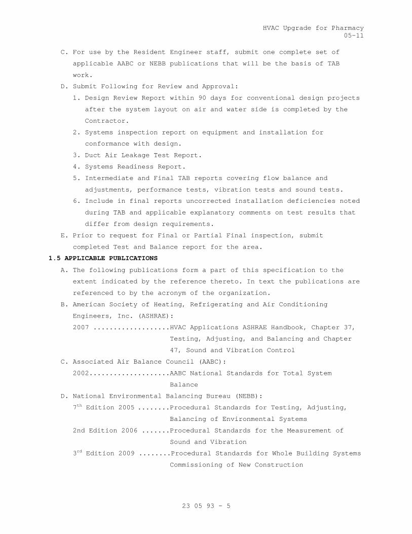
HVAC Upgrade for Pharmacy05-11
23 05 93 - 5
C. For use by the Resident Engineer staff, submit one complete set of
applicable AABC or NEBB publications that will be the basis of TAB
work.
D. Submit Following for Review and Approval:
1. Design Review Report within 90 days for conventional design projects
after the system layout on air and water side is completed by the
Contractor.
2. Systems inspection report on equipment and installation for
conformance with design.
3. Duct Air Leakage Test Report.
4. Systems Readiness Report.
5. Intermediate and Final TAB reports covering flow balance and
adjustments, performance tests, vibration tests and sound tests.
6. Include in final reports uncorrected installation deficiencies noted
during TAB and applicable explanatory comments on test results that
differ from design requirements.
E. Prior to request for Final or Partial Final inspection, submit
completed Test and Balance report for the area.
1.5 APPLICABLE PUBLICATIONS
A. The following publications form a part of this specification to the
extent indicated by the reference thereto. In text the publications are
referenced to by the acronym of the organization.
B. American Society of Heating, Refrigerating and Air Conditioning
Engineers, Inc. (ASHRAE):
2007 ...................HVAC Applications ASHRAE Handbook, Chapter 37,
Testing, Adjusting, and Balancing and Chapter
47, Sound and Vibration Control
C. Associated Air Balance Council (AABC):
2002....................AABC National Standards for Total System
Balance
D. National Environmental Balancing Bureau (NEBB):
7th Edition 2005 ........Procedural Standards for Testing, Adjusting,
Balancing of Environmental Systems
2nd Edition 2006 .......Procedural Standards for the Measurement of
Sound and Vibration
3rd Edition 2009 ........Procedural Standards for Whole Building Systems
Commissioning of New Construction

HVAC Upgrade for Pharmacy05-11
23 05 93 - 6
E. Sheet Metal and Air Conditioning Contractors National Association
(SMACNA):
3rd Edition 2002 ........HVAC SYSTEMS Testing, Adjusting and Balancing
PART 2 - PRODUCTS
2.1 PLUGS
Provide plastic plugs to seal holes drilled in ductwork for test
purposes.
2.2 INSULATION REPAIR MATERIAL
See Section 23 07 11, HVAC and BOILER PLANT INSULATION Provide for
repair of insulation removed or damaged for TAB work.
PART 3 - EXECUTION
3.1 GENERAL
A. Refer to TAB Criteria in Article, Quality Assurance.
B. Obtain applicable contract documents and copies of approved submittals
for HVAC equipment and automatic control systems.
3.2 DESIGN REVIEW REPORT
The TAB Specialist shall review the Contract Plans and specifications
and advise the Resident Engineer of any design deficiencies that would
prevent the HVAC systems from effectively operating in accordance with
the sequence of operation specified or prevent the effective and
accurate TAB of the system. The TAB Specialist shall provide a report
individually listing each deficiency and the corresponding proposed
corrective action necessary for proper system operation.
3.3 SYSTEMS INSPECTION REPORT
A. Inspect equipment and installation for conformance with design.
B. The inspection and report is to be done after air distribution
equipment is on site and duct installation has begun, but well in
advance of performance testing and balancing work. The purpose of the
inspection is to identify and report deviations from design and ensure
that systems will be ready for TAB at the appropriate time.
C. Reports: Follow check list format developed by AABC, NEBB or SMACNA,
supplemented by narrative comments, with emphasis on air handling units
and fans. Check for conformance with submittals. Verify that diffuser
and register sizes are correct. Check air terminal unit installation
including their duct sizes and routing.
3.4 DUCT AIR LEAKAGE TEST REPORT
TAB Agency shall perform the leakage test as outlined in "Duct leakage
Tests and Repairs" in Section 23 31 00, HVAC DUCTS and CASINGS for TAB

HVAC Upgrade for Pharmacy05-11
23 05 93 - 7
agency’s role and responsibilities in witnessing, recording and
reporting of deficiencies.
3.5 SYSTEM READINESS REPORT
A. The TAB Contractor shall measure existing air and water flow rates
associated with existing systems utilized to serve renovated areas as
indicated on drawings. Submit report of findings to resident engineer.
B. Inspect each System to ensure that it is complete including
installation and operation of controls. Submit report to RE in
standard format and forms prepared and or approved by the Commissioning
Agent.
C. Verify that all items such as ductwork piping, ports, terminals,
connectors, etc., that is required for TAB are installed. Provide a
report to the Resident Engineer.
3.6 TAB REPORTS
A. Submit an intermediate report for 25 percent 50 percent of systems and
equipment tested and balanced to establish satisfactory test results.
B. The TAB contractor shall provide raw data immediately in writing to the
Resident Engineer if there is a problem in achieving intended results
before submitting a formal report.
C. If over 20 percent of readings in the intermediate report fall outside
the acceptable range, the TAB report shall be considered invalid and
all contract TAB work shall be repeated and re-submitted for approval
at no additional cost to the owner.
D. Do not proceed with the remaining systems until intermediate report is
approved by the Resident Engineer.
3.7 TAB PROCEDURES
A. Tab shall be performed in accordance with the requirement of the
Standard under which TAB agency is certified by either AABC or NEBB.
B. General: During TAB all related system components shall be in full
operation. Fan and pump rotation, motor loads and equipment vibration
shall be checked and corrected as necessary before proceeding with TAB.
Set controls and/or block off parts of distribution systems to simulate
design operation of variable volume air or water systems for test and
balance work.
C. Coordinate TAB procedures with existing systems and any phased
construction completion requirements for the project. Provide TAB
reports for pre construction air and water flow rate and for each phase
of the project prior to partial final inspections of each phase of the
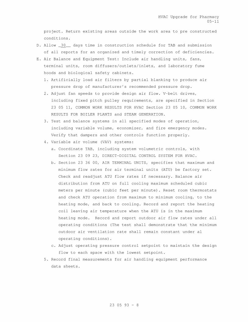
HVAC Upgrade for Pharmacy05-11
23 05 93 - 8
project. Return existing areas outside the work area to pre constructed
conditions.
D. Allow _30__ days time in construction schedule for TAB and submission
of all reports for an organized and timely correction of deficiencies.
E. Air Balance and Equipment Test: Include air handling units, fans,
terminal units, room diffusers/outlets/inlets, and laboratory fume
hoods and biological safety cabinets.
1. Artificially load air filters by partial blanking to produce air
pressure drop of manufacturer’s recommended pressure drop.
2. Adjust fan speeds to provide design air flow. V-belt drives,
including fixed pitch pulley requirements, are specified in Section
23 05 11, COMMON WORK RESULTS FOR HVAC Section 23 05 10, COMMON WORK
RESULTS FOR BOILER PLANTS and STEAM GENERATION.
3. Test and balance systems in all specified modes of operation,
including variable volume, economizer, and fire emergency modes.
Verify that dampers and other controls function properly.
4. Variable air volume (VAV) systems:
a. Coordinate TAB, including system volumetric controls, with
Section 23 09 23, DIRECT-DIGITAL CONTROL SYSTEM FOR HVAC.
b. Section 23 36 00, AIR TERMINAL UNITS, specifies that maximum and
minimum flow rates for air terminal units (ATU) be factory set.
Check and readjust ATU flow rates if necessary. Balance air
distribution from ATU on full cooling maximum scheduled cubic
meters per minute (cubic feet per minute). Reset room thermostats
and check ATU operation from maximum to minimum cooling, to the
heating mode, and back to cooling. Record and report the heating
coil leaving air temperature when the ATU is in the maximum
heating mode. Record and report outdoor air flow rates under all
operating conditions (The test shall demonstrate that the minimum
outdoor air ventilation rate shall remain constant under al
operating conditions).
c. Adjust operating pressure control setpoint to maintain the design
flow to each space with the lowest setpoint.
5. Record final measurements for air handling equipment performance
data sheets.

HVAC Upgrade for Pharmacy05-11
23 05 93 - 9
F. Water Balance and Equipment Test: Include coils, coolers and
condensers:
1. Coordinate water chiller flow balancing with Section 23 64 00,
PACKAGED WATER CHILLERS.
2. Adjust flow rates for equipment. Set coils and evaporator to values
on equipment submittals, if different from values on contract
drawings.
3. Primary-secondary (variable volume) systems: Coordinate TAB with
Section 23 09 23, DIRECT-DIGITAL CONTROL SYSTEM FOR HVAC. Balance
systems at design water flow and then verify that variable flow
controls function as designed.
4. Record final measurements for hydronic equipment on performance data
sheets. Include entering and leaving water temperatures for heating
and cooling coils, and for convertors. Include entering and leaving
air temperatures (DB/WB for cooling coils) for air handling units
and reheat coils. Make air and water temperature measurements at the
same time.
3.8 VIBRATION TESTING
A. Furnish instruments and perform vibration measurements as specified in
Section 23 05 41, NOISE and VIBRATION CONTROL FOR HVAC PIPING and
EQUIPMENT. Field vibration balancing is specified in Section 23 05 11,
COMMON WORK RESULTS FOR HVAC. Provide measurements for all rotating
HVAC equipment of 373 watts (1/2 horsepower) and larger, including
centrifugal/screw compressors, cooling towers, pumps, fans and motors.
B. Record initial measurements for each unit of equipment on test forms
and submit a report to the Resident Engineer. Where vibration readings
exceed the allowable tolerance Contractor shall be directed to correct
the problem. The TAB agency shall verify that the corrections are done
and submit a final report to the Resident Engineer.
3.9 SOUND TESTING
A. Perform and record required sound measurements in accordance with
Paragraph, QUALITY ASSURANCE in Section 23 05 41, NOISE and VIBRATION
CONTROL FOR HVAC PIPING and EQUIPMENT.
1. Take readings in rooms, approximately five percent of all rooms. The
Resident Engineer may designate the specific rooms to be tested.
2. Provide cooling tower sound measurements. Refer to Section 23 65 00,
COOLING TOWERS.

HVAC Upgrade for Pharmacy05-11
23 05 93 - 10
B. Take measurements with a calibrated sound level meter and octave band
analyzer of the accuracy required by AABC or NEBB.
C. Sound reference levels, formulas and coefficients shall be according to
ASHRAE Handbook, "HVAC Applications", Chapter 46, SOUND AND VIBRATION
CONTROL.
D. Determine compliance with specifications as follows:
1. When sound pressure levels are specified, including the NC Criteria
in Section 23 05 41, NOISE and VIBRATION CONTROL FOR HVAC PIPING and
EQUIPMENT:
a. Reduce the background noise as much as possible by shutting off
unrelated audible equipment.
b. Measure octave band sound pressure levels with specified
equipment "off."
c. Measure octave band sound pressure levels with specified
equipment "on."
d. Use the DIFFERENCE in corresponding readings to determine the
sound pressure due to equipment.
DIFFERENCE: 0 1 2 3 4 5 to 9 10 or More
FACTOR: 10 7 4 3 2 1 0
Sound pressure level due to equipment equals sound pressure level
with equipment "on" minus FACTOR.
e. Plot octave bands of sound pressure level due to equipment for
typical rooms on a graph which also shows noise criteria (NC)
curves.
2. When sound power levels are specified:
a. Perform steps 1.a. thru 1.d., as above.
b. For indoor equipment: Determine room attenuating effect, i.e.,
difference between sound power level and sound pressure level.
Determined sound power level will be the sum of sound pressure
level due to equipment plus the room attenuating effect.
c. For outdoor equipment: Use directivity factor and distance from
noise source to determine distance factor, i.e., difference
between sound power level and sound pressure level. Measured
sound power level will be the sum of sound pressure level due to
equipment plus the distance factor. Use 10 meters (30 feet) for
sound level location.

HVAC Upgrade for Pharmacy05-11
23 05 93 - 11
3. Where sound pressure levels are specified in terms of dB(A), as in
Section 23 65 00, COOLING TOWERS, measure sound levels using the "A"
scale of meter. Single value readings will be used instead of octave
band analysis.
E. Where measured sound levels exceed specified level, the installing
contractor or equipment manufacturer shall take remedial action
approved by the Resident Engineer and the necessary sound tests shall
be repeated.
F. Test readings for sound testing could go higher than 15 percent if
determination is made by the Resident Engineer based on the recorded
sound data.
3.10 MARKING OF SETTINGS
Following approval of Tab final Report, the setting of all HVAC
adjustment devices including valves, splitters and dampers shall be
permanently marked by the TAB Specialist so that adjustment can be
restored if disturbed at any time. Style and colors used for markings
shall be coordinated with the Resident Engineer.
3.11 IDENTIFICATION OF TEST PORTS
The TAB Specialist shall permanently and legibly identify the location
points of duct test ports. If the ductwork has exterior insulation, the
identification shall be made on the exterior side of the insulation.
All penetrations through ductwork and ductwork insulation shall be
sealed to prevent air leaks and maintain integrity of vapor barrier.
3.12 PHASING
A. Phased Projects: Testing and Balancing Work to follow project with
areas shall be completed per the project phasing. Upon completion of
the project all areas shall have been tested and balanced per the
contract documents.
B. Existing Areas: Systems that serve areas outside of the project scope
shall not be adversely affected. Measure existing parameters where
shown to document system capacity.
3.13 COMMISSIONING
A. Provide commissioning documentation in accordance with the requirements
of Section 23 08 00 – COMMISSIONING OF HVAC SYSTEMS for all inspection,
start up, and contractor testing required above and required by the
System Readiness Checklist provided by the Commissioning Agent.
B. Components provided under this section of the specification will be
tested as part of a larger system. Refer to Section 23 08 00 –
HVAC Upgrade for Pharmacy05-11
23 05 93 - 12
COMMISSIONING OF HVAC SYSTEMS and related sections for contractor
responsibilities for system commissioning.
- - E N D - - -

HVAC Upgrade for Pharmacy 05-11
23 07 11 - 1
SECTION 23 07 11 HVAC AND BOILER PLANT INSULATION
PART 1 - GENERAL
1.1 DESCRIPTION
A. Field applied insulation for thermal efficiency and condensation
control for
1. HVAC piping, ductwork and equipment.
B. Definitions
1. ASJ: All service jacket, white finish facing or jacket.
2. Air conditioned space: Space having air temperature and/or humidity
controlled by mechanical equipment.
3. Cold: Equipment, ductwork or piping handling media at design
temperature of 16 degrees C (60 degrees F) or below.
4. Concealed: Ductwork and piping above ceilings and in chases and pipe
spaces.
5. Exposed: Piping, ductwork, and equipment exposed to view in finished
areas including mechanical and electrical equipment rooms or exposed
to outdoor weather. Attics and crawl spaces where air handling units
are located are considered to be mechanical rooms. Shafts, chases,
unfinished attics, crawl spaces and pipe basements are not
considered finished areas.
6. FSK: Foil-scrim-kraft facing.
7. Hot: HVAC Ductwork handling air at design temperature above 16
degrees C (60 degrees F);HVAC equipment or piping handling media
above 41 degrees C (105 degrees F).
8. Density: kg/m3 - kilograms per cubic meter (Pcf - pounds per cubic
foot).
9. Runouts: Branch pipe connections up to 25-mm (one-inch) nominal size
to fan coil units or reheat coils for terminal units.
10. Thermal conductance: Heat flow rate through materials.
a. Flat surface: Watt per square meter (BTU per hour per square
foot).
b. Pipe or Cylinder: Watt per square meter (BTU per hour per linear
foot).
11. Thermal Conductivity (k): Watt per meter, per degree C (BTU per inch
thickness, per hour, per square foot, per degree F temperature
difference).

HVAC Upgrade for Pharmacy 05-11
23 07 11 - 2
12. Vapor Retarder (Vapor Barrier): A material which retards the
transmission (migration) of water vapor. Performance of the vapor
retarder is rated in terms of permeance (perms). For the purpose of
this specification, vapor retarders shall have a maximum published
permeance of 0.1 perms and vapor barriers shall have a maximum
published permeance of 0.001 perms.
13. LPS: Low pressure steam (103 kPa [15 psig] and below).
14. LPR: Low pressure steam condensate gravity return.
15. PC: Pumped condensate.
16. HWH: Hot water heating supply.
17. HWHR: Hot water heating return.
18. GH: Hot glycol-water heating supply.
19. GHR: Hot glycol-water heating return.
20. CTPD: Condensate transfer pump discharge.
21. CTPS: Condensate transfer pump suction.
22. R: Pump recirculation.
23. CW: Cold water.
24. SW: Soft water.
25. HW: Hot water.
26. CH: Chilled water supply.
27. CHR: Chilled water return.
28. GC: Chilled glycol-water supply.
29. GCR: Chilled glycol-water return.
30. RS: Refrigerant suction.
31. PVDC: Polyvinylidene chloride vapor retarder jacketing, white.
1.2 RELATED WORK
A. Section 23 05 11, COMMON WORK RESULTS FOR HVAC: General mechanical
requirements and items, which are common to more than one section of
Division 23.
B. Section 23 22 13, STEAM and CONDENSATE HEATING PIPING
C. Section 23 64 00, PACKAGED WATER CHILLERS: Compressor, evaporator and
piping.
D. Section 23 21 13, HYDRONIC PIPING and Section 23 22 13, STEAM and
CONDENSATE HEATING PIPING: Piping and equipment.
E. Section 23 21 13, HYDRONIC PIPING: Hot water, chilled water, and glycol
piping.
F. Section 23 08 00, COMMISSIONING OF HVAC SYSTEMS. Requirements for
commissioning, systems readiness checklists, and training.

HVAC Upgrade for Pharmacy 05-11
23 07 11 - 3
1.3 QUALITY ASSURANCE
A. Refer to article QUALITY ASSURANCE, in Section 23 05 11, COMMON WORK
RESULTS FOR HVAC.
B. Criteria:
1. Comply with NFPA 90A, particularly paragraphs 4.3.3.1 through
4.3.3.6, 4.3.10.2.6, and 5.4.6.4, parts of which are quoted as
follows:
4.3.3.1 Pipe insulation and coverings, duct coverings,vapor retarder facings, adhesives, fasteners, tapes, and supplementary materials added to air ducts, plenums, panels, and duct silencers used in duct systems, unless otherwise provided for in 4.3.3.1.1 or 4.3.3.1.2., shall have, in the form in which they are used, a maximum flame spread index of 25 without evidence of continued progressive combustion and a maximum smoke developed index of 50 when tested in accordance with NFPA 255,
4.3.3.1.1 Where these products are to be applied with adhesives, they shall be tested with such adhesives applied, or the adhesives used shall have a maximum flame spread index of 25 and a maximum smoke developed index of 50 when in the final dry state.
4.3.3.1.2 The flame spread and smoke developed index requirements of 4.3.3.1.1 shall not apply to air duct weatherproof coverings where they are located entirely outside of a building, do not penetrate a wall or roof, and do not create an exposure hazard.
4.3.3.2 Closure systems for use with rigid and flexible air ducts tested in accordance with UL 181, Standard for Safety Factory-Made Air Ducts and Air Connectors, shall have been tested, listed, and used in accordance with the conditions of their listings, in accordance with one of the following:
(1) UL 181A, Standard for Safety Closure Systems for Use with Rigid Air Ducts and Air Connectors
(2) UL 181B, Standard for Safety Closure Systems for Use with Flexible Air Ducts and Air Connectors
4.3.3.3 Air duct, panel, and plenum coverings and linings, and pipe insulation and coverings shall not flame, glow, smolder, or smoke when tested in accordance with a similar test for pipe covering, ASTM C 411, Standard Test Method for Hot-Surface Performance of High-Temperature Thermal Insulation, at the temperature to which they are exposed in service.
4.3.3.3.1 In no case shall the test temperature be below 121°C (250°F).
4.3.3.4 Air duct coverings shall not extend through walls or floors that are required to be fire stopped or required to have a fire resistance rating, unless such coverings meet the requirements of 5.4.6.4.
4.3.3.6 Air duct coverings shall not be installed so as to conceal or prevent the use of any service opening.

HVAC Upgrade for Pharmacy 05-11
23 07 11 - 4
4.3.10.2.6 Materials exposed to the airflow shall be noncombustible or limited combustible and have a maximum smoke developed index of 50 or comply with the following.
4.3.10.2.6.1 Electrical wires and cables and optical fiber cables shall be listed as noncombustible or limited combustible and have a maximum smoke developed index of 50 or shall be listed as having a maximum peak optical density of 0.5 or less, an average optical density of 0.15 or less, and a maximum flame spread distance of 1.5 m (5 ft) or less when tested in accordance with NFPA 262, Standard Method of Test for Flame Travel and Smoke of Wires and Cables for Use in Air-Handling Spaces.
4.3.10.2.6.4 Optical-fiber and communication raceways shall be listed as having a maximum peak optical density of 0.5 or less, an average optical density of 0.15 or less, and a maximum flame spread distance of 1.5 m (5 ft) or less when tested in accordance with UL 2024, Standard for Safety Optical-Fiber Cable Raceway.
4.3.10.2.6.6 Supplementary materials for air distribution systems shall be permitted when complying with the provisions of 4.3.3.
5.4.6.4 Where air ducts pass through walls, floors, or partitions that are required to have a fire resistance rating and where fire dampers are not required, the opening in the construction around the air duct shall be as follows:
(1) Not exceeding a 25.4 mm (1 in.) average clearance on all sides
(2) Filled solid with an approved material capable of preventing the passage of flame and hot gases sufficient to ignite cotton waste when subjected to the time-temperature fire conditions required for fire barrier penetration as specified in NFPA 251,
2. Test methods: ASTM E84, UL 723, or NFPA 255.
3. Specified k factors are at 24 degrees C (75 degrees F) mean
temperature unless stated otherwise. Where optional thermal
insulation material is used, select thickness to provide thermal
conductance no greater than that for the specified material. For
pipe, use insulation manufacturer's published heat flow tables. For
domestic hot water supply and return, run out insulation and
condensation control insulation, no thickness adjustment need be
made.
4. All materials shall be compatible and suitable for service
temperature, and shall not contribute to corrosion or otherwise
attack surface to which applied in either the wet or dry state.
C. Every package or standard container of insulation or accessories
delivered to the job site for use must have a manufacturer's stamp or
label giving the name of the manufacturer and description of the
material.

HVAC Upgrade for Pharmacy 05-11
23 07 11 - 5
1.4 SUBMITTALS
A. Submit in accordance with Section 01 33 23, SHOP DRAWINGS, PRODUCT
DATA, and SAMPLES.
B. Shop Drawings:
1. All information, clearly presented, shall be included to determine
compliance with drawings and specifications and ASTM, federal and
military specifications.
a. Insulation materials: Specify each type used and state surface
burning characteristics.
b. Insulation facings and jackets: Each type used. Make it clear
that white finish will be furnished for exposed ductwork, casings
and equipment.
c. Insulation accessory materials: Each type used.
d. Manufacturer's installation and fitting fabrication instructions
for flexible unicellular insulation.
e. Make reference to applicable specification paragraph numbers for
coordination.
C. Samples:
1. Each type of insulation: Minimum size 100 mm (4 inches) square for
board/block/ blanket; 150 mm (6 inches) long, full diameter for
round types.
2. Each type of facing and jacket: Minimum size 100 mm (4 inches
square).
3. Each accessory material: Minimum 120 ML (4 ounce) liquid container
or 120 gram (4 ounce) dry weight for adhesives / cement / mastic.
1.5 STORAGE AND HANDLING OF MATERIAL
Store materials in clean and dry environment, pipe covering jackets
shall be clean and unmarred. Place adhesives in original containers.
Maintain ambient temperatures and conditions as required by printed
instructions of manufacturers of adhesives, mastics and finishing
cements.
1.6 APPLICABLE PUBLICATIONS
A. The publications listed below form a part of this specification to the
extent referenced. The publications are referenced in the text by basic
designation only.

HVAC Upgrade for Pharmacy 05-11
23 07 11 - 6
B. Federal Specifications (Fed. Spec.):
L-P-535E (2)- 99........Plastic Sheet (Sheeting): Plastic Strip; Poly
(Vinyl Chloride) and Poly (Vinyl Chloride -
Vinyl Acetate), Rigid.
C. Military Specifications (Mil. Spec.):
MIL-A-3316C (2)-90......Adhesives, Fire-Resistant, Thermal Insulation
MIL-A-24179A (1)-87.....Adhesive, Flexible Unicellular-Plastic
Thermal Insulation
MIL-C-19565C (1)-88.....Coating Compounds, Thermal Insulation, Fire-and
Water-Resistant, Vapor-Barrier
MIL-C-20079H-87.........Cloth, Glass; Tape, Textile Glass; and Thread,
Glass and Wire-Reinforced Glass
D. American Society for Testing and Materials (ASTM):
A167-99(2004)...........Standard Specification for Stainless and
Heat-Resisting Chromium-Nickel Steel Plate,
Sheet, and Strip
B209-07.................Standard Specification for Aluminum and
Aluminum-Alloy Sheet and Plate
C411-05.................Standard test method for Hot-Surface
Performance of High-Temperature Thermal
Insulation
C449-07.................Standard Specification for Mineral Fiber
Hydraulic-Setting Thermal Insulating and
Finishing Cement
C533-09.................Standard Specification for Calcium Silicate
Block and Pipe Thermal Insulation
C534-08.................Standard Specification for Preformed Flexible
Elastomeric Cellular Thermal Insulation in
Sheet and Tubular Form
C547-07.................Standard Specification for Mineral Fiber pipe
Insulation
C552-07.................Standard Specification for Cellular Glass
Thermal Insulation
C553-08.................Standard Specification for Mineral Fiber
Blanket Thermal Insulation for Commercial and
Industrial Applications
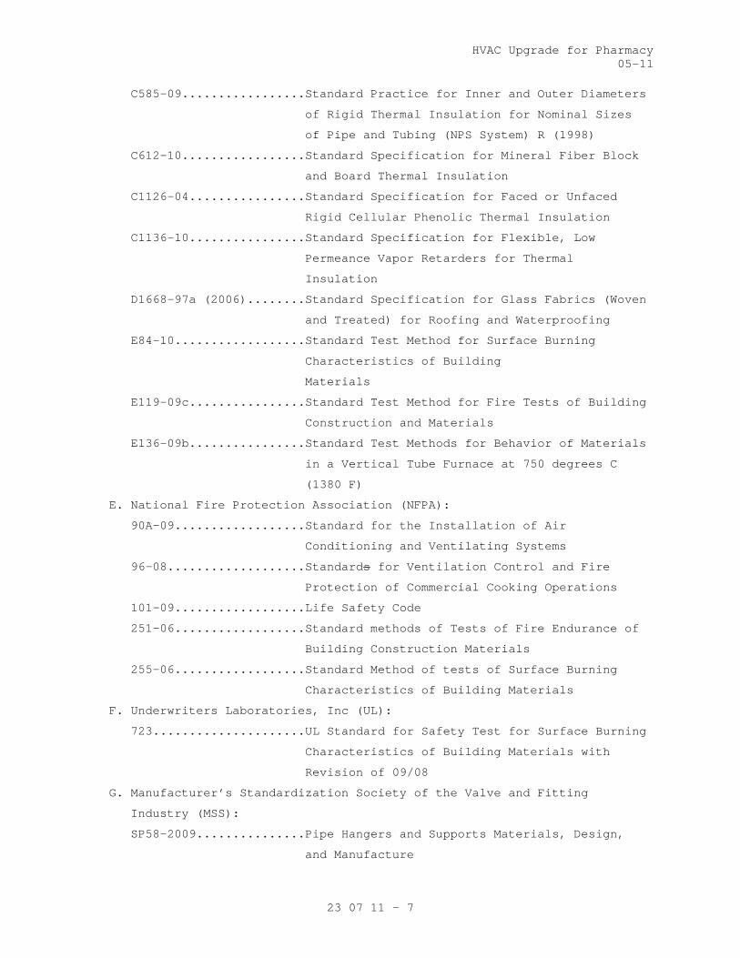
HVAC Upgrade for Pharmacy 05-11
23 07 11 - 7
C585-09.................Standard Practice for Inner and Outer Diameters
of Rigid Thermal Insulation for Nominal Sizes
of Pipe and Tubing (NPS System) R (1998)
C612-10.................Standard Specification for Mineral Fiber Block
and Board Thermal Insulation
C1126-04................Standard Specification for Faced or Unfaced
Rigid Cellular Phenolic Thermal Insulation
C1136-10................Standard Specification for Flexible, Low
Permeance Vapor Retarders for Thermal
Insulation
D1668-97a (2006)........Standard Specification for Glass Fabrics (Woven
and Treated) for Roofing and Waterproofing
E84-10..................Standard Test Method for Surface Burning
Characteristics of Building
Materials
E119-09c................Standard Test Method for Fire Tests of Building
Construction and Materials
E136-09b................Standard Test Methods for Behavior of Materials
in a Vertical Tube Furnace at 750 degrees C
(1380 F)
E. National Fire Protection Association (NFPA):
90A-09..................Standard for the Installation of Air
Conditioning and Ventilating Systems
96-08...................Standards for Ventilation Control and Fire
Protection of Commercial Cooking Operations
101-09..................Life Safety Code
251-06..................Standard methods of Tests of Fire Endurance of
Building Construction Materials
255-06..................Standard Method of tests of Surface Burning
Characteristics of Building Materials
F. Underwriters Laboratories, Inc (UL):
723.....................UL Standard for Safety Test for Surface Burning
Characteristics of Building Materials with
Revision of 09/08
G. Manufacturer’s Standardization Society of the Valve and Fitting
Industry (MSS):
SP58-2009...............Pipe Hangers and Supports Materials, Design,
and Manufacture
HVAC Upgrade for Pharmacy 05-11
23 07 11 - 8
PART 2 - PRODUCTS
2.1 MINERAL FIBER OR FIBER GLASS
A. ASTM C612 (Board, Block), Class 1 or 2, density 48 kg/m3 (3 pcf), k =
0.037 (0.26) at 24 degrees C (75 degrees F), external insulation for
temperatures up to 204 degrees C (400 degrees F) with foil scrim (FSK)
facing.
B. ASTM C553 (Blanket, Flexible) Type I, Class B-3, Density 16 kg/m3 (1
pcf), k = 0.045 (0.31) at 24 degrees C (75 degrees F), for use at
temperatures up to 204 degrees C (400 degrees F) with foil scrim (FSK)
facing.
C. ASTM C547 (Pipe Fitting Insulation and Preformed Pipe Insulation),
Class 1, k = 0.037 (0.26) at 24 degrees C (75 degrees F), for use at
temperatures up to 230 degrees C (450 degrees F) with an all service
vapor retarder jacket with polyvinyl chloride premolded fitting
covering.
2.2 MINERAL WOOL OR REFRACTORY FIBER
A. Comply with Standard ASTM C612, Class 3, 450 degrees C (850 degrees F).
2.3 RIGID CELLULAR PHENOLIC FOAM
A. Preformed (molded) pipe insulation, ASTM C1126, type III, grade 1, k =
0.021(0.15) at 10 degrees C (50 degrees F), for use at temperatures up
to 121 degrees C (250 degrees F) with all service vapor retarder jacket
with polyvinyl chloride premolded fitting covering.
B. Equipment and Duct Insulation, ASTM C 1126, type II, grade 1, k = 0.021
(0.15) at 10 degrees C (50 degrees F), for use at temperatures up to
121 degrees C (250 degrees F) with rigid cellular phenolic insulation
and covering, and all service vapor retarder jacket.
2.4 CELLULAR GLASS CLOSED-CELL
A. Comply with Standard ASTM C177, C518, density 120 kg/m3 (7.5 pcf)
nominal, k = 0.033 (0.29) at 240 degrees C (75 degrees F).
B. Pipe insulation for use at temperatures up to 200 degrees C (400
degrees F) with all service vapor retarder jacket.
2.5 POLYISOCYANURATE CLOSED-CELL RIGID
A. Preformed (fabricated) pipe insulation, ASTM C591, type IV,
K=0.027(0.19) at 24 degrees C (75 degrees F), flame spread not over 25,
smoke developed not over 50, for use at temperatures up to 149 degree C

HVAC Upgrade for Pharmacy 05-11
23 07 11 - 9
(300 degree F) with factory applied PVDC or all service vapor retarder
jacket with polyvinyl chloride premolded fitting covers.
B. Equipment and duct insulation, ASTM C 591,type IV, K=0.027(0.19) at 24
degrees C (75 degrees F), for use at temperatures up to 149 degrees C
(300 degrees F) with PVDC or all service jacket vapor retarder jacket.
2.6 FLEXIBLE ELASTOMERIC CELLULAR THERMAL
ASTM C177, C518, k = 0.039 (0.27) at 24 degrees C (75 degrees F), flame
spread not over 25, smoke developed not over 50, for temperatures from
minus 4 degrees C (40 degrees F) to 93 degrees C (200 degrees F). No
jacket required.
2.8 CALCIUM SILICATE
A. Preformed pipe Insulation: ASTM C533, Type I and Type II with indicator
denoting asbestos-free material.
B. Premolded Pipe Fitting Insulation: ASTM C533, Type I and Type II with
indicator denoting asbestos-free material.
C. Equipment Insulation: ASTM C533, Type I and Type II
D. Characteristics:
Insulation Characteristics
ITEMS TYPE I TYPE II
Temperature, maximum degrees C
(degrees F)
649 (1200) 927 (1700)
Density (dry), Kg/m3 (lb/ ft3) 232 (14.5) 288 (18)
Thermal conductivity:
Min W/ m K (Btu in/h ft2 degrees F)@
mean temperature of 93 degrees C
(200 degrees F)
0.059
(0.41)
0.078
(0.540)
Surface burning characteristics:
Flame spread Index, Maximum
0
0
Smoke Density index, Maximum 0 0
2.9 INSULATION FACINGS AND JACKETS
A. Vapor Retarder, higher strength with low water permeance = 0.02 or less
perm rating, Beach puncture 50 units for insulation facing on exposed
ductwork, casings and equipment, and for pipe insulation jackets.
Facings and jackets shall be all service type (ASJ) or PVDC Vapor
Retarder jacketing.
HVAC Upgrade for Pharmacy 05-11
23 07 11 - 10
B. ASJ jacket shall be white kraft bonded to 0.025 mm (1 mil) thick
aluminum foil, fiberglass reinforced, with pressure sensitive adhesive
closure. Comply with ASTM C1136. Beach puncture 50 units, Suitable for
painting without sizing. Jackets shall have minimum 40 mm (1-1/2 inch)
lap on longitudinal joints and minimum 75 mm (3 inch) butt strip on end
joints. Butt strip material shall be same as the jacket. Lap and butt
strips shall be self-sealing type with factory-applied pressure
sensitive adhesive.
C. Vapor Retarder medium strength with low water vapor permeance of 0.02
or less perm rating), Beach puncture 25 units: Foil-Scrim-Kraft (FSK)
or PVDC vapor retarder jacketing type for concealed ductwork and
equipment.
D. Field applied vapor barrier jackets shall be provided, in addition to
the specified facings and jackets, on all exterior piping and ductwork
as well as on interior piping and ductwork exposed to outdoor air
(i.e.; in ventilated attics, piping in ventilated (not air conditioned)
spaces, etc.)in high humidity areas conveying fluids below ambient
temperature. The vapor barrier jacket shall consist of a multi-layer
laminated cladding with a maximum water vapor permeance of 0.001 perms.
The minimum puncture resistance shall be 35 cm-kg (30 inch-pounds) for
interior locations and 92 cm-kg (80 inch-pounds) for exterior or
exposed locations or where the insulation is subject to damage.
E. Glass Cloth Jackets: Presized, minimum 0.18 kg per square meter (7.8
ounces per square yard), 2000 kPa (300 psig) bursting strength with
integral vapor retarder where required or specified. Weather proof if
utilized for outside service.
F. Factory composite materials may be used provided that they have been
tested and certified by the manufacturer.
G. Pipe fitting insulation covering (jackets): Fitting covering shall be
premolded to match shape of fitting and shall be polyvinyl chloride
(PVC) conforming to Fed Spec L-P-335, composition A, Type II Grade GU,
and Type III, minimum thickness 0.7 mm (0.03 inches). Provide color
matching vapor retarder pressure sensitive tape.
H. Aluminum Jacket-Piping systems and circular breeching and stacks: ASTM
B209, 3003 alloy, H-14 temper, 0.6 mm (0.023 inch) minimum thickness
with locking longitudinal joints. Jackets for elbows, tees and other
fittings shall be factory-fabricated to match shape of fitting and of
0.6 mm (0.024) inch minimum thickness aluminum. Fittings shall be of
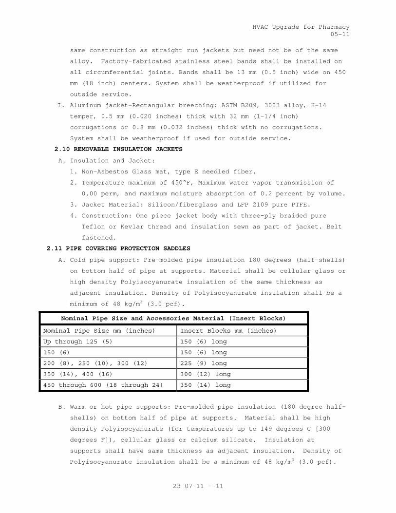
HVAC Upgrade for Pharmacy 05-11
23 07 11 - 11
same construction as straight run jackets but need not be of the same
alloy. Factory-fabricated stainless steel bands shall be installed on
all circumferential joints. Bands shall be 13 mm (0.5 inch) wide on 450
mm (18 inch) centers. System shall be weatherproof if utilized for
outside service.
I. Aluminum jacket-Rectangular breeching: ASTM B209, 3003 alloy, H-14
temper, 0.5 mm (0.020 inches) thick with 32 mm (1-1/4 inch)
corrugations or 0.8 mm (0.032 inches) thick with no corrugations.
System shall be weatherproof if used for outside service.
2.10 REMOVABLE INSULATION JACKETS
A. Insulation and Jacket:
1. Non-Asbestos Glass mat, type E needled fiber.
2. Temperature maximum of 450°F, Maximum water vapor transmission of
0.00 perm, and maximum moisture absorption of 0.2 percent by volume.
3. Jacket Material: Silicon/fiberglass and LFP 2109 pure PTFE.
4. Construction: One piece jacket body with three-ply braided pure
Teflon or Kevlar thread and insulation sewn as part of jacket. Belt
fastened.
2.11 PIPE COVERING PROTECTION SADDLES
A. Cold pipe support: Pre-molded pipe insulation 180 degrees (half-shells)
on bottom half of pipe at supports. Material shall be cellular glass or
high density Polyisocyanurate insulation of the same thickness as
adjacent insulation. Density of Polyisocyanurate insulation shall be a
minimum of 48 kg/m3 (3.0 pcf).
Nominal Pipe Size and Accessories Material (Insert Blocks)
Nominal Pipe Size mm (inches) Insert Blocks mm (inches)
Up through 125 (5) 150 (6) long
150 (6) 150 (6) long
200 (8), 250 (10), 300 (12) 225 (9) long
350 (14), 400 (16) 300 (12) long
450 through 600 (18 through 24) 350 (14) long
B. Warm or hot pipe supports: Pre-molded pipe insulation (180 degree half-
shells) on bottom half of pipe at supports. Material shall be high
density Polyisocyanurate (for temperatures up to 149 degrees C [300
degrees F]), cellular glass or calcium silicate. Insulation at
supports shall have same thickness as adjacent insulation. Density of
Polyisocyanurate insulation shall be a minimum of 48 kg/m3 (3.0 pcf).
HVAC Upgrade for Pharmacy 05-11
23 07 11 - 12
2.12 ADHESIVE, MASTIC, CEMENT
A. Mil. Spec. MIL-A-3316, Class 1: Jacket and lap adhesive and protective
finish coating for insulation.
B. Mil. Spec. MIL-A-3316, Class 2: Adhesive for laps and for adhering
insulation to metal surfaces.
C. Mil. Spec. MIL-A-24179, Type II Class 1: Adhesive for installing
flexible unicellular insulation and for laps and general use.
D. Mil. Spec. MIL-C-19565, Type I: Protective finish for outdoor use.
E. Mil. Spec. MIL-C-19565, Type I or Type II: Vapor barrier compound for
indoor use.
F. ASTM C449: Mineral fiber hydraulic-setting thermal insulating and
finishing cement.
G. Other: Insulation manufacturers' published recommendations.
2.13 MECHANICAL FASTENERS
A. Pins, anchors: Welded pins, or metal or nylon anchors with galvanized
steel-coated or fiber washer, or clips. Pin diameter shall be as
recommended by the insulation manufacturer.
B. Staples: Outward clinching monel or galvanized steel.
C. Wire: 1.3 mm thick (18 gage) soft annealed galvanized or 1.9 mm (14
gage) copper clad steel or nickel copper alloy.
D. Bands: 13 mm (0.5 inch) nominal width, brass, galvanized steel,
aluminum or stainless steel.
2.14 REINFORCEMENT AND FINISHES
A. Glass fabric, open weave: ASTM D1668, Type III (resin treated) and Type
I (asphalt treated).
B. Glass fiber fitting tape: Mil. Spec MIL-C-20079, Type II, Class 1.
C. Tape for Flexible Elastomeric Cellular Insulation: As recommended by
the insulation manufacturer.
D. Hexagonal wire netting: 25 mm (one inch) mesh, 0.85 mm thick (22 gage)
galvanized steel.
E. Corner beads: 50 mm (2 inch) by 50 mm (2 inch), 0.55 mm thick (26 gage)
galvanized steel; or, 25 mm (1 inch) by 25 mm (1 inch), 0.47 mm thick
(28 gage) aluminum angle adhered to 50 mm (2 inch) by 50 mm (2 inch)
Kraft paper.
F. PVC fitting cover: Fed. Spec L-P-535, Composition A, 11-86 Type II,
Grade GU, with Form B Mineral Fiber insert, for media temperature 4
degrees C (40 degrees F) to 121 degrees C (250 degrees F). Below 4
degrees C (40 degrees F) and above 121 degrees C (250 degrees F).

HVAC Upgrade for Pharmacy 05-11
23 07 11 - 13
Provide double layer insert. Provide color matching vapor barrier
pressure sensitive tape.
2.15 FIRESTOPPING MATERIAL
Other than pipe and duct insulation, refer to Section 07 84 00
FIRESTOPPING.
2.16 FLAME AND SMOKE
Unless shown otherwise all assembled systems shall meet flame spread 25
and smoke developed 50 rating as developed under ASTM, NFPA and UL
standards and specifications. See paragraph 1.3 "Quality Assurance".
PART 3 - EXECUTION
3.1 GENERAL REQUIREMENTS
A. Required pressure tests of duct and piping joints and connections shall
be completed and the work approved by the Resident Engineer for
application of insulation. Surface shall be clean and dry with all
foreign materials, such as dirt, oil, loose scale and rust removed.
B. Except for specific exceptions, insulate entire specified equipment,
piping (pipe, fittings, valves, accessories), and duct systems.
Insulate each pipe and duct individually. Do not use scrap pieces of
insulation where a full length section will fit.
C. Where removal of insulation of piping, ductwork and equipment is
required to comply with Section 02 82 11, TRADITIONAL ASBESTOS
ABATEMENT and Section 02 82 13.13, GLOVEBAG ASBESTOS ABATEMENT, such
areas shall be reinsulated to comply with this specification.
D. Insulation materials shall be installed in a first class manner with
smooth and even surfaces, with jackets and facings drawn tight and
smoothly cemented down at all laps. Insulation shall be continuous
through all sleeves and openings, except at fire dampers and duct
heaters (NFPA 90A). Vapor retarders shall be continuous and
uninterrupted throughout systems with operating temperature 16 degrees
C (60 degrees F) and below. Lap and seal vapor retarder over ends and
exposed edges of insulation. Anchors, supports and other metal
projections through insulation on cold surfaces shall be insulated and
vapor sealed for a minimum length of 150 mm (6 inches).
E. Install vapor stops at all insulation terminations on either side of
valves, pumps and equipment and particularly in straight lengths of
pipe insulation.
F. Construct insulation on parts of equipment such as chilled water pumps
and heads of chillers, convertors and heat exchangers that must be
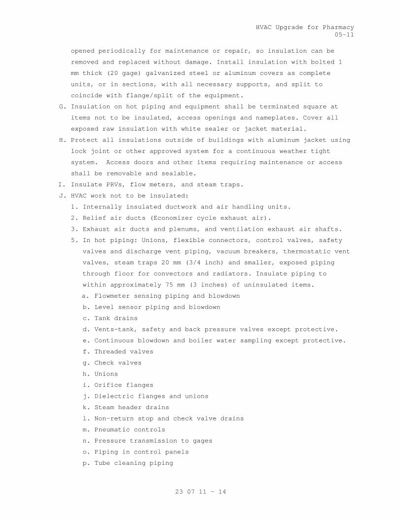
HVAC Upgrade for Pharmacy 05-11
23 07 11 - 14
opened periodically for maintenance or repair, so insulation can be
removed and replaced without damage. Install insulation with bolted 1
mm thick (20 gage) galvanized steel or aluminum covers as complete
units, or in sections, with all necessary supports, and split to
coincide with flange/split of the equipment.
G. Insulation on hot piping and equipment shall be terminated square at
items not to be insulated, access openings and nameplates. Cover all
exposed raw insulation with white sealer or jacket material.
H. Protect all insulations outside of buildings with aluminum jacket using
lock joint or other approved system for a continuous weather tight
system. Access doors and other items requiring maintenance or access
shall be removable and sealable.
I. Insulate PRVs, flow meters, and steam traps.
J. HVAC work not to be insulated:
1. Internally insulated ductwork and air handling units.
2. Relief air ducts (Economizer cycle exhaust air).
3. Exhaust air ducts and plenums, and ventilation exhaust air shafts.
5. In hot piping: Unions, flexible connectors, control valves, safety
valves and discharge vent piping, vacuum breakers, thermostatic vent
valves, steam traps 20 mm (3/4 inch) and smaller, exposed piping
through floor for convectors and radiators. Insulate piping to
within approximately 75 mm (3 inches) of uninsulated items.
a. Flowmeter sensing piping and blowdown
b. Level sensor piping and blowdown
c. Tank drains
d. Vents-tank, safety and back pressure valves except protective.
e. Continuous blowdown and boiler water sampling except protective.
f. Threaded valves
g. Check valves
h. Unions
i. Orifice flanges
j. Dielectric flanges and unions
k. Steam header drains
l. Non-return stop and check valve drains
m. Pneumatic controls
n. Pressure transmission to gages
o. Piping in control panels
p. Tube cleaning piping
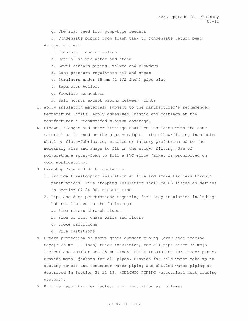
HVAC Upgrade for Pharmacy 05-11
23 07 11 - 15
q. Chemical feed from pump-type feeders
r. Condensate piping from flash tank to condensate return pump
4. Specialties:
a. Pressure reducing valves
b. Control valves-water and steam
c. Level sensors-piping, valves and blowdown
d. Back pressure regulators-oil and steam
e. Strainers under 65 mm (2-1/2 inch) pipe size
f. Expansion bellows
g. Flexible connectors
h. Ball joints except piping between joints
K. Apply insulation materials subject to the manufacturer's recommended
temperature limits. Apply adhesives, mastic and coatings at the
manufacturer's recommended minimum coverage.
L. Elbows, flanges and other fittings shall be insulated with the same
material as is used on the pipe straights. The elbow/fitting insulation
shall be field-fabricated, mitered or factory prefabricated to the
necessary size and shape to fit on the elbow/ fitting. Use of
polyurethane spray-foam to fill a PVC elbow jacket is prohibited on
cold applications.
M. Firestop Pipe and Duct insulation:
1. Provide firestopping insulation at fire and smoke barriers through
penetrations. Fire stopping insulation shall be UL listed as defines
in Section 07 84 00, FIRESTOPPING.
2. Pipe and duct penetrations requiring fire stop insulation including,
but not limited to the following:
a. Pipe risers through floors
b. Pipe or duct chase walls and floors
c. Smoke partitions
d. Fire partitions
N. Freeze protection of above grade outdoor piping (over heat tracing
tape): 26 mm (10 inch) thick insulation, for all pipe sizes 75 mm(3
inches) and smaller and 25 mm(1inch) thick insulation for larger pipes.
Provide metal jackets for all pipes. Provide for cold water make-up to
cooling towers and condenser water piping and chilled water piping as
described in Section 23 21 13, HYDRONIC PIPING (electrical heat tracing
systems).
O. Provide vapor barrier jackets over insulation as follows:

HVAC Upgrade for Pharmacy 05-11
23 07 11 - 16
1. All piping and ductwork exposed to outdoor weather.
2. All interior piping and ducts conveying fluids exposed to outdoor
air (i.e. in attics, ventilated (not air conditioned) spaces, etc.)
below ambient air temperature in high humidity areas.
P. Provide metal jackets over insulation as follows:
1. All piping and ducts exposed to outdoor weather.
2. Piping exposed in building, within 1800 mm (6 feet) of the floor,
that connects to sterilizers, kitchen and laundry equipment. Jackets
may be applied with pop rivets. Provide aluminum angle ring
escutcheons at wall, ceiling or floor penetrations.
3. A 50 mm (2 inch) overlap is required at longitudinal and
circumferential joints.
3.2 INSULATION INSTALLATION
A. Mineral Fiber Board:
1. Faced board: Apply board on pins spaced not more than 300 mm (12
inches) on center each way, and not less than 75 mm (3 inches) from
each edge of board. In addition to pins, apply insulation bonding
adhesive to entire underside of horizontal metal surfaces. Butt
insulation edges tightly and seal all joints with laps and butt
strips. After applying speed clips cut pins off flush and apply
vapor seal patches over clips.
2. Plain board:
a. Insulation shall be scored, beveled or mitered to provide tight
joints and be secured to equipment with bands spaced 225 mm (9
inches) on center for irregular surfaces or with pins and clips
on flat surfaces. Use corner beads to protect edges of
insulation.
b. For hot equipment: Stretch 25 mm (1 inch) mesh wire, with edges
wire laced together, over insulation and finish with insulating
and finishing cement applied in one coat, 6 mm (1/4 inch) thick,
trowel led to a smooth finish.
c. For cold equipment: Apply meshed glass fabric in a tack coat 1.5
to 1.7 square meter per liter (60 to 70 square feet per gallon)
of vapor mastic and finish with mastic at 0.3 to 0.4 square meter
per liter (12 to 15 square feet per gallon) over the entire
fabric surface.

HVAC Upgrade for Pharmacy 05-11
23 07 11 - 17
3. Exposed ductwork and equipment in unfinished areas, mechanical and
electrical equipment rooms and attics, interstitial spaces and duct
work exposed to outdoor weather:
a. 40 mm (1-1/2 inch) 50 mm (2 inch) thick insulation faced with ASJ
(white all service jacket): Supply air duct unlined air handling
units and afterfilter housing.
b. 40 mm (1-1/2 inch) 50 mm (2 inch) thick insulation faced with
ASJ: Return air duct, mixed air plenums and prefilter housing.
c. Outside air intake ducts: no insulation required 25 mm (one inch)
thick insulation faced with ASJ.
d. Exposed, unlined supply and return ductwork exposed to outdoor
weather: 50 mm (2 inch) thick insulation faced with a reinforcing
membrane and two coats of vapor barrier mastic or multi-layer
vapor barrier with a maximum water vapor permeability of 0.001
perms.
4. Supply air duct in the warehouse and in the laundry: 25 mm (one
inch) thick insulation faced with ASJ.
5. Cold equipment: 40 mm (1-1/2inch) thick insulation faced with ASJ.
a. Chilled water pumps, water filter, chemical feeder pot or tank.
b. Pneumatic, cold storage water and surge tanks.
6. Hot equipment: 40 mm (1-1/2 inch) thick insulation faced with ASJ.
a. Convertors, air separators, steam condensate pump receivers.
b. Reheat coil casing and separation chambers on steam humidifiers
located above ceilings.
c. Domestic water heaters and hot water storage tanks (not factory
insulated).
d. Booster water heaters for dietetics dish and pot washers and for
washdown grease-extracting hoods.
7. Laundry: Hot exhaust ducts from dryers and from ironers, where duct
is exposed in the laundry.
B. Flexible Mineral Fiber Blanket:
1. Adhere insulation to metal with 75 mm (3 inch) wide strips of
insulation bonding adhesive at 200 mm (8 inches) on center all
around duct. Additionally secure insulation to bottom of ducts
exceeding 600 mm (24 inches) in width with pins welded or adhered on
450 mm (18 inch) centers. Secure washers on pins. Butt insulation
edges and seal joints with laps and butt strips. Staples may be used

HVAC Upgrade for Pharmacy 05-11
23 07 11 - 18
to assist in securing insulation. Seal all vapor retarder
penetrations with mastic. Sagging duct insulation will not be
acceptable. Install firestop duct insulation where required.
2. Supply air ductwork to be insulated includes main and branch ducts
from AHU discharge to room supply outlets, and the bodies of ceiling
outlets to prevent condensation. Insulate sound attenuator units,
coil casings and damper frames. To prevent condensation insulate
trapeze type supports and angle iron hangers for flat oval ducts
that are in direct contact with metal duct.
3. Concealed supply air ductwork.
a. Above ceilings at a roof level, in attics, and duct work exposed
to outdoor weather: 50 mm (2 inch) thick insulation faced with
FSK.
b. Above ceilings for other than roof level: 40 mm (1 ½ inch) thick
insulation faced with FSK.
4. Concealed return air duct:
a. In attics (where not subject to damage) and where exposed to
outdoor weather: 50mmm (2 inch)thick insulation faced with FSK,
b. Above ceilings at a roof level, unconditioned areas, and in
chases with external wall or containing steam piping; 40 mm (1-
1/2 inch) thick, insulation faced with FSK.
c. In interstitial spaces (where not subject to damage): 40 mm (1-
1/2 inch thick insulation faced with FSK.
d. Concealed return air ductwork in other locations need not be
insulated.
5. Concealed outside air duct: 40 mm (1-1/2 inch) thick insulation
faced with FSK.
6. Exhaust air branch duct from autopsy refrigerator to main duct: 40
mm (1-1/2 inch) thick insulation faced with FSK.
C. Molded Mineral Fiber Pipe and Tubing Covering:
1. Fit insulation to pipe or duct, aligning longitudinal joints. Seal
longitudinal joint laps and circumferential butt strips by rubbing
hard with a nylon sealing tool to assure a positive seal. Staples
may be used to assist in securing insulation. Seal all vapor
retarder penetrations on cold piping with a generous application of
vapor barrier mastic. Provide inserts and install with metal
insulation shields at outside pipe supports. Install freeze
protection insulation over heating cable.
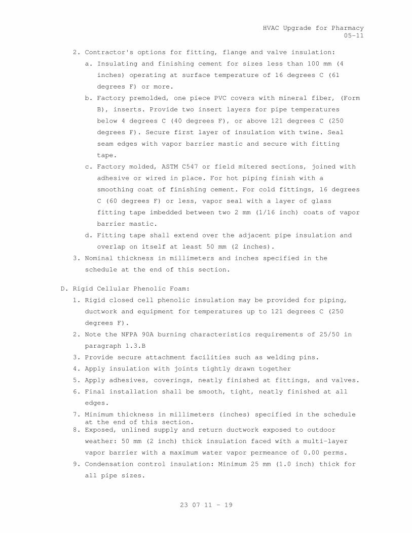
HVAC Upgrade for Pharmacy 05-11
23 07 11 - 19
2. Contractor's options for fitting, flange and valve insulation:
a. Insulating and finishing cement for sizes less than 100 mm (4
inches) operating at surface temperature of 16 degrees C (61
degrees F) or more.
b. Factory premolded, one piece PVC covers with mineral fiber, (Form
B), inserts. Provide two insert layers for pipe temperatures
below 4 degrees C (40 degrees F), or above 121 degrees C (250
degrees F). Secure first layer of insulation with twine. Seal
seam edges with vapor barrier mastic and secure with fitting
tape.
c. Factory molded, ASTM C547 or field mitered sections, joined with
adhesive or wired in place. For hot piping finish with a
smoothing coat of finishing cement. For cold fittings, 16 degrees
C (60 degrees F) or less, vapor seal with a layer of glass
fitting tape imbedded between two 2 mm (1/16 inch) coats of vapor
barrier mastic.
d. Fitting tape shall extend over the adjacent pipe insulation and
overlap on itself at least 50 mm (2 inches).
3. Nominal thickness in millimeters and inches specified in the
schedule at the end of this section.
D. Rigid Cellular Phenolic Foam:
1. Rigid closed cell phenolic insulation may be provided for piping,
ductwork and equipment for temperatures up to 121 degrees C (250
degrees F).
2. Note the NFPA 90A burning characteristics requirements of 25/50 in
paragraph 1.3.B
3. Provide secure attachment facilities such as welding pins.
4. Apply insulation with joints tightly drawn together
5. Apply adhesives, coverings, neatly finished at fittings, and valves.
6. Final installation shall be smooth, tight, neatly finished at all
edges.
7. Minimum thickness in millimeters (inches) specified in the schedule at the end of this section.
8. Exposed, unlined supply and return ductwork exposed to outdoor
weather: 50 mm (2 inch) thick insulation faced with a multi-layer
vapor barrier with a maximum water vapor permeance of 0.00 perms.
9. Condensation control insulation: Minimum 25 mm (1.0 inch) thick for
all pipe sizes.
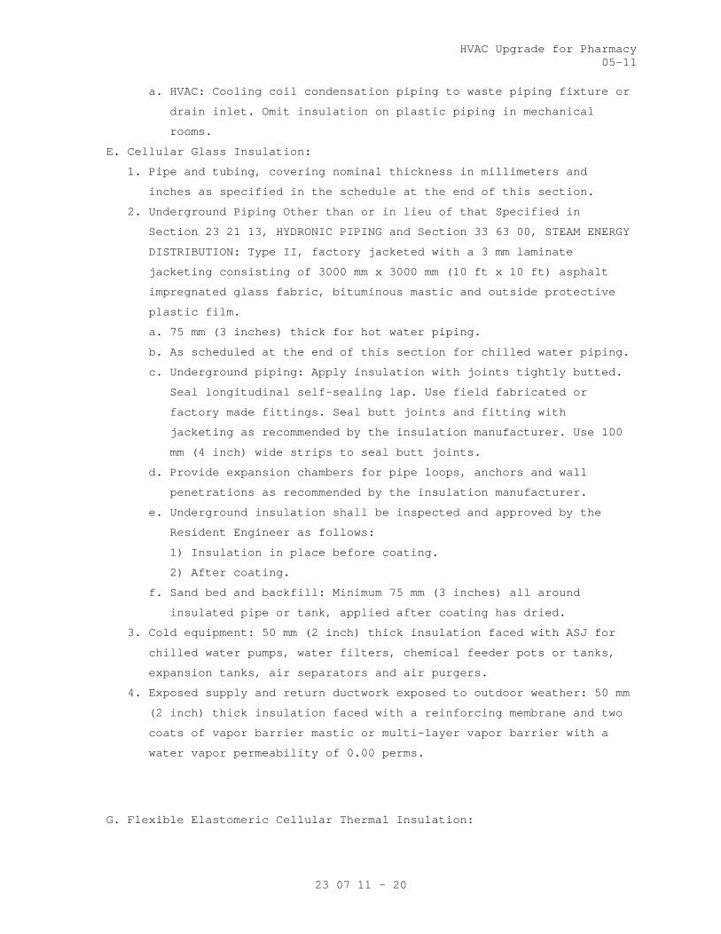
HVAC Upgrade for Pharmacy 05-11
23 07 11 - 20
a. HVAC: Cooling coil condensation piping to waste piping fixture or
drain inlet. Omit insulation on plastic piping in mechanical
rooms.
E. Cellular Glass Insulation:
1. Pipe and tubing, covering nominal thickness in millimeters and
inches as specified in the schedule at the end of this section.
2. Underground Piping Other than or in lieu of that Specified in
Section 23 21 13, HYDRONIC PIPING and Section 33 63 00, STEAM ENERGY
DISTRIBUTION: Type II, factory jacketed with a 3 mm laminate
jacketing consisting of 3000 mm x 3000 mm (10 ft x 10 ft) asphalt
impregnated glass fabric, bituminous mastic and outside protective
plastic film.
a. 75 mm (3 inches) thick for hot water piping.
b. As scheduled at the end of this section for chilled water piping.
c. Underground piping: Apply insulation with joints tightly butted.
Seal longitudinal self-sealing lap. Use field fabricated or
factory made fittings. Seal butt joints and fitting with
jacketing as recommended by the insulation manufacturer. Use 100
mm (4 inch) wide strips to seal butt joints.
d. Provide expansion chambers for pipe loops, anchors and wall
penetrations as recommended by the insulation manufacturer.
e. Underground insulation shall be inspected and approved by the
Resident Engineer as follows:
1) Insulation in place before coating.
2) After coating.
f. Sand bed and backfill: Minimum 75 mm (3 inches) all around
insulated pipe or tank, applied after coating has dried.
3. Cold equipment: 50 mm (2 inch) thick insulation faced with ASJ for
chilled water pumps, water filters, chemical feeder pots or tanks,
expansion tanks, air separators and air purgers.
4. Exposed supply and return ductwork exposed to outdoor weather: 50 mm
(2 inch) thick insulation faced with a reinforcing membrane and two
coats of vapor barrier mastic or multi-layer vapor barrier with a
water vapor permeability of 0.00 perms.
G. Flexible Elastomeric Cellular Thermal Insulation:

HVAC Upgrade for Pharmacy 05-11
23 07 11 - 21
1. Apply insulation and fabricate fittings in accordance with the
manufacturer's installation instructions and finish with two coats
of weather resistant finish as recommended by the insulation
manufacturer.
2. Pipe and tubing insulation:
a. Use proper size material. Do not stretch or strain insulation.
b. To avoid undue compression of insulation, provide cork stoppers
or wood inserts at supports as recommended by the insulation
manufacturer. Insulation shields are specified under Section
23 05 11, COMMON WORK RESULTS FOR HVAC and Section 23 05 10,
COMMON WORK RESULTS FOR BOILER PLANT and STEAM GENERATION.
c. Where possible, slip insulation over the pipe or tubing prior to
connection, and seal the butt joints with adhesive. Where the
slip-on technique is not possible, slit the insulation and apply
it to the pipe sealing the seam and joints with contact adhesive.
Optional tape sealing, as recommended by the manufacturer, may be
employed. Make changes from mineral fiber insulation in a
straight run of pipe, not at a fitting. Seal joint with tape.
3. Apply sheet insulation to flat or large curved surfaces with 100
percent adhesive coverage. For fittings and large pipe, apply
adhesive to seams only.
4. Pipe insulation: nominal thickness in millimeters (inches as
specified in the schedule at the end of this section.
5. Minimum 20 mm (0.75 inch) thick insulation for pneumatic control
lines for a minimum distance of 6 m (20 feet) from discharge side of
the refrigerated dryer.
6. Use Class S (Sheet), 20 mm (3/4 inch) thick for the following:
a. Chilled water pumps
b. Bottom and sides of metal basins for winterized cooling towers
(where basin water is heated).
c. Chillers, insulate any cold chiller surfaces subject to
condensation which has not been factory insulated.
d. Piping inside refrigerators and freezers: Provide heat tape under
insulation.
7. Exposed, unlined supply and return ductwork exposed to outdoor
weather: 50 mm (2 inch) thick insulation faced with a multi-layer
vapor barrier with a water vapor permeance of 0.00 perms.
I. Calcium Silicate:

HVAC Upgrade for Pharmacy 05-11
23 07 11 - 22
1. Minimum thickness in millimeter (inches) specified in the schedule
at the end of this section for piping other than in boiler plant.
See paragraphs 3.3 through 3.7 for Boiler Plant Applications.
2. Engine Exhaust Insulation for Emergency Generator and Diesel Driven
Fire Pump: Type II, Class D, 65 mm (2 1/2 inch) nominal thickness.
Cover exhaust completely from engine through roof or wall
construction, including muffler. Secure with 16 AWG galvanized
annealed wire or 0.38 x 12 mm 0.015 x 1/2 IN wide galvanized bands
on 300 mm 12 IN maximum centers. Anchor wire and bands to welded
pins, clips or angles. Apply 25 mm 1 IN hex galvanized wire over
insulation. Fill voids with 6 mm 1/4 IN insulating cement.
3. ETO Exhaust (High Temperature): Type II, class D, 65 mm (2.5 inches)
nominal thickness. Cover duct for entire length. Provide sheet
aluminum jacket for all exterior ductwork.
4. MRI Quench Vent Insulation: Type I, class D, 150 mm (6 inch) nominal
thickness.
3.3 APPLICATION –PIPE, VALVES, STRAINERS AND FITTINGS:
A. Temperature range 120 to 230 degrees C (251 to 450 degrees F);
1. Application; Steam service 110 kpa (16 psig nominal) and higher,
high pressure condensate to trap assembly, boiler bottom blowoff
from boiler to blowoff valve closest to boiler.
2. Insulation and Jacket:
a. Calcium silicate for piping from zero to 1800 mm (6 feet) above
boiler room floor, feedwater heater mezzanine floor or access
platform and any floors or platforms on which tanks or pumps are
located.
b. Mineral fiber for remaining locations.
c. ASJ with PVC premolded fitting coverings.
d. Aluminum jacket from zero to 1800 mm (6 feet) above floor on
atomizing steam and condensate lines at boilers and burners.
3. Thickness:

HVAC Upgrade for Pharmacy 05-11
23 07 11 - 23
Nominal Thickness Of Calcium Silicate Insulation
(Boiler Plant)
Pipe Diameter mm
(in)
Insulation Thickness mm
(in)
25 (1 and below) 125 (5)
25 to 38 (1-1/4 to 1-
1/2)
125 (5)
38 (1-1/2) and above 150 (6)
B. Temperature range 100 to 121 degrees C (211 to 250 degrees F):
1. Application: Steam service 103 kPa (15 psig) and below, trap
assembly discharge piping, boiler feed-water from feed-water heater
to boiler feed pump recirculation, feed-water heater overflow,
heated oil from oil heater to burners.
2. Insulation and Jacket:
a. Calcium silicate for piping from zero to 1800 mm (0 to 6 feet)
above boiler room floor, feed-water heater mezzanine floor and
access platform, and any floors or access platforms on which
tanks or pumps are located.
b. Mineral Fiber or rigid closed cell phenolic foam for remaining
locations.
c. ASJ with PVC pre-molded fitting coverings.
d. Aluminum jacket from zero to 1800 mm (6 feet) above floor on
condensate lines at boilers and burners.
3. Thickness-calcium silicate and mineral fiber insulation:
Nominal Thickness Of Insulation
Pipe Diameter mm (in) Insulation Thickness mm (in)
25 (1 and below) 50 (2)
25 to 38 (1-1/4 to 1-
1/2)
50 (2)
38 (1-1/2) and above 75 (3)
4. Thickness-rigid closed-cell phenolic foam insulation:

HVAC Upgrade for Pharmacy 05-11
23 07 11 - 24
Nominal Thickness Of Insulation
Pipe Diameter mm (in) Insulation Thickness mm (in)
25 (1 and below) 38 (1.5)
25 to 38 (1-1/4 to 1-
1/2)
38 (1.5)
38 (1-1/2) and above 75(3)
C. Temperature range 32 to 99 degrees C (90 to 211 degrees F):
1. Application: Pumped condensate, vacuum heating return, gravity and
pumped heating returns, condensate transfer, condensate transfer
pump recirculation, heated oil system to heaters and returns from
burners, condensate return from convertors and heated water storage
tanks.
2. Insulation Jacket:
a. Calcium silicate for piping from zero to 1800 mm (six feet above
boiler room floor, feed-water heater mezzanine floor and access
platform and any floor or access platform on which tanks or pumps
are located.
b. Mineral fiber or rigid closed-cell phenolic foam for remaining
locations.
c. ASJ with PVC pre-molded fitting coverings.
3. Thickness-calcium silicate and mineral fiber insulation:
Nominal Thickness Of Insulation
Pipe Diameter mm (in) Insulation Thickness mm (in)
25 (1 and below) 38 (1.5)
25 to 38 (1-1/4 to 1-1/2) 50(2)
38 (1-1/2) and above 75 (3)
4. Thickness-rigid closed-cell phenolic foam insulation:
Nominal Thickness Of Insulation
Pipe Diameter mm (in) Insulation Thickness mm (in)
25 (1 and below) 19 (0.75)
25 to 38 (1-1/4 to 1-1/2) 19 (0.75)
38 (1-1/2) and above 25 (1)
D. Protective insulation to prevent personnel injury:

HVAC Upgrade for Pharmacy 05-11
23 07 11 - 25
1. Application: Piping from zero to 1800 mm (6 feet) above all floors
and access platforms including continuous blowoff, feedwater and
boiler water sample, blowoff tank vent, flash tank vents and
condensater tank vent, shot-type chemical feed, fire tube boiler
bottom blowoff after valves, valve by-passes.
2. Insulation thickness: 25 mm (1 inch).
3. Insulation and jacket: Calcium silicate with ASJ except provide
aluminum jacket on piping at boilers within 1800 mm (6 feet) of
floor. Use PVC premolded fitting coverings when all service jacket
is utilized.
E. Installation:
1. At pipe supports, weld pipe covering protection saddles to pipe,
except where MS-SP58, type 3 pipe clamps are utilized.
2. Insulation shall be firmly applied, joints butted tightly,
mechanically fastened by stainless steel wires on 300 mm (12 inch)
centers.
3. At support points, fill and thoroughly pack space between pipe
covering protective saddle bearing area.
4. Terminate insulation and jacket hard and tight at anchor points.
5. Terminate insulation at piping facilities not insulated with a 45
degree chamfered section of insulating and finishing cement covered
with jacket.
6. On calcium silicate, mineral fiber and rigid closed-cell phenolic
foam systems, insulated flanged fittings, strainers and valves with
sections of pipe insulation cut, fitted and arranged neatly and
firmly wired in place. Fill all cracks, voids and coat outer surface
with insulating cement. Install jacket. Provide similar construction
on welded and threaded fittings on calcium silicate systems or use
premolded fitting insulation.
7. On mineral fiber systems, insulate welded and threaded fittings more
than 50 mm (2 inches) in diameter with compressed blanket insulation
(minimum 2/1) and finish with jacket or PVC cover.
8. Insulate fittings 50 mm (2 inches) and smaller with mastic finishing
material and cover with jacket.
9. Insulate valve bonnet up to valve side of bonnet flange to permit
bonnet flange removal without disturbing insulation.
10. Install jacket smooth, tight and neatly finish all edges. Over wrap
ASJ butt strips by 50 percent. Secure aluminum jacket with stainless

HVAC Upgrade for Pharmacy 05-11
23 07 11 - 26
steel bands 300 mm (12 inches) on center or aluminum screws on 200
mm (4 inch) centers.
11. Do not insulate basket removal flanges on strainers.
3.7 COMMISSIONING
A. Provide commissioning documentation in accordance with the requirements
of section 23 08 00 – COMMISSIONING OF HVAC SYSTEMS for all inspection,
start up, and contractor testing required above and required by the
System Readiness Checklist provided by the Commissioning Agent.
B. Components provided under this section of the specification will be
tested as part of a larger system. Refer to section 23 08 00 –
COMMISSIONING OF HVAC SYSTEMS and related sections for contractor
responsibilities for system commissioning.
3.8 PIPE INSULATION SCHEDULE
Provide insulation for piping systems as scheduled below:
Insulation Thickness Millimeters (Inches)
Nominal Pipe Size Millimeters (Inches)
Operating Temperature Range/Service
Insulation Material
Less than
25 (1)
25 – 32 (1 – 1¼)
38 – 75
(1½ - 3)
100 (4) and Above
122-177 degrees C (251-350 degrees F)
(HPS, MPS)
Mineral Fiber (Above ground piping only)
75 (3) 100 (4) 113 (4.5) 113 (4.5)
93-260 degrees C (200-500 degrees F)
(HPS, HPR)
Calcium Silicate
100 (4) 125 (5) 150 (6) 150 (6)
100-121 degrees C (212-250 degrees F)
(HPR, MPR, LPS, vent piping from PRV Safety Valves, Condensate receivers and flash tanks)
Mineral Fiber (Above ground piping only)
62 (2.5)
62 (2.5) 75 (3.0) 75 (3.0)
100-121 degrees C (212-250 degrees F)
(HPR, MPR, LPS, vent piping from PRV Safety Valves,
Rigid Cellular Phenolic Foam
50 (2.0)
50 (2.0) 75 (3.0) 75 (3.0)

HVAC Upgrade for Pharmacy 05-11
23 07 11 - 27
Condensate receivers and flash tanks)
38-94 degrees C (100-200 degrees F)
(LPR, PC, HWH, HWHR, GH and GHR)
Mineral Fiber (Above ground piping only)
38 (1.5)
38 (1.5) 50 (2.0) 50 (2.0)
38-99 degrees C
(100-211 degrees F)
(LPR, PC, HWH, HWHR, GH and GHR)
Rigid Cellular Phenolic Foam
38 (1.5)
38 (1.5) 50 (2.0) 50 (2.0)
39-99 degrees C (100-211 degrees F)
(LPR, PC, HWH, HWHR, GH and GHR)
Polyiso-cyanurate Closed-Cell Rigid (Exterior Locations only)
38 (1.5)
38 (1.5) ---- ----
38-94 degrees C (100-200 degrees F)
(LPR, PC, HWH, HWHR, GH and GHR)
Flexible Elastomeric Cellular Thermal (Above ground piping only)
38 (1.5)
38 (1.5) ---- ----
4-16 degrees C
(40-60 degrees F)
(CH, CHR, GC, GCR and RS for DX refrigeration)
Rigid Cellular Phenolic Foam
38 (1.5)
38 (1.5) 38 (1.5) 38 (1.5)
4-16 degrees C
(40-60 degrees F)
(CH and CHR within chiller room and pipe chase and underground)
Cellular Glass Closed-Cell
50 (2.0)
50 (2.0) 75 (3.0) 75 (3.0)
4-16 degrees C
(40-60 degrees F)
(CH, CHR, GC, GCR and RS for DX refrigeration)
Cellular Glass Closed-Cell
38 (1.5)
38 (1.5) 38 (1.5) 38 (1.5)
4-16 degrees C
(40-60 degrees F)
(CH, CHR, GC and GCR (where underground)
Polyiso-cyanurate Closed-Cell Rigid
38 (1.5)
38 (1.5) 50 (2.0) 50 (2.0)

HVAC Upgrade for Pharmacy 05-11
23 07 11 - 28
4-16 degrees C
(40-60 degrees F)
(CH, CHR, GC, GCR and RS for DX refrigeration)
Polyiso-cyanurate Closed-Cell Rigid (Exterior Locations only)
38 (1.5)
38 (1.5) 38 (1.5) 38 (1.5)
(40-60 degrees F)
(CH, CHR, GC, GCR and RS for DX refrigeration)
Flexible Elastomeric Cellular Thermal (Above ground piping only)
38 (1.5)
38 (1.5) 38 (1.5) 38 (1.5)
- - - E N D - - -
HVAC Upgrade for Pharmacy07-10
23 08 00 - 1
SECTION 23 08 00COMMISSIONING OF HVAC SYSTEMS
PART 1 - GENERAL
1.1 DESCRIPTION
A. The requirements of this Section apply to all sections of Division 23.
B. This project will have selected building systems commissioned. The
complete list of equipment and systems to be commissioned are specified
in Section 01 91 00 GENERAL COMMISSIONING REQUIREMENTS. The
commissioning process, which the Contractor is responsible to execute,
is defined in Section 01 91 00 GENERAL COMMISSIONING REQUIREMENTS. A
Commissioning Agent (CxA) appointed by the Department of Veterans
Affairs will manage the commissioning process.
1.2 RELATED WORK
A. Section 01 00 00 GENERAL REQUIREMENTS.
B. Section 01 91 00 GENERAL COMMISSIONING REQUIREMENTS.
C. Section 01 33 23 SHOP DRAWINGS, PRODUCT DATA, AND SAMPLES.
1.3 SUMMARY
A. This Section includes requirements for commissioning the HVAC systems,
subsystems and equipment. This Section supplements the general
requirements specified in Section 01 91 00 GENERAL COMMISSIONING
REQUIREMENTS.
B. The commissioning activities have been developed to support the VA
requirements to meet guidelines for Federal Leadership in
Environmental, Energy, and Economic Performance.
C. Refer to Section 01 91 00 GENERAL COMMISSIONING REQUIREMENTS for more
specifics regarding processes and procedures as well as roles and
responsibilities for all Commissioning Team members.
1.4 DEFINITIONS
A. Refer to Section 01 91 00 GENERAL COMMISSIONING REQUIREMENTS for
definitions.
1.5 COMMISSIONED SYSTEMS
A. Commissioning of a system or systems specified in this Division is part
of the construction process. Documentation and testing of these
systems, as well as training of the VA’s Operation and Maintenance
personnel, is required in cooperation with the VA and the Commissioning
Agent.
B. The following HVAC systems will be commissioned:

HVAC Upgrade for Pharmacy07-10
23 08 00 - 2
1. Air Handling Systems (including terminal units)
2. Air Handling Systems (Fans, motors, Variable Speed Drives, cooling
coils and control valves, heating coils and control valves, filters,
dampers, safeties such as smoke detectors or freezestats and damper
end switches, controls, gages, and vibration isolation).
3. Heating Hot Water Systems (controls, instrumentation and gages,
heating water pumps and motors, Variable Speed Drives, mixing
valves).
4. Chilled Water Systems (Chilled water pumps and motors, Variable
Speed Drives, chiller motor/compressor, controls, instrumentation
and safeties, isolation valves, blending valves, side stream water
cleaners/scrubbers/filters).
5. Exhaust Fans (Fan, motor, Variable Speed Drives, controls and
safeties).
6. Steam System (controls, gages and instrumentation, safety relief
valves, combustion burners/fans/motors, fuel delivery pumps and
motors, flues).
7. Direct Digital Control System (BACnet or similar Local Area Network
(LAN), Operator Work Station hardware and software, building
controller hardware and software, terminal unit controller hardware
and software, all sequences of operation, system accuracy and
response time).
8. Laboratory Ventilation Systems (Supply air terminal units and
controls, pressure controls and alarms, fans, motors, and Variable
Speed Drives).
9. OR Air Handling Systems (Fans, motors, Variable Speed Drives, Energy
recovery devices – such as heat pipes, cooling coils and control
valves, heating coils and control valves, filters, HEPA filter
performance, dampers, safeties such as smoke detectors or
freezestats and damper end switches, controls, gages, and vibration
isolation).
10. Room Pressurization Equipment (Pressure sensors, terminal
units/dampers, and controls and alarms).
11. HVAC Water Treatment Systems (Closed circuits – including shot
feeders and final water analysis, open circuits – including water
analysis, chemical/biocide tanks, injection piping, chemical/biocide
pumps and motors, controls, water meter, and automatic blowdown).

HVAC Upgrade for Pharmacy07-10
23 08 00 - 3
1.6 SUBMITTALS
A. The commissioning process requires review of selected Submittals. The
Commissioning Agent will provide a list of submittals that will be
reviewed by the Commissioning Agent. This list will be reviewed and
approved by the VA prior to forwarding to the Contractor. Refer to
Section 01 33 23 SHOP DRAWINGS, PRODUCT DATA, and SAMPLES for further
details.
B. The commissioning process requires Submittal review simultaneously with
engineering review. Specific submittal requirements related to the
commissioning process are specified in Section 01 91 00 GENERAL
COMMISSIONING REQUIREMENTS.
PART 2 - PRODUCTS (NOT USED)
PART 3 - EXECUTION
3.1 PRE-FUNCTIONAL CHECKLISTS
A. The Contractor shall complete Pre-Functional Checklists to verify
systems, subsystems, and equipment installation is complete and systems
are ready for Systems Functional Performance Testing. The
Commissioning Agent will prepare Pre-Functional Checklists to be used
to document equipment installation. The Contractor shall complete the
checklists. Completed checklists shall be submitted to the VA and to
the Commissioning Agent for review. The Commissioning Agent may spot
check a sample of completed checklists. If the Commissioning Agent
determines that the information provided on the checklist is not
accurate, the Commissioning Agent will return the marked-up checklist
to the Contractor for correction and resubmission. If the
Commissioning Agent determines that a significant number of completed
checklists for similar equipment are not accurate, the Commissioning
Agent will select a broader sample of checklists for review. If the
Commissioning Agent determines that a significant number of the broader
sample of checklists is also inaccurate, all the checklists for the
type of equipment will be returned to the Contractor for correction and
resubmission. Refer to SECTION 01 91 00 GENERAL COMMISSIONING
REQUIREMENTS for submittal requirements for Pre-Functional Checklists,
Equipment Startup Reports, and other commissioning documents.
3.2 CONTRACTORS TESTS
A. Contractor tests as required by other sections of Division 23 shall be
scheduled and documented in accordance with Section 01 00 00 GENERAL
REQUIREMENTS. The Commissioning Agent will witness selected Contractor
HVAC Upgrade for Pharmacy07-10
23 08 00 - 4
tests. Contractor tests shall be completed prior to scheduling Systems
Functional Performance Testing.
3.3 SYSTEMS FUNCTIONAL PERFORMANCE TESTING:
A. The Commissioning Process includes Systems Functional Performance
Testing that is intended to test systems functional performance under
steady state conditions, to test system reaction to changes in
operating conditions, and system performance under emergency
conditions. The Commissioning Agent will prepare detailed Systems
Functional Performance Test procedures for review and approval by the
Resident Engineer. The Contractor shall review and comment on the
tests prior to approval. The Contractor shall provide the required
labor, materials, and test equipment identified in the test procedure
to perform the tests. The Commissioning Agent will witness and
document the testing. The Contractor shall sign the test reports to
verify tests were performed. See Section 01 91 00 GENERAL
COMMISSIONING REQUIREMENTS, for additional details.
3.4 TRAINING OF VA PERSONNEL
A. Training of the VA’s operation and maintenance personnel is required in
cooperation with the Resident Engineer and Commissioning Agent.
Provide competent, factory authorized personnel to provide instruction
to operation and maintenance personnel concerning the location,
operation, and troubleshooting of the installed systems. The
instruction shall be scheduled in coordination with the Resident
Engineer after submission and approval of formal training plans.
Refer to Section 01 91 00 GENERAL COMMISSIONING REQUIREMENTS and
Division 23 Sections for additional Contractor training requirements.
----- END -----

HVAC Upgrade for Pharmacy 09-11
23 09 23 - 1
SECTION 23 09 23 DIRECT-DIGITAL CONTROL SYSTEM FOR HVAC
PART 1 - GENERAL
1.1 DESCRIPTION
A. Provide (a) direct-digital control system(s) as indicated on the
project documents, point list, interoperability tables, drawings and as
described in these specifications. Include a complete and working
direct-digital control system. Include all engineering, programming,
controls and installation materials, installation labor, commissioning
and start-up, training, final project documentation and warranty.
1. The direct-digital control system(s) shall consist of high-speed,
peer-to-peer network of DDC controllers, a control system server, and
an Engineering Control Center. Provide a remote user using a
standard web browser to access the control system graphics and change
adjustable setpoints with the proper password.
2. The direct-digital control system(s) shall be native BACnet. All
new workstations, controllers, devices and components shall be listed
by BACnet Testing Laboratories. All new workstations, controller,
devices and components shall be accessible using a Web browser
interface and shall communicate exclusively using the ASHRAE Standard
135 BACnet communications protocol without the use of gateways,
unless otherwise allowed by this Section of the technical
specifications, specifically shown on the design drawings and
specifically requested otherwise by the VA.
a. If used, gateways shall support the ASHRAE Standard 135 BACnet
communications protocol.
b. If used, gateways shall provide all object properties and
read/write services shown on VA-approved interoperability
schedules.
3. The work administered by this Section of the technical
specifications shall include all labor, materials, special tools,
equipment, enclosures, power supplies, software, software licenses,
Project specific software configurations and database entries,
interfaces, wiring, tubing, installation, labeling, engineering,
calibration, documentation, submittals, testing, verification,
training services, permits and licenses, transportation, shipping,
handling, administration, supervision, management, insurance,
HVAC Upgrade for Pharmacy 09-11
23 09 23 - 2
Warranty, specified services and items required for complete and
fully functional Controls Systems.
4. The control systems shall be designed such that each mechanical
system shall operate under stand-alone mode. The contractor
administered by this Section of the technical specifications shall
provide controllers for each mechanical system. In the event of a
network communication failure, or the loss of any other controller,
the control system shall continue to operate independently. Failure
of the ECC shall have no effect on the field controllers, including
those involved with global strategies.
B. Some products are furnished but not installed by the contractor
administered by this Section of the technical specifications. The
contractor administered by this Section of the technical specifications
shall formally coordinate in writing and receive from other contractors
formal acknowledgements in writing prior to submission the installation
of the products. These products include the following:
1. Control valves.
2. Flow switches.
3. Flow meters.
4. Sensor wells and sockets in piping.
5. Terminal unit controllers.
C. Some products are installed but not furnished by the contractor
administered by this Section of the technical specifications. The
contractor administered by this Section of the technical specifications
shall formally coordinate in writing and receive from other contractors
formal acknowledgements in writing prior to submission the procurement
of the products. These products include the following:
1. Factory-furnished accessory thermostats and sensors furnished with
unitary equipment.
D. Some products are not provided by, but are nevertheless integrated with
the work executed by, the contractor administered by this Section of
the technical specifications. The contractor administered by this
Section of the technical specifications shall formally coordinate in
writing and receive from other contractors formal acknowledgements in
writing prior to submission the particulars of the products.
E. Responsibility Table:
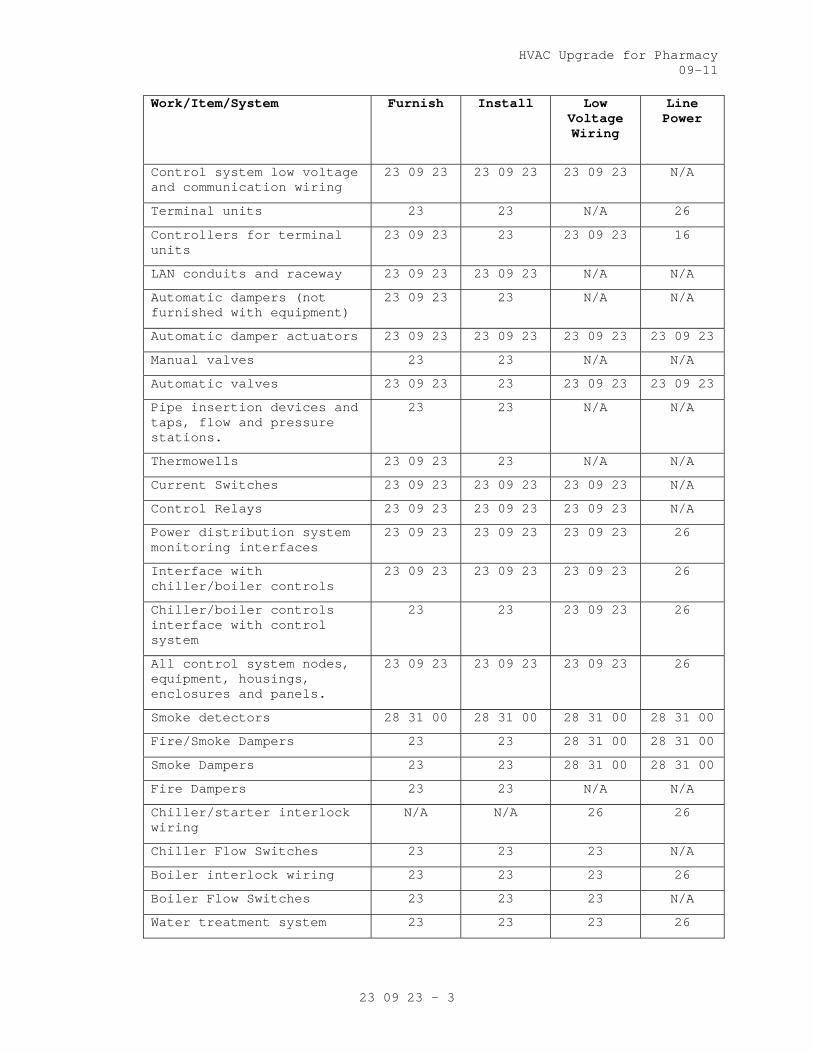
HVAC Upgrade for Pharmacy 09-11
23 09 23 - 3
Work/Item/System Furnish Install Low Voltage Wiring
Line Power
Control system low voltage and communication wiring
23 09 23 23 09 23 23 09 23 N/A
Terminal units 23 23 N/A 26
Controllers for terminal units
23 09 23 23 23 09 23 16
LAN conduits and raceway 23 09 23 23 09 23 N/A N/A
Automatic dampers (not furnished with equipment)
23 09 23 23 N/A N/A
Automatic damper actuators 23 09 23 23 09 23 23 09 23 23 09 23
Manual valves 23 23 N/A N/A
Automatic valves 23 09 23 23 23 09 23 23 09 23
Pipe insertion devices and taps, flow and pressure stations.
23 23 N/A N/A
Thermowells 23 09 23 23 N/A N/A
Current Switches 23 09 23 23 09 23 23 09 23 N/A
Control Relays 23 09 23 23 09 23 23 09 23 N/A
Power distribution system monitoring interfaces
23 09 23 23 09 23 23 09 23 26
Interface with chiller/boiler controls
23 09 23 23 09 23 23 09 23 26
Chiller/boiler controls interface with control system
23 23 23 09 23 26
All control system nodes, equipment, housings, enclosures and panels.
23 09 23 23 09 23 23 09 23 26
Smoke detectors 28 31 00 28 31 00 28 31 00 28 31 00
Fire/Smoke Dampers 23 23 28 31 00 28 31 00
Smoke Dampers 23 23 28 31 00 28 31 00
Fire Dampers 23 23 N/A N/A
Chiller/starter interlock wiring
N/A N/A 26 26
Chiller Flow Switches 23 23 23 N/A
Boiler interlock wiring 23 23 23 26
Boiler Flow Switches 23 23 23 N/A
Water treatment system 23 23 23 26
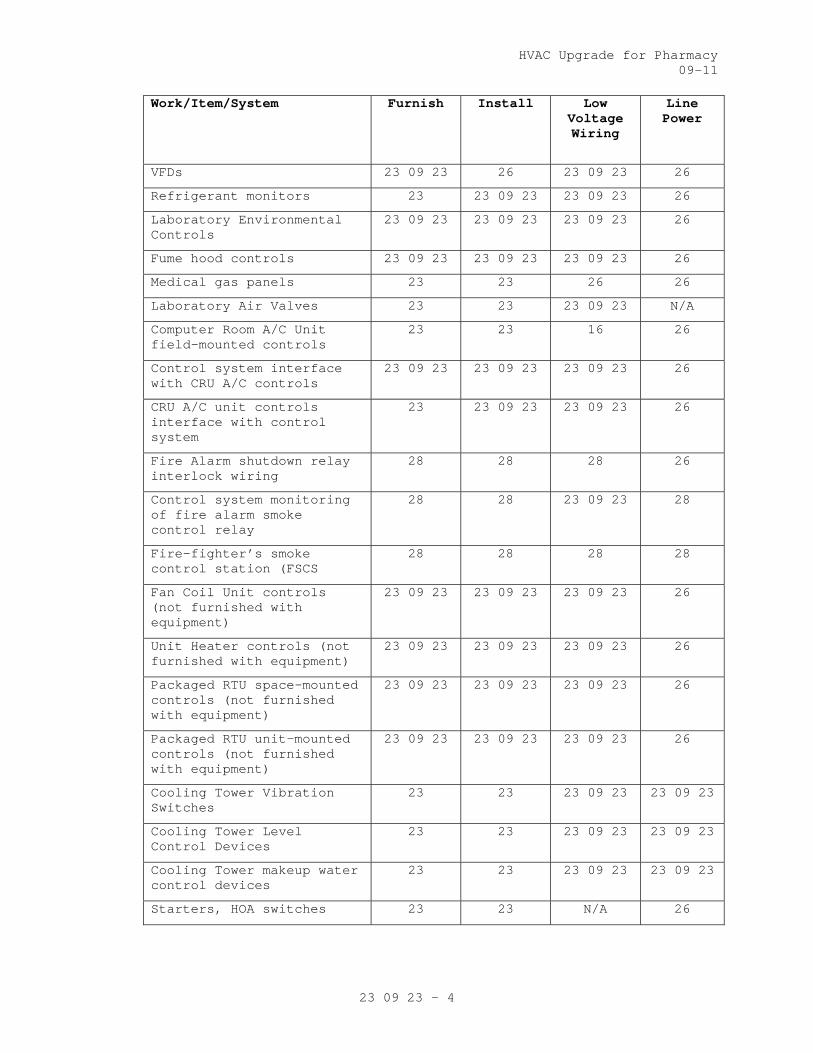
HVAC Upgrade for Pharmacy 09-11
23 09 23 - 4
Work/Item/System Furnish Install Low Voltage Wiring
Line Power
VFDs 23 09 23 26 23 09 23 26
Refrigerant monitors 23 23 09 23 23 09 23 26
Laboratory Environmental Controls
23 09 23 23 09 23 23 09 23 26
Fume hood controls 23 09 23 23 09 23 23 09 23 26
Medical gas panels 23 23 26 26
Laboratory Air Valves 23 23 23 09 23 N/A
Computer Room A/C Unit field-mounted controls
23 23 16 26
Control system interface with CRU A/C controls
23 09 23 23 09 23 23 09 23 26
CRU A/C unit controls interface with control system
23 23 09 23 23 09 23 26
Fire Alarm shutdown relay interlock wiring
28 28 28 26
Control system monitoring of fire alarm smoke control relay
28 28 23 09 23 28
Fire-fighter’s smoke control station (FSCS
28 28 28 28
Fan Coil Unit controls (not furnished with equipment)
23 09 23 23 09 23 23 09 23 26
Unit Heater controls (not furnished with equipment)
23 09 23 23 09 23 23 09 23 26
Packaged RTU space-mounted controls (not furnished with equipment)
23 09 23 23 09 23 23 09 23 26
Packaged RTU unit-mounted controls (not furnished with equipment)
23 09 23 23 09 23 23 09 23 26
Cooling Tower Vibration Switches
23 23 23 09 23 23 09 23
Cooling Tower Level Control Devices
23 23 23 09 23 23 09 23
Cooling Tower makeup water control devices
23 23 23 09 23 23 09 23
Starters, HOA switches 23 23 N/A 26

HVAC Upgrade for Pharmacy 09-11
23 09 23 - 5
F. This facility’s existing direct-digital control system is manufactured
by Automated Logic Corp. (ALC) Chicago Branch Operations, 2400 Ogden
Ave, Suite 100, Lisle, IL 60532, (630) 816-0358, Fax (630) 852-9330
www.automatedlogic.com and this work shall be an extension of the
existing ALC Web.Ctrl ECC. The contractor administered by this Section
of the technical specifications shall observe the capabilities,
communication network, services, spare capacity of the existing control
system and its ECC prior to beginning work.
1. Provide new ALC BACnet communications network and controllers as
required to accomplish the sequence of operations and provide a
programmable internetworking supervisory controller allowing for
real-time communication between the existing direct-digital control
system and the new BACnet control components. Real-time
communication shall provide all object properties and read/write
services shown on VA-approved interoperability schedules. The
contractor administered by this Section of the technical
specifications shall provide all necessary investigation and site-
specific programming to execute the interoperability schedules.
a. The combined system shall operate and function as one complete
system including one database of control point objects and global
control logic capabilities. Facility operators shall have
complete operations and control capability over all systems, new
and existing including; monitoring, trending, graphing,
scheduling, alarm management, global point sharing, global
strategy deployment, graphical operations interface and custom
reporting as specified.
G. Unitary standalone systems including Unit Heaters, Cabinet Unit
Heaters, Fan Coil Units, Base Board Heaters, thermal comfort
ventilation fans, and similar units for control of room environment
conditions may be equipped with integral controls furnished and
installed by the equipment manufacturer or field mounted. Refer to
equipment specifications and as indicated in project documents.
Application of standalone unitary controls is limited to at least those
systems wherein remote monitoring, alarm and start-up are not
necessary. Examples of such systems include:
1. Light-switch-operated toilet exhaust
2. Vestibule heater

HVAC Upgrade for Pharmacy 09-11
23 09 23 - 6
3. Exterior stair heater
4. Attic heating and ventilation
5. Mechanical or electrical room heating and ventilation.
I The direct-digital control system shall start and stop equipment, move
(position) damper actuators and valve actuators, and vary speed of
equipment to execute the mission of the control system. Use
electricity as the motive force for all damper and valve actuators,
unless use of pneumatics as motive force is specifically granted by the
VA.
1.2 RELATED WORK
A. Section 01 33 23, SHOP DRAWINGS, PRODUCT DATA, AND SAMPLES.
EE. Section 23 21 13, Hydronic Piping.
FF. Section 23 22 13, Steam and Condensate Heating Piping.
GG. Section 23 31 00, HVAC Ducts and Casings.
HH. Section 23 36 00, Air Terminal Units.
LL. Section 23 64 00, Packaged Water Chillers.
NN. Section 23 74 13, Packaged, Outdoor, Central-Station Air-Handling
Units.
OO. Section 23 81 00, Decentralized Unitary HVAC Equipment.
SS. Section 23 84 00, Humidity Control Equipment.
UU. Section 26 05 11, Requirements for Electrical Installations.
VV. Section 26 05 21, Low-Voltage Electrical Power Conductors and Cables
(600 Volts and Below).
WW. Section 26 05 26, Grounding and Bonding for Electrical Systems.
XX. Section 26 05 33, Raceway and Boxes for Electrical Systems.
ZZ. Section 26 22 21, Specialty Transformers.
AAA. Section 26 27 26, Wiring Devices.
BBB. Section 26 29 11, Motor Starters.
DDD. Section 27 15 00, Communications Horizontal Cabling
EEE. Section 28 31 00, Fire Detection and Alarm.
1.2 DEFINITION
A. Algorithm: A logical procedure for solving a recurrent mathematical
problem; A prescribed set of well-defined rules or processes for the
solution of a problem in a finite number of steps.
B. ARCNET: ANSI/ATA 878.1 - Attached Resource Computer Network. ARCNET is
a deterministic LAN technology; meaning it's possible to determine the
maximum delay before a device is able to transmit a message.
HVAC Upgrade for Pharmacy 09-11
23 09 23 - 7
C. Analog: A continuously varying signal value (e.g., temperature,
current, velocity etc.
D. BACnet: A Data Communication Protocol for Building Automation and
Control Networks , ANSI/ASHRAE Standard 135. This communications
protocol allows diverse building automation devices to communicate data
over and services over a network.
E. BACnet/IP: Annex J of Standard 135. It defines and allows for using a
reserved UDP socket to transmit BACnet messages over IP networks. A
BACnet/IP network is a collection of one or more IP sub-networks that
share the same BACnet network number.
F. BACnet Internetwork: Two or more BACnet networks connected with
routers. The two networks may sue different LAN technologies.
G. BACnet Network: One or more BACnet segments that have the same network
address and are interconnected by bridges at the physical and data link
layers.
H. BACnet Segment: One or more physical segments of BACnet devices on a
BACnet network, connected at the physical layer by repeaters.
I. BACnet Broadcast Management Device (BBMD): A communications device
which broadcasts BACnet messages to all BACnet/IP devices and other
BBMDs connected to the same BACnet/IP network.
J. BACnet Interoperability Building Blocks (BIBBs): BACnet
Interoperability Building Blocks (BIBBs) are collections of one or more
BACnet services. These are prescribed in terms of an "A" and a "B"
device. Both of these devices are nodes on a BACnet internetwork.
K. BACnet Testing Laboratories (BTL). The organization responsible for
testing products for compliance with the BACnet standard, operated
under the direction of BACnet International.
L. Baud: It is a signal change in a communication link. One signal change
can represent one or more bits of information depending on type of
transmission scheme. Simple peripheral communication is normally one
bit per Baud. (e.g., Baud rate = 78,000 Baud/sec is 78,000 bits/sec, if
one signal change = 1 bit).
M. Binary: A two-state system where a high signal level represents an "ON"
condition and an "OFF" condition is represented by a low signal level.
N. BMP or bmp: Suffix, computerized image file, used after the period in a
DOS-based computer file to show that the file is an image stored as a
series of pixels.

HVAC Upgrade for Pharmacy 09-11
23 09 23 - 8
O. Bus Topology: A network topology that physically interconnects
workstations and network devices in parallel on a network segment.
P. Control Unit (CU): Generic term for any controlling unit, stand-alone,
microprocessor based, digital controller residing on secondary LAN or
Primary LAN, used for local controls or global controls
Q. Deadband: A temperature range over which no heating or cooling is
supplied, i.e., 22-25 degrees C (72-78 degrees F), as opposed to a
single point change over or overlap).
R. Device: a control system component that contains a BACnet Device Object
and uses BACnet to communicate with other devices.
S. Device Object: Every BACnet device requires one Device Object, whose
properties represent the network visible properties of that device.
Every Device Object requires a unique Object Identifier number on the
BACnet internetwork. This number is often referred to as the device
instance.
T. Device Profile: A specific group of services describing BACnet
capabilities of a device, as defined in ASHRAE Standard 135-2008, Annex
L. Standard device profiles include BACnet Operator Workstations (B-
OWS), BACnet Building Controllers (B-BC), BACnet Advanced Application
Controllers (B-AAC), BACnet Application Specific Controllers (B-ASC),
BACnet Smart Actuator (B-SA), and BACnet Smart Sensor (B-SS). Each
device used in new construction is required to have a PICS statement
listing which service and BIBBs are supported by the device.
U. Diagnostic Program: A software test program, which is used to detect
and report system or peripheral malfunctions and failures. Generally,
this system is performed at the initial startup of the system.
V. Direct Digital Control (DDC): Microprocessor based control including
Analog/Digital conversion and program logic. A control loop or
subsystem in which digital and analog information is received and
processed by a microprocessor, and digital control signals are
generated based on control algorithms and transmitted to field devices
in order to achieve a set of predefined conditions.
W. Distributed Control System: A system in which the processing of system
data is decentralized and control decisions can and are made at the
subsystem level. System operational programs and information are
provided to the remote subsystems and status is reported back to the
Engineering Control Center. Upon the loss of communication with the

HVAC Upgrade for Pharmacy 09-11
23 09 23 - 9
Engineering Control center, the subsystems shall be capable of
operating in a stand-alone mode using the last best available data.
X. Download: The electronic transfer of programs and data files from a
central computer or operation workstation with secondary memory devices
to remote computers in a network (distributed) system.
Y. DXF: An AutoCAD 2-D graphics file format. Many CAD systems import and
export the DXF format for graphics interchange.
Z. Electrical Control: A control circuit that operates on line or low
voltage and uses a mechanical means, such as a temperature sensitive
bimetal or bellows, to perform control functions, such as actuating a
switch or positioning a potentiometer.
AA. Electronic Control: A control circuit that operates on low voltage and
uses a solid-state components to amplify input signals and perform
control functions, such as operating a relay or providing an output
signal to position an actuator.
BB. Engineering Control Center (ECC): The centralized control point for the
intelligent control network. The ECC comprises of personal computer and
connected devices to form a single workstation.
CC. Ethernet: A trademark for a system for exchanging messages between
computers on a local area network using coaxial, fiber optic, or
twisted-pair cables.
DD. Firmware: Firmware is software programmed into read only memory (ROM)
chips. Software may not be changed without physically altering the
chip.
EE. Gateway: Communication hardware connecting two or more different
protocols. It translates one protocol into equivalent concepts for the
other protocol. In BACnet applications, a gateway has BACnet on one
side and non-BACnet (usually proprietary) protocols on the other side.
FF. GIF: Abbreviation of Graphic interchange format.
GG. Graphic Program (GP): Program used to produce images of air handler
systems, fans, chillers, pumps, and building spaces. These images can
be animated and/or color-coded to indicate operation of the equipment.
HH. Graphic Sequence of Operation: It is a graphical representation of the
sequence of operation, showing all inputs and output logical blocks.
II. I/O Unit: The section of a digital control system through which
information is received and transmitted. I/O refers to analog input
(AI, digital input (DI), analog output (AO) and digital output (DO).
Analog signals are continuous and represent temperature, pressure, flow

HVAC Upgrade for Pharmacy 09-11
23 09 23 - 10
rate etc, whereas digital signals convert electronic signals to digital
pulses (values), represent motor status, filter status, on-off
equipment etc.
JJ. I/P: a method for conveying and routing packets of information over LAN
paths. User Datagram Protocol (UDP) conveys information to “sockets”
without confirmation of receipt. Transmission Control Protocol (TCP)
establishes "sessions", which have end-to-end confirmation and
guaranteed sequence of delivery.
KK. JPEG: A standardized image compression mechanism stands for Joint
Photographic Experts Group, the original name of the committee that
wrote the standard.
LL. Local Area Network (LAN): A communication bus that interconnects
operator workstation and digital controllers for peer-to-peer
communications, sharing resources and exchanging information.
MM. Network Repeater: A device that receives data packet from one network
and rebroadcasts to another network. No routing information is added to
the protocol.
NN. MS/TP: Master-slave/token-passing (ISO/IEC 8802, Part 3). It is not an
acceptable LAN option for VA health-care facilities. It uses twisted-
pair wiring for relatively low speed and low cost communication.
OO. Native BACnet Device: A device that uses BACnet as its primary method
of communication with other BACnet devices without intermediary
gateways. A system that uses native BACnet devices at all levels is a
native BACnet system.
PP. Network Number: A site-specific number assigned to each network segment
to identify for routing. This network number must be unique throughout
the BACnet internetwork.
QQ. Object: The concept of organizing BACnet information into standard
components with various associated properties. Examples include analog
input objects and binary output objects.
RR. Object Identifier: An object property used to identify the object,
including object type and instance. Object Identifiers must be unique
within a device.
SS. Object Properties: Attributes of an object. Examples include present
value and high limit properties of an analog input object. Properties
are defined in ASHRAE 135; some are optional and some are required.
Objects are controlled by reading from and writing to object
properties.
HVAC Upgrade for Pharmacy 09-11
23 09 23 - 11
TT. Operating system (OS): Software, which controls the execution of
computer application programs.
UU. PCX: File type for an image file. When photographs are scanned onto a
personal computer they can be saved as PCX files and viewed or changed
by a special application program as Photo Shop.
VV. Peripheral: Different components that make the control system function
as one unit. Peripherals include monitor, printer, and I/O unit.
WW. Peer-to-Peer: A networking architecture that treats all network
stations as equal partners- any device can initiate and respond to
communication with other devices.
XX. PICS: Protocol Implementation Conformance Statement, describing the
BACnet capabilities of a device. All BACnet devices have published
PICS.
YY. PID: Proportional, integral, and derivative control, used to control
modulating equipment to maintain a setpoint.
ZZ. Repeater: A network component that connects two or more physical
segments at the physical layer.
AAA. Router: a component that joins together two or more networks using
different LAN technologies. Examples include joining a BACnet Ethernet
LAN to a BACnet MS/TP LAN.
BBB. Sensors: devices measuring state points or flows, which are then
transmitted back to the DDC system.
CCC. Thermostats : devices measuring temperatures, which are used in control
of standalone or unitary systems and equipment not attached to the DDC
system.
1.4 QUALITY ASSURANCE
A. Criteria:
1. Single Source Responsibility of subcontractor: The Contractor shall
obtain hardware and software supplied under this Section and
delegate the responsibility to a single source controls installation
subcontractor. The controls subcontractor shall be responsible for
the complete design, installation, and commissioning of the system.
The controls subcontractor shall be in the business of design,
installation and service of such building automation control systems
similar in size and complexity.
2. Equipment and Materials: Equipment and materials shall be cataloged
products of manufacturers regularly engaged in production and
installation of HVAC control systems. Products shall be

HVAC Upgrade for Pharmacy 09-11
23 09 23 - 12
manufacturer’s latest standard design and have been tested and
proven in actual use.
3. The controls subcontractor shall provide a list of no less than five
similar projects which have building control systems as specified in
this Section. These projects must be on-line and functional such
that the Department of Veterans Affairs (VA) representative would
observe the control systems in full operation.
4. The controls subcontractor shall have in-place facility within 50
miles with technical staff, spare parts inventory for the next five
(5) years, and necessary test and diagnostic equipment to support
the control systems.
5. The controls subcontractor shall have minimum of three years
experience in design and installation of building automation systems
similar in performance to those specified in this Section. Provide
evidence of experience by submitting resumes of the project manager,
the local branch manager, project engineer, the application
engineering staff, and the electronic technicians who would be
involved with the supervision, the engineering, and the installation
of the control systems. Training and experience of these personnel
shall not be less than three years. Failure to disclose this
information will be a ground for disqualification of the supplier.
6. Provide a competent and experienced Project Manager employed by the
Controls Contractor. The Project Manager shall be supported as
necessary by other Contractor employees in order to provide
professional engineering, technical and management service for the
work. The Project Manager shall attend scheduled Project Meetings as
required and shall be empowered to make technical, scheduling and
related decisions on behalf of the Controls Contractor.
B. Codes and Standards:
1. All work shall conform to the applicable Codes and Standards.
2. Electronic equipment shall conform to the requirements of FCC
Regulation, Part 15, Governing Radio Frequency Electromagnetic
Interference, and be so labeled.
1.5 PERFORMANCE
A. The system shall conform to the following:
1. Graphic Display: The system shall display up to four (4) graphics on
a single screen with a minimum of twenty (20) dynamic points per
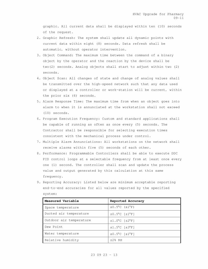
HVAC Upgrade for Pharmacy 09-11
23 09 23 - 13
graphic. All current data shall be displayed within ten (10) seconds
of the request.
2. Graphic Refresh: The system shall update all dynamic points with
current data within eight (8) seconds. Data refresh shall be
automatic, without operator intervention.
3. Object Command: The maximum time between the command of a binary
object by the operator and the reaction by the device shall be
two(2) seconds. Analog objects shall start to adjust within two (2)
seconds.
4. Object Scan: All changes of state and change of analog values shall
be transmitted over the high-speed network such that any data used
or displayed at a controller or work-station will be current, within
the prior six (6) seconds.
5. Alarm Response Time: The maximum time from when an object goes into
alarm to when it is annunciated at the workstation shall not exceed
(10) seconds.
6. Program Execution Frequency: Custom and standard applications shall
be capable of running as often as once every (5) seconds. The
Contractor shall be responsible for selecting execution times
consistent with the mechanical process under control.
7. Multiple Alarm Annunciations: All workstations on the network shall
receive alarms within five (5) seconds of each other.
8. Performance: Programmable Controllers shall be able to execute DDC
PID control loops at a selectable frequency from at least once every
one (1) second. The controller shall scan and update the process
value and output generated by this calculation at this same
frequency.
9. Reporting Accuracy: Listed below are minimum acceptable reporting
end-to-end accuracies for all values reported by the specified
system:
Measured Variable Reported Accuracy
Space temperature ±0.5°C (±1°F)
Ducted air temperature ±0.5°C [±1°F]
Outdoor air temperature ±1.0°C [±2°F]
Dew Point ±1.5°C [±3°F]
Water temperature ±0.5°C [±1°F]
Relative humidity ±2% RH

HVAC Upgrade for Pharmacy 09-11
23 09 23 - 14
Water flow ±1% of reading
Air flow (terminal) ±10% of reading
Air flow (measuring stations) ±5% of reading
Carbon Monoxide (CO) ±5% of reading
Carbon Dioxide (CO2) ±50 ppm
Air pressure (ducts) ±25 Pa [±0.1"w.c.]
Air pressure (space) ±0.3 Pa [±0.001"w.c.]
Water pressure ±2% of full scale *Note 1
Electrical Power ±0.5% of reading
Note 1: for both absolute and differential pressure
10. Control stability and accuracy: Control sequences shall maintain
measured variable at setpoint within the following tolerances:
Controlled Variable Control Accuracy Range of Medium
Air Pressure ±50 Pa (±0.2 in. w.g.)
0–1.5 kPa (0–6 in. w.g.)
Air Pressure ±3 Pa (±0.01 in. w.g.) -25 to 25 Pa (-0.1 to 0.1 in. w.g.)
Airflow ±10% of full scale
Space Temperature ±1.0ºC (±2.0ºF)
Duct Temperature ±1.5ºC (±3ºF)
Humidity ±5% RH
Fluid Pressure ±10 kPa (±1.5 psi)
0–1 MPa (1–150 psi)
Fluid Pressure ±250 Pa (±1.0 in. w.g.) 0–12.5 kPa (0–50 in. w.g.) differential
11. Extent of direct digital control: control design shall allow for at
least the points indicated on the points lists on the drawings.
1.6 WARRANTY
A. Labor and materials for control systems shall be warranted for a period
as specified under Warranty in FAR clause 52.246-21.
B. Control system failures during the warranty period shall be adjusted,
repaired, or replaced at no cost or reduction in service to the owner.
The system includes all computer equipment, transmission equipment, and
all sensors and control devices.

HVAC Upgrade for Pharmacy 09-11
23 09 23 - 15
1.7 SUBMITTALS
A. Submit shop drawings in accordance with Section 01 33 23, SHOP
DRAWINGS, PRODUCT DATA, AND SAMPLES.
B. Manufacturer’s literature and data for all components including the
following:
1. A wiring diagram for each type of input device and output device
including DDC controllers, modems, repeaters, etc. Diagram shall
show how the device is wired and powered, showing typical
connections at the digital controllers and each power supply, as
well as the device itself. Show for all field connected devices,
including but not limited to, control relays, motor starters,
electric or electronic actuators, and temperature pressure, flow and
humidity sensors and transmitters.
2. A diagram of each terminal strip, including digital controller
terminal strips, terminal strip location, termination numbers and
the associated point names.
3. Control dampers and control valves schedule, including the size and
pressure drop.
4. Catalog cut sheets of all equipment used. This includes, but is not
limited to software (by manufacturer and by third parties), DDC
controllers, panels, peripherals, airflow measuring stations and
associated components, and auxiliary control devices such as
sensors, actuators, and control dampers. When manufacturer’s cut
sheets apply to a product series rather than a specific product, the
data specifically applicable to the project shall be highlighted.
Each submitted piece of literature and drawings should clearly
reference the specification and/or drawings that it supposed to
represent.
5. Sequence of operations for each HVAC system and the associated
control diagrams. Equipment and control labels shall correspond to
those shown on the drawings.
6. Color prints of proposed graphics with a list of points for display.
7. Furnish a BACnet Protocol Implementation Conformance Statement
(PICS) for each BACnet-compliant device.
8. Schematic wiring diagrams for all control, communication and power
wiring. Provide a schematic drawing of the central system
installation. Label all cables and ports with computer

HVAC Upgrade for Pharmacy 09-11
23 09 23 - 16
manufacturers’ model numbers and functions. Show all interface
wiring to the control system.
9. An instrumentation list for each controlled system. Each element of
the controlled system shall be listed in table format. The table
shall show element name, type of device, manufacturer, model number,
and product data sheet number.
10. Riser diagrams of wiring between central control unit and all
control panels.
11. Scaled plan drawings showing routing of LAN and locations of control
panels, controllers, routers, gateways, ECC, and larger controlled
devices.
12. Construction details for all installed conduit, cabling, raceway,
cabinets, and similar. Construction details of all penetrations and
their protection.
13. Quantities of submitted items may be reviewed but are the
responsibility of the contractor administered by this Section of the
technical specifications.
C. Product Certificates: Compliance with Article, QUALITY ASSURANCE.
D. Licenses: Provide licenses as needed for all software residing on and
used by the Controls Systems and transfer these licenses to the Owner
prior to completion.
E. As Built Control Drawings:
1. Furnish three (3) copies of as-built drawings for each control
system. The documents shall be submitted for approval prior to final
completion.
2. Furnish one (1) stick set of applicable control system prints for
each mechanical system for wall mounting. The documents shall be
submitted for approval prior to final completion.
3. Furnish one (1) CD-ROM in CAD DWG and/or .DXF format for the
drawings noted in subparagraphs above.
F. Operation and Maintenance (O/M) Manuals):
1. Submit in accordance with Article, INSTRUCTIONS, in Specification
Section 01 00 00, GENERAL REQUIREMENTS.
2. Include the following documentation:
a. General description and specifications for all components,
including logging on/off, alarm handling, producing trend
reports, overriding computer control, and changing set points and
other variables.

HVAC Upgrade for Pharmacy 09-11
23 09 23 - 17
b. Detailed illustrations of all the control systems specified for
ease of maintenance and repair/replacement procedures, and
complete calibration procedures.
c. One copy of the final version of all software provided including
operating systems, programming language, operator workstation
software, and graphics software.
d. Complete troubleshooting procedures and guidelines for all
systems.
e. Complete operating instructions for all systems.
f. Recommended preventive maintenance procedures for all system
components including a schedule of tasks for inspection, cleaning
and calibration. Provide a list of recommended spare parts needed
to minimize downtime.
g. Training Manuals: Submit the course outline and training material
to the Owner for approval three (3) weeks prior to the training
to VA facility personnel. These persons will be responsible for
maintaining and the operation of the control systems, including
programming. The Owner reserves the right to modify any or all of
the course outline and training material.
h. Licenses, guaranty, and other pertaining documents for all
equipment and systems.
G. Submit Performance Report to Resident Engineer prior to final
inspection.
1.8 INSTRUCTIONS
A. Instructions to VA operations personnel: Perform in accordance with
Article, INSTRUCTIONS, in Specification Section 01 00 00, GENERAL
REQUIREMENTS, and as noted below. First Phase: Formal instructions to
the VA facilities personnel for a total of Qty-16 hours, given in
multiple training sessions (each no longer than four hours in length),
conducted sometime between the completed installation and prior to the
performance test period of the control system, at a time mutually
agreeable to the Contractor and the VA.
1. Second Phase: This phase of training shall comprise of on the job
training during start-up, checkout period, and performance test
period. VA facilities personnel will work with the Contractor’s
installation and test personnel on a daily basis during start-up and
checkout period. During the performance test period, controls

HVAC Upgrade for Pharmacy 09-11
23 09 23 - 18
subcontractor will provide Qty -16 hours of instruction, given in
multiple training sessions (each no longer than four hours in
length), to the VA facilities personnel.
2. The O/M Manuals shall contain approved submittals as outlined in
Article 1.7, SUBMITTALS. The Controls subcontractor will review the
manual contents with VA facilities personnel during second phase of
training.
3. Training shall be given by ALC Factory Branch employees of the
controls system manufacturer.
1. Training is to be provided On-Site to owner’s designated personnel and will include
a. Course outline and training materials and one complete copy of training material per student.
b. Training material to be covered includes: i. Proficiently operate system ii. Understand control system architecture and configuration iii. Understand DDC system components iv. Understand system operation, including DDC system control
and optimizing routines (algorithms) v. Operate workstation and peripherals vi. Log on and off system vii. Access graphics, point reports, and logs viii. Adjust and change system set points, time schedules, and
holiday schedules ix. Understand system drawings and Operation and Maintenance
manual x. Understand job layout and location of control components xi. Access data from DDC controllers xii. Create, delete, and modify alarms, including configuring
alarm reactions xiii. Create, delete, and modify point trend logs (graphs) and
multi-point trend graphs xiv. Configure and run reports xv. Add new users and understand password security procedures
4. Instructors will be factory-trained and experienced in presenting
this material.
1.9 PROJECT CONDITIONS (ENVIRONMENTAL CONDITIONS OF OPERATION)
A. The ECC and peripheral devices and system support equipment shall be
designed to operate in ambient condition of 20 to 35°C (65 to 90°F) at a
relative humidity of 20 to 80% non-condensing.
B. The CUs used outdoors shall be mounted in NEMA 4 waterproof enclosures,
and shall be rated for operation at –40 to 65°C (-40 to 150°F).
C. All electronic equipment shall operate properly with power fluctuations
of plus 10 percent to minus 15 percent of nominal supply voltage.

HVAC Upgrade for Pharmacy 09-11
23 09 23 - 19
D. Sensors and controlling devices shall be designed to operate in the
environment, which they are sensing or controlling.
1.10 APPLICABLE PUBLICATIONS
A. The publications listed below form a part of this specification to the
extent referenced. The publications are referenced in the text by the
basic designation only.
B. American Society of Heating, Refrigerating, and Air-Conditioning
Engineers (ASHRAE):
Standard 135-10.........BACNET Building Automation and Control Networks
C. American Society of Mechanical Engineers (ASME):
B16.18-01...............Cast Copper Alloy Solder Joint Pressure Fittings.
B16.22-01...............Wrought Copper and Copper Alloy Solder Joint Pressure Fittings.
D. American Society of Testing Materials (ASTM):
B32-08..................Standard Specification for Solder Metal B88-09..................Standard Specifications for Seamless Copper
Water Tube B88M-09.................Standard Specification for Seamless Copper
Water Tube (Metric) B280-08.................Standard Specification for Seamless Copper Tube
for Air-Conditioning and Refrigeration Field Service
D2737-03................Standard Specification for Polyethylene (PE) Plastic Tubing
E. Federal Communication Commission (FCC):
Rules and Regulations Title 47 Chapter 1-2001 Part 15: Radio Frequency Devices.
F. Institute of Electrical and Electronic Engineers (IEEE):
802.3-11................Information Technology-Telecommunications and Information Exchange between Systems-Local and Metropolitan Area Networks- Specific Requirements-Part 3: Carrier Sense Multiple Access with Collision Detection (CSMA/CD) Access method and Physical Layer Specifications
G. National Fire Protection Association (NFPA):
70-11...................National Electric Code 90A-09..................Standard for Installation of Air-Conditioning
and Ventilation Systems
H. Underwriter Laboratories Inc (UL):
94-10...................Tests for Flammability of Plastic Materials for Parts and Devices and Appliances
294-10..................Access Control System Units 486A/486B-10............Wire Connectors

HVAC Upgrade for Pharmacy 09-11
23 09 23 - 20
555S-11.................Standard for Smoke Dampers 916-10..................Energy Management Equipment 1076-10.................Proprietary Burglar Alarm Units and Systems
PART 2 - PRODUCTS
2.1 MATERIALS
A. Use new products that the manufacturer is currently manufacturing and
that have been installed in a minimum of 25 installations. Spare parts
shall be available for at least five years after completion of this
contract.
2.2 CONTROLS SYSTEM ARCHITECTURE
A.NATIVE ASHRAE BACNET ARCHITECTURE
a. Control products, communication media, connectors, repeaters, hubs, and routers will comprise a BACnet internetwork. Controller and operator interface communication will conform to ANSI/ASHRAE Standard 135, BACnet.
i. New wiring and network devices as required to provide a complete and workable control network, integrating the existing power meters and monitors and the existing controls currently under control of the legacy architecture. Use existing Ethernet and/or communication BUS backbone for network segments.
ii. Each controller will have a communication port for temporary connection to a laptop computer or other operator interface. Connection will support memory downloads and other commissioning and troubleshooting operations.
iii. Internetwork operator interface and value passing will be transparent to internetwork architecture.
iv. An operator interface connected to a controller will allow the operator to interface with each internetwork controller as if directly connected. Controller information such as data, status, and control algorithms will be viewable and editable from each internetwork controller.
v. Inputs, outputs, and control variables used to integrate control strategies across multiple controllers will be readable by each controller on the internetwork.
vi. System will be expandable to at least twice the required input and output objects with additional controllers, associated devices, and wiring.
vii. System will support Web services data exchange with any other system that complies with XML (extensible markup language) and SOAP (simple object access protocol) standards. Web services support will as a minimum be provided at the workstation or web server level and will enable data to be read from or written to the system.
b. Operator Interface to include:
i. A standard browser connected to server will be able to access all system information.
HVAC Upgrade for Pharmacy 09-11
23 09 23 - 21
ii. An operator authentication system that requires an operator to log in before viewing or editing any data, and which can be configured to limit the privileges of an individual operator.
iii. The ability to view and acknowledge any alarm in the system.
iv. A summary page or pages for each piece of equipment in the system. This page will include the current values of all critical I/O points and will allow the operator to lock binary points on or off and to lock analog points to any value within their range.
v. Navigation links that allow the operator to quickly navigate from the home screen to any piece of equipment in the system, and then return to the home screen. These links will be arranged in a hierarchical fashion, navigating from the home screen to a particular building, then to a specific floor in the building, and then to a specific room or piece of equipment.
vi. Communication. Web server or workstation and controllers will communicate using BACnet protocol. Web server or workstation and control network backbone will communicate using ISO 8802-3 (Ethernet) Data Link/Physical layer protocol and BACnet/IP addressing.
c. Operator Functions to include:
i. Operator interface will allow each authorized operator to execute the following functions as a minimum through Internet Explorer (IP connection and internet service required)
ii. Log In and Log Out. System will require user name and password to log in to operator interface.
iii. Point-and-click Navigation. Operator interface will be graphically based and will allow operators to access graphics for equipment and geographic areas using point-and-click navigation.
iv. View and Adjust Equipment Properties. Operators will be able to view controlled equipment status and to adjust operating parameters such as set points, PID gains, on and off controls, and sensor calibration.
v. View and Adjust Operating Schedules. Operators will be able to view scheduled operating hours of each schedulable piece of equipment on a weekly or monthly calendar-based graphical schedule display, to select and adjust each schedule and time period, and to simultaneously schedule related equipment. System will clearly show exception schedules and holidays on the schedule display.
vi. View and Respond to Alarms. Operators will be able to view a list of currently active system alarms, to acknowledge each alarm, and to clear (delete) unneeded alarms.

HVAC Upgrade for Pharmacy 09-11
23 09 23 - 22
vii. View and Configure Trends. Operators will be able to view a trend graph of each trended point and to edit graph configuration to display a specific time period or data range. Operator will be able to create custom trend graphs to display on the same page data from multiple trended points.
viii. View and Configure Reports. Operators will be able to run preconfigured reports, to view report results, and to customize report configuration to show data of interest.
ix. Manage Control System Hardware. Operators will be able to view controller status, to restart (reboot) each controller, and to download new control software to each controller.
x. Manage Operator Access. Typically, only a few operators are authorized to manage operator access. Authorized operators will be able to view a list of operators with system access and of functions they can perform while logged in. Operators will be able to add operators, to delete operators, and to edit operator function authorization. Operator will be able to authorize each operator function separately.
d. System Graphics
i. Operator interface will be graphically based and will include at least one graphic per piece of equipment or occupied zone and graphics that summarize conditions on each floor of each building, including detailed system graphics.
ii. Functionality. Graphics will allow operator to monitor system status, to view a summary of the most important data for each controlled zone or piece of equipment, to use point-and-click navigation between zones or equipment, and to edit set points and other specified parameters.
iii. Animation. Graphics will be able to animate by displaying different image files for changed object status.
iv. Alarm Indication. Indicate areas or equipment in an alarm condition using color or other visual indicator.
v. Format. Graphics will be saved in an industry-standard format such as BMP, JPEG, PNG, or GIF. Web-based system graphics will be viewable on browsers compatible with World Wide Web Consortium browser standards. Web graphic format will require no plug-in (such as HTML and JavaScript) or will only require widely available no-cost plug-ins (such as Active-X and Adobe Flash).
e. System Tools.
i. System will provide the following functionality to authorized operators as an integral part of the operator interface.

HVAC Upgrade for Pharmacy 09-11
23 09 23 - 23
ii. Automatic System Database Configuration. Each workstation or web server will store on its hard disk a copy of the current system database, including controller firmware and software. Stored database will be automatically updated with each system configuration or controller firmware or software change.
iii. Controller Memory Download. Operators will be able to download memory from the system database to each controller.
iv. System Configuration. Operators will be able to configure the system.
v. Online Help. Context-sensitive online help for each tool will assist operators in operating and editing the system.
vi. Security. System will require a user name and password to view, edit, add, or delete data.
vii. Operator Access. Each user name and password combination will define accessible viewing, editing, adding, and deleting functions in each system application, editor, and object. Authorized operators will be able to vary and deny each operator's accessible functions based on equipment or geographic location.
viii. Automatic Log Out. Automatically log out each operator if no keyboard or mouse activity is detected. Operators will be able to adjust automatic log out delay.
ix. Encrypted Security Data. Store system security data including operator passwords in an encrypted format. System will not display operator passwords.
x. System Diagnostics. System will automatically monitor controller and I/O point operation. System will annunciate controller failure and I/O point locking (manual overriding to a fixed value).
xi. Alarm Processing. System input and status objects will be configurable to alarm on departing from and on returning to normal state. Operator will be able to enable or disable each alarm and to configure alarm limits, alarm limit differentials, alarm states, and alarm reactions for each system object.
xii. Alarm Messages. Alarm messages will use an English language descriptor without acronyms or mnemonics to describe alarm source, location, and nature.
xiii. Alarm Reactions. Operator will be able to configure (by object) actions workstation or web server will initiate on receipt of each alarm. As a minimum, workstation or web server will be able to log, print, start programs, display messages, send e-mail, send page, and audibly annunciate.
xiv. Alarm Maintenance. Operators will be able to view system alarms and changes of state chronologically, to acknowledge and delete alarms, and to archive closed alarms to the
HVAC Upgrade for Pharmacy 09-11
23 09 23 - 24
workstation or web server hard disk from each workstation or web browser interface.
xv. Trend Configuration. Operator will be able to configure trend sample or change of value (COV) interval, start time, and stop time for each system data object and will be able to retrieve data for use in spreadsheets and standard database programs. Controller will sample and store trend data and will be able to archive data to the hard disk.
xvi. Object and Property Status and Control. Operator will be able to view, and to edit if applicable, the status of each system object and property by menu, on graphics, or through custom programs.
xvii. Reports and Logs. Operator will be able to select, to modify, to create, and to print reports and logs. Operator will be able to store report data in a format accessible by standard spreadsheet and word processing programs.
xviii. Standard Reports. Furnish the following standard system reports:
xix. Objects. System objects and current values filtered by object type, by status (in alarm, locked, normal), by equipment, by geographic location, or by combination of filter criteria.
xx. Alarm Summary. Current alarms and closed alarms. System will retain closed alarms for an adjustable period.
xxi. Logs. System will log the following to a database or text file and will retain data for an adjustable period:
xxii. Alarm History. xxiii. Trend Data. Operator will be able to select trends to be
logged.
Operator Activity. At a minimum, system will log operator log in and log
out, control parameter changes, schedule changes, and alarm
acknowledgment and deletion. System will date and time- stamp logged
activity.
16. Trend reports shall be generated on demand or pre-defined schedule
and directed to monitor display, printers or disk. The system shall
allow the operator to easily obtain reports:
19.Scheduling and Override:
a. Provide override access through menu selection from the graphical
interface and through a function key.
b. Provide a calendar type format for time-of-day scheduling and
overrides of building control systems. Schedules reside in the
ECC. The digital controllers shall ensure equipment time
scheduling when the ECC is off-line. The ECC shall not be

HVAC Upgrade for Pharmacy 09-11
23 09 23 - 25
required to execute time scheduling. Provide the following
spreadsheet graphics as a minimum:
1) Weekly schedules.
2) Zone schedules, minimum of 100 zones.
3) Scheduling up to 365 days in advance.
4) Scheduled reports to print at workstation.
20. Collection and Analysis of Historical Data:
a. Provide trending capabilities that will allow the operator to
monitor and store records of system activity over an extended
period of time. Points may be trended automatically on time based
intervals or change of value, both of which shall be user
definable. The trend interval could be five (5) minutes to 120
hours. Trend data may be stored on hard disk for future
diagnostic and reporting. Additionally trend data may be archived
to network drives or removable disk media for off-site retrieval.
b. Reports may be customized to include individual points or
predefined groups of at least six points. Provide additional
functionality to allow pre-defined groups of up to 250 trended
points to be easily accessible by other industry standard word
processing and spreadsheet packages. The reports shall be time
and date stamped and shall contain a report title and the name of
the facility.
c. System shall have the set up to generate spreadsheet reports to
track energy usage and cost based on weekly or monthly interval,
equipment run times, equipment efficiency, and/or building
environmental conditions.
d. Provide additional functionality that will allow the operator to
view real time trend data on trend graph displays. A minimum of
20 points may be graphed regardless of whether they have been
predefined for trending. In addition, the user may pause the
graph and take snapshots of the screens to be stored on the
workstation disk for future reference and trend analysis. Exact
point values may be viewed and the graph may be printed. Operator
shall be able to command points directly on the trend plot by
double clicking on the point.
21. Alarm Management:
HVAC Upgrade for Pharmacy 09-11
23 09 23 - 26
a. Alarm routing shall allow the operator to send alarm notification
to selected printers or operator workstation based on time of
day, alarm severity, or point type.
b. Alarm notification shall be provided via two alarm icons, to
distinguish between routine, maintenance type alarms and critical
alarms. The critical alarms shall display on the screen at the
time of its occurrence, while others shall display by clicking on
their icon.
c. Alarm display shall list the alarms with highest priority at the
top of the display. The alarm display shall provide selector
buttons for display of the associated point graphic and message
in English language. The operator shall be able to sort out the
alarms.
d. Alarm messages shall be customized for each point to display
detailed instructions to the operator regarding actions to take
in the event of an alarm.
e. An operator with proper security level access may acknowledge and
clear the alarm. All that have not been cleared shall be archived
at workstation disk.
22. Remote Communications: The system shall have the ability to dial
out in the event of an alarm. Receivers shall include operator
workstations, e-mail addresses, and alpha-numeric pagers. The alarm
message shall include the name of the calling location, the device
that generated the alarm, and the alarm message itself.
23. System Configuration:
a. Network control strategies shall not be restricted to a single
digital controller, but shall be able to include data from all
other network devices to allow the development of global control
strategies.
b. Provide automatic backup and restore of all digital controller
databases on the workstation hard disk. In addition to all backup
data, all databases shall be performed while the workstation is
on-line without disturbing other system operations.
2.5 PORTABLE OPERATOR’S TERMINAL (POT)
A. Provide a portable operator’s terminal (POT) that shall be capable of
accessing all system data. POT may be connected to any point on the
system network or may be connected directly to any controller for
programming, setup, and troubleshooting. POT shall communicate using
HVAC Upgrade for Pharmacy 09-11
23 09 23 - 27
BACnet protocol. POT may be connected to any point on the system
network or it may be connected directly to controllers using the BACnet
PTP (Point-To-Point) Data Link/ Physical layer protocol. The terminal
shall use the Read (Initiate) and Write (Execute) BACnet Services. POT
shall be an IBM-compatible notebook-style PC including all software and
hardware required.
B. Hardware: POT shall conform to the BACnet Advanced Workstation (B-AWS)
Profile and shall be BTL-Listed as a B-AWS device.
1. POT shall be commercial standard with supporting 32- or 64-bit
hardware (as limited by the direct-digital control system software)
and software enterprise server. Internet Explorer v6.0 SP1 or
higher, Windows Script Hosting version 5.6 or higher, Windows
Message Queuing, Windows Internet Information Services (IIS) v5.0 or
higher, minimum 2.8 GHz processor, minimum 500 GB 7200 rpm SATA hard
drive with 16 MB cache, minimum 2GB DDR3 SDRAM (minimum 1333 Mhz)
memory, 512 MB video card, minimum 16 inch (diagonal) screen, 10-
100-1000 Base-TX Ethernet NIC with an RJ45 connector or a 100Base-FX
Ethernet NIC with an SC/ST connector, 56,600 bps modem, an ASCII RS-
232 interface, and a 16 speed high density DVD-RW+/- optical drive.
C. Software: POT shall include software equal to the software on the ECC.
2.7 NETWORK AND DEVICE NAMING CONVENTION
A. Network Numbers
1. BACnet network numbers shall be based on a "facility code, network"
concept. The "facility code" is the VAMC’s or VA campus’ assigned
numeric value assigned to a specific facility or building. The
"network" typically corresponds to a "floor" or other logical
configuration within the building. BACnet allows 65535 network
numbers per BACnet internet work.
2. The network numbers are thus formed as follows: "Net #" = "FFFNN"
where:
a. FFF = Facility code (see below)
b. NN = 00-99 This allows up to 100 networks per facility or
building
B. Device Instances
1. BACnet allows 4194305 unique device instances per BACnet internet
work. Using Agency's unique device instances are formed as follows:
"Dev #" = "FFFNNDD" where
HVAC Upgrade for Pharmacy 09-11
23 09 23 - 28
a. FFF and N are as above and
b. DD = 00-99, this allows up to 100 devices per network.
2. Note Special cases, where the network architecture of limiting
device numbering to DD causes excessive subnet works. The device
number can be expanded to DDD and the network number N can become a
single digit. In NO case shall the network number N and the device
number D exceed 4 digits.
3. Facility code assignments:
4. 000-400 Building/facility number
5. Note that some facilities have a facility code with an alphabetic
suffix to denote wings, related structures, etc. The suffix will be
ignored. Network numbers for facility codes above 400 will be
assigned in the range 000-399.
C. Device Names
1. Name the control devices based on facility name, location within a
facility, the system or systems that the device monitors and/or
controls, or the area served. The intent of the device naming is to
be easily recognized. Names can be up to 254 characters in length,
without embedded spaces. Provide the shortest descriptive, but
unambiguous, name. For example, in building #123 prefix the number
with a “B” followed by the building number, if there is only one
chilled water pump "CHWP-1", a valid name would be "B123.CHWP.
1.STARTSTOP". If there are two pumps designated "CHWP-1", one in a
basement mechanical room (Room 0001) and one in a penthouse
mechanical room (Room PH01), the names could be "B123.R0001.CHWP.1.
STARTSTOP" or "B123.RPH01.CHWP.1.STARTSTOP". In the case of unitary
controllers, for example a VAV box controller, a name might be
"B123.R101.VAV". These names should be used for the value of the
"Object_Name" property of the BACnet Device objects of the
controllers involved so that the BACnet name and the EMCS name are
the same.
2.8 BACNET DEVICES
A. All BACnet Devices – controllers, gateways, routers, actuators and
sensors shall conform to BACnet Device Profiles and shall be BACnet
Testing Laboratories (BTL) -Listed as conforming to those Device
Profiles. Protocol Implementation Conformance Statements (PICSs),
describing the BACnet capabilities of the Devices shall be published
and available of the Devices through links in the BTL website.

HVAC Upgrade for Pharmacy 09-11
23 09 23 - 29
1. BACnet Building Controllers, historically referred to as NACs, shall
conform to the BACnet B-BC Device Profile, and shall be BTL-Listed
as conforming to the B-BC Device Profile. The Device’s PICS shall
be submitted.
2. BACnet Advanced Application Controllers shall conform to the BACnet
B-AAC Device Profile, and shall be BTL-Listed as conforming to the
B-AAC Device Profile. The Device’s PICS shall be submitted.
3. BACnet Application Specific Controllers shall conform to the BACnet
B-ASC Device Profile, and shall be BTL-Listed as conforming to the
B-ASC Device Profile. The Device’s PICS shall be submitted.
4. BACnet Smart Actuators shall conform to the BACnet B-SA Device
Profile, and shall be BTL-Listed as conforming to the B-SA Device
Profile. The Device’s PICS shall be submitted.
5. BACnet Smart Sensors shall conform to the BACnet B-SS Device
Profile, and shall be BTL-Listed as conforming to the B-SS Device
Profile. The Device’s PICS shall be submitted.
6. BACnet routers and gateways shall conform to the BACnet B-OTH Device
Profile, and shall be BTL-Listed as conforming to the B-OTH Device
Profile. The Device’s PICS shall be submitted.
2.9 CONTROLLERS
A. General. Provide an adequate number of BTL-Listed B-BC building
controllers and an adequate number of BTL-Listed B-AAC advanced
application controllers to achieve the performance specified in the
Part 1 Article on “System Performance.” Each of these controllers shall
meet the following requirements.
1. The controller shall have sufficient memory to support its operating
system, database, and programming requirements.
2. The building controller shall share data with the ECC and the other
networked building controllers. The advanced application controller
shall share data with its building controller and the other
networked advanced application controllers.
3. The operating system of the controller shall manage the input and
output communication signals to allow distributed controllers to
share real and virtual object information and allow for central
monitoring and alarms.
4. Controllers that perform scheduling shall have a real-time clock.

HVAC Upgrade for Pharmacy 09-11
23 09 23 - 30
5. The controller shall continually check the status of its processor
and memory circuits. If an abnormal operation is detected, the
controller shall:
a. assume a predetermined failure mode, and
b. generate an alarm notification.
6. The controller shall communicate with other BACnet devices on the
internetwork using the BACnet Read (Execute and Initiate) and Write
(Execute and Initiate) Property services.
7. Communication.
a. Each controller shall reside on a BACnet network using the ISO
8802-3 (Ethernet) Data Link/Physical layer protocol for its
communications. Each building controller also shall perform
BACnet routing if connected to a network of custom application
and application specific controllers.
b. The controller shall provide a service communication port using
BACnet Data Link/Physical layer protocol for connection to a
portable operator’s terminal.
9. Serviceability. Provide diagnostic LEDs for power, communication,
and processor. All wiring connections shall be made to field-
removable, modular terminal strips or to a termination card
connected by a ribbon cable.
10. Memory. The controller shall maintain all BIOS and programming
information in the event of a power loss for at least 72 hours.
11. The controller shall be able to operate at 90% to 110% of nominal
voltage rating and shall perform an orderly shutdown below 80%
nominal voltage. Controller operation shall be protected against
electrical noise of 5 to 120 Hz and from keyed radios up to 5 W at 1
m (3 ft).
B. Provide BTL-Listed B-ASC application specific controllers for each
piece of equipment for which they are constructed. Application
specific controllers shall communicate with other BACnet devices on the
internetwork using the BACnet Read (Execute) Property service.
1. Each B-ASC shall be capable of stand-alone operation and shall
continue to provide control functions without being connected to the
network.
2. Each B-ASC will contain sufficient I/O capacity to control the
target system.
3. Communication.

HVAC Upgrade for Pharmacy 09-11
23 09 23 - 31
a. Each controller shall reside on an ARCNET network using the ISO
8802-2 Data Link/Physical layer protocol for its communications.
b. Each controller shall have a BACnet Data Link/Physical layer
compatible connection for a laptop computer or a portable
operator’s tool. This connection shall be extended to a space
temperature sensor port where shown.
4. Serviceability. Provide diagnostic LEDs for power, communication,
and processor. All wiring connections shall be made to field-
removable, modular terminal strips or to a termination card
connected by a ribbon cable.
5. Memory. The application specific controller shall use nonvolatile
memory and maintain all BIOS and programming information in the
event of a power loss.
6. Immunity to power and noise. Controllers shall be able to operate at
90% to 110% of nominal voltage rating and shall perform an orderly
shutdown below 80%. Operation shall be protected against electrical
noise of 5-120 Hz and from keyed radios up to 5 W at 1 m (3 ft).
7. Transformer. Power supply for the ASC must be rated at a minimum of
125% of ASC power consumption and shall be of the fused or current
limiting type.
C. Direct Digital Controller Software
1. The software programs specified in this section shall be
commercially available, concurrent, multi-tasking operating system
and support the use of software application that operates under DOS
or Microsoft Windows.
2. All points shall be identified by up to 30-character point name and
16-character point descriptor. The same names shall be used at the
ECC.
3. All control functions shall execute within the stand-alone control
units via DDC algorithms. The VA shall be able to customize control
strategies and sequences of operations defining the appropriate
control loop algorithms and choosing the optimum loop parameters.
4. All controllers shall be capable of being programmed to utilize
stored default values for assured fail-safe operation of critical
processes. Default values shall be invoked upon sensor failure or,
if the primary value is normally provided by the central or another
CU, or by loss of bus communication. Individual application software
packages shall be structured to assume a fail-safe condition upon

HVAC Upgrade for Pharmacy 09-11
23 09 23 - 32
loss of input sensors. Loss of an input sensor shall result in
output of a sensor-failed message at the ECC. Each ACU and RCU shall
have capability for local readouts of all functions. The UCUs shall
be read remotely.
5. All DDC control loops shall be able to utilize any of the following
control modes:
a. Two position (on-off, slow-fast) control.
b. Proportional control.
c. Proportional plus integral (PI) control.
d. Proportional plus integral plus derivative (PID) control. All PID
programs shall automatically invoke integral wind up prevention
routines whenever the controlled unit is off, under manual
control of an automation system or time initiated program.
e. Automatic tuning of control loops.
6. System Security: Operator access shall be secured using individual
password and operator’s name. Passwords shall restrict the operator
to the level of object, applications, and system functions assigned
to him. A minimum of six (6) levels of security for operator access
shall be provided.
7. Application Software: The controllers shall provide the following
programs as a minimum for the purpose of optimizing energy
consumption while maintaining comfortable environment for occupants.
All application software shall reside and run in the system digital
controllers. Editing of the application shall occur at the ECC or
via a portable operator’s terminal, when it is necessary, to access
directly the programmable unit.
a. Night Setback/Morning Warm up Control: The system shall provide
the ability to automatically adjust set points for this mode of
operation.
b. Optimum Start/Stop (OSS): Optimum start/stop program shall
automatically be coordinated with event scheduling. The OSS
program shall start HVAC equipment at the latest possible time
that will allow the equipment to achieve the desired zone
condition by the time of occupancy, and it shall also shut down
HVAC equipment at the earliest possible time before the end of
the occupancy period and still maintain desired comfort
conditions. The OSS program shall consider both outside weather
conditions and inside zone conditions. The program shall
HVAC Upgrade for Pharmacy 09-11
23 09 23 - 33
automatically assign longer lead times for weekend and holiday
shutdowns. The program shall poll all zones served by the
associated AHU and shall select the warmest and coolest zones.
These shall be used in the start time calculation. It shall be
possible to assign occupancy start times on a per air handler
unit basis. The program shall meet the local code requirements
for minimum outdoor air while the building is occupied.
Modification of assigned occupancy start/stop times shall be
possible via the ECC.
c. Event Scheduling: Provide a comprehensive menu driven program to
automatically start and stop designated points or a group of
points according to a stored time. This program shall provide the
capability to individually command a point or group of points.
When points are assigned to one common load group it shall be
possible to assign variable time advances/delays between each
successive start or stop within that group. Scheduling shall be
calendar based and advance schedules may be defined up to one
year in advance. Advance schedule shall override the day-to-day
schedule. The operator shall be able to define the following
information:
1) Time, day.
2) Commands such as on, off, auto.
3) Time delays between successive commands.
4) Manual overriding of each schedule.
5) Allow operator intervention.
d. Alarm Reporting: The operator shall be able to determine the
action to be taken in the event of an alarm. Alarms shall be
routed to the ECC based on time and events. An alarm shall be
able to start programs, login the event, print and display the
messages. The system shall allow the operator to prioritize the
alarms to minimize nuisance reporting and to speed operator’s
response to critical alarms. A minimum of six (6) priority levels
of alarms shall be provided for each point.
e. Automatic start/stop of chillers and auxiliaries in accordance
with the sequence of operation shown on the drawings, while
incorporating requirements and restraints, such as starting
frequency of the equipment imposed by equipment manufacturers.
HVAC Upgrade for Pharmacy 09-11
23 09 23 - 34
2.10 SPECIAL CONTROLLERS
A. Room Differential Pressure Controller: The differential pressure in
laboratory rooms, operating rooms and isolation rooms shall be
maintained by controlling the quantity of air exhausted from or
supplied to the room. A sensor-controller shall measure and control the
velocity of air flowing into or out of the room through a sampling tube
installed in the wall separating the room from the adjacent space, and
display the value on its monitor. The sensor-controller shall meet the
following as a minimum:
a. Provide Critical Room Control room monitor (CRC-RM). The room
pressure monitor shall be capable of measuring the differential
pressure between two individual spaces at all locations shown on
drawings. Each monitor is capable of both visual and audible alarms.
Each monitor will use direct pressure measurement utilizing industrial
quality differential pressure transducer technology.
b. Each monitor shall have a microprocessor based controller. Each room shall have an internal controller capable of stand-alone operation. Internal controller shall have no less than (4) analog input, (4) analog output, (4) digital input and (4) digital output. Controller shall provide integration to BACnet, Modbus or N2 through RS-485 communication. Screen will be full color TFT touch screen interface. Touch screen shall be capable of displaying room conditions in full color (i.e. Red screen for alarm). All settings and programming shall be made via touch screen. The monitor shall have a color TFT / VGA touch display with 240 X 160 resolution
c. Display shall be fully programmable with custom graphics and fonts. Monitor will store all settings in non volatile memory. Monitor to be capable to incorporate custom JPEG’s or BMP’s for display. Monitor will continually display room differential pressure. Monitor settings shall be accessed via programmable and password protected touch screen. Monitor shall be recess mounted. Supply voltage shall be 24 volt ac/dc.
d. Monitors using single or multiple line LCD alphanumeric character displays and or LED indicators are not acceptable. Touch pads and layered programming menus are not acceptable.
e. The pressure sensor and power supply shall be mounted above ceiling or in remote location as indicated. The pressure sensor will continuously monitor and or control bi-directional room pressurization using direct pressure sensing referenced to the adjacent space. Wall / ceiling mounted assembly fittings and stainless steel cover plate for the isolation room shall be provided with the controller as a complete unit
f. CRC-RM Room pressure monitor shall be provided for:
i. Storage Area
ii. Ante Room
HVAC Upgrade for Pharmacy 09-11
23 09 23 - 35
iii. Formulation Room
2.11 SENSORS (AIR, WATER AND STEAM)
A. Sensors’ measurements shall be read back to the DDC system, and shall
be visible by the ECC.
B. Temperature and Humidity Sensors shall be electronic, vibration and
corrosion resistant for wall, immersion, and/or duct mounting. Provide
all remote sensors as required for the systems.
1. Temperature Sensors: thermistor type for terminal units and
Resistance Temperature Device (RTD) with an integral transmitter
type for all other sensors.
a. Duct sensors shall be rigid or averaging type as shown on
drawings. Averaging sensor shall be a minimum of 1 linear ft of
sensing element for each sq ft of cooling coil face area.
b. Immersion sensors shall be provided with a separable well made of
stainless steel, bronze or monel material. Pressure rating of
well is to be consistent with the system pressure in which it is
to be installed.
c. Space sensors shall be equipped with in-space User set-point
adjustment, override switch, numerical temperature display on
sensor cover, and communication port. Match room thermostats.
Provide a tooled-access cover.
1) Public space sensor: setpoint adjustment shall be only through
the ECC or through the DDC system’s diagnostic device/laptop.
Do not provide in-space User set-point adjustment. Provide an
opaque keyed-entry cover if needed to restrict in-space User
set-point adjustment.
2) Psychiatric patient room sensor: sensor shall be flush with
wall, shall not include an override switch, numerical
temperature display on sensor cover, shall not include a
communication port and shall not allow in-space User set-point
adjustment. Setpoint adjustment shall be only through the ECC
or through the DDC system’s diagnostic device/laptop. Provide
a stainless steel cover plate with an insulated back and
security screws.
d. Outdoor air temperature sensors shall have watertight inlet
fittings and be shielded from direct sunlight.

HVAC Upgrade for Pharmacy 09-11
23 09 23 - 36
e. Room security sensors shall have stainless steel cover plate with
insulated back and security screws.
f. Wire: Twisted, shielded-pair cable.
g. Output Signal: 4-20 ma.
2. Humidity Sensors: Bulk polymer sensing element type.
a. Duct and room sensors shall have a sensing range of 20 to 80
percent with accuracy of ± 2 to ± 5 percent RH, including
hysteresis, linearity, and repeatability.
b. Outdoor humidity sensors shall be furnished with element guard
and mounting plate and have a sensing range of 0 to 100 percent
RH.
c. 4-20 ma continuous output signal.
C. Static Pressure Sensors: Non-directional, temperature compensated.
1. 4-20 ma output signal.
2. 0 to 5 inches wg for duct static pressure range.
3. 0 to 0.25 inch wg for Building static pressure range.
H. Current Switches: Current operated switches shall be self powered,
solid state with adjustable trip current as well as status, power, and
relay command status LED indication. The switches shall be selected to
match the current of the application and output requirements of the DDC
systems.
2.12 CONTROL CABLES
A. General:
1. Ground cable shields, drain conductors, and equipment to eliminate
shock hazard and to minimize ground loops, common-mode returns,
noise pickup, cross talk, and other impairments. Comply with
Sections 27 05 26 and 26 05 26.
2. Cable conductors to provide protection against induction in
circuits. Crosstalk attenuation within the System shall be in excess
of -80 dB throughout the frequency ranges specified.
3. Minimize the radiation of RF noise generated by the System equipment
so as not to interfere with any audio, video, data, computer main
distribution frame (MDF), telephone customer service unit (CSU), and
electronic private branch exchange (EPBX) equipment the System may
service.
4. The as-installed drawings shall identify each cable as labeled, used
cable, and bad cable pairs.

HVAC Upgrade for Pharmacy 09-11
23 09 23 - 37
5. Label system’s cables on each end. Test and certify cables in
writing to the VA before conducting proof-of-performance testing.
Minimum cable test requirements are for impedance compliance,
inductance, capacitance, signal level compliance, opens, shorts,
cross talk, noise, and distortion, and split pairs on all cables in
the frequency ranges used. Make available all cable installation and
test records at demonstration to the VA. All changes (used pair,
failed pair, etc.) shall be posted in these records as the change
occurs.
6. Power wiring shall not be run in conduit with communications trunk
wiring or signal or control wiring operating at 100 volts or less.
B. Analogue control cabling shall be not less than No. 18 AWG solid, with
thermoplastic insulated conductors as specified in Section 26 05 21.
C. Copper digital communication cable between the ECC and the B-BC and B-
AAC controllers shall be 100BASE-TX Ethernet, Category 5e or 6, not
less than minimum 24 American Wire Gauge (AWG) solid, Shielded Twisted
Pair (STP) or Unshielded Twisted Pair (UTP), with thermoplastic
insulated conductors, enclosed in a thermoplastic outer jacket, as
specified in Section 27 15 00.
1. Other types of media commonly used within IEEE Std 802.3 LANs (e.g.,
10Base-T and 10Base-2) shall be used only in cases to interconnect
with existing media.
D. Optical digital communication fiber, if used, shall be Multimode or
Singlemode fiber, 62.5/125 micron for multimode or 10/125 micron for
singlemode micron with SC or ST connectors as specified in TIA-568-C.1.
Terminations, patch panels, and other hardware shall be compatible with
the specified fiber and shall be as specified in Section 27 15 00.
Fiber-optic cable shall be suitable for use with the 100Base-FX or the
100Base-SX standard (as applicable) as defined in IEEE Std 802.3.
2.13 THERMOSTATS AND HUMIDISTATS
A. Room thermostats controlling unitary standalone heating and cooling
devices not connected to the DDC system shall have three modes of
operation (heating - null or dead band - cooling). Thermostats for
patient bedrooms shall have capability of being adjusted to eliminate
null or dead band. Wall mounted thermostats shall have polished or
brushed aluminum satin chrome manufacturer's recommendation finish,
setpoint range and temperature display and external adjustment:

HVAC Upgrade for Pharmacy 09-11
23 09 23 - 38
1. Electronic Thermostats: Solid-state, microprocessor based,
programmable to daily, weekend, and holiday schedules.
a. Public Space Thermostat: Public space thermostat shall have a
thermistor sensor and shall not have a visible means of set point
adjustment. Adjustment shall be via the digital controller to
which it is connected.
b. Patient Room Thermostats: thermistor with in-space User set point
adjustment and an on-casing room temperature numerical
temperature display.
c. Psychiatric Patient Room Sensors: Electronic duct sensor as noted
under Article 2.4.
d. Battery replacement without program loss.
B. Strap-on thermostats shall be enclosed in a dirt-and-moisture proof
housing with fixed temperature switching point and single pole, double
throw switch.
C. Freezestats shall have a minimum of 300 mm (one linear foot) of sensing
element for each 0.093 square meter (one square foot) of coil area. A
freezing condition at any increment of 300 mm (one foot) anywhere along
the sensing element shall be sufficient to operate the thermostatic
element. Freezestats shall be manually-reset.
D. Room Humidistats: Provide fully proportioning humidistat with
adjustable throttling range for accuracy of settings and conservation.
The humidistat shall have set point scales shown in percent of relative
humidity located on the instrument. Systems showing moist/dry or
high/low are not acceptable.
2.14 FINAL CONTROL ELEMENTS AND OPERATORS
A. Fail Safe Operation: Control valves and dampers shall provide "fail
safe" operation in either the normally open or normally closed position
as required for freeze, moisture, and smoke or fire protection.
B. Spring Ranges: Range as required for system sequencing and to provide
tight shut-off.
C. Power Operated Control Dampers (other than VAV Boxes): Factory
fabricated, balanced type dampers. All modulating dampers shall be
opposed blade type and gasketed. Blades for two-position, duct-mounted
dampers shall be parallel, airfoil (streamlined) type for minimum noise
generation and pressure drop.

HVAC Upgrade for Pharmacy 09-11
23 09 23 - 39
1. Leakage: Except as specified in subparagraph 2 below, maximum
leakage in closed position shall not exceed 7 L/S (15 CFMs)
differential pressure for outside air and exhaust dampers and 200
L/S/ square meter (40 CFM/sq. ft.) at 50 mm (2 inches) differential
pressure for other dampers.
2. Frame shall be galvanized steel channel with seals as required to
meet leakage criteria.
3. Blades shall be galvanized steel or aluminum, 200 mm (8 inch)
maximum width, with edges sealed as required.
4. Bearing shall be nylon, bronze sleeve or ball type.
5. Hardware shall be zinc-plated steel. Connected rods and linkage
shall be non-slip. Working parts of joints shall be brass, bronze,
nylon or stainless steel.
6. Maximum air velocity and pressure drop through free area the
dampers:
a. Smoke damper in air handling unit: 305 meter per minute (1000
fpm).
b. Duct mounted damper: 600 meter per minute (2000 fpm).
c. Maximum static pressure loss: 50 Pascal (0.20 inches water gage).
D. Smoke Dampers and Combination Fire/Smoke Dampers: Dampers and
operators are specified in Section 23 31 00, HVAC DUCTS AND CASINGS.
Control of these dampers is specified under this Section.
E. Control Valves:
1. Valves shall be rated for a minimum of 150 percent of system
operating pressure at the valve location but not less than 900 kPa
(125 psig).
2. Valves 50 mm (2 inches) and smaller shall be bronze body with
threaded or flare connections.
3. Valves 60 mm (2 1/2 inches) and larger shall be bronze or iron body
with flanged connections.
4. Brass or bronze seats except for valves controlling media above 100
degrees C (210 degrees F), which shall have stainless steel seats.
5. Flow characteristics:
a. Three way modulating valves shall be globe pattern. Position
versus flow relation shall be linear relation for steam or equal
percentage for water flow control.

HVAC Upgrade for Pharmacy 09-11
23 09 23 - 40
b. Two-way modulating valves shall be globe pattern. Position
versus flow relation shall be linear for steam and equal
percentage for water flow control.
c. Two-way 2-position valves shall be ball, gate or butterfly type.
6. Maximum pressure drop:
a. Two position steam control: 20 percent of inlet gauge pressure.
b. Modulating Steam Control: 80 percent of inlet gauge pressure
(acoustic velocity limitation).
c. Modulating water flow control, greater of 3 meters (10 feet) of
water or the pressure drop through the apparatus.
7. Two position water valves shall be line size.
F. Damper and Valve Operators and Relays:
1. Electric operator shall provide full modulating control of dampers
and valves. A linkage and pushrod shall be furnished for mounting
the actuator on the damper frame internally in the duct or
externally in the duct or externally on the duct wall, or shall be
furnished with a direct-coupled design. Metal parts shall be
aluminum, mill finish galvanized steel, or zinc plated steel or
stainless steel. Provide actuator heads which allow for electrical
conduit attachment. The motors shall have sufficient closure torque
to allow for complete closure of valve or damper under pressure.
Provide multiple motors as required to achieve sufficient close-off
torque.
a. Minimum valve close-off pressure shall be equal to the system
pump’s dead-head pressure, minimum 50 psig for valves smaller
than 4 inches.
3. Electronic damper operators: Metal parts shall be aluminum, mill
finish galvanized steel, or zinc plated steel or stainless steel.
Provide actuator heads which allow for electrical conduit
attachment. The motors shall have sufficient closure torque to allow
for complete closure of valve or damper under pressure. Provide
multiple motors as required to achieve sufficient close-off torque.
a. VAV Box actuator shall be mounted on the damper axle or shall be
of the air valve design, and shall provide complete modulating
control of the damper. The motor shall have a closure torque of
35-inch pounds minimum with full torque applied at close off to
attain minimum leakage.

HVAC Upgrade for Pharmacy 09-11
23 09 23 - 41
2.15 AIR FLOW CONTROL
A. Airflow and static pressure shall be controlled via digital controllers
with inputs from airflow control measuring stations and static pressure
inputs as specified. Controller outputs shall be analog or pulse width
modulating output signals. The controllers shall include the
capability to control via simple proportional (P) control, proportional
plus integral (PI), proportional plus integral plus derivative (PID),
and on-off. The airflow control programs shall be factory-tested
programs that are documented in the literature of the control
manufacturer.
a. Each air flow sensor shall contain two individual thermal sensing
elements. One element shall determine the velocity of the air
stream while the other element shall compensate for changes in
temperature. Each thermal flow sensor and its associated control
circuit and signal conditioning circuit shall be factory
calibrated and be interchangeable to allow replacement of a
sensor without recalibration of the entire flow station. The
sensor in the array shall be located at the center of equal area
segment of the duct and the number of sensors shall be adequate
to accommodate the expected velocity profile and variation in
flow and temperature. The airflow station shall be of the
insertion type in which sensor support structures are inserted
from the outside of the ducts to make up the complete electronic
velocity array.
b. Thermal flow sensor shall be constructed of hermetically sealed
thermistors or nickel chromium or reference grade platinum wire,
wound over an epoxy, stainless steel or ceramic mandrel and
coated with a material suitable for the conditions to be
encountered. Each dual sensor shall be mounted in an extruded
aluminum alloy strut.
1. Air Flow Sensor Grid Array:
a. Each sensor grid shall consist of a lattice network of
temperature sensors and linear integral controllers (ICs)
situated inside an aluminum casing suitable for mounting in a
duct. Each sensor shall be mounted within a strut facing
downstream of the airflow and located so that it is protected on
the upstream side. All wiring shall be encased (out of the air
stream) to protect against mechanical damage.

HVAC Upgrade for Pharmacy 09-11
23 09 23 - 42
b. The casing shall be made of welded aluminum of sufficient
strength to prevent structural bending and bowing. Steel or iron
composite shall not be acceptable in the casing material.
c. Pressure drop through the flow station shall not exceed 4 Pascal
(0.015" W.G.) at 1,000 meter per minute (3,000 FPM).
2. Electronics Panel:
a. Electronics Panel shall consist of a surface mounted enclosure
complete with solid-state microprocessor and software.
b. Electronics Panel shall be A/C powered 120 VAC 24 VAC and shall
have the capability to transmit signals of 0-5 VDC, 0-10 VCD or
4-20 ma for use in control of the HVAC Systems. The electronic
panel shall have the capability to accept user defined scaling
parameters for all output signals.
c. Electronics Panel shall have the capability to digitally display
airflow in CFM LPS and temperature in degrees F degrees C. The
displays shall be provided as an integral part of the electronics
panel. The electronic panel shall have the capability to totalize
the output flow in CFM for two or more systems, as required. A
single output signal may be provided which will equal the sum of
the systems totalized. Output signals shall be provided for
temperature and airflow. Provide remote mounted air flow or
temperature displays where indicated on the plans.
d. Electronics Panel shall have the following:
1) Minimum of 12-bit A/D conversion.
2) Field adjustable digital primary output offset and gain.
3) Airflow analog output scaling of 100 to 10,000 FPM.
4) Temperature analog output scaling from -45°C to 70°C (-50°F to
160°F).
5) Analog output resolution (full scale output) of 0.025%.
e. All readings shall be in I.P. S.I.units.
4. Thermal flow sensors and its electronics shall be installed as per
manufacturer’s instructions. The probe sensor density shall be as
follows:
Probe Sensor Density
Area (sq.ft.) Qty. Sensors
<=1 2
>1 to <4 4

HVAC Upgrade for Pharmacy 09-11
23 09 23 - 43
4 to <8 6
8 to <12 8
12 to <16 12
>=16 16
a. Complete installation shall not exhibit more than ± 2.0% error in
airflow measurement output for variations in the angle of flow of
up to 10 percent in any direction from its calibrated
orientation. Repeatability of readings shall be within ± 0.25%.
D. Static Pressure Measuring Station: shall consist of one or more static
pressure sensors and transmitters along with relays or auxiliary
devices as required for a complete functional system. The span of the
transmitter shall not exceed two times the design static pressure at
the point of measurement. The output of the transmitter shall be true
representation of the input pressure with plus or minus 25 Pascal (0.1
inch) W.G. of the true input pressure:
1. Static pressure sensors shall have the same requirements as Airflow
Measuring Devices except that total pressure sensors are optional,
and only multiple static pressure sensors positioned on an equal
area basis connected to a network of headers are required.
2. For systems with multiple major trunk supply ducts, furnish a static
pressure transmitter for each trunk duct. The transmitter signal
representing the lowest static pressure shall be selected and this
shall be the input signal to the controller.
3. The controller shall receive the static pressure transmitter signal
and CU shall provide a control output signal to the supply fan
capacity control device. The control mode shall be proportional plus
integral (PI) (automatic reset) and where required shall also
include derivative mode.
4. In systems with multiple static pressure transmitters, provide a
switch located near the fan discharge to prevent excessive pressure
during abnormal operating conditions. High-limit switches shall be
manually-reset.
E. Constant Volume Control Systems shall consist of an air flow measuring
station along with such relays and auxiliary devices as required to
produce a complete functional system. The transmitter shall receive its
air flow signal and static pressure signal from the flow measuring
station and shall have a span not exceeding three times the design flow
rate. The CU shall receive the transmitter signal and shall provide an

HVAC Upgrade for Pharmacy 09-11
23 09 23 - 44
output to the fan volume control device to maintain a constant flow
rate. The CU shall provide proportional plus integral (PI) (automatic
reset) control mode and where required also inverse derivative mode.
Overall system accuracy shall be plus or minus the equivalent of 2
Pascal (0.008 inch) velocity pressure as measured by the flow station.
F. Airflow Synchronization:
1. Systems shall consist of an air flow measuring station for each
supply and return duct, the CU and such relays, as required to
provide a complete functional system that will maintain a constant
flow rate difference between supply and return air to an accuracy of
±10%. In systems where there is no suitable location for a flow
measuring station that will sense total supply or return flow,
provide multiple flow stations with a differential pressure
transmitter for each station. Signals from the multiple transmitters
shall be added through the CU such that the resultant signal is a
true representation of total flow.
2. The total flow signals from supply and return air shall be the input
signals to the CU. This CU shall track the return air fan capacity
in proportion to the supply air flow under all conditions.
PART 3 - EXECUTION
3.1 INSTALLATION
A. General:
1. Examine project plans for control devices and equipment locations;
and report any discrepancies, conflicts, or omissions to Resident
Engineer for resolution before proceeding for installation.
2. Install equipment, piping, wiring /conduit parallel to or at right
angles to building lines.
3. Install all equipment and piping in readily accessible locations. Do
not run tubing and conduit concealed under insulation or inside
ducts.
4. Mount control devices, tubing and conduit located on ducts and
apparatus with external insulation on standoff support to avoid
interference with insulation.
5. Provide sufficient slack and flexible connections to allow for
vibration of piping and equipment.
6. Run tubing and wire connecting devices on or in control cabinets
parallel with the sides of the cabinet neatly racked to permit
tracing.

HVAC Upgrade for Pharmacy 09-11
23 09 23 - 45
7. Install equipment level and plum.
A. Electrical Wiring Installation:
1. All wiring cabling shall be installed in conduits. Install conduits
and wiring in accordance with Specification Section 26 05 33,
RACEWAY AND BOXES FOR ELECTRICAL SYSTEMS. Conduits carrying control
wiring and cabling shall be dedicated to the control wiring and
cabling: these conduits shall not carry power wiring. Provide
plastic end sleeves at all conduit terminations to protect wiring
from burrs.
2. Install analog signal and communication cables in conduit and in
accordance with Specification Section 26 05 21. Install digital
communication cables in conduit and in accordance with Specification
Section 27 15 00, Communications Horizontal Cabling.
3. Install conduit and wiring between operator workstation(s), digital
controllers, electrical panels, indicating devices, instrumentation,
miscellaneous alarm points, thermostats, and relays as shown on the
drawings or as required under this section.
3. Install all electrical work required for a fully functional system
and not shown on electrical plans or required by electrical
specifications. Where low voltage (less than 50 volt) power is
required, provide suitable Class B transformers.
5. Install all system components in accordance with local Building Code
and National Electric Code.
a. Splices: Splices in shielded and coaxial cables shall consist of
terminations and the use of shielded cable couplers. Terminations
shall be in accessible locations. Cables shall be harnessed with
cable ties.
b. Equipment: Fit all equipment contained in cabinets or panels with
service loops, each loop being at least 300 mm (12 inches) long.
Equipment for fiber optics system shall be rack mounted, as
applicable, in ventilated, self-supporting, code gauge steel
enclosure. Cables shall be supported for minimum sag.
c. Cable Runs: Keep cable runs as short as possible. Allow extra
length for connecting to the terminal board. Do not bend flexible
coaxial cables in a radius less than ten times the cable outside
diameter.

HVAC Upgrade for Pharmacy 09-11
23 09 23 - 46
d. Use vinyl tape, sleeves, or grommets to protect cables from
vibration at points where they pass around sharp corners, through
walls, panel cabinets, etc.
6. Conceal cables, except in mechanical rooms and areas where other
conduits and piping are exposed.
7. Permanently label or code each point of all field terminal strips to
show the instrument or item served. Color-coded cable with cable
diagrams may be used to accomplish cable identification.
8. Grounding: ground electrical systems per manufacturer’s written
requirements for proper and safe operation.
C. Install Sensors and Controls:
1. Temperature Sensors:
a. Install all sensors and instrumentation according to
manufacturer’s written instructions. Temperature sensor locations
shall be readily accessible, permitting quick replacement and
servicing of them without special skills and tools.
b. Calibrate sensors to accuracy specified, if not factory
calibrated.
c. Use of sensors shall be limited to its duty, e.g., duct sensor
shall not be used in lieu of room sensor.
d. Install room sensors permanently supported on wall frame. They
shall be mounted at 1.5 meter (5.0 feet) above the finished
floor.
e. Mount sensors rigidly and adequately for the environment within
which the sensor operates. Separate extended-bulb sensors form
contact with metal casings and coils using insulated standoffs.
f. Sensors used in mixing plenum, and hot and cold decks shall be of
the averaging of type. Averaging sensors shall be installed in a
serpentine manner horizontally across duct. Each bend shall be
supported with a capillary clip.
g. All pipe mounted temperature sensors shall be installed in wells.
h. All wires attached to sensors shall be air sealed in their
conduits or in the wall to stop air transmitted from other areas
affecting sensor reading.
i. Permanently mark terminal blocks for identification. Protect all
circuits to avoid interruption of service due to short-circuiting
or other conditions. Line-protect all wiring that comes from
HVAC Upgrade for Pharmacy 09-11
23 09 23 - 47
external sources to the site from lightning and static
electricity.
2. Pressure Sensors:
a. Install duct static pressure sensor tips facing directly
downstream of airflow.
b. Install high-pressure side of the differential switch between the
pump discharge and the check valve.
c. Install snubbers and isolation valves on steam pressure sensing
devices.
3. Actuators:
a. Mount and link damper and valve actuators according to
manufacturer’s written instructions.
b. Check operation of damper/actuator combination to confirm that
actuator modulates damper smoothly throughout stroke to both open
and closed position.
c. Check operation of valve/actuator combination to confirm that
actuator modulates valve smoothly in both open and closed
position.
4. Flow Switches:
a. Install flow switch according to manufacturer’s written
instructions.
b. Mount flow switch a minimum of 5 pipe diameters up stream and 5
pipe diameters downstream or 600 mm (2 feet) whichever is
greater, from fittings and other obstructions.
c. Assure correct flow direction and alignment.
d. Mount in horizontal piping-flow switch on top of the pipe.
D. Installation of network:
1. Ethernet:
a. The network shall employ Ethernet LAN architecture, as defined by
IEEE 802.3. The Network Interface shall be fully Internet
Protocol (IP) compliant allowing connection to currently
installed IEEE 802.3, Compliant Ethernet Networks.
b. The network shall directly support connectivity to a variety of
cabling types. As a minimum provide the following connectivity:
100 Base TX (Category 5e cabling) for the communications between
the ECC and the B-BC and the B-AAC controllers.
2. Third party interfaces: Contractor shall integrate real-time data
from building systems by other trades and databases originating from

HVAC Upgrade for Pharmacy 09-11
23 09 23 - 48
other manufacturers as specified and required to make the system
work as one system.
E. Installation of digital controllers and programming:
1. Provide a separate digital control panel for each major piece of
equipment, such as air handling unit, chiller, pumping unit etc.
Points used for control loop reset such as outdoor air, outdoor
humidity, or space temperature could be located on any of the remote
control units.
2. Provide sufficient internal memory for the specified control
sequences and trend logging. There shall be a minimum of 25 percent
of available memory free for future use.
3. System point names shall be modular in design, permitting easy
operator interface without the use of a written point index.
4. Provide software programming for the applications intended for the
systems specified, and adhere to the strategy algorithms provided.
5. Provide graphics for each piece of equipment and floor plan in the
building. This includes each chiller, cooling tower, air handling
unit, fan, terminal unit, boiler, pumping unit etc. These graphics
shall show all points dynamically as specified in the point list.
3.2 SYSTEM VALIDATION AND DEMONSTRATION
A. As part of final system acceptance, a system demonstration is required
(see below). Prior to start of this demonstration, the contractor is
to perform a complete validation of all aspects of the controls and
instrumentation system.
B. Validation
1. Prepare and submit for approval a validation test plan including
test procedures for the performance verification tests. Test Plan
shall address all specified functions of the ECC and all specified
sequences of operation. Explain in detail actions and expected
results used to demonstrate compliance with the requirements of this
specification. Explain the method for simulating the necessary
conditions of operation used to demonstrate performance of the
system. Test plan shall include a test check list to be used by the
Installer’s agent to check and initial that each test has been
successfully completed. Deliver test plan documentation for the
performance verification tests to the owner’s representative 30 days
prior to start of performance verification tests. Provide draft
HVAC Upgrade for Pharmacy 09-11
23 09 23 - 49
copy of operation and maintenance manual with performance
verification test.
2. After approval of the validation test plan, installer shall carry
out all tests and procedures therein. Installer shall completely
check out, calibrate, and test all connected hardware and software
to insure that system performs in accordance with approved
specifications and sequences of operation submitted. Installer
shall complete and submit Test Check List.
C. Demonstration
1. System operation and calibration to be demonstrated by the installer
in the presence of the Architect or VA's representative on random
samples of equipment as dictated by the Architect or VA’s
representative. Should random sampling indicate improper
commissioning, the owner reserves the right to subsequently witness
complete calibration of the system at no addition cost to the VA.
2. Demonstrate to authorities that all required safeties and life
safety functions are fully functional and complete.
3. Make accessible, personnel to provide necessary adjustments and
corrections to systems as directed by balancing agency.
4. The following witnessed demonstrations of field control equipment
shall be included:
a. Observe HVAC systems in shut down condition. Check dampers and
valves for normal position.
b. Test application software for its ability to communicate with
digital controllers, operator workstation, and uploading and
downloading of control programs.
c. Demonstrate the software ability to edit the control program off-
line.
d. Demonstrate reporting of alarm conditions for each alarm and
ensure that these alarms are received at the assigned location,
including operator workstations.
e. Demonstrate ability of software program to function for the
intended applications-trend reports, change in status etc.
f. Demonstrate via graphed trends to show the sequence of operation
is executed in correct manner, and that the HVAC systems operate
properly through the complete sequence of operation, e.g.,
seasonal change, occupied/unoccupied mode, and warm-up condition.
HVAC Upgrade for Pharmacy 09-11
23 09 23 - 50
g. Demonstrate hardware interlocks and safeties functions, and that
the control systems perform the correct sequence of operation
after power loss and resumption of power loss.
h. Prepare and deliver to the VA graphed trends of all control loops
to demonstrate that each control loop is stable and the set
points are maintained.
i. Demonstrate that each control loop responds to set point
adjustment and stabilizes within one (1) minute. Control loop
trend data shall be instantaneous and the time between data
points shall not be greater than one (1) minute.
5. Witnessed demonstration of ECC functions shall consist of:
a. Running each specified report.
b. Display and demonstrate each data entry to show site specific
customizing capability. Demonstrate parameter changes.
d. Execute digital and analog commands in graphic mode.
e. Demonstrate DDC loop precision and stability via trend logs of
inputs and outputs (6 loops minimum).
f. Demonstrate EMS performance via trend logs and command trace.
----- END -----
HVAC Upgrade for Pharmacy03-10
23 21 13-1
SECTION 23 21 13HYDRONIC PIPING
PART 1 - GENERAL
1.1 DESCRIPTION
A. Water piping to connect HVAC equipment, including the following:
1. Chilled water, condenser water, heating hot water and drain piping.
1.2 RELATED WORK
A. Section 01 00 00, GENERAL REQUIREMENTS.
B. Section 01 33 23, SHOP DRAWINGS, PRODUCT DATA, and SAMPLES.
C. Section 23 05 11, COMMON WORK RESULTS FOR HVAC and STEAM GENERATION:
General mechanical requirements and items, which are common to more
than one section of Division 23.
D. Section 23 82 00, CONVECTION HEATING AND COOLING UNITS: VAV and CV
units, fan coil units, and radiant ceiling panels.
E. Section 23 09 23, DIRECT-DIGITAL CONTROL SYSTEM FOR HVAC: Temperature
and pressure sensors and valve operators.
1.3 QUALITY ASSURANCE
A. Section 23 05 11, COMMON WORK RESULTS FOR HVAC and STEAM GENERATION,
which includes welding qualifications.
B. Submit prior to welding of steel piping a certificate of Welder’s
certification. The certificate shall be current and not more than one
year old.
C. For mechanical pressed sealed fittings, only tools of fitting
manufacturer shall be used.
D. Mechanical pressed fittings shall be installed by factory trained
workers.
E. All grooved joint couplings, fittings, valves, and specialties shall be
the products of a single manufacturer. Grooving tools shall be the
same manufacturer as the grooved components.
1. All castings used for coupling housings, fittings, valve bodies,
etc., shall be date stamped for quality assurance and traceability.
1.4 SUBMITTALS
A. Submit in accordance with Section 01 33 23, SHOP DRAWINGS, PRODUCT
DATA, and SAMPLES.
B. Manufacturer's Literature and Data:
1. Pipe and equipment supports. Submit calculations for variable spring
and constant support hangers.
HVAC Upgrade for Pharmacy03-10
23 21 13-2
2. Pipe and tubing, with specification, class or type, and schedule.
3. Pipe fittings, including miscellaneous adapters and special
fittings.
4. Flanges, gaskets and bolting.
5. Grooved joint couplings and fittings.
6. Valves of all types.
7. Strainers.
8. Flexible connectors for water service.
9. Pipe alignement guides.
10. Expansion joints.
11. Expansion compensators.
12. All specified hydronic system components.
13. Water flow measuring devices.
14. Gages.
15. Thermometers and test wells.
16. Electric heat tracing systems.
17. Seismic bracing details for piping.
C. Manufacturer's certified data report, Form No. U-1, for ASME pressure
vessels
D. Submit the welder’s qualifications in the form of a current (less than
one year old) and formal certificate.
E. Coordination Drawings: Refer to Article, SUBMITTALS of Section 23 05
11, COMMON WORK RESULTS FOR HVAC and STEAM GENERATION.
F. As-Built Piping Diagrams: Provide drawing as follows for chilled water,
condenser water, and heating hot water system and other piping systems
and equipment.
1. One wall-mounted stick file with complete set of prints. Mount stick
file in the chiller plant or control room along with control diagram
stick file.
2. One complete set of reproducible drawings.
3. One complete set of drawings in electronic Autocad and pdf format.
1.5 APPLICABLE PUBLICATIONS
A. The publications listed below form a part of this specification to the
extent referenced. The publications are referenced in the text by the
basic designation only. American National Standards Institute, Inc.
B. American Society of Mechanical Engineers/American National Standards
Institute, Inc. (ASME/ANSI):
B1.20.1-83(R2006).......Pipe Threads, General Purpose (Inch)

HVAC Upgrade for Pharmacy03-10
23 21 13-3
B16.4-06................Gray Iron Threaded FittingsB16.18-01 Cast
Copper Alloy Solder joint Pressure fittings
B16.23-02...............Cast Copper Alloy Solder joint Drainage
fittings
B40.100-05..............Pressure Gauges and Gauge Attachments
C. American National Standards Institute, Inc./Fluid Controls Institute
(ANSI/FCI):
70-2-2006...............Control Valve Seat Leakage
D. American Society of Mechanical Engineers (ASME):
B16.1-98................Cast Iron Pipe Flanges and Flanged Fittings
B16.3-2006..............Malleable Iron Threaded Fittings: Class 150 and
300
B16.4-2006..............Gray Iron Threaded Fittings: (Class 125 and
250)
B16.5-2003..............Pipe Flanges and Flanged Fittings: NPS ½
through NPS 24 Metric/Inch Standard
B16.9-07................Factory Made Wrought Butt Welding Fittings
B16.11-05...............Forged Fittings, Socket Welding and Threaded
B16.18-01...............Cast Copper Alloy Solder Joint Pressure
Fittings
B16.22-01...............Wrought Copper and Bronze Solder Joint Pressure
Fittings.
B16.24-06...............Cast Copper Alloy Pipe Flanges and Flanged
Fittings
B16.39-06...............Malleable Iron Threaded Pipe Unions
B16.42-06...............Ductile Iron Pipe Flanges and Flanged Fittings
B31.1-08................Power Piping
E. American Society for Testing and Materials (ASTM):
A47/A47M-99 (2004)......Ferritic Malleable Iron Castings
A53/A53M-07.............Standard Specification for Pipe, Steel, Black
and Hot-Dipped, Zinc-Coated, Welded and
Seamless
A106/A106M-08...........Standard Specification for Seamless Carbon
Steel Pipe for High-Temperature Service
A126-04.................Standard Specification for Gray Iron Castings
for Valves, Flanges, and Pipe Fittings
A183-03 .................Standard Specification for Carbon Steel Track
Bolts and Nuts

HVAC Upgrade for Pharmacy03-10
23 21 13-4
A216/A216M-08 ...........Standard Specification for Steel Castings,
Carbon, Suitable for Fusion Welding, for High
Temperature Service
A234/A234M-07 ...........Piping Fittings of Wrought Carbon Steel and
Alloy Steel for Moderate and High Temperature
Service
A307-07 .................Standard Specification for Carbon Steel Bolts
and Studs, 60,000 PSI Tensile Strength
A536-84 (2004) ..........Standard Specification for Ductile Iron Castings
A615/A615M-08 ...........Deformed and Plain Carbon Steel Bars for
Concrete Reinforcement
A653/A 653M-08 ..........Steel Sheet, Zinc-Coated (Galvanized) or Zinc-
Iron Alloy Coated (Galvannealed) By the Hot-Dip
Process
B32-08 ..................Standard Specification for Solder Metal
B62-02 ..................Standard Specification for Composition Bronze or
Ounce Metal Castings
B88-03 ..................Standard Specification for Seamless Copper Water
Tube
B209-07 .................Aluminum and Aluminum Alloy Sheet and Plate
C177-04 ................Standard Test Method for Steady State Heat Flux
Measurements and Thermal Transmission Properties
by Means of the Guarded Hot Plate Apparatus
C478-09 .................Precast Reinforced Concrete Manhole Sections
C533-07 .................Calcium Silicate Block and Pipe Thermal
Insulation
C552-07 .................Cellular Glass Thermal Insulation
D3350-08 ................Polyethylene Plastics Pipe and Fittings
Materials
C591-08 .................Unfaced Preformed Rigid Cellular
Polyisocyanurate Thermal Insulation
D1784-08 ................Rigid Poly (Vinyl Chloride) (PVC) Compounds and
Chlorinated Poly (Vinyl Chloride) (CPVC)
Compound
D1785-06 ................Poly (Vinyl Chloride0 (PVC) Plastic Pipe,
Schedules 40, 80 and 120
D2241-05 ................Poly (Vinyl Chloride) (PVC) Pressure Rated Pipe
(SDR Series)

HVAC Upgrade for Pharmacy03-10
23 21 13-5
F439-06 .................Standard Specification for Chlorinated Poly
(Vinyl Chloride) (CPVC) Plastic Pipe Fittings,
Schedule 80
F441/F441M-02 ...........Standard Specification for Chlorinated Poly
(Vinyl Chloride) (CPVC) Plastic Pipe, Schedules
40 and 80
F477-08 .................Elastomeric Seals Gaskets) for Joining Plastic
Pipe
F. American Water Works Association (AWWA):
C110-08.................Ductile Iron and Grey Iron Fittings for Water
C203-02.................Coal Tar Protective Coatings and Linings for
Steel Water Pipe Lines Enamel and Tape Hot
Applied
G. American Welding Society (AWS):
B2.1-02.................Standard Welding Procedure Specification
H. Copper Development Association, Inc. (CDA):
CDA A4015-06............Copper Tube Handbook
I. Expansion Joint Manufacturer’s Association, Inc. (EJMA):
EMJA-2003...............Expansion Joint Manufacturer’s Association
Standards, Ninth Edition
J. Manufacturers Standardization Society (MSS) of the Valve and Fitting
Industry, Inc.:
SP-67-02a...............Butterfly Valves
SP-70-06................Gray Iron Gate Valves, Flanged and Threaded
Ends
SP-71-05................Gray Iron Swing Check Valves, Flanged and
Threaded Ends
SP-80-08................Bronze Gate, Globe, Angle and Check Valves
SP-85-02................Cast Iron Globe and Angle Valves, Flanged and
Threaded Ends
SP-110-96...............Ball Valves Threaded, Socket-Welding, Solder
Joint, Grooved and Flared Ends
SP-125-00...............Gray Iron and Ductile Iron In-line, Spring
Loaded, Center-Guided Check Valves
K. National Sanitation Foundation/American National Standards Institute,
Inc. (NSF/ANSI):
14-06...................Plastic Piping System Components and Related
Materials

HVAC Upgrade for Pharmacy03-10
23 21 13-6
50-2009a................Equipment for Swimming Pools, Spas, Hot Tubs
and other Recreational Water Facilities –
Evaluation criteria for materials, components,
products, equipment and systems for use at
recreational water facilities
61-2008.................Drinking Water System Components – Health
Effects
L. Tubular Exchanger Manufacturers Association: TEMA 9th Edition, 2007
1.6 SPARE PARTS
A. For mechanical pressed sealed fittings provide tools required for each
pipe size used at the facility.
PART 2 - PRODUCTS
2.1 PIPE AND EQUIPMENT SUPPORTS, PIPE SLEEVES, AND WALL AND CEILING PLATES
A. Provide in accordance with Section 23 05 11, COMMON WORK RESULTS FOR
HVAC and STEAM GENERATION.
2.2 PIPE AND TUBING
A. Chilled Water, Condenser Water, Heating Hot Water, and Glycol-Water,
and Vent Piping:
1. Steel: ASTM A53 Grade B, seamless or ERW, Schedule 40.
2. Copper water tube option: ASTM B88, Type K or L, hard drawn.
B. Cooling Coil Condensate Drain Piping:
1. From air handling units: Copper water tube, ASTM B88, Type M, or
schedule 40 PVC plastic piping.
2. From fan coil or other terminal units: Copper water tube, ASTM B88,
Type L for runouts and Type M for mains.
C. Chemical Feed Piping for Condenser Water Treatment: Chlorinated
polyvinyl chloride (CPVC), Schedule 80, ASTM F441.
D. Pipe supports, including insulation shields, for above ground piping:
Section 23 05 11, COMMON WORK RESULTS FOR HVAC and STEAM GENERATION.
2.3 FITTINGS FOR STEEL PIPE
A. 50 mm (2 inches) and Smaller: Screwed or welded joints.
1. Butt welding: ASME B16.9 with same wall thickness as connecting
piping.
2. Forged steel, socket welding or threaded: ASME B16.11.
3. Screwed: 150 pound malleable iron, ASME B16.3. 125 pound cast iron,
ASME B16.4, may be used in lieu of malleable iron. Bushing reduction
of a single pipe size, or use of close nipples, is not acceptable.
4. Unions: ASME B16.39.

HVAC Upgrade for Pharmacy03-10
23 21 13-7
5. Water hose connection adapter: Brass, pipe thread to 20 mm (3/4
inch) garden hose thread, with hose cap nut.
B. 65 mm (2-1/2 inches) and Larger: Welded or flanged joints. Contractor’s
option: Grooved mechanical couplings and fittings are optional.
1. Butt welding fittings: ASME B16.9 with same wall thickness as
connecting piping. Elbows shall be long radius type, unless
otherwise noted.
2. Welding flanges and bolting: ASME B16.5:
a. Water service: Weld neck or slip-on, plain face, with 6 mm (1/8
inch) thick full face neoprene gasket suitable for 104 degrees C
(220 degrees F).
1) Contractor's option: Convoluted, cold formed 150 pound steel
flanges, with teflon gaskets, may be used for water service.
b. Flange bolting: Carbon steel machine bolts or studs and nuts,
ASTM A307, Grade B.
C. Welded Branch and Tap Connections: Forged steel weldolets, or
branchlets and threadolets may be used for branch connections up to one
pipe size smaller than the main. Forged steel half-couplings, ASME
B16.11 may be used for drain, vent and gage connections.
D. Grooved Mechanical Pipe Couplings and Fittings (Contractor’s Option):
Grooved Mechanical Pipe Couplings and Fittings may be used, with cut or
roll grooved pipe, in water service up to 110 degrees C (230 degrees F)
in lieu of welded, screwed or flanged connections. All joints must be
rigid type.
1. Grooved mechanical couplings: Malleable iron, ASTM A47 or ductile
iron, ASTM A536, fabricated in two or more parts, securely held
together by two or more track-head, square, or oval-neck bolts, ASTM
A449 and A183.
2. Gaskets: Rubber product recommended by the coupling manufacturer for
the intended service.
3. Grooved end fittings: Malleable iron, ASTM A47; ductile iron, ASTM
A536; or steel, ASTM A53 or A106, designed to accept grooved
mechanical couplings. Tap-in type branch connections are acceptable.
2.4 FITTINGS FOR COPPER TUBING
A. Joints:
1. Solder Joints: Joints shall be made up in accordance with
recommended practices of the materials applied. Apply 95/5 tin and
antimony on all copper piping.
HVAC Upgrade for Pharmacy03-10
23 21 13-8
2. Contractor’s Option: Mechanical press sealed fittings, double
pressed type, NSF 50/61 approved, with EPDM (ethylene propylene
diene monomer) non-toxic synthetic rubber sealing elements for up 65
mm (2-1/2 inch) and below are optional for above ground water piping
only.
3. Mechanically formed tee connection in water and drain piping: Form
mechanically extracted collars in a continuous operation by drilling
pilot hole and drawing out tube surface to form collar, having a
height of not less than three times the thickness of tube wall.
Adjustable collaring device shall insure proper tolerance and
complete uniformity of the joint. Notch and dimple joining branch
tube in a single process to provide free flow where the branch tube
penetrates the fitting.
B. Bronze Flanges and Flanged Fittings: ASME B16.24.
C. Fittings: ANSI/ASME B16.18 cast copper or ANSI/ASME B16.22 solder
wrought copper.
2.5 FITTINGS FOR PLASTIC PIPING
A. Schedule 40, socket type for solvent welding.
B. Schedule 40 PVC drain piping: Drainage pattern.
C. Chemical feed piping for condenser water treatment: Chlorinated
polyvinyl chloride (CPVC), Schedule 80, ASTM F439.
2.6 DIELECTRIC FITTINGS
A. Provide where copper tubing and ferrous metal pipe are joined.
B. 50 mm (2 inches) and Smaller: Threaded dielectric union, ASME B16.39.
C. 65 mm (2 1/2 inches) and Larger: Flange union with dielectric gasket
and bolt sleeves, ASME B16.42.
D. Temperature Rating, 99 degrees C (210 degrees F).
E. Contractor’s option: On pipe sizes 2” and smaller, screwed end brass
ball valves may be used in lieu of dielectric unions.
2.7 SCREWED JOINTS
A. Pipe Thread: ANSI B1.20.
B. Lubricant or Sealant: Oil and graphite or other compound approved for
the intended service.
2.8 VALVES
A. Asbestos packing is not acceptable.
B. All valves of the same type shall be products of a single manufacturer.
HVAC Upgrade for Pharmacy03-10
23 21 13-9
C. Provide chain operators for valves 150 mm (6 inches) and larger when
the centerline is located 2400 mm (8 feet) or more above the floor or
operating platform.
D. Shut-Off Valves
1. Ball Valves (Pipe sizes 2” and smaller): MSS-SP 110, screwed or
solder connections, brass or bronze body with chrome-plated ball
with full port and Teflon seat at working pressure rating. Provide
stem extension to allow operation without interfering with pipe
insulation.
2. Butterfly Valves (Pipe Sizes 2-1/2” and larger): Provide stem
extension to allow 50 mm (2 inches) of pipe insulation without
interfering with valve operation. MSS-SP 67, flange lug type or
grooved end rated 1205 kPa (175 psig) working pressure at 93 degrees
C (200 degrees F). Valves shall be ANSI Leakage Class VI and rated
for bubble tight shut-off to full valve pressure rating. Valve
shall be rated for dead end service and bi-directional flow
capability to full rated pressure. Not permitted for direct buried
pipe applications.
a. Body: Cast iron, ASTM A126, Class B. Malleable iron, ASTM A47
electro-plated, or ductile iron, ASTM A536, Grade 65-45-12
electro-plated.
b. Trim: Bronze, aluminum bronze, or 300 series stainless steel
disc, bronze bearings, 316 stainless steel shaft and
manufacturer's recommended resilient seat. Resilient seat shall
be field replaceable, and fully line the body to completely
isolate the body from the product. A phosphate coated steel shaft
or stem is acceptable, if the stem is completely isolated from
the product.
c. Actuators: Field interchangeable. Valves for balancing service
shall have adjustable memory stop to limit open position.
1) Valves 150 mm (6 inches) and smaller: Lever actuator with
minimum of seven locking positions, except where chain wheel
is required.
2) Valves 200 mm (8 inches) and larger: Enclosed worm gear with
handwheel, and where required, chain-wheel operator.
3) 3. Gate Valves (Contractor’s Option in lieu of Ball or
Butterfly Valves):

HVAC Upgrade for Pharmacy03-10
23 21 13-10
a) 50 mm (2 inches) and smaller: MSS-SP 80, Bronze, 1034 kPa
(150 psig), wedge disc, rising stem, union bonnet.
b) 65 mm (2 1/2 inches) and larger: Flanged, outside screw and
yoke. MSS-SP 70, iron body, bronze mounted, 861 kPa (125
psig) wedge disc.
E. Globe and Angle Valves
1. Globe Valves
a. 50 mm (2 inches) and smaller: MSS-SP 80, bronze, 1034 kPa (150
lb.) Globe valves shall be union bonnet with metal plug type
disc.
b. 65 mm (2 1/2 inches) and larger: 861 kPa (125 psig), flanged,
iron body, bronze trim, MSS-SP-85 for globe valves.
2. Angle Valves:
a. 50 mm (2 inches) and smaller: MSS-SP 80, bronze, 1034 kPa (150
lb.) Angle valves shall be union bonnet with metal plug type
disc.
b. 65 mm (2 1/2 inches) and larger: 861 kPa (125 psig), flanged,
iron body, bronze trim, MSS-SP-85 for angle.
F. Check Valves
1. Swing Check Valves:
a. 50 mm (2 inches) and smaller: MSS-SP 80, bronze, 1034 kPa (150
lb.), 45 degree swing disc.
b. 65 mm (2 1/2 inches) and larger: 861 kPa (125 psig), flanged,
iron body, bronze trim, MSS-SP-71 for check valves.
2. Non-Slam or Silent Check Valve: Spring loaded double disc swing
check or internally guided flat disc lift type check for bubble
tight shut-off. Provide where check valves are shown in chilled
water and hot water piping. Check valves incorporating a balancing
feature may be used.
a. Body: MSS-SP 125 cast iron, ASTM A126, Class B, or steel, ASTM
A216, Class WCB, or ductile iron, ASTM 536, flanged, grooved, or
wafer type.
b. Seat, disc and spring: 18-8 stainless steel, or bronze, ASTM B62.
Seats may be elastomer material.
G. Water Flow Balancing Valves: For flow regulation and shut-off. Valves
shall be line size rather than reduced to control valve size.
1. Ball or Globe style valve.
HVAC Upgrade for Pharmacy03-10
23 21 13-11
2. A dual purpose flow balancing valve and adjustable flow meter, with
bronze or cast iron body, calibrated position pointer, valved
pressure taps or quick disconnects with integral check valves and
preformed polyurethane insulating enclosure.
3. Provide a readout kit including flow meter, readout probes, hoses,
flow charts or calculator, and carrying case.
H. Automatic Balancing Control Valves: Factory calibrated to maintain
constant flow (plus or minus five percent) over system pressure
fluctuations of at least 10 times the minimum required for control.
Provide standard pressure taps and four sets of capacity charts. Valves
shall be line size and be one of the following designs:
1. Gray iron (ASTM A126) or brass body rated 1205 kPa (175 psig) at 93
degrees C (200 degrees F), with stainless steel piston and spring.
2. Brass or ferrous body designed for 2067 kPa (300 psig) service at
121 degrees C (250 degrees F), with corrosion resistant, tamper
proof, self-cleaning piston/spring assembly that is easily removable
for inspection or replacement.
3. Combination assemblies containing ball type shut-off valves, unions,
flow regulators, strainers with blowdown valves and pressure
temperature ports shall be acceptable.
4. Provide a readout kit including flow meter, probes, hoses, flow
charts and carrying case.
2.9 WATER FLOW MEASURING DEVICES
A. Minimum overall accuracy plus or minus three percent over a range of 70
to 110 percent of design flow. Select devices for not less than 110
percent of design flow rate.
B. Venturi Type: Bronze, steel, or cast iron with bronze throat, with
valved pressure sensing taps upstream and at the throat.
C. Wafer Type Circuit Sensor: Cast iron wafer-type flow meter equipped
with readout valves to facilitate the connecting of a differential
pressure meter. Each readout valve shall be fitted with an integral
check valve designed to minimize system fluid loss during the
monitoring process.
D. Self-Averaging Annular Sensor Type: Brass or stainless steel metering
tube, shutoff valves and quick-coupling pressure connections. Metering
tube shall be rotatable so all sensing ports may be pointed down-stream
when unit is not in use.

HVAC Upgrade for Pharmacy03-10
23 21 13-12
E. Insertion Turbine Type Sensor: Section 23 09 23, DIRECT-DIGITAL CONTROL
SYSTEM FOR HVAC.
F. Flow Measuring Device Identification:
1. Metal tag attached by chain to the device.
2. Include meter or equipment number, manufacturer's name, meter model,
flow rate factor and design flow rate in l/m (gpm).
G. Portable Water Flow Indicating Meters:
1. Minimum 150 mm (6 inch) diameter dial, forged brass body,
beryllium-copper bellows, designed for 1205 kPa (175 psig) working
pressure at 121 degrees C (250 degrees F).
2. Bleed and equalizing valves.
3. Vent and drain hose and two 3000 mm (10 feet) lengths of hose with
quick disconnect connections.
4. Factory fabricated carrying case with hose compartment and a bound
set of capacity curves showing flow rate versus pressure
differential.
5. Provide one portable meter for each range of differential pressure
required for the installed flow devices.
H. Permanently Mounted Water Flow Indicating Meters: Minimum 150 mm (6
inch) diameter, or 450 mm (18 inch) long scale, for 120 percent of
design flow rate, direct reading in lps (gpm), with three valve
manifold and two shut-off valves.
2.10 STRAINERS
A. Basket or Y Type.
1. Screens: Bronze, monel metal or 18-8 stainless steel, free area not
less than 2-1/2 times pipe area, with perforations as follows: 1.1
mm (0.045 inch) diameter perforations for 100 mm (4 inches) and
larger: 3.2 mm (0.125 inch) diameter perforations.
B. Suction Diffusers: Specified in Section 23 21 23, HYDRONIC PUMPS.
2.11 FLEXIBLE CONNECTORS FOR WATER SERVICE
A. Flanged Spool Connector:
1. Single arch or multiple arch type. Tube and cover shall be
constructed of chlorobutyl elastomer with full faced integral
flanges to provide a tight seal without gaskets. Connectors shall be
internally reinforced with high strength synthetic fibers
impregnated with rubber or synthetic compounds as recommended by
connector manufacturer, and steel reinforcing rings.
HVAC Upgrade for Pharmacy03-10
23 21 13-13
2. Working pressures and temperatures shall be as follows:
a. Connector sizes 50 mm to 100 mm (2 inches to 4 inches), 1137 kPa
(165psig) at 121 degrees C (250 degrees F).
b. Connector sizes 125 mm to 300 mm (5 inches to 12 inches), 965 kPa
(140 psig) at 121 degrees C (250 degrees F).
3. Provide ductile iron retaining rings and control units.
B. Mechanical Pipe Couplings:
See other fittings specified under Part 2, PRODUCTS.
2.13 HYDRONIC SYSTEM COMPONENTS
1. Tube fouling factor: TEMA Standards, but not less than 0.001.
2. Materials:
a. Shell: Steel.
b. Tube sheet and tube supports: Steel or brass.
c. Tubes: 20 mm (3/4 inch) OD copper.
d. Head or bonnet: Cast iron or steel.
3. Construction: In accordance with ASME Pressure Vessel Code for 861
kPa (125 psig) working pressure for shell and tubes. Provide
manufacturer's certified data report, Form No. U-1.
B. Pressure Reducing Valve (Water): Diaphragm or bellows operated, spring
loaded type, with minimum adjustable range of 28 kPa (4 psig) above and
below set point. Bronze, brass or iron body and bronze, brass or
stainless steel trim, rated 861 kPa (125 psig) working pressure at 107
degrees C (225 degrees F).
C. Pressure Relief Valve: Bronze or iron body and bronze or stainless
steel trim, with testing lever. Comply with ASME Code for Pressure
Vessels, Section 8, and bear ASME stamp.
D. Automatic Air Vent Valves (where shown): Cast iron or semi-steel body,
1034 kPa (150 psig) working pressure, stainless steel float, valve,
valve seat and mechanism, minimum 15 mm (1/2 inch) water connection and
6 mm (1/4 inch) air outlet. Air outlet shall be piped to the nearest
floor drain.
2.14 GAGES, PRESSURE AND COMPOUND
A. ASME B40.100, Accuracy Grade 1A, (pressure, vacuum, or compound for
air, oil or water), initial mid-scale accuracy 1 percent of scale
(Qualify grade), metal or phenolic case, 115 mm (4-1/2 inches) in
diameter, 6 mm (1/4 inch) NPT bottom connection, white dial with black
graduations and pointer, clear glass or acrylic plastic window,
HVAC Upgrade for Pharmacy03-10
23 21 13-14
suitable for board mounting. Provide red "set hand" to indicate normal
working pressure.
B. Provide brass lever handle union cock. Provide brass/bronze pressure
snubber for gages in water service.
C. Range of Gages: Provide range equal to at least 130 percent of normal
operating range.
1. For condenser water suction (compound): Minus 100 kPa (30 inches Hg)
to plus 700 kPa (100 psig).
2.15 PRESSURE/TEMPERATURE TEST PROVISIONS
A. Pete's Plug: 6 mm (1/4 inch) MPT by 75 mm (3 inches) long, brass body
and cap, with retained safety cap, nordel self-closing valve cores,
permanently installed in piping where shown, or in lieu of pressure
gage test connections shown on the drawings.
B. Provide one each of the following test items to the Resident Engineer:
1. 6 mm (1/4 inch) FPT by 3 mm (1/8 inch) diameter stainless steel
pressure gage adapter probe for extra long test plug. PETE'S 500 XL
is an example.
2. 90 mm (3-1/2 inch) diameter, one percent accuracy, compound gage, –—
100 kPa (30 inches) Hg to 700 kPa (100 psig) range.
3. 0 - 104 degrees C (220 degrees F) pocket thermometer one-half degree
accuracy, 25 mm (one inch) dial, 125 mm (5 inch) long stainless
steel stem, plastic case.
2.16 THERMOMETERS
A. Mercury or organic liquid filled type, red or blue column, clear
plastic window, with 150 mm (6 inch) brass stem, straight, fixed or
adjustable angle as required for each in reading.
B. Case: Chrome plated brass or aluminum with enamel finish.
C. Scale: Not less than 225 mm (9 inches), range as described below, two
degree graduations.
D. Separable Socket (Well): Brass, extension neck type to clear pipe
insulation.
E. Scale ranges:
1. Chilled Water and Glycol-Water: 0-38 degrees C (32-100 degrees F).
2. Hot Water and Glycol-Water: -1 – 116 degrees C (30-240 degrees F).
2.17 FIRESTOPPING MATERIAL
Refer to Section 23 05 11, COMMON WORK RESULTS FOR HVAC and STEAM
GENERATION.
HVAC Upgrade for Pharmacy03-10
23 21 13-15
2.18 ELECTRICAL HEAT TRACING SYSTEMS
A. Systems shall meet requirements of the National Electrical Code (NEC),
Section 427.
B. Provide tracing for outdoor piping subject to freezing temperatures
(Below 38 degrees F) as follows:
3. Chilled water piping at units ___CH-1_ and all other areas exposed
to the weather.
C. Heat tracing shall be provided to the extent shown on the drawings
(Floor plans and Elevations). Heat tracing shall extend below grade to
below the defined frost line.
D. Heating Cable: Flexible, parallel circuit construction consisting of a
continuous self-limiting resistance, conductive inner core material
between two parallel copper bus wires, designed for cut-to-length at
the job site and for wrapping around valves and complex fittings.
Self-regulation shall prevent overheating and burnouts even where the
cable overlaps itself.
1. Provide end seals at ends of circuits. Wire at the ends of the
circuits is not to be tied together.
2. Provide sufficient cable, as recommended by the manufacturer, to
keep the pipe surface at 2.2 degrees C (36 degrees F) minimum during
winter outdoor design temperature, but not less than the following:
a. 75 mm (3 inch) pipe and smaller with 25 mm (1 inch) thick
insulation: 4 watts per foot of pipe.
b. 100 mm (4 inch)pipe and larger 38 mm (1-1/2 inch) thick
insulation: 8 watts per feet of pipe.
E. Electrical Heating Tracing Accessories:
1. Power supply connection fitting and stainless steel mounting
brackets. Provide stainless steel worm gear clamp to fasten bracket
to pipe.
2. 13 mm (1/2 inch) wide fiberglass reinforced pressure sensitive cloth
tape to fasten cable to pipe at 300 mm (12 inch) intervals.
3. Pipe surface temperature control thermostat: Cast aluminum, NEMA 4
(watertight) enclosure, 13 mm (1/2 inch) NPT conduit hub, SPST
switch rated 20 amps at 480 volts AC, with capillary and copper bulb
sensor. Set thermostat to maintain pipe surface temperature at not
less than 1.1 degrees C (34 degrees F).

HVAC Upgrade for Pharmacy03-10
23 21 13-16
4. Signs: Manufacturer's standard (NEC Code), stamped "ELECTRIC TRACED"
located on the insulation jacket at 3000 mm (10 feet) intervals
along the pipe on alternating sides.
PART 3 - EXECUTION
3.1 GENERAL
A. The drawings show the general arrangement of pipe and equipment but do
not show all required fittings and offsets that may be necessary to
connect pipes to equipment, fan-coils, coils, radiators, etc., and to
coordinate with other trades. Provide all necessary fittings, offsets
and pipe runs based on field measurements and at no additional cost to
the government. Coordinate with other trades for space available and
relative location of HVAC equipment and accessories to be connected on
ceiling grid. Pipe location on the drawings shall be altered by
contractor where necessary to avoid interferences and clearance
difficulties.
B. Store materials to avoid excessive exposure to weather or foreign
materials. Keep inside of piping relatively clean during installation
and protect open ends when work is not in progress.
C. Support piping securely. Refer to PART 3, Section 23 05 11, COMMON WORK
RESULTS FOR HVAC and STEAM GENERATION. Install heat exchangers at
height sufficient to provide gravity flow of condensate to the flash
tank and condensate pump.
D. Install piping generally parallel to walls and column center lines,
unless shown otherwise on the drawings. Space piping, including
insulation, to provide 25 mm (one inch) minimum clearance between
adjacent piping or other surface. Unless shown otherwise, slope drain
piping down in the direction of flow not less than 25 mm (one inch) in
12 m (40 feet). Provide eccentric reducers to keep bottom of sloped
piping flat.
E. Locate and orient valves to permit proper operation and access for
maintenance of packing, seat and disc. Generally locate valve stems in
overhead piping in horizontal position. Provide a union adjacent to one
end of all threaded end valves. Control valves usually require reducers
to connect to pipe sizes shown on the drawing. Install butterfly valves
with the valve open as recommended by the manufacturer to prevent
binding of the disc in the seat.
F. Offset equipment connections to allow valving off for maintenance and
repair with minimal removal of piping. Provide flexibility in equipment

HVAC Upgrade for Pharmacy03-10
23 21 13-17
connections and branch line take-offs with 3-elbow swing joints where
noted on the drawings.
G. Tee water piping runouts or branches into the side of mains or other
branches. Avoid bull-head tees, which are two return lines entering
opposite ends of a tee and exiting out the common side.
H. Provide manual or automatic air vent at all piping system high points
and drain valves at all low points. Install piping to floor drains
from all automatic air vents.
I. Connect piping to equipment as shown on the drawings. Install
components furnished by others such as:
1. Water treatment pot feeders and condenser water treatment systems.
2. Flow elements (orifice unions), control valve bodies, flow switches,
pressure taps with valve, and wells for sensors.
J. Thermometer Wells: In pipes 65 mm (2-1/2 inches) and smaller increase
the pipe size to provide free area equal to the upstream pipe area.
K. Firestopping: Fill openings around uninsulated piping penetrating
floors or fire walls, with firestop material. For firestopping
insulated piping refer to Section 23 07 11, HVAC, PLUMBING, and BOILER
PLANT INSULATION.
L. Where copper piping is connected to steel piping, provide dielectric
connections.
3.2 PIPE JOINTS
A. Welded: Beveling, spacing and other details shall conform to ASME B31.1
and AWS B2.1. See Welder’s qualification requirements under "Quality
Assurance" in Section 23 05 11, COMMON WORK RESULTS FOR HVAC and STEAM
GENERATION.
B. Screwed: Threads shall conform to ASME B1.20; joint compound shall be
applied to male threads only and joints made up so no more than three
threads show. Coat exposed threads on steel pipe with joint compound,
or red lead paint for corrosion protection.
C. Mechanical Joint: Pipe grooving shall be in accordance with joint
manufacturer's specifications. Lubricate gasket exterior including
lips, pipe ends and housing interiors to prevent pinching the gasket
during installation. Lubricant shall be as recommended by coupling
manufacturer.
D. 125 Pound Cast Iron Flange (Plain Face): Mating flange shall have
raised face, if any, removed to avoid overstressing the cast iron
flange.
HVAC Upgrade for Pharmacy03-10
23 21 13-18
E. Solvent Welded Joints: As recommended by the manufacturer.
3.5 LEAK TESTING ABOVEGROUND PIPING
A. Inspect all joints and connections for leaks and workmanship and make
corrections as necessary, to the satisfaction of the Resident Engineer.
Tests may be either of those below, or a combination, as approved by
the Resident Engineer.
B. An operating test at design pressure, and for hot systems, design
maximum temperature.
C. A hydrostatic test at 1.5 times design pressure. For water systems the
design maximum pressure would usually be the static head, or expansion
tank maximum pressure, plus pump head. Factory tested equipment
(convertors, exchangers, coils, etc.) need not be field tested. Isolate
equipment where necessary to avoid excessive pressure on mechanical
seals and safety devices.
3.6 FLUSHING AND CLEANING PIPING SYSTEMS
A. Water Piping: Clean systems as recommended by the suppliers of
chemicals specified in Section 23 25 00, HVAC WATER TREATMENT.
1. Initial flushing: Remove loose dirt, mill scale, metal chips, weld
beads, rust, and like deleterious substances without damage to any
system component. Provide temporary piping or hose to bypass coils,
control valves, exchangers and other factory cleaned equipment
unless acceptable means of protection are provided and subsequent
inspection of hide-out areas takes place. Isolate or protect clean
system components, including pumps and pressure vessels, and remove
any component which may be damaged. Open all valves, drains, vents
and strainers at all system levels. Remove plugs, caps, spool
pieces, and components to facilitate early debris discharge from
system. Sectionalize system to obtain debris carrying velocity of
1.8 m/S (6 feet per second), if possible. Connect dead-end supply
and return headers as necessary. Flush bottoms of risers. Install
temporary strainers where necessary to protect down-stream
equipment. Supply and remove flushing water and drainage by various
type hose, temporary and permanent piping and Contractor's booster
pumps. Flush until clean as approved by the Resident Engineer.
2. Cleaning: Using products supplied in Section 23 25 00, HVAC WATER
TREATMENT, circulate systems at normal temperature to remove
adherent organic soil, hydrocarbons, flux, pipe mill varnish, pipe
joint compounds, iron oxide, and like deleterious substances not

HVAC Upgrade for Pharmacy03-10
23 21 13-19
removed by flushing, without chemical or mechanical damage to any
system component. Removal of tightly adherent mill scale is not
required. Keep isolated equipment which is "clean" and where
dead-end debris accumulation cannot occur. Sectionalize system if
possible, to circulate at velocities not less than 1.8 m/S (6 feet
per second). Circulate each section for not less than four hours.
Blow-down all strainers, or remove and clean as frequently as
necessary. Drain and prepare for final flushing.
3. Final Flushing: Return systems to conditions required by initial
flushing after all cleaning solution has been displaced by clean
make-up. Flush all dead ends and isolated clean equipment. Gently
operate all valves to dislodge any debris in valve body by
throttling velocity. Flush for not less than one hour.
3.7 WATER TREATMENT
A. Install water treatment equipment and provide water treatment system
piping.
B. Close and fill system as soon as possible after final flushing to
minimize corrosion.
C. Charge systems with chemicals specified in Section 23 25 00, HVAC WATER
TREATMENT.
D. Utilize this activity, by arrangement with the Resident Engineer, for
instructing VA operating personnel.
3.8 ELECTRIC HEAT TRACING
A. Install tracing as recommended by the manufacturer.
B. Coordinate electrical connections.
3.9 OPERATING AND PERFORMANCE TEST AND INSTRUCTION
A. Refer to PART 3, Section 23 05 11, COMMON WORK RESULTS FOR HVAC and
STEAM GENERATION.
B. Adjust red set hand on pressure gages to normal working pressure.
- - - E N D - - -

HVAC Upgrade for Pharmacy03-10
23 22 13 - 1
SECTION 23 22 13STEAM AND CONDENSATE HEATING PIPING
PART 1 - GENERAL
1.1 DESCRIPTION
A. Steam, condensate and vent piping inside buildings. Boiler plant and
outside steam distribution piping is covered in specification Section 33
63 00, STEAM ENERGY DISTRIBUTION and Section 23 21 11, BOILER PLANT
PIPING SYSTEMS.
1.2 RELATED WORK
A. Excavation and backfill: Section 31 20 00, EARTH MOVING.
B. Underground steam and condensate distribution: Section 33 63 00, STEAM
ENERGY DISTRIBUTION.
D. General mechanical requirements and items, which are common to more than
one section of Division 23: Section 23 05 11, COMMON WORK RESULTS FOR
HVAC AND STEAM GENERATION.
E. Heating Coils and Humidifiers: Section 23 73 00, INDOOR CENTRAL-STATION
AIR-HANDLING UNITS and SECTION 23 31 00, HVAC DUCTS AND CASING.
F. Heating coils: Section 23 82 16, AIR COILS.
G. Temperature and pressure sensors and valve operators: Section 23 09 23,
DIRECT-DIGITAL CONTROL SYSTEM FOR HVAC.
1.3 QUALITY ASSURANCE
A. Section 23 05 11, COMMON WORK RESULTS FOR HVAC AND STEAM GENERATION,
which includes welding qualifications.
1.4 SUBMITTALS
A. Submit in accordance with Section 01 33 23, SHOP DRAWINGS, PRODUCT DATA,
and SAMPLES.
B. Manufacturer's Literature and Data:
1. Pipe and equipment supports
2. Pipe and tubing, with specification, class or type, and schedule.
3. Pipe fittings, including miscellaneous adapters and special fittings.
4. Flanges, gaskets and bolting.
5. Valves of all types.
6. Strainers.
7. Pipe alignment guides.
8. Expansion joints.
9. Expansion compensators.
10. Flexible ball joints: Catalog sheets, performance charts, schematic
drawings, specifications and installation instructions.
11. All specified steam system components.
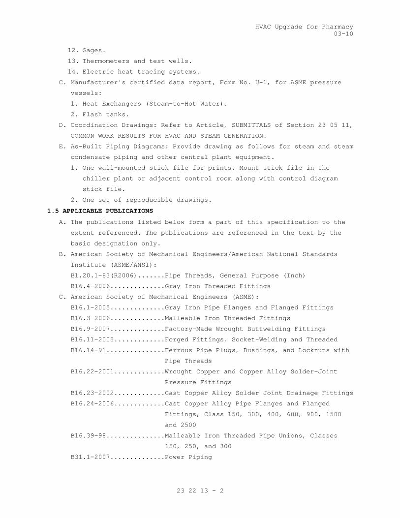
HVAC Upgrade for Pharmacy03-10
23 22 13 - 2
12. Gages.
13. Thermometers and test wells.
14. Electric heat tracing systems.
C. Manufacturer's certified data report, Form No. U-1, for ASME pressure
vessels:
1. Heat Exchangers (Steam-to-Hot Water).
2. Flash tanks.
D. Coordination Drawings: Refer to Article, SUBMITTALS of Section 23 05 11,
COMMON WORK RESULTS FOR HVAC AND STEAM GENERATION.
E. As-Built Piping Diagrams: Provide drawing as follows for steam and steam
condensate piping and other central plant equipment.
1. One wall-mounted stick file for prints. Mount stick file in the
chiller plant or adjacent control room along with control diagram
stick file.
2. One set of reproducible drawings.
1.5 APPLICABLE PUBLICATIONS
A. The publications listed below form a part of this specification to the
extent referenced. The publications are referenced in the text by the
basic designation only.
B. American Society of Mechanical Engineers/American National Standards
Institute (ASME/ANSI):
B1.20.1-83(R2006).......Pipe Threads, General Purpose (Inch)
B16.4-2006..............Gray Iron Threaded Fittings
C. American Society of Mechanical Engineers (ASME):
B16.1-2005..............Gray Iron Pipe Flanges and Flanged Fittings
B16.3-2006..............Malleable Iron Threaded Fittings
B16.9-2007..............Factory-Made Wrought Buttwelding Fittings
B16.11-2005.............Forged Fittings, Socket-Welding and Threaded
B16.14-91...............Ferrous Pipe Plugs, Bushings, and Locknuts with
Pipe Threads
B16.22-2001.............Wrought Copper and Copper Alloy Solder-Joint
Pressure Fittings
B16.23-2002.............Cast Copper Alloy Solder Joint Drainage Fittings
B16.24-2006.............Cast Copper Alloy Pipe Flanges and Flanged
Fittings, Class 150, 300, 400, 600, 900, 1500
and 2500
B16.39-98...............Malleable Iron Threaded Pipe Unions, Classes
150, 250, and 300
B31.1-2007..............Power Piping

HVAC Upgrade for Pharmacy03-10
23 22 13 - 3
B31.9-2008..............Building Services Piping
B40.100-2005............Pressure Gauges and Gauge Attachments
Boiler and Pressure Vessel Code: SEC VIII D1-2001, Pressure Vessels,
Division 1
D. American Society for Testing and Materials (ASTM):
A47-99..................Ferritic Malleable Iron Castings
A53-2007................Pipe, Steel, Black and Hot-Dipped, Zinc-Coated,
Welded and Seamless
A106-2008...............Seamless Carbon Steel Pipe for High-Temperature
Service
A126-2004...............Standard Specification for Gray Iron Castings
for Valves, Flanges, and Pipe Fittings
A181-2006...............Carbon Steel Forgings, for General-Purpose
Piping
A183-2003...............Carbon Steel Track Bolts and Nuts
A216-2008...............Standard Specification for Steel Castings,
Carbon, Suitable for Fusion Welding, for High
Temperature Service
A285-01.................Pressure Vessel Plates, Carbon Steel, Low-and-
Intermediate-Tensile Strength
A307-2007...............Carbon Steel Bolts and Studs, 60,000 PSI Tensile
Strength
A516-2006...............Pressure Vessel Plates, Carbon Steel, for
Moderate-and- Lower Temperature Service
A536-84(2004)e1.........Standard Specification for Ductile Iron Castings
B32-2008................Solder Metal
B61-2008................Steam or Valve Bronze Castings
B62-2009................Composition Bronze or Ounce Metal Castings
B88-2003................Seamless Copper Water Tube
F439-06.................Socket-Type Chlorinated Poly (Vinyl Chloride)
(CPVC) Plastic Pipe Fittings, Schedule 80
F441-02(2008)...........Chlorinated Poly (Vinyl Chloride) (CPVC) Plastic
Pipe, Schedules 40 and 80
E. American Welding Society (AWS):
A5.8-2004...............Filler Metals for Brazing and Braze Welding
B2.1-00.................Welding Procedure and Performance Qualifications
F. Manufacturers Standardization Society (MSS) of the Valve and Fitting
Industry, Inc.:
SP-67-95................Butterfly Valves
SP-70-98................Cast Iron Gate Valves, Flanged and Threaded Ends

HVAC Upgrade for Pharmacy03-10
23 22 13 - 4
SP-71-97................Gray Iron Swing Check Valves, Flanged and
Threaded Ends
SP-72-99................Ball Valves with Flanged or Butt-Welding Ends
for General Service
SP-78-98................Cast Iron Plug Valves, Flanged and Threaded Ends
SP-80-97................Bronze Gate, Globe, Angle and Check Valves
SP-85-94................Cast Iron Globe and Angle Valves, Flanged and
Threaded Ends
G. Military Specifications (Mil. Spec.):
MIL-S-901D-1989.........Shock Tests, H.I. (High Impact) Shipboard
Machinery, Equipment, and Systems
H. National Board of Boiler and Pressure Vessel Inspectors (NB): Relieving
Capacities of Safety Valves and Relief Valves
I. Tubular Exchanger Manufacturers Association: TEMA 18th Edition, 2000
PART 2 - PRODUCTS
2.1 PIPE AND EQUIPMENT SUPPORTS, PIPE SLEEVES, AND WALL AND CEILING PLATES
A. Provide in accordance with Section 23 05 11, COMMON WORK RESULTS FOR
HVAC AND STEAM GENERATION.
2.2 PIPE AND TUBING
A. Steam Piping: Steel, ASTM A53, Grade B, seamless or ERW; A106 Grade B,
Seamless; Schedule 40.
B. Steam Condensate and Pumped Condensate Piping:
1. Concealed above ceiling, in wall or chase: Copper water tube ASTM
B88, Type K, hard drawn.
2. All other locations: Copper water tube ASTM B88, Type K, hard drawn;
or steel, ASTM A53, Grade B, Seamless or ERW, or A106 Grade B
Seamless, Schedule 80.
C. Vent Piping: Steel, ASTM A53, Grade B, seamless or ERW; A106 Grade B,
Seamless; Schedule 40, galvanized.
2.3 FITTINGS FOR STEEL PIPE
A. 50 mm (2 inches) and Smaller: Screwed or welded.
1. Butt welding: ASME B16.9 with same wall thickness as connecting
piping.
2. Forged steel, socket welding or threaded: ASME B16.11.
3. Screwed: 150 pound malleable iron, ASME B16.3. 125 pound cast iron,
ASME B16.4, may be used in lieu of malleable iron, except for steam
and steam condensate piping. Provide 300 pound malleable iron, ASME
B16.3 for steam and steam condensate piping. Cast iron fittings or
piping is not acceptable for steam and steam condensate piping.
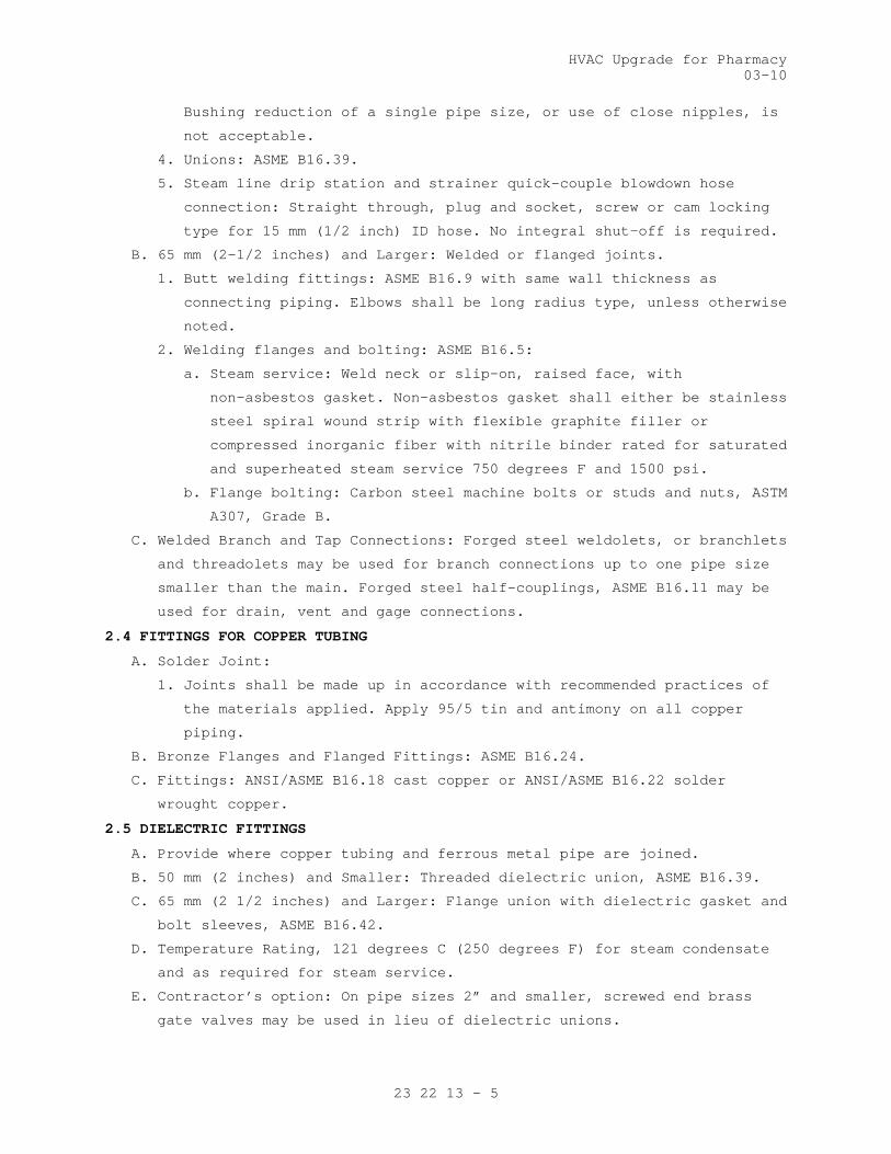
HVAC Upgrade for Pharmacy03-10
23 22 13 - 5
Bushing reduction of a single pipe size, or use of close nipples, is
not acceptable.
4. Unions: ASME B16.39.
5. Steam line drip station and strainer quick-couple blowdown hose
connection: Straight through, plug and socket, screw or cam locking
type for 15 mm (1/2 inch) ID hose. No integral shut-off is required.
B. 65 mm (2-1/2 inches) and Larger: Welded or flanged joints.
1. Butt welding fittings: ASME B16.9 with same wall thickness as
connecting piping. Elbows shall be long radius type, unless otherwise
noted.
2. Welding flanges and bolting: ASME B16.5:
a. Steam service: Weld neck or slip-on, raised face, with
non-asbestos gasket. Non-asbestos gasket shall either be stainless
steel spiral wound strip with flexible graphite filler or
compressed inorganic fiber with nitrile binder rated for saturated
and superheated steam service 750 degrees F and 1500 psi.
b. Flange bolting: Carbon steel machine bolts or studs and nuts, ASTM
A307, Grade B.
C. Welded Branch and Tap Connections: Forged steel weldolets, or branchlets
and threadolets may be used for branch connections up to one pipe size
smaller than the main. Forged steel half-couplings, ASME B16.11 may be
used for drain, vent and gage connections.
2.4 FITTINGS FOR COPPER TUBING
A. Solder Joint:
1. Joints shall be made up in accordance with recommended practices of
the materials applied. Apply 95/5 tin and antimony on all copper
piping.
B. Bronze Flanges and Flanged Fittings: ASME B16.24.
C. Fittings: ANSI/ASME B16.18 cast copper or ANSI/ASME B16.22 solder
wrought copper.
2.5 DIELECTRIC FITTINGS
A. Provide where copper tubing and ferrous metal pipe are joined.
B. 50 mm (2 inches) and Smaller: Threaded dielectric union, ASME B16.39.
C. 65 mm (2 1/2 inches) and Larger: Flange union with dielectric gasket and
bolt sleeves, ASME B16.42.
D. Temperature Rating, 121 degrees C (250 degrees F) for steam condensate
and as required for steam service.
E. Contractor’s option: On pipe sizes 2” and smaller, screwed end brass
gate valves may be used in lieu of dielectric unions.

HVAC Upgrade for Pharmacy03-10
23 22 13 - 6
2.6 SCREWED JOINTS
A. Pipe Thread: ANSI B1.20.
B. Lubricant or Sealant: Oil and graphite or other compound approved for
the intended service.
2.7 VALVES
A. Asbestos packing is not acceptable.
B. All valves of the same type shall be products of a single manufacturer.
C. Provide chain operators for valves 150 mm (6 inches) and larger when the
centerline is located 2100 mm (7 feet) or more above the floor or
operating platform.
D. Shut-Off Valves
1. Gate Valves:
a. 50 mm (2 inches) and smaller: MSS-SP80, Bronze, 1034 kPa (150
lb.), wedge disc, rising stem, union bonnet.
b. 65 mm (2 1/2 inches) and larger: Flanged, outside screw and yoke.
1) High pressure steam 413 kPa (60 psig) and above nominal MPS
system): Cast steel body, ASTM A216 grade WCB, 1034 kPa (150
psig) at 260 degrees C (500 degrees F), 11-1/2 to 13 percent
chrome stainless steel solid disc and seats. Provide 25 mm (1
inch) factory installed bypass with globe valve on valves 100
mm (4 inches) and larger.
2) All other services: MSS-SP 70, iron body, bronze mounted, 861
kPa (125 psig) wedge disc.
E. Globe and Angle Valves:
1. Globe Valves:
a. 50 mm (2 inches) and smaller: MSS-SP 80, bronze, 1034 kPa (150
lb.) Globe valves shall be union bonnet with metal plug type disc.
b. 65 mm (2 1/2 inches) and larger:
1) Globe valves for high pressure steam 413 kPa (60 psig) and
above nominal MPS system): Cast steel body, ASTM A216 grade
WCB, flanged, OS&Y, 1034 kPa (150 psig) at 260 degrees C (500
degrees F), 11-1/2 to 13 percent chrome stainless steel disc
and renewable seat rings.
2) All other services: 861 kPa (125 psig), flanged, iron body,
bronze trim, MSS-SP-85 for globe valves.
2. Angle Valves
a. 50 mm (2 inches) and smaller: MSS-SP 80, bronze, 1034 kPa (150
lb.) Angle valves shall be union bonnet with metal plug type disc.
b. 65 mm (2 1/2 inches) and larger:

HVAC Upgrade for Pharmacy03-10
23 22 13 - 7
1) Angle valves for high pressure steam 413 kPa (60 psig) and
above nominal MPS system): Cast steel body, ASTM A216 grade
WCB, flanged, OS&Y, 1034 kPa (150 psig) at 260 degrees C (500
degrees F), 11-1/2 to 13 percent chrome stainless steel disc
and renewable seat rings.
2) All other services: 861 kPa (125 psig), flanged, iron body,
bronze trim, MSS-SP-85 for angle valves.
F. Swing Check Valves
1. 50 mm (2 inches) and smaller: MSS-SP 80, bronze, 1034 kPa (150 psig),
45 degree swing disc.
2. 65 mm (2-1/2 inches) and Larger:
a Check valves for high pressure steam 413 kPa (60 psig) and above
nominal MPS system: Cast steel body, ASTM A216 grade WCB, flanged,
OS&Y, 1034 kPa (150 psig) at 260 degrees C (500 degrees F), 11-1/2
to 13 percent chrome stainless steel disc and renewable seat
rings.
b. All other services: 861 kPa (125 psig), flanged, iron body, bronze
trim, MSS-SP-71 for check valves.
G. Manual Radiator/Convector Valves: Brass, packless, with position
indicator.
2.8 STRAINERS
A. Basket or Y Type. Tee type is acceptable for gravity flow and pumped
steam condensate service.
B. High Pressure Steam: Rated 1034 kPa (150 psig) saturated steam.
1. 50 mm (2 inches) and smaller: Iron, ASTM A116 Grade B, or bronze,
ASTM B-62 body with screwed connections (250 psig).
2. 65 mm (2-1/2 inches) and larger: Flanged cast steel or 1723 kPa (250
psig) cast iron.
C. All Other Services: Rated 861 kPa (125 psig) saturated steam.
1. 50 mm (2 inches) and smaller: Cast iron or bronze.
2. 65 mm (2-1/2 inches) and larger: Flanged, iron body.
D. Screens: Bronze, monel metal or 18-8 stainless steel, free area not less
than 2-1/2 times pipe area, with perforations as follows:
1. 75 mm (3 inches) and smaller: 20 mesh for steam and 1.1 mm (0.045
inch) diameter perforations for liquids.
2. 100 mm (4 inches) and larger: 1.1 mm (0.045) inch diameter
perforations for steam and 3.2 mm (0.125 inch) diameter perforations
for liquids.
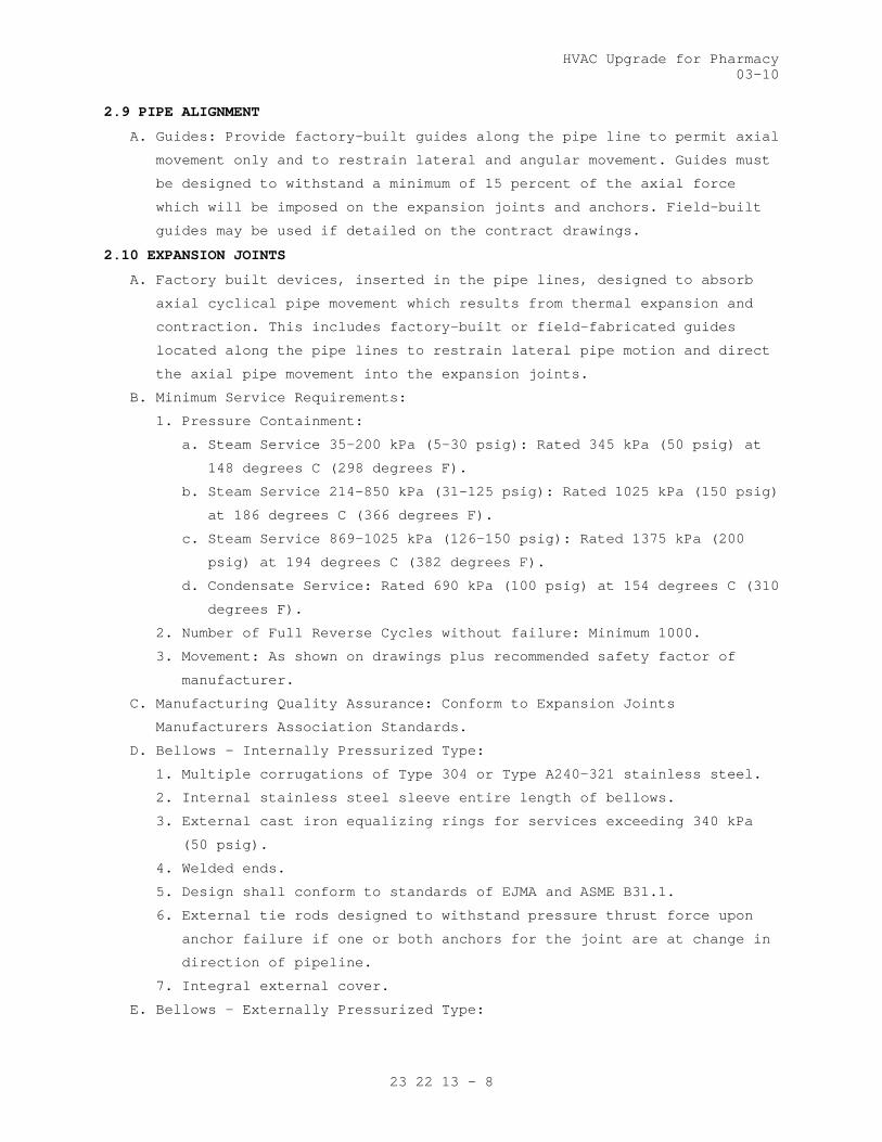
HVAC Upgrade for Pharmacy03-10
23 22 13 - 8
2.9 PIPE ALIGNMENT
A. Guides: Provide factory-built guides along the pipe line to permit axial
movement only and to restrain lateral and angular movement. Guides must
be designed to withstand a minimum of 15 percent of the axial force
which will be imposed on the expansion joints and anchors. Field-built
guides may be used if detailed on the contract drawings.
2.10 EXPANSION JOINTS
A. Factory built devices, inserted in the pipe lines, designed to absorb
axial cyclical pipe movement which results from thermal expansion and
contraction. This includes factory-built or field-fabricated guides
located along the pipe lines to restrain lateral pipe motion and direct
the axial pipe movement into the expansion joints.
B. Minimum Service Requirements:
1. Pressure Containment:
a. Steam Service 35-200 kPa (5-30 psig): Rated 345 kPa (50 psig) at
148 degrees C (298 degrees F).
b. Steam Service 214-850 kPa (31-125 psig): Rated 1025 kPa (150 psig)
at 186 degrees C (366 degrees F).
c. Steam Service 869-1025 kPa (126-150 psig): Rated 1375 kPa (200
psig) at 194 degrees C (382 degrees F).
d. Condensate Service: Rated 690 kPa (100 psig) at 154 degrees C (310
degrees F).
2. Number of Full Reverse Cycles without failure: Minimum 1000.
3. Movement: As shown on drawings plus recommended safety factor of
manufacturer.
C. Manufacturing Quality Assurance: Conform to Expansion Joints
Manufacturers Association Standards.
D. Bellows - Internally Pressurized Type:
1. Multiple corrugations of Type 304 or Type A240-321 stainless steel.
2. Internal stainless steel sleeve entire length of bellows.
3. External cast iron equalizing rings for services exceeding 340 kPa
(50 psig).
4. Welded ends.
5. Design shall conform to standards of EJMA and ASME B31.1.
6. External tie rods designed to withstand pressure thrust force upon
anchor failure if one or both anchors for the joint are at change in
direction of pipeline.
7. Integral external cover.
E. Bellows - Externally Pressurized Type:

HVAC Upgrade for Pharmacy03-10
23 22 13 - 9
1. Multiple corrugations of Type 304 stainless steel.
2. Internal and external guide integral with joint.
3. Design for external pressurization of bellows to eliminate squirm.
4. Welded ends.
5. Conform to the standards of EJMA and ASME B31.1.
6. Threaded connection at bottom, 25 mm (one inch) minimum, for drain or
drip point.
7. Integral external cover and internal sleeve.
F. Expansion Joint Identification: Provide stamped brass or stainless steel
nameplate on each expansion joint listing the manufacturer, the
allowable movement, flow direction, design pressure and temperature,
date of manufacture, and identifying the expansion joint by the
identification number on the contract drawings.
2.11 FLEXIBLE BALL JOINTS
A. Design and Fabrication: One piece component construction, fabricated
from steel with welded ends, designed for a working steam pressure of
1720 kPa (250 psig) and a temperature of 232 degrees C (450 degrees F).
Each joint shall provide for 360 degrees rotation in addition to a
minimum angular flexible movement of 30 degrees for sizes 6 mm (1/4
inch) to 150 mm (6 inch) inclusive, and 15 degrees for sizes 65 mm
(2-1/2 inches) to 750 mm (30 inches). Joints through 350 mm (14 inches)
shall have forged pressure retaining members; while size 400 mm (16
inches) through 760 mm (30 inches) shall be of one piece construction.
B. Material:
1. Cast or forged steel pressure containing parts and bolting in
accordance with Section II of the ASME Boiler Code or ASME B31.1.
Retainer may be ductile iron ASTM A536, Grade 65-45-12, or ASME
Section II SA 515, Grade 70.
2. Gaskets: Steam pressure molded composition design for a temperature
range of from minus 10 degrees C (50 degrees F) to plus 274 degrees C
(525 degrees F).
C. Certificates: Submit qualifications of ball joints in accordance with
the following test data:
1. Low pressure leakage test: 41 kPa (6psig) saturated steam for 60
days.
2. Flex cycling: 800 Flex cycles at 3445 kPa (500 psig) saturated steam.
3. Thermal cycling: 100 saturated steam pressure cycles from atmospheric
pressure to operating pressure and back to atmospheric pressure.

HVAC Upgrade for Pharmacy03-10
23 22 13 - 10
4. Environmental shock tests: Forward certificate from a recognized test
laboratory, that ball joints of the type submitted has passed shock
testing in accordance with Mil. Spec MIL-S-901.
5. Vibration: 170 hours on each of three mutually perpendicular axis at
25 to 125 Hz; 1.3 mm to 2.5 mm (0.05 inch to 0.1 inch) double
amplitude on a single ball joint and 3 ball joint off set.
2.12 STEAM SYSTEM COMPONENTS
A. Heat Exchanger (Steam to Hot Water): Shell and tube type, U-bend
removable tube bundle, steam in shell, water in tubes, equipped with
support cradles.
1. Maximum tube velocity: 2.3 m/s (7.5 feet per second).
2. Tube fouling factor: TEMA Standards, but not less than 0.00018 m2K/W
(0.001 ft2hrF/Btu).
3. Materials:
a. Shell: Steel.
b. Tube sheet and tube supports: Steel or brass.
c. Tubes: 20 mm (3/4 inch) OD copper.
d. Head or bonnet: Cast iron or steel.
4. Construction: In accordance with ASME Pressure Vessel Code for 861
kPa (125 psig) working pressure for shell and tubes. Provide
manufacturer's certified data report, Form No. U-1.
B. Optional Heat Transfer Package: In lieu of field erected individual
components, the Contractor may provide a factory or shop assembled
package of heat exchangers, pumps, and other components supported on a
welded steel frame.
C. Steam Pressure Reducing Valves in PRV Stations:
1. Type: Single-seated, diaphragm operated, spring-loaded, external or
internal steam pilot-controlled, normally closed, adjustable set
pressure. Pilot shall sense controlled pressure downstream of main
valve.
2. Service: Provide controlled reduced pressure to steam piping systems.
3. Pressure control shall be smooth and continuous with maximum drop of
10 percent. Maximum flow capability of each valve shall not exceed
capacity of downstream safety valve(s).
4. Main valve and pilot valve shall have replaceable valve plug and seat
of stainless steel, monel, or similar durable material.
a. Pressure rating for high pressure steam: Not less than 1034 kPa
(150 psig) saturated steam.
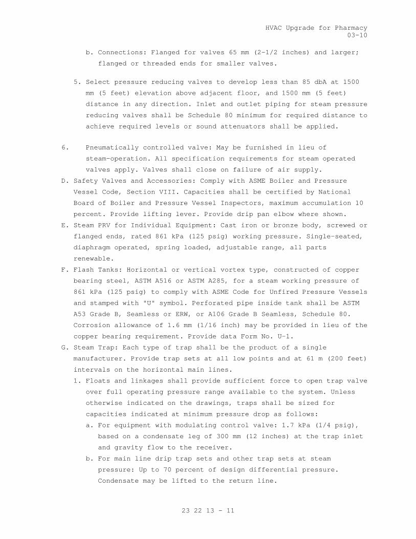
HVAC Upgrade for Pharmacy03-10
23 22 13 - 11
b. Connections: Flanged for valves 65 mm (2-1/2 inches) and larger;
flanged or threaded ends for smaller valves.
5. Select pressure reducing valves to develop less than 85 dbA at 1500
mm (5 feet) elevation above adjacent floor, and 1500 mm (5 feet)
distance in any direction. Inlet and outlet piping for steam pressure
reducing valves shall be Schedule 80 minimum for required distance to
achieve required levels or sound attenuators shall be applied.
6. Pneumatically controlled valve: May be furnished in lieu of
steam-operation. All specification requirements for steam operated
valves apply. Valves shall close on failure of air supply.
D. Safety Valves and Accessories: Comply with ASME Boiler and Pressure
Vessel Code, Section VIII. Capacities shall be certified by National
Board of Boiler and Pressure Vessel Inspectors, maximum accumulation 10
percent. Provide lifting lever. Provide drip pan elbow where shown.
E. Steam PRV for Individual Equipment: Cast iron or bronze body, screwed or
flanged ends, rated 861 kPa (125 psig) working pressure. Single-seated,
diaphragm operated, spring loaded, adjustable range, all parts
renewable.
F. Flash Tanks: Horizontal or vertical vortex type, constructed of copper
bearing steel, ASTM A516 or ASTM A285, for a steam working pressure of
861 kPa (125 psig) to comply with ASME Code for Unfired Pressure Vessels
and stamped with "U" symbol. Perforated pipe inside tank shall be ASTM
A53 Grade B, Seamless or ERW, or A106 Grade B Seamless, Schedule 80.
Corrosion allowance of 1.6 mm (1/16 inch) may be provided in lieu of the
copper bearing requirement. Provide data Form No. U-1.
G. Steam Trap: Each type of trap shall be the product of a single
manufacturer. Provide trap sets at all low points and at 61 m (200 feet)
intervals on the horizontal main lines.
1. Floats and linkages shall provide sufficient force to open trap valve
over full operating pressure range available to the system. Unless
otherwise indicated on the drawings, traps shall be sized for
capacities indicated at minimum pressure drop as follows:
a. For equipment with modulating control valve: 1.7 kPa (1/4 psig),
based on a condensate leg of 300 mm (12 inches) at the trap inlet
and gravity flow to the receiver.
b. For main line drip trap sets and other trap sets at steam
pressure: Up to 70 percent of design differential pressure.
Condensate may be lifted to the return line.

HVAC Upgrade for Pharmacy03-10
23 22 13 - 12
2. Trap bodies: Bronze, cast iron, or semi-steel, constructed to permit
ease of removal and servicing working parts without disturbing
connecting piping. For systems without relief valve traps shall be 5.
Mechanism: Brass, stainless steel or corrosion resistant alloy.
rated for the pressure upstream of the PRV supplying the system.
3. Balanced pressure thermostatic elements: Phosphor bronze, stainless
steel or monel metal.
4. Valves and seats: Suitable hardened corrosion resistant alloy.
6. Floats: Stainless steel.
7. Inverted bucket traps: Provide bi-metallic thermostatic element for
rapid release of non-condensables.
H. Thermostatic Air Vent (Steam): Brass or iron body, balanced pressure
bellows, stainless steel (renewable) valve and seat, rated 861 kPa (125
psig) working pressure, 20 mm (3/4 inch) screwed connections. Air vents
shall be balanced pressure type that responds to steam
pressure-temperature curve and vents air at any pressure.
I. Steam Humidifiers:
1. Steam separator type that discharges steam into the air stream
through a steam jacketed distribution manifold or dispersion tube.
Humidifiers shall be complete with Y-type steam supply strainer;
modulating, normally closed steam control valve; normally closed
condensate temperature switch; and manufacturer's standard steam
trap.
2. Steam separator: Stainless steel or cast iron.
3. Distribution manifold: Stainless steel, composed of dispersion pipe
and surrounding steam jacket, manifold shall span the width of duct
or air handler, and shall be multiple manifold type under any of the
following conditions:
a. Duct section height exceeds 900 mm (36 inches).
b. Duct air velocity exceeds 5.1 m/s (1000 feet per minute).
b. If within 900 mm (3 feet) upstream of fan, damper or pre-filter.
d. If within 3000 mm (10 feet) upstream of after-filter.
J. Unfired clean steam generator
1. Provide a packaged factory assembled, pre-piped unfired steam
generator consisting of stainless steel shell, stainless steel tube
coil, stainless steel steam piping, valves and controls All stainless
steel piping shall be type //304//316 factory-fabricated and provided
as a part of the complete package.

HVAC Upgrade for Pharmacy03-10
23 22 13 - 13
2. Shell: Stainless steel ASME code construction with flanged piping
connections. 345 kPa (50 psig) maximum WSP.
3. Tubes: Copper tubes suitable for 862 kPa (125 psig) working pressure.
4. Design: Heated fluid in shell and heating fluid (higher pressure
steam) in tubes.
5. Each steam generator shall be furnished with the following
accessories:
a. Resilient insulation.
b. Pilot operated modulating control valve with pressure controller.
c. Control pilot to maintain constant steam output.
d. Pressure relief valve.
e. Vessel and tube side pressure gages.
f. Liquid level controller with brass feed water solenoid valve, in
check valve and strainer.
g. Over-pressure limit system with auto-reset.
h. Factory packaging.
i. Dual F&T condensate traps.
j. Manual blow down valve.
k. Time based TDS based automatic blow down
l. Low water cut-off and high pressure cut-off.
m. Fully wired control box.
n. Automatic drain solenoid valve.
6. Provide solid state control module with LED backlit LCD display and
LED pilot lights to indicate on-off, high pressure, low pressure, low
water and water feed. Control module shall allow the local adjustment
of pressure limits on display screen. Control module shall have alarm
light and alarm horn with built in alarm silence relay. Control
module shall be supplied with dry contact closure outputs to indicate
to building automation controls (BAC) the occurrence of power on,
high pressure, low pressure, low water and water feed. The control
module shall allow the BAC to turn the unfired steam generator on or
off through a remote relay suitable for 24 VAC, 1 amp. The control
module shall allow the BAC to remotely monitor the operating
pressure. Control module shall be supplied with an on-off switch and
shall be mounted in a NEMA 1 panel. All solenoids and limits shall be
24 VAC.
K. Steam Gun Set: Furnish for ready coupling to building steam and cold
water and designed for rinsing equipment (such as carts and racks) with
hot or cold water, cleaning such articles with detergent-laden hot water
or steam, or alternately sanitizing the articles with only live steam.
HVAC Upgrade for Pharmacy03-10
23 22 13 - 14
1. Gun: Fit gun for finger-tip release of steam. Design so siphoning
action will automatically mix detergent with gun effluent. Equip gun
with hardwood front and rear handgrips. Include a 25 mm (15/16-inch)
diameter, double tube butyl hose reinforced with braid and designed
for 1034 kPa (150 psig) pressure. Hose shall be 3600 mm (12 feet)
long.
2. Detergent Tank: Furnish 9.5 L (2-1/2 gallon) polyethylene or
fiberglass storage tank and fit for wall mounting. Also provide 13 mm
(1/2 inch) diameter neoprene double wall detergent hose of the same
length as steam hose. Fit hose-to-tank connection with strainer. Fit
other end of hose with valve to regulate amount of detergent to be
mixed with steam.
3. Steam/Water Selector: Furnish manifold for wall mounting; design
manifold to deliver only steam or water, or steam and water mix to
gun. Construct mounting panel of stainless steel. Valves and piping
located in panel shall be brass.
4. Accessories: Provide one pair of protective gloves and three 50 mm (2
inch) diameter brushes, one nylon and two stainless-steel.
L. Steam Hose and Accessories: Hose shall be sufficiently flexible to be
placed in a 100 mm (4 feet) diameter coil.
1. Furnish and install in the mechanical room housing each PRV station a
7500 mm (25 feet) length of 13 mm (1/2 inch) ID steam hose, rated 861
kPa (125 psig) and a hose rack. In one end of the hose install a
quick-couple device, suitable for steam service, to match
corresponding devices in the PRV blowdown connections.
2. Hose storage rack: Wall-mounted, steel, iron or aluminum,
semi-circular shape, with capacity to store 7500 mm (25 feet) of 13
mm (1/2 inch) ID steam hose.
M. Steam Flow Meter/Recorder: Section 23 09 23, DIRECT-DIGITAL CONTROL
SYSTEM FOR HVAC.
N. Steam Exhaust Head: Cast iron, fitted with baffle plates, to trap and
drain condensed water.
2.13 GAGES, PRESSURE AND COMPOUND
A. ASME B40.1, Accuracy Grade 1A, (pressure, vacuum, or compound), initial
mid-scale accuracy 1 percent of scale (Qualify grade), metal or phenolic
case, 115 mm (4-1/2 inches) in diameter, 6 mm (1/4 inch) NPT bottom
connection, white dial with black graduations and pointer, clear glass
or acrylic plastic window, suitable for board mounting. Provide red "set
hand" to indicate normal working pressure.

HVAC Upgrade for Pharmacy03-10
23 22 13 - 15
B. Provide brass, lever handle union cock. Provide brass/bronze pressure
snubber for gages in water service. Provide brass pigtail syphon for
steam gages.
C. Range of Gages: For services not listed provide range equal to at least
130 percent of normal operating range:
Low pressure steam and steamcondensate to 103 kPa(15 psig)
0 to 207 kPa (30 psig).
2.14 PRESSURE/TEMPERATURE TEST PROVISIONS
A. Provide one each of the following test items to the Resident Engineer:
1. 6 mm (1/4 inch) FPT by 3 mm (1/8 inch) diameter stainless steel
pressure gage adapter probe for extra long test plug. PETE'S 500 XL
is an example.
2. 90 mm (3-1/2 inch) diameter, one percent accuracy, compound gage, 762
mm (30 inches) Hg to 689 kPa (100 psig) range.
3. 0 - 104 degrees C (32-220 degrees F) pocket thermometer one-half
degree accuracy, 25 mm (one inch) dial, 125 mm (5 inch) long
stainless steel stem, plastic case.
2.15 FIRESTOPPING MATERIAL
A. Refer to Section 23 05 11, COMMON WORK RESULTS FOR HVAC AND STEAM
GENERATION.
2.16 ELECTRICAL HEAT TRACING SYSTEMS
A. Systems shall meet requirements of the National Electrical Code (NEC),
Section 427.
B. Provide tracing for outdoor piping subject to freezing temperatures
(Below 38 degrees F) as follows:
1. Steam piping exposed to weather.
2. Steam condensate exposed to weather.
3. Pumped condensate piping exposed to weather.
C. Heat tracing shall be provided to the piping located on the roof. Heat
tracing shall extend below grade to below the defined frost line.
D. Heating Cable: Flexible, parallel circuit construction consisting of a
continuous self-limiting resistance, conductive inner core material
between two parallel copper bus wires, designed for cut-to-length at the
job site and for wrapping around valves and complex fittings.
Self-regulation shall prevent overheating and burnouts even where the
cable overlaps itself.
1. Provide end seals at ends of circuits. Wires at the ends of the
circuits are not to be tied together.

HVAC Upgrade for Pharmacy03-10
23 22 13 - 16
2. Provide sufficient cable, as recommended by the manufacturer, to keep
the pipe surface at 2.2 degrees C (36 degrees F) minimum during
winter outdoor design temperature, but not less than the following:
a. 75 mm (3 inch) pipe and smaller with 25 mm (1 inch) thick
insulation: 4 watts per foot of pipe.
b. 100 mm (4 inch)pipe and larger 38 mm (1-1/2 inch) thick
insulation: 8 watts per feet of pipe.
E. Electrical Heating Tracing Accessories:
1. Power supply connection fitting and stainless steel mounting
brackets. Provide stainless steel worm gear clamp to fasten bracket
to pipe.
2. 13 mm (1/2 inch) wide fiberglass reinforced pressure sensitive cloth
tape to fasten cable to pipe at 300 mm (12 inch) intervals.
3. Pipe surface temperature control thermostat: Cast aluminum, NEMA 4
(watertight) enclosure, 13 mm (1/2 inch) NPT conduit hub, SPST switch
rated 20 amps at 480 volts AC, with capillary and copper bulb sensor.
Set thermostat to maintain pipe surface temperature at not less than
1.1 degrees C (34 degrees F).
4. Signs: Manufacturer's standard (NEC Code), stamped "ELECTRIC TRACED"
located on the insulation jacket at 3000 mm (10 feet) intervals along
the pipe on alternating sides.
PART 3 - EXECUTION
3.1 GENERAL
A. The drawings show the general arrangement of pipe and equipment but do
not show all required fittings and offsets that may be necessary to
connect pipes to equipment, fan-coils, coils, radiators, etc., and to
coordinate with other trades. Provide all necessary fittings, offsets
and pipe runs based on field measurements and at no additional cost to
the government. Coordinate with other trades for space available and
relative location of HVAC equipment and accessories to be connected on
ceiling grid. Pipe location on the drawings shall be altered by
contractor where necessary to avoid interferences and clearance
difficulties.
B. Store materials to avoid excessive exposure to weather or foreign
materials. Keep inside of piping relatively clean during installation
and protect open ends when work is not in progress.
C. Support piping securely. Refer to PART 3, Section 23 05 11, COMMON WORK
RESULTS FOR HVAC AND STEAM GENERATION. Install convertors and other heat

HVAC Upgrade for Pharmacy03-10
23 22 13 - 17
exchangers at height sufficient to provide gravity flow of condensate to
the flash tank and condensate pump.
D. Install piping generally parallel to walls and column center lines,
unless shown otherwise on the drawings. Space piping, including
insulation, to provide 25 mm (one inch) minimum clearance between
adjacent piping or other surface. Unless shown otherwise, slope steam,
condensate and drain piping down in the direction of flow not less than
25 mm (one inch) in 12 m (40 feet). Provide eccentric reducers to keep
bottom of sloped piping flat.
E. Locate and orient valves to permit proper operation and access for
maintenance of packing, seat and disc. Generally locate valve stems in
overhead piping in horizontal position. Provide a union adjacent to one
end of all threaded end valves. Control valves usually require reducers
to connect to pipe sizes shown on the drawing. Install butterfly valves
with the valve open as recommended by the manufacturer to prevent
binding of the disc in the seat.
F. Offset equipment connections to allow valving off for maintenance and
repair with minimal removal of piping. Provide flexibility in equipment
connections and branch line take-offs with 3-elbow swing joints where
noted on the drawings.
G. Tee water piping runouts or branches into the side of mains or other
branches. Avoid bull-head tees, which are two return lines entering
opposite ends of a tee and exiting out the common side.
H. Connect piping to equipment as shown on the drawings. Install components
furnished by others such as:
1. Flow elements (orifice unions), control valve bodies, flow switches,
pressure taps with valve, and wells for sensors.
I. Firestopping: Fill openings around uninsulated piping penetrating floors
or fire walls, with firestop material. For firestopping insulated piping
refer to Section 23 07 11, HVAC, PLUMBING, and BOILER PLANT INSULATION.
J. Where copper piping is connected to steel piping, provide dielectric
connections.
K. Pipe vents to the exterior. Where a combined vent is provided, the cross
sectional area of the combined vent shall be equal to sum of individual
vent areas. Slope vent piping one inch in 40 feet (0.25 percent) in
direction of flow. Provide a drip trap elbow on relief valve outlets if
the vent rises to prevent backpressure. Terminate vent minimum 0.3 M
(12 inches) above the roof or through the wall minimum 2.5 M (8 feet)
above grade with down turned elbow.

HVAC Upgrade for Pharmacy03-10
23 22 13 - 18
3.2 PIPE JOINTS
A. Welded: Beveling, spacing and other details shall conform to ASME B31.1
and AWS B2.1. See Welder’s qualification requirements under "Quality
Assurance" in Section 23 05 11, COMMON WORK RESULTS FOR HVAC and STEAM
GENERATION.
B. Screwed: Threads shall conform to ASME B1.20; joint compound shall be
applied to male threads only and joints made up so no more than three
threads show. Coat exposed threads on steel pipe with joint compound, or
red lead paint for corrosion protection.
C. 125 Pound Cast Iron Flange (Plain Face): Mating flange shall have raised
face, if any, removed to avoid overstressing the cast iron flange.
3.3 EXPANSION JOINTS (BELLOWS AND SLIP TYPE)
A. Anchors and Guides: Provide type, quantity and spacing as recommended by
manufacturer of expansion joint and as shown. A professional engineer
shall verify in writing that anchors and guides are properly designed
for forces and moments which will be imposed.
B. Cold Set: Provide setting of joint travel at installation as recommended
by the manufacturer for the ambient temperature during the installation.
C. Preparation for Service: Remove all apparatus provided to restrain joint
during shipping or installation. Representative of manufacturer shall
visit the site and verify that installation is proper.
D. Access: Expansion joints must be located in readily accessible space.
Locate joints to permit access without removing piping or other devices.
Allow clear space to permit replacement of joints and to permit access
to devices for inspection of all surfaces and for adding packing.
3.4 STEAM TRAP PIPING
A. Install to permit gravity flow to the trap. Provide gravity flow (avoid
lifting condensate) from the trap where modulating control valves are
used. Support traps weighing over 11 kg (25 pounds) independently of
connecting piping.
3.6 LEAK TESTING
A. Inspect all joints and connections for leaks and workmanship and make
corrections as necessary, to the satisfaction of the Resident Engineer
in accordance with the specified requirements. Testing shall be
performed in accordance with the specification requirements.
B. An operating test at design pressure, and for hot systems, design
maximum temperature.
C. A hydrostatic test at 1.5 times design pressure. For water systems the
design maximum pressure would usually be the static head, or expansion

HVAC Upgrade for Pharmacy03-10
23 22 13 - 19
tank maximum pressure, plus pump head. Factory tested equipment
(convertors, exchangers, coils, etc.) need not be field tested. Avoid
excessive pressure on mechanical seals and safety devices.
3.7 FLUSHING AND CLEANING PIPING SYSTEMS
A. Steam, Condensate and Vent Piping: No flushing or chemical cleaning
required. Accomplish cleaning by pulling all strainer screens and
cleaning all scale/dirt legs during start-up operation.
3.8 OPERATING AND PERFORMANCE TEST AND INSTRUCTION
A. Refer to PART 3, Section 23 05 11, COMMON WORK RESULTS FOR HVAC and
STEAM GENERATION.
B. Adjust red set hand on pressure gages to normal working pressure.
- - - E N D - - -
HVAC Upgrade for Pharmacy04-11
23 31 00 - 1
SECTION 23 31 00HVAC DUCTS AND CASINGS
PART 1 - GENERAL
1.1 DESCRIPTION
A. Ductwork and accessories for HVAC including the following:
1. Supply air, return air, outside air, exhaust, roof hoods, goosenecks
and relief systems.
B. Definitions:
1. SMACNA Standards as used in this specification means the HVAC Duct
Construction Standards, Metal and Flexible.
2. Seal or Sealing: Use of liquid or mastic sealant, with or without
compatible tape overlay, or gasketing of flanged joints, to keep air
leakage at duct joints, seams and connections to an acceptable
minimum.
3. Duct Pressure Classification: SMACNA HVAC Duct Construction
Standards, Metal and Flexible.
4. Exposed Duct: Exposed to view in a finished room.
1.2 RELATED WORK
A. Outdoor and Exhaust Louvers: Section 08 90 00, LOUVERS AND VENTS.
B. General Mechanical Requirements: Section 23 05 11, COMMON WORK RESULTS
FOR HVAC.
C. Noise Level Requirements: Section 23 05 41, NOISE AND VIBRATION CONTROL
FOR HVAC PIPING AND EQUIPMENT.
D. Duct Insulation: Section 23 07 11, HVAC AND PLUMBING INSULATION
E. Duct Mounted Coils: Section 23 82 16, AIR COILS.
F. Duct Mounted Instrumentation: Section 23 09 23, DIRECT-DIGITAL CONTROL
SYSTEM FOR HVAC.
G. Testing and Balancing of Air Flows: Section 23 05 93, TESTING,
ADJUSTING, AND BALANCING FOR HVAC.
1.3 QUALITY ASSURANCE
A. Refer to article, QUALITY ASSURANCE, in Section 23 05 11, COMMON WORK
RESULTS FOR HVAC.
B. Fire Safety Code: Comply with NFPA 90A.
C. Duct System Construction and Installation: Referenced SMACNA Standards
are the minimum acceptable quality.
D. Duct Sealing, Air Leakage Criteria, and Air Leakage Tests: Ducts shall
be sealed as per duct sealing requirements of SMACNA Standards for duct
pressure classes shown on the drawings.
HVAC Upgrade for Pharmacy04-11
23 31 00 - 2
E. Duct accessories exposed to the air stream, such as dampers of all types
(except smoke dampers) and access openings, shall be of the same
material as the duct or provide at least the same level of corrosion
resistance.
1.4 SUBMITTALS
A. Submit in accordance with Section 01 33 23, SHOP DRAWINGS, PRODUCT DATA,
AND SAMPLES.
B. Manufacturer's Literature and Data:
1. Rectangular ducts:
a. Schedules of duct systems, materials and selected SMACNA
construction alternatives for joints, sealing, gage and
reinforcement.
b. Duct liner.
c. Sealants and gaskets.
d. Access doors.
2. Round and flat oval duct construction details:
a. Manufacturer's details for duct fittings.
b. Duct liner.
c. Sealants and gaskets.
d. Access sections.
e. Installation instructions.
3. Volume dampers, back draft dampers.
4. Upper hanger attachments.
5. Fire dampers, fire doors, and smoke dampers with installation
instructions.
6. Sound attenuators, including pressure drop and acoustic performance.
7. Flexible ducts and clamps, with manufacturer's installation
instructions.
8. Flexible connections.
9. Instrument test fittings.
10. Details and design analysis of alternate or optional duct systems.
C. Coordination Drawings: Refer to article, SUBMITTALS, in Section 23 05
11, COMMON WORK RESULTS FOR HVAC.
1.5 APPLICABLE PUBLICATIONS
A. The publications listed below form a part of this specification to the
extent referenced. The publications are referenced in the text by the
basic designation only.
B. American Society of Civil Engineers (ASCE):

HVAC Upgrade for Pharmacy04-11
23 31 00 - 3
ASCE/SEI 7-05...........Minimum Design Loads for Buildings and Other
Structures
C. American Society for Testing and Materials (ASTM):
A653/A653M-08...........Standard Specification for Steel Sheet,
Zinc-Coated (Galvanized) or Zinc-Iron Alloy
coated (Galvannealed) by the Hot-Dip process
B209-07.................Standard Specification for Aluminum and
Aluminum-Alloy Sheet and Plate
C1071-05e1..............Standard Specification for Fibrous Glass Duct
Lining Insulation (Thermal and Sound Absorbing
Material)
E84-09..................Standard Test Method for Surface Burning
Characteristics of Building Materials
D. National Fire Protection Association (NFPA):
90A-09..................Standard for the Installation of Air
Conditioning and Ventilating Systems
E. Sheet Metal and Air Conditioning Contractors National Association
(SMACNA):
3rd Edition – 2005......HVAC Duct Construction Standards, Metal and
Flexible
1st Edition, 1985.......HVAC Air Duct Leakage Test Manual
F. Underwriters Laboratories, Inc. (UL):
UL 33...................Heat Responsive Links for Fire-Protection
Service
UL 181..................Factory-Made Air Ducts and Connectors
UL 555 .................Fire Dampers
UL 555S ................Smoke Dampers
PART 2 - PRODUCTS
2.1 DUCT MATERIALS AND SEALANTS
A. General: Except for systems specified otherwise, construct ducts and
accessories of galvanized sheet steel, ASTM A527, coating G90; or,
aluminum sheet, ASTM B209, alloy 1100, 3003 or 5052.
B. Joint Sealing:
1. Sealant: Elastomeric compound, gun or brush grade, maximum 25 flame
spread and 50 smoke developed (dry state) compounded specifically for
sealing ductwork as recommended by the manufacturer. Generally
provide liquid sealant, with or without compatible tape, for low
clearance slip joints and heavy, permanently elastic, mastic type

HVAC Upgrade for Pharmacy04-11
23 31 00 - 4
where clearances are larger. Oil base caulking and glazing compounds
are not acceptable because they do not retain elasticity and bond.
2. Tape: Use only tape specifically designated by the sealant
manufacturer and apply only over wet sealant. Pressure sensitive tape
shall not be used on bare metal or on dry sealant.
3. Gaskets in Flanged Joints: Soft neoprene.
C. Approved factory made joints such as DUCTMATE SYSTEM may be used.
2.2 DUCT CONSTRUCTION AND INSTALLATION
A. Follow SMACNA HVAC Duct Construction Standards.
B. Duct Pressure Class: 500 Pa 2 inch W.G.
C. Seal Class: As shown on the drawings and in accordance with SMACNA
Standards.
D. Round Ducts: Furnish duct and fittings made by the same manufacturer to
insure good fit of slip joints. When submitted and approved in advance,
round and flat oval duct, with size converted on the basis of equal
pressure drop, may be furnished in lieu of rectangular duct design shown
on the drawings.
1. Elbows: Diameters 150mm through 200 mm (6 through 8 inches) shall be
two sections die stamped, all others shall be gored construction,
maximum 18 degree angle, with all seams continuously welded or
standing seam. Coat galvanized areas of fittings damaged by welding
with corrosion resistant aluminum paint or galvanized repair
compound.
2. Provide bell mouth, conical tees or taps, laterals, reducers, and
other low loss fittings as shown in SMACNA HVAC Duct Construction
Standards.
E. Volume Dampers: Single blade, opposed blade, or multi-louver type as
detailed in SMACNA Standards.
F. Duct Hangers and Supports: Refer to SMACNA Standards. Avoid use of
trapeze hangers for round duct.
2.3 DUCT ACCESS DOORS, PANELS AND SECTIONS
A. Provide access doors, sized and located for maintenance work, upstream,
in the following locations:
1. Each duct mounted coil.
2. Each fire damper (for link service), smoke damper and automatic
control damper.
3. Each duct mounted smoke detector.
HVAC Upgrade for Pharmacy04-11
23 31 00 - 5
B. Openings shall be as large as feasible in small ducts, 300mm by 300mm
(12 inch by 12 inch) minimum where possible. Access sections in
insulated ducts shall be double-wall, insulated.
1. Refer to SMACNA HVAC Duct Construction Standards.
2.4 FIRE DAMPERS
A. Galvanized steel, interlocking blade type, UL listing and label, 1-1/2
hour rating, 70 degrees C (160 degrees F) fusible link, 100 percent free
opening with no part of the blade stack or damper frame in the air
stream.
B. Fire dampers shall be galvanized steel.
1. The damper frame may be of design and length as to function as the
mounting sleeve, thus eliminating the need for a separate sleeve, as
allowed by UL 555. Otherwise provide sleeves and mounting angles,
minimum 1.9mm (14 gage), required to provide installation equivalent
to the damper manufacturer's UL test installation.
2. Submit manufacturer's installation instructions conforming to UL 555
rating test.
2.5 COMBINATION FIRE AND SMOKE DAMPERS
A. Type: Static and dynamic; rated and labeled according to UL 555 and UL
555S.
B. Closing rating in ducts up to 1 kPa (4-inch wg) static pressure class
and minimum 20 m/s (4000-fpm) velocity.
C. Fire Rating: 1-1/2 and 3 hours.
D. Frame: Multiple-blade type; fabricated with roll-formed, 0.85mm (0.034
inch) thick galvanized steel; with mitered and interlocking corners.
E. Heat-Responsive Device: Replaceable, 74 deg C (165 deg F)rated, fusible
links.
F. Smoke Detector: Integral, factory wired for single-point connection.
G. Blades: Roll-formed, horizontal, interlocking, 0.85mm (0.034 inch)
thick, galvanized sheet steel. In place of interlocking blades, use
full-length, 0.85mm (0.034 inch thick, galvanized-steel blade
connectors.
H. Leakage: Class I
I. Rated pressure and velocity to exceed design airflow conditions.
J. Mounting Sleeve: Factory-installed, 1.3mm (0.052 inch) thick,
galvanized sheet steel; length to suit wall or floor application.
K. Damper Motors: Two-position action.

HVAC Upgrade for Pharmacy04-11
23 31 00 - 6
L. Comply with NEMA designation, temperature rating, service factor,
enclosure type, and efficiency requirements for motors specified in
Section 23 05 12 GENERAL MOTOR REQUIREMENTS FOR HVAC EQUIPMENT.
1. Spring-Return Motors: Equip with an integral spiral-spring mechanism
where indicated. Enclose entire spring mechanism in a removable
housing designed for service or adjustments. Size for running torque
rating of 17 Nm (150 in. x lbf) and breakaway torque rating of 17 Nm
(150 in. x lbf).
2. Outdoor Motors and Motors in Outdoor-Air Intakes: Equip with O-ring
gaskets designed to make motors weatherproof. Equip motors with
internal heaters to permit normal operation at minus 40 deg F (minus
40 deg C).
2.6 SMOKE DAMPERS
A. Maximum air velocity, through free area of open damper, and pressure
loss: Low pressure and medium pressure duct (supply, return, exhaust,
outside air): 450 m/min (1500 fpm). Maximum static pressure loss: 32 Pa
(0.13 inch W.G.).
B. Maximum air leakage, closed damper: 0.32 cubic meters /min/square meter
(4.0 CFM per square foot) at 750 Pa (3 inch W.G.) differential pressure.
C. Minimum requirements for dampers:
1. Shall comply with requirements of UL 555S, except for the Fire
Endurance and Hose Stream Test.
2. Frame: Galvanized steel channel with side, top and bottom stops or
seals.
3. Blades: Galvanized steel, parallel type preferably, 300 mm (12 inch)
maximum width, edges sealed with neoprene, rubber or felt, if
required to meet minimum leakage. Airfoil (streamlined) type for
minimum noise generation and pressure drop are preferred for duct
mounted dampers.
4. Shafts: Galvanized steel.
5. Bearings: Nylon, bronze sleeve or ball type.
6. Hardware: Zinc plated.
7. Operation: Automatic open/close. No smoke damper that requires manual
reset or link replacement after actuation is acceptable. See drawings
for required control operation.
D. Motor operator (actuator): Provide electric as required by the automatic
control system, externally mounted on stand-offs to allow complete
insulation coverage.

HVAC Upgrade for Pharmacy04-11
23 31 00 - 7
2.7 FLEXIBLE AIR DUCT
A. General: Factory fabricated, complying with NFPA 90A for connectors not
passing through floors or buildings. Flexible ducts shall not penetrate
any fire or smoke barrier which is required to have a fire resistance
rating of one hour or more. Flexible duct length shall not exceed 1.5 m
(5 feet). Provide insulated flexible air duct connectors in supply air
duct systems and elsewhere as shown.
B. Flexible ducts shall be listed by Underwriters Laboratories, Inc.,
complying with UL 181. Ducts larger than 200 mm (8 inches) in diameter
shall be Class 1. Ducts 200 mm (8 inches) in diameter and smaller may be
Class 1 or Class 2.
C. Insulated Flexible Air Duct: Factory made including mineral fiber
insulation with maximum C factor of 0.25 at 24 degrees C (75 degrees F)
mean temperature, encased with a low permeability moisture barrier outer
jacket, having a puncture resistance of not less than 50 Beach Units.
Acoustic insertion loss shall not be less than 3 dB per 300 mm (1 foot)
of straight duct, at 500 Hz, based on 150 mm (6 inch) duct, of 750 m/min
(2500 fpm).
D. Application Criteria:
1. Temperature range: -18 to 93 degrees C (0 to 200 degrees F) internal.
2. Maximum working velocity: 1200 m/min (4000 feet per minute).
3. Minimum working pressure, inches of water gage: 2500 Pa (10 inches)
positive, 500 Pa (2 inches) negative.
E. Duct Clamps: 100 percent nylon strap, 80 kg (175 pounds) minimum loop
tensile strength manufactured for this purpose or stainless steel strap
with cadmium plated worm gear tightening device. Apply clamps with
sealant and as approved for UL 181, Class 1 installation.
2.8 FLEXIBLE CONNECTIONS
A. Where duct connections are made to fans and air handling units, install
a non-combustible flexible connection of 822g (29 ounce) neoprene coated
fiberglass fabric approximately 150 mm (6 inches) wide. For connections
exposed to sun and weather provide hypalon coating in lieu of neoprene.
Burning characteristics shall conform to NFPA 90A. Securely fasten
flexible connections to round ducts with stainless steel or zinc-coated
iron draw bands with worm gear fastener. For rectangular connections,
crimp fabric to sheet metal and fasten sheet metal to ducts by screws
50mm (2 inches) on center. Fabric shall not be stressed other than by
air pressure. Allow at least 25 mm (one inch) slack to insure that no
vibration is transmitted.
HVAC Upgrade for Pharmacy04-11
23 31 00 - 8
2.9 SOUND ATTENUATING UNITS
A. Casing, not less than 1.0 mm (20 gage) galvanized sheet steel, or 1.3 mm
(18 gage) aluminum fitted with suitable flanges to make clean airtight
connections to ductwork. Sound-absorbent material faced with glass fiber
cloth and covered with not less than 0.6mm (24 gage) or heavier
galvanized perforated sheet steel, or 0.85 mm (22 gage) or heavier
perforated aluminum. Perforations shall not exceed 4 mm (5/32-inch)
diameter, approximately 25 percent free area. Sound absorbent material
shall be long glass fiber acoustic blanket meeting requirements of NFPA
90A.
B. Entire unit shall be completely air tight and free of vibration and
buckling at internal static pressures up to 2000 Pa (8 inches W.G.) at
operating velocities.
C. Pressure drop through each unit: Not to exceed indicated value at design
air quantities indicated.
D. Submit complete independent laboratory test data showing pressure drop
and acoustical performance.
E. Cap open ends of attenuators at factory with plastic, heavy duty paper,
cardboard, or other appropriate material to prevent entrance of dirt,
water, or any other foreign matter to inside of attenuator. Caps shall
not be removed until attenuator is installed in duct system.
2.10 THERMOMETER (AIR)
Refer to Section 23 09 23, DIRECT-DIGITAL CONTROL SYSTEM FOR HVAC.
2.11 INSTRUMENT TEST FITTINGS
A. Manufactured type with a minimum 50 mm (two inch) length for insulated
duct, and a minimum 25 mm (one inch) length for duct not insulated. Test
hole shall have a flat gasket for rectangular ducts and a concave gasket
for round ducts at the base, and a screw cap to prevent air leakage.
B. Provide instrument test holes at each duct mounted temperature sensor or
transmitter, and at entering and leaving side of each heating coil,
cooling coil, and heat recovery unit.
PART 3 - EXECUTION
3.1 INSTALLATION
A. Comply with provisions of Section 23 05 11, COMMON WORK RESULTS FOR
HVAC, particularly regarding coordination with other trades and work in
existing buildings.
B. Fabricate and install ductwork and accessories in accordance with
referenced SMACNA Standards:

HVAC Upgrade for Pharmacy04-11
23 31 00 - 9
1. Drawings show the general layout of ductwork and accessories but do
not show all required fittings and offsets that may be necessary to
connect ducts to equipment, boxes, diffusers, grilles, etc., and to
coordinate with other trades. Fabricate ductwork based on field
measurements. Provide all necessary fittings and offsets at no
additional cost to the government. Coordinate with other trades for
space available and relative location of HVAC equipment and
accessories on ceiling grid. Duct sizes on the drawings are inside
dimensions which shall be altered by Contractor to other dimensions
with the same air handling characteristics where necessary to avoid
interferences and clearance difficulties.
2. Provide duct transitions, offsets and connections to dampers, coils,
and other equipment in accordance with SMACNA HVAC Duct Construction
Standards. Provide streamliner, when an obstruction cannot be avoided
and must be taken in by a duct. Repair galvanized areas with
galvanizing repair compound.
3. Provide bolted construction and tie-rod reinforcement in accordance
with SMACNA HVAC Duct Construction Standards.
C. Install duct hangers and supports in accordance with SMACNA HVAC Duct
Construction Standards.
D. Install fire dampers in accordance with the manufacturer's instructions
to conform to the installation used for the rating test.
E. Seal openings around duct penetrations of floors and fire rated
partitions with fire stop material as required by NFPA 90A.
F. Flexible duct installation: Refer to SMACNA HVAC Duct Construction
Standards. Ducts shall be continuous, single pieces not over 1.5m (5
feet) long, as straight and short as feasible, adequately supported.
Centerline radius of bends shall be not less than two duct diameters.
Make connections with clamps as recommended by SMACNA Standards. Clamp
per SMACNA Standards with one clamp on the core duct and one on the
insulation jacket. Flexible ducts shall not penetrate floors, or any
chase or partition designated as a fire or smoke barrier, including
corridor partitions fire rated one hour or two hour. Support flexible
ducts per SMACNA HVAC Duct Construction Standards.
G. Control Damper Installation:
1. Provide necessary blank-off plates required to install dampers that
are smaller than duct size. Provide necessary transitions required to
install dampers larger than duct size.

HVAC Upgrade for Pharmacy04-11
23 31 00 - 10
2. Install all damper control/adjustment devices on stand-offs to allow
complete coverage of insulation.
H. Air Flow Measuring Devices (AFMD): Install units with minimum straight
run distances, upstream and downstream as recommended by the
manufacturer.
I. Low Pressure Duct Liner: Install in accordance with SMACNA HVAC Duct
Construction Standards.
J. Protection and Cleaning: Adequately protect equipment and materials
against physical damage. Place equipment in first class operating
condition, or return to source of supply for repair or replacement, as
determined by RE/COTR. Protect equipment and ducts during construction
against entry of foreign matter to the inside and clean both inside and
outside before operation and painting. When new ducts are connected to
existing ductwork, clean both new and existing ductwork by mopping and
vacuum cleaning inside and outside before operation.
3.2 DUCT LEAKAGE TESTS AND REPAIR
A. Leak testing company shall be independent of the sheet metal company
employed by General Contractor.
B. Ductwork leak test shall be performed for the entire air distribution
supply, return, exhaust system Section by Section including fans, coils
and filter Section designated as static pressure class 750 Pa (3 inch
W.G.) and above. All supply ductwork less than 500 Pa (3 inch W.G) shall
also be tested where there is no air terminal unit employed in the
system.
C. Test procedure, apparatus and report shall conform to SMACNA HVAC Air
Duct Leakage Test Manual. The maximum leakage rate allowed is 4 percent
of the design air flow rate.
D. All ductwork shall be leak tested first before enclosed in a shaft or
covered in other inaccessible areas.
E. All tests shall be performed in the presence of the RE/COTR and the Test
and Balance agency. The Test and Balance agency shall measure and record
duct leakage and report to the RE/COTR and identify leakage source with
excessive leakage.
F. If any portion of the duct system tested fails to meet the permissible
leakage level, the Contractor shall rectify sealing of ductwork to bring
it into compliance and shall retest it until acceptable leakage is
demonstrated to the RE/COTR.
G. All tests and necessary repairs shall be completed prior to insulation
or concealment of ductwork.

HVAC Upgrade for Pharmacy04-11
23 31 00 - 11
H. Make sure all openings used for testing flow and temperatures by TAB
Contractor are sealed properly.
3.4 TESTING, ADJUSTING AND BALANCING (TAB)
Refer to Section 23 05 93, TESTING, ADJUSTING, AND BALANCING FOR HVAC.
3.5 OPERATING AND PERFORMANCE TESTS
Refer to Section 23 05 11, COMMON WORK RESULTS FOR HVAC
- - - E N D - - -

HVAC Upgrade for Pharmacy
23 31 13 - 1
SECTION 23 31 13METAL DUCTS
PART 1 - GENERAL
1.1 Summary
A. Work Includes: fabrication and installation of HVAC ductwork asshown on the drawings and described in the Scope of Work, to include,but not limited to, the following:
1. Furnish all materials, tools and equipment necessary for the work2. Fabrication3. Delivery to the jobsite4. Installation5. Ductwork leak testing
B. Related work:
230553 Identification For HVAC Piping and Equipment233300 Air Duct Accessories
1.2 Submittals
A. All submittals shall be made in accordance with Abbott LaboratoriesEquipment and Materials Submittal Control List.
B. The Contractor shall submit the following within fifteen (15) workingdays after the award of contract:
1. Drawings, samples or otherwise describe the sheet metalconstruction methods pertaining to material gauge, sealing,transverse joints, longitudinal joints and reinforcement that heintends to use.
2. Drawings, catalog cuts and samples to describe the hangerattachment to structure, upper attachment devices, lower hangerattachments and hanger rod description.
3. Evidence and test samples to demonstrate qualification of weldingprocedures in accordance with AWS Standard D9.1-90.
All of the above shall be submitted at the same time, with thewritten material assembled in a binder. In partial compliancewith the above, the use of the shop standards form, Appendix 18in the SMACNA Standards is preferred.
1.3 Quality Assurance
A. Qualifications:
1. Contractor shall have specific experience in sheet metalfabrication techniques, application and installation of thematerial types and sizes as referenced herein, and as shown in theContract Documents. Any materials the Contractor has not hadspecific working experience with shall be made known to Owner withthe submittal of the bid documents. Owner reserves the right toverify all Contractors' qualifications, and to require that theContractor provide specific work experience documentation.
2. Each welder on stainless steel shall be pre-qualified to Owner'ssatisfaction. Each welder shall be qualified by test in accordancewith AWS standards. Qualification tests are to be submitted forapproval, and welding is not to be

HVAC Upgrade for Pharmacy
23 31 13 - 2
started until such approval is obtained. If new welders arebrought in during the job, this same qualification procedure shallbe followed for each. Throughout the job, a sampling of finishedwelds will be made for inspection. The number and selection ofthese will be as directed by Owner, based on the welder'scapabilities and the requirements of the job.
C. Codes and Standards:
The work shall comply with codes, ordinances, rules, andregulations of all governmental authorities having jurisdictionover the work; and the following standards, as applicable to thework:
ANSI American National Standards InstituteASME American Society of Mechanical EngineersASTM American Society for Testing and MaterialsAWS American Welding SocietySMACNA Sheet Metal and Air Conditioning Contractor's National
Association
1.4 Delivery, Storage & Handling
A. Materials shall be delivered in the sequence shown on the approvedshop drawings.
B. Materials shall be handled in a manner that will not causeoverstress, warp, twist or other damage.
C. Precautions shall be taken to prevent damage to protective coatingson surfaces of materials.
D. Materials shall be stored and protected at the jobsite from damage,deterioration and corrosion. If necessary, store materials inweathertight enclosures.
E. Packaged materials shall be stored in their original unbrokencontainer. In the event of damaged items or previously openedpackaged materials, immediately repair and/or replace such items asis necessary, to the Owner’s satisfaction, at no extra cost to Owner.
F. Accumulations of mud, dirt and other foreign substances shall beremoved from materials immediately prior to erection.
G. All material shall be segregated upon receipt and stored in anorderly manner. Materials shall be kept clean and elevated abovegrade or floor by timbers, structural steel or other suitable method.Materials stored outside shall be protected from damage due toweather.
H. Stainless steel components shall not be stored in contact with carbonsteel, storage rack bends or other carbon steel items. All basicmaterial groups shall be segregated according to material type (i.e.,carbon steel, stainless steel, copper, etc.).
HVAC Upgrade for Pharmacy
23 31 13 - 3
PART 2 - PRODUCTS
2.1 Ductwork Materials:
A. Galvanized ductwork shall be G-90 coated steel, new, prime, lowcarbon, galvanized steel of lock-forming quality, ASTM A-525, withminimum galvanizing of 1-1/4 ounces per square foot, marked accordingto the ASTM standard.
B. Carbon steel ductwork shall be hot rolled, ASTM A-569.
C. Stainless steel ductwork shall be ASTM A-240 Type 304L or Type 316L,as shown on the drawings, with the following finish:
1. Finish No. 2B where architectural or ornamental appearance is notrequired.
2. Finish No. 4 for duct, hoods or other devices exposed in a finishedspace, where a bright appearance with medium reflectivity isdesired.
D. Aluminum ductwork shall be alloy 3003-H-14-ASTM B-209.
2.2 Manufactured Materials
A. Round and flat oval spiral ductwork shall be manufactured by UnitedSheet Metal, Semco, Ajax, Lindab or Gustafson.
B. Sealant shall be United Duct Sealer as manufactured by United-McGillCorp.
C. Brazing shall be "Everdur" silicon bronze.
D. Hanger devices shall be C-clamp, Grinnell Fig. 87, malleable ironclamp; hardened steel cup point set screw, with retaining clip.
E. Stainless steel fittings shall be manufactured by Felker BrothersCorporation or fabricated by the Contractor. Welded fittings of thesame quality as the ductwork may be used, in order to meet thedimensional requirements of the contract drawings.
PART 3 - EXECUTION
3.1 General
A. For construction details not shown on the drawings and diagrams, orin this specification, refer to the applicable sections of the latestedition of "HVAC Duct Construction Standards, Metal and Flexible",published by SMACNA.
B. The following is a list of "SMACNA" figures not permitted; this listis representative, but not limiting.
Fig. No. Description Not Permitted1-4 Transverse Girth Joints 15, 16, 17, 18, 191-5 Longitudinal Seams L-21-14 Corner Closures - Pocket Locks Pocket Locks3-1 Seams - Round Duct and Fittings 2, 3, 6A, 6B, 7, 84-2 Upper Attachment Devices - Typical1, 4, 5, 9, 10, 11, 144-4 Lower Hangers Attachments See Note 1
Note 1: Strap Hangers with or without screws, wire hangers, singlestraps forming hanger and wrapped around duct in onecontinuous band, are not permitted.

HVAC Upgrade for Pharmacy
23 31 13 - 4
C. All systems shall be constructed to satisfy the conditions ofpressure to be encountered. Pressure class shall be as shown on thedrawings or as indicated elsewhere in this specification.
D. Sheet metal screws shall not be permitted.
E. Splitter dampers or extractors shall not be installed.
F. Flexible ductwork runs shall not be longer than 6 feet. Flexibleduct shall be supported, if required to prevent kinks. Flexible ductshall not be installed in a configuration that results in shortradius 90° bends. If 90° bends are required in a flexible duct run,sheet metal elbows shall be used.
G. All ducts shall conform to a 3IWF minimum standard, cross brokendesign.
H. For flexible duct insulation specifications, refer to ductinsulation.
3.2 Leakage Testing
A. All ductwork shall be tested for leakage.
B. Ductwork shall be tested at its specified pressure class.
C. Test procedure shall be as described in the "HVAC Air Duct LeakageTest Manual", published by SMACNA.
D. Duct systems, including all devices and appurtenances/installedtherein shall have an allowable leakage in cfm per 100 square feet ofduct surface in accordance with the following:
Pressure Class Allowable
Up to 2" W.G.3.0 CFM / 100
Ft2
2.1" to 3" 4.73.1" to 5" 6.1
5.1" and higher 8.6
E. For leakage testing standard, refer to the latest edition of "HVACAir Duct Leakage Test Manual" published by the Sheet Metal and AirConditioning Contractors' National Association, Inc.(SMACNA).
3.3 Sealing of Joints
A. All transverse and longitudinal seams and connection joints shall besealed to achieve the leakage requirements, SMACNA Seal Class "A".
B. The Contractor shall seal all devices furnished by the Owner toachieve the leakage requirements.
C. Apply United McGill Corp., United Duct Sealer to locations specifiedin strict accordance with manufacturer's prescriptive directions.
D. Shrink bands, manufactured by Raychem and applied in accordance withmanufacturer's instructions, are acceptable on round ducts. Foilmastic tape, Polyken 360-17, applied in accordance withmanufacturer’s instructions, are acceptable on round ducts.

HVAC Upgrade for Pharmacy
23 31 13 - 5
E. At the discretion of the Owner, an on-site test of the particularjoining method proposed may be required to prove compliance withrequirements. Owner reserves the right to establish the conditionsof the test, evaluate the results, and accept or reject the joiningmethod.
3.4 Rectangular Ductwork
A. All rectangular ductwork shall be constructed in accordance with theSMACNA Standard for the pressure classification to which the ductwill be operated.
B. Manufactured duct joining systems such as Ductmate or TransverseDuct Connectors (TDC) may be used, provided they meet therequirements of SMACNA for the pressure class and independenttesting laboratory data is furnished to the Owner.
C. Radius elbows shall have a centerline radius 1.5 times the ductwidth. (R/W = 1.5)
D. Where specifically approved, mitered elbows with turning vanes maybe used. Turning vanes shall be double thickness with embossedrunners.
E. Turning vanes shall be either HEP double thickness trailing edgetype as manufactured by Seco/Dyne Co., Los Altos, CA (Rep: SirfloCo., Milwaukee, WI) or single thickness trailing edge fabricated perSMACNA HVAC Duct Construction Standards Fig. 2-3. Contractor shallapply to inside (1 side) and outside (4 sides) a permanent markerindicating the airflow direction.
F. Where specifically approved, and space does not permit radiuselbows, metered elbows at 45° or less may be used. In this case theelbows shall be un-vaned.
G. Mitered elbows are not permitted between 45° and 90° unlessspecifically approved by Owner in writing.
3.5 Round Ductwork - Galvanized
A. Round ductwork shall be spiral lock seam, constructed in accordancewith the SMACNA Standard.
1. Ducts to be under positive pressure shall be made to the 10" W.G.static positive gauge requirement (minimum).
2. Ducts to be under negative pressure shall be made to the 2"maximum w.g. static negative gauge requirement (minimum).
B. Assembly shall be made with self-sealing pop rivets. Rivets shallbe spaced approximately 8 inches apart with a minimum of 3 rivetsper connection.
C. Fittings and couplings shall be of the following gauges:
Diameter Gauge3” through 12” 22 gauge14" through 36" 20 gauge38" through 50" 18 gauge
Over 50" 16 gauge
D. Fittings shall be welded.

HVAC Upgrade for Pharmacy
23 31 13 - 6
E. Elbows shall be fabricated to a center line radius of 1.5 times thecross section diameter. 90° elbows under 8" in diameter shall be 2section die-stamped; 8" up to 12” in diameter they shall be 5 goreconstruction or 2 section die-stamped; over 12” in diameter theyshall be 5 gore construction.
F. Seams in fittings which are not spiral locked shall be welded.
G. Duct-to-duct joints shall be made with rolled bead reinforced sleevecouplings.
H. Duct-to-fitting joints shall be by slip-fit of rolled bead reinforcedcollar ends on fittings into the duct.
I. For duct, fittings and installation methods not otherwise specified,United Sheet Metal products and methods shall be the standard ofquality to determine equivalency.
3.6 Welded Ductwork - Stainless Steel
A. Ductwork and fittings shall be 16 gauge minimum.
B. Stainless steel hoods shall be constructed from 18 gauge minimum.
C. Bracing, reinforcement and all ductwork accessories such as blastgate dampers, fire dampers, etc. shall be stainless steel.
D. All exposed hangers in the room shall be constructed in accordancewith the ductwork and meet the same requirement for appearance.
E. Welding shall be the Tungsten Inert Gas (TIG) Method and shallconform to the requirements of the American Welding Society AWS 9.1-90 specification for welding of sheet metal.
F. Welding equipment shall be of a size and type suitable for the workand shall be maintained in such a condition as to ensure acceptablewelds.
G. Electrodes shall be 1/16" diameter thoriated tungsten conforming toAWS-ASTM, ESTh2 classification. They are to be sharpened asrequired and re-sharpened often enough to keep them clean. Theelectric current for welding shall be direct current, straightpolarity (electrode negative). Voltages and amperes chosen must bewithin the recommended range as provided by the electrodemanufacturer and produce welds of acceptable quality. All weldsshall be shielded with welding grade argon at a controlled ratethrough a flow meter. Duct is to be welded in one pass, using nofiller metal.
H. Just before starting to weld, the sheet metal must be cleaned. Thiscleaning shall be accomplished by mechanical means. No grease, oil,dust, dirt, paint, sugar or other contaminating materials may beleft on the ductwork. Welders shall use clean gloves when handlingthe sheet metal and filler metal.
I. Ends of ductwork shall be carefully aligned so as to have the leastpossible misalignment and offset. Alignment should be re-checkedafter tacking. All internal and external shielding requirementsshall apply to tacking as well as to welding. All tacks shall becarefully cleaned before welding proceeds.
HVAC Upgrade for Pharmacy
23 31 13 - 7
J. Automatic welding is preferred for all shop welds. All welds onstainless steel material must be made to minimize carbideprecipitation and stress.
K. Inspection of welds shall be visual in accordance with AWS StandardD9.1. The completed weld is to be smooth and even, with as littlebuild-up or undercut as possible. The weld must be free of pits,crevices and cracks. There must be complete fusion. If polished orfinished welds are required, the finish must be blended to match thefinish of the adjacent duct. No finishing operation may be allowedto cut into the weld in such a way as to weaken it or cause leakage.
L. All welds inside the room below the ceiling shall be ground andpolished with a non-carbon type wheel, to achieve a bright aestheticappearance.
- - - E N D - - -

HVAC Upgrade for Pharmacy
23 33 00 - 1
SECTION 23 33 00AIR DUCTS ACCESSORIES
PART 1 - GENERAL
1.1 Summary
A. Work Includes: furnish and install ductwork accessories for HVACsystems as shown on the drawings and described in the Scope of Work, toinclude, but not limited to, the following:
1. Furnish all materials, tools and equipment necessary for the Work2. Fabrication of all accessories necessary for the Work3. Delivery to the jobsite4. Installation
B. Types of ductwork accessories required for the project include, but arenot limited to the following:
1. Fire, manual volume, blast gate, control, and backdraft dampers 2. Access doors 3. Grilles, registers and diffusers 4. Sound attenuators 5. Stacks
C. Use of materials other than that stated in this document must beidentified in Bid Proposal and be approved by Owner. Exceptions to thisspecification, as indicated on plan drawings or equipment schedules,take precedence over the materials and equipment stated in thisdocument.
D. Related work:
230553 Identification for HVAC piping and equipment233113 Metal Ducts
1.2 Submittals
A. All submittals shall be made in accordance with procedures defined attime of award.
B. The Contractor shall submit the following within fifteen (15) workingdays after the award of contract:
1. Product data, to include drawings and/or catalog cuts asappropriate to describe the ductwork accessories and theirinstallation procedures
2. Representative samples.
1.3 Quality Assurance
A. Contractor Qualifications: firms regularly engaged in the manufactureof ductwork accessories, of types and sizes required, whose productshave been in satisfactory use in similar service for not less than 3years.
B. Codes and Standards:
The work shall comply with codes, ordinances, rules, and regulations ofall governmental authorities having jurisdiction over the work; and thefollowing standards, as applicable to the work:

HVAC Upgrade for Pharmacy
23 33 00 - 2
ANSI American National Standards InstituteASME American Society of Mechanical EngineersASTM American Society for Testing and MaterialsNFPA National Fire Protection AgencySMACNA Sheet Metal and Air Conditioning Contractor's National
AssociationUL Underwriters Laboratories
The Work shall comply with applicable portions of the following:
1.SMACNA "HVAC Duct Construction Standards, Metal and Flexible,"2.Construction, testing and labeling of fire dampers in accordance
with UL Standard 555 "Fire Dampers and Ceiling Dampers," and3.NFPA 90A "Air Conditioning and Ventilating Systems," pertaining
to installation of ductwork accessories.
1.4 Delivery, Storage & Handling
A. Materials shall be delivered in accordance with the constructionscheduler as directed by the Owner.
B. Materials shall be handled and stored to prevent damage to the product.The Contractor is fully responsible for all materials stored on site.
PART 2 - PRODUCTS
2.1 Materials for Ductwork Accessories
Ductwork accessories, unless specifically noted otherwise, shall beconstructed of the same material specification as the ductwork to whichit is installed.
2.2 Dampers
A. Fire Dampers (1-1/2 Hour Rating):
1. Dampers shall be the dynamic type with interlocking curtain blade,with a UL listed 165°F fusible link, unless noted otherwise.
2. Fire dampers shall carry the UL fire damper label per UL Standard555, and the installation shall comply with NFPA 90A.
3. Dampers for vertical or horizontal installations shall be providedwith closure springs and latches.
4. The damper design shall be such that the damper curtain (bladepackage) is out of the air stream.
5. Duct to fire damper sleeve connection shall be the break-away typeon both sides of the penetration. Sleeves and mounting angles shallbe a minimum 16 gauge.
6. An access door of adequate size shall be provided to permitreplacement of the fusible link.
7. Manufacturer shall be Ruskin, DIBD2 style B type fire dampers.
B. Manual Balancing Dampers:
1. The minimum criteria for construction of manual volume dampers shallbe as described in the latest edition of SMACNA.
2. All manual volume dampers shall have locking quadrants with 2”standoff brackets that are durable and properly installed so as tohold the damper in a fixed position without vibration.

HVAC Upgrade for Pharmacy
23 33 00 - 3
3. Damper component penetration of the duct must be closed to a degreeconsistent with the sealing classification for the ductwork minimumpressure class.
4. Single leaf dampers shall have a maximum leaf width of 12" and amaximum leaf length of 48".
5. Multi-leaf manual dampers shall have a maximum leaf width of 9inches. The blades shall have interlocking edges with an opposedblade operation.
6. Manual dampers shall be installed where specified or where shown onthe drawings.
7. Square or rectangular manual volume dampers shall be Ruskin MD25 fordamper sizes up to 12” x 36” and duct velocities up to 1500 fpm. Fordamper widths greater than 19”, blades shall be 16 gage and axlesshall be 1/2” diameter. For larger sizes or higher velocities,manual volume dampers shall be Ruskin MD35.
8. Round manual volume dampers shall be Ruskin MDRS25 for damper sizesup to 24” and duct velocities up to 1500 fpm. For larger sizes orhigher velocities, round manual volume dampers shall be Ruskin CDR25.
C. Blast Gate Dampers:
1. Cast aluminum frames with stainless steel blades shall be used ingalvanized ducts.
2. Stainless steel frames and blades shall be installed when the blastgate damper is mounted in stainless steel ductwork. Frames shall bea minimum 18 gauge.
3. Blades shall be a minimum 16 gauge in ducts up to and including 12"in diameter, 14 gauge shall be the minimum for larger ducts.
4. Dampers shall be furnished will a locking mechanism for securing thedamper in place.
D. Control Dampers:
1. Damper component penetration of the duct must be closed to a degreeconsistent with the sealing classification for the ductwork minimumpressure class. For pressure classifications 3" WG and above, endbearings or other seals are required.
2. Single leaf dampers shall have a maximum leaf width of 12" and amaximum leaf length of 48".
3. Multi-leaf control dampers shall be used in ducts where the width ofa single leaf damper is greater than 12 inches. The blades shallhave interlocking edges. The maximum single leaf width shall be 9inches. Maximum single sections shall be 48" wide by 72" high.Dampers consisting of more than one section must be mechanicallyinterlocked with intermediate mullions.
4. Control dampers shall be installed with an extended control shaft.Where multiple sections are driven by a common jack-shaft, the jack-shaft shall extend out on both sides of the duct to allow attachmentof actuators.
5. All control damper motors and linkages other than the shaft shall befurnished by others.

HVAC Upgrade for Pharmacy
23 33 00 - 4
6. The space between the damper frame and the duct shall be caulked airtight.
7. All control dampers shall have opposed blade operation.
8. Control dampers shall be furnished and installed where shown ondrawings.
9. Control dampers shall be Ruskin Manufacturing or Tamco. Specificmodel shall be as shown on the Control Damper Schedule.
E. Backdraft Damper:
1. Backdraft dampers serving roof-mounted exhaust fans shall beconstructed with galvanized steel frames and aluminum blades.
2. Blades shall have felt seals and shall have a balanced type design tominimize airflow resistance.
3. Dampers shall be selected by the fan manufacturer to ensure properoperation.
2.3 Bubble Tight Isolation Dampers/Butterfly Valves:
A. These devices should be provided for Class XV & XVI systems and otherapplications which require highest degree of isolation.
B. Bubble Tight Isolation Dampers:
1. The dampers shall be round, of an all welded design and fabricatedof 316L stainless steel materials.
2. The housing wall shall be of a minimum 11 gauge thick stainlesssteel, the blade shall be made of two 3/16” thick stainless steelplates with a solid silicone gasket between them.
3. The shaft shall be stainless steel and be furnished with shaftseals.
4. The dampers shall be bubble-tight at a differential pressure of 10inches water gauge.
5. Acceptable bubble tight isolation damper manufacturers includeFlanders Corp. / CSC.
6. Manually operated dampers sizes 6” and larger shall use gearoperators. For automatically operated dampers, the size and type ofactuator shall be matched to the damper and selected to deliver aminimum of 150% of the maximum damper required torque.
C. Bubble Tight Isolation Butterfly Valves:
1. The butterfly valves shall be 150# ANSI class, ductile iron body,lug type, with EPDM seat, type 316 stainless steel disc, type 416stainless steel stem with Teflon bushings.
2. Butterfly valves shall be fabricated for gas service.
3. Acceptable butterfly valve manufacturers include Bray, Demco,Keystone, Nibco and Stockham.
4. Manually operated valves sizes 6” and larger shall use gearoperators. For automatically operated valves, the actuator shall bematched to the valve and selected to deliver a minimum of 150% ofthe maximum valve required torque.

HVAC Upgrade for Pharmacy
23 33 00 - 5
2.4 Access Doors
A. Access door shall be installed in the following locations whetheridentified on plan drawings or not:
1. Upstream side of all duct mounted coils2. At fire dampers, in the location that provides the easiest access to
the damper for replacing the fusible link
B. Access doors in supply ductwork shall be a round, double wall insulateddoor, with a gasketed galvanized steel outer frame attached and caulkedto the ductwork. The access door dimension to be the maximum sizeallowable by the duct dimension up to a maximum 24" round door. Accessdoors shall be round with spin in collars, the "Inspector Series,"manufactured by Flexmaster.
C Access doors installed in exhaust ductwork shall be round oval sandwichpanel type with a cellular sponge gasket. Door size shall be 10" x 6"for up to 16" round duct and 16" x 12" for larger diameter ducts.Doors shall be installed with a protective gasket around the exposedsheet metal opening. Doors shall be galvanized steel manufactured byW.D.C.I.
2.5 Grilles, Registers and Diffusers
A. Grilles, registers and diffusers shall be provided to meet theperformance characteristic and dimensional requirements indicated onthe drawings.
B. Submittals for approval shall include performance data as follows:
1. CFM2. Neck Size (inches)3. Neck Velocity (FPM)4. Throw (feet)5. Total Pressure (inches WG)6. Noise Criteria (NC Curve)
C. Performance data shall be certified by the Air Diffusion Council TestCode 1062R4.
D. Grilles and diffusers shall be aluminum or steel with a baked enamelfinish. Material and color shall be as shown on the schedule drawings.Color and finish shall be submitted for approval.
C. Grilles, registers and diffuser shall be manufactured by Titus, Price,or approved equal.
2.6 Sound Attenuators
A. Duct mounted sound attenuators shall be provided to meet theperformance characteristic and dimensional requirement as indicated onthe drawings.
B. Submittal data shall include the following:
1. Net insertion loss data2. Self-generated noise data3. Pressure drop4. Model and manufacture5. Combustion rating

HVAC Upgrade for Pharmacy
23 33 00 - 6
C. Combustion rating for the silencer acoustic fill shall not exceed thefollowing, when tested in accordance with ASTM E84, NFPA Standard 255or UL 73:
1. Flame spread classification 252. Smoke development rating 03. Fuel contribution 20
D. Outer casing shall be made of minimum 22 gauge galvanized steel.Interior baffles shall be a minimum of 26 gauge galvanized steel.
E. Sound attenuator shall be manufactured by Industrial Acoustic Companyor approved equal.
2.7 Flexible Connectors
A. Flexible connectors shall be provided on all fan inlet and discharge tominimize fan vibration from being transmitted to the ductwork. Fansthat support vertical stacks shall be hard piped between the fan andthe stack.
B. Flexible connectors shall be installed with a minimum of one inch slackin the material and shall be pressure rated to withstand the ductdesign pressure.
C. Flexible connectors shall be made of fire retardant materials andcomply with UL standard number 214, and is accepted by the NFPA forvibration isolation connectors in duct systems, as covered by paragraph2-1.2.3 NFPA Bulletin 90A (1989).
D. Flexible connectors shall consist of a heavy glass fabric, coated onboth sides with neoprene.
E. Flexible connectors shall be "Ventglas" for indoor locations and"Ventlon" for outdoor locations as manufactured by Vent Fabrics or anapproved equal.
2.8 Exhaust Stacks
A. Exhaust stacks shall extend a minimum of 8 feet above the roof, if notspecifically shown on drawings. This dimension is measured to the topof the rain stack.
B. Stacks shall be constructed of 16 gauge steel longitudinally welded.
C. Stack material shall be coated with a paintable galvanizing materialreferred to as "Paint Grip" or "Galvaneal."
PART 3 - EXECUTION
(NOT USED)
- - - E N D - - -
HVAC Upgrade for Pharmacy11-09
23 34 00 - 1
SECTION 23 34 00HVAC FANS
PART 1 - GENERAL
1.1 DESCRIPTION
A. Fans for heating, ventilating and air conditioning.
B. Product Definitions: AMCA Publication 99, Standard l-66.
1.2 RELATED WORK
A. Section 01 00 00, GENERAL REQUIREMENTS.
B. Section 01 33 23, SHOP DRAWINGS, PRODUCT DATA, AND SAMPLES.
c. Section 23 05 12, GENERAL MOTOR REQUIREMENTS FOR HVAC AND STEAM
GENERATION EQUIPMENT.
D. Section 23 05 93, TESTING, ADJUSTING, AND BALANCING FOR HVAC.
E. Section 23 09 23, DIRECT-DIGITAL CONTROL SYSTEM FOR HVAC.
F. Section 23 82 16, AIR COILS.
1.3 QUALITY ASSURANCE
A. Refer to paragraph, QUALITY ASSURANCE, in Section 23 05 11, COMMON WORK
RESULTS FOR HVAC AND STEAM GENERATION.
B. Fans and power ventilators shall be listed in the current edition of
AMCA 26l, and shall bear the AMCA performance seal.
C. Operating Limits for Centrifugal Fans: AMCA 99 (Class I, II, and III).
D. Fans and power ventilators shall comply with the following standards:
l. Testing and Rating: AMCA 2l0.
2. Sound Rating: AMCA 300.
E. Vibration Tolerance for Fans and Power Ventilators: Section 23 05 41,
NOISE AND VIBRATION CONTROL FOR HVAC PIPING AND EQUIPMENT.
F. Performance Criteria:
l. The fan schedule shall show the design air volume and static
pressure. Select the fan motor HP by increasing the fan BHP by 10
percent to account for the drive losses and field conditions.
2. Select the fan operating point as follows:
a. Forward Curve and Axial Flow Fans: Right hand side of peak
pressure point
b. Air Foil, Backward Inclined, or Tubular: At or near the peak
static efficiency
G. Safety Criteria: Provide manufacturer's standard screen on fan inlet and
discharge where exposed to operating and maintenance personnel.
H. Corrosion Protection:
1. Except for fans in fume hood exhaust service, all steel shall be
mill-galvanized, or phosphatized and coated with minimum two coats,

HVAC Upgrade for Pharmacy11-09
23 34 00 - 2
corrosion resistant enamel paint. Manufacturers paint and paint
system shall meet the minimum specifications of: ASTM D1735 water
fog; ASTM B117 salt spray; ASTM D3359 adhesion; and ASTM G152 and
G153 for carbon arc light apparatus for exposure of non-metallic
material.
2. Fans for general purpose fume hoods, or chemical hoods, and
radioisotope hoods shall be constructed of materials compatible with
the chemicals being transported in the air through the fan.
I. Spark resistant construction: If flammable gas, vapor or combustible
dust is present in concentrations above 20% of the Lower Explosive Limit
(LEL), the fan construction shall be as recommended by AMCA's
Classification for Spark Resistant Construction. Drive set shall be
comprised of non-static belts for use in an explosive.
1.4 SUBMITTALS
A. Submit in accordance with Section 01 33 23, SHOP DRAWINGS, PRODUCT DATA,
and SAMPLES.
B. Manufacturers Literature and Data:
l. Fan sections, motors and drives.
2. Centrifugal fans, motors, drives, accessories and coatings.
a. Utility fans and vent sets.
3. Prefabricated roof curbs.
C. Certified Sound power levels for each fan.
D. Motor ratings types, electrical characteristics and accessories.
E. Roof curbs.
F. Belt guards.
G. Maintenance and Operating manuals in accordance with Section 01 00 00,
GENERAL REQUIREMENTS.
H. Certified fan performance curves for each fan showing cubic feet per
minute (CFM) versus static pressure, efficiency, and horsepower for
design point of operation.
1.5 APPLICABLE PUBLICATIONS
A. The publications listed below form a part of this specification to the
extent referenced. The publications are referenced in the text by the
basic designation only.
B. Air Movement and Control Association International, Inc. (AMCA):
99-86...................Standards Handbook
2l0-06..................Laboratory Methods of Testing Fans for
Aerodynamic Performance Rating
HVAC Upgrade for Pharmacy11-09
23 34 00 - 3
26l-09..................Directory of Products Licensed to bear the AMCA
Certified Ratings Seal - Published Annually
300-08..................Reverberant Room Method for Sound Testing of
Fans
C. American Society for Testing and Materials (ASTM):
B117-07a................Standard Practice for Operating Salt Spray (Fog)
Apparatus
D1735-08................Standard Practice for Testing Water Resistance
of Coatings Using Water Fog Apparatus
D3359-08................Standard Test Methods for Measuring Adhesion by
Tape Test
G152-06.................Standard Practice for Operating Open Flame
Carbon Arc Light Apparatus for Exposure of Non-
Metallic Materials
G153-04.................Standard Practice for Operating Enclosed Carbon
Arc Light Apparatus for Exposure of Non-Metallic
Materials
D. National Fire Protection Association (NFPA):
NFPA 96-08..............Standard for Ventilation Control and Fire
Protection of Commercial Cooking Operations
E. National Sanitation Foundation (NSF):
37-07...................Air Curtains for Entrance Ways in Food and Food
Service Establishments
F. Underwriters Laboratories, Inc. (UL):
181-2005................Factory Made Air Ducts and Air Connectors
1.6 EXTRA MATERIALS
A. Provide one additional set of belts for all belt-driven fans.
PART 2 - PRODUCTS
2.2 CENTRIFUGAL FANS
A. Standards and Performance Criteria: Refer to Paragraph, QUALITY
ASSURANCE. Record factory vibration test results on the fan or furnish
to the Contractor.
B. Fan arrangement, unless noted or approved otherwise:
l. DWDl fans: Arrangement 3.
2. SWSl fans: Arrangement l0
C. Construction: Wheel diameters and outlet areas shall be in accordance
with AMCA standards.
l. Housing: Low carbon steel, arc welded throughout, braced and
supported by structural channel or angle iron to prevent vibration or

HVAC Upgrade for Pharmacy11-09
23 34 00 - 4
pulsation, flanged outlet, inlet fully streamlined. Provide lifting
clips, and casing drain. Provide manufacturer's standard access door.
Provide 12.5 mm (1/2 inches) wire mesh screens for fan inlets without
duct connections.
2. Wheel: Steel plate with die formed blades welded or riveted in place,
factory balanced statically and dynamically.
3. Shaft: Designed to operate at no more than 70 percent of the first
critical speed at the top of the speed range of the fans class.
4. Bearings: Heavy duty ball or roller type sized to produce a Bl0 life
of not less than 50,000 hours, and an average fatigue life of 200,000
hours. Extend filled lubrication tubes for interior bearings or
ducted units to outside of housing.
5. Belts: Oil resistant, non-sparking and non-static.
6. Belt Drives: Factory installed with final alignment belt adjustment
made after installation.
7. Motors and Fan Wheel Pulleys: Adjustable pitch for use with motors
through 15HP, fixed pitch for use with motors larger than 15HP.
Select pulleys so that pitch adjustment is at the middle of the
adjustment range at fan design conditions.
8. Motor, adjustable motor base, drive and guard: Furnish from factory
with fan. Refer to Section 23 05 11, COMMON WORK RESULTS FOR HVAC
AND STEAM GENERATION for specifications. Provide protective sheet
metal enclosure for fans located outdoors.
9. Furnish variable speed fan motor controllers where shown on the
drawings. Refer to Section, MOTOR STARTERS. Refer to Section 23 05
11, COMMON WORK RESULTS FOR HVAC AND STEAM GENERATION for
controller/motor combination requirements.
G. Utility Fans, Vent Sets and Small Capacity Fans: Class l design, arc
welded housing, spun intake cone. Applicable construction specification,
paragraphs A and C, for centrifugal fans shall apply for wheel diameters
300 mm (l2 inches) and larger. Requirement for AMCA seal is waived for
wheel diameters less than 300 mm (l2 inches) and housings may be cast
iron.
PART 3 - EXECUTION
3.1 INSTALLATION
A. Install fan, motor and drive in accordance with manufacturer's
instructions.
B. Align fan and motor sheaves to allow belts to run true and straight.
C. Bolt equipment to curbs with galvanized lag bolts.
HVAC Upgrade for Pharmacy11-09
23 34 00 - 5
D. Install vibration control devices as shown on drawings and specified in
Section 23 05 41, NOISE AND VIBRATION CONTROL FOR HVAC PIPING AND
EQUIPMENT.
3.2 PRE-OPERATION MAINTENANCE
A. Lubricate bearings, pulleys, belts and other moving parts with
manufacturer recommended lubricants.
B. Rotate impeller by hand and check for shifting during shipment and check
all bolts, collars, and other parts for tightness.
C. Clean fan interiors to remove foreign material and construction dirt and
dust.
3.3 START-UP AND INSTRUCTIONS
A. Verify operation of motor, drive system and fan wheel according to the
drawings and specifications.
B. Check vibration and correct as necessary for air balance work.
C. After air balancing is complete and permanent sheaves are in place
perform necessary field mechanical balancing to meet vibration tolerance
in Section 23 05 41, NOISE AND VIBRATION CONTROL FOR HVAC PIPING AND
EQUIPMENT.
- - - E N D - - -

HVAC Upgrade for Pharmacy03-10
23 36 00 - 1
SECTION 23 36 00AIR TERMINAL UNITS
PART 1 - GENERAL
1.1 DESCRIPTION
Air terminal units, air flow control valves.
1.2 RELATED WORK
A. Section 23 09 23, DIRECT-DIGITAL CONTROL SYSTEM FOR HVAC: Valve
operators.
B. Section 23 05 93, TESTING, ADJUSTING, AND BALANCING FOR HVAC: Flow
rates adjusting and balancing.
C. Section 23 82 16, AIR COILS: Heating and Cooling Coils pressure
ratings.
1.3 QUALITY ASSURANCE
Refer to Paragraph, QUALITY ASSURANCE, in Section 23 05 11, COMMON WORK
RESULTS FOR HVAC AND STEAM GENERATION.
1.4 SUBMITTALS
A. Submit in accordance with Section 01 33 23, SHOP DRAWINGS, PRODUCT
DATA, and SAMPLES.
B. Manufacturer's Literature and Data:
1. Air Terminal Units: Submit test data.
2. Air flow control valves.
C. Samples: Provide one typical air terminal unit for approval by the
Resident Engineer. This unit will be returned to the Contractor after
all similar units have been shipped and deemed acceptable at the job
site.
D. Certificates:
1. Compliance with paragraph, QUALITY ASSURANCE.
2. Compliance with specified standards.
E. Operation and Maintenance Manuals: Submit in accordance with paragraph,
INSTRUCTIONS, in Section 01 00 00, GENERAL REQUIREMENTS.
1.5 APPLICABLE PUBLICATIONS
A. The publications listed below form a part of this specification to the
extent referenced. The publications are referenced in the text by the
basic designation only.
B. Air Conditioning and Refrigeration Institute (AHRI)/(ARI):
880-08..................Air Terminals Addendum to ARI 888-98
incorporated into standard posted 15th December
2002

HVAC Upgrade for Pharmacy03-10
23 36 00 - 2
C. National Fire Protection Association (NFPA):
90A-09..................Standard for the Installation of Air
Conditioning and Ventilating Systems
D. Underwriters Laboratories, Inc. (UL):
181-08..................Standard for Factory-Made Air Ducts and Air
Connectors
E. American Society for Testing and Materials (ASTM):
C 665-06................Standard Specification for Mineral-Fiber
Blanket Thermal Insulation for Light Frame
Construction and Manufactured Housing
1.6 GUARANTY
In accordance with the GENERAL CONDITIONS
PART 2 - PRODUCTS
A. Terminal Units
1. Terminal volume control units shall be pressure independentvolume control units. The units shall include the housing, damper,multipoint flow sensor and all accessories described herein andidentified on the Drawings or attached schedule. The size of theunit shall be identified by the dimension of the inlet.
2. The assembly supplied shall be constructed of 22 gauge galvanizedsteel, pop riveted construction, internally lined with 3/4 inchdual density insulation which complies with NFPA 90A or unlined asspecified. Insulation and liner shall not exceed a flame spreadindex of 25 or a smoke developed index of 50. The damper shafthole through the insulation and facing shall be sealed using anylon flanged bushing. Housing shall be sealed internally using amold-resistant caulking material at all seams, joints and coilpenetrations. Units shall have one inlet and one outlet. Round orrectangular inlets and outlets shall be as specified on theDrawings or attached schedule. A protective metal cover shall beprovided to enclose the box mounted control components. The inletconnection shall extend at least 4 inches beyond the inlet flowsensor.
Liner construction for supply air applications, if not specified inattached Drawings and Schedules, shall be as follows:
Application Liner ConstructionLaboratories,manufacturing &cleanrooms
w 3/4” engineered polymer foaminsulation as manufactured byIMCOA, or
w 3/4” dual density insulation withsolid sheet metal liner
Terminal volume control units for return or exhaust applicationsshall be unlined.

HVAC Upgrade for Pharmacy03-10
23 36 00 - 3
1. The damper blades shall be a minimum 22 gauge construction with ashaft that pivots in self-lubricating bearings. Dampers shall beconstructed of two blades that sandwich around the shaft and aperipheral gasket of cross-linked polyurethane foam, and shall bepermanently joined together. Blades up to eight (8") diametershall be attached to the shaft with a minimum two (2) pop rivets;larger blades shall have at least three (3) pop rivets. Stainlesssteel bolts that are permanently secured may be substituted for poprivets. The blades shall seal with less than 2% of leakage ofmaximum design airflow capacity at 3 inches static pressure. Shaftshall be continuous solid steel cadmium plated construction.Damper shaft shall be machined to match linkage attachment toprevent slip at the connection to the actuator.
2. The inlet flow sensor shall be a minimum 12 point averaging typesensor providing an amplified velocity pressure signal to thecontroller.
3. The units shall be delivered in the sizes and quantitiesscheduled without individual identification for volume setup andadjustment. Universal identification labels shall be provided forfield marking.
4. Terminal volume control units shall be manufactured by Titus; E. H. Price or approved equal.
B. Accessories and Options
1. Hot Water Coil: The hot water coils shall be furnished with thenumber of rows as indicated on the Drawings or attached schedule.Coils shall have 1/2" diameter copper tubes with a wall thickness of0.016", 0.006" thick aluminum fin, with not more than 10 fins per inch.Coils shall be leak tested at 250 PSIG minimum. Coils shall bedrainable and self venting. Coils shall meet the requirements of ARIStandard 410-81. Coil connections shall be as specified on theDrawings or attached schedule as either left or right side connections.
a. Access Panel: Removable panel with a continuous closed cellgasket shall be provided for access to the upstream side of coil.
2. Hot Water Control Valve:
a. Electronic Control Valve: The hot water control valve actuatorshall be linear reversible synchronous type gear motor, sized tofit the valve and compatible with the terminal volume box control.The valve shall have a globe style body made out of bronze withstainless steel stem and plug. The valve shall be furnished asspecified on the Drawings or attached schedule.
3. DDC Controller:
a. The DDC controller shall be a reset type electrical controllerwhose velocity setpoint is reset between a minimum and a maximumlimit by a master controller, typically, a room thermostat. Thecontroller shall be either direct acting, reverse acting, normallyopen or normally closed as specified on the Drawings or attached
HVAC Upgrade for Pharmacy03-10
23 36 00 - 4
schedule. The main air pressure to the controller shall be 30PSIG.
4. Microprocessor Based Controller:
a. Each controller shall have an integral software clock to implementset point changes and changes in control state in accordance withprogrammable resident occupancy schedules. Controller serialnumber shall be tagged on controls enclosure cover.
b. Each controller shall be programmable with cooling and heatingtemperature set points in the occupied, unoccupied, and nightsetback modes, and with maximum and minimum air flow set points inboth cooling and heating modes.
c. All set points and occupancy schedules programmed into eachcontroller shall be retained in nonvolatile programmable memoryindefinitely, regardless of power failure or loss of communication,but may be reprogrammed from the building management system atanytime. No batteries shall be required.
d. Flow transmitter shall be an onboard pressure transducer type, theoutput signal of which shall not be affected by changes of ambientor medium temperature. Transducers shall be calibrated at 0" and2" water column. Diaphragm actuated devices will not beacceptable.
e. A 115V toggle switch shall be provided within the control enclosureto shut off power at the unit.
f. Unit shall be provided with a 24 VAC transformer with 115V primaryvoltage.
g. The controllers shall communicate all the information in theirenvironment on request or on a change of state to the central EMSbuilding management system. It shall be possible to adjust setpoints, limits, and the integral and derivative constants for eachPID control algorithm from the building management system. Itshall also be possible to review and change the schedules residentin each controller for occupied and unoccupied operation.
h. Controllers shall be American Automatrix Solo/Tx Model or SiemensTEC controller. Controllers shall be furnished with latest versionof software unless specifically noted otherwise.
5. Microprocessor Based Controller Options:
a. Temperature sensing elements shall be Thermistor Type III 10,000ohm @ 70°F for room mounting. Room temperature sensing elementsshall have capability for occupant adjustment within programmedrange of space temperature.
b. Interface card for operating current to pneumatic transducerinstead of electric motor actuator.
c. Current to pneumatic transducer Bellofram Type 1000 I/P Transducer.
d. Provide 11 k-ohm resistor when specifying American Automatrixcontroller to be installed across the thermistor input terminals.
6. Damper Actuators:
a. Electronic actuators shall have linear reversible motor withsynchronous type gears with two mechanical stops, sized to fit

HVAC Upgrade for Pharmacy03-10
23 36 00 - 5
damper shaft and compatible with the DDC box controller. Standardmotor speed shall be 90 seconds for 90° rotation unless specifieddifferently. Motor shall be Belimo Model NM 24 or Powers model SQRElectronic Rotary Damper Actuator.
7. Stainless Steel Box Construction:
a. When specified on the Drawings or attached schedule, the terminalunit volume control unit shall have the duct portion of the boxconstructed out of a minimum 22 gauge, Type 304 stainless steel,the damper shall be 22 gauge Type 316 SS and the shaft Type 316 SSwith polyethylene bearings and damper gaskets.
8. Heresite Coating
a. When specified on Drawings or attached schedule, the internallining of the volume box shall be coated with a heresite protectivecoating over all metals exposed to the air stream.
9. Hanging Tabs:
a. When specified on schedule drawings, terminal volume boxes shallbe furnished with hanging tabs for installing volume boxes in thehorizontal position.
PART 3 - EXECUTION
3.1 INSTALLATION
A. Work shall be installed as shown and according to the manufacturer’s
diagrams and recommendations.
B. Handle and install units in accordance with manufacturer's written
instructions.
C. Support units rigidly so they remain stationary at all times.
Cross-bracing or other means of stiffening shall be provided as
necessary. Method of support shall be such that distortion and
malfunction of units cannot occur.
D. Locate air terminal units to provide a straight section of inlet duct
for proper functioning of volume controls. See VA Standard Detail.
3.2 OPERATIONAL TEST
Refer to Section 23 05 11, COMMON WORK RESULTS FOR HVAC AND STEAM
GENERATION.
- - - E N D - - -


HVAC Upgrade for Pharmacy11-09
23 37 00 - 1
SECTION 23 37 00AIR OUTLETS AND INLETS
PART 1 - GENERAL
1.1 DESCRIPTION
A. Roof Curbs
B. Air Outlets and Inlets: Diffusers, Registers, and Grilles.
1.2 RELATED WORK
A. Testing and Balancing of Air Flows: Section 23 05 93, TESTING,
ADJUSTING, AND BALANCING FOR HVAC.
1.3 Quality Assurance
A. Qualifications: Manufacturers shall have not less than three (3)years of satisfactory experience in the manufacture of HEPA filterelements, of types and sizes required.
B. Codes and Standards:
The work shall comply with codes, ordinances, rules, andregulations of all regulatory authorities having jurisdiction overthe work; and the following standards, as applicable to the work:ASME American Society of Mechanical EngineersIEST Institute of Environmental Sciences and TechnologyUL Underwriters Laboratories
C. The filter elements shall comply with applicable portions of thefollowing:
IEST-RP-CC001: HEPA and ULPA FiltersIEST-RP-CC007: Testing ULPA FiltersIEST-RP-CC021: Testing HEPA and ULPA Filter MediaIEST-RP-CC034: HEPA and ULPA Filter Leak Tests
D. Labeling and Reporting:
a. All performance data shall be certified by the manufacturer.
b. All performance data shall be documented using GoodDocumentation Practices.
c. Each filter element shall have a label that includes:
filter size,model number,serial number,date of construction,measured pressure drop,percent overall efficiency andtest date.
d. Filter labels shall be affixed to the filter frame in alocation that will be visible after installation without havingto remove the filter from the housing.
HVAC Upgrade for Pharmacy11-09
23 37 00 - 2
e. A certificate shall be shipped with each filter element thatincludes actual factory scan test data, model number, serialnumber, lot number, pressure drop and overall efficiency.
1.4 SUBMITTALS
A. Submit in accordance with Section 01 33 23, SHOP DRAWINGS, PRODUCT DATA,
and SAMPLES.
B. Manufacturer's Literature and Data:
1. Air intake/exhaust hoods.
2. Diffusers, registers, grilles and accessories.
C. Coordination Drawings: Refer to article, SUBMITTALS, in Section 23 05
11, COMMON WORK RESULTS FOR HVAC AND STEAM GENERATION.
1.5 APPLICABLE PUBLICATIONS
A. The publications listed below form a part of this specification to the
extent referenced. The publications are referenced in the text by the
basic designation only.
B. Air Diffusion Council Test Code:
1062 GRD-84.............Certification, Rating, and Test Manual 4th
Edition
C. American Society of Civil Engineers (ASCE):
ASCE7-05................Minimum Design Loads for Buildings and Other
Structures
D. American Society for Testing and Materials (ASTM):
A167-99 (2004)..........Standard Specification for Stainless and
Heat-Resisting Chromium-Nickel Steel Plate,
Sheet and Strip
B209-07.................Standard Specification for Aluminum and
Aluminum-Alloy Sheet and Plate
E. National Fire Protection Association (NFPA):
90A-09..................Standard for the Installation of Air
Conditioning and Ventilating Systems
F. Underwriters Laboratories, Inc. (UL):
181-08..................UL Standard for Safety Factory-Made Air Ducts
and Connectors
PART 2 - PRODUCTS
2.1 Manufacturers
A. Filters shall be manufactured by one of the following:1. American Air Filter2. Camfil Farr or3. Phamaseal
2.2 Filter Media
HVAC Upgrade for Pharmacy11-09
23 37 00 - 3
A. Filter media used in the construction of HEPA filter elements shall beall glass fiber.
B. Filter media used in the construction of Type E BioHazard Grade shallbe all glass fiber and shall conform to the latest requirements ofmilitary specifications MIL-F-51477 or MIL-F-51068.
C. Filter media shall be permanently bonded in a completely leak-tightmanner to the frame using a solid urethane sealant.
2.3 Filter Frames
A. Frames shall be manufactured from extruded anodized aluminum or 316Lstainless steel, unless noted otherwise in the Datasheets.
B. Frames shall fit in the associated filter housing and be of the samematerial of construction as the associated filter housing.
2.4 Filter Elements
A. Type A Industrial Grade HEPA filter elements shall be separatorlesstype.
B. Type C Laminar Flow Grade and Type E BioHazard Grade HEPA filterelements shall be separatorless type or aluminum separator type.
C. The filter elements will be installed from the bottom of the housing.Tabs will be provided to support and hold the filter element in placeto the filter housing.
D. Faceguards shall be provided.
2.5 Sealants & Caulking
A. The perimeter of the filter element shall have a channel and sealantto seal the filter element in a completely leak-tight manner to thehousing, on the downstream side of the filter.
B. Channels shall be filled with a factory-installed, non-flowing,factory-cured, self-healing, self-adhesive, silicone gel sealantcompound.
C. If noted in the Datasheet, the channel shall have a seamlesspolyurethane foam gasket seal, as manufactured by Camfil.
D. The filter element seal shall be consistent with the design of theassociated housing.
2.6 Testing
A. HEPA filter elements shall be tested according to applicable IESTrecommended practices.
2.5 FILTER RETURN/EXHAUST GRILLE
A. Provide grille with in stream 1-inch deep MERV 4 filter and
removable face.
1. Finish: Off-white baked enamel for ceiling mounted units. Wall units
shall have a prime coat for field painting, or shall be extruded
HVAC Upgrade for Pharmacy11-09
23 37 00 - 4
aluminum with manufacturer's standard aluminum finish. Stainless
Steel shall be No. 4 finish.
2. Standard Type: Fixed horizontal face bars set at 30 to 45 degrees,
approximately 30 mm (1-1/4 inch) margin.
3. Steel, Aluminum, or Stainless steel as scheduled.
4. Standard face connected to a mounting frame with space for a
throwaway filter. Hold face closed by a locking screw. Provide
retaining clips to hold filter in place. Provide fiberglass
throwaway filter.
PART 3 - EXECUTION
3.1 INSTALLATION
A. Comply with provisions of Section 23 05 11, COMMON WORK RESULTS FOR HVAC
AND STEAM GENERATION, particularly regarding coordination with other
trades and work in existing buildings.
B. Protection and Cleaning: Protect equipment and materials against
physical damage. Place equipment in first class operating condition, or
return to source of supply for repair or replacement, as determined by
Resident Engineer. Protect equipment during construction against entry
of foreign matter to the inside and clean both inside and outside before
operation and painting.
3.3 TESTING, ADJUSTING AND BALANCING (TAB)
Refer to Section 23 05 93, TESTING, ADJUSTING, AND BALANCING FOR HVAC.
3.4 OPERATING AND PERFORMANCE TESTS
Refer to Section 23 05 11, COMMON WORK RESULTS FOR HVAC AND STEAM
GENERATION
- - - E N D - - -

HVAC Upgrade for Pharmacy 04-11
23 64 00 - 1
Section 23 64 00 Air-Cooled Condenser Chillers
Part 1 - General
1.1 Related Documents
2.1 General Description
A. This section includes the design, controls and installation requirements for air-cooled condenser chillers.
3.1 Quality Assurance
A. Unit shall be certified in accordance with UL Standard 1995, Safety Standard for Heating and Cooling Equipment.
B. Unit and refrigeration system shall comply with ASHRAE 15, Safety Standard for Mechanical Refrigeration.
C. Unit shall be safety certified by ETL and be ETL US. Unit nameplate shall include the ETL label.
D. Unit shall be rated in accordance with AHRI Standard 550/590, Standard for Water Chilling Packages Using the Vapor Compression Cycle.
4.1 Submittals
A. Product Data: Literature shall be provided that indicates dimensions, operating and shipping weights, capacities, ratings, pump performance, factory supplied accessories, electrical characteristics and connection requirements. Installation, Operation and Maintenance manual with startup requirements shall be provided.
B. Shop Drawings: Unit drawings shall be provided indicating assembly, unit dimensions, construction details, clearances and connection details. Computer generated pump curves for each pump shall be submitted with specific design operation point noted. Wiring diagram shall be provided with details for both power and control systems and differentiate between factory installed and field installed wiring.
5.1 Delivery, Storage, and Handling
A. Unit shall be shipped with doors bolted shut to prevent damage during transport and thereafter while in storage awaiting installation.
B. Installation, Operation, and Maintenance manual instructions for rigging, moving, and unloading the unit at its final location shall be followed.
C. Unit shall be stored in a clean, dry place protected from construction traffic in accordance with the Installation, Operation and Maintenance manual.
6.1 Warranty

HVAC Upgrade for Pharmacy 04-11
23 64 00 - 2
A. Manufacturer shall provide a limited “parts only” warranty for a period of 12 months from the date of equipment startup or 18 months from the date of original equipment shipment from the factory, whichever is less. Warranty shall cover material and workmanship that prove defective, within the specified warranty period, provided manufacturer’s written instructions for installation, operation and maintenance have been followed. Warranty excludes parts associated with routine maintenance.
Part 2 - Products
2.01 Manufacturer
A. Products shall be provided by the following manufacturers:
1. AAON or approved equivalent.
2. Substitute equipment may be considered for approval that include at a minimum:
a. R-410A refrigerant
b. Variable capacity compressors with 10-100% capacity
c. Hinged access doors with lockable handles
d. All other provisions of the specifications must be satisfactorily addressed
2.02 Chillers
A. General Description
1. Chillers shall include compressors, evaporator, air-cooled condenser coils, variable speed condenser fans, (chiller pumping package,) and unit controls.
2. Unit shall be factory assembled and tested including leak testing of the coils, pressure testing of the refrigeration circuit, and run testing of the completed unit. Run test report shall be supplied with the unit in the service compartment’s literature pocket.
3. Unit shall have decals and tags to indicate lifting and rigging, service areas and caution areas for safety and to assist service personnel.
4. Unit shall be factory assembled and shipped in one section.
5. Unit components shall be labeled, including refrigeration system components and electrical and controls components.
6. Installation, Operation and Maintenance manual shall be supplied within the unit.
7. Laminated color-coded wiring diagram shall match factory installed wiring and be provided in both point-to-point and ladder form and affixed to the interior of the controls compartment’s access door.

HVAC Upgrade for Pharmacy 04-11
23 64 00 - 3
8. Unit nameplate shall be provided in two locations on the unit, affixed to the exterior of the unit and affixed to the interior of the service compartment’s access door.
B. Construction
1. All cabinet walls, access doors and roof shall be fabricated of G90 galvanized steel. Doors shall be double wall with fiberglass insulation.
2. Unit shall be designed for outdoor application.
3. Exterior paint finish shall be capable of withstanding at least 1,000 hours, with no visible corrosive effects, when tested in a salt spray and fog atmosphere in accordance with ASTM B 117-95 test procedure.
4. Service compartment shall provide access to compressors and electrical control panel. Service compartment shall include hinged access doors with quarter-turn, zinc cast, lockable handles. Stainless steel hinges shall be included on the doors.
5. Access to condenser coils, condenser fans, [pumping package], and water piping shall be through hinged access doors with quarter-turn, zinc cast, lockable handles. Stainless steel hinges shall be included on the doors.
6. Unit shall include lifting spaces along the base of the unit.
7. Unit shall include painted, galvanized steel, louvered guards covering the full area of the condenser coils.
C. Electrical
1. Unit shall be provided with standard power block for connecting power to the unit.
a. Unit shall be provided with a factory installed and factory wired, non-fused disconnect switch.
b. Unit shall be provided with a factory installed and factory wired 115V, 15 amp GFI outlet with outlet disconnect switch in the unit control panel.
c. Unit shall be provided with factory installed and field wired 115V, 15 amp GFI outlet in the unit control panel.
d. Unit shall be provided with phase and brown out protection which shuts down all motors in the unit if the electrical phases are more than 10% out of balance on voltage, the voltage is more than 10% under design voltage or on phase reversal.
D. Chilled Water/Glycol Piping and Pumping Package

HVAC Upgrade for Pharmacy 04-11
23 64 00 - 4
1. Unit shall be provided with a factory installed pumping package that consists of a standard (premium) efficiency Armstrong® pump, butterfly valves, air scoop, suction guide and strainers, ball valves, and pressure relief valves for the primary pumping system.
2. Suction guide and strainer shall have a cast iron body, outlet guide vanes, removable stainless steel strainer and a fine mesh start-up strainer. Contractor shall inspect the strainer prior to start-up of pump and shall remove the fine mesh brass strainer 24 hours after startup.
3. The discharge side of each pump shall include an Armstrong Flo-Trex combination valve incorporating three functions in one body: tight shut-off, spring-closure type silent non-slam check and flow measurement/throttling. The body shall have two ¼” NPT connections on each side of the valve seat. Connections shall have brass pressure and temperature metering ports with Nordel check valves and gasketted caps. The valve disc shall be bronze plug disc type with high impact engineered resin seat to ensure tight shut-off and silent check valve operation.
a. Variable frequency drives shall be factory wired and mounted in the unit controls compartment. Pump motors shall be premium efficiency.
b. Unit shall have factory installed thermometers to monitor entering and leaving water temperature.
c. Unit shall have a factory installed differential pressure gauge monitoring the difference between inlet and outlet pressure of each pump.
d. Armstrong Series 4360 close coupled vertical in-line centrifugal pump
1. Pump motor shall be standard (premium) efficiency.
2. Pump casing shall be cast iron, suitable for 175 psig working pressure at 140ºF and shall be radially split to allow removal of the rotating element without disturbing the pipe connections.
3. Pump impeller shall be the fully enclosed type.
4. Pump shaft shall be a stainless steel stub shaft for frame 56 motors. The steel motor shaft is enclosed by a bronze shaft sleeve, on other motor sizes.
5. Mechanical seal shall be single spring inside type with carbon and ceramic faces. EPDM elastomer, stainless steel spring and hardware shall be provided. Factory installed seal vent line, piped from the seal area to the pump suction connection shall be provided.
HVAC Upgrade for Pharmacy 04-11
23 64 00 - 5
e. Armstrong Series 4380 close coupled type vertical in-line centrifugal pump
1. Pump motor shall be standard (premium) efficiency.
2. Pump casing shall be cast iron, suitable for 175 psig working pressure at 140ºF and shall be radially split to allow removal of the rotating element without disturbing the pipe connections.
3. Pump impeller shall be bronze, fully enclosed type and shall be dynamically balanced.
4. Mechanical seal shall be single spring inside type with carbon and ceramic faces. EPDM elastomer, stainless steel spring and hardware shall be provided. Factory installed seal vent line, piped from the seal area to the pump suction connection shall be provided.
f. Armstrong Series 4382 dualArm close coupled type vertical in-line centrifugal pumps
1. Pump motor shall be standard (premium) efficiency.
2. Pump casing shall be cast iron, suitable for 175 psig working pressure at 140ºF and shall incorporate two radially split, centrifugal pumps, to allow removal of the rotating element without disturbing the pipe connections.
3. Each pump impeller shall be bronze, fully enclosed type and shall be dynamically balanced
4. The inlet and outlet ports on the pump casing shall be at least one size larger than the single pump size, so that both units may operate in parallel with no loss of single pump efficiency.
5. Each port shall be fitted with a stainless steel isolation valves that allow the units to operate in parallel, or standby, yet may be used to isolate one pumping unit for servicing or removal, with the other pump still operating.
E. Evaporator
1. Shell and Tube Heat Exchanger
a. Evaporator shall be of shell and tube type construction and designed for use with R-410A refrigerant. The shell shall be fabricated from carbon steel with the inside tubes made of seamless copper. The evaporator shall be designed, constructed, and inspected to comply with the current ASME code for unfired pressure vessels. The waterside design working pressure shall be a minimum of 150 psig at 150°F.
b. Maximum operating pressure on the water side of the heat exchanger shall be 125 psi.
HVAC Upgrade for Pharmacy 04-11
23 64 00 - 6
c. Evaporator shall be insulated and heat traced.
d. Evaporator shall be furnished with a factory installed thermostatic expansion valves.
e. All field installed piping shall be hydrostatically tested before being put into service. Test pressure of 125 psi shall be applied for 2 hours. Leaks and loss in test pressure constitute defects. If test fails, corrections shall be made to the system and the test shall then be repeated to make certain all defects were corrected. All testing shall be performed to ASTM Standards. Shipping vibrations may loosen connections in the water piping, the water system must be leak tested on jobsite prior to startup.
f. Water connection location shall be outside the cabinet on the back of the unit.
g. Factory installed schedule 40 black pipe will be provided with grooved end piping and fittings.
h. Unit shall be provided with factory installed heat trace on water piping.
2. Brazed Plate Heat Exchanger
a. Evaporator shall be high efficiency brazed plated type heat exchanger designed for use with R-410A refrigerant. Heat exchanger shall be circuited in a counter flow arrangement to the refrigerant system. Plates shall be stainless steel.
b. Maximum operating pressure on the water side of the heat exchanger shall be 125 psi.
c. Evaporator shall be insulated and heat traced.
d. Evaporator shall be furnished with a factory installed thermostatic expansion valves.
e. All field installed piping shall be hydrostatically tested before being put into service. Test pressure of 125 psi shall be applied for 2 hours. Leaks and loss in test pressure constitute defects. If test fails, corrections shall be made to the system and the test shall then be repeated to make certain all defects were corrected. All testing shall be performed to ASTM Standards. Shipping vibrations may loosen connections in the water piping, the water system must be leak tested prior to startup.
f. Water connection location shall be outside the cabinet on the back of the unit.
g. Factory installed schedule 40 black pipe will be provided with grooved piping fittings.
h. Unit shall be provided with factory installed heat trace on water piping.
HVAC Upgrade for Pharmacy 04-11
23 64 00 - 7
F. Refrigeration System
1. Unit shall be factory charged with R-410A refrigerant.
2. Compressors shall be R-410A scroll type with thermal overload protection, dual (individually) circuited and carry a 1 (5) year non-prorated warranty, from the date of original equipment shipment from the factory. Each compressor shall be furnished with a crankcase heater.
3. Compressors shall be mounted in the service compartment which can be accessed without affecting unit operation. Hinged access doors will be lockable to prevent unauthorized entry.
4. Compressors shall be isolated from the base pan with the compressor manufacturer’s recommended rubber vibration isolators, to reduce any transmission of noise from the compressors.
5. Each refrigeration circuit shall be equipped with thermostatic expansion valve type refrigerant flow control.
6. Each refrigeration circuit shall be equipped with automatic reset low pressure and manual reset high pressure refrigerant safety controls, Schrader type service fittings on both the high pressure and low pressure sides and factory installed liquid line filter driers.
7. Unit shall include 10-100% variable capacity scroll compressor on each circuit.
8. Variable speed condenser fans shall be provided to allow operation down to 25°F ambient.
a. Each refrigeration circuit shall be equipped with a liquid line sight glass.
b. Each refrigeration circuit shall be equipped with suction and discharge compressor isolation valves.
c. Lead (All) refrigeration circuits shall be equipped with flooded condenser low ambient head pressure control to allow operation down to 0°F ambient. Option includes variable speed condenser fans.
G. Condensers
1. Air-Cooled Condenser
a. Condenser fans shall be vertical discharge, axial flow, direct drive fans.
b. Coils shall be designed for use with R-410A refrigerant and constructed of copper tubes with aluminum fins mechanically bonded to the tubes and aluminum end casings. Fin design shall be sine wave rippled.
c. Coils shall be designed for a minimum of 10°F of refrigerant sub-cooling.
HVAC Upgrade for Pharmacy 04-11
23 64 00 - 8
d. Coils shall be helium leak tested.
e. Coils shall be protected by painted, galvanized steel, louvered guards covering the full area of the condenser coils.
1. Coils shall have a flexible, epoxy polymer e-coat uniformly applied to all coil surface areas without material bridging between fins. Humidity and water immersion resistance shall be up to a minimum 1,000 and 250 hours respectively (ASTM D2247-92 and ASTM D870-92). Corrosion durability shall be confirmed through testing to no less than 6,000 hours salt spray per ASTM B117-90. Coated coils shall receive a spray-applied, UV-resistant polyurethane topcoat to prevent UV degradation of the e-coat. Coating shall carry a 5 year warranty, from the date of original equipment shipment from the factory. The first 12 months from the date of equipment startup, or 18 months from the date of original equipment shipment from the factory, whichever is less, shall be covered under the standard AAON limited parts warranty. The remaining period of the warranty shall be covered by Luvata Electrofin. The Luvata Electrofin written instructions for installation, operation, coil cleaning, maintenance, and recording keeping must be followed. Refer to the Luvata Electrofin Terms and Conditions of Sale.
H. Controls
1. Factory Installed and Factory Provided Controller
a. Unit controller shall be capable of controlling the features and options of the unit. Controller shall be factory installed in the unit controls compartment and factory tested.
b. Controller shall cycle and modulate the capacity of the compressors to maintain leaving water temperature.
c. Controller shall be capable of standalone operation with unit configuration, setpoint adjustment, sensor status viewing, unit alarm viewing, and occupancy scheduling available without dependence on a building management system.
d. Unit configuration, setpoint adjustment, sensor status viewing, unit alarm viewing, and occupancy scheduling shall be accomplished with connection to interface module with LCD screen and input keypad.
e. Unit configuration, setpoint adjustment, sensor status viewing, unit alarm viewing, and occupancy scheduling shall be accomplished with RS-232 or Ethernet connection to a PC with the MCS-Connect software.
f. Controller shall have an onboard clock and calendar functions that allow for occupancy scheduling.

HVAC Upgrade for Pharmacy 04-11
23 64 00 - 9
g. Controller shall include non-volatile memory to retain all programmed values, without the use of an external battery backup, in the event of a power failure.
h. Controller shall have terminals available for remote start/stop and remote reset of the leaving water temperature setpoint (0-10VDC).
i. Controller shall be provided with Ethernet communications port to allow end user interfacing via the BACnet IP or Modbus IP protocols.
j. Controller shall be provided with EIA-485 communications port to allow end user interfacing via the Modbus RTU or Johnson N2 protocols.
1. Controller shall be provided with adapter EIA-485 communications port to allow end user interfacing via the BACnet MS/TP protocol.
2. Controller shall be provided with adapter communications port to allow end user interfacing via the LonTalk protocol.
3. Controller shall be provided with a 56K modem. The modem will allow MCS, AAON, or customer to remotely communicate with the unit in order to assist service in the field, reducing diagnostic time and allowing field updates to the unit program.
4. Controller shall include a diagnostics package with suction and discharge pressure transducers, temperature sensors that monitor compressor performance and current sensors to confirm mode of operation.
Part 3 - Execution
3.01 Installation, Operation and Maintenance
A. Installation, Operation and Maintenance manual shall be supplied with the unit.
B. Installing contractor shall install unit, including field installed components, in accordance with Installation, Operation and Maintenance manual instructions.
C. Start up and maintenance requirements shall be complied with to ensure safe and correct operation of the unit.
- - - E N D - - -

HVAC Upgrade for Pharmacy 04-11
23 74 13 - 1
SECTION 23 74 13 AIR HANDLING UNITS
PART 1 – GENERAL 1.1 SUMMARY
A. Work Includes: 1. Design, fabrication, testing, cleaning, packaging and delivery to
the jobsite of custom-built air handling units (AHU's) as shown on the Drawings and in accordance with this Specification, including the Design and Performance Data Sheets which are considered to be part of this Specification.
B. Work Not Included: 1. AHU's will be set in place and installed by others.
C. Related Work: 1. Electrical Requirements for Packaged Equipment
1.2 SYSTEM DESCRIPTION A. AHU's will be designed and fabricated in accordance with the drawings,
the Design and Performance Data Sheets and the design and performance requirements specified in Part 2 of this Specification.
1.3 SUBMITTALS A. The bid proposal submittal shall include the following:
Total cost and individual unit costs. Technical information as requested under "Vendor Proposed" on the Design and Performance Data Sheets. Air handling unit drawings showing dimensions, weights, configuration, major component location, access door locations, and shipping split locations. Promised delivery dates.
B. All submittals shall be made in accordance with Owner’s Equipment and
Materials Submittal Control List.
C. After the award, the successful Vendor shall submit for review five copies of shop drawings and equipment data. The submittal shall be made within ten (10) calendar days of notice of award.
D. The shop drawings and equipment data submittals shall be complete in
all respects including the following information: E. Indicate purchase order number, equipment number and project number. A. Overall unit dimensions and individual components and sections
dimensions. B. Shipping and operating weight of unit and/or sections. C. Materials of construction. D. Cross section details of typical wall, floor and roof construction. E. Fan manufacturer and performance curves with the operating points.
Motor information. F. Coil selections indicating sizes, rows, fin spacing and material, face
velocity, air and fluid temperatures and flow rates, air and fluid pressure drops, and pipe connection sizes.
G. Filters manufacturer and model, sizes, efficiency, and pressure drop. H. Filter frame manufacturer and model I. Other component equipment data. J. Electrical data, wiring diagrams, and accessory panel layouts. Clearly
indicate portions of wiring that are factory installed and the portions to be field installed.
K. Unit performance data including sound data. L. Details of coil support in a coil bank. M. Piping connection sizes and locations.
HVAC Upgrade for Pharmacy 04-11
23 74 13 - 2
N. Access doors locations and sizes, and window sizes. O. Main drain pan and intermediate drain pan (multiple coils in height)
details. P. Factory testing procedures. Q. Rigging requirements and installation instructions, including equipment
support requirements
R. Vendor shall resubmit drawings that have been returned for correction within ten (10) calendar days of receipt.
S. 1.3.6 Prior to shipment, the Vendor shall submit five (5) bound copies
of operating and maintenance data on all equipment furnished (separated by individual unit) to include, but not limited to, the following:
T. As-built Shop Drawings. U. Model, system/tag and serial numbers of all equipment. V. Performance data/curves. Fan curves for fans with inlet vanes shall
show fan performance at various percentages of vane openings from 100% to 0% in 10% increments.
W. Manufacturer's written instructions for the operation and maintenance of the component equipment.
X. Lubrication schedule indicating all equipment to be lubricated, recommended lubrication interval and type and quality of lubricant to be used.
Y. Recommended spare parts. Z. As-built controls documents.
1.4 CODES AND STANDARDS
A. All materials and workmanship described herein shall be in accordance with the latest editions and addenda of the codes and standards listed below and all applicable Federal, State and local codes. Should there be any conflict between any code, standard, and/or specification, the more stringent shall govern.
AMCA Air Movement and Control Association 9 - 1986 Standard Handbook AMCA 211 Certified Ratings Program - Air Performance AMCA 311 Certified Sound Ratings for Air Moving Devices ANSI American National Standards Institute ARI American Refrigeration Institute ARI 410-81 Forced-Circulation Air Cooling and Air Heating Coils ARI 430 Central Station Air Handling Units. ASHRAE American Society of Heating, Refrigerating and Air Conditioning Engineers ASHRAE 33-78 Method of Testing and Rating Forced Circulation Air Cooling and Air Heating Coils ASHRAE 52-76 Methods of Testing Air Cleaning Devices used in General Ventilation for Removing Particulate Matter ASME American Society of Mechanical Engineers ASTM American Society for Testing and Materials AWS American Welding Society NEMA National Electrical Manufacturers Association NFPA National Fire Protection Association UL Underwriters Laboratories, Inc.
1.5 CLEANING, DELIVERY, STORAGE AND HANDLING
HVAC Upgrade for Pharmacy 04-11
23 74 13 - 3
A. Thoroughly clean the equipment, components and subassemblies of water, dirt, debris, weld splatter, grease, oil and other foreign matter prior to shipment.
B. All equipment shall be prepped and completely sealed for protection
during shipment to the jobsite and for storing the equipment outside exposed to the weather. Seal all openings in unit casings with gasketed, thin gauge sheet metal closure sheets. Seal closures, caps and plugs dust and moisture tight. Protect pipe flanges with plywood coverings; protect pipe threads with plastic end caps. Protect machined surfaces with suitable, easily removed rust preventive. Provide a full charge of proper lubricant for grease lubricated bearings. Provide desiccant bags where required to keep the components dry. Air handling units shipped on open trailers shall be protected with a minimum of two layers of heavy mill shrink-wrap plastic. Covering the units with tarpaulins will not be acceptable.
C. Vendor shall submit written recommendations for field storage.
D. Where multiple units are required, a schedule of priority will be
furnished which shall determine the manufacturing and delivery sequence.
E. In general, units shall be delivered in one piece unless indicated
otherwise. Where size and trucking limitations require that the units shipped in more than one piece, the manufacturer shall indicate this on the shop drawings.
F. All items shipped loose such as filters, steam humidifier assemblies,
caulking, etc. shall be itemized on the shipping ticket and be suitably secured in the unit or on a separate pallet.
1.6 AIR HANDLING UNIT NAMEPLATE
A. Provide a non-corrosive nameplate permanently attached to the equipment containing the following information: 1. Vendor’s project and serial number. 2. Owner system tag number. 3. Date of manufacture.
1.7 START-UP AND OWNER TRAINING
A. Equipment start-up and owner maintenance training shall be the responsibility of the unit manufacturer in order to activate the equipment warranty and assure that the Owner and his facility personnel are comfortable and familiar with equipment maintenance. Manufacturer shall include a minimum of two (2) man days and one (1) trip for start-up and owner maintenance training and orientation.
1.8 WARRANTY
A. The manufacturer shall provide the warranty for all equipment, materials and workmanship supplied by him and by all vendors supplied components. Said warranty shall be for a period of one year from equipment start-up or 1½ years from equipment delivery.

HVAC Upgrade for Pharmacy 04-11
23 74 13 - 4
During the warranty period, the manufacturer shall repair or replace, providing all parts and labor, at no additional cost to Owner, any equipment, material or workmanship in which defects may develop. Unit casing and structural base shall be warranted against corrosion or failure under normal operating conditions for a period of fifteen (15) years from the date of unit delivery. PART 2 - PRODUCTS 2.1 MANUFACTURERS The air handling unit manufacturer shall be HUNTAIR, Buffalo Air Handling Company, or TMI. 2.2 MATERIALS All materials shall be new and unused, and free of defects and imperfections. 2.3 HOUSINGS
1. Design Considerations: 1. Custom built-up units shall be of the configuration, capacity and
style as indicated on the drawings and in the Design and Performance Data Sheets and as specified herein. Properly designed access; ease of maintenance, removability of components, and unit serviceability shall be assured.
2. Units shall be provided with a complete lighting system using 4-foot fluorescent lamps with switches and receptacles, damper operators furnished and installed on all dampers, and motor wiring to safety disconnect switches.
3. Units shall be manufactured using aluminum materials wherever possible (panels, bases, flooring, supports, safing, etc.) to reduce overall unit weight and minimize facility maintenance requirements. Condensate drain pans, coil casings, coil slide rack support system and filter racks shall be stainless steel.
4. Provide safing between internal components and unit casing to prevent air bypass. Safing material shall match unit interior. All seams or voids between safing, components and unit casing shall be caulked and sealed airtight.
5. Provide hygienic unit design with interior suitable for washing down. The use of support members framed within the unit casing, which will allow for trapping of debris between the supports and casing will not be allowed. Unit insulation must be completely encapsulated.
6. The units are to be shipped factory assembled in three sections minimum.
7. Coil banks shall be arranged so that space between coil banks is a minimum of 24 inches.
8. Fan compartment shall be arranged such that the space between the fan inlet(s) and the housing is a minimum of one fan diameter.
9. Arrangement of components shall be such that coil face velocity distribution shall not vary by more than 20% from the average coil velocity.
10. Coil assembly shall have provisions to facilitate total or partial removal from coil bank. Removal panels shall be provided on both sides of the unit.
11. Multiple coil banks shall have coils independently supported. Outdoor and return air mixing box shall be arranged to minimize stratification. Air blending devices or mixing columns shall be provided if necessary. 12. Housing shall be designed and sealed to minimize air and water
vapor leakage. Housing shall be designed and tested to meet a maximum leakage of 1% of system design capacity when tested at 1-1/2

HVAC Upgrade for Pharmacy 04-11
23 74 13 - 5
times the design operating pressure or 30 CFM, whichever is greater. Factory testing shall be done on the assembled unit, if unit is comprised of multiple pieces. Owner may choose to have a representative at the factory to witness the test. All the housings shall incorporate a no through metal path design with an integral thermal break
B. Unit Base and Floor Construction: 1. The unit base shall be constructed on an all-aluminum structural
base. The base shall be designed to distribute loads properly to a suitable mounting surface and be braced to support internal components without sagging, pulsating or oil canning.
2. The unit base shall be provided with a fully welded sump (minimum 2” depth) in the (1) outside air intake areas; (2) cooling coil condensate area; (3) humidifier areas; (4) heating coil area. Sumps to be of aluminum construction welded and guaranteed waterproof. Each area shall include an aluminum cleanout floor drain extended through the unit base.
3. The base floor shall be minimum 1/8” thick aluminum plate welded at all joints and to structural members. Floor material shall have safety-tread surface. The base floor shall be designed for a minimum live load of 100 pounds per square foot throughout the unit. The base floor is to be supported with adequate stiffening members to prevent oil canning. Caulking, gaskets and mechanical fasteners to guarantee seals and water tightness of joints will not be acceptable.
4. The perimeter support members shall be min 6” structural members properly sized to support all major components and the housing during rigging, handling and operation of the unit.
5. The underside of the base pan, floor and base perimeter shall be insulated with minimum 2” thick 1.5-pcf high density polyisocyanurate foam insulation. A 0.040” thick aluminum sheet attached to the bottom of the base shall protect insulation.
6. Each section of the unit base shall contain a minimum 1” NPT drain to facilitate system wash down. Drain shall be stainless steel. Areas in the base where potential standing water cannot be removed through drains or weep holes are not acceptable. Clean out drains shall be provided with removable caps of non-corrosive material.
7. All equipment within air handling unit shall be provided with a minimum 2" high base to raise equipment off unit floor for housekeeping. Equipment mounted directly on unit floor is unacceptable, need to provide steel channels.
8. Air openings shall be framed with 2” high water dam continuously welded to the floor to allow proper duct connections and to prevent moisture from entering the openings. Framed openings shall be provided with removable aluminum or 304 stainless steel grating designed and fabricated for a live load of 100 pounds per square foot. Galvanized or painted steel grating will not be accepted.
9. All unit base service openings shall be framed with a minimum 2” high water dam continuously welded to the floor. All pipe and electric conduit chases with openings to building or elements shall be covered with thin gage aluminum or 304 stainless steel.
10. Fastening to floor plate or joining of unit sections shall be accomplished by bolting through gasketed joints above the floor line or continuously welding. Fasteners, which penetrate base floor plate, are not acceptable.

HVAC Upgrade for Pharmacy 04-11
23 74 13 - 6
11. Unit shall be provided with properly located permanent lifting plates or removable lifting lugs for each section to adequately allow rigging of the unit sections in place.
C. Unit Casing: 1. Air handling unit casing shall be built up from the unit base with
panels. The unit manufacturer shall be the manufacturer of the panel system. Panels shall be load bearing and capable of forming the enclosure without additional structural members. Panels shall be joined together with independent joining member and fastened with closed end aluminum rivets. The rivets shall have an aluminum cover caps. Plated fasteners will not be accepted.
2. All panels shall be double wall all-aluminum construction with minimum 0.040” exterior and interior skin thicknesses. The finish of the interior panels shall be smooth, mill finish; the finish of the exterior panels shall be a low-reflective textured mill finish. Each panel shall contain an integral frame or be properly supported by a structural framing system. Panels shall have continuous tight seal at the interior and exterior skins completely encapsulating the insulation.
3. Panel system shall incorporate an integral thermal break system such that there is no through metal path between the interior and exterior surface of the unit casing at all locations. The thermal break shall consist of a minimum 1/2" structural epoxy bridge. Adhesive tapes or gaskets do not constitute an acceptable thermal break.
4. The minimum panel thickness shall be 2” thick with 3-pcf high density polyisocyanurate foam or fiberglass insulation. Panel shall comply with NFPA 90A requirements.
5. Thickness of the panel skin, core density, rib structural frame spacing shall be regulated to eliminate panel pulsation and restrict the maximum deflection to 1/200 of any span at design load of 1-1/2 times the design positive or negative pressure plus snow and wind loading. Casings shall be built to meet or exceed AMCA Class “C” requirements.
6. All casing walls shall be of panel construction, including but not limited to the fan discharge walls, mixing section walls and divider wall to the access corridor. Corner pieces shall be made of extruded aluminum and filled with 3 pcf high density polyisocyanurate foam or fiberglass insulation.
7. Any equipment flashing, internal partitions or other attachments to the casing shall be made in such a way as to ensure a permanent leak-tight connection. Attachments that are bolted, screwed, or welded to or through the casing creating air bypass, air leakage or rust propagation areas are not acceptable.
8. All ductwork penetrations through unit enclosure shall be provided with framed openings of size indicated on drawing. Openings shall be provided with flanged duct connections of same material as casing interior extending a minimum of 4” from surface of unit casing.
9. Pipe and conduit penetrations through the unit casings shall be provided by the unit manufacturer and be properly sealed prior to leaving the factory. Penetrations sealed by simply caulking around extension shall not be acceptable. Penetrations shall include aluminum cover plates.
10. Removable access panels shall be provided where component removal is not possible through an access door. Access panels shall be of the same construction as panels described above. Removable access
HVAC Upgrade for Pharmacy 04-11
23 74 13 - 7
panels shall be designed and constructed such that removal and replacement may be accomplished without disturbing adjacent panels. Airtight integrity must be maintained.
11. Panel joints and seams when required shall be sealed with an FDA approved sealant.
12. If it is necessary to ship the units in sections, due to rigging or shipping constraints, the unit shall be designed to minimize the number of sections. For units to be used in production facilities, laboratories, etc., the flange at the connection between sections shall stand to the outside of the unit.
13. For units to be used in offices, etc., the flange at the connection between sections shall stand to the inside of the unit.
14. Instrument, testing and balancing (T&B) holes shall be provided upstream and downstream of all coils and filters for pressure and temperature measurement and where shown on the drawings, or specified in the Data Sheets. Instruments and T&B holes shall be Air Enterprises standard test port, 1" long, with screwed cap.
D. Access Doors: 1. Provide minimum 24” wide access doors for access to all internal
components. Access doors shall be installed to open against the greatest pressure relative to air pressure on each side of access door.
2. Access doors shall be of the same no-through metal construction as the panels described above.
3. The access doors shall incorporate two continuous separate gasket seals around the entire periphery of the door. Gasket material shall be UV-resistant, closed cell neoprene; gaskets shall be attached by adhesive and not mechanically held in place. Single gasket seals will not be accepted.
4. Each access door shall contain a thermopane safety glass window (min. 10” square).
5. Each access door shall be mounted with a stainless steel continuous piano hinge and shall have a least two (2) non-corrosive handles operable from either side.
E. Drain Pan: 1. Full length drain pans shall be provided in the unit base for each
bank of cooling coils. The drain pan shall be built into the base of the unit. The drain pan shall be of stainless steel construction welded, tested watertight. The minimum depth of the pan shall be 3”, and the width 24”. The drain pan shall be double sloped (minimum ¼” per foot) toward the unit drain.
2. Where cooling coils are stacked, intermediate full length drain pans shall be provided. These pans shall be provided with downcomers draining individually to the unit base drain pan. The downcomer shall be minimum 1-1/4 diameter, made of stainless steel or copper.
3. Intermediate drain pans shall be constructed from minimum 16 gauge 304 stainless steel. Intermediate drain pans shall be minimum 1-1/2” deep, extending at least 3” upstream and at least 12” downstream of the coil face.
4. Intermediate drain pans shall be pitched toward the condensate outlet, and all pans shall be installed to be completely self draining.
5. The drain pan at the unit base shall be provided with a drain connection of sufficient size (minimum1-1/2” dia.) to remove the condensate, and shall be extended to the unit exterior for connection by others. The drain pan condensate outlet shall be at a

HVAC Upgrade for Pharmacy 04-11
23 74 13 - 8
sufficient height, considering the internal pressure, positive or negative, to permit the installation of a field fabricated pipe seal trap, within the height of the structural member of the unit base.
2.4 CENTRIFUGAL FANS AND MOTORS (USE FAN-WALL SYSTEM) A. General:
Quality Assurance 1. NFPA 90A - Installation of Air Conditioning and Ventilation Systems. 2. ANSI/AFBMA 9 - Load Ratings and Fatigue Life for Ball Bearings. 3. SMACNA - HVAC Duct Construction standards. 4. ARI 410 - Standard for Forced Circulation Air-Cooling and Air-
Heating Coils. 5. ANSI/UL 900 - Test Performance of Air Filter Units. 6. AMCA 300 - Reverberant Method for Sound Testing of Fans. 7. AMCA 320 - Sound Intensity Method for Sound testing of Fans 8. AMCA 301 - Method for Publishing Sound Ratings for Air Moving
Devices. 9. ASHRAE 68 - Laboratory Method of Testing In-Duct Sound Power
Measurement Procedure for Fans. B. Provide fans that have been rated in accordance with AMCA testing
procedures for fan performance installed and configured as indicated in the design documents. AMCA rated performance that has not been corrected for project specific equipment configuration will not be approved. Manufacturers providing multiple fan arrays that do not manufacture, test and rate their own fans must provide test data indicating multiple fan array performance for air flow and acoustical modeling for the configuration and design for the specific project. Such testing, at the discretion of the consultant and/or owner shall be witnessed. Required testing shall be done at the manufacturing site for the Air Handling Units, and results of testing for acoustics and air flow performance shall be provided to the engineer for approval prior to the date of tender. Tender offers that are not preceded by prior approved testing for multiple fan arrays will be rejected.
C. Electrical work shall conform to local code requirements including but not limited to NEC requirements and for off shore use, per the requirements of the IEC: International Electromechanical Committee standards.
D. Adhesives and insulation materials shall have a composite fire and smoke hazard rating per NFPA 90A and UL 181, manufacturer labeled accordingly.
E. Centrifugal Fan Array: 1. Each unit shall have an array of centrifugal fans. These fans
are to be mounted within a self contained independent module. The module is to be constructed in a double wall design. The inner lining is to be perforated metal, and the module is to have a solid exterior face. The materials of the modules are to be consistent with the unit housing. The fans shall be direct drive type single width curved blade, single inlet plenum type. All mild steel components of the fan shall be power coated for maximum corrosion protection.
2. The fan units shall be balanced at the factory to not exceed 1.5 in/sec displacement in any axis when measured at the bearing. Additionally, the fans shall not pass through their first critical speed at any catalogued RPM. All fan modules to include rubber vibration dampeners, and a flexible inlet connection to the fan module.
HVAC Upgrade for Pharmacy 04-11
23 74 13 - 9
3. Each fan inlets shall have a protective guard meeting OSHA
requirements for protection of rotating equipment. 4. Fan motors shall be ODP premium efficiency T frame, specifically
rated for the speed & duty of the application. 5. Each individual fan module to have a local safety disconnect. 6. Fan array to be designed to operate as a complete system,
adjusting to changes in demand load by varying the speed of all of the individual fans as a single unit.
7. Fans array to be controlled by means of a variable speed drive. Large arrays of fan arrays are to be controlled by multiple drives integrated to groups of fans.
8. Variable speed drives shall include the following features: disconnect, main fusing, running and fault pilot lights, individual motor short circuit fusing and overload relays with interlocks wired to a terminal strip.
F. Frame and/or Sub-Base:
1. The frame and/or sub-base which supports the fan housing and the motor and drive package shall be on springs. The frame and/or sub-base or inertia type base shall be fabricated of heavy gauge steel construction adequately reinforced as required to assure permanent motor, drive and fan shaft alignment and to hold vibration to an absolute minimum.
2. An adjustable motor base shall be provided to allow for easy alignment and adjustment of belt tension.
3. The frame and/or sub-base shall be provided by the fan manufacturer.
G. Motors: A. Motor shall be NEMA Design B squirrel cage induction type designed for
across-the-line starting and continuous duty. B. Motors shall be 460 volts, 3-phase, 60 HZ, operating at 1800 RPM. C. Motors shall be of the premium efficiency TEFC type, with a 1.15 S.F.
and shall be Siemens Electric Type GP100, Reliance Type XE, General Electric Type KE w/ground lug, or Marathon Electric XRI w/ground lug.
D. On units with belt drives, motors shall be installed on a slide rail having a minimum of two adjusting screws.
E. On units with direct drives, motors shall be installed on a fabricated steel base plate with motor alignment adjusting bolts.
F. Motors are to be sized such that the motor BHP at operating conditions will not exceed motor nameplate rating.
H. Drive Arrangements shall be furnished as follows: Type of Fan Belt Drives Coupling Drives
SWSI (Single Width Single Inlet)
Arrangement 1, except that Arrangement 3 shall be used if space limitations preclude use of Arrangement 1
Arrangement 8, except that Arrangement 7 shall be used if space limitations preclude use of Arrangement 8
I. Finishes:
1. Equipment surfaces and structural members shall be free of scale, weld splatter and other foreign substances or blemishes.
2. All surfaces shall be prepared as required by the Steel Structures Painting Council (SSPC) surface preparation specifications SP1, SP2 and SP3.
HVAC Upgrade for Pharmacy 04-11
23 74 13 - 10
3. The equipment and structural members shall be primed and painted with two coats of water-borne alkyd enamel. Color should be manufacturer's standard.
J. Fan Manufacturers shall be one of the following: 1. Huntair, 2. Barry Blower, 3. Buffalo Forge, 4. New York Blower, 5. Chicago Blower, 6. Twin City Blower. 7. Zeihl Abegg
2.5 COILS A. General:
1. Coils shall be selected to meet the performance and design conditions shown on the attached "Design and Performance Data" sheets or equipment schedule drawings.
2. Coil "in" and "out" connections shall be identified. 3. Coils shall be certified as to their testing and rating in
accordance with the ASHRAE Standard 33-78 "Method of Testing and Rating Forced Circulation Air Cooling and Air Heating Coils," or ARI Standard 410-81 "Forced- Circulation Air Cooling and Air Heating Coils."
4. Fins shall have a slight corrugation similar to the type B fin selection of a Heatcraft coil.
5. Maximum fin spacing shall be 8 fins per inch. More fins per inch may be used when 85% ASHRAE filtration is provided before the coil, if approved by Owner, but never more than 11 fins per inch.
6. Fins shall be aluminum 0.0095" thick minimum. 7. No coil shall have more than 8 rows depth. However, if approved
by Owner, up to 10 rows may be used when 85% ASHRAE filtration is provided before the coil.
8. Coils shall be degreased to remove oil. 9. Headers shall be minimum 0.035" thick copper pipe with brazed
joints. 10. U-bend ends shall be made up of formed copper U-bends with
high temperature silver-brazed joints. The fitting wall thickness shall be the same as the tubes.
11. Tubes, fins, headers, spacers, and related items shall be mounted in a stainless steel casing of not less than 16 gauge.
12. Casing flanges shall be punched around entire periphery to provide bolt holes for connecting to ductwork or housing sheet metal.
13. Coils over 42" in length shall have steel center support. Coils over 96" in length shall have two tube supports.
14. Connections to coils shall have thread protectors (caps or plugs) furnished with coils. Supply and return connections shall be on the same end of the coil, extended and sealed through the casing wall; drain and vent connections shall be terminated internally, fitted with ball valves.
15. Coil assembly shall have provisions to facilitate total or partial removal from coil bank.
16. Coils shall be circuited to provide the required performance; the use of internal restrictive devices or turbulators, is not acceptable.
B. Steam and Chilled Water Coils:

HVAC Upgrade for Pharmacy 04-11
23 74 13 - 11
1. Coils shall be constructed with 5/8" O.D. seamless copper tube. Coils shall have a minimum 0.025" wall thickness.
2. Chilled water coils shall have 16 gauge 304 stainless steel casings and 304 stainless steel center supports. Chilled water coils shall be individually supported by a stainless steel rack system. The rack shall allow any coil to be removed, without disturbing any other coil.
3. Heating coils shall have 16 gauge galvanized steel casings and galvanized steel center supports. Heating coils shall be individually supported by an all aluminum rack system. The rack shall allow any coil to be removed, without disturbing any other coil.
4. Coils shall have continuous plate fins. Spiral fins are not allowed.
5. Headers shall be provided with valved drain and vent openings at the highest and lowest points in the coil.
6. Coil connections shall be threaded Schedule 40 red brass. 7. Coils shall be suitable for operation at 200 PSIG and 220°F and
shall have been tested with minimum air pressure of 250 PSIG while coil is under water.
8. Coils shall be by the following manufacturers: Huntair, Aerofin, Anderson-Snow, Heatcraft, Marlo Coil, or McQuay.
2.6 LIGHTS, OUTLETS AND OTHER ELECTRICAL EQUIPMENT A. All electrical work shall be installed in full compliance with the
National Electric Code, and all local codes and requirements. Where applicable, components shall be UL approved. All wiring and components inside air handling plenums shall be weatherproof and rated for such use. All equipment shall contain a grounding conductor. All electrical work shall comply with the requirements in Specification 16.019 unless otherwise noted herein.
B. Aluminum rigid conduit, minimum 3/4” dia. utilizing compression type fittings. Conduit and wiring for lights, motor, and receptacles shall be mounted on the exterior of the unit except final connection to power conduit drop to the motor. All conduit penetrations in the unit housing and penetrations across the cooling coil sections and humidifier sections shall be internally sealed with foam sealant to prevent the migration of water vapor in the conduit. Wiring shall be 600 volt rated, type THHN copper, size #12 minimum.
C. Unit manufacturer shall furnish, install and wire a complete lighting system to one (1) identified 120 volt feed location. Lighting system to include light fixtures, switches, and GFCI receptacles.
D. Light fixtures, one 4-feet fluorescent for each door in the unit, shall be dust and moisture resistant, fluorescent light fixture, (2) 40 watt, cool white, rapid start bulbs with a low temperature starter. Each access section to be provided with minimum of one (1) light fixture. For units wider than 8 feet, provide 2 light fixtures per compartment.
E. Provide a single light switch for the air handling unit. Light switch shall be 20 AMP, single pole, toggle switch in lug type device box with weatherproof cover.
F. At the unit fan section provide a GFCI convenience outlet inside and one outside. The GFCI convenience outlets shall be 20 AMP, NEMA 5-20R, duplex receptacle in lug type device box with weatherproof cover.
G. The air handling unit manufacturer shall furnish, install and wire a fan motor disconnect switch for each fan motor to one (1) identified 460 volt feed location. Final connection to motors shall be made

HVAC Upgrade for Pharmacy 04-11
23 74 13 - 12
through Sealtight flexible conduit. Fan motor disconnect shall be 3 pole, 600V, horsepower rated, heavy duty, non-fused, safety switch with 2 pole control circuit interlock if used in conjunction with variable speed drive. Disconnect switch shall be NEMA 4 for units mounted outdoors, and NEMA 12 for units mounted indoors. Disconnect switches shall be manufactured by Square-D or Cutler-Hammer.
2.7 FILTERS, FILTER FRAMES AND FILTER BANKS A. Prefilters:
1. The filter shall consist of a pleated media; media support grid and enclosing frame. The filters shall be labeled by Underwriters Laboratories as Class 2.
2. The media shall be non-woven cotton fabric and shall have a minimum efficiency of 25% (MERV6) with minimum arrestance of 90%.
3. The gross media area for a 12" x 24" x 2" filter shall be a minimum of 8 square feet. The gross media area for a 24" x 24" x 2" filter shall be a minimum of 17 square feet.
4. The media support shall be a welded wire grid with an effective open area of not less than 90%. The grid shall be bonded to the filter media to eliminate media oscillation and pull-away.
5. The enclosing frame shall be constructed of rigid, heavy duty, high wet strength beverage board. The frame shall be bonded to the filter pack.
6. Prefilters sizes shall be 12" x 24" x 2" deep and 24" x 24" x 2" deep.
7. Filters shall be Airguard Type DP 40, Camfil Farr 30/60 or American Air Filter AmAir 300x.
B. Final Filters: 1. The final filter shall be bag type, rigid type, rigid separator type
or rigid V-bank mini-pleat type as designated on the drawings. C. Bag Type:
1. The filter shall be a high performance, extended area type and shall consist of glass fiber media, individual dust holding pockets and enclosing frame. The filter shall be listed by Underwriter Laboratories as Class 2.
2. The filter media shall be high density microfibers laminated to a non-woven synthetic backing to form a lofted filter blanket. The media shall have a minimum efficiency of 60% (MERV 11) or as designated on drawings (whichever is greater) with a minimum arrestance of 97%.
3. The dust holding pockets shall be configured to maintain uniform air entering and exiting velocities. Dust holding pockets shall be double-stitched and sealed for maximum durability and security.
4. The enclosing frame shall be constructed of galvanized steel or extruded aluminum.
5. Bag type filters shall be 24" x 24" with 8 pockets. Where 12"h x 24"w filters are required, the number of pockets shall be 6. Where 24"h x 12"w filters are required, the minimum number of pockets shall be 4. Depth shall be a minimum of 22" unless otherwise designated on the drawings.
6.Filters shall be Airguard VENTI-PAK, Camfil Farr HI-FLO or American Air
D. Filter Dri Pack. E. Rigid Type:
1. The filter shall be a high performance, deep pleated, totally rigid type and shall consist of a glass fiber media; media support grid,

HVAC Upgrade for Pharmacy 04-11
23 74 13 - 13
contour stabilizers and enclosing frame. The filter shall be labeled by Underwriters Laboratories as Class 2.
2. The filter media shall be a high density microfine fibers laminated to a non-woven synthetic backing to form a lofted filter blanket. The media shall have a minimum efficiency of 60% (MERV 11) or as designated on drawings (whichever is greater) with a minimum arrestance of 97%.
3. The media support shall be a metal grid with an effective open area of not less than 96%. The grid shall be bonded to the filter media to eliminate media oscillation and pull-away. The grid shall support the media both vertically and horizontally.
4. The contour stabilizers shall be permanently installed on both the air entering and exiting sides of the filter media pack to ensure the pleat configuration is maintained throughout the life of the filter.
5. The enclosing frame shall be constructed of galvanized steel. It shall be constructed and assembled to provide a rigid and durable enclosure for the filter pack. The frame shall be bonded to the filter pack.
6. Standard sizes shall be 12" x 24" x 12" deep and 24" x 24" x 12" deep.
7. Filters shall be Airguard VARI-PAK, Camfil Farr RIGA-FLO or American Air Filter Varicel.
F. Rigid Separator Type: 1. The filter shall be a high performance, totally rigid type and
consist of a glass microfiber paper media, aluminum separators, and enclosing frame. The filter shall be constructed for operation at temperatures up to 200oF. The filter shall be labeled by Underwriters Laboratories as Class 1.
2. The filter media shall consist of high density microfine fibers processed into a water-resistant paper media. The media shall have a minimum efficiency of 85% (MERV 13) or as designated on the drawings (whichever is greater) with a minimum arrestance of 98%.
3. Corrugated aluminum separators shall be provided to maintain spacing between each media pleat and to provide uniform and unrestricted air flow to the entire media pack. The separators shall be designed to prevent damage to the media.
4. The filter pack shall be sealed on all four sides to protect the media during handling and shipping and to prevent unfiltered air from bypassing the media.
5. The enclosing frame shall be constructed of galvanized steel. It shall be constructed and assembled to provide a rigid and durable enclosure for the filter pack.
6. Standard sizes shall be 12" x 24" x 12" deep and 24" x 24" x 12" deep.
7. Filters shall be Airguard VARIFLOW, Camfil Farr AEROPAC or American Air Filter Varicel.
G. Rigid V-bank Mini-Pleat Type: 1. The filter shall be high performance, mini-pleated multiple panels,
totally rigid type and shall consist of a glass fiber media and enclosing frame. The filter shall be labeled by Underwriter Laboratories as class 2.
2. The filter media shall be a high density microfine fibers laminated to a non-woven synthetic backing to form a lofted filter blanket. The media shall have a minimum efficiency of 60% (MERV 11) or as

HVAC Upgrade for Pharmacy 04-11
23 74 13 - 14
designated on drawings (whichever is greater) with a minimum arrestance of 97%.
3. Standard sizes shall be 12" x 24" x 12" deep and 24" x 24" x 12" deep.
4. Filters shall be Airguard Vari+Plus, Camfil Farr DURAFIL or American Air Filter Varicel V.
H. Filters shall be upstream removable. Side access is not acceptable. Pre-filter sections shall be complete with holding frames capable of holding prefilters with high efficiency filters. Prefilters shall be capable of being removed and installed without affecting seal of the high efficiency filter.
I. Filter frames of cooling coils or humidifiers shall be 16 gauge galvanized steel construction; stainless steel or aluminum construction required for locations downstream of cooling coils or humidifiers. Frames to be provided with closed cell neoprene gasketing and all associated clips required to hold filter cells.
J. Filter holding frames shall be installed and individually sealed to
prevent leakage around frames. Filter banks shall be reinforced with vertical stiffeners every 48” for units over three frames high to assure rigidity. Unit manufacturer shall provide flashing between filter banks and unit casings to prevent air leakage or bypass around the frames.
K. Unit manufacturer shall provide two sets of prefilter media and two sets of final filter media, with the unit for installation by others.
2.8 DAMPERS A. Dampers shall be low leakage, opposed blade design, capable of
withstanding 8” wg differential pressure at 2,000 fpm approach velocity. Leakage rate not to exceed 6 CFM per ft.2 at 4” wg differential pressure and 2,000 fpm approach velocity.
B. Damper frames shall be made of extruded aluminum. Damper blades shall be extruded aluminum airfoil shape to withstand high velocities and static pressures. Dampers shall be provided with stainless steel blade end seals and flexible synthetic blade edge seals. All linkage must be exposed to ensure easy accessibility for adjustment and maintenance.
C. Dampers shall be Ruskin CD-50, Tamco Series 1000, or approved equal. D. Damper actuators shall be furnished and factory mounted by the unit
manufacturer. Actuators shall be mounted so as to be outside of the airstream, unless approved otherwise by Owner.
E. Actuators shall be Johnson Controls with pilot positioner. F. Linkage shall be factory set-up for smooth damper operation. Damper
operation shall be factory tested. 2.9 AIR FILTER GAUGES A. Air filter gauges shall be provided for each bank of filters. B. For all types of air filters, the filter gauge shall be a diaphragm
actuated, dial type gauge with zero adjustment, 3-way vent valves, static pressure tips, integral compression fittings on both valves and tips, and aluminum surface mounting bracket with screws. Gauge shall be Dwyer Instruments Inc., Series 2000 Magnehelic differential pressure gauge with optional air filter gauge accessory package or approved equal.
C. For installations that require interface with a control system, the air filter gauges shall be Dwyer Instruments Inc., Series 3000 Photohelic differential pressure gauge with pneumatic taps.
D. For all types of air filters except HEPA filters, gauge range shall be 0 - 3" w.g., unless otherwise indicated. For HEPA filters, gauge range shall be 0 - 4" w.g., unless otherwise indicated.

HVAC Upgrade for Pharmacy 04-11
23 74 13 - 15
2.10 PRE-PIPED PRV STATION SPECIFICATIONS A. Inverted bucket trap valve stations shall be installed at the end of
all steam mains, at all risers, ahead of all steam temperature and pressure regulators.
B. Shut off valves shall be installed in the pressure regulator inlet and outlet piping.
C. Pressure gauges shall be installed in the inlet piping and after each pressure regulator.
D. Unions or flanges shall be installed at both sides of the pressure regulator to allow for removal.
E. Y Type strainer with blow down valve shall be installed in the piping before each pressure regulator.
F. Safety Relief valve shall be installed in the piping on the low-pressure side of the pressure reducing station. This valve shall be set at a pressure of 10 psig higher or 10% higher than the downstream pressure; whichever is greater.
G. Drain separators shall be installed at the inlet of each PRV prior to the shut off valves.
H. Joints 2” and smaller shall be threaded and joints 2-1/2” and larger shall be welded and flanged.
I. PRV stations shall be equipped with a by-pass line unless otherwise stated.
J. Inlet and outlet pipe shall be sized not to exceed velocities of 8000 ft/min.
K. Steam Pressure Reducing Valves shall be manufactured by Armstrong International.
L. All steam pressure reducing stations shall be of an externally piloted design. Ductile iron body rated to 300psi at 450F. Steam pressure reducing valves shall be installed in the size and configuration described in the equipment schedule or installation drawings. Typical installation configuration will be single stage, two-stage or a parallel valve reducing (typically 1/3 – 2/3) station.
1. Regulators shall have the pilot valve integrally mounted to the main valve.
2. Regulator valve body shall be constructed of ductile iron with NPT connections (1/2” – 2”) rated 300 PSI or flanged connections (2” – 6”) shall be either 150lbs or 300lb flanged.
3. Regulator outlet pressure accuracy shall be +/- 1% from 5 to 100% of flow.
4. Regulator shall be field adjustable to desired set pressure and the valve shall be rated for dead end service (Class IV).
5. The valve and seat shall be of hardened stainless steel. 6. The diaphragms shall be of stainless steel. 7. All working parts shall be renewable inline. 8. The turndown ratio (pressure) shall be 20:1. 9. The rangeability (flow) shall be 20:1. 10. The valve shall be field adjustable to desired set
pressure. M. Steam traps shall be manufactured by Armstrong International.
N. Steam Traps – Inverted Bucket Trap Valve Station:
1. Trap valve stations shall be inverted bucket type steam traps equipped with integral isolation valces.
2. Inverted Bucket trap valve station shall be made of cast iron (ASTM A48 Class 30) and capable of pressures to 250 PSIG @ 450°F unless otherwise stated.

HVAC Upgrade for Pharmacy 04-11
23 74 13 - 16
3. The steam trap mechanism shall be a free floating valve design with no fixed pivot points.
4. The discharge valve will be attached to the valve lever so that it is free to rotate for even wear distribution.
5. Integral isolation valves shall be piston-style with removable bonnets and completely sealed stem(s) to protect against corrosion. The valves shall be inline repairable
6. The trap valve station(s) shall be capable of accepting an integral strainer, check valve or thermic bucket vent without exceeding maximum face to face dimension of 7-3/4”(197mm).
O. Strainers Manufacturer:
1. Strainers shall be manufactured by Armstrong International. 2. Y Type Strainer 3. Strainers shall be Y type and made of cast iron (ASTM A48 Class
30). 4. Strainers installed before all PRVs shall have a 100 mesh screen
unless otherwise stated. 5. Strainers 2” and below shall be NPT connection and rated for 250
PSIG. 6. Strainers 2-1/2” and larger shall be flanged connection. If the
system pressures are less than or equal to 125 psig then the strainer will be rated at 125 psig. If the system pressures are greater than 125 psig then the strainer will be rated for 250 psig
P. DRAIN SEPARATORS:
1. Manufacturer: a. Drain separators shall be manufactured by Armstrong
International. b. Drain Separators shall meet types, sizes, capacities, and
characteristics as listed on the Equipment Schedule or shown on drawings.
2. Separators – DS Series moisture separators: a. Drain Separators shall be made of ductile iron. b. Drain Separators shall operate with centrifugal force from a
cyclone construction. c. Drain Separators shall be capable of removing 98% of all
entrained droplets and particles 10 microns and larger.
Q. Gate / Globe Valve 1. Manufacturer:
a. Gate and Globe valves shall be manufactured by a suitable manufacturer.
b. Gate and Globe Valves c. Gate or Globe valves 2” and below shall be NPT connection and
constructed of bronze. If the system pressures are less than or equal to 150 psig then the valves will be rated at 150 psig. If the system pressures are greater than 150 psig then the valves will be rated for 300 psig.
d. 2-1/2” and larger shall be flanged and constructed of cast iron. If the system pressures are less than or equal to 125 psig then the valves will be rated at 125 psig. If the system pressures are greater than 125 psig then the valves will be rated for 250 psig.
R. Pipe and fittings
HVAC Upgrade for Pharmacy 04-11
23 74 13 - 17
1. Manufacturer: a. Pipe and fittings shall be manufactured by a suitable
manufacturer. 2. Pipe
a. 2” and below are schedule 80 carbon steel construction. b. 2-1/2” and larger are schedule 40 carbon steel construction
unless otherwise stated. 3. Fittings
a. 2” and below are 2000# forged steel threaded fittings b. 2-1/2” and larger are carbon steel butt weld fittings.
S. Gaskets 1. All gaskets shall be Garlock Gylon style 3510 PTFE with barium
sulfate filler. Gaskets shall be able to withstand a maximum temperature of 500F and a maximum pressure of 1200psig unless otherwise stated.
T. Safety Relief Valves
1. Manufacturer: a. Safety Relief valves shall be manufactured by Kunkle.
2. Safety Relief Valves a. Safety relief valves shall be manufactured in accordance with
ASME Section VIII Steam. 3. Safety relief valve shall be either series 6010 or 6252.
2.11 STEAM SEPARATOR
A. Provide Armstrong cyclone type steam separators complete with steam trap module. Separators shall be line size with threaded connections for sizes 2” and below, flanged end connections for 2-1/2” and larger, and as follows:DS series ductile iron separator complete with float and thermostatic trap.
B. Pneumatic Steam Pressure Reducing Valves
C. Steam pressure reducing control valve shall be pneumatic globe type,
equal to Armstrong 1100 series with cast steel body construction, and screwed NPT end connections up to size 2” and flanged end connections for sizes 2½” to 6”. Valves shall have stainless steel seat arrangement. Valve exit velocity shall not exceed 800 fps and ideally should be between 550-650 fps.
D. Select valve size based on exit velocity, noise levels, flow
conditions, pressure drop required. Show all full and complete Cv calculations for valve selection at time of drawing submission.
E. Valves shall be provided complete with appropriate pneumatic
positioner, and actuators. All valves shall be supplied with the correct actuators as required.
F. Maximum operating pressure of the valve body with stainless steel trim
shall be as follows: Model Size
In Inches Material Connections Maximum
Operating Pressure
Maximum Operating Temperature
1100 1/2”-2” Cast Steel Screwed NPT 300 psig 450 F 1100 2 1/2”-4” Cast Steel Flanged 300 psig
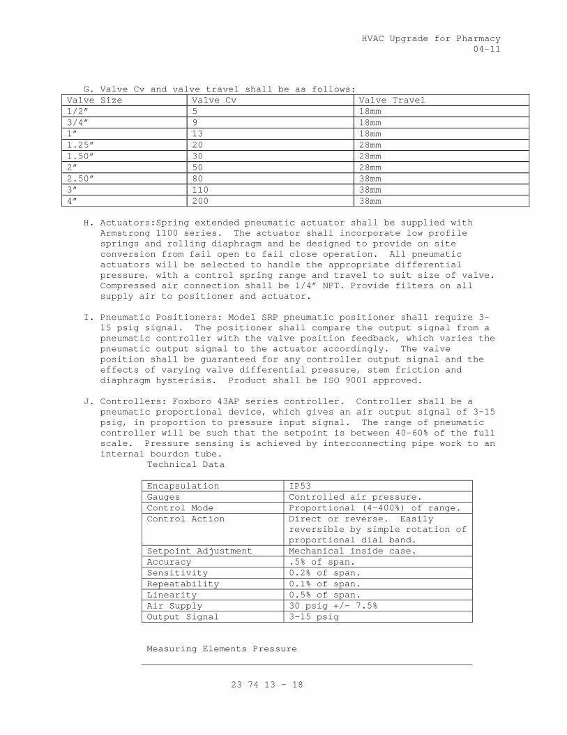
HVAC Upgrade for Pharmacy 04-11
23 74 13 - 18
G. Valve Cv and valve travel shall be as follows:
Valve Size Valve Cv Valve Travel 1/2” 5 18mm 3/4” 9 18mm 1” 13 18mm 1.25” 20 28mm 1.50” 30 28mm 2” 50 28mm 2.50” 80 38mm 3” 110 38mm 4” 200 38mm
H. Actuators:Spring extended pneumatic actuator shall be supplied with Armstrong 1100 series. The actuator shall incorporate low profile springs and rolling diaphragm and be designed to provide on site conversion from fail open to fail close operation. All pneumatic actuators will be selected to handle the appropriate differential pressure, with a control spring range and travel to suit size of valve. Compressed air connection shall be 1/4” NPT. Provide filters on all supply air to positioner and actuator.
I. Pneumatic Positioners: Model SRP pneumatic positioner shall require 3-
15 psig signal. The positioner shall compare the output signal from a pneumatic controller with the valve position feedback, which varies the pneumatic output signal to the actuator accordingly. The valve position shall be guaranteed for any controller output signal and the effects of varying valve differential pressure, stem friction and diaphragm hysterisis. Product shall be ISO 9001 approved.
J. Controllers: Foxboro 43AP series controller. Controller shall be a
pneumatic proportional device, which gives an air output signal of 3-15 psig, in proportion to pressure input signal. The range of pneumatic controller will be such that the setpoint is between 40-60% of the full scale. Pressure sensing is achieved by interconnecting pipe work to an internal bourdon tube.
Technical Data Encapsulation IP53 Gauges Controlled air pressure. Control Mode Proportional (4-400%) of range. Control Action Direct or reverse. Easily
reversible by simple rotation of proportional dial band.
Setpoint Adjustment Mechanical inside case. Accuracy .5% of span. Sensitivity 0.2% of span. Repeatability 0.1% of span. Linearity 0.5% of span. Air Supply 30 psig +/- 7.5% Output Signal 3-15 psig
Measuring Elements Pressure
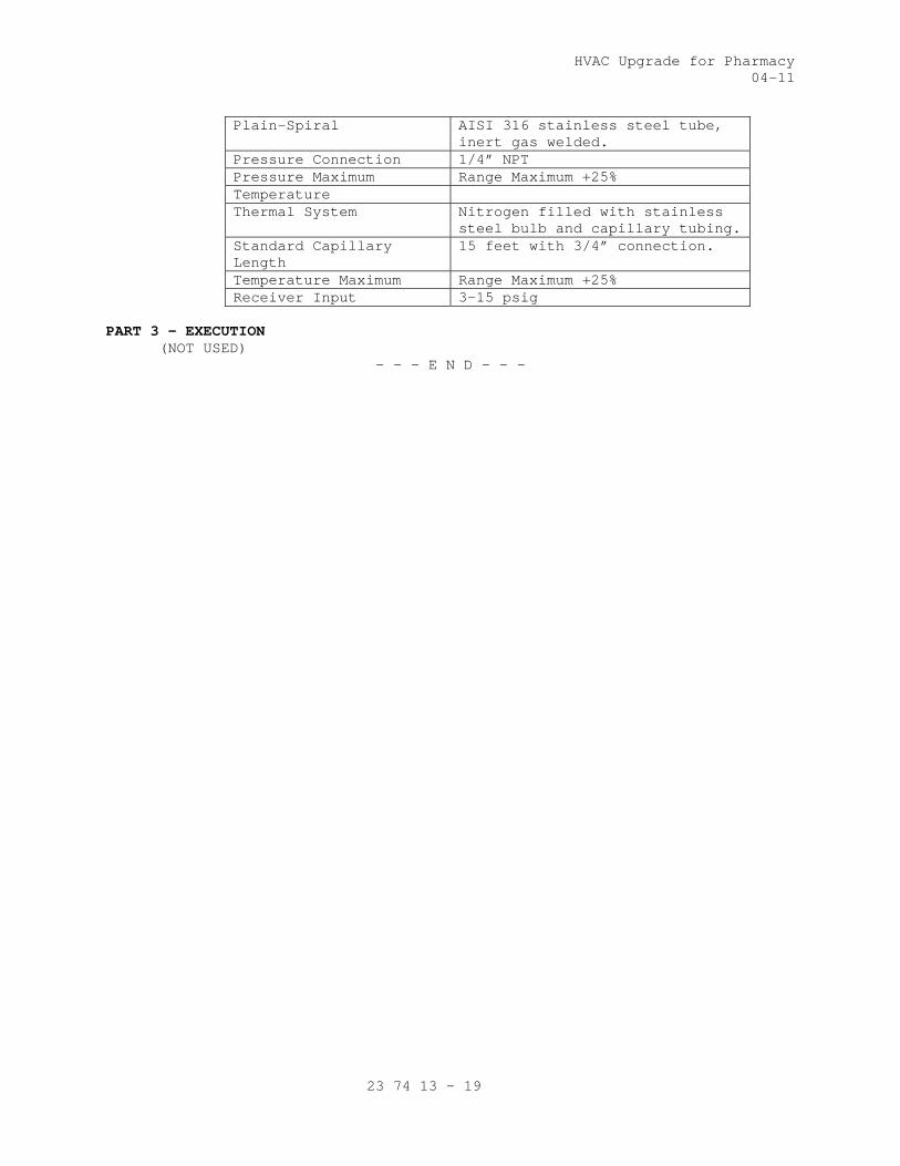
HVAC Upgrade for Pharmacy 04-11
23 74 13 - 19
Plain-Spiral AISI 316 stainless steel tube, inert gas welded.
Pressure Connection 1/4” NPT Pressure Maximum Range Maximum +25% Temperature Thermal System Nitrogen filled with stainless
steel bulb and capillary tubing.Standard Capillary Length
15 feet with 3/4” connection.
Temperature Maximum Range Maximum +25% Receiver Input 3-15 psig
PART 3 – EXECUTION (NOT USED)
- - - E N D - - -


HVAC Upgrade for Pharmacy 04-11
23 82 16 - 1
SECTION 23 82 16 AIR COILS
PART 1 - GENERAL
1.1 DESCRIPTION
Heating duct applications
1.2 RELATED WORK
A. Section 23 05 11, COMMON WORK RESULTS FOR HVAC.
B. Section 23 36 00, AIR TERMINAL UNITS: Reheat coils for VAV/CV terminals.
C. Section 23 74 13, PACKAGED, OUTDOOR, CENTRAL-STATION AIR-HANDLING UNITS
D. Section 23 08 00, COMMISSIONING OF HVAC SYSTEMS: Requirements for
commissioning, systems readiness checklists, and training.
1.3 QUALITY ASSURANCE
A. Refer to paragraph, QUALITY ASSURANCE, Section 23 05 11, COMMON WORK
RESULTS FOR HVAC,
B. Unless specifically exempted by these specifications, heating and
cooling coils shall be tested, rated, and certified in accordance with
AHRI Standard 4l0 and shall bear the AHRI certification label.
1.4 SUBMITTALS
A. Submit in accordance with Section 01 33 23, SHOP DRAWINGS, PRODUCT DATA,
and SAMPLES.
B. Manufacturer's Literature and Data for Heating and Cooling Coils: Submit
type, size, arrangements and performance details. Present application
ratings in the form of tables, charts or curves.
C. Provide installation, operating and maintenance instructions.
D. Certification Compliance: Evidence of listing in current ARI Directory
of Certified Applied Air Conditioning Products.
E. Coils may be submitted with Section 23 73 00, Section 23 74 13,
PACKAGED, OUTDOOR, CENTRAL-STATION, Section 23 36 00, AIR TERMINAL UNITS
F. Completed System Readiness Checklists provided by the Commissioning
Agent and completed by the contractor, signed by a qualified technician
and dated on the date of completion, in accordance with the requirements
of Section 23 08 00 COMMISSIONING OF HVAC SYSTEMS.
1.5 APPLICABLE PUBLICATIONS
A. The publications listed below form a part of this specification to the
extent referenced. The publications are referenced in the text by the
basic designation only.
B. Air Conditioning and Refrigeration Institute (AHRI):
Directory of Certified Applied Air Conditioning Products

HVAC Upgrade for Pharmacy 04-11
23 82 16 - 2
AHRI 4l0-01.............Forced-Circulation Air-Cooling and Air-Heating
Coils
C. American Society for Testing and Materials (ASTM):
B75/75M-02..............Standard Specifications for Seamless Copper Tube
D. National Fire Protection Association (NFPA):
70-11...................National Electric Code
E. National Electric Manufacturers Association (NEMA):
250-11..................Enclosures for Electrical Equipment (1,000 Volts
Maximum)
F. Underwriters Laboratories, Inc. (UL):
1996-09.................Electric Duct Heaters
PART 2 - PRODUCTS
2.1 HEATING COILS
A. Conform to ASTM B75 and AHRI 410.
B. Surgical Suites – All Locations: All coils installed in the air
handling units serving surgical suites, duct-mounted reheat coils, and
air terminal unit-mounted reheat coils shall be equipped with copper
fins.
C. High Humidity Locations: For air unit mounted coils provide the
following corrosion treatment:
1. Epoxy Immersion Coating – Electrically Deposited: The multi-stage
corrosion-resistant coating application comprises of cleaning (heated
alkaline immersion bath) and reverse-osmosis immersion rinse prior to
the start of the coating process. The coating thickness shall be
maintained between 0.6-mil and 1.2-mil. Before the coils are
subjected to high-temperature oven cure, they are treated to permeate
immersion rinse and spray. Where the coils are subject to UV
exposure, UV protection spray treatment comprising of UV-resistant
urethane mastic topcoat shall be applied. Provide complete coating
process traceability for each coil and minimum five years of limited
warranty.
2. The coating process shall such that uniform coating thickness is
maintained at the fin edges. The quality control shall be maintained
by ensuring compliance to the applicable ASTM Standards for the
following:
a. Salt Spray Resistance (Minimum 6,000 Hours)
b. Humidity Resistance (Minimum 1,000 Hours)
c. Water Immersion (Minimum 260 Hours)
d. Cross-Hatch Adhesion (Minimum 4B-5B Rating)
e. Impact Resistance (Up to 160 Inch/Pound)
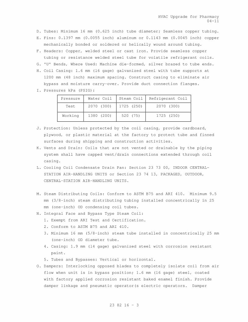
HVAC Upgrade for Pharmacy 04-11
23 82 16 - 3
D. Tubes: Minimum 16 mm (0.625 inch) tube diameter; Seamless copper tubing.
E. Fins: 0.1397 mm (0.0055 inch) aluminum or 0.1143 mm (0.0045 inch) copper
mechanically bonded or soldered or helically wound around tubing.
F. Headers: Copper, welded steel or cast iron. Provide seamless copper
tubing or resistance welded steel tube for volatile refrigerant coils.
G. "U" Bends, Where Used: Machine die-formed, silver brazed to tube ends.
H. Coil Casing: 1.6 mm (l6 gage) galvanized steel with tube supports at
1200 mm (48 inch) maximum spacing. Construct casing to eliminate air
bypass and moisture carry-over. Provide duct connection flanges.
I. Pressures kPa (PSIG):
Pressure Water Coil Steam Coil Refrigerant Coil
Test 2070 (300) 1725 (250) 2070 (300)
Working 1380 (200) 520 (75) 1725 (250)
J. Protection: Unless protected by the coil casing, provide cardboard,
plywood, or plastic material at the factory to protect tube and finned
surfaces during shipping and construction activities.
K. Vents and Drain: Coils that are not vented or drainable by the piping
system shall have capped vent/drain connections extended through coil
casing.
L. Cooling Coil Condensate Drain Pan: Section 23 73 00, INDOOR CENTRAL-
STATION AIR-HANDLING UNITS or Section 23 74 13, PACKAGED, OUTDOOR,
CENTRAL-STATION AIR-HANDLING UNITS.
M. Steam Distributing Coils: Conform to ASTM B75 and ARI 410. Minimum 9.5
mm (3/8-inch) steam distributing tubing installed concentrically in 25
mm (one-inch) OD condensing coil tubes.
N. Integral Face and Bypass Type Steam Coil:
1. Exempt from ARI Test and Certification.
2. Conform to ASTM B75 and ARI 410.
3. Minimum 16 mm (5/8-inch) steam tube installed in concentrically 25 mm
(one-inch) OD diameter tube.
4. Casing: 1.9 mm (l4 gage) galvanized steel with corrosion resistant
paint.
5. Tubes and Bypasses: Vertical or horizontal.
O. Dampers: Interlocking opposed blades to completely isolate coil from air
flow when unit is in bypass position; 1.6 mm (l6 gage) steel, coated
with factory applied corrosion resistant baked enamel finish. Provide
damper linkage and pneumatic operator(s electric operators. Damper

HVAC Upgrade for Pharmacy 04-11
23 82 16 - 4
operators shall be of same manufacturer as controls furnished under
Section 23 09 23, DIRECT-DIGITAL CONTROL SYSTEM FOR HVAC.
2.2 REHEAT COILS, DUCT MOUNTED
The coils shall be continuous circuit booster type for steam or hot
water as shown on drawings. Use the same coil material as listed in
Paragraphs 2.1.
2.3 WATER COILS, INCLUDING GLYCOL-WATER
A. Use the same coil material as listed in Paragraphs 2.1.
B. Drainable Type (Self Draining, Self Venting); Manufacturer standard:
l. Cooling, all types.
2. Heating or preheat.
3. Runaround energy recovery. ARI certification of capacity adjustment
is waived. See Section 23 72 00, AIR-TO-AIR ENERGY RECOVERY
EQUIPMENT.
C. Cleanable Tube Type; manufacturer standard:
l. Well water applications.
2. Waste water applications.
PART 3 - EXECUTION
3.1 INSTALLATION
A. Follow coil manufacturer's instructions for handling, cleaning,
installation and piping connections.
B. Comb fins, if damaged. Eliminate air bypass or leakage at coil sections.
3.2 STARTUP AND TESTING
A. The Commissioning Agent will observe startup and contractor testing of
selected equipment. Coordinate the startup and contractor testing
schedules with the Resident Engineer and Commissioning Agent. Provide a
minimum of 7 days prior notice.
3.3 COMMISSIONING
A. Provide commissioning documentation in accordance with the requirements
of Section 23 08 00 – COMMISSIONING OF HVAC SYSTEMS for all inspection,
start up, and contractor testing required above and required by the
System Readiness Checklist provided by the Commissioning Agent.
B. Components provided under this section of the specification will be
tested as part of a larger system. Refer to Section 23 08 00 –
COMMISSIONING OF HVAC SYSTEMS and related sections for contractor
responsibilities for system commissioning.
3.4 DEMONSTRATION AND TRAINING
A. Provide services of manufacturer’s technical representative for four
hours to instruct VA personnel in operation and maintenance of units.

HVAC Upgrade for Pharmacy 04-11
23 82 16 - 5
B. Submit training plans and instructor qualifications in accordance with
the requirements of Section 23 08 00 – COMMISSIONING OF HVAC SYSTEMS.
- - - E N D - - -


HVAC Upgrade for Pharmacy 05-11
23 84 00 - 1
SECTION 23 84 00 HUMIDITY CONTROL EQUIPMENT
PART 1 - GENERAL
1.1 DESCRIPTION
This section specifies dehumidifier units for preconditioning of
existing or new air conditioning systems and stand-alone units use
for dehumidifying air. Humidity system must be part of the air
handling unit. Basis of design humidity system must be Nortec
system.
1.2 RELATED WORK
A. Section 01 00 00, GENERAL REQUIREMENTS: Requirements for pre-test
of equipment.
B. Section 23 05 11, COMMON WORK RESULTS FOR HVAC: General mechanical
requirements and items, which are common to more than one section
of Division 23.
C. Section 23 21 13, HYDRONIC PIPING: Requirements for field hot
water piping.
D. Section 23 22 13, STEAM AND CONDENSATE HEATING PIPING:
Requirements for field steam and condensate piping.
E. Section 23 82 16, AIR COILS: Requirements for run-around system
coils.
F. Section 23 09 23, DIRECT-DIGITAL CONTROL SYSTEM FOR HVAC:
Requirements for controls and instrumentation.
G. Section 23 05 93, TESTING, ADJUSTING, AND BALANCING FOR HVAC:
Requirements for testing, adjusting and balancing of HVAC system.
H. Section 23 05 12, GENERAL MOTOR REQUIREMENTS FOR HVAC AND STEAM
GENERATION EQUIPMENT: Requirements for HVAC motors.
I. 01 91 00, GENERAL COMMISSIONING REQUIREMENTS
1.3 QUALITY ASSURANCE
A. Refer to the GENERAL CONDITIONS.
B. Refer to specification Section 01 00 00, GENERAL REQUIREMENTS for
performance tests and instructions to VA personnel.
C. Refer to paragraph, QUALITY ASSURANCE, in specification Section
23 05 11, COMMON WORK RESULTS FOR HVAC.
D. Unit(s) shall be provided by a manufacturer who has been
manufacturing desiccant dehumidifiers and have been in
satisfactory service for at least three (3) years.
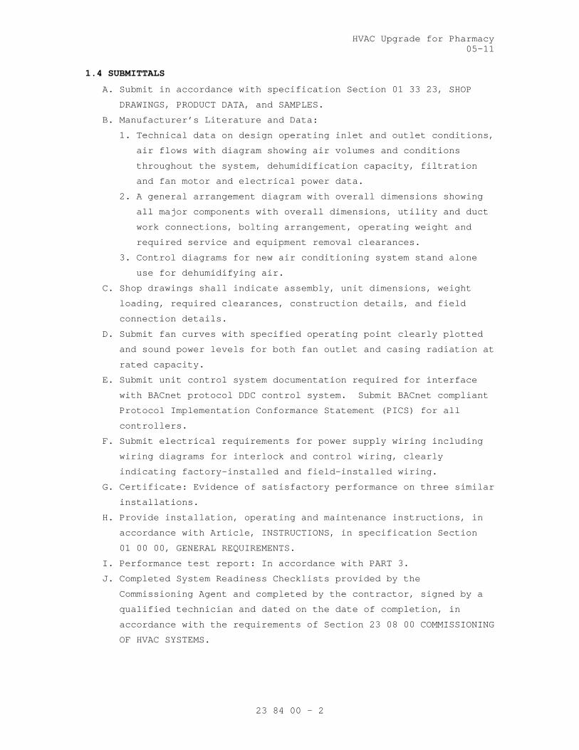
HVAC Upgrade for Pharmacy 05-11
23 84 00 - 2
1.4 SUBMITTALS
A. Submit in accordance with specification Section 01 33 23, SHOP
DRAWINGS, PRODUCT DATA, and SAMPLES.
B. Manufacturer’s Literature and Data:
1. Technical data on design operating inlet and outlet conditions,
air flows with diagram showing air volumes and conditions
throughout the system, dehumidification capacity, filtration
and fan motor and electrical power data.
2. A general arrangement diagram with overall dimensions showing
all major components with overall dimensions, utility and duct
work connections, bolting arrangement, operating weight and
required service and equipment removal clearances.
3. Control diagrams for new air conditioning system stand alone
use for dehumidifying air.
C. Shop drawings shall indicate assembly, unit dimensions, weight
loading, required clearances, construction details, and field
connection details.
D. Submit fan curves with specified operating point clearly plotted
and sound power levels for both fan outlet and casing radiation at
rated capacity.
E. Submit unit control system documentation required for interface
with BACnet protocol DDC control system. Submit BACnet compliant
Protocol Implementation Conformance Statement (PICS) for all
controllers.
F. Submit electrical requirements for power supply wiring including
wiring diagrams for interlock and control wiring, clearly
indicating factory-installed and field-installed wiring.
G. Certificate: Evidence of satisfactory performance on three similar
installations.
H. Provide installation, operating and maintenance instructions, in
accordance with Article, INSTRUCTIONS, in specification Section
01 00 00, GENERAL REQUIREMENTS.
I. Performance test report: In accordance with PART 3.
J. Completed System Readiness Checklists provided by the
Commissioning Agent and completed by the contractor, signed by a
qualified technician and dated on the date of completion, in
accordance with the requirements of Section 23 08 00 COMMISSIONING
OF HVAC SYSTEMS.

HVAC Upgrade for Pharmacy 05-11
23 84 00 - 3
1.5 APPLICABLE PUBLICATIONS
A. The publications listed below form a part of this specification to
the extent referenced. The publications are referenced in the text
by the basic designation only.
B. Air-conditioning, Heating and Refrigeration Institute (AHRI)
410-01..................Forced–Circulation Air-Cooling and Air-
Heating Coils
C. Air Movement and Control Association (AMCA):
99-10...................Standards Handbook
210-07..................Laboratory Methods of Testing Fans for
Aerodynamic Performance Rating (ANSI)
301-06..................Laboratory Methods of Testing Fans for
Aerodynamic Performance Rating (ANSI)
D. American Society of Heating, Refrigerating and Air-Conditioning
Engineers (ASHRAE)
52.2-07.................METHOD OF TESTING General Ventilation Air
Cleaning Devices for Removal Efficiency by
Particle Size (ANSI)
62.1-10.................Ventilation for Acceptable Indoor Air
Quality (ANSI)
E. American Bearing Manufacturers Association (ABMA)
9-1990 (R2008)..........Load Ratings and Fatigue Life for Ball
Bearings (ANSI)
F. National Fire Protection Association (NFPA)
90A-09..................Standard for the Installation of Air-
Conditioning and Ventilating Systems
70-11...................National Electrical Code
1.6 QUALITY ASSURANCE
A. Fan Performance Ratings: Conform to AMCA 210 and bear the AMCA
Certified Rating Seal.
B. Sound Ratings: AMCA 301; tested to AMCA 300 and bear AMCA
Certified Sound Rating Seal.
C. Fabrication: Conform to AMCA 99.
D. Air Coils: Certify capacities, pressure drops, and selection
procedures in accordance with AHRI 410.
E. Product of manufacturer regularly engaged in production of pool
dehumidification equipment who issues complete catalog data on
total product.

HVAC Upgrade for Pharmacy 05-11
23 84 00 - 4
1.7 DELIVERY, STORAGE, AND HANDLING
A. Accept products on site in factory-fabricated protective
containers, with factory-installed shipping skids and lifting
lugs. Inspect for damage.
B. Store in clean dry place and protect from weather and construction
traffic. Handle carefully to avoid damage to components,
enclosures and finish.
C. Comply with manufacturer’s rigging and installation instructions.
1.8 PROJECT CONDITIONS
Do not operate units for any purpose, temporary or permanent,
until ductwork is clean, filters are in place, bearings
lubricated, fan has been test run, all piping is connected and
energized and all wiring complete and tested.
1.9 ADDITIONAL REQUIREMENTS
A. Provide one additional set of fan belts and disposable panel
filters for each unit.
B. CORROSION PROTECTION
For air-handling unit mounted coils provide the following
corrosion treatment:
1. Epoxy Immersion Coating – Electrically Deposited: The multi-
stage corrosion-resistant coating application comprises of
cleaning (heated alkaline immersion bath) and reverse-osmosis
immersion rinse prior to the start of the coating process. The
coating thickness shall be maintained between 0.6-mil and 1.2-
mil. Before the coils are subjected to high-temperature oven
cure, they are treated to permeate immersion rinse and spray.
Where the coils are subject to UV exposure, UV protection spray
treatment comprising of UV-resistant urethane mastic topcoat
shall be applied. Provide complete coating process
traceability for each coil and minimum five years of limited
warranty.
2. The coating process shall such that uniform coating thickness
is maintained at the fin edges. The quality control shall be
maintained by ensuring compliance to the applicable ASTM
Standards for the following:
a. Salt Spray Resistance (Minimum 6,000 Hours)
b. Humidity Resistance (Minimum 1,000 Hours)
c. Water Immersion (Minimum 260 Hours)
d. Cross-Hatch Adhesion (Minimum 4B-5B Rating)

HVAC Upgrade for Pharmacy 05-11
23 84 00 - 5
e. Impact Resistance (Up to 160 Inch/Pound)3.
3. Casing Surfaces (Exterior and Interior): All exposed and
accessible exterior and interior metal surfaces shall be
protected with a water-reducible acrylic with stainless steel
pigment spray-applied over the manufacturer’s standard finish.
The spray coating thickness shall be 2-4 mils and provide
minimum salt-spray resistance of 1,000 hours (ASTM B117) and
500 hours UV resistance (ASTM D4587).
PART 2 – PRODUCTS
2.1 DEHUMIDIFIER UNITS
A. General: Units shall be complete, factory assembled, and tested;
and of sizes, arrangements, capacities, and performance as
scheduled and as specified in the schedules shown in the drawings
outdoor installation preconditioning of new air conditioning
system stand alone use for dehumidifying air.
1. Dehumidification shall be accomplished by use of a desiccant to
absorb water vapor and maintain humidity control level
independent of load variations within design limit.
2. Unit(s) shall be capable and designed for year-round, 24-hours-
a-day operation; and requiring only connections of ducts,
utilities, and remote sensors, controllers, and monitors.
3. Unit(s) shall include active regeneration system for control of
dehumidification processes.
B. Casing:
1. Double-wall construction with corrosion-protective removable
panels hinged access doors with neoprene gaskets, minimum 50-mm
(2-inch) thick thermal insulation fill, stainless steel
fasteners, knockouts for electrical and piping connections
through the side of the unit, condensate drain connection, and
lifting lugs.
2. The unit housing the internal partitions shall be constructed
of minimum 18 gage galvanized steel or aluminum pre-insulated
double wall panels with a minimum of 50-mm (2-inch) thermal
insulation. The base shall be all welded, structural steel or
formed 14-gage, galvanized steel. Units shall have cross
supports for each major component and base channels and lifting
eyes to facilitate rigging. The units shall be of water and air
tight construction over all with interior air tight
construction between various sections of the units. Adjoining
panels shall be sealed with a silicon compound or heavy duty

HVAC Upgrade for Pharmacy 05-11
23 84 00 - 6
compression type gaskets. Leakage rate shall not exceed 2
percent at a pressure of 746 Pa (3.0 inches water gage).
3. All non-pre-insulated exterior panels shall be insulated with
minimum 25-mm (1-inch) vinyl- or foil-faced fiberglass
insulation without exposed edges, and secured by permanent
mechanical fasteners.
4. All exterior panels shall be embossed aluminum cabinet panels
constructed with corrosion-protective coating on the
manufacturer's standard coating.
5. All internal air-processing and air-treatment components shall
be removable through removable access panels without
dismantling plenums or ductwork.
6. Access panels shall be provided with resilient gaskets and
quick-release hardware.
7. Access doors for filters and control adjustment shall have
corrosion-resistant, continuous hinge or heavy-duty, multiple
hinges.
8. Surfaces in contact with the airstream shall comply with
requirements in ASHRAE 62.1-2007.
C. Dehumidifier:
1. The dehumidifier shall include a desiccant wheel utilizing a
fractional horsepower electric motor and a variable speed drive
and reactivation air flow indicating devices steam electric
reactivation fan/motor assembly, reactivation energy modulation
system, electric/mechanical rotation fault circuitry and
necessary manual and automatic dampers for proper functioning
of the unit under all operating conditions.
2. Dehumidifier shall rotary type, designed for continuous
operation, and arranged to provide a counter flow of process
and reactivation air streams with full-face pressure seals or
low-friction contact seals on both sides to prevent cross
leakage for external static pressure of up to 622 Pa (2.5
inches w.g.)
3. Desiccant rotor shall have synthesized silica gel, enhanced
with titanium, bonded to a ceramic matrix, with filled voids
and encapsulating the ceramic. Driver shall be a motor with
adjustable drive sheaves and belt-tensioning idler pulley or
adjustable motor mount.
4. The rotary desiccant shall transfer water in the vapor phase.
The design and geometry shall provide for laminar flow over the

HVAC Upgrade for Pharmacy 05-11
23 84 00 - 7
operating range for minimum pressure loss with maximum transfer
surface and minimum power requirements. The desiccant shall be
a permanent integral part of the structure.
D. Heat Exchanger:
1. The heat exchanger shall be constructed of non-hygroscopic
material with corrosion protection, described above for the
coils and surfaces thermal wheel to prevent the transfer of
water vapor or an air-to-air heat pipe with copper tubes and
aluminum fins, fabricated with capillary wick structure charged
with ozone friendly refrigerant to be used in the process and
reactivation air steams. Refrigerant shall comply with ASHRAE
15, Group 1. For thermal wheel, supply and cooling air streams
shall be counter flow and the component provided with full face
contact seals on both sides to prevent leakage. The heat
transfer effectiveness of the heat exchanger shall be minimum
80 percent with a maximum air pressure loss of 125 Pa (0.50
inch w.g.)
2. Electric motor shall be fractional-horsepower with close-
coupled speed reducer and a belt drive with belt tensioning
system for the thermal wheel.
E. Controls and Wiring: Factory-installed microprocessor type to
control and monitor unit and communicate to central-control
processor, and shall operate dehumidification units and maintain
humidity and temperature set points. The controller shall be
connected to the building DDC control system via an open protocol
BACnet interface.
1. The unit shall have a factory wired and unit mounted central,
electrical control panel with a single power supply connection.
All internal wiring shall be in accordance with the National
Electrical Code. Unit shall have a non-fused main power
disconnect and control components required for automatic
operation based on signals from space mounted humidity and
temperature controls. Control panel shall have terminals for
remote control devices.
2. Controls shall be capable of shutting down the dehumidifier
when humidity loads are reduced and the process shall be
reversed when there is an increase in humidity loads.
3. Reactivation energy shall be automatically reduced at lower
than design humidity loads.
HVAC Upgrade for Pharmacy 05-11
23 84 00 - 8
4. Carbon dioxide sensor mounted in return air shall operate
minimum outdoor-air damper position.
5. Discharge-air, outdoor-air, conditioned-space, control set-
point-temperature, and outdoor-air enthalpy shall be displayed
with a LCD in control panel.
6. Filter pressure drop and alarm shall be displayed by an LCD in
control panel.
7. Airflow, fans, system, unit operation, and operating mode
status shall be displayed in control panel.
PART 3 – EXECUTION
3.1 INSTALLATION
A. Follow equipment manufacturer’s written instructions for handling
and installation of equipment.
B. Adjust seals and purge of rotating wheels as recommended by the
manufacturer.
C. Verify correct settings and installation of controls.
D. Install vibration-control devices.
1. Floor-Mounted Units: Support on concrete bases using neoprene
pads having a minimum static deflection of (0.25 inch). Secure
units to anchor bolts installed in concrete bases.
2. Suspended Units: Suspend units from structural-steel support
frame using threaded steel rods and spring hangers.
3.2 CONNECTIONS
A. Install piping adjacent to machine to allow service and
maintenance.
B. Connect piping to dehumidification units mounted on vibration
isolators with flexible connectors.
C. Connect condensate drain pans using minimum DN 32 NPS 1-1/4copper
tubing. Extend to nearest equipment or floor drain. Construct
deep trap at connection to drain pan, and install clean out at
changes in direction.
D. Steam and Condensate Piping: Comply with applicable requirements
in Section 23 22 13, STEAM AND CONDENSATE HEATING PIPING. Connect
with shutoff valve and union or flange.
3.3 STARTUP SERVICE
A. Perform the following final checks before startup:
1. Verify that shipping, blocking, and bracing are removed.
2. Verify that unit is secure on mountings and supporting devices
and that connection to piping, ducts, and electrical systems

HVAC Upgrade for Pharmacy 05-11
23 84 00 - 9
are complete. Verify that proper thermal-overload protection
is installed in motors, starters, and disconnect switches.
3. Perform cleaning and adjusting specified in this Section.
4. Verify lubrication of bearings, pulleys, belts, and other
moving parts.
5. Install clean filters.
6. Verify that manual and automatic volume control and fire and
smoke dampers in connected duct systems are in fully open
position.
B. Perform the following starting procedures for dehumidification
units:
1. Energize motor; verify proper operation of motor, drive system,
and fan wheel. Adjust fan to indicated rpm. Replace
malfunctioning motors, bearings, and fan wheels.
2. Measure and record motor electrical values for voltage and
amperage.
3. Manually operate dampers from fully closed to fully open
position and record fan performance.
C. Complete installation and startup checks according to
manufacturer's written instructions.
D. Startup Report: Report findings during startup. Identify startup
steps, corrective measures taken, and final results.
E. The Commissioning Agent will observe startup and contractor
testing of selected equipment. Coordinate the startup and
contractor testing schedules with the Resident Engineer and
Commissioning Agent. Provide a minimum of 7 days prior notice.
3.4 ADJUSTING
A. Adjust damper linkages for proper damper operation.
B. Adjust initial temperature and humidity set points.
3.5 CLEANING
A. Clean dehumidification units internally, on completion of
installation, according to manufacturer's written instructions.
Clean fan interiors to remove foreign material and construction
dirt and dust. Vacuum clean fan wheels, cabinets, and coils'
entering-air face.
B. After completing system installation, testing, and startup service
of dehumidification units, clean filter housings and install new
filters.
HVAC Upgrade for Pharmacy 05-11
23 84 00 - 10
3.6 INSTRUCTIONS
Provide services of manufacturer’s technical representative for
eight hours to instruct VA personnel in operation and maintenance
of desiccant dehumidifiers.
3.7 COMMISSIONING
A. Provide commissioning documentation in accordance with the
requirements of Section 23 08 00 – COMMISSIONING OF HVAC SYSTEMS
for all inspection, start up, and contractor testing required
above and required by the System Readiness Checklist provided by
the Commissioning Agent.
B. Components provided under this section of the specification will
be tested as part of a larger system. Refer to Section 23 08 00 –
COMMISSIONING OF HVAC SYSTEMS and related sections for contractor
responsibilities for system commissioning.
3.8 DEMONSTRATION AND TRAINING
A. Provide services of manufacturer’s technical representative for
four hours to instruct VA personnel in operation and maintenance
of units.
B. Submit training plans and instructor qualifications in accordance
with the requirements of Section 23 08 00 – COMMISSIONING OF HVAC
SYSTEMS.
- - - E N D- - -
HVAC Upgrade for Pharmacy09-10
26 05 11 - 1
SECTION 26 05 11REQUIREMENTS FOR ELECTRICAL INSTALLATIONS
PART 1 - GENERAL
1.1 DESCRIPTION
A. This section applies to all sections of Division 26.
B. Furnish and install electrical wiring, systems, equipment and
accessories in accordance with the specifications and drawings.
Capacities and ratings of motors, cable, panelboards, and other items
and arrangements for the specified items are shown on drawings.
C. Wiring ampacities specified or shown on the drawings are based on copper
conductors, with the conduit and raceways accordingly sized. Aluminum
conductors and aluminum conduits are prohibited.
1.2 MINIMUM REQUIREMENTS
A. References to the International Building Code (IBC), National Electrical
Code (NEC), Underwriters Laboratories, Inc. (UL) and National Fire
Protection Association (NFPA) are minimum installation requirement
standards.
B. Drawings and other specification sections shall govern in those
instances where requirements are greater than those specified in the
above standards.
1.3 TEST STANDARDS
A. All materials and equipment shall be listed, labeled or certified by a
nationally recognized testing laboratory to meet Underwriters
Laboratories, Inc., standards where test standards have been
established. Equipment and materials which are not covered by UL
Standards will be accepted provided equipment and material is listed,
labeled, certified or otherwise determined to meet safety requirements
of a nationally recognized testing laboratory. Equipment of a class
which no nationally recognized testing laboratory accepts, certifies,
lists, labels, or determines to be safe, will be considered if inspected
or tested in accordance with national industrial standards, such as
NEMA, or ANSI. Evidence of compliance shall include certified test
reports and definitive shop drawings.
B. Definitions:
1. Listed; Equipment, materials, or services included in a list
published by an organization that is acceptable to the authority
having jurisdiction and concerned with evaluation of products or
services, that maintains periodic inspection of production or listed

HVAC Upgrade for Pharmacy09-10
26 05 11 - 2
equipment or materials or periodic evaluation of services, and whose
listing states that the equipment, material, or services either meets
appropriate designated standards or has been tested and found
suitable for a specified purpose.
2. Labeled; Equipment or materials to which has been attached a label,
symbol, or other identifying mark of an organization that is
acceptable to the authority having jurisdiction and concerned with
product evaluation, that maintains periodic inspection of production
of labeled equipment or materials, and by whose labeling the
manufacturer indicates compliance with appropriate standards or
performance in a specified manner.
3. Certified; equipment or product which:
a. Has been tested and found by a nationally recognized testing
laboratory to meet nationally recognized standards or to be safe
for use in a specified manner.
b. Production of equipment or product is periodically inspected by a
nationally recognized testing laboratory.
c. Bears a label, tag, or other record of certification.
4. Nationally recognized testing laboratory; laboratory which is
approved, in accordance with OSHA regulations, by the Secretary of
Labor.
1.4 QUALIFICATIONS (PRODUCTS AND SERVICES)
A. Manufacturers Qualifications: The manufacturer shall regularly and
presently produce, as one of the manufacturer's principal products, the
equipment and material specified for this project, and shall have
manufactured the item for at least three years.
B. Product Qualification:
1. Manufacturer's product shall have been in satisfactory operation, on
three installations of similar size and type as this project, for
approximately three years.
2. The Government reserves the right to require the Contractor to submit
a list of installations where the products have been in operation
before approval.
C. Service Qualifications: There shall be a permanent service organization
maintained or trained by the manufacturer which will render satisfactory
service to this installation within four hours of receipt of
notification that service is needed. Submit name and address of service
organizations.
HVAC Upgrade for Pharmacy09-10
26 05 11 - 3
1.5 APPLICABLE PUBLICATIONS
Applicable publications listed in all Sections of Division are the
latest issue, unless otherwise noted.
1.6 MANUFACTURED PRODUCTS
A. Materials and equipment furnished shall be of current production by
manufacturers regularly engaged in the manufacture of such items, for
which replacement parts shall be available.
B. When more than one unit of the same class or type of equipment is
required, such units shall be the product of a single manufacturer.
C. Equipment Assemblies and Components:
1. Components of an assembled unit need not be products of the same
manufacturer.
2. Manufacturers of equipment assemblies, which include components made
by others, shall assume complete responsibility for the final
assembled unit.
3. Components shall be compatible with each other and with the total
assembly for the intended service.
4. Constituent parts which are similar shall be the product of a single
manufacturer.
D. Factory wiring shall be identified on the equipment being furnished and
on all wiring diagrams.
1.7 EQUIPMENT REQUIREMENTS
Where variations from the contract requirements are requested in
accordance with Section 00 72 00, GENERAL CONDITIONS and Section 01 33
23, SHOP DRAWINGS, PRODUCT DATA, AND SAMPLES, the connecting work and
related components shall include, but not be limited to additions or
changes to branch circuits, circuit protective devices, conduits, wire,
feeders, controls, panels and installation methods.
1.8 EQUIPMENT PROTECTION
A. Equipment and materials shall be protected during shipment and storage
against physical damage, vermin, dirt, corrosive substances, fumes,
moisture, cold and rain.
1. Store equipment indoors in clean dry space with uniform temperature
to prevent condensation.
2. During installation, equipment shall be protected against entry of
foreign matter; and be vacuum-cleaned both inside and outside before
testing and operating. Compressed air shall not be used to clean
equipment. Remove loose packing and flammable materials from inside
equipment.
HVAC Upgrade for Pharmacy09-10
26 05 11 - 4
3. Damaged equipment shall be, as determined by the COTR, placed in
first class operating condition or be returned to the source of
supply for repair or replacement.
4. Painted surfaces shall be protected with factory installed removable
heavy kraft paper, sheet vinyl or equal.
5. Damaged paint on equipment and materials shall be refinished with the
same quality of paint and workmanship as used by the manufacturer so
repaired areas are not obvious.
1.9 WORK PERFORMANCE
A. All electrical work must comply with the requirements of NFPA 70 (NEC),
NFPA 70B, NFPA 70E, OSHA Part 1910 subpart J, OSHA Part 1910 subpart S
and OSHA Part 1910 subpart K in addition to other references required by
contract.
B. Job site safety and worker safety is the responsibility of the
contractor.
C. Electrical work shall be accomplished with all affected circuits or
equipment de-energized. When an electrical outage cannot be accomplished
in this manner for the required work, the following requirements are
mandatory:
1. Electricians must use full protective equipment (i.e., certified and
tested insulating material to cover exposed energized electrical
components, certified and tested insulated tools, etc.) while working
on energized systems in accordance with NFPA 70E.
2. Electricians must wear personal protective equipment while working on
energized systems in accordance with NFPA 70E.
3. Before initiating any work, a job specific work plan must be
developed by the contractor with a peer review conducted and
documented by the COTR and Medical Center staff. The work plan must
include procedures to be used on and near the live electrical
equipment, barriers to be installed, safety equipment to be used and
exit pathways.
4. Work on energized circuits or equipment cannot begin until prior
written approval is obtained from the COTR.
D. For work on existing stations, arrange, phase and perform work to assure
electrical service for other buildings at all times. Refer to Article
OPERATIONS AND STORAGE AREAS under Section 01 00 00, GENERAL
REQUIREMENTS.
E. New work shall be installed and connected to existing work neatly,
safely and professionally. Disturbed or damaged work shall be replaced
HVAC Upgrade for Pharmacy09-10
26 05 11 - 5
or repaired to its prior conditions, as required by Section 01 00 00,
GENERAL REQUIREMENTS.
F. Coordinate location of equipment and conduit with other trades to
minimize interferences.
1.10 EQUIPMENT INSTALLATION AND REQUIREMENTS
A. Equipment location shall be as close as practical to locations shown on
the drawings.
B. Working spaces shall not be less than specified in the NEC for all
voltages specified.
C. Inaccessible Equipment:
1. Where the Government determines that the Contractor has installed
equipment not conveniently accessible for operation and maintenance,
the equipment shall be removed and reinstalled as directed at no
additional cost to the Government.
2. "Conveniently accessible" is defined as being capable of being
reached quickly for operation, maintenance, or inspections without
the use of ladders, or without climbing or crawling under or over
obstacles such as, but not limited to, motors, pumps, belt guards,
transformers, piping, ductwork, conduit and raceways.
1.11 EQUIPMENT IDENTIFICATION
A. In addition to the requirements of the NEC, install an identification
sign which clearly indicates information required for use and
maintenance of items such as switchboards and switchgear, panelboards,
cabinets, motor controllers (starters), fused and unfused safety
switches, automatic transfer switches, separately enclosed circuit
breakers, individual breakers and controllers in switchboards,
switchgear and motor control assemblies, control devices and other
significant equipment.
B. Nameplates for Normal Power System equipment shall be laminated black
phenolic resin with a white core with engraved lettering. Nameplates
for Essential Electrical System (EES) equipment, as defined in the NEC,
shall be laminated red phenolic resin with a white core with engraved
lettering. Lettering shall be a minimum of 1/2 inch [12mm] high.
Nameplates shall indicate equipment designation, rated bus amperage,
voltage, number of phases, number of wires, and type of EES power branch
as applicable. Secure nameplates with screws.
C. Install adhesive arc flash warning labels on all equipment as required
by NFPA 70E. Label shall indicate the arc hazard boundary (inches),
working distance (inches), arc flash incident energy at the working

HVAC Upgrade for Pharmacy09-10
26 05 11 - 6
distance (calories/cm2), required PPE category and description including
the glove rating, voltage rating of the equipment, limited approach
distance (inches), restricted approach distance (inches), prohibited
approach distance (inches), equipment/bus name, date prepared, and
manufacturer name and address.
1.12 SUBMITTALS
A. Submit in accordance with Section 01 33 23, SHOP DRAWINGS, PRODUCT DATA,
AND SAMPLES.
B. The Government's approval shall be obtained for all equipment and
material before delivery to the job site. Delivery, storage or
installation of equipment or material which has not had prior approval
will not be permitted at the job site.
C. All submittals shall include adequate descriptive literature, catalog
cuts, shop drawings and other data necessary for the Government to
ascertain that the proposed equipment and materials comply with
specification requirements. Catalog cuts submitted for approval shall
be legible and clearly identify equipment being submitted.
D. Submittals for individual systems and equipment assemblies which consist
of more than one item or component shall be made for the system or
assembly as a whole. Partial submittals will not be considered for
approval.
1. Mark the submittals, "SUBMITTED UNDER SECTION__________________".
2. Submittals shall be marked to show specification reference including
the section and paragraph numbers.
3. Submit each section separately.
E. The submittals shall include the following:
1. Information that confirms compliance with contract requirements.
Include the manufacturer's name, model or catalog numbers, catalog
information, technical data sheets, shop drawings, pictures,
nameplate data and test reports as required.
3. Elementary and interconnection wiring diagrams for communication and
signal systems, control systems and equipment assemblies. All
terminal points and wiring shall be identified on wiring diagrams.
4. Parts list which shall include those replacement parts recommended by
the equipment manufacturer.
F. Manuals: Submit in accordance with Section 01 00 00, GENERAL
REQUIREMENTS.
1. Maintenance and Operation Manuals: Submit as required for systems and
equipment specified in the technical sections. Furnish four copies,

HVAC Upgrade for Pharmacy09-10
26 05 11 - 7
bound in hardback binders, (manufacturer's standard binders) or an
approved equivalent. Furnish one complete manual as specified in the
technical section but in no case later than prior to performance of
systems or equipment test, and furnish the remaining manuals prior to
contract completion.
2. Inscribe the following identification on the cover: the words
"MAINTENANCE AND OPERATION MANUAL," the name and location of the
system, equipment, building, name of Contractor, and contract number.
Include in the manual the names, addresses, and telephone numbers of
each subcontractor installing the system or equipment and the local
representatives for the system or equipment.
3. Provide a "Table of Contents" and assemble the manual to conform to
the table of contents, with tab sheets placed before instructions
covering the subject. The instructions shall be legible and easily
read, with large sheets of drawings folded in.
4. The manuals shall include:
a. Internal and interconnecting wiring and control diagrams with data
to explain detailed operation and control of the equipment.
b. A control sequence describing start-up, operation, and shutdown.
c. Description of the function of each principal item of equipment.
d. Installation instructions.
e. Safety precautions for operation and maintenance.
f. Diagrams and illustrations.
g. Periodic maintenance and testing procedures and frequencies,
including replacement parts numbers and replacement frequencies.
h. Performance data.
i. Pictorial "exploded" parts list with part numbers. Emphasis shall
be placed on the use of special tools and instruments. The list
shall indicate sources of supply, recommended spare parts, and
name of servicing organization.
j. List of factory approved or qualified permanent servicing
organizations for equipment repair and periodic testing and
maintenance, including addresses and factory certification
qualifications.
G. Approvals will be based on complete submission of manuals together with
shop drawings.
H. After approval and prior to installation, furnish the COTR with one
sample of each of the following:

HVAC Upgrade for Pharmacy09-10
26 05 11 - 8
1. A 300 mm (12 inch) length of each type and size of wire and cable
along with the tag from the coils of reels from which the samples
were taken.
2. Each type of conduit coupling, bushing and termination fitting.
3. Conduit hangers, clamps and supports.
4. Duct sealing compound.
5. Each type of receptacle, toggle switch, occupancy sensor, outlet box,
manual motor starter, device wall plate, engraved nameplate, wire and
cable splicing and terminating material, and branch circuit single
pole molded case circuit breaker.
1.13 SINGULAR NUMBER
Where any device or part of equipment is referred to in these
specifications in the singular number (e.g., "the switch"), this
reference shall be deemed to apply to as many such devices as are
required to complete the installation as shown on the drawings.
1.15 ACCEPTANCE CHECKS AND TESTS
The contractor shall furnish the instruments, materials and labor for
field tests.
1.16 TRAINING
A. Training shall be provided in accordance with Article 1.25,
INSTRUCTIONS, of Section 01 00 00, GENERAL REQUIREMENTS.
B. Training shall be provided for the particular equipment or system as
required in each associated specification.
C. A training schedule shall be developed and submitted by the contractor
and approved by the COTR at least 30 days prior to the planned training.
- - - E N D - - -

HVAC Upgrade for Pharmacy09-10
26 05 21 - 1
SECTION 26 05 21LOW-VOLTAGE ELECTRICAL POWER CONDUCTORS AND CABLES (600 VOLTS AND BELOW)
PART 1 - GENERAL
1.1 DESCRIPTION
This section specifies the furnishing, installation, and connection of
the low voltage power and lighting wiring.
1.2 RELATED WORK
A. Section 07 84 00, FIRESTOPPING: Sealing around penetrations to maintain
the integrity of fire-rated construction.
B. Section 26 05 11, REQUIREMENTS FOR ELECTRICAL INSTALLATIONS: General
electrical requirements that are common to more than one section.
C. Section 26 05 33, RACEWAY AND BOXES FOR ELECTRICAL SYSTEMS: Conduits for
cables and wiring.
1.3 QUALITY ASSURANCE
Refer to Paragraph, QUALIFICATIONS, in Section 26 05 11, REQUIREMENTS
FOR ELECTRICAL INSTALLATIONS.
1.4 FACTORY TESTS
Low voltage cables shall be thoroughly tested at the factory per NEMA
WC-70 to ensure that there are no electrical defects. Factory tests
shall be certified.
1.5 SUBMITTALS
In accordance with Section 26 05 11, REQUIREMENTS FOR ELECTRICAL
INSTALLATIONS, submit the following:
1. Manufacturer's Literature and Data: Showing each cable type and
rating.
2. Certifications: Two weeks prior to the final inspection, submit four
copies of the following certifications to the COTR
a. Certification by the manufacturer that the materials conform to
the requirements of the drawings and specifications.
b. Certification by the contractor that the materials have been
properly installed, connected, and tested.
1.6 APPLICABLE PUBLICATIONS
A. Publications listed below (including amendments, addenda, revisions,
supplements and errata) form a part of this specification to the extent
referenced. Publications are reference in the text by designation only.

HVAC Upgrade for Pharmacy09-10
26 05 21 - 2
B. American Society of Testing Material (ASTM):
D2301-04................Standard Specification for Vinyl Chloride
Plastic Pressure-Sensitive Electrical Insulating
Tape
C. National Fire Protection Association (NFPA):
70-08...................National Electrical Code (NEC)
D. National Electrical Manufacturers Association (NEMA):
WC 70-09................Power Cables Rated 2000 Volts or Less for the
Distribution of Electrical Energy
E. Underwriters Laboratories, Inc. (UL):
44-05...................Thermoset-Insulated Wires and Cables
83-08...................Thermoplastic-Insulated Wires and Cables
467-071.................Electrical Grounding and Bonding Equipment
486A-486B-03............Wire Connectors
486C-04.................Splicing Wire Connectors
486D-05.................Sealed Wire Connector Systems
486E-94.................Equipment Wiring Terminals for Use with Aluminum
and/or Copper Conductors
493-07..................Thermoplastic-Insulated Underground Feeder and
Branch Circuit Cable
514B-04.................Conduit, Tubing, and Cable Fittings
1479-03.................Fire Tests of Through-Penetration Fire Stops
PART 2 - PRODUCTS
2.1 CONDUCTORS AND CABLES
A. Conductors and cables shall be in accordance with NEMA WC-70 and as
specified herein.
B. Single Conductor:
1. Shall be annealed copper.
2. Shall be stranded for sizes No. 8 AWG and larger, solid for sizes No.
10 AWG and smaller.
3. Shall be minimum size No. 12 AWG, except where smaller sizes are
allowed herein.
C. Insulation:
1. XHHW-2 or THHN-THWN shall be in accordance with NEMA WC-70, UL 44,
and UL 83.
D. Color Code:
1. Secondary service feeder and branch circuit conductors shall be
color-coded as follows:

HVAC Upgrade for Pharmacy09-10
26 05 21 - 3
208/120 volt Phase 480/277 volt
Black A Brown
Red B Orange
Blue C Yellow
White Neutral Gray *
* or white with colored (other than green) tracer.
a. Lighting circuit “switch legs” and 3-way switch “traveling wires”
shall have color coding that is unique and distinct (e.g., pink
and purple) from the color coding indicated above. The unique
color codes shall be solid and in accordance with the NEC.
Coordinate color coding in the field with the COTR
2. Use solid color insulation or solid color coating for No. 12 AWG and
No. 10 AWG branch circuit phase, neutral, and ground conductors.
3. Conductors No. 8 AWG and larger shall be color-coded using one of the
following methods:
a. Solid color insulation or solid color coating.
b. Stripes, bands, or hash marks of color specified above.
c. Color as specified using 0.75 in [19 mm] wide tape. Apply tape in
half-overlapping turns for a minimum of 3 in [75 mm] for terminal
points, and in junction boxes, pull-boxes, troughs, and manholes.
Apply the last two laps of tape with no tension to prevent
possible unwinding. Where cable markings are covered by tape,
apply tags to cable, stating size and insulation type.
4. For modifications and additions to existing wiring systems, color
coding shall conform to the existing wiring system.
2.2 SPLICES AND JOINTS
A. In accordance with UL 486A, C, D, E, and NEC.
B. Aboveground Circuits (No. 10 AWG and smaller):
1. Connectors: Solderless, screw-on, reusable pressure cable type, rated
600 V, 220 F [105 C], with integral insulation, approved for copper
and aluminum conductors.
2. The integral insulator shall have a skirt to completely cover the
stripped wires.
3. The number, size, and combination of conductors, as listed on the
manufacturer's packaging, shall be strictly followed.

HVAC Upgrade for Pharmacy09-10
26 05 21 - 4
C. Aboveground Circuits (No. 8 AWG and larger):
1. Connectors shall be indent, hex screw, or bolt clamp-type of high
conductivity and corrosion-resistant material, listed for use with
copper and aluminum conductors.
2. Field-installed compression connectors for cable sizes 250 kcmil and
larger shall have not fewer than two clamping elements or compression
indents per wire.
3. Insulate splices and joints with materials approved for the
particular use, location, voltage, and temperature. Splice and joint
insulation level shall be not less than the insulation level of the
conductors being joined.
4. Plastic electrical insulating tape: Per ASTM D2304, flame-retardant,
cold and weather resistant.
2.3 CONTROL WIRING
A. Unless otherwise specified elsewhere in these specifications, control
wiring shall be as specified for power and lighting wiring, except that
the minimum size shall be not less than No. 14 AWG.
B. Control wiring shall be large enough such that the voltage drop under
in-rush conditions does not adversely affect operation of the controls.
2.4 WIRE LUBRICATING COMPOUND
A. Lubricating compound shall be suitable for the wire insulation and
conduit, and shall not harden or become adhesive.
PART 3 - EXECUTION
3.1 GENERAL
A. Install in accordance with the NEC, and as specified.
B. Install all wiring in raceway systems.
C. Splice cables and wires only in outlet boxes, junction boxes, pull-
boxes, manholes, or handholes.
D. Wires of different systems (e.g., 120 V, 277 V) shall not be installed
in the same conduit or junction box system.
E. Install cable supports for all vertical feeders in accordance with the
NEC. Provide split wedge type which firmly clamps each individual cable
and tightens due to cable weight.
F. For panel boards, cabinets, wireways, switches, and equipment
assemblies, neatly form, train, and tie the cables in individual
circuits.
G. Seal cable and wire entering a building from underground between the
wire and conduit where the cable exits the conduit, with a non-hardening
approved compound.
HVAC Upgrade for Pharmacy09-10
26 05 21 - 5
H. Wire Pulling:
1. Provide installation equipment that will prevent the cutting or
abrasion of insulation during pulling of cables. Use lubricants
approved for the cable.
2. Use nonmetallic ropes for pulling feeders.
3. Attach pulling lines for feeders by means of either woven basket
grips or pulling eyes attached directly to the conductors, as
approved by the COTR.
4. All cables in a single conduit shall be pulled simultaneously.
5. Do not exceed manufacturer’s recommended maximum pulling tensions and
sidewall pressure values.
I. No more than three single-phase branch circuits shall be installed in
any one conduit.
3.3 SPLICE INSTALLATION
A. Splices and terminations shall be mechanically and electrically secure.
B. Tighten electrical connectors and terminals according to manufacturer's
published torque values.
C. Where the Government determines that unsatisfactory splices or
terminations have been installed, remove the devices and install
approved devices at no additional cost to the Government.
3.4 FEEDER IDENTIFICATION
A. In each interior pull-box and junction box, install metal tags on all
circuit cables and wires to clearly designate their circuit
identification and voltage. The tags shall be the embossed brass type,
1.5 in [40 mm] in diameter and 40 mils thick. Attach tags with plastic
ties.
3.5 EXISTING WIRING
Unless specifically indicated on the plans, existing wiring shall not be
reused for a new installation.
3.6 CONTROL AND SIGNAL WIRING INSTALLATION
A. Unless otherwise specified in other sections, install wiring and connect
to equipment/devices to perform the required functions as shown and
specified.
B. Except where otherwise required, install a separate power supply circuit
for each system so that malfunctions in any system will not affect other
systems.
C. Where separate power supply circuits are not shown, connect the systems
to the nearest panel boards of suitable voltages, which are intended to
HVAC Upgrade for Pharmacy09-10
26 05 21 - 6
supply such systems and have suitable spare circuit breakers or space
for installation.
3.7 CONTROL AND SIGNAL SYSTEM WIRING IDENTIFICATION
A. Install a permanent wire marker on each wire at each termination.
B. Identifying numbers and letters on the wire markers shall correspond to
those on the wiring diagrams used for installing the systems.
C. Wire markers shall retain their markings after cleaning.
3.9 ACCEPTANCE CHECKS AND TESTS
A. Feeders and branch circuits shall have their insulation tested after
installation and before connection to utilization devices, such as
fixtures, motors, or appliances. Test each conductor with respect to
adjacent conductors and to ground. Existing conductors to be reused
shall also be tested.
B. Applied voltage shall be 500VDC for 300-volt rated cable, and 1000VDC
for 600-volt rated cable. Apply test for one minute or until reading is
constant for 15 seconds, whichever is longer. Minimum insulation
resistance values shall not be less than 25 megohms for 300-volt rated
cable and 100 megohms for 600-volt rated cable.
C. Perform phase rotation test on all three-phase circuits.
D. The contractor shall furnish the instruments, materials, and labor for
all tests.
- - - E N D - - -

HVAC Upgrade for Pharmacy 09-10
26 05 33 - 1
SECTION 26 05 33 RACEWAY AND BOXES FOR ELECTRICAL SYSTEMS
PART 1 - GENERAL
1.1 DESCRIPTION
A. This section specifies the furnishing, installation, and connection of
conduit, fittings, and boxes, to form complete, coordinated, grounded
raceway systems. Raceways are required for all wiring unless shown or
specified otherwise.
B. Definitions: The term conduit, as used in this specification, shall mean
any or all of the raceway types specified.
1.2 RELATED WORK
A. Section 06 10 00, ROUGH CARPENTRY: Mounting board for telephone closets.
B. Section 07 60 00, FLASHING AND SHEET METAL: Fabrications for the
deflection of water away from the building envelope at penetrations.
C. Section 07 84 00, FIRESTOPPING: Sealing around penetrations to maintain
the integrity of fire rated construction.
D. Section 07 92 00, JOINT SEALANTS: Sealing around conduit penetrations
through the building envelope to prevent moisture migration into the
building.
E. Section 09 91 00, PAINTING: Identification and painting of conduit and
other devices.
F. Section 26 05 11, REQUIREMENTS FOR ELECTRICAL INSTALLATIONS: General
electrical requirements and items that are common to more than one
section of Division 26.
1.3 QUALITY ASSURANCE
Refer to Paragraph, QUALIFICATIONS, in Section 26 05 11, REQUIREMENTS
FOR ELECTRICAL INSTALLATIONS.
1.4 SUBMITTALS
In accordance with Section 26 05 11, REQUIREMENTS FOR ELECTRICAL
INSTALLATIONS, submit the following:
A. Manufacturer's Literature and Data: Showing each cable type and rating.
The specific item proposed and its area of application shall be
identified on the catalog cuts.
B. Shop Drawings:
1. Size and location of main feeders.
2. Size and location of panels and pull-boxes.
3. Layout of required conduit penetrations through structural elements.
C. Certifications:
HVAC Upgrade for Pharmacy 09-10
26 05 33 - 2
1. Two weeks prior to the final inspection, submit four copies of the
following certifications to the COTR:
a. Certification by the manufacturer that the material conforms to
the requirements of the drawings and specifications.
b. Certification by the contractor that the material has been
properly installed.
1.5 APPLICABLE PUBLICATIONS
A. Publications listed below (including amendments, addenda, revisions,
supplements, and errata) form a part of this specification to the extent
referenced. Publications are referenced in the text by designation only.
B. American National Standards Institute (ANSI):
C80.1-05................Electrical Rigid Steel Conduit
C80.3-05................Steel Electrical Metal Tubing
C80.6-05................Electrical Intermediate Metal Conduit
C. National Fire Protection Association (NFPA):
70-08...................National Electrical Code (NEC)
D. Underwriters Laboratories, Inc. (UL):
1-05....................Flexible Metal Conduit
5-04....................Surface Metal Raceway and Fittings
6-07....................Electrical Rigid Metal Conduit - Steel
50-95...................Enclosures for Electrical Equipment
360-093.................Liquid-Tight Flexible Steel Conduit
467-07..................Grounding and Bonding Equipment
514A-04.................Metallic Outlet Boxes
514B-04.................Conduit, Tubing, and Cable Fittings
797-07..................Electrical Metallic Tubing
1242-06.................Electrical Intermediate Metal Conduit - Steel
E. National Electrical Manufacturers Association (NEMA):
FB1-07..................Fittings, Cast Metal Boxes and Conduit Bodies
for Conduit, Electrical Metallic Tubing and
Cable
PART 2 - PRODUCTS
2.1 MATERIAL
A. Conduit Size: In accordance with the NEC, but not less than 0.5 in [13
mm] unless otherwise shown. B. Conduit:
1. Rigid steel: Shall conform to UL 6 and ANSI C80.1.
2. Rigid intermediate steel conduit (IMC): Shall conform to UL 1242 and
ANSI C80.6.
HVAC Upgrade for Pharmacy 09-10
26 05 33 - 3
3. Electrical metallic tubing (EMT): Shall conform to UL 797 and ANSI
C80.3. Maximum size not to exceed 4 in [105 mm] and shall be
permitted only with cable rated 600 V or less.
4. Flexible galvanized steel conduit: Shall conform to UL 1.
5. Liquid-tight flexible metal conduit: Shall conform to UL 360.
6. Surface metal raceway: Shall conform to UL 5.
C. Conduit Fittings:
1. Rigid steel and IMC conduit fittings:
a. Fittings shall meet the requirements of UL 514B and NEMA FB1.
b. Standard threaded couplings, locknuts, bushings, conduit bodies,
and elbows: Only steel or malleable iron materials are acceptable.
Integral retractable type IMC couplings are also acceptable.
c. Locknuts: Bonding type with sharp edges for digging into the metal
wall of an enclosure.
d. Bushings: Metallic insulating type, consisting of an insulating
insert, molded or locked into the metallic body of the fitting.
Bushings made entirely of metal or nonmetallic material are not
permitted.
e. Erickson (union-type) and set screw type couplings: Approved for
use in concrete are permitted for use to complete a conduit run
where conduit is installed in concrete. Use set screws of case-
hardened steel with hex head and cup point to firmly seat in
conduit wall for positive ground. Tightening of set screws with
pliers is prohibited.
f. Sealing fittings: Threaded cast iron type. Use continuous drain-
type sealing fittings to prevent passage of water vapor. In
concealed work, install fittings in flush steel boxes with blank
cover plates having the same finishes as that of other electrical
plates in the room.
3. Electrical metallic tubing fittings:
a. Fittings and conduit bodies shall meet the requirements of UL
514B, ANSI C80.3, and NEMA FB1.
b. Only steel or malleable iron materials are acceptable.
c. Setscrew couplings and connectors: Use setscrews of case-hardened
steel with hex head and cup point, to firmly seat in wall of
conduit for positive grounding.
d. Indent-type connectors or couplings are prohibited.
e. Die-cast or pressure-cast zinc-alloy fittings or fittings made of
"pot metal" are prohibited.

HVAC Upgrade for Pharmacy 09-10
26 05 33 - 4
4. Flexible steel conduit fittings:
a. Conform to UL 514B. Only steel or malleable iron materials are
acceptable.
b. Clamp-type, with insulated throat.
5. Liquid-tight flexible metal conduit fittings:
a. Fittings shall meet the requirements of UL 514B and NEMA FB1.
b. Only steel or malleable iron materials are acceptable.
c. Fittings must incorporate a threaded grounding cone, a steel or
plastic compression ring, and a gland for tightening. Connectors
shall have insulated throats.
6. Surface metal raceway fittings: As recommended by the raceway
manufacturer. Include couplings, offsets, elbows, expansion joints,
adapters, hold-down straps, end caps, conduit entry fittings,
accessories, and other fittings as required for complete system.
7. Expansion and deflection couplings:
a. Conform to UL 467 and UL 514B.
b. Accommodate a 0.75 in [19 mm] deflection, expansion, or
contraction in any direction, and allow 30 degree angular
deflections.
c. Include internal flexible metal braid, sized to guarantee conduit
ground continuity and a low-impedance path for fault currents, in
accordance with UL 467 and the NEC tables for equipment grounding
conductors.
d. Jacket: Flexible, corrosion-resistant, watertight, moisture and
heat-resistant molded rubber material with stainless steel jacket
clamps.
D. Conduit Supports:
1. Parts and hardware: Zinc-coat or provide equivalent corrosion
protection.
2. Individual Conduit Hangers: Designed for the purpose, having a
pre-assembled closure bolt and nut, and provisions for receiving a
hanger rod.
3. Solid Masonry and Concrete Anchors: Self-drilling expansion shields,
or machine bolt expansion.
E. Outlet, Junction, and Pull Boxes:
1. UL-50 and UL-514A.
2. Cast metal where required by the NEC or shown, and equipped with
rustproof boxes.
3. Sheet metal boxes: Galvanized steel, except where otherwise shown.
HVAC Upgrade for Pharmacy 09-10
26 05 33 - 5
F. Wireways: Equip with hinged covers, except where removable covers are shown. Include couplings, offsets, elbows, expansion joints, adapters,
hold-down straps, end caps, and other fittings to match and mate with
wireways as required for a complete system.
PART 3 - EXECUTION
3.1 PENETRATIONS
A. Cutting or Holes:
1. Cut holes in advance where they should be placed in the structural
elements, such as ribs or beams. Obtain the approval of the COTR
prior to drilling through structural elements.
2. Cut holes through concrete and masonry in new and existing structures
with a diamond core drill or concrete saw. Pneumatic hammers, impact
electric, hand, or manual hammer-type drills are not allowed, except
where permitted by the COTR as required by limited working space.
B. Firestop: Where conduits, wireways, and other electrical raceways pass
through fire partitions, fire walls, smoke partitions, or floors,
install a fire stop that provides an effective barrier against the
spread of fire, smoke and gases as specified in Section 07 84 00,
FIRESTOPPING.
C. Waterproofing: At floor, exterior wall, and roof conduit penetrations,
completely seal clearances around the conduit and make watertight, as
specified in Section 07 92 00, JOINT SEALANTS.
3.2 INSTALLATION, GENERAL
A. In accordance with UL, NEC, as shown, and as specified herein.
B. Essential (Emergency) raceway systems shall be entirely independent of
other raceway systems.
C. Install conduit as follows:
1. In complete mechanically and electrically continuous runs before
pulling in cables or wires.
2. Unless otherwise indicated on the drawings or specified herein,
installation of all conduits shall be concealed within finished
walls, floors, and ceilings.
3. Flattened, dented, or deformed conduit is not permitted. Remove and
replace the damaged conduits with new undamaged material.
4. Assure conduit installation does not encroach into the ceiling height
head room, walkways, or doorways.
5. Cut square, ream, remove burrs, and draw up tight.
6. Independently support conduit at 8 ft [2.4 M] on centers. Do not use
other supports, i.e., suspended ceilings, suspended ceiling

HVAC Upgrade for Pharmacy 09-10
26 05 33 - 6
supporting members, lighting fixtures, conduits, mechanical piping,
or mechanical ducts.
7. Support within 12 in [300 mm] of changes of direction, and within 12
in [300 mm] of each enclosure to which connected.
8. Close ends of empty conduit with plugs or caps at the rough-in stage
until wires are pulled in, to prevent entry of debris.
9. Conduit installations under fume and vent hoods are prohibited.
10. Secure conduits to cabinets, junction boxes, pull-boxes, and outlet
boxes with bonding type locknuts. For rigid and IMC conduit
installations, provide a locknut on the inside of the enclosure, made
up wrench tight. Do not make conduit connections to junction box
covers.
11. Flashing of penetrations of the roof membrane is specified in Section
07 60 00, FLASHING AND SHEET METAL.
12. Conduit bodies shall only be used for changes in direction, and shall
not contain splices.
D. Conduit Bends:
1. Make bends with standard conduit bending machines.
2. Conduit hickey may be used for slight offsets and for straightening
stubbed out conduits.
3. Bending of conduits with a pipe tee or vise is prohibited.
E. Layout and Homeruns:
1. Install conduit with wiring, including homeruns, as shown on
drawings.
2. Deviations: Make only where necessary to avoid interferences and only
after drawings showing the proposed deviations have been submitted
approved by the COTR.
3.3 CONCEALED WORK INSTALLATION
A. In Concrete:
1. Conduit: Rigid steel, IMC, or EMT. Do not install EMT in concrete
slabs that are in contact with soil, gravel, or vapor barriers.
2. Align and run conduit in direct lines.
3. Install conduit through concrete beams only:
a. Where shown on the structural drawings.
b. As approved by the COTR prior to construction, and after submittal
of drawing showing location, size, and position of each
penetration.
4. Installation of conduit in concrete that is less than 3 in [75 mm]
thick is prohibited.
HVAC Upgrade for Pharmacy 09-10
26 05 33 - 7
a. Conduit outside diameter larger than one-third of the slab
thickness is prohibited.
b. Space between conduits in slabs: Approximately six conduit
diameters apart, and one conduit diameter at conduit crossings.
c. Install conduits approximately in the center of the slab so that
there will be a minimum of 0.75 in [19 mm] of concrete around the
conduits.
5. Make couplings and connections watertight. Use thread compounds that
are UL approved conductive type to ensure low resistance ground
continuity through the conduits. Tightening setscrews with pliers is
prohibited.
B. Above Furred or Suspended Ceilings and in Walls:
2. Conduit for conductors 600 V and below: Rigid steel, IMC, rigid
aluminum, or EMT. Mixing different types of conduits indiscriminately
in the same system is prohibited.
3. Align and run conduit parallel or perpendicular to the building
lines.
4. Connect recessed lighting fixtures to conduit runs with maximum 6 ft
[1.8 M] of flexible metal conduit extending from a junction box to
the fixture.
5. Tightening setscrews with pliers is prohibited.
3.4 EXPOSED WORK INSTALLATION
A. Unless otherwise indicated on the drawings, exposed conduit is only
permitted in mechanical and electrical rooms.
C. Conduit for Conductors 600 V and Below: Rigid steel, IMC, or EMT. Mixing
different types of conduits indiscriminately in the system is
prohibited.
D. Align and run conduit parallel or perpendicular to the building lines.
E. Install horizontal runs close to the ceiling or beams and secure with
conduit straps.
F. Support horizontal or vertical runs at not over 8 ft [2.4 M] intervals.
G. Surface metal raceways: Use only where shown.
3.7 WET OR DAMP LOCATIONS
A. Unless otherwise shown, use conduits of rigid steel or IMC.
B. Provide sealing fittings to prevent passage of water vapor where
conduits pass from warm to cold locations, i.e., refrigerated spaces,
constant-temperature rooms, air-conditioned spaces, building exterior
walls, roofs, or similar spaces.

HVAC Upgrade for Pharmacy 09-10
26 05 33 - 8
C. Unless otherwise shown, use rigid steel or IMC conduit within 5 ft [1.5
M] of the exterior and below concrete building slabs in contact with
soil, gravel, or vapor barriers. Conduit shall be half-lapped with 10
mil PVC tape before installation. After installation, completely recoat
or retape any damaged areas of coating.
3.8 MOTORS AND VIBRATING EQUIPMENT
A. Use flexible metal conduit for connections to motors and other
electrical equipment subject to movement, vibration, misalignment,
cramped quarters, or noise transmission.
B. Use liquid-tight flexible metal conduit for installation in exterior
locations, moisture or humidity laden atmosphere, corrosive atmosphere,
water or spray wash-down operations, inside airstream of HVAC units, and
locations subject to seepage or dripping of oil, grease, or water.
Provide a green equipment grounding conductor with flexible metal
conduit.
3.9 EXPANSION JOINTS
A. Conduits 3 in [75 mm] and larger that are secured to the building
structure on opposite sides of a building expansion joint require
expansion and deflection couplings. Install the couplings in accordance
with the manufacturer's recommendations.
B. Provide conduits smaller than 3 in [75 mm] with junction boxes on both
sides of the expansion joint. Connect conduits to junction boxes with
sufficient slack of flexible conduit to produce 5 in [125 mm] vertical
drop midway between the ends. Flexible conduit shall have a bonding
jumper installed. In lieu of this flexible conduit, expansion and
deflection couplings as specified above for conduits 15 in [375 mm] and
larger are acceptable.
C. Install expansion and deflection couplings where shown.
3.10 CONDUIT SUPPORTS, INSTALLATION
A. Safe working load shall not exceed one-quarter of proof test load of
fastening devices.
B. Use pipe straps or individual conduit hangers for supporting individual
conduits.
C. Support multiple conduit runs with trapeze hangers. Use trapeze hangers
that are designed to support a load equal to or greater than the sum of
the weights of the conduits, wires, hanger itself, and 200 lbs [90 kg].
Attach each conduit with U-bolts or other approved fasteners.
D. Support conduit independently of junction boxes, pull-boxes, fixtures,
suspended ceiling T-bars, angle supports, and similar items.
E. Fasteners and Supports in Solid Masonry and Concrete:

HVAC Upgrade for Pharmacy 09-10
26 05 33 - 9
1. New Construction: Use steel or malleable iron concrete inserts set in
place prior to placing the concrete.
2. Existing Construction:
a. Steel expansion anchors not less than 0.25 in [6 mm] bolt size and
not less than 1.125 in [28 mm] embedment.
b. Power set fasteners not less than 0.25 in [6 mm] diameter with
depth of penetration not less than 3 in [75 mm].
c. Use vibration and shock-resistant anchors and fasteners for
attaching to concrete ceilings.
E. Hollow Masonry: Toggle bolts.
F. Bolts supported only by plaster or gypsum wallboard are not acceptable.
G. Metal Structures: Use machine screw fasteners or other devices
specifically designed and approved for the application.
H. Attachment by wood plugs, rawl plug, plastic, lead or soft metal
anchors, or wood blocking and bolts supported only by plaster is
prohibited.
I. Chain, wire, or perforated strap shall not be used to support or fasten
conduit.
J. Spring steel type supports or fasteners are prohibited for all uses
except horizontal and vertical supports/fasteners within walls.
K. Vertical Supports: Vertical conduit runs shall have riser clamps and
supports in accordance with the NEC and as shown. Provide supports for
cable and wire with fittings that include internal wedges and retaining
collars.
3.11 BOX INSTALLATION
A. Boxes for Concealed Conduits:
1. Flush-mounted.
2. Provide raised covers for boxes to suit the wall or ceiling,
construction, and finish.
B. In addition to boxes shown, install additional boxes where needed to
prevent damage to cables and wires during pulling-in operations.
C. Remove only knockouts as required and plug unused openings. Use threaded
plugs for cast metal boxes and snap-in metal covers for sheet metal
boxes.
D. Outlet boxes mounted back-to-back in the same wall are prohibited. A
minimum 24 in [600 mm] center-to-center lateral spacing shall be
maintained between boxes.
E. Minimum size of outlet boxes for ground fault interrupter (GFI)
receptacles is 4 in [100 mm] square x 2.125 in [55 mm] deep, with device
covers for the wall material and thickness involved.

HVAC Upgrade for Pharmacy 09-10
26 05 33 - 10
F. Stencil or install phenolic nameplates on covers of the boxes identified
on riser diagrams; for example "SIG-FA JB No. 1."
G. On all branch circuit junction box covers, identify the circuits with
black marker.
- - - E N D - - -
HVAC Upgrade for Pharmacy09-10
26 29 21 - 1
SECTION 26 29 21DISCONNECT SWITCHES
1.1 DESCRIPTION
This section specifies the furnishing, installation, and connection of
low voltage disconnect switches.
1.2 RELATED WORK
A. Section 26 05 11, REQUIREMENTS FOR ELECTRICAL INSTALLATIONS: General
electrical requirements and items that are common to more than one
section of Division 26.
B. Section 26 05 21, LOW-VOLTAGE ELECTRICAL POWER CONDUCTORS AND CABLES 600
VOLTS AND BELOW: Cables and wiring.
C. Section 26 05 33, RACEWAY AND BOXES FOR ELECTRICAL SYSTEMS: Conduits for
cables and wiring.
1.3 QUALITY ASSURANCE
Refer to Paragraph, QUALIFICATIONS, in Section 26 05 11, REQUIREMENTS
FOR ELECTRICAL INSTALLATIONS.
1.4 SUBMITTALS
A. Submit in accordance with Section 26 05 11, REQUIREMENTS FOR ELECTRICAL
INSTALLATIONS.
B. Shop Drawings:
1. Clearly present sufficient information to determine compliance with
drawings and specifications.
2. Include electrical ratings, dimensions, mounting details, materials,
enclosure types, and fuse types and classes.
3. Show the specific switch and fuse proposed for each specific piece of
equipment or circuit.
C. Manuals:
1. Provide complete maintenance and operating manuals for disconnect
switches, including technical data sheets, wiring diagrams, and
information for ordering replacement parts. Deliver four copies to
the COTR two weeks prior to final inspection.
2. Terminals on wiring diagrams shall be identified to facilitate
maintenance and operation.
3. Wiring diagrams shall indicate internal wiring and any interlocking.
D. Certifications: Two weeks prior to the final inspection, submit four
copies of the following certifications to the COTR:
1. Certification by the manufacturer that the materials conform to the
requirements of the drawings and specifications.

HVAC Upgrade for Pharmacy09-10
26 29 21 - 2
2. Certification by the contractor that the materials have been properly
installed, connected, and tested.
1.5 APPLICABLE PUBLICATIONS
A. Publications listed below (including amendments, addenda, revisions,
supplements, and errata) form a part of this specification to the extent
referenced. Publications are referenced in the text by designation only.
B. National Electrical Manufacturers Association (NEMA):
KS l-06.................Enclosed and Miscellaneous Distribution
Equipment Switches (600 Volts Maximum)
C. National Fire Protection Association (NFPA):
70-08...................National Electrical Code (NEC)
D. Underwriters Laboratories, Inc. (UL):
98-04...................Enclosed and Dead-Front Switches
PART 2 - PRODUCTS
2.1 LOW VOLTAGE FUSIBLE SWITCHES RATED 600 AMPERES AND LESS
A. In accordance with UL 98, NEMA KS1, and NEC.
B. Shall have NEMA classification Heavy Duty (HD) for 480 V switches.
C. Shall be HP rated.
D. Shall have the following features:
1. Switch mechanism shall be the quick-make, quick-break type.
2. Copper blades, visible in the OFF position.
3. An arc chute for each pole.
4. External operating handle shall indicate ON and OFF position and have
lock-open padlocking provisions.
5. Mechanical interlock shall permit opening of the door only when the
switch is in the OFF position, defeatable to permit inspection.
6. Fuse holders for the sizes and types of fuses specified.
7. Ground lugs for each ground conductor.
10. Enclosures:
a. Shall be the NEMA types shown on the drawings for the switches.
b. Where the types of switch enclosures are not shown, they shall be
the NEMA types most suitable for the ambient environmental
conditions. Unless otherwise indicated on the plans, all outdoor
switches shall be NEMA 3R.
c. Shall be finished with manufacturer’s standard gray baked enamel
paint over pretreated steel (for the type of enclosure required).

HVAC Upgrade for Pharmacy09-10
26 29 21 - 3
PART 3 - EXECUTION
3.1 INSTALLATION
A. Install disconnect switches in accordance with the NEC and as shown on
the drawings.
3.2 SPARE PARTS
Two weeks prior to the final inspection, furnish one complete set of
spare fuses for each fusible disconnect switch installed on the project.
Deliver the spare fuses to the Resident Engineer.
- - - E N D - - -