
934-0602 Onan MDL3 MDL4 MDL6 Marine Genset ...
44
MDL3 MDL4 MDL6 Printed in USA. 1-91 934-0602
-
Upload
khangminh22 -
Category
Documents
-
view
0 -
download
0
Transcript of 934-0602 Onan MDL3 MDL4 MDL6 Marine Genset ...

MDL3 MDL4 MDL6
Printed in USA. 1-91 934-0602

Safety Precautions Before operating the generator set, read the Operator's F.lnnu,il In3 bi:,zomefamiliarwith itand your unit Safeend effi- cient operation can be achieved only i f the unit Is properly operakd and maintained. Many accidents are caused byfaii- ure to fiJlow fundamental rules and precautions.
Tnraugi-,cut this manual you will notice syrnbo!s which alert you to poten!ially dangerous conditions to the operator, service per- donnet, or the equipment itself.
m m This symbol warns o f immediate har- ards M,.hich will result In severe personal injury or death.
Gw AViG This symbol refers to a hazard or unsafe practice which can result in severe personal injury or death.
_ _ 1~ C A U T I O ~ Thissymbolrefers toa h a r d or unsafe
practir e which can result in personal injury or prod- uct or oroperty damage.
FUEL, ENGINE OIL, AND FUMES ARE FLAMMABLE AND TOXIC. Fire, explosion and personal injury can result from im- proper 1: ractices
eercene and lead, found in some gasoline, have been ide,itified by some state and federal agencies as causing car cer or reproductive toxicity. When checking. draining or idding gasoiine. take care not to ingest, breathe the furies, or contact gasoline.
Ust.d engine oiis havebeenidentified bysomestateorfed- era1 agencies as causing cancer or reproductive toxicity. Wh?n checking or changing engine oil, take care not to in- oe: t , breathe the fumes, or contact used oil.
Do iiot fill fuel tanks with the engine runni3. Do not smoke arc:md the generator set area. wipe up any oil or gas spii s. Do not leave oily rags in engine compartment or on the generator set. Keep this and surrounding area clean.
Inspect fuel system before each operation and periodically wh. e running.
Eqpip the engine fuel supply with a positive fuel shutoff.
Always disconnect the battery ground (-) lead first and re- coriect rt last. Make sure you connect the battery cor- recly. A direct short across the battery terminals can CaLse an explosion. Do not smoke whle servicing batter- ies. Hydrogen gas given off during charging is very exple sivt .
Kec p a fire extinguisher available in or near the engine compartment and in other areas throughout the vessel. Uw the correct extmguisher for the area. For most types of fires, an extinguisher rated ABC by the NFPA is avail- abk, and suitable for use on all types of fues except dco- hol
EXHAUST GASES A R E DEADLY
Be sur? proplsion and gensrator set enginr- ~ x ~ : J L J : J sy' - terns are free of leaks. Perform thorough. periodic inspec- tions of the exhabst system arid repztir I d c . imrnedi-itt.ly Exhaust gases are deadly.
Never sleep in the vessel with th+ generator :,it rur,?ir,'? unless the vessel is equipped with an operating c d x 1 - l monaiide detector.
HOT COOLANT C A N CAUSE SEVERE PERSONAL INJURY
Hot coolant is under pressure. Do not loosen the COOIZJ~I pressure cap wniie the engine is hot Let the engine cod before o?ening ihe pressure cap.
MOVING PARTS C A N CAUSE SEVERE PERSONAL INJURY OR DEATH
Do not remove any b 4 t guards or covers with the gt!ri',r+ tcr set runr,;ng.
Keep hands a d hose clothing away from rnoit;i?3 pid: Do not wear lewelry while servic'ng any part of the yr lera- tor set.
Never step on the generator set (as *hen entering 01 kiav- ing the engine compartment). It can stress and break unit components, possible resulting in dangerou., op~~rcttiriq conditions.. .from leaking fuel, leaking exhaust fume:.. 4 s .
Before performing any maintenance on the generator =et, disconnect its batteries to prevent accidental z t a r t q dc, not disconnect or connect battery cables i f fuel vapor5 arc* present Ventilate the generabr set compartment or hilqr. thoroughly with the power exhauster.
ELECTRICAL SHOCK WILL CAUSE SEVERE PERSONAL INJURY OR DEATH
Do not make adjustments in the control panel or on engine with unit running. High voltages are present Work that must bedone while unrt is runriing should be done only by qualified service personnel standing on dry surfaces to r"- duce shock hazard.
DO NOT CONNECT THE GENERATOR SET TO ME PUBLIC UTILITY OR TO ANY OTHER ELECTRICAL POWER SYSTEM. Electrocubon or damage to property can m u r at a site remote from the boat where line or equipmentrepairsare being madeiftheset sconnectdto the power system. An approved ?ramfer switch must be used if more than one power xu rce is to be made avail- able to senrice the boat
Do not workon this equipment when mentally or physically fatigued, or after consuming any alcohol or drug that makes the operation of equipment unsaie.
M8
Copy and postthesesugge&ons in potenttal hazard ~c8as of the vesseJ.

Table of Contents
SECTION TITLE ....................................................... PAGE
2
3
4
5
7
8
SAFETY PRECAUTIONS ............................... Inside Front Cover 1 INTRODUCTION ................................................... 1-1
General ......................................................... 1-1 Installation Codes and Safety Recommendations ........................ 1-1
SPECIFICATIONS .................................................. 2-1 MDL3 .......................................................... 2-1 MDL4 .......................................................... 2-2 MDL6 .......................................................... 2-3
LOCATION and MOUNTING ......................................... 3-1 Location ........................................................ 3-1 Mounting ........................................................ 3-1 SoundAttenuating Housing ......................................... 3-1 Outline Drawings ................................................. 3-2
VENTILATION ..................................................... 4-1 General ......................................................... 4-1 Requirements .................................................... 4-1 Coast Guard and NFPA Requirements ................................ 4-1
COOLING SYSTEM ................................................. 5-1 General ......................................................... 5-1 Heat Exchanger Coaling ............................................ 5-2 Combined cobling Systems ......................................... 5-3 Cooling System Check ............................................. 5-3
EXHAUST SYSTEM ................................................ 6-1 General ......................................................... 6-1 Below Load-Waterline Installation ..................................... 6-2 Above Load-Waterline Installation .................................... 6-4
FUELSYSTEM .................................................... 7-1 General ......................................................... 7-1
Siphon Protection ................................................. 7-3 Fuel Tanks ...................................................... 7-3 Fuel System Test ................................................. 7-3
ELECTRICAL SYSTEM .............................................. 8-1 General .......................................... .............. 8-1 Load Connections ................................................. 8-1 Remote Controls ................................................. 8-9 mery ......................................................... &9 Grounding ...................................................... 8-10 Bonding ........................................................ 8.11
FINAL IkISTALLATION CHECKS ....................................... 9-1 Installation Checks ............................................... -9-1 initial Starting and Checks .......................................... 9-1 Voltage Adjustment ............................................... 9-1
Fueltin es ....................................................... 7-1
i

V
Section 1 m Introduction . GENERAL
Each marine genset must be installed properly if it is to operate reliable, quietly, and most importantly-safely. Therefore, read this entire manual before starb'ng the in- stallation. The manual should be used only as a guide, as each installation must be considered on an individual basis. For operation and maintenance procedures, refer to the Operator's Manual 934-0124 that accompanies each genset.
I
Proper installation is very important. Requirements to consider include:
0 Adequate cooling air Adequate combustion air Discharge of exhaust gases Discharge of circulated air Electrical connections and bonding Fuel connections Sea water connection Accessibility for operation and servicing
0 Level mounting surface 0 Adequate support under mounting points
Noise levels
INSTALLATION CODES AND SAFETY RECOMMENDATIONS
The installation must follow recommendations of the American Boat and Yacht Council (ABYC) and the Na- tional Fire Protection Association (NFPA).
The installer should be familiar with the appropriate guid- ance found in the following publications:
ABYC "Safety Standards for Small CfMfrom:
ABYC 15 East 26th St. New York, NY 10010
NFPA 302 "Pleasure and Commercial Motor Craft'from:
NFPA Batterymarch Park Quincy, MA 02269
USCG 33CFR183 from:
US. Government Printing Office Washington, D.C. 20404
INCORRECTSERVICE OR REPLACEMENTOFPARTS CAN RESULTIN SEVERE PERSONAL INJURY, DEATH, AND/OR EQUIPMENT DAMAGE. SERVICE PER- SONNEL MUST BE QUAURED TO PERFORM ELECTRICAL AND/OR MECHANk CAL SERVICE.


Section 2. Specifications
GENERATOR DETAILS Type .................................................. Revolving Field, 4-Pole, Brushless Ratings, General Mm'ne:
60 Hertz 3-phase ........................................... 15 kW, 18.75 kVA at 0.8 P F 1-phase ............................................. 15 kW, 15 kVAat 1.0 PF
50 Hertz 3-phase ............................................. 12 kW, 15 kVA at 0.8 PF 1-phase ............................................. 12 kW, 12 kVA at 1.0 PF
60 Hertz 3-phase ........................................ 12.5 kW, 15.625 kVA at 0.8 PF 1-phase .......................................... 12.5 kW, 12.5 kVA at 1.0 PF
50Hertz 3-phase ............................................ lOkW,12.5kVAat0.8PF 1-phase ............................................. 10 kW, 10 kVAat 1.0 PF
ElectronicRegulation ............................................................. MagneticRegulation ............................................................ ~%
AC Voltage Regulation:
ENGINE DETAILS Engine ............................................................. [email protected] Engine Speed (r/min) ........................................................ 180011 500 Fuel .................................................................... No.2 Diesel
50 Hertz, 12.0 kW, Full Load ......................................... 1.3 gph (4.9 Uh) Half Load ....................................... 0.50 gph (1.89 Uh)
10.0 kW, Full Load ......................................... 1.1 gph (4.2 Uh) Half Load ......................................... 0.6 gph (2.3 uh)
60 Hertz, 15.0 kW, Full Load ......................................... 1.6 gph (6.1 Uh) Half Load ......................................... 0.8 gph (3.0 Uh)
12.5 kW, Full Load ........................................ 1.34 gph (5.1 Lh) Half Load ........................................ 0.74 gph (2.8 Uh)
Fuel Inlet Size ......................................................... .1/4-18 NPTF Fuel Return Outlet Size. ................................................... 1/8-27 NPT
Exhaust Outlet Hose Fitting ............................................ 2.5 in. (64 mm) OD Battery Requirements:
Battery Voltage, Standard System .................................................. 12 *Quantity Required ............................................................... 1
Coding System Capacity ................................................. 10 quarts (9.4 L) Sea Water InleVOutbt Hose Size ............................ ........... 1 .O Inch (25.4 mm) Sea Water Flow Rate: 60 Heitz ......................................................... .15 gpm (57 Umin) 50 Hertz ........................................................ 125 gpm (47 Umin)
Total Air Per Minute Required (Genetator Cooling and Combustion): 60 Hertz .................................................. 344 cu. ft/min (9.8 nWmin) 50 Hertz .................................................. 287 cu. ft/min (8.2 m3/min)
Engine Oil Capacity (Filter, tines, Crankcase) ................................. 6 quarts (5.7 L)
Average Fuel Consumption:
Cold Cranldng Amps Q Oo F (-18O C) .............................................. 500
revo l t opttonel systm ..................................................... Two l?rVoR Ba#erks in SIllea

MDL4
GENERATOR DETAILS Type .................................................. Revolving Field, CPole, Brushless
60 Hertz 3-phase ............................................. 20 kW, 25 kVA at 0.8 PF 1-phase ............................................. 20 kW, 20 kVA at 1 .O PF
50 Hertz 3-phase ............................................. 16 kW, 20 kVA at 0.8 PF 1-phase ............................................. 16 kW, 16 kVA at 1.0 PF
Magnetic Regulation ........................................................... .S%
Ratings, General Mm'ne:
AC Voltage Regulation: ElectronicRegulation ...... .......................................................
ENGINE DETAILS Engine ............................................................. Cummins@ 4A2.3 . Engine Speed (r/min) ........................................................ 18OO/1500 Fuel .................................................................... No.2 Diesel
50 Hertz, Full Load ................................................. 1.7 gph (6.4 Lh) Half Load ................................................. 1.0 gph (3.8 Uh)
60 Hertz Full Load .................................................. 2.1 gph (7.9 Uh) Half Load, ................................................ 1.2 gph (4.5 vh)
Fuel Inlet Size ......................................................... ,1144 8 NPTF Fuel Return Outlet Size ................................................... .1/8-27 NPT
Exhaust Outiet Hose Fth'ng ............................................ 2.5 in. (64 mm) OD
Cold Cranking Amps @ Oo F (-18" C) .............................................. 500 Battery Voltage, Standard System .................................................. 12 *Quantily Required ............................................................... 1
Cooling System Capacity ................................................ 10 quarts (9.4 L) Sea Water InleVOutlet Hose Size ........................................ 1 .O Inch (25.4 mm)
.......................................................... 15 gpm (57 Umin)
........................................................ 12.5 gpm (47 Umin)
359 cu. ft/min (1 0.2 mWmin) 50 Hertz .................................................. 298 cu. ft/min (8.5 rWmin)
Engine Oil Capacity (Fitter, tines, Crankcase) ................................. 6 quarts (5.7 L)
'24-V0lt Opti~nel S ~ ~ W I I ..................................................... TWO 12-VOH
Average Fuel Consumption:
Battery Requirements:
Sea Water Flow Rate:
Total Air Per Minute Required (Generator Cooling and Combustion):
60 Hertz 50 Hertz
60 Hertz .................................................
h Sd08
E
.
2-2 . . .

MDL6 GENERATOR DETAILS
Ratings, General Matine: Type .................................................. Revolving Field, CPole, Brushless
60 Hertz 3-phase ............................................ 30 kW, 37.5 kVA at 0.8 PF l-phase ............................................. 30 kW, 30 kVA at 1.0 PF
50 Hertz 3-phase ........................................... 25 kW, 31.25 kVA at 0.8 PF 1-phase ............................................. 25 kW, 25 kVA at 1.0 PF
Electronic Regulation ............................................................... e% Magnetic Regulation ................................................................ i!5%
AC Voltage Regulation: '
ENGINE DETAILS Engine ............................................................. Cummins@ 6A3.4 .. EngineSpeed(r/min) ........................................................ 1800/1500 Fuel .................................................................... No.2Diesel
Average Fuel Consumption: 50 Hertz, Full Load ................................................. 2.6 gph (9.6 Uh)
Half Load ................................................. 1.5 gph (5.7 Uh) 60 Hertz Full Load ............................................... 2.92 gph (10.8 Uh)
Half Load, ............................................... 1.68 gph (6.2 Uh) Fuel Inlet Size ......................................................... .1/4-18 NPTF Fuel Return Outlet Size .................................................... 1/8-27 NPT
Exhaust Outlet Hose Fitting ............................................ 2.5 in. (64 mm) OD
Cold Cranking Amps @ Oo F (-18" C) .............................................. 500 Battery Voltage, Standard System .................................................. 12 *Quantity Required ............................................................... 1
Cooling System Capacity ................................................ .3.3 gal. (1 2.5 L) Sea Water InletlOutlet Hose Size ....................................... 1.25 Inch (31.7 mm)
60 Hertz ......................................................... .24 gpm (91 Umin) 50 Hertz ......................................................... .20 gpm (76 Umin)
60 Hertz ................................................. 390 GU. ft./min (1 1.1 m3/min) 50 He@ .................................................. 325 cu. ft./min (7.1 tnVmin)
Engine 01 Capacity (Filter, Lines, Crankcase) ................................. 9 qua& (8.5 L)
Battery Requirements:
Sea Water Flow Rate:
Total Air Per Minute Required (Generator Cooling and Combustion):
'24-Volt Optional System ..................................................... Two 12-VoIt Werk In Series
.
2-3

P

Section 3. Location and Mounting LOCATION
The genset location must be a well ventilated area, insu- lated, close to the fuel supply and the center of electrical load distribution. Usually those conditions are in the same room or compartment as the propulsion engine. However, a genset cannot be installed in the propulsion engine compartment unless specific conditions are met.
USCG regulation 33CFR183 pertains to gasoline fuel systems, and requires a genset operating in a gasoline fuel environment to be ignitionprotected. This means a genset capable of operating in an explosive environment without igniting that environment.
The MDL-series gensets are not ignifion protected and cannot be operated in a gasoline-fueled environment. They can, however, be operated in a diesel-fueled envi- ronment.
Gasollne fire or expioslon can result in severe personal injuy or death. Do not install a die- sel generator set in the same room or wmpartment of a gasoline propulsion engine or generator set. The diesel unit may not be ignifion protected and can ignite gasollne fumes.
Select a location that will allow adequate space on all sides for ventilation and servicing of the genset, prefer- ably on and parallel with the keel or vessel center line. Keep the genset away from living quarters, and away from bilge splash and vapors.
MOUNTING
combustion, as well as for service access. Also, allow access for periodic maintenance such as oil fill, coolant fill, spark plug replacement, etc. The entire exhaust sys- tem must be accessible so a periodic visual and audible check for leakage can be made by the operator.
Figure 3-2 shows the drip pan dimensions. Install two holddown clamps, or two through-bolts (112 inch [13 mm]) to the drip pan on both sides of the genset. Tighten all fasteners securely.
Figure 3-3 on the following page shows the genset out- line drawings. All pertinent dimensions and location of hook-ups are shown.
SOUND AlTENUATlNG HOUSING The sound attenuating housing, shown in Figure 3-1, is an option available for noise reduction. It is an insulated enclosure that totally surrounds the genset. Openings are provided for all external connections. Installation in- structions are furnished with the housing. Contact the lo- cal dealer or distributor for details.
The floor must be flat and give support directly under the genset mounting points. See Figure 3-2. A one inch (25 mm) clearance around the genset is required to permit rocking on its mounts without restraint. Additional space must be allowed for proper air-ventilation for cooling and
. mlw
FIGURE 3-1. SOUND AiTENuATlNG HOUSING

DIMENSIONS IN INCHES
DRIWflOHT: 845 LBS (383 KG) ww
MDL3
I 27.4 ew
Eta %=
MHAUST ANDSEA WATER
(WT
WNALVE
DIMENSIONS IN INCHES Wl DRY WEIGHT: 1025 LBS (465 KO)
MDL4 '=Ww-- I -* 16.8(427.5) I
t ' b I a.7
rn
FIGURE 3-S GENSET DRIP PANDVEW DIMENSIONS
3-2

DIMENSIONS IN INCHES
DRY WEIGHT: 1309 LBS (594 KO) (M9
MDL6
SEA WATER INLET
4b (1017)
p
FIGURE 3-2B. G E N E T DRIP PWOVERALL DIMENSIONS
3-3

Section 4, Ventilation GENERAL
Follow ABYC and NFPA ventilation installation guide- lines pertaining to diesel-powered boats (see publication listing in the next column - ABYC and NFPA Require- ments). Many requirements and recommendations found on this page are excerpts from these publications, but are not inclusive.
Marine diesel gensets must have air ventilation for three irnporlant reasons:
1.
2.
3.
To remove flammable or other harmful gases. Because of diesel fuel characteristics and the closed nature of the engine fuel system, neither mechanical nor natural ventilation (as prescribed for gasoline powered vessels) is necessary to remove diesel fuel vapors. However, compartments containing storage batteries must be vented to provide for the escape of hydrogen in accordance with ABYC E-10, "Location and Installation of Storage Baitenes.."
To provide alr for engine combustion and gen- erator coollng. Provide ventilation to the compart- ment space for combustion airand generator cooling air. See Specifications (Section 2) for the total air re- quirements per model. Having a ventilation air ca- pacity 1 1/2 to 2 times the minimum genset total air requirements is recommended.
The ventilation openings may functionasa means of providing natural ventilation. Power ventilation may be used in the compartment space for odor control and personnel comfort while providing maintenance or seMce to the genset, or other equipment.
To control compartment temperature during genset operation. This will avoid overheating which can result in shutdown, engine or control corn ponent damage, and power loss. For design pur- poses, the ambient temperature of the genset com- partment is considered to be 122" F (50" C). As a general rule, the operating environment for a diesel marine genset shoukl not exceed 160" F (71O C). While marine gensets can operate for periods at higher temperatures, maintaining a lower m-murn will result in better pehmmce and longer life. A
power blower is often required to maintain lower temperatures when the genset is operating, espe dally when the boat is not moving.
The cornparbnent must have air inlets and outlets to pro- vide this air. Inlet ducts should have cowls or equivalent fittings of twice the area of the duct, larger if the opening is screened. Do not use recessed or flushed inlets, or louvered-transom outlets. Ventilation openings must be located to prevent entrance of water under maximum conditions of heel, trim, reverse operation, eccentric loading or wave action. The openings must not be closer than 15 inches (38 cm) from the diesel fill and vent fit- tings.
ABYC AND NFPA REQUIREMENTS The installation of boat ventilation systems must meet all current ABYC and NFPA requirements pertaining to die sel-fueled boats. These requirements are covered in the following' publications:
ABYC "Standard and Recommended Practices For Small Craft', Section H-32 - Recommended Prac tices and Standards Covering Ventilation of Boats Using Diesel Fuel.
NFPA 302 "Fre Protection Standard for Pleasure and CommercialMotorCrfl, Chapter 2-2 - Venti- lation.
The genset must have at least one ventilation air inlet and one outlet. To prevent movement of fumes between living quarters and any compartment containing an en- gine or its exhaust system, seal all cracks, feed-through holes, and conduit ends.
A carbon monoxide (CO) detector listed for marine use should be installed in the living quarters of the vessel. The m y ventilation variables (such as wind shifts, boat in motion, at dockside where there can be exhaust gas from other vessels, etc.) make a CO detector an impor- tant accessory.
1-1 htmbtion ofexhaustgases can cause unconsciousness, personal injuw, and dreatfr. Ex- haust gases conlain ca-n monoxfde - an odor- less, coiot%s, and poisonous gas.


Section 5. Cooling System GENERAL
Throughout this manual, flotation water drawn into the boat for engine cooling is called sea wateE Water recir- culated through the closed system will be called captive water. Thus, confusion is avoided with other generic terms describing water origin and use.
The MDL-series gensets use heat exchanger cooling. The heat exchanger is an integral part of the engine cool- ing system and is covered on the following page.
System Plumbing
To adequately cool the genset under all conditions, the plumbing system must be properly planned and in- stalled. Excess lengths of plumbing increases flow resis- tance and results in reduced cooling. An air leak in the sea water intake will reduce cooling, cause corrosion, and can even destroy the neoprene impeller in the sea water pump. The neoprene impeller must never be run dry, and the pump should be primed before initial startup of the genset.
The water line should have a minimum inside diameter of 1 .O inch (25.4 mm) for MDL3 and MDL4 models; 1.25 inch (31.7 mm) for the MDL6 model. For runs over 20 feet (5.2 m), increase the line one pipesize for each addi- tional 10 feet (2.6 m) of length. Water lines can be either copper tubing or flexible hose. Be sure a length of flex- ible hose is used at the genset to allow for movement, and for noise abatement.
Because sea water cannot be relied upon to always be clean, OnanQ recommends a water strainer or filter to protect the engine coding system. See Figure 5-1.
Onan has a hull strainer (furnished with some muffler kits) that can be used with a flush through-hull fitting. The strainer (Figure SI), installed with the slots parallel to the keel, helps prevent pressure or vacuum when the boat is underway. h a y s use aflush-type inlet with a hy- drodynamic marine muffier.
To GENSET
/ \ FUisH \ -
THROUGH- HULL FtrnNG
\-. HULL CROSSSECTiON
FIGURE 5-1. SEA WATER INLET
[CAUiloNI Restriction in the sea wafer Inlet line can cause engine overheating and shutdown. The flush-fype, fhrough-hull wafer inlef must have an opening af least as large as the wafer inlet line.
Stagger the genset water inlet so it is not directly in line with other inlets. Not doing so can reduce the amount of sea water available to the genset when underway and cause overheating. Never use scoop type water inlet fit- tings with a hydrodynamic muffler.
l-1 DO NOT US€ SCOOP TYPE WATER IN- LETrrrnNcS WTH A HYDRODYNAMIC MUFFLER Fonvard faclng scoops can develop sufficknf ram pressure to force wafer past the generafor set sea waferpump. This can flood the exhaust systemand fhe engine cyilndem. ntls happens when the gen- erator set is not running and the boat is underway. Rear faclng scoops develop vacuum whlch can Im- pede coollng water flow.

HEAT EXCHANGER COOLING This type of cooling system keeps sea water, and sedi- ment deposits (salt, silt, etc.), away from the engine mol- ing jacket. As a result, the engine water jacket stays cleaner for optimum heat transfer. Figure 5-2 shows the flow direction of sea water and captive water.
The sea water pump constantly renews the water bath in the heat exchanger, and then dumps it into the exhaust elbow. The water flow cools the exhaustelbow, connect- ing hoses, and muffler in the exhaust system.
THERMOSTAT HEWED WATER FROM
EXHAUST MANIFOLO BYPASS \
The captive waterpumpforces waterthrough the engine water jacket, exhaust manifold and heat exchanger. In the heat exchanger, the hot captive water is piped through a bath of cool sea water. The cooled captive water returns to the pump and is recirculated.
The captive water temperaturehlow rate is regulated by the thermostat. See Figure 52. Thecaptive cooling sys- tem should always use a5O-50 mixture of ethylene glycol and distilled water to help prevent corrosion. See the In- stallation Checkout section for filling instructions.
EXHAUST MANIFOLD
/
FIGURE 52. COOLANT FLOW, HEAT EXCHANGER COOUNG SYSTEM
5-2

COMBINED COOLING SYSTEMS Onan does not recommend combining the genset cool- ing system with the propulsion engine cooling system. For the installer, this involves a great amount of experi- ence and knowledge, as well as complete characteristics of both the genset and the propulsion engines.
-1 Some propulsion engines use scoop- type water inlet flftings which musf not he used on a generator set wifb a hydrodynamic mmler. when not operating, ram pressure may force water past the generator set's sea waferpump and flood the ex- hausf system. From there it can flow back, flooding the engine cylinders and possibly the engine com- partment.
COOLING SYSTEM CHECK Before initial operation, some cooling system checks must be performed. These are outlined in the following text.
Sea Water System
Before initial operation, the sea'water pump should be primed. The water lubricates the neoprene impeller and prevents dry operation, especially on an abovewater- line installation. Prime the pump by removing the inlet hose at the pump connection. Fill the pump with water and replace the hose. When the genset is started, check the exhaust outlet for delivery of water to the system. The flow should be about as listed in the Specifications sedion.
1-1 Do not operate the generator set if the coollngsystem Is faulty. Dolngso can result In dam- age to water-cooled exhaust system components and englne.
Captive Water System
The genset has a high coolant-temperature shutdown switch. This switch can prevent engine damage only if the cobling system is kept dean and property main- tained. A coolant-recovery tank kit is supplied with the genset and must be installed per the endosed instruc- tions. Be sure the system is full of coolant, and @e recov-
ery tank filled to the COLD mark before delivery to the customer.
Use a50-50 mixture of ethylene glycol and distilled water as an engine coolant-even when freezing temperatures are not expected. In addition to lowering the freezing point, it contains rust inhibitors that help prevent corro- sion and scale.
-1 Do not exceed a 50-50 mlxture of efhyl- ene glycol and wafer. A stronger mixfure of ethylene glycol will alter heat transfer properties of the cool- ani.
Filling the Cooling System Verify that all drain cocks are closed, and all hose clamps secure. Remove the pressure cap on the heat ex- changer and slowly fill thesystem with the recommended coolant.
Leave the pressure cap off the heat exchanger and start the genset. As trapped air is expelled from the system, the coolant level may drop and additional coolant can be added. Replace the pressure cap when coolant level is stable. Excess coolant will be expelled through the over- flow hose and into the recovery tank.
Coolant Recovery Tank: Fill the recovery tank with coolant mixture to the COLD mark. Operate the genset until normal operating temperature is maintained as ob- served on the temperature gauge (option), or about 15 minutes of operation. Stop the genset and let it cool down. Add coolant into the recovery tank (if needed) to the COLD mark. The level should stabilize after several operation cydes.
Contact with hot coolant can result In seHous bums. Do not bleed hot, pressurized COOI- ant fmm a closed cooling system. -1 The high englne temperature swltch will shut down the engine in an overheat condiflon only If coolant can contact the switch. Loss of cool- ant wiil allow engine to overheat WJthout shufdown pmtecflon, thereby causing severe damage to the englne. lfls Imperative that adequate englne coolant levels be malnfalned for opmtlon integrity of the cooling sysfem and coolant shutdown protecflon.
Y


Section 6. Exhaust System GENERAL
Installation of two types of water-cooled exhaust sys- tems are covered under separate headings. They are below-load waterline and above-load waterline.
- All marine water-cooled exhaust systems must meet ABYC "Standard and Recommended Pracfces For Small Craft: and NFPA 302 "Fire Profecfion Standard For Pleasure and Commercial Motor Cra." Many re- quirements and recommendations in this section are ex- cerpts from these publications, but are not inclusive. In- stallations must meet each of the following requirements:
Failure to meet fhese requirements and any appllcabie codes can result in severe propefty damage, personal Injugf or death.
0 The entire exhaust system must be accessible so a periodic visual and audible leakage-check can be done by the operator.
0 The exhaust system must be water cooled, and the water injected as near to the genset as possible.
0 The exhaust line must be installed to prevent back- flow of water to the engine under all conditions; and the exhaust system outlet must be above the load Waterline. Water backflow into the engine will dam- age it.
0 The genset exhaust system must not be combined with the exhaust system of another engine.
0 A flexible section of marine exhaust hose must be used near the engine to allow for engine movement and vibration during operation. All exhaust system hoses must be CERTIFIED for marine exhaust use. 'Theexhaust system must be of sufficient size to pre- vent excessive back pressure. See Back Pressure data in this section. Make sure all sink, shower or other cabin drains are properly trapped to prevent entrance of exhaust gas.
1-1 Baekfiowof watercan causesevereen- glne damage and posslbk flooding of the boat Makesure fhe hose from the exhaus€manlfold to the muffler dopes a minlmum of 1/2 Inch per linear foot (42 mwm). An uphlil section between the exhaust manifold and muffler can cause Wkflow of water
Be sure that the verb'cal rise of the exhaust hose meas- ured fromthe battom of the mufflerto its peakis not more than 48 inches (1 2 m) as shown in Figures 6-1 and 6-2 The vertical rise must not slope - it must be vertical in relation to the base of the hydrodynamic muffler.
,
$ and Is not pemisslble - NO EXCEP7lOM.
The exhaust tUbing (between the exhaust elbow and muffler, and between the top of the vertical Mting and hull outlet) on both above and below load-waterline installa- tions must be pitched downward at a minimum down- grade of 112 inch per linear foot (42 mdm). There must also be a 1 2-inch (305 mm) minimum drop in the hose at these locations - level sections, dips or rises are not al- lowed.
Provide adequate support for long hose lengths to pre- vent sagging, bending, and formation of water pockets. The use of automotive-type pipe hangers will help stop noise transmission to the boat hull.
Allow space between the marine muffler and its mount- ing surface by using spacers under the mounting flanges. This allows air circulation under the muffler and discour- ages condensation.
Material Use material recommended in publication by ABYGP1. The exhaust line must be at least as large as the engine exhaust manifold outlet. See the following section head- ing on Back Pressure.
1-1 Exhaust gas contains carbon monox- ide, an odorless, colorless, highly-polsonous gas thatpresents the hazard of severepersonallnjwy or death. Place special emphasis on the following:
Be sure €he flexible exhaust hose Is deslgned and certified for marine exhaust-llne use. Use two clamps at each end of all ifexlble ex- haust hose connectlons.
0 Do not make sharp bends In the exhaust hose. 0 Positlon exhaust ouflet to prevent bacMlow of
Use flexible hose designed and CERTIFIED for marine exhaust-line use to ease installation, and for flexibility. The muffler must be at the lowest point of the entire ex- haust system. The munler inlet should be at least 12 inches (305 mm) below the engine exhaust manifold out- let. if this distance is less, backflow of water toward the manifold is more likely.
exhaust gases Into the vessel.
Use two clamps at each end of exhaust hoses as shown in Figures 6-1 and 6-2. The damps must be m o s i o n resistant metal, and a minimum of 1/2 inch (127 mm) wide. They should be spaced at least one dampwidth apart, and at least one clampwidth from the end of the hose. Clamps depending solely on spring tension must not be used.

Back Pressure Exhaust back pressure is an important measure of an adequate exhaust system. If the exhaust installation re- quires a long run of pipe (more than 30 feet [9 m] overall), back pressure should be checked. Exhaust back pres- sure of the genset should not exceed 3.0 inches (76 mm) of mercury (10 kPa).
Increase the exhaust pipe diameter from the muffler to the hull outlet one standard pipe size for every 10 feet (3 m) beyond 30 feet (9 m) of overall length.
Exhaust Cooling Water Injection The neoprene impeller pump moves the sea water through the cooling system and into the exhaust mani- fold. The injected water cools the exhaust and prevents exhaust system damage. A temperature operated switch on the exhaust manifold shuts down the genset if overheating occurs. The switch closes if temperature reaches 185' to 195" F (85' to 91 O C) and actuates the Fault Reset breaker on the control panel.
If high exhaust-temperature shutdown occurs, the entire exhaust system should be checked for any signs of over- heating, especially the exhaust hoses. Replace defec- tive components immediately, and do not operate the genset until the system is repaired.
-1 lnhalaflon of exhaustgas can causese- vere personal Injury or death. Do not operate the generator set after a hlgh exhaust temperature shut- down until the entire exhaust system has been checked and sendced as required.
-1 DO NOT USE SCOOP TYPE WATER IN- LET IWTINGS. Forward facing scoops can develop sumclent mm pressure to force water past the gen- era tor set% sea water pump. This can flood the ex- haust system and the engine cyllndem. This hap- pens when the generator set is not tunning and the boat Is undernay. Rear faclng scoops develop vac- uum whlch can Impede coollng water flow.
BELOW LOAD-WATERLINE INSTALLATION
Figure 6-1 shows details of a recommended below load- waterline installation. Review and apply data from the preceding General section (page 6-1 ), plus the following.
Siphon Break
Install a siphon break (anti-siphon) if the sea water injeo tion port on the exhaust manifold is at or below load- waterline. The siphon break is a vacuum-operated vent valve that opens the exhaust water discharge line to the atmosphere when the engine is not operating. The open vent valve prevents sea water from being siphoned into the exhaust manifold and engine cylinders.
The siphon break hoses connect between the exhaust manifold water-injection port and the manifold water out- let. Connect the siphon break hose ends to these con- nectors.
Locate the siphon break in a vertical position at least 12 inches (305 mm) above the load-waterline. 'See Figure 6-1. Remote mounting is permissible within a 5 foot (1.5 m) radius of the injection port. The vertical position and height of the valve must be maintained.
The siphon break must be mounted vertically with the hose fitting pointing down. Use pipe strap material to se cure the assembly to the frame or bulkhead. Be sure the slolted-opening in the siphon break valve is open to at- mospheric pressure. The valve will not function if the opening is closed in any way.
-1 Failure to use a slphon break when the exhaust manlfofd injecfion-port Is at or below the load-waferllne Will result In sea wafer damage to the engine, and posslble floodlng of the boat
6-2

MINIMUM DOWNGRADE lk IN/UNEAR FOOT (42 MWM) SEE TMT HANGER
\ EXHAUST ELBOW
(MUST MEET ABYC SPECS IF USED) \ SIPHON BREAK
IS AT OR BELOW LOAD WATERLINE. SEE TEXT (USE IFMANIFOLD WATER INJECnON - -
EXHAUSTAND COOLING WATER
OUTLET - MINEFLEXIBLE EXHAUST HOSE
HYDRODYNAMIC M I N E YUFNR
\ r
FIGURE 61. BELOW LOAD-WATERLINE INSTAWTON

ABOVE LOAD-WATERLINE INSTALLATION
Figure 6-2 show a recommended above load-waterline installation. A siphon break valve is not required with this
installation. Review and apply data from the General section (page 6-1). Be sure the minimum drop and downward pitch of exhaust runs are applied, and that all hose end connections have two clamps as shown.
MINIMUM DOWNGRADE 1/2 IWUNEAR FOOT
HANGER (42Mhl/M) S E E m
EXHAUSTELBOW
HYDRODYNAMIC MARINEMUFFLER
TWO CLAMPS
FIGURE 62. ABOVE LOABWATERLtNE INSTALLATION

Section 7. Fuel System GENERAL
The diesel fuel system installation must meet all current ABYC and NFPA requirements. These requrements are covered in the following publications:
ABYC "Standard and Recommended Practices for Small Craft', Project H-33 - Diesel Fuel Systems.
N FPA 302 "Fire Protection Standard for Pleasure and Commercial Motor Craft" Chapter 5 - Fuel Systems.
Many requirements and recommendations found in this section are excerpts from these publications, but are not inclusive.
In all diesel engine installations, fuel system cleanliness is of utmost importance. Make every effort to prevent en- trance of dirt, moisture, or other contaminants. Carefully clean all diesel fuel system components before installa- tion and putting the genset into operation.
1-1 Dirt or water in the fuel system is fhe major cause of diesel englne failure. A tinypiece of dirt, or a few drops of water in the injection system can stop the genset.
-1 Fuel leakage in boats presents fire and exploslon hazards that can result in severe personal injuty or death. For this reason, it is Important that the maWal, design, construction and installation of all fuel sysh?m components meet the highest possl- ble standaMs. Use oniy products specified for ma= rim application.
If the propulsion engine uses diesel fuel, it is possible to use the same fuel tank for the genset. However, before that decision is made, the following factors must be con- sidered:
Adequatefuelcapaeityforboth engines. SeeSpeci- fications section for genset requirements.
The fuel returned to the tank after coding the injec- tors is warm. To obtain maximum engine efficiency,
e
fuel delivered to the injectors must be cool. The fuel tank volume must be adequate to cool the returned fuel.
Distance of tank from the genset. Fuel lift and re- strictions to the fuel transfer pump should not allow suction to exceed 2.5 psi (17 kPa) at the pump inlet. The transfer pump maximum lift is 6 feet (1.8 m). If these values are exceeded, either an additional fuel pump or separate tank will be required.
FUEL LINES
Make sure all fuel lines are properly supported and con- nections tightened securely. The line should be s u p ported throughout its length with clips or straps spaced no more than 14 inches (355 mm). Use a n approved pipe-joint compound acceptable for use with diesel fuel at all thread fittings. Fuel distribution lines must have as few connections as practicable, and be protected against mechanical injury and vibration.
If a metallic fuel line is run intothe genset compartment, a length of flexible hose must be installed to withstand gen- set vibration. The flexible fuel hose must meet USCG re- quirement 33CFR183.558 and be stamped "USCG W E A". There cannot be an electrical connection (such as braid reinforcement) between the hose end fit- tings. A bad ground in the cranking circuit will cause a braid-reinforced hose to became hot, and ignite Ute fuel during cranking.
1-1 ignition of fuel can cause fire and se- vere personal Injuw or death. Be sure ihe fiexibie section of fuel line used at the generator set meets USCG requirement 33CFR183.558 and is stamped "USCG TYPE A",
1-1 Leakage of fuelin oraround ihegenem- tor sef compartment presenls a hazard of fire or ex- ploslon and can cause severe personal injuty or death. Do not pennit any &me, spa& cigarette, pl- lot light, arcing equipmenf; or other ignition source nearfhegenemtorset The ventiiation system must provide a constant flow of air to safely expel all fuel vapom.
7-1
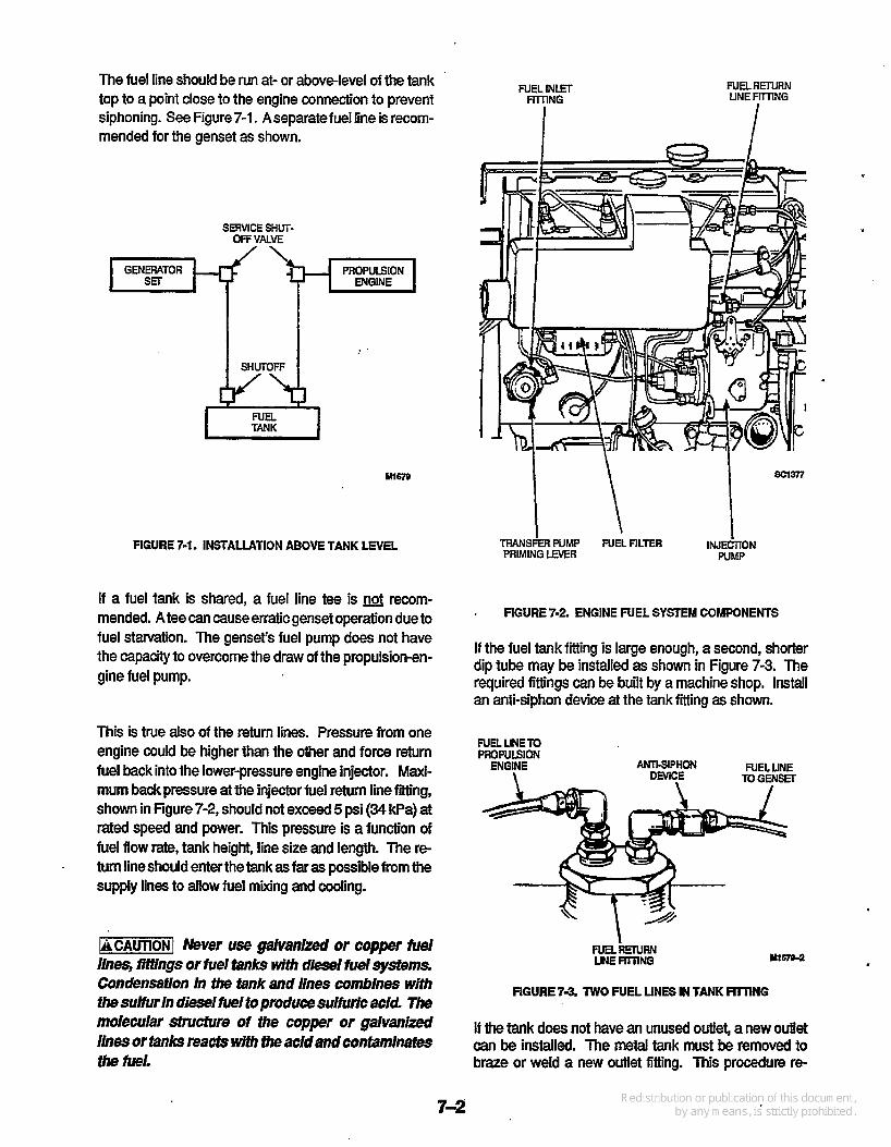
The fuel line should be run at- or abovelevel of the tank top to a point close to the engine connection to prevent siphoning. See Figure7-1. Aseparatefuel line is recorn- mended for the genset as shown.
N E L INLET FliTlNG I
FUELRETURN LINE FilllNG
n I SERVICE SHUT-
OFFVALVE wy’”;” PROPULSION
. .
Mlm
FIGURE 7-1. INSTALLATION ABOVE TANK LEVEL
If a fuel tank is shared, a fuel line tee is recom- mended. A tee can cause erratic genset operation due to fuel starvation. The genset‘s fuel pump does not have the capacity to overcome the draw of the propulsion-en- gine fuel pump.
This is true also of the return lines. Pressure from one engine could be higher than the other and force return fuel back into the lower-pressure engine injector. Maxi- mum back pressure at the injector fuel return line fitting, shown in Figure 7-2, should not exceed 5 psi (34 kPa) at rated speed and power. This pressure is a function of fuel flow rate, tank height, line size and length. The re- turn line should enter the tank as far as possible from the supply lines to allow fuel mixing and cooling.
-1 Never use gakanized or copper &e/ iinw, fffdngs or fuel fmks wjth diesel fuel systems. Condensation In the tank and lines comblnes with the sumr In diesel fuel to produce sutfwc acld. The molecular structure of the copper or ga/vanized ihes or tanks reacts with the acld and confamlnates tin? fuel.
TRANSFER PUMP FUEL FILTER I N J E ~ O N PRIMING LEVER PUMP
I FIGURE 7-2. ENGINE FUEL SYSTEM COMPONENTS
If the fuel tank fitting is large enough, a second, shorter dip tube may be installed as shown in Figure 7-3. The required fittings can be built by a machine shop. Install an anti-siphon device at the tank fitting as shown.
FUEL UNETO PRopLlLsloN
ENGINE \
ANll-SIPHON N E L UNE TO GENS3
LINEFITllNG yl67B-2
FIGURE 7-3. TWO FUEL UNES IN TANK FIRING
If the tank does not have an unused outlet, a new outlet can be installed. The metal tank must be removed to braze or weld a new outlet fitting. This procedure r e

t
quires the service of a welder familiar with the essential safety measures.
[AWiRRNGl IgnItion of fuel vapors can cause severe personal Injury or death. Welding a fuel tank, empty or noi: is extremely dangerous! Vapors may ignjfe causlng an exploslon and fire. Have weiding done only by experienced personnel.
SIPHON PROTECTION
Whenthefuel tankis installedabovethe enginelevel, an anti-siphon device is needed to prevent siphoning if the line breaks below the fuel level. See Figure 7-4. This de- vice is installed at the tank withdrawal fitting, or at a loca- tion where the line from the tank will no longer remain above the fuel tank top level. The device can be either a mechanical check valve, or an electric valve with me- chanical override. The electric valve is connected to open only when the engine fuel solenoid is on.
AMl-SlPHON VALVE OR ELECTlUlcALLy WERATED FUEL STOP VANE
I
I yl-' pzkp-l F\
FIGURE 7-4. SIPHON PROTECTION
FUEL TANKS
A valve must be installed directly at the tank connection to shut off luel flow. This vahre may be electrically or manually operated. If electrically operated, i t must be en- ergized only during engine operation, and have a manual override to comply with USCG regulations. This valve can be pur&ased from Onan, and is listed in the parts minual.
The manual valve must have an arrangement for opera- tion outside the compartment in which the tank is lo- cated, preferable from above deck.
A USCG approved service shutoff valve must be in- stalled at the engine end of the fuel line under conditions listed below. Thisvahrestopsthefuelfiow ifthegensetis Serviced.
0 When fuel tanks are located in a compartment other than the engine.
0 When the engine and fuel tanks are separated more than 12 feet (3.7 m).
If the propulsion engines and genset use different fuels, a separate fuel tank is required. Use only an approved tank designed for marine application. Be sure that the compartment is well ventilated (see Ventilation section). Fuel consumption data in the Specifications section is useful for determining the tank size.
When installing a separate tank, locate it close as possi- ble to the genset compartment. Be sure it is accessible and can be removed for inspection.
r-1 Fuel starvation can cause marginal op- eration of the generator set Fiberglass fuel fanks can present a problem If the fuel pickup tube Is too close fo fhe tank bottom. Fiberglass flbers can settle and form a mat with time. Makea diagonalcut on the bottom of the pickup tube and Install 11'2 to 2Inches (13 to 51 mm) from the tank bottom.
Mount the fuel tank and secure into position. The NFPA recommends that flat bottomtanks beinstalled on slatted wooden platforms to help prevent moisture condensa- tion. Cylindrical tanks should be set in chocks or cradles and securely fastened.
Small fuel tanks can be suspended from deck beams. Support and brace the tank to prevent movement. Line up braces with the tank internal baffle plates. Insulate all wood or metal surfaces from the tank surface with anon- abrasive and nonabsorbent material. Heavy tubber-im- pregnated cotton fabric or oil- and acid-resistant plastics work well.
Ignition of fuel when filling the tank can result In severepersonallnjury or death. All mefalllc &el tanks MUST be electrically bonded to the boat wmmon ground. Also bond the fliler neck or open- lng to the tank If a hose Is used beiween them. Thls helpspreventsbflcspark when filllngthatcanlgnlfe the fuel.
Position the tank fill and vent pipes so fuel or vapor can- not escape into the bilge. Run the vent and fill pipes from separateopenings inthe tank. Ifthefill pipe hasaflexible section of fuel hose, installaseparate grounding wire be tween thedeck fuel plateand tank. Install the vent open- ing as far from other hull opening as possible, and with a gooseneck so water cannot enter. Install a flame arres- ter on the vent opening.
FUEL SYSTEM TEST After installation, test the fuel system for leakage per ABYC H-33.5. Any leakmustbefoundand comecfedbe- fore putting the fuel system into service.

..
t
,
Section 8. Electrical System GENERAL
Installing the genset electrical system indudes installing line circuit breakers, connecting the load, installing the remote start control (if used), and connecting the battery. The battery must always be connected last to avoid acci- dental genset starting during the installation.
1-1 Accidental starting of the generator set during lnstallatlon creates a hazard of serious per- sonal injury or death. Do not connect the sfartlng baffery until Instructed. Have all wiring installed by a qualiiied electrician. Wiring diagrams do not include customer-added components.
The wiring must meet ABYC "Standard and Recom- mended Practices For Small CrafY'and NFPA 302 "Fire Protection Standard for Pleasure and Commercial Motor CrWrequirements, and all other applicable codes. The requirements and recommendations found in this sec- tion are excerpts from these publications, but are not in- clusive.
Be sure to seal all openings made for wiring so exhaust or fuel vapors cannot enter the living quarters. Ifflexible- metal conduit is used, it must be sealed internally at the end where it terminates within the junction box or panel- board. Flexible-metal conduit is not vapor-tight along its length due to its unique construction.
-1 lnhalatlon of exhaust gas or Ignltlon of fuel vapor can cause severe personal Injury or death. Be sure fo vaporweal flexible mew conduit, and all openlngsmade durlng lnstalllatlon of the gen- erator set, with a slllcone/Nbber-based sealant.
-1 Faultjf electrical equipment can cause shockandseverepe~nallnjuryor death. Use only approved power supply assemblles, and never re- move the grounding pln from the power cord. No grouM, or an Incomtgtvund, can cause the ves- sel to become electrically "hot".
b
LOAD CONNECTIONS * Line Clrcult Breaker
Alinecircuitbreakermustbeinstalfedtoprotectthegen- erator from short circuit or other overloads. When sup- plied by Onan, they mount on the side of the control box. Other breakers must meet code specifications to prop- erly protect the generator.
Use a section of flexible conduit at the genset to absorb movement and vibration. Flexible, multi-strand wire must be used throughout to reduce the danger of break- age due to boat movement or vibration. Grounding must comply with wiring codes.
-1 Contact with elecfricaly "hot" equip- ment can result In severe personal Injury or death. it is exfremely Important that bondlng and equipment grounding be properly done. All meiaillc parfs whlch could become energized under abnormal conditions must be properly grounded.
-1 Improper wlrlng can resulf In flre and severe personal Injury or death. Do not connect electrical wlrlng to the fuel line.
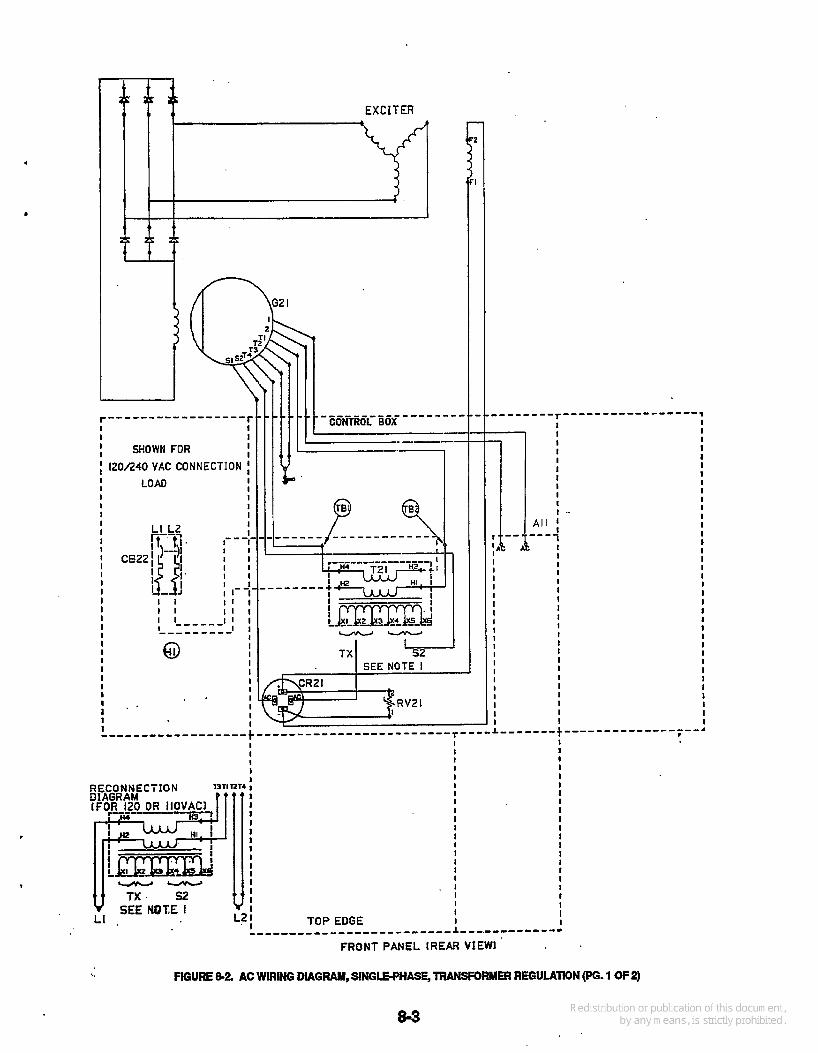
Non-Reconnectable Generators The single-phase 120,120/240-voIt (1 1 5 , i 15/230-vott), two- and three-wire connections are shown on the AC wiring and schematic diagrams, Figure 8-2. These gen- erators are transformer regulated as shown. The load leads are connected to the load circuit breaker.
When output is taken fromtwo generator windings (such as 120/240 volts), the 120-volt loads must be balanced across the windings. Taking full load from one winding can cause poor voltage regulation and damage to the equipment or generator. A 220-, 230- or 240-volt load is connected across both windings. The load circuit break- e r must be sized to the AC output current.
International 50 hertz or 60 hertz generators can be con- nected for 2-wire, 220-, 230-, or 240-voIt, singlephase output. This is done by grounding lead l2, and lifting and insulating (by eledrical tape or isolation terminal) lead LO on transformer-regulated generators. In these connee tions, only the hot lead L1 is connected through the breaker trip; and lead L2 is connected directly to ground (notthrough the breakertrip). Seethe reconnection dia- grams in Figure 8-5.
Reconnectable Generators Reconnectable, multi-lead generators have wide ranges of single or three-phase voltages. These generators have electronic regulation. The connecfions are shown on the AC wiring and schematic diagram, Figures 8-4 and 8-5. The line circuit breaker must be sized to the AC output current and meet code specifications.

Dockside Power Connection
While at dock, most boats have a dockside c- nneci
the commercial power. Theswitch must never permitthe genset and commercial power to be connected together, nor permit aroover between them. Use either a manual switch or a shoreline power transfer switch of the proper rating in accordance with ABYC E-8.4. See Figure 8-1.
r for use of commercial power. These installations must have a positiveoff switching device to isolate the genset and
TO BRANCH CIRCUIT PROTECTIVE DMCES I
FIGURE 8-1. SHORELINE POWER TRANSFER SWITCH
‘
I 120/240 VAC CONNECTION I I LOAD I I I I I I I I I I I I
I I I I I I I I I I I I I I I I I I '
1 CBZZ
!
21
-- I TX %+
SEE NOTE I
FfGURE 8-2 AC WIRING DIAGRLUI, SIffiL6PHASE, TRANSFORMER REGULATION (PG. 1 OF 2)

AC SCHEMATIC SINGLE PHASE TRANSFORMER REG I 120/240 OR I10/220VACl
A l l r - - I A C
I I I I I I I I I L - - - - J
< * 4 .
\d LO LIL2 '
DASHNO. MODELNO. -01 ...... -60 HZ (MDLA) -02 ....... 50 Hz (MDL4) -03 ...... .6OHZ(MDL3) -04 ...... -60 HZ (MDL6 -05,-07 ... 5OHZ(MDL6) -06 ...... -60 HZ (12.5 MDI-3)
COMPONENT' IDENTIFICATION
I REFDES jl TB1,Z
DESCRIPTION
PCB Ass'y, Engine Monitor Circuit Breaker, Load Bridge Rectifiir Generator, Ac Suppressor Ass'y Standoff Insulator Transformer, Regulation
NOTES 1. TO ADJUST OUTPUT VOLTAGE, MOVE TAPS ON
T2l ACCORDING TO CHART BELOW. 2. UNLESS OTHERWISE NOTED, ALL COMPONENTS
ARE SHOWN IN THE DE-ENERGIZED POSITION. 3. DASHED UNES INDtCATE W E N USED.
POSITION BY DAW NO.
OUTPUT VOLTAGE
ADJUSTMENT ~
T INCREASE
DECREASE
1
FIGURE 83. AC SCHEMATIC DIAGRAM, SINGLE-PHASE, TRANSFORMER REGULATION (Po. 2 OF 2)
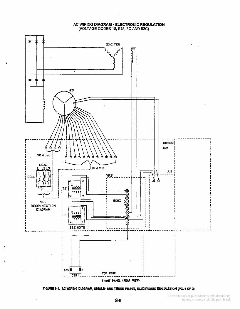
AC WIRING DIAGRAM - ELECTRONIC REGULATION (VOLTAGE CODES l8,518,3C AND 53C)
I
FIGURE 84. AC WRING DIAGRAM, -LE; AND THRE6PHASE, ELEcIRONtC REGULATION (PG. 1 OF 2)

AC SCHEMATIC - ELECTRONIC REGULATION (VOLTAGE CODES 18,518,3C AND 53C)
I
RECONNECTION DIAGRAM
tl L2 nw N R Lo
i3
I CODE# SOH2 120
Ai 1 CB21 CB22 021 I 2 1 121 VR21
PCB Ass'y. Engine Monitor Circuit Breaker, 3 Ampere Circuit Breaker, Load Generator, AC Reactor Assembly Transformer, Voltage Ref. Voltaae Reaulator Assembhr
NOTES: 1. CUT LEADS 3 AND 4 FROM L21. THESE LEADS
ARE NOT USED. 2 UNLESS OTHERWISE NOTED, ALL COMPONENTS
3. DASHED LINES INDICATE CONNECTIONS WHEN USED.
ARE SHOWN IN M E DE-ENERGIZED POSITION.
i2
n CODE 3c KL' z r
74 f L2
W E s3c Iwy llSV ow m m
CODE X
I I
FIGURE 8-5. AC SCHEMATIC WIRING, S I N G E AND THREE-PHASE, ELECTRONIC REGULATION (PO. 2 OF 2)
8-6
L
.
I I I I I I I I I I I
I I I I I .I I I f I I I I I I I i 1 I I I I I
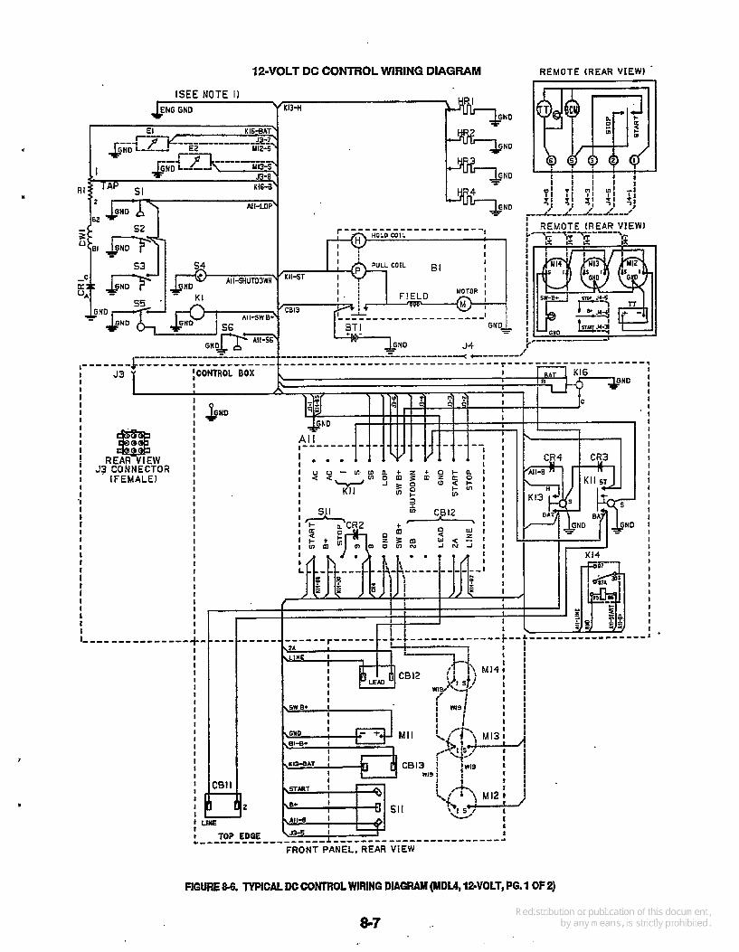
12-VOLT DC CONTROL WIRING DIAGRAM REMOTE (REAR VIEW)
[SEE NOTE I1 K13-H
GND Kl6%Al
YIZ-5
Y13-5
Kl6-8 R I
I I I I R W I
J3 CONNECTOR IFEMALEI I
I I I I I I I I I I I I I I I I I 4 I I
I 3-
I I
I I
I '
-- I I I I I I
I I I I I I I I I I I I I I I I I I I I I I I I I I I I I
* I
. , - I *
2
FIGURE &6. TYPICAL DC COHlROL WIRING DIAGRAM (MDLA, 12=VOLT, PG. 1 OF 2)

12-VOLT DC CONTROL SCHEMATIC DIAGRAM
I J 1 I 1 I I I I I I I I
I I I I I I I I I I I I I I I 1 I I I I I I I I I I I I ' I I I
I I 1 I I I I I I I I ' I I I I I I I I I
I I I
I I I I
I
I
I
I
1 1
t
I I
E
CRUZ
15,~ :: K15 E - m
CB12 LINE L E M
14
$1 87
A l l - C R l l c
A l l - R I
NN GNO '
1
I .. I R I ... n I +* I
G N D ~
A1 1 A1 1x12 A1 1x15 A1 1-Ri A1 1-R2 B1 BTl CBl1 CB12 CBi3 CRi CR2 CR3,CRd cw1 El E2 HR14 J3 J4 K1 Kl 1 Ki 3 K14 K16 M i 1 Mi2 Mi3 M14 Ri si s2 !XI s4 s5 s6 si 1
DESCRIPTION
PCB M y , E n g i i Monitor Relay, Power Relay, Starter Protection R e s i i r , K12 Resistor, LOP Timing SWer & Solenoid Battery, 12v Circuit Breaker, Control Circuit Breaker, Fault Circuit Breaker (SO Amp) Reditkr, Battery Charging Rectifier b y , Stop Rectifier winding, B a r n Charging sender, oa pressure Sender, Codant Temp Heater, Glow Plug connector. control Connector, Remote Control solenoid, Fuel Relay, Start Solenoid, Pilot Relay, Heater Relay. Ign Start
Meter, TiieToWking Gauge, Oil Pressure Gauge, Coohntiemp. voltmeter Resistor, Battery Charging Switch, Low Oil Pressure switch, Hi@ COOhntTemp. switch, Hi& Exhaust Temp. switch, overspeed Switch,LowcodantLeYel swiw1,contrciPwr.Latch switch,starvstap
Regulator, V o b p (2Step, lZ-VoIt)
Nom. 1. UNLESS OTHfSWlSE NOTED, AIL COMPONENTS ARE . SHOWN IN D6ENERGIED POSiTfON, 2 DASHED UNES INDICATE CONNECTIONS WHEN USED.
FIGURE 87. TYPICAL DC CONTROL SCHEMATIC DIAGRAM (MDU, 12-VOLT, Po. 2 OF 2)
8 4

REMOTE CONTROLS
cablo- -
Provision is made on the genset for connection of a re- mote control panel. A 9-pin remote connector (53) on the control box connects to a connector (J4) on the remote panel. See Figure 8-6. Onan has two remote kits (with or without meters) complete with installation instructions. Also available are complete harness assemblies with end-connectors in 15, 25, and &foot (4.6, 7.6, and 13.7 m) lengths. Call the Onan dealer or distributor for assistance in securing these items.
2 1 0 00 o 0 o o o o o
(lam) (ism) (Zl m) (271n) (Sam) ( e m ) 4n 5n 7t OR i i n 148
Additional control stations (without meters) can be added if desired. The genset senders (temperature and oil pressure) can each control only one meter. If the genset control box has meters, they must be disconnected to prevent erroneous readings. The electrical code does not allow the remotecontrol harness or wiring to be routed in the same conduit with AC wiring.
-1 lnterchanglng fhe connecflons (shown In fhe confro/ Wt insfrucfion sheet, or fhe generafor set wiring diagram) can cause equipment damage.
Be sure to seal all openings made for the wiring so ex- haust or fuel vapors cannot enter the living quarters. If flexible-metal conduit is used for remote wiring, it must be sealed internally at the end where it terminates within the junction box. Flexible-metal conduit is not vapor-tight along its length due to its unique construction.
7 1 Inhalation of exhaust gas or ignnlon of fuel vapor can cause severe petsonai Injury or deafh. Be sure to vapor-seal flexlMe mefa/ conduit and all openlngs made during Installafion of the gen- emfor set with a sillcondrubkr-based sedanti
BAllERY General
Always use a battery at least as large as specified. The battery should be installed dose to the genset, prefer- ably in a separate compartment. The compartment must be well ventilated to prevent accumulation of explosive mrygases.
Mount the battery in an add resistant tray on a ptaiform above the floor. It must be secured to prevent shifting. If mounted in an engine comparbnent, always install anon- metalliccoverto prevent battery damage and arcing from accidentally dropped tools. Figure 8-8 shows a typical battery tray and cover.
FIGURE 88. TYPICAL BATTERY TRAY AND COVER
Maintenance free batteries definitely should be cpnsid- ered for marine application. The technology in these bat- teries make them completely sealed and maintenance free. They offer higher output ratings (CCA), and better durability.
Connection
[BWARNINGI Leakage of fueiin oraround fhegenera- for set compartment presents a hazard of fire or ex- plosion that can cause severe personal injury or deafh. Do not disconnect or connecf batfery cables if fuel vapors are present Venfiiafe the compaft- ment thoroughiy Wfh fhe bilge blowers orpower ex- hausters.
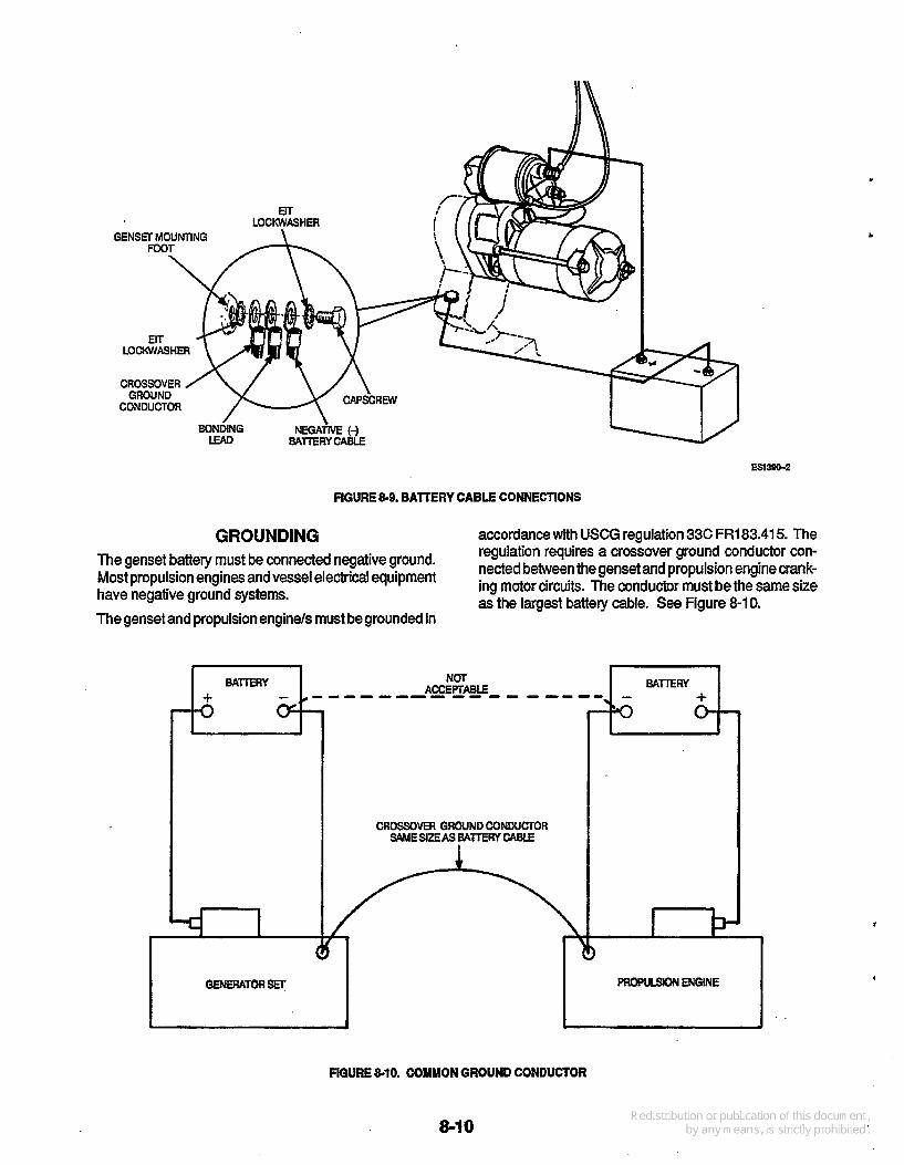
Using cable size speafied in Table 8-1, connect the bat- tery negative (-) lead to the genset at the location shown in Figure 8-9. Failure to do so can cause arcing or resis- tance in the cranking circuit. Be sure to use an EIT lock- washer on each side of the genset battery-negative (-) connector to help make a good electrical connection. Connect the battery positive (+) lead to the start solenoid as shown.
The lgnitlon of diesel fuel or fumes can result In severe personal Injury or death. Conned the generator set battery ground (-) lead only at the location shown. Connectthecablestothebatleryasshown,thenegath'e (-) battery terminal last. Be surethe battery connections are clean and tight; then cover the battery temhls with a dielectric grease to retard corrosion.
TABLE 8-1. BATTERY CABLE SIZE REQUIREMENTS
(Maximum Lenath of One CaMe)
.
FIGURE &@, BATTERY CABLE CONNECTIONS
GROUNDING accordance with USCG regulation 33C FR183.415. The regulation requires a cro&over ground conductor con-
as the largest battery cable. See Figure 8-1 0.
The genset battery must be connected ground* Most propulsion engines and vessel electrical equipment nected bebeen the gensetand propulsion engine crank-
ing motor circuits. The conductor must bethe Same size have negative ground systems. The genset and propulsion enginels must be grounded in
I .
U
CROSSOVER GROUND CONDUCTOR SAME SEAS 6AlTEKY CABLE
I I
OENERAToRsEr
> J
FIGURE 810. COMMON GROUND CONDUCTOR
8-10
The conductor prevents accidental passage of cranking current through the fuel systems and smaller electrical conductors common tothe engines. This can happen if a cranking motor ground circuit becomes resistive or opens from corrosion, vibration, bad cable, etc.
E 1-1 Improper ground can cause severe per- sonal injury or death from fire or explusjon. Be sure to install a common ground conductor between all on-board cranking circuits.
BONDING
The genset must be bonded to the vessel common-bond- ing conductor with a bonding lead or strap attached to the same location as the negative (-) battery cable). See Figure 8-9 for hardware used, and the proper assembly. Do not connect the battery negative (-) lead at a location other than shown.
If a metallic fuel line is installed between the fuel tankand the genset shutoff valve, it too must be bonded to the vessel common-bonding conductor.


I
1
Section 9. Final Installation Checks INSTALLATION CHECKS
Before trying to start the genset, determine that the in- stallation is complete by answering affirmatively the fol- lowing questions:
supports. If any leaks are found, shut down the gen- set immediately and repair.
-1 Exhaust gas Is deadly. For thls reason, shut down the generator set immedl-
Is the exhaust system secure and all connections tight?
Is a flexible section of exhaust hose used between the genset and muffler?
Is all exhaust hose certified for marine exhaust appli- cation, and adequately supported and protected?
Is the exhaust outlet terminated away from windows, vents or other openings that might allow exhaust gases to enter the vessel, or be pulled into the vessel when in motion?
Are the AC generator and load wires securely and correctly connected to the circuit breaker?
Are the battery cables connected correctly and se- curely at the genset and battery?
H a s crankcase oil been added to the engine, and at the correct level? See the Maintenance section of the Operator's Manual.
Oil, coolant, and fuel have been drained from the englne at the factoty prlor to shipment Opention without oil and coolant will damage the engine.
INITIAL STARTING AND CHECKS
Refer to the Operator's Manual before trying to start the genset. Prime the sea water pump on initial start-up. Make sure the fuel shutoff valve and sea water cock are open. Operation without water will ruin the pump neo- prene impeller.
Start the genset by hdding the Starvstop switch in Start position. The genset should start within a few seconds. If not, check fuel supply and shutoff valvels.
Check water flow at the hull exhaust outlet, and op- eration of the genset. -Refer to Operator's Manual for proper parameters.
Check the exhaust system for leaks-visually and audibiy. Note the security of the exhaust system
ately i f an exhaust leak or exhaust component needs repair. Do not run the generator set until the exhaust system is repaired.
Check the genset for fuel, oil and coolant leaks. If any are found, shut down the genset and repair the leak before making any more checks.
Connect an accurate AC voltmeter and frequency meter across two line terminals. Apply load to the generator and check the output.
Output frequency is determined by engine speed and normally does not require adjustment. Verify that fre quency is correct before making voltage adjustments. Call an authorized distributor or dealer for assistance if needed.
VOLTAGE ADJUSTMENT
if the voltage is not within specs, it can be adjusted using the following procedures for either Transformer or Eleo tronic regulation.
1-1 High voltages within the control cabi- net can cause severe personal injury or death. Pro- ceed with care and do not touch electrical contacfs wlfh any tool, clothing, jewely or body part
Magnetic Regulation 1. Wdh the genset running, note if voltage needs to be
increased or decreased.
2. Stop the genset Disconnect the negative (-) bat- tery cable before proceeding.
-1 Accidental star€ing of the pnera- tor set can cause severe personal lnjuq or death. Dlsconnect thenegative (-) hiie~~eabk? beforeadjusting theregulator fransfonnertaps.
3. Move taps of transfonnerT21 as shown on the chart in Figure 8-3 (page 2 of 2).
4. Reconnect the battery cable. Operate the genset and recheck output voltage. If necessary, repeat the above steps. The genset is now ready for og eration.
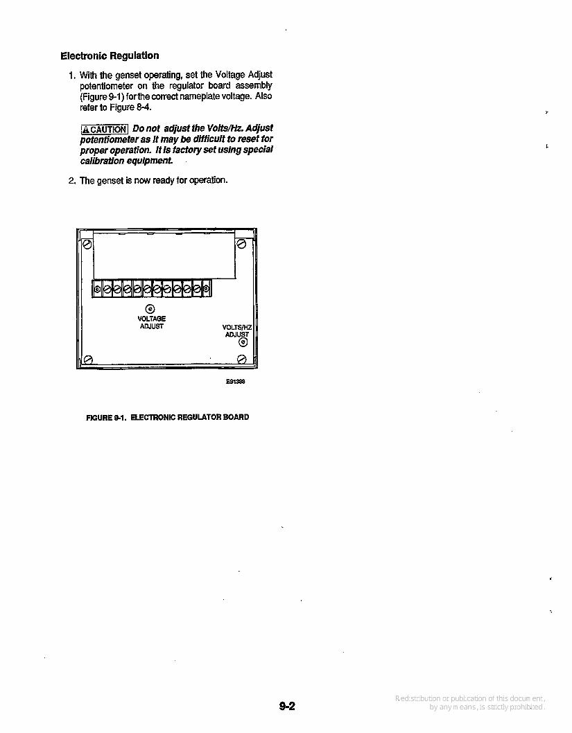
Electronic Regulation
1. with the genset operating, set the Voltage Adjust potentiometer on the regulator board assembly (Figure 9-1) forthe correct nameplate voltage. Also refer to Figure 8-4.
-CAUTION] Do not adjust the Volts/Hz. Aqust pofentjometer as it may be difficult to reset for proper operation. It Is factory set using special calibration equipment.
2. The genset is now ready for operation.
RGURE 9-1. ELECTRONIC REGULATOR BOARD


Onan Corporation 1400 73rd Avenue N.E. Minneapolis, MN 55432
612-574-5000 International Use Telex: 275477
Onan IS a rw?istered trademark 01 Onafl Carparatian
1-800-888QNAN
Fax: 612-574-8087