8 Bed CNet wholly - VTechWorks - Virginia Tech
154
AN APPLICATION OF THE SYSTEMS ENGINEERING PROCESS TO THE EVALUATION AND SELECTION OF AN ARCHITECTURAL COMPUTER AIDED DESIGN SYSTEM by ~ Kristen S. Rindin Project and report submitted to the faculty of the Virginia Polytechnic Institute and State University in partial fulfillment of the requirements for the degree of MASTER OF SCIENCE in Systems Engineering APPROVED: W.G. Sullivan, Chairman 8 Bed CNetwholly B.S. Blanchard C.M.Kolley 2 December 1993 Blacksburg, Virginia
-
Upload
khangminh22 -
Category
Documents
-
view
6 -
download
0
Transcript of 8 Bed CNet wholly - VTechWorks - Virginia Tech

AN APPLICATION OF THE SYSTEMS ENGINEERING PROCESS
TO THE EVALUATION AND SELECTION OF AN
ARCHITECTURAL COMPUTER AIDED DESIGN SYSTEM
by ~
Kristen S. Rindin
Project and report submitted to the faculty of the
Virginia Polytechnic Institute and State University in partial fulfillment of the requirements for the degree of
MASTER OF SCIENCE
in
Systems Engineering
APPROVED:
W.G. Sullivan, Chairman
8 Bed CNet wholly B.S. Blanchard C.M.Kolley
2 December 1993
Blacksburg, Virginia

CL
BY,
VES! 1993 R563

AN APPLICATION OF THE SYSTEMS ENGINEERING PROCESS
TO THE EVALUATION AND SELECTION OF AN
ARCHITECTURAL COMPUTER AIDED DESIGN SYSTEM
by
Kristen S. Rindin
Committee Chairman: Professor William G. Sullivan
( ABSTRACT )
The Systems Engineering Process has been applied to the evaluation
and selection of a Computer Aided Design system for AER Architects to
automate the design and drafting process, establish computer-based
compatibility with contractors and vendors, and improve productivity.
A needs analysis establishes the architecture firm's desire to produce
higher quality drawings in a reduced time schedule. Detailed functional,
operational, and maintenance requirements are developed through
interactive meetings with the Principal Architect, and a set of desired
advanced software capabilities is identified. Alternative CAD software
packages are compared, and two packages are selected for further
evaluation. A brief discussion of decision making models is included, with
justification for the utilization of the Analytic Hierarchy Process model.
The two CAD software packages are evaluated against the objective and
subjective attributes defined by the Principal Architect through the use of
Automan, a software package developed by Stephen F. Weber of the
National Institute of Standards and Technology.
ii

ACKNOWLEDGMENTS
I wish to acknowledge the valuable assistance of my committee
chairman, Professor William G. Sullivan, in completing this project. His
knowledge of the systems engineering process kept me on track. I'd also
like to acknowledge the persistent guidance of committee member Chet
Kolley. Chet spent a significant amount of his personal time reviewing
each revision for continuity and clarity, which helped produce a quality
report. Dean Blanchard should be recognized for his valuable assistance
during my graduate student career for the last three years, as well as on this
project. I am deeply indebted to the Principal Architect of AER Architects
for assisting me with all phases of this project during the last four months.
Finally, special recognition goes to Jeffrey A. Rindin, my patient
husband, who has weathered the last three years of classes two nights a
week and the significant stress level introduced by the challenges of this
Masters Degree Program. I am thankful for the assistance Jeff provided on
this project, and for his support during the last two months.
il

Table of Contents
Section Title Page
Abstract li
Acknowledgments ill
List of Figures Vil
List of Tables Vill
1 Introduction 1
1.1 Background Information 1
1.2 Project Objectives 4
1.3 Definition of Need 6
1.4 Feasibility Study 9
2 The Systems Engineering Process 13
2.1 Introduction 13
2.2 Conceptual Design Phase 14
2.3 Preliminary Design Phase 17
2.4 Detail Design Phase 20
2.5 Summary 22
3 Development of System Requirements 22
3.1 Requirements Definition Process 23
3.1.1 Requirements Collection Process 23
3.2 Operational Concept and Requirements 26
3.2.1 Operational Use Requirements 28
3.2.2 Operational Requirements Flow Diagrams 30
1V

Table of Contents, continued
Section Title Page
3.3 Maintenance Concept and Requirements 34
3.3.1 Maintainability of CAD Software 4]
3.4 Functional Analysis and Requirements 42
3.4.1 Description of Required CAD Software Capabilities 50
3.4.2 Compatibility Functional Requirements 51
3.4.3 Operational Life Cycle of the CAD Software 53
3.4.4 Effectiveness Factors 53
3.5 Definition of System Support Requirements 54
3.5.1 Training Requirements 54
3.5.2 Vendor Requirements 55
3.6 Summary and Allocation of Requirements 57
4 Analysis and Evaluation of Alternatives 60
4.1 Discussion of the Multiattribute Decision Analysis 60
4.1.1 Sequential Elimination Methods 62
4.1.2 Graphical Techniques 63
4.1.3 Weighted Evaluation of Alternatives 65
4.2 Application of Multiattribute Decision Analysis 67
43 Life Cycle Cost Analysis of Preferred Alternatives 71
4.3.1 Assumptions 72
4.3.2 Equivalent Worth Calculations for Alternatives 73
4.3.3 Results of Equivalent Economic Worth Calculations 81

Table of Contents, continued
Section Title Page
4.4 Description of Analytic Hierarchy Process 82
4.5 Application of Analytic Hierarchy Process 85
4.6 Results of Analytic Hierarchy Process 86
5 Future Study Recommendations 87
5.1 Hardware Study and Evaluation 87
5.1.1 Hardware Operating Environment 89
5.1.2 Benchmark Hardware System 89
5.1.3 Hardware Life Cycle Cost Analysis 92
5.2 Networking 93
5.3 Productivity Measurement 94
6 Conclusions 95
6.1 Summary of the Application of the System Engineering 95
Appendix A Summary of Software Packages Reviewed 97
Appendix B Summary of Automan Computer Output 109
Appendix C Automan Sensitivity Analysis 118
Footnotes 140
References 142
Vita 144
vi

List of Figures
Figure Title Page
1 CAD System Conceptual Design Phase 16
2 CAD System Preliminary Design Phase 19
3 CAD System Detail Design Phase 21
4 Weekly System Usage Scenario 29
5 Operational Functional Flow Diagram 31
6 Operational Functional Flow Diagram, cont. 32
7 Operational Functional Flow Diagram, cont. 33
8 Top Level Maintenance Functional Flow Diagram 37
9 First Level Maintenance Functional Flow Diagram 38
10 First Level Maintenance Functional Flow Diagram, cont. 39
11 CAD System Maintenance Policies 40
12. Top Level Requirements Functional Flow Diagram 44
13. ~~ First Level Requirements Functional Flow Diagram 45
14 Second Level Requirements Functional Flow Diagram 46
15 Second Level Requirements Functional Flow Diagram, cont. 47
16 Second Level Requirements Functional Flow Diagram, cont. 48
17 Second Level Requirements Functional Flow Diagram, cont. 49
i8 Graphical Evaluation Technique 64
19 Schematic Model of Alternative 1 Costs 76
20 Schematic Model of Alternative 2 Costs 79
21 Analytic Hierarchy Process Model 84
22 Proposed System Hardware Configuration 88
vil

List of Tables
Table __ Title Page
1 Survey of Architecture Firm Results 10
2 Summary and Allocation of Requirements 58-9
3 Attribute Score Scale for Alternatives 69
4 Summary of Alternative Evaluations 70
5 Summary of Cost Data for Alternative 1 75
6 Summary of Cost Data for Alternative 2 78
7 Summary of Equivalent Economic Worth Calculations 81
Vill

CHAPTER ONE
INTRODUCTION
1.1 Background Information
The computer aided design (CAD) field has expanded exponentially
with affordable and powerful software packages in the past five years.
Architecture firms wishing to adopt computer aided design tools and
techniques must do so carefully, only after establishing a budget,
identifying and reaffirming their goals and objectives, defining their
requirements and thoroughly analyzing the alternatives. While the number
of CAD software packages designed for architectural applications continues
to skyrocket, firms are finding that they do not have the resources or time to
perform a complete analysis of the software and hardware comprising the
computer aided design systems on the market. In general, architects do not
possess the computer hardware or software knowledge and are unable to
distinguish between product capabilities to select a CAD system. (1) The
systems engineering process is a valuable methodology to employ in this
situation to assist architecture firms in making an educated decision
regarding which CAD system will best satisfy their needs.
An example of this dilemma facing many architecture firms forms
the basis for this project. AER Architects, a small architecture firm in
Alexandria, Virginia, has requested a systems engineering analysis to
evaluate several computer aided design software packages. The Principal
Architect of AER is aware of the difficulties of venturing into an unknown
market, and has expressed a wariness of over-zealous salespersons and
vendors wishing to profit from his lack of computer knowledge. This past
year was profitable for AER, and the Chief Financial Officer has budgeted
$ 8,000 for the procurement of the CAD hardware and software required to
establish a CAD system at the request of the principal architect. The
budget is allocated for the purchase, installation, and training on the
operation of the complete CAD system.
Many articles printed in architecture trade magazines have
documented measurable productivity gains made by firms adopting the
computer aided design tools. In the September 1993 issue of Architectural
Record, the article "ADD Inc. Opts for No CAD Operators" describes how
the firm has eliminated the CAD operators to allow the architects to create
their own drawings. ADD Inc. has experienced improvements in the
quality of their drawings and in the time required to create the drawings by
removing the middleman, both of which are measurable forms of
productivity improvement by the firm. They have also significantly
improved their ability to create “extraordinary marketing presentations"
leading to an increase in the new business generated and a greater output of
designs by the firm. (2)
Measuring the exact amount of productivity improvement is a time
intensive task. A CAD Productivity Study performed by Hampton R.
Liggett and Steven R. Foster in 1986 at The University of Tennessee's

Center for Computer Integrated Engineering and Manufacturing documents
two procedures developed to measure productivity improvement ratios. (3)
These procedures can be implemented during the selection of CAD systems
or after a system has been purchased and installed. Both procedures require
keeping accurate records of the time used to perform design tasks using
manual design and drafting techniques prior to the installation of the CAD
system, as well as efforts using the CAD system after its installation.
Unfortunately, AER Architects has not maintained accurate records of the
time spent creating and editing recent architectural projects. The
measurement and evaluation of the productivity improvements are not made
in this paper due to the lack of required data. The assumption is made in
this paper that AER Architects will realize a significant productivity gain if
suitable training on the system is provided following its installation.
Liggett and Foster state in their study that "the amount of training provided
to CAD personnel will often be the difference between marginally
successful users and an exceptionally productive, highly motivated CAD
team." (4) In addition, interviews with architecture firms that have adopted
CAD tools during the last two years indicate that the firms have shown
great improvement in productivity when measured by the number of
projects produced per time period and the time required per project. (5)

1.2 Project Objective
This report summarizes the activities required to assist an
architecture firm in automating its design and drafting process.
Incorporating automation into other small architecture firms has resulted in
a significant improvement in the productivity of the architects, as estimated
by the architecture project managers. (6) The CAD system will enhance the
principal architect's ability to complete multiple drawings in the time it used
to require to complete a single drawing. In addition, the editing process
will be shortened by providing the architect with the capability to quickly
manipulate the drawing in softcopy and print out a modified drawing.
The objective of this project is to apply the systems engineering
process as described by Blanchard and Fabrycky in their book, Systems
Engineering and Analysis, to the evaluation and selection of a computer
aided design software package based on the automation requirements of an
architecture firm. (7) The paper presents a needs analysis in Chapter One
that establishes the architecture firm's desire to implement a cost effective
CAD system to reduce the cycle time of producing quality designs and
drawings. The paper then applies the systems engineering process to the
system design in Chapter Two. An approach is described for completing
the design phases of the engineering process, including the Conceptual
Design, Preliminary Design, and the Detail Design Phases.

This report addresses the Conceptual and Preliminary Design Phases
of the CAD hardware and software life cycle analysis. The analysis
establishes the CAD system's conceptual design in Chapter Three by
developing the system's functional and operational requirements,
conducting a functional analysis, and deriving the system's configuration
using preliminary design information obtained from a variety of vendors.
The paper then presents a description and application of the Analytic
Hierarchy Process decision making model to evaluate the alternative
software packages that satisfy the CAD requirements of AER Architects as
described in Chapter Four. A life cycle cost analysis is also conducted and
used in the decision making model as an evaluation attribute. In Chapter
Five, the paper then concludes with a summary of topics recommended for
future study that fall outside the scope of this project. An analysis of the
success of applying the systems engineering process to the topic of
selecting a CAD system for an architecture firm is presented in the
conclusion m Chapter Six.
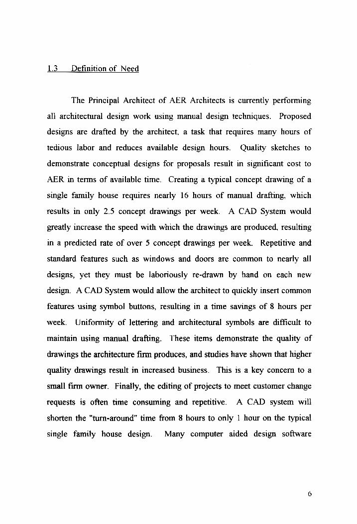
1.3 _ Definition of Need
The Principal Architect of AER Architects is currently performing
all architectural design work using manual design techniques. Proposed
designs are drafted by the architect, a task that requires many hours of
tedious labor and reduces available design hours. Quality sketches to
demonstrate conceptual designs for proposals result in significant cost to
AER in terms of available time. Creating a typical concept drawing of a
single family house requires nearly 16 hours of manual drafting, which
results in only 2.5 concept drawings per week. A CAD System would
greatly increase the speed with which the drawings are produced, resulting
in a predicted rate of over 5 concept drawings per week. Repetitive and
standard features such as windows and doors are common to nearly all
designs, yet they must be laboriously re-drawn by hand on each new
design. A CAD System would allow the architect to quickly insert common
features using symbol buttons, resulting in a time savings of 8 hours per
week. Uniformity of lettering and architectural symbols are difficult to
maintain using manual drafting. These items demonstrate the quality of
drawings the architecture firm produces, and studies have shown that higher
quality drawings result in increased business. This is a key concern to a
small firm owner. Finally, the editing of projects to meet customer change
requests is often time consuming and repetitive. A CAD system will
shorten the "turn-around" time from 8 hours to only 1 hour on the typical
single family house design. Many computer aided design software

packages provide these basic capabilities to the architects using the
software.
The Principal Architect of AER Architects has also seen some
demonstrations of the advanced capabilities of CAD systems, and is
interested in acquiring a fast system that will improve the firm's ability to
quickly create presentation quality drawings in 3D with a minimum of
required software add-on packages. In addition, AER Architects has heard
that CAD systems have a proven potential based on previous experience by
other architects to greatly improve productivity. AER Architects believes
that acquiring a CAD system will help maximize profitability and
ultimately make AER Architects a stronger firm.
AER Architects has recently felt increasing pressure from the
multiple clients, vendors, contractors and collaborating firms it works with
on a daily basis to become compatible via the computer. Compatibility via
the computer can be achieved through the CAD software package's ability
to read and write common file formats that are used by most firms, clients,
and vendors. Pressure from these organizations has led AER Architects to
consider purchasing a computer aided design system to foster improved
compatibility. Compatibility will result in an estimated 20 % increase in
business, based on the output potential of skilled architects using a
powerful CAD System.

The factors listed above, coupled with the desire of AER to move
into the 1990's computer aided design (CAD) arena, comprise the definition
of need that has launched this project.

1.4 Feasibility Study
Following the definition of need, a survey of architecture firms and a
market study was completed to determine the feasibility of automating an
architecture firm's design and drafting capabilities to improve productivity.
The initial survey based on a random selection of 15 firms found that 60 %
of the small to midsize architecture firms have automated capabilities with
varying degrees of sophistication. Interviews with nine (9) small to
midsize architecture firms using CAD systems revealed an industry that was
quickly becoming reliant on the technology and the functionality it
provides. The firms are all located in the Washington, D.C. area, and
employ anywhere from one (1) to twenty-seven (27) architects. The
average number of architects employed by the nine firms using automated
CAD systems was eight (8). Many of the firms had obtained CAD systems
during the last three years, with the exception of one firm, ADD
Incorporated, the employer of twenty-seven (27) architects, that began
using CAD in 1988. A table of the architecture firm survey results is
located in Table 1. The products used by some of the firms are included in
the list of alternatives evaluated through the systems engineering analysis in
Chapter Four.

TABLE 1. RESULTS OF ARCHITECTURE FIRM SURVEY
. .__| Number of | CAD |... Which Which Archi
chitecture Firm Architects | Capable? Since Date Software? Hardware?
Kohler and 4 Yes | May'93 | DataCAD | PC Clone Associates
Hickock ckock and 6 Yes | July'93 | AutoCAD | PCClone Warner
ADD, 7 Yes 1988 AutoCAD Macintosh Incorporated
chitectural 12 Yes Dec. '91 | Microstation PC Clone Design Team
BDR Architects 4 Yes | May'91 | AutoCAD | PC Clone
Col ole & Lenny, 2 Yes | Aug.'92| VersaCAD | PC Clone Incorporated
Nora Design 4 Yes Nov. '90 | Microstation PC Clone
Sasaki Associates 5 Yes Jan. ‘91 AutoCAD PC Clone Architects
M
. etcalf Torey & 9 Yes | Sept. '92 | Microstation | PC Clone Partners
SLM Group 6 No
Stephen B. Smith | No
Harry J. Graef 1 No
The Tucson 4 N
Group .
Laurel 2 No
Consortium
Elliott Architects 3 No
10

Additional software products were reviewed to determine if they
should be included in the evaluation of alternatives during a market study.
The market study was conducted to assess if any commercial off-the-shelf
(COTS) products (not identified by the architecture firms during the user
survey) existed to satisfy the computer aided design requirement. Appendix
A shows the list of Architectural CAD packages that were selected for the
initial evaluation, and includes the manufacturer data. The market study
resulted in a plethora of ten (10) design packages. The initial evaluation
served a valuable purpose by significantly reducing the field to a more
manageable number of software products. Two software packages met the
criteria and requirements identified in Chapter Three, which will be further
described and evaluated in Chapter Four.
A minimal amount of deliberation was given to the build or buy
decision. Past experience with complex graphical user interface software
development efforts has proven to be valuable in understanding the labor
hours required to complete such a task. Hence, custom development of an
architectural design package was not considered as an viable option for this
project due to the overwhelming procurement cost and schedule, as well as
significant operational costs required for maintenance. Estimates for a
simple graphical package (primitive compared to the CAD software meeting
AER Architect's requirements) and its development effort have been well
over $ 100,000.
11

After evaluating the definition of need and the results of the
feasibility study, it is believed that the goal of providing a commercial off-
the-shelf computer aided design system for an architecture firm is very
realistic.
12

CHAPTER TWO
THE SYSTEMS ENGINEERING PROCESS
2.1 Introduction
The systems engineering process provides a logical approach to
evaluate the options available to an architecture firm wishing to automate
its design and drafting capabilities. The process coordinates engineering
activities that start after establishing the need for the system and identifying
system functional and operational requirements to satisfy the need. The
systems engineering process uses analytical techniques to establish and
continually evaluate the system's design, operation, and maintenance
throughout its life-cycle. The activities conducted as part of the systems
engineering process correspond to life-cycle activities such as the
Conceptual Design, Preliminary Design, Detail Design, Construction,
Operation, and Retirement Phases as described by Blanchard and Fabrycky
(8).
This chapter outlines the design and development activities that
apply to defining and evaluating the alternatives for automating AER
Architects' designing techniques, including the Conceptual Design,
Preliminary Design, and Detail Design Phases. The results of these
activities are documented within Chapters Three and Four.
13

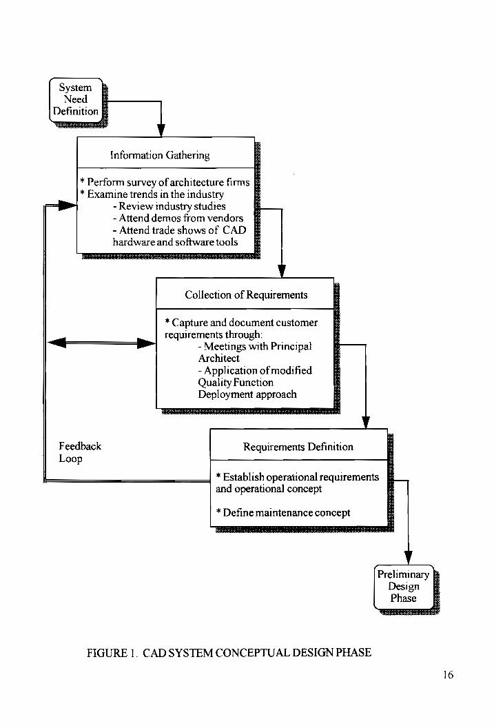
2.2 _ Conceptual Design Phase
The needs analysis established AER Architects’ desire to improve the
drafting capability of the Principal Architect by automating the design and
drafting process. The analysis identified a CAD System as the method of
choice for automation. Figure 1 summarizes the activities associated with
the Conceptual Design Phase.
The Conceptual Design Phase starts by reviewing current trends of
computer aided design in the architecture field and collecting related
information. The analysis determines the availability of computer aided
design software packages designed specifically for architecture firms to
help the architects improve the quality and quantity of designs they
_ produce. Analysis of the trends in the architectural drafting industry and
interviews with architects and vendors revealed information on the
capabilities of the CAD software packages. Additional studies were
completed to assess the availability of small personal computer systems that
could be purchased in a single system configuration and would run CAD
software. Large scale workstations and operating systems were not
considered because they were cost prohibitive, with several workstations
priced in the $ 50,000 range.
Multiple meetings with the Principal Architect of AER Architects
were held to elicit and capture the preferences and requirements for the
CAD hardware and software system. Quality Functional Deployment
14

(QFD), an inter functional design approach developed in 1972 was
implemented in a modified format to ensure that the customer requirements
and preferences are considered during the design process. The modified
QFD approach used during the Conceptual Design Phase is described in
more detail in Section 3.1.1, the Requirements Collection Process. The
systems engineering process uses the information obtained from this
research to develop the operational requirements and a maintenance concept
for both the computer hardware and the CAD software package. The
requirements provide the foundation for performing a functional analysis
and evaluation of alternatives. Following the Conceptual Design Phase, the
design of the CAD system moves into the Preliminary Design Phase of the
life-cycle analysis.
The detailed description of the application of the Conceptual Design
Phase is contained within Chapter Three.
15
System Need §&
Definition & OTe
Information Gathering
* Perform survey of architecture firms [7 * Examine trends in the industry e
—— iP - Review industry studies - Attend demos from vendors & - Attend trade shows of CAD § hardware and softwaretools §
SRR AR TSR TCR ARE RT a DT tat SNe oe ee Sit a ny RP ei Cee eR RN aa eae SOC TC EOD Oe a OC OOO EO OT TOLD
Collection of Requirements
* Capture and document customer requirements through:
<——" > - Meetings with Principal Architect - Application of modified Quality Function Deployment approach
Feedback Requirements Definition Loop
* Establish operational requirements E and operational concept
* Define maintenance concept Preliminary
Design § Phase EET ene rr ents ane Re MERE eRe ane eat
FIGURE 1. CADSYSTEM CONCEPTUAL DESIGN PHASE
16

2.3 Preliminary Design Phase
The Preliminary Design Phase refines the CAD system's high-level
requirements and conducts a functional analysis to establish the CAD
system's functional requirements and maintenance concept more
thoroughly. The functional and operational requirements are allocated to
hardware and software subsystems. The allocated requirements provide a
template or benchmark for the identification of multiple alternative software
selections. The systems engineering process develops the system functional
requirements in more detail through an iterative analysis shown by the
feedback loops in Figure 2. The iterative process for capturing the
functional requirements follows a customer requirements gathering
technique modified from the Quality Function Deployment approach
described further in Chapter Three.
The CAD system synthesis process identifies several alternative
CAD software packages that satisfy four of the functional, operational, and
maintenance requirements. Once the field of alternative CAD software
packages is narrowed to two "preferred" alternatives, a more detailed
evaluation of the packages is conducted to determine which CAD software
package satisfies the greatest percentage of the weighted objective and
subjective requirements.
The Preliminary Design Phase software optimization step includes
activities that lead to the selection of the optimal CAD system software
17

package through a multiattribute evaluation technique called Analytic
Hierarchy Process (AHP). Economic goals and specific system functional
and operational requirements comprise the evaluation attributes and
subattributes. The selected CAD software package is has operational
specifications that are critical to the next stage of the CAD system's
development, the Detail Design Phase, where detailed hardware component
specifications will be established.
Definition of alternative CAD hardware systems and optimization of
the hardware are not presented in this project. Once the operational and
functional requirements of the hardware and software are defined, the
project focuses on the optimization and evaluation of the CAD software
package. The activities comprising the Preliminary Design Phase are
contained within Chapters Three and Four. The hardware optimization and
selection activities are described in more detail in Chapter Five.
18

Conceptual B Design £
TR SOE OO ODEO Sais Mee ERLE ata
CAD System Functional Analysis
* Establish detailed functional requirements
> - Modified Quality Function S
Deployment approach
* Identify system support requirements * Identify system operational functions * Identify system maintenance functions Ce v
CAD System Synthesis
* Allocate requirements
—j—<$<<$— Po - Hardware and Software Subsystems :
* Define alternattve CAD Software Packages f
CAD System Optimization
* Perform analysis of alternatives using Feedback multiattribute evaluation techniques Loop * Refine alternatives to two “preferred”
configurations for each CAD subsystem |
* Perform life cycle cost analysis of
alternatives
* Establish multiattribute evaluation criteria based on requirements and costs
Detail Design
FIGURE 2. CAD SYSTEM PRELIMINARY DESIGN PHASE
19

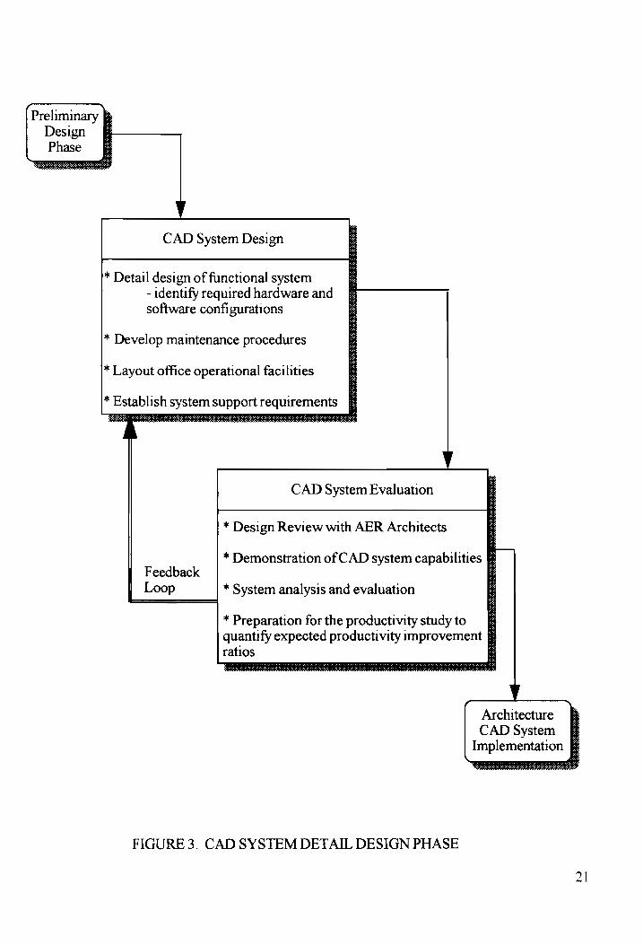
2.4 Detail Design Phase
The Detail Design Phase of the CAD system's life-cycle, shown in
Figure 3, completes development of the CAD system through additional
analysis and design. Specific activities associated with the Detail Design
Phase include designing the system and its components in more detail,
evaluating the suitability of the design, and modifying the design of the
components, as necessary. Some examples of the activities that occur in
this phase of the design process include developing detailed maintenance
procedures; designing operational office layout configurations; and
establishing the system support requirements. In addition, the integration of
the CAD system hardware and software should be planned for durmg the
Detail Design Phase. A complete system evaluation should also be
performed, including a major design review, hands-on demonstrations of
vendor products for the Principal Architect of AER Architects, a complete
system analysis, and preparation for a productivity study to evaluate design
and drafting capabilities following the selection, procurement, and
installation of the complete system. Chapter Five provides additional
information and recommendations for these system design and evaluation
activities and their impact on the CAD system's design and development.
20
CAD System Design
* Detail design of functional system - identify required hardware and software configurations
* Develop maintenance procedures
* Layout office operational facilities CAD System Evaluation
y
* Design Review with AER Architects
Feedback Loop * System analysis and evaluation
FIGURE 3. CAD SYSTEM DETAIL DESIGN PHASE
* Demonstration of CAD system capabilities :
* Preparation for the productivity studyto ff quantify expected productivity improvement fF
Architecture CAD System
Implementation Ee
21

2.5 Summary
The activities outlined for these design phases provide the high-level
guidance to select the CAD software and hardware system for AER
Architects. However, this paper describes the application of a modified
process tailored from Blanchard and Fabrycky for the CAD system's
Conceptual and Preliminary Design Phases only. The modified process
allows for the collection and analysis of the requirements, and the
identification of a CAD software package that provides the most
satisfaction for the architects that provided the requirements and will
eventually use the complete system. (9) Future study recommendations are
provided in Chapter Five, and are intended to satisfy some of the hardware
related Preliminary Design Phase activities, and all of the Detail Design
Phase activities.
22

CHAPTER THREE
DEVELOPMENT OF SYSTEM REQUIREMENTS
3.1 Requirements Definition Process
Blanchard and Fabrycky state that the technical parameters for
system design evolve from an analysis of the need. (10) Many questions
regarding the operational concept of the CAD system are asked of the
Principal Architect of AER Architects in order to facilitate the
establishment of the system operational requirements in accordance with
the steps in the Conceptual Design Phase.
3.1.1 Requirements Collection Process
Interactive meetings were held between the Principal Architect and
the system engineer to discuss the desired capabilities of the CAD system.
The meetings were designed to follow a modified system design process
known as Quality Function Deployment (QFD) and were used to capture
the operational and functional requirements during both the Conceptual and
Preliminary Design Phases. QFD is a management approach developed at
one of Mitsubishi's ship yards in 1972 aimed at improving the design of
products by incorporating customer input. Planning and communication
routines form the basis of QFD, and are used to channel the skills within
the engineering organization to result in an inter-functional design that
achieves both customer and engineering goals. The design effort is a team
23

effort. Products are designed "to reflect the customers’ desires and tastes"
as described by John R. Hauser and Don Clausing in the Harvard Business
Review article, "The House of Quality." (11)
Hauser and Clausing propose that the design process "begins with
the customer, whose requirements are called customer attributes (CAs) -
phrases customers use to describe products and product characteristics.”
(12) The Principal Architect of AER Architects described many of the
characteristics he wished to have in an architectural CAD system. His
requirements were for both hardware and software, and were functional and
operational. The system engineer captured the ‘customer attributes’
described and translated them into ‘engineering characteristics’ (identified as
ECs in the Hauser and Clausing article) or requirements that can be
satisfied by many of the CAD systems in the marketplace, with the
Principal Architect's consent at each step of the process. This process was
iterative, and the Principal Architect provided enough CAs to allow them to
be bundled into primary groupings of requirements, which are presented in
the requirements functional flow diagrams found in later in this Chapter.
Once bundled, the ECs, or requirements, were ranked and weighted
by the Principal Architect and documented here in this report. The
evaluations that are performed on the variety of software packages are
based solely on the information provided and approved by the eventual user
of the CAD system. All of the requirements that were collected and
24
recorded directly affect the Principal Architect's perceptions of the CAD
system and its ability to address his desires and tastes.
While the ‘quality function deployment’ approach, as described in
"The House of Quality", was not used in its complete format, a modified
approach, as described above, was applied to accurately elicit and capture
the engineering characteristics of the CAD system hardware and software
from the primary end user, the Principal Architect of AER Architects. One
goal of this project is to focus on achieving customer satisfaction through
careful application of the system engineering process.
25

3.2 _ Operational Concept and Requirements
Defining the operational concept must occur during the Conceptual
Design Phase, prior to the generation of the operational requirements. This
section details many of the desired operational capabilities of the CAD
system as expressed by the Principal Architect during the interactive
meetings with the system engineer. The operational concept addresses
issues including the prime operating mission of the proposed CAD system
and a desired hardware computer configuration for the operation of the
CAD system software.
The prime operating mission of the CAD system for AER Architects
is to provide a method for the Principal Architect to create and store
computer representations of newly initiated project designs, existing
designs, or concept designs. The CAD system shall automate many of the
manual drawing functions performed by the Principal Architect during the
creation of a set of project plans, elevations, sections and detail views. The
CAD system shall display designs in 2-D and provide a capability for 3-D
rendering as well. The rendering features built into the software will allow
the Principal Architect to move through the designs as if to "walk through"
or "fly through" and inspect the designs from a virtual reality point-of-view.
The CAD system shall also provide the architect with the ability to print out
high-quality drawings for use in client meetings, proposals, and
demonstrations. The CAD system shall be "user-friendly”, as determined
by the evaluating architect, and the Principal Architect will require basic,
26
intermediate, and possibly advanced training on the CAD system to become
a skilled and knowledgeable user.
The proposed CAD system shall be assembled of a powerful
software package capable of satisfying the operational requirements, and
one complete personal computer whose physical and performance
parameters shall be defined by the selected CAD software package. The
personal computer shall be defined as a Computer Processing Unit (CPU), a
color monitor, a small black and white monitor (optional), a keyboard, a
mouse, and a black and white printer. Only one CAD system 1s required
for deployment to the AER Architects' office at this time.
The Principal Architect of AER Architects has established specific
requirements that the new CAD system be a PC based system, and use the
DOS operating system, paired with a Microsoft Windows interface. Both
the Principal Architect and the CFO are familiar and comfortable with the
Microsoft Windows interface, and have taken training courses for word
processing on Microsoft Word for Windows 2.0. The Principal Architect
and the system engineer believe that installing a Windows based CAD
system will maintain the existing level of software comfort.
27

3.2.1 Operational Use Requirements
The CAD system is to be used by the Principal Architect of AER
Architects. Interviews with the Principal Architect to capture the required
operational use periods resulted in the operational usage scenarios in Figure
4. The required CAD system usage is 56.5 hours per week. This includes
weekday and weekend usage of the CAD system to maximize output
capacity. The shaded areas on the Figure represent the planned operational
use periods during a typical week, as defined by the Principal Architect.
28

WEEKDAY WEEKEND
0700
0900 ———_
1030 ——_
1200
1300 ——_
1700 ——
1900
2100
8.5 hours/day 7 hours/day
x 5 days x 2 days
42.5 hours/week 14 hours/week
TOTAL HOURS PER WEEK = 56.5
FIGURE 4. WEEKLY SYSTEM USAGE SCENARIO
29
3.2.2 Operational Requirements Flow Diagrams
The high level operational activities of the CAD system operator are
presented in Figures 5 through 7. The operational functional flow diagrams
provide a format for portraying the steps required to operate the CAD
system, the feedback loops, and the operational interactions within the
system. Three levels of detail are presented in the operational flow
diagrams, progressing from the top level definition to more detailed
definitions on each lower level. The levels are linked with progression and
feedback loops depending on the nature of the function. The numbering
scheme provides a reference to identify the functions for traceability
between levels.
Details about the capabilities of the CAD software program are
developed through the functional analysis in the Preliminary Design Phase.
The functional analysis serves to further describe the desired requirements
of the CAD software according to the Principal Architect of AER
Architects. Section 3.4 documents the functional requirements.
30

2.0 1.0 3.0
Perform Design GoNetON |) andDrafting | | PowerOFF | TOPLEVEL
y Work on System System
11 1.2
Activate > Ensure rat all . FIRST LEVEL
Power Source powered’ componens display power ‘ON
SECOND LEVEL
1.2.1 1.2.2 1.2.3 1.2.4
Check CPU || Check Monitor | Check Printer ; >) Check Power light Power light Power light Keyboard
and Mouse Operation
FIGURE 5. OPERATIONAL FUNCTIONAL FLOW DIAGRAM
31

2.0
1.0 perform Des 3.0 g>| Perform Design
coer ON and Drafting - | Power OFF TOP LEVEL y Work on System System
2.1 FIRST LEVEL
| Create New
Drawing 2.3 2.4 2.5 (or \ Save ‘Print [") Review
2.2 Design Design Design | Edit / Modify A Existing
> Drawing 16
_ Exit - Software
=
533 pe} 2.3.1
“ Select new . na Incorporate or existing SECOND LEVEL
drawing Modifications file name
FIGURE 6 . OPERATIONAL FUNCTIONAL FLOW DIAGRAM
32

1.0 2.0
. 3.0
> Perform Design
cower ON and Drafting >) Power OFF
y Work on System System
3.1 3.2
—pm Ensure all Ensure all
files are printing is closed complete
TOP LEVEL
FIRST LEVEL
FIGURE 7. OPERATIONAL FUNCTIONAL FLOW DIAGRAM
33

3.3 Maintenance Concept and Requirements
The anticipated levels of maintenance support for the selected CAD
system are defined in the CAD system maintenance concept. Blanchard
and Fabrycky specify that the maintenance concept must define the policies
that establish the suitability of repairing and replacing system components;
identify responsible parties for conducting maintenance actions; and specify
the logistical support requirements. (13) Figures 8 through 10 present the
functional flow diagrams for the maintenance activities. The top level and
first level of the required maintenance activities are shown for monitoring
equipment operation, performing preventive maintenance, and performing
corrective maintenance.
The maintenance concept defined here will establish the high-level
support for maintaining an operational CAD system. The concept identifies
maintenance tasks, frequency of accomplishing preventive and corrective
maintenance actions, and the level of support assigned to complete the
action. This concept specifies two levels of maintenance support: AER
Architects, the procuring organization; and the vendor who sells the CAD
system to AER Architects.
AER Architects will complete organizational maintenance actions,
including hardware and software component inspections and checkouts
during system startup; monitor CAD system activity and component status
during equipment operation to verify operational functionality; and identify
34

CAD system malfunctions and initiate corrective actions following
component failures. AER Architects will perform corrective and preventive
maintenance on the CAD system components, to the limit of their ability.
AER Architects will notify the vendor in the event that the required
maintenance actions or diagnostic skills are beyond AER Architects’
computer hardware technical capabilities.
AER Architects will enter contractual agreements with the vendor
operational support organizations during the life-cycle of the CAD system.
A warranty on the system components for a minimum of the first year will
be provided by all component vendors, which will further protect AER
Architects from poorly manufactured hardware or software not meetmg the
operational capabilities advertised by the vendor company.
Logistical support of replacement parts needed to perform corrective
and preventative maintenance will be coordinated by the vendor support
organization. The only replacement part that will be kept at the AER
Architect office is one (1) printer cartridge replacement. On site
maintenance will be conducted in the CAD systems operational area, unless
more room is required for disassembly of the hardware components.
Disassembly of the hardware will be completed on the floor of the office
area. In the event that more space is required by the vendor during a
corrective or preventive maintenance activities, the vendor will perform the
maintenance action on the CAD system component at the vendor's office
location. Figure 11 describes the CAD system maintenance policies

describing which organization will perform the maintenance, where it shall
be performed, and what types of activities are planned.
36

Plan to Operate Equipment or Conduct Preventative Maintenance on System
40
Monitor Equipment
Operation
5.0
Preventative
Marntenance
Action
6.0
Corrective
Maintenance
Action
FIGURE 8. TOP LEVEL MAINTENANCE FUNCTIONAL FLOW DIAGRAM
37

42
Operational Checkout
4.0 41
Monitor a (or )
Equipment SvarniP ut '
Operation 43
Document -—H| 6.0
Problem
5.0 5.1 5.2 5
Preventative > Schedule | Perform Maintenance Preventative Maint. ia Pvaluate Action Maintenance esults
5.4
Document 6.0 or New Problem
| 5.5 5.6
Document nas Return to
Completion Operations
FIGURE 9. FIRST LEVEL MAINTENANCE FUNCTIONAL FLOW DIAGRAM
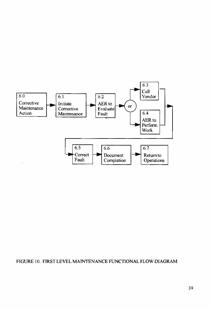
6.0
Corrective
Maintenance
Action
FIGURE 10. FIRST LEVEL MAINTENANCE FUNCTIONAL FLOW DIAGRAM
6.3
Call 6.1 6.2 Vendor
Initiate AER to
Corrective Evaluate
Maintenance Fault 6.4
AER to Perform = Work
6.5 6.6 6.7
— Correct [PB Document Return to Fault Completion Operations
39

Location:
Performer:
Activities:
AER Maintenance
AER Office
AER Architect
Visual Inspection
Operational Checkout
Monitor Operation
Schedule Maintenance
Minor Preventive
and Corrective
Maintenance on some
components
- Clean components
- Use dust covers
- Avoid food
consumption near CAD system
- Install new printer ink
cartridge or ribbon
Vendor Maintenance
AER Office or Vendor
Facility
Vendor Personnel
Detailed Inspection
and system checkout
Equipment Repair
Preventive
Maintenance
Overhaul Components
Major System Modifications
- Install new software
versions - Reconfigure system for
new components
Warranty Work
FIGURE 11. CAD SYSTEM MAINTENANCE POLICIES
40

3.3.1 Maintainability of CAD Software
Several additional requirements are needed to address the
maintainability issues related to the CAD system software. The most
critical maintainability requirement to AER Architect's Principal Architect
is that the CAD software shall provide for upgrades that are transparent to
the user and do not require total system reconfiguration. This can best be
described in terms of the next release of the software, and that its
installation is easily made and does not require the Principal Architect or
vendor to spend several days modifying the CAD software to achieve
operational status again.
The second most critical maintainability issue also involves new
releases of the CAD software. New releases should be "upward
compatible", i.e., a new release should have at least the same functionality
as the previous version. None of the capabilities of the software should be
discontinued; only new capabilities may be added.
As mentioned earlier, the software should be purchased with a
specific warranty effective for at least one year. Any software release
during the warranty period should be provided by the vendor or
manufacturer to AER Architects at no cost. New version releases of
software programs generally correct manufacturer or developer "bugs" that
are missed during the manufacturer's integration tests.
4]

3.4 Functional Analysis and Requirements
Once the operational concept and requirements and the maintenance
concept have been defined during the Conceptual Design Phase, the project
moves into the Prelimmary Design Phase. The first activity of the
Preliminary Design Phase is for the systems engineer to conduct the CAD
system functional analysis. Blanchard and Fabrycky define a "function" as
"a specific or discrete action required to achieve a given objective." (14)
Functional analysis is described as the systematic approach used to design
and develop a system. It is intended to facilitate the process in a logical and
complete manner. The functional analysis is based on the operational
concept and the maintenance concept. Functional flow diagrams are used
in the Preliminary Design Phase for the purpose of structuring system
requirements into functional terms. It is important to justify the need for
CAD system hardware or software capabilities prior to defining which
hardware or software is desired.
The functional requirements of the CAD system as defined by the
Principal Architect were captured as part of the Preliminary Design Phase.
Functional flow diagrams provide a format for portraying the functions a
system performs, the feedback loops, and the functional interactions within
the system. The requirements functional flow diagrams progress from the
top level definition to more detailed definitions on each lower level. The
levels are linked with progression and feedback loops depending on the
42

nature of the function. The numbering scheme provides a reference to
identify the functions for traceability between levels.
Figures 12 through 17 show the multi-level functional requirements
of the CAD system hardware and software. For the purposes of this
discussion, a drawing of a single family home is used as the function to be
performed by the AER architect. These functional flow diagrams were
created through iterative discussions and reviews with AER Architects’
Principal Architect to define the mission definition, performance
parameters, use requirements, operational deployment, operational life
cycle predictions, desired effectiveness factors, and the expected operating
environment. Each flow diagram has been approved by the Principal
Architect. The requirements functional flow diagrams are defined in terms
of mission capabilities that the CAD system software and hardware will be
required to perform. Please note that the 2.X family forms the requirements
for the CAD system software, while the 3.X family defines the CAD system
hardware functional requirements.
43
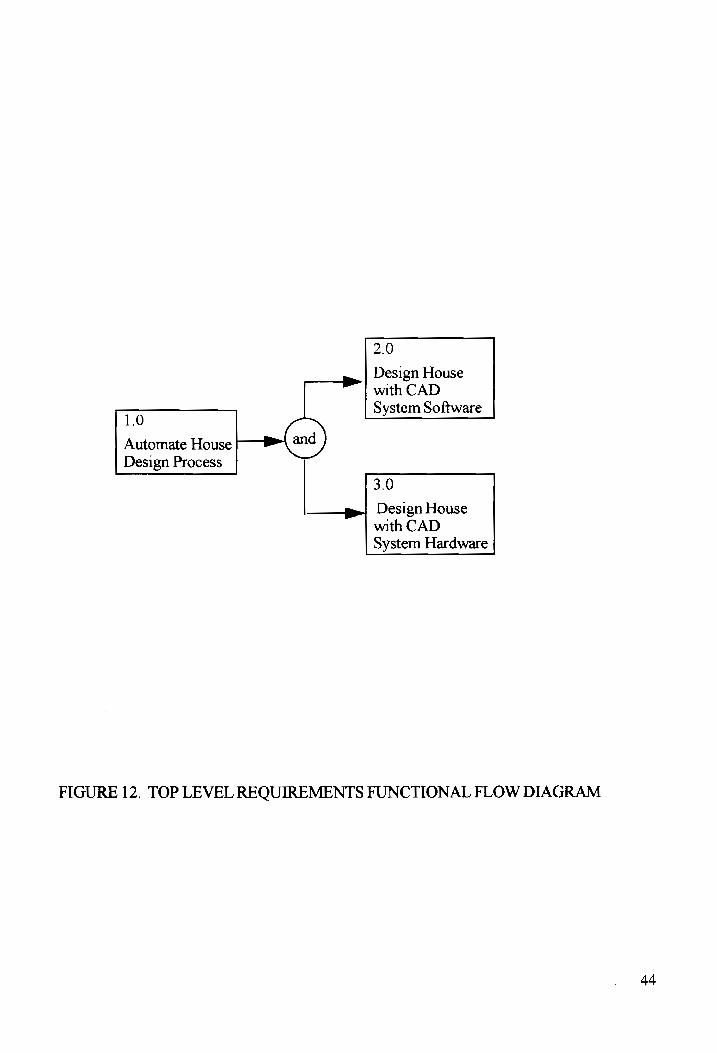
1.0
Automate House
Design Process
2.0
Design House with CAD System Software
3.0
Design House with CAD System Hardware
FIGURE 12. TOP LEVEL REQUIREMENTS FUNCTIONAL FLOW DIAGRAM
44

2.0 2.1 2.2 2.3 Design House nat Create i Edit p| Create
with CAD Concept Concept Schematic
System Software Diagrams Diagrams Diagrams
2.6 2.7 Consult Consult With With = |B) Contractors Clients and Consultants
2.4 2.5
—pe| Prepare pe | Create Final Construction Design Documents
3.0 3.1 3.2 3.3
Design House —_|_gy| Access pe! View House | Manipulate with CAD Stored Design during House System Hardware System interactive Design
Software design process
3.4 3.5
—pe| Provide |_| Save Design Hardcopy in Permanent of House Memory Design
FIGURE 13. FIRST LEVEL REQUIREMENTS FUNCTIONAL FLOW DIAGRAM

2.1.1
2.1.2
a Draw Add texture 213 Create ge} Outlineof | yl to lines pe! Use “Symbol Concept house USING with “User Library” buttons Diagrams auetine Defined to add details
rawin ; » feataree Line Styles to drawings
2.1.4 210 « 2.1.6 Create “Reference View Desi
| Dimension |--¥>| Files” of multiple >>> 3 Drawings drawings to show Rend 59
alternate views encerins
x 2.2.1 2.2.2 223
~ Manipulate Associative . Save modified Edit | ge! drawings Dimensioning — . Concept to satisfy | automatically drawings Diagrams clients re-dimensions under new
drawing file name
FIGURE 14. SECOND LEVEL REQUIREMENTS FUNCTIONAL FLOW DIAGRAM
46

23 oe draw 2.3.2 2.33 Create _ with electrical, > create p| View layered Schematic plumbing, and i mop © designs using Diagrams mechanical f hv; 3-D rendering
details of eacn view
2.5.1
2.5 Create plan, 2.5.2 2.5.3 section, elevation, Prepar
Constevetion and detail drawings Bilof ° Building Documents for each contractor. Materials Specifications
Include finishing schedules
2.6,2.7 2.6.1 2.6.2
Consult with ; Display design “Walk-through” Clients using advanced [—B>| and P| 2.22.3
Contractors, “Presentation “Fly-through” Consultants Capabilities” design.
FIGURE 15. SECOND LEVEL REQUIREMENTS FUNCTIONAL FLOW DIAGRAM

; 1 “
pe! Use ystem
Software to
3.1 3.1.1 Design House
Access Initiate Stored [Lpp| Software +B» (or System from Software Computer
Hard Drive 3.1.3
| pe} Edit System Software Configuration
3.2.1
Display House Design to Architect via
3.2 large color monitor
View House +@
Design during 3.22
interactive .
design process Display software control windows
via small black and white monitor
3.1.5
Exit System Software
3.1.4
Software
Configuration Save Modified (or )
3.2.3
Display Updates to House Design after each edit
FIGURE 16. SECOND LEVEL REQUIREMENTS FUNCTIONAL FLOW DIAGRAM
48

3.3.1
Use Keyboard to annotate
—t> House Design 333 33 with consistent ~
lettering vss Keyboard Manipulate (and) and Mouse
House ! together to —w| 2.0 Design 3.3.2 operate system
Use Mouse to software edit House details
3.4 3.4.1 342. 2.6 Print design
owas PP) using black [Bm Review | and) copy and white and verify of House graphics accuracy py! 27
Design printer of designs
3.5.1 3.5.2 3.5.3
3.5 Ensure Allocate St des
Save Design |g) permanent hard drive Store design in Permanent memory , memory rH} in designated Memory hard drive to directory
is large directory structure enough structure
FIGURE 17. SECOND LEVEL REQUIREMENTS FUNCTIONAL FLOW DIAGRAM
3.4.1 Description of Required CAD Software Capabilities
The CAD software package shall provide the set of standard
computer aided design capabilities, as well as those functions specific to
architectural drafting, including the capability to draw double lines and
multiple lines. The required advanced capabilities and features of the CAD
system per the Principal Architect's functional requirements and the
description are as follows. These requirements are listed in the priority
order as identified by the Principal Architect.
1. Applicability to architecture right out of the box, prior to "add-ons".
This requirement is intended to identify the best "pure" architectural CAD
system software. CAD design engines that require multiple "add-on"
packages to provide the required architectural functionality may introduce
significant added costs to the life cycle cost estimates.
2. Multiple reference files associated to one drawing. This requirement
will allow the Principal Architect to examine multiple views
simultaneously, and to manipulate the multiple views with relative ease.
3. 3-D Rendering. This requirement will allow the Principal Architect to
view the design in three dimensions, a feature that greatly enhances the
architect's and client's understanding of how the finished project will look
and feel.
50

4. Presentation Capabilities. This requirement will provide the Principal
Architect with the ability to create visually pleasing presentations using the
graphical capabilities of the CAD software. Presentations are vitally
important to the clients who want to "see" what designs the firm has done
previously, and to "view" their projects from realistic perspectives.
5. User defined line styles. This requirement will allow the Principal
Architect to specify two points and a material for the line connecting the
two points, and the CAD system software will insert the specified texture
for the line.
6. Multi-line capability. This requirement will allow the Principal
Architect to draw more than 2 lines simultaneously with different colors
and textures, resulting in reduced design time.
3.4.2 Compatibility Functional Requirements
Compatibility requirements as described by the Principal Architect
include the requirement that the CAD system software shall provide the
ability to read and write multiple file formats. This will enhance the
Principal Architect's ability to be compatible via the computer.
Manipulation of multiple file formats allows other vendor CAD software
products to be compatible with the selected CAD software. This is the
most critical compatibility requirement because all clients, contractors and
consultants use different CAD software packages, and being able to read
51

and write to many of the other packages will result in greater
communicability of designs.
Compatibility with third party vendors is the second most important
compatibility requirement according to the Principal Architect. While this
is related to the previous requirement, it also is a measure of the number of
third party software "add-ons" that are available for the selected CAD
software engine. Some CAD software packages provide the base computer
aided design and drafting capabilities, and require "add-ons" to gain further,
specialized functionality. For example, many CAD software packages do
not have 3D rendering capabilities, and, to accommodate users that require
this capability, they offer an "add-on" that is easily integrated with the main
package. Specialized libraries of architectural symbols are a popular type
of "add-on" software product for CAD systems.
The last major compatibility requirement specified by the Principal
Architect is that the CAD software shall be configured with built-in
database macros to allow the Principal Architect to store drawings in a
database file structure. Most CAD software packages do not have a built in
database and often require an "add-on" to gain this functionality. However,
a macro that is already built-in or installed in the CAD software allows for
an easy adaptation of the "add-on" database package. Special databases are
required after the architect has created numerous designs, and requires
additional storage assistance.
52

3.4.3 Operational Life Cycle of the CAD Software
The operational life cycle for this evaluation project will be designed
to be four years. Reviews of the computer technology turnover rates
indicate that the current capabilities and capacities will be significantly
replaced every four years. Hypothetical upgrades to the CAD system
software shall be included in this paper in the cost analysis only. An
assumption will be made that the next version release date for the
alternative software packages will be 24 months in the future, based on the
release date of the evaluated package. Estimated cost impacts for the
purchase of upgraded software will be included in the cost analysis section
of Chapter Four.
3.4.4 Effectiveness Factors
The effectiveness factors included within the scope of this project
are limited to the operator skill levels, the CAD system use times, the mean
time between maintenance, and the maximum allowable maintenance
downtime. These factors are established as requirements to be met during
the detail design phase of the CAD system. The operators shall be trained
at the advanced level through vendor training courses. The planned usage of
the CAD system shall be 56.5 hours per week, as specified by the Principal
Architect. The CAD system shall support a mean time between
maintenance of 1000 hours, and the maximum allowable down time shall
be one day.
53

3.5 _ Definition of System Support Requirements
System support requirements are also defined during the Preliminary
Design Phase and the system functional analysis. One of the purposes of
the functional analysis is to identify additional system related requirements
that fall outside the software capabilities arena. Both training and the
vendor support and viability were identified by the system engineer as
critical requirements that must be considered when evaluating software
packages. The Principal Architect did not state these as functions or
requirements during the interactive discussions that resulted in the
functional flow diagrams. Nonetheless, he agrees they are important and
should be included. Brief descriptions of the support related requirements
are contained in this section.
3.5.1 Training Requirements
The most critical training requirement is the availability of the
training courses for the Principal Architect. Classes shall be scheduled
frequently and will address the beginner, intermediate, and advanced levels
of training. This requirement will ensure that the Principle Architect shall
become skilled on the CAD software at his earliest convenience.
The effectiveness of the training shall be determined based on the
evaluations given by previous students. This requirement is critical in
determining the value of the training class and the associated costs. The
54

Principle Architect will be able to gauge his learning progress through the
planned use of the CAD software following each training session.
The convenience of the training is also an important factor to
consider. The training shall be located close to or in AER Architects’ office
and require a minimum of travel and living costs while attending the
training courses.
The training shall include a variety of training methods, including
videos, live instruction, guide books, and on-line self-paced computer based
training. Variety in the training methods will allow the Principal Architect
to determine which training technique is preferred and most effective.
3.5.2 Vendor Requirements
The viability and support capabilities of the CAD software vendor
are important requirements that are to be included in the evaluation of the
CAD software packages. In order of decreasing importance, the following
are the vendor related requirements.
The CAD software vendor shall have a qualified technical staff
sufficient to perform the product development and maintenance, and not be
top-heavy with sales persons who promise more than the technical staff can
deliver. The percentage of technical staff indicates the commitment a
vendor makes to the quality of the software product.
55

The vendor shall provide installation support, both on-site and via a
telephone hot-line. The installation support is essential for AER Architects
to activate the CAD system. The Principal Architect is unfamiliar with the
technical aspects of configuring a CAD software package.
The CAD software vendor shall provide operational support, both
on-site and via the telephone hot-line. The vendor shall have a well
established record of prompt responses to problem reports. Operational
support is a critical step towards ensuring that the CAD system will be
successfully integrated into the daily routine at AER Architects.
The vendor shall have an ongoing program to enhance the users
understanding of the CAD software product's capabilities in the form of a
newsletter and free seminars. "User groups" are another form of
communication between the vendor and the users that helps enhance the
useability of the CAD software.
Finally, the vendor shall be a mature and stable company, with
several years in the CAD software industry. Maturity in the CAD industry
indicates that the vendor is well known and their software is reliable.
56

3.6 | Summary and Allocation of Requirements
The requirements that have been identified in Chapter Three
comprise the metrics that will be used in Chapter Four to evaluate CAD
packages. A complete list of the requirements in provided in Table 2. The
requirement numbers were derived from the paragraph numbers in Chapter
Three where the requirements were stated. The column labeled "allocated
to” indicates to which subsystem (software or hardware) and which
attribute within the subsystem each requirement is allocated. The
hardware requirements are not defined to the attribute level in Chapter
Three. This task is recommended as a future study in Chapter Five.
57
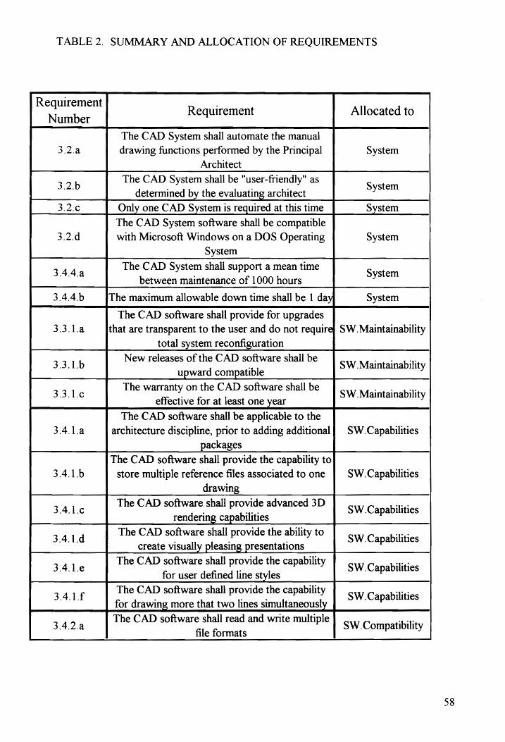
TABLE 2. SUMMARY AND ALLOCATION OF REQUIREMENTS
Requirement , 4 Requirement Allocated to Number
The CAD System shall automate the manual
3.2.a drawing functions performed by the Principal System
Architect
32b The CAD System shall be user-friendly as System
determined by the evaluating architect 3.2.¢ Only one CAD System is required at this time System
The CAD System software shall be compatible
3.2.d with Microsoft Windows on a DOS Operating System
System
The CAD System shall support a mean time 3.4.4.
a between maintenance of 1000 hours System
3.4.4.b The maximum allowable down time shall be 1 da System
The CAD software shall provide for upgrades
3.3.1.a that are transparent to the user and do not requires SW. Maintainability
total system reconfiguration
33.1b New releases of the CAD software shall be SW Maintainability
upward compatible
33.16 The warranty on the CAD software shall be SW Maintainability
effective for at least one year
The CAD software shall be applicable to the
3.4.1.a architecture discipline, prior to adding additional] SW.Capabilities
packages
The CAD software shall provide the capability to
3.4.1.b store multiple reference files associated to one SW.Capabilities
drawing
3416 The CAD software shall provide advanced 3D SW Capabilities
rendering capabilities
341d The CAD software shall provide the ability to SW Capabilities
create visually pleasing presentations
341. The CAD software shall provide the capability SW Capabilities
for user defined line styles
341f The CAD software shall provide the capability SW Capabilities
for drawing more that two lines simultaneously
342a The CAD software shall read and write multiple SW.Compatibility file formats
58
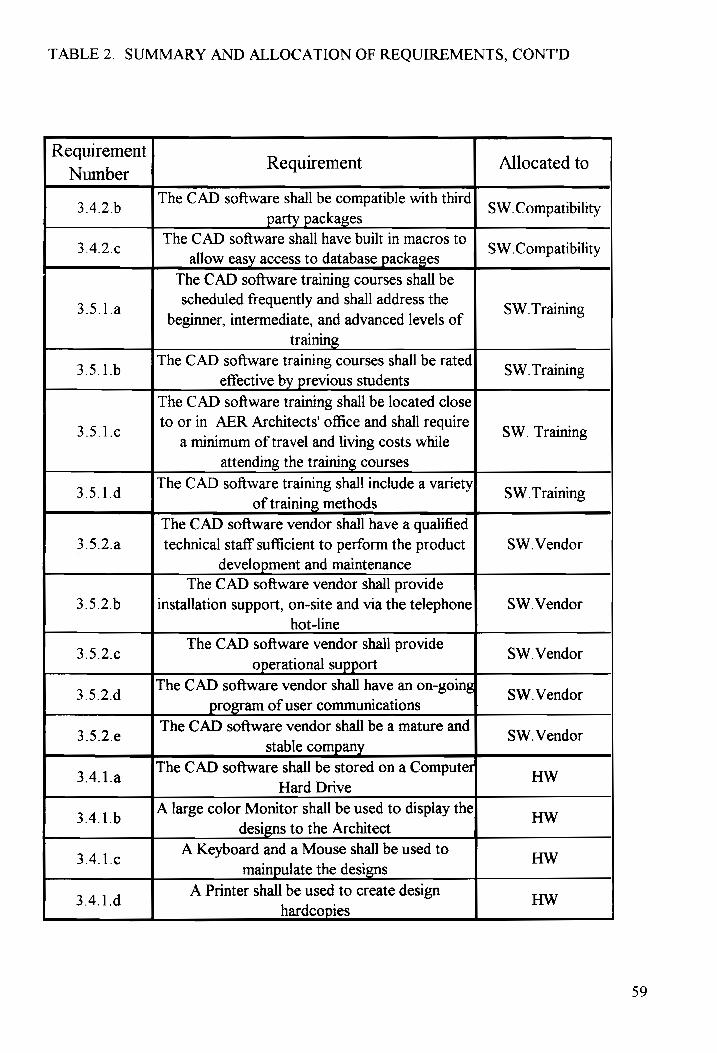
TABLE 2. SUMMARY AND ALLOCATION OF REQUIREMENTS, CONT'D
Requirement . d Requirement Allocated to Number
3426 The CAD software shall be compatible with third SW Compatibility
_ party packages
342¢ The CAD software shall have built in macros to SW.Compatibility
allow easy access to database packages
The CAD software training courses shall be
351a scheduled frequently and shall address the SW Training
beginner, intermediate, and advanced levels of
training
35. 1b The CAD software training courses shall be rated SW Training
effective by previous students
The CAD software training shall be located close
35.16 to or in AER Architects office and shall require SW. Training
a minimum of travel and living costs while
attending the training courses
351d The CAD software training shall include a variety SW Training
of training methods
The CAD software vendor shall have a qualified 3.5.2.a technical staff sufficient to perform the product SW. Vendor
development and maintenance
The CAD software vendor shall provide 3.5.2.6 installation support, on-site and via the telephone SW .Vendor
hot-line
35.2 The CAD software vendor shall provide SW Vendor
operational support
3524 The CAD software vendor shall have an on-going SW Vendor
__ program of user communications
35.2¢ The CAD software vendor shall be a mature and SW Vendor
stable company
34.1a The CAD software shall be stored on a Computer HW
Hard Drive
341b A large color Monitor shall be used to display the HW
designs to the Architect
341 A Keyboard and a Mouse shall be used to Hw
mainpulate the designs
341d A Printer shall be used to create design HW hardcopies
59

CHAPTER FOUR
ANALYSIS AND EVALUATION OF ALTERNATIVES
4.1 _ Discussion of the Multiattribute Decision Analysis
Following the definition of the requirements for AER Architect's
CAD system software, a list of ten candidate software packages was
compiled from the interviews, survey, and market study of architecture
firms and their principal architects. The decision making process is an
orderly and quantifiable process of eliminating alternatives and identifying
the CAD software package that most closely satisfies the Principal
Architect's requirements. Multiple techniques exist for performing
evaluations similar to this, including simple studies addressing one or two
of the more critical requirements, or decision making based on price alone.
In a situation where there are many quantifiable requirements, Canada and
Sullivan state that the "multiattribute decision techniques seem to provide
an easily understood, yet comprehensive, set of quantitative/qualitative
approaches" to select computer aided design software systems. (15) The
multiattribute decision techniques have many variations that can be tailored
for use in comparing and eliminating alternatives of CAD software
packages.
60

Whichever method is selected for use during this evaluation, the act
and process of making the decision will allow the following benefits for all
involved parties. The decision making process will:
1. Force focus on the objectives, alternatives,
attributes and risks of selecting CAD software.
2. Facilitate communication between the architect(s),
systems engineer, analysts, and chief financial
officer of AER Architects.
3. Promote a more developed evaluation procedure.
4. Encourage generation of new alternatives and
requirements.
5. Assist the selling of the final recommendation
based on a rational decision making process.
Identification of the attributes is a critical step to be taken prior to
analyzing alternative CAD system software packages. The most critical
restriction in the identification of attributes is that they be mdependent of
one another, according to Canada and Sullivan. Selecting key attributes
that are likely to differ between the alternatives allows the decision making
techniques to be used efficiently, without becoming cluttered or confused
with inconsequential details. Avoiding this common trap provides the
decision maker with more time and effort with which to possibly identify
better alternatives. Canada and Sullivan recommend starting with a few
attributes and performing an initial analysis. Future, in-depth, analyses
61

should be performed using a more diverse number and range of attributes to
help eliminate alternatives. This process was used to narrow the field of ten
CAD system software packages to the best candidates that deserve added
consideration.
Methods used for such evaluations include sequential elimination
methods, graphical techniques and weighted evaluation of attributes. Brief
descriptions of the various techniques are provided in the next several
sections.
4.1.1 Sequential Elimination Methods
Sequential elimination methods are useful decision rules to help
eliminate several alternatives and narrow the field of candidates. This
method can be used when the attributes and alternatives are easily specified
by a numerical value. The attributes are not weighted when employing the
sequential elimination methods. In addition, the attributes are described by
Canada and Sullivan as "noncompensatory", which indicates that trade-offs
among the attributes across the alternatives are not recognized. Variations
of the sequential elimination methods compare attributes against attributes
and alternatives against alternatives. Each variation of the method requires
that values be determined for each alternative, and that the alternatives are
then compared against each other or against a fixed standard. A
choreographed process of elimination is then followed to identify the most
preferred alternative.
62

4.1.2 Graphical Techniques
The graphical techniques allow the decision makers to readily absorb
large amounts of information when presented in a powerful format. Similar
to the sequential elimination methods, the graphical techniques do not
include weightings of attributes. This can be advantageous because the
weightings can sometimes be non-exact and vary among the decision
makers. Shaded circles are a popular means of portraying relative
evaluations of alternatives with respect to identified attributes. While this
is not the method used in the analysis and display of the CAD system
software results, a example of the shaded circles is in Figure 18.
63

CAD CAD CAD Software Software Software
A B C
Training Effectivity
Presentation
Quality
Applicability to Architecture
ODVOWO Exceptional Above Average Below
Average Average
Advanced Capabilities
FIGURE 18. GRAPHICAL EVALUATION TECHNIQUE
64

4.1.3 Weighted Evaluation of Alternatives
The weighted evaluation of alternatives involves the ranking of
attributes and the weighting of attributes. Prior to ranking the attributes, the
decision maker must align them in order of decreasing preference, with the
most preferable attributes listed first. Pairwise comparisons among the
attributes helps one determine the order of importance, and results in a
comparative summary of the attributes. The mathematical symbols <, =,
and > are used to indicate the degree of preference.
Weighting the attributes requires quantification of the relative
importance of each attribute with respect to each other attribute. The steps
to be taken by the decision maker to perform the weighting is as listed
below:
1. Assign values to the ranked list of attributes,
usually 0 to 100.
2. Validate the assigned weightings to each
attribute through internal comparisons to the
other attributes' assigned weighting values.
3. Normalize the weightings using a simple
summation equation.
65

Once all attributes have assigned weights, the decision maker must
record values for each alternative representing the level to which the
alternative satisfied each attribute. This task can be completed for the CAD
system software packages with assistance from the Principal Architect or
the surveyed architects who are very familiar with the software capabilities.
Gathering the data can be time consuming, but it is critical to the thorough
evaluation of the CAD software packages. The values assigned to each of
the four attributes were selected using a rating scale of 1 to 10.
66

4.2 _ Application of Multiattribute Decision Analysis
A worksheet has been developed for the evaluation of each of the ten
CAD software packages identified in Appendix A. Several key attributes
have been selected for this first evaluation, which is aimed at eliminating
many of the alternatives and narrowing the field of candidates. The
Principal Architect reviewed each of the packages against these four
attributes that were selected because they provide a good initial indication
of how well a CAD software package will satisfy all the requirements
documented in Chapter Three.
The weighted attribute evaluation technique will be used for this first
elimination round. The four attributes each package will be evaluated
against are listed below, along with their respective weightings and
normalized weightings. The rank order and weightings were determined by
the process defined by Canada and Sullivan, which is summarized in
Section 4.1.3.
Initial Normalized
Weighting Factor
Assignment Weight
Runs on a PC with Windows 100 30
Compatibility with other products 90 27
3-D Rendering 80 24
User Defined Line Styles 65 19
Sum = 335 Sum = 100
67

The tables in Appendix A show the calculations involved in
evaluating which packages should be considered for the further studies.
Please note that the scores for the alternatives against the four attributes
clearly identify whether each CAD software package provides the required
capabilities as defined by the attributes. The scores are the result of the
Principal Architect reviewing the package and determining how well the
software achieved the required attributes.
The scale used to evaluate each software package against the criteria
is Shown in Table 3. The summary in Table 4 at the conclusion provides a
concise look at the scores. Only two packages received weighted
evaluation scores above 84: Autodesk Inc. AutoCAD Release 12 for
Windows, and Intergraph's MicroStation PC Version 5. These two
preferred alternatives will be evaluated using more quantitative and in-
depth techniques to determine which is the best CAD software package for
AER Architects based on their requirements.
68

TABLE 3. ATTRIBUTE SCORE SCALE FOR ALTERNATIVES
Attribute Weighting Scale
0 2.5 5 7.5 10
Runs ona PC with Neither PC Only Both Windows
Compatible with
other Vendors and | None Few Many | Dozens |Hundreds|
Products
3-D Rendering None Below Average Above Excellent Average Average
User Defined Line None Below Average Above Excellent
Styles Average Average
69
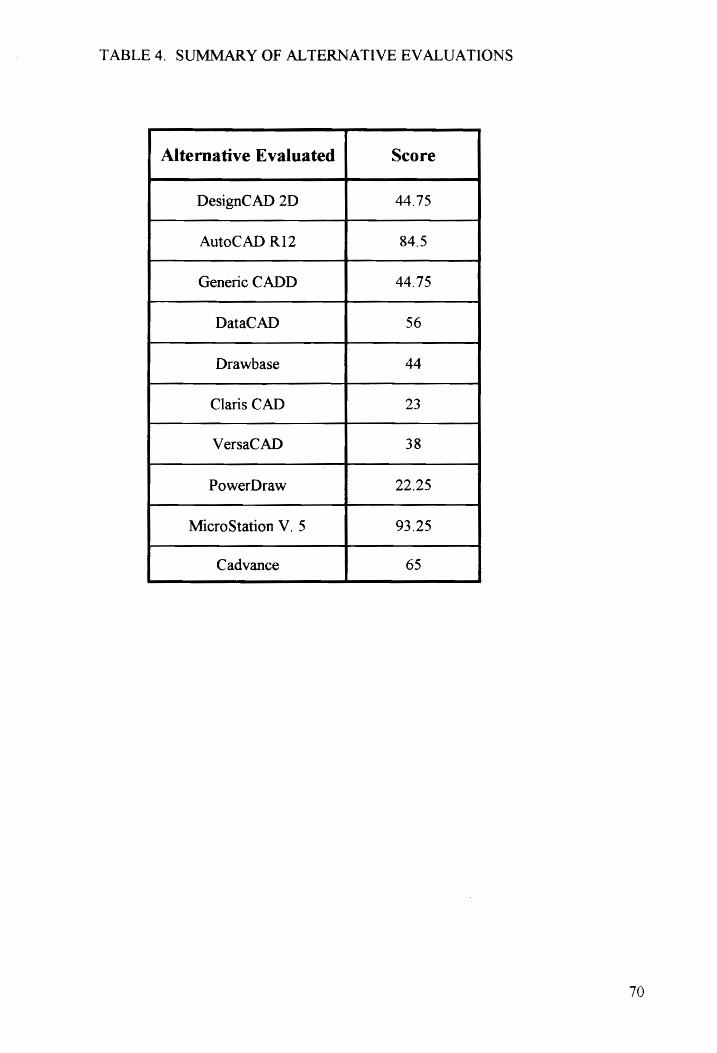
TABLE 4. SUMMARY OF ALTERNATIVE EVALUATIONS
Alternative Evaluated Score
DesignCAD 2D 44.75
AutoCAD R12 84.5
Generic CADD 44.75
DataCAD 56
Drawbase 44
Claris CAD 23
VersaCAD 38
PowerDraw 22.25
MicroStation V. 5 93.25
Cadvance 65
70
43 Life Cycle Cost Analysis of Preferred Alternatives
The economic considerations of purchasing CAD software are very
important to the decision making role of the systems engineering analysis.
Comparing the two alternative CAD software packages on the basis of the
identified costs is an essential step towards selecting the best package. Life
cycle cost 1s a critical attribute to be considered during a complete
multiattribute analysis of the two preferred alternatives. The equivalent
cost is not considered as the primary decision making criteria, and it will be
used in following sections that detail the multiattribute analysis. The goal
is to identify the equivalent worth costs of the two CAD software
alternatives and incorporate that information into the decision making
process.
This section of the paper details the assumptions made prior to the
life cycle cost analyses for the two preferred alternatives, and the
application of the equivalent worth methods to the life cycle cost data.
71

4.3.1 Assumptions
Several assumptions are made prior to performing the economic
analysis.
First, all calculations will be made using before
tax equivalent worth methods.
Second, both alternatives are assumed to have the
same benefits, hence only the costs are considered.
Third, the interest rate used in all equivalent worth
calculations is 10 %.
Fourth, the life of both alternatives is the same,
and is assumed to be four years.
Fifth, neither alternative has a salvage value.
72

4.3.2 Equivalent Worth Calculations for Alternatives
The procedure utilized for systematically comparing the two
alternatives’ equivalent worth is outlined as shown:
1. Identify the alternatives
Specify the evaluation period
Estimate the cash flows for each alternative
Specify the interest rate
Calculate the equivalent worth
an Ye
F YN
Compare the alternatives
Blanchard and Fabrycky identify three factors that must be known
prior to determining equivalent sums of money: ™ (1) the amount of the
sums, (2) the time occurrence of the sums, and (3) the interest rate." (16)
The economic equivalence function is defined symbolically by
E=f(F,i,n) Equation 1
where E = present, annual, or future equivalent worth
F = the sum of money, either positive or negative,
at the end of the year
1 = annual interest rate
n = number of years for evaluation.
73

For convenience, all costs that occur during the year are assumed to
occur at the start of the next year. Blanchard and Fabrycky indicate that
this assumption introduces an insignificant error when compared to the
typical errors made in the initial estimates. (17)
Two equivalence evaluations were performed for each alternative
using the available cost data. The Present Equivalent Evaluations allow for
the comparison of the alternatives on the basis of equivalent cost at the
present time, which is assumed to be January 1, 1994 in this study. The
Annual Equivalent Evaluation calculates the annual equivalent cost series
over the life of the CAD software, which is expected to be three years. The
data required to perform the equivalent cost calculations is presented in
Tables 5 and 6. The series of calculations and the results are detailed on the
next few pages. Schematic models for the money flow over time are
presented for both alternatives in Figures 19 and 20. Downward arrows in
the schematic models are commonly used to represent disbursements or
expenses.
74
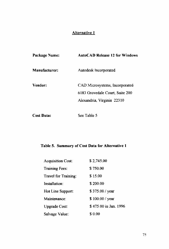
Alternative 1
Package Name:
Manufacturer:
Vendor:
Cost Data:
AutoCAD Release 12 for Windows
Autodesk Incorporated
CAD Microsystems, Incorporated
6183 Grovedale Court, Suite 200
Alexandria, Virginia 22310
See Table 5
Table 5. Summary of Cost Data for Alternative 1
Acquisition Cost:
Traming Fees:
Travel for Training:
Installation:
Hot Line Support:
Maintenance:
Upgrade Cost:
Salvage Value:
$ 2,745.00
$ 750.00
$ 15.00
$ 200.00
$ 375.00 / year
$ 100.00 / year
$ 475.00 in Jan. 1996
$ 0.00
75
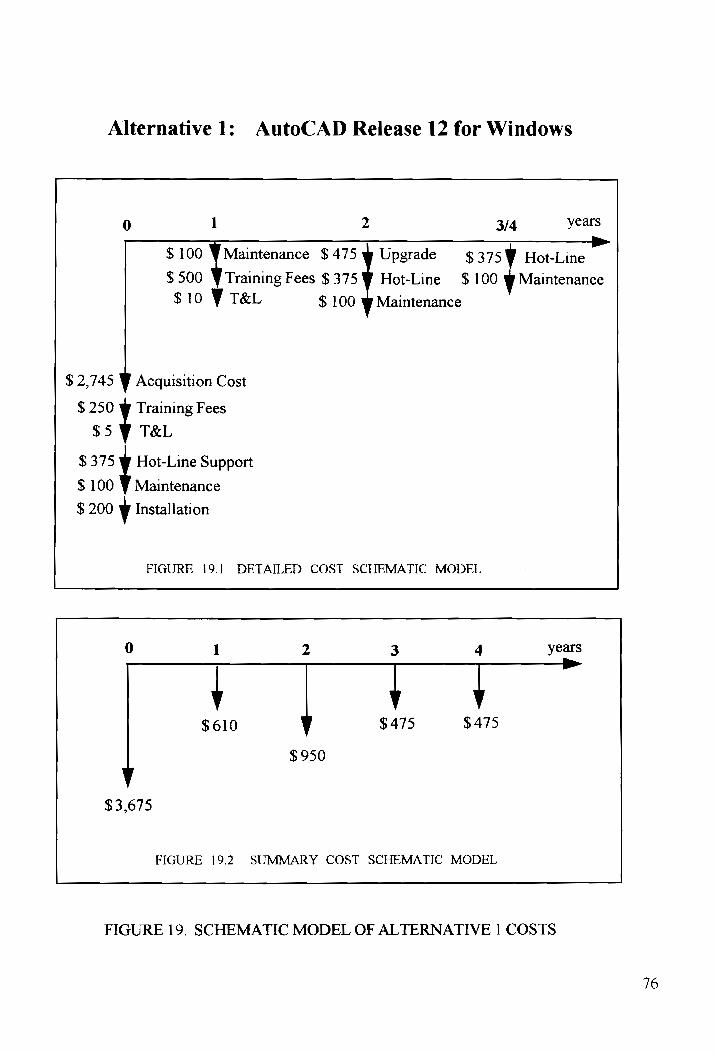
Alternative 1: AutoCAD Release 12 for Windows
0 1 2 3/4 years >
$100 ¥ Maintenance $475 w Upgrade ¢ 3759 Hot-Line
$ 500 $10 V T&L $ 100 w Maintenance
$ 2,745 y Acquisition Cost
$ 250 Y Training Fees
$5 9 T&L
$ 375 Ww Hot-Line Support
$ 100 ¥ Maintenance
$ 200 y Installation
FIGURE 19.1 DETAILED COST SCHEMATIC MODEL
Training Fees $375 WY Hot-Line $100 ¥ Maintenance
0 1 2 3 4 years
$610 $ 475 $475
$950
$3,675
FIGURE 19.2 SUMMARY COST SCHEMATIC MODEL
FIGURE 19. SCHEMATIC MODEL OF ALTERNATIVE 1 COSTS
76

Reviewing the schematic model of the life cycle costs for Alternative
1, the present worth cost (PW-C) and equivalent uniform annual cost
(EUAC) calculations are performed as follows:
Present Worth Cost: (PW-C)
PW-C = 3675 + 610( P/F, 10%, 1) + 950( P/F, 10%, 2)+
475 ( P/F, 10%, 3 ) +475 ( P/F, 10%, 4)
Substituting values for the factor functional symbols taken from
Canada and Sullivan (18):
3675 + 610( .9091) + 950( .8265 ) +475 (.7513 ) +
475 ( .6830 )
PW-C= $ 5696.02
Equivalent Uniform Annual Cost: (EUAC)
EUAC = { 3675 + 610( P/F, 10%, 1) + 950( P/F, 10%, 2) +
475 ( P/F, 10%, 3 ) + 475 ( P/F, 10%, 4 )}
( A/P, 10%, 4)
= {3675 + 610( .9091) + 950( .8265 )+475(.7513 )
+475 ( .6830 )} ( .3155 )
EUAC = $ 1797.09
77

Alternative 2
Package Name:
Manufacturer:
Vendor:
Cost Data:
MicroStation PC Version 5
Intergraph Corporation
HM Systems, Incorporated
18221-A Flower Hill Way
Gaithersburg, Maryland 20879
See Table 6
Table 6. Summary of Cost Data for Alternative 2
Acquisition Cost:
Training Fees:
Travel for Training:
Installation:
Hot Line Support:
Maintenance:
Upgrade Cost:
Salvage Value:
$ 2,950.00
$ 1800.00
$ 30.00
$ 200.00
$ No charge
$ 100.00 / year
$ 100.00 in Jan. 1996
$ 0.00
78

Alternative 2: MicroStation PC Version 5
0 1 2 3/4 years
$ 100 ¥ Maintenance $ 100 Yen $ 1009 Maintenance
$ 100 wW Maintenance
$ 2,950 w Acquisition Cost
$ 1800 ¥ Training Fees
$ 30 v T&L
$ 100 V Maintenance
$ 200 © Installation
FIGURE 20.1 DETAILED COST SCHEMATIC MODEL
sea
0 1 2 3 4 years
YY $ 100 $ 100 $ 100
$ 200
$ 5,080
FIGURE 20.2 SUMMARY COST SCHEMATIC MODEL
FIGURE 20. SCHEMATIC MODEL OF ALTERNATIVE 2 COSTS
719

Reviewing the schematic model of the life cycle costs for Alternative
2, the present worth cost (PW-C) and equivalent uniform annual cost
(EUAC) calculations are performed as follows:
Present Worth Cost: (PW-C)
PW-C = $ 5080 + 100( P/F, 10%, 1) + 200( P/F, 10%, 2)+
100 ( P/F, 10%, 3) + 100 ( P/F, 10%, 4)
Substituting values for the factor functional symbols taken from
Canada and Sullivan (18):
= $ 5080 + 100( .9091) + 200( .8265 )+ 100(.7513 )
+ 100 ( .6830 )
PW-C= $ 5479.64
Equivalent Uniform Annual Cost: (EUAC)
EUAC = $ {5080 + 100( P/F, 10%, 1) + 200( P/F, 10%,2)+
100 ( P/F, 10%, 3 ) + 100 ( P/F, 10%, 4 )}
( A/P, 10%, 4)
= $ {5080 + 100( .9091) + 200( .8265 )+ 100( .7513)
+ 100 ( 6830 )} (3155 )
EUAC = $ 1728.83
80

4.3.3 Results of the Equivalent Economic Worth Calculations
Table 16 shows the results of the present worth equivalent cost and
the annual worth equivalent cost calculations. It appears that Alternative 2,
MicroStation PC Version 5 is slightly less expensive. If both CAD
software packages offered the same capabilities, then these results would
provide enough information to make a final choice between the two
alternatives. However, since the two CAD software packages offer slightly
different capabilities, a more detailed analysis is required through an
application of the Analytic Hierarchy Process.
Table 7. Summary of Equivalent Economic Worth Calculations
Alternative 1 Alternative 2
(AutoCAD R12) (MicroStation V5)
PW-C $ 3696.02 $ 3479.64
EUAC $ 1797.09 $ 1728.83
81

4.4 Description of Analytic Hierarchy Process
Given the broad range of attributes and requirements that are to be
used to select a CAD software package, a more detailed and quantitative
methodology is needed for the evaluation. The selected methodology, the
Analytic Hierarchy Process (AHP), provides the decision maker with the
ability to structure a complex multiattribute problem hierarchically. AHP
was developed by Thomas Saaty and is described in Canada and Sullivan in
Chapter 10. Figure 21 is a model of the attributes, subattributes, and
alternatives to show how the problem can be structured for analysis.
Comparisons of the alternatives and attributes (also referred to as elements)
in a "pairwise" method promotes establishing a scale to indicate the relative
strength of the elements. The scale is converted into priority weights or
scores that are used in the comparison of alternatives.
The Analytic Hierarchy Process offers many benefits over other
evaluation techniques. First, it is easy to understand and use. Second, AHP
necessitates developing a hierarchy of attributes and subattributes, which
promotes and encourages communication of the problem and _ the
recommended solution. Finally, it offers a unique means of quantifying
both subjective and objective criteria.
The calculations required by AHP are time consuming and tedious.
A software program called Automan was developed by Stephen F. Weber at
the National Institute of Standards and Technology that automates the
82

analytic hierarchy process. Automan accepts the inputs and model
information, creates the AHP model, calculates the preference values, and
provides a recommendation. The computer generated output from Automan
for this model is located in Appendix B.
83

§ NOISHHA
Jd NOILV.LSOWIN
HdVYDOYALNI
Aun,
‘OUWIOZ) 198;
AJOuR A
dU] -}0}
| SOUITUDAUO)
AQUB.LIB AA, pond
TAGOW
SSAI0Ud AHOUVAFIH OLLATVNV
SMOCNIM YOd
cle QVOOLNV
ASAGOLNV
‘tc aednNols
duryesq]
aur] apdninyw
sajAIg our]
pouyad 19s;
SOB
SUOHBIUISOL
aseqeie(]
Uy Ing
vioddng jyeisuy
AWAN OAs]
BuLapusy
Cie
sIOpudsA AUB
PIN]
SAAILVNUGLTV
0 THAN
SGALNEGRMLiIvans
€ THART
AYVMLAOS GVO LSAd LOATAS
aiqnedwio) premd))
1S.) Saft]
soualgay sjdniniyy
i YOM,
“SweuOT SEF
Berg jeouuysa |,
Au LgeyeEAy
sopesad) jussatg
atdninpy aiyypeay
posmbay aemMyos
UCQ-Ppy
YONA | | O
NINIVUL
| | ALIMIGVNIVLNIVW || LSOO || ALITMELLVdNOO | |
SALLITIGWdVD
SLOSALIHOUV WAV YO
Sa.LNARILLV
Cc THAT
SNOO4
PVAIART

4.5 _ Application of Analytic Hierarchy Process
Each of the following categories were defined as critical
requirements during the functional analysis activities of the Preliminary
Design Phase. Each category constitutes an attribute of the CAD system
software. The summary of requirements in the end of Chapter Three show
which subattributes are paired with each attribute. Figure 21 also shows
these relationships.
Capabilities
Compatibility
Cost
Maintainability
Training
Vendor
Pairwise comparisons between the attributes, among the
subattributes within each attribute category, and between each alternative
and the subattributes were generated with the Principal Architect, and were
based on his familiarity with each of the "preferred" software packages.
The Principal Architect had a very active role in the evaluation and
comparisons of the two packages, and made multiple trips to both vendors
for demonstrations, training, and product reviews. His requirements and
relative ranking were translated into weightings and input into Automan.
Several iterations of Automan were run until the Principal Architect was
satisfied with the weightings calculated by the evaluation program. The
final run produced the results located in Appendix B.
85

4.6 Results of Analytic Hierarchy Process
Reviewing the results in Appendix B shows a very strong preference
for Intergraph's MicroStation PC Version 5. MicroStation 1s selected over
AutoCAD by a 71% majority. The combination of the attribute weightings
and the software product ratings by the Principal Architect indicate that the
MicroStation software is the most satisfactory product. Based on the
volume of information and requirements that were defined and input into
Automan, the results are a good indication of how well the two packages
would satisfy the Principal Architect. MicroStation PC Version 5 appears
to be a superior product and will provide the best match for the Principal
Architect's needs.
A sensitivity analysis was performed on the results of the Automan
multiattribute analysis. Appendix C has the sensitivity analysis output from
Automan. Review of the graphs shows that the selection of MicroStation
PC Version 5 is not sensitive to minor alterations in the weightings of the
attributes or subattributes. This indicates that the selection of MicroStation
is a valid selection and is not easily swayed by changing one weighting. A
completely different set of weightings would have to be applied to the
attributes and subattributes for a different conclusion to be reached.
The Analytic Hierarchy Process shows that very complex
multiattribute problems can be manipulated mathematically and reduced to
simple equations to assist the evaluating party in reaching a valid decision.
86

CHAPTER FIVE
FUTURE STUDY RECOMMENDATIONS
5.1 Hardware Study and Evaluation
Completing the Detail Design Phase of this project will require an
extensive hardware study. The selected software alternatives require a
hardware configuration as described in the next few paragraphs. The
identification and trade-off analysis based on a market study of hardware is
beyond the scope of this project. However, it is the next step that must be
completed prior to the purchase of software or hardware. The proposed
"system" to satisfy AER's definition of need requires one complete Personal
Computer (PC), to include a monitor (or two), central processing unit
(CPU), keyboard, mouse, printer, and the computer aided software design
package. Figure 22 is a conceptual drawing of the required system
components.
Two monitors have been mentioned several times by the Principal
Architect as a hardware requirement because the secondary monitor can be
filled with the menus and icons that are used to control the software. The
secondary monitor shall be a small, black and white monitor. This leaves
the primary monitor free for the architectural design field. The primary
monitor shall be much larger, with smaller resolution and a large color
scale. The design is much easier to manipulate when it is larger and
displayed in color and great detail. Several CAD systems on the market,
87

Primary . Monitor
Printer
Keyboard
Surge Protector
FIGURE 22. PROPOSED SYSTEM HARDWARE CONFIGURATION
88

including Intergraph Microstation PC Version 5 can be configured easily to
a two monitor operating scenario.
5.1.1 Hardware Operating Environment
The system will be placed on an existing computer table in AER's
office and shall be powered and protected from power surges by an existing
urge protector. The computer table will reside in an office controlled to
typical household comfort standards of 70 degrees in the winter and 78
degrees in the summer. Humidity is controlled by both a dehumidifier and
a humidifier. New windows in the office were recently installed to
minimize drafts and the potential for water damage. Venetian blinds
control the amount of light accessing the office. The office windows face
north, so very little direct sun will strike the venetian blinds.
5.1.2 Benchmark Hardware System
The requirements for performance and physical parameters of the
ideal system, or the benchmark, have been determined by the latest trends
in the computer industry, with an emphasis on quality, not quantity. The
benchmark hardware provides the basis for the evaluation of candidate
hardware components. The performance of the assembled system is a
critical requirement or the advanced capabilities of the software will be
non-functional. Defining the performance characteristics will require
additional knowledge into computer architecture, and thorough
89

understanding of the current capabilities offered by the industry.
Specifying the performance requirements is outside the scope of this paper.
The hardware system benchmark requirements are detailed in the next few
pages.
Both of the "preferred" CAD software programs require a hardware
system of these specifications to achieve the vendor and manufacturer
specified performance capabilities. Decreasing any of the capacities is
likely to have a negative effect on the CAD system's performance.
90

System Benchmark Specifications
Primary Monitor
Secondary Monitor
486 DX2/66 MHz CPU
System Hard Drive
17" flat screen
256 colors
non-interlaced
resolution up to 1,024 x 768 pixels, or greater
tilt and swivel base
front control panel
11” screen
black and white
16 MB standard RAM minimum
1 MB VRAM
upgradeable to the Pentium Processor
248 MB minimum
High or dual density Disk Drive(s)
Option Slot
Mouse
Keyboard
3.5"
5.25"
3 EISA slots
2 button
Standard
9}

5.1.3. Hardware Life Cycle Cost Analysis
A detailed cost analysis on the candidate hardware systems should
be performed to determine if the project is feasible within the $ 8,000
budget, or if more money is required. The software cost analysis showed a
present worth cost of $ 5,015 leaving less than $ 3,000 for a computer
hardware system.
If the budget is expanded following a dramatic increase in
productivity from AER Architects, and a resulting mcrease in cash flow,
then additional hardware may be considered for purchase, to enhance the
current CAD system operations. The Principal Architect has generated a
"wish list" of expensive hardware options for further evaluation. The
additional hardware to be evaluated, per discussions with the Principal
Architect include:
Plotter
D or E size
Black and White
Scanner
Color
CD ROM
92

5.2. _ Networking
Only one hardware system is required at this time, although the
capability to network the PC to another in the event of expansion at AER
should also be considered in future studies. Networking requires the
installation of a Network Interface Card or NIC. NICs are designed to be
compatible with the PC by installing the NIC in an Extended Internal
Systems Architecture (EISA) slot located in the back of the CPU.
Additional hardware will be required if the Principal Architect
wishes to achieve compatibility over the telephone lines in order to
facilitate the exchange of files and data with clients, consultants,
contractors, and vendors. A high speed modem for data transmission is
required to perform this type of activity. Studies must be made into
required transmission data rates, modem characteristics, performance data,
and costs. Comparisons of this information will indicate which modem will
satisfy the requirement.
93
5.3 Productivity Measurement
In order to fully determine and evaluate the impact of the CAD
system on the productivity of AER Architects, a future study must be
completed. This activity can be done using the procedures defined by
Liggett and Foster in A CAD Productivity Study. The procedures they
devised require compiling complete records of the time taken to design,
draft, and revise architectural drawings both before and after the
implementation of the CAD system in the design process. Calculations
based on the times will enable the architecture firm or their Systems
Engineer Consultant to measure the productivity improvement ratios.
Similar efforts to improve productivity of an architectural firm's design and
drafting capabilities by installing CAD systems have resulted in significant
gains.
94

CHAPTER SIX
CONCLUSIONS
6.1 Summary of the Application of the Systems Engineering Process
The systems engineering life cycle process appears to work very well
in this application to the evaluation and selection of a computer aided
design system for AER Architects. The Conceptual Design Phase
specified the operational concept and maintenance requirements through
interactive discussions between the Principal Architect and the systems
engineer. The multiple meetings with the Principal Architect were an
application of a Quality Function Deployment approach which aimed to
capture and address all customer attributes in the system design process.
The Preliminary Design Phase activities consisted of a functional analysis
of the CAD system software and hardware capabilities, which resulted in a
series of functional requirements flow diagrams that helped isolate the
desired CAD system capabilities from the Principal Architect's point of
view.
A market study, industry surveys and interviews with Principal
Architects from other Washington D. C. area architecture firms resulted in a
list of ten CAD software packages that formed the slate of candidates for
the first application of a decision technique. Each package was evaluated
on a small selection of criteria designed to identify the best CAD software
packages to satisfy several of AER Architects’ system level requirements.
95

Once all the CAD software capabilities were defined, additional
requirements including compatibility, cost, maintainability, training, and
vendor were documented. Each major category of requirements was
identified as CAD system "attributes", and the specific requirements
supporting each attribute were referred to as "subattributes.". Each of the
attributes and subattributes was ranked and weighted in the application of
the Analytic Hierarchy Process (AHP), a multiattribute decision making
tool. The weights were input into Automan, a computer software program
that performs all the calculations required by AHP. Automan calculated the
optimal CAD software package from two "preferred packages."
AutoCAD Release 12 for Windows offered significantly fewer of the
requirements specified by AER Architects. As a result, Intergraph's
MicroStation PC Version 5 was selected by a wide margin as the optimal
CAD software package for AER Architects.
The recommended next steps of the system engineering process are
to move into the Detailed Design Phase and complete a study of the
hardware required to run MicroStation Version 5.
The systems engineering process provided a logical and systematic
approach to perform the evaluation and selection of a CAD software
package based on the specific requirements of AER Architects.
96

APPENDIX A
SUMMARY OF CAD PACKAGES EVALUATED
97

Name of Software Package
Design CAD 2D
AutoCAD R12 for Windows
Generic CADD
DataCAD
Drawbase
Claris CAD
VersaCAD
PowerDraw
MicroStation PC V.5
Cadvance
Manufacturer
American Small Business
Computers
Autodesk
Autodesk Retail
Cadkey Inc.
CADworks Inc.
Claris Corp.
Computervision
Engineered Software
Intergraph Corp.
Isicad Inc
98

Alternative Evaluated DesignCAD 2D
Attribute Normalized Attribute] Evaluation | Weighted
Weight Rating Evaluation
Runs on a PC with
Microsoft Windows 30 ° I)
Compatibility with 57 75 20.25
other Vendors
3-D Rendering 24 0 0
User Defined Line 19 5 95
Styles
Score: 44.75 |
99

Alternative Evaluated AutoCAD R12
Attribut Normalized Attribute} Evaluation | Weighted
rune Weight Rating Evaluation
Runs on a PC with . ; 10 30
Microsoft Windows 30
Compatibility with 10 27
other Vendors 2
3-D Rendering 24 7.5 18
User Defined Line 19 5 95
Styles
Score: 84.5
100
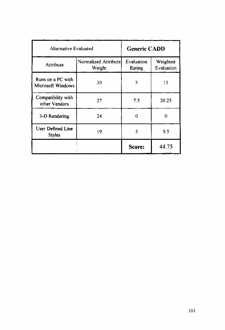
Alternative Evaluated Generic CADD
Attribute Normalized Attribute] Evaluation | Weighted
Weight Rating Evaluation
Runs on a PC with
Microsoft Windows 30 ° ID
Compatibility with 77 75 20.25
other Vendors
3-D Rendering 24 0 0
User Defined Line 19 5 95
Styles
Score: 44.75
101

Alternative Evaluated DataCAD
, Normalized Attribute] Evaluation | Weighted Attribute . . .
Weight Rating Evaluation
Runs on a PC with . . 5
Microsoft Windows 30 °
Compatibility with 27 5 13.5
other Vendors
3-D Rendering 24 7.5 18
User Defined Line 19 5 95
Styles
Score: 56

Alternative Evaluated Drawbase
Attribut Normalized Attribute} Evaluation | Weighted mure Weight Rating Evaluation
Runs on a PC with ; . 5 15
Microsoft Windows 30
Compatibility with 27 5 13.5
other Vendors
3-D Rendering 24 2.5 6
User Defined Line 19 5 95
Styles
| Score: 44
103

Alternative Evaluated Claris CAD
; Normalized Attribute] Evaluation | Weighted Attribute ; ,;
Weight Rating Evaluation
Runs on a PC with
Microsoft Windows 30 0 0
Compatibility with 7 5 13.5
other Vendors 2
3-D Rendering 24 0 0
User Defined Line 19 5 95
Styles
Score: 23
104

Alternative Evaluated VersaCAD
. Normalized Attribute] Evaluation | Weighted Attribute ; ;
Weight Rating Evaluation
Runs on a PC with ; . 5
Microsoft Windows 30 °
Compatibility with 13.
other Vendors 27 > 3.5
3-D Rendering 24 0 0
User Defined Line 19 5 95
Styles
! Score: 38
105

Alternative Evaluated PowerDraw
Attribute Normalized Attribute} Evaluation | Weighted
Weight Rating Evaluation
Runs on a PC with
Microsoft Windows 30 0 0
Compatibility with 7
other Vendors 27 2. 6.79
3-D Rendering 24 2.5 6
User Defined Line 19 5 95
Styles
| Score: 22.25
106

Alternative Evaluated MicroStation V.5
, Normalized Attribute] Evaluation Weighted Attribute . .
Weight Rating Evaluation
Runs ona PC with
Microsoft Windows 30 10 30
Compatibility with 37 75 50.25
other Vendors
3-D Rendering 24 10 24
User Defined Line 19 10 19
Styles
: Score: 93.25
107

Alternative Evaluated Cadvance
; Normalized Attribute} Evaluation | Weighted Attribute .; .
Weight Rating Evaluation
Runs on a PC with
Microsoft Windows 30 10 30
Compatibility with
other Vendors 27 ° 13.5
3-D Rendering 24 5 12
User Defined Line 19 5 95
Styles
Score: 65
108

APPENDIX B
SUMMARY OF OUTPUT FROM AUTOMAN
109

Model: AER3--Expanded Evaluation of CAD S/W Packages 11/01/93 Pg 1
Table 1. Ranking of Alternatives by Overall Rating
RANK ALTERNATIVE RATING
=>) MicroSta O.713 fhistetyiddy digo ettivetal po fgliioo ate
2 AutoCAD 0.287 [Jil it debi ligyd di
110
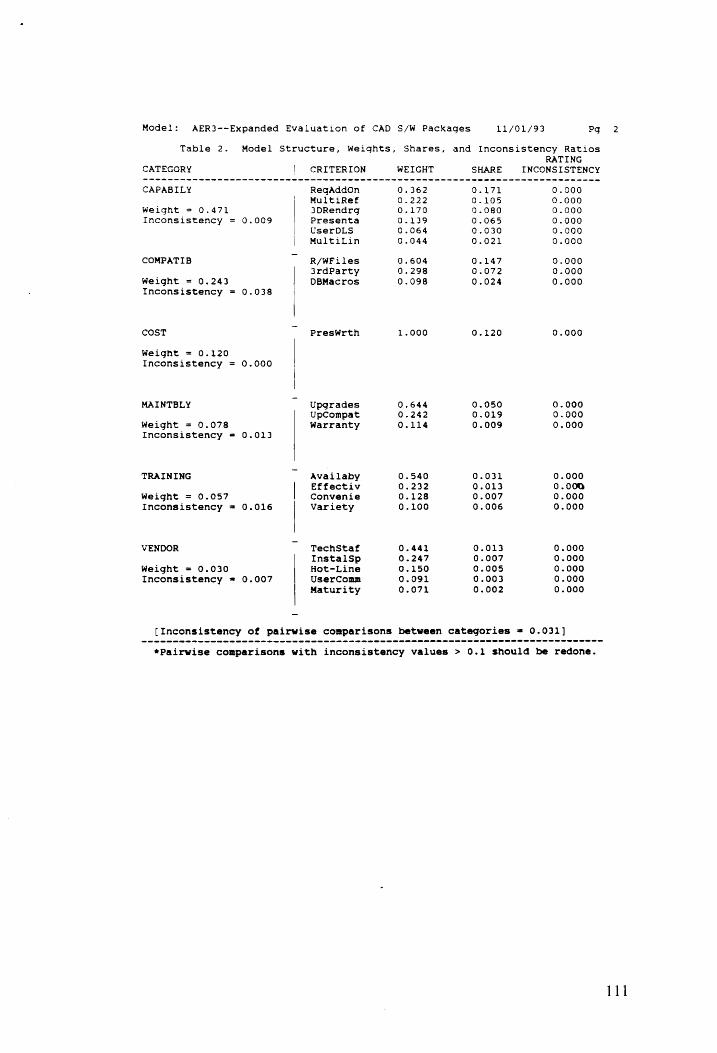
Model:
Ta
CATEGORY
AER3--Expanded Evaluation of CAD S/W Packages
ble 2. Model Structure,
CRITERION
Weights, Snares,
WEIGHT
11/01/93 Pg
and Inconsistency Ratios
RATING INCONSISTENCY
wee we ee ewe wee ee ewe Rew wee ew wee eww ee Oe ee ew ee eee ee ee we we ee ee wwe ee we ew ee
CAPABILY
Weight = 0.471
Inconsistency
COMPATIB
Weight = Inconsistency =
cost
Weight = Inconsistency =
MAINTBLY
Weight = Inconsistency =
TRAINING
Weight = Inconsistency =
VENDOR
Weight = 0.030 Inconsistency =
0.243
0.120
0.078
0.057
0.009
0.038
0.000
0.013
0.016
0.007
ReqAddon
MultiRef 3DRendrg
Presenta
UserDLS
MultiLin
R/WFiles
3rdParty
DBMacros
PresWrth
Upgrades Upcompat
Warranty
Availaby Effectiv Convenie Variety
TechStaf
InstalSp
Hot-Line
UserConm
Maturity
1.000
-644
»242
-114 ooo
0.540 0.232 0.128 0.100
0.441
0.247
0.150
0.091
0.071
0.050
0.019
0.009
0.031
0.013 0.007
0.006
0.013 0.007 0.005 0.003 0.002
0.000
0.000 0.000
0.000
0.000
0.000 0.000
0.000
0.000 0.000 0.000 0.000 0.000
[Inconsistency of pairwise comparisons between categories = 0.031]
*Pairwise comparisons with inconsistency values > 0.1 should be redone.
2
111
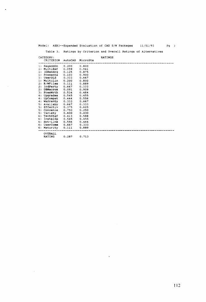
Model:
Table 3.
CATEGORY:
wee ew Me we mew ee we we we wee we ee we we we ewe ew wwe wee ew ewe wwe we we we ew ewe ee we ee we we eee ew ee
CRITERION
ReqAddon
MultiRef
3DRendrg
Presenta UserDLs
MultiLin R/WFiles
3rdParty
DBMacros
PresWrth
Upgrades
UpCompat
Warranty
Avalilaby Effectiv
Convenie Variety TechStaf
InstalSp
Hot-Line
UserComn
Maturity
Ratings by Criterion and Overall Ratings of Alternatives
AutoCAD
AER3--Expanded Evaluation of CAD S/W Packages
MicroSta
ee
OVERALL
RATING 0.287 0.713
112

Model:
Table 4.
Capabily Compatib cost
Maintbly
Training Vendor
ReqAddon
MultiRef
3DRendrg
Presenta
UserDLsS
MultiLin
R/WFiles
3rdParty DBMacros
PresWrth
Upgrades UpCompat Warranty
Availaby Effectiv
Convenie Variety
TechStaf InstalSp Hot-Line UserComm Maturity
and for Rating Alternatives
Comparisons between Capabily Compatib
3.000
Comparisons between ReqaAddOn MultiRef
1.500
Comparisons between R/WFiles 3rdParty
2.500
Comparisons between PresWrth
Comparisons hetween Upgrades UpCompat
3.000
Comparisons between Availaby Effectiv
2.500
Comparisons between TechStaf InstalSp
2.000
AER3--Expanded Evaluation of CAD S/W Packages 11/01/93 Pg
Pairwise Comparison Data for Weighting Categories and Criteria
g Vendor
9.250 6.750 4.000 3.500 3.000
Capabily MultiLin 7,000
6.000
4,000
3.500
1.250
Compatib
Cost
Maintbly
Training
Vendor
Categories
Cost Maintbly Trainin 4.500 6.000 7.500
2.500 4.000 5.000 2.000 2.500
1.750
Criteria within Category: 3DRendrg Presenta UserDLs
2.250 3.500 5.000
1.000 1.500 3.750
1.000 2.500
2.000
Criteria within Category: DBMacros
5.000
3.750
Criteria within Category:
Criteria within Category: Warranty 5.000
2.400
Criteria within Category: Convenie Variety 4.000 5.500
1.500 3.000
1.000
Criteria within Category: Hot-Line UserComm Maturity 3.000 4.500 6.000 1.750 2.500 4.000
1.500 2.500
1.000
113

Model: AER3--Expanded Evaluation of CAD S/W Packages 11/01/93 Pg
Table 4. Pairwise Comparison Data for Weighting Categories and Criteria and for Rating Alternatives
Comparisons between Alternatives rated by Criterion: ReqAddon
AutoCAD MicroSta AutoCAD 0.250
MicroSta
Comparisons between Alternatives rated by Criterion: MultiRef
(See Table 5 for Performance Data]
Comparisons between Alternatives rated by Criterion: 3DRendrg AutoCAD MicroSta
Autocad 0.143
MicroSta
Comparisons between Alternatives rated by Criterion: Presenta AutoCAD MicroSta
AutocaD Oo.11l
MicroSta
Comparisons between Alternatives rated by Criterion: UserDLs AutoCAD MicroSta
AutocaD 0.500
MicroSta
Comparisons between Alternatives rated by Criterion: MultiLin
{See Table 5 for Performance Data]
Comparisons between Alternatives rated by Criterion: R/WFiles AutocaD MicroSta
AutoCAD 0.125
MicroSta
Comparisons between Alternatives rated by Criterion: i3rdParty AutoCaD MicroSta
AutoCAD 2.000 MicroSta
Comparisons between Alternatives rated by Criterion: DOBMacros AutoCAD MicroSta
AutocCaD 0.100
MicroSta
Comparisons between Alternatives rated by Criterion: PresWrth
{See Table 5 for Performance Data]
114

Model:
Table 4.
AutoCAD
MicroSta
AutoCAD
Microsta
AutocaD
MicroSta
AutoCaD
MicroSta
AutoCAD
MicrosSta
AutoCAD
MicroSta
AutoCAD
Microsta
AutoCAD
Microsta
and for Rating Alternatives
Comparisons between Alternatives rated AutoCAD MicroSta
1.200
Comparisons between Alternatives rated
AutocaD MicroSta 0.800
Comparisons between Alternatives rated
{See Table 5 for Performance Data]
Comparisons between Alternatives rated
AutocaAD MicroSta 2.000
Comparisons between Alternatives rated
AutoCAD MicroSta 0.600
Comparisons between Alternatives rated
AutoCAD MicroSta 3.000
Comparisons between Alternatives rated AutoCAD MicroSta
1.500
Comparisons between Alternatives rated
[See Table 5 for Performance Data]
Comparisons between Alternatives rated AutoCAD MicroSta
1.200
Comparisons between Alternatives rated AutoCAD MicroSta
1.250
AER3--Expanded Evaluation of CAD S/W Packages
by
by
by
by
by
by
by
by
by
by
Criterion:
Criterion:
Criterion:
Criterion:
Criterion:
Criterion:
Criterion:
Criterion:
Criterion:
Criterion:
11/01/93
Upgrades
UpCompat
Warranty
Availaby
Effectiv
Convenie.
Variety
TechStaf
InstalSp
Hot-Line
Pg
Pairwise Comparison Data for Weighting Categories and Criteria

Model: AER3--Expanded Evaluation of CAD S/W Packages 11/01/93 Po 7
Table 4. Pairwise Comparison Data for Weighting Categories and Criteria and for Rating Alternatives
Comparisons between Alternatives rated by Criterion: UserComm
AutoCaD MicroSta AutoCAD 2.000
MicroSta
Comparisons between Alternatives rated by Criterion: Maturity AutoCAD MicroSta
AutoCAD 0.125
MicroSta
116
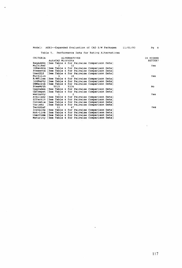
Model:
Table 5.
CRITERIA
ReqAddon MultiRef
3DRendrg
Presenta UserDLS
MultiLin R/WFiles jrdParty DBMacros
PresWrth
Upgrades UpCompat
Warranty Avallaby Effectiv Convenie Variety TechStaf
InstalSp
Hot-Line UserComm Maturity
ALTERNATIVES
AUTOCAD MicroSta
[See Table
2 [See Table
{See Table
[See Table 4
[See Table
[See Table
{See Table
5015
[See Table
[See Table
1
[See Table
{See Table
{See Table
{See Table
33
[See Table
[See Table
{See Table
{See Table
4 AD DD
> mph
for Pairwise 32
for Pairwise
for Pairwise
for Pairwise
16
for Pairwise
for Pairwise for Pairwise
5336
for Pairwise
for Pairwise
2
for Pairwise
for Pairwise
for Pairwise
for Pairwise 47
for Pairwise
for Pairwise
for Pairwise
for Pairwise
Comparison
Comparison Comparison Comparison
Comparison Comparison Comparison
Comparison Comparison
Comparison
Comparison Comparison Comparison
Comparison
Comparison
Comparison Comparison
AER3--Expanded Evaluation of CAD S/W Packages
Performance Data for Rating Alternatives
Data]
Data}
Data]
Data]
Data ]
Data] Data}
Data} Data }
Data ]
Data]
Data ]
Data]
Data }
Data]
Data]
Data]
Pg 8
IS HIGHER
BETTER?
Yes
Yes
No
Yes
Yes
117

APPENDIX C
AUTOMAN SENSITIVITY ANALYSIS
118

OVERALL
RATING
SENSITIVITY ANALYSIS on ReqAddOn
2.998
7
HicraSta_@ 88
0 rel ee —
8.68;
0.58;
0.401
@.304°°.. |
e Current Share oo 7
o.2 T T ™ “wT —v - - eee
oe
a 10 2a 38 #8 | 68 7 a 8
Z 2 Zaan
‘a .
= s
RutoCR® MicroSta
119

OQUERALL
RATING
SENSITIVITY ANALYSIS on MultiRef
HicraSta 6 34 2777
7?
--7"
277"
-7f
--77 7 ~« a?
. aor”
--?% aor”
0.28; 8.18 3.@8 ~ 2 —_ ¥ ™ T r

SENSITIVITY ANALYSIS on 3DRendrg
OQUERALL
RATING
o
i |
. ok
HicroSta 6 84 -'
7-7” - - - er?
~e7 7 -- -77
wort” “2”
wv?
ec oe - 7
oo
af”
-_--" 274
in
8.18
121

ore
“7” “777
7 777
a7" 2077
-- 3.88, aoe of
--7 277
_-
2-77 a)
= @ --
0.7Or |
OQUERALL
RATING
> e
e 38
a
' +
0.3: a4
toCne ©
°.28,
nt Share
-
a Me
ne
-
)
_ T
rT —T T
T 48
122

SENSITIVITY ANALYSIS on UserDLS
7
ave! Dn
TNT tee ee HieroSta
8 67
0.65}
2.68.
Z 0.55: = < <
z a ges 8.48;
0.354 FutoCr® @.33
ei} |. i aaee cennee nneen tggtn eee
. 4—- Current Share
_
- —— —
T "T —T
> wo = 08 «© 3S oo mw CO ie P = Print 2 = Zon PERCENTAGE SHORE for UserBLs
RutoCAD MicroSta
123

SENSITIVITY ANALYSSS on MultiLin
0.98,
0.e8 HicroSta_e 8d
amt
Z m= 8.68, z ual
: = 28.98 s o
@.48-
0.38;
@-Current Share ee, ce
0.28 : _~_ : —__futpcA @ 26 a 13 2 38 46 S38 8 a a8 3a 198
Z = Zaon P = Print
124

SENSITIVITY ANALYSIS on R/WFiles 0.93 MNicraSta 98 .Bg
=v” oe
=<” “17
ane -* -?
OUERALL
RATING
os 8
e.. 8
@
: 4
0.384.
0.204
¢ Current Share oe 0.18 RutoCRD e111
a 1.2 060 38 “a en) 73 ge og 498
Z = Joan PERCENTAGE SHARE fer R/UFies P = Print
FatoCAB NicroSta

OQUERALL
RATING
SENSITIVITY ANALYSIS on 38rdParty
984
vei of TS futoCAB @ 67
. 6. yA SA
584 oe
me
- 48; ya . “s. x
HicraSta 6.33
284
4~ Gurrent Share
2 r “Tt T — T rT T TT
8 49 2 38 4 ca ee 7 ge fe 138
<2 2 Zaon P = Print PERCENTAGE SWARE fer SedParty
RartoCRD WNicroGta
126

SENSITIVITY ANALYSIS on DBMacros
=-- err” +
errr’ ve oo . 77”
= *
OVERALL
RATING
o 9
MieroSta 8 - “77” > o?
31
a7" -a 7
2.304
8.28,
2.18. utocr @ eg @ Current Share
2.6 T v v T v v ¥ T
a 48 v. | 36 4 Se ce 7 | 58 4828
zZ 2 Zoon P @ Print PERCENTRGE SHRRE for BGMarros
futoCARD ficroSta
127

QUERALL
RATING
SENSITIVITY ANALYSIS on PresWrth
2.98
-
2. 7a, arn
26a] ..
"Ss furtocr @ Sz 8.58; ‘i icroSta 8 44
®.484
8.38;
a- Current Share
6.28 v T T Fr T Tv T v
a 49 2B 36 4 58 7a 90 98 1be
2 2 ZoOn P 2 Print PERCENTAGE SHARE for Presilirth
RutoCAB WNicroSta
128

QUERALL
RATING
SENSITIVITY ANALYSIS on Upgrades
f RutoCRD 8.55
@e
‘ 1 z
.. 4
MicraSta @ 46 th
“le Current Share
a rT 22 30 ea se oe 7” ae o@ rT
Z = Zoon PERCENTAGE SHARE for Upgrades P = Print
AutoCAD MicroGts
129

OQUERALL
RATING
dh
SENSITIVITY ANALYSIS on UpCompat
val aa
- .-
HicraSta @.56
@ ' 1
futoCRB @ 44
‘Te- Current Share
@.25 T 7 rm T T T r T
a 43 2 36 46 58 7 ae o@ 19
Z = Zoon PERCENTAGE SHRAE for Uotempat P = Print
AutoCARB WNMicroGta
130

SENSITIVITY ANALYSIS on Warranty
0.78;
@
°®
: ‘
a 2
QUER
ALL
RATING
= a
wea ~*Nee le
“Tene ere ee meee
Mem en ee Le -"se. ceNe HicraSta 6 6?
futoCAB 8.39 9 rT os 38 6 5a ¢6e 7 oe o@ 190
2 = Zoom PERCENTAGE SHARE for Worroety P = Print
AutcCAB NicroGta
131

SENSITIVITY ANALYSIS on Availaby
RutcCAD @
QUERALL
RATING
s 9
¢. a
~
- e Current Share
KicraSta 8. 2 = doon PERCENTIGE SHARE for Quedeby P= Print
fetoCRD HicroSta
6?
39
a 49 = 98 a Se 73 qe o@ 198
132

QUERALL
RATING
@
PERCENTAGE SHARE for Effect) ficroSta
SENSITIVITY ANALYSIS on Effectiv 3
70! ieee
en
""HieraSta © 64
64
SB
504
6!
*, FutoCAB @ 3a
3B:
:
Pen +- Gurrent Share
25 a
. ° ) | :
a 2 2 720 © ss 8 2 @ 9 42a
Zz 3 Zaon
_

QUERALL
RATING
0.28
SENSITIVITY ANALYSIS on Convenie
4— Qurrent Share
flutcCAD @.75
NicraSta @ 25
a 49
Z = Zoon
r aa T™ r ee
38 8 ce oe 78 98 o¢ 1pe
PERCENTAGE SHARE fer Cenwenie P = Print
RutcoCAB WMNicroSta
134

QUERALL
RATING
e.2
SENSITIVITY ANALYSIS on Variety
Te futcCAB 6 6a
HioraSta @ 428
Gurrent Share ¥ T r r Tv
a 49 % 38 p Sa ce 7 ge o¢ 198
Z = Zoon PERCENTAGE SHARE fer Lleriety P = Print
AutoCAD MicroSta

QUERALL
RATING
cj
SENSITIVITY ANALYSIS on TechStaf
.
0.78 “oye see “a.
Re aA
8.65; vA wae 7s
en.
6.68, HieroSta 8.59
RutoCRs ©. 41
e
. 2
6.35;
0.3: ee
-<— Current Share 8.23
a 18 ” 38 a 5a oe r ge 9@ rT
Z = Zoon PERCENTAGE SHRINE fer TechStef P = Print
fFutoCAB MicroGta
136

SENSITIVITY ANALYSIS on InstalSp
QUERALL
RATING
* 9
e FF
e.204 4— Gurrent Share
“Tey futoCAB @.55
HieraSta 6 46
9 49 s 30
Zz = Zaan PERCENTAGE SHARE for lnstei$p
e sc @& 2 8
AutoCAB WNicroSta
198
P = Print
» j

SENSITIVITY ANALYSIS on UserComm
ye
Q
OUERALL
BATING
e Current Share
RutoCh® © 5?
3g
a 19
2 = Zoom PERCENTAGE SHARE fer liserfomm
v tc t
P = Print
AutoCAD WNicroSta
138
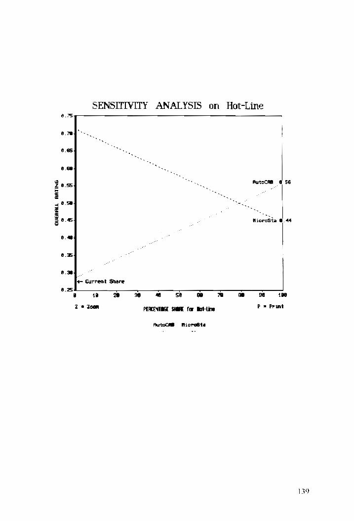
SENSITIVITY ANALYSIS on Hot-Line
8 OUERALL
RATING
a
.*}
he
4—- Current Share FutoCAB 6 56
a a
HicraSta 6.44
9 42 Y 38
Z = Zaan PERCENTAGE SHARE for Mat-Line
6 52 ce 7 98 o@ rT)
P @ Print
RutoCR® HicroSta

(1)
(2)
(3)
(4)
(5)
(6)
(7)
(8)
(9)
(10)
FOOTNOTES
Interviews with architects: Matthew Maio
Will Johnson
Jeff Elliott
Architectural Record, September 1993, p.54-55.
Liggett and Foster, p.6.
Liggett and Foster, p.7.
Interviews with architects: Matthew Maio
Will Johnson
Jeff Elliott
Ibid.
Blanchard and Fabrycky.
Blanchard and Fabrycky.
Blanchard and Fabrycky. p 22.
Blanchard and Fabrycky. p 36.
8/24, 9/9/93
9/17/93
9/22/93
8/24, 9/9/93
9/17/93
9/22/93
140

(11)
(12)
(13)
(14)
(15)
(16)
(17)
(18)
Hauser and Clausing. p. 63.
Ibid.
Blanchard and Fabrycky. p. 40.
Blanchard and Fabrycky. p. 55-56.
Canada and Sullivan. p. 211.
Blanchard and Fabrycky. p 152.
Blanchard and Fabrycky. p 155.
Canada and Sullivan. p. 467.
141

REFERENCES
Architectural Record. McGraw Hill: New York. September 1993.
Blanchard, Benjamin S. and Wolter J. Fabrycky. Systems Engineering and
Analysis. Prentice Hall: New Jersey. 1990.
Canada, John R. and William G. Sullivan. Economic and Multiattribute
Evaluation of Advanced Manufacturing Systems. Prentice Hall:
New Jersey. 1989.
Computer-Aided Engineering. May 1993.
Computer Graphics World. June 1993.
Dummer, G.W.A. and R.C. Winton. An Elementary Guide to Reliability.
Pergamon Press, Oxford. 1974.
Hauser, John R. and Don Clausing. "The House of Quality." Harvard
Business Review. May-June 1988.
Liggett, Hampton R. and Steven R. Foster. CAD Productivity Study. The
University of Tennessee Center for Computer Integrated Engineering
and Manufacturing: Knoxville, Tennessee. 1986.
142

Progressive Architecture. Pentin Publishing: Cleveland, Ohio. August
1993.
Sink, D. Scott. Productivity Management: Planning, Measurement and
Evaluation, Control and Improvement. John Wiley and Sons: New
York. 1985.
Smith, David J. and Alex H. Babb. Maintainability Engineering. John
Wiley and Sons, New York. 1973.
Stores. National Retail Federation Inc.: New York. April 1992.
143

VITA
Kristen Sue Badgley Rindin was born as a small child in Ithaca, New
York, in the summer of 1966, while her father, Dr. Robert H. Badgley was
studying for his PhD in Nuclear Physics. Kristen's mother, Dorothea A.
Steffan, was quite busy at the time supporting Dr. Bob (as we often refer to
him) in his post-graduate work at Cornell while working full time as a
nurse, raising the first child, Robert Jr., and carrying young Kristen around
for nine long months.
Kristen went on to achieve greatness in many arenas as a child,
including playing the French Horn for 10 years, performing in church
choirs and plays, competing in gymnastics and basketball athletic events,
and demonstrating a noticeable lack of talent in both tap and ballet classes.
Kristen was an outstanding student through junior high and high school,
and graduated second in a class of 532 from South Lakes High School in
Reston, Virginia. Her studious nature resulted in her admittance to all
colleges to which she submitted applications. She selected Virginia
Polytechnic Institute and State University over Carnegie Mellon and
Cornell after reviewing the family finances with Dr. Bob. Virginia Tech
offered the largest scholarship and had one of the finest and progressive
engineering schools in the country.
Four fun-filled years later, in 1988, Kristen graduated with a
Bachelors Degree in Mechanical Engineering, and has managed to avoid
designing turbomachinery in her jobs with General Electric Aerospace and
the Martin Marietta Corporation. Her career has concentrated in the test
144

and evaluation of large scale mainframe computer systems and software,
and the systems integration and installation of a worldwide LAN with
Computer Integrated Manufacturing capabilities. Her latest career
assignment is as a member of the first Washington area Technical
Leadership Development Program for Martin Marietta. Kristen was
selected as one of the four members from a selection pool of over two-
thousand employees for this prestigious program. The rotational
assignments over the next two years will provide Kristen with valuable
insight into the division and corporate level activities that propel Martin
Marietta to be the largest remaining defense contractor in the United States.
One of Kristen's favorite activities outside of work and graduate
school for the last three years has been running. Kristen has been
increasing her mileage lately, and spending more time at the George Mason
Track working on improving her road and track race times. She won a spot
on the Martin Marietta Corporate Track and Field Team this past June, and
competed in the "Corporate Olympics" in Seattle in July. She has
continued her running, and achieved a milestone on 17 October 1993 by
running im the Army Ten Mile as part of the Martin Marietta Women's
Team, which placed second in the event.
Kristen is married to Jeffrey A. Rindin, an F-16 pilot with the D.C.
Air National Guard, and the architect that inspired this project topic with
his repeated requests for his own CAD system. In a calculated effort to
minimize the dollars flowing from the joint checkbook, Kristen embarked
upon this evaluation to identify the CAD system that provides the most
advanced capabilities for the most reasonable cost.
Jai | 145