7981:ALKO Owner's Manual Replacement Pages 4/16/08 9 ...
52
7981:ALKO Owner's Manual Replacement Pages 4/16/08 9:54 PM Page 2
-
Upload
khangminh22 -
Category
Documents
-
view
0 -
download
0
Transcript of 7981:ALKO Owner's Manual Replacement Pages 4/16/08 9 ...

7981:ALKO Owner's Manual Replacement Pages 4/16/08 9:54 PM Page 2

2
04/06

3
Table of Contents
Approved
Introduction..................................................................
Safety...........................................................................
Before The First Trip....................................................
General Maintenance..................................................
Weighing The Trailer....................................................
Storage Maintenance...................................................
Service Preparation.....................................................
Brake Assemblies.......................................................
Adjustment........................................................
Shoe & Lining...................................................
Magnet..............................................................
Bearings, Races and Seals.........................................
Brake Drum/Rotor........................................................
Completing Service.....................................................
Tire Inspection.............................................................
Troubleshooting...........................................................
Suspension Components............................................
Replacement Parts......................................................
Asbestos and Non-Asbestos Fiber Warning................
Wheel Mounting and Compatibility..............................
Warranty......................................................................
Service Record............................................................
4
5
6-7
8-9
10
11
12
13-20
13-14
15-17
18-20
21-22
23-25
26
27
28-31
32-33
34-44
45
46
47
48-51

4
Introduction
This manual contains information about axle assemblies, attaching
parts, electric brakes, hydraulic drum brakes, hydraulic disc brakes and
air brakes.
16K Air Brake (Axle Assembly) 10K General Duty (Axle Assembly)
Hub/Drum and Hydraulic Brake
AL-KO Kober Corporation is a major supplier to the trailer industry.
Our axles, brakes, hubs and drums are in operation around the world,
helping trailers tow smoothly and stop safely. Our product line is the
result of years of advanced engineering in the United States as well as
Germany, where vehicular technology is unsurpassed. AL-KO products
have undergone years of exhaustive testing and we continue to strive for
superior reliability, safety and performance.
Hub/Drum and Electric Brake
Adhering to the recommended service schedule on pages 8-9 will
ensure the finest towing and stopping action available.
Always use genuine AL-KO Kober replacement parts.
5
This manual describes service and repair procedures for AL-KO Kober
trailer axles. Technicians must follow their employer’s procedures andthese procedures when servicing or repairing equipment or components.Before performing any service or maintenance, review the trailermanufacturer’s recommendation for procedures and warnings.
Safety First
!
A
Fasteners must be tightened to a
specific torque value. The technician
must use the proper torque wrench to perform these operations.
Improper torque can result in product failure which could cause
property damage, serious injury, or loss of life.
To prevent serious eye injury, always wear
safety eye protection when you perform vehicle
maintenance or service.
Current AL-KO brake linings are
asbestos free. Other brake linings may
contain asbestos fibers, a cancer and lung disease hazard. Many
brake linings contain non-asbestos fibers, whose long-term effects
to health are unknown. You must use caution when you handle
both asbestos and non-asbestos materials. (See page 45.)
This indicates a procedure that you
must follow exactly to avoid damaging equipment or components
and to avoid serious personal injury or loss of life.
The service and maintenance procedures are provided for use byqualified service technicians. Do not attempt to service, repair orwork on brakes or axles unless you have appropriate mechanicalknowledge and skills. You must understand all procedures andinstructions before you begin to work on a unit. Some proceduresrequire the use of special tools for safe and correct service. Failureto use special tools when required can cause damage to equipmentand components. Lack of proper training, failure to follow properprocedures, or not using proper tools or safety equipment, canresult in property damage, serious personal injury, or loss of life.
The following symbols are used to warn the user of potential dangersthat could cause serious damage to equipment or cause personal injuryor death.

6
Before The First Trip
Torque wheel nuts now and then
every fifty miles for the first 200 miles
and then according to the schedule
on page 8. Over-or under-torqued wheel nuts can cause the
wheel to separate from the wheel mounting surface during
operation. Wheel separation can result in property damage,
serious personal injury, or loss of life. (See page 26 for torque
specifications.)
Adjust brakes: Many of AL-KO Kober's heavy duty brakes are
self adjusting. Depending on the conditions, some may need to be
manually adjusted. Before the first trip, read the brake section that
corresponds with your braking system - electric, hydraulic drum or
hydraulic disc. Be sure to follow all procedures. A “green brake” isan unburnished brake. Normal manufacturing tolerances dictate
that there is a break-in period required after which the lining will
seat and become perfectly concentric with the drum. During this
break-in period, the user must be aware that additional brake
adjustments are mandatory to achieve optimum braking
performance.
Failure to adjust brakes can result in
brake lockup, reduced brake performance, or total loss of brakes
which can lead to serious personal injury or loss of life.
Set wheel nut torque as it may loosen several times before
the wheel is properly seated to the wheel mounting surface. Wheel
nut torque must be checked with a torque wrench and adjusted if
necessary. Do not overtighten. Be sure to follow the instructions on
page 26.
Set the hitch or pin height of the tow vehicle so that the trailer
is being pulled in a horizontal position. Trailers must be towed as
level as possible. If the trailer leans down in the front it will distribute
too much weight to the front axle. If the hitch or pin height is too high,
the rear axle will receive too much of the load. Either condition can
overload an axle even if the trailer is not overloaded.
Improper trailer position can cause
tow vehicle handling problems resulting in property damage,
serious personal injury, or loss of life.

7
Synchronize the trailer brakes with the tow vehicle
brakes. Trailer brakes are designed to stop the trailer. They cannot
stop both the tow vehicle and trailer. Improper synchronization
between the trailer and tow vehicle brakes can overload the
brakes and generate excessive heat, causing brake fade or
failure. Proper synchronization is achieved when the trailer’sbrakes have a slight lead over the tow vehicle’s brakes. This is
accomplished by adjusting the brake actuation mechanism. There
are several types of Actuation Systems available depending on
the type of brakes. These include Electric Brake Controller,
Electric Over Hydraulic, Vacuum Over Hydraulic, Air Over
Hydraulic and Straight Air. See the manufacturer’srecommendation for adjusting the Actuation System. When done
properly, there should be no sensation of the trailer “pushing” or
“pulling” the tow vehicle.
Road test before using. Be sure area is
clear of traffic and pedestrians. Do not
exceed 30 m.p.h. Follow procedures outlined by the controller
manufacturer. Failure to do so could result in property damage,
serious personal injury, or loss of life.
Weigh the trailer after it is fully loaded and ready for use.
Axles, brakes, wheels, tires, frames and suspension components
are designed to carry a specific maximum weight. Locate the VIN
(Vehicle Identification Number) plate on the trailer. It will show the
GVWR (Gross Vehicle Weight Rating). The GVWR is the total
amount your trailer (including tongue weight) can weigh when it is
completely loaded. The GAWR (Gross Axle Weight Rating) is the
maximum load that the axles will carry and the maximum load the
brakes will stop. Follow the instructions on page 10 for weighing
the trailer and determining weight distribution.
Exceeding the GVWR (Gross Vehicle
Weight Rating), the GAWR (Gross AxleWeight Rating), or having improper weight distribution can resultin reduced performance or failure of the axle(s), brakes, and other
suspension components. This failure can lead to property
damage, serious personal injury, or loss of life.
Before The First Trip

8
Ge
ne
ral M
ain
ten
an
ce
To k
eep a
tra
iler
tow
ing s
mooth
ly a
nd s
toppin
g s
afe
ly,
it is
recom
mended that serv
ice b
e d
one a
t th
e inte
rvals
belo
w.
(Severe
conditio
ns,
inclu
din
g e
xcessiv
e b
rake u
se,
extr
em
ely
rough r
oads, etc
. m
ay r
equire m
ore
fre
quent m
ain
tenance.)
Imp
rop
er
or
inad
eq
uate
main
ten
an
ce c
ou
ld
resu
lt i
n p
rem
atu
re w
ear
or
co
mp
on
en
t fa
ilu
re
wh
ich
co
uld
resu
lt i
n p
rop
ert
y d
am
ag
e,
seri
ou
s
pers
on
al
inju
ry,
or
loss o
f life
.
�

9
10
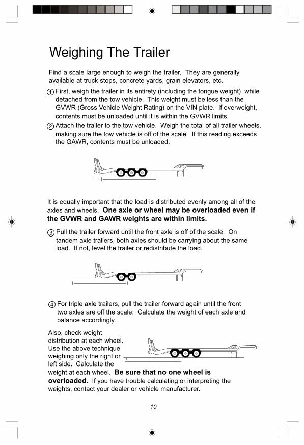
Weighing The Trailer
Find a scale large enough to weigh the trailer. They are generally
available at truck stops, concrete yards, grain elevators, etc.
It is equally important that the load is distributed evenly among all of the
axles and wheels. One axle or wheel may be overloaded even if
the GVWR and GAWR weights are within limits.
Pull the trailer forward until the front axle is off of the scale. On
tandem axle trailers, both axles should be carrying about the same
load. If not, level the trailer or redistribute the load.
For triple axle trailers, pull the trailer forward again until the front
two axles are off the scale. Calculate the weight of each axle and
balance accordingly.
Also, check weight
distribution at each wheel.
Use the above technique
weighing only the right or
left side. Calculate the
weight at each wheel. Be sure that no one wheel is
overloaded. If you have trouble calculating or interpreting the
weights, contact your dealer or vehicle manufacturer.
First, weigh the trailer in its entirety (including the tongue weight) while
detached from the tow vehicle. This weight must be less than the
GVWR (Gross Vehicle Weight Rating) on the VIN plate. If overweight,
contents must be unloaded until it is within the GVWR limits.
Attach the trailer to the tow vehicle. Weigh the total of all trailer wheels,
making sure the tow vehicle is off of the scale. If this reading exceeds
the GAWR, contents must be unloaded.

11
Storage Maintenance
Disconnect the break-away battery and store indoors. Periodically
check and recharge if necessary.
Park trailer on a level area.
Lift trailer per instructions on page 12.
Place auxiliary blocking under the frame so that all weight is removed
from the wheels.
Before Storing
Follow instructions on page 12 for “Service Preparation”. Mark
location for each wheel and hub/drum. They will be reinstalled on the
same spindle.
Check suspension for wear and proper fastener torque.
(See page 32-33.)
Install a fully charged break-away battery.
Follow all hub/drum and brake service procedures. Replace or repair
any worn or damaged parts. Be sure to remove and check
bearings. (See pages 21-22.)
Reinstall hub/drums and wheels in same position as removed.
After Storage (Two Months or Longer)
Wheel nut torque must be checked with a
torque wrench and adjusted if necessary.
Do not overtighten. Be sure to follow the instructions on page 26.
Lubricate the moving suspension parts. (See page 32.)
If axles have been exposed to immersion or excessive moisture,
check hub/drum and bearings for moisture and change oil as
necessary. (See pages 21-22.)
Oil will settle in the hub/drum. Rotate the wheel every one to two
weeks to redistribute oil.
See manufacturer,s recommendation
for position of blocks. Never use the
axle or any portion of the suspension to lift or support the trailer.
This will damage the axle and lead to premature failure which could
result in property damage, serious personal injury, or loss of life.

12
Service Preparation
Lift the trailer until wheel rotates freely and secure trailer withappropriate jacks and auxiliary blocking. Never use the axle or any
portion of the suspension to lift or support the trailer. This will
damage the axle and lead to premature failure.
Many service and maintenance procedures require the trailer to beelevated. Follow the trailer manufacturer’s recommendations for liftingthe trailer.
Do not work under a vehicle supportedonly by jacks or jack stands. Use
additional auxiliary blocking. Jacks or jack stands could failresulting in property damage, serious personal injury, or loss of life.
If service requires the hub/drum or hub/rotor to be removed, remove
the wheel and follow steps 3-5. Refer to the schematic on page 24.
Remove the hub/drum or hub/rotor
assembly by removing the grease or oilcap, cotter pin, castle nut, spindle washer (where required) and outerbearing. If a bearing drops it may be damaged and should be replaced.Pull the drum straight off the spindle being careful not to damage thespindle, bearings or races. The inner bearing and seal may stick to thespindle. If so, use a bearing puller to remove inner bearing.
Pry the seal with a seal removing tool or screwdriver. Do not drive
seal out by hitting, punching, or tapping the inner bearing.
Wash bearings and races with solvent. Do not use water or steam as
they may damage components or cause components to come loose.Apply a thin layer of grease or oil until ready to repack.
Lifting Trailer
The service and maintenance procedures are provided for use byqualified service technicians. Do not attempt to service, repair orwork on brakes or axles unless you have appropriate mechanicalknowledge and skills. You must understand all procedures andinstructions before you begin to work on a unit. Some proceduresrequire the use of special tools for safe and correct service. Failureto use special tools when required can cause damage to equipmentand components. Lack of proper training, failure to follow properprocedures, or not using proper tools or safety equipment, can resultin property damage, serious personal injury, or loss of life.

13
Replacing Complete Drum Brake
Assembly (Electric & Hydraulic)
Lift trailer as outlined on page 12 “Service Preparation”. Do not
remove the wheels or hub/drum assembly.
Locate the adjusting slot and, while spinning the wheel, use
a standard brake adjusting tool or the blade of a screwdriver to rotatethe star wheel until there is a heavy brake drag.
Loosen until the wheel turns
freely about 3/4 to one full turn.
Replace the protective plug to
keep dirt and moisture out.
Repeat procedure for other
wheels. Never adjust just one brake.It is recommended that all brakes onthe trailer, or at least both brakes ofone axle, be adjusted at the same time.
Replace all parts and lower
trailer as outlined on page 26"Completing Service".
Adjusting
Tool
Adjusting Screw
Improper brake adjustment can result in
reduced brake performance or loss of
brakes. Reduced brake performance can lead to property damage,
serious personal injury, or loss of life.
Backing
Plate
K80 Electric Brake: K80 brakes are not self adjusting. Followservice schedule on page 8.
Follow “Service Preparation” instructions on page 12.
Remove fasteners which attach the brake backing plate to the brake
flange. See schematics on pages 34-39.
Install new brakes. Be sure to use the proper side and install the
brake with the magnet on the bottom or wheel cylinder at the top.When replacing a Hayes Brake with an AL-KO Brake, discard the oldtwo piece dust cover. Reinstall fasteners and torque per page 25.
Reinstall hub/drum per instructions on page 24.
Follow instructions on page 26 for “Completing Service”.

14
Improper brake nut torque can causethe backing plate to become detachedfrom the brake flange causing brake
failure. Reduced brake performance can lead to property damage,
serious personal injury or loss of life.
10K-16K Air Drum BrakesSlack adjusters should be adjusted to keep push rod travel to a minimumwithout the brakes dragging.
8K-12K Hydraulic Drum BrakeThe 12" x 3-3/8" and 12-1/4" x 3-1/2" hydraulic drum brakes are selfadjusting during stops. The first application of the brakes during bleedingwill expand the shoes to the drum diameter and the self-adjuster will holdthem with proper clearance.
To release the shoes, reach through the backing plate with a brakeadjuster or large screwdriver and lift the rachet lever allowing the shoesto collapse, thus allowing easy removal of the hub and drum.
10K-12K Hydraulic Disc BrakeThe hydraulic disc is self adjusting. To remove the hub and rotor, thecaliper assembly must be removed from the torque plate by removingtwo 3/8" bolts and the retainer plates.
8K-16K Electric Drum BrakeThe 12" x 3-3/8", 12-1/4" x 3-1/2" and 12-1/4" x 5" electric brakes are selfadjusting during hard reverse stops. When the leading shoe leaves theanchor pin, the adjuster cable pulls the adjuster pawl upward to engagethe next tooth of the adjuster star wheel if adjustment is necessary due tonormal wear. To release the shoes, the adjuster pawl must be pulled awaybefore the star wheel can be turned backward to decrease brakeadjustment.
Upon reinstallation, the shoes should be adjusted to the point of lightlydragging the drum and approximately .010" clearance on the shoe withthe most shoe to drum clearance measured at the 3 or 9 o'clock position.
Brake Adjustment Cont.

15
Follow “Service Preparation” procedures on page 12. With the trailer
lifted and the hub/drum removed, inspect the linings for wear or
contamination from oil or grease. Hairline heat fissures are not
uncommon in bonded shoes and pose no cause for concern. If there
are any questions concerning the severity of cracking, consult with an
expert. If the lining is worn to 1/16" or less on bonded and 1/32" or less
on riveted linings, or shows irregular wear or contamination from foreign
substances, the shoes should be replaced with original AL-KO parts.
Inspecting & Replacing
Brake Linings
Current AL-KO brake linings are
asbestos free. Other brake linings may
contain asbestos fibers, a cancer and lung disease hazard. Many
brake linings contain non-asbestos fibers, whose long-term effects
to health are unknown. You must use caution when you handle
both asbestos and non-asbestos materials. (See page 45.)
To prevent serious eye injury, always wear safety
eye protection when you perform vehicle
maintenance or service.
Brake shoes should always be replaced
in pairs, both brakes on the same axle.
Failure to replace in pairs can result in reduced brake performance
or loss of brakes which could result in property damage, serious
personal injury, or loss of life.

16
Replacing Brake Linings
(Electric and Hydraulic Drum Brakes)
8K-12K Electric and Lining Replacement Procedures
Remove hub/drum assembly. Clean and inspect hub/drum assembly,
bearings, seal and spindle.
Clean brake assembly with a non-residual brake cleaner.
Inspect magnet and lever assembly for damage and/or abnormal or
excessive wear.
Secure magnet assembly to lever arm with a heavy rubber band
or thread.
For ease of installation, disconnect magnet lead wires from power
source and remove brake assembly from axle beam.
Remove magnet, lever assembly and slipper block from
brake assembly.
To remove old shoe and linings, remove the hold down bolts, washers,
nuts, and cotter pins.
Remove bias lever and adjuster lever from old shoe and linings.
Install on new shoe and linings.
Clean and properly lubricate backing plate and adjuster assembly with
Lubriplate, block grease or equivalent.
Install new shoe and linings.
Install slipper block, magnet and lever assembly.
8K-12K Hydraulic Shoe and Lining Replacement Procedures
Remove hub/drum assembly. Clean and inspect hub/drum assembly,
bearings, seal and spindle.
Clean brake assembly with a non-residual brake cleaner.
Remove self-adjuster assembly and springs.
To remove old shoe and linings, remove the hold down bolts, washers,
nuts, and cotter pins.
Clean and properly lubricate backing plate and adjuster assembly with
Lubriplate, block grease or equivalent.
Install new shoe and lining assemblies. Make sure cylinder push rods
are properly located on shoe web.
Install self-adjuster assembly and springs.
Collapse self-adjuster assembly enough to get the hub and
drum installed.

17
Use only genuine AL-KO replacement parts.Other shoes may “fit” but not function properly.
Installation of non-AL-KO parts could result in reduced brake performance or loss ofbrakes. Reduced brake performance can lead to property damage, serious personalinjury, or loss of life.
Torque wheel nuts after reinstalling wheel andthen every fifty miles for the following 200 miles.Over or under torqued wheel nuts can cause thewheel to separate from the wheel mounting
surface during operation. (See page 26 for specifications.) Wheel separation canlead to property damage, serious personal injury, or loss of life.
Replacing Brake Linings
(Electric and Hydraulic Drum Brakes)
10K-12K Disc Pads Replacement Procedures
Release brake line pressure by opening the bleeder screw.
Using large C-clamp, retract pistons into caliper.
Remove retainer plates, upper and lower.
Lift caliper from torque plate being careful not to kink brake hose.
Inspect rotor for wear and repair or replace if needed.
Lift worn brake pad from torque plate and install new one.
Replace outer pad on caliper housing.
Reinstall caliper on rotor.
Torque caliper retainer clips to 18ft. lbs. of torque.
Bleed system. (Follow actuation system instructions for bleeding all
hydraulic brakes.)
8K-12K Hydraulic Wheel Cylinder Replacement Procedures
Remove drum.
Clean brake assembly with a non-residual brake cleaner.
To remove shoes from backing plate you must:
a. Remove self-adjuster
b. Remove retract springs (upper & lower)
c. Remove hold down bolts, washers, nuts, and cotter pins.
Disconnect hydraulic line from cylinder.
Inspect new wheel cylinder and parts to ensure hydraulic lines
will connect.
Install new wheel cylinder in reverse order.
Install drum.
Ensure proper operation, bleeding hydraulic system if necessary.
Bleed system. (Follow actuation system instructions for bleeding all
hydraulic brakes.)

18
Follow the procedures on page 12 for “Service Preparation”.
The magnet assembly can be inspected for wear while it is still
assembled to the brake. Lay a straight edge over the length of the
magnet face and check for flatness.
Normal Wear
If you suspect that the magnet is not functioning properly and it
shows no sign of abnormal or excessive wear, check for a short
circuit. Remove the magnet from the brake as follows:
✓ Disconnect the magnet leads from the trailer’s wiring
harness and remove the strain relief to allow the magnet leads
to be pulled through the backing plate.
✓ Remove clips holding magnet leads to the lever arm
or return spring.
✓ Remove clips holding magnet to lever arm and
remove magnet. Keep the clips and magnet spring. Follow
procedures on page 19.
Abnormal
Wear
(Replace)
Inspecting & Replacing
Brake Magnets
Straight Edge
If magnet shows abnormal wear, inspect the brake drum armature
surface. The armature plate may also need to be replaced.
All AL-KO electric brakes use
magnets that are similar in design.
Properly functioning magnets that show
normal wear may be used until copper coil
is visible through the friction material in the
center of the magnet.
19
Magnet Electrical
Evaluation
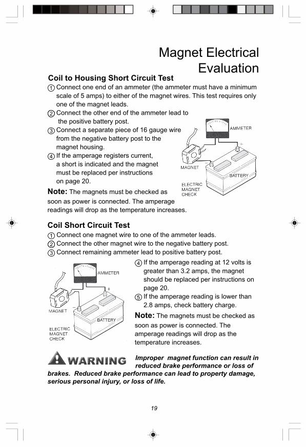
Connect one magnet wire to one of the ammeter leads.
Connect the other magnet wire to the negative battery post.
Connect remaining ammeter lead to positive battery post.
Coil Short Circuit Test
If the amperage reading at 12 volts is
greater than 3.2 amps, the magnet
should be replaced per instructions on
page 20.
If the amperage reading is lower than
2.8 amps, check battery charge.
Note: The magnets must be checked as
soon as power is connected. The
amperage readings will drop as the
temperature increases.
Improper magnet function can result in
reduced brake performance or loss of
brakes. Reduced brake performance can lead to property damage,
serious personal injury, or loss of life.
Connect one end of an ammeter (the ammeter must have a minimum
scale of 5 amps) to either of the magnet wires. This test requires only
one of the magnet leads.
Connect the other end of the ammeter lead to
the positive battery post.
Connect a separate piece of 16 gauge wire
from the negative battery post to the
magnet housing.
If the amperage registers current,
a short is indicated and the magnet
must be replaced per instructions
on page 20.
Note: The magnets must be checked as
soon as power is connected. The amperage
readings will drop as the temperature increases.
Coil to Housing Short Circuit Test

20
** Some brakes do not use wire clips. Route magnet wire with loomretaining ring, as previously installed.
To prevent serious eye injury, always wear safety
eye protection when you perform vehicle
maintenance or service.
Road test before using. Be sure area is
clear of traffic and pedestrians. Do not exceed 30 m.p.h. Follow
procedures outlined by the controller manufacturer. Failure to do
so could result in property damage, serious personal injury, or loss
of life.
Remove Hub/Drum assembly, clean and inspect Hub/Drum
assembly, bearings, seals and spindle.
Clean brake assembly with a non-residual brake cleaner.
Disconnect magnet lead wires from terminals on dust cover.
Remove strain relief and
adapter from backing
plate.
Pull lead wires through
backing plate hole.
Remove wire retaining
rings holding magnet lead
wires to lever arm.
Remove magnet.
Install new magnet
assembly to lever arm,
securing magnet body to
lever arm with a heavy rubber-band or thread. (First heavy braking
will roll off or break rubber-band or thread)
Reinstall magnet lead wires to lever arm using wire retaining rings.
Reinstall strain relief and adapter into backing plate connecting lead
wires to dust cover terminals.
Reinstall drum.
8K-12K Magnet Replacement
Procedures

21
Inspecting Bearings
Races & Seals
Most trailer axle bearings require periodic maintenance (see pages 8-9)to ensure reliable, safe operation of your trailer.
Improperly torqued spindle nuts cancause the hub/drum & wheel to separatefrom the axle resulting in property
damage, serious personal injury, or loss of life.
Follow the procedures outlined on page 12 for “Service Preparation.”Refer to the schematic on pages 35-44.
Wash the bearings and races with solvent cleaner to remove all old
grease or oil. Do not use compressed air or steam. They maydamage components or cause components to come loose.
Check the bearings and races for worn, scored, damaged, grooved,
indented, etched, spalled, gouged, nicked, corroded or otherwisedamaged parts.
Check seal for nicks, tears or wear.
Always replace bearings and races in matched sets.Replace damaged seals, bearings or races (see page 22).

22
Installing Bearings
Races & Seals
Install RacesAlways replace bearings and races as a set. Install races (new hub/
drums should have races already installed) using a mild steel drift or bar.
Do not use hardened steel or brass bars as they may damage, chip or
leave deposits on the races. Final setting of the race against the
shoulder should be checked with feeler gauges and be within 0.002" of
the shoulder in the hub/drum.
Improper seal or bearing installation oradjustment, or insufficient maintenance,can lead to wheel bearing failure which
could cause the hub/drum and wheel to separate from the axleduring operation resulting in property damage, serious personalinjury, or loss of life.
Pack Bearings (Grease Lubrication Only)Prior to repacking bearings, all grease must be removed from the hub/
drum and bearings. Bearings should be packed by machine or by hand
methods to insure that grease is forced into the cavities between the
rollers, cone and cage of the bearings. For axles equipped with oil, fill
hub with oil after assembly.
GreaseUse a high temperature, automotive type wheel bearing grease
produced by a reputable manufacturer. The soap type should be lithium
complex or equivalent. Use NLGI Grade 2 product with a minimum
dropping point of 440o F.
Installing SealsIt is recommended to install a new seal after removing the hub/drum/rotor.
For ease of removal and installation, remove the armature plate (for
electric brakes) by removing the six flat head screws. Be sure that the
inner race and fully packed (for grease only) inner bearing are installed.
Apply a thin layer of permatex (or similar) sealant to the outside diameter
of oil seal. Install the seal using the correct size seal driver. If this is not
available, use a clean block of wood which is large enough to cover the
entire seal. Tap block to seat seal. Reinstall armature plate if required.
To prevent serious eye injury, always wear safety
eye protection when you perform vehicle
maintenance or service.
Follow the procedures outlined on page 12 for
“Service Preparation.”
Oil: Use a high grade, SAE 90 gear oil.

23
Brake Drum/Rotor
Inspect the drum or rotor's shoe surface. This surface should have a
dull gray appearance and be free from heavy scoring and/or excessive
wear. One or two light score marks are not cause for resurfacing or
replacing the drum or rotor. If there are any questions concerning the
condition of a part, consult an expert. Drums or rotors that are heavily
scored or with 0.020" runout should be replaced or resurfaced. Do not
exceed the maximum diameter cast in the brake drum. Replace drums
worn to more than 12.39".
Resurfacing the Brake DrumA standard drum lathe may be used to machine the shoe surface. Do
not exceed the maximum diameter cast into the brake drum or the
minimum thickness cast into the rotor. The drum should be replaced if it
must be bored more than the maximum diameter cast in the brake drum.
Be sure to remove any metallic chips and contamination resulting from
drum machining.
Reinstall races per instructions on page 22. Replacement or new hub/
drums should have races already installed.
Check the armature surface (electric braked axles only) for excessive
galling due to severe contamination (mud, stones, etc.). One or two
light score marks are not cause for replacing the armature. Under
normal conditions, the armature surface should last indefinitely.
Follow the procedures outlined on page 12 for “Service Preparation”.
Inspecting the Brake Drum
Heavily scored, worn or oversized
drums or rotors can result in reduced
brake performance or loss of brakes. This could result in property
damage, serious personal injury, or loss of life.
Failure to remove chips could cause
bearing failure which could cause the
hub/drum and wheel to separate from the axle. This could result in
property damage, serious personal injury, or loss of life.

24
For both grease and oil, apply a thin film of NLGI 2 grease (not oil) to
spindle bearing journals to help protect them from fretting or corrosion.
Install inner bearing and seal in hub/drums. (See page 22.) For
grease applications, pack inner bearing before installation.
Slide hub/drum onto spindle, taking care not to damage spindle
bearing or seal. Press until inner bearing stops against the inner
bearing journal.
Install outer bearing. Pack outer bearings for grease applications.
Re-install washer when required (see pages 35, 40-44).
Follow bearing adjustment procedures on page 25.
Note: When installing a new or resurfaced drum or
rotor be sure to use new brake shoes or pads and
new magnets (electric brakes).
Hub and drum (#99 & #120) Removal
Use a 2-1/4" socket or large wrench to remove oil cap.
Use a catch container for oil as cap is removed.
Remove wheels and tires.
Use pliers to remove cotter key from nut and spindle.
Using a 2-1/4" socket or large wrench remove spindle nut, washer and
outer bearing from spindle.
Work drum from spindle (if you have a large puller) and attach to the
drum studs, pushing against spindle end makes this task much easier
removing hub/drum or rotor.
25
To get the proper “feel” for bearing clearance, the spindle nut must
turn freely on the spindle and the brake must be readjusted so that
there is no drag on the drum.
While slowly turning the hub/drum, tighten the spindle nut to
approximately 20 ft/lbs then loosen. This is especially important if
new bearing races have been installed.
With drum stationary (do not rotate), retighten the spindle nut to 7 ft/
lbs (zero clearance) then back off one slot (0.001"- 0.010" end play)
and align cotter pin hole. Insert cotter pin and bend both ends over
end of spindle. Install grease cap or oil cap.
For oil applications fill wheel end with an approved gear oil to oil cap
fill line. Note that oil must be given sufficient time to settle prior to
final check of oil level.
Bearing Adjustment
Improper bearing adjustment can lead
to wheel bearing failure which could
cause the hub/drum and wheel to
separate from the axle during operation. This could result in
property damage, serious personal injury, or loss of life.
Drum Replacement #120 Spindle Only
Place hub & drum on a clean surface.
Remove armature plate, if electric brakes, by removal of the six flat
head screws.
Remove the (8) drum attachment bolts to separate drum from hub.
Install replacement drum on pilot.
Using a crisscross pattern tighten the (8) bolts until the drum is fully
seated on the pilot.
Torque the (8) mounting bolts to 120 ft/lbs.
Remount the armature plate if required.

26
Completing ServiceBe sure that all components have been properly installed.
Adjust the brakes (pages 13-14). For new brakes, shoes, pads,
rotors, drums, or magnets, follow break in procedure (pages 8-9).
Check brake function while trailer is still raised. Connect trailer to tow
vehicle actuation system. The trailer brakes should activate and
prevent the hub/drum/rotor from turning. Repeat for all brakes.
Install the wheels.
Wheel nut torque requirements vary depending on the stud, size and
manufacturer of the wheel.
Tighten each lug nut in the order shown to the torque shown in
the chart.
Lower trailer and stow jacks, jack stands and auxiliary blocking.
Start all lug nuts by hand to prevent cross threading.
It is important to maintain proper torqueto provide safe and secure attachment of
the wheel to the hub. Be sure to use wheel nuts that are compatiblewith the coin in the wheel. Improperly torqued wheel nuts cancause the wheel to separate from the wheel mounting surfaceduring operation. This could result in property damage, seriouspersonal injury, or loss of life.
When installing wheels other thanthose originally installed on the trailer,
see the “Wheel Compatibility” warning on page 46. Installation ofincorrect wheel could cause wheel separation which could result inproperty damage, serious personal injury, or loss of life.
Road test before using. Be sure area is
clear of traffic and pedestrians. Do not
exceed 30 m.p.h. Follow procedures outlined by the controller
manufacturer. Failure to do so could result in property damage,
serious personal injury, or loss of life.
Tighten wheel nuts by stages according to the following chart.
6 LUG BOLT PATTERN 8 LUG BOLT PATTERN 10 LUG BOLT PATTERN
27
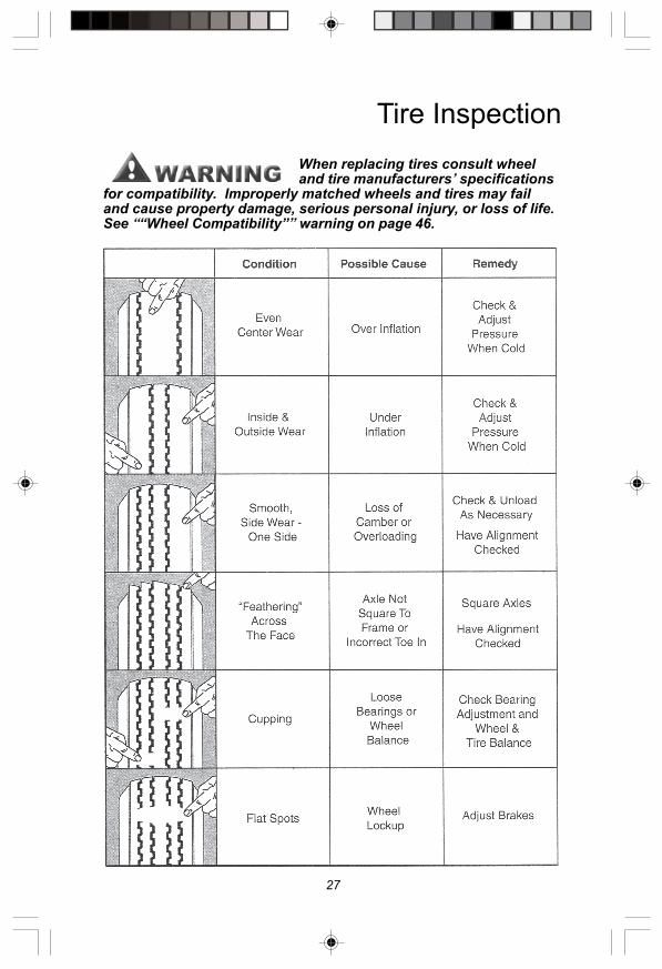
Tire Inspection
When replacing tires consult wheeland tire manufacturers’ specifications
for compatibility. Improperly matched wheels and tires may failand cause property damage, serious personal injury, or loss of life.See ““Wheel Compatibility”” warning on page 46.

28
Troubleshooting
(Electric and Hydraulic Brakes)The most common reason for poor brake performance is improper brakeadjustment. The first step in correcting brake problems is to adjust thebrakes. (See pages 13-14.) This standard maintenance should beperformed according to the schedule on pages 8-9.
The second most common problem is faulty, improperly installed orimproperly used wiring, electrical components, hydraulic lines andactuation components. These components are not supplied or installedby AL-KO Kober but can greatly affect the performance of the brakes.
If none of the brakes are working, they probably have no power. If allof the brakes experience the same problem it is probably caused by animproper signal to the brakes. Possible causes include operator error,improper synchronization, faulty controller, break-away switch oractuator, and any wiring or plumbing problem. The first step in isolatingbrake problems is to identify the amount of power or pressure going tothe brakes.
System voltage is measured at the magnets by connecting a voltmeter to the magnet lead wires. Connect the trailer wire connector tothe tow vehicle. The engine of the tow vehicle should be running. Thevoltage should start at 0 volts. As the controller bar is slowly actuated, itshould gradually increase to about 12 volts. If the increase is notgradual the brakes would apply instantaneously. The lower thethreshold voltage the smoother the brakes will apply.
Use either alligator clips or volt/
ohm meter probes.
Avoid working in wet conditions. Although you are not
likely to get seriously shocked by 12 volt D.C. current, it
can create a spark and ignite anything flammable.
System amperage is the amperage beingdrawn by all brakes on the trailer. Singlemagnet amperage can be measured with anammeter attached at the magnet lead wires.Follow procedure above. Each magnet shoulddraw about 3 amps at 12 volts. To check thetotal system the controller output to the brakesmust be disconnected and the ammeter putinto series in the circuit. With magnets cold(70o F), the ammeter should read about 3amps for each brake or 12 amps for a tandemaxle trailer (4 brakes). (Amperage is affectedby the length and gauge of wire betweenammeter and brake as well as between thepower source and brakes.)

29
Troubleshooting
(Electric and Hydraulic Brakes)Many brake problems result from faulty wiring, plumbing or a faulty
component in the circuit. AL-KO Kober does not supply or install these
components. For electrical or plumbing problem assistance contact the
trailer manufacturer, dealer, or component (eg. brake controller)
manufacturer.
Cause Procedure
Ineffective or
Weak Brakes
Brakes are
Overloaded
Electrical Component
or Wiring Problem
Improperly Set or
Defective Controller
or Actuator
Improper Brake
Adjustment
Worn, Damaged or
Contaminated Linings
Worn or Faulty Brake
Magnet
Worn Brake Drums
Adjust Load
See Page 10
Electrical Problem
Troubleshoot Circuit
Repair or Replace
Adjust Brakes
See Page 13-14
Replace Linings
See Pages 15-17
Replace Magnet
See Pages 18-20
Replace Drum
See Page 23-25
Improperly Set or
Defective Controller
Cracked Brake
Drums
Improper Wiring or
Ground
Worn, Damaged or
Contaminated Linings
Intermittent or
Surging Brakes
Repair or Replace
Replace Drum
See Pages 23-25
Electrical Problem
Identify & Remedy
Replace Linings
See Pages 15-17
Improper Function of
Wheel or Master
Cylinder
Repair or Replace
Defective Cylinder
Air Trapped in
Hydraulic LinesBleed Lines

30
Troubleshooting
Improperly Set or
Defective Controller
or Actuator
Corroded Brake
Assemblies
Damaged or Worn
Brake Parts
Improper Brake
Adjustment
Dragging Brakes
Repair or Replace
Replace Brakes
See Page 13-14
Replace Parts
See Pages 13-25
Adjust Brakes
See Page 13-14
Cause Procedure
No Brakes
Defective Circuit
Breaker
Open or Short Circuit
Improper Wiring or
Ground
Improperly Set, or
Defective Controller
or Actuator
Improper Resistor
Function
Faulty Trailer/Tow
Vehicle Connector
Improper Brake
Adjustment
Electrical Problem
Identify & Correct
Electrical Problem
Identify & Correct
Electrical Problem
Identify & Correct
Repair or Replace
Electrical Problem
Identify & Correct
Electrical Problem
Identify & Correct
Adjust Brakes
See Page 13-14
Worn or Defective
MagnetsReplace Magnets
See Pages 18-20
Broken or Kinked
Hydraulic LineRepair or Replace
Trapped Line
Pressure
Repair or Replace
Defective Line or
Actuation Component

31
Troubleshooting
Noisy Brakes
Worn, Damaged or
Contaminated Linings
Weak or Broken
Shoe Return Spring
Bent Brake Backing
Plate
Worn or Improperly
Adjusted Bearings
Worn or Damaged
Magnets
Improper Brake
Adjustment
Replace Linings
See Pages 15-17
Replace Spring
See Pages 15-17
Replace Brake
See Pages 13-14
Replace or Correct
See Pages 21-22
Replace Magnet
See Pages 18-20
Adjust Brakes
See Page 13
Grabbing or
Locking Brakes
Improperly Set or
Defective Controller
Improper or Defective
Variable Resistor
Loose or Worn Wheel
Bearings
Brakes Under
Adjusted
Loose or Broken
Brake Components
Worn, Damaged or
Contaminated Linings
Repair or Replace
Electrical Problem
Identify & Replace
Adjust or Replace
See Pages 21-22
Adjust Brakes
See Page 13-14
Replace
See Pages 13-25
Replace Linings
See Pages 15-17
Inadequate
LubricationApply Light Film Lubriplate
See Page 16
Cause Procedure

32
Leaf Spring Suspension
All suspension components should be visually inspected at least every
6,000 miles or 6 months. Check for loose fasteners and torque to
proper values.
Slipper Suspension
See “Lifting Trailer” instructions onpage 12. Failure to adhere to these
instructions could result in property damage, serious personalinjury, or loss of life.
Improper torque can cause componentfailure and the axles to becomedetached from the frame. This could
result in property damage, serious personal injury, or loss of life.
Description
MINIMUM MAXIMUM
UB or B
Spring Eye Bolt 225 Ft. Lbs 275 Ft. Lbs.
Equalizer 375 Ft. Lbs. 425 Ft. Lbs
TORQUE VALUES
Torque (Ft. Lbs.)
120 Ft. Lbs.
Spring Hanger Equalizer U-Bolt Tie Plate
Follow the procedures outlined on page 12 for “Service Preparation”.
Place suitable blocks under the axle beam. The blocks are only to support
the axle weight once components are disconnected. Frame must besupported as outlined in “Service Preparation” on page 12.
Disassemble the U-Bolts, nuts and tie plates and rest the axle assembly on
the blocks.
Replace axle, springs, spring eye bushings, equalizers and/or fasteners
as required.
Reinstall repaired or replaced parts using proper torque values.
Although routine lubrication is not required, pivotal suspension points may be
greased if desired.
33
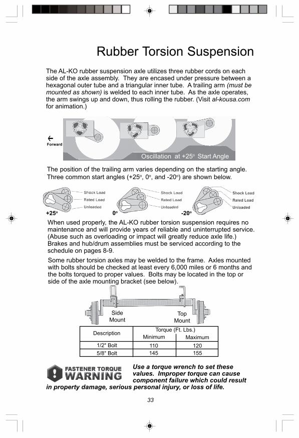
Rubber Torsion Suspension
When used properly, the AL-KO rubber torsion suspension requires nomaintenance and will provide years of reliable and uninterrupted service.(Abuse such as overloading or impact will greatly reduce axle life.)Brakes and hub/drum assemblies must be serviced according to theschedule on pages 8-9.
The AL-KO rubber suspension axle utilizes three rubber cords on eachside of the axle assembly. They are encased under pressure between ahexagonal outer tube and a triangular inner tube. A trailing arm (must bemounted as shown) is welded to each inner tube. As the axle operates,the arm swings up and down, thus rolling the rubber. (Visit al-kousa.comfor animation.)
Some rubber torsion axles may be welded to the frame. Axles mountedwith bolts should be checked at least every 6,000 miles or 6 months andthe bolts torqued to proper values. Bolts may be located in the top orside of the axle mounting bracket (see below).
Side
MountTop
Mount
The position of the trailing arm varies depending on the starting angle.
Three common start angles (+25o, 0o, and -20o) are shown below.
Use a torque wrench to set thesevalues. Improper torque can causecomponent failure which could result
in property damage, serious personal injury, or loss of life.
Oscolation at +25o Start Angle
0o -20o
Oscillation
Forward
DescriptionMinimum Maximum
110 120
145 155
1/2" Bolt
5/8" Bolt
Torque (Ft. Lbs.)
+25o

34
Electric Brake K-80 / 8K Axle
No. Brake Part Description AL-KO HayesPart No. Part No.
0 RH Brake Assembly Complete 568132 —0 LH Brake Assembly Complete 568133 —1 Brake Mounting Stud, 3/8" - 24 363989 0907612 Shoe Hold Down Pin 568094 096611063 Plug Adjuster Slot 568089 0969324 Backing Plate Assembly — —5 Brake Lock Washer 3/8" 363334 3633346 Brake Mounting Nut 3/8" - 24 363333 0906257 RH Lever Assembly 568113 —7 LH Lever Assembly (Shown) 568114 —8 Clip, Wire & Magnet 568092 096808159 Strain Relief, Wire 568090 09271510 Magnet Spring 568103 09652211 Magnet Assembly 568111 56811112 Primary Shoe & Lining 568150 —13 Secondary Shoe & Lining 568151 —14 Shoe Hold Down Spring 568093 1044315 Shoe Retract Spring 568096 09652716 Adjuster Screw Assembly 568110 6027240116 Adjuster Screw Socket 568086 6027280117 Adjuster Screw Spring 568095 096526

35
Hub & Drum Assembly
K-80 / 8K Axle
No. Hub Part Description AL-KO HayesPart No. Part No.
18 Grease Seal 568120 —19 Inner Bearing Cone 28580 568125 09373720 Inner Bearing Cup 28521 568152 09373621 Hub & Drum w/Cups & Studs — —21 A 8 on 6.5" Bolt Circle 9/16" Studs K80 568141 —21 B 8 on 6.5" Bolt Circle 5/8" Studs K80 568142 —22 A Wheel Stud 9/16" - 18 363906 0925110022 B Wheel Stud 5/8" - 18 363910 09073723 A Wheel Nut 9/16" - 18 60° Cone 363895 09064023 B Wheel Nut 5/8" - 18 90° Cone 363698 09064324 Outer Bearing Cup 25520 568153 09370125 Outer Bearing Cone 25580 568130 09375126 Spindle Washer 1 1/2" 568136 09052527 Cotter Pin 568137 09190328 Spindle Nut 568135 09062329 Grease Cap 568124 —

36
Electric Brake
T-80, D-80, H-80 / 8K Axles
No. Brake Part Description AL-KO HayesPart No.
0 RH Brake Assembly complete (shown) 363602 602043060 LH Brake Assembly Complete 363601 602044061 Brake Attaching Nut, 1/2" - 20 568235 0906172 Dust Cover 568289 096946123 Shoe Hold Down Cotter Pin 568224 0919054 Shoe Hold Down Nut 568233 0906476 Shoe Hold Down Washer 568232 0905417 Pin Retaining “C” Clip 568249 0968068 Backing Plate Assembly — —9 Brake Mounting Stud 1/2" - 20 568250 0925152310 Strain Relief Adapter 568258 09693711 Strain Relief 568243 09271512 Self Adjuster Pivot Pin 568238 09661813 RH Auto Adjust Lever (shown) 568253 09632113 LH Auto Adjust Lever 568254 09632214 Self Adjuster Bias Lever 568241 09632315 Self Adjuster Spring 568239 09652316 Shoe and Lining Kit K363924 K36392417 Shoe Hold Down Bolt 568227 09075918 Cable Assembly Self Adjuster 568245 09693619 Cable Guide 568246 575820 Shoe Retract Spring 568226 560921 Self Aduster Socket 568272 60272322 RH Adjuster Assembly (shown) 568256 60271722 LH Adjuster Assembly 568257 60271823 Slipper Block 568242 09693924 RH Lever Assembly (shown) 568236 60313524 LH Lever Assembly 568237 60313625 Magnet Spring 568240 09652226 Lever Retaining Washer 568248 09054027 Lever Retaining “E” Clip 568247 09680328 Magnet — —29 Magnet Assembly Kit K568252 K568252
contains #10,#11,#25,#28

37
Hydraulic Brake
T-80, D-80, H-80 / 8K Axles
No. Brake Part Description AL-KO HayesPart No. Part No.
0 LH or RH Brake Assembly 568004 602068031 Dust Cover 568289.3 —1 Dust Cover — 096946122 Shoe Hold Down Cotter Pin 568224 091905013 Shoe Hold Down Nut 568233 0906474 Shoe Hold Down Belleville Washer 568225 5682255 Shoe Hold Down Washer 568232 0905416 Brake Attaching Nut 1/2" - 20 568235 0906177 Bolt 3/8" – 16 x 3/4" 568231 0907188 Lock Washer 3/8" 363334 0905329 Backing Plate Assembly — —10 Shoe Hold Down Bolt 568227 09075911 Shoe & Lining Kit K363925 K36392512 Push Rod (Wheel Cylinder) 568228 0955000313 Cylinder-Wheel 568296 0955000214 Self-Adjuster Assembly 568259 6027300114 A Rack — —14 B Clevis Pin 3/8" x 3/4" — —14 C Pawl — —
14 D Spring-Pawl — —14 E Sleeve Assembly — —14 F Cotter Pin 5/32" x 3/4" — —15 Shoe Retract Spring 568226 0965291216 Connector-Brake Line, (not shown) 568230 09344501

38
Electric Brake
10K & 12K Axles
No. Brake Part Description AL-KO HayesPart No. Part No.
0 RH Brake Assembly Complete 568255.1 568255.10 LH Brake Assembly Complete 568255.2 568255.21 Brake Attaching Nut, 1/2" – 20 568235 0906172 RH Dust Cover Assembly (AL-KO only) 568229.1 —2 LH Dust Cover Assembly (AL-KO only) 568229.2 —2 A Upper RH Dust Cover (Hayes only) — 096934022 B Upper LH Dust Cover (Hayes only) — 096934032 C Lower 1/2 Dust Cover (Hayes only) — 096934013 Shoe Hold Down Cotter Pin 568224 0919054 Shoe Hold Down Nut 568233 0906476 Shoe Hold Down Washer 568232 0905417 Pin Retaining “C” Clip 568249 0968068 Backing Plate Assembly — —9 Brake Mounting Stud 1/2" - 20 568250 09075510 Strain Relief Adapter 568258 09693711 Strain Relief 568243 09271512 Self Adjuster Pivot Pin 568238 09661813 RH Auto Adjust Lever (shown) 568253 09632113 LH Auto Adjust Lever 568254 09632214 Self Adjuster Bias Lever 568241 09632315 Self Adjuster Spring 568239 09652316 Shoe & Lining Kit K568251 K56825117 Shoe Hold Down Bolt 568227 09075918 Cable Assembly 568245 09693619 Cable Guide 568246 575820 Shoe Retract Spring 568226 560921 Self Adjuster Socket 568272 60272322 RH Adjuster Assembly (shown) 568256 60271722 LH Adjuster Assembly 568257 60271823 Slipper Block 568242 09693924 RH Lever Assembly (shown) 568236 6031350124 LH Lever Assembly 568237 6031360125 Magnet Spring 568240 0965291526 Lever Retaining Washer 568248 09054027 Lever Retaining “E” Clip 568247 09680328 Magnet — —29 Magnet Assembly Kit K568252 K568252
contains #10,#11,#25,#28

39
Hydraulic Brake
10K & 12K Axles
No. Brake Part Description AL-KO HayesPart No. Part No.
0 LH or RH Brake Assembly 568213 602068011 Dust Cover Assembly (AL-KO) 568229 —1 Dust Cover Lower Half (Hayes only) — 096934011 Dust Cover Upper Half (Hayes only) — 096934042 Shoe Hold Down Cotter Pin 568224 091905013 Shoe Hold Down Nut 568233 0906544 Shoe Hold Belleville Washer 568225 5682255 Shoe Hold Down Washer 568232 0905416 Brake Attaching Nut 1/2" - 20 568235 0906177 Bolt 3/8" – 16 x 3/4" 568231 0907188 Lock Washer 3/8" 363334 0905329 Backing Plate Assembly — —10 Shoe Hold Down Bolt 568227 09075911 Shoe & Lining Kit K568234 K56823412 Push Rod 568228 0955000313 Cylinder-Wheel 568214 0955000114 Self-Adjuster Assembly 568259 6027300114 A Rack — —14 B Clevis Pin 3/8" x 3/4" — —14 C Pawl — —14 D SpringPawl — —14 E Sleeve Assembly — —14 F Cotter Pin 5/32" x 3/4" — —15 Shoe Retract Spring 568226 0965291216 Connector-Brake Line, Not Shown 568230 09344501

40
Hub & Drum Assembly
T-80, D-80, H-80 / 8K Axles
No. Hub Part Description AL-KO HayesPart No. Part No.
1 Oil Seal 370219BG (National) 568284 091033092 Inner Bearing Cone 25580 363196 0937033 Inner Bearing Cup 25520 363911 0937014 Hub & Drum 9/16" Stud 4.75 pilot 363694 090806444 A Hub & Drum 5/8" Stud 4.75 pilot 363697 090806545 Wheel Stud 9/16" - 18 363906 092511005 A Wheel Stud 5/8" - 18 x 2.75" 363910 097376 Wheel Nut 9/16" - 18 60° Cone 363895 0906406 A Wheel Nut 5/8" - 18 90° Cone 363698 0906437 Outer Bearing Cup, 02420 363917 0937448 Outer Bearing Cone, 02475 363604 0937459 Spindle Washer 568326 09050910 Spindle Nut 363257 0906010111 Cotter Pin 363258 09190112 Oil Cap Assembly K363587 K36358712 Oil Cap Assembly (Hayes prior to 1997) K363587.1 K363587.112 A Gasket, Oil Cap 568298 0910350112 B Oil Cap Plug 568223 092126

41
Hub & Drum Assembly
General Duty 10K Axle
No. Hub Part Description AL-KO HayesPart No. Part No.
1 Oil Seal B370352BG (National) 568303 0910302 Inner Bearing Cone, 28580 568125 0937373 Inner Bearing Cup, 28521 568152 093736
♦ 4 Armature Plate 568261 092406♦ 4 A Flat Head Bolt, 1/4" – 20 568263 09070301♦ 4 B Lock Washer, 1/4" 568264 090502♦ 4 C Hex Nut, 1/4" – 20 Flat Face 568265 090610♦♦ 5 Hub & Drum Flat Face 4.88 pilot 568270 09080572✶ 5 A Hub & Drum Coined 4.75 pilot 568704 09080567♦✶♦✶5 A Hub & Drum (F.F.) 4.75 pilot for dual and/or single wheels 568353 09080587♦✶♦✶6 Wheel Stud, 5/8" x 2 3/4" for Single & Flat Face 363910 090737♦✶♦✶7 Dual Wheel Nut – Swiveling Flange 5/8" - 18 568216 09065602✶ 7 A Dual Wheel Nut – Fixed Flanged (Coined) 568703 090633✶✶ 7 B Single Wheel Nut 5/8" - 18 90° Cone 363698 090643
8 Outer Bearing Cup, 25520 568153 0937019 Outer Bearing Cone, 25580 568130 09375110 Spindle Washer 568136 09052511 Spindle Nut 568135 09062312 Cotter Pin 568137 09190313 Oil Cap Assembly K568220 K56822013 A Gasket 568297 0910350213 B O-Ring 568222 1069313 C Oil Cap Plug 568223 09212614 Wheel Clamp Ring for 5/8" Studs 568348 —
♦♦ Used with Flat Face Wheels ♦ For Electric Brake Only✶ Used with Coined Wheel ✶✶ Used with Single Wheel and/or Clamp Ring

42
No. Hub Part Description AL-KO HayesPart No. Part No.
8 STUDS ON 6.50 DIAMETER (flat faced shown)1 Oil Seal B370014BG (National) 568217 0910232 Inner Bearing Cone JM511946 568219 0937173 Inner Bearing Cup JM 511910 568267 0937164 Armature Plate 568261 0924064 Armature Plate w/ Exciter Ring Air Brake — 51064 A Flat Head Bolt, 1/4" - 20 568263 090703014 B Lock Washer, 1/4" 568264 0905024 C Hex Nut, 1/4" - 20 568265 0906105 Hub & Drum (Flat Face) Elec/Hyd 5/8" Stud 568260 090894015 Hub & Drum (Coined) Elec/Hyd 5/8" Stud — 0908715 Hub & Drum (Flat Face) Air 5/8" Stud — 090894115 Hub & Drum (Coined) Air 5/8" Stud — 090806385 Hub & Drum (Flat Face) Elec/Hyd 3/4" Stud — 090894085 Hub & Drum (Coined) Elec/Hyd 3/4" Stud — 09080631
* 5 Hub & Drum (Flat Face) Air 3/4" Stud — 09089415** 5 Hub & Drum (Coined) Air 3/4" Stud — 09080637
5 A Hub & Drum Mounting Bolt 568262 0907455 B Hub Assembly (Flat Face) 5/8" Stud 568215 090893715 B Hub Assembly (Coined) 5/8" Stud — 090884
* 5 B Hub Assembly (Flat Face) 3/4" Stud — 09089372** 5 B Hub Assembly (Coined) 3/4" Stud — 09080630
5 C Dual Wheel Nut Swiveling Flange 5/8" 568216 090656025 C Swiveling Flange Nut 3/4" (F.F.) 1-5/8" Flange — 090656035 D Wheel Stud 5/8" - 18 x 2.75" 363910 0907375 D Wheel Stud 3/4" - 16 x 3" — 090771155 E Drum Only (Air) — 090904025 E Drum Only Elec/Hyd Less Armature Plate 568699 0904046 B Flange Nut, 3/4" (Coined) — 090651057 Outer Bearing Cup JM205110 568266 0937148 Outer Bearing Cone JM205149 568218 09371510 Cotter Pin 568137 09190311 Spindle Washer 1 1/2" 568136 09052512 Spindle Nut 568135 09062313 Oil Cap Assembly K568220 K56822013 A O-Ring 568222 1069313 C Plug 568223 09212613 B Gasket 568297 09103502
Hub & Drum Assembly
Heavy Duty 10K & 12K Axle

43
No. Hub Part Description AL-KO HayesPart No. Part No.
* 14 Wheel Clamp Ring for 5/8" Studs 568348 —15 Wheel Nut 5/8" - 18 90° Cone 363698 —
6 STUDS ON 8.75 DIAMETER5 Hub Drum Assembly (Air) — 090807245 B Hub — 090807865 D Stud 3/4" x 3 1/2" — 090771165 F Swiveling Flange Nut - 2" Flange — 090651149 Wheel Stud Sleeve — 09141905
HUB WITH DOUBLE CAP NUTS5 B RH Hub — 090835105 B LH Hub — 090835115 D Stud 3/4" RH — 090771525 D Stud 3/4" LH — 090771536 A Inner Cap Nut RH (Steel Wheels) — 090651106 A Inner Cap Nut LH (Steel Wheels) — 090651116 B Outer Cap Nut RH (Steel Wheels) — 090651126 B Outer Cap Nut LH (Steel Wheels) — 09065113
10 STUDS ON 8.75 DIAMETER5 Hub Drum Assembly (Air) — 090807215 B Hub — 090807835 D Stud 3/4" — 090771165 F Swiveling Flange Nut - 2" Flange — 090651149 Wheel Stud Sleeve — 09141905
HUB WITH DOUBLE CAP NUTS5 B RH Hub — 090835305 B LH Hub — 090835315 D Stud 3/4" RH — 090771525 D Stud 3/4" LH — 090771536 A Inner Cap Nut RH (Steel Wheels) — 090651106 A Inner Cap Nut LH (Steel Wheels) — 090651116 B Outer Cap Nut RH (Steel Wheels) — 09065112
6 B Outer Cap Nut LH (Steel Wheels) — 09065113
*Used with flat face wheels **Used with coin in-out wheels (replacement only)

44
Hub & Rotor Assembly
10K & 12K Disc Brake Axles
No. Hub Part Description AL-KO HayesPart No. Part No.
8 Studs on 6.50" Diameter1 Oil Seal B370014BG (National) 568217 0910232 Inner Bearing Cone JM511946 568219 0937173 Inner Bearing Cup JM511910 568267 0937164 Hub & Rotor Flat Face 5/8" 09089421 090894214 Hub & Rotor Coined 5/8" 090814 0908144 Hub & Rotor Flat Face 3/4" 09089425 090894254 Hub & Rotor Coined 3/4" 09080632 090806325 Wheel Stud 5/8" - 18 363910 0907375 A Wheel Stud 3/4" - 16 x 3" — 09077115
✶ 6 5/8" Swiveling Flange Nut 568216 090656026 A 5/8" 90° Cone Wheel Nut 363698 090643
✶✶6 B 5/8" Flanged Wheel Nut — 090633✶✶6 B 3/4" Flanged Wheel Nut — 09065105✶ 6 3/4" Swiveling Flange Nut - 1 5/8" Flange — 09065603
7 Outer Bearing Cup JM205110 568266 0937148 Outer Bearing Cone JM205149 568218 0937159 Cotter Pin 568137 09190310 Spindle Washer 1 1/2" 568136 09052511 Spindle Nut 568135 09062312 Plastic Oil Cap Assembly K568220 K56822012 A O-Ring 568222 1069312 B Gasket 568297 0910350212 C Rubber Plug 568223 09212613 Wheel Clamp Ring for 5/8" Studs 568348 —
✶ Use with Flat Face Wheels ✶✶ Use with Coined Wheel

45
Contact OSHA for details concerningthe dangers and proper handling of
asbestos and non-asbestos fibers.
Contact OSHA for procedures to reduce exposure to asbestos fiberdust, a cancer and lung disease hazard. Because some brake liningscontain asbestos, workers who service brakes must understand thepotential hazards of asbestos and precautions for reducing risks.Exposure to airborne asbestos dust can cause serious and possiblyfatal diseases, including asbestosis (a chronic lung disease) andcancer, principally lung cancer and mesothelioma (a cancer of the liningof the chest or abdominal cavities). Some studies show that the risk oflung cancer among persons who smoke and who are exposed toasbestos is much greater than the risk for non-smokers. Symptoms ofthese diseases may not become apparent for fifteen or more years afterthe first exposure to asbestos.
Workers must use caution to avoid creating and breathing dust whenservicing brakes. Specific recommended work practices forreducing exposure to asbestos should be obtained from OSHA.Consult your employer’s procedures for more details.
Following is a partial list of procedures that may apply.
Separate Work Areas. Whenever feasible, service brakes in aseparate area away from other operations to reduce risks tounprotected persons.
Respiratory Protection. Wear a respirator equipped with a high-efficiency (HEPA) filter approved by NIOSH or MSHA for use withasbestos at all times when servicing brakes.
Compressed Air. Never use compressed air by itself, dry brushing,or a vacuum not equipped with HEPA filter when cleaning brake partsor assemblies.
Worker Clean-Up. After servicing brakes, wash your hands beforeyou eat, drink or smoke. Shower after work. Do not wear work clotheshome. Use a vacuum equipped with HEPA filter to vacuum work clothesafter they are worn. Launder them separately. Do not shake or usecompressed air to remove dust from work clothes.
Waste Disposal. Dispose of discarded linings, used rags, cloths andHEPA filters with care such as in clear plastic bags. Consult applicableEPA, state and local regulations on waste disposal.
Asbestos and Non-Asbestos
Fiber Warning

46
Unless otherwise specified, AL-KO Kober axles are built using our standard
4.88" diameter pilot for flat face wheels and swiveling flange nuts, which are supplied with
the axles.
The following optional wheel pilots are available but must be specified at the time of order.
4.88" diameter, flat face hub for use with dual flat face wheels, a tension
ring and 5/8" 90 degree wheel nuts.
4.75" diameter, coined hub for use with dual, flat face wheels, a tension
ring and 5/8" 90 degree wheel nuts.
4.75" diameter, coined hub for use with dual flat face wheels using
swiveling flange nuts.
4.75" diameter, coined hub for use with single coined wheels using 5/8"
90 degree wheel nut.
4.75" diameter, coined hub for coined in and out wheels as used on
older axles and using a flange cap nut.
Wheel Mounting & Compatibility
AL-KO Kober Corporation manufactures hubs and drums that are compatible with many
wheels used in the trailer industry that have matching bolt patterns. AL-KO does not
manufacture wheels, nor do they recommend a specific wheel for compatibility with the
hubs and drums they manufacture. The wheel manufacturer should be contacted for proof
of compatibility before use.
Be sure to read and understand the followinginformation before installing wheels.
Installation of wheels which are not compatible with the axle assemblycould result in wheel separation which can lead to property damage,serious personal injury, or loss of life.
Customers using wheels which have not been tested for compatibility, must doso to insure they are compatible with AL-KO hubs and drums. Elements ofcompatibility include but are not limited to:
✓ Diameter of the hub mounting surface.
✓ Stud length and diameter.
✓ Location and number of studs.
✓ Center hole diameter for the wheel.
✓ Wheel mounting offset from the rim center.
✓ Rated capacity of the wheel.
✓ Wheel fastener torque.
✓ Wheel nut size and shape.
✓ Impact of the use of any wheel accessories (such as
decorative center caps) that could affect the proper seating of the wheel
to the hub surface.
A cornering fatigue test based on SAE J1095/SAE J267 and field tests are recommended
for all wheels and rims to be installed on AL-KO hubs and drums. These tests require
special expertise and equipment. Persons without such equipment or expertise should
contact the wheel manufacturer to verify that a wheel is compatible with the AL-KO hubs
and drums. AL-KO Kober Corporation is not responsible for wheels or rims that are
installed on their hubs or drums.

47
Limited Warranty
AL-KO KOBER CORPORATION warrants to the original purchaser of its products that allworkmanship and materials utilized in the construction of said parts by AL-KO KOBERCORPORATION will be free from substantial defects in material and workmanship for a period ofone (1) year from the date of purchase of said product, with the following exception: In place of theone (1) year limited warranty, rubber suspension axles manufactured by AL-KO KOBERCORPORATION are warranted as provided herein for a period of five (5) years.
DISCLAIMER: THIS WARRANTY IS IN LIEU OF ALL OTHER WARRANTIES, EXPRESSEDOR IMPLIED, INCLUDING BUT NOT LIMITED TO THE IMPLIED WARRANTIES OFMERCHANTABILITY AND FITNESS FOR A PARTICULAR PURPOSE, WHICH AREEXPRESSLY DISCLAIMED. THERE ARE NO WARRANTIES THAT EXTEND BEYOND THEFACE HEREOF.
Exclusions: In addition thereto, the following items are specifically excluded from coverage by theterms of this Limited Warranty to wit: damage or defects which result from accident, collision,abuse, normal wear and tear, neglect, improper maintenance, improper installation, alignment,improper wheel nut torque, hub imbalance or any damage caused thereby, alteration, oroverloading.
This warranty extends only to the original installation of AL-KO KOBER CORPORATION’sproducts and is not transferable to any other parties. AL-KO KOBER CORPORATION does notassume responsibility for any promises, warranties, or representations beyond those expressed inthis written document.
AL-KO KOBER CORPORATION’s obligations and undertakings in this warranty are limited to therepair or replacement, at its option, of any defective products manufactured by AL-KO KOBERCORPORATION, and in no event shall AL-KO KOBER CORPORATION be liable for anyconsequential, indirect, or incidental costs or damages, including loss of use or any other damagesof any type arising out of such defective parts or products.
Some states do not allow exclusion or limitation of incidental or consequential damages or impliedwarranties. In addition you may have other rights which vary from state to state. Any terms of thiswarranty which conflict with the laws of your state are deemed amended by the law of your state. Inthe event you believe any product manufactured by AL-KO KOBER CORPORATION has a defector malfunction or failure to conform to this written warranty, you should contact AL-KO KOBERCORPORATION at one of its service location addresses:
If you feel that a repair should be covered under warranty, be sure to contact AL-KO beforehaving any warranty work performed.In accordance with the following procedure:
1. Contact the closest service location. 2. A “Returned Merchandise Authorization” (RMA) number will be assigned to you. 3. Return the product to AL-KO KOBER CORPORATION at the service location chosen
by you, freight prepaid. PLEASE RETURN ONLY THE DEFECTIVE PART OR PARTS AS DIRECTED WITH APPROPRIATE PRECAUTIONS AGAINST DAMAGE.
4. Supply the following information with the returned merchandise: (a) Name, address, and telephone number of the original purchaser of the product
and include the date of purchase (b) Serial number and model or make of unit to which the axle is attached
(c) Serial number of the axle itselfAL-KO KOBER CORPORATION will replace or repair any defective products within a reasonableperiod of time and return them to you. If AL-KO KOBER CORPORATION determines there is nofailure to conform to this Limited Warranty, you will be notified to retrieve your product from theservice facility. AL-KO KOBER CORPORATION assumes no responsibility for merchandise notretrieved within thirty (30) days of notification to the original purchaser or owner of the product.This warranty has been drafted to comply with federal legislation and rules promulgated by theFederal Trade Commission. You may have additional legal rights in addition to those set forth in thiswritten Limited Warranty.
21611 Protecta Dr.
Elkhart, IN 46516
(574) 294-6651
301 N. Kennedy
Shawnee, OK 74801
(405) 273-9315
4250 E. Lowell St.
Ontario, CA 91761-1529
(909) 390-7171

48
Service Record
See An Authorized Dealer or Service Center
This section is designed to allow your dealer or qualified service
technician to record that the recommended maintenance was completed
at the appropriate mileage intervals. Be sure to ask your service
provider to record the date and type of service performed.
continued

49
Service Record
continued

50
Service Record
continued
51
Service Record

www.al-kousa.com Information contained in this publication was in effect at the time the publication was approved
for printing and is subject to change without notice or liability.
AL-KO Manufacturing Facilities
AL-KO Distributors
Repair Facilities
Elkhart, IN574-294-6651
Shawnee, OK405-273-9315
Baldwyn, MS662-365-5566
Ontario, CA909-390-7171• • •
7981:ALKO Owner's Manual Replacement Pages 4/16/08 9:54 PM Page 1