6.RE MAXIMA DIESEL 12.cdr - global bajaj
79
cover User’s Guide RE WORLD’S NO.1 Three Wheeler
-
Upload
khangminh22 -
Category
Documents
-
view
0 -
download
0
Transcript of 6.RE MAXIMA DIESEL 12.cdr - global bajaj

cover
User’s Guide
RE
WORLD’S NO.1 Three Wheeler

IdentificationIdentification1 De compression knob
4 Speedometer & Odometer
7 Ignition parking switch
3 Engine stop knob
6 Hazard switch
5 Switch LH
8 Switch RH
2 Reverse knob
9 Tell Tale Indicator
10 Mobile Charger
2 Low oil pressure indicator
5 High beam indicator
1 Battery charge indicator
3 LH & RH Turn indicator
6 Neutral indicator
4 glow plug indicator
7 Fuel level indicator
8 Speedometer and odometer
A
1
2
3
4
6
5
7
8
1 2 3
5
10
94
8
76

RE
1B
Dear Customer,
We Thank you for choosing the “ ”, which would give you ‘Value for Money, For Years’. We are sure that you will be happy with its performance.
The salient features of this vehicle are 5 speed gear box, dry clutch (car type), stronger chassis & body.
Before driving, please read this User's Guide carefully to familiarize yourself with the mechanism and the controls of the vehicle.
To maintain your autorickshaw in perfect running condition and to deliver consistent performance, we earnestly advise you to avail periodic services, at Bajaj distributor / dealers.
You can entrust Bajaj distributor / dealers, who are well equipped with all necessary facilities, skill sets and trained manpower for servicing and repairs of your “ ”. In the event of going to a local garage, always insist on Genuine Bajaj Spares to ensure safety, performance and longer life of your vehicle.
Should you require any additional information, please approach Bajaj distributor / dealer. If necessary, you may also write to selling distributor / dealer, with relevant details like Registration no. Chassis no., Engine no., Date of purchase, Kms. run, name of selling distributor / dealer and your contact numbers.
Finally, may we request you to give your vehicle proper care and regular maintenance, as described in this manual. We are sure this will offer you a long trouble-free ownership experience.
Wishing you happy driving for many years.
International Business
BAJAJ AUTO LIMITED
Akurdi Pune - 411 035 India
RE MAXIMA Diesel
RE MAXIMA Diesel

RE
Chassis No.:
Engine No.:
• The above vehicle was inspected/test driven by me/my representative at the time of taking delivery and it was found to be acceptable and free from any operational or visual defects.
Place :
Date : Customer's Signature
(TO BE RETAINED BY SELLING DEALER)
F
M
Delivery Certificate
C

REDelivery Certificate
Date of Sale :
Customer’s Name :
Address :
Phone No. :
Dealer’s Name :
Address :
D

IMPORTANT
WARNING / CAUTION / NOTE
Please read this manual and follow its instructions carefully. To emphasize special information, the symbol and the words WARNING, CAUTION and NOTE have special meaning. These special meaning apply except when laws or regulations require that the single words be used with a different meaning. Pay special attention to the messages highlighted by these signal words.
Indicates a potential hazard that could result in death or injury.
WARNING
Indicates a potential hazard that could result in vehicle damage.
NOTE
Indicates special information to make maintenance easier or instruction clear.
Do not modify your vehicle. Modification could adversely affect safety, handling, performance or durability & may violate governmental regulations.
WARNING
Severe damage may be caused by the use of either poor quality fuel or lubricants not recommended by BAL.
WARNING
CAUTION
RE
E

REIndex
Index
1. Before Driving 1
2. Operating your vehicle 35
3. Preventive maintenance 45
4. Pre Delivery Inspection Check Points 68
5. Notice
F

RE
1
Before Driving
Index
1.1. Locks
1.2. Mirrors
1.3. Handle bar and Dashboard
1.4. Other controls
1.5. Other Important parts location
1.6. Identification data
1.7. Technical Specification
1. Before Driving

RE1.1 Locks
Steering Lock Steering Lock
2
Steering Lock
• Steering lock is below dashboard.
Steering lock operation :
• Locking : Turn the Handle bar to LH side, rotate the key in anti-clockwise direction to align the lock position, push in and rotate clockwise. After confirming the locking of handle bar, take out the key from barrel.
• Un-locking : Turn the key anti-clockwise, move the handle bar a bit, the lock will pop backwards unlocking the steering lock

Glove box lock:To Unlock or lock glove box lock insert the key and rotate it clockwise or anticlockwise respectively.
Stereo Cover Lock:Lockable cover for stereo is provided on RH side of dashboard To Unlock or lock stereo cover lock insert the key and rotate it clockwise or anticlockwise respectively.
Glove Box Lock
Lock
Unlock
Unlock
Lock
Stereo Cover Lock
3
RE

Diesel Tank Cap lock :
• For filling diesel, open tank cap lock.
• To open the lock, insert the key & rotate it Clockwise.
• To close the lock, insert the key & rotate it Anticlockwise.
4
RE
Note
Never wrap a plastic or polythene cover on fuel tank mouth as this may lead to vaccum lock

RE1.2 Mirrors
Mirrors
Outside Rear View Mirror:
• Adjust the outside rear view mirror so that you can see the rear sides of your vehicle in the mirrors.
Be careful when judging the size or distance of a vehicle or other objects seen in the side convex mirror. Be aware that objects look smaller & appear farther away than when seen in a flat mirror.
WARNING
5

C
E
D
F
J
I
G
H
B
A
RE1.3 Handle Bar and Dashboard
A. Instrument cluster
B. Switch RH
C. Switch LH
D. Ignition parking switch
E. Mobile charger
F. De compression knob
G. Engine stop knob
H. Reverse knob
I. Hazard switch
J. Stereo switch
6

RE
7
1.3 A. Instrument Cluster
1. Battery charging indicator
2. Low oil pressure indicator
3. LH turn pilot indicator
4. Fuel gauge
5. Glow plug (heater) indicator
6. Hi beam indicator
7. Neutral indicator
8. RH turn pilot indicator
9. Speedometer and Odometer
E F1/2
10
20
30
km
km/h
4050
60
70
80
0 0 0 0 1 5
N
1
2
4
3
5
6
7
9
8

8
1. Battery Charging Indicator : This light will glow when the Ignition switch is switched ON and will go off after engine is started.
If this indicator glows continuously even after engine is started, it indicates that the battery is not getting charged.
In this case immediately contact the Distributor / Dealer.
2. Low oil pressure indicator : This indicator will glow when ignition key is turned 'ON' and will go off after engine is started.
If this indicator glows continuously even after engine is started, it indicates that the oil pressure is less inside the engine.
In this case check the oil level in engine and if it is ok, then contact the Distributor / Dealer.
1 2
RE
NOTEIf oil found less than “MIN” mark of dipstick, please top it up with API CH4 15W40 ( upto “MAX” mark) grade oil before starting the engine.
9
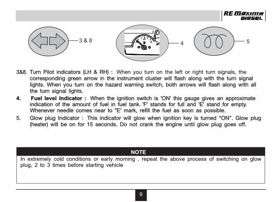
3 & 8
3&8. Turn Pilot indicators (LH & RH) :corresponding green arrow in the instrument cluster will flash along with the turn signal lights. When you turn on the hazard warning switch, both arrows will flash along with all the turn signal lights.
4. Fuel level Indicator : When the ignition switch is 'ON' this gauge gives an approximate indication of the amount of fuel in fuel tank. 'F' stands for full and 'E' stand for empty. Whenever needle comes near to "E' mark, refill the fuel as soon as possible.
5. Glow plug Indicator : This indicator will glow when ignition key is turned “ON”. Glow plug (heater) will be on for 15 seconds. Do not crank the engine until glow plug goes off.
When you turn on the left or right turn signals, the
54
RE
NOTEIn extremely cold conditions or early morning , repeat the above process of switching on glow plug, 2 to 3 times before starting vehicle

910
20
30
km
km/h
4050
60
70
80
0 0 0 0 1 5
10
6. Headlamp Hi-beam : When the Headlamp Hi-beam is ON this indicator will glow and give indication to the driver.
7 Neutral : Indicator light will glow as the Ignition switch is switched “ON” provided the vehicle is in Neutral gear. This light will go off as soon as the gear is engaged. This helps the driver to confirm Neutral position while starting and stopping the vehicle.
Note: Starter motor will not operate unless vehicle is in neutral and Decompression lever is pulled.
9. Speedometer : Indicates the vehicle speed in km/h
Odometer : The odometer records total distance the vehicle has covered.
N 76
RE

RE1.3 B. Switch RH
C
Switch R.H. It has 3 control switches for operating head lights, wiper and starting button• With ON/OFF switch ON PositionA. Light switch : It has following positions
: Head and Pilot lights “OFF”.: Parking, Tail and Tell Tale Indicators illumination lamps will be “ON”.: Head, Tail, and Parking lamps will be “ON”. Hi beam indication in Tell Tale Indicators will be
“ON”, if switch is in High Beam position.B. Wiper Motor switch : It has 2 positions.
ON : Wiper motor “ON”.OFF : Wiper motor “OFF”.
C. Start button : For Starting Engine.
Switch RH
A
B
11

RE1.3 C. Switch LH
Switch L.H.
A. Side indicator switch : It has 3 positions.
Center : All side indicator lights remain“OFF”.
LH : Front and Rear, LH side indicator lamps and LH turn pilot indicator will flash simultaneously.
RH : Front & Rear, RH side indicator lamps & RH turn pilot indicator
will flash simultaneously.
B. Dipper switch : It has two positions
Hi beam : Low beam :
C. Horn button : For sounding horn.
It has 3 control switches for operating indicator lights, dipper and horn button.
Switch LH
C
A B
12

RE1.3 D. Ignition - Parking Switch
WARNING
Always remove the ignition key when leaving the vehicle even for short time.
13
Ignition - Parking Switch
Ignition - Parking Switch• It is located on the dash board.• Insert the key and rotate it clockwise to make it on.• It has 3 positions :OFF : All electrical circuits OFF.PARKING : Parking light and hazard operation will be on (when respective switches on switch
board are on and key is in parking position.)ON : All Electrical circuits ON. Fuel Feed pump will be ON. (To be kept in this position when vehicle is being run).

RE1.3 F. Stop Knob
Engine Stop Knob
• It is located on the dash board below wiper motor indicated by “S”
• Pull the knob to cut off the engine.
14
Do not use De-compression lever for stopping the engine.
Pull the knobto operate
CAUTION
RE1.3 G. Decompression Knob
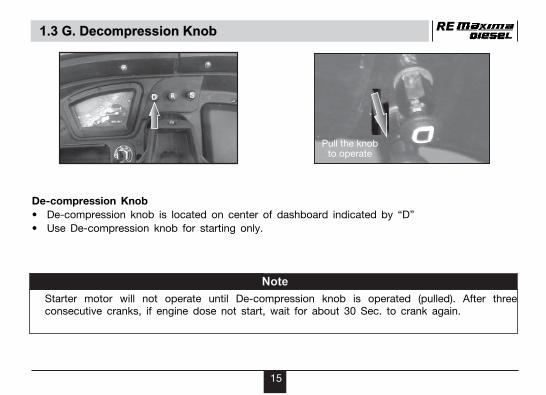
De-compression Knob
• De-compression knob is located on center of dashboard indicated by “D”
• Use De-compression knob for starting only.
Pull the knobto operate
15
Note
consecutive cranks, if engine dose not start, wait for about 30 Sec. to crank again.Starter motor will not operate until De-compression knob is operated (pulled). After three

RE
16
Reverse Gear Knob
• Reverse gear knob is located on Dashboard indicated by “R”.
• To engage reverse gear, change to neutral, stop vehicle with engine idling, pull the reverse gear knob and shift the gear twist grip to “R” position.
• Reverse lamps will glow when reverse gear is engaged.
1.3 H. Reverse Gear Knob
Pull the knobto operate

RE
A. Hazard Warning Switch:
Hazard switch can be switched ON (Irrespective of On/Off key switch position) : Both front and rear LH and RH blinkers will blink simultaneously and both Turn pilot indicators in Instrument cluster will blink simultaneously.
B. Stereo Switch :
Provision is given to connect the stereo.
1.3 I & J. Hazard Warning & Stereo Switch
A. Hazard Warning switch
B. Stereo switch
17
AB

RE
18
1.4 Other Controls
Other Controls
1.4 A. Parking Brake
1.4 B. Brake Pedal
1.4 C. Clutch Lever

RE1.4 A.Parking Brake
Parking Brake• It is located on left side of driver seat.• To apply the parking brake , pull the parking brake
lever all the way up.To release the parking brake push the button (‘B’) in middle of the Parking Brake Lever and lower it to its original position.
Never drive your vehicle with the parking brake applied, rear brake effectiveness can be reduced. Due to overheating, brake life may be shortened or permanent brake damage may result . If the parking brake does not hold the vehicle securely or does not fully release, have your vehicle inspected immediately by an authorized Distributor.
B
Release Parking
CAUTION
19
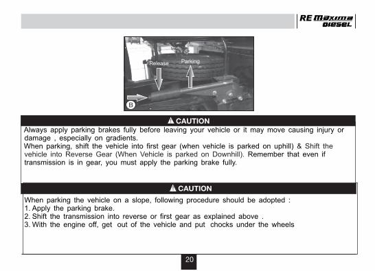
Always apply parking brakes fully before leaving your vehicle or it may move causing injury or damage , especially on gradients. When parking, shift the vehicle into first gear (when vehicle is parked on uphill)
Remember that even if transmission is in gear, you must apply the parking brake fully.
& Shift the vehicle into Reverse Gear (When Vehicle is parked on Downhill).
When parking the vehicle on a slope, following procedure should be adopted :1. Apply the parking brake.2. Shift the transmission into reverse or first gear as explained above .3. With the engine off, get out of the vehicle and put chocks under the wheels
20
B
Release Parking
CAUTION
CAUTION
RE

RE
21
1.4 B. Brake Pedal
caotavanaI
Brake PedalVehicle is provided with hydraulically operating brake system.Master cylinder and brake fluid reservoir is located on chassis on RH side of scudo.
Do not “ride” the brakes by applying them continuously or resting your foot on the pedal .This will result in overheating of the brakes which could cause unpredictable braking action, longer stopping distances, or permanent brake damage .
WARNINGIf brake squeal is excessive and occurs each time the brakes are applied, you should have the brakes checked by an authorized Distributor or dealer.
CAUTION

If water gets into the brake drums, brake performance may become poor and unpredictable. After driving through water or washing the underside of the vehicle, test the brakes while driving at a slow speed to see if they have maintained their normal effectiveness. If the brakes are less affective than normal, dry them by repeatedly applying the brakes while driving slowly until the brakes have regained their normal effectiveness.
22
RE
CAUTION

RE
23
1.4 C. Clutch Pedal
Do not drive with clutch lever in pressed condition or do not rest your foot on clutch pedal. It could result in excessive clutch wear, clutch damage, unexpected loss of engine braking or drop in fuel efficiency.
Clutch PedalClutch operating pedal is located on left side of scudo near floor board as shown in the figure.
Gear change twist grip
It is located on left hand side of the handle barst nd rd th thFor 1 , 2 , 3 , 4 and 5 gear shifting grip to be moved up.
For reverse - After pulling reverse knob on dashboard, shift gear shifting grip to “R” position i.e down
CAUTION

RE
24
1.5 Other Important Parts Location
1.5 A. Fuel Tank and Fuel Feed Pump
1.5 B. Spare Wheel
1.5 C. Battery
1.5 D. Fuse Box
1.5 E. Mobile Charger Socket / Water Bottle Holder.
1.5 F. Fuel Filter / Air Filter
1.5 G. Oil Filter and Oil Cooler

RE
25
1.5 A Fuel Tank, Fuel Feed Pump
Do not run vehicle with very low level of fuel in tank. This may damage the feed pump permanently.Don’t keep the ignition switch in “ON” position whenever not required to avoid battery drain due to continuous operation of Fuel feed pump.
A.Fuel Tank• Fuel tank is mounted on LH side of vehicle behind rear wheel. Fuel tank capacity is 8 liters.• Location of fuel tank cap is as shown in the figure.• Fuel gauge is provided as an indicator of fuel available in tank.
Fuel Feed Pump • Feed pump delivers the fuel at the required pressure to the engine.
A
CAUTION

RE
26
1.5 B Spare Wheel
B.Spare Wheel
• Location of spare wheel is under driver seat.
•
• Tilt the driver seat frame towards handle bar side
• To remove spare wheel, open the spare wheel lock & remove the 2 nuts securing the spare wheel.
Remove 2 bolts of driver seat frame

RE1.5 C Battery
C Battery (12V 50Ah)• It is located on RH side of driver seat.• Check and ensure that the electrolyte level is between the upper (Max) and lower (Min) level in
each cell.• If the electrolyte level is below the lower level in any cell, top up to upper level with distilled water.
Ordinary tap water is not a substitute for distilled water and will shorten the life of the battery.• Check battery terminal voltage and Sp. gravity. Charge the battery, if required. Check connections
of battery terminals and starter relay. Apply petroleum jelly on battery terminals • Do not rest your foot on battery as battery breather holes may get clogged.• Do not overfill electrolyte as the electrolyte may leak on floor & will damage the painted surface • Batteries produce flammable hydrogen gas. Keep flames and sparks away from the battery or an
explosion may occur. Never smoke when working in the vicinity of the battery. When checking or servicing the battery, disconnect the negative cable first. Be careful not to cause a short circuit by allowing metal objects to contact the battery posts & vehicle at the same time.
WARNING
27
RE
28
1.5 D Fuse Box
A
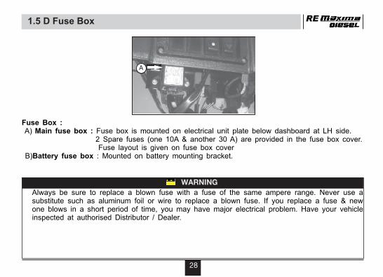
Always be sure to replace a blown fuse with a fuse of the same ampere range. Never use a substitute such as aluminum foil or wire to replace a blown fuse. If you replace a fuse & new one blows in a short period of time, you may have major electrical problem. Have your vehicle inspected at authorised Distributor / Dealer.
WARNING
Fuse Box : A) Main fuse box : Fuse box is mounted on electrical unit plate below dashboard at LH side. 2 Spare fuses (one 10A & another 30 A) are provided in the fuse box cover. Fuse layout is given on fuse box cover B)Battery fuse box : Mounted on battery mounting bracket.

RE
29
1.5 E Mobile Charger Socket
A. Mobile Charger Socket :
Mobile charger socket is on dashboard near instrument cluster. You can charge the mobile while driving the vehicle.
B. Water Bottle Holder :
Water bottle holder is provided for keeping water bottle. It is mounted on RH side of scudo.
A. Mobile Charger Socket B. Water Bottle Socket

RE
Fuel Filter :
Fuel filter is used to provide clean fuel to the engine by filtering the impurities.
It is located below passenger body near to the fuel tank.
Ensure to drain water by opening drain nut once in a month .
Do not over tighten drain nut as it may break.
Air Filter :
Air filter is used to provide clean air to engine. It is located below passenger body near engine
30
1.5 F Fuel Filter & Air Filter
A
B
NOTE
NOTE
After cleaning air filter, arrow mark on filter cap should match with mark on filter body
RE
31
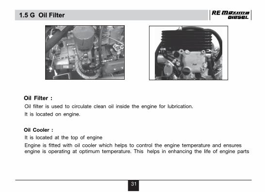
Oil Filter :
Oil filter is used to circulate clean oil inside the engine for lubrication.
It is located on engine.
Oil Cooler :
It is located at the top of engine
Engine is fitted with oil cooler which helps to control the engine temperature and ensures engine is operating at optimum temperature. This helps in enhancing the life of engine parts
1.5 G Oil Filter

RE
32
The Chassis and Engine serial numbers are used to register the vehicle. They are the only means of identifying your particular vehicle from other vehicles of the same model and type.
1.6 Identification Data
Engine Number Location -On LH side
near fuel injection pump.*
Chassis Number Location -At Front on Dashboard .Ú
NOTE
Never open governor cover ( Red colour ) and tamper the setting screws as this may lead to adverse performance of engine .

RE1.7 Technical Specifications
Engine : Four Stroke, Forced air & oil cooled, Compression Ignition Bore X Stroke : 86.00mm x 77.00mmEngine Displacement : 447.3 ccCompression ratio : 24 1 : 1Max. Net Power : 6.62 kW at 3400 150 rpm. of engine (at crank shaft) Max. Net Torque : 23 N.m at 2000 200 rpm of engine Starting : Electric Start
Lubrication : Forced air & oil cooled, Transmission (gears) : 5Forward + 1Reverse Gear
Fuel Tank Capacity : Full - 8.0 liters
±±
±
Idling Speed : 1250 + 150 rpm.
Brakes :Front/Rear : Hydraulically expanding shoe typeHand Brake : Mech. Expanding shoe type on rear wheels.
33

34
Tyre Size : 4.5-10, 8PR
(All four tyres)
Battery : 12V 50 Ah
Head Lamp : 35/35 W
Tail / Stop Lamp : 5/21 W
Side Indicator Lamp : 10 W
Horn : 12V DC
Vehicle Kerb Weight : 505 kg
Max. Total Weight : 886kg
Max. Speed : 52 km/h
Tyre Pressure2Front : 2.4 kg/cm (34PSI)2Rear : 3.2 kg/cm (45PSI)
Electrical System : 12 V, DC
Note :• All dimensions are under UNLADEN condition.• Above information is subject to change. • Please contact international Business for latest information.
RE

RE
35
2. Operating Vehicle
Index
2.1 Daily Safety Checks
2.2 Safe Driving Tips
2.3 Fuel Saving Tips
2.4 Running In
2.5 Starting And Driving

RE
36
2.1 Daily Safety Checks
Before starting the vehicle, it is recommended to do following checks.
Make sure that mirrors, lights & reflectors are clean and unobstructed
Fuel :
Enough fuel in tank. Check fuel pipes for cracks/leakage. Replace if found defective.
Engine Oil : Check oil level daily.
Electrical :
Operating of all tell tale lights, switches, horn etc.
Check battery electrolyte and terminals for tightness.
Brakes:
Effectiveness and lever play.
Steering / Suspension :
Smoothness, any play or looseness.
Controls :
Free play, smooth operation, positive return to the close position.

RE
37
2.2 Safe Driving Tips
Driving on slippery roadsOn rainy days, "Aquaplaning" can occur. It is loss of direct contact between the road surface & the vehicle tyres due to water film forming between them. Steering or braking during aquaplaning can be very difficult, and loss of control may occur. Keep speed down when road surface is wet.
• Don't jam the brakes on wet surfaces, on unmetalled roads or on slippery road beds.
Driving down Hill : When driving down a hill, the engine should be used for braking by shifting to next lower gear
Never drive while under the influence of alcohol or other drugs. Alcohol and drugs can seriously impair your ability to drive safely. You should also avoid driving when you are tired, sick, irritated, or under stress. Avoid driving while talking or operating mobile phone
WARNING
Try not to hold the brake pedal pressed for too long or too often while going down a Steep or long hill. This could cause the brakes to overheat, resulting in reduced braking efficiency. Failure to take this precaution could result in loss of vehicle control.
WARNING

RE2.3 Fuel Saving Tips
38
1. Ride smoothly and steadily at an optimum speed of 30- 40 kmph in 5th Gear
2. Change the gear judiciously according to the speed requirement.
Recommended speed for gear shifting
3. Avoid following
• Sudden acceleration and frequent / sudden braking.
• Driving with foot on brake pedal.
• Driving with partial disengaging of clutch (half clutch).
• Overloading & Driving at high speeds.
• Over / under inflation of the tyres.
• Keeping the engine running at traffic signals if the wait time is more.
Gear 1st 2nd 3rd 4th 5th
Speed 0-8 8-11 11-15 15-20 20 &Above
44

RE2.4 Running - In
•
•
Always keep within the specified running in speeds.
Do not race the engine excessively.
• Do not start moving or race the engine immediately after starting in the morning or in cold conditions . Run the engine for a minute at idle speed to give the oil a chance to work up into the engine.
• During first 2000 km running-in period do not exceed following speed limits.
Gear 1st 2nd 3rd 4th 5th
Speed 8 15 20 30 35
39

RE2.5 Starting & Driving
Starting the Engine
• Turn ignition switch key to ON position.• Ensure that vehicle is in Neutral gear, by confirming the neutral indicator tell tale light on
dashboard is lit.• Check Tell tale lights for Battery charging & Oil Pressure on dash board are lit.• Wait for glow plug indicator to go off.• Pull the ‘De-Compression Knob & crank the engine by pressing start button• Release the ‘De-Compression Knob’. Engine will start as soon as the knob is released.
Slowly, twist the accelerator to rev the engine.• Wait for about a minute for engine to warm up before engaging the gears and moving on.• Do not crank engine for more than 5 seconds. If it does not start, wait for 30 seconds before
cranking.
Starter motor will not operate until De-compression knob is operated (pulled). After three consecutive cranks, if engine dose not start, wait for about 30 Sec. to crank again.
NOTE
40

41
Moving On :
• When the engine has started, battery charging, oil pressure indicator lights should go off.• Release parking brake. Depress the clutch lever.• Shift into first gear, neutral indicator light in instrument cluster should go off.• Open the throttle a little, and start to release the clutch lever very slowly.• As clutch starts to engage, open the throttle a little more, giving the engine just enough power
to keep it from stalling.
RE2.5 Starting & Driving

42
Shifting Gears :
• Close the throttle while pressing the clutch pedal.
• Shift into the next higher or lower gear.
• Open the throttle partly, while releasing the clutch lever.
B. Gear change twist gripA. Clutch Pedal
RE
NOTEDo not rest your foot on clutch pedal in running.
2.5 Starting & Driving

43
Reverse Gear :
For engaging reverse gear -
• Change to neutral, stop the vehicle with engine idling.
• Pull the reverse gear knob.
• Depress clutch Pedal.
• Change the gear change twist grip to reverse (R) position.
• Release the clutch Pedal slowly and open throttle to set the vehicle in motion.
Reverse Gear Knob
Pull the knobto operate
RE2.5 Starting & Driving
44
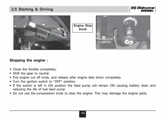
Stopping the engine :
• Close the throttle completely.
• Shift the gear to neutral.
• Pull engine cut off knob, and release after engine dies down completely.
• Turn the ignition switch to “OFF” position.
• If the switch is left in ON position the feed pump will remain ON causing battery drain and reducing the life of fuel feed pump
• Do not use De-compression knob to stop the engine. This may damage the engine parts.
Engine StopKnob
Pull the knobto operate
Pull the knobto operate
RE2.5 Starting & Driving

RE
45
3. Preventive Maintenance
Index
3.1 Periodic Maintenance Chart
3.2 Periodic Lubrication Chart
3.3 Engine Oil - Checking/replacement
3.4 Oil Filter Replacement
3.5 Gear Box Oil - Checking/replacement
3.6 Differential Oil - Checking/replacement
3.7 Recommended Oil Grade and Quantity
3.8 Air Filter Cleaning Procedure
3.9 Fuel Filter
3.10 Battery
3.11 Wiper Motor
3.12 Propeller Shaft
3.13 Brake Oil
3.14 Free Play
3.15 Wheel Changing
3.16 Tyre Rotation

RE3.1 Periodic Maintenance Chart
1 Vehicle washing & Cleaning CL CL CL CL CL CL CL CL
2 Clean/Replace air filter element & ‘O’ ring CL CL CL CL R CL CL CL Replace after every 20K km
3 Check all lights for working C,A C,A C,A C,A C,A C,A C,A C,A Switches, indicators etc
4 Clean oil strainer CL CL Clean after every 20k km
5 Check/adjust st. column Race &lock nut C,A C,A,L C,A,L C,A,L Tighten to torque every 10K km
6 Check & adjust idling RPM C,A C,A C,A C,A
7 Check fuel Pipe C,R C,R C,R C,R
8 Check Battery electrolyte level & top up C,T C,T C,T C,T
9 Check CV shaft bellows crack, Change if required C,R C,R C,R C,R C,R C,R C,R
10 Do Tyre rotation (seq.1 & seq.2) RT RT RT RT RT RT RT "Seq 1 at 5k,15k,25k....km
seq 1 seq 2 seq 1 seq 2 seq 1 seq 2 seq 1 Seq 2 at 10k,20k,30k....km
11 Engine mouting bolts- loosen and retighten C,A C,A C,A C,A C,A C,A Engine mtg- 5K,
12 Drain water from fuel filter/Replace fuel filter CL R CL Drain every 10k & R after every 20K km
13 Replace oil filter element R R R Replace after every 10K km
14 Check and adjust control cables if required C,A C,A C,A
15 Check and adjust valve clearance C,A C,A C,A
16 Check front/rear shock absorber for leakage C,R C,R C,R
17 Check air filter duct & replace if required C,R C,R C,R After every 10k
18 Check & top up brake fluid C,T C,T C,T Replace after every 40,000 km
19 Check brake liner wear, replace if required C R After every 30,000 km
20 Inspect oil cooler pipe replace if required CL,R
21 Check injector for pressure and spray pattern C,A,R After every 20K km
22 Clean oil cooler with water spray CL CL CL After every 10K km
RECOMMENDED ODOMETER READING km
10K5K1K 15K 20K 25K 30K 35KSr.No.
Operation
CL : Clean C : Check A : Adjust T : Top up R : Replace RT : Rotation
46

RE3.2 Lubrication Chart
2 Replace /top up gear box & differential oil T T T R T T T every 20K km
3 Grease Steering races, balls, L L L Lubricate at every 10K km
4 Grease Gear shifter- sector L L L L L L L L
5 Grease Fare meter drive, fr. suspension L L L L L L L L
6 Grease Rear hub bearing every 60K km (kluber grease)
7 Speedometer inner greasing L L L Every 10K km
8 Apply petroleum jelly on Battery terminals L L L L L L L L
9 Apply oil on brake and clutch linkages L L L L L L L L Every 5K km
1 Replace /top up Engine oil R T R T R T R T
L : Lubricate T : Top up R : Replace
35K
RECOMMENDED ODOMETER READING km
15K 20K 25K 30K10K5K1KOperationSr.
No.
47

RE3.3 Engine Oil Checking / Replacement
Engine Oil :
For proper functioning of Engine, oil level inside the engine should be maintained between the max / min. levels marked on dip stick.
Oil Level Inspection :
• Place the vehicle on a level ground.
• Start the engine and run in idling for 5 minutes then stop the engine.
• Let the oil settle for a few minutes.
• Check the Oil level by means of dip stick.
Min
Max
C. Drain PlugA. Dip stick B. Oil Filling Plug
C
A B
NOTE
Oil level on dip stick to be measured by keeping dip stick in vertical position only.
48

• Remove the dip stick carefully.
• Wipe off the dip stick clean.
• Re-insert the dip stick fully (screw in fully) and take out to note the oil level.
• In case the oil level is below the lower mark,
top it up to the upper mark.
Oil replacement :
Replace oil as per Lubrication Chart.
For replacing Engine oil :
• Run the engine for about 10 minutes to warm up the oil.
• Place the vehicle on a level ground so that the oil settles down.
• Remove oil drain plug. Let the oil drain completely.
• Tighten the drain plug.
• Remove oil filling plug and pour the correct quantity of recommended oil.
• Check the oil level
• Fit back oil filling plug. Ensure that there is no oil leakage.
When cleaning oil strainer
When oil strainer is removed for cleaning , after cleaning , fill 1700ml of oil in engine , run the engine in idling for 5 minutes and recheck the oil level on dip stick.
Top up upto “MAX” mark if oil found to be less than “MAX” mark.
Please drain oil for 15 minutes.
RE3.3 Engine Oil Checking / Replacement
49
RE3.4 Oil Filter Replacement
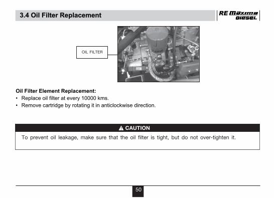
Oil Filter Element Replacement:
•
• Remove cartridge by rotating it in anticlockwise direction.
Replace oil filter at every 10000 kms.
To prevent oil leakage, make sure that the oil filter is tight, but do not over-tighten it.
OIL FILTER
CAUTION
50

RE
Gear Box Oil :Oil level in Gear box is checked with the help of check bolt provided on Gear box cover.
Oil level inspection :• Place the vehicle on a level ground.• Let the oil settle for a few minutes.• Oil level can be checked by means of oil level check bolt. Oil must drip out , which means level is
correct.• If it is less, fill till oil drops out from check bolt.• Check the oil level & top up at recommended frequency
3.5 Gear Box Oil Checking
Oil Level Check Bolt (Gear Box)
B
(Note - Top up 80ml. of Oil over the OilLevel Bolt for Gear Box Oil)
51

RE
52
Gear Box Oil replacement :Replace oil as per Lubrication chart.For replacing gear box oil• Run the engine for about 10 minutes to warm up the oil.• Place the vehicle on a level ground so that the oil settles down.• Remove oil drain plug. Let the oil drain completely.• Tighten the drain plug.• Remove oil filling plug and pour the correct quantity of recommended oil.• Check the oil level.• Fit back oil filling plug. Ensure that there is no oil leakage.
(Note - Top up 80ml. of Oil over the OilLevel Bolt for Gear Box Oil)
B
Drain Bolt
Oil Filling Plug
3.5 Gear Box Oil Replacement
RE
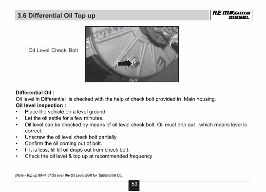
Differential Oil :Oil level in Differential is checked with the help of check bolt provided in Main housing.Oil level inspection :• Place the vehicle on a level ground.• Let the oil settle for a few minutes.
• Oil level can be checked by means of oil level check bolt. Oil must drip out
• Unscrew the oil level check bolt partially• Confirm the oil coming out of bolt.• If it is less, •
, which means level is correct.
fill till oil drops out from check bolt.Check the oil level & top up at recommended frequency
3.6 Differential Oil Top up
Oil Level Check Bolt
(Note - Top up 80ml. of Oil over the Oil Level Bolt for Differential Oil)
53

RE
A
Oil replacement :Replace oil as per Lubrication chart.For replacing differential oil• Run the engine for about 10 minutes to warm up the oil.• Place the vehicle on a level ground so that the oil settles down.• Remove oil drain plug. Let the oil drain completely.• Tighten the drain plug.• Remove oil filling plug and pour the correct quantity of recommended oil.• Check the oil level.• Fit back oil filling plug. Ensure that there is no oil leakage.
(Note - Top up 80ml. of Oil over the Oil Level Bolt for Differential Oil)
3.6 Differential Oil Replacement
54

3.7 Recommended Oil Grade And Quantity
LubricationReplace the oil in accordance with periodic maintenance chart.
• Two different grade of oil should not be mixed.• For rear hub bearing greasing, Kluber make grease to be used.
Note
RE
At every km
5000
5000
Lubrication
Gear shifter sector
Fare meter drive
10000
10000
5000
10000
10000
60000
5000
5000
5000
St.Column race & lock nut
Tyre rotation (Seq 1 & Seq 2)
Steering races, balls
Clutch & Brake Pedal
Front suspension
Battery terminals
Speedo meter inner
Rear hub bearing
A-Adjust At every km
Petroleum jelly onBattery terminals
Recommended Quantityoil grade
Engine Oil refill 1450 ml.W/O oil filter
Engine oil refill 1700 ml.with oil filter
Gear Box Oil 440 ml.
Differential Oil 280 ml.
SAE 15W40 of API CH-4 grade
SAE 20W40 of API CC-grade
55
RE
56
3.8 Air Filter Cleaning Replacement
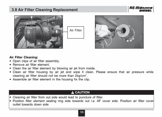
Air Filter Cleaning:• Open clips of air filter assembly.• Remove air filter element.• Clean the air filter element by blowing air jet from inside.• Clean air filter housing by air jet and wipe it clean. Please ensure that air pressure while
2 cleaning air filter should not be more than 2kg/cm .• Assemble air filter element in the housing fix the clip.
Air Filter
•• Position filter element sealing ring side towards out i.e. AF cover side. Position air filter cover
outlet towards down side
Cleaning air filter from out side would lead to puncture of filter.
CAUTION

RE
57
Draining of water from fuel filter housing:
Water gets accumulated at the bottom of fuel filter housing. To drain water :
• Loosen the drain bolt located at bottom of fuel filter housing.
• Allow the water to drain completely
• As soon as fuel starts coming out, close drain bolt and tighten. Check for any leakage.
• Drain water every 5000 km
Water Drain Screw
3.9 Fuel Filter
Do not over tighten the drain screw as over tightening will break the drain screw leading to fuel leakage.
Note

58
Air bleeding ScrewÖ
Air bleeding from fuel lines :
For bleeding air from fuel line:
• Loosen the bolt located on top cover of fuel filter housing.
• Switch on ignition and ensure feed pump is running.
• Allow the fuel with air bubbles to flow from bolt.
• When fuel starts coming out without air bubbles, close the bolt and tighten. Check for any leakage.
Fuel Filter Replacement-Replace fuel filter after every 20000 Km After fitting new fuel filter do air bleeding from fuel line
RE

RE
59
3.10 Battery
A.Battery (12V 50Ah)• It is located on RH side of driver seat.• Check and ensure that the electrolyte level is between the upper (Max) and lower (Min) level in each
cell.• If electrolyte level is below lower level in any cell, top up to upper level with distilled water.
WARNING• Ordinary tap water is not a substitute for distilled water & will shorten life of battery.
• Check battery terminal voltage & Sp. gravity. charge battery, if required. Check connections of battery terminals & starter relay. Apply petroleum jelly on battery terminals

RE
60
3.11 Wiper Motor
Wiper Motor :
• Self parking feature is provided in the wiper motor. Wiper blade will rest in extreme left position. (When viewed from inside the cabin).
WARNING
• Before washing vehicle, wrap the wiper motor with polythene sheet to prevent water entry.

RE3.12 Drive Shaft CV
61
Drive Shaft CV : Rubber Bellows
• Bellows should be kept in good condition & to be replaced immediately if torn.
• Torn bellows will allow dust & water entry into the Drive Shaft flanges which will cause damage to Drive Shaft.
Drive Shaft CV Differential Side
Drive Shaft CV Trailing arm side

RE3.13 Brake Oil
A rapid fluid loss indicates a leak in the brake system which should be inspected by your Distributor / dealer immediately. Brake fluid can harm your eyes & damage painted surfaces. Use caution when refilling the reservoir.
Brake Oil container: Brake oil container is located on master cylinder near brake pedal.Check the brake fluid level by looking at the reservoir. Check that the fluid level is between the “MAX” and “MIN” lines. If the brake fluid level is near the “ MIN” line, fill it up to the “MAX” line with recommended brake fluid.
MinMax
CAUTION
62

Brake Oil• it is advisable that the brake fluid should be replaced at least once in a year.
We recommend following brake fluids.
Marketed by Name of brake fluid
Hindustan Petroleum Hp Super Dutybrake fluid DOT-3
Indian Oil Corporation Servo brake fluid super HD
Bharat Petroleum Bharat Heavy Dutybrake fluid
Castrol India Ltd. Castrol Universalbrake fluid
Note
Please note that two different brands of brake fluids should not be mixed together.
RE
63

RE
64
Free play for :
a. At brake pedal : 10-15 mm
b. At clutch Pedal : 10-15 mm
c. Accelerator grip : 2-3 mm
d. Decompression cable : 3-4 mm
(at engine end)
e. Engine stop cable : 3-4 mm
(at engine end)
3.14 Free Play

RE
Fig. A
65
3.15 Wheel Changing
Changing wheel and tyres :
Pull the parking brake and loosen the wheel retaining nuts. Place the jack as shown in Fig. ‘A’ (For removing Front wheel) and Fig. ‘B’ (For removing Rear wheel) then jack up the vehicle until the wheel clears the ground. Then remove the securing nuts and take out the wheel. During reassembly progressively screw the wheel nuts and lower the vehicle slowly to the ground, then tighten the nuts. Where ever possible change the wheel with the vehicle on a firm and level surface.
Fig. B

RE3.16 Tyre Rotation
66
Tyre rotation : The wheels are interchangeable provided they are correctly inflated. To even out tyre tread wear it is recommended to rotate it after every 5,000 km and inflate it to the specified pressure. The best tyres should always be kept at the rear wheels which are driving wheels, thereafter follow the sequence of rotation.
Sequence -1 After 5,000 ,15,000------ km
Change front tyre face & intechange rear wheels as shown
Sequence -2 After10,000 ,20,000------ km
Interchange Front & rear right wheel ,spare & rear left wheel as shown
FRONT
REAR REAR
B
B
B
B
A
A
A
A
FRONT
REAR REAR
SPARE
Sequence -1 Sequence -2

RE
Tyre Pressure : Keep appropriate tyre pressure as mentioned below to increase life of the tyre and for better fuel consumption.
2 Front 2.4kg/cm (34 Psi)2Rear 3.2 kg/cm (45 Psi)
Tyre Size : 4.5-10, 8PR (All four tyres)
Correct TractionOptimum HandlingOptimum Tyre Life
Danger: Poor Handling Poor Economy
Rapid Wear(Edge)
Danger:Poor GripInsufficient TractionRapid Wear(Center)
Properly inflated Under inflated Over InflatedProperly inflated Under inflated Over Inflated
3.16 Tyre Pressure
Note
• Improper tyre pressure will have adverse effects on vehicle performance and will lead to premature tyre wear, wheel rim damage and suspension failures.
67
RE4. Pre Delivery Inspection
CERTIFIED THAT THE WORK NARRATED ABOVE ISPROPERLY CARRIED OUT BEFORE DELIVERY.
Distributor/Dealer's stamp and Signature
Transit Damage :
Check the vehicle for any transit damages.
Performance:
Check engine , gear box and differential oil levels and top up if necessary
Check gear shifting and clutch for proper adjustment and working.
Check and adjust engine idling if necessary.
Check for drivability, hesitation.
Checks/ Play/ Adjustment/ Cable
Check and adjust all control cables.
Check and correct tyre inflation pressure including that of Spare wheel.
Electrical related:
Check battery electrolyte level and voltage.
Check all lights, horn, wiper motor & switch operation for satisfactory working.
Clean the vehicle before delivery
Fit the accessories before delivery
68

NOTE
RE
For faster response, please furnish the following details in e-mail / written communication to our Distributor.
• Contact Details (Customer Name & Add. Ph./Mob. No)
• Vehicle Details (Engine No., Chassis No., Registration
No., Make and Purchase Date)
• Selling/Servicing Distributors / Dealers
• Nature of Complaint in Brief
For any additional Information or Assistance Please Contact :
Bajaj Auto Limited
Export Service International BusinessAkurdi, Pune 411 035 India
Phone : +91 20 27406278
Fax : +91 20 27407385
E-mail : [email protected]
69

REV. 00,JULY. 2014DOC. NO.71112074
CIN NO. CINL65993PN2007PLC130076
NOTICE RE
The description and illustration in this booklet are not to be taken as binding on the manufacturers. The essential features of the type described and illustrated herein remaining unaltered; Bajaj Auto Limited reserves the right to carry out at any moment without being obliged to bring this booklet up-to-date, modifications on the vehicle, parts or accessories as may be convenient and necessary.
70

Use only Bajaj Genuine Parts
parts
AlwaysInsist
on
For optimum performance of vehicle
For prolonged life ofcomponents & vehicle
For economical maintenance cost
Genuinity Test
For rider's safety
Scratch Hologram to find ‘Genuine’
Partial transparent Hologram
Golden Hologram
RE

To Enable us to provide you faster response
Please use our
Customer Care 'Toll Free No.'
1800 233 2453 (Week days)
Service Department
Bajaj Auto LimitedAkurdi, Pune 411 035 India.
www.bajajauto.com
For faster response please furnishYour Contact no., E-mail & Vehicle details
WEB-SITE
TOLL FREE
Mileage Safety Trust Benefit
Export Service, International Business
Bajaj Auto LimitedAkurdi, Pune 411 035 India.
www.bajajauto.com
WEB-SITE
WORLD’S NO.1 Three Wheeler
Bajaj Auto Limited
Registered & Head Office
Akurdi, Pune - 411 035, India.
Tel. : +91 20 27472851,
+91 20 27476151