6524-066-D-5-15_Solar_Power.pdf - Doorking
42
Model 6524-081 Model 6524-081 Model 6524-081 Copyright 2009 DoorKing, Inc. All rights reserved. Copyright 2015 DoorKing, Inc. All rights reserved. Date Installed: Installer/Company Name: Phone Number: Leave Manual with Owner UL 325 Compliant Circuit Board Serial Number and Revision Letter: Use this manual for circuit board 4100-010 Revision D or higher. Solar Powered Solar Powered Installation/Owner’s Manual Solar Powered Vehicular Swing Gate Operator 6524-066-D-5-15
-
Upload
khangminh22 -
Category
Documents
-
view
0 -
download
0
Transcript of 6524-066-D-5-15_Solar_Power.pdf - Doorking

Model 6524-081Model 6524-081Model 6524-081
Copyright 2009 DoorKing, Inc. All rights reserved.
Copyright 2015 DoorKing, Inc. All rights reserved.
Date Installed:
Installer/Company Name:
Phone Number:
Leave Manual with Owner
UL 325 Compliant
Circuit BoardSerial Numberand Revision Letter:
Use this manual for circuit board 4100-010 Revision D or higher.
Solar Powered
Solar Powered
Installation/Owner’s ManualSolar Powered Vehicular Swing Gate Operator
6524-066-D-5-15

Quick Guide - 1
QUICK GUIDE: DIP-Switches See page 19 for more information about DIP-switches.
Reset button on circuit board MUST be pressed before new DIP-switch settings will take affect.
ON OFFOpens
ClockwiseOpensCounter-Clockwise
Switch Function Setting DescriptionSW 1 (Top 8 Switches)
OperatorOpeningDirection
OFFON
OFFON
OFF
OFFON
6-OFF6-OFF6-ON6-ON
7-OFF7-ON
7-OFF7-ON
Auto-CloseTimer
Accessory Power
Relay:Main TerminalsTerminal 13-14
1
2
3
4
5
8
6 and 7
Switch MUST be turned OFF for Solar.
Auto-close timer is OFF. Manual input required to close gate.Normal Setting. Auto-close timer is ON. Adjustable from 1-23 seconds.
24 VDC 500 mA Constant power for accessories connected to main terminal 12.DO NOT USE for Solar.
OFFON
Quick-close feature is OFF. Quick-close feature is ON. Opening gate will stop and begin to close as soon as all reversing inputs (Reverse loops, photo sensors) are cleared regardless of the distance the gate has opened. Used for slide gates only.Normal Setting. Relay activates when gate is at open limit. Relay activates when gate is not closed.Relay activates when gate is opening and open. Relay activates during opening and closing cycle.
Changes direction operator will cycle open upon initial power up and open command.
Reverses GateNot Used
Quick-CloseTimer Override
(Slide GatesONLY)
Not UsedInput to main terminal 10 and/or reverse loops will reverse gate during close cycle.Do Not use this setting for the 6524.
Setting MUST be used
OFFON
Main terminal 10 is a REVERSE input.DO NOT USE for solar power.
1-OFF1-OFF1-ON1-ON
2-OFF2-ON
2-OFF2-ON
SelectOperator
Type1 and 2
DO NOT USE for the 6524. Slide Gate OperatorSwing Gate OperatorDO NOT USE for the 6524. Barrier Gate Operator DO NOT USE for the 6524. Overhead Gate Operator
Switch Function Setting DescriptionSW 2 (Bottom 8 Switches)
Switches 7 and 8 MUST be turned OFF for Model 6524 operator.OFF
Reverse/ShadowInput
OverlappingBi-Parting Gates
3
4
7 and 8
6
OFFON5
Switch 5 MUST be turned OFF for the 6524.DO NOT USE for solar power. Overlapping gates ARE used (Dual swing gates ONLY). Secondary gate starts to open a few seconds before primary gate starts.
OFFONInput Power
Failure Mode
OFFON
Circuit BoardPower
Management
DO NOT USE for Solar. For 115/230 VAC input power. Board has Constant power.Used for Solar input power. Board Minimizes power when not in use. All terminals shut down power except main terminals 1, 2 and 3.
Not Used
DO NOT USE for Solar.Gate operates normally until batteries get low. Gate will CLOSE and Shutdown operator in close position until battery power reaches an operable level again.

Quick Guide - 2
QUICK GUIDE: Terminal DescriptionsSee page 26 for terminal wiring.
12
34
56
78
ON
12
3
ON
20
19181716
151413
121110
9876
5432
1KEYSWITCH
NO
NC
3 BUTTONCONTROL
SW1
SW2
OFF ON
POWER
P4
6
1 2 3 4 5 6 7 8 9 10
20-Pin Main Terminal
UL 325See pages 22 and 23
NOTUsed
RelayContacts
OPEN
Non
-Con
tact
Sen
sor
CLOS
E No
n-Co
ntac
t Sen
sor
OPEN
Con
tact
Sen
sor
CLOS
E Co
ntac
t Sen
sor
Low
Volta
ge C
omm
onLo
w Vo
ltage
Com
mon
W Main Terminal Input LEDs Note: The LED
that is beside the main terminal wiring input
will light when that terminal input gets
activated.
W MMML
tha
WE MMML
th
WE MMMMLLLL
thh
E MMMMLLLL
thhhh
E MMMMLLL
thhh
E MMMLLL
th
EE MML
t
ERR MM
t
ERR MRRRR
Mai
n Te
rmin
al In
put L
EDs
#2
#10
Low Voltage Common
Full Open
24 VDC - 250 mA max.
Do Not Use
Low Voltage Common
Do Not Use
Low Voltage Common
Do Not Use
Low Voltage Common
Reverse / Shadow
Low Voltage Common
24VDC Accessories
Relay
Relay
Low Voltage Common
Do Not Use
Do Not Use
Low Voltage Common
Do Not Use
Do Not Use
10
12
13 14
Operation of relay is dependent on setting of SW 1, switches 6 and 7. Relay contacts can be set for Normally Open (NO) or Normally Closed (NC) operation.Contact rating is1 amp maximumat 24-volts DC.
ON
12
34
56
78
SW 1
NC
NO
ON
12
34
56
78
SW 1SW1, switch 8 MUST be OFF: 24-VDC 500 mA constant power can be provided for desired accessories wired to terminal 12.
DO NOT turn ONSW1, switch 8.
PhotoSensor
• SW 1, switch 4 MUST be OFF. SW 2, switch 4 MUST be OFF. When gate is closing, an input to main terminal 10 (eg: photo beam gets blocked) will reverse and open the gate. Note: If the auto-close timer is ON, when gate reaches the open position, timer will time out and close the gate.• DO NOT turn SW 1, switch 4 ON.• DO NOT turn SW 2, switch 4 ON.
Note: Main terminal 10 is not available for a photo sensor when using a SHADOW LOOP. See page 24 about shadow loop connection.
ON
12
34
56
78
SW 1
ON
12
34
56
78
SW 2
This input ONLY functions when gate isfully opened or in the closing cycle.
Terminals 1, 2 and 3 are ALWAYS powered up, even after circuit board has powered down to manage the power drain on the batteries, see page 16.Opening devices MUST connect to terminal 2.
Never Powers Down
Note: Board relay is used for a shadow loop when using a SHADOW LOOP. See page 24 about shadow loop connection.

28 3/8”
18 3/8” 23 1/4”
31 5/8”
31”
DoorKing, Inc. reserves the right to make changes in the products described in this manual without notice and without obligation of DoorKing, Inc. to notify any persons of any such revisions or changes. Additionally, DoorKing, Inc. makes no representations or warranties with respect to this manual. This manual is copyrighted, all rights reserved. No portion of this manual may be copied, reproduced, translated, or reduced to any electronic medium without prior written consent from DoorKing, Inc.
Class of Operation UL 325 Class I, II, III, IV Type of Gate Vehicular Swing Gate OnlyMotor Quadra Drive DC MotorPower Input: Volts@Amps 24 VDC @ 8 AmpsBatteries None Included (24 VDC Output Required)Maximum Gate Cycles DKS Solar Power Kit: Solar Panel Power - Continuous DKS Solar Power Kit: ONLY Battery Power - 150+ Cycles Unkown when using Third Party Solar Power Setup
Gate Speed 12-14 SecMax Gate Weight 600 lbs - 272 KgsMax Gate Length 18 Ft - 5.4 Meters Entrapment Protection Inherent entrapment sensing system (Type A) Provision for connection of external photo sensors (Type B1) and/or reversing edges (Type B2).
Use this manual for the Model 6524 operator with circuit board 4100-010 Rev D or higher ONLY.
Battery Power Note: The number of gate cycles when using ONLY battery power WILL vary depending on gate weight, gate length, operating condition of gate hardware, temperature and amount of charge in batteries.
SPECIFICATIONS FOR MODEL 6524-081
OPTIONAL DKS Solar Power Kit Recommended
Two 12 Volt 18 Amp/Hr Batteries
One 24 VDC Solar PanelP/N 2000-070
Mounting PostNot Included
6524-066-D-5-153

TABLE OF CONTENTS
Swing Gate RequirementsSafety Information for Swing Gate OperatorsASTM 2200 Standard for Gate ConstructionImportant Safety InstructionsInstructions regarding intended installationImportant NoticesUL325 Entrapment ProtectionGlossary
2344
4-5567
QUICK GUIDESQuick Guide: DIP-SwitchesQuick Guide: Terminal Descriptions
Quick Guide - 1Quick Guide - 2
SECTION 1 - INSTALLATION 888
9-10111112121314
1.1 Underground Conduit Requirements1.2 Concrete Pad1.3 Type of Installations1.4 Securing Operator to Pad1.5 Attach Gate Bracket1.6 Determining Arm Lengths1.7 Installation of Warning Signs1.8 Concerns BEFORE Solar Panel Installation1.9 Solar Panel Positioning
SECTION 2 - SOLAR POWER TO OPERATOR 151516
2.1 Solar Power Connections2.2 Setting Input Power Jumper and Turning Power ON
SECTION 4 - ENTRAPMENT AND SAFETY PROTECTION 224.1 UL 325 Terminal Wiring4.2 External Entrapment Protection Device Locations4.3 Loop Detector Wiring
222324
SECTION 5 - WIRING TERMINALS 252526
5.1 Terminal Descriptions5.2 Control Wiring
SECTION 7 - MAINTENANCE AND TROUBLESHOOTING 317.1 Maintenance7.3 Troubleshooting7.2 Built-In Diagnostics7.4 Accessory Items7.5 Gearbox Shaft Extension ReplacementModel 6524-081 Solar Input Power Wiring Diagram
3132-33
33343536
SECTION 6 - OPERATING INSTRUCTIONS 276.1 DC Power Switch and Alarm Reset Button6.2 Shutdown Conditions6.3 Manual Gate Operation
2728-2929-30
SECTION 3 - ADJUSTMENTS 173.1 4100 Circuit Board Descriptions and Adjustments3.2 DIP-Switch Settings for 4100 Circuit Board3.3 Limit Sensors3.4 Inherent Reverse Sensor Adjustment
1718-19
2021
6524-066-D-5-15 1

Swing Gate RequirementsThe operator is intended for installation only on gates used for vehicles. Pedestrians must be supplied with a separate access opening. The pedestrian access opening shall be designed to promote pedestrian usage. Locate the gate such that persons will not come in contact with the vehicular gate during the entire path of travel of the vehicular gate.(ref. UL 325 56.8.4.b)
If distance is greater than 4 inches, entrapment protection for this area is required. ASTM F2200 7.1.1.1
If distance is less than 16 inches, entrapment protection in this area is required. ASTM F2200 7.1.1.2
A
B
Not Allowed OK
A
B
Closed Gate
Closed Gates
With the hinge mounted on the corner of the pilaster, the entrapment area is eliminated and protection is NOT required for this area.
Gates shall have smooth bottom edges, with vertical bottom edged protrusions not exceeding 0.50 inches. ASTM F2200 4.3
Closed Gate
Open
ed G
ate
Open
ed G
ate
A
6524-066-D-5-152

Safety Information for Swing Gate Operators
Non-contact SensorReverse Loop
Shadow Loop
Automatic Exit Loop
C D
D
C
Minimizes the potential of the gate closing when a vehicle is present. Number and placement of loops is dependent on the application.
Reverse LoopMinimizes the potential of the gate closing when a vehicle is present. Number and placement of loops is dependent on the application.
(Optional) will provide an open command to the gate operator(s) when a vehicle is exiting the property.
Provides a hold open command to the operator(s) only if the gate(s) are at the full open position.
Separate PedestrianWalkway
Located so pedestrians cannot come in contact with the vehicular gate.
Minimizes the potential of the gate closing on vehicular or other traffic that loops cannot sense.See pages 22-23 for typical layout locations.
Warning SignsD Permanently mounted and easily visible from either side of the gate.
Moving Gate Can Cause Serious Injury or Death KEEP CLEAR! Gate may move at any time without prior warning. Do not let children operate the gate or play in the gate area. This entrance is for vehicles only. Pedestrians must use separate entrance.
See page 24 for loop information.
6524-066-D-5-15 3

Instructions regarding intended installation:
Vehicular gates should be constructed and installed in accordance with ASTM F2200; Standard Specification for Automated Vehicular Gate Construction. For a copy of this standard, contact ASTM directly at 610-832-9585; [email protected]; or www.astm.org.
Important Safety InstructionsWARNING - To reduce the risk of injury or death:1. READ AND FOLLOW ALL INSTRUCTIONS.2. Never let children operate or play with gate controls. Keep the remote control away from children.3. Always keep people and objects away from gate. NO ONE SHOULD CROSS THE PATH OF THE MOVING GATE.4. Test the operator monthly. The gate MUST reverse on contact with a rigid object or stop or reverse when an object activates the non-contact sensors. After adjusting the force or the limit of travel, retest the gate operator. Failure to adjust and retest the gate operator properly can increase the risk of injury or death.5. Use the emergency release only when the gate is not moving.6. KEEP GATES PROPERLY MAINTAINED. Read the owner's manual. Have a qualified service person make repairs to gate hardware.7. The entrance is for vehicles only. Pedestrians must use separate entrance.8. SAVE THESE INSTRUCTIONS!
• Install the gate operator only if: 1. The operator is appropriate for the construction of the gate and the usage class of the gate. 2. All openings of a horizontal slide gate are guarded or screened from the bottom of the gate to a minimum of 6 feet (1.83 m) above the ground to prevent a 2 ¼ inch (57.2 mm) diameter sphere from passing through the openings anywhere in the gate, and in that portion of the adjacent fence that the gate covers in the open position. 3. All exposed pinch points are eliminated or guarded. 4. Guarding is supplied for exposed rollers. • The operator is intended for installation only on gates used for vehicles. Pedestrians must be supplied with a separate access opening. The pedestrian access opening shall be designed to promote pedestrian usage. Locate the gate such that persons will not come in contact with the vehicular gate during the entire path of travel of the vehicular gate. • The gate must be installed in a location so that enough clearance is supplied between the gate and adjacent structures when opening and closing to reduce the risk of entrapment. Swinging gates should not open into public access areas.• The gate must be properly installed and work freely in both directions prior to the installation of the gate operator. Do not over-tighten the operator clutch, pressure relief valve or reduce reversing sensitivity to compensate for a damaged gate.• For gate operators utilizing Type D protection: 1. The gate operator controls must be placed so that the user has full view of the gate area when the gate is moving. 2. A warning placard shall be placed adjacent to the controls. 3. An automatic closing device (such as a timer, loop sensor, or similar device) shall not be employed. 4. No other activation device shall be connected.• Controls intended for user activation must be located at least ten feet (10’) away from any moving part of the gate and where the user is prevented from reaching over, under, around or through the gate to operate the controls. Exception: Emergency access controls only accessible by authorized personnel (e.g., fire, police, EMS) may be placed at any location in the line-of-site of the gate.• The Stop and/or Reset button must be located in the line-of-sight of the gate. Activation of the reset control shall not cause the operator to start.• A minimum of two (2) WARNING SIGNS shall be installed, one on each side of the gate where easily visible.• For gate operators utilizing a non-contact sensor: 1. See the instructions on the placement of non-contact sensors for each type of application. 2. Care shall be exercised to reduce the risk of nuisance tripping, such as when a vehicle trips the sensor while the gate is still moving in the opening direction. 3. One or more non-contact sensors shall be located where the risk of entrapment or obstruction exist, such as the perimeter reachable by a moving gate or barrier.
ASTM F2200 Standard for Gate Construction
6524-066-D-5-154

• For gate operators utilizing contact sensors: 1. One or more contact sensors shall be located where the risk of entrapment or obstruction exist, such as at the leading edge, trailing edge, and post mounted both inside and outside of a vehicular horizontal slide gate. 2. One or more contact sensors shall be located at the bottom edge of a vehicular vertical lift gate. 3. One or more contact sensors shall be located at the pinch point of a vehicular vertical pivot gate. 4. A hardwired contact sensor shall be located and its wiring arranged so that the communication between the sensor and the gate operator is not subjected to mechanical damage. 5. A wireless contact sensor such as one that transmits radio frequency (RF) signals to the gate operator for entrapment protection functions shall be located where the transmission of the signals are not obstructed or impeded by building structures, natural landscaping or similar obstructions. A wireless contact sensor shall function under the intended end-use conditions. 6. One or more contact sensors shall be located at the bottom edge of a vertical barrier (arm).
Vehicular gate operator products provide convenience and security. However, gate operators must use high levels of force to move gates and most people underestimate the power of these systems and do not realize the potential hazards associ-ated with an incorrectly designed or installed system. These hazards may include: • Pinch points • Entrapment areas • Reach through hazards • Absence of entrapment protection devices • Improperly located access controls • Absence of vehicle protection devices • Absence of controlled pedestrian accessIn addition to these potential hazards, automated vehicular gate systems must be installed in accordance with the UL 325 Safety Standard and the ASTM F2200 Construction Standard. Most lay persons are unaware of, or are not familiar with, these standards. If an automated vehicular gate system is not properly designed, installed, used and maintained, serious injuries or death can result. Be sure that the installer has instructed you on the proper operation of the gate and gate operator system.Be sure that the installer has trained you about the basic functions of the required reversing systems associated with your gate operating system and how to test them. These include reversing loops, inherent reversing system, electric edges, photoelectric cells, or other external devices.
• This Owner’s Manual is your property. Keep it in a safe place for future reference. • Be sure that all access control devices are installed a minimum distance of 10 feet away from the gate and gate operator, or in such a way that a person cannot touch the gate or gate operator while using the device. If access control devices are installed in violation of these restrictions, immediately remove the gate operator from service and contact your installing dealer. • Loops and loop detectors, photo-cells or other equivalent devices must be installed to prevent the gate from closing on vehicular traffic. • The speed limit for vehicular traffic through the gate area is 5 MPH. Install speed bumps and signs to keep vehicular traffic from speeding through the gate area. Failure to adhere to posted speed limits can result in damage to the gate, gate operator, and to the vehicle. • Be sure that all persons who will use the gate system are familiar with the proper use of the gate and gate operator and are familiar with the possible hazards associated with the gate system. • Be sure that warning signs are permanently installed on both sides of the gate in an area where they are fully visible to traffic. • It is your responsibility to periodically check all entrapment protection devices. If any of these devices are observed to function improperly, remove the operator from service immediately and contact your installing or servicing dealer. • Follow the recommended maintenance schedule. • Do not allow children to play in the area of the operator or to play with any gate-operating device. • To remove the gate operator from service, operate the gate to the full open position and then shut off power to the operator at the service panel.
Important Notices
6524-066-D-5-15 5

UL 325 Entrapment Protection
Class I - ResidentialVehicular Gate Operator
Class II - Commercial/General AccessVehicular Gate Operator
Class III - Industrial/Limited AccessVehicular Gate Operator
Class IV -Restricted AccessVehicular Gate Operator
A vehicular gate operator (or system) intended for use in garages or parking areas associated with a residence of one‐to four single families.
A vehicular gate operator (or system) intended for use in a commercial location or building such as a multi-family housing unit (five or more single family units), hotel, garages, retail store, or other buildings accessible by or servicing the general public.
A vehicular gate operator (or system) intended for use in an industrial location or building such as a factory or loading dock area or other locations not accessible by or intended to service the general public.
A vehicular gate operator (or system) intended for use in a guarded industrial location or building such as an airport security area or other restricted access locations not servicing the general public, in which unauthorized access is prevented via supervision by security personnel.
UL 325 Classifications
STATE PRISON
AuthorizedPersonnel ONLY
This table illustrates the entrapment protection requirements for each of the four UL 325 classes.
A - Inherent entrapment protection system.B1 - Provision for connection of, or supplied with, a non-contact sensor (photoelectric sensor or the equivalent). When used as the PRIMARY device, must be monitored.B2 - Provision for connection of, or supplied with, a contact sensor (edge device or the equivalent). When used as the PRIMARY device, must be monitored.C - Inherent adjustable clutch or pressure relief device.D - Provision for connection of, or supplied with, an actuating device requiring continuous pressure to maintain opening or closing motion of the gate.
Class I and IIClass IIIClass IV
UL 325Classifications
Horizontal Slide, Vertical Lift, Vertical Pivot Swing and Vertical Barrier (arm)
A B1, B2 or D A, B1, B2, C or DA or CA, B1 or B2 A, B1, B2, or D A, B1, B2, C or DA, B1, B2 or C
A, B1, B2 or D A, B1, B2, or D A, B1, B2, C, or DA, B1, B2, C or D
Primary Protection Secondary Protection Primary Protection Secondary Protection
6524-066-D-5-156

Glossary GATE - A moving barrier such as a swinging, sliding, raising, lowering, or the like, barrier, that is a stand-alone passage barrier or is that portion of a wall or fence system that controls entrance and/or egress by persons or vehicles and completes the perimeter of a defined area. RESIDENTIAL VEHICULAR GATE OPERATOR – CLASS I - A vehicular gate operator (or system) intended for use in a home of one-to four single family dwelling, or garage or parking area associated therewith. COMMERCIAL / GENERAL ACCESS VEHICULAR GATE OPERATOR - CLASS II - A vehicular gate operator (or system) intended for use in a commercial location or building such as a multi-family housing unit (five or more single family units), hotels, garages, retail store, or other building servicing the general public. INDUSTRIAL / LIMITED ACCESS VEHICULAR GATE OPERATOR - CLASS III - A vehicular gate operator (or system) intended for use in an industrial location or building such as a factory or loading dock area or other locations not intended to service the general public. RESTRICTED ACCESS VEHICULAR GATE OPERATOR - CLASS IV - A vehicular gate operator (or system) intended for use in a guarded industrial location or building such as an airport security area or other restricted access locations not servicing the general public, in which unauthorized access is prevented via supervision by security personnel. VEHICULAR BARRIER (ARM) OPERATOR (OR SYSTEM) - An operator (or system) that controls a cantilever type device (or system), consisting of a mechanical arm or barrier that moves in a vertical arc, intended for vehicular traffic flow at entrances or exits to areas such as parking garages, lots or toll areas. VEHICULAR HORIZONTAL SLIDE-GATE OPERATOR (OR SYSTEM) - A vehicular gate operator (or system) that controls a gate which slides in a horizontal direction that is intended for use for vehicular entrance and exit to a drive, parking lot, or the like. VEHICULAR SWING-GATE OPERATOR (OR SYSTEM) - A vehicular gate operator (or system) that controls a gate which moves in an arc in a horizontal plane that is intended for use for vehicular entrance and exit to a drive, parking lot, or the like. SYSTEM - In the context of these requirements, a system refers to a group of interacting devices intended to perform a common function. WIRED CONTROL - A control implemented in a form of fixed physical interconnections between the control, the associated devices, and an operator to perform predetermined functions in response to input signals. WIRELESS CONTROL - A control implemented in means other than fixed physical interconnections (such as radio waves or infrared beams) between the control, the associated devices, and an operator to perform predetermined functions in response to input signals. INHERENT ENTRAPMENT PROTECTION SYSTEM - A system, examples being a motor current or speed sensing system, which provides protection against entrapment upon sensing an object and is incorporated as a permanent and integral part of the operator. EXTERNAL ENTRAPMENT PROTECTION DEVICE - A device, examples being an edge sensor, a photoelectric sensor, or similar entrapment protection device, which provides protection against entrapment when activated and is not incorporated as a permanent part of an operator. ENTRAPMENT - The condition when an object is caught or held in a position that increases the risk of injury.
6524-066-D-5-15 7

SECTION 1 - INSTALLATION
1.1 Underground Conduit Requirements
1.2 Concrete Pad
OperatorPosition
Underground depth of the concrete pad is determined by soil conditions and local building codes. Reinforced concrete recommended. 22” Concrete Pad Width
28”
Con
cret
e Pa
d Le
ngth
Concrete pad MUST be level.Note: Bevel the edges of concrete pad to eliminate water puddling under the operator.
4” minimum
12.5” to
center
11”
21.5” tocenter
of conduit
area
Operator and Conduit Location
22”
Conduit
CAUTIONNEVER REMOVE HUBafter manual release.
Power, Reset Box
Prior to beginning the installation of the swing gate operator, we suggest that you become familiar with the instructions, illustrations, and wiring guide-lines in this manual. This will help insure that your installation is performed in an efficient and professional manner compliant with UL 325 safety and ASTM F2200 construction standards. The proper installation of the vehicular swing gate operator is an extremely important and integral part of the overall access control system. Check all local building ordinances and building codes prior to installing this operator. Be sure your installation is in compliance with local codes.
• The conduit requirements are for a typical swing gate operator installation. The conduit requirements for your application may vary from this depending on your specific needs.• Use only sweeps for conduit bends. Do not use 90° elbows as this will make wire pulls very difficult and can cause damage to wire insulation.• DoorKing recommends using 3/4-inch conduit.• Be sure that all conduits are installed in accordance with local codes.• Never run low voltage rated wire insulation in the same conduit as high voltage rated wire insulation.
ElbowNO
SweepYES
Control Wires (Low Voltage wire insulation)
Loop Lead-In Wires (Low Voltage wire insulation)
Solar Input PowerSweeps
9”
Center Line
ConduitArea
ConduitArea
3.75” 3.75”
31”9”
9”
7”
7”
Note: Bi-parting gates(Dual gate operators)CANNOT be installed.
6524-066-D-5-158

22” 28”
22” 28”
Sp
ac
e G
ain
ed
fro
m A
lte
rna
te I
ns
tall
ati
on
Standard Installation
Operator Installation
1.3 Type of Installations
Recommended for all gate lengths opening 90°.
Concrete Pad
46” 14”
35”
23”
3”
90°
90°
90°
Alternate Installation
Concrete Pad Location
Concrete Pad Location
Operator Installation
Recommended for gates up to 14 feet opening 90°.
Gate opens in approximately 12 seconds.
Gate opens in approximately 15 seconds.
42”
36”
46”
13”
35”
23”
2”
32.5”
31.25”
38.5”
29.5”
Concrete Pad
1
2
6524-066-D-5-15 9

22” 28”
22” 28”
Concrete Pad Location Operator Installation
42”
23”
2”
90° Plus Installation requires the Standard Compact Installation’s concrete pad to be moved 2” away from the gate’s open position. This distance of the gate’s arm will vary depending on how far the gate will open.
Compact Installation
Concrete Pad LocationOperator Installation
Recommended for gates NO LARGER THAN 10 FEET opening 90°.
34”
23”
13”
29.5”
16.5”
2” 26.5”
Concrete Pad
Gates Opening Wider than 90° Installation
26.5”
Concrete Pad is 2” away from open gate.
Gate in desired open position.
35”
Varies
90°
3
4
6524-066-D-5-1510

ElbowAssemblyGate Bracket
Crank Arm
Control Arm
Release hub with release tool. DO NOT REMOVE HUB!
Bolt crank arm to operator.
Slide elbow assembly on crank arm.
Bolt control arm to gate bracket.
Slide control arm into elbow assembly. KEEP ARM ASSEMBLY LEVEL.
Bolt gate bracket to gate.
1.5 Attach Gate Bracket
CAUTION
DO NOT REMOVE HUB!
A
A
D
F
F
E
E D
B
C
C
B
GateBracket
Control Arm
D
31”
Arm assembly and gate bracket MUST be level for gate to function correctly.
Permanently attach the operator to the concrete pad using four (4) 3/8” x 3” sleeve anchors (not supplied).
1.4 Securing Operator to Pad
Sleeve Anchor (Not supplied)
3/8
6524-066-D-5-15 11

excess
excess
1.6 Determining Arm Lengths Slide elbow assembly back and fourth, manually opening and closing gate until satisfied with the gate’s 90° open and fully closed positions.
1.7 Installation of Warning SignsThis DoorKing Swing Gate Operator is shipped with two warning signs. The purpose of the warning sign is to alert uninformed persons, and to remind persons familiar with the gate system, that a possible hazard exists so that appropriate action can be taken to avoid the hazard or to reduce exposure to the hazard. See page 3 for suggested mounting positions of signs.
• Permanently install the supplied warning signs in locations so that the signs are visible by persons on both sides of the gate.
• Use appropriate hardware such as wood or sheet metal screws (not supplied) to install the warning signs.
Mark and cut off excess arms. Secure arms to elbow assembly with 6 allen screws. Tighten hub and replace release tool. Install safety covers.
6524-066-D-5-1512

1.8 Concerns BEFORE Solar Panel InstallationCorrect positioning of the solar panel will determine the efficiency of the system. In general, the panel should be facing TRUE SOUTH at a specific TILT ANGLE towards the sun using the information provided on the next page to achieve the highest efficiency. Some re-adjustment of the panel might be necessary to over time to “Fine Tune” the systems efficiency. The solar panel should be installed as close as possible to the operator in an area free and clear of ALL obstructions and shadows during the ENTIRE day. Generally, If the solar panel does NOT cast a shadow by the sun, the batteries are NOT being charged.
• Trees / Buildings that do not block the solar panel from direct sunlight in the summer, could block the panel during the winter. The sun’s path across the sky is lower during the winter than in the summer. The shadows that do not obstruct the solar panel during the summer months, will cast longer shadows in the winter, which could block the panel then.
• Wind can exert extreme pressure on the solar panel and support post. Make sure they are securely fastened.
• Dust can accumulate on the panel over time. Cleaning the panel every so often is necessary to keep the system operating at its highest efficiency.
• Snow may cover the panel during the winter. You may want to re-adjust the panel to a steeper angle to allow the snow to slide off. Even then, the panel may still accumulate snow and need to be manually cleaned off when necessary to keep the system functioning.
MountingRecommendations
The solar panel will perform MOST efficient when installed as close as possible to the operator (Within a couple of feet). Keep in mind, the efficiency of the solar panel will diminish the farther away the panel is installed from the operator.
TiltAngleSee nextpage
True South
See next page
Underground
Conduit
OPTIONAL DKS Solar Power Kit P/N 2000-070.If other solar sources are used, output MUST be 24 VDC.
6524-066-D-5-15 13

1.9 Solar Panel Positioning
-21°
-20°
-19°
-18°
-17°
-16°
-15°
-14°
-13°
-12°-11°
-10°
-9° -8°
-7°
-6°-5°
35°
75°
-4° -3° -2°-1° +1° +2°
+3°
+4°
+5°
+6°+7°
+8°+9°
+10°+11°
+12°
+13°
+14°+15°
+16°+17°
+18°+19°
+20°+21°
+22°
Degrees East of “Compass 180° Magnetic South”.SUBTRACT to achieve TRUE SOUTH.
Solar Panel MUST Point “TRUE SOUTH”
General Solar Panel “Tilt Angle”
Degrees West of “Compass 180° Magnetic South”.ADD to achieve TRUE SOUTH.
0°SubtractDegreesEast
CompassMagnetic
South
0°
180°
270°
90°
N
S
W
EAdd
DegreesWest
CompassMagneticSouth
0°
180°270°
90°N
SW
E
75° Angle
70° Angle
65° Angle
60° Angle
55° Angle
50° Angle
45° Angle
40° Angle
35° Angle
It is important for proper system operation that the solar panel is oriented to TRUE SOUTH. The directions of magnetic South and TRUE South differ from one another depending on geographic location. The map below shows the difference between magnetic south and TRUE south for your area.
These charts should be used only for estimates. Solar systems can vary from this information. These maps do not take into account small climate changes and may not be 100% accurate for all locations.
It is simplest to mount the solar panel at a fixed tilt angle and leave it (Shown on chart below). To capture more energy from the sun, you can adjust the tilt angle of the solar panel twice a year (At the beginning of summer and winter). Add approximately 6° in the summer and subtract approximately 6° in the winter from your “general” tilt angle on this chart. Your tilt angle may vary from this.
50°
6524-066-D-5-1514

115V
EXIT
LOOP
REVERSE
LOOP
IN POWER/BATTPWR
SEL
REV SENSE
JUMPER ON
SOLAR MODE
P3
SELF TEST
RESET
RED=CHARGING
GREEN=CHARGED
KEY
SWITCH
NO
NC
3 BUTTON
CONTROL
SW1
SW2
OFFON
POWER
P4
P2
1
6
TIME DELAY
PUSH TO OPERATE
technician use only
SECTION 2 - SOLAR POWER TO OPERATORBefore connecting the solar panel wire to the operator, make sure that the solar panel is blocked from the sunlight. The solar panel is “HOT” (discharging power) whenever the sun is shinning on it. It will shock you if you attempt to touch the wires while it is in the sunlight!Permanent wiring must be installed to the operator as required by local electrical codes. It is recommended that a licensed electrical contractor perform this work. Since building codes vary from city to city, we highly recommend that you check with your local building department prior to installing any permanent wiring to be sure that all wiring to the operator (both high and low voltage) complies with local code requirements.
THIS GATE OPERATOR MUST BE PROPERLY GROUNDED!!
2.1 Solar Power Connections
• Cover solar panel BEFORE connecting wire to power terminal.
• Route incoming solar power wire through the solar panel conduit and run wire to the operator’s power terminal.
• Be sure wiring is installed in accordance with local codes. Be sure to color code all wiring.
• It is recommended that a surge suppressor (P/N 1878-010) be installed on the 24V solar power line to help protect the operator and circuit board from surges and power fluctuations.
• Dual gate operators CANNOT be used.
DO NOT power up the operator until “Section 2.2” is complete (see next page). Damage could occur to the gate operator.
Operator AC Power Terminal(Not used)
ChassisGround
SW 2, switch 6 MUST be ON when using Solar power.
Battery connection to operator MUST be 24 VDC.
ON
12
34
56
78
SW 2
TypicalGroundingSources
Ground to metalliccold water pipe.
GroundWire
GroundWire
Grounding rod10 feet in soil.
Operatorground wireconnection.
IMPORTANT: Ground wire shown without safety protection for clarity. Make sure ground wire is protected from being touched or electrical shock could occur!
DIP SwitchInput Power
Setting
Solar Panel Conduit
Support PostNOT included
SolarPowerWire
PosNeg
24 Volt10 Watt24 VDC
Solar PanelConnection
Power Terminal
24 VDCBatteryConnection
#2Battery
12 Volt
18Ahr
Battery
Jumper Wire
12 Volt
18Ahr
Battery
DANGER of
DANGER of
ELECTRIC SHOCK!!
ELECTRIC SHOCK!!
NEVER touch the
positive and negative
battery leads together!
#1Battery
DKS Solar Power Kit batteries fit into battery
tray on back of operator.
Negative
PositivePolarity
MATTERS!
Connect ONLY 24 VDC power. DoorKing Solar Power Kit P/N 2000-070 is recommended. Third party 24 VDC batteries and solar panel can be used if desired.The solar panel will perform MOST efficient when installed as close as possible to the operator (Within a couple of feet). Keep in mind, the efficiency of the solar panel will diminish the farther away the panel is installed from the operator.
• DO NOT install a heater kit when using solar power.
DKS SolarPower Kit
SolarPanel
CAUTIONDO NOT connect an AC input power wire to the Model 6524-081’s power terminal when using Solar Power or DAMAGE will occur and VOID the warranty!
6524-066-D-5-15 15
Automatic ExitLoop
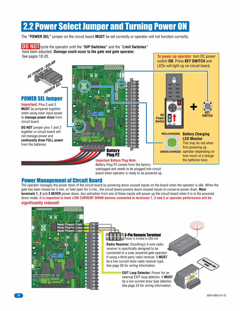
2.2 Power Select Jumper and Turning Power ONThe “POWER SEL” jumper on the circuit board MUST be set correctly or operator will not function correctly.
The operator manages the power drain of the circuit board by powering down unused inputs on the board when the operator is idle. When the gate has been closed for 5 min. or held open for 5 min., the circuit board powers down unused inputs to conserve power drain. Main terminals 1, 2 and 3 NEVER power down. Any activation from one of these inputs will power up the circuit board when it is in the powered down mode. It is important to have LOW CURRENT DRAW devices connected to terminals 1, 2 and 3 or operator performance will besignificantly reduced!
12
34
56
78
ON
12
34
56
78
ON
1 2 3 4 5 6 7 8 9 10
20
19181716
151413
121110
9876
5432
1
EXITLOOP
REVERSELOOP
AC POWER/SOLAR
POWER SEL
REV SENSE
P3
SELF TEST
RESET
RED=CHARGING
GREEN=CHARGED
KEYSWITCH
NO
NC
3 BUTTONCONTROL
SW1
SW2
OFF ON
POWER
P4
P2
1 6
TIME DELAY
12
34
56
78
ON
1 2 3 4 5 6 7 8 9 10
20
19181716
151413
121110
9876
5432
1
EXITLOOP
REVERSELOOP
AC POWER/SOLAR
POWER SEL
REV SENSE
P3
SELF TEST
RESET
RED=CHARGING
GREEN=CHARGED
NO
NC
3 BUTTON
SW2
OFF ON
POWER
P4
P2
1 6
TIME DELAY
DO NOT cycle the operator until the “DIP-Switches” and the “Limit Switches” have been adjusted. Damage could occur to the gate and gate operator.See pages 18-20.
Important Battery Plug Note:Battery Plug P2 comes from the factory unplugged and needs to be plugged into circuit board when operator is ready to be powered up.
EXIT Loop Detector: Power for an external EXIT loop detector. It MUST be a low current draw type detector. See page 24 for wiring information.
Radio Receiver: DoorKing’s 3-wire radio receiver is specifically designed to be connected to a solar powered gate operator. If using a third party radio receiver, it MUST be a low current draw radio receiver type. See page 26 for wiring information.
BatteryPlug P2
Power Management of Circuit Board
POWER SEL Jumper
RED=CHARGING
GREEN=CHARGED
Power is limited to 250 mA3-Pin Remote Terminal1 2 3
Important: Pins 2 and 3 MUST be jumpered together when using solar input power to manage power drain from circuit board.
DO NOT jumper pins 1 and 2 together or circuit board will not manage power and continually draw FULL power from the batteries.
AC POWER / SOLAR
POWER SEL
12
3
Never Powers DownNever Powers DownNever Powers Down
DCPOWER
ALARMRESET
ON
OFF
DCPowerSwitch
KEYSWITCH
Battery ChargingLED Monitor
To power up operator: turn DC power switch ON. Press KEY SWITCH and LEDs will light up on circuit board.
This may be red when first powering up operator depending on how much of a charge the batteries have.
RED=CHARGING
GREEN=CHARGED
+
Diablo
Controls, In
c.
Stuck in traffic
for over 37 years!
NCCOMRELAY
10 to 30 Volts
AC or DC
POWER
DETECT
DSP-7
POWERLOOP
COM+
NO
REM
OVE
CONN
ECTO
RTO
RES
ET
6524-066-D-5-1516

12
34
56
78
ON
12
34
56
78
ON
20
19181716
151413
121110
9876
5432
1
EXITLOOP
REVERSELOOP
POWER SEL
AC POWER/SOLAR
REV SENSE
P3
SELF TEST
RESET
RED=CHARGING
GREEN=CHARGED
KEYSWITCH
NO
NC
3 BUTTONCONTROL
SW1
SW2
OFF ON
POWER
P4
P2
1 6
TIME DELAY
94??Dual
Channel
4100-010
1 2 3 4 5 6 7 8 9 10
SECTION 3 - ADJUSTMENTS
3.1 4100 Circuit Board Descriptions and Adjustments
Self-test mode is for bench checks ONLY! Operator MUST be disconnected from the gate. The operator will continually cycle the gate.
The jumper must be set at normal mode for normal operater function.
Self-TestMode
NormalMode
Limit/Alarm
Plug P3Terminal
External Low Current DrawLoop Detectors
See page 24 and instruction sheetthat comes with loop detector
for more infornmation.
UL 325Terminal
See pages 22-23 and 26.
20-PinMain TerminalSee pages 25 and 26.
Battery Plug P2 Terminal
Self-Test
Inpu
t LED
s Se
e pa
ge 2
5.Tr
acke
rDa
ta
Input LEDs should be OFF and will only illuminate when the input that is next to the LED is activated. See page 25.Limit LEDs will only illuminate when the respective limit switch has been activated.
Limit LEDsSee page 20
Battery ChargingLED MonitorSee page 16
Power Select JumperSee Page 16
Illuminated LEDs Indicates that low voltage power is being applied to the circuit board.
How LEDs Function Adjust reversing sensitivity for the open AND close direction of the operator, See page 21.
Reverse Sensor
Auto-close timer(when turned on) SW 1, switch 2.
Time Delay:Adjust from 1 second (full counter-clockwise) to approximately 23 seconds (full clockwise).
Auto-Close Timer
ON
12
34
56
78
SW 1
DIP-Switches ON
12
34
56
78
SW 1
ON
12
34
56
78
SW 2
Set the DIP-switches on the circuit board to the desired setting. See switch-settings on next 2 pages.
REV SENSEMax Min
LED
Reset Button: Press after changing a DIP-switch setting on the board or if board locks up during operation.
Board RelayDry relay contacts (terminals 13-14) can be set for Normally Open (NO) or Normally Closed (NC) operation by placing the relay shorting bar on the N.O. or N.C. pins respectively. SW 1, switches 6 and 7 must be set to control relay. See next page for descriptions.
NC
NO
The switch settings and adjustments in this chapter should be made after your installation and wiring to the operator(s) is complete. Whenever any of the programming DIP-switches on the circuit board are changed, DC power switch must be shut-off, and then turned back on OR press reset button for the new setting to take effect.
DC Power Switch located inside.
Key Switch: Cycles the operator when pressed. Will use Auto-Close timer when turned ON (see above).
Note: When powering up operator, the key switch MUST be pressed AFTER DC power switch is turned ON to power up operator.
DO NOT USE REVERSE LOOP PORT
DO NOT USE EXIT LOOP PORT
Diablo
Controls, In
c.
Stuck in traffic
for over 37 years!
NCCOMRELAY
10 to 30 Volts
AC or DC
POWER
DETECT
DSP-7
POWERLOOP
COM+
NO
REM
OVE
CONN
ECTO
RTO
RES
ET
Note: Alarm reset button WILL NOT reset circuit board after changing DIP-switch settings.
6524-066-D-5-15 17

ON OFFOpens
ClockwiseOpensCounter-Clockwise
3.2 DIP-Switch Settings for 4100 Circuit Board
Switch Function Setting DescriptionSW 1 (Top 8 Switches)
OperatorOpeningDirection
OFFON
OFFON
OFF
OFFON
6-OFF6-OFF6-ON6-ON
7-OFF7-ON
7-OFF7-ON
Auto-CloseTimer
Accessory Power
Relay:Main TerminalsTerminal 13-14
1
2
3
4
5
8
6 and 7
Switch MUST be turned OFF for Solar.
Auto-close timer is OFF. Manual input required to close gate.Normal Setting. Auto-close timer is ON. Adjustable from 1-23 seconds.
24 VDC 500 mA Constant power for accessories connected to main terminal 12.DO NOT USE for Solar.
OFFON
Quick-close feature is OFF. Quick-close feature is ON. Opening gate will stop and begin to close as soon as all reversing inputs (Reverse loops, photo sensors) are cleared regardless of the distance the gate has opened. Used for slide gates only.Normal Setting. Relay activates when gate is at open limit. Relay activates when gate is not closed.Relay activates when gate is opening and open. Relay activates during opening and closing cycle.
Changes direction operator will cycle open upon initial power up and open command.
Reverses GateNot Used
Quick-CloseTimer Override
(Slide GatesONLY)
Not UsedInput to main terminal 10 and/or reverse loops will reverse gate during close cycle.Do Not use this setting for the 6524.
The two DIP-switches located on the circuit board are used to program the operator to operate in various modes and to turn on or off various operating features. Whenever a switch setting is changed, reset button must be pressed, located on circuit board for the new setting to take affect.
OFFON
Main terminal 10 is a REVERSE input.DO NOT USE for solar power.
1-OFF1-OFF1-ON1-ON
2-OFF2-ON
2-OFF2-ON
SelectOperator
Type1 and 2
DO NOT USE for the 6524. Slide Gate OperatorSwing Gate OperatorDO NOT USE for the 6524. Barrier Gate Operator DO NOT USE for the 6524. Overhead Gate Operator
Switch Function Setting DescriptionSW 2 (Bottom 8 Switches)
Switches 7 and 8 MUST be turned OFF for Model 6524 operator.OFF
Reverse/ShadowInput
OverlappingBi-Parting Gates
3
4
7 and 8
6
OFFON5
Switch 5 MUST be turned OFF for the 6524.DO NOT USE for solar power. Overlapping gates ARE used (Dual swing gates ONLY). Secondary gate starts to open a few seconds before primary gate starts.
OFFONInput Power
Failure Mode
DO NOT USE for Solar.Gate operates normally until batteries get low. Gate will CLOSE and Shutdown operator in close position until battery power reaches an operable level again.
OFFON
Circuit BoardPower
Management
DO NOT USE for Solar. For 115/230 VAC input power. Board has Constant power.Used for Solar input power. Board Minimizes power when not in use. All terminals shut down power except main terminals 1, 2 and 3.
Not Used
Setting MUST be used
6524-066-D-5-1518

3.2 Continued
SW-1 Switch(Top 8 switches oncircuit board)
SW-2 Switch(Bottom 8 switches oncircuit board)
ON
12
34
56
78
SW 1
ON
12
34
56
78
SW 2Typical SettingsMUST use - OFFMUST use - ONMUST use - ON
MUST use - OFFMUST use - OFFMUST use - ON
MUST use - OFFMUST use - OFF
Typical SettingsOpening - RT/LT
Normal - ONMUST use - OFFMUST use - OFFMUST use - OFF
Normal - OFFNormal - OFF
MUST use - OFF
Switch 1 - Operator Opening Direction: Must OPEN the operator’s gate upon initial DC power up and open command. If the first open command begins to close the gate, turn DC power off and reverse this switch.
Switch 2 - Auto-Close Timer: Turns the auto-close timer on or off. If auto-close is ON, maximum time that can be set for is approximately 23 secs.If auto-close is OFF, an open gate will not close until a manual input is received.
Switch 3 - EXIT Loop Port Output / Full Open Input: This switch MUST be turned OFF when using solar power. DO NOT turn this switch ON. DO NOT wire any devices to main terminal 4.
Switch 4 - Standard Reverse: This switch MUST be turned OFF for the Model 6524. An input to main terminal 10 (Photo Sensor) AND/OR Reverse Loops will reverse a CLOSING gate back to open position. If auto-timer is turned ON, timer will time out and close the open gate. Note: SW 2, switch 4 MUST also be turned OFF when an external entrapment device (Photo Sensor) has been wired to main terminal 10 (see below). DO NOT turn this switch ON.
Switch 5 - Quick-Close Timer Override: This switch MUST be turned OFF for the Model 6524. DO NOT turn ON.
Switches 6-7 - Relay: These work in conjunction with each other and determine when the relay on the board (main terminals 13-14) will be activated. This relay can be used as a switch for various functions such as illuminating a warning light when the gate is moving, or turning on a green light when the gate is full open. This relay is used for a shadow loop when using in-ground loops, see page 24.
Switch 8 - Accessory Power: This switch MUST be turned OFF when using solar power. A maximum of 500 mA of constant power is supplied to any accessory connected to main terminals 11 and 12. DO NOT turn this switch ON.
Switches 1-2 - Select Operator Type: Sets the type operator that will be used with the circuit board.
Switch 3 - Input Power Failure Mode: This switch MUST be turned ON when using solar power. In the event that the solar panel cannot charge the batteries and battery power gets depleted through normal gate cycling, gate will CLOSE and operator will shut down. When solar panel power begins charging the batteries and they reach an operable level, the gate will resume normal operation.DO NOT turn this switch OFF.
Switch 4 - Reverse/Shadow: This switch MUST be turned OFF. External entrapment device (Photo Sensor) OR a SHADOW LOOP wired to main terminal 10 is a standard reverse input (see SW 1, switch 4 above).DO NOT turn this switch ON.
Switch 5 - Overlapping Dual Gates: This switch MUST be turned OFF for the 6524. DO NOT turn ON for the 6524.
Switch 6 - Circuit Board Power Management: This switch MUST be turned ON when using solar power. It minimizes the power drain by the circuit board. When the gate has been closed for 5 min. or held open for 5 min., circuit board will power down to conserve power. Main terminals 1, 2 and 3 will remain powered up. An input from one of these connections will power up the circuit board again.DO NOT turn OFF when using solar power.
Switches 7-8 - Not Used: These switches MUST be turned OFF for the Model 6524. DO NOT turn ON.
6524-066-D-5-15 19

3.3 Limit Sensors
Loosen set screw to adjust the limit sensor.
Magnetic OpenLimit Sensor
Magnetic CloseLimit Sensor
Magnetic Sensor Activator
Magnetic sensor activator must be directly above the limit sensor to activate it.
The hub must not slip during operation. Tighten nut to stop any slipping.
CAUTION
DO NOT REMOVE HUB!
OPEN SENSORCLOSE SENSOR
CLOSE
OPEN
P3 Limit Sensors Plug
SW 1, Switch 1 Dip-Switch Settings
Note: If P3 plug is not connected to the circuit board and power is turned on, alarm will sound and operator will NOT function.
Important Limit Sensor Adjustment Note:It is very important NOT to cycle the gate operator before the limit sensors are in the correct position or it could cause damage to the gate and operator.With power ON, Manually release the gate operator hub with the release tool (See page 30). Physically move the gate to the desired open position. Loosen the set screw on the OPEN limit sensor and slowly slide it under the magnetic sensor activator until the OPEN limit Sensor LED lights up on the circuit board. Tighten the set screw and repeat this process for the close gate position. Secure the hub with the release tool and cycle the operator a few times and readjust if necessary.
Rele
ase
Tool
HUB
12
34
56
78
ON
32
1
EXITLOOP
REV SENSE
P3
SELF TEST
RESET
RED=CHARGING
GREEN=CHARGED
KEYSWITCH
3 BUTTONCONTROL
SW1
OFF ON
P4
TIME DELAY
1 2 3 4 5 6 7 8 9 10
Open
Clos
ennnn eeeeeeee
Limit Sensor LEDs
OpensClockwise
OpensCounter-Clockwise
ON
12
34
56
78
SW 1
ON
12
34
56
78
SW 1
ON OFF
6524-066-D-5-1520

Test the operator reversing sensitivity:
1
2
3
3.4 Inherent Reverse Sensor AdjustmentThis vehicular gate operator is equipped with an inherent adjustable reversing sensor (Type A) used as entrapment protection according to UL 325 standards. The gate will reverse direction after “physically” encountering an obstruction in either the opening or closing gate cycle.If the Auto-Close Timer (DIP-switch SW 1, switch 2) is ON and the gate physically encounters an obstruction during the CLOSING cycle, it will reverse to the open position and HOLD the gate at this position (Soft shutdown condition). Another input command is needed before the gate will reset and close again (open device command, safety device command, exit loop input).For the reverse sensors to function correctly, THE HUB MUST NOT SLIP when the gate encounters an obstruction. The gate must be properly installed and work freely in both directions. A good set of roller bearing hinges is essential for proper swing gate operation.For the reverse system to function correctly, the gate must be properly installed and work freely in both directions and the limit sensors must be properly adjusted BEFORE adjusting the reverse sensors. The ideal adjustment will allow the operator to move the gate through its entire travel cycle without reversing, but will reverse upon contact with an obstruction with no more than 40 Lbs of force. This force can be measured with a gate scale.
Note: “Push to Operate” button will use theAuto-Close timer if turned ON (SW 1, switch 2 ON).
CAUTION: Keep pedestrians and vehicles clear of the gate while adjusting and testing sensors!
Press the “Push to Operate” button to OPEN the gate.
Note: The LED will light up during the first seconds of gate travel. Wait until it turns off before adjusting the reverse sensor.
PUSH TO OPERATE
technician use only
PUSH TO OPERATE
technician use only
REV SENSEMax
Sensitivity
Note: The LED will turn on briefly when DC power is turned on.
Safety Note: The LED will remain ON after a cycling gate gets obstructed during normal operation to indicate that the reverse sensor has been tripped. Always check the gate area for possible obstructions before putting operator back in service.
While gate is opening, slowly rotate the reverse sensor clockwise until the LED lights up and the gate reverses direction. Rotate the reverse sensor back counter-clockwise approximately 1/8 turn to decrease the sensitivity (LED will turn off).
Press the “Push to Operate” button and CLOSE the gate.Make sure the gate closes completely. If it reverses andopens (LED will turn on), rotate the reverse sensorcounter-clockwise a little more to decrease the reversesensitivity (LED will turn off). Cycle the gate a few times to be sure that it cycles completely in both directions, adjusting the sensor as necessary.
Min
LED
Place an immobile object along the gate path, allowing the gate to strike it while in the open and close cycles. The gate must reverse direction after striking the object. If it does not, increase the reverse sensitivity and repeat this testing until the correct sensitivity has been achieved in BOTH directions. The operator will assume a soft shutdown (Hold the auto-close timer) after striking and reversing the gate which will require pressing the “Push to Operate” button to cycle the operator again.
6524-066-D-5-15 21

12
34
56
78
ON
12
34
56
78
ON
20
19181716
151413
121110
9876
5432
1
EXITLOOP
REVERSELOOP
AC POWER/SOLAR
POWER SEL
REV SENSE
JUMPER ONSOLAR MODE
P3
SELF TEST
RESET
RED=CHARGING
GREEN=CHARGED
KEYSWITCH
NO
NC
3 BUTTONCONTROL
SW1
SW2
OFF ON
POWER
P4
P2
1 6
TIME DELAY
1 2 3 4 5 6 7 8 9 10
External Entrapment Protection Device:In addition to the inherent reversing sensor system, the Model 6524 has a 10-pin UL 325 terminal for the connection of photo sensors-Type B1 external entrapment protection device required by UL 325 standards. Entrapment protection devices must be installed to reduce the risk of injury. Install these devices where the risk of entrapment or a hazard exists while the gate is moving. Specific installations will vary.
External Entrapment Protection Device Note:Specific gate installations may require more entrapment protection devices than are shown here. Install them where necessary to protect against ANY potential entrapment or hazard area.
SECTION 4 - ENTRAPMENT AND SAFETY PROTECTION
4.1 UL 325 Terminal Description
CLOSE Non-Contact Sensor (Photo Sensor): Obstructed closing-direction photo beam will STOP the gate during the closing-direction only. Gate will resume the close cycle when the obstructed photo beam has been cleared.Note: The closing-direction photo sensor typically should REVERSE the gate when the photo beam gets obstructed. See the next page for “Reverse” closing-direction option.
Low Voltage Common: Common terminals for all the external entrapment protection device inputs.
1
2
5 & 6
OPEN Non-Contact Sensor (Photo Sensor): Obstructed opening-direction photo beam will STOP the gate during the opening-direction only. Gate will resume the open cycle when the obstructed photo beam has been cleared.
Closing-Direction Photo Beam
Opening-DirectionPhoto Beam
Potential EntrapmentZone Hazard Area
Potential PinchPoint Hazard Area
PotentialPinch PointHazard Area
PotentialEntrapment
Area
PotentialHazard Area
PotentialHazard Area
Opening Gate
Closing Gate
Wall
Wall
UL 325 TerminalExternal Entrapment Protection
Device Connection
Low Voltage Comm
onLow Voltage Com
mon
CLOSE Contact SensorOPEN Contact SensorCLOSE Non-Contact SensorOPEN Non-Contact Sensor
Note: terminal can be unplugged from circuit board for easy wire connections.
All inputs are normally open (NO).
1 2 3 4 5 6 7 8 9 10
Com
to UL 325Terminal
to UL 325Terminal
24VDC 500 mAMAX
ON
12
34
56
78
SW 1
Photo Sensors POWER:Terminal 12 supplies 24 VDC, 500 mA of constant power for desired accessories.
SW1, switch 8MUST be OFF
6524-066-D-5-1522
12
34
56
78
ON
12
34
56
78
ON
20
19181716
151413
121110
9876
5432
1KEYSWITCH
NO
NC
3 BUTTONCONTROL
SW1
SW2
OFF ON
POWER
P4
6
1 2 3 4 5 6 7 8 9 10
#1 Common
#10NormallyOpen
“Reverse” Closing-Direction Option SW 1, switch 4
MUST be OFF.
SW 2, switch 4
MUST be OFF.
ON
12
34
56
78
SW 1
ON
12
34
56
78
SW 2
Non-Secure Side Outside Property
Secure Side Inside Property
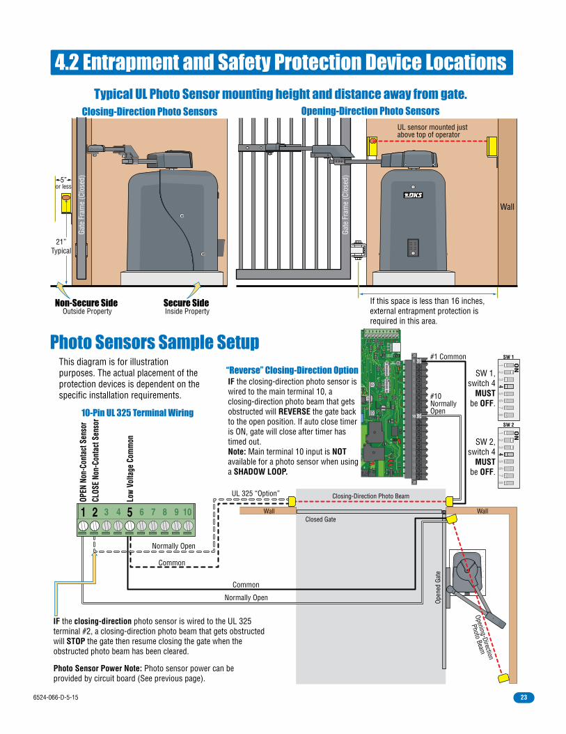
4.2 Entrapment and Safety Protection Device Locations
Photo Sensors Sample Setup
Typical UL Photo Sensor mounting height and distance away from gate.Opening-Direction Photo SensorsClosing-Direction Photo Sensors
Wall
UL sensor mounted justabove top of operator
Normally Open
Normally Open
Common
UL 325 “Option”
Common
If this space is less than 16 inches, external entrapment protection is required in this area.
or less5”
Gate
Fra
me
(Clo
sed)
Gate
Fra
me
(Clo
sed)
21”Typical
Open
ed G
ate
Wall Wall
Opening-Direction
Photo Beam
Closing-Direction Photo Beam
Closed Gate
10-Pin UL 325 Terminal Wiring
IF the closing-direction photo sensor is wired to the UL 325 terminal #2, a closing-direction photo beam that gets obstructed will STOP the gate then resume closing the gate when the obstructed photo beam has been cleared.
This diagram is for illustration purposes. The actual placement of the protection devices is dependent on the specific installation requirements.
OPEN
Non
-Con
tact
Sen
sor
CLOS
E No
n-Co
ntac
t Sen
sor
Low
Volta
ge C
omm
on
Photo Sensor Power Note: Photo sensor power can be provided by circuit board (See previous page).
IF the closing-direction photo sensor is wired to the main terminal 10, a closing-direction photo beam that gets obstructed will REVERSE the gate back to the open position. If auto close timer is ON, gate will close after timer has timed out.Note: Main terminal 10 input is NOT available for a photo sensor when using a SHADOW LOOP.
1 2 3 4 5 6 7 8 9 10
6524-066-D-5-15 23

DiabloControls, Inc.
Stuck in traffic for over 37 years!
NC COMRELAY
10 to 30 VoltsAC or DC
POWER DETECT
DSP-7
POWER LOOPCOM +NO
REM
OVE
CONN
ECTO
RTO
RES
ET
DiabloControls, Inc.
Stuck in traffic for over 37 years!
NC COMRELAY
10 to 30 VoltsAC or DC
POWER DETECT
DSP-7
POWER LOOPCOM +NO
REM
OVE
CONN
ECTO
RTO
RES
ET
Loop lead in wires are twisted approx. 6 twists per foot.
Reverse
Reverse
Automatic Exit
Shadow
4.3 Loop Detector Wiring• Loop detector wiring is shown for Diablo external loop detectors. If other loop detectors are used, refer to the installation instructions supplied with those detectors for wiring instructions.• DO NOT use EXIT or REVERSE loop ports on the circuit board• Loop layout shown is for a typical swing gate application with two-way traffic, or one-way exit only traffic.
To help protect the operator from accidentally closing on vehicles in the gate’s path, DoorKing highly recommends that loops and loop detectors be installed. Loops are laid underneath, cut into asphalt or concrete driveways or buried beneath gravel and earth driveways. A loop detection system will sense a vehicle like a metal detector and send a signal to the gate operator preventing the gate from automatically opening or closing on a vehicle when it is in the gate’s path. DoorKing recommends that a licensed installer perform this work.
Placed on each side of the gate to prevent the gate from closing on a
vehicle in the gate’s path. They will stop or reverse
the cycling of the gate while a vehicle is in or
near the gate’s pathway.
Will ONLY HOLD the gate in the Full Open Position when a vehicle is on the shadow loop. However, it WILL NOT stop or reverse the gate once it starts to close.
Automatically opens the gate for exiting vehicles without having to use a transmitter or keypad. The exit loop can be placed a minimum of 4 feet away from the
reverse loop or far enough away from the gate so the gate has started opening or even completely opened by
the time you drive up to it (Free exit).
4 Ft. min. to
avoid
gate movement
interference.
4 Ft. min. to
avoid gate
movement interference.
4 Ft. min. to
avoid
reverse loop
interference.
12
34
ON
12
34
56
78
ON
20
19181716
151413
121110
9876
5432
1
EXITLOOP
REVERSELOOP
IN POWER/BATT
PWRSEL
REV SENSE
P3
SELF TEST
RESET
RED=CHARGING
GREEN=CHARGED
KEYSWITCH
NO
NC
3 BUTTONCONTROL
SW1
SW2
OFF ON
POWER
P4
P2
1 6
TIME DELAY
4100-010
1 2 3 4 5 6 7 8 9 10
Note: See the specific loop detectorinstruction sheet for more information.
Com
ComSWITCHSSWW TCT
Full Open
24 VDC 500 ma max Power
24 VDC 250 mA max Power
Reverse/Shadow
RelayRelay
DiabloControls, Inc.
Stuck in traffic for over 37 years!
NC COMRELAY
10 to 30 VoltsAC or DC
POWER DETECT
DSP-7
POWER LOOPCOM +NO
REM
OVE
CONN
ECTO
RTO
RES
ET
Automatic Exit Loop
Reverse Loops
Shadow Loop
Loop lead in wires
Loop lead in wires
Loop lead in wires
24 VDC PowerJumper
24 V
DC P
ower
N.O.
N.O.
MUST connect to #3 24 VDC Power
MUST connect to #2 Full Open (N.O.)Single Channel Low Current DrawLoop Detector - P/N 9402-050
Reverse loop lead in wires are twisted approx. 6 twists per foot and are wired in series.
NCNO
Set Relay to N.O.
Swing Gate, Shadow Loop Dip Switch Note:
Relay:SW1,switch 6 OFFswitch 7 OFF
SW 2,switch 4 OFF
ON
12
34
56
78
SW 2
ON
12
34
56
78
SW 1
DO NOT USE LOOP PORTS
6524-066-D-5-1524
Never Powers Down
SECTION 5 - WIRING TERMINALS
12
34
56
78
ON
12
3
ON
20
19181716
151413
121110
9876
5432
1KEYSWITCH
NO
NC
3 BUTTONCONTROL
SW1
SW2
OFF ON
POWER
P4
6
1 2 3 4 5 6 7 8 9 10
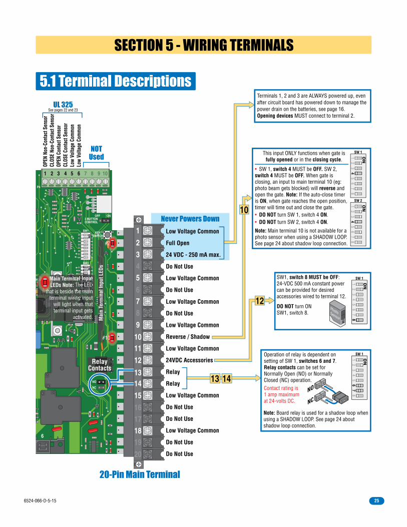
5.1 Terminal Descriptions
20-Pin Main Terminal
UL 325See pages 22 and 23
NOTUsed
RelayContacts
OPEN
Non
-Con
tact
Sen
sor
CLOS
E No
n-Co
ntac
t Sen
sor
OPEN
Con
tact
Sen
sor
CLOS
E Co
ntac
t Sen
sor
Low
Volta
ge C
omm
onLo
w Vo
ltage
Com
mon
W Main Terminal Input LEDs Note: The LED
that is beside the main terminal wiring input
will light when that terminal input gets
activated.
W MMML
tha
WE MMML
th
WE MMMMLLLL
thh
E MMMMLLLL
thhhh
E MMMMLLL
thhh
E MMMLLL
th
EE MML
t
ERR MM
t
ERR MRRRR
Mai
n Te
rmin
al In
put L
EDs
#2
#10
Low Voltage Common
Full Open
24 VDC - 250 mA max.
Do Not Use
Low Voltage Common
Do Not Use
Low Voltage Common
Do Not Use
Low Voltage Common
Reverse / Shadow
Low Voltage Common
24VDC Accessories
Relay
Relay
Low Voltage Common
Do Not Use
Do Not Use
Low Voltage Common
Do Not Use
Do Not Use
10
12
13 14
ON
12
34
56
78
SW 1SW1, switch 8 MUST be OFF: 24-VDC 500 mA constant power can be provided for desired accessories wired to terminal 12.
DO NOT turn ONSW1, switch 8.
PhotoSensor
• SW 1, switch 4 MUST be OFF. SW 2, switch 4 MUST be OFF. When gate is closing, an input to main terminal 10 (eg: photo beam gets blocked) will reverse and open the gate. Note: If the auto-close timer is ON, when gate reaches the open position, timer will time out and close the gate.• DO NOT turn SW 1, switch 4 ON.• DO NOT turn SW 2, switch 4 ON.
Note: Main terminal 10 is not available for a photo sensor when using a SHADOW LOOP. See page 24 about shadow loop connection.
ON
12
34
56
78
SW 1
ON
12
34
56
78
SW 2
This input ONLY functions when gate isfully opened or in the closing cycle.
Terminals 1, 2 and 3 are ALWAYS powered up, even after circuit board has powered down to manage the power drain on the batteries, see page 16.Opening devices MUST connect to terminal 2.
Operation of relay is dependent on setting of SW 1, switches 6 and 7. Relay contacts can be set for Normally Open (NO) or Normally Closed (NC) operation.Contact rating is1 amp maximumat 24-volts DC.
ON
12
34
56
78
SW 1
NC
NO
Note: Board relay is used for a shadow loop when using a SHADOW LOOP. See page 24 about shadow loop connection.
6524-066-D-5-15 25

18
ON
12
34
56
78
ON
20
19181716
151413
121110
9876
5432
1KEYSWITCH
NO
NC
3 BUTTONCONTROL
SW1
SW2
OFF ON
POWER
P4
6
1 2 3 4 5 6 7 8 9 10
Power is limited to 250 mamps.
Com
24 V
olt
Rela
y
3-PinRemote
Terminal 1 2 3Relay Com
Relay
24 Volt Com
24 Volt
4-WireRadio
Receiver
115V
EXIT
LOOP
REVERSE
LOOP
IN POWER/BATTPWR
SEL
REV SENSE
JUMPER ON
SOLAR MODE
P3
SELF TEST
RESET
RED=CHARGING
GREEN=CHARGED
KEY
SWITCH
NO
NC
3 BUTTON
CONTROL
SW1
SW2
OFFON
POWER
P4
P2
1
6
TIME DELAY
PUSH TO OPERATE
technician use only
5.2 Control Wiring
Stand-AloneKey Switch
Safety OpeningDevice
Stand-AloneKeypad
Stand-AloneCard Reader
TelephoneEntry
Reverse “Closing-Direction”Photo Sensors
UL 325 10-Pin Terminal
20-Pin Main Terminal
Note: All stand-aloneand telephone entry devices must use a separate power source.
3-Wire Radio Receiver
#2 N.O.
#10 N.O.
UL 325See pages 22 and 23
OPEN
Non
-Con
tact
Sen
sor
CLOS
E No
n-Co
ntac
t Sen
sor
OPEN
Con
tact
Sen
sor
CLOS
E Co
ntac
t Sen
sor
Low
Volta
ge C
omm
onLo
w Vo
ltage
Com
mon
ON
12
34
56
78
SW 1
ON
12
34
56
78
SW 2
Important: Controls intended for user activation must be located at least ten (10) feet away from any moving part of the gate and where the user is prevented from reaching over, under, around or through the gate to operate the controls. Emergency access controls only accessible by authorized personnel (e.g., fire, police, EMS) may be placed at any location in the line-of-sight of the gate.
Full Open
24 VDC
24 VDC
Com
Com
Com
Com
Com
Com
Com
NotUsed
24 VDC
24 VDC, 500 mA max accessories can be powered by main terminal 12.
Accessories Power
ON
12
34
56
78
SW 1
SW 1, switch 8MUST be OFF.
PhotoSensor
Do Not Use
Do Not Use
Do Not Use
Do Not Use
Do Not Use
Do Not Use
Do Not Use
Reverse/Shadow
Relay
Relay
SW 1, switch 4 MUST be OFF.SW 2, switch 4 MUST be OFF:After photo sensor beam gets obstructed, gate reverses back to open position. Auto timer will close gate.
Note: #10 input is NOT available for a photo sensor when a Shadow Loop is being used. Connect closing-direction photo sensor to #2 10-Pin UL 325 terminal, see page 23 for more information about UL 325 terminal.
1 ON
KKSWSSWWSS
SW1Never Powers Down
See page 16 about power management of
circuit board.
RelayContacts
6524-066-D-5-1526

DCPOWER
ALARMRESET
ON
OFF
SECTION 6 - OPERATING INSTRUCTIONS
WARNING - To reduce the risk of injury or death: 1. READ AND FOLLOW ALL INSTRUCTIONS. 2. Never let children operate or play with gate controls. Keep the remote control away from children. 3. Always keep people and objects away from gate. NO ONE SHOULD CROSS THE PATH OF THE MOVING GATE. 4. Test the operator monthly. The gate MUST reverse on contact with a rigid object or stop or reverse when an object activates the non-contact sensors. After adjusting the force or the limit of travel, retest the gate operator. Failure to adjust and retest the gate operator properly can increase the risk of injury or death. 5. Use the emergency release only when the gate is not moving and power has been shut-off. 6. KEEP GATES PROPERLY MAINTAINED. Read the owner's manual. Have a qualified service person make repairs to gate hardware. 7. The entrance is for vehicles only. Pedestrians must use separate entrance. 8. SAVE THESE INSTRUCTIONS.
Unlock the power switch cover and open to access the DC POWER switch and the operator ALARM RESET button.
6.1 DC Power Switch and Alarm Reset Button
Alarm Reset Button - Only used to turn off the entrapment alarm and to restart the operator AFTER a HARD shutdown has occurred.
Alarm Siren
IMPORTANT SAFETY INSTRUCTIONS
DC Power Switch - Powers the DC ON (toggle left) or OFF (toggle right).
Note: When powering up operator, the key switch
MUST be pressed (located on circuit board) AFTER DC
power switch is turned ON to power up operator.
6524-066-D-5-15 27

6.2 Shutdown ConditionsUnder various entrapment conditions the operator will assume either a soft or hard (alarm) shutdown. To determine what type of reset action is required, you will need to understand how the different entrapment conditions affect the gate operator.
This occurs in various situations where the inherent or external entrapment protection devices have been activated. In a soft shutdown condition, the operator will not respond to any input that was present when the entrapment protection device sensed an obstruction. If the gate stops at the open position, the operator will not respond to the automatic close timer.
NOTE: In some systems, the time clock input comes from the telephone entry system relay. This same relay may also provide open commands for a card reader, MicroPLUS transmitters and the visitor telephone entry. If so, these devices will also be disabled in a soft shutdown condition.
In some conditions, a soft shutdown will reset as soon as the entrapment condition clears. For example, if a non-contact sensor (photo sensor) is sensing an obstruction, the operator will stop the gate and assume a soft shutdown condition. When the photocell clears, the operator will return to normal operation.
When the operator is in a soft shutdown, activation of any “intended input” will reset the operator. An “intended input” includes any command input, any standard safety input and any loop input. Activating any of these inputs will reset the gate. At that point the gate will return to normal operation. If the gate is open, the automatic close timer will then time out and close the gate.
• Example 1 - A time clock keys the gate open in the morning and an entrapment protection device senses an obstruction prior to the gate reaching the full open position. If the entrapment is sensed by the inherent system, the gate will reverse and run back to the closed position. The time clock input is still present, but the gate will not re-open.
• Example 2 - If the gate is closing and an entrapment protection device is activated, the gate will either stop or reverse and run back to the open position, depending upon if the external or inherent device was activated. The automatic close timer will not close the gate.
• Example 3 - Vehicle arrives at open loop and gate runs towards the open position. The inherent entrapment protection is activated. The gate reverses and runs back to the closed position. If the vehicle is still present at the open loop a soft shutdown condition does not occur. The loop input provides an immediate reset of the operator and the gate will again run to the open position.
• Example - The gate is closing and the inherent entrapment protection system senses an obstruction and causes the gate to reverse direction. As the gate begins to run in the open direction, a second obstruction is sensed prior to the gate reaching the full open position. Once the second obstruction has been sensed, the operator will stop, the audio alarm will be activated and all standard inputs are shut down (including open commands, safety commands, loop inputs, etc.).
• After 5 minutes, the audio alarm will “chirp” every 5 seconds. This indicates that the operator is in a hard shutdown condition and the alarm reset button must be activated to reset the operator and silence the alarm.
Soft Shutdown
Resetting a Soft Shutdown
A hard shutdown condition occurs when the inherent entrapment protection system has sensed TWO consecutive obstructions before the gate reaches the full open or closed position.
Hard Shutdown (Alarm Activated)
The audio alarm will sound for five minutes, or until the operator’s alarm reset button is pushed. After (5) five minutes the alarm will “chirp every 5 sec.” and the hard shutdown condition will remain in affect until the alarm reset button is pushed.
Continued on the next page
6524-066-D-5-1528

6.3 Manual Gate OperationThis operator is equipped with a manual release system that will allow the gate to be pushed open in the event of a power outage or equipment failure. NEVER remove the hub from the operator after manually releasing it.
NOTE: DoorKing operators have a built-in alarm reset push button mounted on the operator above the power ON-OFF switch. Activating this button will return the gate operator to normal operation, but will not activate the gate operator.
When the operator is in a hard shutdown condition (audio alarm activated or audio alarm “chirps” every 5 seconds), to silence the alarm, press the alarm reset button.
Once the gate has been reset, an open or close command is needed to start the gate operator. Most activating commands will cause the gate operator to cycle to the open position. This includes activation of a key switch or open command and activation of the automatic exit loop. Activation of a close command will run the gate to the closed position.
• Before resetting a hard shutdown, determine why the shutdown occurred. Inspect the gate for any obstructions along its path that could have activated the inherent entrapment sensing system. Inspect the gate and gate hardware.
1. During normal powered operation, emergency vehicles access the gate by use of the Emergency Vehicle Access Device installed on your gate system. The type of device that is used in your community is dependent on your city codes. These devices may include (but are not limited to) Fire Department lock boxes, Click-2-Enter radio receivers, strobe light sensors, siren sensors, etc.
2. In the event of a power failure, The gate operator is equipped with a built-in Battery Back-Up System, this system will allow the gate operator to continue to function normally when solar input power is removed.
3. In the event of a solar input power failure and a back-up system (DC) power failure (low charged or dead batteries for example), the system must have a release system to allow the gate to be Manually Operated (See next page).
Resetting a Hard Shutdown
The automatic vehicular gate system must be designed to allow access to emergency vehicles under different operating conditions.
Emergency Vehicle Access Conditions
Never attempt to manually push open any gate with an operator attachedto it until you have verified that ALL power to the operator has been shut-off.
This gate operator CAN NOT be manually forced open in the event of apower failure without FIRST manually releasing the gate! (See next page)
DCPOWER
ALARMRESET
ON
OFF
AlarmResetButton
6524-066-D-5-15 29

Manual Release
Remove release tool and place where shown.
Release hub. Gate can now be manually operated.
B
C
Unlock the cover and rotate sliding door.
A
CAUTION
DO NOT REMOVE HUB!
Never attempt to manually push open any gate with an operator attached to it until you have verified that ALL power to the operator has been shut-off.
6524-066-D-5-1530

7.1 Maintenance
SECTION 7 - MAINTENANCE AND TROUBLESHOOTINGInspection and service of this gate operator by a qualified technician should be performed anytime a malfunction is observed or suspected. High cycle usage may require more frequent service checks.
When servicing the gate operator, always check any external reversing devices (loops, photo sensors, etc.) for proper operation. If external reversing devices cannot be made operable, do not place this operator in service until the malfunction can be identified and corrected.
Always check the inherent reversing system when performing any maintenance. If the inherent reversing system cannot be made operable, remove this operator from service until the cause of the malfunction is identified and corrected. Keeping this operator in service when the inherent reversing system is malfunctioning creates a hazard for persons which can result in serious injury or death should they become entrapped in the gate.
When servicing this gate operator, always turn ALL power OFF!!
If gearbox requires oil, use only Mobil SYNTHETIC SHC-629 Oil. Do not completely fill gearbox with oil. Gearbox should be half full only. Do not exceed this level.
OperatorComponent
MaintenanceMonthly Interval
63 12
Alarm
Arms
Batteries
Drive Belt
✓
✓✓
✓
✓
✓
✓
✓✓✓✓
Fire Dept.
Gate
Loop(s)
Release
Primary Reverse System
External Reverse Device
Complete System
Activate the primary (inherent) reverse system by blocking the gate with a solid object. When the gate reverses, block the gate in the opposite direction prior to the limit being reached. The entrapment alarm should activate. Press the alarm reset button to silence the alarm.
Check the batteries for any leakage or loose connections. Batteries should be replaced every two years.
Check set screws and nuts. Check bushings for wear.
Check for alignment, tightness and wear.
Check vehicular reverse and shadow loops for proper operation.
Check manual release for proper operation.
Complete check of gate and gate operating system.
Check emergency vehicle access device for proper operation.
Inspect for damage. Check gate hinges for wear and grease if necessary.
Check that the gate reverses on contact with an object in both the opening and closing cycles. Adjust the reversing sensor if necessary.
Check external reverse device(s) stop or reverse the gate when activated.
6524-066-D-5-15 31

7.2 TroubleshootingHave a good VOM meter with Min/ Max test button to check voltages and continuity. A Meg-Ohm meter capable of checking up to 500 meg-ohms of resistance is necessary to properly check the integrity of the ground loops. When a malfunction occurs, isolate the problem to one of three areas: 1) the operator, 2) the loop system, 3) the keying devices. Use caution when check-ing high voltage areas.
Symptom Possible Solution(s)
• Check that power to the operator is turned ON.• Check for DC power at the power input terminals. If power is absent, check incoming power to operator.• Be sure DC power switch is ON. Check for 24 VDC at P2, terminals 1 (+) and 2 (-). If no power, faulty bridge rectifier or toroidal transformer. If power is present, possible faulty board.
Operator will not run. Power LED is OFF.
1. Check the input indicator LEDs. They should only come ON when a keying device (card reader, push button, etc.) is activated. If any of the input LEDs are ON continuously, this will cause the gate operator to hold open. Disconnect the keying devices one at a time until the LED goes OFF.
2. Check any external entrapment protection devices. Any short or malfunction in these devices can cause the gate operator to stop or to hold open.
3. A malfunction in a loop or loop detector can cause the gate operator to hold open, or to not detect a vehicle when it is present over the loop. The LEDs on the loop detector will light only when the loop has detected an object above it. If the LEDs stays on after the object has gone, then the loop detector has malfunctioned. Disconnect the loop detector from the operator circuit board. If the malfunction persists, the problem is not with the loop system. For more information on trouble shooting loops and loop detectors, refer to your loop detector instruction sheet and to the DoorKing Loop and Loop Detector Information Manual.
4. Check to be sure that there are no shorted or open control wires from the keying devices to the gate operator. If a keying device fails to open the gate, momentarily jumper across terminals 1 and 2 (or 1 and 6) on the gate operator circuit board. If the gate operator starts, this indicates that a problem exist with the keying device and is not with the gate operator.
5. Check the input voltage supply. A voltage drop on the supply line (usually caused by using too small supply voltage wires) will cause the operator to malfunction.
• Check the reversing sensitivity.• Disconnect the gate from the gate operator and check that the gate slides freely without binding. Gate might be too heavy.• Continue troubleshooting.
Gate opens a short distance, then stops and reverses.
• Check ERD (Reverse Sensor) setting.Gate will not reverse when an obstruction is encountered.
6524-066-D-5-1532

Alarm sounds for 5 minutes and then chirps once every 5 seconds. Operator will not run.
Symptom Possible Solution(s)
• Check the input LEDs. Any ON will hold the gate open and indicates a problem with a keying device.• Check the external safety devices. Any activated will hold the gate open and indicates a problem with the safety device.• Check the loop detectors. Any activated can hold the gate open and indicates a problem with the loop detector or ground loop.• Operator may be in a “soft shutdown.” Activate any keying device to determine if operator returns to normal operation.• If automatic close is desired, be sure SW-1, switch 2 is ON.
Gate opens but will not close.
Gate closes but will not open.
Gate closes and then re-opens.
Gate starts to close, then reverses to open.
• Operator may be in a “soft shutdown.” Check input LEDs. If any are ON, momentarily disconnect, then re-connect the wire going to the respective terminal. Operator should open.• Check to be sure that the operator is running in the proper direction. Turn power OFF, and then back ON. Activate a keying device. Operator should run in the open direction. If operator runs in the close direction, turn power OFF and change direction switch SW-1, switch 1. Go to above section if operator now opens but will not close.• Be sure that the respective LED on the control board lights when the keying device connected to the respective terminal is activated. If LED does not light, momentarily place a jumper wire from terminal 1 to the input terminal being checked. If LED lights and gate opens, problem is with the keying device. If LED does not light, replace control board.
• Check that the reverse sensitivity is properly adjusted.• Disconnect the gate from the operator and check that the gate operates freely without any binding.• Check the loop detector LEDs and input LEDs. Any that flash ON will cause the gate to reverse.• Check for proper loop wiring. A mis-wired loop detector will cause the gate to reverse.• Continue troubleshooting.
• Check for any input or loop detector LEDs that are ON.• Check that the operator is running in the proper direction (see “gate closes but will not open” above).
• Operator is in a “hard shutdown” condition. Alarm Reset button must be pressed to return operator to normal operation. See pages 28 and 29 for “hard shutdown” information.
7.3 Built-in DiagnosticsThis gate operator is designed with built-in diagnostics that will alert you to potential or existing problems that the microproces-sor has detected. Specific fault conditions are checked and the operator will signal that a fault exist through the built-in alarm.Constant tone is heard when power is applied: This indicates that the limit switch wire harness is not connected to the circuit board. In this condition, the operator will not run and the tone will continue until the fault is corrected. Check to be sure that the limit switch plug is properly inserted into P3.
Constant tone is heard: This indicates that the operator is in a hard shutdown condition. The tone will continue to sound for five minutes, and then will beep once every five seconds. The alarm reset button must be pressed or power must be removed and then reapplied to return the operator to normal operation.
Short tone is heard every five seconds: This indicates that the operator has been in a hard shutdown condition in excess of five minutes. This will continue until the alarm reset button is pressed or until power is removed from the operator.
Operator runs for 1 second and stops, two short tones are heard: This indicates that there may be a fault with the current sensor circuit. Check that the black current sensor wire has been passed through the hole in the current sensor donut with the correct number of loops (DC motor - 2 loops).
6524-066-D-5-15 33

7.4 Accessory ItemsThe following accessory items are available for the model 6524 swing gate operator.Contact Sensors - For use as a external entrapment protection device. Miller Edge, Inc., MGO20, MGR20, MGS20Photo Cell - Non-contact (photo-cells) sensors for use as a external entrapment protection device. MMTC, Inc. Model IR55 P/N 8080-010 Allen Bradley P/N 8080-011 Carlo Gavazzi Type PMP12 P/N 8080-030 Carlo Gavazzi Type PMT P/N 8080-031Magnetic Lock - Magnetic Gate Lock Kit provides an excellent means to secure swing gates and is a fail-safe device allowing emergency vehicle access upon power outage. P/N 1216-080 and P/N 1216-081Interconnection Cable - Interconnect wire cable contains all the necessary wires to interconnect primary / secondary operators. Cable length 30 feet. P/N 2600-755 Cable length 40 feet. P/N 2600-756 Cable length 50 feet. P/N 2600-757Time Clock - 7 day and 365 day time clocks can be used to automatically open gate at pre-set time and days. Compact clock fits inside the operator. P/N 2600-791 - 7 day clock P/N 2600-795 - 365 day clockUphill Arm Pivot Assembly - Ball joint pivot gate connection used on uphill or downhill opening swing gates. P/N 6500-490Torsion Rods - Torsion rod assembly is used on uphill swing gates for counter balance. P/N 1203-084Hinges - Heavy-duty ball bearing hinges provide easy swing gate operation. P/N 1200-009, P/N 1200-019, P/N 1200-039.Surge Devices - High and low voltage surge suppressors help prevent circuit board failure caused by lightning strikes and power surges. P/N 1879-010 - High Voltage P/N 1878-010 - Low VoltageSpeed Bumps - Prefabricated six-foot speed bump reduces traffic speed through gate system. P/N 1610-15012 Volt 18 Amp/Hr Extended Battery - P/N 1801-004. Two (2) required.24 VDC Solar Power Kit - P/N 2000-070.Low Current Draw External Loop Detector - Detectors are solar friendly and mount into solar control box. Single channel detector - P/N 9402-050
6524-066-D-5-1534

7.5 Gearbox Shaft Extension Replacement
Gearbox Shaft Extension with 4 Keys P/N 6500-147
Key
Crank Arm
Key
Key
Key
Gearbox P/N 2600-717
Snap Ring P/N 2630-007Stainless Steel Washer P/N 2620-075
Limit Sensors Collar P/N 6500-115
Crank Arm Only P/N 6500-255
Control Arm Only P/N 2600-714
Complete Arm Kit P/N 6500-430
P/N 6500-135 Brass Bushing 1 1/8” ID
Hub Assembly Remove the TWO allen screws on bottom of hub to remove the complete hub assembly.
Limit Sensor Assemblies Loosen screws on plastic limit assemblies to remove them. Be CAREFULnot to damage limit sensor wires after the assemblies have been removed.Note: Close Limit Sensor assembly must be reinstalled on TOP of Open Limit Sensor assembly.
Gearbox Collar P/N 6500-146Remove the FOUR allen screws to remove the gearbox collar.
1
1
34
2
2
Screws
CLOS
E
OPEN
6524-066-D-5-15 35
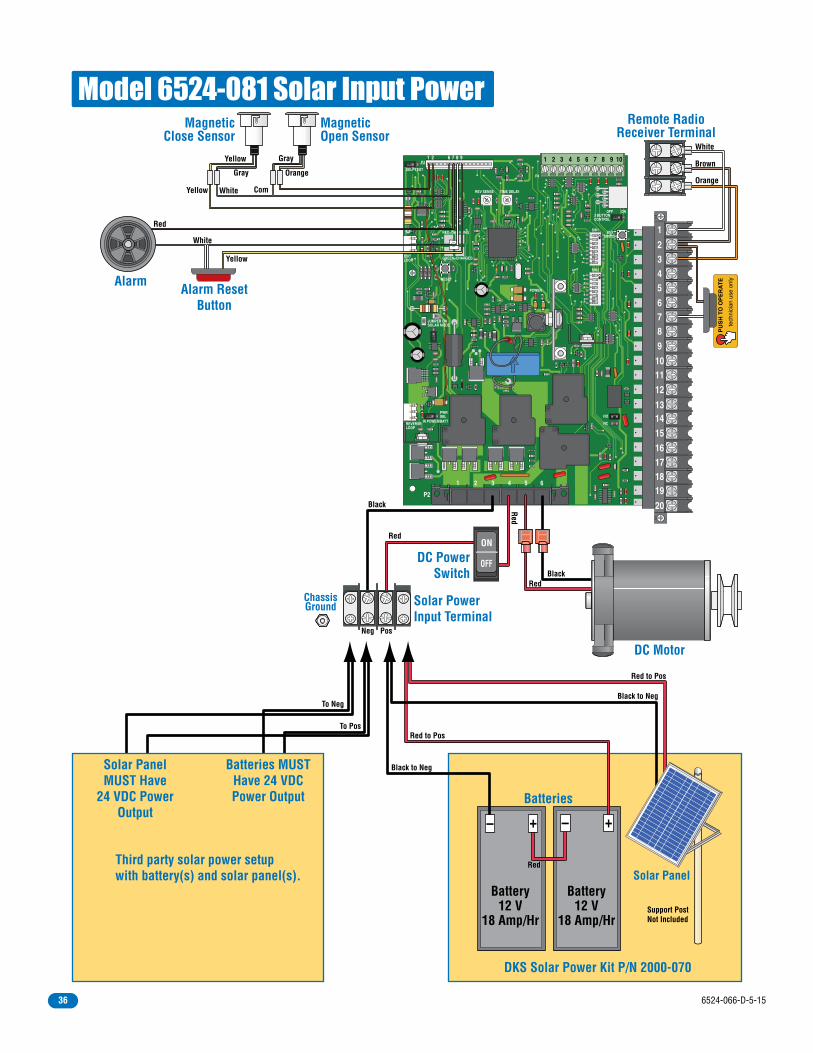
12
34
56
78
ON
12
34
56
78
ON
20
19181716
151413
121110
9876
5432
1
EXITLOOP
REVERSELOOP
IN POWER/BATT
PWRSEL
REV SENSE
JUMPER ONSOLAR MODE
P3
SELF TEST
RESET
RED=CHARGING
GREEN=CHARGED
KEYSWITCH
NO
NC
3 BUTTONCONTROL
SW1
SW2
OFF ON
POWER
P4
P2
1 65432
TIME DELAY
11 2 6 7 8 9 2 3 4 5 6 7 8 9 10
Alarm ResetButton
DC Motor
DC PowerSwitch
Com
Red
Red
Red
Black
Orange
Brown
White
White
White
Yellow
Yellow
Red
PU
SH
TO
OP
ER
AT
E
tech
nici
an u
se o
nly
Remote RadioReceiver Terminal
Alarm
MagneticOpen Sensor
Gray
Gray
Orange
Yellow
MagneticClose Sensor
DKS Solar Power Kit P/N 2000-070
Solar Panel
Support PostNot Included
Red to Pos
Red to Pos
Black to Neg
Black to Neg
To Neg
To Pos
Battery12 V
18 Amp/Hr
Battery12 V
18 Amp/Hr
Batteries
RedThird party solar power setupwith battery(s) and solar panel(s).
Batteries MUSTHave 24 VDCPower Output
Solar PanelMUST Have
24 VDC PowerOutput
Solar PowerInput Terminal
Black
ChassisGround
Neg Pos
OFF
ON
Model 6524-081 Solar Input Power
6524-066-D-5-1536

6524-066-D-5-15 37

Copyright 2009 DoorKing, Inc. All rights reserved.
www.doorking.com
DoorKing, Inc.120 S. Glasgow Avenue
Inglewood, California 90301U.S.A.
Phone: 310-645-0023Fax: 310-641-1586
Use this manual for circuit board 4100-010 Revision D or higher.
Model 6524-081Model 6524-081Model 6524-081Installation/Owner’s ManualSolar Powered Vehicular Swing Gate Operator
6524-066-D-5-15