
6200 Instl Manual 2017 - Rochester Gauges
11
ROCHESTER GAUGES INTERNATIONAL S.A. Z.I. WAVRE NORD - AVENUE LAVOISIER, 6 - 1300 WAVRE – BELGIUM Phone: +32(0)10241010 Fax: +32(0)10228139 Web site: http://www.rochester-gauges.be E-mail: [email protected] 6200 SERIE LIQUID LEVEL GAUGES INSTALLATION MANUAL READ COMPLETELY BEFORE ATTEMPTING INSTALLATION Consumers are not qualified to perform installation described below. For any question, please contact Rochester Gauges or authorized distributor for assistance. WARNING: Improper installation or use of this product may cause serious injury or property damage.
-
Upload
khangminh22 -
Category
Documents
-
view
0 -
download
0
Transcript of 6200 Instl Manual 2017 - Rochester Gauges

ROCHESTER GAUGES INTERNATIONAL S.A. Z.I . WAVRE NORD - AVENUE LAVOISIER, 6 - 1300 WAVRE – BELGIUM
Phone: +32(0)10241010 Fax: +32(0)10228139 Web site: http://www.rochester-gauges.be E-mail: [email protected]
6200 SERIE
LIQUID LEVEL GAUGES
INSTALLATION MANUAL
READ COMPLETELY BEFORE ATTEMPTING INSTALLATION
Consumers are not qualified to perform installation described below.
For any question, please contact Rochester Gauges or authorized distributor for
assistance.
WARNING: Improper installation or use of this product may cause serious injury
or property damage.

6200 Inst. Manual PAGE 2
Table of Content:
1. Product description...............................................................................page 3
2. Mounting position.................................................................................page 3
3. Model identification..............................................................................page 3
4. Inspection of gauge...............................................................................page 4
-Stem length.........................................................................................page 5
-Float length.........................................................................................page 5
-Mounting position...............................................................................page 5
-Counterweight – Float buoyancy.........................................................page 5
-Operation – Float movement..............................................................page 6
5. Marking................................................................................................page 6
6. Adapter-Flange.....................................................................................page 7
7. Installation............................................................................................page 8
8. Dial replacement...................................................................................page 8
9. Refrigerants Warning...........................................................................page 8
10. Troubleshooting.....................................................................................page 9
11. Warranty................................................................................................page 9
12. RMA (return of material authorisation) procedure..............................page 10
13. Declaration of conformity………………………………………………………………...page 11
+32(0)10.24.10.10

6200 Inst. Manual PAGE 3
11.. PPRROODDUUCCTT DDEESSCCRRIIPPTTIIOONN::
6200 gauges serie are mechanical float arm type, magnetically coupled to dial to be installed on storage tanks with diameter up to 2000mm. These are currently used to gauge products such as LPG, Ammonia, Refrigerants, DME, Hydraulic oils, Fuel Oil, etc... The gauge operates by means of a float actuating a powerful magnet inside the flange (head) which in turn provides an invisible magnetic coupling (through the leak-tight flange) together with the magnet of the dial pointer. The dial may be removed and replaced quickly at any time without loss of liquid, pressure, vacuum or costly downtime. These gauges are designed for pressure up to 30 bars and temperature of -40°C to +70°C if adequate construction materials are used.
22.. MMOOUUNNTTIINNGG PPOOSSIITTIIOONN::
① TOP ② END ③ SIDE ④ ANGLE *
(*) angle to be specified from horizontal pane (positive above horizontal, negative below)
33.. MMOODDEELL IIDDEENNTTIIFFIICCAATTIIOONN::
JUNIOR : Ø40mm dial Ø51.6mm bolt circle SENIOR : Ø50/100mm dial Ø63.5mm bolt circle
MODEL N° FLANGE SIZE DIAL MOUNTING
6241 JUNIOR
TWINISTE™ (ELECTRICAL OUTPUT DIAL)
TOP 6244 END / SIDE /ANGLE 6240
SENIOR TOP
6243 END / SIDE /ANGLE 6260 SIDE READING TOP 6281
JUNIOR DIRECT READING Ø40MM TOP
6284 END / SIDE /ANGLE 6280
SENIOR DIRECT READING Ø50MM
TOP 6283 END / SIDE /ANGLE 6290
DIRECT READING Ø100MM TOP
6293 END / SIDE /ANGLE OPTIONS: -Brass head (B suffix) -Stainless Steel float bulb (A suffix)
-Aluminium float bulb -Metal cover (hinged) with window
50%
5%

6200 Inst. Manual PAGE 4
Senior 4’’ (Ø100mm) dial
Senior (Ø50mm) dial Junior (Ø40mm) dial
Twinsite™ Twinsite™
Twinsite™
44.. IINNSSPPEECCTTIIOONN OOFF GGAAUUGGEE::
Before attempting the installation of the gauge, check if the gauge is adequate for your application: the gauges are supplied packed in a cardboard box with a sticker indicating model number, main dimensions (Stem & Float), mounting position, tank dimensions for which the gauge has been manufactured and the product to be gauged.
PART NUMBER ___________________ CUSTOMER ______________________________________ PO N° _____________ QUANTITY ___________ BATCH N° __________ TYPE SCREW YES NO GASKET YES NO GAUGE INTENDED FOR __________________ TANK OUTSIDE DIAMETER ________________ TANK INSIDE DIAMETER ________________ RISER _____________ MOUNTING POSITION _____________ STEM _________ FLOAT __________

6200 Inst. Manual PAGE 5
Stem length: The pivot point (gears) of the float gauge should be on the mid height/diameter of the tank (50% content), hence the Stem length [S] should be:
• TOP / ANGLE mounting: S=0.5*OD+H [mm] • END / SIDE mounting: S=0.3*OD+H [mm]
Where “OD” is the tank outside diameter and “H” the riser length. Float length: The float arm is sized according to the dial indication (being 5-95% in most cases), the tank inside diameter (ID) and the float bulb length (to be half immerged for optimal accuracy):
• Nitrile float (63mm long): F=0.428*ID+31.5 [mm] • Aluminium float bulb (89mm long): F=0.428*ID+44.5 [mm] • Stainless Steel float (64mm long): F=0.428*ID+32 [mm]
Some particular applications may require another dial marking scale or another float bulb length, for which different formulas apply. In any case the float arm may not be longer than 0.5*ID-10 [mm]
*unless specified general manufacturing tolerances are +/- 3 [mm]
Mounting position: To check mounting position for which the gauge has been manufactured, hold the stem in the mounting position (vertical, horizontal or angle), move the float arm to the horizontal plane and check the needle on the dial indicates 50% +/-5%. Counterweight – Float buoyancy: Depending on liquid density, for low specific gravity the float arm is equipped with a counterweight to ensure float buoyancy (50% immerged into liquid). To check if the float arm has been counterbalanced to the product you intend to gauge, set the float bulb on a scale and maintain the float arm horizontally, the weight [W] should be: W=δ*V/2 [gr] with a tolerance of +/- 2[gr]
Where “V” is the float bulb volume (see table)
COUNTE
SCALE
H
I.D
.
O.D
STEM
FLOAT

6200 Inst. Manual PAGE 6
Float p/n Material Volume Length Weight for LPG
(δ=0.55) 0006-00620 Nitrile (standard) 36 [cm³] 63 [mm] 10 [gr]
0006-00406 Aluminium 46 [cm³] 89 [mm] 13 [gr] 0006-00407 Aluminium (short) 31 [cm³] 64 [mm] 9 [gr] 6045S00000 Stainless Steel 42 [cm³] 64 [mm] 12 [gr] 6085S00000 Stainless Steel (long) 62 [cm³] 89 [mm] 17 [gr]
Operation – Float movement: Although the gauges are 100% checked before packing, it is necessary to verify that the gauge has not been damaged in transit. In order to check this, hold the gauge in its intended mounting position and move the float arm slowly upwards and downwards: the movement should be smooth without any heavy point allowing the dial needle to follow the float travel accordingly with the same smooth needle travel.
55.. MMAARRKKIINNGG::
The lateral sides of the head are marked with the necessary datas requested to identify the gauge, such as batch number, сє or R67 marking, tank data (if known) and model number. The presence of “B” letter prefix for batch number indicates the gauge has been manufactured by Rochester Gauges International S.A. Belgium.
BM-AA FFFF СЄ0029PP
max pressure [bar] notified body identification for PED batch number manufacturing year manufacturing month manufactured in Belgium
TTTT-stem-dia
gauge model (6281,...) Stem length [mm] tank diameter [mm]

6200 Inst. Manual PAGE 7
66.. AADDAAPPTTEERR -- FFLLAANNGGEE::
Typically an adapter (flange) is welded on the tank, check if the adapter is appropriate for gauge + gasket + mounting bolts:
FLANGE GASKET
BC OD ID L1 L2 TYPE OD ID TH X
JUN
IOR
51.6 40.5 34.1 14 20 FLAT 39.3 32.9 2.4 1.6
40.0 34.0 14 20 O-RING 38.4 31.34 3.5 3.8
SENIO
R
63.5 53.2 42.0 14 20 FLAT 52 40.5 2.4 1.6
52.5 42.0 15 20 O-RING 47.9 40.87 3.5 4
Screw size Dry torque Gasket
Junior M6x25 or
1/4”x7/8”-28UNF 2.3 to 5.6 [Nm] Buna-N
Senior M8x25 or
5/16”x7/8”-24UNF 3.4 to 6.8 [Nm] Buna-N
CAUTION: do not over-torque. Do not re-torque later unless leaking. Over-tightening may
cause damage to head and gasket with a consequence of potential leaking path.
6200 Inst. Manual PAGE 8
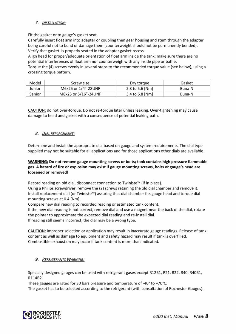
77.. IINNSSTTAALLLLAATTIIOONN::
Fit the gasket onto gauge’s gasket seat. Carefully insert float arm into adapter or coupling then gear housing and stem through the adapter being careful not to bend or damage them (counterweight should not be permanently bended). Verify that gasket is properly seated in the adapter gasket recess. Align head for proper/adequate orientation of float arm inside the tank: make sure there are no potential interferences of float arm nor counterweigh with any inside pipe or baffle. Torque the (4) screws evenly in several steps to the recommended torque value (see below), using a crossing torque pattern. Model Screw size Dry torque Gasket Junior M6x25 or 1/4”-28UNF 2.3 to 5.6 [Nm] Buna-N Senior M8x25 or 5/16”-24UNF 3.4 to 6.8 [Nm] Buna-N
CAUTION: do not over-torque. Do not re-torque later unless leaking. Over-tightening may cause damage to head and gasket with a consequence of potential leaking path.
88.. DDIIAALL RREEPPLLAACCEEMMEENNTT::
Determine and install the appropriate dial based on gauge and system requirements. The dial type supplied may not be suitable for all applications and for those applications other dials are available. WARNING: Do not remove gauge mounting screws or bolts; tank contains high pressure flammable
gas. A hazard of fire or explosion may exist if gauge mounting screws, bolts or gauge’s head are
loosened or removed!
Record reading on old dial, disconnect connection to Twiniste™ (if in place). Using a Philips screwdriver, remove the (2) screws retaining the old dial chamber and remove it. Install replacement dial (or Twiniste™) assuring that dial chamber fits gauge head and torque dial mounting screws at 0.4 [Nm]. Compare new dial reading to recorded reading or estimated tank content. If the new dial reading is not correct, remove dial and use a magnet near the back of the dial, rotate the pointer to approximate the expected dial reading and re-install dial. If reading still seems incorrect, the dial may be a wrong type. CAUTION: improper selection or application may result in inaccurate gauge readings. Release of tank content as well as damage to equipment and safety hazard may result if tank is overfilled. Combustible exhaustion may occur if tank content is more than indicated.
99.. RREEFFRRIIGGEERRAANNTTSS WWAARRNNIINNGG::
Specially designed gauges can be used with refrigerant gases except R12B1, R21, R22, R40, R40B1, R114B2. These gauges are rated for 30 bars pressure and temperature of -40° to +70°C. The gasket has to be selected according to the refrigerant (with consultation of Rochester Gauges).

6200 Inst. Manual PAGE 9
1100.. TTRROOUUBBLLEE SSHHOOOOTTIINNGG::
Even after having followed all above mentioned instructions some field problem may occur due to external sources, mishandling or environment effects. Typically encountered problems being listed below, please contact Rochester Gauges for any further assistance required.
SYMPTOM LOOK FOR:
Gauge not reading at low
extreme when installed in
empty tank
-Float striking obstructions such as dip pipes or baffles.
-Float or counterbalance striking tank wall -> incorrect gauge.
-Float not dropping under its own weight -> defective gauge.
-Float arm too short for counterbalance.
-Broken dial.
Gauge continues reading at low
extreme when tank is full
-Obstruction inside the tank bottom.
-Float improperly counterbalanced for liquid being gauged.
-Float leaks and is filled with liquid.
-Misalignment of counterweight (bended).
-Broken dial.
-Gears – Pinion drag.
Gauge reading at some
midpoint regardless of liquid
level
-Float or counterweight striking internal obstructions.
-Float partially sunk due to leakage or improper
counterbalancing.
-Float hung/loose.
-Dial pointer stuck due to damage or corrosion.
-Incorrect or modified float arm installed on gauge.
-Gears – Pinion drag.
Gauge indicating liquid level
inaccurately
-Gauge not fitting the tank -> incorrect gauge.
-Mounting coupling/flange not aligned with tank axis.
-Tank is not level.
-Liquid – Temperature volume changes not accounted for.
-Gears – Pinion drag.
1111.. WWAARRRRAANNTTYY::
From date of invoice, Rochester Gauges International S.A. guarantees its products for a period of 12 months. This warranty is limited to the product supplied and consists of repair or replacement of the defective part, after inspection in our factory. Incriminated product should be shipped back (at customer’s expenses) according to RMA procedure, unless agreed otherwise by the parties (contact customer service [email protected] ). No claim for misapplication, labour, direct or consequential damage will be allowed.
6200 Inst. Manual PAGE 10
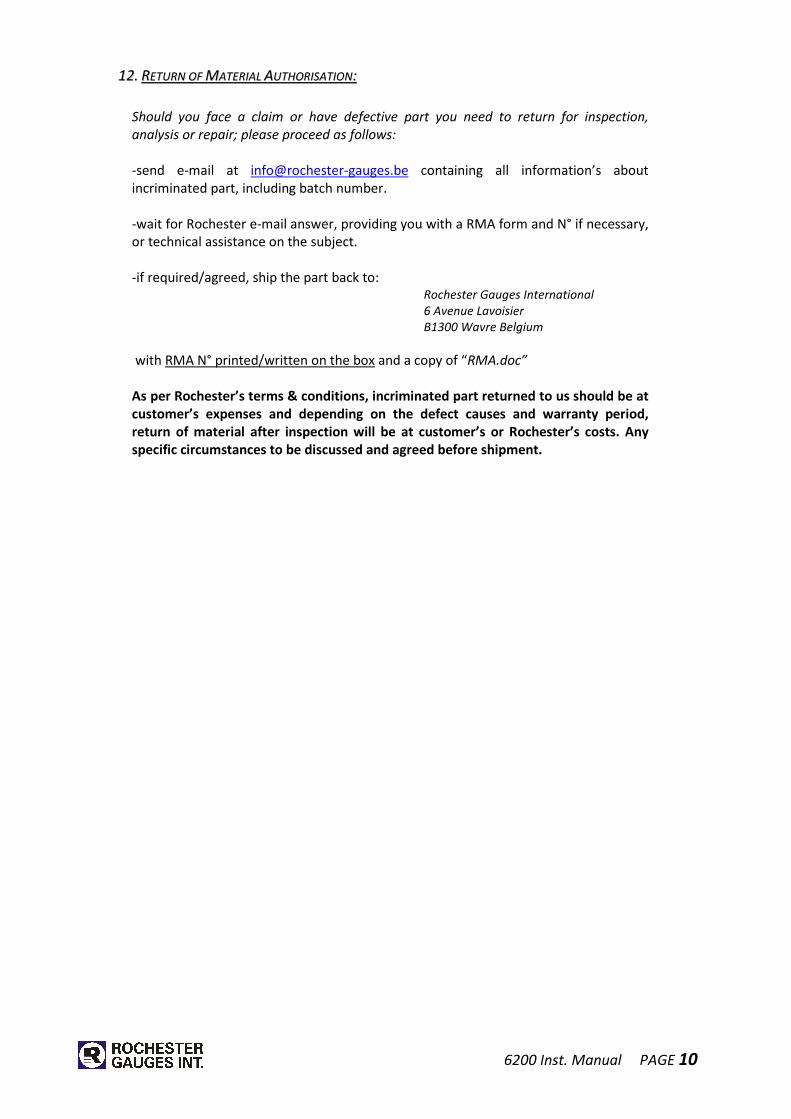
1122.. RREETTUURRNN OOFF MMAATTEERRIIAALL AAUUTTHHOORRIISSAATTIIOONN::
Should you face a claim or have defective part you need to return for inspection,
analysis or repair; please proceed as follows:
-send e-mail at [email protected] containing all information’s about incriminated part, including batch number. -wait for Rochester e-mail answer, providing you with a RMA form and N° if necessary, or technical assistance on the subject. -if required/agreed, ship the part back to: Rochester Gauges International
6 Avenue Lavoisier
B1300 Wavre Belgium
with RMA N° printed/written on the box and a copy of “RMA.doc”
As per Rochester’s terms & conditions, incriminated part returned to us should be at
customer’s expenses and depending on the defect causes and warranty period,
return of material after inspection will be at customer’s or Rochester’s costs. Any
specific circumstances to be discussed and agreed before shipment.

6200 Inst. Manual PAGE 11
DECLARATION OF CONFORMITY (PED)
CERTIFICATE OF CONFORMITY (ATEX) (*1)
I, the undersigned, certify that the level gauge accessory for pressurised
tank of model manufactured under batch n°
intended for in our factory, 6 avenue Lavoisier, B-1300 Wavre, Belgium are in conformity with the essential safety requirements of the European Directive
Directive 97/23/CE + Art. 13 PED 2014/68/EU following modules B + D certified by:
APRAGAZ, chaussée de Vilvoorde 156, B-1120 BRUXELLES, Belgium This serie has been certified by the notify body n°0029 under the
certificates:
� Module B (EC Type examination): 02/BE/329
� Module D (Product process quality assurance system): 02/BE/330
The gauges have been manufactured in conformity with the EN 13799 (2012) Notes: - The Directive 2006/42/CE (Machinery) does not apply. - The Directive 2014/34/EU (ATEX) does not apply due to the fact that the gauge is not
an ignition or explosion source (Risk analysis approved by APRAGAZ Report E00162E06 available on request);
- (*1) In case of use of a sensor for remote reading, the Directive 2014/34/EU (ATEX) applies. Certificates can be downloaded from our web site www.rochester-gauges.be
Date: Lionel PIERRE
Managing Director