
6 V May 2018
12
6 V May 2018 http://doi.org/10.22214/ijraset.2018.5407
-
Upload
khangminh22 -
Category
Documents
-
view
0 -
download
0
Transcript of 6 V May 2018

6 V May 2018
http://doi.org/10.22214/ijraset.2018.5407

International Journal for Research in Applied Science & Engineering Technology (IJRASET) ISSN: 2321-9653; IC Value: 45.98; SJ Impact Factor: 6.887
Volume 6 Issue V, May 2018- Available at www.ijraset.com
2491 ©IJRASET: All Rights are Reserved
Design and Fabrication of Spur Gear Cutting Attachment for Lathe Machine
Chetan R. Patil1, Swapnil Sagar2, Shubham Gavhane3, Dipak Bachhav4, Abhishek Naik5
1Asst. Professor, Department of Mechanical Engineering, SIEM, Nashik
2,3,4,5 Students, Department of Mechanical Engineering, SIEM, Nashik
Abstract: The main objective of the project is to Design and Fabrication of Spur Gear Cutting Attachment for lathe machine for the purpose of Gear Cutting. As gear cutting operation are generally perform on milling machine and the initial cost of milling machine is also very high, which is not economical for the small scale industries and small workshops. So this attachment will reduce the initial investment cost of small scale industries for milling which can use their lathe machine for gear cutting operations. This will also reduce the space cover by the different type of machines and the remaining space can be used for other productive work output. Keywords: Gear cutting, lathe machine, milling, indexing, Attachment.
I. INTRODUCTION As population of developing country like India is increasing day by day, which has result to increase in demand of various type of different products. This has leads to increase in setup of large number of various industries, most of them are small scale industries and small workshops which provide various services to different large scale industries. Cost reduction is the one of the major factor that is consider in setup of small scale industries and small workshops. If industry can reduce the production cost or the cost required for procurement of any machine then it will indirectly result in reducing the selling cost and increase the overall economy of that industry as well as the consumer.
II. RELEVANT THEORY A. Gears Gears are toothed wheel used to transmit power for small distances. It is positive types of drive and mostly preferred in machines. The important use of various types of gears are as follows- 1) Spur gear-sliding mesh gear box, machine tool gearbox 2) Helical gear- automobile gear box 3) Rack & pinion- lathe carriage, steering gear box 4) Worm & worm wheel- wiper mechanism, material handling equipment’s gear box, steering gear box 5) Bevel gear- automobile differential gear box 6) Spiral gear-drives in textile machineries 7) Lathe Machine – Lathe Machine is one of the oldest machine tool and is to remove metal from a workpiece to give it the
required shape and size, by performing some machining operation on workpiece . The lathe consist of a bed, a head stock, a carriage with cross slide, and tool post mounted on the cross slide. The spindle which carries the work holding device is driven by motor usually through a gear box for obtaining various speeds. The carriage moves on the bed guide ways, parallel to the axis of the work spindle, and cross slide provides transverse motion the require power for movements is obtained a feed shaft geared to the spindle drive.
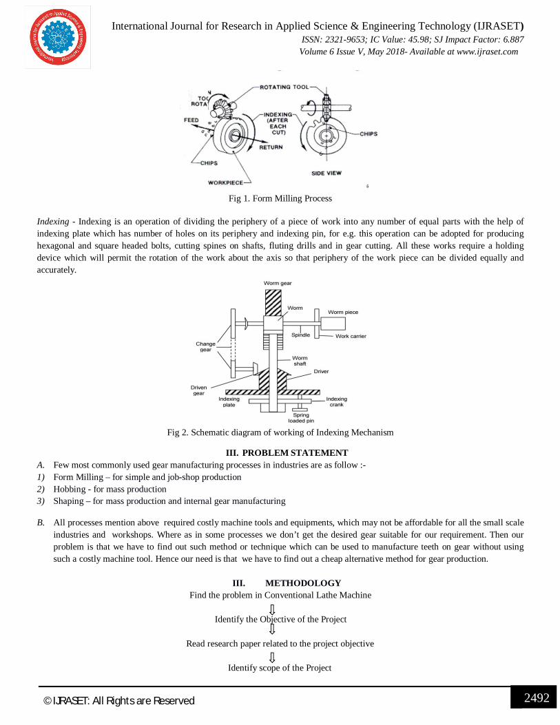
8) Form Milling - From figure the working principle of form milling can be understand, cutter is mounted on arbour with its axis right angle to work piece. Indexing plate provided for indexing movement of work piece which is generally used in gear cutting. In single pass one tooth is finished hence it is time consuming process and suitable for job production.
International Journal for Research in Applied Science & Engineering Technology (IJRASET) ISSN: 2321-9653; IC Value: 45.98; SJ Impact Factor: 6.887
Volume 6 Issue V, May 2018- Available at www.ijraset.com
2492 ©IJRASET: All Rights are Reserved
Fig 1. Form Milling Process
Indexing - Indexing is an operation of dividing the periphery of a piece of work into any number of equal parts with the help of indexing plate which has number of holes on its periphery and indexing pin, for e.g. this operation can be adopted for producing hexagonal and square headed bolts, cutting spines on shafts, fluting drills and in gear cutting. All these works require a holding device which will permit the rotation of the work about the axis so that periphery of the work piece can be divided equally and accurately.
Fig 2. Schematic diagram of working of Indexing Mechanism
III. PROBLEM STATEMENT A. Few most commonly used gear manufacturing processes in industries are as follow :- 1) Form Milling – for simple and job-shop production 2) Hobbing - for mass production 3) Shaping – for mass production and internal gear manufacturing
B. All processes mention above required costly machine tools and equipments, which may not be affordable for all the small scale industries and workshops. Where as in some processes we don’t get the desired gear suitable for our requirement. Then our problem is that we have to find out such method or technique which can be used to manufacture teeth on gear without using such a costly machine tool. Hence our need is that we have to find out a cheap alternative method for gear production.
III. METHODOLOGY
Find the problem in Conventional Lathe Machine
Identify the Objective of the Project
Read research paper related to the project objective
Identify scope of the Project

International Journal for Research in Applied Science & Engineering Technology (IJRASET) ISSN: 2321-9653; IC Value: 45.98; SJ Impact Factor: 6.887
Volume 6 Issue V, May 2018- Available at www.ijraset.com
2493 ©IJRASET: All Rights are Reserved
Initial Design of component of Attachment
Finalizing Design of Attachment
Selection of material for the component of Attachment
Fabrication of the Attachment
Result and Discussion
IV. DESIGN A. Design of Worm and Worm Wheel Manual force ( Input ) Assume = 250 N Revolution of indexing pin per minute we calculate for time 1 min is 20 rpm. N1= 20 rpm Gear Ratio= 40:1
= =
N2= × = = 0.5 rpm N2=0.5 rpm Pin= = ( × )
Pin = × × × ) = 5.2359 watt
μ =0.051
√vs + 0.4
Pitch line velocity (V1) =
= × × = 0.02094 m/sec tan훾 =
or
훾 = 푡푎푛 1
10
훾= 5.71° Z1/Z2/q/m =
1/40/10/2
d1 =20 mm
d2= m × 푍2 d2 = 80 mm C.D. = 10 + 40 = 50 mm Px ( axial pitch )= 휋푚 = 2 × 휋 = 6.28푚푚 Lead =휋푚푧1 =휋 × 2× 1 = 6.28 mm Sliding velocity (vs) = = .
( . ) = 0.021044 m/sec
μ =0.051
√vs + 0.4=
0.051√0.021044 + 0.4

International Journal for Research in Applied Science & Engineering Technology (IJRASET) ISSN: 2321-9653; IC Value: 45.98; SJ Impact Factor: 6.887
Volume 6 Issue V, May 2018- Available at www.ijraset.com
2494 ©IJRASET: All Rights are Reserved
휇 = 0.07859
휑푣 = 푡푎푛 (휇푣) = 푡푎푛 휇
푐표푠휑푛
=푡푎푛 . = 4.7807° ñ= ( )
= .( . . )
=53.74% ñ =
Pout =5.2359× 0.5374 Pout = 2.8137 watt
B. Material 1) Worm :- case hardened steel 2) Worm & worm wheel :- Phosphorous bronze ( sand cast ) Sut= 240 N/푚푚 Reference – Machine design data book , V.B. Bhandari Pg. No 2.40 We select the dissimilar materials for worm & worm wheel because , motion of worm & worm wheel is sliding motion , hence considerable friction so that worm gear made of material having anti-scoring & anti-friction properties like Phosphorous bronze. Worm is subjected to repeatative bending & torsion hence worm is made of material having high strength & ductile like case hardened steel. Check Design safe or Not Module =2 d1= 20 mm & d2=80 mm C.D.= 50 mm 1/40/10/2 q =
= = 10
1) Beam strength Fb= 휎푏푔 × 푚푏 × 푦푐표푠훾
σbg = = = 80N/mm Lewis form factor Y = 0.0484− .
=0.0484− . Y =0.41225 B= 0.75× 푑1 Fb=( 80× 2 × 0.75 × 20 × 0.41225 × cos 5.71) Fb = 1475.32 N 2) Wear stength Fw = dg . b . k K:- worm gear wear factor Its value depends upon the material of worm & worm gear &value of lead angle 훾 훾=5.71< 10° Hence k=0.550 (Ref. Tech-max book DME-II ) Fw = 80× 0.75 × 20 × 0.550 Fw= 660 N Feff= ( )

International Journal for Research in Applied Science & Engineering Technology (IJRASET) ISSN: 2321-9653; IC Value: 45.98; SJ Impact Factor: 6.887
Volume 6 Issue V, May 2018- Available at www.ijraset.com
2495 ©IJRASET: All Rights are Reserved
Kv= but Vg is not given
Vg= = × × . = 2.09 × 10
Kv=( . × )
Kv = 0.996 ≈ 1 Feff =
×
= .. ×
= 1343.69 N As, Fb > 퐹푒푓푓 Fw > 퐹푒푓푓 Design is Safe. Tfinal diamension of worm and worm wheel is as follow - d1=20 mm d2=120 mm C.D. =10 + 60 =70 mm Lead = axial pitch =9.42 mm Lead angle 훾= 5.71 ° Pressure Angle 휑푛 = 20° Helix angle 훼 = 81.47° Length of worm (Lw) =33.30 mm
V. CAD MODEL AND ANALYSIS A. 3D model of Attachment Initial step of any component is to draft a 3D cad model, which give an overview of the component.
Fig 3. 3D model of Attachment Source: - Modelled by using Creo Parametric
B. Analysis of 3D model of Attachment The next step is to see that if the attachment can sustain the working load or not . This is done with the help of analysis software.

International Journal for Research in Applied Science & Engineering Technology (IJRASET) ISSN: 2321-9653; IC Value: 45.98; SJ Impact Factor: 6.887
Volume 6 Issue V, May 2018- Available at www.ijraset.com
2496 ©IJRASET: All Rights are Reserved
Fig. 4 Equivalent (Von-Mises) Stress
Fig. 5 Equivalent Total Strain
Fig. 6 Total Deformation
International Journal for Research in Applied Science & Engineering Technology (IJRASET) ISSN: 2321-9653; IC Value: 45.98; SJ Impact Factor: 6.887
Volume 6 Issue V, May 2018- Available at www.ijraset.com
2497 ©IJRASET: All Rights are Reserved
C. Analysis Results Maximum Stress 1.5336 Mpa Maximum Strain 8.2114e-6 mm/mm
Maximum Deformation 0.00011386 mm Table1. Result of Analysis
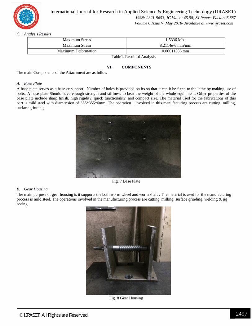
VI. COMPONENTS The main Components of the Attachment are as follow A. Base Plate A base plate serves as a base or support . Number of holes is provided on its so that it can it be fixed to the lathe by making use of bolts. A base plate Should have enough strength and stiffness to bear the weight of the whole equipment. Other properties of the base plate include sharp finish, high rigidity, quick functionality, and compact size. The material used for the fabrications of this part is mild steel with diamension of 355*355*6mm. The operation Involved in this manufacturing process are cutting, milling, surface grinding.
Fig. 7 Base Plate
B. Gear Housing The main purpose of gear housing is it supports the both worm wheel and worm shaft . The material is used for the manufacturing process is mild steel. The operations involved in the manufacturing process are cutting, milling, surface grinding, welding & jig boring.
Fig. 8 Gear Housing

International Journal for Research in Applied Science & Engineering Technology (IJRASET) ISSN: 2321-9653; IC Value: 45.98; SJ Impact Factor: 6.887
Volume 6 Issue V, May 2018- Available at www.ijraset.com
2498 ©IJRASET: All Rights are Reserved
C. Worm Wheel and Worm Shaft The main purpose of worm wheel and worm shaft is it gives the rotation to work piece after completion of single gear cutting operation . The material selected for the worm wheel is phosphrous bronze and worm shaft is EN8. For holding the worm wheel , a shaft manufactured by the material EN8 was selected and the manufacturing process are involved for the fabrication of the shaft are drilling, turning. The operation involved for the manufacturing of worm shaft are turning, threading .
Fig. 9 Worm Wheel
Fig. 10 Worm Shaft
D. Indexing Plate and Indexing Pin The main purpose of the index plate it gives equal spacing between teeth to of gear by the rotation of index pin on index plate . The material selected for index plate and crank is mild steel .The operation involved in manufacturing process are cutting, milling, and surface grinding.
Fig. 11 Indexing Plate and Indexing Pin

International Journal for Research in Applied Science & Engineering Technology (IJRASET) ISSN: 2321-9653; IC Value: 45.98; SJ Impact Factor: 6.887
Volume 6 Issue V, May 2018- Available at www.ijraset.com
2499 ©IJRASET: All Rights are Reserved
E. Milling Cutter The main purpose of cutter is to cutting the gear or blank . The material of cutter is high speed steel. The cutter module is 2 . The properties of the HSS are high hardness, high abrasion resistance, and the high temperature resistance .
Fig. 12 Milling Cutter
VIII. WORKING PROCESS F. Mechanism Of Gear Cutting Attachment To Lathe First remove the tool post from the lathe which is fixed on the compound slide. Now fixed the gear cutting attachment on the cross slide with bolts & nuts . The cutter is tightened to the mandrel with the help of washer & nut .Then one end of mandrel is fixed .Inside the three jaw chuck of the lathe with the help of chuck key .And another end is connected to the revolving dead centre . The workpiece ( gear blank ) is fixed on the spindle or shaft of the attachment andtightened with spacers & nut . The centre of cutter & workpiece is matched. The operation is started by switching ON the lathe. The mandrel in the chuck & revolving centre will revolve and the attachment is moved further by the cross slide i.e. workpiece to cutter. The gear cutting attachment will be started with the indexing mechanism. This operation will be continued till the complete gear teeth cuts.
Fig. 13 Final Setup of Attachment

International Journal for Research in Applied Science & Engineering Technology (IJRASET) ISSN: 2321-9653; IC Value: 45.98; SJ Impact Factor: 6.887
Volume 6 Issue V, May 2018- Available at www.ijraset.com
2500 ©IJRASET: All Rights are Reserved
IX. RESULT
Fig. 14 Gear Cut using the Attachment
A. Gears were successfully made from this attachment. B. Good surface finish is achieved. C. No skilled labour on the part of operator is required to operate the machine. D. The attachment does not vibrate due to machine vibrations good clamping arrangement has been made. E. The attachment is not that much heavy it can be easily transfer from one place to another. F. Different size of gear can been manufactured from this attachment.
X. CONCLUSION From the above result we can conclude that the attachment was successfully able to cut the gear teeth on blank . The design and fabrication of this project was successfully handled and every dimension was calculated by referring to published research on this topic. Thus this attachment can provide a cheap and economical alternative for the gear cutting machine for small scale industries and small workshops.
REFERENCES [1] S. Shinde et al. – “Attachment on Lathe Machine to Perform Gear Cutting Operation”,IJSRD, Vol.5, Issue 01, ISSN: 2321- 0613 (2017) [2] Parmar Harshad et al. – “Review Paper on Additional Attachment on Lathe For Manufacturing Of Gear”, IJAERD, Special Issue SIEICON-2017, e-ISSN: 2348
– 4470 Print-ISSN:2348-6406 (April 2017) [3] M. Sagar Kumar – “Design and Fabrication of Gear Cutting Attachment to Lathe For Machining a Spur Gear”, IJIET, Special Issue NCRTEEFOSS-2016,
ISSN: 2319-1058 (2016) [4] Godhakh Ramesh S. et al. – “Gear Manufacturing By Using Conventional Lathe Machine”, IJRET, Vol.05, Issue 05, ISSN: 2319-1163, ISSN: 2321-7308 (May
2016) [5] Neeraj Kumar et al. – “Analysis of Spur gear cutting using Milling Machine”, IJTRE,Vol.03, Issue 06, ISSN: 2347-4718 (February 2016). [6] K. Sandya et al. – “Static & Dynamic Analysis of Spur Gear using Different materials”, IRJET, Vol.03, Issue 01, ISSN: 2395-0056, ISSN: 2395-0072 (January
2016) [7] Vinayak Dalvi et al. – “Lathe attachment for Gear Manufacturing”, IJARIIE, Vol.03, Issue 02, ISSN: 2395-4396 (2017) [8] M. Kumara Swamy et al. – “Computer-Aided Optimal Design and Finite Element Analysis Of Plain Miling cutter” IJMER , vol.02 ISSN: 2249-6645 (Nov –
Dec 2012 [9] T. B. Rao et al. – “Modeling and Analysis of a plain milling cutter using FEA”, IJERD, Vol.06, Issue 07, ISSN: 2278-067X, ISSN: 2278-800X (April 2013) [10] A. P.Banginwar et al. – “Analysis of Gear Cutter using Finite Element Analysis”, IJERD, Vol.10, Issue 04, ISSN: 2278-067X, ISSN: 2278-800X (April 2014) [11] K. P. Kolhe et al. – “Review paper on analysis of worm gear”, IJRRCME, Vol.02, Issue 01, ISSN: 2393-8471 (April-September 2017).


![arXiv:1805.12282v1 [cs.CL] 31 May 2018](https://static.fdokumen.com/doc/165x107/63290d3d2dd4b030ca0c6924/arxiv180512282v1-cscl-31-may-2018.jpg)


![arXiv:1802.04799v2 [cs.LG] 20 May 2018](https://static.fdokumen.com/doc/165x107/63211233117b4414ec0b4b81/arxiv180204799v2-cslg-20-may-2018.jpg)