Brewing and liquor interests and German and Bolshevik ... - Loc
Upload
khangminh22Category
view
7download
0
B&R 2005 Modules • CPUs • CP340, CP360, CP380 and CP382
Cha
pter
3B&
R 2
005
Mod
ules
129B&R SYSTEM 2005 User's Manual V4.0
5.3 CP340, CP360, CP380 and CP382
5.3.1 General Information
The CP340, CP360, CP380 and CP382 are high-performance CPUs for the B&R SYSTEM2005. The CPUs are operated in the main rack directly beside the power supply module. Theyrequire two or three slots.
It is equipped with one or three insert slots for aPCI interface modules, a Compact Flashinterface for CF memory cards and a floating point unit. An RS232 programming interface, a USBinterface and a 10/100 BASE-T ETHERNET interface are available.
The aPCI insert slot for interface modules makes it possible to connect the CPUs to different busand network systems.
The Compact Flash interface allows the size of the memory to be adjusted to suit differentmemory requirements of many diverse applications.
The CPUs are especially useful for applications where lower cycle times are required, very largeamounts of data must be processed or for applications using the FPU.

130
B&R 2005 Modules • CPUs • CP340, CP360, CP380 and CP382
B&R SYSTEM 2005 User's Manual V4.0
5.3.2 Order Data
Model Number Short Description
CPU
3CP340.60-1 2005 CPU, x86 233 Intel-compatible, 16 MB DRAM, 512 KB SRAM, exchangeable application memory: Compact Flash, 1 insert slot for aPCI modules, 1 USB interface, 1 RS232 interface, 1 Ethernet interface 100 Base-T. Program memory must be ordered separately.
3CP360.60-1 1)
1) This CPU replaces the 3CP360.60-2. The 3CP360.60-1 has one additional USB interface.
2005 CPU, Pentium 266, 32 MB DRAM, 512 KB SRAM, exchangeable application memory: Compact Flash, 1 insert slot for aPCI modules, 1 USB interface, 1 RS232 interface, 1 Ethernet interface 100 Base-T. Program memory must be ordered separately.
3CP380.60-1 2005 CPU, Pentium III 500, 64 MB DRAM, 512 KB SRAM, exchangeable application memory: Compact Flash, 1 insert slot for aPCI modules, 1 USB, 1 RS232 interface, 1 Ethernet interface 100 Base-T. Program memory must be ordered separately.
3CP382.60-1 2005 CPU, Pentium III 500, 64 MB DRAM, 512 KB SRAM, exchangeable application memory: Compact Flash, 3 insert slots for aPCI modules, 1 USB, 1 RS232 interface, 1 Ethernet interface 100 Base-T. Program memory must be ordered separately.
Program Memory 2)
2) Program memory is required to operate the CPUs. It is not included with the delivery of the CPUs, instead it must be ordered as anaccessory.
5CFCRD.0032-01 Compact Flash 32 MB ATA/IDE SanDisk
5CFCRD.0064-01 Compact Flash 64 MB ATA/IDE SanDisk
5CFCRD.0128-01 Compact Flash 128 MB TrueIDE SanDisk
5CFCRD.0256-01 Compact Flash 256 MB ATA/IDE SanDisk
5CFCRD.0512-01 Compact Flash 512 MB ATA/IDE SanDisk
Accessories
0G0001.00-090 Cable PC <-> PLC/PW, RS232, online cable
Table 55: CP340, CP360, CP380 and CP382 order data

B&R 2005 Modules • CPUs • CP340, CP360, CP380 and CP382
Cha
pter
3B&
R 2
005
Mod
ules
131B&R SYSTEM 2005 User's Manual V4.0
5.3.3 Technical Data
Product ID CP340 CP360 CP380 CP382
General Information
C-UL-US Listed Yes
B&R ID Code ---
Module Type B&R 2005 CPU
SlotMain RackExpansion Rack
3 + 4No
3 - 5No
Power Consumption5 V24 VTotal, without memory card and without interface module
Max. 4.5 WMax. 1 W
Max. 5.5 W
Max. 11 WMax. 3 W
Max. 14 W
Max. 13 WMax. 3 W
Max. 16 W
Max. 13 WMax. 4 WMax. 17 W
Processor Section
Clock Frequency 233 MHz 266 MHz 500 MHz
Typical Instruction Cycle Time 0.038 µs 0.02 µs 0.012 µs
Data and Program Code L1 Cache
16 KB 2 x 16 KB 2 x 16 KB
L2 Cache --- 512 KB 256 KB
Standard MemoryRAMUser RAM
16 MB DRAM496 KB SRAM
32 MB DRAM496 KB SRAM
64 MB DRAM496 KB SRAM
Remanent Variables 32 KB 256 KB
FPU Yes
Integrated I/O processor Processes I/O data points in the background
Data BufferingLithium BatteryBattery Monitoring
At least 3 yearsYes
Peripheral
Compact Flash InterfaceConnectionMemory Size
1ATA / True IDE
32 MB to 512 MB (as of 07/2003)
Real-time ClockResolution
Nonvolatile1 s
Reset Button Yes
Status Display LEDs
Insert slots for aPCI interface modules IF7xx
1 3
Table 56: CP340, CP360, CP380 and CP382 technical data

132
B&R 2005 Modules • CPUs • CP340, CP360, CP380 and CP382
B&R SYSTEM 2005 User's Manual V4.0
5.3.4 Restrictions
Standard Communication Interfaces
Application Interface IF1Electrical IsolationDesignDistanceBaud Rate
RS232No
9-pin DSUB plugMax. 15 m / 19200 Baud
Max. 115.2 kBaud
Application Interface IF2Electrical IsolationDesignDistanceBaud Rate
ETHERNETYes
RJ45 socketMax. 100 m
10/100 MBaud
Application Interface IF3 USB Rev. 1.1
Mechanical Characteristics
Dimensions B&R 2005 double-width B&R 2005 triple width
Limitation Replacement
NC Manager software for NC modules NC154 and NC157 are not supported. That means, these NC modules do not function with these CPUs. The NC150 can be used in applications with direct I/O access when the NC Manager is not used.
Direct control of ACOPOS via the CAN interface or ETHERNET Powerlink with the new NC Manager software.
The RIO-Master EX150 is not supported. CAN IO, ETHERNET Powerlink
The PROFIBUS FMS module NW150 is not supported. CAN IO, ETHERNET Powerlink
The IF050 communication module is not supported. IF060
The IF681 interface module is not supported. ETHERNET Onboard Interface
Table 57: CP340, CP360, CP380 and CP382 limitations
Product ID CP340 CP360 CP380 CP382
Table 56: CP340, CP360, CP380 and CP382 technical data (cont.)

B&R 2005 Modules • CPUs • CP340, CP360, CP380 and CP382
Cha
pter
3B&
R 2
005
Mod
ules
133B&R SYSTEM 2005 User's Manual V4.0
5.3.5 Status LEDs
Image LED Description
READY CPU is active
RUN Application running
ERROR SERVICE mode
BAT CPU CPU battery empty or not present
BAT BUS Bus battery empty or not present
CF BUSY Compact Flash BUSY
CF OK Compact Flash OK
100TX 10/100 MBaud ETHERNET
ACT/LNK ETHERNET Activity/Link
Table 58: CP340, CP360, CP380 and CP382 Status LEDs

134
B&R 2005 Modules • CPUs • CP340, CP360, CP380 and CP382
B&R SYSTEM 2005 User's Manual V4.0
5.3.6 Operational and Connection Elements
The operational elements, display elements, one or three insert slots for aPCI interface modules,the slot for the program memory, the battery compartment and the connection plug for the RS232interface are all found behind the module door. The RJ45 socket for the ETHERNET interfaceand the USB interface can be found on the bottom of the module.
CP340, CP360 and CP380
Figure 57: CP340, CP360 and CP380 operational and connection elements
B&R 2005 Modules • CPUs • CP340, CP360, CP380 and CP382
Cha
pter
3B&
R 2
005
Mod
ules
135B&R SYSTEM 2005 User's Manual V4.0
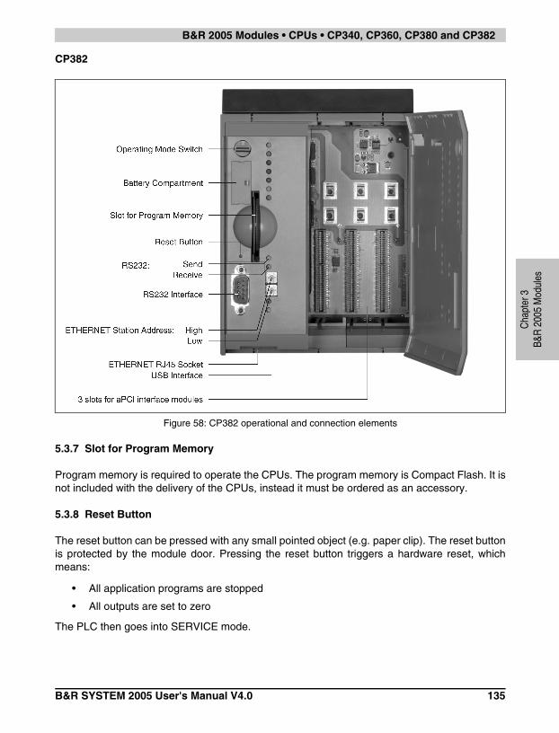
CP382
5.3.7 Slot for Program Memory
Program memory is required to operate the CPUs. The program memory is Compact Flash. It isnot included with the delivery of the CPUs, instead it must be ordered as an accessory.
5.3.8 Reset Button
The reset button can be pressed with any small pointed object (e.g. paper clip). The reset buttonis protected by the module door. Pressing the reset button triggers a hardware reset, whichmeans:
• All application programs are stopped
• All outputs are set to zero
The PLC then goes into SERVICE mode.
Figure 58: CP382 operational and connection elements

136
B&R 2005 Modules • CPUs • CP340, CP360, CP380 and CP382
B&R SYSTEM 2005 User's Manual V4.0
5.3.9 Operating Mode Switch
The CPUs are equipped with a hex switch which acts as an operating mode switch.
5.3.10 RS232 Interface (IF1)
The RS232 interface is not electrically isolated. It can be used as an online interface forcommunicating with the programming device.
5.3.11 ETHERNET Interface (IF2):
IF2 is an ETHERNET interface. The connection is made using a 10/100 BASE-T Twisted PairRJ45 socket on the bottom of the module.
The INA2000 station number for the ETHERNET interface is set with both hex switches.
Switch Position Operating Mode Description
$0 Boot In this switch position the default B&R Automation Runtime™ (AR) is started, and the runtime system can be installed using the online interface (B&R Automation Studio™). User Flash is deleted after the download begins.
$4 Run RUN Mode
$F Diagnostics The CPU boots in Diagnostics mode. Program sections in User RAM and User FlashPROM are not initialized. After diagnostics mode, the CPU always boots with a warm restart.
Table 59: CP340, CP360, CP380 and CP382 operating modes
Interface Description Pin Assignments
PG interfaceRS232
9-pin DSUB plug
The RS232 interface operates as an online interface.
Online connection to the PG is achieved using a standard RS232 cable that is available from B&R:
Module ID RS232 CableModel No. 0G0001.00-090
Max. Baud Rate: 115.2 kBaudMax. Cable Length: 15 m
RS232
1 DCD Data Carrier Detect
2 RXD Receive Signal
3 TXD Transmit Signal
4 DTR Data Terminal Ready
5 GND Ground
6 DSR Data Set Ready
7 RTS Request To Send
8 CTS Clear To Send
9 RI Ring Indicator
Table 60: CP340, CP360, CP380 and CP382 RS232 interface (IF1)
Information:The onboard ETHERNET interface is not suitable for ETHERNET Powerlink.

B&R 2005 Modules • CPUs • CP340, CP360, CP380 and CP382
Cha
pter
3B&
R 2
005
Mod
ules
137B&R SYSTEM 2005 User's Manual V4.0
5.3.12 USB Interface (IF3)
The IF3 is a USB interface. The connection is made using a USB interface for Rev. 1.1 on thebottom of the module.
The USB interface can only be used for devices which have been released by B&R (e.g. floppydisk drive, DiskOnKey or dongle).
5.3.13 Insert Slot
The CPUs are equipped with one or three insert slots for aPCI interface modules.
The B&R SYSTEM 2005 can be connected to various bus or network systems using plug-ininterface modules.
The following aPCI interface modules can be operated presently in the CPUs:
Information:The USB interface (IF3) cannot be used as an online communication interface.
Module Description
3IF761.9 aPCI interface module, 1 PROFIBUS DP interface, electrically isolated and network capable, 1 RS232 interface
3IF762.9 aPCI interface module, 1 PROFIBUS DP interface, electrically isolated and network capable, 1 RS422/RS485 interface, electrically isolated and network capable
3IF772.9 aPCI interface module with one RS232 interface and two CAN interfaces
3IF786.9 aPCI interface module, 1 ETHERNET Powerlink interface, manager or controller function, 1 RS232 interface
3IF787.9 aPCI interface module 1 ETHERNET Powerlink interface, manager or controller function, 1 CAN interface , max. 500 kbps, object buffer in send and receive direction, network capable, electrically isolated. Order TB704 terminal blocks separately.
3IF789.9 aPCI interface interface module, 1 ETHERNET Powerlink Schnittstelle, manager or controller function, 1 X2X Link Master interface, electrically isolated. Order TB704 terminal block separately.
Table 61: CP340, CP360, CP380 and CP382 aPCI interface module inserts

138
B&R 2005 Modules • CPUs • CP340, CP360, CP380 and CP382
B&R SYSTEM 2005 User's Manual V4.0
5.3.14 Data/Real-time Buffering
The following areas are buffered:
• Remanent variables
• User RAM
• System RAM
• Real-time clock
Buffering is achieved using a lithium battery in the following order:
1) CPU battery: The battery is in the CPU
2) Bus battery: The backup battery is either in the B&R 2005 rack or in the AC240 batterymodule
Battery Monitoring
The battery voltage is checked cyclically. The cyclic load test of the battery does not considerablyshorten the battery life, instead it gives an early warning of weakened buffer capacity.
The status information, "Battery OK" is available from the system library function "BatteryInfo".
Battery Change Interval
Battery Change Interval
CPU Battery The battery should be changed every 4 years. The change interval refers to the average life span and operating conditions and is recommended by B&R. This does not correspond to the maximum buffer duration.
Bus Battery See the section "Backup Battery" in the sections 2 "Module Racks" and 17.2 "AC240" (Battery Module).
Table 62: CP340, CP360, CP380 and CP382 battery changing intervals

B&R 2005 Modules • CPUs • CP340, CP360, CP380 and CP382
Cha
pter
3B&
R 2
005
Mod
ules
139B&R SYSTEM 2005 User's Manual V4.0
5.3.15 Changing the Lithium Battery
The CPUs are equipped with a lithium battery. The lithium battery is placed in a separatecompartment and protected by a cover.
Buffer Battery Data
The product design allows the battery to be changed with the PLC switched on or off. In somecountries, safety regulations do not allow batteries to be changed while the module is switchedon.
Lithium Battery 3 V / 950 mAh
Model Number 0AC201.9
Short Description Lithium batteries, 5 pcs., 3 V / 950 mAh, button cell
Storage Temperature -20 to +60° C
Storage Time Max. 3 years at 30° C
Relative Humidity 0 to 95% (non-condensing)
Table 63: CP340, CP360, CP380 and CP382 data for the backup battery
Information:The data stored in the RAM of the CPU is not lost while power is not applied duringa battery change, if the CPU is located in the module rack and the bus battery isfunctioning normally.
The bus battery is located either in the B&R 2005 rack or in the AC240 batterymodule

140
B&R 2005 Modules • CPUs • CP340, CP360, CP380 and CP382
B&R SYSTEM 2005 User's Manual V4.0
Procedure for Changing the Battery
1) Touch the mounting rail or ground connection (not the power supply!) in order to dischargeany electrostatic charge from your body.
2) Remove the cover from the lithium battery holder using a screwdriver.
3) Remove the battery from the holder by pulling the removal strip (don't use uninsulated toolsbecause of risk of short circuiting). The battery should not be held by its edges. Insulatedtweezers may also be used for removing the battery.
Figure 59: CP340, CP360, CP380 and CP382 - removing the cover for the lithium battery
Figure 60: CP340, CP360, CP380 and CP382 - holding the battery correctly

B&R 2005 Modules • CPUs • CP340, CP360, CP380 and CP382
Cha
pter
3B&
R 2
005
Mod
ules
141B&R SYSTEM 2005 User's Manual V4.0
4) Insert the new battery with correct polarity. The removal strip should be pulled to the right ofthe battery holder and the "+" side of the battery should be facing left. In order to be able toremove the battery again in future, the removal strip must be on the right side of the battery.
5) Now wrap the end of the removal strip over the top of the battery and insert it underneath thebattery so that it does not protrude from the battery holder.
6) Replace cover. Insert the lower edge of the cover in the battery holder opening. Press theupper end of the cover home firmly.
5.3.16 Local I/O Bus Expansion
Since the CPUs do not have their own expansion master, the EX350 I/O master controller isneeded for local I/O bus expansion. By using this controller, up to four expansion racks with allI/O modules can be used with the CPUs.
The I/O master controller is operated in the expansion slot of a PS465 power supply module. I/Omodules on the main rack are handled by the CPU. The EX350 module supports the CPU byprocessing I/O module data on the expansion racks.
Figure 61: CP340, CP360, CP380 and CP382 - removal strip should be pulled to the right
Information:Lithium batteries are considered hazardous waste. Used batteries should bedisposed of accordingly.

142
B&R 2005 Modules • CPUs • CP340, CP360, CP380 and CP382
B&R SYSTEM 2005 User's Manual V4.0
5.3.17 Programming System Flash
General Information
The CPUs are delivered with a default B&R Automation Runtime™ (with limited functions)already installed. This runtime system is started in boot mode (operating mode switchposition 0). It initializes and operates the serial RS232 onboard interface, allowing a runtimesystem download via INA2000 protocol.
This runtime system download is carried out during the commissioning of the CPU. The runtimesystem is stored in the program memory (Compact Flash) of the processor. A runtime systemupdate can be carried out later.
A runtime system download or update is made using the programming system (starting with B&RAutomation Studio™ V2.1).
Runtime System Download
When installing the runtime system (runtime system download) the following procedure must becarried out:
1) Turn off power to the PLC.
2) A runtime system download is only possible if the processor is in boot mode. To do this, theoperating mode switch must be turned to 0.
3) Switch on the power supply again.
4) Establish an online connection between the programming device (PC or Industrial PC) andthe CPU. A runtime system download is only possible using the serial RS232 onboardinterface.
5) Start B&R Automation Studio™.
6) Start the download procedure by calling the Services command from the Project menu.Select Transfer Operating System... from the menu shown. Follow the instructions fromB&R Automation Studio™.
7) A dialog box is displayed for configuring the runtime system version. The runtime system version is already preselected by the user's project settings. Using the drop-down menu, the runtime system versions stored in the project can be selected. Clicking on the Browse button allows the selected runtime system version to be loaded from the hard drive or from the CD.
Pressing Next > opens a pop-up window, which allows the user to select whether the modules should be downloaded with SYSTEM ROM target memory using the following runtime system download. Otherwise, modules can also be downloaded using a later application download.
Pressing Next > brings the user to a control box where the current settings are displayed.

B&R 2005 Modules • CPUs • CP340, CP360, CP380 and CP382
Cha
pter
3B&
R 2
005
Mod
ules
143B&R SYSTEM 2005 User's Manual V4.0
8) The download procedure is started by pressing Next >. Download progress is shown in amessage window.
9) The operating mode switch must be turned to 4 when the download procedure is completed.
10) Turn PLC off and then on again.
11) The PLC is now ready for use.
Runtime System Update
When updating the runtime system (online runtime system update) the following procedure mustbe carried out:
1) An online runtime system update is only possible if the processor is in RUN mode. To do this,the operating mode switch must be turned to 4.
2) Switch on the supply voltage.
3) Establish online connection (online cable) between the programming device (PC or IndustrialPC) and the CPU. An online runtime system update is only possible using the CPUinterfaces.
4) Start B&R Automation Studio™.
5) Start the update procedure by calling the Services command from the Project menu. SelectTransfer Operating System... from the menu shown. Follow the instructions from B&RAutomation Studio™.
6) A dialog box is displayed for configuring the runtime system version. The runtime system version is already preselected by the user's project settings. Using the drop-down menu, the runtime system versions stored in the project can be selected. Clicking on the Browse button allows the selected runtime system version to be loaded from the hard drive or from the CD.
Pressing Next > opens a pop-up window, which allows the user to select whether the modules should be downloaded with SYSTEM ROM target memory using the following runtime system update. Otherwise, modules can also be downloaded using a later application download.
Pressing Next > brings the user to a control box where the current settings are displayed.
Information:The User Flash is cleared.

144
B&R 2005 Modules • CPUs • CP340, CP360, CP380 and CP382
B&R SYSTEM 2005 User's Manual V4.0
7) The update procedure is started by pressing Next >. The update progress is shown in amessage window.
8) When the update procedure is complete, the online connection is automatically establishedagain.
9) The PLC is now ready for use.
An operating system update is not only possible through an online connection, but also througha CAN network, serial network (INA2000 protocol) or an ETHERNET network, depending on thesystem configuration.
Information:The User Flash is cleared.
Copyright © 2022 FDOKUMEN