3D map reconstruction with sensor kinect: Searching for solution applicable to small mobile robots
6
3D map reconstruction with sensor Kinect Searching for solution applicable to small mobile robots Peter Beňo, František Duchoň, Michal Tölgyessy, Peter Hubinský, Martin Kajan Institute of Robotics and Cybernetics Slovak University of Technology Bratislava, Slovakia [email protected] Abstract—Although it is relatively easy to equip mobile robot with Kinect sensor, implementation of mapping algorithm can be non trivial. In this article, we describe sensor device, robot map formats and two main approaches to 3D reconstruction, problem closely connected to SLAM mapping problem with Kinect sensor. We experimentally evaluate reference implementations of both algorithms, compare their results and discuss published and possible improvements of both approaches. Keywords—Kinect; RGBD-6D-SLAM, Kinect Fusion, mapping; SLAM; I. INTRODUCTION Simultaneous localization and mapping (SLAM) is one of most important problems in today's mobile robotics. This problem consists of problems of localization (where the robot is?), mapping (what is the environment?) and also navigation in generated map [27]. Researchers were trying to solve this problem by using several types of sensors - laser scanners [15], ultrasound [17], radars [16], monocular cameras [14] or stereovision cameras [18]. There are various algorithms for 2D and 3D map reconstruction and localization of mobile robot based on data from these sensors. With introduction of Microsoft Kinect, new type of cheap sensors appeared on the market. These sensors are commonly referred as RGB-D cameras, because their output consists of standard RGB image from camera, with additional depth channel for each pixel. Output data from this type of sensor are non-uniform 3D point clouds – depth maps. We have seen significant amount of research in exploring various ways to use this data output. One of possible applications is performing 3D reconstruction based on the output data. In our work we investigated two most frequently used approaches to 3D reconstruction for Kinect. We also investigated maps obtained from these algorithms for mobile robotics usage. Although significant results have been published, solution, which will make your robot aware of its environment with Kinect, is still missing. II. 3D RECONSTRUCTION AND SLAM MAPPING 3D reconstruction is common term for multiple methods which aim to obtain exact 3D representations of scanned objects or scanned environments. Most common applications used with RGB-D cameras are 3D reconstruction of a static object and an environment 3D reconstruction. Researchers have achieved significant results in both of these applications [1] [2] [3]. Problem of 3D reconstruction is closely related to problem of mobile robot mapping, but it is not the same problem. 3D reconstruction problem focuses on obtaining most accurate representation of scanned environment and typical output of these algorithms are texturized meshes. Robot mapping problem is problem of obtaining the map of the environment, which is suitable for the robot, so we can localize the robot and navigate it through the environment. We are able to generate multiple types of environment maps with Kinect data - topologic maps, graph-based scan-matching maps, occupancy grid maps and the most common type - mesh maps. Fig 1. Types of robot maps In this article, we will examine two most common approaches to robot mapping with Kinect by investigating their prototype implementations. First approach, which use scan matching technique and graph representation of map will be investigated in RGBD-6D-SLAM algorithm. Second approach, which
Transcript of 3D map reconstruction with sensor kinect: Searching for solution applicable to small mobile robots

3D map reconstruction with sensor Kinect Searching for solution applicable to small mobile robots
Peter Beňo, František Duchoň, Michal Tölgyessy, Peter Hubinský, Martin Kajan Institute of Robotics and Cybernetics
Slovak University of Technology Bratislava, Slovakia [email protected]
Abstract—Although it is relatively easy to equip mobile robot with Kinect sensor, implementation of mapping algorithm can be non trivial. In this article, we describe sensor device, robot map formats and two main approaches to 3D reconstruction, problem closely connected to SLAM mapping problem with Kinect sensor. We experimentally evaluate reference implementations of both algorithms, compare their results and discuss published and possible improvements of both approaches.
Keywords—Kinect; RGBD-6D-SLAM, Kinect Fusion, mapping; SLAM;
I. INTRODUCTION Simultaneous localization and mapping (SLAM) is one of most important problems in today's mobile robotics. This problem consists of problems of localization (where the robot is?), mapping (what is the environment?) and also navigation in generated map [27]. Researchers were trying to solve this problem by using several types of sensors - laser scanners [15], ultrasound [17], radars [16], monocular cameras [14] or stereovision cameras [18]. There are various algorithms for 2D and 3D map reconstruction and localization of mobile robot based on data from these sensors.
With introduction of Microsoft Kinect, new type of cheap sensors appeared on the market. These sensors are commonly referred as RGB-D cameras, because their output consists of standard RGB image from camera, with additional depth channel for each pixel. Output data from this type of sensor are non-uniform 3D point clouds – depth maps. We have seen significant amount of research in exploring various ways to use this data output. One of possible applications is performing 3D reconstruction based on the output data.
In our work we investigated two most frequently used approaches to 3D reconstruction for Kinect. We also investigated maps obtained from these algorithms for mobile robotics usage. Although significant results have been published, solution, which will make your robot aware of its environment with Kinect, is still missing.
II. 3D RECONSTRUCTION AND SLAM MAPPING 3D reconstruction is common term for multiple methods which aim to obtain exact 3D representations of scanned objects or scanned environments. Most common applications used with RGB-D cameras are 3D reconstruction of a static object and an environment 3D reconstruction.
Researchers have achieved significant results in both of these applications [1] [2] [3]. Problem of 3D reconstruction is closely related to problem of mobile robot mapping, but it is not the same problem. 3D reconstruction problem focuses on obtaining most accurate representation of scanned environment and typical output of these algorithms are texturized meshes. Robot mapping problem is problem of obtaining the map of the environment, which is suitable for the robot, so we can localize the robot and navigate it through the environment. We are able to generate multiple types of environment maps with Kinect data - topologic maps, graph-based scan-matching maps, occupancy grid maps and the most common type - mesh maps.
Fig 1. Types of robot maps
In this article, we will examine two most common approaches to robot mapping with Kinect by investigating their prototype implementations. First approach, which use scan matching technique and graph representation of map will be investigated in RGBD-6D-SLAM algorithm. Second approach, which

typically uses Truncated signed distance function (TSDF) as volumetric environment representation will be investigated in it’s reference implementation – KinectFusion [3].
III. SENSOR KINECT The Kinect sensor by Microsoft was introduced to the market in November 2010 as an input device for the Xbox 360 gaming console and was a very successful product with more than 10 million devices sold by March 2011. Kinect device have revolutionized the way end-user interacts with computer because it enables developers to easily recognize people, gestures, faces and voice in their applications. The robotics community quickly discovered that the depth dense technology in the Kinect could be used for other purposes at much lower price than traditional 3D cameras as time-of-flight and stereovision cameras.
A. Kinect Hardware Kinect depth sensor emits structured dotted pattern from its infrared projector and simultaneously captures it with a CMOS camera that is fitted with IR-pass filter. IR emitter is shifted by 0.075m from the IR receiver. The integrated image processor of the Kinect uses the knowledge of the emitted light pattern, lens distortion and distance between emitter and receiver to calculate depth at each pixel in the image. This is done internally by Kinect device. To achieve rate of 30 completed scans per second, computing makes use of values from neighboring points in the pattern. This technology is called Light Coding and it has been developed by PrimeSense company. Actual depth values are distances from sensor plane rather than from sensor itself, so the Kinect device can be seen as a device that returns 3D coordinates of 3D objects. Main hardware specifications of Kinect are available in [4][5].
B. Kinect drivers Currently, there are 3 software solutions for accessing the Kinect device: a.) Libfreenect – original, first, hacked driver [23], b.) OpenNI driver– software developed by original Kinect reference design authors, company PrimeSense which supports auto-calibration. [24] c.) Microsoft Kinect for Windows SDK [19]. All three drivers are capable of delivering depth and RGB data, so all of them are suitable for solving mobile robot mapping with Kinect. For exact mapping, sensor has to be correctly calibrated.
IV. RGBD-6D-SLAM RGBD-6D-SLAM is a method for rapid creation of colored 3D objects and interior scenes with a Kinect sensor or its equivalent. The principle of operation is based on SURF key points location of scanned image and RANSAC usage for robust determination of 3D transformations between frames. To achieve real-time processing the scanned image is compared with only a subset of the previous images with decreasing frequency. In addition, it creates a graph whose nodes correspond to camera angles and edges which represents 3D transformations. The graph is then optimized by HOG-Man in order to reduce the accumulated error in pose estimation. Optimization is particularly important when the
robot while scanning the environment returns to a place already scanned. This method is part of ROS OpenNI framework and it uses software support from OpenSLAM initiative. Algorithm also allows optional using of Iterative closest point algorithm to refine produced mesh. Schematic overview of this algorithm is presented on figure 2.
Fig 2. Schematic diagram of RGBD-6D-SLAM algorithm
Therefore, most important parts of RGBD-6D-SLAM are:
SURF (Speeded up robust features) is robust image feature detector. It was first presented in 2006 and successfully used in computer image processing for object recognition and 3D reconstruction. It was partially inspired by algorithm SIFT (Scale-invariant feature transform) from year 1999 but it is many times faster [7][6]. RANSAC (Random Sample Consensus) is an iterative method for determining the parameters of a mathematical model from the captured data containing outliers (outlier is value that is much smaller or larger than most of the other values in a set of data.) and inliers (points belonging to the model). It is a non-deterministic algorithm in the sense that its output is relevant only with a certain probability while the rise in the number of iteration is likely to increase [10][8]. HOG-Man is an optimization method for graph-oriented SLAM. It provides a highly effective way of minimizing errors and works in 2D and 3D [9]. Iterative closest point is an algorithm which iteratively revises the rigid transformation needed to minimize distance between two sets of points, which can be generated from two
successive scans. Considering two sets of points, the scope is to find optimal transformation composed by translation t and rotation R to align the source set to the target. The problem can be formulated as minimizing the squared distance between each neighboring pairs. As any gradient descent method, the ICP is applicable when we have in advance a relatively good initial guess. Otherwise, it is likely to be trapped into a local minimum. In RGBD-6D-SLAM implementation, ICP is used to refine produced mesh by aligning consecutive scans.
A. RGBDemo RGBDemo is open source software which tries to provide
set of clearly organized simple tools for working with data from the Kinect sensor and for the creation of separate programs for computer image processing of RGB-D data without problems with the integration of many existing libraries. The project is divided into a library called nestk and a few demo programs to demonstrate possibilities of work with this library. RGBDemo tool is built on OpenCV and QT libraries. Some of its components also depend on the Point Cloud Library. It works with OpenNI, libreenect and Kinect for Windows SDK backend. Nestk library provides built-in support for SIFT, SURF and BRIEF: Binary Robust Independent Elementary Features. [11] We were able to compile required libraries, nestk and RGBDemo on all most used operating systems - Windows, Linux and Mac OS X and we also compiled it on two ARM-based boards – Raspberry Pi and Cubieboard. Compilation on ARM platform can be non-trivial, so we are providing full compilation instructions in our Github repository.[12]
B. Experiment with RGBD-6D-SLAM To verify the current 3D scene reconstruction possibilities,
we decided to modify one of the demo programs in RGBDemo - rgbd-reconstructor, which uses RGBD-6D-SLAM. Our implementation compared to the original program did not contain any unnecessary components for our experiments, which would slow down speed of data processing. In addition, ICP was permanently switched on and scanning parameters were modified to achieve higher quality of the reconstructed output. We strongly recommend using computer with highest CPU and memory configuration available to achieve best performance possible. The program operated reliably also on lower configurations such as a conventional notebook - in this case, however the GUI suffered considerable delay in the rendering. Interacting with program windows was very limited but the resulting mesh was comparable with meshes obtained from higher configurations. Algorithm was running correctly.
In our experiment, we used photographic tripod with attached Kinect sensor for scanning to achieve greater control of the camera motion when scanning the environment. Then we rotated the sensor around its horizontal axis manually, giving the algorithm enough time to search for key points when necessary. Mesh generation was running simultaneously with scanning process.
Fig 3. Scanned mesh of laboratory
The final mesh suffered from high amounts of noise in data,
however, after few trivial post processing adjustments (remove isolated pieces, remove duplicate faces, merge close vertices, close holes), we used the mesh to determine dimensions of the environment with satisfying precision. Standard measurement deviation of 5 meters wide room was 10cm.
Fig 4. Scanned mesh of laboratory from top view
Algorithm problems revealed during measurement were: a.) Produced mesh was noisy, b.) Complicated scanning of reflective or light-emitting surfaces. This problem is caused by Kinect operational principle and it can be also noticed on results obtained from Kinect Fusion algorithm. c.) Loop closure problem. Algorithm is not aware of the room context so it only sticks the data together and it is not able to realize the necessity of loop closing. d.) Algorithm has low performance in weak light conditions. In case of fast movement between frames, feature detection fails, because feature detection algorithms use RGB data. If feature detector cannot determine matches between last two frames, algorithm stops and the whole process fails.
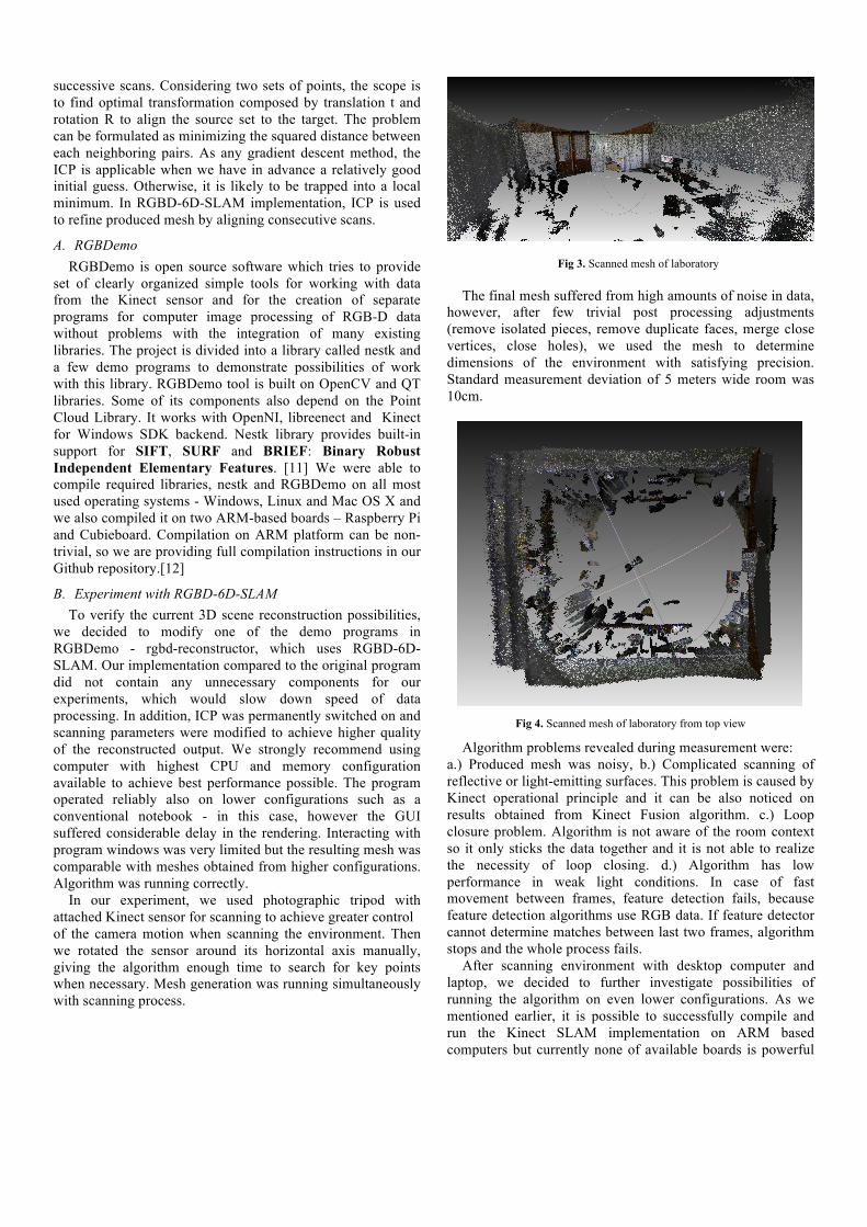
After scanning environment with desktop computer and laptop, we decided to further investigate possibilities of running the algorithm on even lower configurations. As we mentioned earlier, it is possible to successfully compile and run the Kinect SLAM implementation on ARM based computers but currently none of available boards is powerful
enough to process all the data correctly. Frame dropping appears in algorithm and resulting meshes contain only some randomly placed vertexes.
Fig 5. Incomplete mesh - result of whole room scanning on ARM board
V. KINECT FUSION SYSTEM Kinect fusion system allows a user to pick a standard Kinect camera and move rapidly within a room to reconstruct a high-quality, geometrically precise 3D model of the scene. In order to achieve this, the system continually tracks the 6DOF pose of the camera and fuses live depth data from the camera into a single global 3D model in real-time. As the user explores the space, new views of the physical scene are obtained and fused into the scene model. The reconstruction therefore grows in detail after new depth measurements addition. Holes are filled, and the model becomes more complete and refined over time.[3] A core component of the Kinect Fusion algorithm is the truncated signed distance function (TSDF), a volumetric surface representation where each element stores the signed distance to the closest surface. For data integration, Kinect Fusion computes a vertex and normal map from the raw depth data. Vertex and normal maps are then used to compute the camera pose via an ICP-based registration with the predicted surface model raycast from the current TSDF. Given this pose, the depth data is integrated into the TSDF through a weighted running average operation, which over time results in a smooth surface reconstruction [20]. Figure 6 provides an overview of Kinect Fusion method in block form.
Fig 6. Kinect Fusion algorithm block diagram [3]
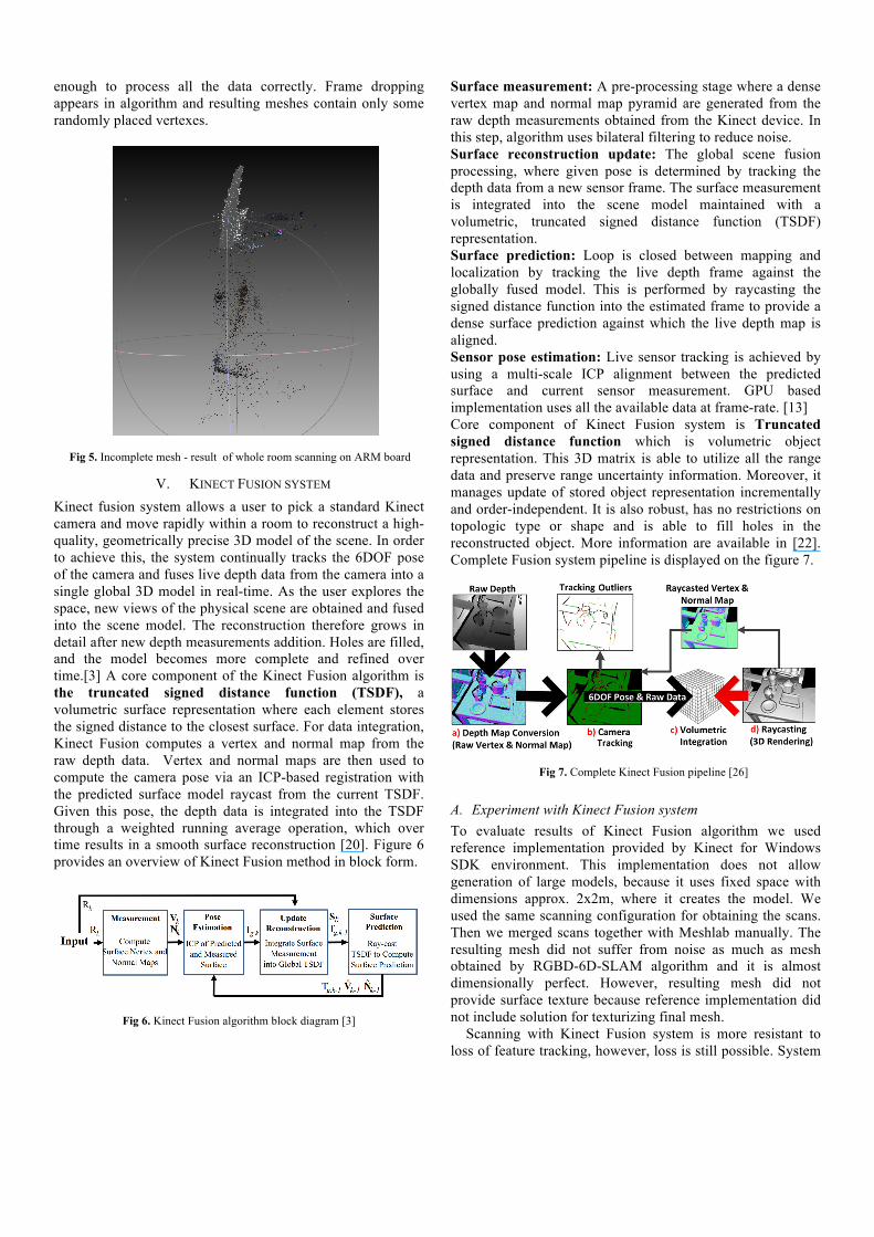
Surface measurement: A pre-processing stage where a dense vertex map and normal map pyramid are generated from the raw depth measurements obtained from the Kinect device. In this step, algorithm uses bilateral filtering to reduce noise. Surface reconstruction update: The global scene fusion processing, where given pose is determined by tracking the depth data from a new sensor frame. The surface measurement is integrated into the scene model maintained with a volumetric, truncated signed distance function (TSDF) representation. Surface prediction: Loop is closed between mapping and localization by tracking the live depth frame against the globally fused model. This is performed by raycasting the signed distance function into the estimated frame to provide a dense surface prediction against which the live depth map is aligned. Sensor pose estimation: Live sensor tracking is achieved by using a multi-scale ICP alignment between the predicted surface and current sensor measurement. GPU based implementation uses all the available data at frame-rate. [13] Core component of Kinect Fusion system is Truncated signed distance function which is volumetric object representation. This 3D matrix is able to utilize all the range data and preserve range uncertainty information. Moreover, it manages update of stored object representation incrementally and order-independent. It is also robust, has no restrictions on topologic type or shape and is able to fill holes in the reconstructed object. More information are available in [22]. Complete Fusion system pipeline is displayed on the figure 7.
Fig 7. Complete Kinect Fusion pipeline [26]
A. Experiment with Kinect Fusion system To evaluate results of Kinect Fusion algorithm we used reference implementation provided by Kinect for Windows SDK environment. This implementation does not allow generation of large models, because it uses fixed space with dimensions approx. 2x2m, where it creates the model. We used the same scanning configuration for obtaining the scans. Then we merged scans together with Meshlab manually. The resulting mesh did not suffer from noise as much as mesh obtained by RGBD-6D-SLAM algorithm and it is almost dimensionally perfect. However, resulting mesh did not provide surface texture because reference implementation did not include solution for texturizing final mesh.
Scanning with Kinect Fusion system is more resistant to loss of feature tracking, however, loss is still possible. System
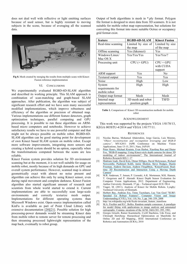
does not deal well with reflective or light emitting surfaces because of used sensor, but is highly resistant to moving subjects in the scene, because of averaging all the scanned data.
Fig 8. Mesh created by merging the results from multiple scans with Kinect
Fusion reference implementation
VI. CONCLUSIONS We experimentally evaluated RGBD-6D-SLAM algorithm and described its working principle. This SLAM approach is combination of scan-matching and graph-based SLAM approaches. After publication, the algorithm was subject of significant research effort and we have seen many successful modified implementations, which improve robustness and efficiency of the algorithm or precision of obtained map. Various implementations use different feature detectors, graph optimization techniques, parallel computing and GPU processing. It is possible to run these algorithms on ARM-based micro computers and notebooks. However to achieve satisfactory results we have to use powerful computer and that might not be always possible on mobile robot. RGBD-6D-SLAM algorithm can be good starting point for development of own Kinect based SLAM system on mobile robot. Except more software improvements, integrating more sensors and creating a hybrid system should be an option, especially when the transformations computed between the scans are less reliable. Kinect Fusion system provides solution for 3D environment scanning but at the moment, it is not well suitable for usage on mobile robot, mostly because of its high demands on GPU and overall system performance. However, scanned map is almost geometrically exact with almost no noise present and algorithm can achieve this only by using Kinect sensor, even during rapid movement and complete darkness. Kinect Fusion algorithm also started significant amount of research and scientists from whole world started to extend it. Current implementations are able to successfully scan large-scale environments and correctly texturize mesh output. Implementations for different operating systems than Microsoft Windows exist. Open-source implementation called KinFu is available as part of Point Cloud Library with extensive documentation [20][21]. Possible solution for high processing-power demands would be streaming Kinect data from mobile robot to remote server for remote processing and then streaming processed lightweight representation of the map back, eventually to robot group.
Output of both algorithms is mesh in *.ply format. Polygon file format is designed to store data from 3D scanners. It is not suitable for mobile robot map representation, but solutions for converting this format into more suitable Octree or occupancy grid format exist.
feature RGBD-6D-SLAM Kinect Fusion Real-time scanning Limited by size of
the map Limited by size of the map
Offline scanning Yes (fakenect) Yes Windows/Linux/ Mac OS X
Yes/Yes/Yes Yes/Yes/?
Processing unit CPU (+ GPU) CPU + GPU with CUDA support
ARM support Yes No Textured output Yes Yes Noise High Low System requirements for mobile robot
High High
Output map format Mesh Mesh Internal map representation
3D mesh and robot position graph
TSFD
Table 1. Comparison of Kinect 3D reconstruction methods for mobile
robot
ACKNOWLEDGMENT This work was supported by the projects VEGA 1/0178/13,
KEGA 003STU-4/2014 and VEGA 1/0177/11.
REFERENCES [1] Nicolas Burrus, Mohamed Abderrahim, Jorge Garcia, Luis Moreno,
“Object reconstruction and recongnition leveraging and RGB-D camera”, MVA2011 IAPR Conference on Machine Vision Applications, June 13-15, 2011, Nara, JAPAN
[2] Peter Henry, Michael Krainin, Evan Herbst, Xiaofeng Ren and Dieter Fox, “RGB-D mapping: Using Kinect-style depth cameras for dense 3D modeling of indoor environments”, The International Journal of Robotics Research 0(0) 1–17
[3] Shahram Izadi, David Kim, Otmar Hilliges, David Molyneaux, Richard Newcombe, Pushmeet Kohli, Jamie Shotton, Steve Hodges, Dustin Freeman, Andrew Davison, Andrew Fitzgibbon, “KinectFusion: Real-time 3D Reconstruction and Interaction Using a Moving Depth Camera”
[4] M.R. Andersen, T. Jensen, P. Lisouski, A.K. Mortensen, M.K. Hansen, T. Gregersen and P. Ahrendt: Kinect Depth Sensor Evaluation for Computer Vision Applications, 2012. Department of Engineering, Aarhus University. Denmark. 37 pp. - Technical report ECE-TR-6
[5] Viager, M. (2011). Analysis of Kinect for Mobile Robots. Lyngby: Technical University of Denmark.
[6] Herbert Bay, Andreas Ess, Tinne Tuytelaars, Luc Van Gool "SURF: Speeded Up Robust Features", Computer Vision and Image Understanding (CVIU), Vol. 110, No. 3, pp. 346–359, 2008
[7] http://en.wikipedia.org/wiki/Scale-invariant_feature_transform [8] M.A. Fischler and R.C. Bolles. Random sample consensus: A paradigm
for model fitting with applications to image analysis and automated cartography. Commu- nications of the ACM, 24(6):381–395, 1981.
[9] Giorgio Grisetti, Rainer Kuemmerle, Cyrill Stachniss, Udo Frese, and Christoph Hertzberg: Hierarchical Optimization on Manifolds for Online 2D and 3D Mapping., IEEE International Conference on Robotics and Automation (ICRA), 2010

[10] Kinfu – an open source implementation of Kinect Fusion + case study: implementing a 3D scanner with PCL, Michele Pirovano, PhD student in Computer Science at POLIMI Research fellow at UNIMI, 3D structure from visual motion 2011/2012, Project Assignment
[11] http://labs.manctl.com/rgbdemo/ [12] https://github.com/najlepsiwebdesigner/kinect-micro-pc [13] Newcombe, Richard, Davison, Andrew J.;Izadi, Shahram; Kohli,
Pushmeet; Hilliges, Otmar; Shotton, Jamie; Molyneaux, David; Hodges, Steve; Kim, David; Fitzgibbon, Andrew, KinectFusion: Real-time dense surface mapping and tracking, October 2011
[14] Eade, E. (2008). Monocular simultaneous localisation and mapping (Doctoral dissertation, PhD thesis, University of Cambridge).
[15] Hähnel, D., Burgard, W., Fox, D., and Thrun, S. A highly efficient fastslam algorithm for generating cyclic maps of large-scale environments from raw laser range measurements. In IROS (Las Vegas (USA), 2003), IEEE/RSJ.
[16] Callmer et al.: Radar SLAM using visual features. EURASIP Journal on Advances in Signal Processing 2011 2011:71.
[17] Muhammad Muneeb Salem: An Economic Simultaneous Localization and Mapping System for Remote Mobile Robot Using SONAR and an Iccovative AI Algorithm, International Journal of Future Computer and Communication, Vol. 2, No. 2, 2. April 2013
[18] P. Elinas, J. Little, “Stereo Vision SLAM: Near Real-time Learning of 3D Point-landmark and 2D Occupancy-grid Maps Using Particle Filter,” The 2007 IEEE/RSJ International Conference on Intelligent Robots and Systems. San Diego, California, USA, 29 Oct.-2 NOV. 2007.
[19] http://www.microsoft.com/en-us/kinectforwindows/ [20] Thomas Whelan, John McDonald, Michael Kaess, Maurice Fallon,
Hordur Johanns- son, and John J. Leonard. Kintinuous: Spatially
extended KinectFusion. In RGB-D Workshop at Robotics: Science and Systems (RSS), 2012.
[21] Henry Roth, Marsette Vona: Moving Volume KinectFusion, College of Computer and Information Science Northeastern University Boston, MA, 2012
[22] CURLESS, Brian; LEVOY, Marc. A volumetric method for building complex models from range images. In: Proceedings of the 23rd annual conference on Computer graphics and interactive techniques. ACM, 1996. p. 303-312.
[23] https://github.com/OpenKinect/libfreenect [24] https://github.com/OpenNI/OpenNI [25] K. Židek, J. Svetlík, and E. Rigasová, „Environment mapping and
localization od mobile robotics“, International Scientific Herald, pp. 272-280.
[26] http://msdn.microsoft.com/en-us/library/dn188670.aspx