3.0 MPI ECT and 3.0 TKS Sterndrive Models - Brunswick ...
130
© 2013 Mercury Marine 3.0 MPI ECT and 3.0 TKS Sterndrive Models *8M0074347* 90-8M0074347 1012 NOTE: The following applies to CE‑marked products only. Declaration of Conformity—Mercury MerCruiser This sterndrive or inboard engine when installed in accordance to Mercury MerCruiser’s instructions complies with the requirements of the following directives by meeting the associated standards, as amended: Recreational Craft Propulsion Engines with the Requirements of Directive 94/25/EC as amended by 2003/44/EC Name of engine manufacturer: Mercury Marine Address: W6250 W. Pioneer Road, P.O. Box 1939 Town: Fond du Lac, WI Post Code: 54936‑1939 Country: USA Name of Authorized Representative: Brunswick Marine in EMEA Inc. Address: Parc Industriel de Petit‑Rechain Town: Verviers Post Code: 4800 Country: Belgium Name of Notified Body for exhaust emission assessment: Det Norske Veritas AS Address: Veritasveien 1 Town: Hovik Post Code: 1322 Country: Norway ID Number: 0575 Conformity assessment module used for exhaust emissions: ☐ B+C ☐ B+D ☐ B+E ☐ B+F ☐ G ☒ H Conformity assessment module used for noise emissions: A ☐ Aa ☐ G ☐ H ☒ Other Community Directives applied: Electromagnetic Compatibility Directive 2004/108/EC Description of Engines and Essential Requirements Engine Type Fuel Type Combustion Cycle ☒ z or sterndrive with integral exhaust ☒ Petrol ☒ 4 stroke Identification of Engines Covered by This Declaration of Conformity Name of engine family: Unique engine identification number: starting serial number EC Module H certificate number: Vazer 100 1A035000 RCD‑H‑1 Vazer 100 ECT 1A035000 RCD‑H‑1 3.0 TKS 0W319169 RCD‑H‑1 3.0 MPI ECT 1A300000 RCD‑H‑1 4.3 TKS 0W319169 RCD‑H‑1 4.3 MPI 0W319169 RCD‑H‑1 4.3 MPI ECT 1A300000 RCD‑H‑1 SeaCore 4.3 0W319169 RCD‑H‑1 5.0 MPI 0W319169 RCD‑H‑1 SeaCore 5.0 0W319169 RCD‑H‑1 5.0 MPI ECT 1A300000 RCD‑H‑1 SeaCore 5.0 ECT 1A300000 RCD‑H‑1 350 MAG 0W319169 RCD‑H‑1 SeaCore 350 MAG 0W319169 RCD‑H‑1 350 MAG ECT 1A300000 RCD‑H‑1 SeaCore 350 MAG ECT 1A300000 RCD‑H‑1 377 MAG 0W319169 RCD‑H‑1 SeaCore 377 MAG 0W319169 RCD‑H‑1
-
Upload
khangminh22 -
Category
Documents
-
view
4 -
download
0
Transcript of 3.0 MPI ECT and 3.0 TKS Sterndrive Models - Brunswick ...

© 2
013
Mer
cury
Mar
ine
3.0
MPI
EC
T an
d 3.
0 TK
S St
ernd
rive
Mod
els
*8M007
4347*
90-8
M00
7434
7 1
012
NOTE: The following applies to CE‑marked products only.
Declaration of Conformity—Mercury MerCruiserThis sterndrive or inboard engine when installed in accordance to Mercury MerCruiser’s instructions complies with therequirements of the following directives by meeting the associated standards, as amended:
Recreational Craft Propulsion Engines with the Requirements of Directive 94/25/EC as amended by 2003/44/EC
Name of engine manufacturer: Mercury MarineAddress: W6250 W. Pioneer Road, P.O. Box 1939Town: Fond du Lac, WI Post Code: 54936‑1939 Country: USA
Name of Authorized Representative: Brunswick Marine in EMEA Inc.Address: Parc Industriel de Petit‑RechainTown: Verviers Post Code: 4800 Country: Belgium
Name of Notified Body for exhaust emission assessment: Det Norske Veritas ASAddress: Veritasveien 1Town: Hovik Post Code: 1322 Country: Norway ID Number: 0575
Conformity assessment module used for exhaust emissions: ☐ B+C ☐ B+D ☐ B+E ☐ B+F ☐ G ☒ HConformity assessment module used for noise emissions: A ☐ Aa ☐ G ☐ H ☒Other Community Directives applied: Electromagnetic Compatibility Directive 2004/108/EC
Description of Engines and Essential Requirements
Engine Type Fuel Type Combustion Cycle☒ z or sterndrive with integral exhaust ☒ Petrol ☒ 4 stroke
Identification of Engines Covered by This Declaration of Conformity
Name of engine family: Unique engine identification number: starting serialnumber EC Module H certificate number:
Vazer 100 1A035000 RCD‑H‑1Vazer 100 ECT 1A035000 RCD‑H‑13.0 TKS 0W319169 RCD‑H‑13.0 MPI ECT 1A300000 RCD‑H‑14.3 TKS 0W319169 RCD‑H‑14.3 MPI 0W319169 RCD‑H‑14.3 MPI ECT 1A300000 RCD‑H‑1SeaCore 4.3 0W319169 RCD‑H‑15.0 MPI 0W319169 RCD‑H‑1SeaCore 5.0 0W319169 RCD‑H‑15.0 MPI ECT 1A300000 RCD‑H‑1SeaCore 5.0 ECT 1A300000 RCD‑H‑1350 MAG 0W319169 RCD‑H‑1SeaCore 350 MAG 0W319169 RCD‑H‑1350 MAG ECT 1A300000 RCD‑H‑1SeaCore 350 MAG ECT 1A300000 RCD‑H‑1377 MAG 0W319169 RCD‑H‑1SeaCore 377 MAG 0W319169 RCD‑H‑1

Name of engine family: Unique engine identification number: starting serialnumber EC Module H certificate number:
377 MAG ECT 1A343300 RCD‑H‑1496 MAG 0W319169 RCD‑H‑1SeaCore 496 MAG 0W319169 RCD‑H‑1496 MAG H.O. 0W319169 RCD‑H‑1SeaCore 496 MAG H.O. 0W319169 RCD‑H‑1496 MAG ECT 1A300000 RCD‑H‑1SeaCore 496 MAG ECT 1A300000 RCD‑H‑1496 MAG H.O. ECT 1A300000 RCD‑H‑1SeaCore 496 MAG H.O. ECT 1A300000 RCD‑H‑18.2 MAG 1A351489 RCD‑H‑1SeaCore 8.2 MAG 1A351489 RCD‑H‑18.2 MAG ECT 1A350340 RCD‑H‑1SeaCore 8.2 MAG ECT 1A350340 RCD‑H‑18.2 MAG H.O. 1A351489 RCD‑H‑1SeaCore 8.2 MAG H.O. 1A351489 RCD‑H‑18.2 MAG H.O. ECT 1A350340 RCD‑H‑1SeaCore 8.2 MAG H.O. ECT 1A350340 RCD‑H‑1
Essential requirements Standards Other normative document/method Technical file Please specify in more detail
(* = mandatory standard)
Annex 1.B—Exhaust EmissionsB.1 engine identification ☐ ☐ ☒
B.2 exhaust emission requirements ☒* ☐ ☐ *EN ISO 8178‑1:1996
B.3 durability ☐ ☐ ☒
B.4 owner's manual ☒ ☐ ☐ ISO 8665:1995
Annex 1.C—Noise EmissionsC.1 Noise emission levels ☒* ☐ ☐ *EN ISO 14509
C.2 Owner's manual ☐ ☒ ☐ Owner's manual
This declaration of conformity is issued under the sole responsibility of the manufacturer. I declare on behalf of the enginemanufacturer that the engine(s) mentioned above complies (comply) with all applicable essential requirements in the wayspecified.
Name / function:Mark Schwabero, President, MercuryMarine
Signature and title:
Date and place of issue: February 17, 2012Fond du Lac, Wisconsin, USA
Regulatory contact:Regulations and Product Safety DepartmentMercury MarineW6250 W. Pioneer RoadFond du Lac, WI 54936USA
Identification RecordPlease record the following information:
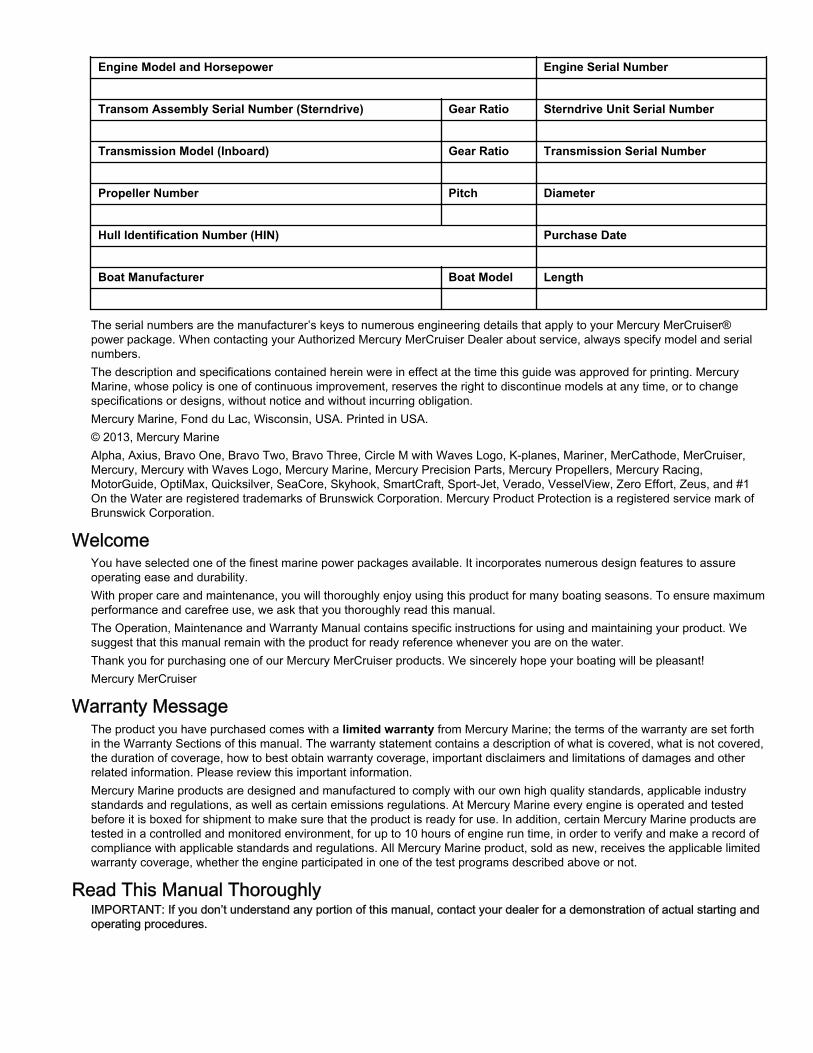
Engine Model and Horsepower Engine Serial Number
Transom Assembly Serial Number (Sterndrive) Gear Ratio Sterndrive Unit Serial Number
Transmission Model (Inboard) Gear Ratio Transmission Serial Number
Propeller Number Pitch Diameter
Hull Identification Number (HIN) Purchase Date
Boat Manufacturer Boat Model Length
The serial numbers are the manufacturer’s keys to numerous engineering details that apply to your Mercury MerCruiser®power package. When contacting your Authorized Mercury MerCruiser Dealer about service, always specify model and serialnumbers.The description and specifications contained herein were in effect at the time this guide was approved for printing. MercuryMarine, whose policy is one of continuous improvement, reserves the right to discontinue models at any time, or to changespecifications or designs, without notice and without incurring obligation.Mercury Marine, Fond du Lac, Wisconsin, USA. Printed in USA.© 2013, Mercury MarineAlpha, Axius, Bravo One, Bravo Two, Bravo Three, Circle M with Waves Logo, K‑planes, Mariner, MerCathode, MerCruiser,Mercury, Mercury with Waves Logo, Mercury Marine, Mercury Precision Parts, Mercury Propellers, Mercury Racing,MotorGuide, OptiMax, Quicksilver, SeaCore, Skyhook, SmartCraft, Sport‑Jet, Verado, VesselView, Zero Effort, Zeus, and #1On the Water are registered trademarks of Brunswick Corporation. Mercury Product Protection is a registered service mark ofBrunswick Corporation.
WelcomeYou have selected one of the finest marine power packages available. It incorporates numerous design features to assureoperating ease and durability.With proper care and maintenance, you will thoroughly enjoy using this product for many boating seasons. To ensure maximumperformance and carefree use, we ask that you thoroughly read this manual.The Operation, Maintenance and Warranty Manual contains specific instructions for using and maintaining your product. Wesuggest that this manual remain with the product for ready reference whenever you are on the water.Thank you for purchasing one of our Mercury MerCruiser products. We sincerely hope your boating will be pleasant!Mercury MerCruiser
Warranty MessageThe product you have purchased comes with a limited warranty from Mercury Marine; the terms of the warranty are set forthin the Warranty Sections of this manual. The warranty statement contains a description of what is covered, what is not covered,the duration of coverage, how to best obtain warranty coverage, important disclaimers and limitations of damages and otherrelated information. Please review this important information.Mercury Marine products are designed and manufactured to comply with our own high quality standards, applicable industrystandards and regulations, as well as certain emissions regulations. At Mercury Marine every engine is operated and testedbefore it is boxed for shipment to make sure that the product is ready for use. In addition, certain Mercury Marine products aretested in a controlled and monitored environment, for up to 10 hours of engine run time, in order to verify and make a record ofcompliance with applicable standards and regulations. All Mercury Marine product, sold as new, receives the applicable limitedwarranty coverage, whether the engine participated in one of the test programs described above or not.
Read This Manual ThoroughlyIMPORTANT: If you don’t understand any portion of this manual, contact your dealer for a demonstration of actual starting andoperating procedures.

NoticeThroughout this publication, and on your power package, dangers, warnings, cautions, and notices, accompanied by the
International Hazard Symbol ! , may be used to alert the installer/user to special instructions concerning a particular serviceor operation that may be hazardous if performed incorrectly or carelessly. Observe them carefully.These safety alerts alone cannot eliminate the hazards they warn of. Strict compliance with these special instructions whileperforming the service, plus common sense operation, are major accident prevention measures.
! DANGERIndicates a hazardous situation which, if not avoided, will result in death or serious injury.
! WARNINGIndicates a hazardous situation which, if not avoided, could result in death or serious injury.
! CAUTIONIndicates a hazardous situation which, if not avoided, could result in minor or moderate injury.
NOTICEIndicates a situation which, if not avoided, could result in engine or major component failure.
IMPORTANT: Identifies information essential to the successful completion of the task.NOTE: Indicates information that helps in the understanding of a particular step or action.
! WARNINGThe operator (driver) is responsible for the correct and safe operation of the boat, the equipment aboard and the safety of alloccupants aboard. We strongly recommend that the operator read this Operation, Maintenance and Warranty Manual andthoroughly understand the operational instructions for the power package and all related accessories before the boat is used.
! WARNINGThe engine exhaust from this product contains chemicals known to the state of California to cause cancer, birth defects orother reproductive harm.

90-8M0074347 eng OCTOBER 2012 Page i
TABLE OF CONTENTS
Section 1 - Warranty
Warranty Information and Policies............................................. 2Warranty Registration—United States and Canada........... 2Warranty Registration—Outside the United States andCanada............................................................................... 2Transfer of Warranty........................................................... 2Mercury Installation Quality Certification Program.............. 3Mercury Product Protection Plan: United States andCanada............................................................................... 3Mercury MerCruiser Limited Warranty (Gasoline‑FueledProducts Only) ................................................................... 43‑Year Limited Warranty Against Corrosion....................... 6
Emission Control Warranty Information—3.0 TKS..................... 7Important Information.......................................................... 7Emission Control Information Label.................................... 7
Owner Responsibility...................................................... 8U.S. EPA Emissions Limited Warranty............................... 9Emission Control System Components.............................. 9
Warranty Policy—Australia and New Zealand......................... 10MerCruiser Limited Warranty—Australia and New ZealandPolicy................................................................................ 10
What is Covered........................................................... 10Guarantees Under Australian Consumer Law.............. 10Duration of Coverage for This Limited Warranty.......... 10Warranty Period for Recreational Use.......................... 10Warranty Period for Commercial Use........................... 10Transfer of Coverage....................................................10Termination of Coverage.............................................. 10Conditions That Must Be Met to Obtain WarrantyCoverage ..................................................................... 11What Mercury Will Do................................................... 11How to Obtain Warranty Coverage Under This LimitedWarranty....................................................................... 11
What is Not Covered.................................................... 11Expense of Claiming This Limited Warranty.................12
Transfer of Warranty—Australia and New ZealandPolicy................................................................................ 12
Global Warranty Application Charts (3.0 TKS)........................ 13TKS Sterndrive Series Non‑Emissions Control(Recreational Use)............................................................ 13TKS Sterndrive Series Non‑Emissions Control(Commercial Use)............................................................. 13TKS Sterndrive Series Non‑Emissions Control(Government Use)............................................................ 14TKS Sterndrive Series Non‑Emissions Control(Recreational Use—Corrosion)......................................... 14TKS Sterndrive Series Non‑Emissions Control(Commercial Use—Corrosion).......................................... 15TKS Sterndrive Series Non‑Emissions Control(Government Use—Corrosion)......................................... 15
Global Warranty Application Charts (3.0 MPI–ECT)................ 16MPI Sterndrive Series with Emissions Control Technology(Recreational Use)............................................................ 16MPI Sterndrive Series with Emissions Control Technology(Commercial Use)............................................................. 16MPI Sterndrive Series with Emissions Control Technology(Government Use)............................................................ 17MPI Sterndrive Series with Emissions Control Technology(Recreational Use—Corrosion)......................................... 17MPI Sterndrive Series with Emissions Control Technology(Commercial Use—Corrosion).......................................... 18MPI Sterndrive Series with Emissions Control Technology(Government Use—Corrosion)......................................... 18
Emission Certification Star Label............................................. 18Hang Tag................................................................................. 19
Section 2 - Getting to Know Your Power Package
Identification Information.......................................................... 22Identification...................................................................... 22Alpha Sterndrive Decal Identification................................ 22Alpha Transom Serial Number......................................... 22Engine Serial Number Decal............................................ 23
Lanyard Stop Switch................................................................ 23Instrumentation........................................................................ 24
VesselView......................................................................... 24SmartCraft Speedometer and Tachometer Digital Gauges........................................................................................... 25System Link Digital Gauges............................................... 25
Remote Controls...................................................................... 26Panel Mount Features........................................................ 26Console Mount Features.................................................... 26
Power Trim............................................................................... 27Single Engine Trim/Trailer.................................................. 28
Dual Engine Trim/Trailer.................................................... 28Electrical System Overload Protection—3.0 MPI ECT............ 28Electrical System Overload Protection—3.0 TKS.................... 31Audio, Visual, and Engine Warning Systems—3.0 MPIECT.......................................................................................... 33
Audio Warning System..................................................... 33Caution......................................................................... 34Severe.......................................................................... 34Testing the Audio Warning System.............................. 34
Service Engine Light and OBD‑M MIL Kit......................... 34Testing the OBD‑M Malfunction Indicator Lamp(MIL)............................................................................. 35
Guardian Strategy............................................................. 35Audio Warning System—3.0 TKS............................................ 35
Testing The Audio Warning System................................... 35

Page ii 90-8M0074347 eng OCTOBER 2012
Section 3 - On the Water
Safe Boating Suggestions...................................................... 38Carbon Monoxide Exposure................................................... 39
Be Alert To Carbon Monoxide Poisoning.......................... 39Stay Clear of Exhaust Areas............................................. 39Good Ventilation .............................................................. 39Poor Ventilation ............................................................... 40
Launching and Boat Operation............................................... 40Operation Chart................................................................ 40
Starting and Stopping the Engine—3.0 MPI ECT................... 41Starting and Stopping the Engine.................................... 41
Starting the Engine......................................................41Stopping the Engine.................................................... 42
Starting the Engine After Stopped While in Gear............ 42Starting and Stopping the Engine—3.0 TKS.......................... 42
Starting and Stopping the Engine.................................... 42Starting the Engine......................................................42Stopping the Engine.................................................... 42
Starting the Engine After It Has Been Stopped While InGear................................................................................ 42
Throttle Only Operation.......................................................... 43Trailering the Boat.................................................................. 43Freezing Temperature Operation........................................... 43Drain Plug and Bilge Pump.................................................... 43Protecting People in the Water............................................... 43
While You Are Cruising..................................................... 43
While Boat Is Stationary................................................... 43High‑Speed and High‑Performance Operation....................... 43Passenger Safety in Pontoon Boats and Deck Boats............ 44
Boats Having an Open Front Deck................................... 44Boats With Front‑Mounted, Raised Pedestal Fishing Seats.......................................................................................... 44
Wave and Wake Jumping....................................................... 44Impact with Underwater Hazards........................................... 45
Drive Unit Impact Protection............................................. 45Conditions Affecting Operation............................................... 45
Weight Distribution (Passengers and Gear) Inside theBoat................................................................................. 45The Bottom of the Boat................................................... 46Cavitation........................................................................ 46Ventilation........................................................................ 46Elevation and Climate..................................................... 46Propeller Selection.......................................................... 46
Getting Started—3.0 MPI ECT............................................... 4720‑Hour Break‑In Period................................................. 47After Break‑In Period....................................................... 47End of First Season Checkup.......................................... 47
Getting Started—3.0 TKS....................................................... 4720‑Hour Break‑In Period................................................. 47After Break‑In Period....................................................... 47End of First Season Checkup.......................................... 48
Section 4 - Specifications
Specifications—3.0 MPI ECT................................................. 50Engine Specifications—3.0 MPI ECT.............................. 50Fuel Requirements.......................................................... 50
Fuel Ratings................................................................ 50Using Reformulated (Oxygenated) Gasoline (USAOnly)............................................................................50Gasoline Containing Alcohol....................................... 51
Engine Oil........................................................................ 51Fluid Specifications......................................................... 52
Sterndrives.................................................................. 52Engine......................................................................... 52
Specifications—3.0 TKS......................................................... 52Engine Specifications—3.0 TKS..................................... 52Fuel Requirements.......................................................... 53
Fuel Ratings................................................................ 53Using Reformulated (Oxygenated) Gasolines (USAOnly)............................................................................53Gasolines Containing Alcohol..................................... 53
Engine Oil........................................................................ 54Fluid Specifications......................................................... 54
Sterndrives.................................................................. 54Engine......................................................................... 54
Section 5 - Maintenance
General Information................................................................ 56Owner/Operator Responsibilities..................................... 56Dealer Responsibilities.................................................... 56Maintenance.................................................................... 56Do‑It‑Yourself Maintenance Suggestions........................ 56Inspection........................................................................ 57Sealed Carburetor Mixture Screw................................... 57
Maintenance Schedules—3.0 MPI ECT................................. 57Routine Maintenance...................................................... 57Scheduled Maintenance.................................................. 58
Maintenance Schedules—3.0 TKS......................................... 59Routine Maintenance...................................................... 59Scheduled Maintenance.................................................. 60
Maintenance Log.................................................................... 61Engine Oil—3.0 MPI ECT....................................................... 62
Checking and Filling........................................................ 62Changing Oil and Filter.................................................... 62Using the Engine Oil Drain Pump.................................... 63Changing the Oil Filter..................................................... 63
Important Information............................................................. 63Engine Oil—3.0 TKS.............................................................. 63
Important Information...................................................... 63Checking and Filling........................................................ 64

90-8M0074347 eng OCTOBER 2012 Page iii
Changing.......................................................................... 64Using the Easy Engine Oil Drain System, IfEquipped...................................................................... 64Using the Engine Oil Drain Pump................................. 65
Changing the Oil Filter...................................................... 65Power‑Assisted Steering Fluid—3.0 MPI ECT......................... 66
Checking........................................................................... 66Filling................................................................................ 66Changing.......................................................................... 66
Power‑Assisted Steering Fluid—3.0 TKS................................ 66Checking............................................................................ 66Filling.................................................................................. 67Changing............................................................................ 67
Engine Coolant—3.0 MPI ECT................................................ 67Checking........................................................................... 67Filling................................................................................ 68Changing ......................................................................... 69
Engine Coolant—3.0 TKS........................................................ 69Checking............................................................................ 69Filling.................................................................................. 70Changing ........................................................................... 70
Alpha Sterndrive Gear Lube.................................................... 70Checking............................................................................ 71Filling.................................................................................. 71Changing............................................................................ 72
Power Trim Fluid...................................................................... 73Checking............................................................................ 73Filling.................................................................................. 73Changing............................................................................ 74
Scheduled Maintenance Procedures Specifically for 3.0 MPIECT.......................................................................................... 74
Cleaning the Flame Arrestor............................................. 74Cleaning the IAC Muffler................................................... 74Changing the Water‑Separating Fuel Filter...................... 75Inspecting the Fuel Pump Sight Tube............................... 76Drive Belts........................................................................ 76
Checking.......................................................................76Replacing Belts on Front Mount Models.......................77
Power Steering Pump Drive Belt............................... 77
Alternator Belt............................................................ 77Replacing Belts on Side Mount Models........................ 77
Power Steering Pump Drive Belt............................... 77Alternator Belt............................................................ 78
Scheduled Maintenance Procedures Specifically for 3.0TKS.......................................................................................... 78
Cleaning the Flame Arrestor............................................. 78Positive Crankcase Ventilation Valve (PCV)................ 79
Changing................................................................... 79Changing the Water‑Separating Fuel Filter...................... 79Fuel Pump Sight Tube Inspection..................................... 80Drive Belts........................................................................ 80
Checking.......................................................................80Replacing ‑ Front Mount Models.................................. 80
Power Steering Pump Drive Belt, if equipped........... 80Alternator Belt............................................................ 81
Replacing ‑ Side Mount Models....................................81Power Steering Pump Drive Belt, if equipped........... 81Alternator Belt............................................................ 82
Lubrication............................................................................... 82Steering System............................................................... 82Manual Steering System................................................... 83Throttle Cable—3.0 MPI ECT........................................... 84Throttle Cable—3.0 TKS................................................... 84Shift Cable ‑ Typical.......................................................... 85Sterndrive U‑joint Shaft Splines and O‑rings (SterndriveUnit Removed).................................................................. 85Engine Coupler................................................................. 85Driveshaft Extension Models............................................ 86
Propellers................................................................................. 86Propeller Repair................................................................ 86Alpha Propeller Removal.................................................. 86Alpha Propeller Installation............................................... 87
Flushing the Power Package................................................... 87Flushing Attachments......................................................... 88Sterndrive Water Pickups................................................... 88
Battery...................................................................................... 89Corrosion Protection................................................................ 89
Painting Your Power Package........................................... 93
Section 6 - Storage
Cold Weather or Extended Storage......................................... 96Preparing Power Package for Storage—3.0 MPI ECT..... 96
Engine and Fuel System Preparation........................... 96Preparing Power Package for Storage—3.0 TKS............. 97
Engine and Fuel System Preparation........................... 98Draining the Seawater System................................................ 99Draining the 3.0 MPI ECT Seawater System........................... 99
Single‑Point Drain System................................................ 99Draining the Seawater Section of Models with ClosedCooling............................................................................ 100
Draining the 3.0 TKS Seawater System................................ 102Single Point Drain System.............................................. 102Draining the Seawater Section of Models With ClosedCooling............................................................................ 103
Clearing Clogged Blue Drain Hoses...................................... 105Draining the Sterndrive.......................................................... 107Battery Storage...................................................................... 107Recommissioning the Power Package.................................. 107
Section 7 - Troubleshooting
Troubleshooting Information and Charts Specifically for 3.0 MPIECT........................................................................................ 110
Diagnosing EFI Problems............................................... 110Engine Guardian System................................................ 110Starter Motor Will Not Crank Engine, or Cranks Slowly.. 110Engine Will Not Start or Is Hard to Start......................... 110
Engine Runs Rough, Misses, or Backfires..................... 111Poor Performance........................................................... 111
Troubleshooting Charts Specifically for 3.0 TKS................... 111Starter Motor Will Not Crank Engine, or Cranks Slow.... 111Engine Will Not Start or Is Hard to Start......................... 111Engine Runs Rough, Misses, or Backfires..................... 112

Page iv 90-8M0074347 eng OCTOBER 2012
Poor Performance......................................................... 112Troubleshooting Charts for 3.0 MPI ECT and 3.0 TKS........ 112
Excessive Engine Temperature.................................... 112Insufficient Engine Temperature................................... 113Low Engine Oil Pressure............................................... 113Battery Will Not Recharge............................................. 113Remote Control Is Difficult to Move, Has Excessive Play,or Makes Unusual Sounds............................................ 113
Steering Wheel Jerks or Is Difficult to Turn................... 113Power Trim Does Not Operate (Motor Does NotOperate)........................................................................ 113Power Trim Does Not Operate (Motor Operates butSterndrive Unit Does Not Move).................................... 114
Section 8 - Customer Assistance Information
Owner Service Assistance.................................................... 116Local Repair Service....................................................... 116Service Away From Home.............................................. 116Stolen Power Package................................................... 116Attention Required After Submersion............................. 116Replacement Service Parts............................................ 116
Parts and Accessories Inquiries................................ 116Resolving a Problem....................................................... 116
Contact Information for Mercury Marine Customer Service........................................................................................ 117
Customer Service Literature................................................. 117English Language........................................................... 117Other Languages............................................................ 118
Ordering Literature............................................................... 118United States and Canada.............................................. 118Outside the United States and Canada.......................... 118
Section 9 - Checklists
Predelivery Inspection (PDI)................................................. 120 Customer Delivery Inspection (CDI)..................................... 121

Section 1 - Warranty
90-8M0074347 eng OCTOBER 2012 Page 1
Section 1 - WarrantyTable of ContentsWarranty Information and Policies.......................................... 2
Warranty Registration—United States and Canada........ 2Warranty Registration—Outside the United States andCanada............................................................................ 2Transfer of Warranty........................................................ 2Mercury Installation Quality Certification Program...........3Mercury Product Protection Plan: United States andCanada............................................................................ 3Mercury MerCruiser Limited Warranty (Gasoline‑FueledProducts Only) ................................................................ 43‑Year Limited Warranty Against Corrosion.................... 6
Emission Control Warranty Information—3.0 TKS................. 7Important Information.......................................................7Emission Control Information Label................................. 7
Owner Responsibility ............................................... 8U.S. EPA Emissions Limited Warranty............................ 9Emission Control System Components........................... 9
Warranty Policy—Australia and New Zealand...................... 10MerCruiser Limited Warranty—Australia and NewZealand Policy............................................................... 10
What is Covered .................................................... 10Guarantees Under Australian Consumer Law ....... 10Duration of Coverage for This Limited Warranty ... 10Warranty Period for Recreational Use ................... 10Warranty Period for Commercial Use .................... 10Transfer of Coverage ............................................ 10Termination of Coverage ....................................... 10Conditions That Must Be Met to Obtain WarrantyCoverage .............................................................. 11What Mercury Will Do ............................................ 11How to Obtain Warranty Coverage Under ThisLimited Warranty ................................................... 11
What is Not Covered ............................................. 11Expense of Claiming This Limited Warranty ......... 12
Transfer of Warranty—Australia and New Zealand Policy....................................................................................... 12
Global Warranty Application Charts (3.0 TKS)..................... 13TKS Sterndrive Series Non‑Emissions Control(Recreational Use)......................................................... 13TKS Sterndrive Series Non‑Emissions Control(Commercial Use).......................................................... 13TKS Sterndrive Series Non‑Emissions Control(Government Use)......................................................... 14TKS Sterndrive Series Non‑Emissions Control(Recreational Use—Corrosion)......................................14TKS Sterndrive Series Non‑Emissions Control(Commercial Use—Corrosion).......................................15TKS Sterndrive Series Non‑Emissions Control(Government Use—Corrosion)...................................... 15
Global Warranty Application Charts (3.0 MPI–ECT)............. 16MPI Sterndrive Series with Emissions ControlTechnology (Recreational Use)..................................... 16MPI Sterndrive Series with Emissions ControlTechnology (Commercial Use)...................................... 16MPI Sterndrive Series with Emissions ControlTechnology (Government Use)......................................17MPI Sterndrive Series with Emissions ControlTechnology (Recreational Use—Corrosion).................. 17MPI Sterndrive Series with Emissions ControlTechnology (Commercial Use—Corrosion)................... 18MPI Sterndrive Series with Emissions ControlTechnology (Government Use—Corrosion).................. 18
Emission Certification Star Label.......................................... 18Hang Tag.............................................................................. 19
1

Section 1 - Warranty
Page 2 90-8M0074347 eng OCTOBER 2012
Warranty Information and PoliciesWarranty Registration—United States and Canada
Outside United States and Canada ‑ Check with your local distributor.1. You may change your address on file with Mercury Marine at any time, including at time of warranty claim, by calling
Mercury Marine or sending a letter or fax with your name, old address, new address, and engine serial number to MercuryMarine’s warranty registration department. Your dealer can also process this change of information.Mercury MarineAttn: Warranty Registration DepartmentW6250 W. Pioneer RoadP.O. Box 1939Fond du Lac, WI 54936-1939920-929-5054Fax +1 920 907 6663NOTE: Registration lists must be maintained by Mercury Marine and any dealer on marine products sold in the UnitedStates, should a safety recall notification under the Federal Safety Act be required.
2. To be eligible for warranty coverage, the product must be registered with Mercury Marine. At the time of sale, the dealershould complete the warranty registration and immediately submit it to Mercury Marine via MercNET, E‑mail, or mail. Uponreceipt of this warranty registration, Mercury Marine will record the registration.
3. Upon processing the warranty registration, Mercury Marine will send registration verification by mail to the purchaser of theproduct. If this registration verification is not received within 30 days, please contact your selling dealer immediately.Warranty coverage is not effective until your product is registered with Mercury Marine.
Warranty Registration—Outside the United States and Canada1. It is important that your selling dealer fills out the warranty registration card completely and mails it to the distributor or
Marine Power Service Center responsible for administering the warranty registration and claim program for your area.2. The warranty registration card identifies your name and address, product model and serial numbers, date of sale, type of
use and the selling distributor's and dealer's code number, name and address. The distributor or dealer also certifies thatyou are the original purchaser and user of the product.
3. A copy of the warranty registration card, designated as the purchaser's copy, must be given to you immediately after thecard has been completely filled out by the selling distributor or dealer. This card represents your factory registrationidentification, and should be retained by you for future use when required. Should you ever require warranty service on thisproduct, your dealer may ask you for the warranty registration card to verify date of purchase and to use the information onthe card to prepare the warranty claim forms.
4. In some countries, the Marine Power Service Center will issue you a permanent (plastic) warranty registration card within30 days after receiving the factory copy of the warranty registration card from your distributor or dealer. If you receive aplastic warranty registration card, you may discard the purchaser's copy that you received from the distributor or dealerwhen you purchased the product. Ask your distributor or dealer if this plastic card program applies to you.
5. For further information concerning the warranty registration card and its relationship to Warranty Claim processing, refer tothe International Warranty. See Table of Contents.
IMPORTANT: Registration lists must be maintained by the factory and dealer in some countries by law. It is our desire to haveALL products registered at the factory should it ever be necessary to contact you. Make sure your Mercury Marine distributor orMercury Marine authorized dealer fills out the warranty registration card immediately and sends the factory copy to the MarinePower International Service Center for your area.
Transfer of WarrantyThe limited warranty is transferable to a subsequent purchaser, but only for the remainder of the unused portion of the limitedwarranty. This will not apply to products used for commercial applications.To transfer the warranty to the subsequent owner, send or fax a copy of the Bill of Sale or Purchase Agreement, new owner’sname, address, and engine serial number to Mercury Marine’s Warranty Registration Department. In the United States andCanada, mail to:Mercury MarineAttn: Warranty Registration DepartmentW6250 W. Pioneer RoadP.O. Box 1939Fond du Lac, WI 54936-1939920-929-5054Fax +1 920 907 6663Upon processing the transfer of warranty, Mercury Marine will send registration verification to the new owner of the product bymail.

Section 1 - Warranty
90-8M0074347 eng OCTOBER 2012 Page 3
There is no charge for this service.For products purchased outside the United States and Canada, contact the distributor in your country, or the Marine PowerService Center closest to you.
Mercury Installation Quality Certification Program
15502
Mercury MerCruiser products installed by a Mercury Installation Quality Certified Manufacturer are Installation Quality Certifiedproducts and may receive an additional one (1) year of limited warranty coverage.The Installation Quality Certification program was developed to recognize MerCruiser boatbuilder customers who haveachieved higher manufacturing standards. It is the first and only comprehensive manufacturer‑installation certification programin the industry.The program has three goals:1. To enhance overall product quality.2. To improve the boat ownership experience.3. To enhance overall customer satisfaction.The certification process is designed to review all facets of manufacturing and engine installation. The program is composed ofdesign, manufacturing, and installation review stages with which builders must comply. Certification applies leading‑edgemethodologies to create:• Efficiencies and best practices specific to engine installation.• World‑class assembly and component specifications.• Efficient installation processes.• Industry standard end‑of‑line test procedures.
Boatbuilders that successfully complete the program and meet all certification requirements earn Installation Quality SystemCertified Manufacturer status and receive an additional one (1) year of Mercury limited factory warranty coverage on allMerCruiser‑powered boats that are registered on and after the boatbuilder's certification date for all worldwide registrations.Mercury has designated a section of our website to promote the Installation Quality Certification Program and communicate itsbenefits to consumers. For a current list of MerCruiser‑powered boat brands that have earned Installation Quality Certification,visit http://www.mercurymarine.com/service‑and‑support/customer‑support/warranty/
Mercury Product Protection Plan: United States and CanadaIMPORTANT: Certain performance products, triple engine installations, and commercial applications are excluded from theMercury Product Protection Plan program.The Mercury Product Protection Plan provides coverage against unexpected mechanical and electrical breakdowns that mayoccur beyond the standard limited warranty. The plan may be purchased up to twelve months after the original engineregistration date and is available with terms ranging from one to five years.The optional Mercury Product Protection Plan is the only factory authorized extended warranty plan available for your engine.See your participating Mercury MerCruiser dealer for complete program details.

Section 1 - Warranty
Page 4 90-8M0074347 eng OCTOBER 2012
Mercury MerCruiser Limited Warranty (Gasoline‑Fueled Products Only)
Mercury MerCruiser Limited Warranty (Gasoline‑Fueled Products Only)What is CoveredMercury Marine warrants its new products to be free of defects in material and workmanship during the period describedfollowing.
Duration of CoverageWarranty Period for Recreational UseThe warranty period begins on the date the product is first sold to a recreational‑use retail purchaser or the date on whichthe product is first put into service, whichever occurs first. Products installed by an Installation Quality Certified Installerreceive one (1) year of additional warranty coverage. The repair or replacement of parts or the performance of service underthis warranty does not extend the life of this warranty beyond its original expiration date. The warranty period is specific tothe model covered; see your model for the base coverage period:
Coverage for Horizon Inboard Models, and Vazer 100 Sterndrive ModelsThe Limited Warranty for Horizon Inboard Models and Vazer 100 Models is four (4) years when installed by anInstallation Quality Certified Installer or three (3) years for non‑certified installations.Coverage for SeaCore Sterndrive ModelsThe Limited Warranty for SeaCore Sterndrive Models is four (4) years when installed by an Installation Quality CertifiedInstaller or three (3) years for non‑certified installations.Coverage for Tow Sports Inboard ModelsThe Limited Warranty for Tow Sports 5.7 TKS models is two (2) years when installed by an Installation Quality CertifiedInstaller or one (1) year for non‑certified installations.The Limited Warranty for all other Tow Sports Inboard models is three (3) years when installed by an InstallationQuality Certified Installer or two (2) years for non‑certified installations.Coverage for All Other ModelsThe Limited Warranty for all other Gasoline Sterndrive and Inboard models except those described above is two (2)years when installed by an Installation Quality Certified Installer or one (1) year for non‑certified installations.
Warranty Period for Commercial UseThe warranty period begins on the date the product is first sold to a commercial‑use retail purchaser or the date on whichthe product is first put into service, whichever occurs first. Commercial users of these products receive warranty coveragefor either one (1) year from the date of first retail sale or the accumulation of 500 hours of operation, whichever occurs first.Commercial use is defined as any work‑related or employment‑related use of the product, or any use of the product thatgenerates income for any part of the warranty period, even if the product is only occasionally used for such purposes. Therepair or replacement of parts or the performance of service under this warranty does not extend the life of this warrantybeyond its original expiration date.
Transfer of CoverageUnexpired warranty coverage can be transferred from one recreational‑use customer to a subsequent recreational‑use customerupon proper reregistration of the product. Unexpired warranty coverage cannot be transferred either to or from a commercial‑usecustomer.
Termination of CoverageWarranty coverage is terminated for used product obtained in any of the following ways:• Repossession from a retail customer• Purchase at auction• Purchase from a salvage yard• Purchase from an insurance company that obtained the product as a result of an insurance claim
Conditions That Must Be Met in Order to Obtain Warranty CoverageWarranty coverage is available only to retail customers that purchase from a dealer authorized by Mercury Marine to distributethe product in the country in which the sale occurred, and then only after the pre‑delivery inspection process specified byMercury Marine is completed and documented. Warranty coverage becomes available upon proper registration of the product bythe authorized dealer. Inaccurate warranty registration information regarding recreational use or subsequent change of use fromrecreational to commercial (unless properly reregistered) may void the warranty at the sole discretion of Mercury Marine. Routinemaintenance must be performed according to the maintenance schedule in the Operation, Maintenance & Warranty manual inorder to obtain warranty coverage. Mercury Marine reserves the right to make any warranty coverage contingent upon proof ofproper maintenance.

Section 1 - Warranty
90-8M0074347 eng OCTOBER 2012 Page 5
What Mercury Marine Will DoMercury Marine's sole and exclusive obligation under this warranty is limited to, at our option, repairing a defective part, replacingsuch part or parts with new or Mercury Marine certified remanufactured parts, or refunding the purchase price of the MercuryMarine product. Mercury Marine reserves the right to improve or modify products from time to time without assuming anobligation to modify products previously manufactured.
How to Obtain Warranty CoverageThe customer must provide Mercury Marine with a reasonable opportunity to repair and reasonable access to the product forwarranty service. Warranty claims shall be made by delivering the product for inspection to a Mercury Marine dealer authorizedto service the product. If the purchaser cannot deliver the product to such a dealer, written notice must be given to MercuryMarine. Mercury Marine will then arrange for the inspection and any covered repair. The purchaser in that case shall pay for allrelated transportation charges and travel time. If the service provided is not covered by this warranty, the purchaser shall pay forall related labor and material and any other expenses associated with that service. The purchaser shall not, unless requested byMercury Marine, ship the product or parts of the product directly to Mercury Marine. Proof of registered ownership must bepresented to the dealer at the time warranty service is requested in order to obtain coverage.
What Is Not CoveredThis limited warranty does not cover the following:• Routine maintenance items• Adjustments• Normal wear and tear• Damage caused by abuse• Abnormal use• Use of a propeller or gear ratio that does not allow the engine to run in its recommended RPM range (see the Operation,
Maintenance & Warranty manual)• Operation of the product in a manner inconsistent with the recommended operation and duty cycle section of the Operation,
Maintenance & Warranty manual• Neglect• Accident• Submersion• Improper installation (proper installation specifications and techniques are set forth in the installation instructions for the
product)• Improper service• Use of an accessory or part that was not manufactured or sold by Mercury Marine and that damages the Mercury product• Jet pump impellers and liners• Operation with fuels, oils, or lubricants that are not suitable for use with the product (see the Operation, Maintenance &
Warranty manual)• Alteration or removal of parts• Water entering the engine through the fuel intake, air intake, or exhaust system or damage to the product from insufficient
cooling water caused by blockage of the cooling system by a foreign body• Running the engine out of water• Mounting the engine too high on the transom• Operating the boat with the engine over trimmed
Use of the product for racing or other competitive activity, or operating with a racing‑type lower unit at any point, even by aprevious owner of the product, voids the warranty. Expenses related to haul‑out, launch, towing, storage, telephone, rental,inconvenience, slip fees, insurance coverage, loan payments, loss of time, loss of income, or any other type of incidental orconsequential damages are not covered by this warranty. Also, expenses associated with the removal or replacement of boatpartitions or other material in order to gain access to the product are not covered by this warranty. No individual or entity,including Mercury Marine authorized dealers, has been given authority by Mercury Marine to make any affirmation,representation, or warranty regarding the product, other than those contained in this limited warranty. If such affirmation,representation, or warranty is made, it shall not be enforceable against Mercury Marine.

Section 1 - Warranty
Page 6 90-8M0074347 eng OCTOBER 2012
DISCLAIMERS AND LIMITATIONSTHE IMPLIED WARRANTIES OF MERCHANTABILITY AND FITNESS FOR A PARTICULAR PURPOSE ARE EXPRESSLYDISCLAIMED. TO THE EXTENT THAT THEY CANNOT BE DISCLAIMED, THE IMPLIED WARRANTIES ARE LIMITED INDURATION TO THE LIFE OF THE EXPRESS WARRANTY. INCIDENTAL AND CONSEQUENTIAL DAMAGES AREEXCLUDED FROM COVERAGE UNDER THIS WARRANTY. SOME STATES/COUNTRIES DO NOT ALLOW FOR THEDISCLAIMERS, LIMITATIONS AND EXCLUSIONS IDENTIFIED ABOVE. AS A RESULT, THEY MAY NOT APPLY TO YOU.THIS WARRANTY GIVES YOU SPECIFIC LEGAL RIGHTS, AND YOU MAY ALSO HAVE OTHER LEGAL RIGHTS WHICHVARY FROM STATE TO STATE AND COUNTRY TO COUNTRY.
3‑Year Limited Warranty Against Corrosion
3‑YEAR LIMITED WARRANTY AGAINST CORROSIONWhat Is Covered
Mercury Marine warrants that each new Mercury, Mariner, Mercury Racing, Sport Jet, M2 Jet Drive,Tracker by Mercury Marine Outboard, MerCruiser Inboard or Sterndrive engine (Product) will not berendered inoperative as a direct result of corrosion for the period of time described below.
Duration of CoverageThis limited corrosion warranty provides coverage for three (3) years from either the date the product isfirst sold, or the date on which the product is first put into service, whichever occurs first. The repair andreplacement of parts, or the performance of service under this warranty does not extend the life of thiswarranty beyond its original expiration date. Unexpired warranty coverage can be transferred tosubsequent (noncommercial use) purchaser upon proper re‑registration of the product. Warrantycoverage is terminated for used product repossessed from a retail customer, purchased at auction, froma salvage yard, or from an insurance company that obtained the product as a result of an insuranceclaim.
Condition That Must Be Met in Order to Obtain Warranty CoverageWarranty coverage is available only to retail customers that purchase from a dealer authorized byMercury Marine to distribute the product in the country in which the sale occurred, and then only after theMercury Marine specified pre‑delivery inspection process is completed and documented. Warrantycoverage becomes available upon proper registration of the product by the authorized dealer. Corrosionprevention devices specified in the Operation, Maintenance & Warranty manual must be in use on theboat, and routine maintenance outlined in the Operation, Maintenance & Warranty manual must be timelyperformed (including without limitation the replacement of sacrificial anodes, use of specified lubricants,and touch‑up of nicks and scratches) in order to maintain warranty coverage. Mercury Marine reservesthe right to make warranty coverage contingent upon proof of proper maintenance.
What Mercury Will DoMercury's sole and exclusive obligation under this warranty is limited to, at our option, repairing acorroded part, replacing such part or parts with new or Mercury Marine certified re‑manufactured parts, orrefunding the purchase price of the Mercury product. Mercury reserves the right to improve or modifyproducts from time to time without assuming an obligation to modify products previously manufactured.
How to Obtain Warranty CoverageThe customer must provide Mercury with a reasonable opportunity to repair, and reasonable access tothe product for warranty service. Warranty claims shall be made by delivering the product for inspectionto a Mercury dealer authorized to service the product. If purchaser cannot deliver the product to such adealer, written notice must be given to Mercury. We will then arrange for the inspection and any coveredrepair. Purchaser in that case shall pay for all related transportation charges and/or travel time. If theservice provided is not covered by this warranty, purchaser shall pay for all related labor and material,and any other expenses associated with that service. Purchaser shall not, unless requested by Mercury,ship the product or parts of the product directly to Mercury. Proof of registered ownership must bepresented to the dealer at the time warranty service is requested in order to obtain coverage.
What Is Not Covered

Section 1 - Warranty
90-8M0074347 eng OCTOBER 2012 Page 7
This limited warranty does not cover electrical system corrosion; corrosion resulting from damage,corrosion which causes purely cosmetic damage, abuse or improper service; corrosion to accessories,instruments, steering systems; corrosion to factory installed jet drive unit; damage due to marine growth;product sold with less than a one year limited Product warranty; replacement parts (parts purchased bythe Customer); products used in a commercial application. Commercial use is defined as any work oremployment related use of the product, or any use of the product which generates income, for any part ofwarranty period, even if the product is only occasionally used for such purposes.
Emission Control Warranty Information—3.0 TKSImportant Information
To identify the applicable emission control warranty coverage for a particular product, refer to the Emission ControlInformation label affixed to the engine.Engines designated as exempt from either Federal EPA or California emission control regulations are not covered by aseparate emission control component warranty. The Mercury MerCruiser manufacturer's warranty is not affected by theengine's designation under Federal EPA or California emission control regulations.For a list of typical emission control related engine components, refer to Emission Control System Components in thewarranty section of your owners manual.
Emission Control Information LabelA tamper‑resistant emission control information (ECI) label is affixed to the engine in a visible location at the time ofmanufacture by Mercury MerCruiser. Please note that the low emissions certification will not affect the fit, function, orperformance of the engine. Boatbuilders and dealers may not remove the label or the part it is affixed to before sale. Ifmodifications are necessary, contact Mercury MerCruiser about the availability of replacement decals before proceeding. Inaddition to the required emissions statement, the label lists the engine serial number, family, applicable emission standard, dateof manufacture (month, year), and engine displacement.
a - Applicable standardb - Engine serial numberc - Engine family named - Hydrocarbons plus oxides of nitrogen family
emission limite - Date of manufacturef - Engine displacement, engine powerg - Carbon monoxide family emission limit
IMPORTANT: A CE mark in the lower right corner of the Emission Control Information label indicates that an EU Declaration ofConformance applies. Refer to the front page of this manual for further information.IMPORTANT: Engines designated as exempt from either Federal EPA or California emission control regulations are notcovered by a separate emission control component warranty. The product's Mercury MerCruiser manufacturer's warranty is notaffected by the engine's designation under Federal EPA or California emission control regulations.
ECI Label Standard of Compliance
REFER TO THE OWNER'S MANUAL FOR MAINTENANCESPECIFICATIONS AND ADJUSTMENTS
FAMILY: XXXXXXXXXXXX
EMISSION CONTROL INFORMATIONNOT FOR SALE IN CALIFORNIA
THIS MARINE ENGINE COMPLIES WITH U.S. EPA EXHAUSTREGULATIONS FOR 2009
XXXXXXXXSERIAL #: DOM: MMM YYYY
DISP: X.XL
ECIE
PA
0575
43518CO FEL : XXX g/kWh
POWER XXX kW : HC+NOx FEL : XX.X g/kWh
Indicates a marine engine compliant with United States EPAexhaust emission regulations for 2009.This marine engine is not for sale in California.
REFER TO THE OWNER'S MANUAL FOR MAINTENANCESPECIFICATIONS AND ADJUSTMENTS
EMISSION CONTROL INFORMATION
THIS ENGINE CONFORMS TO 2009 CALIFORNIA AND U.S. EPAEMISSION REGULATIONS FOR SPARK IGNITION MARINE ENGINES
XXXXXXXXSERIAL #: DOM: MMM YYYY
DISP: X.XL
ECIE
PAC
A
0575HC+NOx FEL : XX.X g/kWhPOWER XXX kW :
CO FEL : XXX g/kWh
FAMILY: XXXXXXXXXXXX
43500
a
bc
d
ef
g

Section 1 - Warranty
Page 8 90-8M0074347 eng OCTOBER 2012
ECI Label Standard of Compliance
REFER TO THE OWNER'S MANUAL FOR MAINTENANCESPECIFICATIONS AND ADJUSTMENTS
FAMILY: XXXXXXXXXXX
EMISSION CONTROL INFORMATION
THIS ENGINE CONFORMS TO 2009 CALIFORNIA EMISSIONREGULATIONS FOR SPARK IGNITION MARINE ENGINES
XXXXXXXXSERIAL #: DOM: MMM YYYY
DISP: X.XL
ECIC
AR
B
0575
43519CO FEL : XXX g/kWh
POWER XXX kW : HC+NOx FEL : XX.X g/kWh
Indicates a marine engine compliant with California CARBexhaust emission regulations for 2009.
REFER TO THE OWNER'S MANUAL FOR MAINTENANCESPECIFICATIONS AND ADJUSTMENTS
EMISSION CONTROL INFORMATION
THIS ENGINE CONFORMS TO 2009 CALIFORNIA AND U.S. EPAEMISSION REGULATIONS FOR SPARK IGNITION MARINE ENGINES
XXXXXXXXSERIAL #: DOM: MMM YYYY
DISP: X.XL
ECIE
PAC
A
0575
43520HC+NOx FEL : XX.X g/kWh
POWER XXX kW : CO FEL : XXX g/kWh
FAMILY: XXXXXXXXXXXX
Indicates a marine engine compliant with California CARB andU.S. EPA regulations for 2009.
REFER TO THE OWNER'S MANUAL FOR MAINTENANCESPECIFICATIONS AND ADJUSTMENTS
EMISSION CONTROL INFORMATIONNOT FOR SALE IN CALIFORNIA
THIS ENGINE IS EXEMPT UNDER 40 CFR 1068.255 FROMEMISSION STANDARDS AND RELATED REQUIREMENTS
XXXXXXXXSERIAL #: DOM: MMM YYYY
DISP: X.XL
ECIE
XEM
P
0575
43521
POWER XXX kW : CO FEL : XXX g/kWh
FAMILY: XXXXXXXXXXXX
HC+NOx FEL : XX.X g/kWh
Indicates a marine engine exempt under 40 CFR 1068.255 fromUnited States EPA exhaust emission regulations for 2010.This marine engine is not for sale in California.
EMISSION CONTROL INFORMATION
XXXXXXXXSERIAL #: DOM: MMM YYYYDISP: X.XL
ECIC
AR
BX
0575
43522
THIS ENGINE CONFORMS TO 2010 CALIFORNIA EMISSIONREGULATIONS FOR SPARK IGNITION MARINE ENGINES. THIS ENGINE IS EXEMPT UNDER 40 CFR 1068.255 FROM EMISSION STANDARDSAND RELATED REQUIREMENTS. REFER TO THE OWNERS MANUALFOR MAINTENANCE SPECIFICATIONS AND ADJUSTMENTS.
POWER XXX kW : CO FEL : XXX g/kWhHC+NOx FEL : XX.X g/kWh
FAMILY: XXXXXXXXXXXX
Indicates a marine engine compliant with 2010 Californiaemission regulations and exempt under 40 CFR 1068.255 fromUnited States EPA exhaust emission regulations.
EMISSION CONTROL INFORMATION
ECIS
ERV
THIS ENGINE DOES NOT COMPLY WITH U.S. EPA NONROAD EMISSION REQUIREMENTS. SELLING OR INSTALLING THIS ENGINE FOR ANY PURPOSE OTHER THAN TO REPLACE A NONROAD ENGINE BUILTBEFORE JANUARY 1, 2010 MAY BE A VIOLATION OF FEDERAL LAW SUBJECT TO CIVIL PENALTY.
XXXXXXXXSERIAL #:
FAMILY: XXXXXXXXXXXXHC+NOx FEL : XX.X g/kWh
DISP: X.XL POWER XXX kW : CO FEL : XXX g/kWh 0575
43499
DOM: MMM YYYY
Indicates a service marine engine that can replace a marineengine built prior to January 1, 2010.
Owner ResponsibilityThe operator must have routine engine maintenance performed to maintain emission levels within prescribed certificationstandards.The operator may not modify the engine in any manner that alters the horsepower or allows emissions levels to exceed factoryspecifications.

Section 1 - Warranty
90-8M0074347 eng OCTOBER 2012 Page 9
U.S. EPA Emissions Limited WarrantyConsistent with the obligations created by 40 CFR Part 1045, Subpart B, Mercury Marine provides an emission warranty ofthree years or 480 hours of engine use whichever occurs first to the retail purchaser, that the engine is designed, built, andequipped so as to conform at the time of sale with applicable regulations under section 213 of the Clean Air Act, and that theengine is free from defects in materials and workmanship which cause the engine to fail to conform with applicable regulations.
Emission Control System ComponentsThe emission‑related warranty covers all components whose failure would increase an engine's emission of any regulatedcomponent including the following list of components:1. Fuel metering system
a. Carburetor and internal parts (or fuel pressure regulator or fuel injection system)b. Air/fuel ratio feedback and control systemc. Cold start enrichment systemd. Intake valves
2. Air induction systema. Controlled hot air intake systemb. Intake manifoldc. Air filterd. Turbo charger systemse. Heat riser valve and assembly
3. Ignition systema. Spark plugsb. Magneto or electronic ignition systemc. Spark control systemd. Ignition coil or control modulee. Ignition wires
4. Lubrication systema. Oil pump and internal partsb. Oil injectorsc. Oil meter
5. Positive crankcase ventilation (PCV) systema. PCV valveb. Oil filler cap
6. Exhaust systema. Exhaust manifoldb. Exhaust elbowc. Intermediate exhaust elbowd. Lower exhaust pipee. Tailpipe
7. Catalysts or thermal reactor systema. Catalytic converterb. Thermal reactorc. Exhaust manifoldd. Exhaust valves
8. Miscellaneous items used in above systemsa. Hoses, clamps, fittings, tubing, sealing gaskets or devices, and mounting hardwareb. Pulleys, belts, and idlersc. Vacuum, temperature, check and time sensitive valves and switchesd. Electronic controls
NOTE: The emission‑related warranty does not cover components whose failure would not increase an engine's emissions onany regulated pollutant.

Section 1 - Warranty
Page 10 90-8M0074347 eng OCTOBER 2012
Warranty Policy—Australia and New ZealandMerCruiser Limited Warranty—Australia and New Zealand Policy
This Limited Warranty is given by Marine Power International Pty Ltd ACN 003 100 007 of 41–71 Bessemer Drive, DandenongSouth, Victoria 3175 Australia (telephone (61) (3) 9791 5822), e‑mail: [email protected].
What is CoveredMercury Marine warrants its new products to be free of defects in material and workmanship during the period described below.The benefits to the consumer given by the warranty are in addition to other rights and remedies of the consumer under a law inrelation to the goods or services to which the warranty relates.
Guarantees Under Australian Consumer LawOur goods come with guarantees that cannot be excluded under the Australian Consumer Law. You are entitled to areplacement or refund for a major failure and compensation for any other reasonably foreseeable loss or damage. You are alsoentitled to have the goods repaired or replaced if the goods fail to be of acceptable quality and the failure does not amount to amajor failure.
Duration of Coverage for This Limited WarrantyYou are only entitled to claim this Limited Warranty for defects which appear during the relevant warranty period (see thefollowing). Your claim must also be received by us before the warranty period expires.
MerCruiser Petrol Sterndrive and Inboard Engines• 2‑year product warranty• 3‑year corrosion warranty• 1‑year/500 hours product warranty light commercial
MerCruiser SeaCore• 3‑year product warranty• 4‑year corrosion warranty• 1‑year/500 hours product warranty light commercial
MerCruiser Tow Sport Engines• 3‑year product warranty• 3‑year corrosion warranty• 1‑year/500 hours product warranty light commercial
Warranty Period for Recreational UseThe warranty period begins on the date the product is first sold to a recreational use retail purchaser or the date on which theproduct is first put into service, whichever occurs first. The repair or replacement of parts or the performance of service underthis warranty does not extend the life of this limited warranty beyond its original expiration date. The warranty period is specificto the model covered. Refer to your model for the base coverage period.
Warranty Period for Commercial UseThe warranty period begins on the date the product is first sold to a commercial use retail purchaser or the date on which theproduct is first put into service, whichever occurs first. Commercial users of these products receive warranty coverage for eitherone (1) year from the date of first retail sale or the accumulation of 500 hours of operation, whichever occurs first. Commercialuse is defined as any work related or employment related use of the product, or any use of the product that generates incomefor any part of the warranty period, even if the product is only occasionally used for such purposes. The repair or replacementof parts or the performance of service under this warranty does not extend the life of this warranty beyond its original expirationdate.
Transfer of CoverageUnexpired warranty coverage can be transferred to a subsequent recreational use customer upon proper registration of theproduct. Unexpired warranty coverage cannot be transferred either to or from a commercial use customer.
Termination of CoverageWarranty coverage under this Limited Warranty is terminated for used product obtained in any of the following ways:

Section 1 - Warranty
90-8M0074347 eng OCTOBER 2012 Page 11
• Purchased from an insurance company that obtained the product as a result of an insurance claim• Purchased from a salvage yard• Repossession from a retail customer• Purchased at an auction
Conditions That Must Be Met to Obtain Warranty CoverageWarranty coverage under this Limited Warranty is available only to retail customers that purchase from a dealer authorized byMercury Marine to distribute the product in the country in which the sale occurred, and then only after the predelivery inspectionprocess specified by Mercury Marine is completed and documented. Warranty coverage becomes available upon properregistration of the product by the authorized dealer. Inaccurate warranty registration information regarding recreational use orsubsequent change of use from recreational to commercial (unless properly registered) may void the warranty at the solediscretion of Mercury Marine. Routine maintenance must be performed according to the maintenance schedule in theOperation, Maintenance, and Warranty manual in order to obtain warranty coverage. Mercury Marine reserves the right tomake any warranty coverage contingent upon proof of proper maintenance.
What Mercury Will DoMercury Marine's sole and exclusive obligation under this Limited Warranty is limited to, at our option, repairing a defective part,replacing such part or parts with new or Mercury Marine certified remanufactured parts, or refunding the purchase price of theMercury Marine product. Mercury Marine reserves the right to improve or modify products from time to time without assumingan obligation to modify products previously manufactured.
How to Obtain Warranty Coverage Under This Limited WarrantyThe customer must provide Mercury Marine with a reasonable opportunity to repair and reasonable access to the product forwarranty service. Warranty claims shall be made by delivering the product for inspection to a Mercury Marine dealer authorizedto service the product. A list of dealers and their contact details is available at http://www.mercurymarine.com.au/home.aspx. Ifthe purchaser cannot deliver the product to such a dealer, written notice must be given to Mercury Marine at the address shownabove. Mercury Marine will then arrange for the inspection and any covered repair. This Limited Warranty will not cover thepurchaser for all related transportation charges and travel time. If the service provided is not covered by this limited warranty,the purchaser shall pay for all related labor and material and any other expenses associated with that service, provided that aconsumer will not be obligated to pay where the service has been carried out to remedy a failure of an acceptable qualityguarantee which is binding on Mercury Marine under the Australian Consumer Law. The purchaser shall not, unless requestedby Mercury Marine, ship the product or parts of the product directly to Mercury Marine. Proof of registered ownership must bepresented to the dealer at the time warranty service is requested in order to obtain coverage under this Limited Warranty.
What is Not CoveredThis limited warranty does not cover the following:• Operating the boat with the engine over trimmed• Routine maintenance items• Adjustments• Normal wear and tear• Damage caused by abuse• Abnormal use• Use of a propeller or gear ratio that does not allow the engine to run in its recommended RPM range. Refer to the
Operation, Maintenance, and Warranty manual.• Operation of the product in a manner inconsistent with the recommended operation and duty cycle section of the
Operation, Maintenance, and Warranty manual.• Neglect• Accident• Submersion• Improper installation (proper installation specifications and techniques are set forth in the installation instructions for the
product)• Improper service• Use of an accessory or part that was not manufactured or sold by Mercury Marine that causes damage to the Mercury
product• Jet pump impellers and liners• Operation with fuels, oils, or lubricants that are not suitable for use with the product. Refer to the Operation, Maintenance,
and Warranty manual.

Section 1 - Warranty
Page 12 90-8M0074347 eng OCTOBER 2012
• Alteration or removal of parts• Water entering the engine through the fuel intake, air intake, or exhaust system or damage to the product from insufficient
cooling water caused by blockage of the cooling system by a foreign body• Running the engine out of water• Mounting the engine too high on the transom
Use of the product for racing or other competitive activity, or operating with a racing‑type lower unit at any point, even by aprevious owner of the product, voids this limited warranty. Expenses related to haul‑out, launch, towing, storage, telephone,rental, inconvenience, slip fees, insurance coverage, loan payments, loss of time, loss of income, or any other type of incidentalor consequential damages are not covered by this limited warranty. Also, expenses associated with the removal or replacementof boat partitions or other material in order to gain access to the product are not covered by this limited warranty. No individualor entity, including Mercury Marine authorized dealers, has been given authority by Mercury Marine to make any affirmation,representation, or warranty regarding the product, other than those contained in this limited warranty. If such affirmation,representation, or warranty is made, it shall not be enforceable against Mercury Marine.
Expense of Claiming This Limited WarrantyThis Limited Warranty does not cover any expenses you may incur claiming the warranty.
DISCLAIMERS AND LIMITATIONS EXCEPT FOR APPLICABLE GUARANTEES AND OTHER RIGHTS AND REMEDIES THAT A CONSUMER MAY HAVEUNDER THE AUSTRALIAN CONSUMER LAW OR OTHER LAW IN RELATION TO WHICH THE PRODUCTS RELATE,THE IMPLIED WARRANTIES OF MERCHANTABILITY AND FITNESS FOR A PARTICULAR PURPOSE AREEXPRESSLY DISCLAIMED. TO THE EXTENT THAT THEY CANNOT BE DISCLAIMED, THE IMPLIED WARRANTIESARE LIMITED IN DURATION TO THE LIFE OF THE EXPRESS WARRANTY. INCIDENTAL AND CONSEQUENTIALDAMAGES ARE EXCLUDED FROM COVERAGE UNDER THIS LIMITED WARRANTY.
Transfer of Warranty—Australia and New Zealand PolicyThe limited warranty is transferable to a subsequent purchaser, but only for the remainder of the unused portion of the limitedwarranty. This will not apply to products used for commercial applications.To transfer the warranty to the subsequent owner, send or fax a copy of the Bill of Sale or Purchase Agreement, new owner’sname, address, and hull identification number (HIN) to Mercury Marine’s Warranty Registration Department. In Australia andNew Zealand, mail to:
Mercury MarineAttn: Warranty Registration DepartmentBrunswick Asia Pacific GroupPrivate Bag 1420Dandenong South, Victoria 3164Australia
Upon processing the transfer of warranty, Mercury Marine will send registration verification to the new owner of the product bymail. There is no charge for this service.You may change your address at any time, including at the time of the warranty claim, by calling Mercury Marine or sending aletter or fax with your name, old address, new address, and hull identification number (HIN) to Mercury Marine’s WarrantyRegistration Department.

Section 1 - Warranty
90-8M0074347 eng OCTOBER 2012 Page 13
Global Warranty Application Charts (3.0 TKS)TKS Sterndrive Series Non‑Emissions Control (Recreational Use)
Recreational Application: Standard Limited Warranty by Region and Boat Manufacturer
All Engines (TKS)
Region Non‑Installation Quality Certified BoatManufacturer
Installation Quality Certified BoatManufacturer
Americas(Excluding Brazil) 1 Year 2 Years
Latin America 1 Year 2 Years
Brazil 2 Years 2 Years
Europe, CIS, South Africa 2 Years 3 Years
Middle East, Africa 1 Year 2 Years
Australia, New Zealand 2 Years 2 Years
Japan 2 YearsStarting 01/01/2013
2 YearsStarting 01/01/2013
South Pacific 2 Years 2 Years
Other Asian Regions 1 Year 1 Year
TKS Sterndrive Series Non‑Emissions Control (Commercial Use)Commercial Application: Standard Limited Warranty by Region and Boat Manufacturer
All Engines (TKS)
Region Non‑Installation Quality Certified BoatManufacturer
Installation Quality Certified BoatManufacturer
Americas(Excluding Brazil) 1 Year 1 Year
Latin America 1 Year or 500 Hours 1 Year or 500 Hours
Brazil 1 Year or 500 Hours 1 Year or 500 Hours
Europe, CIS, South Africa 1 Year or 500 Hours 1 Year or 500 Hours
Middle East, Africa 1 Year or 500 Hours 1 Year or 500 Hours
Australia, New Zealand 1 Year or 500 Hours 1 Year or 500 Hours
Japan 1 Year or 500 Hours 1 Year or 500 Hours
South Pacific 1 Year or 500 Hours 1 Year or 500 Hours
Other Asian Regions 1 Year or 500 Hours 1 Year or 500 Hours

Section 1 - Warranty
Page 14 90-8M0074347 eng OCTOBER 2012
TKS Sterndrive Series Non‑Emissions Control (Government Use)Government Application: Standard Limited Warranty by Region and Boat Manufacturer
All Engines (TKS)
Region Non‑Installation Quality Certified BoatManufacturer
Installation Quality Certified BoatManufacturer
Americas(Excluding Brazil) 1 Year 1 Year
Latin America 1 Year or 500 Hours 1 Year or 500 Hours
Brazil 1 Year or 500 Hours 1 Year or 500 Hours
Europe, CIS, South Africa 1 Year or 500 Hours 1 Year or 500 Hours
Middle East, Africa 1 Year or 500 Hours 1 Year or 500 Hours
Australia, New Zealand 1 Year or 500 Hours 1 Year or 500 Hours
Japan 1 Year or 500 Hours 1 Year or 500 Hours
South Pacific 1 Year or 500 Hours 1 Year or 500 Hours
Other Asian Regions 1 Year or 500 Hours 1 Year or 500 Hours
TKS Sterndrive Series Non‑Emissions Control (Recreational Use—Corrosion)Recreational Application: Standard Limited Corrosion Warranty by Region for All Boat Manufacturers
Region All Engines (TKS)Americas(Excluding Brazil) 3 Years
Latin America 3 Years
Brazil 2 Years
Europe, CIS, South Africa 3 Years
Middle East, Africa 3 Years
Australia, New Zealand 3 Years
Japan 2 YearsStarting 01/01/2013
South Pacific 2 Years
Other Asian Regions 1 Year

Section 1 - Warranty
90-8M0074347 eng OCTOBER 2012 Page 15
TKS Sterndrive Series Non‑Emissions Control (Commercial Use—Corrosion)Commercial Application: Standard Limited Corrosion Warranty by Region for All Boat Manufacturers
Region All Engines (TKS)Americas(Excluding Brazil) 1 Year
Latin America 1 Year or 500 Hours
Brazil 1 Year or 500 Hours
Europe, CIS, South Africa 1 Year or 500 Hours
Middle East, Africa 1 Year or 500 Hours
Australia, New Zealand 1 Year or 500 Hours
Japan 1 Year or 500 Hours
South Pacific 1 Year or 500 Hours
Other Asian Regions 1 Year or 500 Hours
TKS Sterndrive Series Non‑Emissions Control (Government Use—Corrosion)Government Application: Standard Limited Corrosion Warranty by Region for All Boat Manufacturers
Region All Engines (TKS)Americas(Excluding Brazil) 3 Years
Latin America 1 Year or 500 Hours
Brazil 1 Year or 500 Hours
Europe, CIS, South America 2 Years
Middle East, Africa 2 Years
Australia, New Zealand 1 Year or 500 Hours
Japan 1 Year or 500 Hours
South Pacific 1 Year or 500 Hours
Other Asian Regions 1 Year or 500 Hours

Section 1 - Warranty
Page 16 90-8M0074347 eng OCTOBER 2012
Global Warranty Application Charts (3.0 MPI–ECT)MPI Sterndrive Series with Emissions Control Technology (Recreational Use)
Recreational Application: Standard Limited Warranty by Region and Boat Manufacturer
All Engines (MPI)
Region Non‑Installation Quality Certified BoatManufacturer
Installation Quality Certified BoatManufacturer
Americas(Excluding Brazil) 1 Year 2 Years
Latin America 1 Year 2 Years
Brazil 2 Years 2 Years
Europe, CIS, South Africa 2 Years 3 Years
Middle East, Africa 1 Year 2 Years
Australia, New Zealand 2 Years 2 Years
Japan 2 YearsStarting 01/01/2013
2 YearsStarting 01/01/2013
South Pacific 2 Years 2 Years
Other Asian Regions 1 Year 1 Year
MPI Sterndrive Series with Emissions Control Technology (Commercial Use)Commercial Application: Standard Limited Warranty by Region and Boat Manufacturer
All Engines (MPI)
Region Non‑Installation Quality Certified BoatManufacturer
Installation Quality Certified BoatManufacturer
Americas(Excluding Brazil) 1 Year 1 Year
Latin America 1 Year or 500 Hours 1 Year or 500 Hours
Brazil 1 Year or 500 Hours 1 Year or 500 Hours
Europe, CIS, South Africa 1 Year or 500 Hours 1 Year or 500 Hours
Middle East, Africa 1 Year or 500 Hours 1 Year or 500 Hours
Australia, New Zealand 1 Year or 500 Hours 1 Year or 500 Hours
Japan 1 Year or 500 Hours 1 Year or 500 Hours
South Pacific 1 Year or 500 Hours 1 Year or 500 Hours
Other Asian Regions 1 Year or 500 Hours 1 Year or 500 Hours
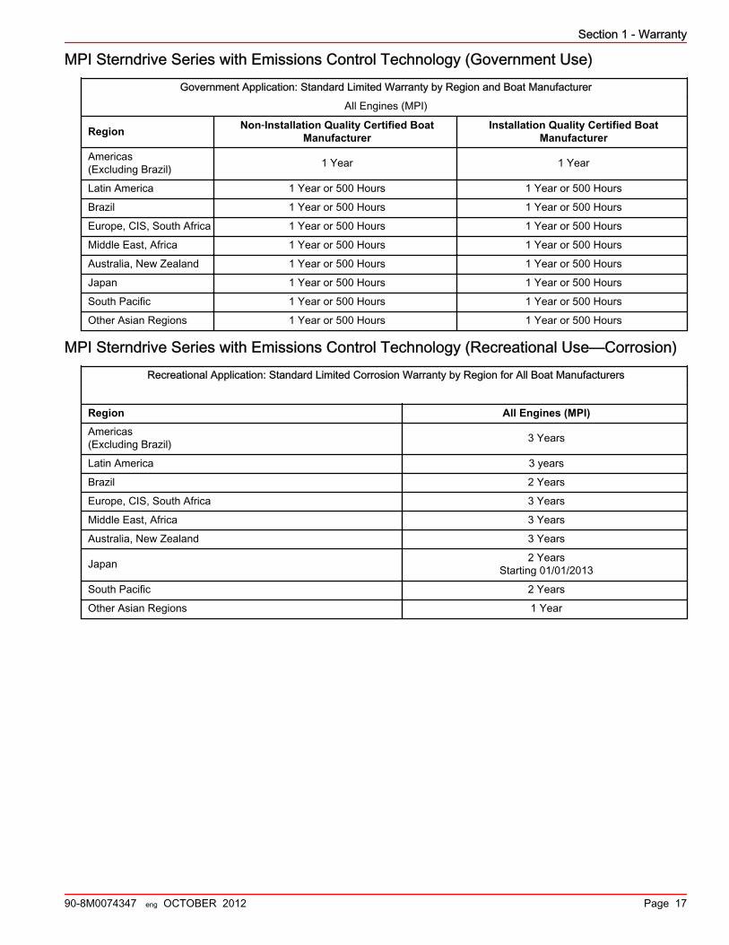
Section 1 - Warranty
90-8M0074347 eng OCTOBER 2012 Page 17
MPI Sterndrive Series with Emissions Control Technology (Government Use)Government Application: Standard Limited Warranty by Region and Boat Manufacturer
All Engines (MPI)
Region Non‑Installation Quality Certified BoatManufacturer
Installation Quality Certified BoatManufacturer
Americas(Excluding Brazil) 1 Year 1 Year
Latin America 1 Year or 500 Hours 1 Year or 500 Hours
Brazil 1 Year or 500 Hours 1 Year or 500 Hours
Europe, CIS, South Africa 1 Year or 500 Hours 1 Year or 500 Hours
Middle East, Africa 1 Year or 500 Hours 1 Year or 500 Hours
Australia, New Zealand 1 Year or 500 Hours 1 Year or 500 Hours
Japan 1 Year or 500 Hours 1 Year or 500 Hours
South Pacific 1 Year or 500 Hours 1 Year or 500 Hours
Other Asian Regions 1 Year or 500 Hours 1 Year or 500 Hours
MPI Sterndrive Series with Emissions Control Technology (Recreational Use—Corrosion)Recreational Application: Standard Limited Corrosion Warranty by Region for All Boat Manufacturers
Region All Engines (MPI)Americas(Excluding Brazil) 3 Years
Latin America 3 years
Brazil 2 Years
Europe, CIS, South Africa 3 Years
Middle East, Africa 3 Years
Australia, New Zealand 3 Years
Japan 2 YearsStarting 01/01/2013
South Pacific 2 Years
Other Asian Regions 1 Year
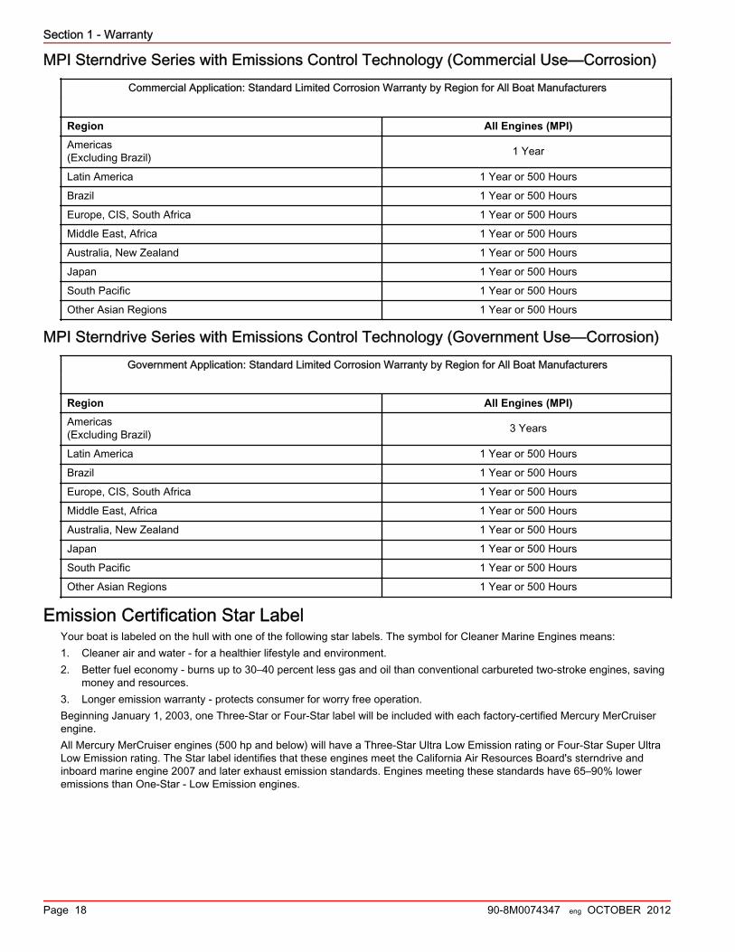
Section 1 - Warranty
Page 18 90-8M0074347 eng OCTOBER 2012
MPI Sterndrive Series with Emissions Control Technology (Commercial Use—Corrosion)Commercial Application: Standard Limited Corrosion Warranty by Region for All Boat Manufacturers
Region All Engines (MPI)Americas(Excluding Brazil) 1 Year
Latin America 1 Year or 500 Hours
Brazil 1 Year or 500 Hours
Europe, CIS, South Africa 1 Year or 500 Hours
Middle East, Africa 1 Year or 500 Hours
Australia, New Zealand 1 Year or 500 Hours
Japan 1 Year or 500 Hours
South Pacific 1 Year or 500 Hours
Other Asian Regions 1 Year or 500 Hours
MPI Sterndrive Series with Emissions Control Technology (Government Use—Corrosion)Government Application: Standard Limited Corrosion Warranty by Region for All Boat Manufacturers
Region All Engines (MPI)Americas(Excluding Brazil) 3 Years
Latin America 1 Year or 500 Hours
Brazil 1 Year or 500 Hours
Europe, CIS, South Africa 1 Year or 500 Hours
Middle East, Africa 1 Year or 500 Hours
Australia, New Zealand 1 Year or 500 Hours
Japan 1 Year or 500 Hours
South Pacific 1 Year or 500 Hours
Other Asian Regions 1 Year or 500 Hours
Emission Certification Star LabelYour boat is labeled on the hull with one of the following star labels. The symbol for Cleaner Marine Engines means:1. Cleaner air and water ‑ for a healthier lifestyle and environment.2. Better fuel economy ‑ burns up to 30–40 percent less gas and oil than conventional carbureted two‑stroke engines, saving
money and resources.3. Longer emission warranty ‑ protects consumer for worry free operation.Beginning January 1, 2003, one Three‑Star or Four‑Star label will be included with each factory‑certified Mercury MerCruiserengine.All Mercury MerCruiser engines (500 hp and below) will have a Three‑Star Ultra Low Emission rating or Four‑Star Super UltraLow Emission rating. The Star label identifies that these engines meet the California Air Resources Board's sterndrive andinboard marine engine 2007 and later exhaust emission standards. Engines meeting these standards have 65–90% loweremissions than One‑Star ‑ Low Emission engines.

Section 1 - Warranty
90-8M0074347 eng OCTOBER 2012 Page 19
The Star label will be affixed on the left side of the hull as shown.
a - Recommended locationb - Secondary location
One Star ‑ Low emission
22531
The one‑star label identifies personal watercraft, outboard, sterndrive and inboard engines thatmeet the Air Resources Board's Personal Watercraft and Outboard marine engine 2001 exhaustemission standards. Engines meeting these standards have 75% lower emissions thanconventional carbureted two‑stroke engines. These engines are equivalent to the U.S. EPAs 2006standards for marine engines.
Two Stars ‑ Very Low emission
42537
The two‑star label identifies personal watercraft, outboard, sterndrive and inboard engines thatmeet the Air Resources Board's Personal Watercraft and Outboard marine engine 2004 exhaustemission standards. Engines meeting these standards have 20% lower emissions than One Star ‑Low‑Emission engines.
Three Stars ‑ Ultra Low emission
42538
The three‑star label identifies engines that meet the Air Resources Board's Personal Watercraftand Outboard marine engine 2008 exhaust emission standards or the sterndrive and inboardmarine engine 2003 exhaust emission standards. Engines meeting these standards have 65%lower emissions than One Star ‑ Low Emission engines.
Four Stars ‑ Super Ultra Low emission
42539
The Four Star label identifies engines that meet the Air Resources Board's sterndrive and inboardmarine engine 2009 exhaust emission standards. Personal Watercraft and Outboard marineengines may also comply with these standards. Engines meeting these standards have 90% loweremissions than One Star ‑ Low Emission engines.
Hang TagThe dealer must mark the appropriate box on one hang tag to match the Star label affixed to the boat. The dealer is responsiblefor displaying the hang tag in a visible location on the boat on display in California. Failure to properly display the hang tagcould result in a citation and possible fine to the dealer from the California Air Resources Board.
XX 1234 XX
32770
a b
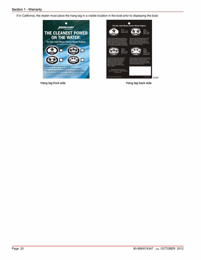
Section 1 - Warranty
Page 20 90-8M0074347 eng OCTOBER 2012
If in California, the dealer must place the hang tag in a visible location in the boat prior to displaying the boat.
43291
Hang tag front side Hang tag back side

Section 2 - Getting to Know Your Power Package
90-8M0074347 eng OCTOBER 2012 Page 21
Section 2 - Getting to Know Your Power PackageTable of ContentsIdentification Information...................................................... 22
Identification...................................................................22Alpha Sterndrive Decal Identification............................. 22Alpha Transom Serial Number...................................... 22Engine Serial Number Decal......................................... 23
Lanyard Stop Switch............................................................. 23Instrumentation..................................................................... 24
VesselView ................................................................... 24SmartCraft Speedometer and Tachometer DigitalGauges ......................................................................... 25System Link Digital Gauges ......................................... 25
Remote Controls................................................................... 26Panel Mount Features .................................................. 26Console Mount Features .............................................. 26
Power Trim........................................................................... 27Single Engine Trim/Trailer ............................................ 28
Dual Engine Trim/Trailer ............................................... 28Electrical System Overload Protection—3.0 MPI ECT......... 28Electrical System Overload Protection—3.0 TKS................. 31Audio, Visual, and Engine Warning Systems—3.0 MPI ECT.............................................................................................. 33
Audio Warning System.................................................. 33Caution .................................................................. 34Severe ................................................................... 34Testing the Audio Warning System ....................... 34
Service Engine Light and OBD‑M MIL Kit......................34Testing the OBD‑M Malfunction Indicator Lamp (MIL).............................................................................. 35
Guardian Strategy..........................................................35Audio Warning System—3.0 TKS........................................ 35
Testing The Audio Warning System ............................. 35
2
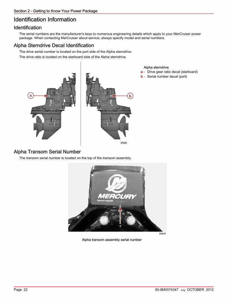
Section 2 - Getting to Know Your Power Package
Page 22 90-8M0074347 eng OCTOBER 2012
Identification InformationIdentification
The serial numbers are the manufacturer's keys to numerous engineering details which apply to your MerCruiser powerpackage. When contacting MerCruiser about service, always specify model and serial numbers.
Alpha Sterndrive Decal IdentificationThe drive serial number is located on the port side of the Alpha sterndrive.The drive ratio is located on the starboard side of the Alpha sterndrive.
Alpha sterndrivea - Drive gear ratio decal (starboard)b - Serial number decal (port)
Alpha Transom Serial NumberThe transom serial number is located on the top of the transom assembly.
25619
Alpha transom assembly serial number
ba
25681

Section 2 - Getting to Know Your Power Package
90-8M0074347 eng OCTOBER 2012 Page 23
Engine Serial Number DecalThe serial number decal is located on the aft portion of the starboard side of the block, near the starter motor.
32121
The engine, transom, and drive serial numbers are also located on the engine identification plate.
a - Engine serial numberb - Transom serial numberc - Drive serial number
Lanyard Stop SwitchThe purpose of a lanyard stop switch is to turn off the engine when the operator moves outside the operator's position (as inaccidental ejection from the operator's position).
a - Stop switchb - Lanyardc - Clips to the operator
Accidental ejections, such as falling overboard, are more likely to occur in:• low‑sided sport boats• bass boats• high‑performance boats
Accidental ejections can also occur from:• poor operating practices• sitting on the seat or gunwale at planing speeds• standing at planing speeds• operating at planing speeds in shallow or obstacle infested waters• releasing your grip on the steering wheel that is pulling in one direction
a
b
c
32636
RUN
OFF
74608
ab
c
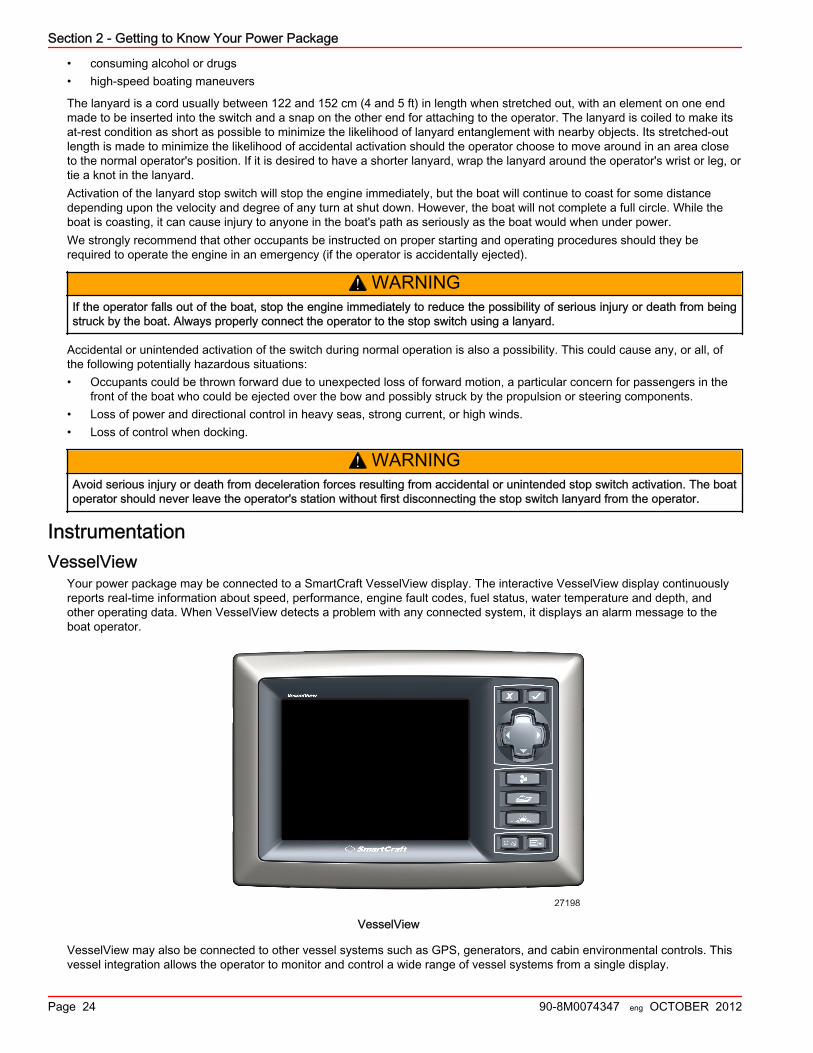
Section 2 - Getting to Know Your Power Package
Page 24 90-8M0074347 eng OCTOBER 2012
• consuming alcohol or drugs• high‑speed boating maneuvers
The lanyard is a cord usually between 122 and 152 cm (4 and 5 ft) in length when stretched out, with an element on one endmade to be inserted into the switch and a snap on the other end for attaching to the operator. The lanyard is coiled to make itsat‑rest condition as short as possible to minimize the likelihood of lanyard entanglement with nearby objects. Its stretched‑outlength is made to minimize the likelihood of accidental activation should the operator choose to move around in an area closeto the normal operator's position. If it is desired to have a shorter lanyard, wrap the lanyard around the operator's wrist or leg, ortie a knot in the lanyard.Activation of the lanyard stop switch will stop the engine immediately, but the boat will continue to coast for some distancedepending upon the velocity and degree of any turn at shut down. However, the boat will not complete a full circle. While theboat is coasting, it can cause injury to anyone in the boat's path as seriously as the boat would when under power.We strongly recommend that other occupants be instructed on proper starting and operating procedures should they berequired to operate the engine in an emergency (if the operator is accidentally ejected).
! WARNINGIf the operator falls out of the boat, stop the engine immediately to reduce the possibility of serious injury or death from beingstruck by the boat. Always properly connect the operator to the stop switch using a lanyard.
Accidental or unintended activation of the switch during normal operation is also a possibility. This could cause any, or all, ofthe following potentially hazardous situations:• Occupants could be thrown forward due to unexpected loss of forward motion, a particular concern for passengers in the
front of the boat who could be ejected over the bow and possibly struck by the propulsion or steering components.• Loss of power and directional control in heavy seas, strong current, or high winds.• Loss of control when docking.
! WARNINGAvoid serious injury or death from deceleration forces resulting from accidental or unintended stop switch activation. The boatoperator should never leave the operator's station without first disconnecting the stop switch lanyard from the operator.
InstrumentationVesselView
Your power package may be connected to a SmartCraft VesselView display. The interactive VesselView display continuouslyreports real‑time information about speed, performance, engine fault codes, fuel status, water temperature and depth, andother operating data. When VesselView detects a problem with any connected system, it displays an alarm message to theboat operator.
27198
VesselView
VesselView may also be connected to other vessel systems such as GPS, generators, and cabin environmental controls. Thisvessel integration allows the operator to monitor and control a wide range of vessel systems from a single display.

Section 2 - Getting to Know Your Power Package
90-8M0074347 eng OCTOBER 2012 Page 25
Refer to your VesselView operations manual for detailed instructions on how to operate this display.
SmartCraft Speedometer and Tachometer Digital GaugesThe SmartCraft instrument package, if equipped, augments the information provided by VesselView. The instrument packagemay display:• Engine RPM• Boat speed• Coolant temperature• Oil pressure• Battery voltage• Fuel consumption• Engine operating hours
SmartCraft tachometer and speedometera - Tachometerb - Speedometerc - LCD display
The SmartCraft instrument package also aids in identifying the fault codes associated with the engine audio warning system.The SmartCraft instrument package displays critical engine alarm data and other potential problems on its LCD display.For basic operation information on the SmartCraft instrument package and for details on the warning functions monitored by thesystem, refer to the manual provided with your gauge package.
System Link Digital GaugesSome instrumentation packages include gauges that augment the information provided by VesselView and the SmartCrafttachometer and speedometer. The owner and operator should be familiar with all the instruments and their functions on theboat. Because of the large variety of instrumentation and manufacturers, have your boat dealer explain the gauges and normalreadings that appear on your boat.The following types of digital gauges may be included with your power package.
a b c d
37925
System Link digital gauges
Item Gauge Indicates
a Oil pressure gauge Engine oil pressure
b Voltmeter Battery voltage
c Water temperature gauge Engine operating temperature
d Fuel gauge Quantity of fuel in tank
a b
cc50400

Section 2 - Getting to Know Your Power Package
Page 26 90-8M0074347 eng OCTOBER 2012
Remote ControlsYour boat may be equipped with Mercury Precision Parts or Quicksilver remote controls. All controls may not have all featuresshown. Consult your dealer for a description and/or demonstration of your remote control.
Panel Mount Features
a - Neutral lock buttonb - Throttle only buttonc - Lanyard stop switchd - Control handle tension adjustment screwe - Control handlef - Trim/tilt button
Neutral lock button ‑ Prevents accidental shift and throttle engagement. Neutral lock button must be pushed into move thecontrol handle out of neutral.Throttle only button ‑ Allows engine throttle advancement without shifting the engine. This is done by disengaging the shiftmechanism from the control handle. The throttle only button can be depressed only when the remote control handle is in theneutral position, and should only be used to assist in starting the engine.Lanyard stop switch ‑ Turns the ignition off whenever the operator (when attached to the lanyard) moves far enough awayfrom the operator's position to activate the switch. Refer to Lanyard Stop Switch for information on the use of this switch.Control handle ‑ Operation of the shift and throttle are controlled by the movement of the control handle. Push the controlhandle forward from neutral with a quick firm motion to the first detent for forward gear. Continue pushing forward to increasespeed. Pull the control handle back from neutral with a quick firm motion to the first detent for reverse gear and continuepushing back to increase speed.Control handle tension adjustment screw (not visible) ‑ This screw is used to adjust the effort required to move the remotecontrol handle. Refer to instructions provided with remote control for complete adjustment instructions.Trim/tilt button ‑ Refer to Power Trim.
Console Mount Features
a - Throttle only buttonb - Control handlec - Power trim switchd - Trailer switch
mc77019-1
b
c
f
a e
d
a cd
b
a
cb
d
mc79503-1

Section 2 - Getting to Know Your Power Package
90-8M0074347 eng OCTOBER 2012 Page 27
Throttle only button ‑ Allows engine throttle advancement without shifting the engine. This is done by disengaging the shiftmechanism from the control handle. The throttle only button can be depressed only when the remote control handle is in theneutral position.Control handles ‑ Operation of the shift and throttle are controlled by the movement of the control handle. Push the controlhandle forward from neutral with a quick firm motion to the first detent for forward gear and continue pushing forward toincrease speed. Pull the control handle back from neutral with a quick firm motion to the first detent for reverse gear andcontinue pushing back to increase speed.Control handle tension adjustment screw (not visible) ‑ This screw is used to adjust the effort required to move the remotecontrol handle. Refer to instructions provided with remote control for complete adjustment instructions.Power trim switch ‑ See Power Trim section for detailed power trim operating procedures.Trailer switch ‑ Used to raise drive unit for trailering, launching, beaching or shallow water operation. See Power Trim fordetailed trailer switch operation.
Power TrimPower trim allows the operator to adjust the sterndrive angle while underway, to provide the ideal boat angle for varying loadand water conditions. Also, the trailering feature allows the operator to raise and lower the sterndrive unit for trailering,beaching, launching, low speed (below 1200 RPM engine speed), and shallow water operation.
! WARNINGExcessive trim can cause serious injury or death at high speeds. Use caution when trimming the sterndrive, and never trimout beyond the gimbal ring support flanges while the boat is underway or at engine speeds above 1200 RPM.
For best performance trim the sterndrive unit so that the boat bottom is at a 3–5° angle to the water.
3 - 5
mc79528
Trimming sterndrive unit up/out can:• Generally increase top speed• Increase clearance over submerged objects or a shallow bottom• Cause boat to accelerate and plane off slower• In excess, cause boat porpoising (bouncing) or propeller ventilation• Cause engine overheating if trimmed up/out to a point where any cooling water intake holes are above the waterline
mc78529
Trimming sterndrive unit down/in can:• Help the boat accelerate and plane off quicker• Generally improve the ride in choppy water• In most cases, reduce boat speed

Section 2 - Getting to Know Your Power Package
Page 28 90-8M0074347 eng OCTOBER 2012
• If in excess, lower the bow of some boats to a point at which they begin to plow with their bow in the water while on plane.This can result in an unexpected turn in either direction called bow steering or over steering if any turn is attempted or if asignificant wave is encountered.
mc79530
Single Engine Trim/TrailerSingle engine applications will have a button that can be pressed to trim the sterndrive unit up or down.To raise the sterndrive unit for trailering, beaching, launching, low speed (below 1200 RPM), and shallow water operation pushthe trim button to raise the sterndrive unit to the full up/out position.Some controls also have a trailer button that trims the sterndrive to a position suitable for trailer purposes only.
Dual Engine Trim/Trailer
NOTICEIf using external tie bars, raising or lowering the drives independently of each other can damage the drive and steeringsystems. If using an external tie bar, raise and lower all drives together as a unit.
Dual engine applications may have a single integral button to operate both sterndrive units simultaneously or may haveseparate buttons for each sterndrive unit.Some controls also have a trailer button that trims the sterndrives to a position suitable for trailer purposes only.
Electrical System Overload Protection—3.0 MPI ECTAn electrical overload will either open a fuse or open a circuit breaker. You must find and repair the source of the overloadbefore replacing the fuse or resetting the circuit breaker.NOTE: In an emergency, when you must operate the engine but cannot isolate the cause for the high current draw, turn off ordisconnect all accessories connected to the engine and instrumentation wiring. Reset the circuit breaker. If the breaker remainsopen, you have not eliminated the electrical overload and the electrical system requires further checks. Contact your authorizedMercury MerCruiser dealer as soon as possible.A circuit breaker protects the engine wiring harness and the instrumentation power lead. Reset the breaker by pushing the redbutton.
51185
Engine wiring harness and instrumentation circuit breaker

Section 2 - Getting to Know Your Power Package
90-8M0074347 eng OCTOBER 2012 Page 29
Four fuses protect the main power, fuel pump, ignition, and accessory circuits. Two 10‑amp fuses protect the O2 sensors.These fuses are located on the top of the engine, underneath the engine information plate.
Fuse locationsa - O2 sensor fusesb - Main power, fuel pump, ignition, and accessory fuses
A 90‑amp fuse, located on the large post of the starter solenoid, protects the engine wiring harness if an electrical overloadoccurs.
mc74907-1
Engine wiring harness fuse
A 15‑amp accessory fuse is located on the rear of the engine. This fuse protects the accessory circuits.
7524
Accessory fuse
a b
32638

Section 2 - Getting to Know Your Power Package
Page 30 90-8M0074347 eng OCTOBER 2012
In the ignition switch "I" terminal lead, there may be a 20‑amp fuse that protects the electrical system. Check for an open fuseor open circuit breaker if you turn the ignition key to the "START" position and nothing happens.
mc70525-1
Ignition switch fuse—typical
The power trim system is protected from overload by a 110‑amp fuse and a 20‑amp spade fuse on the power trim pump. Thetrim pump may also have an in‑line circuit protection device in the power trim positive lead near the battery switch or batteryconnection.
Power trim fusesa - 20‑amp spade fuseb - 110‑amp fuse
A dedicated power harness supplies continuous power to the PCM, to ensure uninterrupted operation. This harness isprotected by a 5‑amp fuse, located at the engine's battery.
a - 5‑amp fuseb - Positive battery terminal (harness lead with fuse)c - Negative battery terminal
a
b 9208
43608
a b c

Section 2 - Getting to Know Your Power Package
90-8M0074347 eng OCTOBER 2012 Page 31
The three‑button power trim control panel is protected by a 20‑amp in‑line fuse.
mc70527-1
Power trim control panel fuse
The MerCathode system has a 5‑amp fuse, which connects to the positive (+) terminal on the controller. If the fuse is open, thesystem will not operate, resulting in a loss of corrosion protection.
a - MerCathodeb - Red/purple wirec - 5‑amp fuse
Electrical System Overload Protection—3.0 TKSAn electrical overload will either open a fuse or open a circuit breaker. You must find and repair the source of the overloadbefore replacing the fuse or resetting the circuit breaker.NOTE: In an emergency, when the engine must be operated and the cause for the high current draw cannot be located andcorrected, turn off or disconnect all accessories connected to the engine and instrumentation wiring. Reset the circuit breaker. Ifthe breaker remains open, the electrical overload has not been eliminated. Further checks must be made on the electricalsystem. Contact your authorized Mercury MerCruiser dealer as soon as possible.A circuit breaker protects the engine wiring harness and the instrumentation power lead. Reset the breaker by pushing the redbutton.
51185
Engine wiring harness and instrumentation circuit breaker
a
c
50534
b

Section 2 - Getting to Know Your Power Package
Page 32 90-8M0074347 eng OCTOBER 2012
A 90‑amp fuse, located on the large post of the starter solenoid, protects the engine wiring harness if an electrical overloadoccurs.
mc74907-1
Engine wiring harness fuse
A 15‑amp accessory fuse is located on the rear of the engine. This fuse protects the accessory circuits. A 20‑amp fuse islocated on the top of the engine to protect the TKS circuit.
7524
Accessory fuse
A 20‑amp fuse may be located in the ignition switch "I" terminal lead to protect the electrical system. Check for an open fuse oropen circuit breaker if the ignition key is turned to the start position and nothing happens.
mc70525-1
Ignition switch fuse—typical

Section 2 - Getting to Know Your Power Package
90-8M0074347 eng OCTOBER 2012 Page 33
The power trim system is protected from overload by a 110‑amp fuse and a 20‑amp spade fuse on the power trim pump. Thetrim pump may also have an in‑line circuit protection device in the power trim positive lead near the battery switch or batteryconnection.
Power trim fusesa - 20‑amp spade fuseb - 110‑amp fuse
The three‑button power trim control panel is further protected by a 20‑amp in‑line fuse.
mc70527-1
Power trim control panel fuse
The MerCathode system has a 5‑amp fuse which connects to the positive (+) terminal on the controller. If the fuse is open, thesystem will not operate, resulting in a loss of corrosion protection.
a - MerCathodeb - Red/purple wirec - 5‑amp fuse
Audio, Visual, and Engine Warning Systems—3.0 MPI ECTAudio Warning System
IMPORTANT: The audio warning system alerts the operator that a problem has occurred. It does not protect the engine fromdamage.
a
b 9208
a
c
50534
b

Section 2 - Getting to Know Your Power Package
Page 34 90-8M0074347 eng OCTOBER 2012
The Mercury MerCruiser power package may be equipped with an audio warning system. Most faults cause the warning horncircuit to activate. How the warning horn activates depends on the severity of the problem.There are two warning horn states:• Caution• Severe
CautionIf a caution state is detected, the audio warning system will sound for six one‑second intervals.
a - Horn (on or off)b - Time (in seconds)
Below are some examples of a caution state:• Drive oil is low (sterndrive models only)• Sensor failure
SevereIMPORTANT: Operators are advised to contact an authorized Mercury MerCruiser dealer if a severe fault is activated.If a severe state is detected, the audio warning system sounds for six seconds, turns off for six seconds, and sounds for sixmore seconds. Then the audio warning system sounds for two half‑second intervals every sixty seconds.
a - Horn (on or off)b - Time (in seconds)
Below are some examples of a severe state:• Transmission fluid temperature is too hot (inboard models only)• Engine oil pressure is too low• Engine temperature is too hot• Seawater pressure is too low• Transmission pressure is low (inboard models only)
Testing the Audio Warning System1. Turn the ignition switch to the on position without cranking the engine.2. Listen for the audio alarm. The alarm will sound if the system is functioning correctly.
Service Engine Light and OBD‑M MIL KitBoats powered by emissions control technology (ECT) catalyzed engines must be equipped with a SmartCraft‑enabled gaugecapable of displaying the service engine icon, or a dash‑mounted service engine light. Malfunction indicator lamp (MIL) kitscontaining a dash‑mounted service engine light and a special harness that connects to the engine harness may be purchasedseparately.
ON ON
OFF
ON
OFF
ON
OFF
ON
OFF
ON
OFF
1
1
1
1
1
1
1
1
1
1
1
OFF
33402
a
b
40388
a
b
ONON
6 6 6
OFFOFF
60 ½
ON
½
ON
OFF
60 ½
ON
½
ON
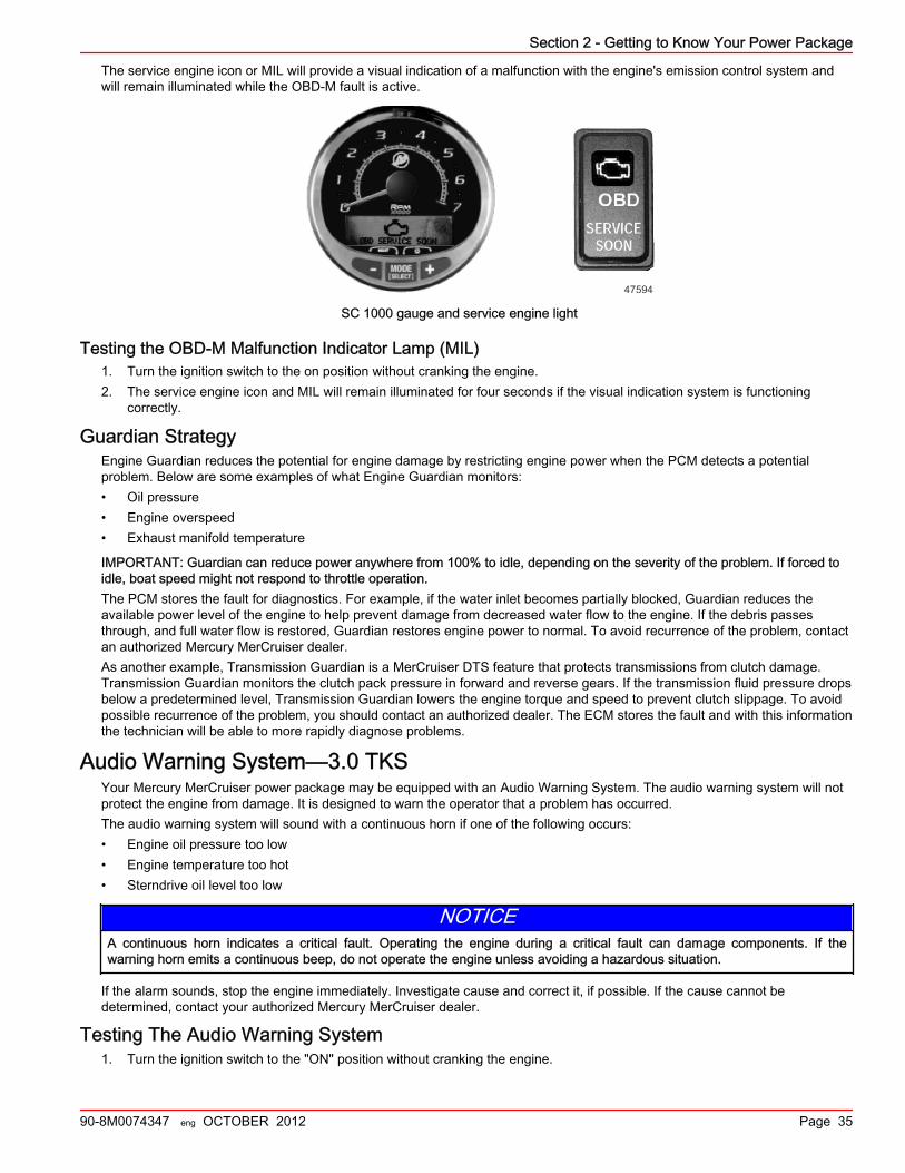
Section 2 - Getting to Know Your Power Package
90-8M0074347 eng OCTOBER 2012 Page 35
The service engine icon or MIL will provide a visual indication of a malfunction with the engine's emission control system andwill remain illuminated while the OBD‑M fault is active.
47594
SC 1000 gauge and service engine light
Testing the OBD-M Malfunction Indicator Lamp (MIL)1. Turn the ignition switch to the on position without cranking the engine.2. The service engine icon and MIL will remain illuminated for four seconds if the visual indication system is functioning
correctly.
Guardian StrategyEngine Guardian reduces the potential for engine damage by restricting engine power when the PCM detects a potentialproblem. Below are some examples of what Engine Guardian monitors:• Oil pressure• Engine overspeed• Exhaust manifold temperature
IMPORTANT: Guardian can reduce power anywhere from 100% to idle, depending on the severity of the problem. If forced toidle, boat speed might not respond to throttle operation.The PCM stores the fault for diagnostics. For example, if the water inlet becomes partially blocked, Guardian reduces theavailable power level of the engine to help prevent damage from decreased water flow to the engine. If the debris passesthrough, and full water flow is restored, Guardian restores engine power to normal. To avoid recurrence of the problem, contactan authorized Mercury MerCruiser dealer.As another example, Transmission Guardian is a MerCruiser DTS feature that protects transmissions from clutch damage.Transmission Guardian monitors the clutch pack pressure in forward and reverse gears. If the transmission fluid pressure dropsbelow a predetermined level, Transmission Guardian lowers the engine torque and speed to prevent clutch slippage. To avoidpossible recurrence of the problem, you should contact an authorized dealer. The ECM stores the fault and with this informationthe technician will be able to more rapidly diagnose problems.
Audio Warning System—3.0 TKSYour Mercury MerCruiser power package may be equipped with an Audio Warning System. The audio warning system will notprotect the engine from damage. It is designed to warn the operator that a problem has occurred.The audio warning system will sound with a continuous horn if one of the following occurs:• Engine oil pressure too low• Engine temperature too hot• Sterndrive oil level too low
NOTICEA continuous horn indicates a critical fault. Operating the engine during a critical fault can damage components. If thewarning horn emits a continuous beep, do not operate the engine unless avoiding a hazardous situation.
If the alarm sounds, stop the engine immediately. Investigate cause and correct it, if possible. If the cause cannot bedetermined, contact your authorized Mercury MerCruiser dealer.
Testing The Audio Warning System1. Turn the ignition switch to the "ON" position without cranking the engine.
Section 2 - Getting to Know Your Power Package
Page 36 90-8M0074347 eng OCTOBER 2012
2. Listen for the audio alarm. The alarm will sound if the system is functioning correctly.

Section 3 - On the Water
90-8M0074347 eng OCTOBER 2012 Page 37
Section 3 - On the WaterTable of ContentsSafe Boating Suggestions.................................................... 38Carbon Monoxide Exposure................................................. 39
Be Alert To Carbon Monoxide Poisoning ..................... 39Stay Clear of Exhaust Areas ........................................ 39Good Ventilation .......................................................... 39Poor Ventilation ........................................................... 40
Launching and Boat Operation............................................. 40Operation Chart ............................................................ 40
Starting and Stopping the Engine—3.0 MPI ECT................. 41Starting and Stopping the Engine.................................. 41
Starting the Engine ................................................ 41Stopping the Engine .............................................. 42
Starting the Engine After Stopped While in Gear.......... 42Starting and Stopping the Engine—3.0 TKS........................ 42
Starting and Stopping the Engine.................................. 42Starting the Engine ................................................ 42Stopping the Engine .............................................. 42
Starting the Engine After It Has Been Stopped While InGear............................................................................... 42
Throttle Only Operation........................................................ 43Trailering the Boat................................................................ 43Freezing Temperature Operation......................................... 43Drain Plug and Bilge Pump.................................................. 43Protecting People in the Water............................................. 43
While You Are Cruising ................................................ 43
While Boat Is Stationary ............................................... 43High‑Speed and High‑Performance Operation..................... 43Passenger Safety in Pontoon Boats and Deck Boats.......... 44
Boats Having an Open Front Deck ............................... 44Boats With Front‑Mounted, Raised Pedestal FishingSeats ............................................................................ 44
Wave and Wake Jumping..................................................... 44Impact with Underwater Hazards......................................... 45
Drive Unit Impact Protection ......................................... 45Conditions Affecting Operation............................................. 45
Weight Distribution (Passengers and Gear) Inside theBoat............................................................................... 45The Bottom of the Boat.................................................. 46Cavitation....................................................................... 46Ventilation...................................................................... 46Elevation and Climate.................................................... 46Propeller Selection.........................................................46
Getting Started—3.0 MPI ECT............................................. 4720‑Hour Break‑In Period................................................ 47After Break‑In Period..................................................... 47End of First Season Checkup........................................ 47
Getting Started—3.0 TKS..................................................... 4720‑Hour Break‑In Period................................................ 47After Break‑In Period..................................................... 47End of First Season Checkup........................................ 48
3

Section 3 - On the Water
Page 38 90-8M0074347 eng OCTOBER 2012
Safe Boating SuggestionsTo safely enjoy the waterways, familiarize yourself with local and all other governmental boating regulations and restrictionsand consider the following suggestions.Know and obey all nautical rules and laws of the waterways.• We recommend that all powerboat operators complete a boating safety course. In the U.S., the U.S. Coast Guard Auxiliary,
the Power Squadron, the Red Cross, and your state or provincial boating law enforcement agency provide courses. Formore information in the U.S., call the Boat U.S. Foundation at 1‑800‑336‑BOAT (2628).
Perform safety checks and required maintenance.• Follow a regular schedule and ensure that all repairs are properly made.
Check safety equipment onboard.• Here are some suggestions of the types of safety equipment to carry when boating:
• Approved fire extinguishers• Signal devices: flashlight, rockets or flares, flag, and whistle or horn• Tools necessary for minor repairs• Anchor and extra anchor line• Manual bilge pump and extra drain plugs• Drinking water• Transistor radio• Paddle or oar• Spare propeller, thrust hubs, and an appropriate wrench• First aid kit and instructions• Waterproof storage containers• Spare operating equipment, batteries, bulbs, and fuses• Compass and map or chart of the area• Personal flotation device (one per person onboard)
Watch for signs of weather change and avoid foul weather and rough‑sea boating.Tell someone where you are going and when you expect to return.Passenger boarding.• Stop the engine whenever passengers are boarding, unloading, or are near the back (stern) of the boat. Shifting the drive
unit into neutral is not sufficient.
Use personal flotation devices.• Federal Law requires that there be a U.S. Coast Guard approved life jacket (personal flotation device), correctly sized and
readily accessible for every person onboard, plus a throwable cushion or ring. We strongly advise that everyone wear a lifejacket at all times while in the boat.
Prepare other boat operators.• Instruct at least one person onboard in the basics of starting and operating the engine and boat handling in case the driver
becomes disabled or falls overboard.
Do not overload your boat.• Most boats are rated and certified for maximum load (weight) capacities (refer to your boat capacity plate). Know your
boat's operating and loading limitations. Know if your boat will float if full of water. When in doubt, contact your authorizedMercury MerCruiser dealer or the boat manufacturer.
Ensure that everyone in the boat is properly seated.• Do not allow anyone to sit or ride on any part of the boat that was not intended for such use. This includes the backs of
seats, gunwales, transom, bow, decks, raised fishing seats and any rotating fishing seat; anywhere that suddenunexpected acceleration, sudden stopping, unexpected loss of boat control, or sudden boat movement could cause aperson to be thrown overboard or into the boat. Ensure that all passengers have a proper seat and are in it before any boatmovement.
Never be under the influence of alcohol or drugs while boating (it is the law).• They impair your judgment and greatly reduce your ability to react quickly.
Know your boating area and avoid hazardous locations.Be alert.

Section 3 - On the Water
90-8M0074347 eng OCTOBER 2012 Page 39
• The operator of the boat is responsible by law to maintain a proper lookout by sight and hearing. The operator must havean unobstructed view particularly to the front. No passengers, load, or fishing seats should block the operator's view whenthe boat is above idle or planing transition speed. Watch out for others, the water, and your wake.
Never drive your boat directly behind a water skier in case the skier falls.• As an example, your boat traveling at 40 km/h (25 mph) will overtake a fallen skier who was 61 m (200 ft) in front of you in
five seconds.
Watch fallen skiers.• When using your boat for waterskiing or similar activities, always keep a fallen or down skier on the operator's side of the
boat while returning to attend to the skier. The operator should always have the down skier in sight and never back up tothe skier or anyone in the water.
Report accidents.• Boat operators are required by law to file a Boating Accident Report with their state boating law enforcement agency when
their boat is involved in certain boating accidents. A boating accident must be reported if 1) there is loss of life or probableloss of life, 2) there is personal injury requiring medical treatment beyond first aid, 3) there is damage to boats or otherproperty where the damage value exceeds $500.00, or 4) there is complete loss of the boat. Seek further assistance fromlocal law enforcement.
Carbon Monoxide ExposureBe Alert To Carbon Monoxide Poisoning
Carbon monoxide (CO) is a deadly gas that is present in the exhaust fumes of all internal combustion engines, including theengines that propel boats, and the generators that power boat accessories. By itself, CO is odorless, colorless, and tasteless,but if you can smell or taste engine exhaust, you are inhaling CO.Early symptoms of carbon monoxide poisoning, which are similar to the symptoms of seasickness and intoxication, includeheadache, dizziness, drowsiness, and nausea.
! WARNINGInhaling engine exhaust gases can result in carbon monoxide poisoning, which can lead to unconsciousness, brain damage,or death. Avoid exposure to carbon monoxide.Stay clear from exhaust areas when engine is running. Keep the boat well‑ventilated while at rest or underway.
Stay Clear of Exhaust Areas
41127
Engine exhaust gases contain harmful carbon monoxide. Avoid areas of concentrated engine exhaust gases. When enginesare running, keep swimmers away from the boat, and do not sit, lie, or stand on swim platforms or boarding ladders. Whileunderway, do not allow passengers to be positioned immediately behind the boat (platform dragging, teak/body surfing). Thisdangerous practice not only places a person in an area of high engine exhaust concentration, but also subjects them to thepossibility of injury from the boat propeller.
Good VentilationVentilate the passenger area, open side curtains or forward hatches to remove fumes.Example of desired air flow through the boat:
43367

Section 3 - On the Water
Page 40 90-8M0074347 eng OCTOBER 2012
Poor VentilationUnder certain running or wind conditions, permanently enclosed or canvas enclosed cabins or cockpits with insufficientventilation may draw in carbon monoxide. Install one or more carbon monoxide detectors in your boat.Although the occurrence is rare, on a very calm day, swimmers and passengers in an open area of a stationary boat thatcontains or is near a running engine may be exposed to a hazardous level of carbon monoxide.1. Examples of poor ventilation while the boat is stationary:
a - Operating the engine when the boatis moored in a confined space
b - Mooring close to another boat thathas its engine operating
2. Examples of poor ventilation while the boat is moving:
a - Operating the boat with thetrim angle of the bow toohigh
b - Operating the boat with noforward hatches open(station wagon effect)
Launching and Boat OperationIMPORTANT: Install bilge drain plug prior to launching boat.
Operation ChartOperation Chart
BEFORE STARTING AFTER STARTING WHILE UNDERWAY AFTER STOPPING
Install bilge drain plug.Observe all gauges tocheck condition of engine.If not normal, stop engine.
Observe all gauges tocheck condition ofengine. If not normal,stop engine.
Turn ignition key to the"OFF" position.
Open engine hatch. Check for fuel, oil, water,fluid, and exhaust leaks.
Listen for the audioalarm.
Turn battery switch to the"OFF" position.
21626
ab
ab
43368

Section 3 - On the Water
90-8M0074347 eng OCTOBER 2012 Page 41
Operation Chart
BEFORE STARTING AFTER STARTING WHILE UNDERWAY AFTER STOPPING
Turn battery switch on. Check shift and throttlecontrol operation. Close fuel shut off valve.
Operate bilge blowers. Check steering operation. Close seacock, ifequipped.
Open fuel shut off valve. Flush cooling system if insaltwater.
Open seacock, if equipped. Drain bilge.
Close the drain system.
Place sterndrive unit in full down/inposition.
Check the engine oil.
Perform all other checks specified by yourdealer and/or boatbuilder.
Listen for the audio warning alarm tosound when the ignition switch is in the"ON" position.
Starting and Stopping the Engine—3.0 MPI ECTStarting and Stopping the Engine
NOTE: Only perform those functions applicable to your power package.
Starting the Engine1. Check all items listed in the Operation Chart.2. Place the remote control handle in neutral.
NOTICEWithout sufficient cooling water, the engine, the water pump, and other components will overheat and suffer damage. Providea sufficient supply of water to the water inlets during operation.
! WARNINGExplosive fumes contained in the engine compartment can cause serious injury or death from fire or explosion. Beforestarting the engine, operate the bilge blower or vent the engine compartment for at least five minutes.
3. Turn ignition key to "START." Release key when engine starts and allow switch to return to "ON" position. Allow engine towarm up (6–10 minutes on first start of the day).
4. If engine does not start after three attempts:a. Push the throttle only button and position the remote control handle/throttle lever to the 1/4 throttle position.b. Turn ignition key to "START." Release key when engine starts and allow switch to return to "ON" position.
5. If engine does not start after step 4:a. Move the remote control handle/throttle lever to full throttle position, then return to 1/4 throttle.b. Turn ignition key to "START." Release key when engine starts and allow switch to return to "ON" position.
6. Inspect the power package for fuel, oil, water, and exhaust leaks.7. Move control handle with a firm, quick motion forward to shift to forward gear, or backward to shift to reverse. After shifting,
advance throttle to desired setting.
NOTICEShifting into gear at engine speeds above idle will damage the drive system. Shift the drive into gear only when the engine isoperating at idle.

Section 3 - On the Water
Page 42 90-8M0074347 eng OCTOBER 2012
Stopping the Engine1. Move the remote control handle to neutral/idle and allow the engine to slow to idle speed. If engine has been operated at
high speed for a long period of time, allow the engine to cool at idle speed for 3–5 minutes.2. Turn ignition key to the "OFF" position.
Starting the Engine After Stopped While in GearIMPORTANT: Avoid stopping the engine if the sterndrive is in gear.If you stopped the engine while in gear, return the shift control to neutral and resume normal starting procedures.
Starting and Stopping the Engine—3.0 TKSStarting and Stopping the Engine
NOTE: Only perform those functions applicable to your power package.
Starting the Engine1. Check all items listed in the Operation Chart.2. Place the remote control handle in neutral.
NOTICEWithout sufficient cooling water, the engine, the water pump, and other components will overheat and suffer damage. Providea sufficient supply of water to the water inlets during operation.
! WARNINGExplosive fumes contained in the engine compartment can cause serious injury or death from fire or explosion. Beforestarting the engine, operate the bilge blower or vent the engine compartment for at least five minutes.
3. Turn ignition key to "START." Release key when engine starts and allow switch to return to "ON" position. Allow the engineto warm up 6–10 minutes on the first start of the day.NOTE: If the engine has not run for a long period it may require a couple of attempts.
4. If engine does not start after three attempts:a. Push the throttle only button and position the remote control handle/throttle lever to the 1/4 throttle position.b. Turn ignition key to "START." Release key when engine starts and allow switch to return to "ON" position.
5. If engine does not start after step 4:a. Move the remote control handle/throttle lever to full throttle position, then return to 1/4 throttle.b. Turn ignition key to "START." Release key when engine starts and allow switch to return to "ON" position.
6. Inspect the power package for fuel, oil, water, and exhaust leaks.7. Move control handle with a firm, quick motion forward to shift to forward gear, or backward to shift to reverse. After shifting,
advance throttle to the desired setting.
NOTICEShifting into gear at engine speeds above idle will damage the gearcase. Shifting into gear when the engine is not runningcan misalign the clutch, preventing proper shifting. Always shift the gearcase into gear when the engine is operating at idle. Ifyou must shift while the engine is not operating, rotate the propeller shaft in the appropriate direction during shifting.
Stopping the Engine1. Move the remote control handle to neutral/idle and allow the engine to slow to idle speed. If engine has been operated at
high speed for a long period of time, allow the engine to cool at idle speed for 3 to 5 minutes.2. Turn ignition key to the "OFF" position.
Starting the Engine After It Has Been Stopped While In GearIMPORTANT: Avoid stopping the engine if the sterndrive unit is in gear. If the engine does stop, refer to the followingprocedure:1. Push and pull repeatedly on the remote control handle until handle returns to the neutral/idle position. This may take
several tries if the power package was operating above idle RPM when the engine stopped.2. After the handle returns to the neutral/idle position, resume normal starting procedures.

Section 3 - On the Water
90-8M0074347 eng OCTOBER 2012 Page 43
Throttle Only Operation1. Refer to Remote Controls section for remote control features.2. Move the control lever to the idle/neutral position.3. Depress and hold the throttle only button, and move the control lever to the idle/forward or idle/reverse position.4. Advancing the control lever beyond the idle/forward or idle/reverse position will cause engine speed to increase.
IMPORTANT: Moving the control lever back to the idle/neutral position will disengage the throttle only button and allow theengine to shift into gear.
5. Throttle only mode is deactivated by moving the control lever to the idle/neutral position. Moving the control lever from theidle/neutral position to the idle/forward or idle/reverse position without pressing the throttle only button will shift the unit intothe chosen gear.
Trailering the BoatYour boat can be trailered with the sterndrive unit in the up or down position. Adequate clearance is required between the roadand sterndrive when transporting.If adequate road clearance is a problem, place the sterndrive unit in full trailer position and support it with an optional trailer kitwhich is available from your authorized Mercury MerCruiser dealer.
Freezing Temperature OperationIMPORTANT: If the boat is operated during periods of freezing temperature, precautions must be taken to prevent freezedamage to the power package. Damage caused by freezing is not covered by Mercury MerCruiser Limited Warranty.
Drain Plug and Bilge PumpThe engine compartment in your boat is a natural place for water to collect. For this reason, boats are normally equipped with adrain plug and/or a bilge pump. It is very important to check these items on a regular basis to ensure that the water level doesnot come into contact with your power package. Components on your engine will be damaged if submerged. Damage causedby submersion is not covered by the Mercury MerCruiser Limited Warranty.
Protecting People in the WaterWhile You Are Cruising
It is very difficult for a person in the water to take quick action to avoid a boat heading in their direction, even at slow speeds.
21604
Always slow down and exercise extreme caution any time you are boating in an area where there might be people in the water.Whenever a boat is moving (even coasting) and the gear shift is in neutral, there is sufficient force by the water on the propellerto cause the propeller to rotate. This neutral propeller rotation can cause serious injury.
While Boat Is Stationary
! WARNINGA spinning propeller, a moving boat, or any solid device attached to the boat can cause serious injury or death to swimmers.Stop the engine immediately whenever anyone in the water is near your boat.
Shift into neutral and shut off the engine before allowing people to swim or be in the water near your boat.
High‑Speed and High‑Performance OperationIf your boat is considered a high‑speed or high‑performance boat and you are unfamiliar with its operation, we recommend thatyou never operate it at its high speed capability without first requesting an initial orientation and demonstration ride with yourdealer or an operator experienced with your boat. For additional information, refer to Hi‑Performance Boat Operation booklet(90‑849250R03) from your dealer, distributor, or Mercury Marine.

Section 3 - On the Water
Page 44 90-8M0074347 eng OCTOBER 2012
Passenger Safety in Pontoon Boats and Deck BoatsWhenever the boat is in motion, observe the location of all passengers. Do not allow any passengers to stand or use seatsother than those designated for traveling faster than idle speed. A sudden reduction in boat speed, such as plunging into alarge wave or wake, a sudden throttle reduction, or a sharp change of boat direction, could throw them over the front of theboat. Falling over the front of the boat between the two pontoons will position them to be run over.
Boats Having an Open Front DeckNo one should ever be on the deck in front of the fence while the boat is in motion. Keep all passengers behind the front fenceor enclosure.Persons on the front deck could easily be thrown overboard or persons dangling their feet over the front edge could get theirlegs caught by a wave and pulled into the water.
mc79555-1
! WARNINGSitting or standing in an area of the boat not designed for passengers at speeds above idle can cause serious injury or death.Stay back from the front end of deck boats or raised platforms and remain seated while the boat is in motion.
Boats With Front‑Mounted, Raised Pedestal Fishing SeatsElevated fishing seats are not intended for use when the boat is traveling faster than idle or trolling speed. Sit only in seatsdesignated for traveling at faster speeds.Any unexpected, sudden reduction in boat speed could result in the elevated passenger falling over the front of the boat.
mc79557-1
Wave and Wake Jumping! WARNING
Wave or wake jumping can cause serious injury or death from occupants being thrown within or out of the boat. Avoid waveor wake jumping whenever possible.
mc79680-1
Operating recreational boats over waves and wakes is a natural part of boating. However, when this activity is done withenough speed to force the boat hull partially or completely out of the water, certain hazards arise, particularly when the boatreenters the water.The primary concern is the boat changing direction while in the midst of the jump. In such cases the landing may cause theboat to violently veer in a new direction. Such a sharp change in direction or turn can cause occupants to be thrown out of theirseats or out of the boat.

Section 3 - On the Water
90-8M0074347 eng OCTOBER 2012 Page 45
There is another less common hazardous result from allowing your boat to launch off of a wave or wake. If the bow of your boatpitches down far enough while airborne, upon water contact it may penetrate under the water surface and submarine for aninstant. This will bring the boat nearly to a stop in an instant and can send the occupants flying forward. The boat may also veersharply to one side.
Impact with Underwater HazardsReduce speed and proceed with caution whenever you're driving a boat in shallow water or in areas where the waters aresuspected of having underwater obstacles that could be struck by the underwater drive components, rudder, or the boatbottom.
mc79679-1
IMPORTANT: The most important thing you can do to help reduce injury or impact damage from striking a floating orunderwater object is control the boat speed. Under these conditions, boat speed should be kept to a maximum speed of24–40 km/h (15–25 mph).Striking a floating/underwater object may result in an infinite number of situations. Some of these situations could result in thefollowing:• The boat could move suddenly in a new direction. Such a sharp change in direction or turn can cause occupants to be
thrown out of their seats or out of the boat.• A rapid reduction in speed. This will cause occupants to be thrown forward, even out of the boat.• Impact damage to the underwater drive components, rudder, and/or boat.
Keep in mind, one of the most important things you can do to help reduce injury or impact damage in these situations is controlthe boat speed. Boat speed should be kept to a minimum planing speed when driving in waters known to have underwaterobstacles.After striking a submerged object, stop the engine as soon as possible and inspect the drive system for any broken or looseparts. If damage is present or suspected, the power package should be taken to an authorized Mercury MerCruiser dealer for athorough inspection and necessary repair.The boat should be checked for hull fractures, transom fractures, and water leaks.Operating with damaged underwater drive components, rudder, or boat bottom could cause additional damage to other parts ofthe power package, or could affect control of the boat. If continued operation is necessary, do so at greatly reduced speeds.
! WARNINGOperating a boat or engine with impact damage can result in product damage, serious injury, or death. If the vesselexperiences any form of impact, have an authorized Mercury Marine dealer inspect and repair the vessel or power package.
Drive Unit Impact ProtectionThe power trim hydraulic system is designed to provide impact protection for the sterndrive unit. If a submerged object is struckwhile the boat is moving forward, the hydraulic system will cushion the kickup of the sterndrive unit as it clears the object,reducing damage to the unit. After the sterndrive unit has cleared the object, the hydraulic system allows the sterndrive unit toreturn to its original operating position, preventing loss of steering control and engine overspeed.Use extreme caution when operating in shallow water or where underwater objects are known to be present. No impactprotection is provided in reverse; use extreme care to prevent striking submerged objects while operating in reverse.IMPORTANT: Impact protection system cannot be designed to ensure total protection from impact damage under allconditions.
Conditions Affecting OperationWeight Distribution (Passengers and Gear) Inside the Boat
Shifting weight to rear (stern):• Generally increases speed and engine RPM

Section 3 - On the Water
Page 46 90-8M0074347 eng OCTOBER 2012
• Causes bow to bounce in choppy water• Increases danger of following wave splashing into the boat when coming off plane• At extremes, can cause the boat to porpoise
Shifting weight to front (bow):• Improves ease of planing• Improves rough water ride• At extremes, can cause the boat to veer back and forth (bow steer)
The Bottom of the BoatTo maintain maximum speed, the boat bottom should be:• Clean, free of barnacles and marine growth• Free of distortion; nearly flat where it contacts the water• Straight and smooth, fore and aft
Marine vegetation may accumulate when the boat is docked. This growth must be removed before operation; it may clog thewater inlets and cause the engine to overheat.
CavitationCavitation occurs when water flow cannot follow the contour of a fast‑moving underwater object, such as a gear housing or apropeller. Cavitation increases propeller speed while reducing boat speed. Cavitation can seriously erode the surface of thegear housing or the propeller. Common causes of cavitation are:• Weeds or other debris snagged on the propeller• Bent propeller blade• Raised burrs or sharp edges on the propeller
VentilationVentilation is caused by surface air or exhaust gases that are introduced around the propeller resulting in propeller speed‑upand a reduction in boat speed. Air bubbles strike the propeller blade and cause erosion of the blade surface. If allowed tocontinue, eventual blade failure (breakage) will occur. Excessive ventilation is usually caused by:• Drive unit trimmed out too far• A missing propeller diffuser ring• A damaged propeller or gear housing, which allows exhaust gases to escape between propeller and gear housing• Drive unit installed too high on transom
Elevation and ClimateElevation and climate changes will affect the performance of your power package. Loss of performance can be caused by:• Higher elevations• Higher temperatures• Low barometric pressures• High humidity
For you to have optimum engine performance under changing weather conditions, it is essential that the engine be propped toallow the engine to operate at or near the top end of the specified maximum RPM range with a normal boat load during yournormal boating weather conditions.In most cases, recommended RPM can be achieved by changing to a lower pitch propeller.
Propeller SelectionIMPORTANT: The engines covered in this manual are equipped with an RPM rev‑limiter that is set to an upper RPM limit. Thislimit, which is slightly above the normal operating range of the engine, helps prevent damage from excessive engine RPM.Once the RPM returns to the recommended operating RPM range, normal engine operation resumes.The boat manufacturer and the selling dealer are responsible for equipping the power package with the correct propeller. Referto Mercury Marine's web page http://www.mercurymarine.com/everything_you_need_to_know_about_propellers6.Select a propeller that will allow the engine power package to operate at or near the top end of the recommended WOToperating RPM range with a normal load.If full‑throttle operation is below the recommended range, the propeller must be changed to prevent loss of performance andpossible engine damage. On the other hand, operating an engine above the recommended operating RPM range will causehigher than normal wear and damage.

Section 3 - On the Water
90-8M0074347 eng OCTOBER 2012 Page 47
After initial propeller selection, the following common problems may require that the propeller be changed to a lower pitch.• Warmer weather and greater humidity cause a loss of RPM.• Operating in a higher elevation causes a loss of RPM.• Operating with a dirty boat bottom causes a loss of RPM.• Operating with increased load (additional passengers, pulling skiers) causes a loss of RPM.
For better acceleration, such as is needed for waterskiing, use the next lower pitch propeller. When not pulling skiers, do notoperate at full throttle when using the lower pitch propeller.
Getting Started—3.0 MPI ECT20‑Hour Break‑In Period
IMPORTANT: The first 20 hours of operation is the engine break‑in period. Correct break‑in is essential to obtain minimum oilconsumption and maximum engine performance. During this break‑in period, the following rules must be observed:• Do not operate below 1500 RPM for extended periods of time for the first 10 hours. Shift into gear as soon as possible after
starting and advance the throttle above 1500 RPM if conditions permit safe operation.• Do not operate at one speed consistently for extended periods.• Do not exceed 3/4 throttle during the first 10 hours. During the next 10 hours, occasional operation at full throttle is
permissible (five minutes at a time maximum).• Avoid full throttle acceleration from idle speed.• Do not operate at full throttle until the engine reaches normal operating temperature.• Frequently check engine oil level. Add oil as needed. It is normal for oil consumption to be high during the break‑in period.
After Break‑In PeriodTo help extend the life of your Mercury MerCruiser power package, the following recommendations should be considered;• Ensure that propeller allows the engine to operate at or near the top of the specified WOT RPM range (Refer to
Specifications and Maintenance) when at full throttle with a normal boat load.• Operation at 3/4 throttle setting or lower is recommended. Refrain from prolonged operation at WOT RPM.• Change the engine oil and oil filter. Refer to Maintenance.
End of First Season CheckupAt the end of the first season of operation, contact an authorized Mercury MerCruiser dealer to discuss and/or performscheduled maintenance items. If you are in an area where the product is operated continuously, year‑round, you should contactyour dealer at the end of the first 100 hours of operation or once yearly, whichever occurs first.
Getting Started—3.0 TKS20‑Hour Break‑In Period
IMPORTANT: The first 20 hours of operation is the engine break‑in period. Correct break‑in is essential to obtain minimum oilconsumption and maximum engine performance. During this break‑in period, the following rules must be observed:• Do not operate below 1500 RPM for extended periods of time for the first 10 hours. Shift into gear as soon as possible after
starting and advance the throttle above 1500 RPM if conditions permit safe operation.• Do not operate at one speed consistently for extended periods.• Do not exceed 3/4 throttle during the first 10 hours. During the next 10 hours, occasional operation at full throttle is
permissible (five minutes at a time maximum).• Avoid full throttle acceleration from idle speed.• Do not operate at full throttle until the engine reaches normal operating temperature.• Frequently check engine oil level. Add oil as needed. It is normal for oil consumption to be high during the break‑in period.
After Break‑In PeriodTo help extend the life of your Mercury MerCruiser power package, the following recommendations should be considered;• Ensure that propeller allows the engine to operate at or near the top of the specified WOT RPM range (Refer to
Specifications and Maintenance) when at full throttle with a normal boat load.• Operation at 3/4 throttle setting or lower is recommended. Refrain from prolonged operation at WOT RPM.• Change the engine oil and oil filter. Refer to Maintenance.• Change the sterndrive gear lube or transmission oil and filter accoding to the apporpriate maintenence schedule. Refer to
Maintenance

Section 3 - On the Water
Page 48 90-8M0074347 eng OCTOBER 2012
End of First Season CheckupAt the end of the first season of operation, contact an authorized Mercury MerCruiser dealer to discuss and/or performscheduled maintenance items. If you are in an area where the product is operated continuously, year‑round, you should contactyour dealer at the end of the first 100 hours of operation or once yearly, whichever occurs first.

Section 4 - Specifications
90-8M0074347 eng OCTOBER 2012 Page 49
Section 4 - SpecificationsTable of ContentsSpecifications—3.0 MPI ECT............................................... 50
Engine Specifications—3.0 MPI ECT............................ 50Fuel Requirements........................................................ 50
Fuel Ratings .......................................................... 50Using Reformulated (Oxygenated) Gasoline (USAOnly) ...................................................................... 50Gasoline Containing Alcohol ................................. 51
Engine Oil...................................................................... 51Fluid Specifications........................................................ 52
Sterndrives ............................................................ 52Engine ................................................................... 52
Specifications—3.0 TKS....................................................... 52Engine Specifications—3.0 TKS.................................... 52Fuel Requirements........................................................ 53
Fuel Ratings .......................................................... 53Using Reformulated (Oxygenated) Gasolines (USAOnly) ...................................................................... 53Gasolines Containing Alcohol ............................... 53
Engine Oil...................................................................... 54Fluid Specifications........................................................ 54
Sterndrives ............................................................ 54Engine ................................................................... 54
4

Section 4 - Specifications
Page 50 90-8M0074347 eng OCTOBER 2012
Specifications—3.0 MPI ECTEngine Specifications—3.0 MPI ECT
NOTE: Performance specifications are obtained and corrected in accordance with SAE J1228/ISO 8665 Crankshaft Power.All measurements are taken with the engine at normal operating temperature.RPM range is measured using an accurate service tachometer with the engine at normal operating temperatures.Oil pressure must be checked with the engine at normal operating temperature.NOTE: Oil pressure specifications are for reference and may vary.
Propshaft power 101 kW (135 hp)
Displacement 3.0 L (181 cid)
Alternator amperageHot 72 A
Cold 65 A
RPM
WOT 4400–4800
Rev limiter 4950
Idle in neutral 700
Minimum oil pressureAt 2000 RPM 207 kPa (30 psi)
At idle 28 kPa (4 psi)
ThermostatSeawater‑cooled models
71° C (160° F)Models with Closed Cooling
Timing at idle Not Adjustable
Firing order 1‑3‑4‑2
Minimum battery rating 375 CCA, 475 MCA, 90 Ah
Spark plug type
AC MR43LTS
Champion RS12YC
NGK BPR6EFS
Spark plug gap 0.9 mm (0.045 in.)
Emission control system Electronic control (EC), heated oxygen sensor(HO2S), catalyst
Fuel Requirements
NOTICERunning out of fuel can damage catalyst components. Do not allow the fuel tanks to become empty during operation.
IMPORTANT: Use of improper gasoline can damage your engine. Engine damage resulting from the use of impropergasoline is considered misuse of the engine and will not be covered under the limited warranty.
Fuel RatingsMercury MerCruiser engines will operate satisfactorily with any major brand of unleaded gasoline that meets the followingspecifications:USA and Canada ‑ A posted pump octane rating of 87 (R+M)/2, minimum. Premium gasoline 92 (R+M)/2 octane is alsoacceptable. Do not use leaded gasoline.Outside USA and Canada ‑ A posted pump octane rating of 91 RON, minimum. Premium gasoline (98 RON) is alsoacceptable. If unleaded gasoline is not available, use a major brand of leaded gasoline.
Using Reformulated (Oxygenated) Gasoline (USA Only)Reformulated gasoline is required in certain areas of the USA and is acceptable for use in your Mercury MerCruiser engine.The two types of oxygenates used in these fuels are alcohol (ethanol) and ether (MTBE or ETBE). If ethanol is the oxygenatethat is used in the gasoline in your area, refer to Gasoline Containing Alcohol.

Section 4 - Specifications
90-8M0074347 eng OCTOBER 2012 Page 51
Gasoline Containing AlcoholIf the gasoline in your area contains either methanol (methyl alcohol) or ethanol (ethyl alcohol), be aware of possible adverseeffects. These adverse effects are more severe with methanol and worsen according to the percentage of alcohol in the fuel.Alcohol in gasoline can absorb moisture from the air, causing the water and the alcohol to separate from the gasoline in the fueltank.IMPORTANT: The fuel system components on your Mercury MerCruiser engine will withstand up to 10% alcohol content in thegasoline. We do not know what percentage your boat's fuel system will withstand. Contact your boat manufacturer for specificrecommendations on your boat's fuel system components (fuel tanks, fuel lines, and fittings).Be aware that gasoline containing alcohol may cause increased:• Corrosion of metal parts• Deterioration of rubber or plastic parts• Fuel permeation through the rubber fuel lines• Starting and operating difficulties
! WARNINGFuel leakage is a fire or explosion hazard, which can cause serious injury or death. Periodically inspect all fuel systemcomponents for leaks, softening, hardening, swelling, or corrosion, particularly after storage. Any sign of leakage ordeterioration requires replacement before further engine operation.
IMPORTANT: If you use gasoline that contains or might contain alcohol, you must increase the frequency of inspection forleaks and abnormalities.IMPORTANT: When operating a Mercury MerCruiser engine on gasoline containing alcohol, do not store the gasoline in thefuel tank for long periods. Cars normally consume alcohol‑blend fuels before they can absorb enough moisture to causetrouble, boats often sit idle long enough for phase separation to take place. Internal corrosion may take place during storage ifalcohol has washed protective oil films from internal components.
Engine OilFor optimum engine performance and maximum protection, use the following oil:
Application Recommended Oil
All MerCruiser engines Mercury MerCruiser Full‑Synthetic Engine Oil, 20W‑40, NMMA FC‑W rated
IMPORTANT: Lubrication requirements for catalyzed engines differ from the requirements for noncatalyzed engines. Somemarine‑grade lubricants contain high levels of phosphorus, which can damage the catalyst system on MerCruiser engines.Although these high‑phosphorus lubricants may allow acceptable engine performance, exposure over time will damage thecatalyst. Catalysts damaged by lubricants containing high levels of phosphorus may not be covered by the MerCruiser LimitedWarranty.If Mercury MerCruiser Full‑Synthetic Engine Oil, 20W‑40 oil is unavailable, use the following lubricants, listed in order ofrecommendation. If you are servicing a catalyst engine, use these for short periods of time only.1. Mercury/Quicksilver 25W‑40 Synthetic Blend, NMMA FC‑W–rated 4‑cycle MerCruiser oil2. Mercury/Quicksilver 25W‑40, NMMA FC‑W–rated 4‑cycle MerCruiser oil3. Other recognized brands of NMMA FC‑W–rated 4‑cycle oils4. A good‑grade, straight‑weight detergent automotive oil according to the last row of the operating chart below

Section 4 - Specifications
Page 52 90-8M0074347 eng OCTOBER 2012
NOTE: We do not recommend nondetergent oils, multi‑viscosity oils (other than as specified), non FC‑W–rated synthetic oils,low‑quality oils, or oils that contain solid additives.
Mercury Full-Synthetic MerCruiser Engine Oil, 20W-40, NMMA FC-W rated
MerCruiser/Quicksilver 25W-40 Synthetic Blend, NMMA FC-W rated 4-cycle MerCruiser oil
Other recognized brands of NMMA FC-W rated oils
SAE 20W
SAE30W
SAE40W
AIR TEMPERATURE
OR
DE
R O
F P
RE
FER
EN
CE
(32° F) 0° C
(50° F)10° C
32878
Mercury/Quicksilver 25W-40, NMMA FC-W rated 4-cycle MerCruiser oil
Fluid SpecificationsSterndrives
NOTE: Oil capacity includes the drive lube monitor.
Model Capacity Fluid Type
Alpha One 1892 mL (64 oz) High Performance Gear Lubricant
EngineIMPORTANT: All capacities are approximate fluid measures.
3.0 MPI Capacity Fluid Type
Engine oil (with filter) 3.8 L (4 US qt) Mercury Full‑Synthetic MerCruiser 20W‑40, NMMA FC‑W rated oil.
Seawater cooling system 9 L (8.5 US qt) Propylene glycol and purified water
Closed cooling system 9 L (8.5 US qt) Mercury Extended Life Coolant Antifreeze or extended life ethylene glycol 5/100antifreeze mixed 50/50 with purified water
Specifications—3.0 TKSEngine Specifications—3.0 TKS
NOTE: Performance specifications are obtained and corrected in accordance with SAE J1228/ISO 8665 Crankshaft Power.All measurements are taken with the engine at normal operating temperature.RPM range is measured using an accurate service tachometer with the engine at normal operating temperatures.Oil pressure must be checked with the engine at normal operating temperature.NOTE: Oil pressure specifications are for reference and may vary.
Propshaft power 101 kW (135 hp)
Displacement 3.0 L (181 cid)
Alternator amperageHot 72 A
Cold 65 A
RPM
WOT 4400–4800
Rev limiter 4950
Idle in neutral 700

Section 4 - Specifications
90-8M0074347 eng OCTOBER 2012 Page 53
Minimum oil pressureAt 2000 RPM 207 kPa (30 psi)
At idle 28 kPa (4 psi)
ThermostatSeawater‑cooled models
71° C (160° F)Models with closed cooling
Timing at idle 2° ATDC
Firing order 1‑3‑4‑2
Minimum battery rating 375 CCA, 475 MCA, 90 Ah
Spark plug type
AC MR43LTS
Champion RS12YC
NGK BPR6EFS
Spark plug gap 0.9 mm (0.045 in.)
Emission control system Engine modification (EM)
Fuel RequirementsIMPORTANT: Use of improper gasoline can damage your engine. Engine damage resulting from the use of impropergasoline is considered misuse of the engine and any resulting damage will not be covered under the limited warranty.
Fuel RatingsMercury MerCruiser engines will operate satisfactorily when using a major brand of unleaded gasoline meeting the followingspecifications:USA and Canada—having a posted pump octane rating of 87 (R+M)/2 minimum. Premium gasoline 92 (R+M)/2 octane is alsoacceptable. Do not use leaded gasoline.Outside USA and Canada—having a posted pump octane rating of 91 RON minimum. Premium gasoline (98 RON) is alsoacceptable. If unleaded gasoline is not available, use a major brand of leaded gasoline.
Using Reformulated (Oxygenated) Gasolines (USA Only)This type of gasoline is required in certain areas of the USA. The two types of oxygenates used in these fuels is alcohol(ethanol) or ether (MTBE or ETBE). If ethanol is the oxygenate that is used in the gasoline in your area, refer to GasolinesContaining Alcohol.These reformulated gasolines are acceptable for use in your Mercury MerCruiser engine.
Gasolines Containing AlcoholIf the gasoline in your area contains either methanol (methyl alcohol) or ethanol (ethyl alcohol), you should be aware of certainadverse effects that can occur. These adverse effects are more severe with methanol. Increasing the percentage of alcohol inthe fuel can also worsen these adverse effects.Some of these adverse effects are caused because the alcohol in the gasoline can absorb moisture from the air, resulting in aseparation of the water‑alcohol mixture from the gasoline in the fuel tank.The fuel system components on your Mercury MerCruiser engine will withstand up to 10% alcohol content in the gasoline. Wedo not know what percentage your boat's fuel system will withstand. Contact your boat manufacturer for specificrecommendations on the boat's fuel system components (fuel tanks, fuel lines, and fittings). Be aware that gasolines containingalcohol may increase:• Corrosion of metal parts• Deterioration of rubber or plastic parts• Fuel permeation through the rubber fuel lines• Difficulty starting and operating the engine
! WARNINGFuel leakage is a fire or explosion hazard, which can cause serious injury or death. Periodically inspect all fuel systemcomponents for leaks, softening, hardening, swelling, or corrosion, particularly after storage. Any sign of leakage ordeterioration requires replacement before further engine operation.
Because of the possible adverse effects of alcohol in gasoline, we recommend only alcohol‑free gasoline when possible. If theonly fuel available contains alcohol or if you do not know whether the fuel contains alcohol, inspect for leaks and abnormalitiesmore frequently.

Section 4 - Specifications
Page 54 90-8M0074347 eng OCTOBER 2012
IMPORTANT: When operating a Mercury MerCruiser engine on gasoline containing alcohol, do not store the gasoline in thefuel tank for long periods. Cars normally consume alcohol‑blend fuels before they can absorb enough moisture to causetrouble, boats often sit idle long enough for phase separation to take place. Internal corrosion may take place during storage ifalcohol has washed protective oil films from internal components.
Engine OilTo help obtain optimum engine performance and to provide maximum protection, we recommend using the following oil:
Application Recommended Oil
All MerCruiser engines Mercury MerCruiser Full‑Synthetic Engine Oil, 20W‑40, NMMA FC‑W rated
If the Mercury MerCruiser Full‑Synthetic, 20W‑40 oil is unavailable, you can use the following lubricants, listed in order ofrecommendation:1. Mercury/Quicksilver 25W‑40 Synthetic Blend, NMMA FC‑W–rated 4‑cycle MerCruiser oil2. Mercury/Quicksilver 25W‑40, NMMA FC‑W–rated 4‑cycle MerCruiser oil3. Other recognized brands of NMMA FC‑W–rated 4‑cycle oils4. A good‑grade, straight‑weight detergent automotive oil per the operating chart below.NOTE: We do not recommend nondetergent oils, multi‑viscosity oils (other than as specified), non FC‑W–rated synthetic oils,low‑quality oils, or oils that contain solid additives.
Mercury Full-Synthetic MerCruiser Engine Oil, 20W-40, NMMA FC-W rated
MerCruiser/Quicksilver 25W-40 Synthetic Blend, NMMA FC-W rated 4-cycle MerCruiser oil
Other recognized brands of NMMA FC-W rated oils
SAE 20W
SAE30W
SAE40W
AIR TEMPERATURE
OR
DE
R O
F P
RE
FER
EN
CE
(32° F) 0° C
(50° F)10° C
32878
Mercury/Quicksilver 25W-40, NMMA FC-W rated 4-cycle MerCruiser oil
Fluid SpecificationsSterndrives
NOTE: Oil capacity includes the drive lube monitor.
Model Capacity Fluid Type
Alpha One 1892 mL (64 oz) High Performance Gear Lubricant
EngineIMPORTANT: All capacities are approximate fluid measures.
3.0 TKS Capacity Fluid Type
Engine oil (with filter) 3.8 L (4 US qt) Mercury Full‑Synthetic MerCruiser 20W‑40, NMMA FC‑W rated oil.
Seawater cooling system 9 L (8.5 US qt) Propylene glycol and purified water
Closed cooling system 9 L (8.5 US qt) Mercury Extended Life Coolant Antifreeze or extended life ethylene glycol 5/100antifreeze mixed 50/50 with purified water

Section 5 - Maintenance
90-8M0074347 eng OCTOBER 2012 Page 55
Section 5 - MaintenanceTable of ContentsGeneral Information.............................................................. 56
Owner/Operator Responsibilities................................... 56Dealer Responsibilities.................................................. 56Maintenance.................................................................. 56Do‑It‑Yourself Maintenance Suggestions...................... 56Inspection...................................................................... 57Sealed Carburetor Mixture Screw..................................57
Maintenance Schedules—3.0 MPI ECT............................... 57Routine Maintenance..................................................... 57Scheduled Maintenance................................................ 58
Maintenance Schedules—3.0 TKS....................................... 59Routine Maintenance..................................................... 59Scheduled Maintenance................................................ 60
Maintenance Log.................................................................. 61Engine Oil—3.0 MPI ECT..................................................... 62
Checking and Filling...................................................... 62Changing Oil and Filter.................................................. 62Using the Engine Oil Drain Pump.................................. 63Changing the Oil Filter................................................... 63
Important Information........................................................... 63Engine Oil—3.0 TKS............................................................ 63
Important Information.....................................................63Checking and Filling...................................................... 64Changing....................................................................... 64
Using the Easy Engine Oil Drain System, IfEquipped ............................................................... 64Using the Engine Oil Drain Pump .......................... 65
Changing the Oil Filter................................................... 65Power‑Assisted Steering Fluid—3.0 MPI ECT..................... 66
Checking........................................................................ 66Filling............................................................................. 66Changing....................................................................... 66
Power‑Assisted Steering Fluid—3.0 TKS............................. 66Checking ....................................................................... 66Filling ............................................................................ 67Changing ...................................................................... 67
Engine Coolant—3.0 MPI ECT............................................. 67Checking........................................................................ 67Filling............................................................................. 68Changing ...................................................................... 69
Engine Coolant—3.0 TKS.................................................... 69Checking ....................................................................... 69Filling ............................................................................ 70Changing ..................................................................... 70
Alpha Sterndrive Gear Lube................................................. 70Checking ....................................................................... 71Filling ............................................................................ 71Changing ...................................................................... 72
Power Trim Fluid.................................................................. 73Checking ....................................................................... 73Filling ............................................................................ 73Changing ...................................................................... 74
Scheduled Maintenance Procedures Specifically for 3.0 MPIECT...................................................................................... 74
Cleaning the Flame Arrestor.......................................... 74Cleaning the IAC Muffler................................................74Changing the Water‑Separating Fuel Filter................... 75Inspecting the Fuel Pump Sight Tube............................76Drive Belts..................................................................... 76
Checking ............................................................... 76Replacing Belts on Front Mount Models ............... 77
Power Steering Pump Drive Belt .................... 77Alternator Belt ................................................ 77
Replacing Belts on Side Mount Models ................. 77Power Steering Pump Drive Belt .................... 77Alternator Belt ................................................ 78
Scheduled Maintenance Procedures Specifically for 3.0 TKS.............................................................................................. 78
Cleaning the Flame Arrestor.......................................... 78Positive Crankcase Ventilation Valve (PCV) ......... 79
Changing ........................................................ 79Changing the Water‑Separating Fuel Filter................... 79Fuel Pump Sight Tube Inspection..................................80Drive Belts..................................................................... 80
Checking ............................................................... 80Replacing ‑ Front Mount Models ........................... 80
Power Steering Pump Drive Belt, if equipped....................................................................... 80Alternator Belt ................................................ 81
Replacing ‑ Side Mount Models ............................ 81Power Steering Pump Drive Belt, if equipped....................................................................... 81Alternator Belt ................................................ 82
Lubrication............................................................................ 82Steering System............................................................ 82Manual Steering System................................................83Throttle Cable—3.0 MPI ECT........................................ 84Throttle Cable—3.0 TKS................................................84Shift Cable ‑ Typical.......................................................85Sterndrive U‑joint Shaft Splines and O‑rings (SterndriveUnit Removed)............................................................... 85Engine Coupler.............................................................. 85Driveshaft Extension Models......................................... 86
Propellers............................................................................. 86Propeller Repair............................................................. 86Alpha Propeller Removal............................................... 86Alpha Propeller Installation............................................ 87
Flushing the Power Package................................................ 87Flushing Attachments ................................................... 88Sterndrive Water Pickups ............................................. 88
Battery.................................................................................. 89Corrosion Protection............................................................. 89
Painting Your Power Package ...................................... 93
5

Section 5 - Maintenance
Page 56 90-8M0074347 eng OCTOBER 2012
General InformationOwner/Operator Responsibilities
It is the operator's responsibility to perform all safety checks, to ensure that all lubrication and maintenance instructions arecomplied with for safe operation and to return the unit to an authorized Mercury MerCruiser dealer for a periodic checkup.Normal maintenance service and replacement parts are the responsibility of the owner/operator and as such, are notconsidered defects in workmanship or material within the terms of the warranty. Individual operating habits and usagecontribute to the need for maintenance service.Proper maintenance and care of your power package will ensure optimum performance and dependability and will keep youroverall operating expenses at a minimum. See your authorized Mercury MerCruiser dealer for service aids.
Dealer ResponsibilitiesIn general, a dealer's responsibilities to the customer include predelivery inspection and preparation such as:• Ensure that the boat is properly equipped.• Prior to delivery, make certain that the Mercury MerCruiser power package and other equipment are in proper operating
condition.• Make all necessary adjustments for maximum efficiency.• Familiarize the customer with the onboard equipment.• Explain and demonstrate the operation of the power package and boat.• Provide you with a copy of a Predelivery Inspection Checklist.• Your selling dealer should fill out the Warranty Registration Card completely and mail it to the factory immediately upon
sale of the new product.
Maintenance
! WARNINGPerforming service or maintenance without first disconnecting the battery can cause product damage, personal injury, ordeath due to fire, explosion, electrical shock, or unexpected engine starting. Always disconnect the battery cables from thebattery before maintaining, servicing, installing, or removing engine or drive components.
! WARNINGFuel vapors trapped in the engine compartment may be an irritant, cause difficulty breathing, or may ignite resulting in a fireor explosion. Always ventilate the engine compartment before servicing the power package.
IMPORTANT: Refer to the maintenance schedule for the complete listing of all scheduled maintenance to be performed. Arepair shop or person of the owner's choosing may maintain, replace, or repair emission control devices and systems. Certainother items should be performed only by an authorized Mercury MerCruiser dealer. Before attempting maintenance or repairprocedures not covered in this manual, we recommend that you purchase a Mercury MerCruiser service manual and read itthoroughly.NOTE: Maintenance points are color‑coded for ease of identification.
Maintenance Point Color Codes
Yellow Engine oil
Black Drive lube
Brown Power steering fluid
Blue Drain or flush
Do‑It‑Yourself Maintenance SuggestionsPresent day marine equipment, such as your Mercury MerCruiser power package, are highly technical pieces of machinery.Electronic ignition and special fuel delivery systems provide greater fuel economies, but also are more complex for theuntrained mechanic.If you are one of those persons who likes to do it yourself, here are some suggestions for you.• Do not attempt any repairs unless you are aware of the Cautions, Warnings, and procedures required. Your safety is our
concern.

Section 5 - Maintenance
90-8M0074347 eng OCTOBER 2012 Page 57
• If you attempt to service the product yourself, we suggest you order the service manual for that model. The service manualoutlines the correct procedures to follow. It is written for the trained mechanic, so there may be procedures you don'tunderstand. Do not attempt repairs if you do not understand the procedures.
• There are special tools and equipment that are required to perform some repairs. Do not attempt these repairs unless youhave these special tools and/or equipment. You can cause damage to the product in excess of the cost a dealer wouldcharge you.
• Also, if you partially disassemble an engine or drive assembly and are unable to repair it, the dealer's mechanic mustreassemble the components and test to determine the problem. This will cost you more than taking it to the dealerimmediately upon having a problem. It may be a very simple adjustment to correct the problem.
• Do not telephone the dealer, service office, or the factory to attempt for them to diagnose a problem or to request the repairprocedure. It is difficult for them to diagnose a problem over the telephone.
Your authorized dealer is there to service your power package. They have qualified factory trained mechanics.It is recommended you have the dealer do periodic maintenance checks on your power package. Have them winterize it in thefall and service it before the boating season. This will reduce the possibility of any problems occurring during your boatingseason when you want trouble free boating pleasure.
InspectionInspect your power package often, and at regular intervals, to help maintain its top operating performance and correct potentialproblems before they occur. The entire power package should be checked carefully, including all accessible engine parts.• Check for loose, damaged or missing parts, hoses and clamps; tighten or replace as necessary.• Check plug leads and electrical leads for damage.• Remove and inspect the propeller. If badly nicked, bent, or cracked, contact your authorized Mercury MerCruiser dealer.• Repair nicks and corrosion damage on power package exterior finish. Contact your authorized Mercury MerCruiser dealer.
Sealed Carburetor Mixture ScrewIMPORTANT: Changing the mixture setting on this engine can affect the exhaust emissions level and void the emissionscertification. Do not adjust or remove the mixture settings or remove the mixture screw seals. See your authorized Mercurydealer or emissions testing agency.
Maintenance Schedules—3.0 MPI ECTRoutine Maintenance
NOTE: Only perform maintenance that applies to your particular power package.New Bravo sterndrive installations may require as much as 470 mL (16 fl oz) of gear lube added to the monitor bottle during thebreak‑in period (20 hours of running time). It is important to monitor and maintain the gear lube level during the break‑in period.During the initial drive installation, air may be trapped in the top of the driveshaft housing. This void is filled from the gear lubemonitor during the sterndrive break‑in period. As the air is purged from the sterndrive through the monitor bottle, the lube levelin the bottle will drop.
Task Interval Maintenance to Be Performed
Each day start
• Check the engine oil level. (You can extend this interval based on experience with theproduct.)
• Check the sterndrive gear lube level.• Check the trim pump oil level.• Check the power‑assisted steering pump or the compact hydraulic steering fluid level,
depending on the steering system of your model.
Each day end• If operating in saltwater, brackish water, or polluted water, flush the seawater section of the
cooling system after each use.
Weekly
• Check the water inlets for debris or marine growth.• Check and clean the seawater strainer, if equipped.• Check the coolant level.• Inspect the sterndrive anodes and replace if eroded 50% or more.

Section 5 - Maintenance
Page 58 90-8M0074347 eng OCTOBER 2012
Task Interval Maintenance to Be Performed
Every two months or 50hours of operation
• Remove the propeller and lubricate the propeller shaft and torque the nut. (If operating only infreshwater, you can extend the interval to every four months.)
• If operating in saltwater, brackish water, or polluted water, apply Corrosion Guard to thepower package.
• Check the battery connections and the fluid level.• Ensure that the gauges and the wiring connections are secure. Clean the gauges. (If
operating in saltwater, reduce this interval to every 25 hours or 30 days, whichever occursfirst.)
Scheduled MaintenanceNOTE: Only perform maintenance which applies to your particular power package.
Task Interval Maintenance to Be Performed
After the initial 20‑hourbreak‑in period Change the engine oil and filter.
Every 50 hours or 2months
(whichever occurs first)
All Bravo models: Lubricate the engine coupler (lubricate the engine coupler every 50 hours ifoperated at idle for prolonged periods of time).
Every 100 hours orannually
(whichever occurs first)
• Touch‑up the paint on the power package.• Change the engine oil and filter.• Change the sterndrive gear lube.• If the condition of the spark plugs, spark plug wires, and the distributor cap and rotor was
satisfactory at the initial inspection (as listed in Every 300 hours or 3 years), inspect thecondition of these components. Replace as necessary.
• On models with closed cooling, check the coolant level and antifreeze concentration foradequate freeze protection. Correct if necessary. Refer to the Specifications section.
• Tighten the connection of the gimbal ring to the steering shaft to specifications.• Replace the water‑separating fuel filter.• Check the steering system and the remote control for loose, missing, or damaged parts.
Lubricate the cables and the linkages.• Check the continuity circuit for loose or damaged connections. Test the MerCathode unit
output if equipped.• Clean the flame arrestor, IAC muffler, and the crankcase ventilation hoses. Inspect the PCV
valve, if equipped.• Inspect the condition and the tension of the belts.• Driveshaft extension models: Lubricate the driveshaft U‑joints, and tailstock input and output
bearings.
Every 150 hours orannually
(whichever occurs first)All Bravo models: Lubricate the engine coupler.

Section 5 - Maintenance
90-8M0074347 eng OCTOBER 2012 Page 59
Task Interval Maintenance to Be Performed
Every 300 hours or 3years
• Check the engine mounts for tightness and torque if necessary.• Check the electrical system for loose, damaged, or corroded fasteners.• Inspect the condition of the spark plugs, spark plug wires, and the distributor cap and rotor, if
equipped. Replace as necessary. If the condition of these components is satisfactory atinspection, repeat inspection every 100 hours or once a year, whichever occurs first.
• Check the cooling system and the exhaust system hose clamps for tightness. Inspect bothsystems for damage or leaks.
• Disassemble and inspect the seawater pump and replace worn components.• On models with closed cooling, clean the seawater section of the closed cooling system.
Clean, inspect, and test the pressure cap.• Inspect the exhaust system components. If the package was equipped with water shutters
(flapper valves), verify that they are not missing or worn.• Check the engine alignment.• Inspect the U‑joints, the splines, the bellows, and check the clamps.• Lubricate the U‑joint splines and cross bearing, if equipped with a grease fitting.• Inspect the gimbal bearing for roughness. Replace if necessary. See your certified Mercury
MerCruiser dealer.• Alpha models and Bravo models: Lubricate the engine coupler.
Every 5 years• Replace the coolant/anitifreeze. Replace every two years if not using extended‑life coolant/
antifreeze.
Maintenance Schedules—3.0 TKSRoutine Maintenance
NOTE: Only perform maintenance that applies to your particular power package.New Bravo sterndrive installations may require as much as 470 mL (16 fl oz) of gear lube added to the monitor bottle during thebreak‑in period (20 hours of running time). It is important to monitor and maintain the gear lube level during the break‑in period.During the initial drive installation, air may be trapped in the top of the driveshaft housing. This void is filled from the gear lubemonitor during the sterndrive break‑in period. As the air is purged from the sterndrive through the monitor bottle, the lube levelin the bottle will drop.
Task Interval Maintenance to Be Performed
Each day start
• Check the engine oil level. (You can extend this interval based on experience with theproduct.)
• Check the sterndrive gear lube level.• Check the trim pump oil level.• Check the power‑assisted steering pump or the compact hydraulic steering fluid level,
depending on the steering system of your model.
Each day end• If operating in saltwater, brackish water, or polluted water, flush the seawater section of the
cooling system after each use.
Weekly
• Check the water inlets for debris or marine growth.• Check and clean the seawater strainer, if equipped.• Check the coolant level.• Inspect the sterndrive anodes and replace if eroded 50% or more.

Section 5 - Maintenance
Page 60 90-8M0074347 eng OCTOBER 2012
Task Interval Maintenance to Be Performed
Every two months or 50hours of operation
• Remove the propeller and lubricate the propeller shaft and torque the nut. (If operating only infreshwater, you can extend the interval to every four months.)
• If operating in saltwater, brackish water, or polluted water, apply Corrosion Guard to thepower package.
• Check the battery connections and the fluid level.• Ensure that the gauges and the wiring connections are secure. Clean the gauges. (If
operating in saltwater, reduce this interval to every 25 hours or 30 days, whichever occursfirst.)
Scheduled MaintenanceNOTE: Only perform maintenance which applies to your particular power package.
Task Interval Maintenance to Be Performed
After the initial 20‑hourbreak‑in period Change the engine oil and filter.
Every 50 hours ofoperation or 2 months(whichever occurs first)
All Bravo models except 496 : Lubricate the engine coupler (lubricate the engine coupler every 50hours if operated at idle for prolonged periods of time).
Every 100 hours ofoperation or annually
(whichever occurs first)
• Touch‑up the paint on the power package.• Change the engine oil and filter.• Change the sterndrive gear lube.• On models with closed cooling, check the coolant level and antifreeze concentration for
adequate freeze protection. Correct if necessary. Refer to the Specifications section.• Tighten the connection of the gimbal ring to the steering shaft to specifications.• Replace the water‑separating fuel filter.• Inspect the fuel pump sight tube on the engine.• Check the steering system and the remote control for loose, missing, or damaged parts.
Lubricate the cables and the linkages.• Check the continuity circuit for loose or damaged connections. Test the MerCathode unit
output if equipped.• Clean the flame arrestor, IAC muffler, and the crankcase ventilation hoses. Inspect the PCV
valve, if equipped.• Inspect the condition and the tension of the belts.• Driveshaft extension models: lubricate the driveshaft U‑joints, and tailstock input and output
bearings.
Every 150 hours ofoperation or annually
(whichever occurs first)All Bravo models except 496: Lubricate the engine coupler.

Section 5 - Maintenance
90-8M0074347 eng OCTOBER 2012 Page 61
Task Interval Maintenance to Be Performed
Every 300 hours ofoperation or 3 years
• Check the engine mounts for tightness and torque if necessary.• Check the electrical system for loose, damaged, or corroded fasteners.• Inspect the condition of the spark plugs, spark plug wires, and the distributor cap and rotor, if
equipped. Replace as necessary.• Check the cooling system and the exhaust system hose clamps for tightness. Inspect both
systems for damage or leaks.• Disassemble and inspect the seawater pump and replace worn components.• On models with closed cooling, clean the seawater section of the closed cooling system.
Clean, inspect, and test the pressure cap.• Inspect the exhaust system components. If the package was equipped with water shutters
(flapper valves), verify that they are not missing or worn.• Check the engine alignment.• Inspect the U‑joints, the splines, the bellows, and check the clamps.• Lubricate the U‑joint splines and cross bearing, if equipped with a grease fitting.• Inspect the gimbal bearing for roughness. Replace if necessary. See your certified Mercury
MerCruiser dealer.• Vazer models, Alpha models, and 496 MAG Bravo models only: Lubricate the engine coupler.
Every 5 years • Replace the coolant. Replace every two years if not using extended‑life coolant.
Maintenance LogRecord all maintenance performed on your power package here. Be sure to save all work orders and receipts.
Date Maintenance Performed Engine Hours

Section 5 - Maintenance
Page 62 90-8M0074347 eng OCTOBER 2012
Engine Oil—3.0 MPI ECTChecking and Filling
NOTICEDischarge of oil, coolant, or other engine/drive fluids into the environment is restricted by law. Use caution not to spill oil,coolant, or other fluids into the environment when using or servicing your boat. Be aware of the local restrictions governingthe disposal or recycling of waste, and contain and dispose of fluids as required.
IMPORTANT: Always use the dipstick to determine the exact quantity of oil or fluid required.1. Stop the engine and allow the oil to drain into the oil pan for approximately five minutes with the boat at rest in the water.2. Remove the dipstick, wipe clean, and install fully into the dipstick tube. Wait 60 seconds to allow trapped air to vent.
NOTE: Install the dipstick with the oil level indication marks facing the rear of the engine.
32550
3. Remove the dipstick and observe the oil level.4. If the level is below the add mark, remove the oil fill cap and add the specified oil to bring the level up to the OK range on
the dipstick. Recheck the oil level as you fill the system.IMPORTANT: Do not overfill the engine with oil.
32610
Oil fill cap
Engine Model Capacity Fluid Type
3.0 MPI 3.8 L (4 US qt) Mercury Full‑Synthetic MerCruiser Oil 20W‑40
5. Replace the fill cap.
Changing Oil and FilterSee Maintenance Schedule for the change interval. Engine oil should be changed before placing the boat in storage.

Section 5 - Maintenance
90-8M0074347 eng OCTOBER 2012 Page 63
IMPORTANT: Change engine oil when the engine is warm from operation. Warm oil flows more freely, carrying away moreimpurities. Use only recommended engine oil (refer to the Specifications section).
Using the Engine Oil Drain Pump1. Loosen the oil filter to vent the system.2. Remove the dipstick.3. Install the oil pump onto the dipstick tube.
a - Oil pumpb - Dipstick tubec - Oil drain hose
4. Insert the hose end of the crankcase oil pump into an appropriate container and, using the handle, pump until thecrankcase is empty.
5. Remove the pump.6. Install the dipstick.7. Change the oil filter. Refer to Changing the Oil Filter.
Changing the Oil FilterIMPORTANT: Always use dipstick to determine exactly how much oil is required.1. Remove and discard the oil filter.2. Coat the sealing ring on the new filter with engine oil.3. Install the oil filter following the filter manufacturer's instructions. Do not overtighten.4. With the boat at rest in the water, remove the oil fill cap and add the specified oil to bring the level up to the OK range on
the dipstick. Recheck the oil level as you fill the system.IMPORTANT: Do not overfill the engine with oil.NOTE: Adding 0.95 L (1 qt) of engine oil will raise the level from the add mark to the top of the OK range.
Engine Model Capacity Fluid Type
3.0 MPI 3.8 L ( 4 US qt) Mercury Full‑Synthetic MerCruiser Oil, 20W‑40
5. Start and operate the engine for three minutes, checking for leaks.6. Stop the engine and allow the oil to drain into the oil pan for approximately five minutes with the boat at rest in the water.7. Check the oil level and add more if necessary.
Important InformationNOTICE
Discharge of oil, coolant, or other engine/drive fluids into the environment is restricted by law. Use caution not to spill oil,coolant, or other fluids into the environment when using or servicing your boat. Be aware of the local restrictions governingthe disposal or recycling of waste, and contain and dispose of fluids as required.
Engine Oil—3.0 TKSImportant Information
NOTICEDischarge of oil, coolant, or other engine/drive fluids into the environment is restricted by law. Use caution not to spill oil,coolant, or other fluids into the environment when using or servicing your boat. Be aware of the local restrictions governingthe disposal or recycling of waste, and contain and dispose of fluids as required.
mc70571-1
a
cb

Section 5 - Maintenance
Page 64 90-8M0074347 eng OCTOBER 2012
Checking and Filling1. Stop the engine. Allow approximately five minutes for the oil to drain into the oil pan. The boat must be at rest in the water.
IMPORTANT: Always use the dipstick to determine the exact quantity of oil or fluid required.2. Remove the dipstick, wipe clean, and install fully into the dipstick tube. Wait 60 seconds to allow trapped air to vent.
NOTE: Install the dipstick with the oil level indication marks facing the rear of the engine (flywheel end).
a - Dipstick tube
3. Remove the dipstick and observe the oil level.4. If the level is below the add mark, remove the oil fill cap and add the specified oil to bring the level up to the OK range on
the dipstick. Check the oil level as you fill the system.5. IMPORTANT: Do not overfill the engine with oil.
a - Oil fill cap
Engine Model Capacity Fluid Type
3.0 TKS 3.8 L (4 US qt) Mercury Full‑Synthetic MerCruiser Oil 20W‑40
6. Install dipstick into dipstick tube.7. Install the oil fill cap.
ChangingRefer to Maintenance Schedules for the engine oil and filter change interval. Engine oil and filter should be changed beforeplacing the boat in storage.IMPORTANT: Change the engine oil when the engine is warm from operation. Warm oil flows more freely, carrying away moreimpurities. Use only recommended engine oil (refer to Specifications).
Using the Easy Engine Oil Drain System, If EquippedNOTE: The boat must be out of the water to perform this procedure.1. Remove the bilge drain plug.
a
7150
a
7519

Section 5 - Maintenance
90-8M0074347 eng OCTOBER 2012 Page 65
2. Pull the tether through the bilge drain.
a - Bilge drain plugb - Tetherc - Clipd - Oil drain hose pluge - Oil drain hosef - Bilge drain flange
3. Place the oil drain hose in a suitable container.4. Remove the drain plug from the oil drain hose.5. Loosen the oil filter to vent the system.6. After oil has drained completely, install the drain plug in the oil drain hose. Securely tighten the drain plug.7. Push the hose through bilge drain and install the plug.8. Change the oil filter and replace the engine oil. Refer to Changing the Oil Filter.
Using the Engine Oil Drain PumpNOTE: This procedure may be performed with the boat at rest in the water or with the boat out of the water.1. Loosen the oil filter to vent the system.2. Remove the dipstick.3. Install the oil pump onto the dipstick tube.
a - Typical oil pumpb - Dipstick tubec - Oil drain hose
4. Insert the hose end of the crankcase oil pump into an appropriate container and, using the handle, pump until thecrankcase is empty.
5. Remove the pump.6. Install the dipstick.7. Change the oil filter and replace the engine oil. Refer to Changing the Oil Filter.
Changing the Oil Filter1. Remove and discard the oil filter.2. Coat the sealing ring on the new filter with engine oil.3. Install the oil filter following the filter manufacturer's instructions. Do not overtighten.4. Remove the oil fill cap.5. Ensure the boat is at rest if it is in the water.
f
ed
cb
a
7284
mc70571-1
a
cb

Section 5 - Maintenance
Page 66 90-8M0074347 eng OCTOBER 2012
IMPORTANT: Always use the dipstick to determine exactly how much oil is required. Do not overfill the engine with oil.6. Add the specified engine oil to bring the level up to up to, but not over, the full or OK range on the dipstick.
NOTE: Adding 0.95 liters (1 quart) of engine oil will raise the level from the add mark to the top of the OK range.
Engine Model Capacity Fluid Type
3.0 TKS 3.8 L (4 US qt) Mercury Full‑Synthetic MerCruiser Oil 20W‑40
7. Start and operate the engine for three minutes, checking for leaks.8. Stop the engine and allow the oil to drain into the oil pan for approximately five minutes with the boat at rest in the water.9. Check the oil level and add more if necessary.
Power‑Assisted Steering Fluid—3.0 MPI ECTChecking
1. Stop the engine and center the sterndrive unit.2. Remove the fill cap from the power steering pump reservoir and observe the level. The oil level must be at the lower mark
when the engine is cold and at the upper mark when the engine is warm.
a - Power steering pump reservoir capb - Warm full markc - Cold full mark
3. Add the specified fluid if required. Refer to Filling.IMPORTANT: If fluid is not visible in pump, contact your authorized Mercury MerCruiser dealer.
Filling1. Remove the fill cap and dipstick and observe the fluid level.2. Add the specified fluid to bring the fluid level up to the proper level.
Tube Ref No. Description Where Used Part No.
114Power Trim and SteeringFluid Power-assisted steering pump 92-858074K01
28Dexron III AutomaticTransmission Fluid Power-assisted steering system Obtain Locally
3. Install the fill cap and dipstick.
ChangingPower‑assisted steering fluid does not require changing unless it becomes contaminated with water or debris. Contact yourauthorized Mercury MerCruiser dealer.
Power‑Assisted Steering Fluid—3.0 TKSChecking
1. Stop the engine and center the sterndrive unit.2. Remove the fill cap/dipstick and observe the level.
a. Proper fluid level with engine at normal operating temperature should be within the warm range.
32553
a
b c

Section 5 - Maintenance
90-8M0074347 eng OCTOBER 2012 Page 67
b. Proper fluid level with engine cold should be within the cold range.
a - Power steering pump fill cap/dipstick
b - Cold rangec - Warm range
3. Fill to full line with specified fluid.IMPORTANT: If fluid is not visible in pump, contact your authorized Mercury MerCruiser dealer.
Filling1. Remove the fill cap/dipstick and observe the level.2. Add Quicksilver Power Trim and Steering Fluid or Dexron III Automatic Transmission Fluid (ATF) to bring the fluid level up
to the proper level.
Tube Ref No. Description Where Used Part No.
114Power Trim and SteeringFluid Power steering system 92-858074K01
3. Reinstall the fill cap/dipstick.
ChangingPower steering fluid does not require changing unless it becomes contaminated with water or debris. Contact your authorizedMercury MerCruiser dealer.
Engine Coolant—3.0 MPI ECTChecking
! CAUTIONA sudden loss of pressure can cause hot coolant to boil and discharge violently resulting in serious injury from burns. Allowthe engine to cool down before removing the coolant pressure cap.
b
c
a
7158

Section 5 - Maintenance
Page 68 90-8M0074347 eng OCTOBER 2012
1. Remove the cap from the thermostat housing and observe the fluid level.
32637
2. The coolant level in the thermostat housing should be at the bottom of the filler neck. If the coolant level is low, contactyour authorized Mercury MerCruiser dealer.
3. Check the antifreeze concentration for adequate freeze protection and correct if necessary. Refer to the Specificationssection.
4. Install the cap onto the thermostat housing.IMPORTANT: Always tighten the pressure cap until it seats on the filler neck.
5. With the engine at normal operating temperature, check that the coolant level in the coolant recovery bottle is between the"ADD" and "FULL" marks.
6102
6. Add the specified fluid as necessary.
Tube Ref No. Description Where Used Part No.
122Extended Life Antifreeze/Coolant Closed Cooling System 92-877770K1
Filling
NOTICEUsing propylene glycol antifreeze in the closed cooling system can damage the cooling system or the engine. Fill the closedcooling system with an ethylene glycol antifreeze solution suitable to the lowest temperature to which the engine will beexposed.
NOTICEWithout sufficient cooling water, the engine, the water pump, and other components will overheat and suffer damage. Providea sufficient supply of water to the water inlets during operation.

Section 5 - Maintenance
90-8M0074347 eng OCTOBER 2012 Page 69
NOTICEAir trapped in the closed cooling system can cause the engine to overheat, resulting in engine damage. Minimize thepossibility of trapping air when initially filling the closed cooling system by positioning the boat so that the front of the engineis higher than the rear of the engine.
NOTE: Add coolant only when the engine is at normal operating temperature.1. Remove the fill cap from the coolant recovery bottle. Inspect the gasket and replace if necessary.
IMPORTANT: Coolant flows at a high rate of speed in this closed cooling system. Higher idle speeds can trap air in thesystem and make purge procedures more difficult. Operate at idle when filling the system or purging air.
2. Fill to the full mark with the specified coolant.
Tube Ref No. Description Where Used Part No.
122Extended Life Antifreeze/Coolant Closed cooling system 92-877770K1
3. Check the antifreeze concentration for adequate freeze protection and correct if necessary. Refer to the Specificationssection.
4. Install the fill cap to the coolant recovery bottle.
ChangingContact your authorized Mercury MerCruiser dealer.
Engine Coolant—3.0 TKSChecking
! CAUTIONA sudden loss of pressure can cause hot coolant to boil and discharge violently resulting in serious injury from burns. Allowthe engine to cool down before removing the coolant pressure cap.
1. Remove the cap from the thermostat housing and observe the fluid level.
a - Thermostat housing cap
2. The coolant level in the thermostat housing should be at the bottom of the filler neck. If the coolant level is low, contactyour authorized Mercury MerCruiser dealer.
3. Install the cap onto the thermostat housing.IMPORTANT: When reinstalling the pressure cap, be sure to tighten it until it seats on the filler neck.
4. With the engine at normal operating temperature, check the coolant level in the coolant recovery bottle.
a
17291

Section 5 - Maintenance
Page 70 90-8M0074347 eng OCTOBER 2012
5. The coolant level should be between the "ADD" and "FULL" marks.
6102
6. Add the specified fluid as necessary.
Tube Ref No. Description Where Used Part No.
122Extended Life Antifreeze/Coolant Closed Cooling System 92-877770K1
Filling
NOTICEUsing propylene glycol antifreeze in the closed cooling system can damage the cooling system or the engine. Fill the closedcooling system with an ethylene glycol antifreeze solution suitable to the lowest temperature to which the engine will beexposed.
NOTICEWithout sufficient cooling water, the engine, the water pump, and other components will overheat and suffer damage. Providea sufficient supply of water to the water inlets during operation.
NOTICEAir trapped in the closed cooling system can cause the engine to overheat, resulting in engine damage. Minimize thepossibility of trapping air when initially filling the closed cooling system by positioning the boat so that the front of the engineis higher than the rear of the engine.
NOTE: Add coolant only when engine is at normal operating temperature.1. Remove the fill cap from the coolant recovery bottle.2. Fill to the "FULL" line with the specified coolant.
Tube Ref No. Description Where Used Part No.
122Extended Life Antifreeze/Coolant Closed Cooling System 92-877770K1
3. Install the fill cap onto the coolant recovery bottle.
ChangingContact your authorized Mercury MerCruiser dealer.
Alpha Sterndrive Gear LubeNOTICE
Discharge of oil, coolant, or other engine/drive fluids into the environment is restricted by law. Use caution not to spill oil,coolant, or other fluids into the environment when using or servicing your boat. Be aware of the local restrictions governingthe disposal or recycling of waste, and contain and dispose of fluids as required.

Section 5 - Maintenance
90-8M0074347 eng OCTOBER 2012 Page 71
CheckingIMPORTANT: The gear lube level fluctuates during operation. Check before starting, when the engine is cold.1. Check the gear lube level in the monitor bottle.
Gear lube monitor bottle locationa - Typical 3.0 TKSb - Typical 3.0 MPI ECT
2. Keep the gear lube level within the recommended operating range. If the gear lube level is below or near the "ADD" mark,refer to Filling.
a - Gear lube level at "ADD" markb - Gear lube level at "OPERATING RANGE" mark
3. Inspect the gear lube condition. If any water is visible in the bottom of the gear lube monitor, if water appears at the fill anddrain plug hole, or if the gear lube appears discolored, these conditions can indicate a water leak in the sterndrive. Contactyour authorized Mercury MerCruiser dealer.
FillingIMPORTANT: If more than 59 ml (2 fl. oz.) of gear lubricant is required to fill the monitor, a seal may be leaking. Damage to thesterndrive unit may occur due to lack of lubrication. Contact your authorized Mercury MerCruiser dealer.1. Remove the gear lube monitor cap.2. Fill the monitor with the specified fluid so that the gear lube level is in the operating range. Do not overfill.
a - "ADD" markb - "OPERATING RANGE" mark
a b
47638
19947
b
a
c
19948
b
a

Section 5 - Maintenance
Page 72 90-8M0074347 eng OCTOBER 2012
Tube Ref No. Description Where Used Part No.
87High Performance GearLubricant Gear lube monitor 92-858064K01
3. Ensure that the rubber gasket is inside the cap and install. Do not over tighten.NOTE: When filling the entire sterndrive unit refer to Changing.
Changing1. Remove the gear lube monitor from the bracket.2. Remove the gear lube monitor cap and empty the contents into a suitable container.3. Install the gear lube monitor in the bracket.4. Place the sterndrive unit in full trim out position, remove the oil fill and drain screw and sealing washer and drain the oil.
a - Oil fill and drain screwb - Sealing washer
5. Remove the oil vent screw and sealing washer. Allow the oil to drain completely.
a - Oil vent screwb - Sealing washer
IMPORTANT: If any water drained from the oil fill/drain hole, or if the oil appears milky, the sterndrive unit is leaking andshould be checked immediately by your authorized Mercury MerCruiser dealer.
6. Lower the sterndrive unit so that the propeller shaft is level. Fill the sterndrive unit through the oil fill and drain hole with thespecified gear lubricant until an air‑free stream of lubricant flows from oil vent hole.
Tube Ref No. Description Where Used Part No.
87High Performance GearLubricant Sterndrive unit 92-858064K01
IMPORTANT: Use only Mercury/Quicksilver High Performance Gear Lubricant in sterndrive unit.7. Install the oil vent screw and sealing washer.8. Continue to pump gear lubricant into the drive through the oil fill and drain plug hole until gear lubricant appears in the gear
lube monitor.9. Fill the monitor so that the gear lube level is in the operating range. Do not overfill.
ab
7160
a
b
7161

Section 5 - Maintenance
90-8M0074347 eng OCTOBER 2012 Page 73
10. Ensure that the rubber gasket is inside the cap and install. Do not over tighten.
a - "ADD" markb - "OPERATING RANGE" mark
NOTE: Oil capacity includes the gear lube monitor.
Model Capacity Fluid Type
Alpha One 1892 ml (64 oz) High Performance GearLubricant
11. Remove the pump from the oil fill and drain hole. Quickly install the sealing washer and oil fill and drain screw. Tightensecurely.
12. Recheck the oil level after the first use.IMPORTANT: The gear lube level fluctuates during operation. Check when the engine is cold.
Power Trim FluidChecking
IMPORTANT: Check the oil level with the sterndrive unit in the full down/in position only.1. Place the sterndrive unit in full down/in position.2. Remove the fill cap from the reservoir.
a - Fill capb - Reservoir fill neckc - "MIN" and "MAX" lines
3. Observe the oil level. Level must be between the "MIN" and "MAX" lines on the reservoir.NOTE: Fill cap is vented.
4. Fill as necessary with the specified fluid.
Tube Ref No. Description Where Used Part No.
114Power Trim and SteeringFluid Power trim pump 92-858074K01
Filling1. Remove the fill cap from the reservoir.2. Add lubricant to bring level to the bottom of the filler neck.
19948
b
a
b
c
a
5573

Section 5 - Maintenance
Page 74 90-8M0074347 eng OCTOBER 2012
Tube Ref No. Description Where Used Part No.
114Power Trim and SteeringFluid Power trim pump 92-858074K01
3. Install the cap.
ChangingPower trim fluid does not require changing unless it becomes contaminated with water or debris. Contact your authorizedMercury MerCruiser dealer.
Scheduled Maintenance Procedures Specifically for 3.0 MPI ECTCleaning the Flame Arrestor
! WARNINGFuel is flammable and explosive. Ensure that the key switch is off and the lanyard is positioned so that the engine cannotstart. Do not smoke or allow sources of spark or open flame in the area while servicing. Keep the work area well ventilatedand avoid prolonged exposure to vapors. Always check for leaks before attempting to start the engine, and wipe up anyspilled fuel immediately.
1. Loosen the flame arrestor clamp.2. Remove the flame arrestor.
a - Flame arrestorb - Clamp
IMPORTANT: Do not use an acid‑based cleaner as it can deteriorate portions of the flame arrestor.3. Clean the flame arrestor with warm, soapy water.4. Inspect the flame arrestor for holes, cracks, or deterioration. Replace if necessary.5. Allow the flame arrestor to air dry completely before use.6. Install the flame arrestor. Tighten the flame arrestor clamp to specifications.
Description Nm lb‑in. lb‑ft
Flame arrestor clamp 3 26 –
Cleaning the IAC Muffler
! WARNINGFuel is flammable and explosive. Ensure that the key switch is off and the lanyard is positioned so that the engine cannotstart. Do not smoke or allow sources of spark or open flame in the area while servicing. Keep the work area well ventilatedand avoid prolonged exposure to vapors. Always check for leaks before attempting to start the engine, and wipe up anyspilled fuel immediately.
1. Locate the idle air control valve (IAC) on the rear of the engine's port side.
32554a b

Section 5 - Maintenance
90-8M0074347 eng OCTOBER 2012 Page 75
2. Remove the IAC muffler from the slot in the air valve plate using needle‑nosed pliers.
a - IACb - IAC muffler location
3. Inspect the muffler for holes, cracks, or deterioration. Replace if damaged.IMPORTANT: Do not use a cleaner that contains methyl ethyl ketone on the IAC or on electrical connections.
4. Clean the muffler with warm water and mild detergent. Replace if necessary.5. Allow the IAC muffler to dry completely before use.6. Install the IAC muffler.
Changing the Water‑Separating Fuel Filter
! WARNINGFuel is flammable and explosive. Ensure that the key switch is off and the lanyard is positioned so that the engine cannotstart. Do not smoke or allow sources of spark or open flame in the area while servicing. Keep the work area well ventilatedand avoid prolonged exposure to vapors. Always check for leaks before attempting to start the engine, and wipe up anyspilled fuel immediately.
1. Shut off the engine and allow to cool for 12 hours.2. Close the fuel supply valve, if equipped.3. Wrap the water separating fuel filter with a cloth to help catch any fuel spills or spray.4. Remove and discard the water separating fuel filter and sealing ring from the mounting bracket.5. Coat the sealing ring on the new filter with engine oil.6. Thread the filter onto the bracket and tighten securely by hand. Do not use a filter wrench.
a - Fuel filter baseb - Sealing ringc - Fuel filter
7. Open the fuel supply valve, if equipped.8. Ensure that the engine compartment is properly ventilated.9. Supply cooling water to the engine.10. Start the engine and check for leaks around the fuel filter assembly. If leaks exist, stop the engine immediately, check the
filter installation, clean spilled fuel, and properly ventilate the engine compartment. If leaks continue, stop the engineimmediately and contact your authorized Mercury MerCruiser dealer.
ab
a
32180
a
b
c
6527

Section 5 - Maintenance
Page 76 90-8M0074347 eng OCTOBER 2012
Inspecting the Fuel Pump Sight TubeThe engine fuel pump sight tube gives you visual evidence of a fuel leak in the fuel pump diaphram. If fuel is ever visible in thetube, see your authorized Mercury MerCruiser dealer to replace the fuel pump.
32555
Fuel pump sight tube
Drive Belts
! WARNINGInspecting the belts with the engine running may cause serious injury or death. Turn off the engine and remove the ignitionkey before adjusting tension or inspecting belts.
a - Power steering pump pulleyb - Water circulating pump pulleyc - Crankshaft pulleyd - Alternator pulley
Checking1. Check the drive belt for excessive wear, fraying, glazed surfaces, or cracks.
NOTE: Minor, transverse cracks (across the belt width) may be acceptable. Longitudinal cracks (in the direction of beltlength) that join transverse cracks are not acceptable.
2. Inspect the drive belt for a proper tension of 6 mm (1/4 in.) deflection. Check the belt tension by applying moderate thumbpressure on the belt at the longest distance between the two pulleys.
b
d
c
a
7170

Section 5 - Maintenance
90-8M0074347 eng OCTOBER 2012 Page 77
Replacing Belts on Front Mount Models
a - Power steering beltb - Alternator beltc - Alternatord - Spacer blocke - Crank position sensor
Power Steering Pump Drive Belt1. Loosen power steering pump attaching bolts and mounting bolts.2. Pivot power steering pump toward engine, as required, until belt can be removed.3. Install new drive belt on pulleys. Adjust tension.
Alternator Belt1. Remove the power steering belt, if equipped.2. Remove the two screws and washers from the front engine mount bracket assembly on the port side.3. Remove the spacer block between the bracket assembly and the engine block. You may need to tap gently on the spacer.4. Loosen the alternator. Remove and replace the alternator belt.5. Replace the spacer block between the bracket assembly and the engine block. Install the two screws using the washers
removed previously.6. Adjust the crank position sensor so the gap between the sensor and the flywheel meets the following specification.
Description Specification
Crankshaft position sensor air gap 0.040 in.
7. Tighten the two spacer block bolts. If necessary, you can loosen the crankshaft position sensor bolts to move the sensorinto position. Tighten all bolts to specification.
Description Nm lb‑in. lb‑ft
Spacer block bolts 68 – 50
Crankshaft position sensor bolts 2 18 –
8. Install power steering belt, if equipped. Adjust the tension of both drive belts.
Description
Deflection 6 mm ( 1/4 in.)
Replacing Belts on Side Mount ModelsPower Steering Pump Drive Belt
1. Loosen power steering pump attaching bolts and mounting bolts.2. Pivot power steering pump toward the engine until you can remove the belt.3. Install the new drive belt. Adjust the tension to the following specification.
Description
Deflection 6 mm (1/4 in.)
32557
ab
c
de

Section 5 - Maintenance
Page 78 90-8M0074347 eng OCTOBER 2012
Alternator Belt1. Remove power steering pump drive belt, if equipped.2. Loosen the alternator.3. Remove and replace the alternator belt.4. Install the power steering belt, if equipped. Move the power steering brace to its original position and adjust tension of both
drive belts.
Description
Deflection 6 mm (1/4 in.)
Scheduled Maintenance Procedures Specifically for 3.0 TKSCleaning the Flame Arrestor
! WARNINGFuel is flammable and explosive. Ensure that the key switch is off and the lanyard is positioned so that the engine cannotstart. Do not smoke or allow sources of spark or open flame in the area while servicing. Keep the work area well ventilatedand avoid prolonged exposure to vapors. Always check for leaks before attempting to start the engine, and wipe up anyspilled fuel immediately.
1. Disconnect and remove the crankcase ventilation hose from the fitting on the flame arrestor and valve cover.2. Remove the flame arrestor.
a - Flame arrestorb - Flame arrestor nut and
washerc - Crankcase ventilation hose
3. Clean the flame arrestor with warm water and a mild detergent.4. Inspect the flame arrestor for holes, cracks, or deterioration. Replace if necessary.5. Allow the flame arrestor to air dry completely before use.6. Clean the crankcase ventilation hose with warm water and a mild detergent. Dry with compressed air or allow to air dry
completely.7. Inspect the crankcase ventilation hose for cracks or deterioration. Replace if necessary.8. Install the flame arrestor, sealing washer, and locknut. Torque the flame arrestor locknut to specification.
Description Nm lb‑in. lb‑ft
Flame arrestor nut 12 106
9. Connect the crankcase ventilation hose to the fitting on the flame arrestor and valve cover.
b
a
c
7164

Section 5 - Maintenance
90-8M0074347 eng OCTOBER 2012 Page 79
Positive Crankcase Ventilation Valve (PCV)Changing
NOTE: We recommend the use of Mercury MerCruiser replacement parts to ensure compliance with emission regulations.NOTE: On V6 models, the PCV valve is non‑serviceable and is an internal component of the valve cover.1. Remove the PCV valve.2. Disconnect the PCV valve from the hose and discard the valve.
a - PCV valveb - Hose
3. Install a new PCV valve in the valve cover and reconnect the hose.4. Ensure that the PCV valve is tightly seated in the valve cover.
Changing the Water‑Separating Fuel Filter
! WARNINGFuel is flammable and explosive. Ensure that the key switch is off and the lanyard is positioned so that the engine cannotstart. Do not smoke or allow sources of spark or open flame in the area while servicing. Keep the work area well ventilatedand avoid prolonged exposure to vapors. Always check for leaks before attempting to start the engine, and wipe up anyspilled fuel immediately.
1. Allow the engine to cool down.NOTE: Mercury MerCruiser recommends that the engine be shut off for 12 hours prior to filter removal.
2. Close the fuel supply valve, if equipped.3. Wrap the water‑separating fuel filter with a cloth to help catch any fuel spills or spray.4. Remove and discard the water‑separating fuel filter and sealing ring from the mounting bracket.5. Coat the sealing ring on the new filter with engine oil.
Tube Ref. No. Description Where Used Part No.
Synthetic Blend MerCruiser Engine OilSAE25W‑40 Filter sealing ring 92‑883725K01
6. Thread the filter onto the bracket and tighten securely by hand. Do not use a filter wrench.
a - Fuel filter baseb - Sealing ringc - Fuel filter
7. Open the fuel supply valve, if equipped.8. Ensure that the engine compartment is properly ventilated.
a
b
17290
a
b
c
6527

Section 5 - Maintenance
Page 80 90-8M0074347 eng OCTOBER 2012
9. Supply cooling water to the engine.10. Start the engine. Check for gasoline leaks around the fuel filter assembly. If leaks exist, stop the engine immediately.
Recheck the filter installation, clean spilled fuel and properly ventilate the engine compartment. If leaks continue, stop theengine immediately and contact your authorized Mercury MerCruiser dealer.
Fuel Pump Sight Tube Inspection1. The engine fuel pump is equipped with a sight tube which gives visible evidence of a ruptured fuel pump diaphram.
IMPORTANT: If fuel is visible in tube, the fuel pump should be replaced by your Authorized Mercury MerCruiser Dealerimmediately.
a - Sight tube
Drive Belts
! WARNINGInspecting the belts with the engine running may cause serious injury or death. Turn off the engine and remove the ignitionkey before adjusting tension or inspecting belts.
a - Power steering pump pulleyb - Water circulating pump pulleyc - Crankshaft pulleyd - Alternator pulley
Checking1. Inspect the drive belt for proper tension and for the following:
• Excessive wear• Cracks
NOTE: Minor, transverse cracks (across the belt width) may be acceptable. Longitudinal cracks (in the direction ofbelt length) that join transverse cracks are NOT acceptable.
• Fraying• Glazed surfaces• Proper tension ‑ 6 mm (1/4 in.) deflection, with moderate thumb pressure, on the belt at the location that has the
longest distance between two pulleys.
Replacing - Front Mount ModelsPower Steering Pump Drive Belt, if equipped
1. Loosen power steering pump attaching bolts and mounting bolts.2. Pivot power steering pump toward engine, as required, until belt can be removed.
a
7162
b
d
c
a
7170

Section 5 - Maintenance
90-8M0074347 eng OCTOBER 2012 Page 81
3. Install new drive belt on pulleys. Adjust tension.
a - Power steering beltb - Spacer blockc - Alternatord - Alternator belt
Description
Deflection 6 mm ( 1/4 inches)
Alternator Belt1. Remove the power steering belt, if equipped.2. Remove the two port side, front engine mount bracket assembly screws and washers.3. Remove the spacer block between the bracket assembly and the engine block. It may be necessary to tape gently on the
spacer to allow removal.4. Loosen the alternator. Remove and replace the alternator belt.5. Replace the spacer block between the bracket assembly and the engine block. Install the two screws using the flat and
lockwashers removed previously. Torque the two spacer block screws.
Description Nm lb. in. lb. ft.
Spacer block screws 28 21
6. Install power steering belt, if equipped. Adjust tension of both drive belts.
Description
Deflection 6 mm ( 1/4 inches)
Replacing - Side Mount ModelsPower Steering Pump Drive Belt, if equipped
1. Loosen power steering pump attaching bolts and mounting bolts.2. Pivot power steering pump toward engine, as required, until belt can be removed.3. Install new drive belt on pulleys. Adjust the tension to the specification following.
a - Power steering beltb - Alternator beltc - Alternator
a
d
c
b
7172
a
b
c
17296

Section 5 - Maintenance
Page 82 90-8M0074347 eng OCTOBER 2012
Description
Deflection 6 mm ( 1/4 inches)
Alternator Belt1. Remove power steering pump drive belt, if equipped.2. Loosen the alternator. Remove and replace the alternator belt.3. Install power steering belt, if equipped. Move the power steering brace to its original position and adjust tension of both
drive belts.
Description
Deflection 6 mm ( 1/4 inches)
LubricationSteering System
! WARNINGIncorrect cable lubrication can cause hydraulic lock, leading to serious injury or death from loss of boat control. Completelyretract the end of the steering cable before applying lubricant.
NOTE: If the steering cable does not have a grease fitting, the inner wire of the cable cannot be greased.1. If the steering cable has grease fittings: Turn the steering wheel until the steering cable is fully retracted into the cable
housing. Apply approximately three pumps of grease from a typical hand‑operated grease gun.
a - Steering cable grease fitting
Tube Ref No. Description Where Used Part No.
34 Special Lubricant 101 Steering cable grease fitting 802859A1
2. Turn the steering wheel until the steering cable is fully extended. Lightly lubricate the exposed part of the cable.
a - Extended steering cable
6221
a
a
6222

Section 5 - Maintenance
90-8M0074347 eng OCTOBER 2012 Page 83
Tube Ref No. Description Where Used Part No.
34 Special Lubricant 101 Steering cable 802859A1
3. Lubricate the steering pin.
a - Steering pin
Tube Ref. No. Description Where Used Part No.
Synthetic Blend MerCruiser Engine OilSAE25W‑40 Steering pin 92‑883725K01
4. On dual engine boats: Lubricate the tie bar pivot points.
Tube Ref. No. Description Where Used Part No.
Synthetic Blend MerCruiser Engine OilSAE25W‑40 Tie bar pivot points 92‑883725K01
5. Upon first starting the engine, turn the steering wheel several times to starboard and then port to ensure that the steeringsystem operates properly before getting underway.
Manual Steering System1. Inspect the bushings for debris and lubricate the bushings.
a - Bushings
Tube Ref No. Description Where Used Part No.
34 Special Lubricant 101 Steering cable end bushings 802859A1
mc71904-1
a
7167
a

Section 5 - Maintenance
Page 84 90-8M0074347 eng OCTOBER 2012
Throttle Cable—3.0 MPI ECT1. Lubricate the pivot points and the guide contact surfaces with oil.
a - Pivot pointsb - Guide contact surfaces
Throttle Cable—3.0 TKS1. Lubricate the pivot points and the guide contact surfaces.
a - Pivot points
Tube Ref. No. Description Where Used Part No.
Synthetic Blend MerCruiser Engine OilSAE25W‑40
Throttle cable pivot points &guide contact surfaces 92‑883725K01
32586
a ab
a
7169

Section 5 - Maintenance
90-8M0074347 eng OCTOBER 2012 Page 85
Shift Cable ‑ TypicalLubricate the pivot points and the guide contact surfaces.
a - Pivot pointsb - Guide contact surfaces
Tube Ref. No. Description Where Used Part No.
Synthetic Blend MerCruiser Engine Oil SAE25W‑40 Shift cable pivot points andguide contact surfaces 92‑883725K01
Sterndrive U‑joint Shaft Splines and O‑rings (Sterndrive Unit Removed)1. Coat sterndrive U‑joint O‑rings and driveshaft splines with grease.
a - U‑joint O‑rings (3)b - Driveshaft splines
Tube Ref No. Description Where Used Part No.
91Engine Coupler SplineGrease Driveshaft splines and U-joint O-rings 8M0071842
2. For propeller shaft lubrication, refer to Propellers.
Engine Coupler1. Lubricate engine coupler splines through grease fittings on coupler by applying approximately 8‑10 pumps of grease from a
typical hand‑operated grease gun.NOTE: If the boat is operated at idle for prolonged periods of time, coupler should be lubricated in the Alpha Models ‑every 150 hours.
Alpha drive couplera - Engine coupler grease fitting
mc79736
a
b
a
b17293
a 6213

Section 5 - Maintenance
Page 86 90-8M0074347 eng OCTOBER 2012
Tube Ref No. Description Where Used Part No.
91Engine Coupler SplineGrease Coupler 8M0071842
NOTE: Alpha Models ‑ Your power package is equipped with a sealed engine coupler and Perm‑a‑Lube U‑joints. The sealedcoupler and shaft splines can be lubricated without removing the sterndrive unit. The Perm‑a‑Lube U‑joints do not requirelubrication.
Driveshaft Extension Models1. Lubricate the transom end grease fitting and engine end grease fitting by applying approximately 10–12 pumps of grease
from a typical hand‑operated grease gun.2. Lubricate the driveshaft grease fittings by applying approximately 3–4 pumps of grease from a typical hand‑operated
grease gun.
a - Driveshaft grease fittingsb - Transom end grease fittingc - Engine end grease fitting
Tube Ref No. Description Where Used Part No.
42U-Joint and GimbalBearing Grease
Transom end grease fitting, engine end grease fitting,driveshaft grease fittings 8M0071842
PropellersPropeller Repair
Some damaged propellers can be repaired. Contact your authorized Mercury MerCruiser dealer.
Alpha Propeller Removal
! WARNINGRotating propellers can cause serious injury or death. Never operate the boat out of the water with a propeller installed.Before installing or removing a propeller, place the drive unit in neutral and engage the lanyard stop switch to prevent theengine from starting. Place a block of wood between the propeller blade and the anti‑ventilation plate.
1. Place a wood block between the propeller blade and the anti‑ventilation plate to prevent rotation. Straighten bent tabs ontab washer.
2. Turn the propeller shaft nut counterclockwise to remove the nut.3. Slide the tab washer, drive sleeve, propeller, and thrust hub off the propeller shaft.
a
b
a
c
17014

Section 5 - Maintenance
90-8M0074347 eng OCTOBER 2012 Page 87
Alpha Propeller Installation
NOTICEOperating the engine with a loose propeller can damage the propeller, the drive, or drive components. Always tighten thepropeller nut or nuts to specification and check for tightness periodically and at the required maintenance interval.
IMPORTANT: If reusing the tab washer, carefully inspect tabs for cracks or other damage. Replace the tab washer if conditionis questionable.
a - Propeller shaftb - Thrust hubc - Flo‑Torq II drive hubd - Propellere - Drive sleevef - Locking tab washerg - Propeller nut
1. Apply a liberal coat of one of the following lubricants to the propeller shaft.
Tube Ref No. Description Where Used Part No.
34 Special Lubricant 101 Propeller shaft 802859A1
94 Anti-Corrosion Grease Propeller shaft Obtain Locally
95 2-4-C with PTFE Propeller shaft 92-802859A 1
2. Slide the thrust hub onto the propeller shaft, with the stepped side toward the propeller hub.3. Install the Flo‑Torq II drive hub into the propeller.
NOTE: The drive sleeve is tapered and will slide fully into the propeller as the nut is tightened and properly torqued.4. Align the splines and place the propeller on the propeller shaft.5. Install the drive sleeve and locking tab washer.6. Install and torque the propeller nut.
Description Nm lb‑in. lb‑ft
Propeller nut (minimum) 75 – 55
7. Bend three tabs on the tab washer down into the grooves in the spline washer. After the first use, bend the three tabsstraight and retorque the propeller nut. Bend tabs back down into the spline washer. Check the propeller every 20 hours ofoperation. Do not operate with a loose propeller.
Flushing the Power PackageYour boat comes equipped with through the sterndrive water pickups. See Sterndrive Water Pickups (following) for theflushing procedure. Consult your authorized Mercury MerCruiser dealer for further explanation.IMPORTANT: Alpha engines with the sterndrive water inlet blocked off at the gimbal housing, and using a through the hullwater inlet, need a supply of cooling water available to both the sterndrive and to the engine during operation
ab c
d
e
g6215
f

Section 5 - Maintenance
Page 88 90-8M0074347 eng OCTOBER 2012
Flushing AttachmentsFlushing Device 91‑44357Q 2
9192
Attaches to the water intakes; provides a fresh water connection when flushingthe cooling system or operating the engine.
Sterndrive Water PickupsThis Mercury MerCruiser sterndrive is equipped with side water pickups. Side pickups require the flushing attachment (44357Q2).
5773
Side Pickup
NOTE: Flushing is needed only for salty, brackish, mineral‑laden, or polluted water applications. Flushing is recommended aftereach outing for best results.
NOTICEFlushing the engine with the boat in the water can cause seawater to flow into the engine, resulting in engine damage. Closethe seacock before flushing the engine. Keep the seacock closed until starting the engine.
NOTE: Closed cooled models are equipped with a heat exchanger on the side of the engine.1. If flushing the cooling system with the boat in the water:
a. Raise the sterndrive to trailer position.b. Install the appropriate flushing attachment over the water inlet holes in the gear housing.c. Lower sterndrive to full down/in position.
2. If flushing the cooling system with the boat out of the water:a. Lower sterndrive to full down/in position.
! WARNINGRotating propellers can cause serious injury or death. Never operate the boat out of the water with a propeller installed.Before installing or removing a propeller, place the drive unit in neutral and engage the lanyard stop switch to prevent theengine from starting. Place a block of wood between the propeller blade and the anti‑ventilation plate.
b. Remove propeller.c. Install the appropriate flushing attachment over the water inlet holes in the gear housing.
3. Connect hose between flushing attachment and water source.

Section 5 - Maintenance
90-8M0074347 eng OCTOBER 2012 Page 89
4. With sterndrive in normal operating position, open the water source completely.5. Place the remote control in the neutral idle speed position and start engine.
NOTICEOperating the engine out of the water at high speeds creates suction, which can collapse the water supply hose and overheatthe engine. Do not operate the engine above 1400 RPM out of the water and without sufficient cooling water supply.
6. Depress the throttle only button and slowly advance the throttle until the engine reaches 1300 RPM (± 100 RPM).7. Observe the water temperature gauge to ensure that the engine is operating in the normal range.8. Operate engine with sterndrive in neutral for about 10 minutes or until discharge water is clear.9. Slowly return throttle to idle speed position.10. Stop engine.11. Shut off water and remove flushing attachment.12. This step is only required if the boat is to be stored in the water. After the flush procedure is completed, remove the
seawater inlet hose from the thermostat housing and plug the hose to prevent water from siphoning into the boat. Thisprevents seawater from contaminating the engine flush.
13. Tag the ignition switch with an appropriate tag requiring the seawater inlet hose to be reconnected prior to operatingengine.
BatteryRefer to specific instructions and warnings accompanying your battery. If this information is not available, observe the followingprecautions when handling a battery.
! WARNINGRecharging a weak battery in the boat, or using jumper cables and a booster battery to start the engine, can cause seriousinjury or product damage from fire or explosion. Remove the battery from the boat and recharge in a ventilated area awayfrom sparks or flames.
! WARNINGAn operating or charging battery produces gas that can ignite and explode, spraying out sulfuric acid, which can causesevere burns. Ventilate the area around the battery and wear protective equipment when handling or servicing batteries.
Corrosion ProtectionNOTICE
Washing the MerCathode assembly can damage components and lead to rapid corrosion. Do not use any cleaningequipment such as brushes or high‑pressure washers to clean the MerCathode assembly.
a - MerCathode reference electrodeb - Do not paintc - Do not pressure wash
6211
c
b
a

Section 5 - Maintenance
Page 90 90-8M0074347 eng OCTOBER 2012
Whenever two or more dissimilar metals (like those found on the sterndrive) are submerged in a conductive solution, such assaltwater, polluted water or water with a high mineral content, a chemical reaction takes place causing electrical current to flowbetween metals. The electrical current flow causes the metal that is most chemically active, or anodic, to erode. This is knownas galvanic corrosion and, if not controlled, it will in time cause the need for replacement of power package componentsexposed to water. Refer to the Marine Corrosion Protection Guide (90‑88181301).Mercury MerCruiser power packages are equipped with anodes to help protect them from galvanic corrosion under moderateconditions. However, for severe conditions (i.e. when using a stainless steel propeller, docking/mooring in areas with rapidwater flow, etc.), it is recommended that a Quicksilver Anti‑Corrosion Anode Kit and/or a MerCathode System be installed(some models have a MerCathode System as standard equipment).
1 - Gearcase anodic plate2 - Ventilation plate anode3 - Gimbal mounted anodic block4 - MerCathode System5 - Anode kit6 - Trim cylinder anodes7 - Bearing carrier anodes (Alpha only)8 - Propshaft Anode (Bravo III standard)
IMPORTANT: Replace sacrificial anodes if eroded 50 percent or more.
5
6 1
7824 3
1 2 3 4
5 6 7 8 17276

Section 5 - Maintenance
90-8M0074347 eng OCTOBER 2012 Page 91
The following sacrificial anodes are installed at different locations on your power package. These anodes help protect againstgalvanic corrosion by sacrificing its metal to be slowly eroded instead of the metal components on the power package.Gearcase Anodic Plate ‑ Mounted on the underside of the lower gearcase.
a - Anode
Ventilation Plate Anode ‑ Mounted on the front of the gearcase.
a - Anode
Drive Mounted Anodic Block (if equipped) ‑ Mounted to underside of gimbal housing.
5640
MerCathode System ‑ Electrode assembly replaces Anodic block. System should be tested to ensure adequate output. Thetest should be performed where boat is moored, using Quicksilver Reference Electrode and Test Meter. Contact yourauthorized Mercury MerCruiser dealer.
a
10952
a
6122

Section 5 - Maintenance
Page 92 90-8M0074347 eng OCTOBER 2012
IMPORTANT: To ensure that the MerCathode reference electrode is not damaged, do not paint or pressure wash.
a - MerCathode controllerb - MerCathode assembly
Anode Kit (if equipped) ‑ Mounted to the boat transom.
5642
Trim Cylinder Anodes ‑ Mounted on each trim cylinder.
a - Trim cylinder anodes
Bearing Carrier Anode (Alpha) ‑ Located in front of the propeller, between the front side of the propeller and the gearhousing.
a - Bearing carrier anodeb - Screws
6206
a
b
a
7460
a
b
7461

Section 5 - Maintenance
90-8M0074347 eng OCTOBER 2012 Page 93
In addition to the corrosion protection devices, the following steps should be taken to inhibit corrosion:1. Paint your power package, refer to Painting Your Power Package.2. Spray power package components on inside of boat annually with Corrosion Guard to protect finish from dulling and
corrosion. External power package components may also be sprayed.3. All lubrication points, especially steering system, shift and throttle linkages, should be kept well lubricated.4. Flush cooling system periodically, preferably after each use.
Painting Your Power PackageIMPORTANT: Corrosion damage that results from the improper application of anti‑fouling paint will not be covered by thelimited warranty.1. Painting Boat Hull or Boat Transom: Anti‑fouling paint may be applied to boat hull and boat transom but you must
observe the following:IMPORTANT: Do NOT paint anodes or MerCathode System reference electrode and anode, as this will render themineffective as galvanic corrosion inhibitors.IMPORTANT: If anti‑fouling protection is required for boat hull or boat transom, copper or tin base paints, if not prohibitedby law, can be used. If using copper or tin based anti‑fouling paints, observe the following:• Avoid any electrical interconnection between the Mercury MerCruiser Product, Anodic Blocks, or MerCathode System
and the paint by allowing a minimum of 40 mm (1‑1/2 in.) unpainted area on transom of the boat around these items.
a - Painted boat transomb - Unpainted Area on Transom
2. Painting Sterndrive Unit or Transom Assembly: Sterndrive unit and transom assembly should be painted with a goodquality marine paint or an anti‑fouling paint that does not contain copper, tin, or any other material that could conductelectrical current. Do not paint drain holes, anodes, MerCathode system, and items specified by boat manufacturer.
b
a
5578

Section 5 - Maintenance
Notes:
Page 94 90-8M0074347 eng OCTOBER 2012

Section 6 - Storage
90-8M0074347 eng OCTOBER 2012 Page 95
Section 6 - StorageTable of ContentsCold Weather or Extended Storage...................................... 96
Preparing Power Package for Storage—3.0 MPI ECT....................................................................................... 96
Engine and Fuel System Preparation .................... 96Preparing Power Package for Storage—3.0 TKS..........97
Engine and Fuel System Preparation .................... 98Draining the Seawater System............................................. 99Draining the 3.0 MPI ECT Seawater System....................... 99
Single‑Point Drain System............................................. 99Draining the Seawater Section of Models with ClosedCooling.........................................................................100
Draining the 3.0 TKS Seawater System............................. 102Single Point Drain System........................................... 102Draining the Seawater Section of Models With ClosedCooling.........................................................................103
Clearing Clogged Blue Drain Hoses................................... 105Draining the Sterndrive....................................................... 107Battery Storage................................................................... 107Recommissioning the Power Package............................... 107
6

Section 6 - Storage
Page 96 90-8M0074347 eng OCTOBER 2012
Cold Weather or Extended StorageIMPORTANT: Mercury MerCruiser strongly recommends that this service should be performed by an authorized MercuryMerCruiser dealer. Damage caused by freezing temperatures is not covered by the Mercury MerCruiser Limited Warranty.
NOTICEWater trapped in the seawater section of the cooling system can cause corrosion or freeze damage. Drain the seawatersection of the cooling system immediately after operation or before any length of storage in freezing temperatures. If the boatis in the water, keep the seacock closed until restarting the engine to prevent water from flowing back into the cooling system.If the boat is not fitted with a seacock, leave the water inlet hose disconnected and plugged.
NOTE: As a precautionary measure, attach a tag to the key switch or steering wheel of the boat reminding the operator to openthe seacock or unplug and reconnect the water inlet hose before starting the engine.IMPORTANT: Mercury MerCruiser requires that propylene glycol antifreeze, mixed to the manufacturer's instructions, be usedin the seawater section of the cooling system for freezing temperatures or extended storage. Ensure that the propylene glycolantifreeze contains a rust inhibitor and is recommended for use in marine engines. Be certain to follow the propylene glycolmanufacturer's recommendations.
Preparing Power Package for Storage—3.0 MPI ECT1. Fill the fuel tanks with fresh gasoline (that does not contain alcohol) and a sufficient amount of Quicksilver Gasoline
Stabilizer for Marine Engines to treat the gasoline. Follow instructions on the container.2. Check the antifreeze concentration. Refer to the Specifications section.3. If the boat is to be placed in storage with fuel containing alcohol in fuel tanks (if fuel without alcohol is not available): Fuel
tanks should be drained as low as possible and Mercury/Quicksilver Gasoline Stabilizer for Marine Engines added to anyfuel remaining in the tank. Refer to Fuel Requirements for additional information.
4. Flush the cooling system. Refer to the Maintenance section.5. Supply cooling water to engine. Refer to the Maintenance section6. Operate the engine sufficiently to bring it up to normal operating temperature and allow fuel with Mercury/Quicksilver
Gasoline Stabilizer to circulate through the fuel system. Shut off the engine.7. Change the oil and oil filter.8. Prepare the engine and fuel system for storage. See Engine and Fuel System Preparation.9. Drain the engine seawater cooling system. See Draining the Seawater System.
NOTICEWater trapped in the seawater section of the cooling system can cause corrosion or freeze damage. Drain the seawatersection of the cooling system immediately after operation or before any length of storage in freezing temperatures. If the boatis in the water, keep the seacock closed until restarting the engine to prevent water from flowing back into the cooling system.If the boat is not fitted with a seacock, leave the water inlet hose disconnected and plugged.
10. For additional assurance against freezing and rust, after draining, fill the seawater cooling system with propylene glycolmixed to the manufacturer's recommendation to protect engine to the lowest temperature to which it will be exposed duringfreezing temperatures or extended storage.
11. Store the battery according to the manufacturer's instructions.
Engine and Fuel System Preparation
! WARNINGFuel is flammable and explosive. Ensure that the key switch is off and the lanyard is positioned so that the engine cannotstart. Do not smoke or allow sources of spark or open flame in the area while servicing. Keep the work area well ventilatedand avoid prolonged exposure to vapors. Always check for leaks before attempting to start the engine, and wipe up anyspilled fuel immediately.
! WARNINGFuel vapors trapped in the engine compartment may be an irritant, cause difficulty breathing, or may ignite resulting in a fireor explosion. Always ventilate the engine compartment before servicing the power package.

Section 6 - Storage
90-8M0074347 eng OCTOBER 2012 Page 97
NOTICERunning out of fuel can damage catalyst components. Do not allow the fuel tanks to become empty during operation.
1. In a 23 liter (6 US gal.) remote fuel tank mix:a. 19 liter (5 US gal.) regular unleaded 87 octane (90 RON) gasolineb. 1.89 liter (2 US qt.) Premium Plus 2‑Cycle TC‑W3 Outboard Oilc. 150 ml (5 oz) Fuel System Treatment and Stabilizer or 30 ml (1 oz) Fuel System Treatment and Stabilizer
Concentrate
Tube Ref No. Description Where Used Part No.
115Premium Plus 2-cycle TC-W3 Outboard Oil Fuel system 92-858026K01
124Fuel System Treatment &Stabilizer Fuel system 92-8M0047932
2. Allow the engine to cool.IMPORTANT: Immediately wipe up any fuel spills or sprays.
3. Close the fuel shut off valve, if equipped. Disconnect and plug the fuel inlet fitting if not equipped with a fuel shut off valve.4. Connect the remote fuel tank (with the fogging mixture) to the fuel inlet fitting.
IMPORTANT: Supply cooling water to the engine.5. Start and operate the engine at 1300 RPM for five minutes.6. After the specified operating time is complete, slowly return the throttle to idle and shut the engine off.
IMPORTANT: Ensure that some fogging mixture remains in the engine. Do not allow the engine's fuel system to becomecompletely dry.
7. Replace the water separating fuel filter element. Refer to Section 5.
Preparing Power Package for Storage—3.0 TKS1. Fill the fuel tanks with fresh gasoline (that does not contain alcohol) and a sufficient amount of Quicksilver Gasoline
Stabilizer for Marine Engines to treat the gasoline. Follow instructions on the container.2. If the boat is to be placed in storage with fuel containing alcohol in fuel tanks (if fuel without alcohol is not available): Fuel
tanks should be drained as low as possible and Mercury/Quicksilver Gasoline Stabilizer for Marine Engines added to anyfuel remaining in the tank. Refer to Fuel Requirements for additional information.
3. Flush the cooling system. Refer to the Maintenance section.IMPORTANT: In order to run the engine as required in the remainder of the storage preparation procedure, water must besupplied to the engine as described in the flushing procedure.
4. Provide cooling water to the engine as done in the previous step.5. Operate the engine sufficiently to bring it up to normal operating temperature and allow fuel with Mercury/Quicksilver
Gasoline Stabilizer to circulate through the fuel system. Shut off the engine.6. Change the oil and oil filter.7. Prepare the engine and fuel system for storage. Refer to Engine and Fuel System Preparation.8. Drain the engine seawater cooling system. Refer to Draining the Seawater System.
NOTICEWater trapped in the seawater section of the cooling system can cause corrosion or freeze damage. Drain the seawatersection of the cooling system immediately after operation or before any length of storage in freezing temperatures. If the boatis in the water, keep the seacock closed until restarting the engine to prevent water from flowing back into the cooling system.If the boat is not fitted with a seacock, leave the water inlet hose disconnected and plugged.
9. Ensure that the sterndrive vent holes and water drain holes and passages are unobstructed and open (refer to DrainingInstructions).
10. For additional assurance against freezing and rust, after draining, fill the cooling system with propylene glycol mixed to themanufacturer's recommendation to protect engine to the lowest temperature to which it will be exposed during freezingtemperatures or extended storage.

Section 6 - Storage
Page 98 90-8M0074347 eng OCTOBER 2012
NOTICEThe universal joint bellows may develop a set when stored in a raised or up position, causing the bellows to fail whenreturned to service and allowing water to enter the boat. Store the sterndrive in the full down position.
11. Store boat with drive unit in full down/in position.12. Store the battery according to the manufacturer's instructions.
Engine and Fuel System Preparation
! WARNINGFuel is flammable and explosive. Ensure that the key switch is off and the lanyard is positioned so that the engine cannotstart. Do not smoke or allow sources of spark or open flame in the area while servicing. Keep the work area well ventilatedand avoid prolonged exposure to vapors. Always check for leaks before attempting to start the engine, and wipe up anyspilled fuel immediately.
! WARNINGFuel vapors trapped in the engine compartment may be an irritant, cause difficulty breathing, or may ignite resulting in a fireor explosion. Always ventilate the engine compartment before servicing the power package.
1. Prepare carbureted fuel system for extended storage as follows:a. Start engine.b. Provide cooling water to the engine as done in the previous step.c. Remove flame arrestor assembly.d. Close the fuel shut off valve, if equipped. Disconnect and plug the fuel inlet fitting if not equipped with a fuel shut off
valve.e. While operating engine at fast idle (1300 RPM), fog internal surfaces of induction system and combustion changers
by spraying approximately 227 g (8 oz.) of Mercury/Quicksilver Storage Seal or SAE 20W engine oil into carburetorbores.
f. Spray the remaining 57 g (2 oz.) of Storage Seal (or oil) rapidly into carburetor, just as the engine begins to stall, dueto lack of fuel. Allow engine to stop.
Tube Ref No. Description Where Used Part No.
119Storage Seal RustInhibitor Carburetor 92-858081K03
g. Turn ignition key to "OFF" position.2. Refer to Flushing the Power Package and appropriately remove the water supply the the seawater pickup pump.3. Clean the flame arrestor and crankcase ventilation hoses and reinstall.4. Lubricate all items listed in the Lubrication section.5. On models with closed cooling systems: Test coolant to ensure that it will withstand the lowest temperature expected
during storage.6. Service batteries according to the manufacturer's instructions.7. Clean the outside of the engine and repaint any areas required with Mercury/Quicksilver Light Gray Primer and Phantom
Black Paint. After paint has dried, wipe down the outside of the engine with Corrosion Guard.
Tube Ref No. Description Where Used Part No.
120 Corrosion Guard Outside of engine 92-802878 55
8. For sterndrive unit lay‑up, refer to appropriate Mercury MerCruiser sterndrive service manual.9. Replace the fuel filter. Refer to the Maintenance section for proper procedure.10. Change the oil and oil filter.

Section 6 - Storage
90-8M0074347 eng OCTOBER 2012 Page 99
Draining the Seawater System! CAUTION
Water can enter the bilge when the drain system is open, damaging the engine or causing the boat to sink. Remove the boatfrom the water or close the seacock, disconnect and plug the seawater inlet hose, and ensure the bilge pump is operationalbefore draining. Do not operate the engine with the drain system open.
IMPORTANT: Only drain the seawater section of the closed cooling system.IMPORTANT: The boat must be as level as possible to ensure complete draining of the cooling system.IMPORTANT: The engine must not be operating at any point during the draining procedure.
Draining the 3.0 MPI ECT Seawater SystemSingle‑Point Drain System
! CAUTIONDisconnecting the blue drain hoses can cause serious burns due to hot water. Check all hose connections before operatingthe engine and never disconnect the hoses until the engine has had suffient time to cool.
NOTICEIf the boat is at rest in the water with the engine off, an open seacock or water inlet hose could introduce water into theengine's cooling system or the boat. Keep the seacock or water inlet hose plugged until ready to start the engine. Attach atag to the ignition switch or steering wheel to inform others of the water inlet connection.
IMPORTANT: Do not start or operate the engine at any point in this procedure.1. If draining with the boat in the water, close the seacock '(if equipped) or remove and plug the water inlet hose. If draining
with the boat out of the water, place it on a level surface to drain completely.2. Turn on the bilge pump.3. Push the quick connect fitting release buttons and remove the blue drain hoses from the bracket.
a - Release button (to engine block)b - T‑handlec - Release button (to exhaust manifold)d - Blue drain hosese - Hose guide
4. Pull the T‑handle until the hose guide is in contact with the quick connect fittings.5. Push down on the T‑handle to force the blue drain hoses below their connection points on the block.6. If water does not drain from all blue drain hoses, refer to Clearing Clogged Drain Hoses.7. Leave the blue drain hoses disconnected until all water drains from the engine.8. Pull the T‑handle until the quick connect fittings on the blue drain hoses are within reach.9. Install the quick connect fittings on the bracket. Pull on the blue drain hoses to ensure they are firmly connected.10. Push down on the T‑handle until seated.11. Turn off the bilge pump.12. If the boat was drained in the water, open the seacock, if equipped, or unplug and reconnect the water inlet hose prior to
operating the engine.IMPORTANT: The next time you start the engine, check the blue drain hoses for leaks.
32559
b
c
d
e
a

Section 6 - Storage
Page 100 90-8M0074347 eng OCTOBER 2012
Draining the Seawater Section of Models with Closed Cooling
NOTICEWater trapped in the seawater section of the cooling system can cause corrosion or freeze damage. Drain the seawatersection of the cooling system immediately after operation or before any length of storage in freezing temperatures. If the boatis in the water, keep the seacock closed until restarting the engine to prevent water from flowing back into the cooling system.If the boat is not fitted with a seacock, leave the water inlet hose disconnected and plugged.
NOTE: As a precautionary measure, attach a tag to the key switch or steering wheel of the boat reminding the operator to openthe seacock or unplug and reconnect the water inlet hose before starting the engine.1. If draining with the boat in the water, close the seacock (if equipped) or remove and plug the water inlet hose. If draining
with the boat out of the water, place the boat on a level surface to ensure complete draining of the system.2. Remove the drain plug from the aft drain plug from the heat exchanger.
a - Aft heat exchanger drain plug
3. Clean out the drain hole with a stiff piece of wire until the entire system is drained.NOTE: It may be necessary to lift or bend hoses to allow water to drain completely.
7184a

Section 6 - Storage
90-8M0074347 eng OCTOBER 2012 Page 101
4. Remove and lower the hose connecting the water inlet to the power steering cooler, or the water inlet to the heatexchanger.
a - Power steering coolerb - Water inlet to heat exchanger hose
5. Ensure that the speedometer pitot hole, gear housing water vent and drain holes, and trim tab cavity vent and drain holesare open and unobstructed.
a - Gear housing vent holesb - Trim tab cavity drain holesc - Gear housing drain holed - Speedometer pitot hole
32651
a
b
a
c
d
b
7329

Section 6 - Storage
Page 102 90-8M0074347 eng OCTOBER 2012
6. Crank the engine over slightly with the starter motor to purge any water trapped in seawater pickup pump. Do not allow theengine to start.
7. After the cooling system has drained completely, apply sealant to the aft heat exchanger plug.
a - Aft heat exchanger drain plug
Tube Ref No. Description Where Used Part No.
19 Perfect Seal Aft heat exchanger plug 92-34227Q02
8. Prior to launching the boat or starting the engine, install the drain plug, reconnect the hoses, and tighten all hose clampssecurely.
9. If the boat was drained in the water, open the seacock (if equipped) or unplug and reconnect the water inlet hose prior tooperating the engine.
Draining the 3.0 TKS Seawater SystemSingle Point Drain System
! CAUTIONDisconnecting the blue drain hoses can cause serious burns due to hot water. Check all hose connections before operatingthe engine and never disconnect the hoses until the engine has had suffient time to cool.
NOTICEIf the boat is at rest in the water with the engine off, an open seacock or water inlet hose could introduce water into theengine's cooling system or the boat. Keep the seacock or water inlet hose plugged until ready to start the engine. Attach atag to the ignition switch or steering wheel to inform others of the water inlet connection.
IMPORTANT: Do not start or operate engine at any point in this procedure.1. If draining with the boat in the water, close the seacock (if equipped) or remove and plug the water inlet hose. If draining
with the boat out of the water, place the boat on a level surface to ensure complete draining of the system.2. Turn on the bilge pump.3. Push the quick connect fitting release buttons and remove the blue drain hoses from the bracket.
a - Release buttonb - Blue drain hoses
7184a
a
b
17217

Section 6 - Storage
90-8M0074347 eng OCTOBER 2012 Page 103
4. Pull the T‑handle until the hose guide is in contact with the quick connect fittings.
a - T‑handleb - Hose guide
5. Push down on the T‑handle to force the blue drain hoses below their connection points on the block.6. Ensure water is draining from blue drain hoses. If water is not draining from all blue drain hoses, refer to Clearing Clogged
Drain Hoses.7. Leave the blue drain hoses disconnected until all water has drained from the engine.8. Pull the T‑handle until the quick connect fittings on the blue drain hoses are within reach.9. Install the quick connect fittings on the bracket. Pull on the blue drain hoses to ensure they are firmly connected.10. Push down on the T‑handle until seated.11. Turn off the bilge pump.12. If the boat was drained in the water, prior to operating the engine open the seacock (if equipped) or unplug and reconnect
the water inlet hose.IMPORTANT: The next time the engine is started, visually inspect that the blue drain hoses are connected and not leaking.
Draining the Seawater Section of Models With Closed Cooling
NOTICEWater trapped in the seawater section of the cooling system can cause corrosion or freeze damage. Drain the seawatersection of the cooling system immediately after operation or before any length of storage in freezing temperatures. If the boatis in the water, keep the seacock closed until restarting the engine to prevent water from flowing back into the cooling system.If the boat is not fitted with a seacock, leave the water inlet hose disconnected and plugged.
NOTE: As a precautionary measure, attach a tag to the key switch or steering wheel of the boat reminding the operator to openthe seacock or unplug and reconnect the water inlet hose before starting the engine.1. If draining with the boat in the water, close the seacock (if equipped) or remove and plug the water inlet hose. If draining
with the boat out of the water, place the boat on a level surface to ensure complete draining of the system.2. Remove the drain plug from the following locations:
a. Aft (rear) drain plug from the heat exchanger.
a - Heat exchanger drain plug
b
a
7183
7184a

Section 6 - Storage
Page 104 90-8M0074347 eng OCTOBER 2012
b. Bottom of exhaust manifold.
a - Exhaust manifold drain plug
3. Clean out the drain holes with a stiff piece of wire until the entire system is drained.NOTE: It may be necessary to lift or bend hoses to allow water to drain completely.
4. Remove and lower the hose from the water inlet to the power steering cooler (if equipped), or the water inlet to the heatexchanger.
a - Power steering cooler, if equippedb - Water inlet to heat exchanger hose
7186
a
a
48856
b

Section 6 - Storage
90-8M0074347 eng OCTOBER 2012 Page 105
5. Ensure the gear housing water vent and drain holes, speedometer pitot hole, and trim tab cavity vent and drain holes areopen and unobstructed.
a - Gear housing vent holesb - Trim tab cavity drain holesc - Gear housing drain holed - Speedometer pitot hole
6. Crank the engine over slightly with the starter motor to purge any water trapped in seawater pickup pump. Do not allow theengine to start.
7. After the cooling system has been drained completely, apply sealant to the aft heat exchanger plug.
a - Heat exchanger drain plug
Tube Ref No. Description Where Used Part No.
19 Perfect Seal Aft heat exchanger plug 92-34227Q02
8. Prior to launching the boat or starting the engine, install the drain plugs, reconnect the hoses, and tighten all hose clampssecurely.
9. If the boat was drained in the water, open the seacock (if equipped) or unplug and reconnect the water inlet hose prior tooperating the engine.
Clearing Clogged Blue Drain Hoses! CAUTION
Disconnecting the blue drain hoses can cause serious burns due to hot water. Check all hose connections before operatingthe engine and never disconnect the hoses until the engine has had suffient time to cool.
1. If the engine can be started proceed to Step 2. If the engine cannot be started, proceed to Step 8.2. If one hose is flowing freely, reconnect it to the bracket.3. Ensure the clogged blue drain hose is in the correct position below its connection point on the block.
a
c
d
b
7329
7184a

Section 6 - Storage
Page 106 90-8M0074347 eng OCTOBER 2012
4. Turn on the bilge pump and supply water to the water inlets. If the boat is out of the water, install the flushing attachmentand open the water source fully to provide maximum water flow.
a - Flushing attachment
Flushing Device 91‑44357Q 2
9192
Attaches to the water intakes; provides a fresh water connection whenflushing the cooling system or operating the engine.
5. Start the engine and allow it to operate at idle until the obstruction is cleared from the hose or for approximately 1 minute,whichever occurs first.
6. Check for water draining from the blue drain hose. If after 1 minute of idling, the blue drain hose is still clogged, proceed toStep 7. If water is draining, shut off the engine and continue with Step 3 of Single Point Drain System.
7. Shut off the engine. Disconnect the water source if connected to a flush device.8. Attach the female end of the water hose adapter fitting to a water supply.
7252
Hose Adapter Fitting (22-863840)
9. Attach the clogged blue drain hose to the male end of the water hose adapter fitting.10. Fully open the water supply and allow it to run for 1 minute.11. Turn off the water supply. Disconnect the water hose adapter from the blue drain hose and the water hose.12. Push down on the T‑handle to force the blue drain hoses down below their connection points on the block.13. Check for water draining from the blue drain hose. If the blue drain hose is still clogged, shut off the bilge pump and
reattach the blue drain hoses following the steps below. The unit will need to be serviced by an authorized MercuryMerCruiser dealer.a. Pull the T‑handle until the quick connect fittings on the blue drain hoses are within reach.b. Install the quick connect fittings on the bracket. Pull on the blue drain hoses to ensure they are firmly connected.c. Push down on the T‑handle until seated.
a
7358

Section 6 - Storage
90-8M0074347 eng OCTOBER 2012 Page 107
14. If water is draining from the blue drain hose, continue with Step 4 of Single Point Drain System.
Draining the SterndriveNOTE: This procedure is needed only for salty, brackish, mineral‑laden, or polluted water applications; and for freezingtemperatures or extended storage.1. Insert a small wire repeatedly to make sure that vent holes, water drain holes, and passages are unobstructed and open.
Sterndrive water drain holesa - Speedometer pitot tubeb - Trim tab cavity vent holec - Trim tab cavity drain passaged - Gear housing water drain hole (one each at port and starboard)e - Gear housing cavity vent holef - Gear housing cavity drain hole
NOTICEThe universal joint bellows may develop a set when stored in a raised or up position, causing the bellows to fail whenreturned to service and allowing water to enter the boat. Store the sterndrive in the full down position.
2. Lower the sterndrive to the full down/in position.3. For additional assurance against freezing and rust, after draining, fill the cooling system with propylene glycol mixed to the
manufacturer's recommendation to protect the engine to the lowest temperature to which it will be exposed during freezingtemperatures or extended storage
Battery StorageWhenever the battery will be stored for an extended period of time, be sure the cells are full of water and the battery is fullycharged and in good operating condition. It should be clean and free of leaks. Follow the battery manufacturer's instructions forstorage.
Recommissioning the Power Package1. Ensure that all cooling system hoses are connected properly and hose clamps are tight.
! CAUTIONDisconnecting or connecting the battery cables in the incorrect order can cause injury from electrical shock or can damagethe electrical system. Always disconnect the negative (‑) battery cable first and connect it last.
2. Install a fully charged battery. Clean the battery cable clamps and terminals and reconnect the cables. Tighten each cableclamp securely when connecting.
3. Coat the terminal connections with a battery terminal anticorrosion agent.4. Perform all the checks in the Before Starting column of the Operation Chart.
b
a
d
e
fc
6146

Section 6 - Storage
Page 108 90-8M0074347 eng OCTOBER 2012
NOTICEWithout sufficient cooling water, the engine, the water pump, and other components will overheat and suffer damage. Providea sufficient supply of water to the water inlets during operation.
5. Start the engine and closely observe instrumentation to ensure that all systems are functioning correctly.6. Carefully inspect the engine for fuel, oil, fluid, water, and exhaust leaks.7. Inspect the steering system, shift and throttle control for proper operation.

Section 7 - Troubleshooting
90-8M0074347 eng OCTOBER 2012 Page 109
Section 7 - TroubleshootingTable of ContentsTroubleshooting Information and Charts Specifically for 3.0MPI ECT............................................................................. 110
Diagnosing EFI Problems............................................ 110Engine Guardian System............................................. 110Starter Motor Will Not Crank Engine, or Cranks Slowly..................................................................................... 110Engine Will Not Start or Is Hard to Start...................... 110Engine Runs Rough, Misses, or Backfires.................. 111Poor Performance........................................................111
Troubleshooting Charts Specifically for 3.0 TKS................ 111Starter Motor Will Not Crank Engine, or Cranks Slow. 111Engine Will Not Start or Is Hard to Start...................... 111Engine Runs Rough, Misses, or Backfires.................. 112
Poor Performance........................................................112Troubleshooting Charts for 3.0 MPI ECT and 3.0 TKS...... 112
Excessive Engine Temperature................................... 112Insufficient Engine Temperature.................................. 113Low Engine Oil Pressure............................................. 113Battery Will Not Recharge........................................... 113Remote Control Is Difficult to Move, Has Excessive Play,or Makes Unusual Sounds...........................................113Steering Wheel Jerks or Is Difficult to Turn................. 113Power Trim Does Not Operate (Motor Does Not Operate)..................................................................................... 113Power Trim Does Not Operate (Motor Operates butSterndrive Unit Does Not Move).................................. 114
7

Section 7 - Troubleshooting
Page 110 90-8M0074347 eng OCTOBER 2012
Troubleshooting Information and Charts Specifically for 3.0 MPI ECTDiagnosing EFI Problems
Your authorized Mercury MerCruiser dealer has the proper service tools for diagnosing problems on electronic fuel injection(EFI) systems. The electronic control module (ECM) on these engines has the ability to detect some problems with the systemwhen they occur, and store a Trouble Code in the ECMs memory. This code can then be read later by a service technicianusing a special diagnostic tool.
Engine Guardian SystemThe Engine Guardian System monitors the critical sensors on the engine for any early indications of problems. The system willrespond to a problem by emitting a continuous beep and/or reducing engine power in order to provide engine protection.If Guardian System has been activated, reduce throttle speed. The horn will turn off when throttle speed is within the allowablelimit. Consult an authorized Mercury MerCruiser dealer for assistance.
Starter Motor Will Not Crank Engine, or Cranks SlowlyPossible Cause Remedy
Battery switch turned off. Turn the switch on.
Remote control not in neutral position. Position the control lever in neutral.
Open circuit breaker or fuse.Check and reset the main power circuit breaker or replace the fuse. Check the5‑amp fuse on the power harness connected to the battery, and replace ifnecessary.
Loose or dirty electrical connections ordamaged wiring.
Check all electrical connections and wires (especially battery cables). Cleanand tighten all faulty connections.
Bad battery or low battery voltage. Test the battery and charge if necessary; replace if bad.
Lanyard stop switch activated. Check the lanyard stop switch.
Engine Will Not Start or Is Hard to StartPossible Cause Remedy
Lanyard stop switch activated. Check the lanyard stop switch.
Improper starting procedure. Read the starting procedure.
Insufficient fuel supply. Fill fuel tank or open valve.
Faulty ignition system component. Service the ignition system.
Clogged fuel filter. Replace fuel filter.
Stale or contaminated fuel. Drain fuel tank. Fill with fresh fuel.
Fuel line or tank vent line kinked or clogged. Replace kinked lines or blow out lines with compressed air to removeobstruction.
Faulty wire connections. Check wire connections.
EFI system fault. Have EFI system checked by an authorized Mercury MerCruiser dealer.

Section 7 - Troubleshooting
90-8M0074347 eng OCTOBER 2012 Page 111
Engine Runs Rough, Misses, or Backfires
Possible Cause RemedyClogged fuel filter. Replace filter.
Stale or contaminated fuel. Drain fuel tank. Fill with fresh fuel.
Kinked or clogged fuel line or fuel tank vent line. Replace kinked lines or blow out lines with compressed air to removeobstruction.
Flame arrestor dirty. Clean the flame arrestor.
Faulty ignition system component. Service ignition system.
Idle speed too low. Have EFI system checked by an authorized Mercury MerCruiser dealer.
EFI system fault. Have EFI system checked by an authorized Mercury MerCruiser dealer.
Poor PerformancePossible Cause Remedy
Throttle not fully open. Inspect the throttle cable and linkages for proper operation.
Damaged or improper propeller. Replace the propeller.
Excessive bilge water. Drain and check for cause of entry.
Boat overloaded or load improperly distributed. Reduce load or redistribute load more evenly.
Flame arrestor dirty. Clean the flame arrestor.
Boat bottom fouled or damaged. Clean or repair as necessary.
Ignition problem. See Engine Runs Rough, Misses, or Backfires.
Engine overheating. See Excessive Engine Temperature.
EFI system fault. Have EFI system checked by an authorized Mercury MerCruiser dealer.
Troubleshooting Charts Specifically for 3.0 TKSStarter Motor Will Not Crank Engine, or Cranks Slow
Possible Cause Remedy
Battery switch turned off. Turn the switch on.
Remote control not in the neutral position. Position the control lever in neutral.
Open circuit breaker or blown fuse. Check and reset the circuit breaker or replace fuse.
Loose or dirty electrical connections or damagedwiring.
Check all electrical connections and wires (especially battery cables).Clean and tighten all faulty connections.
Bad battery or low battery voltage. Test the battery and charge if necessary; replace if bad.
Lanyard stop switch activated. Check the lanyard stop switch.
Engine Will Not Start or Is Hard to StartPossible Cause Remedy
Lanyard stop switch activated. Check the lanyard stop switch.
Improper starting procedure. Read the starting procedure.
Insufficient fuel supply. Fill fuel tank or open valve.
Engine flooded.Turn the key switch off and wait five minutes. Push the throttle only button,push the remote control handle/throttle lever to the 1/4 throttle position, andattempt to restart.
Faulty ignition system component. Service the ignition system.
Clogged fuel filter. Replace fuel filter.

Section 7 - Troubleshooting
Page 112 90-8M0074347 eng OCTOBER 2012
Possible Cause Remedy
Stale or contaminated fuel. Drain fuel tank. Fill with fresh fuel.
Fuel line or tank vent line kinked or clogged. Replace kinked lines or blow out lines with compressed air to removeobstruction.
Faulty wire connections. Check wire connections.
TKS fuse blown. Check TKS fuse. Replace the fuse if blown.
Engine Runs Rough, Misses, or Backfires
Possible Cause RemedyClogged fuel filter. Replace filter.
Stale or contaminated fuel. Drain fuel tank. Fill with fresh fuel.
Kinked or clogged fuel line or fuel tank vent line. Replace kinked lines or blow out lines with compressed air to removeobstruction.
Flame arrestor dirty. Clean flame arrestor.
Faulty ignition system component. Service ignition system.
Poor PerformancePossible Cause Remedy
Throttle not fully open. Inspect the throttle cable and linkages for proper operation.
Damaged or improper propeller. Replace the propeller.
Excessive bilge water. Drain and check for cause of entry.
Boat overloaded or load improperly distributed. Reduce load or redistribute load more evenly.
Flame arrestor dirty. Clean the flame arrestor.
Boat bottom fouled or damaged. Clean or repair as necessary.
Ignition problem. See Engine Runs Rough, Misses, or Backfires.
Engine overheating. See Excessive Engine Temperature.
Running rich. Have authorized Mercury MerCruiser dealer check and repair.
Troubleshooting Charts for 3.0 MPI ECT and 3.0 TKSExcessive Engine Temperature
Possible Cause Remedy
Water inlet or seacock closed. Open.
Drive belt loose or in poor condition. Replace or adjust belt.
Seawater pickups or sea strainer obstructed. Remove obstruction.
Faulty thermostat. Replace.
Coolant level (if equipped) low in closed cooling section. Check for cause of low coolant level and repair. Fill systemwith proper coolant solution.
Heat exchanger or fluid cooler plugged with foreign material. Clean heat exchanger, engine oil cooler, and transmission oilcooler (if equipped).
Loss of pressure in closed cooling section. Check for leaks. Clean, inspect, and test pressure cap.
Faulty seawater pickup pump. Repair.
Seawater discharge restricted or plugged. Clean exhaust elbows.

Section 7 - Troubleshooting
90-8M0074347 eng OCTOBER 2012 Page 113
Insufficient Engine TemperaturePossible Cause Remedy
Faulty thermostat. Replace.
Low Engine Oil PressurePossible Cause Remedy
Insufficient oil in crankcase. Check and add oil.
Excessive oil in crankcase (causing it tobecome aerated).
Check and remove required amount of oil. Check for cause of excessive oil(improper filling).
Diluted or improper viscosity oil. Change oil and oil filter, using correct grade and viscosity oil. Determinecause for dilution (excessive idling).
Battery Will Not RechargePossible Cause Remedy
Excessive current draw from battery. Turn off nonessential accessories.
Alternator drive belt loose or in poor condition. Replace and/or adjust.
Unacceptable battery condition. Test battery, replace if necessary.
Loose or dirty electrical connections or damagedwiring.
Check all associated electrical connections and wires (especiallybattery cables). Clean and tighten faulty connections. Repair orreplace damaged wiring.
Faulty alternator. Test alternator output, replace if necessary.
Remote Control Is Difficult to Move, Has Excessive Play, or Makes Unusual SoundsPossible Cause Remedy
Insufficient lubrication on shift and throttle linkagefasteners. Lubricate.
Obstruction in shift or throttle linkages. Remove obstruction.
Loose or missing shift and throttle linkages. Check all linkages. If any are loose or missing, see authorizedMercury MerCruiser dealer immediately.
Shift or throttle cable kinked. Straighten cable or have authorized Mercury MerCruiser dealerreplace cable if damaged beyond repair.
Steering Wheel Jerks or Is Difficult to TurnPossible Cause Remedy
Low power steering pump fluid level. Check for leak. Refill system with fluid.
Drive belt loose or in poor condition. Replace and/or adjust.
Insufficient lubrication on steering components. Lubricate.
Loose or missing steering fasteners or parts. Check all parts and fasteners. If any are loose or missing, see authorizedMercury MerCruiser dealer immediately.
Contaminated power steering fluid. See authorized Mercury MerCruiser dealer.
Power Trim Does Not Operate (Motor Does Not Operate)Possible Cause Remedy
Blown fuse. Replace fuse. Fuses may be located near the dash trim switch, at the trim pump, in thepositive (red) power trim battery lead near the battery switch, or a combination of these.

Section 7 - Troubleshooting
Page 114 90-8M0074347 eng OCTOBER 2012
Possible Cause Remedy
Loose or dirty electricalconnections or damagedwiring.
Check all associated electrical connections and wires (especially battery cables). Clean andtighten faulty connection. Repair or replace wiring.
Power Trim Does Not Operate (Motor Operates but Sterndrive Unit Does Not Move)Possible Cause Remedy
Trim pump oil level low. Fill pump with oil.
Drive unit binding in gimbal ring. Check for obstruction.

Section 8 - Customer Assistance Information
90-8M0074347 eng OCTOBER 2012 Page 115
Section 8 - Customer Assistance InformationTable of ContentsOwner Service Assistance.................................................. 116
Local Repair Service .................................................. 116Service Away From Home .......................................... 116Stolen Power Package ............................................... 116Attention Required After Submersion ......................... 116Replacement Service Parts ........................................ 116
Parts and Accessories Inquiries .......................... 116Resolving a Problem .................................................. 116
Contact Information for Mercury Marine CustomerService ....................................................................... 117
Customer Service Literature............................................... 117English Language ....................................................... 117Other Languages ........................................................ 118
Ordering Literature............................................................. 118United States and Canada ......................................... 118Outside the United States and Canada ...................... 118
8

Section 8 - Customer Assistance Information
Page 116 90-8M0074347 eng OCTOBER 2012
Owner Service AssistanceLocal Repair Service
If you need service for your Mercury MerCruiser‑powered boat, take it to your authorized dealer. Only authorized dealersspecialize in Mercury MerCruiser products and have factory‑trained mechanics, special tools and equipment, and genuineQuicksilver parts and accessories to properly service your engine.NOTE: Quicksilver parts and accessories are engineered and built by Mercury Marine specifically for Mercury MerCruisersterndrives and inboards.
Service Away From HomeIf you are away from your local dealer and the need arises for service, contact the nearest authorized dealer. If, for any reason,you cannot obtain service, contact the nearest regional service center. Outside the United States and Canada, contact thenearest Marine Power International service center.
Stolen Power PackageIf your power package is stolen, immediately inform the local authorities and Mercury Marine of the model and serial numbersand to whom the recovery is to be reported. This information is maintained in a database at Mercury Marine to aid authoritiesand dealers in recovery of stolen power packages.
Attention Required After Submersion1. Before recovery, contact an authorized Mercury MerCruiser dealer.2. After recovery, immediate service by an authorized Mercury MerCruiser dealer is required to reduce the possibility of
serious engine damage.
Replacement Service Parts
! WARNINGAvoid fire or explosion hazard. Electrical, ignition, and fuel system components on Mercury Marine products comply withfederal and international standards to minimize risk of fire or explosion. Do not use replacement electrical or fuel systemcomponents that do not comply with these standards. When servicing the electrical and fuel systems, properly install andtighten all components.
Marine engines are expected to operate at or near full throttle for most of their life. They are also expected to operate in bothfresh and saltwater environments. These conditions require numerous special parts. Exercise care when replacing marineengine parts because specifications are different from those of the standard automotive engine. For example, one of the mostimportant special replacement parts is the cylinder head gasket. Marine engines cannot use steel‑type automotive headgaskets because saltwater is highly corrosive. A marine engine head gasket uses special materials to resist corrosion.Because marine engines must be capable of running at or near maximum RPM much of the time, they also have special valvesprings, valve lifters, pistons, bearings, camshafts, and other heavy‑duty moving parts.Mercury MerCruiser marine engines have other special modifications to provide long life and dependable performance.
Parts and Accessories InquiriesDirect any inquiries concerning Quicksilver replacement parts and accessories to your local authorized dealer. The dealer hasthe necessary information to order parts and accessories for you. Only authorized dealers can purchase genuine Quicksilverparts and accessories from the factory. Mercury Marine does not sell to unauthorized dealers or retail customers. Wheninquiring about parts and accessories, the dealer requires the engine model and serial numbers to order the correct parts.
Resolving a ProblemSatisfaction with your Mercury MerCruiser product is important to your dealer and to us. If you ever have a problem, question,or concern about your power package, contact your dealer or any authorized Mercury MerCruiser dealership. If you needadditional assistance:1. Talk with the dealership's sales manager or service manager. Contact the owner of the dealership if the sales manager and
service manager have been unable to resolve the problem.2. If your question, concern, or problem cannot be resolved by your dealership, please contact a Mercury Marine Service
Office for assistance. Mercury Marine will work with you and your dealership to resolve all problems.The following information will be needed by Customer Service:• Your name and address• Daytime telephone number

Section 8 - Customer Assistance Information
90-8M0074347 eng OCTOBER 2012 Page 117
• Model and serial numbers for your power package• The name and address of your dealership• Nature of the problem
Contact Information for Mercury Marine Customer ServiceFor assistance, call, fax, or write. Please include your daytime telephone number with mail and fax correspondence.
United States, Canada
Telephone English +1 920 929 5040Français +1 905 636 4751
Mercury MarineW6250 W. Pioneer RoadP.O. Box 1939Fond du Lac, WI 54936-1939Fax English +1 920 929 5893
Français +1 905 636 1704
Website www.mercurymarine.com
Australia, Pacific
Telephone +61 3 9791 5822 Brunswick Asia Pacific Group41–71 Bessemer DriveDandenong South, Victoria 3175Australia
Fax +61 3 9706 7228
Europe, Middle East, Africa
Telephone +32 87 32 32 11 Brunswick Marine EuropeParc Industriel de Petit-RechainB-4800 Verviers,Belgium
Fax +32 87 31 19 65
Mexico, Central America, South America, Caribbean
Telephone +1 954 744 3500 Mercury Marine11650 Interchange Circle NorthMiramar, FL 33025U.S.A.
Fax +1 954 744 3535
Japan
Telephone +072 233 8888 Kisaka Co., Ltd.4-130 Kannabecho Sakai-shi Sakai-ku5900984 Osaka,Japan
Fax +072 233 8833
Asia, Singapore
Telephone +65 65466160 Brunswick Asia Pacific GroupT/A Mercury Marine Singapore Pte Ltd29 Loyang DriveSingapore, 508944
Fax +65 65467789
Customer Service LiteratureEnglish Language
English language publications are available from:Mercury MarineAttn: Publications DepartmentW6250 West Pioneer RoadP.O. Box 1939Fond du Lac, WI 54935-1939Outside the United States and Canada, contact the nearest Mercury Marine or Marine Power International Service Center forfurther information.When ordering be sure to:

Section 8 - Customer Assistance Information
Page 118 90-8M0074347 eng OCTOBER 2012
• List your product, model, year, and serial numbers.• Check the literature and quantities you want.• Enclose full remittance in check or money order (NO COD).
Other LanguagesTo obtain an Operation, Maintenance and Warranty Manual in another language, contact the nearest Mercury Marine or MarinePower International Service Center for information. A list of part numbers for other languages is provided with your powerpackage.
Ordering LiteratureBefore ordering literature, have the following information about your power package available:
Model Serial Number
Horsepower Year
United States and CanadaFor additional literature for your Mercury Marine power package, contact your nearest Mercury Marine dealer or contact:
Mercury Marine
Telephone Fax Mail
(920) 929‑5110(USA only)
(920) 929‑4894(USA only)
Mercury MarineAttn: Publications Department
P.O. Box 1939Fond du Lac, WI 54935-1939
Outside the United States and CanadaContact your nearest Mercury Marine authorized service center to order additional literature that is available for your particularpower package.
Submit the followingorder form with paymentto:
Mercury MarineAttn: Publications DepartmentW6250 West Pioneer RoadP.O. Box 1939Fond du Lac, WI 54936-1939
Ship To: (Copy this form and print or type–This is your shipping label)
Name
Address
City, State, Province
ZIP or postal code
Country
Quantity Item Stock Number Price Total
. .
. .
. .
. .
. .
Total Due .

Section 9 - Checklists
90-8M0074347 eng OCTOBER 2012 Page 119
Section 9 - ChecklistsTable of ContentsPredelivery Inspection (PDI)............................................... 120 Customer Delivery Inspection (CDI)................................... 121
9

Section 9 - Checklists
Page 120 90-8M0074347 eng OCTOBER 2012
Predelivery Inspection (PDI)IMPORTANT: This checklist is for packages that are not equipped with Axius. For engine packages equipped with Axius, usethe Axius‑specific checklist, which appears in Section 5 of the Axius Operation Manual.Perform these tasks before the Customer Delivery Inspection (CDI).
N/A Check/Adjust Item
⃞ ⃞ Service bulletin updates or repairs completed⃞ Drain plug installed and drain valves closed
⃞ ⃞ Seawater inlet valve open⃞ Engine mounts tight
⃞ ⃞ Engine alignment⃞ ⃞ Drive unit fasteners tightened to specifications⃞ ⃞ Power trim cylinders fasteners tight
⃞ Battery of proper rating, fully charged, secured, with protective covers in place⃞ All electrical connections tight⃞ Exhaust system hose clamps tight⃞ All fuel connections tight⃞ Correct propeller selected, installed, and tightened to specifications⃞ Throttle, shift, and steering system fasteners tightened to specifications
⃞ ⃞ Test OBDM warning system and MIL (light) operation (EC models only)⃞ Steering operation throughout range⃞ Throttle plates open and close completely⃞ Crankcase oil level
⃞ ⃞ Power trim oil level⃞ ⃞ Sterndrive unit oil level⃞ ⃞ Power steering fluid level⃞ ⃞ Closed cooling fluid level⃞ ⃞ Transmission fluid level⃞ ⃞ V‑engines: serpentine belt tension⃞ ⃞ Alternator belt tension (3.0L)⃞ ⃞ Power steering pump belt tension (3.0L)⃞ ⃞ SmartCraft gauges calibrated, if equipped⃞ ⃞ Warning system operation⃞ ⃞ Trim limit switch operation

Section 9 - Checklists
90-8M0074347 eng OCTOBER 2012 Page 121
Predelivery Inspection Checklist, Continued
N/A Check/Adjust Item
On‑the‑Water Test⃞ ⃞ Engine alignment (Inboard models only)
⃞ Starter neutral safety switch operation⃞ E‑stop switch/lanyard stop switch operation (all helms)⃞ Seawater pump operation⃞ Operation of instruments⃞ Fuel, oil, and water leaks⃞ Exhaust leaks⃞ Ignition timing⃞ Forward, neutral, and reverse gear operation⃞ Steering operation throughout range⃞ Acceleration from idle RPM is normal⃞ WOT________ RPM within specification (in forward gear)
⃞ ⃞ EC models: run two full operating cycles (key on/off) to WOT with engine at normal operating temperaturewhile monitoring engine with G3 CDS to verify engine goes into closed‑loop engine control.
⃞ ⃞ Power trim operation⃞ ⃞ Boat handling
After On‑the‑Water Test⃞ Propeller nut tightened to specification⃞ Fuel, oil, coolant, water, and fluid leaks⃞ Oil and fluid levels⃞ Apply Quicksilver Corrosion Guard to engine package⃞ Operation, Maintenance & Warranty manual in boat
If Boat Is Registered to a Resident of California⃞ ⃞ CARB hang tag in boat⃞ ⃞ CARB decal properly affixed to boat hull
Customer Delivery Inspection (CDI)IMPORTANT: This checklist is for packages that are not equipped with Axius. For engine packages equipped with Axius, usethe Axius‑specific checklist, which appears in Section 5 of the Axius Operation Manual.Perform these tasks after the Predelivery Inspection (PDI).This inspection must take place in the presence of the customer.
N/A Completed Item⃞ Operation and Maintenance manual—provide and review with customer. Emphasize the importance of
safety warnings and Mercury engine testing procedures.⃞ Approve the external appearance of the product (paint, cowl, decals, etc.)⃞ Warranty—provide and explain the limited warranty to the customer. Explain dealer services.
⃞ ⃞ Explain the optional Mercury Product Protection Plan (North America only)Operation of equipment—explain and demonstrate:
⃞ E‑stop switch/lanyard stop switch operation (all helms)⃞ Cause and effect of steering torque or pull; instruct on using a firm steering grip; explain boat spin‑out and
how to trim for neutral steering⃞ ⃞ U.S. Coast Guard capacity plate
⃞ Proper seating⃞ Importance of personal flotation devices (PFDs or life vests) and throwable PFDs (throw cushions)
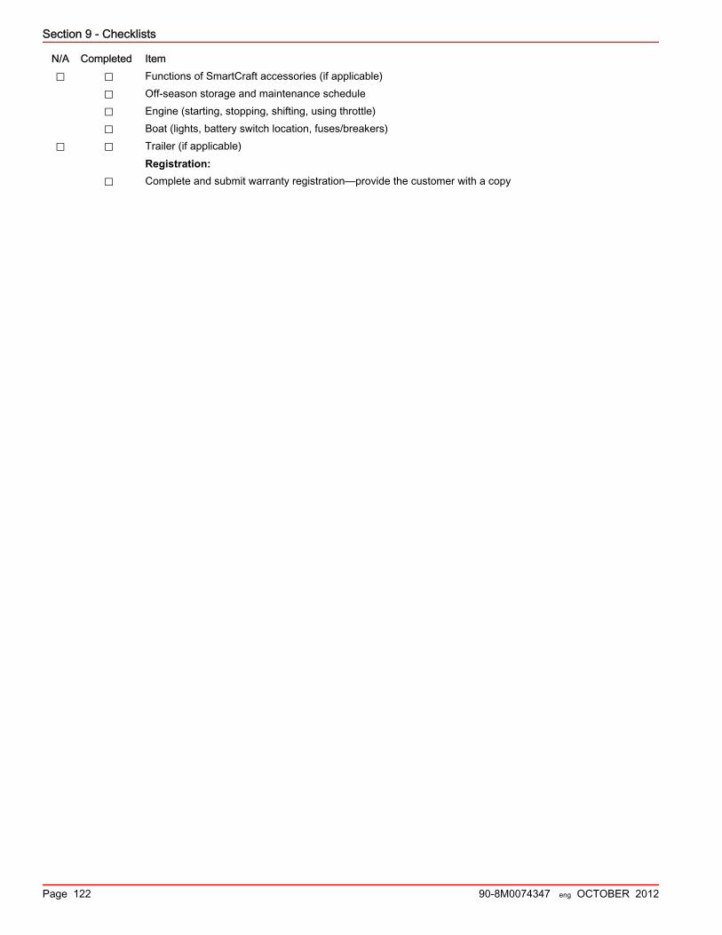
Section 9 - Checklists
Page 122 90-8M0074347 eng OCTOBER 2012
N/A Completed Item⃞ ⃞ Functions of SmartCraft accessories (if applicable)
⃞ Off‑season storage and maintenance schedule⃞ Engine (starting, stopping, shifting, using throttle)⃞ Boat (lights, battery switch location, fuses/breakers)
⃞ ⃞ Trailer (if applicable)Registration:
⃞ Complete and submit warranty registration—provide the customer with a copy