3 AXIS - Purdue Engineering
46
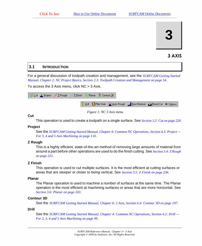
SURFCAM Reference Manual, Chapter 3 • 3 Axis Copyright © 2000 by Surfware, Inc. All Rights Reserved. Click To See: How to Use Online Documents SURFCAM Online Documents $;,6 For a general discussion of toolpath creation and management, see the SURFCAM Getting Started Manual, Chapter 2: NC Project Basics, Section 2.3: Toolpath Creation and Management on page 54. To access the 3 Axis menu, click NC > 3 Axis. Cut This operation is used to create a toolpath on a single surface. See Section 3.2: Cut on page 220. Project See the SURFCAM Getting Started Manual, Chapter 4: Common NC Operations, Section 4.3: Project — For 3, 4 and 5 Axis Machining on page 110. Z Rough This is a highly efficient, state-of-the-art method of removing large amounts of material from around a part before other operations are used to do the finish cutting. See Section 3.4: Z Rough on page 221. Z Finish This operation is used to cut multiple surfaces. It is the most efficient at cutting surfaces or areas that are steeper or closer to being vertical. See Section 3.5: Z Finish on page 236. Planar The Planar operation is used to machine a number of surfaces at the same time. The Planar operation is the most efficient at machining surfaces or areas that are more horizontal. See Section 3.6: Planar on page 243. Contour 3D See the SURFCAM Getting Started Manual, Chapter 6: 2 Axis, Section 6.4: Contour 3D on page 197. Drill See the SURFCAM Getting Started Manual, Chapter 4: Common NC Operations, Section 4.2: Drill — For 2, 3, 4 and 5 Axis Machining on page 99. 3 3.1 INTRODUCTION Figure 1: NC 3 Axis menu
-
Upload
khangminh22 -
Category
Documents
-
view
1 -
download
0
Transcript of 3 AXIS - Purdue Engineering
Click To See: How to Use Online Documents SURFCAM Online Documents
� 685)&$0�5HIHUHQFH�0DQXDO
������
For a general discussion of toolpath creation and management, see the SURFCAM Getting Started Manual, Chapter 2: NC Project Basics, Section 2.3: Toolpath Creation and Management on page 54.
To access the 3 Axis menu, click NC > 3 Axis.
CutThis operation is used to create a toolpath on a single surface. See Section 3.2: Cut on page 220.
ProjectSee the SURFCAM Getting Started Manual, Chapter 4: Common NC Operations, Section 4.3: Project — For 3, 4 and 5 Axis Machining on page 110.
Z RoughThis is a highly efficient, state-of-the-art method of removing large amounts of material from around a part before other operations are used to do the finish cutting. See Section 3.4: Z Rough on page 221.
Z FinishThis operation is used to cut multiple surfaces. It is the most efficient at cutting surfaces or areas that are steeper or closer to being vertical. See Section 3.5: Z Finish on page 236.
PlanarThe Planar operation is used to machine a number of surfaces at the same time. The Planar operation is the most efficient at machining surfaces or areas that are more horizontal. See Section 3.6: Planar on page 243.
Contour 3DSee the SURFCAM Getting Started Manual, Chapter 6: 2 Axis, Section 6.4: Contour 3D on page 197.
DrillSee the SURFCAM Getting Started Manual, Chapter 4: Common NC Operations, Section 4.2: Drill — For 2, 3, 4 and 5 Axis Machining on page 99.
3
3.1 INTRODUCTION
Figure 1: NC 3 Axis menu
SURFCAM Reference Manual, Chapter 3 • 3 AxisCopyright © 2000 by Surfware, Inc. All Rights Reserved.
218 SURFCAM Reference Manual, Chapter 3 • 3 Axis
Pilot HoleSee the SURFCAM Getting Started Manual, Chapter 6: 2 Axis, Section 6.6: Pilot Hole on page 200.
Auto RoughThis operation is an alternate method of removing material. See Section 3.10: Auto Rough on page 253.
Rest MaterialThis is a 3 axis rest machining operation. See Section 3.11: REST Material on page 256.
Pencil CutPencil Cut is an operation used to remove the material that is left along the concave intersection of two surfaces, after other machining operations have been performed. Pencil Cut can also detect the uncut material along concave folds or "crease-like" regions in the interior of a single surface. See Section 3.12: Pencil Cut on page 259.
OptionsSee Section 3.1.3: 3 Axis Options Tab on page 219.
For each NC 3 Axis operation there is a separate dialog box containing parameters that must be set before the operation is performed. The dialog box is displayed after you select the geometry on which the operation will be performed. Most of the parameters in these dialog boxes are displayed on three tabs: Tool Information, Cut Control, and 3 Axis Options. The title of some cut control tabs contain the name of the operation. Some operations have parameters that appear on additional tabs.
All 3 Axis operations contain the same set of parameters on the Tool Information tabs. See the SURFCAM Getting Started Manual, Chapter 3: Common NC Parameters, Section 3.2: Tool Information Tab on page 64.
Many of the parameters for 3 Axis operations appear on the Cut Control tabs for 4 and 5 Axis operations. See the SURFCAM Getting Started Manual, Chapter 3: Common NC Parameters, Section 3.3: Cut Control Tab — 3, 4 and 5 Axis on page 80.
Cut control parameters that are unique to a 3 Axis operation are described in the section devoted to that operation.
See
�� Section 3.4.2: Cut Control Tab — Z Rough on page 227�
�� Section 3.5.2: Cut Control Tab — Z Finish on page 237�
�� Section 3.6.2: Cut Control Tab — Planar on page 247����
� Section 3.10.2: Control Tab — Auto Rough on page 255�
3.1.1 Tool Information Tab
3.1.2 Cut Control Tab
Copyright © 2000 by Surfware, Inc. All Rights Reserved.
SURFCAM Reference Manual, Chapter 3 • 3 Axis 219
.
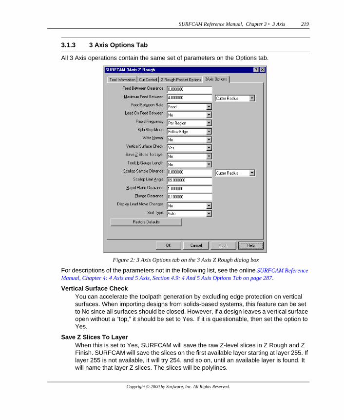
All 3 Axis operations contain the same set of parameters on the Options tab.
For descriptions of the parameters not in the following list, see the online SURFCAM Reference Manual, Chapter 4: 4 Axis and 5 Axis, Section 4.9: 4 And 5 Axis Options Tab on page 287.
Vertical Surface CheckYou can accelerate the toolpath generation by excluding edge protection on vertical surfaces. When importing designs from solids-based systems, this feature can be set to No since all surfaces should be closed. However, if a design leaves a vertical surface open without a “top,” it should be set to Yes. If it is questionable, then set the option to Yes.
Save Z Slices To LayerWhen this is set to Yes, SURFCAM will save the raw Z-level slices in Z Rough and Z Finish. SURFCAM will save the slices on the first available layer starting at layer 255. If layer 255 is not available, it will try 254, and so on, until an available layer is found. It will name that layer Z slices. The slices will be polylines.
3.1.3 3 Axis Options Tab
Figure 2: 3 Axis Options tab on the 3 Axis Z Rough dialog box
Copyright © 2000 by Surfware, Inc. All Rights Reserved.
220 SURFCAM Reference Manual, Chapter 3 • 3 Axis
If there are no layers available, the slices will not be saved.
Scallop Sample DistanceThe distance along the curvature of the surface which will be sampled to determine the assignment of the increment stepover value to achieve the desired scallop height.
Constant / Cutter RadiusThis controls how the value you enter in the accompanying box (on the left) will be used.
ConstantThe value you enter will be used for this parameter.
Cutter RadiusThe value you enter will be multiplied by the radius of the cutter selected to determine this parameter.
Scallop Limit AngleThe angle of the surface, from the horizontal, at which calculations for scallop height for the selected surfaces will be limited. The default is 89 degrees.
Display Lead Move ChangesIn the 2 Axis lead moves, executed in the Z Rough and Z Finish operations, if SURFCAM detects a potential gouge, the move is either trimmed or discarded.
If you want to see a Warning dialog box displayed that indicates there have been changes in Leadin or Leadout moves, click Yes; otherwise, click No. See the SURFCAM Getting Started Manual, Chapter 6: 2 Axis, Display Plunge Changes on page 187.
There are three categories of changes that can be made to these moves: shortened less than 50%, shortened more than 50% and completely discarded. On the toolpath, when Display Lead Move Changes is set to Yes, lead moves shortened by less than 50% are displayed in yellow while those shortened more than 50% are displayed in red.
If needed, the Cut operation provides the capability of cutting only a small portion of the surface with a process called Tool Containment. See the SURFCAM Getting Started Manual, Chapter 4: Common NC Operations, Section 4.4: Tool Containment — Cut and Swarf on page 115.
3.2 CUT
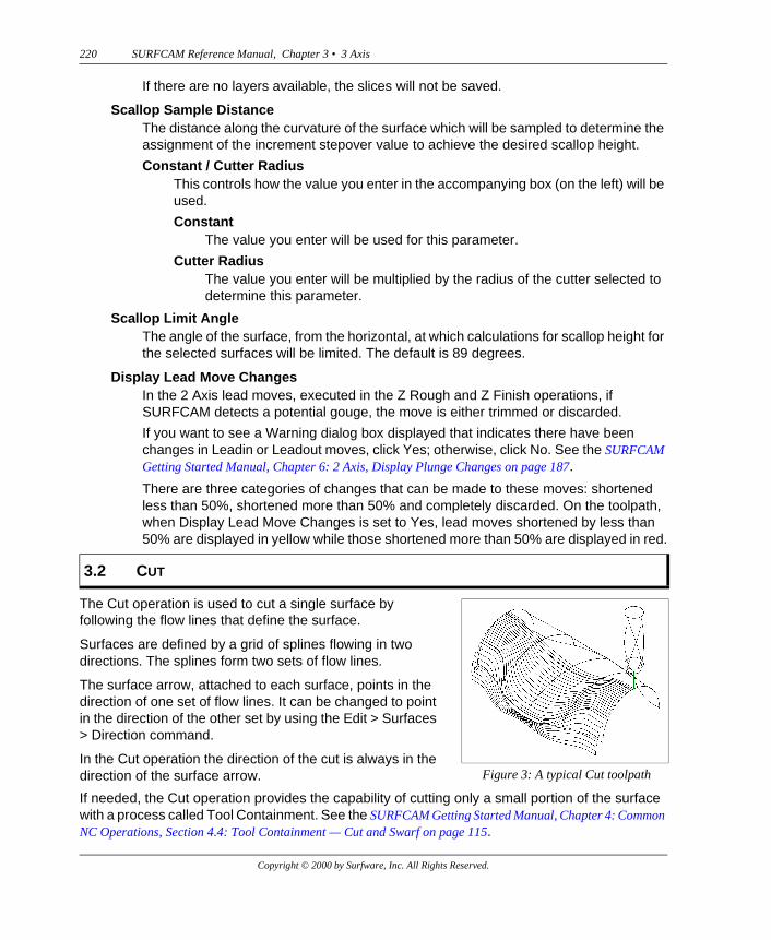
The Cut operation is used to cut a single surface by following the flow lines that define the surface.
Surfaces are defined by a grid of splines flowing in two directions. The splines form two sets of flow lines.
The surface arrow, attached to each surface, points in the direction of one set of flow lines. It can be changed to point in the direction of the other set by using the Edit > Surfaces > Direction command.
In the Cut operation the direction of the cut is always in the direction of the surface arrow. Figure 3: A typical Cut toolpath
Copyright © 2000 by Surfware, Inc. All Rights Reserved.
SURFCAM Reference Manual, Chapter 3 • 3 Axis 221
When you click Cut, SURFCAM will prompt you to “Select a surface.” Click a surface arrow or a point on the surface.
The 3 Axis Cut dialog box will be displayed.
You will enter and/or select your machining strategy parameter values of the current 3 Axis Cut operation on the three tabs of this dialog box.
See
1. the SURFCAM Getting Started Manual, Chapter 3: Common NC Parameters, Section 3.2: Tool Information Tab on page 64,
2. the SURFCAM Getting Started Manual, Chapter 3: Common NC Parameters, Section 3.3: Cut Control Tab — 3, 4 and 5 Axis on page 80, and
3. Section 3.1.3: 3 Axis Options Tab on page 219.
After you make the appropriate changes in parameter values, click OK on the 3 Axis Cut dialog box. SURFCAM will produce the toolpath and display it on the screen. It will then display the Keep Operation dialog box. Click Accept to keep the operation.
Note: To permanently save the toolpaths in the ICD file of your NC project, you must re-save the DSN file using the Save command on the File menu.
See the SURFCAM Getting Started Manual, Chapter 4: Common NC Operations, Section 4.3: Project — For 3, 4 and 5 Axis Machining on page 110.
The Z Rough operation is used to remove large amounts of material from around a part using a 2 axis (X,Y) pocketing cycle in Z axis increments.
A preliminary step in Z-level roughing is to identify the size and shape of the material from which the part will be rough cut. In SURFCAM there are five methods used to describe the shape and size of this material: Extents Box, Box, Bottom Profile, Top Profile and Surfaces.
The Surfaces and Box methods require the creation of a design of the material surfaces in the same drawing as your part design.
The Bottom Profile and Top Profile methods require only that a contour of the material be drawn around your design, and a depth of that material be entered in the Material Information dialog box.
In the Extents Box method, no drawing of the material is required.
Z Roughing is also used to remove large amounts of material from inside a cavity with a method called No Material. When you must create a design for material surfaces, the surface arrows must be pointing inward toward the design. Any number of surfaces can be used to represent the material.
3.3 PROJECT
3.4 Z ROUGH
Copyright © 2000 by Surfware, Inc. All Rights Reserved.
222 SURFCAM Reference Manual, Chapter 3 • 3 Axis
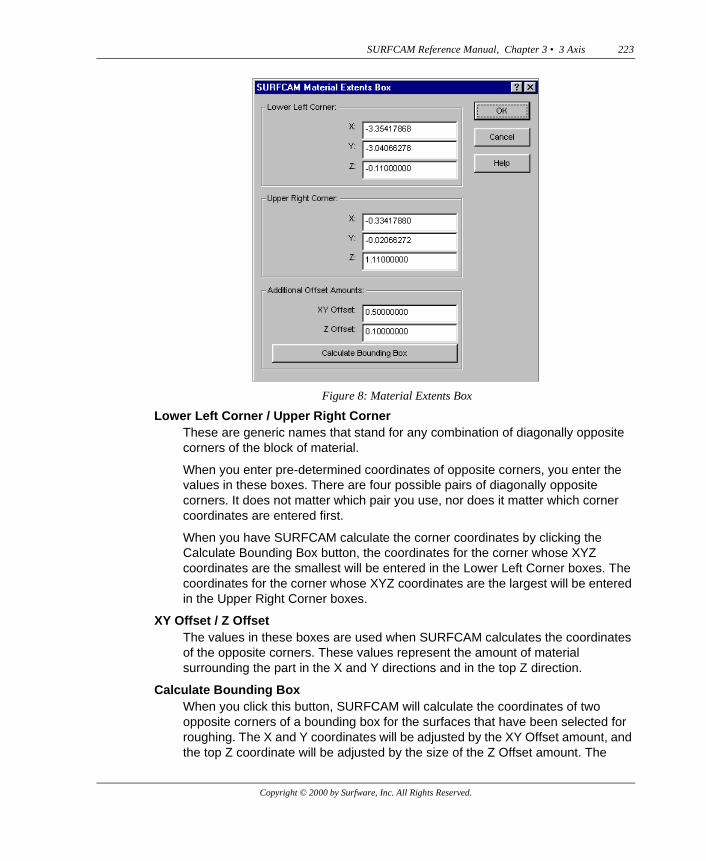
To access the Z Rough operation, click Z Rough on the NC 3 Axis menu. SURFCAM will display the Select menu and prompt you to “Select surfaces to rough.”
After you select the surfaces to rough, the Material Information dialog box will be displayed.
Material TypeThese are the methods used to describe the material from which the part will be cut. The top five are used when the part is a core. The No Material type is used when the part is a cavity.
Extents BoxUse Extents Box when the material will be a rectangular block. You do not need to have a material surface design as part of your drawing.
Click Extents Box and OK to display the Material Extents Box dialog box. There are two ways to use this box. You can enter pre-determined coordinates of two diagonally opposite corners of the block of material, or you can have SURFCAM calculate coordinates of opposite corners.
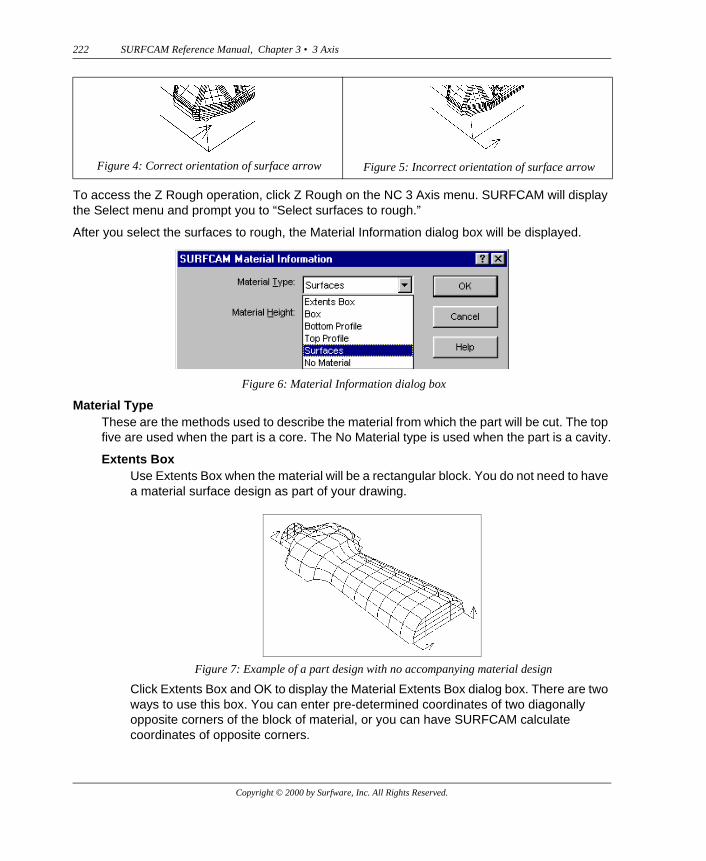
Figure 4: Correct orientation of surface arrow Figure 5: Incorrect orientation of surface arrow
Figure 6: Material Information dialog box
Figure 7: Example of a part design with no accompanying material design
Copyright © 2000 by Surfware, Inc. All Rights Reserved.
SURFCAM Reference Manual, Chapter 3 • 3 Axis 223
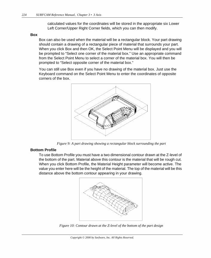
Lower Left Corner / Upper Right CornerThese are generic names that stand for any combination of diagonally opposite corners of the block of material.
When you enter pre-determined coordinates of opposite corners, you enter the values in these boxes. There are four possible pairs of diagonally opposite corners. It does not matter which pair you use, nor does it matter which corner coordinates are entered first.
When you have SURFCAM calculate the corner coordinates by clicking the Calculate Bounding Box button, the coordinates for the corner whose XYZ coordinates are the smallest will be entered in the Lower Left Corner boxes. The coordinates for the corner whose XYZ coordinates are the largest will be entered in the Upper Right Corner boxes.
XY Offset / Z OffsetThe values in these boxes are used when SURFCAM calculates the coordinates of the opposite corners. These values represent the amount of material surrounding the part in the X and Y directions and in the top Z direction.
Calculate Bounding BoxWhen you click this button, SURFCAM will calculate the coordinates of two opposite corners of a bounding box for the surfaces that have been selected for roughing. The X and Y coordinates will be adjusted by the XY Offset amount, and the top Z coordinate will be adjusted by the size of the Z Offset amount. The
Figure 8: Material Extents Box
Copyright © 2000 by Surfware, Inc. All Rights Reserved.
224 SURFCAM Reference Manual, Chapter 3 • 3 Axis
calculated values for the coordinates will be stored in the appropriate six Lower Left Corner/Upper Right Corner fields, which you can then modify.
BoxBox can also be used when the material will be a rectangular block. Your part drawing should contain a drawing of a rectangular piece of material that surrounds your part. When you click Box and then OK, the Select Point Menu will be displayed and you will be prompted to “Select one corner of the material box.” Use an appropriate command from the Select Point Menu to select a corner of the material box. You will then be prompted to “Select opposite corner of the material box.”
You can still use Box even if you have no drawing of the material box. Just use the Keyboard command on the Select Point Menu to enter the coordinates of opposite corners of the box.
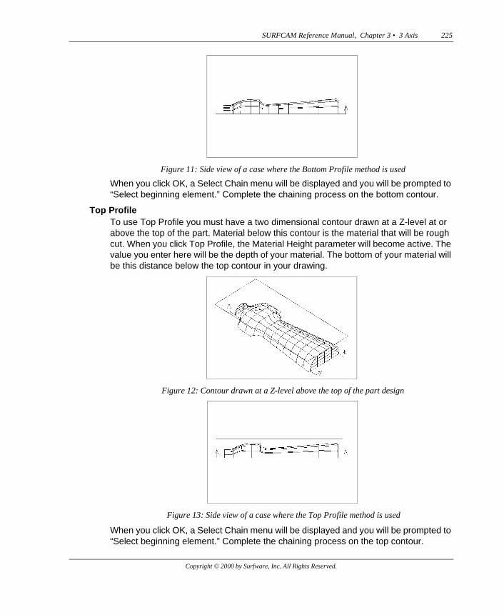
Bottom ProfileTo use Bottom Profile you must have a two dimensional contour drawn at the Z-level of the bottom of the part. Material above this contour is the material that will be rough cut. When you click Bottom Profile, the Material Height parameter will become active. The value you enter here will be the height of the material. The top of the material will be this distance above the bottom contour appearing in your drawing.
Figure 9: A part drawing showing a rectangular block surrounding the part
Figure 10: Contour drawn at the Z-level of the bottom of the part design
Copyright © 2000 by Surfware, Inc. All Rights Reserved.
SURFCAM Reference Manual, Chapter 3 • 3 Axis 225
When you click OK, a Select Chain menu will be displayed and you will be prompted to “Select beginning element.” Complete the chaining process on the bottom contour.
Top ProfileTo use Top Profile you must have a two dimensional contour drawn at a Z-level at or above the top of the part. Material below this contour is the material that will be rough cut. When you click Top Profile, the Material Height parameter will become active. The value you enter here will be the depth of your material. The bottom of your material will be this distance below the top contour in your drawing.
When you click OK, a Select Chain menu will be displayed and you will be prompted to “Select beginning element.” Complete the chaining process on the top contour.
Figure 11: Side view of a case where the Bottom Profile method is used
Figure 12: Contour drawn at a Z-level above the top of the part design
Figure 13: Side view of a case where the Top Profile method is used
Copyright © 2000 by Surfware, Inc. All Rights Reserved.
226 SURFCAM Reference Manual, Chapter 3 • 3 Axis
Note: If you accidentally select Top Profile when you have a drawing containing a bottom contour, or vice versa, a situation will occur in which the part you want to cut will not be contained within the block of material that SURFCAM will create. The reason for this is that SURFCAM measures downward from the chained contour when you select Top Profile, and upward when you select Bottom Profile.
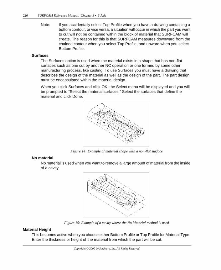
SurfacesThe Surfaces option is used when the material exists in a shape that has non-flat surfaces such as one cut by another NC operation or one formed by some other manufacturing process, like casting. To use Surfaces you must have a drawing that describes the design of the material as well as the design of the part. The part design must be encapsulated within the material design.
When you click Surfaces and click OK, the Select menu will be displayed and you will be prompted to “Select the material surfaces.” Select the surfaces that define the material and click Done.
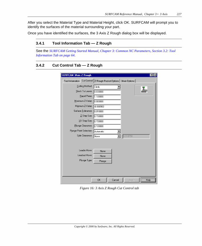
No materialNo material is used when you want to remove a large amount of material from the inside of a cavity.
Material HeightThis becomes active when you choose either Bottom Profile or Top Profile for Material Type. Enter the thickness or height of the material from which the part will be cut.
Figure 14: Example of material shape with a non-flat surface
Figure 15: Example of a cavity where the No Material method is used
Copyright © 2000 by Surfware, Inc. All Rights Reserved.
SURFCAM Reference Manual, Chapter 3 • 3 Axis 227
After you select the Material Type and Material Height, click OK. SURFCAM will prompt you to identify the surfaces of the material surrounding your part.
Once you have identified the surfaces, the 3 Axis Z Rough dialog box will be displayed.
See the SURFCAM Getting Started Manual, Chapter 3: Common NC Parameters, Section 3.2: Tool Information Tab on page 64.
3.4.1 Tool Information Tab — Z Rough
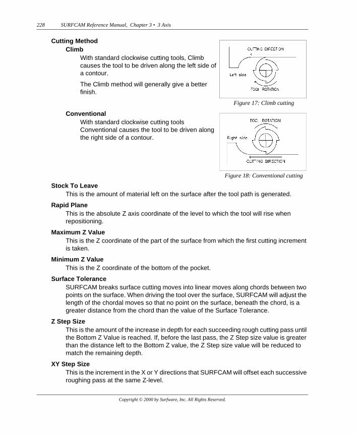
3.4.2 Cut Control Tab — Z Rough
Figure 16: 3 Axis Z Rough Cut Control tab
Copyright © 2000 by Surfware, Inc. All Rights Reserved.
228 SURFCAM Reference Manual, Chapter 3 • 3 Axis
Stock To LeaveThis is the amount of material left on the surface after the tool path is generated.
Rapid PlaneThis is the absolute Z axis coordinate of the level to which the tool will rise when repositioning.
Maximum Z ValueThis is the Z coordinate of the part of the surface from which the first cutting increment is taken.
Minimum Z ValueThis is the Z coordinate of the bottom of the pocket.
Surface ToleranceSURFCAM breaks surface cutting moves into linear moves along chords between two points on the surface. When driving the tool over the surface, SURFCAM will adjust the length of the chordal moves so that no point on the surface, beneath the chord, is a greater distance from the chord than the value of the Surface Tolerance.
Z Step SizeThis is the amount of the increase in depth for each succeeding rough cutting pass until the Bottom Z Value is reached. If, before the last pass, the Z Step size value is greater than the distance left to the Bottom Z value, the Z Step size value will be reduced to match the remaining depth.
XY Step SizeThis is the increment in the X or Y directions that SURFCAM will offset each successive roughing pass at the same Z-level.
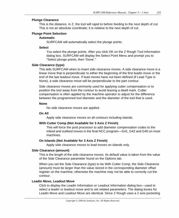
Cutting MethodClimb
With standard clockwise cutting tools, Climb causes the tool to be driven along the left side of a contour.
The Climb method will generally give a better finish.
Figure 17: Climb cutting
ConventionalWith standard clockwise cutting tools Conventional causes the tool to be driven along the right side of a contour.
Figure 18: Conventional cutting
Copyright © 2000 by Surfware, Inc. All Rights Reserved.
SURFCAM Reference Manual, Chapter 3 • 3 Axis 229
Plunge ClearanceThis is the distance, in Z, the tool will rapid to before feeding to the next depth of cut. This is not an absolute coordinate; it is relative to the next depth of cut.
Plunge Point SelectionAutomatic
SURFCAM will automatically select the plunge points.
SelectYou select the plunge points. After you click OK on the Z Rough Tool Information dialog box, SURFCAM will display the Select Point Menu and prompt you to “Select plunge points, then ‘Done’.”
Side Clearance (type)This tells SURFCAM when to insert side clearance moves. A side clearance move is a linear move that is perpendicular to either the beginning of the first leadin move or the end of the last leadout move. If lead moves have not been defined (if Lead Type is None), a side clearance move will be perpendicular to the part contour.
Side clearance moves are commonly used for applying cutter compensation or to position the tool away from the contour to avoid leaving a dwell mark. Cutter compensation is often applied by the machine operator to adjust for the difference between the programmed tool diameter and the diameter of the tool that is used.
NoneNo side clearance moves are applied.
On AllApply side clearance moves on all contours including islands.
With Cutter Comp (Not Available for 3 Axis Z Finish)This will force the post processor to add diameter compensation codes to the infeed and outfeed moves in the final NCC program—G41, G42 and G40 on most machines.
On Islands (Not Available for 3 Axis Z Finish)Apply side clearance moves to lead moves on islands only.
Side Clearance (amount)This is the length of the side clearance moves. Its default value is taken from the value of the Side Clearance parameter found on the Options tab.
When you set the Side Clearance (type) to be With Cutter Comp, the Side Clearance (amount) must be larger than the value stored in the corresponding diameter offset register on the machine; otherwise the machine may not be able to correctly cut the contour.
Leadin Move, Leadout MoveClick to display the Leadin Information or Leadout Information dialog box—used to select a leadin or leadout move and to set related parameters. The dialog boxes for Leadin Move and Leadout Move are identical. Since Z Rough uses a 2 axis pocketing
Copyright © 2000 by Surfware, Inc. All Rights Reserved.
230 SURFCAM Reference Manual, Chapter 3 • 3 Axis
cycle in Z increments, the Leadin/Leadout Information dialog boxes are the same as the ones for 2 Axis machining.
See the SURFCAM Getting Started Manual, Chapter 6: 2 Axis, Section 6.1.2.1: Leadin/Leadout Parameters — 2 Axis on page 177.
Plunge TypeClick Plunge Type to display the Plunge Information dialog box which is used to select a plunge move and set related parameters.
See the SURFCAM Getting Started Manual, Chapter 3: Common NC Parameters, Section 3.3.2: Plunge Parameters on page 90.
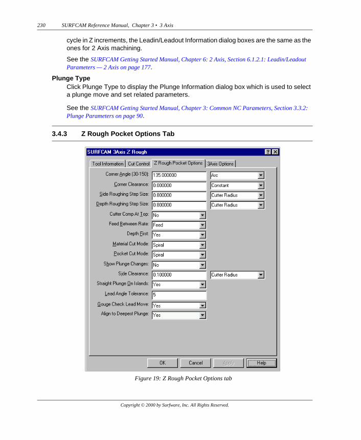
3.4.3 Z Rough Pocket Options Tab
Figure 19: Z Rough Pocket Options tab
Copyright © 2000 by Surfware, Inc. All Rights Reserved.
SURFCAM Reference Manual, Chapter 3 • 3 Axis 231
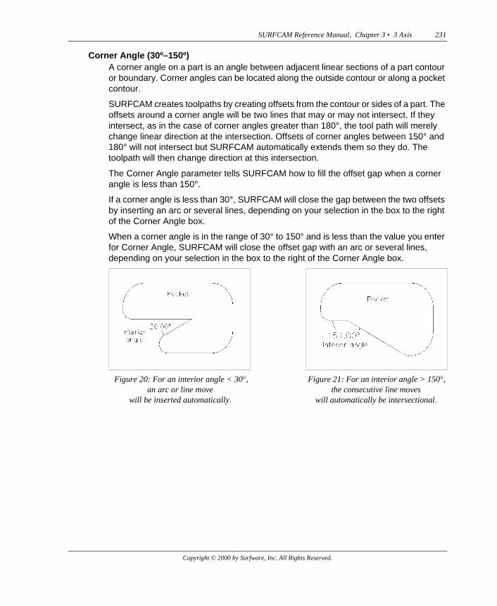
Corner Angle (30º–150º)A corner angle on a part is an angle between adjacent linear sections of a part contour or boundary. Corner angles can be located along the outside contour or along a pocket contour.
SURFCAM creates toolpaths by creating offsets from the contour or sides of a part. The offsets around a corner angle will be two lines that may or may not intersect. If they intersect, as in the case of corner angles greater than 180°, the tool path will merely change linear direction at the intersection. Offsets of corner angles between 150° and 180° will not intersect but SURFCAM automatically extends them so they do. The toolpath will then change direction at this intersection.
The Corner Angle parameter tells SURFCAM how to fill the offset gap when a corner angle is less than 150°.
If a corner angle is less than 30°, SURFCAM will close the gap between the two offsets by inserting an arc or several lines, depending on your selection in the box to the right of the Corner Angle box.
When a corner angle is in the range of 30° to 150° and is less than the value you enter for Corner Angle, SURFCAM will close the offset gap with an arc or several lines, depending on your selection in the box to the right of the Corner Angle box.
Figure 20: For an interior angle < 30�, an arc or line move
will be inserted automatically�
Figure 21: For an interior angle > 150�, the consecutive line moves
will automatically be intersectional�
Copyright © 2000 by Surfware, Inc. All Rights Reserved.
232 SURFCAM Reference Manual, Chapter 3 • 3 Axis
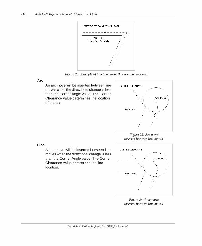
Figure 22: Example of two line moves that are intersectional
ArcAn arc move will be inserted between line moves when the directional change is less than the Corner Angle value. The Corner Clearance value determines the location of the arc.
Figure 23: Arc move inserted between line moves
LineA line move will be inserted between line moves when the directional change is less than the Corner Angle value. The Corner Clearance value determines the line location.
Figure 24: Line moveinserted between line moves
Copyright © 2000 by Surfware, Inc. All Rights Reserved.
SURFCAM Reference Manual, Chapter 3 • 3 Axis 233
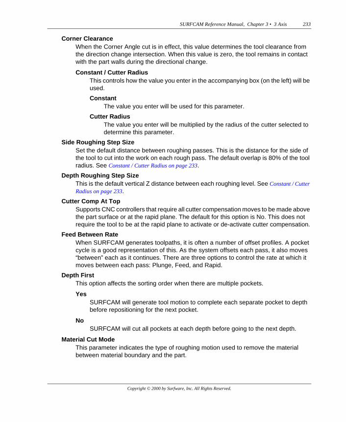
Corner ClearanceWhen the Corner Angle cut is in effect, this value determines the tool clearance from the direction change intersection. When this value is zero, the tool remains in contact with the part walls during the directional change.
Constant / Cutter RadiusThis controls how the value you enter in the accompanying box (on the left) will be used.
ConstantThe value you enter will be used for this parameter.
Cutter RadiusThe value you enter will be multiplied by the radius of the cutter selected to determine this parameter.
Side Roughing Step SizeSet the default distance between roughing passes. This is the distance for the side of the tool to cut into the work on each rough pass. The default overlap is 80% of the tool radius. See Constant / Cutter Radius on page 233.
Depth Roughing Step SizeThis is the default vertical Z distance between each roughing level. See Constant / Cutter Radius on page 233.
Cutter Comp At TopSupports CNC controllers that require all cutter compensation moves to be made above the part surface or at the rapid plane. The default for this option is No. This does not require the tool to be at the rapid plane to activate or de-activate cutter compensation.
Feed Between RateWhen SURFCAM generates toolpaths, it is often a number of offset profiles. A pocket cycle is a good representation of this. As the system offsets each pass, it also moves “between” each as it continues. There are three options to control the rate at which it moves between each pass: Plunge, Feed, and Rapid.
Depth FirstThis option affects the sorting order when there are multiple pockets.
YesSURFCAM will generate tool motion to complete each separate pocket to depth before repositioning for the next pocket.
NoSURFCAM will cut all pockets at each depth before going to the next depth.
Material Cut ModeThis parameter indicates the type of roughing motion used to remove the material between material boundary and the part.
Copyright © 2000 by Surfware, Inc. All Rights Reserved.
234 SURFCAM Reference Manual, Chapter 3 • 3 Axis
SpiralMaterial Cut Spiral cutting consists of inwardly offset tool moves, parallel to the material boundary until the tool nears the part. Then the moves become parallel to the part profile.
Zig ZagMaterial Cut Zig Zag cutting consists of offset parallel linear moves from the material boundary to the part profile, in the direction of a vector you will define. These moves are followed by a single contour move parallel to, and along the part profile.
Contour CutContour Cut moves are parallel to the part profile and inwardly offset from the material boundary to the part.
Pocket Cut ModeThis parameter indicates the type of roughing motion used to remove material from within pockets in the part.
SpiralPocket Cut Spiral cutting consists of outwardly offset tool moves, parallel to the material boundary, from the "center" of the pocket out to the part. When the tool nears the part, the moves become parallel to the part profile.
Zig ZagPocket Cut Zig Zag cutting consists of offset parallel linear moves in the interior of the pocket up to the part profile, in the direction of a vector you will define. These moves are followed by a single contour move parallel to, and along the pocket profile.
Show Plunge ChangesIf you want to see the display that indicates there have been changes in plunge, click Yes; otherwise, click No.
Side Clearance (Options tab)This parameter controls the default value for the Side Clearance amount on the Cut Control tab.
1. Set the Side Clearance amount and type on the Options tab.
2. Choose a new Tool.
Then you will see the Side Clearance amount change on the Cut Control tab.
ConstantIf you choose Constant, Side Clearance default = Side Clearance.
Cutter RadiusIf you choose Cutter Radius, Side Clearance default = Side Clearance * Cutter Radius.
Note that the factory-release default for Side Clearance on the Options tab is 0.1
Copyright © 2000 by Surfware, Inc. All Rights Reserved.
SURFCAM Reference Manual, Chapter 3 • 3 Axis 235
The factory-release default for type is Cutter Radius.
Straight Plunge On IslandsTo perform finish passes on islands when cutting a pocket, SURFCAM retracts after completing the rough passes and ordinarily moves to a SURFCAM selected plunge point near each island. If Straight Plunge on Islands is set to Yes, SURFCAM will retract and move to the user-selected plunge point nearest each island. You select these plunge points using the Plunge command on the Pocket chaining menu that is displayed immediately after you click Pocket on the NC 2 Axis menu. See the SURFCAM Getting Started Manual, Chapter 1: System Basics, Section 1.7.2: Select Chain Menu on page 39.
Lead Angle ToleranceThis is used when Gouge Check Lead Move is set to Yes.
Both line and arc lead moves are defined by angles. Line moves are defined by the angle at which the move approaches a contour. Arc moves are defined by the size of the central angle of the arc.
If a gouge is detected on a lead move, adjustments will be made in these lead move angles—in 1° increments—in an attempt to avoid the gouge. These adjustments will be made up to the number of degrees you specify for Lead Angle Tolerance. For example, if the lead move angle is 60° and you specify 5° as the Lead Angle Tolerance, adjustments will be made up to 65°. If the gouge cannot be avoided within this degree range, the move will be deleted from the toolpath.
Gouge Check Lead MoveIf set to No, SURFCAM will not gouge check Leadin and Leadout moves.
Align to Deepest PlungeChoose Yes to align all the positions of all plunges between Z levels to the position of the lowest plunge. This guarantees that pilot holes generated from these operations will not overlap.
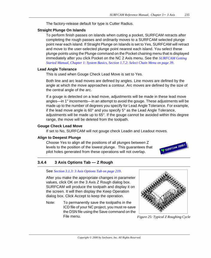
3.4.4 3 Axis Options Tab — Z Rough
See Section 3.1.3: 3 Axis Options Tab on page 219.
After you make the appropriate changes in parameter values, click OK on the 3 Axis Z Rough dialog box. SURFCAM will produce the toolpath and display it on the screen. It will then display the Keep Operation dialog box. Click Accept to keep the operation.
Note: To permanently save the toolpaths in the ICD file of your NC project, you must re-save the DSN file using the Save command on the File menu. Figure 25: Typical Z Roughing Cycle
Copyright © 2000 by Surfware, Inc. All Rights Reserved.
236 SURFCAM Reference Manual, Chapter 3 • 3 Axis
To access Z-level finishing, click Z Finish on the NC 3 Axis menu. SURFCAM will prompt you to “Select surfaces to finish.” From the Select menu choose a command to select the surfaces.
Once you have identified the surfaces, the 3 Axis Z Finish dialog box will be displayed.
You will enter and/or select your machining strategy parameter values of the current Z Finish operation on the four tabs in this dialog box.
See the SURFCAM Getting Started Manual, Chapter 3: Common NC Parameters, Section 3.2: Tool Information Tab on page 64.
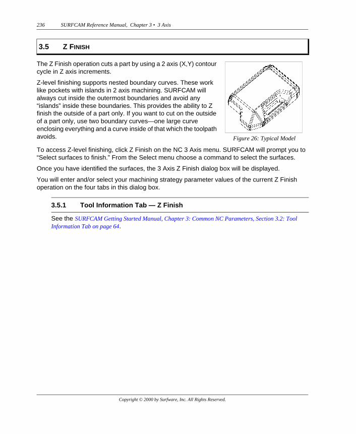
3.5 Z FINISH
The Z Finish operation cuts a part by using a 2 axis (X,Y) contour cycle in Z axis increments.
Z-level finishing supports nested boundary curves. These work like pockets with islands in 2 axis machining. SURFCAM will always cut inside the outermost boundaries and avoid any “islands” inside these boundaries. This provides the ability to Z finish the outside of a part only. If you want to cut on the outside of a part only, use two boundary curves—one large curve enclosing everything and a curve inside of that which the toolpath avoids. Figure 26: Typical Model
3.5.1 Tool Information Tab — Z Finish
Copyright © 2000 by Surfware, Inc. All Rights Reserved.
SURFCAM Reference Manual, Chapter 3 • 3 Axis 237
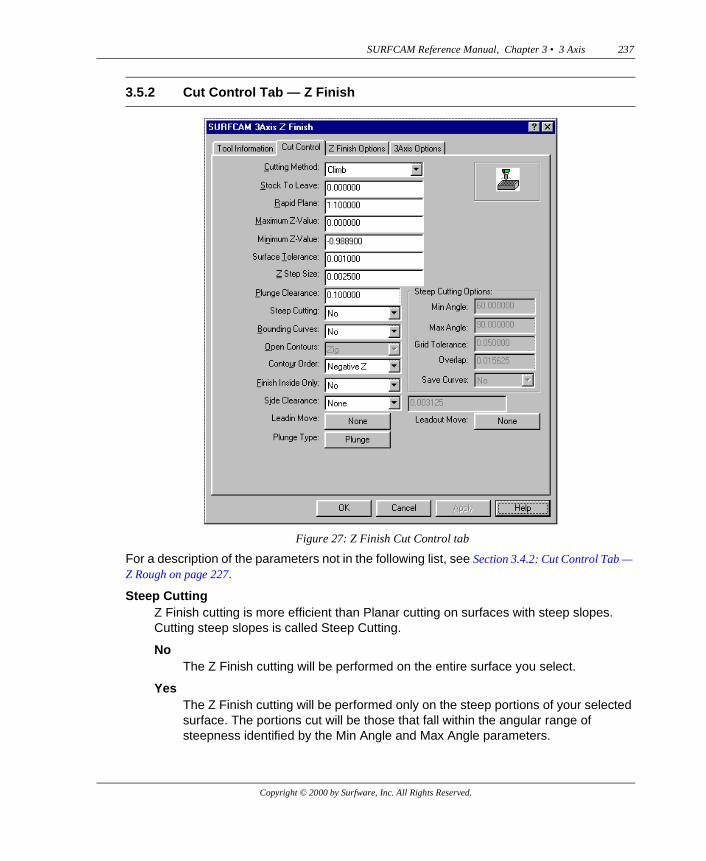
For a description of the parameters not in the following list, see Section 3.4.2: Cut Control Tab — Z Rough on page 227.
Steep CuttingZ Finish cutting is more efficient than Planar cutting on surfaces with steep slopes. Cutting steep slopes is called Steep Cutting.
NoThe Z Finish cutting will be performed on the entire surface you select.
YesThe Z Finish cutting will be performed only on the steep portions of your selected surface. The portions cut will be those that fall within the angular range of steepness identified by the Min Angle and Max Angle parameters.
3.5.2 Cut Control Tab — Z Finish
Figure 27: Z Finish Cut Control tab
Copyright © 2000 by Surfware, Inc. All Rights Reserved.

238 SURFCAM Reference Manual, Chapter 3 • 3 Axis
Steep Cutting OptionsMin Angle
The steepness of a surface, at a specific point, is measured by the angle between the tangent to the surface at that point and the horizontal. Min Angle is the smallest angle, defining steepness, at which you want the Z Finish cutting to begin. It will normally be set to a range of 30º to 60º.
Max AngleMax Angle is the largest angle, defining steepness, at which you want the Z Finish cutting to stop. The Z Finish cutting will take place at areas on the surface whose steepness lies between the Min Angle and Max Angle.
The Max Angle will normally be set to 90º.
Grid ToleranceTo locate the boundary of areas having the steepness defined by the Min and Max Angles, a grid is created (but not displayed) and projected onto the surface. Measurements are taken along the strands of this grid to identify steepness boundaries. Grid Tolerance is the distance between the strands in this grid. The smaller this number, the more accurately the steepness boundaries will be located.
OverlapThis is the distance you want the tool beyond the steepness boundaries to insure complete cutting in the desired region.
Save CurvesWhen SURFCAM performs Steep Cutting, the surfaces are analyzed to determine those surface areas whose slope falls within the angle range indicated by the Min Angle and Max Angle parameters. Temporary surface splines are then drawn along the boundaries of those areas. These splines are then projected onto the Z0 plane where they are used to create the tool paths. You can elect to have these projected splines saved.
Bounding CurvesSee Bounding Curves on page 249.
Open ContoursThis option becomes active when either the Steep Cutting option or the Bounding Curves option is set to Yes. If the area of the surface to be finished is restricted by a bounding curve, the contours to be cut will end at the bounding curve, and thus be open contours. Contours that begin and end at the same point are said to be closed contours.
Zig ZagThe tool will move back and forth in opposite directions as it moves from one contour depth to the next.
ZigThe tool will lift up at the end of every contour cut, so the cuts at each level are always in the same direction. This is the default.
Copyright © 2000 by Surfware, Inc. All Rights Reserved.
SURFCAM Reference Manual, Chapter 3 • 3 Axis 239
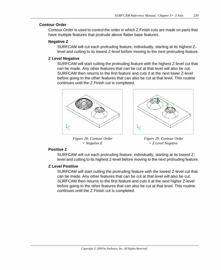
Contour OrderContour Order is used to control the order in which Z Finish cuts are made on parts that have multiple features that protrude above flatter base features.
Negative ZSURFCAM will cut each protruding feature, individually, starting at its highest Z-level and cutting to its lowest Z-level before moving to the next protruding feature.
Z Level NegativeSURFCAM will start cutting the protruding feature with the highest Z-level cut that can be made. Any other features that can be cut at that level will also be cut. SURFCAM then returns to the first feature and cuts it at the next lower Z-level before going to the other features that can also be cut at that level. This routine continues until the Z Finish cut is completed.
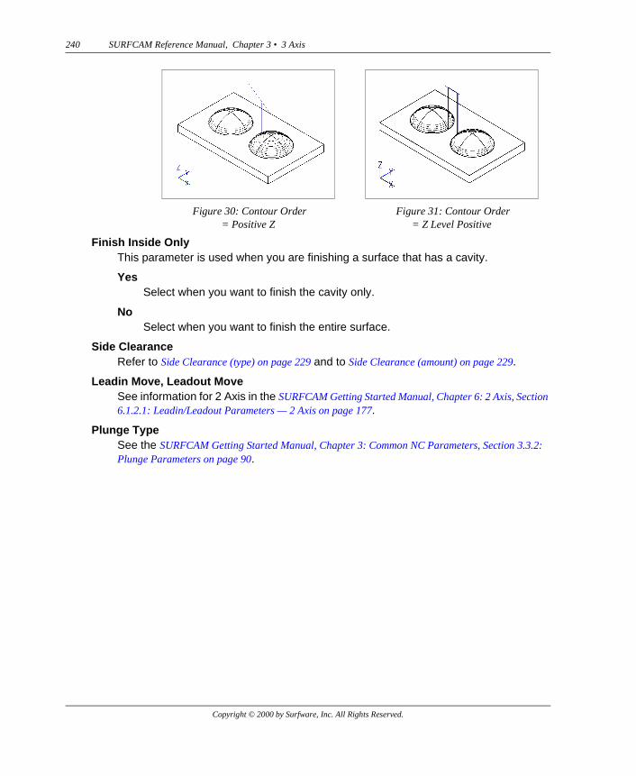
Positive ZSURFCAM will cut each protruding feature, individually, starting at its lowest Z-level and cutting to its highest Z-level before moving to the next protruding feature.
Z Level PositiveSURFCAM will start cutting the protruding feature with the lowest Z-level cut that can be made. Any other features that can be cut at that level will also be cut. SURFCAM then returns to the first feature and cuts it at the next higher Z-level before going to the other features that can also be cut at that level. This routine continues until the Z Finish cut is completed.
Figure 28: Contour Order= Negative Z
Figure 29: Contour Order= Z Level Negative
Copyright © 2000 by Surfware, Inc. All Rights Reserved.
240 SURFCAM Reference Manual, Chapter 3 • 3 Axis
Finish Inside OnlyThis parameter is used when you are finishing a surface that has a cavity.
YesSelect when you want to finish the cavity only.
NoSelect when you want to finish the entire surface.
Side ClearanceRefer to Side Clearance (type) on page 229 and to Side Clearance (amount) on page 229.
Leadin Move, Leadout MoveSee information for 2 Axis in the SURFCAM Getting Started Manual, Chapter 6: 2 Axis, Section 6.1.2.1: Leadin/Leadout Parameters — 2 Axis on page 177.
Plunge TypeSee the SURFCAM Getting Started Manual, Chapter 3: Common NC Parameters, Section 3.3.2: Plunge Parameters on page 90.
Figure 30: Contour Order= Positive Z
Figure 31: Contour Order= Z Level Positive
Copyright © 2000 by Surfware, Inc. All Rights Reserved.
SURFCAM Reference Manual, Chapter 3 • 3 Axis 241
.
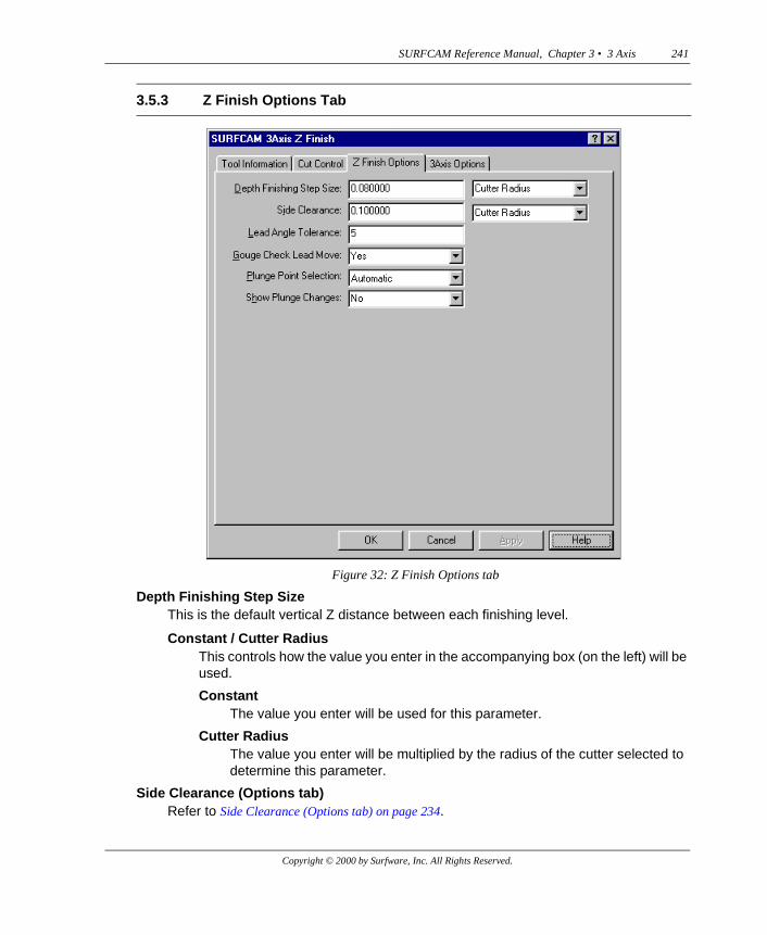
Depth Finishing Step SizeThis is the default vertical Z distance between each finishing level.
Constant / Cutter RadiusThis controls how the value you enter in the accompanying box (on the left) will be used.
ConstantThe value you enter will be used for this parameter.
Cutter RadiusThe value you enter will be multiplied by the radius of the cutter selected to determine this parameter.
Side Clearance (Options tab)Refer to Side Clearance (Options tab) on page 234.
3.5.3 Z Finish Options Tab
Figure 32: Z Finish Options tab
Copyright © 2000 by Surfware, Inc. All Rights Reserved.
242 SURFCAM Reference Manual, Chapter 3 • 3 Axis
Lead Angle ToleranceThis is used when Gouge Check Lead Move is set to Yes.Both line and arc lead moves are defined by angles. Line moves are defined by the angle at which the move approaches a contour. Arc moves are defined by the size of the central angle of the arc.
If a gouge is detected on a lead move, adjustments will be made in these lead move angles—in 1° increments—in an attempt to avoid the gouge. These adjustments will be made up to the number of degrees you specify for Lead Angle Tolerance. For example, if the lead move angle is 60° and you specify 5° as the Lead Angle Tolerance, adjustments will be made up to 65°. If the gouge cannot be avoided within this degree range, the move will be deleted from the toolpath.
Gouge Check Lead MoveIf set to No, SURFCAM will not gouge check Leadin and Leadout moves.
Plunge Point SelectionAutomatic
SURFCAM will automatically select the plunge points.
SelectYou select the plunge points. After you click OK, SURFCAM will display the Select Point Menu and prompt you to “Select plunge points, then ‘Done’.”
Show Plunge ChangesSee the SURFCAM Getting Started Manual, Chapter 6: 2 Axis, Display Plunge Changes on page 187.
See Section 3.1.3: 3 Axis Options Tab on page 219.
After you click OK on the 3 Axis Z Finish dialog box, SURFCAM will produce the toolpath and display it on the screen. It will then display the Keep Operation dialog box. Click Accept to keep the operation.
Note: To permanently save the toolpaths in the ICD file of your NC project, you must re-save the DSN file using the Save command on the File menu.
3.5.4 3 Axis Options Tab — Z Finish
Copyright © 2000 by Surfware, Inc. All Rights Reserved.
SURFCAM Reference Manual, Chapter 3 • 3 Axis 243
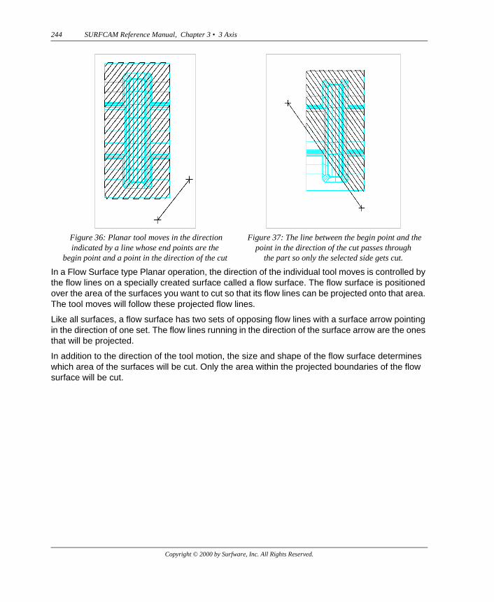
The parallel tool moves direction is determined when you select a beginning point and a point in the direction of the cut. The parallel tool moves direction will be parallel to the line determined by these two points. This line also controls which part of the surfaces will be cut. The Planar cutting occurs on the side of the line you select. If the line passes through the middle of the design, then only the area of the surfaces on that side of the line will be cut.
3.6 PLANAR
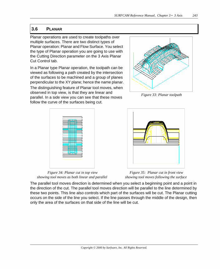
Planar operations are used to create toolpaths over multiple surfaces. There are two distinct types of Planar operation: Planar and Flow Surface. You select the type of Planar operation you are going to use with the Cutting Direction parameter on the 3 Axis Planar Cut Control tab.
In a Planar type Planar operation, the toolpath can be viewed as following a path created by the intersection of the surfaces to be machined and a group of planes perpendicular to the XY plane; hence the name planar.The distinguishing feature of Planar tool moves, when observed in top view, is that they are linear and parallel. In a side view you can see that these moves follow the curve of the surfaces being cut.
Figure 33: Planar toolpath
Figure 34: Planar cut in top view showing tool moves as both linear and parallel
Figure 35: Planar cut in front view showing tool moves following the surface
Copyright © 2000 by Surfware, Inc. All Rights Reserved.
244 SURFCAM Reference Manual, Chapter 3 • 3 Axis
In a Flow Surface type Planar operation, the direction of the individual tool moves is controlled by the flow lines on a specially created surface called a flow surface. The flow surface is positioned over the area of the surfaces you want to cut so that its flow lines can be projected onto that area. The tool moves will follow these projected flow lines.
Like all surfaces, a flow surface has two sets of opposing flow lines with a surface arrow pointing in the direction of one set. The flow lines running in the direction of the surface arrow are the ones that will be projected.
In addition to the direction of the tool motion, the size and shape of the flow surface determines which area of the surfaces will be cut. Only the area within the projected boundaries of the flow surface will be cut.
Figure 36: Planar tool moves in the direction indicated by a line whose end points are the
begin point and a point in the direction of the cut
Figure 37: The line between the begin point and the point in the direction of the cut passes through
the part so only the selected side gets cut.
Copyright © 2000 by Surfware, Inc. All Rights Reserved.
SURFCAM Reference Manual, Chapter 3 • 3 Axis 245
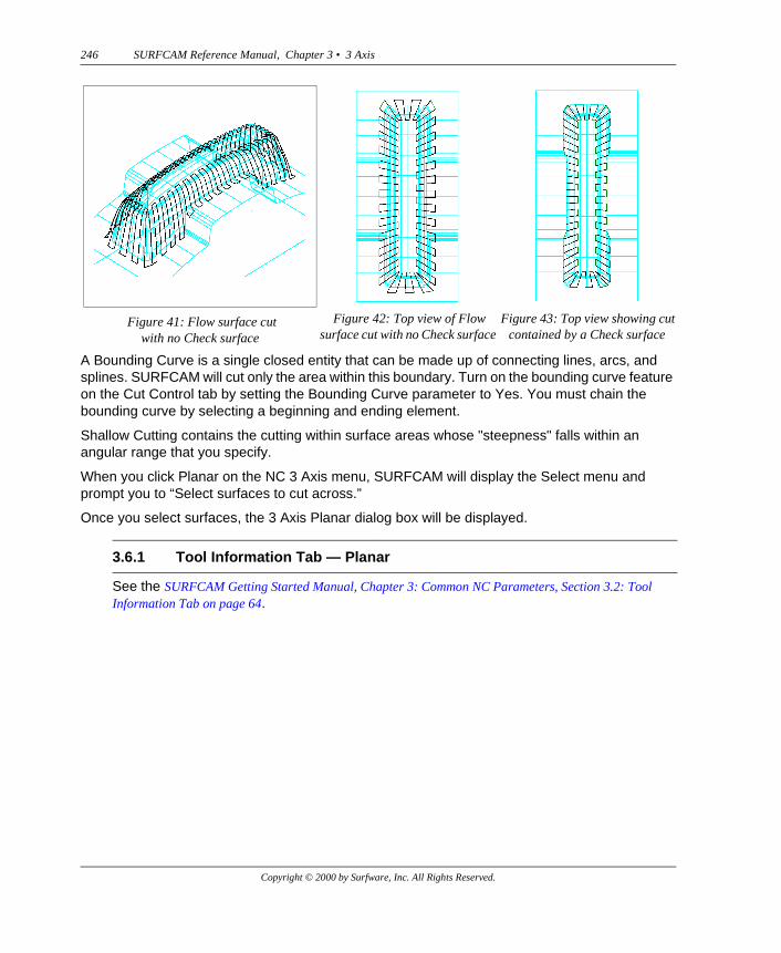
As described previously, both the Planar and Flow Surface Planar operations have tool containment features by which you can control the area of the surfaces to be cut. Both operations have three additional tool containment capabilities called Check Surface, Bounding Curve, and Shallow Cutting.
A Check Surface is a surface on the part that intersects another surface that you want to cut. The intersection of the two surfaces forms a boundary beyond which SURFCAM will not cut. Turn on the Check Surface feature by setting the Check Surfaces parameter to Yes on the Cut Control tab.
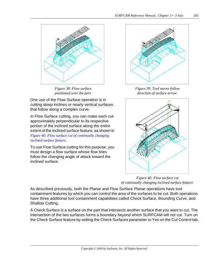
Figure 38: Flow surface positioned over the part
Figure 39: Tool moves follow direction of surface arrow
One use of the Flow Surface operation is in cutting steep inclines or nearly vertical surfaces that follow along a complex curve.
In Flow Surface cutting, you can make each cut approximately perpendicular to its respective portion of the inclined surface along the entire extent of the inclined surface feature, as shown in Figure 40: Flow surface cut of continually changing inclined surface feature.
To use Flow Surface cutting for this purpose, you must design a flow surface whose flow lines follow the changing angle of attack toward the inclined surface.
Figure 40: Flow surface cut of continually changing inclined surface feature
Copyright © 2000 by Surfware, Inc. All Rights Reserved.
246 SURFCAM Reference Manual, Chapter 3 • 3 Axis
A Bounding Curve is a single closed entity that can be made up of connecting lines, arcs, and splines. SURFCAM will cut only the area within this boundary. Turn on the bounding curve feature on the Cut Control tab by setting the Bounding Curve parameter to Yes. You must chain the bounding curve by selecting a beginning and ending element.
Shallow Cutting contains the cutting within surface areas whose "steepness" falls within an angular range that you specify.
When you click Planar on the NC 3 Axis menu, SURFCAM will display the Select menu and prompt you to “Select surfaces to cut across.”
Once you select surfaces, the 3 Axis Planar dialog box will be displayed..
See the SURFCAM Getting Started Manual, Chapter 3: Common NC Parameters, Section 3.2: Tool Information Tab on page 64.
Figure 41: Flow surface cut with no Check surface
Figure 42: Top view of Flow surface cut with no Check surface
Figure 43: Top view showing cut contained by a Check surface
3.6.1 Tool Information Tab — Planar
Copyright © 2000 by Surfware, Inc. All Rights Reserved.
SURFCAM Reference Manual, Chapter 3 • 3 Axis 247
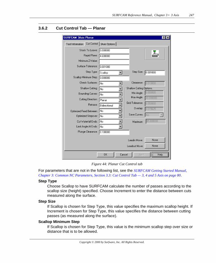
For parameters that are not in the following list, see the SURFCAM Getting Started Manual, Chapter 3: Common NC Parameters, Section 3.3: Cut Control Tab — 3, 4 and 5 Axis on page 80.
Step TypeChoose Scallop to have SURFCAM calculate the number of passes according to the scallop size (height) specified. Choose Increment to enter the distance between cuts measured along the surface.
Step SizeIf Scallop is chosen for Step Type, this value specifies the maximum scallop height. If Increment is chosen for Step Type, this value specifies the distance between cutting passes (as measured along the surface).
Scallop Minimum StepIf Scallop is chosen for Step Type, this value is the minimum scallop step over size or distance that is to be allowed.
3.6.2 Cut Control Tab — Planar
Figure 44: Planar Cut Control tab
Copyright © 2000 by Surfware, Inc. All Rights Reserved.
248 SURFCAM Reference Manual, Chapter 3 • 3 Axis
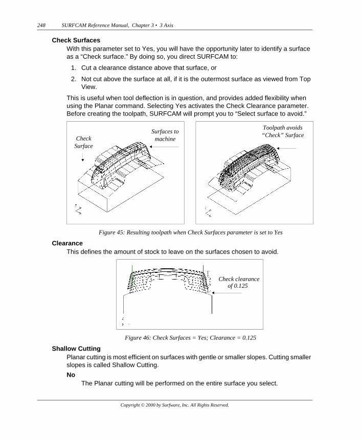
Check SurfacesWith this parameter set to Yes, you will have the opportunity later to identify a surface as a “Check surface.” By doing so, you direct SURFCAM to:
1. Cut a clearance distance above that surface, or
2. Not cut above the surface at all, if it is the outermost surface as viewed from Top View.
This is useful when tool deflection is in question, and provides added flexibility when using the Planar command. Selecting Yes activates the Check Clearance parameter. Before creating the toolpath, SURFCAM will prompt you to “Select surface to avoid.”
ClearanceThis defines the amount of stock to leave on the surfaces chosen to avoid.
Shallow CuttingPlanar cutting is most efficient on surfaces with gentle or smaller slopes. Cutting smaller slopes is called Shallow Cutting.
NoThe Planar cutting will be performed on the entire surface you select.
Figure 45: Resulting toolpath when Check Surfaces parameter is set to Yes
Figure 46: Check Surfaces = Yes; Clearance = 0.125
Surfaces to machineCheck
Surface
Toolpath avoids “Check” Surface
Check clearance of 0.125
Copyright © 2000 by Surfware, Inc. All Rights Reserved.
SURFCAM Reference Manual, Chapter 3 • 3 Axis 249
YesThe Planar cutting will be performed only on the shallow portions of your selected surface. The portions cut will be those that fall within in the angular range of steepness identified by the Min Angle and Max Angle parameters.
Shallow Cutting OptionsMin Angle
The steepness of a surface, at a specific point, is measured by the angle between the tangent to the surface at that point and the horizontal. Min Angle is the smallest angle, defining steepness, at which you want the planar cutting to begin. It will normally be set to zero.
Max AngleMax Angle is the largest angle, defining steepness, at which you want the planar cutting to stop. The planar cutting will take place at areas on the surface whose steepness lies between the Min Angle and Max Angle.
The most efficient planar cutting will occur from zero degrees to around 30º of steepness.
Grid ToleranceTo locate the boundary of areas having the steepness defined by the Min and Max Angles, a grid is created (but not displayed) and projected onto the surface. Measurements are taken along the strands of this grid to identify steepness boundaries. Grid Tolerance is the distance between the strands in this grid. The smaller this number, the more accurately the steepness boundaries will be located.
OverlapThis is the distance you want the tool beyond the steepness boundaries to insure complete cutting in the desired region.
Save CurvesWhen SURFCAM performs Shallow Cutting, the surfaces are analyzed to determine those surface areas whose slope falls within the angle range indicated by the Min Angle and Max Angle parameters. Temporary surface splines are then drawn along the boundaries of those areas. These splines are then projected onto the Z0 plane where they are used to create the tool paths. You can elect to have these projected splines saved.
Bounding CurvesIf set to Yes, cutting will be contained within a number of regions defined by closed boundary curves (combinations of lines, arcs, circles or splines). If the curves don’t lie on the surface, their construction view projection is the boundary. When cutting such a region the center of the tool will not pass beyond the boundary curve.
After you have indicated the direction of cutting with the Select Point menu, the Select Chain menu will be displayed and you will be prompted to "Select beginning element." Chain all the boundary curves and click Done to begin cutting.
Note: Best performance occurs when Maximum Feed Between (on 3 Axis Options tab) is smaller than the shortest distance between two separate boundaries, but larger than Step Size on the Cut Control tab. If a flow surface is used and
Copyright © 2000 by Surfware, Inc. All Rights Reserved.
250 SURFCAM Reference Manual, Chapter 3 • 3 Axis
it is already a trimmed surface, you must select bounding curves to trim the entire surface.
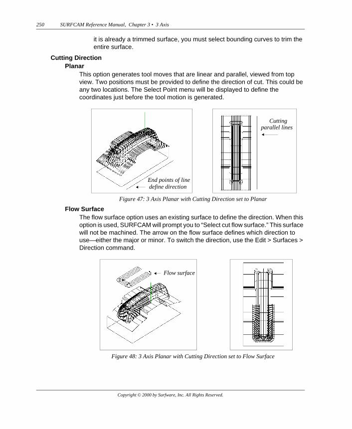
Cutting DirectionPlanar
This option generates tool moves that are linear and parallel, viewed from top view. Two positions must be provided to define the direction of cut. This could be any two locations. The Select Point menu will be displayed to define the coordinates just before the tool motion is generated.
Flow SurfaceThe flow surface option uses an existing surface to define the direction. When this option is used, SURFCAM will prompt you to “Select cut flow surface.” This surface will not be machined. The arrow on the flow surface defines which direction to use—either the major or minor. To switch the direction, use the Edit > Surfaces > Direction command.
Figure 47: 3 Axis Planar with Cutting Direction set to Planar
Figure 48: 3 Axis Planar with Cutting Direction set to Flow Surface
End points of linedefine direction
Cutting parallel lines
Flow surface
Copyright © 2000 by Surfware, Inc. All Rights Reserved.

SURFCAM Reference Manual, Chapter 3 • 3 Axis 251
RetraceRetrace specifies the way the tool will move between successive cutting passes. In Planar cutting there are three Retrace types: Top Plane, Bidirectional and Feed Between. See the Retrace Type (3 Axis and 5 Axis) descriptions in the SURFCAM Getting Started Manual, Chapter 3: Common NC Parameters, Retrace Type (3 Axis and 5 Axis) on page 81.
Optimized Feed BetweenChoose Yes to have SURFCAM analyze the toolpath in order to minimize the number of rapid moves.
Optimized StepoverWhen this parameter is set to Yes, SURFCAM removes the small distance step away moves that can otherwise occur just before and just after a feed between move performed at the edge of a nearly vertical surface.
Cut Waterfall EndsWhen a multi-surface toolpath is generated, there is compensation available for the edges of a surface as well as the surface itself. This is commonly referred to as corner-rounding or waterfalling. The Cut Waterfall Ends parameter provides four options to control the tool motion in relation to edge protection.
NoThis is the default. It cuts nothing other than the available surface area. There is no cutting beyond the edges into the edge protection regions. There will be no waterfalling of the tool paths at the surface edges.
YesClick Yes to cut the surfaces and to extend the cut along or through the edge protection. This results in what is often called the waterfall effect or waterfalling as the tool path cascades over the surface edge.
Figure 49: Cut Waterfall Ends = No Figure 50: Cut Waterfall Ends = Yes
Copyright © 2000 by Surfware, Inc. All Rights Reserved.
252 SURFCAM Reference Manual, Chapter 3 • 3 Axis
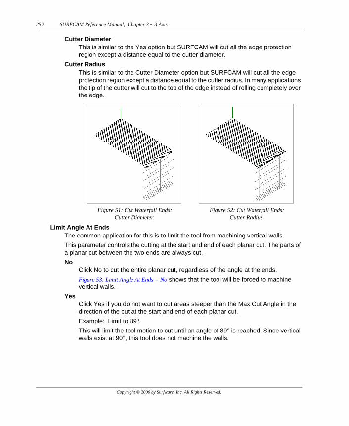
Cutter DiameterThis is similar to the Yes option but SURFCAM will cut all the edge protection region except a distance equal to the cutter diameter.
Cutter RadiusThis is similar to the Cutter Diameter option but SURFCAM will cut all the edge protection region except a distance equal to the cutter radius. In many applications the tip of the cutter will cut to the top of the edge instead of rolling completely over the edge.
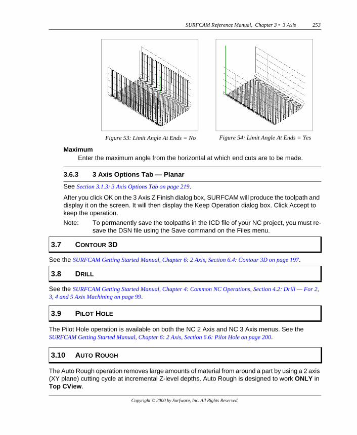
Limit Angle At EndsThe common application for this is to limit the tool from machining vertical walls.
This parameter controls the cutting at the start and end of each planar cut. The parts of a planar cut between the two ends are always cut.
NoClick No to cut the entire planar cut, regardless of the angle at the ends.
Figure 53: Limit Angle At Ends = No shows that the tool will be forced to machine vertical walls.
YesClick Yes if you do not want to cut areas steeper than the Max Cut Angle in the direction of the cut at the start and end of each planar cut.
Example: Limit to 89º.
This will limit the tool motion to cut until an angle of 89° is reached. Since vertical walls exist at 90°, this tool does not machine the walls.
Figure 51: Cut Waterfall Ends: Cutter Diameter
Figure 52: Cut Waterfall Ends: Cutter Radius
Copyright © 2000 by Surfware, Inc. All Rights Reserved.
SURFCAM Reference Manual, Chapter 3 • 3 Axis 253
MaximumEnter the maximum angle from the horizontal at which end cuts are to be made.
See Section 3.1.3: 3 Axis Options Tab on page 219.
After you click OK on the 3 Axis Z Finish dialog box, SURFCAM will produce the toolpath and display it on the screen. It will then display the Keep Operation dialog box. Click Accept to keep the operation.
Note: To permanently save the toolpaths in the ICD file of your NC project, you must re-save the DSN file using the Save command on the Files menu.
See the SURFCAM Getting Started Manual, Chapter 6: 2 Axis, Section 6.4: Contour 3D on page 197.
See the SURFCAM Getting Started Manual, Chapter 4: Common NC Operations, Section 4.2: Drill — For 2, 3, 4 and 5 Axis Machining on page 99.
The Pilot Hole operation is available on both the NC 2 Axis and NC 3 Axis menus. See the SURFCAM Getting Started Manual, Chapter 6: 2 Axis, Section 6.6: Pilot Hole on page 200.
The Auto Rough operation removes large amounts of material from around a part by using a 2 axis (XY plane) cutting cycle at incremental Z-level depths. Auto Rough is designed to work ONLY in Top CView.
Figure 53: Limit Angle At Ends = No Figure 54: Limit Angle At Ends = Yes
3.6.3 3 Axis Options Tab — Planar
3.7 CONTOUR 3D
3.8 DRILL
3.9 PILOT HOLE
3.10 AUTO ROUGH
Copyright © 2000 by Surfware, Inc. All Rights Reserved.
254 SURFCAM Reference Manual, Chapter 3 • 3 Axis
The 2 axis cutting cycle is guided by a toolpath that is created by performing the Planar operation on the part that you want to rough cut. Theoretically, you could use toolpaths from a Cut operation or a Z Finish operation. But, because the tool moves from a Planar operation are linear and parallel, as viewed from Top View, they provide the most efficient guides for Auto Rough cutting.
In preparation for performing the Auto Rough operation, you must perform a Planar operation on your part. When performing this Planar operation, you must set some of the parameters on the Tool Information, and Cut Control tabs so that they meet the needs of the Auto Rough operation. On the Tool Information tab you must use the same tool that you intend to use when performing Auto Rough. On the Cut Control tab you must use the same value for Stock To Leave and you must select Increment for Step Type.
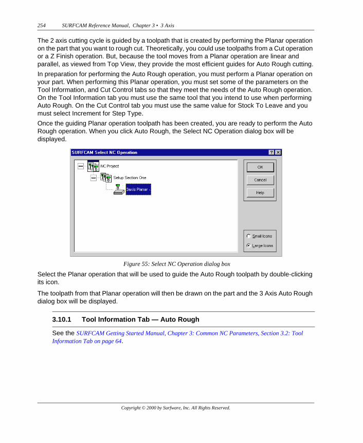
Once the guiding Planar operation toolpath has been created, you are ready to perform the Auto Rough operation. When you click Auto Rough, the Select NC Operation dialog box will be displayed.
Select the Planar operation that will be used to guide the Auto Rough toolpath by double-clicking its icon.
The toolpath from that Planar operation will then be drawn on the part and the 3 Axis Auto Rough dialog box will be displayed.
See the SURFCAM Getting Started Manual, Chapter 3: Common NC Parameters, Section 3.2: Tool Information Tab on page 64.
Figure 55: Select NC Operation dialog box
3.10.1 Tool Information Tab — Auto Rough
Copyright © 2000 by Surfware, Inc. All Rights Reserved.
SURFCAM Reference Manual, Chapter 3 • 3 Axis 255
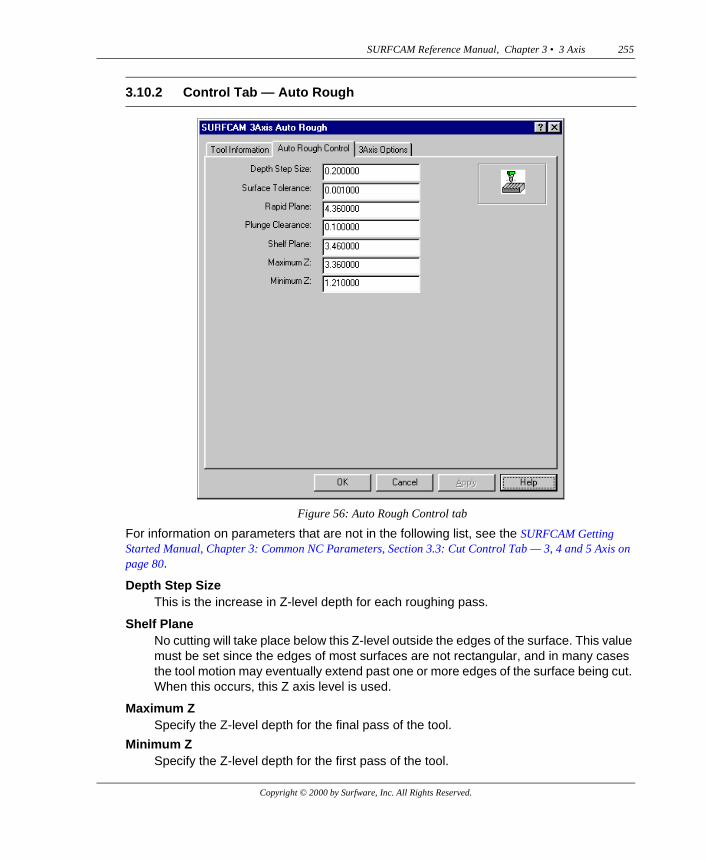
For information on parameters that are not in the following list, see the SURFCAM Getting Started Manual, Chapter 3: Common NC Parameters, Section 3.3: Cut Control Tab — 3, 4 and 5 Axis on page 80.
Depth Step SizeThis is the increase in Z-level depth for each roughing pass.
Shelf PlaneNo cutting will take place below this Z-level outside the edges of the surface. This value must be set since the edges of most surfaces are not rectangular, and in many cases the tool motion may eventually extend past one or more edges of the surface being cut. When this occurs, this Z axis level is used.
Maximum ZSpecify the Z-level depth for the final pass of the tool.
Minimum ZSpecify the Z-level depth for the first pass of the tool.
3.10.2 Control Tab — Auto Rough
Figure 56: Auto Rough Control tab
Copyright © 2000 by Surfware, Inc. All Rights Reserved.
256 SURFCAM Reference Manual, Chapter 3 • 3 Axis
See Section 3.1.3: 3 Axis Options Tab on page 219.
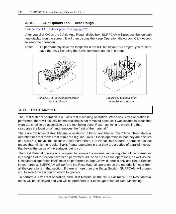
After you click OK on the 3 Axis Auto Rough dialog box, SURFCAM will produce the toolpath and display it on the screen. It will then display the Keep Operation dialog box. Click Accept to keep the operation.
Note: To permanently save the toolpaths in the ICD file of your NC project, you must re-save the DSN file using the Save command on the File menu.
The Rest Material operation is a 3 axis rest machining operation. When any 3 axis operation is performed, there will usually be material that is not removed because it was located in areas that were too small to be accessible by the tool being used. Rest machining is machining that calculates the location of, and removes the “rest of the material.”
There are two types of Rest Material operations: Z Finish and Planar. The Z Finish Rest Material operation has tool moves that mimic the regular 3 axis Z Finish operation in that they are a series of 2 axis (X,Y) moves that occur in Z axis increments. The Planar Rest Material operation has tool moves that mimic the regular 3 axis Planar operation in that they are a series of parallel moves that follow the curve of the surfaces being cut.
The Rest Material operation is designed to remove the material remaining after all the operations in a single Setup Section have been performed. All the Setup Section operations, as well as the Rest Material operation itself, must be performed in Top CView. If there is only one Setup Section in your project, SURFCAM will perform the Rest Material operation on the material left over from all the operations in that section. If there is more than one Setup Section, SURFCAM will prompt you to select the section on which to operate.
To perform a 3 axis rest operation, click Rest Material on the NC 3 Axis menu. The Rest Material menu will be displayed and you will be prompted to “Select Operation for Rest Machining.”
3.10.3 3 Axis Options Tab — Auto Rough
Figure 57: A toolpath appropriate for Auto Rough
Figure 58: Example of an Auto Rough toolpath
3.11 REST MATERIAL
Copyright © 2000 by Surfware, Inc. All Rights Reserved.
SURFCAM Reference Manual, Chapter 3 • 3 Axis 257
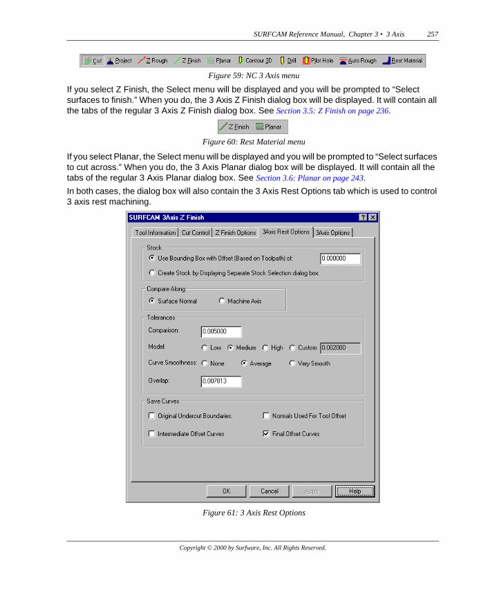
If you select Z Finish, the Select menu will be displayed and you will be prompted to “Select surfaces to finish.” When you do, the 3 Axis Z Finish dialog box will be displayed. It will contain all the tabs of the regular 3 Axis Z Finish dialog box. See Section 3.5: Z Finish on page 236.
If you select Planar, the Select menu will be displayed and you will be prompted to “Select surfaces to cut across.” When you do, the 3 Axis Planar dialog box will be displayed. It will contain all the tabs of the regular 3 Axis Planar dialog box. See Section 3.6: Planar on page 243.
In both cases, the dialog box will also contain the 3 Axis Rest Options tab which is used to control 3 axis rest machining.
Figure 59: NC 3 Axis menu
Figure 60: Rest Material menu
Figure 61: 3 Axis Rest Options
Copyright © 2000 by Surfware, Inc. All Rights Reserved.
258 SURFCAM Reference Manual, Chapter 3 • 3 Axis
StockUse Bounding Box with Offset (Based on Toolpath) of
Select this option to automatically create stock that encloses the part in a box whose dimensions are equal to the extreme outside measurements of the part, plus an offset on all sides equal to the value you enter in the data entry box.
Create Stock by Displaying a Separate Stock Selection dialog boxSelect this option to display the standard stock selection Add Model dialog box. The Add Model dialog box gives you the maximum control over the dimensions of the stock.
Compare AlongIn Rest Material machining, the part as designed is compared to a model of the part containing the material remaining (rest material) after all the operations in the selected Setup Section have been performed. The comparison detects the distances between points on the surface of the rest material and corresponding points on the surface of the part. There are two ways comparisons can be made—that is, two ways the corresponding points are matched up.
Surface NormalThe comparison is made along normals to the surface of the part, as designed. This will be the most frequently used method.
Machine AxisThe comparison is made along the axis of the tool.
TolerancesComparison
If the distances measured in the comparison of the part and the rest material are less than this number, SURFCAM will not treat the material in that area as rest material and will not remove it. The smaller this number, the more rest material that will be removed.
ModelTo determine the location of rest material on the surface of the part, a temporary mesh (not displayed) is created to cover the surface. Model Tolerance sets the size of the cells in the mesh. The smaller the cells, the more of the rest material that will be identified.
Choose one of these options to control the size of the mesh cell: Low, Medium, High and Custom (where you set your own value for the size of the mesh).
Important:The Model Tolerance is expressed in neither inch nor metric units. It should always remain within, or close to, the range of 0.001 to 0.005 (Low, Medium, High).
Curve SmoothnessChoose one of these options (None, Average or Very Smooth) to control the smoothness of the rest material boundary curve and its corresponding offset curve.
Copyright © 2000 by Surfware, Inc. All Rights Reserved.
SURFCAM Reference Manual, Chapter 3 • 3 Axis 259
OverlapThis is the distance you want the tool to move beyond the edge of the rest material to insure complete removal.
Save CurvesOriginal Undercut Boundaries
SURFCAM will determine the edges of the material (the rest material) that was not removed by the previous operations in the selected Setup Section and create boundary curves along these edges. Select this option to display the Undercut Boundaries curves along with the toolpath and save them on the currently active layer. It is best to save it on a layer other than the one containing your drawing.
Intermediate Offset CurvesSURFCAM will determine boundary curves that are offset from the Original Undercut Boundaries. Select this option to display the Intermediate Offset Curves and save them on the currently active layer.
Normals Used For Tool OffsetSURFCAM will display and save normals used to determine the tool offset.
Final Offset CurvesSURFCAM will project the Intermediate Offset Curves onto the 0 Z-level plane. The Final Offset Curves are used to guide the creation of the rest machining toolpath. Select this option to display the final offset curves and save them on the currently active layer.
Pencil Cut is an operation used to remove the material that is left along the concave intersection of two surfaces, after other machining operations have been performed. Pencil Cut can also detect the uncut material along concave folds or "crease-like" regions in the interior of a single surface.
To perform a Pencil Cut, SURFCAM calculates "pencil curves" along the intersections of surfaces and along the "crease-like" folds that may occur on single surfaces. Pencil curves are similar to the cutter intersect splines created with the Create > Spline menu. See Chapter 1: Menus and Dialog Boxes, Cutter Intersect on page 71.
To calculate a pencil curve between two surfaces, an offset from each surface is first calculated. The curve representing the intersection of these offset surfaces becomes the pencil curve. These offset surfaces are determined by the Tool Diameter and Tip Radius of the tool you elect to use to perform the cut.
When the tool is a ballnose, the offset surfaces are those that would be traversed by the center of the ballnose. The resulting pencil curve would be the curve traversed by the center of a ball as it rolls along the intersection of the two surfaces. (In the interior of a single surface, pencil curves are created in those regions that are so concave that the ball can contact the surface in two locations at once.) In similar but more complex ways, offset surfaces are created for bullnose and end mill tools.
3.12 PENCIL CUT
Copyright © 2000 by Surfware, Inc. All Rights Reserved.
260 SURFCAM Reference Manual, Chapter 3 • 3 Axis
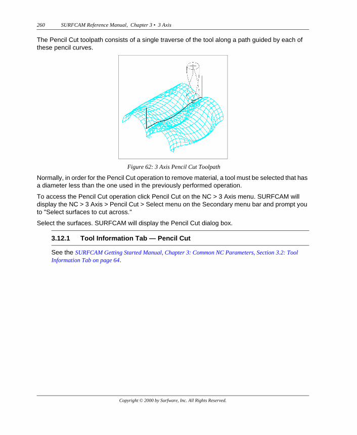
The Pencil Cut toolpath consists of a single traverse of the tool along a path guided by each of these pencil curves.
Normally, in order for the Pencil Cut operation to remove material, a tool must be selected that has a diameter less than the one used in the previously performed operation.
To access the Pencil Cut operation click Pencil Cut on the NC > 3 Axis menu. SURFCAM will display the NC > 3 Axis > Pencil Cut > Select menu on the Secondary menu bar and prompt you to "Select surfaces to cut across."
Select the surfaces. SURFCAM will display the Pencil Cut dialog box.
See the SURFCAM Getting Started Manual, Chapter 3: Common NC Parameters, Section 3.2: Tool Information Tab on page 64.
Figure 62: 3 Axis Pencil Cut Toolpath
3.12.1 Tool Information Tab — Pencil Cut
Copyright © 2000 by Surfware, Inc. All Rights Reserved.
SURFCAM Reference Manual, Chapter 3 • 3 Axis 261
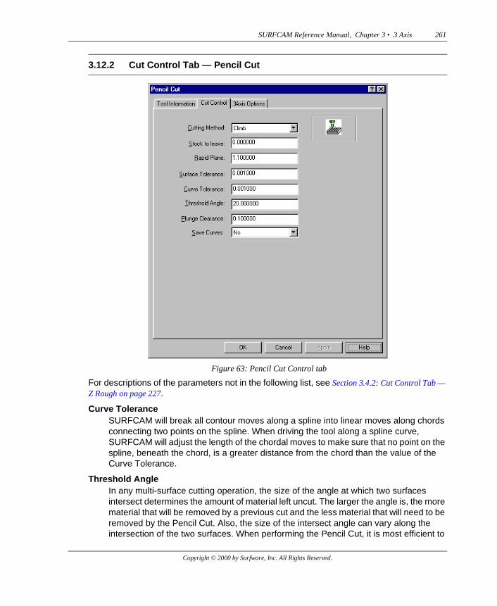
For descriptions of the parameters not in the following list, see Section 3.4.2: Cut Control Tab — Z Rough on page 227.
Curve ToleranceSURFCAM will break all contour moves along a spline into linear moves along chords connecting two points on the spline. When driving the tool along a spline curve, SURFCAM will adjust the length of the chordal moves to make sure that no point on the spline, beneath the chord, is a greater distance from the chord than the value of the Curve Tolerance.
Threshold AngleIn any multi-surface cutting operation, the size of the angle at which two surfaces intersect determines the amount of material left uncut. The larger the angle is, the more material that will be removed by a previous cut and the less material that will need to be removed by the Pencil Cut. Also, the size of the intersect angle can vary along the intersection of the two surfaces. When performing the Pencil Cut, it is most efficient to
3.12.2 Cut Control Tab — Pencil Cut
Figure 63: Pencil Cut Control tab
Copyright © 2000 by Surfware, Inc. All Rights Reserved.
262 SURFCAM Reference Manual, Chapter 3 • 3 Axis
have SURFCAM generate pencil curves only in those regions with small intersect angles. The value for Threshold Angle determines in which regions pencil curves will be generated.
SURFCAM will generate pencil curves in those regions along the intersection of two surfaces where the supplement of the intersect angle is larger than the value for Threshold Angle. A pencil curve will not be generated in those regions where the intersect angle supplement is less than Threshold Angle. But, if any resulting breaks in the pencil curve are smaller than a set value, SURFCAM will connect the separate pieces of the pencil curve so that a smooth and continuous toolpath will be maintained along the intersection.
Save CurvesYou can elect to save the pencil curves, as well as the toolpath, by setting the Save Curves parameter to Yes.
See Section 3.1.3: 3 Axis Options Tab on page 219.
After you click OK on the Pencil Cut dialog box, SURFCAM will produce the toolpath and display it on the screen. It will then display the Keep Operation dialog box. Click Accept to keep the operation.
Note: To permanently save the toolpaths in the ICD file of your NC project, you must re-save the DSN file using the Save command on the File menu.
The Options command displays the NC Option dialog box which contains all the NC mode Options tabs. It provides a convenient way to view and/or edit the 3 Axis Options tab and the tabs of the other NC modes at the same time.
See Section 3.1.3: 3 Axis Options Tab on page 219.
3.12.3 3 Axis Options Tab — Pencil Cut
3.13 OPTIONS
Copyright © 2000 by Surfware, Inc. All Rights Reserved.