2D and 3D Pointing Device Based on a Passive Lights ...
23
University of Kentucky UKnowledge Computer Science Faculty Patents Computer Science 6-13-2017 2D and 3D Pointing Device Based on a Passive Lights Detection Operation Method Using One Camera Fuhua Cheng University of Kentucky, [email protected] Right click to open a feedback form in a new tab to let us know how this document benefits you. Follow this and additional works at: hps://uknowledge.uky.edu/cs_patents Part of the Computer Sciences Commons is Patent is brought to you for free and open access by the Computer Science at UKnowledge. It has been accepted for inclusion in Computer Science Faculty Patents by an authorized administrator of UKnowledge. For more information, please contact [email protected]. Recommended Citation Cheng, Fuhua, "2D and 3D Pointing Device Based on a Passive Lights Detection Operation Method Using One Camera" (2017). Computer Science Faculty Patents. 6. hps://uknowledge.uky.edu/cs_patents/6
-
Upload
khangminh22 -
Category
Documents
-
view
1 -
download
0
Transcript of 2D and 3D Pointing Device Based on a Passive Lights ...

University of KentuckyUKnowledge
Computer Science Faculty Patents Computer Science
6-13-2017
2D and 3D Pointing Device Based on a PassiveLights Detection Operation Method Using OneCameraFuhua ChengUniversity of Kentucky, [email protected]
Right click to open a feedback form in a new tab to let us know how this document benefits you.
Follow this and additional works at: https://uknowledge.uky.edu/cs_patents
Part of the Computer Sciences Commons
This Patent is brought to you for free and open access by the Computer Science at UKnowledge. It has been accepted for inclusion in ComputerScience Faculty Patents by an authorized administrator of UKnowledge. For more information, please contact [email protected].
Recommended CitationCheng, Fuhua, "2D and 3D Pointing Device Based on a Passive Lights Detection Operation Method Using One Camera" (2017).Computer Science Faculty Patents. 6.https://uknowledge.uky.edu/cs_patents/6

c12) United States Patent Cheng
(54) 2D AND 3D POINTING DEVICE BASED ON A PASSIVE LIGHTS DETECTION OPERATION METHOD USING ONE CAMERA
(71) Applicant: University of Kentucky Research Foundation, Lexington, KY (US)
(72) Inventor: Fuhua Cheng, Lexington, KY (US)
(73) Assignee: UNIVERSITY OF KENTUCKY RESEARCH FOUNDATION, Lexington, KY (US)
( *) Notice: Subject to any disclaimer, the term of this patent is extended or adjusted under 35 U.S.C. 154(b) by 0 days.
(21) Appl. No.: 14/339,090
(22) Filed: Jul. 23, 2014
(65) Prior Publication Data
US 2015/0029100 Al Jan. 29, 2015
Related U.S. Application Data
(60) Provisional application No. 61/857,290, filed on Jul. 23, 2013.
(51) Int. Cl. G06F 31033 G06F 310354
(52) U.S. Cl.
(2013.01) (2013.01)
(Continued)
CPC ........ G06F 3103543 (2013.01); G06F 310325 (2013.01); G06F 310346 (2013.01)
(58) Field of Classification Search CPC ........ G06F 3/03; G06F 3/0304; G06F 3/0308;
G06F 3/0325; G06F 3/033; G06F 3/0354; G06F 3/03543
(Continued)
111111 1111111111111111111111111111111111111111111111111111111111111 US009678583B2
(10) Patent No.: US 9,678,583 B2 Jun.13,2017 (45) Date of Patent:
(56) References Cited
U.S. PATENT DOCUMENTS
5,297,061 A * 3/1994 Dementhon .......... G06F 3/0346 345/156
5,532,777 A 7/1996 Zanen
(Continued)
FOREIGN PATENT DOCUMENTS
EP GB
2226707 B1 112013 2388418 A * 1112003
OTHER PUBLICATIONS
G06F 3/0325
Pranav Mistry; Mouseless, the 'invisible' computer mouse (wNideo); Phys.org; Jul. 8, 2010; 2 pages; http://phys.org/ news 197792915 .html.
(Continued)
Primary Examiner- Jason Mandeville (74) Attorney, Agent, or Firm- King & Schickli, PLLC
(57) ABSTRACT
Systems for surface-free pointing and/or command input include a computing device operably linked to an imaging device. The imaging device can be any suitable video recording device including a conventional webcam. At least one pointing/input device is provided including first, second, and third sets of actuable light sources, wherein at least the first and second sets emit differently colored light. The imaging device captures one or more sequential image frames each including a view of a scene including the activated light sources. One or more computer program products calculate a two-dimensional or three-dimensional position and/or a motion and/or an orientation of the pointing/input device in the captured image frames by identifying a two-dimensional or three-dimensional position of the activated light sources of the first, second, and/or third sets of light sources. Certain activation patterns of light sources are mapped to particular pointing and/or input commands.
17 Claims, 11 Drawing Sheets

US 9,678,583 B2 Page 2
(51) Int. Cl. G06F 3103 (2006.01) G06F 310346 (2013.01)
(58) Field of Classification Search USPC ......................... 345/156, 157, 158, 163-166 See application file for complete search history.
(56) References Cited
U.S. PATENT DOCUMENTS
5,581,276 A * 12/1996 Cipolla ................... G06F 3/017 345/156
5,909,209 A 6/1999 Dickinson 6,057,540 A 5/2000 Gordon eta!. 6,525,306 Bl 2/2003 Bohn 6,603,865 Bl * 8/2003 Yagi .......................... G06T7/70
382/103 6,643,396 Bl 1112003 Hendriks et a!. 7,274,800 B2 9/2007 Nefian eta!. 7,849,421 B2 12/2010 Yoo eta!. 8,062,126 B2 * 1112011 Marks ..................... G06F 3/017
382/103 8,224,024 B2 * 7/2012 Foxlin ....................... G06T 7/73
348/135 8,269,721 B2 9/2012 Lin 8,686,939 B2 * 4/2014 Mao ........................ A63F 13/06
345/156 9,201,519 B2 * 12/2015 Cheng ................... G06F 3/0325 9,507,437 B2 * 1112016 Cheng ................... G06F 3/0346
2004/0063480 Al * 4/2004 Wang ...................... A63F 13/02 463/8
2007/0080940 Al * 4/2007 Aoki ..................... G06F 3/0304 345/158
2007/0081695 Al * 4/2007 Foxlin ....................... G06T 7/73 382/103
2007/0117625 Al * 5/2007 Marks ..................... G06F 3/017 463/30
2008/0001951 Al * 112008 Marks ..................... A63F 13/06 345/474
2008/0100825 Al * 5/2008 Zalewski ................ A63F 13/06 356/29
2009/0174657 Al * 7/2009 Miyazaki .................. G06F 3/01 345/158
2009/0315825 Al 12/2009 Cauchi 2010/0017115 Al 112010 Gautarna 2010/0105475 Al * 4/2010 Mikhailov .............. A63F 13/06
463/33 201110169734 Al 7/2011 Cho et al. 201110310230 Al 12/2011 Cheng 2014/0359536 Al * 12/2014 Cheng ..................... G06F 11169
715/848 2015/0022449 Al * 112015 Cheng . . . . . . . . . . . . . . . . . . . G06F 3/0346
345/163 2015/0049021 Al * 212015 Cheng ................. G06F 3/03543
345/163
OTHER PUBLICATIONS
Pranav Mistry and Pattie Maes; "Mouseless"; MIT Media Laboratory, Oct. 2010, pp. 441-442. "Mouse (computing)"; Wikipedia; Sep. 25, 2013; 8 pages; http:// en. wikipedia.org/wiki/Mouse_( computing). Freanz Madritsch; "CCD-Carnera Based Optical Tracking for Human-Computer Interaction"; Proceedings 1st European Conference on Disability, Virtual Reality and Associated Technologies, Maidenhead; pp. 161-170 (1996). Richard Hartley, et a!.; "Triangulation"; Computer Vision and Image Understanding, vol. 68, No. 2, pp. 146-157 (1997); Article No. IV970547. Philips; "uWand technology"; How uWand Works-Intuitive3 Remotes for SmartTV; 1 page printed on Sep. 16, 20 14; http://www. uwand.corn/how-uwand-works.html. Wii from Wikipedia; 33 pages printed on Sep. 16, 2014; http://en. wikipedia.org/wiki/Wii. U.S. Appl. No. 14/089,881, filed Nov. 26, 2013 entitled Algorithms, Software and an Interaction System That Support the Operation of an on the Fly Mouse.
* cited by examiner
U.S. Patent Jun.13,2017 Sheet 1 of 11
Fig.l (Prior Art)
10 vt··
US 9,678,583 B2

U.S. Patent Jun.13,2017 Sheet 2 of 11 US 9,678,583 B2
Fig. 4
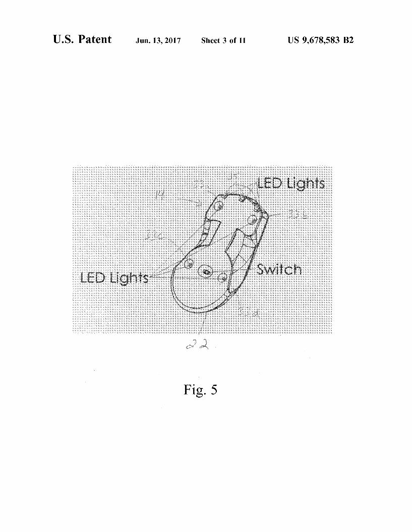
U.S. Patent Jun.13,2017 Sheet 3 of 11 US 9,678,583 B2
Fig. 5
U.S. Patent Jun.13,2017 Sheet 4 of 11 US 9,678,583 B2
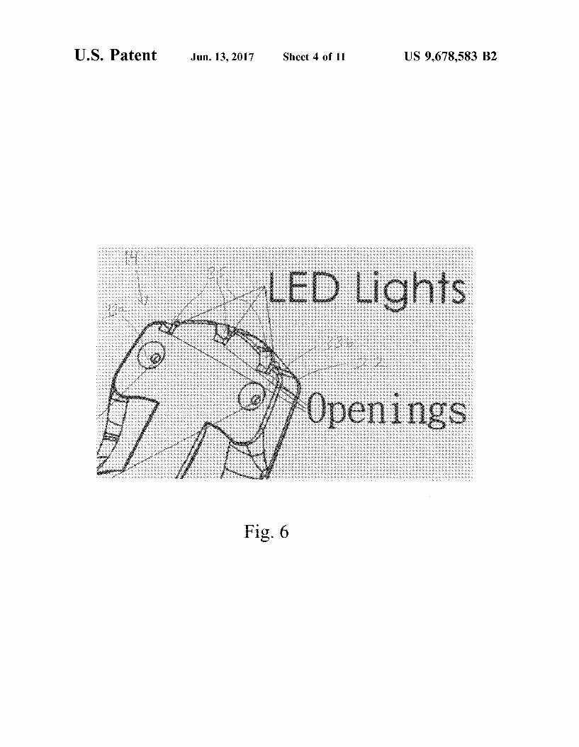
Fig. 6
U.S. Patent Jun.13,2017 Sheet 5 of 11 US 9,678,583 B2
Fig. 7
U.S. Patent Jun.13,2017 Sheet 6 of 11 US 9,678,583 B2
10
Fig. 8

U.S. Patent Jun.13,2017
/ i ,,,). .. ··
n1: ,/ v
... ~ ............. 1-:·:::: "'
~ -~~ ... /·
~
/f._ ,./
.t
/ i,)
c::>
0 (] c::J c::J I ,.___.
Sheet 7 of 11 US 9,678,583 B2
, .. ___ ..... ,.·.• (...:7'~ ·::.::>
.. ·''
·0\\ I r ...__...
Fig. 9
U.S. Patent Jun.13,2017 Sheet 8 of 11 US 9,678,583 B2
0 :Yl·· .. ~-:.:.-::-F·.::.;~~~-~-:;_·_---~--~-. ~----- ~~-~
.. ,
··-..
········---~------------------.-·-·-··---~·:·::.,;, . ·-...
:Fig. 10
.... ··-~-~~---·· ......... -·------~- .......... ~ ..... _ .. -·· vv ___ ... -··
Vl · . .....,.
··--- ........ \._ ...... . ............ -~ .. ··· .
____ .. ,.·· . '·'v>
V4
U.S. Patent Jun.13,2017 Sheet 9 of 11 US 9,678,583 B2
[······ ... ' ··--............. .......
o~.~:~~~~~=~~~~-~',,,_1,,· ~c-j~; >~::::: ~~~~;=··~•::.·:;:.~."~'··.2,, ·''' ..... ~.·· ......... ::>,Fl I '
.:·: ·. . ~ \
i \
'I \ ··~-·:-~-~:-.-... .... 1 '. VJ
F2 ........
i
Fig. 11
U.S. Patent Jun.13,2017 Sheet 10 of 11
···~.
"-..
··· ....
'·.
Fig. 12
··· ..•
US 9,678,583 B2
·,, i
'· . 1 (aL.d.-f} FJ ,, ! !
U.S. Patent Jun.13,2017 Sheet 11 of 11 US 9,678,583 B2
w V2
b
V4 3
:Fig. 13
US 9,678,583 B2 1
2D AND 3D POINTING DEVICE BASED ON A PASSIVE LIGHTS DETECTION OPERATION
METHOD USING ONE CAMERA
This utility patent application claims the benefit of priority in U.S. Provisional Patent Application Ser. No. 61/857, 290 filed on Jul. 23, 2013, the entirety of the disclosure of which is incorporated herein by reference.
TECHNICAL FIELD
2 surface. These surfaces, when lit at a grazing angle by the displacement detection LED, cast distinct shadows that resemble a hilly terrain lit at sunset. Images of these surfaces are captured in continuous succession as the mouse is translated over the surface, often at a speed of more than one thousand frames per second. Depending on the speed with which the mouse is moved, each image will be offset from the previous image by a fraction of a pixel or as many as several pixels. By using cross correlation to calculate how
10 much each successive image is offset from the previous image, a displacement processor can determine the distance the mouse has moved from image data captured by the sensor. The movement of the mouse can then be translated
The present disclosure relates to human-computer interaction systems. More specifically, this disclosure pertains to methods and systems for use of a conventional video recorder such as a webcam for two-dimensional (2D) and 15
three-dimensional (3D) pointing and command inputs in a computing system relying on passive light detection for both 2D and 3D modes. Embodiments of a pointing/input device for use in the methods and systems are disclosed.
or converted into a corresponding movement of a visible marker such as a cursor on a graphical user interface such as a computer screen.
Even though a special surface such as a mouse-pad is not needed by a modern optical mouse, operation of the mouse still requires a surface on which to rest and over which to
BACKGROUND OF THE INVENTION
The operation of a conventional mechanical or optical pointing or input device such as a mechanical or optical computer mouse is well known in the art. By use of these devices, a user can select files, programs, or actions from lists, groups of icons, etc., and can "gesturally" move files, programs, etc. issue commands or map to specific actions, for example in drawing programs.
As examples, a mechanical computer mouse relies on one or more wheels and/or balls to track movement or displacement information relative to forward-backward and left-toright movement of the computer mouse, for example by interrupting infrared beams of light directed at light sensors
20 travel. If a suitable operating surface is not available and an alternative such as a touchpad or trackball is also not available, a conventional optical mouse cannot be used. In turn, certain tasks often done with pointing/input devices such as a computer mouse are difficult to impossible to
25 accomplish with alternative pointing/input devices such as touchpads or trackballs. For example, use of drawing programs without a computer mouse can be difficult if not impossible. Likewise, tasks such as two-dimensional (2D) or 3D sculpturing or drawing, "flying" in multi-dimensional
30 space (for example, three-dimensional space defined by X, Y, and Z axes) such as during gaming, etc. would be difficult to accomplish using a conventional touchpad, trackball, etc. Still more, personal computers (PCs) are not merely tools for surfing the internet and sending e-mail in the modern world.
35 Increasingly, PCs serve as digital media centers to view photos, listen to music, and watch video clips, films and TV shows. Indeed, notebook, laptop, and desktop computers are rapidly becoming accepted accessories or supplements to
to create pulses representative of wheel or ball movement. Simple logic circuits interpret the relative timing of the pulses to indicate which direction the wheel(s) or ball(s) is moving, which is then converted by driver software into motion of a visual indicator such as a pointer, cursor, or cross-hair along X andY axes of a computing device display 40
(and in certain situations replacing) the home entertaiument center.
screen. An optical computer mouse replaces the mechanical
mouse wheels or balls with one or more visible or invisible light sources such as light-emitting diodes (LEDs), laser diodes, infra-red light, etc. to detect movement of the mouse relative to an underlying surface such as a mouse pad. The inertial/gyroscopic computer mouse uses a tuning fork or other accelerometer to detect rotary movement for every axis supported, most commonly using 2 degrees of rotational freedom and being insensitive to spatial translation. The user need only perform small wrist rotations to move a pointer or cursor on a display screen.
Almost all modem 2D pointing devices utilize an active approach for detecting movement of the device. The underlying technology of modem surface-independent (meaning that a specific surface type is not required, although some type of surface is) 2D pointing/input devices such as optical mice (see FIG. 1) is known as digital image correlation. The mouse includes a shell or housing and a variety of input means such as left and right buttons, a scroll wheel, etc. A displacement detection LED disposed on a bottom surface of the mouse is used to detect movement of the mouse over a surface. An optical or optoelectronic mouse uses an optoelectronic sensor (essentially, a tiny low-resolution video camera) to image a naturally occurring texture of an underlying surface made of materials such as wood, cloth, mouse pad materials and Formica, using light reflected from the
Likewise, the modem television is no longer just a TV, offering integrated Internet capabilities and set-top boxes that offer more advanced computing ability and connectivity than a contemporary basic TV set. The modern "smart" TV
45 can deliver content from computers or network attached storage devices, such as photos, movies and music. These devices also provide access to Internet-based services including traditional broadcast TV channels, pre-recorded programs, video-on-demand, electronic program guides,
50 interactive advertising, personalization, voting, games, social networking, and other multimedia applications. All of these require a remote control-like device that can provide cursor control, i.e. a pointing/input device as is known for computing devices. Unfortunately, traditional television
55 remote controls cannot conveniently provide such functionality. As noted above, a conventional pointing/input device such as a computer mouse requires a desk or other hard surface to function.
For this reason, attempts have been made to adapt the 60 familiar computer mouse to operate in the air or "on the fly,"
to avoid the need for a surface over which to translate the mouse for operation. Indeed, 3D pointing has long been a desired feature in human-computer interaction to allow tasks that are not possible with a 2D pointing device, such as 3D
65 sculpturing or space navigating. However, 3D pointing technology has not reached a stage that is considered both reasonably affordable and manipulative.

US 9,678,583 B2 3 4
clicking activities of an "on the fly" pointing device for 2D and 3D pointing in a 3D human-computer interaction system.
SUMMARY OF THE INVENTION
To solve the foregoing problems and address the identi-
For 3D pointing, it is necessary to identify the location of the pointing device with respect to a reference point in a 3D space. Unlike 2D pointing which mainly uses an active approach, 3D pointing has been attempted using both active and passive approaches. The approach taken depends on whether the pointing device includes a displacement detection system that works in 3D space. The optical displacement detection system of an optical mouse can only work on a surface due to the operating mechanism summarized above; it cannot work if suspended in 3D space. 10
fied need in the art, the present disclosure provides devices, and methods and computing systems incorporating the devices, for accomplishing two-dimensional and three-dimensional pointing/command input operations in "air
In the active approach, typically an imager such as an IR camera is integrated into the pointing device to detect lights from an IR emitter of a console such as the console of a gaming device, and calculate spatial coordinates for the pointing device accordingly. The Wii® Remote marketed by Nintendo® falls within that category. A problem with this approach is that the pointing device spatial coordinates can only be calculated when its imager has a direct line of sight to a sensor bar associated with the gaming device console.
Another active type of 3D mouse uses a tnning fork or other accelerometer to detect rotary movement for every axis supported. Logitech® and Gyration's inertial mice (also called gyroscopic mice) fall in this category. The most common models work using 2 degrees of rotational freedom. An operator uses wrist rotations to move the cursor. The inertial mouse is insensitive to spatial translations. More recently, an inertial mouse was developed, equipped with g-sensors (pairs of accelerometers extended over a region of space) to calculate the mouse position, orientation and velocity; hence such a mouse can provide at least 9 spatial parameters for pointing purposes. However, the price of such an inertial mouse is quite high; usually 10 times more than the price of a typical optical mouse.
mode," i.e. without requiring translating a pointing device over a surface and measuring a distance displacement thereof. In the disclosure are described such devices, meth-
15 ods, and systems using a passive detection method, which advantageously can be accomplished using a conventional imaging device such as a common web cam.
In one aspect, a pointing/input device for two-dimensional and three-dimensional pointing/command input is
20 described. In one embodiment, a pointing/input device for effecting two-dimensional and three-dimensional pointing and/or command input by way of a single imaging device operatively connected to a computing device is provided. The device includes a first set of actuable light sources
25 disposed on a first surface of the device housing. At least one light source of the first set emits a first color light. A second set of actuable light sources is disposed on the first surface of the housing, the second set emitting a second color light that is different from the first color. In an embodiment, the
30 first color may be blue and the second color may be red. A third set of actuable light sources is disposed on a second surface of the housing. The third set of light sources emits a color light that may be the same as or different from the first or second color.
One or more actuators are provided for differently acti-vating one or more of the light sources of the first, second, and third sets of light sources. The activated first set and second set of light sources are visible to and detectable by the imaging device when either of the first surface of the
For pointing devices that do not include a distance mea- 35
suring component, a passive approach has been evaluated requiring a separate component to measure the distance between the pointing device and, for example, a gaming device or base station, or to identify the location of the pointing device with respect to the gaming device or base station. All gesture-based pointing device approaches, such
40 housing or the second surface of the housing are facing a field of view of the imaging device.
as the Kinect® device marketed by Microsoft®, belong to this latter category. In this case, the fingers or the hands of a user play the role of a pointing device and a special imaging device is required to identifY the locations of the fingers or hands of the user. Three-dimensional mice such as 3Dconnexion/Logitech's® SpaceMouse® in the early 1990s and Kantek's® 3D RingMouse® in the late 1990s, also known as bats, flying mice or wands, also fall in this category. As an example, the RingMouse® was tracked by a base station through ultrasound. This approach has been found to provide insufficient resolution.
In another aspect, a method for two-dimensional and three-dimensional pointing/command input is described which uses passive light detection and requires only a single
45 conventional imaging device. In an embodiment, the method comprises providing at least one pointing/input device as described above, and holding and/or moving the at least one pointing/input device within a field of view of the imaging device. The imaging device captures a plurality of sequential
50 image frames each including a view of the at least one pointing/input device having at least one light source of the first set, the second set, and/or the third set of light sources activated to emit light. Still other attempts have been made to implement passive
detection of a pointing device location by combining pointing and imaging functionalities in a single device. In one such device, a digital camera mounted into the housing of a computer mouse includes a mode selection system to switch the device between a 2D mouse function and a digital camera function (see FIG. 1). The device could not be used for 3D pointing. In another attempt, three one-dimensional 60
imaging devices were used to track a point light source, to recognize and execute gestures input by the operator. The problem with this approach is that a holding time is required before each operation such as a click or drag can be performed.
Next, from one or more views of at least one of the first 55 set, the second set, and/or the third set of light sources in the
captured plurality of sequential image frames, a two-dimensional or a three-dimensional position and/or motion and/or orientation of the at least one pointing/input device is calculated. A visual marker can then be rendered on a graphical user interface, the visual marker corresponding to the calculated position and/or motion and/or orientation of the at least one pointing/input device. Activation patterns of the first set and/or the second set and/or the third set of light sources may be mapped to a predetermined pointing and/or
65 input command, and to a three-dimensional position and/or motion and/or orientation of the at least one pointing/input device.
To date, the present inventors are unaware of any attempts to use a single-lens imaging device to capture the motion and
US 9,678,583 B2 5
In yet another aspect, a computing system for twodimensional and three-dimensional pointing/command input is described which uses passive light detection and requires only a single conventional imaging device. In an embodiment, the computing system comprises a computing device having at least one processor, at least one memory, and at least one graphical user interface, at least one pointing/input device as described above, an imaging device operably linked to the computing device and configured for capturing a plurality of sequential image frames, and at least one 10
computer program product operable on the computing device processor.
6 human-computer interaction system of FIG. 3, for accomplishing a two-dimensional pointing/command input operation;
FIG. 9 shows the pointing/input device of FIG. 4 in a field of view of the imaging device of the human-computer interaction system of FIG. 3, for accomplishing a threedimensional pointing/command input operation;
FIG. 10 depicts a perspective projection of a rectangle on a projection plane P;
FIG. 11 graphically depicts a perspective view of a projection of four vertices V 1 V 2 V 3 V 4 of the rectangle of FIG. 10 on projection plane P CVv V 2 , V 3 , and V4 ) wherein none of the edges of the rectangle defined by V 1 V 2 V 3 V 4 are parallel to the projection plane P, used to calculate a position and/or orientation of the pointing/input device of FIG. 4;
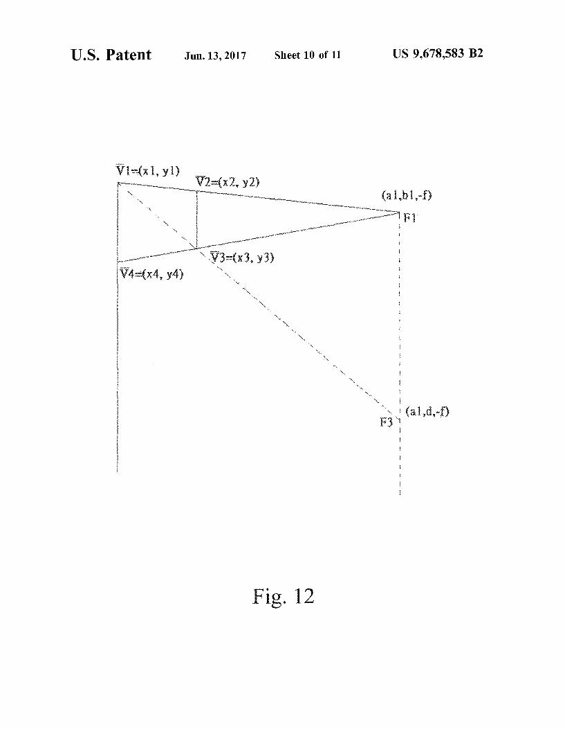
FIG. 12 graphically depicts a perspective view of a projection of four vertices V 1 V 2 V 3 V 4 of the rectangle of FIG. 10 on projection plane P CVv V 2 , V 3 , and V4 ) wherein v2v3 and v1v4 are parallel to the projection plane p but V 1V2 and V3V4 are not, used to calculate a position and/or orientation of the pointing/input device of FIG. 4; and
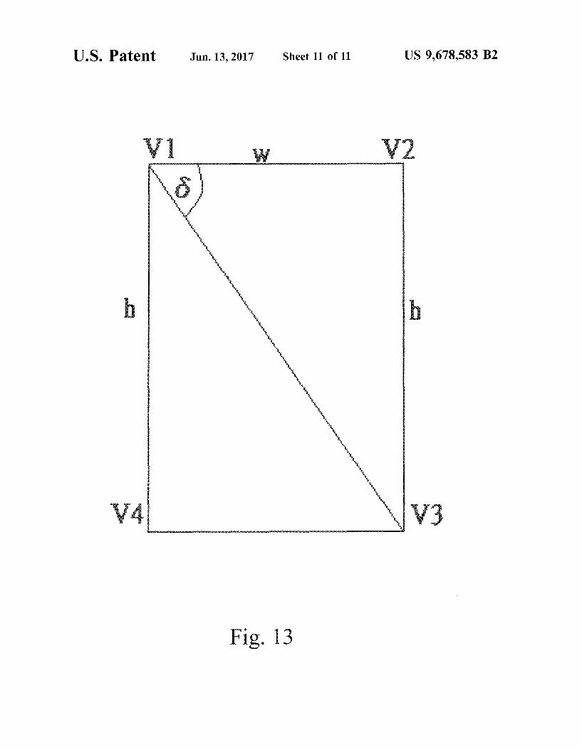
FIG. 13 schematically depicts an angle ll between OF 1 and OF 3 , which is the same as the angle between V 1 V 2 and v1v3.
DETAILED DESCRIPTION OF THE INVENTION
In the following detailed description of the illustrated
The computer program product includes executable instructions for determining at least a two-dimensional or three-dimensional position and/or a motion and/or an ori- 15
entation of the at least one pointing/input device from digital data of the plurality of sequential image frames providing views of at least one activated light source of the first set, the second set, and the third set of light sources held and/or moved within a field of view of the imaging device, and for 20
rendering on the graphical user interface a visual marker corresponding to the determined position and/or the motion and/or the orientation of the at least one pointing/input device. The imaging device may be a conventional web cam. Computer-executable instructions of the computer program 25
product map an activation pattern of one or more light sources of the first, second, and third sets oflight sources to predetermined pointing and input commands, and to a three-dimensional position and/or motion of the pointing/ input device. 30 embodiments, reference is made to the accompanying draw
ings that form a part hereof, and in which is shown by way of illustration, specific embodiments in which the invention may be practiced. These embodiments are described in
These and other embodiments, aspects, advantages, and features of the present invention will be set forth in the description which follows, and in part will become apparent to those of ordinary skill in the art by reference to the following description of the invention and referenced draw- 35
ings or by practice of the invention. The aspects, advantages, and features of the invention are realized and attained by means of the instrumentalities, procedures, and combinations particularly pointed out in the appended claims. Unless otherwise indicated, any patent and/or non-patent citations 40
discussed herein are specifically incorporated by reference
sufficient detail to enable those skilled in the art to practice the invention. Also, it is to be understood that other embodiments may be utilized and that process, reagent, materials, software, and/or other changes may be made without departing from the scope of the present invention.
The present disclosure relates to a human-computer interaction system 10 that allows 2D and 3D pointing operations in air mode, i.e. without any requirement for translating a pointing device over a surface and measuring a distance displacement thereof. The system 10 comprises a specialized pointing/input device 14, an imaging device 12, and at
in their entirety into the present disclosure.
BRIEF DESCRIPTION OF THE DRAWINGS
The accompanying drawings incorporated in and forming a part of the specification, illustrate several aspects of the present invention, and together with the description serve to explain the principles of the invention. In the drawings:
FIG. 1 shows a side view of a prior art optoelectronic mouse including an integrated digital camera;
FIG. 2 depicts a human-computer interaction system according to the present disclosure using a stand-alone webcam as an imaging device;
FIG. 3 depicts a human-computer interaction system according to the present disclosure using an embedded webcam as an imaging device;
FIG. 4 shows a front perspective view of a pointing/input device according to the present disclosure;
FIG. 5 shows a bottom perspective view of the pointing/ input device of FIG. 4;
FIG. 6 shows an enlarged view of the pointing/input device of FIG. 5;
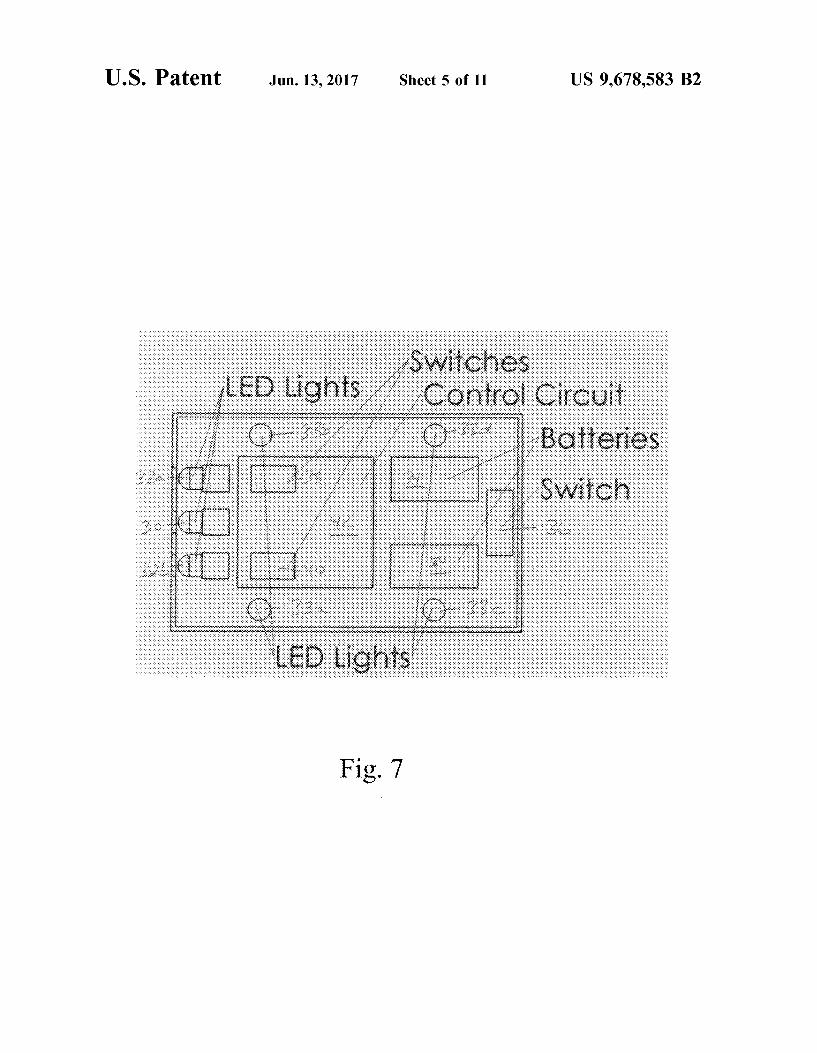
FIG. 7 depicts schematically a top view of a control mechanism for the pointing/input device of FIG. 4;
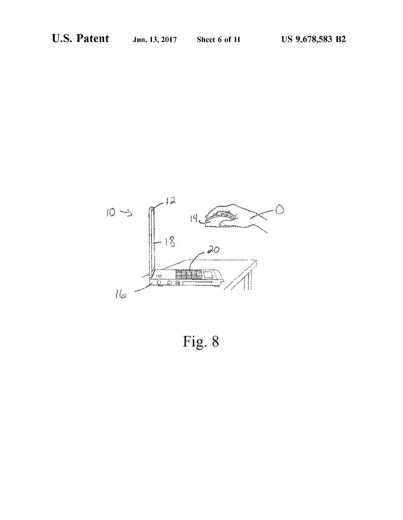
FIG. 8 shows a user holding the pointing/input device of FIG. 4 in a field of view of the imaging device of the
45 least one light tracking computer program. The imaging device 12 may be connected as a separate peripheral to a computing device 16 by wired means such as universal serial bus (USB) cables 17 (see FIG. 2), or by wireless means such as a USB receiver that receives a signal sent by
50 a wireless imaging device 12 (not shown). Alternatively, the imaging device 12 may be provided as an embedded or integrated attachment to a computing device 16 (see FIG. 3). The computing device 16 includes a graphical user interface 18, such as a conventional 2D or 3D screen, and an input
55 means such as a keyboard 20. The imaging device 12 is typically a single lens imager
such as a conventional webcam, although use of multi-view imaging devices is contemplated. The imaging device 12 includes a digital video recorder operatively coupled to an
60 image sensor which encodes images for later decoding by the computing device 16. Any suitable video recorder which is or can be configured for use with computing devices 16 is contemplated, such as a conventional webcam or other recorder or recorder configuration for providing digital data
65 representative of captured image frames showing a particular view. A number of suitable image sensors are known in the art and are contemplated for inclusion in the present
US 9,678,583 B2 7
system 10, including without limitation conventional charge-coupled device (CCD) or complementary metal oxide semiconductor (CMOS) technology. The resolution of the imaging device 12 will typically be at least VGA level, i.e., 640x480, although it may be higher.
In one exemplary embodiment, the imaging device 12 is installed as a component of or a peripheral to a keyboard of
8 colors. For example, a green point light source set 30 could be provided when an RGB (red-green-blue) color model is used. In such an instance, image frames would be converted into an HSV (hue, saturation, and value) color model, i.e. a cylindrical-coordinate representation of the RGB color model, and an intensity of the new color in the image could be computed. The light sources may actually emit light of a wavelength defining the desired color, or may be covered by a suitable cover that will cause the emitted light to be in the
a computing device 16 such as a laptop or notebook computer (see FIGS. 2-3). Of course, the skilled artisan will appreciate that the system 10 can be integrated as a component of or provided as a peripheral for any known or to-be-developed computing device 16, including without limitation desktop or laptop computers, other portable computers, tablet computers, smartphones, personal digital assistants (PDAs), Web-enabled or so-called "smart" televisions, and the like.
10 desired color. Slots 35 are defined in housing 22 (see FIGS. 4-6). As will
be discussed in greater detail below, this allows activated light sources from first set 30 and second set 32 to be visible to an imaging device 12 regardless of whether the pointing/
In one embodiment (see FIGS. 4-6), the pointing/input device 14 substantially resembles a conventional pointing device in its exterior configuration, including a housing 22,
15 input device 14 is disposed with the first surface facing the imaging device 12 or the second surface facing the imaging device 12.
a right button 24, and a left button 26. The familiar scroll 20
wheel is replaced by an actuator 28. In terms of its pointing/ input functions, the pointing/input device 14 typically functions wirelessly as will be described in greater detail below. That is, the pointing/input device 14 is typically not directly operatively connected with the imaging device 12 or the 25
computing device 16, i.e. is not "hard-wired" thereto nor specifically configured to send a specialized signal thereto. However, it will be appreciated that some use of wiring/ cabling is contemplated. For example, a USB or other cable may connect the pointing/input device 14 to the computing 30
device 16, to provide a power source for the operation of the pointing/input device 14. Alternatively, a power source such as one or more batteries may be internally included (see FIG. 7) in the pointing/input device 14.
The pointing/input device 14 includes a series of actuable 35
light sources which when actuated allow the system 10 to interpret various patterns of activated light sources or sets of light sources as specific pointing or input commands. In an embodiment, a first set of light sources 30 and a second set of light sources 32 are provided on a first surface of the 40
pointing/input device 14. The individual light sources of first and second sets 30, 32 may be aligned one with another as shown in FIG. 4. The first set 30 is configured to emit light of a first predetermined color, and the second set 32 is configured to emit light of a second predetermined color that 45
is different from the first predetermined color. Use of LED lights as the light sources is contemplated, although it will be appreciated that LED lights are only one non-limiting example of potential structures serving as first and second point light source sets 30, 32, and that other suitable light 50
sources emitting visible or non-visible light wavelengths are contemplated for use. A third set 33 of light sources is provided disposed on a second surface of the housing 22 (see FIG. 5-6). The third set 33 is configured to emit light of a color which may be the same as or different from the color 55
emitted by the first set 30 or the second set 32 of light sources.
In an embodiment, first light source 30 emits a blue light color, and second light source set 32 and third light source set 33 emit light a red light color, since the light wavelengths 60
for red (450-495 nm) and blue (620-750 nm) are at nearly opposite ends of the visible light spectrum (380-750 nm) and so can readily be distinguished by the computer program products that will be discussed in greater detail below.
However, use of other colors is contemplated, and the 65
skilled artisan can readily derive the corresponding wavelengths of the visible spectrum corresponding to alternative
The pointing/input device 14 also includes various interior mechanisms, including batteries 34 (or an alternative power source as described above), main switch 36 and additional switches 38 and 40, and various circuits (shown generally as control circuit 42) (see FIG. 7). The batteries 34 provide power to the light source sets 30, 32, 33 via control circuit 42, and the switches 36, 38, and 40 variously control the power supply to the light source sets 30, 32, 33. In an embodiment, main switch 36 provides overall control of the operating mode (two-dimensional versus three-dimensional) of the pointing/input device 14. Switch 38 controls the power supply to the right point light source of second light source 32 and switch 40 controls the power supply to the left point light source of second light source 32. Of course, this arrangement is merely representative, and alternative configurations of switches, point light sources, and circuits can readily be envisioned. The requirement is that activation of the first, second, and third sets 30, 32, 33 oflight sources and of certain individual light sources of the first, second, and third sets 30, 32, 33 of light sources may be differently controlled.
For purposes of the following examples, a light source of first set 30 will occasionally be referred to herein as blue LED 30. The light sources of second set 32 occasionally will be referred to as red LEDs 32a, 32b. The light sources of third set 33 will occasionally be referred to as red LEDs 33a, 33b, 33c, 33d. The various calculations and computations will be tied to use of red and blue point light sources as described. However, as discussed above alternate colors are contemplated and alternate types of light sources may be easily adapted to the invention, and so are contemplated for use herein.
As surnn1arized above, the pointing/input device 14 is adapted for both 2D and 3D pointing. For 2D pointing mode, the operator 0 activates the imaging device 12 and the pointing/input device 14 in 2D mode using button 28 which activates switch 36. This activates blue LED 30. The operator 0 then holds the pointing/input device 14 in his/her hand with the first surface (in the depicted embodiment, the front side) of the device facing and within a vertical and horizontal field of view of the imaging device 12, as shown in FIG. 8.
The operator 0 moves the screen cursor (not shown) around by moving the pointing/input device 14 around in 3D space, and conveniently performs clicking or dragging operations by pushing/holding the corresponding buttons 24, 26, similar to performing those operations using a conventional computer mouse. The operator 0 can control the screen cursor and move it in any desired direction as long as the first and second light source sets 30, 32 of the pointing/
US 9,678,583 B2 9
input device 14 are facing the imaging device 12 and the pointing/input device 14 is within the horizontal and vertical fields of view of the imaging device 12. When the operator moves the pointing/input device 14 in the air, the images taken by the imaging device 12 will be processed by one or more computer program products to determine a location of the LED 30. That information is then used to determine the location of a cursor (not shown) displayed on graphical user interface 18.
Computer program product(s) and calculations for performing this tracking job for 2D pointing are described in detail in co-pending U.S. utility patent application Ser. No. 14/089,881 for "Algorithms, software, and an interaction system that support the operation of an on the fly mouse," the entirety of which is incorporated herein by reference. Briefly, one or more computer program products include executable instructions for calculating a position of activated blue LED 30 in a captured image including a view of the pointing/input device 14, and mapping that LED 30 position to a corresponding visual marker position in a graphical user interface 18. Acquired digital image frames are converted to digital data by an imaging device 12 sensor, and analyzed to determine regions of increased color intensity corresponding to a position of the LED 30 in the image frame. The data may be subjected to one or more filtering steps to remove areas
10 device 14 in 2D mode except these functions are performed in the air, instead of requiring a surface over which the device 14 is translated.
For operation of the pointing/input device in 3D mode, in the depicted embodiment operator 0 places the pointing/ input device 14 in 3D mode using button 28. This action deactivates first light set 30 and activates third light source set 33, which in the depicted embodiment emit light having a red color. Operator 0 then holds pointing/input device 14
10 with the second surface (in the depicted embodiment, the bottom surface) in which third light source set 33 is disposed facing a field of view of the imaging device 12 (see FIG. 9). The computer program products of the system 10 can now analyze sequential image frames captured and converted to
15 digital data by the imaging device 12 to compute a 3D depth of the pointing/input device 14 and from that information also an angle of the pointing device (with respect to an xz-plane) in each captured image frame. Therefore, by moving the pointing/input device 14 in three-dimensional
20 space, information regarding the depth and angle of the pointing/input device 14 can be input to the computing device 16 and interpreted to control, for instance, the dimension of a window or a drawing, or the orientation of an object or a photo, as rendered on a graphical user interface 18. The
25 process of computing a 3D depth and/or angle of pointing/ input device 14 including aligned point light sources is described in detail below. of lesser color intensity, and to remove areas displaying a
color that is other than the predetermined blue color of LED 30. Data representative of a location of the LED 30 are scaled in a non-linear fashion to render a visual marker such 30
When in 3D mode, the above-summarized 2D "click," "double click," and "drag" commands are interpreted similarly because second light source set 32 is visible to the imaging device 12 through slots 35 and so can detect as a cursor on the graphical user interface 18, corresponding
to a calculated position and/or motion of the LED 30 moved in three-dimensional space.
The use of the pointing/input device 14 for left click, right click, drag, etc. operations will now be described. For a left click operation, actuating left button 26 of pointing/input device 14 actuates left switch 40 which in tum actuates a left LED 32b of the second set of light sources 32, which as noted above in the depicted embodiment emits a red light. The left LED 32b will remain in an "on" status as long as the left button 26 is not released. Therefore, by processing the corresponding images including an activated blue LED 30 and an activated red left LED 32b, the pointing computer programs interpret the combination of activated point light sources and the length of time of activation of! eft LED 32b as a left click command, a double click command, or a drag command. Right click functions are performed and processed similarly, except that operator 0 actuates right button 24 to activate right (red) LED 32a.
It will be appreciated that the two red LEDs 32a, 32b are not activated simultaneously, therefore the software differentiates left click and right click commands by the position (in a captured image) of the activated red LED relative to the activated blue LED 30. Thus, activation of the left-side (relative to the blue LED 30) red LED 32b is interpreted as a left click command, and activation of the right side LED 32a is interpreted as a right click command. To execute a double click command, it is required only to detect a "click," i.e. a separate event of activating a point light source, twice within a constant predetermined time period, for example 100 ms. In an embodiment, the following actions are interpreted as a drag command: (a) activate left (red) LED 32a;
activation of one or more of the light sources of second light source set 32. Left/right click and drag commands are still performed by pushing and holding the left button 26 or right
35 button 24, respectively, of the pointing/input device 14. However, many additional three-dimensional operations are possible because eighteen attribute parameters are provided to the computing device 16. When pointing/input device 14 is in 3D mode, a position of the pointing/input device 14
40 (and therefore a location of a screen cursor; not shown) is not determined by light source set 30 as is the case for 2D mode, since light source 30 is deactivated. Instead, a position of the pointing/input device 14 (and therefore a location of a screen cursor; not shown) is determined by one of the
45 light sources of third light source set 33, in the depicted embodiment light source 33a (see FIG. 6).
Exemplary calculations used by the one or more computer program products for using captured images showing the variously actuated point light sources of the first, second,
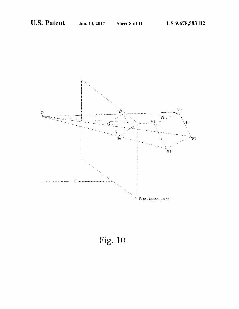
50 and third sets 30, 32, 33 of light sources will now be described. For this process, one assumption is that a pinhole of the imaging device 12 (0) is the center of perspective projection (see FIG. 10); P, a sensor plane of the imaging device 12, is the projection plane; V,=(X,, Y,, Z,), i=1, 2, 3,
55 4 are the to-be-determined coordinates of the third set 33 of light sources 33a, 33b, 33c, 33d; V,=(x,, y,, z,), i=1, 2, 3, 4 are the known projections ofV,=(X,, Z,), i=1, 2, 3, 4 on the projection plane. The computation process is shown below.
Certain variables in the calculations are as follows: 60 Given:
O~(O,O,O): center of projection
(b) track the activated left (red) LED 32a; and (c) inactivate left (red) LED 32a. The process of tracking an activated red light source is substantially as described supra for tracking 65
the blue LED 30. Hence, all familiar pointing functions of a computer mouse can be performed by the pointing/input
V 1V2V3V4 : a rectangle with vertices V,=(x,, y,, z,), i=1, 2, 3, 4. The width and height of the rectangle are w and h, respectively.
P: projection plane. The distance between 0 and P is f. Here we assume 0 is the origin of a three-dimensional
US 9,678,583 B2 11
coordinate system and the projection plane is perpendicular to the z-axis of the coordinate system at the point (0, 0, -f).
V,: projection ofV, on the projection plane P; V,=(X,, y,, -f).
To calculate V, from V,, i=l, 2, 3, 4 (see FIG. 11 for an illustration of the given condition), in one case an assumption is made that none of the edges of the rectangle V 1V2V3V4 are parallel to the projection plane P. Without loss of generality, we assume V 1 is closer to the projection 10
plane than the other three vertices of the rectangle. In this case, if we extend v1v2 and v3v4 to the right, the lines would intersect. Let the intersection point be F 1 =( a1 , b u -f). F1 is called a vanishing point. Since Y 1 , Y2 , Y3 and Y4 are known to us, a1 and b1 are computable. ThatV1V2V3 is not 15
parallel to perpendicular to the projection plane P means that Y 1 , Y2 and Y3 are not coinciding, i.e., Y 1>'Y2 >'Y3 . Since Y 1 ,
Y2 and V3 are known, the distance between Y 1 and Y2 , and the distance between v2 and v3 can be computed.
Similarly, extending Y 1Y4 and Y2Y3 , the lines would intersect at a point at the bottom (see FIG. 11). Let the intersection point be named F2 =(a2 , b2 , -f). F2 is also a vanishing point and the coordinates a2 and b2 are computable.
Since the line OF 1 is parallel to V 1 V 2 and the line OF 2 is parallel to V 1V4 , the angle between OF 1 and OF2 is 90°, consequently, we have
(1)
20
25
What this means is, the distance between 0 and the projec- 30
tion plane does not have to be given to us, because f can be computed from (1) as follows:
(2)
With the information on F u F 2 and f, we can compute V 1 , 35
V2 , V3 and V4 now. First, we know that
(3)
12 By substituting the expression for t2 in (8) into ( 6), we get
GJW (jXJ + ---,=====
~ ay +by+ j2
If x1 * x2 , we get
(X2- GJ)W t1 = and
(xi -x2)~ay +by+ J2
(9)
(10)
Consequently, we can use (3) to get V 1 , (4) or (5) to get V2 . Once we have Yu we can use the following equations to get V3 and then V4 :
OF2 (11) v, = V1 + -=--h
IOF2I
OF1 (12) V4 = v, + -=--w
IOF1I
So locations of all four vertices of the rectangle are known to us now.
In a second case, Y 1Y2 is not parallel to Y4Y3 , but Y 1Y4
is parallel to Y2Y3 (see FIG.12). This case means V2V3 and V 1 V 4 are parallel to the projection plane but V 1 V 2 and V 3 V 4
are not. Without loss of generality, we assume that V 2 V 3 and V 1 V 4 are also parallel to the y-axis. In this case, like the previous case, if we extend Y 1Y2 and Y4 Y3 , we get a vanishing point F 1 =(au b1 , -f), the intersection point ofY1
Y2 and Y4Y3 , but we don't get an intersection point for Y 1
Y4 and Y2Y3 . However, in this case, if we connect Y 1 and v3 with a line and extend this line, it would intersect the for some positive parameter t1 . Since OF 1 1s parallel to
V 1 V 2 , V 2 can be expressed as
(4)
40 vertical line that passes through F 1 (see FIG. 14). The intersection point is also a vanishing point. We will call this vanishing point F3 . It is obvious that F3=(au d, -f) where d is to be determined. Note that
where w is the width of the rectangle V 1 V 2 V 3 V 4 and IOF 1 1
is the norm of the vector OF 1 . On the other hand, V 2 must be a point on the ray defined by 0 and Y2 , i.e.,
45
Y3- YI d- YI
(5) 50 Hence, we have
for some positive parameter t2 . Hence, from (3), ( 4) and (5), we have
GJW f1X1 + = t2X2
~ ay +by+ j2
(6)
b1W (7) f1Y1 + = t2Y2
~ ay +by+ j2
(8)
(13)
55
On the other hand, since OF 1 is parallel to V 1 V 2 and OF 3
is parallel to V 1V3 , the angle between OF 1 and OF3 is the same as the angle between v1v2 and v1v3 which is 0 (see
60 FIG. 13), therefore, the inner product of OF1 and OF3
satisfies the following equation a/+b1d+f2=Ya/+b/+f2 *
Ya/+d2 +f*cos o
65 or
(a 12 +b 1 d+/)~( a 1
2 +b 12 +/)(a 1
2 +d2 +/)cos2 6
US 9,678,583 B2 13
This equation is equivalent to
(a 14 sin2 0+b? sin20+2a/b 1d-a/d2 cos20-a?b/
cos21>)+(2a/ sin2 1>+2b 1d-b/ cos21>-d2 cos21>lf+ sin21>/~o
Let
14 "smart" television, and the like in either 2D or 3D mode, transitioning between these modes by simple switch actuations. Still further, the system of the present disclosure can be readily retrofitted to existing computing devices as long as the devices support operation of an integrated or peripheral imaging device such as a webcam.
C=a/ sin20+b/d2 sin2 0+2a?b 1d-a/d2 cos20-a12b/ cos20
One of ordinary skill in the art will recognize that additional embodiments of the invention are also possible without departing from the teachings herein. Thus, the foregoing
10 description is presented for purposes of illustration and description of the various aspects of the invention, and one of ordinary skill in the art will recognize that additional embodiments of the invention are possible without departing
Then (14) can be written as
Arl+Bt+C~O
Solving the above equation provides:
15 from the teachings herein. This detailed description, and particularly the specific details of the exemplary embodiments, is given primarily for clarity of understanding, and no unnecessary limitations are to be imported, for modifications will become obvious to those skilled in the art upon reading
2 -B±..JB2 -4AC f = t = ----,2;-;A __ _
20 this disclosure and may be made without departing from the spirit or scope of the invention. Relatively apparent modifications, of course, include combining the various features of one or more figures with the features of one or more of other figures. All such modifications and variations are
Take the positive root and then take its square root to getf. Once we have information on F 1 , F 3 and f, we can compute V 1 , V 2 , V 3 and V 4 using an approach similar to the one used in Case 1.
25 within the scope of the invention as determined by the appended claims when interpreted in accordance with the breadth to which they are fairly, legally and equitably entitled.
In a third case, V 1V2 is parallel to V4V3 and V 1V4 is parallel to V 2 Vy In this case, the problem is nnsolvable. One 30
needs to perturb the rectangle V 1V2V3V4 a little bit to get into either Case 1 or Case 2, and then proceed.
Thus, by use of digital data rendered from captured images including the activated light sources variously of first light source set 30, second light source set 32, and third light 35
source set 33, a depth and/or orientation of pointing/input device 14 in 3D space may be calculated as described and rendered as a cursor on a graphical user interface 18. Particular combinations of activated light sources of second set 32 are interpreted as particular pointing or command 40
inputs of the pointing/input device 14 as described, and rendered on a graphical user interface 18 of a computing device 16.
Summarizing, the present disclosure provides a pointing/ input system including an input or pointing device 14 which 45
allows pointing and command input in 2D and 3D mode, without requiring a direct connection to a computing device 16 or a surface over which pointing/input device 14 must be translated. All standard functions of the pointing/input device 14 such as left click, right click, drag and drop, etc. 50
are performed using buttons and actions corresponding to those with which a user of a conventional computer mouse is familiar. The pointing/input device 14 is inexpensive and simple, requiring only sets of aligned visible point light sources and simple circuitry. Advantageously, the disclosed 55
system 10 is likewise economical and simple, and many elements of the system are likely already available in many homes but for the pointing/input device 14 and software. But for the pointing/input device 14 and software, for additional hardware the system 10 requires only a computing device 16 60
and a conventional imaging device 12 such as a standard webcam, and has no requirement for any specific wired or wireless connection (such as wiring or cabling, or a specialized IR or other signal) between the pointing/input device 14 and the imaging device 12. Exemplary advantages of the 65
disclosed system include allowing an operator to point and/or input gesture commands to a computing device, a
What is claimed is: 1. A pointing/input device for effecting two-dimensional
and three-dimensional pointing and/or command input using a single imaging device operatively connected to a computing device having at least one processor and at least one memory, comprising:
a housing; a first set oflight sources disposed on a first surface of the
housing, at least one light source of the first set emitting a first light color when activated;
a second set of light sources disposed on the first surface of the housing, the second set emitting a second light color when activated that is different from the first color;
a third set of light sources disposed on a second surface of the housing, the third set emitting a light color when activated that may be the same as or different from the first or second color; and
one or more actuators for differently activating one or more of the light sources of the first, second, and third sets of light sources to provide a plurality of light source activation patterns corresponding to a plurality of pointing and/or input commands.
2. The pointing/input device of claim 1, wherein the first color is blue and the second color is red.
3. The pointing/input device of claim 1, including an actuator for activating the first set of light sources.
4. The pointing/input device of claim 1, including an actuator for activating the second set of light sources.
5. The pointing/input device of claim 1, including an actuator for activating the third set of light sources that may be the same as or different from the actuator for activating the first set of light sources.
6. The pointing/input device of claim 1, wherein light emitted by the first set and second set of light sources is visible to an imaging device when either of the first surface of the housing or the second surface of the housing is facing a field of view of the imaging device.
US 9,678,583 B2 15
7. In a computing system environment, a method for two-dimensional and three-dimensional pointing and/or command input, comprising:
16 11. The method of claim 7, including calculating from the
captured plurality of sequential image frames at least a spatial and a velocity parameter of the at least one pointing/ input device when moved through three-dimensional space and rendering on the graphical user interface a visual marker corresponding to the calculated spatial and velocity parameter of the at least one pointing/input device.
providing at least one pointing/input device including a first set of light sources emitting a first light color when activated, a second set of light sources emitting a second light color when activated that is different from the first color, and a third set of light sources emitting 12. The method of claim 11, including providing at least
one computer program product comprising executable 10 instructions operable on the computing device, for calculat
ing from the captured image frames at least the spatial and velocity parameters of the at least one pointing/input device.
13. A computing system for tracking a motion and/or an orientation of a pointing/input device, comprising:
a light color that may be the same as or different from the first or second color, the pointing/input device further including one or more actuators for differently activating one or more of the light sources of the first, second, and third sets of light sources to provide a plurality oflight source activation patterns correspond-
15 ing to a plurality of pointing and/or input commands;
while actuating the one or more actuators to provide the plurality of light source activation patterns, holding and/or moving the at least one pointing/input device within a field of view of an imaging device operably 20
connected to a computing device having at least one processor, at least one memory, and at least one graphi-cal user interface;
by the imaging device, capturing a plurality of sequential image frames each including a view of the at least one 25
pointing/input device having at least one light source of the first set, the second set, and/or the third set of light sources activated to emit light;
from one or more views of at least one of the first set, the second set, and/or the third set of light sources in the 30
captured plurality of sequential image frames, calculating a two-dimensional or a three-dimensional position and/or motion and/or orientation of the at least one pointing/input device; and
rendering a visual marker on the graphical user interface 35
corresponding to the calculated position and/or motion and/or orientation of the at least one pointing/input device.
8. The method of claim 7, further including mapping an activation pattern of the first set and/or the second set and/or 40
the third set of light sources to a predetermined pointing and/or input command.
9. The method of claim 7, including mapping and displaying in the graphical user interface a three-dimensional position and/or motion and/or orientation of the at least one 45
pointing/input device, comprising: determining a three-dimensional coordinate of each acti
vated light source of the third set of light sources in each of said plurality of sequential image frames;
converting the determined three-dimensional coordinate 50
into a three-dimensional position of the visual marker in the graphical user interface; and
displaying the three-dimensional position of the visual marker in the graphical user interface.
10. The method of claim 9, further including determining 55
the three-dimensional coordinate by: calculating a depth of each activated light source of the
third set of light sources with respect to a pre-determined origin of a three-dimensional coordinate system;
calculating an angle of a light beam emitted by each 60
activated light source of the third set of light sources with respect to a projection plane defining a plane perpendicular to a z-axis of the three-dimensional coordinate system; and
determining a three-dimensional coordinate and orienta- 65
tion of the at least one pointing/input device from said calculated depth and angle.
a computing device having at least one processor, at least one memory, and at least one graphical user interface;
at least one pointing/input device according to claim 1; an imaging device operably linked to the computing
device and configured for capturing a plurality of sequential image frames; and
at least one computer program product operable on the computing device processor, the at least one computer program product including executable instructions for determining at least a two-dimensional or three-dimensional position and/or a motion and/or an orientation of the at least one pointing/input device from digital data of the plurality of sequential image frames providing views of at least one activated light source of the first set, the second set, and the third set oflight sources held and/or moved within a field of view of the imaging device, and for rendering on the graphical user interface a visual marker corresponding to the determined position and/or the motion and/or the orientation of the at least one pointing/input device.
14. The system of claim 13, wherein the imaging device is a web cam.
15. The system of claim 13, wherein the at least one computer program product includes executable instructions for mapping an activation pattern of at least one light source of the first set and/or the second set and/or the third set of light sources to a predetermined pointing and/or input com-mand.
16. The system of claim 15, wherein the at least one computer program product further includes executable instructions for mapping and displaying in the graphical user interface a three-dimensional position and/or motion of the at least one pointing/input device, comprising:
determining a three-dimensional coordinate of each activated light source of the third set of light sources in each of said plurality of sequential image frames;
converting the determined three-dimensional coordinate into a three-dimensional position of the visual marker in the graphical user interface; and
displaying the three-dimensional position of the visual marker in the graphical user interface.
17. The system of claim 16, wherein the at least one computer program product includes executable instructions for determining the three-dimensional coordinate in each of said plurality of sequential image frames by:
calculating a depth of each activated light source of the third set of light sources with respect to a pre-deter-mined origin of a three-dimensional coordinate system;
calculating an angle of a light beam emitted by each activated light source of the third set of light sources with respect to a projection plane defining a plane perpendicular to a z-axis of the three-dimensional coor-dinate system; and

US 9,678,583 B2 17
determining a three-dimensional coordinate and orientation of the at least one pointing/input device from said calculated depth and angle.
* * * * *
18