23 July, 2014 TransAsia Airways Flight GE222 ATR72-212A ...
382
23 July, 2014 TransAsia Airways Flight GE222 ATR72-212A, B-22810 Impacted Terrain and Collided with a Residential Area Northeast of the Threshold of Runway 20 at Magong Airport ASC-AOR-16-01-002 Aviation Occurrence Report
-
Upload
khangminh22 -
Category
Documents
-
view
2 -
download
0
Transcript of 23 July, 2014 TransAsia Airways Flight GE222 ATR72-212A ...

23 July, 2014
TransAsia Airways Flight GE222
ATR72-212A, B-22810
Impacted Terrain and Collided
with a Residential Area
Northeast of the Threshold of Runway 20
at Magong Airport
ASC-AOR-16-01-002
11 Floor, 200, Section 3, Beixin Road, Xindian District,231 New Taipei City, Taiwan (R.O.C.)
t h
TEL (02)89127388FAX (02)89127399URL http://www.asc.gov.tw
23
Ju
ly,
2014,
Tra
ns
Asia
Airw
ays
Flig
ht
GE
222
AT
R72-2
12A
,
B-2
2810
Imp
acte
dTerra
inan
dC
ollid
ed
with
aR
esid
en
tial
Are
a
No
rtheast
of
the
Th
resh
old
of
Ru
nw
ay
20
at
Mag
on
gA
irpo
rt
Aviation Occurrence Report
Aviatio
nO
ccurren
ceR
epo
rt
GPN:4910500148
ISBN 978-986-04-7990-4
9 7 8 9 8 6 0 4 7 9 9 0 4
Aviation Occurrence Report ASC-AOR-16-01-002 23 July, 2014TransAsia Airways Flight GE222ATR72-212A, B-22810Impacted Terrain and Collided with a Residential AreaNortheast of the Threshold of Runway 20 at Magong Airport
AVIATION SAFETY COUNCIL

Aviation Occurrence Report: 23 July 2014, Trans Asia Airways Flight GE222,
ATR72-212A, B-22810, Impacted Terrain and Collided with a Residential Area,
Northeast of the Threshold of Runway 20 at Magong Airport
Edited and published by Aviation Safety Council
11F, No.200, Sec.3, Beisin Rd., Sindian City.
Taipei County 231, Taiwan, R.O.C.
Tel: +886-2-8912-7388
Fax: +886-2-8912-7399
http://www.asc.gov.tw
GPN : 4910500148
ISBN : 9789860479904
First printing, January, 2016
Copyright 2016 by Aviation Safety Council

According to the Aviation Occurrence Investigation Act of the Republic of China and the International Civil Aviation Organization (ICAO) Annex 13, this report is only for the improvements of flight safety.
Aviation Occurrence Investigation Act of the Republic of China, Article 5
The objective of the ASC‘s investigation of aviation occurrence is to prevent
recurrence of similar occurrences. It is not the purpose of such investigation to
apportion blame or liability.
ICAO Annex 13, Chapter 3, Section 3.1
The sole objective of the investigation of an accident or incident shall be the
prevention of accidents and incidents. It is not the purpose of this activity to apportion
blame or liability.
This report is written in both Chinese and English.

Intentionally left blank

Executive Summary
I
Executive Summary
On 23 July 2014, an ATR-GIE Avions de Transport Régional ATR72-212A
(ATR72) aircraft, registered B-22810, TransAsia Airways (TNA) flight GE222, with
two pilots, two cabin crew, and 54 passengers, was being operated on an instrument
flight rules (IFR) regular public transport service from Kaohsiung to Magong in the
Penghu archipelago. At 1906 Taipei Local Time, the aircraft impacted terrain
approximately 850 meters northeast of the threshold of runway 20 at Magong Airport
and then collided with a residential area on the outskirts of Xixi village approximately
200 meters to the southeast of the initial impact zone. At the time of the occurrence, the
crew was conducting a very high frequency omni-directional radio range (VOR)
non-precision approach to runway 20. The aircraft was destroyed by impact forces and
a post-impact fire. Ten passengers survived the occurrence and five residents on the
ground sustained minor injuries.
The occurrence was the result of controlled flight into terrain, that is, an airworthy
aircraft under the control of the flight crew was flown unintentionally into terrain with
limited awareness by the crew of the aircraft’s proximity to terrain. The crew continued
the approach below the minimum descent altitude (MDA) when they were not visual
with the runway environment contrary to standard operating procedures. The
investigation report identified a range of contributing and other safety factors relating
to the flight crew of the aircraft, TransAsia’s flight operations and safety management
processes, the communication of weather information to the flight crew, coordination
issues at civil/military joint-use airport, and the regulatory oversight of TransAsia by
the Civil Aeronautics Administration (CAA).
This investigation identified important learning opportunities for pilots, operators
and regulatory agencies to improve future aviation safety and to seek to ensure such an
accident never happen again. The Aviation Safety Council (ASC) has issued a series of

Aviation Occurrence Report
II
safety recommendations to TransAsia Airways, CAA, and the military to correct the
safety deficiencies identified during the investigation.
According to Article 6 of the Republic of China (ROC) Aviation Occurrence
Investigation Act, and the content of Annex 13 to the Convention on International Civil
Aviation, the ASC, an independent aviation occurrence investigation agency, was
responsible for conducting the investigation. The investigation team also included
members from BEA (Bureau d'Enquêtes et d'Analyses, France), TSB (Transportation
Safety Board, Canada), NTSB (National Transportation Safety Board, USA), ATR
(Avions de Transport Régional), P&WC (Pratt & Whitney Canada), Honeywell
Aerospace/USA, CAA Taiwan, Ministry of National Defense ROC, and TNA.
The ‘Final Draft Report’ of the occurrence investigation was completed in July
2015. In accordance with the procedures, it was reviewed at ASC’s 35th Council
Meeting on 29 July 2015 and then sent to relevant organizations and authorities for
comments. After comments were collected and integrated, the English version of the
investigation report was reviewed and approved by ASC’s 39th Council Meeting on 24
November 2015. The Chinese version of the investigation report was first reviewed by
ASC’s 40th Council Meeting on 29 December 2015. With the approval of ASC’s 41st
Council Meeting on 26 January 2016, both final reports were published on 29 January
2016.
There are a total of 46 findings from the Final Report, and 29 safety
recommendations issued to the related organizations.
Findings as the result of this investigation
The ASC presents the findings derived from the factual information gathered
during the investigation and the analysis of the occurrence. The findings are presented
in three categories: findings related to probable causes, findings related to risk, and
other findings.

Executive Summary
III
The findings related to probable causes identify elements that have been shown
to have operated in the occurrence, or almost certainly operated in the occurrence.
These findings are associated with unsafe acts, unsafe conditions, or safety deficiencies
associated with safety significant events that played a major role in the circumstances
leading to the occurrence.
The findings related to risk identify elements of risk that have the potential to
degrade aviation safety. Some of the findings in this category identify unsafe acts,
unsafe conditions, and safety deficiencies including organizational and systemic risks,
that made this occurrence more likely; however, they cannot be clearly shown to have
operated in the occurrence alone. Furthermore, some of the findings in this category
identify risks that are unlikely to be related to the occurrence but, nonetheless, were
safety deficiencies that may warrant future safety actions.
Other findings identify elements that have the potential to enhance aviation
safety, resolve a controversial issue, or clarify an ambiguity point which remains to be
resolved. Some of these findings are of general interests that are often included in the
ICAO format accident reports for informational, safety awareness, education, and
improvement purposes.
Findings Related to Probable Causes
Flight Operations
1. The flight crew did not comply with the published runway 20 VOR non-precision
instrument approach procedures at Magong Airport with respect to the minimum
descent altitude (MDA). The captain, as the pilot flying, intentionally descended the
aircraft below the published MDA of 330 feet in the instrument meteorological
conditions (IMC) without obtaining the required visual references.
2. The aircraft maintained an altitude between 168 and 192 feet before and just after
overflying the missed approach point (MAPt). Both pilots spent about 13 seconds

Aviation Occurrence Report
IV
attempting to visually locate the runway environment, rather than commencing a
missed approach at or prior to the MAPt as required by the published procedures.
3. As the aircraft descended below the minimum descent altitude (MDA), it diverted to
the left of the inbound instrument approach track and its rate of descent increased as
a result of the flying pilot’s control inputs and meteorological conditions. The
aircraft’s hazardous flight path was not detected and corrected by the crew in due
time to avoid the collision with the terrain, suggesting that the crew lost situational
awareness about the aircraft’s position during the latter stages of the approach.
4. During the final approach, the heavy rain and associated thunderstorm activity
intensified producing a maximum rainfall of 1.8 mm per minute. The runway visual
range (RVR) subsequently reduced to approximately 500 meters. The degraded
visibility significantly reduced the likelihood that the flight crew could have
acquired the visual references to the runway environment during the approach.
5. Flight crew coordination, communication, and threat and error management were
less than effective. That compromised the safety of the flight. The first officer did
not comment about or challenge the fact that the captain had intentionally descended
the aircraft below the published minimum descent altitude (MDA). Rather, the first
officer collaborated with the captain’s intentional descent below the MDA. In
addition, the first officer did not detect the aircraft had deviated from the published
inbound instrument approach track or identify that those factors increased the risk of
a controlled flight into terrain (CFIT) event.
6. None of the flight crew recognized the need for a missed approach until the aircraft
reached the point (72 feet, 0.5 nautical mile beyond the missed approach point)
where collision with the terrain became unavoidable.
7. The aircraft was under the control of the flight crew when it collided with foliage
850 meters northeast of the runway 20 threshold, two seconds after the go around
decision had been made. The aircraft sustained significant damage and subsequently
collided with buildings in a residential area. Due to the high impact forces and

Executive Summary
V
post-impact fire, the crew and most passengers perished.
8. According to the flight recorders data, non-compliance with standard operating
procedures (SOPs) was a repeated practice during the occurrence flight. The crew’s
recurring non-compliance with SOPs constituted an operating culture in which high
risk practices were routine and considered normal.
9. The non-compliance with standard operating procedures (SOPs) breached the
obstacle clearances of the published procedure, bypassed the safety criteria and risk
controls considered in the design of the published procedures, and increased the risk
of a controlled flight into terrain (CFIT) event.
Weather
10.Magong Airport was affected by the outer rainbands of Typhoon Matmo at the time
of the occurrence. The meteorological conditions included thunderstorm activities of
heavy rain, significant changes in visibility, and changes in wind direction and
speed.
Findings Related to Risk
Flight Operations
1. The captain did not conduct a descent and approach briefing as required by standard
operating procedures (SOPs). The first officer did not question the omission of that
required briefing. That deprived the crew of an opportunity to assess and manage the
operational risks associated with the approach and landing.
2. The captain was likely overconfident in his flying skills. That might lead to his
decision to continue the approach below the minimum descent altitude (MDA)
without an appreciation of the safety risks associated with that decision.
3. The results of the fatigue analysis indicated that, at the time of the occurrence, the
captain’s performance was probably degraded by his fatigue accumulated from the
multiple sectors/day flown and flight and duty times during the months preceding
Aviation Occurrence Report
VI
the occurrence.
4. The TransAsia Airways observation flights conducted by the investigation team and
the interviews with members of the airline’s flight operations division show
prevalent tolerance for non-compliance with procedures within the airline’s ATR
fleet.
5. The non-compliances with standard operating procedures (SOPs) during the
TransAsia Airways’ ATR simulator training sessions were observed by the
investigation team but not corrected by the instructors. The tolerance for or
normalization of SOPs non-compliance behaviors was symptomatic of an ineffective
check and training system with inadequate supervision by the airline’s flight
operations management.
6. The non-compliance with standard operating procedures (SOPs) was not restricted
to the occurrence flight but was recurring, as identified by previous TransAsia
Airways ATR occurrence investigations, line observations, simulator observations,
internal and external audits or inspections, and interviews with TransAsia Airways
flight operations personnel, including managers. The non-compliant behaviors were
an enduring, systemic problem and formed a poor safety culture within the airline’s
ATR fleet.
Airline Safety Management
7. The TransAsia Airways’ inadequate risk management processes and assessments,
ineffective safety meetings, unreliable and invalid safety risk indices, questionable
senior management commitment to safety, inadequate safety promotion activities,
underdeveloped flight operations quality assurance (FOQA) system, and inadequate
safety and security office and flight operations resources and capabilities constituted
an ineffective safety management system (SMS).
8. The safety risks associated with change within the TransAsia Airways were not
assessed and mitigated. For example, the company did not assess or mitigate the
Executive Summary
VII
safety risks associated with the increase in ATR operational tempo as a result of the
recent increase in ATR fleet size and crew shortage that, in turn, elevated crew flying
activities and the potential safety risks associated with crew fatigue.
9. Findings regarding non-compliance with standard operating procedures (SOPs)
during operations by the TransAsia Airways’ ATR crews had been identified by
previous Aviation Safety Council occurrence investigations. The proposed corrective
safety actions were not implemented by the airline.
10.TransAsia Airways self-audits were mostly spot checks rather than system audits or
system self-evaluations. The self-audits failed to assess and address those safety
deficiencies, including standard operating procedures non-compliance behaviors,
lack of standardization in pilot check and training activities, and high crew flying
activities on the ATR fleet. Such deficiencies had been pointed out in previous
occurrences and audits and were considered by senior flight operations managers
as problems.
11.The TransAsia Airways annual audit plan did not include an evaluation of the
implementation and/or effectiveness of corrective actions in response to the safety
issues identified in previous audits, regulatory inspection findings, or safety
occurrence investigation recommendations. The airline’s self-audit program was
not consistent with the guidance contained in AC-120-002A.
12.The TransAsia Airways had not developed a safety management system (SMS)
implementation plan. This led to a disorganized, nonsystematic, incomplete and
ineffective implementation, which made it difficult to establish robust and resilient
safety management capabilities and functions.
13.The Civil Aeronautics Administration’s (CAA) safety management system (SMS)
assessment team had identified TransAsia Airways’ SMS deficiencies, but
TransAsia Airways failed to respond to the CAA’s corrective actions request. That
deprived the airline of an opportunity to improve the level of safety assurance in its

Aviation Occurrence Report
VIII
operations.
14.The TransAsia Airways did not implement a data-driven fatigue risk management
system (FRMS) or alternative measures to manage the operational safety risks
associated with crew fatigue due to fleet expansion and other operational factors.
15.The ATR flight operation did not include in its team a standards pilot to oversee
standard operating procedures (SOPs) compliance, SOP-related flight operations
quality assurance (FOQA) events handling, and standard operations audit (SOA)
monitoring before the GE222 occurrence.
16.The safety and security office, due to resource and capability limitations, was
unable to effectively accomplish the duties they were required to undertake.
17.The safety and security office staff was not included in the flight safety action group.
That deprived the airline of an opportunity to identify, analyze and mitigate flight
safety risks more effectively in the flight operations.
18.The TransAsia Airways’ safety management system was overly dependent on its
internal reactive safety and irregularity reporting system to develop full awareness
of the airline’s safety risks. It did not take advantage of the instructive material
from external safety information sources. That limited the capability of the system
to identify and assess safety risks.
19.The TransAsia Airways’ flight operations quality assurance (FOQA) settings and
analysis capabilities were unable to readily identify those events involving standard
operating procedures (SOPs) non-compliance during approach and likely other
stages of flight. The FOQA events were not analyzed sufficiently or effectively,
leaving some safety issues in flight operations unidentified and uncorrected. Some
problems with crew performance and reductions in safety indicated in the FOQA
trend analyses were not investigated further. Clearly, the airline’s FOQA program
was not used to facilitate proactive operational safety risk assessments.
Civil Aeronautics Administration
Executive Summary
IX
20.The Civil Aeronautics Administration’s oversight of TransAsia Airways did not
identify and/or correct some crucial operational safety deficiencies, including crew
non-compliance with procedures, non-standard training practices, and
unsatisfactory safety management practices.
21.To develop and maintain a safety management system (SMS) implementation plan
at TransAsia Airways was not enforced by the Civil Aeronautics Administration.
That deprived the regulator of an opportunity to assess and ensure that the airline
had the capability to implement a resilient SMS.
22.Issues regarding the TransAsia Airways’ crew non-compliance with standard
operating procedures (SOPs) and deficiencies with pilot check and training had
previously been identified by the Aviation Safety Council investigation reports.
However, the Civil Aeronautics Administration (CAA) did not monitor whether the
operator has implemented the recommended corrective actions; correlatively, the
CAA failed to ensure the proper measures for risk reduction have been adopted.
23.The Civil Aeronautics Administration provided limited guidance to its inspectors to
enable them to effectively and consistently evaluate the key aspects of operators’
management systems. These aspects included evaluating organizational structure
and staff resources, the suitability of key personnel, organizational change, and risk
management processes.
24.The Civil Aeronautics Administration did not have a systematic process for
determining the relative risk levels of airline operators.
Air Traffic Service and Military
25.The runway visual range (RVR) reported in the Magong aerodrome routine
meteorological reports (METAR) and the aerodrome special meteorological reports
(SPECI) was not in accordance with the requirements documented in the Air Force
Meteorological Observation Manual.
26.The discrepancies between the reported runway visual range (RVR) and automated
Aviation Occurrence Report
X
weather observation system (AWOS) RVR confused the tower controllers about the
reliability of the AWOS RVR data.
27.During the final approach, the runway 20 runway visual range (RVR) values
decreased from 1,600 meters to 800 meters and then to a low of about 500 meters.
The RVR information was not communicated to the occurrence flight crew by air
traffic control. Such information might influence the crew’s decision regarding the
continuation of the approach.
Other Findings
1. The flight crew were properly certificated and qualified in accordance with the Civil
Aeronautics Administration and company requirements. No evidence indicated any
preexisting medical conditions that might have adversely affected the flight crew’s
performance during the occurrence flight.
2. The airworthiness and maintenance of the occurrence aircraft were in compliance
with the extant civil aviation regulations. There were no aircraft, engine, or system
malfunctions that would have prevented normal operation of the aircraft.
3. All available evidence, including extensive simulations, indicated that the enhanced
ground proximity warning system (EGPWS) functioned as designed.
4. The enhanced ground proximity warning system (EGPWS) manufacturer’s latest
generation EGPWS equipment would have provided flight crews with an additional
warning if aircraft encountered similar circumstances to the occurrence flight.
Installing the latest EGPWS equipment on the occurrence aircraft would have
required approved modifications.
5. According to the Civil Aeronautics Administration (CAA) regulations, a 420 meter
simple approach lighting system should have been installed to help pilots visually
identify runway 20. The CAA advised that the Runway End Identification Lights, a
flashing white light system, was installed at the runway’s threshold as an alternative
visual aid to replace the simple approach lighting system.

Executive Summary
XI
6. From the perspective of flight operations, the location of the runway 20 VOR missed
approach point (MAPt) was not in an optimal position. With the same Obstacle
Clearance Altitude, if the MAPt had been set closer to the runway threshold, it
would have increased the likelihood of flight crews to visually locate the runway.
7. During holding, the occurrence flight crew requested the runway 02 instrument
landing system (ILS) approach after receiving the weather information that the
average wind speed for runway 02 had decreased to below the tailwind landing limit.
While the decision for the use of the reciprocal runway was still under consideration
by the Magong Air Force Base duty officer, the weather report indicated that the
visibility had improved to 1,600 meters, which met the landing visibility minimal
requirement for an approach to runway 20. The flight crew subsequently amended
their request and elected to use runway 20.
8. At the time of the occurrence, the weather information exchange and runway
availability coordination between civil and military personnel at Magong’s joint-use
airport could have been more efficient.
9. ATR’s flight data recorder (FDR) readout document contained unclear information.
That affected the efficiency of the occurrence investigation.
Safety Recommendations
To TransAsia Airways
1. Implement effective safety actions to rectify the multiple safety deficiencies
previously identified by the Aviation Safety Council investigations, internal and
external Civil Aeronautics Administration audit and inspection findings, and
deficiencies noted in this report to reduce the imminent safety risks confronting the
airline. (ASC-ASR-16-01-010)
2. Conduct a thorough review of the airline’s safety management system and flight
crew training programs, including crew resource management and threat and error
management, internal auditor training, safety management system (SMS) training

Aviation Occurrence Report
XII
and devise systematic measures to ensure:
� Flight crew check and training are standardized;
� All flight crews comply with standard operating procedures (SOPs);
� Staff who conduct audits receive appropriate professional auditor training;
� All operational and senior management staff receive SMS training, including
thorough risk assessment and management training; and
� Proportional and consistent rules, in accordance with a “Just Culture”, are
implemented to prevent flight crew from violating the well-designed SOPs and/or
being engaged in unsafe behavior.
(ASC-ASR-16-01-011)
3. Conduct a rigorous review of the safety management system (SMS) to rectify the
significant deficiencies in:
� Planning;
� Organizational structure, capability and resources;
� Risk management processes and outputs;
� Flight operations quality assurance (FOQA) limitations and operations, including
inadequate data analysis capabilities;
� Safety meetings;
� Self-audits;
� Safety performance monitoring, including risk indices;
� Safety education; and
� Senior management commitment to safety.
(ASC-ASR-16-01-012)
4. Rectify the human resources deficits in the flight operations division and the safety
and security office, including:
� Crew shortages;
� Inadequate support staff in the Flight Standards and Training Department,
including insufficient standards pilots and crew to conduct operational safety risk

Executive Summary
XIII
assessments; and
� Safety management staff with the required expertise in flight operations, safety
and flight data analytics, safety risk assessment and management, human factors,
and safety investigations.
(ASC-ASR-16-01-013)
5. Review and improve the airline’s internal compliance oversight and auditing system
and implement an effective corporate compliance and quality assurance system to
ensure that oversight activities provide the required level of safety assurance and
accountability. (ASC-ASR-16-01-014)
6. Implement an effective safety management process, such as a data-driven fatigue
risk management system (FRMS), to manage the flight safety risks associated with
crew fatigue. (ASC-ASR-16-01-015)
7. Provide flight crew with adequate fatigue management education and training,
including the provision of effective strategies to manage fatigue and performance
during operations. (ASC-ASR-16-01-016)
8. Implement an effective change management system as a part of the airline’s safety
management system (SMS) to ensure that risk assessment and mitigation activities
are formally conducted and documented before significant operational changes are
implemented, such as the introduction of new aircraft types or variants, increased
operational tempo, opening new ports, and so on. (ASC-ASR-16-01-017)
9. Implement a more advanced flight operations quality assurance (FOQA) program
with adequate training and technical support for the FOQA staff to ensure that they
can exploit the analytical capabilities of the program. As such, the FOQA staff can
more effectively identify and manage the operational safety risks confronting flight
operations. (ASC-ASR-16-01-018)
10.Implement an effective standard operating procedures (SOPs) compliance
monitoring system, such as the line operations safety audit (LOSA) program, to
help identifying threats to operational safety and to minimize the associated risks.

Aviation Occurrence Report
XIV
The system should adopt a data-driven method to assess the level of organizational
resilience to systemic threats and can detect issues such as habitual non-compliance
with SOPs. (ASC-ASR-16-01-019)
To Civil Aeronautics Administration
1. Strengthen surveillance on TransAsia Airways to assess crew’s discipline and
compliance with standard operating procedures (SOPs). (ASC-ASR-16-01-020)
2. Implement a more robust process to identify safety-related shortcomings in
operators’ operations, within an appropriate timescale, to ensure that the operators
meet and maintain the required standards. (ASC-ASR-16-01-021)
3. Provide inspectors with detailed guidance on how to evaluate the effectiveness of an
operator’s safety management system (SMS), including:
� Risk assessment and management practices;
� Change management practices;
� Flight operations quality assurance (FOQA) system and associated data analytics;
and
� Safety performance monitoring.
(ASC-ASR-16-01-022)
4. Provide inspectors with comprehensive training and development to ensure that they
can conduct risk-based surveillance and operational oversight activities effectively.
(ASC-ASR-16-01-023)
5. Enhance inspector supervision and performance evaluation to ensure all inspectors
conduct surveillance activities effectively and are able to identify and communicate
critical safety issues to their supervisors. (ASC-ASR-16-01-024)
6. Enhance the oversight of operators transitioning from traditional safety management
to safety management systems. (ASC-ASR-16-01-025)
7. Develop a systematic process for determining the relative risk levels of airline
operators. (ASC-ASR-16-01-026)

Executive Summary
XV
8. Review the current regulatory oversight surveillance program with a view to
implementing a more targeted risk-based approach for operator safety evaluations.
(ASC-ASR-16-01-027)
9. Ensure all safety recommendations issued by the occurrence investigation agency
are implemented by the operators. (ASC-ASR-16-01-028)
10. Develop detailed guidance for operators to implement effective fatigue risk
management processes and training. (ASC-ASR-16-01-29)
11. Review runway approach lighting systems in accordance with their existing radio
navigation and landing aids to ensure that adequate guidance is available for pilots
to identify the visual references to the runway environment, particularly in poor
visibility condition or at night. (ASC-ASR-16-01-030)
12. Review the design procedures for determining the location of missed approach
point with the intention of increasing the likelihood of pilots to locate the runway
without compromising the required obstacle clearance altitude.
(ASC-ASR-16-01-031)
13. Request tower controllers to advise the flight crews of aircraft on final approach of
the updated information in accordance with the provisions of the air traffic
management procedures (ATMP). (ASC-ASR-16-01-032)
14. Coordinate with Air Force Command Headquarters to review and improve the
weather information exchange and runway availability coordination between civil
air traffic control and military personnel at Magong Airport.
(ASC-ASR-16-01-033)
To ATR-GIE Avions de Transport Régional
1. Evaluate the feasibility of a modification to allow the new enhanced ground
proximity warning system (EGPWS) to be fitted on all ATR72-500 aircraft.
(ASC-ASR-16-01-034)
2. Review the flight data recorder (FDR) readout document for any erroneous
Aviation Occurrence Report
XVI
information and provide timely revisions of the manual to assist airline operators
and aviation occurrence investigation agencies. (ASC-ASR-16-01-035)
To Air Force Command Headquarters, Ministry of National Defense
1. Coordinate with the Civil Aeronautics Administration to ensure the reliability and
validity of automated weather observation system (AWOS) runway visual range
(RVR) sensors and their data. (ASC-ASR-16-01-036)
2. Conduct the runway visual range (RVR) reporting operations and requirements in
accordance with the provisions of the Air Force Meteorological Observation Manual.
(ASC-ASR-16-01-037)
3. Coordinate with the Civil Aeronautics Administration to review and improve the
weather information exchange and runway availability coordination between civil
air traffic control and military personnel at Magong Airport. (ASC-ASR-16-01-038)
Content
XVII
Contents
Executive Summary ......................................................................................................... I
Contents..................................................................................................................... XVII
Tables ..................................................................................................................... XXVII
Figures......................................................................................................................XXIX
Abbreviation.............................................................................................................XXIII
Chapter 1 Factual Information .........................................................................................1
1.1 History of Flight.............................................................................................1
1.2 Injuries to Persons ..........................................................................................5
1.2.1 Distribution of Injuries.......................................................................5
1.3 Damage to Aircraft .........................................................................................6
1.4 Other Damage ................................................................................................6
1.5 Personnel Information....................................................................................6
1.5.1 Flight Crew Background and Experience ..........................................6
1.5.1.1 Captain ...............................................................................6
1.5.1.2 First Officer........................................................................6
1.5.2 Flight Crew Training Record .............................................................7
1.5.2.1 Captain ...............................................................................7
1.5.2.2 First Officer........................................................................8
1.5.3 Flight Crew Medical Information ......................................................9
1.5.3.1 Captain ...............................................................................9
1.5.3.2 First Officer........................................................................9
1.5.4 Flight Crew Activities within 72 hours Before the Occurrence.........9
1.5.4.1 Captain ...............................................................................9
1.5.4.2 First Officer......................................................................10
1.5.5 Flight Crew Alertness and Fatigue...................................................10
1.6 Airplane Information....................................................................................12
Aviation Occurrence Report
XVIII
1.6.1 Aircraft and Engine Basic Information ........................................... 12
1.6.2 Aircraft Maintenance Records ........................................................ 13
1.6.3 Enhanced Ground Proximity Warning System ............................... 14
1.6.4 Automatic Flight Control System ................................................... 17
1.6.4.1 General ............................................................................ 17
1.6.4.2 Advisory Display Unit .................................................... 18
1.6.5 Weight and Balance Information..................................................... 18
1.7 Weather Information.................................................................................... 19
1.7.1 Synopsis .......................................................................................... 19
1.7.2 Surface Weather Observations ........................................................ 20
1.7.3 Automated Weather Observation Systems...................................... 22
1.7.4 Weather Information Summary....................................................... 25
1.7.5 Sounding Data ................................................................................. 26
1.7.6 Satellite Data ................................................................................... 27
1.7.7 Weather Radar Information............................................................. 28
1.7.8 Significant Weather Chart ............................................................... 31
1.8 Aids to Navigation ...................................................................................... 31
1.8.1 VOR/DME ...................................................................................... 31
1.9 Communication ........................................................................................... 33
1.10 Aerodrome................................................................................................... 33
1.10.1 Airside Basic Information ............................................................... 33
1.10.2 Approach and Runway Lighting Systems....................................... 34
1.10.3 Runway Lighting System................................................................ 36
1.10.4 Information from Airport CCTV..................................................... 37
1.11 Flight Recorders .......................................................................................... 38
1.11.1 Cockpit Voice Recorder................................................................... 40
1.11.2 Flight Data Recorder ....................................................................... 41
1.11.3 Other Flight Data and Radar Track Data......................................... 47

Content
XIX
1.11.3.1 GE220 Flight Data ...........................................................47
1.11.3.2 B7 647 Flight Data...........................................................47
1.11.4 Flight Path Reconstruction and Unrecorded Parameters .................48
1.11.4.1 Flight Path Reconstruction and Mapping ........................48
1.11.4.2 Unrecorded Parameters and Derived Parameters ............50
1.12 Wreckage and Impact Information...............................................................52
1.12.1 Site Survey .......................................................................................52
1.12.1.1 Terrain Profile and Height of Foliage ..............................53
1.12.2 Wreckage in Zone 1 .........................................................................55
1.12.3 Wreckage in Zone 2 .........................................................................58
1.12.4 Power Plant ......................................................................................61
1.12.4.1 Fuel and Oil Samples .......................................................66
1.13 Medical and Pathological Information.........................................................66
1.13.1 Medical Treatment of Injured ..........................................................66
1.13.2 Flight Crew Medical History ...........................................................67
1.13.3 Flight Crew Toxicology ...................................................................67
1.13.4 Flight Crew Autopsies......................................................................67
1.13.5 Victims' Inspections .........................................................................67
1.14 Fire ...............................................................................................................68
1.14.1 Notification and Dispatch ................................................................68
1.14.2 Post Fire and Fire Fighting...............................................................68
1.15 Survival Aspects...........................................................................................69
1.15.1 Escape from the Aircraft ..................................................................69
1.16 Tests and Research .......................................................................................69
1.16.1 EGPWS Simulation Flights .............................................................69
1.16.2 EGPWS NVM Data Download and Simulation ..............................70
1.16.3 Simulation Flights of GE222 Performance......................................72
1.16.4 Line Operation Observation.............................................................74

Aviation Occurrence Report
XX
1.16.5 TNA Simulator Training Observation............................................. 75
1.16.6 Magong Runway 20 VOR Special Flight Inspection...................... 77
1.17 Organizational and Management Information ............................................ 78
1.17.1 CAA Airline Operations Inspection ................................................ 78
1.17.1.1 Cockpit En Route Inspection .......................................... 80
1.17.1.2 Operator In-depth Inspections......................................... 80
1.17.2 SMS Development and Oversight................................................... 82
1.17.2.1 CAA SMS Development Policy and Oversight .............. 82
1.17.2.2 TNA SMS Development ................................................. 84
1.17.3 TNA Flight Operation Division ...................................................... 85
1.17.3.1 Organization Structure .................................................... 85
1.17.3.2 Fleet Management Department ....................................... 85
1.17.3.2.1 ATR Fleet Manpower Management.......... 86
1.17.3.3 Standard & Training Department .................................... 87
1.17.3.3.1 Standardization & Training Section.......... 89
1.17.4 TNA Safety Management Organization and Activities................... 89
1.17.4.1 Safety Committee............................................................ 89
1.17.4.1.1 Flight Safety Action Group ....................... 91
1.17.4.2 Safety and Security Office .............................................. 91
1.17.5 Safety & Irregularity Reporting System ......................................... 92
1.17.6 FOQA Operations and Analysis ...................................................... 92
1.17.6.1 Flight Data Analysis Program ......................................... 92
1.17.6.2 TNA FOQA Program ...................................................... 93
1.17.6.2.1 TNA FOQA Event Category ..................... 94
1.17.6.2.2 FOQA Self-report...................................... 95
1.17.6.3 FOQA Event Handling Process....................................... 95
1.17.6.3.1 FOQA Event Review Meeting .................. 95
1.17.6.3.2 FOQA Case Handling ............................... 95
Content
XXI
1.17.6.3.3 FOQA Event Statistics and Analysis..........96
1.17.7 Operational Safety Risk Management .............................................96
1.17.7.1 Risk Management Process ...............................................96
1.17.7.2 Monitoring the Effectiveness of Risk Control .................97
1.17.8 Self-audit Program ...........................................................................99
1.17.8.1 Program Introduction .......................................................99
1.17.8.2 Self-audit of the Flight Operation Division ...................100
1.17.8.2.1 Standard Operations Audit .......................100
1.17.8.3 Self-audit of the Safety and Security Office ..................103
1.17.9 Safety Information Sharing............................................................104
1.17.9.1 Policy and Technical Notices .........................................104
1.17.9.2 Safety Information Update.............................................105
1.17.10Previous Occurrence Investigation Findings and Safety Actions..105
1.18 Additional Information ..............................................................................106
1.18.1 Aircraft Operating Procedures .......................................................106
1.18.1.1 Flight Operations Manual ..............................................106
1.18.1.2 ATR72-212A Normal Checklist.....................................109
1.18.1.3 ATR72 Flight Crew Operation Manual, FCOM ............110
1.18.1.4 Flight Crew Compliance with Airline's ATR72 Standard
Operating Procedures on Occurrence Flight..................114
1.18.1.5 The Importance of Standard Operating Procedures.......116
1.18.1.6 Violations .......................................................................117
1.18.2 Non-Technical Skills Training .......................................................119
1.18.2.1 Crew Resource Management ........................................119
1.18.2.2 Threat and Error Management ......................................120
1.18.2.3 Trans-cockpit Authority Gradient.................................122
1.18.3 Aerodrome Operating Minima.......................................................123
1.18.4 RCQC VOR RWY20 Aeronautical Chart ......................................125

Aviation Occurrence Report
XXII
1.18.5 Runway Selection in Magong Airport........................................... 126
1.18.6 Weather Information and Coding.................................................. 127
1.18.7 Controlled Flight Into Terrain Accidents ...................................... 130
1.18.8 Interview Summaries .................................................................... 135
1.18.8.1 UNI Airways B7 647 Flight Crew ................................ 135
1.18.8.2 TNA Flight Crew Interview .......................................... 135
1.18.8.3 CAA Principle Operations Inspector............................. 137
1.18.8.4 CAA Flight Operation Section Manager....................... 139
1.18.8.5 Magong Weather Center................................................ 140
1.18.8.6 Kaohsiung Approach..................................................... 142
1.18.8.7 The Magong Air Force Base Duty Officer.................... 144
1.18.8.8 The Magong Tower ....................................................... 145
Chapter 2 Analysis ...................................................................................................... 151
2.1 General ...................................................................................................... 151
2.2 Occurrence Scenario ................................................................................. 151
2.2.1 The Approach ................................................................................ 151
2.2.1.1 Final Approach .............................................................. 151
2.2.2 Post Impact Structural Failure Sequence ...................................... 158
2.3 Compliance with Standard Operating Procedures .................................... 160
2.3.1 SOP Non-compliance during the Occurrence Flight .................... 160
2.3.2 The Phenomenon of SOP Non-compliance in TNA's ATR Fleet . 161
2.3.3 Organizational Factors Related to SOP Non-compliance ............. 162
2.3.3.1 Functions of Standard and Training Department .......... 163
2.3.3.2 Flight Crew Check and Training................................... 163
2.3.3.3 High Flying Activities on ATR Fleet............................. 164
2.4 Human Factors Issues and Crew Coordination......................................... 165
2.4.1 Crew Resource Management and Threat and Error Management 165
2.4.2 Crew Monitoring and Cross-Checking ......................................... 167

Content
XXIII
2.4.3 Overconfidence ..............................................................................168
2.4.4 Fatigue............................................................................................169
2.5 TNA Safety Management...........................................................................171
2.5.1 Organizational Structure, Capability and Resources .....................172
2.5.2 Hazard Identification and Risk Management ................................172
2.5.3 TNA FOQA Program .....................................................................174
2.5.4 Self-Audit.......................................................................................176
2.5.5 Safety Performance Monitoring.....................................................177
2.5.6 Safety Education ............................................................................179
2.6 TNA's SMS Development and CAA Oversight.........................................179
2.6.1 SMS Implementation Plan .............................................................179
2.6.2 Follow-up Actions of the SMS Assessment...................................180
2.7 CAA Flight Operations Oversight..............................................................180
2.7.1 Guidance for Evaluating Organizational Change ..........................183
2.7.2 Guidance for Evaluating Risk Management Processes .................184
2.7.3 Regulatory Requirements for Safety Management Systems .........184
2.7.4 Processes for Assessing an Operator's Risk Profile .......................184
2.7.5 Previous ASC Investigation ...........................................................185
2.7.6 Effectiveness of CAA Inspections .................................................186
2.7.7 Risk-based Approach to Surveillance ............................................186
2.8 Meteorological Issues.................................................................................187
2.8.1 Rainbands of Typhoon Matmo.......................................................187
2.8.2 Surface Weather Observations and Reporting ...............................188
2.8.3 RVR Reporting...............................................................................189
2.8.3.1 Updating Weather Information to the Aircraft ...............189
2.8.3.2 RVR Reporting in METAR/SPECI................................191
2.8.4 Active Runway Selection...............................................................191
2.8.5 Coordination at Magong Joint-use Airport ....................................192

Aviation Occurrence Report
XXIV
2.9 Atmospheric Environment during Final Approach................................... 192
2.9.1 The Aircraft Behavior ................................................................... 192
2.9.2 Windshear...................................................................................... 193
2.9.3 Turbulence..................................................................................... 194
2.10 Aircraft Systems........................................................................................ 196
2.10.1 Aircraft Airworthiness................................................................... 196
2.10.2 Enhanced Ground Proximity Warning System ............................. 196
2.10.3 The New EGPWS Computer ........................................................ 197
2.11 The FDR Recording Parameters Related Issues ....................................... 198
2.11.1 The FDR Readout Document........................................................ 198
2.11.2 TNA's FOQA Events Setting ........................................................ 200
2.12 Aerodrome Factors.................................................................................... 202
2.12.1 Approach Lighting System on Runway 20 ................................... 202
2.12.2 Determination of Aerodrome Operating Minimum ...................... 204
2.12.3 The Location of Missed Approach Point ...................................... 205
Chapter 3 Conclusions ................................................................................................ 207
3.1 Findings Related to Probable Causes........................................................ 207
3.2 Findings Related to Risk ........................................................................... 209
3.3 Other Findings........................................................................................... 214
Chapter 4 Safety Recommendations ........................................................................... 217
4.1 Recommendations ..................................................................................... 217
4.2 Safety Actions Accomplished ................................................................... 221
4.2.1 Civil Aeronautics Administration.................................................. 221
4.2.2 TransAsia Airways ........................................................................ 222
Appendix 1 Sequence of ATS Weather Communications........................................ 223
Appendix 2 The Photos Extracted from Airport CCTV Camera ............................. 229
Appendix 3 CVR Transcripts ................................................................................... 233
Appendix 4 ATR Full Flight Simulation - Descent Rates........................................ 285

Content
XXV
Appendix 5 Comments on ASC's Final Draft Report ...............................................287
Appendix 5-1 Comments on ASC's Final Draft Report from BEA......................288
Appendix 5-2 Comments on ASC's Final Draft Report from TSB.......................289
Appendix 5-3 Comments on ASC's Final Draft Report from NTSB....................290
Appendix 5-4 Comments on ASC's Final Draft Report from CAA Taiwan .........291
Appendix 5-5 Comments on ASC's Final Draft Report from TransAsia
Airways ..........................................................................................326

Aviation Occurrence Report
XXVI
Intentionally Left Blank
Tables
XXVII
Tables
Table 1.2-1 Injury table ...............................................................................................5
Table 1.5-1 Flight crew basic information ..................................................................7
Table 1.6-1 Aircraft basic information table .............................................................13
Table 1.6-2 Engine basic information table ..............................................................13
Table 1.6-3 Weight and balance data.........................................................................18
Table 1.7-1 Summarized weather information............................................................25
Table 1.10-1 Summary of airport video footage .........................................................38
Table 1.12-1 No.1 engine chip detectors and filter checks .........................................64
Table 1.12-2 No.2 engine chip detectors and filter checks .........................................66
Table 1.16-1 Findings from the line observation flights on TNA’s ATR72-500 fleet.74
Table 1.16-2 Observations of TNA ATR simulator sessions.......................................76
Table 1.18-1 Occurrence flight crew’s non-compliance with SOPs .........................114
Table 2.2-1 Flight Crews’ dialogue regarding approach chart ................................152
Table 2.2-2 Sequence of flight crew actions regarding the decision to continue
the approach below the MDA. .............................................................153
Table 2.2-3 Flight crew’s intention to maintain altitude below the MDA during
the final approach in instrument meteorological conditions................155
Table 2.2-4 Sequence of flight crew actions and aircraft state during the
attempt to visually locate the runway...................................................156
Table 2.8-1 One-minute mean RVR at Magong Airport AWOS N. ........................188
Table 2.9-1 Turbulence Strength Levels and Threshold Values..............................194
Table 2.12-1 Effect of HAT/HAA on Visibility Minimums......................................205

Aviation Occurrence Report
XXVIII
Intentionally left blank

Figures
XXIX
Figures
Figure 1.1-1 Final approach track.............................................................................4
Figure 1.2-1 Injury and fatality distribution .............................................................5
Figure 1.6-1 TCF alert curve ..................................................................................15
Figure 1.6-2 Plan view of expanded alert ...............................................................16
Figure 1.6-3 Automatic Flight Control System (AFCS) ........................................17
Figure 1.6-4 Advisory Display Unit (ADU)...........................................................18
Figure 1.7-1 Magong typhoon warning termination report ....................................19
Figure 1.7-2 Weather Center and Magong tower AWOS displays .........................23
Figure 1.7-3 AWOS sensor locations......................................................................23
Figure 1.7-4 AWOS wind speed/direction..............................................................24
Figure 1.7-5 AWOS rainfall and RVR....................................................................24
Figure 1.7-6 Skew T log P diagram ........................................................................27
Figure 1.7-7 Wind profile from the surface to 9,000 feet .......................................27
Figure 1.7-8 Infrared satellite image at 1857 hours................................................28
Figure 1.7-9 CWB weather radar composite images..............................................29
Figure 1.7-10 Chiku weather radar images before and after the occurrence............30
Figure 1.7-11 SIGWX chart......................................................................................31
Figure 1.10-1 Magong Airport chart.........................................................................34
Figure 1.10-2 Magong Airport’s approach and runway lighting system..................35
Figure 1.10-3 Available distance measured from Runway 20 (image from Google
Earth)..................................................................................................36
Figure 1.10-4 RWY 02/20 lighting systems .............................................................37
Figure 1.10-5 The location of airport CCTV No.7 & No.9 ......................................38
Figure 1.11-1 (a) Damaged SSCVR exterior view and its teardown; (b) Raw data
download as suggested in the A200S AIK.........................................40
Figure 1.11-2 FDR exterior view, teardown and download process ........................42
Aviation Occurrence Report
XXX
Figure 1.11-3 Entire Flight Data Plot for occurrence flight GE222 (source: FDR) 44
Figure 1.11-4 Flight Data Plot (Below 1,000 feet RA)............................................ 45
Figure 1.11-5 Flight Data Plot (Below 250 feet RA)............................................... 46
Figure 1.11-6 GE220 flight data plot (below 2,500 feet) ........................................ 47
Figure 1.11-7 Uni Airways ATR72-600 Flight Data Plot ........................................ 48
Figure 1.11-8 Superimposed GE222 flight path and VOR chart............................. 49
Figure 1.11-9 Superimposed GE222 flight path with satellite imagery for the last 40
seconds. ............................................................................................. 50
Figure 1.11-10 Calculated reference distance and vertical speed.............................. 51
Figure 1.11-11 Derived control column and control wheel positions and associated
parameters below 2,000 ft ................................................................. 52
Figure 1.12-1 GE222 site survey zones superimposed on Google map .................. 53
Figure 1.12-2 Superimposed GE222 flight path with time marks and wreckage
zones.................................................................................................. 54
Figure 1.12-3 Comparison of terrain profiles .......................................................... 55
Figure 1.12-4 Initial impact point and damaged foliage in Zone 1 ......................... 56
Figure 1.12-5 Damaged foliage and relevant trees .................................................. 57
Figure 1.12-6 Superimposed aircraft wreckage distribution and component photos
........................................................................................................... 58
Figure 1.12-7 Wreckages distribution overlaid on Xixi village street map............. 59
Figure 1.12-8 Aircraft main wreckage distribution and damaged buildings ........... 60
Figure 1.12-9 Initial aircraft impact, propeller, and rubber marks on building ....... 61
Figure 1.12-10 No.1 Engine....................................................................................... 62
Figure 1.12-11 No.2 Engine....................................................................................... 62
Figure 1.17-1 TNA flight operations division organization chart............................ 85
Figure 1.18-1 ICAO PANS-OPS Non-Precision Approach OCA/MDA............... 124
Figure 1.18-2 Jeppesen RCQC VOR RWY20 chart .............................................. 125
Figure 2.2-1 GE222 approach profile .................................................................. 154

Figures
XXXI
Figure 2.2-2 Aircraft track and altitude deviations as flight crew attempted to
visually locate the runway................................................................157
Figure 2.2-3 Aerial image of occurrence site superimposed with the main
wreckage and final flight trajectory .................................................159
Figure 2.8-1 Rainband activity at Magong before the occurrence. ......................188
Figure 2.9-1 Relevant FDR and derived parameters ............................................193
Figure 2.9-2 GE 222 vertical acceleration and calculated EDR (last two minutes)
..........................................................................................................196
Figure 2.11-1 GE222 and GE220 flight profiles ....................................................201
Figure 2.12-1 The typical simple approach lighting system...................................204
Figure 2.12-2 Magong MAPt location and runway 20 VOR approach procedure.206

Aviation Occurrence Report
XXXII
Intentionally left blank

Abbreviation
XXXIII
Abbreviation AC Advisory Circular Ads Airworthiness Directives ADU Advisory Display Unit AFB Air Force Base AFE Above Field Elevation AFCS Automatic Flight Control System AIC Aeronautical Information Circular AIK Accident Investigator's Kit AIP Aeronautical Information Publication ALA Approach and Landing Accident ALAR Approach and Landing Accident Reduction AMHS ATS Message Handling System ANWS Air Navigation and Weather Services AOC Air Operating Certificate AOM Aerodrome Operating Minima ARI Average Risk Indicator ASC Aviation Safety Council ATC Air Traffic Control ATIS Automatic Terminal Information Service ATMP Air Traffic Management Procedures AP Autopilot ATPL Air Transport Pilot License AWOS Automated Weather Observation System CAA Civil Aeronautics Administration CASS Canadian Aviation Safety Seminar CCTV Closed-Circuit Television CDFA Continuous Descent Final Approach CFIT Controlled Flight Into Terrain CFT Cumulative Flight Time CG Center of Gravity CIO Combat Information Office CPs Check Pilots CPL Commercial Pilot License CRM Crew Resource Management CSAG Cabin Safety Action Group CSMU Crash Survival Memory Unit CVOR Conventional VOR CVR Cockpit Voice Recorder CWB Central Weather Bureau DA/H Decision Altitude/Height DME Distance Measuring Equipment
Aviation Occurrence Report
XXXIV
DPE Designated Pilot Examiners DRI Direct Risk Indicator DSM Digital Surface Model DTM Digital Terrain Model DVOR Doppler VOR EADI Electronic Attitude Director Indicator EASA European Aviation Safety Agency EDR Eddy Dissipation Rate EFIS Electronic Flight Instrument System EGPWS Enhanced Ground Proximity Warning System EHSI Electronic Horizontal Situation Indicator EAFDM European Authorities Coordination Group on Flight Data Monitoring ETOPS Extended Range Twin-Engine Operations FAA US Federal Aviation Administration FAF Final Approach Fix FCO Flight Control Office FD Flight Director FDAP Flight Data Analysis Program FDR Flight Data Recorder FFS Full Flight Simulator FIR Flight Information Region FMD Fleet Management Department FO First Officer FOD Flight Operations Division FOQA Flight Operations Quality Assurance FRMS Fatigue Risk Management System FSAG Flight Safety Action Group FSF Flight Safety Foundation FSMIS Flight Safety Management Information System GPS Global Positioning System GSAG Ground Safety Action Group IATA International Air Transport Association ICAO International Civil Aviation Organization IFALPA International Federation of Air Line Pilots' Associations IFM Institute of Forensic Medicine IFR Instrument Flight Rules ILS Instrument Landing System IMC Instrument Meteorological Conditions Ips Instructor Pilots KSS Karolinska Sleepiness Scale LOC Localizer LOC-I Loss of Control in Flight LOCAL Aerodrome Local Meteorological Report LOFT Line Oriented Flight Training

Abbreviation
XXXV
LOSA Line Operations Safety Audit LVO Low Visibility Operations MAC Mean Aerodynamic Chord MAPt Missed Approach Point MDA Minimum Descent Altitude MDA/H Minimum Descent Altitude/Height MEL Minimum Equipment List METAR Aerodrome Routine Meteorological Report MKG Magong (VOR) MO Meteorological Office MSAG Maintenance Safety Action Group MZG Magong (Airport) NALS No Approach Lighting System NDB Non-Directional Beacon NLR National Aerospace Laboratory NLSC National Land Survey and Mapping Center NM Nautical Mile NTSB National Transportation Safety Board of United States NVM Non-Volatile Memory OCA/H Obstacle Clearance Altitude/Height ORMIT Operational Risk Management Integration Tools PAPI Precision Approach Path Indicator PANS-OPS ICAO Procedures for Air Navigation Services - Aircraft Operations PBN Performance Based Navigation PEC Propeller Controller PF Pilot Flying PM Pilot Monitoring POI Principal Operations Inspector PVM Propeller Valve Module QCC Quality Control Center REIL Runway End Identifier Lights RFCF Runway Field Clearance Floor RNAV Area Navigation ROC Republic of China ROSE Read-Out Support Equipment RVR Runway Visual Range RVSM Reduced Vertical Separation Minimum SAFE System for Aircrew Fatigue Evaluation SAGs Safety Action Groups SARPs Standards and Recommended Practices SBs Service Bulletins SDR Service Difficulty Reports SIGMET Significant Meteorological Information SIGWX Significant Weather
Aviation Occurrence Report
XXXVI
SMM Safety Management Manual SMS Safety Management System SOA Standard Operations Audit SOC System Operations Control SOPs Standard Operating Procedures SPECI Aerodrome Special Meteorological Report SSAG Security Safety Action Group SSCVR Solid-State CVR SSFDR Solid-State FDR SSO Safety and Security Office STC Supplemental Type Certificate STS Standardization & Training Section TAD Terrain Awareness & Display TAWS Terrain Awareness and Warning System TC Type Certificate TCF Terrain Clearance Floor TEM Threat and Error Management TERPS FAA Standards for Terminal Instrument Procedures TNA TransAsia Airways TQ Torque UAV Unmanned Aerial Vehicle USOAP Universal Safety Oversight Audit Program VHF Very High Frequency VOR Very High Frequency Omni-Directional Range WFO Weather Forecast Officer WO Weather Observer WWO Weather Watch Office YD Yaw Damper

Chapter 1 Factual Information
1
Chapter 1 Factual Information
1.1 History of Flight
On 23 July 2014, an ATR-GIE Avions de Transport Régional ATR72-212A
(ATR72) aircraft, Republic of China (ROC) registration B-22810, TransAsia Airways
(TNA) flight GE222, with two pilots, two cabin crew, and 54 passengers, was being
operated on an instrument flight rules (IFR) regular public transport service from
Kaohsiung to Magong in the Penghu archipelago. At 1906 Taipei Local Time1, the
aircraft impacted terrain approximately 850 meters north-east of the threshold of
runway 20 at Magong Airport2 and then collided with a residential area on the
outskirts of Xixi village approximately 200 meters to the southeast of the initial impact
zone. At the time of the occurrence, the crew was conducting a very high frequency
omni-directional range (VOR)3 non-precision approach to runway 20. The aircraft was
destroyed by impact forces and a post-impact fire. Ten passengers survived the
occurrence4. Nine of those passengers sustained serious injuries and one passenger
sustained minor injuries. Five residents on the ground sustained minor injuries. The captain occupied the left seat in the cockpit and was the pilot flying (PF) for
the occurrence flight. The first officer (FO) occupied the right seat and was the pilot monitoring (PM). The occurrence flight departed Kaohsiung International Airport at 1745:02 in a westerly direction before tracking northbound to Magong Airport at an altitude of 7,000 feet above mean sea level.
At the time of the occurrence flight, Typhoon “Matmo” was approximately 142
nautical miles (nm) north-northwest of Magong Airport and moving northwest away
1 Unless otherwise noted, the 24-hour clock is used in this report to describe the local time of day, Taipei Local
Time, as particular events occurred. Taipei Local Time is Universal Coordinated Time (UTC) +8 hours. 2 ICAO airport code RCQC. 3 A VOR is a radio navigation system that provides bearing information to the flight crew of an aircraft. 4 An additional passenger died on 22 November, 2014. However, according to the Annex 13 to the Convention
on International Civil Aviation, for statistical uniformity only, an injury resulting in death within thirty days of the date of the accident is classified as a fatal injury in aircraft accident reports.

Aviation Occurrence Report
2
from Magong. The typhoon warning for Magong Airport was terminated at 1740.
According to the aerodrome routine meteorological report (METAR) for Magong
Airport current at 1800, the weather conditions were wind from 220 degrees at 17
knots gusting to 27 knots with visibility of 800 meters in heavy thunderstorms with
rain. The cloud coverage5 was scattered at 200 feet, broken at 600 feet with few
cumulonimbus6 at 1,200 feet, and overcast at 1,600 feet.
Magong Airport had a single runway oriented north-northeast and
south-southwest designated as runway 02/20. Runway 02 was equipped with an
instrument landing system (ILS)7. The landing visibility limitation for runway 02 was
800 meters. Runway 20 was equipped with a VOR non-precision approach system with
a landing visibility limitation of 1,600 meters. Given the wind direction, the runway in
use at the time of the occurrence was runway 20.
According to the flight data recorder (FDR), cockpit voice recorder (CVR), and
the air traffic control (ATC) radio communications recording, Kaohsiung Ground
Control had informed the GE222 flight crew that the weather conditions at Magong
Airport were below landing minima. The flight crew decided to continue their flight
but to hold until weather conditions improved. When the aircraft approached Penghu
Island, it was radar vectored by ATC and entered a holding pattern at 1811:17.
During the hold, the reported visibility at Magong Airport was 800 meters.
Including GE222, there were a total of four aircraft in the hold waiting for an approach
clearance for Magong runway 20. At 1827:38, the Magong Tower controller informed
the GE222 flight crew that the visibility was still 800 meters with the wind for an
5 Cloud amounts are reported in oktas. An okta is a unit of sky area equal to one-eighth of total sky visible to the
celestial horizon. Few = 1 to 2 oktas, scattered = 3 to 4 oktas, broken = 5 to 7 oktas and overcast = 8 oktas. The METAR reports the height of the cloud base in hundreds of feet above aerodrome elevation.
6 Thunderstorms are associated with cumulonimbus cloud.
7 An ILS is a standard ground aid to landing, comprising two directional radio transmitters: the localizer, which provides direction in the horizontal plane or lateral flightpath tracking guidance; and the glideslope for vertical plane direction or vertical flightpath tracking guidance usually at an inclination of 3°. Distance measuring equipment (DME) or marker beacons along the approach provide distance information.

Chapter 1 Factual Information
3
arrival to runway 02 of 210 degrees at 6 knots maximum 11 knots. The reported wind
for an arrival to runway 20 was 200 degrees at 12 knots maximum 16 knots. After the
GE222 flight crew discussed the visibility and tail wind landing limitations for runway
02, at 1829:50, they requested radar vectors for the runway 02 ILS approach.
While the flight crew were still waiting for the runway 02 ILS approach clearance,
at 1842:28 Kaohsiung Approach broadcast that the visibility for runway 20 had
improved to 1,600 meters. At 1845, the GE222 flight crew subsequently requested the
runway 20 VOR approach. Kaohsiung Approach issued radar vectors to the crew and
assigned them a lower altitude.
At 1855:10, the GE222 flight crew were cleared for the runway 20 VOR approach
from an altitude of approximately 3,000 feet when the aircraft was about 25 nm
northeast of Magong Airport. The aircraft descended to and maintained 2,000 feet.
At 1902:50, shortly before overflying the final approach fix (FAF), the aircraft
started to descend from 2,000 feet8 to the crew selected altitude of 400 feet.
At 1905:12.4, three seconds after the “500 feet auto call-out” was annunciated,
the captain stated “um three hundred” while the aircraft was passing through 450 feet,
and then the selected altitude was reset to 300feet. At 1905:25.7, when the aircraft
descended through 344 feet, the captain stated “…two hundred”. The selected altitude
was reset to 200 feet and the aircraft kept descending.
The minimum descent altitude (MDA) 9 for the Magong runway 20 VOR
approach was 330 feet. No discussion by the flight crew regarding the necessity to
obtain the required visual references by the MDA before continuing the approach was
recorded on the CVR as the aircraft descended below the MDA.
When the aircraft descended through 249 feet, the first officer said “we will get to
8 Unless otherwise noted, the occurrence aircraft altitudes below 2,000 feet stated in this report were pressure
altitudes with QNH 997 hPa. 9 The minimum descent altitude (MDA) is a specified altitude in a non-precision approach or circling approach
below which descent must not be made without the required visual reference.
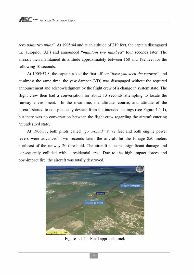
Aviation Occurrence Report
4
zero point two miles”. At 1905:44 and at an altitude of 219 feet, the captain disengaged
the autopilot (AP) and announced “maintain two hundred” four seconds later. The
aircraft then maintained its altitude approximately between 168 and 192 feet for the
following 10 seconds.
At 1905:57.8, the captain asked the first officer “have you seen the runway”, and
at almost the same time, the yaw damper (YD) was disengaged without the required
announcement and acknowledgment by the flight crew of a change in system state. The
flight crew then had a conversation for about 13 seconds attempting to locate the
runway environment. In the meantime, the altitude, course, and attitude of the
aircraft started to conspicuously deviate from the intended settings (see Figure 1.1-1),
but there was no conversation between the flight crew regarding the aircraft entering
an undesired state.
At 1906:11, both pilots called “go around” at 72 feet and both engine power
levers were advanced. Two seconds later, the aircraft hit the foliage 850 meters
northeast of the runway 20 threshold. The aircraft sustained significant damage and
consequently collided with a residential area. Due to the high impact forces and
post-impact fire, the aircraft was totally destroyed.
Figure 1.1-1 Final approach track

Chapter 1 Factual Information
5
1.2 Injuries to Persons
There were a total of 58 persons on board comprising two pilots, two cabin crew, and 54 passengers. All 4 crew members and 44 passengers sustained fatal injuries. Nine passengers sustained serious injuries and one passenger sustained minor injuries. Five residents on the ground sustained minor injuries.
Table 1.2-1 Injury table
Injuries Flight Crew
Flight Attendants Passengers Other Total
Fatal 2 2 44 0 48 Serious 0 0 9 0 9 Minor 0 0 1 5 6 None 0 0 0 Not applicable 0 Total 2 2 54 5 63
Note: According to the Annex 13 to the Convention on International Civil Aviation, for statistical uniformity only, an injury resulting in death within thirty days of the date of the accident is classified as a fatal injury in aircraft accident reports.
1.2.1 Distribution of Injuries
The ATR72’s passenger cabin was configured with 72 economy class seats. There were two pilot seats in the cockpit and two cabin crew seats in the cabin.
Figure 1.2-1 shows the injury and fatality distribution via seat location. The passenger seating positions were based on the airline seating plan and interviews with the surviving passengers.
Figure 1.2-1 Injury and fatality distribution

Aviation Occurrence Report
6
1.3 Damage to Aircraft
The aircraft was destroyed.
1.4 Other Damage
The occurrence resulted in the collapse of nine residential dwellings, one ground
vehicle, and one electric power pole.
1.5 Personnel Information
1.5.1 Flight Crew Background and Experience
1.5.1.1 Captain
The captain, a Republic of China citizen, had served in the Army Aviation
Command as a pilot. He joined TNA in July 1992 after he retired from the army. He
completed first officer training in December 1992 and served as a first officer on the
ATR42/72 fleet. In October 1995, he completed ATR42/72 command upgrade training
and was promoted to captain in November 1995. As of the occurrence, he had
accumulated a total flight time of 22,994 hours, which included 19,069 hours on the
ATR42/72 aircraft type.
The captain held an air transport pilot license (ATPL) issued by the Civil
Aeronautics Administration (CAA) of the Republic of China with Multi-Engine Land
rating, ATR72 type rating, and endorsed with radiotelephone privileges. The pilot’s
English language proficiency was recorded as ICAO level 4 with an expiry date of 23
March 201410.
1.5.1.2 First Officer
The first officer was a Republic of China citizen. He was hired by TNA in July
2011 with no previous airline experience. After completing flight training, he was
appointed and served as an ATR72 first officer. His total flight time was 2,392 hours at
10 English language proficiency is not a requirement for flight crew solely operating Taiwan domestic flights.

Chapter 1 Factual Information
7
the time of the occurrence.
The first officer held a commercial pilot license (CPL) issued by the CAA with
Multi-Engine land rating, ATR72 first officer type rating, and endorsed with
radiotelephone privileges. The pilot’s English language proficiency was recorded as
ICAO level 4 with an expiry date of 8 January 2015.
Table 1.5-1 Flight crew basic information Item Captain First Officer
Gender Male Male Age as of the Occurrence 60 39
Commenced Employment with TNA 01 July 1992 01 July 2011 License type issued ATPL – Aeroplane CPL – Aeroplane
Aircraft Type Rating Date of Expiry
ATR 72 08 November 2015
ATR 72 F/O 08 January 2017
Medical certificate issued Date of Expiry
First Class 31 August 2014
First Class 31 May 2015
Total flying time 22,994 hrs. and 29 min. 2,392 hrs. and 55 min. Total flying time on ATR 42/72 19,069 hrs. and 56 min. 2,083 hrs. and 55 min. Total flying time last 12 months 945 hrs. and 10 min. 964 hrs. and 46 min.
Total flying time last 90 days 278 hrs. and 06 min. 264 hrs. and 44 min. Total flying time last 30 days 100 hrs. and 59 min. 88 hrs. and 55 min. Total flying time last 7 days 22 hrs. and 18 min. 22 hrs. and 35 min.
Total flying time last 24 hours 03 hrs. and 31 min. 03 hrs. and 31 min. Available rest period before occurrence 15 hrs. and 07 min. 15 hrs. and 07min.
1.5.2 Flight Crew Training Record
1.5.2.1 Captain
Initial training:
The captain completed initial ATR42 type rating training at Flight Safety
International from 14 September to 28 September 1992. The training included
academic and simulator training. He completed the initial training successfully as
indicated by the certification issued by Flight Safety International on 28 September
1992. He continued his training with the airline and qualified as an ATR42/72 first
officer on 06 November 1992. He finished his ATR42/72 route training on 12

Aviation Occurrence Report
8
December 1992 and passed the first officer line check on 14 December 1992.
Upgrade training:
The captain attended ATR42/72 command upgrade training at Flight Safety
International from 16 August 1995 to 22 September 1995. The training included
ground school and simulator training. He completed the upgrade training successfully
as indicated by the certification issued by Flight Safety International. He qualified as a
captain on 12 October 1995 and passed the line check on 27 October 1995.
Recurrent training:
The most recent annual recurrent ATR72 ground school was undertaken by the
captain on 6 March 2014. The 8 hours of training included adverse weather operations,
terrain awareness, abnormal procedures, and aircraft limitations. The captain’s most
recent annual proficiency training was conducted on 17 March 2014. The captain’s
performance was assessed as “satisfactory”. The subsequent annual proficiency check
was passed on 18 March 2014. The latest annual line check was successfully
completed on 25 December 2013.
1.5.2.2 First Officer
Initial training:
The first officer commenced initial ATR72 type rating training on 18 July 2011 at
the TNA. The training curriculum included ground school of 326 hours, route
observation training of 25 hours, 15 sessions of simulator training, 5 hours of local
training, and 3 phases of line training comprising 135 hours. He completed initial
training on 8 April 2012 with a successful line check.
Recurrent training:
The first officer completed annual recurrent ATR72 ground school on 9 May 2014.
The 8 hours of training included adverse weather operations, terrain awareness,
Chapter 1 Factual Information
9
abnormal procedures, and aircraft limitations. The first officer’s most recent annual
proficiency training and subsequent proficiency check was successfully completed
between 21 and 22 April 2014. The latest annual line check was successfully
completed on 10 April 2014.
1.5.3 Flight Crew Medical Information
1.5.3.1 Captain
The captain’s first class medical certificate was issued by the CAA on 14 April
2014 with the limitation that the “Holder shall wear corrective lenses”.
1.5.3.2 First Officer
The first officer’s first class medical certificate was issued by the CAA on 08 May
2014 with no limitations.
1.5.4 Flight Crew Activities within 72 hours Before the Occurrence
1.5.4.1 Captain
1.20 July: Reported to Songshan Airport at 0640 and operated scheduled flights from
Songshan to Magong to Songshan to Magong to Kinmen to Magong to
Kaohsiung, then had a layover at Kaohsiung after the flight duty ended at
1502.
2.21 July: Reported to Kaohsiung Airport at 1420 and operated scheduled flights from
Kaohsiung to Magong to Kaohsiung to Magong to Kaohsiung to Magong to
Kaohsiung, then had a layover at Kaohsiung after the flight duty ended at
2108.
3.22 July: Reported to Kaohsiung Airport at 1440 and operated scheduled flights from
Kaohsiung to Kinmen to Kaohsiung to Magong to Kaohsiung to Magong to
Kaohsiung, then had a layover at Kaohsiung after the flight duty ended at
2213.
4.23 July: Reported to Kaohsiung Airport at 1320 and were expected to operate

Aviation Occurrence Report
10
Kaohsiung to Magong to Kaohsiung to Magong (the occurrence flight) to
Songshan to Magong to Songshan.
1.5.4.2 First Officer
From 20 July to 23 July, the first officer was assigned to the same flight duty
patterns as the captain.
1.5.5 Flight Crew Alertness and Fatigue
Fatigue can be defined as a state of impairment that can include physical and/or
mental elements associated with lower alertness and reduced performance. Fatigue can
impair individual capability to a level where a person cannot continue to perform tasks
safely and/or efficiently11.
The investigation examined the likelihood that the operating flight crew were
fatigued at the time of the occurrence and the effect that fatigue may have had on their
performance. Both the captain and first officer were based in Taipei. However, the
flight crew’s operating pattern in the three days before the occurrence commenced and
ended at Kaohsiung. Therefore, the flight crew spent the three nights before the
occurrence in company provided accommodation in Kaohsiung. While the flight crew
had sufficient opportunity to obtain sleep, the investigation was unable to determine
the quantity and quality of sleep obtained by the flight crew in Kaohsiung.
QinetiQ’s biomathematical fatigue model System for Aircrew Fatigue Evaluation
(SAFE) was used to assess, in part, the flight crew’s level of alertness and task
effectiveness. It is a well validated model.12,13,14,15,16 Both the flight crew’s rosters for
11 Yen, J. R., Hsu, C. C., Yang, H., & Ho, H. (2009). An investigation of fatigue issues on different flight
operations. Journal of Air Transport Management, 15(5), 236-240. 12 Civil Aviation Authority. (2007). Aircrew fatigue: A review of research undertaken on behalf of the UK Civil
Aviation Authority (CAA Paper 2005/04, Issue 2). London, UK: CAA. 13 Powell, D., Spencer, M. B., Holland, D., Broadbent, E., & Petrie, K. J. (2007). Pilot fatigue in short-haul
operations: Effects of number of sectors, duty length, and time of day. Aviation, Space, and Environmental Medicine, 78, 698-701.
14 Powell, D., Spencer, M. B., Holland, D., & Petrie, K. J. (2008). Fatigue in two-pilot operations: Implications for flight and duty time limitations. Aviation, Space, and Environmental Medicine, 79, 1047-1050.
Chapter 1 Factual Information
11
the two months before the occurrence were assessed by SAFE. SAFE’s estimated sleep
function was used to allocate sleep at appropriate times in between crew duties because
actual sleep data was not available. While the automated sleep data was based on
airline pilot fatigue research findings, it provides a conservative sleep solution which
may not necessarily coincide with the quantity or quality of actual sleep obtained.
The captain’s SAFE result was consistent with the pilot being a little tired on
approach to Magong. The captain’s SAFE metrics included:
� Alertness score 45.2 out of 100;
� Samn-Perelli17 score of 3.7 (OK, between somewhat fresh to a little tired);
� Karolinska Sleepiness Scale18 (KSS) indicating neither sleepy nor alert;
� Response time on a visual vigilance task degraded by 7.5% compared with a
typical rested value;
� Response time on a warning light on a complex task degraded by 48.4%
compared to a typical rested value;
� Percentage of missed responses in a sustained attention task 22.04% compared to
a typical rested value of 6%; and
� Performance equivalent to that of a person with 0.034% blood alcohol
concentration.
However, there were some salient indications recorded on the CVR that suggested
the captain was experiencing a higher level of fatigue than that derived from SAFE.
15 Spencer, M. B., & Robertson, K. A. (2000). A diary study of aircrew fatigue in short-haul multi-sector
operations (DERA Report No. DERA/CHS/PPD/CR00394). Farnborough, UK: DERA. 16 Spencer, M. B., & Robertson, K. A. (2002). Aircrew alertness during short-haul operations, including the
impact of early starts (QinetiQ Report No. QINETIQ/CHS/PPD/CRO10406/1.0). Farnborough, UK: QinetiQ. 17 The Samn Perelli (SP) is a 7-point scale with possible scores ranging from 1 (“fully alert, wide awake”) to 7
(“completely exhausted, unable to function effectively”). This scale has been validated and widely used in aviation (Samn & Perelli, 1982; Samel et al, 1997) and is one of the metrics provided as an output of the SAFE model.
18 The Karolinska Sleepiness Scale (KSS) is a one-dimensional scale ranging from 1 (“very alert”) to 9 (“very sleepy, great effort to keep awake”). It has been validated against objective measurement of sleepiness such as electroencephalographic (EEG) and electrooculographic (EOG) activity (Åkerstedt & Gillberg, 1990) and performance evaluation (Kaida et al, 2006).

Aviation Occurrence Report
12
The captain stated he was very tired and his yawning was detected by the CVR. In
addition, lapses in radio communications with ATC, incorrect VOR approach course
selection, and incorrect automatic flight control system (AFCS) mode selections, all
requiring the first officer to intervene. Furthermore, the captain’s real-time roster
indicated an elevated flying activity where he routinely completed 6 sector days and
had accumulated a total flight time of 278 hours in the last 90 days.
There were no salient indications recorded on the CVR to indicate that the first
officer was fatigued; such as yawning and prolonged silence, or the disengagement of
the first officer from conversations. The first officer’s SAFE result was consistent with
the pilot not being unduly affected by fatigue. The first officer’s SAFE metrics
included:
� Alertness score of 56.9 out of 100;
� Samn-Perelli score of 3.2 (OK, somewhat fresh);
� KSS in between alert and neither sleepy nor alert;
� Response time on a visual vigilance task degraded by 4.9% compared with a
typical rested value;
� Response time on a warning light on a complex task degraded by 27.6%
compared to a typical rested value;
� Percentage of missed responses in a sustained attention task 14.66% compared to
a typical rested value of 6%; and
� Performance equivalent to that of a person with 0.017% blood alcohol
concentration.
1.6 Airplane Information
1.6.1 Aircraft and Engine Basic Information
Basic information of the occurrence aircraft is shown in Table 1.6-1
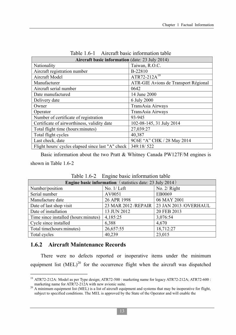
Chapter 1 Factual Information
13
Table 1.6-1 Aircraft basic information table Aircraft basic information (date: 23 July 2014)
Nationality Taiwan, R.O.C. Aircraft registration number B-22810 Aircraft Model ATR72-212A19 Manufacturer ATR-GIE Avions de Transport Régional Aircraft serial number 0642 Date manufactured 14 June 2000 Delivery date 6 July 2000 Owner TransAsia Airways Operator TransAsia Airways Number of certificate of registration 93-945 Certificate of airworthiness, validity date 102-08-145, 31 July 2014 Total flight time (hours:minutes) 27,039:27 Total flight cycles 40,387 Last check, date 9C6E “A” CHK / 28 May 2014 Flight hours/ cycles elapsed since last "A" check 349:18/ 522
Basic information about the two Pratt & Whitney Canada PW127F/M engines is
shown in Table 1.6-2
Table 1.6-2 Engine basic information table Engine basic information statistics date: 23 July 2014
Number/position No. 1/ Left No. 2/ Right Serial number AV0051 EB0069 Manufacture date 26 APR 1998 06 MAY 2001 Date of last shop visit 23 MAR 2012 /REPAIR 23 JAN 2013 /OVERHAUL Date of installation 13 JUN 2012 20 FEB 2013 Time since installed (hours:minutes) 4,185:25 3,076:54 Cycle since installed 6,388 4,670 Total time(hours:minutes) 26,657:55 18,712:27 Total cycles 40,239 23,015
1.6.2 Aircraft Maintenance Records
There were no defects reported or inoperative items under the minimum
equipment list (MEL)20 for the occurrence flight when the aircraft was dispatched
19 ATR72-212A: Model as per Type design; ATR72-500 : marketing name for legacy ATR72-212A; ATR72-600 :
marketing name for ATR72-212A with new avionic suite. 20 A minimum equipment list (MEL) is a list of aircraft equipment and systems that may be inoperative for flight,
subject to specified conditions. The MEL is approved by the State of the Operator and will enable the
Aviation Occurrence Report
14
from Kaohsiung Airport. A review of the last 6 months of the aircraft’s technical
logbook indicated that there was no system anomaly related to the occurrence. A
review of the aircraft’s maintenance records indicated that it was in compliance with
all applicable airworthiness directives (ADs) and service bulletins (SBs).
1.6.3 Enhanced Ground Proximity Warning System
The enhanced ground proximity warning system (EGPWS) 21 is a terrain
awareness and warning system (TAWS) that provides basic GPWS functions in
addition to enhanced terrain alerting and display features. The EGPWS uses aircraft
inputs including geographic position, attitude, altitude, airspeed, and glideslope
deviation. These are used with respect to internal terrain, obstacle, and airport
databases to predict a potential conflict between the aircraft flight path and terrain or
an obstacle. A conflict will result in the EGPWS providing a visual and audio caution
or warning alert. In addition, the EGPWS provides alerts for excessive glideslope
deviation, too low with flaps extended or gear not in the landing configuration. The
system also provides bank angle and altitude callouts based on system configuration
selection.
The occurrence aircraft was equipped with a Honeywell EGPWS, model MARK
VIII, Part Number 965-1216-011. The EGPWS contained the following alert modes:
- Basic GPWS modes
� Mode 1: excessive descent rate
� Mode 2: excessive terrain closure rate
� Mode 3: altitude loss after take-off
� Mode 4: unsafe terrain clearance
pilot-in-command to determine whether a flight may be commenced or continued from any intermediate stop should an instrument, equipment or systems become inoperative.
21 EGPWS is the Honeywell Inc. proprietary name for a Terrain Awareness and Warning System (TAWS). TAWS is the term used to describe equipment meeting the ICAO standards and recommendations for GPWS equipment that provides predictive terrain-hazard warnings.

Chapter 1 Factual Information
15
� Mode 5: below glideslope
� Mode 6: altitude callouts
- Enhanced modes
� Terrain clearance floor (TCF)
� Terrain awareness & display (TAD)
The TCF mode creates an increasing terrain clearance envelope around the airport
runway directly related to the distance from the runway. The alert is based on current
aircraft location, nearest runway center point position and radio altitude. TCF is
activated during takeoff, cruise and final approach and complements the existing Mode
4 by providing an alert based on insufficient terrain clearance even when in the landing
configuration. A runway field clearance floor (RFCF) alert is also provided for
runways that are located on top of a hill. This alert is similar to the TCF alert but is
based on height above the runway. The aural message "Too Low Terrain" will occur
once when the TCF envelope is initially breached and one time thereafter for each 20%
degradation in radio altitude. At the same time the "GPWS" red alerts are illuminated
on the instrument panels and remain on until the alert envelope is exited (see Figures
1.6-1 and 1.6-2).
Figure 1.6-1 TCF alert curve

Aviation Occurrence Report
16
Figure 1.6-2 Plan view of expanded alert
The terrain awareness function uses the aircraft’s geographic position provided by
the onboard global positioning system (GPS), aircraft altitude and a worldwide terrain
database to predict potential conflicts between the aircraft flight path and the terrain. It
also provides an aural alert and graphic display of the conflicting terrain. Caution and
Warning envelopes below and ahead of the aircraft path are computed as a function of
groundspeed and flight path angle.
If the terrain penetrates the Caution envelope boundary, an aural message
"TERRAIN AHEAD. TERRAIN AHEAD" is generated with the red "GPWS" alerts
illuminated on each pilot’s instrument panel. Simultaneously, the terrain areas which
conflict with the Caution criteria are shown in solid yellow on the terrain display. If the
terrain penetrates the Warning envelope boundary, an aural message "TERRAIN
AHEAD, PULL UP" is generated with the red "GPWS" alerts illuminated on each
pilot’s instrument panel. Simultaneously, the terrain areas which conflict with the
warning criteria are shown in solid red on the terrain display.
The terrain data can be displayed on the electronic flight instrument system
(EFIS). When the terrain display is present, it replaces the weather radar display and
can be available to the flight crew at any time. A discrete pop-up signal provided by the

Chapter 1 Factual Information
17
EGPWS is used to automatically display the detected threatening terrain on the EFIS
with an auto-range of 10 nm. The local terrain forward of the aircraft is depicted as
variable density dot patterns in green, yellow or red. The density and color are a
function of how close the terrain is relative to the aircraft’s altitude. Terrain Alerts are
depicted by painting the threatening terrain as solid yellow or red.
1.6.4 Automatic Flight Control System
1.6.4.1 General
The ATR72 is equipped with an automatic flight control system (AFCS, see
Figure 1.6-3) which includes:
� Autopilot function and/or yaw damper (AP/ YD);
� Flight director function (FD); and
� Altitude alert.
Main components include:
� One computer;
� One control panel;
� One advisory display unit (ADU); and
� Three servo-actuators (one on each axis).
Systematic use of the AP/FD is highly recommended by ATR in order to:
� Increase the accuracy of guidance and tracking in all weather conditions, from
early climb after takeoff down to landing minima;
� Provide increased passenger comfort through smooth and repeatable altitude and
heading changes in all atmospheric conditions; and
� Reduce crew workload and increase safety.
Figure 1.6-3 Automatic Flight Control System (AFCS)

Aviation Occurrence Report
18
1.6.4.2 Advisory Display Unit
The advisory display unit (ADU) provides advisory/caution messages and mode
information to the pilots (see Figure 1.6-4).
Figure 1.6-4 Advisory Display Unit (ADU)
1.6.5 Weight and Balance Information
The actual takeoff weight of the occurrence aircraft was 46,235 lbs. The aircraft’s
center of gravity (CG) for takeoff was located at 29.2% mean aerodynamic chord
(MAC) which was within the certified limitation between 19.7% and 37 % MAC.
Table 1.6-3 shows the weight and balance data. The aircraft’s weight and balance was
within the specified limitations for the duration of the occurrence flight. Table 1.6-3 Weight and balance data
Max. zero fuel weight 44,092 lbs. Actual zero fuel weight 41,294 lbs. Max. takeoff weight 48,501 lbs. Actual takeoff weight 46,235 lbs. Take off fuel 4,941 lbs. Estimated trip fuel 800 lbs. Max. landing weight 48,171 lbs. Estimated landing weight 45,435 lbs. Takeoff CG 29.2% MAC
CG: center of gravity MAC: mean aerodynamic chord

Chapter 1 Factual Information
19
1.7 Weather Information
1.7.1 Synopsis
The center of Typhoon Matmo was approximately 142 nm north-northwest of
Magong Airport around the time of occurrence. The typhoon’s radius was
approximately 80 nm. The typhoon warning for Magong Airport was terminated at
1740, as shown in Figure 1.7-1. The Magong Weather Center issued a hazardous
weather forecast for Magong Airport at the same time as follows:
1740 to 1940 hours, visibility 1,200 meters in rain and mist, broken cloud at 200
feet, intermittent thunderstorm rain.
Figure 1.7-1 Magong typhoon warning termination report
The CAA’s air navigation and weather services (ANWS) Taipei Aeronautical
Meteorological Center issued multiple significant meteorological information
advisories (SIGMET)22 for the Taipei flight information region (FIR) on the day of the
occurrence, one of which remained valid at the time of the occurrence as follows:
SIGMET 5- valid from 1800 to 2100 hours for Taipei FIR, tropical cyclone
22 Information concerning the occurrence or expected occurrence of specified en-route weather phenomena
which may affect the safety of aircraft operations.

Aviation Occurrence Report
20
Matmo centered at N2536 E11906 at 1700L, moving NW at 11 knots with intensity
weakening, cumulonimbus is within 190 nautical miles of the center with a cloud top
altitude below FL420. The storm center was forecasted to be located at N2630 E11830
at 2300 hours.
1.7.2 Surface Weather Observations
The Weather Center was in charge of weather observations and dissemination for
Magong Airport. METAR, aerodrome special meteorological reports (SPECI) and
aerodrome local meteorological reports (LOCAL) around the time of the occurrence
were as follows:
METAR at 1800 hours, wind from 220 degrees at 17 knots gusting to 27 knots,
visibility 800 meters in heavy thunderstorm rain, scattered clouds at 200 feet, broken at
600 feet, few cumulonimbus at 1,200 feet, overcast at 1,600 feet, temperature 23°C;
dew point temperature 22°C, altimeter setting 995 hPa, trend forecast-no significant
change. Remarks: altimeter setting 29.41 in-Hg, runway visual range23 800 meters
with no significant change at Runway 20, hourly precipitation 13.5 millimeters24,
stationary thunderstorm overhead (ATIS L25).
METAR at 1830 hours, wind from 200 degrees at 14 knots gusting to 24 knots,
visibility 800 meters in heavy thunderstorm rain, scattered clouds at 200 feet, broken at
600 feet, few cumulonimbus at 1,200 feet, overcast at 1,600 feet, temperature 22°C;
dew point temperature 22°C, altimeter setting 995 hPa, trend forecast-no significant
change. Remarks: altimeter setting 29.41 in-Hg, runway visual range 800 meters at
Runway 20, stationary thunderstorm overhead (ATIS M).
23 Runway visual range (RVR) is the distance at which the runway, or the specified lights or markers delineating
it, can be seen from a position above a specified point on its centerline. It is normally included in aerodrome meteorological reports when visibility or RVR is less than 1,500 meters.
24 Hourly precipitation in the METAR of Magong airport was not presented in ATS message handling system (AMHS) of ANWS, CAA.
25 It indicated that meteorological information used in automatic terminal information service (ATIS) No. L was extracted from the report (excluding remarks) but in different format.
Chapter 1 Factual Information
21
SPECI at 1840 hours, wind from 190 degrees at 13 knots gusting to 24 knots,
visibility 1,600 meters in thunderstorm rain, scattered clouds at 200 feet, broken at 600
feet, few cumulonimbus at 1,200 feet, overcast at 1,600 feet, temperature 22°C; dew
point temperature 22°C, altimeter setting 996 hPa. Remarks: altimeter setting 29.42
in-Hg, recent heavy rain, stationary thunderstorm overhead (ATIS N).
METAR at 1900 hours, wind from 220 degrees at 11 knots gusting to 21 knots,
visibility 1,600 meters in thunderstorm rain, scattered clouds at 200 feet, broken at 600
feet, few cumulonimbus at 1,200 feet, overcast at 1,600 feet, temperature 23°C; dew
point temperature 22°C, altimeter setting 997 hPa, trend forecast-no significant change.
Remarks: altimeter setting 29.45 in-Hg, recent heavy rain, hourly precipitation 7.0
millimeters, stationary thunderstorm overhead (ATIS O).
SPECI at 1910 hours, wind from 250 degrees at 18 knots gusting to 28 knots,
visibility 800 meters in heavy thunderstorm rain, scattered clouds at 200 feet, broken at
600 feet, few cumulonimbus at 1,200 feet, overcast at 1,600 feet, temperature 22°C;
dew point temperature 22°C, altimeter setting 998 hPa. Remarks: altimeter setting
29.48 in-Hg, runway visual range 800 meters at Runway 20, stationary thunderstorm
overhead (ATIS P).
LOCAL26 at 1918 hours, wind from 230 degrees at 23 knots gusting to 33 knots,
visibility 800 meters in heavy thunderstorm rain, scattered clouds at 200 feet, broken at
600 feet, few cumulonimbus at 1,200 feet, overcast at 1,600 feet, temperature 24°C;
dew point temperature 23°C, altimeter setting 998 hPa. Remarks: altimeter setting
29.48 in-Hg, runway visual range 800 meters with no significant change at Runway 20,
stationary thunderstorm overhead (ATIS Q).
METAR at 1930 hours, wind from 230 degrees at 19 knots gusting to 29 knots,
visibility 800 meters in heavy thunderstorm rain, scattered clouds at 200 feet, broken at
600 feet, few cumulonimbus at 1,200 feet, overcast at 1,600 feet, temperature 24°C;
dew point temperature 23°C, altimeter setting 998 hPa, trend forecast-no significant
26 This report was the additional observation after Weather Center received the notification of the occurrence.

Aviation Occurrence Report
22
change. Remarks: altimeter setting 29.48 in-Hg, runway visual range 800 meters with
no significant change at Runway 20, stationary thunderstorm overhead (ATIS R).
METAR at 2000 hours, wind from 210 degrees at 13 knots gusting to 23 knots,
visibility 800 meters in heavy thunderstorm rain, scattered clouds at 200 feet, broken at
600 feet, few cumulonimbus at 1,200 feet, overcast at 1,600 feet, temperature 24°C;
dew point temperature 23°C, altimeter setting 997 hPa, trend forecast-no significant
change. Remarks: altimeter setting 29.46 in-Hg, runway visual range 800 meters at
Runway 20, hourly precipitation 26.0 millimeters, stationary thunderstorm overhead
(ATIS S).
1.7.3 Automated Weather Observation Systems
Magong Airport’s new automated weather observation system27 (AWOS) became
operational in June 2011. The AWOS sensors were located at the approach ends and
midpoint of the runway, providing real-time weather information to the displays
located at the Weather Center and Magong tower, as shown in Figure 1.7-2. The
location of Magong Airport’s AWOS sensors and the Central Weather Bureau’s (CWB)
Penghu weather station are shown in Figure 1.7-3. The relevant weather parameters
from 1800 to 2000 hours are shown in Figure 1.7-4 to 1.7-5.
AWOS N was located approximately 0.5 nautical mile south-southwest of the
occurrence site. The wind gradually turned westerly from south-southwest between
1837 and 1847 hours, and then returned to the south-southwest at 1932 hours.
One-minute average wind speed increased from 9 knots at 1858 hours to 31 knots at
1913, gusting to 36 knots at 1911 hours. Rainfall began to intensify at 1900 hours,
accompanied by the runway visual range (RVR) reducing from more than 2,000 meters
at 1859 hours, to between 500 and 900 meters between 1901 and1931 hours. RVR
returned to more than 2,000 meters at 1947 hours.
27 AWOS is a system that continuously measures weather information, including wind speed and direction,
visibility, RVR, precipitation, cloud cover, temperature, dew point, altimeter setting, and lightning. The previous AWOS was not equipped with RVR capability.

Chapter 1 Factual Information
23
Figure 1.7-2 Weather Center and Magong tower AWOS displays
Figure 1.7-3 AWOS sensor locations

Aviation Occurrence Report
24
Figure 1.7-4 AWOS wind speed/direction
Figure 1.7-5 AWOS rainfall and RVR

Chapter 1 Factual Information
25
1.7.4 Weather Information Summary
The visibilities, RVRs and other weather information provided by Weather Center,
AWOS, and ATC units were summarized in Table 1.7-1. Table 1.7-1 Summarized weather information
Time Source Details GE222 received
1700 METAR Visibility 2,400 meters in thunderstorm rain, ceiling at 600 feet (ATIS I) No
1700 AWOS RVR28 Above 2,000 meters No 1728 Kaohsiung Tower Thunderstorm overhead at Magong Airport Yes
1730 METAR Visibility 2,400 meters in thunderstorm rain, ceiling at 600 feet (ATIS J) No
1730 AWOS RVR Above 2,000 meters No 1740 AWOS RVR From above 2,000 to 500 meters from 1731 to 1740 No 1742 Kaohsiung Tower Magong Airport was below landing minima Yes
1751 GE222 CVR ATIS Information Kilo of Magong Airport Visibility 800 meters in heavy thunderstorm rain, ceiling at 600 feet
Yes
1756 Kaohsiung Approach
Magong Airport was below landing minimum. Broadcasted hazardous weather forecast of Magong Airport
Yes
1800 AWOS RVR Around 900 to 1,400 meters from 1751 to 1800 No
1801 GE222 CVR ATIS Information Lima of Magong Airport Visibility 800 meters in heavy thunderstorm rain, ceiling at 600 feet
Yes
1821 Kaohsiung Approach
Broadcasted thunderstorm will probably continue for another hour at Magong Airport Yes
1827 Kaohsiung Approach
Broadcasted Magong Airport runway 02 instant wind was 210 degrees at 5 knots maximum 11 knots, runway 20 instant wind was 190 degrees at 11 knots maximum 15 knots
Yes
1830 AWOS RVR Above 2,000 meters No
1836 Kaohsiung Approach
ATIS Information Mike of Magong Airport Visibility 800 meters in heavy thunderstorm rain, ceiling at 600 feet
Yes
1840 AWOS RVR Above 2,000 meters No 1841 Magong Tower Informed Kaohsiung Approach visibility was 1,600 No
28 In tower, one-minute mean RVRs were reported to aircraft. In METAR/SPECI, ten-minute mean RVRs are
reported. There were only one -minute mean RVRs recorded in AWOS.

Aviation Occurrence Report
26
Time Source Details GE222 received
meters
1842 Kaohsiung Approach
Visibility was 1,600 meters and thunderstorm overhead at Magong Airport Yes
1845 Kaohsiung Approach
ATIS Information November of Magong Airport Visibility 1,600 meters in thunderstorm rain, ceiling at 600 feet
Yes
1859 AWOS RVR Above 2,000 meters No
1900 METAR Visibility 1,600 meters in thunderstorm rain , ceiling at 600 feet (ATIS O) No
1900 AWOS RVR 1,800 meters No 1901 AWOS RVR 800 meters No 1901 Magong Tower QNH was 997 Yes 1902 AWOS RVR 650 meters No 1903 AWOS RVR 600 meters No 1903 Magong Tower Wind was 250 degrees at 19 knots Yes 1904 AWOS RVR 650 meters No 1905 AWOS RVR 600 meters No 1906 AWOS RVR 500 meters No
1910 SPECI Visibility 800 meters in heavy thunderstorm rain, RVR 800 meters at runway 20, ceiling at 600 feet (ATIS P) No
1.7.5 Sounding Data
The 2000 hours routine upper air sounding (that is, a vertical profile of
atmospheric conditions) for Magong Airport was conducted at 1835 hours on the day
of the occurrence. A SkewT/logP29 diagram drawn from the observation data is shown
in Figure 1.7-6. The wind profile presented in Figure 1.7-7 identified a southwest wind
near the surface at about 16 knots. Above the surface, the wind backed to the
south-southwest, then veered to the southwest, and increased in magnitude to about 50
knots at 2,000 feet. Between 2,000 feet and 9,000 feet, the wind was generally from a
southwesterly direction at about 45 to 50 knots.
29 SkewT/logP diagram is a standard meteorological plot using temperature and the logarithmic of pressure as
coordinates. It is used to display winds, temperature, dew point, and various indices used to define the vertical structure of the atmosphere.
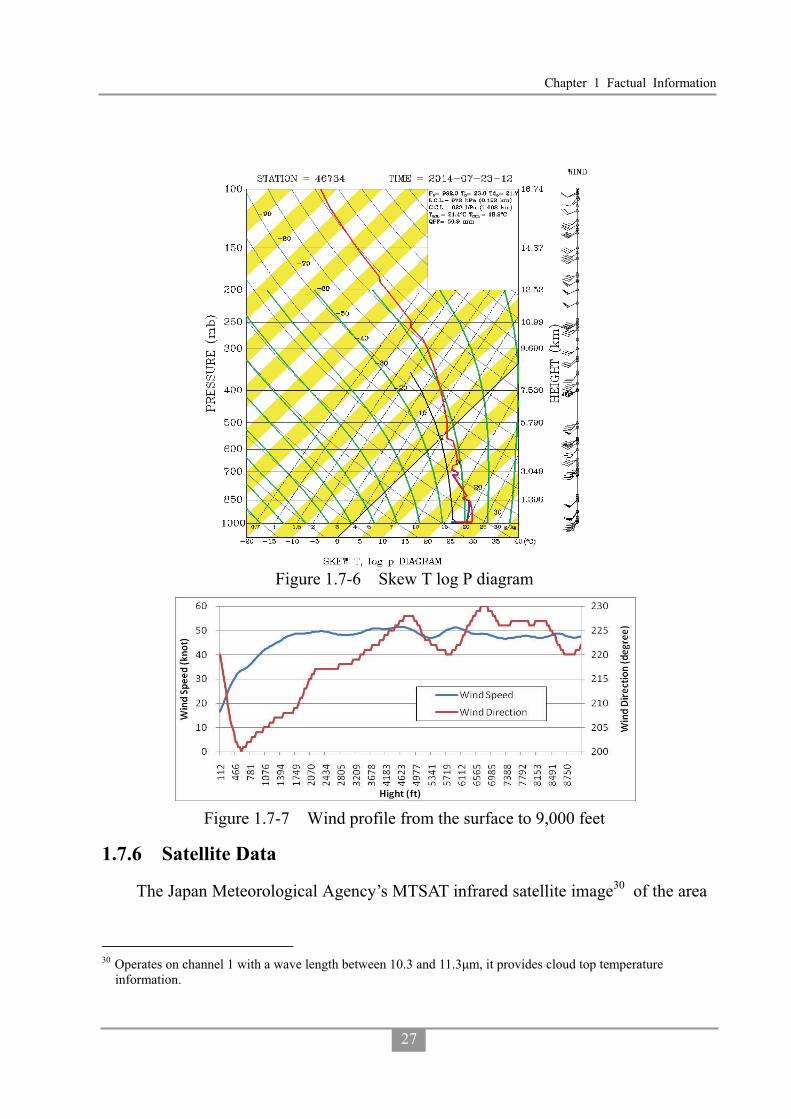
Chapter 1 Factual Information
27
Figure 1.7-6 Skew T log P diagram
Figure 1.7-7 Wind profile from the surface to 9,000 feet
1.7.6 Satellite Data
The Japan Meteorological Agency’s MTSAT infrared satellite image30 of the area
30 Operates on channel 1 with a wave length between 10.3 and 11.3�m, it provides cloud top temperature
information.

Aviation Occurrence Report
28
at 1857 hours is shown in Figure 1.7-8. Compared with the sounding data, the cloud
top height was about 53,000 feet over Penghu.
Figure 1.7-8 Infrared satellite image at 1857 hours
1.7.7 Weather Radar Information
The CWB had four S-band 10 centimeter wavelength Doppler weather radars. It
took 6 to 7.5 minutes to complete a series of specific scans. The composite image of
the radars at 1900 hours and cropped images of the Penghu area from 1830 to 1912
hours are shown in Figure 1.7-9. The time indicated on the figure is the start time for
the scans. The figure shows that a stronger echo moved to Magong Airport from
southwest to northeast between 1900 and 1912 hours.
Chiku weather radar was located approximately 35 nm to the southeast of the
occurrence site. A scan was completed every 7.5 minutes. With the scan taken at 0.5°
elevation, the airspace between about 1,100 and 4,700 feet above mean sea level above
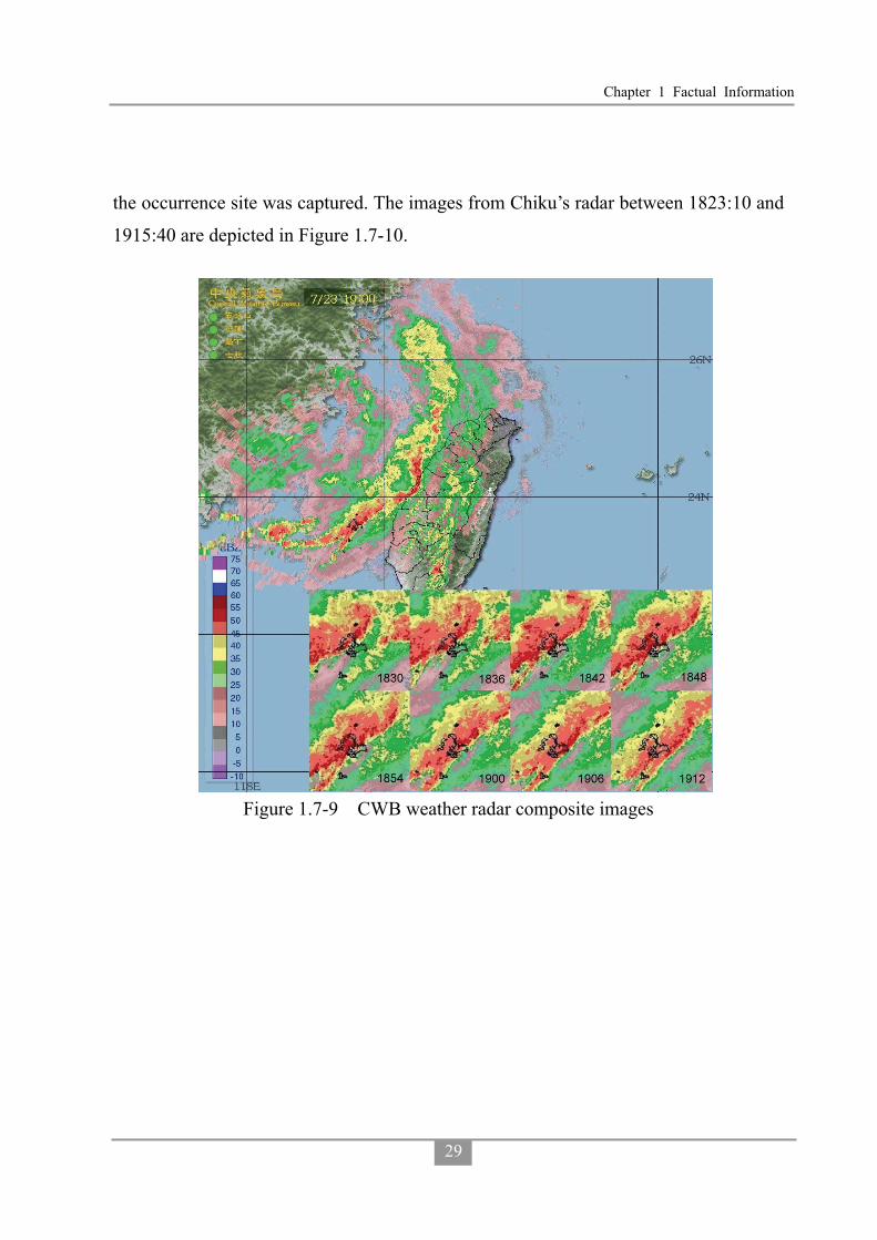
Chapter 1 Factual Information
29
the occurrence site was captured. The images from Chiku’s radar between 1823:10 and
1915:40 are depicted in Figure 1.7-10.
Figure 1.7-9 CWB weather radar composite images
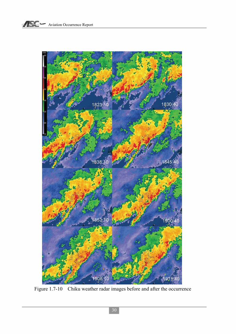
Aviation Occurrence Report
30
Figure 1.7-10 Chiku weather radar images before and after the occurrence
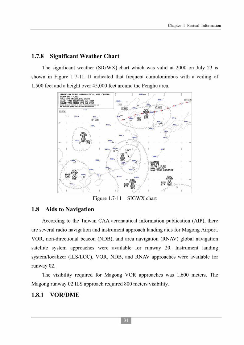
Chapter 1 Factual Information
31
1.7.8 Significant Weather Chart
The significant weather (SIGWX) chart which was valid at 2000 on July 23 is
shown in Figure 1.7-11. It indicated that frequent cumulonimbus with a ceiling of
1,500 feet and a height over 45,000 feet around the Penghu area.
Figure 1.7-11 SIGWX chart
1.8 Aids to Navigation
According to the Taiwan CAA aeronautical information publication (AIP), there
are several radio navigation and instrument approach landing aids for Magong Airport.
VOR, non-directional beacon (NDB), and area navigation (RNAV) global navigation
satellite system approaches were available for runway 20. Instrument landing
system/localizer (ILS/LOC), VOR, NDB, and RNAV approaches were available for
runway 02.
The visibility required for Magong VOR approaches was 1,600 meters. The
Magong runway 02 ILS approach required 800 meters visibility.
1.8.1 VOR/DME

Aviation Occurrence Report
32
The VOR navigation and non-precision approach aid is an aircraft navigation
system operating in the very high frequency (VHF) band. VORs broadcast a VHF
radio composite signal and data that allows the airborne receiving equipment to derive
the magnetic bearing from the station to the aircraft. An infinite number of bearings
can be obtained and they may be visualized as radiating from the beacon like spokes
from the hub of a wheel. However, for practical purposes the number of bearings can
be considered to be limited to 360, one degree apart, and these 360 bearings are known
as radials. A radial is identified by its magnetic bearing outbound from the VOR
beacon. The VOR enables a pilot to select, identify, and locate a line of position from a
particular VOR beacon.
Magong VOR was upgraded from a conventional VOR (CVOR) to a Doppler
VOR (DVOR) 1 June 1 2013. The DVOR system is more resistant to multipath
interference compared to the traditional CVOR. The Magong DVOR (model
DVOR1150A) was manufactured by SELEX, and was equipped with dual transmitters,
dual monitors and dual power supplies to ensure VOR signal integrity and continuity.
The Magong VOR operating frequency was 115.2 MHz with an identifier of MKG.
There were two main functions of the DVOR: enroute, which provided aircraft
tracking guidance for air routes31 A1 and W6; and terminal, which provided approach
tracking guidance for both runway 02 and runway 20.
The Magong DME (distance measuring equipment) was a transponder-based
radio navigation aid that measured slant range distance from a land-based transponder
by timing the propagation delay of UHF radio signals.
Magong DME was replaced on 1 June 1 2013. The new unit (model DME1119A)
was manufactured by SELEX and was equipped with dual transmitters, dual monitors
31 An air route is a specified route designed for channeling the flow of traffic as necessary for the provision of air
traffic services. A legacy design feature of air routes, prior to the development and implementation of the Global Positioning System, Area Navigation, Performance Based Navigation (PBN) and improved aircraft navigation capabilities, was the requirement to track via ground-based radio navigation aids.

Chapter 1 Factual Information
33
and dual power supplies, and was co-located with the DVOR as an aid to enroute
navigation and instrument approaches. The DME identifier and frequency was the
same as the DVOR.
The Magong VOR monitoring receiver log indicated that the system was fully
functional on the day of the occurrence. In addition, the most recent flight testing of
the Magong VOR, conducted on 6 May 2014, indicated that the system was
performing within standard tolerances and was “unrestricted”. There were no pilot
reports of the VOR malfunctioning since its commissioning on 1 June 2013.
1.9 Communication
The radio communication frequencies used by Kaohsiung tower, Kaohsiung
approach and Magong tower were 121.9/118.7 MHz, 124.7/128.1 MHz and 118.3 MHz
respectively.
The telephone communication transcripts between the Magong tower controllers,
Kaohsiung approach controllers, Magong flight operations section, the meteorological
office, weather watch office and Magong flight control office are summarized in
Appendix 1.
1.10 Aerodrome
1.10.1 Airside Basic Information
Magong Airport32 is located 10.2 km northeast of Magong City. It had a single
runway oriented north-northeast and south-southwest designated as runway 02/20.
Runway 02’s precise magnetic heading was 21.67° with declared dimensions of 3,000
meters long, 45 meters wide, and an elevation of 103 feet at the threshold. It had a
clearway which was 300 meters long and 60 meters wide but no stopway. Runway 20’s
precise magnetic heading was 201.67° and an elevation of 46 feet at the threshold. It
had a 285 meter long clearway that was 75 meters wide but no stopway (see Figure
32 Aeronautical information publication (AIP) TAIPEI FIR effective10 JUL 14. ICAO airport code RCQC.
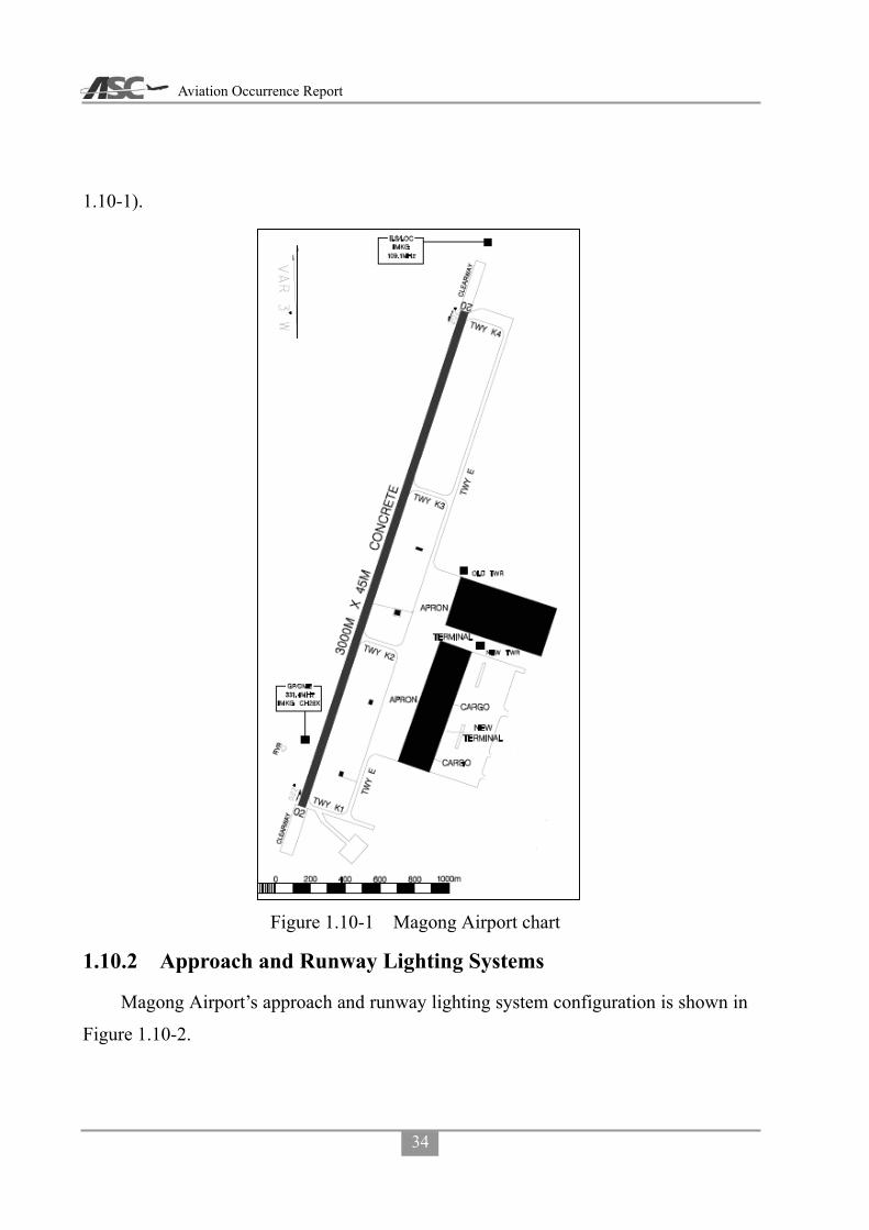
Aviation Occurrence Report
34
1.10-1).
Figure 1.10-1 Magong Airport chart
1.10.2 Approach and Runway Lighting Systems
Magong Airport’s approach and runway lighting system configuration is shown in
Figure 1.10-2.

Chapter 1 Factual Information
35
Figure 1.10-2 Magong Airport’s approach and runway lighting system
There was no approach lighting system for runway 20. According to ICAO Annex
14 section 5.3.4 and the CAA Civil Aerodrome Design and Operations Specifications
section 5.3.4, where physically practicable, a simple approach lighting system shall be
provided to serve a non-precision approach runway. A simple approach lighting system
shall consist of a row of lights on the extended center line of the runway extending,
where possible, over a distance of not less than 420 meters from the threshold.
Measurement of the extended center line for runway 20 indicated that about 500
meters was available for an approach lighting system within the airport area, as shown
in Figure 1.10-3.

Aviation Occurrence Report
36
Figure 1.10-3 Available distance measured from Runway 20 (image from Google Earth)
1.10.3 Runway Lighting System
Both runway 02 and runway 20 had 6 fixed bidirectional runway threshold/end
lights33 installed, which were illuminated green in the direction of approach to the
runway. Runway 02 and runway 20 also had installed 10 fixed unidirectional runway
threshold lights which were illuminated green in the direction of approach to the
runway. The runway also had two groups of green wing bar lights positioned
symmetrically about the runway centerline on each side of the runway threshold. Each
wing bar contained 5 lights extending 10 meters outward from, and at right angles to,
the line of the runway edge lights. The innermost light of each wing bar was aligned
with the runway edge lights.
The western side of runway 02 was equipped with a precision approach path
indicator (PAPI)34 guidance system positioned 400 meters forward of the runway
33 Magong Airport runway/taxiway reconstruction engineering contract. 34 The precision approach path indicator (PAPI) is a visual aid that provides guidance information to help a pilot
acquire and maintain the designated glideslope (typically 3°) for an approach to an airport. It is generally located beside the runway beyond the landing threshold of the runway. The ratio of white to red lights seen is dependent on the angle of approach to the runway. Above the designated glideslope a pilot will observe more

Chapter 1 Factual Information
37
threshold. The eastern side of runway 20 was equipped with a PAPI positioned 321
meters forward of the runway threshold.
Runway 02/20 had white/yellow runway edge lighting installed at 60 meter (200
feet) intervals.
Runway end identifier lights (REIL) were also installed on both sides of the
runway 20 threshold. The REIL provided a rapid and positive identification of the end
of the runway35. The system comprised two types of synchronized flashing lights that
were unidirectional or omni-directional. The unidirectional lights were directed
towards the approach area. REIL were effective for: identification of a runway
surrounded by a preponderance of other lighting; identification of a runway which
lacked contrast with surrounding terrain; and identification of a runway under reduced
visibility. The REIL had three intensity settings and can be seen by flight crew at an
approximate range of 3 miles during daylight and 20 miles at night.
Figure 1.10-4 RWY 02/20 lighting systems
1.10.4 Information from Airport CCTV
Magong Airport’s closed-circuit television (CCTV) provided information on the
status of the runway lighting systems, local visibility, and emergency response
activities at the time of the occurrence.
The investigation team obtained copies of the video footage from No.7 and No.9
white lights than red, at approaches below the ideal angle more red lights than white will be seen. For the optimum approach angle the ratio of white to red lights will remain equal throughout.
35 https://www.faa.gov/about/office_org/headquarters_offices/ato/service_units/techops/navservices/lsg/reil/

Aviation Occurrence Report
38
airport surveillance cameras. The camera locations and filming directions are shown in
Figure 1.10-5. The camera footage encompassing the time period between 1830 and
1930 on the day of the occurrence was examined. Relevant images extracted from
No.7 and No.9 cameras are presented in Appendix 2. A summary of the information
obtained from the video footage is presented in Table 1.10-1.
Table 1.10-1 Summary of airport video footage Time Observations
1830-1858 Raining, runway edge lights and control tower visible.
1858-1903 Storm suddenly intensifies accompanied by continuous lightning, runway edge lights not visible.
1903-1910 Very poor visibility, no objects could be recognized from camera.
1913-1930 Airport rescue firefighting vehicles were dispatched. Storm conditions improved and some runway edge lights were visible.
Figure 1.10-5 The location of airport CCTV No.7 & No.9
1.11 Flight Recorders
The flight data recorder (FDR) and the cockpit voice recorder (CVR) were
recovered by the search and rescue team at Xixi village on the night of the occurrence,
and were later handed over to the duty officer at Magong Airport. The recorders were

Chapter 1 Factual Information
39
transported to the Aviation Safety Council (ASC) Investigation Laboratory for
disassembly and readout on 24 July.
1.11.1 Cockpit Voice Recorder
The aircraft was equipped with an L-3 Communications solid-state CVR
(SSCVR), model A200S, serial number 00452. The CVR is capable of recording 2
hours of 2-channel standard quality cockpit audio, and 30 minutes of 4-channel high
quality cockpit audio.
CVR Condition and Disassembly
The exterior of the CVR sustained significant structural damage as a result of
impact forces. While the CVR’s exterior casing was deformed, it was not punctured or
compromised by fire. In accordance with ASC standard damaged recorder disassembly
procedures, the dust cover was removed by cutting it away from the steel crash case
(Figure 1.11-1). The crash survival memory unit (CSMU) was then removed from the
CVR, and was found in good condition.
CVR Download and Readout
Following the A200S accident investigator’s kit (AIK), provided by the recorder
manufacturer L-3 Communications, download operation of the recorder was
performed.

Aviation Occurrence Report
40
Figure 1.11-1 (a) Damaged SSCVR exterior view and its teardown; (b) Raw data download as suggested in the A200S AIK
An examination of the downloaded CVR data indicated that the first 25 minutes
and 57 seconds of the 2-channel, standard quality recordings, and the final 4 minutes of
the 4-channel, high quality recordings, were both misplaced to the other end of their
tracks, probably as a result of impact forces. However, the audio quality of each
channel was either good or excellent.
The CVR recording applicable to the occurrence started at 1739:09.5 and ended at
1906:18.9. It covered the entire occurrence flight from pushback to final approach. The
CVR transcript for the entire flight is available at Appendix 3.
Recorder Timing Synchronization and Correlation
Timings for the CVR recording were established by correlating the CVR events to
common events on the FDR and then synchronizing those events with the Kaohsiung
Approach timing system. The entire air traffic equipment and surveillance radar timing
system was based on GPS time, provided by the National Time and Frequency

Chapter 1 Factual Information
41
Standard Laboratory, Telecommunication Laboratories, Chunghwa Telecom Co., Ltd36.
As a result of the synchronization:
FDR UTC + 28.0 seconds = ATC UTC
CVR UTC + 28.2 seconds = ATC UTC
1.11.2 Flight Data Recorder
The aircraft was equipped with an L-3 Communications solid-state FDR (SSFDR),
part number S800-3000-00, serial number 00381.
Disassembly and readout of the FDR were accomplished using the standard
hardware and software at the ASC’s laboratory, which included the L-3
Communications F1000 AIK, read-out support equipment (ROSE), and Insight
analysis software. The ATR reader database was used in accordance with service letter
no. ATR72-31-6010 revision 10.
The FDR recording contained about 35 hours 41 minutes and 7 seconds of data.
The occurrence flight was the last flight of the recording and its duration was 1 hour 27
minutes and 10 seconds. The FDR stopped recording at 1906:18.9, which was the time
of the occurrence.
FDR Condition and Disassembly
There was no evidence of heat or fire damage on the exterior of the FDR. The
FDR casing had sustained some impact damage and two CSMU support units were
broken. The CSMU was not damaged and all applicable data was recovered. Figures
1.11-2 shows the FDR exterior view, teardown and download process.
36 Website http://www.stdtime.gov.tw/english/e-home.aspx.

Aviation Occurrence Report
42
Figure 1.11-2 FDR exterior view, teardown and download process
Download, Readout, and Data Plots
After downloading the raw data from the L-3 read-out support equipment in
accordance with the F1000 accident investigator’s kits procedures, the FDR raw data
was converted to an un-pack binary formation and imported into the Insight Analysis
software.
The plot of selected parameters covering the entire occurrence flight is presented
in Figure 1.11-3. Parameters in Figure 1.11-3 include master warning, main landing
gear air/ground status, barometric pressure setting, VHF keying status, vertical
acceleration, both engine NP speeds, both engine power lever positions, indicated
airspeed, GPS ground speed, standard pressure altitude, and associated QNH corrected
pressure altitude37- PALT (QNH 997).
37 Pressure altitude correction: the pressure altitude recorded by the FDR is standard pressure altitude, which
corresponds to the static pressure sensed at the aircraft’s static port. For the occurrence flight, the QNH altimeter settings varied between 1000 and 996 milibars (mb), in accordance with information provided by Kaohsiung approach and Magong tower. From 1902:43, the Magong QNH was 997 mb.

Chapter 1 Factual Information
43
The plot of recorded parameters during the final approach (below 1,000 feet
Radar Altitude [RA]) and associated wind information is presented in Figure 1.11-4.
Parameters displayed in Figure 1.11-4 include: autopilot engaged status, yaw damper38
status, VOR capture status, pitch attitude, roll attitude, angle of attack, wind direction,
wind speed, selected altitude, indicated airspeed, ground speed, radio height and
pressure altitude.
Figure 1.11-5 presents the engine related parameters and accelerations for the last
30 seconds of the recording. Parameters displayed in Figure 1.11-5 include: vertical
acceleration, longitudinal acceleration, lateral acceleration, magnetic heading, both
engine NP speeds, engine torques, engine power lever angles, radio height and pressure
altitude.
Below a pressure altitude of 2,000ft and before impact, the average wind speed
was 41 knots +/- 10.6 knots, average wind direction 242 degrees +/- 38 degrees. In
addition, the aircraft’s average vertical acceleration was 1.025g +/- 0.0086 g’s. The
turbulence intensity was based on the Eddy Dissipation Rate39 which is calculated
from vertical acceleration and true airspeed.
38 The yaw effort, applied on the rudder pedal, which triggers the yam damper disagreement parameter recording
on the FDR is in the range of 25.5 daN to 31.5daN. 39 Refer to ICAO Annex 3, Meteorological Service for International Air Navigation.

Aviation Occurrence Report
44
Figu
re 1
.11-
3En
tire
Flig
ht D
ata
Plot
for o
ccur
renc
e fli
ght G
E222
(sou
rce:
FD
R)
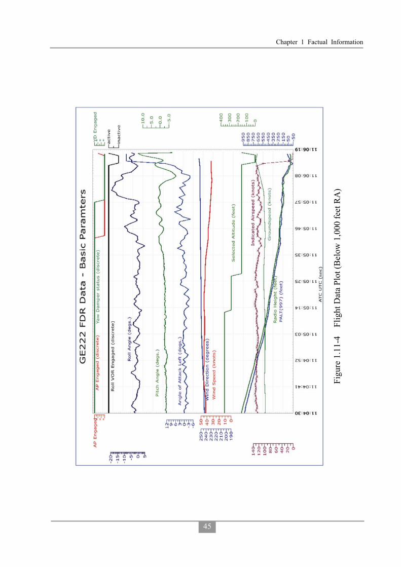
Chapter 1 Factual Information
45
Figu
re 1
.11-
4Fl
ight
Dat
a Pl
ot (B
elow
1,0
00 fe
et R
A)

Aviation Occurrence Report
46
Figu
re 1
.11-
5Fl
ight
Dat
a Pl
ot (B
elow
250
feet
RA
)
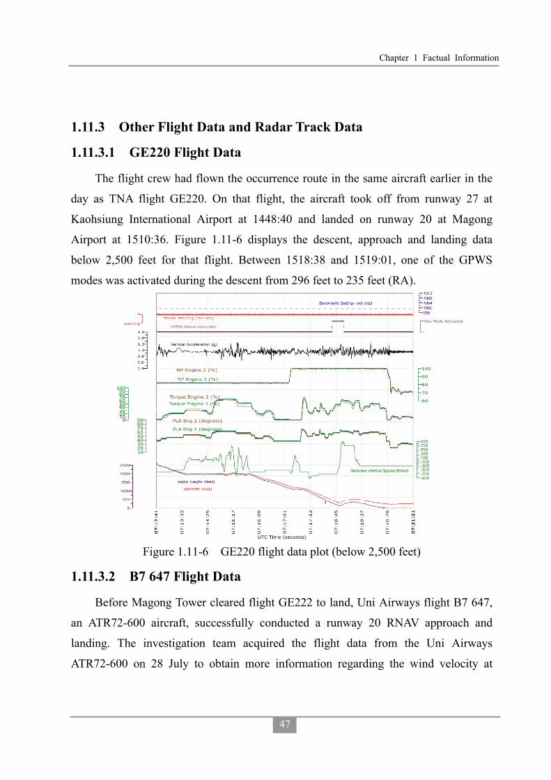
Chapter 1 Factual Information
47
1.11.3 Other Flight Data and Radar Track Data
1.11.3.1 GE220 Flight Data
The flight crew had flown the occurrence route in the same aircraft earlier in the
day as TNA flight GE220. On that flight, the aircraft took off from runway 27 at
Kaohsiung International Airport at 1448:40 and landed on runway 20 at Magong
Airport at 1510:36. Figure 1.11-6 displays the descent, approach and landing data
below 2,500 feet for that flight. Between 1518:38 and 1519:01, one of the GPWS
modes was activated during the descent from 296 feet to 235 feet (RA).
Figure 1.11-6 GE220 flight data plot (below 2,500 feet)
1.11.3.2 B7 647 Flight Data
Before Magong Tower cleared flight GE222 to land, Uni Airways flight B7 647,
an ATR72-600 aircraft, successfully conducted a runway 20 RNAV approach and
landing. The investigation team acquired the flight data from the Uni Airways
ATR72-600 on 28 July to obtain more information regarding the wind velocity at

Aviation Occurrence Report
48
Magong Airport. Figure 1.11-7 provides a plot of recorded parameters for that aircraft.
The data indicated that the ATR72-600 took off from runway 36 at Tainan Airport at
1705:10 on 23 July and landed on runway 20 at Magong Airport at 1857:25.
The flight parameters in Figure 1.11-7 include: UTC time, air/ground switch
status, pitch attitude, ro1l attitude, magnetic heading, wind speed, wind direction,
vertical acceleration, airspeed, ground speed, GPS latitude position, GPS longitude
position, and Baro-corrected altitude. The data indicated that below 2,000ft
baro-altitude, average wind speed was 22.5 knots +/- 6.6 knots, average wind direction
was 259 degrees +/- 4.6 degrees, and the average vertical acceleration was 1.0066 g +/-
0.061 g’s.
Figure 1.11-7 Uni Airways ATR72-600 Flight Data Plot
1.11.4 Flight Path Reconstruction and Unrecorded Parameters
1.11.4.1 Flight Path Reconstruction and Mapping
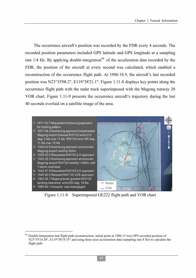
Chapter 1 Factual Information
49
The occurrence aircraft’s position was recorded by the FDR every 4 seconds. The
recorded position parameters included GPS latitude and GPS longitude at a sampling
rate 1/4 Hz. By applying double-integration40 of the acceleration data recorded by the
FDR, the position of the aircraft at every second was calculated, which enabled a
reconstruction of the occurrence flight path. At 1906:18.9, the aircraft’s last recorded
position was N23°35'08.2", E119°38'21.1". Figure 1.11-8 displays key points along the
occurrence flight path with the radar track superimposed with the Magong runway 20
VOR chart. Figure 1.11-9 presents the occurrence aircraft’s trajectory during the last
40 seconds overlaid on a satellite image of the area.
Figure 1.11-8 Superimposed GE222 flight path and VOR chart
40 Double-Integration and flight path reconstruction: initial point at 1906:15 was GPS recorded position of
N23°35'14.30", E119°38'19.35" and using three-axes acceleration data (sampling rate 8 Hz) to calculate the flight path.

Aviation Occurrence Report
50
Figure 1.11-9 Superimposed GE222 flight path with satellite imagery for the last 40 seconds.
1.11.4.2 Unrecorded Parameters and Derived Parameters
The reference distance between the aircraft and Magong runway 20 threshold,
vertical speed, control column position and control wheel position were derived from
the relevant recorded parameters.
Calculation of Reference Distance and Vertical Speed
Based on the FDR recording parameters (DME 1, DME 2) and the relevant way
points around Magong Airport, the flight crew selections on the on-board GPS were
calculated.
The results indicated that during the approach, from 1857:13 to 1858:37, DME 1
and DME 2 recorded the distance of the occurrence aircraft to the MKG VOR 13 DME
(the initial approach fix). From 1858:38 to 1901:45, DME 1 and DME 2 recorded the
distance of the occurrence aircraft to MKG VOR. From 1901:46 until the end of the
FDR recording, DME1 recorded the distance to MKG VOR; DME 2 recorded the
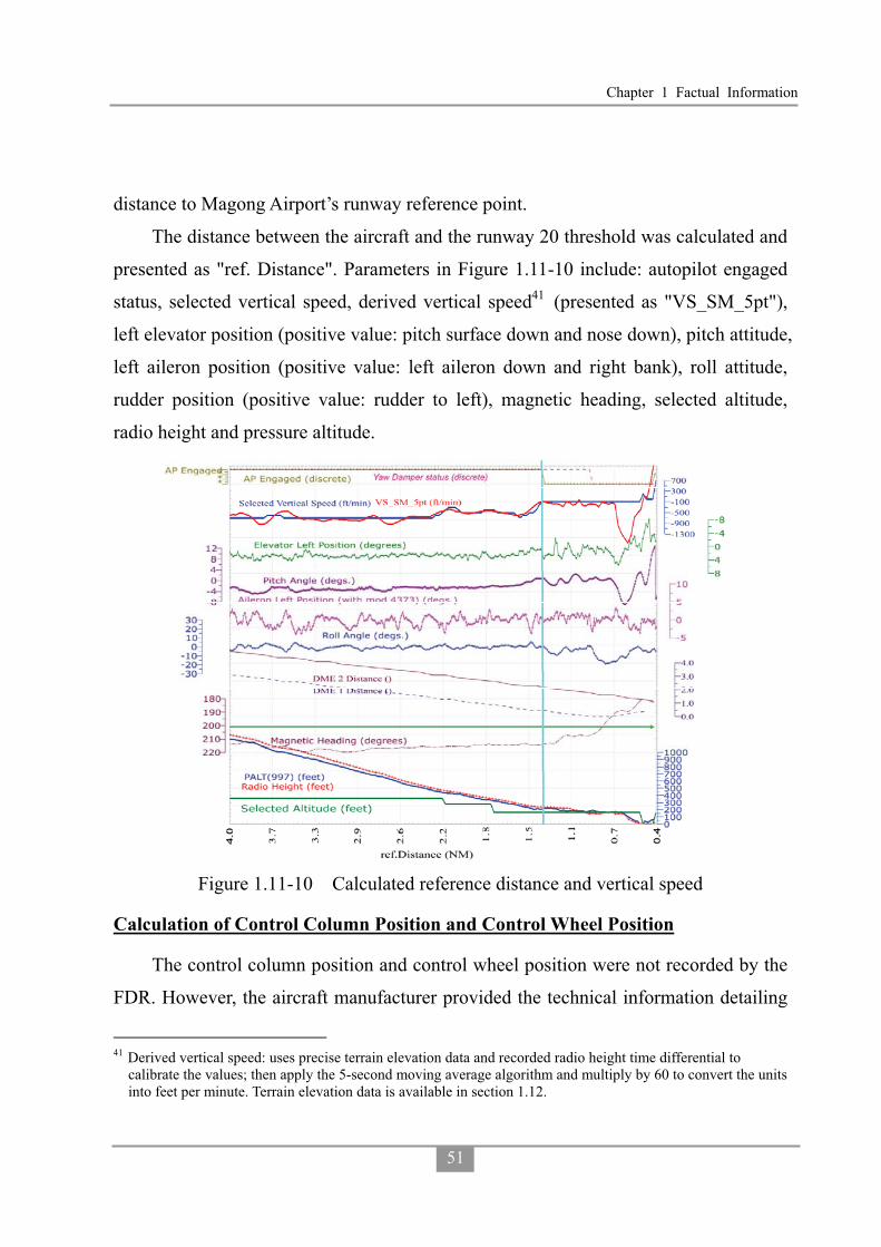
Chapter 1 Factual Information
51
distance to Magong Airport’s runway reference point.
The distance between the aircraft and the runway 20 threshold was calculated and
presented as "ref. Distance". Parameters in Figure 1.11-10 include: autopilot engaged
status, selected vertical speed, derived vertical speed41 (presented as "VS_SM_5pt"),
left elevator position (positive value: pitch surface down and nose down), pitch attitude,
left aileron position (positive value: left aileron down and right bank), roll attitude,
rudder position (positive value: rudder to left), magnetic heading, selected altitude,
radio height and pressure altitude.
Figure 1.11-10 Calculated reference distance and vertical speed
Calculation of Control Column Position and Control Wheel Position
The control column position and control wheel position were not recorded by the
FDR. However, the aircraft manufacturer provided the technical information detailing
41 Derived vertical speed: uses precise terrain elevation data and recorded radio height time differential to
calibrate the values; then apply the 5-second moving average algorithm and multiply by 60 to convert the units into feet per minute. Terrain elevation data is available in section 1.12.

Aviation Occurrence Report
52
the relationships between control column position, control wheel position, elevator
deflection and aileron deflection which allowed the positions of those flight controls to
be calculated42.
Figure 1.11-11 depicts the following parameters below 2,000 feet, including:
derived control column position, derived control wheel position, aileron left position,
elevator left position, pitch attitude, roll attitude, selected vertical speed, derived
vertical speed, radio height and pressure altitude.
Figure 1.11-11 Derived control column and control wheel positions and associated parameters below 2,000 ft.
1.12 Wreckage and Impact Information
1.12.1 Site Survey
The investigation team utilized GPS equipment, compass, and measuring tape to
conduct a ground survey of the occurrence site. The team also deployed an
42 Detail information is available in GE222 Factual Report 09 Flight Recorders, Appendix 9-6.

Chapter 1 Factual Information
53
autonomous rotary-wing unmanned aerial vehicle (UAV) to conduct an aerial survey of
the site. The UAV was equipped with on-board GPS, pressure altitude sensor, digital
compass and digital camera, which enabled it to fly a pre-defined route and take
photos.
Figure 1.12-1 illustrates that the aircraft wreckage was distributed in two areas:
the foliage or brushwood area (Zone 1); and the residential area (Zone 2). The aircraft
impacted terrain approximately 850 meters north-east of the threshold of runway 20 at
Magong Airport and then collided with a residential area on the outskirts of Xixi
village approximately 200 meters to the south-east of the initial impact zone.
Figure 1.12-1 GE222 site survey zones superimposed on Google map
1.12.1.1 Terrain Profile and Height of Foliage
The UAV aerial survey generated a geo-reference map and 3D terrain model
(DSM43) of the occurrence area. Figure 1.12-2 shows the UAV area of operations
superimposed on the occurrence flight path with timings and wreckage zones.
43 DSM - digital surface model, represents the earth's surface, and includes all objects on it.

Aviation Occurrence Report
54
Figure 1.12-2 Superimposed GE222 flight path with time marks and wreckage zones
A set of terrain data (DTM44) from the National Land Survey and Mapping Center
(NLSC) was obtained to compare with the UAV survey results. The results are shown
in Figure 1.12-3. The comparative terrain profiles are depicted for the last 9 seconds of
the occurrence flight and extend a further 200 meters to ensure coverage of the
wreckage display and associated collateral damage.
44 DTM - digital terrain model, represents the bare ground surface without any objects like plants and buildings.
The DSM and DTM data provided by the NLSC was measured between year 2007 and 2009.

Chapter 1 Factual Information
55
Figure 1.12-3 Comparison of terrain profiles
1.12.2 Wreckage in Zone 1
Zone 1 comprised brushwood, trees and other foliage, which were damaged by
the initial impact. The height of the foliage varied from 4.4 meters to 6.5 meters. The
area of the initial impact zone was approximately 110 meters by 10 meters.
The aircraft cut a swathe through the foliage as depicted in Figure 1.12-2.
Moreover, Figures 1.12-4 (a), (b), (c) illustrate two parallel grooves through the
brushwood on a heading of 170 degrees with a width between 5 meters and 7 meters.
The damaged tree tops indicated where the aircraft first impacted the foliage. The
area contained many bent trees and broken branches.

Aviation Occurrence Report
56
Figure 1.12-4 Initial impact point and damaged foliage in Zone 1
Damaged foliage and relevant tree height (H) information is depicted in Figure
1.12-5 (a) Damaged trees on the ground, (b) Damaged tree in canopy (H=6.3 meters),
(c) Damaged tree in canopy (H=5.5 meters), (d) Felled trees . The largest damaged
tree had a diameter of about 25 cm.

Chapter 1 Factual Information
57
Figure 1.12-5 Damaged foliage and relevant trees
Some aircraft wreckage was found along the swathe through the foliage. Those
pieces of wreckage were identified as: nose landing gear aft doors, radome, left-hand
heat exchanger, ram air inlet, ram air check valve, left-hand main landing gear door,
belly fairing inspection doors, and belly fairing panels. The superimposed aircraft
wreckage distribution and identified components on the UAV’s orthogonal image45 is
shown in figure 1.12-6.
45 The ground resolution of the UAV orthogonal image was 5 centimeters.

Aviation Occurrence Report
58
Figure 1.12-6 Superimposed aircraft wreckage distribution and component photos
1.12.3 Wreckage in Zone 2
Zone 2 was located in a residential area of Xixi village. The trajectory of the
aircraft was from north to south. The aircraft collided with multiple buildings and
broke apart into several major sections. The main wreckage site, which included the
cockpit, forward fuselage, left wing, and no.1 engine came to rest in a street in the
south of Zone 2. The distance between the main wreckage site and the first building
collision was about 120 meters. Figure 1.12-7 depicts the aircraft wreckage distribution
overlaid on a Xixi village street map. The red area indicates extensive damage to
housing; the yellow area indicates houses with minor damage; and the light blue area
indicates undamaged houses. In addition, smaller items of debris such as passenger
seats, window frames, baggage, and fuselage skin were scattered throughout Zone 2
over an area of approximately 80 meters by 120 meters. The aircraft main wreckage
distribution and damaged buildings are shown in Figure 1.12-8.

Chapter 1 Factual Information
59
Figure 1.12-7 Wreckages distribution overlaid on Xixi village street map

Aviation Occurrence Report
60
Figure 1.12-8 Aircraft main wreckage distribution and damaged buildings
Building no. 7-1 was the first building that the aircraft collided with. It exhibited
impact damage primarily on its northern wall. One window on the second floor was
shattered and the wall was pushed in. The iron bars reinforcing the wall structure were
damaged in the direction of aircraft movement.
The damage on the second floor was consistent with a main landing gear impact.
The northeastern corner of the roof exhibited rubber traces from either the tires or wing
deicing boots. Five parallel, almost evenly distributed, witness marks were visible on
the top of the roof. Those marks were consistent with contact from the right side
propellers. There was also a long prominent mark almost as wide as the wall, at the
top of the northern side of the building. It continued on to the western wall. The mark
was close to horizontal (approximately 10 to 15 degrees). That damage was consistent
with right-wing impact. Figure 1.12-9 depicts the relevant aircraft impact marks,
propeller marks, rubber marks and cracks at no. 7-1 building.

Chapter 1 Factual Information
61
Figure 1.12-9 Initial aircraft impact, propeller, and rubber marks on building
1.12.4 Power Plant
Both engines were recovered from the occurrence site. The no.1 engine was still
attached to the left wing. The propeller pitch angle was estimated to be -10°. The no.1
engine air inlet was found full of tree debris. An impact dent was located at the lower
part of the intake (see Figure 1.12-10).

Aviation Occurrence Report
62
Figure 1.12-10 No.1 Engine
The no.2 engine had separated from the wing but was located in wreckage Zone 2
(see Figure 1.12-11). The propeller pitch angle was estimated to be 10°. No tree debris
was found in the air inlet. The remaining propeller blades from the no.2 engine
sustained more impact damage than the propellers from the no. 1 engine.
Figure 1.12-11 No.2 Engine

Chapter 1 Factual Information
63
� No.1 Engine Examination (S/N AV0051)
External Condition: The engine was still fully contained in its nacelle. The rear
portion of the nacelle showed fire damage between the 6 and 9 o’clock position, just
forward of the exhaust case. The remainder of the nacelle was structurally intact. The
engine was partially covered in soot; however, there was no evidence of fire
originating from the engine itself. The damage was consistent with an external
post-impact fire.
External Cases: All cases were structurally intact. All oil, fuel and air lines
including the P3 line from the intercompressor case to the fuel control were intact. All
fittings leading to the fuel control were tight and secured.
Turbine Section: Examination of the second stage power turbine through the
exhaust showed no evidence of damage. Oil residues covered some blades. The turbine
assembly was free to rotate and continuous with the propeller. The power turbine
blades exhibited no evidence of impact damage.
Combustion Section: The internal components were not examined. Externally,
the fuel nozzles, manifolds and all fuel delivery tubes were intact and no evidence of
fuel leakage was observed.
Compressor Section: The engine inlet was filled with a large quantity of organic
debris mostly comprising small branches twigs and cone nuts. This debris was carried
from the time the aircraft exited the initial impact zone with the tree line to its final
post-crash resting point. The visible portion of the impeller showed light leading edge
impact damage.
Reduction Gearbox: The internal components were not examined. Free rotation
was observed and no evidence of internal distress was noted during rotation.
Accessory Gearbox: The internal components were not examined. Free rotation
and continuity was observed with the high pressure rotor.
Controls and Accessories Evaluation: All components were intact and no visual

Aviation Occurrence Report
64
damage was observed. The fuel control unit, fuel pump, electronic engine control,
propeller controller (PEC) and propeller valve module (PVM) were retained for
precautionary examination should it be required.
No.1 Engine Chip Detectors and Filter Checks: Detailed observations listed in
Table 1.12-1.
Table 1.12-1 No.1 engine chip detectors and filter checks Item Observation
Main Chip Detector Clean
Main Oil Filter Clean of any large debris. The residual oil contained in the housing appeared to contain a small quantity of fine shiny metallic like debris.
Reduction Gearbox Scavenge Chip Detector Clean
Reduction Gearbox Scavenge Oil Filter
The filter was clean. The filter housing contained only a small quantity of oil which could not be drained into a sample container. The oil appeared clear and free of debris.
Fuel Filters The low pressure filter was clean. The housing was clean but contained no residual fuel. The high pressure filter was not examined and remained with the fuel pump.
� No.2 Engine Examination (S/N EB0069)
External Condition: The engine nacelle was heavily damaged and partially torn
from the engine. The engine showed impact damage on most external oil, fuel and air
lines. The P3 line from the intercompressor case to the fuel control was intact and all
fittings were tight and secure. Fracture of the rear inlet case resulted in axial
displacement of approximately 10° towards the right side in the plane of the diffuser
case. This partially exposed the low pressure impeller shroud and gave partial access to
the impeller which could be rotated with force on a small arc. Tactile examination of
accessible impeller blades revealed light leading impact damage. Soot and fire damage
to the external airframe components was observed behind the firewall. There was no
evidence that this fire originated from the engine itself.
External Cases: All reduction gearbox housings appeared intact.

Chapter 1 Factual Information
65
Inlet Cases: The rear inlet case/accessory gearbox was fractured adjacent and
into the bolting flange to the low pressure diffuser case between the 2 and 6 o’clock
position. The low pressure diffuser case was intact except for some slight bending of
its mounting flange where the rear inlet case was found fractured. The intercompressor
case appeared structurally intact. The gas generator case appeared structurally intact.
The impact damage to the turbine support case was visible in the plane of the power
turbines. The damage was located between the 11 and 12 and between the 2 and 3
o’clock position. This damage prevented removal of the engine exhaust duct.
Turbine Section: The power turbine module was free to turn with no apparent
restriction. The shaft was no longer coupled to the reduction gearbox and propeller.
Removal of the torque shaft cover on the front inlet case revealed no damage to the
torque shaft. This suggested that the shaft was sectioned at a location corresponding to
the axial displacement of the engine. The power turbine blades exhibited no evidence
of impact damage.
Combustion Section: The internal components were not examined. Externally,
the fuel nozzles, manifolds and all fuel delivery tubes were intact and no evidence of
fuel leakage was observed.
Compressor Section: The compressor inlet revealed a significant amount of mud
accompanied with small rocks adhering to all surfaces. The impeller showed light
impact damage to the leading edge of all blades. The impeller could be moved only
slightly and was not capable of rotation.
Reduction Gearbox: The gearbox was intact. Internal components were not
examined.
Accessory Gearbox: The gearbox portion from the rear inlet case was intact. The
transfer tube of the drive shaft to the angle drive was bent and dislodged exposing the
drive shaft itself.
Controls and Accessories Evaluation: The AC generator drive shaft was
fractured at the “shear shaft” feature. The fracture surface showed features

Aviation Occurrence Report
66
characteristic of torsional overload with no evidence of fatigue. The handling bleed
valve was fractured from the engine and heavily damaged by impact. Fracture of the
oil cooler support was noted. The fuel control unit, fuel pump, electronic engine
control, PEC and PVM were intact and retained for precautionary examination should
it be required.
No.2 Engine Chip Detectors and Filter Checks: Detailed observation listed in
Table 1.12-2.
Table 1.12-2 No.2 engine chip detectors and filter checks Item Observation
Main Chip Detector Clean
Main Oil Filter
The oil filter was clean. Residual oil found in the housing contained what appeared to be a small amount of metallic like fine particles. The oil was very cloudy and showed a slight greenish color. The impending bypass indicator was in the stowed position.
Reduction Gearbox Scavenge Chip Detector Clean
Reduction Gearbox Scavenge Oil Filter
The filter was clean. Residual oil contained in the filter appeared clear but contained a small amount of what appeared to be fine metallic like particles. The impending bypass indicator was in the stowed position.
Fuel Filters The low pressure filter was clean. The housing was also clean and contained residual fuel clear in color. No phase separation was noted and no visual contaminants were visible.
1.12.4.1 Fuel and Oil Samples
The occurrence aircraft’s fuel and oil samples and associated filters taken from
both engines were sent to a Taiwan Air Force Laboratory for examination on 6 August
2014. The engine manufacturer reviewed the results. No anomalies which could have
prevented normal engine operation were found.
1.13 Medical and Pathological Information
1.13.1 Medical Treatment of Injured
The injured were initially transported to Penghu Hospital and Tri-Service General

Chapter 1 Factual Information
67
Hospital, Penghu Branch. They were then transported to various hospitals in Taiwan
main island a few days later when they were in a stable condition.
1.13.2 Flight Crew Medical History
The captain’s medical records indicated that he had hypertension. The treatment
included taking a Syntace46 10mg/tablet and an Amlodipine47 5mg/tablet per day.
1.13.3 Flight Crew Toxicology
The Institute of Forensic Medicine (IFM), Ministry of Justice, conducted
toxicology examinations of the two flight crew members. The test items included
alcohol content, poisons, sedatives, hypnotics, carbon monoxide hemoglobin and the
basic drugs screen (about one thousand items).
The captain’s toxicology report indicated 1% of carbon monoxide in the
hemoglobin and the presence of Ramipril48 and Amlodipine in the urine. No other
drug or toxin was detected.
The first officer’s toxicology report was clear.
1.13.4 Flight Crew Autopsies
The forensic pathologists from the IFM conducted the autopsies of the two flight
crew members.
The autopsy reports indicated that both flight crew members had suffered multiple
traumatic injuries.
1.13.5 Victims’ Inspections
The victims’ inspections conducted by the IFM indicated that the primary causes
of death were multiple traumatic injuries and burns.
46 The product name of Ramipril. 47 Amlodipine: A calcium channel blocker heart medication used in the treatment of hypertension. (FAA website:
http://jag.cami.jccbi.gov/toxicology/DrugDetail.asp?did=128) 48 Ramipril is an angiotensin-converting enzyme (ACE) inhibitor, used to treat hypertension and congestive heart
failure. (FAA website: http://jag.cami.jccbi.gov/toxicology/DrugDetail.asp?did=279)

Aviation Occurrence Report
68
1.14 Fire
1.14.1 Notification and Dispatch
The local Magong fire bureau’s notification records indicated that three people
reported the aircraft accident and/or houses on fire between 1906 and 1912. At 1907:12,
the local emergency command center initially dispatched 1 fire engine (2 people), 1
water tank (2 people) and 1 ambulance (1 person) from the Huxi firefighting station to
the scene. At 19:09, the command center was noticed that the aircraft had crashed by a
local policeman. After the first responders arrived on site at 1912:45 and reported the
situation to the command center, a further 30 firefighting and search and rescue
personnel from Peng Nan, Baisha, Shiyeu and Magong firefighting stations were
dispatched to the scene.
According to airport task logs and local fire bureau notification records, at
approximately 1910, the Magong air traffic control tower notified the airport’s airside
operations division that they had lost contact with an aircraft. At 1929, airport
personnel confirmed that an aircraft had crashed and notified the local fire bureau.
Three airport standby fire fighting vehicles were dispatched to the scene after the
airport was closed at 1943.
1.14.2 Post Fire and Fire Fighting
According to interviews with Xixi village residents, at around 1900, there was
heavy rain with thunder and lightning in the area. A few minutes later, one of the
residents heard a loud bang similar to thunder and then heard a noise like a rotating
propeller hitting objects. The resident walked outside from his house and saw flames
erupting nearby in front of an alley. He notified emergency services immediately.
Interviews with the local fire fighters revealed that their vehicles could not access
the occurrence site because the alleyways in the village were too narrow. The fire
fighters did not see any smoke or fire when they first arrived at the village. When they
disembarked from their vehicles to confirm the location of the occurrence site, they

Chapter 1 Factual Information
69
heard a loud explosion and saw towering flames. The fire fighters positioned their
hoses along an alley towards the occurrence site. Their efforts were impeded by a
further explosion and the need to don oxygen masks. They attempted to extinguish the
burning cockpit and wing sections using foam. They also requested more personnel
and vehicles for support. The fire was suppressed at 2005 and extinguished at 2037.
However, the fire reignited at 0231 the next morning. Firefighting personnel from Huxi
station were dispatched to extinguish the secondary flare up.
The local fire bureau’s records and report indicated that there had been a total of
87 firefighting and rescue vehicle movements, 26 ambulance movements and a total of
1,526 people involved in the search and rescue response.
1.15 Survival Aspects
1.15.1 Escape from the Aircraft
The surviving passengers reported that the aircraft encountered frequent
turbulence on the occurrence flight and that there was heavy rain with thunder and
lightning before the aircraft approached Penghu. At approximately 1900, the captain
announced to the passengers to prepare for landing. Shortly thereafter, there were loud
impact sounds. The aircraft was still moving after the initially impact until it finally
came to a stop. The aircraft’s front cabin was engulfed in flames and the fuselage broke
apart. Some passengers were thrown out of the cabin while the aircraft was still
moving forward and other passengers ran out of the cabin through the holes in the
fuselage. There were two reported explosions after the survivors egressed from the
aircraft. Most of the surviving passengers went to a nearby house for help.
1.16 Tests and Research
1.16.1 EGPWS Simulation Flights
No EGPWS warning was recorded by the aircraft’s FDR or CVR. However, the
FDR records indicated that an EGPWS warning had occurred on the same aircraft with
Aviation Occurrence Report
70
the same flight crew, operating the same route49 on approach to Magong earlier on the
day of the occurrence. To determine if the aircraft’s EGPWS was operating correctly
on the day of the occurrence a series of simulated flights were conducted using the
aircraft manufacturer's flight simulator at Toulouse, France, on 5 November 2014. The
testing also examined the nature of the EGPWS warning that had occurred on GE220
earlier on the day of the occurrence. The testing indicated that50:
� The investigation team conducted three simulations of the occurrence flight using
the FDR data. None of the simulated flights triggered an EGPWS terrain warning
because the flight profile was just outside the terrain warning zone.
� The investigation team also conducted three simulations of the earlier flight
GE220 using the applicable FDR data. Consistent with the actual flight, all three
simulated flights triggered the EGPWS alerts "Too Low Terrain" and "Terrain
Ahead Pull-up. The alerts were activated at 1.6 nm or 1.8 nm from the Magong
VOR station.
1.16.2 EGPWS NVM Data Download and Simulation
The aircraft was equipped with a Honeywell EGPWS model MARK VIII. The
EGPWS computer (Part Number: 965-1216-011, Serial Number: 2573) was recovered
from occurrence site. According to maintenance records, the EGPWS database was
updated on 23 April 2014 and contained the current version 470, which included
runway data for Magong Airport.
The recovered EGPWS computer was sent to Honeywell for non-volatile memory
(NVM) data download. The data download was performed by Honeywell on 16
October 2014 and witnessed by the United States National Transportation Safety Board
(NTSB). At ASC’s request, Honeywell used the downloaded data and FDR data to
49 TNA flight GE220 from Kaohsiung to Magong. 50 The simulation scenarios and settings were described in the Flight Operations Group Factual Report available
at www.asc.gov.tw.

Chapter 1 Factual Information
71
generate an “Analysis of enhanced ground proximity warning system” report for this
occurrence investigation. That report and further communications with the
manufacture indicated:
� EGPWS Warning Flight History Database did not contain alert event data for the
occurrence flight.
� No EGPWS caution or warning was triggered during the simulations of the
occurrence flight. The aircraft did not penetrate the terrain envelopes including
the TCF envelope, runway field clearance floor (RFCF) envelope and Terrain
Awareness “Look-Ahead” envelope for Software Version -011.
� EGPWS Warning Flight History Database for the earlier flight (GE220) on
approach to Magong included: “Too Low Terrain” (RFCF) at 346 feet Geometric
Altitude / 315 feet RA, “Terrain Ahead” at 226 feet Geometric Altitude / 182 feet
RA, and “Terrain Ahead Pull-Up” at 176 feet Geometric Altitude / 142 feet RA. A
comparison of the altitude data from the FDR and EGPWS indicated an altitude
analysis error of up to 170 feet for GE220.
� Simulation of the occurrence flight using the latest EGPWS software version
(-022 and newer) would have triggered the "Too Low Terrain" warning. That is,
the occurrence flight would have penetrated RFCF and TCF envelopes.
� The latest EGPWS software version (-022 and newer) requires hardware with
base part number 965-1180/1190/1210/1220/1610. The Honeywell service
bulletin relevant to this new version is ATA No. 965-1180/ 1190/ 1210/ 1220/
1610-XXX-34-33 (Pub. No. 012-0709-133)51 which was released on 14 August
2004.
� The Honeywell Service Information Letter, SIL NO. EGPWS-MKVI-MKVIII- 07,
released on 30 May 30 2003, referred to the introduction of new Honeywell Mk
VI/VIII EGPWS part numbers: numbers: 965-1180-020, 965-1190-020,
51 This SB was not applicable to the EGPWS (P/N: 965-1216-011) installed on the occurrence aircraft.

Aviation Occurrence Report
72
965-1210-020, 965-1220-020 and Real Time Clock Configuration Module,
700-1710-020.
� No faults were present in the downloaded EGPWS data to suggest a malfunction
of the aircraft’s EGPWS system. No alert was generated by the EGPWS during
the occurrence flight. Therefore, no data was recorded by the EGPWS and the
actual parameters being monitored were not retained. If the EGPWS installation
utilizes the barometric altitude rate52, for turboprop aircraft, the presence of
ground effect on the barometric rate data prevents its use close to the ground
because of the potential for nuisance warnings. Consequently, Mode 1 is inhibited
at 50 feet radio altitude. In addition, there is a 0.8 second delay for the "Sinkrate"
caution to minimize nuisance alerts caused by momentary penetration of the outer
envelope. There is also a delay for the "Pull Up" warning to guarantee that at least
one "Sinkrate" (or equivalent) message will be annunciated before the "Pull Up"
message is activated.
1.16.3 Simulation Flights of GE222 Performance
To further understand the occurrence aircraft’s performance and behavior under
different conditions, two additional simulator sessions were conducted at the ATR
training center, Toulouse, France from 5 to 7 November 201453. The main objective
was to understand the ATR72-500’s performance under the following conditions:
� Stabilized power settings during the occurrence approach
� AFCS and FD behavior when approaching and passing Magong VOR
� Aircraft behavior after the AP disconnected
� Aircraft behavior after the YD was disengaged
52 Product specification for the MK VI and MK VIII Enhanced Ground Proximity Warning System, EGPWS,
P/Ns_965-1176-XXX. 53 The full flight simulators (FFS) are designed and certified for training purposes based on mandatory items
defined by the respective certification authorities (such as the European Aviation Safety Agency (EASA) and FAA). In that intent any test performed on an FFS, outside of the above mentioned mandatory items, may not be fully representative of the aircraft handling characteristics.

Chapter 1 Factual Information
73
� Rudder force required to disengage the YD
� Control column force required to obtain 9° pitch down
� Descent rate with 9° pitch down
� AFCS basic mode
The simulated flight profile was derived from the FDR occurrence data and the
weather at the time of the occurrence. The final approach profile was flown in
accordance with the ATR maneuver guide54.
The findings from the simulated flights included:
� 28 % torque (TQ) was required on both engines to stabilize the descent at a 700
feet/minute descent rate and 125 knots Indicated Air Speed.
� 43 % TQ was required on both engines to stabilize the descent at a 100
feet/minute descent rate and 125 knots Indicated Air Speed.
� If the aircraft remained on course, the course deviation bar on the EHSI
(electronic horizontal situation indicator) remained center and the green VOR
changed to green VOR* on the ADU when the aircraft passed the Magong VOR
at either 200 feet or 500 feet altitude.
� Aircraft attitude did not change after the AP was disconnected.
� Aircraft banked to 9° left after the YD was disengaged with minor left bank angle
(1°or 2°).
� Aircraft banked to 11° right after the YD was disengaged with minor right bank
angle (1°or 2°).
� 30 daN rudder pedal force was required to disengage the YD.
� 15 daN control column push force was required to reach 9° pitch down.
� Base on the simulation results55, 4 sets of data were presented to indicate the
54 The scenarios and setting of the simulation are described in the GE222 Flight Operation Group Factual Report
at www.asc.gov.tw. 55 The simulation noted that the Vertical Speed Indicators showed a descent of 900 feet/minute with 9° pitch
down, which was published in the Flight Operations Group Factual Report. After reviewing the vertical speed recorded in the simulator, the investigation team decided to use the recorded data instead of the observed data.

Aviation Occurrence Report
74
aircraft response to the pitch down attitude commanded by the occurrence captain.
Compared to the FDR data which indicated that the occurrence aircraft pitched
down to -9° at 1906:09, the results of the simulations were a pitch down to -7.1°,
with a maximum descent rate of 1,400 feet/minute; pitch down to -7.5°, with a
maximum descent rate of 1,300 feet/minute; pitch down to -9.7°, with a maximum
descent rate of 1,600 feet/minute; pitch down to -8.0°, with a maximum descent
rate of 1,450 feet/minute. The results of the simulations are attached in Appendix
4. In addition, the simulated performance of the aircraft was re-examined using
different turbulence intensity settings. No aircraft performance differences were identified between the conditions with and without turbulence56.
1.16.4 Line Operation Observation
The purpose of the line operation observations was to develop an understanding
of operational practices on TNA’s ATR72-500 fleet
A total of 24 flights were observed between 4 August and 5 September 2014. All
flights were turn around flights from Songshan to Hualien, Magong, or Kinmen. A
summary of the findings were listed in Table 1.16-1.
Table 1.16-1 Findings from the line observation flights on TNA s ATR72-500 fleet
Item Line operation observations 1 Instead of using the applicable checklist, the flight crew actioned the normal checklists
from memory, especially after takeoff and after landing. 2 Some flight crew did not refer to the applicable abnormal checklists while
encountering abnormal conditions such as, starter fault, bleed air fault and ice detection fault.
3 During aircraft systems preparation, clocks were not correctly set, and/or some crew dismissed that procedure.
4 During start engine phase, “FUEL FLOW RISING”, “ITT RISING”, “OIL PRESSURE RISING” the required callout response “CHECK” was not verbalized by
56 Turbulence intensity was set as high as 50%.

Chapter 1 Factual Information
75
Item Line operation observations some crew members
5 During the before takeoff phase, “LIGHT ON” check was supposed to be performed by checking the spoiler light panel after the associated pilot checked “SPOILER UP” by looking outside. It seemed that this procedure was just a called out by crew without actually visually confirming the status of the associated lights.
6 Take off TORQUE was not computed for certain flights. 7 During the climb phase, “GEAR UP SET” was not announced by PM57; “SET SPEED
TO WHITE BUG” was not called out by PF58 after the “ACCELERATION ALTITUDE” call by PM. Either “TEN MILES” or “ONE ZERO THOUSAND FEET” call outs were missed on certain flights.
8 Some crews were not following the climb speed specified in the standard operating procedure (SOP).
9 No call outs were made for IAS, V/S and HDG change and adjustment during AFCS operation.
10 During approach briefings, certain flight crew did not cross check the FMC or the approach course setting against the aeronautical charts.
11 During the approach phase, “OM/FAF/FAP, ALTITUDE ______ FEET”, “CHECKED ____ FEET” calls were not performed on certain flights, reported airport in sight well before 30NM to obtain a visual approach from ATC, and applied basic modes without good reason. Crew flew too low on some approaches as indicated by four red lights on the PAPI but without challenge and response calls from the PF and PM.
12 During the after landing phase, certain flight crew performed the after landing checklist from memory.
13 During the landing rollout phase, “LOW PITCH LIGHTS ON” call out was missed on certain flights.
14 Flight crew did not announce or positively identify and test the radio navigation aids selected before the approach. They also did not cross check the approach plate number and date with each other.
15 Some unstable approaches were observed with approach speeds in excess of Vref +20kts but the PM did not challenge the PF.
1.16.5 TNA Simulator Training Observation
The investigation conducted an abridged evaluation of the airline’s ATR72
simulation training and checking at TNA’s contracted training center in Bangkok,
Thailand.
Three simulator sessions were observed. Each session was four hours and split
57 PM is the designated pilot monitoring for the sector. 58 PF is the designated pilot flying for the sector.

Aviation Occurrence Report
76
evenly between two pilots. The last transition training lesson 7 was observed on 12
October 2014 with two first officer trainees. The transition check was observed on 14
October 2014 with the same flight crew. Proficiency training was observed on 15
October 2014 with a line captain and first officer.
The observations were summarized in Table 1.16-2.
Table 1.16-2 Observations of TNA ATR simulator sessions Item Simulator training observations
1 There were 19 technical subjects and 5 maneuvers, including steep turns, stall recovery, unusual attitude recovery, TCAS and EGPWS events to practice in the two hour session.
2 Non-precision approaches were conducted via step-down rather than with a constant descent profile as illustrated in TNA’s operations manual.
3 For an unusual high pitch attitude with bank, pilot under instruction was told to recover by leveling the wing first then lowering the nose. The trainee did not challenge the instructor for that non-compliance with the TNA Flight Crew Training Manual.
4 DH for a non-precision approach was set on the electronic attitude director indicator (EADI) instead of the DH for a precision approach.
5 Both pilots operated the AFCS control panel with AP engaged, when the PF was designated to do so.
6 Scenario: ON GROUND ENG FIRE followed by ON GROUND EMER EVACUATION. The evacuation was executed immediately after the second fire extinguishing bottle was discharged without checking whether the fire had been extinguished. Had the fire been extinguished, there was no requirement to evacuate.
7 During two unstable approaches, one pilot failed by flying one dot too high on the glideslope at 1,000 feet but the other pilot passed when he was too high as indicated by 4 white PAPI lights on short final and a subsequent long landing.
8 TO/MCT was not selected on PWR MGT panel for EGPWS maneuver as required by procedures.
9 CL was not set OVRD position for TCAS escape maneuver as required by procedures. 10 The following discrepancies were not corrected by the instructors.
�4 white PAPI lights (too high on approach) were visible on short final, PM did not call it out and the PF was not instructed to correct it.
�PM did not callout speed low or high on short final. PF was not instructed to correct it.
�None of the pilots made the standard “Approaching Minimum” callouts during a non-precision approach.
�None of the pilots made the standard “OM/FAF” callouts during approach. � “Minimum” standard callouts were not made. �PM “FLAPS ZERO” and PF “CHECKED” standard callouts were not announced

Chapter 1 Factual Information
77
Item Simulator training observations during some flap movements.
�PM “GEAR UP SET” and PF “CHECKED” standard callouts were not announced during some landing gear operations.
� “Level two on” standard callouts for icing conditions were not made. �Start timing on start push button depressed during engine start. �CM159 “STARTER ON” CM2 “STARTER LGHT OFF” CM1 “CHECKED”
standard callouts were not made during engine start. �CM1 “TIMING” and “NOTCH” standard callouts were not made during take-off. �Some AFCS mode selection standard callouts were not made. �Missing ADU annunciation standard callouts. �ACW TOTAL LOSS abnormal checklist was only partially read. �After Take Off checklist was not executed. �The slip indicator was not in the correct position during single engine operations. �The aircraft descended during a single engine go around without the PM
announcing it. �LOC/GS deviation standard callout was not made. �Stabilized approach criteria were not met during a raw data ILS approach. �LO BANK was selected for simulator session. �NDB identification was not made by pilots.
1.16.6 Magong Runway 20 VOR Special Flight Inspection
After the occurrence, the ASC requested a validation of the VOR’s signal stability
for approaches. An inflight evaluation of the VOR was conducted by the CAA on 30
July 2014. The test procedure comprised three tests as follows:
The first test: The runway 20 VOR approach was flown commencing from an
altitude of 3,000 feet and 10 nm from the aid. The test aircraft flew overhead the VOR
at 330 feet.
The second test: The runway 20 VOR approach was flown commencing from an
altitude of 3,000 feet and 10 nm from the aid. The test aircraft flew overhead the VOR
at 200 feet.
The third test: The runway 20 VOR approach was flown commencing from an
altitude of 3,000 feet and 10 nm from the aid. The test aircraft completed the
59 CM1 refers to the crewmember in the LEFT hand seat; CM2 refers to the crewmember in the RIGHT hand
seat.

Aviation Occurrence Report
78
instrument approach to landing.
The test flight results were: Test Item First Test Second Test Third Test
Where did CDI begin to shift 1.5 NM (nautical mile) 1.4 NM 0.1 NM
How many dots of deviation were indicated on the CDI
2.0 dots maximum
(around 0.2 DME)
1.9 dots maximum
(around 0.2 DME)
2.0 dots maximum
(around 0.1 DME)
Where did the TO/FROM indication of the VOR begin to
oscillate to indicate station passage
0.5 NM 0.4 NM 0.1 NM
Note: According to the CAA’s Flight Check Group, Flight Standards Division, the distance described in the table was “before” passing the MKG VOR.
1.17 Organizational and Management Information
1.17.1 CAA Airline Operations Inspection
The primary objective of the CAA airline operations inspection regime is to
determine that a person, an item, or a certain segment of an operation associated with
air transportation meets at least the same standards that were required for initial
certification or approval by the CAA. For inspectors to make these determinations,
inspections must be conducted in an orderly and standardized manner. Each type of
inspection must have individual objectives and be conducted each time in generally the
same manner according to the direction and guidance in the CAA Operations
Inspector’s Handbook.
CAA inspectors were assigned to oversee each operator. The principal operations
inspector (POI) was the primary interface between the assigned operator and the CAA.
The POI was responsible for ensuring that assigned organizations met CAA regulations
and policies. The POI was also responsible for determining the annual surveillance and
inspection programs. The annual work program usually comprised annual, semi-annual,

Chapter 1 Factual Information
79
quarterly and monthly surveillance activities based on the inspection job functions. The
job functions were described in the Chapter 4, Volume II of the CAA Operations
Inspector’s Handbook.
CAA inspectors conducted 1,044 operations inspections60 of the operator from 1
August 2013 to 22 July 2014 and issued 41 comments, including 6 findings, 10
concerns and 25 recommendations. Of the 41 comments: 22 were related to the annual
Main Base Inspections in 2013 and 2014; 7 were related to flight safety events; and the
remaining 12 comments were the results of routine operations/cabin inspections. The
41 comments were classified according to their common characteristics:
� Record or sheet related deficiencies: 13 comments;
� Manual related deficiencies: 9 comments;
� Flight safety events follow-up: 7 comments;
� Insufficient personnel resources and staff turnover issues: 4 comments;
� Self-audit frequency or record related deficiencies: 3 comments;
� Flight crew did not carry license on their person: 2 comments;
� Cabin diagram or equipment deficiencies: 2 comments;
� Training insufficient: 1 comment.
Official records and documentation indicated that contact between the CAA and
TNA included quarterly flight safety meetings attended by the CAA POIs/AOIs61 and
senior TNA managers. Meeting agendas included the presentation of CAA safety
policy statements and instructions by POIs/AOIs.
The CAA POI assigned to TNA stated that there was no fixed format for the joint
CAA-industry meetings62 between the regulator and the operator. Numerous operator
meetings were held with the participation of the POI and operator’s staff on a regular
60 Total operations inspection activities. 61 Assistant Operations Inspector. 62 According to the CAA Operations Inspector’s Handbook Section 2.1.1, Chapter 1, Volume 1, the POI should
chair the joint CAA-industry meetings to maintain regular contact with the assigned organizations and coordinate with senior management officials.
Aviation Occurrence Report
80
and irregular basis. For example, meetings included instructor pilot/check pilot
meetings and flight safety meetings, in which key position holders attended and where
major safety issues and associated corrective measures and areas for improvement
were discussed. Meeting minutes were documented.
1.17.1.1 Cockpit En Route Inspection
The primary objective of the cockpit enroute inspections was for an inspector to
observe and evaluate the inflight operations of a certificate holder within the total
operational environment of the air transportation system. According to the CAA
Operations Inspector’s Handbook, enroute inspections were one of the most effective
methods of accomplishing the regulatory surveillance objectives and responsibilities.
These inspections provided the CAA with an opportunity to assess elements of the
aviation system that were both internal and external to an operator.
The CAA conducted 166 Cockpit En Route Inspections of TNA from 1 August
2013 to 22 July 2014 and issued one recommendation. It recommended that flight
crews hold a valid checklist and chart during the departure and arrival briefings; flight
crews performed each step of a given procedure and cross check to ensure that the
procedure had been actioned correctly in the interests of flight safety. The
recommendation was consistent with and indicative of flight crews not complying with
standard operating procedures. The CAA closed the case after TNA issued a relevant
notice to flight crews. Since it was not a requirement to follow up the actions taken for
a recommendation, no further assessment of the apparent procedural non-compliance
behavior was conducted.
1.17.1.2 Operator In-depth Inspections
The objective of an operator in-depth inspection was to determine if an operator
or repair station was in compliance with ICAO standards and recommended practices
(SARPs), domestic CAA regulations, and the operator’s manuals and procedures. The
inspection was designed to identify compliance deficiencies and ensure appropriate
Chapter 1 Factual Information
81
corrective actions were implemented. The inspection formed part of the CAA’s
systematic approach in fulfilling its regulatory surveillance responsibilities. One of the
key features of the inspection program included a focus on critical areas with
significant or acute deficiencies.
An in-depth inspection of an operator was normally conducted every three years
by a selected team of inspectors. The inspection was conducted in accordance with
specific terms of reference, scope and objectives. For example, the areas of an airline
to be examined were selected by the CAA’s Flight Standards Division. Such an
inspection might focus on operations, management and administration, operations
specifications, operations training, crew qualifications, manuals and procedures, flight
controls, flight operations, operations records and facilities and equipment. Inspection
methods included reviews of manuals, records and other documentation, reviews of
operator’s training programs and procedures, and an inspection of the operator’s
aircraft and facilities. The inspectors assigned to the operator were usually not part of
the team. However, they were advised of the inspection’s progress.
The in-depth inspection report contained findings that were categorized into two
groups: Category A which was any non-compliance with a regulation; and Category B
which was a failure of the operator to adhere to its documented standard operating
procedures that have been approved or accepted by the CAA’s Flight Standards
Division.
Non-compliance findings and associated corrective actions were followed-up by
the assigned POI.
Special in-depth inspections were conducted on an as-needed basis whenever
there were indications that the performance of a particular operator was falling below
an acceptable level or in the event of an accident, incident, violation, complaint or
serious company financial situation.
CAA conducted an in-depth inspection of the TNA flight operations division
(FOD), system operations control (SOC) and safety and security office from 14 to 30

Aviation Occurrence Report
82
August 2014 after the GE 222 occurrence. The inspection scope included: policy
making, operations standards, personnel analysis, operational systems, resource
requirements and corrective action schedule, etc. An inspection report was issued to
TNA on 16 October 2014. The safety issues identified during the in-depth inspection
included problems with: the airline’s safety management system (SMS) and flight
operations quality assurance (FOQA) systems, standardization of flight crew training
and checking, procedures for continuous descent final approach (CDFA), crew
resource management and flight crew fatigue management.
1.17.2 SMS Development and Oversight
1.17.2.1 CAA SMS Development Policy and Oversight
The Aircraft Flight Operations Regulations require all Taiwan civil aviation operators to establish and implement a SMS acceptable to the CAA. The Advisory Circular (AC) 120-32C63 for SMS issued on 25 January 2011 by CAA stated that an operator should develop, adhere to, and maintain a SMS implementation plan. The implementation plan should be based on the results of a SMS gap analysis64 and be endorsed by the operator’s applicable senior manager. The AC also provided guidance on developing a SMS implementation plan and suggested that an operator should develop a SMS in four progressive phases. The final phase should be completed by 31 December 2012.
The CAA was responsible for overseeing and assessing the implementation and
effectiveness of an operator’s SMS and included routine surveillance and SMS
assessment projects65.
63 The purpose of the AC was to describe an acceptable means for compliance with the requirements of CAR
07-02A, article 9, and CAR 06-02A, article 27, in the establishment and implementation of a safety management system. The AC also contained guidance material for operators and repair stations on how to implement and maintain a SMS.
64 A SMS gap analysis is the first step in developing a SMS. The analysis determines which components and elements of a SMS are currently in place and which components or elements must be included or modified to meet the SMS’s requirements.
65 Job Function 18.1 safety management system Assessment in Chapter 5, Volume II of CAA Operations

Chapter 1 Factual Information
83
SMS assessment projects were conducted by a specialist CAA SMS assessment
team. After an assessment, the POI was tasked with monitoring the operator’s
corrective actions.
As of the end of 2013, the CAA had conducted SMS assessments for six civil air
transportation operators and two repair stations. The objectives of the project66 were:
� To review/ensure SMS implementation of the certificate holders (operators and
repair stations) consistent with ICAO SMS documentation, and CAA
regulations and policy;
� To adjust CAA SMS promotional strategies and assist the certificate holders in
implementing an SMS effectively based on the data collected from the assessment
project.
All deficiencies identified during the SMS assessments were not to be categorized
as a finding or concern in the CAA flight safety management information system
(FSMIS), but rather the CAA was to notify the concerned certificate holder to improve
its SMS implementation plan and to comply with the regulations and CAA policy
within the SMS implementation timeline.
After the SMS assessment project, CAA held a SMS conference for senior
managers of operators and repair stations on 4 December 2013. The CAA
representatives at the conference advised that:
� The 2013 SMS assessment project identified that some operators had not
developed a SMS implementation plan, and therefore, recommended that all
operators establish a SMS implementation plan;
� Safety management system AC 120-32D will be published before 2014 and will
be based on the 3rd edition of the applicable ICAO DOC 9859 issued in May
2013;
Inspector's Handbook The 11th edition and effective date is January 1st, 2013).
66 The following information is based on the CAA response to the GE222 Investigation Questionnaire (Attachment 8-42).

Aviation Occurrence Report
84
� The timeline for SMS implementation will be extended until the end of 2015;
� SMS training courses will be provided to operators and repair stations before
2014; and
� The CAA will conduct a second SMS assessment in accordance with the SMS
development progress of operators.
The CAA conducted two SMS training courses for operators/repair stations on
19-21August 2014 and 15-17 September 2014.
The CAA issued AC 120-32D for SMS on 20 October 2014 and further extended
the SMS implementation timeline until 31 December 2016 (5 years required for the
implementation of a mature SMS) in accordance with ICAO Annex 19 and ICAO
Document 9859 Safety Management Manual 3rd edition issued in May 2013.
1.17.2.2 TNA SMS Development
The TNA conducted a SMS gap analysis in 2011. TNA did not develop a SMS
implementation plan which is required in the AC 120-32C. The TNA safety and
security office (SSO) Supervisor stated that the TNA developed SMS via internal
discussions and tasks assignments, and reviewed SMS development progress in routine
meetings.
The CAA conducted an assessment of TNA’s SMS between 23 April and 31 May
2013 and notified the assessment results to TNA via official document on 11 June 2013.
The official document indicated that the CAA had identified 24 deficiencies during the
assessment and required TNA to submit a corrective actions plan for re-assessment.
TNA did not officially submit any corrective actions plan to the CAA but engaged in
communications with the CAA about the corrective actions plan.
Interviews with the TNA SSO manager indicated that the CAA SMS assessment
team stated that the purpose of 2013 SMS assessment was to assist operators to
develop an SMS. Therefore, TNA thought that the SMS assessment results should be
considered as recommendations only, not deficiencies. TNA reported the status of their

Chapter 1 Factual Information
85
SMS implementation to the CAA on two occasions as a result of the POI’s inquiry.
Towards the end of 2013, TNA advised the POI orally that they would improve their
SMS through the acquisition of an SMS software system. In July 2014, TNA advised
the CAA via e-mail that they would complete their Safety Management Manual
(SMM) revision and implement the SMS software system by the beginning of 2015.
1.17.3 TNA Flight Operation Division
1.17.3.1 Organization Structure
The head of the airline’s flight operations division (FOD) was designated an
assistant vice president. The FOD comprised the fleet management department and
standard & training department as described in the flight operations division operations
manual67. The organization chart for the FOD is shown in Figure 1.17-1.
Figure 1.17-1 TNA flight operations division organization chart
1.17.3.2 Fleet Management Department
The manager of the fleet management department (FMD) was responsible for line
operations on the A320 fleet, A330 fleet, ATR fleet and administration. A chief pilot
was designated for each fleet. The responsibilities of the fleet management department
67 The 31st edition dated 2 February 2014.

Aviation Occurrence Report
86
included:
� Pilots’ personnel management;
� Assignment and execution of flight tasks;
� Flight time monitoring and record keeping; and
� SMS implementation and operational security.
1.17.3.2.1 ATR Fleet Manpower Management
In 2013, there were 9 ATR72-500 aircrafts in the TNA ATR fleet. In 2014, TNA
introduced ATR72-600 and phased out several ATR72-500 aircrafts. Since April 2014,
TNA had 10 ATR72 aircraft, including 3 ATR72-600s and 7 ATR72-500s. TNA data
indicated significant growth in demand for the airline’s services of 9.7% and 15.3%
between 2013 and 2014. However, the increase in flying activity was accompanied by
a 3.7% decrease in the number of pilots at the airline68.
The TNA staff advised that that the increase of one additional ATR aircraft to a
total of 10 aircraft was not in the original operating plan. TNA expected to maintain an
ATR flight crew/aircraft ratio of 6 to 1. That is, the ATR fleet of 10 aircraft required 60
pilots, which meant that the airline was 8 ATR crew short at the time of the occurrence.
The chief executive had decided not to phase out the 3rd ATR72-500 in order to
increase flight numbers. The issues associated with an insufficient number of ATR
flight crew and the subsequent increase in flight and duty times were highlighted but
the decision remain unchanged.
The airline subsequently changed the daily ATR flight patterns from a maximum
of 6 sectors/day in 2013 to a maximum of 8 sectors/day from May to July 2014.
In addition, the data also showed that 30 ATR fleet pilots had accrued over 270
hours cumulative flight time (CFT) from May to July in 2014. Compared with the
68 The ATR fleet had 2,376 revenue flights in May 2013. The revenue flights increased 231 flights to 2,610 in
May 2014. And 354 revenue flights increased from 2,311 flights in June 2013 to 2,665 flights in June 2014. However, the number of the ATR pilots decreased from 54 in May and June, 2013 to 52 pilots in the corresponding period of 2014.
Chapter 1 Factual Information
87
same period in 2013, there were only 4 pilots with CFT over 270 hours69. During the
peak travel season from July to September in 2013, there were 14 pilots with CFT over
270 hours70.
The coordinator responsible for pilot rosters and scheduling stated that the factors
contributing to the significant increase in CFT from May to July 2014 included the
introduction of the ATR72-600, increased revenue flights, and a reduction in the
number of available fight crew. Those factors were also the reasons that ATR pilots had
8-flight sectors in the daily schedule.
The FMD manager reported that the ATR fleet did have a crewing shortage in
2014. The monthly roster data also showed that flight crews had high average flight
times. The FMD manager stated that monthly flight times of 85 hours for three
consecutive months might be a warning signal from a fleet management perspective.
However, he stated that the Department had to accept this condition because the flight
times were still within the regulated flight and duty time limitations.
1.17.3.3 Standard & Training Department
An assistant manager was responsible for the Standard & Training Department,
which included three sections: Training Planning, Standardization and Training, and
Planning and Development. The tasks conducted by the Standard and Training
Department included:
� Establishing and revising flight crew SOPs;
� Conducting standard operations audits;
� Conducting aircraft performance analyses;
� Establishing and maintaining the flight operations manuals;
� Developing and implementing of digital learning systems for crew;
� Monitoring flight crews’ qualifications and certifications; and
69 GE 222 Captain (227.03hrs)/ First Officer (260.58hrs). 70 GE 222 Captain (256.13hrs)/ First Officer (297.95hrs).

Aviation Occurrence Report
88
� Implementing operational aspects of the SMS.
The Standard & Training Department provided the following flight crew trainings
and checks for all aircraft, including the ATR fleet:
(a)Aircraft Type Training
(b)Ground School
(c)Initial Training
(d)Recurrent Training
(e)Transition Training
(f)Upgrade Training
(g)Instructor and Examiner Training
(h)Ab-initio Training
(i)Re-Qualification Training
(j)Cross Crew Qualification (Airbus) and Differences (ATR) Training.
In addition, the standard & training department provided dangerous goods
training and special operations training, such as reduced vertical separation minimum
(RVSM), performance based navigation (PBN), extended range twin-engine operations
(ETOPS), low visibility operations (LVO), cold weather operations, high elevation
airport operations, and fatigue management.
TNA flight crews received two hours of crew fatigue management training in
April 2013. That training addressed revised flight and duty time limitations and rest
periods in the CAA’s Aircraft Flight Operations Regulations. Advanced training
regarding to crew fatigue was not provided and the airline had not implemented a
fatigue risk management system (FRMS) nor was it required to do so at the time of the
occurrence.
The CAA had authorized the standard & training department to nominate suitably
qualified and experienced training captains as designated pilot examiners (DPE) to
conduct aircraft type rating checks.
Chapter 1 Factual Information
89
Between 2011 and 2013, only one pilot had failed a proficiency check on the
ATR72-500 fleet. All other pilots on the fleet had passed the type rating, proficiency
and line checks during that period.
1.17.3.3.1 Standardization & Training Section
An Airbus A330 captain managed the airline’s standardization & training section
(STS) and was designated as the STS Supervisor. While the STS Supervisor officially
had no support staff, the airline’s designated instructor pilots (IPs) and check pilots
(CPs) were tasked with assisting the STS Supervisor in the conduct of the airline’s
check and training program. The responsibilities of the STS Supervisor included:
� Establishing and revising flight crew SOPs, checklists and relevant training
manuals;
� Collating and preparing flight crew training materials and the test database;
� Supervising the conduct and performance of the IPs and CPs;
� Evaluating and improving flight crew training programs; and
� Participating in pilot selection and evaluation.
1.17.4 TNA Safety Management Organization and Activities
1.17.4.1 Safety Committee
According to TNA’s Safety Management Manual71 (SMM), the airline safety
committee was responsible for reviewing the overall safety performance of the
operations in the company. The President of the company was the chairman of the
safety committee. The Committee members included managers from the FOD and the
SSO. The SSO manager was the Executive Secretary and was responsible for
organizing the meeting schedule and preparing meeting agendas and minutes. The
71 The airline’s Safety Management Manual (SMM) current at the time of the occurrence, comprised 10 Chapters
including safety management organization, safety policy and safety culture, SMS concepts, safety reporting systems, safety investigation, safety monitoring system, self and external audit, safety risk management, and safety promotion.

Aviation Occurrence Report
90
Committee met at quarterly intervals.
Five safety action groups (SAGs) reported to the airline safety committee. Those
SAGs included the flight safety action group (FSAG), cabin safety action group
(CSAG), ground safety action group (GSAG), maintenance safety action group
(MSAG), and the security safety action group (SSAG). Each SAG conducted monthly
meetings. However, except the SSAG, SSO staffs were not members of nor did they
attend the other SAGs meetings.
The airline safety committee reviewed the company’s safety performance
indicators and targets, and any revisions to safety-related company policies and
procedures. The implications of CAA regulatory changes on company operations and
procedures were also reviewed. The Committee members also reported self-audit
findings, flight operations risk assessment status, internal safety investigation findings,
quality assurance audit findings, and associated corrective actions and preventive
measures.
According to airline safety committee meeting minutes and materials between
2013 and 2014, the following topics were discussed:
� Actions taken since previous meetings;
� Safety information and CAA policy announcements;
� Reports on all safety relevant topics and issues;
� Identified safety deficiencies and corrective actions taken;
� Safety management performance of each safety action groups;
� Service difficulty reports (SDR) and incidents reported to the CAA; and
� FOQA events and standard operations audit frequency and findings.
The SSO manager presented the following items at the airline safety committee
meetings: safety & irregularity reports, FOQA self-report numbers, safety investigation
updates, self-audit results, FOQA events and trend analysis, and the Direct Risk Index
and Average Risk Index for specific airline divisions and the company overall.
The safety meeting minutes indicated that few safety issues of any substance were

Chapter 1 Factual Information
91
raised by the SAGs.
1.17.4.1.1 Flight Safety Action Group
The flight safety action group (FSAG) was responsible for assessing operational
safety risks in flight operations. The FSAG chairman was the manager of the FMD.
Members comprised managers, supervisors, engineers and coordinators from the flight
operations division and system operations control. The FSAG conducted monthly
meetings.
The FSAG was also responsible for:
� Ensuring that appropriate flight safety data collection mechanisms and safety
reporting systems were available;
� Ensuring that hazard identification and safety risk assessments were conducted by
appropriate personnel; and
� Ensuring that safety improvements were implemented in an effective and timely
manner.
The FSAG’s routine meeting topics included the preceding monthly safety &
irregularity reports, FOQA results, standard operations audit results, and flight
statistics. The flight statistics included revenue flight numbers, flight cancellation
numbers and air return/diversions. Other items included SMS implementation progress,
and safety issues such as bird strike events and aircraft configuration setting errors72.
Interviews with the FMD manager indicated that the focus of FSAG meetings was
on the previous monthly FOQA events and corrective actions, flight data trends for
higher risk yellow and amber events, standard operations audit results and safety issues
raised by the attendees. The purpose of the meeting was to identify and address
recurring safety issues.
1.17.4.2 Safety and Security Office
72 The information was based on FSAG meeting minutes from January 2013 to July 2014.
Aviation Occurrence Report
92
The airline’s safety and security office (SSO) had 6 staffs. The SSO manager had
a reporting line to the airline’s President. The SSO was responsible for: implementing
and supervising the annual safety working plan; handling voluntary safety reports,
investigating safety events, analyzing FOQA data and monitoring associated corrective
actions. The SSO also reviewed and analyzed information which might affect flight
safety, monitored safety trends, conducted risk assessments, implemented preventive
and corrective measures to reduce the level of risk, and published safety bulletins on
the SSO website.
The SSO conducted quarterly flight safety meetings where they discussed safety
bulletins, policy announcements, recent regulatory enforcement action and bulletins,
local and international safety occurrences and reports.
1.17.5 Safety & Irregularity Reporting System
The airline had a safety and irregularity reporting system to identify safety issues
and risks. The airline’s Safety Management Manual required staff to complete a safety
and irregularity report for all aircraft accidents, serious incidents, incidents, or
operational hazards. Safety & irregularity reports were submitted through two channels
and required the reporter’s name in each case: the applicable operational department
and/or the SSO. Reports sent directly to the SSO contained some protections for the
reporter’s identity.
The SSO did not have a confidential reporting system in place. The SSO manager
advised that SSO received confidential reports directly from staff but the SSO did not
maintain the records or share the report’s content.
1.17.6 FOQA Operations and Analysis
1.17.6.1 Flight Data Analysis Program
A flight data analysis program (FDAP) is also known as a flight operations quality
assurance (FOQA) program. FOQA provides a systematic tool to proactively identify,

Chapter 1 Factual Information
93
assess, and manage flight operations hazards and their associated risks.
The ICAO FDAP Manual (DOC 10000) states:
FDAP is a non-punitive program for routine collection and analysis of flight data
to develop objective information for advancing safety through improvements in
flight crew performance, training effectiveness, operational procedures….
FDAP involves:
a) capturing and analyzing flight data to determine if the flight deviated
from a safe operating envelope;
b) identifying trends; and
c) promoting action to correct potential problems.
1.17.6.2 TNA FOQA Program
The airline’s FOQA program used the AirFASE® system to analyze all flights.
The system was configured with the standard operational data set for the ATR72. The
system potentially enabled the airline to evaluate flight operations trends in each fleet,
identify associated operational safety risks and to initiate information-based,
preventive and/or corrective safety actions.
The FOQA system analyzed between 1,000 to 1,500 flights for the ATR fleet each
month. The system automatically identified flights where a pre-set parameter was
exceeded and quantified the magnitude of that exceedance. Further investigation was
required to ascertain the reasons for a given exceedance, including non-compliance
with standard operating procedures.
The SSO was responsible for the administration of the FOQA program, including:
� Implementing the FOQA program;
� Conducting FOQA event analysis;
� Identifying FOQA event trends;
� Reviewing corrective actions in response to FOQA events;

Aviation Occurrence Report
94
� Updating and amending FOQA-related procedures; and
� Organizing FOQA event review meetings.
The FOD was responsible for:
� Arranging flight crew to attending FOQA event review meetings;
� Conducting FOQA events investigations;
� Developing and implementing improvement measures; and
� Assist in modifying FOQA parameters.
1.17.6.2.1 TNA FOQA Event Category
FOQA events were categorized as red, amber and yellow depending on the degree
of deviation or exceedance. After review, the events were designated as either a
corrective case or for information.
A red event was defined as a critical safety event that exceeded aircraft structural
limits or standard operating procedures (SOPs). Red events were automatically
classified as corrective cases. Red events were sent to the applicable operational
division (e.g., flight operations, engineering) for action. Corrective action plans were
required to be documented within five working days of notification of the event.
An amber event was defined as a safety event where SOPs were exceeded but
there was no immediate threat to flight safety. Amber events were reviewed at the
FOQA event review meeting to determine if the case should be designated for
corrective action or for information or no action. FOQA corrective cases were
investigated by the applicable operational division. For FOQA information cases, the
event flight crew were notified and asked to provide a context for or explanation of the
event with suggested corrective action within 10 working days.
Yellow events were defined as relatively minor events that exceeded SOPs. The
data was used for trend and statistical analyses. The safety and security office informed
the applicable operational division when an analysis indicated an upward trend.
Routine event analysis included information such as the number, nature and trend of

Chapter 1 Factual Information
95
different red, amber, and yellow events for each fleet.
1.17.6.2.2 FOQA Self-report
Flight crews were required to complete a FOQA self-report if they identified any
non-compliance with SOPs in flight. The report was to be sent to the SSO within three
working days. The SSO retained such reports until the completion of the FOQA event
review meeting. Disciplinary action was discretionary and in proportion to the
seriousness of the event and the degree of intent to deviate from SOPs.
1.17.6.3 FOQA Event Handling Process
1.17.6.3.1 FOQA Event Review Meeting
The FOQA event review meeting was coordinated by the SSO. The review board
members included the SSO manager, FOD managers, and four pilots from the fleet.
Additional information and FOQA self-reports were also provided.
FOQA review members assessed the amber FOQA events and determined via
vote if the event warranted corrective action. All FOQA review meeting attendees
reviewed the amber events and documented their assessments on a FOQA Event
Review Form. That form included basic event information without the name of the
crew.
The SSO was required to forward all red FOQA events and the monthly FOQA
event review meeting minutes to the company’s President.
1.17.6.3.2 FOQA Case Handling
FOQA cases that involved technical or operational issues or the violation of SOPs
requiring subsequent disciplinary consideration were forwarded to the Standard &
Training Department. Events were reviewed for their potential training benefit. Cases
that involved the violation of SOPs were sent to the respective fleet chief pilot for
disciplinary action.
The SSO sent the FOQA Event Review Forms to the FOD after the FOQA event

Aviation Occurrence Report
96
review meetings. The respective fleet chief pilot or deputy would review the event data
and animation with the event crew in the SSO. The chief pilot then completed an event
form, which included an event description and any corrective actions.
The FOD was responsible for conducting FOQA event investigations and
developing and implementing safety improvement measures. The SSO also recorded
the FOQA corrective actions implemented by the FOD in the monthly FOQA event
review meeting minutes.
1.17.6.3.3 FOQA Event Statistics and Analysis
The SSO generated quarterly FOQA analysis and statistics reports. The reports included the top 10 Amber events and landing or take-off events at domestic airports. The FOD provided comments and corrective actions in response to the safety issues identified by the flight data analysis. The reports were also sent to the company president, vice president and FOD management.
There were three FOQA quarterly analysis and statistics reports produced in 2013 and two quarterly reports produced in 2014 before the GE222 occurrence. In 2013, the flight data program recorded two red events and 23 amber information events resulting in seven corrective cases. In 2014, there were 13 amber information events resulting in one corrective case.
The airline’s ATR72 FOQA data during the three months before the occurrence
identified two amber events related to approaches that were triggered by: (1) speed low,
approach speed low detected at 1,170 feet; and (2) rate of descent high on approach,
between 1,000 feet and 500 feet. The crews did not execute a go around in those cases
as required by SOPs.
1.17.7 Operational Safety Risk Management73
1.17.7.1 Risk Management Process
73 The details of safety risk management operations of FOD are described in Chapter 9 and Appendix 9-Risk
Management Program of SMM.

Chapter 1 Factual Information
97
The FSAG was responsible for hazard identification, risk assessment, control and
evaluation. Hazards and associated safety risks were identified through documented
safety reports, verbal safety reports, and feedback on safety issues during standard
operations audits (SOA).
The airline’s FOD has identified and assessed the risks associated with 201
hazards at the time of the occurrence. If the FSAG identified a new hazard, an
assessment was conducted and the risk register was updated. If an already documented
risk was a recurring problem, an assessment of the effectiveness of the risk controls
was undertaken.
The airline’s flight operations safety risk register had not been updated since
March 2011. The register divided risks into phase of flight. Non-compliance with SOPs
had been identified but the risk control was to remind crews to follow procedures. The
crew non-compliance with SOPs had continued unabated as indicated by the line
observations, interviews and the occurrence itself.
1.17.7.2 Monitoring the Effectiveness of Risk Control
To monitor the effectiveness of risk controls and evaluate the overall flight
operations safety risk, the FOD calculated two risk metrics known as the direct risk
indicator (DRI) and average risk indicator (ARI) by using the operational risk
management integration tools (ORMIT) software. The risk indices were calculated on
a monthly basis and reported at all safety meetings.
DRI Calculation and Record Review
The DRI was calculated by weighting the results of 140 individual risk indicators.
Each indicator was selected from the FOD operations risk checklist.
Within the 140 individual indicators, the measurements of 13 indicators were
involved with the results of flight crew self-evaluation, such as: standard operating
procedure (SOP) compliance, flight briefings, sleep conditions, team cooperation,
monitoring weather conditions and so on.

Aviation Occurrence Report
98
Several individual indicators were evaluated positively or as satisfactory from
May to July in 2014. For example, the indicators of fleet manpower evaluation, flight
crew duty periods, and internal communication were all evaluated favorably, despite
some of the reported problems with crew shortages and flight and duty times on the
ATR72 fleet.
ARI Calculation and Record Review
The monthly ARI was calculated by weighting the number of identified hazards in
accordance with their different risk levels. The ORMIT software included three types
of ARI calculations as follows:
� Original ARI: the risk level of an organization at the beginning of a risk
management project. The input data was the number of safety events that occurred
before the project;
� Expected ARI: the expected risk level of an organization after implementing risk
control measures. The input data was the number of expected safety events; and
� Real ARI: the real risk level of an organization after implementing risk control
measures. The input data was the number of actual safety events.
The FOD only utilized the ARI calculation and used the number of identified
hazards as input data rather than number of actual safety events during the ARI
calculation process.
The ARI records showed that the FOD had maintained an ARI value of 1.36 since
March 2011. The identified flight operations also remained unchanged during the same
period.
The FSAG chairman advised that he was aware that the ARI and DRI had not
changed significantly during the previous two years. However, he was not aware that
the ARI had been static since March 2011. The FSAG reviewed the ARI and DRI risk
indices each month. If an individual indicator experienced a significant change, the
FSAG would discuss the reasons for such a change. The FSAG did not have a periodic
Chapter 1 Factual Information
99
review mechanism for evaluating the suitability of the individual DRI indicators.
1.17.8 Self-audit Program
1.17.8.1 Program Introduction
The TNA’s self-audit program was designed to:
� Identify and correct potential safety issues;
� Provide a high level of assurance that the company’s safety risk controls were
effective;
� Meet company safety targets; and
� Ensure conformance to and compliance with company policies and procedures
and regulatory requirements.
There were two levels of self-audit. The first level was conducted internally by all
operational divisions no less than four times per year. The second level was conducted
by the SSO and quality control center (QCC) twice a year. The QCC conducted second
level audits of the Engineering and Maintenance Division. The SSO conducted second
level audits of the Flight Operation Division, System Operations Center, In-Flight
Services Division, Cargo Sales Department and Freight/Ramp Service operations at
each airport terminal. The scope of the audits was to confirm the division was in
compliance with the operational standards and regulations.
All operational departments/divisions were required to develop, review, amend
and implement their self-audit plans. The SSO summarized and reviewed all
departments/divisions self-audit plans and supervised their implementation.
Self-audits were conducted by trained auditors using checklists. Audit findings or
corrective actions were issued to the relevant divisions. Responses were assessed
during subsequent audits. The audit reports were also submitted to the SSO. The SSO
provided the company President with a summary of the audits every 6 months.
The auditor training was conducted by the SSO or by qualified auditors within the
divisions. The minimum training was two hours, which was below the aviation

Aviation Occurrence Report
100
industry’s average quality assurance auditor training. Such courses typically require up
to five days of training, with even higher qualifications, training and experience
required for lead auditors and evaluators.
1.17.8.2 Self-audit of the Flight Operation Division
The assistant vice president of the FOD was responsible for supervising all FOD
departments’ self-audit activities.
The self-audit check items for the fleet management department included crew
flight and duty time management and planning. The self-audit check items for the
Standards and Training Department included deficiencies identified during annual
simulator training or by the SOA. The Risk Management Team Operations self-audit
check items for the safety management system included safety reporting, investigations,
inspection and audit, safety risk management and safety promotion.
The FOD conducted quarterly self-audits in March, June, September and
December 2013 and in March and June of 2014, before the GE222 occurrence. There
were no audit findings issued during 2013 and 2014.
1.17.8.2.1 Standard Operations Audit
The airline’s Flight Operations Division Operating Manual stated that the purpose
of the standard operations audit (SOA) program was to:
� Implement non-routine audits to ensure flight crew complied with SOPs;
� Ensure the effectiveness of safety risk controls;
� Identify safety deficiencies and the implementation of corrective actions;
� Implement risk prevention measures;
� Continue to monitor SOP compliance;
� Ensure that the company’s safety performance indicators and targets were met;
and
� Comply with regulatory requirements.
There were two types of SOA auditors: the Flight Crew Auditors; and the Office
Chapter 1 Factual Information
101
Staff Auditors. FOD management pilots, CPs or IPs served as Flight Crew Auditors.
The supervisor, deputy supervisor and other authorized personnel from the Standards
and Training Department served as Office Staff Auditors. A minimum of 20 SOAs
were conducted each month, four of which were conducted by Flight Crew Auditors. If
the monthly audit targets were not met, the audit shortfall could be made up within the
same year if approved by the FOD assistant vice president.
The SOA auditors utilized checklists to conduct and record the results of the audit,
which were then submitted to the Standards and Training Department. The Standards
and Training Department reviewed the audits and produced a report with a view to
improving operations.
An SOA Checklist Review Meeting was conducted each December to re-examine
and update the content of the audit checklists. One SOA audit checklist item had been
revised since the beginning of the SOA program.
SOA auditors were to receive risk management training and be familiar with
operational risk factors. Auditors were expected to annotate observed safety risk
factors on the SOA form. If safety risk issues manifested during the audit, flight crew
were to be issued a Self-Evaluation Form during the audit. The completed form was to
be submitted to the auditor and then reviewed by the FSAG with a view to conducting
a more detailed risk assessment of the identified safety issues.
SOA Records Review
The airline’s monthly SOA statistics showed that 245 audits had been conducted
in 2013 (Airbus fleet 157, ATR fleet 88) and 134 audits had been conducted up until 31
July 2014 (Airbus fleet 59, ATR fleet 75). Only 24 ‘Self-Evaluation Forms’ were filed
from a total of 379 audits.
From 1 January 2013 to 31 July 2014, 8 SOA checklists (3 ATR fleet and 5 Airbus
fleet) had been ticked with ‘No’ items, which meant that the flight crew were not
complying with standard operating procedures. However, only two of those audits

Aviation Occurrence Report
102
were recorded in the monthly SOA statistics report. In addition, the ‘12-month-rolling
accumulation’74 statistics in the monthly report were also not accurate.
SOA Related Interview Summary
The Standards and Training Department supervisor stated that no specific risk
management training had been given to the SOA auditors except the basic risk
management course provided by safety and security office. Office Staff Auditors would
check whether the operation was in compliance with the checklist only. They would
not comment or evaluate crew performance. To explain the discrepancies in the audit
reports and records, the supervisor stated that there may have been an oversight by the
staff responsible for maintaining the records. The supervisor only reviewed the
statistics and did not verify the detailed audit data.
The newly employed engineer in charge of audit records stated that the errors in
the ‘12-month-rolling accumulation’ report might have been the result of his omission
of the initial value input and not updating the excel file. Furthermore, the absence of
‘Self-Evaluation Forms’ might have been a result inadequate file management or some
flight crew auditors may not know that the ‘Self-Evaluation Form’ is required to be
issued to flight crew during the audit.
The ATR chief pilot stated that when he observed deficiencies during a SOA, he
usually made recommendations to the pilot in person rather than recording the
deficiencies in the checklist. He was not aware that any manual required flight crew to
fill out ‘Self-Evaluation Forms’ during the SOA. Therefore, he didn’t ask flight crews
to do it when conducting the audit.
SOA in Consequence of FOQA Event
In response to some FOQA events, the ATR chief pilot had recommended that
some SOAs be conducted to further evaluate the factors for the FOQA events. Most of
74 The sum of all ‘No’ items in the previous 12 months.
Chapter 1 Factual Information
103
the subsequent audits were conducted by the ATR chief pilot. Interviews with the
standards and training department manager indicated that the Department may conduct
further training if the FOQA event was related to non-compliance with SOPs. In
addition, if the chief pilot recommended conducting SOAs for a FOQA event, the
Standards and Training Department would monitor the corrective actions taken after
the audit.
1.17.8.3 Self-audit of the Safety and Security Office
The SSO produced an annual audit plan, including a self-audit plan of all
operating departments/divisions. The annual audit reports were presented to the
President for approval.
Checklist Review
The SSO self-audit and safety audit checklists for airports, airline office facilities
and flight operations were in the Safety Management Manual.
The SSO audits of flight operations included regulatory compliance, manual
conformance, bulletins, emergency response procedures, safety related practices, and
crew check and training records.
The checklist items for the SSO self-audit included:
� Safety reports and investigations;
� Procedures for reviewing the effectiveness of the airline’s safety performance;
� Effectiveness of self-reporting system;
� The risk identification, assessment and control system;
� Effectiveness of the risk controls;
� Efficacy of the company safety inspection, corrective action process; and
� Issuing safety recommendations and proposed corrective actions to senior
management.
Record Review
Aviation Occurrence Report
104
The safety and security office conducted first level SSO self-audits in March, June,
September and December 2013 and in January, May, and June 2014 just prior to the
occurrence.
The SSO conducted second level self-audits of flight operations on 17 July and 31
December 2013 with no findings. A subsequent SSO second level self-audit of flight
operations conducted on 22 May 2014, the month before the GE222 occurrence,
contained no findings.
The SSO and FOD self-audit records showed that auditors usually ticked
‘satisfied’, ‘dissatisfied’, or ‘not implemented’ for each check item without referring to
explicit audit standards and objective reference information.
Interview Summary
Interviews with the SSO manager indicated that the SSO self-audit checklists for
flight operations were inadequate. For example, there were no items pertaining to risk
assessment, management and evaluation, or the effectiveness of the internal self-audit
or SOA program.
1.17.9 Safety Information Sharing
1.17.9.1 Policy and Technical Notices
The FOD provided flight operations and safety information to pilots via policy
and technical notices. The notices were available on the FOD intranet.
The policy notices included:
� General safety bulletins;
� Flight safety bulletins;
� FOD regular meeting minutes;
� FOD flight safety meeting materials; and
� Safety reminders from FOD managers.
Both of the FOD assistant vice president and ATR fleet chief pilot issued policy

Chapter 1 Factual Information
105
notices to flight crew in April and May 2014 admonishing crews to keep adhering to
SOPs and that safety is the first priority in mind with increased working hours, reduced
manpower and an increase in flight demands.
The technical notices include:
� Findings from FOQA reviews;
� Resolutions from IPs meetings;
� Corrective actions in response to the airline’s safety occurrences;
� Findings from CAA operations inspections; and
� FSAG meeting minutes.
1.17.9.2 Safety Information Update
The airline’s safety and security office established an internal website for safety
information sharing with staff. However, the SSO did not periodically update the safety
information available on its website. A review of the website found that:
� The aviation occurrence investigation reports were current up until 2005;
� The monthly safety meeting materials were current up until Q4 2012; and
� The Safety Bulletins were current up until 2013.
1.17.10 Previous Occurrence Investigation Findings and Safety Actions
On 2 May 2012, TNA flight GE515, an ATR72, experienced an in-flight engine
fire during the climb. The ASC conducted an investigation and published the report in
May 2013. The ASC recommended that TNA ensure that flight crew conduct ILS
approaches in accordance with company SOPs, including the conduct of an approach
briefing, setting the approach course, adjusting speed appropriately, and performing the
standard callouts as required by SOPs.
Similar recommendations were issued to the CAA to supervise the operator’s
corrective actions. The CAA replied in August 2013 that TNA flight crew auditors
would specifically focus on the approach and standard callouts when conducting
standard operations audits.

Aviation Occurrence Report
106
During the GE222 occurrence investigation, the investigation team reviewed
related records and found that there was no evidence to indicate that TNA had
conducted relevant standard operations audit activities with a focus on approaches and
standard callouts.
The SSO manager stated at interview that the safety recommendations from the
previous occurrence were reviewed and the corrective actions forwarded to the CAA.
The investigation conclusions and findings were conveyed by the chief pilot to flight
crews.
The TNA ATR chief pilot was responsible for the implementation of flight
operations safety actions in response to occurrences. Interviews with the ATR chief
pilot indicated that he had reviewed the draft ASC reports of TNA’s two previous
occurrences75 but he was not aware of the follow-up actions by the company after the
investigation reports were published. Regarding corrective safety actions in response to
the two previous occurrences, the corresponding procedures were modified and
simulator training had been enhanced in accordance with the safety recommendations.
He stated that standard callouts were already one of the check items in the standard
operations audit. He did not specifically focus on the approach and standard callouts
during routine standard operations audits.
1.18 Additional Information
1.18.1 Aircraft Operating Procedures
Contents of the airline’s operations manuals and procedures related to the
occurrence are presented below:
1.18.1.1 Flight Operations Manual
Chapter 2 Definitions and Abbreviations
75 There was another TNA ATR-72 occurrence, flight GE 5111 on 1 July 2013.

Chapter 1 Factual Information
107
2.1 Definitions
Minimum descent altitude (MDA). A specified altitude in a non-precision
approach or circling approach below which descent must not be made without the
required visual reference. Minimum descent altitude (MDA) is referenced to mean sea
level.
Chapter 7 Flight Operations Procedure
7.1 Standard Operating Procedure
7.1.11 Approach
1. General:
b. Approach may not be continued below the applicable DA/DH or MDA unless:
(a) the aircraft is continuously in a position from which a descent to a landing on
the intended runway can be made at a normal rate of descent using normal
maneuvers and where such a descent rate will allow touchdown to occur
within TDZ of the runway of intended landing;
(b) the flight visibility is not less than the visibility prescribed in the standard
instrument approach procedure being used; and
(c) at least one of the following visual references for the intended runway is
distinctly visible and identifiable to the flight crew.
��Elements of the approach light system, except that below 100 ft above TDZ,
approach lights may not be used as a reference;
��The threshold;
��The threshold markings;
��The runway end identification lights;
��The visual glide slope indicator;
��The TDZ or TDZ markings;
��The TDZ lights;
Aviation Occurrence Report
108
��The runway or runway markings;
��The runway lights.
If at any time after descent below the DH/DA or MDA, the PF cannot
maintain visual contact with the runway environments, he/she shall immediately
execute a go-around following the appropriate missed approach procedure and
inform ATC.
4. The following guidance applies to continuation of non-precision approaches:
(a) an instrument approach shall not be continued beyond below 300 m
(1000ft) above the airport unless the reported visibility or
controlling RVR is above the specified minimum.
(b) If after descending below 300 m (1,000 ft) above the airport, the
reported visibility or controlling RVR falls below the specified
minimum, the approach may be continued to MDA. In the event
that a go-around is required, pilots shall follow the standard
charted missed approach procedure or ATC instructions.
(c) Unless otherwise defined by local authorities, the controlling RVR
specified in item (a) & (b) above means RVR measured at the
touch down zone area.
7.1.14 Go-Around
1. A go-around shall be made without hesitation at any time a successful
landing becomes doubtful, especially when any operating crew or ATC
instructing a go-around. (For the definitions of a stable approach, see
7.1.11.7.)
2. Go-around is a normal procedure. The company shall not check into the
responsibility of a go-around. When a PF performs a go-around under
abnormal circumstances, Flight Operations Division will only ask the reason,
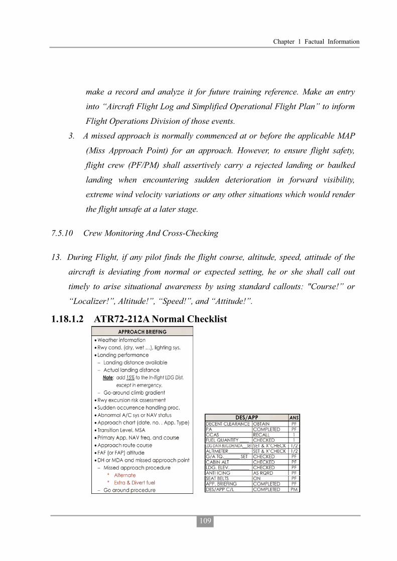
Chapter 1 Factual Information
109
make a record and analyze it for future training reference. Make an entry
into “Aircraft Flight Log and Simplified Operational Flight Plan” to inform
Flight Operations Division of those events.
3. A missed approach is normally commenced at or before the applicable MAP
(Miss Approach Point) for an approach. However, to ensure flight safety,
flight crew (PF/PM) shall assertively carry a rejected landing or baulked
landing when encountering sudden deterioration in forward visibility,
extreme wind velocity variations or any other situations which would render
the flight unsafe at a later stage.
7.5.10 Crew Monitoring And Cross-Checking
13. During Flight, if any pilot finds the flight course, altitude, speed, attitude of the
aircraft is deviating from normal or expected setting, he or she shall call out
timely to arise situational awareness by using standard callouts: "Course!” or
“Localizer!”, Altitude!”, “Speed!”, and “Attitude!”.
1.18.1.2 ATR72-212A Normal Checklist
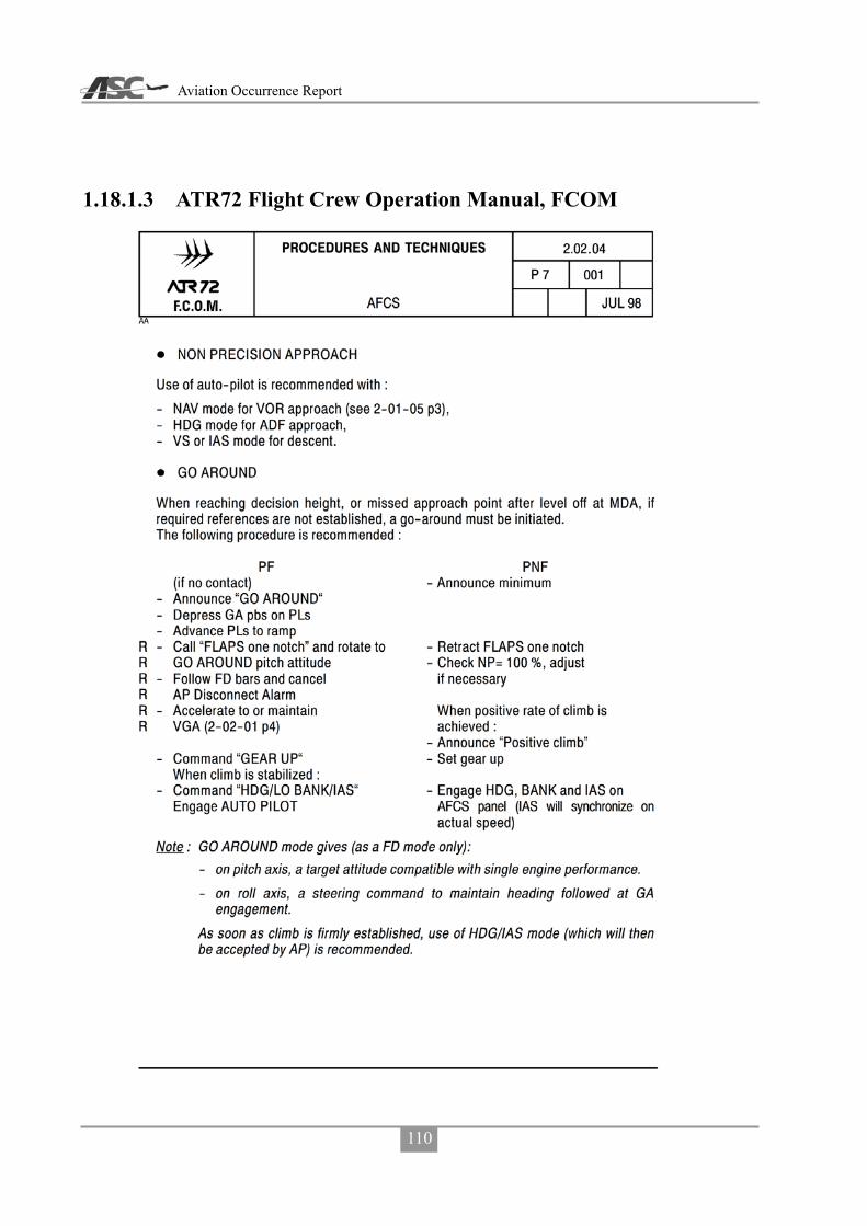
Aviation Occurrence Report
110
1.18.1.3 ATR72 Flight Crew Operation Manual, FCOM

Chapter 1 Factual Information
111

Aviation Occurrence Report
112
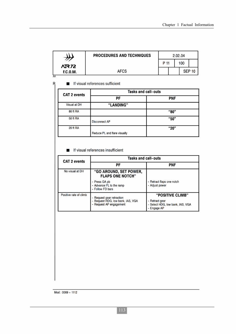
Chapter 1 Factual Information
113

Aviation Occurrence Report
114
1.18.1.4 Flight Crew Compliance with Airline’s ATR72 Standard Operating Procedures on Occurrence Flight
The investigation compared the flight crew’s actions on the occurrence flight with
the required actions stipulated in the airline’s ATR72 standard operating procedures
(SOPs). Table 1.18-1 lists the flight crew’s non-compliant actions and omissions during
the flight.
Table 1.18-1 Occurrence flight crew s non-compliance with SOPs
Item Phase Flight Crew Behaviors TNA ATR SOP 1 After
Takeoff PF did not call for “Flap Zero” and “AFTER TAKE OFF CHECKLIST”, but the PM announced “flap zero set after takeoff checklist”.
PF: “FLAPS ZERO” PM: “FLAPS ZERO” “FLAPS
ZERO SET” PF: “CHECKED” PF: “AFTER TAKE OFF
CHECKLIST” 2 Cruise In CRUISE CHECKLIST, PM read
out “ALTIMETER 999” and PF responded “999 set”
PM should read out “ALTIMETER, SPEED AND ALTITUDE” and both PF and PM respond “SET & CROSSCHECK”
3 Descent Did not conduct approach briefing after requesting MKG VOR RWY 20 APP.
Should conduct approach briefing when leaving cruise altitude.
4 Did not perform DESCENT/APPROACH CHECKLIST.
Should conduct DESCENT/APPROACH CHECKLIST when descent clearance is obtained.
5 PF called for “FLAPS 15” from 0.3 NM before FAF and PM set “FLAPS 15” from 0.1 NM before FAF.
Should begin this process from 3 NM Before FAF.
6
Approach
PF did not call for “BEFORE LANDING CHECKLIST”, but PM performed and completed it without responses from PF, when the aircraft position was 0.5 NM after FAF, and the autopilot was engaged.
PF and PM should crosscheck and confirm the “Before Landing Checklist” when the aircraft position is 0.5 NM before FAF.

Chapter 1 Factual Information
115
Item Phase Flight Crew Behaviors TNA ATR SOP 7 When the aircraft position was at
FAF, PF and PM did not crosscheck altitude and position agreement with the approach chart.
When the aircraft position is at FAF, PF and PM should crosscheck altitude and position agree with the approach chart.
8 PM advised PF of the MDA and preselected it before reaching FAF, but PF selected altitudes lower than MDA after passing the FAF and before reaching the missed approach point (MAPt) during the final approach, and descent below MDA.
PF should obtain required visual reference before making decision to continue descending below MDA. PM should raise disagreement to PF’s nonstandard operations.
9 100 Feet Above MDA, PM did not call “APPROACHING MDA”, PF did not respond “CHECKED”.
100 Feet Above MDA, PM should call “APPROACHING MDA”, PF should respond “CHECKED”.
10 Due to PF selecting altitudes commanding descent below MDA, MDA ALT won’t capture and “SET MISSED APPROACH ALTITUDE” was not initiated by PF and performed by PM, then checked by PF.
When MDA ALT Captured PM: “ALTITUDE CAPTURE”
PF: Check the MDA Altitude is Held “CHECKED” “SET MISSED APPROACH ALTITUDE _____”
PM: Preset Missed Approach Altitude on ADU “MISSED APPROACH ALTITUDE _____ SET”
PF: Check the Missed Approach Altitude on ADU “CHECKED”
11 When the aircraft position was at MAPt: PM did not call “MISSED APPROACH POINT, RUNWAY NOT IN SIGHT, GO AROUND”, the PF asked the PM whether he saw the runway or not when the aircraft was passing the MAPt, instead of initiating a missed approach.
When the aircraft position is at MAPt: PM: “RUNWAY NOT IN SIGHT,
GO AROUND”, (or “MISSED APPROACH POINT, RUNWAY CLEAR”)
PF: “GO AROUND”, (or “LANDING”)
12
Approach
PF did not call out before he disengaged the autopilot.
To establish crew resource management (CRM), the

Aviation Occurrence Report
116
Item Phase Flight Crew Behaviors TNA ATR SOP 13 There was no call out before the YD
was disengaged. communications between flight crewmembers shall be based on standard callouts. Except as otherwise noted specifically, all changes to switches, push buttons and flight modes have to be called out and crosschecked by PF and PM according to respective SOPs.
1.18.1.5 The Importance of Standard Operating Procedures
Standard operating procedures (SOPs) provide flight crews a step-by-step
guidance to ensure that operations are conducted in a predictable, uniform and safe
manner. They are one of the most important factors in assuring flight safety during
normal and abnormal operations.
Research on the use of procedures in complex socio-technical industries, such as
the airline, maritime and nuclear power industries, found that procedural deviations
were the highest ranking category in crew or operator caused accidents.76, 77 Degani
and Weiner’s (1997) study on the use of procedures in airline operations concluded
that:
The function of a well-designed procedure is to aid flight crews by dictating
and specifying a progression of sub-tasks and actions to ensure that the primary
task at hand will be carried out in a manner that is logical, efficient, and also error
resistant. 78
Lautman and Gallimore (1987) found that pilot deviation from basic operational
procedures was the leading ‘crew-caused factor’ in 93 hull-loss accidents that occurred
76 Perrow, C. (1984). Normal accidents. New York, NY: Basic Books. 77 Trager, E. A. (1988). Special study report: Significant events involving procedures (Office for Analysis and
Evaluation of Operational Data AOED/S801).Washington, DC: Nuclear Regulatory Commission. 78 Degani, A., and Wiener, E. L. (1997). Procedures in complex systems: The airline cockpit. IEEE Transactions
on Systems, Man, and Cybernetics, 27(3), 302-312.

Chapter 1 Factual Information
117
in the period 1977-1984.79 A study of 37 airline accidents conducted by the NTSB
determined that procedural errors accounted for 24% of all flight crew errors, and was
by far the most dominant factor.80
1.18.1.6 Violations
Violations81 are intentional deviations from an organization’s safety procedures82
drawn up for the safe or efficient operation and maintenance of plant or equipment.83
In broad terms, the individual’s plan, and execution of that plan, has achieved what
they wanted, but in doing so their behavior has deviated, with some degree of intention,
from some form of procedure. Violations typically reflect a social/motivational
phenomenon rather than an information processing problem. The emphasis in the definition of violations is on the word ‘intentional’. Many
individual actions may involve non-compliance with a procedure of some form, but with violations the key issue was that there was some intention to deviate. Even though violations are intentional breaches, it should be noted that they can be conducted with good intentions (i.e. to assist the organization to meet its objectives).84
Violations are not usually the last event in an occurrence sequence. However, they
tend to increase the risk of subsequent errors as they make the environment less
understood and less error-tolerant.85 Violations are a significant safety issue because
they undermine a basic assumption of a safety management system – that procedures
will be followed. Some violations can also be difficult to detect because employees
79 Lautman, L., and Gallimore, P. L. (1987, April-June). Control of the crew caused accident: Results of a
12-operator survey. Boeing Airliner, 1-6. 80 National Transportation Safety Board. (1994). A review of flightcrew-involved major accidents of U.S. air
carriers, 1978 through 1990. (Safety study, NTSB/SS-94/01).Washington, DC: Author. 81 The material for this section is based on Walker, M. (2010). Topic 2: Individual actions. ATSB human factors
course (pp.1-18). Canberra, ACT: ATSB. 82 The term ‘procedures’ also includes rules, instructions and regulations in this context. 83 Health and Safety Executive. (1995). Improving compliance with safety procedures. London: HSE Books. 84 Mason, S. (1997). Procedural violations—causes, costs and cures. In F. Redmill & J. Rajan (Eds.), Human
factors in safety-critical Systems. Oxford: Butterworth. 85 Hudson, P. (2000). Non-adherence to procedures: Distinguishing errors and violations. Proceedings of the 11th
Airbus Human Factors Symposium, Melbourne.

Aviation Occurrence Report
118
tend to hide them because they want to minimize the likelihood of any disciplinary
action. Violations are also important because of what they say about an organization.
The extent of violations, and the way they are treated by employees and managers,
provides a good insight into the overall safety culture in an organization.
Three types of violation are of particular interest to safety management86, 87. Routine violations: These violations are those which have become the normal
way of operating for employees in the work environment of interest. They usually involve cutting corners at the skill-based level of performance. They have usually developed because they reduce effort or discomfort and are associated with a very low perception of accident risk. They are also usually associated with a lack of enforcement or appear to be tolerated by management.
Optimizing violations: These violations develop due to an individual’s desire to
improve his/her work situation by fulfilling motivational goals unrelated to the
functional aspects of their job. Examples of such motives include a need for excitement
(during a boring task), a desire to impress others or inquisitiveness. The tendency to
optimize non-functional goals can become part of some individual’s style of working.
Optimizing violations are generally done at a rule-based level of performance and
involve a low perception of risk. Situational violations: These violations arise in a particular situation because a
deviation from procedures appears to be needed to get the job done. In other words, employees have to deal with a mismatch between the work situation and the procedures. Situational violations are typically conducted at a rule-based level of performance, but in exceptional cases can occur at the knowledge-based level. They can be associated with a higher level of perceived risk than routine violations. If the situation keeps repeating, then the employee behavior may develop into a routine violation.
86 Reason, J. (1997). Managing the risks of organizational accidents. Aldershot, UK: Ashgate. 87 Reason, J., & Hobbs, A. (2003). Managing maintenance error: A practical guide. Aldershot, UK: Ashgate.
Chapter 1 Factual Information
119
1.18.2 Non-Technical Skills Training
While technical skills are important, over recent decades another set of pilot skills
has been identified as contributing to airline accidents. These skills are termed human
factors or non-technical skills, and include crew resource management (CRM) and
threat and error management (TEM).
1.18.2.1 Crew Resource Management
In a multi-crew cockpit environment, human factors is also concerned with
ensuring the crew work in a coordinated way with each other, the aircraft systems, and
the broader aviation system. Traditionally, this has been known as crew resource
management. Crew resource management (CRM) has generally been defined as a
crew’s ‘effective use of all available resources - people, equipment, and information –
to achieve safe, efficient operations’88. Effective CRM means that all crew members
function as a team, rather than as a collection of technically competent individuals.
The TNA had adopted the following definition for CRM: CRM consists of all the
knowledge, skills and roles used to most effectively direct, control and coordinate all
available resources towards safe and efficient operations.
The airline had documented the following CRM policy:
1. CRM ability and a facility for teamwork will be one of the criteria for flight
crewmember selection.
2. CRM principles and practices will be fully integrated into all aspects of flight
operations training.
3. All crewmembers will share the responsibility for establishing an environment of
trust and mutual commitment prior to each flight, encouraging his fellow
crewmember(s) to speak out and to accept mutual responsibility for the safety and
well-being of the passengers and equipment entrusted to them. “What’s right, not
88 Lauber, J. K. (1984). Resource management in the cockpit. Air Line Pilot, 53, 20-23.
Aviation Occurrence Report
120
who’s right” will be the motto of TNA crews.
4. Each flight crewmember will be responsible for notifying the pilot in command if
any condition or circumstance exists that could endanger the aircraft or impair the
performance of any crewmember.
According to the TNA’s Flight Training Management Manual, CRM ground and
simulator training were included as part of every transition and initial training.
Recurrent CRM ground training was conducted at least every three years and CRM
training in the simulator was conducted annually.89 The airline’s CRM instructors had
received specific Human Performance and Human Factors training.
The airline’s flight crew, cabin crew and dispatchers also completed joint CRM
course.
1.18.2.2 Threat and Error Management
Threat and error management (TEM)90 is a method that can be used by flight
crew to identify and mitigate risks and errors that may have an impact on safe flight.
The concept of TEM was derived from the line operations safety audit (LOSA)
program by researchers involved in the University of Texas Human Factors Research
Project.91 The LOSA program involves trained observers recording the non-technical
aspects of crew performance from the flight deck observation seat. At the core of the
LOSA process are the crew’s identification and management of threats and errors.
There are three basic components in the TEM model: threats, errors and undesired
aircraft states.
Threats are ‘events or errors that occur beyond the influence of the flight crew,
89 Known as line oriented flight training (LOFT). 90 Material based on Australian Transport Safety Bureau. (2009). Threat and error management: Attitudes
towards training and the applicability of TEM to general aviation and low capacity air transport operations (Aviation Research and Analysis AR-2006-156(1)). Canberra, ACT: Author.
91 Helmreich, R.L., Klinect, J.R., & Wilhelm, J.A. (1999). Models of threat, error, and CRM in flight operations. In Proceedings of the Tenth International Symposium on Aviation Psychology (pp. 677-682). Columbus, OH: The Ohio State University.

Chapter 1 Factual Information
121
increase operational complexity, and which must be managed to maintain the margins
of safety’.92 When undetected, unmanaged or mismanaged, threats may lead to errors
or even an undesired aircraft state.
Errors are ‘actions or inactions by the pilot that lead to deviations from
organizational or pilot intentions or expectations’.93 When undetected, unmanaged or
mismanaged, errors may lead to undesired aircraft states.
Undesired aircraft states are defined as ‘an aircraft deviation or incorrect
configuration associated with a clear reduction in safety margins’94. Undesired aircraft
states are considered the last stage before an incident or accident. Therefore, the
management of undesired aircraft states represents the last opportunity for flight crews
to avoid an unsafe outcome.
While the TEM model is not a linear model of adverse event causation, the basic
principles are consistent with the idea that threats that are not adequately managed can
lead to errors, and errors that are not adequately managed often lead to undesired
aircraft states. These in turn can lead to undesired consequences.
Effective monitoring and assessment of environmental cues, being aware of what
is going on, and detecting any changes are essential if pilots are to recognize potential
threats and mitigate the associated safety risks before they escalate. Moreover, to
ensure the highest levels of safety each flight crewmember must carefully monitor the
aircraft’s flight path and systems, as well as actively crosscheck the actions of each
other. Effective crew monitoring and cross-checking can literally be the last line of
defense.95
92 Maurino, D. (April, 2005). Threat and Error Management (TEM). Paper presented at the meeting of the
Canadian Aviation Safety Seminar (CASS), Vancouver, BC. 93 Maurino, D. (April, 2005). Threat and Error Management (TEM). Paper presented at the meeting of the
Canadian Aviation Safety Seminar (CASS), Vancouver, BC. 94 Maurino, D. (April, 2005). Threat and Error Management (TEM). Paper presented at the meeting of the
Canadian Aviation Safety Seminar (CASS), Vancouver, BC. 95 Sumwalt, R.L., Thomas, R.J., & Dismukes, K. (2002). Enhancing flight-crew monitoring skills can increase
flight safety. Paper presented at the 55th International Air Safety Seminar, Dublin, Ireland.

Aviation Occurrence Report
122
The crucial task of monitoring was highlighted in the results of a LOSA cited at
the First Pan American Aviation Safety Summit in 201096, where it was identified that
19 % of errors and 69% of undesired aircraft states could have been eliminated through
more effective crew monitoring and crosschecking.
In 2006, the ICAO adopted TEM in pilot licensing standards and recommended
practices.97 Further information on ICAOs TEM requirements for flight crew training
and the flight crew licensing requirements are detailed in Annex 1, Personnel
Licensing.
The TNA had developed and implemented a TEM training program for its crews
but had not implemented the optional LOSA program.
1.18.2.3 Trans-cockpit Authority Gradient
A trans-cockpit authority gradient refers to the differences in the expected
operational contributions by each crew member. The gradient may be influenced by the
crew member’s experience, authority, national culture, company culture, and
willingness to act as an individual or as part of a team. An inappropriate balance of
these factors can interfere with the effective exchange of information in the cockpit,
which will adversely affect the safe operation of the aircraft. A steep gradient between
a highly experienced and older captain and younger much less experienced first officer
may result in the first officer being less willing to communicate important information
to the captain or acceding to his non-compliant behavior.
An optimum trans-cockpit authority gradient recognizes the command authority
of the captain, while encouraging the first officer to contribute to the crew’s decision
making processes. This optimum gradient facilitates communication, enables
participative leadership, establishes a team culture and enhances crew situational
96 Curzio, J. C. G. & Arroyo, C. (2010). Pilot monitoring training. Presentation at the First Pan American Aviation
Safety Summit 2010, Sao Paulo, Brazil. 97 International Civil Aviation Organization (2006). Annex 1 to the Convention on International Civil Aviation –
Personnel Licensing (10th ed.). Montréal, Quebec: Author.

Chapter 1 Factual Information
123
awareness. These concepts are part of the CRM training syllabus outlined in the ICAO
Human Factors Training Manual.98
1.18.3 Aerodrome Operating Minima
In order to meet ICAO Universal Safety Oversight Audit Program (USOAP)
standards, the CAA decided to convert Taiwan’s Instrument Flight Procedures, based
on the US Federal Aviation Administration (FAA) standards for terminal instrument
procedures (TERPS) to ICAO procedures for air navigation services – aircraft
operations (PANS-OPS) standards in 2009. Three meetings were conducted to discuss
the conversion on 12 November 2009 (2 meetings) and 25 January 2010. The CAA had
also issued aeronautical information circular (AIC) 02/10 to describe this conversion
on 13 August 2010.
According to ICAO DOC 8168 PANS-OPS, Volume I, Flight Procedures, Section
4, the relationship between obstacle clearance altitude/height (OCA/H) to operating
minima (landing) is shown in Figure 1.18-1.
At interview, the CAA flight operations section manager indicated that the Air
Traffic Services division was responsible for the transition of approach chart designs
from TERPS to PANSOPS specifications. To explain why the approach charts in the
AIP only showed the OCA (H) instead of DA (H) / MDA (H) on the Jeppesen charts,
the section manager stated that, with regard to “aerodrome operating minima (AOM)”,
section 4.2.8 in Annex 6 stated “The State of the operator shall require that the operator
establish aerodrome operating minima for each aerodrome to be used in operations and
shall approve the method of determination of such minima. Such minima shall not be
lower than any that may be established for such aerodromes by the State in which the
aerodrome is located, except when specifically approved by that State.” The section
manager stated that the standard is prescribed in the article 28 of Aircraft Flight
98 International Civil Aviation Organization. (1998). Human Factors Training Manual (Doc683-AN/950).
Montreal, Canada: ICAO.

Aviation Occurrence Report
124
Operation Regulations and it does not require the State in which the aerodrome is
located to establish aerodrome operating minima.
Operators shall implement the aforementioned regulation by adding required
contents in company manuals such as Operations Specifications, Operations Manuals,
Route Manuals, and Jeppesen charts and AIP procedures. Operators shall also instruct
flight crew members to comply with the minima prescribed in the manuals. Such
minima shall be treated as the minimum standard for takeoff, approach and landing.
Figure 1.18-1 ICAO PANS-OPS Non-Precision Approach OCA/MDA
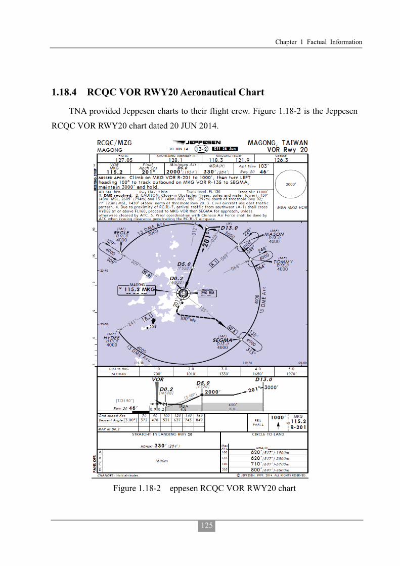
Chapter 1 Factual Information
125
1.18.4 RCQC VOR RWY20 Aeronautical Chart
TNA provided Jeppesen charts to their flight crew. Figure 1.18-2 is the Jeppesen
RCQC VOR RWY20 chart dated 20 JUN 2014.
Figure 1.18-2 eppesen RCQC VOR RWY20 chart

Aviation Occurrence Report
126
1.18.5 Runway Selection in Magong Airport
According to the air traffic management procedures (ATMP), Chapter 3, 3-5-1
Selection:
a. Selection of runway-in-use:
1. Normally, an aircraft will land and take off into wind unless safety, the
runway configuration, meteorological conditions and available
instrument approach procedures or air traffic conditions determine that a
different direction is preferable. In selecting the runway-in-use, however,
the unit providing aerodrome control service shall take into consideration,
besides surface wind speed and direction, other relevant factors such as
the aerodrome traffic circuits, the length of runways, and the approach
and landing aids available.
2. The term “runway-in-use” shall be used to indicate the runway or
runways that, at a particular time, are considered by the aerodrome
control tower to be the most suitable for use by the types of aircraft
expected to land or take off at the aerodrome.
3. If the runway-in-use is not considered suitable for the operation involved,
the flight crew may request permission to use another runway and, if
circumstances permit, should be cleared accordingly.
b. Except otherwise specified, use the runway most nearly aligned with the wind
when 5 knots or more or the "calm wind" runway when less than 5 knots
unless use of another runway:
NOTE:
If a pilot prefers to use a runway different from that specified, the pilot is
expected to advise ATC.
1. Will be operationally advantageous.
2. Is requested by the pilot.
Chapter 1 Factual Information
127
c. When conducting aircraft operations on other than the advertised runway-in-use, state the runway in use.
Magong Tower Operations Manual, Chapter 3, 3.3 Procedures for runway
usage99:
3.3.1 For the selection of runway-in-use, according to the provisions of ATMP
3-5-1, use the runway most nearly aligned with the wind when 5 knots or
more.
3.3.2 When the Air Force stationed, runway shall be changed for aircraft to land
and take off into wind if the tailwind exceeds (not included) to 5 knots. It
shall coordinate with the Air Force duty officer before changing runway. 3.3.3 Pilots may request takeoff from or landing on the other direction of runway
when the runway is not suitable. Because of fighters on alert, it is prohibited except for special reasons when the Air Force stationed.
3.3.4 Before changing runway, apart from the sudden change in weather, tower
shall consider the current traffic and set aside 10 minutes to the flight
control and related vehicles to inspect the arresting equipments and the
runway conditions. As soon as the flight control and related vehicles finish
the inspection and report normal, tower may declare the runway has been
changed.
1.18.6 Weather Information and Coding
According to the ATMP, Chapter 2, Section 8 Runway Visibility Reporting – Terminal:
2-8-1 Furnish RVR Values Where RVR equipment is operational, irrespective of subsequent operation or
non-operation of navigational or visual aids for the application of RVR as a takeoff or landing minima, furnish the values for the runway in use in accordance with para
99 Translated from Chinese.

Aviation Occurrence Report
128
2-8-3, Terminology.
2-8-2 Arrival/Departure Runway Visibility
a. Issue current touchdown RVR for the runway(s) in use:
NOTE: RVR is reported just after the visibility group of METAR when RVR
near or above threshold being equal or less than 1,500m and the weather
minimum will be based on the RVR.
1. When visibility is 1500 meters or less regardless of the value indicated.
2. When RVR indicates a reportable value regardless of the visibility.
NOTE: Reportable values are: RVR 2000 meters or less.
b. Issue both mid-point and rollout RVR when the value of either is less than 600
meters and the touchdown RVR is greater than the mid-point or roll-out RVR.
c. Aerodrome control shall issue the current RVR to each aircraft prior to landing
or departure in accordance with subpara a. and b.
ATMP, Chapter 3, 3-10-2 Updating Information on Final Approach:
a. As soon as possible after transfer from approach control to tower, advise
aircraft of the following:
1. Runway.
2. QNH.
3. Significant changes in the wind direction and speed:
NOTE: If the controller possesses wind information in the form of
components, the significant changes are:
Mean head-wind component: 10 kts
Mean tail-wind component: 2 kts
Mean cross –wind component: 5 kts
4. The latest information, if any, on wind shear and/or turbulence in the final
approach area.
5. Issue the visibility if less than 10km or, when applicable, issue RVR values
for the runway to be used.

Chapter 1 Factual Information
129
b. During final approach, advise aircraft of the following, without delay:
1. The sudden occurrence of hazards (e.g. unauthorized traffic on the runway).
2. Significant variations in the current surface wind, expressed in terms of
minimum and maximum values.
3. Significant changes in runway surface conditions.
4. Changes in the operational status of required visual or non-visual aids.
5. Changes in observed RVR value(s) or visibility.
According to the Air Force Meteorological Observation Manual, Chapter 4,
Section 5, the timing and provisions for runway visual range observation and reporting
were described as follows:
1. Observe and report RVR when the reported prevailing visibility is less than 1,500
m or the RVR value of runway used for landing is less than 1,500 m. The reported
RVR value represents the runway visual range of the touchdown zone of runway
used for landing
2. RVR reporting scales:
i. In steps of 25 m when the RVR is less than 400 m.
ii. In steps of 50 m when it is between 400 m and 800 m.
iii. In steps of 100 m when the RVR is more than 800 m.
3. Any observed value which does not fit the reporting scale in use shall be rounded
down to the nearest lower step in the scale. For example, to report 750 m if
observed RVR is 780 m.
4. 50 m should be considered the lower limit and 2,000 m the upper limit for RVR.
Outside of these limits, METAR and SPECI should merely indicate that the
runway visual range is less than 50 m (M0050) or more than 2,000 m (P2000).
5. If the 1-minute RVR values during the 10-minute period vary from the mean
value by more than 50 m or more than 20 percent of the mean value, whichever is
greater, the 1-minute mean minimum and the 1-minute mean maximum values

Aviation Occurrence Report
130
should be reported instead of the 10-minute mean value.
6. RVR shall not be reported if RVR instrument of runway used for landing is
malfunctioned, or RVR instrument is not installed.
1.18.7 Controlled Flight Into Terrain Accidents
Controlled flight into terrain (CFIT) refers to an unintended inflight collision with
terrain, water, or obstacles without any indication of the loss of control of an aircraft.
The factors leading to CFIT events are varied. They can include loss of flight crew
situational awareness, loss of terrain awareness, non-adherence to standard operating
procedures, conduct of improvised approach procedures in instrument meteorological
conditions (IMC) and operations in areas of low cloud base and/or poor visibility.100
The Netherlands National Aerospace Laboratory (NLR) examined factors
associated with 156 CFIT events involving commercial aircraft operators between
1988 and 1994.101 The report found that the descent and approach phases of landing
accounted for about 70 percent of the accident sample. The report also concluded that
on a world-wide basis, there appeared to be a five-fold increase in accident risk for
commercial aircraft flying non-precision approaches compared with those flying
precision approaches.
In 1993, the Flight Safety Foundation (FSF) organized an international CFIT Task
Force that was dedicated to reducing CFIT events. The international CFIT Task Force
comprised representatives from aircraft manufacturers, aviation training organizations,
aircraft equipment manufacturers, airlines, pilot groups and government and regulatory
agencies. The FSF CFIT Task Force concluded that:
� establishing and adhering to adequate standard operating procedures and flight
crew decision-making processes improve approach-and-landing safety;
100Australian Transport Safety Bureau. (2007). CFIT: Australia in context 1996-2005 (Aviation Research and
Analysis Report B2006/0352). Canberra, ACT: Author. 101Khatwa, R., & Roelen, A. L. C. 9(1997). Controlled flight into terrain (CFIT) accidents of air taxi, regional and
major operators. (National Aerospace Laboratory NLR TP 977270). Netherlands, NLR.

Chapter 1 Factual Information
131
� failure to recognize the need for a missed approach and to execute a missed
approach is a major cause of approach-and-landing accidents;
� unsterilized approaches cause approach-and-landing accidents;
� the risk of approach-and-landing accidents increases in operations conducted in
low light and poor visibility;
� effective use of radio altimeters will help to prevent approach-and-landing
accidents; and
� global sharing of aviation information decreases the risk of approach-and-landing
accidents.102
The Task Force subsequently developed a data-driven CFIT education and
training aid known as the FSF approach and landing accident reduction (ALAR) tool
kit. ICAO has recommended that those in positions of responsibility in civil aviation
should apply the recommendations of the CFIT Task Force and make the best use of
the education and training material.
The FSF updated its approach and landing accident (ALA) analysis in 2010 to
ascertain if the rate of ALAs had reduced and whether the contributing factors for
ALAs had changed over time. The original study contained 287 fatal ALA events from
1980 to 1996 whereas the updated study contained 1007 fatal and non-fatal ALAs from
1995 to 2007. A breakdown of the most recent data set indicated that much of the
developing world had fatal ALA rates above the world average. The underlying
contributing factors for ALAs were largely unchanged since the original study,
although there was some shift in the relative rankings of contributing factors. The most
frequently cited causal factors in the latest data set was “omission of
action/inappropriate action”, followed by “poor professional judgment/airmanship”,
and “failure in crew resource management”. Common circumstantial 103 factors
102Flight Safety Foundation. (1996). An analysis of controlled-flight-into-terrain (CFIT) accidents of commercial
operators 1988 through 1994. Flight Safety Digest, 15 (4/5), 1-45. 103 FSF defined a circumstantial factor as “an event or item that was not directly in the causal chain of events but

Aviation Occurrence Report
132
included weather, poor visibility, and runway conditions. While CFIT events had
reduced they were still in the top ten most frequent ALA accidents.104
Standard Operating Procedures
Standard operating procedures (SOPs) are specified in an operations manual to ensure that flight operations are conducted in a consistent and safe manner and are resistant to crew error. Effective crew coordination and crew performance depend upon the crew having a shared mental model of each task. That mental model, in turn, is founded on SOPs. The ALAR briefing note Operating Philosophy described the importance of SOPs as a risk control for minimizing CFIT accidents. The briefing note stated that:
Adherence to standard operating procedures (SOPs) is an effective method of preventing approach and landing accidents (ALAs), including those involving controlled flight into terrain (CFIT). Crew resource management (CRM) is not effective without adherence to SOPs.
The Flight Safety Foundation Approach-and landing Accident Reduction
(ALAR) Task Force found that ‘omission of action/inappropriate action’ (i.e.,
inadvertent deviation from SOPs) was a causal factor in 72 percent of 76
approach-and-landing accidents and serious incidents worldwide in 1984 through
1997.
The task force also found that ‘deliberate non-adherence to procedures’ was a
causal factor in 40 percent of the accidents and serious incidents.
The ALAR briefing note included a standard operating procedures template that
was adapted from the FAA Advisory Circular 120-71, standard operating procedures
for Flight Deck Crewmembers. The template topics included approach philosophy
(including stabilized approaches being standard, limits for stabilized approaches and
could have contributed to the accident.”
104 Flight Safety Foundation. (2010). Killers in aviation: An update. Flight Safety Foundation ALAR Tool Kit Update (pp. 1-24). Alexandria, VA: Author.

Chapter 1 Factual Information
133
go-arounds), information needed for each type of approach (including flap/gear
extension, standard calls and procedures) and the initiation of go-arounds.
Non-precision Approach Issues
The Flight Safety Foundation ALAR briefing note, Constant-angle Non-precision
Approach, identified from training feedback and line-operations experience the factors
that reduced the performance of crew conducting non-precision approaches. Some of
those factors identified were:
� Late descent preparation;
� Incomplete briefing;
� Inadequate cross-check and backup by the handling pilot/non-handling pilot;
� Late configuration of the aircraft;
� Final approach speed not stabilized at the final approach fix;
� Incorrect identification of the final approach fix; and
� Premature descent to the next step-down altitude (if multiple step-downs) or
below the minimum descent altitude.
The briefing note also identified the elements of a successful non-precision
approach. Some of the relevant elements were:
� Completing an approach briefing;
� Planning aircraft configuration setup;
� Monitoring descent;
� Managing aircraft energy condition during intermediate approach and final
approach;
� Not descending below an altitude before reaching the associated fix;
� Determining the correct angle (vertical speed) during the final descent; and
� Beginning the descent at the correct point.
CFIT Risk Assessment
Risk management is a component of a SMS and encompasses the identification,

Aviation Occurrence Report
134
analysis and assessment of risks and the design and implementation of risk treatments
or controls in a structured process. Once controlled, mitigated or treated, risks must
continue to be monitored to ensure that the risk treatment process is effective. Risks
rarely remain static, and changes in an operational context can result in different risks
emerging or a change to the levels of risks. When an operational context is changed,
for whatever reason, the risk events that can affect achievement of the changed
objectives must be identified, analyzed, evaluated and treated.
An airline CFIT event is almost certain to result in major to catastrophic
consequences and the risk of the event will almost certainly be high to extreme. The
risk should therefore be assessed, and if identified, it must be managed. The Flight
Safety Foundation designed and published CFIT Checklist: Evaluate the Risk and Take
Action to evaluate CFIT risk, as part of its international program to reduce CFIT events
that present risk to aircraft, flight crews, and passengers. The checklist is currently
published in Arabic, Chinese, English, French, Russian and Spanish.
The Flight Safety Foundation intended that the checklist be used to ‘assess CFIT
risks for specific flights, identify factors that identify those risks, and enhance pilot
awareness of CFIT risk’. The checklist was designed to allow a pilot/operator to assign
numerical values to a variety of factors that allow a CFIT risk score to be determined.
A significant CFIT risk score can be analyzed to determine strategies for reducing that
risk.
The Flight Safety Foundation recommended specific interventions to manage
CFIT risk including:
� The use of standard operating procedures, standard call-outs and checklists;
� The content and conduct of descent approach briefings;
� Crew resource management;
� Strategies and procedures for handling interruptions/distractions;
� Procedures for barometric and radio altimeters;
� Descent and approach profile management;

Chapter 1 Factual Information
135
� Terrain awareness;
� The use of stabilized approaches; and
� The use of constant angle non-precision approaches.
There was no evidence that the TNA had conducted any specific CFIT risk
assessments, documented the findings, implemented appropriate CFIT risk controls,
and confirmed the ongoing effectiveness of those risk CFIT controls.
1.18.8 Interview Summaries
1.18.8.1 UNI Airways B7 647 Flight Crew
The interviewee stated that he had flown B7 647 to Magong before the occurrence.
The onboard weather radar indicated that the weather conditions were very bad. He
was told to hold in the air about 40 minutes. The aircraft was in cloud most of the time.
He requested the runway 02 ILS approach during holding. ATIS reported the weather
conditions were above landing minima but he was not approved to continue the
approach by the controller. On approach to Magong runway 20, the crew became
visual with the runway when they were descending through 1,000 ft. Even though
flight conditions were turbulent during the approach, no downdrafts were encountered.
The visibility suddenly deteriorated after landing and by the time they reached their
parking bay no.2 after vacating the runway, a severe thunderstorm began producing
heavy rain showers which prevented the passengers from disembarking. They had to
wait for a while before they could disembark. By the time the disembarkation was
almost complete, the flight crew saw fire engines standing by near the runway, but they
were not aware of the aircraft accident.
Though other pilots once submitted unsatisfactory reports on the weather
forecasts for Magong Airport, the interviewee felt that they were accurate enough. He
also stated that the VOR signal was good. It might temporarily fail but the indications
were accurate.
1.18.8.2 TNA Flight Crew Interview

Aviation Occurrence Report
136
The investigation team interviewed 15 TNA ATR flight crew after the GE222
occurrence. The interviewees included the assistant vice president of the FOD, the ATR
fleet chief pilot, one check pilot, one instructor pilot, 5 captains and 6 first officers. The
interviews revealed the following:
Crew Flying Activity
Most interviewees stated that minimum flight crew manpower was employed at
TNA and that created high flying activities which were overlooked by senior
management. Crewing numbers were reduced in 2014. The number of daily flight
sectors had increased considerably and were much higher compared to other domestic
operators. Interviewees considered that 4 sectors a day were reasonable, 6 sectors were
manageable, but 8 sectors/day were almost unacceptable. With tight daily schedules,
there were risks that crews might experience fatigue and distraction.
SOP Compliance
Most interviewees stated that deviations from SOPs mostly occurred when crew
made several return trips between the same ports or felt fatigued. The SOP deviations
included absence of cross checks, lack of call outs, briefings without using the briefing
card, and overlooking some of the procedures, etc.
Some interviewees stated that different captains might react differently when an
omission of a standard call out occurred during the daily operation. Some captains
might make up the call outs by themselves, while others might overlook it.
Regarding the decision to continue or discontinue an approach, different captains
might make different decisions. For example: at a 330 feet MDA, some crew might
initiate go around if the runway was not in sight at 400 feet, while some crew might
make the decision when the aircraft is at 330 feet. Moreover, a few flight crew might
continue to descend below the MDA even if the required visual references had not
been obtained. They might continue if they see parts of the runway or approach
lighting, or if they can only see the ground.

Chapter 1 Factual Information
137
Understanding of Previous Occurrences
Some interviewees were not aware of the previous GE515 and GE5111
occurrences occurred in 2012 and 2013 respectively.
Comments on Occurrence Flight Crews
Most interviewees stated that the occurrence captain was a very considerate
person with good flying technique. Some interviewees indicated that under certain
adverse weather conditions, some crew might initiate a missed approach, while the
occurrence captain might still land the aircraft because of his proficient skills.
The FOD assistant vice president stated that he was aware of the occurrence
captain’s flying behaviors before the occurrence. He stated that he had communicated
with senior pilots, including the occurrence captain, about risky landings, and received
positive responses.
Most interviewees stated that the occurrence first officer would accommodate the
captains’ flying habits, and tended not to challenge captains’ landing decisions. Many
newly employed first officers have a similar attitude. While this situation has improved
gradually, it still exists.
1.18.8.3 CAA Principle Operations Inspector
The principle operations inspector (POI) joined the CAA in 1999. He had been
responsible for the oversight of TNA’s operations since 2008.
The POI generated an annual inspection plan in accordance with the Inspector’s
Handbook issued by the CAA. However, in practice inspection frequency, timelines
and some items may vary in accordance with demands. For example, the working
hours spent on Cockpit En-Route inspections are usually higher than the allocated
allotment. .
Regarding Cockpit En-Route inspections of TNA’s operations, the POI attributed
the few findings to the short duration of domestic flights. It constrained the inspectors

Aviation Occurrence Report
138
from going through the process thoroughly. The other reason was that when the
inspector was sitting in the cockpit, most pilots will demonstrate their best behavior.
However, normal operational practices may not necessarily be the same.
From his viewpoint, with the exception of some newly recruited pilots who had
some difficulty in complying with SOPs because they were not yet proficient to cope
with the time pressure of domestic short haul flights, most pilots were able to follow
company SOPs. He thought that the occurrence flight crew’s non-compliances with
SOPs was an individual case.
The “air carrier management effectiveness inspections” and the “supervisory
inspection of flight safety activities” were the two requisite job functions that he
performed every month. Since the CAA does not officially require the POI to hold a
formal joint meeting with the operator, he usually took these opportunities to oversee
and communicate with TNA.
When technical deficiencies were addressed in the (in-depth) inspection report, he
would conduct En-Route inspections or simulator observations as a follow-up to see
whether further actions were needed.
He reviewed the company’s risk management statistical data provided by the
flight operations division. Further discussions were made if certain figures indicated an
adverse trend. However, he did not look into the details of how those indexes had been
generated and evaluated.
He noted the very few deficiencies in the SOA records, but did not interfere
because it was the operator’s responsibility to ensure the effectiveness of their own
safety management. He said that with the limited time and manpower, inspectors were
unable to supervise all aspects of the operation.
He reviewed the FOQA statistical reports every month and would look into the
details for those safety related events. He considered that the limited manpower in the
TNA FOQA team decreased the performance, effectiveness, and potential safety
benefits of the program.

Chapter 1 Factual Information
139
The average monthly flight time for TNA’s flight crews were 80 to 90 hours;
some of them even exceeded 100 hours. It was relatively high compared to other
operators. The POI was aware of the situation, which was associated with a crew
shortage and had raised the issue with TNA management. However, the relatively low
pilot pay was unfavorable for recruiting so the situation remained unsolved.
With reference to the Safety Management Manual, TNA did not pass the initial
acceptance audit and required improvements to be implemented by the end of 2014 for
the second audit.
1.18.8.4 CAA Flight Operation Section Manager
The interviewee stated that the scope and depth of the Main Base inspection and
the in-depth audit were different than the routine inspection. The inspections were
conducted by a task force team with more manpower. Those inspections or audits were
followed up by the inspectors assigned to the operator through a computerized FSMIS
and an official notice was sent to the operator. The FSMIS data was able to identify the
safety trends and warnings which could assist inspectors to better understand and
capture unsafe indications and changes.
The CAA required inspectors to conduct a joint meeting with the operator. The
manager was not sure about whether there were meeting records or who was
responsible for the meeting record. The main purpose was to have an open
communication channel between the CAA and the operator. The meeting formalities
also depended on the size of the operator.
The interviewee stated that the CAA formed a special SMS task force. That task
force examined operators’ SMS programs and conducted an initial assessment. Those
assessment results were sent to the inspectors assigned to the operator. The interviewee
considered those results comprised suggested improvements. The operator SMS
implementation is a learning process for both the CAA and the operators, however, the
operator needs to understand the program and have the will to improve. This also

Aviation Occurrence Report
140
applied to the SMS safety performance index which the operator was responsible for,
not the CAA. The CAA regulations currently required that an operator implement an
SMS plan under the State Safety Program. There was no regulatory requirement for an
operator to have implemented an SMS at the time of the occurrence. SMS is a
continuous improvement process and cannot be achieved overnight.
The interviewee responded to questions about the Cockpit En-Route inspections
where almost no findings were recorded. He stated that no findings during the
inspections might be due to the accuracy of the inspection process or the technical
capability of the inspector. However, there might also be inspector bias, or different
inspector might have a different focus during the inspections, and/or the environment
might be different for each inspection. Therefore, the interviewee considered it was
acceptable that some inspections have fewer findings than others. He stated that the
number of the findings was not important. The important thing was that the inspectors
report their observations to the CAA. In addition, the CAA only required inspectors to
record non-compliances or violations in accordance with the regulations, rather than
findings base on an inspector’s personal opinion.
The interviewee stated that not all inspectors were assigned to the Flight
Operations Section. The annual inspector performance evaluation was conducted by
their designated section chief. However, he was still able to review all inspectors’
performance through the inspection records or when he accompanied the inspectors
during inspections.
1.18.8.5 Magong Weather Center
The Weather Forecast Officer in the Meteorological Office
At around 1824 hours, the tower called to ask about visibility because a flight was
already holding for 25 minutes and the crew wanted to attempt an approach if visibility
permitted; the interviewee answered that the visibility was still 800 meters, but may
improve in ten minutes, and would deteriorate once again in 10 to 20 minutes because

Chapter 1 Factual Information
141
of another approaching radar echo; therefore, the visibility report would remain 800
meters. The interviewee went outside to perform an actual observation of the weather
which indicated that the visibility was not looking good. The interviewee called the
weather watch office to inquire about the current visibility. The weather observer then
went outside to observe the weather. The interviewee remembered that the weather
observer replied that visibility was 1,600 or 2,400 meters. The weather forecast officer
told the weather observer to report a special weather report for the improved visibility.
During that period of time, the radar return was green in color with an intensity of
20-25dBz. When the second weather squall arrived, the visibility decreased again.
The Surface Weather Observer in the Weather Watch Office
The interviewee was on the duty shift from 1800 hours to 0800 hours the next day.
It was raining excessively heavy when he took over the duty; the rain became light at
around 1837 hours, the visibility was about 2,000 meters. At that moment, the reported
visibility was 1,600 meters. In order to produce the 1900 hours METAR, an
observation was made by going outside the office at 1855 hours but the visibility
remained at 1,600 meters. All the weather information that had been collated had to be
relayed to the control tower, weather office, and other relevant units. The whole relay
operation was completed at 1902 hours. Suddenly, a temporary heavy rain shower
arrived, and the interviewee had to go outside to confirm the visibility; at 1904 or 1905
hours, the weather forecast officer called and the observer advised that the visibility
had dropped down to 800 meters. The observer was still observing the conditions at the
time. It would require three minutes to relay a special weather update. As a result, the
updated report was issued at 1910 hours. In order to make reports of prevailing
visibility, the AWOS would also have been referenced.
The Weather Watch Office Supervisor
The interviewee began his duty shift at 0800 hours on the day of occurrence. He
left the weather watch office at 1730 hours after the termination of the typhoon

Aviation Occurrence Report
142
warning.
Compared with the old system, the new AWOS provided pressure, lightning, and
RVR data. Due to the limitations of the RVR equipment, sometimes the displayed data
would be different to the manual observations. For example, when rain drops fall on
the sensors lenses during heavy rain, or the lenses are not clean, there will be some
differences between the automatically generated data and those obtained by manual
observation. When these anomalies are found, maintenance personnel will be asked to
deal with them, or the system will return to normal after the meteorological office
reboots the system. RVR is calculated by using results of a transmissometer with
corrections for ambient light. Once the lenses used to measure visibility has been taken
care of, the system will operate normally.
On that afternoon, it had happened that the visibility and RVR values reported in
the METAR were 800 meters but the RVR values displayed by the AWOS were greater
than 2,000 meters. According to the manual, AWOS RVR values should take
precedence but the sensitivity of the transmissometers is very high, which results in
fluctuating RVR values. Moreover, actual conditions and safety concerns have to be
taken into account when AWOS RVR values are higher than the observed visibility.
For example, if the visibility observed by the meteorological sergeant is 600 or 800
meters, but the AWOS RVR value indicates 2,000 meters, the meteorological sergeant
will perform a manual adjustment instead of using the data from the AWOS. However,
according to the prescriptions of observation manual, when RVR values are less than
the observed visibility, a ten minute average of such RVR values should be used for
editing a METAR/SPECI report. When the visibility is 1,600 meters or less, military
flight operations are prohibited, therefore the surface weather observers tend to be
conservative when reporting weather information, particularly when the visibility is
less than 1,600 meters.
1.18.8.6 Kaohsiung Approach
Chapter 1 Factual Information
143
The Magong Position Controller from 1800 to 1900
The interviewee was on his Magong radar shift from 1800 to 1900 hours. He was
responsible for 7 aircraft, of which 4 were holding. The numbers of flights on that day
were as usual, but most of the flights had requested changes of heading or altitude due
to the bad weather. The radio communications were more frequent than usual but the
workload was acceptable.
The flights were waiting for their approach sequences while holding. The first one
was B7647, the second one was GE222, the third one was FE3055, and the last one
was GE5113. The crews were all eager to know the likelihood of the weather
improving. At 1821 hours, the interviewee advised B7647 that thunderstorms were
going to last for an hour. Later on when the interviewee obtained the updated wind
information from Magong tower, it was broadcasted accordingly. At 1830 hours,
B7647 requested the interviewee for the runway 02 ILS approach, which was then
relayed to the tower for approval, but confirmation of this request was pending. Given
the delays associated with the request, the interviewee informed B7647 of the updated
weather received at 1842 hours and that the visibility had improved to 1,600 meters.
Upon providing this information, B7647 withdrew their previous request for a change
of runway and decided to conduct the runway 20 RNAV approach. After that, GE222
requested the runway 20 VOR approach and was radar vectored for that approach. The
interviewee had been relieved from his duty shift before GE222 was established on the
inbound course for the approach.
The Magong Position Controller from 1900
The interviewee began his Magong radar duty shift at 1900 hours. GE222 was
about 11 nautical miles from the airport and at an altitude of more than 2,000 feet.
GE222 did not seem to have any anomaly, and descended normally on the inbound
course. By the time the tower relayed the information that GE222 was going around,
he saw on the radar that GE222 had passed over MKG VOR at an altitude of 300 feet

Aviation Occurrence Report
144
or so, but soon disappeared from his radar display. The interviewee said it was hard for
radar to collect stable and reliable information from aircraft at low altitude or just
airborne from Magong Airport. In particular, the TNA ATR aircraft would not be
visible on the radar until they reached an altitude of 1,000 feet and above.
The Supervisor
At 1830 hours, the interviewee was asked by the Magong position coordinator to
liaise with the duty officer at Magong Air Force Base (AFB) to change the landing
runway direction. The request had been made to and coordinated with the Magong
tower as usual, but the tower replied that the Magong AFB duty officer rejected the
request. The controllers’ and coordinators’ positions did not have a direct hot line with
the duty officer. The coordinator asked the supervisor for help to coordinate the
request.
At that time, the visibility of 800 meters was below landing minima for both the
runway 20 VOR and RNAV approaches. B7647 had requested the runway 02 ILS
approach (which required a change of runway) because the visibility criteria could be
met. The interviewee discussed with the duty officer for a very long period and the
duty officer disagreed with him for two reasons. The duty officer emphasized that he
had already asked the weather watch office to confirm that the weather conditions were
suitable for runway 20. The second was the tail wind was too strong to use runway 02.
During the coordination, the Magong position coordinator told the supervisor that the
visibility had raised to 1,600 meters and that met the standard for runway 20
approaches. Therefore, the B7647 crew decided to request the runway 20 RNAV
approach and the coordination ended.
1.18.8.7 The Magong Air Force Base Duty Officer
At 1740 hours, the typhoon warning had been terminated. All typhoon related
preventive actions had been cancelled and all combat readiness duties resumed. It was
still raining at that moment. The meteorological office issued a hazardous weather
Chapter 1 Factual Information
145
forecast valid until 2100 hours. Around 1830 hours, the interviewee received a phone
call from the combat information office informing him that the tower had relayed a
request to use opposite direction runway. Given that it was against the airport’s
operational policy, the interviewee asked the combat information duty officer, on his
behalf, to advise the tower that he needed time to analyze current conditions and an
immediate answer was highly unlikely. As soon as the interviewee hung up the phone,
he made the next phone call to the meteorological office to collect the current weather
information. At that time, he assumed the request to use the opposite direction runway
was due to an emergency. When the interviewee hung up the phone, the Kaohsiung
approach supervisor called him about the request for use of the opposite runway.
Before making a decision, he and the supervisor were having a discussion, during
which the supervisor told him that the aircraft in flight had already cancelled the
request. The discussion ended at around 1840 hours.
The interviewee stated that with regard to the request to use the opposite runway
direction, the speed and direction of the wind were his main concerns. At military
airports, duty officers made decisions regarding runway use. It was a basic principle to
take off and land in a headwind.
1.18.8.8 The Magong Tower
The Local Controller from 1800 to 1900
The interviewee was on his duty shift from 1800 to 1900 hours on the day of
occurrence. Before 1840 hours, the 800 meters visibility was below the landing
minima for runway 20, but met the standard for the runway 02 ILS approach. At that
moment, there were 4 or 5 aircraft in that area and the crews had requested Kaohsiung
Approach to provide updated weather information. The meteorological office replied
that it was not expecting the weather to improve before 1830 hours. Some time later,
aircraft in flight requested updated weather information again and the meteorological
office revealed that there would be a temporary improvement of the weather, but they

Aviation Occurrence Report
146
had no intention to revise the visibility value - the 800 meters visibility report would
remain. The interviewee noticed that the wind for runway 02 provided by the AWOS
was not so strong. He felt that the aircraft in flight may like to use runway 02 for
landing. Therefore, the wind information for both ends of the runway had been
provided to approach control, and also relayed to the aircraft in the air for them to
make their own decisions. Flights requested use of opposite direction runway. The final
authority for changing the runway in use resided with the Air Force duty officer
because Magong is a civil/military joint-use airport. The tower coordinated the request
between both parties but the request was not approved. He kept pushing for the change
of runway direction. At 1840 hours, the visibility in the weather report was increased to
1,600 meters so the request for using runway 02 was no longer needed.
When military personnel were editing weather reports, it seemed that the RVR
value was manually calibrated. The reported RVR value was often 80 or 90 percent the
same as the observed visibility. However, in the tower, the RVR value displayed on the
AWOS screen was often greater than 2,000 meters, different from the reported RVR.
When in doubt, the tower will use the RVR value reported by the weather watch office.
For example, the AWOS RVR showed 2,000 meters while the observed visibility was
reported as 800 meters on the occurrence day.
The Local Controller from 1900
The interviewee began his airport duty shift at1900 hours on the day of the
occurrence. After fully taking over the shift, he was responsible for two flights, one of
which FE082 had received a takeoff clearance, but it taxied very slow due to the bad
weather. The interviewee did not have the runway threshold in sight from the tower.
Taxiway K3 was visible at best. At about 1901 hours, GE222 had established
communication with the tower on a 8 or 9 nautical mile final.
When the interviewee issued the landing clearance, GE222 was on about a 5 or 6
nautical mile final, approaching and descending into the airport. The aircraft stopped

Chapter 1 Factual Information
147
descending at an altitude of 300 feet or so. When GE222 reached a one or two nautical
mile final, the tower controllers heard their go around call. The interviewee issued the
missed approach procedure to GE222, but there was no response.
AWOS RVR was provided to crews during low visibility. According to the
controller’s one year experience in the Magong tower, it was quite unlikely for low
visibility conditions to occur at Magong Airport. There were previous cases when the
weather was good and the visibility was more than 10 kilometers, but the RVR
readouts indicated otherwise. The interviewee considered this made no sense at all,
then contacted the meteorological units to verify if a malfunction had occurred or the
lenses were not clean, and thereafter documented the anomalies. Sometimes such
anomalies could be solved by rebooting the system or cleaning the lenses. The
meteorological units would inform the tower once the system had returned to normal.
When the interviewee took over his duty position around 1900 hours, the RVR on
screen was around 1,600 meters, which coincided with the visibility reported by the
METAR. AWOS RVR was not provided to the aircraft on the day of the occurrence
because at around 1700 or 1800 hours, the AWOS RVR values were different from the
RVR reported in the METAR. The local controller on duty at that time called the tower
chief for advice. The chief instructed the controller to trust those professionals in the
meteorological units. Therefore, the controller used the RVR value in the weather
reports, that is, if the RVR was reported in the weather report, it was provided to the
aircraft crews.
The approach visibility minima for runway 20 was 1,600 meters, therefore the
interviewee paid more attention to changes in visibility. At 1901 hours the controller
received the 1900 hours METAR. At that time the visibility was 1,600 meters, no RVR
reported. It was the same as the visibility in the 1840 hours METAR. The QNH
changed from 996 to 997 and was provided to the GE222 crew immediately. Given the
poor visibility from the tower in the heavy rain, the interviewee continuously paid
attention to the relative positions of FE082 and GE222, and monitored the radar and
Aviation Occurrence Report
148
the ground movements all the time. GE222 was on about a 4 or 5 mile final when
FE082 was handed over to approach control. The interviewee glanced at the wind
speed and direction on the AWOS display once again and found no noticeable changes.
While GE222 was on a 3 or 4 mile final, the interviewee could not sight the aircraft in
the poor weather; however, he kept an eye on the aircraft altitude and ground speed
displayed on the radar to see if there were any flight anomalies or signs of the aircraft
executing a missed approach. When the interviewee was checking to see if there were
any obvious changes of wind speed and direction, he did remember the fluctuating
RVR readouts but could not recall those exact values because his first priority was to
maintain aircraft separation and watch those inbound flights.
The Chief
After the new AWOS was commissioned, related chapters in the ATMP manual
had explained the system for controllers. The Air Force did not provide any operational
manual. The AWOS parameters used mainly in the tower were wind direction, wind
speed and RVR. QNH, visibility and ceiling were provided by the weather watch office.
Controllers checked the AWOS data on screen when in contact with traffics, and if the
weather was becoming more unstable, or during the alternation of the runway,
controllers paid more attention to the AWOS.
On the afternoon of the occurrence, the local controller on duty called to express
doubt about the RVR because the RVR value was more than 2,000 meters but the RVR
reported by the weather center was 800 meters. The local controller mentioned that he
had asked the weather forecast officer whether the RVR generated by the AWOS was
usable. The weather forecast officer replied it was ok to use those RVR values, but the
local controller still had doubts. The interviewee mentioned that, as a manager, he had
to consider all the conditions and possibilities. The instrument’s observed value is
instantaneous and prone to fluctuation and subject to the influences of the surrounding
environment such as spider webs, bird droppings, water vapor, and salt. The

Chapter 1 Factual Information
149
interviewee thought about such influences. All operations had to follow the ATMP. The
front part of the ATMP 2-8 mentioned that the RVR will only be provided when the
lowest takeoff and landing minima are established by RVR values and the equipment is
working normally. Instead of using RVR values, the lowest visibility landing minima
for runway 20 was 1,600 meters. On the other hand, the lowest landing minima for
runway 02 had both RVR and visibility values published. Therefore, considering all
these factors and safety concerns, the interviewee told the controller to trust the
weather professionals in the airport and use the reported RVR in the weather report for
operations.

Aviation Occurrence Report
150
Intentionally Left Blank
Chapter 2 Analysis
151
Chapter 2 Analysis
2.1 General
The captain and the first officer of TransAsia Airways flight GE222 were properly
certificated and qualified under Civil Aeronautics Administration (CAA) and company
requirements. No evidence indicated any pre-existing medical conditions that might
have adversely affected the flight crew’s performance during the occurrence flight. The
occurrence aircraft was properly certified, equipped, and maintained in accordance
with CAA regulations and approved company procedures. No evidence indicated
pre-existing engine, system, or structural failures.
This analysis focuses primarily on the flight crew’s performance, TransAsia
Airways’ operational and safety management, and CAA airline safety oversight. The
analysis also addresses the roles of some human factors issues in the occurrence,
meteorological factors, aerodrome and navigation aids, and aircraft systems.
2.2 Occurrence Scenario
2.2.1 The Approach
Magong Airport was affected by the outer rain bands of Typhoon Matmo around
the time of the occurrence flight. When the occurrence flight approached Penghu
Island, it was vectored by air traffic control and entered a holding pattern because the
visibility at Magong was below the landing minima.
After about 34 minutes holding, the visibility for runway 20 had reportedly
improved to 1,600 meters. At 1845, the GE222 flight crew requested the runway 20
very high frequency omni-directional range (VOR) approach. Kaohsiung Approach
then issued radar vectors to the crew to establish them on the required flight path and
assigned them a lower altitude.
2.2.1.1 Final Approach

Aviation Occurrence Report
152
The cockpit voice recorder (CVR) indicated that after Kaohsiung Approach
cleared GE222 for the Magong runway 20 VOR approach (1845:04.2), the flight crew
neither conducted an approach briefing nor did they action the descent/approach
checklists as company policy and standard operating procedures required. Even
though the flight crew did not formally brief or discuss the details in the approach chart,
the first officer did remind the captain of particular limitations, including height and
distance requirements. The relevant dialogue is presented in Table 2.2-1:
Table 2.2-1 Flight Crews dialogue regarding approach chart
Time Source (CVR) Context Pressure ALT (ft.)
18:55:34.9 first officer v-o-r two zero 2,908 18:55:36.3 captain oh 2,905
18:55:39.7 first officer five miles two thousand after passing five miles we can descend three three zero 2,904
18:59:09.9 first officer sir do we preset next altitude three four zero or four hundred 2,033
18:59:14.2 first officer preset next altitude four hundred 2,029 18:59:14.3 captain oh 2,029 18:59:17.3 first officer descend at five miles four hundred 2,027 18:59:18.3 captain um okay okay okay four hundred 2,023 18:59:58.8 captain five miles two thousand um 2,019 19:00:01.2 first officer can only descend after passing five miles 2,022 19:00:03.4 captain oh 2,024 19:02:40.7 first officer oh I will set landing configuration at five miles 1,989 19:02:57.6 first officer passing five miles 1,931 19:02:58.1 captain okay flap fifteen 1,925 19:05:37.9 first officer we will get to zero point two miles 249
The substance of the flight crews’ dialogue confirmed critical information on the
approach chart, such as “Minimum altitude is 2,000 feet before overflying FAF105”,
“MDA106 is at 330 feet”, and “MAPt107 is 0.2 NM ahead of Magong VOR station”,
105 Final approach fix. 106 Minimum descent altitude. 107 Missed approach point.

Chapter 2 Analysis
153
which revealed that the flight crew had already known what they needed to know for
the approach.
When the aircraft was maintaining an altitude of 2,000 feet inbound for approach,
the first officer obtained permission from the captain to preset the next altitude to 400
feet (1859:15). The aircraft then started to descend (1902:50) with a selected vertical
speed of -700 feet/min. Based on weather data and the sound of the windshield wipers
increasing in speed on the CVR (1903:36.1), the aircraft probably penetrated heavy
thunderstorm rain around then. Three seconds after the “500 feet auto call-out” was
annunciated, the selected altitude was reset to 300 feet while the aircraft was
descending through 450 feet (1905:12.4). When the aircraft had descended to 344 feet,
the selected altitude was reset to 200 feet and the aircraft kept descending (1905:25.7).
The sequence of flight crew actions regarding the decision to continue the approach
below the MDA is shown in Table 2.2-2. The GE222 approach profile is shown in
Figure 2.2-1.
Table 2.2-2 Sequence of flight crew actions regarding the decision to continue the approach below the MDA.
Time Source Context Pressure ALT (ft.)
Selected Altitude (ft.)
19:05:09.4 CAM five hundred 479 19:05:11.2 first officer um 456 19:05:12.4 captain um three hundred 450 19:05:12.6 first officer alt star three hundred 450
400
19:05:15.9 captain sigh 432 19:05:25.7 captain sigh sigh sigh sigh two hundred 344
300
19:05:28 330 19:05:35.9 first officer alt star 273 19:05:37.5 captain um 249
200
Below MDA

Aviation Occurrence Report
154
Figure 2.2-1 GE222 approach profile
There was no discussion by the crew on whether the required visual references
had been obtained before the captain as the pilot flying (PF) continued to descend the
aircraft below the MDA. The first officer, in his capacity as the pilot monitoring (PM)
did not object or intervene but rather coordinated with the captain’s decision to
descend below the MDA in contravention of standard operating procedures (SOPs).
When the aircraft had descended to 249 feet, the first officer illustrated the
position of the MAPt by saying “we will get to zero point two miles”. At 1905:44,
altitude 219 feet, the captain disengaged the autopilot. Four seconds later, the captain
announced “maintain two hundred”. The captain maintained the aircraft’s altitude
between approximately 168 and 192 feet in the following 10 seconds (see Table 2.2-3).
The flight crew intentionally operated the aircraft below the MDA. They then
maintained about 200 feet while attempting to visually sight the runway so they could
land the aircraft.
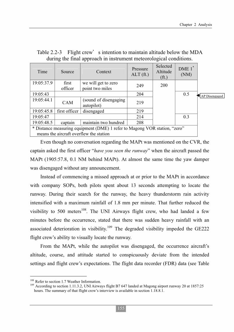
Chapter 2 Analysis
155
Table 2.2-3 Flight crew s intention to maintain altitude below the MDA during the final approach in instrument meteorological conditions.
Time Source Context Pressure ALT (ft.)
Selected Altitude
(ft.)
DME 1*
(NM)
19:05:37.9 first officer
we will get to zero point two miles 249
19:05:43 204 19:05:44.1 CAM (sound of disengaging
autopilot) 219
19:05:45.8 first officer disengaged 219
0.5
19:05:47 214 19:05:48.5 captain maintain two hundred 208
200
0.3
* Distance measuring equipment (DME) 1 refer to Magong VOR station, “zero” means the aircraft overflew the station
Even though no conversation regarding the MAPt was mentioned on the CVR, the
captain asked the first officer “have you seen the runway” when the aircraft passed the
MAPt (1905:57.8, 0.1 NM behind MAPt). At almost the same time the yaw damper
was disengaged without any announcement.
Instead of commencing a missed approach at or prior to the MAPt in accordance
with company SOPs, both pilots spent about 13 seconds attempting to locate the
runway. During their search for the runway, the heavy thunderstorm rain activity
intensified with a maximum rainfall of 1.8 mm per minute. That further reduced the
visibility to 500 meters108. The UNI Airways flight crew, who had landed a few
minutes before the occurrence, stated that there was sudden heavy rainfall with an
associated deterioration in visibility.109 The degraded visibility impeded the GE222
flight crew’s ability to visually locate the runway.
From the MAPt, while the autopilot was disengaged, the occurrence aircraft’s
altitude, course, and attitude started to conspicuously deviate from the intended
settings and flight crew’s expectations. The flight data recorder (FDR) data (see Table
108 Refer to section 1.7 Weather Information. 109 According to section 1.11.3.2, UNI Airways flight B7 647 landed at Magong airport runway 20 at 1857:25
hours. The summary of that flight crew’s interview is available in section 1.18.8.1.
AP Disengaged

Aviation Occurrence Report
156
2.2-4 and Figure 2.2-2) indicated that the aircraft’s heading changed from 207° to 188°
as a result of the bank angle changing from approximately wings level to 19° left and
then decreasing to 4° left, which was consistent with the aircraft commencing a left
turn away from the required approach course. The aircraft also commenced a descent
from previously maintained altitude of 200 feet. The aircraft pitch angle decreased
from 0.4° nose up to 9° nose down then returned to 5.4° nose down which produced a
reduction altitude from 179 feet to 72 feet.
Table 2.2-4 Sequence of flight crew actions and aircraft state during the attempt to visually locate the runway.
Time Source: CVR Transcript
Selected /Actual
ALT (ft.)
Selected/ Actual
Heading (deg)
Pitch (deg)
Bank (deg)
DME 1
(NM)
19:05:51 200 / 176 201 / 207.1 -1.0 -0.7 0.2 19:05:55 200 / 180 201 / 206.7 1.2 -1.8 0.1 19:05:57.8 captain: have you seen the runway 19:05:58 200 / 179 201 / 207.4 0.4 0.7 19:05:59 200 / 192 201 / 206.4 0.5 -2.5 0 19:06:00 200 / 175 201 / 205.3 1.1 -10.5 19:06:00.7 first officer: runway 19:06:01 200 / 167 201 / 203.6 0.3 -15.5 19:06:01.8 captain: um 19:06:02 200 / 169 201 / 201.1 0.0 -16.2 19:06:03 200 / 162 201 / 197.6 0.2 -19.3 0 19:06:04 200 / 157 201 / 195.1 0.6 -18.6 19:06:04.9 captain: sigh wow ha ha ha 19:06:05 200 / 166 201 / 193 0.1 -17.2 19:06:06 200 / 170 201 / 190.2 -1.6 -16.9 19:06:06.8 first officer: no 19:06:07 200 / 161 201 / 189.2 -4.1 -13.7 0.1 19:06:07.6 captain: no 19:06:08 200 / 164 201 / 188.8 -7.7 -10.9 19:06:09 200 / 131 201 / 189.2 -9.0 -12.3 19:06:09.8 first officer: no sir 19:06:10 200 / 99 201 / 189.5 -7.6 -8.8 19:06:10.4 captain: okay okay okay 19:06:11 200 / 72 201 / 188.1 -5.4 -3.9 0.3
Passed MAPt
YD Disengaged

Chapter 2 Analysis
157
Time Source: CVR Transcript
Selected /Actual
ALT (ft.)
Selected/ Actual
Heading (deg)
Pitch (deg)
Bank (deg)
DME 1
(NM)
19:06:11.1 first officer: go around 19:06:11.4 captain: go around 19:06:12 200 / 47 201 / 186 -1.5 -1.8 19:06:13 200 / 39 201 / 183.2 2.2 0 19:06:13.3 CAM: unidentified sound lasting 1.5 seconds 19:06:14 0 /-48 0 / 180.7 2.9 -2.5 19:06:15 0 / 43 45 / 180.7 -1.1 -4.6 0.4
Figure 2.2-2 Aircraft track and altitude deviations as flight crew attempted to visually locate the runway.
The combination of the captain’s left control wheel input and strong right
crosswind (32 to 34 kts from 252°) had turned the aircraft to the left, which
consequently resulted in the aircraft’s deviating from the required instrument approach
course. In addition, the combination of the captain’s forward control column input and
the possible effects of moderate turbulence pitched the aircraft nose down with a
subsequent loss of altitude below the previously maintained altitude of 200 feet.
Hit Bush

Aviation Occurrence Report
158
The aircraft’s flight profile appeared to continue unchecked during the 10 seconds
of flight before the first officer and captain announced their decision to go around at an
altitude of 72 feet and 0.5 nautical mile from the MAPt. The CVR indicated that the
crew were looking ahead of the aircraft trying to establish visual contact with the
ground. The aircraft collided with foliage located 850 meters to the northeast of the
runway 20 threshold two seconds after the crew made the go around call.
The captain diverted the aircraft from the published runway 20 VOR
non-precision approach procedure by descending below the published MDA before
obtaining the required visual references. The aircraft also diverted to the left of the
inbound instrument approach track as a result of several factors but the crew did not
identify and/or correct that deviation. The first officer did not challenge the captain’s
violation of the MDA. The crew’s decision to continue the approach below the minima
provided the crew with no margin for avoidance maneuvering and exponentially
increased the risk of controlled flight into terrain (CFIT). The flight crew did not
appear to identify the hazards associated with the approach and were therefore not in a
position to manage the associated risks.
2.2.2 Post Impact Structural Failure Sequence
According to site survey data, the aircraft subsequently collided with a building
on a magnetic heading about 183 degrees, with a nose up, left bank attitude110. The top
of that building’s roof had been damaged by rotating propeller blades.
The aircraft’s right wing also collided with the northern wall of the first impacted
building. After the first impact, the aircraft’s direction of movement was altered to
about 170 degrees and it then collided with several other buildings before it finally
came to rest. Figure 2.2-3 shows an aerial image of occurrence site superimposed with
the main wreckage and final flight trajectory.
110 Last recording on the FDR: pitch attitude +12.7 degrees, left bank 4.9 degrees.

Chapter 2 Analysis
159
Figure 2.2-3 Aerial image of occurrence site superimposed with the main wreckage and final flight trajectory
Aviation Occurrence Report
160
2.3 Compliance with Standard Operating Procedures
2.3.1 SOP Non-compliance during the Occurrence Flight
The operator’s standard operating procedures (SOPs) provided a framework by
which the flight crew were intended to operate the aircraft. The procedures provided
guidance to ensure that the flight crew conducted operations in a predictable, uniform
and safe manner, and they were therefore an important factor in assuring flight safety.
There was, however, significant flight crew non-compliance with those procedures
during the descent into Magong. Moreover, the flight crew’s non-compliance with the
published non-precision instrument approach and missed approach procedures at
Magong during flight in instrument meteorological conditions was a primary
contributing factor in the events leading up to the occurrence.
The flight crew’s compliance with procedures was not at a level to ensure the safe
operation of the aircraft. The captain did not conduct an approach briefing before he
commenced the descent into Magong. The CVR data revealed that the first officer did
not comment on the omission of this procedure, which would have provided the crew
with an opportunity to assess the risks for the approach to Magong. 111 The
non-compliance with company SOPs continued throughout the descent and approach
where the required checklists were not performed.
The Flight Safety Foundation (FSF) approach and landing accident reduction
(ALAR) task force found that the conduct of an inadequate approach briefing was a
factor in ALAR accidents. The Task Force identified that an approach briefing should
contain the following elements:
� Minimum Safe Altitudes;
� Terrain and man-made obstacles;
111The US Federal Aviation Administration’s (FAA) Advisory Circular (AC) 120-74B (dated 30 July 2012),
Flightcrew Procedures During Taxi Operations, Appendix 2, contained information regarding effective approach briefings, which can increase crew performance by highlighting those potential areas that need special attention and consideration.

Chapter 2 Analysis
161
� Weather conditions and runway conditions;
� Other approach hazards, as applicable;
� Minimums (ceiling and visibility or runway visual range);
� Stabilization height;
� Final approach descent gradient and vertical speed; and
� Go-around altitude and missed approach initial steps.
While the airline’s approach briefing checklist contained most of these elements,
the flight crew did not brief any of the items which was contrary to the operator’s
standard operating procedures. The investigation concluded that because these items
were not briefed, the crew did not have an adequate awareness of all the relevant safety
factors associated with the approach and landing, thereby progressively increasing the
risk of a CFIT event.
The captain then intentionally descended the aircraft below the MDA. The risk of
a CFIT event is reduced if an approach is flown no lower than the published MDA of
an instrument approach procedure until visual flight can assured and maintained.
Continuing the descent below the MDA in instrument meteorological conditions (IMC)
in close proximity to terrain meant that the risk of a CFIT event had increased to an
unacceptably high level and could not be mitigated. Impact with terrain was almost
certain from that point onwards.
Had the flight crew followed the runway 20 VOR approach procedure as
published on either the Jeppesen or CAA charts, and not descended below the MDA
but conducted a go around in accordance with the published missed approach
procedures, the accident would not have occurred. There was no evidence of any
inflight emergency that would have warranted the flight crew of the occurrence aircraft
to disregard or deviate from the published inflight procedures.
2.3.2 The Phenomenon of SOP Non-compliance in TNA’s ATR Fleet
In order to further understand if the numerous and habitual non-compliances with

Aviation Occurrence Report
162
SOPs identified on the occurrence flight were indicative of a systemic problem within
the airline’s ATR72 fleet or isolated to the occurrence crew, the investigation team
conducted various line observations. The findings from those are presented in Table
1.16-1 in section 1.16.4.
The airline observation flights conducted by the investigation team and interviews
with members of the airline’s flight operations division supported the conclusion that
there was a tolerance for non-compliance with procedures within the ATR72 operation.
That is, routine violations of procedures were normal. In particular, the flight crew
were known to descend below the minima before acquiring the required visual
references. If the airline had implemented a line operations safety audit (LOSA)
program, it would have readily identified the magnitude and frequency of the systemic
routine SOP non-compliance committed by crews at the airline.
In addition, similar findings with reference to TransAsia Airways (TNA) flight
crews not complying with SOPs during normal and abnormal operations had been
previously identified by Aviation Safety Council (ASC) occurrence investigations.112
In response, the airline proposed various corrective safety actions, which were
reportedly subjected to CAA oversight. However, the safety actions and their
subsequent oversight were clearly inadequate and ineffective because the habitual
non-compliance with SOPs continued at the airline unabated. The ASC investigations
provided further evidence that routine violations were normal practice for the airline’s
flight crews.
2.3.3 Organizational Factors Related to SOP Non-compliance
Human factors research113 has indicated that, in addition to individual mental or
112GE515, ATR-72-500, engine fire during climb, May 2, 2012. GE5111, ATR-72-500, electric smoke after
takeoff, July 1, 2013. 113 “Human factors that lead to non-compliance with standard operating procedures” research report by Health
and Safety Executive, UK, 2012. ICAO Safety Management Manual, the third edition, 2013. “ A human error approach to aviation accident analysis, Dr. Wiegmann and Shappell, 2003.

Chapter 2 Analysis
163
physiological factors, job and organizational factors may also directly or indirectly lead
to SOP non-compliance by front-line personnel. For example, inconsistent SOPs,
excessive workload, poor check and training, morale problems, ineffective safety
management, and inappropriate operational objectives can contribute to the prevalence
of failures to comply with SOPs.
A review of TNA’s flight operations and safety management structure and
activities, identified several organizational factors related to the prevalence of SOP
non-compliance in the ATR72 fleet:
� Functions of the Standards and Training Department;
� Pilot training and checks; and
� High ATR crew flying activity.
2.3.3.1 Functions of Standard and Training Department
The head of the standards and training department was an assistant manager
without a flying background. There was no standards pilot for the ATR flight operation
to oversee SOP compliance, SOP-related flight operations quality assurance (FOQA)
events handling, and standard operations audits (SOA) monitoring before the GE222
occurrence.
While there was a supervisor for the Standards and Training Section, the high
flight times and instructional workload of the check and training pilots assigned to
assist him was such that they had insufficient time available to perform support tasks
such as reviewing SOPs, training, audits, and operational safety risk assessments. In
addition, the shortage of standards pilots may have been another reason why the SOP
non-compliances identified by the FOQA program and the conduct of the SOA audit
program were not as effective as they could have been.
2.3.3.2 Flight Crew Check and Training
Table 1.16-2 in section 1.16.5 presents the various discrepancies observed during
some of the airline’s simulator training sessions. The non-compliance with SOPs which

Aviation Occurrence Report
164
were observed and not corrected indicated a tolerance for or normalization of SOP
non-compliance behaviors. This was symptomatic of a complicit and ineffective check
and training system with inadequate and ineffective supervision and oversight by flight
operations management.
Simulator training is an optimum opportunity for senior instructors and check
pilots to model compliant and effective safety behaviors to ensure that crews
understand and replicate the required performance standards. Crews under check or
training who do not model the required safety behaviors, including compliance with
SOPs, should be corrected and given an opportunity to demonstrate the required
behaviors. Standardization is a cornerstone for producing safe and proficient crews.
However, the airline’s ATR72 check and training system tolerated a lack of crew
discipline as demonstrated by the acceptance of operational discrepancies. Furthermore,
the CAA had not identified this problem earlier through inspections while the
investigation team was able to identify the discrepancies by observing a simulator
session. Even under official observation and after the airline had experienced a major
aircraft accident, the crews simulator performance indicated significant
non-compliance with SOPs.
2.3.3.3 High Flying Activities on ATR Fleet
Most of the ATR pilots who were interviewed and the rostering data had indicated
a significant increase in crew flying activities as indicated by increased flight times and
flight sectors. From May to July 2014, 57.7% of ATR pilots had accrued over 270
hours flight time which was significantly higher than for the same period and summer
peak season in 2013, where only 7.4% and 26.3% of crews respectively had accrued
more than 270 hours. The number of daily sectors flown had also increased to a
maximum of 8, which many crew found exhausting.
Many of the ATR pilots who were interviewed agreed that most deviations from
the SOPs occurred while the crew felt fatigued, particularly when operating flight

Chapter 2 Analysis
165
sectors later in the day. Despite protestations by crew at the time and concern within
flight operations, senior management did not conduct a formal risk assessment to
inform their decision making process.
The situation presented the risk of increased fatigue and the potential for
non-compliance behaviors. However, the company had not implemented a safety
management process to assess the safety risks associated with the increase in
operational tempo.
2.4 Human Factors Issues and Crew Coordination
2.4.1 Crew Resource Management and Threat and Error Management
Operating a multi-crew aircraft, particularly in high workload situations, requires
the two pilots to work in a coordinated manner and effectively communicate with each
other. A breakdown in crew coordination or communication can lead to an unequal
workload burden between the crew, a loss of cross-checking of information and
detection of errors, and/or incorrect or untimely information being communicated.
There were several factors that led to ineffective levels of crew coordination and
communication, including the following:
� There was probably a steep trans-cockpit authority gradient, resulting from large
differences between the crew in terms of age, experience, and position in TNA;
� Reports that indicated concerns about the captain’s unsafe operational behavior;
and
� Reports that the first officer and, the airline’s junior first officers generally, were
not naturally assertive.
A steep trans-cockpit authority gradient without appropriate crew resource
management (CRM) skills reduced the likelihood that the first officer would voice any
concerns that he may have had about the captain’s decisions and actions. It would have
also increased the probability that the captain made decisions without consulting the
first officer.

Aviation Occurrence Report
166
The aircraft’s impact with terrain was a direct consequence of the captain
descending the aircraft below the published MDA for the runway 20 VOR approach
procedure. Moreover, it was also as a result of poor planning by the flight crew and
less than effective CRM and threat and error management (TEM). During the landing
approach, the actions of the flight crew progressively increased the risk of a CFIT to an
extreme level, yet they seemed unaware that the likelihood of impact with terrain was
almost certain until less than two seconds before it occurred.
The captain was responsible for the safety of the flight crew, cabin crew,
passengers, and aircraft, and had full control of, and authority for, the operation of the
aircraft. The first officer had a duty and responsibility to ensure that the flight was
operated safely, yet he appeared to either passively condones, or did not question, the
unsafe operation of the aircraft during the latter stages of the flight. The crew did not
effectively discharge their responsibilities in the operation of the aircraft. Even though
the captain was the flying pilot for the sector, the first officer had a responsibility to
alert the captain about deviations from standard operating procedures, which resulted
in the aircraft being operated in an unsafe manner. The CVR data revealed, however,
that the first officer made no significant pro-active contribution to ensure that the
aircraft was operated safely during the final stages of the flight.
Effective application of TEM principles can reduce safety risk. Even though the
crew had undertaken TEM training, they did not demonstrate an appreciation of the
safety risks and how to manage them on the day of the occurrence.
The airline had implemented a TEM training program. The integration of TEM
with CRM provided crews with a useful framework to manage threats, errors and
undesired aircraft states. However, the systemic safety problems at the airline indicated
that their TEM training program was not effective otherwise they might have been
more cognizant of the risks confronting the crew on the day of the occurrence.
Examples of such risks included:
� The captain was experiencing a moderate level of tiredness, which may have

Chapter 2 Analysis
167
affected his performance during the approach; � The identification and mitigation of threats were not active components of the
operator’s approach briefing model. Therefore, the issues associated with runway use and availability, non-precision approaches, CFIT risk, and the provision of weather information at civil/military joint-use airports were not identified as potential threats;
� Non-compliance with SOPs was a major threat that undermined safety
assurance.
2.4.2 Crew Monitoring and Cross-Checking
Inadequate flight crew monitoring and cross-checking has been identified as an aviation safety problem. To ensure the highest levels of safety, each flight crewmember must carefully monitor the aircraft’s flight path and systems, and actively cross-check the actions of other crewmembers. This monitoring function is always essential, and particularly so during approach and landing when CFIT occurrences are most common114.
During GE222’s final approach, several unsafe behaviors regarding crew monitoring and cross-checking were identified. Examples included:
� Contrary to SOPs, the first officer proposed that he conducted the before
landing check by himself without a cross-check from the captain, which was
approved by the captain. The cross-check function had been intentionally
dismissed by the crew despite its safety purpose;
� When the aircraft was overhead the final approach fix, the captain and the first
officer did not cross check the aircraft altitude and position;
� When the aircraft was at about 100 feet above MDA, the captain and the first
officer did not cross check that the aircraft was approaching the MDA;
� The first officer did not challenge the captain’s decision to fly below the MDA,
114 “Crew Resource Management Training”, Advisory Circular 120-51E of the FAA, 1/22/2004.
Aviation Occurrence Report
168
but assisted the captain to do so without hesitation.
Effective crew monitoring and cross-checking can be the last line of defense that
prevents an occurrence. However, this monitoring function was ineffective on GE222.
The crewmembers did not correct the unsafe behaviors or decisions but rather
collaborated together to intentionally conduct an unsafe operation. The behaviors were
consistent with what had been identified in previous TNA ATR occurrences, simulator
observations and interviews, and indicated a poor safety culture within the ATR fleet.
2.4.3 Overconfidence
Overconfidence is a hazardous attitude that can create an unsafe situation. It is an adverse mental state when an individual overvalues or overestimates personal capability, the capability of others or the capability of aircraft/vehicles or equipment115. Overconfidence is often coupled with a poor appreciation of safety risk.
Interviews with ATR line pilots indicated that the captain had good flying skills.
Some interviewees further stated that the captain had landed safely in adverse weather
conditions previously because of his proficiency where some pilots might have
initiated a missed approach. The interviews indicated that the captain was quite
confident of his flying skills. This might be one of the factors that explained why the
captain intentionally flew below the MDA and tried to visually locate the runway while
maintaining 200ft. The TNA flight operations manager was aware of the captain’s flying behaviors.
However, subsequent discussions with the captain and the issuance of various safety notices regarding SOP compliance were clearly ineffective.
Well-designed SOPs and tasks reduce the risk of non-compliance. However, there are occasions when suitable and appropriate SOPs are not adhered to. Such unacceptable behavior is typically a social or motivational problem and may be a function of implicit organizational incentives. The extent of SOP non-compliance, and
115 “Department of Defense Human Factors Analysis and Classification System”, DOD, USA, January 11, 2005.

Chapter 2 Analysis
169
the way they are treated by employees and managers, provides a good insight into the overall safety culture in an organization. Proportional and consistent consequences, in accordance with a “Just Culture”, need to be implemented to manage flight crew who continue to violate well-designed SOPs and/or engage in unsafe behavior.
2.4.4 Fatigue
Fatigue is a major aviation human factors hazard because it can impair a crew’s
performance.116.
To establish the potential presence and influence of fatigue, it is important to:
� Determine if the crew were susceptible to fatigue;
� Evaluate if the crew’s presentation, performance and behaviors at the time of the
occurrence were consistent with the effects of fatigue.117, 118
Several contributing factors of fatigue as identified by research119 were evaluated
during the investigation. The captain’s medical records and toxicology report did not
indicate that he was adversely affected by any medication or physical health problem.
The occurrence flight was not at a time that corresponded with a normal individual’s
circadian low, where human performance was not optimal. The possibility of
sleep-related fatigue, including acute sleep disruption, chronic sleep disruption and
extended wakefulness, were unable to be assessed because specific information about
the captain’s wake/sleep cycles in the days before the occurrence were not available.
Both operational crew members’ performance metrics produced by the System for
Aircrew Fatigue Evaluation (SAFE) biomathematical model indicated that the captain
was a little tired and the first officer was not adversely affected by fatigue. However,
116“Fatigue Risk Management System Implementation Guide for operators”, published by IATA, ICAO and
IFALPA, July 2011. 117This approach is adopted by several aviation investigation agencies such as NTSB, TSB and ATSB, etc. 118 “Methodology for Investigating Operator Fatigue in a Transportation Accident”, NTSB, 2006. “Guide to
Investigating Sleep-Related Fatigue”, TSB, 2014. 119 “Methodology for Investigating Operator Fatigue in a Transportation Accident”, NTSB, 2006; “Guide to
Investigating Sleep-Related Fatigue”, TSB, 2014.

Aviation Occurrence Report
170
accurate sleep/wake information for both flight crew members was not available.
Therefore, it is important to note that the model used conservative sleep assumptions,
which may not have reflected the actual amount of sleep obtained in the period before
the occurrence. The SAFE biomathematical model indicated that there were times
during the previous two months of rosters for both the captain and first officer where
fatigue levels were elevated enough to significantly degrade their operational
performance.
The crew were local short-haul regional pilots. Their rosters indicated a common
fatigue-producing factor of early starts and/or late finishes, where short-haul pilots tend
to progressively lose more sleep throughout a given roster cycle.120, 121 The fatigue
research findings for short-haul airline pilots indicated that approximately 15 minutes
of sleep was lost for every hour that the start of duty was advanced prior to 0900 hours.
In addition, self-rated fatigue at the start of duty was highest for duty periods that
commenced between 0400 and 0500 local time, and lowest for duty periods that
commenced between 0900 and 1000 local time. Therefore, it was highly probable that
the GE222 flight crew had obtained less sleep throughout their roster cycle than that
estimated by the SAFE model.
The operational workload for both crew members was also very high as
demonstrated by their flight time and number of sectors flown in the three months
before the occurrence. There were also some salient indications recorded on the CVR
that suggested the captain was experiencing a higher level of fatigue than that derived
from SAFE. The captain stated he was very tired and his yawning was detected by the
CVR. In addition, lapses in radio communications with air traffic control (ATC),
incorrect VOR approach course selection, incorrect recall of ATC wind information,
120Roach, G. D., Sargent, C., Darwent, D., & Dawson, D. (2012). Duty periods with early start times restrict the
amount of sleep obtained by short-haul airline pilots. Accident Analysis & Prevention, 45, 22-26. 121Drury, D. A., Ferguson, S. A., & Thomas, M. J. (2012). Restricted sleep and negative affective states in
commercial pilots during short haul operations. Accident Analysis & Prevention, 45, 80-84.

Chapter 2 Analysis
171
and incorrect automatic flight control system (AFCS) mode selections, which required
the first officer to intervene, were consistent with the captain experiencing lapses of
attention, decreased vigilance, and low risk perception.
The fatigue analysis concluded that the captain’s performance was probably
degraded by fatigue at the time of the occurrence but that the first officer’s
performance was not adversely affected by fatigue.
Although it was not a requirement, had the airline implemented a data-driven
fatigue risk management system (FRMS) or an effective safety management process to
manage the flight safety risks associated with fatigue in accordance with the FRMS
Implementation Guide for Operators jointly developed by the International Civil
Aviation Organization (ICAO), the International Air Transport Association (IATA), and
the International Federation of Air Line Pilots’ Associations (IFALPA), the fatigue
levels and subsequent performance decrements among its ATR crews would have been
less acute.
2.5 TNA Safety Management
Effective safety management comprises a systematic approach to managing safety,
including the necessary organizational structures, accountabilities, policies and
procedures. A safety management system (SMS) is a planned, documented and
verifiable method of managing hazards and associated risks.
TNA’s SMS was not as effective as it could have been. There were limitations
with several of TNA’s safety management capabilities and processes related to assuring
the safety of its flight operations. The investigation identified reasons for these
limitations in terms of:
� Organizational structure, capability and resources;
� Risk management processes;
� FOQA limitations;
� Audits;

Aviation Occurrence Report
172
� Safety performance monitoring; and
� Safety education.
2.5.1 Organizational Structure, Capability and Resources
Safety committee was responsible for reviewing the overall safety performance of
the operations. The safety and security office (SSO) was a committee members and the
manager was the Executive Secretary of the committee. However, no staff member
from the SSO attended the flight safety action group (FSAG) or any of the other safety
action groups (SAGs) except the security safety action group (SSAG). That deprived
the SSO of an opportunity to discuss and develop an appreciation of the detailed safety
issues confronting each operational department. The safety action group minutes were
not an informative source of safety intelligence because they generally contained no
safety information of substance, which was perplexing given the safety issues that had
been identified in previous and current occurrences.
The SSO had limited resources and capability for the scope of duties they were
required to undertake, which included processing safety and security reports,
conducting safety and security investigations, SMS implementation, preparing the
monthly safety meeting agendas and minutes, FOQA analysis, audits of flight
operations, cabin, and ground/airport operations, facilitating and documenting
operational safety risk assessments, and conducting safety education and promotion
activities. The audit staff had not received sufficient auditor training and the audit
checklists did not contain risk assessment items. Furthermore, the CAA had noted in an
inspection report that the full capabilities of the FOQA system were not being
exploited because of resourcing limitations, thereby depriving the airline of an
opportunity to obtain significant insight into its flight operations risks. It was apparent
that the SSO was overwhelmed by the volume and complexity of tasks it was required
to undertake, which prevented it from implementing an effective SMS.
2.5.2 Hazard Identification and Risk Management
Chapter 2 Analysis
173
Hazards identification is the first step of the safety risk management. It is a
process where organizational hazards are identified and managed so that safety is not
compromised.
The investigation evaluated the specific risk factors associated with the
occurrence flight using the Flight Safety Foundation CFIT checklist. Based on the
information about the adequacy of TNA’s corporate culture, flight standards, hazard
awareness and training, previous occurrences, line observations, and interviews, the
evaluation indicated that the CFIT risk for TNA operating an ATR72 on a
non-precision approach into Magong in those weather conditions with crew not
complying with SOPs was a ‘significant threat’. The assessed risk was at a level such
that, to reduce the risk to an acceptable level, improvements were required in TNA’s
practices, flight standards, training and hazard awareness.
CFIT reduction initiatives have been a significant part of the work conducted by
ICAO and the FSF. This collaborative work has resulted in the production of the FSF
ALAR Tool Kit. The potential risk of CFIT can be reduced by using current
technology and equipment, implementing and complying with effective standard
operating procedures and ensuring ongoing compliance with such procedures through
an effective flight operations quality assurance program that includes flight data
analysis, documented operational risk assessments, regular safety audits, and by
developing effective crew decision-making and threat and error management processes.
The implementation of an effective data-driven SMS and operational compliance and
quality assurance system has the potential to reduce an airline’s operational safety
risks.
TNA had established and maintained a reactive safety and irregularity reporting
system which combined the mandatory and voluntary reporting systems. The voluntary
reporting system was operationally and administratively ineffective, which deprived
the airline of another opportunity to identify and assess its safety risks. In addition, the
airline focused on internal data sources to develop an appreciation of operational risks

Aviation Occurrence Report
174
and did not expand its horizons to external information sources, which deprived it of a
further opportunity to learn from other operators’ occurrences.
The airline’s risk register had not been updated since 2011 and contained no
formal proactive CFIT risk assessments. The airline’s SMS was not effective or
consistent with the guidance provided in the ICAO Safety Management Manual.
2.5.3 TNA FOQA Program
The FOQA program provided a means to identify potential safety risks and
mitigate those risks through by modifying the company’s risk controls such as standard
operating procedures, pilot training programs, and rosters.
According to the UK CAA’s Flight Data Monitoring CAP 739, a flight data
monitoring program can identify significant changes or deviations from acceptable
levels of performance. In addition to being an occurrence investigation tool, FOQA
data’s primary purpose is to analyze normal operations with a view to identifying or
predicting potential risks to flight operations. For example, FOQA will identify ports
that are at risk of unstable approaches, problematic instrument approaches, non-
compliances with SOPs and so on.
The FOQA Staff
The ICAO DOC 10000, flight data analysis program (FDAP) manual, stated that
an airline’s FOQA team should have a flight operations specialist and a technical
specialist who have in-depth knowledge of company standard operations procedures
and aircraft handling characteristics so they can interpret the FOQA data accurately.
Those specialists then need to identify operational hazards emerging from the FOQA
data analyses. In addition, it is beneficial to utilize an independent non-management
pilot as the flight data ‘gatekeeper’ who can contact and discuss events with the event
pilots in a confidential manner to clarify the context of an event on behalf of the safety
department.
The TNA FOQA team did not have a flight operations or technical specialist

Chapter 2 Analysis
175
embedded in the SSO. The absence of such specialists made it difficult for the
designated FOQA officer to fully understand and analyze the data from an operational
perspective. Interviews indicated that the ATR chief pilot usually accompanied the
event pilots to review the event. The chief pilot/fleet manager will be able to
understand the flight data. However, event flight crew may be reticent to openly
discuss the context of a flight data event with a senior management pilot because of
potentially adverse consequences, thereby depriving the airline of another opportunity
to accurately identify and assess an operational risk.
FOQA Event Handling
SOP non-compliance presents a high level of risk to flight operations and needs to
be identified and rectified in a timely manner.
A review of the TNA FOQA data between January and June 2014 indicated that
there had been several crew non-compliance events, such as an over-weight landing,
late flap setting, unstable approaches, late landing gear retraction, high descent rate
below 500 feet and so on. Some event data had been sent to the training department
and chief pilot for corrective actions. However, the FOQA events were sometimes not
administered in accordance with the company’s own procedures and that resulted in the
FOQA data not being used to identify and mitigate operational safety risks.
FOQA Trend Analysis
Effective FOQA trend analyses will identify systemic event types.
A review of the TNA FOQA monthly data analysis reports from January 2013 to
June 2014 identified recurring flight data events such as long flare, GPWS warning
between 500 and 1,000 feet, and heading deviation during landing roll. There was no
evidence to indicate that those events or the FOQA trend analysis results were
discussed during safety meetings. The SSO issued notices to company flight crew
outlining the FOQA data without any technical advisory or explanatory information. In
addition, the SSO did not monitor the FOQA trend analysis data so it was not in a
Aviation Occurrence Report
176
position to raise safety issues with the Flight Operation Division if an adverse trend
was apparent.
The TNA FOQA program was not used as an effective tool to identify SOP
non-compliance events and provide the relevant information to flight operations for
training intervention. In addition, the program did not function as required to provide a
systematic tool to proactively identify hazards, assess and mitigate the associated risks.
2.5.4 Self-Audit
The CAA’s Flight Operations Self-Audit Advisory Circular (AC-120-002A) dated
1 July 2002 defined self-audit as an internal flight operations quality assurance system
designed to continuously monitor compliance with regulations, policies, and
procedures. The audit was designed to focus on system self-evaluation, analysis, and
corrective actions rather than spot checks of outputs. Company self-audits provided an
opportunity to identify the frequency and magnitude of non-compliances with standard
operating procedures. Moreover, operators were required to conduct special self-audits
in response to serious incidents, and other events with the potential to increase risks,
such as violations, fleet changes or expansion, and human resource shortages. TNA self-audit records indicated that there were very few self-audit findings in
2013 and 2014 before the occurrence. The audits were mostly spot checks rather than system audits or system self-evaluations. The self-audits were ineffective because they failed to identify and address those safety deficiencies that had already been identified in previous occurrences and were known by senior flight operations management to be problems, including SOP non-compliance behaviors, lack of standardization in pilot check and training activities, and high crew flying activities on the ATR fleet.
Moreover, there was no evidence that TNA had conducted a special audit after an earlier ATR72 occurrence122 which also occurred during a time when the ATR72-600 aircraft variant was being introduced into the company’s ATR72 fleet for the first time.
122 GE5111 occurrence occurred on 1 July 2013.
Chapter 2 Analysis
177
Furthermore, the TNA annual audit plan had not included an evaluation of responses to those safety issues and/or recommendations which had been identified during previous audits, CAA regulatory inspections, and occurrence investigations. The TNA self-audit program was not consistent with the guidance contained in CAA AC-120-002A.
Standard Operation Audit (SOA)
TNA’s SOA program was a component of the flight operations division’s
self-audit program. The primary function of the SOA was to monitor normal line
operations for SOP compliance and to identify safety risks in flight operations. The
SOA program also included a flight crew self-evaluation process.
The TNA training for SOA auditors was insufficient and ineffective. Interviews
indicated that apart from rudimentary risk management training, there was no
additional or specific training and supervision to ensure that the auditors were
equipped with the skills required to identify safety risks in flight operations.
Company audit records indicated that from 1 January 2013 to 31 July 2014, TNA
staff had conducted 163 SOAs of the ATR fleet. Only 3 of those 163 audits had been
identified non-compliances with SOPs. No corrective actions were implemented in
response to those audit findings, which had not been captured by the monthly SOA
statistics report.
Flight crew self-evaluations were typically not conducted during the SOAs. SOA
audits were not conducted as required to ensure that previously issued corrective safety
actions had been implemented and were effective. SOA audits were ineffective because
they failed to identify and address those safety deficiencies that had already been
identified in previous occurrences, FOQA flight data and were known by senior flight
operations management to be problems. Furthermore, the monthly SOA statistics
report and the 12-month-rolling accumulation statistics were inaccurate and did not
reflect SOA audit report findings.
2.5.5 Safety Performance Monitoring

Aviation Occurrence Report
178
The flight operations division (FOD) had implemented two composite risk indices, the direct risk indicator (DRI) and average risk indicator (ARI), to provide an overall assessment of risk confronting flight operations. However, those risk indices did not accurately reflect the current level of safety risk to TNA flight operations. That is, the risk measures used to monitor safety performance were misleading and not a valid representation of the critical safety risks in flight operations.
The DRI comprised 13 factors, which included items such as SOP
non-compliance, fatigue, crew resource management items and so on. The data for
these items were extracted from the results of flight crew self-evaluations. However,
only 24 crew self-evaluations were obtained as part of the 379 SOA audits which were
conducted on the Airbus and ATR fleets from 1 January 2013 to 31 July 2014. In
addition, some DRI factors did not reflect the actual situation confronting the ATR fleet.
For example, the DRI item pertaining to fleet manpower evaluation was scored to
indicate that there were no crew shortages. However, the ATR fleet was short of at least
8 pilots at the time of the occurrence.123 That is, the DRI was not a valid reflection of
actual safety risk because it was calculated using insufficient and/or inaccurate
self-evaluation data. The ARI was calculated using the number of hazards grouped by risk level. The
input hazards were established from the brainstorming sessions when the system was first implemented and were revised in accordance with operational data until March 2011. The hazards were not revised or re-evaluated after that time. That is, the ARI input data was not current or informed by recent data from line operations. The ARI had not changed since 2011, which meant that it was not a reliable, valid or meaningful indicator of safety risk at the time of the occurrence.
The airline’s safety performance monitoring system did not provide a current,
reliable or valid indication of safety risk in flight operations. Furthermore, the CAA
123The pilot to ATR aircraft ratio established by TNA was 6:1. That is, there should have been 60 pilots available
to operate the 10 ATR aircraft from May to July 2014. However, there were only 52 pilots at that time.

Chapter 2 Analysis
179
had not identified the accuracy and safety risk level of the airline.
2.5.6 Safety Education
The TNA SSO had established an internal website for the dissemination of safety
information within the company. However, the website was not routinely updated with
the latest safety information, including the safety investigation reports and safety
lessons from the company’s ATR72 occurrences in 2012 and 2013, which were
investigated by the ASC. Interviews with ATR flight crew indicated that they were not
aware of the contributing factors and safety recommendations related to SOP
compliance issued by the ASC in the two occurrence investigation reports.
TNA did not have an effective safety information and education system, which
deprived flight crews from further developing an appreciation of the safety risks
confronting flight operations, particularly the risks associated with non-compliance
with SOPs.
2.6 TNA’s SMS Development and CAA Oversight
2.6.1 SMS Implementation Plan
According to the CAA AC 120-32C, local airlines should have implemented a
SMS by 31 December 2012.124
An SMS implementation plan is the foundation for establishing an effective SMS
and was endorsed by CAA AC-120-32C.125
TNA had not developed an SMS implementation plan. This led to a disorganized,
nonsystematic, and incomplete approach to establishing conforming safety
management capabilities and functions and ensuring that those elements were effective.
124See CAA Advisory Circular AC-120-32C dated 25 January 2011. CAA AC-120-32D, dated 20 October 2014,
extended the SMS implementation date to 31 December 2016. 125An SMS implementation plan is a necessary component of the SMS development process. It includes timelines
and implementation milestones for the various components or elements. It should also be endorsed by the airline’s senior management, including the accountable manager (CEO), and reviewed regularly and updated as required.

Aviation Occurrence Report
180
Poor SMS planning resulted in significant deficiencies in senior management
engagement, the quality of safety data, the effectiveness of safety meetings,
responsiveness to safety recommendations, auditing and risk assessment capabilities,
safety performance monitoring, and safety education.
Both ICAO and the FAA advised that a State’s civil aviation regulatory authority
needs to assess and review an airline’s SMS implementation plan for acceptance or
approval. 126 , 127 The CAA did not require operators to submit their SMS
implementation plans for approval. Moreover, the CAA did not consider the absence of
an SMS implementation plan at TNA fundamental to SMS oversight. This view
deprived the CAA of an opportunity to detect and rectify the manifold deficiencies
with TNA’s developing SMS at an early stage of the process.
2.6.2 Follow-up Actions of the SMS Assessment
The CAA Operations Inspector's Handbook indicated that the inspectors assigned
to TNA were responsible for monitoring the airline’s response to SMS deficiencies
identified by CAA’s SMS assessment project team.
The 24 TNA SMS deficiencies noted by the CAA’s SMS assessment project team
in 2013, included concerns about the data used for hazard identification, the
application of risk management in senior management decision-making, lack of SMS
effectiveness evaluation tools and so on. The CAA requested a corrective action plan
from the airline but the airline did not submit one. Moreover, the airline’s allocated
CAA inspectors did not pursue the airline for its corrective actions plan. This resulted
in unresolved deficiencies with the airline’s SMS.
2.7 CAA Flight Operations Oversight
An air operating certificate (AOC) holder had a clearly defined responsibility
126International Civil Aviation Organization. (2012). Safety management manual (3rd Ed.) (DOC 9859-AN/474).
Québec, CAN: ICAO. 127“Safety management systems for aviation service providers”, FAA Advisory Circular No. 120-92B, 1/8/15.

Chapter 2 Analysis
181
under the CAA regulations to ensure the safety of its operations. The regulator, CAA,
also had defined responsibilities for overseeing the activities of an AOC holder,
through the processes of approving AOC variations and other permissions, as well as
conducting surveillance of the activities of the operator.
AOC approval and surveillance processes will have constraints in their ability to
detect problems. There is restricted time available for these activities. Regulatory
surveillance is also a sampling exercise, and cannot examine every aspect of an
operator’s activities, nor identify all the limitations associated with these activities.
While AOC approval and surveillance processes focus on regulatory requirements,
which provide legal checks and a minimum standard of safety, the CAA was also
tasked with overseeing airline safety management processes.
Despite the constraints, the CAA still had significant interactions with TNA,
through the conduct of scheduled in-depth and cockpit en-route inspections,
monitoring the implementation of corrective actions in response to inspections and
safety occurrences, SMS assessment, and other approval activities. As a result of these
interactions, the CAA had identified some areas for improvement in TNA’s SMS,
flight crew training, procedures and practices, and FOQA program. However, it did not
detect fundamental problems associated with the airline’s risk management of flight
operations, such as systemic problems with flight crew not complying with SOPs, lack
of standardization in pilot checking and training activities, SSO organizational
structure and capability, and demonstrated management commitment to safety.
Given the significance of the problems within TNA, and the amount of
interactions CAA had with the airline, it is reasonable to conclude that some of these
problems should have been detected by the CAA. In considering the reasons why these
problems with TNA were not detected, the investigation identified safety factors in the
following areas:
� Consistency of oversight activities with CAA policies, procedures and guidelines;
� Guidance for evaluating management systems;

Aviation Occurrence Report
182
� Risk assessments for changes in operations;
� Regulatory assessments of safety management systems and the implementation of
SMS regulations; and
� Processes for assessing an operator’s risk profile.
Assessments of an organization’s management systems necessarily involve the
use of professional judgement by inspectors. To ensure that such judgements were
appropriate, CAA needed to ensure that its inspectors had the appropriate skills to
make judgements on management systems, or had an appropriate amount of guidance
material to assist them in making these judgements. The CAA only provided limited
guidance material to assist inspectors with their evaluations of management systems.
While the CAA had formed an SMS project assessment team to assess an airline’s
SMS implementation progress, the assessment was conducted independent of the CAA
inspectors allocated to the airline. It would have been beneficial for the inspectors to be
accompanied by the SMS assessment team in routine SMS inspections so that they
could develop a better appreciation of the safety challenges confronting the airline.
Although some CAA inspectors probably had sufficient background and skills to
conduct assessments in these areas, the guidance provided did not ensure that all of the
airline inspectors had these competencies. That is, the CAA had not provided itself
with assurance that key components of an operator’s management systems were able to
be effectively examined by its inspectors. In the context of TNA, there were limitations
in guidance evident in the following areas:
� Evaluating organizational structure and staff resources;
� Evaluating the suitability of key personnel;
� Evaluating organizational change; and
� Evaluating risk management processes.
When assessing an airline’s management systems and capability, CAA inspectors
needed to consider whether an organization had an appropriate structure and sufficient
personnel to carry out the required functions of the organization. Despite the

Chapter 2 Analysis
183
importance of ensuring an organization had an appropriate number of personnel, and
the workload of key personnel was not excessive, CAA provided limited guidance to
its inspectors on how to evaluate these requirements.
In terms of the suitability of an organization’s structure, the CAA inspectors’
manuals provided a minimal amount of guidance. Organizations can vary greatly in
terms of their size, structure and complexity, and it would be impracticable to provide
detailed guidance about every specific situation that CAA inspectors may encounter.
However, it would seem practicable to provide case examples of what was and was not
considered appropriate, as well as a list of criteria to consider when making evaluations.
Such guidelines could be developed based on CAA’s past experience, the experience
of other regulatory agencies, discussion with key industry groups, and findings from
research into organizational behavior in a variety of fields.
2.7.1 Guidance for Evaluating Organizational Change
TNA was experiencing a period of significant growth and change in operations:
the introduction of the ATR72-600 and the general growth in revenue flights. However,
the airline was also experiencing a shortage of ATR flight crew and a subsequent
significant increase in flight and duty times. There was limited CAA guidance or
mechanisms that required inspector’s to review the impact of these events as a whole,
or guidance on how to conduct such an evaluation. A series of incremental changes
could be made to an organization’s activities, each with the approval of CAA. Each
change by itself may be justified as having minimal impact, but overall may have had a
significant impact.
By not making such decisions at the approval stage, the regulator was relying on
its surveillance processes to detect and rectify any problems. However, the guidance on
examining an organization’s change management processes was limited and focused
on what changes had occurred rather than the adequacy of an organization’s processes
to manage the changes.
Aviation Occurrence Report
184
2.7.2 Guidance for Evaluating Risk Management Processes
SMS require processes for identifying hazards, analysing risks, treating risks and
evaluating the effect of treatments or controls. The ability of an operator to develop
and implement these processes should be evaluated during the SMS oversight by the
CAA. However, there was limited CAA guidance to inspectors allocated to the
operator for evaluating the operator’s risk management process. Furthermore, although
some deficiencies of the risk management processes in TNA were identified during the
SMS assessment team’s audit, the CAA’s SMS oversight to the TNA did not appear to
be of sufficient depth to evaluate the quality or effectiveness of the operator’s existing
processes.
2.7.3 Regulatory Requirements for Safety Management Systems
The CAA’s AC-120-32C required that operator implement a SMS by 31
December 2012. The AC is advisory or demonstrative of an acceptable means of
compliance with the associated regulations but not the only means. In addition to
specific CAA SMS regulations, there were also general regulatory requirements for
CAA to ensure that an AOC holder conducted operations safely.
The CAA SMS AC-120-32C contained sufficient scope for the CAA to facilitate
safety improvements by operators and to monitor an operator’s responses to those
requested safety actions. TNAs safety program was a safety management system,
albeit ineffective. The CAA had not ensure that the airline responded effectively to the
safety deficiencies and corrective actions issued by the CAA, undermined the levels of
system safety assurance and facilitated a lack of accountability at the airline.
2.7.4 Processes for Assessing an Operator’s Risk Profile
There was no formal safety risk trend indicator system used by the CAA to assess
the relative risk level of operators. Rather, the CAA inspectors relied on the risk
metrics produced by the operators. In the case of TNA, the airline’s risk indices were

Chapter 2 Analysis
185
not current, reliable or valid but the CAA inspectors had limited means to assess the
veracity of the airline’s risk indices or to calculate an independent safety risk indicator
for the airline. Had such a safety risk trend indicator system been in place, it would
have identified that the operator was ‘high risk’ due to a range of issues such as
significant expansion of operations, ATR crew shortage, previous serious incidents,
unresponsive or ineffective responses to previous ASC safety recommendations,
unresponsive or ineffective responses to internal and CAA external audits and
inspection corrective actions, ineffective risk management processes and assessments,
ineffective safety meetings, questionable senior management commitment to safety,
inadequate SSO and flight operations resources, lack of standardization during flight
crew check and training activities, non-compliance with procedures and unsafe
practices. This would have been a useful tool for triggering the need for additional
special audits of the operator.
2.7.5 Previous ASC Investigation
On 20 May 2013, the ASC issued Safety Recommendation ASC-ASR-13-05-014,
which recommended that the CAA oversaw TNA’s efforts to reinforce the requirement
that flight crew comply with standard operating procedures (SOPs), including standard
callouts during approach. On 18 September 2013, the CAA replied that TNA would
specifically focus on approach operations and standard callouts when conducting an
additional SOA. The proposed actions for the Safety Recommendation were accepted.
A review of TNA SOA audit records contained no evidence that TNA had
conducted SOAs with a focus on SOP compliance during approach, including standard
callouts, as the company had advised the CAA they were going to do. The CAA
inspector for TNA did not follow up the implementation of the safety actions which
were supposed to be implemented by TNA. The SOP non-compliances identified by
the previous occurrence investigation were not corrected and the hazard remained in
TNA flight operations practices.

Aviation Occurrence Report
186
2.7.6 Effectiveness of CAA Inspections
While the regulatory surveillance activities of CAA inspectors assigned to TNA
identified some safety deficiencies, the inspections were not as targeted and/or as
effective as they could have been. For example, there were major safety events at the
airline, including two serious ATR72 occurrences in 2012 and 2013, which should
have triggered a special audit by the CAA. Despite the ASC investigation reports had
identified crew non-compliance with SOPs and deficiencies with pilot check and
training, the CAA did not pursue the matter. Furthermore, identified safety issues were
often closed prematurely by CAA inspectors without verifying the implementation or
effectiveness of the safety actions implemented by the airline. It wasn’t until after the
GE222 fatal accident that the CAA elected to conduct a special audit of the airline,
where multiple serious safety deficiencies were identified.
2.7.7 Risk-based Approach to Surveillance
A safety management environment provides for a more dynamic assessment of
safety performance. Regulatory oversight surveillance programs generally include
mechanisms for calibrating the scope or frequency of surveillance according to actual
safety performance. This risk-based approach to surveillance prioritization facilitates
the allocation of resources according to areas of greater risk, concern or need. A
regulator’s surveillance program should be data-driven so that its resources are focused
and prioritized according to areas of highest risk or safety concerns.
In the past, the CAA surveillance methodology focused primarily on determining
regulatory compliance using a system of direct inspection of a certificate holder’s
aircraft, personnel, records and other systems. The inspectors planned the inspection
program based on the inspection job functions and conducted the inspections according
to the direction and guidance in the Operations Inspector’s Handbook. With the
increasing number of local operators and other regulatory activities, the volume of
inspection work increased substantially. Coupled with inspector shortages, that created
Chapter 2 Analysis
187
high CAA inspector workloads, which may had a bearing on the inspectors’
performance.
The introduction of SMS has instigated significant changes for the way civil
aviation regulatory authorities assess the safety of operators. While an airline is
responsible for implementing effective risk management procedures and practices, the
regulator is responsible for ensuring that those procedures and practices are robust,
effective and provided for a high degree of safety assurance. Civil aviation regulators
cannot abdicate their responsibilities for ensuring the safety of airline operations just
because an operator has implemented an SMS.
Civil aviation regulators need to provide safety leadership in an increasingly
complex and continuously changing air transportation system. The CAA’s surveillance
activities may be more effective if they implement a more targeted risk-based approach
to operator safety evaluations. The CAA may refer other civil aviation regulatory
agencies to redefine oversight model, transform the internal structure, and revisited
future capability needs. The prioritized approach will focus resources on addressing
major safety issues within the constraints of limited regulatory resources.
2.8 Meteorological Issues
2.8.1 Rainbands of Typhoon Matmo
Magong Airport was affected by the outer rainbands of Typhoon Matmo at the
time of the occurrence. The automated weather observation system (AWOS) and radar
data showed that these rainbands were similar to squall lines. The radar images (see
Figure 2.8-1) indicated that two waves of rainband passed through Magong Airport
before and during the occurrence. The first bow echo affected Magong Airport from
1738 to 1803; the second echo was from 1901 to 1945. These bow echoes may cause
significant changes in wind speed and wind direction with associated heavy rain
showers.

Aviation Occurrence Report
188
Figure 2.8-1 Rainband activity at Magong before the occurrence.
2.8.2 Surface Weather Observations and Reporting
According to the weather radar information and AWOS data, the rain intensity at
Magong Airport from 1803 to 1901 was moderate. The echo intensity was less than
20-25 dBZ and the rain intensity decreased between 1835 and 1900. When the second
rainband approached Magong Airport at 1901, the echo intensity was about 50-55 dBZ.
The rain then intensified and the runway visual range (RVR) decreased rapidly. Table
2.8-1 shows one-minute mean RVR from 1859 to 1908.
Table 2.8-1 One-minute mean RVR at Magong Airport AWOS N. Time 1859 1900 1901 1902 1903 1904 1905 1906 1907 1908RVR (m)
ABV 2000 1800 800 650 600 650 600 500 450 550

Chapter 2 Analysis
189
The telephone communications recordings indicated that at 1821:59, the tower
asked the forecast officer about that visibility. The response indicated that the visibility
was improving a little bit but another wave of weather was soon to arrive at the airport
where was estimated to become poor. Between 1824 and 1825, the tower asked the
forecast officer twice about the visibility, and the forecast officer replied the tower that
visibility might improve in ten minutes but would deteriorate once again in 10 to 20
minutes. Therefore, the visibility report would remain 800 meters.
At 1838:35, the forecast officer asked the weather observer about the actual
visibility. The forecast officer recalled that the weather observer replied that visibility
was about 1,600 or 2,400 meters. The weather observer then reported an improved
visibility of 1,600 meters. That visibility report was included in the aerodrome special
meteorological reports (SPECI) issues at 1840. The GE222 crew requested the
approach to runway 20 at 1843. The AWOS data indicated that between 1900 and 1901
the RVR deteriorated rapidly from 1,800 to 800 meters, which was below the landing
minima for the runway 20 VOR approach.
According to the “Air Force Meteorological Observation Manual”, the
observation of special weather report shall be completed within three minutes after the
weather changed. The manual also instructs that, before conducting visibility
observations at night, observers shall spend 3-5 minutes in the darkness to allow their
eyes to become adapt to the low light condition. Based on the telephone records, the
weather observer had made a phone call to the tower at 1901:01 for the 1900 METAR
information. The observer had received two phone calls at 1902:02 and 1904:24 to
provide visibility information. After completed the weather observation, the special
weather observation report with the visibility decreased to 800 meters was issued at
1910.
2.8.3 RVR Reporting
2.8.3.1 Updating Weather Information to the Aircraft

Aviation Occurrence Report
190
According to the air traffic management procedures (ATMP), as soon as possible
after an aircraft is transferred from approach control, the tower is required to issue the
crew with visibility or RVR. In addition, during final approach, the tower is required to
advise the crew when there are changes in observed RVR values or visibility. Between
1901 and 1906, the occurrence aircraft was transferred to the Magong tower and was
on its final approach to Runway 20. During that period of time, the RVR values started
decreased further from 800 meters to 500 meters.
At 1901:13, the GE222 crew contacted the Magong tower controller who
confirmed the runway in use and QNH information. The tower controller did not
advise the flight crew that the RVR was 800 meters. At 1903:39, the tower controller
issued a landing clearance to GE222, and reported wind speed and direction
information, but did not advise that the RVR was 600 meters. Had the revised visibility
been communicated to the occurrence flight crew, such information might influence
the crew’s decision regarding the continuation of the approach.
There was no anomaly of the AWOS RVR recorded at Magong tower and
Magong weather center on the occurrence day. At 1804, the weather forecast officer
had replied the local controller that the AWOS RVR was serviceable. Compared the
AWOS RVR records, AWOS rain gauge records, and information from airport CCTV,
the AWOS RVR values on the occurrence day were reasonable and consistent with the
changes of the weather.
Interview records indicated that the tower controller did not provide the RVR
information to the flight crew was because of the discrepancies between the AWOS
RVR data and the RVR reported by the weather observer, which was included in the
METARs issued during the hour before the occurrence. The tower controller was
concerned about the validity of the AWOS data. After discussion with the tower chief,
the tower controller used the visibility and RVR information reported in the applicable
METAR/SPECI, which was 1,600 meters.
Chapter 2 Analysis
191
2.8.3.2 RVR Reporting in METAR/SPECI
Air Force Meteorological Observation Manual stated that the RVR shall be
reported whenever the visibility or RVR is less than 1,500 meters.
The 1830 METAR128 reported that visibility was 800 meters and the RVR was
also 800 meters. However, between 1804 and 1859, the 1-minute mean AWOS RVRs
recorded were above 2,000 meters. According to the manual, the RVR in the 1830
METAR should be reported as “more than 2,000 meters”.
The weather watch office supervisor stated that actual conditions and safety
concerns had to be taken into account when AWOS RVR values were higher than the
observed visibility. For example, if the visibility observed by the weather observer was
800 meters but the AWOS RVR value indicated 2,000 meters, the RVR would be the
observed visibility. When AWOS RVR values were less than the observed visibility,
then the weather observer would use the AWOS RVR value for the METAR/SPECI
report.
Magong Airport is a civil/military joint-use airport. The Air Force Weather Center
didn’t provide an AWOS operations manual to the civil Tower when the new AWOS
was installed. There was a lack of communication between the civil and military
authorities on RVR reporting requirements and practices.
2.8.4 Active Runway Selection
During the time of the occurrence flight, the runway in use at Magong Airport
was runway 20 due to the wind speed and direction. The average wind speed for
runway 02 decreased to about 5 to 7 knots between 1824 and 1828, which was below
the 10 kts tailwind landing limit. At 1827:38, Kaohsiung Approach relayed the wind
information for runway 02 to the holding inbound aircraft crews. Some of the crews
subsequently requested the runway 02 instrument landing system (ILS) approach.
128 The METAR reported ten-minute mean RVRs. There were only one-minute mean RVRs recorded in AWOS.

Aviation Occurrence Report
192
The use of other direction of runway application procedures for the civil/military
joint-use airport indicated that, when the military aircrafts stationed at the airport, the
application could only be authorized by the Magong Air Force Base (AFB) duty
officer.
At 1833:35, the AFB duty officer received the use of other direction of runway
application because three inbound aircraft had requested the runway 02 ILS approach
due to runway 20 was no longer suitable given the landing minima visibility
requirements. While the decision for the application was still under consideration, the
1840 weather report indicated that the visibility had improved to 1,600 meters, which
met the landing visibility minima requirements for an approach to runway 20. The
crews subsequently amended their request and elected to use runway 20.
2.8.5 Coordination at Magong Joint-use Airport
At the time of the occurrence, the mechanisms in place for weather information
and runway availability coordination between civil and military personnel at Magong’s
joint-use airport were less effective than what they could have been. In particular, the
inconsistent information or discrepancies regarding airport visibility during the
aircraft’s approach were unresolved. In addition, the rapidly changing AWOS RVR
data was not communicated by the tower controller to the occurrence flight crew.
Those inconsistencies meant that there was no collaborative decision-making
relationship between the civil air traffic controllers, military weather observer, and
flight crew. That resulted in the occurrence flight crew not being fully aware of the
rapidly deteriorating RVR while on approach and the high likelihood that the RVR
would not be sufficient for landing. Had the local controller provided the flight crew
with RVR updates during the approach, it may have placed the crew in a better position
to determine the advisability of continuing the approach.
2.9 Atmospheric Environment during Final Approach
2.9.1 The Aircraft Behavior

Chapter 2 Analysis
193
Based on the FDR data and the technical information provided by the ATR, the
vertical speed, control column position, and control wheel position of the occurrence
flight after the autopilot was disengaged were calculated. Relevant FDR parameters
and the three derived parameters are depicted in Figure 2.9-1. Derived vertical speed is
denoted as “VS_SM_5PT”, derived control column position and control wheel position
are denoted as “CCP_derived” and “CWP_derived”, respectively.
The occurrence aircraft’s increased rate of descent from 150 ft/min to 1,600 ft/min
between 1906:05 and 1906:10 was the result of an elevator control input by the captain.
The nose down pitch angle of the aircraft was a maximum of 9 degrees. While
descending, the aircraft turned to the left as a result of left aileron input. That is, the
aircraft behavior was consistent with the control surface inputs.
Figure 2.9-1 Relevant FDR and derived parameters
2.9.2 Windshear

Aviation Occurrence Report
194
An examination of flight data from the occurrence aircraft and from aircraft
landing at Magong shortly before the occurrence aircraft indicated no evidence that the
occurrence aircraft encountered windshear129 or microburst130 activity.
Between 1906:00 and 1906:12, the FDR recorded wind indicated that the
headwind decayed from 19 knots to 15 knots. The right crosswind increased from 27
knots to 30 knots. That is, the final approach conditions were not consistent with a
windshear encounter.
2.9.3 Turbulence
Turbulence is caused by the relative movement of disturbed air through which an
aircraft is flying. Turbulence strength can be divided into three levels: light, moderate,
and severe. This section uses two methods to analyze the intensity of turbulence for the
occurrence flight, vertical acceleration peak threshold, and Eddy Dissipation Rate
(EDR), detail in Table 2.9-1.
Table 2.9-1 Turbulence Strength Levels and Threshold Values Turbulence
strength Vertical acceleration peak threshold
(FDR 8 Hz)131 Eddy Dissipation Rate (1 km
moving average)132 Light 0.51g’s ~ 1.49 g’s 0.1 ~ 0.40
Moderate 0.00 g’s ~ 0.50 g’s 1.50 g’s ~ 1.99 g’s
0.41 ~ 0.70
Severe <= 0.00 g’s >= 2.00 g’s
> = 0.70
Based on the FDR data, the vertical acceleration for the last two minutes of the
occurrence flight is shown in Figure 2.9-2. The plot indicated that the vertical
129According to ICAO Manual on Low-level Wind Shear (DOC 9817), wind shear is defined as the change in
wind speed and/or direction in space, including updrafts and downdrafts. Low Level Wind Shear is a rapid change in wind speed and/or direction below 1,600 feet AGL. It can affect the safety of aircraft during takeoff and landing. The manual also indicated that when an aircraft encounters a change in the headwind or tailwind of 15 knots or more, the probability of wind shear is high.
130A microburst is a small-scale but violent downburst of a very localized column of sinking air caused by a small and intense downdraft within a thunderstorm.
131Guide to Meteorological Instruments and Methods of Observation, 2010 updated, World Meteorological Organization.
132Reference ICAO Annex 3 Meteorological Services for International Air Navigation.

Chapter 2 Analysis
195
acceleration fluctuated between 0.8 and 1.2 g’s until 1906:08, the vertical acceleration
reached the minimum value of 0.72g’s. The decrease of the vertical acceleration
probably had a relationship with the pitch down maneuvers of the aircraft. The vertical
acceleration then started to increase when the flight crew decided to go around. The
vertical acceleration reached the maximum of 1.51 g’s at 1906:13, when the aircraft hit
the trees.
Stated in the ICAO Annex 3, the EDR is an aircraft-independent measure of
turbulence. The relationship between the EDR value and the perception of turbulence
is a function of aircraft type, and the mass, altitude, configuration and airspeed of
the aircraft. The EDR values of the occurrence flight were calculated and shown in
Figure 2.9-2. Similar to the vertical acceleration, the EDR values were less than 0.2
most of the time during the last two minutes of the flight. About 1906:00, the EDR
value started to increase and reached the maximum of 0.65 just before the aircraft
contacted with the trees.
Compare with the FDR data, between 1906:00 and the end of the flight, the
occurrence aircraft had large amount of pitch and roll angle changes. The increased
vertical acceleration and EDR values probably are cause by the combination of the
turbulence and the aircraft maneuver. Based on the values, the turbulence strength of
the occurrence flight during the last 2 minutes could be classified as “light to
moderate” level.

Aviation Occurrence Report
196
Figure 2.9-2 GE 222 vertical acceleration and calculated EDR (last two minutes)
2.10 Aircraft Systems
2.10.1 Aircraft Airworthiness
The evidence indicated that the occurrence aircraft was dispatched without defects
and in compliance with all applicable airworthiness directives and service bulletins.
There were no reported anomalies with the aircraft’s navigation, autopilot or flight
control systems in the six months before the occurrence. The CVR and FDR indicated
no aircraft system or powerplant faults during the occurrence flight.
The wreckage examination indicated that the aircraft damage was the result of
impact forces. Post-impact examination of primary components, including engines
indicated no pre-impact anomalies. Based on the available evidence, there was no
pre-existing engine, system, or structural problems with the occurrence aircraft.
2.10.2 Enhanced Ground Proximity Warning System
CVR transcripts, FDR data, and EGPWS computer NVM data indicated that no
EGPWS warning activated during the approach before the aircraft collided with
Chapter 2 Analysis
197
terrain. The function of EGPWS is expected to automatically warn pilots if the aircraft
was dangerously approaching to the terrain. However to prevent unwarranted warnings and the available technology used when the EGPWS being designed and developed, those factors limited EGPWS warning envelop boundaries.
The investigation study results indicated that the occurrence aircraft’s approach profile was outside the EGPWS terrain warning zone, which meant that the crew did not receive a warning of an impending collision with terrain.
2.10.3 The New EGPWS Computer
During the investigation, the EGPWS manufacturer advised that a software update for newer EGPWS computers would have generated a “Too Low Terrain” warning because of the revised runway field clearance floor and terrain clearance floor envelopes.
The new -022 software was an evolution and is currently not compatible with the
current EGPWS fitted on ATR72-500 fleet from a hardware point of view and there is
no capability to upgrade existing EGPWS hardware 965-1216-XXX133 certified on
ATR72-500 to new EGPWS hardware that includes the -022 software. The latest
version software (-022 and newer) of EGPWS has an improved terrain clearance floor
mode and an increased terrain look-up time than the current version (-011).
To install the new EGPWS parts on the ATR72-500 aircraft is different from its
original certification, the ATR provided the following response,
The modifications to implement the new EGPWS hardware that includes the -022
software can be developed in two ways:
� As a type certificate (TC) holder, ATR can initiate a change to the Aircraft type
certificate. ATR would have to develop the modification and associated Service
Bulletin. In addition, this modification will require certification works to be
133The occurrence aircraft EGPWS hardware was 965-1216-011.

Aviation Occurrence Report
198
performed.
� Via a supplemental type certificate (STC) which is a national aviation
authority-approved modification to the existing type certified aircraft. A STC can
be developed by an entity other than the aircraft manufacturer i.e. an STC can be
developed by the operator or a service provider for an operator and approved by
the national aviation authority. As for the modification that can be done by ATR,
the STC will require the same certification works to be performed.
The EGPWS manufacturer’s latest generation EGPWS equipment would have
provided flight crews with an additional warning if aircraft encountered similar
circumstances to the occurrence flight.
2.11 The FDR Recording Parameters Related Issues
The FDR recording contained 35 hours 41 minutes and 7 seconds of data. The total number of recorded parameters was 180. The FDR complied with the requirements of national and international regulations that the recording shall contain at least the last 25 hours of the operation. The number of mandatory recording parameters is 15 (Taiwan CAA) or 16 (ICAO)134.
The following sections discuss the FDR readout document and TNA’s FOQA event settings.
2.11.1 The FDR Readout Document
According to ICAO standards and CAA regulations135, aircraft manufacturers shall provide the following flight recording system information to an appropriate authority: (a) operating instructions, equipment limitations and installation procedures; (b) origin or source of a flight parameter and its converting equation(s) to engineering units if any; and (c) manufacturer’s test reports.
134ICAO Annex 6 Part 1- 6.3.2.4 All aeroplanes of a maximum certificated take-off mass of over 5,700 kg, up to
and including 27,000 kg, for which the individual certificate of airworthiness is first issued on or after 1 January 1989, shall be equipped with a Type II FDR.
135ICAO Annex 6, Annex 8, and CAA 07-02A Aircraft Flight Operation Regulations, Attachment 12.
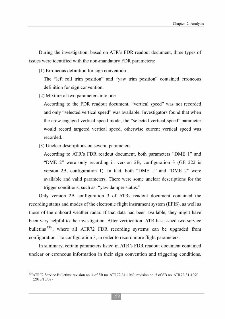
Chapter 2 Analysis
199
During the investigation, based on ATR’s FDR readout document, three types of
issues were identified with the non-mandatory FDR parameters:
(1) Erroneous definition for sign convention
The “left roll trim position” and “yaw trim position” contained erroneous
definition for sign convention.
(2) Mixture of two parameters into one
According to the FDR readout document, “vertical speed” was not recorded
and only “selected vertical speed” was available. Investigators found that when
the crew engaged vertical speed mode, the “selected vertical speed” parameter
would record targeted vertical speed, otherwise current vertical speed was
recorded.
(3) Unclear descriptions on several parameters
According to ATR’s FDR readout document, both parameters “DME 1” and
“DME 2” were only recording in version 2B, configuration 3 (GE 222 is
version 2B, configuration 1). In fact, both “DME 1” and “DME 2” were
available and valid parameters. There were some unclear descriptions for the
trigger conditions, such as: “yaw damper status.”
Only version 2B configuration 3 of ATRs readout document contained the
recording status and modes of the electronic flight instrument system (EFIS), as well as
those of the onboard weather radar. If that data had been available, they might have
been very helpful to the investigation. After verification, ATR has issued two service
bulletins 136 , where all ATR72 FDR recording systems can be upgraded from
configuration 1 to configuration 3, in order to record more flight parameters.
In summary, certain parameters listed in ATR’s FDR readout document contained
unclear or erroneous information in their sign convention and triggering conditions.
136ATR72 Service Bulletins: revision no. 4 of SB no. ATR72-31-1069, revision no. 5 of SB no. ATR72-31-1070
(2013/10/08)

Aviation Occurrence Report
200
The parameter “selected vertical speed” was confusing and it had an adverse effect on
the efficiency of the occurrence investigation. A reduction in the complexity of ATR’s
FDR readout document, by applying the principles of ED-112A137, would assist future
occurrence investigations.
2.11.2 TNA’s FOQA Events Setting
FOQA is a program for the routine collection and analysis of flight data and
provides information about the safety risks confronting flight operations. The program
can provide objective information to enhance safety, training effectiveness, and
operational procedures. The FOQA events will be extracted from the raw digital data
stream based on parameters, threshold values, and/or routine operational measurements
that are specified by the operator. The analysis may focus on events that fall outside
normal operating boundaries as determined by the operator’s operational standards.
The parameters and threshold values setting of the TNA FOQA program were in
accordance with the manufacturer’s suggestions. Based on the airline’s FOQA system,
on the day of occurrence, flight GE 220 triggered three red events: altitude below 500
feet - heading deviation greater than 20 degrees, GPWS warning triggered 24 seconds
and level off below 1,400 feet above field elevation (AFE) exceeded 10 seconds. The
occurrence flight GE222 triggered two red events: excessive bank angle on final
approach below 100 feet AFE, and high rate of descent on approach between 500 and
50 Feet AFE. See Figure 2.11-1 for GE222 and GE220 flight profiles.
137ED-112A Minimum operational performance specification for crash protected airborne recorder systems.

Chapter 2 Analysis
201
Figure 2.11-1 GE222 and GE220 flight profiles
However, the traditional FOQA program was not configured to be able to readily
identify, without further analysis, those events that were indicative of non-compliance
with SOPs including violations of approach procedures, such as descent below
minimum safe altitudes. No current FOQA system can readily integrate all the required
data sources needed to identify some violations of SOPs.
The European Authorities Coordination Group on Flight Data Monitoring
(EAFDM)138 has proposed a set of standard indicators for flight data monitoring
events. For example, for CFIT and loss of control in flight (LOC-I) avoidance,
EAFDM recommended not only monitoring a triggering altitude and the duration of
that alert, but also setting up a severity index that considers the surrounding terrain and
pilot maneuvering. In addition, the integration of contextual information with flight
data such as time, visibility conditions, local weather conditions, aircraft mass and
138Guidance for National Aviation Authorities Setting up a national Flight Data Monitoring Forum (EAFDM,
2012, Oct.); Developing Standardized FDM-Based Indicators (EAFDM, 2013, Dec.)

Aviation Occurrence Report
202
balance has been proposed. The EAFDM also suggested that the severity index of the
events should consider aircraft limitations, flight crew decision-making requirements,
crew reaction times to warnings or alerts, compliance with SOPs for go around, aircraft
configuration and engine power settings, navigation mode settings and so on.
TNA’s flight operations division and safety and security office need to implement
a more advanced FOQA program, with associated training and staff with the required
technical expertise to amend system settings and provide more informative data
analyses.
2.12 Aerodrome Factors
2.12.1 Approach Lighting System on Runway 20
An approach lighting system allows the flight crew to visually identify the runway
environment and align the aircraft with the runway at the prescribed point on an
approach.
According to the CAA Civil Aerodrome Design and Operation Guidance section
5.3.4.1139, where physically practicable, a simple approach lighting system shall be
provided to serve a non-precision approach and night operation runway, except when
the runway is used only in conditions of good visibility or sufficient guidance is
provided by other visual aids. Magong runway 20 has a non-precision approach and is used for night operations.
There is approximately 500 meters of extended space along the runway 20 centerline within the airport area. According to the regulations, a 420 meter simple approach lighting system should be installed to help pilots visually identify the runway. Runway 20 did not have the required lighting system installed. The CAA advised that the Runway end identification lights (REIL), a flashing white light system, was installed at the runway’s threshold as an alternative visual aid to replace the simple approach
139The contents in the CAA Aerodrome Design and Operation Guidance are almost identical with the ICAO
Annex 14.

Chapter 2 Analysis
203
lighting system.
The intensity of the runway 20 REIL was 22,500 cd whereas a simple approach
lighting system was 10,000 cd. The REIL system would have enabled the crew to more
easily locate runway 20 visually on approach compared to a simple approach lighting
system140.
However, according to the CAA Civil Aerodrome Design and Operation Guidance
5.3.4.7141 note 3, at locations where identification of the simple approach lighting
system is difficult at night due to surrounding lights, sequence flashing lights installed
on the outer portion of the system may resolve this problem.
The illumination or intensity of the sequence flashing lights installed on the outer
portion of a simple approach lighting system was higher than the REIL system142.
The MAPt for the runway 20 VOR approach was about 2,000 meters from the
threshold. The visibility landing minima was 1,600 meters. There is a high likelihood
that the occurrence flight crew would not have been able to visually identify the
runway at the MAPt when the visibility was just above landing minima.
The installation of a simple approach lighting system with the sequence flashing
lights on the outer portion would probably increase the likelihood of crews being able
to visually locate the runway in degraded visibility in the future.
140The illumination of the REIL on the distance about 2,000 meters (location of the MAPt) from threshold
(location of the REIL) is 0.005625. The illumination of the outmost fixed lights (420 meters from threshold) of the simple approach lighting system on the distance of MAPt is 0.004.
141Note3— at locations where identification of the simple approaching system is difficult at night due to surrounding lights, sequence flashing lights installed outer portion of system may resolve this problem.
142The illumination of the sequence flashing lights installed outer portion of the simple approach lighting system on the MAPt will be 0.009

Aviation Occurrence Report
204
Figure 2.12-1 The typical simple approach lighting system
2.12.2 Determination of Aerodrome Operating Minimum
The runway 20 VOR approach was originally designed under the FAA TERPS
standards. In order to comply with the ICAO standards, the CAA decided to adopt
ICAO procedures for air navigation services – aircraft operations (PANS-OPS) criteria
for the design of instrument flight procedures. After completing the instrument
approach charts re-design, a Taipei flight information region (FIR) aeronautical
information circular (AIC), dated 13 August, 2010, was issued to explain the
differences between TERPS and PANS-OPS, and the different stages of implementing
the conversions of charts.
The PANS-OPS criteria used an OCA/H rather than a minimum descent
altitude/height (MDA/H), decision altitude/height (DA/H) in the approach charts.
Furthermore, in accordance with ICAO DOC 8168 Aircraft Operations, the CAA was

Chapter 2 Analysis
205
not required to issue visibility landing minima. However, given that operators and the
air traffic control system were accustomed to visibility landing minima the CAA still
issued visibility landing minima in accordance with the TERPS visibility limitations
guidance for instrument approach procedures143 (refer to Table 2.12-1 Effect of
HAT/HAA on Visibility Minimums). Therefore, according to the aeronautical
information publication (AIP), the OCH for the runway 20 VOR approach was 284
feet. The visibility landing minima was 1,600 meters after considering the factors
associated with a VOR/DME non-precision approach, approach category B, no
approach lighting system (NALS), and no vertical guidance.
Table 2.12-1 Effect of HAT/HAA on Visibility Minimums
*RVR in feet; SM: Statute Mile; M: Meter
2.12.3 The Location of Missed Approach Point
According to the AIP, the distance from the runway 20 VOR missed approach point (MAPt) to the runway 20 threshold is 1.1 nautical miles (2,037.2 meters) (see Figure 2.12-2). The distance is longer than the published visibility landing minima of 1,600 meter.
The final approach segment for a non-precision approach procedure begins at the FAF and ends at the MAPt. Approaching aircraft need to descend to and maintain an altitude not below the Obstacle Clearance Altitude/Obstacle Clearance Height (OCA/OCH) and align with the runway. If the runway environment cannot be visually identified at the MAPt, the flight crew should execute the missed approach procedure.
143FAA Order 8260.3B United States Standard for Terminal Instrument Procedures (TERPS).

Aviation Occurrence Report
206
According to ICAO DOC 8168 Volume II Part I section 4, paragraph 6.1.5.2, “the
optimum location of the MAPt is the runway threshold. Where necessary, the MAPt
may be moved closer to the FAF…”. In practice, the instrument procedure designer will
set the MAPt location with the objective to minimize the OCA/OCH heights.
The CAA used the PANS_OPS Designer software to calculate the OCA for the
runway 20 VOR approach. The CAA advised that the calculations indicated if the
MAPt was located at the threshold, the OCA would be 394 feet. If the MAPt was at 1.1
nm from the threshold, the OCA could be lowered to 328 feet. The investigation team
asked the CAA to re-calculate the OCA for the runway 20 VOR approach by moving
the MAPt to different locations toward the threshold. The results indicated that moving
the MAPt to 0.8 nm (1,460 meters) from the threshold, the OCA was 328 feet.
With the same OCA, if the MAPt was set closer to the runway threshold, it would
have increased the likelihood of crews being able to visually identify the runway in the
future.
Figure 2.12-2 Magong MAPt location and runway 20 VOR approach procedure

Chapter 3 Conclusion
207
Chapter 3 Conclusion
In this Chapter, the Aviation Safety Council presents the findings derived from the
factual information gathered during the investigation and the analysis of the occurrence.
The findings are presented in three categories: findings related to probable causes,
findings related to risk, and other findings.
The findings related to probable causes identify elements that have been shown
to have operated in the occurrence, or almost certainly operated in the occurrence.
These findings are associated with unsafe acts, unsafe conditions, or safety deficiencies
associated with safety significant events that played a major role in the circumstances
leading to the occurrence.
The findings related to risk identify elements of risk that have the potential to
degrade aviation safety. Some of the findings in this category identify unsafe acts,
unsafe conditions, and safety deficiencies including organizational and systemic risks,
that made this occurrence more likely; however, they cannot be clearly shown to have
operated in the occurrence alone. Furthermore, some of the findings in this category
identify risks that are unlikely to be related to the occurrence but, nonetheless, were
safety deficiencies that may warrant future safety actions.
Other findings identify elements that have the potential to enhance aviation
safety, resolve a controversial issue, or clarify an ambiguity point which remains to be
resolved. Some of these findings are of general interests that are often included in the
ICAO format accident reports for informational, safety awareness, education, and
improvement purposes.
3.1 Findings Related to Probable Causes
Flight Operations
1. The flight crew did not comply with the published runway 20 VOR non-precision
instrument approach procedures at Magong Airport with respect to the minimum
Aviation Occurrence Report
208
descent altitude (MDA). The captain, as the pilot flying, intentionally descended the
aircraft below the published MDA of 330 feet in the instrument meteorological
conditions (IMC) without obtaining the required visual references. (1.1, 1.18.1.4,
2.2.1.1, 2.3.1)
2. The aircraft maintained an altitude between 168 and 192 feet before and just after
overflying the missed approach point (MAPt). Both pilots spent about 13 seconds
attempting to visually locate the runway environment, rather than commencing a
missed approach at or prior to the MAPt as required by the published procedures.
(1.1, 2.2.1.1)
3. As the aircraft descended below the minimum descent altitude (MDA), it diverted to
the left of the inbound instrument approach track and its rate of descent increased as
a result of the flying pilot’s control inputs and meteorological conditions. The
aircraft’s hazardous flight path was not detected and corrected by the crew in due
time to avoid the collision with the terrain, suggesting that the crew lost situational
awareness about the aircraft’s position during the latter stages of the approach. (1.1,
1.11.4.2, 2.2.1.1, 2.9)
4. During the final approach, the heavy rain and associated thunderstorm activity
intensified producing a maximum rainfall of 1.8 mm per minute. The runway visual
range (RVR) subsequently reduced to approximately 500 meters. The degraded
visibility significantly reduced the likelihood that the flight crew could have
acquired the visual references to the runway environment during the approach. (1.7,
2.2.1.1, 2.8)
5. Flight crew coordination, communication, and threat and error management were
less than effective. That compromised the safety of the flight. The first officer did
not comment about or challenge the fact that the captain had intentionally descended
the aircraft below the published minimum descent altitude (MDA). Rather, the first
officer collaborated with the captain’s intentional descent below the MDA. In
addition, the first officer did not detect the aircraft had deviated from the published

Chapter 3 Conclusion
209
inbound instrument approach track or identify that those factors increased the risk of
a controlled flight into terrain (CFIT) event. (1.1, 1.18.7, 2.2.1.1, 2.3.1, 2.4.1, 2.4.2,
Appendix 3)
6. None of the flight crew recognized the need for a missed approach until the aircraft
reached the point (72 feet, 0.5 nautical mile beyond the missed approach point)
where collision with the terrain became unavoidable. (1.1, 1.18.1.4, 2.2.1.1)
7. The aircraft was under the control of the flight crew when it collided with foliage
850 meters northeast of the runway 20 threshold, two seconds after the go around
decision had been made. The aircraft sustained significant damage and subsequently
collided with buildings in a residential area. Due to the high impact forces and
post-impact fire, the crew and most passengers perished. (1.11.4.2, 1.12.1, 1.13,
2.2.1.1)
8. According to the flight recorders data, non-compliance with standard operating
procedures (SOPs) was a repeated practice during the occurrence flight. The crew’s
recurring non-compliance with SOPs constituted an operating culture in which high
risk practices were routine and considered normal. (1.18.1.4, 2.3.1)
9. The non-compliance with standard operating procedures (SOPs) breached the
obstacle clearances of the published procedure, bypassed the safety criteria and risk
controls considered in the design of the published procedures, and increased the risk
of a controlled flight into terrain (CFIT) event. (1.18.7, 2.2.1.1, 2.3.1)
Weather
10. Magong Airport was affected by the outer rainbands of Typhoon Matmo at the time
of the occurrence. The meteorological conditions included thunderstorm activities
of heavy rain, significant changes in visibility, and changes in wind direction and
speed. (1.7, 2.2.1, 2.8)
3.2 Findings Related to Risk
Flight Operations

Aviation Occurrence Report
210
1. The captain did not conduct a descent and approach briefing as required by standard
operating procedures (SOPs). The first officer did not question the omission of that
required briefing. That deprived the crew of an opportunity to assess and manage the
operational risks associated with the approach and landing. (1.1, 1.18.1.4, 2.2.1.1,
2.3.1, Appendix 3)
2. The captain was likely overconfident in his flying skills. That might lead to his
decision to continue the approach below the minimum descent altitude (MDA)
without an appreciation of the safety risks associated with that decision. (1.18.8.2,
2.4.3)
3. The results of the fatigue analysis indicated that, at the time of the occurrence, the
captain’s performance was probably degraded by his fatigue accumulated from the
multiple sectors/day flown and flight and duty times during the months preceding
the occurrence. (1.5.5, 1.17.3.2.1, 2.3.3.3, 2.4.4)
4. The TransAsia Airways observation flights conducted by the investigation team and
the interviews with members of the airline’s flight operations division show
prevalent tolerance for non-compliance with procedures within the airline’s ATR
fleet. (1.16.4, 1.18.8.2, 2.3.3)
5. The non-compliances with standard operating procedures (SOPs) during the
TransAsia Airways’ ATR simulator training sessions were observed by the
investigation team but not corrected by the instructors. The tolerance for or
normalization of SOPs non-compliance behaviors was symptomatic of an ineffective
check and training system with inadequate supervision by the airline’s flight
operations management. (1.16.5, 2.3.3.2)
6. The non-compliance with standard operating procedures (SOPs) was not restricted
to the occurrence flight but was recurring, as identified by previous TransAsia
Airways ATR occurrence investigations, line observations, simulator observations,
internal and external audits or inspections, and interviews with TransAsia Airways
flight operations personnel, including managers. The non-compliant behaviors were

Chapter 3 Conclusion
211
an enduring, systemic problem and formed a poor safety culture within the airline’s
ATR fleet. (1.16.4, 1.16.5, 1.17.1.1, 1.17.8.2.1, 1.17.10, 1.18.8.2, 2.3.2, 2.4.2)
Airline Safety Management
7. The TransAsia Airways’ inadequate risk management processes and assessments,
ineffective safety meetings, unreliable and invalid safety risk indices, questionable
senior management commitment to safety, inadequate safety promotion activities,
underdeveloped flight operations quality assurance (FOQA) system, and inadequate
safety and security office and flight operations resources and capabilities constituted
an ineffective safety management system (SMS). (1.17.4, 1.17.5, 1.17.6, 1.17.7,
1.17.9, 1.17.10, 2.3.3.1,2.3.33, 2.5)
8. The safety risks associated with change within the TransAsia Airways were not
assessed and mitigated. For example, the company did not assess or mitigate the
safety risks associated with the increase in ATR operational tempo as a result of the
recent increase in ATR fleet size and crew shortage that, in turn, elevated crew flying
activities and the potential safety risks associated with crew fatigue. (1.17.3.2.1,
2.3.3.3)
9. Findings regarding non-compliance with standard operating procedures (SOPs)
during operations by the TransAsia Airways’ ATR crews had been identified by
previous Aviation Safety Council occurrence investigations. The proposed corrective
safety actions were not implemented by the airline. (1.17.10, 2.3.2, 2.7.5)
10.TransAsia Airways self-audits were mostly spot checks rather than system audits or
system self-evaluations. The self-audits failed to assess and address those safety
deficiencies, including standard operating procedures non-compliance behaviors,
lack of standardization in pilot check and training activities, and high crew flying
activities on the ATR fleet. Such deficiencies had been pointed out in previous
occurrences and audits and were considered by senior flight operations managers
as problems. (1.17.8, 2.5.4)

Aviation Occurrence Report
212
11.The TransAsia Airways annual audit plan did not include an evaluation of the
implementation and/or effectiveness of corrective actions in response to the safety
issues identified in previous audits, regulatory inspection findings, or safety
occurrence investigation recommendations. The airline’s self-audit program was
not consistent with the guidance contained in AC-120-002A. (1.17.8, 2.5.4)
12.The TransAsia Airways had not developed a safety management system (SMS)
implementation plan. This led to a disorganized, nonsystematic, incomplete and
ineffective implementation, which made it difficult to establish robust and resilient
safety management capabilities and functions. (1.17.2, 2.6.1)
13.The Civil Aeronautics Administration’s (CAA) safety management system (SMS)
assessment team had identified TransAsia Airways’ SMS deficiencies, but
TransAsia Airways failed to respond to the CAA’s corrective actions request. That
deprived the airline of an opportunity to improve the level of safety assurance in its
operations. (1.17.2, 2.6.2)
14.The TransAsia Airways did not implement a data-driven fatigue risk management
system (FRMS) or alternative measures to manage the operational safety risks
associated with crew fatigue due to fleet expansion and other operational factors.
(1.17.3.2.1, 2.4.4)
15.The ATR flight operation did not include in its team a standards pilot to oversee
standard operating procedures (SOPs) compliance, SOP-related flight operations
quality assurance (FOQA) events handling, and standard operations audit (SOA)
monitoring before the GE222 occurrence. (1.17.3.1, 1.17.6.3, 2.3.3.1, 2.5.3)
16.The safety and security office, due to resource and capability limitations, was
unable to effectively accomplish the duties they were required to undertake.
(1.17.4.2, 2.5.1)
17.The safety and security office staff was not included in the flight safety action group.
That deprived the airline of an opportunity to identify, analyze and mitigate flight
safety risks more effectively in the flight operations. (1.17.4.1.1, 2.5.1)

Chapter 3 Conclusion
213
18.The TransAsia Airways’ safety management system was overly dependent on its
internal reactive safety and irregularity reporting system to develop full awareness
of the airline’s safety risks. It did not take advantage of the instructive material
from external safety information sources. That limited the capability of the system
to identify and assess safety risks. (1.17.5, 1.17.7.1, 2.5.2)
19.The TransAsia Airways’ flight operations quality assurance (FOQA) settings and
analysis capabilities were unable to readily identify those events involving standard
operating procedures (SOPs) non-compliance during approach and likely other
stages of flight. The FOQA events were not analyzed sufficiently or effectively,
leaving some safety issues in flight operations unidentified and uncorrected. Some
problems with crew performance and reductions in safety indicated in the FOQA
trend analyses were not investigated further. Clearly, the airline’s FOQA program
was not used to facilitate proactive operational safety risk assessments. (1.17.6,
2.5.3)
Civil Aeronautics Administration
20.The Civil Aeronautics Administration’s oversight of TransAsia Airways did not
identify and/or correct some crucial operational safety deficiencies, including crew
non-compliance with procedures, non-standard training practices, and
unsatisfactory safety management practices. (1.17.1, 1.17.2.2, 2.7)
21.To develop and maintain a safety management system (SMS) implementation plan
at TransAsia Airways was not enforced by the Civil Aeronautics Administration.
That deprived the regulator of an opportunity to assess and ensure that the airline
had the capability to implement a resilient SMS. (1.17.2.2, 2.6.1)
22.Issues regarding the TransAsia Airways’ crew non-compliance with standard
operating procedures (SOPs) and deficiencies with pilot check and training had
previously been identified by the Aviation Safety Council investigation reports.
However, the Civil Aeronautics Administration (CAA) did not monitor whether the

Aviation Occurrence Report
214
operator has implemented the recommended corrective actions; correlatively, the
CAA failed to ensure the proper measures for risk reduction have been adopted.
(1.17.10, 2.7.6)
23.The Civil Aeronautics Administration provided limited guidance to its inspectors to
enable them to effectively and consistently evaluate the key aspects of operators’
management systems. These aspects included evaluating organizational structure
and staff resources, the suitability of key personnel, organizational change, and risk
management processes. (1.17.1, 2.7)
24.The Civil Aeronautics Administration did not have a systematic process for
determining the relative risk levels of airline operators. (1.17.1, 2.7)
Air Traffic Service and Military
25.The runway visual range (RVR) reported in the Magong aerodrome routine
meteorological reports (METAR) and the aerodrome special meteorological reports
(SPECI) was not in accordance with the requirements documented in the Air Force
Meteorological Observation Manual. (1.7.2, 1.18.6, 2.8.3.2)
26.The discrepancies between the reported runway visual range (RVR) and automated
weather observation system (AWOS) RVR confused the tower controllers about the
reliability of the AWOS RVR data. (1.18.8.8, 2.8.3.1)
27.During the final approach, the runway 20 runway visual range (RVR) values
decreased from 1,600 meters to 800 meters and then to a low of about 500 meters.
The RVR information was not communicated to the occurrence flight crew by air
traffic control. Such information might influence the crew’s decision regarding the
continuation of the approach. (1.7.4, 2.8.3.1)
3.3 Other Findings
1. The flight crew were properly certificated and qualified in accordance with the Civil
Aeronautics Administration and company requirements. No evidence indicated any
pre-existing medical conditions that might have adversely affected the flight crew’s

Chapter 3 Conclusion
215
performance during the occurrence flight. (1.5, 1.13, 2.1)
2. The airworthiness and maintenance of the occurrence aircraft were in compliance
with the extant civil aviation regulations. There were no aircraft, engine, or system
malfunctions that would have prevented normal operation of the aircraft. (1.12, 2.1)
3. All available evidence, including extensive simulations, indicated that the enhanced
ground proximity warning system (EGPWS) functioned as designed. (1.6.3, 1.16.1,
1.16.2, 2.10.2)
4. The enhanced ground proximity warning system (EGPWS) manufacturer’s latest
generation EGPWS equipment would have provided flight crews with an additional
warning if aircraft encountered similar circumstances to the occurrence flight.
Installing the latest EGPWS equipment on the occurrence aircraft would have
required approved modifications. (1.6.3, 1.16.2, 2.10.3)
5. According to the Civil Aeronautics Administration (CAA) regulations, a 420 meter
simple approach lighting system should have been installed to help pilots visually
identify runway 20. The CAA advised that the Runway End Identification Lights, a
flashing white light system, was installed at the runway’s threshold as an alternative
visual aid to replace the simple approach lighting system. (1.10.2, 2.12.1)
6. From the perspective of flight operations, the location of the runway 20 VOR missed
approach point (MAPt) was not in an optimal position. With the same Obstacle
Clearance Altitude, if the MAPt had been set closer to the runway threshold, it
would have increased the likelihood of flight crews to visually locate the runway.
(1.18.3, 1.18.4, 2.12.3)
7. During holding, the occurrence flight crew requested the runway 02 instrument
landing system (ILS) approach after receiving the weather information that the
average wind speed for runway 02 had decreased to below the tailwind landing limit.
While the decision for the use of the reciprocal runway was still under consideration
by the Magong Air Force Base duty officer, the weather report indicated that the
visibility had improved to 1,600 meters, which met the landing visibility minimal

Aviation Occurrence Report
216
requirement for an approach to runway 20. The flight crew subsequently amended
their request and elected to use runway 20. (1.1, 1.18.5, 2.8.4)
8. At the time of the occurrence, the weather information exchange and runway
availability coordination between civil and military personnel at Magong’s joint-use
airport could have been more efficient. (1.18.8.6, 1.18.8.7, 2.8)
9. ATR’s flight data recorder (FDR) readout document contained unclear information.
That affected the efficiency of the occurrence investigation. (1.11.2, 2.11.1)
Chapter 4 Safety Recommendations
217
Chapter 4 Safety Recommendations
4.1 Recommendations
To TransAsia Airways
1. Implement effective safety actions to rectify the multiple safety deficiencies
previously identified by the Aviation Safety Council investigations, internal and
external Civil Aeronautics Administration audit and inspection findings, and
deficiencies noted in this report to reduce the imminent safety risks confronting the
airline. (ASC-ASR-16-01-010)
2. Conduct a thorough review of the airline’s safety management system and flight
crew training programs, including crew resource management and threat and error
management, internal auditor training, safety management system (SMS) training
and devise systematic measures to ensure:
� Flight crew check and training are standardized;
� All flight crews comply with standard operating procedures (SOPs);
� Staff who conduct audits receive appropriate professional auditor training;
� All operational and senior management staff receive SMS training, including
thorough risk assessment and management training; and
� Proportional and consistent rules, in accordance with a “Just Culture”, are
implemented to prevent flight crew from violating the well-designed SOPs and/or
being engaged in unsafe behavior.
(ASC-ASR-16-01-011)
3. Conduct a rigorous review of the safety management system (SMS) to rectify the
significant deficiencies in:
� Planning;
� Organizational structure, capability and resources;
� Risk management processes and outputs;

Aviation Occurrence Report
218
� Flight operations quality assurance (FOQA) limitations and operations, including
inadequate data analysis capabilities;
� Safety meetings;
� Self-audits;
� Safety performance monitoring, including risk indices;
� Safety education; and
� Senior management commitment to safety.
(ASC-ASR-16-01-012)
4. Rectify the human resources deficits in the flight operations division and the safety
and security office, including:
� Crew shortages;
� Inadequate support staff in the Flight Standards and Training Department,
including insufficient standards pilots and crew to conduct operational safety risk
assessments; and
� Safety management staff with the required expertise in flight operations, safety
and flight data analytics, safety risk assessment and management, human factors,
and safety investigations.
(ASC-ASR-16-01-013)
5. Review and improve the airline’s internal compliance oversight and auditing system
and implement an effective corporate compliance and quality assurance system to
ensure that oversight activities provide the required level of safety assurance and
accountability. (ASC-ASR-16-01-014)
6. Implement an effective safety management process, such as a data-driven fatigue
risk management system (FRMS), to manage the flight safety risks associated with
crew fatigue. (ASC-ASR-16-01-015)
7. Provide flight crew with adequate fatigue management education and training,
including the provision of effective strategies to manage fatigue and performance
during operations. (ASC-ASR-16-01-016)

Chapter 4 Safety Recommendations
219
8. Implement an effective change management system as a part of the airline’s safety
management system (SMS) to ensure that risk assessment and mitigation activities
are formally conducted and documented before significant operational changes are
implemented, such as the introduction of new aircraft types or variants, increased
operational tempo, opening new ports, and so on. (ASC-ASR-16-01-017)
9. Implement a more advanced flight operations quality assurance (FOQA) program
with adequate training and technical support for the FOQA staff to ensure that they
can exploit the analytical capabilities of the program. As such, the FOQA staff can
more effectively identify and manage the operational safety risks confronting flight
operations. (ASC-ASR-16-01-018)
10.Implement an effective standard operating procedures (SOPs) compliance
monitoring system, such as the line operations safety audit (LOSA) program, to
help identifying threats to operational safety and to minimize the associated risks.
The system should adopt a data-driven method to assess the level of organizational
resilience to systemic threats and can detect issues such as habitual non-compliance
with SOPs. (ASC-ASR-16-01-019)
To Civil Aeronautics Administration
1. Strengthen surveillance on TransAsia Airways to assess crew’s discipline and
compliance with standard operating procedures (SOPs). (ASC-ASR-16-01-020)
2. Implement a more robust process to identify safety-related shortcomings in
operators’ operations, within an appropriate timescale, to ensure that the operators
meet and maintain the required standards. (ASC-ASR-16-01-021)
3. Provide inspectors with detailed guidance on how to evaluate the effectiveness of an
operator’s safety management system (SMS), including:
� Risk assessment and management practices;
� Change management practices;
� Flight operations quality assurance (FOQA) system and associated data analytics;

Aviation Occurrence Report
220
and
� Safety performance monitoring.
(ASC-ASR-16-01-022)
4. Provide inspectors with comprehensive training and development to ensure that they
can conduct risk-based surveillance and operational oversight activities effectively.
(ASC-ASR-16-01-023)
5. Enhance inspector supervision and performance evaluation to ensure all inspectors
conduct surveillance activities effectively and are able to identify and communicate
critical safety issues to their supervisors. (ASC-ASR-16-01-024)
6. Enhance the oversight of operators transitioning from traditional safety management
to safety management systems. (ASC-ASR-16-01-025)
7. Develop a systematic process for determining the relative risk levels of airline
operators. (ASC-ASR-16-01-026)
8. Review the current regulatory oversight surveillance program with a view to
implementing a more targeted risk-based approach for operator safety evaluations.
(ASC-ASR-16-01-027)
9. Ensure all safety recommendations issued by the occurrence investigation agency
are implemented by the operators. (ASC-ASR-16-01-028)
10.Develop detailed guidance for operators to implement effective fatigue risk
management processes and training. (ASC-ASR-16-01-029)
11.Review runway approach lighting systems in accordance with their existing radio
navigation and landing aids to ensure that adequate guidance is available for pilots
to identify the visual references to the runway environment, particularly in poor
visibility condition or at night. (ASC-ASR-16-01-030)
12.Review the design procedures for determining the location of missed approach
point with the intention of increasing the likelihood of pilots to locate the runway
without compromising the required obstacle clearance altitude.
(ASC-ASR-16-01-031)

Chapter 4 Safety Recommendations
221
13.Request tower controllers to advise the flight crews of aircraft on final approach of
the updated information in accordance with the provisions of the air traffic
management procedures (ATMP). (ASC-ASR-16-01-032)
14.Coordinate with Air Force Command Headquarters to review and improve the
weather information exchange and runway availability coordination between civil
air traffic control and military personnel at Magong Airport.
(ASC-ASR-16-01-033)
To ATR-GIE Avions de Transport Régional
1. Evaluate the feasibility of a modification to allow the new enhanced ground
proximity warning system (EGPWS) to be fitted on all ATR72-500 aircraft.
(ASC-ASR-16-01-034)
2. Review the flight data recorder (FDR) readout document for any erroneous
information and provide timely revisions of the manual to assist airline operators
and aviation occurrence investigation agencies. (ASC-ASR-16-01-035)
To Air Force Command Headquarters, Ministry of National Defense
1. Coordinate with the Civil Aeronautics Administration to ensure the reliability and
validity of automated weather observation system (AWOS) runway visual range
(RVR) sensors and their data. (ASC-ASR-16-01-036)
2. Conduct the runway visual range (RVR) reporting operations and requirements in
accordance with the provisions of the Air Force Meteorological Observation Manual.
(ASC-ASR-16-01-037)
3. Coordinate with the Civil Aeronautics Administration to review and improve the
weather information exchange and runway availability coordination between civil
air traffic control and military personnel at Magong Airport. (ASC-ASR-16-01-038)
4.2 Safety Actions Accomplished
4.2.1 Civil Aeronautics Administration

Aviation Occurrence Report
222
On 6 October 2015, Civil Aeronautics Administration provided the safety actions
accomplished or being accomplished after the GE222 occurrence. Those actions were
not verified by the Aviation Safety Council. The information is in the“Appendix 5-4
Comments on ASC’s Final Draft Report from Civil Aeronautics Administration.”
4.2.2 TransAsia Airways
On 18 December 2015, TransAsia Airways provided the safety actions
accomplished or being accomplished after the GE222 occurrence. Those actions were
not verified by the Aviation Safety Council. The information is in the“Appendix 5-5
Comments on ASC’s Final Draft Report from TransAsia Airways.”

Appendix 1 Sequence of ATS Weather Communications
223
Appendix 1 Sequence of ATS Weather Communications
Time Event 1700 MZG (Magong) METAR at 1700 (ATIS I): wind from 200 degrees at 18 knots
gusting to 28 knots, visibility 2,400 meters in thunderstorm rain, thunderstorm overhead.
1724:23 The military MZG weather forecast officer (WFO) informed the Air Force Base (AFB) duty officer that the typhoon warning for Magong Airport will be terminated at 1730. However, a hazardous weather forecast will be issued from 1730 to 1930.
1728:58 GE222 flight crew acknowledged thunderstorm overhead Magong Airport from KHH Ground controller and proceeded to depart.
1740 MZG SPECI at 1740 (ATIS K): wind from 190 degrees at 21 knots gusting to 31 knots, visibility 800 meters in thunderstorm rain, thunderstorm overhead.
1741:03 Military MZG weather watch office (WWO) informed MZG tower of 1740 SPECI.
1742:42 GE222 flight crew acknowledged that the weather at Magong Airport was below landing minima from KHH Ground controller and proceeded to depart.
1743:26 The MZG WFO informed MZG tower that the termination time for the typhoon warning will be amended to 1740. However, a hazardous weather forecast will be issued from 1740 to 1940.
1745:35 The MZG WFO informed the MZG WWO that the typhoon warning will be terminated at 1740. A hazardous weather forecast will then be issued from 1740 to 1940. The military MZG weather observer (WO) informed the MZG WFO that the visibility was less than 1,200 meters. The MZG WFO replied to report what the actual weather was.
1750:51 The MZG WFO informed the AFB duty officer that the termination time for the typhoon warning will be amended to 1740. A hazardous weather forecast will then be issued till 1940.
1753:54 MZG tower asked the MZG WFO if the visibility will soon increase to 1,600 meters. The MZG WFO advised that the visibility will not increase.
1756:28 The KHH approach controller informed the GE222 flight crew that the weather for Magong Airport was below landing minima and instructed them to join the SEGMA holding pattern.
1756:56 The KHH approach controller broadcasted a hazardous weather forecast report for Magong Airport.
1759:36 MZG WWO informed MZG tower of the 1800 MZG METAR. 1800 MZG METAR at 1800 (ATIS L): wind from 220 degrees at 17 knots gusting to
27 knots, visibility 800 meters in heavy thunderstorm rain, thunderstorm overhead.
1803:52 The KHH approach controller informed the GE222 flight crew that the current ATIS was Lima (L).
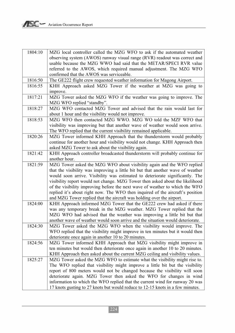
Aviation Occurrence Report
224
1804:10 MZG local controller called the MZG WFO to ask if the automated weather observing system (AWOS) runway visual range (RVR) readout was correct and usable because the MZG WWO had said that the METAR/SPECI RVR value referred to the AWOS, which required manual adjustment. The MZG WFO confirmed that the AWOS was serviceable.
1816:50 The GE222 flight crew requested weather information for Magong Airport. 1816:55 KHH Approach asked MZG Tower if the weather at MZG was going to
improve. 1817:21 MZG Tower asked the MZG WFO if the weather was going to improve. The
MZG WFO replied “standby”. 1818:27 MZG WFO contacted MZG Tower and advised that the rain would last for
about 1 hour and the visibility would not improve. 1818:53 MZG WFO then contacted MZG WWO. MZG WO told the MZF WFO that
visibility was improving but that another wave of weather would soon arrive. The WFO replied that the current visibility remained applicable.
1820:26 MZG Tower informed KHH Approach that the thunderstorm would probably continue for another hour and visibility would not change. KHH Approach then asked MZG Tower to ask about the visibility again.
1821:42 KHH Approach controller broadcasted thunderstorm will probably continue for another hour.
1821:59 MZG Tower asked the MZG WFO about visibility again and the WFO replied that the visibility was improving a little bit but that another wave of weather would soon arrive. Visibility was estimated to deteriorate significantly. The visibility report would not change. MZG Tower then asked about the likelihood of the visibility improving before the next wave of weather to which the WFO replied it’s about right now. The WFO then inquired of the aircraft’s position and MZG Tower replied that the aircraft was holding over the airport.
1824:00 KHH Approach informed MZG Tower that the GE222 crew had asked if there was any temporary break in the MZG weather. MZG Tower replied that the MZG WFO had advised that the weather was improving a little bit but that another wave of weather would soon arrive and the situation would deteriorate.
1824:30 MZG Tower asked the MZG WFO when the visibility would improve. The WFO replied that the visibility might improve in ten minutes but it would then deteriorate once again in another 10 to 20 minutes.
1824:56 MZG Tower informed KHH Approach that MZG visibility might improve in ten minutes but would then deteriorate once again in another 10 to 20 minutes. KHH Approach then asked about the current MZG ceiling and visibility values.
1825:27 MZG Tower asked the MZG WFO to estimate what the visibility might rise to. The WFO replied that visibility might improve a little bit but the visibility report of 800 meters would not be changed because the visibility will soon deteriorate again. MZG Tower then asked the WFO for changes in wind information to which the WFO replied that the current wind for runway 20 was 17 knots gusting to 27 knots but would reduce to 12-15 knots in a few minutes.

Appendix 1 Sequence of ATS Weather Communications
225
1826:42 MZG Tower informed KHH Approach that MZG visibility might improve a little bit but the MZG visibility report would not be changed. MZG Tower then advised that the average wind speed was 17 knots maximum 27 knots, runway 02 instant wind was 210 degrees at 5 knots maximum 11 knots, runway 20 instant wind was 190 degrees at 11 knots maximum 15 knots.
1827:00 MZG WFO informed the MZG WWO of the weather information provided to MZG Tower a moment ago and that some aircraft were holding over the airport because of visibility.
1827:24 GE222 flight crew changed radio frequency to MZG Tower and requested weather information.
1827:38 MZG Tower replied that the forecast visibility will remain at 800 meters and the 10 minute average wind was 220 degrees at 17 knots maximum 27 knots; runway 02 instant wind was 210 degrees at 6 knots maximum 11 knots, runway 20 instant wind was 200 degrees at 12 knots maximum 16 knots.
1827:39 KHH Approach controller broadcasted that the runway 02 wind was 210 degrees at 5 knots maximum 11 knots, runway 20 wind was 190 degrees at 11 knots maximum 15 knots, with a visibility of 800 meters but would improve, however, no adjustment would be issued.
1829 Uni Airways B7647 and GE222 flight crews both requested radar vectors for the runway 02 ILS approach.
1829:44 KHH Approach coordinator asked MZG Tower to apply to the military to use the different runway.
1829:58 MZG Tower informed the military flight control office (FCO) that there were 3 or 4 aircraft requesting a different runway at MZG because of visibility.
1830 MZG METAR at 1830 (ATIS M): wind from 200 degrees at 14 knots gusting to 24 knots, visibility 800 meters in heavy thunderstorm rain, thunderstorm overhead.
1830:19 MZG WWO informed MZG Tower of the 1830 METAR. 1831:05 The FCO informed the combat information office (CIO) that there were 3 or 4
aircraft requesting a different runway at MZG due to visibility. 1833:35 The CIO informed the MZG AFB duty officer that there were 3 aircraft
requesting a different runway due to visibility. The runway in use was runway 20. The AFB duty officer asked if there was a visibility or equipment problem and wanted to know the real reason.
1833:41 The KHH Approach coordinator asked MZG Tower to expedite the application for a change of runway with the military.
1834:55 The AFB duty officer called the military MZG Weather Center and asked for the current visibility and the reply was 800 meters. The AFB duty officer then asked for the wind and ceiling information. He was informed that the wind was from 200 degrees at 14 knots gusting to 24 knots, ceiling at 600 feet. The AFB duty officer then said it was OK to use runway 20.
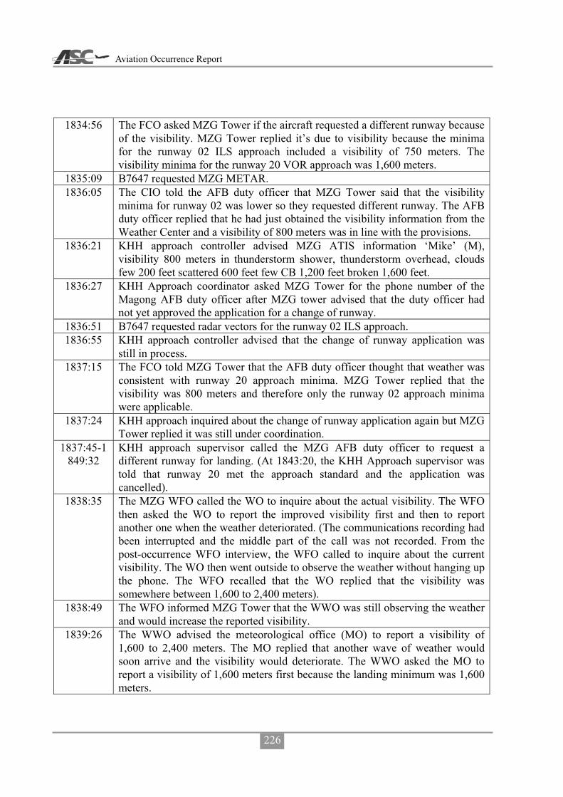
Aviation Occurrence Report
226
1834:56 The FCO asked MZG Tower if the aircraft requested a different runway because of the visibility. MZG Tower replied it’s due to visibility because the minima for the runway 02 ILS approach included a visibility of 750 meters. The visibility minima for the runway 20 VOR approach was 1,600 meters.
1835:09 B7647 requested MZG METAR. 1836:05 The CIO told the AFB duty officer that MZG Tower said that the visibility
minima for runway 02 was lower so they requested different runway. The AFB duty officer replied that he had just obtained the visibility information from the Weather Center and a visibility of 800 meters was in line with the provisions.
1836:21 KHH approach controller advised MZG ATIS information ‘Mike’ (M), visibility 800 meters in thunderstorm shower, thunderstorm overhead, clouds few 200 feet scattered 600 feet few CB 1,200 feet broken 1,600 feet.
1836:27 KHH Approach coordinator asked MZG Tower for the phone number of the Magong AFB duty officer after MZG tower advised that the duty officer had not yet approved the application for a change of runway.
1836:51 B7647 requested radar vectors for the runway 02 ILS approach. 1836:55 KHH approach controller advised that the change of runway application was
still in process. 1837:15 The FCO told MZG Tower that the AFB duty officer thought that weather was
consistent with runway 20 approach minima. MZG Tower replied that the visibility was 800 meters and therefore only the runway 02 approach minima were applicable.
1837:24 KHH approach inquired about the change of runway application again but MZG Tower replied it was still under coordination.
1837:45-1849:32
KHH approach supervisor called the MZG AFB duty officer to request a different runway for landing. (At 1843:20, the KHH Approach supervisor was told that runway 20 met the approach standard and the application was cancelled).
1838:35 The MZG WFO called the WO to inquire about the actual visibility. The WFO then asked the WO to report the improved visibility first and then to report another one when the weather deteriorated. (The communications recording had been interrupted and the middle part of the call was not recorded. From the post-occurrence WFO interview, the WFO called to inquire about the current visibility. The WO then went outside to observe the weather without hanging up the phone. The WFO recalled that the WO replied that the visibility was somewhere between 1,600 to 2,400 meters).
1838:49 The WFO informed MZG Tower that the WWO was still observing the weather and would increase the reported visibility.
1839:26 The WWO advised the meteorological office (MO) to report a visibility of 1,600 to 2,400 meters. The MO replied that another wave of weather would soon arrive and the visibility would deteriorate. The WWO asked the MO to report a visibility of 1,600 meters first because the landing minimum was 1,600 meters.
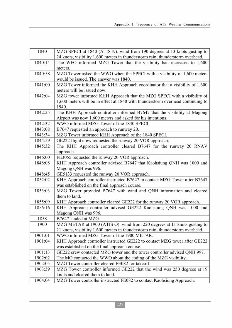
Appendix 1 Sequence of ATS Weather Communications
227
1840 MZG SPECI at 1840 (ATIS N): wind from 190 degrees at 13 knots gusting to 24 knots, visibility 1,600 meters in thunderstorm rain, thunderstorm overhead.
1840:14 The WFO informed MZG Tower that the visibility had increased to 1,600 meters.
1840:58 MZG Tower asked the WWO when the SPECI with a visibility of 1,600 meters would be issued. The answer was 1840.
1841:00 MZG Tower informed the KHH Approach coordinator that a visibility of 1,600 meters will be issued now.
1842:04 MZG tower informed KHH Approach that the MZG SPECI with a visibility of 1,600 meters will be in effect at 1840 with thunderstorm overhead continuing to 1940.
1842:25 The KHH Approach controller informed B7647 that the visibility at Magong Airport was now 1,600 meters and asked for his intentions.
1842:32 WWO informed MZG Tower of the 1840 SPECI. 1843:08 B7647 requested an approach to runway 20. 1843:34 MZG Tower informed KHH Approach of the 1840 SPECI. 1844:59 GE222 flight crew requested the runway 20 VOR approach. 1845:32 The KHH Approach controller cleared B7647 for the runway 20 RNAV
approach. 1846:00 FE3055 requested the runway 20 VOR approach. 1848:08 KHH Approach controller advised B7647 that Kaohsiung QNH was 1000 and
Magong QNH was 996. 1848:45 GE5133 requested the runway 20 VOR approach. 1852:02 KHH Approach controller instructed B7647 to contact MZG Tower after B7647
was established on the final approach course. 1853:03 MZG Tower provided B7647 with wind and QNH information and cleared
them to land. 1855:09 KHH Approach controller cleared GE222 for the runway 20 VOR approach. 1856:16 KHH Approach controller advised GE222 Kaohsiung QNH was 1000 and
Magong QNH was 996. 1858 B7647 landed at MZG. 1900 MZG METAR at 1900 (ATIS O): wind from 220 degrees at 11 knots gusting to
21 knots, visibility 1,600 meters in thunderstorm rain, thunderstorm overhead. 1901:01 WWO informed MZG Tower of the 1900 METAR. 1901:04 KHH Approach controller instructed GE222 to contact MZG tower after GE222
was established on the final approach course. 1901:13 GE222 crew contacted MZG tower and the tower controller advised QNH 997. 1902:02 The MO contacted the WWO about the coding of the MZG visibility. 1902:05 MZG Tower controller cleared FE082 for takeoff. 1903:39 MZG Tower controller informed GE222 that the wind was 250 degrees at 19
knots and cleared them to land. 1904:04 MZG Tower controller instructed FE082 to contact Kaohsiung Approach.
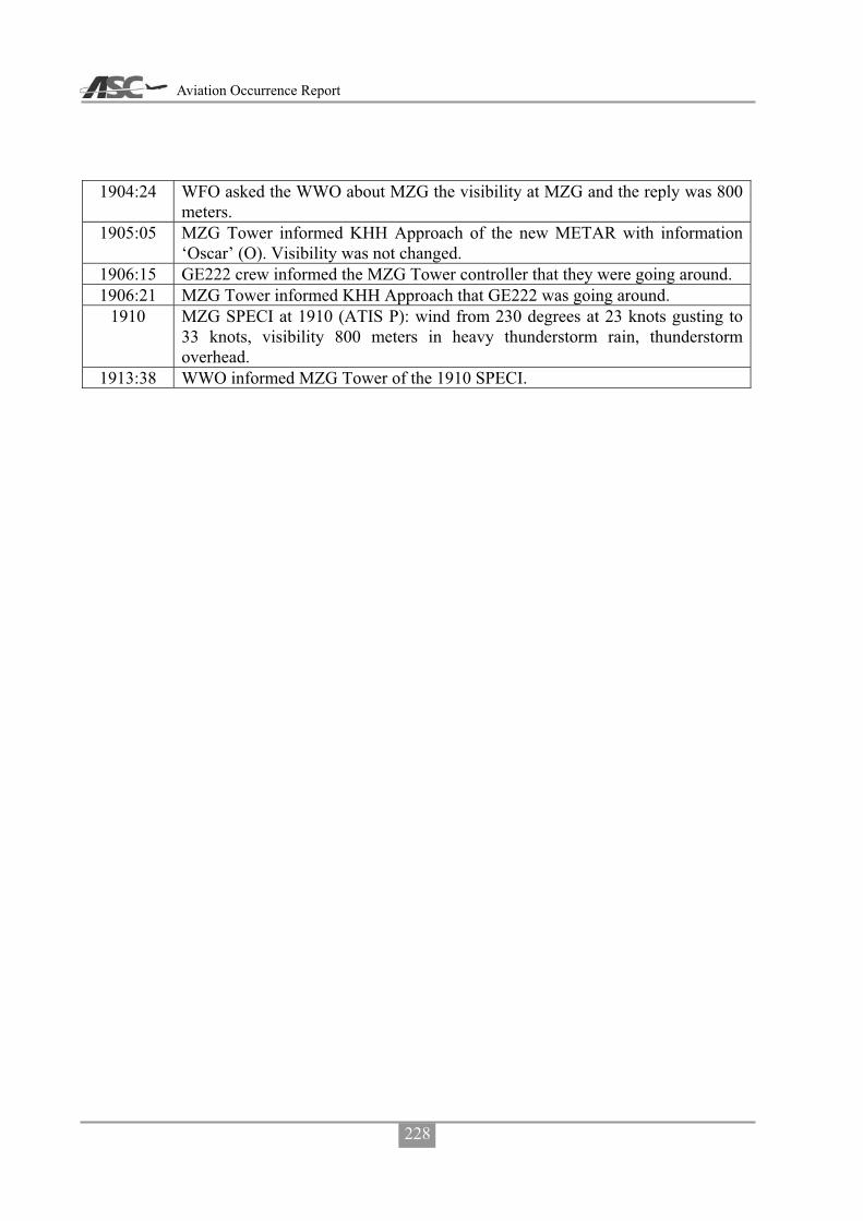
Aviation Occurrence Report
228
1904:24 WFO asked the WWO about MZG the visibility at MZG and the reply was 800 meters.
1905:05 MZG Tower informed KHH Approach of the new METAR with information ‘Oscar’ (O). Visibility was not changed.
1906:15 GE222 crew informed the MZG Tower controller that they were going around. 1906:21 MZG Tower informed KHH Approach that GE222 was going around.
1910 MZG SPECI at 1910 (ATIS P): wind from 230 degrees at 23 knots gusting to 33 knots, visibility 800 meters in heavy thunderstorm rain, thunderstorm overhead.
1913:38 WWO informed MZG Tower of the 1910 SPECI.

Appendix 2 The Photos Extracted from Airport CCTV Camera
229
Appendix 2 The Photos Extracted from Airport CCTV Camera
No. 7 18:30.00 No. 7 18:40.18
No. 7 18:58.11 No. 7 18:59.00
No. 7 19:01.00 No. 7 19:02.09

Aviation Occurrence Report
230
No. 7 19:03.01 No. 7 19:05.30
No. 7 19:07.01 No. 7 19:09.33
No. 7 19:13.03 No. 7 19:22

Appendix 2 The Photos Extracted from Airport CCTV Camera
231
No. 9 18:30.00 No. 9 18:40.00
No. 9 18:50.05 No. 9 18:59.01
No. 9 19:01.00 No. 9 19:02.00

Aviation Occurrence Report
232
No. 9 19:03.00 No. 9 19:05.30
No. 9 19:07.00 No. 9 19:09.34
No. 9 19:14.00 No. 9 19:20.00
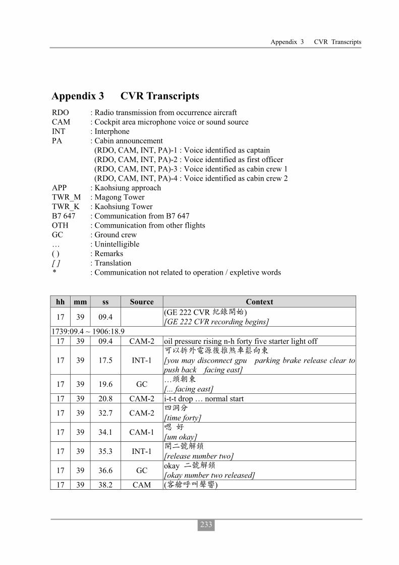
Appendix 3 CVR Transcripts
233
Appendix 3 CVR Transcripts RDO : Radio transmission from occurrence aircraft CAM : Cockpit area microphone voice or sound source INT : Interphone PA : Cabin announcement (RDO, CAM, INT, PA)-1 : Voice identified as captain (RDO, CAM, INT, PA)-2 : Voice identified as first officer (RDO, CAM, INT, PA)-3 : Voice identified as cabin crew 1
(RDO, CAM, INT, PA)-4 : Voice identified as cabin crew 2 APP : Kaohsiung approach TWR_M : Magong Tower TWR_K : Kaohsiung Tower B7 647 : Communication from B7 647 OTH : Communication from other flights GC : Ground crew … : Unintelligible ( ) : Remarks [ ] : Translation * : Communication not related to operation / expletive words
hh mm ss Source Context
17 39 09.4 (GE 222 CVR ) [GE 222 CVR recording begins]
1739:09.4 ~ 1906:18.9 17 39 09.4 CAM-2 oil pressure rising n-h forty five starter light off
17 39 17.5 INT-1
[you may disconnect gpu parking brake release clear to push back facing east]
17 39 19.6 GC … [... facing east]
17 39 20.8 CAM-2 i-t-t drop … normal start
17 39 32.7 CAM-2 [time forty]
17 39 34.1 CAM-1 [um okay]
17 39 35.3 INT-1 [release number two]
17 39 36.6 GC okay [okay number two released]
17 39 38.2 CAM ( )

Aviation Occurrence Report
234
hh mm ss Source Context [sound of cabin call]
17 39 38.9 INT-3 cabin is ready
17 39 41.4 INT-2 [okay thank you]
17 39 42.4 CAM-1 (um)
17 39 43.0 CAM-2 ready [ready so fast]
17 39 44.2 CAM-1 [um okay] 17 39 45.8 CAM-2 oil pressure rising i-t-t rising n-p rising 17 39 50.2 CAM (single chime) 17 39 52.1 CAM-2 oil pressure rising n-h forty five starter light off 17 40 04.5 CAM-2 i-t-t drop and stable normal start 17 40 08.8 CAM-1 after start check
17 40 10.5 CAM-2 after start check down to the line packs and bleeds one and two
17 40 12.3 CAM-1 on 17 40 13.5 CAM-2 prop brake 17 40 14.1 CAM-1 released 17 40 14.7 CAM-2 a-d-u heading lo bank 17 40 16.2 CAM-1 check
17 40 16.3 CAM-2 flaps [one one seven seven thousand flaps]
17 40 17.4 CAM-1 fifteen 17 40 18.1 CAM-2 anti skid test 17 40 18.6 CAM-1 check 17 40 19.1 CAM-2 radar 17 40 19.6 CAM-1 standby 17 40 20.2 CAM-2 after start checklist down to the line complete 17 40 25.0 CAM-1 ( )[sound of coughing] 17 40 26.7 CAM-1 ( )[sound of coughing] 17 40 35.6 CAM-1 ( )[sound of coughing] 17 40 37.5 CAM-2 single channel 17 40 42.1 RDO-2 transasia two two two request taxi
17 40 43.0 GC [sir parking brake please]
17 40 45.0 INT-1 [parking brake set and you may disconnect]
17 40 45.7 GC byebye…
17 40 46.5 GND transasia two two two taxi via golf sierra foxtrot holding point runway two seven
17 40 51.3 RDO-2 taxi via golf sierra foxtrot holding point runway two seven
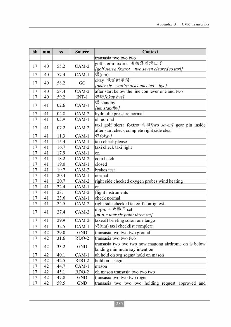
Appendix 3 CVR Transcripts
235
hh mm ss Source Context transasia two two two
17 40 55.2 CAM-2 golf sierra foxtrot [golf sierra foxtrot two seven cleared to taxi]
17 40 57.4 CAM-1 (um)
17 40 58.2 GC okay [okay sir you’re disconnected bye]
17 40 58.4 CAM-2 after start below the line con lever one and two 17 40 59.2 INT-1 [okay bye]
17 41 02.6 CAM-1 standby [um standby]
17 41 04.8 CAM-2 hydraulic pressure normal 17 41 05.9 CAM-1 uh normal
17 41 07.2 CAM-2 taxi golf sierra foxtrot [two seven] gear pin inside after start check complete right side clear
17 41 11.3 CAM-1 [okay] 17 41 15.4 CAM-1 taxi check please 17 41 16.7 CAM-2 taxi check taxi light 17 41 17.9 CAM-1 on 17 41 18.2 CAM-2 com hatch 17 41 19.0 CAM-1 closed 17 41 19.7 CAM-2 brakes test 17 41 20.4 CAM-1 normal 17 41 20.7 CAM-2 right side checked oxygen probes wind heating 17 41 22.4 CAM-1 on 17 41 23.1 CAM-2 flight instruments 17 41 23.6 CAM-1 check normal 17 41 24.5 CAM-2 right side checked takeoff config test
17 41 27.4 CAM-2 m-p-c set [m-p-c four six point three set]
17 41 29.9 CAM-2 takeoff briefing sosan one tango 17 41 32.5 CAM-1 (um) taxi checklist complete 17 42 29.0 GND transasia two two two ground 17 42 31.6 RDO-2 transasia two two two
17 42 33.2 GND transasia two two two now magong airdrome on is below landing minimum say intention
17 42 40.1 CAM-1 uh hold on seg segma hold on mason 17 42 42.5 RDO-2 hold on segma 17 42 44.7 CAM-1 mason 17 42 45.1 RDO-2 oh mason transasia two two two 17 42 47.8 GND transasia two two two roger 17 42 59.5 GND transasia two two two holding request approved and

Aviation Occurrence Report
236
hh mm ss Source Context contact tower one one eight decimal seven
17 43 05.6 RDO-2 contact tower transasia two two two
17 43 08.9 CAM ( ) [sound of radio frequency switching]
17 43 12.2 RDO-2 kaohsiung tower good afternoon transasia two two two taxi on sierra
17 43 16.8 TWR_K transasia two two two kaohsiung tower roger
17 43 27.0 TWR_K transasia two two two runway two seven wind two zero zero degree one four knots gusting two five knots cleared for takeoff
17 43 34.7 INT-1 cabin crew cleared for departure 17 43 35.7 RDO-2 cleared for departure transasia two two two
17 43 37.5 CAM-2 gust [two zero zero fourteen gust two five]
17 43 39.8 CAM-1 ( )[sound of coughing]
17 43 39.9 PA-3 ( 1743:49.8) [cabin passenger announcement until 1743:49.8]
17 43 40.1 CAM-2 [cleared for takeoff]
17 43 49.4 CAM-1 flight control check 17 43 50.1 CAM-2 left side spoiler light on 17 43 52.5 CAM-2 right side spoiler check spoiler up
17 43 54.0 CAM-1 [hey um haven’t seen it uh ok ok later]
17 43 56.8 CAM-2 flight control left side spoiler light on 17 43 57.8 CAM-1 un light on
17 44 00.4 CAM-2 complete before takeoff checklist runway [two seven] verify
17 44 03.9 CAM-1 [two seven] 17 44 04.4 CAM-2 flight controls 17 44 05.2 CAM-1 normal 17 44 05.8 CAM-2 right side checked c-cas 17 44 06.9 CAM-1 takeoff inhibit 17 44 08.4 CAM-2 transponder 17 44 09.4 CAM-1 altitude
17 44 09.7 CAM-2 lights [one one seven lights]
17 44 11.0 CAM-1 on 17 44 11.5 CAM-2 cabin crew 17 44 12.1 CAM-1 advised 17 44 12.8 CAM-2 b air flow
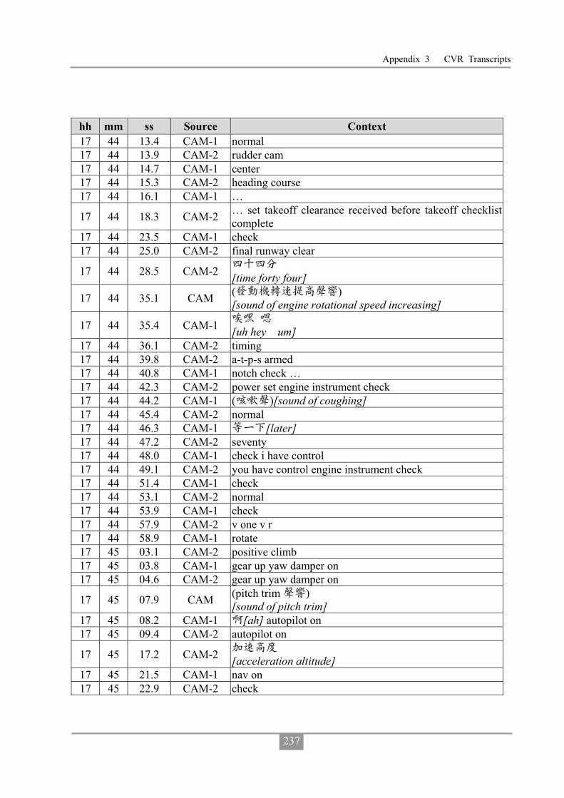
Appendix 3 CVR Transcripts
237
hh mm ss Source Context 17 44 13.4 CAM-1 normal 17 44 13.9 CAM-2 rudder cam 17 44 14.7 CAM-1 center 17 44 15.3 CAM-2 heading course 17 44 16.1 CAM-1 …
17 44 18.3 CAM-2 … set takeoff clearance received before takeoff checklist complete
17 44 23.5 CAM-1 check 17 44 25.0 CAM-2 final runway clear
17 44 28.5 CAM-2 [time forty four]
17 44 35.1 CAM ( ) [sound of engine rotational speed increasing]
17 44 35.4 CAM-1 [uh hey um]
17 44 36.1 CAM-2 timing 17 44 39.8 CAM-2 a-t-p-s armed 17 44 40.8 CAM-1 notch check … 17 44 42.3 CAM-2 power set engine instrument check 17 44 44.2 CAM-1 ( )[sound of coughing] 17 44 45.4 CAM-2 normal 17 44 46.3 CAM-1 [later] 17 44 47.2 CAM-2 seventy 17 44 48.0 CAM-1 check i have control 17 44 49.1 CAM-2 you have control engine instrument check 17 44 51.4 CAM-1 check 17 44 53.1 CAM-2 normal 17 44 53.9 CAM-1 check 17 44 57.9 CAM-2 v one v r 17 44 58.9 CAM-1 rotate 17 45 03.1 CAM-2 positive climb 17 45 03.8 CAM-1 gear up yaw damper on 17 45 04.6 CAM-2 gear up yaw damper on
17 45 07.9 CAM (pitch trim ) [sound of pitch trim]
17 45 08.2 CAM-1 [ah] autopilot on 17 45 09.4 CAM-2 autopilot on
17 45 17.2 CAM-2 [acceleration altitude]
17 45 21.5 CAM-1 nav on 17 45 22.9 CAM-2 check

Aviation Occurrence Report
238
hh mm ss Source Context
17 45 28.8 TWR_K transasia two two two contact departure one two four decimal seven
17 45 32.2 RDO-2 contact departure one two four decimal seven transasia two two two good day
17 45 36.3 CAM ( ) [sound of radio frequency switching]
17 45 40.1 RDO-2 kaohsiung approach good evening transasia two two two passing one thousand two hundred sigang one sosan one tango departure
17 45 44.0 CAM (pitch trim ) [sound of pitch trim]
17 45 46.7 CAM-1 (um) roger
17 45 47.1 APP transasia two two two kaohsiung approach roger climb and maintain seven thousand
17 45 50.9 RDO-2 climb maintain seven thousand transasia two two two
17 45 52.9 CAM-2 [ climb and maintain seven thousand]
17 45 53.9 CAM-1 check
17 45 54.3 CAM (pitch trim ) [sound of pitch trim]
17 45 55.1 CAM-2 flap zero set after takeoff checklist 17 45 56.5 CAM-1 (um)
17 45 57.2 CAM-2
gears up flap zero power management climb con lever auto n-p … taxi lights off anti icing off seat belts on bleed and air flow high approach brief uh after takeoff checklist complete
17 46 16.5 APP transasia two two two squawk ident
17 46 20.4 RDO-2 ident passing one thousand niner hundred transasia two two two
17 46 25.1 APP two two roger now radar contact two miles west of the airport climb and maintain seven thousand
17 46 29.9 RDO-2 climb and maintain seven thousand transasia two two two
17 46 32.9 CAM-2 [climb and maintain seven thousand]
17 46 34.4 CAM-1 (um) 17 46 37.3 CAM-1 (um)
17 46 50.1 OTH ( 2082 ATC ) [communication between GE 2082 and ATC]
17 46 54.4 APP ( 2082 ) [communication with GE 2082]
17 47 00.3 OTH ( 2082 ATC ) [communication between GE 2082 and ATC]
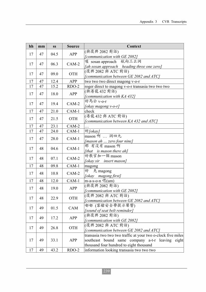
Appendix 3 CVR Transcripts
239
hh mm ss Source Context
17 47 04.5 APP ( 2082 ) [communication with GE 2082]
17 47 06.3 CAM-2 sosan approach [ah sosan approach heading three one zero]
17 47 09.0 OTH ( 2082 ATC ) [communication between GE 2082 and ATC]
17 47 12.4 APP two two two direct magong v-o-r 17 47 15.2 RDO-2 roger direct to magong v-o-r transasia two two two
17 47 18.0 APP ( 432 ) [communication with KA 432]
17 47 19.4 CAM-2 v-o-r [okay magong v-o-r]
17 47 21.0 CAM-1 check
17 47 21.5 OTH ( 432 ATC ) [communication between KA 432 and ATC]
17 47 23.1 CAM-2 … 17 47 24.0 CAM-1 [okay]
17 47 28.0 CAM-1 mason … [mason ah … zero four nine]
17 48 04.6 CAM-1 mason [that is mason there ah]
17 48 07.1 CAM-2 mason [okay sir insert mason]
17 48 09.8 CAM-1 magong
17 48 10.8 CAM-2 magong [okay magong first]
17 48 12.0 CAM-1 m-a-s-o-n (um)
17 48 19.0 APP ( 2082 ) [communication with GE 2082]
17 48 22.9 OTH ( 2082 ATC ) [communication between GE 2082 and ATC]
17 49 01.5 CAM ( ) [sound of seat belt reminder]
17 49 17.2 APP ( 2082 ) [communication with GE 2082]
17 49 26.8 OTH ( 2082 ATC ) [communication between GE 2082 and ATC]
17 49 33.1 APP transasia two two two traffic at your two o-clock five miles southeast bound same company a-t-r leaving eight thousand four hundred to eight thousand
17 49 43.2 RDO-2 information looking transasia two two two
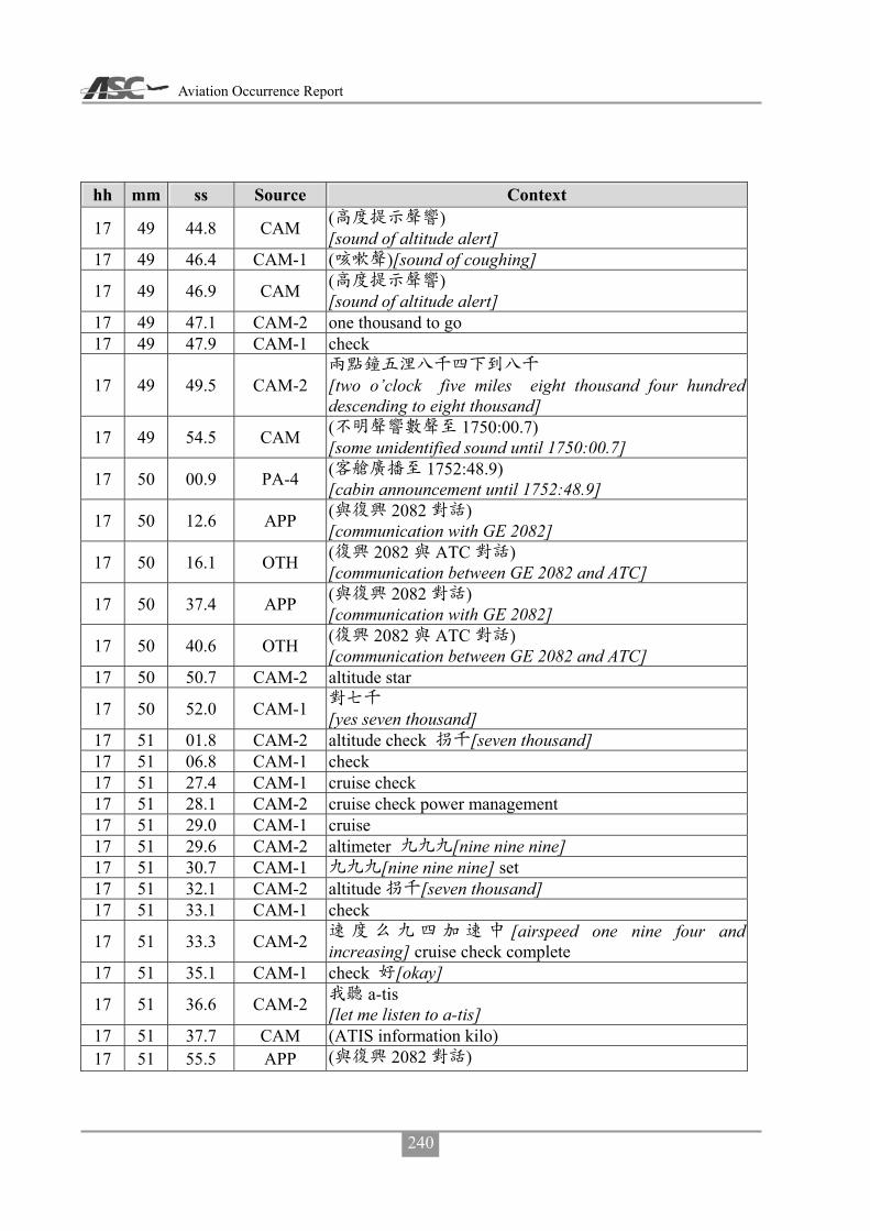
Aviation Occurrence Report
240
hh mm ss Source Context
17 49 44.8 CAM ( ) [sound of altitude alert]
17 49 46.4 CAM-1 ( )[sound of coughing]
17 49 46.9 CAM ( ) [sound of altitude alert]
17 49 47.1 CAM-2 one thousand to go 17 49 47.9 CAM-1 check
17 49 49.5 CAM-2
[two o’clock five miles eight thousand four hundred descending to eight thousand]
17 49 54.5 CAM ( 1750:00.7) [some unidentified sound until 1750:00.7]
17 50 00.9 PA-4 ( 1752:48.9) [cabin announcement until 1752:48.9]
17 50 12.6 APP ( 2082 ) [communication with GE 2082]
17 50 16.1 OTH ( 2082 ATC ) [communication between GE 2082 and ATC]
17 50 37.4 APP ( 2082 ) [communication with GE 2082]
17 50 40.6 OTH ( 2082 ATC ) [communication between GE 2082 and ATC]
17 50 50.7 CAM-2 altitude star
17 50 52.0 CAM-1 [yes seven thousand]
17 51 01.8 CAM-2 altitude check [seven thousand] 17 51 06.8 CAM-1 check 17 51 27.4 CAM-1 cruise check 17 51 28.1 CAM-2 cruise check power management 17 51 29.0 CAM-1 cruise 17 51 29.6 CAM-2 altimeter [nine nine nine] 17 51 30.7 CAM-1 [nine nine nine] set 17 51 32.1 CAM-2 altitude [seven thousand] 17 51 33.1 CAM-1 check
17 51 33.3 CAM-2 [airspeed one nine four and increasing] cruise check complete
17 51 35.1 CAM-1 check [okay]
17 51 36.6 CAM-2 a-tis [let me listen to a-tis]
17 51 37.7 CAM (ATIS information kilo) 17 51 55.5 APP ( 2082 )

Appendix 3 CVR Transcripts
241
hh mm ss Source Context [communication with GE 2082]
17 51 58.6 OTH ( 2082 ATC ) [communication between GE 2082 and ATC]
17 52 45.2 CAM-1 … check broken broken [... check that broken how high is the broken]
17 52 46.2 CAM ( ) [toot]
17 52 47.9 CAM-2 [six hundred] 17 52 48.7 CAM-1 [six hundred uh] 17 52 49.5 CAM-2 [yes]
17 52 50.3 CAM-2
scatter broken few c-b overcast
[scatter two hundred broken six hundred few c-b at one thousand two hundred overcast at one thousand six hundred]
17 52 53.9 CAM-1 [oh]
17 52 54.6 CAM-2 [then twenty four degree twenty two nine nine three]
17 52 56.4 CAM-1 [oh]
17 52 57.4 CAM-2 [visibility eight hundred feet] r-a thunder visibility thunderstorm
17 52 59.2 CAM-1 [oh] 17 53 01.6 CAM-1 [oh]
17 53 01.9 CAM-2 below minimum gust [below minimum one nine zero twenty one gust three two]
17 53 05.5 CAM-1 [oh] 17 53 10.1 CAM-1 ( )[ah] [sound of coughing]
17 53 19.4 APP ( 2082 ) [communication with GE 2082]
17 53 22.4 OTH ( 2082 ATC ) [communication between GE 2082 and ATC]
17 53 25.3 APP ( 2082 ) [communication with GE 2082]
17 53 26.4 CAM ( ) [sound of seat belt reminder]
17 53 33.1 OTH ( 2082 ATC ) [communication between GE 2082 and ATC]
17 53 33.8 PA-4 ( 1753:54.9) [cabin announcement until 1753:54.9]
17 54 17.9 OTH ( )
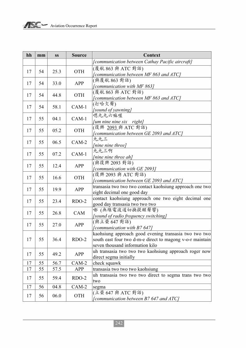
Aviation Occurrence Report
242
hh mm ss Source Context [communication between Cathay Pacific aircraft]
17 54 25.3 OTH ( 863 ATC ) [communication between MF 863 and ATC]
17 54 33.0 APP ( 863 ) [communication with MF 863]
17 54 44.8 OTH ( 863 ATC ) [communication between MF 863 and ATC]
17 54 58.1 CAM-1 ( ) [sound of yawning]
17 55 04.1 CAM-1 [um nine nine six right]
17 55 05.2 OTH ( 2093 ATC ) [communication between GE 2093 and ATC]
17 55 06.5 CAM-2 [nine nine three]
17 55 07.2 CAM-1 [nine nine three ah]
17 55 12.4 APP ( 2093 ) [communication with GE 2093]
17 55 16.6 OTH ( 2093 ATC ) [communication between GE 2093 and ATC]
17 55 19.9 APP transasia two two two contact kaohsiung approach one two eight decimal one good day
17 55 23.4 RDO-2 contact kaohsiung approach one two eight decimal one good day transasia two two two
17 55 26.8 CAM ( ) [sound of radio frequency switching]
17 55 27.0 APP ( 647 ) [communication with B7 647]
17 55 36.4 RDO-2 kaohsiung approach good evening transasia two two two south east four two d-m-e direct to magong v-o-r maintain seven thousand information kilo
17 55 49.2 APP uh transasia two two two kaohsiung approach roger now direct segma initially
17 55 56.7 CAM-2 check squawk 17 55 57.5 APP transasia two two two kaohsiung
17 55 59.4 RDO-2 uh transasia two two two direct to segma trans two two two
17 56 04.8 CAM-2 segma
17 56 06.0 OTH ( 647 ATC ) [communication between B7 647 and ATC]

Appendix 3 CVR Transcripts
243
hh mm ss Source Context
17 55 09.6 APP ( 647 ) [communication with B7 647]
17 56 11.3 CAM-2 e-g-m-a 17 56 14.4 CAM-2 g
17 56 15.5 OTH ( 647 ATC ) [communication between B7 647 and ATC]
17 56 17.1 CAM-2 [oh]
17 56 18.0 APP transasia two two two for your information magong airport now below landing minimum
17 56 23.4 RDO-2 copy that request hold at segma transasia two two two
17 56 27.9 APP transasia two two two roger maintain seven thousand direct segma join holding pattern report join
17 56 34.5 RDO-2 maintain seven thousand direct to segma and join holding pattern report join transasia two two two
17 56 41.6 CAM-2 [okay] segma report 17 56 42.8 CAM-1 segma [one three five] 17 56 46.3 CAM-2 [one three five] 17 56 48.7 CAM-1 [wow]
17 56 50.2 CAM-2 [sir we are deviating to the right oh]
17 56 50.7 APP [kaohsiung approach call GE 222 and FE 3055]
17 56 56.8 APP
[latest sigmet forcasts magong airport visibility 1,200 meters thunderstorm fog scatter 200 for the next two-hour]
17 57 09.7 CAM-2 [oh]
17 57 11.4 RDO-2 [GE222 copy that]
17 57 12.9 APP [thanks all]
17 57 14.8 CAM-2 [visibility 1,200 meters thunderstorm fog for two-hour]
17 57 19.1 CAM-1 [oh]
17 57 19.8 CAM-2 scatter [then scatter scatter 200]
17 57 25.5 CAM-1
[one thousand two hundred we need one thousand six hundred]
17 57 27.7 CAM-2

Aviation Occurrence Report
244
hh mm ss Source Context [affirmative sir]
17 57 34.3 APP ( 895 ) [communication with B7 895]
17 57 43.5 OTH ( 647 ATC ) [communication between B7 647 and ATC]
17 57 48.6 APP ( 647 ) [communication with B7 647]
17 57 52.3 OTH ( 647 ATC ) [communication between B7 647 and ATC]
17 58 01.6 APP ( ) [communication with Uni Air flight]
17 58 08.8 OTH ( ) [communication with other aircraft]
17 58 13.8 CAM-1 [seems to be ok]
17 58 14.1 APP ( 3055 ) [communication with FE 3055]
17 58 17.5 CAM-2 [that that’s the one]
17 58 17.7 CAM-1 [hey hey]
17 58 19.7 APP ( 3055 ) [communication with FE 3055]
17 58 19.9 CAM-2 [the red one is much worse looks ok behind it]
17 58 29.1 CAM-1 segma
17 58 29.4 APP ( 786 ) [communication with AE 786]
17 58 31.5 OTH ( 786 ATC ) [communication between AE 786 and ATC]
17 58 36.2 APP ( 786 ) [communication with AE 786]
17 58 41.7 OTH ( 786 ATC ) [communication between AE 786 and ATC]
17 58 42.7 CAM-2 segma [to sigma via where]
17 58 43.6 APP ( 786 ) [communication with AE 786]
17 58 47.5 CAM-2 [we request one minute or ten miles]
17 58 50.6 OTH ( 786 ATC ) [communication between AE 786 and ATC]

Appendix 3 CVR Transcripts
245
hh mm ss Source Context 17 58 52.5 CAM-1 [um um] 17 58 53.7 CAM-2 [ah]
17 58 54.2 CAM-1 [it is okay let’s wait awhile for him]
17 58 55.2 APP ( 786 ) [communication with AE 786]
17 58 55.6 CAM-2 [okay]
17 58 58.5 CAM-1 [ah direct entry]
17 58 59.4 OTH ( 786 ATC ) [communication between AE 786 and ATC]
17 59 00.4 CAM-2 [sir which which one for us to direct to]
17 59 03.1 CAM-1 … [direct entry I know you]
17 59 05.3 CAM-2 [I see]
17 59 05.5 CAM-1 holding [join holding pattern]
17 59 06.7 CAM-2 holding hold hold
[I know it’s holding but to hold by leg length in one minute or by distance]
17 59 09.0 CAM-1 hold hold (hold ah hold by distance]
17 59 10.4 CAM-2 hold [hold by distance I would request from ATC]
17 59 13.7 CAM-1 [oh five miles] 17 59 14.4 CAM-2 [five miles roger] 17 59 23.1 CAM-1 segma [thirteen]
17 59 25.6 CAM-1 [request later]
17 59 26.7 CAM-2 ( ) [oh oh laughing]
17 59 27.0 APP ( 647 ) [communication with B7 647]
17 59 30.2 OTH ( 647 ATC ) [communication between B7 647 and ATC]
17 59 34.2 APP ( 647 ) [communication with B7 647]
17 59 37.2 OTH ( 647 ATC ) [communication between B7 647 and ATC]
17 59 38.0 CAM-2 [later]

Aviation Occurrence Report
246
hh mm ss Source Context
17 59 38.1 OTH ( 786 ATC ) [communication between B7 647 and ATC]
17 59 41.2 CAM-2 ... thunderstorm [... these squall line thunderstorms should be the one would be great if they move this way]
17 59 42.0 APP ( 786 ) [communication with AE 786]
17 59 46.2 CAM-1 [oh]
17 59 47.1 CAM-2 [now wind from southwest blows them over]
17 59 47.1 OTH ( 786 ATC ) [communication between AE 786 and ATC]
17 59 50.9 APP ( 786 ) [communication with AE 786]
17 59 56.1 APP ( 786 ) [communication with AE 786]
18 00 04.4 APP ( 895 ) [communication with B7 895]
18 00 16.6 CAM-1 mason mason mason
18 00 20.4 APP ( 647 ) [communication with B7 647]
18 00 24.0 OTH ( 647 ATC ) [communication between B7 647 and ATC]
18 00 28.3 CAM-1 [four nine] 18 00 30.9 CAM-1 ( )[sigh [sound of coughing]]
18 00 36.3 CAM-1 mason [request holding at mason]
18 00 37.9 APP ( 3055 ) [communication with FE 3055]
18 00 39.5 CAM-2 [okay] 18 00 41.2 CAM-1 [later]
18 00 45.1 CAM-2 [later when you ask me to I will tell them]
18 00 46.4 CAM-1 [okay]
18 00 46.8 APP ( 3055 ) [communication with FE 3055]
18 00 55.6 APP ( 3055 ) [communication with FE 3055]
18 00 58.4 CAM ( ) [sound of radio frequency switching]
18 01 00.9 CAM (ATIS information lima)

Appendix 3 CVR Transcripts
247
hh mm ss Source Context
18 01 08.1 APP ( ) [communication with other aircraft]
18 01 10.8 CAM-2 [weather is changing]
18 01 11.8 APP ( 786 ) [communication with AE 786]
18 01 16.5 OTH ( 786 ATC ) [communication between AE 786 and ATC]
18 01 19.5 APP ( 786 ) [communication with AE 786]
18 01 20.3 APP ( 3055 ) [communication with FE 3055]
18 01 49.1 APP ( 6295 ) [communication with B7 6295]
18 01 53.4 CAM-1 mason mason
[okay we request request direct to mason to hold at mason]
18 01 55.0 APP ( 3055 ) [communication with FE 3055]
18 01 57.1 CAM-2 [okay direct course by five miles]
18 02 00.0 CAM-1 [um yes]
18 02 02.0 RDO-2 transasia two two two request direct to mason and join holding pattern at five mile leg
18 02 10.5 APP confirm far eastern tree zero five five 18 02 12.3 RDO-2 negative transasia two two two
18 02 14.4 APP transasia two two two roger approved as requested maintain seven thousand
18 02 18.2 RDO-2 maintain seven thousand direct to mason transasia two two two
18 02 20.5 CAM (ATIS information lima)
18 02 25.8 APP ( ) [communication with other aircraft]
18 02 39.5 APP ( 647 ) [communication with B7 647]
18 02 44.1 OTH ( 647 ATC ) [communication between B7 647 and ATC]
18 03 00.3 CAM-2 [okay] information lima
18 03 02.4 CAM ( ) [sound of radio frequency switching]
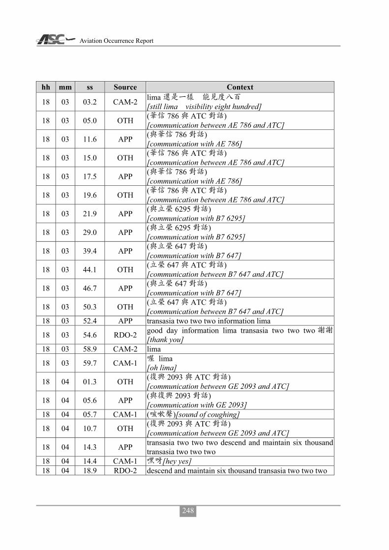
Aviation Occurrence Report
248
hh mm ss Source Context
18 03 03.2 CAM-2 lima [still lima visibility eight hundred]
18 03 05.0 OTH ( 786 ATC ) [communication between AE 786 and ATC]
18 03 11.6 APP ( 786 ) [communication with AE 786]
18 03 15.0 OTH ( 786 ATC ) [communication between AE 786 and ATC]
18 03 17.5 APP ( 786 ) [communication with AE 786]
18 03 19.6 OTH ( 786 ATC ) [communication between AE 786 and ATC]
18 03 21.9 APP ( 6295 ) [communication with B7 6295]
18 03 29.0 APP ( 6295 ) [communication with B7 6295]
18 03 39.4 APP ( 647 ) [communication with B7 647]
18 03 44.1 OTH ( 647 ATC ) [communication between B7 647 and ATC]
18 03 46.7 APP ( 647 ) [communication with B7 647]
18 03 50.3 OTH ( 647 ATC ) [communication between B7 647 and ATC]
18 03 52.4 APP transasia two two two information lima
18 03 54.6 RDO-2 good day information lima transasia two two two[thank you]
18 03 58.9 CAM-2 lima
18 03 59.7 CAM-1 lima [oh lima]
18 04 01.3 OTH ( 2093 ATC ) [communication between GE 2093 and ATC]
18 04 05.6 APP ( 2093 ) [communication with GE 2093]
18 04 05.7 CAM-1 ( )[sound of coughing]
18 04 10.7 OTH ( 2093 ATC ) [communication between GE 2093 and ATC]
18 04 14.3 APP transasia two two two descend and maintain six thousand transasia two two two
18 04 14.4 CAM-1 [hey yes] 18 04 18.9 RDO-2 descend and maintain six thousand transasia two two two

Appendix 3 CVR Transcripts
249
hh mm ss Source Context
18 04 20.6 PA-1
[ladies and gentlemen good afternoon this is captain speaking welcome onboard our flilght from kaohsiung to penghu we are now flying over tainan at an altitude of seven thousand feet with an average speed of um three hundred kilometers per hour due to current weather condition magong is below landing minimum we will be holding at the north of magong and I will keep you updated on further weather information wish you a good day thank you]
18 04 24.7 CAM ( ) [sound of altitude alert]
18 04 26.4 CAM-2 one thousand to go
18 04 29.5 APP ( ) [communication with other aircraft]
18 04 55.9 APP ( 647 ) [communication with B7 647]
18 04 57.7 CAM-2 …
[remain heading maintain six thousand… speed one eighty]
18 04 58.6 OTH ( 647 ATC ) [communication between B7 647 and ATC]
18 05 01.1 CAM-1 [okay] 18 05 01.8 CAM-2 no change 18 05 03.7 CAM-1 yah i have control 18 05 04.5 CAM-2 you have control
18 05 05.0 APP ( 647 ) [communication with B7 647]
18 05 08.1 OTH ( 647 ATC ) [communication between B7 647 and ATC]
18 05 13.3 APP ( 647 ) [communication with B7 647]
18 05 15.3 OTH ( 647 ATC ) [communication between B7 647 and ATC]
18 05 18.8 APP ( 6295 ) [communication with B7 6295]
18 05 23.5 CAM-1
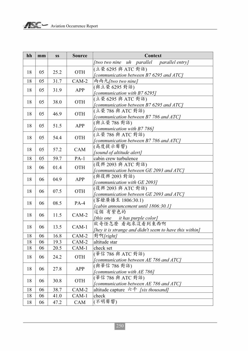
Aviation Occurrence Report
250
hh mm ss Source Context [two two nine uh parallel parallel entry]
18 05 25.2 OTH ( 6295 ATC ) [communication between B7 6295 and ATC]
18 05 31.7 CAM-2 [two two nine]
18 05 31.9 APP ( 6295 ) [communication with B7 6295]
18 05 38.0 OTH ( 6295 ATC ) [communication between B7 6295 and ATC]
18 05 46.9 OTH ( 786 ATC ) [communication between B7 786 and ATC]
18 05 51.5 APP ( 786 ) [communication with B7 786]
18 05 54.4 OTH ( 786 ATC ) [communication between B7 786 and ATC]
18 05 57.2 CAM ( ) [sound of altitude alert]
18 05 59.7 PA-1 cabin crew turbulence
18 06 01.4 OTH ( 2093 ATC ) [communication between GE 2093 and ATC]
18 06 04.9 APP ( 2093 ) [communication with GE 2093]
18 06 07.5 OTH ( 2093 ATC ) [communication between GE 2093 and ATC]
18 06 08.5 PA-4 ( 1806:30.1) [cabin announcement until 1806:30.1]
18 06 11.5 CAM-2 [this one it has purple color]
18 06 13.5 CAM-1 [hey it is strange and didn't seem to have this within]
18 06 16.8 CAM-2 [right] 18 06 19.3 CAM-2 altitude star 18 06 20.5 CAM-1 check set
18 06 24.2 OTH ( 786 ATC ) [communication between AE 786 and ATC]
18 06 27.8 APP ( 786 ) [communication with AE 786]
18 06 30.8 OTH ( 786 ATC ) [communication between AE 786 and ATC]
18 06 38.7 CAM-2 altitude capture [six thousand] 18 06 41.0 CAM-1 check 18 06 47.2 CAM ( )

Appendix 3 CVR Transcripts
251
hh mm ss Source Context [unidentified sound]
18 06 50.7 CAM-1 ( )[um [sound of coughing]]
18 07 04.2 OTH ( 786 ATC ) [communication between AE 786 and ATC]
18 07 08.4 APP ( 786 ) [communication with AE 786]
18 07 10.9 OTH ( 786 ATC ) [communication between AE 786 and ATC]
18 07 12.4 APP ( 786 ) [communication with AE 786]
18 07 17.8 OTH ( 786 ATC ) [communication between AE 786 and ATC]
18 07 21.5 APP ( 786 ) [communication with AE 786]
18 07 24.1 OTH ( 786 ATC ) [communication between AE 786 and ATC]
18 07 29.8 APP ( 647 ) [communication with B7 647]
18 07 33.0 OTH ( 647 ATC ) [communication between B7 647 and ATC]
18 07 36.3 APP ( 647 ) [communication with B7 647]
18 07 55.1 CAM-1 [um]
18 08 06.1 APP ( 3055 ) [communication with FE 3055]
18 08 32.6 CAM-1 ( )[sound of coughing]
18 08 38.0 CAM-1 mason *
[mason was looking good moments ago what the * it was blown to here]
18 08 41.2 CAM-2 [wind blows it here]
18 08 42.1 CAM-1 [oh]
18 09 01.4 APP ( 692 ) [communication with B7 692]
18 09 05.3 OTH ( 692 ATC ) [communication between B7 692 and ATC]
18 09 08.3 APP ( 692 ) [communication with B7 692]
18 09 11.3 OTH ( 692 ATC ) [communication between B7 692 and ATC]
18 09 14.8 APP ( 692 )

Aviation Occurrence Report
252
hh mm ss Source Context [communication with B7 692]
18 09 19.0 OTH ( 692 ATC ) [communication between B7 692 and ATC]
18 09 31.6 CAM-2 [oh two two nine]
18 09 32.7 CAM-1
[oh let us request heading three two zero to join the holding pattern of one three miles from magong two zero one okay]
18 09 39.1 CAM-2 okay
18 09 40.5 APP ( 3055 ) [communication with FE 3055]
18 09 46.5 RDO-2 transasia two two two request heading tree two zero and join correction tree one zero turn left heading and join magong two zero one one tree d-m-e
18 09 50.3 CAM-1 tree one zero 18 10 01.5 APP transasia two two two approved as requested 18 10 05.0 CAM-2 [three one zero]
18 10 05.1 APP ( 3055 ) [communication with FE 3055]
18 10 06.7 CAM-1 [three one zero] 18 10 15.2 CAM-2 [uh]
18 10 15.8 APP ( 3055 ) [communication with FE 3055]
18 10 17.7 CAM-1 * [uh uh I am so * tired]
18 10 28.4 CAM-2 [sir are we holding here]
18 10 30.4 CAM-1 [yes]
18 10 30.9 CAM-2 right orbit left orbit [right orbit or left orbit]
18 10 32.5 CAM-1
[no not that this will do do right orbit holding pattern]
18 10 37.3 CAM-2 okay
18 10 38.2 APP ( 692 ) [communication with B7 692]
18 10 40.5 CAM-2 [two zero one]
18 10 44.2 OTH ( 692 ATC ) [communication between B7 692 and ATC]

Appendix 3 CVR Transcripts
253
hh mm ss Source Context
18 10 51.1 RDO-2 transasia two two two ah request magong two zero one one tree d-m-e right pattern
18 10 59.7 APP transasia two two two approved as requested 18 11 02.0 RDO-2 thank you 18 11 03.0 CAM-1 [sigh]
18 11 04.5 APP ( 2093 ) [communication with GE 2093]
18 11 08.3 OTH ( 2093 ATC ) [communication between GE 2093 and ATC]
18 11 11.6 CAM-2 [oh established I will report to him]
18 11 13.4 CAM-1 [okay]
18 11 16.7 RDO-2 transasia two two two join uh holding pattern request five mile leg
18 11 17.7 CAM-1 [um] 18 11 21.3 APP transasia two two two approved as requested 18 11 23.5 CAM-1 [yes] 18 11 23.9 RDO-2 thank you transasia two two two
18 11 25.4 APP ( ) [communications with other aircraft]
18 11 25.4 CAM-2 [okay] 18 11 36.6 CAM-1 [um]
18 11 42.1 CAM-1 [oh blown away immediately]
18 11 46.0 CAM-2 [um]
18 11 47.4 APP ( ) [communication with other aircraft]
18 11 50.7 CAM-2 leg [five mile leg]
18 11 52.1 CAM-1 [sigh]
18 11 53.7 APP ( 3055 ) [communication with FE 3055]
18 12 08.5 CAM-1
[ah thirteen miles three thousand five miles two thousand]
18 12 13.1 CAM-2 [one eight one eight reaches five miles too]
18 12 15.0 CAM-1 [um um]
18 12 16.3 CAM-2 holding
[no I said if we’re holding we have to turn inbound at

Aviation Occurrence Report
254
hh mm ss Source Context one one eight miles]
18 12 16.5 APP ( 5133 ) [communication with GE 5133]
18 12 24.9 CAM-1 [sigh two zero one]
18 12 27.9 CAM-2 course [course is two zero one]
18 12 29.1 CAM-1 [okay zero two this is zero two one]
18 12 31.7 CAM-2
[sir I will initially set two zero one because we need this wind correction]
18 12 34.5 CAM-1 [okay]
18 12 35.2 CAM-2 [we can have this wind correction now]
18 12 39.3 CAM-1 [um] 18 12 43.4 CAM-1 [oh I see]
18 12 54.0 CAM-2
[later we need to turn to how much two three one wind is so strong]
18 13 04.3 CAM-1 [um]
18 13 12.2 CAM-2 [okay sir here comes the five miles]
18 13 14.2 CAM-1 [okay]
18 13 25.7 APP ( 6295 ) [communication with B7 6295]
18 13 34.7 APP ( 6295 ) [communication with B7 6295]
18 13 38.1 CAM-2 [two three one let me see]
18 13 50.2 APP ( 3055 ) [communication with FE 3055]
18 14 12.8 APP ( 786 ) [communication with AE 786]
18 14 24.0 OTH ( 786 ATC ) [communication between AE 786 and ATC]
18 14 29.5 APP ( 786 ) [communication with AE 786]
18 14 31.4 OTH ( 786 ATC ) [communication between AE 786 and ATC]
18 14 36.4 APP ( 2093 )

Appendix 3 CVR Transcripts
255
hh mm ss Source Context [communication with GE 2093]
18 14 40.9 OTH ( 2093 ATC ) [communication between GE 2093 and ATC]
18 14 43.6 APP ( 6295 ) [communication with B7 6295]
18 14 53.9 CAM-1 [take a look]
18 15 02.6 CAM-2 thunderstorm [coming um thunderstorm is gonna be blown toward us]
18 15 06.0 CAM-1 [oh]
18 15 06.6 CAM-2 [yes so magong we may the first one for the approach]
18 15 12.3 CAM-1 [um uh]
18 15 13.9 OTH ( 786 ATC ) [communication between AE 786 and ATC]
18 15 19.7 APP ( 786 ) [communication with AE 786]
18 15 25.6 OTH ( 786 ATC ) [communication between AE 786 and ATC]
18 15 34.0 APP ( 5133 ) [communication with GE 5133]
18 15 37.0 OTH ( ) [communication between BR flights]
18 15 41.5 OTH ( ) [other aircraft communication]
18 15 48.2 OTH ( ) [other aircraft communication]
18 15 52.8 OTH ( ) [other aircraft communication]
18 15 57.9 CAM-1 [better evade it]
18 15 58.3 OTH ( ) [other aircraft communication]
18 15 59.9 CAM-2 [copy that]
18 16 01.4 APP ( 786 ) [communication with B7 786]
18 16 03.2 CAM-2
[then we happen to circumvent it happens to circumvent the right side one]
18 16 07.1 CAM-1 [oh] 18 16 07.8 CAM-2 [yes] 18 16 18.4 APP ( 3055 )

Aviation Occurrence Report
256
hh mm ss Source Context [communication with FE 3055]
18 16 20.5 OTH ( 758 ATC ) [communication between BR 758 and ATC]
18 16 22.2 APP ( 3055 ) [communication with FE 3055]
18 16 28.6 APP ( 3055 ) [communication with FE 3055]
18 16 36.5 CAM-1
[ask whether the weather is getting better we request to continue the approach]
18 16 41.5 CAM-1 tempo [any tempo]
18 16 42.8 APP ( 786 ) [communication with AE 786]
18 16 43.5 CAM-2 [okay]
18 16 46.5 OTH ( 786 ATC ) [communication between AE 786 and ATC]
18 16 50.4 RDO-2
check
[kaohsiung transasia two two two um is magong weather getting better and if yes we will request for approach]
18 16 54.4 CAM-1 tempo [tempo weather]
18 16 55.9 APP [okay i will apply for I will inquire about it for you]
18 16 58.1 CAM-1 [temporary good weather]
18 17 00.5 CAM-2 [okay]
18 17 15.4 APP ( 3055 ) [communication with FE 3055]
18 17 20.4 OTH ( 758 ATC ) [communication between BR 758 and ATC]
18 17 29.9 CAM-2 holding
[okay sir here is the one three miles we are going to turn for another holding orbit]
18 17 35.1 CAM-1 [yes then if turn needed turn left]
18 17 38.3 CAM-2 orbit [left turn orbit]
18 17 39.6 CAM-1 [okay]

Appendix 3 CVR Transcripts
257
hh mm ss Source Context 18 17 40.8 RDO-2 transasia two two two request left turn orbit one orbit 18 17 45.3 APP transasia two two two approved as requested 18 17 48.1 RDO-2 left turn one orbit transasia two two two
18 17 50.2 CAM-2 one orbit [okay left turn one orbit]
18 17 56.4 CAM-1 [it seems to look look like it is clear]
18 17 58.8 CAM-2 [it is passing over]
18 17 59.9 APP ( 3055 ) [communication with FE 3055]
18 18 04.1 CAM-2 [sir I will listen to it]
18 18 05.4 CAM-1 [okay]
18 18 06.5 CAM ( ) [sound of radio frequency switching]
18 18 06.6 CAM (ATIS information lima)
18 18 08.1 APP ( 3055 ) [communication with FE 3055]
18 18 12.3 CAM-2 lima [still lima]
18 18 16.3 APP ( 3055 ) [communication with FE 3055]
18 18 20.9 CAM ( ) [sound of radio frequency switching]
18 18 21.7 CAM-2 lima [sir still lima]
18 18 23.1 CAM-1 [oh oh] 18 18 24.4 CAM-2 [um annoying]
18 18 40.5 B7 647
approach
[approach glory um six four seven how many aircraft to magong are holdind now]
18 18 46.1 APP [there are four including you and you are the first]
18 18 49.5 B7 647 [roger]
18 18 51.4 APP [sir say your intention please]
18 18 54.0 B7 647
[we will make our decision after the weather you provide us]

Aviation Occurrence Report
258
hh mm ss Source Context
18 18 56.8 APP
[okay we already have the tower to inquire about it thank you]
18 19 00.4 CAM-2 ( ) [weather weather is not good [laughing]]
18 19 00.5 B7 647 [thank you]
18 19 21.3 APP ( 786 ) [communication with AE 786]
18 19 25.1 OTH ( 786 ATC ) [communication between AE 786 and ATC]
18 19 29.4 APP ( 786 ) [communication between AE 786 and ATC]
18 19 32.4 OTH ( 786 ATC )
18 19 35.5 APP ( 786 ) [communication with AE 786]
18 19 44.4 CAM-2 [to which shall we switch to]
18 19 46.3 CAM ( ) [sound of radio frequency switching]
18 19 46.9 CAM-2 [okay] 18 19 47.6 CAM-1 [listening watch for awhile] 18 19 48.6 CAM-2 okay
18 19 52.3 APP ( 3055 ) [communication with FE 3055]
18 19 57.1 CAM-1 [sigh]
18 19 58.2 APP ( 3055 ) [communication with FE 3055]
18 20 14.5 APP ( 3055 ) [communication with FE 3055]
18 20 35.5 CAM-1
[then we’re turning randomly turn randomly to dodge the weather]
18 20 39.1 CAM-2 orbit [anyway the orbit is ours this whole area is ours]
18 20 42.0 CAM-1 [okay] 18 20 51.1 CAM-1 [looks pretty good] 18 20 54.5 CAM-2 [um] 18 20 59.5 CAM-1 [um okay]
18 20 59.9 APP ( 5133 ) [communication with GE 5133]
18 21 01.7 CAM-2 thunderstorm

Appendix 3 CVR Transcripts
259
hh mm ss Source Context [almost completely passing through the thunderstorm is about to pass over soon]
18 21 04.7 CAM-1 [yes]
18 21 12.8 APP ( 786 ) [communication with AE 786]
18 21 17.5 CAM-2 orbit [keep requesting keep requesting orbit]
18 21 18.0 OTH ( 786 ATC ) [communication between AE 786 and ATC]
18 21 23.1 CAM-1 [um yes]
18 21 25.9 RDO-2 transasia two two two ah request left orbit at two zero one radial one tree d-m-e
18 21 33.3 APP confirm transasia two two two 18 21 34.8 RDO-2 affirmative 18 21 35.7 APP transasia two two two approved as requested 18 21 37.6 RDO-2 thank you transasia two two two
18 21 39.1 CAM-2
[okay we will remain here at one three one three one one three miles]
18 21 39.2 APP [glory six four seven kaohsiung]
18 21 41.4 B7 647 [um go ahead]
18 21 42.4 APP
[sir tower reported that thunderstorm will probably continue for another hour and we are still requesting the visibility]
18 21 50.0 B7 647 [okay thank you]
18 21 51.3 APP confirm [transasia two two two sir confirm you copy that]
18 21 54.3 RDO-2 [roger transasia two two two ]
18 21 56.8 CAM-2 [sigh one hour]
18 21 57.4 APP ( 3055 ) [communication with FE 3055]
18 21 59.7 APP ( 5133 ) [communication with GE 5133]
18 22 05.9 APP ( 5133 ) [communication with GE 5133]

Aviation Occurrence Report
260
hh mm ss Source Context
18 22 10.8 APP ( 5133 ) [communication with GE 5133]
18 22 11.7 APP ( 3055 ) [communication with FE 3055]
18 22 15.9 APP ( 3055 ) [communication with FE 3055]
18 22 20.0 CAM-2 … orbit [okay… then we have to turn orbit]
18 22 22.1 CAM-1 [okay]
18 22 30.1 RDO-1
[um transasia two two two is there any temporary good weather]
18 22 34.9 APP
[sir we are waiting for an answer we will let you know immediately if there is any]
18 22 38.1 RDO-1 [okay thank you] 18 22 39.2 APP [you are welcome] 18 22 58.4 CAM-1 [sigh sigh sigh] 18 23 31.7 CAM-1 [sigh sigh sigh]
18 23 48.1 CAM-2 [let me check the distance]
18 24 07.1 CAM-2 [yes it should be clear]
18 24 08.9 CAM-1 [hey yes]
18 24 09.1 CAM-2 * [* here it comes again]
18 24 33.3 CAM-1 ( )[sigh [sound of coughing]] 18 24 44.1 CAM-1 [gone yet] 18 24 45.7 CAM-2 [it’s gone] 18 24 48.3 CAM-1 [should be good now] 18 24 51.7 CAM-1 [sigh] 18 25 06.6 CAM-2 [sigh]
18 25 17.3 APP ( ) [communication with other aircraft]
18 25 21.5 APP ( ) [communication with other aircraft]
18 25 25.1 APP ( 3055 ) [communication with FE 3055]
18 25 30.4 CAM-2 ( ) … ( ) [[laughing] … seven thousand and all up to you [laughing]]

Appendix 3 CVR Transcripts
261
hh mm ss Source Context
18 25 36.3 APP ( ) [communication with other aircraft]
18 25 57.4 CAM-1 … [sigh ... all right]
18 26 25.4 CAM-1 …
18 27 04.4 CAM-2 [contact him or not]
18 27 05.6 CAM-1 [ah wait a second]
18 27 07.3 CAM-2 [okay]
18 27 12.1 CAM-2 tower [or ask magong tower]
18 27 19.3 CAM-1 [okay let me ask him]
18 27 20.2 CAM-2 [okay sir]
18 27 23.9 RDO-1
[magong tower transasia two two two is the weather temporarily in good conditon it looks fine from our perspective]
18 27 38.2 TWR_M
[transasia two two two tower sir we just confirmed with the forecast office and the forecast now visibility will remain at eight hundred and as for ground wind average ten minutes wind two two zero degrees one seven knots maximum two seven knots runway zero two wind two one zero degrees six knots maximum one one knots runway two zero wind two zero zero degrees one two knots maximum one six knots]
18 27 38.4 APP
approach …
confirm
[kaohsiung approach broadcasts magong forecast chief reported that visibility will improve in the next ten to ten twenty minutes but... runway zero two wind two one zero degrees five knots maximum one one knots

Aviation Occurrence Report
262
hh mm ss Source Context runway two zero wind one nine zero degrees one one knots maximum one five knots confirm you copy it glory six four seven]
18 28 05.0 APP glory six four seven [kaohsiung]
18 28 07.5 B7 647
[glory six four seven can you repeat runway zero two wind information at runway zero two]
18 28 12.0 APP
[runway zero two wind two one zero degrees five knots maximum one one knots runway two zero wind one nine zero degrees one one knots maximum one five knots]
18 28 18.6 RDO-1 [roger thank you]
18 28 20.2 TWR_M [you are welcome sir]
18 28 21.9 CAM-2 [okay sir I will switch over now]
18 28 22.5 B7 647 [what about the visibility didn't he report the visibility]
18 28 24.3 CAM ( ) [sound of radio frequency switching]
18 28 25.6 APP
[they the forecast chief said they will not issue any adjustment but he said the weather will get better a little bit]
18 28 25.9 CAM-2 [remain at eight hundred]
18 28 32.2 B7 647 [what about now]
18 28 34.0 CAM-2 [eight hundred]
18 28 34.2 APP [now let me check for you]
18 28 37.1 CAM-2 [still eight hundred]
18 28 42.6 APP
metar
[glory six four seven sir right now magong metar visibility eight hundred meters]
18 28 58.1 RDO-1 approach

Appendix 3 CVR Transcripts
263
hh mm ss Source Context [approach two two two may we request wind information at runway zero two]
18 29 04.8 APP
[um zero two zero two wind two one zero degrees five knots maximum one one knots runway two zero wind one nine zero degrees one one knots maximum one five knots]
18 29 15.2 CAM-1 [copy yet runway zero two]
18 29 18.0 RDO-2 please say again [transasia two two two]
18 29 20.6 APP
transasia two two two runway zero two wind two one zero degrees five knots maximum one one knots runway two zero wind one niner zero degrees one one knots maximum one five knots
18 29 32.4 RDO-2 copy standby transasia two two two
18 29 34.7 CAM-2 i-l-s [let me guess the visibility at i-l-s zero two]
18 29 38.3 B7 647
approach glory i-l-s
[kaohsiung approach glory six four seven request radar vector for i-l-s runway zero two approach]
18 29 39.4 CAM-1 [then it works]
18 29 39.8 CAM-2 [visibility eight hundred is good for zero two]
18 29 44.3 CAM-2 * [how dare * they are going to descend]
18 29 44.8 APP [I will apply for you]
18 29 46.4 CAM-2 [they run in front of us sir we would request the same]
18 29 46.7 B7 647 [okay] 18 29 48.3 CAM-1 [okay]
18 29 50.3 RDO-2 [kaohsiung] transasia two two two request radar vector to i-l-s runway zero two
18 29 55.4 APP transasia two two two roger standby for coordination with magong tower
18 29 59.8 RDO-2 thank you standby transasia two two two continue left orbit
18 30 03.4 CAM-1 ( )[sound of coughing] 18 30 03.5 APP roger 18 30 04.6 CAM-2 orbit

Aviation Occurrence Report
264
hh mm ss Source Context [sir let us continue the orbit]
18 30 06.3 CAM-1 [okay]
18 30 08.1 CAM-2 [he is contacting tower to assist us]
18 30 10.2 CAM-1 [okay]
18 30 11.0 CAM-2 maximum
[two one zero five knots maximum one one under tail wind limit]
18 30 14.5 CAM-1 [okay]
18 30 15.1 CAM-2 i-l-s [visibility eight hundred i-l-s zero two is good]
18 30 17.5 CAM-1 [okay] 18 30 35.1 CAM-2 ( )[sound of coughing]
18 30 38.3 CAM-1 [request heading one eight zero to south]
18 30 41.9 RDO-2 transasia two two two request heading one eight zero and to south
18 30 46.9 APP transasia two two two roger approved as requested and heading one eight zero
18 30 51.1 RDO-2 heading one eight zero transasia two two two
18 30 53.6 CAM-2 [heading one eight zero approved]
18 30 54.8 CAM-1 [okay]
18 30 56.6 CAM-1 ... [um and for landing...]
18 30 58.7 CAM-2
[same use zero eight one three three six six one for landing we have tail wind now so no more addition]
18 31 03.6 CAM-1 [okay]
18 31 37.8 CAM-1 [request one six zero sigh]
18 31 39.7 CAM-2 [one six zero] 18 31 40.6 CAM-1 [hey one six zero]
18 31 42.1 RDO-2 transasia two two two request heading turn left one six zero
18 31 46.9 APP transasia two two two heading one six zero approved 18 31 49.5 RDO-2 one six zero thank you transasia two two two
18 31 52.3 APP transasia two two two any deviation is approved maintain ah maintain six thousand
18 31 57.6 RDO-2 maintain six thousand thank you transasia two two two

Appendix 3 CVR Transcripts
265
hh mm ss Source Context 18 32 00.2 APP welcome sir
18 32 01.3 CAM-2
[okay it is all up to us now as long as maintaining six thousand]
18 32 03.9 CAM-1 [okay]
18 32 07.2 CAM-2 q-c a [sir I just keyed in q-c zero two a]
18 32 09.3 CAM-1 [okay]
18 32 12.8 CAM-1 [okay heading one eight zero]
18 32 14.4 CAM-2 [up to us he said up to us]
18 32 15.2 CAM-1 [up to us up to us]
18 32 16.5 CAM-2 any deviation ( ) [he said up to us any deviation [laughing]]
18 32 19.7 CAM-1 ( )[sound of coughing] 18 32 21.1 CAM-1 a-d-m … 18 32 22.9 CAM-2 [uh]
18 32 23.2 CAM-1 [what did he say]
18 32 24.0 CAM-2 [he said] any deviation 18 32 25.4 CAM-1 any deviation…
18 32 26.3 CAM-2 any deviation approved maintain six thousand [it means it is all up to us]
18 32 27.2 CAM-1 okay [oh oh oh okay okay okay okay okay]
18 32 32.4 CAM-2
[because they do not care and there is no other aircraft in this area anyway]
18 32 35.4 CAM-1 [oh]
18 32 39.6 CAM-1 [sigh]
18 32 57.9 CAM-2 [sir the wind becomes mild]
18 33 00.2 CAM-1 [yes]
18 33 00.9 CAM-2 [yes it becomes five knots]
18 33 02.6 CAM-1 [yes]
18 33 02.7 CAM-2 maximum gust [maximum one one it was one seven gusting two seven]
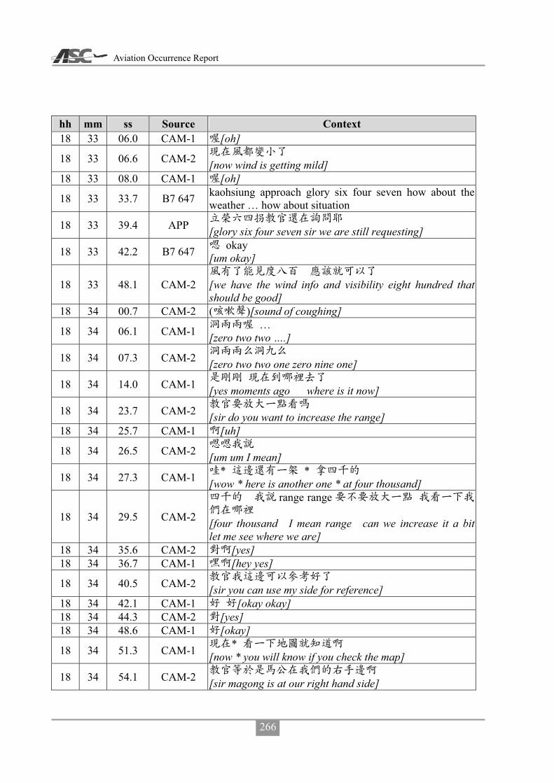
Aviation Occurrence Report
266
hh mm ss Source Context 18 33 06.0 CAM-1 [oh]
18 33 06.6 CAM-2 [now wind is getting mild]
18 33 08.0 CAM-1 [oh]
18 33 33.7 B7 647 kaohsiung approach glory six four seven how about the weather … how about situation
18 33 39.4 APP [glory six four seven sir we are still requesting]
18 33 42.2 B7 647 okay [um okay]
18 33 48.1 CAM-2
[we have the wind info and visibility eight hundred that should be good]
18 34 00.7 CAM-2 ( )[sound of coughing]
18 34 06.1 CAM-1 … [zero two two ….]
18 34 07.3 CAM-2 [zero two two one zero nine one]
18 34 14.0 CAM-1 [yes moments ago where is it now]
18 34 23.7 CAM-2 [sir do you want to increase the range]
18 34 25.7 CAM-1 [uh]
18 34 26.5 CAM-2 [um um I mean]
18 34 27.3 CAM-1 * * [wow * here is another one * at four thousand]
18 34 29.5 CAM-2
range range
[four thousand I mean range can we increase it a bit let me see where we are]
18 34 35.6 CAM-2 [yes] 18 34 36.7 CAM-1 [hey yes]
18 34 40.5 CAM-2 [sir you can use my side for reference]
18 34 42.1 CAM-1 [okay okay] 18 34 44.3 CAM-2 [yes] 18 34 48.6 CAM-1 [okay]
18 34 51.3 CAM-1 * [now * you will know if you check the map]
18 34 54.1 CAM-2 [sir magong is at our right hand side]

Appendix 3 CVR Transcripts
267
hh mm ss Source Context 18 34 57.6 CAM-1 [oh]
18 34 58.5 CAM-2
v-o-r
[now it shall be um roughly two seven zero at our nine o’clock direction magong v-o-r]
18 35 04.7 CAM-1 [oh]
18 35 10.0 B7 647
metar
[kaohsiung glory six four seven what is the magong metar at time three zero]
18 35 18.3 APP [I will inquire about it for you]
18 35 19.9 B7 647 [okay]
18 35 25.1 CAM-2 [not updated yet]
18 35 26.0 CAM-1 [um]
18 35 30.6 CAM ( ) [sound of radio frequency switching]
18 35 30.7 CAM (ATIS information lima)
18 35 37.9 CAM ( ) [sound of radio frequency switching]
18 35 38.4 CAM-2 [no change yet]
18 35 52.8 CAM-2 [so it is flying outbound at outer area]
18 35 55.6 CAM-1 [oh]
18 35 56.2 CAM-2 [we are at inner area but it’s altitude is lower than us]
18 35 58.7 CAM-1 [hey]
18 36 14.3 CAM-1 v-o-r [just passing magong v-o-r]
18 36 16.0 CAM-2 v-o-r
[hey magong v-o-r is at our two zero one nine zero direction]
18 36 22.1 APP
information mikemike
c b [glory six four seven now information mike information mike visibility eight hundred meters thunderstorm thundershower um still thunderstorm overhead clouds few two hundred meters scattered six hundred few c-b one thousand two hundred um broken one thousand six

Aviation Occurrence Report
268
hh mm ss Source Context hundred]
18 36 47.8 B7 647 [is magong airport close]
18 36 50.4 APP [um we are not close]
18 36 51.3 B7 647 okay i-l-s [okay good radar vector i-l-s runway zero two prepare for approach]
18 36 54.6 CAM-2 [wind direction]
18 36 55.3 APP
[okay sir we because we are using runway two zero now and if you prefer runway zero two an approval from magong military office is required we have applied it for you but it is still in process please wait]
18 37 08.3 B7 647 [roger]
18 37 10.3 CAM-2 [I will tell him the same thing]
18 37 12.7 CAM-1
[no we don’t have to we know it already hey we just told him]
18 37 13.5 CAM-2 [no need to tell them] 18 37 16.0 CAM-2 [okay okay okay]
18 37 17.6 CAM-2 [doesn’t magong military office belong to air force ]
18 37 19.7 CAM-1 [hey magong military office]
18 37 21.6 CAM-2 [oh magong military office ha ha ha ha]
18 37 23.9 CAM-1 [air force base duty team]
18 37 25.0 CAM-2 ( ) [hey hey hey hey] [laugh]
18 37 26.5 CAM-1 [they are going to change that]
18 37 28.3 CAM-2 [a net or something]
18 37 29.6 CAM-1 [yes]

Appendix 3 CVR Transcripts
269
hh mm ss Source Context
18 37 30.0 CAM-2
* *
[but in this kind of weather condition * fighters are not going to get airborne right * they are not willing to get airborne at all]
18 37 54.8 APP
[glory six four seven please standby we have made three requests to magong military office already please wait]
18 38 01.9 CAM-2 ( ) [sir looks like here is better any deviation as we like]
18 38 02.4 B7 647 [roger thank you]
18 38 31.7 APP ( 5133 ) [communication with GE 5133]
18 38 35.0 OTH ( 5133 ATC ) [communication between GE 5133 and ATC]
18 38 43.3 CAM-2 five one tree tree 18 38 59.9 CAM-2 *
18 39 00.5 OTH ( 5084 ATC ) [communication between GE 5084 and ATC]
18 39 06.1 CAM-2 [ouch]
18 39 06.5 APP ( 5084 ) [communication with GE 5084]
18 39 13.5 OTH ( 5084 ATC ) [communication between GE 5084 and ATC]
18 39 17.3 APP ( 5084 ) [communication with GE 5084]
18 39 23.1 OTH ( 5084 ATC ) [communication between GE 5084 and ATC]
18 39 28.1 APP ( 5084 ) [communication with GE 5084]
18 39 33.8 OTH ( 5084 ATC ) [communication between GE 5084 and ATC]
18 39 38.6 CAM-2 check q-n-h
[I will check q-n-h with him he reported one zero zero zero moments ago]
18 39 42.7 RDO-2 transasia two two two check magong q-n-h
18 39 45.8 APP transasia two two two kaohsiung q-n-h one zero zero zero and magong q-n-h uh magong q-n-h niner niner five
18 39 54.9 CAM-1 [oh]
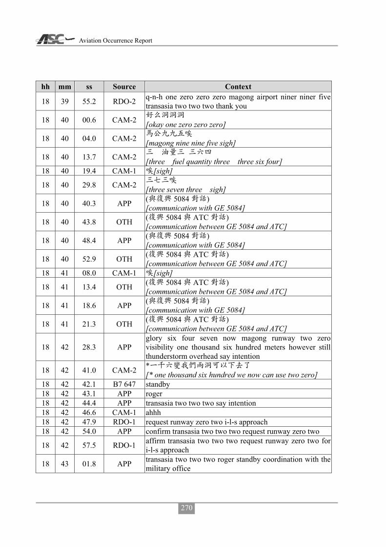
Aviation Occurrence Report
270
hh mm ss Source Context
18 39 55.2 RDO-2 q-n-h one zero zero zero magong airport niner niner five transasia two two two thank you
18 40 00.6 CAM-2 [okay one zero zero zero]
18 40 04.0 CAM-2 [magong nine nine five sigh]
18 40 13.7 CAM-2 [three fuel quantity three three six four]
18 40 19.4 CAM-1 [sigh]
18 40 29.8 CAM-2 [three seven three sigh]
18 40 40.3 APP ( 5084 ) [communication with GE 5084]
18 40 43.8 OTH ( 5084 ATC ) [communication between GE 5084 and ATC]
18 40 48.4 APP ( 5084 ) [communication with GE 5084]
18 40 52.9 OTH ( 5084 ATC ) [communication between GE 5084 and ATC]
18 41 08.0 CAM-1 [sigh]
18 41 13.4 OTH ( 5084 ATC ) [communication between GE 5084 and ATC]
18 41 18.6 APP ( 5084 ) [communication with GE 5084]
18 41 21.3 OTH ( 5084 ATC ) [communication between GE 5084 and ATC]
18 42 28.3 APP glory six four seven now magong runway two zero visibility one thousand six hundred meters however still thunderstorm overhead say intention
18 42 41.0 CAM-2 * [* one thousand six hundred we now can use two zero]
18 42 42.1 B7 647 standby 18 42 43.1 APP roger 18 42 44.4 APP transasia two two two say intention 18 42 46.6 CAM-1 ahhh 18 42 47.9 RDO-1 request runway zero two i-l-s approach 18 42 54.0 APP confirm transasia two two two request runway zero two
18 42 57.5 RDO-1 affirm transasia two two two request runway zero two for i-l-s approach
18 43 01.8 APP transasia two two two roger standby coordination with the military office
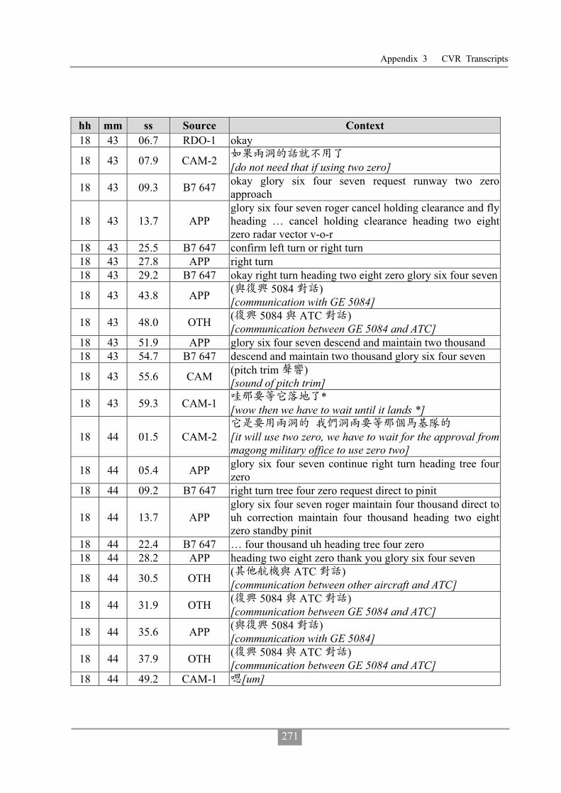
Appendix 3 CVR Transcripts
271
hh mm ss Source Context 18 43 06.7 RDO-1 okay
18 43 07.9 CAM-2 [do not need that if using two zero]
18 43 09.3 B7 647 okay glory six four seven request runway two zero approach
18 43 13.7 APP glory six four seven roger cancel holding clearance and fly heading … cancel holding clearance heading two eight zero radar vector v-o-r
18 43 25.5 B7 647 confirm left turn or right turn 18 43 27.8 APP right turn 18 43 29.2 B7 647 okay right turn heading two eight zero glory six four seven
18 43 43.8 APP ( 5084 ) [communication with GE 5084]
18 43 48.0 OTH ( 5084 ATC ) [communication between GE 5084 and ATC]
18 43 51.9 APP glory six four seven descend and maintain two thousand 18 43 54.7 B7 647 descend and maintain two thousand glory six four seven
18 43 55.6 CAM (pitch trim ) [sound of pitch trim]
18 43 59.3 CAM-1 * [wow then we have to wait until it lands *]
18 44 01.5 CAM-2
[it will use two zero, we have to wait for the approval from magong military office to use zero two]
18 44 05.4 APP glory six four seven continue right turn heading tree four zero
18 44 09.2 B7 647 right turn tree four zero request direct to pinit
18 44 13.7 APP glory six four seven roger maintain four thousand direct to uh correction maintain four thousand heading two eight zero standby pinit
18 44 22.4 B7 647 … four thousand uh heading tree four zero 18 44 28.2 APP heading two eight zero thank you glory six four seven
18 44 30.5 OTH ( ATC ) [communication between other aircraft and ATC]
18 44 31.9 OTH ( 5084 ATC ) [communication between GE 5084 and ATC]
18 44 35.6 APP ( 5084 ) [communication with GE 5084]
18 44 37.9 OTH ( 5084 ATC ) [communication between GE 5084 and ATC]
18 44 49.2 CAM-1 [um]

Aviation Occurrence Report
272
hh mm ss Source Context 18 44 52.5 RDO-1 transasia two two two confirm ah number two 18 44 56.5 APP transasia two two two affirm ah number two say intention18 45 00.5 RDO-1 roger request runway two zero for v-o-r approach
18 45 04.2 APP transasia two two two roger ah fly heading ah zero two ah tree six zero radar vector v-o-r approach
18 45 10.7 RDO-2 right turn heading tree six zero radar vector v-o-r runway two zero transasia two two two
18 45 14.7 CAM-2 [turn right heading three six zero]
18 45 17.9 CAM-1 [sigh]
18 45 19.0 CAM-2 v-o-r [sigh v-o-r zero two zero]
18 45 21.6 CAM-1 roger 18 45 22.9 CAM-2 [two zero one]
18 45 26.7 APP glory six four seven now information november and direct to pinit
18 45 31.1 B7 647 direct to pinit glory six four seven
18 45 33.7 APP glory six four seven one six mile from uh pinit cleared r-nav runway two zero approach
18 45 35.1 CAM-1 uh … [uh do not descend yet]
18 45 36.9 CAM-2 …[I know…]
18 45 39.0 B7 647 clear for r-nav runway two zero approach glory six four seven
18 45 44.6 APP transasia two two two continue maintain six thousand heading tree six zero radar vector v-o-r
18 45 50.8 RDO-2 clear maintain present maintain six thousand heading three six zero transasia two two two
18 45 52.5 CAM-1 [um sigh] 18 45 55.6 CAM-1 ( )[sound of coughing]
18 45 57.0 APP ( 3055 ) [communication with FE 3055]
18 45 02.5 CAM-2 …
18 46 03.9 APP ( 3055 ) [communication with FE 3055]
18 46 05.8 CAM-1
[so tell them to descend to two thousand but they have not done so]
18 46 08.4 CAM-2 [yes] 18 46 09.3 CAM-1 [ohoh] 18 46 10.8 CAM-2 [cannot stand him]

Appendix 3 CVR Transcripts
273
hh mm ss Source Context
18 46 11.9 OTH ( 5084 ATC ) [communication between GE 5084 and ATC]
18 46 16.5 APP ( 5084 ) [communication with GE 5084]
18 46 20.8 OTH ( 5084 ATC ) [communication between GE 5084 and ATC]
18 46 30.9 CAM-1 [request heading zero three zero]
18 46 32.1 APP ( 5133 ) [communication with GE 5133]
18 46 41.8 CAM-1 [forget about it]
18 46 42.0 OTH ( 5133 ATC ) [communication between GE 5133 and ATC]
18 46 43.6 CAM-2 [no] 18 46 44.5 CAM-1 [no]
18 46 50.5 CAM-2 * [they… that Uni Air flight ahead of us is so * slow]
18 46 56.5 CAM-1 …
18 46 57.6 CAM-2 *
[cleared them for descend, and vectored them, I don’t understand why they are so slow]
18 47 03.2 CAM-1 … [now …. cleared it to descend to two thousand]
18 47 04.5 B7 647 kaohsiung approach glory six four seven due to weather request direct to mause
18 47 08.7 CAM-2 * r-nav [* r-nav]
18 47 09.1 APP glory six four seven can you accept after one zero mile for mause
18 47 17.6 B7 647 affirm glory six four seven
18 47 19.0 CAM-2 [approve them after five miles]
18 47 19.6 APP … glory six four seven roger continue present heading descend and maintain tree thousand radar vector to mause
18 47 27.2 B7 647 present heading three thousand ah standby at mause glory six four seven
18 47 33.6 CAM-2 mause [they need to fly ten miles to mause]
18 47 51.4 CAM-2 [vectored them further away]
18 47 52.2 CAM-1 [sigh] 18 48 04.6 CAM-2 okay …

Aviation Occurrence Report
274
hh mm ss Source Context
18 48 05.3 B7 647 kaohsiung approach glory six four seven confirm local q-n-h
18 48 08.3 CAM-2 [he turned it off]
18 48 09.4 APP glory six four seven kaohsiung q-n-h one zero zero zero magong q-n-h niner niner six
18 48 17.7 B7 647 niner niner six one zero zero zero glory six four seven
18 48 18.3 CAM ( ) [sound of cabin call]
18 48 21.1 CAM-1 [okay later heading zero four zero]
18 48 21.8 APP transasia two two two turn right heading zero two zero descend and maintain five thousand
18 48 27.3 CAM-1 zero four zero (later zero four zero um)
18 48 29.1 RDO-2 right turn heading zero two zero and request heading zero four zero descend and maintain five thousand transasia two two two
18 48 36.4 APP transasia two two two heading zero four zero approved maintain five thousand
18 48 40.4 RDO-2 heading zero four zero five thousand transasia two two two
18 48 40.5 CAM ( ) [sound of altitude alert]
18 48 43.1 APP ( 5133 ) [communication with GE 5133]
18 48 43.2 CAM-2 [okay let us go in]
18 48 50.3 APP ( 5133 ) [communication with GE 5133]
18 49 06.9 OTH ( 5084 ATC ) [communication between GE 5084 and ATC]
18 49 11.3 APP ( 5084 ) [communication with GE 5084]
18 49 17.8 OTH ( 5084 ATC ) [communication between GE 5084 and ATC]
18 49 21.6 B7 647 kaohsiung approach glory six four seven due to weather request left turn direct to mause
18 49 26.3 APP glory six four zero direct to mause approved and position six miles from mause cleared r-nav runway two zero approach
18 49 33.5 B7 647 cleared for r-nav runway two zero approach glory six four

Appendix 3 CVR Transcripts
275
hh mm ss Source Context seven
18 50 11.2 CAM-1 heading zero two zero … zero tree zero [okay heading zero two zero … do zero tree zero]
18 50 16.9 CAM-2 [zero three zero]
18 50 17.5 CAM-1 [okay zero three zero]
18 50 19.2 RDO-2 transasia two two two request turn left heading zero tree zero
18 50 22.8 APP transasia two two two heading zero tree zero approved and descend and maintain four thousand
18 50 27.1 RDO-2 heading zero tree zero descend and maintain four thousand transasia two two two
18 50 30.9 CAM-2 [okay four thousand zero three zero]
18 50 31.9 APP ( 3055 ) [communication with FE 3055]
18 50 37.5 CAM-1 [um sigh]
18 50 38.4 APP ( 5133 ) [communication with GE 5133]
18 50 58.9 CAM ( ) [sound of altitude alert]
18 50 59.2 CAM-2 oh one thousand to go 18 51 01.0 CAM-1 [um sigh]
18 51 08.3 OTH ( 1831 ATC ) [communication between AE 1831 and ATC]
18 51 13.9 APP ( 1831 ) [communication with AE 1831]
18 51 17.6 OTH ( 1831 ATC ) [communication between AE 1831 and ATC]
18 51 26.3 OTH ( 1831 ATC ) [communication between AE 1831 and ATC]
18 51 33.0 OTH ( 1831 ATC ) [communication between AE 1831 and ATC]
18 51 37.6 APP ( 1831 ) [communication with AE 1831]
18 51 41.0 OTH ( 1831 ATC ) [communication between AE 1831 and ATC]
18 51 44.4 APP ( 1831 ) [communication with AE 1831]
18 51 50.4 OTH ( 1831 ATC ) [communication between AE 1831 and ATC]

Aviation Occurrence Report
276
hh mm ss Source Context 18 51 53.1 APP another traffic say again 18 51 58.6 APP are there any traffic calling kaohsiung 18 52 03.0 B7 647 kaohsiung approach glory six four seven established final
18 52 06.2 APP glory six four seven contact magong tower one one eight decimal tree see you
18 52 09.1 B7 647 contact tower see you glory six four seven 18 52 11.7 APP transasia two two two turn left heading two niner zero 18 52 14.3 RDO-2 turn left heading two niner zero transasia two two two
18 52 17.3 CAM-2 [two left heading two two nine zero]
18 52 18.9 CAM-1 [okay um] 18 52 22.6 CAM-1 up five mile up five mile 18 52 25.2 CAM-2 five mile
18 52 25.8 CAM-1 up up five mile [oh up up five mile after five miles]
18 52 27.3 CAM-2 okay
18 52 29.1 RDO-2 transasia two two two request another five mile and turn left heading two niner zero
18 52 34.3 APP transasia two two two approved as requested descend and maintain tree thousand
18 52 37.7 RDO-2 descend maintain tree thousand approved five mile two niner zero transasia two two two
18 52 42.5 CAM-2
[okay now maintain three thousand after five miles two nine zero]
18 52 44.2 CAM-1 [um]
18 52 45.7 APP ( 5133 ) [communication with GE 5133]
18 52 50.2 CAM ( ) [unidentified sound]
18 52 54.7 APP ( 5133 ) [communication with GE 5133]
18 52 58.3 CAM ( ) [sound of altitude alert]
18 53 00.6 CAM-2 one thousand to go
18 53 19.1 CAM-2 basic mode [sir this is basic mode]
18 53 21.1 CAM-1 [oh sigh]
18 53 24.0 CAM-2 okay [okay thank you]
18 53 25.9 APP ( 3055 )

Appendix 3 CVR Transcripts
277
hh mm ss Source Context [communication with FE 3055]
18 54 02.4 CAM ( ) [sound of seat belt reminder]
18 54 04.5 CAM-1 heading two nine zero [heading two nine zero oh]
18 54 06.2 CAM-2 [yes] two nine zero
18 54 06.3 APP ( ) [communication with other aircraft]
18 54 08.8 PA-3 ( 1854:52.3) [cabin announcement until 1854:52.3]
18 54 44.1 CAM-1 [I want two four zero]
18 54 46.5 CAM-2 …
18 54 47.4 CAM-1 heading [heading two four zero]
18 54 47.4 RDO-2 transasia two two two request left turn heading two four zero
18 54 51.1 APP transasia two two two heading two four zero approved 18 54 53.2 RDO-2 heading two four zero transasia two two two
18 54 55.0 CAM-2 [two four zero approved]
18 54 56.5 CAM-1 [sigh] 18 54 56.6 CAM-2 altitude check [three thousand] 18 55 04.4 CAM-1 [sigh]
18 55 05.4 CAM-2
[if this patch we just saw is blown away then magong is clear]
18 55 09.7 APP
transasia two two two position two five miles northeast of magong airdrome turn left heading two three zero descend and maintain two thousand till establish final approach course cleared v-o-r runway two zero approach
18 55 19.9 RDO-2 turn left heading two three zero descend maintain two thousand until establish cleared v-o-r runway two zero approach transasia two two two
18 55 27.7 CAM ( ) [sound of altitude alert]
18 55 28.0 APP ( 3055 ) [communication with FE 3055]
18 55 30.4 CAM-2 one thousand to go
18 55 31.9 CAM-2 [two three zero cleared for approach]

Aviation Occurrence Report
278
hh mm ss Source Context 18 55 34.9 CAM-2 v-o-r [v-o-r two zero] 18 55 36.3 CAM-1 [oh]
18 55 39.7 CAM-2
[five miles two thousand after passing five miles we can descend three three zero]
18 55 42.5 APP ( 3055 ) [communication with FE 3055]
18 55 58.6 CAM-1 [sigh] 18 56 08.6 RDO-2 transasia two two two check q-n-h for approach 18 56 12.8 APP transasia two two two say again
18 56 14.7 RDO-2 check q-n-h [oh sir we would like to check q-n-h]
18 56 17.2 APP
roger
[um transasia two two two sir roger kaohsiung q-n-h one zero zero zero magong q-n-h niner niner six]
18 56 23.2 RDO-2
[okay one zero zero zero niner niner six thank you transasia two two two]
18 56 27.3 APP [you are welcome sir report when established]
18 56 29.8 RDO-2 [report when established]
18 56 31.1 CAM-2 [okay niner niner six report when established]
18 56 33.1 CAM-1 [um]
18 56 34.5 CAM-2 [yay sir negative]
18 56 39.9 APP ( 3055 ) [communication with FE 3055]
18 56 45.4 APP ( 5133 ) [communication with GE 5133]
18 56 51.6 OTH ( 8297 ATC ) [communication with B7 8297]
18 56 59.6 CAM-1 [sigh um]
18 57 00.7 APP ( 8297 ) [communication with B7 8297]
18 57 02.9 CAM ( ) [sound of altitude alert]
18 57 04.0 OTH ( 8297 ATC ) [communication between B7 8297 and ATC]

Appendix 3 CVR Transcripts
279
hh mm ss Source Context 18 57 08.2 CAM-2 altitude star 18 57 09.1 CAM-1 check 18 57 25.2 CAM-2 alt captured [two thousand] 18 57 26.8 CAM-1 check 18 56 31.3 CAM-1 [sigh um] 18 57 37.6 CAM-1 ( )[sound of coughing]
18 57 54.0 APP ( 5133 ) [communication with GE 5133]
18 58 34.6 CAM-1 … nav [… nav]
18 58 34.5 CAM-2 [two zero one]
18 58 40.5 OTH ( 8297 ATC ) [communication between B7 8297 and ATC]
18 58 44.2 APP ( 8297 ) [communication with B7 8297]
18 58 47.2 OTH ( 8297 ATC ) [communication between B7 8297 and ATC]
18 58 49.6 APP ( 3055 ) [communication with FE 3055]
18 58 57.4 CAM-2 course [our course is two zero one]
18 59 58.6 CAM-1 course [um course two zero one]
18 59 01.5 CAM-2 yes sir
18 59 03.3 CAM ( ) [sound of seatbelt reminder]
18 59 09.9 CAM-2 preset
[sir do we preset next altitude three four zero or four hundred]
18 59 13.5 CAM-1 [uh]
18 59 14.2 CAM-2 preset [preset next altitude four hundred]
18 59 14.3 CAM-1 [oh]
18 59 15.7 CAM-2 [five miles]
18 59 15.8 CAM-1 … [… altitude um]
18 59 17.3 CAM-2 [descend at five miles four hundred]
18 59 18.3 CAM-1
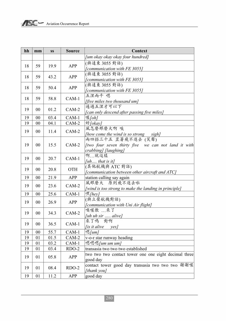
Aviation Occurrence Report
280
hh mm ss Source Context [um okay okay okay four hundred]
18 59 19.9 APP ( 3055 ) [communication with FE 3055]
18 59 43.2 APP ( 3055 ) [communication with FE 3055]
18 59 50.4 APP ( 3055 ) [communication with FE 3055]
18 59 58.8 CAM-1 [five miles two thousand um]
19 00 01.2 CAM-2 [can only descend after passing five miles]
19 00 03.4 CAM-1 [oh] 19 00 04.1 CAM-2 [okay]
19 00 11.4 CAM-2 [how come the wind is so strong sigh]
19 00 15.5 CAM-2 ( )
[two four seven thirty five we can not land it with crabbing] [laughing]
19 00 20.7 CAM-1 … [uh…. that is it]
19 00 20.8 OTH ( ATC ) [communication between other aircraft and ATC]
19 00 21.9 APP station calling say again
19 00 23.6 CAM-2 [wind is too strong to make the landing in principle]
19 00 25.6 CAM-1 [hey]
19 00 26.9 APP ( ) [communication with Uni Air flight]
19 00 34.3 CAM-2 … [uh uh sir ….. alive]
19 00 36.5 CAM-1 [is it alive yes]
19 00 55.7 CAM-1 [um] 19 01 01.5 CAM-2 v-o-r star runway heading 19 01 03.2 CAM-1 [um um um] 19 01 03.4 RDO-2 transasia two two two established
19 01 05.8 APP two two two contact tower one one eight decimal three good day
19 01 08.4 RDO-2 contact tower good day transasia two two two [thank you]
19 01 11.2 APP good day

Appendix 3 CVR Transcripts
281
hh mm ss Source Context
19 01 12.1 CAM ( ) [sound of radio frequency switching]
19 01 13.2 RDO-2 magong tower good evening transasia two two two eight miles for v-o-r runway two zero
19 01 19.9 TWR_M transasia two two two good evening magong tower runway two zero q-n-h niner niner seven continue approach
19 01 26.7 RDO-2 runway two zero q-n-h niner niner seven continue transasia two two two
19 01 31.3 CAM-2 [nine nine seven two zero continue approach]
19 01 32.8 CAM-1 Roger
19 01 38.8 CAM-1 [uh is radar off yet]
19 01 39.9 CAM-2 [okay sir radar off]
19 01 53.8 TWR_M ( 082 ) [communication with FE 082]
19 01 57.7 OTH ( 082 ATC ) [communication between FE 082 and ATC]
19 02 00.0 TWR_M ( 082 ) [communication with FE 082]
19 02 02.5 OTH ( 082 ATC ) [communication between FE 082 and ATC]
19 02 05.7 TWR_M ( 082 ) [communication with FE 082]
19 02 12.3 OTH ( 082 ATC ) [communication between FE 082 and ATC]
19 02 14.9 CAM-2 [uh one four knots one one eight]
19 02 18.0 CAM-1 [one one eight]
19 02 18.9 CAM-2 [I will add ten knots due to two zero]
19 02 21.1 CAM-1 [oh] 19 02 26.1 CAM-1 [um]
19 02 36.2 CAM-2 [um i]
19 02 37.8 PA-1 [cabin crew prepare for landing]
19 02 39.0 CAM-1 [um]
19 02 40.7 CAM-2 [oh I will set landing configuration at five miles]
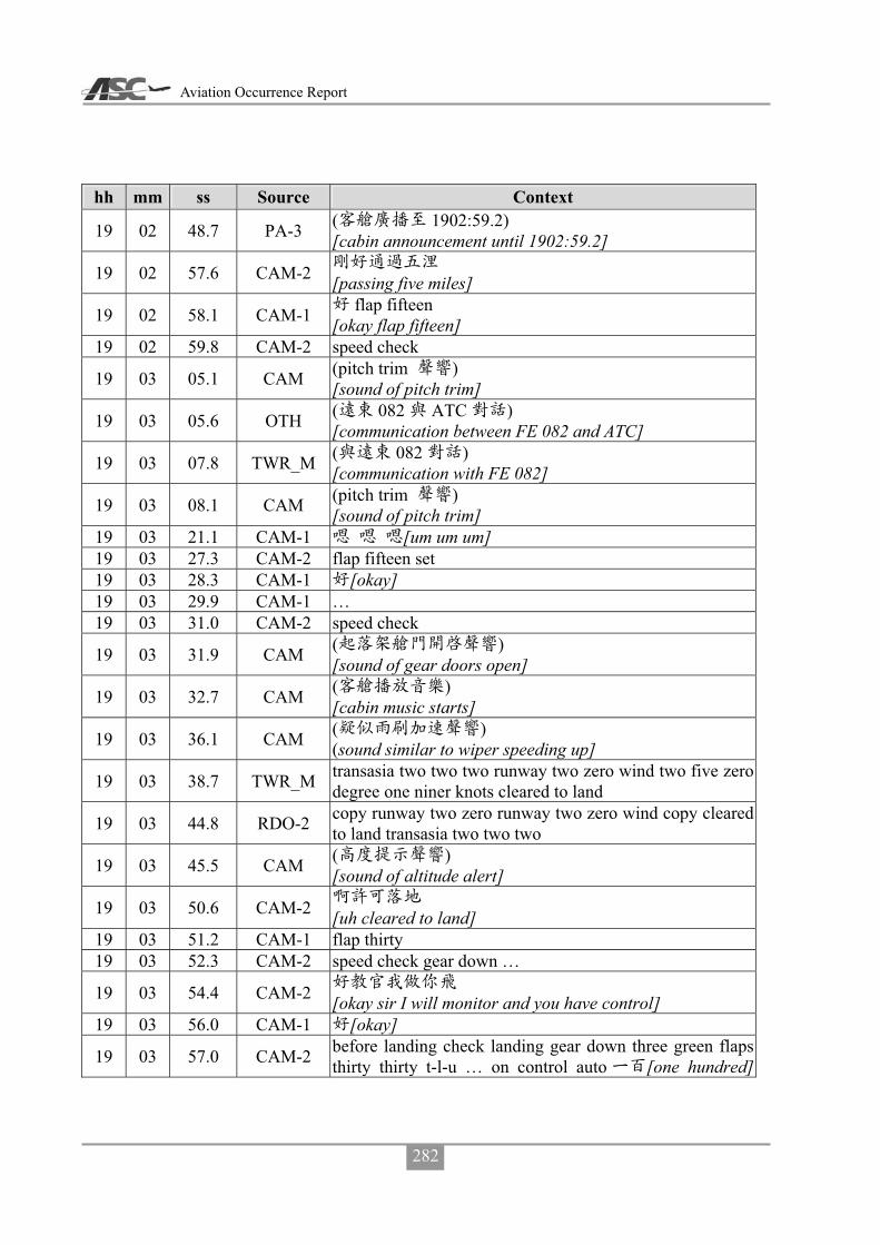
Aviation Occurrence Report
282
hh mm ss Source Context
19 02 48.7 PA-3 ( 1902:59.2) [cabin announcement until 1902:59.2]
19 02 57.6 CAM-2 [passing five miles]
19 02 58.1 CAM-1 flap fifteen [okay flap fifteen]
19 02 59.8 CAM-2 speed check
19 03 05.1 CAM (pitch trim ) [sound of pitch trim]
19 03 05.6 OTH ( 082 ATC ) [communication between FE 082 and ATC]
19 03 07.8 TWR_M ( 082 ) [communication with FE 082]
19 03 08.1 CAM (pitch trim ) [sound of pitch trim]
19 03 21.1 CAM-1 [um um um] 19 03 27.3 CAM-2 flap fifteen set 19 03 28.3 CAM-1 [okay] 19 03 29.9 CAM-1 … 19 03 31.0 CAM-2 speed check
19 03 31.9 CAM ( ) [sound of gear doors open]
19 03 32.7 CAM ( ) [cabin music starts]
19 03 36.1 CAM ( ) (sound similar to wiper speeding up]
19 03 38.7 TWR_M transasia two two two runway two zero wind two five zero degree one niner knots cleared to land
19 03 44.8 RDO-2 copy runway two zero runway two zero wind copy cleared to land transasia two two two
19 03 45.5 CAM ( ) [sound of altitude alert]
19 03 50.6 CAM-2 [uh cleared to land]
19 03 51.2 CAM-1 flap thirty 19 03 52.3 CAM-2 speed check gear down …
19 03 54.4 CAM-2 [okay sir I will monitor and you have control]
19 03 56.0 CAM-1 [okay]
19 03 57.0 CAM-2 before landing check landing gear down three green flaps thirty thirty t-l-u … on control auto [one hundred]

Appendix 3 CVR Transcripts
283
hh mm ss Source Context power management takeoff lights on icing a-o-a light off runway [two zero] verify landing clearance received before landing complete
19 03 58.8 CAM (pitch trim ) [sound of pitch trim]
19 03 04.7 TWR_M ( 082 ) [communication with FE082]
19 04 07.8 CAM-1 [wind two niner zero] 19 04 09.3 CAM-2 [two five zero] 19 04 10.2 CAM-1 [two five zero] 19 04 10.8 CAM-2 [yes] 19 04 12.5 CAM-2 one thousand stable continue 19 04 14.0 CAM-1 check
19 04 26.4 CAM-1 ( ) [sneezing]
19 04 35.3 CAM-1 … 19 04 41.0 CAM-1 [uh um] 19 05 09.4 CAM five hundred 19 05 11.2 CAM-2 [um] 19 05 12.4 CAM-1 [um three hundred]
19 05 12.6 CAM-2 alt star [alt star three hundred]
19 05 15.9 CAM-1 [sigh]
19 05 25.7 CAM-1 [sigh sigh sigh sigh two hundred]
19 05 35.9 CAM-2 alt star 19 05 37.5 CAM-1 [um]
19 05 37.9 CAM-2 [we will get to zero point two miles]
19 05 38.1 CAM-1 … 19 05 39.7 CAM-1 [okay] 19 05 40.5 CAM-2 [one point five]
19 05 42.6 CAM (pitch trim ) [sound of pitch trim]
19 05 43.5 CAM-1 [um]
19 05 44.1 CAM ( ) [sound of disengaging autopilot]
19 05 45.8 CAM-2 disengaged 19 05 46.8 CAM-1 [okay]
19 05 48.5 CAM-1 [maintain two hundred]

Aviation Occurrence Report
284
hh mm ss Source Context
19 05 57.8 CAM-1 [have you seen the runway]
19 06 00.7 CAM-2 [runway] 19 06 01.8 CAM-1 [um]
19 06 04.9 CAM-1 [sigh wow ha ha ha]
19 06 06.8 CAM-2 [no] 19 06 07.6 CAM-1 [no]
19 06 09.8 CAM-2 [no sir]
19 06 10.4 CAM-1 okay [okay okay okay]
19 06 11.1 CAM-2 go around 19 06 11.4 CAM-1 go around
19 06 13.3 CAM ( 1.5 ) (unidentified sound lasting 1.5 seconds]
19 06 15.8 RDO-2 go around go around 19 06 17.2 TWR_M roger
19 06 18.0 CAM ( ) [unidentified sound]
19 06 18.9 CVR [CVR recording ends]

Appendix 4 ATR Full Flight Simulation – Descent Rates
285
Appendix 4 ATR Full Flight Simulation – Descent Rates
ATR Full Flight Simulation Result (2014/11/05 CASE 1)
ATR Full Flight Simulation Result (2014/11/05 CASE 2)

Aviation Occurrence Report
286
ATR Full Flight Simulation Result (2014/11/06 CASE 1)
ATR Full Flight Simulation Result (2014/11/06 CASE 2)

Appendix 5 Comments on ASC’s Final Draft Report
287
Appendix 5 Comments on ASC’s Final Draft Report
Appendix 5-1 Comments on ASC’s Final Draft Report from BEA (Bureau d'Enquêtes et d'Analyses, France)
Appendix 5-2 Comments on ASC’s Final Draft Report from TSB (Transportation Safety Board, Canada)
Appendix 5-3 Comments on ASC’s Final Draft Report from NTSB (National Transportation Safety Board, USA)
Appendix 5-4 Comments on ASC’s Final Draft Report from CAA (Civil Aeronautics Administration, Taiwan)
Appendix 5-5 Comments on ASC’s Final Draft Report from TNA (TransAsia Airways)

Aviation Occurrence Report
288
Appendix 5-1 Comments on ASC’s Final Draft Report from BEA

Appendix 5 Comments on ASC’s Final Draft Report
289
Appendix 5-2 Comments on ASC’s Final Draft Report from TSB

Aviation Occurrence Report
290
Appendix 5-3 Comments on ASC’s Final Draft Report from
NTSB

Appendix 5 Comments on ASC’s Final Draft Report
291
Appendix 5-4 Comments on ASC’s Final Draft Report from CAA
Taiwan
GE222 Accident Investigation Submission
ASC Accident File:ASC-AOR-16-01-002
Operator: TransAsia Airways
Model: ATR-72
Aircraft Number: B-22810
Location of Accident: Magong Airport (RCQC)
Date of Accident: July 23, 2014
Civil Aeronautical Administration, MOTC Jan. 27, 2016
Aviation Occurrence Report
292
Table of Content
Forward……………………………………… P.293
Issue 1 – Flight Operation and SMS………… P.295
Issue 2 - RVR Information…………………... P309
Issue 3 - Location of Missed Approach Point...P.313
Issue 4- Approach Lighting System ………….P.317
Appendix 5 Comments on ASC’s Final Draft Report
293
Foreword
In accordance with International Civil Aviation Organization (ICAO) Annex 13,
Aircraft Accident and Incident Investigation, the Civil Aeronautics Administration
(CAA) is providing this submission that details its review of the ASC’s draft factual
report related to the accident of TransAsia Flight GE222
The sole objective of the investigation of an accident or incident shall be the
prevention of accidents and incidents, based on the credible information provided in the
investigation report by the authority of investigation. ICAO Doc 9756 Part 4 “Manual of
Aircraft Accident and Incident Investigation” Appendix 1 to Chapter 1- 2.2 The
analysis part should contain an evaluation of the evidence presented in the factual
information part and should discuss the circumstances and events that existed or may
have existed. The reasoning must be logical and may lead to the formulation of
hypotheses which are then discussed and tested against the evidence. Any hypothesis
which is not supported by the evidence should be eliminated; it is then important to
clearly state the reasons why a particular hypothesis was rejected. When a hypothesis is
not based on fact but is an expression of opinion, this should be clearly indicated. As
well, the justification for sustaining the validity of a hypothesis should be stated and
reference should be made to the supporting evidence. Contradictory evidence must be
dealt with openly and effectively. Cause related conditions and events should be
identified and discussed. The discussion in the analysis should support the findings and
the immediate and systemic causes and/or contributing factors of the accident.
Therefore, the investigation report shall provide clear information and indisputable
evidence.
The CAA appreciates the opportunity to provide comments on the ASC’s draft
report. The CAA staff of subject-matter experts in the areas of Flight Standards, Air
Traffic Control (ATC) and Instrument Approach (IAP) Design and Lighting participated
in the investigative activities as a Party to the ASC investigation. After reviewing the
investigation report, the CAA has identified issues in the Factual, Analysis, Conclusions
Aviation Occurrence Report
294
and Safety Recommendations sections that require correction, clarification, or the
inclusion of additional information. Furthermore, the CAA is very concerned that some
pertinent factual information was not fully developed; and that the report contains
statements and information, as well as Findings and Conclusions, that are factually
incorrect or without merit and relevance to this accident. Additionally, the draft report
contains several Safety Recommendation that are not supported by factual evidence and,
if implemented, would result in a degradation in aviation safety.
It is apparent from the several discussions presented in the Factual Report that the
ASC investigator(s) do not have the expertise in the areas of Safety Management
System, flight safety oversight and surveillance, Air Traffic Control, Instrument
Approach Procedure (IAP) design and lighting. For instance, the ASC was critical of the
CAA regarding its oversight of the SMS program, especially at TransAsia Airways.
Without proper expertise in the relevant area during investigation, the information
provided in the report may not reflect the truth of matters. The objective of the investigation of an accident or incident shall be the prevention
of accidents and incidents by investigating all the facts, conditions and circumstances available to identify the causes and contributing factors. The investigation must be objective and without bias, and the information that is developed must be thoroughly researched by subject matter experts to determine if any element of the respective issue is causal or contributory to the accident. The CAA is very concerned that despite it’s best effort to provide expertise to the ASC, the information presented in various sections of the ASC report may have been mis-stated, misinterpreted or factually incorrect, and not based on regulatory requirements or industry standards and practices. The CAA strongly disagrees with the ASC’s analysis and conclusions regarding the CAA’s oversight of air carriers, instrument approach procedure design, flight operations training and the analysis of SMS. Therefore, the CAA respectfully submits the following information to provide clarification, and to correct the factual record with a comprehensive and corrected description of the misinformation and the issues that are of concern for the CAA.
Appendix 5 Comments on ASC’s Final Draft Report
295
1. Issue 1 -Flight Operation and SMS
1.1 Introductions
This unfortunate accident that happened on July 23, 2014 was a typical CFIT
(Controlled Flight Into Terrain) in an adverse weather condition. Many previous similar
accidents that have occurred worldwide were because the flight crew failed to follow the
respective air carrier policies or procedures, and/or the Federal regulations. In these
accidents, the regulatory authority was not held responsible, nor found to be the
cause/contributing factors for the accident flight crews’ improper actions.
It is apparent, with regard to the analysis of SMS in the draft report, the ASC does
not fully understand that the CAA advisory circular AC 120-32C and the revised
issuance of AC 120-32D is not enforceable by regulation, but rather, as the name implies,
… sufficient understanding on SMS concepts and the development of management
policies and processes to implement and maintain an SMS that meets ICAO and CAA
requirements. In addition, the stated purpose of the AC is to provide … an acceptable
means, but not the only means, to show compliance with Article 9 of “Aircraft Flight
Operation Regulations” or Article 27 of “Regulations for Repair Station Certification
and Management” for establishing and implementing a safety management system.
In addition, it is apparent the ASC has confused the regulatory requirement of air
carriers implementing an SMS program with the information presented in the Advisory
Circular, which indicates that air carriers should set target of implementation of an SMS
program by 2012. The ASC inadequately described the efforts of the CAA to assist the
air carriers. They also failed to provide important information, such as the fact that the
CAA performed two “SMS Assessment Projects” to determine the status of the
implementation of SMS programs in the various air carriers regulated by the CAA. The
assessments lead to the CAA identifying issues that the air carriers were having
regarding the implementation of the SMS program, and as a result, the CAA conducted
an SMS Conference.
Aviation Occurrence Report
296
1.2 Factual Information
1.2.1 The CAA has conducted an SMS assessment project for 6 civil air transportation
operators and 2 repair stations by the end of 2013. The objectives of the project
were:
��To review/ensure SMS implementation of the certificate holders (operators and
repair stations) in consistence with the ICAO requirement, CAA regulations and
policy;
��To adjust the CAA promoting strategies and assist the certificate holders to
implement the SMS effectively in accordance with the data collected from the
assessment project; and
��All deficiencies identified during the assessment would not be categorized as
finding or concern in the CAA FSMIS, but the CAA will notify the concerned
certificate holder to improve its SMS implementation plan and to comply with the
regulations and the CAA policy within the SMS implementation timeline.
1.2.2 After the assessment project, the CAA held an SMS conference for senior
managers of operators and repair stations on December 4, 2013. Several
promoting strategies delivered by the CAA representatives in the conference are
summarized as follows:
��From the SMS assessment project in 2013, the CAA identified that some operators
did not develop a SMS implementation plan, and therefore suggested all operators
should establish a SMS implementation plan accordingly;
��The AC 120-32D will be published before 2014 and will be based on the 3rd edition
of the ICAO Doc 9859;
��The timeline of SMS implementation will be extended to the end of 2016;
��SMS training course will be provided for the operators and repair stations before
2014.
1.2.3 Based on the CAA’s SMS Assessment Project, the CAA understand that it is

Appendix 5 Comments on ASC’s Final Draft Report
297
necessary to further extend SMS implementation program to the end of 2016,
which will comply with the 3rd edition of ICAO Doc9859 Safety Management
Manual (SMM), published on May 8, 2013 with numerous updates. Due to the
changes in the SMM and the fact that ICAO was intending to publish a new
Annex (identified as Annex 19), the CAA waited until the Annex was published
to update AC 120-32C, so that the new information could be incorporated into a
revised AC, identified as 120-32D.
1.3 Analysis
1.3.1 CAA’s clarification
The ASC has asserted in the report and concluded based on its analysis that the
CAA was responsible for the accident flight crew’s intentional non-compliance with
both the air carrier policies and procedures, and the CAA regulations, because the ASC
believes the CAA’s oversight of training and line operations was inadequate. It is also
apparent that the ASC made these conclusions based on the ASC findings of deficiencies
and procedural non-compliance by flight crews during their “observations” of training
sessions as part of their investigative activities.
This conclusion may not accurately represent the TransAsia Airways training
program, or the oversight by the CAA since the ASC’s observations were very limited
and only a “snap-shot” of a continual program.
The discussion in this report of the CAA’s SMS by the ASC indicates that the ASC
may not fully understand the CAA’s efforts in developing the SMS and in the
incorporation of SMS into an air carrier. Unfortunately, the way it is described in the
report suggests that the SMS program would have been functional immediately; and that
the accident would not have occurred if the CAA inspectors had received training or had
better guidance information; and had TransAsia Airways submitted an implementation
plan.
Therefore, the CAA believes it is necessary to provide appropriate information in

Aviation Occurrence Report
298
order to clarify some points in this report, especially those areas involving the CAA
oversight and SMS program.
1.3.2 The CAA recommended changes to the ASC Report
1.3.2.1 Chapter 3.2 Findings Related to Risks
� Item 20. Refer to investigation report chapter 3.2.20
The Civil Aeronautics Administration’s oversight of TransAsia Airways did
not identify and/or correct some crucial operational safety deficiencies,
including crew non-compliance with procedures, non-standard training
practices, and unsatisfactory safety management practices.
Reason to change:
1. The CAA's oversight activities follow international standards and recommended
practices to oversee air carriers. Practically, it is not possible to observe all the
operational flights, and it is difficult to identify particular flight crew who may not
follow SOPs during which a CAA inspector is not present in the cockpit.
2. There is difference between the case of the accident flight crews' intention to
violate discipline and non-compliance of SOP of Standard Call Out. ASC is too
subjective to describe CAA’s oversight as not able to identify correct.
3. The paragraph 2.7.3 in ASC report” ……The CAA had not ensure that the airline
responded effectively to the safety deficiencies and corrective actions issued by the
CAA…….’’ shows ASC agree the CAA’s inspection still identified some safety
deficiencies.
Recommend to amend as:
The Civil Aeronautics Administration’s oversight of TransAsia Airways did not promptly identify the deficiencies of crew non-compliance with procedures and non-standard training practices.
(Relocate to 3.3)
Appendix 5 Comments on ASC’s Final Draft Report
299
� Item 21. Refer to investigation report chapter 3.2.21
To develop and maintain a safety management system (SMS) implementation
plan at TransAsia Airways was not enforced by the Civil Aeronautics
Administration. That deprived the regulator of an opportunity to assess and
ensure that the airline had the capability to implement a resilient SMS.
Reason to change:
1. ICAO Annex 19 was published in 2013 and defines the SMS implementation program
into 4 different phases, which require 5 years to accomplish. The CAA regulations
and Advisory Circular comply with ICAO requirement to set the target date of SMS
accomplishment on Dec 31, 2016.
2. Most of airlines are required to implement the SMS by the other authorities at the
stage of implementation plan, the implementation stage are required in Taiwan like
China Airline and EVA Air.
3. TNA do have the SMS implementation instead of " not develop the implementation
plan of SMS " TNA submitted its SMS implementation plan in 2013 , however it was
uncompleted . the CAA raise the 24 items to recommend TNA improving the SMS
system including Hazzard identification , risk management and decision making for
top manager and lack of assessment tool for evaluating the effectiveness of SMS. The
CAA has requested the TNA to improve the deficiencies and corrected according
CAA recommendation, TNA was not complete the corrective action. There are
difference between " not develop the SMS implementation plan " and " not complete
the implementation plan"
Recommend to amend as:
Although CAA had demanded TNA to develop and maintain a safety management system (SMS) implementation plan TNA has not complete the implementation of SMS, that made the regulator cannot completely evaluate the SMS, which is still established by TNA.
Aviation Occurrence Report
300
� Item 22. Refer to investigation report chapter 3.2.22
Issues regarding the TransAsia Airways’ crew non-compliance with standard
operating procedures (SOPs) and deficiencies with pilot check and training
had previously been identified by the Aviation Safety Council investigation
reports. However, the Civil Aeronautics Administration (CAA) did not
monitor whether the operator has implemented the recommended corrective
actions; correlatively, the CAA failed to ensure the proper measures for risk
reduction have been adopted.
Reason to change:
1. The CAA follows the procedure and regulations of Aviation Occurrence Investigation
Act to process the safety recommendations identified in the previous ASC occurrence
report which required corrective actions: the process was closed after it had been
confirmed and accepted by the ASC.
2. The ASC should review the proper corrective actions that had been accepted and
closed, which indicate that the CAA had increased surveillance activities and dispatch
inspectors abroad to monitor the corrective actions regarding the TransAsia Airways
flight crews' non-compliance of SOP(including Standard Call Out), training and
check programs.
3. ASC should rethink the relevance between the recommendations that had been
closed(including the TransAsia Airways flight crews' non-compliance of SOP and
training and check programs) and the accident flight crews' non-compliance of the
minimum descent altitude.
Recommend to amend as:
The Civil Aeronautics Administration should have monitored and ensured the
implementation of recommended corrective actions and adoption of proper
measures regarding issues that had previously been identified by the Aviation

Appendix 5 Comments on ASC’s Final Draft Report
301
Safety Council investigation reports, including TransAsia Airways’ crew
non-compliance with standard operating procedures (SOPs) and deficiencies with
pilot check and training. (Relocate to 3.3)
� Item 23. Refer to investigation report chapter 3.2.23
The Civil Aeronautics Administration provided limited guidance to its
inspectors to enable them to effectively and consistently evaluate the key
aspects of the operators’ management systems. These aspects included
evaluating organizational structure and staff resources, the suitability of key
personnel, organizational change, and risk management processes.
Reason to change:
1. The CAA has developed SMS programs and checklists in the Operations Inspectors
Handbook. The AC-120-32D issued by CAA and ICAO Doc.9859 could be the
guidance of inspectors.
2. CAA’s foreign consultants had gave SMS training course to inspectors. The inspectors
has also took courses yearly.
3. The evaluations and recommendations to TransAsia Airways’ implantation of SMS
before the accident shows the appropriate capability of inspectors.
Recommend to amend as:
The Civil Aeronautics Administration should provide the last updated documents
to its inspectors to enable them to effectively and consistently evaluate the key
aspects of operators’ management systems. These aspects included evaluating
organizational structure and staff resources, the suitability of key personnel,
organizational change, and risk management processes. (Relocate to 3.3)
� Item 24. Refer to investigation report chapter 3.2.24
The Civil Aeronautics Administration did not have a systematic process for
determining the relative risk levels of airline operators.
Aviation Occurrence Report
302
Reason to change:
1. In accordance with the risk management and safety assurance in the SSP, the CAA
collects the deficiencies from oversight activities, compulsory reports, violation
events, surveillance data, and in-depth inspection as basis to form the airline risks
level assessment. In addition, the FSD review the surveillance results both quarterly
and annually in order to adjust surveillance next quarter / year as necessary.
2. The factual information in the report includes the interview record of the POI of
TransAsia Airways and his surveillance results, and does not represent a
comprehensive picture of the CAA regulations and oversight. ASC would not
conclude a description of” The Civil Aeronautics Administration did not have a
systematic process” if had a more comprehensively understanding on CAA’s
surveillance laws and system.
Recommend to amend as:
The Civil Aeronautics Administration should develop constantly a systematic
process for determining the relative risk levels of airline operators. (Relocate to
3.3).
1.3.2.2 Chapter 4.1 Safety Recommendations from CAA
� Item 2: Refer to investigation report chapter 4.1
Implement a more robust process to identify safety-related shortcomings in
operators’ operations, within an appropriate timescale, to ensure that the
operators meet and maintain the required standards.
Recommend to delete and the reason to delete:
1. CAA had set the phases of SMS’s promotion and operation in its related rules and
guidance foucument.
2. CAA recommend operators to implement SMS from Jan 01, 2009 and to accomplish
the 4 phases of implementation before Dec 31, 2016 according to ICAO requirement.

Appendix 5 Comments on ASC’s Final Draft Report
303
CAA Advisory Circular AC 120-32 provides information and instruction of SMS
implementation, which has been amended up to 4th edition.
3. To understand and help operators to implant and operate SMS and assist them to
utilize SMS as a tool of safety management. The CAA SMS assessment project team
assessed, identified and notified the issues of the operators and repair station in
compliance with SMS. The CAA holds conferences to communicate with senior
management of operators, to assure the effectiveness of SMS implementation.
4. CAA arranged SMS training courses for operators in both Aug & Sep 2014 and in Sep
& Oct 2015 to assist them in implement of SMS according the assessment.
5. CAA also issued the AC 120-050 “Evaluate operators’ FOQA application” and AC
120-049 “Safety performance Indicator “as a guide to implant and operate SMS for
operators effectively.
� Item 3 4 : Refer to investigation report chapter 4.1
3. Provide inspectors with detailed guidance on how to evaluate the
effectiveness of an operator’s safety management system (SMS), including:
��Risk assessment and management practices;
��Change management practices;
��Flight operations quality assurance (FOQA) system and associated data
analytics; and
��Safety performance monitoring.
4. Provide inspectors with comprehensive training and development to ensure
that they can conduct risk-based surveillance and operational oversight
activities effectively.
Recommend to integrate and the reason to integrate:
1. The CAA has developed SMS programs and checklists in the Operations Inspectors
Handbook. The AC-120-32D issued by CAA and ICAO Doc.9859 could be the
Aviation Occurrence Report
304
guidance of inspectors.
2. CAA’s foreign consultants had gave SMS training course to inspectors. The inspectors
has also took courses yearly.
3. The evaluations and recommendations to TransAsia Airways’ implantation of SMS
before the accident shows the appropriate capability of inspectors.
Recommend to integrate as:
Constantly provide inspectors with updated guidance to its inspectors on how to
evaluate the effectiveness of an operator’s safety management system (SMS)
including Risk assessment and management Change management practices Flight
operations quality assurance (FOQA) system and associated data analytics and
Safety performance monitoring, to ensure that they can conduct risk-based
surveillance and operational oversight activities effectively and identity the
operators’ risk level of safety.
� Item 5 : Refer to investigation report chapter 4.1
Enhance inspector supervision and performance monitoring to ensure all inspectors
conduct surveillance activities effectively and are able to identify and communicate
critical safety issues to their supervisors.
Recommend to delete and the reason to delete:
CAA had enacted Executive Procedures Governing Flight Safety Inspection and Flight Inspection of CAA, MOTC, and established job function of Air Carrier Management Effectiveness in the Operations Inspectors Handbook as a guidance document, thus the inspectors can follow to train, dispatch, oversight and check.
� Item 6 7 8 : Refer to investigation report chapter 4.1
6. Enhance the oversight of operators transitioning from traditional safety management
to safety management systems.
7. Develop a systematic process for determining the relative risk levels of airline
operators.

Appendix 5 Comments on ASC’s Final Draft Report
305
8. Review the current regulatory oversight surveillance program with a view to
implementing a more targeted risk-based approach for operator safety evaluations
Recommend to integrate and the reason to integrate:
1. In accordance with the risk management and safety assurance in the SSP, the CAA
collects the deficiencies from oversight activities, compulsory reports, violation
events, surveillance data, and in-depth inspection as basis to form the airline risks
level assessment. In addition, the FSD review the surveillance results both quarterly
and annually in order to adjust surveillance next quarter / year as necessary.
2. The factual information in the report includes the interview record of the POI of
TransAsia Airways and his surveillance results, and does not represent a
comprehensive picture of the CAA regulations and oversight. ASC would not
conclude a description of” The Civil Aeronautics Administration did not have a
systematic process” if had a more comprehensively understanding on CAA’s
surveillance laws and system.
Recommend to integrate as:
Enhance the oversight of operators transitioning from traditional safety
management to safety management systems. After operators implement SMS,
establish a relative safety management mechanism for operators.
� Item 9 : Refer to investigation report chapter 4.1
Ensure all safety recommendations issued by the occurrence investigation
agency are implemented by the operators.
Recommend to delete and the reason to delete:
1. The CAA follows the procedure and regulations of Aviation Occurrence Investigation
Act to process the safety recommendations identified in the previous ASC occurrence
report which required corrective actions: the process was closed after it had been
confirmed and accepted by the ASC.
Aviation Occurrence Report
306
2. The ASC should review the proper corrective actions that had been accepted and
closed, which indicate that the CAA had increased surveillance activities and dispatch
inspectors abroad to monitor the corrective actions regarding the TransAsia Airways
flight crews' non-compliance of SOP(including Standard Call Out), training and
check programs.
� Item 10 : Refer to investigation report chapter 4.1
Develop detailed guidance for operators to implement effective fatigue risk
management processes and training.
Reason to change:
1. CAA has established the regulation with respect to flight time, duty time and rest time
limitation.
2. Refer to FAA’s Advisory Circular, CAA also issued the Advisory Circular AC
F120-103 Fatigue Risk Management Systems for Aviation Safety related to FRMS.
Recommend to amend as:
Encourage the operators self-evaluate and develop policy of fatigue risk management in
order to reduce fatigue factor.
1.4 Conclusions
1.4.1 The ASC investigation indicates the cause of this accident was the result of
controlled flight into terrain, that is, an airworthy aircraft under the control of the
flight crew was flown unintentionally into terrain with limited awareness by the
crew of the aircraft’s proximity to terrain. The crew continued the approach
below the minimum descent altitude (MDA) when they were not visual with the
runway environment contrary to standard operating procedures.
1.4.2 The actions of the accident Captain were personally systemic and, regardless of
the quality of TransAsia’s pilot training program or the oversight by the CAA,
the accident Captain was not going to comply with the policies, procedures or
Appendix 5 Comments on ASC’s Final Draft Report
307
regulations. This type of hazardous attitude is characterized as “Anti-Authority”
and is described in the FAA Advisory Circular (AC) 60-22, titled “Aeronautical
Decision Making (ADM). The CAA had no way knowing that the accident
Captain exhibited an "anti-authority" attitude and a complete disregard for
policies, procedures or regulations.
1.4.3 The progress of ICAO developing aviation safety management standard is based
on the lesson learns from the accumulated accidents and incidents. The evolution
is from early stage of Accident Prevention Program Self-Audit program until to
the latest stage of Safety Management System. All the programs or system can
meet the requirements of safety operation.
1.4.4 Once again, the incorporation of a Safety Management System (SMS) into an air
carrier is both a challenging and dynamic process. The amount of time and
resources that are necessary to develop an effective program, implement the
program so that it is supported by 100 percent of the employees are considerable,
and then oversee a program for which the air carrier has primary responsibility.
The CAA originally issued Advisory AC 120-32C as a guidance document to
assist air carriers in the development of their respective SMS program. And like
its predecessor, AC120-32D it is not enforceable by regulation, but rather, as the
name implies, it is an “Advisory Circular” which provides “… sufficient
understanding on SMS concepts and the development of management policies
and processes to implement and maintain an SMS that meets ICAO and CAA
requirements.” Due to the nature of complexity, the Federal Aviation
Administration (FAA) still has not developed a regulatory requirement for U.S.
air carriers to have an SMS program.
1.4.5 With reference to the CAA oversight in the ASC report, to some extent the ASC
chose to focus critically on the CAA’s procedures and methodologies, that
unfortunately and unfairly portray a picture of incompetence by the regulatory
authority. Unfortunately, the ASC concluded that CAA inspector surveillance

Aviation Occurrence Report
308
and oversight was “inadequate” or “ineffective” because of their lack of training
or limited guidance. In fact, the CAA Operations Inspector Handbook showed
that there is a substantial amount of guidance information in the form of policies,
procedures, and examples for inspectors to perform air carrier surveillance,
which includes pilot training and proficiency checks, en-route flight checks, and
SMS implementation and oversight. However, it is not logical or possible for the
CAA to have inspectors continually observing all training sessions, in-flight
operations or management functions.

Appendix 5 Comments on ASC’s Final Draft Report
309
2. Issue 2 - RVR Information
2.1 Introduction
2.1.1
In the ASC report, Section 1.7.4, Table 1.7-1 shows AWOS, visibility, RVR and
other weather information. The rightmost column indicates whether the weather
information was received by GE222 or not.
2.1.2
In the ASC report, Section 3.2, Item 27. “During the final approach, the runway 20
RVR values decreased from 1,600 meters to 800 meters and then to a low of about 500
meters. The RVR information was not communicated to the occurrence flight crew by
air traffic control. Such information might influence the crew’s decision regarding the
continuation of the approach.”
2.2 Factual Information
2.2.1 Weather information ATC provided
Aviation Occurrence Report
310
When GE222 established contact with Magong tower, ATC provided the necessary
information to flight crew according to the Air Traffic Management Procedure (ATMP).
When the QNH changed, ATC updated the QNH to flight crew immediately.
2.2.2 The relative regulation in ATMP
2.2.2.1 ATMP 2-8-1 FURNISH RVR VALUES
Where RVR equipment is operational, irrespective of subsequent operation or
non-operation of navigational or visual aids for the application of RVR as a takeoff or
landing minima, furnish the values for the runway in use in accordance with para 2-8-3,
TERMINOLOGY.
2.2.2.2 ATMP 2-8-2 Arrival/Departure Runway Visibility
Reference to ASC report, section 1.18.6 for details
2.2.2.3 ATMP 3-10-2 Updating Information on Final Approach
Reference to ASC report, section 1.18.6 for details
2.3 Analysis
2.3.1 Table 1.7-1
2.3.1.1
The website of ASC did not publish the Table 1.7-1 in factual report.
2.3.1.2
According to ATMP and the requirement of flight operation, not all the information
on table 1.7-1 are necessary and mandatory needed to rely to GE222. For example,
GE222 did not obtain the METAR and RVR of AWOS of Magong airport at 17:00L,
because at that time GE222 still at Kaohsiung airport and did not take off yet. GE222
did not be received the RVR information when the value was more than 2000 meters,
because according to ATMP ATC do not need to provide the RVR when the value is

Appendix 5 Comments on ASC’s Final Draft Report
311
more than 2000 meters.
2.3.2 Reliability of RVR
Reference to the ASC report, section 3.2 item 26 “The discrepancies between the
reported runway visual range (RVR) and automated weather observation system
(AWOS) RVR confused the tower controllers about the reliability of the AWOS RVR
data. (1.18.8.8, 2.8.3.1) “, therefore, the controller did not provide the unreliable RVR
value that day.
2.3.3 Essential weather information provided to flight crew
2.3.3.1 VOR Runway 20 is Non-Precision Approach procedure, and its landing
minimum is based on visibility rather than RVR.
2.3.3.2 Flight crew were provided the visibility information from automatic terminal
information system (ATIS) “N” and “O”. The visibility of ATIS “N” and “O”
were the same as 1600M.
2.3.3.3 After GE222 contacted with tower (at 1901L), reported visibility was not
changed till 1910L.
2.3.4 Comments from the CAA
2.3.4.1 Table 1.7-1 do not explain and elaborate the relationship between the weather
information and if the GE222 should obtain the weather information or not. The
table just shows “yes” or “no”. It might misleading the reader that ATC did not
provide the weather information to GE222 on purpose. The appendix 1 of the
report already has a table for showing all weather information. CAA suggest the
table 1.7-1 should be removed.
2.3.4.2 Controllers furnish RVR values to the crew when the takeoff or landing minima
is based on RVR value, and the landing minima of Magong runway 20 VOR
approach is based on “prevailing visibility”. While the aircraft was in the final
approach segment, Magong tower already updated all the visibility values to

Aviation Occurrence Report
312
the crew.
2.3.4.3 The ASC suggests that the tower should have provided the unreliable RVR
information to the occurrence flight crew. The ASC thought that data might
influence the crew’s decision regarding the continuation of the approach. In
CAA’s point of view, it is not well-founded and unacceptable. The weather
information is for reference. During the approach segment, flight crew should
execute the miss approach procedure when the altitude reached MDA if they
did not have the visual reference of runway rather than spending 13 seconds
searching for the runway when the altitude was lower than MDA.
2.3.4.4 This issue should not be classified as a risk because controllers provide the
weather information in accordance with regulation.
2.4 Conclusions
Refer to section 3.2 item 26 “The discrepancies between the reported runway
visual range (RVR) and automated weather observation system (AWOS) RVR
confused the tower controllers about the reliability of the AWOS RVR data”; the
controller did not provide the weather information to the flight crew in
accordance with ATMP due to ATC considered the RVR were unreliable.

Appendix 5 Comments on ASC’s Final Draft Report
313
3. Issue 3 – Location of Missed Approach Point
3.1 Introduction
In the ASC report sections 2.12.3 “With the same minimum OCA, if the MAPt was
set closer to the runway threshold, it would have increased the likelihood of crews being
able to visually identify the runway in the future.”
In the ASC report section 3.3 “The location of the runway 20 VOR missed
approach point (MAPt) was not in an optimal position. With the same Obstacle
Clearance Altitude, if the MAPt had been set closer to the runway threshold, it would
have increased the likelihood of flight crews to visually locate the runway.”
3.2 Factual Information
3.2.1 On July 23, 2014, TransAsia flight 222(GE222) crashed short of runway 20 at
Magong Airport during VOR approach following the request for go-around at
1906 local time. According to the ASC report, the aircraft’s altitude was 176ft by
1905L when passing Missed Approach Point (MAPt). It is also identified in the
analysis section of the ASC report that the crew were aware of MDA at 330 feet
for the VOR RWY20 approach procedure and the captain had diverted the
aircraft from the published runway 20 VOR non-precision approach procedure
by descending below the published MDA before obtaining the required visual
references. (Refer to investigation report section 2.2.1.1)
3.2.2 The VOR RWY20 approach procedure was designed by the CAA in accordance
with ICAO PANS-OPS (Document 8168) Volume II instrument flight procedure
designing criteria. The MAPt is 1.1 nautical mile from runway 20 threshold.
Obstacle clearance Altitude/Height (OCA/H) is 330/284 feet with visibility of
1600 meter for category A and B aircraft.
3.3 Analysis
3.3.1 International Practices

Aviation Occurrence Report
314
According to ICAO PANS-OPS, the instrument flight procedure design focuses on
the clearance between aircraft and obstacles (Ref. Vol II 1.3). In all types of approach
procedures, the location of MAPt is merely part of the designing process, and has no
relationship with visibility requirement.
Based on various locations of MAPt, the same approach procedure may yield
different assessment result. The procedure designer may have considerations to finalize
the design parameters. ICAO has the recommendation to place the MAPt at runway
threshold. However, ICAO also identified that, when necessary, the MAPt may be
moved toward Final Approach Fix (FAF) (Ref. Doc. 8168 Vol II Part I Section 4).
According to both ICAO PANS-OPS and Annex 6, visibility is established based
on the obstacle clearance height (OCH) derived from the obstacle evaluation with
considerations of aircraft performance, crew training, etc.
When an aircraft has descended below the MDA/H, the instrument flight procedure
can no longer provide the minimum obstacle clearance (MOC) required, and thus cannot
be provide for safety between obstacles. The proper obstacle clearance in such cases will
be for the pilot to assume responsibility to maintain the required visual reference.
3.3.2 CAA’s approach
The CAA conducts instrument flight procedure design in accordance with
provisions in ICAO PANS-OPS. However, the current visibility requirement was
established mainly based on FAA FO 8260.3B Terminal Instrument Procedures
(TERPS). Nonetheless, the CAA would like to point out that different States, operators
or chart vendors may adopt different set of rules to determine the actual value of
visibility.
3.3.3 Comments from the CAA
3.3.3.1 The assumption of “moving the MAPt would have increased the likelihood of
flight crews to visually locate the runway” is not proper in this case. It is
apparent from the factual information that the accident flight crew was not
Appendix 5 Comments on ASC’s Final Draft Report
315
aware of their position relative to the airport and runway 20 during the
execution of the VOR approach. This is exemplified by the flight crews’
discussions recorded on the CVR. The ASC report also shows, the flight crew
failed to maintain the proper inbound heading and deviated significantly to the
left of course, they flew beyond both published MAPt (1.1 nautical mile from
runway threshold) and the ASC proposed MAPt (0.8 nautical mile from the
runway threshold) location with altitude below MDA, but still had no airport
environment or runway in sight. This precludes the ASC assumption of moving
the MAPt in the Finding and Recommendation sections.
3.3.3.2 The VOR RWY20 approach in Magong airport meets the criteria specified of
ICAO DOC 8168; and Approach visibility minima is not a valid parameter for
designing an instrument approach procedure.
3.3.3.3 The FAA Aeronautical Information Manual related to flight operations, clearly
addresses to pilots “The MAPt on a non-precision instrument approach
procedure is not designed for consideration of beginning descent but based on
terrain, obstructions, NAVAID location and possibly air traffic considerations.
3.3.3.4 The ASC’s recommendations aims at improving safety, but recommending to
move all the MAPt closer to the runway threshold may as well lead to a crew
identifying the runway at the MAPt and attempting to land, increasing the
potential risk of overshooting the runway. The CAA strongly recommends the
ASC to reconsider the negative implication very carefully.
3.4 Conclusions
3.4.1 It is demonstrated that the ASC’s recommendation of moving the location of
MAPt to increase the likelihood of sighting runway environment in this case is
not valid.
3.4.2 It is international common practice that visibility plays no roles in the instrument
flight procedure design activity. The ASC’s recommendation will impose a

Aviation Occurrence Report
316
peculiar local requirement to the CAA’s instrument flight procedure design
activity that is different from any other countries, which has very high
probability to introduce new risk or to lead to significant liability consequence in
the future. The CAA cannot assure if such peculiar recommendation would bring
in any unknown hazard.
3.4.3 The CAA has tried the best to deliver the above actual international regulations
and common practice to the ASC during the investigation(Table 3-1). The CAA
has also invited reputable international accident investigation expert to examine
the argument proposed by the CAA, which reflects the true rationale behind the
provisions. The CAA has also delivered various procedures from other States
demonstrating the location of MAPt has no relationship with the visibility.
Table 3-1 International Examples for MAPt-Threshold distance greater than visibility minimum in VOR approach procedures.
Airport Procedure MAPt-THR distance
Visibility minimum
Haneda, Japan VOR RWY 34L 1.2NM(2225m) 1500m
Kagoshima, Japan VOR DME RWY 32 2.5 NM (4630m) 1500m
Kansai, Japan VOR RWY 06R 1.1 NM (2037m) 1500m
Brussels, Belgium VOR RWY 25 1.0 NM (1825m) 1600m
Barcelona GRO, Spain VOR RWY 20 1.1 NM (2037m) 1500m
Willington, New Zealand VOR DME RWY 16 1.9 NM (3519m) 1500m
Nuremburg, Germany VOR RWY 10 1.0 NM (1825m) 1500m
Tahiti, French Polynesia VOR Z RWY 22 1.6 NM (2963m) 1500m
3.4.4 Therefore the ASC assumption of moving the MAPt does not apply and should
be removed from the Finding and Recommendation sections.

Appendix 5 Comments on ASC’s Final Draft Report
317
4. Issue 4- Approach Lighting System
4.1 Introduction
In the ASC report, section 3.3 item 5. “According to the Civil Aeronautics
Administration (CAA) regulations, a 420 meter simple approach lighting system should
have been installed to help pilots visually identify runway 20. The CAA advised that the
Runway End Identification Lights, a flashing white light system, was installed at the
runway’s threshold as an alternative visual aid to replace the simple approach lighting
system.”
Also in the ASC report, section 4.1 item 11: “Review runway approach lighting
systems in accordance with their existing radio navigation and landing aids to ensure
that adequate guidance is available for pilots to identify the visual references to the
runway environment, particularly in poor visibility condition or at night.”
4.2 Factual Information
4.2.1 In the CAA’s Civil Aerodrome Design and Operations Specifications, section
5.3.4.1.B. “Where physically practicable, a simple approach lighting system
shall be provided to serve a non-precision approach runway, except when the
runway is used only in conditions of good visibility or sufficient guidance is
provided by other visual aids.”
4.2.2 Runway end identifier lights (REIL) were installed on both sides of the runway
20 threshold of Magong airport. The REIL provided a rapid and positive
identification of the end of the runway. The system comprised of synchronized
unidirectional flashing lights. These lights were directed towards the approach
area. The REIL had three intensity settings and can be seen by flight crew at an
approximate range of 3 miles during daylight and 20 miles at night.
4.2.3 Runway 20 was equipped with a precision approach path indicator (PAPI)
positioned 320 meters facing forward of the runway threshold. It provide visual
guidance of landing approach path (approx. 3 degrees). The PAPI can be seen by
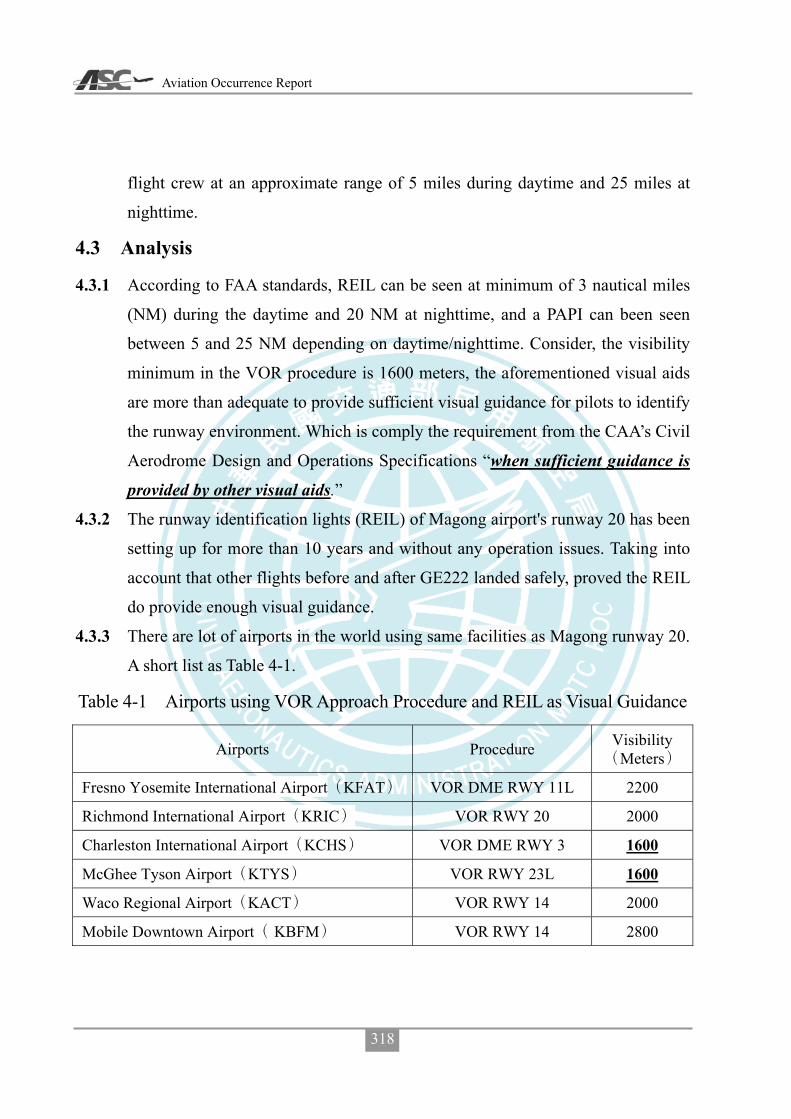
Aviation Occurrence Report
318
flight crew at an approximate range of 5 miles during daytime and 25 miles at
nighttime.
4.3 Analysis
4.3.1 According to FAA standards, REIL can be seen at minimum of 3 nautical miles
(NM) during the daytime and 20 NM at nighttime, and a PAPI can been seen
between 5 and 25 NM depending on daytime/nighttime. Consider, the visibility
minimum in the VOR procedure is 1600 meters, the aforementioned visual aids
are more than adequate to provide sufficient visual guidance for pilots to identify
the runway environment. Which is comply the requirement from the CAA’s Civil
Aerodrome Design and Operations Specifications “when sufficient guidance is
provided by other visual aids.”
4.3.2 The runway identification lights (REIL) of Magong airport's runway 20 has been
setting up for more than 10 years and without any operation issues. Taking into
account that other flights before and after GE222 landed safely, proved the REIL
do provide enough visual guidance.
4.3.3 There are lot of airports in the world using same facilities as Magong runway 20.
A short list as Table 4-1.
Table 4-1 Airports using VOR Approach Procedure and REIL as Visual Guidance
Airports Procedure Visibility Meters
Fresno Yosemite International Airport KFAT VOR DME RWY 11L 2200
Richmond International Airport KRIC VOR RWY 20 2000
Charleston International Airport KCHS VOR DME RWY 3 1600
McGhee Tyson Airport KTYS VOR RWY 23L 1600
Waco Regional Airport KACT VOR RWY 14 2000
Mobile Downtown Airport KBFM VOR RWY 14 2800
Appendix 5 Comments on ASC’s Final Draft Report
319
4.4 Conclusions
To operate in coordination with related navigation aids, instrument flight
procedures and flight operations restrictions, the runway identification lights (REIL) of
Magong airport’s runway 20 are compliant with the CAA related regulations. As severe
weather is often accompanied by thunderstorms, low clouds, strong winds, etc. (as in
this case, for example), there is no factual information that can be corroborated that
setting up a 420 meters simple approach runway lights can enhance the runway
identification in case of severe weather. The safe operation of aircraft approach in severe
weather, is dependent upon flight crews visually identifying the runway; or else they
should perform the missed approach procedure at (or before) the missed approach point.
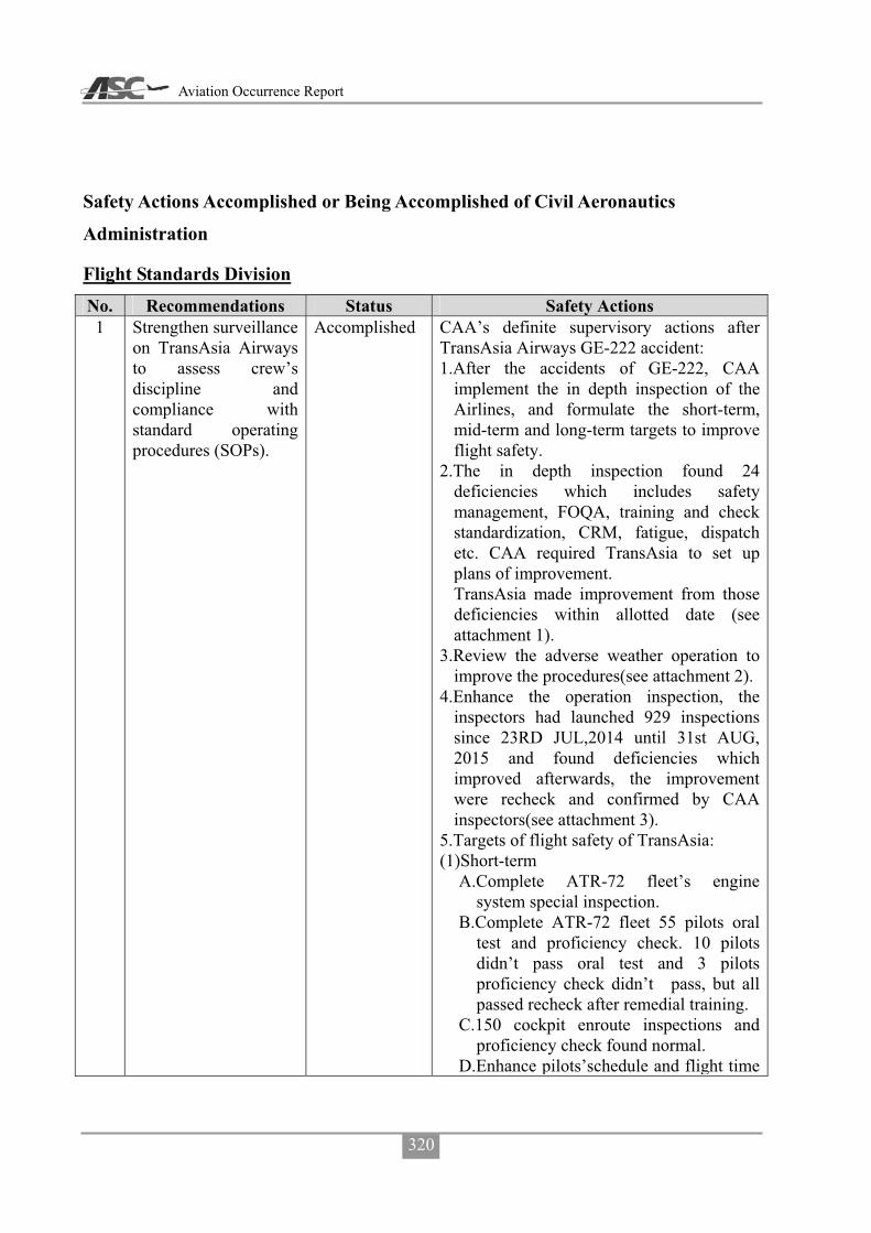
Aviation Occurrence Report
320
Safety Actions Accomplished or Being Accomplished of Civil Aeronautics
Administration
Flight Standards Division No. Recommendations Status Safety Actions 1 Strengthen surveillance
on TransAsia Airways to assess crew’s discipline and compliance with standard operating procedures (SOPs).
Accomplished CAA’s definite supervisory actions after TransAsia Airways GE-222 accident: 1.After the accidents of GE-222, CAA
implement the in depth inspection of the Airlines, and formulate the short-term, mid-term and long-term targets to improve flight safety.
2.The in depth inspection found 24 deficiencies which includes safety management, FOQA, training and check standardization, CRM, fatigue, dispatch etc. CAA required TransAsia to set up plans of improvement. TransAsia made improvement from those deficiencies within allotted date (see attachment 1).
3.Review the adverse weather operation to improve the procedures(see attachment 2).
4.Enhance the operation inspection, the inspectors had launched 929 inspections since 23RD JUL,2014 until 31st AUG, 2015 and found deficiencies which improved afterwards, the improvement were recheck and confirmed by CAA inspectors(see attachment 3).
5.Targets of flight safety of TransAsia: (1)Short-term
A.Complete ATR-72 fleet’s engine system special inspection.
B.Complete ATR-72 fleet 55 pilots oral test and proficiency check. 10 pilots didn’t pass oral test and 3 pilots proficiency check didn’t pass, but all passed recheck after remedial training.
C.150 cockpit enroute inspections and proficiency check found normal.
D.Enhance pilots’schedule and flight time

Appendix 5 Comments on ASC’s Final Draft Report
321
No. Recommendations Status Safety Actions monitoring(see attachment 4).
(2)Mid-term A.Implement A330 and A320/321 pilot’s
oral test and proficiency check, with the result: 3 of 102 pilots take oral retest and 2 pilots take remedial training after recheck, the pilot proficiency check will finish before 31st DEC,2015.
B.Enhance the mechanism to effectively control of mechanical troubles and arranged the main base inspection to verify the implementation.
C.SMS implementation, is now in the phase 3 of the plan, and CAA will continue to monitor the implementation accordingly.
D.To coordinate with Flight Safety Foundation action team to evaluate safety management of TransAsia Airways, list the priorities of safety related issues and continue to improve those.
(3)Long-term(before 31st DEC,2016) A.Complete SMS implementation. B.Supervise the airlines SMS plan. C.Develp the methods of airlines
management. 6.Works of supervise: (1)Oversee the management of organization
and improve the proficiency of employees.(2)Supervise the improvement of safety
related issues according the targets. 7.Reviews: (1)Except the deficiencies found in the
in-depth inspection and targets of safety improvement required by CAA, the recommendations made by ASC , action team and authority of aircraft manufacture are also included in the measure of improvement.
(2)Though the TransAsia Airways has improved it’s flight safety by measures in all aspect, but leave of employees and

Aviation Occurrence Report
322
No. Recommendations Status Safety Actions change of management still a major concern. The airlines is one of the major domestic carriers, suggest not to increase flight either domestic or international due to the manpower issue. The application of emergency medical service flight will be review and restricted as well.
(3)CAA required TransAsia Airways to take actions to improve flight safety after accident. The immediate action to improve were the knowledge and skills, it has been effective improvement and will continue to enhance the performance. As to the organization, company culture, employees etc. are the human factors which is a long-term issues to improve, CAA will continue to oversee performance of the airlines. Due the CAA oversight activities are continuously and persistently, suggest to close the 1st and 2nd ASC recommendations to CAA.
2 Implement a more robust process to identify safety-related shortcomings in operators’ operations, within an appropriate timescale, to ensure that the operators meet and maintain the required standards.
Suggest to close recommendation, the statement same as aforementioned.
5 Enhance inspector supervision and performance evaluation to ensure all inspectors conduct surveillance activities effectively and are able to identify and communicate critical safety issues to their supervisors.
CAA Flight Standards Division holds Operations Section and Airworthiness Inspection Section meeting and Airlines group report meeting monthly. The details of Section meeting includes policies proclaiming operations and airworthiness inspection work reporting and inspectors performance review, special items of inspection and jobs emphasis in coming months. Airlines groups meeting details includes POI

Appendix 5 Comments on ASC’s Final Draft Report
323
No. Recommendations Status Safety Actions work reports and reviews (includes airlines events or deficiencies improvement), emphasis of inspection, recommendations. The interim review meeting of airlines performance are also included.
Air Traffic Services Division No. Recommendations Status Safety Actions 11 Review runway
approach lighting systems in accordance with their existing radio navigation and landing aids to ensure that adequate guidance is available for pilots to identify the visual references to the runway environment, particularly in poor visibility condition or at night.
Accomplished The simple approach lighting system of runway 20 of Magong airport was commissioned on March 18, 2015. And the instrument landing system(ILS) of runway 20 was commissioned on June 25, 2015. After the aforementioned facilities are commissioned, the runway operational visibility limitation, has been upgraded from previously 1600 meters down to 1200 meters.
Air Navigation and Weather Services No. Recommendations Status Safety Actions 11 Review runway
approach lighting systems in accordance with their existing radio navigation and landing aids to ensure that adequate guidance is available for pilots to identify the visual references to the runway environment, particularly in poor visibility condition or at night.
Accomplished 20REIL
104 3 1820
13 Request tower controllers to advise the flight crews of
Accomplished 1. 103 7 311030007601
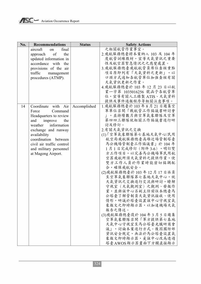
Aviation Occurrence Report
324
No. Recommendations Status Safety Actions aircraft on final approach of the updated information in accordance with the provisions of the air traffic management procedures (ATMP).
2. 103 104
3.
4. 103 12 23
1035016256ATIS
14 Coordinate with Air
Force Command Headquarters to review and improve the weather information exchange and runway availability coordination between civil air traffic control and military personnel at Magong Airport.
Accomplished 1. 103 8 21
2. (1) /
1041 1 3-6
(2) 103 12 17
(3) 104 3 5
AWOS
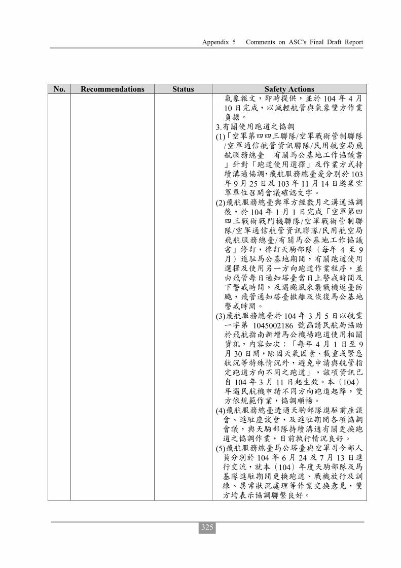
Appendix 5 Comments on ASC’s Final Draft Report
325
No. Recommendations Status Safety Actions 104 4
10
3. (1) /
/ /
1039 25 103 11 14
(2)
104 1 1/
/ //
4 9
(3) 104 3 5
1045002186
4 1 930
104 3 11 104
(4)
(5)
104 6 24 7 13104

Aviation Occurrence Report
326
Appendix 5-5 Comments on ASC’s Final Draft Report from TransAsia Airways

Appendix 5 Comments on ASC’s Final Draft Report
327

Aviation Occurrence Report
328

Appendix 5 Comments on ASC’s Final Draft Report
329
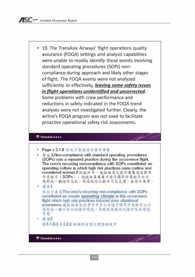
Aviation Occurrence Report
330

Appendix 5 Comments on ASC’s Final Draft Report
331

Aviation Occurrence Report
332

Appendix 5 Comments on ASC’s Final Draft Report
333

Aviation Occurrence Report
334
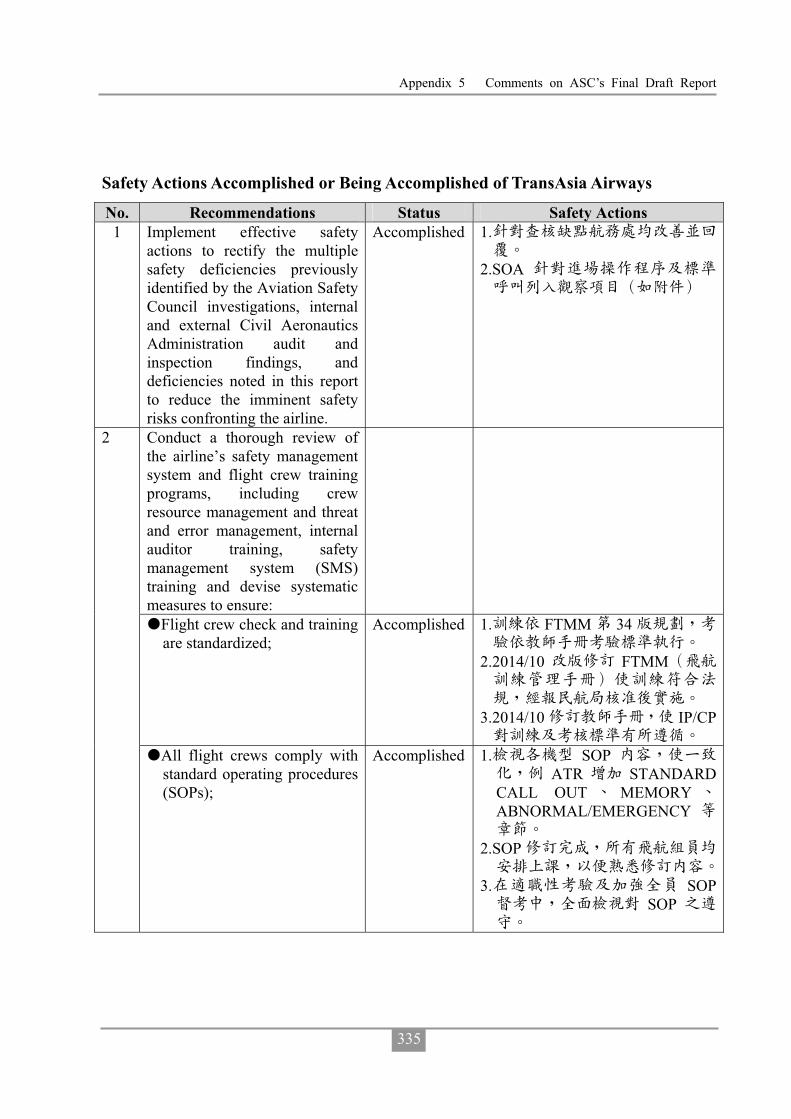
Appendix 5 Comments on ASC’s Final Draft Report
335
Safety Actions Accomplished or Being Accomplished of TransAsia Airways
No. Recommendations Status Safety Actions 1 Implement effective safety
actions to rectify the multiple safety deficiencies previously identified by the Aviation Safety Council investigations, internal and external Civil Aeronautics Administration audit and inspection findings, and deficiencies noted in this report to reduce the imminent safety risks confronting the airline.
Accomplished 1.
2.SOA
Conduct a thorough review of the airline’s safety management system and flight crew training programs, including crew resource management and threat and error management, internal auditor training, safety management system (SMS) training and devise systematic measures to ensure:
�Flight crew check and training are standardized;
Accomplished 1. FTMM 34
2.2014/10 FTMM
3.2014/10 IP/CP
2
�All flight crews comply with standard operating procedures (SOPs);
Accomplished 1. SOPATR STANDARD
CALL OUT MEMORYABNORMAL/EMERGENCY
2.SOP
3. SOPSOP

Aviation Occurrence Report
336
No. Recommendations Status Safety Actions �Staff who conduct audits
receive appropriate professional auditor training;
Accomplished 1.7 50
2.E-IOSA 12 7
10 IATAARGUS/PRO 25
E-IOSA 3. 105 1
�All operational and senior
management staff receive SMS training, including thorough risk assessment and management training; and
Accomplished
�Proportional and consistent rules, in accordance with a “Just Culture”, are implemented to prevent flight crew from violating the well-designed SOPs and/or being engaged in unsafe behavior.
Accomplished SOP
SOP
3 Conduct a rigorous review of the safety management system (SMS) to rectify the significant deficiencies in: �Planning; �Organizational structure,
capability and resources; �Risk management processes
and outputs; �Flight operations quality
assurance (FOQA) limitations and operations, including inadequate data analysis capabilities;
�Safety meetings; �Self-audits; �Safety performance
monitoring, including risk indices;
Accomplished 102 5 20 SMS103 11
4 1035015287103 11
05
SMM3-2 TR001104 6 11
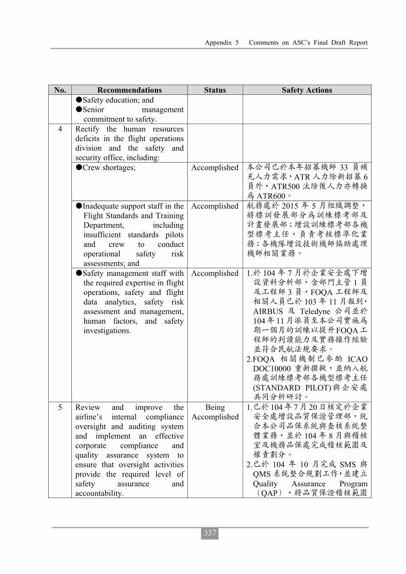
Appendix 5 Comments on ASC’s Final Draft Report
337
No. Recommendations Status Safety Actions �Safety education; and �Senior management
commitment to safety. Rectify the human resources deficits in the flight operations division and the safety and security office, including:
�Crew shortages; Accomplished 33ATR 6
ATR500ATR600
�Inadequate support staff in the Flight Standards and Training Department, including insufficient standards pilots and crew to conduct operational safety risk assessments; and
Accomplished 2015 5
4
�Safety management staff with the required expertise in flight operations, safety and flight data analytics, safety risk assessment and management, human factors, and safety investigations.
Accomplished 1. 104 71
3 FOQA103 11
AIRBUS Teledyne104 11
FOQA
2.FOQA ICAO
DOC10000
(STANDARD PILOT)
5 Review and improve the airline’s internal compliance oversight and auditing system and implement an effective corporate compliance and quality assurance system to ensure that oversight activities provide the required level of safety assurance and accountability.
Being Accomplished
1. 104 7 20
104 8
2. 104 10 SMS
QMSQuality Assurance Program
QAP

Aviation Occurrence Report
338
No. Recommendations Status Safety Actions
Safety Assurance
3. 104 12 SMS
6 Implement an effective safety
management process, such as a data-driven fatigue risk management system (FRMS), to manage the flight safety risks associated with crew fatigue.
Accomplished 1.8 6
4-6
2. FRMS105
7 Provide flight crew with adequate fatigue management education and training, including the provision of effective strategies to manage fatigue and performance during operations.
Accomplished 1.
2.
8 Implement an effective change management system as a part of the airline’s safety management system (SMS) to ensure that risk assessment and mitigation activities are formally conducted and documented before significant operational changes are implemented, such as the introduction of new aircraft types or variants, increased operational tempo, opening new ports, and so on.
Accomplished SMSSMM3-2 TR001
104 6 11
9 Implement a more advanced flight operations quality assurance (FOQA) program with adequate training and technical support for the FOQA staff to ensure that they can exploit the analytical capabilities of the program. As such, the FOQA staff can more effectively identify and manage the
Accomplished 103/10/1FOQA
103 11FOQA
104.03.01 FOQA104 3 16 FOQA
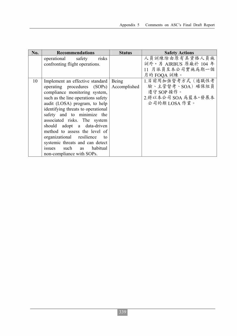
Appendix 5 Comments on ASC’s Final Draft Report
339
No. Recommendations Status Safety Actions operational safety risks confronting flight operations. AIRBUS 104
11FOQA
10 Implement an effective standard operating procedures (SOPs) compliance monitoring system, such as the line operations safety audit (LOSA) program, to help identifying threats to operational safety and to minimize the associated risks. The system should adopt a data-driven method to assess the level of organizational resilience to systemic threats and can detect issues such as habitual non-compliance with SOPs.
Being Accomplished
1.SOA
SOP 2. SOA
LOSA

Aviation Occurrence Report
340
Intentionally Left Blank

23 July, 2014
TransAsia Airways Flight GE222
ATR72-212A, B-22810
Impacted Terrain and Collided
with a Residential Area
Northeast of the Threshold of Runway 20
at Magong Airport
ASC-AOR-16-01-002
11 Floor, 200, Section 3, Beixin Road, Xindian District,231 New Taipei City, Taiwan (R.O.C.)
t h
TEL (02)89127388FAX (02)89127399URL http://www.asc.gov.tw
23
Ju
ly,
2014,
Tra
ns
Asia
Airw
ays
Flig
ht
GE
222
AT
R72-2
12A
,
B-2
2810
Imp
acte
dTerra
inan
dC
ollid
ed
with
aR
esid
en
tial
Are
a
No
rtheast
of
the
Th
resh
old
of
Ru
nw
ay
20
at
Mag
on
gA
irpo
rt
Aviation Occurrence Report
Aviatio
nO
ccurren
ceR
epo
rt
GPN:4910500148
ISBN 978-986-04-7990-4
9 7 8 9 8 6 0 4 7 9 9 0 4