20210607_ResptoQ001.pdf - Green Mountain Care Board
60
MEMORANDUM TO: Donna Jerry Senior Health Policy Analyst Green Mountain Care Board FROM: Commissioner Sarah Squirrell Department of Mental Health DATE: June 4, 2021 SUBJECT: Docket No. GMCB-002-21con, Construction of Secure Residential Treatment Program for individuals requiring residential treatment program services for mental health conditions. Project cost: $21,900,521. Below please find responses to questions posed in the letter dated May 27, 2021, from the Green Mountain Care Board. 1. Submit dimension plans of all clinical and non-clinical spaces for the new building and provide detailed information for any renovated areas, including the existing gym. Please see attachments on pages 3 through 7. 2. Provide a chart depicting compliance with the most recent FGI (Facilities GuidelinesInstitute) requirements pertaining to all aspects of the new building. Please note that this residence will not meet the FGI guideline around a Seclusion and Restraint Room and handrails throughout all corridors. This is due to the fact that this residence will not be engaging in ANY Emergency Involuntary Procedures that would require the use of a seclusion and restraint room. In keeping with a residential design and keeping in mind the target resident population to be served at this residence, handrails in all corridors have not been included. In addition, this facility is being designed and operated as a residential program and not an inpatient psychiatric hospital. In an effort to provide as safe an environment as possible for this population, the design elements of much of this residence meets the most recent FGI requirements. For the chart, please see attachments on pages 8 through 22. 3. Provide a narrative of proposed mechanical/electrical/plumbing/fire protection system forthe new building. Please see attachments on pages 23 through 26.
-
Upload
khangminh22 -
Category
Documents
-
view
1 -
download
0
Transcript of 20210607_ResptoQ001.pdf - Green Mountain Care Board

MEMORANDUM
TO: Donna Jerry
Senior Health Policy Analyst Green Mountain Care Board
FROM: Commissioner Sarah Squirrell
Department of Mental Health DATE: June 4, 2021 SUBJECT: Docket No. GMCB-002-21con, Construction of Secure Residential Treatment
Program for individuals requiring residential treatment program services for mental health conditions. Project cost: $21,900,521.
Below please find responses to questions posed in the letter dated May 27, 2021, from the Green Mountain Care Board. 1. Submit dimension plans of all clinical and non-clinical spaces for the new building and provide detailed
information for any renovated areas, including the existing gym. Please see attachments on pages 3 through 7.
2. Provide a chart depicting compliance with the most recent FGI (Facilities Guidelines Institute) requirements pertaining to all aspects of the new building.
Please note that this residence will not meet the FGI guideline around a Seclusion and Restraint Room and handrails throughout all corridors. This is due to the fact that this residence will not be engaging in ANY Emergency Involuntary Procedures that would require the use of a seclusion and restraint room. In keeping with a residential design and keeping in mind the target resident population to be served at this residence, handrails in all corridors have not been included. In addition, this facility is being designed and operated as a residential program and not an inpatient psychiatric hospital. In an effort to provide as safe an environment as possible for this population, the design elements of much of this residence meets the most recent FGI requirements. For the chart, please see attachments on pages 8 through 22.
3. Provide a narrative of proposed mechanical/electrical/plumbing/fire protection system for the new building. Please see attachments on pages 23 through 26.

4. Submit a narrative of finishes to be used for the new building. Include a description of the type of doors and hardware used for the rooms and accessories to be used in patient bathrooms so we may confirm they are ligature resistant. Please see attachments on pages 27 through 48.
5. Submit a plan and list of furniture and equipment to be purchased or replaced. Confirm that all furniture and equipment used for patient use are ligature resistant and made for use in behavioral health facilities. Please confirm that furniture and equipment costs are included in the total project cost. Please see attachments on pages 49 through 56.
6. Provide a letter from Efficiency Vermont that outlines their review of the project and energy efficient components included in the project including the ground source heat pump (geothermal) heating system. Also confirm that the new structure is being built to be compliant with the 2020 Vermont Commercial Building Energy Standard (CBES). Please list any energy efficiency or renewable energy components of the project that go beyond what is required by the 2020 CBES. Please see attachment on page 57.
7. Address whether you have discussed this project and the heating system with Green Mountain Power and whether the ground source heat pump heating system is eligible for Tier-3 incentives. Please see attachment on page 58.
8. Given the increase in the number of beds (seven to sixteen beds) and work force shortages, explain how you will recruit the number and types of qualified staff for the delivery of services outlined in the application.
The current staff at the Middlesex Therapeutic Community Residence (MTCR), of which this project is to replace, accounts for nearly half of the staff required for this new facility. As for recruiting new staff, the Department of Mental Health (DMH) has several plans to support our additional staffing needs. First, one of the factors supporting the chosen site was its location in the largest population center in Vermont which we feel will be an asset for recruitment. Second, in addition to the normal recruitment practices of the State (various forms of advertising and posting electronically and print media), DMH plans to engage local undergraduate and graduate programs to recruit staff and interns to create a steady flow of potential ongoing staff. Third, DMH already has numerous contracts with travelling nurse companies that provide staff for MTCR as well as the Vermont Psychiatric Care Hospital (VPCH) and we would continue to utilize these to fill gaps in our staffing, particularly around nursing needs. These contracts also include Mental Health Specialist staffing opportunities, which DMH can utilize if we are unable to immediately open with all the permanent state employees in those positions. Finally, regarding the advanced degree, professional staff (social work, psychology, and psychiatry), DMH will need to recruit one additional social worker and one additional psychologist. These two positions are felt to be recruitable given the population of the greater Burlington area and the several local graduate level mental health degree programs. As for psychiatry, DMH anticipates expanding the current contract with UVMMC which already provides psychiatric coverage for MTCR and VPCH.

CR
CR
CR
CR
EXERCISE
ROOM
131
LEVEL 3
RESIDENT
LAUNDRY
/RECYCLING
104
LEVEL 3
SERENITY
ROOM /
CONSULT
129
LEVEL 2
SINGLE
PATIENT
RM
121
LEVEL 4
VISITOR
TOILET
103
LEVEL 4
SNGL
PATIENT
RM - ADA
128
LEVEL 4
3/4 BATH
122
LEVEL 4
3/4 BATH
123
LEVEL 4
SINGLE
PATIENT
RM
124
LEVEL 4
SNGL
PATIENT
RM - ADA
125
LEVEL 4
ADA BATH
127
LEVEL 4
ADA BATH
126
LEVEL 4
HANDWASH
116
SINGLE
PATIENT
RM
115
LEVEL 4
3/4 BATH
114
LEVEL 4
3/4 BATH
113
LEVEL 4
SINGLE
PATIENT
RM
112
LEVEL 4
SINGLE
PATIENT
RM
108
LEVEL 4
3/4 BATH
106
LEVEL 4
3/4 BATH
107
LEVEL 4
SINGLE
PATIENT
RM
105
LEVEL 4
H1
AI100.B
H1
AI100.B
103 104
130131
127
128
126
125
123
124
106
107
108 115
114
113
112
121
AI400
C1
AI401
H1
AI410 B3
C7
AI410
D1
AI410
AI410 H9
AI410
G2
AI651
D1
AI652
C1
AI652
F1
DATA
110
LEVEL 1
VEST.
111
LEVEL 1
HSKPG
109
LEVEL 1
155°
AI401
J1
MIN
1' -
6"
MIN
1' -
6"
MIN
1' -
6"
MIN
1' -
6"
W11
W11
W11W11
W30
W30
111
109
110
W11
W30
W22
W8W22
12
X
Y
1110
AI410
F10
23' -
3 7
/8"
7' -
7 1
/4"
23' -
3 7
/8"
ART/
ACTIVITY
ROOM
130
LEVEL 3
12'-4 7/8" 13'-0" 11'-0" 10'-7" 6'-4 1/8" 10'-5" 10'-5" 5'-1 1/2" 11'-1" 6"
10' - 7" 5' - 9 1/2" 10' - 5" 5' - 4 1/2" 6' - 5" 10' - 5" 5' - 9 1/2" 10' - 5"
10' -
0 1
/2"
10' -
7 1
/2"
6'-11 1/2" 12'-5 3/4"
EQ
EQ
3' - 3 123/256"
3'-4 3
/4"
EQ
EQ
122
A
129
105
AI100.A
J1
12' - 0 1/8"
W11
W11
1
W24
w25
W24A
10' - 5"
LADDER
117
LEVEL 1
117
EQ
EQ
H1
56
5656 56
56
565656 56
5656
56
56
56
56
56
56
56
W22
W8
W9
W22
W26
W26
E111
AB
C
D
KEYPLAN
GENERAL PARTITION NOTES
1. ALL PARTITIONS ARE TYPE W7 UNLESS OTHERWISE INDICATED.
2. AT ALL ROOMS SCHEDULED TO RECEIVE 09 30 00 - CERAMIC WALL TILE, USE TILE BACKER BOARD IN LIEU
OF GWB BEHIND TILE.
3. ACOUSTICAL CONSTRUCTION: SEAL ALL CRACKS, JOINTS, AND VOIDS IN ACOUSTICAL CONSTRUCTION AIR
TIGHT. SEALING SHALL INCLUDE:
a. SEALING BOTTOM EDGES OF GYPSUM BOARD TO FLOOR BEHIND BASE AT BOTH SIDES OF PARTITIONS.
b. SEALING TOP AND SIDE EDGES OF GYPSUM BOARD AT BOTH SIDES OF WALLS ABUTTING OTHER
CONSTRUCTION.
c. SEALING TOP OF WALL TO DECK FLUTES.
d. SEALING ALL WALL PENETRATIONS INCLUDING ELECTRICAL BOXES, PIPES, CONDUITS, DUCTS, BEAMS,
JOISTS, ETC.
SMOKE PARTITION
1 HOUR RATED PARTITION
2 HOUR RATED PARTITION
Y YY
ORIGINATION DATE: SCALE:
DRAWN BY: CHECKED BY:
FFF PROJECT NO:
ISSUE LOG:
SHEET CONTENTS:
SHEET NO:
81 Maple Street ▪ Burlington VT 05401
802▪864▪6844 ▪ www.fffinc.com
© 2021 Freeman French Freeman Inc.
Architect of Record | Core and Shell
COLCHESTER,
VERMONT
155 Dow St, Suite 400 ▪ Manchester NH 03101
603▪622▪5450 ▪ www.lbpa.comArchitecture | Behavioral Health Specialist
120 Graham Way # ▪ Shelburne, VT 05482
802▪497▪3531 ▪ www.artisaneng.comStructural Engineering
208 Flynn Ave. #21 ▪ Burlington, VT 05401
802▪655▪1753 ▪ www.lnconsulting.comMechanical | Electrical | Plumbing | Fire Protection
95 Main Street ▪ Brattleboro, VT 05302
802▪257▪9329 ▪ www.stevens-assoc.comCivil | Landscape Architecture
50
% C
ON
STR
UC
TIO
N S
ET -
NO
T FO
R C
ON
STR
UC
TIO
N
MA
Y 2
8, 2
02
1
As indicated
6/1/2
02
1 5
:11
:08
PM
AI100.A
A2005.00
05/28/21
ADH Checker
FIRST FLOOR -
PLAN AREA A
DMH RECOVERY
RESIDENCE
05/28/2150% CD SET
SCALE: 1/4" = 1'-0"AI100.A
H1 FIRST FLOOR PLAN - A
SCALE: 1 1/2" = 1'-0"AI100.A
J1 COLUMN PLAN DETAIL

CR
CR
CR
CR
CR
AI412
B7
AI411
C1
AI412
B12
AI410J6
D1
H1
AI100.A
H1
AI100.A
J1
AI100.C
J1
AI100.C
J1
AI100.D
J1
AI100.D
WORK RM
192
LEVEL 1
MUTIPURPOSE
ROOM
132
LEVEL 2
RESIDENT
SKILLS
KITCHEN
166
LEVEL 3
DINING
133
LEVEL 2
LIVING
ROOM
102
LEVEL 2
166
132
134
102
100B
101A
F1
J1
AI412
D7
AI412
D5
AI411H1
AI411
H6
AI412
D11
AI651
B4
AI651
G1
AI651
J1
AI651
B1
AI411D5
45°
145°
2' - 0"
135°
135°
10' - 4
1/2
"
8' -
11 3
/4"
W31
W31
X
Y
109
8
7
6
C
B
5
21
' -
8 1
/8"
1' -
9 1
/2"
8' -
2 1
/2"
1' -
10
"1
0' -
7 1
/2"
10
' -
0"
CDC
B
132B
AI100.B
E12
E
6' - 6 3/4"
1' - 6"
8' - 5"
2' - 4"
32' - 4 1/2"
AI100.B
G12
6' - 4 1/4" 7' - 5 1/8" 20' - 4 1/4"5
' -
5"
5' -
8"
6' -
0"
AI100.B
J3
AI100.B
J5
AI100.B
J1
B.5
AI411
J13
AI100.B
J8
9' -
2"
1' -
4"
10"
AI652
G6
2' - 4 1/32"11 15/32"
E100
dishwashers
FD PANEL
KNOX BOXAI410G
1
F
56
56
100
ENTRY
VEST
100A
LEVEL 2
CORRIDOR
120
LEVEL 2
191
101
MED. RM
191
LEVEL 1
NURSE
101
LEVEL 1
WAITING
100
LEVEL 2
CHECKIN
101A
101B
W31
W31
W31
W30
W11
J
H
W9
STAFF LOCKERS
GENERAL PARTITION NOTES
1. ALL PARTITIONS ARE TYPE W7 UNLESS OTHERWISE INDICATED.
2. AT ALL ROOMS SCHEDULED TO RECEIVE 09 30 00 - CERAMIC WALL TILE, USE TILE BACKER BOARD IN LIEU OF GWB BEHIND TILE.
3. ACOUSTICAL CONSTRUCTION: SEAL ALL CRACKS, JOINTS, AND VOIDS IN ACOUSTICAL CONSTRUCTION AIR TIGHT. SEALING SHALL INCLUDE:a. SEALING BOTTOM EDGES OF GYPSUM BOARD TO FLOOR BEHIND BASE AT BOTH SIDES OF PARTITIONS. b. SEALING TOP AND SIDE EDGES OF GYPSUM BOARD AT BOTH SIDES OF WALLS ABUTTING OTHER CONSTRUCTION.c. SEALING TOP OF WALL TO DECK FLUTES.d. SEALING ALL WALL PENETRATIONS INCLUDING ELECTRICAL BOXES, PIPES, CONDUITS, DUCTS, BEAMS, JOISTS, ETC.
SMOKE PARTITION
1 HOUR RATED PARTITION
2 HOUR RATED PARTITION
AB
C
D
KEYPLAN
9
99
9
9
8
9
9
99
7
ORIGINATION DATE: SCALE:
DRAWN BY: CHECKED BY:
FFF PROJECT NO:
ISSUE LOG:
SHEET CONTENTS:
SHEET NO:
81 Maple Street ▪ Burlington VT 05401
802▪864▪6844 ▪ www.fffinc.com
© 2021 Freeman French Freeman Inc.
Architect of Record | Core and Shell
COLCHESTER,
VERMONT
155 Dow St, Suite 400 ▪ Manchester NH 03101
603▪622▪5450 ▪ www.lbpa.comArchitecture | Behavioral Health Specialist
120 Graham Way # ▪ Shelburne, VT 05482
802▪497▪3531 ▪ www.artisaneng.comStructural Engineering
208 Flynn Ave. #21 ▪ Burlington, VT 05401
802▪655▪1753 ▪ www.lnconsulting.comMechanical | Electrical | Plumbing | Fire Protection
95 Main Street ▪ Brattleboro, VT 05302
802▪257▪9329 ▪ www.stevens-assoc.comCivil | Landscape Architecture
50
% C
ON
STR
UC
TIO
N S
ET -
NO
T FO
R C
ON
STR
UC
TIO
N
MA
Y 2
8, 2
02
1
As indicated
6/1/2
02
1 5
:20
:47
PM
AI100.B
A2005.00
05/28/21
ADH Checker
FIRST FLOOR -
PLAN AREA B
DMH RECOVERY
RESIDENCE
05/28/2150% CD SET
SCALE: 1/4" = 1'-0"AI100.B
H1 FIRST FLOOR PLAN - AREA B
SCALE: 1 1/2" = 1'-0"AI100.B
E12 PLAN DETAIL
SCALE: 1 1/2" = 1'-0"AI100.B
G12 PLAN DETAIL LIVING ROOM
SCALE: 1 1/2" = 1'-0"AI100.B
J5 COL DETAIL
SCALE: 1 1/2" = 1'-0"AI100.B
J1 COL DETAIL 2
SCALE: 1 1/2" = 1'-0"AI100.B
J3 COL DETAIL 3
SCALE: 1 1/2" = 1'-0"AI100.B
J8 COLUMN @ MULTI

CR
CR
CR
CR
CR
CR
CR
H1
AI100.B
J1
AI100.D
J1
AI100.D
H1
AI100.B
PSYCH
CONSULT
189
LEVEL 2
BACK OF
HOUSE
KITCHEN
171
LEVEL 1
UNIT
DIRECTOR
184
LEVEL 1
SHARED
CONF
186
LEVEL 1
ACTIVITY
OFFICE
187
LEVEL 1
SOCIAL
WRKS
SHARED
188
LEVEL 2
EXAM/
CONSULT
172
LEVEL 5
STAFF
BREAK
174
LEVEL 1
CORRIDOR
170
LEVEL 2
FOCUS RM
173
LEVEL 1
STAFF
TOILET
176
LEVEL 1
STAFF
TOILET
175
LEVEL 1
SECURED
CORRIDOR
177
LEVEL 4
NURSE
MANAGER
190
LEVEL 2
3/4 BATH
179
LEVEL 1
SOILED
178
LEVEL 1
MED REC/
HR
STAFFING
183
LEVEL 1
AI401
E1
AI400
J1
AI411
H11
AI411
X-36
AI411
J8J11
AI412
F12
AI412
F1 F5
F9
AI411
H9
166
170
172 188
189
176
174
187
186
187B
190173
174B
177
184
180
178
183
182
8'-4
"
8'-6
"
9'-0
7/8
"
9'-9
1/8
"
14'-5
"
11'-3
5/8
"
14'-1
1 3/
4"
177A
E
F
8
7
6
4
G
D
C
5
7' - 8"
7' - 6"
11' - 10 3/4"
8' - 10"
6' - 6 3/4"
12' - 3"
4' - 11"
10' -
11
5/8"
3' -
2 1/
2"
7' -
9 1/
2"
9' -
4"
9' -
2"
9' -
6"
10' -
2 1
/4"
6' -
6 1/
4"
1' -
0"
7' -
3 1/
2"
3' - 9"
4' -
3 1/
2"
181
OFFICE
180
LEVEL 1
ATTIC
ACCESS
181
LEVEL 1
AI100.C
E12
AI100.C
H12
8' - 8 3/4"
ENTRY
VEST
177B
LEVEL 4
8' - 2"
6' - 5"
8 1/2"
6' - 5"
6' - 0"
2' - 0"
3' - 0"
5' - 5"
12' - 5"
3' - 0"
2' - 10"
AI411
J13
LACTATION
ROOM
179
LEVEL 1
179
DEPRESS SLAB @ COOLER - COORDINATE W/ STRUCTURAL AND FOOD SERVICE
7' -
0"
6' - 0"
156E
E177
E171
F10
AI801
AB
C
D
KEYPLAN
GENERAL PARTITION NOTES
1. ALL PARTITIONS ARE TYPE W7 UNLESS OTHERWISE INDICATED.
2. AT ALL ROOMS SCHEDULED TO RECEIVE 09 30 00 - CERAMIC WALL TILE, USE TILE BACKER BOARD IN LIEU
OF GWB BEHIND TILE.
3. ACOUSTICAL CONSTRUCTION: SEAL ALL CRACKS, JOINTS, AND VOIDS IN ACOUSTICAL CONSTRUCTION AIR
TIGHT. SEALING SHALL INCLUDE:
a. SEALING BOTTOM EDGES OF GYPSUM BOARD TO FLOOR BEHIND BASE AT BOTH SIDES OF PARTITIONS.
b. SEALING TOP AND SIDE EDGES OF GYPSUM BOARD AT BOTH SIDES OF WALLS ABUTTING OTHER
CONSTRUCTION.
c. SEALING TOP OF WALL TO DECK FLUTES.
d. SEALING ALL WALL PENETRATIONS INCLUDING ELECTRICAL BOXES, PIPES, CONDUITS, DUCTS, BEAMS,
JOISTS, ETC.
SMOKE PARTITION
1 HOUR RATED PARTITION
2 HOUR RATED PARTITION
7
X.7
77
X.7
E 7
E77 E
ORIGINATION DATE: SCALE:
DRAWN BY: CHECKED BY:
FFF PROJECT NO:
ISSUE LOG:
SHEET CONTENTS:
SHEET NO:
81 Maple Street ▪ Burlington VT 05401
802▪864▪6844 ▪ www.fffinc.com
© 2021 Freeman French Freeman Inc.
Architect of Record | Core and Shell
COLCHESTER,
VERMONT
155 Dow St, Suite 400 ▪ Manchester NH 03101
603▪622▪5450 ▪ www.lbpa.comArchitecture | Behavioral Health Specialist
120 Graham Way # ▪ Shelburne, VT 05482
802▪497▪3531 ▪ www.artisaneng.comStructural Engineering
208 Flynn Ave. #21 ▪ Burlington, VT 05401
802▪655▪1753 ▪ www.lnconsulting.comMechanical | Electrical | Plumbing | Fire Protection
95 Main Street ▪ Brattleboro, VT 05302
802▪257▪9329 ▪ www.stevens-assoc.comCivil | Landscape Architecture
50
% C
ON
STR
UC
TIO
N S
ET -
NO
T FO
R C
ON
STR
UC
TIO
N
MA
Y 2
8, 2
02
1
As indicated
6/1/2
02
1 5
:13
:03
PM
AI100.C
A2005.00
05/28/21
ADH Checker
FIRST FLOOR -
PLAN AREA C
DMH RECOVERY
RESIDENCE
05/28/2150% CD SET
SCALE: 1/4" = 1'-0"AI100.C
J1 FIRST FLOOR PLAN - AREA C
SCALE: 1 1/2" = 1'-0"AI100.C
E12 COL DETAIL
SCALE: 1 1/2" = 1'-0"AI100.C
H12 COL. DETAIL

CR
CR
CR
CR
CR
CR
CR
H1
AI100.B
H1
AI100.B
J1
AI100.C
J1
AI100.C
SNGL
PATIENT
RM - ADA
151
LEVEL 5
PROGRAM
FLEX
SPACE
150
LEVEL 5
ADA 3/4
BATH
152
LEVEL 5
SNGLE
PATIENT
RM -
BARIATRIC
155
LEVEL 4
SINGLE
PATIENT
RM
149
LEVEL 5
3/4 BA.
BATH
154
LEVEL 4
SINGLE
PATIENT
RM
146
LEVEL 4
SINGLE
PATIENT
RM
157
LEVEL 4
SINGLE
PATIENT
RM
144
LEVEL 4
3/4 BATH
158
LEVEL 4
3/4 BATH
160
LEVEL 4
SINGLE
PATIENT
RM
159
LEVEL 4
3/4 BATH
142
LEVEL 4
3/4 BATH
143
LEVEL 4
SINGLE
PATIENT
RM
141
LEVEL 4
RESIDENT
LAUNDRY
165
LEVEL 3
MEP
162
LEVEL 1
CLEAN
STORAGE
153
LEVEL 1
SENSORY
ROOM
136
LEVEL 3
RESIDENT
TOILET
135
LEVEL 4
GREENHOUSE
134
LEVEL 3
CORRIDOR
140
LEVEL 2
3/4 BATH
148
LEVEL 5
3/4 BATH
147
LEVEL 4
TOILET
163
LEVEL 1
CORRIDOR
138
LEVEL 2
MEZZANINE
STAIR
161
LEVEL 1
CORRIDOR
137
LEVEL 2
AI401
C1
AI401
E7
AI400
F1
AI412
J4J7
AI412
H5
12' - 6
3/8
"
8 5/8"
7'-2"
10'-4 1/4"
1' - 9 3/4"
8' - 7 1/2"
4' - 7 3/4"
7' - 0"
135°
MIN1'
- 4"
MIN1'
- 4"
60" MIN
5' - 8 13/128" +/-
60" M
IN
6' -
1 12
1/25
6" +
/-
MIN1'
- 4"
10' - 6
"
AI400
H1
161
165
135
136
162
138
134
140
158
141
159
157
156
144
155
146
153
149
150A
154
152
151
148
147
143
142
W10
W24
W12
W10
4
D
C
B
A1
2
3
5
23' -
3 7
/8"
7' -
7 1/
4"
23' -
3 7
/8"
8' - 5 1/4"
12' - 7 1/2"
1' - 1 1/2"
4' - 5 1/4"
10' - 2 1/2"
5' - 9 1/2"
10' - 5"
12' - 10"
8' - 4 3/4"
10' - 7"
7' - 2"
11' - 1"
5' - 1 1/2"
10' - 5"
10' - 5"
5' - 9 1/2"
10' - 7"
13' - 4"
AI400
C1
TYP
A
10' -
4"
3' -
4"
EQ
EQ
EQ
EQ
1' -
6 1/
2"
AI100.D
E12
B.5
W11
W11
W11
W11
W22
W22
W26
E161
E162
E171
E138
E134
5656
56
56
56
56
56
56
56
56
56
56
56
56
56
AI410
D1
Sim
GENERAL PARTITION NOTES
1. ALL PARTITIONS ARE TYPE W7 UNLESS OTHERWISE INDICATED.
2. AT ALL ROOMS SCHEDULED TO RECEIVE 09 30 00 - CERAMIC WALL TILE, USE TILE BACKER BOARD IN LIEU
OF GWB BEHIND TILE.
3. ACOUSTICAL CONSTRUCTION: SEAL ALL CRACKS, JOINTS, AND VOIDS IN ACOUSTICAL CONSTRUCTION AIR
TIGHT. SEALING SHALL INCLUDE:
a. SEALING BOTTOM EDGES OF GYPSUM BOARD TO FLOOR BEHIND BASE AT BOTH SIDES OF PARTITIONS.
b. SEALING TOP AND SIDE EDGES OF GYPSUM BOARD AT BOTH SIDES OF WALLS ABUTTING OTHER
CONSTRUCTION.
c. SEALING TOP OF WALL TO DECK FLUTES.
d. SEALING ALL WALL PENETRATIONS INCLUDING ELECTRICAL BOXES, PIPES, CONDUITS, DUCTS, BEAMS,
JOISTS, ETC.
SMOKE PARTITION
1 HOUR RATED PARTITION
2 HOUR RATED PARTITION
AB
C
D
KEYPLAN
4
4
ORIGINATION DATE: SCALE:
DRAWN BY: CHECKED BY:
FFF PROJECT NO:
ISSUE LOG:
SHEET CONTENTS:
SHEET NO:
81 Maple Street ▪ Burlington VT 05401
802▪864▪6844 ▪ www.fffinc.com
© 2021 Freeman French Freeman Inc.
Architect of Record | Core and Shell
COLCHESTER,
VERMONT
155 Dow St, Suite 400 ▪ Manchester NH 03101
603▪622▪5450 ▪ www.lbpa.comArchitecture | Behavioral Health Specialist
120 Graham Way # ▪ Shelburne, VT 05482
802▪497▪3531 ▪ www.artisaneng.comStructural Engineering
208 Flynn Ave. #21 ▪ Burlington, VT 05401
802▪655▪1753 ▪ www.lnconsulting.comMechanical | Electrical | Plumbing | Fire Protection
95 Main Street ▪ Brattleboro, VT 05302
802▪257▪9329 ▪ www.stevens-assoc.comCivil | Landscape Architecture
50
% C
ON
STR
UC
TIO
N S
ET -
NO
T FO
R C
ON
STR
UC
TIO
N
MA
Y 2
8, 2
02
1
As indicated
6/1/2
02
1 5
:13
:50
PM
AI100.D
A2005.00
05/28/21
ADH Checker
FIRST FLOOR -
PLAN AREA D
DMH RECOVERY
RESIDENCE
05/28/2150% CD SET
SCALE: 1/4" = 1'-0"AI100.D
J1 FIRST FLOOR PLAN - AREA D
SCALE: 1 1/2" = 1'-0"AI100.D
E12 COL PLAN

W
D
SECURED OUTDOOR SPACE
SECURED OUTDOOR SPACE
GYMNASIUM
G01
25'-0"
CAP BATHROOM AT 10FT WITH LIGHT GAUGE METAL FRAMING "ROOF" WITH SOUND ATTENUATION BATT
ONLY FINISH CHANGE IN GYM SPACE IS TO PAINT NEW WALL.PROVIDE WALL BASE TO MATCH RISK LEVEL 2 IN MAIN FACILITY (FOR COST)
PROVIDE INSULATED OVERHEAD DOOR, 10X10
3 X 7 SWING EXTERIOR INSULATED DOOR WITH CARD READER
EXISTING CANOPY WILL NEED TO BE ALTERED TO MEET RISK LEVEL CONCERNS
RELOCATE BASKETBALL HOP & STRUCTURE
EXIST FE CAB
EXIST FIRE PULL/ ANNUNCIATOR SYSTEM
EXIST ELEC PANEL
SECURITY FENCE WITH GATE, SEE CIVIL DRAWINGS
e5
e4
e3
e2
e1
EXISTING WALL ASSEMBLYMETAL SIDINGAIR GAPGALV CHICKEN WIRE6" METAL STUD FRAMING, R19 FIBERGLAS BATT5/8" 5/8" FIRE RATED GWB4" CONC BLOCK, 8FT TALL WITH BULLNOSE TOP COURSE, ANCHORED TO FRAMING
10'-0"
FUTURE WORK BENCH WITH (4) OUTLETS
FUTURE WORK COUNTER W/ (3) POWER & (3) DATA
FUTURE WASHER & DRYER
EXIST SPRINKLER RISER & CAGE
FUTURE OFFICE WALL & DOOR
PROVIDE SUB-PANEL (100 AMP) OR (3) CIRCUITES, (1) 220 OUTLET FOR WELDER
A2034
A203
3
4R2
4M4M
3xM3xM
3A
COORDINATE FIRE DEPARTMENT CONNECTION W/ LN. MUST BE OUTSIDE SECURED AREA.
MAINTENANCEROOM
G02
SECURITY FENCE WITH GATE, SEE CIVIL DRAWINGS
SECURITY FENCE, SEE CIVIL DRAWINGS
EG
01
EG01.1
G02
G03
G04
EG
02OFFICE
G04
BATH
G03
11'-4"
2'-10"
1'-6"
7'-7"
16'-7"
1'-6"
FIRE DEPARTMENT CONNECTION
KNOX BOX LOCATION
KNOX BOX LOCATION
EG02.1
FFF TO CONFIRM W/ BGS IF SPACE SHOULD GO ROOF OR HAVE STRUCTURAL CAP
MOP SINK WITH HOLDER, FRP ON ALL SIDES, SEE SPEC FOR DETAILS
BGS PARKING AREA
AB
C
D
KEYPLAN
FLOOR PLAN LEGEND
SEE I- SERIES DRAWINGS FOR ALL INTERIOR LAYOUT AND CONSTRUCTION INFORMATION
101
1i
E A
DOOR NUMBER
DOOR TAG - SEE INTERIOR SHEETS
WALL TYPE
EXTERIOR WALL TAG - SEE A310 SERIES
WINDOW TAGSEE SHEET A810
WHERE A WALLTYPE LEADER PASSES THROUGH 2 OR MORE WALLS, ALL OF THOSE WALLS SHALL BE OF THE TYPE INDICATED
CURTAINWALL TYPESEE SHEET A810
CWE
FLOOR PLAN GENERAL NOTES
1. DIMENSIONS: ALL EXTERIOR DIMENSIONS ARE TO FINISH FACE OF WALL OR OPENING. SEE I-SERIES DRAWINGS FOR INTERIOR DIMENSIONS.
2. PLANS ARE TO BE VIEWED IN CONJUNCTION WITH CIVIL, LANDSCAPE, STRUCTURAL, MEP/FP AND ALL OTHER TRADES, AS APPROPRIATE. DISCREPANCIES ARE TO BE BROUGHT TO THE ARCHITECT’S ATTENTION FOR RESOLUTION BEFORE COMMENCING WORK.
3. ALL NON-ARCHITECTURAL INFORMATION SHOWN HERE IS FOR REFERENCE ONLY.
4. REFER TO CIVIL PLANS FOR LIMIT OF WORK.5. REFER TO G200 LIFE SAFETY PLANS FOR LOCATIONS OF SMOKE AND
FIRE RESISTANT RATED CONSTRUCTION.6. ALL VERTICAL AND HORIZONTAL PENETRATIONS THROUGH RATED
ASSEMBLIES ARE TO BE BE SEALED WITH UL-LISTED FIRESAFING AND/OR SEALANT ASSEMBLIES TO MAINTAIN RATING.
7. KEEP STANDPIPES AND ASSOCIATED ASSEMBLIES CLEAR OF THE REQUIRED PATH OF EGRESS.
8. SEE A003 FOR TYPICAL FLOOR ASSEMBLIES.
SEE I-SERIES DRAWINGS FOR ALL INTERIOR LAYOUT AND CONSTRUCTION INFORMATION. ALSO SEE SYMBOL LEGEND ON COVER SHEET.
ORIGINATION DATE: SCALE:
DRAWN BY: CHECKED BY:
FFF PROJECT NO:
ISSUE LOG:
SHEET CONTENTS:
SHEET NO:
81 Maple Street ▪ Burlington VT 05401
802▪864▪6844 ▪ www.fffinc.com
© 2021 Freeman French Freeman Inc.
Architect of Record | Core and Shell
ESSEX, VERMONT
155 Dow St, Suite 400 ▪ Manchester NH 03101
603▪622▪5450 ▪ www.lbpa.comArchitecture | Behavioral Health Specialist
120 Graham Way # ▪ Shelburne, VT 05482
802▪497▪3531 ▪ www.artisaneng.comStructural Engineering
208 Flynn Ave. #21 ▪ Burlington, VT 05401
802▪655▪1753 ▪ www.lnconsulting.comMechanical | Electrical | Plumbing | Fire Protection
95 Main Street ▪ Brattleboro, VT 05302
802▪257▪9329 ▪ www.stevens-assoc.comCivil | Landscape Architecture
50
% C
ON
STR
UC
TIO
N S
ET -
NO
T FO
R C
ON
STR
UC
TIO
N
MA
Y 8
6, 2
02
1
As indicatedAs indicatedAs indicatedAs indicated
5/28
/20
21 3
:34
:59
PM
A105
A2005.00A2005.00A2005.00A2005.00
05/28/2105/28/2105/28/2105/28/21
JGJGJGJG SBSBSBSB
GYMNASIUM PLAN
& INTERIOR
ELEVATIONS
DMH RECOVERYDMH RECOVERYDMH RECOVERYDMH RECOVERY
RESIDENCERESIDENCERESIDENCERESIDENCE
05/28/2105/28/2105/28/2105/28/2150% CD SET50% CD SET50% CD SET50% CD SET
SCALE: 3/16" = 1'-0"A105
1 GYMNASIUM PLAN NTm
N - PROJECT NORTHT - TRUE NORTHm - MAGNETIC NORTH
4'0 8' 16'
GRAPHIC SCALE

Page 1 of 17
DMH RECOVERY RESIDENCE 06 01 2021
COMPLIANCE CHECKLIST Psychiatric Patient Care Unit The following checklist is intended to be used in the plan review applications for health care facilities. This checklist summarizes and references the applicable requirements from the 2018 Edition of the FGI Guidelines for Design and Construction of Hospitals specific to section 2.5 Psychiatric Hospitals. 1.
X = Requirement is met, for new space, for renovated space, or for existing direct support space for an expanded service.
= Check box under section titles or individual requirements lines for optional services or functions that are not included in the project area.
E = Requirement relative to an existing suite or area that has been licensed for its designated function, is not affected by the construction project and does not pertain to a required direct support space for the specific service affected by the project. “E” must not be used for an existing required support space associated with a new patient care room or area.
W = Waiver requested for specific section of the Regulations or FGI Guidelines, where hardship in meeting requirement can be demonstrated (a Physical Plant Waiver Form must be completed for each waiver request). An explicit floor plan or plan detail must be attached to each waiver request.
Facility Name: CoN Project Number: (if applicable)
Facility Address:
Patient Care Unit Bed Complements:
Current = 0 Proposed = 16 beds
Satellite Name: (if applicable)
Building/Floor Location:
Satellite Address: (if applicable)
Submission Dates:
Project Description: Initial Date:
Revision Date:

DMH RECOVERY RESIDENCE 06 01 2021
Compliance Checklist: Psychiatric Patient Care Unit Page 2 of 17
Architectural Requirements Building Systems Requirements 2.2-2.12 PSYCHIATRIC PATIENT CARE UNIT
2.2-2.12.1.2 Environment of Care: X facility provides therapeutic
environment appropriate for planned treatment programs
2.2-2.12.1.3 Safety & Security: 1.2-4.6.2.2(1) X patient environment designed to protect
the privacy, dignity, & health of patients X patient environment designed to
address the potential risks related to patient elopement & harm to self, others, & the environment
2.2-2.12.1.4 Shared Facilities: NA adult & pediatric patient populations are
kept separate (nurse stations or support areas may be shared)
2.2-2.12.2 PSYCHIATRIC PATIENT ROOM 2.5-2.2.2.1 Capacity:
maximum room capacity of two patients
2.5-2.2.2.2 Space Requirements: Ventilation: (1) Single-Patient Rooms: X Min. 4 air changes per hour Table 7.1
☐ check if not included in project min. clear floor area 100 sf
Lighting: X General lighting X Reading light for each patient
2.1-8.3.4.3(1)
bed (2) Multiple-Patient Rooms: X controls accessible to (a)
X check if not included in project min. clear floor area 80 sf per bed
patients in bed X Night-light located in each
(b)
2.5-2.2.2.3 Windows in Patient Rooms: 2.1-7.2.2.5(1) X each patient room provided with natural
light by means of window to outside 2.1-7.2.2.5(2) X operable windows in patient rooms
☐ check if not included in project X window operation is limited with
either stop limit/restrictor hardware or open guard/screen
X prevents passage of 4-inch diameter sphere through opening
2.1-7.2.2.6 X insect screens 2.1-7.2.2.5(3) (a) X min. net glazed area be no less than 8% of
required min. clear floor area (b) X max. 36” windowsill height above
finished floor
patient room X no central control of
night-lights outside room X night-light illuminates
path from room entrance to bedside
X night-light illuminates path between bed & toilet room

DMH RECOVERY RESIDENCE 06 01 2021
Compliance Checklist: Psychiatric Patient Care Unit Page 3 of 17
Architectural Requirements Building Systems Requirements
2.5-2.2.2.6 X Patient toilet room
(1) X each patient has access to toilet room without having to enter corridor
or no direct access to toilet room in specific
patient bedrooms where use of corridor access is part of written Clinical Risk Assessment & Management Program copy of Clinical Risk Assessment
& Management Program is attached to Project Narrative
(2)
(3)
X toilet room serve no more than 2 patient
bedrooms & no more than 4 patients X toilet & handwashing station
Ventilation: X Min. 10 air changes per hour X Exhaust X Negative pressure
Table 7.1
X No recirculating room units (4) (a)
(b)
Toilet Room Doors: X keyed locks that allow staff to
control access to toilet room ☐ check if not included in project (only if not required by safety risk assessment)
X swing-type door ☐ check if not included in project X door to toilet room swings
outward or is double-acting
(5)(a)
(5)(b)
(5)(c)
ADA Compliant Toilet Rooms: X thresholds designed to facilitate use
& to prevent tipping of wheelchairs & other portable wheeled equipment by patients & staff
X grab bars designed to facilitate use & to be ligature-resistant
X entry door provides space for health care providers to transfer patients to toilet using portable mechanical lift
2.5-2.2.2.7 Patient Bathing Facilities: X bathtub or shower provided in patient
care unit for each 6 beds not otherwise served by bathing facilities at patient bedrooms
Ventilation: X Min. 10 air changes per hour X Exhaust X Negative pressure X No recirculating room units
Table 7.1
2.5-2.2.2.8 X Patient storage X separate wardrobe locker or closet for
each patient
(1) X shelves for folded garments instead of arrangements for hanging garments
(2) X storage for daily change of clothes for seven days
2.2-2.12.4.1 ELECTROCONVULSIVE THERAPY (ECT) X check if not included in project
2.5-3.4.2.2 ECT treatment room (1) Space Requirements: Ventilation:
min. clear floor area 200 sf (2)
min. clear dimension of 14’-0” handwashing station

DMH RECOVERY RESIDENCE 06 01 2021
Compliance Checklist: Psychiatric Patient Care Unit Page 6 of 17
Architectural Requirements Building Systems Requirements
2.2-2.12.4.3 SECLUSION ROOM
W Designed for short-term occupancy 2.1-2.4.3.1 (1) Capacity: (a) each room for only one patient (b) at least one seclusion room for each 24
beds or fewer & for each major fraction thereof on each psychiatric unit
(c) facility has more than one psychiatric patient care unit ☐ check if not included in project number of seclusion rooms is
function of total number of psychiatric beds in facility
(2) (a) Located to permit observation from nurse station
2.1-2.4.3.2 Space Requirements: Ventilation:
(1) min. wall length 7’-0” max. wall length 11’-0”
Min. 4 air changes per hour Table 7.1
(2) room used for restraining patients min. clear floor area 80 sf
or room not used for restraining patients
min. clear floor area 60 sf
2.1-2.4.3.1(3)
Anteroom
provides access to seclusion room & toilet room
Nurse Call System:
Staff assistance station Emergency call station
Table 2.1-2 + Errata
2.1-2.4.3.9 Special Design Elements: designed & constructed to avoid
features that enable patient hiding, escape, injury or suicide
(1)(a) walls ceiling & floor designed to withstand direct & forceful impact
(1)(b) min. ceiling height 9’-0” (1)(c) door to seclusion room swings out 2.1-7.2.2.3(2) (a)
Door Opening: min. 45.5” clear door width min. 83.5” clear door height
doors permit staff observation of patient through view panel
provisions for patient privacy view panel made of fixed glazing with
polycarbonate or laminate on inside of glazing
(1)(d) seclusion rooms do not contain outside corners or edges
(2)(a) all items including lighting fixtures, sprinkler heads, HVAC grilles & surveillance cameras tamper-resistant & designed to prevent injury to patient
(2)(b) no electrical switches or receptacles

DMH RECOVERY RESIDENCE 06 01 2021
Compliance Checklist: Psychiatric Patient Care Unit Page 7 of 17
Architectural Requirements Building Systems Requirements 2.2-2.12.8
2.5-2.2.8.1(1)
SUPPORT AREAS FOR PSYCHIATRIC PATIENT CARE UNIT X Support areas listed are located in or readily
accessible* to each patient care unit unless otherwise noted
2.5-2.2.8.1(2) X Support areas provided on each patient care floor (may serve more than one unit)
2.5-2.2.8.2 X Administrative center or nurse station Nurse Call System:
Nurse master station Table 2.1-2 2.1-2.8.2.1(1) space for counters 2.1-2.8.2.1(2) handwashing station next to or directly
accessible* or X hand sanitation dispenser next to or
directly accessible*
2.5-2.2.8.3 X Documentation area separate charting area with provisions
for acoustic & patient file privacy 2.5-2.2.8.4 X Office for staff
2.5-2.2.8.5 X Multipurpose room X location either in psychiatric patient
care unit or immediately accessible*
2.1-2.8.8.2(1)
X medication preparation room
(a) x under visual control of nursing staff Ventilation: (b) X work counter Min. 4 air changes per hour Table 7.1
handwashing station Lighting: lockable refrigerator Task lighting 2.1-2.8.8.1(2)(d) locked storage for controlled drugs sharps containers
(c)
☐ check if not included in project self-contained
medication-dispensing unit ☐ check if not included in project room designed with space to
prepare medications or
Architectural Requirements Building Systems Requirements
2.1-2.8.8.2(2) automated medication-dispensing unit (a) located at nurse station, in clean
workroom or in alcove Lighting: Task lighting
2.1-2.8.8.1(2)(d)
(c) handwashing station located next to stationary medication-dispensing units or stations
2.5-2.2.8.9
Nourishment Area:
(1) nourishment station or

DMH RECOVERY RESIDENCE 06 01 2021
Compliance Checklist: Psychiatric Patient Care Unit Page 8 of 17
(2) kitchenette designed for patient use staff control of heating & cooking
devices or
(3) (a) (b) (c) (d)
X kitchen area X handwashing station X secured storage X refrigerator X facilities for meal preparation
and/or service
2.5-2.2.8.10
X Ice-making equipment
2.5-2.2.8.11 X Clean workroom or clean supply room
2.1-2.8.11.2 clean workroom used for preparing patient care items
Ventilation: Min. 4 air changes per hour
Table 7.1
(1) work counter Positive pressure (2) handwashing station (3) storage facilities for clean & sterile
supplies or
2.1-2.8.11.3 X clean supply room Ventilation: X used only for storage & holding as
part of system for distribution of clean & sterile supplies
X Min. 4 air changes per hour X Positive pressure
Table 7.1
2.5-2.2.8.12
X Soiled workroom or soiled holding room
2.1-2.8.12.2 soiled workroom Ventilation: Min. 10 air changes per hour
Table 7.1
(1)(a) handwashing station Exhaust (1)(b) flushing-rim clinical service sink
with bedpan-rinsing device or equivalent flushing-rim fixture
Negative pressure No recirculating room units
(1)(c) work counter (1)(d) space for separate covered
containers for waste & soiled linen
(2) fluid management system is used ☐ check if not included in project
(a) electrical & plumbing connections that meet manufacturer requirements
(b) space for docking station or

DMH RECOVERY RESIDENCE 06 01 2021
Compliance Checklist: Psychiatric Patient Care Unit Page 9 of 17
Architectural Requirements Building Systems Requirements
2.1-2.8.12.3 X soiled holding room Ventilation: X Min. 10 air changes per hour
Table 7.1
(1) X handwashing station or hand sanitation station
X Exhaust X Negative pressure
(2) X space for separate covered containers for waste & soiled linen
X No recirculating room units
2.5-2.2.8.13(1)
X Clean linen storage
2.1-2.8.13.1(1) stored in clean workroom or X separate closet or covered cart distribution system on
each floor
2.1-2.8.13.1(2) storage of clean linen carts in designated corridor alcoves, clean workroom or closets
2.5-2.2.8.13(3)
X Wheelchair storage space
2.1-2.8.13.4 X Emergency equipment storage
(1) X each patient care unit has at least one emergency equipment storage location
(2) provided under visual observation of staff (3) storage locations in corridors do not
encroach on min. required corridor width
2.5-2.2.8.13(5) X Administrative supplies storage
2.5-2.2.8.14(1) X Environmental services room
2.5-2.2.8.14(2) located outside patient care unit on same floor
or X located in patient care unit
designed to minimize risk to patient population
2.1-2.8.14.2 (1) service sink or floor-mounted mop sink (2) provisions for storage of supplies &
housekeeping equipment Ventilation: Min. 10 air changes per hour
Table 7.1
(3) handwashing station or hand sanitation station
Exhaust Negative pressure No recirculating room units
2.5-2.2.8.16
X Consultation rooms
(1) X min. clear floor area of 100 sf X one consultation room for each 12
psychiatric beds or fewer
(2) X designed for acoustic & visual privacy X sound insulation per See Table 1.2-6
(3) X dedicated rooms or combined with visitor room
2.5-2.2.8.17
Conference & treatment planning room

DMH RECOVERY RESIDENCE 06 01 2021
Compliance Checklist: Psychiatric Patient Care Unit Page 10 of 17
Architectural Requirements Building Systems Requirements 2.5-2.2.8.18 X Space for group therapy
X serves more than 12 patients
or serves no more than 12 patients
combined with quiet activity space at least 225 sf of enclosed private
space is available for group therapy activities
2.2-2.12.9 SUPPORT AREAS FOR STAFF 2.5-2.2.9.1 X Staff lounge facilities 2.5-2.2.9.2 X Staff toilet room Ventilation:
X Min. 10 air changes per hour X Exhaust X Negative pressure X No recirculating room units
Table 7.1
2.5-2.2.9.3 X Staff storage locations X securable closets or cabinet
compartments for personal effects of nursing personnel
X immediately accessible* to administrative center or nurse station
2.2-2.12.10 SUPPORT AREAS FOR PATIENTS & VISITORS 2.5-2.2.10.1 Visitor room
min. floor area of 100 sf
2.5-2.2.10.2 Social Spaces: (1) X at least two separate social spaces one
appropriate for noisy activities & one for quiet activities
X combined area of these spaces min. 25 sf per patient X at least 120 sf for each of two spaces
(2)(a) X Dining area (2)(b) X dedicated space
X 20 sf per patient provided for dining
or social space used for dining activities
additional 15 sf per patient (total 40 sf for two social spaces)
2.5-2.2.10.3 X patient laundry facilities X equipped with washer & dryer
2.5-2.2.10.4 X Patient storage facilities (1) X staff-controlled secured storage area
provided for patients effects determined (2) to be potentially harmful (may be
combined with clean workroom or clean supply room)
2.5-2.2.10.5 X Space for locked storage of visitor belongings

DMH RECOVERY RESIDENCE 06 01 2021
Compliance Checklist: Psychiatric Patient Care Unit Page 11 of 17
2.5-7.2.2 ARCHITECTURAL DETAILS CORRIDOR WIDTH:
2.1-7.2.2.1 NFPA 101, 18.2.3.4
Aisles, corridors & ramps required for exit access for an acute patient care unit are not less than 8'-0" in clear & unobstructed width ☐ check if not included in project
or Detailed code review incorporated
in Project Narrative
2.1-7.2.2.1 NFPA 101, 18.2.3.5
X Aisles, corridors & ramps required for exit access in a psychiatric unit are not less than 6'-0" in clear & unobstructed width
or Detailed code review incorporated
in Project Narrative Aisles, corridors & ramps in adjunct
areas not intended for the housing, treatment, or use of inpatients not less than 44” in clear & unobstructed width
or Detailed code review incorporated
in Project Narrative
2.5-7.2.2.3 DOORS & DOOR HARDWARE:
(2) X Door openings for patient use have min. clear width of 34 inches
(3) X Doors to private patient toilet rooms or bathing facilities swing out, are double-acting with emergency strike or have other barricade-resistant provisions to allow for staff emergency access
(4) Door Closers: X check if not included in project
door closer devices required for patient care reasons on patient bedroom door mortised type or surface
mounted on public side of door rather than private patient side of door
(5) (a)
(b)
Door Hinges: X Door hinges be designed to
minimize points for hanging (i.e. cut hinge type)
X Door hinges consistent with level of care for patient
(6) Fasteners: X all hardware have tamper-
resistant fasteners
2.5-7.2.2.5 WINDOWS: (1)
(a)
X Windows located in areas used by patients are designed to limit opportunities for patients to seriously harm themselves
X Glass mirrors fabricated with polycarbonate or laminate on inside of glazing
X Glazing meets or exceeds requirements for Class 1.4 per ASTM F1233
(b) X All glazing for borrowed lights fabricated with polycarbonate, laminate or tempered glass
(2)
(a)
(b)
Window Assembly: (includes anchorage, frame & hardware) X designed to resist impact
loads of 2,000 foot-pounds applied from inside
X tested in accordance with AAMA 501.8
(3) X Min. net glazed area of no less than 8% of floor area of each social & dining space
Architectural Details & MEP Requirements Specific to Psychiatric Patient Care Units
*LOCATION TERMINOLOGY: Directly accessible: Connected to the identified area or room through a doorway, pass-through, or other opening without going through an intervening room or public space Adjacent: Located next to but not necessarily connected to the identified area or room Immediately accessible: Available either in or adjacent to the identified area or room Readily accessible: Available on the same floor or in the same clinic as the identified area or room

DMH RECOVERY RESIDENCE 06 01 2021
Compliance Checklist: Psychiatric Patient Care Unit Page 12 of 17
2.5-7.2.4.2 X no clothing rods X robe or towel hooks designed
for ligature resistance ☐ check if not included in project
2.5-7.2.4.3 X Window treatments in patient areas ☐ check if not included in project X designed without accessible
anchor points or cords
2.1-8.2 HEATING VENTILATION & AIR-CONDITIONING (HVAC) SYSTEMS
Part 3/7.6 X Exposed equipment located in patient areas have enclosures with rounded corners & tamper-resistant fasteners
X HVAC equipment arranged so that maintenance personnel are not required to enter patient care spaces for service (except for any room recirculating units)
2.5-8.3 ELECTRICAL SYSTEMS 2.5-8.3.4 LIGHTING: 2.5-8.3.4.1 X General luminaires tamper-
resistant 2.5-8.3.4.2(1) X Patient bedrooms have general
lighting & night lighting X at least one nightlight fixture
in each bedroom is controlled at room entrance
2.5-8.3.6 RECEPTACLES: 2.5-8.3.6.1 X Receptacles in patient bedrooms
☐ check if not included in project (1) X tamper-resistant (2) X controlled by single switch
under control of staff outside room
(3) equipped with ground-fault circuit interrupter devices
or on circuit protected by
ground-fault circuit breaker
2.5-8.4 PLUMBING SYSTEMS
2.5-8.4.2 X Shower heads of flush-mounted design minimizes hanging appendages
2.5-8.5.1 CALL SYSTEMS X check if patient use call system is not included in project
2.5-8.5.1.1(1) X Staff response call systems low voltage with limited current
2.5-7.2.2.6 PATIENT TOILET/BATHING ROOMS: X hardware & accessories designed
to prevent injury & suicide (1) X grab bars anchored to sustain
concentrated load of 250 pounds (2)(a) (2)(b) (2)(c)
X no towel bars X no shower curtain rods X no lever handles (except where
specifically designed anti-ligature lever handle is used)
2.5-7.2.2.7 FIRE SPRINKLERS & OTHER PROTRUSIONS:
(1) X Fire sprinklers in patient areas are designed to minimize patient tampering
(2) X In patient toilet rooms & bathing facilities light fixtures, fire sprinklers, electrical receptacles & other appurtenances are tamper/ligature-resistant types
2.5-7.2.3 SURFACES: 2.5-7.2.3.3 Ceilings in Seclusion Rooms,
Patient Bedrooms, Toilet Rooms & Bathing Facilities:
(1) (a)
(b)
monolithic ceilings ceiling secured from patient
access mechanical electrical &
plumbing systems other than terminal elements serving room are concealed above ceiling
(2) X Ventilation grilles in seclusion rooms, bedrooms, patient toilet rooms & bathing facilities are designed to prevent them from being used as ligature points
(3) X Ceiling access doors are without gaps & secured with keyed lock and/or tamper-resistant fasteners
2.1-8.1.1 X Ceiling & air distribution devices, lighting fixtures, sprinkler heads & other appurtenances are of tamper- & ligature-resistant type in patient rooms, toilet rooms & seclusion rooms
2.5-7.2.4 FURNISHINGS: 2.5-7.2.4.1(1) X Built-in furnishings constructed to
minimize potential for injury, suicide or elopement
2.5-7.2.4.1(2) no doors or drawers 2.5-7.2.4.1(3) X open shelves fixed with
tamper-resistant hardware
DMH RECOVERY RESIDENCE 06 01 2021
Compliance Checklist: Psychiatric Patient Care Unit Page 13 of 17
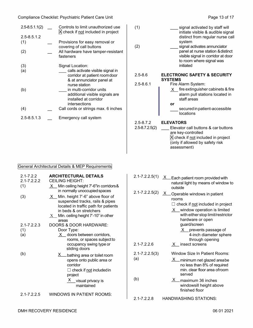
2.1-7.2.2 ARCHITECTURAL DETAILS 2.1-7.2.2.2 CEILING HEIGHT: (1) X Min ceiling height 7'-6"in corridors &
in normally unoccupied spaces (3) X Min. height 7’-6” above floor of
suspended tracks, rails & pipes located in traffic path for patients in beds & on stretchers
X Min. ceiling height 7’-10” in other areas
2.1-7.2.2.3 (1) (a)
DOORS & DOOR HARDWARE: Door Type: X doors between corridors,
rooms, or spaces subject to occupancy swing type or sliding doors
(b) X bathing area or toilet room opens onto public area or corridor ☐ check if not included in project
X visual privacy is maintained
2.1-7.2.2.5 WINDOWS IN PATIENT ROOMS:
2.1-7.2.2.5(1) X Each patient room provided with natural light by means of window to outside
2.1-7.2.2.5(2) X Operable windows in patient rooms ☐ check if not included in project X window operation is limited
with either stop limit/restrictor hardware or open guard/screen X prevents passage of
4-inch diameter sphere through opening
2.1-7.2.2.6 X insect screens
2.1-7.2.2.5(3) Window Size In Patient Rooms: (a) X minimum net glazed area be
no less than 8% of required min. clear floor area of room served
(b) X maximum 36 inches windowsill height above finished floor
2.1-7.2.2.8 HANDWASHING STATIONS:
General Architectural Details & MEP Requirements
(1) signal activated by staff will initiate visible & audible signal distinct from regular nurse call system
(2) signal activates annunciator panel at nurse station & distinct visible signal in corridor at door to room where signal was initiated
2.5-8.6 ELECTRONIC SAFETY & SECURITY SYSTEMS
2.5-8.6.1 Fire Alarm System: X fire extinguisher cabinets & fire
alarm pull stations located in staff areas
or secured in patient-accessible
locations
2.5-8.7.2 ELEVATORS
2.5-8.7.2.5(2) Elevator call buttons & car buttons are key-controlled X check if not included in project (only if allowed by safety risk assessment)
2.5-8.5.1.1(2) Controls to limit unauthorized use X check if not included in project
2.5-8.5.1.2
(1) Provisions for easy removal or covering of call buttons
(2) All hardware have tamper-resistant fasteners
(3) (a)
(b)
Signal Location: calls activate visible signal in
corridor at patient room door & at annunciator panel at nurse station
in multi-corridor units additional visible signals are installed at corridor intersections
(4) Call cords or strings max. 6 inches
2.5-8.5.1.3 Emergency call system

DMH RECOVERY RESIDENCE 06 01 2021
Compliance Checklist: Psychiatric Patient Care Unit Page 14 of 17
(4) Flooring surfaces including those on stairways are stable, firm & slip-resistant
(5) Floors & wall bases of soiled workrooms, toilet rooms & other areas subject to frequent wet cleaning are constructed of materials that are not physically affected by germicidal or other types of cleaning solutions
2.1-7.2.3.2 WALLS & WALL PROTECTION: (1)(a) Wall finishes are washable (1)(b) Wall finishes near plumbing fixtures
are smooth, scrubbable & water-resistant
(2) Wall surfaces in areas routinely subjected to wet spray or splatter are monolithic or have sealed seams that are tight & smooth
2.1-7.2.3.3 CEILINGS: (1) Ceilings provided in all areas
except mechanical, electrical & communications equipment rooms
(a) Ceilings cleanable with routine housekeeping equipment
(b) Acoustic & lay-in ceilings where used do not create ledges or crevices
2.1-8.2 HEATING VENTILATION & AIR-CONDITIONING (HVAC) SYSTEMS
Part 3/6.1 UTILITIES: Part 3/6.1.2 Heating & Cooling Sources: Part 3/6.1.2.1 X heat sources sufficient for facility
needs (reserve capacity) even when any one of heat sources or essential accessories is not operating due to breakdown or routine maintenance
X capacity of remaining source or sources is sufficient to provide for domestic hot water & to provide heating for inpatient rooms
Part 3/6.1.2.2 Central cooling systems greater than 400 tons (1407 kW) peak cooling load ☐ check if not included in project X number & arrangement of
cooling sources & essential accessories is sufficient to support facility operation plan upon breakdown or routine maintenance of any one of cooling sources
Part 3/6.2 AIR-HANDLING UNIT (AHU) DESIGN:
(3)(a) X Handwashing station countertops made of porcelain, stainless steel, solid-surface materials or impervious plastic laminate assembly
(3)(b) X Countertops substrate ☐ check if not included in project X marine-grade plywood (or
equivalent material) with impervious seal
(4) X Handwashing station casework ☐ check if not included in project X designed to prevent storage
beneath sink (5) X Provisions for drying hands (a) X hand-drying device does not
require hands to contact dispenser
(b) X hand-drying device is enclosed to protect against dust or soil & to ensure single-unit dispensing
(6) X Liquid or foam soap dispensers 2.1-7.2.2.10 HANDRAILS: (1) W Handrails installed on both sides
of patient use corridors (3) Rail ends return to wall or floor (4) Handrail gripping surfaces &
fasteners are smooth (free of sharp or abrasive elements) with 1/8-inch min. radius
(5) Handrails have eased edges & corners
(6) Handrail finishes are cleanable 2.5-7.2.4.2/ Policy
Handrails are ligature-resistant
2.1-7.2.2.12 NOISE CONTROL: (1) X Recreation rooms, exercise
rooms equipment rooms & similar spaces where impact noises may be generated are not located directly over patient bed areas
or Special provisions are made to
minimize impact noise
(2) X Noise reduction criteria in Table
1.2-6 applicable to partitions, floors & ceiling construction are met in patient areas
2.1-7.2.3 SURFACES 2.1-7.2.3.1 FLOORING & WALL BASES: (1) X Flooring surfaces cleanable &
wear-resistant for location (3) X Smooth transitions provided
between different flooring materials

DMH RECOVERY RESIDENCE 06 01 2021
Compliance Checklist: Psychiatric Patient Care Unit Page 15 of 17
Part 3/6.2.1 AHU casing is designed to prevent
water intrusion, resist corrosion & permit access for inspection & maintenance
. Part 3/6.3 OUTDOOR AIR INTAKES & EXHAUST
DISCHARGES: Part 3/6.3.1 Outdoor Air Intakes: Part 3/6.3.1.1 located min. of 25 ft from
cooling towers & all exhaust & vent discharges
outdoor air intakes located such that bottom of air intake is at least 6'-0" above grade
air intakes located away from public access
Part 3/6.3.1.3 intakes on top of buildings ☐ check if not included in project located with bottom of air
intake min. 3'-0" above roof level
Part 3/6.3.1.4 intake in areaway X check if not included in project bottom of areaway air
intake opening is at least 6'-0" above grade
bottom of air intake opening from areaway into building is at least 3'-0" above bottom of areaway
Part 3/6.4 FILTRATION: Two filter banks for inpatient care
(see Table 6.4) Filter Bank No. 1: MERV 7 Filter Bank No. 2: MERV 14
Each filter bank with efficiency of greater than MERV 12 is provided with differential pressure measuring device to indicate when filter needs to be changed
Part 3/6.4.1 Filter Bank No. 1 is placed upstream of heating & cooling coils
Part 3/6.4.2 Filter Bank No. 2 is placed downstream of all wet-air cooling coils & supply fan
Part 3/6.7 AIR DISTRIBUTION SYSTEMS: Part 3/6.7.1 pressure relationships required
in tables 7.1 maintained in all modes of HVAC system operation
Spaces that have required pressure relationships are served by fully ducted return systems or fully ducted exhaust systems
Inpatient facilities are served by fully ducted return or exhaust systems
Part 3/6.7.2 Air Distribution Devices:
X supply air outlets comply with Table 6.7.2
Part 3/6.7.3 Smoke Barriers: X HVAC zones coordinated
with compartmentation to minimize ductwork penetrations of fire & smoke barriers.
Part 3/6.8 ENERGY RECOVERY SYSTEMS: ☐ check if not included in project
Part 3/6.8.1 Located upstream of Filter Bank No. 2
Part 3/6.8.3 Energy recovery systems with leakage potential ☐ check if not included in project arranged to minimize potential
to transfer exhaust air directly back into supply airstream
designed to have no more than 5% of total supply airstream consisting of exhaust air
Part 3/7 SPACE VENTILATION Part 3/7.1.a
Part 3/7.1.a.1
Spaces ventilated according to Table 7.1
Air movement is from clean to less- clean areas
Part 3/7.1a.5 Air recirculation through room units ☐ check if not included in project comply with Table 7.1
room units receive filtered & conditioned outdoor air
provide min. MERV 6 filter located upstream of any cold surface so that all of air passing over cold surface is filtered
2.1-8.3 ELECTRICAL SYSTEMS 2.1-8.3.2.2 Panelboards: (1) panelboards serving life safety
branch circuits serve floors on which they are located & floors immediately above & below
(2) panelboard critical branch circuits serve floors on which
they are located (3) panelboards not located in exit
enclosures or exit passageways 2.1-8.3.4 LIGHTING: 2.1-8.3.4.2 Luminaires in wet areas (e.g.
kitchens showers) have smooth cleanable shatter-resistant lenses & no exposed lamps

DMH RECOVERY RESIDENCE 06 01 2021
Compliance Checklist: Psychiatric Patient Care Unit Page 16 of 17
2.1-8.4.2.6 Drainage Systems: (1)(a) drainage piping installed
above ceiling of or exposed in electronic data processing areas & electric closets ☐ check if not included in project
special provisions to protect space below from leakage & condensation
(1)(b) drip pan for drainage piping above ceiling of sensitive area ☐ check if not included in project accessible overflow drain with outlet
located in normally occupied area
2.1-8.4.3 PLUMBING FIXTURES 2.1-8.4.3.1(1) Materials used for plumbing fixtures
are non-absorptive & acid-resistant
2.1-8.4.3.2 Handwashing Station Sinks: (2) sink basins have nominal size of
no less than 144 square inches sink basins have min. dimension
9 inches in width or length (3) sink basins are made of
porcelain, stainless steel or solid-surface materials
(5) water discharge point min. 10” above bottom of basin
(7) anchored to resist so that allowable stresses are not exceeded where vertical or horizontal force of 250 lbs. is applied
(8) sinks used by medical staff, patients & public have fittings that can be operated without using hands (may be single-lever or wrist blade)
(a) blade handles ☐ check if not included in project at least 4 inches in length
provide clearance required for operation
(b) sensor-regulated water fixtures ☐ check if not included in project
meet user need for temperature & length of time water flows
designed to function at all times and during loss of normal power
2.1-8.3.4.3(1) Reading light for each bed (a) incandescent & halogen lights
☐ check if not included in project placed or shielded to protect
patient from injury light source covered by
diffuser or lens 2.1-8.3.4.3(2) Patient care unit corridors have
general illumination with provisions for reducing light levels at night
2.1-8.3.5 ELECTRICAL EQUIPMENT: 2.1-8.3.5.1 Handwashing sinks that depends
on building electrical service for operation are connected to essential electrical system ☐ check if not included in project
2.1-8.3.6 ELECTRICAL RECEPTACLES: 2.1-8.3.6.1 Receptacles In Corridors: (1) duplex-grounded receptacles
for general use installed 50’-0” apart or less in all corridors
duplex-grounded receptacles for general use installed within 25’-0” of corridor ends
(2) receptacles in corridors are of tamper-resistant type
2.1-8.3.6.3 Essential Electrical System Receptacles:
(1) cover plates distinctively colored or marked for identification
(2) same color is used throughout facility
2.1-8.4 PLUMBING SYSTEMS 2.1-8.4.2 Plumbing & Other Piping Systems: 2.1-8.4.2.1(3) no plumbing piping exposed
overhead or on walls where possible accumulation of dust or soil may create cleaning problem
2.1-8.4.2.5 Heated Potable Water Distribution Systems:
(2) heated potable water distribution systems serving patient care areas are under constant recirculation
non-recirculated fixture branch piping max. length 25’-0”
(3)(a)
(3)(c)
no installation of dead-end piping (except for empty risers mains & branches for future use)
(3)(b) any existing dead-end piping is removed ☐ check if not included in project
(4)(a) water-heating system supplies water at temperatures & amounts indicated in Table 2.1-4

DMH RECOVERY RESIDENCE 06 01 2021
Compliance Checklist: Psychiatric Patient Care Unit Page 17 of 17
2.1-8.6.2 ELECTRONIC SURVEILLANCE SYSTEMS ☐ check if not included in project
2.1-8.6.2.2 X Monitoring devices are located so they are not readily observable by general public or patients
2.1-8.6.2.3 X Electronic surveillance systems receive power from essential electrical system
2.1-8.4.3.3 Showers & Tubs: (1) X nonslip surfaces 2.1-8.4.3.5 Clinical Flushing-Rim Sinks:
X check if not included in project (1)
(a)
trimmed with valves that can are operated without hands (may be single-lever or wrist blade devices)
(b) handles are at least 6 in. long (2) integral trap wherein upper
portion of water trap provides visible seal

ARCHITECTURAL QUESTION #3
Temperature Control – Space temperature shall be controlled via thermostats located in each temperature control zone. In general, offices, conference rooms, exam rooms, and other non-secure spaces occupied spaces shall be provided with adjustable thermostats to allow for local temperature control. Corridors, private rooms, and other secure function space would be provided with tamperproof, anti-ligature temperature sensors which would be controlled and monitored through the direct digital control system with no local adjustment. Humidity Control – Building humidity will be monitored via return air relative humidity sensor and controlled during the cooling season via the ventilation air cooling coil dehumidification sequence to improve comfort. Ventilation Design – The ventilation rates supplied to each space were calculated based on the procedures outlined in ASHRAE 62.1 for dedicated outdoor air systems. Heating and Cooling – The proposed facility shall be conditioned and ventilated via a 20,000 CFM central air handling unit with a 6,000 CFM energy recovery unit located in the attic space. The air handling unit equipped with a hot water heating preheat coil and chilled water coil. The unit will be provided with a fully modulating mixing box to allow for 100% economizer operation. The unit shall be provided with MERV 7 prefilters and MERV 13 final filters as well as smoke dampers on the supply discharge and return discharge. Supply and return air ductwork shall be distributed through the attic space to variable air volume boxes also located within the attic space. Each temperature control zone is provided with a supply and return air variable air volume box. Each supply variable air volume is provided with a hot water reheat coil. Exhaust will be provided from bathrooms, soiled holding, exercise area, laundry, art therapy, and other areas requiring direct exhaust. All registers, grilles, and diffusers located in secure spaces shall be psych safe, anti-ligature type. All duct insulation shall be per Vermont Energy Code Standards. The central heating and cooling plants shall consist of closed-loop geothermal system interconnected with (2) 40 ton water to water heat pumps. The water to water heat pump system would be located on site and would be capable of providing 100% of the chilled and heating hot water to the space all through an electric based source. The natural gas boiler would be located in the mechanical room and would be utilized for snowmelt operation only. All central systems shall be configured with dedicated redundant circulators to allow for a primary-secondary configuration to the heating hot water and chilled water distribution loops. All circulators will be provided with EC motors for variable volume operation. The final central system selection and capacities will be based on site geothermal production testing, budget, and life cycle costs through energy modeling. Heating Hot Water Loop – A heating hot water loop shall be distributed from the central heating plant to all heating hot water reheat coils and central air handling unit heating coil. All circulators will be provided with EC motors with demand controls for variable volume operation. Chilled Water Loop – A chilled water loop shall be distributed from the central chilled water plant to the central air handling unit cooling coil. All circulators will be provided with EC motors with demand controls for variable volume operation. Controls – All HVAC systems will be provided with a direct digital controls system with remote monitoring and control capabilities.

Electrical Distribution i. The proposed electric service will be 208 volt, three phase, four wire, fed from a new pad mounted. The transformer pad shall be per Green Mountain Power (GMP) standards. GMP shall run new primary voltage cables via customer-provided conduits to the new pad transformer. The service size is estimated to be 1600 amps. ii. The main distribution system within the proposed facility be made up of a 1,600 amp, 208 volt Main Distribution Panel (MDP). Branch panelboards shall be fed from the distribution panel for lighting and general power loads and large central equipment such as air handling units, heat pumps, and central mechanical plant pumps would be fed directly from the main distribution panels. iii. The project will reuse the existing emergency generator that is located onsite. iv. Most interior power circuiting shall be completed with EMT conduit and THWN copper conductor. Where EMT is impractical or not cost effective, metal clad cable may be used. v. All exterior exposed circuiting shall be completed with PVC-coated RGC conduit within 5 feet of the building foundations and Schedule 40 PVC beyond 5’ of foundation. All circuiting will be THWN copper conductor, except for larger circuits where aluminum conductors will be used. vi. All equipment circuiting and disconnects will be provided as required by all relevant codes. Electrical Receptacle Locations and Types i. All receptacles shall be Leviton 20 amp receptacles or equivalent. All secure spaces shall be provided with tamper proof, anti-ligature outlets. ii. All Private Rooms shall be provided with a single tamper proof, anti-ligature outlet located near the bed. This outlet shall have the capabilities of being powered off by a switch located outside room in corridor. iii. Non Secure Toilet rooms - at least (1) GFCI protected receptacle. iv. Storage areas - At least (1) receptacle every 12 L.F. of partition. At least (1) receptacle for each storage closet. v. Office and reception areas - Should have a minimum duplex receptacle every 4 LF with a minimum of two per workstation. vi. All receptacles within 6 feet of a water source shall be GFCI. vii. Provide GFCI service receptacles in weatherproof enclosures within each piece of mechanical equipment located outdoors. viii. Each copy machine shall be fitted with a duplex receptacle fed with a dedicated circuit. Coordinate copy machine locations with Architectural Documents. Lighting i. All lighting shall be LED type fixtures per energy code requirements. ii. Outdoor site lighting will be LED type. iii. In general all offices, break room, and exam spaces shall be provided with 2’x2’ Recessed LED dimmable lighting. iv. Residential spaces and specific resident function shall be provided with recessed and secure dimmable LED can lighting with the ability to tube color temperature. Resident bedrooms shall have a reading light above bed that can be locally switched. Resident bathrooms shall be provided with recessed downlighting in shower and a wall mount vanity over bathroom sink. All fixtures and switches shall be tamper proof and anti-ligature type. v. Lighting in staff bathrooms shall be wall mount, indirect LED vanity fixtures, with supplemental LED down-lighting as needed. vi. Lighting in kitchens, food preparation and similar areas will be tamper proof, 2x2 recessed LED designed for use in cooking areas.

Lighting Control i. All lighting luminance levels shall be per IES. ii. In general for offices and conference rooms, upon entering the space occupants must manually turn on lights. If occupants do not manually turn off lights once they leave space, the occupancy sensors will automatically turn lights off. iii. For storage and resident laundry spaces will automatically turn lights on or off depending on if it senses occupant(s). iv. Areas capable of taking advantage of ambient lighting to be provided with daylighting control in addition to occupancy sensors, step-dimming and full dimming controls. v. Corridors will be provided with occupancy sensors and manual staff override controls. vi. Exterior lighting will be controlled by photocell and time clock control via the Building Management System (BMS). Additional lighting may be added to BMS depending on occupancy. Telecommunications i. Offices and Conference room data and voice locations, types and/or quantities will be provided based on space program requirements. ii. All telecommunications shall be installed per State Of Vermont Standards Switching equipment and all cabling from site to building to be outside scope of this project. iii. IT equipment to be located within same rooms as electrical panels. Fire Alarm Systems i. The proposed building shall be provided with a new addressable fire alarm system per NFPA 72 and State of Vermont requirements. The fire alarm system will be installed as a class “A” wiring configured loop. ii. The fire alarm system will be provided with a remote annunciator. iii. Provide duct smoke detectors per code requirements to provide for air handling system shut down and alarming. iv. Sprinkler system shall be tied to fire alarm system in accordance with NFPA 13 and NFPA 101. Other – Anti-ligature and tamper proof nurse call shall be provided in resident areas and bathrooms. Notification shall be provided outside space for staff assistance. Plumbing – The proposed building domestic water entrance shall be 2”. A new reduced pressure zone assembly shall be provided off the new water entrance located in the mechanical room. The proposed building’s domestic hot water system shall be supported from 120 gallon gas fired water heaters, equivalent to the AO Smith BTH-300. Water heaters to be located in the mechanical room and a recirculation loop shall be provided throughout the building. Domestic hot and cold supply piping and waste and vent piping shall be provided to all plumbing fixtures as needed. Each resident room shall be provided with dedicated hot and cold water to plumbing fixtures. A solenoid shall be provided on each domestic water line to resident rooms and shall be controlled via a switch outside resident room door in corridor. All resident plumbing fixtures shall be anti-ligature and tamper proof type. In general, all fixtures shall have a white stainless steel finish. We recommend Whitehall WH3740 for all lavatories. All resident lavatories and sinks shall be provided with behavioral safety SF390 faucets. Showers will be provided Model WH538-FH-CSH-SRCH shower valve assembly and Whitehall WHLD Linear Drain. We would recommend that all Resident water closets be provided as Metcraft 4680 with white powder coat anti-microbial finish and Sloan Concealed manual push button flush valve. The intent is to allow the servicing of all secure fixtures through a mechanical space, attic, or corridor if possible. In general, all new water closets shall be high efficiency 1.28 gpf flushometers, lavatories will

be equipped with 0.5 gpm aerators, showers shall be equipped with 1.5 gpm heads, and sinks shall be equipped with 1.0 gpm aerators for water conservation. A new gas entrance will be required depending on what mechanical option is chosen. Natural gas piping shall be routed to the boiler plant id provided in project. Natural gas lines shall be sized for equipment btu requirement and pressure based on distance from natural gas entrance service as indicated in NFPA 54. Fire Protection: A new wet-type fire protection system entrance shall be provided in the mechanical room. Distribution shall be provided throughout the program space and attic per NFPA 13 requirements. All sprinkler heads in secure locations shall be tamper proof anti ligature type equivalent to Tycho Raven Heads.
08 11 13 – HOLLOW METAL DOORS AND FRAMES FFF Project No. A2005Lavallee Brensinger Architects PSRR – Vermont, VT
HOLLOW METAL DOORS AND FRAMESDesign Development – 02/26/2021 Not for construction 08 11 13 - 1 of 6
SECTION 08 11 13HOLLOW METAL DOORS AND FRAMES
PART 1 GENERAL1.01 SECTION INCLUDES
A. Steel doors and frames, steel frames for wood doors, steel frames for glazing, and accessories.1.02 RELATED REQUIREMENTS
A. Section 08 71 00 - Door Hardware.B. Section 08 80 00 - Glazing: Glass for doors and borrowed lites.C. Section 09 90 00 - Painting and Coating: Field painting.D. Division 26 - Electrical: Security system interface with doors and frames.
1.03 REFERENCE STANDARDSA. ADA Standards - Americans with Disabilities Act (ADA) Standards for Accessible Design; 2010.B. ANSI/ICC A117.1 - American National Standard for Accessible and Usable Buildings and
Facilities; International Code Council.C. ANSI/SDI A250.4 - Test Procedure and Acceptance Criteria for Physical Endurance for Steel
Doors, Frames and Frame Anchors; 2011.D. ANSI/SDI A250.8 - Specifications for Standard Steel Doors and Frames (SDI-100); 2014.E. ANSI/SDI A250.10 - Test Procedure and Acceptance Criteria for Prime Painted Steel Surfaces
for Steel Doors and Frames; 2011.F. ASTM A653 - Standard Specification for Steel Sheet, Zinc-Coated (Galvanized) or Zinc-Iron
Alloy-Coated (Galvannealed) by the Hot-Dip Process; 2011.G. ASTM A1008 - Standard Specification for Steel, Sheet, Cold-Rolled, Carbon, Structural, High-
Strength Low-Alloy, High-Strength Low-Alloy with Improved Formability, Solution Hardened, and Bake Hardenable; 2015.
H. ASTM A1011 - Standard Specification for Steel, Sheet and Strip, Hot-Rolled, Carbon, Structural, High-Strength Low-Alloy, High-Strength Low-Alloy with Improved Formability, and Ultra-High Strength; 2014.
I. ASTM E413 - Classification for Rating Sound Insulation; 2010.J. BHMA A156.115 - American National Standard for Hardware Preparation in Steel Doors and
Steel Frames; 2014.K. NAAMM HMMA 805 - Recommended Selection and Usage Guide for Hollow Metal Doors and
Frames; 2012.L. NAAMM HMMA 840 - Guide Specifications for Installation and Storage of Hollow Metal Doors
and Frames.M. NAAMM HMMA 860 - Guide Specifications for Hollow Metal Doors and Frames; 2013.N. NAAMM HMMA 861 - Guide Specifications for Commercial Hollow Metal Doors and Frames.O. UL 10B - Standard for Fire Tests of Door Assemblies; Current Edition, Including All Revisions.P. UL 10C - Standard for Positive Pressure Fire Tests of Door Assemblies; Current Edition,
Including All Revisions.Q. UL 1784 - Standard for Air Leakage Tests of Door Assemblies; Current Edition, Including All
Revisions.R. SDI 117: Manufacturing Tolerances for Standard Steel Doors and Frames.

08 11 13 – HOLLOW METAL DOORS AND FRAMES FFF Project No. A2005Lavallee Brensinger Architects PSRR – Vermont, VT
HOLLOW METAL DOORS AND FRAMESDesign Development – 02/26/2021 Not for construction 08 11 13 - 2 of 6
1.04 SUBMITTALSA. See Section 01 30 00 - Administrative Requirements for submittal procedures.B. Product Data: Materials and details of design and construction, hardware locations,
reinforcement type and locations, cores, sound ratings, profiles, anchorage and fastening methods, and finishes.
C. Shop Drawings: Details of each opening, showing elevations, fire-ratings, glazing, frame profiles, anchors, and identifying location of different finishes, if any.
D. Samples: Upon request, submit samples of typical frame, door section, glazing frame and loose stop.
E. Installation Instructions: Manufacturer's published instructions, including any special installation instructions relating to this Project.
1.05 QUALITY ASSURANCEA. Manufacturer Qualifications: Company specializing in manufacturing the products specified in
this Section with minimum ten years documented experience and a member of the Steel Door Institute.
B. Copies of Documents at Project Site: Maintain at the project site a copy of each referenced document that prescribes installation requirements.
1.06 DELIVERY, STORAGE, AND HANDLINGA. Store in accordance with NAAMM HMMA 840. Store all materials upright, in a protected dry
area, at least 1" or more off the ground or floor and at least 1/4" between individual pieces. Materials shall not be permitted to rust or corrode.
B. Protect with resilient packaging; avoid humidity build-up under coverings; prevent corrosion.
PART 2 PRODUCTS2.01 MANUFACTURERS
A. Basis of Design, Steel Doors: (General) 707 Series by Curries Door Co.; (EIP Suite) 847 Series by Curries Door Co.
B. Acceptable Manufacturer Steel Doors and Frames: 1. Ceco.2. Republic Doors3. Steelcraft.4. Curries Door Co.5. Pioneer.
2.02 DESIGN CRITERIAA. Requirements for Hollow Metal Doors and Frames:
1. Steel used for fabrication of doors and frames shall comply with one or more of the following requirements; Galvannealed steel conforming to ASTM A653, cold-rolled steel conforming to ASTM A1008, or hot-rolled pickled and oiled (HRPO) steel conforming to ASTM A1011, Commercial Steel (CS) Type B for each.
2. Accessibility: Comply with ICC A117.1 and ADA Standards.3. Door Top Closures: Welded, flush with top of faces and edges.4. Door Edge Profile: Manufacturers standard for application indicated.5. Typical Door Face Sheets: Flush. 6. Glazed Lights: Non-removable stops on secure side; sizes and configurations as
indicated on Drawings.a. NOTE: Bottom of glazed lights must extend to within 43" of the floor and shall be at
least 10" above the floor.
08 11 13 – HOLLOW METAL DOORS AND FRAMES FFF Project No. A2005Lavallee Brensinger Architects PSRR – Vermont, VT
HOLLOW METAL DOORS AND FRAMESDesign Development – 02/26/2021 Not for construction 08 11 13 - 3 of 6
7. Hardware Preparation: In accordance with DHI A115 Series, with reinforcement welded in place, in addition to other requirements specified in door grade standard.
8. Hardware Preparation for New Doors at New Frames: Hardware mounting heights shall match similar existing conditions, subject to modifications during shop drawing review.
9. Galvanizing for Units in Wet Areas: Components hot-dipped zinc-iron alloy-coated (galvannealed) in accordance with ASTM A653, with manufacturer's standard coating thickness
B. Fire-Rated Door Assemblies:1. All fire-rated doors and frames shall conform to and/or be tested by the requirements of:
a. UL 10C - Pressure Fire Test of Door Assemblies.b. International Building Code, 2015.c. ASTM E119 - Standard Method for Testing Construction Assemblies.d. UL 1784: Smoke and draft control air leakage not to exceed 3.0 cu ft / min / sq ft of
door opening at 0.10 inch of water for ambient and elevated temperature tests.2. All components of a fire-rated assembly (door, glazing, locks, closers, latches, lite frames,
louvers, hinges, frames, etc.) shall be rated at or exceed the intended fire protection rating indicated for the assembly.
3. Exit Enclosure Door Temperature Rise Rating: Max transmitted temperature of 450 degrees F. above ambient with 30 minutes of fire exposure, except for fully sprinkled buildings.
4. Fire-rated doors and door frames shall be labeled in accordance with NFPA 80; permanently labeled and listed by UL, Intertek or Warnock Hersey.a. Oversize fire-rated door assemblies: For door assemblies required to be fire-rated
and exceeding sizes of tested assemblies, provide a certificate and label from an approved independent testing and inspection agency, indicating that the door and frame assembly conforms to the requirements of design, materials, and construction as established by individual listings for tested assemblies.
b. If any door or frame specified by the Architect to be fire-rated cannot qualify for appropriate labeling because of its design, hardware or any other reason, the Architect shall be so advised before proceeding with fabrication.
C. Fire Rated Door Frame and Window Assembly Ratings: As indicated on Door and Frame Schedule on the Drawings.
2.03 HOLLOW METAL DOORSA. General:
1. Doors shall be strong, rigid and neat in appearance, free of warpage or buckle. Corner bends shall be true, straight, and of minimum radius for the gauge of metal specified.
2. Door faces shall be joined at their vertical edges by continuously welding the faces to the internal stiles extending the full height of the doors. Welds shall be ground and dressed to make them invisible, providing a smooth finish surface.
3. Tops and bottoms of the doors shall have an inverted channel made of 16-gauge galvanized steel; spot-welded 5 inches on center to the door faces. Openings shall be provided in the bottom channel to permit the escape of entrapped moisture
B. Interior Doors, Non-Fire Rated (Risk Levels 2 thru 5):1. Product: Security Wood Door by Ambico2. Core: Steel-stiffened HM core, with sound attenuation between the stiffeners, with stain
grade 2-ply wood veneer faces and hardwood door edges. Plain sawn-white Maple finish3. Thickness: 1-3/4 inches.
C. Interior Doors, Steel-Stiffened (EIP Suite):1. Grade: ANSI A250.8 Full Flush Heavy-duty, (14 gage face) Level 4, physical performance
Level A, seamless.2. Core: Polystyrene, with 18 gage steel stiffeners 4-inches on center, spot welded to each
skin at 4” intervals and fully welded widths on each end.

08 11 13 – HOLLOW METAL DOORS AND FRAMES FFF Project No. A2005Lavallee Brensinger Architects PSRR – Vermont, VT
HOLLOW METAL DOORS AND FRAMESDesign Development – 02/26/2021 Not for construction 08 11 13 - 4 of 6
3. Thickness: 1-3/4 inches.
D. Interior Doors, Fire Rated:1. Grade: Same as Non-fire Rated.2. Core: Mineral board, as required for fire protection level.3. Fire Rating: As indicated on Door and Frame Schedule, tested in accordance with UL
10C ("positive pressure"). All fire-rated doors shall also be smoke and draft control labeled.a. Provide units listed and labeled by UL, WH, or other State of Vermont approved
testing laboratory.b. Attach fire rating label to each fire rated unit indicating hourly rating, temperature rise
rating and smoke / draft control "S" label.4. Smoke and Draft Control Doors (If not fire-rated, noted as "S" on the door schedule):
Same construction as fire-rated doors with indicated fire rating, plus:a. Maximum Air Leakage: 3.0 cfm per sq ft of door opening at 0.10 inch w.g. pressure,
when tested in accordance with UL 1784 at both ambient and elevated temperatures.b. Gaskets: No added gaskets or seals allowed.c. Label: UL "S" label.
E. Exterior Doors1. Product: 707 Series by Curries2. Core: Polyurethane Core. 16 ga face skins, embossed panel options.3. Thickness: 1-3/4 inches.
2.04 HOLLOW METAL FRAMESA. General:
1. Provide 14 gage for interior frames, fully welded type, for fire rated and non-fire rated.2. Provide minimum 16 gage mortar guard boxes at hardware cut-outs in frames for masonry
walls and at strike reinforcement in frames for stud partitions.3. Frames wider than 48 Inches: Reinforce with steel channel, minimum 12 gage, factory
welded to the frame head, flush with top. Such stiffeners shall not be used as lintels or load-carrying members.
4. Commercial quality cold rolled steel per ASTM A366 and A568 general requirements.B. Interior Door Frames, Fire Rated: Fire rating label to match door label.C. Frames for Interior Glazing or Borrowed Lites: Construction and face dimensions to match door
frames, and as indicated on Drawings.D. Corner joints shall be die mitered and have all contact edges closed tight and continuously
welded.E. Frame, trim and profiles shall be as scheduled by the Architect and verified by the Contractor.
All frame depths shall be coordinated with partition type depths by the Contractor. Frames for drywall partitions shall have 1/2 inch backbends with hooked profile.
F. Minimum depth of stops shall be 5/8", use 3/4” where required for fire rating or security.G. When shipping limitations so dictate, frames for large openings shall be fabricated in sections
designed for splicing in the field. All splicing locations and details shall be clearly identified on shop drawings.
H. Frames for multiple or special openings shall have mullion and/or rail members that are closed tubular shapes having no visible seams or joints. All joints between faces of abutting members shall be securely welded and finished smooth.
I. Frames shall be provided with supplemental internal concealed steel reinforcement, as engineered by the manufacturer.

08 11 13 – HOLLOW METAL DOORS AND FRAMES FFF Project No. A2005Lavallee Brensinger Architects PSRR – Vermont, VT
HOLLOW METAL DOORS AND FRAMESDesign Development – 02/26/2021 Not for construction 08 11 13 - 5 of 6
J. Floor Anchors: Minimum 14 gauge steel, ASTM A-591 zinc coated; securely welded inside each jamb, with 2 holes provided at each jamb for floor anchorage. Where required adjustable floor anchors, providing not less than 2" height adjustment, shall be provided.
K. Jamb Anchors at Stud Partitions: Minimum 16 gauge steel; ASTM A591 zinc coated; compatible with the actual stud used. Provide 4 anchors for frames up to 7'-6" high, 5 anchors for frames up to 8'-0" high and 1 additional anchor for each 2'-0" of height over 8'-0".
L. Masonry Jamb Anchors: Frames for installation in masonry walls shall be provided with adjustable jamb anchors of the T-strap type, 16 gage minimum, zinc coated per ASTM A591. Provide 3 anchors for frames up to 7'-6" high, 4 anchors for frames up to 8'-0" high and 1 additional anchor for each 2'-0" of height over 8'-0".
2.05 ACCESSORY MATERIALSA. Glazing: As specified in Section 08 80 00 - Glazing, field installed.B. Removable Stops: Rectangular, flush set, 18 gage galvanized, primed steel, butted corners;
prepared for countersink style torx tamperproof screws.C. Fixed Stops: Custom full-flush with no apparent seams on the face of the door at the outside of
spaces to be secured.D. Silencers: Resilient rubber, fitted into drilled hole; 3 on strike side of single door, 3 on center
mullion of pairs, and 2 on head of pairs without center mullions.E. Temporary Frame Spreaders: Provide for all factory or shop-assembled frames.F. Grout for Frames: Portland cement grout with maximum 4 inch slump for hand troweling;
thinner pumpable grout is prohibited.2.06 FINISH MATERIALS
A. Primer: Factory applied, rust-inhibiting, complying with ANSI A250.10, door manufacturer's standard.
B. After fabrication, all tool marks and surface imperfections shall be dressed, permanently filled and sanded as required to make all faces and vertical edges smooth, level and free of all irregularities. Doors shall be primed to ensure maximum paint adhesion, on all exposed surfaces with a rust-inhibitive primer in accordance with ANSI A-250 "Test Procedure and Acceptance Criteria for Primed Painted Steel Surfaces".
PART 3 EXECUTION3.01 EXAMINATION
A. The Contractor shall take all measurements, make all investigations, and in general, provide field work and coordination as required to ensure the proper fit of all Work specified herein. Frames shall be sized, positioned, and installed in accordance with the design intent represented on the Drawings. The design intent shall not be modified due to the Contractor's failure to provide coordination or obtain properly fabricated materials. Such coordination shall be provided sufficiently in advance so as to avoid delays in the construction schedule.
B. Verify that opening sizes and tolerances are acceptable. It shall be the responsibility of the Contractor to coordinate frame thicknesses with wall and partition types to ensure proper fit.
3.02 INSTALLATIONA. Install in accordance with the requirements of the specified door grade standard and NAAMM
HMMA 840. In addition, install fire rated units in accordance with NFPA 80.B. Coordinate frame anchor placement with wall construction. Wherever possible, leave frame
spreader bars intact until frames are set perfectly square and plumb, and anchors are securely attached. Verify that frames are square and plumb following removal of temporary spreaders.

08 11 13 – HOLLOW METAL DOORS AND FRAMES FFF Project No. A2005Lavallee Brensinger Architects PSRR – Vermont, VT
HOLLOW METAL DOORS AND FRAMESDesign Development – 02/26/2021 Not for construction 08 11 13 - 6 of 6
C. Coordinate installation of hardware in accordance with hardware manufacturer's templates and instructions. Doors and frames fabricated with hardware cutouts and reinforcing which will not properly accommodate finish hardware shall be rejected and replaced at no additional cost to the Owner.
D. Coordinate installation of glazing.E. Coordinate installation of electrical connections to electrical hardware items.F. Immediately after erection, areas where prime coat or galvanizing has been damaged shall be
sanded smooth and touch up with same primer or zinc rich rust-inhibitor primer as applied at the factory. Remove rust before touch-up is applied.
3.03 TOLERANCESA. Clearances between Door and Frame:
1. Steel doors and frame, at head and jambs: 1/8", with maximum 1/16" +/- variation.2. Wood doors and frame, at head and jambs: 1/8" maximum.3. Door bottoms: 3/4”.4. Smoke-rated door bottoms: 3/8" maximum.5. Meeting edges of pairs of doors: 1/8" maximum.6. Face of door and stop: 1/8".7. Note: Door sills, except at fire-rated doors, shall be undercut greater than the clearances
above if so scheduled on the Drawings and/or on the Door & Frame Schedule. Fire-rated doors shall have clearances as specified in NFPA 80.
B. Maximum Diagonal Distortion: 1/16 in measured with straight edge, corner to corner.3.04 ADJUSTING
A. Adjust for smooth and balanced door movement.B. Protect installed doors, frames and accessories against damage from other construction work.
Any damage prior to acceptance shall be repaired or replaced, if such action complies with the requirements and shows no evidence of repair or refinishing.
3.05 SCHEDULEA. Refer to Door and Frame Schedule See Drawings.
END OF SECTION

08 14 16 – FLUSH WOOD DOORS FFF Project No. A2005Lavallee Brensinger Architects PSRR – Vermont, VT
FLUSH WOOD DOORSDesign Development – 02/26/2021 Not for construction 08 14 16 - 1 of 5
SECTION 08 14 16FLUSH WOOD DOORS
PART 1 GENERAL1.01 SECTION INCLUDES
A. Security Level 1 (Staff only spaces): Flush wood doors; flush and flush glazed configuration; fire rated and non-rated.
B. Factory finishing of wood doors.1.02 RELATED REQUIREMENTS
A. Section 08 11 13 - Hollow Metal Doors and Frames.B. Section 08 71 00 - Door Hardware.C. Section 08 80 00 - Glazing: Site glazing of doors.
1.03 REFERENCE STANDARDSA. AWI/AWMAC/WI (AWS) - Architectural Woodwork Standards; 2009.B. ICC (IBC) - International Building Code, 2006.C. NFPA 80 - Standard for Fire Doors and Other Opening Protectives; 2010.D. NFPA 252 - Standard Methods of Fire Tests of Door Assemblies; National Fire Protection
Association; 2008.E. UL (BMD) - Building Materials Directory; Underwriters Laboratories Inc.; current edition.F. UL 10B - Standard for Fire Tests of Door Assemblies; Current Edition, Including All Revisions.G. UL 10C - Standard for Positive Pressure Fire Tests of Door Assemblies; Current Edition,
Including All Revisions.H. WDMA I.S.1-A - Architectural Wood Flush Doors; Window and Door Manufacturers
Association; 2004.1.04 SUBMITTALS
A. See Section 01 30 00 - Administrative Requirements for submittal procedures.B. Product Data: Indicate door core materials and construction; veneer species, type and
characteristics. Submit manufacturer's certification of compliance with quality standards.C. Shop Drawings: Show doors and frames, elevations, sizes, types, swings, undercuts, beveling,
blocking for hardware, factory machining, factory finishing, cutouts for glazing and other details.D. Specimen warranty, and warranty executed in Owner’s name.E. Samples:
1. Upon request, submit one sample of door construction, 8x8 inch in size cut from top corner of door and samples of lite frame section.
2. Submit two samples of door veneer, 6x6 inch minimum in size illustrating selected wood grain, stain color, and sheen.
F. Manufacturer's certification that products are manufactured in the United States.G. Manufacturer's Installation Instructions: Indicate special installation instructions.
1.05 QUALITY ASSURANCEA. Manufacturer Qualifications: Company specializing in manufacturing the products specified in
this Section with minimum ten years of documented experience.B. Fire Rated Door and Transom Panel Assemblies: Conform to the following standards for fire
rated class as indicated.1. UL 10c UBC-10 Pressure Fire Test of Door Assemblies2. NFPA 252 Methods of Fire Tests of Door Assemblies

08 14 16 – FLUSH WOOD DOORS FFF Project No. A2005Lavallee Brensinger Architects PSRR – Vermont, VT
FLUSH WOOD DOORSDesign Development – 02/26/2021 Not for construction 08 14 16 - 2 of 5
3. NFPA 80 Standard for Fire Doors and Windows4. NFPA 101 Life Safety Code5. NFPA 105 Standard for Smoke and Draft Control Assemblies6. Fire & Smoke/Draft labeled and listed by Underwriters Laboratories or Warnock Hersey.
C. All components of a fire-rated assembly (door, glazing, locks, closers, latches, lite frames, louvers, hinges, etc.) shall be rated at or exceed the intended fire protection rating indicated for the assembly.1. Temperature Rise Rating: At exit enclosures, provide doors that have a temperature rise
rating of 450 degrees F maximum in 30 minutes of fire exposure.2. Pressure Test: After 5 minutes into the test, the neutral pressure level in furnace shall be
established at 40 inches or less above the sill.3. Wood doors with fire rating requirements exceeding 20 minutes shall be Category A doors
with integral intumescent strips.4. All wood doors shall be smoke rated, S labeled.
1.06 DELIVERY, STORAGE, AND HANDLINGA. Protect materials during transit, storage, and handling to prevent deterioration, damage and
soiling. Package each door at the factory in a separate heavy sealed poly bag. Mark each bag at top and bottom of doors for location to correspond with opening number on the Drawings.
B. Accept doors on site in manufacturer's packaging. Inspect for damage. In the event of damage, immediately make all repairs and replacements necessary for approval of the Architect and at no additional cost to the Owner.
C. Protect doors with resilient packaging. Do not store in damp or wet areas; or in areas where sunlight might bleach veneer. Seal top and bottom edges with tinted sealer if stored more than one week. Break seal on site to permit ventilation. Deliver door to job site only when building is dry and has reached average prevailing relative humidity of locality.
D. Coordinate the work with door opening construction, door frame and door hardware installation. The Contractor shall take all measurements, make all investigations, and in general provide field work and coordination as required to ensure the proper fit of all Work specified herein. Doors and frames shall be sized, positioned and installed in accordance with the design intent represented on the Drawings. The design intent shall not be modified due to the Contractor's failure to provide coordination or obtain properly fabricated materials. Such coordination shall be provided sufficiently in advance so as to avoid delays in the construction schedule.
1.07 WARRANTYA. See Section 01 78 10 - Warranties for additional warranty requirements.B. Interior Doors: Provide a special manufacturer's warranty, signed by both the manufacturer,
installer and Contractor, for the life of the installation.C. Include coverage for delamination of veneer, defective materials, telegraphing core
construction, and warping. Unsatisfactory warpage shall be more than 1/4" in a 42" x 84" section and telegraphed core construction shall be defined as exceeding 0.01 inch in a 3 inch span. The warranty shall also include refinishing and reinstalling which may be required due to repair or replacement of defective doors.
PART 2 PRODUCTS2.01 MANUFACTURERS
A. Wood Veneer Faced Doors:1. Graham Wood Doors: www.grahamdoors.com.2. Eggers Industries: www.eggersindustries.com.3. Marshfield DoorSystems, Inc: www.marshfielddoors.com.4. Buell Door Co.. www.buelldoor.com5. Algoma Hardwoods Inc.; www.algomahardwoods.com

08 14 16 – FLUSH WOOD DOORS FFF Project No. A2005Lavallee Brensinger Architects PSRR – Vermont, VT
FLUSH WOOD DOORSDesign Development – 02/26/2021 Not for construction 08 14 16 - 3 of 5
6. Lambton; www.lambton.com7. VT Industries; www.vtindustries.com8. Mohawk Flush Doors; www.mohawkdoors.com9. Substitutions: See Section 01 60 00 - Product Requirements.
2.02 DOORSA. All Doors: See drawings for locations and additional requirements.
1. Quality Level: Premium Grade, in accordance with AWI/AWMAC Architectural Woodwork Quality Standards Illustrated, Section 1300.
2. Wood Veneer Faced Doors: 5-ply unless otherwise indicated.B. Interior Doors: 1-3/4 inches thick unless otherwise indicated; flush construction.
1. Provide solid core doors at all locations.2. Fire Rated Doors: Tested to fire ratings indicated on Door Schedule in accordance with
International Building Code ("positive pressure"); UL or WH (ITS) labeled without any visible seals when door is open.
3. Smoke and Draft Control Doors: All door assemblies shall be labeled and tested in accordance with UL 1784 with maximum air leakage of 3.0 cfm per sq ft of door opening at 0.10 inch w.g. pressure at both ambient and elevated temperatures; if necessary, provide additional gasketing or edge sealing.
4. Wood veneer facing with factory transparent finish.2.03 DOOR AND PANEL CORES
A. Fire-Rated Doors: Mineral core, Type FD, plies and faces as indicated above; with core blocking as required to provide adequate anchorage of hardware without through-bolting.1. 20 min Particle Core: AWI Type FD 1/3.2. Fire-rated Mineral Core C Label: AWI Type FD 3/4. Category A with integral intumescent
strips. Fire-resistive particle board core C Label also allowed.3. Fire-rated Mineral Core B Label: AWI Type FD 1-1/2. Category A with integral intumescent
strips.4. Cores for fire-rated doors shall be non-combustible mineral board, 30.8 to 34.7 pcf,
containing no asbestos, as required for scheduled fire-resistance.5. Provide fire-rated pairs of doors with fire-retardant stiles of labeled and listed matching
face veneer without formed steel edges and astragals.B. Doors scheduled to receive closers and /or exit devices shall have solid lumber rails, without
compromising labeling or listing requirements. Thru-bolting of finish hardware shall not be permitted, unless specifically noted elsewhere in the Contract Documents.
2.04 DOOR FACINGSA. Wood Veneer Facing for Transparent Finish: White Maple, veneer grade as specified by
quality standard, plain sliced, book veneer match, running assembly match; unless otherwise indicated.1. Vertical Edges: Same species as face veneer.2. Pairs: Pair match each pair; set match pairs within 10 feet of each other when doors are
closed.2.05 ACCESSORIES
A. Glazing Stops: Wood, of same species as door facing, mitered corners; prepared for concealed fasteners at wood and countersunk oval head screws at metal frames. Fill fastener holes with color matching filler in the field.1. Note: The bottom edge of all lites shall be at least 10 inches above the floor and not more
than 43 inches above the floor.B. Astragals for Fire Rated Double Doors: Steel, T shaped, overlapping and recessed at face
edge, specifically for double doors.2.06 DOOR CONSTRUCTION
A. Fabricate doors in accordance with door quality standard specified.

08 14 16 – FLUSH WOOD DOORS FFF Project No. A2005Lavallee Brensinger Architects PSRR – Vermont, VT
FLUSH WOOD DOORSDesign Development – 02/26/2021 Not for construction 08 14 16 - 4 of 5
B. Cores Constructed with stiles and rails: 1. Provide solid blocks at lock edge for hardware reinforcement.2. Provide solid blocking for other through-bolted hardware.
C. Factory machine doors for hardware other than surface-mounted hardware, in accordance with hardware requirements and dimensions.
D. Factory machine doors for hardware to match existing conditions at existing doorframes, subject to modifications during shop drawing review.
E. Factory fit doors for frame opening dimensions identified on shop drawings, with edge clearances in accordance with specified quality standard.
2.07 FACTORY FINISHING - WOOD VENEER DOORSA. Factory finish doors in accordance with specified quality standard:
1. Transparent Finish: Transparent catalyzed polyurethane, Premium quality, AWI TR-6 equal to Algoma Hardwoods "Univar" Catalyzed Polyurethane or Eggers Industries "Gardall II".
B. Factory finish doors in accordance with approved sample.C. Seal door top edge with color sealer to match door facing.
PART 3 EXECUTION3.01 EXAMINATION
A. Examine all doors before hanging and reject doors with defects.B. Verify existing conditions before starting work.C. Verify that opening sizes and tolerances are acceptable.D. Do not install doors in frame openings that are not plumb or are out-of-tolerance for size or
alignment. Proceed with installation only after unsatisfactory conditions have been corrected.3.02 INSTALLATION
A. Install doors in accordance with manufacturer's instructions and specified quality standard.B. Install fire-rated doors in accordance with NFPA 80 requirements.C. Factory-Finished Doors: Do not field cut or trim; if fit or clearance is not correct, replace door.D. Use machine tools to cut or drill for hardware.E. Coordinate installation of doors with installation of frames and hardware.F. Coordinate installation of glazing.
3.03 TOLERANCESA. Conform to specified quality standard for telegraphing, warp, and squareness.B. Edge Clearances shall be provided as follows:
1. Between wood doors and steel frames at heads and jambs: 1/8" maximum.2. At door sills without thresholds: 1/2" to top of floor finish.3. At smoke rated door sills without thresholds: 3/8" max.4. At door sills with thresholds: 1/4" max.5. Between meeting edges of pairs of doors: 1/8" max.6. Note: Doors that are not fire or smoke rated shall be undercut greater than the clearances
noted above if so indicated on the Drawings and/or Door Schedule. Undercutting shall be performed as part of factory fabrication process to prevent excessive removal of bottom rail.
3.04 ADJUSTINGA. Adjust doors for smooth and balanced door movement.B. Adjust closers for full closure.

08 14 16 – FLUSH WOOD DOORS FFF Project No. A2005Lavallee Brensinger Architects PSRR – Vermont, VT
FLUSH WOOD DOORSDesign Development – 02/26/2021 Not for construction 08 14 16 - 5 of 5
C. Align in frames for uniform clearance at each edge. Restore finish before installation if on-site fitting or machining is required. Replace or re-hang any doors which do not swing or operate freely, or are warped or twisted. Pre-finished doors damaged prior to acceptance shall be repaired or replaced. Doors may be prepared or refinished if work complies with requirements and show no evidence of repair or refinishing.
3.05 SCHEDULEA. Refer to Door and Frame Schedule on the Drawings.
END OF SECTION

08 15 00 – SPECIALTY DOOR AND HARDWARE FFF Project No. A2005Lavallee Brensinger Architects PSRR – Vermont, VT
SPECIALTY DOOR AND HARDWAREDesign Development – 02/26/2021 Not for construction 08 15 00 - 1 of 1
SECTION 08 15 00SPECIALTY DOOR AND HARDWARE
PART 1 GENERAL1.01 SECTION INCLUDES
A. Ligature resistant show door system.1.02 RELATED REQUIREMENTS
A. Section 06 10 54 - Wood Blocking and Curbing: Concealed FT wood blocking for mounting equipment.
B. Section 09 21 16 - Gypsum Board Assemblies: Interior metal stud wall assemblies.1.03 SUBMITTALS
A. See Section 01 30 00 - Administrative Requirements, for submittal procedures.B. Product Data: Manufacturer's data indicating dimensions, style, mounting requirements, finish.
PART 2 PRODUCTS2.01 LIGATURE RESISTANT SHOWER DOOR SYSTEM
A. Shower door system including 1-3/4” thick double action bathroom door with reduced height door leaf, door pulls, rubber gaskets, swinghinge for shower frame head cap. 1. Size: As indicated on the Drawings.2. Product: Shower Ligature Resistant Door System by Kingsway Group.3. Section 01 60 00 - Product Requirements.
PART 3 EXECUTION3.01 EXAMINATION AND INSTALLATION
A. Verify finished, framed opening for shower door assembly.B. Install in accordance with manufacturer's instructions.C. Adjust door for proper operation.
END OF SECTION
08 31 00 – ACCESS DOORS & PANELS FFF Project No. A2005Lavallee Brensinger Architects PSRR – Vermont, VT
ACCESS DOORS AND PANELSDesign Development – 02/26/2021 Not for construction 08 31 00 - 1 of 2
SECTION 08 31 00ACCESS DOORS AND PANELS
PART 1 GENERAL1.01 SECTION INCLUDES
A. Wall access door and frame units.B. Ceiling access door and frame units.C. It is not intended that the Drawings or Specifications identify specific access door sizes or
locations. Subcontractors whose work requires access panels in wall, floor, and ceiling assemblies shall thoroughly examine all Contract Documents and provide suitable access to all equipment, hardware, accessories and all other items that may require adjustment, observation or maintenance. Note: Access doors located in mechanical equipment or ductwork are provided as part of the work of Division 23 - HVAC.
1.02 RELATED REQUIREMENTSA. Section 09 90 00 - Painting and Coating: Field paint finish.B. Division 22 - PlumbingC. Division 23 - HVACD. Division 26 - Electrical
1.03 REFERENCE STANDARDSA. ITS - Directory of Listed Products; Intertek Testing Services NA, Inc.; current edition.B. UL - Fire Resistance Directory; Underwriters Laboratories Inc.; current edition.
1.04 SUBMITTALSA. See Section 01 30 00 - Administrative Requirements, for submittal procedures.B. Product Data: Provide materials, construction, profiles, types, finishes, hardware, locking
provisions, and details of adjoining work.C. Manufacturer's Installation Instructions: Indicate installation requirements.
PART 2 PRODUCTS2.01 MANUFACTURERS
A. Wall and Ceiling Access Doors:1. Karp Associates, Inc.2. Milcor.3. Nystrom Products.4. Larsens Manufacturing Co.
2.02 ACCESS DOORS AND PANELSA. All Units: Factory fabricated, fully assembled units with corner joints welded, filled, and ground
flush; square and without rack or warp; coordinate requirements with assemblies units are to be installed in.
B. Units in Fire Rated Assemblies: Fire rating equivalent to the fire rated assembly in which they are to be installed. Provide products listed and labeled by UL or ITS (Warnock Hersey) as suitable for the purpose specified and indicated.
2.03 WALL AND CEILING UNITSA. Door and Frame Units: Formed steel.

08 31 00 – ACCESS DOORS & PANELS FFF Project No. A2005Lavallee Brensinger Architects PSRR – Vermont, VT
ACCESS DOORS AND PANELSDesign Development – 02/26/2021 Not for construction 08 31 00 - 2 of 2
1. Frames and flanges: 0.058 inch (16 ga) steel with anchoring devices appropriate for the related wall or ceiling construction.a. Exposed flanges shall be nominal one inch wide.b. Frames for gypsum board assemblies shall be furnished with edge trim for gypsum
board mud-in frame installations.2. Non-rated door panels: .048 inch (18 ga) minimum single thickness steel sheet.3. Non-rated door panels separating heated from non-heated space: 0.070 inch double sheet
with integral non-combustible insulation filler.4. Fire-rated door panels: .048 inch minimum double sheet with integral non-combustible
insulation filler.a. All doors in fire-rated construction shall be fire-rated in conformance with the fire
rating requirement of the construction assembly and labeled "For Horizontal Installation" or "For Vertical Installation".
b. All doors located in proximity to combustibles shall be labeled to indicate a maximum surface temperature rise of 250 degrees F.
5. Size: 8”x8” minimum and as indicated on the Drawings or as required to meet specific job requirements.
6. Hardware:a. Hinge: Concealed constant force closure spring type.b. Lock: Cylinder lock with latch, two keys for each unit.c. Horizontal Applications: Equip with restraints to prevent doors from falling open or
closed upon release. All doors greater in size than 300 square inches and installed horizontally shall be provided with the following sign in 1/2" high red letters adjacent to the door lock: "Caution: Door will drop upon lock release".
d. Gaskets: Provide at all doors in construction separating heated and unheated space.7. Prime coat with baked on rust-inhibitive shop primer and shall be field painted to match
adjacent surfaces.8. Exposed Fastener: (only if concealed fastening cannot be implemented): All exposed
fasteners shall be anti-vandal type, pin-in torx with countersunk tapered heads, of material and corrosion resistance required for the application. Where heads cannot be countersunk, torx pan head type shall be used. Other types of fasteners for exposed locations proposed for use by the Contractor shall be reviewed and approved by the Owner prior to installation.
PART 3 EXECUTION3.01 EXAMINATION
A. Verify that rough openings for door and frame are correctly sized and located.B. Door locations that may physically or visually conflict with adjacent construction or building
features shall be brought to the attention of the Architect prior to 'roughing-in'. Doors installed in locations objectionable to the Architect shall be removed, patched, and relocated at no additional cost to the Owner.
3.02 INSTALLATIONA. Install units in accordance with manufacturer's instructions.B. Install frames plumb and level in openings. Secure rigidly in place.C. Position units to provide convenient access to the concealed work requiring access.D. Adjust hardware and panels after installation for proper operation.E. Door lock keys shall be labeled and turned over to the Owner per Project Close-out
requirements.END OF SECTION

08 71 00 – DOOR HARDWARE FFF Project No. A2005Lavallee Brensinger Architects PSRR – Vermont, VT
DOOR HARDWAREDesign Development – 02/26/2021 Not for construction 06 20 00 - 1 of 8
SECTION 08 71 00 DOOR HARDWARE
PART 1 GENERAL1.01 SECTION INCLUDES
A. Hardware for hollow metal and wood doors.B. Verify compatibility of new hardware scheduled to be installed on existing doors or existing door
frames prior to submitting proposals for this phase of the Work. No claims for extras due to hardware compatibility will be accepted after bids are submitted.
C. Removal of existing hardware, patching and/or concealment hardware of door and frame hardware prep recesses and cut-outs not used by new hardware.
1.02 RELATED REQUIREMENTSA. Section 08 11 13 - Hollow Metal Doors and Frames.B. Section 08 14 16 – Flush Wood Doors.
1.03 REFERENCE STANDARDSA. ANSI/ICC A117.1 - American National Standard for Accessible and Usable Buildings and
Facilities.B. ANSI/BHMA A156 Series - Certified Product Standards, most current edition.C. Americans with Disabilities Act Accessibility Guidelines for Buildings and Facilities, 2011D. DHI WDHS.3 - Recommended Locations for Architectural Hardware for Flush Wood Doors.E. NFPA 80 - Standard for Fire Doors and Other Opening Protectives.F. NFPA 101 - Life Safety Code, 2015.G. NFPA 105 - Smoke and Draft Control Door Assemblies, latest edition.H. UL 10B - Fire Tests of Door Assemblies.I. UL 305 - Panic Hardware.J. UL - Building Materials Directory.
1.04 ADMINISTRATIVE REQUIREMENTSA. Coordinate the manufacture, fabrication, and installation of products onto which door hardware
will be installed.B. Furnish templates for door and frame preparation to manufacturers and fabricators of products
requiring internal reinforcement for door hardware.C. Sequence installation to ensure utility connections are achieved in an orderly and expeditious
manner.1.05 SUBMITTALS
A. See Section 01 30 00 - Administrative Requirements.B. Product Data: Manufacturer's catalog literature for each type of hardware, marked to clearly
show products to be furnished for this project.1. Name and manufacturer of each item, type, style, function, size and finish for each item.2. Door and frame sizes, thicknesses, materials, hand, degrees of opening for doors, with
closers and/or overhead holders, and labeling.3. Explanation of all abbreviations, symbols, and codes used on schedules, and any other
relevant information.4. The schedule shall be reviewed prior to submission by a certified Architectural Hardware
Consultant (AHC).

08 71 00 – DOOR HARDWARE FFF Project No. A2005Lavallee Brensinger Architects PSRR – Vermont, VT
DOOR HARDWAREDesign Development – 02/26/2021 Not for construction 06 20 00 - 2 of 8
C. Samples: Upon request, submit samples of hinge, latchset, lockset, and closer illustrating style, color, and finish. Approved samples will be incorporated into the Work, rejected samples will be returned to the contractor and shall be re-submitted.
D. Hardware Schedule: Detailed listing of each item of hardware to be installed on each door. Use door numbering scheme as included in the Contract Documents. Identify electrically operated items and include power requirements.
E. Keying Schedule: It shall be the responsibility of the hardware supplier to meet with the Owner to determine keying for the Project. Submit separate detailed schedule, indicating clearly how the Owner's final instructions on keying of locks has been fulfilled. As part of this meeting, the following shall be reviewed with the Owner:1. Function of door, flow of traffic, degree of security required, lockset function.
F. Manufacturer's Installation Instructions: Indicate special procedures, perimeter conditions requiring special attention.
G. Close-out Documents:1. Maintenance Data: Include data on operating hardware, lubrication requirements, and
inspection procedures related to preventative maintenance.2. Catalog pages for each product, contact information for local representative for each
manufacturer.3. As-installed hardware schedule, as-installed wiring diagrams and final keying schedule.4. All warranties and certification that electronic security hardware has been inspected and
proper operation has been verified.H. Warranty: Submit manufacturer's warranty and ensure that forms have been completed in
Owner's name and registered with manufacturer.1.06 QUALITY ASSURANCE
A. Manufacturer Qualifications: Company specializing in manufacturing the products specified in this section with minimum twenty years of documented experience.
B. Hardware Supplier Qualifications: Company specializing in supplying commercial door hardware with ten years of experience.
C. Hardware Supplier Personnel: Employ an Architectural Hardware Consultant (AHC) to assist in the work of this section.
D. Quantities: Furnish appropriate hardware for all doors in the Project. Approval of incomplete hardware schedule or acceptance of incorrect quantities at the job site will not alter this requirement. It is the intent of the hardware sets, indicated under Part 3 of this Section, to accurately list the hardware required for each door on this project. However, should any doors have been inadvertently omitted from the sets it will be the hardware suppliers responsibility to furnish hardware for these doors that is of the same quality, type, size, function, and finish as that specified for similar doors on the Project.
1.07 DELIVERY, STORAGE, AND HANDLINGA. All hardware shall be brought to the job site in the manufacturer's original packaging, with each
hardware item individually labeled and identified with door opening code to match hardware schedule.
1.08 WARRANTYA. See Section 01 78 10 - Warranties, for additional warranty requirements.B. All finish hardware shall be warranted against manufacturing defects and faulty workmanship
for a period of three years from the date of Substantial Completion, except for the following:1. Non-electronic door closers shall be warranted for ten years.2. Concealed overhead closers shall be warranted for two years.3. Ligature resistant cylindrical locksets shall be warranted for five years.4. Hinges shall be warranted for 30 years minimum.

08 71 00 – DOOR HARDWARE FFF Project No. A2005Lavallee Brensinger Architects PSRR – Vermont, VT
DOOR HARDWAREDesign Development – 02/26/2021 Not for construction 06 20 00 - 3 of 8
C. The hardware supplier, at his expense, shall adjust, repair, or replace, including labor for installation, any finish hardware supplied under this Section, which is found to be malfunctioning or defective during the above warrantee periods, except due to abuse.
PART 2 PRODUCTS2.01 DOOR HARDWARE - GENERAL
A. Provide all hardware specified or required to make doors fully functional, compliant with applicable codes, and secure to the extent indicated.
B. Provide all items of a single type of the same model by the same manufacturer.C. Provide products that comply with the following:
1. Applicable provisions of federal, state, and local codes.2. ANSI/ICC A117.1, American National Standard for Accessible and Usable Buildings and
Facilities.3. All Hardware on Fire-Rated Doors: Listed and classified by UL as suitable for the purpose
specified and indicated.4. Hardware for Smoke and Draft Control Doors: Provide hardware that enables door
assembly to comply with air leakage requirements of the applicable code.D. Finishes: All door hardware the same finish unless otherwise indicated.
1. In general, all hardware shall be US26D (satin chromium), unless noted otherwise.2. Exit devices: US32D (satin stainless steel).3. Closers: Sprayed enamel or baked epoxy powder to match.4. Continuous geared hinges: US32D.5. Gaskets: Natural satin anodized aluminum.
E. Fasteners:1. All hardware shall be installed with fasteners provided by the hardware manufacturer and
shall be tamper-resistant torx type where exposed. Exposed fasteners shall be finished to match the hardware finish. Generally, fasteners for hardware shall be concealed when the door is closed.
2. Closers shall not be thru-bolted except at high use/abuse locations as determined by the Architect.
F. Acceptable Manufacturers: Only hardware manufactured by one of the companies indicated below shall be accepted for use in the Project, and acceptance is limited only to the category of hardware for which the manufacturer is specified or listed as an acceptable equal.
2.02 CONTINUOUS HINGESA. Continuous Hinges:
1. Provide a continuous hinge on each door leaf as scheduled.2. Continuous hinges shall be heavy duty stainless steel or 6063-T6 aluminum alloy; split
nylon bearings or stainless steel bearings at each hinge knuckle for quiet, smooth, self-lubricating operation. Hinges shall be capable of supporting door weights up to 600 pounds, and shall be successfully tested for 1,500,000 cycles. On fire-rated door assemblies, provide UL listed hinges. Install hinges with fasteners supplied by the manufacturer. Hole pattern shall be symmetrical.
3. Basis of Design: MCK-FM3500 by McKinney.4. Acceptable Manufacturer: A5500 by ABH.
B. Double Swing Hinges: ANSI/BHMA A156.26 Grade 1. 6063-T6 aluminum.1. Behavioral health hinge, ligature resistant, with continuous stainless steel pin & barrel; 100
degrees maximum swing in either direction; medical bearing. Capacity of 600 lbs max. door weight.
2. Provide emergency release stop.3. Finish: Clear anodized.
08 71 00 – DOOR HARDWARE FFF Project No. A2005Lavallee Brensinger Architects PSRR – Vermont, VT
DOOR HARDWAREDesign Development – 02/26/2021 Not for construction 06 20 00 - 4 of 8
4. Basis of Design: Markar DSH1000 by Pemko with ERS stop.2.03 HINGES
A. Butt Hinges (Security Risk Level 1 only): BHMA A156.1 and A156.7, ball-bearing steel hinges1. Provide five-knuckle full mortise butt hinges as scheduled.2. Hinge pins shall be steel non-rising at interior doors. Provide non-removeable pin hinges
on out-swinging access controlled doors.3. Provide three hinges on each door leaf.4. Where electrified hardware is mounted in door leaf, provide power transfer hinges.5. Standard weight, 4-1/2" high, for doors up to 3 feet wide; heavy weight, 5" high, for doors
over 3 feet wide.6. Provide hinge width of 4" or as required to clear surrounding trim. Provide long throw or
clear swing hinges where frames are recessed in the wall and where greater than 110 degree swing is required.
7. Basis of Design:a. McKinney TA 2714 (up to 3 feet wide).b. McKinney TB 2714 (greater than 3 feet wide).c. McKinney T4B 3795 (swing clear)
8. Acceptable Manufacturers:a. Stanley Hardware.b. Hager Company.
2.04 LOCKS AND LATCHES - GENERALA. Cylinders: Permanent cylinders, interchangeable seven-pin cores with slide pin cover, and keys
shall be furnished and installed by the Contractor, coordinated with the Owner. Provide cams and/or tailpieces as required for locking devices required.1. Product: Falcon, Interchangeable Core, Owner’s standard, no substitutions.
B. Behavioral Health Mortise Locksets (Security Levels 2 thru 5): ANSI/BHMA A156.13, Grade 1, anti-ligature, with case and parts manufactured from heavy gauge steel, stainless steel rose, lever, latchbolt, faceplate and strike.1. Standard 2-3/4" backset with a full 3/4" throw.2. All doors opening into or from hazardous areas shall have knurled or roughened levers for
tactile warning to the visually impaired.3. Provide wrought boxes and strikes with proper lip length to protect trim but not to project
more than 1/8 inch beyond trim, frame or inactive leaf.4. All lock functions shall be reviewed with the Owner during the keying meeting prior to
ordering.5. Anti-ligature, free-moving integrated lever and escutcheon plate.6. Basis of Design: 8200 Series with BHW Trim by Sargent Manufacturing Company. No
substitutions.
C. Mortise Locksets (Security Level 1): ANSI/BHMA A156.13, Grade 1, with case and parts manufactured from heavy gauge steel, stainless steel rose, lever, latchbolt, faceplate and strike.1. Standard 2-3/4" backset with a full 3/4" throw.2. All doors opening into or from hazardous areas shall have knurled or roughened levers for
tactile warning to the visually impaired.3. Provide wrought boxes and strikes with proper lip length to protect trim but not to project
more than 1/8 inch beyond trim, frame or inactive leaf.4. All lock functions shall be reviewed with the Owner during the keying meeting prior to
ordering.5. Lever and roses from manufacturer’s full standard line .6. Basis of Design: 8200 Series by Sargent Manufacturing Company. No substitutions.

08 71 00 – DOOR HARDWARE FFF Project No. A2005Lavallee Brensinger Architects PSRR – Vermont, VT
DOOR HARDWAREDesign Development – 02/26/2021 Not for construction 06 20 00 - 5 of 8
D. Secure Seclusion Room Lock (EIP Suite): ANSI/BHMA A156.13, Grade 1, multi-point deadlocking, surface mounted, stainless steel deadbolts with 1” throw, no exposed interior hardware1. Basis of Design: SSRLU-3 (Unsupervised model) with SSRL-SK3 Aluminum angled strike
kit by Best Behavioral Healthcare Solutions
2.05 AUXILIARY LOCKS (DEAD LOCKS) A. Dead Locks: BHMA A156.5, Grade 1, cylinder only blank plate bored deadbolt with secure
keyway.1. Basis of Design: 480 Series by Sargent.
2.06 CLOSERSA. Closers: Comply with BHMA A156.4. Fully hydraulic rack and pinion action with a high
strength cast iron 1-1/2" diameter cylinder and full cover. 1. Provide a door closer on every fire- and smoke-rated door.2. On pairs of swinging doors, if an overlapping astragal is present, provide coordinator to
ensure the leaves close in proper order.3. Locate surface mounted closers only in low risk staff areas on staff room side of door.5. Provide appropriate closers for doors required to swing 180 degrees.6. Sizing of closers: Unless otherwise indicated, comply with the manufacturer's closer sizing
recommendations for door size, and anticipated frequency of use.7. Closer Adjustment: Separate adjustment for latch speed, general speed, and backcheck;
spring power shall be continuously adjustable over the full range of closer sizes and shall provide for reduced opening force for the physically challenged.
8. The Contractor shall adjust closing and latching speeds of all closers as required to provide smooth, continuous closing action.
9. Delayed Action: Provide ADA compliant delayed action option for all closers.10. Comply with UL-10C and UBC 7-2 for Positive Pressure Fire Test. Closers shall be listed
for use on fire rated doors.B. Arms: Solid forged steel main arms and fore arms.
1. Where mechanical dead-stop is indicated, provide heavy duty arms and brackets with integral positive stop.
2. Where mechanical hold open is indicated, provide heavy duty units with built-in mechanical holder assembly designed to hold open against normal wind and traffic conditions. Holder shall be manually selectable to on-off position.
3. Where indicated to have a cushion type stop, provide heavy duty arms and brackets with spring stop mechanism to cushion door.
4. Attachment Accessories: As required to properly attach the closer to the door and frame; including, but not limited to: drop plates, spacers, brackets and special arms.
C. Basis of Design:1. Concealed Overhead: Series 700 by Rixson.2. Surface Mounted: 9500 Series by Norton.
D. Acceptable Manufacturers:1. Sargent.2. LCN.
2.07 EXIT DEVICESA. Locking Functions: Functions as defined in BHMA A156.3, and as follows:
1. Entry/Exit, Always-Unlocked: Outside lever unlocked, no outside key access, no latch holdback.
2. Entry/Exit, Free Swing: Key outside retracts latch, latch holdback (dogging) for free swing during occupied hours, not fire-rated; outside trim must be specified as lever or pull.

08 71 00 – DOOR HARDWARE FFF Project No. A2005Lavallee Brensinger Architects PSRR – Vermont, VT
DOOR HARDWAREDesign Development – 02/26/2021 Not for construction 06 20 00 - 6 of 8
3. Entry/Exit, Always-Latched: Key outside locks and unlocks lever, no latch holdback (dogging).
4. Entry/Exit, Always-Locked: Key outside retracts latchbolt but does not unlock lever, no latch holdback.
5. Exit Only, Secure: No outside trim, no key entry, no latch holdback, deadlocking latchbolt.B. Exit Devices: Push-pad type, fabricated of brass, bronze, stainless steel, or aluminum, plated to
match the architectural finish on the balance of the door hardware. All exit devices shall incorporate a fluid damper or other device to eliminate noise associated with device operation. The touch pad shall extend a minimum of one half of the door width. Only compression springs shall be used in devices, latches, and outside trims or controls. All devices shall incorporate a dead latching feature.1. Exit devices shall be UL listed panic exit hardware. All devices for fire rated openings shall
be UL labeled fire exit hardware.2. Provide forged or cast heavy duty outside lever trim to closely match interior lockset lever
design. C. Conventional Push Rail Exit Devices (Heavy Duty): ANSI/BHMA A156.3, Grade 1 certified
panic and fire exit hardware devices furnished in the functions specified in the Hardware Sets. Mounting rails to be formed from smooth stainless steel, brass or bronze architectural materials no less than 0.072" thick, with push rails a minimum of 0.062" thickness. Painted or aluminum metal rails are not acceptable.
D. Basis of Design: ED 5800 Concealed Vertical Rod Device by Corbin Russwin.2.08 STOPS AND HOLDERS
A. Stops: Comply with BHMA A156.8, Grade 1; provide a stop for every swinging door, unless otherwise indicated.1. Provide wall stops, unless otherwise indicated or if field conditions do not allow for a wall
stop. Concealed blocking for attachment to walls shall be provided under Section 06 10 00 or 06 10 54. If wall stops can not be used, provide a floor mounted stop. It shall be the responsibility of the Contractor to properly coordinate stops to suit specific job conditions.
2. If wall stops are not practical, due to configuration of room or furnishings, provide overhead stop.
3. A stop is not required at doors with magnetic door holders. A positive stop feature of the door closer is not an acceptable substitute for a stop unless specifically indicated.
B. Closer - Holders: Heavy duty for smoke and fire-rated doors; UL listed; ANSI A156.6, Grade 11. Track, slide, arm and jamb bracket shall be constructed of extruded bronze and shock
absorber spring of heavy tempered steel.2. Adjustable hold-open force; momentary on/off switch for testing; concealed wiring.3. Voltage: 120 volt. Electrical Contractor shall wire closer-holders via relay to the building
fire alarm system. A separate power supply from fire alarm system shall be provided.4. Holder shall be mounted on wall close to floor.
C. Basis of Design:1. Wall Stops: KG182 by Kingsway. No substitutions.2. Floor Stops: KG181 Stop by Trimco. No substitutions.3. Magnetic Door Holder: 990M by Rixson.
2.09 GASKETS & THRESHOLDSA. Sound Gaskets: BHMA 156.22. On doors indicated as "sound-rated", "acoustical", or with an
STC rating, provide sound-rated gaskets and automatic door bottoms; make gaskets completely continuous, do not cut or notch gaskets for installation. Provide threshold for auto door bottoms.1. Products:

08 71 00 – DOOR HARDWARE FFF Project No. A2005Lavallee Brensinger Architects PSRR – Vermont, VT
DOOR HARDWAREDesign Development – 02/26/2021 Not for construction 06 20 00 - 7 of 8
a. Gaskets: Pemko 303.b. Door Bottoms: Pemko 315N.
B. Weatherstripping: On each exterior door, provide weatherstrip gaskets at head, jambs, and meeting rails of paired doors, and door bottoms.
1. Products: a. Gaskets: Pemko 303.b. Door Bottoms: Pemko 315N.
C. Thresholds: Aluminum; with barrier-free profiles. Exterior thresholds shall be thermally broken. Field cut threshold to frame for tight fit. At openings with one or more mullions, cut out around mullions and extend continuously for the entire opening. Set thresholds in continuous bead of sealant. Use non-ferrous solid brass or stainless steel screws to secure thresholds.1. Products: Pemko 253.
2.11 CLEANINGA. Clean adjacent surfaces soiled by hardware installation. Clean finished hardware per
manufacturer's instructions after final adjustments has been made. Replace items that cannot be cleaned to manufacturer's level of finish quality at no additional cost.
2.12 PREPARATIONA. For steel doors and frames: Comply with DHI "Recommended Locations for Architectural
Hardware for Steel Doors and Frames."1. For steel doors and frames: See Section 08 11 13.2. Install hardware on fire-rated doors and frames in accordance with code and NFPA 80.
B. Install hardware in accordance with manufacturer's instructions and applicable codes.C. Hardware shall only be installed by experienced finish hardware installers. Set units level,
plumb and true to line and locations.D. Verify that electric power is available to power operated devices and of the correct
characteristics.E. Verify that doors and frames are ready to receive work; labeled, fire-rated doors and frames are
present and properly installed, and dimensions are as indicated on shop drawings.
PART 3 EXECUTION3.01 TEMPLATES
A. Use templates provided by hardware item manufacturer.B. For wood doors: Comply with DHI "Recommended Locations for Architectural Hardware for
Wood Flush Doors."3.02 ADJUSTING AND INSPECTION
A. Provide an Architectural Hardware Consultant to inspect installation and certify that hardware and installation has been furnished and installed in accordance with manufacturer's instructions and as specified.
B. Adjust and check each item of hardware and each door, to ensure proper operation or function of every unit. Replace units that cannot be adjusted to operate freely and smoothly as intended for the application. Adjust door control devices to operate smoothly after building HVAC systems are operational for compliance with opening force requirements of the ADA Guidelines.
C. After the hardware has been installed, the hardware supplier shall inspect the Project and ascertain that all items of hardware have been properly installed, fastened, and are functioning as required. Any discrepancies shall be called to the attention of the Contractor, who shall be responsible for correcting them.

08 71 00 – DOOR HARDWARE FFF Project No. A2005Lavallee Brensinger Architects PSRR – Vermont, VT
DOOR HARDWAREDesign Development – 02/26/2021 Not for construction 06 20 00 - 8 of 8
D. Clean adjacent surfaces soiled by hardware installation. All hardware shall be protected from dents and scratches. Hardware that is damaged prior to building completion shall be replaced at no cost to the Owner.
E. Approximately six months after the date of Substantial Completion, the installer and/or representatives of the latchset, lockset, panic device, closer and door control device hardware manufacturers shall return to the Project to perform the following work:1. Examine and re-adjust each item of door hardware as necessary to restore proper
function. Consult with and instruct the Owner's personnel in recommended maintenance procedures.
2. Replace hardware items that have deteriorated or failed due to faulty design, materials or installation of hardware units.
3. Prepare a written report of current and predicable problems of substantial nature in the performance of the hardware.
3.03 HARDWARE SETSA. See the Drawings for Hardware sets.
END OF SECTION

VT DMH RECOVERY RESIDENCE 06 01 2021
Furniture Scope
Room NameRoom
NumberItem Qty
Appropriate
for Safety
Levels
Manufacturer/Product Specification DescriptionFabric Application
(Manf, Pattern, Color)Wood/Powdercoat/Misc.
ACTIVITY OFFICE 187 Task Chair 1 Level 1Mid-Back Task chair with Height Adjustable Arms
& Lumbar Support
Private Office Desk 1 30"D x 60"W n/a
Mobile Pedestal Files 1 Mobile BBF Pedestal with lock n/a
Adjustable Wall Shelving 2 14"D x 96"W n/a
ART/ ACTIVITY
ROOM129 Table 72" Rectangle 4 Level 3 n/a
Chairs 16 Pineapple-Rock n/a
Solid Birch Frame w/ Plywood Seat.
Egger Platinum White ST15 Laminate
Finish
CORRIDOR Varies Built-in Bench Seating 2 Custom millwork with upholstered back and seat
DINING 133 Table 48" Round 4 Level 2 Spec-TRHD Round
Chairs 16 Pineapple-Ryno DIning n/a Polyethylene
EXAM/ CONSULT 172 Table 36" Round 1 Level 5 n/a
Chairs 2 Spec-Companion 4201MHD
FOCUS RM 173 Task Chair 1 Level 1Mid-Back Task chair with Height Adjustable Arms
& Lumbar Support
GREENHOUSE 134 Table 72" Rectangle 1 Level 3 n/a
Chairs 4 Pineapple-Rock n/a
Solid Birch Frame w/ Plywood Seat.
Egger Platinum White ST15 Laminate
Finish
Adjustable Wall Shelving 2 Varied witdth and depth n/a
Plant Stands 3 n/a
LIVING ROOM 102 Occasional Tables 1 Level 2 Stance-36D-20-H 36"D x 20"H Drum table without plinth base n/a
Occasional Tables 2 Stance-30D-20-H 30"D x 20"H Drum table without plinth base n/a
Lounge Chair 3 Pineapple-Purl Plus Low back armchair Vinyl Chrome Legs
Lounge Chair 3 Pineapple-Purl Plus Low back 2-seater Vinyl Chrome Legs
Lounge Chair 2 Wieland-Healthcare Capital Glider, Upholstered arm, urethane cap
Occasional Tables 3 Spec-Sidekick 18" square side table 22"H n/a
Built-in Bench Seating 1 Custom millwork with upholstered back and seat
Floor Lamp 3 n/a
G:\projects\20-002-00\Dwgs & Graphics\FFE\Furniture\20-002-00_PSRR-Furniture Scope-working Page 1 of 6

VT DMH RECOVERY RESIDENCE 06 01 2021
Furniture Scope
Room NameRoom
NumberItem Qty
Appropriate
for Safety
Levels
Manufacturer/Product Specification DescriptionFabric Application
(Manf, Pattern, Color)Wood/Powdercoat/Misc.
Bookshelves 2 n/a
OFFICE 180 Task Chair 1 Level 2Mid-Back Task chair with Height Adjustable Arms
& Lumbar Support
Private Office Desk 1 30"D x 60"W n/a
Mobile Pedestal Files 1 Mobile BBF Pedestal with lock n/a
MED REC/ HR
STAFFING183 Task Chair 3 Level 1
Mid-Back Task chair with Height Adjustable Arms
& Lumbar Support
Private Office Desk 3 30"D x 60"W n/a
Mobile Pedestal Files 3 Mobile BBF Pedestal with lock n/a
Lateral Files 5 5 drawer file cabinets n/a
MUTIPURPOSE
ROOM132 Lounge Chair 2 Level 2 Pineapple-Purl Plus Low back armchair
Lounge Chair 1 Pineapple-Purl Plus Low back 2-seater
Chairs 12 Spec-Companion 4201MHDSeat:
Back:Poly Arm Color: Taupe 7006
Bariatric Chairs 2 Spec-Companion 4201GHD
Chairs 10 Spec-Snowball 2Stackable chair with dolly. Upholstered back and
seat with four point base with arms
Occasional Tables 6 Stance-20D-20-H 20"D x 20"H Drum table without plinth base n/a
NURSE 101 Task Chair 4 Level 2Mid-Back Task chair with Height Adjustable Arms
& Lumbar Support
NURSE MANAGER 190 Task Chair 1 Level 2Mid-Back Task chair with Height Adjustable Arms
& Lumbar Support
Private Office Desk 1 30"D x 60"W n/a
Mobile Pedestal Files 1 Mobile BBF Pedestal with lock n/a
Lounge Chair 2 Stance-Verona 20"Seat VEL100
Occasional Tables 1 Stance-20D-20-H 20"D x 20"H Drum table without plinth base n/a
LACTATION ROOM 179 Sofa 1 Level 1
Side Table 1 n/a
Aprartment refrigerator 1
SINGLE PATIENT RM Varies Bed 1 Level 4 Nemschoff-Behavioral HealthBehavioral health custom full size bed with
headboard and drawersn/a
Chairs 1 Pineapple-ohio Fully upholstered chair with ski feet Vinyl Wood Legs
G:\projects\20-002-00\Dwgs & Graphics\FFE\Furniture\20-002-00_PSRR-Furniture Scope-working Page 2 of 6

VT DMH RECOVERY RESIDENCE 06 01 2021
Furniture Scope
Room NameRoom
NumberItem Qty
Appropriate
for Safety
Levels
Manufacturer/Product Specification DescriptionFabric Application
(Manf, Pattern, Color)Wood/Powdercoat/Misc.
Built-in Bench Seating 1 Custom millwork with upholstered back and seat
G:\projects\20-002-00\Dwgs & Graphics\FFE\Furniture\20-002-00_PSRR-Furniture Scope-working Page 3 of 6

VT DMH RECOVERY RESIDENCE 06 01 2021
Furniture Scope
Room NameRoom
NumberItem Qty
Appropriate
for Safety
Levels
Manufacturer/Product Specification DescriptionFabric Application
(Manf, Pattern, Color)Wood/Powdercoat/Misc.
PSYCH 189 Task Chair 1 Level 2Mid-Back Task chair with Height Adjustable Arms
& Lumbar Support
Private Office Desk 1 30"D x 60"W n/a
Mobile Pedestal Files 1 Mobile BBF Pedestal with lock n/a
Lounge Chair 2 Stance-Verona 20"Seat VEL100
Occasional Tables 1 Stance-20D-20-H 20"D x 20"H Drum table without plinth base n/a
RESIDENT SKILLS
KITCHEN166 Guest Chairs 5 Level 2 Pineapple-Rock n/a
Solid Birch Frame w/ Plywood Seat.
Egger Platinum White ST15 Laminate
Finish
SENSORY ROOM 136 Lounge Chair 1 Level 4 Pineapple-Zen Duo + FootstoolFully upholstered chair with matching fully
upholstered footstoolVinyl n/a
Lounge Chair 1 Norix-Rocksmart Molded poly rocking chair n/a Polyethylene
Occasional Tables 1 Stance-30D-20-H 30"D x 20"H Drum table without plinth base n/a
SERENITY ROOM 129 Occasional Tables 2 Level 2 Stance-30D-20-H 30"D x 20"H Drum table without plinth base n/a
Lounge Chair 3 Pineapple-Purl Plus Low back armchair Vinyl Chrome Legs
Lounge Chair 2 Pineapple-Purl Plus Low back 2-seater Vinyl Chrome Legs
Occasional Tables 1 Stance-20D-20-H 20"D x 20"H Drum table without plinth base n/a
Chairs 4 Spec-Companion 4201MHD
Table 30" Round 2 Spec-TRHD Round n/a
Bookshelves 2 n/a
SHARED CONF 186 Table 66" Rectangle 2 Level 1 Spec--Manhattan 66" Training table with T base n/a
Table 48" Rectangle 1 Spec--Manhattan 48" Training table with T base n/a
Chairs 11 Spec-Snowball 3Stackable chair. Hard back, upholstered seat with
four point base with arms
Private Office Desk 1 30"D x 60"W n/a
SOCIAL WRKS
SHARED188 Task Chair 2 Level 2
Mid-Back Task chair with Height Adjustable Arms
& Lumbar Support
Private Office Desk 2 30"D x 60"W n/a
Mobile Pedestal Files 2 Mobile BBF Pedestal with lock n/a
Lounge Chair 1 Stance-Verona 20"Seat VEL100
G:\projects\20-002-00\Dwgs & Graphics\FFE\Furniture\20-002-00_PSRR-Furniture Scope-working Page 4 of 6

VT DMH RECOVERY RESIDENCE 06 01 2021
Furniture Scope
Room NameRoom
NumberItem Qty
Appropriate
for Safety
Levels
Manufacturer/Product Specification DescriptionFabric Application
(Manf, Pattern, Color)Wood/Powdercoat/Misc.
Occasional Tables 1 Stance-20D-20-H 20"D x 20"H Drum table without plinth base n/a
G:\projects\20-002-00\Dwgs & Graphics\FFE\Furniture\20-002-00_PSRR-Furniture Scope-working Page 5 of 6

VT DMH RECOVERY RESIDENCE 06 01 2021
Furniture Scope
Room NameRoom
NumberItem Qty
Appropriate
for Safety
Levels
Manufacturer/Product Specification DescriptionFabric Application
(Manf, Pattern, Color)Wood/Powdercoat/Misc.
STAFF BREAK 174 Table 36" Round 2 Level 1 36" round table with trumpet base n/a
Table 36" Round Hightop 1 36" round high top table with trumpet base n/a
Chairs 4 Spec-Snowball 3Hard back, upholstered seat with four point base
with arms
Stools 2 Spec-Snowball 3Hard back, upholstered seat with four point base
armless
Booth 3 Stance-Booth, Upholstered Back 46" Seat width
UNIT DIRECTOR 184 Task Chair 1 Level 1Mid-Back Task chair with Height Adjustable Arms
& Lumbar Support
Private Office Desk 1 30"D x 60"W n/a
Credenza 1 Box/File Left,Open Right 48"W n/a
Table 48" round 1 n/a
Chairs 4 Spec-Snowball 3Hard back, upholstered seat with four point base
with arms
Storage Tower 1 24"D x 66"H Hinge left n/a
Mobile Pedestal Files 1 Mobile BBF Pedestal with lock n/a
WAITING 100 Task Chair 2 Level 2Mid-Back Task chair with Height Adjustable Arms
& Lumbar Support
Lounge Chair 1 Pineapple-Purl Plus Low back armchair Vinyl Chrome Legs
Lounge Chair 3 Pineapple-Purl Plus Low back 2-seater Vinyl Chrome Legs
G:\projects\20-002-00\Dwgs & Graphics\FFE\Furniture\20-002-00_PSRR-Furniture Scope-working Page 6 of 6

4". 09 65 00 - RESILIENT SHEET FLOORING
09 65 00 - COVE FORMER
09 65 00 - COVE FILLER
07 90 05 - SEALANT(TAMPER-RESISTANT)
07 90 05 - SEALANT(PICK PROOF)
NEW WALL FINISH OVER METAL FURRING - SEE FLOOR PLANS
FINISH LEGEND
1. REFER TO RCP SHEET SET FOR ALL INFORMATION REGARDING CEILING TYPES AND TYPE LOCATIONS.
2. ALL ARCHITECTURE INTERIOR SHEET DIMENSIONS ARE TO FACE OF FINISH, UNO.
06 20 00 / 06 41 00 / 12 36 00 PLASTIC LAMINATE
PL-1 TYPE:MANUF:COLOR:EDGE:
PLASTIC LAMINATEWILSONARTTBD-
TYPE:MANUF:COLOR:EDGE:
PLASTIC LAMINATEWILSONARTGATHERING SPOT Y0766-
TYPE:MANUF:COLOR:
EDGE:
PLASTIC LAMINATEWILSONARTCUSTOM - GATHERING SPOT Y0766 (WITHOUT WORDS)-
PL-2
PL-3
09 65 00 RESILIENT FLOORING
RF-1 TYPE:MANUF:SERIES:COLOR:WELDROD:
RUBBER SHEET NORAENVIRONCARE 2MMTBDTO MATCH
RUBBER TILE NORAARAGO 3.5MMTBD
RF-2
09 65 00 WALL BASE (RESILIENT/ INTEGRAL)
WB-1 TYPE:MANUF:SERIES:HEIGHT:COLOR:
RUBBER BASE / VINYL BASETARKETTTBDTBDTBD
09 90 00 PAINT and COATING
PT-1 TYPE:MANUF:COLOR:
PAINTSHERWIN WILLIAMSTBD
TYPE:MANUF:COLOR:
TYPE:MANUF:COLOR:
PT-2
PT-3
10 26 01 WALL PROTECTION
WALL PROTECTION INPRORIDGID SHEET.060TBD
WP-4 TYPE:MANUF:SERIES:THICKNESS:COLOR:
TYPE:MANUF:SERIES:COLOR:
WB-2 TYPE:MANUF:SERIES:HEIGHT:COLOR:
SANITARY BASENORATBDTBDTBD
MISCELLANEOUS & GENERAL NOTES
TO BE DETERMINED
SEALED CONCRETE (FLOORING)
TBD
SC
12 36 00 SOLID SURFACE
SS-1 TYPE:MANUF:COLOR:
--TBD
SS-2
LUXURY VINYL TILESHAWSTRATUM XL 034UV8.96" X 72.05"HUDE PARK ASHSEE FINISH PLAN
TYPE:MANUF:SERIES:SIZE:COLOR:INSTALL:
09 30 00 TILE CERAMIC / PORCELAIN
12 48 13 ENTRANCE MATS
MAT-1 TYPE:MANUF:SERIES:COLOR:
ENTRANCE MATFORBOCORAL BRUSH TILESTBD
WB-3 TYPE:HEIGHT: NOTES:
INTEGRAL COVE BASE6"REFER TO FLOORING TYPE ON SCHEDULE FOR MATERIAL.INDICATE BASE CAP TYPE.
06 20 00 WOOD BASE/ TRIM PAINTED/ STAINED
WB-1 TYPE:WOOD:HEIGHT:FINISH:
TYPE:MANUF:COLOR:
--TBD
TYPE:MANUF:COLOR:
--TBD
SS-3
QUARRY TILE---TBD--
TC-_
TILE DECORATIVEGARDEN STATE TILEBOLT2"X10"GREEN HALITE GLOSSYTBDUSE WITH TE-1
TD-1 TYPE:MANUF:SERIES:SIZE:COLOR:GROUT:NOTE:
RF-3
RF-5
TYPE:MANUF:SERIES:SIZE:COLOR:INSTALL:GROUT:
TYPE:MANUF:SERIES:SIZE:COLOR:
RF-9
TYPE:MANUF:SERIES:COLOR:
SLIP RESISTANT SHEET VINYLALTROAQUARIUS6' - 7"TBDUSE WITH FT-1
RF-4
08 80 00 PLASTIC FILM
PF-1 TYPE:MANUF:SERIES:HEIGHT:
FILMSOLYX--
09 65 00 RESILIENT FLOORING
RESILIENT FLOORING GENERAL NOTES:
1. HATCH PATTERNS ARE ONLY SHOWN ON AI PLANS WHEN MULTIPLE FLOORING TYPES ARE USED, ALL OTHER FLOORING INFORMATION WILL BE NOTED ON FINISH SCHEDULE. REFER TO AI FLOOR PLAN DRAWINGS FOR FLOOR PATTERNS.
2. REFERENCE 09 65 00 RESILIENT FLOORING TRANSITIONS / STAIR NOSINGS AS NEEDED. COORDINTATE TRIMS AND INTEGRAL CAPS (IF NEEDED).
3. ALL FINISHED FLOORING SHALL EXTEND BENEATH CASEWORK, MILLWORK, AND PLUMBING FIXTURES UNO
4. ALL SHEET FLOORING SEAMS SHALL BE WELDED WITH MATCHING WELD COLORS.
5. STAIRS: CALL OUT MATERIALS FOR TREAD, RISER, RAILING, LANDING, NOSING (IF APPLICABLE)
CERAMIC / PORCELAIN FLOORING GENERAL NOTES:
1. HATCH PATTERNS ARE ONLY SHOWN ON AI PLANS WHEN MULTIPLE FLOORING TYPES ARE USED, ALL OTHER FLOORING INFORMATION WILL BE NOTED ON FINISH SCHEDULE. REFER TO AI FLOOR PLAN DRAWINGS FOR FLOOR PATTERNS.
2. COORDINATE WITH 09 30 00 TILE EDGE/ FLOORING TRANSITION PRODUCTS.
09 30 00 TILE CERAMIC / PORCELAIN
09 30 00 TILE EDGE/ FLOORING TRANSITION
TE-1 TYPE:MANUF:PROFILE:FINISH:NOTE:
TILE EDGESCHLUTERSCHIENESATIN ANODIZED-
FT-1 TYPE:MANUF:PROFILE:FINISH:NOTE:
FLOORING TRANSITION - SHOWERALTROASF WETTRIMLIGHT GRAY-
09 90 00 PAINT and COATING
PAINT GENERAL NOTES:
1. SEE FINISH SCHEDULE FOR ALL GENERAL WALL PAINT and COATINGS. REFER TO AI DRAWINGS FOR ACCENT WALL LOCATIONS.
2. REFER TO SPECIFICATION FOR PAINT/COATING FINISHES U.N.O BELOW.
3. HM DOOR FRAMES AND WINDOW FRAMES ARE TO BE PTD *** PT-1 *** U.N.O ON DRAWINGS OR SCHEDULE. *** TRANSITIONS SHALL OCCUR ON THE INSIDES OF THE DOOR STOP. ***
4. CEILING PAINT:
- ALL GWB CEILINGS AND SOFFITS SHALL BE PAINTED PT-1 UNLESS NOTED OTHERWISE ON THE REFLECTED CEILING PLAN.
- REFER TO RCP FOR ALL NOTATIONS REGARDING ACCENT SOFFITS AND GWB CEILING PAINTS.
5. ALL EXPOSED STEEL COMPONENTS ARE TO BE PAINTED.
_
WALL PROTECTION GENERAL NOTES:
1. REFER TO A_.__ SERIES FLOOR PLANS FOR WALL PROTECTION TYP/LOCATIONS.
2. WALL PROTECTION IS NOTED ON AI SCHEUDLE FOR MATERIAL TYPE ONLY AND SHOULD BE COORDINATED WITH ELEATIONS AND ACCENT WALL COLORS PRIOR TO ORDERING.
3. CORNER GUARDS ADJACENT TO WALL PROTECTION SHALL TERMINATE AT WALL PROTECTION TERMINATION HEIGHT.
4. COORDINATE ACCESSORY TYPES WITH WALL PROTECTION TYPES.
10 26 01 WALL PROTECTION
06 20 00 / 06 41 00 / 12 36 00 PLASTIC LAMINATE / SOLID SURFACE
MILLWORK GENERAL NOTES:
1. TYPICAL NOTES IN REFERENCE TO SPECIFIC MILLWORK LOCATIONS, BENCHES, FEATURE WALLS ECT.
2. WINDOW SILLS TO BE SS-1.
3. BENCHES: - RESILIENT BASE TO BE WB-1- BASE FORM TO BE PL-_ - UPHOLSTERED SEAT CUSHION AND BACK TO BE
FB-1 & 2. SEE DETAIL __/___
4. BUILT-IN SHELVING UNIT:- RESILIENT BASE TO BE WB-1- SHELVING FORM TO BE HP-1/ SEE DETAIL __/___- MOLDED TRIM TO BE TR-_
5. REGISTRATION/ NURSE STATION DESK: - RESILIENT BASE TO BE WB-1- BASE FORM OF DESK TO BE PL-_- WORKSURFACE AND TRANSACTION TOP TO BE
SS-1. SEE DETAIL __/___
PLASTIC FILM GENERAL NOTES:
1. REFERENCE FILM LOCATIONS AND / OR COORDINATE WITH DOOR SHEETS.
08 80 00 PLASTIC FILM
FLOCKED SHEETFORBOFLOTEX METROMINERAL 546018
RF-6
TYPE:MANUF:SERIES:COLOR:
FLOCKED SHEETFORBOFLOTEX METROGULL 546004
RF-7 TYPE:MANUF:SERIES:COLOR:
FLOCKED TILEFORBOFLOTEX SEAGRASSALMOND 111003
WP-3
_
WP-2 TYPE:MANUF:SERIES:THICKNESS:COLOR:
WALL PROTECTIONALTROWHITROCKSTANDARD WHITEALTO 'J' TRIM AT OUTSIDE EDGES
_
WP-1 TYPE:MANUF:COLOR:NOTE:
WALL PROTECTION KING STARBOARDTBDROUTE OUT PANELS FOR BEADBOARD AESTHETIC
56
06 20 00 HIGH DENSITY POLYETHYLENE
HP-1 TYPE:MANUF:COLOR:
HIGH DENSITY POLYETHYLENEKING STARBOARD-
WALL PROTECTIONALTROWHITROCKTBDALTO 'J' TRIM AT OUTSIDE EDGES
TYPE:MANUF:SERIES:THICKNESS:COLOR:
06 20 00 FABRIC SELECTION
FB-1 TYPE:MANUF:SERIES:COLOR:
SEATARCHITEXBERMUDATBD
06 20 00 / 06 42 26 SOLID WOOD
WD-1 TYPE:WOOD:FINISH:NOTE:
SOLID WOODREFER TO SPECIFICATIONSSTAIN TO MATCH PL-3
06 20 00 / 08 80 00 RESIN PANEL
RP-1 TYPE:MANUF:SERIES:COLOR:DIFFUSION:PANEL SIZE:THICKNESS:
RESIN PANEL3FORMVARIAFOSSIL LEAF SPADE RANDOMPAPERWHITETBD1/4"
FB-2 TYPE:MANUF:SERIES:COLOR:
BACKARCHITEXBERMUDATBD
TYPE:MANUF:SERIES:RISER:COLOR:VIS STRIP:
STAIR TREAD RISERNORASTAIRTREAD NORAMENT SATURAINTEGRAL RISER5110 ARABOARDWALK BLUE
WOOD TRIM PAINTEDREFER TO SPECIFICATIONSSEE DETAIL __/___PT-1
TYPE:MANUF:COLOR:
PT-4
PAINTSHERWIN WILLIAMSTBD
PAINTSHERWIN WILLIAMSTBD
PAINTSHERWIN WILLIAMSTBD
RF-8 TYPE:MANUF:SERIES:COLOR:WELDROD:
RUBBER SHEET NORAENVIRONCARE 2MMTBDTO MATCH
P-1, P-ACCENT
_-PATTERN
PATTERN INSTALL WOOD GRAIN DIRECTION
ACCENT PAINT, REFER TO FINISH PLANS FOR COORDINATION COLORS AND LOCATIONS
SHOWN ON FINISH SCHEDULE WHEN THERE IS PATTERN OR MULTIPLE FLOOR TYPES IN ONE ROOM. REDER TO FINISH PLANS FOR PATTERN AND PRODUCT COLORS.
STONE VENEERCHAMPLAIN STONELOCAL GRANITE3/4"TBD
ST-1 TYPE:MANUF:SERIES:SIZE:COLOR:
04 43 01 NATURAL STONE VENEER
ORIGINATION DATE: SCALE:
DRAWN BY: CHECKED BY:
FFF PROJECT NO:
ISSUE LOG:
SHEET CONTENTS:
SHEET NO:
81 Maple Street ▪ Burlington VT 05401
802▪864▪6844 ▪ www.fffinc.com
© 2021 Freeman French Freeman Inc.
Architect of Record | Core and Shell
COLCHESTER,
VERMONT
155 Dow St, Suite 400 ▪ Manchester NH 03101
603▪622▪5450 ▪ www.lbpa.comArchitecture | Behavioral Health Specialist
120 Graham Way # ▪ Shelburne, VT 05482
802▪497▪3531 ▪ www.artisaneng.comStructural Engineering
208 Flynn Ave. #21 ▪ Burlington, VT 05401
802▪655▪1753 ▪ www.lnconsulting.comMechanical | Electrical | Plumbing | Fire Protection
95 Main Street ▪ Brattleboro, VT 05302
802▪257▪9329 ▪ www.stevens-assoc.comCivil | Landscape Architecture
50
% C
ON
STR
UC
TIO
N S
ET -
NO
T FO
R C
ON
STR
UC
TIO
N
MA
Y 2
8, 2
02
1
As indicated
6/1/2
02
1 1
2:5
9:4
8 P
M
AI900
A2005.00
05/28/21
EP Checker
GENERAL NOTES,
LEGENDS, ROOM
FINISH
SCHEDULES
DMH RECOVERY
RESIDENCE
05/28/2150% CD SET
SCALE: 6" = 1'-0"AI900
J12 WALL BASE DETAIL
ID FINISH SCHEDULE
ROOM# ROOM NAME FLOORING
WALLBASE WALLS WALL PROTECTION COUNTERTOPS MILLWORK COMMENTS
100 WAITING RF-2 WB-1 PT-ACCENT - - SEE MILLWORK GENERAL NOTE #2 & 5 -
100A ENTRY VEST RF-2 WB-1 PT-1 - SS-1 PL-_
101 NURSE RF-1 WB-1 PT-ACCENT - SS-1
101A CHECKIN RF-1 WB-1 PT-ACCENT - SS-1
102 LIVING ROOM RF-3 WB-1 PT-ACCENT - - SEE MILLWORK GENERAL NOTE #2 & 4
103 VISITOR TOILET RF-6 WB-3 PT-1 WP-3 SS-1 SS-1
104 RESIDENT LAUNDRY/RECYCLING
RF-1 WB-3 PT-1 WP-4 SS-1 HP-1
105 SINGLE PATIENT RM RF-PATTERN WB-2 PT-ACCENT SEE FINISH PLAN SS-1 WD-1
106 3/4 BATH RF-6 WB-3 PT-1 SEE ENLARGED PLANS SS-1 SS-1
107 3/4 BATH RF-6 WB-3 PT-1 SEE ENLARGED PLANS SS-1 SS-1
108 SINGLE PATIENT RM RF-PATTERN WB-2 PT-ACCENT SEE FINISH PLAN SS-1 WD-1
109 HSKPG RF-2 WB-1 PT-1 WP-4 - -
110 DATA RF-2 WB-1 PT-1 - - -
111 VEST. RF-2 WB-1 PT-1 - - -
112 SINGLE PATIENT RM RF-PATTERN WB-2 PT-ACCENT SEE FINISH PLAN SS-1 WD-1
113 3/4 BATH RF-6 WB-3 PT-1 SEE ENLARGED PLANS SS-1 SS-1
114 3/4 BATH RF-6 WB-3 PT-1 SEE ENLARGED PLANS SS-1 SS-1
115 SINGLE PATIENT RM RF-PATTERN WB-2 PT-ACCENT SEE FINISH PLAN SS-1 WD-1
116 HANDWASH RF-1 WB-1 PT-1 - SS-1 SS-1
117 LADDER RF-2 WB-1 PT-1 - - -
120 CORRIDOR RF-3 -PATTERN WB-1 PT-ACCENT WP-1 (WHERE INDICATEDON PLAN)
- SEE MILLWORK GENERAL NOTE #2
121 SINGLE PATIENT RM RF-PATTERN WB-2 PT-ACCENT SEE FINISH PLAN SS-1 WD-1
122 3/4 BATH RF-6 WB-3 PT-1 SEE ENLARGED PLANS SS-1 SS-1
123 3/4 BATH RF-6 WB-3 PT-1 SEE ENLARGED PLANS SS-1 SS-1
124 SINGLE PATIENT RM RF-PATTERN WB-2 PT-ACCENT SEE FINISH PLAN SS-1 WD-1
125 SNGL PATIENT RM - ADA RF-PATTERN WB-2 PT-ACCENT SEE FINISH PLAN SS-1 WD-1
126 ADA BATH RF-6 WB-3 PT-1 SEE ENLARGED PLANS SS-1 SS-1
127 ADA BATH RF-6 WB-3 PT-1 SEE ENLARGED PLANS SS-1 SS-1
128 SNGL PATIENT RM - ADA RF-6 WB-3 PT-1 SEE ENLARGED PLANS SS-1 SS-1
129 SERENITY ROOM RF-4 WB-1 PT-1 - - -
130 ART/ ACTIVITY ROOM RF-1 WB-2 PT-ACCENT - SS-1 HP-1
131 EXERCISE ROOM RF-1 WB-2 PT-ACCENT WP-4 SS-1 HP-1
132 MUTIPURPOSE ROOM RF-3 WB-1 PT-ACCENT - - SEE MILLWORK GENERAL NOTE #4
133 DINING RF-3 -PATTERN WB-1 PT-ACCENT - SS-1 HP-1
134 GREENHOUSE RF-2 WB-2 PT-ACCENT - SS-1 HP-1
135 RESIDENT TOILET RF-6 WB-3 PT-1 WP-3 SS-1 SS-1
136 SENSORY ROOM RF-4 WB-1 PT-1 WP-_ - - WC-1 - SEE FINISH PLAN
137 CORRIDOR RF-3 -PATTERN WB-1 PT-ACCENT WP-_ - -
138 CORRIDOR MAT-1 WB-1 PT-1 - - -
140 CORRIDOR RF-1 WB-1 PT-ACCENT - - -
141 SINGLE PATIENT RM RF-PATTERN WB-2 PT-ACCENT SEE FINISH PLAN SS-1 WD-1
142 3/4 BATH RF-6 WB-3 PT-1 SEE ENLARGED PLANS SS-1 SS-1
143 3/4 BATH RF-6 WB-3 PT-1 SEE ENLARGED PLANS SS-1 SS-1
144 SINGLE PATIENT RM RF-PATTERN WB-2 PT-ACCENT SEE FINISH PLAN SS-1 WD-1
145 HANDWASH RF-1 WB-1 PT-1 - SS-1 SS-1
146 SINGLE PATIENT RM RF-PATTERN WB-2 PT-ACCENT SEE FINISH PLAN SS-1 WD-1
147 3/4 BATH RF-6 WB-3 PT-1 SEE ENLARGED PLANS SS-1 SS-1
148 3/4 BATH RF-6 WB-3 PT-1 SEE ENLARGED PLANS SS-1 SS-1
149 SINGLE PATIENT RM RF-PATTERN WB-2 PT-ACCENT SEE FINISH PLAN SS-1 WD-1
150 PROGRAM FLEX SPACE RF-1 WB-1 PT-ACCENT - - -
150A STORAGE RF-1 WB-1 PT-1 - - -
151 SNGL PATIENT RM - ADA RF-PATTERN WB-2 PT-ACCENT SEE FINISH PLAN SS-1 WD-1
152 ADA 3/4 BATH RF-6 WB-3 PT-1 SEE ENLARGED PLANS SS-1 SS-1
153 STORAGE RF-1 WB-1 PT-1 - - -
154 3/4 BA. BATH RF-6 WB-3 PT-1 SEE ENLARGED PLANS SS-1 SS-1
155 SNGLE PATIENT RM -BARIATRIC
RF-PATTERN WB-2 PT-ACCENT SEE FINISH PLAN SS-1 WD-1
157 SINGLE PATIENT RM RF-PATTERN WB-2 PT-ACCENT SEE FINISH PLAN SS-1 WD-1
158 3/4 BATH RF-6 WB-3 PT-1 SEE ENLARGED PLANS SS-1 SS-1
159 SINGLE PATIENT RM RF-PATTERN WB-2 PT-ACCENT SEE FINISH PLAN SS-1 WD-1
160 3/4 BATH RF-6 WB-3 PT-1 SEE ENLARGED PLANS SS-1 SS-1
161 MEZZANINE STAIR RF-2, RF-9 FOR STAIRPACKAGE
WB-1 PT-1 - - -
162 MEP RF-2 WB-1 PT-1 - SS-1 PL-_
163 TOILET RF-6 WB-3 PT-1 WP-3 SS-1 SS-1
165 RESIDENT LAUNDRY RF-1 WB-3 PT-1 WP-4 SS-1 HP-1
166 RESIDENT SKILLSKITCHEN
RF-3 -PATTERN WB-1 PT-ACCENT - SS-1 PL-_
170 CORRIDOR RF-1 WB-1 PT-ACCENT WP-_ - -
171 BACK OF HOUSEKITCHEN
172 EXAM/ CONSULT RF-1 WB-2 PT-ACCENT WP-4 SS-1 PL-_
173 FOCUS RM RF-7 WB-1 PT-ACCENT - - -
174 STAFF BREAK RF-3 WB-1 PT-ACCENT - SS-1 PL-_
175 STAFF TOILET RF-6 WB-3 PT-1 WP-3 SS-1 SS-1
176 STAFF TOILET RF-6 WB-3 PT-1 WP-3 SS-1 SS-1
177 SECURED CORRIDOR MAT-1 WB-1 PT-1 - - -
177B ENTRY VEST MAT-1 WB-1 PT-1 - - -
178 SOILED RF-1 WB-1 PT-1 WP-4 - -
179 3/4 BATH RF-6 WB-3 PT-1 SEE ENLARGED PLANS SS-1 SS-1
179 LACTATION ROOM RF-3 WB-1 PT-ACCENT - SS-1 -
180 OFFICE RF-7 WB-1 PT-ACCENT - - -
181 ATTIC ACCESS RF-1 WB-1 PT-1 - - -
183 MED REC/ HR STAFFING RF-7 WB-1 PT-ACCENT - - -
184 UNIT DIRECTOR RF-7 WB-1 PT-ACCENT - - -
186 SHARED CONF RF-7 WB-1 PT-ACCENT - - PL-_
187 ACTIVITY OFFICE RF-7 WB-1 PT-ACCENT - - PL-_
188 SOCIAL WRKS SHARED RF-7 WB-1 PT-ACCENT - - -
189 PSYCH RF-7 WB-1 PT-ACCENT - - -
190 NURSE MANAGER RF-7 WB-1 PT-ACCENT - - -
191 MED. RM RF-1 WB-1 PT-ACCENT - SS-1
192 WORK RM RF-1 WB-1 PT-ACCENT - SS-1
SCALE: 1 1/2" = 1'-0"AI900
J10 TYPICAL SHOWER CURB DETAIL

CR
CR
CR
CR
CR
CR
CR
CR
CR
CR
CR
CR
CR
CR
CR
CR
CR
CR
CR
CR
SINGLE
PATIENT
RM
146
LEVEL 4
SINGLE
PATIENT
RM
144
LEVEL 4
3/4
BATH
143
LEVEL 4
3/4
BATH
142
LEVEL 4
SINGLE
PATIENT
RM
141
LEVEL 4
3/4
BATH
147
LEVEL 4
3/4
BATH
148
LEVEL 5
SINGLE
PATIENT
RM
149
LEVEL 5
PROGRAM
FLEX
SPACE
150
LEVEL 5
SNGL
PATIENT
RM -
ADA
151
LEVEL 5
SNGLE
PATIENT
RM -
BARIATRIC
155
LEVEL 4
3/4 BA.
BATH
154
LEVEL 4
ADA 3/4
BATH
152
LEVEL 5
CLEAN
STORAGE
153
LEVEL 1
SINGLE
PATIENT
RM
157
LEVEL 4
SINGLE
PATIENT
RM
159
LEVEL 4
3/4
BATH
158
LEVEL 4
3/4
BATH
160
LEVEL 4
SENSORY
ROOM
136
LEVEL 3
RESIDENT
TOILET
135
LEVEL 4
GREENHOUSE
134
LEVEL 3
MEP
162
LEVEL 1
TOILET
163
LEVEL 1
RESIDENT
LAUNDRY
165
LEVEL 3
RESIDENT
SKILLS
KITCHEN
166
LEVEL 3
DINING
133
LEVEL 2
MUTIPURPOSE
ROOM
132
LEVEL 2
EXERCISE
ROOM
131
LEVEL 3
SERENITY
ROOM /
CONSULT
129
LEVEL 2
SINGLE
PATIENT
RM
108
LEVEL 4
SINGLE
PATIENT
RM
105
LEVEL 4
SINGLE
PATIENT
RM
112
LEVEL 4
SINGLE
PATIENT
RM
115
LEVEL 4
SINGLE
PATIENT
RM
121
LEVEL 4
SINGLE
PATIENT
RM
124
LEVEL 4
SNGL
PATIENT
RM -
ADA
125
LEVEL 4
SNGL
PATIENT
RM -
ADA
128
LEVEL 4
ADA
BATH
126
LEVEL 4
ADA
BATH
127
LEVEL 4
3/4
BATH
123
LEVEL 4
3/4
BATH
122
LEVEL 4
3/4
BATH
114
LEVEL 4
3/4
BATH
113
LEVEL 4
3/4
BATH
107
LEVEL 4
3/4
BATH
106
LEVEL 4
RESIDENT
LAUNDRY
/RECYCLING
104
LEVEL 3
VISITOR
TOILET
103
LEVEL 4
LIVING
ROOM
102
LEVEL 2
WAITING
100
LEVEL 2
WORK
RM
192
LEVEL 1
NURSE
MANAGER
190
LEVEL 2
PSYCH
CONSULT
189
LEVEL 2
SOCIAL
WRKS
SHARED
188
LEVEL 2
ACTIVITY
OFFICE
187
LEVEL 1
SHARED
CONF
186
LEVEL 1UNIT
DIRECTOR
184
LEVEL 1
MED
REC/ HR
STAFFING
183
LEVEL 1
SOILED
178
LEVEL 1
3/4
BATH
179
LEVEL 1
SECURED
CORRIDOR
177
LEVEL 4
STAFF
TOILET
176
LEVEL 1
STAFF
TOILET
175
LEVEL 1
STAFF
BREAK
174
LEVEL 1
EXAM/
CONSULT
172
LEVEL 5
FOCUS
RM
173
LEVEL 1
BACK
OF
HOUSE
KITCHEN
171
LEVEL 1
OFFICE
180
LEVEL 1
DATA
110
LEVEL 1
VEST.
111
LEVEL 1
HSKPG
109
LEVEL 1
27'-4
"
13'-4"
60'-11"
15'-10"
23'-7"
90'-5"
55'-10"
55'-1
0"
29'-6
"
34'-6
"
15'-2"
40'-0"
4'-11"
55'-10"
ENTRY
VEST
177B
LEVEL 4
LACTATION
ROOM
179
LEVEL 1
ENTRY
VEST
100A
LEVEL 2
MED.
RM
191
LEVEL 1
ART/
ACTIVITY
ROOM
130
LEVEL 3
CORRIDOR
138
LEVEL 2
CORRIDOR
140
LEVEL 2
3' - 0
47/2
56"
9' - 8 9/16"
22
' -
9 3
/4"
5' - 4 1/8"
TYP SINGLE PATIENT ROOM
DIMENSIONS
NURSE
101
LEVEL 1
SCALE: 1/8" = 1'-0"
OVERALL FLOOR PLANDMH RECOVERY RESIDENCE
06/01/21

www.efficiencyvermont.com 888-921-5990 | 802-860-4095
20 Winooski Falls Way, 5th Floor ∞ Winooski, VT 05404
6/7/2021
Tabrena Karish, Project Manager State of Vermont - Buildings and General Services 2 Gov Aiken Ave Montpelier VT 05602
Dear Ms. Karish,
Thank you for reaching out to Efficiency Vermont about the new Dept. of Mental Health Recovery Residence planned for Essex Junction Vermont. We are very excited to be working with you and the design team on this 17,400 sq ft new building. Our goal is to help the State of Vermont and the design meet and or exceed the 2020 Commercial Building Energy Standard (CBES).
Based on the mechanical system study done by LN Consulting, the proposed ground source heat pump system has the lowest life cycle cost. This all electric system aligns with the State’s Comprehensive Energy Plan’s goal of reducing dependence in fossil fuels and a move to building electrification.
Efficiency Vermont will continue to stay engaged with the design and provide feedback on each edition of the drawings. As designed, we anticipate that the building will use less total energy than a code compliant building. We can also review proposed selection of kitchen equipment and water using devices and encourage use of Energy Star equipment and EPA WaterSense fixtures.
Please feel free to reach out any time at [email protected] or 802-540-7715.
Sincerely,
Mary Jane Poynter

GMP Business Innovation Program Date
Customer: State of Vermont Physically Secure Recovery Residence
Scheduled Completion Date: 8/30/2021
Project: The state of Vermont is building a new Physically Secure Recovery Residence facility in Colchester Vermont. This building will be approximately 16,700 square feet with private rooms, shared areas, office space, commercial kitchen, and a greenhouse. To align with the state’s overall goals, the state is looking into using the least amount of fossil fuels they can during the construction of this building. The baseline option for the state is to install a natural gas fired boiler for a central air handling unit with heat recovery. The alternative system would be a geothermal water to water system. Project Partnership:
• State of Vermont asserts that Green Mountain Powers (GMP) project contribution towards the installation of a geothermal system is material to the success of this project.
GMP BUSINESS INNOVATION REBATE:
• Green Mountain Power Energy Transformation Incentive: $61,600
• GMP incentive will be in the form of a Check
• Project must be completed by: 8/30/2021
• Incentive will be paid upon inspection of the installed equipment.
TAXES It is the responsibility of the customer to understand and assume any liability for taxes associated with the innovation incentive. On behalf of the State of Vermont On behalf of Green Mountain Power:
__________________________________ __________________________________ Print Name Print Name
__________________________________ __________________________________ Title Title
__________________________________ __________________________________ Signature Signature
_________________________________ __________________________________