2020-06-10 Item #10A -Attachment CC-7 Part 1 1 of 177
177
1 Paul Brencick From: Peter Sierck <[email protected]> Sent: Friday, May 22, 2020 1:30 PM To: Roy Sapau Subject: 5G Compliance Testing Follow Up Flag: Flag for follow up Flag Status: Flagged [NOTICE: Caution: External Email] Dear Mr. Sapau: Two days ago, I participated in an International RF experts’ workshop on how to conduct 5G technology RF compliance measurements. The answers were stunning. Current FCC or RF protocols will not work anymore, and new testing methodologies need to be designed and implemented. Here is where it becomes important for the City. 5G measurements will require a significant amount of specific antenna data from the carriers, which are all variables in the measurement equation. Therefore, it is important that the city collect or have access to such data in a City’s RF Registry (data base) or implement language in the ordinance to make it possible obtaining these variables when needed. Such a sentence could be: Applicant or carrier most provide (at the application or later when requested by the City or its consultant) the necessary specific antenna data to allow a third party to conduct RF compliance measurements for 5G technology. Just to list a few variables, active vs. passive antenna, MIMO or not, how many MIMIO cells, 4x4 or 64x64, beam forming or not, can software upgrades to existing antennas make beamforming possible, frequency of the PSCB channel,……….. Several universities and electrical engineering association such as the IEEE are working on this challenge. Listed below are links to the papers trying to develop a methodology. Sam Aerts et.al.: In-Situ Measurement Methodology for the Assessment of 5G NR Massive MIMO Base Station Exposure at Sub-6 GHz Frequencies; in: IEEE Access https://ieeexplore.ieee.org/document/8937514 METAS Schweiz: Technischer Bericht: Messmethode für 5G-NR-Basisstationen im Frequenzbereich bis zu 6 GHz https://www.metas.ch/metas/de/home/dok/publikationen/medienmitteilungen/2020-02-18.html Respectfully Your, Peter Sierck Principal/Senior Industrial Hygienist Radio Frequency Safety Officer Electromagnetic Radiation Specialist ET&T 1106 Second Street #102, Encinitas, CA 92024 USA 760-942-9400 Direct Line ● 760-519-2271 Cell www.EMFRF.com www.ETandT.com
-
Upload
khangminh22 -
Category
Documents
-
view
5 -
download
0
Transcript of 2020-06-10 Item #10A -Attachment CC-7 Part 1 1 of 177

1
Paul Brencick
From: Peter Sierck <[email protected]>Sent: Friday, May 22, 2020 1:30 PMTo: Roy SapauSubject: 5G Compliance Testing
Follow Up Flag: Flag for follow upFlag Status: Flagged
[NOTICE: Caution: External Email]
Dear Mr. Sapau: Two days ago, I participated in an International RF experts’ workshop on how to conduct 5G technology RF compliance measurements. The answers were stunning. Current FCC or RF protocols will not work anymore, and new testing methodologies need to be designed and implemented. Here is where it becomes important for the City.
5G measurements will require a significant amount of specific antenna data from the carriers, which are all variables in the measurement equation. Therefore, it is important that the city collect or have access to such data in a City’s RF Registry (data base) or implement language in the ordinance to make it possible obtaining these variables when needed. Such a sentence could be:
Applicant or carrier most provide (at the application or later when requested by the City or its consultant) the necessary specific antenna data to allow a third party to conduct RF compliance measurements for 5G technology.
Just to list a few variables, active vs. passive antenna, MIMO or not, how many MIMIO cells, 4x4 or 64x64, beam forming or not, can software upgrades to existing antennas make beamforming possible, frequency of the PSCB channel,………..
Several universities and electrical engineering association such as the IEEE are working on this challenge. Listed below are links to the papers trying to develop a methodology.
Sam Aerts et.al.: In-Situ Measurement Methodology for the Assessment of 5G NR Massive MIMO Base Station Exposure at Sub-6 GHz Frequencies; in: IEEE Access https://ieeexplore.ieee.org/document/8937514
METAS Schweiz: Technischer Bericht: Messmethode für 5G-NR-Basisstationen im Frequenzbereich bis zu 6 GHz https://www.metas.ch/metas/de/home/dok/publikationen/medienmitteilungen/2020-02-18.html
Respectfully Your,
Peter Sierck Principal/Senior Industrial Hygienist Radio Frequency Safety Officer Electromagnetic Radiation Specialist ET&T 1106 Second Street #102, Encinitas, CA 92024 USA 760-942-9400 Direct Line ● 760-519-2271 Cellwww.EMFRF.comwww.ETandT.com

Federal Institute of Metrology METAS
Technical Report 5G – 18.02.2020 METAS Page 1 of 25
Technical Report: Measurement Method for 5G NR Base Stations
up to 6 GHz
18 February 2020
(Version 2.1 from 20 April 2020)

Technical Report 5G – 18.02.2020 METAS Page 2 of 25
Publisher Federal Institute of Metrology METAS
Lindenweg 50
3003 Bern-Wabern
Tel. +41 58 387 01 11
www.metas.ch
Copyright This document may not be published or
forwarded other than in full.
Report METAS-report 154.1-2020-5218-1016
This report is available in PDF format at
the following link: http://www.metas.ch/nisv
( Technische Berichte / Rapports techniques/ Rapporti tecnici)
Bern-Wabern, 18 February 2020
Version 2.1: 20 April 2020; changes from version 2.0 are made visible (track change mode)

Technical Report 5G – 18.02.2020 METAS Page 3 of 25
Table of content
1 Introduction ..................................................................................................................... 4
1.1 The Ordinance relating to Protection from Non-Ionising Radiation ........................... 4
1.2 Measurement recommendations .............................................................................. 4
1.3 Motivation and scope of this document .................................................................... 4
1.4 Outline ..................................................................................................................... 4
1.5 Scope ...................................................................................................................... 5
1.6 Application and outlook ............................................................................................ 5
2 Code-selective measurement method ............................................................................. 6
2.1 Measurand .............................................................................................................. 6
2.2 Appreciation value ................................................................................................... 7
2.3 Comment ................................................................................................................. 8
3 Extrapolation factor for the SSS ...................................................................................... 9
4 Antenna Correction Factor ............................................................................................ 10
4.1 Definition ............................................................................................................... 10
4.2 Comment ............................................................................................................... 11
4.3 Simplifications ........................................................................................................ 12
5 Beam statistic factor ..................................................................................................... 13
6 Duplex factor ................................................................................................................ 14
7 Summing all cells and technologies .............................................................................. 14
7.1 Compliance assessment ........................................................................................ 14
8 Frequency selective method ......................................................................................... 15
8.1 Measurand ............................................................................................................ 15
8.2 Appreciation value ................................................................................................. 15
8.3 Compliance assessment ........................................................................................ 16
9 Literature ...................................................................................................................... 17
10 Annex A: Basics in NR (informative) .......................................................................... 18
10.1 SS / PBCH Block structure according to [9] ........................................................... 18
10.2 Timing of the SS/PBCH blocks according to [10] ................................................... 19
11 Annex B: Examples ................................................................................................... 20
11.1 Code-selective measurement ................................................................................ 21
11.2 Frequency-selective measurement ........................................................................ 22
12 Annex C: Definitions, symbols and abbreviations ...................................................... 23

Technical Report 5G – 18.02.2020 METAS Page 4 of 25
1 Introduction
1.1 The Ordinance relating to Protection from Non-Ionising Radiation
The “Ordinance relating to Protection from Non-Ionising Radiation” (ONIR) [1] published in
1999 (in its version of the 1st of June 2019), defines
Exposure limit values for electromagnetic fields for frequencies ranging from 0 Hz to
300 GHz (based on ICNIRP [2]).
The so called “installation limit values” that are more stringent than the exposure
limit values. These limit values have been introduced as precautionary limitation of
emissions. They apply to the radiation emitted by one installation in its reference-op-
erating mode, which corresponds (in case of mobile telecommunication systems) to
the operation at maximum “speech and data” traffic and at maximum transmission
power. They have to be respected at places of sensitive use, e.g. apartments, offices,
schools, children’s playgrounds etc.
In other words, compliance assessment of a mobile phone base station includes a measure-
ment of the electric field strength at a defined time as well as an extrapolation of the meas-
ured values to the reference-operating mode.
1.2 Measurement recommendations
As a consequence of the definitions described above, to assess the conformity of an installa-
tion with the legal requirements, a measurement of the electric field strength and additional
calculations are needed. These two steps make it possible to determine the field strengths
that are expected in the reference-operating mode. In order to harmonize the way these
measurements and extrapolations are performed, a series of technology specific “measure-
ment recommendations” or technical reports have already been published: GSM [3], EDGE
[4], UMTS [5], Broadcasting [6], and LTE [7].
1.3 Motivation and scope of this document
With the introduction of New Radio (NR) as a technology in the 5G mobile telecommunica-
tion networks, it is necessary to develop a reference method for measuring field levels of NR
installations in indoor and outdoor environments. The method should be:
robust and practicable,
providing extrapolations that are accurate, avoiding over- or underestimation of the
electric field strength in the reference operating mode,
taking into account the beam steering features of the 5G technology,
taking into account the variability of the transmission direction and antenna pattern
from adaptive antennas according to annex 1, paragraph 63 of the ONIR [1], as of 1st
of June 2019,
in line with the previous measurement recommendations,
applicable to FDD as well as to TDD duplexing modes.
1.4 Outline
As in the case of the previous measurement recommendations, two different methods are
proposed here:
The code-selective method allows the compliance assessment of an installation with
the installation limit value and is considered as the reference method.
The spectral method (frequency selective method) does not allow the distinction of
two different cells of the same operator/installation. Moreover, it suffers from overesti-
mation of the extrapolated field strength of the reference-operating mode. While it is

Technical Report 5G – 18.02.2020 METAS Page 5 of 25
able to demonstrate compliance of an installation with the regulation, it fails to make a
final assessment on the non-compliance (even if the extrapolated field strength ex-
ceeds the installation limit value). This method is therefore considered as an approxi-
mate method (“Orientierende Messung”).
1.5 Scope
According to release 15 of the 5G-release 15 standard [8], the NR technology covers two fre-
quency ranges: the first frequency range from 450 MHz to 6 GHz, and the second frequency
range from 24.5 GHz to 52.6 GHz. The present report is restricted to the first frequency
range up to 6 GHz.
1.6 Application and outlook
This document includes a statistical extrapolation (reduction) for adaptive antennas that has
for the moment a conservative default value of 1. The precise value has to be defined in an
execution recommendation to the ONIR [1].
This document can be applied for compliance tests of NR base stations with respect to the
ONIR, until a new version or an official measurement recommendation of the Federal Insti-
tute of Metrology (METAS) and the Federal Office for the Environment (FOEN) is published.

Technical Report 5G – 18.02.2020 METAS Page 6 of 25
2 Code-selective measurement method
2.1 Measurand
The measurement method is based on the determination of the radiated field produced by
the Secondary Synchronization Signal (SSS) of the downlink of the Physical Broadcast
Channel (PBCH). The identification of the SS/PBCH beam identity (SS/PBCH block index) is
required. The SSS is part of the SS/PBCH blocks which are distributed over a bandwidth of
3.6 MHz up to 7.2 MHz (for carrier frequency up to 6 GHz) within the NR downlink signal
(see Annex A). The SSS occupies a bandwidth of 1.905 MHz or 3.810 MHz (127 resource
elements). The SS/PBCH block is in general not centered with the downlink carrier fre-
quency. Each SS/PBCH block occupies a set of four consecutive OFDM symbols. The
SS/PBCH block contains the Demodulation Reference Signal (DM-RS). The DM-RS re-
source elements of the SS/PBCH block carry information on the cell identity number (0 to
1007) as well as on the SS/PBCH beam identity (SS/PBCH block index) [9]. Measurement of
the SSS, as well as decoding of the DM-RS signal, requires a code-selective field probe, a
measuring receiver or a spectrum analyzer capable of decoding NR signals and of quantify-
ing their power.
The bandwidth of the measuring instrumentation to quantify the SSS is not specified, but
must at least cover the total SSS downlink signal bandwidth. The SSS signal bandwidth is
127 ∙ Δ𝑓, whereas the SS/PBCH block has a bandwidth of 240 ∙ Δ𝑓 where Δ𝑓 is the subcarrier
spacing of the PBCH block. According to NR numerology, the subcarrier spacing can be
15 kHz, 30 kHz, and 60 kHz for carrier frequencies up to 6 GHz. The subcarrier spacings of
120 kHz and 240 kHz are intended for carrier frequencies above 24 GHz according to [8],
and they are therefore not further considered in this document. For carrier frequencies up to
6 GHz, the possible subcarrier spacings Δ𝑓 for the PBCH are only 15 kHz and 30 kHz ac-
cording to [10] (60 kHz is not used for PBCH). Different numerologies (subcarrier spacing)
might be multiplexed within the same OFDM symbol as mentioned in [8].
In a given location, the measurement is performed as follows: for each NR cell 𝑖, all measur-
able SS/PBCH blocks must be identified in terms of their cell number 𝑖 and SS/PBCH block
index 𝑗 (obtained by demodulating the DM-RS signal). Each SS/PBCH block with index 𝑗 cor-
responds to a PBCH antenna beam. For each SS/PBCH block (identified by its index 𝑗), the
electric field strength 𝐸𝑖,𝑗SSS(RE)
per resource element of the SSS is measured. The electric
field strengths 𝐸𝑖,𝑗SSS(RE)
of all SS/PBCH blocks within a half frame are then added quadrati-
cally to build a new value. The spatial maximum 𝐸𝑖,maxSSS(RE)
of this value has to be found within
the measurement volume. According to [10], all SS/PBCH blocks are transmitted within the
same half frame (see Annex A.2), and one might assume [10] that this half frame is transmit-
ted with a periodicity of 2 frames, meaning 20 ms.
The spatial maximum is determined by scanning the receive antenna taking into account:
Standing waves in the measurement volume
Polarization of the measuring antenna (receive antenna)
Orientation (azimuth and elevation) of the measuring antenna.
And the following measurement conditions apply:
Minimum distance to walls, floor, ceiling, furniture and windows : 50 cm
Height above the floor between 0.5 m and 1.75 m.
The receive antenna used for the measurements should be of small dimensions so that it
may easily be used indoor. A calibration certificate must confirm the traceability of the re-
ceive antenna to the international system of units (SI).

Technical Report 5G – 18.02.2020 METAS Page 7 of 25
2.2 Appreciation value
For each NR-cell 𝑖 of the base station, the measured value the electric field strength has to
be extrapolated to the reference operating mode:
𝐸𝑖,ℎ = 𝐸𝑖,maxSSS(RE)
∙ 𝐾𝑖(𝜑𝑖 , 𝜃𝑖) (1)
with
𝐸𝑖,maxSSS(RE)
= max (√∑ (𝐸𝑖,𝑗SSS(RE)
)2
𝑗
) (2)
𝐾𝑖(𝜑𝑖, 𝜃𝑖) = 𝐾𝑖SSS(RE)
∙ 𝐾𝑖antenna(𝜑𝑖, 𝜃𝑖) ∙ 𝐾𝑖
stat ∙ 𝐾duplex
(3)
The variables are defined as
𝐸𝑖,ℎ Extrapolated value of the electric field strength for cell i in V/m.
𝐸𝑖,maxSSS(RE)
Spatial maximum within the measurement volume of the quadratic sum
of the SSS electric field strength per resource element (RE) of all
SS/PBCH blocks of cell 𝑖 as defined by equation (2). The sum is per-
formed on all available SS/PBCH blocks indexes 𝑗 located within the
same half frame.
𝐸𝑖,𝑗SSS(RE)
Electric field strength (in V/m) per resource element (RE) of the SSS of
cell 𝑖 and SS/PBCH block index 𝑗. This value is the quadratic mean of
all measured SSS resource elements within the same SS/PBCH block.
𝐾𝑖(𝜑𝑖, 𝜃𝑖) Global extrapolation factor for cell 𝑖. The global factor depends on the
azimuth 𝜑𝑖 and on the elevation 𝜃𝑖.
𝐾𝑖SSS(RE)
SSS extrapolation factor for cell 𝑖.
𝐾𝑖antenna(𝜑𝑖, 𝜃𝑖) Antenna correction factor taking into account the difference between
the antenna diagram of the SS/PBCH signal of cell 𝑖 and the antenna
diagram of the total signal in the maximum permitted operating condi-
tion. The antenna correction factor depends on the azimuth 𝜑𝑖 and on
the elevation 𝜃𝑖.
𝜑𝑖 Azimuth, defined as the horizontal angle in a spherical coordinate sys-
tem, of the measurement location with respect to the transmit antenna
of cell 𝑖.
𝜃𝑖 Elevation, defined as the vertical angle in a spherical coordinate sys-
tem, of the measurement location with respect to the transmit antenna
of cell 𝑖.
𝐾𝑖stat Beam statistic factor for cell 𝑖.
𝐾duplex Duplex factor.

Technical Report 5G – 18.02.2020 METAS Page 8 of 25
Equation (1) is similar to the extrapolation of the other measuring recommendations [3,4,5,7],
with the difference of the azimuth and elevation dependence. In given situations, the depend-
ence of the azimuth and of the elevation can be neglected, thus providing a unique extrapo-
lation factor for each cell. This is discussed further in section 4.
2.3 Comment
In contrast to LTE where the cell specific reference signals are permanently transmitted on
the same antenna ports as the payload data, the NR works differently. In NR, the payload
data are transmitted on the Physical Downlink Shared Channel (PDSCH) via the logical an-
tenna ports 1000 to 1011, whereas the synchronization and identification signals are trans-
mitted on the PBCH channels using the logical antenna port 4000. The SS/PBCH blocks can
be transmitted on up to 4, or 8 (up to 6 GHz) different SS/PBCH beams.
The PDSCH channel has its own beams that are generally more focused than the SS/PBCH
beams (see Figure 1). The PDSCH beam intensity depends on the payload data, and might
consequently vary in time.
For the determination of the appreciation value, the electric field strength of the different
SS/PBCH block indexes are combined as defined in equation (2). The motivation to combine
the field strength of different SS/PBCH block indexes is first to take into account the multi-
path propagation of the base station radiation, and secondly to provide more realistic values
of the radiation of the base station, especially in the region between two SS/PBCH beams as
illustrated by Figure 1.
Figure 1: Schematic representation (seen from above) of the horizontal radiation pattern of a
NR-base station cell. The PDSCH beams are not all represented.
Antenna of
one cell of a
base station
SS/PBCH
Beam PDSCH
Beam
Estimate of the SS/ PBCH
radiation diagram of after
quadratic addition of the in-
dividual SS/PBCH beams
…
…

Technical Report 5G – 18.02.2020 METAS Page 9 of 25
3 Extrapolation factor for the SSS
For each cell 𝑖 and for each SS/PBCH block index 𝑗 of the base station, an extrapolation fac-
tor 𝐾𝑖SSS(RE)
is defined as:
𝐾𝑖SSS(RE)
= √𝑃𝑖,permitted
𝑃𝑖SSS(RE)
(4)
with
𝐾𝑖SSS(RE)
SSS extrapolation factor for cell 𝑖.
𝑃𝑖SSS(RE)
Actual effective radiated power (ERP) per resource element (RE) of the
SSS of the SS/PBCH block of cell 𝑖 in W. It corresponds to the maxi-
mum in all directions of the "summed SSS ERP radiation pattern"
𝑃𝑖SSS(RE)(𝜑𝑖, 𝜃𝑖), and it is given by the following equation:
𝑃𝑖SSS(RE)
= max𝜑𝑖,𝜃𝑖
𝑃𝑖SSS(RE)
(𝜑𝑖, 𝜃𝑖) (5)
𝑃𝑖SSS(RE)(𝜑𝑖, 𝜃𝑖). "summed SSS ERP radiation pattern" obtained by summing the ERP
radiated power per resource element of all SS/PBCH beams as de-
fined by the following equation:
𝑃𝑖SSS(RE)(𝜑𝑖, 𝜃𝑖) = ∑ 𝑃𝑖,𝑗
SSS(RE)(𝜑𝑖, 𝜃𝑖)
𝑗
(6)
𝑃𝑖,𝑗SSS(RE)(𝜑𝑖, 𝜃𝑖) Actual "effective radiated power" per resource element in W of the SSS
of the SS/PBCH block of cell 𝑖 and index 𝑗 in the direction given by the
azimuth 𝜑𝑖 and by the elevation 𝜃𝑖.
𝑃𝑖,permitted Maximum permitted ERP in W, taking into account the signal of all an-
tenna ports of cell 𝑖: PSDCH, PBCH, and PDCCH.
Notes
1. The maximum ERP 𝑃𝑖,permitted refers to the maximum permitted ERP without any reduc-
tion. 2. The permitted power 𝑃𝑖,permitted (according to the location datasheet) and the actual
power of the reference signals 𝑃𝑖SSS(RE)
are provided by the network operator.
3. The actual power of the reference signals 𝑃𝑖SSS(RE)
is defined as the power per resource
element, and not as the total power of the SS/PBCH block.

Technical Report 5G – 18.02.2020 METAS Page 10 of 25
4 Antenna Correction Factor
4.1 Definition
For each cell 𝑖 and for each azimuth 𝜑𝑖 and elevation 𝜃𝑖, the corresponding extrapolation
factors 𝐾𝑖antenna(𝜑𝑖, 𝜃𝑖) are defined as:
𝐾𝑖antenna(𝜑𝑖, 𝜃𝑖) =
(7)
with
𝐴𝑖SSS(RE)
(𝜑𝑖, 𝜃𝑖) = √𝑃𝑖
SSS(RE)
𝑃𝑖SSS(RE)(𝜑𝑖, 𝜃𝑖)
(8)
𝐾𝑖,maxantenna = max
{𝜑𝑖,𝜃𝑖 |𝐴𝑖SSS(RE)
(𝜑𝑖,𝜃𝑖)<10} 𝐴𝑖
SSS(RE)(𝜑𝑖, 𝜃𝑖)/𝐴𝑖total(𝜑𝑖, 𝜃𝑖) (9)
The variables are defined as
𝐾𝑖antenna(𝜑𝑖, 𝜃𝑖) Antenna correction factor taking into account the difference between
the antenna diagram of the SS/PBCH signal of cell 𝑖 and the antenna
diagram of the total signal in the maximum permitted operating condi-
tion. The antenna correction factor depends on the azimuth 𝜑𝑖 and on
the elevation 𝜃𝑖.
𝐾𝑖,maxantenna Maximum value of the ratio 𝐴𝑖
SSS(RE)(𝜑𝑖, 𝜃𝑖)/𝐴𝑖total(𝜑𝑖 , 𝜃𝑖), where the
maximum is taken on all directions for which the attenuation
𝐴𝑖SSS(RE)(𝜑𝑖, 𝜃𝑖) of the SS/PBCH beam is less than 10 (corresponds to
20 dB).
1 if 𝐴𝑖SSS(RE)(𝜑𝑖, 𝜃𝑖) < 10
and 𝐴𝑖SSS(RE)
(𝜑𝑖, 𝜃𝑖) ≤ 𝐴𝑖total(𝜑𝑖, 𝜃𝑖)
𝐴𝑖SSS(RE)
(𝜑𝑖, 𝜃𝑖)/𝐴𝑖total(𝜑𝑖, 𝜃𝑖) if 𝐴𝑖
SSS(RE)(𝜑𝑖, 𝜃𝑖) < 10
and 𝐴𝑖SSS(RE)
(𝜑𝑖, 𝜃𝑖) > 𝐴𝑖total(𝜑𝑖, 𝜃𝑖)
𝐾𝑖,maxantenna if 𝐴𝑖
SSS(RE)(𝜑𝑖, 𝜃𝑖) ≥ 10

Technical Report 5G – 18.02.2020 METAS Page 11 of 25
𝐴𝑖SSS(RE)
(𝜑𝑖, 𝜃𝑖) Attenuation, according to equation (8), of the "summed SSS ERP radi-
ation pattern" of cell 𝑖 in the direction given by the azimuth 𝜑𝑖 and by
the elevation 𝜃𝑖, as given by equation (6). This ratio is greater than 1,
and it can sometimes be expressed in dB as
20 ∙ log10 (𝐴𝑖SSS(RE)
(𝜑𝑖, 𝜃𝑖)).
𝐴𝑖total(𝜑𝑖, 𝜃𝑖) Attenuation of the total signal radiation pattern of cell 𝑖 in the direction
given by the azimuth 𝜑𝑖 and by the elevation 𝜃𝑖. The total radiation
pattern corresponds to the envelope of all worst case radiation patterns
in the permitted operation mode. This attenuation is defined as a "volt-
age ratio" (in contrast to a "power ratio") greater than 1, and it can
sometimes be expressed in dB as
20 ∙ log10 (𝐴𝑖total(𝜑𝑖 , 𝜃𝑖)).
𝑃𝑖,permitted Maximum permitted ERP in W, taking into account the signal of all an-
tenna ports of cell 𝑖: PSDCH, PBCH, and PDCCH.
𝑃𝑖SSS(RE)(𝜑𝑖, 𝜃𝑖) "summed SSS ERP radiation pattern" obtained by summing the ERP
radiated power per resource element of all SS/PBCH beams as de-
fined by equation (6).
𝑃𝑖SSS(RE)
Actual ERP per resource element of the SSS of the SS/PBCH block of
cell 𝑖 in W, as defined by the equation (5).
4.2 Comment The antenna correction factor 𝐾𝑖
antenna(𝜑𝑖, 𝜃𝑖) takes into account the difference between the
antenna diagram of the SS/PBCH signal of cell 𝑖 and the antenna diagram of the total signal.
Figure 2: Schematic representation (seen from above) of the horizontal radiation pattern of a
NR-base station cell.
"summed SSS ERP
radiation pattern" total radiation pattern
direction 1
direction 2
direction 3 direction 4

Technical Report 5G – 18.02.2020 METAS Page 12 of 25
The equation (7) can be explained using the following Figure 2:
In direction 1, we have approximately 𝐴𝑖SSS(RE)(𝜑𝑖, 𝜃𝑖) ≅ 1 (0 dB) and 𝐴𝑖
total(𝜑𝑖 , 𝜃𝑖) ≅ 1
(0 dB). In this case, the first part of equation (7) applies: 𝐾𝑖antenna(𝜑𝑖, 𝜃𝑖) = 1.
In direction 2, let us assume that 𝐴𝑖SSS(RE)
(𝜑𝑖, 𝜃𝑖) = 1 (0 dB) and 𝐴𝑖total(𝜑𝑖, 𝜃𝑖) = 1.1
(0.83 dB). The first part of equation (7) applies: 𝐾𝑖antenna(𝜑𝑖, 𝜃𝑖) = 1. This means that
no reduction factor is applied despite the fact that the total radiated beam in direction
2 is more attenuated than the SS/PBCH beam in this direction.
In direction 3, let us assume that 𝐴𝑖SSS(RE)
(𝜑𝑖, 𝜃𝑖) = 1.25 (1.94 dB) and 𝐴𝑖total(𝜑𝑖, 𝜃𝑖) =
1.1 (0.83 dB). The second part of equation (7) applies: 𝐾𝑖antenna(𝜑𝑖, 𝜃𝑖) = 1.14. This
means that an extrapolation factor is applied to take into account the fact that the
SS/PBCH beam in this direction is more attenuated than the total radiated beam.
In direction 4, we are behind the transmit antenna. The radiation pattern does not to-
tally vanish, but the radiation is small compared to radiation in the front direction. Let
us assume that 𝐴𝑖SSS(RE)(𝜑𝑖, 𝜃𝑖) = 25 (27.96 dB) and 𝐴𝑖
total(𝜑𝑖, 𝜃𝑖) = 5.0 (13.98 dB). In
this case, the third part of equation (7) applies: 𝐾𝑖antenna(𝜑𝑖, 𝜃𝑖) = 𝐾𝑖,max
antenna. The value
𝐾𝑖,maxantenna is the maximum of 𝐾𝑖
antenna(𝜑𝑖, 𝜃𝑖) among all directions for which the
SS/PBCH beam is sufficiently strong (𝐴𝑖SSS(RE)
(𝜑𝑖, 𝜃𝑖) < 10). This region is repre-
sented in white in Figure 2 whereas the region where this condition is not fulfilled is
represented in light grey. Since the worst case antenna correction factor is approxi-
mately given by the direction 3, we have: 𝐾𝑖antenna(𝜑𝑖, 𝜃𝑖) ≅ 1.14.
This examples is a didactic illustration the equation (7) for a horizontal cut of the antenna dia-
grams as represented in Figure 2. However, the equation (7) is more general and it also
takes into account the elevation 𝜃𝑖.
The antenna correction factors 𝐾𝑖antenna(𝜑𝑖, 𝜃𝑖) depend on the type of antenna and on the ori-
entation of the antenna. These factors must be available, for example in a database or from
the antenna manufacturer.
4.3 Simplifications For practical reasons, the direction dependent antenna correction factors 𝐾𝑖
antenna(𝜑𝑖, 𝜃𝑖) can
be simplified to one value 𝐾𝑖,maxantenna as defined by equation (9). This simplification is totally ac-
ceptable to determine the appreciation value. However, it might lead to a too important over-
estimation of the signal from the operator point of view. In this case, different strategies are
available:
As illustrated in Figure 1, the azimuthal difference between the PDSCH beam and the
SS/PBCH beam should not significant. Therefore, one might simplify the antenna correc-
tion factor as:
𝐾𝑖antenna( 𝜃𝑖) = max
𝜑𝑖
𝐾𝑖antenna(𝜑𝑖, 𝜃𝑖) (10)
The antenna correction factor has thus only a dependence on the elevation 𝜃𝑖.
Figure 3 below illustrates a typical elevation (vertical cut) difference between the PDSCH
beam and the SS/PBCH beam.
Technical Report 5G – 18.02.2020 METAS Page 13 of 25
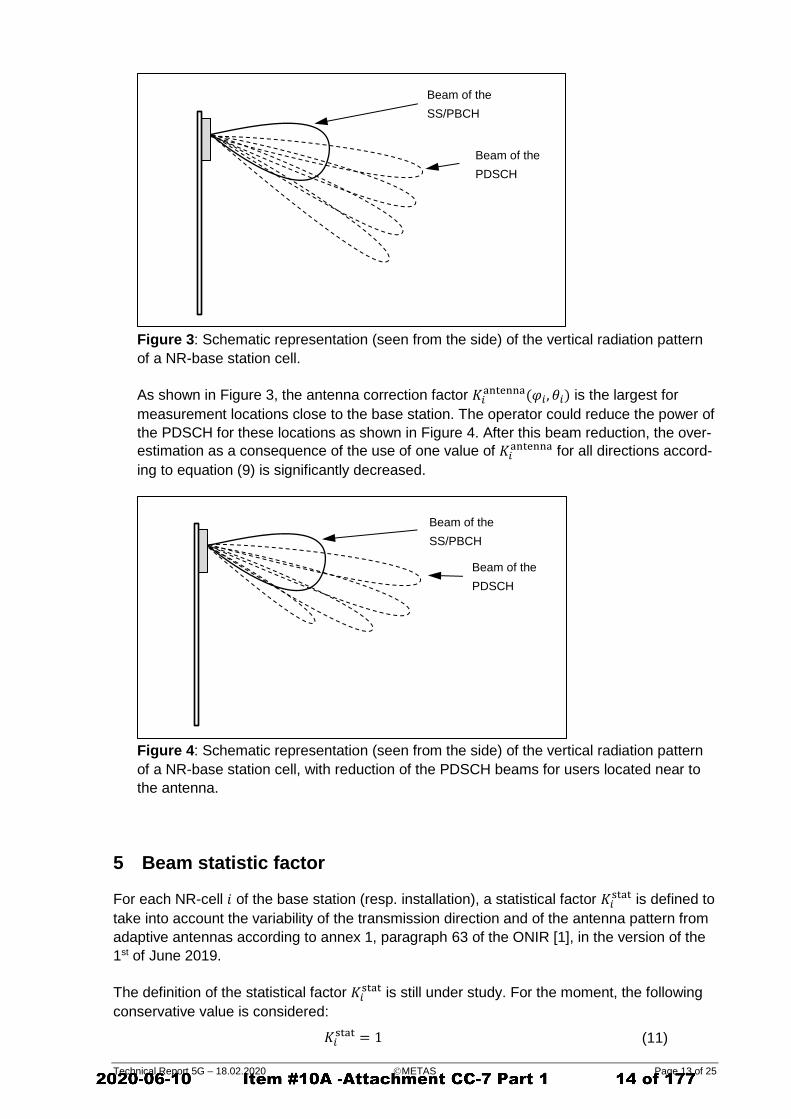
Figure 3: Schematic representation (seen from the side) of the vertical radiation pattern
of a NR-base station cell.
As shown in Figure 3, the antenna correction factor 𝐾𝑖antenna(𝜑𝑖, 𝜃𝑖) is the largest for
measurement locations close to the base station. The operator could reduce the power of
the PDSCH for these locations as shown in Figure 4. After this beam reduction, the over-
estimation as a consequence of the use of one value of 𝐾𝑖antenna for all directions accord-
ing to equation (9) is significantly decreased.
Figure 4: Schematic representation (seen from the side) of the vertical radiation pattern
of a NR-base station cell, with reduction of the PDSCH beams for users located near to
the antenna.
5 Beam statistic factor
For each NR-cell 𝑖 of the base station (resp. installation), a statistical factor 𝐾𝑖stat is defined to
take into account the variability of the transmission direction and of the antenna pattern from
adaptive antennas according to annex 1, paragraph 63 of the ONIR [1], in the version of the
1st of June 2019.
The definition of the statistical factor 𝐾𝑖stat is still under study. For the moment, the following
conservative value is considered:
𝐾𝑖stat = 1 (11)
Beam of the
SS/PBCH
Beam of the
PDSCH
Beam of the
SS/PBCH
Beam of the
PDSCH

Technical Report 5G – 18.02.2020 METAS Page 14 of 25
6 Duplex factor
The duplex factor 𝐾duplex is defined as:
𝐾duplex = {√𝑟DL for TDD
1 for TDD with unknown 𝑟𝐷𝐿
1 for FDD
(12)
where 𝑟𝐷𝐿 denotes the maximum ratio of the downlink transmission time in a time interval.
This choice is determined by the interpretation of the E-field limits as a quadratic time aver-
age of the electric field strength.
7 Summing all cells and technologies
All NR cell-specific extrapolated electric field strength values are then summed together as:
𝐸ℎ = √∑ 𝐸𝑖,ℎ2
𝑛
𝑖=1
(13)
with
𝐸ℎ Extrapolated electric field strength of NR for a given network, in V/m.
𝐸𝑖,ℎ Extrapolated electric field strength measurement for cell i, in V/m.
𝑛 Number of cells of the base station respectively of the installation.
Finally, the appreciation value 𝐸𝐵
is obtained by summing the contributions 𝐸Network𝑗,ℎ
𝐸Network𝑘,ℎ of all networks belonging to the same installation:
𝐸B = √𝐸Network1,ℎ2 + 𝐸Network2,ℎ
2 + ⋯
(14)
Examples of calculations can be found in Annex B.
For base stations running, in addition to NR, GSM, UMTS, or LTE services simultaneously, all
these signals have to be taken into account, and 𝐸B
has to be determined according to [5] (chap-
ter 9).
7.1 Compliance assessment
The compliance or non-compliance of an installation can be unequivocally assessed:
𝐸B ≤ 𝐸limit : The installation fulfills the requirements.
𝐸B > 𝐸limit : The installation does not fulfill the requirements.
The expanded measurement uncertainty 𝑈 (k=2) is not taken into account directly in the
compliance assessment (so called “shared risk” or “simple acceptance” according to [13]).
However, the measurement uncertainty 𝑈 must
include a contribution of ±15% (k=1) for the sampling of the measurement volume,
not exceed the value of ± 45% (k=2).

Technical Report 5G – 18.02.2020 METAS Page 15 of 25
8 Frequency selective method
8.1 Measurand
The frequency selective method is derived from the code selective measurement method de-
scribed in equation (1), and it is also based on the measurements of the secondary synchro-
nization signal (SSS). Frequency selective measurements of the synchronization signals re-
quire a spectrum analyzer with true RMS-detector, a minimum resolution bandwidth of the
SSS bandwidth (127 ∙ Δ𝑓) and a maximum hold-function. The measurements are performed
in “Zero Span” mode, and the sweep time must be chosen so that the measuring time for one
value is less than one-half of the duration of an SSS OFDM symbol. Depending on the nu-
merology used (15 kHz or 30 kHz), the duration of the OFDM symbol without prefix is
1/15 kHz ≅ 66 µs for 15 kHz numerology, and 1/30 kHz ≅33 µs for 30 kHz numerology.
The spatial maximum of the synchronization signals have to be measured as mentioned in
the section 2.1.
8.2 Appreciation value
The value of the 𝐸𝑖,maxSSS(RE)
cannot be measured directly by a frequency selective measuring
instrument, since it requires the quadratic addition of signals from different SS/PBCH beams.
However, based on realistic estimations, the following expression is used:
𝐸𝑖,maxmeasured ∙ √
1
127∙ 𝐾𝑖
FSM (15)
with
𝐸𝑖,maxmeasured
Max & Hold value of the electric field strength measured over the
whole measuring bandwidth (at least SSS bandwidth) set on the spec-
trum analyzer.
√1 127⁄ Reduction factor to obtain the field strength per resource element.
𝐾𝑖FSM Frequency Selective Method (FSM) factor defined as 𝐾𝑖
FSM = √2 if the
cell 𝑖 has more than one SS/PBCH beam, and as 𝐾𝑖FSM = 1 if the cell 𝑖
has only one SS/PBCH beam. It takes into account the fact that the
electric field produced by individual beams cannot be measured, and
therefore cannot be added quadratically.
The measured value of the electric field strength has to be extrapolated to the reference op-
erating mode as
𝐸ℎ ≅ (𝐸𝑖,maxmeasured ∙ √
1
127∙ 𝐾𝑖
FSM) ∙ max𝑖=1..𝑛
(𝐾𝑖(𝜑𝑖 , 𝜃𝑖))
with
(16)
𝑛 Number of cells of the base station respectively of the installation.

Technical Report 5G – 18.02.2020 METAS Page 16 of 25
The following aspects have to be considered:
The center frequency of the measuring instrument has to be set to the center fre-
quency of the SS/PBCH block, which does not in general match the center frequency
of the downlink NR channel. The center frequency of the SSS must be given by the
operator.
Since the spectrum analyser cannot distinguish uplink and downlink in a TDD trans-
mission scheme, it is important to switch off every mobile phone in the vicinity of the
measuring system.
Finally, the appreciation value 𝐸B is obtained by summing over the contributions of all net-
work operators and services as in the previous section (examples in Annex B).
8.3 Compliance assessment
Overestimations are highly probable with this method. Therefore the compliance of an instal-
lation can be assessed while non-compliance cannot:
𝐸B ≤ 𝐸limit : The installation fulfills the requirements.
𝐸B > 𝐸limit : No assessment is possible. For clarification, a code selective
measurement is necessary.

Technical Report 5G – 18.02.2020 METAS Page 17 of 25
9 Literature
1. “Ordinance relating to Protection from Non-Ionising Radiation (ONIR)” (document No.
814.710), December 1999. Available in German, French, Italian.
2. ICNIRP commission, "Guidelines for limiting exposure to time-varying electric, magnetic,
and electromagnetic fields (up to 300 GHz)", Health Physics Vol. 74, No 4, pp 494-522,
1998.
3. Measurement recommendation for GSM: “Nichtionisierende Strahlung: Mobilfunk-Basis-
stationen (GSM) - Messempfehlung“, 2002. Available at www.bafu.admin.ch/elektros-
mog.
4. Measurement recommendation for GSM with Edge: “NIS-Abnahmemessung bei GSM-
Basisstationen mit EDGE-Betrieb”, Entwurf vom 28.11.2005, November 2011. Available
at www.bafu.admin.ch/elektrosmog.
5. Measurement recommendation for UMTS: “ Nichtionisierende Strahlung: Mobilfunk-Ba-
sisstatinonen (UMTS – FDD), Entwurf vom 17.9.2003“, September 2003. Available at
www.bafu.admin.ch/elektrosmog.
6. Measurement recommendation for Broadcasting: “Nichtionisierende Strahlung: Runk-
funk- und Funkrufsendeanlagen, Vollzugsempfehlung zur NISV, Entwurf vom 6.7.2005“,
July 2005. Available at www.bafu.admin.ch/elektrosmog.
7. METAS-Report 2012-218-808: "Technical Report: Measurement Method for LTE Base
Stations", May 2012, available at www.metas.ch.
8. ETSI TS 138 104, "5G; NR; Base Station (BS) radio transmission and reception (3GPP
TS 38.104 version 15.3.0 Release 15)", October 2018
9. ETSI TS 138 211, “5G; NR; Physical channels and modulation (3GPP TS 38.211 version
15.2.0 Release 15)”, July 2018.
10. ETSI TS 138 213, “5G; NR; Physical layer procedures for control (3GPP TS 38.213 ver-
sion 15.6.0 Release 15)”, July 2019.
11. ETSI TS 138 214, “5G; NR; Physical layer procedures for data (3GPP TS 38.214 version
15.3.0 Release 15)”, October 2018.
12. H. Keller, “On The Assessment of Human Exposure to Electromagnetic Fields Transmit-
ted by 5G NR Base Stations“, Health Physics, April 23, 2019.
13. JCGM 106, “Evaluation of measurement data – The role of measurement uncertainty in
conformity assessment”, May 2009.

Technical Report 5G – 18.02.2020 METAS Page 18 of 25
10 Annex A: Basics in NR (informative)
10.1 SS / PBCH Block structure according to [9]
Figure A.1: NR downlink SS/PBCH block (reconstructed from [9]).
0
0
0
0
…
0 0
0 0
0 0
0 0
…
…
0 0
0
0
…
0
0
0
0
time
fre
qu
en
cy
1 subcarrier bandwidth: Δ𝑓
Part of 1 OFDM symbol containing the SS/PBCH block 1 resource element
SS/PBCH block
Bandwidth
of SSS
and PSS
signals:
127
sub-carri-
ers
Duration of an SS/PBCH block
= 4 OFDM symbols
DM-RS resource elements:
periodicity of 4 subcarriers
with offset 𝜈
PSS
SSS
Bandwidth
SS/PBCH
Block:
240
sub-
carriers

Technical Report 5G – 18.02.2020 METAS Page 19 of 25
10.2 Timing of the SS/PBCH blocks according to [10]
The position of the SS/PBCH block within the NR time/frequency grid might be represented
as follows. The exact position of the SS/PBCH blocks is defined in the standard:
Figure A.2: position of the SS/PBCH blocks in the NR-signal according to [10] for a
SS/PBCH subcarrier spacing of 15 kHz. Up to 4 blocks (dark grey) are used for 𝐿max = 4
beams. Up to 8 blocks are used for 𝐿max = 8 beams.
Figure A.3: position of the SS/PBCH blocks in the NR signal according to [10] for a
SS/PBCH subcarrier spacing of 30 kHz. Up to 4 blocks (dark grey) are used for 𝐿max = 4
beams. Up to 8 blocks are used for 𝐿max = 8 beams.
1 frame (10 ms)
1/2 frame (5 ms)
1 subframe (1 ms)
time
fre
qu
en
cy
𝑗 = 0 𝑗 = 1 𝑗 = ⋯
1 frame (10 ms)
1/2 frame (5 ms)
1 subframe (1 ms)
time
fre
qu
en
cy

Technical Report 5G – 18.02.2020 METAS Page 20 of 25
11 Annex B: Examples
A network operator provides NR services using 3 antennas mounted on a mast. All three
cells operate in the 3500 MHz band. The main beams of the antennas are 120 degrees from
each other as shown in the Figure B.1. Technical data of the installation are listed in Table
B.1. According to the ONIR the installation limit value is 6 V/m.
Cell ID 214 215 216
Antenna A1 A2 A3
Main beam direction (azimuth) 30º 150º 270º
Main beam direction (elevationl) -10º -12º -12º
Number of PBCH beams 1 4 4
Service NR-3500
Center Frequency 3515 MHz
Center Frequency of the PBCH (MHz)
3509 MHz
Bandwidth 30 MHz
Numerology 30 kHz
Actual ERP of the SSS per re-
source element 𝑃𝑖SSS(RE)
200 mW 120 mW 120 mW
Total permitted ERP 𝑃𝑖,permitted 400 W 200 W 200 W
Table B.1: Technical data of the installation.
Figure B.1: representation of an installation with the three antennas and the measurement
location.
A1
A2
A3
N
Measurement
location

Technical Report 5G – 18.02.2020 METAS Page 21 of 25
11.1 Code-selective measurement
With code-selective measurement equipment, the electric field strength of each cell can be
measured separately. Therefore, the spatially maximum field value 𝐸𝑖,𝑗,𝑚𝑎𝑥SSS(RE)
𝐸𝑖,𝑚𝑎𝑥
SSS(RE) within
the measurement volume is measured. The extrapolation process is represented in the fol-
lowing Table.
Cell ID 214 215 216
Antenna A1 A2 A3
Main beam direction (azimuth) 30º 150º 270º
Main beam direction (elevationl) -10º -12º -11º
Number of PBCH beams 1 4 4
Service NR-3500
Center Frequency 3515 MHz
Center Frequency of the PBCH (MHz)
3509 MHz
Bandwidth 30 MHz
Actual ERP of the SSS per re-
source element 𝑃𝑖SSS(RE)
200 mW 120 mW 120 mW
Total permitted ERP 𝑃𝑖,permitted 400 W 200 W 200 W
Extrapolation factor
for the SSS 𝐾𝑖SSS(RE)
44.72 40.82 40.82
Measurement location specific correction
Horizontal angle of the OMEN with respect to the main beam
-160º 80º -40º
Vertical angle of the OMEN with re-spect to the main beam
-15º -13º -14º
Attenuation of the SS/PBCH beam in OMEN direction
𝐴𝑖SSS(RE)(𝜑𝑖, 𝜃𝑖) 14.13 (23 dB ) 7.94 (18 dB) 1.78 (5 dB)
Attenuation of the total beam in the OMEN direction
𝐴𝑖total(𝜑𝑖 , 𝜃𝑖) 31.62 (30 dB) 12.59 (22 dB) 1.41 (3 dB)
Antenna correction factor
𝐾𝑖antenna(𝜑𝑖, 𝜃𝑖)
1.80 1.00 1.26
Other corrections
Statistical factor 𝐾𝑖stat
1 1 1
Duplex factor 𝐾duplex 1 1 1
Global factor
Global factor 𝐾𝑖(𝜑𝑖, 𝜃𝑖) 80.50 40.82 51.40
Measurements
Measured Value 𝐸𝑖,maxSSS(RE)
4.30 mV/m 7.20 mV/m 88.00 mV/m
Extrapolated Value 𝐸𝑖,ℎ 0.35 V/m 0.29 V/m 4.52 V/m
Table B.2: example of extrapolation process. For this calculation we have assumed that the
maximum ratio 𝐾𝑖,maxantenna defined by equation (9) was 1.8. Cells with italic characters can be
determined by calculation from other cells values.

Technical Report 5G – 18.02.2020 METAS Page 22 of 25
The value of the electric field strength extrapolated to the reference-operating mode is
𝐸𝐵 = 𝐸ℎ = √∑ 𝐸𝑖,ℎ2
𝑖
= √0.352 + 0.292 + 4.522 = 4.54 V/m
This value is lower than the limit of 6 V/m. The installation is considered as compliant.
11.2 Frequency-selective measurement
The spatial maximum value of the electric field strength measured with a spectrum analyzer
having a resolution bandwidth of 5 MHz is found to be 𝐸𝑖,maxmeasured = 1.05 V/m. The resolution
bandwidth was chosen as the next resolution available above the bandwidth of the SSS:
127 ∙ 30 kHz = 3.810 MHz. Since at least one of the cells have more than one PBCH beam,
the frequency selective method factor 𝐾𝑖FSM = √2. The electric field per resource element is:
𝐸𝑖,maxmeasured ∙ √
1
127∙ 𝐾𝑖
FSM = 0.131 V/m
The extrapolation factor is the maximum value of all extrapolation factors 𝐾𝑖(𝜑𝑖, 𝜃𝑖) in Table
1, in our example: 80.50. The extrapolated field value is therefore:
𝐸𝐵 = 𝐸ℎ = 0.131V
𝑚∙ 80.50 = 10.60 V/m
𝐸𝐵 = 𝐸ℎ = 0.131 V m⁄ ∙ 80.50 = 10.60 V/m
The value of the electric field strength extrapolated to the reference-operating mode is higher
than the limit value of 6 V/m. The conformity of the installation cannot be assessed, and a
code selective measurement is required.

Technical Report 5G – 18.02.2020 METAS Page 23 of 25
12 Annex C: Definitions, symbols and abbreviations
DM-RS Demodulation reference signals
EDGE Enhanced Data Rates for GSM Evolution
ERP Effective Radiated Power
FDD Frequency Division MultiplexDuplex
FSM Frequency Selective Method
GSM Global System for Mobile Communication
ICNIRP International Commission on Non-Ionizing Radiation Protection
LTE Long-Term-Evolution
NR New Radio
OFDM Orthogonal Frequency-Division Multiplexing
ONIR Ordinance relating to Protection from Non-Ionising Radiation
PBCH Physical Broadcast Channel
PDSCH Physical Downlink Shared Channel
PSS Primary Synchronization Signal
SS/PBCH Synchronization Signal and PBCH
SSS Secondary Synchronization Signal
TDD Time Division MultiplexDuplex
UMTS Universal Mobile Telecommunications System
𝐴𝑖SSS(RE)(𝜑𝑖, 𝜃𝑖) Attenuation of the SS/PBCH signal of cell 𝑖 in the direction given by the azi-
muth 𝜑𝑖 and by the elevation 𝜃𝑖
𝐴𝑖total(𝜑𝑖 , 𝜃𝑖) Attenuation of the total signal of cell 𝑖 in the direction given by the azimuth
𝜑𝑖 and by the elevation 𝜃𝑖
𝐸B Acceptance value for the installation in V/m
𝐸limit Limit electric field value, in V/m 𝐸ℎ Extrapolated NR field strength, in V/m 𝐸𝑖,ℎ Extrapolated field strength measurement for cell i, in V/m

Technical Report 5G – 18.02.2020 METAS Page 24 of 25
𝐸𝑖,maxmeasured
Max & Hold value of the electric field strength measured over the whole
measuring bandwidth set on the spectrum analyzer
𝐸𝑖,maxSSS(RE)
Spatial maximum within the measurement volume of the quadratic sum of
the SSS electric field strength 𝐸𝑖,𝑗SSS(RE)
𝐸𝑖,𝑗SSS(RE)
Electric field strength (in V/m) per resource element (RE) of the SSS of cell 𝑖
and SS/PBCH block index 𝑗
𝐸Network𝑘,ℎ
Extrapolated field strength measurement related to network 𝑘j
𝑖 Identification number of the base station cell
𝑗 Identification number of the SS/PBCH block index
𝑘 Identification number for the network
𝐾𝑖(𝜑𝑖 , 𝜃𝑖) Global extrapolation factor for cell 𝑖. The factor is measurement place spe-
cific
𝐾𝑖,maxantenna Maximum value of the ratio 𝐴𝑖
SSS(RE)(𝜑𝑖, 𝜃𝑖)/𝐴𝑖
total(𝜑𝑖 , 𝜃𝑖), where the maxi-
mum is taken on all directions for which the attenuation 𝐴𝑖SSS(RE)(𝜑𝑖, 𝜃𝑖) of
the SS/PBCH beam is less than 10 (corresponds to 20 dB)
𝐾𝑖antenna( 𝜃𝑖) Antenna correction factor for cell 𝑖 defined as worst case (among all azi-
muths 𝜑𝑖) of the antenna correction factor 𝐾𝑖antenna(𝜑𝑖, 𝜃𝑖)
𝐾𝑖antenna(𝜑𝑖, 𝜃𝑖) Antenna correction factor taking into account the difference between the
antenna diagram of the SS/PBCH signal of cell 𝑖 and the antenna diagram
of the total signal in the maximum permitted operating condition
𝐾𝑖SSS(RE)
SSS extrapolation factor for cell 𝑖
𝐾𝑖FSM Frequency Selective Method (FSM) factor.
𝐾𝑖stat Statistic factor for cell 𝑖
𝐾duplex Duplex factor
𝑛 Number of cells of the base station respectively of the installation
𝑃𝑖,permitted Maximum permitted ERP in W, taking into account the signal of all antenna
ports of cell 𝑖: PSDCH, PBCH, and PDCCH
𝑃𝑖SSS(RE)
Actual ERP per resource element of the SSS of the SS/PBCH block of cell 𝑖
in W
𝑃𝑖SSS(RE)(𝜑𝑖, 𝜃𝑖) "summed SSS ERP radiation pattern" obtained by summing the ERP radi-
ated power per resource element of all SS/PBCH beams
Technical Report 5G – 18.02.2020 METAS Page 25 of 25
𝑃𝑖,𝑗SSS(RE)
(𝜑𝑖, 𝜃𝑖) Actual "effective radiated power" in W per resource element of the SSS of
the SS/PBCH block of cell 𝑖 and index 𝑗 in the direction given by the azi-
muth 𝜑𝑖 and by the elevation 𝜃𝑖
𝑟𝐷𝐿 Maximum ratio of downlink transmission time in a time interval
Δ𝑓 Subcarrier spacing of the SS/PBCH block
𝜑𝑖 Azimuth, defined as the horizontal angle in a spherical coordinate system,
of the measurement location with respect to transmit antenna of cell 𝑖
𝜃𝑖 Elevation, defined as the vertical angle in a spherical coordinate system, of
the measurement location with respect to transmit antenna of cell 𝑖

Received November 4, 2019, accepted December 13, 2019, date of publication December 20, 2019,date of current version December 31, 2019.
Digital Object Identifier 10.1109/ACCESS.2019.2961225
In-situ Measurement Methodology forthe Assessment of 5G NR MassiveMIMO Base Station Exposure atSub-6 GHz FrequenciesSAM AERTS 1, LEEN VERLOOCK 1, MATTHIAS VAN DEN BOSSCHE 1, DAVIDE COLOMBI 2,LUC MARTENS 1, CHRISTER TÖRNEVIK 2, (Member, IEEE), AND WOUT JOSEPH 11Department of Information Technology, Ghent University/imec, 9052 Ghent, Belgium2Ericsson Research, Ericsson AB, 16480 Stockholm, Sweden
Corresponding author: Sam Aerts ([email protected])
This work was supported by the Mobile and Wireless Forum (MWF). The work of S. Aerts was supported by the ResearchFoundation–Flanders (FWO), Belgium.
ABSTRACT As the roll-out of the fifth generation (5G) of mobile telecommunications is well underway,standardized methods to assess the human exposure to radiofrequency electromagnetic fields from 5G basestation radios are needed in addition to existing numerical models and preliminary measurement studies.Challenges following the introduction of 5G New Radio (NR) include the utilization of new spectrum bandsand the widespread use of technological advances such as Massive MIMO (Multiple-Input Multiple-Output)and beamforming. We propose a comprehensive and ready-to-use exposure assessment methodology for usewith common spectrum analyzer equipment to measure or calculate in-situ the time-averaged instantaneousexposure and the theoretical maximum exposure from 5G NR base stations. Besides providing the correctmethod and equipment settings to capture the instantaneous exposure, the procedure also comprises a numberof steps that involve the identification of the Synchronization Signal Block, which is the only 5G NRcomponent that is transmitted periodically and at constant power, the assessment of the power density carriedby its resources, and the subsequent extrapolation to the theoretical maximum exposure level. The procedurewas validated on site for a 5G NR base station operating at 3.5 GHz, but it should be generally applicableto any 5G NR signal, i.e., as is for any sub-6 GHz signal and after adjustment of the proposed measurementsettings for signals in the millimeter-wave range.
INDEX TERMS 5G, radiofrequency electromagnetic fields (RF-EMF), exposure assessment, measurement,massive MIMO, mobile telecommunications, new radio, spectrum analyzer.
I. INTRODUCTIONThe introduction worldwide of the fifth generation (5G) ofmobile telecommunications [1] is well underway. In contrastto second to fourth generation (2G–4G) mobile technologies(such as Global System for Mobile communications (GSM),Universal Mobile Telecommunications System (UMTS), andLong Term Evolution (LTE)), the 5G New Radio (NR) tech-nologywill make use of a huge span of radiofrequencies (RF),split in two broad ranges: one spanning from 410 MHz to
The associate editor coordinating the review of this manuscript and
approving it for publication was Jesús Hamilton Ortiz .
7.125 GHz (‘sub-6 GHz’), and the other from 24.25 GHzto 52.6 GHz (‘mmWaves’). Furthermore, one of the maintechnological advances introduced or enhanced in 5GNRwillbe the widespread use of Massive Multiple-Input Multiple-Output (MaMIMO), in which many antenna elements (up tohundreds) can be used to narrow and steer the transmit beamin order to optimize the signal at the receiver device.
Guidelines on limiting the human exposure toelectromagnetic fields (EMF) have been issued by theInternational Commission on Non-Ionizing Radiation Pro-tection (ICNIRP) and the Institute of Electrical andElectronics Engineers (IEEE) based on decades of scientific
184658 This work is licensed under a Creative Commons Attribution 4.0 License. For more information, see http://creativecommons.org/licenses/by/4.0/ VOLUME 7, 2019

S. Aerts et al.: In-situ Measurement Methodology for the Assessment of 5G NR Massive MIMO Base Station Exposure
TABLE 1. Constant-power signal components of second through fifthgeneration telecommunications technologies.
research [2], [3]. These guidelines have formed the basis forrecommendations by internationally recognized institutionssuch as the World Health Organization (WHO), the USFederal Communications Commission (FCC) [4], and theInternational Telecommunications Union (ITU), as well asthe Recommendation of the European Council [5]. How-ever, some countries or regions (such as Brussels, Bel-gium) have adopted their own, more strict legal regulations,which may delay or even impede the deployment of 5Gnetworks due to EMF saturation where current limit levelshave already been reached with pre-5G telecommunicationsinfrastructure [6]–[9].
In the last few years, there have been a few publicationsdiscussing how to properly assess the exposure levels from5G base stations [10]–[15], some of which include numericalstudies and preliminary measurements. However, as of yet,there is no standardized method available.
EMF exposure assessment methods for time-variantmobile telecommunications signals have relied on the mea-surement and subsequent extrapolation of user-independentsignals that are transmitted continuously (or periodically) atconstant power, independent of the traffic load [16]–[18].These signals differ from one telecommunications technol-ogy to the other (Table 1): i.e., the Broadcast Control Chan-nel (BCCH) for GSM, the Common Pilot Channel (CPICH)for UMTS, and the cell-specific reference signal (CRS),synchronization signals (SS) and physical broadcast chan-nel (PBCH) for LTE. In the case of NR, there is no CRS, butthe ‘always-on’ signal components are, as in LTE, the primaryand secondary synchronization signals (PSS and SSS) andthe PBCH. The PSS and SSS are used by user devices tofind, identify, and synchronize to a network, while the PBCHcontains aminimum amount of system information. Together,these signals form the SS/PBCH block (also denoted as SSblock or SSB).
Although previous studies (e.g., [14], [15]) have discussedextrapolation methods based on measuring the power of theSSB, none have been molded into a feasible assessmentmethodology, nor have they been tested in the field.
This paper presents a comprehensive description of a mea-surement methodology to assess the RF-EMF exposure ofa 5G NR base station on site. First, we describe the mainprinciples of the 5G NR physical layer that are important
for an accurate assessment. Second, we introduce and discussthe proposed measurement equipment and methods to mea-sure or calculate the time-averaged instantaneous exposureand the theoretical (and actual) maximum exposure. Andlastly, the proposed methodology was validated in-situ in thevicinity of a 5G NR base station operating at 3.5 GHz inDüsseldorf, Germany.
II. 5G NEW RADIO AND RF-EMF EXPOSUREThe accurate assessment of an RF signal requires that thesettings of the measurement device be optimized to the char-acteristics of the considered signal. Here, we discuss the mainprinciples of the physical layer of 5G NR that are importantfor RF exposure assessment. More detailed information isout of the scope of this paper but can be found in the 3GPPtechnical specifications [1].
A. 5G NR GRID STRUCTURELike 4G LTE, 5G NR supports both frequency divisionduplexing (FDD) and time division duplexing (TDD) andsignals are modulated by using Orthogonal Frequency Divi-sion Multiplexing (OFDM) with a cyclic prefix. Moreover,5G NR also uses a grid structure consisting of subcarriersin the frequency domain and OFDM symbols in the timedomain. The basic granularity of the 5G NR resource grid(i.e., in frequency and time) is the resource element (RE),which spans one OFDM symbol in time and one subcarrierin frequency.
In the frequency domain, the grid structure is further orga-nized in resource blocks (RBs), with each RB consistingof twelve contiguous subcarriers. The total number of RBsavailable for data transmission (NRB) depends on the channelbandwidth (up to 100 MHz for sub-6 GHz signals) and thenumerology or sub-carrier spacing (SCS), which is 15 kHz,30 kHz, or 60 kHz for sub-6 GHz signals. This is in contrastto LTE, where the SCS is fixed at 15 kHz and the bandwidthat up to 20 MHz.
In the time domain, the structure is organized in frames.A 5G NR radio frame is 10 ms long and consists of tensubframes of each 1 ms. A subframe is further divided intoslots, which each comprise 14 (in the case of a normal cyclicprefix) or 12 OFDM symbols (in the case of an extendedcyclic prefix). The number of slots and the duration of asymbol depend on the SCS. For example, in the case of anSCS of 30 kHz, a subframe consists of two slots and thesymbol duration is 35.68 µs. Analogous to an RB in thefrequency domain, a slot is the basic transmission unit inthe time domain.
The SS/PBCH block, which comprises the constant-powersignal components of 5G NR, spans four OFDM symbols inthe time domain and 240 contiguous subcarriers, or 12 RBs,in the frequency domain (Fig. 1). As opposed to the consti-tuting signal equivalents in LTE, in 5G NR the SSB is notfixed to the center frequency of the radio channel, but insteadits position (denoted by SSREF ) is determined by the GlobalSynchronization Raster Channel (GSCN) value, which fixes
VOLUME 7, 2019 184659

S. Aerts et al.: In-situ Measurement Methodology for the Assessment of 5G NR Massive MIMO Base Station Exposure
FIGURE 1. Structure of the SS/PBCH block in time and frequency, withindication of the minimum (BWSSB,min) and maximum bandwidth(BWSSB,max ).
it on a discrete raster. Furthermore, whereas in 4G LTE thesynchronization signals are transmitted over the entire cell,5G NR systems can apply beamforming, in which case thebase station repeatedly transmits the SSB in a number ofpredefined directions (or beams) in an SS burst or SS burstset (consecutive SS bursts). The SS burst (set) is transmittedat regular time intervals, which can be 5, 10, 20, 40, 80 or160 ms (with the default being 20 ms), within the span of onehalf-frame (5 ms) [1].
B. TIME-AVERAGED INSTANTANEOUS EXPOSUREAssessment of the time-averaged instantaneous exposurelevel Eavg of an RF signal means measuring the actual,instantaneous electric-field strength over the entire sig-nal channel bandwidth during a certain time and subse-quently taking the average. For example, for comparisonto the ICNIRP limits (both basic restrictions and refer-ence levels), we should measure for 6 min [2], and forIEEE 30 min [3]—although, in practice, a shorter measure-ment time (e.g., 1 min per component) is often sufficientto derive an exposure value representative of longer averag-ing times [19], [20]. This is a straightforward measurement,although onemust be careful to use the correct settings, whichare signal-specific [17], [21].
C. THEORETICAL MAXIMUM EXPOSUREThe exposure level at an evaluation point in line ofsight (LOS) of a 5G NR base station will reach the maximalvalue when the traffic load is at its maximum (i.e., whenthe 5G NR frame is completely filled with downlink data)and all traffic is transmitted at the maximum possible gainGmax in the direction of the evaluation point. Then, to obtainthe worst-case (theoretical maximum) exposure level Emax ,the electric-field strength per RE of the dominant SSB beam(ERE,SSB) is extrapolated based on the bandwidth of the chan-nel and the radiation pattern of the traffic beam(s):
Emax =√α
√12NRB ERE,SSB, (1)
where NRB is the number of resource blocks available overthe 5G NR channel bandwidth (e.g., 273 for a signal withSCS 30 kHz and BW 100 MHz), and
α =GmaxGSSB
(2)
is the ratio of Gmax to the gain of the dominant SSB, GSSB.This ratio has to be derived based on the pattern of thebase station product. Additional information is provided inSection IV-F.
D. ACTUAL MAXIMUM EXPOSURESince (1) assumes that the radio frame is fully occupied(i.e., at 100% slot occupation) with downlink traffic andbroadcast/control data which is all continually transmitted atthe highest possible gain in the direction of the evaluationpoint, Emax represents an unrealistic overestimation of theexposure level [11], [14], [15]. Whereas this value mighthave had its use for previous technologies, in reality, dueto the increased variability of the usage in space and time,it is unrealistic for a 5G NR base station to transmit at itsmaximum power and to concentrate all of its power in asingle beam during an extensive amount of time (e.g., 6 min,the averaging time required by the ICNIRP guidelines [2]).By taking into account additional factors such as the basestation utilization, the spatial distribution of energy during acertain time, as well as a downlink duty cycle (in the case ofTDD), one can calculate a more realistic, actual maximumexposure level. Refs. [11], [17], [22] provide further infor-mation on the assessment of the actual maximum exposure.
III. PROPOSED MEASUREMENT PROCEDUREA. OVERVIEW OF 5G NR ASSESSEMENT PROCEDUREThe proposed measurement methodology consists of fivesteps:• Step 1 ‘‘Spectrum overview’’—Weperform an overviewmeasurement of the telecommunications frequencyrange to identify the RF signals that are present at themeasurement location and in particular the 5GNR signalfrom the base station under test.
• Step 2 ‘‘Locating the SS burst’’— An important step inthe assessment of a 5GNR signal based on extrapolationof the SSB power, is the determination of the actuallocation of the SS burst. In this step, we identify SSREFas well as the numerology of the SSB(s).
• Step 3 ‘‘Obtaining the field level per RE of the SSB’’— We measure the electric-field strength per resourceelement of the dominant SSB, ERE,SSB.
• Step 4 ‘‘Measuring the instantaneous field level" —Wedetermine the time-averaged instantaneous electric-fieldstrength over the channel bandwidth, Eavg, measuredduring a certain time, Tavg (e.g., 6 or 30 min).
• Step 5 ‘‘Post-processing’’ — We extrapolate ERE,SSBto the theoretical maximum exposure level Emax byusing (1). We then compare the obtained exposure levelswith the relevant exposure limits such as those proposed
184660 VOLUME 7, 2019

S. Aerts et al.: In-situ Measurement Methodology for the Assessment of 5G NR Massive MIMO Base Station Exposure
TABLE 2. Spectrum analyzer settings for sub-6 GHz 5G signals.
by ICNIRP [2] of IEEE [3] (in this case, the refer-ence levels for the electric-field strength). Furthermore,we can calculate the actual maximum exposure in caseadditional deduction factors are known (Section II-D).
While 5G NR demodulation software can assist in locatingthe SSB, identifying its numerology, and measuring its powerper RE [15], we focus in this paper on a procedure usablewith a common spectrum analyzer (SA). The general methodoutlined here remains the same in either case.
Finally, the specific steps to be taken depend on the objec-tive of the measurement. If the only objective is to determinethe maximum theoretical exposure, step 4 is unnecessary.Likewise, only steps 1 and 4 are needed if the time-averagedpower is the sole quantity of interest.
B. SPECTRUM ANALYZER MEASUREMENT SETUPThe measurement setup used for this study consisted ofa Rohde & Schwarz FSV spectrum & signal analyzerFSV30 connected to a Clampco Sistemi AT6000 tri-axialantenna. An SA setup measures the received power P (dBm)of a signal, which is then converted to an electric-field valueE (V/m) by using the antenna factor AF (dB/m):
E =1√20
10P+AF20 (3)
In order to capture the total electric-field level, all threeorthogonal components (X , Y , and Z ) of the electric-fieldvector are to be measured. In this study, they were evaluatedsequentially by internally switching the respective axis of theClampco antenna.
Furthermore, the R&S FSV30 was equipped with optionR&S FSV-K14 to use it in ‘spectrogram mode’. Besides
offering a graphical overview of successive measurementsweeps or traces as a function of time (i.e., the ‘spectrogram’),this option also allowed us to store a high number of measure-ment traces (up to 20,000 for the R&S FSV-30) and exportingthem with a minimum of lag or ‘blind time’.
The SA settings proposed for each step of the measurementprocedure can be found in Table 2 and will be discussed in thefollowing section. It is important to note that the mentionedsettings may be specific to our measurement equipment, andequivalent settings for other equipment can be used.
C. DISCUSSION OF MEASUREMENT SETTINGS1) SA SETTINGS FOR STEP 1In the first step, a spectrum overview measurement is used toidentify the RF signals present in the frequency range usedby telecommunication signals (e.g., 700 MHz – 6 GHz). Theproposed settings can be found in Table 2.In order to distinguish between different telecommunica-
tion signals (2G–5G), the resolution bandwidth (RBW) isset to a value approximating the minimal bandwidth of theexisting telecommunications signals, which is 200 kHz (usedby 2G). By using a peak detector in combination with a longsweep time (SWT) and maximum-hold mode, and measur-ing until the display of the SA is relatively stable, all non-continuous but repetitive signals present at the measurementlocation are detected. Themeasurement time per sample is setequal to the duration of one 5G NR radio frame (i.e. 10 ms),by configuring the SWT accordingly.
It is important to note that, with these settings, the mea-sured power levels provide only an indication of the peakvalues (typically a large overestimate due to the effect ofmodulation) and no further conclusions can be made.
VOLUME 7, 2019 184661

S. Aerts et al.: In-situ Measurement Methodology for the Assessment of 5G NR Massive MIMO Base Station Exposure
2) SA SETTINGS FOR STEP 2After the present 5G NR channel(s) is/are identified, the fre-quency positions of their broadcast signals are located.If, at the location of assessment, SSREF and the SSBnumerology (which defines the BW of the SSB) werenot provided by the operator and thus unknown, they canbe determined using the following measurement (settingsin Table 2).
The center frequency (CF) of the considered 5G NR chan-nel is obtained from the previous step (or from operatorinformation). The frequency span is set to 100 MHz, whichis the largest BW for sub-6 GHz 5G NR signals, and theRBW to 1 MHz, as this is the widest possible setting for ourmeasurement setup narrower than the minimum bandwidthof the SSB (i.e., BWSSB,min = 1.9 MHz for SCS 15 kHz;Fig 1). Furthermore, the measurement time per sample orsweep point is set to 143 µs, which is the shortest duration ofthe SSB in case of sub-6 GHz 5G NR signals (SCS 30 kHz).In combination with 101 sweep points, this corresponds to anSWT of 14.4 ms.
In the absence of traffic, which may be transmitted at ahigher gain than the broadcast signals, these settings resultin the highest power levels when the SA sweeps the (exact)frequency and time range of an SSB, i.e., when within themeasurement time per sample, exactly two (SCS 15 kHz) orfour symbols (30 kHz) were transmitted at the same power.Hence, by plotting the maximum power per frequency overall measurement traces, we are able to identify the SSBfrequency range.
3) SA SETTINGS FOR STEP 3Thirdly, the power distribution of the REs that are part of theSSB is determined. As we are looking for a recurrent signal ofa certain duration (which depends on the structure of the SSburst [1]), aligningmeasurement samples in time should showus when the SS burst was transmitted. Then, we retain onlythose samples that were measured during the dominant SSBof the SS burst. The proposed settings for this measurementcan be found in Table 2.
In order to continuously measure the power received in theSSB frequency range, we opt for a zero-span measurement,i.e., a measurement of the received power within a certainfrequency band as a function of time, with SSREF as CF andan RBW that is smaller than or equal to BWSSB,min (Fig. 1)[15]. To average out the variations in time (due to OFDMmodulation [15]) and in frequency, a measurement time persample about equal to the symbol time of the SSB and anRBW of at least 1 MHz are proposed, in combination with anroot-mean-square (rms) detector (Table 2). Finally, to deter-mine the power per RE (i.e. over a BW equal to the SCS),a deduction factor
fBW = 10 log10(RBW/SCS) (4)
has to be applied to the resulting power measurements.
4) SA SETTINGS FOR STEP 4The time-averaged instantaneous electric-field strength canbe measured with an SA in both frequency and zero-spanmode. The proposed settings for both measurements can befound in Table 2.
Depending on the SA specifications, it is possible to mea-sure a 100-MHz bandwidth signal at once in frequency mode.In this case, Eavg is determined by calculating the averageof the field levels of N successive measurement traces, Ej(j = 1 . . .N ), spanning a time much longer than the durationof a 5G NR radio frame (10 ms):
Eavg =
√√√√√ N∑j=1
E2j
N. (5)
In zero-span mode, on the other hand, the RBW of mostcommercially available SAs is too narrow to completely con-tain the signal spectrumwithin the passband of the instrument(e.g., for the FSV30, the maximum RBW is 28 MHz in zero-span mode). In this case, the measurement is split in a numberof contiguous parts to cover the whole channel bandwidthof the 5G NR signal. For each part k , the time-averagedfield level Ek,avg over Mk successive samples is calculatedas follows:
Ek,avg =
√√√√ Mk∑i=1
E2i
Mk, (6)
after which Ek,avg are summed to obtain the total time-averaged field level Eavg.
IV. IN-SITU VALIDATIONA. DESCRIPTION OF THE LOCATION AND TESTSThe proposed exposure assessment methodology was val-idated in LOS of a 5G NR base station, operating at3.5 GHz, situated on the upper level of a parking buildingin Düsseldorf, Germany, on 28 May 2019 (Fig. 2). This sitewas chosen as it was available for testing purposes and thelocation was suitable to conveniently position the measure-ment equipment. The base station antenna was situated at aheight of about 12 m above the floor level. The amount of cartraffic during the measurements was minimal and assumed tohave no influence on the measurements.
Although the base station was not part of a commercialnetwork, one user equipment (UE) was available for testingpurposes. We investigated six test cases, described in Table 3.First, Steps 1 and 2 procedure were followed in the case with-out UE and thus without traffic (T1). Then Steps 3 to 5 ofthe procedure were validated with three representative usecases, namely a voice call (usingWhatsApp, T2), a video call(WhatsApp, T3), and video streaming (on YouTube, T4), andwith downlink and uplink traffic forced at 100% capacity (byusing the iPerf tool, https://iperf.fr/) of the base station (T5)and the UE (T6a and T6b in Table 3), respectively.Most of the tests (T1 to T6a) were conducted at Pos. 1,
at a distance of 62 m to the base station antenna and
184662 VOLUME 7, 2019

S. Aerts et al.: In-situ Measurement Methodology for the Assessment of 5G NR Massive MIMO Base Station Exposure
TABLE 3. Description of the performed tests, measurement results of the average electric-field strength (Eavg) and the field strength per resourceelement (ERE,SSB), and extrapolation of the latter to the theoretical maximum electric-field strength (Emax ).
FIGURE 2. Measurement site in in LOS of a 5G NR base station situatedon the upper level of a parking building in Düsseldorf, Germany.
approximately 7 m to the UE. To explore the influence ofthe UE, another test with 100% uplink (T6b) was conductedat Pos. 2, at a distance of approximately 3 m to the UE and66 m from the antenna, and at a different azimuth angle to thebase station. The height of the measurement probe was 1.5 mabove floor level.
The base station was set to operate constantly with afixed beam in order to validate the methodology in a well-controlled environment.
B. STEP 1 — OVERVIEW MEASUREMENTFirst, we performed a spectrum overview measurement(with settings of Table 2) at Pos. 1 during T1. As can beseen in Fig. 3, the RF signals observed at this locationincluded earlier-generation mobile telecommunications sig-nals in the frequency range 700–2700 MHz (i.e., frequencybands around 800 MHz, 925 MHz, 1800 MHz, 2100 MHz,and 2600 MHz), a few other, non-identified signals at fre-quencies of up to about 3 GHz (at 460 MHz and 2880 MHz),and finally, a 5G NR signal at approximately 3.52 GHz.
It should be noted that the specific frequency allocationsare dependent on the country and mobile operator. Parts of
FIGURE 3. Overview measurement at Pos. 1 during T1 (Table 3), showingas a function of frequency the electric-field strength relative to themaximum measured field strength (Erel ). (The used settings (Table 2) donot allow us to accurately measure the field strength, hence this type ofmeasurement can only be used to identify the present RF signals.)Besides a number of earlier-generation mobile telecommunicationssignals, a 5G NR signal is identified at approximately 3.52 GHz.
the frequency spectrum are auctioned by the government, andthe operators themselves choose which bands they employ forwhich technologies.
C. STEP 2 — LOCATING THE SS BURSTThe second step consisted in locating the CF of the SS burst,SSREF . Fig. 4 depicts for each field component the maximumpower levels measured per frequency during T1, using the SAwith settings of Table 2 and with CF 3.52 GHz.With the proposed approach, a 7-MHz wide bump in the
spectrum was observed on the left side of a 40-MHz wide5G NR channel (Fig. 4). With no data traffic assumed (sincethe UE was not connected) the characteristics of this bump(i.e., CF of 3516 MHz and width of about 7 MHz) revealnot only the approximate position of the SS burst but alsoits SCS: as the 20 RBs of the SSB cover 7 MHz, the SCSwas 30 kHz. Furthermore, we obtained the bandwidth of the5G NR signal, which was 40 MHz. In Fig. 4, we also showtwo 7-MHz bandwidth parts corresponding to GSCN valuesof 7857 (black dashed lines) and 7858 (red dotted lines). It isimmediately clear that we can distinguish the former as theonly candidate, and thus SSREF = 3516.96 MHz.
VOLUME 7, 2019 184663

S. Aerts et al.: In-situ Measurement Methodology for the Assessment of 5G NR Massive MIMO Base Station Exposure
FIGURE 4. Maximum-hold measurement of the power levels per fieldcomponent as a function of frequency within a 100 MHz range around theCF of the identified 5G NR signal (3.52 GHz) to identify the approximateCF (3516 MHz) and bandwidth (7 MHz) of the SS burst. The black dashedlines indicate a 7-MHz bandwidth around 3515.52 MHz (GSCN = 7857),whereas the red lines indicate a 7-MHz bandwidth around 3516.96 MHz(GSCN = 7858). It is clear that the former is the only possible candidateand that we can identify SSREF with this type of measurement.
D. STEP 3 — ELECTRIC-FIELD STRENGTH PER RESOURCEELEMENT OF THE SSBTo determine the electric-field strength per RE of theSSB, zero-span measurements were performed for each UEtest (T2–T6b, Table 3) with an RBW of 1 MHz, a CFof 3515.52 MHz, and a measurement time per sampleof 35.63 µs, i.e., one symbol for an SCS of 30 kHz (Table 2).By plotting the measurement samples such that the x-axisholds two radio frames of 10 ms, or 560 symbols, and succes-sive two-frame periods are stacked along the y-axis, while thecolor of the pixel indicates the power P received by the SAaveraged (RMS detector) over the duration of one symbol,one can visualize the diversity and periodicity of the 5G NRsignal components that are transmitted within the measuredbandwidth (we call this a ‘waterfall reconstruction’).
Three examples are shown in Fig. 5, depicting waterfallreconstruction plots ofmeasurements during 1 s (50 times tworadio frames) of the X -component of the electric-field vectorfor tests T3 and T5 at Pos. 1 (Table 3). A fourth example(Fig. 6) depicts the results for the 100% uplink test at Pos. 2,which was closer to the UE, and further from the base station.
Located in subframe 0 of the first frame in Figs. 5 and 6,a four-symbol-long SS burst was identified—so in this case,there was indeed only one, cell-wide SSB beam—and itsdefault 20-ms period confirmed. The received rms powersper symbol of the (one and thus dominant) SSB were gath-ered from all captured traces (roughly 56 per electric-fieldcomponent when measuring during 1 min, Table 2), and afterapplying a deduction factor fBW = 15.2 dB to the median,the electric-field strength per RE and per component wascalculated by using (3). Finally, the median total electric-fieldstrength per RE, ERE,SSB, was obtained by adding the threevector components (Table 3).Whereas we measured an ERE,SSB of about 0.065 V/m
consistently during all UE tests at Pos. 1 (T2 to T6a, Table 3),Test T6b (Fig. 6) was performed further away from the basestation and closer to the edge of the antenna’s main beam,
FIGURE 5. ‘Waterfall reconstruction’ plots of measurement traces of theX -component of the electric field during tests T3 (a) and T5 (b) (Table 3).Differences in pixel color reflect differences in received power P (in dBm)within the 1 MHz bandwidth around SSREF . Consecutive two-framemeasurement periods (each 20 ms) are stacked on top of each other,while on the x-axis, the labels show the subframe number within tworadio frames. Periodic signals are observed in subframe 0 of the firstframe with a period of 20 ms and a length of four symbols—this is theSSB. Five more periodic signals (shorter than four symbols) are present insubframes 8 and 9 of the first frame, possibly corresponding to othercontrol/broadcast signals. During test T3 (a), when a video call was setup, downlink traffic data was observed in random slots (each 14 symbolslong) across the grid. Furthermore, during test T5 (b), 100% downlink loadconditions were forced on the base station, which resulted in theallocation of roughly three out of four slots to downlink resources.
which resulted in a lower ERE,SSB (Table 3). Furthermore,in Fig. 6 we can observe the presence of the uplink trafficsignals in the measurements. Hence, at this distance fromthe UE (∼3 m), UE uplink traffic will have an influenceon measurements that assess the time-averaged instantaneousexposure from the base station (i.e., Step 4).
To validate the method described above, we also calculatedERE,SSB based on measurements of the Reference SignalsReceived Power (RSRP, i.e., the power of the REs of thePSS and SSS) using an R&S TSME scanner with ROMES5G demodulation software. The result was a median ERE,SSBof 0.059 V/m, which was very close to the values obtainedwith Step 3 (Table 3).
E. STEP 4 — INSTANTANEOUS ELECTRIC-FIELD STRENGTHThe time-averaged instantaneous electric-field strength Eavgwas measured with the SA both in frequency and zero-span mode (Table 3). The deviation between the two options
184664 VOLUME 7, 2019

S. Aerts et al.: In-situ Measurement Methodology for the Assessment of 5G NR Massive MIMO Base Station Exposure
FIGURE 6. ‘Waterfall reconstruction’ plot of a measurement trace of theX -component of the electric field during test T6b at Pos. 2 (Table 3).During this test, the UE was forced to 100% uplink (using iPerf), withroughly one out of four slots of the 5G NR channel allocated to uplinkresources.
ranged between 0.4 dB and 1.3 dB, with frequency-modemeasurements resulting in higher field values.
The instantaneous exposure levels (measured in zero-span)ranged from 0.288 V/m (video streaming, T4) to 3.716 V/m(at 100% downlink load, T5), with the latter reflecting aworst-case downlink exposure scenario. In comparison to thescenarios with a single UE, the exposure level was about130 to 170 times higher when the 5G NR channel was fullyoccupied with downlink resources (T5) (Table 3). In any case,all values were well below the ICNIRP/IEEE reference levelof 61 V/m at 3.5 GHz [2], [3].
F. STEP 5 — POST-PROCESSING1) TIME-DIVISION DUPLEXINGIn Figs. 5 and 6, the difference in the occurrence of traffic databetween the tests can be observed. The allocation of downlinktraffic is variable in Fig. 5(b), and whereas Fig. 5(b) showsthat roughly three out of every four slots (in fixed subframes)were allocated to downlink traffic, fromFig. 6we observe thatslots allocated to uplink traffic were essentially complemen-tary, barring a few slots that were allocated to neither (e.g.,last slot of subframe 9). From these results (29 downlink slotsout of 40), we obtain a factor FTDD = 0.725 for downlink.
2) DIFFERENCE IN GAIN BETWEEN SSB AND TRAFFICSince we can distinguish SSB signals from traffic signals inthe measurements of Step 3 (Fig. 5), it is possible to derivean approximation of the maximum gain difference betweenbroadcast and traffic beams.
In Fig. 7, we compared the distributions of theSSB (orange) and the traffic samples (green) for theX -component of the electric field. Whereas the SSB samplesfollow one Gaussian distribution (with median −51.9 dBm),the traffic samples follow a mixture of three Gaussian distri-butions (and a smaller fourth). These distributions correspondto different amounts of RBs (or REs) allocated to trafficsignals within the part of the channel bandwidth demarcatedby the configuredRBWaround SSREF . By taking into account
FIGURE 7. Histogram of the total power (of the X -component of theelectric field) captured over 1 MHz (or 34 subcarriers) per symbol for SSB(in orange) and traffic signals (in green) during T5 (iPerf 100% downlink,Table 3).
the difference in power between the SSB distribution andthe dominant Gaussian of the traffic samples for all threecomponents, a total difference in gain of 7.3 dB is obtained(corresponding to a factor α = 5.37).
3) MAXIMUM ELECTRIC-FIELD STRENGTHBased on an ERE,SSB of 0.067 V/m (Table 3) and a maximumchannel occupancy of NRB = 106, the theoretical maximumelectric-field strengthwithout taking into account a differencein gain between traffic and SSB signals in (1) would be2.39 V/m (or 2.03 V/m when accounting for TDD) at Pos. 1.This value is actually lower than the maximum instantaneousfield strength of 3.72 V/mmeasured at this position (Table 3).However, when applying α = 5.37, experimentally derivedbased on the difference in power per 1MHz (or 34 subcarriersin this case) between symbols allocated to SSB and to traffic(Fig. 7), in (1), we obtain 5.537 V/m (4.715 V/m with TDD).
V. DISCUSSION AND CONCLUSIONIn this paper we introduced and tested on a 5G site for the firsttime a comprehensivemethodology to assess in-situ the expo-sure to radiofrequency (RF) electromagnetic fields (EMFs)emitted by fifth generation NewRadio (5GNR) base stations.
The proposed five-step measurement methodology con-sists of (1) a spectrum overview to identify the 5G NR chan-nels; (2) the identification of the frequency position SSREFof the synchronization signal block (SSB), which containsthe 5G NR ‘always-on’ signals, as well as the subcarrierspacing (SCS) of the SSB, and the channel bandwidth ofthe signal under test); (3) the measurement of the electric-field strength per resource element (RE) of the SSB; (4) themeasurement of the time-averaged instantaneous exposurelevel; and (5) the extrapolation of the electric-field strengthper RE to the (theoretical) maximum electric-field level,based on a fully-occupied 5G NR channel, and, if known,the difference in gain between SSB and data traffic beams.Furthermore, to obtain the actual maximum exposure level,following IEC Standard 62232:2017 [17], additional factorssuch as a spatial duty cycle factor (for spatial multiplexing
VOLUME 7, 2019 184665

S. Aerts et al.: In-situ Measurement Methodology for the Assessment of 5G NR Massive MIMO Base Station Exposure
of MaMIMO), a temporal duty cycle factor (due to varyinguse of resources), and a TDD factor can be added to thetheoretical maximum exposure level.
The procedure was validated in LOS of a 5G NR basestation operating at 3.5 GHz in Düsseldorf, Germany. At thevalidation site, one user equipment (UE) was available withwhich various tests (100% downlink or uplink, voice call,video call, and video streaming) were performed. At a dis-tance of 62–66 m from the base station radio, electric-fieldlevels per RE of the SSB of 0.032–0.067 V/m were measuredand extrapolated to a (conservative) theoretical maximumfield strength of 5.537 V/m (4.715 V/m when accounting forTDD), while the time-averaged electric-field levels rangedbetween 0.288 V/m for a single UE scenario (video stream-ing) and 3.716 V/m for a 100% downlink scenario. All thesevalues are well below the ICNIRP reference level of 61 V/mat 3.5 GHz [2].
Frequency-selective extrapolation was previously dis-cussed by Keller [15], who stated two preconditions for it towork: (1) REs outside the SSB are not transmitted at higherpower or antenna gain than the SSB REs, and (2) SSB REsare transmitted at a constant power and constant gain. Whilewe agree with the second, the former is not a preconditionfor our proposed extrapolation method. To account for thedifference in antenna gain between broadcast and traffic sig-nals, we introduced the factor α in (1). Keller actually added asimilar parameter in his extrapolation equation accounting forthe transmission of REs outside the SSB at a different power(ksystem [15]).
The assessed base station was not part of a commercialnetwork and it was set to transmit with a fixed beam. More-over, just one UE was available for tests. While this allowedto validate the proposed methodology in a well-controlledenvironment but for very different traffic scenarios, additionaltests should nevertheless be carried out in a live network togeneralize the methodology. For example, it is possible thatthe current method and SA settings for Step 2 (Table 2) arenot adequate to identify the SS burst frequency position in thepresence of traffic signals. It is also important to note that theextrapolation of ERE,SSB to the theoretical maximum electric-field level Emax of (1) assumes that traffic and broadcastbeams are subject to the same propagation path.
In addition, although we were unable to perform tests with5G NR signals at higher frequencies (‘mmWaves’), the pro-cedure should remain valid, providing that the measurementsettings of Table 2 are adjusted to account for wider channelbandwidths as well as SCS of 120 kHz and 240 kHz.
Finally, since the focus of this paper was on the mea-surement of base station downlink exposure, uplink trafficcontributions were unwanted. In the case of TDD, uplinktraffic can contribute to the measured field levels using theSA method if a UE was in the vicinity of the measurementprobe (such as at Pos. 2, Fig. 6). The influence of UE on themeasurements and the distance beyond which uplink signalsfrom UE do not impact the measurement results should befurther evaluated in future work.
REFERENCES[1] The 3GPP Specification 38 Series, document TS 38, 3GPP, 2017. [Online].
Available: https://www.3gpp.org/DynaReport/38-series.htm[2] The International Commission on Non-Ionizing Radiation Protection
(ICNIRP), ‘‘Guidelines for limiting exposure to time-varyingelectric, magnetic, and electromagnetic fields (up 300 GHz),’’Health Phys., vol. 74, no. 4, pp. 494–522, 1998. [Online]. Available:https://www.ncbi.nlm.nih.gov/pubmed/9525427
[3] IEEE Standard for Safety Levels With Respect to Human Exposure toElectric, Magnetic, and Electromagnetic Fields, IEEE Standard C95.1-2019, 2019.
[4] Evaluating Compliance With FCC Guidelines for Human Exposure toRadiofrequency Electromagnetic Fields, OET Bulletin, Federal Commu-nication Commission (FCC), Washington, DC, USA, Aug. 1997.
[5] Council Recommendation of 12 July 1999 on the Limitation of Exposureof the General Public to Electromagnetic Fields (0 Hz to 300 GHz),document 1999/519/EC, 1999. [Online]. Available: https://eur-lex.europa.eu/LexUriServ/LexUriServ.do?uri=OJ:L:1999:199:0059:0070:EN:PDF
[6] GSMA. (2014). Arbitrary Radio Frequency Exposure Limits: Impact on4G Network Deployment. [Online] Available: https://www.gsma.com/publicpolicy/wp-content/uploads/2014/03/ArbitraryRadio-Frequencyexposure-limits_Impact-on-4G-networksdeployment_WEB.pdf
[7] The Impact of RF-EMF Exposure Limits Stricter than the ICNIRP or IEEEGuidelines on 4G and 5G Mobile Network Deployment, document ITU-TK Suppl. 14, May 2018. [Online] Available: https://www.itu.int/net/ITU-T/lists/standards.aspx?Group=5&Domain=40
[8] L. Chiaraviglio, A. S. Cacciapuoti, G. Di Martino, M. Fiore,M. Montesano, D. Trucchi, and N. B. Melazzi, ‘‘Planning 5G networksunder EMF constraints: State of the art and vision,’’ IEEE Access, vol. 6,pp. 51021–51037, 2018.
[9] S. Persia, C. Carciofi, M. Barbiroli, C. Volta, D. Bontempelli, andG. Anania, ‘‘Radio frequency electromagnetic field exposure assessmentfor future 5G networks,’’ in Proc. IEEE 29th Annu. Int. Symp. Pers.,Indoor Mobile Radio Commun. (PIMRC), Bologna, Italy, Sep. 2018,pp. 1203–1207.
[10] E. Degirmenci, B. Thors, and C. Törnevik, ‘‘Assessment of compliancewith RF EMF exposure limits: Approximate methods for radio base stationproducts utilizing array antennas with beam-forming capabilities,’’ IEEETrans. Electromagn. Compat., vol. 58, no. 4, pp. 1110–1117, Aug. 2016.
[11] B. Thors, A. Furuskär, D. Colombi, and C. Törnevik, ‘‘Time-averagedrealistic maximum power levels for the assessment of radio frequencyexposure for 5G radio base stations using massive MIMO,’’ IEEE Access,vol. 5, pp. 19711–19719, 2017.
[12] P. Baracca, A. Weber, T. Wild, and C. Grangeat, ‘‘A statistical approachfor RF exposure compliance boundary assessment in massive MIMO sys-tems,’’ in Proc. 22nd Int. ITG Workshop Smart Antennas (WSA), Bochum,Germany, Mar. 2018, pp. 1–6.
[13] S. Persia, C. Carciofi, S. D’Elia, and R. Suman, ‘‘EMF evaluations forfuture networks based on massive MIMO,’’ in Proc. IEEE 29th Annu.Int. Symp. Pers., Indoor Mobile Radio Commun. (PIMRC), Bologna, Italy,Sep. 2018, pp. 1197–1202.
[14] R. Pawlak, P. Krawiec, and J. Zurek, ‘‘Onmeasuring electromagnetic fieldsin 5G technology,’’ IEEE Access, vol. 7, pp. 29826–29835, Mar. 2019.
[15] H. Keller, ‘‘On the assessment of human exposure to electromagneticfields transmitted by 5G NR base stations,’’ Health Phys., vol. 117, no. 5,pp. 541–545, Apr. 2019.
[16] Basic Standard for the In-Situ Measurement of Electromagnetic FieldStrength Related to Human Exposure in the Vicinity of Base Stations,Standard EN 50492:2008+A1:2014, CENELEC, 2014.
[17] Determination of RF Field Strength, Power Density and SAR in the Vicin-ity of Radiocommunication Base Stations for the Purpose of EvaluatingHuman Exposure, Standard IEC 62232:2017.
[18] W. Joseph, L. Verloock, F. Goeminne, G. Vermeeren, and L. Martens,‘‘In situ LTE exposure of the general public: Characterization andextrapolation,’’ Bioelectromagnetics, vol. 33, no. 6, pp. 466–475,Jan. 2012.
[19] L. Verloock, W. Joseph, G. Vermeeren, and L. Martens, ‘‘Procedurefor assessment of general public exposure from WLAN in offices andin wireless sensor network testbed,’’ Health Phys., vol. 98, no. 4,pp. 628–638, 2010.
[20] Guidance for Assessment, Evaluation and Monitoring of Human Exposureto Radiofrequency Electromagnetic Fields, document Rec. ITU-T K.91,Jan. 2018. [Online]. Available: https://www.itu.int/rec/T-REC-K.91/en
184666 VOLUME 7, 2019

S. Aerts et al.: In-situ Measurement Methodology for the Assessment of 5G NR Massive MIMO Base Station Exposure
[21] W. Joseph, L. Verloock, F. Goeminne, G. G. Vermeeren, and L. Martens,‘‘Assessment of RF exposures from emerging wireless communicationtechnologies in different environments,’’ Health Phys., vol. 102, no. 2,pp. 72–161, Feb. 2012.
[22] Case Studies Supporting IEC 62232—Determination of RF Field Strength,Power Density and SAR in the Vicinity of Radiocommunication BaseStations for the Purpose of Evaluating Human Exposure, Standard IECTR 62669:2019, 2019.
SAM AERTS was born in Sint-Niklaas, Belgium,in 1988. He received the M.Sc. degree in appliedphysics and the Ph.D. degree in electrical engi-neering from Ghent University, Ghent, Belgium,in 2011 and 2017, respectively. Since 2017,he has been a Postdoctoral Fellow with theResearch Foundation–Flanders (FWO), Belgium,with the WAVES Research Group, Ghent Univer-sity (UGent)-imec.
LEEN VERLOOCK was born in Eeklo, Belgium,in 1979. She received the degree of M.Sc.degree in electronics engineering from KatholiekeHogeschool Ghent, Belgium, in 2001. Since 2001,she has been a Technical and Research Assistantwith the WAVES Research Group, Departmentof Information Technology, INTEC, Ghent Uni-versity, Ghent, Belgium. The WAVES ResearchGroup is part of the imec Institute since 2004.
MATTHIAS VAN DEN BOSSCHE received theM.Sc. degree in electronics engineering fromKU Leuven, in 2013. Since 2013, he has beena Technical and Research Assistant with theWAVES Research Group, Department of Infor-mation Technology, INTEC, Ghent University,Ghent, Belgium. The WAVES Research Group ispart of the imec Institute since 2004.
DAVIDE COLOMBI received the M.Sc. degree(summa cum laude) in telecommunication engi-neering from Politecnico di Milano, Italy, in 2009.Since 2009, he has been with Ericsson Research,Stockholm, Sweden, where is currently workingwith research and standardization related to radiofrequency exposure from wireless communicationequipment. Since 2014, he has been involved inactivities related to EMF compliance of 5G wire-less equipment. He was a recipient of the 2018 IEC
1906 Award. He was a Convener of IEC TC106 AHG 10. He is also Co-Chair of the Standardization Working Group within the Mobile andWirelessForum.
LUC MARTENS received theM.Sc. degree in elec-trical engineering from Ghent University, Ghent,Belgium, in 1986, and the Ph.D. degree, in 1990.
From 1986 to 1990, he was a Research Assistantwith the Department of Information Technology,Ghent University. During this period, his scien-tific research focused on the physical aspects ofhyperthermic cancer therapy. His research dealtwith electromagnetic and thermal modeling, andthe development of measurement systems for that
application. Since 1991, he has been managing theWAVES Research Group,INTEC. The WAVES Research Group is part of the imec Institute, since2004. Since 1993, he has been a Professor with Ghent University.
CHRISTER TÖRNEVIK (M’98) received theM.Sc. degree in applied physics from theLinköping University, Linköping, Sweden, in1986, and the Licentiate degree in materials sci-ence from the Royal Institute of Technology,Stockholm, Sweden, in 1991. He joined Ericsson,in 1991. Since 1993, he has been involved inresearch activities related to radio frequency expo-sure from wireless communication equipment.He is currently a Senior Expert with responsibility
for electromagnetic fields and health within the Ericsson Group. From2003 to 2005, he was the Chairman of the Mobile and Wireless Forum,where he is also the Secretary of the Board. Since 2006, he has beenleading the Technical Committee on electromagnetic fields of the SwedishElectrotechnical Standardization Organization, SEK, and he has as an Expertcontributed to the development of several CENELEC, IEC, ITU, and IEEEstandards on the assessment of RF exposure from wireless equipment.
WOUT JOSEPH was born in Ostend, Belgium,in 1977. He received the M.Sc. and Ph.D. degreesin electrical engineering from Ghent University,Ghent, Belgium, in 2000 and 2005, respectively.From 2000 to 2005, he was a Research Assistantwith the Department of Information Technology,Ghent University. During this period, his scien-tific research focused on electromagnetic exposureassessment. Since 2005, he has been a Postdoc-toral Researcher with INTEC, UGent–imec. Since
2009, he has been a Professor in the domain of experimental characterizationof wireless communication systems. From 2007 to 2013, he was a Postdoc-toral Fellow with the Research Foundation–Flanders (FWO), Belgium. He isspecialized in wireless performance analysis and quality of experience. Hisresearch interests include measuring and modeling electromagnetic fieldsaround base stations for mobile communications, health effects of exposureto electromagnetic radiation, electromagnetic exposure assessment, propa-gation for wireless communication systems, and antennas and calibration.
VOLUME 7, 2019 184667

1106 Second Street, Suite 102 ◆ Encinitas, CA 92024 ◆ Tel: (760) 804-9400 ◆ www.ETandT.com
Friday, May 22, 2020 Roy Sapau City Manager
City of Encinitas 505 South Vulcan Avenue Encinitas, CA 92024
RE: RF Compliance Testing for 5G Antenna Sites
Dear Mr. Sapau:
Two days ago, I participated in an International RF experts’ workshop on how to conduct 5G technology RF compliance measurements. The answers were stunning. Current FCC or RF protocols will not work anymore, and new testing methodologies need to be designed and implemented. Here is where it becomes important for the City.
5G measurements will require a significant amount of specific antenna data from the carriers, which are all variables in the measurement equation. Therefore, it is important that the city collect or have access to such data in a City’s RF Registry (data base) or implement language in the ordinance to make it possible obtaining these variables when needed. Such a sentence could be:
Applicant or carrier most provide (at the application or later when requested by the City or its consultant) the necessary specific antenna data to allow a third party to conduct RF compliance measurements for 5G technology.
Just to list a few variables, active vs. passive antenna, MIMO or not, how many MIMIO cells, 4x4 or 64x64, beam forming or not, can software upgrades to existing antennas make beamforming possible, frequency of the PSCB channel,………..
Several universities and electrical engineering association such as the IEEE are working on this challenge. Listed below are links to the papers trying to develop a methodology.
Sam Aerts et.al.: In-Situ Measurement Methodology for the Assessment of 5G NR Massive MIMO Base Station Exposure at Sub-6 GHz Frequencies; in: IEEE Access https://ieeexplore.ieee.org/document/8937514
METAS Schweiz: Technischer Bericht: Messmethode für 5G-NR-Basisstationen im Frequenzbereich bis zu 6 GHz https://www.metas.ch/metas/de/home/dok/publikationen/medienmitteilungen/2020-02-18.html
Respectfully Your,
Peter H. Sierck Principal/Senior Industrial Hygienist Radio Frequency Safety Officer RFSO Electromagnetic Radiation Specialist EMRS

1
Paul Brencick
From: Shari WatsonSent: Wednesday, February 19, 2020 5:48 PMTo: [email protected]: 5g info from City of Encinitas
Good evening Lynnette, Thank you for your call today. As I mentioned, our City Planner Roy Sapau can best respond to your questions on the status of 5G. However, the City does have an informative webpage on small wireless facilities. Please click on this link to access the page: https://encinitasca.gov/Government/Departments/Development-Services/Planning-Division/Land-Development/Small-Wireless-Facilities The page contains links to the August 21, 2019 and October 30, 2019 City Council agenda reports on the issue, as well as other resources including a “wireless map” – here’s the link to the map: http://encinitas.maps.arcgis.com/apps/webappviewer/index.html?id=7166c5223bfc40c18ed75b853a549641 I understand you are looking for additional maps, and Roy will have more information as to whether we have any. Thanks again Lynnette. Enjoy your Wednesday evening. Kind Regards, Shari Watson City of Encinitas 760-633-2770


1
Paul Brencick
From: Susan Foster <[email protected]>Sent: Tuesday, January 21, 2020 8:57 PMTo: Roy SapauCc: Corinne; Richard Van EverySubject: A thank you, a referral to Peter Sierck, & Meeting w/ Debbie, Justin, SusanAttachments: Carlsbad Map.JPG; Carlsbad RF survey.jpg; Encinitas Map.JPG; Encinitas RF survey.jpg; LA
Map.JPG; LA RF Survey.jpg
[NOTICE: Caution: External Email]
Hi Roy,
Thank you so much for meeting with Corinne, Rich Van Every and me this afternoon as we presented the Ordinance from Stop 5G Encinitas. We very much want to see this Ordiance work, without litigation, toward making Encinitas a relatively protected city within the confines of the very strict FCC (5G) Order. I trust Tripp and Ariel Strauss will be able to work out the majority of whatever differences there maybe. I think there's a great deal of mutual respect between those two men.
We were extremely impressed to hear that Encinitas is already interviewing third-party RF measurements experts. I would urge you to include Peter Sierck of Environmental Testing & Technologies in Encinitas as one of those potential third-party experts. Peter truly is the best in the country and his measurements are unimpeachable. He uses spectrum analyzers for his measurements, and these are instruments that start at $30,000. He explained during the workshop on Saturday why the spectrum analyzer is so crucial to understanding an accurate picture of exposure. He's often brought in to mitigate exposures when towers cannot be moved, and I suspect the city may need to call on him for this expertise as the rollout continues.
I did not get a chance to mention today that I actually hired Peter Sierck to do the measurements in the firefighter study I organized in central California in 2004. There certainly were experts in the Santa Barbara area who were relatively local, but I knew that no one could criticize the measurements that would be done by Peter. Over the last 15 years this is one aspect of the study that has never received a single criticism, and my 2013 filing with the FCC on the study has been available online now for seven years, and I've written about the study extensively. I wanted unimpeachable results and I got them.
I am attaching 6 slides Peter sent me as a sample of what he has done with these slow-drive-by measurements. They are imperfect, but they certainly give a value or a baseline as to what's going on in certain areas. I think there would be tremendous value to Encinitas hiring Peter to drive through the streets of Encinitas @ 5 mph (ideally with sheriff escorts in front and behind with flashing lights so this is under safe driving conditions!). If this could happen every 6 months that would be ideal to get a sense for the levels of ambient radiation, identification of hotspots, and identification of gaps in coverage. If this information could then be coordinated with the study that Drs. Debbie Sie and Justin Hoffman and I are working on, it could prove extremely useful to Encinitas.
Even though we have put Residential in a restricted area in the Ordinance, there is an exceptions clause. There has to be or the city could get sued. There are going to be some very upset residents, and some of them will be members of Stop 5G Encinitas, I'm sure. I do think it would show due diligence and caring for the citizens of Encinitas if you opt to monitor the radiation in this way.
Here is Peter Sierck's contact information. http://www.etandt.com/staff.php I believe Peter has done quite a bit of work for the City already through Jace Schwarm/Risk Management.
Environmental Testing & Technology, Inc. (ET&T) 1106 Second Street, Suite 102 Encinitas, CA 92024 760-804-9400 office 760-630-9303 fax Email: [email protected]

2
The repeated claim from industry has been that there is no evidence that 5G is harmful but there are also no studies. And as I mentioned today, in testimony before Congress representatives of multiple wireless carriers said they had no plans to study 5G.
I could see Encinitas being a leader among cities, and a proactive city in terms of attempting to protect the health and well-being of its residents. Debbie Sie, Justin Hoffman & I would work to ensure that Encinitas was aware of our findings among survey respondents in the study we are planning. But such a survey without measurements carries far less impact, and likewise measurements without a sense of how the population is doing in the face of a new exposure is less than half the picture.
Debbie, Justin and I would love to come talk to you at your earliest convenience. If you could please give me two or three possible times when you might be able to find a free hour, we would love to meet you with you.
Thank you for giving us this opportunity to work on the Ordinance. You showed tremendous trust in our group, and we are immensely grateful.
All best,
Susan
SUSAN FOSTER U.S. Adviser, Radiation Research Trust (UK) Honorary Firefighter, San Diego Fire Department Medical Writer Rancho Santa Fe CA 92091 858 756-3532 [email protected]


From: Annemarie Clisby
Sent: Tuesday, February 11, 2020 11:22 AM
To: Roy Sapau
Subject: FW: 5G
Mayor and City Council are blind copied.
From: Alexandra Cassaniti <[email protected]>
Sent: Tuesday, February 11, 2020 11:06 AM
To: Annemarie Clisby <[email protected]>
Subject: 5G
[NOTICE: Caution: External Email]
Dear Mayor and City Council,
5G, the next generation of wireless technology, poses unique risks to our community ranging
from scientifically-documented human health and environmental problems to property devaluation.
While many legislators are under the impression that there is no legal recourse to push back against the
unfettered rollout of 5G, the attached sample 5G legislative code is evidence that there are in fact many ways
to effectively delay, or in some cases, stop 5G antennas from being installed near residences, day care
centers, schools, and other sensitive areas.
With that said, I respectfully urge you to adopt the sample code found below, in part or in full, to impose
restrictions on small cell deployments in our area.
Thank you for your consideration of this urgent matter.
Sincerely
Alexandra Cassaniti

1
Roy Sapau
From: Annemarie Clisby
Sent: Wednesday, October 30, 2019 1:27 PM
To: Roy Sapau
Subject: FW: Small Cell Tower Ordinance Hearing 10/30/19
Mayor and City Council are blind copied.
From: Barbara Martin <[email protected]>
Sent: Wednesday, October 30, 2019 12:04 PM
To: Annemarie Clisby <[email protected]>
Subject: Small Cell Tower Ordinance Hearing 10/30/19
[NOTICE: Caution: External Email]
This Letter is for public record
Dear Council Executive Assistant Annemarie Clisby,
As you know we are all on information overload, and it is impossible to
do all the necessary research to keep ourselves healthy, especially in
today's environment that continually bombards us with pollutants &
chemicals in our water, food, air, soil, & electronics. I object to any
installation of 4G or 5G cell towers for many reason, however,
forefront for all of us is the unseen damage that our high speed
electronics has done to us.
I am a volunteer with the American Cancer Society, and teach a class
called Look Good Feel Better, as well as the Southern California's area
trainer. This is a hands on class for ladies that are going through cancer
treatment. They are taught how to deal with hair loss, radiation burns, &
skin changes among other related physical and emotional changes that
come with their illness & treatment.
My son R.J. Martin, Ph.D., researched and wrote a paper when he was
in Jr. High School, 28 years ago, citing the harmful effects of EMF's, with
multiple European countries having safe zones where towers and
equipment could NOT be installed. The research has been available for a
very long time. Of course it is refuted by those that will gain financially.

2
All of our health is at risk if you live or work in Encinitas. It is up to the
Encinitas City Council to make the right decision, to Not allow this
equipment to be installed.
This bell can not be unrung.
Sincerely,
Barbara Martin
542 Camino el Dorado
Encinitas, CA 92024 --
Let me know if you have any questions or need additional information.
Sincerely,
Barbara L. Martin
(858) 254-5009
Educator, American Cancer Society
Look Good, Feel Better Program
www.lookgoodfeelbetter.org
1 (800) 395-LOOK (5665)

1
Paul Brencick
From: Corinne <[email protected]>Sent: Thursday, February 13, 2020 3:44 PMTo: Roy SapauCc: Brandi LewisSubject: CHIEF STEIN Conference Call Fire Hazard information attachedAttachments: POLICY C035 Redline 1-21-20.docx; 1 Bill Bathgate Fire Testimony section only.docx;
DIRECT TESTIMONY AND EXHIBITS OF WILLIAM S. BATHGATE.pdf; Fire Chiefs Testimony Smart Meter Fires Meters Recalled.docx
[NOTICE: Caution: External Email]
Hello Roy, We have confirmed Wed. Feb 19 at 4 pm, for our call with you and Chief Stein to discuss the amendments to the Policy C035 regarding additional fire safety concerns that are in the redline I sent to you. I'm attaching a copy of the Policy redline that you can forward in case the Chief doesn't have it yet. At our meeting before the holidays Susan gave you a thick stack of research information for Chief Stein about these fire hazards, and I have attached here one of those documents. Our expert is William Bathgate, an engineer who testified before the Michigan Public Service Commission in 2017, about the fire hazards we will be discussing. His work history includes being Global Program Manager, power distribution systems, for Emerson Electric company. I included a copy of his full testimony attached here. A second attachment is his testimony specifically focused on the fire hazards due to the lack of adequate surge protectors in utility "Smart" meters, that has caused many fires in home installations. I also included testimony of fire chiefs who witnessed these Smart meter fires, and one was in the chiefs own home. These Smart meters are located in each of the 4G and 5G small cell facility equipment on each light pole or utility pole. The call is for one hour, but that may not be necessary. If we have extra time after we are finished with Chief Stein and Mr Bathgate, our insurance broker, Ian, would like to discuss the insurance pollution policy he has found for the city, that I just sent you, to answer any questions. Please see the attachments. The fire hazards amendments redline of the Policy are in two places: the last paragraph in section 6, and section 9 (a)(23) (a b c). If there is a problem with the conference line, or for any questions please call me at 760-230-6477.
Conference Call number and access code: (605) 313-5111 Access code: 402937 Thank you so much, Roy! We look forward to the call. Sincerely, Corinne Sent with ProtonMail Secure Email.

2

This is the Fire Hazard section of William Bathgate’s Testimony
S
STATE OF MICHIGAN
BEFORE THE MICHIGAN PUBLIC SERVICE COMMISSION
Case No. U-18255
DIRECT TESTIMONY AND EXHIBITS OF
WILLIAM S. BATHGATE
On Behalf of Residential Customer Group
August 29, 2017
Page 6
The fire hazard referenced above can result from the operation of the AMI Meters from several
sources:
The SMPS circuit board has very limited surge protection resulting from incoming voltage
transients. The main component on the SMPS that is vulnerable is called a Varistor, which looks
like a small black square on the SMPS board. See Exhibit RCG-06 (WSB-06).
This small electronic part cannot withstand more than a 300 Volts AC surge. The part will
explode when a line voltage surge exceeds this limit, such as when a tree branch touches the high
voltage lines or lightning strike occurs nearby.
Once this Varistor explosion has occurred it permits high voltage transfer to the other circuit
board components and the circuit board substrate. This results in the AMI meter literally
exploding from the meter socket or in a severe melting of the plastic components, likely leading
to a fire and/or severe home damage.
Most customers that comment when this occurs say they hear a load pop or a boom, followed by
lights flickering, and followed by arcing at the meter housing. This is not how a circuit board
should be protected. In series with the Varistor should be a small fuse that would stop voltage
progression to the remaining circuit components and interconnections. Every SMPS in the
home from a vast array of electronic appliances has a Varistor, such as TV’s, PC power
supplies, electronically controlled refrigerators, washers, dryers and heating/cooling
systems but also has a fuse or fuse-able link that will break the circuit before catastrophic
damage progressively results from a surge.

There is no sound electronic engineering firm that would permit 240 volts AC to short circuit
across the circuit boards due to a component failure such as a Varistor. This is extremely
dangerous. Once the progression of the subsequent short circuit begins the line transformer will
apply up to 2,000 Amps to the meter housing until either the feed lines to the home disintegrate
and vaporize or the transformer line breaker/fuse trips out after 50 seconds. By this time the
damage is so extensive it is jeopardizing human and animal life. No such condition is
possible from an Analog Meter. In fact the occurrence of an Analog Meter fire is almost
unheard of.
There are also unseen dangers from the meter to meter box contacts. At my own home which
was built in 2015, the Analog Meter was replaced with an AMI meter installed in October of
2015. In the winter of 2017, I could not get remote electronic readings from my meter to the
utility. The result was that I could only get estimated readings for Feb, March, April and May.
Numerous attempts to resolve this issue were unsuccessful. Since I have the instrumentation at
home I knew that the meter was transmitting. I was told by the utility that the deployment of
AMI meters would eliminate estimated readings. This was not true based on my observations. I
decided to ask for an Opt-Out meter to be installed so I could get a meter manually read and end
the frustration of estimated bills.
When the AMI meter was removed. I discovered that the one set of contacts had all burned up
from excessive heat. See Exhibit RCG-07 (WSB-07). This was a new meter box in 2015 and in
use for about 2 years. It could have easily led to a meter fire without warning. If I had not
changed my meter, I would never have known there was a problem. How many other meter
boxes are at risk with the same conditions today? The only way we will know is when we begin
to see more meter fires. Unfortunately once a fire begins at the meter contacts all evidence of the
root cause are near impossible to determine. The utility concludes without any evidence that the
meter fire occurred due to customer wiring. Had I known that placing an AMI meter on my
home would lead to burned contacts on my home, I would never have permitted its
installation. There are supposed to be sensors of high heat within the meter, but it did not
detect the condition at my home.

STATE OF MICHIGAN
BEFORE THE MICHIGAN PUBLIC SERVICE COMMISSION
In the matter of the application of DTE ENERGY COMPANY for authority to increase its rates amend its rate schedules and rules governing the distribution and supply of electric energy, and for miscellaneous accounting authority ______________________________________/
Case No. U-18255
DIRECT TESTIMONY AND EXHIBITS OF
WILLIAM S. BATHGATE
On Behalf of
Residential Customer Group
August 29, 2017

1
I. QUALIFICATIONS 1
Q. Please state your name and address. 2
A. My name is William S. Bathgate, and my business address is 10909 Monticello Road 3
Pinckney, MI 48169. 4
Q. Please state your qualifications and background. 5
A. I am an engineer having significant experience with the technology used in AMI Meters, 6
including the type of AMI Meter that DTE Energy Company and Detroit Energy 7
Company have been installing in their respective service territories. My educational 8
background includes: 9
Bachelors of Science, Western, Illinois University, Macomb, IL and Advanced 10
Masters work from Iowa State University. My course of study was in industrial 11
electrical control system and computer engineering controls. My work experience 12
includes: 13
Professional Work History 14 15 2015 - 2017 TATA Consulting, Fiat Chrysler Automotive Account – Current Position 16 17 2015 – 2017 Global Program Manager, Vehicle Systems – Auburn Hills, MI 18 19 2009 - 2015 Emerson Electric Corporation, Avocent Division 20 21 2009 – 2015 Global Program Manager, Power Distribution Systems, Emerson Corp., 22
Avocent Div. – Huntsville, AL 23 24 1995–2009 Hewlett-Packard Co. 25 26 2005-2009 Managing Director, General Motors Account – Detroit, MI 27 28 2003–2005 Director of HP, Information Systems, Audit & Compliance - Americas, 29
CDN, USA, LA 30 31 2000-2003 Director of Global Operations, Ford Motors & Visteon Account – Detroit, MI 32 33 1998-2000 Director of HP Programs & Data Center Operations - Toronto, Canada 34

2
1 1995-1998 HP Electronic Systems Engineer, Instruments Division – Palo Alto, CA 2 3 1983–1995 IBM Co. 4 5 1983-1995 IBM Corporation, Electronic Systems Engineer, Systems Division 6
– Armonk, New York 7 8 1977-1983 Textron Corporation 9 10 1977-1983 Textron Corporation, Control Systems Engineer Sundstrand Division 11
– Rockford, IL 12 13 14 Specific Technology Expertise 15 16 High tech power management systems, UPS and power distribution 17 Switched Mode Power Supplies 18 Electrical and Electronic hardware engineering 19 Computer systems engineering 20 Radio Systems design and testing 21 High Current and High Voltage switches 22 Internet communications using both wired and wireless technologies 23 UL, CE (Europe), Africa, Japan, Australia and China product safety certifications 24 Cyber encryption and protection of Radio Communications using digital signals 25 RFI/EMI mitigation 26
My resume is provided as Exhibit RCG-01 (WSB-01) filed with this testimony. 27
II. DIRECT TESTIMONY 28
Q. Please describe the cost impact to residential customers as a result of an AMI smart 29
meter being installed at the homes of residential customers. 30
A. In contrast to an analog meter, an AMI smart meter itself utilizes significant electric 31
energy, see Exhibit RCG-02 (WSB-02). Specifically, on average, a smart meter will 32
consume approximately 2.37 kWh per day which equates to approximately 865 kWh per 33
year, at a varying dollar cost depending upon the existence of higher per kWh tariff 34
charges during peak times of the day. The specific costs can range from approximately 35
$0.12135 per kWh inclusive of distribution and fuel optimization charges relative to 36
meter operations during off-peak hours, and approximately $0.19835 for meter 37

3
consumption occurring during peak hours. For standard flat rates inclusive of distribution 1
and energy optimization charges of approximately $0.13950 @ 2.37 Average kWh per 2
day amounts to approximately $120.674 annual cost borne by the consumer depending on 3
rate tariffs, distribution charges and fuel recovery. These costs were never disclosed in 4
advance to consumers as an outcome of the installation of an AMI Meter on their home. 5
In fact, the consumer was informed this would help them save money. The evidence is to 6
the contrary. If all the consumers in Michigan were told the new AMI would cost them 7
over $120.00 a year in energy costs there would be a large public outcry. The 8
promotional material provisioned by the utilities represented that the AMI would lead to 9
consumer energy savings. This clearly is not the case. The sad part of this story is that 10
this is hitting every low income person and senior citizens the hardest of all. This 11
represents an added $ 253.42 Million in annual revenue from DTE Energy’s 2.1 Million 12
customers and 3.924 Billion Tons of CO2 introduced into the atmosphere just to run the 13
AMI meters. The Analog meters in prior use cost no party any energy either for DTE 14
Energy or the end customer. Just by replacing the Analog Meter with an AMI meter, 15
DTE Energy has obtained a windfall in revenue without a truthful petition to the 16
Commission and is creating more greenhouse CO2 without obvious notice or disclosure 17
to the public or the FERC. 18
Q. Please explain why the AMI smart meters consume this amount of energy. 19
A. The AMI Meter operates continuously measuring voltages and current consumed by the 20
household and EMI/RFI by products from the meter Switched Mode Power Supply 21
(SMPS) which converts the 240 VAC to the various DC voltages. There are current 22
losses in the SMPS operation and there is a 100 ohm resistor shorted across the two 240 23

4
VAC line coming into the SMPS. See Exhibit RCG-04 (WSB-04). This resistor at 240 1
VAC on its own consumes power in addition to the losses in the SMPS board. There is 2
also the current consumed by the two other circuit boards, the Metrology and RF board 3
which includes a full computer system in the AMI meter. The RF signals transmit 4
throughout the day to pulsate through the surrounding air and the wires of a household to 5
gather specific energy consumption and consumes power constantly. As you can see in 6
the DTE Energy Insight Application it is displaying frequent communications, contrary to 7
all public testimony by DTE. So, it is not unreasonable to conclude that an average of 8
2.37 kWh per day consumption is a typical average. Actual VOM readings of current 9
draw at the meter in isolation and no other load results in between 90-105 Watts current 10
draw. This current draw increased or decreased based in the measured input voltage and 11
RF pulse quantities and durations which varied in a very unpredictable manner. In tests 12
conducted in contrast, an analog meter incurs no such energy consumption as it is a 13
current measuring meter which records overall energy consumption without utilizing the 14
two-way pulsating capturing of data concerning specific energy consumption throughout 15
the household. 16
Q. Do you have recommendations concerning how residential customers that want to 17
keep or to have an analog meter should be treated in view of the increased energy 18
consumption caused by smart meters? 19
A. First, I recommend that the company and the Commission provide customers who want 20
an analog meter to be given that option, whether it involves retaining an existing analog 21
meter, or involves a requirement that the company replace an AMI meter and install an 22
analog meter. Analog Meters are still available in large quantities. 23

5
Second, I recommend that the Commission eliminate initial and monthly surcharges for 1
opt-out customers that retain or have analog meters, since the opt-out customers pay for 2
all costs via the electric tariffs of the AMI system whether they opt or not, and because 3
the Analog opt-out customers who have not consented to an AMI meter are not causing 4
the costs on a per-unit basis for the AMI infrastructure and installation and operation of 5
the system. In fact, meter reading can be done without dispatch of a meter reader to 6
customers who choose to retain or have an analog meter by simply taking a photo of their 7
reading each month and communicate their readings to the utility with an annual or 8
semiannual audit by the utility. This was done for many years by the utility with 9
customers and existing phone dial-in meter readings are still available with all the 10
utilities. 11
Third, I recommend that the increased energy usage that AMI opt-out customers are 12
being charged as I have discussed above be credited against any opt-out surcharges if said 13
surcharges are retained by the Commission. It appears likely that the amount being 14
charged for increased energy consumption caused by the AMI Meters may involve costs 15
which exceed the monthly opt-out surcharges. 16
Fourth, there should be a full disclosure to the public via an information letter sent via US 17
Mail explaining to consumers that their new AMI Meter is increasing their electric bill to 18
pay for the energy required to run the meter. Otherwise the utility is taking unfair 19
advantage of customers. What I have discovered in AMI meter power consumption is a 20
real condition that can be easily replicated by going to any home, turning off the power 21
breakers off and reading the digital readout on the meter after 24 hours. This is very 22
repeatable. 23

6
Q. Are customers with AMI Meters incurring any other costs or risks that should be 1
considered by the Commission? 2
A. Yes. The customers with smart meters have increased risk of fires, electrical medical 3
equipment damage and appliance damage occurring due to the AMI Meters design 4
creating EMI/RFI effects commonly called conducted emissions and also called EMC. 5
See Exhibit RCG-05 (WSB-05) A portion of the customers have concerns relating to the 6
operation of the AMI Meters and the resulting electromagnetic infiltration of their homes 7
from Electro-Magnetic and Radio Frequency Interference generated within the unfiltered 8
AMI Meter Switched Mode Power Supply (SMPS), to which some persons also suffer 9
negative health effects from early medical equipment failures. Analog meters have no 10
such EMI/RFI artifacts imposed on the electric wires and only the low frequency 11
sinusoidal wave form shown in the Exhibit RCG-05 (WSB-05) should be present. The 12
large osculating waveform shown in Exhibit RCG-06 (WSB-06) is not present with an 13
analog meter. 14
The Commission should fully consider this information for at least two reasons: (1) these 15
costs and risks should be an additional basis for the Commission to rule that customers 16
should have the option to opt out of having the AMI meter at their home and to have 17
instead an Analog Meter, and without incurring surcharges for exercising this option; and 18
(2) the Commission should utilize its review power on a continuous on-going basis over 19
time regarding health and safety issues relating to electric utility service, including this 20
time. 21
The fire hazard referenced above can result from the operation of the AMI Meters from 22
several sources: 23

7
1. The SMPS circuit board has very limited surge protection resulting from 1
incoming voltage transients. The main component on the SMPS that is vulnerable 2
is called a Varistor, which looks like a small black square on the SMPS board. 3
See Exhibit RCG-06 (WSB-06). This small electronic part cannot withstand 4
more than a 300 Volts AC surge. The part will explode when a line voltage surge 5
exceeds this limit, such as when a tree branch touches the high voltage lines or 6
lightning strike occurs nearby. Once this Varistor explosion has occurred it 7
permits high voltage transfer to the other circuit board components and the circuit 8
board substrate. This results in the AMI meter literally exploding from the meter 9
socket or in a severe melting of the plastic components, likely leading to a fire 10
and/or severe home damage. Most customers that comment when this occurs say 11
they hear a load pop or a boom, followed by lights flickering, and followed by 12
arcing at the meter housing. This is not how a circuit board should be protected. 13
In series with the Varistor should be a small fuse that would stop voltage 14
progression to the remaining circuit components and interconnections. Every 15
SMPS in the home from a vast array of electronic appliances has a Varistor, such 16
as TV’s, PC power supplies, electronically controlled refrigerators, washers, 17
dryers and heating/cooling systems but also has a fuse or fuse-able link that will 18
break the circuit before catastrophic damage progressively results from a surge. 19
There is no sound electronic engineering firm that would permit 240 volts AC to 20
short circuit across the circuit boards due to a component failure such as a 21
Varistor. This is extremely dangerous. Once the progression of the subsequent 22
short circuit begins the line transformer will apply up to 2,000 Amps to the meter 23

8
housing until either the feed lines to the home disintegrate and vaporize or the 1
transformer line breaker/fuse trips out after 50 seconds. By this time the damage 2
is so extensive it is jeopardizing human and animal life. No such condition is 3
possible from an Analog Meter. In fact the occurrence of an Analog Meter fire is 4
almost unheard of. 5
2. There are also unseen dangers from the meter to meter box contacts. At my own 6
home which was built in 2015, the Analog Meter was replaced with an AMI 7
meter installed in October of 2015. In the winter of 2017, I could not get remote 8
electronic readings from my meter to the utility. The result was that I could only 9
get estimated readings for Feb, March, April and May. Numerous attempts to 10
resolve this issue were unsuccessful. Since I have the instrumentation at home I 11
knew that the meter was transmitting. I was told by the utility that the deployment 12
of AMI meters would eliminate estimated readings. This was not true based on 13
my observations. I decided to ask for an Opt-Out meter to be installed so I could 14
get a meter manually read and end the frustration of estimated bills. 15
When the AMI meter was removed. I discovered that the one set of contacts had 16
all burned up from excessive heat. See Exhibit RCG-07 (WSB-07). This was a 17
new meter box in 2015 and in use for about 2 years. It could have easily led to a 18
meter fire without warning. If I had not changed my meter, I would never have 19
known there was a problem. How many other meter boxes are at risk with the 20
same conditions today? The only way we will know is when we begin to see more 21
meter fires. Unfortunately once a fire begins at the meter contacts all evidence of 22
the root cause are near impossible to determine. The utility concludes without any 23

9
evidence that the meter fire occurred due to customer wiring. Had I known that 1
placing an AMI meter on my home would lead to burned contacts on my home, I 2
would never have permitted its installation. There are supposed to be sensors of 3
high heat within the meter, but it did not detect the condition at my home. 4
3. There are also a serious issue presented in the RF emitting mesh network used by 5
DTE. The use of the unlicensed spectrum of the 33cm frequency band (901 to 928 6
MHz) is a violation of my FCC privileges as an Amateur Radio operator. Amateur 7
operations is a primary user of this spectrum and cannot be interfered with by 8
unlicensed user equipment. Such as the AMI meter. I run satellite 9
communications and Fast Scan Amateur TV (ATV) on this band. The FCC 10
license used by the AMI is for only one meter, not thousands. Today because of 11
all the AMI meters my ATV transmissions are frequently interrupted suffering 12
from disconnections and poor signal reception. The bandwidth of the ATV signal 13
in use in my station is 6 MHz, the other receiving station also uses 6 MHz so 14
together we use 12 MHz of the 27 MHz spectrum. The AMI meters have caused 15
so much interference that it is making my ATV operation nearly impossible. 16
In addition my communications with government satellites in this section of the 17
frequency band is severely impacted. I frequently have dropped message streams 18
With all the AMI meters in use my communications is severely affected. This is a 19
direct violation of FCC rules as specified by law. DTE never did the due diligence 20
about the deployment of AMI meters, they never understood what they were 21
doing with complete saturation of the 33 cm band. It is not a first come first 22
served frequency allocation. It is not the Amateur operator that needs to halt 23

10
operations it is the unlicensed stations that must not interfere with the licensed 1
operators. With almost a 1,000 AMI meters transmitters near my home these are 2
interfering with my operations and it against the federal law. Please see the 3
following laws that apply. I can make a complaint to the FCC and cause DTE to 4
cease operations of the AMI mesh network. 5
The Communications Act of 1934 6
Section 301 - requires persons operating or using radio transmitters to be licensed or 7
authorized under the Commission’s rules (47 U.S.C. § 301) 8
Section 302(b) - prohibits the manufacture, importation, marketing, sale or operation 9
of these devices within the United States (47 U.S.C. § 302a(b)) 10
Section 333 - prohibits willful or malicious interference with the radio 11
communications of any station licensed or authorized under the Act or operated by 12
the U.S. Government (47 U.S.C. § 333) 13
Section 503 - allows the FCC to impose forfeitures for willful or repeated violations 14
of the Communications Act, the Commission's rules, regulations, or related orders, as 15
well as for violations of the terms and conditions of any license, certificate, or other 16
Commission authorization, among other things. 17
Sections 510 - allows for seizure of unlawful equipment (47 U.S.C. § 510) 18
The Commission's Rules 19
Section 2.803 - prohibits the manufacture, importation, marketing, sale or operation 20
of these devices within the United States (47 C.F.R. § 2.803) 21
Section 2.807 - provides for certain limited exceptions, such as the sale to U.S. 22
government users (47 C.F.R. § 2.807) 23
24

11
The Criminal Code (Enforced by the Department of Justice) 1
Title 18, Section 1362 - prohibits willful or malicious interference to US government 2
communications; subjects the operator to possible fines, imprisonment, or both (18 3
U.S.C. § 1362) 4
Title 18, Section 1362 - prohibits willful or malicious interference to US government 5
communications; subjects the operator to possible fines, imprisonment, or both (18 6
U.S.C. § 1362) 7
Title 18, Section 1362 - prohibits willful or malicious interference to US government 8
communications; subjects the operator to possible fines, imprisonment, or both (18 9
U.S.C. § 1362) 10
Title 18, Section 1367(a) - prohibits intentional or malicious interference to satellite 11
communications; subjects the operator to possible fines, imprisonment, or both (18 12
U.S.C. § 1367(a)) 13
Prior to AMI meters I had no difficulties with communications for any other station on 14
the 33cm band, now it is near impossible. 15
Q. Does DTE Energy's failure to independently test AMI meters put customers at 16
risk? If so, how? 17
A. The AMI Meter Switched Mode Power Supply (SMPS) design is lacking what is called a 18
differential voltage and common mode current filter circuit to keep it from back-feeding 19
high frequency voltage transients and magnetic currents as an electrical by-product onto 20
the home primary wiring circuits. See Exhibit RCG-03 (WSB-03) and Exhibit RCG-05 21
(WSB-05). The result is magnetic fields and high frequency radio emissions surrounding 22
every room. This class of emissions is called EMI/RFI (commonly called EMC) and is 23
viewed by the FCC as Conducted Emissions. The FCC has limits for Conducted 24
Emissions (please note not the mesh network RF meter reading emissions) and any 25
electronic device that has Conducted Emissions in excess of 9 KHz switching oscillators 26

12
must comply with FCC conducted emissions specifications. See Exhibit RCG-08 (WSB-1
08). There are two classes of devices, Class A for industrial application and Class B 2
which is more stringent for computer based applications. The AMI meter has a computer 3
CPU and Memory just like any PC has, and therefore FCC Class B regulations apply. No 4
AMI meter used by DTE Energy has been independently tested to ensure compliance 5
with the FCC recommended line impedance stabilization network (“LISN”) test 6
equipment. LISN tests are done by third parties on behalf of manufacturers and provide 7
manufacturers public documented assurance their products comply with FCC Conducted 8
Emissions standards. Nor has DTE Energy published any LISN test results for Conducted 9
Emissions from an independent third party. This would be very difficult to achieve 10
because an LISN test setup requires a ground reference. There is no ground connection to 11
the SMPS so it would likely not be able to be tested per FCC Specifications for 12
conducted emissions. It is important to note that these tests must be performed under 13
varying loads and with typical home appliances, not by some backroom lab at idle 14
current, because when current demand is applied the variations in Conducted Emissions 15
are exacerbated. 16
My testing has shown that Conducted Emissions far exceed FCC limits with typical peak 17
to peak voltages of 14-19 Volts and at frequencies ranging from 2 KHz to 36 MHz In 18
addition, I have found through testing a home under load that measured in excess of 27 19
Volts peak-to-peak at frequencies exceeding 40 MHz max. See Exhibit RCG-08 (WSB-20
08). The oscilloscope trace I have provided is a typical home with no branch circuits 21
active and only measuring the Conducted Omissions from only the AMI meter. As noted in 22
the oscilloscope trace, the frequency of the emissions varies dramatically in phase with the 23
13
60 Cycle AC. This makes it very problematic to state that the emissions are of a certain 1
fixed frequency, because they are constantly varying. This makes mitigating these 2
emissions downstream from the AMI meter (with high amperages in the home requiring 3
multiple low pass limits to allow only the 60 cycle frequency to be present) extremely 4
expensive to procure, exceeding $7,000. All medical facilities and data centers used by the 5
US DoD place these filters in line with the main electric service classified in Mil Spec 6
MIL-STD-461F NCE02 for 10 KHz to 10 MHz (see attached Exhibit RCG-09 (WSB-09) 7
http://incompliancemag.com/article/design-practices-for-military-emc-and-environmental-8
compliance/). Based on these standards no AMI meter could ever be directly connected to 9
the primary building wiring of sensitive facilities such as a senior health center, doctors 10
office, hospital or emergency center without an EMC mitigating high voltage and high 11
amperage low pass filter between the utility source and the buildings load panels. Every 12
medical office has many highly sensitive electronic equipment such as EKG and X-ray 13
equipment that are subject to the deleterious effects of these high conducted emissions 14
which can degrade equipment or affect the reading and operational life of this type of 15
equipment. Yet the utility has proceeded to install AMI meters in these facilities and not 16
notified the owners of these businesses of the conducted emissions risks they now are 17
subject to as the result of installing an AMI or Opt-Out meter. Unfortunately the only fix 18
for the conducted emissions from the SMPS is a complete redesign with a connected wire 19
ground reference. This would effectively cause a redesign of the AMI meter. The other 20
option is an Analog Meter. 21
Q. Are DTE Energy's residential customers similarly at risk, particularly those 22
operating medical equipment? 23

14
A. Yes, the same is true for households for residents with life sustaining electronic 1
equipment such as the following: 2
Tank type Respirator (Iron Lung) 3
Cuirasses Respirator (Chest Respirator) 4
Rocking Bed 5
Electrically operated Respirator 6
Suction Machine (Pump) 7
Hemodialysis Equipment (Kidney Machine) 8
Intermittent Positive Pressure Respirator 9
Special Air Conditioning (specific humidity control) 10
Heart Rate Monitor 11
PD APENA Monitor (Parkinson’s disease control) 12
Diaphragm Stimulator 13
Oxygen Concentrator 14
Medical Pump 15
Press Respirator (for Hypertension treatment) 16
CP Drum ventilator (for particulate filtering for persons with Cystic Fibrosis lung 17
diseases) 18
All this essential medical equipment will either unexpectedly fail operation in an 19
unpredictable manner or be unpredictably compromised from normal operation when 20

15
subjected to the level of Conducted Emissions present in the AMI meter in use by DTE 1
Energy, or any other utility. A person with a sensitive condition could die or suffer a 2
serious degraded health from a critical device failure. 3
Q. How can the Commission address and alleviate the risks you have described? 4
A. The only means to prevent harm to the residents of homes and certain medical offices is 5
the elimination of the AMI installation and replacement with an Analog Meter. In fact, 6
National Grid in Massachusetts is trying to address this problem today and has a process 7
in place to assure safe electric service to consumers with this type of medical equipment. 8
See Exhibit RCG-10 (WSB-10). However, here in Michigan no consideration or 9
accommodation is provided by any utility. Instead, the MPSC until now has approved or 10
acquiesced to the utilities punitive internal polices and directives that a customer must 11
either accept the installation of an AMI type meter or do without electric service and/or to 12
pay opt-out rate surcharges as well. The Commission should undertake actions to reverse 13
and modify these policies. Placing at risk medically vulnerable persons with severe 14
conditions just because the utility wants its way is unconscionable. The current AMI 15
Opt-Out Meter solution provides no protection from harm from Conducted Emissions. 16
The current practice is either accept an AMI which can damage your life sustaining 17
equipment or risk death. The Analog Meter has no electronic components that created 18
Conducted Emission effects. The Commission never provided guidance or conditions 19
applicable to the AMI rollout. The utilities have done this as they willed. Yet, it is the 20
Commission’s role to ensure that SAFE reliable electric service is provided. The 21
Commission should provide new guidance to all Utilities that customer accommodation 22
to their wishes should be provided. Today the lack of guidance has caused harm or 23

16
ongoing risks of harm to thousands of citizens for a program requiring only an Opt-In 1
offering, resulting in a forced AMI technology implementation by DTE Energy and the 2
other major providers such as DTE. Even with the amount of time the utilities have had 3
to educate consumers, most residents do not even know they have an AMI meter on their 4
home. 50% of my neighbors I polled have no any idea what an AMI meter is until it is 5
specifically pointed out to them. 6
Q. Does this complete your testimony? 7
A Yes. 8

William S. Bathgate Certifications - PMP, ITIL, COBIT, CISA, CRISC, CISM, CGEIT
US DOD Top Secret Security Clearance Bachelors of Sciences, Western Illinois University
[email protected] 10909 Monticello Road
Pinckney, MI 48169 256-529-1076
Global Technology Professional
Professional Work History
2015 - 2017 TATA Consulting, Fiat Chrysler Automotive Account – Current Position
2015 – 2017 Global Program Manager – Auburn Hills, MI
Manger of Global Programs for enhancements of systems for MOPAR, Secure Vehicle. U-Connect Radio Systems, Connected Vehicle and Autonomous Vehicles. Reports directly to FCA Director of Systems Planning.
2009 - 2015 Emerson Electric Corporation, Avocent Division
2009 – 2015 Global Program Manager, Emerson Corporation, Avocent Div. – Huntsville, AL
Program Manager of a power distribution products portfolio. Responsible for global engineering development and release of newly developed electrical products engineered in the USA and Germany but built in in Mexico and Czech Republic. This product is called MPH and MPH II. This is a computer network controlled high voltage and high amperage load control device engineered for worldwide installations adapted for each local countries either three phase and single phase AC distribution grid. As Program Manager I also provided direction and oversite of product safety testing and certifications, such as UL, CSA, CE, and PSE for product safety compliance in over 100 countries. So far over 1 Million units of the products I developed are in service. This role reported to the Vice President of Engineering of Emerson’s Avocent Division.
1995–2009 Hewlett-Packard Co.
2005-2009 Managing Director, General Motors Account – Detroit, MI
Managed Global infrastructures, Global Data Centers, IT Operations, Global Networks, Network and System Security, disaster recovery preparedness and rehearsals. As Managing Director of a Global Team of 600 support personnel, I successfully directed multiple multi-million dollar complex mission critical projects involving modernizing computing facilities and internal systems for power, cooling, networks and automated SCADA control systems.
2003–2005 Director of HP, Information Systems, Audit & Compliance - Americas, CDN, USA, LA
Managed HP Internal IT infrastructures, Data Centers, IT Operations, Networks, Network and System Security. Ensured US government compliance, managed Information Security Audit function, built Disaster Recovery Centers, managed secure VPN, Secure Information Systems Certificate Encryption Authority (CA), CBX, IVR, VOIP systems, systems and network monitoring, Responsible for and managed the staff of 1,100 IT and Network Security professionals in the disciplines of Networks, UNIX, Linux, VM Ware, MS Exchange, and Web B2B and B2C applications. Responsible for and managed the corporate portfolio of projects and programs for all of HP Internal IT within North America and South America.
2000-2003 Director of Global Operations, Ford Motors & Visteon Account – Detroit, MI
Managed Global Ford applications and infrastructures, Ford Data Centers, IT Operations, WAN Networks, $42M Annual Personnel Budget, Network and System Security, VOIP systems, Ford systems and network monitoring. Built new data centers to host control center operations and service desk. Implemented ITIL processes, workflows and CMDB. Responsible for developing the Visteon Corporation Competency Center, that enabled Mainframe application conversions to SAP.
Case No. U-18255 Exhibit RCG-01 (WSB-01)
Witness: William S. Bathgate Date: August 29, 2017
Page 1 of 3

William S. Bathgate page 2 of 3
1998-2000 Director of HP Programs & Data Center Operations - Toronto, Canada
Managed HP Canada and CIBC Bank Tier IV Data Centers, IT Operations, 30,000 Unit ATM Secure Network, Network and System Security, Help Desk. New systems Implementation and Operations. Re-engineered data centers for power, cooling and networking to host Canada Operations center and service desk. Implemented processes, incident, problem, change management process workflows and implemented a comprehensive Configuration Management Data Base (CMDB).
1995-1998 HP Electronic Systems Engineer, Instruments Division – Palo Alto, CA
Now this division is called “Keysight Technologies”. Developed new automated instrument calibration systems and new circuit designs for oscilloscopes, high precision DC power supplies, EMI & EMC Measurements, Phase Noise, Physical Layer Test Systems, RF & Microwave Test Accessories, Device Current Waveform Analyzers, AC and DC power analyzers. Network analyzers and vector signal analyzers.
1983–1995 IBM Corporation
1983-1995 IBM Corporation, Electronic Systems Engineer, Systems Division – Armonk, New York Developed Mainframe computer CPU, Memory and Input and Output peripherals for S/370 and S/3090 platforms. Part of the design team for the first IBM PC products, responsible for power supplies, main computer circuit boards and Operating Systems integration. Also assigned to NASA in Houston, Cape Canaveral and Marshall space flight centers for launch control and space vehicle telecommunications using high frequency and microwave RF signals.
1983–1995 Textron Corporation
1977-1983 Textron Corporation, Sundstrand Division, Control Systems Engineer – Rockford, IL
Developed Electronic Control Systems for control of Aerospace applications generating power for inflight services, control of engine start, elevators, rudder and aileron controls. Subcontractor to Lockheed Martin for enhancements to the flight data recorder (Black Box) improving circuit mountings for improved crash survival. Developed control systems for off road construction equipment such as cement mixers, combines, bulldozers and high rise cranes.
Industry Certifications & Expertise Certified Project Management Professional (PMI/PMP) Certified in Governance of Enterprise IT (CGEIT) Certified in Risk and Information Systems Control (CRISC) Certified Information Systems Auditor (CISA) Certified Information Security Manager (CISM) Certified in Control Objectives of IT (COBIT) Certified in Information Systems IT Infrastructure Library (ITIL) for Operations, Design and Configuration FCC Amateur Extra Class License Holder FCC Land Mobile License Holder FCC Marine Mobile License Holder High tech power management systems, UPS and power distribution Switched Mode Power Supplies Electrical and Electronic hardware engineering Computer systems engineering Radio Systems design and testing High Current and High Voltage switches Internet communications using both wired and wireless technologies UL, CE (Europe), Africa, Japan, Australia and China product safety certifications Cyber encryption and protection of Radio Communications using digital signals RFI/EMI mitigation
Case No. U-18255 Exhibit RCG-01 (WSB-01)
Witness: William S. Bathgate Date: August 29, 2017
Page 2 of 3

William S. Bathgate page 3 of 3
Hold a US DOD Top Secret Clearance and am an instructor of information security encryption control and compliance to the US Missile Defense Agency, NASA, and US Department of Homeland Security.
Case No. U-18255 Exhibit RCG-01 (WSB-01)
Witness: William S. Bathgate Date: August 29, 2017
Page 3 of 3

My Energy ReadingsWilliam S. Bathgate
Case No. U-18255 Exhibit RCG-02 (WSB-02)
Witness: William S. Bathgate Date: August 29, 2017
Page 1 of 5

The following information is to support the testimony found in Exhibit RCG-3 (WSB-3)
The first page shows the AMI meter SMPS board noting the location of the 100 ohm resorts that draws 1.3 kWh per day.
The purpose of this second page of this exhibit is to document the energy consumed by the AMI meter at idle on a home with no power breakers on. No branch circuit breakers were turned on and exterior temperatures were in 60’s during daylight hours and 45 degrees overnight.
The third page of this exhibit shows the cost per kWh are based on current rates inclusive of distribution charges and fuel optimization costs. The costs can vary based on time of year or tariff effective dates, but are mathematically sound determination of cost factors. Also is the environmental impact of this added energy in CO2
Case No. U-18255 Exhibit RCG-02 (WSB-02)
Witness: William S. Bathgate Date: August 29, 2017
Page 2 of 5

The ITRON Meter SMPS Board
You will notice that there is no Common & Differential mode filter circuit at all, no coil, no fuse and no differential capacitor filter
Current – KW measurement
16 MHz Oscillator
240 Volts IN
240 Volts OUT
100 ohm resistor @5% accuracy, draws 1.3 kWh a day
Thermistor that will explode with a lighting strike or power surge
Case No. U-18255 Exhibit RCG-02 (WSB-02)
Witness: William S. Bathgate Date: August 29, 2017
Page 3 of 5

My Energy ReadingsAvg. Daily AMI kWh Use 2.37 kWh @ 0.139 per kWh = $0.319 x (865 kWh/Yr.)
Note – No breakers were on and the time and reading of the meter is not a simple “Text” message
As you can see this is not just simply reading power consumption once a day, but is done many times, all day
Case No. U-18255 Exhibit RCG-02 (WSB-02)
Witness: William S. Bathgate Date: August 29, 2017
Page 4 of 5

Impact to the EnvironmentAnnual Cost per Customer
Rev $ for DTE
Rev $ for CE
kWh per DTE
kWh per CE
CO² Per DTE
CO² Per CE
$120.67/Yr. $253.42M $217.21M 1.816B 1.521B 3.924BT 3.879BT
Total Consumer Costs Yr.
Total kWh Consumed Yr.
Total CO² Per Yr. (Coal @ 2.16 lbs kWh)
$470.63M 3.337B 7.803BT
Conclusion: There is absolutely NO evidence the AMI Meter program saves CO², energy in kWh or money, in fact it only drains the bank accounts of the consumer, pads utility revenue and adds to Global Warming.
The only way the AMI program will save kWh’s is to use it to aggressively ration power to consumers via Demand Response/Time of Use rate structures at 4-10 X normal rates where the elderly, disabled and young families with a parent and small children at home can least afford it or do without power during the Demand Response/Time of Use period. Under this scenario the AMI program is the largest fleecing of the consumer to ever exist and a deception to our citizens regarding reducing costs, CO² and protecting our environment.
Case No. U-18255 Exhibit RCG-02 (WSB-02)
Witness: William S. Bathgate Date: August 29, 2017
Page 5 of 5

EMI/RFI from the AMI MeterThis set of pages shows what a proper UL approved 240 Volt AC to 12
Volt DC Switched Mode Power Supply versus the AMI Meter
Case No. U-18255 Exhibit RCG-03 (WSB-03)
Witness: William S. Bathgate Date: August 29, 2017
Page 1 of 5

SMPS with Proper differential and Common Mode Filter – UL Approved Example
Please note this is an example of a UL approved 240 Volt AC to 12 Volt DC SMPSThis design does not inject high frequency oscillations onto the incoming AC line because it has a common mode & differential filter circuit (left hand side of the circuit board)
AC In
DC Out
Note the DC Out has + - and a ground lead (center) which is connected to a true ground
Transformer that converts 240 volts to 12 volts
Case No. U-18255 Exhibit RCG-03 (WSB-03)
Witness: William S. Bathgate Date: August 29, 2017
Page 2 of 5

Common Mode Filter - SamplePlease note this is an example of the Common Mode Filter in the design example
Safety Fuse (under plastic cover)
Common Mode Filter
Thermistor
Filler Capacitor
AC IN
Case No. U-18255 Exhibit RCG-03 (WSB-03)
Witness: William S. Bathgate Date: August 29, 2017
Page 3 of 5

The ITRON Meter SMPS Board
You will notice that there is no Common & Differential mode filter circuit at all, no coil, no fuse and no differential capacitor filter
Current – KW measurement
16 MHz Oscillator
240 Volts IN
240 Volts OUT
Note under this plastic is the current carrying tab, if this gets hot it melts
Thermistor that will explode with a lighting strike or power surge
Case No. U-18255 Exhibit RCG-03 (WSB-03)
Witness: William S. Bathgate Date: August 29, 2017
Page 4 of 5

The ITRON Meter SMPS Board – Back Side of Board
Here are the hall effect sensors that are used to measure Current/kWh
Case No. U-18255 Exhibit RCG-03 (WSB-03)
Witness: William S. Bathgate Date: August 29, 2017
Page 5 of 5

The Power to Run the AMI meter
This next page shows the location of the 100 ohm resistor that consume 1.3 kWh and is a large part of the total 2.37 kWh required to run the
meter by itself. The balance of the power 1.07 kWh to make up the total is consumed within the other two remaining boards.
Case No. U-18255 Exhibit RCG-04 (WSB-04)
Witness: William S. Bathgate Date: August 29, 2017
Page 1 of 4

The ITRON Meter SMPS Board
You will notice that there is no Common & Differential mode filter circuit at all, no coil, no fuse and no differential capacitor filter
16 MHz Oscillator
240 Volts IN
240 Volts OUT
100 ohm resistor @5% accuracy, draws 1.3 kWh a day
Thermistor that will explode with a lighting strike or power surge
Case No. U-18255 Exhibit RCG-04 (WSB-04)
Witness: William S. Bathgate Date: August 29, 2017
Page 2 of 4

The ITRON Meter System Board
In this photo is the metrology memory board and additional voltages for the disconnect solenoid (24 V) and is used for the LCD display (on Back of this board)
To the disconnect solenoid (24 V)
Case No. U-18255 Exhibit RCG-04 (WSB-04)
Witness: William S. Bathgate Date: August 29, 2017
Page 3 of 4

The ITRON Meter Computer and RF Transceiver Board
In this photo is the computer chip (ARM Chip) board and the two transceivers
The two transceivers 900 MHz and 2.4 GHz The ARM Computer Chip
Case No. U-18255 Exhibit RCG-04 (WSB-04)
Witness: William S. Bathgate Date: August 29, 2017
Page 4 of 4

My Energy ReadingsWilliam S. Bathgate
Case No. U-18255 Exhibit RCG-05 (WSB-05)
Witness: William S. Bathgate Date: August 29, 2017
Page 1 of 5

The following information is to support the testimony found in Exhibit RCG‐3 (WSB‐3)
The first page shows the AMI meter SMPS board noting the location of the 100 ohm resorts that draws 1.3 kWh per day.
The purpose of this second page of this exhibit is to document the energy consumed by the AMI meter at idle on a home with no power breakers on. No branch circuit breakers were turned on and exterior temperatures were in 60’s during daylight hours and 45 degrees overnight.
The third page of this exhibit shows the cost per kWh are based on current rates inclusive of distribution charges and fuel optimization costs. The costs can vary based on time of year or tariff effective dates, but are mathematically sound determination of cost factors. Also is the environmental impact of this added energy in CO2
Case No. U-18255 Exhibit RCG-05 (WSB-05)
Witness: William S. Bathgate Date: August 29, 2017
Page 2 of 5

The ITRON Meter SMPS Board
You will notice that there is no Common & Differential mode filter circuit at all, no coil, no fuse and no differential capacitor filter
8/29/2017 3
Current – KW measurement
16 MHz Oscillator
240 Volts IN
240 Volts OUT
100 ohm resistor @5% accuracy, draws current
Thermistor that will explode with a lighting strike or power surge
Case No. U-18255 Exhibit RCG-05 (WSB-05)
Witness: William S. Bathgate Date: August 29, 2017
Page 3 of 5

My Energy ReadingsAvg. Daily AMI kWh Use 2.37 kWh @ 0.139 per kWh = $0.319 x (865 kWh/Yr.)
8/29/2017 4Note – No breakers were on and the time and reading of the meter is not a simple “Text” message
As you can see this is not just simply reading power consumption once a day, but is done many times, all day
Case No. U-18255 Exhibit RCG-05 (WSB-05)
Witness: William S. Bathgate Date: August 29, 2017
Page 4 of 5

Impact to the EnvironmentAnnual Cost per Customer
Rev $ for DTE
Rev $ for CE
kWh per DTE
kWh per CE
CO² Per DTE
CO² Per CE
$120.67/Yr. $253.42M $217.21M 1.816B 1.521B 3.924BT 3.879BT
8/29/2017 5
Total Consumer Costs Yr.
Total kWh Consumed Yr.
Total CO² Per Yr. (Coal @ 2.16 lbs kWh)
$470.63M 3.337B 7.803BT
Conclusion: There is absolutely NO evidence the AMI Meter program saves CO², energy in kWh or money, in fact it only drains the bank accounts of the consumer, pads utility revenue and adds to Global Warming.
The only way the AMI program will save kWh’s is to use it to aggressively ration power to consumers via Demand Response/Time of Use rate structures at 4‐10 X normal rates where the elderly, disabled and young families with a parent and small children at home can least afford it or do without power during the Demand Response/Time of Use period. Under this scenario the AMI program is the largest fleecing of the consumer to ever exist and a deception to our citizens regarding reducing costs, CO² and protecting our environment.
Case No. U-18255 Exhibit RCG-05 (WSB-05)
Witness: William S. Bathgate Date: August 29, 2017
Page 5 of 5

Explosive Parts in an AMI meter
Case No. U-18255 Exhibit RCG-06 (WSB-06)
Witness: William S. Bathgate Date: August 29, 2017
Page 1 of 2

The ITRON Meter SMPS Board
You will notice that there is no Common & Differential mode filter circuit at all, no coil, no fuse and no differential capacitor filter
Current – KW measurement
16 MHz Oscillator
240 Volts IN
240 Volts OUT
Note under this plastic is the current carrying tab, if this gets hot it melts
Thermistor that will explode with a lighting strike or power surge
Case No. U-18255 Exhibit RCG-06 (WSB-06)
Witness: William S. Bathgate Date: August 29, 2017
Page 2 of 2

Bad Contacts from AMI meter installed
Case No. U-18255 Exhibit RCG-07 (WSB-07)
Witness: William S. Bathgate Date: August 29, 2017
Page 1 of 2

Case No. U-18255 Exhibit RCG-07 (WSB-07)
Witness: William S. Bathgate Date: August 29, 2017
Page 2 of 2

Module 8:
EMC Regulations
Case No. U-18255 Exhibit RCG-08 (WSB-08)
Witness: William S. Bathgate Date: August 29, 2017
Page 1 of 13

8-1
Introduction
The goal of electromagnetic compatibility, or EMC, is to design electronic systemsthat are electromagnetically compatible with their environment. EMC requirements existso that electronic systems designers have a set of guidelines that explain the limits of whatis considered electromagnetically compatible. There is not, however, one all-encompassingset of EMC guidelines. Instead, EMC guidelines are created by individual productmanufacturers, and by the government. Requirements set forth by the government are legalrequirements that products must meet, while the requirements set forth by the manufacturerare self-imposed and often more stringent than those set forth by the government.
Government Requirements
Not all countries have the same EMC requirements. In fact, each country isresponsible to enforce their own set of requirements. This does not, however, mean thateach country has a unique set of EMC requirements. In fact, the various EMC requirementsset forth by all the countries of the world are very similar, and many countries are movingtoward accepting an international standard for EMC requirements know as the CISPR 22standards. These standards have been adopted throughout much of Europe and weredeveloped in 1985 by CISPR (the French translation meaning International SpecialCommittee on Radio Interference).
In the United States the Federal Communications Commission (FCC) is charged withthe regulation of radio and wire communication. Radio frequency devices are the primaryconcern in EMC. A radio frequency device is defined by the FCC as any device that iscapable of emitting radio frequency energy by radiation, conduction or other means whetherintentionally or not. Radio frequencies are defined by the FCC to be the range offrequencies extending from 9 kHz to 3000 GHz. Some examples of radio frequency devicesare digital computers whose clock signals generate radiated emissions, blenders that havedc motors where arcing at the brushes generates energy in this frequency range, andtelevisions that employ digital circuitry. In fact nearly all digital devices are consideredradio frequency devices.
With the advent of computers and other digital devices becoming popular, the FCCrealized that it was necessary to impose limits on the electromagnetic emissions of thesedevices in order to minimize the potential that they would interfere with radio and wirecommunications. As a result the FCC set limits on the radiated and conducted emissions ofdigital devices. Digital devices are defined by the FCC as any unintentional radiator (deviceor system) that generates and uses timing pulses at a rate in excess of 9000 pulses (cycles)per second and uses digital techniques . All electronic devices with digital circuitry anda clock signal in excess of 9 kHz are covered under this rule, although there are a fewexceptions.
The law makes it illegal to market digital devices that have not had their conductedand radiated emissions measured and verified to be within the limits set for by the FCCregulations. This means that digital devices that have not been measured to pass therequirements can not be sold, marketed, shipped, or even be offered for sale. Although the
Case No. U-18255 Exhibit RCG-08 (WSB-08)
Witness: William S. Bathgate Date: August 29, 2017
Page 2 of 13

8-2
penalties for violating these regulations include fines and or jail time, companies are moreconcerned with the negative publicity that would ensue once it became known that they hadmarketed a product that fails to meet FCC regulations. Furthermore, if the product inquestion were already made available to the public, the company would be forced to recallthe product. Thus it is important that every unit that a company produces is FCC compliant.Although the FCC does not test each and every module, they do perform random tests onproducts and if a single unit fails to comply, the entire product line can be recalled.
The FCC has different sets of regulations for different types of digital devices.Devices that are marketed for use in commercial, industrial or business environments areclassified as Class A digital devices. Devices that are marketed for us in residentialenvironments, notwithstanding their use in commercial, industrial, or business environmentsare classified as Class B digital devices. In general the regulations for Class B devices aremore stringent than those for Class A devices. This is because in general digital devicesare in closer proximity in residential environments, and the owners of the devices are lesslikely to have the abilities and or resources to correct potential problems. The followingtable shows a comparison of the Class A and Class B conducted emissions limits, where youcan clearly see that the regulation for Class B devices are more strict than those for Class Adevices. A comparison for radiated emissions will be shown later. Personal computers area subcategory of Class B devices and are regulated more strictly than other digital devices.Computer manufacturers must test their devices and submit their test results to the FCC. Noother digital devices require that test data be sent to the FCC, rather the manufacturer isexpected to test their own devices to be sure they are electromagnetically compatible and theFCC will police the industry through testing of random product samples.
106
107
0
500
1000
1500
2000
2500
3000
3500FCC Conduc ted E m iss ion Lim its
Frequency (Hz)
Vol
tage
(uV
)
C lass B Digital Devices
Class A Digital Devices
1.705 M Hz
250
Case No. U-18255 Exhibit RCG-08 (WSB-08)
Witness: William S. Bathgate Date: August 29, 2017
Page 3 of 13

8-3
Since the FCC regulations are concerned with radiated and conducted emissions ofdigital products, it is useful to understand what these emissions are. Conducted emissionsare the currents that are passed out through the unit’s AC power cord and placed on thecommon power net. Conducted emissions are undesirable because once these currents areonto the building wiring they radiate very efficiently as the network of wires acts like a largeantenna. The frequency range of conducted emissions extends from 450 kHz to 30 MHz.Devices are tested for compliance with conducted emissions regulations by inserting a lineimpedance stabilization network (LISN) into the unit’s AC power cord. Current passesthrough the AC power line and into the LISN, which measures the interference current andoutputs a voltage for measurement purposes. The actual FCC regulations set limits on theseoutput voltages from the LISN even though the current is what is truly being regulated.Radiated emissions are the electric and magnetic fields radiated by the device that may bereceived by other devices, and cause interference in those devices. Although radiatedemissions are both electric and magnetic fields, the FCC and other regulatory agencies onlyrequire that electric fields be measured for certification. The magnitudes of these fields aremeasured in dB V/m and the frequency range for radiated emissions extends from 30 MHzto 40 GHz. Radiated field measurements for FCC compliance are done in either asemianechoic chamber or at an open field test site. The product under test must be rotatedso that the maximum radiation will be achieved and measurements must be made both withthe measurement antenna in vertical and horizontal polarizations with respect to the groundplane.
The method for measuring radiated emissions varies depending on the type of devicebeing measured. Class A digital devices must be measured at a distance of 10 m from theproduct and Class B devices are to be measured at a distance of 3 m from the product. Asexplained earlier, the Class B devices, which are marketed for residential use, have stricterregulations and thus must be measured in closer proximity than Class A devices. Thefollowing graph displays the radiated emission limits that are defined by the FCC for ClassA and Class B digital devices. Because the measurement distances defined by the tworequirements are different, we must scale the measurement distances so that they are bothat the same distances in order to achieve an accurate comparison. One way to do this is withthe inverse distance method, which assumes that emissions fall off linearly with increasingdistance to the measurement antenna. Thus emissions at 3 m are assumed to be reduced by3/10 if the antenna is moved out to a distance of 10 m. So, to translate Class A limits froma distance of 10 m to 3 m , we add 20log10 (3/10) = 10.46 dB to the Class A limits. Thisapproximation is only valid, however, if the measurements are taken in the far field of theemitter. We can assume that the far field boundary is three wavelengths from the emitter,and with the radiated emissions frequency range defined as 30 MHz to 40 GHz, themaximum distance from the emitter that the measurements will be in the far field is 30 m.Thus, at 10 m not all measurements will be in the far field. At 10 m frequencies of 90 MHzand higher will be in the far zone. So, for the case of this plot, the inverse distance methodcan be assumed to be accurate for frequencies above 90 MHz, but begins to break down atlower frequencies. However, this comparison still nicely demonstrated how Class B limitstend to be roughly 10 dB more strict than Class A radiated emission requirements.
Case No. U-18255 Exhibit RCG-08 (WSB-08)
Witness: William S. Bathgate Date: August 29, 2017
Page 4 of 13

8-4
108
109
30
35
40
45
50
55
60
65FCC Radiated Emiss ion Limits (Measurement Distance 3 m)
Frequency (Hz)
Ele
ctric
Fie
ld(d
BuV
/m) Class A Digital Devices
Class B Digital Devices
30 MHz
88 MHz
216 MHz
960 MHz
49.5 dBuV/m
54 dBuV/m
56.5 dBuV/m
60 dBuV/m
40 dBu V/m
43.5 dBuV/m
46 dBu V/m
54 dBuV/m
Internationally EMC requirements differ from those in the United States. Asdiscussed earlier, each country is responsible for its own set of EMC regulations. Since theCISPR 22 regulations have been adopted by several countries we will examine them andcompare them to the FCC regulations in the United States. CISPR 22 regulations requirethat radiated emissions measurements for Class A devices be measured at a distance of 30m and Class B devices be measured at a distance of 10 m. Again using the inverse distancemethod, we can scale the measurement limits to a common distance and plot the CISPR 22and FCC regulations together to compare them. As you can see, although the regulationsvary slightly in different frequency ranges, there isn’t much difference between the FCC andCISPR 22 regulations for radiated emissions.
Radiated Emissions Limits for Class A Digital Devices
Case No. U-18255 Exhibit RCG-08 (WSB-08)
Witness: William S. Bathgate Date: August 29, 2017
Page 5 of 13

8-6
108
109
25
30
35
40
45Radiated Emiss ion Limits (Measurement distance 30 m)
Frequency (Hz)
Ele
ctric
Fie
ld(d
BuV
/m)
FCC
CISPR 22
30 MHz
88 MHz
216 MHz
230 MHz 960 MHz
29.5
34
36.537
Radiated Emissions Limits for Class B Digital Devices
108
109
25
30
35
40
45Radiated Emiss ion Limits (Measurement distance 10 m)
Frequency (Hz)
Ele
ctric
Fie
ld(d
BuV
/m)
FCC
CISPR 22
30 MHz
88 MHz
216 MHz
230 MHz 960 MHz
29.5
33
35.5
37
43.5
Case No. U-18255 Exhibit RCG-08 (WSB-08)
Witness: William S. Bathgate Date: August 29, 2017
Page 6 of 13

8-7
The differences in the FCC and CISPR 22 regulations become much more obviouswhen looking at the conducted emissions limits. The most notable difference is thefrequency range that is regulated for conducted emissions. While they both have amaximum frequency of 30 MHz, the CISPR 22 regulations extend down to 150 kHz, whilethe FCC regulations only extend down to 450 kHz. You can see that the CISPR 22 limit forclass B devices rises for frequencies below 500 kHz. This extension was put in place tocover the emissions of switching power supplies, which are growing in importance overlinear power supplies due to their efficiency and light weight. Another difference is that theCISPR 22 regulations for conducted emissions are given for when the receiver uses a quasi-peak detector (QP) and when the receiver uses an average detector (AV). FCC conductedemissions limits and CISPR 22 and FCC conducted emissions limits all apply to the use ofa quasi-peak detector.
106
107
55
60
65
70
75
80Class A Conduc ted E m iss ion Lim its
Frequency (Hz )
Vol
tage
(dB
uV/m
) FCC
CIS PR 22 (QP)
CIS PR 22 (AV )
150 kHz 450 kHz500 kHz
1.705 M Hz 30 M Hz
66
69.5
73
79
Case No. U-18255 Exhibit RCG-08 (WSB-08)
Witness: William S. Bathgate Date: August 29, 2017
Page 7 of 13

8-8
106
107
45
50
55
60
65
70Class B Conducted E m iss ion Limit s
Frequency (Hz )
Vol
tage
(dB
uV/m
)
FCC
CIS PR 22 (QP )
CIS PR 22 (AV )
150 kHz 450 kHz500 kHz
5 M Hz 30 M Hz
46
48
56
66
Military EMC regulations also exist. As you would expect, EMC issues are veryimportant in military applications so that missions will not be compromised. Along withconducted and radiated emissions, the military also regulates susceptibility. This is veryimportant in military applications, as it is vital that military equipment is immune to outsideinterference. The military is more strict in its regulations than the FCC or CISPR and it alsohas a much larger frequency range that is regulated and has several subdivisions within thatfrequency range. Additionally, the military may deem to have the EMC requirementswaived for certain applications if it is judged that it is necessary to mission success. CISPRand FCC regulations cannot be waived for commercial products.
Measuring Radiated Emissions
In order to ensure that testing for radiated emissions are accurate, the FCC andCISPR have testing standards that explain how testing must be done. This ensures that thetesting is accurate and repeatable. For radiated emissions the FCC specifies that themeasurements of radiated and conducted emissions must be performed on the completesystem. All interconnect cables to peripheral equipment must be connected and the systemmust be in a typical configuration. The cables and the system must also be configured in arepresentative way such that the emissions are maximized. For instance, a unit with interiorwire harnesses must have the harnesses configured in such that for all possible ways the unitcan be assembled with those wire harnesses, the way with the most radiated emissions mustbe tested. This ensures that for mass production of a unit, the worst case scenario is takeninto consideration.
Case No. U-18255 Exhibit RCG-08 (WSB-08)
Witness: William S. Bathgate Date: August 29, 2017
Page 8 of 13

8-9
The testing standards set forth by the FCC for radiated emissions testing are veryspecific and difficult to automate. Radiated emissions are to be measured at a distance of10 m for Class A devices and at a distance of 3 m for Class B devices. These measurementsare to be made over a ground plane using a tuned dipole antenna at an open field test site.Additionally, the tests are to be made with the measurement antenna in both the vertical andhorizontal positions. During development of products, however, most companies test theirproducts in a semianechoic chamber, which is a shielded room with radio frequencyabsorbing cones on the walls and ceiling. This semianechoic chamber simulates an openfield test site, and eliminates any ambientambient signals that may be present in an openfield environment. An example of this setup can be seen in the following figure.
Shielded Room
Spectrum Analyzeror Receiver
Sca nhe ight1-4 m
vert icaland
horizontalpolar izat ion
s
3 mor
10 m
Ground Plane
DUT
Another way that companies simplify the FCC test procedure is by using a broadbandantenna such as a log-periodic or discone antenna. Such antennas are desireable since,
Case No. U-18255 Exhibit RCG-08 (WSB-08)
Witness: William S. Bathgate Date: August 29, 2017
Page 9 of 13

8-10
unlike a tuned dipole, their length does not need to be adjusted with each frequency change.This allows companies to test their products using a frequency sweep rather than having todo each frequency separately and adjusting the dipole lengths with each measurement.
One last test requirement for radiated emissions testing is the bandwidth of thereceiver being used to measure the signal must be at least 100 kHz. By having such a largebandwidth, the test will not pick up intended narrowband signals such as clock signals, butit will detect emissions from broadband sources such as the arcing at the brushes of a dcmotor. A related issue is the detector used in the output stage of the receiver. Althoughtypical spectrum analyzers us peak detectors, the FCC and CISPR test procedures requirethat the receiver use a quasi-peak detector. This ensures that fast changing, momentarysignals such as randomly occurring spikes will not charge up the quasi-peak detector to ashigh a level as periodic signals. After all, the FCC is not concerned with randomlyoccurring one time signals. Rather, they are concerned with more significant and frequentemissions that would cause interference with radio and wire communications.
Measurement Requirements for Conducted Emissions
The intent of conducted emissions limits is to prevent noise currents from passingout through the AC power cord of the device onto the common power net of the installation.The common power net of an installation is an array of interconnected wires in theinstallation walls, and can be seen as a large antenna. Noise currents placed onto thecommon power net will consequently radiate very efficiently. An example of this is theinterference that occurs on your television or radio when you use the blender. The arcingof the brushes of the dc motor in the blender causes noise currents that pass out through thepower cord of the blender and into the common power net of your house. The wiring in thehouse acts as an antenna and radiates the noise, which is picked up as interference in yourtelevision and radio.
Therefore, conducted emissions are concerned with the current that is passed outthrough the power cord of the device. However, the FCC and CISPR 22 conducted emissionlimits are given in units of volts. This is because the LISN, which is used to measureconducted emissions converts the noise currents to voltage. In order to understand thefunction of the LISN it is important to understand the standard ac power distribution system.In the United States, AC voltage used in residential and business environments has afrequency of 60 Hz and an RMS voltage of 120 V. The power wires in a home consist of3 wires, a phase wire, a neutral wire, and the green wire. Both the phase and neutral wirescarry the 60 Hz power and the potential between each wire and ground is 120 V. Thecurrents that need to be measured for conducted emissions tests are the currents that occuron the phase and neutral wires.
Case No. U-18255 Exhibit RCG-08 (WSB-08)
Witness: William S. Bathgate Date: August 29, 2017
Page 10 of 13

8-11
1C 1C
2C
501R
PV 501R
NV
2C
NI
NI
PI
PI
1L
1L
PN
GW
G r e e n w i r e
Pro du c tU n d e rTe s t
L IS N
T oA Cp o w e rn e t
The above figure shows the LISN used for FCC conducted emissions tests. A similarLISN is used for CISPR 22 conducted emissions testing, but the component values aredifferent due to the different frequency range defined by CISPR for conducted emissionstesting. The LISN has two functions. The first function is to isolate external noise from thecommon ac net from contaminating the measurement. The second purpose of the LISN isto present a constant impedance in frequency from site to site to the product between phaseand ground and between neutral and ground.
Following is an explanation of how the LISN works. First, one of the 50 resistors
represents the input impedance of the spectrum analyzer, and the other 50 resistor is a
dummy load. The capacitors C1 =0.1 F is in place to prevent any dc from overloading thetest receiver and the resistors R1=1kW are in place to provide a path an path for C1 todischarge in the event the 50 resistors are disconnected. The product under test shouldoperate normally at 60 Hz power frequencies. Thus, at 60 Hz the capacitors will look likeopen circuits and the inductors will look like short circuits, and the equivalent circuit willlook like this:
NI
PI
PN
GW
Gre en wi re
Pr o du c tU n d e rT es t
L I S N
T oA Cpowe rne t
Case No. U-18255 Exhibit RCG-08 (WSB-08)
Witness: William S. Bathgate Date: August 29, 2017
Page 11 of 13

8-12
Thus the product under test will operate as if there were nothing between it and the ac powernet at 60 Hz. In the frequency range of conducted emissions (450 kHz-30 MHz), however,the conductors will look like short circuits and the inductors will look like open circuits.The equivalent circuit will look like this:
501R
PV 501R
NV
NI
NI
PI
PI
PN
GW
G r e e n w i r e
Pro du c tU n d e rTe s t
L IS N
T oA Cp o w e rn e t
Thus, the currents on the neutral and phase lines can be isolated and measured at the 50resistors. Notice that the currents on the phase and neutral lines have no path that they canget onto the ac power net with.
Additional Product Requirements
As stated earlier, the FCC and CISPR 22 regulations are requirements set forth bylaw to regulate digital devices. Individual companies, however, self impose their own setof regulations on their products, which are often much more stringent than the requiredregulations. The automobile industry, for example is exempt from FCC requirements, yettheir self-imposed regulations far exceed those that the FCC sets forth for normal digitaldevices. This is because companies stand to lose far more money as a result of a faulty orpoorly designed product, than they would by investing to make sure their product is safe andwell designed. After all, people put their lives in the hands of auto manufacturers every timethey drive a vehicle, and auto manufacturers cannot afford to have lax standards.
Aside from imposing stricter versions of government regulations on themselves,many companies also impose design constraints on their products that protect against,radiated immunity, conducted immunity, and electrostatic discharge (ESD). The FCC doesnot regulate these areas because they do not pose a threat to radio or wire communications,so individual manufacturers are left to create their own standards. Furthermore, as each of
Case No. U-18255 Exhibit RCG-08 (WSB-08)
Witness: William S. Bathgate Date: August 29, 2017
Page 12 of 13

8-13
these categories pertains to a products ability to function despite outside interference, theyare of the utmost importance for manufacturers to guard against. Radiated immunity is aproducts ability to operate in the face of high power transmitters, such as AM and FMtransmitters and airport surveillance radars. Manufacturers test their products byilluminating their product with typical waveforms and signal strengths that simulate worstcase exposure that the product could encounter. Conducted immunity is the ability of aproduct to operate despite a variety of interferences that enter the device via the ac powercord. An obvious example of such interference would be a power surge caused by lightningstrike. Manufacturers must design tests that would simulate the effect of lightning inducedtransients and design their product to resist such interference accordingly. Electrostaticdischarge is when static charge builds up on the human body or furniture and is subsequentlydischarged to the product when the person or furniture comes in contact with the product.Such static voltage can approach 25 kV in magnitude. When the discharge through theproduct occurs, large currents momentarily coarse through the product. These currents cancause machines to reset, IC memories to clear, etc. Manufacturers test their products bysubjecting them to controlled ESD events and design their product to operate successfullyin the event of such ESD occurances.
References
1. Paul, C. Introduction to Electromagnetic Compatibility, John Wiley & Sons, 1992
Case No. U-18255 Exhibit RCG-08 (WSB-08)
Witness: William S. Bathgate Date: August 29, 2017
Page 13 of 13

www.incompliancemag.com February 2014 In Compliance 35
Design Practices for Military EMC and Environmental Compliance
Coupled with dense packaging, high-power radio and radar illumination, Hazards of
Electromagnetic Radiation to Ordnance (HERO), and a possible electromagnetic pulse (EMP), the military equipment environmental requirements can be extreme indeed.
In order to expedite equipment availability and reduce cost, the acquisition of commercial-off-the-shelf (COTS) equipment for US military applications is an attractive consideration. But many types of commercial equipment are unlikely to meet all military environmental requirements as manufactured, so some modification or re-design is usually needed. Defining the gap between the commercial equipment’s environmental performance and its military expectations is a first step in determining its potential suitability.
The full cycle of US military product development from environmental
assessment, to definition of requirements, to test reports, is carefully spelled out in the relevant military standards or ancillary documents for the applicable physical and electromagnetic environments. These provide the design guidance, along with competent engineering practices, for a cost-effective and robust military product design.
THE ELECTROMAGNETIC ENVIRONMENT
Electromagnetic compatibility (EMC) requires the component, equipment or system to perform its designed functions without causing or suffering unacceptable degradation due to electromagnetic interference to or from other equipment. The starting point for EMC is self-compatibility, where the final product or system does not interfere with its own operation. This is a basic requirement in military EMC standards; for example, in MIL-STD-461F clause 4.2.3:
The operational performance of an equipment or subsystem shall not be degraded, nor shall it malfunction, when all of the units or devices in the equipment or subsystem are operating together at their designed levels of efficiency or their design capability.
As we shall see, this is the modest starting point for military EMC, which extends to both lower and higher frequencies than most commercial EMC standards and to both lower emission limits and much higher susceptibility requirements. Test methods generally differ from their commercial counterparts in both setup and detail.
History of Military EMCEMC problems in commercial applications were first noted worldwide in the 1930s, when early broadcast radios were being installed in automobiles. Reception was degraded by ignition noise and electrostatic buildup caused by non-conductive rubber tires.
The reliable operation of complex electronic communications, control and armament systems in extreme environments demands stringent design criteria and careful validation. Severe shock, vibration, heat, humidity and airborne contaminants are common in land, sea and air platforms.
BY MILITARY EMC STAFF, INTERTEK
Case No. U-18255 Exhibit RCG-09 (WSB-09)
Witness: William S. Bathgate Date: August 29, 2017
Page 1 of 12

36 In Compliance February 2014 www.incompliancemag.com
The first US military specification on EMC also addressed this problem. It was published by the US Army Signal Corps in 1934 as SCL-49, “Electrical Shielding and Radio Power Supply in Vehicles”. It required shielding of the vehicle ignition system, regulator and generator. With the increased use of mobile military radio communications, SCL-49 became inadequate. In 1942 it was superseded by specification 71-1303, “Vehicular Radio Noise Suppression.”
In the period 1950 - 1965, each major military agency imposed its own EMC specifications. The Air Force used MIL-I-6181 and MIL-I-26600; the Navy used MIL-I-16910; the Army used MIL-I-11748 and MIL-E-55301(EL). These specifications limited the levels of conducted and radiated emissions, and they set susceptibility levels which systems and equipment must reject. These specifications also detailed the test configurations and methods for demonstrating compliance.
Unfortunately, over this period of time the various military EMC standards diverged from each other in test frequency ranges, limits and required test equipment. The differences made it quite expensive for a test lab or manufacturer to be fully equipped to test to all EMC specifications.
In 1960 the US Department of Defense enacted a comprehensive electromagnetic compatibility program that charged the military services to build EMC into all of their communications and electronics equipment. In 1966, EMC personnel of the three military departments jointly drafted standards addressing the overall EMC needs of the Department of Defense. That program resulted in 1967 in military standards 461 (requirements), 462 (methods) and 463 (definitions and acronyms). After revision, MIL-STD-461A was issued in August 1968. Subsequent revisions were designated B, C, and D. MIL-STD-463 was withdrawn after 1990.
In 1999 the 461D and 462D standards were merged into one document, MIL-STD-461E. The current version is MIL-STD-461F (2007), and updates to it are in the planning stage. Prior revision levels A-E may still be specified for testing.
USA: Supporting DocumentationThe designer of military electronic equipment has an abundance of guidance available for successfully meeting the EMC demands of the intended operating environments.
StandardsActive military standards (Table 1) specify a variety of scopes, environ-mental sub-categories, limits and test methods clearly and in great detail.
The most commonly-used MIL standards are 461 (subsystems and equipment) and 464 (systems), and they apply to ground-based, shipboard and airborne applications. Other
Title
T le e ilit t e i e t te ili e
Case No. U-18255 Exhibit RCG-09 (WSB-09)
Witness: William S. Bathgate Date: August 29, 2017
Page 2 of 12

www.incompliancemag.com February 2014 In Compliance 37
government documents may apply to a specific platform or application, and some of these are listed in the standards such as MIL-STD-461 and -464.
HandbooksIn addition to the EMC standards listed in Table 1, there are a number of handbooks available that provide procedural, EMC assessment and design guidance for specific military applications. These provide guidance only, and are not to be construed as requirements. A list of relevant handbooks is given in Table 2.
Generally these handbooks are tutorial in nature, clearly written, and with explanations of the underlying physical
principles. They provide invaluable assistance to the equipment or systems designer.
Data Item DescriptionsFinally, there are very detailed documentation specifications associated with military EMC standards. In some cases the required documentation is described in separate Data Item Descriptions (DIDs) or Test Operational Procedures (TOPs). These Data Item Descriptions cover EMC design procedures, test and verification procedures, and test reports. Table 3 contains a list of Data Item Descriptions and TOPs and the military standards with which they are associated.
For example, the Data Item Description DI-EMCS-80199C associated with standard MIL-STD-461F is very explicit in the level of detail to be provided regarding equipment design procedures:
3.2. Design techniques and procedures. The EMICP [Electromagnetic Interference Control Procedures] shall describe the specific design techniques and procedures used to meet each emission and susceptibility requirement, including the following:
a. Spectrum management techniques.
b. EMI mechanical design, including the following:
e e e e Title
T le e ilit el t
e e e e Title i te it
-pliance - any
T le t te e i Te t e l e e
Case No. U-18255 Exhibit RCG-09 (WSB-09)
Witness: William S. Bathgate Date: August 29, 2017
Page 3 of 12

38 In Compliance February 2014 www.incompliancemag.com
(1) Type of metals, casting, finishes, and hardware employed in the design.
(2) Construction techniques, such as isolated compartments; filter mounting, isolation of other parts; treatment of openings (ventilation ports, access hatches, windows, metal faces and control shafts), and attenuation characteristics of Radio Frequency (RF) gaskets used on mating surfaces.
(3) Shielding provisions and techniques used for determining shielding effectiveness.
(4) Corrosion control procedures.(5) Methods of bonding mating
surfaces, such as surface preparation and gaskets.
c. Electrical wiring design, including cable types or characteristics, cable routing, cable separation, grounding philosophy, and cable shielding types and termination methods.
d. Electrical and electronic circuit design, including the following:
(1) Filtering techniques, technical reasons for selecting types of filters, and associated filter character-istics, including attenuation and line-to-ground capacitance values of AC and DC power line filters.
(2) Part location and separation for reducing EMI.
(3) Location, shielding, and isolation of critical circuits.
T T
Test es i e e Test es i e e
CS01 CS01
CS02 CS02
CS03 CS03
CS04 CS04
CS05 CS05
CS06 CS06
CS07 CS07
CS08 CS08
CS09 CS09
CS10 CS10
RS01 RS01
RS02 RS02
RS03 RS03
RS04 RS04
RS05 RS05
T le T e i e e t es e si s
Case No. U-18255 Exhibit RCG-09 (WSB-09)
Witness: William S. Bathgate Date: August 29, 2017
Page 4 of 12

www.incompliancemag.com February 2014 In Compliance 39
This DID also requires, among other items, analysis (results demonstrating how each applicable requirement is going to be met) and developmental testing (testing to be performed during development such as evaluations of breadboards, prototypes, and engineering models). For the equipment designer, these points to be documented constitute a virtual punch list of EMC design attributes.
MIL-STD-461F – EMC for Subsystems and EquipmentThis is no doubt the most widely-used standard for US military EMC assessment. Specific test requirements are grouped according to conducted (C) or radiated (R) coupling, and emissions (E) or susceptibility (S). Thus the tests are designated:Conducted emissions: CE---Radiated emissions: RE---
Conducted susceptibility: CS---Radiated susceptibility: RS---
The dashes are replaced by the test ref-erence number. Over time, the numeri-cal test designations have transitioned from 01 to 101, 02 to 102, etc., but the prefixes have remained constant. Table 4 indicates the changes in MIL-STD-461 test requirements from versions A through E, and Table 5 (page 40) reflects the present version F requirements.
T T
Test es i e e Test es i e e
CS101 CS101
CS103 CS103
CS104Signals
CS104Signals
CS105 CS105
RS101 RS101
RS103 RS103
RS105 RS105
CS109 CS109
CS114 CS114
CS115 Impulse CS115 Impulse
CS116 CS116
Case No. U-18255 Exhibit RCG-09 (WSB-09)
Witness: William S. Bathgate Date: August 29, 2017
Page 5 of 12

40 In Compliance February 2014 www.incompliancemag.com
ESD and lightning effects are not included in MIL-STD-461F, although they are being discussed for inclusion in the next (G) version which is currently in draft to be released in 2014. ESD and lightning protection are covered in MIL-STD-464A, and in the current US standard for commercial aircraft equipment DO-160G, “Environmental Conditions and Test Procedures for Airborne Equipment.” DO-160G contains a number of non-EMC environmental requirements, and equipment qualified to revisions C – F of RTCA DO-160 is often suitable for military aircraft applications. A
summary of DO-160G test categories is given in Table 6.
The military electronic equipment designer needs to know the types of EMC tests that will be applied to the equipment, the magnitudes or limits of the tests, and the frequency ranges of the tests, in order to design for compliance. The designer also needs to know that, where the equipment will be used in more than one environment, the most stringent requirements apply. Generally of secondary importance to the designer are the test configuration details, which are amply documented
in MIL-STD-461F. These test details are of course essential to the testing personnel.
What is important to the equipment designer, for the purpose of understanding the limits, are the radiated emissions test distances – which differ from the normal commercial separations of 3m or 10m. MIL-STD-461F is almost unique among EMC standards in requiring a 1m distance between the electric field antenna and the test setup boundary (RE102). Only DO-160G and CISPR 25 (Automotive) has a similar radiated
Test es iest issi
i est s e ilites e si
-
-
-
CS101
CS103 -
CS104 -
CS105 -
CS106
CS109 -
CS114
CS115 -
CS116 necessary.
RS101
RS103 1m.
RS105 -
T le T e i e e t es e si s t
Case No. U-18255 Exhibit RCG-09 (WSB-09)
Witness: William S. Bathgate Date: August 29, 2017
Page 6 of 12

www.incompliancemag.com February 2014 In Compliance 41
emissions test distance. The magnetic field measurement distance in RE101 is 7 cm.
Radiated Susceptibility (RS 103) also has a 1m separation distance and typically requires a field strength of 200V/m in contrast to the 3V/m and 10V/m commonly encountered with commercial product standards such as EN61000-4-3. This higher field strength requirement can often be a hurdle for many designers involved with COTS or used to working on products intended for the commercial market.
In addition to the changes noted in Table 5, MIL-STD-461F addresses several topics of general applicability:
The requirement to qualify “Line-Replaceable Modules (LRMs)” is added;
Restricts the testing of shielded power cables;
General
n ir n ental e ire ents
Icing
e ire ents
Ta le an en ir n ental re ire ents in T G
i re test set s in antenna istan e rT
Includes software in the requirement to verify test procedures;
Frequency step size above 1 GHz has been increased for susceptibility testing.
Simultaneously with the publication of the F version of MIL-STD-461 (December 2007), the F version of RTCA DO-160 was published. DO-160F also included, for the first time, the CS106 test that was originally in MIL-STD-461 but later deleted only to be restored in the latest version. Since that time DO-160G has been released (December 2010), bringing more clarifications and updates.
RTCA DO-160F and G include the ESD and lightning requirements currently absent from MIL-STD-461F, and it includes the environmental requirements which are found in separate MIL documents discussed below. The European Union version of DO-160G is EUROCAE/ED-14G, which is identically worded.
MIL-STD-464A – EMC Requirements for SystemsThis standard establishes electromagnetic environmental effects (E3), interface requirements and verification criteria for airborne, sea, space, and ground systems, including associated ordnance. MIL-STD-464A contains two sections, the main body
Case No. U-18255 Exhibit RCG-09 (WSB-09)
Witness: William S. Bathgate Date: August 29, 2017
Page 7 of 12

42 In Compliance February 2014 www.incompliancemag.com
and an appendix. The main body of the standard specifies a baseline set of requirements. The appendix portion provides a detailed rationale and guidance, so that the baseline requirements can be tailored for a particular application.
Verification is intended to cover all life cycle aspects of the system. This includes (as applicable) normal in-service operation, checkout, storage, transportation, handling, packaging, loading, unloading, launch, and the normal operating procedures associated with each aspect.
The scope of E3 as used in this standard is very broad: all electromagnetic disciplines, including electromagnetic compatibility; electromagnetic interference; electromagnetic vulnerability; electromagnetic pulse; hazards of electromagnetic radiation to personnel, ordnance, and volatile materials; and natural phenomena effects of lightning and static.
Margin requirements apply to all EMC related tests performed in a 464A verification exercise. The intent is to account for manufacturing variations,
aging and maintenance to assure that all equipment, not just test samples, will be compliant in the field over the equipment lifetime. Additional compliance margins to the limits specified in the standard are required for safety-critical, mission-critical and electrically-initiated devices (EIDs) such as electroexplosive devices and fusible links. The additional margins are:
≥ 6 dB for safety critical and mission critical system functions;
≥ 16.5 dB of maximum no-fire stimulus for safety assurances;
la se ara eter est issi n r i est s e ilit
5.2
5.2.1
5.2.2
5.2.3
5.3
5.49
5.5
5.6
5.6.1
5.6.2
5.7
5.8
5.10.3
5.11.1 <
5.13 < 2
Ta le ar T re ire ents T e i el stren t s s e ilit al es r in ra ar an s
Case No. U-18255 Exhibit RCG-09 (WSB-09)
Witness: William S. Bathgate Date: August 29, 2017
Page 8 of 12

www.incompliancemag.com February 2014 In Compliance 43
≥ 6dB of maximum no-fire stimulus for other purposes.
The worst-case (lowest emission limit or highest susceptibility requirement) for the environments categorized in MIL-STD-464A are summarized in Table 7. In many cases the requirements are frequency-dependent, and are much lower than worst-case over much of the frequency range. The standard should be consulted for details and definitions.
MIL-STD-1310H – Shipboard Bonding, Grounding and Other Techniques for EMCThis document specifies standard practices in wiring, bonding, grounding and shielding to facilitate achievement of the intra-ship and inter-ship electromagnetic compatibility (EMC), electromagnetic pulse (EMP), bonding, and intermodulation interference (IMI) requirements of MIL-STD-464A. It applies to metal and nonmetallic hull ships and is applicable during ship construction, overhaul, alteration, and repair. MIL-STD-1310H is not a typical EMC standard, but it provides the methods guidance appropriate to obtaining EMC in the shipboard environment.
This revision of MIL-STD-1310 has been expanded to include procedures for Electromagnetic Pulse (EMP) hardening. It also provides procedures and guidance to more easily address MIL-STD-464A requirements in relationship to intra- and inter-ship EMC, hull-generated IMI, lifecycle electromagnetic environmental effects (E3) hardness, EMP, and electrical bonding. A separate appendix is included, with procedures to identify whether commercial-off-the-shelf equipment (COTS) or non-developmental items (NDI) meets appropriate safety requirements before use, and to provide direction to bring them into conformance when necessary.
MIL-STD-1541A – Space SystemsThe requirements covered by this standard apply to launch and space vehicles plus the associated grounds airborne, or spaceborne operational and support elements of the space system. It applies to new and modified or redesigned equipment or systems, and to existing equipment used in new applications.
MIL-STD-1541A establishes the electromagnetic compatibility requirements for space systems, including frequency management, and the related requirements for the electrical and electronic equipment used in space systems. It also includes requirements designed to establish an effective ground reference for the installed equipment and designed to inhibit adverse electrostatic effects. Bonding and prevention of electrostatic buildup are covered in detail.
As with MIL-STD-464A, this standard imposes additional compliance margin requirements in critical situations:Category I: Serious injury or loss of life, damage to property, or major loss or delay of mission capability; 12 dB for qualification; 6 dB for acceptanceCategory II: Degradation of mission capability, including any loss of autono-mous operational capability; 6 dB
Category III: Loss of functions not essential to mission; 0 dB
Intersystem and intrasystem analysis is required by the standard, which also references all emission and susceptibility requirements in MIL-STD-461 (as modified by MIL-STD-1541A) for the relevant class of equipment. Some of the specific requirements of this standard not covered in MIL-STD-461 are summarized in Table 8. Thorough qualification testing is emphasized in the standard.
MIL-STD-1542B – Space System FacilitiesThis standard is intended for selected space system facilities. The requirements are applicable to all related facilities including, but not limited to, launch complexes, tracking stations, data processing rooms, satellite control centers, checkout stations, spacecraft or booster assembly buildings, and any associated stationary or mobile structures that house electrical and electronic equipment.
MIL-STD-1542B addresses in detail the appropriate bonding, shielding, electrical power and ground network for space system facilities. The facility ground network consists of the following electrically interconnected subsystems:
Asking $400,000, Net $170,000 yearlyClose to Atlanta, SBA available.
Room for expansion
(770) 889-1113
TESTING BUSINESSFOR SALE
Case No. U-18255 Exhibit RCG-09 (WSB-09)
Witness: William S. Bathgate Date: August 29, 2017
Page 9 of 12

44 In Compliance February 2014 www.incompliancemag.com
e n Test i it
5.2.5
5.2.6
< 108
< 7
10
5.2.10 Surges
<-3
5.3.3
CS02 and RS03 apply
Ta le e re ire ents in T
e eren e Title
Ta le e T T Gs rela n t
e eren e Title
Ta le inistr e en e stan ar s
Case No. U-18255 Exhibit RCG-09 (WSB-09)
Witness: William S. Bathgate Date: August 29, 2017
Page 10 of 12

www.incompliancemag.com February 2014 In Compliance 45
a. The earth electrode subsystem.b. The lightning protection subsystem.c. The equipment fault protection
subsystem.d. The signal reference (technical
ground) subsystem.
EMC performance for equipment installed in space system facilities is referenced to MIL-STD-461. COTS (commercial-off-the-shelf) equipment installed in these facilities shall also meet the requirements of MIL-STD-461.
As with the other military EMC standards discussed here, MIL-STD-1542B requires electromagnetic self-compatibility of equipment and systems. Clause 4.2 stipulates:
Facility electrical and electronic subsystems and equipment shall be compatible with each other as well as with the technical equipment installed in the facility for support of space system operations.
UK: DefStan DocumentsEquipment procured for military purposes by the UK’s Ministry of Defence must meet their defence standards (DefStan). Non-military equipment must meet the essential requirements of the EMC Directive 2004/108/EC. Ministry of Defence EMC standards are listed in Table 9.
Collectively the UK DefStan documents cover the same concerns as UK military standards. Specifically, DefStan 59-411-3 (Part 3) corresponds closely to MIL-STD-461F in methods, limits and frequency ranges. For example, Magnetic emissions are measured at 70 cm in both standards, and high-frequency radiated emissions are measured at 1m in both standards. However there are structural and content differences between the two standards:
Individual EMC tests in 59-411-3 are denoted DCS---, DCE---, DRE---, DRS--- where the “D” denotes “Defence” and is absent from -461 test references.
DefStan 59-411-3 uses susceptibility criteria A…D, which are familiar to users of commercial IEC and EU EMC standards. Default performance criteria are defined for each susceptibility test in terms of safety-critical or safety-related function, mission-critical function, or non-safety-critical or non-essential function.
“Man worn” and “man portable” categories and test requirements are specified in detail in DefStan 59-411-3. Testing for man-worn
applications requires the use of a non-conductive dummy approximating the shape
NATO: STANAG documentsThe term “STANAG” stands for “Standardization Agreement” among the NATO member countries. There are literally hundreds of active agreements in place, usually drawing from one or more countries’ existing standards. Some of the STANAG agreements relating to EMC are summarized in Table 10.
Both environmental considerations and EMC are covered under STANAG 4370. It references several separate documents termed “Allied
esi n r lian e
Case No. U-18255 Exhibit RCG-09 (WSB-09)
Witness: William S. Bathgate Date: August 29, 2017
Page 11 of 12

46 In Compliance February 2014 www.incompliancemag.com
Environmental Conditions and Test Publication” (AECPT). We will explore the environmental aspects later, but we will look at EMC first.
STANAG 4370 references AECPT-500 (Edition 3, 2009), “Electromagnetic Environmental Effects Test and
Verification.” AECPT-500 draws for its tests and methods both from MIL-STD-461 and DefStan 59-411, as shown in Table 11. Individual EMC tests in AECPT-500 are denoted NCS---, NCE---, NRE---, NRS--- where the “N” denotes “NATO” and is absent from -461 test references.
AECPT-500 also contains a flow chart to guide the gap analysis between commercial and military EMC requirements, when COTS (commercial-off-the-shelf) or MOTS (military-off-the-shelf) acquisitions are being considered.
Look for Part 2 of this article in the April 2014 issue of In Compliance.
This paper was authored by Intertek. Currently Intertek sits on more than 70 SAE standards committees to help draft the test and certifications necessary to keep people safe. Find more articles on EMC issues at www.interk.com. For more information on this topic or to find an Intertek EMC testing lab near you contact [email protected] or 1-800-WORLDLAB.
e eren e es ri n Test eri e r
NCS01
NCS02
NCS03
NCS04
NCS05
NCS06
NCS07
NCS08
NCS09
NCS10
NCS11
NCS12
NCS13
NRS01
NRS02
NRS03
NRS04
Ta le r ss re eren e et een T test re eren es T an e tan
i re an rn test n ra n r e tan
Case No. U-18255 Exhibit RCG-09 (WSB-09)
Witness: William S. Bathgate Date: August 29, 2017
Page 12 of 12

Case No. U-18255 Exhibit RCG-10 (WSB-10)
Witness: William S. Bathgate Date: August 29, 2017
Page 1 of 1

1
STATE OF MICHIGAN
BEFORE THE MICHIGAN PUBLIC SERVICE COMMISSION
In the matter of the Application of DTE Electric Company for authority to increase its rates, amend its rate schedules and rules governing the distribution and supply of electric energy, and for miscellaneous accounting authority ___________________________________/
Case No. U-18255
PROOF OF SERVICE
On August 29, 2017, an electronic copy of the Direct Testimony and Exhibits of
William S. Bathgate was served on the following:
Name/Party E-mail Address Administrative Law Judge Hon. Mark D. Eyster
Detroit Edison Company Jon P. Christinidis Michael Solo David Maquera Andrea Hayden Richard P. Middleton
[email protected] [email protected] [email protected] [email protected] [email protected] [email protected]
The Kroger Company Kurt Boehm Jody Kyler Cohn
[email protected] [email protected]
Association of Businesses Advocating Tariff Equity Robert A. W. Strong Sean P. Gallagher Michael J. Pattwell Stephen A. Campbell
[email protected] [email protected] [email protected] [email protected]
Constellation New Energy Jennifer U. Heston
Michigan Environmental Council, Sierra Club, and Natural Resources Defense Council Tracy Jane Andrews

2
Energy Michigan Timothy J. Lundgren Laura A. Chappelle Toni L. Newell
[email protected] [email protected] [email protected]
Michigan Waste Energy, Inc., d/b/a Detroit Renewable Power and Detroit Thermal, LLC Arthur J. LeVasseur
Environmental Law & Policy Center Meredith Kearney
Midwest Cogeneration Association John Liskey Patricia Sharkey
[email protected] [email protected]
Michigan State Utility Workers Council, Utility Workers Union of America, AFL-CIO John A. Canzano Patrick J. Rorai
[email protected] [email protected]
Wal-Mart Stores East, LP and Sam’s East, Inc. Melissa M. Horne
MPSC Staff Lauren Donofrio Heather M.S. Durian Michael Orris
[email protected] [email protected] [email protected]
Michigan Cable Telecommunications Association David E. S. Marvin Michael S. Ashton
[email protected] [email protected]
Detroit Public Schools Michael G. Oliva

3
Attorney General Bill Schuette Michael E. Moody
The statements above are true to the best of my knowledge, information and belief. Dated: August 29, 2017
PUBLIC LAW RESOURCE CENTER PLLC Carol A. Dane Public Law Resource Center PLLC University Office Place 333 Albert Avenue, Suite 425 East Lansing, MI 48823 Telephone: (517) 999-3782 E-mail: [email protected]

Fire Chiefs’ Testimony of Smart Meter Fires, and Utility Companies Recalled Thousands of Smart Meters
1. Fire Chief of Luzerne, Michigan Duane Roddy testified to the Michigan House
Energy Committee in 2017 that he watched a Smart Meter ignite and arc at his home
from a surge.13 The electricity kept flowing and arcing, melting the lines to his house, and didn’t stop until the transformer on the pole blew, and then the fuse on the pole finally tripped. He said if he had not been there, he would have lost his home from the fire. See video starting at 47:30
https://www.youtube.com/watch?v=qhQGmP_ixJw testimony at Michican House Energy Committee Hearing 2017
2. Fire Chief of Firebaugh, CA John Borboa, and Deputy Fire Marshall of Fresno,
CA, Don Macalpine, comment on a description of a fire caused by a Smart Meter.
https://youtu.be/PnoMEGYilDc
3. PGE replacing 70,000 electricity smart meters because of fire risk
https://www.oregonlive.com/business/2014/07/pge_replacing_some_electricity.html
4. SaskPower ordered to remove all 105,000 smart meters
https://globalnews.ca/news/1483134/saskpower-ordered-to-remove-all-smart-meters-in-the-province/

Page 1 | 3 8
CITY OF ENCINITAS
CITY COUNCIL POLICY
ADMINISTRATIVE MANUAL
Policy Title: Small Wireless Facilities Section: City Council
Responsible Department: City Manager’s Office Number: C035
Approved By: City Council Date Approved: 08/21/19 – Resolution No. 2019-66
Date Amended: 10/30/19 – Resolution No. 2019-91
CONTENTS
SECTION 1. BACKGROUND AND INTRODUCTION ............................................... 2
SECTION 2. PURPOSE AND INTENT ...................................................................... 2
SECTION 3. DEFINITIONS ..................................................................................... 54
SECTION 4. APPLICABILITY .................................................................................. 76
SECTION 5. REQUIRED PERMITS AND APPROVALS ......................................... 86
SECTION 6. APPLICATION AND REVIEW PROCEDURES .................................. 87
SECTION 7. PUBLIC NOTICES .......................................................................... 1613
SECTION 8. DECISIONS .................................................................................... 1713
SECTION 9. CONDITIONS OF APPROVAL ....................................................... 1914
SECTION 10. LOCATION STANDARDS .............................................................. 3123
SECTION 11. DESIGN STANDARDS .................................................................. 3325
SECTION 12. PREAPPROVED DESIGNS ........................................................... 4536
SECTION 13 EXCEPTIONS ................................................................................. 4637

Page 2 | 3 8
SECTION 1. BACKGROUND AND INTRODUCTION In 1996, Congress adopted the Telecommunications Act to balance the national interest in advanced communications services and infrastructure with legitimate local government authority to enforce zoning and other regulations to manage infrastructure deployments on private property and in the public rights-of-way. Under section 704, which applies to personal wireless service facilities (i.e., cell sites),, local governments retain all their traditional zoning authority subject to specifically enumerated limitations.1 Section 253 preempts local regulations that prohibit or effectively prohibit telecommunication services (i.e., common carrier services) except competitively neutral and nondiscriminatory regulations to manage the public rights-of-way and require fair and reasonable compensation. Communication technologies have significantly changed since 1996. Whereas cell sites were traditionally deployed on tall towers and rooftops over low frequency bands that travel long distances, cell sites are increasingly installed on streetlights and utility infrastructure on new frequency bands that travel shorter distances. According to the Federal Communications Commission (“FCC”) and the wireless industry, these so-called “small wireless facilities” or “small cells” are essential to the next technological evolution. The industry currently estimates that each national carrier will need to deploy between 30 and 60 small cells, connected by approximately 8 miles of fiber optic cable, per square mile.
On September 27, 2018, the FCC adopted a Declaratory Ruling and Third Report and Order, FCC 18-133 (the “Small Cell Order”), in connection with two informal rulemaking proceedings entitled Accelerating Wireless Broadband Deployment by Removing Barriers to Infrastructure Investment, WT Docket No. 17-79, and Accelerating Wireline Broadband Deployment by Removing Barriers to Infrastructure Investment, WC Docket No. 17-84. In general, the Small Cell Order: (1) restricts the fees and other compensation state and local governments may receive from applicants; (2) requires all aesthetic regulations to be reasonable, no more burdensome than those applied to other infrastructure deployments, objective and published in advance; (3) mandates that local officials negotiate access agreements, review permit applications and conduct any appeals within significantly shorter timeframes; and (4) creates new evidentiary presumptions that make it more difficult for local governments to defend themselves if an action or failure to act is challenged in court. The regulations adopted in the Small Cell Order significantly curtail the local authority over wireless and wireline communication facilities reserved to State and local governments under sections 253 and 704 in the Telecommunications Act.
The City of Encinitas (“City”), nevertheless, retains “broad authority to determine, for
purposes of the public health, safety, and welfare, the appropriate uses of land within a local jurisdiction's borders”, T-Mobile West LLC v. City & County of San Francisco (2019) 6 Cal.5th 1107, 1116, including all zoning powers that are not specifically preempted by federal law, T-Mobile S., LLC v. City of Roswell (2015) 574 U.S. 293, 303
SECTION 2. PURPOSE AND INTENT
(a) The City of Encinitas City Council, in keeping with the mission and values of City of Encinitas “to serve the people by protecting life, property and the environment”,
1 Local zoning regulations cannot prohibit or effectively prohibit personal wireless services, unreasonably discriminate among functionally equivalent services or regulate based on environmental impacts from radiofrequency (“RF”) emissions. In addition, local decisions must be made within a reasonable time and any denial requires a written decision based on substantial evidence in the written record.

Page 3 | 3 8
recognizes that this coastal city is one of the most beautiful cities in California, known for its beaches, ocean views, and stewardship in ecological preservation, which all serve as a draw for tourists, which is a boon to the local economy. Encinitas has become a microcosm of natural beauty with the vistas of the Pacific Ocean to our west, the San Elijo Lagoon ecological reserve and its estuaries to the south, and mountain views to the east. Encinitas possesses world-famous beaches which draw surfing competitions making Encinitas a year-round tourist destination of distinction. Encinitas has always been an environmentally-minded city protecting the ocean and its pristine beaches, the inland waterways, and the natural habitat. To incrementally achieve increased beautification, the City has a general policy of requiring the undergrounding of new utilities (see Muni. Code § 23.36.120). Encinitas is proud to have protected its scenic beauty along the coast, with both elements serving to promote tourism in the area. Along historic Route 101 and throughout the city there are architectural reminders that Encinitas is taking care to preserve historic landmarks in as close to their original state as possible.
(a)(b) The City of Encinitas (the “City”) intends this Policy to establish reasonable, uniform and comprehensive standards and procedures for small wireless facilities deployment, construction, installation, collocation, modification, operation, relocation and removal within the City’s territorial boundaries, consistent with and to the extent permitted under federal and California state law. The standards and procedures contained in this Policy are intended to, and should be applied to, protect and promote public health, safety and welfare, and balance the benefits that flow from robust, advanced wireless services with the City’s local values, which include without limitation the aesthetic character of the City, its neighborhoods and community. This Policy is also intended to reflect and promote the community interest by (1) ensuring that the balance between public and private interests is maintained; (2) protecting the City’s visual character (particularly in residential zones, open spaces, primary viewsheds and areas with community and civic character) from potential adverse impacts, clutter and/or visual blight created or exacerbated by small wireless facilities and related communications infrastructure; (3) protecting and preserving the City’s environmental resources; (4) protecting and preserving the City’s public rights-of-way and municipal infrastructure located within the City’s public rights-of-way; and (5) promoting access to high-quality, advanced wireless services for the City’s residents, businesses and visitors.
(c) Notwithstanding the forgoing objectives, Section 704 of the Telecommunications Act of 1996 as interpreted by court decisions and FCC rules prohibit the City from taking into consideration the potential health effects and environmental consequences of RF radiation emissions from wireless facilities that are compliant with FCC standards. The City is nevertheless aware of an increasing body of scientific research documenting biological and environmental damage from RF radiation at levels below FCC limits, such as the FDA-nominated National Toxicology Program’s Cell Phone Radio Frequency Radiation study (https://ntp.niehs.nih.gov/whatwestudy/topics/cellphones/index.html) released in 2018. Peer reviewed studies have reported biological damage, including but not limited to genotoxicity, carcinogenicity, neurotoxicity in humans and animals, brain and heart cancer, autoimmune disease, DNA damage, mitochondrial damage, brain damage, breakdown of the brain's protective blood brain barrier, infertility and insomnia at levels below FCC limits. The City does not consider the RF standards set by the FCC to adequately protect health and safety.
(b)(d) This Policy is intended to establish clear procedures for application intake and completeness review. The City of Encinitas City Council (“City Council”) finds that chronically incomplete applications significantly contribute to unreasonable delay and

Page 4 | 3 8
create barriers to infrastructure deployment. Chronically incomplete applications unfairly prejudice other applicants who may be prepared to submit complete applications for infrastructure in the same or substantially the same location. Chronically incomplete applications also unfairly prejudice the City’s ability to act on such applications within the “presumptively reasonable” timeframes established by the FCC. The provisions in this Policy afford applicants and City staff opportunities for direct, real-time communication about completeness issues to mitigate incomplete applications prior to submittal. The provisions in this Policy also encourage applicants to timely respond to incomplete notices.
(c)(e) This Policy is intended to establish regulations, standards and guidelines for all infrastructure deployments unless specifically prohibited by applicable law. For example, the City Council recognizes that certain state safety regulations, like the CPUC’s General Order 95, require equipment on joint utility poles to be installed or separated from other equipment in ways that may result in larger or bulkier installations than the City would otherwise prefer. This Policy has been designed to mitigate those potential aesthetic impacts to the extent possible without violating those health and safety regulations. The City Council also recognizes that different infrastructure deployments may be managed through other mechanisms, such as franchise or license agreements. Although such deployments may be exempt from the “ROW administrative design review permit” established in this Policy, the City Council intends that the City official or department that administers such deployment shall apply the same regulations, standards and guidelines, including but not limited to the restrictions and preferences in Section 10, to the permit or other approval issued in connection with a request for authorization under such franchise, license or other agreement. The City Council also recognizes that different infrastructure deployments may have different impacts on the public rights-of-way that require different regulations, standards or guidelines to protect public health, safety and welfare. However, to the extent that different regulations, standards or guidelines are applied to small wireless facilities or other infrastructure deployments, the City Council intends that they be no more burdensome than the other when viewed under the totality of the circumstances.
(d)(f) This Policy is not intended to, nor shall it be interpreted or applied to: (1) prohibit or effectively prohibit any personal wireless service provider’s ability to provide personal wireless services; (2) prohibit or effectively prohibit any entity’s ability to provide any telecommunications service, subject to any competitively neutral and nondiscriminatory rules, regulations or other legal requirements for rights-of-way management; (3) unreasonably discriminate among providers of functionally equivalent personal wireless services; (4) deny any request for authorization to place, construct or modify personal wireless service facilities on the basis of environmental effects of radio frequency emissions to the extent that such wireless facilities comply with the FCC’s regulations concerning such emissions; (5) prohibit any collocation or modification that the City may not deny under federal or California state law; (6) impose any unreasonable, discriminatory or anticompetitive fees that exceed the reasonable cost to provide the services for which the fee is charged; or (7) otherwise authorize the City to preempt any applicable federal or California law.
(g) However, many aspects of the Small Cell Order are under current legal challenge and Congressional bills are under consideration that may, in the future, afford the City additional authority over the approval and siting of wireless facilities. The City therefore intends to retain the ability to regulate existing and future wireless facilities, including any approved by this Policy, and minimize the permanent effect of potentially temporary legal restraints.

Page 5 | 3 8
(h) Due to the possibility of rapid and unforeseeable developments in telecommunication technology and customer preferences, and the long-term adverse aesthetic clutter of numerous wireless facilities, the City intends to conduct the roll out of new wireless facilities in a methodical and measured manner to ultimately permit no more facilities than necessary to provide quality personal wireless services to the community.
(e)(i) This Policy is not intended to limit or prejudice any individual’s ability to seek a reasonable accommodation under the AmericanAmericans with Disabilities Act, the Fair Housing Act Amendments Actof 1988, or any other similar federal or state law due to electromagnetic sensitivity or symptoms based on exposure to radio frequency emissions.
SECTION 3. DEFINITIONS The definitions in this SECTION 3 shall be applicable to the terms, phrases and words in this Policy. Undefined terms, phrases or words will have the meanings assigned to them in 47 U.S.C. § 153 or, if not defined therein, will have the meaning assigned to them in Encinitas Municipal Code or, if not defined in either therein, will have their ordinary meanings. If any definition assigned to any term, phrase or word in this SECTION 3 conflicts with any federal or state-mandated definition, the federal or state-mandated definition will control. “accessory equipment” means equipment other than antennas used in connection with a small wireless facility or other infrastructure deployment. The term includes “transmission equipment” as defined by the FCC in 47 C.F.R. § 1.6100(b)(8), as may be amended or superseded. “antenna” means the same as defined by the FCC in 47 C.F.R. § 1.6002(b), as may be amended or superseded. “batched application” means more than one application submitted at the same time. “collector road” means four-lane undivided roadway, with a typical right-of-way width of 70-84 feet and a curb-to-curb pavement width of approximately 64 feet. A collector road’s function is to distribute traffic between local streets and major and prime arterials. Although some collector roads serve as through routes, their primary function is to provide access from surrounding land uses. The term “collector road” as used in this Policy is defined in the Encinitas General Plan, Circulation Element, page C-18. “collocation” means the same as defined by the FCC in 47 C.F.R. § 1.6002(g), as may be amended or superseded, which defines that term as mounting or installing an antenna facility on a pre-existing structure and/or modifying a structure for the purpose of mounting or installing an antenna facility on that structure. For clarification, the FCC defines the term “collocation” in two contexts, one for small wireless facilities in 47 C.F.R. § 1.6002(g) and another for requests pursuant to Section 6409 in 47 C.F.R. § 1.6100(b)(2). This Policy uses the term “collocation” as defined for small wireless facilities unless expressly provided otherwise. “CPUC” means the California Public Utilities Commission established in the California Constitution, Article XII, § 5, or its duly appointed successor agency. “decorative pole” means any pole that includes decorative or ornamental features, design elements and/or materials for aesthetic purposes. “Director” means the Director of Development Services Department or the Director’s designee.

Page 6 | 3 8
“FCC” means the Federal Communications Commission or its duly appointed successor agency. “FCC Shot Clock” means the FCC’s interpretation of presumptively reasonable time frame, accounting for any tolling or extension, within which the City generally must act on a request for authorization in connection with a personal wireless service facility, as such time frame is defined by the FCC and as may be amended or superseded. In the event that the FCC Shot Clock becomes inapplicable or are extended for any reason, the timetables provided in this Policy, to the extent determined by the FCC Shot Clock, shall also automatically become inapplicable or extended. “local street” means streets designed to provide access to individual parcels in the City. Local streets consist of two lanes with a typical right-of-way width of 50-70 feet and a pavement width of 40 feet. The term “local street” as used in this Policy is defined in the Encinitas General Plan, Circulation Element, page C-18. “major arterial” means a four-lane divided roadway, with a typical right-of-way width of 85-120 feet and a curb-to-curb pavement width of approximately 80 feet. The term “major arterial” as used in this Policy is defined in the Encinitas General Plan, Circulation Element, page C-18. “ministerial permit” means any City-issued non-discretionary permit required to commence or complete any construction or other activity subject to the City’s jurisdiction. Ministerial permits may include, without limitation, any building permit, construction permit, electrical permit, encroachment permit, excavation permit, right-of-way utility permit, right-of-way construction permit, traffic control permit and/or any similar over-the-counter approval issued by the City’s departments. “OTARD” means an “over-the-air reception device” and includes all antennas and antenna supports covered by 47 C.F.R. § 1.4000(a)(1), as may be amended or superseded. “personal wireless services” means the same as defined in 47 U.S.C. § 332(c)(7)(C)(i), as may be amended or superseded. “personal wireless service facilities” means the same as defined in 47 U.S.C. § 332(c)(7)(C)(i), as may be amended or superseded. “persons entitled to notice” means the record owners and legal occupants of all properties within 5001,000 feet from the proposed project site. Notice to the legal occupants shall be deemed given when sent to the property’s physical address. “prime arterial” means a six-lane divided roadway, with a typical right-of-way width of 120-130 feet and curb-to-curb pavement width of 100-110 feet. The term “prime arterial” as used in this Policy is defined in the Encinitas General Plan, Circulation Element, page C-16. “prohibited support structure” means any support structure on which the City prohibits the deployment of wireless facilities, except when authorized as a pre-approved design pursuant to this Policy. Prohibited support structures include electrical and telephone wires and other cables, decorative poles; traffic signal poles, cabinets or related structures; new, nonreplacement wood poles; and any utility pole scheduled for removal within 18 months from the time the Director acts on the ROW application for such pole. “public right-of-way” or “public rights-of-way” means land or an interest in land which by deed,

Page 7 | 3 8
conveyance, agreement, easement, dedication, usage or process of law is reserved for or dedicated to or open to the use by the general public for road or highway purposes. The term does not include private or public utility easements unless such easement is reserved for or dedicated to or open to the use by the general public for road or highway purposes. “RF” means radio frequency or electromagnetic waves. “Section 6409” means Section 6409(a) of the Middle -Class Tax Relief and Job Creation Act of 2012, Pub. L. No. 112-96, 126 Stat. 156, codified as 47 U.S.C. § 1455(a), as may be amended or superseded. “shot clock days” means calendar days counted toward the presumptively reasonable time under the applicable FCC Shot Clock. The term “shot clock days” does not include any calendar days on which the FCC Shot Clock is tolled (i.e., “paused”). As an illustration and not a limitation, if an applicant applies on April 1, receives a valid incomplete notice on April 5 and then resubmits on April 20, only four “shot clock days” have elapsed because the time between the incomplete notice and resubmittal are not counted. “small wireless facility” means the same as defined by the FCC in 47 C.F.R. § 1.6002(l), as may be amended or superseded. “support structure” means a “structure” as defined by the FCC in 47 C.F.R. § 1.6002(m), as may be amended or superseded. “technically infeasible” means a circumstance in which the applicant has demonstrated by applicable clear and convincing evidence (photos, technical data, etc.) that compliance with a specific requirement within this Policy is physically impossible and not merely more difficult or expensive than a noncompliant alternative. For example, the existence of a lease, lease option or other agreement shall not be deemed to make other locations not subject to such agreements technically infeasible. “underground utility district” means any area in the City within which overhead wires, cables, cabinets and associated overhead equipment, appurtenances and other improvements are either (1) prohibited by ordinance, resolution or other applicable law; (2) scheduled to be relocated underground within 18 months from the time an application is submitted; or (3) primarily located underground at the time an application is submitted.
SECTION 4. APPLICABILITY
(a) Small Wireless Facilities. Except as expressly provided otherwise, the provisions in this Policy shall be applicable to all existing small wireless facilities and all applications and requests for authorization to construct, install, attach, operate, collocate, modify, reconstruct, relocate, remove or otherwise deploy small wireless facilities within the public rights-of-way within the City’s jurisdictional and territorial boundaries. The provisions of this Policy shall apply to any applications received prior to the effective date of this Policy except that SECTIONS 6, 10 and 11 shall not apply if the Director determines that implementing such application requirements will result in the City being unable to comply with any applicable FCC Shot clocks.
(b) Other Infrastructure Deployments. To the extent that other infrastructure deployments, including without limitation any deployments that require approval pursuant to Encinitas Municipal Code Chapter 15.04, involve the same or substantially similar structures,

Page 8 | 3 8
apparatus, antennas, equipment, fixtures, cabinets, cables or improvements, the Director or other official responsible to review and approve or deny requests for authorization in connection with such other infrastructure deployment shall apply the provisions in this Policy unless specifically prohibited by applicable law. However, this Policy is not intended to and shall not be applied to allow the installation or operation within the City of (1) any other RF-emitting devices (including on-strand devices) or (2) any facial recognition or other surveillance equipment or devices. Furthermore, this Policy shall not limit the authority of the City to refuse or otherwise condition approval of installation of a wireless facility on City property in its proprietary capacity.
SECTION 5. REQUIRED PERMITS AND APPROVALS
(a) ROW Administrative Design Review Permit. A “ROW administrative design review permit”,” (“permit”), subject to the Director’s review and approval in accordance with this Policy, shall be required for all small wireless facilities and other infrastructure deployments located in whole or in part within the public rights-of-way.
(b) Exemptions. Notwithstanding anything in this Policy to the contrary, a ROW administrative design review permit shall not be required for:
(1) wireless facilities or other infrastructure deployments owned and operated by the City for its use;
(2) OTARD facilities; or
(3) requests for approval to collocate, replace or remove transmission equipment at an existing wireless tower or base station submitted pursuant to Section 6409, except that the notice provisions of SECTION 7, and the provisions of paragraphs 7, 8, 10, 11, 12 and 13 of subsection (a) and subsections (g) and (j) of SECTION 6, and all the conditions of SECTION 9, together with any other requirements provided by law, must be satisfied and accepted by applicants or permittees seeking to conduct activities covered by this paragraph and shall be required to enter into appropriate agreements with the City.
(c) Other Permits and Approvals. In addition to a ROW administrative design review permit, the applicant must obtain all other permits and regulatory approvals as may be required by any other federal, state or local government agencies, which includes without limitation any ministerial permits and/or other approvals issued by other City departments or divisions. All applications for ministerial permits submitted in connection with a proposed small wireless facility or other infrastructure deployment must contain a valid ROW administrative design review permit issued by the City for the proposed facility. Any application for any ministerial permit(s) submitted without such ROW administrative design review permit may be denied without prejudice. Any ROW administrative design review permit granted under this policy shall remain subject to all lawful conditions and/or legal requirements associated with such other permits or approvals. Furthermore, and to avoid potential confusion, an exemption from the ROW administrative design review permit requirement under Subsection 5(b) does not exempt the same wireless facilities or other infrastructure deployments from any other permits or approvals, which includes without limitation any ministerial permits from the City.
SECTION 6. APPLICATION AND REVIEW PROCEDURES

Page 9 | 3 8
(a) Application Requirements for Small Wireless Facilities. In addition to any other publicly stated requirements, all ROW administrative design review permit applications for small wireless facilities must include the following information and materials:
(1) Application Form. The applicant shall submit a complete, duly executed ROW administrative design review permit application on the then-current form prepared by the City. The applicant shall state which FCC Shot Clock it asserts will apply to the proposed project and explain the basis for its assertion.
(2) Application Fee. The applicant shall submit the applicable ROW administrative design review permit application fee adopted by City Council resolution. Batched applications must include the applicable ROW administrative design review permit application fee for each small wireless facility in the batch. If no ROW administrative design review permit application fee has been adopted, then the applicant must submit a signed written statement that acknowledges that the applicant will be required to submit a deposit estimated by the Director to reimburse the City for its reasonable costs incurred in connection with the application. Should the deposit be inadequate an additional deposit shall be required. If the deposit exceeds the actual costs, the difference will be returned to the applicant.
(3) Construction Drawings. The applicant shall submit true and correct construction drawings, prepared, signed and stamped by a licensed or registered engineer, that depict all the existing and proposed improvements, equipment and conditions related to the proposed project, which includes without limitation any and all poles, posts, pedestals, traffic signals, towers, streets, sidewalks, pedestrian ramps, driveways, curbs, gutters, drains, handholes, manholes, fire hydrants, equipment cabinets, antennas, cables, trees and other landscape features. The construction drawings must: (i) contain cut sheets that contain the technical specifications for all existing and proposed antennas and accessory equipment, which includes without limitation the manufacturer, model number and physical dimensions; (ii) identify all potential support structures within 50075 feet from the proposed project site and call out such structures’ overall height above ground level; (iii) depict the applicant’s preliminary plan for electric and data backhaul utilities, which shall include the anticipated locations for all conduits, cables, wires, handholes, junctions, transformers, meters, disconnect switches, and points of connection; and (iv) demonstrate that proposed project will be in full compliance with all applicable health and safety laws, regulations or other rules, which includes without limitation all building codes, fire codes, electric codes, local street standards and specifications, and public utility regulations and orders.
(4) Site Survey. For any small wireless facility, the applicant shall submit a survey prepared, signed and stamped by a licensed or registered engineer. The survey must identify and depict all existing boundaries, encroachments and other structures within 75 feet from the proposed project site and any new improvements, which includes without limitation all: (i) traffic lanes; (ii) all private properties and property lines; (iii) above and below-grade utilities and related structures and encroachments; (iv) fire hydrants, roadside call boxes and other public safety infrastructure; (v) streetlights, decorative poles, traffic signals and permanent signage; (vi) sidewalks, driveways, parkways, curbs, gutters and storm

Page 10 | 3 8
drains; (vii) benches, trash cans, mailboxes, kiosks and other street furniture; and (viii) existing trees, planters and other landscaping features.
(5) Photo Simulations. The applicant shall submit site photographs and photo simulations that show the existing location and proposed small wireless facility in context from at least three vantage points within the public streets or other publicly accessible spaces, together with a vicinity map that shows the proposed site location and the photo location for each vantage point. At least one simulation must depict the small wireless facility from a vantage point approximately 50 feet from the proposed support structure or location. The photo simulations and vicinity map shall be incorporated into the construction plans submitted with the application. The photo simulations must show all required elements of the facility that will be visible and shall be based on actual site photographs.
(6) Project Narrative and Justification. The applicant shall submit a written statement that explains in plain factual detail whether and why the proposed facility qualifies as a “small wireless facility” as defined by the FCC in 47 C.F.R. § 1.6002(l). A complete written narrative analysis will state the applicable standard and all the facts that allow the City to conclude the standard has been met—bare conclusions not factually supported do not constitute a complete written analysis. As part of the written statement the applicant must also include (i) whether and why the proposed support is a “structure” as defined by the FCC in 47 C.F.R. § 1.6002(m); (ii) whether and why the proposed wireless facility meets each required finding for a ROW administrative design review permit as provided in Subsection 8(b); and (iii) a written report(iii) analysis of all other technically feasible locations within or without the City that could serve the area intended to be served by the facility; (iv) an inventory of existing support structures within 1,000 feet of the location of the proposed site; (v) demonstrate a bona fide plan to actually deploy facilities by the applicant bor a specific third-party wireless tenant; (vi) identification of each proposed lessee or owner of an antenna to be installed on the facility; and (vii) a written report from a recognized fire safety specialist that describes the potential fire hazards posed by the facility to surrounding vegetation and/or structures, and any steps taken by the applicant to mitigate such hazards.
A. Master Plan. The project narrative shall also include a statement as to any other planned deployments by the applicant within the City over the 12-month period from the date of submittalnext 24-month period from the date of submittal. The master plan shall visually depict all anticipated site locations and be accompanied by list of proposed facilities including type of technology (cellular, PCS, ESMR, etc.), type of service to be provided and purpose of the facility, anticipated date of installation, address and zoning district of each site and site size and topography, number of antennae and base stations per site and per carrier, location (pole, roof, etc.) and type of antennae on each site, identity of carriers that will occupy each site, any restrictions imposed by site owner, RF range and wattage output of equipment, height of equipment, and properties and rights of ways from which facilities will be visible. The master plan list shall be provided to the City in a digital form in an Excel (or equivalent) spreadsheet. The Director shall not approve any application for a facility not shown on a master plan submitted by the applicant or any agent for the applicant within the previous 24 months unless the applicant (1) demonstrates to the satisfaction of the Director materially changed conditions that could not have been reasonably anticipated justify the need for the proposed wireless facility, or (2) the applicant meets the exception standards in SECTION 13.

Page 11 | 3 8
B. Compliance with NEPA. All applications shall include confirmation that an environmental assessment, or other application determination, has been completed by or on behalf of the FCC for any facility proposed in a location identified in 47 C.F.R. 1.307 (including a floodplain) or as otherwise required by National Environmental Policy Act.
(6)(7) RF Compliance Report. The applicant, and each intended owner or operator of an antenna to be installed on the site, shall submit an RF exposure compliance report that certifies under penalty of perjury that the proposed small wireless facility, both individually and cumulatively with all other emitters that contribute more than five percent to the cumulative emissions in the vicinity (if any), will comply with applicable federal RF exposure standards and exposure limits. The RF report must be prepared and certified by an RF engineer acceptable to the Director. The RF report must include the actual frequency bands and power levels (in watts effective radiated power) for all existing and proposed antennas at the site and exhibits that show the location and orientation of all transmitting antennas and the boundaries of areas with RF exposures in excess of the uncontrolled/general population limit (as that term is defined by the FCC) and also the boundaries of areas with RF exposures in excess of the controlled/occupational limit (as that term is defined by the FCC). Each such boundary shall be clearly marked and identified for every transmitting antenna at the project site. If the applicant submits a batched application, a separate RF report shall be prepared for each facility associated with the batch. All RF compliance reports and the selection of circumference of the vicinity subject to testing shall be reviewed and confirmed by a RF qualified engineer, or other RF licensed professional, retained by the City pursuant to paragraph (h) below.
(7)(8) Regulatory Authorization. The applicant shall submit evidence of the applicant’s regulatory status under federal and California law to provide the services and construct the small wireless facility proposed in the application.
(8)(9) Pole License Agreement. For any small wireless facility proposed to be installed on any structure owned or controlled by the City and located within the public rights-of-way, the applicant shall submit an executed Pole License Agreement on a form prepared by the City that states the terms and conditions for such non-exclusive use by the applicant. No changes shall be permitted to the City’s Pole License Agreement except as may be indicated on the form itself. Any unpermitted changes to the City’s Pole License Agreement shall be deemed a basis to deem the application incomplete. Refusal to accept the terms and conditions in the City’s Pole License Agreement shall be an independently sufficient basis to deny the application without prejudice.
(9)(10) Property Owner’s Authorization. The applicant must submit a written authorization from the support structure owner(s) that authorizes the applicant to submit and accept a ROW administrative design review permit in connection with the subject structure.
(11) Advanced SDG&E Approval. For any wireless facility proposed to be sited on an SDG&E support structure, in the initial application, the applicant shall provide a copy of the approved SDG&E license, if such license can be obtained prior to obtaining a City permit. In the event that SDG&E will not issue a license until after

Page 12 | 3 8
the City issues an ROW administrative design review permit, the applicant shall demonstrate to the City its present ability to obtain an SDG&E license upon receipt of a ROW administrative design review permit.
(10)(12) Acoustic Analysis. The applicant shall submit an acoustic analysis prepared and certified by a licensed engineer for the proposed small wireless facility and all associated equipment including all environmental control units, sump pumps, temporary backup power generators and permanent backup power generators demonstrating compliance with the City’s noise regulations. The acoustic analysis must also include an analysis of the manufacturers’ specifications for all noise-emitting equipment and a depiction of the proposed equipment relative to all adjacent property lines.
(13) Structural Analysis. The applicant shall submit a report prepared and certified by an engineer licensed by the State of California (or other qualified personnel acceptable to the City) that evaluates whether the underlying pole or support structure has the structural integrity to support all the proposed equipment and attachments. At a minimum, the analysis must be consistent with all applicable requirements in CPUC General Order 95 (including, but not limited to, load and pole overturning calculations), the National Electric Safety Code, the standards and practices required for an ANSI/TIA-222 Maintenance and Conditions Assessment (under the most current revision at the time of submittal) and any safety and construction standards required by law and the utility provider. The report shall contain tolerances including but not limited to guy tensions if applicable, plumb, twist, slip splices and take-up devices.
A. Residents of the City increasingly rely on wireless service (texting, voice, VOIP)
to receive emergency notifications and communicate with family members during emergencies. Therefore, wireless facilities must be designed to remain resilient during outages, earthquakes and extreme weather events. Consequently, applicants shall (1) provide a certificate from a structural engineer licensed by the State, or other appropriate licensed professional acceptable to the Director, that (i), when fully loaded with antennas, transmitters, and other equipment and camouflaging the facility is designed to withstand the forces expected during the maximum credible earthquake and maximum credible wind speeds, and (ii) components, and the all connections between various components of the facility and with necessary power and utility lines, are designed to be protected against damage by “100-year” flooding, historical maximum ambient temperature sustained over the maximum credible duration, area maximum credible high wind, maximum credible earthquake, lightning strike and power surge events; (2) provide a diagram detailing buildings and other features located in fall zones or launch distances of components in the event of facility failure due to high wind or ground movement; (3) detailed description of measures taken, including backup power coverage for a portion of regional facilities, to ensure that basic communication service is available in the event of a disaster or power loss; (4) detailed description of the failure or outage history of facility components or similar systems (such as during SDG&E and PG&E power shutoffs in October and November 2019) operated by the operator on whose behalf the application is submitted; and (5) detailed description of hazards posed by the facility in the event of failure due to flood, high wind, high heat, earthquake, outage, lightning strike or wildfire.

Page 13 | 3 8
(11)(14) Environmental Impact Assessment. The applicant shall submit an environmental impact assessment on the then-current form prepared by the City to determine whether the proposed project is categorically exempt under Article 19 of the CEQA Guidelines, or whether the proposed project will require a Negative Declaration, Mitigated Negative Declaration or an Environmental Impact Report.
(12)(15) Exception Request. Any application that involves a request for an exception pursuant to SECTION 13 of this Policy shall include a written statement in a separate document that includes all the following information: (i) whether the applicant seeks an exception pursuant to Subsections 13(b)(1), 13(b)(2) or both; (ii) the specific provision(s) and/or requirement(s) in this Policy from which the applicant seeks an exception; (iii) the specific provision(s) of federal or state law under which the applicant seeks an exception; (iv) the standard of evidence applicable to each specific provision(s) of federal or state law under which the applicant seeks an exception; (v) a statement of the factual evidence that supports the findings for the exception requested; (vi) a statement that describes the extent of the exception required and the factual evidence to show the exception would be narrowly tailored in compliance with Subsection 13(e); and (vii) any other information the applicant believes relevant to the issues raised in the exception request. Given the short timeframe in which the City must review the application and the deployment volume anticipated by both the FCC and wireless industry, this written statement must be included with the initial submittal to afford City staff a reasonable time to act on the application. Any request by the applicant to consider an exception after the initial submittal shall be treated as a new application.
(13)(16) Truth and Accuracy Statement. Any application submitted pursuant to this Policy shall be signed by the applicant, or a person knowledgeable about the proposed facility and authorized to act on the applicant’s behalf, attesting, that under penalty of perjury, that all information, representations and disclosures in the application are true, correct and complete.
(b) Voluntary Pre-submittal Meetings.
(1) Pre-submittal Conference. The City strongly encourages, but does not require, applicants to schedule and attend a pre-submittal conference with the Director and other City staff. This voluntary, pre-submittal conference does not cause the FCC Shot Clock to begin and is intended to streamline the review process through collaborative, informal discussion that includes, without limitation, the appropriate project classification and review process; any latent issues in connection with the proposed project and/or project site, including compliance with generally applicable rules for public health and safety; potential concealment issues or concerns (if applicable); coordination with other City departments implicated by the proposed project; and application completeness issues. Pre-submittal conferences are especially encouraged when an applicant seeks to submit one or more batched applications so that the Director may advise the applicant about any staffing, or scheduling or unusual circumstances issues that may hinder the City’s ability to meet the presumptively

Page 14 | 3 8
reasonable timeframes under the FCC Shot Clock. To mitigate unnecessary delays due to application incompleteness, applicants are encouraged (but not required) to bring any draft applications, plans, maps or other materials so that City staff may provide informal feedback and guidance about whether such applications or other materials may be incomplete or unacceptable in their then-current form. The Director will use reasonable efforts to provide the applicant with an appointment within approximately five working days after receiving a written request and any applicable fee or deposit to reimburse the City for its reasonable costs to provide the staff and/or consulting time and services rendered in the pre-submittal conference. Staff shall take the time necessary to complete an application properly. The FCC Shot Clock does not prohibit the City from taking the time required to address any unusual circumstances and this Policy shall not be construed to limit the City’s right to take the appropriate amount of time to complete an application. If it is anticipated that additional time is required, staff should document the unusual circumstances justifying additional time and the Director should contact the applicant to attempt to enter into a tolling agreement to avoid legal uncertainty. Shot clock days are tolled during the duration of any period in which the applicant consents to tolling, such as in a tolling agreement.
(2) Community Meeting. The City also strongly encourages, but does not require, applicants to schedule, notice, arrange, and attend a pre-submittal community meeting with all interested members of the public. This voluntary, pre-submittal public meeting does not cause the FCC Shot Clock to begin and is intended to give applicants the opportunity to hear from members of the public regarding proposed deployment. Applicants are encouraged (but not required) to bring any draft applications, plans, maps, presentations or other materials to facilitate the public’s understanding of the applicant’s proposal. The City seeks to encourage dialogue that may allow applicants to address areas of concern and may lessen the likelihood of appeals of the Director’s decision to the City Council by any interested person or entity.
(c) Submittal Appointments. All applications must be submitted in person to the City at a pre-scheduled appointment with the Director. Prospective applicants may generally submit one application per appointment, or up to five individual applications per appointment as a batch. Potential applicants may schedule successive appointments for multiple applications whenever feasible and not prejudicial to other applicants for any other development project as determined by the Director. The Director shall use reasonable efforts to offer an appointment within five working days after the Director receives a written request from a potential applicant. Any purported application received without an appointment, whether delivered in-person, by mail or through any other means, will not be considered duly filed, whether the City retains, returns or destroys the materials received.
(d) On-Site Inspection. A physical inspection by City staff or the City’s designee maygenerally will be required, unless waived by the Director for good cause, for any application that involves: (i) a new facility on a new or replacement structure; (ii) any modification to an existing facility if no physical inspection has occurred in the last 12-month period; (iii) any request for an exception pursuant to SECTION 13 of this Policy. This paragraph does not limit the City’s ability to conduct inspections at the Director’s discretion.
(e) Incomplete Applications Deemed Withdrawn. Any application governed under this Policy shall be automatically deemed withdrawn by the applicant when the applicant fails to submit a substantive response to the Director within 60 calendar days after the Director deems the application incomplete by written notice. As used in this subsection (d), a

Page 15 | 3 8
“substantive response” must include, at a minimum, the complete materials identified as incomplete in the written incomplete notice.
(f) Additional Administrative Requirements and Regulations. The City Council authorizes the Director to develop, publish and from time to time update or amend permit application requirements, forms, checklists, guidelines, informational handouts and other related materials that the Director finds necessary, appropriate or useful for processing any application governed under this policy. so long as such updates or amendments do not diminish any requirement provided in this Policy. The City Council further authorizes the Director to establish other reasonable rules and regulations for duly filed applications, which may include without limitation regular hours for appointments and/or submittals without appointments, as the Director deems necessary or appropriate to organize, document and manage the application intake process. All such requirements, materials, rules and regulations must be in written form and publicly stated to provide all interested parties with prior notice.
(g) Fire Department Review. After submittal by the applicant, the Director shall transmit the entire application packet to the Fire Prevention Division. The Fire Chief shall review the application for compliance with objective health and safety standards related to fire hazards, including but not limited to all applicable provisions in Title 10 of the Encinitas Municipal Code. The Fire Chief shall inform the Director in writing of its conclusions and any recommended conditions for public health and safety. Review by the Fire Prevention Division may reasonably require additional processing time, including potentially exceeding FCC Shot Clock timelines if necessary.
(h) Peer and Independent Consultant Review. The City Council authorizes the Director to, in the Director’s discretion, select and retain an independent consultant with specialized training, experience and/or expertise in telecommunications issues satisfactory to the Director in connection any permit application. The Director may request an independent consultant review on any issue that involves specialized or expert knowledge in connection with wireless facilities deployment or permit applications for wireless facilities, which include without limitation: (a) permit application completeness and/or accuracy, including performing a drive test or other form of reception testing to determine whether the proposed facility is necessary to achieve the applicant’s objectives as may be required in order to determine the necessity of an exception pursuant to SECTION 13; (b) pre-construction planned compliance with applicable regulations for human exposure to RF emissions; (c) post-construction actual compliance with applicable regulations for human exposure to RF emissions; (d) whether and to what extent a proposed project will comply with applicable laws; (e) the applicability, reliability and/or sufficiency of any information, analyses or methodologies used by the applicant to reach any conclusions about any issue with the City’s discretion to review; and (f) any other issue identified by the Director that requires expert or specialized knowledge, including without limitation any issues related to an exception requested by the applicant pursuant to SECTION 13 of this Policy. Until such time as the City hires staff possessing specialized expertise described in this paragraph, the City generally will be required to hire an independent consultant in connection with any application but, in the event that City staff obtains such required expertise, references in this Policy to independent consultant shall include such expert City staff. The Director may request that the independent consultant prepare written reports, testify at public meetings, hearings and/or appeals and attend meetings with City staff and/or the applicant. Subject to applicable law, in the event that the Director elects to retain an independent consultant in connection with any permit application, the applicant shall be responsible for the reasonable costs in connection with the services provided,

Page 16 | 3 8
which may include without limitation any costs incurred by the independent consultant to attend and participate in any meetings or hearings. Before the independent consultant may perform any services, the applicant shall tender to the City a deposit in an amount equal to the estimated cost for the services to be provided, as determined by the Director until the City adopts the initial required deposit by fee schedule. The Director may request additional deposits as reasonably necessary to ensure sufficient funds are available to cover the reasonable costs in connection with the independent consultant’s services. In the event that the deposit exceeds the total costs for consultant’s services, the Director shall promptly return any unused funds to the applicant after the wireless facility has been installed and passes a final inspection by the Director or his or her designee. In the event that the reasonable costs for the independent consultant’s services exceed the deposit, the Director shall invoice the applicant for the balance. The City shall not issue any construction or encroachment permit to any applicant with any unpaid deposit requests or invoices. In addition, the Fire Chief (or his or her designee) has the explicit authority to select and retain an independent consultant with expertise and/or specialized training in fire safety and fire hazard mitigation and prevention satisfactory to the Fire Chief in connection with any permit application. The Fire Chief may request independent consultant review on any matter committed to Fire Department review or approval. Subject to applicable law, in the event that the Fire Chief elects to retain an independent consultant in connection with any permit application, the applicant shall be responsible for the reasonable costs in connection with the services provided, which may include without limitation any costs incurred by the independent consultant to attend and participate in any meetings or hearings. The same procedures for fee deposits, cost reimbursements and refunds to the applicant as described above shall be applicable to independent consultant review required by the Fire Chief.
(i) Batched Applications. Applicants may submit up to five individual applications for a small wireless facility permit in a batch, and no more than one batch per 30-day period per applicant or provider; provided, however, that small wireless facilities in a batch must be proposed with substantially the same equipment in the same configuration on the same support structure type. Each application in a batch must meet all the requirements for a complete application, which includes without limitation the application fee for each application in the batch. If any application in a batch is incomplete, the Director, his or her discretion, shall determine whether the entire batch shall be deemed incomplete. If any application is withdrawn or deemed withdrawn from a batch, the Director shall determine whether the entire batch shall be deemed withdrawn. If any application in a batch fails to meet the required findings for approval, the Director shall Determine whether the entire batch shall be denied.
(j) Fire Safety Standards. All wireless facilities shall include 1) a power shut off immediately accessible to fire service personnel, such as by means of rapid entry Knox or similar type systems installed as required by the Fire Chief, upon arrival at the scene of a fire and/or anticipated power surge due to power being turned off or on for any reason; 2) surge protection devices capable of mitigating a direct or partial direct lightning discharge; 3) surge protection devices capable of mitigating significant electrical disturbances that may enter the facility via conductive cables; 4) at least one-hour fire resistant interior surfaces to be used in the composition of all structures. and 5) monitored automatic fire notification and extinguishing systems for all wireless facilities approved by the Fire Chief.
SECTION 7. PUBLIC NOTICES

Page 17 | 3 8
(a) Application Submittal Notice. The applicant shall include with the application a list that identifies all persons entitled to notice (as defined in this policy) together with three preaddressed envelopes with correct postage for each person entitled to notice. Within approximately 10 calendar 3 business days after an application is received and prior to any approval, conditional approval or denial, the City shall mail public notice to all persons entitled to notice. The notice must contain: (1) a general project description; (2) the applicant’s identification and contact information as provided on the application submitted to the City; (3) contact information for the Director for interested parties to submit comments; (4) a statement that the Director will act on the application without a public hearing but that any interested person or entity may appeal the Director’s decision directly to the City Council; (5) if the application is for a small wireless facility, a general statement that the FCC requires the City to take final action on such applications within 60 days for collocations and 90 days for facilities on new support structures; and (6) a statement that any person that wishes to seek a reasonable accommodation under the AmericanAmericans with Disabilities Act, or Fair Housing Act Amendments Act of 1988, or other applicable state or federal law, may do so. in accordance with the City’s standard disability accommodation process and such requests shall be kept confidential per California Code of Regulations, Title 2, Section 12176(b).
(b) Public Information. Individuals desiring to receive e-mail notifications regarding pending and completed applications may do so through a designated portal on the Planning Department webpage. Information regarding the location and status of proposed and active wireless facilities, and applicant contact information and applicable City code enforcement personnel, shall also be posted on the webpage.
(c) Location Identification. Within two business days of submitting an application, an applicant shall have obtained approval from the person or entity in control of the site location and shall post a notice on the proposed site in the form to be provided by the City, which will describe the facility, anticipated FCC Shot Clock date of approval and contact information of applicant and Planning Department.
(a)(d) Application Decision Notice. Within five calendar days after the Director acts on a ROW administrative design review permit application, the Director shall provide written notice to the applicant and all persons entitled to notice. If the Director denies an application (with or without prejudice) for a small wireless facility, the written notice must also contain the reasons for the denial.
SECTION 8. DECISIONS
(a) Initial Administrative Decision. Not more than 29 shot clock days (as such shot clock days may be extended as described in SECTION 3, SECTION 6 and elsewhere in this Policy) after the application has been deemed complete, the Director shall approve, conditionally approve or deny a complete and duly filed ROW administrative design review permit application without a public hearing. Failure of the Director to comply with the timetable in this paragraph shall not affect the Director’s authority to approve or deny any permit.
(b) Required Findings for Approval. The Director may approve or conditionally approve a complete and duly filed application for a ROW administrative design review permit when the Director finds:

Page 18 | 3 8
(1) the proposed project complies with all applicable design and location standards in this Policy;
(2) the proposed project would be in the most preferred location pursuant to Section 10(b) within 5001,000 feet from the proposed site in any direction or the applicant has demonstrated with clear and convincing evidence in the written record that any more-preferred location(s) within 5001,000 feet would be technically infeasible;
(3) the proposed project would not be located on a prohibited support structure identified in this Policy;
(4) the proposed project would be on the most preferred support structure within 5001,000 feet from the proposed site in any direction or the applicant has demonstrated with clear and convincing evidence in the written record that any more-preferred support structure(s) within 5001,000 feet would be technically infeasible;
(5) if the proposed project involves a wireless facility, the proposed project fits within the definition for a “small wireless facility” as defined by the FCC;
(6) if the proposed project involves a wireless facility, the applicant has demonstrated that the proposed project will be in planned compliance with all applicable FCC regulations and guidelines for human exposure to RF emissions;
(7) the proposed project has been reviewed and approved or conditionally approved by the Fire Chief in accordance with Section 6(g) of this Policy; and
(8) all public notices required for the application have been given. and
(9) the applicant provided a complete application.
(c) Conditional Approvals; Denials Without Prejudice. Subject to any applicable federal or California laws, nothing in this Policy is intended to limit the Director’s ability to conditionally approve or deny without prejudice any ROW administrative design review permit application as may be necessary or appropriate to ensure compliance with this Policy.
(d) Basis for Denial. Notwithstanding compliance with Section 8(b), the Director may disapprove an application in the event that the proposed small wireless facility: (i) is not compliant with fire, safety or safety-related codes and requirements; (ii) is not compliant with any provision of the Encinitas Municipal Code or other applicable law; (iii) substantially conflicts with the historic nature or character of a neighborhood or district; (iv) is contrary to the designated purpose of a specific zoning or land use designation; (v) would, due to the unique surrounding conditions, pose an unacceptable safety or financial risk to residents, the City, individuals servicing the facility or other persons; or (vi) otherwise conflicts with the provisions of this Policy.
(d)(e) Appeals. Any interested person or entity may appeal the decision by the Director to the City Council; provided, however, that appeals from an approval shall not be permitted when based solely on the environmental effects from RF emissions that are compliant with applicable FCC regulations and guidelines. An appeal notice must be filed within seventen
Page 19 | 3 8
calendar days after the date on the Director’s decision notice. The notice must contain a short and plain statement about the basis for the appeal, which may be supplemented after the notice period has expired but before the appeal hearing. The City Council shall hear appeals de novo and issue the applicant and any person entitled to notice a written decision within five calendar days after the appeal hearing. If the City Council denies the application on appeal (whether by affirmation or reversal), the written notice shall contain the reasons for the decision.
SECTION 9. CONDITIONS OF APPROVAL
(a) Standard Conditions. Except as may be authorized in subsection (b), all ROW administrative design review permits issued under this Policy shall be automatically subject to the conditions in this subsection (a).
(1) Permit Term. This permit will automatically expire 10 years and one day from its issuance unless California Government Code § 65964(b) authorizes the City to establish a shorter term for public safety reasons. Any other permits or approvals issued in connection with any collocation, modification or other change to this wireless facility, which includes without limitation any permits or other approvals deemed-granted or deemed-approved under federal or state law, will not extend this term limit unless expressly provided otherwise in such permit or approval or required under federal or state law. The Director may establish a shorter permit term if (i) the Fire Chief concludes that the proposed wireless facility presents a potential fire hazard and (ii) the potential fire hazard cannot be mitigated by changes to the facility or other conditions. Notwithstanding the revocation procedures in Section 9(a)(12), in the event that a shorter permit period may become allowable by law, any permit issued under this Policy may, upon written notice of the Director to permittee, be immediately limited, in the Director’s discretion, to a specified duration not to exceed two years, which shall be not less than one year from the date of the initial issuance of the permit.
(2) Permit Renewal. The permittee may apply for permit renewal not more than one year before this ROW administrative design review permit expires. The permittee must demonstrate that the subject small wireless facility or other infrastructure deployment complies with all the conditions of approval associated with this ROW administrative design review permit and all applicable provisions in the Encinitas Municipal Code and this Policy that exists at the time the decision to renew or not renew is rendered. The Director may modify or amend the conditions on a case-by-case basis as may be necessary or appropriate to ensure compliance with the Encinitas Municipal Code, this Policy or other applicable law. Upon renewal, this ROW administrative design review permit will automatically expire 10 years and one day from its issuance. unless issued for a shorter term pursuant to Section 9(a)(1).
(3) Post-Installation Certification. Within 60 calendar days after the permittee commences full, unattended operations of a small wireless facility or other infrastructure deployment approved or deemed-approved, the permittee shall provide the Director with documentation reasonably acceptable to the Director that the small wireless facility or other infrastructure deployment has been installed and/or constructed in strict compliance with the approved construction drawings and photo simulations. Such documentation shall include without limitation as-built

Page 20 | 3 8
drawings, GIS data and site photographs. and shall be reviewed for compliance by an independent consultant retained by the City pursuant to Section 6(h).
(4) Build-Out Period. This ROW administrative design review permit will automatically expire 12 months from the approval date (the “build-out period”) unless the permittee obtains all other permits and approvals required to install, construct and/or operate the approved small wireless facility or other infrastructure deployment, which includes without limitation any permits or approvals required by any federal, state or local public agencies with jurisdiction over the subject property, support structure or the small wireless facility or other infrastructure deployment and its use. The permittee may request in writing, and the City may grant in writing, one six-month extension if the permittee submits substantial and reliable written evidence demonstrating justifiable cause for a six-month extension. If the build-out period and any extension finally expire, the permit shall be automatically void but the permittee may resubmit a complete application, including all application fees, for the same or substantially similar project.
(5) Site Maintenance. The permittee shall keep the site, which includes without limitation any and all improvements, equipment, structures, access routes, fences and landscape features, in a neat, clean and safe condition in accordance with the approved construction drawings and all conditions in this ROW administrative design review permit. The permittee shall keep the site area free from all litter and debris at all times. The permittee, at no cost to the City, shall remove and remediate any graffiti or other vandalism at the site within 48 hours after the permittee receives notice or otherwise becomes aware that such graffiti or other vandalism occurred. All portions of the facility where the RF emission levels are in compliance with FCC “occupational/controlled exposure” levels but exceed FCC “general population/uncontrolled exposure” levels must be barricaded with a suitable barrier and with signage to discourage approaching into the area in excess of the FCC’s regulations.
(6) Compliance with Laws. The permittee shall maintain compliance at all times with all federal, state and local statutes, regulations, orders or other rules that carry the force of law (“laws”) applicable to the permittee, the subject property, the small wireless facility or other infrastructure deployment or any use or activities in connection with the use authorized in this ROW administrative design review permit, which includes without limitation any laws applicable to human exposure to RF emissions and any standards, specifications or other requirements identified by the Director (such as, without limitation, those requirements affixed to an encroachment permit). If the Director at any time finds good cause to believe that the facility is not in compliance with any laws applicable to human exposure to RF emissions, the Director mayshall (a) require that an RF field test be conducted by an independent consultant (see Section 6(h)) without notice to the permittee, the cost of which shall be borne by the permittee, and (b) require the permittee to submit a written report certified by a qualified radio frequency engineer familiar with the facility that certifies that the facility is in compliance with all such laws. The Director mayshall order the facility to immediately be powered down if, based on objective evidence, the Director finds that the facility is in fact not in compliance with any laws applicable to human exposure, including laws applicable to RF emissions, until such time that the permittee demonstrates actual compliance with such laws. The permittee expressly acknowledges and agrees that this obligation is intended to be broadly construed and that no other specific requirements in these conditions are intended to reduce, relieve

Page 21 | 3 8
or otherwise lessen the permittee’s obligations to maintain compliance with all laws. No failure or omission by the City to timely notice, prompt or enforce compliance with any applicable provision in the Encinitas Municipal Code, this Policy, any permit, any permit condition or any applicable law or regulation, shall be deemed to relieve, waive or lessen the permittee’s obligation to comply in all respects with all applicable provisions in the Encinitas Municipal Code, this Policy, any permit, any permit condition or any applicable law or regulation.
A. Within 15 days of issuance of permit, permittee shall serve of copies of California Public Utility Commission notification letters to City Clerk, Director and City Manager, as required by CPUC General Order No. 159A § (IV)(C)(2).
(7) Adverse Impacts on Other Properties. The permittee shall use all reasonable
efforts to avoid any and all unreasonable, undue or unnecessary adverse impacts on nearby properties that may arise from the permittee’s or its authorized personnel’s construction, installation, operation, modification, maintenance, repair, removal and/or other activities on or about the site. The permittee shall not perform or cause others to perform any construction, installation, operation, modification, maintenance, repair, removal or other work that involves heavy equipment or machines except during normal construction work hours authorized by the Encinitas Municipal Code. The restricted work hours in this condition will not prohibit any work required to prevent an actual, immediate harm to property or persons, or any work during an emergency declared by the City or other state or federal government agency or official with authority to declare an emergency within the City. The Director may issue a stop work order for any activities that violates this condition in whole or in part. If the Director finds good cause to believe that ambient noise from a facility violates applicable provisions in the Encinitas Municipal Code, the Director may, in addition to any other actions or remedies authorized by the permit, the Encinitas Municipal Code or other applicable laws, require the permittee to commission a noise study by a qualified professional to evaluate the facility’s compliance. The permittee shall, at its sole cost and expense, repair and restore any and all damages to public and private properties that result from any activities performed in connection with the installation or maintenance of a small wireless facility in the public right-of-way. The permittee shall restore such areas, structures and systems to the condition in which they existed prior to the installation or maintenance that necessitated the repairs. In the event the permittee fails to complete such repair within the number of days stated on a written notice by the City Manager or designee, the City Manager or designee shall cause such repair to be completed at permittee’s sole cost and expense. Permittee agrees to fully cooperate with the City in assisting the City to achieve its accommodation obligations under the Americans with Disabilities Act, the Fair Housing Act Amendments of 1988 and other applicable laws.
(8) Inspections; Emergencies. The permittee expressly acknowledges and agrees that the City’s officers, officials, staff, agents, contractors or other designees may enter onto the site and inspect the improvements and equipment upon reasonable prior notice to the permittee. Notwithstanding the prior sentence, the City’s officers, officials, staff, agents, contractors or other designees may, but will not be obligated to, enter onto the site area without prior notice to support, repair, disable or remove any improvements or equipment in emergencies or when such improvements or equipment threatens actual, imminent harm to property or persons. The permittee, if present, may observe the City’s officers, officials, staff or other designees while any such inspection or emergency access occurs.

Page 22 | 3 8
(9) Permittee’s Contact Information. Prior to final inspection and at all times relevant to this permit,
the permittee shall keep on file with the Director basic contact and site information on a form to be supplied by the City. This information shall include, but is not limited to, the following: (a) the name, physical address, notice address (if different), direct telephone number and email address for (i) the permittee and, if different from the permittee, the (ii) site operator, (ii) equipment owner, (iii) site manager and (iv) agent for service of process; (b) the regulatory authorizations held by the permittee and, to the extent applicable, site operator, equipment owner and site manager as may be necessary for the facility’s continued operation; (c) the facility’s site identification number and/or name used by the permittee and, to the extent applicable, site operator, equipment owner and site manager; and (d) a toll-free telephone number to the facility’s network operations center where a live person with power-down control over the facility is available 24 hours-per-day, seven days-per-week. Within 10 business days after a written request by the City, the permittee shall furnish the City with an updated form that includes all the most-current information described in this condition. Such contact information shall be made publicly available on the City website to permit the public to contact the site operator to address any concerns, including but not limited to excess noise.
(10) Indemnification. The permittee, each owner or operator of an antenna on the facility, and,
if applicable, the property owner upon which the small wireless facility or other infrastructure deployment is installed shall defend, indemnify and hold harmless the City, City Council and the City’s boards, commissions, agents, officers, officials, employees and volunteers (collectively, the “indemnitees”) from any and all (i) damages, liabilities, injuries, losses, costs and expenses and from any and all claims, (including on the basis of RF emissions), demands, law suits, writs and other actions or proceedings (“claims”) brought against the indemnitees to challenge, attack, seek to modify, set aside, void or annul the City’s approval of this ROW administrative design review permit, and (ii) other claims of any kind or form, whether for personal injury, death or property damage, that arise from or in connection with the permittee’s or its agents’, directors’, officers’, employees’, contractors’, subcontractors’, licensees’ or customers’ acts or omissions in connection with this ROW administrative design review permit or the small wireless facility claims (including on the basis of RF emissions) or other infrastructure deployment. In the event the City becomes aware of any claims, the City will use best efforts to promptly notify the permittee and the private property owner (if applicable) and shall reasonably cooperate in the defense. The permittee expressly acknowledges and agrees that the City shall have the right to approve, which approval shall not be unreasonably withheld, the legal counsel providing the City’s defense, and the property owner and/or permittee (as applicable) shall promptly reimburse the City for any costs and expenses directly and necessarily incurred by the City in the course of the defense. The permittee expressly acknowledges and agrees that the permittee’s indemnification obligations under this condition are a material consideration that motivates the City to approve this ROW administrative design review permit, and that such indemnification obligations will survive the expiration, revocation or other termination of this ROW administrative design review permit.
(11) Performance Bond. Before the City issues any permits required to commence
construction in connection with this permit, the permittee shall post a performance bond from a surety and in a form acceptable to the Director in an amount reasonably necessary to cover the cost to remove the improvements and restore all affected areas based on a written estimate from a qualified contractor with experience in wireless facilities or other infrastructure removal. The written estimate must include the cost to remove all equipment and other improvements, which includes without limitation all antennas, radios, batteries, generators, utilities, cabinets, mounts, brackets, hardware, cables, wires, conduits, structures, shelters, towers, poles, footings and foundations, whether above ground or below ground, constructed or installed in connection with

Page 23 | 3 8
the wireless facility, plus the cost to completely restore any areas affected by the removal work to a standard compliant with applicable laws. In establishing or adjusting the bond amount required under this condition, the Director shall take into consideration any information provided by the permittee regarding the cost to remove the small wireless facility or other infrastructure deployment to a standard compliant with applicable laws. The performance bond shall expressly survive the duration of the permit term to the extent required to effectuate a complete removal of the subject wireless facility or other infrastructure deployment in accordance with this condition.
(12) Permit Revocation. Any permit granted under this Policy may be revoked in accordance
with the provisions and procedures in this condition. The Director may initiate revocation proceedings when the Director has information that the permittee has made changes to the transmission equipment or other material aspects of the facility without obtaining written approval from the City or that the facility may not be in compliance with all applicable laws, which includes without limitation, any permit in connection with the facility and any associated conditions with such permit(s). Before any public hearing to revoke a permit granted under this Policy, the Director must issue a written notice to the permittee that specifies (i) the facility; (ii) the violation(s) to be corrected; (iii) the timeframe in which the permittee must correct such violation(s); and (iv) that, in addition to all other rights and remedies the City may pursue, the City may initiate revocation proceedings for failure to correct such violation(s). A permit granted under this Policy may be revoked only by the City Council after a duly notice public hearing. The City Council may revoke a permit when it finds substantial evidence in the written record to show that the facility is not in compliance with any applicable laws, which includes without limitation, any permit in connection with the facility and any associated conditions with such permit(s). Any decision by the City Council to revoke or not revoke a permit shall be final and not subject to any further appeals. Within five business days after the City Council adopts a resolution to revoke a permit, the Director shall provide the permittee with a written notice that specifies the revocation and the reasons for such revocation.
(13) Record Retention. Throughout the permit term, the permittee must maintain a complete
and accurate copy of the written administrative record, which includes without limitation the ROW administrative design review permit application, ROW administrative design review permit, the approved plans and photo simulations incorporated into this approval, all conditions associated with this approval, any ministerial permits or approvals issued in connection with this approval and any records, memoranda, documents, papers and other correspondence entered into the public record in connection with the ROW administrative design review permit (collectively, “records”). If the permittee does not maintain such records as required in this condition, any ambiguities or uncertainties that would be resolved by inspecting the missing records will be construed against the permittee. The permittee shall protect all records from damage from fires, floods and other hazards that may cause deterioration. The permittee may keep records in an electronic format; provided, however, that hard copies or electronic records kept in the City’s regular files will control over any conflicts between such City-controlled copies or records and the permittee’s electronic copies, and complete originals will control over all other copies in any form. The requirements in this condition shall not be construed to create any obligation to create or prepare any records not otherwise required to be created or prepared by other applicable laws. Compliance with the requirements in this condition shall not excuse the permittee from any other similar record-retention obligations under applicable law.
(14) Abandoned Facilities. The small wireless facility or other infrastructure deployment
authorized under this ROW administrative design review permit shall be deemed abandoned if not operated for any continuous six-month period. Within 90 days after a small wireless facility or other infrastructure deployment is abandoned or deemed abandoned, the permittee and/or property owner shall completely remove the small wireless facility or other infrastructure

Page 24 | 3 8
deployment and all related improvements and shall restore all affected areas to a condition compliant with all applicable laws, which includes without limitation the Encinitas Municipal Code. In the event that neither the permittee nor the property owner complies with the removal and restoration obligations under this condition within said 90-day period, the City shall have the right (but not the obligation) to perform such removal and restoration with or without notice, and the permittee and property owner shall be jointly and severally liable for all costs and expenses incurred by the City in connection with such removal and/or restoration activities. A permittee shall promptly respond in writing to any City inquiry regarding the continued operational status of any facility.
A. Landscaping.In order to prevent circumvention of the intent of the provisions of this
paragraph and further ensure that functionally non-operational facilities do not remain in the ROW, contributing to excessive visual clutter due to changing technological requirements, demand patterns or other reasons, permittees shall by January 30th of each year certify under penalty of perjury that all antennae in a facility (1) continue to remain necessary to provide the personal wireless services specified in the application (see Section 6(a)(6)(vii)), or (2) are necessary to provide specifically described, additional, documented personal wireless services. Failure to provide such certification and documentation satisfactory to the Director shall result in the facility being deemed abandoned six months after the Director provides written notice of the failure to provide documentation. In the event that the Director has good cause to doubt the reliability of information provided under item (2) of this paragraph, the Director may order testing as described in Section 6(h)(a).
(15) Landscaping. All telecommunications facilities shall be installed in such a manner so as to maintain and enhance existing native vegetation and to install suitable landscaping to screen the facility where necessary. Where appropriate, facilities shall be installed so as to maintain and enhance existing landscaping on the site, including trees, foliage and shrubs, whether or not utilized for screening. Additional landscaping shall be planted, irrigated and maintained where such vegetation is deemed necessary by the City to provide screening or to block the line of sight between facilities and adjacent uses.
To this end following measures shall be implemented:
A. landscape plan shall be submitted with project application submittal indicating all existing vegetation that is to be retained on the site and any additional vegetation that is needed to satisfactorily screen the facility from adjacent land uses in public view areas. That landscape plan shall conform to all the requirements set forth in the City landscape guidelines manual as required by City of Encinitas Municipal Code Section 23.24.190. Because Encinitas prides itself on the natural beauty of its habitat, no tree is to be removed in the process of siting and constructing a small cell structure.
A.B. Existing trees and other screening vegetation in the vicinity of the facility and along
the access roads and power/telecommunications line roots involved shall be protected from damage, both during the construction and thereafter. To this end, the following measures shall be implemented: (1) a tree protection plan shall be submitted with the building permit or improvement plan, and this plan shall be prepared by a certified arborist and give specific measures to protect trees during project construction and/or improvement; (2) Grading, cutting, filling, and the storage and parking of equipment and vehicles used during construction and/or improvement shall be prohibited in landscaped areas to be protected and the drip line of any trees required to be preserved. Such areas shall be fenced to the satisfaction of the Director, as appropriate. Trash, debris, and

Page 25 | 3 8
materials used in construction and/or improvement shall not be placed within these fences nor shall the fences be opened or moved until the project is complete and written approval to take the fences down has been received from the Director; and (3) all underground lines shall be routed such that a minimum amount of damage is done to tree root systems; (4) The permittee shall replace any landscape features damaged or displaced by the construction, installation, operation, maintenance or other work performed by the permittee or at the permittee’s direction on or about the site. If any trees are damaged or displaced, the permittee shall hire and pay for a licensed arborist to select plant and maintain replacement landscaping in an appropriate location for the species., or pay an in-lieu fee to the City in an amount determined by the Director. Only International Society of Arboriculture certified workers under the supervision of a licensed arborist shall be used to install the replacement tree(s). Any replacement tree must be substantially the same size as the damaged tree or as otherwise approved by the City. The permittee shall, at all times, be responsible to maintain any replacement landscape features.
(15)(16) Cost Reimbursement. The permittee acknowledges and agrees that (i) the permittee’s request for authorization to construct, install and/or operate the wireless facility will cause the City to incur costs and expenses; (ii) the permittee shall be responsible to reimburse the City for all costs incurred in connection with the permit, which includes without limitation costs related to application review, permit issuance, site inspection and any other costs reasonably related to or caused by the request for authorization to construct, install and/or operate the wireless facility or other infrastructure deployment; (iii) any application fees required for the application may not cover all such reimbursable costs and that the permittee shall have the obligation to reimburse the City for all such costs 10 days after a written demand for reimbursement and reasonable documentation to support such costs; and (iv) the City shall have the right to withhold any permits or other approvals in connection with the wireless facility until and unless any outstanding costs have been reimbursed to the City by the permittee.
(16)(17) Future Undergrounding Programs. Notwithstanding any term remaining on any ROW
administrative design review permit, if other utilities or communications providers in the public rights-of-way underground their facilities in the segment of the public rights-of-way where the permittee’s small wireless facility or other infrastructure deployment is located, the permittee must also underground its equipment, except the antennas and any approved electric meter, at approximately the same time. Accessory equipment such as radios and computers that require an environmentally controlled underground vault to function shall not be exempt from this condition. Small wireless facilities and other infrastructure deployments installed on wood utility poles that will be removed pursuant to the undergrounding program may be reinstalled on a streetlight that complies with the City’s standards and specifications. Such undergrounding shall occur at the permittee’s sole cost and expense except as may be reimbursed through tariffs approved by the state public utilities commission for undergrounding costs.
(17)(18) Electric Meter Upgrades. If the commercial electric utility provider adopts or changes its
rules obviating the need for a separate or ground-mounted electric meter and enclosure, the permittee on its own initiative and at its sole cost and expense shall remove the separate or ground-mounted electric meter and enclosure. Prior to removing the electric meter, the permittee shall apply for any encroachment and/or other ministerial permit(s) required to perform the removal. Upon removal, the permittee shall restore the affected area to its original condition that existed prior to installation of the equipment.
(18)(19) Rearrangement and Relocation. The permittee acknowledges that the City, in its sole
discretion and at any time, may: (A) change any street grade, width or location; (B) add, remove or otherwise change any improvements in, on, under or along any street owned by the City or any

Page 26 | 3 8
other public agency, which includes without limitation any sewers, storm drains, conduits, pipes, vaults, boxes, cabinets, poles and utility systems for gas, water, electric or telecommunications; and/or (C) perform any other work deemed necessary, useful or desirable by the City (collectively, “City work”). The City reserves the rights to do any and all City work without any admission on its part that the City would not have such rights without the express reservation in this ROW administrative design review permit. If the Director determines that any City work will require the permittee’s small wireless facility located in the public rights-of-way to be rearranged and/or relocated, the permittee shall, at its sole cost and expense, do or cause to be done all things necessary to accomplish such rearrangement and/or relocation. If the permittee fails or refuses to either permanently or temporarily rearrange and/or relocate the permittee’s small wireless facility or other infrastructure deployment within a reasonable time after the Director’s notice, the City may (but will not be obligated to) cause the rearrangement or relocation to be performed at the permittee’s sole cost and expense. The City may exercise its rights to rearrange or relocate the permittee’s small wireless facility or other infrastructure deployment without prior notice to permittee when the Director determines that City work is immediately necessary to protect public health or safety. The permittee shall reimburse the City for all costs and expenses in connection with such work within 10 days after a written demand for reimbursement and reasonable documentation to support such costs. Except as may be expressly permitted otherwise, nothing in this permit will be construed to require the City or authorize the permittee to change any street grade, width or location, or add, remove or otherwise change any improvements owned by the City or any other public agency located in, on, under or along the site area or any portion of the public rights-of-way, which includes without limitation any sewers, storm drains, conduits, pipes, vaults, boxes, cabinets, poles and utility systems for gas, water, electric or telecommunications, for the permittee’s or any third party’s convenience or necessity.
(19)(20) Truthful and Accurate Statements. The permittee acknowledges that the City’s approval
relies on the written and/or oral statements by permittee and/or persons authorized to act on permittee’s behalf. In any matter before the City in connection with the ROW administrative design review permit or the small wireless facility or other infrastructure approved under the ROW administrative design review permit, neither the permittee nor any person authorized to act on permittee’s behalf shall, in any written or oral statement, intentionally provide material factual information that is incorrect or misleading or intentionally omit any material information necessary to prevent any material factual statement from being incorrect or misleading.
(21) Radio Frequency Testing. To confirm compliance with FCC RF emissions standards, as
permitted in A Local Government Official’s Guide to Transmitting Antenna RF Emission Safety: Rules, Procedures, and Practical Guidance 1 (June 2, 2000), at permittee’s expense, within 30 days of completion of the facility, field RF testing shall (a) be conducted without notice to the permittee by a qualified and licensed engineer retained by the City. (b) The facility shall subsequently be tested while the transmitter is operating at maximum operating power, and the testing shall occur outwards to a distance where the RF emissions no longer exceed the uncontrolled/general population limit. The City will also conduct random spectrum analysis measurements at some location to verify information provided to City. The results of such tests shall be made publicly available on the City website. In the event of any documented non-compliance with RF standards, including RF emissions exceeding FCC RF levels on account of emissions from a combination of facilities, the facility (or the smallest number of facilities contributing to the exceedance of FCC levels, starting with the facility closest to the area of documented exceedance or other facility as determined by City’s consultant) shall immediately be powered down until such time as the permittee demonstrates through field testing to the satisfaction of the Director that that the facility is in compliance, and, in the event of repeated non-compliance, proceedings shall be initiated to revoke the facility’s permit pursuant to Section 9(a)(12). Residents within 1,500 feet of the facility shall be notified at permittee’s expense of any

Page 27 | 3 8
documented exceedance of RF emissions standards. Follow-up field RF testing must further be conducted in the same manner at least every two years, and 90 days prior to renewal of any permit under Section 9(a)(2).
(20)(22) Affirmation of Radio Frequency Standards Compliance. On or before January 30th in
each calendar year, the permittee and each operator or owner of an antenna on the site acknowledges and agrees that the permittee shall submit: (1) an affirmation, under penalty of perjury, that the proposed installation is and will beremain FCC compliant, because it will not cause members of the general public to be exposed to RF levels that exceed the maximum permission exposure levels deemed safe by the FCC; (2) a copy of the fully completed FCC form “A Local Government Official’s Guide to Transmitting Antenna RF Emission Safety: Rules, Procedures, and Practical Guidance: Appendix A titled “Optional Checklist for Determination of Whether a Facility is Categorically Excluded” for each frequency band of RF emissions to be transmitted from the proposed facility upon the approval of the application. All planned radio frequency emissions on all frequency bands must be shown on the Appendix A form(s) attached to the application. All radio frequency emissions are to be entered on each Appendix A form only in wattage units of “effective radiated power.” Any facility approved pursuant to this Policy shall automatically become subject to the most stringent RF emission standards that may become allowable by law.
(21)(23) Safety Hazard Protocols. If the Fire Chief (or his or her designee) or Board of Chiefs of
the North County Dispatch Joint Powers Authority finds good cause to believe that the facility (including, without limitation, its accessory equipment, antenna and/or base station) presents a fire risk, electrical hazard or other immediate threat to public health and safety in violation of any applicable law, such officials may order the facility to be shut down and powered off until such time as the fire risk or electrical hazard has been mitigated. Any mitigations required shall be at the permittee’s sole cost and expense.
A. Continued Monitoring. The Fire Chief (or designee) will continue to monitor the safety of
wireless facilities in the City and publish a yearly review of fire safety considerations regarding potential risks posed by electrical components of new technologies, the presence of numerous small cell wireless facilities in the ROW and any fire events or near-miss events related to wireless facilities.
B. Oversight Authority. The Fire Chief (or designee), in his or her discretion, may issue
written fire safety performance directives that shall apply to all existing permits within the scope of such directives and shall be considered as though incorporated into such permits. All permittees shall be required to comply with such directives at the permittee’s sole cost and expense.
C. Investigations. (i) The Fire Chief (or designee) shall receive and investigate any credible
fire safety complaint made by a resident of the City regarding a wireless facility in the City. Cost of such investigation shall be borne by the permittee. Permittees shall also inform the Fire Chief in writing within one business day of any fire or near-ignition event at any facility or replacement of any facility component in connection with any malfunction pertaining to excess heat, sparking or discharged current. (ii) The Fire Chief (or designee) shall further investigate any fire in or around the vicinity of a small cell wireless facility. If the conclusion of the investigation is that any facility component is at fault, the Fire Chief shall immediately notify the Encinitas City Council of his/her findings, and the facility at issue shall be powered down until such time as the permittee provides assurances or undertakes precautions satisfactory to the Fire Chief (or designee) that such event or similar event will not reoccur. In the event that no such assurance is received, and the Fire

Page 28 | 3 8
Chief (or designee) has good cause to believe that such failure to comply constitutes a threat to health or safety, permit revocation shall be initiated by the Director pursuant to the procedures in Section 9(a)(12) and removal pursuant to Section 9(a)(14).
(22)(24) Insurance. Permittee, and each owner or operator of an antenna on the facility, shall
obtain, and at all times relevant to this permit maintain, insurance policies at least as broad as follows:
(A) Commercial General Liability. Insurance Services Office Form CG 00 01 covering Commercial General Liability (“CGL”) on an “occurrence” basis, with limits not less than $12,000,000 per occurrence per wireless carrier or $24,000,000 per wireless carrier in the aggregate. If a general aggregate limit applies, either the general aggregate limit shall apply separately to this project/location or the general aggregate limit shall be twice the required occurrence limit. CGL insurance must include coverage for the following: Bodily Injury and Property Damage; Personal Injury/Advertising Injury; Premises/Operations Liability; Products/Completed Operations Liability; Aggregate Limits that Apply per Project; Explosion, Collapse and Underground (“UCX”) exclusion deleted; Contractual Liability with respect to the permit; Broad Form Property Damage; and Independent Consultants Coverage. The policy shall contain no endorsements or provisions limiting coverage for (i) contractual liability; (ii) cross -liability exclusion for claims or suits by one insured against another; (iii) products/completed operations liability; or (iv(iv) bodily injury or damage from RF exposure at levels exceeding FCC limits, or (v) contain any other exclusion contrary to the conditions in this permit.
(B) Automotive Insurance. Insurance Services Office Form Number CA 00 01 covering, Code 1 (any auto), or if permittee has no owned autos, Code 8 (hired) and 9 (non-owned), with limit no less than $1,000,000 per accident for bodily injury and property damage.
(C) Workers’ Compensation. The permittee shall certify that it is aware of the provisions of California Labor Code § 3700, which requires every employer to be insured against liability for workers’ compensation or to undertake self-insurance in accordance with the provisions of that code, and further certifies that the permittee will comply with such provisions before commencing work under this permit. To the extent the permittee has employees at any time during the term of this permit, at all times during the performance of the work under this permit the permittee shall maintain insurance as required by the State of California, with Statutory Limits, and Employer’s Liability Insurance with limit of no less than $1,000,000 per accident for bodily injury or disease.
(D) Errors and Omissions Policy. The permittee shall maintain Professional Liability (Errors and Omissions) Insurance appropriate to the permittee’s profession, with limit no less than $1,000,000 per occurrence or claim. This insurance shall be endorsed to include contractual liability applicable to this permit and shall be written on a policy form coverage specifically designed to protect against acts, errors or omissions of the permittee. “Covered Professional Services” as designed in the policy must specifically include work performed under this permit.

Page 29 | 3 8
(E) Umbrella Policy. If an umbrella or excess liability insurance policy is used to satisfy the minimum requirements for CGL or Automobile Liability insurance coverage listed above, the umbrella or excess liability policies shall provide coverage at least as broad as specified for the underlying coverages and covering those insured in the underlying policies. Coverage shall be “pay on behalf,” with defense costs payable in addition to policy limits. permitteePermittee shall provide a “follow form” endorsement or schedule of underlying coverage satisfactory to the City indicating that such coverage is subject to the same terms and conditions as the underlying liability policy. Proof to be provided annually or upon the Director’s request.
(E)(F) Endorsements. The relevant policy(ies) shall name the City, its elected/ appointed officials, commission members, officers, representatives, agents, volunteers and employees as additional insureds. The permittee shall use its best efforts to provide thirty (30) days’ prior notice to the City of to the cancellation or material modification of any applicable insurance policy.
(7) Successors and Assigns. The conditions, covenants, promises and terms contained in this permit will bind and inure to the benefit of the City and permittee and their respective successors and assigns.
(25) Successors and Assigns. The conditions, covenants, promises and terms contained in this permit will bind and inure to the benefit of the City and permittee and their respective successors and assigns. Prior to any voluntary assignment or assumption, permittee shall submit a written request identifying any proposed successor or assignee. In the event that the existing City permit for the facility includes a provision requiring continued compliance with additional City standards, the applicant shall also submit a statement identifying any manner in which the facility, particularly any facility approved prior to the effective date of this Policy, is not in compliance with this Policy, including the design standards in SECTION 11 and submittal of all safety and other reporting required in SECTION 6. The permittee shall submit a compliance plan identifying all actions to be taken to bring the facility into compliance with this Policy, including submittal of any safety or engineering reports required by this Policy, or demonstrate by clear and convincing written evidence why it is technically infeasible to bring the facility into compliance or why an exception under Section 13 is warranted. To the extent permitted by the facility’s existing permit, no assignment shall be approved until the facility is brought into compliance as detailed in the approved compliance plan. In the event that no RF field test was previously conducted for the facility, no assignment shall be approved until compliance with the testing requirements of SECTION 9 has been achieved The proposed successor or assignee shall demonstrate to the satisfaction of the Director its full ability to comply with all conditions of this Policy and the applicable permit. Any voluntary assignment made without prior written approval of the City shall be void. In the event that a new permit is not issued to the assignee or permittee, such entity shall execute an assumption agreement in the form specified by the Director specifically attesting to its ability and obligation to fulfill all requirements of the permit and this Policy.
(23)(26) Severability of Conditions. If any provision in these conditions or such provision’s
application to any person, entity or circumstances is or held by any court with competent jurisdiction to be invalid or unenforceable: (1) such provision or its application to such person, entity or circumstance will be deemed severed from this permit; (2) all other provisions in this permit or their application to any person, entity or circumstance will not be affected; and (3) all

Page 30 | 3 8
other provisions in this permit or their application to any person, entity or circumstance will be valid and enforceable to the fullest extent permitted by law.
(24)(27) City’s Standing Reserved. The City’s grant or grant by operation of law of a permit
pursuant to this Policy does not waive, and shall not be construed to waive, any standing by the City to challenge any FCC rules that interpret the Telecommunications Act, the Spectrum Act or any permit issued pursuant to this Policy.
(28) Modified Conditions.; Permits Conditional. The City Council authorizes the Director to modify, add or remove conditions to any ROW administrative design review permit as the Director deems necessary or appropriate to: (1) protect and/or promote the public health, safety and welfare; (2) tailor the standard conditions in subsection (a) to the particular facts and circumstances associated with the deployment; and/or (3) memorialize any changes to the proposed deployment need for compliance with the Encinitas Municipal Code, this policy, generally applicable health and safety requirements and/or any other applicable laws. To the extent required by In the event of a change in any state or federal law affecting this Policy, including judicial decisions applicable FCC regulations, to such laws, all permits issued pursuant to this Policy shall be reviewed and modified by the Director shall take care to ensure to maximally effectuate the objectives of this Policy.
A. Changes to FCC Small Cell Order and Other Preemptive Laws. In addition
to the authority provided in the above paragraph, in the event of alteration, invalidation or revocation of the FCC Small Cell Order, or other changes to similar preemptive federal or state law, to the extent permitted by law, the Director shall immediately halt consideration of all new and in-process permit applications. At permittees’ sole cost and expense, the Director shall direct the City’s expert to identify any facilities that any differentare not necessary to fill a gap in coverage. The Director shall adopt or reject, or adopt or reject with respect to specific facilities, the opinion of the expert within five days of such expert report having been submitted to the Director, which shall be made public on the applicable City website. The Director shall thereafter immediately order power down all such facilities with permits that contain conditions applied to small wireless facilities are no more burdensome than those applied to other infrastructure deployments.in their existing permits allowing for such action, starting with the newest facilities first, that are not necessary for fill a gap in coverage and notify the permittee in writing of the determination. Unless, in the determination of the Director, (a) the finding of gap is rebutted by clear and convincing evidence or (b) the permittee establishes (or reestablishes as applicable) eligibility for an exception under SECTION 13, within 30 days of mailing of the notice, the identified facility shall remain powered down during the pendency of permit revocation that shall be initiated in accordance with the procedures in Section 9(a)(12) and removed pursuant to Section 9(a)(14). Existing permittees subject to revocation and new applicants will be eligible to seek a new permit as conditional use permit (major) under Chapter 30.74 of the Municipal Code. Any interested party may appeal a determination made to City Council under this paragraph pursuant to Municipal Code Chapter 1.12.

Page 31 | 3 8
SECTION 10. LOCATION STANDARDS
(a) Restricted Site Locations. All of the following locations will be deemed “Restricted Site Locations” that require an exception pursuant to SECTION 13 of this Policy:
(1) any location within a residential zone;
(2) any location within 500 feet from a residential dwelling unit;
(3) any location within 500 feet from a daycare facility or, school, or fire station;
(4) any location within a Very High Fire Hazard Severity Zone; and, or other equivalent successor zone designated by the Fire Chief;
(4)
(5) any location within thean Ecological Resource/Open Space/Park Zone.;
(6) any location within 100 feet of the inland sand line of beaches, or bluff line where applicable;
(7) any location within 100 feet of any state, federal or City-designated historic landmark; and
(8) any location within 100 feet of all Scenic Vista Points as designated by the Resource Management Element of the General Plan.
(b) Location Preferences. To better assist applicants and decision makers understand and respond to the community’s aesthetic preferences and values, this subsection sets out listed preferences for locations to be used in connection with small wireless facilities in an ordered hierarchy. Applications that involve lesser-preferred locations may be approved so long as the applicant demonstrates by clear and convincing evidence in the written record that: (1) any more preferred locations or structures (including sites outside of the City and available sites outside of the ROW) within 5001,000 feet from the proposed site would be technically infeasible; and (2) if the proposed site or the most-preferred location within 5001,000 feet from the proposed site is within a Restricted Site Location, the applicant qualifies for an exception pursuant to SECTION 13 of this Policy. The City prefersrequires that small cells in the public rights-of-way to be installed in locations, ordered from most preferred to least preferred, as follows:
(1) locations within industrial zones, commercial zones, business parks or office professional zones on or along prime arterials;
(2) locations within industrial zones, commercial zones, business parks or office professional zones on or along major arterials;
(3) locations within industrial zones, commercial zones, business parks or office professional zones on or along collector roads;
(4) locations within industrial zones, commercial zones, business parks or office professional zones on or along local streets;
Formatted: Font color: Text 1
Formatted: Normal, No bullets or numbering

Page 32 | 3 8
(5) any location withinnot less than 500 feet from any residential zoneRestricted Site Location;
(6) any location not less than 500 feet of police/sheriff stations, nursing homes, assisted living facilities, adult day care, physicians’ offices, and religious facilities;
(7) any location not less than 500 feet from hospitals for which the owner requests such a setback.;
(6)(8) locations within residential zones on or along prime arterials;
(7)(9) locations within residential zones on or along major arterials;
(8)(10) locations within residential zones on or along collector roads;
(9)(11) locations within residential zones on or along local streets;
(10) any location within 1,000 feet from an existing/proposed small wireless facility;
(12) locations not less than 100 feet of a residence.
To minimize visual clutter, the collocation of any facility within a location class identified in subsection (b) above is more preferred than non-collocation within that same class (without simultaneously being located in a lower priority class) so long as collocation can be achieved within existing shrouding and without sacrificing achievement of the objectives in SECTION 11. In the event that a proposed facility would be within 500100 feet from two or more restricted site locationsof a residence, the technically feasible location furthest from all residences will be deemed to be the most preferred alternative. In the event that a proposed facility would be located within a Restricted Site Location (as defined in Subsection 10(a)), and the proposed facility qualifies for an exception pursuant to SECTION 13 of this Policy, the facility must be located in the technically feasible location furthest from all such restricted site locations will be deemedof highest priority class while not simultaneously located in a lower priority class pursuant to be the most preferred alternative.this subsection (b).
(c) Encroachments Over Private Property. No small cell antennas, accessory equipment or other improvements may encroach onto or over any private or other property outside the public rights-of-way without the property owner’s express written consent.
(d) No Interference with Other Uses. Small cells and any associated antennas, accessory equipment or improvements shall not be located in any place or manner that would physically interfere with or impede access to any: (1) worker access to any above-ground or underground infrastructure for traffic control, streetlight or public transportation, including without limitation any curb control sign, parking meter, vehicular traffic sign or signal, pedestrian traffic sign or signal, barricade reflectors; (2) access to any public transportation vehicles, shelters, street furniture or other improvements at any public transportation stop; (3) worker access to above-ground or underground infrastructure owned or operated by any public or private utility agency; (4) fire hydrant or water valve; (5) access to any doors, gates, sidewalk doors, passage doors, stoops or other ingress

Page 33 | 3 8
and egress points to any building appurtenant to the rights-of-way; or (6) access to any fire escape.
(e) Replacement Pole Location. All replacement poles must: (1) be located as close to the removed pole as possible; (2) be aligned with the other existing poles along the public rights-of-way; and (3) be compliant with all applicable standards and specifications by the identified or required by the Director.
(f) Additional Placement Requirements. In addition to all other requirements in this Policy, small wireless facilities, other infrastructure deployments and all related equipment and improvements shall:
(1) be placed as close as possible to the property line between two parcels that abuts the public rights-of-way;
(2) not be placed directly in front of any door or window;
(3) not be placed within any sight distance triangles at any intersections;
(4) not be placed in any location that obstructs view lines for traveling vehicles, bicycles and pedestrian;
(5) not be placed in any location that obstructs views of any traffic signs or signals;
(6) not be placed in any location that obstructs illumination patterns for existing streetlights;
(7) be placed at least 15 feet away from any driveway or established pedestrian pathway between a residential structure and the public rights-of-way; and
(8) be placed at least 50100 feet away from any driveways for police/sheriff’s stations, fire stations or other emergency responder facilities..;
(9) not require a new support structures unless the applicant provides clear and convincing evidence demonstrating that a new support structure is the only technically feasible option to the exclusion of any alternative or reasonable combination of alternatives; and
(10) not be placed within 1,500 feet from an existing/proposed small wireless facility of each and all individual carriers’ small wireless facilities.
SECTION 11. DESIGN STANDARDS
(a) Aesthetics. The city of Encinitas has a long-standing policy for the concealment of
personal wireless facilities (Chapter 9.70 WIRELESS COMMUNICATION
FACILITIES, 9.70.080 B.3). Antenna and support structure must be concealed and
be in harmony with surroundings. A tower or other support structure and any and all
accessory or associated structures and equipment shall maximize the use of building
materials, colors and textures designed to harmonize with the natural surroundings
so as to make the facility substantially invisible. All wireless communications

Page 34 | 3 8
applicant/permittees shall utilize all practical means to conceal or minimize the
number of facilities and reduce their visual impact, including:
(1) Minimizing the Visual Impact: For aesthetic reasons all proposed facilities and modifications to facilities shall be designed so as to minimize the physical and visual impact on the community, including but not limited to the use of stealth or camouflaging siting techniques, so as to make the facility substantially invisible, or as nearly so as is reasonably possible.
(2) Profile: So as to be the least visually intrusive reasonably possible given the facts and circumstances involved, all antennas and support equipment must meet the requirements of Section 11 (h), (j) and (k). All antennas attached to a support structure shall be flush mounted or as near to flush mounted as is possible, or if mounted on the top of a pole have an antenna diameter no larger than 2.5 pole diameters and extend above the support structure no more than 5’ or the zoning height restriction, whichever is less. All accessory equipment must be undergrounded.
(3) Placement of Electronic Equipment and Wires: For reasons of aesthetics and to
minimize visual clutter, a. All electronic equipment not attached to the antenna(s) shall be placed
underground in a weather-proof vault or contained in the base of the support structure.
b. All new wires needed to service the antennas must be concealed within the
antenna shroud and installed within the width of the existing pole so as to not
exceed the diameter and height of the existing pole.
(4) New and Replacement Poles: Primarily but not exclusively for aesthetic reasons, the
City reserves the right to in certain instances and at applicant’s cost require a new pole,
or a replacement pole if a new pole is needed to accommodate wireless facility
equipment. The new or replacement pole shall be a hollow metal or non-corrodible
functionally equivalent structure that is in keeping with the nature and character of the
surrounding area or neighborhood.
(4)(5) Finishes. All exterior surfaces shall be painted, colored and/or wrapped in flat,
nonreflective hues that match the underlying support structure or blend with the surrounding environment. All surfaces shall be treated with graffiti-resistant sealant. All finishes shall be subject to the Director’s prior approval.
(a)(b) Noise. Small cells and all associated antennas, accessory equipment and other improvements must comply with all applicable noise control standards and regulations in the Encinitas Municipal Code Chapter 9.32 and shall not exceed, either on an individual or cumulative basis, the noise limit in the applicable zone.
(b)(c) Lights. All streetlights and streetlight fixtures must be aimed and shielded so that their illumination effects are directed downwards and confined within the public rights-of-way in a manner consistent with any other standards and specifications by the as identified or required by the Director. All antennas, accessory equipment and other improvements with indicator or status lights must be installed in locations and within enclosures that eliminate illumination impacts visible from publicly accessible areas.

Page 35 | 3 8
(c)(d) Trees and Landscaping. Small wireless facilities and other infrastructure deployments shall not be installed (in whole or in part) within any tree drip line. Small wireless facilities and other infrastructure deployments may not displace any existing tree or landscape features unless: (A) such displaced tree or landscaping is replaced with native and/or drought-resistant trees, plants or other landscape features approved by the Director and (B) the applicant submits and adheres to a landscape maintenance plan. Only International Society of Arboriculture certified workers under a licensed arborist’s supervision shall be used to install the replacement tree(s). Any replacement tree must be substantially the same size as the damaged tree unless approved by the Director. The permittee shall, at all times, be responsible to maintain any replacement landscape features.
(d)(e) Signs and Advertisements. All small wireless facilities and other infrastructure deployments that involve RF transmitters must include signage that accurately identifies the site owner/operator, the owner/operator’s site name or identification number and a toll-free number to the owner/operator’s network operations center. Small wireless facilities and other infrastructure deployments may not bear any other signage or advertisements unless expressly approved by the City, required by law or recommended under FCC or other United States governmental agencies for compliance with RF emissions regulations.
(e)(f) Site Security Measures. Small wireless facilities and other infrastructure deployments may incorporate reasonable and appropriate site security measures, such as locks and anti-climbing devices, to prevent unauthorized access, theft or vandalism. The Director shall not approve any barbed wire, razor ribbon, electrified fences or any similarly dangerous security measures. All exterior surfaces on small wireless facilities shall be constructed from or coated with graffiti-resistant materials. Cabinets and equipment shroud must be kept secured to prevent unauthorized access.
(f)(g) Compliance with Health and Safety Regulations. All small wireless facilities and other infrastructure deployments shall be designed, constructed, operated and maintained in compliance with all generally applicable health and safety regulations, which includes without limitation all applicable regulations for human exposure to RF emissions and compliance with the federal Americans with Disabilities Act of 1990 (42 U.S.C. §§ 12101 et seq.)..) and the Fair Housing Act Amendments of 1988 and any other applicable disability/handicap accommodation laws.
(h) Antennas. The provisions in this subsection (h) (i) are generally applicable to all antennas.
(1) Antenna Size: All small cell or DAS antennas and equipment attached to and directly associated with the antenna(s), excluding cabling, shall cumulatively not exceed three cubic feet (3 cu.ft.) in volume, nor be larger than two feet (2’) in height.
(2) Lateral Extension: If permitted to be mounted externally, no wireless antenna or other pole-mounted equipment shall extend laterally beyond the diameter of the structure as measured at the point of attachment;

Page 36 | 3 8
(3) Point of Attachment of Antennas: If permitted to be mounted externally, the point of attachment of any antennas shall not be more than three inches (3”) from the pole or other support structure, and the space between the structure and the attachment point of the antenna shall be concealed with a weather-proof material the same color as the structure or the antenna;
(1)(4) Shrouding. All antennas and associated cables, jumpers, wires, mounts, masts,
brackets and other connectors and hardware must be installed within a single shroud or radome. For pole-top antennas, the shroud shall not exceed 2.5 times the median pole diameter and must taper down to pole. For side-arm antennas, the shroud must cover the cross arm and any cables, jumpers, wires or other connectors between the vertical riser and the antenna.
Figure 1: Antenna concealed within a single shroud (or radome) with a tapered cable shroud between the antenna and pole-top
(1) Antenna Volume. Each individual antenna associated with a single small cell shall not exceed three cubic feet. The cumulative volume for all antennas on a single small cell shall not exceed: (A) three cubic feet in residential areas; or (B) six cubic feet in nonresidential areas.
(2)(5) Overall Height. No antenna may extend more than five feet above the support structure, plus any minimum separation between the antenna and other pole attachments required by applicable health and safety regulations.
(2) Horizontal Projection. Side-mounted antennas, where permitted, shall not project: (A) more than 24 inches from the support structure; (B) over any roadway for vehicular travel; or (C) over any abutting private property. If applicable laws require a side-mounted antenna to project more than 24 inches from the support

Page 37 | 3 8
structure, the projection shall be no greater than required for compliance with such laws.
Figure 2: Pole-top antenna on a wood utility pole
(j) Accessory Equipment Volume. The cumulative volume for all accessory equipment for a single small wireless facility or other infrastructure deployment shall not exceed: (A) seven cubic feet to the extent feasible, but in no event greater than nine cubic feet in residential areas, or (B) 12 cubic feet in nonresidential areas. The volume limits in this subsection do not apply to any undergrounded accessory equipment.
(i) Undergrounded Accessory Equipment.
(1) Where Required. Accessory equipment (other than any electric meter (where
permitted) and an emergency disconnect switch) shall be placed underground when proposed in any (A) underground utility district or (B) any location where the Director finds substantial evidence that the additional above-ground accessory equipment would incommode the public’s uses in the public rights-of-way. Notwithstanding the preceding sentence, the Director may grant an exception when the applicant demonstrates by clear and convincing evidence that compliance with this section would be technically infeasible..
(2) Vaults. All undergrounded accessory equipment must be installed in an environmentally controlled vault that is load-rated to meet the City’s standards and specifications. Underground vaults located beneath a sidewalk must be constructed with a slip-resistant

Page 38 | 3 8
cover and properly secured to prevent unauthorized access. Vents for airflow shall be flush-to-grade when placed within the sidewalk and may not exceed two feet above grade when placed off the sidewalk. Vault lids shall not exhibit logos or commercial advertisements.
Figure 3: Flush-to-grade underground equipment vault
(g) Pole-Mounted Accessory Equipment. The provisions in this subsection (k) are applicable to all pole-mounted accessory equipment in connection with small wireless facilities and other infrastructure deployments.
(1) Preferred Concealment Techniques. Applicants should propose to place any pole-mounted accessory equipment in the least conspicuous position under the circumstances presented by the proposed pole and location. Pole-mounted accessory equipment may be installed behind street, traffic or other signs to the extent that the installation complies with applicable public health and safety regulations.
(2) Minimum Vertical Clearance. The lowest point on any pole-mounted accessory equipment shall be at least 10 feet above ground level adjacent to the pole. If

Page 39 | 3 8
applicable laws require any pole-mounted accessory equipment component to be placed less than 10 feet above ground level, the clearance from ground level shall be no less than required for compliance with such laws.
Figure 4: Pole-mounted accessory equipment shroud on a wood utility pole
(3) Horizontal Projection. Pole-mounted accessory equipment shall not project: (i) more than 18 inches from the pole surface; (ii) over any roadway for vehicular travel; or (iii) over any abutting private property. All pole-mounted accessory equipment shall be mounted flush to the pole surface. If applicable laws preclude flush-mounted equipment, the separation gap between the pole and the accessory equipment shall be no greater than required for compliance with such laws and concealed by opaque material (such as cabinet “flaps” or “wings”).

Page 40 | 3 8
Figure 5: Shrouded, side-mounted antenna on wood utility pole to comply with CPUC horizontal separation requirements

Page 41 | 3 8
Figure 6: Flush-mounted radio shroud
(4) Orientation. Unless placed behind a street sign or some other concealment that dictates the equipment orientation on the pole, all pole-mounted accessory equipment should be oriented away from prominent views. In general, the proper orientation will likely be toward the street to reduce the overall profile when viewed from the nearest abutting properties. If orientation toward the street is not feasible, then the proper orientation will most likely be away from oncoming traffic. If more than one orientation would be technically feasible, the Director may select the most appropriate orientation.

Page 42 | 3 8
Figure 7: Accessory equipment concealed behind banners
(h) Ground-Mounted or Base-Mounted Accessory Equipment. The provisions in this subsection (l) are applicable to all ground-mounted and base-mounted accessory equipment in connection with small wireless facilities and other infrastructure deployments.

Page 43 | 3 8
Figure 8: Base-mounted accessory equipment
(1) Ground-Mounted Concealment. On collector roads and local roads, the City prefers ground-mounted accessory equipment to be concealed as follows: (A) within a landscaped parkway, median or similar location, behind or among new/existing landscape features and painted or wrapped in flat natural colors to blend with the landscape features; and (B) if landscaping concealment is not technically feasible, disguised as other street furniture adjacent to the support structure, such as, for example, mailboxes, benches, trash cans and information kiosks. On arterial roads outside underground utility districts, proposed ground-mounted accessory equipment should be completely shrouded or placed in a cabinet substantially similar in appearance to existing ground-mounted accessory equipment cabinets.

Page 44 | 3 8
Figure 9: Ground-mounted accessory equipment concealed as a mailbox
(2) Public Safety Visibility. To promote and protect public health and safety and prevent potential hazards hidden behind large equipment cabinets, no individual ground-mounted accessory equipment cabinet may exceed four feet in height or four feet in width. Ground-mounted and base-mounted equipment cabinets shall not have any horizontal flat surfaces greater than 1.5 square inches to prevent litter or other objects left on such surfaces.
(j) Accessory Equipment Volume. The cumulative volume for all accessory equipment for a single small wireless facility or other infrastructure deployment shall not exceed: (A)

Page 45 | 3 8
seven cubic feet to the extent feasible, but in no event greater than nine cubic feet in residential areas, or (B) 12 cubic feet in nonresidential areas. The volume limits in this subsection do not apply to any undergrounded accessory equipment.
(j)(k) Utilities. The provisions in this subsection (m) are applicable to all utilities and other related improvements that serve small wireless facilities and other infrastructure deployments.
(1) Overhead Lines. The Director shall not approve any new overhead utility lines in underground utility districts. In areas with existing overhead lines, new communication lines shall be “overlashed” with existing communication lines. No new overhead utility service drops shall be permitted to traverse any roadway used for vehicular transit.
(2) Vertical Cable Risers. All cables, wires and other connectors must be routed through conduits within the pole or other support structure, and all conduit attachments, cables, wires and other connectors must be concealed from public view. To the extent thatWhere cables, wires and other connectors cannot be routed through the pole, such as with wood utility poles, applicants shall route them through a single external conduit or shroud that has been finished to match the underlying pole.the City prefers the installation of a new or replacement pole of hollow metal or non-corrodible functionally equivalent structure that is in keeping with the nature and character of the surrounding area or neighborhood.
(3) Spools and Coils. To reduce clutter and deter vandalism, excess fiber optic or coaxial cables shall not be spooled, coiled or otherwise stored on the pole outside equipment cabinets or shrouds.
(4) Electric Meters. Small cells and other infrastructure deployments shall use flat-rate electric service or other method that obviates the need for a separate above-grade electric meter. If flat-rate service is not available, applicants may install a shrouded “smart meter” that shall not exceed the width of the pole. Any pole mounted “smart meter” shall be placed not less than 10 feet above the public ROW. If the proposed project involves a ground-mounted equipment cabinet, an electric meter may be integrated with and recessed into the cabinet, but the Director shall not approve a separate ground-mounted electric meter pedestal.
(5) Existing Conduit or Circuits. To reduce unnecessary wear and tear on the public rights-of-way, applicants are encouraged to use existing conduits and/or electric circuits whenever available and technically feasible. Access to any conduit and/or circuits owned by the City shall be subject to the Director’s prior written approval, which the Director may withhold or condition as the Director deems necessary or appropriate to protect the City’s infrastructure, prevent interference with the City’s municipal functions and public health and safety.
(l) Existing Facilities. To the extent allowable under the facility’s existing permit, any small cell wireless facilities installed in the ROW prior to the effective date of this Policy must be brought into compliance with Section 11 requirements within two years of effective date of this Policy.
SECTION 12. PREAPPROVED DESIGNS

Page 46 | 3 8
(a) Purpose. To expedite the review process and encourage collaborative designs among applicants and the City, the City Council authorizes the Director to designate one or more preapproved designs for small wireless facilities and other infrastructure deployments. This SECTION 12 sets out the process to establish or repeal a preapproved design and the expedited review procedures and findings applicable to these applications.
(b) Adoption. The Director may, in the Director’s discretion, establish a preapproved design only when the Director finds that a proposed preapproved design exceeds the design standards in this Policy. The Director shall specify the zones, aesthetic environments or other contexts in which any preapproved design type will be applicable. The Director shall post a public notice posted at Encinitas City Hall, with the City Clerk and in a newspaper of general circulation within the City. The notice must generally describe the preapproved design, include a photograph or photo simulation, specify whether the preapproved design would be limited or restricted in any zones and contain a reference to the appeal procedure. Unless appealed pursuant to the Encinitas Municipal Code, the preapproved design shall become effective 15 days from the notice required in this subsection. A decision by the Director not to adopt a proposed preapproved design or the Director’s failure to act on a request for a proposed preapproved design is not appealable.
(c) Repeal. The Director may repeal any preapproved design by written notice posted at Encinitas City Hall. The repeal shall be immediately effective. The Director’s repeal, refusal to repeal or failure to act on a request to repeal a preapproved design is not appealable.
(d) Modified Review Process. In nonresidential zones, applications for a preapproved design shall not be subject to the notice requirements in Subsection 7(a) or any potential appeals under Subsection 8(d). In residential zones, applications for a preapproved design shall remain subject to the notice requirements in SECTION 7 of this Policy and any potential appeals under Subsection 8(d).
(e)(d) Modified Findings. When an applicant submits a complete application for a preapproved design, the Director shall presume that the findings for approval in Subsections 8(b)(1) and 8(b)(5) are satisfied and shall evaluate the application for compliance with the findings for approval in the remaining paragraphs of Subsections 8(b)(2), 8(b)(3), 8(b)(4), 8(b)(6) and 8(b)(7).
(f)(e) Nondiscrimination. Any applicant may propose to use any preapproved design whether the applicant initially requested that the Director adopt such preapproved design or not. The Director’s decision to adopt a preapproved design expresses no preference or requirement that applicants use the specific vendor or manufacturer that fabricated the design depicted in the preapproved plans. Any other vendor or manufacturer that fabricates a facility to the standards and specifications in the preapproved design with like materials, finishes and overall quality shall be acceptable as a preapproved design.
SECTION 13 EXCEPTIONS Preface. The provisions in this SECTION 13 establish a procedure by which the City may grant an exception to the standards in this Policy but only to the extent necessary to avoid conflict with applicable federal or state law. When the applicant requests an exception, the Director (or the City Council on appeal) shall consider the findings in Subsection 13(b) in addition to the findings

Page 47 | 3 8
required under Subsection 8(b). Each exception is specific to the facts and circumstances in connection with each application. An exception granted in one instance shall not be deemed to create a presumption or expectation that an exception will be granted in any other instance. Other than a request pertaining to placement of a facility in a location described in Section 10(a)(4), exceptions shall not be approved to override any fire safety or other public safety standard determined to be appropriate by the Fire Chief or designee.
(a) Findings for an Exception. The Director (or the City Council on appeal) may grant an exception to any provision or requirement in this Policy only if the Director (or City Council on appeal) finds that:
(1) a denial based on the application’s noncompliance with a specific provision or requirement would violate federal law, state law or both; or
(2) a provision in this Policy, as applied to the applicant, would violate any rights or privileges conferred on the applicant by federal or state law.
(b) Exception Requests. An applicant may request an exception only at the time the applicant submits an application. in conformance with Section 6(a)(14). The Director (or City Council on appeal) may consider additional information provided by the applicant after submittal to supplement the initial exception request. Any request for an exception after the initial submittal shall be deemed to be a new application.
(c) Expert Review. Due to the technical nature of issues likely to be raised, independent consultant review will generally be appropriate when considering an exception request. The Director shall specifically justify why independent consultant request would not be beneficial to the City in any instance in which such a consultant is not retained.
(c)(d) Burden of Proof. The applicant shall have the burden to prove to the Director (or City Council on appeal) that an exception should be granted pursuant to Subsection 13(b). The standard of evidence shall be the same as required by applicable federal or state law for the issue raised in the applicant’s request for an exception.
(e) Legal Review. The approval of any exception request shall require the sign-off of the City Attorney as to the validity and legal justification for the exception.
(d)(f) Scope of Exception. If the Director (or the City Council on appeal) finds that an exception should be granted, the exception shall be narrowly tailored so that the exception deviates from this Policy to least extent necessary for compliance with federal or state law.
(e)(g) Change in Law. Permits issued under this Section are conditional on the continued applicability of the overriding federal or state law. In the event that the federal or state law requiring issuance of the permit ceases to be applicable, the facility may be powered down and the permit terminated pursuant to Section 9(a)(28)(A).

![p~ - f\ Cc.-oS] - USAID](https://static.fdokumen.com/doc/165x107/631320b8c72bc2f2dd03ea3e/p-f-cc-os-usaid.jpg)