2016 NORTH AMERICAN PRODUCT CATALOG ...
263
NOTE − Due to Lennox’ ongoing commitment to quality, Specifications, Ratings and Dimensions subject to change without notice and without incurring liability. Page 1 Improper installation, adjustment, alteration, service or maintenance can cause property damage or personal injury. Installation and service must be performed by a qualified installer and servicing agency. ©2016 Lennox Industries Inc. PRODUCT CATALOG January 2016 Supersedes June 2015 2016 NORTH AMERICAN PRODUCT CATALOG RESIDENTIAL EQUIPMENT
-
Upload
khangminh22 -
Category
Documents
-
view
3 -
download
0
Transcript of 2016 NORTH AMERICAN PRODUCT CATALOG ...

NOTE − Due to Lennox’ ongoing commitment to quality, Specifications, Ratings and Dimensions subject to change without notice and without incurring liability. Page 1Improper installation, adjustment, alteration, service or maintenance can cause property damage or personal injury.Installation and service must be performed by a qualified installer and servicing agency. ©2016 Lennox Industries Inc.
P R O D U C T C ATA L O G January 2016Supersedes June 2015
2 0 1 6 N O R T H A M E R I C A NP R O D U C T C A T A L O G
R E S I D E N T I A L E Q U I P M E N T


P R O D U C T C ATA L O G
NOTE − Due to Lennox’ ongoing commitment to quality, Specifications, Ratings and Dimensions subject to change without notice and without incurring liability.Improper installation, adjustment, alteration, service or maintenance can cause property damage or personal injury.Installation and service must be performed by a qualified installer and servicing agency. ©2016 Lennox Industries Inc.
T A B L E O F C O N T E N T S
January 2016Supersedes June 2015
Page 1
T A B L E O F C O N T E N T S
GAS FURNACESSLP98UHV . . . . . . . . . . . . . . . . . . . . . . . . . . . . . . . . . . . . . . . . . 1
Upflow/Horizontal - Precise Comfort™ Variable Capacity Heating; AirFlex™ Variable Speed Blower - Direct Vent - SilentComfort™ Technology; AFUE - Up to 98.7% - Input - 66,000 to 132,000 Btuh
SLP98DFV . . . . . . . . . . . . . . . . . . . . . . . . . . . . . . . . . . . . . . . . . 3Downflow - Precise Comfort™ Variable Capacity Heating; AirFlex™ Variable Speed Blower - Direct Vent - Silent-Comfort™ Technology; AFUE - 97.5% - Input - 66,000 to 110,000 Btuh
SL280UHV . . . . . . . . . . . . . . . . . . . . . . . . . . . . . . . . . . . . . . . . . 7Upflow/Horizontal - Two-Stage Heat - Variable Speed Blower; SilentComfort™ Technology; AFUE - 80% - Input - 66,000 to 132,000 Btuh
SL280DFV . . . . . . . . . . . . . . . . . . . . . . . . . . . . . . . . . . . . . . . . . 9Downflow - Two-Stage Heat - Variable Speed Blower; SilentComfort™ Technology; AFUE - 80% - Input - 66,000 to 110,000 Btuh
EL296UHV . . . . . . . . . . . . . . . . . . . . . . . . . . . . . . . . . . . . . . . . 13Upflow/Horizontal - Two-Stage Heat - Variable Speed Blower; Direct/Non-Direct Vent AFUE - 96% - Input - 44,000 to 132,000 Btuh
EL296DFV . . . . . . . . . . . . . . . . . . . . . . . . . . . . . . . . . . . . . . . . 15Upflow/Horizontal - Two-Stage Heat - Variable Speed Blower; Direct/Non-Direct Vent AFUE - 96% - Input - 44,000 to 110,000 Btuh
EL296UHE . . . . . . . . . . . . . . . . . . . . . . . . . . . . . . . . . . . . . . . . 19Upflow/Horizontal - Two-Stage Heat; High Efficiency Blower Motor - Direct/Non-Direct Vent AFUE - Up to 96% - Input - 44,000 to 132,000 Btuh
EL296DFE . . . . . . . . . . . . . . . . . . . . . . . . . . . . . . . . . . . . . . . . 21Downflow - Two-Stage Heat; High Efficiency Blower Motor - Direct/Non-Direct Vent AFUE - 96% - Input - 44,000 to 110,000 Btuh
EL280UH . . . . . . . . . . . . . . . . . . . . . . . . . . . . . . . . . . . . . . . . . 25Upflow/Horizontal; AFUE - 80%; Input - 66,000 to 132,000 Btuh
EL280DF . . . . . . . . . . . . . . . . . . . . . . . . . . . . . . . . . . . . . . . . . 27Downflow; AFUE - 80%; Input - 66,000 to 110,000 Btuh
EL195UHE . . . . . . . . . . . . . . . . . . . . . . . . . . . . . . . . . . . . . . . . 31Upflow/Horizontal - High Efficiency Blower Motor Direct/Non-Direct Vent AFUE - 95% - Input - 44,000 to 132,000 Btuh
EL195DFE . . . . . . . . . . . . . . . . . . . . . . . . . . . . . . . . . . . . . . . . 33Downflow - High Efficiency Blower Motor Direct/Non-Direct Vent AFUE - 95% - Input - 44,000 to 110,000 Btuh
EL180UHE . . . . . . . . . . . . . . . . . . . . . . . . . . . . . . . . . . . . . . . . 37Upflow/Horizontal - High Efficiency Blower Motor; AFUE - 80%; Input - 44,000 to 132,000 Btuh
EL180DFE . . . . . . . . . . . . . . . . . . . . . . . . . . . . . . . . . . . . . . . . 39Downflow - High Efficiency Blower Motor; AFUE - 80%; Input - 44,000 to 110,000 Btuh
ML195UH . . . . . . . . . . . . . . . . . . . . . . . . . . . . . . . . . . . . . . . . . 43Upflow/Horizontal - Direct/Non-Direct Vent; AFUE - 95%; Input - 44,000 to 132,000 Btuh
ML195DF . . . . . . . . . . . . . . . . . . . . . . . . . . . . . . . . . . . . . . . . . 45Downflow - Direct/Non-Direct Vent; AFUE - 95%; Input - 44,000 to 110,000 Btuh
ML193UH . . . . . . . . . . . . . . . . . . . . . . . . . . . . . . . . . . . . . . . . . 49Upflow/Horizontal - Direct/Non-Direct Vent; AFUE - 93%; Input - 44,000 to 132,000 Btuh
ML193DF . . . . . . . . . . . . . . . . . . . . . . . . . . . . . . . . . . . . . . . . . 51Downflow - Direct/Non-Direct Vent; AFUE - 93%; Input - 44,000 to 110,000 Btuh
ML180UH . . . . . . . . . . . . . . . . . . . . . . . . . . . . . . . . . . . . . . . . . 55Upflow/Horizontal; AFUE - 80%; Input - 44,000 to 132,000 Btuh
ML180DF . . . . . . . . . . . . . . . . . . . . . . . . . . . . . . . . . . . . . . . . . 57Downflow; AFUE - 80%; Input - 44,000 to 110,000 Btuh
GAS UNIT HEATERS / DUCT FURNACESLF24 . . . . . . . . . . . . . . . . . . . . . . . . . . . . . . . . . . . . . . . . . . . . . . 1
Horizontal, Low Profile, Gas-Fired Unit Heaters; Steady State Efficiency - Up to 81.0%; Input - 30,000 to 75,000 Btuh
OIL FURNACESSLO185UFV . . . . . . . . . . . . . . . . . . . . . . . . . . . . . . . . . . . . . . . . 1
Upflow - Variable Speed Blower - SilentComfort™ Tech-nology; AFUE - Up to 87%; Input - 79,000 to 141,000 Btuh
SLO185BV . . . . . . . . . . . . . . . . . . . . . . . . . . . . . . . . . . . . . . . . . 3Lo-Boy - Variable Speed Blower - SilentComfort™ Tech-nology; AFUE - Up to 87%; Input - 79,000 to 141,000 Btuh
ELO183UF . . . . . . . . . . . . . . . . . . . . . . . . . . . . . . . . . . . . . . . . . 5Upflow; AFUE - Up to 84%; Input - 68,000 to 154,000 Btuh
ELO183B . . . . . . . . . . . . . . . . . . . . . . . . . . . . . . . . . . . . . . . . . . 7Lo-Boy; AFUE - 83%; Input - 101,000 to 154,000 Btuh
ELO183DH . . . . . . . . . . . . . . . . . . . . . . . . . . . . . . . . . . . . . . . . . 9Horizontal / Downflow; AFUE - 83%; Input - 101,000 to 154,000 Btuh
GWM-IE . . . . . . . . . . . . . . . . . . . . . . . . . . . . . . . . . . . . . . . . . . . 1Gas-Fired, Modulating, Condensing, Wall Hung Hot Water Boiler; AFUE - 95% ; Input - 50,000 to 200,000 Btuh

NOTE − Due to Lennox’ ongoing commitment to quality, Specifications, Ratings and Dimensions subject to change without notice and without incurring liability. Improper installation, adjustment, alteration, service or maintenance can cause property damage or personal injury.Installation and service must be performed by a qualified installer and servicing agency. ©2016 Lennox Industries Inc.
P R O D U C T C ATA L O G
T A B L E O F C O N T E N T S
January 2016Supersedes June 2015
Page 2
WATER HEATERS / BOILERSGWB9-IH . . . . . . . . . . . . . . . . . . . . . . . . . . . . . . . . . . . . . . . . . . 3
Gas-Fired - Hot Water Boiler; AFUE - 90% ; Input - 50,000 to 100,000 Btuh
GWB8-IE . . . . . . . . . . . . . . . . . . . . . . . . . . . . . . . . . . . . . . . . . . 5Gas-Fired - Hot Water Boiler; AFUE - Up to 84.4% ; Input - 42,000 to 225,000 Btuh
GWB8-E . . . . . . . . . . . . . . . . . . . . . . . . . . . . . . . . . . . . . . . . . . . 7Gas-Fired - Hot Water Boiler; AFUE - Up to 83.9% ; Input - 50,000 to 299,000 Btuh
GSB8-E . . . . . . . . . . . . . . . . . . . . . . . . . . . . . . . . . . . . . . . . . . . 9Gas-Fired - Steam Boiler; AFUE - Up to 82.7%; Input - 75,000 to 299,000 Btuh
COWB3 . . . . . . . . . . . . . . . . . . . . . . . . . . . . . . . . . . . . . . . . . . 11Oil-Fired - Hot Water Boiler; AFUE - Up to 85.2%; Input - 105,000 to 245,000 Btuh
CBWMV . . . . . . . . . . . . . . . . . . . . . . . . . . . . . . . . . . . . . . . . . . 13Residential Hot Water Air Handler; Heating Capacity - 23,700 to 220,000 Btuh; Add-On Cooling - 2 - 5 Tons
AIR CONDITIONERSXC25 . . . . . . . . . . . . . . . . . . . . . . . . . . . . . . . . . . . . . . . . . . . . . . 1
R-410A - Variable-Capacity Scroll Compressor; SEER - Up to 26.00; 2 to 5 Tons
XC21 . . . . . . . . . . . . . . . . . . . . . . . . . . . . . . . . . . . . . . . . . . . . . . 3R-410A - Two-Stage Scroll Compressor; SEER - Up to 21.00; 2 to 5 Tons
SL18XC1 . . . . . . . . . . . . . . . . . . . . . . . . . . . . . . . . . . . . . . . . . . 5R-410A - Scroll Compressor - SilentComfort™ Technology; SEER - Up to 18.50; 2 to 5 Tons
XC17 . . . . . . . . . . . . . . . . . . . . . . . . . . . . . . . . . . . . . . . . . . . . . . 7R-410A - Scroll Compressor - SilentComfort™ Technology; SEER - Up to 18.00; 2 to 5 Tons
XC20 . . . . . . . . . . . . . . . . . . . . . . . . . . . . . . . . . . . . . . . . . . . . . . 9R-410A - Variable-Capacity Scroll Compressor; SEER - Up to 20.00; 2 to 5 Tons
XC16 . . . . . . . . . . . . . . . . . . . . . . . . . . . . . . . . . . . . . . . . . . . . . 11R-410A - Two-Stage Scroll Compressor; SEER - Up to 17.00; 2 to 5 Tons
XC14 . . . . . . . . . . . . . . . . . . . . . . . . . . . . . . . . . . . . . . . . . . . . . 13R-410A; SEER - Up to 16.00; 1.5 to 5 Tons
XC13 . . . . . . . . . . . . . . . . . . . . . . . . . . . . . . . . . . . . . . . . . . . . . 15R-410A; SEER - Up to 15.50; 1.5 to 5 Tons
14ACX . . . . . . . . . . . . . . . . . . . . . . . . . . . . . . . . . . . . . . . . . . . 17R-410A; SEER - Up to 16.00; 1.5 to 5 Tons
13ACX . . . . . . . . . . . . . . . . . . . . . . . . . . . . . . . . . . . . . . . . . . . 19R-410A; SEER - Up to 15.50; 1.5 to 5 Tons
HEAT PUMP OUTDOOR UNITSXP25 . . . . . . . . . . . . . . . . . . . . . . . . . . . . . . . . . . . . . . . . . . . . . . 1
R-410A - Variable-Capacity Scroll Compressor; SEER - Up to 23.50; 2 to 5 Tons
XP21 . . . . . . . . . . . . . . . . . . . . . . . . . . . . . . . . . . . . . . . . . . . . . . 3R-410A - Two-Stage Scroll Compressor - SilentComfort™ Technology; SEER - Up to 19.20; 2 to 5 Tons
SL18XP1 . . . . . . . . . . . . . . . . . . . . . . . . . . . . . . . . . . . . . . . . . . 5R-410A - Scroll Compressor - SilentComfort™ Technology; SEER - Up to 18.50; 2 to 5 Tons
XP17 . . . . . . . . . . . . . . . . . . . . . . . . . . . . . . . . . . . . . . . . . . . . . . 7R-410A - Scroll Compressor - SilentComfort™ Technology; SEER - Up to 17.50; 2 to 5 Tons
XP20 . . . . . . . . . . . . . . . . . . . . . . . . . . . . . . . . . . . . . . . . . . . . . . 9R-410A - Variable-Capacity Scroll Compressor; SEER - Up to 20.00; 2 to 5 Tons
XP16 . . . . . . . . . . . . . . . . . . . . . . . . . . . . . . . . . . . . . . . . . . . . . 11R-410A - Two-Stage Scroll Compressor; SEER - Up to 17.00; 2 to 5 Tons
XP14 . . . . . . . . . . . . . . . . . . . . . . . . . . . . . . . . . . . . . . . . . . . . . 13R-410A; SEER - Up to 16.50; 1.5 to 5 Tons
14HPX . . . . . . . . . . . . . . . . . . . . . . . . . . . . . . . . . . . . . . . . . . . 15R-410A; SEER - Up to 16.00; 1.5 to 5 Tons
SOLAR - KITS / ACCESSORIESSUNSOURCE® . . . . . . . . . . . . . . . . . . . . . . . . . . . . . . . . . . . . . . 1
Home Energy SystemINDOOR COILSCX34 . . . . . . . . . . . . . . . . . . . . . . . . . . . . . . . . . . . . . . . . . . . . . . 1
R-410A - Upflow - Cased; 1.5 to 5 TonsC33 (CASED) . . . . . . . . . . . . . . . . . . . . . . . . . . . . . . . . . . . . . . . 3
Upflow - Cased; 1.5 to 5 TonsC33 (UNCASED) . . . . . . . . . . . . . . . . . . . . . . . . . . . . . . . . . . . . 5
Upflow - Uncased; 1.5 to 5 TonsCH33 . . . . . . . . . . . . . . . . . . . . . . . . . . . . . . . . . . . . . . . . . . . . . 7
Horizontal - Cased; 1.5 to 5 TonsCR33 . . . . . . . . . . . . . . . . . . . . . . . . . . . . . . . . . . . . . . . . . . . . . 9
Downflow - Cased; 1.5 to 5 TonsCH23 . . . . . . . . . . . . . . . . . . . . . . . . . . . . . . . . . . . . . . . . . . . . 13
Horizontal - Cased; 1.5 to 5 TonsCX35 . . . . . . . . . . . . . . . . . . . . . . . . . . . . . . . . . . . . . . . . . . . . . 15
R-410A - Upflow - Cased; 1.5 to 5 TonsC35 . . . . . . . . . . . . . . . . . . . . . . . . . . . . . . . . . . . . . . . . . . . . . . 17
Upflow - Cased; 1.5 to 5 TonsCH35 . . . . . . . . . . . . . . . . . . . . . . . . . . . . . . . . . . . . . . . . . . . . 19
Horizontal - Cased; 1.5 to 5 Tons

P R O D U C T C ATA L O G
NOTE − Due to Lennox’ ongoing commitment to quality, Specifications, Ratings and Dimensions subject to change without notice and without incurring liability.Improper installation, adjustment, alteration, service or maintenance can cause property damage or personal injury.Installation and service must be performed by a qualified installer and servicing agency. ©2016 Lennox Industries Inc.
T A B L E O F C O N T E N T S
January 2016Supersedes June 2015
Page 3
AIR HANDLERSCBX40UHV . . . . . . . . . . . . . . . . . . . . . . . . . . . . . . . . . . . . . . . . 1
Multi-Position - R-410A - Variable Speed Blower; 2 to 5 Tons; Optional Electric Heat - 2.5 to 25 kW
CBX32MV . . . . . . . . . . . . . . . . . . . . . . . . . . . . . . . . . . . . . . . . . . 3Multi-Position - R-410A - Variable Speed Blower; 1.5 to 5+ Tons; Optional Electric Heat - 2.5 to 25 kW
CBX32M . . . . . . . . . . . . . . . . . . . . . . . . . . . . . . . . . . . . . . . . . . . 5Multi-Position - R-410A; 1.5 to 5 Tons; Optional Electric Heat - 2.5 to 25 kW
CBX27UH . . . . . . . . . . . . . . . . . . . . . . . . . . . . . . . . . . . . . . . . . . 7Upflow / Horizontal - R410A; 1.5 to 5 Tons; Optional Elec-tric Heat - 2.5 to 25 kW
CBX25UHV . . . . . . . . . . . . . . . . . . . . . . . . . . . . . . . . . . . . . . . . 9Upflow / Horizontal - R410A - Programmable Multi-Speed Blower Motor; 1.5 to 5 Tons; Optional Electric Heat - 2.5 to 20 kW
CBX25UH . . . . . . . . . . . . . . . . . . . . . . . . . . . . . . . . . . . . . . . . . 11Upflow / Horizontal - R410A; 1.5 to 5 Tons; Optional Elec-tric Heat - 2.5 to 20 kW
MINI-SPLIT SYSTEMSMS8Z . . . . . . . . . . . . . . . . . . . . . . . . . . . . . . . . . . . . . . . . . . . . . 1
Multi-Zone Heat Pump System - R-410A; SEER - Up to 16.00 HSPF - 8.20
MS8C/MS8H . . . . . . . . . . . . . . . . . . . . . . . . . . . . . . . . . . . . . . . 13Single-Zone Air Conditioner and Heat Pump System - R-410A; SEER - Up to 22.00; 0.5 to 2.5 Tons
PACKAGED GAS/ELECTRICLRP14GE . . . . . . . . . . . . . . . . . . . . . . . . . . . . . . . . . . . . . . . . . . 1
R-410A - AFUE - 81% / SEER - 14.0; 2 to 5 Tons - Net Cooling Capacity - 22,600 to 57,000 Btuh; Heating Input Capacity - 54,000 to 126,000 Btuh
PACKAGED ELECTRIC / ELECTRICLRP14AC . . . . . . . . . . . . . . . . . . . . . . . . . . . . . . . . . . . . . . . . . . 1
R-410A; SEER - 14.0 - 2 to 5 Tons; Net Cooling Capacity - 22,600 to 57,000 Btuh
PACKAGED HEAT PUMPSLRP14HP . . . . . . . . . . . . . . . . . . . . . . . . . . . . . . . . . . . . . . . . . . 1
R-410A - SEER - 14.0 - 2 to 5 Tons; Net Cooling Capac-ity - 22,600 to 57,000 Btuh; Heating Capacity - 22,000 to 56,000 Btuh
LRP14DF . . . . . . . . . . . . . . . . . . . . . . . . . . . . . . . . . . . . . . . . . . 5R-410A - SEER - 14.0 - AFUE - 81% - 2 to 5 Tons; Net Cooling Capacity - 22,600 to 57,000 Btuh; Heating Capac-ity - 22,000 to 56,000 Btuh / Input Gas Heating Capacity - 72,000 to 126,000 Btuh

NOTE − Due to Lennox’ ongoing commitment to quality, Specifications, Ratings and Dimensions subject to change without notice and without incurring liability. Improper installation, adjustment, alteration, service or maintenance can cause property damage or personal injury.Installation and service must be performed by a qualified installer and servicing agency. ©2016 Lennox Industries Inc.
P R O D U C T C ATA L O G
T A B L E O F C O N T E N T S
January 2016Supersedes June 2015
Page 4
INDOOR AIR QUALITYPCO3 . . . . . . . . . . . . . . . . . . . . . . . . . . . . . . . . . . . . . . . . . . . . . 1
PUREAIR® Air Purification SystemHC11 / HC16 . . . . . . . . . . . . . . . . . . . . . . . . . . . . . . . . . . . . . . . 3
MERV 11 and Carbon Clean 16™ (MERV 16) Media Air Cleaners
CARBON CLEAN 16™ FILTERS . . . . . . . . . . . . . . . . . . . . . . . 5Boxed Filters
MERV 11 FILTERS . . . . . . . . . . . . . . . . . . . . . . . . . . . . . . . . . . . 6Boxed Filters
MERV 16 FILTERS . . . . . . . . . . . . . . . . . . . . . . . . . . . . . . . . . . 7Expandable Filter Kits
MERV 11 FILTERS . . . . . . . . . . . . . . . . . . . . . . . . . . . . . . . . . . . 8Expandable Filter Kits
MERV 8 FILTERS . . . . . . . . . . . . . . . . . . . . . . . . . . . . . . . . . . . 9 Pleated Filters
HEPA . . . . . . . . . . . . . . . . . . . . . . . . . . . . . . . . . . . . . . . . . . . . 10HEPA Bypass Air Filtration System
UVC . . . . . . . . . . . . . . . . . . . . . . . . . . . . . . . . . . . . . . . . . . . . . 11Ultraviolet Germicidal Light
UV . . . . . . . . . . . . . . . . . . . . . . . . . . . . . . . . . . . . . . . . . . . . . . . 12Ultraviolet Germicidal Light
LVCS . . . . . . . . . . . . . . . . . . . . . . . . . . . . . . . . . . . . . . . . . . . . 13Lennox Ventilation Control System
HCWP3 . . . . . . . . . . . . . . . . . . . . . . . . . . . . . . . . . . . . . . . . . . . 15Power Humidifier; 18 Gallons Per Day
HCWB3 . . . . . . . . . . . . . . . . . . . . . . . . . . . . . . . . . . . . . . . . . . 16By-Pass Humidifier; 12 to 17 Galllons Per Day
HRV/ERV . . . . . . . . . . . . . . . . . . . . . . . . . . . . . . . . . . . . . . . . . 17Heat Recovery Ventilator; Energy Recovery Ventilator
HCWHD . . . . . . . . . . . . . . . . . . . . . . . . . . . . . . . . . . . . . . . . . . 21Whole-Home Dehumidifier; Nominal Capacity - 70 to 130 pints per day
EDA . . . . . . . . . . . . . . . . . . . . . . . . . . . . . . . . . . . . . . . . . . . . . 23Humiditrol® Whole-Home Dehumidification System
ZONINGIHARMONY® ZONING SYSTEM . . . . . . . . . . . . . . . . . . . . . . . . 1
Zoning System for Residential Communicating,; Variable Air Volume Heating/Cooling Systems
HARMONY III™ ZONING SYSTEM . . . . . . . . . . . . . . . . . . . . . . 5Zone Control for Residential, Variable Air Volume; Heating/Cooling Systems
LZP-4 . . . . . . . . . . . . . . . . . . . . . . . . . . . . . . . . . . . . . . . . . . . . . 9Four Zone Control Panel; For Residential, Non-Variable Air Volume, Heating/Cooling Systems
LZP-2 . . . . . . . . . . . . . . . . . . . . . . . . . . . . . . . . . . . . . . . . . . . . 10Dual Zone Control Panel; For Residential, Non-Variable Air Volume, Heating/Cooling Systems; Not for Heat Pump Systems
CONTROLSICOMFORT® S30 . . . . . . . . . . . . . . . . . . . . . . . . . . . . . . . . . . . . 1
Wi-Fi ThermostatICOMFORT WI-FI® . . . . . . . . . . . . . . . . . . . . . . . . . . . . . . . . . . . 2
Wi-Fi ThermostatEIM . . . . . . . . . . . . . . . . . . . . . . . . . . . . . . . . . . . . . . . . . . . . . . . 3
iComfort® Equipment Interface Module (EIM)COMFORTSENSE® 7500 . . . . . . . . . . . . . . . . . . . . . . . . . . . . . . 4
Touchscreen 7 Day Programmable ThermostatCOMFORTSENSE® 5500 . . . . . . . . . . . . . . . . . . . . . . . . . . . . . . 5
Touchscreen 7 Day Programmable ThermostatsCOMFORTSENSE® 3000 . . . . . . . . . . . . . . . . . . . . . . . . . . . . . . 6
5-2 Day Programmable ThermostatsCOMFORTSENSE® 3000 . . . . . . . . . . . . . . . . . . . . . . . . . . . . . . 7
Non-Programmable ThermostatsDSL . . . . . . . . . . . . . . . . . . . . . . . . . . . . . . . . . . . . . . . . . . . . . . 8
Digital Slimline Thermostats

P R O D U C T C ATA L O G
NOTE − Due to Lennox’ ongoing commitment to quality, Specifications, Ratings and Dimensions subject to change without notice and without incurring liability.Improper installation, adjustment, alteration, service or maintenance can cause property damage or personal injury.Installation and service must be performed by a qualified installer and servicing agency. ©2016 Lennox Industries Inc.
G A S F U R N A C E S
A C C E S S O R I E S
D I M E N S I O N S
Page 1
L I M I T E D W A R R A N T Y
F E A T U R E SJanuary 2016
Supersedes June 2015
G A S F U R N A C E S
33(838)
B19-7/16(494)
23(584)
14(356)
*29-3/4(743)
AIRFLOW
A *Includes door
Upflow/Horizontal - Precise Comfort™ Variable Capacity HeatingAirFlex™ Variable Speed Blower - Direct Vent - SilentComfort™ Technology
AFUE - Up to 98.7% - Input - 66,000 to 132,000 Btuh
DAVE LENNOX SIGNATURE® COLLECTIONSLP98UHV
See page 5Cabinet• Condensate Kits• Condensate Drain Heat Cable• Crawl Space Vent Drain Kit• Horizontal Suspension Kit• Return Air Base
Controls• iComfort® S30 Thermostat• ComfortSense® 7500 Thermostat• Thermostat• iHarmony® Zoning System
Filter Kits• Air Filter and Rack Kits
Gas Heating• Gas Conversion Kits• High Altitude Pressure Switch Kits• Termination Kits
Service Kits• Night Service Kit• Universal Service Kit - Switches
Heat Exchanger - lifetimeAll other covered components - ten yearsRefer to Lennox Equipment Limited Warranty certificate included with equipment for details
Heating SystemLennox Duralok Plus™ Aluminized Steel Heat Exchanger Assembly Aluminized Steel Inshot Burners Variable Capacity Gas Control Valve with 100% Safety ShutoffFlame Rollout SwitchSureLight® Hot Surface IgnitorVariable Speed Combustion Air InducerLimit ControlDirect Vent Sealed CombustionDirect Vent - combustion air supplied from outdoorsSureLight® Control (iComfort® compatible)iComfort® Control communicates information about the unit to the iComfort® S30 thermostat.24 Volt TransformerApplicable to the iHarmony® Zoning System.Variable-Speed Blower MotorHigh efficiency, variable speed ECM (Electronically Commutated Motor) Maintains specified air volumes up to a maximum of 1.0 in. w.g. total external static.CabinetUpflow, horizontal-left or horizontal-right applications.Bottom/end or side return airPre-painted cabinet finishSealed blower compartmentInner blower compartment access panel.Fully insulated cabinet with foil-faced insulation on sides and back of heating compartment and mat-faced insulation in blower compartment.Coil Match-upAll furnaces match C33/35 and CX34/35 cased upflow indoor coils and CH33 horizontal indoor coils with same letter designation in model number.
Furnace Width “B" “C" “D"A Dimension 17-1/2
(446)21
(533)24-1/2 (622)
B Dimension 16-3/8 (416)
19-7/8 (454)
23-3/8 (546)
Bottom return
Width 16 (406)
19-1/2 (495)
23 (584)
Depth 23-1/2 (597)
23-1/2 (597)
23-1/2 (597)

NOTE − Due to Lennox’ ongoing commitment to quality, Specifications, Ratings and Dimensions subject to change without notice and without incurring liability. Improper installation, adjustment, alteration, service or maintenance can cause property damage or personal injury.Installation and service must be performed by a qualified installer and servicing agency. ©2016 Lennox Industries Inc.
Product Catalog - Gas FurnacesPage 2
January 2016Supersedes June 2015
SPECIFICATIONSGas Heating Performance
Model No. SLP98UH070XV36B SLP98UH090XV36C SLP98UH090XV48C1 AFUE 98.0% 98.0% 98.0%
Maximum Input - Btuh 66,000 88,000 88,000Output - Btuh 64,000 85,000 85,000
Temperature rise range - °F 50 - 80 60 - 90 50 - 80Gas Manifold Pressure (in. w.g.) NG/LPG 3.5 / 10.0 3.5 / 10.0 3.5 / 10.0
Minimum Input - Btuh 22,000 31,000 31,000Output - Btuh 23,000 30,000 30,000
Temperature rise range - °F 35 - 65 35 - 65 35 - 65Gas Manifold Pressure (in. w.g.) NG/LPG 0.5 / 1.5 0.5 / 1.5 0.5 / 1.5
High static - in. w.g. 0.8 0.8 0.8Connections in.
Intake / Exhaust Pipe (PVC) 2 / 2 2 / 2 2 / 2Gas pipe size IPS 1/2 1/2 1/2
Condensate Drain Trap (PVC pipe) - i.d. 3/4 3/4 3/4with furnished 90° street elbow 3/4 slip x 3/4 Mipt 3/4 slip x 3/4 Mipt 3/4 slip x 3/4 Mipt
with field supplied (PVC coupling) - o.d. 3/4 slip x 3/4 MPT 3/4 slip x 3/4 MPT 3/4 slip x 3/4 MPTIndoor Blower
Wheel nominal diameter x width - in. 10 x 9 10 x 9 11 x 11Motor output - hp 1/2 1/2 3/4
Tons of add-on cooling 2 - 3 2 - 3.5 2.5 - 4Air Volume Range - cfm 339 - 1365 520 - 1360 528 - 1770
Electrical Data Voltage (Maximum Amps) 120 volts - 60 hertz - 1 phaseBlower motor full load amps 7.7 7.7 10.1
Maximum overcurrent protection 15 15 15Shipping Data lbs. - 1 package 138 155 165NOTE - Filters and provisions for mounting are not furnished and must be field provided.
1 Annual Fuel Utilization Efficiency based on DOE test procedures and according to FTC labeling regulations. Isolated combustion system rating for non-weatherized furnaces.
SPECIFICATIONSGas Heating Performance
Model No. SLP98UH090XV60C SLP98UH110XV60C SLP98UH135XV60D1 AFUE 98.7% 98.0% 98.0%
Maximum Input - Btuh 88,000 110,000 132,000Output - Btuh 85,000 106,000 128,000
Temperature rise range - °F 50 - 80 50 - 80 55 - 85Gas Manifold Pressure (in. w.g.) NG/LPG 3.5 / 10.0 3.5 / 10.0 3.5 / 10.0
Minimum Input - Btuh 31,000 39,000 46,000Output - Btuh 30,000 38,000 45,000
Temperature rise range - °F 35 - 65 35 - 65 35 - 65Gas Manifold Pressure (in. w.g.) NG/LPG 0.5 / 1.5 0.5 / 1.5 0.5 / 1.5
High static - in. w.g. 0.8 0.8 0.8Connections in.
Intake / Exhaust Pipe (PVC) 2 / 2 2 / 2 2 / 2Gas pipe size IPS 1/2 1/2 1/2
Condensate Drain Trap (PVC pipe) - i.d. 3/4 3/4 3/4with furnished 90° street elbow 3/4 slip x 3/4 Mipt 3/4 slip x 3/4 Mipt 3/4 slip x 3/4 Mipt
with field supplied (PVC coupling) - o.d. 3/4 slip x 3/4 MPT 3/4 slip x 3/4 MPT 3/4 slip x 3/4 MPTIndoor Blower
Wheel nominal diameter x width - in. 11 x 11 11 x 11 11 x 11Motor output - hp 1 1 1
Tons of add-on cooling 3 - 5 3 - 5 3.5 - 5Air Volume Range - cfm 375 - 2195 554 - 2125 634 - 2190
Electrical Data Voltage (Maximum Amps) 120 volts - 60 hertz - 1 phaseBlower motor full load amps 12.8 12.8 12.8
Maximum overcurrent protection 20 20 20Shipping Data lbs. - 1 package 165 175 190NOTE - Filters and provisions for mounting are not furnished and must be field provided.
1 Annual Fuel Utilization Efficiency based on DOE test procedures and according to FTC labeling regulations. Isolated combustion system rating for non-weatherized furnaces.

P R O D U C T C ATA L O G
NOTE − Due to Lennox’ ongoing commitment to quality, Specifications, Ratings and Dimensions subject to change without notice and without incurring liability.Improper installation, adjustment, alteration, service or maintenance can cause property damage or personal injury.Installation and service must be performed by a qualified installer and servicing agency. ©2016 Lennox Industries Inc.
G A S F U R N A C E S
A C C E S S O R I E S
D I M E N S I O N S
Page 3
L I M I T E D W A R R A N T Y
F E A T U R E S January 2016Supersedes June 2015
See page 5Cabinet• Downflow Combustible Flooring
Base• Condensate Kits• Condensate Drain Heat Cable• Crawl Space Vent Drain Kit• Return Air Base
Controls• iComfort® S30 Thermostat• ComfortSense® 7500 Thermostat• Thermostat• iHarmony® Zoning System
Filter Kits• Downflow Filter Kits
Gas Heating• Gas Conversion Kits• High Altitude Pressure Switch Kits• Termination Kits
Service Kits• Night Service Kit• Universal Service Kit - Switches
33(838)
A
B19-7/16(494)
AIRFLOW
*29-3/4(743)
*Includes door
Heat Exchanger - lifetimeAll other covered components - ten yearsRefer to Lennox Equipment Limited Warranty certificate included with equipment for details
Heating SystemLennox Duralok Plus™ Aluminized Steel Heat Exchanger Assembly Aluminized Steel Inshot Burners Variable Capacity Gas Control Valve with 100% Safety ShutoffFlame Rollout SwitchSureLight® Hot Surface IgnitorVariable Speed Combustion Air InducerLimit ControlDirect Vent Sealed CombustionDirect Vent - combustion air supplied from outdoorsSureLight® Control (iComfort® compatible)iComfort® Control communicates information about the unit to the iComfort® S30 thermostat.24 Volt TransformerApplicable to the iHarmony® Zoning System.Variable-Speed Blower MotorHigh efficiency, variable speed ECM (Electronically Commutated Motor) Maintains specified air volumes up to a maximum of 1.0 in. w.g. total external static.CabinetDownflow applicationsPre-painted cabinet finishSealed blower compartmentInner blower compartment access panel.Fully insulated cabinet with foil-faced insulation on sides and back of heating compartment and mat-faced insulation in blower compartment.Coil Match-upCR33 downflow indoor coils will physically match the furnace supply air opening with the same letter designation in the model number.
Downflow - Precise Comfort™ Variable Capacity HeatingAirFlex™ Variable Speed Blower - Direct Vent - SilentComfort™ Technology
AFUE - 97.5% - Input - 66,000 to 110,000 Btuh
DAVE LENNOX SIGNATURE® COLLECTIONSLP98DFV
Furnace Width “B" “C" A Dimension 17-1/2
(446)21
(533)B Dimension 16-3/8
(416)19-7/8 (454)
Bottom supply
Width 16 (406)
19-1/2 (495)
Depth 19-1/4 (489)
19-1/4 (489)

NOTE − Due to Lennox’ ongoing commitment to quality, Specifications, Ratings and Dimensions subject to change without notice and without incurring liability. Improper installation, adjustment, alteration, service or maintenance can cause property damage or personal injury.Installation and service must be performed by a qualified installer and servicing agency. ©2016 Lennox Industries Inc.
Product Catalog - Gas FurnacesPage 4
January 2016Supersedes June 2015
SPECIFICATIONSGas Heating Performance
Model No. SLP98DF070XV36B SLP98DF090XV36C SLP98DF090XV48C1 AFUE 97.5% 97.5% 97.5%
Maximum Input - Btuh 66,000 88,000 88,000Output - Btuh 64,000 84,000 85,000
Temperature rise range - °F 50 - 80 60 - 90 50 - 80Gas Manifold Pressure (in. w.g.) NG/LPG 3.5 / 10.0 3.5 / 10.0 3.5 / 10.0
Minimum Input - Btuh 23,000 31,000 31,000Output - Btuh 22,000 30,000 30,000
Temperature rise range - °F 35 - 65 35 - 65 35 - 65Gas Manifold Pressure (in. w.g.) NG/LPG 0.5 / 1.5 0.5 / 1.5 0.5 / 1.5
High static - in. w.g. 0.8 0.8 0.8Connections in.
Intake / Exhaust Pipe (PVC) 2 / 2 2 / 2 2 / 2Gas pipe size IPS 1/2 1/2 1/2
Condensate Drain Trap (PVC pipe) - i.d. 3/4 3/4 3/4with furnished 90° street elbow 3/4 slip x 3/4 Mipt 3/4 slip x 3/4 Mipt 3/4 slip x 3/4 Mipt
with field supplied (PVC coupling) - o.d. 3/4 slip x 3/4 MPT 3/4 slip x 3/4 MPT 3/4 slip x 3/4 MPTIndoor Blower
Wheel nominal diameter x width - in. 10 x 9 10 x 9 11 x 11Motor output - hp 1/2 1/2 3/4
Tons of add-on cooling 2 - 3 2 - 3 3 - 4Air Volume Range - cfm 410 - 1365 488 - 1385 545 - 1745
Electrical Data Voltage (Maximum Amps) 120 volts - 60 hertz - 1 phaseBlower motor full load amps 7.7 7.7 10.1
Maximum overcurrent protection 15 15 15Shipping Data lbs. - 1 package 140 155 165NOTE - Filters and provisions for mounting are not furnished and must be field provided.
1 Annual Fuel Utilization Efficiency based on DOE test procedures and according to FTC labeling regulations. Isolated combustion system rating for non-weatherized furnaces.
SPECIFICATIONSGas Heating Performance
Model No. SLP98DF090XV60C SLP98DF110XV60C1 AFUE 97.5% 97.5%
Maximum Input - Btuh 88,000 110,000Output - Btuh 85,000 107,000
Temperature rise range - °F 50 - 80 50 - 80Gas Manifold Pressure (in. w.g.) NG/LPG 3.5 / 10.0 3.5 / 10.0
Minimum Input - Btuh 31,000 39,000Output - Btuh 30,000 38,000
Temperature rise range - °F 35 - 65 35 - 65Gas Manifold Pressure (in. w.g.) NG/LPG 0.5 / 1.5 0.5 / 1.5
High static - in. w.g. 0.8 0.8Connections in.
Intake / Exhaust Pipe (PVC) 2 / 2 2 / 2Gas pipe size IPS 1/2 1/2
Condensate Drain Trap (PVC pipe) - i.d. 3/4 3/4with furnished 90° street elbow 3/4 slip x 3/4 Mipt 3/4 slip x 3/4 Mipt
with field supplied (PVC coupling) - o.d. 3/4 slip x 3/4 MPT 3/4 slip x 3/4 MPTIndoor Blower
Wheel nominal diameter x width - in. 11 x 11 11 x 11Motor output - hp 1 1
Tons of add-on cooling 3.5 - 5 3.5 - 5Air Volume Range - cfm 467 - 2130 575 - 2180
Electrical Data Voltage (Maximum Amps) 120 volts - 60 hertz - 1 phaseBlower motor full load amps 12.8 12.8
Maximum overcurrent protection 20 20Shipping Data lbs. - 1 package 165 174NOTE - Filters and provisions for mounting are not furnished and must be field provided.
1 Annual Fuel Utilization Efficiency based on DOE test procedures and according to FTC labeling regulations. Isolated combustion system rating for non-weatherized furnaces.

P R O D U C T C ATA L O G
NOTE − Due to Lennox’ ongoing commitment to quality, Specifications, Ratings and Dimensions subject to change without notice and without incurring liability.Improper installation, adjustment, alteration, service or maintenance can cause property damage or personal injury.Installation and service must be performed by a qualified installer and servicing agency. ©2016 Lennox Industries Inc.
G A S F U R N A C E S
Page 5January 2016
Supersedes June 2015
SLP98UHV, SLP98DFV - OPTIONAL ACCESSORIES
OPTIONAL ACCESSORIES - ORDER SEPARATELYNOTE - FURNACE CANNOT BE TWINNED!
“B” Width “C” Width “D” WidthCABINET ACCESSORIES
Downflow Combustible Flooring Base - Downflow only 11M60 11M61 - - -Horizontal Suspension Kit - Horizontal only 51W10 51W10 51W10Return Air Base - Upflow only 50W98 50W99 51W00CONDENSATE DRAIN KITS
Condensate Drain Heat Cable 6 ft. 26K68 26K68 26K6824 ft. 26K69 26K69 26K69
Crawl Space Vent Drain Kit 51W18 51W18 51W18CONTROLSiComfort® S30 Thermostat 12U67 12U67 12U671 Remote Outdoor Air Temperature Sensor (for dual fuel and Humiditrol®) X2658 X2658 X2658
2 Discharge Air Temperature Sensor 88K38 88K38 88K38ComfortSense® 7500 Thermostat 13H14 13H14 13H143 Remote Outdoor Air Temperature Sensor (for dual fuel and Humiditrol®) X2658 X2658 X2658DOWNFLOW FILTER KITS
Downflow Filter Cabinet 51W07 51W08 - - -4 No. and size of filter - in. (2) 16 x 20 x 1 (2) 16 x 20 x 1 - - -
UPFLOW/HORIZONTAL FILTER KITS4 Air Filter and
Rack KitHorizontal (end) 87L96 87L97 87L98
Size of filter - in. 18 x 25 x 1 20 x 25 x 1 25 x 25 x 1Side Return Single 44J22 44J22 44J22
Ten Pack 66K63 66K63 66K63Size of filter - in. 16 x 25 x 1 16 x 25 x 1 16 x 25 x 1
SERVICE KITSNight Service Kit 10U37 10U37 10U37Universal Service Kit - Switches 89W20 89W20 89W20TERMINATION KITS - Direct Vent Applications Only. See Installation Instructions for specific venting information.
Termination Kits Concentric US - 2 in. 71M80 69M29 - - -3 in. - - - 60L46 60L46
Canada - 2 in. 44W92 44W92 - - -3 in. - - - 44W93 44W93
Flush-Mount
US - 2, 2-1/2 or 3 in. 51W11 51W11 51W11Canada - 2, 2-1/2 or 3 in. 51W12 51W12 51W12
Wall - Close Couple
US - 2 in. 22G44 - - - - - -3 in. 44J40 44J40 44J40
Wall - Close Couple WTK
Canada - 2 in. 30G28 - - - - - -3 in. 81J20 81J20 81J20
Termination Kits
Roof 2 in. 15F75 15F75 - - -Wall - Wall Ring Kit 2 in. 15F74 15F74 - - -
Roof Termination Flashing Kit (2 flashings) 3 in. 44J41 44J41 44J411 Remote Outdoor Temperature Sensor is used with conventional (non-iComfort®-enabled) outdoor units (sensor is furnished with iComfort®-enabled outdoor units).
Allows the thermostat to display outdoor temperature. Required in dual-fuel and Humiditrol® applications.2 Optional for service diagnostics.3 Remote Outdoor Temperature Sensor for ComfortSense® 7500 Thermostat must be connected directly to the thermostat, Do not connect it to the SureLight® control.4 Cleanable frame type filter.NOTE - Termination Kits 44W92, 44W93, 30G28, 51W12, 81J20 are certified to ULC S636 standard for use in Canada only.
NOTE − Due to Lennox’ ongoing commitment to quality, Specifications, Ratings and Dimensions subject to change without notice and without incurring liability. Improper installation, adjustment, alteration, service or maintenance can cause property damage or personal injury.Installation and service must be performed by a qualified installer and servicing agency. ©2016 Lennox Industries Inc.
P R O D U C T C ATA L O G
G A S F U R N A C E S
Page 6January 2016
Supersedes June 2015
SLP98UHV, SLP98DFV - OPTIONAL ACCESSORIES
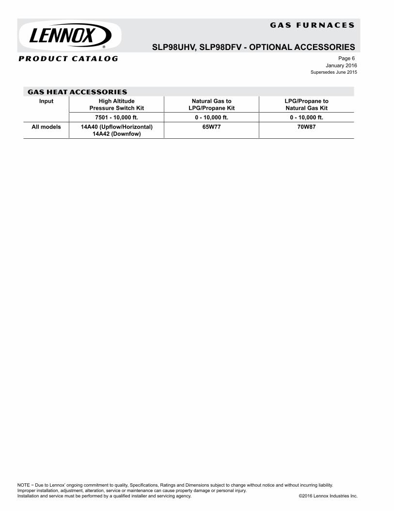
GAS HEAT ACCESSORIESInput High Altitude
Pressure Switch KitNatural Gas to
LPG/Propane KitLPG/Propane to Natural Gas Kit
7501 - 10,000 ft. 0 - 10,000 ft. 0 - 10,000 ft.All models 14A40 (Upflow/Horizontal)
14A42 (Downfow)65W77 70W87

P R O D U C T C ATA L O G
NOTE − Due to Lennox’ ongoing commitment to quality, Specifications, Ratings and Dimensions subject to change without notice and without incurring liability.Improper installation, adjustment, alteration, service or maintenance can cause property damage or personal injury.Installation and service must be performed by a qualified installer and servicing agency. ©2016 Lennox Industries Inc.
G A S F U R N A C E S
A C C E S S O R I E S
D I M E N S I O N S
F E A T U R E S
January 2016Supersedes June 2015
Page 7
L I M I T E D W A R R A N T Y
Heat Exchanger - twenty yearsAll other covered components - ten yearsRefer to Lennox Equipment Limited Warranty certificate included with equipment for details
Furnace Width
“A" “B" “C" “D”
A Dimension 14-1/2 (368)
17-1/2 (446)
21 (533)
24-1/2 (622)
B Dimension 13-3/8(340)
16-3/8 (416)
19-7/8 (454)
23-3/8 (546)
Bottom return
Width 13(330)
16 (406)
19-1/2 (495)
23 (584)
Depth 23-1/2 (597)
23-1/2 (597)
23-1/2 (597)
23-1/2 (597)
See page 11Cabinet• Horizontal Suspension Kit• Return Air Base
Controls• iComfort® S30 Thermostat• ComfortSense® 7500 Thermostat• Thermostat• iHarmony® Zoning System
Filter Kits• Air Filter and Rack Kits
Gas Heating• Gas Conversion Kits• High Altitude Pressure Switch Kits
Service Kits• Night Service Kit• Universal Service Kit - Switches
Heating SystemLennox Duralok™ Aluminized Steel Heat Exchanger AssemblyAluminized Steel Inshot BurnersTwo-Stage Gas Control Valve with 100% Safety ShutoffFlame Rollout SwitchesLimit ControlsSureLight® Hot Surface IgnitorTwo-Speed Combustion Air InducerSureLight® Control (iComfort® compatible)iComfort® Control communicates information about the unit to the iComfort® S30 thermostat.24 Volt TransformerField Wiring Make-up BoxApplicable to the iHarmony® Zoning System.Variable-Speed Blower MotorHigh efficiency, variable speed ECM (Electronically Commutated Motor) Maintains specified air volumes up to a maximum of 1.0 in. w.g. (cooling)total external static.CabinetUpflow, horizontal-left or horizontal-right applications.Bottom/end or side return airPre-painted cabinet finishSealed blower compartmentInner blower compartment access panel.Fully insulated cabinet with foil-faced insulation on sides and back of heating compartment and mat-faced insulation in blower compartment.Coil Match-upAll furnaces match C33/35 and CX34/35 cased upflow indoor coils and CH33 horizontal indoor coils with same letter designation in model number.
Upflow/Horizontal - Two-Stage Heat - Variable Speed BlowerSilentComfort™ Technology
AFUE - 80% - Input - 66,000 to 132,000 Btuh
DAVE LENNOX SIGNATURE® COLLECTIONSL280UHV
33(838)
B19-7/16(494)
23(584)
14(356)
*29-3/4(743)
AIRFLOW
A *Includes door
NOTE - Not Available In Canada!

NOTE − Due to Lennox’ ongoing commitment to quality, Specifications, Ratings and Dimensions subject to change without notice and without incurring liability. Improper installation, adjustment, alteration, service or maintenance can cause property damage or personal injury.Installation and service must be performed by a qualified installer and servicing agency. ©2016 Lennox Industries Inc.
January 2016Supersedes June 2015
Product Catalog - Gas FurnacesPage 8
SPECIFICATIONSGas Heating Performance
Model No. SL280UH070V36A SL280UH090V36B SL280UH090V48BModel No. - Low Nox SL280UH070XV36A - - - SL280UH090XV48B
1 AFUE 80% 80% 80%High Fire
Input - Btuh 66,000 88,000 88,000Output - Btuh 52,000 70,000 70,000
Temperature rise range - °F 40 - 70 40 - 70 40 - 70Gas Manifold Pressure (in. w.g.)
Nat. Gas / LPG/Propane3.5 / 10 3.5 / 10 3.5 / 10
Low Fire
Input - Btuh 43,000 57,000 57,000Output - Btuh 35,000 47,000 47,000
Temperature rise range - °F 25 -55 25 -55 25 -55Gas Manifold Pressure (in. w.g.)
Nat. Gas / LPG/Propane1.7 / 4.9 1.7 / 4.9 1.7 / 4.9
High static - in. w.g. Heating 0.8 0.8 0.8Cooling 1.0 1.0 1.0
Connections in.
Flue connection - in. round 4 4 4Gas pipe size IPS 1/2 1/2 1/2
Indoor Blower
Wheel nominal diameter x width - in. 10 X 8 10 X 9 11-1/2 X 9Motor output - hp 1/2 1/2 1.0
Tons of add-on cooling 2 - 3 2 - 3.5 2.5 - 4Air Volume Range - cfm 606 - 1345 498 - 1393 679 - 2002
Electrical Data Voltage 120 volts - 60 hertz - 1 phaseMaximum overcurrent protection 15 15 20
Shipping Data lbs. - 1 package 128 143 154NOTE - Filters and provisions for mounting are not furnished and must be field provided.1 Annual Fuel Utilization Efficiency based on DOE test procedures and according to FTC labeling regulations. Isolated combustion system rating for non-weatherized furnaces.
SPECIFICATIONSGas Heating Performance
Model No. SL280UH090V60C SL280UH110V60C SL280UH135V60DModel No. - Low Nox - - - SL280UH110XV60C - - -
1 AFUE 80% 80% 80%High Fire
Input - Btuh 88,000 110,000 132,000Output - Btuh 70,000 87,000 105,000
Temperature rise range - °F 35 - 65 35 - 65 40 - 70Gas Manifold Pressure (in. w.g.)
Nat. Gas / LPG/Propane3.5 / 10.0 3.5 / 10.0 3.5 / 10.0
Low Fire
Input - Btuh 57,000 72,000 86,000Output - Btuh 47,000 58,000 64,000
Temperature rise range - °F 25 -55 25 -55 25 -55Gas Manifold Pressure (in. w.g.)
Nat. Gas / LPG/Propane1.7 / 4.9 1.7 / 4.9 1.7 / 4.9
High static - in. w.g. Heating 0.8 0.8 0.8Cooling 1.0 1.0 1.0
Connections in.
Flue connection - in. round 4 4 2 4Gas pipe size IPS 1/2 1/2 1/2
Indoor Blower
Wheel nominal diameter x width - in. 11-1/2 X 10 11-1/2 X 10 11-1/2 X 11Motor output - hp 1.0 1.0 1.0
Tons of add-on cooling 3 - 5 3 - 5 3.5 - 5Air Volume Range - cfm 826 - 2305 812 - 2125 828 - 2257
Electrical Data Voltage 120 volts - 60 hertz - 1 phaseMaximum overcurrent protection 20 20 20
Shipping Data lbs. - 1 package 173 181 199NOTE - Filters and provisions for mounting are not furnished and must be field provided.1 Annual Fuel Utilization Efficiency based on DOE test procedures and according to FTC labeling regulations. Isolated combustion system rating for non-weatherized furnaces.2 Flue connection on the unit is 4 in. diameter. Most applications will require 5 in. venting and field supplied 4 x 5 in. adaptor. See Venting Tables in the Installation Instruc-
tions for detailed information.

P R O D U C T C ATA L O G
NOTE − Due to Lennox’ ongoing commitment to quality, Specifications, Ratings and Dimensions subject to change without notice and without incurring liability.Improper installation, adjustment, alteration, service or maintenance can cause property damage or personal injury.Installation and service must be performed by a qualified installer and servicing agency. ©2016 Lennox Industries Inc.
G A S F U R N A C E S
A C C E S S O R I E S
D I M E N S I O N S
F E A T U R E S
January 2016Supersedes June 2015
Page 9
L I M I T E D W A R R A N T Y
Furnace Width
“A" “B" “C"
A Dimension 14-1/2 (368)
17-1/2 (446)
21 (533)
B Dimension 13-3/8(340)
16-3/8 (416)
19-7/8 (454)
Bottom supply
Width 13(330)
16 (406)
19-1/2 (495)
Depth 19-1/4 (489)
19-1/4 (489)
19-1/4 (489)
See page 11Cabinet• Downflow Combustible Flooring
BaseControls• iComfort® S30 Thermostat• ComfortSense® 7500 Thermostat• Thermostat• iHarmony® Zoning System
Filters• Downflow Filter Kits
Gas Heating• Gas Conversion Kits• High Altitude Pressure Switch Kits
Service Kits• Night Service Kit• Universal Service Kit - Switches
Heat Exchanger - twenty yearsAll other covered components - ten yearsRefer to Lennox Equipment Limited Warranty certificate included with equipment for details
Heating SystemLennox Duralok™ Aluminized Steel Heat Exchanger AssemblyAluminized Steel Inshot BurnersTwo-Stage Gas Control Valve with 100% Safety ShutoffFlame Rollout SwitchesLimit ControlsSureLight® Hot Surface IgnitorTwo-Speed Combustion Air InducerSureLight® Control (iComfort® compatible)iComfort® Control communicates information about the unit to the iComfort® S30 thermostat.24 Volt TransformerField Wiring Make-up BoxApplicable to the iHarmony® Zoning System.Variable-Speed Blower MotorHigh efficiency, variable speed ECM (Electronically Commutated Motor) Maintains specified air volumes up to a maximum of 1.0 in. w.g. (cooling) total external static.CabinetDownflow applications.Pre-painted cabinet finishSealed blower compartmentInner blower compartment access panel.Fully insulated cabinet with foil-faced insulation on sides and back of heating compartment and mat-faced insulation in blower compartment.Coil Match-upCR33 downflow indoor coils will physically match the furnace supply air opening with the same letter designation in the model number.
Downflow - Two-Stage Heat - Variable Speed BlowerSilentComfort™ Technology
AFUE - 80% - Input - 66,000 to 110,000 Btuh
SL280DFV
33(838)
A
B19-7/16(494)
AIRFLOW
*29-3/4(743)
*Includes door
NOTE - Not Available In Canada!
DAVE LENNOX SIGNATURE® COLLECTION

NOTE − Due to Lennox’ ongoing commitment to quality, Specifications, Ratings and Dimensions subject to change without notice and without incurring liability. Improper installation, adjustment, alteration, service or maintenance can cause property damage or personal injury.Installation and service must be performed by a qualified installer and servicing agency. ©2016 Lennox Industries Inc.
January 2016Supersedes June 2015
Product Catalog - Gas FurnacesPage 10
SPECIFICATIONS
Gas Heating Performance
Model No. SL280DF070V36A SL280DF090V48B SL280DF090V60C SL280DF110V60C1 AFUE 80% 80% 80% 80%
High Fire
Input - Btuh 66,000 88,000 88,000 110,000
Output - Btuh 52,000 69,000 70,000 87,000
Temperature rise range - °F 35-65 35-65 35-65 35-65
Gas Manifold Pressure (in. w.g.) Nat. Gas / LPG/Propane
3.5 / 10.0 3.5 / 10.0 3.5 / 10.0 3.5 / 10.0
Low Fire
Input - Btuh 43,000 57,000 57,000 72,000
Output - Btuh 35,000 46,000 46,000 59,000
Temperature rise range - °F 25-55 25-55 25-55 25-55
Gas Manifold Pressure (in. w.g.) Nat. Gas / LPG/Propane
1.7 / 4.9 1.7 / 4.9 1.7 / 4.9 1.7 / 4.9
High static - in. w.g. Heating 0.8 0.8 0.8 0.8
Cooling 1.0 1.0 1.0 1.0
Connections in.
Flue connection - in. round 4 4 4 4
Gas pipe size IPS 1/2 1/2 1/2 1/2
Indoor Blower
Wheel nominal diameter x width - in. 10 x 8 11 x 9 11 x 10 11 x 10
Motor output - hp 1/2 1 1 1
Tons of add-on cooling 2 - 3 3 - 4 3.5 - 5 3.5 - 5
Air Volume Range - cfm 589 - 1514 830 - 1996 899 - 2273 882 - 2120
Electrical Data
Voltage 120 volts - 60 hertz - 1 phase
Maximum overcurrent protection 15 20 20 20
Shipping Data lbs. - 1 package 130 153 164 173NOTE - Filters and provisions for mounting are not furnished and must be field provided.1 Annual Fuel Utilization Efficiency based on DOE test procedures and according to FTC labeling regulations. Isolated combustion system rating for non-weatherized furnaces.

P R O D U C T C ATA L O G
NOTE − Due to Lennox’ ongoing commitment to quality, Specifications, Ratings and Dimensions subject to change without notice and without incurring liability.Improper installation, adjustment, alteration, service or maintenance can cause property damage or personal injury.Installation and service must be performed by a qualified installer and servicing agency. ©2016 Lennox Industries Inc.
G A S F U R N A C E S
January 2016Supersedes June 2015
Page 11
SL280UHV, SL280DFV - OPTIONAL ACCESSORIES
OPTIONAL ACCESSORIES - ORDER SEPARATELYNOTE - FURNACE CANNOT BE TWINNED!
“A” Width “B” Width “C” Width “D” WidthCABINET ACCESSORIES
Downflow Combustible Flooring Base - Downflow only 11M59 11M60 11M61 - - -Horizontal Suspension Kit - Horizontal only 51W10 51W10 51W10 51W10Return Air Base - Upflow only 65W75 50W98 50W99 51W00CONTROLS
iComfort® S30Thermostat 12U67 12U67 12U67 12U671 Remote Outdoor Air Temperature Sensor (for dual fuel and Humiditrol®) X2658 X2658 X2658 X2658
2 Discharge Air Temperature Sensor 88K38 88K38 88K38 88K38ComfortSense® 7500 Thermostat 13H14 13H14 13H14 13H143 Remote Outdoor Air Temperature Sensor (for dual fuel and Humiidtrol®) X2658 X2658 X2658 X2658DOWNFLOW FILTER KITS
Downflow Filter Cabinet 51W06 51W07 51W08 - - -1 No. and size of filter - in. (1) 20 x 20 x 1 (2) 16 x 20 x 1 (2) 16 x 20 x 1 - - -
UPFLOW/HORIZONTAL FILTER KITS4 Air Filter and Rack Kit Horizontal (end) 87L95 87L96 87L97 87L98
Size of filter - in. 14 x 25 x 1 18 x 25 x 1 20 x 25 x 1 25 x 25 x 1Side Return Single 44J22 44J22 44J22 44J22
Ten Pack 66K63 66K63 66K63 66K63Size of filter - in. 16 x 25 x 1 16 x 25 x 1 16 x 25 x 1 16 x 25 x 1
SERVICE KITS
Night Service Kit 14C98 14C98 14C98 14C98Universal Service Kit - Switches 89W19 89W19 89W19 89W19VENTING
Vent Adaptor - 6 in. connection size upflow applications only 18M79 18M79 18M79 18M791 Remote Outdoor Temperature Sensor is used with conventional (non-iComfort®-enabled) outdoor units (sensor is furnished with iComfort®-enabled outdoor units).
Allows the thermostat to display outdoor temperature. Required in dual-fuel and Humiditrol® applications.2 Optional for service diagnostics.3 Remote Outdoor Temperature Sensor for ComfortSense® 7500 Thermostat must be connected directly to the thermostat, Do not connect it to the SureLight® control.4 Cleanable frame type filter.
GAS HEAT ACCESSORIES
Input
High Altitude Pressure Switch Kit
Natural Gas to LPG/Propane
Kit
LPG/Propane to Natural Gas
Kit
Natural Gas High Altitude
Orifice Kit
LPG/Propane High Altitude
Orifice Kit
0 - 4500 ft. 4501 - 7500 ft.7501 - 10,000 ft.
0 - 7500 ft. 0 - 7500 ft. 7501 - 10,000 ft. 7501 - 10,000 ft.UH DF
070 No Change No Change 73W35 73W36 11K51 77W09 73W37 77W11090 No Change 69W56 73W35 73W36 11K51 77W09 73W37 77W11110 No Change 69W56 73W35 73W35 11K51 77W09 73W37 77W11135 No Change 73W33 73W34 - - - 11K51 77W09 73W37 77W11


P R O D U C T C ATA L O G
NOTE − Due to Lennox’ ongoing commitment to quality, Specifications, Ratings and Dimensions subject to change without notice and without incurring liability.Improper installation, adjustment, alteration, service or maintenance can cause property damage or personal injury.Installation and service must be performed by a qualified installer and servicing agency. ©2016 Lennox Industries Inc.
G A S F U R N A C E S
A C C E S S O R I E S
D I M E N S I O N S
January 2016Supersedes June 2015
Page 13
L I M I T E D W A R R A N T Y
F E A T U R E S
EL296UHVELITE® SERIES
Upflow/Horizontal - Two-Stage Heat - Variable Speed BlowerDirect/Non-Direct Vent
AFUE - 96% - Input - 44,000 to 132,000 Btuh
Furnace Width “B" “C" “D"A Dimension 17-1/2
(446)21
(533)24-1/2 (622)
B Dimension 16-3/8 (416)
19-7/8 (454)
23-3/8 (546)
Bottom return
Width 16 (406)
19-1/2 (495)
23 (584)
Depth 23-1/2 (597)
23-1/2 (597)
23-1/2 (597)
Heat Exchanger - lifetimeAll other covered components - five yearsRefer to Lennox Equipment Limited Warranty certificate included with equipment for details
Heating SystemLennox Duralok Plus™ Aluminized Steel Heat Exchanger AssemblyAluminized Steel Inshot BurnersTwo-Stage Gas Control Valve with 100% Safety ShutoffFlame Rollout SwitchesLimit ControlsSureLight® Hot Surface IgnitorTwo-Speed Combustion Air InducerDirect Vent/Non-Direct Vent Sealed CombustionDirect Vent - combustion air supplied from outdoorsNon-Direct Vent - combustion air supplied from indoorsSureLight® Control (iComfort® compatible)iComfort® Control communicates information about the unit to the iComfort® S30 thermostat.24 Volt TransformerField Wiring Make-up BoxApplicable to the iHarmony® Zoning System.Variable-Speed Blower MotorHigh efficiency, variable speed ECM (Electronically Commutated Motor) Maintains specified air volumes up to a maximum of 1.0 in. w.g. (cooling)total external static.CabinetUpflow, downflow, horizontal-left or horizontal-right applications without any internal modifications to the unit.Pre-painted cabinet finishFully insulated cabinet with foil-faced insulation on sides and back of heating compartment and mat-faced insulation in blower compartment.Coil Match-upAll furnaces match C33/35 and CX34/35 cased upflow indoor coils and CH33 horizontal indoor coils with same letter designation in model number.
See page 35Cabinet• Condensate Kits• Condensate Drain Heat Cable• Crawl Space Vent Drain Kit• Horizontal Suspension Kit• Return Air Base
Controls• iComfort® S30 Thermostat• ComfortSense® 7500 Thermostat• Thermostat• iHarmony® Zoning System
Filter Kits• Air Filter and Rack Kits
Gas Heating• Gas Conversion Kits• High Altitude Orifice Kits• High Altitude Pressure Switch Kits• Termination Kits
Service Kits• Night Service Kit• Universal Service Kit - Switches
33(838)
B19-7/16(494)
23(584)
14(356)
*29-3/4(743)
AIRFLOW
A *Includes door

NOTE − Due to Lennox’ ongoing commitment to quality, Specifications, Ratings and Dimensions subject to change without notice and without incurring liability. Improper installation, adjustment, alteration, service or maintenance can cause property damage or personal injury.Installation and service must be performed by a qualified installer and servicing agency. ©2016 Lennox Industries Inc.
January 2016Supersedes June 2015
Product Catalog - Gas FurnacesPage 14
SPECIFICATIONSGas Heating Performance
Model No. EL296UH 045XV36B
EL296UH 070XV36B
EL296UH 090XV36C
EL296UH 090XV48C
1 AFUE 96% 96% 96% 96%High Fire
Input - Btuh 44,000 66,000 88,000 88,000Output - Btuh 42,000 62,000 84,000 85,000
Temperature rise range - °F 35-65 50-80 30-60 45-75Gas Manifold Pressure (in. w.g.) Nat. Gas / LPG/Propane 3.5 / 10.0 3.5 / 10.0 3.5 / 10.0 3.5 / 10.0
Low Fire
Input - Btuh 29,000 43,000 57,000 57,000Output - Btuh 28,000 41,000 55,000 55,000
Temperature rise range - °F 20 - 50 25 - 55 30 - 60 25 - 55Gas Manifold Pressure (in. w.g.) Nat. Gas / LPG/Propane 1.7 / 4.9 1.7 / 4.9 1.7 / 4.9 1.7 / 4.9
High static - in. w.g. Heating 0.8 0.8 0.8 0.8Cooling 1.0 1.0 1.0 1.0
Connections in.
Intake / Exhaust Pipe (PVC) 2 / 2 2 / 2 2 / 2 2 / 2Gas pipe size IPS 1/2 1/2 1/2 1/2
Condensate Drain Trap (PVC pipe) - i.d. 3/4 3/4 3/4 3/4with furnished 90° street elbow 3/4 slip x 3/4 Mipt
with field supplied (PVC coupling) - o.d. 3/4 slip x 3/4 MPTIndoor Blower
Wheel nominal diameter x width - in. 10 x 9 10 x 9 10 x 9 11 x 11Motor output - hp 1/2 1/2 1/2 3/4
Tons of add-on cooling 2 - 3 2 - 3 2 - 3 2.5 - 4Air Volume Range - cfm 465 - 1370 490 - 1365 520 - 1360 680 - 1770
Electrical Data Voltage 120 volts - 60 hertz - 1 phaseBlower motor full load amps 7.7 7.7 7.7 10.1
Maximum overcurrent protection 15 15 15 20Shipping Data lbs. - 1 package 130 138 154 165
SPECIFICATIONSGas Heating Performance
Model No. EL296UH0 90XV60C
EL296UH 110XV48C
EL296UH 110XV60C
EL296UH 135XV60D
1 AFUE 96% 96% 96% 96%High Fire
Input - Btuh 88,000 110,000 110,000 132,000Output - Btuh 85,000 105,000 106,000 126,000
Temperature rise range - °F 40-70 60-90 45-75 55-85Gas Manifold Pressure (in. w.g.) Nat. Gas / LPG/Propane 3.5 / 10.0 3.5 / 10.0 3.5 / 10.0 3.5 / 10.0
Low Fire
Input - Btuh 57,000 72,000 72,000 86,000Output - Btuh 55,000 70,000 70,000 84,000
Temperature rise range - °F 30 - 60 36 - 65 35 - 65 40 - 70Gas Manifold Pressure (in. w.g.) Nat. Gas / LPG/Propane 1.7 / 4.9 1.7 / 4.9 1.7 / 4.9 1.7 / 4.9
High static - in. w.g. Heating 0.8 0.8 0.8 0.8Cooling 1.0 1.0 1.0 1.0
Connections in.
Intake / Exhaust Pipe (PVC) 2 / 2 2 / 2 2 / 2 2 / 2Gas pipe size IPS 1/2 1/2 1/2 1/2
Condensate Drain Trap (PVC pipe) - i.d. 3/4 3/4 3/4 3/4with furnished 90° street elbow 3/4 slip x 3/4 Mipt
with field supplied (PVC coupling) - o.d. 3/4 slip x 3/4 MPTIndoor Blower
Wheel nominal diameter x width - in. 11 x 11 11 x 11 11 x 11 11 x 11Motor output - hp 1 3/4 1 1
Tons of add-on cooling 3 - 5 2.5 - 4 3-5 3-5Air Volume Range - cfm 840 - 2195 670 - 1760 850 - 2125 950 - 2250
Electrical Data Voltage 120 volts - 60 hertz - 1 phaseBlower motor full load amps 12.8 10.1 12.8 12.8
Maximum overcurrent protection 20 20 20 20Shipping Data lbs. - 1 package 166 173 174 188NOTE - Filters and provisions for mounting are not furnished and must be field provided.1 Annual Fuel Utilization Efficiency based on DOE test procedures and according to FTC labeling regulations. Isolated combustion system rating for non-weatherized furnaces.

P R O D U C T C ATA L O G
NOTE − Due to Lennox’ ongoing commitment to quality, Specifications, Ratings and Dimensions subject to change without notice and without incurring liability.Improper installation, adjustment, alteration, service or maintenance can cause property damage or personal injury.Installation and service must be performed by a qualified installer and servicing agency. ©2016 Lennox Industries Inc.
G A S F U R N A C E S
January 2016Supersedes June 2015
Page 15
L I M I T E D W A R R A N T Y
F E A T U R E S
A C C E S S O R I E S
D I M E N S I O N S
EL296DFVELITE® SERIES
See page 35Cabinet• Downflow Combustible Flooring
Base• Condensate Kits• Condensate Drain Heat Cable• Crawl Space Vent Drain Kit• Return Air Base
Controls• iComfort® S30 Thermostat• ComfortSense® 7500 Thermostat• Thermostat• iHarmony® Zoning System
Filter Kits• Downflow Filter Kits
Gas Heating• Gas Conversion Kits• High Altitude Orifice Kits• High Altitude Pressure Switch Kits• Termination Kits
Service Kits• Night Service Kit• Universal Service Kit - Switches
33(838)
A
B19-7/16(494)
AIRFLOW
*29-3/4(743)
*Includes door
Furnace Width “B" “C" A Dimension 17-1/2
(446)21
(533)B Dimension 16-3/8
(416)19-7/8 (454)
Bottom supply
Width 16 (406)
19-1/2 (495)
Depth 19-1/4 (489)
19-1/4 (489)
Heat Exchanger - lifetimeAll other covered components - five yearsRefer to Lennox Equipment Limited Warranty certificate included with equipment for details
Heating SystemLennox Duralok Plus™ Aluminized Steel Heat Exchanger AssemblyAluminized Steel Inshot BurnersTwo-Stage Gas Control Valve with 100% Safety ShutoffFlame Rollout SwitchesLimit ControlsSureLight® Hot Surface IgnitorTwo-Speed Combustion Air InducerDirect Vent/Non-Direct Vent Sealed CombustionDirect Vent - combustion air supplied from outdoorsNon-Direct Vent - combustion air supplied from indoorsSureLight® Control (iComfort® compatible)iComfort® Control communicates information about the unit to the iComfort® S30 thermostat.24 Volt TransformerField Wiring Make-up BoxApplicable to the iHarmony® Zoning System.Variable-Speed Blower MotorHigh efficiency, variable speed ECM (Electronically Commutated Motor) Maintains specified air volumes up to a maximum of 1.0 in. w.g. (cooling)total external static.CabinetDownflow applications.Pre-painted cabinet finishFully insulated cabinet with foil-faced insulation on sides and back of heating compartment and mat-faced insulation in blower compartment.Coil Match-upCR33 downflow indoor coils will physically match the furnace supply air opening with the same letter designation in the model number.
Upflow/Horizontal - Two-Stage Heat - Variable Speed BlowerDirect/Non-Direct Vent
AFUE - 96% - Input - 44,000 to 110,000 Btuh

NOTE − Due to Lennox’ ongoing commitment to quality, Specifications, Ratings and Dimensions subject to change without notice and without incurring liability. Improper installation, adjustment, alteration, service or maintenance can cause property damage or personal injury.Installation and service must be performed by a qualified installer and servicing agency. ©2016 Lennox Industries Inc.
January 2016Supersedes June 2015
Product Catalog - Gas FurnacesPage 16
SPECIFICATIONSGas Heating Performance
Model No. EL296DF045XV36BEL296DF070XV48BEL296DF090XV60CEL296DF110XV60C1 AFUE 96% 96% 96% 96%
High Fire
Input - Btuh 44,000 66,000 88,000 110,000Output - Btuh 43,000 64,000 85,000 106,000
Temperature rise range - °F 35-65 35-65 40-70 45-75Gas Manifold Pressure (in. w.g.)
Nat. Gas / LPG/Propane3.5 / 10.0 3.5 / 10.0 3.5 / 10.0 3.5 / 10.0
Low Fire
Input - Btuh 29,000 43,000 57,000 72,000Output - Btuh 28,000 42,000 56,000 70,000
Temperature rise range - °F 20 - 50 25 - 55 30 - 60 35 - 65Gas Manifold Pressure (in. w.g.)
Nat. Gas / LPG/Propane1.7 / 4.9 1.7 / 4.9 1.7 / 4.9 1.7 / 4.9
High static - in. w.g.
Heating 0.8 0.8 0.8 0.8Cooling 1.0 1.0 1.0 1.0
Connections in.
Intake / Exhaust Pipe (PVC) 2 / 2 2 / 2 2 / 2 2 / 2Gas pipe size IPS 1/2 1/2 1/2 1/2
Condensate Drain Trap (PVC pipe) - i.d. 3/4 3/4 3/4 3/4with furnished 90° street elbow 3/4 slip x 3/4 Mipt 3/4 slip x 3/4 Mipt 3/4 slip x 3/4 Mipt 3/4 slip x 3/4 Mipt
with field supplied (PVC coupling) - o.d. 3/4 slip x 3/4 MPT 3/4 slip x 3/4 MPT 3/4 slip x 3/4 MPT 3/4 slip x 3/4 MPTIndoor Blower
Wheel nom. diameter x width - in. 10 x 9 11 x 10 11 x 11 11 x 11Motor output - hp 1/2 3/4 1 1
Tons of add-on cooling 2 - 3 2.5 - 4 3 - 5 3 - 5Air Volume Range - cfm 545 - 1360 575 - 1800 890 - 2130 860 - 2180
Electrical Data
Voltage 120 volts - 60 hertz - 1 phaseBlower motor full load amps 7.7 10.1 12.8 12.8
Maximum overcurrent protection 15 20 20 20Shipping Data lbs. - 1 package 131 136 164 176NOTE - Filters and provisions for mounting are not furnished and must be field provided.
1 Annual Fuel Utilization Efficiency based on DOE test procedures and according to FTC labeling regulations. Isolated combustion system rating for non-weatherized furnaces.

P R O D U C T C ATA L O G
NOTE − Due to Lennox’ ongoing commitment to quality, Specifications, Ratings and Dimensions subject to change without notice and without incurring liability.Improper installation, adjustment, alteration, service or maintenance can cause property damage or personal injury.Installation and service must be performed by a qualified installer and servicing agency. ©2016 Lennox Industries Inc.
G A S F U R N A C E S
January 2016Supersedes June 2015
Page 17
EL296UHV, EL296DFV - OPTIONAL ACCESSORIES
OPTIONAL ACCESSORIES - ORDER SEPARATELYNOTE - FURNACE CANNOT BE TWINNED!
“B” Width “C” Width “D” WidthCABINET ACCESSORIES
Downflow Combustible Flooring Base - Downflow only 11M60 11M61 - - -Horizontal Suspension Kit - Horizontal only 51W10 51W10 51W10Return Air Base - Upflow only 50W98 50W99 51W00CONDENSATE DRAIN KITS
Condensate Drain Heat Cable 6 ft. 26K68 26K68 26K6824 ft. 26K69 26K69 26K69
Crawl Space Vent Drain Kit 51W18 51W18 51W18CONTROLSiComfort® S30 Thermostat 12U67 12U67 12U671 Remote Outdoor Air Temperature Sensor (for dual fuel and Humiditrol®) X2658 X2658 X2658
2 Discharge Air Temperature Sensor 88K38 88K38 88K38ComfortSense® 7500 Thermostat 13H14 13H14 13H143 Remote Outdoor Air Temperature Sensor (for dual fuel and Humiditrol®) X2658 X2658 X2658DOWNFLOW FILTER KITS
Downflow Filter Cabinet 51W07 51W08 - - -4 No. and size of filter - in. (2) 16 x 20 x 1 (2) 16 x 20 x 1 - - -
UPFLOW/HORIZONTAL FILTER KITS4 Air Filter and
Rack KitHorizontal (end) 87L96 87L97 87L98
Size of filter - in. 18 x 25 x 1 20 x 25 x 1 25 x 25 x 1Side Return Single 44J22 44J22 44J22
Ten Pack 66K63 66K63 66K63Size of filter - in. 16 x 25 x 1 16 x 25 x 1 16 x 25 x 1
SERVICE KITSNight Service Kit 14C99 14C99 14C99Universal Service Kit - Switches 89W20 89W20 89W20TERMINATION KITS - Direct Vent Applications Only. See Installation Instructions for specific venting information.
Termination Kits Concentric US - 2 in. 71M80 69M29 - - -3 in. - - - 60L46 60L46
Canada - 2 in. 44W92 44W92 - - -3 in. - - - 44W93 44W93
Flush-Mount
US - 2, 2-1/2 or 3 in. 51W11 51W11 51W11Canada - 2, 2-1/2 or 3 in. 51W12 51W12 51W12
Wall - Close Couple
US - 2 in. 22G44 - - - - - -3 in. 44J40 44J40 44J40
Wall - Close Couple WTK
Canada - 2 in. 30G28 - - - - - -3 in. 81J20 81J20 81J20
Termination Kits
Roof 2 in. 15F75 15F75 - - -Wall - Wall Ring Kit 2 in. 15F74 15F74 - - -
Roof Termination Flashing Kit (2 flashings) 3 in. 44J41 44J41 44J411 Remote Outdoor Temperature Sensor is used with conventional (non-iComfort®-enabled) outdoor units (sensor is furnished with iComfort®-enabled outdoor units).
Allows the thermostat to display outdoor temperature. Required in dual-fuel and Humiditrol® applications.2 Optional for service diagnostics.3 Remote Outdoor Temperature Sensor for ComfortSense® 7500 Thermostat must be connected directly to the thermostat, Do not connect it to the SureLight® control.4 Cleanable frame type filter.NOTE - Termination Kits 44W92, 44W93, 30G28, 51W12, 81J20 are certified to ULC S636 standard for use in Canada only.

NOTE − Due to Lennox’ ongoing commitment to quality, Specifications, Ratings and Dimensions subject to change without notice and without incurring liability. Improper installation, adjustment, alteration, service or maintenance can cause property damage or personal injury.Installation and service must be performed by a qualified installer and servicing agency. ©2016 Lennox Industries Inc.
P R O D U C T C ATA L O G
G A S F U R N A C E S
January 2016Supersedes June 2015
Page 18
GAS HEAT ACCESSORIES
Input High Altitude
Pressure Switch KitNatural Gas to
LPG/Propane Kit LPG/Propane
to Natural Gas Kit
Natural Gas High Altitude
Orifice Kit
LPG/Propane High Altitude
Orifice Kit4501 - 7500 ft. 7501 - 10,000 ft. 0 - 7500 ft. 0 - 7500 ft. 7501- 10,000 ft. 7501- 10,000 ft.
045 93W81 93W84 78W93 77W09 73W37 78W96
070 11X65 (UH) / 11X70 (DF)
98W79 (UH) / 11X71 (DF) 78W93 77W09 73W37 78W96
090 11X72 (UH) / 11X65 (DF)
11X65 (UH) / 98W79 (DF) 78W93 77W09 73W37 78W96
110 93W80 93W85 78W93 77W09 73W37 78W96135 93W93 93W85 78W93 77W09 73W37 78W96
EL296UHV, EL296DFV - OPTIONAL ACCESSORIES

P R O D U C T C ATA L O G
NOTE − Due to Lennox’ ongoing commitment to quality, Specifications, Ratings and Dimensions subject to change without notice and without incurring liability.Improper installation, adjustment, alteration, service or maintenance can cause property damage or personal injury.Installation and service must be performed by a qualified installer and servicing agency. ©2016 Lennox Industries Inc.
G A S F U R N A C E S
A C C E S S O R I E S
D I M E N S I O N S
January 2016Supersedes June 2015
Page 19
L I M I T E D W A R R A N T Y
F E A T U R E S
EL296UHEELITE® SERIES
Upflow/Horizontal - Two-Stage HeatHigh Efficiency Blower Motor - Direct/Non-Direct Vent
AFUE - Up to 96% - Input - 44,000 to 132,000 Btuh
Furnace Width “B" “C" “D"A Dimension 17-1/2
(446)21
(533)24-1/2 (622)
B Dimension 16-3/8 (416)
19-7/8 (454)
23-3/8 (546)
Bottom return
Width 16 (406)
19-1/2 (495)
23 (584)
Depth 23-1/2 (597)
23-1/2 (597)
23-1/2 (597)
Heat Exchanger - lifetimeAll other covered components - five yearsRefer to Lennox Equipment Limited Warranty certificate included with equipment for details
Heating SystemLennox Duralok Plus™ Aluminized Steel Heat Exchanger AssemblyAluminized Steel Inshot BurnersTwo-Stage Gas Control Valve with 100% Safety ShutoffFlame Rollout SwitchesLimit ControlsSureLight® Hot Surface IgnitorTwo-Speed Combustion Air InducerDirect Vent/Non-Direct Vent Sealed CombustionDirect Vent - combustion air supplied from outdoorsNon-Direct Vent - combustion air supplied from indoorsControlsSurelight® integrated Two-Stage Furnace Control24 Volt TransformerField Wiring Make-up BoxBlowerHigh Efficiency Constant Torque BlowerDC Brushless MotorCabinetUpflow, downflow, horizontal-left or horizontal-right applications without any internal modifications to the unit.Pre-painted cabinet finishFully insulated cabinet with foil-faced insulation on sides and back of heating compartment and mat-faced insulation in blower compartment.Coil Match-upAll furnaces match C33/35 and CX34/35 cased upflow indoor coils and CH33 horizontal indoor coils with same letter designation in model number.
See page 35Cabinet• Condensate Kits• Condensate Drain Heat Cable• Crawl Space Vent Drain Kit• Horizontal Suspension Kit• Return Air Base
Controls• Thermostat
Filter Kits• Air Filter and Rack Kits
Gas Heating• Gas Conversion Kits• High Altitude Orifice Kits• High Altitude Pressure Switch Kits• Termination Kits
Service Kits• Night Service Kit• Universal Service Kit - Switches
33(838)
B19-7/16(494)
23(584)
14(356)
*29-3/4(743)
AIRFLOW
A *Includes door

NOTE − Due to Lennox’ ongoing commitment to quality, Specifications, Ratings and Dimensions subject to change without notice and without incurring liability. Improper installation, adjustment, alteration, service or maintenance can cause property damage or personal injury.Installation and service must be performed by a qualified installer and servicing agency. ©2016 Lennox Industries Inc.
January 2016Supersedes June 2015
Product Catalog - Gas FurnacesPage 20
SPECIFICATIONSGas Heating Performance
Model No. EL296UH110XE60C EL296UH135XE60D1 AFUE 96% 96%
High Fire
Input - Btuh 110,000 132,000Output - Btuh 106,000 127,000
Temperature rise range - °F 40 - 70 45 - 75Gas Manifold Pressure (in. w.g.)
Nat. Gas / LPG/Propane3.5 / 10.0 3.5 / 10.0
Low Fire
Input - Btuh 72,000 86,000Output - Btuh 70,000 84,000
Temperature rise range - °F 30 - 60 35 - 65Gas Manifold Pressure (in. w.g.) Nat. Gas / LPG/Propane 1.7 / 4.9 1.7 / 4.9
High static - in. w.g. 0.5 0.5Connections in.
Intake / Exhaust Pipe (PVC) 2 / 2 2 / 2Gas pipe size IPS 1/2 1/2
Condensate Drain Trap (PVC pipe) - i.d. 3/4 3/4with furnished 90° street elbow 3/4 slip x 3/4 Mipt 3/4 slip x 3/4 Mipt
with field supplied (PVC coupling) - o.d. 3/4 slip x 3/4 MPT 3/4 slip x 3/4 MPTIndoor Blower
Wheel nominal diameter x width - in. 11-1/2 x 10 11-1/2 x 10Motor output - hp 1 1
Tons of add-on cooling 3 - 5 3.5 - 5Air Volume Range - cfm 1055 - 2220 1260 - 2405
Electrical Data Voltage 120 volts - 60 hertz - 1 phaseBlower motor full load amps 10.9 10.9
Maximum overcurrent protection 15 15Shipping Data lbs. - 1 package 174 189NOTE - Filters and provisions for mounting are not furnished and must be field provided.
1 Annual Fuel Utilization Efficiency based on DOE test procedures and according to FTC labeling regulations. Isolated combustion system rating for non-weatherized furnaces.
SPECIFICATIONSGas Heating Performance
Model No. EL296UH045XE36B EL296UH070XE36B EL296UH090XE48C1 AFUE 96% 96% 96%
High Fire
Input - Btuh 44,000 66,000 88,000Output - Btuh 43,000 64,000 84,000
Temperature rise range - °F 30 - 60 35 - 65 40 - 70Gas Manifold Pressure (in. w.g.)
Nat. Gas / LPG/Propane3.5 / 10.0 3.5 / 10.0 3.5 / 10.0
Low Fire
Input - Btuh 29,000 43,000 57,000Output - Btuh 28,000 42,000 55,000
Temperature rise range - °F 20 - 50 25 - 55 30 - 60Gas Manifold Pressure (in. w.g.) Nat. Gas / LPG/Propane 1.7 / 4.9 1.7 / 4.9 1.7 / 4.9
High static - in. w.g. 0.5 0.5 0.5Connections in.
Intake / Exhaust Pipe (PVC) 2 / 2 2 / 2 2 / 2Gas pipe size IPS 1/2 1/2 1/2
Condensate Drain Trap (PVC pipe) - i.d. 3/4 3/4 3/4with furnished 90° street elbow 3/4 slip x 3/4 Mipt 3/4 slip x 3/4 Mipt 3/4 slip x 3/4 Mipt
with field supplied (PVC coupling) - o.d. 3/4 slip x 3/4 MPT 3/4 slip x 3/4 MPT 3/4 slip x 3/4 MPTIndoor Blower
Wheel nominal diameter x width - in. 10 x 8 10 x 8 10 x 10Motor output - hp 1/2 1/2 3/4
Tons of add-on cooling 1.5 - 3 1.5 - 3 2.5 - 4Air Volume Range - cfm 520 - 1345 550 - 1380 760 - 1740
Electrical Data Voltage 120 volts - 60 hertz - 1 phaseBlower motor full load amps 6.8 6.8 8.4
Maximum overcurrent protection 15 15 15Shipping Data lbs. - 1 package 129 133 159

P R O D U C T C ATA L O G
NOTE − Due to Lennox’ ongoing commitment to quality, Specifications, Ratings and Dimensions subject to change without notice and without incurring liability.Improper installation, adjustment, alteration, service or maintenance can cause property damage or personal injury.Installation and service must be performed by a qualified installer and servicing agency. ©2016 Lennox Industries Inc.
G A S F U R N A C E S
A C C E S S O R I E S
F E A T U R E S
January 2016Supersedes June 2015
Page 21
L I M I T E D W A R R A N T Y
D I M E N S I O N S
EL296DFEELITE® SERIES
See page 35Cabinet• Downflow Combustible Flooring
Base• Condensate Kits• Condensate Drain Heat Cable• Crawl Space Vent Drain Kit• Return Air Base
Controls• Thermostat
Filter Kits• Downflow Filter Kits
Gas Heating• Gas Conversion Kits• High Altitude Orifice Kits• High Altitude Pressure Switch Kits• Termination Kits
Service Kits• Night Service Kit• Universal Service Kit - Switches
33(838)
A
B19-7/16(494)
AIRFLOW
*29-3/4(743)
*Includes door
Furnace Width “B" “C" A Dimension 17-1/2
(446)21
(533)B Dimension 16-3/8
(416)19-7/8 (454)
Bottom supply
Width 16 (406)
19-1/2 (495)
Depth 19-1/4 (489)
19-1/4 (489)
Heat Exchanger - lifetimeAll other covered components - five yearsRefer to Lennox Equipment Limited Warranty certificate included with equipment for details
Heating SystemLennox Duralok Plus™ Aluminized Steel Heat Exchanger AssemblyAluminized Steel Inshot BurnersTwo-Stage Gas Control Valve with 100% Safety ShutoffFlame Rollout SwitchesLimit ControlsSureLight® Hot Surface IgnitorTwo-Speed Combustion Air InducerDirect Vent/Non-Direct Vent Sealed CombustionDirect Vent - combustion air supplied from outdoorsNon-Direct Vent - combustion air supplied from indoorsControlsSurelight® integrated Two-Stage Furnace Control24 Volt TransformerField Wiring Make-up Box24 Volt TransformerField Wiring Make-up BoxBlowerHigh Efficiency Constant Torque Blower MotorDC Brushless MotorCabinetDownflow applications.Pre-painted cabinet finishFully insulated cabinet with foil-faced insulation on sides and back of heating compartment and mat-faced insulation in blower compartment.Coil Match-upCR33 downflow indoor coils will physically match the furnace supply air opening with the same letter designation in the model number.
Downflow - Two-Stage HeatHigh Efficiency Blower Motor - Direct/Non-Direct Vent
AFUE - 96% - Input - 44,000 to 110,000 Btuh

NOTE − Due to Lennox’ ongoing commitment to quality, Specifications, Ratings and Dimensions subject to change without notice and without incurring liability. Improper installation, adjustment, alteration, service or maintenance can cause property damage or personal injury.Installation and service must be performed by a qualified installer and servicing agency. ©2016 Lennox Industries Inc.
January 2016Supersedes June 2015
Product Catalog - Gas FurnacesPage 22
SPECIFICATIONSGas Heating Performance
Model No. EL296DF045XE36BEL296DF070XE48BEL296DF090XE48CEL296DF110XE60C1 AFUE 96% 96% 96% 96%
High Fire
Input - Btuh 44,000 66,000 88,000 110,000Output - Btuh 43,000 64,000 85,000 106,000
Temperature rise range - °F 35-65 35-65 40-70 45-75Gas Manifold Pressure (in. w.g.)
Nat. Gas / LPG/Propane3.5 / 10.0 3.5 / 10.0 3.5 / 10.0 3.5 / 10.0
Low Fire
Input - Btuh 29,000 43,000 57,000 72,000Output - Btuh 28,000 42,000 55,000 70,000
Temperature rise range - °F 20 - 50 25 - 55 30 - 60 35 - 65Gas Manifold Pressure (in. w.g.)
Nat. Gas / LPG/Propane1.7 / 4.9 1.7 / 4.9 1.7 / 4.9 1.7 / 4.9
High static - in. w.g. 0.5 0.5 0.5 0.5Connections in.
Intake / Exhaust Pipe (PVC) 2 / 2 2 / 2 2 / 2 2 / 2Gas pipe size IPS 1/2 1/2 1/2 1/2
Condensate Drain Trap (PVC pipe) - i.d. 3/4 3/4 3/4 3/4with furnished 90° street elbow 3/4 slip x 3/4 Mipt 3/4 slip x 3/4 Mipt 3/4 slip x 3/4 Mipt 3/4 slip x 3/4 Mipt
with field supplied (PVC coupling) - o.d. 3/4 slip x 3/4 MPT 3/4 slip x 3/4 MPT 3/4 slip x 3/4 MPT 3/4 slip x 3/4 MPTIndoor Blower
Wheel nom. diameter x width - in. 10 x 8 11-1/2 x 10 10 x 10 11 x 11Motor output - hp 1/2 3/4 3/4 1
Tons of add-on cooling 1.5 - 3 2 - 4 2 - 4 3 - 5Air Volume Range - cfm 485 - 1395 520 - 1770 760 - 1765 1045 - 2285
Electrical Data
Voltage 120 volts - 60 hertz - 1 phaseBlower motor full load amps 6.8 8.4 8.4 10.9
Maximum overcurrent protection 15 15 15 15Shipping Data lbs. - 1 package 134 145 163 175NOTE - Filters and provisions for mounting are not furnished and must be field provided.
1 Annual Fuel Utilization Efficiency based on DOE test procedures and according to FTC labeling regulations. Isolated combustion system rating for non-weatherized furnaces.

P R O D U C T C ATA L O G
NOTE − Due to Lennox’ ongoing commitment to quality, Specifications, Ratings and Dimensions subject to change without notice and without incurring liability.Improper installation, adjustment, alteration, service or maintenance can cause property damage or personal injury.Installation and service must be performed by a qualified installer and servicing agency. ©2016 Lennox Industries Inc.
G A S F U R N A C E S
January 2016Supersedes June 2015
Page 23
OPTIONAL ACCESSORIES - ORDER SEPARATELYNOTE - FURNACE CANNOT BE TWINNED!
“B” Width “C” Width “D” Width
CABINET ACCESSORIES
Downflow Combustible Flooring Base - Downflow only 11M60 11M61 - - -Horizontal Suspension Kit - Horizontal only 51W10 51W10 51W10Return Air Base - Upflow only 50W98 50W99 51W00CONDENSATE DRAIN KITS
Condensate Drain Heat Cable 6 ft. 26K68 26K68 26K6824 ft. 26K69 26K69 26K69
Crawl Space Vent Drain Kit 51W18 51W18 51W18DOWNFLOW FILTER KITS
Downflow Filter Cabinet 51W07 51W08 - - -4 No. and size of filter - in. (2) 16 x 20 x 1 (2) 16 x 20 x 1 - - -
UPFLOW/HORIZONTAL FILTER KITS1 Air Filter and
Rack KitHorizontal (end) 87L96 87L97 87L98
Size of filter - in. 18 x 25 x 1 20 x 25 x 1 25 x 25 x 1Side Return Single 44J22 44J22 44J22
Ten Pack 66K63 66K63 66K63Size of filter - in. 16 x 25 x 1 16 x 25 x 1 16 x 25 x 1
SERVICE KITS
Night Service Kit 10B39 10B39 10B39Universal Service Kit - Switches 89W20 89W20 89W20TERMINATION KITS - Direct Vent Applications Only. See Installation Instructions for specific venting information.
Termination Kits Concentric US - 2 in. 71M80 69M29 - - -3 in. - - - 60L46 60L46
Canada - 2 in. 44W92 44W92 - - -3 in. - - - 44W93 44W93
Flush-Mount
US - 2, 2-1/2 or 3 in. 51W11 51W11 51W11Canada - 2, 2-1/2 or 3 in. 51W12 51W12 51W12
Wall - Close Couple
US - 2 in. 22G44 - - - - - -3 in. 44J40 44J40 44J40
Wall - Close Couple WTK
Canada - 2 in. 30G28 - - - - - -3 in. 81J20 81J20 81J20
Termination Kits
Roof 2 in. 15F75 15F75 - - -Wall - Wall Ring Kit 2 in. 15F74 15F74 - - -
Roof Termination Flashing Kit (2 flashings) 3 in. 44J41 44J41 44J411 Cleanable frame type filter.NOTE - Termination Kits 44W92, 44W93, 30G28, 51W12, 81J20 are certified to ULC S636 standard for use in Canada only.
EL296UHE, EL296DFE - OPTIONAL ACCESSORIES

NOTE − Due to Lennox’ ongoing commitment to quality, Specifications, Ratings and Dimensions subject to change without notice and without incurring liability. Improper installation, adjustment, alteration, service or maintenance can cause property damage or personal injury.Installation and service must be performed by a qualified installer and servicing agency. ©2016 Lennox Industries Inc.
P R O D U C T C ATA L O G
G A S F U R N A C E S
January 2016Supersedes June 2015
Page 24
GAS HEAT ACCESSORIES
Input High Altitude
Pressure Switch KitNatural Gas to
LPG/Propane Kit LPG/Propane
to Natural Gas Kit
Natural Gas High Altitude
Orifice Kit
LPG/Propane High Altitude
Orifice Kit4501 - 7500 ft. 7501 - 10,000 ft. 0 - 7500 ft. 0 - 7500 ft. 7501- 10,000 ft. 7501- 10,000 ft.
045 93W81 (UH) / 93W81 (DF)
93W94 )UH) / 93W84 (DF) 78W93 77W09 73W37 78W96
070 11X65 (UH) / 11X70 (DF)
98W79 (UH) / 11X71 (DF) 78W93 77W09 73W37 78W96
090 11X72 (UH) / 11X65 (DF)
11X65 (UH) / 98W79 (DF) 78W93 77W09 73W37 78W96
110 93W80 93W85 (UH) / 93W85 (DF) 78W93 77W09 73W37 78W96
135 93W83 93W85 78W93 77W09 73W37 78W96
EL296UHE, EL296DFE - OPTIONAL ACCESSORIES

P R O D U C T C ATA L O G
NOTE − Due to Lennox’ ongoing commitment to quality, Specifications, Ratings and Dimensions subject to change without notice and without incurring liability.Improper installation, adjustment, alteration, service or maintenance can cause property damage or personal injury.Installation and service must be performed by a qualified installer and servicing agency. ©2016 Lennox Industries Inc.
G A S F U R N A C E S
A C C E S S O R I E S
D I M E N S I O N S
January 2016Supersedes June 2015
Page 25
L I M I T E D W A R R A N T Y
EL280UHELITE® SERIES
Upflow/HorizontalAFUE - 80%
Input - 66,000 to 132,000 Btuh
See page 29Cabinet• Horizontal Suspension Kit• Return Air Base
Controls• Thermostat
Filter Kits• Air Filter and Rack Kits
Gas Heating• Gas Conversion Kits• High Altitude Orifice Kit (natural
gas only)• High Altitude Pressure Switch Kit
Service Kits• Night Service Kit• Universal Service Kit - Switches
Heat Exchanger - twenty yearsAll other covered components - five yearsRefer to Lennox Equipment Limited Warranty certificate included with equipment for details
Heating SystemLennox Duralok™ Aluminized Steel Heat Exchanger AssemblyAluminized Steel Inshot BurnersTwo-Stage Gas Control Valve with 100% Safety ShutoffFlame Rollout SwitchesSureLight® Hot Surface IgnitorLimit ControlsControlsSurelight® integrated Two-Stage Furnace Control24 Volt TransformerField Wiring Make-up BoxBlowerMulti-Speed, Direct Drive BlowerCabinetUpflow/Horizontal applicationsPre-painted Cabinet FinishFully insulated cabinet with foil-faced insulation on sides and back of heating compartment and mat-faced insulation in blower compartment.Coil Match-upAll furnaces match C33/35 and CX34/35 cased upflow indoor coils and CH33 horizontal indoor coils with same letter designation in model number.
Furnace Width
“A" “B" “C" “D”
A Dimension 14-1/2 (368)
17-1/2 (446)
21 (533)
24-1/2 (622)
B Dimension 13-3/8(340)
16-3/8 (416)
19-7/8 (454)
23-3/8 (546)
Bottom return
Width 13(330)
16 (406)
19-1/2 (495)
23 (584)
Depth 23-1/2 (597)
23-1/2 (597)
23-1/2 (597)
23-1/2 (597)
NOTE - Not Available In Canada!
F E A T U R E S
33(838)
B19-7/16(494)
23(584)
14(356)
*29-1/4(743)
AIRFLOW
A *Includes door

NOTE − Due to Lennox’ ongoing commitment to quality, Specifications, Ratings and Dimensions subject to change without notice and without incurring liability. Improper installation, adjustment, alteration, service or maintenance can cause property damage or personal injury.Installation and service must be performed by a qualified installer and servicing agency. ©2016 Lennox Industries Inc.
January 2016Supersedes June 2015
Product Catalog - Gas FurnacesPage 26
SPECIFICATIONSGas Heating Performance
Model No. EL280UH 070P24A
EL280UH 070P36A
EL280UH 090P36B
EL280UH 090P48B
Model No. - Low Nox - - - EL280UH 070XP36A
- - - EL280UH 090XP48B
1 AFUE 80% 80% 80% 80%High Fire
Input - Btuh 66,000 66,000 88,000 88,000Output - Btuh 52,000 53,000 70,000 69,000
Temperature rise range - °F 40 - 70 30 - 60 35 - 65 30 - 60Gas Manifold Pressure (in. w.g.) Nat. Gas / LPG/Propane 3.5 / 10.0 3.5 / 10.0 3.5 / 10.0 3.5 / 10.0
Low Fire
Input - Btuh 43,000 43,000 57,000 57,000Output - Btuh 35,000 35,000 46,000 46,000
Temperature rise range - °F 25 - 55 20 - 50 25 - 55 20 - 50Gas Manifold Pressure (in. w.g.) Nat. Gas / LPG/Propane 1.7 / 4.9 1.7 / 4.9 1.7 / 4.9 1.7 / 4.9
High static - in. w.g. 0.5 0.5 0.5 0.5Connections in.
Flue connection − in. round 4 4 4 4Gas pipe size IPS 1/2 1/2 1/2 1/2
Indoor Blower
Wheel nominal diameter x width - in. 10 x 7 10 x 8 10 x 9 10 x 10Motor output - hp 1/5 1/3 1/3 1/2
Tons of add-on cooling 1.5 - 2 2 - 3.5 2 - 3.5 3 - 4Air Volume Range - cfm 560 - 1135 775 - 1620 785 - 1760 1020 - 2030
Electrical Data Voltage 120 volts - 60 hertz - 1 phaseBlower motor full load amps 3.1 6.1 6.1 8.2
Maximum overcurrent protection 15 15 15 15Shipping Data lbs. - 1 package 122 126 141 144NOTE - Filters and provisions for mounting are not furnished and must be field provided.1 Annual Fuel Utilization Efficiency based on DOE test procedures and according to FTC labeling regulations. Isolated combustion system rating for non-weatherized furnaces.
SPECIFICATIONSGas Heating Performance
Model No. EL280UH 110P48C
EL280UH 110P60C
EL280UH 135P60D
Model No. - Low Nox - - - EL280UH 110XP60C
- - -
1 AFUE 80% 80% 80%High Fire
Input - Btuh 110,000 110,000 132,000Output - Btuh 86,000 87,000 106,000
Temperature rise range - °F 35 - 65 30 - 60 35 - 65Gas Manifold Pressure (in. w.g.) Nat. Gas / LPG/Propane 3.5 / 10.0 3.5 / 10.0 3.5 / 10.0
Low Fire
Input - Btuh 72,000 72,000 86,000Output - Btuh 58,000 58,000 70,000
Temperature rise range - °F 25 - 55 20 - 50 25 - 55Gas Manifold Pressure (in. w.g.) Nat. Gas / LPG/Propane 1.7 / 4.9 1.7 / 4.9 1.7 / 4.9
High static - in. w.g. 0.5 0.5 0.5Connections in.
Flue connection − in. round 4 4 2 4Gas pipe size IPS 1/2 1/2 1/2
Indoor Blower
Wheel nominal diameter x width - in. 10 x 10 11-1/2 x 10 11 x 11Motor output - hp 1/2 1 1
Tons of add-on cooling 3 - 4 4 - 5 4 - 5Air Volume Range - cfm 1050 - 2125 1470 - 2520 1435 - 2750
Electrical Data Voltage 120 volts - 60 hertz - 1 phaseBlower motor full load amps 8.2 10 11.5
Maximum overcurrent protection 15 15 15Shipping Data lbs. - 1 package 161 169 188NOTE - Filters and provisions for mounting are not furnished and must be field provided.1 Annual Fuel Utilization Efficiency based on DOE test procedures and according to FTC labeling regulations. Isolated combustion system rating for non-weatherized furnaces.

P R O D U C T C ATA L O G
NOTE − Due to Lennox’ ongoing commitment to quality, Specifications, Ratings and Dimensions subject to change without notice and without incurring liability.Improper installation, adjustment, alteration, service or maintenance can cause property damage or personal injury.Installation and service must be performed by a qualified installer and servicing agency. ©2016 Lennox Industries Inc.
G A S F U R N A C E S
A C C E S S O R I E S
D I M E N S I O N S
F E A T U R E S
January 2016Supersedes June 2015
Page 27
L I M I T E D W A R R A N T Y
EL280DFELITE® SERIES
DownflowAFUE - 80%
Input - 66,000 to 110,000 Btuh
See page 29Cabinet• Downflow Combustible Flooring
BaseControls• Blower Motor Relay Kit• Thermostat
Filter Kits• Downflow Filter Kits
Gas Heating• Gas Conversion Kits• High Altitude Orifice Kit (natural
gas only)• High Altitude Pressure Switch Kit
Service Kits• Night Service Kit• Universal Service Kit - Switches
Heat Exchanger - twenty yearsAll other covered components - five yearsRefer to Lennox Equipment Limited Warranty certificate included with equipment for details
Heating SystemLennox Duralok™ Aluminized Steel Heat Exchanger AssemblyAluminized Steel Inshot BurnersTwo-Stage Gas Control Valve with 100% Safety ShutoffFlame Rollout SwitchesHot Surface, Nitride IgnitorLimit ControlsControlsIntegrated Two-Stage Furnace Control24 Volt TransformerField Wiring Make-up BoxBlowerMulti-Speed, Direct Drive BlowerCabinetDownflow applicationsPre-painted Cabinet FinishFully insulated cabinet with foil-faced insulation on sides and back of heating compartment and mat-faced insulation in blower compartment.Coil Match-upCR33 downflow indoor coils will physically match the furnace supply air opening with the same letter designation in the model number.
NOTE - Not Available In Canada!
F E A T U R E S
33(838)
A
B19-7/16(494)
AIRFLOW
*29-1/4(743)
*Includes door
Furnace Width
“A" “B" “C"
A Dimension 14-1/2 (368)
17-1/2 (446)
21 (533)
B Dimension 13-3/8(340)
16-3/8 (416)
19-7/8 (454)
Bottom supply
Width 13(330)
16 (406)
19-1/2 (495)
Depth 19-1/4 (489)
19-1/4 (489)
19-1/4 (489)

NOTE − Due to Lennox’ ongoing commitment to quality, Specifications, Ratings and Dimensions subject to change without notice and without incurring liability. Improper installation, adjustment, alteration, service or maintenance can cause property damage or personal injury.Installation and service must be performed by a qualified installer and servicing agency. ©2016 Lennox Industries Inc.
January 2016Supersedes June 2015
Product Catalog - Gas FurnacesPage 28
SPECIFICATIONS
Gas Heating Performance
Model No. EL280DF070P36A EL280DF090P48B EL280DF110P60C1 AFUE 80% 80% 80%
High Fire
Input - Btuh 66,000 88,000 110,000
Output - Btuh 52,000 69,000 87,000
Temperature rise range - °F 30 - 60 35 - 65 40 - 70
Gas Manifold Pressure (in. w.g.) Nat. Gas / LPG/Propane
3.5 / 10.0 3.5 / 10.0 3.5 / 10.0
Low Fire
Input - Btuh 43,000 57,000 72,000
Output - Btuh 35,000 46,000 59,000
Temperature rise range - °F 20 - 50 20 - 50 25 - 55
Gas Manifold Pressure (in. w.g.) Nat. Gas / LPG/Propane
1.7 / 4.9 1.7 / 4.9 1.7 / 4.9
High static - in. w.g. 0.5 0.5 0.5
Connections in.
Flue connection - in. round 4 4 4
Gas pipe size IPS 1/2 1/2 1/2
Indoor Blower
Wheel nominal diameter x width - in. 10 x 8 10 x 10 11-1/2 x 10
Motor output - hp 1/3 1/2 1
Tons of add-on cooling 2 - 3.5 3 - 4 4 - 5
Air Volume Range - cfm 717 - 1562 917 - 1929 1517 - 2760
Electrical Data
Voltage 120 volts - 60 hertz - 1 phase
Blower motor full load amps 6.1 8.2 11.5
Maximum overcurrent protection 15 15 15
Shipping Data lbs. - 1 package 128 140 160NOTE - Filters and provisions for mounting are not furnished and must be field provided.
1 Annual Fuel Utilization Efficiency based on DOE test procedures and according to FTC labeling regulations. Isolated combustion system rating for non-weatherized furnaces.

P R O D U C T C ATA L O G
NOTE − Due to Lennox’ ongoing commitment to quality, Specifications, Ratings and Dimensions subject to change without notice and without incurring liability.Improper installation, adjustment, alteration, service or maintenance can cause property damage or personal injury.Installation and service must be performed by a qualified installer and servicing agency. ©2016 Lennox Industries Inc.
G A S F U R N A C E S
January 2016Supersedes June 2015
Page 29
EL280UH, EL280DF - OPTIONAL ACCESSORIES
OPTIONAL ACCESSORIES - ORDER SEPARATELY
NOTE - FURNACES CANNOT BE TWINNED!
“A” Width “B” Width “C” Width “D” Width
CABINET ACCESSORIES
Downflow Combustible Flooring Base - Downflow only 11M59 11M60 11M61 - - -
Horizontal Suspension Kit - Horizontal only 51W10 51W10 51W10 51W10
Return Air Base - Upflow only 65W75 50W98 50W99 51W00
DOWNFLOW FILTER KITS
Downflow Filter Cabinet 51W06 51W07 51W08 - - -
No. and Size of filter - in. (1) 20 x 20 x 1 (2) 16 x 20 x 1 (2) 16 x 20 x 1 - - -
FILTERS1 Air Filter and Rack Kit Horizontal (end) 87L95 87L96 87L97 87L98
Size of filter - in. 14 x 25 x 1 18 x 25 x 1 20 x 25 x 1 25 x 25 x 1
Side Return Single 44J22 44J22 44J22 44J22
Ten Pack 66K63 66K63 66K63 66K63
Size of filter - in. 16 x 25 x 1 16 x 25 x 1 16 x 25 x 1 16 x 25 x 1
SERVICE KITS
Night Service Kit 84W46 84W46 84W46 84W46
Universal Service Kit - Switches 89W19 89W19 89W19 89W19
VENTING
Vent Adaptor − 6 in. connection size upflow applications only 18M79 18M79 18M79 18M791 Cleanable polyurethane, frame-type filter.
GAS HEAT ACCESSORIES
Input
High Altitude Pressure Switch Kit
Natural Gas to LPG/Propane
Kit
LPG/Propane to Natural Gas
Kit
Natural Gas High Altitude
Orifice Kit
LPG/Propane High Altitude
Orifice Kit
0 - 4500 ft.4501 - 7500 ft. 7501 - 10,000 ft.
0 - 7500 ft. 0 - 7500 ft. 7501 - 10,000 ft. 7501 - 10,000 ft.UH DF UH DF
070 No Change 91W53 No Change 73W35 73W36 11K51 77W09 73W37 77W11090 No Change 91W53 No Change 73W35 73W36 11K51 77W09 73W37 77W11110 No Change 91W53 No Change 73W35 73W35 11K51 77W09 73W37 77W11135 No Change 73W33 - - - 73W34 - - - 11K51 77W09 73W37 77W11


P R O D U C T C ATA L O G
NOTE − Due to Lennox’ ongoing commitment to quality, Specifications, Ratings and Dimensions subject to change without notice and without incurring liability.Improper installation, adjustment, alteration, service or maintenance can cause property damage or personal injury.Installation and service must be performed by a qualified installer and servicing agency. ©2016 Lennox Industries Inc.
G A S F U R N A C E S
A C C E S S O R I E S
D I M E N S I O N S
F E A T U R E S
January 2016Supersedes June 2015
Page 31
L I M I T E D W A R R A N T Y
EL195UHEELITE® SERIES
Upflow/Horizontal - High Efficiency Blower Motor Direct/Non-Direct Vent
AFUE - 95% - Input - 44,000 to 132,000 Btuh
Furnace Width “B" “C" “D"A Dimension 17-1/2
(446)21
(533)24-1/2 (622)
B Dimension 16-3/8 (416)
19-7/8 (454)
23-3/8 (546)
Bottom return
Width 16 (406)
19-1/2 (495)
23 (584)
Depth 23-1/2 (597)
23-1/2 (597)
23-1/2 (597)
Heat Exchanger - lifetimeAll other covered components - five yearsRefer to Lennox Equipment Limited Warranty certificate included with equipment for details
Heating SystemLennox Duralok Plus™ Aluminized Steel Heat Exchanger AssemblyAluminized Steel Inshot BurnersGas Control Valve with 100% Safety ShutoffFlame Rollout SwitchesHot Surface IgnitorCombustion Air InducerLimit ControlDirect Vent/Non-Direct Vent Sealed CombustionDirect Vent - combustion air supplied from outdoorsNon-Direct Vent - combustion air supplied from indoorsControlsIntegrated Furnace Control24 Volt TransformerField Wiring Make-up BoxBlowerHigh Efficiency Constant Torque Blower MotorDC Brushless MotorCabinetUpflow, downflow, horizontal-left or horizontal-right applications without any internal modifications to the unit.Pre-painted cabinet finishFully insulated cabinet with foil-faced insulation on sides and back of heating compartment and mat-faced insulation in blower compartment.Coil Match-upAll furnaces match C33/35 and CX34/35 cased upflow indoor coils and CH33 horizontal indoor coils with same letter designation in model number.
See page 35Cabinet• Condensate Kits• Condensate Drain Heat Cable• Crawl Space Vent Drain Kit• Horizontal Suspension Kit• Return Air Base
Controls• Blower Motor Relay Kit• Thermostat
Filter Kits• Air Filter and Rack Kits
Gas Heating• Gas Conversion Kits• High Altitude Orifice Kits• High Altitude Pressure Switch Kits• Termination Kits
Service Kits• Night Service Kit• Universal Service Kit - Switches
33(838)
B19-7/16(494)
23(584)
14(356)
*29-3/4(743)
AIRFLOW
A *Includes door

NOTE − Due to Lennox’ ongoing commitment to quality, Specifications, Ratings and Dimensions subject to change without notice and without incurring liability. Improper installation, adjustment, alteration, service or maintenance can cause property damage or personal injury.Installation and service must be performed by a qualified installer and servicing agency. ©2016 Lennox Industries Inc.
January 2016Supersedes June 2015
Product Catalog - Gas FurnacesPage 32
SPECIFICATIONSGas Heating Performance
Model No. EL195UH030XE24B EL195UH045XE24B EL195UH045XE36B EL195UH070XE36B1 AFUE 95% 95% 95% 95%
Input - Btuh 30,000 44,000 44,000 66,000Output - Btuh 28,000 42,000 42,000 63,000
Temperature rise range - °F 30 - 60 35 - 65 35 - 65 35 - 65Gas Manifold Pressure (in. w.g.)
Nat. Gas / LPG/Propane 3.5 / 10 3.5 / 10 3.5 / 10 3.5 / 10
High static - in. w.g. 0.5 0.5 0.5 0.5Energy Star® Certified Yes Yes Yes YesConnections in.
Intake / Exhaust Pipe (PVC) 2 / 2 2 / 2 2 / 2 2 / 2Gas pipe size IPS 1/2 1/2 1/2 1/2
Condensate Drain Trap (PVC pipe) - i.d. 3/4 3/4 3/4 3/4with furnished 90° street elbow 3/4 slip x 3/4 Mipt 3/4 slip x 3/4 Mipt 3/4 slip x 3/4 Mipt 3/4 slip x 3/4 Mipt
with field supplied (PVC coupling) - o.d. 3/4 slip x 3/4 MPT 3/4 slip x 3/4 MPT 3/4 slip x 3/4 MPT 3/4 slip x 3/4 MPTIndoor Blower
Wheel nom. dia. x width - in. 10 x 8 10 x 8 10 x 8 10 x 8Motor output - hp 1/2 1/2 1/2 1/2
Tons of add-on cooling 1 - 2 1 - 2 1.5 - 3 1.5 - 3Air Volume Range - cfm 260 - 990 260 - 990 520 - 1345 550 - 1380
Electrical Data Voltage 120 volts - 60 hertz - 1 phaseBlower motor full load amps 6.8 6.8 6.8 6.8
Maximum overcurrent protection 15 15 15 15Shipping Data lbs. - 1 package 129 129 129 134NOTE - Filters and provisions for mounting are not furnished and must be field provided.
1 Annual Fuel Utilization Efficiency based on DOE test procedures and according to FTC labeling regulations. Isolated combustion system rating for non-weatherized furnaces.
SPECIFICATIONSGas Heating Performance
Model No. EL195UH090XE48C EL195UH110XE60C EL195UH135XE60D1 AFUE 95% 95% 95%
Input - Btuh 88,000 110,000 132,000Output - Btuh 85,000 106,000 128,000
Temperature rise range - °F 40 - 70 45 - 75 50 - 80Gas Manifold Pressure (in. w.g.)
Nat. Gas / LPG/Propane3.5 / 10 3.5 / 10 3.5 / 10
High static - in. w.g. 0.5 0.5 0.5Energy Star® Certified Yes Yes NoConnections in.
Intake / Exhaust Pipe (PVC) 2 / 2 2 / 2 2 / 2Gas pipe size IPS 1/2 1/2 1/2
Condensate Drain Trap (PVC pipe) - i.d. 3/4 3/4 3/4with furnished 90° street elbow 3/4 slip x 3/4 Mipt 3/4 slip x 3/4 Mipt 3/4 slip x 3/4 Mipt
with field supplied (PVC coupling) - o.d. 3/4 slip x 3/4 MPT 3/4 slip x 3/4 MPT 3/4 slip x 3/4 MPTIndoor Blower
Wheel nom. dia. x width - in. 10 x 10 11-1/2 x 10 11-1/2 x 10Motor output - hp 3/4 1 1
Tons of add-on cooling 2.5 - 4 3 - 5 3.5 - 5Air Volume Range - cfm 760 - 1740 1055 - 2220 1260 - 2405
Electrical Data Voltage 120 volts - 60 hertz - 1 phaseBlower motor full load amps 8.4 10.9 10.9
Maximum overcurrent protection 15 15 15Shipping Data lbs. - 1 package 158 170 187NOTE - Filters and provisions for mounting are not furnished and must be field provided.
1 Annual Fuel Utilization Efficiency based on DOE test procedures and according to FTC labeling regulations. Isolated combustion system rating for non-weatherized furnaces.

P R O D U C T C ATA L O G
NOTE − Due to Lennox’ ongoing commitment to quality, Specifications, Ratings and Dimensions subject to change without notice and without incurring liability.Improper installation, adjustment, alteration, service or maintenance can cause property damage or personal injury.Installation and service must be performed by a qualified installer and servicing agency. ©2016 Lennox Industries Inc.
G A S F U R N A C E S
A C C E S S O R I E S
D I M E N S I O N S
F E A T U R E S
January 2016Supersedes June 2015
Page 33
L I M I T E D W A R R A N T Y
EL195DFEELITE® SERIES
Downflow - High Efficiency Blower Motor Direct/Non-Direct Vent
AFUE - 95% - Input - 44,000 to 110,000 Btuh
See page 35Cabinet• Downflow Combustible Flooring
Base• Condensate Kits• Condensate Drain Heat Cable• Crawl Space Vent Drain Kit• Return Air Base
Controls• Blower Motor Relay Kit• Thermostat
Filter Kits• Downflow Filter Kits
Gas Heating• Gas Conversion Kits• High Altitude Orifice Kits• High Altitude Pressure Switch Kits• Termination Kits
Service Kits• Night Service Kit• Universal Service Kit - Switches
33(838)
A
B19-7/16(494)
AIRFLOW
*29-3/4(743)
*Includes door
Furnace Width “B" “C" A Dimension 17-1/2
(446)21
(533)B Dimension 16-3/8
(416)19-7/8 (454)
Bottom supply
Width 16 (406)
19-1/2 (495)
Depth 19-1/4 (489)
19-1/4 (489)
Heat Exchanger - lifetimeAll other covered components - five yearsRefer to Lennox Equipment Limited Warranty certificate included with equipment for details
Heating SystemLennox Duralok Plus™ Aluminized Steel Heat Exchanger AssemblyAluminized Steel Inshot BurnersGas Control Valve with 100% Safety ShutoffFlame Rollout SwitchesHot Surface IgnitorCombustion Air InducerLimit ControlDirect Vent/Non-Direct Vent Sealed CombustionDirect Vent - combustion air supplied from outdoorsNon-Direct Vent - combustion air supplied from indoorsControlsIntegrated Furnace Control24 Volt TransformerField Wiring Make-up BoxBlowerHigh Efficiency Constant Torque Blower MotorDC Brushless MotorCabinetDownflow applications.Pre-painted cabinet finishFully insulated cabinet with foil-faced insulation on sides and back of heating compartment and mat-faced insulation in blower compartment.Coil Match-upCR33 downflow indoor coils will physically match the furnace supply air opening with the same letter designation in the model number.

NOTE − Due to Lennox’ ongoing commitment to quality, Specifications, Ratings and Dimensions subject to change without notice and without incurring liability. Improper installation, adjustment, alteration, service or maintenance can cause property damage or personal injury.Installation and service must be performed by a qualified installer and servicing agency. ©2016 Lennox Industries Inc.
January 2016Supersedes June 2015
Product Catalog - Gas FurnacesPage 34
SPECIFICATIONS
Gas Heating Performance
Model No. EL195DF045XE36B EL195DF070XE48B EL195DF090XE48C EL195DF110XE60C1 AFUE 95% 95% 95% 95%
Input - Btuh 44,000 66,000 88,000 110,000
Output - Btuh 42,000 64,000 85,000 106,000
Temperature rise range - °F 25 - 55 25 - 55 40 - 70 40 - 70
Gas Manifold Pressure (in. w.g.) Nat. Gas / LPG/Propane
3.5 / 10 3.5 / 10 3.5 / 10 3.5 / 10
High static - in. w.g. 0.5 0.5 0.5 0.5
Connections in.
Intake / Exhaust Pipe (PVC) 2 / 2 2 / 2 2 / 2 2 / 2
Gas pipe size IPS 1/2 1/2 1/2 1/2
Condensate Drain Trap (PVC pipe) - i.d. 3/4 3/4 3/4 3/4
with furnished 90° street elbow 3/4 slip x 3/4 Mipt 3/4 slip x 3/4 Mipt 3/4 slip x 3/4 Mipt 3/4 slip x 3/4 Mipt
with field supplied (PVC coupling) - o.d. 3/4 slip x 3/4 MPT 3/4 slip x 3/4 MPT 3/4 slip x 3/4 MPT 3/4 slip x 3/4 MPT
Indoor Blower
Wheel nom. dia. x width - in. 10 x 8 11-1/2 x 10 10 x 10 11 x 11
Motor output - hp 1/2 3/4 3/4 1
Tons of add-on cooling 1.5 - 3 2 - 4 2 - 4 3 - 5
Air Volume Range - cfm 485 - 1395 520 - 1770 760 - 1765 1045 - 2285
Electrical Data
Voltage 120 volts - 60 hertz - 1 phase
Blower motor full load amps 6.8 8.4 8.4 10.9
Maximum overcurrent protection 15 15 15 15
Shipping Data lbs. - 1 package 131 144 160 174
NOTE - Filters and provisions for mounting are not furnished and must be field provided. 1 Annual Fuel Utilization Efficiency based on DOE test procedures and according to FTC labeling regulations. Isolated combustion system rating for non-weatherized furnaces.

P R O D U C T C ATA L O G
NOTE − Due to Lennox’ ongoing commitment to quality, Specifications, Ratings and Dimensions subject to change without notice and without incurring liability.Improper installation, adjustment, alteration, service or maintenance can cause property damage or personal injury.Installation and service must be performed by a qualified installer and servicing agency. ©2016 Lennox Industries Inc.
G A S F U R N A C E S
January 2016Supersedes June 2015
Page 35
EL195UHE, EL195DFE - OPTIONAL ACCESSORIES
OPTIONAL ACCESSORIES - ORDER SEPARATELYNOTE - FURNACE CANNOT BE TWINNED!
“B” Width “C” Width “D” WidthCABINET ACCESSORIES
Downflow Combustible Flooring Base - Downflow only 11M60 11M61 - - -Horizontal Suspension Kit - Horizontal only 51W10 51W10 51W10Return Air Base - Upflow only 50W98 50W99 51W00CONDENSATE DRAIN KITS
Condensate Drain Heat Cable 6 ft. 26K68 26K68 26K6824 ft. 26K69 26K69 26K69
Crawl Space Vent Drain Kit 51W18 51W18 51W18CONTROLS
Blower Motor Relay Kit 85W66 85W66 85W66DOWNFLOW FILTER KITS
Downflow Filter Cabinet 51W07 51W08 - - -1 No. and size of filter - in. (2) 16 x 20 x 1 (2) 16 x 20 x 1 - - -
UPFLOW/HORIZONTAL FILTER KITS1 Air Filter and Rack Kit
Horizontal (end) 87L96 87L97 87L98Size of filter - in. 18 x 25 x 1 20 x 25 x 1 25 x 25 x 1
Side Return Single 44J22 44J22 44J22Ten Pack 66K63 66K63 66K63
Size of filter - in. 16 x 25 x 1 16 x 25 x 1 16 x 25 x 1SERVICE KITS
Night Service Kit 84W48 84W48 84W48Universal Service Kit - Switches 89W20 89W20 89W20TERMINATION KITS - Direct Vent Applications Only. See Installation Instructions for specific venting information.
Termination Kits Concentric US - 2 in. 71M80 69M29 - - -3 in. - - - 60L46 60L46
Canada - 2 in. 44W92 44W92 - - -3 in. - - - 44W93 44W93
Flush-Mount
US - 2, 2-1/2 or 3 in. 51W11 51W11 51W11Canada - 2, 2-1/2 or 3 in. 51W12 51W12 51W12
Wall - Close Couple
US - 2 in. 22G44 - - - - - -3 in. 44J40 44J40 44J40
Wall - Close Couple WTK
Canada - 2 in. 30G28 - - - - - -3 in. 81J20 81J20 81J20
Termination Kits
Roof 2 in. 15F75 15F75 - - -Wall Ring Kit 2 in. 15F74 3 15F74 - - -
2 Roof Termination Flashing Kit (2 flashings) 3 in. 44J41 44J41 44J411 Cleanable frame type filter.2 Kits contain enough parts for two, non−direct vent installations.3 Non-direct vent only.NOTE - Termination Kits 44W92, 44W93, 30G28, 51W12, 81J20 are certified to ULC S636 standard for use in Canada only.
GAS HEAT ACCESSORIES
Input High Altitude
Pressure Switch KitNatural Gas to
LPG/Propane Kit LPG/Propane
to Natural Gas Kit
Natural Gas High Altitude
Orifice Kit
LPG/Propane High Altitude
Orifice Kit4501 - 7500 ft. 7501 - 10,000 ft. 0 - 7500 ft. 0 - 7500 ft. 7501 - 10,000 ft. 7501 - 10,000 ft.
030 No Change 93W87 13X54 N/A 14C90 14C91045 No Change 93W87 11K49 73W81 73W37 68W68070 93W93 93W86 11K49 73W81 73W37 68W68090 93W92 93W86 11K49 73W81 73W37 68W68110 93W93 93W86 11K49 73W81 73W37 68W68135 93W92 93W86 11K49 73W81 73W37 68W68


P R O D U C T C ATA L O G
NOTE − Due to Lennox’ ongoing commitment to quality, Specifications, Ratings and Dimensions subject to change without notice and without incurring liability.Improper installation, adjustment, alteration, service or maintenance can cause property damage or personal injury.Installation and service must be performed by a qualified installer and servicing agency. ©2016 Lennox Industries Inc.
G A S F U R N A C E S
A C C E S S O R I E S
D I M E N S I O N S
F E A T U R E S
January 2016Supersedes June 2015
Page 37
L I M I T E D W A R R A N T Y
See page 41Cabinet• Horizontal Suspension Kit• Return Air Base
Controls• Blower Motor Relay Kit• Thermostat
Filter Kits• Air Filter and Rack Kits
Gas Heating• Gas Conversion Kits• High Altitude Orifice Kit (natural
gas only)• High Altitude Pressure Switch Kit
Service Kits• Night Service Kit• Universal Service Kit - Switches
Heat Exchanger - twenty yearsAll other covered components - five yearsRefer to Lennox Equipment Limited Warranty certificate included with equipment for details
Heating SystemLennox Duralok™ Aluminized Steel Heat Exchanger AssemblyAluminized Steel Inshot BurnersGas Control Valve with 100% Safety ShutoffFlame Rollout SwitchesHot Surface, Nitride IgnitorCombustion Air InducerLimit ControlControlsIntegrated Furnace Control24 Volt TransformerField Wiring Make-up BoxBlowerHigh Efficiency Constant Torque Blower MotorDC Brushless MotorCabinetUpflow/Horizontal applicationsPre-painted Cabinet FinishFully insulated cabinet with foil-faced insulation on sides and back of heating compartment and mat-faced insulation in blower compartment.Coil Match-upAll furnaces match C33/35 and CX34/35 cased upflow indoor coils and CH33 horizontal indoor coils with same letter designation in model number.
Upflow/Horizontal - High Efficiency Blower MotorAFUE - 80%
Input - 44,000 to 132,000 Btuh
ELITE® SERIESEL180UHE
Furnace Width
“A" “B" “C" “D”
A Dimension 14-1/2 (368)
17-1/2 (446)
21 (533)
24-1/2 (622)
B Dimension 13-3/8(340)
16-3/8 (416)
19-7/8 (454)
23-3/8 (546)
Bottom return
Width 13(330)
16 (406)
19-1/2 (495)
23 (584)
Depth 23-1/2 (597)
23-1/2 (597)
23-1/2 (597)
23-1/2 (597)
NOTE - Not Available In Canada!
33(838)
B19-7/16(494)
23(584)
14(356)
*29-1/4(743)
AIRFLOW
A *Includes door

NOTE − Due to Lennox’ ongoing commitment to quality, Specifications, Ratings and Dimensions subject to change without notice and without incurring liability. Improper installation, adjustment, alteration, service or maintenance can cause property damage or personal injury.Installation and service must be performed by a qualified installer and servicing agency. ©2016 Lennox Industries Inc.
January 2016Supersedes June 2015
Product Catalog - Gas FurnacesPage 38
SPECIFICATIONSGas Heating Performance
Model No. EL180UH045E36A EL180UH070E36B EL180UH090E48BModel No. - Low Nox EL180UH045XE36A EL180UH070XE36B EL180UH090XE48B
1 AFUE 80% 80% 80%Input - Btuh 44,000 66,000 88,000
Output - Btuh 36,000 53,000 72,000Temperature rise range - °F 15 - 45 40 - 70 35 - 65
Gas Manifold Pressure (in. w.g.) Nat. Gas / LPG/Propane
3.5 / 10.0 3.5 / 10.0 3.5 / 10.0
High Static - in. w.g. 0.50 0.50 0.50Connections in.
Flue connection - in. round 4 4 4Gas pipe size IPS 1/2 1/2 1/2
Indoor Blower
Wheel nom. dia. x width - in. 10 x 8 10 x 10 10 x 10Motor output - hp 1/2 1/2 3/4
Tons of add-on cooling 1.5 - 3 1.5 - 3 2.5 - 4Air Volume Range - cfm 350 - 1380 395 - 1415 750 - 1785
Electrical Data
Voltage 120 volts - 60 hertz - 1 phaseBlower motor full load amps 6.8 6.8 8.4
Maximum overcurrent protection 15 15 15Shipping Data lbs. - 1 package 111 127 142
SPECIFICATIONSGas Heating Performance
Model No. EL180UH090E60C EL180UH110E60C EL180UH135E60DModel No. - Low Nox - - - EL180UH110XE60C - - -
1 AFUE 80% 80% 80%Input - Btuh 88,000 110,000 132,000
Output - Btuh 72,000 90,000 107,000Temperature rise range - °F 30 - 60 35 - 65 30 - 60
Gas Manifold Pressure (in. w.g.) Nat. Gas / LPG/Propane
3.5 / 10.0 3.5 / 10.0 3.5 / 10.0
High Static - in. w.g. 0.50 0.50 0.50Connections in.
Flue connection - in. round 4 4 4Gas pipe size IPS 1/2 1/2 1/2
Indoor Blower
Wheel nom. dia. x width - in. 11-1/2 x 10 11-1/2 x 10 11 x 11Motor output - hp 1 1 1
Tons of add-on cooling 3 - 5 3 - 5 3.5 - 5Air Volume Range - cfm 990 - 2290 920 - 2315 1140 - 2495
Electrical Data
Voltage 120 volts - 60 hertz - 1 phaseBlower motor full load amps 10.9 10.9 10.9
Maximum overcurrent protection 15 15 15Shipping Data lbs. - 1 package 152 160 178NOTE - Filters and provisions for mounting are not furnished and must be field provided.
1 Annual Fuel Utilization Efficiency based on DOE test procedures and according to FTC labeling regulations. Isolated combustion system rating for non-weatherized furnaces.

P R O D U C T C ATA L O G
NOTE − Due to Lennox’ ongoing commitment to quality, Specifications, Ratings and Dimensions subject to change without notice and without incurring liability.Improper installation, adjustment, alteration, service or maintenance can cause property damage or personal injury.Installation and service must be performed by a qualified installer and servicing agency. ©2016 Lennox Industries Inc.
G A S F U R N A C E S
A C C E S S O R I E S
D I M E N S I O N S
F E A T U R E S
January 2016Supersedes June 2015
Page 39
L I M I T E D W A R R A N T Y
See page 41Cabinet• Downflow Combustible Flooring
BaseControls• Blower Motor Relay Kit• Thermostat
Filters• Downflow Filter Kits
Gas Heating• Gas Conversion Kits• High Altitude Pressure Switch Kits
Service Kits• Night Service Kit• Universal Service Kit - Switches
Heat Exchanger - twenty yearsAll other covered components - five yearsRefer to Lennox Equipment Limited Warranty certificate included with equipment for details
Heating SystemLennox Duralok™ Aluminized Steel Heat Exchanger AssemblyAluminized Steel Inshot BurnersGas Control Valve with 100% Safety ShutoffFlame Rollout SwitchHot Surface, Nitride IgnitorCombustion Air InducerLimit ControlsControlsIntegrated Furnace Control24 Volt TransformerField Wiring Make-up BoxBlowerHigh Efficiency Constant Torque Blower MotorDC Brushless MotorCabinetDownflow applicationsPre-painted cabinet finishFully insulated cabinet with foil-faced insulation on sides and back of heating compartment and mat-faced insulation in blower compartment.Coil Match-upCR33 downflow indoor coils will physically match the furnace supply air opening with the same letter designation in the model number.
Downflow - High Efficiency Blower MotorAFUE - 80%
Input - 44,000 to 110,000 Btuh
ELITE® SERIESEL180DFE
Furnace Width
“A" “B" “C"
A Dimension 14-1/2 (368)
17-1/2 (446)
21 (533)
B Dimension 13-3/8(340)
16-3/8 (416)
19-7/8 (454)
Bottom return
Width 13(330)
16 (406)
19-1/2 (495)
Depth 19-1/4 (489)
19-1/4 (489)
19-1/4 (489)
NOTE - Not Available In Canada!
33(838)
A
B19-7/16(494)
AIRFLOW
*29-1/4(743)
*Includes door

NOTE − Due to Lennox’ ongoing commitment to quality, Specifications, Ratings and Dimensions subject to change without notice and without incurring liability. Improper installation, adjustment, alteration, service or maintenance can cause property damage or personal injury.Installation and service must be performed by a qualified installer and servicing agency. ©2016 Lennox Industries Inc.
January 2016Supersedes June 2015
Product Catalog - Gas FurnacesPage 40
SPECIFICATIONSGas Heating Performance
Model No. EL180DF045E36A EL180DF070E36B EL180DF090E48B EL180DF110E60C1 AFUE 80% 80% 80% 80%
Input - Btuh 44,000 66,000 88,000 110,000
Output - Btuh 36,000 54,000 72,000 90,000
Temperature rise range - °F 15 - 45 30 - 60 30 - 60 30 - 60
Gas Manifold Pressure (in. w.g.) Nat. Gas / LPG/Propane
3.5 / 10.0 3.5 / 10.0 3.5 / 10.0 3.5 / 10.0
High Static - in. w.g. 0.50 0.50 0.50 0.50
Connections in.
Flue connection - in. round 4 4 4 4
Gas pipe size IPS 1/2 1/2 1/2 1/2
Indoor Blower
Wheel nom. dia. x width - in. 10 x 8 10 x 10 10 x 10 11-1/2 x 10
Motor output - hp 1/2 1/2 3/4 1
Tons of add-on cooling 1.5 - 3 1.5 - 3 2.5 - 4 3 - 5
Air Volume Range - cfm 355 - 1430 430 - 1475 680 - 1750 990 - 2410Electrical Data
Voltage 120 volts - 60 hertz - 1 phaseBlower motor full load amps 6.8 6.8 8.4 10.9
Maximum overcurrent protection 15 15 15 15Shipping Data lbs. - 1 package 113 128 140 160NOTE - Filters and provisions for mounting are not furnished and must be field provided.
1 Annual Fuel Utilization Efficiency based on DOE test procedures and according to FTC labeling regulations. Isolated combustion system rating for non-weatherized furnaces.

P R O D U C T C ATA L O G
NOTE − Due to Lennox’ ongoing commitment to quality, Specifications, Ratings and Dimensions subject to change without notice and without incurring liability.Improper installation, adjustment, alteration, service or maintenance can cause property damage or personal injury.Installation and service must be performed by a qualified installer and servicing agency. ©2016 Lennox Industries Inc.
G A S F U R N A C E S
January 2016Supersedes June 2015
Page 41
OPTIONAL ACCESSORIES - ORDER SEPARATELY
NOTE - FURNACE CANNOT BE TWINNED!
“A” Width “B” Width “C” Width “D” Width
CABINET ACCESSORIES
Downflow Combustible Flooring Base - Downflow only 11M59 11M60 11M61 - - -
Horizontal Suspension Kit - Horizontal only 51W10 51W10 51W10 51W10
Return Air Base - Upflow only 65W75 50W98 50W99 51W00
CONTROLS
Blower Motor Relay Kit 85W66 85W66 85W66 85W66
DOWNFLOW FILTER KITS
Downflow Filter Cabinet 51W06 51W07 51W08 - - -1 No. and size of filter - in. (1) 20 x 20 x 1 (2) 16 x 20 x 1 (2) 16 x 20 x 1 - - -
SERVICE KITS
Night Service Kit 84W47 84W47 84W47 84W47
Universal Service Kit - Switches 89W19 89W19 89W19 89W19
UPFLOW/HORIZONTAL FILTER KITS
1 Air Filter and Rack Kit Horizontal (end) 87L95 87L96 87L97 87L98
Size of filter - in. 14 x 25 x 1 18 x 25 x 1 20 x 25 x 1 25 x 25 x 1
Side Return Single 44J22 44J22 44J22 44J22
Ten Pack 66K63 66K63 66K63 66K63
Size of filter - in. 16 x 25 x 1 16 x 25 x 1 16 x 25 x 1 16 x 25 x 1
VENTING
Vent Adaptor - 6 in. connection size upflow applications only 18M79 18M79 18M79 18M791 Cleanable frame type filter.
EL180UHE, EL180DFE - OPTIONAL ACCESSORIES
GAS HEAT ACCESSORIES
InputHigh Altitude
Pressure Switch KitNatural Gas to
LPG/Propane Kit LPG/Propane
to Natural Gas Kit
Natural Gas High Altitude
Orifice Kit
0 - 4500 ft. 4501 - 7500 ft. 7501 - 10,000 ft. 0 - 7500 ft. 7501 - 10,000 ft. 0 - 7500 ft. 7501 - 10,000 ft.
045 No Change80W52 (upflow) (no change for
downflow)80W51 11K49 76W15 73W81 73W37
070 No Change 80W52 80W51 11K49 76W15 73W81 73W37
090 No Change80W52 (upflow) (no change for
downflow)80W51 11K49 76W15 73W81 73W37
110 No Change 80W57 80W52 11K49 76W15 73W81 73W37
135 No Change 80W52 80W51 11K49 76W15 73W81 73W37


P R O D U C T C ATA L O G
NOTE − Due to Lennox’ ongoing commitment to quality, Specifications, Ratings and Dimensions subject to change without notice and without incurring liability.Improper installation, adjustment, alteration, service or maintenance can cause property damage or personal injury.Installation and service must be performed by a qualified installer and servicing agency. ©2016 Lennox Industries Inc.
G A S F U R N A C E S
A C C E S S O R I E S
D I M E N S I O N S
F E A T U R E S
January 2016Supersedes June 2015
Page 43
L I M I T E D W A R R A N T Y
See page 47Cabinet• Condensate Kits• Condensate Drain Heat Cable• Crawl Space Vent Drain Kit• Horizontal Suspension Kit• Return Air Base
Controls• Thermostat
Filter Kits• Air Filter and Rack Kits
Gas Heating• Gas Conversion Kits• High Altitude Pressure Switch Kits• High Altitude Orifice Kits• Termination Kits
Service Kits• Night Service Kit• Universal Service Kit - Switches
Heat Exchanger - twenty yearsAll other covered components - five yearsRefer to Lennox Equipment Limited Warranty certificate included with equipment for details
Heating SystemLennox Designed Aluminized Steel Heat Exchanger AssemblyAluminized Steel Inshot BurnersGas Control Valve with 100% Safety ShutoffFlame Rollout SwitchHot Surface Silicone Nitride IgnitorCombustion Air InducerLimit ControlDirect Vent/Non-Direct Vent Sealed CombustionDirect Vent - combustion air supplied from outdoorsNon-Direct Vent - combustion air supplied from indoorsControlsIntegrated Furnace ControlBuilt-in Twinning Capability24 Volt TransformerField Wiring Make-up BoxBlowerMulti-Speed, Direct Drive BlowerCabinetUpflow/Horizontal applicationsPre-painted cabinet finishFoil-faced insulation on sides and back of heating compartment.Coil Match-upAll furnaces match C33/35 and CX34/35 cased upflow indoor coils and CH33 horizontal indoor coils with same letter designation in model number.
Upflow/Horizontal - Direct/Non-Direct VentAFUE - 95%
Input - 44,000 to 132,000 Btuh
MERIT® SERIESML195UH
33(838)
B19-7/16(494)
*28-3/4(730)A
23(584)
14(356)
AIRFLOW
*Includes door
Furnace Width “B" “C" “D"A Dimension 17-1/2
(446)21
(533)24-1/2 (622)
B Dimension 16-3/8 (416)
19-7/8 (454)
23-3/8 (546)
Bottom return
Width 16 (406)
19-1/2 (495)
23 (584)
Depth 23-1/2 (597)
23-1/2 (597)
23-1/2 (597)

NOTE − Due to Lennox’ ongoing commitment to quality, Specifications, Ratings and Dimensions subject to change without notice and without incurring liability. Improper installation, adjustment, alteration, service or maintenance can cause property damage or personal injury.Installation and service must be performed by a qualified installer and servicing agency. ©2016 Lennox Industries Inc.
January 2016Supersedes June 2015
Product Catalog - Gas FurnacesPage 44
SPECIFICATIONSGas Heating Performance
Model No. ML195UH 045XP24B
ML195UH 045XP36B
ML195UH 070XP36B
ML195UH 090XP36C
1 AFUE 95% 95% 95% 95%Input - Btuh 44,000 44,000 66,000 88,000
Output - Btuh 41,000 42,000 64,000 85,000Temperature rise range - °F 35 - 65 25 - 55 40 - 70 40 - 70
Gas Manifold Pressure (in. w.g.) Nat. Gas / LPG/Propane
3.5 / 10.0 3.5 / 10.0 3.5 / 10.0 3.5 / 10.0
High static - in. w.g. 0.5 0.5 0.5 0.5Connections in.
Intake / Exhaust Pipe (PVC) 2 / 2 2 / 2 2 / 2 2 / 2Gas pipe size IPS 1/2 1/2 1/2 1/2
Condensate Drain Trap (PVC pipe) - i.d. 3/4 3/4 3/4 3/4with furnished 90° street elbow 3/4 slip x 3/4 Mipt 3/4 slip x 3/4 Mipt 3/4 slip x 3/4 Mipt 3/4 slip x 3/4 Mipt
with field supplied (PVC coupling) - o.d. 3/4 slip x 3/4 MPT 3/4 slip x 3/4 MPT 3/4 slip x 3/4 MPT 3/4 slip x 3/4 MPTIndoor Blower
Wheel nom. dia. x width - in. 10 x 8 10 x 8 10 x 8 10 x 8Motor output - hp 1/2 1/3 1/3 1/3
Tons of add-on cooling 1.5 - 2 2 - 3 2.5 - 3 2 - 3Air Volume Range - cfm 390 - 1140 700 - 1605 650 - 1585 655 - 1630
Electrical Data
Voltage 120 volts - 60 hertz - 1 phaseBlower motor full load amps 3.1 6.1 6.1 6.1
Maximum overcurrent protection 15 15 15 15Shipping Data lbs. - 1 package 119 121 127 142NOTE - Filters and provisions for mounting are not furnished and must be field provided.
1 Annual Fuel Utilization Efficiency based on DOE test procedures and according to FTC labeling regulations. Isolated combustion system rating for non-weatherized furnaces.
SPECIFICATIONSGas Heating Performance
Model No. ML195UH 090XP48C
ML195UH 090XP60C
ML195UH 110XP48C
ML195UH 110XP60C
ML195UH 135XP60D
1 AFUE 95% 95% 95% 95% 95%Input - Btuh 88,000 88,000 110,000 110,000 132,000
Output - Btuh 85,000 85,000 105,000 106,000 126,000Temperature rise range - °F 40 - 70 30 - 60 40 - 70 40 - 70 45 - 75
Gas Manifold Pressure (in. w.g.) Nat. Gas / LPG/Propane
3.5 / 10.0 3.5 / 10.0 3.5 / 10.0 3.5 / 10.0 3.5 / 10.0
High static - in. w.g. 0.5 0.5 0.5 0.5 0.5Connections in.
Intake / Exhaust Pipe (PVC) 2 / 2 2 / 2 2 / 2 2 / 2 2 / 2Gas pipe size IPS 1/2 1/2 1/2 1/2 1/2
Condensate Drain Trap (PVC pipe) - i.d. 3/4 3/4 3/4 3/4 3/4with furnished 90° street elbow (slip x Mipt) 3/4 slip x 3/4 Mipt 3/4 slip x 3/4 Mipt 3/4 slip x 3/4 Mipt 3/4 slip x 3/4 Mipt 3/4 slip x 3/4 Mipt
with field supplied (PVC coupling) - o.d. 3/4 slip x 3/4 MPT 3/4 slip x 3/4 MPT 3/4 slip x 3/4 MPT 3/4 slip x 3/4 MPT 3/4 slip x 3/4 MPTIndoor Blower
Wheel nom. dia. x width - in. 10 x 10 11-1/2 x 10 10 x 10 11-1/2 x 10 11-1/2 x 10Motor output - hp 1/2 1 1/2 1 1
Tons of add-on cooling 3 - 4 4 - 5 3 - 4 4 - 5 4 - 5Air Volume Range - cfm 900 - 2140 1290 - 2445 715 - 2000 1235 - 2485 1135 - 2595
Electrical Data
Voltage 120 volts - 60 hertz - 1 phaseBlower motor full load amps 8.2 11.5 8.2 11.5 11.5
Maximum overcurrent protection 15 15 15 15 15Shipping Data lbs. - 1 package 147 152 159 164 177NOTE - Filters and provisions for mounting are not furnished and must be field provided.
1 Annual Fuel Utilization Efficiency based on DOE test procedures and according to FTC labeling regulations. Isolated combustion system rating for non-weatherized furnaces.

P R O D U C T C ATA L O G
NOTE − Due to Lennox’ ongoing commitment to quality, Specifications, Ratings and Dimensions subject to change without notice and without incurring liability.Improper installation, adjustment, alteration, service or maintenance can cause property damage or personal injury.Installation and service must be performed by a qualified installer and servicing agency. ©2016 Lennox Industries Inc.
G A S F U R N A C E S
A C C E S S O R I E S
D I M E N S I O N S
F E A T U R E S
January 2016Supersedes June 2015
Page 45
L I M I T E D W A R R A N T Y
See page 47Cabinet• Condensate Kits• Condensate Drain Heat Cable• Crawl Space Vent Drain Kit• DownflowCombustible Flooring
BaseControls• Thermostat
Filter Kits• Downflow Filter Kits
Gas Heating• Gas Conversion Kits• High Altitude Pressure Switch Kits• High Altitude Orifice Kits• Termination Kits
Service Kits• Night Service Kit• Universal Service Kit - Switches
Heat Exchanger - twenty yearsAll other covered components - five yearsRefer to Lennox Equipment Limited Warranty certificate included with equipment for details
Heating SystemLennox Designed Aluminized Steel Heat Exchanger AssemblyAluminized Steel Inshot BurnersGas Control Valve with 100% Safety ShutoffFlame Rollout SwitchHot Surface Silicone Nitride IgnitorCombustion Air InducerLimit ControlDirect Vent/Non-Direct Vent Sealed CombustionDirect Vent - combustion air supplied from outdoorsNon-Direct Vent - combustion air supplied from indoorsControlsIntegrated Furnace ControlBuilt-in Twinning Capability24 Volt TransformerField Wiring Make-up BoxBlowerMulti-Speed, Direct Drive BlowerCabinetDownflow applicationsPre-painted cabinet finishFoil-faced insulation on sides and back of heating compartment.Coil Match-upCR33 downflow indoor coils will physically match the furnace supply air opening with the same letter designation in the model number.
19-7/16(494)
B
*28-3/4(730)
A
33(838)AIR
FLOW
*Includes door
Downflow - Direct/Non-Direct VentAFUE - 95%
Input - 44,000 to 110,000 Btuh
MERIT® SERIESML195DF
Furnace Width “B" “C"A Dimension 17-1/2
(446)21
(533)B Dimension 16-3/8
(416)19-7/8 (454)
Bottom supply
Width 16 (406)
19-1/2 (495)
Depth 19-1/4 (489)
19-1/4 (489)

NOTE − Due to Lennox’ ongoing commitment to quality, Specifications, Ratings and Dimensions subject to change without notice and without incurring liability. Improper installation, adjustment, alteration, service or maintenance can cause property damage or personal injury.Installation and service must be performed by a qualified installer and servicing agency. ©2016 Lennox Industries Inc.
January 2016Supersedes June 2015
Product Catalog - Gas FurnacesPage 46
SPECIFICATIONS
Gas Heating Performance
Model No. ML195DF045XP36B ML195DF070XP36B ML195DF090XP60C ML195DF110XP60C1 AFUE 95% 95% 95% 95%
Input - Btuh 44,000 66,000 88,000 110,000
Output - Btuh 43,000 64,000 86,000 106,000
Temperature rise range - °F 25 - 55 35 - 65 30 - 60 40 - 70
Gas Manifold Pressure (in. w.g.) Nat. Gas / LPG/Propane
3.5 / 10.0 3.5 / 10.0 3.5 / 10.0 3.5 / 10.0
High static - in. w.g. 0.50 0.50 0.50 0.50
Connections in.
Intake / Exhaust Pipe (PVC) 2 / 2 2 / 2 2 / 2 2 / 2
Gas pipe size IPS 1/2 1/2 1/2 1/2
Condensate Drain Trap (PVC pipe) - i.d. 3/4 3/4 3/4 3/4
with furnished 90° street elbow 3/4 slip x 3/4 Mipt 3/4 slip x 3/4 Mipt 3/4 slip x 3/4 Mipt 3/4 slip x 3/4 Mipt
with field supplied (PVC coupling) - o.d. 3/4 slip x 3/4 MPT 3/4 slip x 3/4 MPT 3/4 slip x 3/4 MPT 3/4 slip x 3/4 MPT
Indoor Blower
Wheel nom. dia. x width - in. 10 x 8 10 x 8 11 ½ x 10 11 ½ x 10
Motor output - hp 1/3 1/3 1 1
Tons of add-on cooling 2.5 - 3 2.5 - 3 4 - 5 4 - 5
Air Volume Range - cfm 605 - 1615 560 - 1505 1270 - 2305 1210 - 2410
Electrical Data
Voltage 120 volts - 60 hertz - 1 phase
Blower motor full load amps 6.1 6.1 11.5 11.5
Maximum overcurrent protection 15 15 15 15
Shipping Data lbs. - 1 package 121 127 152 164
NOTE - Filters and provisions for mounting are not furnished and must be field provided. 1 Annual Fuel Utilization Efficiency based on DOE test procedures and according to FTC labeling regulations. Isolated combustion system rating for non-weatherized furnaces.

P R O D U C T C ATA L O G
NOTE − Due to Lennox’ ongoing commitment to quality, Specifications, Ratings and Dimensions subject to change without notice and without incurring liability.Improper installation, adjustment, alteration, service or maintenance can cause property damage or personal injury.Installation and service must be performed by a qualified installer and servicing agency. ©2016 Lennox Industries Inc.
G A S F U R N A C E S
January 2016Supersedes June 2015
Page 47
OPTIONAL ACCESSORIES - ORDER SEPARATELY “B” Width “C” Width “D” Width
CABINET ACCESSORIESDownflow Combustible Flooring Base - Downflow only 11M60 11M61 11M62Horizontal Suspension Kit - Horizontal only 51W10 51W10 51W10Return Air Base - Upflow only 50W98 50W99 51W00CONDENSATE DRAIN KITS
Condensate Drain Heat Cable 6 ft. 26K68 26K68 26K6824 ft. 26K69 26K69 26K69
Crawl Space Vent Drain Kit 51W18 51W18 51W18DOWNFLOW FILTER KITS
Downflow Filter Cabinet 51W07 51W08 - - -4 No. and size of filter - in. (2) 16 x 20 x 1 (2) 16 x 20 x 1 - - -
UPFLOW/HORIZONTAL FILTER KITS1 Air Filter and Rack Kit
Horizontal (end) Size of filter - in. 87L96 - 18 x 25 x 1 87L97 - 20 x 25 x 1 87L98 - 25 x 25 x 1Side Return Single 44J22 44J22 44J22
Ten Pack 66K63 66K63 66K63Size of filter - in. 16 x 25 x 1 16 x 25 x 1 16 x 25 x 1
SERVICE KITSNight Service Kit 68W80 68W80 68W80Universal Service Kit - Switches 89W20 89W20 89W20TERMINATION KITS
See Installation Instructions for specific venting information.Termination Kits - Direct Vent Applications Only
Concentric US - 2 in. 71M80 69M29 - - -3 in. - - - 60L46 60L46
Canada - 2 in. 44W92 44W92 - - -3 in. - - - 44W93 44W93
Flush-Mount
US - 2, 2-1/2 or 3 in. 51W11 51W11 51W11Canada - 2, 2-1/2 or 3 in. 51W12 51W12 51W12
Wall - Close Couple
2 in. 22G44 - - - - - -3 in. 44J40 44J40 44J40
Close Couple WTK 2 in. 30G28 - - - - - -3 in. 81J20 81J20 81J20
Termination Kits - Direct or Non-Direct vent
Roof 2 in. 15F75 15F75 - - -Wall - Wall Ring Kit 2 in. 15F74 3 15F74 - - -
2 Roof Termination Flashing Kit (2 flashings) 3 in. 44J41 44J41 44J411 Cleanable polyurethane frame type filter.2 Kits contain enough parts for two, non-direct vent installations.3 Non-direct vent only.NOTE - Termination Kits 44W92, 44W93, 30G28, 51W12, 81J20 are certified to ULC S636 standard for use in Canada only.
ML195UH, ML195DF - OPTIONAL ACCESSORIES
GAS HEAT ACCESSORIES
Input High Altitude
Pressure Switch KitNatural Gas to
LPG/Propane Kit LPG/Propane
to Natural Gas Kit
Natural Gas High Altitude
Orifice Kit
LPG/Propane High Altitude
Orifice Kit
1 36K Derate Kit
(Natural Gas)4501 - 7500 ft. 7501 - 10,000 ft. 0 - 7500 ft. 0 - 7500 ft. 7501- 10,000 ft. 7501- 10,000 ft. 0 - 10,000 ft.
045 No Change 11U65 11K49 73W81 73W37 68W68 10K55070 11U71 11U64 11K49 73W81 73W37 68W68 - - -090 11U70 11U64 11K49 73W81 73W37 68W68 - - -110 11U71 11U64 11K49 73W81 73W37 68W68 - - -135 11U70 11U64 11K49 73W81 73W37 68W68 - - -
1 NOTE - 36K Derate Kit information - Reduced Input is 36,000 Btuh, output is 34,200 Btuh.


P R O D U C T C ATA L O G
NOTE − Due to Lennox’ ongoing commitment to quality, Specifications, Ratings and Dimensions subject to change without notice and without incurring liability.Improper installation, adjustment, alteration, service or maintenance can cause property damage or personal injury.Installation and service must be performed by a qualified installer and servicing agency. ©2016 Lennox Industries Inc.
G A S F U R N A C E S
A C C E S S O R I E S
D I M E N S I O N S
F E A T U R E S
January 2016Supersedes June 2015
Page 49
L I M I T E D W A R R A N T Y
See page 53Cabinet• Condensate Kits• Condensate Drain Heat Cable• Crawl Space Vent Drain Kit• Horizontal Suspension Kit• Return Air Base
Controls• Thermostat
Filter Kits• Air Filter and Rack Kits
Gas Heating• Gas Conversion Kits• High Altitude Pressure Switch Kits• High Altitude Orifice Kits• Termination Kits
Service Kits• Night Service Kit• Universal Service Kit - Switches
Heat Exchanger - twenty yearsAll other covered components - five yearsRefer to Lennox Equipment Limited Warranty certificate included with equipment for details
Heating SystemLennox Designed Aluminized Steel Heat Exchanger AssemblyAluminized Steel Inshot BurnersGas Control Valve with 100% Safety ShutoffFlame Rollout SwitchHot Surface Silicone Nitride IgnitorCombustion Air InducerLimit ControlDirect Vent/Non-Direct Vent Sealed CombustionDirect Vent - combustion air supplied from outdoorsNon-Direct Vent - combustion air supplied from indoorsControlsIntegrated Furnace ControlBuilt-in Twinning Capability24 Volt TransformerField Wiring Make-up BoxBlowerMulti-Speed, Direct Drive BlowerCabinetUpflow/Horizontal applicationsPre-painted cabinet finishFoil-faced insulation on sides and back of heating compartment.Coil Match-upAll furnaces match C33/35 and CX34/35 cased upflow indoor coils and CH33 horizontal indoor coils with same letter designation in model number.
Upflow/Horizontal - Direct/Non-Direct VentAFUE - 93%
Input - 44,000 to 132,000 Btuh
MERIT® SERIESML193UH
33(838)
B19-7/16(494)
*28-3/4(730)A
23(584)
14(356)
AIRFLOW
*Includes door
Furnace Width “B" “C" “D"A Dimension 17-1/2
(446)21
(533)24-1/2 (622)
B Dimension 16-3/8 (416)
19-7/8 (454)
23-3/8 (546)
Bottom return
Width 16 (406)
19-1/2 (495)
23 (584)
Depth 23-1/2 (597)
23-1/2 (597)
23-1/2 (597)

NOTE − Due to Lennox’ ongoing commitment to quality, Specifications, Ratings and Dimensions subject to change without notice and without incurring liability. Improper installation, adjustment, alteration, service or maintenance can cause property damage or personal injury.Installation and service must be performed by a qualified installer and servicing agency. ©2016 Lennox Industries Inc.
January 2016Supersedes June 2015
Product Catalog - Gas FurnacesPage 50
SPECIFICATIONSGas Heating Performance
Model No. ML193UH 045XP24B
ML193UH 045XP36B
ML193UH 070XP24B
ML193UH 070XP36B
ML193UH 090XP36C
1 AFUE 93% 93% 93% 93% 93%Input - Btuh 44,000 44,000 66,000 66,000 88,000
Output - Btuh 41,000 42,000 62,000 62,000 83,000Temperature rise range - °F 35 - 65 25 - 55 50 - 80 40 - 70 50 - 80
Gas Manifold Pressure (in. w.g.) Nat. Gas / LPG/Propane
3.5 / 10.0 3.5 / 10.0 3.5 / 10.0 3.5 / 10.0 3.5 / 10.0
High static - in. w.g. 0.50 0.50 0.50 0.50 0.50Connections in.
Intake / Exhaust Pipe (PVC) 2 / 2 2 / 2 2 / 2 2 / 2 2 / 2Gas pipe size IPS 1/2 1/2 1/2 1/2 1/2
Condensate Drain Trap (PVC pipe) - i.d. 3/4 3/4 3/4 3/4 3/4with furnished 90° street elbow 3/4 slip x 3/4 Mipt 3/4 slip x 3/4 Mipt 3/4 slip x 3/4 Mipt 3/4 slip x 3/4 Mipt 3/4 slip x 3/4 Mipt
with field supplied (PVC coupling) - o.d. 3/4 slip x 3/4 MPT 3/4 slip x 3/4 MPT 3/4 slip x 3/4 MPT 3/4 slip x 3/4 MPT 3/4 slip x 3/4 MPTIndoor Blower
Wheel nom. dia. x width - in. 10 x 8 10 x 8 10 x 8 10 x 8 10 x 8Motor output - hp 1/5 1/3 1/5 1/3 1/3
Tons of add-on cooling 1.5 - 2 2.5 - 3 1.5 - 2 2.5 - 3 2 - 3Air Volume Range - cfm 390 - 1140 700 - 1600 390 - 1140 660 - 1615 695 - 1620
Electrical Data
Voltage 120 volts - 60 hertz - 1 phaseBlower motor full load amps 15 6.1 3.1 6.1 6.1
Maximum overcurrent protection 15 15 15 15 15Shipping Data lbs. - 1 package 120 122 125 127 143NOTE - Filters and provisions for mounting are not furnished and must be field provided.1 Annual Fuel Utilization Efficiency based on DOE test procedures and according to FTC labeling regulations. Isolated combustion system rating for non-weatherized furnaces.
SPECIFICATIONSGas Heating Performance
Model No. ML193UH 090XP48C
ML193UH 110XP48C
ML193UH 110XP60C
ML193UH 135XP60D
1 AFUE 93% 93% 93% 93%Input - Btuh 88,000 110,000 110,000 132,000
Output - Btuh 83,000 104,000 104,000 124,000Temperature rise range - °F 40 - 70 50 - 80 40 - 70 45 - 75
Gas Manifold Pressure (in. w.g.) Nat. Gas / LPG/Propane
3.5 / 10.0 3.5 / 10.0 3.5 / 10.0 3.5 / 10.0
High static - in. w.g. 0.50 0.50 0.50 0.50Connections in.
Intake / Exhaust Pipe (PVC) 2 / 2 2 / 2 2 / 2 2 / 2Gas pipe size IPS 1/2 1/2 1/2 1/2
Condensate Drain Trap (PVC pipe) - i.d. 3/4 3/4 3/4 3/4with furnished 90° street elbow 3/4 slip x 3/4 Mipt 3/4 slip x 3/4 Mipt 3/4 slip x 3/4 Mipt 3/4 slip x 3/4 Mipt
with field supplied (PVC coupling) - o.d. 3/4 slip x 3/4 MPT 3/4 slip x 3/4 MPT 3/4 slip x 3/4 MPT 3/4 slip x 3/4 MPTIndoor Blower
Wheel nom. dia. x width - in. 10 x 10 10 x 10 11 ½ x 10 11 ½ x 10Motor output - hp 1/2 1/2 1 1
Tons of add-on cooling 3 - 4 3 - 4 4 - 5 4 - 5Air Volume Range - cfm 900 - 2025 850 - 2030 1210 - 2525 1340 - 2800
Electrical Data
Voltage 120 volts - 60 hertz - 1 phaseBlower motor full load amps 8.2 8.2 11.5 11.5
Maximum overcurrent protection 15 15 15 15Shipping Data lbs. - 1 package 146 155 161 178NOTE - Filters and provisions for mounting are not furnished and must be field provided.1 Annual Fuel Utilization Efficiency based on DOE test procedures and according to FTC labeling regulations. Isolated combustion system rating for non-weatherized furnaces.

P R O D U C T C ATA L O G
NOTE − Due to Lennox’ ongoing commitment to quality, Specifications, Ratings and Dimensions subject to change without notice and without incurring liability.Improper installation, adjustment, alteration, service or maintenance can cause property damage or personal injury.Installation and service must be performed by a qualified installer and servicing agency. ©2016 Lennox Industries Inc.
G A S F U R N A C E S
A C C E S S O R I E S
D I M E N S I O N S
F E A T U R E S
January 2016Supersedes June 2015
Page 51
L I M I T E D W A R R A N T Y
See page 53Cabinet• Condensate Kits• Condensate Drain Heat Cable• Crawl Space Vent Drain Kit• DownflowCombustible Flooring
BaseControls• Thermostat
Filter Kits• Downflow Filter Kits
Gas Heating• Gas Conversion Kits• High Altitude Pressure Switch Kits• High Altitude Orifice Kits• Termination Kits
Service Kits• Night Service Kit• Universal Service Kit - Switches
Heat Exchanger - twenty yearsAll other covered components - five yearsRefer to Lennox Equipment Limited Warranty certificate included with equipment for details
Heating SystemLennox Designed Aluminized Steel Heat Exchanger AssemblyAluminized Steel Inshot BurnersGas Control Valve with 100% Safety ShutoffFlame Rollout SwitchHot Surface Silicone Nitride IgnitorCombustion Air InducerLimit ControlDirect Vent/Non-Direct Vent Sealed CombustionDirect Vent - combustion air supplied from outdoorsNon-Direct Vent - combustion air supplied from indoorsControlsIntegrated Furnace ControlBuilt-in Twinning Capability24 Volt TransformerField Wiring Make-up BoxBlowerMulti-Speed, Direct Drive BlowerCabinetDownflow applicationsPre-painted cabinet finishFoil-faced insulation on sides and back of heating compartment.Coil Match-upCR33 downflow indoor coils will physically match the furnace supply air opening with the same letter designation in the model number.
19-7/16(494)
B
*28-3/4(730)
A
33(838)AIR
FLOW
*Includes door
Downflow - Direct/Non-Direct VentAFUE - 93%
Input - 44,000 to 110,000 Btuh
MERIT® SERIESML193DF
Furnace Width “B" “C"A Dimension 17-1/2
(446)21
(533)B Dimension 16-3/8
(416)19-7/8 (454)
Bottom supply
Width 16 (406)
19-1/2 (495)
Depth 19-1/4 (489)
19-1/4 (489)

NOTE − Due to Lennox’ ongoing commitment to quality, Specifications, Ratings and Dimensions subject to change without notice and without incurring liability. Improper installation, adjustment, alteration, service or maintenance can cause property damage or personal injury.Installation and service must be performed by a qualified installer and servicing agency. ©2016 Lennox Industries Inc.
January 2016Supersedes June 2015
Product Catalog - Gas FurnacesPage 52
SPECIFICATIONS
Gas Heating Performance
Model No. ML193DF045XP36B ML193DF070XP36B ML193DF090XP48C ML193DF110XP60C1 AFUE 93% 93% 93% 93%
Input - Btuh 44,000 66,000 88,000 110,000
Output - Btuh 41,000 61,000 82,000 102,000
Temperature rise range - °F 25 - 55 40 - 70 40 - 70 40 - 70
Gas Manifold Pressure (in. w.g.) Nat. Gas / LPG/Propane
3.5 / 10.0 3.5 / 10.0 3.5 / 10.0 3.5 / 10.0
High static - in. w.g. 0.50 0.50 0.50 0.50
Connections in.
Intake / Exhaust Pipe (PVC) 2 / 2 2 / 2 2 / 2 2 / 2
Gas pipe size IPS 1/2 1/2 1/2 1/2
Condensate Drain Trap (PVC pipe) - i.d. 3/4 3/4 3/4 3/4
with furnished 90° street elbow 3/4 slip x 3/4 Mipt 3/4 slip x 3/4 Mipt 3/4 slip x 3/4 Mipt 3/4 slip x 3/4 Mipt
with field supplied (PVC coupling) - o.d. 3/4 slip x 3/4 MPT 3/4 slip x 3/4 MPT 3/4 slip x 3/4 MPT 3/4 slip x 3/4 MPT
Indoor Blower
Wheel nom. dia. x width - in. 10 x 8 10 x 8 10 x 10 11 ½ x 10
Motor output - hp 1/3 1/3 1/2 1
Tons of add-on cooling 2.5 - 3 2.5 - 3 3 - 4 4 - 5
Air Volume Range - cfm 605 - 1615 560 - 1550 920 - 2145 1210 - 2410
Electrical Data
Voltage 120 volts - 60 hertz - 1 phase
Blower motor full load amps 6.1 6.1 8.2 11.5
Maximum overcurrent protection 15 15 15 15
Shipping Data lbs. - 1 package 124 129 147 162
NOTE - Filters and provisions for mounting are not furnished and must be field provided. 1 Annual Fuel Utilization Efficiency based on DOE test procedures and according to FTC labeling regulations. Isolated combustion system rating for non-weatherized furnaces.

P R O D U C T C ATA L O G
NOTE − Due to Lennox’ ongoing commitment to quality, Specifications, Ratings and Dimensions subject to change without notice and without incurring liability.Improper installation, adjustment, alteration, service or maintenance can cause property damage or personal injury.Installation and service must be performed by a qualified installer and servicing agency. ©2016 Lennox Industries Inc.
G A S F U R N A C E S
January 2016Supersedes June 2015
Page 53
ML193UH, ML193DF - OPTIONAL ACCESSORIES
OPTIONAL ACCESSORIES - ORDER SEPARATELY “B” Width “C” Width “D” Width
CABINET ACCESSORIESDownflow Combustible Flooring Base - Downflow only 11M60 11M61 11M62Horizontal Suspension Kit - Horizontal only 51W10 51W10 51W10Return Air Base - Upflow only 50W98 50W99 51W00CONDENSATE DRAIN KITS
Condensate Drain Heat Cable 6 ft. 26K68 26K68 26K6824 ft. 26K69 26K69 26K69
Crawl Space Vent Drain Kit 51W18 51W18 51W18DOWNFLOW FILTER KITS
Downflow Filter Cabinet 51W07 51W08 - - -4 No. and size of filter - in. (2) 16 x 20 x 1 (2) 16 x 20 x 1 - - -
UPFLOW/HORIZONTAL FILTER KITS1 Air Filter and Rack Kit
Horizontal (end) Size of filter - in. 87L96 - 18 x 25 x 1 87L97 - 20 x 25 x 1 87L98 - 25 x 25 x 1Side Return Single 44J22 44J22 44J22
Ten Pack 66K63 66K63 66K63Size of filter - in. 16 x 25 x 1 16 x 25 x 1 16 x 25 x 1
SERVICE KITSNight Service Kit 68W80 68W80 68W80Universal Service Kit - Switches 89W20 89W20 89W20TERMINATION KITS
See Installation Instructions for specific venting information.Termination Kits - Direct Vent Applications Only
Concentric US - 2 in. 71M80 69M29 - - -3 in. - - - 60L46 60L46
Canada - 2 in. 44W92 44W92 - - -3 in. - - - 44W93 44W93
Flush-Mount
US - 2, 2-1/2 or 3 in. 51W11 51W11 51W11Canada - 2, 2-1/2 or 3 in. 51W12 51W12 51W12
Wall - Close Couple
2 in. 22G44 - - - - - -3 in. 44J40 44J40 44J40
Close Couple WTK 2 in. 30G28 - - - - - -3 in. 81J20 81J20 81J20
Termination Kits - Direct or Non-Direct vent
Roof 2 in. 15F75 15F75 - - -Wall - Wall Ring Kit 2 in. 15F74 3 15F74 - - -
2 Roof Termination Flashing Kit (2 flashings) 3 in. 44J41 44J41 44J411 Cleanable polyurethane frame type filter.2 Kits contain enough parts for two, non-direct vent installations.3 Non-direct vent only.NOTE - Termination Kits 44W92, 44W93, 30G28, 51W12, 81J20 are certified to ULC S636 standard for use in Canada only.
GAS HEAT ACCESSORIES
ModelsHigh Altitude
Pressure Switch Kit
Natural Gas to LPG/Propane
Kit
LPG/Propane to Natural Gas
Kit
Natural Gas High Altitude
Orifice Kit
LPG/Propane High Altitude
Orifice Kit
1 36K Derate Kit
(Natural Gas)4501 - 7500 ft. 7501 - 10,000 ft. 0 - 7500 ft. 0 - 7500 ft. 7501- 10,000 ft. 7501- 10,000 ft. 0 - 10,000 ft.
045 11U65 11U66 11K49 73W81 73W37 68W68 10K55070, 090, 110 11U65 11U66 11K49 73W81 73W37 68W68 - - -
135 11U70 11U68 11K49 73W81 73W37 68W68 - - -1 NOTE - 36K Derate Kit information - Reduced Input is 36,000 Btuh, output is 33,500 Btuh.


P R O D U C T C ATA L O G
NOTE − Due to Lennox’ ongoing commitment to quality, Specifications, Ratings and Dimensions subject to change without notice and without incurring liability.Improper installation, adjustment, alteration, service or maintenance can cause property damage or personal injury.Installation and service must be performed by a qualified installer and servicing agency. ©2016 Lennox Industries Inc.
G A S F U R N A C E S
A C C E S S O R I E S
D I M E N S I O N S
F E A T U R E S
January 2016Supersedes June 2015
Page 55
L I M I T E D W A R R A N T Y
Cabinet• Horizontal Suspension Kit• Return Air Base
Controls• Thermostat
Filter Kits• Air Filter and Rack Kits
Gas Heating• Gas Conversion Kits• High Altitude Orifice Kit (natural
gas only)• High Altitude Pressure Switch Kit
Service Kits• Night Service Kit• Universal Service Kit - Switches
Heat Exchanger - twenty yearsAll other covered components - five yearsRefer to Lennox Equipment Limited Warranty certificate included with equipment for details
Heating SystemLennox Designed Aluminized Steel Heat Exchanger AssemblyAluminized Steel Inshot BurnersGas Control Valve with 100% Safety ShutoffFlame Rollout SwitchesHot Surface Silicone Nitride IgnitorCombustion Air InducerLimit ControlControlsIntegrated Furnace ControlBuilt-in Twinning Capability24 Volt TransformerField Wiring Make-up BoxBlowerMulti-Speed, Direct Drive BlowerCabinetUpflow/Horizontal applicationsPre-painted Cabinet FinishFoil-faced insulation on sides and back of heating compartment.Coil Match-upAll furnaces match C33/35 and CX34/35 cased upflow indoor coils and CH33 horizontal indoor coils with same letter designation in model number.
Upflow/HorizontalAFUE - 80%
Input - 44,000 to 132,000 Btuh
MERIT® SERIESML180UH
Furnace Width
“A" “B" “C" “D”
A Dimension 14-1/2 (368)
17-1/2 (446)
21 (533)
24-1/2 (622)
B Dimension 13-3/8(340)
16-3/8 (416)
19-7/8 (454)
23-3/8 (546)
Bottom return
Width 13(330)
16 (406)
19-1/2 (495)
23 (584)
Depth 23-1/2 (597)
23-1/2 (597)
23-1/2 (597)
23-1/2 (597)
NOTE - Not Available In Canada!
*28-1/2(730)A
33(838)
23(584)
14(356)
AIRFLOW
B19-7/16(494)
*Includes door

NOTE − Due to Lennox’ ongoing commitment to quality, Specifications, Ratings and Dimensions subject to change without notice and without incurring liability. Improper installation, adjustment, alteration, service or maintenance can cause property damage or personal injury.Installation and service must be performed by a qualified installer and servicing agency. ©2016 Lennox Industries Inc.
January 2016Supersedes June 2015
Product Catalog - Gas FurnacesPage 56
SPECIFICATIONSGas Heating Performance
Model No. ML180UH 045P24A
ML180UH 045P36A
ML180UH 070P24A
ML180UH 070P36A
ML180UH 090P36B
Model No. - Low Nox - - - ML180UH 045XP36A
- - - ML180UH 070XP36A
- - -
1 AFUE 80% 80% 80% 80% 80%Input - Btuh 44,000 44,000 66,000 66,000 88,000
Output - Btuh 35,000 35,000 54,000 54,000 71,000Temperature rise range - °F 20 - 50 15 - 45 30 - 60 30 - 60 25 - 55
Gas Manifold Pressure (in. w.g.) Nat. Gas / LPG/Propane
3.5 / 10.0 3.5 / 10.0 3.5 / 10.0 3.5 / 10.0 3.5 / 10.0
High Static - in. w.g. 0.50 0.50 0.50 0.50 0.50Connections in.
Flue connection - in. round 4 4 4 4 4Gas pipe size IPS 1/2 1/2 1/2 1/2 1/2
Indoor Blower
Wheel nom. dia. x width - in. 10 x 7 10 x 8 10 x 7 10 x 8 10 x 9Motor output - hp 1/5 1/3 1/5 1/3 1/3
Tons of add-on cooling 2 - 3 2 - 3 1.5 - 2 2 - 3 2 - 3Air Volume Range - cfm 345 - 1130 650 - 1670 420 - 1160 785 - 1660 680 - 1795
Electrical Data Voltage 120 volts - 60 hertz - 1 phaseBlower motor full load amps 3.1 6.1 3.1 6.1 6.1
Maximum overcurrent protection 15 15 15 15 15Shipping Data lbs. - 1 package 105 110 114 119 131NOTE - Filters and provisions for mounting are not furnished and must be field provided.
1 Annual Fuel Utilization Efficiency based on DOE test procedures and according to FTC labeling regulations. Isolated combustion system rating for non-weatherized furnaces.
SPECIFICATIONSGas Heating Performance
Model No. ML180UH 090P48B
ML180UH 110P48C
ML180UH 110P60C
ML180UH 135P60D
Model No. - Low Nox ML180UH 090XP48B
- - - ML180UH 110XP60C
- - -
1 AFUE 80% 80% 80% 80%Input - Btuh 88,000 110,000 110,000 132,000
Output - Btuh 71,000 89,000 89,000 107,000Temperature rise range - °F 25 - 55 25 - 55 25 - 55 30 - 60
Gas Manifold Pressure (in. w.g.) Nat. Gas / LPG/Propane
3.5 / 10.0 3.5 / 10.0 3.5 / 10.0 3.5 / 10.0
High Static - in. w.g. 0.50 0.50 0.50 0.50Connections in.
Flue connection - in. round 4 4 4 4Gas pipe size IPS 1/2 1/2 1/2 1/2
Indoor Blower
Wheel nom. dia. x width - in. 10 x 10 10 x 10 11-1/2 x 10 11 x 11Motor output - hp 1/2 1/2 1 1
Tons of add-on cooling 3 - 4 3 - 4 4 - 5 4 - 5Air Volume Range - cfm 920 - 2160 910 - 2170 1355 - 2715 1380 - 2810
Electrical Data Voltage 120 volts - 60 hertz - 1 phaseBlower motor full load amps 8.2 8.2 10 11.5
Maximum overcurrent protection 15 15 15 15Shipping Data lbs. - 1 package 183 151 161 174NOTE - Filters and provisions for mounting are not furnished and must be field provided.
1 Annual Fuel Utilization Efficiency based on DOE test procedures and according to FTC labeling regulations. Isolated combustion system rating for non-weatherized furnaces.

P R O D U C T C ATA L O G
NOTE − Due to Lennox’ ongoing commitment to quality, Specifications, Ratings and Dimensions subject to change without notice and without incurring liability.Improper installation, adjustment, alteration, service or maintenance can cause property damage or personal injury.Installation and service must be performed by a qualified installer and servicing agency. ©2016 Lennox Industries Inc.
G A S F U R N A C E S
A C C E S S O R I E S
D I M E N S I O N S
F E A T U R E S
January 2016Supersedes June 2015
Page 57
L I M I T E D W A R R A N T Y
See page 59Cabinet• Downflow Combustible Flooring
BaseControls• Thermostat
Filters• Downflow Filter Kits
Gas Heating• Gas Conversion Kits• High Altitude Pressure Switch Kits
Service Kits• Night Service Kit• Universal Service Kit - Switches
Heat Exchanger - twenty yearsAll other covered components - five yearsRefer to Lennox Equipment Limited Warranty certificate included with equipment for details
Heating SystemLennox Designed Aluminized Steel Heat Exchanger AssemblyAluminized Steel Inshot BurnersGas Control Valve with 100% Safety ShutoffFlame Rollout SwitchHot Surface Silicone Nitride IgnitorCombustion Air InducerLimit ControlsControlsIntegrated Furnace ControlBuilt-in Twinning Capability24 Volt TransformerField Wiring Make-up BoxBlowerMulti-Speed, Direct Drive BlowerCabinetDownflow applicationsPre-painted cabinet finishFoil-faced insulation on sides and back of heating compartment.Coil Match-upCR33 downflow indoor coils will physically match the furnace supply air opening with the same letter designation in the model number.
DownflowAFUE - 80%
Input - 44,000 to 110,000 Btuh
MERIT® SERIESML180DF
Furnace Width
“A" “B" “C"
A Dimension 14-1/2 (368)
17-1/2 (446)
21 (533)
B Dimension 13-3/8(340)
16-3/8 (416)
19-7/8 (454)
Bottom return
Width 13(330)
16 (406)
19-1/2 (495)
Depth 19-1/4 (489)
19-1/4 (489)
19-1/4 (489)
NOTE - Not Available In Canada!
33(838)
B19-7/16(494)
*28-1/2(730)A *Includes
door
AIRFLOW
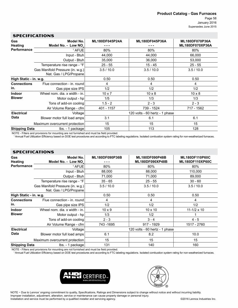
NOTE − Due to Lennox’ ongoing commitment to quality, Specifications, Ratings and Dimensions subject to change without notice and without incurring liability. Improper installation, adjustment, alteration, service or maintenance can cause property damage or personal injury.Installation and service must be performed by a qualified installer and servicing agency. ©2016 Lennox Industries Inc.
January 2016Supersedes June 2015
Product Catalog - Gas FurnacesPage 58
SPECIFICATIONSGas Heating Performance
Model No. Model No. - Low NOx
ML180DF045P24A - - -
ML180DF045P36A - - -
ML180DF070P36A ML180DF070XP36A
1 AFUE 80% 80% 80%Input - Btuh 44,000 44,000 66,000
Output - Btuh 35,000 36,000 53,000Temperature rise range - °F 25 - 55 15 - 45 25 - 55
Gas Manifold Pressure (in. w.g.) Nat. Gas / LPG/Propane
3.5 / 10.0 3.5 / 10.0 3.5 / 10.0
High Static - in. w.g. 0.50 0.50 0.50Connections in.
Flue connection - in. round 4 4 4Gas pipe size IPS 1/2 1/2 1/2
Indoor Blower
Wheel nom. dia. x width - in. 10 x 7 10 x 8 10 x 8Motor output - hp 1/5 1/3 1/3
Tons of add-on cooling 1.5 - 2 2 - 3 2 - 3Air Volume Range - cfm 401 - 1157 739 - 1524 717 - 1562
Electrical Data
Voltage 120 volts - 60 hertz - 1 phaseBlower motor full load amps 3.1 6.1 6.1
Maximum overcurrent protection 15 15 15Shipping Data lbs. - 1 package 105 113 128NOTE - Filters and provisions for mounting are not furnished and must be field provided.
1 Annual Fuel Utilization Efficiency based on DOE test procedures and according to FTC labeling regulations. Isolated combustion system rating for non-weatherized furnaces.
SPECIFICATIONSGas Heating Performance
Model No. Model No. - Low NOx
ML180DF090P36B - - -
ML180DF090P48B ML180DF090XP48B
ML180DF110P60C ML180DF110XP60C
1 AFUE 80% 80% 80%Input - Btuh 88,000 88,000 110,000
Output - Btuh 71,000 71,000 89,000Temperature rise range - °F 35 - 65 25 - 55 30 - 60
Gas Manifold Pressure (in. w.g.) Nat. Gas / LPG/Propane
3.5 / 10.0 3.5 / 10.0 3.5 / 10.0
High Static - in. w.g. 0.50 0.50 0.50Connections in.
Flue connection - in. round 4 4 4Gas pipe size IPS 1/2 1/2 1/2
Indoor Blower
Wheel nom. dia. x width - in. 10 x 9 10 x 10 11-1/2 x 10Motor output - hp 1/3 1/2 1
Tons of add-on cooling 2 - 3 3 - 4 4 - 5Air Volume Range - cfm 743 -1695 917 - 1929 1517 - 2760
Electrical Data
Voltage 120 volts - 60 hertz - 1 phaseBlower motor full load amps 6.1 8.2 10.0
Maximum overcurrent protection 15 15 15Shipping Data lbs. - 1 package 131 140 160NOTE - Filters and provisions for mounting are not furnished and must be field provided.
1 Annual Fuel Utilization Efficiency based on DOE test procedures and according to FTC labeling regulations. Isolated combustion system rating for non-weatherized furnaces.

P R O D U C T C ATA L O G
NOTE − Due to Lennox’ ongoing commitment to quality, Specifications, Ratings and Dimensions subject to change without notice and without incurring liability.Improper installation, adjustment, alteration, service or maintenance can cause property damage or personal injury.Installation and service must be performed by a qualified installer and servicing agency. ©2016 Lennox Industries Inc.
G A S F U R N A C E S
January 2016Supersedes June 2015
Page 59
ML180UH, ML180DF - OPTIONAL ACCESSORIES
OPTIONAL ACCESSORIES - ORDER SEPARATELY
“A” Width “B” Width “C” Width “D” Width
CABINET ACCESSORIES
Downflow Combustible Flooring Base - Downflow only 11M59 11M60 11M61 - - -
Horizontal Suspension Kit - Horizontal only 51W10 51W10 51W10 51W10
Return Air Base - Upflow only 65W75 50W98 50W99 51W00
DOWNFLOW FILTER KITS
Downflow Filter Cabinet 51W06 51W07 51W08 - - -1 No. and size of filter - in. (1) 20 x 20 x 1 (2) 16 x 20 x 1 (2) 16 x 20 x 1 - - -
SERVICE KITS
Night Service Kit 68W80 68W80 68W80 68W80
Universal Service Kit - Switches 89W19 89W19 89W19 89W19
UPFLOW/HORIZONTAL FILTER KITS
1 Air Filter and Rack Kit Horizontal (end) 87L95 87L96 87L97 87L98
Size of filter - in. 14 x 25 x 1 18 x 25 x 1 20 x 25 x 1 25 x 25 x 1
Side Return Single 44J22 44J22 44J22 44J22
Ten Pack 66K63 66K63 66K63 66K63
Size of filter - in. 16 x 25 x 1 16 x 25 x 1 16 x 25 x 1 16 x 25 x 1
VENTING
Vent Adaptor - 6 in. connection size upflow applications only 18M79 18M79 18M79 18M791 Cleanable frame type filter.
GAS HEAT ACCESSORIES
InputHigh Altitude
Pressure Switch KitNatural Gas to
LPG/Propane Kit LPG/Propane
to Natural Gas Kit
Natural Gas High Altitude
Orifice Kit0 - 4500 ft. 4501 - 7500 ft. 7501 - 10,000 ft. 0 - 7500 ft. 7501 - 10,000 ft. 0 - 7500 ft. 7501 - 10,000 ft.
045 No Change 80W52 (UH) / No Change (DF) 80W51 11K49 76W15 73W81 73W37
070 No Change 80W52 80W51 11K49 76W15 73W81 73W37
090 No Change 80W52 (UH) / No Change (DF) 80W51 11K49 76W15 73W81 73W37
090X No Change 80W52 80W51 11K49 76W15 73W81 73W37
110 No Change 80W57 (UH) / 80W52 (DF) 80W52 11K49 76W15 73W81 73W37
135 No Change 80W52 80W51 11K49 76W15 73W81 73W37


A C C E S S O R I E S
P R O D U C T C ATA L O G
NOTE − Due to Lennox’ ongoing commitment to quality, Specifications, Ratings and Dimensions subject to change without notice and without incurring liability.Improper installation, adjustment, alteration, service or maintenance can cause property damage or personal injury.Installation and service must be performed by a qualified installer and servicing agency. ©2016 Lennox Industries Inc.
D I M E N S I O N S
F E A T U R E S
January 2016Supersedes June 2015
Page 1
L I M I T E D W A R R A N T Y
G A S U N I T H E A T E R S / D U C T F U R N A C E S
25(635)
B
A
• LPG/Propane Conversion Kit• Thermostat
Aluminized Steel Heat Exchanger - ten yearsAll other covered components - five yearsRefer to Lennox Equipment Limited Warranty certificate included with equipment for details
Heating SystemAluminized Steel Tubular Heat ExchangerAluminized Steel Inshot BurnersLimit Control24 volt Gas Control Valve with 100% Safety ShutoffCombustion Air InducerControls24V transformerCombination Ignition/Fan Timer Control with LED DiagnosticsElectronic Direct Spark IgnitionElectronic Flame Sensor ControlFanEfficient, quiet operating, propeller-type, direct drive fan.CabinetLow ProfileHeavy gauge painted steelInsulated CabinetAdjustable LouversWiring Junction BoxTerminal stripHanging Brackets
Horizontal, Low Profile, Gas-Fired Unit HeatersSteady State Efficiency - Up to 81.0%
Input - 30,000 to 75,000 Btuh
LF24
Model No. LF24-30A LF24-45A
LF24-60A LF24-75A
A 13 (330) 18 (457)B (overall) 24 (610) 25 (635)

NOTE − Due to Lennox’ ongoing commitment to quality, Specifications, Ratings and Dimensions subject to change without notice and without incurring liability. Improper installation, adjustment, alteration, service or maintenance can cause property damage or personal injury.Installation and service must be performed by a qualified installer and servicing agency. ©2016 Lennox Industries Inc.
January 2016Supersedes June 2015
Product Catalog - Gas Unit Heaters / Duct FurnacesPage 2
SPECIFICATIONSGas Heating Performance
Model No. LF24-30A LF24-45A LF24-60A LF24-75AHeating Capacity Input - Btuh 30,000 45,000 60,000 75,000
Heating Capacity Output - Btuh 24,300 36,500 48,000 60,000Steady State Efficiency 81.0% 81.0% 80.0% 80.0%
Temperature rise - °F 42 45 55 60Connections in.
Flue size (round) 1 3 1 3 2 4 2 4Gas Piping Size 1/2 1/2 1/2 1/2
Fan Data Number of fans 1 1 1 1Fan Diameter - in. 10 10 14 14Number of blades 4 4 3 3Motor Output - hp 1/20 1/20 1/8 1/8
Amps 1.7 1.7 4.1 4.1rpm 1650 1650 1050 1050
Air Volume - cfm 535 750 830 950Air throw at 8 ft. mounting height - ft. 25 25 40 40
Electrical Characteristics 115 volts - 60 hertz - 1 phaseShipping Weight - lbs. 1 package 60 63 87 91
OPTIONAL ACCESSORIES - ORDER SEPARATELYLPG/Propane Kit 20L05 20L05 20L05 20L05NOTE - Transitions are furnished for flue connection to unit combustion air inducer outlet.1 2-1/8 in. (unit) x 3 in. (flue) diameter transition is furnished with unit for flue connection2 2 in. (unit) x 4 in. (flue) diameter transition is furnished with unit for flue connection.
STRAIGHT VENT PIPE - FOR HORIZONTAL VENTINGUnit Heater Model No. Vent Diameter (in.) Length (in.) Catalog No.LF24-30 LF24-45
C5VENT3P6 3 6 75W74C5VENT3P12 3 12 75W75C5VENT3P36 3 36 75W76
LF24-60 LF24-75
C5VENT4P6 4 6 75W77C5VENT4P12 4 12 75W78C5VENT4P36 4 36 75W79
HORIZONTAL VENT KITS AND ELBOWREQUIRED FOR RESIDENTIAL HORIZONTAL VENTING APPLICATIONS
Unit Heater
Model No.
Vent Diameter
(in.)
Upslope Vent Kit
Catalog No.
Downslope Vent Kit
Catalog No. 45° Elbow Catalog
No. 90° Elbow Catalog No.
1 Minimum Vent
Length (ft.)
LF24-30 LF24-45 3 C5VENT3KU 75W62 C5VENT3KD 75W66 C5VENT3E45
(Optional) 87W79 C5VENT3E (Optional) 75W70 5
LF24-60 LF24-75 4 C5VENT4KU 75W63 C5VENT4KD 75W67 C5VENT4E45
(Optional) 87W80 C5VENT4E (Optional) 75W71 5
1 Length does not include temrination (or elbow if used).

A C C E S S O R I E S
P R O D U C T C ATA L O G
NOTE − Due to Lennox’ ongoing commitment to quality, Specifications, Ratings and Dimensions subject to change without notice and without incurring liability.Improper installation, adjustment, alteration, service or maintenance can cause property damage or personal injury.Installation and service must be performed by a qualified installer and servicing agency. ©2016 Lennox Industries Inc.
D I M E N S I O N S
F E A T U R E S
January 2016Supersedes June 2015
Page 1
L I M I T E D W A R R A N T Y
O I L F U R N A C E SO I L F U R N A C E S
A
C
B
D
54(1372)
14 (356)
22(559)
AIRFLOW
• Oil Filter• Two-Stage Oil Pump• Thermostat• ComfortSense® 7500 Thermostat• Air Intake Kit
Heat Exchanger - lifetimeAll other covered components - ten yearsRefer to Lennox Equipment Limited Warranty certificate included with equipment for details
Heating SystemBeckett™ NX Oil BurnerAdvanced Air Tube TechnologyEZ Clean Heat ExchangerAlumina Silica Ceramic Fiber Combustion ChamberFlame Inspection TubeBarometric Draft ControlLimit ControlControlsAdvanced Burner Control controls oil burner motor and igniterCadmium Sulfide Cell Flame Detector120VAC Primary Safety ControlElectronic Blower Control24V TransformerVariable-Speed Blower MotorHigh efficiency, variable speed ECM (Electronically Commutated Motor) Maintains specified air volumes up to a maximum of 0.8 in. w.g. total external static.CabinetUpflow applicationsPre-painted cabinet finishHeating section is insulated with foil faced insulationInsulated blower compartmentTop or Side Flue Pipe Connection
Upflow - Variable Speed Blower - SilentComfort™ TechnologyAFUE - Up to 87%
Input - 79,000 to 141,000 Btuh
DAVE LENNOX SIGNATURE® COLLECTIONSLO185UFV
79/105 124/141A 19-1/2
(495)22-1/2 (572)
B 30-5/8 (778)
33-1/8 (841)
C 18 (457)
21 (533)
D 19-5/8 (498)
22-1/8 (562)
Bottom return
Width 16 (406)
18 (457)
Depth 22 (559)
22 (559)
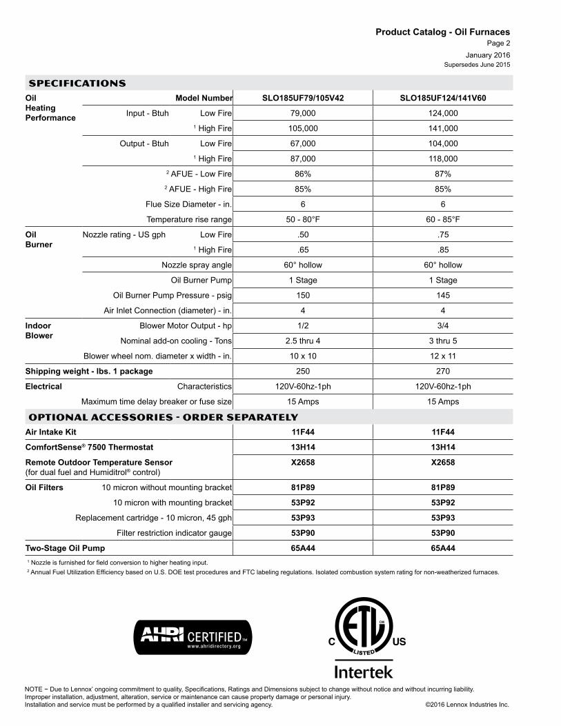
NOTE − Due to Lennox’ ongoing commitment to quality, Specifications, Ratings and Dimensions subject to change without notice and without incurring liability. Improper installation, adjustment, alteration, service or maintenance can cause property damage or personal injury.Installation and service must be performed by a qualified installer and servicing agency. ©2016 Lennox Industries Inc.
January 2016Supersedes June 2015
Product Catalog - Oil FurnacesPage 2
SPECIFICATIONSOil Heating Performance
Model Number SLO185UF79/105V42 SLO185UF124/141V60
Input - Btuh Low Fire 79,000 124,0001 High Fire 105,000 141,000
Output - Btuh Low Fire 67,000 104,0001 High Fire 87,000 118,000
2 AFUE - Low Fire 86% 87%2 AFUE - High Fire 85% 85%
Flue Size Diameter - in. 6 6
Temperature rise range 50 - 80°F 60 - 85°F
Oil Burner
Nozzle rating - US gph Low Fire .50 .751 High Fire .65 .85
Nozzle spray angle 60° hollow 60° hollow
Oil Burner Pump 1 Stage 1 Stage
Oil Burner Pump Pressure - psig 150 145
Air Inlet Connection (diameter) - in. 4 4
Indoor Blower
Blower Motor Output - hp 1/2 3/4
Nominal add-on cooling - Tons 2.5 thru 4 3 thru 5
Blower wheel nom. diameter x width - in. 10 x 10 12 x 11
Shipping weight - lbs. 1 package 250 270
Electrical Characteristics 120V-60hz-1ph 120V-60hz-1ph
Maximum time delay breaker or fuse size 15 Amps 15 Amps
OPTIONAL ACCESSORIES - ORDER SEPARATELYAir Intake Kit 11F44 11F44
ComfortSense® 7500 Thermostat 13H14 13H14
Remote Outdoor Temperature Sensor (for dual fuel and Humiditrol® control)
X2658 X2658
Oil Filters 10 micron without mounting bracket 81P89 81P89
10 micron with mounting bracket 53P92 53P92
Replacement cartridge - 10 micron, 45 gph 53P93 53P93
Filter restriction indicator gauge 53P90 53P90
Two-Stage Oil Pump 65A44 65A441 Nozzle is furnished for field conversion to higher heating input.2 Annual Fuel Utilization Efficiency based on U.S. DOE test procedures and FTC labeling regulations. Isolated combustion system rating for non-weatherized furnaces.

A C C E S S O R I E S
P R O D U C T C ATA L O G
NOTE − Due to Lennox’ ongoing commitment to quality, Specifications, Ratings and Dimensions subject to change without notice and without incurring liability.Improper installation, adjustment, alteration, service or maintenance can cause property damage or personal injury.Installation and service must be performed by a qualified installer and servicing agency. ©2016 Lennox Industries Inc.
D I M E N S I O N S
F E A T U R E S
January 2016Supersedes June 2015
Page 3
L I M I T E D W A R R A N T Y
O I L F U R N A C E S
CB
DE
A
F
D
Return AirOpening
Supply AirOpening
• Oil Filter• Two-Stage Oil Pump• Thermostat• ComfortSense® 7500 Thermostat• Air Intake Kit
Heat Exchanger - lifetimeAll other covered components - ten yearsRefer to Lennox Equipment Limited Warranty certificate included with equipment for details
Heating SystemBeckett™ NX Oil BurnerAdvanced Air Tube TechnologyEZ Clean Heat ExchangerAlumina Silica Ceramic Fiber Combustion ChamberFlame Inspection TubeBarometric Draft ControlLimit ControlControlsAdvanced Burner Control controls oil burner motor and igniterCadmium Sulfide Cell Flame Detector120VAC Primary Safety ControlElectronic Blower Control24V TransformerVariable-Speed Blower MotorHigh efficiency, variable speed ECM (Electronically Commutated Motor) Maintains specified air volumes up to a maximum of 0.8 in. w.g. total external static.CabinetLo-boy applicationsPre-painted cabinet finishHeating section is insulated with foil faced insulation.Insulated Blower CompartmentTop or Side Flue Pipe ConnectionAir FiltersLarge, cleanable frame-type filter
Lo-Boy - Variable Speed Blower - SilentComfort™ TechnologyAFUE - Up to 87%
Input - 79,000 to 141,000 Btuh
DAVE LENNOX SIGNATURE® COLLECTIONSLO185BV
79/105 124/141A 37
(940)37
(940)B 19-1/2
(495)22-1/2 (572)
C 52 (1321)
52 (1321)
D 18 (457)
21 (533)
E 16 (406)
16 (406)
F 21 (533)
21 (533)

NOTE − Due to Lennox’ ongoing commitment to quality, Specifications, Ratings and Dimensions subject to change without notice and without incurring liability. Improper installation, adjustment, alteration, service or maintenance can cause property damage or personal injury.Installation and service must be performed by a qualified installer and servicing agency. ©2016 Lennox Industries Inc.
January 2016Supersedes June 2015
Product Catalog - Oil FurnacesPage 4
SPECIFICATIONSOil Heating Performance
Model Number Front Flue Rear Flue
SLO185BF79/105V42 SLO185BR79/105V42
SLO185BF124/141V60 SLO185BR124/141V60
Input - Btuh Low Fire 79,000 124,0001 High Fire 105,000 141,000
Output - Btuh Low Fire 67,000 104,0001 High Fire 87,000 118,000
2 AFUE - Low Fire Front Flue 86% 85%2 AFUE - High Fire Front Flue 85% 85%
2 AFUE - Low Fire Rear Flue 87% 85%2 AFUE - High Fire Rear Flue 85% 85%
Flue Size Diameter - in. 6 6Temperature rise range 50 - 80°F 45 - 70°F Front Flue
50 - 80°F Rear FlueOil Burner
Nozzle rating - US gph Low Fire .50 .751 High Fire .65 .85
Nozzle spray angle 60° hollow 60° hollowOil Burner Pump 1 Stage 1 Stage
Oil Burner Pump Pressure - psig 150 145Indoor Blower
Blower Motor Output - hp 1/2 1Nominal add-on cooling - Tons 2.5 thru 4 3 thru 5
Blower wheel nom. diameter x width - in. 10 x 9 12 x 103 Filter Number of filters 1 1
Size of filters - in. 18 x 19 x 1 19 x 21 x 1Shipping weight - lbs. 1 package 225 (Front Flue)
230 (Rear Flue)270
Electrical Characteristics 120V-60hz-1ph 120V-60hz-1phMaximum Overcurrent Protection (amps) 15 15
OPTIONAL ACCESSORIES - ORDER SEPARATELYAir Intake Kit 11F44 11F44ComfortSense® 7500 Thermostat 13H14 13H14Remote Outdoor Temperature Sensor (for dual fuel and Humiditrol® control)
X2658 X2658
Oil Filters 10 micron without mounting bracket 81P89 81P8910 micron with mounting bracket 53P92 53P92
Replacement cartridge - 10 micron, 45 gph 53P93 53P93Filter restriction indicator gauge 53P90 53P90
Two-Stage Oil Pump without solenoid 65A44 65A44with solenoid 71M18 71M18
1 Nozzle is furnished for field conversion to higher heating input.2 Annual Fuel Utilization Efficiency based on U.S. DOE test procedures and FTC labeling regulations. Isolated combustion system rating for non-weatherized furnaces.3 Cleanable flame type filters furnished.

A C C E S S O R I E S
P R O D U C T C ATA L O G
NOTE − Due to Lennox’ ongoing commitment to quality, Specifications, Ratings and Dimensions subject to change without notice and without incurring liability.Improper installation, adjustment, alteration, service or maintenance can cause property damage or personal injury.Installation and service must be performed by a qualified installer and servicing agency. ©2016 Lennox Industries Inc.
D I M E N S I O N S
F E A T U R E S
January 2016Supersedes June 2015
Page 5
L I M I T E D W A R R A N T Y
O I L F U R N A C E S
A
C
B
D
54(1372)
14 (356)
22(559)
AIRFLOW
UpflowAFUE - Up to 84%
Input - 68,000 to 154,000 Btuh
ELITE® SERIESELO183UF
• Oil Filter• Two-Stage Oil Pump• Thermostat
Heat Exchanger - lifetimeAll other covered components - five yearsRefer to Lennox Equipment Limited Warranty certificate included with equipment for details
Heating SystemBeckett™ Flame-Retention AFG Oil BurnerEZ Clean Heat ExchangerAlumina Silica Ceramic Fiber Combustion ChamberFlame Inspection TubeBarometric Draft ControlControlsAdvanced Burner Control controls oil burner motor and igniterCadmium Sulfide Cell Flame DetectorPrimary Safety ControlFan and Limit ControlTerminal StripBlower Cooling Relay24V TransformerBlowerMulti-Speed, Direct Drive BlowerCabinetUpflow applicationsPre-painted cabinet finishHeating section is insulated with foil faced insulationInsulated blower compartmentTop or Side Flue Pipe Connection
68/86 101/114
135/150
A 19-1/2 (495)
22-1/2 (572)
B 30-5/8 (778)
33-1/8 (841)
C 18 (457)
21 (533)
D 19-5/8 (498)
22-1/8 (562)
Bottom return
Width 16 (406)
18 (457)
Depth 22 (559)
22 (559)

NOTE − Due to Lennox’ ongoing commitment to quality, Specifications, Ratings and Dimensions subject to change without notice and without incurring liability. Improper installation, adjustment, alteration, service or maintenance can cause property damage or personal injury.Installation and service must be performed by a qualified installer and servicing agency. ©2016 Lennox Industries Inc.
January 2016Supersedes June 2015
Product Catalog - Oil FurnacesPage 6
SPECIFICATIONSOil Heating Performance
Model Number ELO183UF68/86P36 ELO183UF101/114P48 ELO183UF135/150P60Input - Btuh Low Fire 67,500 101,000 135,000
1 High Fire 85,500 113,500 151,000
Output - Btuh Low Fire 57,000 84,000 113,0001 High Fire 72,000 95,000 126,000
2 AFUE 84% 83% 83%
Flue Size Diameter - in. 6 6 6
Temperature rise range 50 - 80°F 50 - 80°F 55 - 85°F
Oil Burner
Nozzle rating - US gph Low Fire .50 .65 .851 High Fire .65 .75 1.00
Nozzle spray angle Low Fire 80° hollow 80° solid 80°B solid1 High Fire 80° solid 80° solid 80° solid
Oil Burner Pump 1 Stage 1 Stage 1 Stage
Oil Burner Pump Pressure - psig 100 140 140
Air Inlet Connection (diameter) - in. 4 4 4
Indoor Blower
Blower Motor Output - hp 1/2 1/2 3/4
Nominal add-on cooling - Tons 1.5 thru 3 2 thru 3.5 3 to 5
Blower wheel nom. diameter x width - in. 10 x 8 10 x 10 12 x 11
Air Volume Range - cfm 605 - 1410 690 - 1755 1110 - 2090
Shipping weight - lbs. 1 package 230 250 270
Electrical Characteristics 120V-60hz-1ph 120V-60hz-1ph 120V-60hz-1ph
Maximum Overcurrent Protection (amps) 15 15 15
OPTIONAL ACCESSORIES - ORDER separatelyCombustion Air Boot (4 in. diameter) 83W32 83W32 83W32Oil Filters 10 micron without mounting bracket 81P89 81P89 81P89
10 micron with mounting bracket 53P92 53P92 53P92Replacement cartridge - 10 micron, 45 gph 53P93 53P93 53P93
Filter restriction indicator gauge 53P90 53P90 53P90Two-Stage Oil Pump without solenoid 65A44 65A44 65A44
with solenoid 71M18 71M18 71M181 Nozzle must be field provided for field conversion to higher heating input.2 Annual Fuel Utilization Efficiency based on U.S. DOE test procedures and FTC labeling regulations. Isolated combustion system rating for non-weatherized furnaces.

A C C E S S O R I E S
P R O D U C T C ATA L O G
NOTE − Due to Lennox’ ongoing commitment to quality, Specifications, Ratings and Dimensions subject to change without notice and without incurring liability.Improper installation, adjustment, alteration, service or maintenance can cause property damage or personal injury.Installation and service must be performed by a qualified installer and servicing agency. ©2016 Lennox Industries Inc.
D I M E N S I O N S
F E A T U R E S
January 2016Supersedes June 2015
Page 7
L I M I T E D W A R R A N T Y
O I L F U R N A C E S
CB
DE
A
F
D
Return AirOpening
Supply AirOpening
• Oil Filter• Two-Stage Oil Pump• Thermostat
Heat Exchanger - lifetimeAll other covered components - five yearsRefer to Lennox Equipment Limited Warranty certificate included with equipment for details
Heating SystemBeckett™ Flame-Retention AFG Oil BurnerEZ Clean Heat ExchangerAlumina Silica Ceramic Fiber Combustion ChamberFlame Inspection TubeBarometric Draft ControlControlsAdvanced Burner Control controls oil burner motor and igniterCadmium Sulfide Cell Flame DetectorPrimary Safety ControlFan and Limit ControlTerminal StripBlower Cooling Relay24V TransformerBlowerMulti-Speed, Direct Drive BlowerCabinetLo-boy applicationsPre-painted cabinet finishHeating section is insulated with foil faced insulation.Insulated Blower CompartmentTop or Side Flue Pipe ConnectionAir FiltersLarge, cleanable frame-type filter
Lo-BoyAFUE - 83%
Input - 101,000 to 154,000 Btuh
ELITE® SERIESELO183B
101/114 135/150A 37
(940)37
(940)B 19-1/2
(495)22-1/2 (572)
C 52 (1321)
52 (1321)
D 18 (457)
21 (533)
E 16 (406)
16 (406)
F 21 (533)
21 (533)

NOTE − Due to Lennox’ ongoing commitment to quality, Specifications, Ratings and Dimensions subject to change without notice and without incurring liability. Improper installation, adjustment, alteration, service or maintenance can cause property damage or personal injury.Installation and service must be performed by a qualified installer and servicing agency. ©2016 Lennox Industries Inc.
January 2016Supersedes June 2015
Product Catalog - Oil FurnacesPage 8
SPECIFICATIONSOil Heating Performance
Model Number Front Flue Rear Flue
ELO183BF101/114P48 ELO183BR101/114P48
ELO183BF135/150P60 ELO183BR135/150P60
Input - Btuh Low Fire 101,000 134,0001 High Fire 113,500 151,000
Output - Btuh Low Fire 85,000 113,0001 High Fire 95,000 127,000
2 AFUE 83% 83%Flue Size Diameter - in. 6 6Temperature rise range 45 - 75°F 45 - 75°F
Oil Burner
Nozzle rating - US gph Low Fire .65 .851 High Fire .75 1.00
Nozzle spray angle 80° solid 80° solidOil Burner Pump 1 Stage 1 Stage
Oil Burner Pump Pressure - psig 140 140Air Inlet Connection (diameter) - in. 4 4
Indoor Blower
Blower Motor Output - hp 1/2 3/4Nominal add-on cooling - Tons 2.5 thru 4 3 to 5
Blower wheel nom. diameter x width - in. 10 x 9 12 x 10Air Volume Range - cfm 650 - 1760 1225 - 2360
3 Filter Number of filters 1 1Size of filters - in. 18 x 19 x 1 19 x 21 x 1
Shipping weight - lbs. 1 package 225 Front Flue / 230 Rear Flue 270Electrical Characteristics 120V-60hz-1ph 120V-60hz-1ph
Maximum Overcurrent Protection (amps) 15 15
OPTIONAL ACCESSORIES - ORDER separatelyCombustion Air Boot (4 in. diameter) 83W32 83W32Oil Filters 10 micron without mounting bracket 81P89 81P89
10 micron with mounting bracket 53P92 53P92Replacement cartridge - 10 micron, 45 gph 53P93 53P93
Filter restriction indicator gauge 53P90 53P90Two-Stage Oil Pump without solenoid 65A44 65A44
with solenoid 71M18 71M181 Nozzle must be field provided for field conversion to higher heating input.2 Annual Fuel Utilization Efficiency based on U.S. DOE test procedures and FTC labeling regulations. Isolated combustion system rating for non-weatherized furnaces.3 Cleanable flame type filters furnished.

P R O D U C T C ATA L O G
NOTE − Due to Lennox’ ongoing commitment to quality, Specifications, Ratings and Dimensions subject to change without notice and without incurring liability.Improper installation, adjustment, alteration, service or maintenance can cause property damage or personal injury.Installation and service must be performed by a qualified installer and servicing agency. ©2016 Lennox Industries Inc.
D I M E N S I O N S
F E A T U R E S
January 2016Supersedes June 2015
Page 9
L I M I T E D W A R R A N T Y
O I L F U R N A C E S
A C C E S S O R I E S
59 (1499)
A
B
A
Horizontal / DownflowAFUE - 83%
Input - 101,000 to 154,000 Btuh
ELITE® SERIES
Model No. 101/114 135/150A 20-1/2 (521) 23-1/2 (597)B 18 (457) 21 (533)
Heat Exchanger - lifetimeAll other covered components - five yearsRefer to Lennox Equipment Limited Warranty certificate included with equipment for details
• Downflow Combustible Floor Base• Filter Kits• Oil Filter• Two-Stage Oil Pump• Thermostat
Heating SystemBeckett™ Flame-Retention AFG Oil BurnerEZ Clean Heat ExchangerAlumina Silica Ceramic Fiber Combustion ChamberFlame Inspection TubeBarometric Draft ControlControlsAdvanced Burner Control controls oil burner motor and igniterCadmium Sulfide Cell Flame DetectorPrimary Safety ControlFan and Limit ControlTerminal StripBlower Cooling Relay24V TransformerBlowerMulti-speed, direct-drive blowerCabinetPre-painted cabinet finishHeating section is insulated with foil faced insulation.Insulated Blower CompartmentFront Flue Pipe Connection
ELO183DH

NOTE − Due to Lennox’ ongoing commitment to quality, Specifications, Ratings and Dimensions subject to change without notice and without incurring liability. Improper installation, adjustment, alteration, service or maintenance can cause property damage or personal injury.Installation and service must be performed by a qualified installer and servicing agency. ©2016 Lennox Industries Inc.
January 2016Supersedes June 2015
Product Catalog - Oil FurnacesPage 10
SPECIFICATIONSOil Heating Performance
Model Number ELO183DH101/114P36 ELO183DH135/150P60Input - Btuh Low Fire 101,000 135,000
1 High Fire 113,500 135,000Output - Btuh Low Fire 85,000 113,000
1 High Fire 95,000 126,0002 AFUE 83% 83%
Flue Size Diameter - in. 6 6Temperature rise range 45 - 75°F 45 - 75°F
Oil Burner
Nozzle rating - US gph Low Fire .65 .852 High Fire .75 1.00
Nozzle spray angle 80° solid 80° solidOil Burner Pump 1 Stage 1 Stage
Oil Burner Pump Pressure - psig 140 140Indoor Blower
Blower Motor Output - hp 1/2 3/4Nominal add-on cooling - Tons 2 to 3 3 to 5
Blower wheel nom. diameter x width - in. 10 x 10 12 x 9Air Volume Range - cfm 545 - 1410 1100 - 2205
Shipping weight - lbs. 1 package 250 270Electrical Characteristics 120V-60hz-1ph 120V-60hz-1ph
Maximum Overcurrent Protection (amps) 15 15
OPTIONAL ACCESSORIES - order separatelyDownflow Combustible Flooring Base 35K07 35K08Filter Kit 35K05 35K06
Number & size of filters - in. (2) 10-1/4 x 20-1/2 x 1 (2) 11-3/4 x 23-1/2 x 1Oil Filters 10 micron without mounting bracket 81P89 81P89
10 micron with mounting bracket 53P92 53P92Replacement cartridge - 10 micron, 45 gph 53P93 53P93
Filter restriction indicator gauge 53P90 53P90Two-Stage Oil Pump without solenoid 65A44 65A44
with solenoid 71M18 71M181 Nozzle must be field provided for field conversion to higher heating input.2 Annual Fuel Utilization Efficiency based on U.S. DOE test procedures and FTC labeling regulations. Isolated combustion system rating for non-weatherized furnaces.

A C C E S S O R I E S
P R O D U C T C ATA L O G
NOTE − Due to Lennox’ ongoing commitment to quality, Specifications, Ratings and Dimensions subject to change without notice and without incurring liability.Improper installation, adjustment, alteration, service or maintenance can cause property damage or personal injury.Installation and service must be performed by a qualified installer and servicing agency. ©2016 Lennox Industries Inc.
W A T E R H E A T E R S / B O I L E R S
D I M E N S I O N S
F E A T U R E S
January 2016Supersedes June 2015
Page 1
W A R R A N T Y
B
AC
Gas-Fired, Modulating, Condensing, Wall Hung Hot Water BoilerAFUE - 95%
Input - 50,000 to 200,000 Btuh
• Concentric Termination Kit• Thermostat
Cast Aluminum Boiler Assembly - fifteen yearsAll other covered components - ten yearsRefer to Lennox Equipment Limited Warranty certificate included with equipment for details
Heating SystemDirect Vent Sealed Combustion SystemStainless Steel Helical Heat Exchanger AssemblyStainless Steel Mesh Modulating BurnerDirect Spark IgniterCasting Temperature Safety Switch24 Volt Gas Control Valve Combustion Air BlowerCPVC Flue Condensate CollectorPressure Relief Valve and Air VentFlame Rollout SwitchCombination Temperature/Pressure GaugeBrass Drain ValveVent Temperature SensorLPG/Propane Kit FurnishedIntegrated Primary/Secondary Piping With PumpCirculating PumpControlsFully Modulating Electronic ControlUser Interface ControlLCD DisplayFlame SensorIntegrated Low Water Cutoff Control24V TransformerSupply Water SwitchReturn Water Temperature SensorTerminal BlockHigh Voltage Junction BoxCabinetHeavy-gauge steel with baked-on enamel finish.Wall Hanging Support Bracket
GWM-IE
Model No A B C DGWM-050IE GWM-075IE GWM-100IE
20 (508)
31 (787)
14 (356)
28 (711)
GWM-150IE GWM-200IE
23 (584)
42 (109)
16 (406)
40 (1016)
W A T E R H E A T E R S / B O I L E R S

NOTE − Due to Lennox’ ongoing commitment to quality, Specifications, Ratings and Dimensions subject to change without notice and without incurring liability. Improper installation, adjustment, alteration, service or maintenance can cause property damage or personal injury.Installation and service must be performed by a qualified installer and servicing agency. ©2016 Lennox Industries Inc.
January 2016Supersedes June 2015
Product Catalog - Water Heaters / BoilersPage 2
USC
SPECIFICATIONSModel No. GWM-050IE GWM-075IE GWM-100IE GWM-150IE GWM-200IE
Gas Heating Performance
Heating capacity input Btuh (Maximum) 50,000 75,000 100,000 150,000 200,000
Btuh (Minimum) 10,000 15,000 20,000 30,000 40,000
Heating capacity output - Btuh 46,000 69,000 91,000 139,000 185,0001 Net AHRI I=B=R rating - Btuh 40 50 79 121 161
2 AFUE 95% 95% 95% 95% 95%
Connections in.
Flue size diameter (round) 2 2 2 3 3
Gas piping size 1/2 NPT 1/2 NPT 1/2 NPT 3/4 NPT 3/4 NPT
Water supply and return size 1-1/4 NPT 1-1/4 NPT 1-1/4 NPT 1-1/4 NPT 1-1/4 NPT
Drain connection size 3/4 NPT 3/4 NPT 3/4 NPT 3/4 NPT 3/4 NPT
Electrical characteristics 120 volts - 60 hertz - 1 phase (less than 12 amps)
Shipping Data lbs. - 1 package 111 111 111 182 182
OPTIONAL ACCESSORIESConcentric Termination Kit US - 2 inch 69M29 69M29 69M29 - - - - - -
3 inch - - - 60L46 60L46 60L46 60L46
Canada - 2 inch 44W92 44W92 44W92 - - - - - -
3 inch - - - 44W93 44W93 44W93 44W931 AHRI I=B=R ratings indicate the amount of equivalent direct radiation each boiler will produce under normal conditions and thermostatic control. Ratings based on an
allowance of 1.15 in accordance with the factors shown on the I=B=R Standard as published by The Hydronics Institute. Selection of boiler size should be based on “Net I=B=R Rating” being equal to or greater than the calculated heat loss of the building.
2 Heating Capacity and AFUE (Annual Fuel Utilization Efficiency) based on US DOE test procedures and FTC labeling regulations.NOTE - Termination Kits 44W92, 44W93 are certified to ULC S636 standard for use in Canada only.

A C C E S S O R I E S
P R O D U C T C ATA L O G
NOTE − Due to Lennox’ ongoing commitment to quality, Specifications, Ratings and Dimensions subject to change without notice and without incurring liability.Improper installation, adjustment, alteration, service or maintenance can cause property damage or personal injury.Installation and service must be performed by a qualified installer and servicing agency. ©2016 Lennox Industries Inc.
W A T E R H E A T E R S / B O I L E R S
D I M E N S I O N S
F E A T U R E S
January 2016Supersedes June 2015
Page 3
W A R R A N T Y
10-3/8(264)
36-1/4(921)
17-1/4(438)
Front
17-3/4(451)
• Concentric Termination Kit• LPG/Propane Conversion Kit• Thermostat
Cast Aluminum Boiler Assembly - fifteen yearsAll other covered components - ten yearsRefer to Lennox Equipment Limited Warranty certificate included with equipment for details
Heating SystemDirect Vent Sealed Combustion SystemCast Aluminium Boiler AssemblyStainless Steel Premix Inshot Burner24 Volt Gas Control Valve Hot Surface IgniterInduced Draft BlowerDifferential Pressure Air Proving Switch/Blocked Vent Safety ShutoffPressure Relief Valve/Air VentCombination Temperature/Pressure GaugeCirculating PumpVent Temperature Safety SwitchBrass Drain ValveCondensate TrapControlsIntegrated Boiler Control ModuleThermal Purge OperationCasting Temperature Safety SwitchHydrostat Combination High Limit Control / Low Water Cut Off With Boiler Temperature ResetInduced Draft Blower Temperature Safety Switch24V TransformerJunction BoxCabinetHeavy-gauge steel with baked-on enamel finish.
Gas-Fired - Hot Water BoilerAFUE - 90%
Input - 50,000 to 100,000 Btuh
GWB9-IH

NOTE − Due to Lennox’ ongoing commitment to quality, Specifications, Ratings and Dimensions subject to change without notice and without incurring liability. Improper installation, adjustment, alteration, service or maintenance can cause property damage or personal injury.Installation and service must be performed by a qualified installer and servicing agency. ©2016 Lennox Industries Inc.
January 2016Supersedes June 2015
Product Catalog - Water Heaters / BoilersPage 4
USC
SPECIFICATIONSModel No. GWB9-050IH-3 GWB9-075IH-3 GWB9-100IH-3
Gas Heating Performance
Heating capacity input - Btuh 50,000 75,000 100,000
Heating capacity output - Btuh 45,000 68,000 90,0001 Net AHRI I=B=R rating - Btuh 39,000 59,000 78,000
2 AFUE 90% 90% 90%
Boiler Data Number of boiler sections 2 2 2
Boiler capacity 2.6 US gallons 2.6 US gallons 2.6 US gallons
Connections in.
3 Flue size connection diameter - round 2 2 2
Gas piping size I.P.S. 1/2 1/2 1/2
Water supply and return connection size 1-1/4 NPT 1-1/4 NPT 1-1/4 NPT
Drain connection size 3/4 NPT 3/4 NPT 3/4 NPT
Electrical characteristics 120 volts - 60 hertz - 1 phase (less than 12 amps)
Shipping Data lbs. - 1 package 220 220 220
OPTIONAL ACCESSORIESConcentric Vent Kit US - 2 inch 69M29 69M29 69M29
3 inch 60L46 60L46 60L46
Canada - 2 inch 44W92 44W92 44W92
3 inch 44W93 44W93 44W93
LPG/Propane Conversion Kit 0 - 10,000 ft 75E01 - - - 10T27
0 - 5000 ft - - - 70E01 - - -
5001 - 10,000 ft - - - 77E01 - - -
See Lennox Price Book For Complete Listing of Optional Accessories (Expansion Tanks, Valves, Circulator Pumps, etc.)1 AHRI I=B=R ratings indicate the amount of equivalent direct radiation each boiler will produce under normal conditions and thermostatic control. Ratings based on an
allowance of 1.15 in accordance with the factors shown on the I=B=R Standard as published by The Hydronics Institute. Selection of boiler size should be based on “Net I=B=R Rating” being equal to or greater than the calculated heat loss of the building.
2 Heating Capacity and AFUE (Annual Fuel Utilization Efficiency) based on US DOE test procedures and FTC labeling regulations.3 CPVC pipe MUST be used in the first five feet. Unit ships with 5 ft. of 2 in. CPVC pipe, one 2 in CPVC coupling, one nipple and one elbow.NOTE - Termination Kits 44W92, 44W93 are certified to ULC S636 standard for use in Canada only.

A C C E S S O R I E S
P R O D U C T C ATA L O G
NOTE − Due to Lennox’ ongoing commitment to quality, Specifications, Ratings and Dimensions subject to change without notice and without incurring liability.Improper installation, adjustment, alteration, service or maintenance can cause property damage or personal injury.Installation and service must be performed by a qualified installer and servicing agency. ©2016 Lennox Industries Inc.
W A T E R H E A T E R S / B O I L E R S
D I M E N S I O N S
F E A T U R E S
January 2016Supersedes June 2015
Page 5
W A R R A N T Y
23-1/4(591)
29(737)
Front
A
• Combustible Flooring Base• LPG/Propane Conversion Kit• Thermostat
Cast Iron Boiler Assembly - twenty yearsAll other covered components - five yearsRefer to Lennox Equipment Limited Warranty certificate included with equipment for details
Heating SystemCast Iron Boiler AssemblyTitanium BurnersAutomatic Gas Control ValveElectronic IgnitionInduced Draft BlowerPressure Relief ValveFlame Rollout SwitchCombination Temperature/Pressure GaugeCirculating Pump (shipped separately)Brass Drain ValveControlsIntegrated Boiler Control ModuleLimit SensorTransformerCabinetHeavy-gauge steel with baked-on enamel finish.Fully insulated with fiberglass insulation.
Gas-Fired - Hot Water BoilerAFUE - Up to 84.4%
Input - 42,000 to 225,000 Btuh
GWB8-IE
Model No A B C
042IE-2 11 (280)
23-1/4 (591)
29 (737)
075IE-2 14-1/4 (362)
23-1/4 (591)
29 (737)
112IE-2 17-1/2 (445)
23-1/4 (591)
29 (737)
150IE-2 20-3/4 (527)
23-1/4 (591)
29 (737)
187IE-2 24 (610)
23-1/4 (591)
29 (737)
225IE-2 27-1/4 (705)
23-1/4 (591)
29 (737)

NOTE − Due to Lennox’ ongoing commitment to quality, Specifications, Ratings and Dimensions subject to change without notice and without incurring liability. Improper installation, adjustment, alteration, service or maintenance can cause property damage or personal injury.Installation and service must be performed by a qualified installer and servicing agency. ©2016 Lennox Industries Inc.
January 2016Supersedes June 2015
Product Catalog - Water Heaters / BoilersPage 6
SPECIFICATIONS
Model No. GWB8 -042IE-2
GWB8 -075IE-2
GWB8 -112IE-2
GWB8 -150IE-2
GWB8 -187IE-2
GWB8 -225IE-2
Gas Heating Performance
Heating capacity input - Btuh 42,500 75,000 112,500 150,000 187,500 225,000
Heating capacity output - Btuh 36,000 63,000 94,000 125,000 155,000 186,000
1 Net AHRI I=B=R rating - Btuh 31,000 55,000 82,000 109,000 135,000 162,000
2 AFUE 84.4% 83.4% 83.0% 82.7% 82.3% 82.0%
Boiler Data Number of boiler sections 2 3 4 5 6 7
Net boiler heating surface - sq. ft. 4.61 8.17 11.73 15.29 18.85 22.41
Boiler capacity - U.S. gallons 1.75 3.00 4.25 5.50 6.75 8.00
Connections in.
3 Flue Size diameter (round)
Conventional 4 4 4 4 4 4
Horizontal 3 3 3 3 4 4
Gas piping size I.P.S.
Natural gas 1/2 1/2 1/2 1/2 3/4 3/4
LPG/Propane 3/4 3/4 3/4 3/4 3/4 3/4
Water supply and return size 1-1/4 NPT 1-1/4 NPT 1-1/4 NPT 1-1/4 NPT 1-1/4 NPT 1-1/4 NPT
Drain connection size 3/4 NPT 3/4 NPT 3/4 NPT 3/4 NPT 3/4 NPT 3/4 NPT
Electrical characteristics 120 volts - 60 hertz - 1 phase (less than 12 amps)
Shipping Data lbs. - 1 package 232 290 355 426 493 569
OPTIONAL ACCESSORIES
See Lennox Price Book For Complete Listing of Optional Accessories
LPG/Propane Conversion Kit
Standard (0-5000 ft.) 72M81 72M81 72M81 72M81 72M81 72M81
High Altitude (5000+ ft.) 54L58 54L58 54L58 54L58 54L58 54L58
Combustible Flooring Base N/A N/A N/A N/A 18P26 18P26
Sidewall Power Venting Venting Kit 79J15 79J15 79J15 79J15 N/A N/A1 Net AHRI water ratings indicate the amount of equivalent direct radiation each boiler will produce under normal conditions and thermostatic control. Ratings based on an
allowance of 1.15 in accordance with the factors shown on the I=B=R Standard as published by The Hydronics Institute. Selection of boiler size should be based on “Net I=B=R Rating” being equal to or greater than the calculated heat loss of the building.
2 Annual Fuel Utilization Efficiency based on US DOE test procedures and FTC labeling regulations.3 3 in. to 4 in. adaptor furnished for flue connection to induced draft blower.

A C C E S S O R I E S
P R O D U C T C ATA L O G
NOTE − Due to Lennox’ ongoing commitment to quality, Specifications, Ratings and Dimensions subject to change without notice and without incurring liability.Improper installation, adjustment, alteration, service or maintenance can cause property damage or personal injury.Installation and service must be performed by a qualified installer and servicing agency. ©2016 Lennox Industries Inc.
W A T E R H E A T E R S / B O I L E R S
D I M E N S I O N S
F E A T U R E S
January 2016Supersedes June 2015
Page 7
W A R R A N T Y
27(781)
30-3/4(686)
Front
A
• Combustible Flooring Base• LPG/Propane Conversion Kit• Thermostat
Cast Iron Boiler Assembly - twenty yearsAll other covered components - five yearsRefer to Lennox Equipment Limited Warranty certificate included with equipment for details
Heating SystemCast Iron Boiler AssemblyStainless Steel Burners (050 to 200 models)Titanium Burners (262 and 299 models)Automatic Gas Control ValveRelief ValveCombination Temperature/Pressure GaugeCirculating Pump (shipped separately)Brass Drain ValveVentingBlocked Vent Shutoff SensorIntegral Draft HoodVent DamperControlsIntegrated Boiler Control ModuleElectronic IgnitionFlame Rollout SwitchLimit SensorTransformerJunction BoxCabinetHeavy-gauge steel with baked-on enamel finish.Fully insulated with fiberglass insulation.
Gas-Fired - Hot Water BoilerAFUE - Up to 83.9%
Input - 50,000 to 299,000 Btuh
GWB8-E
Model No A050E-2 11-1/8 (283)075E-2 15 (381)100E-2 15 (381)125E-2 18-7/8 (479)150E-2 18-7/8 (479)170E-2 22-3/4 (578)200E-2 22-3/4 (578)262E-2 27-1/2 (699)299E-2 30-3/4 (781

NOTE − Due to Lennox’ ongoing commitment to quality, Specifications, Ratings and Dimensions subject to change without notice and without incurring liability. Improper installation, adjustment, alteration, service or maintenance can cause property damage or personal injury.Installation and service must be performed by a qualified installer and servicing agency. ©2016 Lennox Industries Inc.
January 2016Supersedes June 2015
Product Catalog - Water Heaters / BoilersPage 8
SPECIFICATIONSModel No. GWB8-050E-2 GWB8-075E-2 GWB8-100E-2 GWB8-125E-2 GWB8-150E-2
Gas Heating Performance
Heating capacity input - Btuh 50,000 75,000 100,000 125,000 150,000Heating capacity output - Btuh 42,000 63,000 83,000 104,000 124,000
1 Net AHRI I=B=R rating - Btuh 37,000 55,000 72,000 90,000 108,0002 AFUE 83.5% 83.1% 83.0% 82.0% 83.0%
Boiler Data Number of boiler sections 1 2 2 3 3Boiler capacity - U.S. gallons 2.4 4.0 4.0 5.6 5.6
Connections in.
Flue Size diameter (round) 4 5 6 6 7Gas piping size I.P.S.
Natural gas 1/2 NPT 1/2 NPT 1/2 NPT 1/2 NPT 1/2 NPTLPG/Propane 1/2 NPT 1/2 NPT 1/2 NPT 1/2 NPT 1/2 NPT
Water supply and return size 1-1/4 NPT 1-1/4 NPT 1-1/4 NPT 1-1/4 NPT 1-1/4 NPTDrain connection size 3/4 NPT 3/4 NPT 3/4 NPT 3/4 NPT 3/4 NPT
Electrical characteristics 120 volts - 60 hertz - 1 phase (less than 12 amps)Shipping Data lbs. - 1 package 205 253 253 315 315
OPTIONAL ACCESSORIESSee Lennox Price Book For Complete Listing of Optional AccessoriesLPG/Propane Conversion Kit 68E01 76E01 68E01 71E01 68E011 Net AHRI water ratings indicate the amount of equivalent direct radiation each boiler will produce under normal conditions and thermostatic control. Ratings based on an
allowance of 1.15 in accordance with the factors shown on the I=B=R Standard as published by The Hydronics Institute. Selection of boiler size should be based on “Net I=B=R Rating” being equal to or greater than the calculated heat loss of the building.
2 Annual Fuel Utilization Efficiency based on US DOE test procedures and FTC labeling regulations.
SPECIFICATIONSModel No. GWB8-170E-2 GWB8-200E-2 GWB8-262E-2 GWB8-299E-2
Gas Heating Performance
Heating capacity input - Btuh 170,000 200,000 262,000 299,000Heating capacity output - Btuh 139,000 165,000 220,000 251,000
1 Net I=B=R rating - Btuh 121,000 143,000 191,000 218,0002 AFUE 82.0% 82.0% 83.9% 83.7%
Boiler Data Number of boiler sections 4 4 7 8Boiler capacity - U.S. gallons 7.2 7.2 12.7 14.4
Connections in.
Flue Size diameter (round) 7 8 7 7Gas piping size I.P.S.
Natural gas 1/2 NPT 1/2 NPT 3/4 NPT 3/4 NPTLPG/Propane 1/2 NPT 1/2 NPT 1/2 NPT 1/2 NPT
Water supply and return size 1-1/4 NPT 1-1/4 NPT 1-1/4 NPT 1-1/4 NPTDrain connection size 3/4 NPT 3/4 NPT 3/4 NPT 3/4 NPT
Electrical characteristics 120 volts - 60 hertz - 1 phase (less than 12 amps)Shipping Data lbs. - 1 package 377 377 552 616
OPTIONAL ACCESSORIESSee Lennox Price Book For Complete Listing of Optional AccessoriesLPG/Propane Conversion Kit 71E01 68E01 72E01 74E01Combustible Flooring Base 18P26 18P26 18P26 18P261 Net AHRI water ratings indicate the amount of equivalent direct radiation each boiler will produce under normal conditions and thermostatic control. Ratings based on an
allowance of 1.15 in accordance with the factors shown on the I=B=R Standard as published by The Hydronics Institute. Selection of boiler size should be based on “Net I=B=R Rating” being equal to or greater than the calculated heat loss of the building.
2 Annual Fuel Utilization Efficiency based on US DOE test procedures and FTC labeling regulations.

A C C E S S O R I E S
P R O D U C T C ATA L O G
NOTE − Due to Lennox’ ongoing commitment to quality, Specifications, Ratings and Dimensions subject to change without notice and without incurring liability.Improper installation, adjustment, alteration, service or maintenance can cause property damage or personal injury.Installation and service must be performed by a qualified installer and servicing agency. ©2016 Lennox Industries Inc.
W A T E R H E A T E R S / B O I L E R S
D I M E N S I O N S
F E A T U R E S
January 2016Supersedes June 2015
Page 9
W A R R A N T Y
A
36-3/8(924)
Front
26-1/2(67)
Gas-Fired - Steam BoilerAFUE - Up to 82.7%
Input - 75,000 to 299,000 Btuh
Model No A75E 11-1/4 (286)112E 14-1/2 (368)150E 17-3/4 (451)187E 21 (533)225E 24-1/4 (616)262E 27-1/2 (699)299E 30-3/4 (781)
Cast Iron Boiler Assembly - twelve yearsAll other covered components - five yearsRefer to Lennox Equipment Limited Warranty certificate included with equipment for details
• Combustible Flooring Base• LPG/Propane Conversion Kit• Thermostat
Heating SystemCast Iron Boiler SectionsTitanium BurnersAutomatic Gas Control ValvePressure Relief ValveBrass Drain ValveSteam Pressure GaugeLow Water Cut-OffWater Level GaugeMotorized Vent DamperControlsElectronic IgnitionFlame Rollout SwitchSteam Pressure Limit ControlLow Water Cut-OffTransformerWiring Junction BoxVentingBlocked Vent Shutoff SensorVent DamperCabinetHeavy-gauge steel with baked-on enamel finish.Fully insulated with fiberglass insulation.
GSB8-E
NOTE - Not Available In Canada!

NOTE − Due to Lennox’ ongoing commitment to quality, Specifications, Ratings and Dimensions subject to change without notice and without incurring liability. Improper installation, adjustment, alteration, service or maintenance can cause property damage or personal injury.Installation and service must be performed by a qualified installer and servicing agency. ©2016 Lennox Industries Inc.
January 2016Supersedes June 2015
Product Catalog - Water Heaters / BoilersPage 10
USC
SPECIFICATIONSModel No. GSB8
-075EGSB8 -112E
GSB8 -150E
GSB8 -187E
GSB8 -225E
GSB8 -262E
GSB8 -299E
Gas Heating Performance
Heating capacity Btuh
Input Natural gas 75,000 112,500 150,000 187,000 225,000 262,500 299,000LPG/Propane 70,000 105,000 140,000 175,000 210,000 245,000 280,000
Output Natural gas 62,000 91,000 122,000 153,000 183,000 214,000 245,000LPG/Propane 58,000 85,000 114,000 143,000 171,000 200,000 229,000
1 Net AHRI I=B=R rating - Btuh
Natural gas 47,000 68,000 92,000 115,000 137,000 161,000 184,000LPG/Propane 44,000 64,000 86,000 107,000 128,000 150,000 172,000
1 Net AHRI I=B=R rating - sq. ft. radiation
Natural gas 196 283 383 479 571 671 767LPG/Propane 183 267 358 446 553 625 717
2 AFUE 82.7% 82.0% 82.0% 82.0% 82.0% 82.0% 82.0%Boiler Data Number of boiler sections 3 4 5 6 7 8 9
Boiler capacity - U.S. gallons
Full 4.2 5.90 7.60 9.30 11.00 12.70 14.40Water level 2.6 3.80 5.00 6.20 7.40 8.60 9.80
Connections in.
Flue size diameter (round) 5 6 6 7 7 7 7Gas piping Natural gas 1/2 1/2 1/2 3/4 3/4 3/4 3/4
LPG/Propane 1/2 1/2 1/2 3/4 3/4 3/4 3/4Water supply size 2-1/2 NPTWater return size 2-1/2 NPT
Drain size 3/4 NPTElectrical characteristics 120 volts - 60 hertz - 1 phase (less than 12 amps)Shipping weight - lbs. 1 package 325 404 483 564 649 719 800
OPTIONAL ACCESSORIESSee Lennox Price Book For Complete Listing of Optional AccessoriesLPG/Propane Conversion Kit
Standard Kit 57L60 54L59 54L61 54L63 54L65 54L67 54L69High Altitude (over 5000 ft.) 57L61 54L60 54L62 54L64 54L66 54L68 54L70
Combustible Flooring Base N/A N/A N/A N/A 18P26 18P26 18P261 Net AHRI steam ratings indicate the amount of equivalent direct radiation each boiler will produce under normal conditions and thermostatic control. Steam ratings based
on an allowance of 1.333 in accordance with the factors shown on the I=B=R Standard as published by The Hydronics Institute. Selection of boiler size should be based on “Net I=B=R Rating” being equal to or greater than installed radiation in square feet.
2 Annual Fuel Utilization Efficiency based on US DOE test procedures and FTC labeling regulations.

A C C E S S O R I E S
P R O D U C T C ATA L O G
NOTE − Due to Lennox’ ongoing commitment to quality, Specifications, Ratings and Dimensions subject to change without notice and without incurring liability.Improper installation, adjustment, alteration, service or maintenance can cause property damage or personal injury.Installation and service must be performed by a qualified installer and servicing agency. ©2016 Lennox Industries Inc.
W A T E R H E A T E R S / B O I L E R S
D I M E N S I O N S
F E A T U R E S
January 2016Supersedes June 2015
Page 11
W A R R A N T Y
A20−1/2(521)
36(914)
Front
COWB3
Oil-Fired - Hot Water BoilerAFUE - Up to 85.2%
Input - 105,000 to 245,000 Btuh
Model No A Overall Depth
COWB3-3 14-1/2 (368) 28-1/4 (718)
COWB3-4 17-3/4 (451) 31-1/2 (800)
COWB3-5 21 (533) 34-3/4 (883)
Cast Iron Boiler Assembly - twenty yearsAll other covered components - five yearsRefer to Lennox Equipment Limited Warranty certificate included with equipment for details
• Tankless Hot Water Coil• Thermostat
Heating SystemCast Iron Boiler AssemblyBeckett Oil BurnerPressure Relief ValveCombination Temperature/Pressure GaugeCirculating PumpBrass Drain ValveFlue BrushVentingBarometric Draft ControlControlsHigh Limit and Circulator Relay ControlCabinetHeavy gauge steel with baked-on enamel finish.Fully insulated with fiberglass insulation.

NOTE − Due to Lennox’ ongoing commitment to quality, Specifications, Ratings and Dimensions subject to change without notice and without incurring liability. Improper installation, adjustment, alteration, service or maintenance can cause property damage or personal injury.Installation and service must be performed by a qualified installer and servicing agency. ©2016 Lennox Industries Inc.
January 2016Supersedes June 2015
Product Catalog - Water Heaters / BoilersPage 12
USC
SPECIFICATIONSModel No. COWB3-3 COWB3-4 COWB3-5
Oil Heating Performance
Input - Btuh Low Fire Nozzle 105,000 175,000 245,000High Fire Nozzle 140,000 210,000 - - -
1 Output - Btuh Low Fire Nozzle 92,000 151,000 210,000High Fire Nozzle 120,000 179,000 - - -
2 Net AHRI I=B=R rating - Btuh
Low Fire Nozzle 80,000 131,000 183,000High Fire Nozzle 104,000 156,000 - - -
3 AFUE Low Fire Nozzle 85.2% 85.0% 84.3%High Fire Nozzle 84.0% 84.0% - - -
Boiler Number of boiler sections 3 4 5Net boiler heating surface - sq. ft. 18.54 25.16 31.78
Boiler capacity - U.S. gallons 9.6 11.6 13.74 Nozzle
RatingsU.S. gallons/min. Low Fire Nozzle 0.75 1.25 1.75
High Fire Nozzle 1.00 1.50 - - -Oil Burner Pump Factory setting 100 psi 1 stage 1 stage 1 stageConnections in.
Oil piping size N.P.T. 1/4 1/4 1/4Flue size diameter 6 6 6
Water supply size N.P.T. 1-1/4 1-1/4 1-1/4Water return size N.P.T. 1-1/4 1-1/4 1-1/4
Drain connection size N.P.T. 3/4 3/4 3/4Shipping Data - lbs. (1 package) 492 575 673Electrical characteristics 120 volts - 60 hertz - 1 phase (less than 12 amps)
OPTIONAL ACCESSORIESSee Lennox Price Book For Complete Listing of Optional Accessories5 Tankless Water Heater
Catalog Number 27M20 27M20 27M20U.S. gallons/min. Low Fire Nozzle 3.00 3.50 4.00
High Fire Nozzle 3.25 3.75 4.25NOTE - Circulating pump is not furnished in Canada and must be field supplied.1 Heating capacity based on 13% CO2 with 0.02 in. w.g. draft over fire and #1 smoke or less.2 Net AHRI ratings indicate the amount of equivalent direct radiation each boiler will produce under normal conditions and thermostatic control. Ratings based on an
allowance of 1.15 in accordance with the factors shown on the I=B=R Standard as published by The Hydronics Institute. Selection of boiler size should be based on “Net I=B=R Rating” being equal to or greater than the calculated heat loss of the building.
3 Annual Fuel Utilization Efficiency based on U.S. DOE test procedures and FTC labelling regulations.4 Based on 140,000 Btuh per gallon.5 Water heated from 40°F to 140°F with 200°F boiler water temperature, intermittent draw.

A C C E S S O R I E S
P R O D U C T C ATA L O G
NOTE − Due to Lennox’ ongoing commitment to quality, Specifications, Ratings and Dimensions subject to change without notice and without incurring liability.Improper installation, adjustment, alteration, service or maintenance can cause property damage or personal injury.Installation and service must be performed by a qualified installer and servicing agency. ©2016 Lennox Industries Inc.
W A T E R H E A T E R S / B O I L E R S
D I M E N S I O N S
F E A T U R E S
January 2016Supersedes June 2015
Page 13
W A R R A N T Y
40(1016)
14 (356)
28-1/2(724)
19-7/16(494)
B
23(584)
A
AIRFLOW
Cabinet• Horizontal Support Frame Kit• RAB Return Air Base• Air Filter and Rack Kit (Horizontal)• Air Filter and Rack Kit (Upflow)• EZ Filter Base (Upflow)
Heating System• Circulating Pump• Freezestat
Controls• ComfortSense® 7500 Thermostat• Thermostat
All covered components - ten yearsRefer to Lennox Equipment Limited Warranty certificate included with equipment for details.
CBWMV can be used with properly sized gas-fired or oil-fired water heating devices.Hot water is circulated through the CBMWV hot water coil, supply air blower moves the return air past the coil to extract the heat and then distribute the heated air throughout the conditioned space.Cannot be used with potable water.Multi-positionLennox add-on indoor coil with remote air conditioners, air cleaners, automatic humidifier, and all Lennox Indoor Air Quality products can easily be added for a complete, all-season system.Heating SystemHot Water Coil - Seamless, corrosion resistant copper tubes with corrugated/lanced aluminum fins.FreezestatControlsElectronic Blower Control24 Volt TransformerBlower/Pump ControlBlowerVariable-speed, Direct-Drive BlowerCabinetHeavy gauge steel construction with and baked-on enamel paint finish.Foil faced fiberglass insulation on hot water coil access door panel, side panels and on back panel.Black mat faced fiberglass in blower compartment.Field Make-up Box
Residential Hot Water Air HandlerHeating Capacity - 23,700 to 220,000 Btuh
Add-On Cooling - 2 - 5 Tons
CBWMV
“B” Width
“C” Width
A 17-1/2 (446)
21 (533)
B 16-3/8 (416)
19-7/8 (454)
Bottom return
Width 16 (406)
19-1/2 (495)
Depth 23-1/2 (597)
23-1/2 (597)

NOTE − Due to Lennox’ ongoing commitment to quality, Specifications, Ratings and Dimensions subject to change without notice and without incurring liability. Improper installation, adjustment, alteration, service or maintenance can cause property damage or personal injury.Installation and service must be performed by a qualified installer and servicing agency. ©2016 Lennox Industries Inc.
January 2016Supersedes June 2015
Product Catalog - Water Heaters / BoilersPage 14
SPECIFICATIONS
Model No. CBWMV -24B-040
CBWMV -36B-070
CBWMV -36C-090
CBWMV -60C-100
CBWMV -60C-120
Heating Performance
Nominal heating capacity - Btuh 40,000 70,000 90,000 100,000 120,000 1 Temperature rise range - °F 32 - 101 45 - 125 51 - 125 41 - 113 45 - 125
Indoor Blower
Wheel nominal diameter x width - in. 10 x 8 10 x 8 10 x 8 11-1/2 x 10 11-1/2 x 10Blower motor output - hp 1/2 1/2 1/2 1 1
Tons of add-on cooling 2 - 3 2 - 3 2 - 3 3.5 - 5 3.5 - 5Air volume range - cfm 510 - 1440 490 - 1430 520 - 1450 930 - 2200 930 - 2200
Heating Coil
Heating capacity range Btuh 23,700 - 84,700
30,300 - 123,800
31,400 - 138,400
49,600 - 181,700
55,000 - 220,000
Net face area - sq. ft. 3.83 3.83 4.33 4.33 4.33 Tube diameter & no. of rows - in. 3/8 - 1 3/8 - 2 3/8 - 2 3/8 - 2 3/8 - 3
Fins per inch 16 16 16 16 16 Water Line Connections (sweat) - in. I.D.
Inlet 3/4 3/4 1 1 Outlet 3/4 3/4 1 1 1
Shipping Data lbs. - 1 package 127 144 157 157 165
ELECTRICAL DATA
Electrical characteristics 120 volts - 60 hertz - 1 phase2 Maximum Overcurrent Protection 15 15 15 20 20
Minimum Circuit Ampacity 10.2 10.2 10.4 16.8 16.8
Optional Accessories (ORDER SEPARATELY)3 Air Filter & Rack Kit Size of filter
Horizontal (end) - in. 87L96 18 x 25 x 1
87L97 20 x 25 x 1 in.
Side Return - in. Single 44J22 or Ten Pack - (1) 16 x 25 x 1 Circulating Pump
Catalog Number 99K69 99K69 53J76 53J76 53J76Motor output - hp 1/40 1/40 1/25 1/25 1/25
Capacity - U.S. gpm 6 6 9.5 9.5 9.5 Pressure drop thru coil @ rated flow - psi 3 3 3 3 3
EZ Filter Base
Catalog Number 73P56 73P57Dimensions - H x W x D - in. 4 x 17-5/8 x 28-5/8 4 x 21-5/8 x 28-5/8
Size of field provided filter - in. 16 x 25 x 1 20 x 25 x 1 Horizontal Support Frame Kit 56J18 56J18 56J18 56J18 56J18 RAB Return Air Base 98M60 98M60 98M58 98M58 98M58ComfortSense® 7500 Thermostat 13H14 13H14 13H14 13H14 13H141 Minimum temperature rise is based off 140°F entering water temperature and the maximum heating air volume. Maximum temperature rise is based off 200°F entering
water temperature and the minimum heating air volume using Harmony III™ Zone Control.2 HACR type breaker or fuse.3 Cleanable polyurethane frame type filter.

P R O D U C T C ATA L O G
NOTE − Due to Lennox’ ongoing commitment to quality, Specifications, Ratings and Dimensions subject to change without notice and without incurring liability.Improper installation, adjustment, alteration, service or maintenance can cause property damage or personal injury.Installation and service must be performed by a qualified installer and servicing agency. ©2016 Lennox Industries Inc.
A I R C O N D I T I O N E R S
D I M E N S I O N S
January 2016Supersedes June 2015
Page 1
See AHRI Ratings Supplement
A H R I R A T I N G S
A C C E S S O R I E S
F E A T U R E S
L I M I T E D W A R R A N T Y
A I R C O N D I T I O N E R S
47(1194)
39-1/2(1003)
35-1/2(902)
See page 21Controls• Freezestat
Refrigerant System• Expansion Valve Kits• Refrigerant Line Kits
Compressor - ten yearsAll covered components - ten yearsRefer to Lennox Equipment Limited Warranty certificate included with equipment for details
Refrigerant SystemVariable capacity scroll compressor with crankcase heater and sound cover.Non-chlorine, ozone friendly, R-410A refrigerant.Copper tube construction with enhanced ripple-edged aluminum fins.Super-quiet outdoor fan with SilentComfort™ TechnologyVariable-speed outdoor fan motor and specially designed fan blades reduce operating sound levels.PVC coated, steel fan guard.Fully serviceable brass service valvesFactory installed, hi-capacity liquid line drierControlsiComfort® Control communicates information about the unit to the iComfort® thermostat (required).DC Inverter Control adjusts compressor output in increments as small as 1%.High Pressure SwitchLoss of Charge SwitchPrecise Comfort™ TechnologyThe Variable Capacity Compressor and DC Inverter Control is an integrated system that operates together to reduce overall energy usage when compared to conventional air conditioners.CabinetSmartHinge™ Louvered Coil Protection.PermaGuard™ zinc-coated base.Heavy-gauge galvanized steel cabinet with powder paint finish.
R-410A - Variable-Capacity Scroll CompressorSEER - Up to 26.00
2 to 5 Tons
DAVE LENNOX SIGNATURE® COLLECTIONXC25
SunSource® Solar-Ready Components (order separately)See page 23• Lennox Solar Subpanel• Solar Modules• Roof Mounting Kits• Installation Kits• Envoy Communications Gateway
R E Q U I R E D C O N T R O L S
• iComfort® S30 Thermostat• Discharge Air Temperature Sensor
NOTE - The Dave Lennox Signature Collection XC25 Air Conditioner can only be used with the iComfort® S30 Thermostat.
NOTE - The XC25 can only be matched with iComfort®-enabled variable-speed indoor furnaces and air handlers.
iComfort® S30 Thermostat required. Not furnished

NOTE − Due to Lennox’ ongoing commitment to quality, Specifications, Ratings and Dimensions subject to change without notice and without incurring liability. Improper installation, adjustment, alteration, service or maintenance can cause property damage or personal injury.Installation and service must be performed by a qualified installer and servicing agency. ©2016 Lennox Industries Inc.
January 2016Supersedes June 2015
Product Catalog - Air ConditionersPage 2
SPECIFICATIONSGeneral Data
Model No. XC25-024 XC25-036 XC25-048 XC25-060Nominal Tonnage 2 3 4 5
Indoor Unit Expansion Valve (TXV) (If needed) 12J18 12J19 12J20 12J201 Sound Rating Number (dB) Min. 59 59 66 64
Max. 70 73 74 74Connections (sweat)
Liquid line (o.d.) - in. 3/8 3/8 3/8 3/8Suction line (o.d.) - in. 7/8 7/8 7/8 1-1/8
Refrigerant 2 R-410A charge furnished 13 lbs. 10 oz. 10 lbs. 12 oz. 14 lbs. 8 oz. 14 lbs. 8 oz. Outdoor Fan
Diameter - in. 26 26 26 26No. of blades 5 5 5 5
Motor hp 1/3 1/3 1/3 1/3Shipping Data - lbs. - 1 pkg. 303 303 330 330
ELECTRICAL DATALine voltage data - 60hz 208/230V-1ph 208/230V-1ph 208/230V-1ph 208/230V-1ph3 Maximum overcurrent protection (amps) 25 30 50 504 Minimum circuit ampacity 14.9 19.5 32.9 34.1Compressor Rated load amps 10.3 14.0 24.7 25.7
Locked rotor amps 18 18 29 29Power factor 0.97 0.98 0.99 0.99
Outdoor Fan Motor - Full load amps 2.0 2.0 2.0 2.0
REQUIRED COMPONENTS - ORDER SEPARATELYiComfort® S30 Thermostat 12U67 12U67 12U67 12U675 Discharge Air Temperature Sensor 88K38 88K38 88K38 88K38 NOTE - Extremes of operating range are plus 10% and minus 5% of line voltage.1 Sound Rating Number in accordance with test conditions included in AHRI Standard 270.2 Refrigerant charge sufficient for 15 ft. length of refrigerant lines. For longer line set requirements see the Installation Instructions for information about line set length and
additional refrigerant charge required.3 HACR type breaker or fuse.4 Refer to National or Canadian Electrical Code manual to determine wire, fuse and disconnect size requirements.4 Optional for service diagnostics.

A H R I R A T I N G S
P R O D U C T C ATA L O G
NOTE − Due to Lennox’ ongoing commitment to quality, Specifications, Ratings and Dimensions subject to change without notice and without incurring liability.Improper installation, adjustment, alteration, service or maintenance can cause property damage or personal injury.Installation and service must be performed by a qualified installer and servicing agency. ©2016 Lennox Industries Inc.
A I R C O N D I T I O N E R S
A C C E S S O R I E S
D I M E N S I O N S
F E A T U R E S
January 2016Supersedes June 2015
See AHRI Ratings Supplement
Page 3
L I M I T E D W A R R A N T Y 47(1194)
39-1/2(1003)
35-1/2(902)
See page 21Compressor• Compressor Hard Start Kit• Compressor Low Ambient Cut-Off• Compressor Time-Off Control
Controls• iComfort® S30 Thermostat• ComfortSense® 7500 Thermostat• Thermostat• Freezestat• Indoor Blower Off Delay Relay• Indoor Blower Speed Relay Kit• Low Ambient Kit
Refrigerant System• Expansion Valve Kits• Refrigerant Line Kits
Compressor - ten yearsAll covered components - ten yearsRefer to Lennox Equipment Limited Warranty certificate included with equipment for details
Refrigerant SystemTwo-Stage scroll compressor with crankcase heaterNon-chlorine, ozone friendly, R-410A refrigerant.Copper tube construction with enhanced ripple-edged aluminum fins.Super-quiet outdoor fan with SilentComfort™ TechnologyVariable-speed outdoor fan motor and specially designed fan blades reduce operating sound levels.PVC coated, steel fan guard.Fully serviceable brass service valvesFactory installed, hi-capacity liquid line drierControlsiComfort® Control communicates information about the unit to the optional iComfort® thermostat.High Pressure SwitchLoss of Charge SwitchCabinetHeavy-gauge galvanized steel cabinet with powder paint finish.SmartHinge™ Louvered Coil Protection.PermaGuard™ zinc-coated base.Compressor and control box located in a separate compartment, insulated with thick fiberglass insulation.
R-410A - Two-Stage Scroll CompressorSEER - Up to 21.00
2 to 5 Tons
DAVE LENNOX SIGNATURE® COLLECTIONXC21
SunSource® Solar-Ready Components (order separately)See page 23• Lennox Solar Subpanel• Solar Modules• Roof Mounting Kits• Installation Kits• Envoy Communications Gateway

NOTE − Due to Lennox’ ongoing commitment to quality, Specifications, Ratings and Dimensions subject to change without notice and without incurring liability. Improper installation, adjustment, alteration, service or maintenance can cause property damage or personal injury.Installation and service must be performed by a qualified installer and servicing agency. ©2016 Lennox Industries Inc.
January 2016Supersedes June 2015
Product Catalog - Air ConditionersPage 4
SPECIFICATIONS General Data
Model No. XC21-024 XC21-036 XC21-048 XC21-060Nominal Tonnage 2 3 4 5
Indoor Unit Expansion Valve (TXV) (If needed) 12J18 12J19 12J20 12J201 Sound Rating Number (dB) 69 71 73 73Connections (sweat)
Liquid line (o.d.) - in. 3/8 3/8 3/8 3/8Suction line (o.d.) - in. 7/8 7/8 7/8 1-1/8
Refrigerant 2 R-410A charge furnished 11 lbs.12 oz. 12 lbs. 5 oz. 13 lbs. 8 oz. 12 lbs. 5 oz.Outdoor Fan
Diameter - in. 26 26 26 26No. of blades 5 5 5 5
Motor hp 1/3 1/3 1/3 1/3Shipping Data lbs. - 1 package 314 331 337 357
ELECTRICAL DATA
Line voltage data - 60hz - 1 ph 208/230V 208/230V 208/230V 208/230V3 Maximum overcurrent protection (amps) 25 35 45 60
4 Minimum circuit ampacity 20 21.1 28.5 35.8Compressor - Rated load amps 11.7 15.3 21.2 27.1Outdoor Fan Motor - Full load amps 2.0 2.0 2.0 2.0
NOTE – Extremes of operating range are plus 10% and minus 5% of line voltage.1 Sound Rating Number rated in accordance with test conditions included in AHRI Standard 270.2 Refrigerant charge sufficient for 15 ft. length of refrigerant lines.3 HACR type circuit breaker or fuse.4 Refer to National or Canadian Electrical Code manual to determine wire, fuse and disconnect size requirements

A H R I R A T I N G S
P R O D U C T C ATA L O G
NOTE − Due to Lennox’ ongoing commitment to quality, Specifications, Ratings and Dimensions subject to change without notice and without incurring liability.Improper installation, adjustment, alteration, service or maintenance can cause property damage or personal injury.Installation and service must be performed by a qualified installer and servicing agency. ©2016 Lennox Industries Inc.
A I R C O N D I T I O N E R S
A C C E S S O R I E S
D I M E N S I O N S
F E A T U R E S
January 2016Supersedes June 2015
See AHRI Ratings Supplement
Page 5
L I M I T E D W A R R A N T Y
A
39-1/2(1003)
35-1/2(902)
See page 21Compressor• Compressor Hard Start Kit• Compressor Low Ambient Cut-Off• Compressor Time-Off Control
Controls• iComfort® S30 Thermostat• ComfortSense® 7500 Thermostat• Freezestat• Indoor Blower Off Delay Relay• Low Ambient Kit• Thermostat
Refrigerant System• Expansion Valve Kits• Refrigerant Line Kits
Refrigerant SystemScroll compressor with crankcase heater and sound coverNon-chlorine, ozone friendly, R-410A refrigerant.Lennox Quantum™ Coil - Aluminum tube construction with enhanced ripple-edged aluminum fins.Super-quiet outdoor fan with SilentComfort™ TechnologySpecially designed fan blades reduce operating sound levels.PVC coated, steel fan guard.Fully serviceable brass service valvesFactory installed, hi-capacity liquid line drierControlsiComfort® Control communicates information about the unit to the optional iComfort® thermostat.High Pressure SwitchLoss of Charge SwitchCabinetHeavy-gauge galvanized steel cabinet with powder paint finish.SmartHinge™ Louvered Coil Protection.PermaGuard™ zinc-coated base.
R-410A - Scroll Compressor - SilentComfort™ TechnologySEER - Up to 18.50
2 to 5 Tons
DAVE LENNOX SIGNATURE® COLLECTIONSL18XC1
Model No. ASL18XC1-024 SL18XC1-048 SL18XC1-060
47 (1194)
SL18XC1-030 SL18XC1-036 SL18XC1-042
41 (1041)
SunSource® Solar-Ready Components (order separately)See page 23• Lennox Solar Subpanel• Solar Modules• Roof Mounting Kits• Installation Kits and Tools• Envoy Communications Gateway
Compressor - ten yearsAll covered components - ten yearsRefer to Lennox Equipment Limited Warranty certificate included with equipment for details

NOTE − Due to Lennox’ ongoing commitment to quality, Specifications, Ratings and Dimensions subject to change without notice and without incurring liability. Improper installation, adjustment, alteration, service or maintenance can cause property damage or personal injury.Installation and service must be performed by a qualified installer and servicing agency. ©2016 Lennox Industries Inc.
January 2016Supersedes June 2015
Product Catalog - Air ConditionersPage 6
SPECIFICATIONSGeneral Data
Model No. SL18XC1-024 SL18XC1-030 SL18XC1-036 SL18XC1-042 SL18XC1-048 SL18XC1-060Nominal Tonnage 2 2.5 3 3.5 4 5
Indoor Unit Expansion Valve (TXV) (If needed) 12J18 12J18 12J19 12J20 12J20 12J201 Sound Rating Number (dB) 65 68 71 71 74 74Connections (sweat)
Liquid line (o.d.) - in. 3/8 3/8 3/8 3/8 3/8 3/8Suction line (o.d.) - in. 3/4 3/4 7/8 7/8 7/8 1-1/8
Refrigerant 2 R-410A charge furnished 7 lbs. 0 oz. 8 lbs. 8 oz. 8 lbs. 8 oz. 10 lbs. 3 oz. 10 lbs. 13 oz. 12 lbs. 0 oz.Outdoor Fan
Diameter - in. 26 26 26 26 26 26No. of blades 5 5 5 5 5 5
Motor hp 1/3 1/3 1/3 1/3 1/3 1/3Shipping Data - lbs. 1 pkg. 241 258 260 280 296 298
ELECTRICAL DATALine voltage data - 60hz - 1 ph 208/230V 208/230V 208/230V 208/230V 208/230V 208/230V3 Maximum overcurrent protection (amps) 25 30 30 40 45 504 Minimum circuit ampacity 20 20 20 24.4 26.0 31.6Compressor Rated load amps 11.2 12.8 14.1 17.9 19.2 23.7
Locked rotor amps 60.8 67.8 72.2 112.0 117 152.5Power factor .97 .97 .99 .97 .97 .96
Outdoor Fan Motor Full load amps 2.0 2.0 2.0 2.0 2.0 2.0NOTE – Extremes of operating range are plus 10% and minus 5% of line voltage.1 Sound Rating Number rated in accordance with test conditions included in AHRI Standard 270.2 Refrigerant charge sufficient for 15 ft. length of refrigerant lines.3 HACR type circuit breaker or fuse.4 Refer to National or Canadian Electrical Code manual to determine wire, fuse and disconnect size requirements

A H R I R A T I N G S
P R O D U C T C ATA L O G
NOTE − Due to Lennox’ ongoing commitment to quality, Specifications, Ratings and Dimensions subject to change without notice and without incurring liability.Improper installation, adjustment, alteration, service or maintenance can cause property damage or personal injury.Installation and service must be performed by a qualified installer and servicing agency. ©2016 Lennox Industries Inc.
A I R C O N D I T I O N E R S
A C C E S S O R I E S
D I M E N S I O N S
F E A T U R E S
January 2016Supersedes June 2015
See AHRI Ratings Supplement
Page 7
L I M I T E D W A R R A N T Y
A
39-1/2(1003)
35-1/2(902)
See page 21Compressor• Compressor Hard Start Kit• Compressor Low Ambient Cut-Off• Compressor Time-Off Control
Controls• iComfort® S30 Thermostat• ComfortSense® 7500 Thermostat• Freezestat• Indoor Blower Off Delay Relay• Low Ambient Kit• Thermostat
Refrigerant System• Expansion Valve Kits• Refrigerant Line Kits
Compressor - ten yearsAll covered components - ten yearsRefer to Lennox Equipment Limited Warranty certificate included with equipment for details
Refrigerant SystemScroll compressor with crankcase heater and sound coverNon-chlorine, ozone friendly, R-410A refrigerant.Copper tube construction with enhanced ripple-edged aluminum fins.Super-quiet outdoor fan with SilentComfort™ TechnologySpecially designed fan blades reduce operating sound levels.PVC coated, steel fan guard.Fully serviceable brass service valvesFactory installed, hi-capacity liquid line drierControlsiComfort® Control communicates information about the unit to the optional iComfort® thermostat.High Pressure SwitchLoss of Charge SwitchCabinetHeavy-gauge galvanized steel cabinet with powder paint finish.SmartHinge™ Louvered Coil Protection.PermaGuard™ zinc-coated base.
R-410A - Scroll Compressor - SilentComfort™ TechnologySEER - Up to 18.00
2 to 5 Tons
DAVE LENNOX SIGNATURE® COLLECTIONXC17
Model No. AXC17-024 41 (1041)XC17-030 XC17-036 XC17-042 XC17-048 XC17-060
47 (1194)
SunSource® Solar-Ready Components (order separately)See page 23• Lennox Solar Subpanel• Solar Modules• Roof Mounting Kits• Installation Kits and Tools• Envoy Communications Gateway

NOTE − Due to Lennox’ ongoing commitment to quality, Specifications, Ratings and Dimensions subject to change without notice and without incurring liability. Improper installation, adjustment, alteration, service or maintenance can cause property damage or personal injury.Installation and service must be performed by a qualified installer and servicing agency. ©2016 Lennox Industries Inc.
January 2016Supersedes June 2015
Product Catalog - Air ConditionersPage 8
SPECIFICATIONS GeneralData
Model No. XC17-024 XC17-030 XC17-036 XC17-042 XC17-048 XC17-060Nominal Tonnage 2 2.5 3 3.5 4 5
Indoor Unit Expansion Valve (TXV) (If needed) 12J18 12J18 12J19 12J20 12J20 12J201 Sound Rating Number (dB) 62 64 70 70 73 73Connections(sweat)
Liquid line (o.d.) - in. 3/8 3/8 3/8 3/8 3/8 3/8Suction line (o.d.) - in. 3/4 3/4 7/8 7/8 7/8 1-1/8
Refrigerant 2 R-410A charge furnished 7 lbs.14 oz. 8 lbs. 0 oz. 7 lbs. 12 oz. 7 lbs. 14 oz. 12 lbs. 12 oz. 12 lbs. 14 oz.OutdoorFan
Diameter - in. 26 26 26 26 26 26No. of blades 5 5 5 5 5 5
Motor hp 1/4 1/4 1/4 1/4 1/4 1/4Shipping Data - lbs. 1 pkg. 263 285 286 311 344 349
ELECTRICAL DATA Line voltage data - 60hz - 1 ph 208/230V 208/230V 208/230V 208/230V 208/230V 208/230V
3 Maximum overcurrent protection (amps) 30 30 30 40 50 504 Minimum circuit ampacity 20.0 20.0 20.0 24.4 29.3 33.3
Compressor - Rated load amps 13.5 12.8 14.1 17.9 21.8 25.0
Condenser Fan Motor - Full load amps 2 2 2 2 2 2NOTE - Extremes of operating range are plus 10% and minus 5% of line voltage.1 Sound Rating Number rated in accordance with test conditions included in AHRI Standard 270.2 Refrigerant charge sufficient for 15 ft. length of refrigerant lines.3 HACR type breaker or fuse.4 Refer to National or Canadian Electrical Code manual to determine wire, fuse and disconnect size requirements.

P R O D U C T C ATA L O G
NOTE − Due to Lennox’ ongoing commitment to quality, Specifications, Ratings and Dimensions subject to change without notice and without incurring liability.Improper installation, adjustment, alteration, service or maintenance can cause property damage or personal injury.Installation and service must be performed by a qualified installer and servicing agency. ©2016 Lennox Industries Inc.
A I R C O N D I T I O N E R S
January 2016Supersedes June 2015
Page 9
See AHRI Ratings Supplement
A H R I R A T I N G S
A C C E S S O R I E S
F E A T U R E S
L I M I T E D W A R R A N T Y
See page 21Controls• Freezestat
Refrigerant System• Expansion Valve Kits• Refrigerant Line Kits
Compressor - ten yearsAll covered components - ten yearsRefer to Lennox Equipment Limited Warranty certificate included with equipment for details
Refrigerant SystemVariable capacity scroll compressor with crankcase heater.Non-chlorine, ozone friendly, R-410A refrigerant.Copper tube construction with enhanced ripple-edged aluminum fins.Variable-Speed Outdoor Coil Fan Motor With Integrated Control is programmed for variable capacity operation. Fan speed is directly controlled by the iComfort® communications between the outdoor unit iComfort® control and the iComfort® Thermostat.PVC coated, steel fan guard.Fully serviceable brass service valvesFactory installed, hi-capacity liquid line drierControlsiComfort® Control communicates information about the unit to the iComfort® thermostat (required).DC Inverter Control adjusts compressor output in increments as small as 1%.High Pressure SwitchLow Pressure SwitchPrecise Comfort™ TechnologyThe Variable Capacity Compressor and DC Inverter Control is an integrated system that operates together to reduce overall energy usage when compared to conventional air conditioners.CabinetSmartHinge™ Louvered Coil Protection.PermaGuard™ zinc-coated base.Heavy-gauge galvanized steel cabinet with powder paint finish.
R-410A - Variable-Capacity Scroll CompressorSEER - Up to 20.00
2 to 5 Tons
ELITE® SERIESXC20
R E Q U I R E D C O N T R O L S
• iComfort® S30 Thermostat• Discharge Air Temperature Sensor
NOTE - The XC20 Air Conditioner can only be used with the iComfort® S30 Thermostat.
NOTE - The XC20 can only be matched with iComfort®-enabled variable-speed indoor furnaces and air handlers.
A
C
B
Model No. A B CXC20-024 39
(991)35-1/2 (902)
39-3/8 (1000)
XC20-036 39 (991)
35-1/2 (902)
39-3/8 (1000)
XC20-048 45 (1143)
35-1/2 (902)
39-3/8 (1000)
XC20-060 45 (1143)
35-1/2 (902)
39-3/8 (1000)
iComfort® S30 Thermostat required. Not furnished

NOTE − Due to Lennox’ ongoing commitment to quality, Specifications, Ratings and Dimensions subject to change without notice and without incurring liability. Improper installation, adjustment, alteration, service or maintenance can cause property damage or personal injury.Installation and service must be performed by a qualified installer and servicing agency. ©2016 Lennox Industries Inc.
January 2016Supersedes June 2015
Product Catalog - Air ConditionersPage 10
SPECIFICATIONSGeneral Data
Model No. XC20-024 XC20-036 XC20-048 XC20-060Nominal Tonnage 2 3 4 5
Indoor Unit Expansion Valve (TXV) (If needed) 12J18 12J19 12J20 12J201 Sound Rating Number (dB) - Min./Max. 65/72 67/75 68/77 69/77Connections (sweat)
Liquid line (o.d.) - in. 3/8 3/8 3/8 3/8Suction line (o.d.) - in. 3/4 7/8 7/8 1-1/8
Refrigerant 2 R-410A charge furnished 7 lbs. 5 oz. 8 lbs. 6 oz. 10 lbs. 7 oz. 12 lbs. 1 oz.Outdoor Fan
Diameter - in. 22 22 22 26No. of blades 4 4 4 3
Motor hp 1/6 1/4 1/3 1/3Shipping Data - lbs. 1 pkg. 243 241 287 321
ELECTRICAL DATALine voltage data - 60hz 208/230V-1ph 208/230V-1ph 208/230V-1ph 208/230V-1ph3 Maximum overcurrent protection (amps) 30 30 50 504 Minimum circuit ampacity 19.1 20.6 29.1 29.3Compressor Rated load amps 13.0 14.2 21.0 21.2
Locked rotor amps 13.0 13.0 20.0 20Power factor .98 .99 .99 .99
Outdoor Fan Motor Full load amps 2.8 2.8 2.8 2.8NOTE - Extremes of operating range are plus 10% and minus 5% of line voltage.1 Sound Rating Number rated in accordance with test conditions included in AHRI Standard 270.2 Refrigerant charge sufficient for 15 ft. length of refrigerant lines. For longer line set requirements see the Installation Instructions for information about line set length and
additional refrigerant charge required.3 HACR type breaker or fuse.4 Refer to National or Canadian Electrical Code manual to determine wire, fuse and disconnect size requirements.

A H R I R A T I N G S
P R O D U C T C ATA L O G
NOTE − Due to Lennox’ ongoing commitment to quality, Specifications, Ratings and Dimensions subject to change without notice and without incurring liability.Improper installation, adjustment, alteration, service or maintenance can cause property damage or personal injury.Installation and service must be performed by a qualified installer and servicing agency. ©2016 Lennox Industries Inc.
A I R C O N D I T I O N E R S
A C C E S S O R I E S
D I M E N S I O N S
F E A T U R E S
January 2016Supersedes June 2015
See AHRI Ratings Supplement
Page 11
L I M I T E D W A R R A N T Y
A
C
B
R-410A - Two-Stage Scroll CompressorSEER - Up to 17.00
2 to 5 Tons
See page 21Compressor• Compressor Hard Start Kit• Compressor Low Ambient Cut-Off• Compressor Time-Off Control• Compressor Monitor
Controls• Freezestat• Indoor Blower Off Delay Relay• Indoor Blower Speed Relay Kit• Low Ambient Kit• ComfortSense® 7500 Thermostat• Thermostat
Refrigerant System• Expansion Valve Kits• Refrigerant Line KitsCompressor - ten years
All covered components - five yearsRefer to Lennox Equipment Limited Warranty certificate included with equipment for details
Refrigerant SystemTwo-Stage scroll compressor with crankcase heaterNon-chlorine, ozone friendly, R-410A refrigerant.Copper tube construction with enhanced ripple-edged aluminum fins.PVC coated, steel fan guard.Fully serviceable brass service valvesFactory installed, hi-capacity liquid line drierControlsHigh Pressure SwitchLoss of Charge SwitchCabinetHeavy-gauge galvanized steel cabinet with powder paint finish.SmartHinge™ Louvered Coil Protection.PermaGuard™ zinc-coated base.
ELITE® SERIESXC16
Model No. A B CXC16-024 45
(1143)30-1/2 (775)
35 (889)
XC16-036 31 (787)
30-1/2 (775)
35 (889)
XC16-048 39 (991)
30-1/2 (775)
35 (889)
XC16-060 45 (1143)
35-1/2 (902)
39-1/2 (1003)

NOTE − Due to Lennox’ ongoing commitment to quality, Specifications, Ratings and Dimensions subject to change without notice and without incurring liability. Improper installation, adjustment, alteration, service or maintenance can cause property damage or personal injury.Installation and service must be performed by a qualified installer and servicing agency. ©2016 Lennox Industries Inc.
January 2016Supersedes June 2015
Product Catalog - Air ConditionersPage 12
SPECIFICATIONSGeneral Data
Model No. All Regions XC16-024 XC16-036 XC16-048 XC16-060North / South Regions XC16S024 XC16S036 XC16S048 XC16S060
Nominal Tonnage 2 3 4 5Indoor Unit Expansion Valve (TXV) (If needed) 12J18 12J19 12J20 12J20
1 Sound Rating Number (dB) 73 74 74 74Connections (sweat)
Liquid line (o.d.) - in. 3/8 3/8 3/8 3/8Suction line (o.d.) - in. 3/4 7/8 7/8 1-1/8
Refrigerant 2 R-410A charge furnished 7 lbs. 5 oz. 8 lbs. 6 oz. 10 lbs. 7 oz. 12 lbs. 1 oz.Outdoor Fan
Diameter - in. 22 22 22 26No. of blades 4 4 4 3
Motor hp 1/6 1/4 1/3 1/3Shipping Data - lbs. 1 pkg. 249 243 268 332
ELECTRICAL DATALine voltage data - 60hz 5 230V-1ph 5 230V-1ph 5 230V-1ph 5 230V-1ph3 Maximum overcurrent protection (amps) 25 35 50 604 Minimum circuit ampacity 15.7 20.8 29.2 35.6Compressor Rated load amps 11.66 15.25 21.15 27.1Outdoor Fan Motor
Full load amps 1.0 1.7 2.8 1.8
NOTE - Extremes of operating range are plus 10% and minus 5% of line voltage.1 Sound Rating Number rated in accordance with test conditions included in AHRI Standard 270.2 Refrigerant charge sufficient for 15 ft. length of refrigerant lines. For longer line set requirements see the Installation Instructions for information about line set length and
additional refrigerant charge required.3 HACR type breaker or fuse.4 Refer to National or Canadian Electrical Code manual to determine wire, fuse and disconnect size requirements.5 Hard start kit is required in applications where the supply voltage is less than 230V.

A H R I R A T I N G S
P R O D U C T C ATA L O G
NOTE − Due to Lennox’ ongoing commitment to quality, Specifications, Ratings and Dimensions subject to change without notice and without incurring liability.Improper installation, adjustment, alteration, service or maintenance can cause property damage or personal injury.Installation and service must be performed by a qualified installer and servicing agency. ©2016 Lennox Industries Inc.
A I R C O N D I T I O N E R S
A C C E S S O R I E S
D I M E N S I O N S
F E A T U R E S
January 2016Supersedes June 2015
See AHRI Ratings Supplement
Page 13
L I M I T E D W A R R A N T Y
A
C
B
R-410ASEER - Up to 16.00
1.5 to 5 Tons
ELITE® SERIESXC14
See page 21Compressor• Compressor Crankcase Heater• Compressor Hard Start Kit• Compressor Low Ambient Cut-Off• Compressor Time-Off Control
Controls• Freezestat• Indoor Blower Off Delay Relay• Loss of Charge Switch Kit• Low Ambient Kit• Thermostat
Refrigerant System• Expansion Valve Kits• Refrigerant Line Kits
Refrigerant SystemScroll Compressor with sound coverNon-chlorine, ozone friendly, R-410A refrigerant.Copper tube construction with enhanced ripple-edged aluminum fins.Units applicable to expansion valve systems or RFC systems when matched with specific indoor coils.Fully serviceable brass service valves.Factory installed, hi-capacity liquid line drierTotally enclosed, direct drive outdoor fan motor with sleeve bearings.PVC coated, steel fan guard.ControlsHigh Pressure Switch.CabinetHeavy-gauge galvanized steel cabinet with powder paint finish.SmartHinge™ Louvered Coil Protection.PermaGuard™ zinc-coated base.Corner patch plate allows access to compressor.
Compressor - ten yearsAll covered components - five yearsRefer to Lennox Equipment Limited Warranty certificate included with equipment for details
Model No. A B CXC14-018 31
(787)27
(729)28
(711)XC14-024 31
(787)30-1/2 (775)
35 (889)
XC14-030 XC14-036 XC14S036 XC14-041
39 (991)
30-1/2 (775)
35 (889)
XC14-042 35 (889)
30-1/2 (775)
35 (889)
XC14-048 39 (991)
30-1/2 (775)
35 (889)
XC14-047 XC14-060
35 (889)
35-1/2 (902)
39-1/2 (1003)

NOTE − Due to Lennox’ ongoing commitment to quality, Specifications, Ratings and Dimensions subject to change without notice and without incurring liability. Improper installation, adjustment, alteration, service or maintenance can cause property damage or personal injury.Installation and service must be performed by a qualified installer and servicing agency. ©2016 Lennox Industries Inc.
January 2016Supersedes June 2015
Product Catalog - Air ConditionersPage 14
SPECIFICATIONSGeneral Data
Model No. All Regions XC14-018 XC14-024 XC14-030 - - -North / South Regions - - - - - - - - - XC14S036
Southwest Region - - - - - - - - - XC14-036Nominal Tonnage 1.5 2 2.5 3
Indoor Unit Expansion Valve (TXV) (If needed) 12J18 12J18 12J18 12J19RFCIV Metering Orifice Usage See AHRI Air Conditioner System Matches (Bulletin No. 210561AC)
1 Sound Rating Number (dB) 71 71 71 70Connections (sweat)
Liquid line (o.d.) - in. 3/8 3/8 3/8 3/8Suction line (o.d.) - in. 3/4 3/4 3/4 7/8
Refrigerant 2 R-410A charge furnished 4 lbs. 13 oz. 5 lbs. 6 oz. 6 lbs. 11 oz. 6 lbs. 11 oz.Outdoor Fan
Diameter - in. 18 22 22 22No. of blades 3 3 3 3
Motor hp 1/10 1/6 1/6 1/6Shipping Data - lbs. 1 pkg. 163 200 215 217
ELECTRICAL DATALine voltage data - 60hz 208/230V-1ph 208/230V-1ph 208/230V-1ph 208/230V-1ph3 Maximum overcurrent protection (amps) 20 25 25 304 Minimum circuit ampacity 12.4 15.0 17.1 18.6Compressor Rated load amps 9.4 11.2 12.9 14.1Outdoor Fan Motor Full load amps 0.7 1.0 1.0 1.0
SPECIFICATIONSGeneral Data
Model No. All Regions XC14-041 XC14-042 XC14-047 XC14-048 XC14-060Nominal Tonnage 3.5 3.5 4 4 5
Indoor Unit Expansion Valve (TXV) (If needed) 12J20 12J20 12J20 12J20 12J20RFCIV Metering Orifice Usage See AHRI Air Conditioner System Matches (Bulletin No. 210561AC)
1 Sound Rating Number (dB) 73 73 73 73 73Connections (sweat)
Liquid line (o.d.) - in. 3/8 3/8 3/8 3/8 3/8Suction line (o.d.) - in. 7/8 7/8 7/8 7/8 1-1/8
Refrigerant 2 R-410A charge furnished 10 lbs. 1 oz. 8 lbs. 10 oz. 11 lbs. 3 oz. 10 lbs. 0 oz. 12 lbs. 0 oz.Outdoor Fan
Diameter - in. 22 22 26 22 26No. of blades 4 4 4 4 4
Motor hp 1/4 1/4 1/3 1/4 1/3Shipping Data - lbs. 1 pkg. 253 243 284 255 290
ELECTRICAL DATALine voltage data - 60hz 208/230V-1ph 208/230V-1ph 208/230V-1ph 208/230V-1ph 208/230V-1ph3 Maximum overcurrent protection (amps) 35 40 45 45 604 Minimum circuit ampacity 22.6 24.1 26.7 26.7 34.8Compressor Rated load amps 16.7 17.9 19.9 20 26.4Outdoor Fan Motor Full load amps 1.7 1.7 1.8 1.7 1.8NOTE – Extremes of operating range are plus 10% and minus 5% of line voltage.1 Sound Rating Number rated in accordance with test conditions included in AHRI Standard 270.2 Refrigerant charge sufficient for 15 ft. length of refrigerant lines.3 HACR type breaker or fuse.4 Refer to National or Canadian Electrical Code manual to determine wire, fuse and disconnect size requirements.

A H R I R A T I N G S
P R O D U C T C ATA L O G
NOTE − Due to Lennox’ ongoing commitment to quality, Specifications, Ratings and Dimensions subject to change without notice and without incurring liability.Improper installation, adjustment, alteration, service or maintenance can cause property damage or personal injury.Installation and service must be performed by a qualified installer and servicing agency. ©2016 Lennox Industries Inc.
A I R C O N D I T I O N E R S
A C C E S S O R I E S
D I M E N S I O N S
F E A T U R E S
January 2016Supersedes June 2015
See AHRI Ratings Supplement
Page 15
L I M I T E D W A R R A N T Y
A
C
B
Refrigerant SystemScroll CompressorNon-chlorine, ozone friendly, R-410A refrigerant.Copper tube construction with enhanced ripple-edged aluminum fins.Units applicable to expansion valve systems or RFC systems when matched with specific indoor coils.Fully serviceable brass service valves.Factory installed, hi-capacity liquid line drierTotally enclosed, direct drive outdoor fan motor with sleeve bearings.PVC coated, steel fan guard.Discharge thermostat.ControlsHigh pressure switch.CabinetHeavy-gauge galvanized steel cabinet with powder paint finish.SmartHinge™ Louvered Coil Protection.PermaGuard™ zinc-coated base.Corner patch plate allows access to compressor.
Compressor - ten yearsAll covered components - five yearsRefer to Lennox Equipment Limited Warranty certificate included with equipment for details
See page 22Compressor• Compressor Crankcase Heater• Compressor Hard Start Kit• Compressor Low Ambient Cut-Off• Compressor Sound Cover• Compressor Time-Off Control
Controls• Freezestat• Indoor Blower Off Delay Relay• Loss of Charge Switch Kit• Low Ambient Kit• Thermostat
Refrigerant System• Expansion Valve Kits• Refrigerant Line Kits
R-410ASEER - Up to 15.50
1.5 to 5 Tons
ELITE® SERIESXC13
Model No. A B CXC13N018 XC13N024
27 (686)
27 (729)
28 (711)
XC13N030 XC13N036
31 (787)
27 (729)
28 (711)
XC13N042 39 (991)
31 (787)
35 (889)
XC13N048 35 (889)
31 (787)
35 (889)
XC13N060 31 (787)
31 (787)
35 (889)

NOTE − Due to Lennox’ ongoing commitment to quality, Specifications, Ratings and Dimensions subject to change without notice and without incurring liability. Improper installation, adjustment, alteration, service or maintenance can cause property damage or personal injury.Installation and service must be performed by a qualified installer and servicing agency. ©2016 Lennox Industries Inc.
January 2016Supersedes June 2015
Product Catalog - Air ConditionersPage 16
SPECIFICATIONSGeneral Data
Model No. North Region XC13N018 XC13N024 XC13N030 XC13N036 XC13N042 XC13N048 XC13N060Nominal Tonnage 1.5 2 2.5 3 3.5 4 5
Indoor Unit Expansion Valve (TXV) (If needed) 12J18 12J18 12J18 12J19 12J20 12J20 12J20RFCIV Metering Orifice Usage See AHRI Air Conditioner System Matches (Bulletin No. 210561AC)
1 Sound Rating Number (dB) 74 74 76 76 76 76 76Connections (sweat)
Liquid line o.d. - in. 3/8 3/8 3/8 3/8 3/8 3/8 3/8Suction line o.d. - in. 3/4 3/4 3/4 3/4 7/8 7/8 7/8
2 Refrigerant (R-410A) furnished 3 lbs. 13 oz. 4 lbs. 6 oz. 4 lbs. 4 oz. 5 lbs. 4 oz. 6 lbs. 9 oz. 7 lbs. 12 oz. 9 lbs. 0 oz.Outdoor Fan
Diameter - in. 18 18 18 18 22 22 22Number of blades 3 3 4 4 4 4 4
Motor hp 1/10 1/10 1/5 1/5 1/4 1/4 1/4Shipping Data - lbs. 1 package 150 150 161 164 240 232 249
ELECTRICAL DATALine voltage data - 60 hz - 1ph 208/230V 208/230V 208/230V 208/230V 208/230V 208/230V 208/230V
3 Maximum overcurrent protection (amps) 20 25 30 40 45 50 604 Minimum circuit ampacity 12.4 14.7 18.7 24.4 28.1 32.0 34.6
Compressor Rated load amps 9.4 11.2 14.1 18.6 21.2 24.2 26.3Locked rotor amps 56.6 60.8 64 70 90 100 125
Power factor 0.98 0.98 0.98 0.99 0.99 0.99 0.99Condenser Fan Motor
Full load amps 0.7 0.7 1.1 1.1 1.7 1.7 1.7Locked rotor amps 1.4 1.4 2.0 2.0 3.2 3.2 3.2
NOTE – Extremes of operating range are plus 10% and minus 5% of line voltage.1 Sound Rating Number rated in accordance with test conditions included in AHRI Standard 270.2 Refrigerant charge sufficient for 15 ft. length of refrigerant lines.3 HACR type circuit breaker or fuse.4 Refer to National or Canadian Electrical Code manual to determine wire, fuse and disconnect size requirements

A H R I R A T I N G S
P R O D U C T C ATA L O G
NOTE − Due to Lennox’ ongoing commitment to quality, Specifications, Ratings and Dimensions subject to change without notice and without incurring liability.Improper installation, adjustment, alteration, service or maintenance can cause property damage or personal injury.Installation and service must be performed by a qualified installer and servicing agency. ©2016 Lennox Industries Inc.
A I R C O N D I T I O N E R S
A C C E S S O R I E S
D I M E N S I O N S
F E A T U R E S
January 2016Supersedes June 2015
See AHRI Ratings Supplement
Page 17
L I M I T E D W A R R A N T Y
A
BB
See page 22Cabinet• Mounting Base• Unit Stand-Off Kit Compressor• Compressor Crankcase Heater• Compressor Hard Start Kit• Compressor Low Ambient Cut-Off• Compressor Sound Cover• Compressor Time-Off Control
Controls• Freezestat• Indoor Blower Off Delay Relay• Low Ambient Kit• Loss of Charge Switch Kit• Thermostat
Refrigerant System• Expansion Valve Kits• Refrigerant Line Kits
Compressor - five yearsAll covered components - five yearsRefer to Lennox Equipment Limited Warranty certificate included with equipment for details
Refrigerant SystemScroll CompressorNon-chlorine, ozone friendly, R-410A refrigerant.Units applicable to expansion valve systems or RFC systems when matched with specific indoor coilsCopper tube construction with enhanced ripple-edged aluminum fins.Fully serviceable brass service valves.High pressure switchLiquid line drier shipped with unitTotally enclosed, direct drive outdoor fan motor with sleeve bearings.Louvered steel top fan guard.CabinetHeavy-gauge galvanized steel cabinet with powder paint finish.Steel louvered panels provide complete coil protectionPermaGuard™ zinc-coated base.Corner patch plate allows access to compressor.
R-410ASEER - Up to 16.00
1.5 to 5 Tons
MERIT® SERIES14ACX
Model No. A B14ACX-018 29-1/4
(743)24-1/4 (616)
14ACX-024 29-1/4 (743)
28-1/4 (718)
14ACX-030 14ACX-036 14ACX-041
37-1/4 (946)
28-1/4 (718)
14ACX-042 33-1/4 (845)
28-1/4 (718)
14ACX-048 37-1/4 (946)
28-1/4 (718)
14ACX-059 37-1/4 (946)
32-1/4 (819)
14ACX-047 14ACX-060
33-1/4 (845)
32-1/4 (819)

NOTE − Due to Lennox’ ongoing commitment to quality, Specifications, Ratings and Dimensions subject to change without notice and without incurring liability. Improper installation, adjustment, alteration, service or maintenance can cause property damage or personal injury.Installation and service must be performed by a qualified installer and servicing agency. ©2016 Lennox Industries Inc.
January 2016Supersedes June 2015
Product Catalog - Air ConditionersPage 18
SPECIFICATIONSGeneral Data
Model No. All Regions - - - - - - - - - - - - 14ACX-041North / South Regions 14ACXS018 14ACXS024 14ACXS030 14ACXS036 - - -
Southwest Region 14ACX-018 14ACX-024 14ACX-030 14ACX-036 - - -Nominal Tonnage 1.5 2 2.5 3 3.5
Indoor Unit Expansion Valve (TXV) (If needed) 12J18 12J18 12J18 12J19 12J20RFCIV Metering Orifice Usage See AHRI Air Conditioner System Matches (Bulletin No. 210561AC)
1 Sound Rating Number (dB) 76 76 76 76 78Connections (sweat)
Liquid line o.d. - in. 3/8 3/8 3/8 3/8 3/8 Suction line o.d. - in. 3/4 3/4 3/4 7/8 7/8
2 Refrigerant (R-410A) furnished 4 lbs. 13 oz. 5 lbs. 6 oz. 6 lbs. 11 oz. 6 lbs. 11 oz. 10 lbs. 1 oz.Outdoor Fan
Diameter - in. 18 22 22 22 22Number of blades 3 3 3 3 4
Motor hp 1/10 1/6 1/6 1/6 1/4 Shipping Data - lbs. 1 package 138 158 171 177 209
ELECTRICAL DATALine voltage data - 60 hz - 1ph 208/230V 208/230V 208/230V 208/230V 208/230V
3 Maximum overcurrent protection (amps) 20 25 25 30 354 Minimum circuit ampacity 12.4 15.0 17.1 18.6 22.6
Compressor Rated load amps 9.4 11.2 12.9 14.1 16.7Condenser Fan Motor Full load amps 0.7 1.0 1.0 1.0 1.7
SPECIFICATIONSGeneral Data
Model No. All Regions - - - 14ACX-047 14ACX-048 14ACX-059 14ACX-060North / South Regions 14ACXS042 - - - - - - - - - - - -
Southwest Region 14ACX-042 - - - - - - - - - - - -Nominal Tonnage 3.5 4 4 5 5
Indoor Unit Expansion Valve (TXV) (If needed) 12J20 12J20 12J20 12J20 12J20RFCIV Metering Orifice Usage See AHRI Air Conditioner System Matches (Bulletin No. 210561AC)
1 Sound Rating Number (dB) 78 80 78 78 80Connections (sweat)
Liquid line o.d. - in. 3/8 3/8 3/8 3/8 3/8Suction line o.d. - in. 7/8 7/8 7/8 1-1/8 1-1/8
1 Refrigerant (R-410A) furnished 8 lbs. 10 oz. 11 lbs. 3 oz. 10 lbs. 8 oz. 11 lbs. 2 oz. 12 lbs. 0 oz.Outdoor Fan
Diameter - in. 22 26 22 26 26Number of blades 4 4 4 4 4
Motor hp 1/4 1/3 1/4 1/3 1/3Shipping Data - lbs. 1 package 208 250 228 266 253
ELECTRICAL DATALine voltage data - 60 hz - 1ph 208/230V 208/230V 208/230V 208/230V 208/230V
2 Maximum overcurrent protection (amps) 40 45 45 50 603 Minimum circuit ampacity 24.1 26.7 26.7 34.1 34.8
Compressor Rated load amps 17.9 19.9 20 25 26.4Condenser Fan Motor Full load amps 1.7 1.8 1.7 2.8 1.8NOTE – Extremes of operating range are plus 10% and minus 5% of line voltage.1 Sound Rating Number rated in accordance with test conditions included in AHRI Standard 270.2 Refrigerant charge sufficient for 15 ft. length of refrigerant lines.3 HACR type circuit breaker or fuse.4 Refer to National or Canadian Electrical Code manual to determine wire, fuse and disconnect size requirements

A H R I R A T I N G S
P R O D U C T C ATA L O G
NOTE − Due to Lennox’ ongoing commitment to quality, Specifications, Ratings and Dimensions subject to change without notice and without incurring liability.Improper installation, adjustment, alteration, service or maintenance can cause property damage or personal injury.Installation and service must be performed by a qualified installer and servicing agency. ©2016 Lennox Industries Inc.
A I R C O N D I T I O N E R S
A C C E S S O R I E S
D I M E N S I O N S
F E A T U R E S
January 2016Supersedes June 2015
See AHRI Ratings Supplement
Page 19
L I M I T E D W A R R A N T Y
A
BB
See page 22Cabinet• Mounting Base• Unit Stand-Off Kit
Compressor• Compressor Crankcase Heater• Compressor Hard Start Kit• Compressor Low Ambient Cut-Off• Compressor Sound Cover• Compressor Time-Off Control
Controls• Freezestat• Indoor Blower Off Delay Relay• Low Ambient Kit• Loss of Charge Switch Kit• Thermostat
Refrigerant System• Expansion Valve Kits• Refrigerant Line Kits
Refrigerant SystemScroll CompressorNon-chlorine, ozone friendly, R-410A refrigerant.Units applicable to expansion valve systems or RFC systems when matched with specific indoor coilsCopper tube construction with enhanced ripple-edged aluminum fins.Fully serviceable brass service valves.Liquid line drier shipped with unitHigh Pressure SwitchTotally enclosed, direct drive outdoor fan motor with sleeve bearings.Louvered steel top fan guard.CabinetHeavy-gauge galvanized steel cabinet with powder paint finish.Steel louvered panels provide complete coil protectionPermaGuard™ zinc-coated base.Corner patch plate allows access to compressor.
Compressor - five yearsAll covered components - five yearsRefer to Lennox Equipment Limited Warranty certificate included with equipment for details
R-410ASEER - Up to 15.50
1.5 to 5 Tons
MERIT® SERIES13ACX
Model No. A B13ACXN018 13ACXN024
25-1/4 (616)
24-1/4 (616)
13ACXN030 13ACXN036
29-1/4 (743)
24-1/4 (616)
13ACXN042 29-1/4 (743)
28-1/4 (718)
13ACXN048 33-1/4 (845)
28-1/4 (718)
13ACXN060 29-1/4 (743)
28-1/4 (718)

NOTE − Due to Lennox’ ongoing commitment to quality, Specifications, Ratings and Dimensions subject to change without notice and without incurring liability. Improper installation, adjustment, alteration, service or maintenance can cause property damage or personal injury.Installation and service must be performed by a qualified installer and servicing agency. ©2016 Lennox Industries Inc.
January 2016Supersedes June 2015
Product Catalog - Air ConditionersPage 20
SPECIFICATIONSGeneral Data
Model No. North Region 13ACXN018 13ACXN024 13ACXN030 13ACXN036 13ACXN042 13ACXN048 13ACXN060Nominal Tonnage 1.5 2 2.5 3 3.5 4 5
Indoor Unit Expansion Valve (TXV) (If needed) 12J18 12J18 12J18 12J19 12J20 12J20 12J20RFCIV Metering Orifice Usage See AHRI Air Conditioner System Matches (Bulletin No. 210561AC)
1 Sound Rating Number (dB) 76 76 76 76 79 79 79Connections (sweat)
Liquid line o.d. - in. 3/8 3/8 3/8 3/8 3/8 3/8 3/8Suction line o.d. - in. 5/8 5/8 3/4 3/4 3/4 7/8 7/8
2 Refrigerant (R-410A) furnished 3 lbs. 15 oz. 3 lbs. 15 oz. 5 lbs. 2 oz. 5 lbs. 4 oz. 6 lbs. 8 oz. 7 lbs. 12 oz. 9 lbs. 0 oz.Outdoor Fan
Diameter - in. 18 18 18 18 22 22 22Number of blades 3 3 4 4 4 4 4
Motor hp 1/10 1/10 1/5 1/5 1/4 1/4 1/4Shipping Data - lbs. 1 package 138 138 144 151 188 195 218
ELECTRICAL DATALine voltage data - 60 hz - 1ph 208/230V 208/230V 208/230V 208/230V 208/230V 208/230V 208/230V
3 Maximum overcurrent protection (amps) 20 25 30 35 45 50 604 Minimum circuit ampacity 12.4 14.7 18.7 22.0 28.1 31.9 34.6
Compressor Rated load amps 9.4 11.2 14.1 16.7 21.2 24.2 26.3Condenser Fan Motor
Full load amps 0.7 0.7 1.1 1.1 1.7 1.7 1.7
NOTE – Extremes of operating range are plus 10% and minus 5% of line voltage.1 Sound Rating Number rated in accordance with test conditions included in AHRI Standard 270.2 Refrigerant charge sufficient for 15 ft. length of refrigerant lines.3 HACR type circuit breaker or fuse.4 Refer to National or Canadian Electrical Code manual to determine wire, fuse and disconnect size requirements

P R O D U C T C ATA L O G
NOTE − Due to Lennox’ ongoing commitment to quality, Specifications, Ratings and Dimensions subject to change without notice and without incurring liability.Improper installation, adjustment, alteration, service or maintenance can cause property damage or personal injury.Installation and service must be performed by a qualified installer and servicing agency. ©2016 Lennox Industries Inc.
A I R C O N D I T I O N E R S
January 2016Supersedes June 2015
Page 21
OPTIONAL ACCESSORIES
OPTIONAL ACCESSORIES - ORDER SEPARATELY Model No. XC20
XC25XC21 SL18CX1
XC17XC16 XC14
-024
-036
-048
-060
-024
-036
-048
-060
-024
-030
-036
-042
-048
-060
-024
-036
-048
-060
-018
-024
-030
-036
-041
-042
-047
-048
-060
iComfort® S30 Thermostat 12U67 1 Remote Outdoor Air Sensor X2658
2 Discharge Air Temperature Sensor 88K38 ComfortSense® 7500 Thermostat 13H14
Outdoor Temperature Sensor X2658
Compressor Crankcase Heater 93M04
93M06
Factory F F F F F F F
Compressor Hard Start Kit 63W22
63W2310J42
12J90
63W24
81J69
88M91
Compressor Low Ambient Cut-Off 45F08
Compressor Time-Off Control 47J27
3 Freezestat 3/8 in. tubing 93G35 5/8 in. tubing 50A93
Indoor Blower Off Delay Relay 58M81
Indoor Blower Speed Relay Kit 40K58
Loss of Charge Kit 84M23
Factory F F F F F F F F3 Low Ambient Kit
(TXV systems only)68M04
34M72
Refrigerant Line Sets
L15-41-20 L15-41-30
L15-41-40 L15-41-50
L15-65-30 L15-65-40 L15-65-50
Field Fabricate 1 Remote Outdoor Temperature Sensor is used with conventional (non-iComfort®-enabled) outdoor units (sensor is furnished with iComfort®-enabled outdoor units). Allows
the thermostat to display outdoor temperature. Required in dual-fuel and Humiditrol® applications.2 Optional for service diagnostics.3 Crankcase Heater (if not furnished) and Freezestat are recommended with Low Ambient Kit.F = Factory Installed

NOTE − Due to Lennox’ ongoing commitment to quality, Specifications, Ratings and Dimensions subject to change without notice and without incurring liability. Improper installation, adjustment, alteration, service or maintenance can cause property damage or personal injury.Installation and service must be performed by a qualified installer and servicing agency. ©2016 Lennox Industries Inc.
P R O D U C T C ATA L O G
A I R C O N D I T I O N E R S
January 2016Supersedes June 2015
Page 22
OPTIONAL ACCESSORIES
OPTIONAL ACCESSORIES - ORDER SEPARATELY Model No. XC13 14ACX 13ACX
N01
8N
024
N03
0N
036
N04
2N
048
N06
0-0
18-0
24-0
30-0
36-0
41-0
42-0
47-0
48-0
59-0
60N
018
N02
4N
030
N03
6N
042
N04
8N
060
Compressor Crankcase Heater 93M04
93M05
Factory F F F F F
Compressor Hard Start Kit 10J42
88M91
Compressor Sound Cover 27W55
27W56
Compressor Low Ambient Cut-Off 45F08
Compressor Time-Off Control 47J27
Freezestat 3/8 in. tubing 93G35
5/8 in. tubing 50A93
Indoor Blower Off Delay Relay 58M81
Loss of Charge Switch Kit 84M23 1 Low Ambient Kit (TXV systems only) 34M72
68M04
Mounting Base 69J06
69J07
Refrigerant Line Sets L15-26-20 L15-26-35
L15-26-35 L15-26-50
L15-41-20 L15-41-30
L15-41-40 L15-41-50
L15-65-30 L15-65-40 L15-65-50
Field Fabricate
Unit Stand Off Kit 94J45
1 Crankcase Heater and Freezestat are recommended with Low Ambient Kit. F = Factory Installed

P R O D U C T C ATA L O G
NOTE − Due to Lennox’ ongoing commitment to quality, Specifications, Ratings and Dimensions subject to change without notice and without incurring liability.Improper installation, adjustment, alteration, service or maintenance can cause property damage or personal injury.Installation and service must be performed by a qualified installer and servicing agency. ©2016 Lennox Industries Inc.
A I R C O N D I T I O N E R S
January 2016Supersedes June 2015
Page 23
SUNSOURCE® HOME ENERGY SYSTEM
LENNOX® SOLAR SUBPANEL - OUTDOOR UNIT USAGE
UPPERSUBPANEL
LOWERSUBPANELS
27 in. (686 mm)
21 in. (533 mm)
Outdoor Unit Model No.Lower Subpanel Height - in. (mm)
21 (533) 27 (686)
SL18XC1-030-036-042 X
SL18XC1-024-048-060 X
XC17-024 X
XC17-030-036-042-048-060 X
XC21 (All Sizes) X
XC25 (All Sizes) X
SUNSOURCE® - PRE-ENGINEERED KITS
SunSource® Pre-Engineered Kits are available for composition shingle roofs, standing seam roofs, trapezoid metal roofs, flat tile roofs and S tile roofs. See the Sunsource Home Energy System Product Specifications bulletin for complete Pre-Engineered Kits ordering instructions and the Ordering Process Flowchart/Worksheet.
ORDERINGNOTE - Order Solar Modules, Microinverters and Balance of System Separately
NOTE - Balance of System DOES NOT contain the Solar Modules or Microinverter!Balance of System DOES contain the appropriate number of required Rails, Cables, Splices, Brackets, Clamps, the Solar Module installation.NOTE - The Lennox® Solar Sub-Panel for the outdoor unit must be ordered separately. See below for ordering information.
Lennox® Solar Sub-PanelOrder one per outdoor unit. Replaces the outdoor unit piping panel and provides the connection between the solar modules and outdoor unit.
62E02


P R O D U C T C ATA L O G
NOTE − Due to Lennox’ ongoing commitment to quality, Specifications, Ratings and Dimensions subject to change without notice and without incurring liability.Improper installation, adjustment, alteration, service or maintenance can cause property damage or personal injury.Installation and service must be performed by a qualified installer and servicing agency. ©2016 Lennox Industries Inc.
January 2016Supersedes June 2015
Page 1
H E A T P U M P O U T D O O R U N I T S
January 2016Supersedes June 2015
D I M E N S I O N S
F E A T U R E S
Refrigerant SystemVariable capacity scroll compressor with crankcase heater and sound cover.Non-chlorine, ozone friendly, R-410A refrigerant.Super-quiet outdoor fan with SilentComfort™ TechnologyVariable-speed outdoor fan motor and specially designed fan blades reduce operating sound levels.PVC coated, steel fan guard.Factory installed, hi-capacity liquid line drierCopper tube construction with enhanced ripple-edged aluminum fins.Fully serviceable brass service valvesOutdoor unit expansion valveFour-way interchange reversing valve.ControlsiComfort® Control communicates information about the furnace to the optional iComfort® thermostat (required).DC Inverter Control adjusts compressor output in increments as small as 1%.High Pressure SwitchLow Pressure SwitchPrecise Comfort™ TechnologyThe Variable Capacity Compressor and DC Inverter Control is an integrated system that operates together to reduce overall energy usage when compared to conventional air conditioners.CabinetSmartHinge™ Louvered Coil Protection.PermaGuard™ zinc-coated base.Heavy-gauge galvanized steel cabinet with powder paint finish.
R-410A - Variable-Capacity Scroll CompressorSEER - Up to 23.50
2 to 5 Tons
DAVE LENNOX SIGNATURE® COLLECTIONXP25
SunSource® Solar-Ready Components (order separately)See page 19• Lennox Solar Subpanel• Solar Modules• Microinverter• Roof Mounting Kits• Installation Kits• Envoy Communications Gateway
NOTE - The Dave Lennox Signature Collection XP25 Heat Pump can only be used with the iComfort® S30 Thermostat.
NOTE - The XP25 can only be matched with iComfort®-enabled variable-speed indoor furnaces and air handlers.
See AHRI Ratings Supplement
A H R I R A T I N G S
A C C E S S O R I E S
L I M I T E D W A R R A N T Y
37 (940)024-036
47 (1194)048-060
39-1/2(1003)
35-1/2(902)
See page 17Cabinet• Snow Guard
Controls• Freezestat
Refrigerant System• Expansion Valve Kits• Refrigerant Line Kits
Compressor - ten yearsAll covered components - ten yearsRefer to Lennox Equipment Limited Warranty certificate included with equipment for details
R E Q U I R E D C O N T R O L S
• iComfort® S30 Thermostat• Discharge Air Temperature Sensor
iComfort® S30 Thermostat required. Not furnished

NOTE − Due to Lennox’ ongoing commitment to quality, Specifications, Ratings and Dimensions subject to change without notice and without incurring liability. Improper installation, adjustment, alteration, service or maintenance can cause property damage or personal injury.Installation and service must be performed by a qualified installer and servicing agency. ©2016 Lennox Industries Inc.
January 2016Supersedes June 2015
Product Catalog - Heat Pump Outdoor UnitsPage 2
SPECIFICATIONS General Data
Model No. XP25-024 XP25-036 XP25-048 XP25-060Nominal Tonnage 2 3 4 5
Indoor Unit Expansion Valve (TXV) (If needed) 12J18 12J19 12J20 12J201 Sound Rating Number (dB) Min. 58 58 64 64
Max. 68 73 74 74
Connections (sweat)
Liquid line (o.d.) - in. 3/8 3/8 3/8 3/8
Vapor line (o.d.) - in. 7/8 7/8 7/8 1-1/8
Refrigerant 2 R-410A charge furnished 11 lbs. 5 oz. 11 lbs. 8 oz. 13 lbs. 14 oz. 13 lbs. 0 oz.
Outdoor Fan
Diameter - in. 26 26 26 26
No. of blades 3 3 3 3
Motor hp (W) 1/3 1/3 1/3 1/3
Shipping Data - lbs. - 1 pkg. 277 277 341 335
ELECTRICAL DATA Line voltage data - 60hz - 1 ph 208/230V 208/230V 208/230V 208/230V
3 Maximum overcurrent protection (amps) 25 30 50 504 Minimum circuit ampacity 15.7 20.3 33.7 34.9
Compressor Rated load amps 10.3 14.0 24.7 25.7
Outdoor Coil Fan Motor Full load amps 2.8 2.8 2.8 2.8
REQUIRED COMPONENTS - ORDER SEPARATELYiComfort® S30 Thermostat 12U67 12U67 12U67 12U675 Discharge Temperature Sensor 88K38 88K38 88K38 88K38NOTE - Extremes of operating range are plus 10% and minus 5% of line voltage.1 Sound Rating Number in accordance with test conditions included in AHRI Standard 270.2 Refrigerant charge sufficient for 15 ft. length of refrigerant lines. For longer line set requirements see the Installation Instructions for information about line set length and
additional refrigerant charge required.3 HACR type breaker or fuse.4 Refer to National or Canadian Electrical Code manual to determine wire, fuse and disconnect size requirements.5 Optional for service diagnostics.

P R O D U C T C ATA L O G
NOTE − Due to Lennox’ ongoing commitment to quality, Specifications, Ratings and Dimensions subject to change without notice and without incurring liability.Improper installation, adjustment, alteration, service or maintenance can cause property damage or personal injury.Installation and service must be performed by a qualified installer and servicing agency. ©2016 Lennox Industries Inc.
H E A T P U M P O U T D O O R U N I T S
January 2016Supersedes June 2015
Page 3January 2016
Supersedes June 2015
D I M E N S I O N S
A C C E S S O R I E S
See AHRI Ratings Supplement
A H R I R A T I N G S
F E A T U R E S
L I M I T E D W A R R A N T Y
A
39-1/2(1003)
35-1/2(902)
See page 17Cabinet• Snow Guard
Compressor• Compressor Hard Start Kit• Compressor Low Ambient Cut-Out
Controls• iComfort® S30 Thermostat• ComfortSense® 7500 Thermostat• Thermostat• Freezestat• Indoor Blower Off Delay Relay• Low Ambient Kit• Mild Weather Kit• Monitor Kit (Service Light)• Outdoor Thermostat Kit
Refrigerant System• Check/Expansion Valve Kits• Refrigerant Line Kits
Compressor - ten yearsAll covered components - ten yearsRefer to Lennox Equipment Limited Warranty certificate included with equipment for details
Refrigerant SystemTwo-Stage scroll compressor with crankcase heater.Non-chlorine, ozone friendly, R-410A refrigerant.Super-quiet outdoor fan with SilentComfort™ TechnologyVariable-speed outdoor fan motor and specially designed fan blades reduce operating sound levels.PVC coated, steel fan guard.Factory installed, hi-capacity liquid line drierCopper tube construction with enhanced ripple-edged aluminum fins.Fully serviceable brass service valvesOutdoor unit expansion valveFour-way interchange reversing valve.ControlsiComfort® Control communicates information about the furnace to the optional iComfort® thermostat.Intellifrost™ Adaptive Defrost ControlHigh Pressure SwitchLow Pressure SwitchDischarge Temperature SwitchCabinetSmartHinge™ Louvered Coil Protection.PermaGuard™ zinc-coated base.Heavy-gauge galvanized steel cabinet with powder paint finish.Compressor and control box located in a separate compartment, insulated with thick fiberglass insulation.
R-410A - Two-Stage Scroll Compressor - SilentComfort™ TechnologySEER - Up to 19.20
2 to 5 Tons
DAVE LENNOX SIGNATURE® COLLECTIONXP21
Model No. AXP21-024 XP21-036
37 (940)
XP21-048 XP21-060
47 (1194)
SunSource® Solar-Ready Components (order separately)See page 19• Lennox Solar Subpanel• Solar Modules• Microinverter• Roof Mounting Kits• Installation Kits• Envoy Communications Gateway

NOTE − Due to Lennox’ ongoing commitment to quality, Specifications, Ratings and Dimensions subject to change without notice and without incurring liability. Improper installation, adjustment, alteration, service or maintenance can cause property damage or personal injury.Installation and service must be performed by a qualified installer and servicing agency. ©2016 Lennox Industries Inc.
January 2016Supersedes June 2015
Product Catalog - Heat Pump Outdoor UnitsPage 4
SPECIFICATIONS General Data
Model No. XP21-024 XP21-036 XP21-048 XP21-060Nominal Tonnage 2 3 4 5
Indoor Unit Expansion Valve (TXV) (If needed) 12J18 12J19 12J20 12J201 Sound Rating Number (dB) 67 72 73 73Connections (sweat)
Liquid line (o.d.) - in. 3/8 3/8 3/8 3/8Vapor line (o.d.) - in. 7/8 7/8 7/8 1-1/8
Refrigerant 2 R-410A charge furnished 11 lbs. 0 oz. 11 lbs. 0 oz. 13 lbs. 0 oz. 13 lbs. 2 oz.Outdoor Fan
Diameter - in. 26 26 26 26 No. of blades 5 5 5 5Motor hp (W) 1/3 1/3 1/3 1/3
Shipping Data - lbs. 1 pkg. 297 303 346 381
ELECTRICAL DATA Line voltage data - 60hz - 1 ph 208/230V 208/230V 208/230V 208/230V
3 Maximum overcurrent protection (amps) 25 35 45 604 Minimum circuit ampacity 16.6 21.1 28.5 38
Compressor Rated load amps 11.7 15.3 21.2 28.8Outdoor Coil Fan Motor Full load amps 2.0 2.0 2.0 2.0NOTE - Extremes of operating range are plus 10% and minus 5% of line voltage.1 Sound Rating Number in accordance with test conditions included in AHRI Standard 270.2 Refrigerant charge sufficient for 15 ft. length of refrigerant lines.3 HACR type breaker or fuse.4 Refer to National or Canadian Electrical Code manual to determine wire, fuse and disconnect size requirements.

P R O D U C T C ATA L O G
NOTE − Due to Lennox’ ongoing commitment to quality, Specifications, Ratings and Dimensions subject to change without notice and without incurring liability.Improper installation, adjustment, alteration, service or maintenance can cause property damage or personal injury.Installation and service must be performed by a qualified installer and servicing agency. ©2016 Lennox Industries Inc.
H E A T P U M P O U T D O O R U N I T S
D I M E N S I O N S
January 2016Supersedes June 2015
Page 5
A C C E S S O R I E S
See AHRI Ratings Supplement
A H R I R A T I N G S
L I M I T E D W A R R A N T Y
F E A T U R E S
A
39-1/2(1003)
35-1/2(902)
See page 17Cabinet• Snow Guard
Compressor• Compressor Hard Start Kit• Compressor Low Ambient Cut-Out
Controls• iComfort® S30 Thermostat• ComfortSense® 7500 Thermostat• Thermostat• Freezestat• Indoor Blower Off Delay Relay• Low Ambient Kit• Mild Weather Kit• Monitor Kit (Service Light)• Outdoor Thermostat Kit
Refrigerant System• Check/Expansion Valve Kits• Refrigerant Line Kits
Refrigerant SystemScroll Compressor with crankcase heater and sound cover.Non-chlorine, ozone friendly, R-410A refrigerant.Lennox Quantum™ Coil - Aluminum tube construction with enhanced ripple-edged aluminum fins.Super-quiet outdoor fan with SilentComfort™ TechnologyVariable-speed outdoor fan motor and specially designed fan blades reduce operating sound levels.PVC coated, steel fan guard.Factory installed, hi-capacity liquid line drierFully serviceable brass service valvesOutdoor unit expansion valveFour-way interchange reversing valve.ControlsiComfort® Control communicates information about the furnace to the optional iComfort® thermostat.Intellifrost™ Adaptive Defrost ControlHigh Pressure SwitchLow Pressure SwitchDischarge Temperature SwitchCabinetSmartHinge™ Louvered Coil Protection.PermaGuard™ zinc-coated base.Heavy-gauge galvanized steel cabinet with powder paint finish.
Compressor - ten yearsAll covered components - ten yearsRefer to Lennox Equipment Limited Warranty certificate included with equipment for details
R-410A - Scroll Compressor - SilentComfort™ TechnologySEER - Up to 18.50
2 to 5 Tons
DAVE LENNOX SIGNATURE® COLLECTIONSL18XP1
Model No. ASL18XP1-024 SL18XP1-030
37 (940)
SL18XP1-036 SL18XP1-042
41 (1041)
SL18XP1-048 SL18XP1-060
47 (1194)
SunSource® Solar-Ready Components (order separately)See page 19• Lennox Solar Subpanel• Solar Modules• Microinverter• Roof Mounting Kits• Installation Kits and Tools• Envoy Communications Gateway

NOTE − Due to Lennox’ ongoing commitment to quality, Specifications, Ratings and Dimensions subject to change without notice and without incurring liability. Improper installation, adjustment, alteration, service or maintenance can cause property damage or personal injury.Installation and service must be performed by a qualified installer and servicing agency. ©2016 Lennox Industries Inc.
January 2016Supersedes June 2015
Product Catalog - Heat Pump Outdoor UnitsPage 6
SPECIFICATIONS General Data
Model No. SL18XP1-024 SL18XP1-030 SL18XP1-036 SL18XP1-042 SL18XP1-048 SL18XP1-060Nominal Tonnage 2 2.5 3 3.5 4 5
Indoor Unit Expansion Valve (TXV) (If needed) 12J18 12J18 12J19 12J20 12J20 12J201 Sound Rating Number (dB) 67 69 70 70 70 73Connections (sweat)
Liquid line (o.d.) - in. 3/8 3/8 3/8 3/8 3/8 3/8Vapor (Suction) line (o.d.) - in. 3/4 3/4 7/8 7/8 7/8 1-1/8
Refrigerant 2 R-410A charge furnished 8 lbs. 11 oz. 8 lbs. 11 oz. 9 lbs. 14 oz. 9 lbs. 11 oz. 11 lbs. 0 oz. 10 lbs. 5 oz.Outdoor Fan
Diameter - in. 26 26 26 26 26 26No. of blades 3 3 3 3 3 3
Motor hp 1/3 1/3 1/3 1/3 1/3 1/3Cfm 2600 2800 3650 3650 4000 4300Rpm 730 800 800 800 800 875
Watts 65 85 160 160 160 200Shipping Data - lbs. 1 pkg. 253 257 271 294 319 321
ELECTRICAL DATALine voltage data - 60hz - 1 ph 208/230V 208/230V 208/230V 208/230V 208/230V 208/230V
2 Maximum overcurrent protection (amps) 25 30 35 40 45 603 Minimum circuit ampacity 20.0 20.0 22.0 25.2 26.8 32.4
Compressor Rated load amps 10.9 13.5 15.4 17.9 19.2 23.7Locked rotor amps 59.3 72.5 83.9 112.0 117.0 152.5
Power factor 0.98 0.98 0.98 0.97 0.97 0.98Outdoor Fan Motor Full load amps 2.8 2.8 2.8 2.8 2.8 2.8NOTE – Extremes of operating range are plus 10% and minus 5% of line voltage.1 Sound Rating Number in accordance with test conditions included in AHRI Standard 270.2 Refrigerant charge sufficient for 15 ft. length of refrigerant lines.3 HACR type breaker or fuse.4 Refer to National or Canadian Electrical Code manual to determine wire, fuse and disconnect size requirements.

P R O D U C T C ATA L O G
NOTE − Due to Lennox’ ongoing commitment to quality, Specifications, Ratings and Dimensions subject to change without notice and without incurring liability.Improper installation, adjustment, alteration, service or maintenance can cause property damage or personal injury.Installation and service must be performed by a qualified installer and servicing agency. ©2016 Lennox Industries Inc.
H E A T P U M P O U T D O O R U N I T S
D I M E N S I O N S
January 2016Supersedes June 2015
Page 7
A C C E S S O R I E S
See AHRI Ratings Supplement
A H R I R A T I N G S
L I M I T E D W A R R A N T Y
F E A T U R E S
A
39-1/2(1003)
35-1/2(902)
See page 17Cabinet• Snow Guard
Compressor• Compressor Hard Start Kit• Compressor Low Ambient Cut-Out
Controls• iComfort® S30 Thermostat• ComfortSense® 7500 Thermostat• Thermostat• Freezestat• Indoor Blower Off Delay Relay• Low Ambient Kit• Mild Weather Kit• Monitor Kit (Service Light)• Outdoor Thermostat Kit
Refrigerant System• Check/Expansion Valve Kits• Refrigerant Line Kits
Refrigerant SystemScroll Compressor with crankcase heater and sound coverNon-chlorine, ozone friendly, R-410A refrigerantSuper-quiet outdoor fan with SilentComfort™ TechnologyVariable-speed outdoor fan motor and specially designed fan blades reduce operating sound levels.PVC coated, steel fan guard.Factory installed, hi-capacity liquid line drierCopper tube construction with enhanced ripple-edged aluminum fins.Fully serviceable brass service valvesOutdoor unit expansion valveFour-way interchange reversing valve.ControlsiComfort® Control communicates information about the furnace to the optional iComfort® thermostat.Intellifrost™ Adaptive Defrost ControlHigh Pressure SwitchLow Pressure SwitchDischarge Temperature SwitchCabinetSmartHinge™ Louvered Coil Protection.PermaGuard™ zinc-coated base.Heavy-gauge galvanized steel cabinet with powder paint finish.Compressor and control box located in a separate compartment, insulated with thick fiberglass insulation.
Compressor - ten yearsAll covered components - ten yearsRefer to Lennox Equipment Limited Warranty certificate included with equipment for details
R-410A - Scroll Compressor - SilentComfort™ TechnologySEER - Up to 17.50
2 to 5 Tons
DAVE LENNOX SIGNATURE® COLLECTIONXP17
Model No. AXP17-024 XP17-030 XP17-036 XP17-042
37 (940)
XP17-048 XP17-060
47 (1194)
SunSource® Solar-Ready Components (order separately)See page 19• Lennox Solar Subpanel• Solar Modules• Microinverter• Roof Mounting Kits• Installation Kits and Tools• Envoy Communications Gateway

NOTE − Due to Lennox’ ongoing commitment to quality, Specifications, Ratings and Dimensions subject to change without notice and without incurring liability. Improper installation, adjustment, alteration, service or maintenance can cause property damage or personal injury.Installation and service must be performed by a qualified installer and servicing agency. ©2016 Lennox Industries Inc.
January 2016Supersedes June 2015
Product Catalog - Heat Pump Outdoor UnitsPage 8
SPECIFICATIONS General Data
Model No. XP17-024 XP17-030 XP17-036 XP17-042 XP17-048 XP17-060Nominal Tonnage 2 2.5 3 3.5 4 5
Indoor Unit Expansion Valve (TXV) (If needed) 21J18 12J18 12J19 12J20 12J20 12J201 Sound Rating Number (dB) 63 67 71 72 73 73Connections (sweat)
Liquid line (o.d.) - in. 3/8 3/8 3/8 3/8 3/8 3/8Vapor (Suction) line (o.d.) - in. 3/4 3/4 7/8 7/8 7/8 1-1/8
Refrigerant 2 R-410A charge furnished 9 lbs. 10 oz. 9 lbs. 12 oz. 10 lbs. 2 oz. 11 lbs. 0 oz. 14 lbs. 0 oz. 14 lbs. 8 oz.Outdoor Fan
Diameter - in. 26 26 26 26 26 26No. of blades 5 5 5 5 5 5
Motor hp 1/3 1/3 1/3 1/3 1/3 1/3Shipping Data - lbs. 1 pkg. 287 287 288 312 349 356
ELECTRICAL DATA Line voltage data - 60hz - 1 ph 208/230V 208/230V 208/230V 208/230V 208/230V 208/230V
3 Maximum overcurrent protection (amps) 30 30 35 40 50 604 Minimum circuit ampacity 20.0 20.0 22.9 24.4 29.3 35.0
Compressor Rated load amps 13.5 14.1 16.7 17.9 21.8 26.4Outdoor Fan Motor Full load amps 2 2 2 2 2 2NOTE – Extremes of operating range are plus 10% and minus 5% of line voltage.1 Sound Rating Number in accordance with test conditions included in AHRI Standard 270.2 Refrigerant charge sufficient for 15 ft. length of refrigerant lines.3 HACR type breaker or fuse.4 Refer to National or Canadian Electrical Code manual to determine wire, fuse and disconnect size requirements.

A H R I R A T I N G S
P R O D U C T C ATA L O G
NOTE − Due to Lennox’ ongoing commitment to quality, Specifications, Ratings and Dimensions subject to change without notice and without incurring liability.Improper installation, adjustment, alteration, service or maintenance can cause property damage or personal injury.Installation and service must be performed by a qualified installer and servicing agency. ©2016 Lennox Industries Inc.
H E A T P U M P O U T D O O R U N I T S
D I M E N S I O N S
January 2016Supersedes June 2015
See AHRI Ratings Supplement
Page 9F E A T U R E S
A C C E S S O R I E S
L I M I T E D W A R R A N T Y
R-410A - Variable-Capacity Scroll CompressorSEER - Up to 20.00
2 to 5 Tons
See page 17Cabinet• Snow Guard
Controls• Freezestat
Refrigerant System• Check/Expansion Valve Kits• Refrigerant Line Kits
Compressor - ten yearsAll covered components - five yearsRefer to Lennox Equipment Limited Warranty certificate included with equipment for details
Refrigerant SystemVariable capacity scroll compressor with crankcase heater.Non-chlorine, ozone friendly, R-410A refrigerant.Variable-Speed Outdoor Coil Fan Motor With Integrated Control is programmed for variable capacity operation. Fan speed is directly controlled by the iComfort® communications between the outdoor unit iComfort® control and the iComfort® Thermostat.PVC coated, steel fan guard.Factory installed, hi-capacity liquid line drierCopper tube construction with enhanced ripple-edged aluminum fins.Fully serviceable brass service valvesOutdoor unit expansion valveFour-way interchange reversing valve.ControlsiComfort® Control communicates information about the furnace to the optional iComfort® thermostat (required).High Pressure SwitchLow Pressure SwitchDischarge Temperature SwitchDefrost control with integrated anti-short cycle.Precise Comfort™ TechnologyThe Variable Capacity Compressor and DC Inverter Control is an integrated system that operates together to reduce overall energy usage when compared to conventional heat pumps.CabinetSmartHinge™ Louvered Coil Protection.PermaGuard™ zinc-coated base.Heavy-gauge galvanized steel cabinet with powder paint finish.
ELITE® SERIESXP20
A
C
B
Model No. A B CXP20-024 39
(991)35-1/2 (902)
39-1/2 (1003)
XP20-036 39 (991)
35-1/2 (902)
39-1/2 (1003)
XP20-048 45 (1143)
35-1/2 (902)
39-1/2 (1003)
XP20-060 45 (1143)
35-1/2 (902)
39-1/2 (1003)
NOTE - The XP20 Heat Pump can only be used with the iComfort® S30 Thermostat.
NOTE - The XP20 can only be matched with iComfort®-enabled variable-speed indoor furnaces and air handlers.
iComfort® S30 Thermostat required. Not furnished
R E Q U I R E D C O N T R O L S
• iComfort® S30 Thermostat• Discharge Air Temperature Sensor

NOTE − Due to Lennox’ ongoing commitment to quality, Specifications, Ratings and Dimensions subject to change without notice and without incurring liability. Improper installation, adjustment, alteration, service or maintenance can cause property damage or personal injury.Installation and service must be performed by a qualified installer and servicing agency. ©2016 Lennox Industries Inc.
January 2016Supersedes June 2015
Product Catalog - Heat Pump Outdoor UnitsPage 10
SPECIFICATIONS General Data
Model No. XP20-024 XP20-036 XP20-048 XP20-060Nominal Tonnage 2 3 4 5
Indoor Unit Expansion Valve (TXV) (If needed) 12J18 12J19 12J20 12J201 Sound Rating Number (dB) Min. 65 67 68 69
Max. 72 75 75 75
Connections (sweat)
Liquid line (o.d.) - in. 3/8 3/8 3/8 3/8
Vapor line (o.d.) - in. 3/4 7/8 7/8 1-1/8
Refrigerant 2 R-410A charge furnished 7 lbs. 9 oz. 10 lbs. 11 oz. 12 lbs. 11 oz. 13 lbs. 15 oz.
Outdoor Fan
Diameter - in. 26 26 26 26
No. of blades 3 3 3 3
Motor hp (W) 1/3 1/3 1/3 1/3
Shipping Data - lbs. - 1 pkg. 247 280 326 330
ELECTRICAL DATA Line voltage data - 60hz 208/230V-1ph 208/230V-1ph 208/230V-1ph 208/230V-1ph
3 Maximum overcurrent protection (amps) 30 35 50 604 Minimum circuit ampacity 19.1 20.8 29.3 34.9
Compressor Rated load amps 13.0 14.4 21.2 25.7
Outdoor Coil Fan Motor - Full load amps 2.8 2.8 2.8 2.8
REQUIRED COMPONENTS - ORDER SEPARATELYiComfort® S30 Thermostat 12U67 • • • •
iComfort Wi-Fi® Thermostat 10F81 • • • •4 Discharge Temperature Sensor 88K38 • • • •NOTE - Extremes of operating range are plus 10% and minus 5% of line voltage.1 Sound Rating Number in accordance with test conditions included in AHRI Standard 270.2 Refrigerant charge sufficient for 15 ft. length of refrigerant lines. For longer line set requirements see the Installation Instructions for information about line set length and
additional refrigerant charge required.3 HACR type breaker or fuse.4 Refer to National or Canadian Electrical Code manual to determine wire, fuse and disconnect size requirements.

A H R I R A T I N G S
P R O D U C T C ATA L O G
NOTE − Due to Lennox’ ongoing commitment to quality, Specifications, Ratings and Dimensions subject to change without notice and without incurring liability.Improper installation, adjustment, alteration, service or maintenance can cause property damage or personal injury.Installation and service must be performed by a qualified installer and servicing agency. ©2016 Lennox Industries Inc.
H E A T P U M P O U T D O O R U N I T S
A C C E S S O R I E S
D I M E N S I O N S
F E A T U R E S
January 2016Supersedes June 2015
See AHRI Ratings Supplement
Page 11
L I M I T E D W A R R A N T Y
A
B
C
R-410A - Two-Stage Scroll CompressorSEER - Up to 17.00
2 to 5 Tons
See page 17Cabinet• Snow Guard
Compressor• Compressor Hard Start Kit• Compressor Low Ambient Cut-Out
Controls• Freezestat• Low Ambient Kit• Indoor Blower Off Delay Relay• Indoor Blower Speed Relay Kit• Mild Weather Kit• Monitor Kit (Service Light)• Outdoor Thermostat Kit• ComfortSense® 7500 Thermostat• Thermostat
Refrigerant System• Check/Expansion Valve Kits• Refrigerant Line Kits
Compressor - ten yearsAll covered components - five yearsRefer to Lennox Equipment Limited Warranty certificate included with equipment for details
Refrigerant SystemTwo-Stage scroll compressor with crankcase heaterNon-chlorine, ozone friendly, R-410A refrigerant.PVC coated, steel fan guard.Factory installed, hi-capacity liquid line drierCopper tube construction with enhanced ripple-edged aluminum fins.Fully serviceable brass service valvesOutdoor unit expansion valveFour-way interchange reversing valve.ControlsHigh Pressure SwitchLow Pressure SwitchDischarge Temperature SwitchDefrost control with integrated anti-short cycle.CabinetSmartHinge™ Louvered Coil Protection.PermaGuard™ zinc-coated base.Heavy-gauge galvanized steel cabinet with powder paint finish.
ELITE® SERIESXP16
Model No.
A B C
XP16-024 35 (889)
27 (729)
28 (711)
XP16-036 35 (889)
35-1/2 (902)
39-1/2 (1003)
XP16-048 35 (889)
35-1/2 (902)
39-1/2 (1003)
XP16-060 45 (1143)
35-1/2 (902)
39-1/2 (1003)

NOTE − Due to Lennox’ ongoing commitment to quality, Specifications, Ratings and Dimensions subject to change without notice and without incurring liability. Improper installation, adjustment, alteration, service or maintenance can cause property damage or personal injury.Installation and service must be performed by a qualified installer and servicing agency. ©2016 Lennox Industries Inc.
January 2016Supersedes June 2015
Product Catalog - Heat Pump Outdoor UnitsPage 12
SPECIFICATIONS General Data
Model No. XP16-024 XP16-036 XP16-048 XP16-060Nominal Tonnage 2 3 4 5
Indoor Unit Expansion Valve (TXV) (If needed) 12J18 12J19 12J20 12J201 Sound Rating Number (dB) 74 76 76 78Connections (sweat)
Liquid line (o.d.) - in. 3/8 3/8 3/8 3/8Vapor line (o.d.) - in. 3/4 7/8 7/8 1-1/8
Refrigerant 1 R-410A charge furnished 8 lbs. 11 oz. 10 lbs. 6 oz. 10 lbs. 9 oz. 11 lbs. 8 oz.Outdoor Fan
Diameter - in. 18 22 26 26No. of blades 3 4 3 3
Motor hp 1/10 1/4 1/3 1/3Shipping Data lbs. - 1 package 222 273 294 353
ELECTRICAL DATA Line voltage data - 60hz - 1 ph 5 208/230V 5 208/230V 5 208/230V 5 208/230V
3 Maximum overcurrent protection (amps) 25 35 45 604 Minimum circuit ampacity 15.3 20.8 28.3 36.8
Compressor Rated load amps 11.70 15.30 21.20 27.10Outdoor Coil Fan Motor Full load amps 0.7 1.7 1.8 2.8NOTE – Extremes of operating range are plus 10% and minus 5% of line voltage.1 Sound Rating Number in accordance with test conditions included in AHRI Standard 270.2 Refrigerant charge sufficient for 15 ft. length of refrigerant lines.3 HACR type breaker or fuse.4 Refer to National or Canadian Electrical Code manual to determine wire, fuse and disconnect size requirements.5 Hard start kit is required in applications where the supply voltage is less than 230V.

A H R I R A T I N G S
P R O D U C T C ATA L O G
NOTE − Due to Lennox’ ongoing commitment to quality, Specifications, Ratings and Dimensions subject to change without notice and without incurring liability.Improper installation, adjustment, alteration, service or maintenance can cause property damage or personal injury.Installation and service must be performed by a qualified installer and servicing agency. ©2016 Lennox Industries Inc.
H E A T P U M P O U T D O O R U N I T S
A C C E S S O R I E S
D I M E N S I O N S
F E A T U R E S
January 2016Supersedes June 2015
See AHRI Ratings Supplement
Page 13
L I M I T E D W A R R A N T Y
R-410ASEER - Up to 16.50
1.5 to 5 Tons
A
B
C
See page 17Compressor• Compressor Crankcase Heater
(-018-024-030)• Compressor Hard Start Kit• Compressor Low Ambient Cut-Off
Controls• Freezestat• Indoor Blower Off Delay Relay• Low Ambient Kit• Mild Weather Kit• Outdoor Thermostat Kit• Thermostat
Refrigerant System• Check/Expansion Valve Kits• Refrigerant Line KitsCompressor - ten years
All covered components - five yearsRefer to Lennox Equipment Limited Warranty certificate included with equipment for details
Refrigerant SystemScroll compressor with sound coverCrankcase Heater (-036-042-048-060)Non-chlorine, ozone friendly, R-410A refrigerant.Copper tube construction with enhanced ripple-edged aluminum fins.Fully serviceable brass service valves.Factory installed, hi-capacity liquid line drierOutdoor unit expansion valveFour-Way interchange reversing valveTotally enclosed, direct drive outdoor fan motor with sleeve bearings.PVC coated, steel fan guard.ControlsHigh Pressure Switch.Low Pressure Switch.Defrost Control with integrated anti-short cycle.CabinetSmartHinge™ Louvered Coil Protection.PermaGuard™ zinc-coated base.Heavy-gauge galvanized steel cabinet with powder paint finish.Corner patch plate allows access to compressor.
ELITE® SERIESXP14
Model No.
A B C
XP14-018 39 (991)
30-1/2 (775)
35 (889)
XP14-024 XP14-030
39 (991)
30-1/2 (775)
35 (889)
XP14-036 35 (889)
30-1/2 (775)
35 (889)
XP14-042 XP14-048
39 (991)
35-1/2 (902)
39-1/2 (1003)
XP14-060 45 (1143)
35-1/2 (902)
39-1/2 (1003)

NOTE − Due to Lennox’ ongoing commitment to quality, Specifications, Ratings and Dimensions subject to change without notice and without incurring liability. Improper installation, adjustment, alteration, service or maintenance can cause property damage or personal injury.Installation and service must be performed by a qualified installer and servicing agency. ©2016 Lennox Industries Inc.
January 2016Supersedes June 2015
Product Catalog - Heat Pump Outdoor UnitsPage 14
SPECIFICATIONS General Data
Model No. XP14-018 XP14-024 XP14-030 XP14-036 XP14-042 XP14-048 XP14-060Nominal Tonnage 1.5 2 2.5 3 3.5 4 5
Indoor Unit Expansion Valve (TXV) (If needed) 12J18 12J18 12J18 12J19 12J20 12J20 12J201 Sound Rating Number (dB) 71 71 71 71 71 73 73Connections (sweat)
Liquid line o.d. - in. 3/8 3/8 3/8 3/8 3/8 3/8 3/8Vapor line o.d. - in. 3/4 3/4 3/4 7/8 7/8 7/8 1-1/8
1 Refrigerant R-410A charge furnished 5 lbs.11 oz. 5 lbs. 14 oz. 5 lbs. 10 oz. 9 lbs. 6 oz. 11 lbs. 14 oz. 10 lbs. 7 oz. 12 lbs. 11 oz.Outdoor Fan
Diameter - in. 22 22 22 22 26 26 26No. of Blades 3 3 3 3 4 4 4
Motor hp 1/6 1/6 1/6 1/6 1/3 1/3 1/3Shipping Data lbs. - 1 package 213 213 213 236 310 312 339
ELECTRICAL DATA Line voltage data - 60 hz - 1ph 208/230V 208/230V 208/230V 208/230V 208/230V 208/230V 208/230V
2 Maximum overcurrent protection (amps) 20 30 30 30 40 50 503 Minimum circuit ampacity 12.2 17.9 17.4 18.7 24.2 29.0 29.4
Compressor Rated Load Amps 9.0 13.5 13.1 14.08 17.92 21.76 22.10Outdoor Fan Motor Full Load Amps 1.0 1.1 1.1 1.1 1.8 1.8 1.8NOTE – Extremes of operating range are plus 10% and minus 5% of line voltage.1 Sound Rating Number in accordance with test conditions included in AHRI Standard 270.2 Refrigerant charge sufficient for 15 ft. length of refrigerant lines.3 HACR type breaker or fuse.4 Refer to National or Canadian Electrical Code manual to determine wire, fuse and disconnect size requirements.

A H R I R A T I N G S
P R O D U C T C ATA L O G
NOTE − Due to Lennox’ ongoing commitment to quality, Specifications, Ratings and Dimensions subject to change without notice and without incurring liability.Improper installation, adjustment, alteration, service or maintenance can cause property damage or personal injury.Installation and service must be performed by a qualified installer and servicing agency. ©2016 Lennox Industries Inc.
H E A T P U M P O U T D O O R U N I T S
A C C E S S O R I E S
D I M E N S I O N S
F E A T U R E S
January 2016Supersedes June 2015
See AHRI Ratings Supplement
Page 15
L I M I T E D W A R R A N T Y
A
BB
See page 18Cabinet• Mounting Base• Unit Stand-off Kit
Compressor• Compressor Crankcase Heater
(-018-024-030)• Compressor Hard Start Kit• Compressor Low Ambient Cut-Off• Compressor Sound Cover
Controls• Freezestat• Indoor Blower Off Delay Relay• Loss of Charge Switch• Low Ambient Kit / Mild Weather Kit• Monitor Kit (Service Light)• Outdoor Thermostat Kit• Thermostat
Refrigerant System• Check/Expansion Valve Kits• Refrigerant Line Kits
Compressor - five yearsAll covered components - five yearsRefer to Lennox Equipment Limited Warranty certificate included with equipment for details
Refrigerant SystemScroll CompressorCompressor crankcase heater (-036-042-48-060)Non-chlorine, ozone friendly, R-410A refrigerant.Copper tube construction with enhanced ripple-edged aluminum fins.Fully serviceable brass service valvesFactory installed, hi-capacity liquid line drierTotally enclosed, direct drive outdoor fan motor with sleeve bearings.Louvered steel top fan guard.Outdoor unit expansion valveFour-way interchange reversing valve.ControlsDefrost control with integrated anti-short cycle.High Pressure SwitchCabinetSteel louvered panels provide complete coil protection.PermaGuard™ zinc-coated base.Heavy-gauge galvanized steel cabinet with powder paint finish.Corner patch plate allows access to compressor.
R-410ASEER - Up to 16.00
1.5 to 5 Tons
MERIT® SERIES14HPX
Model No. A B14HPX-018 37-1/4
(946)28-1/4 (718)
14HPX-024 14HPX-030
37-1/4 (946)
28-1/4 (718)
14HPX-036 33-1/4 (845)
28-1/4 (718)
14HPX-042 14HPX-048
37-1/4 (946)
32-1/4 (819)
14HPX-060 43-1/4 (1099)
32-1/4 (819)

NOTE − Due to Lennox’ ongoing commitment to quality, Specifications, Ratings and Dimensions subject to change without notice and without incurring liability. Improper installation, adjustment, alteration, service or maintenance can cause property damage or personal injury.Installation and service must be performed by a qualified installer and servicing agency. ©2016 Lennox Industries Inc.
January 2016Supersedes June 2015
Product Catalog - Heat Pump Outdoor UnitsPage 16
SPECIFICATIONS General Data
Model No. 14HPX-018 14HPX-024 14HPX-030Nominal Tonnage 1.5 2 2.5
Indoor Unit Expansion Valve (TXV) (If needed) 12J18 12J18 12J181 Sound Rating Number (dB) 76 76 76Connections (sweat)
Liquid line o.d. - in. 3/8 3/8 3/8Vapor line o.d. - in. 3/4 3/4 3/4
2 Refrigerant R-410A charge furnished 5 lbs. 11 oz. 5 lbs. 14 oz. 5 lbs. 10 oz.Outdoor Fan
Diameter - in. 22 22 22No. of Blades 3 3 3
Motor hp 1/6 1/6 1/6Shipping Data lbs. - 1 package 165 177 177
ELECTRICAL DATA Line voltage data - 60 hz - 1ph 208/230V 208/230V 208/230V
3 Maximum overcurrent protection (amps) 20 30 254 Minimum circuit ampacity 12.2 17.9 17.1
Compressor Rated Load Amps 8.96 13.50 12.80Outdoor Fan Motor Full Load Amps 1.0 1.1 1.1NOTE – Extremes of operating range are plus 10% and minus 5% of line voltage.1 Sound Rating Number in accordance with test conditions included in AHRI Standard 270.2 Refrigerant charge sufficient for 15 ft. length of refrigerant lines.3 HACR type breaker or fuse.4 Refer to National or Canadian Electrical Code manual to determine wire, fuse and disconnect size requirements.
SPECIFICATIONS General Data
Model No. 14HPX-036 14HPX-042 14HPX-048 14HPX-060Nominal Tonnage 3 3.5 4 5
Indoor Unit Expansion Valve (TXV) (If needed) 12J19 12J20 12J20 12J201 Sound Rating Number (dB) 79 79 80 80Connections (sweat)
Liquid line o.d. - in. 3/8 3/8 3/8 3/8Vapor line o.d. - in. 7/8 7/8 7/8 7/8
2 Refrigerant R-410A charge furnished 9 lbs. 6 oz. 11 lbs. 14 oz. 10 lbs. 7 oz. 12 lbs. 11 oz.Outdoor Fan
Diameter - in. 22 22 22 22No. of Blades 3 4 4 4
Motor hp 1/6 1/3 1/3 1/3Shipping Data lbs. - 1 package 202 272 273 295
ELECTRICAL DATA Line voltage data - 60 hz - 1ph 208/230V 208/230V 208/230V 208/230V
3 Maximum overcurrent protection (amps) 30 40 50 504 Minimum circuit ampacity 18.7 24.2 29.0 29.4
Compressor Rated Load Amps 14.10 17.92 21.76 22.1Outdoor Fan Motor Full Load Amps 1.1 1.8 1.8 1.8NOTE – Extremes of operating range are plus 10% and minus 5% of line voltage.1 Sound Rating Number in accordance with test conditions included in AHRI Standard 270.2 Refrigerant charge sufficient for 15 ft. length of refrigerant lines.3 HACR type breaker or fuse.4 Refer to National or Canadian Electrical Code manual to determine wire, fuse and disconnect size requirements.

H E A T P U M P O U T D O O R U N I T S
P R O D U C T C ATA L O G
NOTE − Due to Lennox’ ongoing commitment to quality, Specifications, Ratings and Dimensions subject to change without notice and without incurring liability.Improper installation, adjustment, alteration, service or maintenance can cause property damage or personal injury.Installation and service must be performed by a qualified installer and servicing agency. ©2016 Lennox Industries Inc.
January 2016Supersedes June 2015
Page 17
OPTIONAL ACCESSORIES
OPTIONAL ACCESSORIES - ORDER SEPARATELY Model No. XP20
XP25XP21 SL18XP1
XP17XP16 XP14
-024
-036
-048
-060
-024
-036
-048
-060
-024
-030
-036
-042
-048
-060
-024
-036
-048
-060
-018
-024
-030
-036
-042
-048
-060
iComfort® S30 Thermostat 12U67 1 Remote Outdoor Air Sensor X2658
2 Discharge Air Temperature Sensor 88K38 ComfortSense® 7500 Thermostat 13H14
Outdoor Temperature Sensor X2658
Compressor Crankcase Heater
93M04
Factory F F F F F F F F F F F FCompressor Hard Start Kit 10J42
81J6988M91
63W22
63W23
63W24
Compressor Low Ambient Cut-Off 45F08 3 Freezestat 3/8 in. tubing 93G35
5/8 in. tubing 50A93 High Pressure Switch Kit Factory F F F F F F F FIndoor Blower Off Delay Relay 58M81
Indoor Blower Relay 40K58 3 Low Ambient Kit 54M89
68M04
Loss of Charge Kit Factory F F F F F F F F F F F F F F FMild Weather Kit 33M07
Monitor Kit - Service Light 76F53
Outdoor Thermostat Kit
Thermostat 56A87
Mounting Box 31461
Refrigerant Line Sets
L15-41-20 L15-41-30
L15-41-40 L15-41-50
L15-65-30 L15-65-40 L15-65-50
Field Fabricate
Snow Guard X8781
X8782 4 4 4 4 Y1033 5 5 5 5
1 Remote Outdoor Temperature Sensor is used with conventional (non-iComfort®-enabled) outdoor units (sensor is furnished with iComfort®-enabled outdoor units). Allows the thermostat to display outdoor temperature. Required in dual-fuel and Humiditrol® applications.
2 Optional for service diagnostics.3 Crankcase Heater (if not furnished) and Freezestat are recommended with Low Ambient Kit.4 X8782 is used with XP25.5 Y1033 is used with XP20F = Factory Installed.

NOTE − Due to Lennox’ ongoing commitment to quality, Specifications, Ratings and Dimensions subject to change without notice and without incurring liability. Improper installation, adjustment, alteration, service or maintenance can cause property damage or personal injury.Installation and service must be performed by a qualified installer and servicing agency. ©2016 Lennox Industries Inc.
P R O D U C T C ATA L O G
H E A T P U M P O U T D O O R U N I T S
January 2016Supersedes June 2015
Page 18
OPTIONAL ACCESSORIES
OPTIONAL ACCESSORIES - ORDER SEPARATELY Model No. 14HPX
-018
-024
-030
-036
-042
-048
-060
1 Compressor Crankcase Heater
93M04
Factory F F F F
Compressor Hard Start Kit 10J42
88M91
Compressor Low Ambient Cut-Off 45F08
Compressor Sound Cover 27W55
27W56 1 Freezestat 3/8 in. tubing 93G35
5/8 in. tubing 50A93
Indoor Blower Off Delay Relay 58M81 1 Low Ambient Kit 54M89
Loss of Charge Kit 84M23
Mild Weather Kit 33M07
Monitor Kit - Service Light 76F53
Mounting Base 69J06
69J07
Outdoor Thermostat Kit
Thermostat 56A87
Mounting Box 31461
Refrigerant Line Sets
L15-41-20 L15-41-30
L15-41-40 L15-41-50
L15-65-30 L15-65-40 L15-65-50
Unit Stand-Off Kit 94J45 1 Crankcase Heater (if not furnished) and Freezestat are recommended with Low Ambient Kit.

H E A T P U M P O U T D O O R U N I T S
P R O D U C T C ATA L O G
NOTE − Due to Lennox’ ongoing commitment to quality, Specifications, Ratings and Dimensions subject to change without notice and without incurring liability.Improper installation, adjustment, alteration, service or maintenance can cause property damage or personal injury.Installation and service must be performed by a qualified installer and servicing agency. ©2016 Lennox Industries Inc.
January 2016Supersedes June 2015
Page 19
SUNSOURCE® HOME ENERGY SYSTEM
LENNOX® SOLAR SUBPANEL - OUTDOOR UNIT USAGE
UPPERSUBPANEL
LOWERSUBPANELS
27 in. (686 mm)
17 in. (432 mm)
5 (1
27)
3-1/
2(8
9)
21 in. (533 mm)
Outdoor Unit Model No.
Lower Subpanel Height - in. (mm)
17 (432) (Top hole
3-1/2 in. on center from top edge)
17 (432) (Top hole 5 in. on
center from top edge)
21 (533) 27 (686)
SL18XP1-024-030 X
SL18XP1-036-042 X
SL18XP1-048-060 X
XP17-024-030-036-042 X
XP17-048-060 X
XP21-024-036 X
XP21-048-060 X
XP25-024-036 X
XP25-048-060 X
SUNSOURCE® - PRE-ENGINEERED KITS
SunSource® Pre-Engineered Kits are available for composition shingle roofs, standing seam roofs, trapezoid metal roofs, flat tile roofs and S tile roofs. See the Sunsource Home Energy System Product Specifications bulletin for complete Pre-Engineered Kits ordering instructions and the Ordering Process Flowchart/Worksheet.
ORDERINGNOTE - Order Solar Modules, Microinverters and Balance of System Separately
NOTE - Balance of System DOES NOT contain the Solar Modules or Microinverter!Balance of System DOES contain the appropriate number of required Rails, Cables, Splices, Brackets, Clamps, the Solar Module installation.NOTE - The Lennox® Solar Sub-Panel for the outdoor unit must be ordered separately. See below for ordering information.
Lennox® Solar Sub-PanelOrder one per outdoor unit. Replaces the outdoor unit piping panel and provides the connection between the solar modules and outdoor unit.
62E02


P R O D U C T C ATA L O G
NOTE − Due to Lennox’ ongoing commitment to quality, Specifications, Ratings and Dimensions subject to change without notice and without incurring liability.Improper installation, adjustment, alteration, service or maintenance can cause property damage or personal injury.Installation and service must be performed by a qualified installer and servicing agency. ©2016 Lennox Industries Inc.
January 2016Supersedes June 2015
Page 1
C O M P O N E N T S
F E A T U R E S
Home Energy System
SUNSOURCE®S O L A R - K I T S / A C C E S S O R I E S
C O M P O N E N T S
All SunSource® Solar-Ready, Dave Lennox Signature® Collection air conditioners and heat pumps are upgradable to the SunSource® Home Energy System.Units can be upgraded at the time of installation or in the future.Solar energy is first used to meet cooling/heating demands. When the cooling and heating system is not operating, the system powers lighting, appliances and other electronic devices in the home. And in some locations, any surplus power is sent back to the utility company for a possible credit (check with your local utility company for availability).The SunSource system consists of the following components:• Lennox Solar Sub-Panel field
installed in a Dave Lennox Signature® Collection air conditioner or heat pump unit.
• SolarWorld Pre-Engineered Kits consisting of:
• SolarWorld Solar Modules (4 to 16 may be used to vary the amount of electricity generated).
• Enphase Microinverter that converts Direct Current to Alternating Current.
• Enphase Envoy Communications Gateway for solar power performance monitoring.
• Roof Mounting ComponentsWiring from the roof mounted solar modules is routed to the outdoor unit. From there power travels to the home electrical service panel using the existing outdoor unit power wiring.APPROVALSThe SunSource® Home Energy System meets the requirements for federal tax credit eligibility listed under the U.S. Emergency Economic Stabilization Act of 2008, covering 30% of the cost of the solar modules, including installation.
Solar Modules - 10-year limited warranty. 25-year limited performance guarantee that covers a 97% output for one year and an annual solar module output decline of less than 0.7% for 24 years.Enphase Microinverter - 15-year limited warranty.Enphase Envoy Communications Monitor - 1-year limited warranty.Roof Mounting System Components - 25-Year limited warranty.
L I M I T E D W A R R A N T Y
Outdoor Units• Dave Lennox Signature®
Collection• XC25/XP25 Variable-Capacity• XC21/XP21 Two-Stage• XC17/XP17/SL18XC1
Single StageSunSource® Home Energy Components• See next page

NOTE − Due to Lennox’ ongoing commitment to quality, Specifications, Ratings and Dimensions subject to change without notice and without incurring liability. Improper installation, adjustment, alteration, service or maintenance can cause property damage or personal injury.Installation and service must be performed by a qualified installer and servicing agency. ©2016 Lennox Industries Inc.
January 2016Supersedes June 2015
Product Catalog - Solar - Kits / AccessoriesPage 2
LENNOX® SOLAR SUB-PANELNOTE - The Lennox® Solar Sub-Panel for the outdoor unit must be ordered separately. See below for ordering information.
Order one per outdoor unit. Replaces the outdoor unit piping panel and provides the connection between the solar modules and outdoor unit.
62E02
SOLARWORLD® PRE-ENGINEERED KITS - COMPONENTSDescription No. of Components in Kit
Number of Modules 4 6 8 12 16Solar Modules, Enphase Microinverter and Monitoring Components
Solar Module 280W (Silver) or 275W (Black) Mono 4 6 8 12 16
Enphase Microinverter (M250) 4 6 8 12 16
Enphase Envoy Communications Gateway (with Wireless Capability)
1 1 1 1 1
Enphase Engage CableEnphase Engage Cable, 240V Trunk Cable Port, portrait aligned (no. of connectors)
4 7 9 14 18
Enphase Engage Cable Terminator 1 1 1 1 1
Enphase Engage Disconnect Tool 1 1 1 1 1
Enphase Engage Water-tight Sealing Cap - - - 1 1 2 2
Enphase Microinverter Mounting ComponentsL-Bracket for microinverter, 100 mm, clear anodized aluminum, adjustment slots and serrated mating surfaces
4 6 8 12 16
Flange Nut, 5/16”-16 serrated edge, 18-8 stainless steel
5 7 9 13 18
Truss Screw, HD, 5/16”-18 x 0.75”, 18-8 stainless steel
5 7 9 13 18

January 2016Supersedes June 2015
Product Catalog - Solar - Kits / AccessoriesPage 3
SOLARWORLD® PRE-ENGINEERED KITS - COMPONENTSDescription No. of Components in Kit
Number of Modules 4 6 8 12 16Roof Mounting Components
Composition Shingle Roof Mount Mount/Flashing with base block, hanger bolt and hardware, 12” x 12” (305 x 305 mm), Black or Silver
8 12 16 24 32
Standing Seam Roof Mount, S-5!® S-5-U M8 8 12 16 24 32
Trapezoid Metal Roof Mount, S-5!® VersaBracket 8 12 16 24 32
Flat Tile Roof Mount, 18” x 18”, Quick Mount PV QBase Universal Tile, Black or Silver
8 12 16 24 32
S Tile Roof Mount, 18” x 18”, Quick Mount PV QBase, Black or Silver
8 12 16 24 32
Rail, two modules,122 in. (3099 mm) length - - - 4 - - - - - - - - -
Rail, three modules, 162 in. (4115 mm) length 2 - - - 4 6 8
Rail Splice Bar Connector - - - - - - 2 4 4
Top Clamp Assembly (M8 bolt with channel nut and bolt positioning retainer), 1-1/4 in. (31 mm), silver or black
14 20 24 34 48
End Clamp Aluminum Spacer, 1-1/4 in. (31 mm), silver or black
6 10 10 14 20
Flange Nut, M8, serrated edge, stainless steel 16 22 28 40 56
T-Bolt M8 x 20, stainless steel 13 19 25 37 50

NOTE − Due to Lennox’ ongoing commitment to quality, Specifications, Ratings and Dimensions subject to change without notice and without incurring liability. Improper installation, adjustment, alteration, service or maintenance can cause property damage or personal injury.Installation and service must be performed by a qualified installer and servicing agency. ©2016 Lennox Industries Inc.
January 2016Supersedes June 2015
Product Catalog - Solar - Kits / AccessoriesPage 4
SOLARWORLD® PRE-ENGINEERED KITS - COMPONENTSDescription No. of Components in Kit
Number of Modules 4 6 8 12 16Roof Mounting Components (Continued)
L-Bracket, clear anodized aluminum 8 12 16 24 32
Wire Clip, 10AWG, 50-pack 1 1 1 1 1
Cable Ties, 13”, UV resistant, black, 50-pack 1 1 1 1 1
Ground Lug, WEEB 8.0, tin plated, lay-in 5 7 9 13 18
Ground Screw, 10-pack 1 1 1 2 2
Rail-equipment Ground WEEB-lug 8.0 with T-bolt assembly
3 5 5 7 10
WEEB DPF Module Grounding Clip. 8 12 16 24 32
Rail splice ground jumper WEEB 8.0 pre-assembled with T-bolts
- - - - - - 3 5 8
Hex Bit, T40-2”, 1/4” shank 1 1 1 1 1
Rooftop Junction Box, Soladeck JBOX, Composition with flashing or Flat Tile/S Tile
1 1 1 1 1
Soladeck 1 Branch or 2 Branch AC Passthru Kit, used with Rooftop Junction Box (no. of branches)
1 (1) 1 (1) 1 (1) 1 (1) 1 (2)
NOTE - Additional items not included that may be required for installation: Lightning arrestors, array marking, or site specific system detail plaques, conduit, conduit fittings, ground/bonding conductor, AC disconnect switch, roof sealant.

P R O D U C T C ATA L O G
NOTE − Due to Lennox’ ongoing commitment to quality, Specifications, Ratings and Dimensions subject to change without notice and without incurring liability.Improper installation, adjustment, alteration, service or maintenance can cause property damage or personal injury.Installation and service must be performed by a qualified installer and servicing agency. ©2016 Lennox Industries Inc.
F E A T U R E S
January 2016Supersedes January 2015
Page 1
L I M I T E D W A R R A N T Y
D I M E N S I O N S
I N D O O R C O I L S
A
BC
19−1/2(495)
D
R-410A - Upflow - Cased1.5 to 5 Tons
CX34
Limited WarrantyAll covered components - five yearsRefer to Lennox Equipment Limited Warranty certificate included with equipment for details
Refrigerant System Copper tube construction with enhanced ripple-edged aluminum fins. Twin coil construction in an “A” configuration for large surface area. UV-resistant polymer drain pan with dual fpt drain connections.Factory installed R-410A Check/Expansion Valve.CabinetPre-painted cabinet finish.Fully insulated cabinet with thick fiberglass insulation.Coil Match-UpAll CX34 cased upflow indoor coils match furnaces with same letter designation in model number.
Cased Model No.
A B C D Inlet - W Inlet - Din. mm in. mm in. mm in. mm in. mm in. mm
CX34-18/24A-6F 16-1/2 419 14-1/2 368 21 533 13 330 13-3/8 340 20-7/16 519CX34-18/24B-6F 16-1/2 419 17-1/2 445 21 533 16 406 16-3/8 416 20-7/16 519CX34-18/24C-6F 16-1/2 419 21 533 21 533 19-1/2 495 19-7/8 505 20-7/16 519CX34-19A-6F 16-1/2 419 14-1/2 368 21 533 13 330 13-3/8 340 20-7/16 519CX34-25A-6F 18-1/2 470 14-1/2 368 21 533 13 330 13-3/8 340 20-7/16 519CX34-25B-6F 18-1/2 470 17-1/2 445 21 533 16 406 16-3/8 416 20-7/16 519CX34-30A-6F 20-1/2 521 14-1/2 368 21 533 13 330 13-3/8 340 20-7/16 519CX34-30B-6F 20-1/2 521 17-1/2 445 21 533 16 406 16-3/8 416 20-7/16 519CX34-30C-6F 20-1/2 521 21 533 21 533 19-1/2 495 19-7/8 505 20-7/16 519CX34-31A-6F 22-1/2 572 14-1/2 368 21 533 13 330 13-3/8 340 20-7/16 519CX34-31B-6F 22-1/2 572 17-1/2 445 21 533 16 406 16-3/8 416 20-7/16 519CX34-36A-6F 24-1/2 622 14-1/2 368 21 533 13 330 13-3/8 340 20-7/16 519CX34-36B-6F 24-1/2 622 17-1/2 445 21 533 16 406 16-3/8 416 20-7/16 519CX34-36C-6F 24-1/2 622 21 533 21 533 19-1/2 495 19-7/8 505 20-7/16 519CX34-38A-6F 24-1/2 622 14-1/2 368 21 533 13 330 13-3/8 340 20-7/16 519CX34-38B-6F 24-1/2 622 17-1/2 445 21 533 16 406 16-3/8 416 20-7/16 519CX34-42B-6F 24-1/2 622 17-1/2 445 21 533 16 406 16-3/8 416 20-7/16 519CX34-43B-6F 27-1/2 699 17-1/2 445 21 533 16 406 16-3/8 416 20-7/16 519CX34-43C-6F 27-1/2 699 21 533 21 533 19-1/2 495 19-7/8 505 20-7/16 519CX34-44/48B-6F 24-1/2 622 17-1/2 445 21 533 16 406 16-3/8 416 20-7/16 519CX34-44/48C-6F 24-1/2 622 21 533 21 533 19-1/2 495 19-7/8 505 20-7/16 519CX34-49C-6F 29-1/2 749 21 533 22 559 19-1/2 495 19-7/8 505 21-7/16 545CX34-50/60C-6F 27-1/2 699 21 533 21 533 19-1/2 495 19-7/8 505 20-7/16 519CX34-60D-6F 25-1/2 648 24-1/2 622 21 533 23 584 23-3/8 594 20-7/16 519CX34-62C-6F 31-1/2 800 21 533 22 559 19-1/2 495 19-7/8 505 21-7/16 545CX34-62D-6F 29-1/2 749 24-1/2 622 21 533 23 584 23-3/8 594 20-7/16 519NOTE- CX34-60D and CX34-62D coil are positioned with coil running left to right, all other coil sizes are positioned like drawing.

NOTE − Due to Lennox’ ongoing commitment to quality, Specifications, Ratings and Dimensions subject to change without notice and without incurring liability. Improper installation, adjustment, alteration, service or maintenance can cause property damage or personal injury.Installation and service must be performed by a qualified installer and servicing agency. ©2016 Lennox Industries Inc.
January 2016Supersedes January 2015
Product Catalog - Indoor CoilsPage 2
SPECIFICATIONS 1.5 - 2 TONGeneral Data Model No. CX34-18/24A-6F CX34-18/24B-6F CX34-18/24C-6F CX34-19A-6F CX34-25A-6F
Nominal size - tons 1.5/2 1.5/2 1.5/2 1.5 2Factory Installed Expansion Valve 12J18 12J18 12J18 12J18 12J18
Line Connections
Suction/Vapor o.d. - in. sweat 3/4 3/4 3/4 3/4 3/4 Liquid o.d. - in. sweat 3/8 3/8 3/8 3/8 3/8
Condensate drain - in. (fpt) (2) 3/4 (2) 3/4 (2) 3/4 (2) 3/4 (2) 3/4 Shipping Data - lbs. - 1 package 31 31 41 35 39
SPECIFICATIONS 2 - 2.5 TONGeneral Data Model No. CX34-25B-6F CX34-30A-6F CX34-30B-6F CX34-30C-6F CX34-31A-6F CX34-31B-6F
Nominal size - tons 2 2.5 2.5 2.5 2.5 2.5 Factory Installed Expansion Valve 12J18 12J18 12J18 12J18 12J18 12J18
Line Connections
Suction/Vapor o.d. - in. sweat 3/4 3/4 3/4 3/4 3/4 3/4 Liquid o.d. - in. sweat 3/8 3/8 3/8 3/8 3/8 3/8
Condensate drain - in. (fpt) (2) 3/4 (2) 3/4 (2) 3/4 (2) 3/4 (2) 3/4 (2) 3/4 Shipping Data - lbs. - 1 package 41 37 40 48 47 49
SPECIFICATIONS 3 TONGeneral Data Model No. CX34-36A-6F CX34-36B-6F CX34-36C-6F CX34-38A-6F CX34-38B-6F
Nominal size - tons 3 3 3 3 3 Factory Installed Expansion Valve 12J19 12J19 12J19 21J19 12J19
Line Connections
Suction/Vapor o.d. - in. sweat 3/4 3/4 3/4 3/4 3/4 Liquid o.d. - in. sweat 3/8 3/8 3/8 3/8 3/8
Condensate drain - in. (fpt) (2) 3/4 (2) 3/4 (2) 3/4 (2) 3/4 (2) 3/4 Shipping Data - lbs. - 1 package 45 46 50 49 51
SPECIFICATIONS 3.5 - 4 TONGeneral Data Model No. CX34-42B-6F CX34-43B-6F CX34-43C-6F CX34-44/48B-6F CX34-44/48C-6F
Nominal size - tons 3.5 3.5 3.5 3.5/4 3.5/4 Factory Installed Expansion Valve 12J20 12J20 12J20 12J20 12J20
Line Connections
Suction/Vapor o.d. - in. sweat 7/8 7/8 7/8 7/8 7/8 Liquid o.d. - in. sweat 3/8 3/8 3/8 3/8 3/8
Condensate drain - in. (fpt) (2) 3/4 (2) 3/4 (2) 3/4 (2) 3/4 (2) 3/4 Shipping Data - lbs. - 1 package 47 60 63 52 55
SPECIFICATIONS 4 - 5 TONGeneral Data Model No. CX34-49C-6F CX34-50/60C-6F CX34-60D-6F CX34-62C-6F CX34-62D-6F
Nominal size - tons 4 4/5 5 5 5 Factory Installed Expansion Valve 12J20 12J20 12J20 12J20 12J20
Line Connections
Suction/Vapor o.d. - in. sweat 7/8 7/8 7/8 7/8 7/8 Liquid o.d. - in. sweat 3/8 3/8 3/8 3/8 3/8
Condensate drain - in. (fpt) (2) 3/4 (2) 3/4 (2) 3/4 (2) 3/4 (2) 3/4 Shipping Data - lbs. - 1 package 72 66 66 77 76

P R O D U C T C ATA L O G
NOTE − Due to Lennox’ ongoing commitment to quality, Specifications, Ratings and Dimensions subject to change without notice and without incurring liability.Improper installation, adjustment, alteration, service or maintenance can cause property damage or personal injury.Installation and service must be performed by a qualified installer and servicing agency. ©2016 Lennox Industries Inc.
I N D O O R C O I L S
A C C E S S O R I E S
F E A T U R E S
January 2016Supersedes January 2015
Page 3
L I M I T E D W A R R A N T Y
D I M E N S I O N S
All covered components - five yearsRefer to Lennox Equipment Limited Warranty certificate included with equipment for details
Upflow - Cased1.5 to 5 Tons
C33 (CASED)
• Expansion Valve Kits
Refrigerant SystemCopper tube construction with enhanced ripple-edged aluminum fins.Twin coil construction in an “A” configuration for large surface area.UV-resistant polymer drain pan with dual fpt drain connections.Refrigerant Control ChoiceAll models applicable to Lennox RFCIV refrigerant metering system when matched with specific air conditioners.Optional expansion valves available.Cabinet - Cased OnlyPre-painted cabinet finish.Fully insulated cabinet with thick fiberglass insulation.Coil Match-UpAll C33 cased upflow indoor coils match furnaces with same letter designation in model number.
Model No. A B C D Inlet - W Inlet - Din. mm in. mm in. mm in. mm in. mm in. mm
C33-18A-2F 12-1/2 318 14-1/2 368 21 533 13 330 13-3/8 340 20-7/16 519C33-19A-2F 16-1/2 419 14-1/2 368 21 533 13 330 13-3/8 340 20-7/16 519C33-24A-2F 16-1/2 419 14-1/2 368 21 533 13 330 13-3/8 340 20-7/16 519C33-24B-2F 16-1/2 419 17-1/2 445 21 533 16 406 16-3/8 416 20-7/16 519C33-24C-2F 16-1/2 419 21 533 21 533 19-1/2 495 19-7/8 505 20-7/16 519C33-25A-2F 18-1/2 470 14-1/2 368 21 533 13 330 13-3/8 340 20-7/16 519C33-25B-2F 18-1/2 470 17-1/2 445 21 533 16 406 16-3/8 416 20-7/16 519C33-30A-2F 20-1/2 521 14-1/2 368 21 533 13 330 13-3/8 340 20-7/16 519C33-30B-2F 20-1/2 521 17-1/2 445 21 533 16 406 16-3/8 416 20-7/16 519C33-30C-2F 20-1/2 521 21 533 21 533 19-1/2 495 19-7/8 505 20-7/16 519C33-31A-2F 22-1/2 572 14-1/2 368 21 533 13 330 13-3/8 340 20-7/16 519C33-31B-2F 22-1/2 572 17-1/2 445 21 533 16 406 16-3/8 416 20-7/16 519C33-36A-2F 24-1/2 622 14-1/2 368 21 533 13 330 13-3/8 340 20-7/16 519C33-36B-2F 24-1/2 622 17-1/2 445 21 533 16 406 16-3/8 416 20-7/16 519C33-36C-2F 24-1/2 622 21 533 21 533 19-1/2 495 19-7/8 505 20-7/16 519C33-38A-2F 24-1/2 622 14-1/2 368 21 533 13 330 13-3/8 340 20-7/16 519C33-38B-2F 24-1/2 622 17-1/2 445 21 533 16 406 16-3/8 416 20-7/16 519C33-42B-2F 24-1/2 622 17-1/2 445 21 533 16 406 16-3/8 416 20-7/16 519C33-43B-2F 27-1/2 699 17-1/2 445 21 533 16 406 16-3/8 416 20-7/16 519C33-43C-2F 27-1/2 699 21 533 21 533 19-1/2 495 19-7/8 505 20-7/16 519C33-44C-2F 24-1/2 622 21 533 21 533 19-1/2 495 19-7/8 505 20-7/16 519C33-48B-2F 24-1/2 622 17-1/2 445 21 533 16 406 16-3/8 416 20-7/16 519C33-48C-2F 24-1/2 622 21 533 21 533 19-1/2 495 19-7/8 505 20-7/16 519C33-49C-2F 29-1/2 749 21 533 22 559 19-1/2 495 19-7/8 505 21-7/16 545C33-50/60C-2F 27-1/2 699 21 533 21 533 19-1/2 495 19-7/8 505 20-7/16 519C33-60D-2F 25-1/2 648 24-1/2 622 21 533 23 584 23-3/8 594 20-7/16 519C33-62C-2F 31-1/2 800 21 533 22 559 19-1/2 495 19-7/8 505 20-7/16 519C33-62D-2F 29-1/2 749 24-1/2 622 21 533 23 584 23-3/8 594 21-7/16 545NOTE- C33-60D and C33-62D coil are positioned with coil running left to right, all other coil sizes are positioned like drawing.
A
BC
19−1/2(495)
D

NOTE − Due to Lennox’ ongoing commitment to quality, Specifications, Ratings and Dimensions subject to change without notice and without incurring liability. Improper installation, adjustment, alteration, service or maintenance can cause property damage or personal injury.Installation and service must be performed by a qualified installer and servicing agency. ©2016 Lennox Industries Inc.
January 2016Supersedes January 2015
Product Catalog - Indoor CoilsPage 4
SPECIFICATIONS 1.5 - 2 TON
General Data
Model No. C33-18A-2FC33-19A-2FC33-24A-2FC33-24B-2FC33-24C-2FC33-25A-2FC33-25B-2F
Nominal size - tons 1.5 1.5 2 2 2 2 2
Line Connections
Suction/Vapor o.d. - in. sweat 3/4 3/4 3/4 3/4 3/4 3/4 3/4
Liquid o.d. - in. sweat 3/8 3/8 3/8 3/8 3/8 3/8 3/8
Condensate drain - in. (fpt) (2) 3/4 (2) 3/4 (2) 3/4 (2) 3/4 (2) 3/4 (2) 3/4 (2) 3/4
RFCIV metering device orifice size 0.051 0.051 0.057 0.057 0.057 0.057 0.057
Shipping Data - lbs. (1 package) 27 35 31 31 39 39 41
SPECIFICATIONS 2.5 - 3 TON
General Data
Model No. C33-30A-2FC33-30B-2FC33-30C-2FC33-31A-2FC33-31B-2FC33-36A-2FC33-36B-2F
Nominal size - tons 2.5 2.5 2.5 2.5 2.5 3 3
Line Connections
Suction/Vapor o.d. - in. sweat 3/4 3/4 3/4 3/4 3/4 3/4 3/4
Liquid o.d. - in. sweat 3/8 3/8 3/8 3/8 3/8 3/8 3/8
Condensate drain - in. (fpt) (2) 3/4 (2) 3/4 (2) 3/4 (2) 3/4 (2) 3/4 (2) 3/4 (2) 3/4
RFCIV metering device orifice size 0.065 0.065 0.065 0.065 0.065 0.073 0.073
Shipping Data - lbs. (1 package) 37 40 46 47 49 45 46
SPECIFICATIONS 3 - 3.5 TON
General Data
Model No. C33-36C-2FC33-38A-2FC33-38B-2FC33-42B-2F C33-43B-2 C33-43C-2FC33-44C-2F
Nominal size - tons 3 3 3 3.5 3.5 3.5 3.5
Line Connections
Suction/Vapor o.d. - in. sweat 3/4 3/4 3/4 7/8 7/8 7/8 7/8
Liquid o.d. - in. sweat 3/8 3/8 3/8 3/8 3/8 3/8 3/8
Condensate drain - in. (fpt) (2) 3/4 (2) 3/4 (2) 3/4 (2) 3/4 (2) 3/4 (2) 3/4 (2) 3/4
RFCIV metering device orifice size 0.073 0.073 0.073 0.076 0.076 0.076 0.076
Shipping Data - lbs. (1 package) 50 49 51 47 60 63 55
SPECIFICATIONS 4 - 5 TON
General Data
Model No. C33-48B-2FC33-48C-2FC33-49C-2FC33-50/60C-2FC33-60D-2FC33-62C-2FC33-62D-2F
Nominal size - tons 4 4 4 4/5 5 5 5
Line Connections
Suction/Vapor o.d. - in. sweat 7/8 7/8 7/8 7/8 7/8 7/8 7/8
Liquid o.d. - in. sweat 3/8 3/8 3/8 3/8 3/8 3/8 3/8
Condensate drain - in. (fpt) (2) 3/4 (2) 3/4 (2) 3/4 (2) 3/4 (2) 3/4 (2) 3/4 (2) 3/4
RFCIV metering device orifice size 0.082 0.082 0.082 0.082 0.093 0.093 0.093
Shipping Data - lbs. (1 package) 52 55 72 66 66 77 76

P R O D U C T C ATA L O G
NOTE − Due to Lennox’ ongoing commitment to quality, Specifications, Ratings and Dimensions subject to change without notice and without incurring liability.Improper installation, adjustment, alteration, service or maintenance can cause property damage or personal injury.Installation and service must be performed by a qualified installer and servicing agency. ©2016 Lennox Industries Inc.
I N D O O R C O I L S
A C C E S S O R I E S
F E A T U R E S
January 2016Supersedes January 2015
Page 5
L I M I T E D W A R R A N T Y
D I M E N S I O N S
A
B C
All covered components - five yearsRefer to Lennox Equipment Limited Warranty certificate included with equipment for details
Upflow - Uncased1.5 to 5 Tons
C33 (UNCASED)
• Adjustable Coil / Adaptor Seal• Expansion Valve Kits
Refrigerant SystemCopper tube construction with enhanced ripple-edged aluminum fins.Twin coil construction in an “A” configuration for large surface area.UV-resistant polymer drain pan with dual fpt drain connections.Refrigerant Control ChoiceAll models applicable to Lennox RFCIV refrigerant metering system when matched with specific air conditioners.Optional expansion valves available.Coil Match-UpUncased coils match furnaces but require adaptor base or field fabricated transition.
Model No. A B Cin. mm in. mm in. mm
C33-18A-2 9-3/4 248 13 330 19-1/2 495C33-19A-2 14 356 13 330 19-1/2 495C33-24A-2 14 356 13 330 19-1/2 495C33-24B-2 13-7/8 352 15-1/2 394 19-1/2 495C33-24C-2 13-7/8 352 20 508 19-1/2 495C33-25A-2 16-1/4 413 13 330 19-1/2 495C33-25B-2 15-7/8 403 15-1/2 394 19-1/2 495C33-30A-2 18 457 13 330 19-1/2 495C33-30B-2 17-3/4 451 15-1/2 394 19-1/2 495C33-30C-2 17-3/4 451 20 508 19-1/2 495C33-31A-2 21-1/4 540 13 330 19-1/2 495C33-31B-2 20-1/4 514 15-1/2 394 19-1/2 495C33-36A-2 22-1/8 562 13 330 19-1/2 495C33-36B-2 21-7/8 556 15-1/2 394 19-1/2 495C33-36C-2 21-1/4 540 20 508 19-1/2 495C33-38A-2 22-1/4 565 13 330 19-1/2 495C33-38B-2 22 559 15-1/2 394 19-1/2 495C33-42B-2 21-7/8 556 15-1/2 394 19-1/2 495C33-43B-2 26-1/4 667 15-1/2 394 19-1/2 495C33-43C-2 25-3/4 654 20 508 19-1/2 495C33-44C-2 21-1/2 546 20 508 19-1/2 495C33-48B-2 22-1/8 562 15-1/2 394 19-1/2 495C33-48C-2 21-1/2 546 20 508 19-1/2 495C33-49C-2 28-1/2 724 19-1/2 495 21-1/2 546C33-50/60C-2 26-3/4 629 20 508 19-1/2 495C33-60D-2 24-3/4 629 23 584 19-1/2 495C33-62C-2 30-5/8 778 19-1/2 495 21-1/2 546C33-62D-2 28-3/4 730 23 584 19-1/2 495NOTE- C33-60D and C33-62D coil are positioned with coil running left to right, all other coil sizes are positioned like drawing.

NOTE − Due to Lennox’ ongoing commitment to quality, Specifications, Ratings and Dimensions subject to change without notice and without incurring liability. Improper installation, adjustment, alteration, service or maintenance can cause property damage or personal injury.Installation and service must be performed by a qualified installer and servicing agency. ©2016 Lennox Industries Inc.
January 2016Supersedes January 2015
Product Catalog - Indoor CoilsPage 6
SPECIFICATIONS 1.5 - 2 TONGeneral Data
Model No. C33-18A-2 C33-19A-2 C33-24A-2 C33-24B-2 C33-24C-2 C33-25A-2 C33-25B-2Nominal size - tons 1.5 1.5 2 2 2 2 2
Line Connections
Suction/Vapor o.d. - in. sweat 3/4 3/4 3/4 3/4 3/4 3/4 3/4 Liquid o.d. - in. sweat 3/8 3/8 3/8 3/8 3/8 3/8 3/8
Condensate drain - in. (fpt) (2) 3/4 (2) 3/4 (2) 3/4 (2) 3/4 (2) 3/4 (2) 3/4 (2) 3/4RFCIV metering device orifice size 0.051 0.051 0.057 0.057 0.057 0.057 0.057Shipping Data - lbs. (1 package) 14 19 18 20 25 23 24
OPTIONAL ACCESSORIES - ORDER SEPARATELYAdjustable Coil Adaptor/Seal - Uncased Coils Only (Ten Pack)
11L09 11L09 11L09 11L09 11L09 11L09 11L09
SPECIFICATIONS 2.5 - 3 TONGeneral Data
Uncased Model No. C33-30A-2 C33-30B-2 C33-30C-2 C33-31A-2 C33-31B-2 C33-36A-2 C33-36B-2Nominal size - tons 2.5 2.5 2.5 2.5 2.5 3 3
Line Connections
Suction/Vapor o.d. - in. sweat 3/4 3/4 3/4 3/4 3/4 3/4 3/4 Liquid o.d. - in. sweat 3/8 3/8 3/8 3/8 3/8 3/8 3/8
Condensate drain - in. (fpt) (2) 3/4 (2) 3/4 (2) 3/4 (2) 3/4 (2) 3/4 (2) 3/4 (2) 3/4 RFCIV metering device orifice size 0.065 0.065 0.065 0.065 0.065 0.073 0.073Shipping Data - lbs. (1 package) 22 23 28 31 32 26 27 OPTIONAL ACCESSORIES - ORDER SEPARATELY
Adjustable Coil Adaptor/Seal - Uncased Coils Only (Ten Pack)
11L09 11L09 11L09 11L09 11L09 11L09 11L09
SPECIFICATIONS 3 - 3.5 TONGeneral Data
Uncased Model No. C33-36C-2 C33-38A-2 C33-38B-2 C33-42B-2 C33-43B-2 C33-43C-2 C33-44C-2Nominal size - tons 3 3 3 3.5 3.5 3.5 3.5
Line Connections
Suction/Vapor o.d. - in. sweat 3/4 3/4 3/4 7/8 7/8 7/8 7/8 Liquid o.d. - in. sweat 3/8 3/8 3/8 3/8 3/8 3/8 3/8
Condensate drain - in. (fpt) (2) 3/4 (2) 3/4 (2) 3/4 (2) 3/4 (2) 3/4 (2) 3/4 (2) 3/4 RFCIV metering device orifice size 0.073 0.073 0.073 0.076 0.076 0.076 0.076Shipping Data - lbs. (1 package) 29 31 33 27 43 44 34 OPTIONAL ACCESSORIES - ORDER SEPARATELY
Adjustable Coil Adaptor/Seal - Uncased Coils Only (Ten Pack)
11L09 11L09 11L09 11L09 11L09 11L09 11L09
SPECIFICATIONS 4 - 5 TONGeneral Data
Uncased Model No. C33-48B-2 C33-48C-2 C33-49C-2 C33-50/60C-2 C33-60D-2 C33-62C-2 C33-62D-2Nominal size - tons 4 4 4 4/5 5 5 5
Line Connections
Suction/Vapor o.d. - in. sweat 7/8 7/8 7/8 7/8 7/8 7/8 7/8 Liquid o.d. - in. sweat 3/8 3/8 3/8 3/8 3/8 3/8 3/8
Condensate drain - in. (fpt) (2) 3/4 (2) 3/4 (2) 3/4 (2) 3/4 (2) 3/4 (2) 3/4 (2) 3/4 RFCIV metering device orifice size 0.082 0.082 0.082 0.082 0.093 0.093 0.093Shipping Data - lbs. (1 package) 33 35 53 40 42 58 48 OPTIONAL ACCESSORIES - ORDER SEPARATELY
Adjustable Coil Adaptor/Seal - Uncased Coils Only (Ten Pack)
11L09 11L09 11L09 11L09 11L09 11L09 11L09

P R O D U C T C ATA L O G
NOTE − Due to Lennox’ ongoing commitment to quality, Specifications, Ratings and Dimensions subject to change without notice and without incurring liability.Improper installation, adjustment, alteration, service or maintenance can cause property damage or personal injury.Installation and service must be performed by a qualified installer and servicing agency. ©2016 Lennox Industries Inc.
I N D O O R C O I L S
A C C E S S O R I E S
D I M E N S I O N S
F E A T U R E S
January 2016Supersedes January 2015
Page 7
L I M I T E D W A R R A N T YB
A21−1/2(463)
Refrigerant SystemCopper tube construction with enhanced ripple-edged aluminum fins.Twin coil construction for large surface area.Non-corrosive drain pan with dual fpt drain connections.Refrigerant Control ChoiceAll models applicable to Lennox RFCIV refrigerant metering system when matched with specific air conditioners.Optional expansion valves available.CabinetPre-painted cabinet finish.Fully insulated cabinet with thick fiberglass insulation.Coil Match-UpAll CH33 cased horizontal indoor coils match furnaces with same letter designation in model number.
Limited WarrantyAll covered components - five yearsRefer to Lennox Equipment Limited Warranty certificate included with equipment for details
• Expansion Valve Kits
Horizontal - Cased1.5 to 5 Tons
CH33
Model No. A B Supply Opening Return OpeningHeight Width Height Width
in. mm in. mm in. mm in. mm in. mm in. mmCH33-18A-2F 21-1/2 546 14-1/2 368 13 330 20 508 13-3/8 340 20-3/8 518CH33-19A-2F 26-1/2 673 14-1/2 368 13 330 20 508 13-3/8 340 20-3/8 518CH33-24/30A-2F 26-1/2 673 14-1/2 368 13 330 20 508 13-3/8 340 20-3/8 518CH33-25A-2F 26-1/2 673 14-1/2 368 13 330 20 508 13-3/8 340 20-3/8 518CH33-25B-2F 26-1/2 673 17-1/2 444 16 406 20 508 16-3/8 416 20-3/8 518CH33-31A-2F 31-1/2 800 14-1/2 368 13 330 20 508 13-3/8 340 20-3/8 518CH33-31B-2F 26-1/2 673 17-1/2 444 16 406 20 508 16-3/8 416 20-3/8 518CH33-36A-2F 26-1/2 673 14-1/2 368 13 330 20 508 13-3/8 340 20-3/8 518CH33-36B-2F 26-1/2 673 17-1/2 444 16 406 20 508 16-3/8 416 20-3/8 518CH33-36C-2F 26-1/2 673 21 533 19-1/2 495 20 508 19-7/8 505 20-3/8 518CH33-42B-2F 26-1/2 673 17-1/2 444 16 406 20 508 16-3/8 416 20-3/8 518CH33-43B-2F 31-1/2 800 17-1/2 444 16 406 20 508 16-3/8 416 20-3/8 518CH33-43C-2F 26-1/2 673 21 533 19-1/2 495 20 508 19-7/8 505 20-3/8 518CH33-44/48B-2F 31-1/2 800 17-1/2 444 16 406 20 508 16-3/8 416 20-3/8 518CH33-48C-2F 26-1/2 673 21 533 19-1/2 495 20 508 19-7/8 505 20-3/8 518CH33-49C-2F 31-1/2 800 21 533 19-1/2 495 20 508 19-7/8 505 20-3/8 518CH33-50/60C-2F 31-1/2 800 21 533 19-1/2 495 20 508 19-7/8 505 20-3/8 518CH33-60D-2F 26-1/2 673 24-1/2 622 23 584 20 508 23-3/8 594 20-3/8 518CH33-62D-2F 31-1/2 800 24-1/2 622 23 584 20 508 23-3/8 594 20-3/8 518

NOTE − Due to Lennox’ ongoing commitment to quality, Specifications, Ratings and Dimensions subject to change without notice and without incurring liability. Improper installation, adjustment, alteration, service or maintenance can cause property damage or personal injury.Installation and service must be performed by a qualified installer and servicing agency. ©2016 Lennox Industries Inc.
January 2016Supersedes January 2015
Product Catalog - Indoor CoilsPage 8
SPECIFICATIONS 1.5 to 2.5 TON
General Data Model No. CH33 -18A-2F
CH33 -19A-2F
CH33 -24/30A-2F
CH33 -25A-2F
CH33 -25B-2F
CH33 -31A-2F
CH33 -31B-2F
Nominal size - tons 1.5 1.5 2/2.5 2 2 2.5 2.5Line Connections
Suction/Vapor o.d. - in. sweat 3/4 3/4 3/4 3/4 3/4 3/4 3/4Liquid o.d. - in. sweat 3/8 3/8 3/8 3/8 3/8 3/8 3/8
Condensate drain - in. (fpt) (2) 3/4 (2) 3/4 (2) 3/4 (2) 3/4 (2) 3/4 (2) 3/4 (2) 3/4RFCIV metering device orifice size 0.053 0.053 0.062 0.062 0.062 0.071 0.071Horizontal Matching Furnace
Cabinet Designation A A A A B A BCoil and Furnace Height 14-1/2 14-1/2 14-1/2 14-1/2 17-1/2 14-1/2 17-1/2
Shipping Data lbs. - 1 package 20 37 42 38 38 40 45
SPECIFICATIONS 3 TO 3.5 TON
General Data Model No. CH33 -36A-2F
CH33 -36B-2F
CH33 -36C-2F
CH33 -42B-2F
CH33 -43B-2F
CH33 -43C-2F
Nominal size - tons 3 3 3 3.5 3.5 3.5Line Connections
Suction/Vapor o.d. - in. sweat 3/4 3/4 3/4 7/8 7/8 7/8Liquid o.d. - in. sweat 3/8 3/8 3/8 3/8 3/8 3/8
Condensate drain - in. (fpt) (2) 3/4 (2) 3/4 (2) 3/4 (2) 3/4 (2) 3/4 (2) 3/4RFCIV metering device orifice size 0.076 0.076 0.076 0.082 0.082 0.082Horizontal Matching Furnace
Cabinet Designation A B C B B CCoil and Furnace Height 14-1/2 17-1/2 21 17-1/2 17-1/2 21
Shipping Data lbs. - 1 package 54 44 48 60 76 82
SPECIFICATIONS 3.5 TO 5 TON
General Data Model No. CH33 -44/48B-2F
CH33 -48C-2F
CH33 -49C-2F
CH33 -50/60C-2F
CH33 -60D-2F
CH33 -62D-2F
Nominal size - tons 3.5/4 4 4 4/5 5 5Line Connections
Suction/Vapor o.d. - in. sweat 7/8 7/8 7/8 7/8 7/8 7/8Liquid o.d. - in. sweat 3/8 3/8 3/8 3/8 3/8 3/8
Condensate drain - in. (fpt) (2) 3/4 (2) 3/4 (2) 3/4 (2) 3/4 (2) 3/4 (2) 3/4RFCIV metering device orifice size 0.082 0.091 0.091 0.091 0.099 0.099Horizontal Matching Furnace
Cabinet Designation B C C C D DCoil and Furnace Height 17-1/2 21 21 21 24-1/2 24-1/2
Shipping Data lbs. - 1 package 72 76 86 86 87 97

P R O D U C T C ATA L O G
NOTE − Due to Lennox’ ongoing commitment to quality, Specifications, Ratings and Dimensions subject to change without notice and without incurring liability.Improper installation, adjustment, alteration, service or maintenance can cause property damage or personal injury.Installation and service must be performed by a qualified installer and servicing agency. ©2016 Lennox Industries Inc.
I N D O O R C O I L S
A C C E S S O R I E S
D I M E N S I O N S
F E A T U R E S
January 2016Supersedes January 2015
Page 9
L I M I T E D W A R R A N T Y
A
B26−1/8(664)
C22−5/8(575)
CR33
Downflow - Cased1.5 to 5 Tons
• Expansion Valve Kits
All covered components - five yearsRefer to Lennox Equipment Limited Warranty certificate included with equipment for details
Refrigerant SystemCopper tube construction with enhanced ripple-edged aluminum fins.Twin coil construction in a “V” configuration for large surface area.Non-corrosive drain pan with dual fpt drain connections.Refrigerant Control ChoiceAll models applicable to Lennox RFCIV refrigerant metering system when matched with specific air conditioners.Optional expansion valves available.CabinetPre-painted cabinet finish.Fully insulated cabinet with thick fiberglass insulation.Coil Match-UpCoil inlet openings match corresponding Lennox furnace supply air openings with same letter designation in the model number. No adaptor required. See Coil/Furnace Match-Up Charts in this section for additional information.
Model No. A B C Supply Air OpeningWidth Depth
in. mm in. mm in. mm in. mm in. mmCR33-18A-F 14-1/8 359 17-1/2 445 13-1/2 343 15-1/2 394 23-3/16 589CR33-24A-F 14-1/8 359 17-1/2 445 13-1/2 343 15-1/2 394 23-3/16 589CR33-24B-F 14-1/8 359 17-1/2 445 16-1/2 419 15-1/2 394 23-3/16 589CR33-30/36A-F 16-1/8 410 17-1/2 445 13-1/2 343 15-1/2 394 23-3/16 589CR33-30/36B-F 16-1/8 410 17-1/2 445 16-1/2 419 15-1/2 394 23-3/16 589CR33-30/36C-F 16-1/8 410 21 533 20 508 19 483 23-3/16 589CR33-48B-F 20 508 21 533 16-1/2 419 19 483 23-3/16 589CR33-48C-F 20 508 21 533 20 508 19 483 23-3/16 589CR33-50/60C-F 23-5/8 600 24-1/2 622 20 508 22-1/2 572 23-3/16 589CR33-60D-F 23-5/8 600 24-1/2 622 23-1/2 597 22-1/2 572 23-3/16 589

NOTE − Due to Lennox’ ongoing commitment to quality, Specifications, Ratings and Dimensions subject to change without notice and without incurring liability. Improper installation, adjustment, alteration, service or maintenance can cause property damage or personal injury.Installation and service must be performed by a qualified installer and servicing agency. ©2016 Lennox Industries Inc.
January 2016Supersedes January 2015
Product Catalog - Indoor CoilsPage 10
SPECIFICATIONS 1.5 to 3 ToN
General Data Model No. CR33-18A-F CR33-24A-F CR33-24B-F CR33-30/36A-F CR33-30/36B-F
Nominal size - tons 1.5 2 3 2.5/3 2.5/3
Line connections in.
Suction / vapor o.d. - in. sweat 7/8 7/8 7/8 7/8 7/8
Liquid o.d. in. - sweat 3/8 3/8 3/8 3/8 3/8
Condensate drain - in. (fpt) (2) 3/4 (2) 3/4 (2) 3/4 (2) 3/4 (2) 3/4
Shipping weight lbs. - 1 package 44 44 49 58 57
SPECIFICATIOns 2 to 5 ToN
General Data Model No. CR33-30/36C-F CR33–48B-F CR33-48C-F CR33-50/60C-F CR33- 60D-F
Nominal size - tons 2.5/3 4 4 4/5 5
Line connections in.
Suction / vapor o.d. in. - sweat 7/8 7/8 7/8 7/8 7/8
Liquid o.d. - in. sweat 3/8 3/8 3/8 3/8 3/8
Condensate drain - in. (fpt) (2) 3/4 (2) 3/4 (2) 3/4 (2) 3/4 (2) 3/4
Shipping weight lbs. - 1 package 60 72 71 85 84

P R O D U C T C ATA L O G
NOTE − Due to Lennox’ ongoing commitment to quality, Specifications, Ratings and Dimensions subject to change without notice and without incurring liability.Improper installation, adjustment, alteration, service or maintenance can cause property damage or personal injury.Installation and service must be performed by a qualified installer and servicing agency. ©2016 Lennox Industries Inc.
I N D O O R C O I L S
January 2016Supersedes January 2015
Page 11
Physical MatchesCR33
DOWNFLOW GAS FURNACES - CR33 COILS(Note – Coil opening will physically match the furnace supply air opening with the same letter designation in the model number.
Furnaces
CR33-18A−FCR33-24A−F
CR33-30/36A−F
14-1/2(368)
33 in. (838 mm) 33 in. (838 mm)
16-3/8(416)
13-3/8(340)
WARNING!Coil Cabinet Wider
Than Furnace Cabinet(Supply Air Openings
Match)
14-1/8 (359)14-1/8 (359)16-1/8 (410)
PhysicalMatch
CR33-24B−FCR33-30/36B−F
14-1/8 (359)16-1/8 (410)
17-1/2(446)
Furnaces
WARNING!Coil Cabinet Wider
Than Furnace Cabinet(Supply Air Openings
Match)
CR33−48B−F 20 (508)
)644( 2/1-71
21 (533)
)644( 2/1-71

NOTE − Due to Lennox’ ongoing commitment to quality, Specifications, Ratings and Dimensions subject to change without notice and without incurring liability. Improper installation, adjustment, alteration, service or maintenance can cause property damage or personal injury.Installation and service must be performed by a qualified installer and servicing agency. ©2016 Lennox Industries Inc.
P R O D U C T C ATA L O G
I N D O O R C O I L S
January 2016Supersedes January 2015
Page 12
CR33Physical Matches
DOWNFLOW GAS FURNACES - CR33 COILS(Note – Coil opening will physically match the furnace supply air opening with the same letter designation in the model number.
19-7/8(504)
CR33-30/36C−FCR33-48C−F
16-1/8 (410)20 (508)
PhysicalMatch
21 (533)
Furnaces
WARNING!Coil Cabinet Wider
Than Furnace Cabinet(Supply Air Openings
Match)
CR33−50/60C−FCR33-60D-F
23-5/8 (600)
21 (533) 24-1/2 (622)
33 in. (838 mm)

P R O D U C T C ATA L O G
NOTE − Due to Lennox’ ongoing commitment to quality, Specifications, Ratings and Dimensions subject to change without notice and without incurring liability.Improper installation, adjustment, alteration, service or maintenance can cause property damage or personal injury.Installation and service must be performed by a qualified installer and servicing agency. ©2016 Lennox Industries Inc.
I N D O O R C O I L S
A C C E S S O R I E S
D I M E N S I O N S
F E A T U R E S
January 2016Supersedes January 2015
Page 13
L I M I T E D W A R R A N T Y
A
B
10(254)
23(584)
21-1/2(546)
NOTE − Opening same both ends.
CH23
Horizontal - Cased1.5 to 5 Tons
Refrigerant SystemCopper tube construction with enhanced ripple-edged aluminum fins.Non-corrosive drain pan with dual fpt drain connections.Refrigerant Control ChoiceAll models applicable to Lennox RFCIV refrigerant metering system.Optional expansion valves available.CabinetPre-painted cabinet finish.Fully insulated cabinet with thick fiberglass insulation.
• Expansion Valve Kits
All covered components - five yearsRefer to Lennox Equipment Limited Warranty certificate included with equipment for details
Model No.
A Bin. mm in. mm
CH23-21 27 686 22-3/4 578CH23-31 31 787 26-3/4 679CH23-41 31 787 26-3/4 679CH23-51 35 889 30-3/4 781CH23-65 41 1041 36-3/4 933CH23-68 47 1194 42-3/4 1086

NOTE − Due to Lennox’ ongoing commitment to quality, Specifications, Ratings and Dimensions subject to change without notice and without incurring liability. Improper installation, adjustment, alteration, service or maintenance can cause property damage or personal injury.Installation and service must be performed by a qualified installer and servicing agency. ©2016 Lennox Industries Inc.
January 2016Supersedes January 2015
Product Catalog - Indoor CoilsPage 14
SPECIFICATIONS 1.5 - 5 TON
General Data Model No. CH23-21 CH23-31 CH23-41 CH23-51 CH23-65 CH23-68
Nominal size - tons 1.5 2.5 3 4 5 5+
Line Connections
Suction/Vapor o.d. - in. sweat 2 7/8 2 7/8 3 7/8 7/8 7/8 7/8
Liquid o.d. - in. sweat 1 3/8 1 3/8 3/8 3/8 3/8 3/8
Condensate drain - in (fpt) (2) 3/4 (2) 3/4 (2) 3/4 (2) 3/4 (2) 3/4 (2) 3/4
Shipping Data lbs. - 1 package 30 34 42 46 55 75 1 3/8 x 5/16 in. reducing coupling shipped with coil.2 7/8 x 5/8 in. reducing bushing shipped with coil.3 7/8 x 3/4 in. reducing bushing shipped with coil.

P R O D U C T C ATA L O G
NOTE − Due to Lennox’ ongoing commitment to quality, Specifications, Ratings and Dimensions subject to change without notice and without incurring liability.Improper installation, adjustment, alteration, service or maintenance can cause property damage or personal injury.Installation and service must be performed by a qualified installer and servicing agency. ©2016 Lennox Industries Inc.
I N D O O R C O I L S
January 2016Supersedes January 2015
Page 15
L I M I T E D W A R R A N T Y
F E A T U R E S
D I M E N S I O N S
A
BC
19−1/2(495)
D
R-410A - Upflow - Cased1.5 to 5 Tons
CX35
Limited WarrantyAll covered components - five yearsRefer to Lennox Equipment Limited Warranty certificate included with equipment for details
Refrigerant SystemAluminum tube and hairpin construction with enhanced ripple-edged aluminum fins.Copper distributor, header tubes and refrigerant sweat connections. Twin coil construction in an “A” configuration for large surface area. UV-resistant polymer drain pan with dual fpt drain connections.Factory installed R-410A Check/Expansion Valve.CabinetPre-painted cabinet finish.Fully insulated cabinet with thick fiberglass insulation.Coil Match-UpAll CX35 cased upflow indoor coils match furnaces with same letter designation in model number.
Cased Model No.
A B C D Inlet - W Inlet - Din. mm in. mm in. mm in. mm in. mm in. mm
CX35-18/24A-6F 16-1/2 419 14-1/2 368 21 533 13 330 13-3/8 340 20-7/16 519CX35-18/24B-6F 16-1/2 419 17-1/2 445 21 533 16 406 16-3/8 416 20-7/16 519CX35-24A-6F 18-1/2 470 14-1/2 368 21 533 13 330 13-3/8 340 20-7/16 519CX35-24B-6F 18-1/2 470 17-1/2 445 21 533 16 406 16-3/8 416 20-7/16 519CX35-30A-6F 22-1/2 572 14-1/2 368 21 533 13 330 13-3/8 340 20-7/16 519CX35-30B-6F 22-1/2 572 17-1/2 445 21 533 16 406 16-3/8 416 20-7/16 519CX35-30/36A-6F 24-1/2 622 14-1/2 368 21 533 13 330 13-3/8 340 20-7/16 519CX35-30/36B-6F 24-1/2 622 17-1/2 445 21 533 16 406 16-3/8 416 20-7/16 519CX35-30/36C-6F 24-1/2 622 21 533 21 533 19-1/2 495 19-7/8 505 20-7/16 519CX35-36A-6F 24-1/2 622 14-1/2 368 21 533 13 330 13-3/8 340 20-7/16 519CX35-36B-6F 24-1/2 622 17-1/2 445 21 533 16 406 16-3/8 416 20-7/16 519CX35-48B-6F 27-1/2 699 17-1/2 445 21 533 16 406 16-3/8 416 20-7/16 519CX35-48C-2F 27-1/2 699 21 533 21 533 19-1/2 495 19-7/8 505 20-7/16 519CX35-49C-2F 29-1/2 749 21 533 22 559 19-1/2 495 19-7/8 505 21-7/16 545CX35-50/60C-6F 27-1/2 699 21 533 21 533 19-1/2 495 19-7/8 505 20-7/16 519CX35-60C-2F 31-1/2 800 21 533 22 559 19-1/2 495 19-7/8 505 21-7/16 545CX35-60D-6F 29-1/2 749 24-1/2 622 21 533 23 584 23-3/8 594 20-7/16 519NOTE- CX35-60D coil is positioned with coil running left to right inside the cabinet, all other coil sizes are positioned like drawing.
NOTE - Air Conditioning Only!

NOTE − Due to Lennox’ ongoing commitment to quality, Specifications, Ratings and Dimensions subject to change without notice and without incurring liability. Improper installation, adjustment, alteration, service or maintenance can cause property damage or personal injury.Installation and service must be performed by a qualified installer and servicing agency. ©2016 Lennox Industries Inc.
January 2016Supersedes January 2015
Product Catalog - Indoor CoilsPage 16
SPECIFICATIONS 1.5 TO 2 TONGeneral Data Model No. CX35-18/24A-6F CX35-18/24B-6F CX35-24A-6F CX35-24B-6F
Nominal size - Tons 1.5 / 2 1.5 / 2 2 2Factory Installed Expansion Valve 12J18 12J18 12J18 12J18
Line Connections in.
Suction / vapor o.d. - sweat 3/4 3/4 3/4 3/4Liquid o.d. - sweat 3/8 3/8 3/8 3/8
Condensate drain (fpt) (2) 3/4 (2) 3/4 (2) 3/4 (2) 3/4 Shipping Data - lbs. 30 34 38 43
SPECIFICATIONS 2.5 TO 3 TONGeneral Data Model No. CX35-30A-6F CX35-30B-6F CX35-30/36A-6F CX35-30/36B-6F
Nominal size - Tons 2.5 2.5 2.5 / 3 2.5 / 3Factory Installed Expansion Valve 12J18 12J18 12J19 12J19
Line Connections in.
Suction / vapor o.d. - sweat 3/4 3/4 3/4 3/4Liquid o.d. - sweat 3/8 3/8 3/8 3/8
Condensate drain (fpt) (2) 3/4 (2) 3/4 (2) 3/4 (2) 3/4Shipping Data - lbs. 45 50 41 45
SPECIFICATIONS 2.5 TO 4 TONGeneral Data Model No. CX35-30/36C-6F CX35-36A-6F CX35-36B-6F CX35-48B-6F CX35-48C-6F
Nominal size - Tons 2.5 / 3 3 3 3.5 / 4 3.5 / 4Factory Installed Expansion Valve 12J19 12J19 12J19 12J20 12J20
Line Connections in.
Suction / vapor o.d. - sweat 3/4 3/4 3/4 7/8 7/8Liquid o.d. - sweat 3/8 3/8 3/8 3/8 3/8
Condensate drain (fpt) (2) 3/4 (2) 3/4 (2) 3/4 (2) 3/4 (2) 3/4 Shipping Data - lbs. 48 46 50 55 60
SPECIFICATIONS 4 TO 5 TONGeneral Data
Model No. CX35-49C-6F CX35-50/60C-6F CX35-60C-6F CX35-60D-6FNominal size - Tons 4 4 / 5 5 5
Factory Installed Expansion Valve 12J20 12J20 12J20 12J20Line Connections in.
Suction / vapor o.d. - sweat 7/8 7/8 7/8 7/8Liquid o.d. - sweat 3/8 3/8 3/8 3/8
Condensate drain (fpt) (2) 3/4 (2) 3/4 (2) 3/4 (2) 3/4 Shipping Data - lbs. 70 60 73 72

P R O D U C T C ATA L O G
NOTE − Due to Lennox’ ongoing commitment to quality, Specifications, Ratings and Dimensions subject to change without notice and without incurring liability.Improper installation, adjustment, alteration, service or maintenance can cause property damage or personal injury.Installation and service must be performed by a qualified installer and servicing agency. ©2016 Lennox Industries Inc.
I N D O O R C O I L S
A C C E S S O R I E S
F E A T U R E S
January 2016Supersedes January 2015
Page 17
L I M I T E D W A R R A N T Y
D I M E N S I O N S
All covered components - five yearsRefer to Lennox Equipment Limited Warranty certificate included with equipment for details
Upflow - Cased1.5 to 5 Tons
C35
• Expansion Valve Kits (required)
Refrigerant SystemAluminum tube and hairpin construction with enhanced ripple-edged aluminum fins.Copper distributor, header tubes and refrigerant sweat connections.Twin coil construction in an “A” configuration for large surface area.UV-resistant polymer drain pan with dual fpt drain connections.Optional expansion valve is required.CabinetPre-painted cabinet finish.Fully insulated cabinet with thick fiberglass insulation.Coil Match-UpAll C35 cased upflow indoor coils match furnaces with same letter designation in model number.
Model No.A B C D Inlet - W Inlet - D
in. mm in. mm in. mm in. mm in. mm in. mmC35-18/24A-2F 16-1/2 419 14-1/2 368 21 533 13 330 13-3/8 340 20-7/16 519C35-18/24B-2F 16-1/2 419 17-1/2 445 21 533 16 406 16-3/8 416 20-7/16 519C35-24A-2F 18-1/2 470 14-1/2 368 21 533 13 330 13-3/8 340 20-7/16 519C35-24B-2F 18-1/2 470 17-1/2 445 21 533 16 406 16-3/8 416 20-7/16 519C35-30A-2F 22-1/2 572 14-1/2 368 21 533 13 330 13-3/8 340 20-7/16 519C35-30B-2F 22-1/2 572 17-1/2 445 21 533 16 406 16-3/8 416 20-7/16 519C35-30/36A-2F 24-1/2 622 14-1/2 368 21 533 13 330 13-3/8 340 20-7/16 519C35-30/36B-2F 24-1/2 622 17-1/2 445 21 533 16 406 16-3/8 416 20-7/16 519C35-30/36C-2F 24-1/2 622 21 533 21 533 19-1/2 495 19-7/8 505 20-7/16 519C35-36A-2F 24-1/2 622 14-1/2 368 21 533 13 330 13-3/8 340 20-7/16 519C35-36B-2F 24-1/2 622 17-1/2 445 21 533 16 406 16-3/8 416 20-7/16 519C35-48B-2F 27-1/2 699 17-1/2 445 21 533 16 406 16-3/8 416 20-7/16 519C35-48C-2F 27-1/2 699 21 533 21 533 19-1/2 495 19-7/8 505 20-7/16 519C35-49C-2F 29-1/2 749 21 533 22 559 19-1/2 495 19-7/8 505 21-7/16 545C35-50/60C-2F 27-1/2 699 21 533 21 533 19-1/2 495 19-7/8 505 20-7/16 519C35-60C-2F 31-1/2 800 21 533 22 559 19-1/2 495 19-7/8 505 21-7/16 545C35-60D-2F 29-1/2 749 24-1/2 622 21 533 23 584 23 584 20-7/16 519NOTE- C35-60D coil is positioned with coil running left to right, all other coil sizes are positioned like drawing.
NOTE - Air Conditioning Only!
A
BC
19−1/2(495)
D

NOTE − Due to Lennox’ ongoing commitment to quality, Specifications, Ratings and Dimensions subject to change without notice and without incurring liability. Improper installation, adjustment, alteration, service or maintenance can cause property damage or personal injury.Installation and service must be performed by a qualified installer and servicing agency. ©2016 Lennox Industries Inc.
January 2016Supersedes January 2015
Product Catalog - Indoor CoilsPage 18
SPECIFICATIONS 1.5 TO 2 TONGeneral Data Model No. C35-18/24A-2F C35-18/24B-2F C35-24A-2F C35-24B-2F
Nominal size - Tons 1.5 / 2 1.5 / 2 2 2Line Connections in.
Suction / vapor o.d. - sweat 3/4 3/4 3/4 3/4Liquid o.d. - sweat 3/8 3/8 3/8 3/8
Condensate drain (fpt) (2) 3/4 (2) 3/4 (2) 3/4 (2) 3/4
RFCIV metering device orifice size 0.053 0.053 0.057 0.057Shipping Data - lbs. 30 34 38 43
SPECIFICATIONS 2.5 TO 3 TONGeneral Data Model No. C35-30A-2F C35-30B-2F C35-30/36A-2F C35-30/36B-2F
Nominal size - Tons 2.5 2.5 2.5 / 3 2.5 / 3Line Connections in.
Suction / vapor o.d. - sweat 3/4 3/4 3/4 3/4Liquid o.d. - sweat 3/8 3/8 3/8 3/8
Condensate drain (fpt) (2) 3/4 (2) 3/4 (2) 3/4 (2) 3/4RFCIV metering device orifice size 0.067 0.067 0.057 0.057Shipping Data - lbs. 45 50 41 45
SPECIFICATIONS 2.5 TO 4 TONGeneral Data Model No. C35-30/36C-2F C35-36A-2F C35-36B-2F C35-48B-2F C35-48C-2F
Nominal size - Tons 2.5 / 3 3 3 3.5 / 4 3.5 / 4Line Connections in.
Suction / vapor o.d. - sweat 3/4 3/4 3/4 7/8 7/8Liquid o.d. - sweat 3/8 3/8 3/8 3/8 3/8
Condensate drain (fpt) (2) 3/4 (2) 3/4 (2) 3/4 (2) 3/4 (2) 3/4 RFCIV metering device orifice size 0.057 0.070 0.070 0.071 0.071Shipping Data - lbs. 48 46 50 55 60
SPECIFICATIONS 4 TO 5 TONGeneral Data
Model No. C35-49C-2F C35-50/60C-2F C35-60C-2F C35-60D-2FNominal size - Tons 4 4 / 5 5 5
Line Connections in.
Suction / vapor o.d. - sweat 7/8 7/8 7/8 7/8Liquid o.d. - sweat 3/8 3/8 3/8 3/8
Condensate drain (fpt) (2) 3/4 (2) 3/4 (2) 3/4 (2) 3/4 RFCIV metering device orifice size 0.076 0.070 0.077 0.077Shipping Data - lbs. 70 60 73 72

P R O D U C T C ATA L O G
NOTE − Due to Lennox’ ongoing commitment to quality, Specifications, Ratings and Dimensions subject to change without notice and without incurring liability.Improper installation, adjustment, alteration, service or maintenance can cause property damage or personal injury.Installation and service must be performed by a qualified installer and servicing agency. ©2016 Lennox Industries Inc.
I N D O O R C O I L S
A C C E S S O R I E S
D I M E N S I O N S
F E A T U R E S
January 2016Supersedes January 2015
Page 19
L I M I T E D W A R R A N T YB
A21−1/2(463)
Refrigerant SystemAluminum tube and hairpin construction with enhanced ripple-edged aluminum fins.Copper distributor, header tubes and refrigerant sweat connections.Twin coil construction in an “A” configuration for large surface area.UV-resistant polymer drain pan with dual fpt drain connections.Optional expansion valve is required.CabinetPre-painted cabinet finish.Fully insulated cabinet with thick fiberglass insulation.Coil Match-UpAll CH35 cased horizontal indoor coils match furnaces with same letter designation in model number.
Limited WarrantyAll covered components - five yearsRefer to Lennox Equipment Limited Warranty certificate included with equipment for details
• Expansion Valve Kits (required)
Horizontal - Cased1.5 to 5 Tons
CH35
Model No. A B Supply Opening Return OpeningHeight Width Height Width
in. mm in. mm in. mm in. mm in. mm in. mmCH35-18A-2F 26-1/2 673 14-1/2 368 13 330 20 508 13-3/8 340 20-3/8 518
CH35-24A-2F 26-1/2 673 14-1/2 368 13 330 20 508 13-3/8 340 20-3/8 518
CH35-24B-2F 26-1/2 673 17-1/2 444 16 406 20 508 16-3/8 416 20-3/8 518
CH35-30A-2F 31-1/2 800 14-1/2 368 13 330 20 508 13-3/8 340 20-3/8 518
CH35-30B-2F 26-1/2 673 17-1/2 444 16 406 20 508 16-3/8 416 20-3/8 518
CH35-36A-2F 26-1/2 673 14-1/2 368 13 330 20 508 13-3/8 340 20-3/8 518
CH35-36B-2F 26-1/2 673 17-1/2 444 16 406 20 508 16-3/8 416 20-3/8 518
CH35-36C-2F 26-1/2 673 21 533 19-1/2 495 20 508 19-7/8 505 20-3/8 518
CH35-42B-2F 31-1/2 800 17-1/2 444 16 406 20 508 16-3/8 416 20-3/8 518
CH35-42C-2F 26-1/2 673 21 533 19-1/2 495 20 508 19-7/8 505 20-3/8 518
CH35-48B-2F 31-1/2 800 17-1/2 444 16 406 20 508 16-3/8 416 20-3/8 518
CH35-48C-2F 26-1/2 673 21 533 19-1/2 495 20 508 19-7/8 505 20-3/8 518
CH35-51C-2F 31-1/2 800 21 533 19-1/2 495 20 508 19-7/8 505 20-3/8 518
CH35-60D-2F 31-1/2 800 24-1/2 622 23 584 20 508 23-3/8 594 20-3/8 518
NOTE - Air Conditioning Only!
NOTE - Not available in all areas! Contact your nearest Lennox Sales Office for details.

NOTE − Due to Lennox’ ongoing commitment to quality, Specifications, Ratings and Dimensions subject to change without notice and without incurring liability. Improper installation, adjustment, alteration, service or maintenance can cause property damage or personal injury.Installation and service must be performed by a qualified installer and servicing agency. ©2016 Lennox Industries Inc.
January 2016Supersedes January 2015
Product Catalog - Indoor CoilsPage 20
SPECIFICATIONS 1.5 TO 3 TONGeneral Data Model No. CH35
-18A-2FCH35
-24A-2FCH35
-24B-2FCH35
-30A-2FCH35
-30B-2FCH35
-36A-2FCH35
-36B-2FNominal size - Tons 1.5 2 2 2.5 2.5 3 3
Line connections in.
Suction o.d. - sweat 3/4 3/4 3/4 3/4 3/4 3/4 3/4Liquid o.d. - sweat 3/8 3/8 3/8 3/8 3/8 3/8 3/8
Condensate drain (fpt) (2) 3/4 (2) 3/4 (2) 3/4 (2) 3/4 (2) 3/4 (2) 3/4 (2) 3/4Shipping Data - lbs. 43 45 49 55 53 47 48
SPECIFICATIONS 3 TO 5 TONGeneral Data Model No. CH35
-36C-2FCH35
-42B-2FCH35
-42C-2FCH35
-48B-2FCH35
-48C-2FCH35
-51C-2FCH35
-60D-2FNominal size - Tons 3 3.5 3.5 3.5/4 3.5/4 4 5
Line connections in.
Suction o.d. - sweat 3/4 7/8 7/8 7/8 7/8 7/8 7/8Liquid o.d. - sweat 3/8 3/8 3/8 3/8 3/8 3/8 3/8
Condensate drain (fpt) (2) 3/4 (2) 3/4 (2) 3/4 (2) 3/4 (2) 3/4 (2) 3/4 (2) 3/4Shipping Data - lbs. 55 66 60 60 59 69 78

A C C E S S O R I E S
P R O D U C T C ATA L O G
NOTE − Due to Lennox’ ongoing commitment to quality, Specifications, Ratings and Dimensions subject to change without notice and without incurring liability.Improper installation, adjustment, alteration, service or maintenance can cause property damage or personal injury.Installation and service must be performed by a qualified installer and servicing agency. ©2016 Lennox Industries Inc.
F E A T U R E S
January 2016Supersedes June 2015
Page 1
D I M E N S I O N SL I M I T E D W A R R A N T Y
A I R H A N D L E R S
A
AIRFLOW
B
11-1/16(281)
D
C
All covered components - Ten yearsRefer to Lennox Equipment Limited Warranty certificate included with equipment for details
See page 16Cabinet• Downflow Additive Base• Downflow Conversion Kit• Healthy Climate® UVC Germicidal
Light• Horizontal Support Frame Kit
(Upflow)• Side Return Unit Stand (Upfow)• Wall Hanging Bracket Kit
Controls• iComfort® S30 Thermostat• ComfortSense® 7500 Thermostat• Thermostat• iHarmony® Zoning System
Electric HeatSee page 13• Electric Heat - 2.5 to 25 kW• Circuit Breaker Cover Kit• Single-Point Power Source Control
Box• Single-Point Power Source Control
Box
Refrigerant SystemCopper tube construction with enhanced ripple-edged aluminum fins.Twin coil construction in an “A” configuration for large surface area.Dual, anti-microbial drain pans resist
growth of mold and mildew.
Factory installed R-410A Check/Expansion Valve.ControlsiComfort® Control communicates information about the furnace to the optional iComfort® S30 thermostat.24 Volt TransformerApplicable to the iHarmony® Zoning System.Variable-Speed Blower MotorHigh efficiency, variable speed ECM (Electronically Commutated Motor) Maintains specified air volumes up to a maximum of 0.8 in. w.g. total external static.IAQ ReadyFactory-installed MERV 16 Precision Pleat™ filterDelta plate knock-out for optional Healthy Climate® UVC Germicidal LightCabinetMulti-Position Capability with optional Downflow Conversion Kit.Pre-painted cabinet finish.Fully insulated cabinet with thick fiberglass insulation.All models have less than 2% air leakage and meet ANSI/ASHRAE Standard 193-2010Tool-less access.
Multi-Position - R-410A - Variable Speed Blower2 to 5 Tons
Optional Electric Heat - 2.5 to 25 kW
DAVE LENNOX SIGNATURE® COLLECTIONCBX40UHV
-024-030-036
-042-048-060
A 55-1/4 (1403)62-3/4 (1594)B 22-5/8 (575) 25-5/8 (651)C 21-1/4 (540) 21-1/4 (540)D 19-3/4 (502) 19-3/4 (502)
Return Air
Width 20 (508) 20 (508)Depth 21 (633) 24 (610)

NOTE − Due to Lennox’ ongoing commitment to quality, Specifications, Ratings and Dimensions subject to change without notice and without incurring liability. Improper installation, adjustment, alteration, service or maintenance can cause property damage or personal injury.Installation and service must be performed by a qualified installer and servicing agency. ©2016 Lennox Industries Inc.
January 2016Supersedes June 2015
Product Catalog - Air HandlersPage 2
SPECIFICATIONS
General Data Model Number CBX40UHV -024
CBX40UHV -030
CBX40UHV -036
CBX40UHV -042
CBX40UHV -048
CBX40UHV -060
Nominal tonnage 2 2.5 3 3.5 4 5
Factory Installed Expansion Valve 12J18 12J18 12J19 12J20 12J20 12J20
Connections in.
Suction / vapor (o.d.) line - sweat 5/8 3/4 3/4 7/8 7/8 7/8
Liquid line (o.d.) - sweat 3/8 3/8 3/8 3/8 3/8 3/8
Condensate drain - in. (fpt) (2) 3/4 (2) 3/4 (2) 3/4 (2) 3/4 (2) 3/4 (2) 3/4
Blower Data Wheel nominal diameter x width - in. 11 x 8 11 x 8 11 x 8 11-1/2 x 9 11-1/2 x 9 11-1/2 x 9
Motor output - hp 1/2 1/2 3/4 1 1 1
Air Volume Range - cfm 385 - 1130 540 - 1320 900 - 1545 1205 - 2150 1205 - 2150 1250 - 2150
Filters MERV 16 1 Size - in. 20 x 20 x 5 20 x 20 x 5 20 x 20 x 5 20 x 25 x 5 20 x 25 x 5 20 x 25 x 5
Shipping Data - 1 Package - lbs. 165 167 172 214 216 216
ELECTRICAL DATA
Voltage - phase - 60hz 208/230V-1ph2 Maximum overcurrent protection (unit only) 15 15 15 20 20 20
3 Minimum circuit ampacity (unit only) 5 5 10 10 10 101 Disposable frame type filter.2 HACR type circuit breaker or fuse.3 Refer to National or Canadian Electrical Code manual to determine wire, fuse and disconnect size requirements. Use wires suitable for at least 167°F.

A C C E S S O R I E S
P R O D U C T C ATA L O G
NOTE − Due to Lennox’ ongoing commitment to quality, Specifications, Ratings and Dimensions subject to change without notice and without incurring liability.Improper installation, adjustment, alteration, service or maintenance can cause property damage or personal injury.Installation and service must be performed by a qualified installer and servicing agency. ©2016 Lennox Industries Inc.
A I R H A N D L E R S
D I M E N S I O N S
F E A T U R E S
January 2016Supersedes June 2015
Page 3
L I M I T E D W A R R A N T Y
A
AIRFLOW
B
11-1/16(281)
D
C
Multi-Position - R-410A - Variable Speed Blower1.5 to 5+ Tons
Optional Electric Heat - 2.5 to 25 kW
DAVE LENNOX SIGNATURE® COLLECTION
LImited WarrantyAll covered components - Ten yearsRefer to Lennox Equipment Limited Warranty certificate included with equipment for details
Refrigerant SystemCopper tube construction with enhanced ripple-edged aluminum fins.Twin coil construction in an “A” configuration for large surface area.Dual, anti-microbial drain pans resist
growth of mold and mildew.
Factory installed R-410A Check/Expansion Valve.ControlsiComfort® Control communicates information about the furnace to the optional iComfort® S30 thermostat.24 Volt TransformerApplicable to the iHarmony® Zoning System.Variable-Speed Blower MotorHigh efficiency, variable speed ECM (Electronically Commutated Motor) Maintains specified air volumes up to a maximum of 0.8 in. w.g. total external static.IAQ ReadyDelta plate knock-out for optional Healthy Climate® UVC Germicidal LightCabinetMulti-Position CapabilityPre-painted cabinet finish.Fully insulated cabinet with thick fiberglass insulation.All models have less than 2% air leakage and meet ANSI/ASHRAE Standard 193-2010.Tool-less access to disposable, frame-type filter
See page 16Cabinet• Downflow Combustible Base• Healthy Climate® UVC Germicidal
Light• Horizontal Support Frame Kit
(Upflow)• Side Return Unit Stand (Upfow)• Wall Hanging Bracket Kit (Upflow)
Controls• iComfort® S30 Thermostat• ComfortSense® 7500 Thermostat• Thermostat• iHarmony® Zoning System
Electric HeatSee page 13• Electric Heat - 2.5 to 25 kW• Circuit Breaker Cover Kit• Single-Point Power Source Control
Box
CBX32MV
-018/ 024
-024/ 030
-036 -048 -060
068
A 45-1/4 (1149)
49-1/4 (1251)
51 (1295)
58-1/2 (1486)
65 1651
B 20-5/8 (524)
20-5/8 (524)
22-5/8 (575)
24-5/8 (625)
26-5/8 (676)
C 16-1/4 (413)
21-1/4 (540)
21-1/4 (540)
21-1/4 (540)
21-1/4 (540)
D 14-3/4 (375)
19-3/4 (502)
19-3/4 (502)
19-3/4 (502)
19-3/4 (502)
Return Air
Width 15 (381)
20 (508)
20 (508)
20 (508)
20 (508)
Depth 19 (483)
19 (483)
21 (533)
23 (584)
25 (635)

NOTE − Due to Lennox’ ongoing commitment to quality, Specifications, Ratings and Dimensions subject to change without notice and without incurring liability. Improper installation, adjustment, alteration, service or maintenance can cause property damage or personal injury.Installation and service must be performed by a qualified installer and servicing agency. ©2016 Lennox Industries Inc.
January 2016Supersedes June 2015
Product Catalog - Air HandlersPage 4
SPECIFICATIONS General Data Model Number CBX32MV-018/024 CBX32MV-024/030 CBX32MV-036
Nominal tonnage 1.5 to 2 2 to 2.5 3Factory Installed Expansion Valve 12J18 12J18 12J19
Connections in.
Suction / vapor (o.d.) line - sweat 5/8 3/4 3/4Liquid line (o.d.) - sweat 3/8 3/8 3/8
Condensate drain - in. (fpt) (2) 3/4 (2) 3/4 (2) 3/4Blower Data Wheel nominal diameter x width - in. 10 x 7 10 x 8 10 x 8
Motor output - hp 1/2 1/2 1/2Air Volume Range - cfm 385 - 1130 540 - 1320 900 - 1545
Filters 1 Number and size - in. (1) 15 x 20 x 1 (1) 20 x 20 x 1 (1) 20 x 20 x 1Shipping Data - 1 Package - lbs. 126 152 183ELECTRICAL DATA
Voltage - phase - 60hz 208/230V-1ph 208/230V-1ph 208/230V-1ph2 Maximum overcurrent protection (unit only) 15 15 15
3 Minimum circuit ampacity (unit only) 5 5 51 Disposable frame type filter.2 HACR type circuit breaker or fuse.3 Refer to National or Canadian Electrical Code manual to determine wire, fuse and disconnect size requirements. Use wires suitable for at least 167°F.
SPECIFICATIONS General Data Model Number CBX32MV-048 CBX32MV-060 CBX32MV-068
Nominal tonnage 4 5 5+Factory Installed Expansion Valve 12J20 12J20 12J20
Connections in.
Suction / vapor (o.d.) line - sweat 7/8 7/8 1-1/8Liquid line (o.d.) - sweat 3/8 3/8 3/8
Condensate drain - in. (fpt) (2) 3/4 (2) 3/4 (2) 3/4Indoor Coil
Net face area - ft.2 7.22 7.22 7.77Tube outside diameter - in. 3/8 3/8 3/8
Number of rows 3 3 3Fins per inch 12 12 12
Blower Data Wheel nominal diameter x width - in. 12 x 9 12 x 9 15 x 9Motor output - hp 1 1 1
Air Volume Range - cfm 1205 - 2150 1205 - 2150 1250 - 2150 Filters 1 Number and size - in. (1) 20 x 24 x 1 (1) 20 x 24 x 1 (1) 20 x 25 x 1Shipping Data - 1 Package - lbs. 212 212 244ELECTRICAL DATA
Voltage - phase - 60hz 208/230V-1ph 208/230V-1ph 208/230V-1ph2 Maximum overcurrent protection (unit only) 20 20 20
3 Minimum circuit ampacity (unit only) 11 11 111 Disposable frame type filter.2 HACR type circuit breaker or fuse.3 Refer to National or Canadian Electrical Code manual to determine wire, fuse and disconnect size requirements. Use wires suitable for at least 167°F.

A C C E S S O R I E S
P R O D U C T C ATA L O G
NOTE − Due to Lennox’ ongoing commitment to quality, Specifications, Ratings and Dimensions subject to change without notice and without incurring liability.Improper installation, adjustment, alteration, service or maintenance can cause property damage or personal injury.Installation and service must be performed by a qualified installer and servicing agency. ©2016 Lennox Industries Inc.
A I R H A N D L E R S
D I M E N S I O N S
F E A T U R E S
January 2016Supersedes June 2015
Page 5
L I M I T E D W A R R A N T Y
ELITE® SERIESCBX32M
Multi-Position - R-410A1.5 to 5 Tons
Optional Electric Heat - 2.5 to 25 kW
A
AIRFLOW
B
11-1/16(281)
D
C
See page 16 Cabinet• Downflow Combustible Base• Downflow Conversion Kit• Horizontal Support Frame Kit• Side Return Unit Stand (Upflow)• Wall Hanging Bracket Kit (Upflow)
Controls• Thermostat
Electric HeatSee page 14• Electric Heat - 2.5 to 30 kW• Circuit Breaker Cover Kit• Single-Point Power Source Control
Box
Limited WarrantyAll covered components - Five yearsRefer to Lennox Equipment Limited Warranty certificate included with equipment for details
Refrigerant SystemCopper tube construction with enhanced ripple-edged aluminum fins.Twin coil construction in an “A” configuration for large surface area.Dual, anti-microbial drain pans resist growth of mold and mildew.Factory installed R-410A Check/Expansion Valve.Controls24 Volt TransformerBlower Cooling RelayTerminal StripBlowerMulti-speed, Direct-Drive BlowerCabinetMulti-Position CapabilityAll models are shipped in one piece but can be separated for ease of installation.Pre-painted cabinet finish.Fully insulated cabinet with thick fiberglass insulation.All models have less than 2% air leakage and meet ANSI/ASHRAE Standard 193-2010Tool-less access to disposable, frame-type filter -018/
024-030 -036 -042 -048
-060A 45-1/4
(1149)49-1/4 (1251)
51 (1295)
52-1/2 (1334)
58-1/2 (1486)
B 20-5/8 (524)
20-5/8 (524)
22-5/8 (575)
22-5/8 (575)
24-5/8 (625)
C 16-1/4 (413)
21-1/4 (540)
21-1/4 (540)
21-1/4 (540)
21-1/4 (540)
D 14-3/4 (375)
19-3/4 (502)
19-3/4 (502)
19-3/4 (502)
19-3/4 (502)
Return Air
Width 15 (381)
20 (508)
20 (508)
20 (508)
20 (508)
Depth 19 (483)
19 (483)
21 (533)
21 (533)
23 (584)

NOTE − Due to Lennox’ ongoing commitment to quality, Specifications, Ratings and Dimensions subject to change without notice and without incurring liability. Improper installation, adjustment, alteration, service or maintenance can cause property damage or personal injury.Installation and service must be performed by a qualified installer and servicing agency. ©2016 Lennox Industries Inc.
January 2016Supersedes June 2015
Product Catalog - Air HandlersPage 6
SPECIFICATIONS
General Data
Model Number CBX32M -018/024
CBX32M -030
CBX32M -036
CBX32M -042
CBX32M -048
CBX32M -060
Nominal Tonnage 1.5 - 2 2.5 3 3.5 4 5Factory Installed Expansion Valve 12J18 12J18 12J19 12J20 12J20 12J20
Connections in.
Suction (vapor) line - sweat 5/8 3/4 3/4 7/8 7/8 7/8Liquid line - sweat 3/8 3/8 3/8 3/8 3/8 3/8
Condensate drain - fpt (2) 3/4 (2) 3/4 (2) 3/4 (2) 3/4 (2) 3/4 (2) 3/4
Blower Data Wheel nom. diameter x width - in. 10 x 7 10 x 8 11 x 8 11 x 8 11-1/2 x 9 12 x 9Blower motor output - hp 1/5 1/3 1/3 1/3 1/3 1/2Air Volume Range - cfm 350 - 1030 335 - 1290 485 - 1525 700 - 1825 740 - 1910 1050 - 2115
Filters 1 Number 1 1 1 1 1 1Size - in. 15 x 20 x 1 20 x 20 x 1 20 x 20 x 1 20 x 20 x 1 20 x 24 x 1 20 x 24 x 1
Shipping Data lbs. (1 package) 136 157 177 181 206 206
ELECTRICAL DATA
Voltage - 1 phase 208/230V 208/230V 208/230V 208/230V 208/230V 208/230VVoltage - 3 phase - - - - - - 4 460V - - - 4 460V 4 460V
2 Maximum overcurrent protection (unit only) all voltages 15 15 15 15 15 153 Minimum circuit ampacity (unit only) - 208/230V 2 2 2 3 3 5
460V - - - - - - 2 - - - 2 31 Disposable frame type filter.2 HACR type circuit breaker or fuse.3 Refer to National or Canadian Electrical Code manual to determine wire, fuse and disconnect size requirements. Use wires suitable for at least 167°F.4 Blower motor is 460V - 1 phase. Optional electric heat is 460V - 3 phase.

A C C E S S O R I E S
P R O D U C T C ATA L O G
NOTE − Due to Lennox’ ongoing commitment to quality, Specifications, Ratings and Dimensions subject to change without notice and without incurring liability.Improper installation, adjustment, alteration, service or maintenance can cause property damage or personal injury.Installation and service must be performed by a qualified installer and servicing agency. ©2016 Lennox Industries Inc.
A I R H A N D L E R S
D I M E N S I O N S
F E A T U R E S
January 2016Supersedes June 2015
Page 7
L I M I T E D W A R R A N T Y
Upflow / Horizontal - R410A1.5 to 5 Tons
Optional Electric Heat - 2.5 to 25 kW
ELITE® SERIESCBX27UH
Refrigerant SystemCopper tube construction with enhanced ripple-edged aluminum finsTwin coil construction in an “A” configurationDual position, deep, corrosion resistant drain pansFactory installed R-410A Check/Expansion valveControls24 Volt TransformerBlower Cooling RelayTerminal StripProgrammable Multi-speed BlowerHigh efficiency, multi-speed ECM (Electronically Commutated Motor) with electronic brakingIAQ ReadyDelta plate knock-out for optional Healthy Climate® UVC Germicidal LightCabinetUpflow / Horizontal Configuration (downflow with optional kit)Shipped in one piece but can be separated for ease of installationPre-painted cabinet finishFully insulated cabinet with thick fiberglass insulationAll models have less than 2% air leakage and meet ANSI/ASHRAE Standard 193-2010Tool-less access to disposable, frame-type filter
All covered components - Five yearsRefer to Lennox Equipment Limited Warranty certificate included with equipment for details
See page 16Cabinet• Downflow Combustible Base• Downflow Conversion Kit• Healthy Climate® UVC Germicidal
Light• Horizontal Support Frame Kit• Side Return Unit Stand (Upflow)• Wall Hanging Bracket Kit (Upflow)
Controls• ComfortSense® 7500 Thermostat• Thermostat
Electric HeatSee page 14• Electric Heat - 2.5 to 25 kW• Circuit Breaker Cover Kit• Single-Point Power Source Control
Box
A
AIRFLOW
B
11-1/16(281)
D
C
-018 -024
-030 -036
-042 -048
-060
A 49-1/4 (1251)
51 (1295)
58-1/2 (1486)
62-1/2 (1588)
B 20-5/8 (524)
22-5/8 (575)
24-5/8 (625)
24-5/8 (625)
C 21-1/4 (540)
21-1/4 (540)
21-1/4 (540)
21-1/4 (540)
D 19-3/4 (502)
19-3/4 (502)
19-3/4 (502)
19-3/4 (502)
Return Air
Width 20 (508)
20 (508)
20 (508)
20 (508)
Depth 19 (483)
21 (533)
23 (584)
23 (584)

NOTE − Due to Lennox’ ongoing commitment to quality, Specifications, Ratings and Dimensions subject to change without notice and without incurring liability. Improper installation, adjustment, alteration, service or maintenance can cause property damage or personal injury.Installation and service must be performed by a qualified installer and servicing agency. ©2016 Lennox Industries Inc.
January 2016Supersedes June 2015
Product Catalog - Air HandlersPage 8
SPECIFICATIONS General Data
Model Number CBX27UH-018 CBX27UH-024 CBX27UH-030 CBX27UH-036Nominal tonnage 1.5 2 2.5 3
Factory Installed Expansion Valve 12J18 12J18 12J18 12J19Connections Suction (vapor) line (o.d.) - in. sweat 3/4 3/4 3/4 3/4
Liquid line (o.d.) - in. sweat 3/8 3/8 3/8 3/8Condensate - in. fpt (2) 3/4 (2) 3/4 (2) 3/4 (2) 3/4
Blower Wheel nominal diameter x width - in. 10 x 8 10 x 8 11 x 8 11 x 8Blower motor output - hp 1/2 1/2 1/2 1/2Air Volume Range - cfm 170-1010 320-1190 360-1365 515-1555
1 Filters Size of filter - in. 20 x 20 x 1 20 x 20 x 1 20 x 20 x 1 20 x 20 x 1Shipping Data -1 package - lbs. 148 148 159 159ELECTRICAL DATA
Voltage - 1 phase - 60hz 208/230V-1ph 208/230V-1ph 208/230V-1ph 208/230V-1phVoltage - 3 phase - 60hz - - - - - - - - - 4 460V-1ph
2 Maximum overcurrent protection (unit only) - All voltages 15 15 15 15Minimum circuit ampacity (unit only) - 208/230V 5 5 5 5
Blower Motor Full Load Amps - 208/230V 4.1 4.1 4.1 4.13 Minimum circuit ampacity (unit only) - 460V - - - - - - - - - 2.6
Blower Motor Full Load Amps - 460V - - - - - - - - - 2.11 Disposable frame type filter.2 HACR type circuit breaker or fuse.3 Refer to National or Canadian Electrical Code manual to determine wire, fuse and disconnect size requirements. Use wires suitable for at least 167°F.4 Blower motor is 460V - 1 phase. Optional electric heat is 460V - 3 phase.
SPECIFICATIONS General Data
Model Number CBX27UH-042 CBX27UH-048 CBX27UH-060Nominal tonnage 3.5 4 5
Factory Installed Expansion Valve 12J20 12J20 12J20Connections Suction (vapor) line (o.d.) - in. sweat 7/8 7/8 7/8
Liquid line (o.d.) - in. sweat 3/8 3/8 3/8Condensate - in. fpt (2) 3/4 (2) 3/4 (2) 3/4
Blower Wheel nominal diameter x width - in. 12 x 9 12 x 9 12 x 9Blower motor output - hp 1 1 1Air Volume Range - cfm 825-1815 810-1860 965-2365
1 Filters Size of filter - in. 20 x 24 x 1 20 x 24 x 1 20 x 24 x 1Shipping Data -1 package lbs. 194 194 216ELECTRICAL DATA
Voltage - 1 phase - 60hz 208/230V-1ph 208/230V- 1ph 208/230V- 1phVoltage - 3 phase - 60hz - - - 4 460V-1ph 4 460V-1ph
2 Maximum overcurrent protection (unit only) - All voltages 15 15 15Minimum circuit ampacity (unit only) - 208/230V 10 10 10
Blower Motor Full Load Amps - 208/230V 7.6 7.6 7.63 Minimum circuit ampacity (unit only) - 460V - - - 5 5
Blower Motor Full Load Amps - 460V - - - 4 41 Disposable frame type filter.2 HACR type circuit breaker or fuse.3 Refer to National or Canadian Electrical Code manual to determine wire, fuse and disconnect size requirements. Use wires suitable for at least 167°F.4 Blower motor is 460V - 1 phase. Optional electric heat is 460V or 575V - 3 phase.

A C C E S S O R I E S
P R O D U C T C ATA L O G
NOTE − Due to Lennox’ ongoing commitment to quality, Specifications, Ratings and Dimensions subject to change without notice and without incurring liability.Improper installation, adjustment, alteration, service or maintenance can cause property damage or personal injury.Installation and service must be performed by a qualified installer and servicing agency. ©2016 Lennox Industries Inc.
A I R H A N D L E R S
D I M E N S I O N S
January 2016Supersedes June 2015
Page 9
L I M I T E D W A R R A N T Y
F E A T U R E S
Upflow / Horizontal - R410A - Programmable Multi-Speed Blower Motor1.5 to 5 Tons
Optional Electric Heat - 2.5 to 20 kW
MERIT® SERIESCBX25UHV
Refrigerant SystemCopper tube construction with enhanced ripple-edged aluminum finsTwin coil construction in an “A” configurationAnti-microbial dual posiiton drain pans resist growth of mold and mildew.Factory installed R-410A Check/Expansion valveControlsBDC3 Electronic Blower Control24 Volt TransformerBlower RelayTerminal StripBlowerProgrammable Multi-Speed Blower MotorCabinetUpflow / Horizontal Configuration Pre-painted cabinet finishFully insulated cabinet with thick fiberglass insulationAll models have less than 2% air leakage and meet ANSI/ASHRAE Standard 193-2010Tool-less access to disposable, frame-type filter
All covered components - Five yearsRefer to Lennox Equipment Limited Warranty certificate included with equipment for details
See page 16Cabinet• Horizontal Support Frame Kit• Side Return Unit Stand (Upflow)• Wall Hanging Bracket Kit (Upflow)
Controls• Thermostat
Electric HeatSee page 15• Electric Heat - 2.5 to 20 kW• Single-Point Power Source Control
Box
A
AIRFLOW
B
DE
C
-018 -024 -030 -036 -042 -048 -060
A 38 (965)
40-1/2 (1029)
43 (1092)
48 (1219)
48 (1219)
52-1/2 (1334)
B 22 (559)
22 (559)
22 (559)
22 (559)
26 (660)
26 (660)
C 15 (381)
18-1/2 (470)
18-1/2 (470)
21-7/8 (556)
21-7/8 (556)
21-7/8 (556)
D 13 ((330)
16-1/2 (419)
16-1/2 (419)
19-7/8 (505)
19-7/8 (505)
19-7/8 (505)
E 17 (432)
17 (432)
17 (432)
17 (432)
21 (533)
21 (533)
Return Air
Width 12-1/2 (318)
16 (406)
16 (406)
19-3/8 (492)
19-3/8 (492)
19-3/8 (492)
Depth 20-3/4 (527)
20-3/4 (527)
20-3/4 (527)
20-3/4 (527)
24-3/4 (629)
24-3/4 (629)

NOTE − Due to Lennox’ ongoing commitment to quality, Specifications, Ratings and Dimensions subject to change without notice and without incurring liability. Improper installation, adjustment, alteration, service or maintenance can cause property damage or personal injury.Installation and service must be performed by a qualified installer and servicing agency. ©2016 Lennox Industries Inc.
January 2016Supersedes June 2015
Product Catalog - Air HandlersPage 10
SPECIFICATIONSGeneral Data
Model Number CBX25UHV-018 CBX25UHV-024 CBX25UHV-030 CBX25UHV-036Nominal tonnage 1.5 2 2.5 3
Factory Installed Expansion Valve 12J18 12J18 12J18 12J19Connections Suction/Vapor line (o.d.) - in. sweat 3/4 3/4 7/8 7/8
Liquid line (o.d.) - in. sweat 3/8 3/8 3/8 3/8Condensate - in. fpt (2) 3/4 (2) 3/4 (2) 3/4 (2) 3/4
Indoor Coil
Net face area - ft.2 3.11 3.56 4.00 4.89Tube outside diameter - in. 3/8 3/8 3/8 3/8
Number of rows 3 3 3 3Fins per inch 14 14 14 14
Blower Wheel nominal diameter x width - in. 9 x 6 9 x 6 10 x 8 10 x 8Blower motor output - hp 1/2 1/2 1/2 1/2Air Volume Range - cfm 350 - 1090 300 - 1125 340 - 1330 505 - 1435
1 Filters Size of filter - in. 12 x 20 x 1 15 x 20 x 1 15 x 20 x 1 18 x 20 x 1
ELECTRICAL DATAVoltage - 1 phase (60 hz) 208/240V 208/240V 208/240V 208/240V
2 Maximum overcurrent protection (unit only) 15 15 15 153 Minimum circuit ampacity (unit only) 4.9 4.9 4.9 4.9
Blower Motor Full Load Amps 3.9 3.9 3.9 3.9Shipping Data -1 package - lbs. 105 123 126 161
SPECIFICATIONSGeneral Data
Model Number CBX25UHV-042 CBX25UHV-048 CBX25UHV-060Nominal tonnage 3.5 4 5
Factory Installed Expansion Valve 12J20 12J20 12J20Connections Suction/Vapor line (o.d.) - in. sweat 7/8 7/8 7/8
Liquid line (o.d.) - in. sweat 3/8 3/8 3/8Condensate - in. fpt (2) 3/4 (2) 3/4 (2) 3/4
Indoor Coil
Net face area - ft.2 5.83 7.00 7.00Tube outside diameter - in. 3/8 3/8 3/8
Number of rows 3 3 3Fins per inch 14 14 14
Blower Wheel nominal diameter x width - in. 12 x 8 12 x 9 12 x 9Blower motor output - hp 3/4 1 1Air Volume Range - cfm 650 - 1800 850 - 2340 1015 - 2275
1 Filters Size of filter - in. 18 x 24 x 1 18 x 24 x 1 18 x 24 x 1
ELECTRICAL DATAVoltage - 1 phase (60 hz) 208/240V 208/240V 208/240V
2 Maximum overcurrent protection (unit only) 15 15 153 Minimum circuit ampacity (unit only) 6.5 8.6 8.6
Blower Motor Full Load Amps 5.2 6.9 6.9Shipping Data -1 package - lbs. 163 186 1861 Disposable filter.2 HACR type circuit breaker or fuse.3 Refer to National or Canadian Electrical Code manual to determine wire, fuse and disconnect size requirements. Use wires suitable for at least 167°F.

A C C E S S O R I E S
P R O D U C T C ATA L O G
NOTE − Due to Lennox’ ongoing commitment to quality, Specifications, Ratings and Dimensions subject to change without notice and without incurring liability.Improper installation, adjustment, alteration, service or maintenance can cause property damage or personal injury.Installation and service must be performed by a qualified installer and servicing agency. ©2016 Lennox Industries Inc.
A I R H A N D L E R S
D I M E N S I O N S
F E A T U R E S
January 2016Supersedes June 2015
Page 11
L I M I T E D W A R R A N T Y
Upflow / Horizontal - R410A1.5 to 5 Tons
Optional Electric Heat - 2.5 to 20 kW
MERIT® SERIESCBX25UH
Refrigerant SystemCopper tube construction with enhanced ripple-edged aluminum finsTwin coil construction in an “A” configurationAnti-microbial dual posiiton drain pans resist growth of mold and mildew.Factory installed R-410A Check/Expansion valveControls24 Volt TransformerBlower Cooling RelayTerminal StripBlowerMulti-Speed, Direct-Drive BlowerCabinetUpflow / Horizontal Configuration (downflow with optional kit)Pre-painted cabinet finishFully insulated cabinet with thick fiberglass insulationAll models have less than 2% air leakage and meet ANSI/ASHRAE Standard 193-2010Tool-less access to disposable, frame-type filter
All covered components - Five yearsRefer to Lennox Equipment Limited Warranty certificate included with equipment for details
See page 16Cabinet• Downflow Conversion Kit• Horizontal Support Frame Kit• Side Return Unit Stand (Upflow)• Wall Hanging Bracket Kit (Upflow)
Controls• Thermostat
Electric HeatSee page 15• Electric Heat - 2.5 to 20 kW• Single-Point Power Source Control
Box
A
AIRFLOW
B
DE
C
-018 -024 -030 -036 -042 -048 -060
A 38 (965)
40-1/2 (1029)
43 (1092)
48 (1219)
48 (1219)
52-1/2 (1334)
B 22 (559)
22 (559)
22 (559)
22 (559)
26 (660)
26 (660)
C 15 (381)
18-1/2 (470)
18-1/2 (470)
21-7/8 (556)
21-7/8 (556)
21-7/8 (556)
D 13 ((330)
16-1/2 (419)
16-1/2 (419)
19-7/8 (505)
19-7/8 (505)
19-7/8 (505)
E 17 (432)
17 (432)
17 (432)
17 (432)
21 (533)
21 (533)
Return Air
Width 12-1/2 (318)
16 (406)
16 (406)
19-3/8 (492)
19-3/8 (492)
19-3/8 (492)
Depth 20-3/4 (527)
20-3/4 (527)
20-3/4 (527)
20-3/4 (527)
24-3/4 (629)
24-3/4 (629)

NOTE − Due to Lennox’ ongoing commitment to quality, Specifications, Ratings and Dimensions subject to change without notice and without incurring liability. Improper installation, adjustment, alteration, service or maintenance can cause property damage or personal injury.Installation and service must be performed by a qualified installer and servicing agency. ©2016 Lennox Industries Inc.
January 2016Supersedes June 2015
Product Catalog - Air HandlersPage 12
SPECIFICATIONSGeneral Data
Model Number CBX25UH-018 CBX25UH-024 CBX25UH-030 CBX25UH-036Nominal tonnage 1.5 2 2.5 3
Factory Installed Expansion Valve 12J18 12J18 12J18 12J19Connections Suction/Vapor line (o.d.) - in. sweat 3/4 3/4 3/4 7/8
Liquid line (o.d.) - in. sweat 3/8 3/8 3/8 3/8Condensate - in. fpt (2) 3/4 (2) 3/4 (2) 3/4 (2) 3/4
Indoor Coil
Net face area - ft.2 3.11 3.56 4.00 4.89Tube outside diameter - in. 3/8 3/8 3/8 3/8
Number of rows 3 3 3 3Fins per inch 14 14 14 14
Blower Wheel nominal diameter x width - in. 9 x 6 9 x 6 10 x 8 9 x 10Blower motor output - hp 1/5 1/3 1/3 1/2Air Volume Range - cfm 325 - 905 580 - 1130 740 - 1240 990 - 1660
1 Filters Size of filter - in. 12 x 20 x 1 15 x 20 x 1 15 x 20 x 1 18 x 20 x 1Shipping Data -1 package - lbs. 105 123 126 161ELECTRICAL DATA
Voltage - 1 phase (60 hz) 208/240V 208/240V 208/240V 208/240V2 Maximum overcurrent protection (unit only) 15 15 15 15
3 Minimum circuit ampacity (unit only) 1.4 2.0 2.4 2.9Blower Motor Full Load Amps 1.1 1.6 1.9 2.3
SPECIFICATIONSGeneral Data
Model Number CBX25UH-042 CBX25UH-048 CBX25UH-060Nominal tonnage 3.5 4 5
Factory Installed Expansion Valve 12J20 12J20 12J20Connections Suction/Vapor line (o.d.) - in. sweat 7/8 7/8 7/8
Liquid line (o.d.) - in. sweat 3/8 3/8 3/8Condensate - in. fpt (2) 3/4 (2) 3/4 (2) 3/4
Indoor Coil
Net face area - ft.2 5.83 7.00 7.00Tube outside diameter - in. 3/8 3/8 3/8
Number of rows 3 3 3Fins per inch 14 14 14
Blower Wheel nominal diameter x width - in. 12 x 8 11 x 9 12 x 9Blower motor output - hp 1/3 1/2 1/2Air Volume Range - cfm 1225 - 1820 1470 - 2070 1450 - 2140
1 Filters Size of filter - in. 18 x 24 x 1 18 x 24 x 1 18 x 24 x 1Shipping Data -1 package - lbs. 163 186 186ELECTRICAL DATA
Voltage - 1 phase (60 hz) 208/240V 208/240V 208/240V2 Maximum overcurrent protection (unit only) 15 15 15
3 Minimum circuit ampacity (unit only) 2.4 4.9 4.9Blower Motor Full Load Amps 1.9 3.9 3.9
1 Disposable filter. 2 HACR type circuit breaker or fuse. 3 Refer to National or Canadian Electrical Code manual to determine wire, fuse and disconnect size requirements. Use wires suitable for at least 167°F.

P R O D U C T C ATA L O G
NOTE − Due to Lennox’ ongoing commitment to quality, Specifications, Ratings and Dimensions subject to change without notice and without incurring liability.Improper installation, adjustment, alteration, service or maintenance can cause property damage or personal injury.Installation and service must be performed by a qualified installer and servicing agency. ©2016 Lennox Industries Inc.
A I R H A N D L E R S
January 2016Supersedes June 2015
Page 13
OPTIONAL ELECTRIC HEAT
OPTIONAL ELECTRIC HEAT - ORDER SEPARATELYItem CBX32MV CBX40UHV
-018
/024
-024
/030
-036
-048
-060
-068
-024
-030
-036
-042
-048
-060
208/240V-1ph - Terminal Block Models2.5 kW ECB40-2.5 12L68
4 kW ECB40-4 12L76
5 kW ECB40-5 12L79
6 kW ECB40-6 12L86
8 kW ECB40-8 12L87
208/240V-1ph - Circuit Breaker Models4 kW ECB40-4CB 12L78
5 kW ECB40-5CB 12L88
6 kW ECB40-CB6 12L89
8 kW ECB40-8CB 12L90
9 kW ECB40-9CB 12L91
12.5 kW ECB40-12.5CB 12L92
15 kW ECB40-15CB 12L93
20 kW ECB40-20CB 12L94
25 kW ECB40-25CB 12L95
208/240V-3ph - Terminal Block Models8 kW ECB40-8 12L96
10 kW ECB40-10 12L97
208/240V-3ph - Circuit Breaker Models15 kW ECB40-15CB 12L98
20 kW ECB40-20CB 12L99
25 kW ECB40-25CB 12M75

NOTE − Due to Lennox’ ongoing commitment to quality, Specifications, Ratings and Dimensions subject to change without notice and without incurring liability. Improper installation, adjustment, alteration, service or maintenance can cause property damage or personal injury.Installation and service must be performed by a qualified installer and servicing agency. ©2016 Lennox Industries Inc.
P R O D U C T C ATA L O G
A I R H A N D L E R S
January 2016Supersedes June 2015
Page 14
OPTIONAL ELECTRIC HEAT
OPTIONAL ELECTRIC HEAT - ORDER SEPARATELYItem CBX32M CBX27UH
-018
/024
-030
-036
-042
-048
-060
-018
-024
-030
-036
-042
-048
-060
208/240V-1ph - Terminal Block Models2.5 kW ECB29-2.5 12L27
4 kW ECB29-4 12L30
5 kW ECB29-5 12L35
6 kW ECB29-6 12L44
8 kW ECB29-8 12L50
10 kW ECB29-10 12L51
208/240V-1ph - Circuit Breaker Models4 kW ECB29-4CB 12L45
5 kW ECB29-5CB 12L47
6 kW ECB29-6CB 12L49
8 kW ECB29-8CB 12L52
9 kW ECB29-9CB 12L53
10 kW ECB29-10CB 12L54
12.5 kW ECB29-12.5CB 12L55
15 kW ECB29-15CB 12L56
20 kW ECB29-20CB 12L58
25 kW ECB29-25CB 12L59
30 kW ECB29-30CB 12L60
208/240V-3ph - Terminal Block Models8 kW ECB29-8 12L61
10 kW ECB29-10 12L62
208/240V-3ph - Circuit Breaker Models15 kW ECB29-15CB 12L63
20 kW ECB29-20CB 12L64
25 kW ECB29-25CB 12L65
460V-3ph - Terminal Block Models10 kW ECB29-10 28K47
15 kW ECB29-15 28K48
20 kW ECB29-20 28K49
25 kW ECB29-25 28K50
575V-3ph - Terminal Block Models (575V to 460V step-down transformer furnished with 575V electric heaters for use with 460V air handlers in 575V applications)20 kW ECB29-20 28K51
25 kW ECB29-25 28K52

P R O D U C T C ATA L O G
NOTE − Due to Lennox’ ongoing commitment to quality, Specifications, Ratings and Dimensions subject to change without notice and without incurring liability.Improper installation, adjustment, alteration, service or maintenance can cause property damage or personal injury.Installation and service must be performed by a qualified installer and servicing agency. ©2016 Lennox Industries Inc.
A I R H A N D L E R S
January 2016Supersedes June 2015
Page 15
OPTIONAL ELECTRIC HEAT
OPTIONAL ELECTRIC HEAT - ORDER SEPARATELYItem CBX25UH / CBX25UHV
-018
-024
-030
-036
-042
-048
-060
208/240V-1ph - Wire Lead Models2.5 kW ECB25-2.5 12R08
208/240V-1ph - Terminal Block Models5 kW ECB25-5 12R45
7.5 kW ECB25-7.5 12R61
10 kW ECB25-10 10Z43
208/240V-1ph - Circuit Breaker Models5 kW ECB25-5CB 12R60
7.5 kW ECB25-7.5CB 12S08
10 kW ECB25-10CB 10T37
12.5 kW ECB25-12.5CB 12S77
15 kW ECB2655-15CB 12S87
20 kW ECB2655-20CB 10T35

NOTE − Due to Lennox’ ongoing commitment to quality, Specifications, Ratings and Dimensions subject to change without notice and without incurring liability. Improper installation, adjustment, alteration, service or maintenance can cause property damage or personal injury.Installation and service must be performed by a qualified installer and servicing agency. ©2016 Lennox Industries Inc.
P R O D U C T C ATA L O G
A I R H A N D L E R S
January 2016Supersedes June 2015
Page 16
OP
TIO
NA
L A
CC
ES
SO
RIE
S
Item
CB
X32M
CB
X32M
VC
BX4
0UH
V
-024
-030
-036
-042
-048
-060
-018/024
-024/030
-036
-048
-060
-068
-024
-030
-036
-042
-048
-060
Circ
uit B
reak
er C
over
Kit
82W
01
Com
fort
Sens
e® 7
500
Ther
mos
tat
13H
14
Deh
umid
ifica
tion
Rel
ay K
it26
W62
Dis
char
ge A
ir Se
nsor
(For
Eve
nHea
ter A
pplic
atio
ns)
88K
38
Dow
nflow
Com
bust
ible
Flo
orin
g B
ase
34J7
2
44K
15
Dow
nflow
Con
vers
ion
Kit
83M
57
43W
10
Filte
r Bas
e3
in. b
ase
heig
ht
for 1
or 2
in. t
hick
filte
rs
1 AC
E162
0-3
Filte
r - 1
6 x
2032
X54
2 AC
E202
0-3
Filte
r - 2
0 x
2032
X55
3 AC
E202
5-3
Filte
r - 2
5 x
2032
X57
Filte
r Bas
e6
in. b
ase
heig
ht
for 1
, 2 o
r 4 in
. thi
ck fi
lters
1 AC
E162
0-6
Filte
r - 1
6 x
2062
N00
2 AC
E202
0-6
Filte
r - 2
0 x
2062
N01
3 AC
E202
5-6
Filte
r - 2
5 x
2032
X58
Hea
lthy
Clim
ate®
UVC
Ger
mic
idal
Lig
htU
VC-2
4V (2
4V)
X942
3
UVC
-41W
-S
(110
/230
V-1
ph)
X942
4
Shie
ldin
g Ba
ffle
(requ
ired)
X990
0
Hor
izon
tal S
uppo
rt F
ram
e K
it56
J18
iCom
fort
® S
30 T
herm
osta
t12
U67
Side
Ret
urn
Uni
t Sta
nd
(Upfl
ow O
nly)
45K
31
45K
32
Sing
le P
oint
Pow
er S
ourc
e C
ontr
ol B
ox
(2 o
r 3 c
ircui
ts)
21H
39
Wal
l Han
ging
Bra
cket
Kit
(Upfl
ow O
nly)
45K
30
1 C
abin
et s
ize
D x
W -
17-3
/8 x
22
in.
2 Cab
inet
siz
e D
x W
- 21
-3/8
x 2
2 in
.3 C
abin
et s
ize
D x
W -
26-3
/8 x
22
in.

P R O D U C T C ATA L O G
NOTE − Due to Lennox’ ongoing commitment to quality, Specifications, Ratings and Dimensions subject to change without notice and without incurring liability.Improper installation, adjustment, alteration, service or maintenance can cause property damage or personal injury.Installation and service must be performed by a qualified installer and servicing agency. ©2016 Lennox Industries Inc.
A I R H A N D L E R S
January 2016Supersedes June 2015
Page 17O
PT
ION
AL
AC
CE
SS
OR
IES
Item
CB
X25U
HV
CB
X25U
HC
BX2
7UH
-018
-024
-030
-036
-042
-048
-060
-018
-024
-030
-036
-042
-048
-060
-018
-024
-030
-036
-042
-048
-060
Circ
uit B
reak
er C
over
Kit
82W
01•
••
••
••
Com
fort
Sens
e® 7
500
Ther
mos
tat
13H
14•
••
••
••
Deh
umid
ifica
tion
Rel
ay K
it26
W62
••
••
••
•
Dow
nflow
Com
bust
ible
Flo
orin
g B
ase
44K
15•
••
••
••
Dow
nflow
Con
vers
ion
Kit
96W
37•
96W
38•
•
97W
95•
97W
96•
••
83M
57•
••
••
••
Filte
r Bas
e3
in. b
ase
heig
ht
for 1
or 2
in. t
hick
filte
rs
1 AC
E202
0-3
Filte
r - 2
0 x
2032
X55
••
••
•
2 AC
E202
5-3
Filte
r - 2
5 x
2032
X57
••
Filte
r Bas
e6
in. b
ase
heig
ht
for 1
, 2 o
r 4 in
. thi
ck fi
lters
1 AC
E202
0-6
Filte
r - 2
0 x
2062
N01
••
••
•
2 AC
E202
5-6
Filte
r - 2
5 x
2032
X58
••
Hea
lthy
Clim
ate®
UVC
Ger
mic
idal
Lig
htU
VC-2
4V (2
4V)
X942
3•
••
••
••
UVC
-41W
-S
(110
/230
V-1
ph)
X942
4•
••
••
••
Shie
ldin
g Ba
ffle
(requ
ired)
X990
0•
••
••
••
Hor
izon
tal S
uppo
rt F
ram
e K
it56
J18
••
••
••
••
••
••
••
••
••
••
•
Side
Ret
urn
Uni
t Sta
nd (U
pflow
Onl
y)45
K31
••
45K
32•
••
••
••
••
••
••
••
••
••
Sing
le P
oint
Pow
er S
ourc
e C
ontr
ol B
ox
(2 o
r 3 c
ircui
ts)
21H
39•
••
••
••
••
••
••
••
••
••
••
Wal
l Han
ging
Bra
cket
Kit
(Upfl
ow O
nly)
45K
30•
••
••
••
••
••
••
••
••
••
••
1 Cab
inet
siz
e D
x W
- 21
-3/8
x 2
2 in
.2 C
abin
et s
ize
D x
W -
26-3
/8 x
22
in.


P R O D U C T C ATA L O G
NOTE − Due to Lennox’ ongoing commitment to quality, Specifications, Ratings and Dimensions subject to change without notice and without incurring liability.Improper installation, adjustment, alteration, service or maintenance can cause property damage or personal injury.Installation and service must be performed by a qualified installer and servicing agency. ©2016 Lennox Industries Inc.
January 2016Supersedes June 2015
Page 1
M I N I - S P L I T S Y S T E M S
Multi-Zone Heat Pump System - R-410ASEER - Up to 16.00
HSPF - 8 .20
LENNOX® 8 SERIESMS8Z
A C C E S S O R I E S
F E A T U R E S
L I M I T E D W A R R A N T Y
See page 4Outdoor Unit• Condenser Pad• Disconnect• Fuses• Line Sets• Male Flare Adaptor (required)• Wall Brackets• Whips
Indoor Unit• Condensate Pump• Drain Line• Indoor/Outdoor Wiring Cable• Remote Control Holder
Installation Kits And Tools• Universal Mini-Split Installation Kit• Speedichannel™ System
Compressor - five yearsAll covered components - five yearsRefer to Lennox Equipment Limited Warranty certificate included with equipment for details
OUTDOOR UNITS
ZoningMulti-zone heat pumps allow two, three, or four indoor units to be connected to one outdoor unit.CompressorVariable frequency rotary compressorControlsDC inverter controlOutdoor unit microprocessorElectronic expansion valveCompressor overcurrent protectionCondenser high temperature protectionHigh pressure discharge temperature protectionIntelligent Power Module (IPM) ProtectionLow voltage protectionTerminal stripDefrost controlReversing valveOutdoor Unit CabinetHeavy gauge steelCondensate drain outletsAccess cover for power and control wiringAccess cover for service valvesINDOOR UNITS
Indoor Unit CabinetHigh impact plastic cabinetUnit display on front of cabinetWall mounting plate furnishedAir deflection louversCoilCopper tubes/aluminum finsCondensate drainBlowerDual cross-flow centrifugal blowerTurbo functionCold Blow prevention
FilterCleanable filterControlsIndoor Unit MicroprocessorTerminal StripIndoor Coil Freeze ProtectionTime DelayAuto OperationWIRELESS REMOTE CONTROL (FURNISHED)
Complete remote control of system.
D I M E N S I O N S
See page 11

NOTE − Due to Lennox’ ongoing commitment to quality, Specifications, Ratings and Dimensions subject to change without notice and without incurring liability. Improper installation, adjustment, alteration, service or maintenance can cause property damage or personal injury.Installation and service must be performed by a qualified installer and servicing agency. ©2016 Lennox Industries Inc.
January 2016Supersedes June 2015
Product Catalog - Mini-Split SystemsPage 2
SPECIFICATIONS - OUTDOOR UNITModel No. MS8-ZO-18P2 MS8-ZO-24P3 MS8-ZO-30P4 MS8-ZO-36P4
Number of Zones 2 2 or 3 2, 3 or 4 4
Ambient Temperature Operating Range - °F
Cooling 23 - 118 23 - 118 23 - 118 23 - 118
Heating 5 - 80 5 - 80 5 - 80 5 - 80
Connections No. (in.)
Liquid line o.d. - flare (2) 1/4 (3) 1/4 (4) 1/4 (4) 1/4
Suction line o.d. - flare (2) 3/8 (3) 3/8 (4) 3/8 (4) 3/8
Refrigerant (R-410A) furnished 2 lbs. 9 oz. 4 lbs. 8 oz. 4 lbs. 8 oz. 6 lbs. 4 oz.
Outdoor Coil
Net face area - sq. ft. 4.5 6.3 6.3 10.9
Tube diameter - in. 5/16 3/8 3/8 1/3
Number of rows 2 2 2 2
Fins per inch 18 18 18 18
Outdoor Fan Motor (cfm)
Diameter - in. 17-1/2 20-1/2 20-1/2 22
No. of blades 3 3 3 3
High 2600 3300 3300 2200
Standard 2300 2900 2900 1600
Low 1600 2400 2400 1400
Outdoor Fan Motor Rpm
High 830 690 690 820
Standard 670 600 600 640
Low 500 500 500 560
Shipping Data - lbs. 106 145 148 152
ELECTRICAL DATA
Line voltage data - 60 hz - 1ph 208/230V 208/230V 208/230V 208/230V1 Max. overcurrent protection (amps) 25 40 40 45
2 Minimum circuit ampacity 15 25 25 26
Compressor Locked rotor amps 27 45 45 - - -
Rated load amps 10 13 13 213 Compressor Power Input (W) Cooling High 680 650 650 - - -
Standard 1650 3050 3450 2200
Low 2800 4500 4500 - - -
Heating High 680 980 980 - - -
Standard 1640 2800 2850 2200
Low 2800 3950 3950 - - -
Outdoor Fan Motor
Rated load amps 0.54 0.59 0.59 - - -
Output (W) 60 60 60 120NOTE - Extremes of operating range are plus 10% and minus 5% of line voltage.1 HACR type circuit breaker or fuse.2 Refer to National or Canadian Electrical Code manual to determine wire, fuse and disconnect size requirements.3 Rated Input

NOTE − Due to Lennox’ ongoing commitment to quality, Specifications, Ratings and Dimensions subject to change without notice and without incurring liability.Improper installation, adjustment, alteration, service or maintenance can cause property damage or personal injury.Installation and service must be performed by a qualified installer and servicing agency. ©2016 Lennox Industries Inc.
January 2016Supersedes June 2015
Product Catalog - Mini-Split SystemsPage 3
SPECIFICATIONS - INDOOR UNIT
Model No. MS8-HI-09P1 MS8-HI-12P1 MS8-HI-18P1
Connections (in.)
Liquid line o.d. - flare 1/4 1/4 1/4
Suction line o.d. - flare 3/8 3/8 1/2
Indoor Blower Air Volume (cfm)
Maximum 305 335 500
High 275 275 460
Medium 255 255 385
Low 220 220 325
Indoor Blower RPM (Cooling/Heating)
Maximum 1260/1320 1330/1350 1500/1500
High 1100/1200 1100/1170 1200/1250
Medium 950/1100 950/1050 1050/1150
Low 750/950 750/950 900/1050
Indoor Coil
Net face area - sq. ft. 1.65 1.65 2.33
Tube diameter - in. 1/4 1/4 1/4
Number of rows 2 2 2
Fins per inch 17 17 17
Indoor Blower
Diameter x Length 3.6 in. x 25.4 in. 3.6 in. x 25.4 in. 3.9 in. x 28 in.
Type Cross-flow Cross-flow Cross-flow
Shipping Data - lbs. 31 29 38
Electrical Data
Line voltage data - 60 hz - 1ph 208/230V 208/230V 208/230V
Rated Load Amps 0.20 0.20 0.32
Output (W) 20 20 20

NOTE − Due to Lennox’ ongoing commitment to quality, Specifications, Ratings and Dimensions subject to change without notice and without incurring liability. Improper installation, adjustment, alteration, service or maintenance can cause property damage or personal injury.Installation and service must be performed by a qualified installer and servicing agency. ©2016 Lennox Industries Inc.
January 2016Supersedes June 2015
Product Catalog - Mini-Split SystemsPage 4
OPTIONAL ACCESSORIES - ORDER SEPARATELY
Description Catalog No.
Size09 12 18 24 30 36
OUTDOOR UNITCondenser Pad (18 x 36 x 2) 48X92
No outdoor units
available in these sizes
• • • •Disconnects 30 amp, fused, 1 ph 27P37 • • • •
60 amp, non-fused, 1 ph 27P39 • • • •Fuses 30A 83P75 • • • •
60A 83P77 • • • •Line Sets 1/4 in. x 3/8 in. x 25 ft. 90X53 • • • •
1/4 in. x 3/8 in. x 50 ft. X0258 • • • •1 1/4 in. x 1/2 in. x 25 ft. 90X52 N/A • • •1 1/4 in. x 1/2 in. x 50 ft. X0259 N/A • • •
Male Flare Adaptor 5/16 in. quick connect x 1/4 in. MF Y0576 • • • •Wall Brackets 30 inch Y5020 • • N/A N/A
36 inch Y5021 N/A N/A • •Whips 10 Gauge - 1/2 in. x 6 ft. 29P54 • • • •
8 Gauge - 3/4 in. x 6 ft. 27P44 • • • •INDOOR UNIT
Condensate Pump - ClearVue Mini™ - 7.9 US gallons per hour, 35 ft. lift - 120/240V Y5170 • • •No indoor units
available in these sizes
Condensate Mini-Split Drain Line - 5/8 in. I.D. 160 ft. Y3401 • • •Indoor/Outdoor Wiring Cable - 14 Gauge, 4 conductor wire, THHN, 250 ft. Y2067 • • •Wireless Remote Control Holder Y5073 • • •
INSTALLATION KITUniversal Mini-Split Installation Kit Y3247 • • • • • •
SPEEDICHANNEL™ SYSTEMSpeediChannel™ Starter Kit - 4 in. Y3387
No outdoor units
available in these sizes
• • • •SpeediChannel - 4 in. x 6-1/2 ft. Y3388 • • • •Union Coupling - 4 in. Y3389 • • • •90° Flat Bend Elbow - 4 in. Y3390 • • • •90° Inside Elbow - 4 in. Y3391 • • • •45° Flat Bend Elbow - 4 in. Y3392 • • • •Flex Joint - 4 in. Y3393 • • • •T-Joint - 4 in. Y3394 • • • •Duct End - 4 in. Y3395 • • • •Flat Wall Escutcheon - 4 in. Y3396 • • • •Wall Penetration Cover - 4 in. Y3399 • • • •Mount Block (White) Qty, 2 - 14 in. Y3397 • • • •Mount Block (White) Qty, 2 - 36 in. Y3398 • • • •1 Two 3/8 to 1/2 in. refrigerant line adaptors are furnished with MS8-ZO-24P3, MS8-ZO-30P4 and MS8-ZO-36P4 outdoor units for the suction line connection to the
outdoor unit when 1/4 in. x 1/2 in. line sets are used with MS8-HI-18P1 indoor units.NOTE - In system matches utilizing only one MS8-HI-18P1 indoor unit only one adaptor will be required.See System Matches - Line Set Usage on page 5 for additional information.

NOTE − Due to Lennox’ ongoing commitment to quality, Specifications, Ratings and Dimensions subject to change without notice and without incurring liability.Improper installation, adjustment, alteration, service or maintenance can cause property damage or personal injury.Installation and service must be performed by a qualified installer and servicing agency. ©2016 Lennox Industries Inc.
January 2016Supersedes June 2015
Product Catalog - Mini-Split SystemsPage 5
SYSTEM MATCHES - LINE SET USAGEOutdoor Model
Indoor Model
Line Set Required
MS8-ZO-18P2 (2) MS8-HI-09P1 (2) 1/4 in. x 3/8 in.
(1) MS8-HI-09P1 (1) 1/4 in. x 3/8 in.
(1) MS8-HI-12P1 (1) 1/4 in. x 3/8 in.
1 MS8-ZO-24P3 (2) MS8-HI-09P1 (2) 1/4 in. x 3/8 in.
(1) MS8-HI-09P1 (1) 1/4 in. x 3/8 in.
(1) MS8-HI-12P1 (1) 1/4 in. x 3/8 in.
(1) MS8-HI-09P1 (1) 1/4 in. x 3/8 in.
(1) MS8-HI-18P1 1 (1) 1/4 in. x 1/2 in.
(2) MS8-HI-12P1 (2) 1/4 in. x 3/8 in.
(1) MS8-HI-12P1 (1) 1/4 in. x 3/8 in.
(1) MS8-HI-18P1 1 (1) 1/4 in. x 1/2 in.
(2) MS8-HI-18P1 1 (2) 1/4 in. x 1/2 in.
(3) MS8-HI-09P1 (3) 1/4 in. x 3/8 in.
(2) MS8-HI-09P1 (2) 1/4 in. x 3/8 in.
(1) MS8-HI-12P1 (1) 1/4 in. x 3/8 in.
(2) MS8-HI-09P1 (2) 1/4 in. x 3/8 in.
(1) MS8-HI-18P1 1 (1) 1/4 in. x 1/2 in.
(1) MS8-HI-09P1 (1) 1/4 in. x 3/8 in.
(2) MS8-HI-12P1 (2) 1/4 in. x 3/8 in.
(3) MS8-HI-12P1 (3) 1/4 in. x 3/8 in.1 Two 3/8 to 1/2 in. refrigerant line adaptors are furnished with MS8-ZO-24P3
and MS8-ZO-30P4 outdoor units for the suction line connection to the outdoor unit when 1/4 in. x 1/2 in. line sets are used with MS8-HI-18P1 indoor units.
NOTE - In system matches utilizing only one MS8-HI-18P1 indoor unit only one adaptor will be required.
SYSTEM MATCHES - LINE SET USAGEOutdoor Model
Indoor Model
Line Set Required
1 MS8-ZO-30P4 (2) MS8-HI-09P1 (2) 1/4 in. x 3/8 in.
(1) MS8-HI-09P1 (1) 1/4 in. x 3/8 in.
(1) MS8-HI-12P1 (1) 1/4 in. x 3/8 in.
(1) MS8-HI-09P1 (1) 1/4 in. x 3/8 in.
(1) MS8-HI-18P1 1 (1) 1/4 in. x 1/2 in.
(2) MS8-HI-12P1 (2) 1/4 in. x 3/8 in.
(1) MS8-HI-12P1 (1) 1/4 in. x 3/8 in.
(1) MS8-HI-18P1 1 (1) 1/4 in. x 1/2 in.
(2) MS8-HI-18P1 1 (2) 1/4 in. x 1/2 in.
(3) MS8-HI-09P1 (3) 1/4 in. x 3/8 in.
(2) MS8-HI-09P1 (2) 1/4 in. x 3/8 in.
(1) MS8-HI-12P1 (1) 1/4 in. x 3/8 in.
(2) MS8-HI-09P1 (2) 1/4 in. x 3/8 in.
(1) MS8-HI-18P1 1 (1) 1/4 in. x 1/2 in.
(1) MS8-HI-09P1 (1) 1/4 in. x 3/8 in.
(2) MS8-HI-12P1 (2) 1/4 in. x 3/8 in.
(1) MS8-HI-09P1 (1) 1/4 in. x 3/8 in.
(1) MS8-HI-12P1 (1) 1/4 in. x 3/8 in.
(1) MS8-HI-18P1 1 (1) 1/4 in. x 1/2 in.
(3) MS8-HI-12P1 (3) 1/4 in. x 3/8 in.
(1) MS8-HI-12P1 (1) 1/4 in. x 3/8 in.
(2) MS8-HI-18P1 1 (2) 1/4 in. x 1/2 in.
(4) MS8-HI-09P1 (4) 1/4 in. x 3/8 in.
(3) MS8-HI-09P1 (3) 1/4 in. x 3/8 in.(1) MS8-HI-12P1 (1) 1/4 in. x 3/8 in.(2) MS8-HI-09P1 (2) 1/4 in. x 3/8 in.(2) MS8-HI-12P1 (2) 1/4 in. x 3/8 in.
1 Two 3/8 to 1/2 in. refrigerant line adaptors are furnished with MS8-ZO-24P3 and MS8-ZO-30P4 outdoor units for the suction line connection to the outdoor unit when 1/4 in. x 1/2 in. line sets are used with MS8-HI-18P1 indoor units.
NOTE - In system matches utlilizing only one MS8-HI-18P1 indoor unit only one adaptor will be required.

NOTE − Due to Lennox’ ongoing commitment to quality, Specifications, Ratings and Dimensions subject to change without notice and without incurring liability. Improper installation, adjustment, alteration, service or maintenance can cause property damage or personal injury.Installation and service must be performed by a qualified installer and servicing agency. ©2016 Lennox Industries Inc.
January 2016Supersedes June 2015
Product Catalog - Mini-Split SystemsPage 6
SYSTEM MATCHES - LINE SET USAGE
Outdoor Model
Indoor Model
Line Set Required
1 MS8-ZO-36P4 (2) MS8-HI-09P1 (2) 1/4 in. x 3/8 in.
(1) MS8-HI-09P1 (1) 1/4 in. x 3/8 in.
(1) MS8-HI-12P1 (1) 1/4 in. x 3/8 in.
(1) MS8-HI-09P1 (1) 1/4 in. x 3/8 in.
(1) MS8-HI-18P1 1 (1) 1/4 in. x 1/2 in.
(2) MS8-HI-12P1 (2) 1/4 in. x 3/8 in.
(1) MS8-HI-12P1 (1) 1/4 in. x 3/8 in.
(1) MS8-HI-18P1 1 (1) 1/4 in. x 1/2 in.
(2) MS8-HI-18P1 1 (2) 1/4 in. x 1/2 in.
(3) MS8-HI-09P1 (3) 1/4 in. x 3/8 in.
(2) MS8-HI-09P1 (2) 1/4 in. x 3/8 in.
(1) MS8-HI-12P1 (1) 1/4 in. x 3/8 in.
(2) MS8-HI-09P1 (2) 1/4 in. x 3/8 in.
(1) MS8-HI-18P1 1 (1) 1/4 in. x 1/2 in.
(1) MS8-HI-09P1 (1) 1/4 in. x 3/8 in.
(2) MS8-HI-18P1 1 (2) 1/4 in. x 1/2 in
(1) MS8-HI-09P1 (1) 1/4 in. x 3/8 in.
(2) MS8-HI-12P1 (2) 1/4 in. x 3/8 in.
(1) MS8-HI-09P1 (1) 1/4 in. x 3/8 in.
(1) MS8-HI-12P1 (1) 1/4 in. x 3/8 in.
(1) MS8-HI-18P1 1 (1) 1/4 in. x 1/2 in.
(3) MS8-HI-12P1 (3) 1/4 in. x 3/8 in.
(1) MS8-HI-12P1 (1) 1/4 in. x 3/8 in.
(2) MS8-HI-18P1 1 (2) 1/4 in. x 1/2 in.
(2) MS8-HI-12P1 (2) 1/4 in. x 3/8 in.
(1) MS8-HI-18P1 1 (1) 1/4 in. x 1/2 in.
(3) MS8-HI-18P1 1 (3) 1/4 in. x 1/2 in.1 Two 3/8 to 1/2 in. refrigerant line adaptors are furnished with MS8-ZO-36P4
outdoor unit for the suction line connection to the outdoor unit when 1/4 in. x 1/2 in. line sets are used with MS8-HI-18P1 indoor units.
NOTE - In system matches utlilizing only one MS8-HI-18P1 indoor unit only one adaptor will be required.
SYSTEM MATCHES - LINE SET USAGE
Outdoor Model
Indoor Model
Line Set Required
1 MS8-ZO-36P4 (4) MS8-HI-09P1 (4) 1/4 in. x 3/8 in.
(3) MS8-HI-09P1 (3) 1/4 in. x 3/8 in.
(1) MS8-HI-12P1 (1) 1/4 in. x 3/8 in.
(2) MS8-HI-09P1 (2) 1/4 in. x 3/8 in.
(2) MS8-HI-12P1 (2) 1/4 in. x 3/8 in.
(2) MS8-HI-09P1 (2) 1/4 in. x 3/8 in.
(1) MS8-HI-12P1 (1) 1/4 in. x 3/8 in.
(1) MS8-HI-18P1 1 (1) 1/4 in. x 1/2 in.
(3) MS8-HI-09P1 (3) 1/4 in. x 3/8 in.
(1) MS8-HI-18P1 1 (1) 1/4 in. x 1/2 in.
(1) MS8-HI-09P1 (1) 1/4 in. x 3/8 in.
(3) MS8-HI-12P1 (3) 1/4 in. x 3/8 in.
(1) MS8-HI-09P1 (1) 1/4 in. x 3/8 in.
(2) MS8-HI-12P1 (2) 1/4 in. x 3/8 in.
(1) MS8-HI-18P1 1 (1) 1/4 in. x 1/2 in.
(2) MS8-HI-09P1 (2) 1/4 in. x 3/8 in.
(2) MS8-HI-18P1 1 (2) 1/4 in. x 1/2 in.
(4) MS8-HI-12P1 (4) 1/4 in. x 3/8 in.1 Two 3/8 to 1/2 in. refrigerant line adaptors are furnished with MS8-ZO-36P4
outdoor unit for the suction line connection to the outdoor unit when 1/4 in. x 1/2 in. line sets are used with MS8-HI-18P1 indoor units.
NOTE - In system matches utlilizing only one MS8-HI-18P1 indoor unit only one adaptor will be required.

NOTE − Due to Lennox’ ongoing commitment to quality, Specifications, Ratings and Dimensions subject to change without notice and without incurring liability.Improper installation, adjustment, alteration, service or maintenance can cause property damage or personal injury.Installation and service must be performed by a qualified installer and servicing agency. ©2016 Lennox Industries Inc.
January 2016Supersedes June 2015
Product Catalog - Mini-Split SystemsPage 7
SYSTEM MATCHESNOTES:Per AHRI, the certified ratings for multi-zone mini-split systems are valid for all combinations of indoor units with the specific outdoor unit listed below and in the AHRI Directory of Certified Equipment. Please visit http://www.ahridirectory.org for further details.Any system that is a combination of ALL NON-DUCTED indoor units (MS8-HI models) meets the rating requirement listed below.
AHRI Standard 210/240 Ratings Indoor Unit Combinations
Outdoor Model
Cooling Capacity SEER EER
Heat Capacity HSPF Region IV
AHRI Ref. No.
Indoor Model
Cooling / HeatingHigh Low Zone 1 Zone 2 Zone 3 Zone 4
MS8-ZO-18P2 18,000 16.00 10.20 19,000 9,600 8.20 5454432 1 (1) MS8-HI-09P1 9,000/ 9,500 - - - - - - - - -
1 (1) MS8-HI-12P1 12,000/ 13,000 - - - - - - - - -
(2) MS8-HI-09P1 9,000/ 9,500
9,000/ 9,500 - - - - - -
(1) MS8-HI-09P1 (1) MS8-HI-12P1
9,000/ 9,500
12,000/ 13,000 - - - - - -
MS8-ZO-24P3 26,000 16.00 8.20 29,000 17,000 8.20 5454433 (2) MS8-HI-09P1 9,000/ 9,500
9.000/ 9,500 - - - - - -
(1) MS8-HI-09P1 (1) MS8-HI-12P1
9,000/ 9,000
12,000/ 13,000 - - - - - -
(1) MS8-HI-09P1 (1) MS8-HI-18P1
8,400/ 9,000
16,600/ 18,000 - - - - - -
(2) MS8-HI-12P1 12,000/ 13,000
12,000/ 13,000 - - - - - -
(1) MS8-HI-12P1 (1) MS8-HI-18P1
10,000/ 11,200
15,000/ 16,800 - - - - - -
(2) MS8-HI-18P1 12,750/ 14,250
12,750/ 14,250 - - - - - -
(3) MS8-HI-09P1 8,665/ 9,665
8,665/ 9,665
8,665/ 9,665 - - -
(2) MS8-HI-09P1 (1) MS8-HI-12P1
8,000/ 9,000
8,000/ 9,000
10,000/ 11,000 - - -
(2) MS8-HI-09P1 (1) MS8-HI-18P1
7,000/ 6,000
7,000/ 6,000
12,000/ 17,000 - - -
(1) MS8-HI-09P1 (2) MS8-HI-12P1
6,000/ 6,000
10,000/ 11,500
10,000/ 11,500 - - -
(3) MS8-HI-12P1 8,665/ 9,665
8,665/ 9,665
8,665/ 9,665 - - -
1 One MS8-ZO-18P2 Outdoor Unit may be matched with one MS8-HI-09P1 or one MS8-HI-12P1 Indoor Unit for single zone applications. A second indoor unit can be added at a later date for multi-zone applications.
NOTES: Ratings are AHRI certified to AHRI Standard 210/240; • Cooling Ratings - 95°F outdoor air temperature and 80 °F db/67° F wb entering indoor coil air. • High Temperature Heating Ratings - 47° F db/43° F wb outdoor air temperature and 70 °F db entering indoor coil air. • Low Temperature Heating Ratings - 17 °F db/15° F wb outdoor air temperature and 70 °F db entering indoor coil air.
To convert HSPF from Region IV to Region V - Divide by 1.15.

NOTE − Due to Lennox’ ongoing commitment to quality, Specifications, Ratings and Dimensions subject to change without notice and without incurring liability. Improper installation, adjustment, alteration, service or maintenance can cause property damage or personal injury.Installation and service must be performed by a qualified installer and servicing agency. ©2016 Lennox Industries Inc.
January 2016Supersedes June 2015
Product Catalog - Mini-Split SystemsPage 8
SYSTEM MATCHESNOTES:Per AHRI, the certified ratings for multi-zone mini-split systems are valid for all combinations of indoor units with the specific outdoor unit listed below and in the AHRI Directory of Certified Equipment. Please visit http://www.ahridirectory.org for further details.Any system that is a combination of ALL NON-DUCTED indoor units (MS8-HI models) meets the rating requirement listed below.
AHRI Standard 210/240 Ratings Indoor Unit Combinations
Outdoor Model
Cooling Capacity SEER EER
Heat Capacity HSPF Region IV
AHRI Ref. No.
Indoor Model
Cooling / HeatingHigh Low Zone 1 Zone 2 Zone 3 Zone 4
MS8-ZO-30P4 29,000 16.00 7.30 30,400 16,500 8.20 5454434 (2) MS8-HI-09P1 9,000/ 9,500
9,000/ 9,500 - - - - - -
(1) MS8-HI-09P1 (1) MS8-HI-12P1
9,000/ 9,500
12,000/ 13,000 - - - - - -
(1) MS8-HI-09P1 (1) MS8-HI-18P1
8,400/ 9,000
16,600/ 18,000 - - - - - -
(2) MS8-HI-12P1 12,000/ 13,000
12,000/ 13,000 - - - - - -
(1) MS8-HI-12P1 (1) MS8-HI-18P1
10,000/ 11,200
15,000/ 16,800 - - - - - -
(2) MS8-HI-18P1 12,750/ 14,250
12,750/ 14,250 - - - - - -
(3) MS8-HI-09P1 8,665/ 9,665
8,665/ 9,665
8,665/ 9,665 - - -
(2) MS8-HI-09P1 (1) MS8-HI-12P1
8,000/ 9,000
8,000/ 9,000
10,000/ 11,000 - - -
(2) MS8-HI-09P1 (1) MS8-HI-18P1
7,000/ 6,000
7,000/ 6,000
12,000/ 17,000 - - -
(1) MS8-HI-09P1 (2) MS8-HI-12P1
6,000/ 6,000
10,000/ 11,500
10,000/ 11,500 - - -
(1) MS8-HI-09P1 (1) MS8-HI-12P1 (1) MS8-HI-18P1
6,800/ 7,200
7,200/ 8,000
13,000/ 14,000 - - -
(3) MS8-HI-12P1 8,665/ 9,665
8,665/ 9,665
8,665/ 9,665 - - -
(1) MS8-HI-12P1 (2) MS8-HI-18P1
6,500/ 7,200
6,500/ 7,000
15,000/ 16,000 - - -
(4) MS8-HI-09P1 7,250/ 7,625
7,250/ 7,625
7,250/ 7,625
7,250/ 7,625
(3) MS8-HI-09P1 (1) MS8-HI-12P1
7,000/ 7,100
7,000/ 7,100
7,000/ 7,100
8,000/ 9,200
(2) MS8-HI-09P1 (2) MS8-HI-12P1
6,800/ 6,500
6,800/ 6,500
7,700/ 9,000
7,700/ 9,000
NOTES: Ratings are AHRI certified to AHRI Standard 210/240; • Cooling Ratings - 95°F outdoor air temperature and 80 °F db/67° F wb entering indoor coil air. • High Temperature Heating Ratings - 47° F db/43° F wb outdoor air temperature and 70 °F db entering indoor coil air. • Low Temperature Heating Ratings - 17 °F db/15° F wb outdoor air temperature and 70 °F db entering indoor coil air.
To convert HSPF from Region IV to Region V - Divide by 1.15.

NOTE − Due to Lennox’ ongoing commitment to quality, Specifications, Ratings and Dimensions subject to change without notice and without incurring liability.Improper installation, adjustment, alteration, service or maintenance can cause property damage or personal injury.Installation and service must be performed by a qualified installer and servicing agency. ©2016 Lennox Industries Inc.
January 2016Supersedes June 2015
Product Catalog - Mini-Split SystemsPage 9
SYSTEM MATCHESNOTES:Per AHRI, the certified ratings for multi-zone mini-split systems are valid for all combinations of indoor units with the specific outdoor unit listed below and in the AHRI Directory of Certified Equipment. Please visit http://www.ahridirectory.org for further details.Any system that is a combination of ALL NON-DUCTED indoor units (MS8-HI models) meets the rating requirement listed below.
AHRI Standard 210/240 Ratings Indoor Unit Combinations
Outdoor Model
Cooling Capacity SEER EER
Heat Capacity HSPF Region IV
AHRI Ref. No.
Indoor Model
Cooling / Heating (Btuh)High Low Zone 1 Zone 2 Zone 3
MS8-ZO-36P4 34,000 16.00 7.95 35,800 22,000 8.20 6484324 (2) MS8-HI-09P1 9,000/ 9,500
9,000/ 9,500 - - -
(1) MS8-HI-09P1 (1) MS8-HI-12P1
9,000/ 9,500
12,000/ 13,000 - - -
(1) MS8-HI-09P1 (1) MS8-HI-18P1
8,400/ 9,000
16,600/ 18,000 - - -
(2) MS8-HI-12P1 12,000/ 13,000
12,000/ 13,000 - - -
(1) MS8-HI-12P1 (1) MS8-HI-18P1
10,000/ 11,200
15,000/ 16,800 - - -
(2) MS8-HI-18P1 12,800/ 14,300
12,800/ 14,300 - - -
(3) MS8-HI-09P1 8,700/ 9,700
8,700/ 9,700
8,700/ 9,700
(2) MS8-HI-09P1 (1) MS8-HI-12P1
8,000/ 9,000
8,000/ 9,000
10,000/ 11,000
(2) MS8-HI-09P1 (1) MS8-HI-18P1
7,000/ 6,000
7,000/ 6,000
12,000/ 17,000
(1) MS8-HI-09P1 (2) MS8-HI-12P1
6,000/ 6,000
10,000/ 11,500
10,000/ 11,500
(1) MS8-HI-09P1 (1) MS8-HI-12P1 (1) MS8-HI-18P1
6,800/ 7,200
7,200/ 8,000
13,000/ 14,000
(1) MS8-HI-09P1 (2) MS8-HI-18P1
6,000/ 7,200
11,800/ 14,100
11,800/ 14,100
(3) MS8-HI-12P1 8,700/ 9,700
8,700/ 9,700
8,700/ 9,700
(2) MS8-HI-12P1 (1) MS8-HI-18P1
6,500/ 7,200
6,500/ 7,000
15,000/ 16,000
(1) MS8-HI-12P1 (2) MS8-HI-18P1
9,200/ 11,000
12,300/ 14,700
12,300/ 14,700
(3) MS8-HI-18P1 9,900/ 11,900
9,900/ 11,900
9,900/ 11,900
NOTES: Ratings are AHRI certified to AHRI Standard 210/240; • Cooling Ratings - 95°F outdoor air temperature and 80 °F db/67° F wb entering indoor coil air. • High Temperature Heating Ratings - 47° F db/43° F wb outdoor air temperature and 70 °F db entering indoor coil air. • Low Temperature Heating Ratings - 17 °F db/15° F wb outdoor air temperature and 70 °F db entering indoor coil air. To convert HSPF from Region IV to Region V - Divide by 1.15.

NOTE − Due to Lennox’ ongoing commitment to quality, Specifications, Ratings and Dimensions subject to change without notice and without incurring liability. Improper installation, adjustment, alteration, service or maintenance can cause property damage or personal injury.Installation and service must be performed by a qualified installer and servicing agency. ©2016 Lennox Industries Inc.
January 2016Supersedes June 2015
Product Catalog - Mini-Split SystemsPage 10
SYSTEM MATCHESNOTES:Per AHRI, the certified ratings for multi-zone mini-split systems are valid for all combinations of indoor units with the specific outdoor unit listed below and in the AHRI Directory of Certified Equipment. Please visit http://www.ahridirectory.org for further details.Any system that is a combination of ALL NON-DUCTED indoor units (MS8-HI models) meets the rating requirement listed below.
AHRI Standard 210/240 Ratings Indoor Unit Combinations
Outdoor Model
Cooling Capacity SEER EER
Heat Capacity HSPF Region IV
AHRI Ref. No.
Indoor Model
Cooling / Heating (Btuh)
High Low Zone 1 Zone 2 Zone 3 Zone 4
MS8-ZO-36P4 34,000 16.00 7.95 35,800 22,000 8.20 6484324 (4) MS8-HI-09P1 8,400/ 10,000
8,400/ 10,000
8,400/ 10,000
8,400/ 10,000
(3) MS8-HI-09P1 (1) MS8-HI-12P1
7,500/ 9,000
7,500/ 9,000
7,500/ 9,000
10,900/ 13,100
(2) MS8-HI-09P1 (1) MS8-HI-12P1 (1) MS8-HI-18P1
6,300/ 7,600
6,300/ 7,600
8,900 10,600
12,300/ 14,700
(3) MS8-HI-09P1 (1) MS8-HI-18P1
6,800/ 8,200
6,800/ 8,200
6,800/ 8,200
12,300/ 14,700
(2) MS8-HI-09P1 (2) MS8-HI-12P1
6,800/ 8,200
6,800/ 8,200
9,900/ 11,900
9,900/ 11,900
(1) MS8-HI-09P1 (3) MS8-HI-12P1
7,800/ 9,400
8,500/ 10,200
8,500/ 10,200
8,500/ 10,200
(1) MS8-HI-09P1 (2) MS8-HI-12P1 (1) MS8-HI-18P1
6,100/ 7,400
7,500/ 9,000
7,500/ 9,000
12,300/ 14,700
(2) MS8-HI-09P1 (2) MS8-HI-18P1
5,500/ 6,600
5,500/ 6,600
11,300/ 13,500
11,300/ 13,500
(4) MS8-HI-12P1 8,400/ 10,000
8,400/ 10,000
8,400/ 10,000
8,400/ 10,000
NOTES: Ratings are AHRI certified to AHRI Standard 210/240; • Cooling Ratings - 95°F outdoor air temperature and 80 °F db/67° F wb entering indoor coil air. • High Temperature Heating Ratings - 47° F db/43° F wb outdoor air temperature and 70 °F db entering indoor coil air. • Low Temperature Heating Ratings - 17 °F db/15° F wb outdoor air temperature and 70 °F db entering indoor coil air. To convert HSPF from Region IV to Region V - Divide by 1.15.

NOTE − Due to Lennox’ ongoing commitment to quality, Specifications, Ratings and Dimensions subject to change without notice and without incurring liability.Improper installation, adjustment, alteration, service or maintenance can cause property damage or personal injury.Installation and service must be performed by a qualified installer and servicing agency. ©2016 Lennox Industries Inc.
January 2016Supersedes June 2015
Product Catalog - Mini-Split SystemsPage 11
B
A
C
B
A
C
DIMENSIONS
SOUND DATA - INDOOR
Indoor Unit Model No.
Sound Rating Number (dBA)Low Medium High Maximum
Pressure Power Pressure Power Pressure Power Pressure PowerMS8-HI-09P1 32 42 35 45 38 48 42 52MS8-HI-12P1 33 43 36 46 39 49 42 52MS8-HI-18P1 35 45 40 50 44 54 49 59
SOUND DATA - OUTDOOR
Outdoor Unit Model No.
Sound Rating Number (dBA)
Pressure PowerMS8-ZO-18P2 56 66MS8-ZO-24P3 59 69MS8-ZO-30P4 59 69MS8-ZO-30P4 59 69
Model No.A B C
in. mm in. mm in. mmMS8-ZO-18P2 23-12 596 32 815 14-7/8 378MS8-ZO-24P3MS8-ZO-30P4
27-1/2 700 35-1/8 892 15-5/8 396
MS8-ZO-36P4 31 789 36-1/4 920 16-5/8 427
Model No.A B C
in. mm in. mm in. mmMSO-HI-09P1 10-7/8 275 33-3/8 848 7 180MSO-HI-12P1 10-7/8 275 33-3/8 848 7 180MSO-HI-18P1 11-3/4 298 39-3/4 1010 8 203


P R O D U C T C ATA L O G
NOTE − Due to Lennox’ ongoing commitment to quality, Specifications, Ratings and Dimensions subject to change without notice and without incurring liability.Improper installation, adjustment, alteration, service or maintenance can cause property damage or personal injury.Installation and service must be performed by a qualified installer and servicing agency. ©2016 Lennox Industries Inc.
M I N I - S P L I T S Y S T E M S
January 2016Supersedes June 2015
Page 13
A C C E S S O R I E S
F E A T U R E S
L I M I T E D W A R R A N T Y
See page 16Outdoor Unit• Condenser Pad• Disconnect• Fuses• Line Sets• Male Flare Adaptor (required)• Wall Brackets• Whips
Indoor Unit• Condensate Pump• Drain Line• Indoor/Outdoor Wiring Cable• Remote Control Holder
Installation Kits And Tools• Universal Mini-Split Installation Kit• Speedichannel™ System
Compressor - five yearsAll covered components - five yearsRefer to Lennox Equipment Limited Warranty certificate included with equipment for details
OUTDOOR UNITS
CompressorVariable frequency rotary compressorCompressor Crankcase Heater (heat pump modles)ControlsDC inverter controlOutdoor unit microprocessorElectronic expansion valveCompressor overcurrent protectionCondenser high temperature protectionCompressor pressure discharge temperature protectionIntelligent Power Module (IPM) ProtectionTerminal stripDefrost control (heat pump models)Reversing valve (heat pump models)CabinetHeavy gauge steelCondensate drain outletsAccess cover for power and control wiringINDOOR UNITS
CabinetHigh impact plastic cabinetUnit display on front of cabinetWall mounting plate furnishedAir deflection louversCoilCopper tubes/aluminum finsCondensate drainBlowerDual cross-flow centrifugal blowerTurbo functionCold Blow prevention (heat pumps)FilterCleanable filter
Single-Zone Air Conditioner and Heat Pump System - R-410ASEER - Up to 22.00
0.5 to 2.5 Tons
LENNOX® 8 SERIESMS8C/MS8H
MS8-CO Air Conditioner Outdoor Unit MS8-HO Heat Pump Outdoor Unit
MS8-CI Air Conditioner Indoor Unit MS8-HI Heat Pump Indoor Unit
Wireless Remote Control
(furnished)
ControlsIndoor Unit MicroprocessorTerminal StripIndoor Coil Freeze ProtectionTime DelayEmergency OperationAuto Button OperationWIRELESS REMOTE CONTROL
Complete remote control of system.
D I M E N S I O N S
See page 18

NOTE − Due to Lennox’ ongoing commitment to quality, Specifications, Ratings and Dimensions subject to change without notice and without incurring liability. Improper installation, adjustment, alteration, service or maintenance can cause property damage or personal injury.Installation and service must be performed by a qualified installer and servicing agency. ©2016 Lennox Industries Inc.
January 2016Supersedes June 2015
Product Catalog - Mini-Split SystemsPage 14
SPECIFICATIONS - AIR CONDITIONER SYSTEMSOUTDOOR UNIT
Nominal Tonnage 0 .75 0 .75 1 1 1 .5 2Outdoor Unit Model No. MS8-CO-09L MS8-CO-09P MS8-CO-12L MS8-CO-12P MS8-CO-18P MS8-CO-24P
Connections (in.)
Small line o.d. - flare 1/4 1/4 1/4 1/4 1/4 1/4Large line o.d. - flare 3/8 3/8 3/8 3/8 1/2 5/8
Ambient Temperature Operating Range - °F 41 - 115 0 - 109 41 - 115 0 - 109 5 - 109 5 - 1091 Refrigerant (R-410A) furnished 2 lbs. 6 oz. 2 lbs. 14 oz. 2 lbs. 14 oz. 2 lbs. 14 oz. 3 lbs. 1 oz. 3 lbs. 9 oz.Outdoor Coil
Net face area - sq. ft. 3.95 4.08 4.08 4.49 5.96 7.66Tube diameter - in. 1/4 1/4 3/8 3/8 1/4 1/4
Number of rows 2 2 2 2 2 2Fins per inch 18 20 18 20 20 20
Outdoor Fan Motor
Diameter - in. 15-5/8 15-3/4 15-5/8 15-3/4 20-1/2 21-3/4No. of blades 3 3 3 3 3 3
Cfm 1120 940 1120 940 1885 2355Rpm 650/900 680/900 680/900 680/900 800 800
Shipping Data - lbs. Outdoor Unit 91 91 97 97 110 132ELECTRICAL DATA
Line voltage data - 60 hz - 1ph 115V 208/230V 115V 208/230V 208/230V 208/230V2 Maximum overcurrent protection (amps) 35 15 40 15 20 25
3 Minimum circuit ampacity 22 10 23 10 13 16Compressor Rated load amps 16 7.2 17.5 6.5 9.7 114 Compressor Power Input (W) 1050 1075 1450 860 1200 1420Outdoor Fan Motor
Rated load amps 0.17 0.13 0.17 0.13 0.28 1.1Output (W) 40 40 40 30 60 90
MATCHING INDOOR UNITIndoor Unit Model No. MS8-CI-09L MS8-CI-09P MS8-CI-12L MS8-CI-12P MS8-CI-18P MS8-CI-24P
Connections (in.)
Small line o.d. - flare 1/4 1/4 1/4 1/4 1/4 1/4Large line o.d. - flare 3/8 3/8 3/8 3/8 1/2 5/8
Indoor Blower Air Volume (cfm)
Turbo 330 305 300 335 500 590High 295 275 275 275 460 470
Medium 255 255 255 255 385 410Low 220 220 215 220 325 355
Indoor Blower RPM
Turbo 1260 1260 1260 1330 1500 1500High 1050 1100 1070 1100 1200 1200
Medium 920 950 900 950 1050 1050Low 730 750 730 750 900 900
Indoor Coil
Net face area - sq. ft. 1.85 1.65 1.85 1.65 2.33 3.23Tube diameter - in. 1/4 1/4 1/4 1/4 1/4 1/4
Number of rows 2 2 2 2 2 2Fins per inch 18 20 18 20 20 18
Indoor Blower
Diameter x Length - in. 3.6 x 25.4 3.6 x 25.4 3.6 x 25.4 3.6 x 25.4 3.9 x 28 3.9 x 30Type Cross-flow Cross-flow Cross-flow Cross-flow Cross-flow Cross-flow
Shipping Data - lbs. Indoor Unit 31 31 31 29 38 47ELECTRICAL DATA
Line voltage data - 60 hz - 1ph 115V 208/230V 115V 208/230V 208/230V 208/230VRated Load Amps 0.38 0.20 0.38 0.20 0.32 0.24
Output (W) 20 20 20 20 20 60NOTE - Extremes of operating range are plus 10% and minus 5% of line voltage.
1 Refrigerant charge sufficient for 15 ft. of lineset.2 HACR type circuit breaker or fuse.3 Refer to National or Canadian Electrical Code manual to determine wire, fuse and disconnect size requirements.4 Rated Input

NOTE − Due to Lennox’ ongoing commitment to quality, Specifications, Ratings and Dimensions subject to change without notice and without incurring liability.Improper installation, adjustment, alteration, service or maintenance can cause property damage or personal injury.Installation and service must be performed by a qualified installer and servicing agency. ©2016 Lennox Industries Inc.
January 2016Supersedes June 2015
Product Catalog - Mini-Split SystemsPage 15
SPECIFICATIONS - HEAT PUMP SYSTEMSOUTDOOR UNIT
Nominal Tonnage 0 .75 0 .75 1 1 1 .5 2 2 .5Outdoor Unit Model No. MS8-HO-09L MS8-HO-09P MS8-HO-12L MS8-HO-12P MS8-HO-18P MS8-HO-24P MS8-HO-30P
Connections (in.)
Small line o.d. - flare 1/4 1/4 1/4 1/4 1/4 1/4 1/4Large line o.d. - flare 3/8 3/8 3/8 3/8 1/2 5/8 5/8
Ambient Temperature Operating Range - °F
Cooling 41 - 115 0 - 109 41 - 115 0 - 109 14 - 109 14 - 109 5 - 109Heating 5 - 86 –5 - 75 5 - 86 –5 - 75 19 - 75 19 - 75 17 - 75
1 Refrigerant (R-410A) furnished 2 lbs. 6 oz. 2 lbs. 14 oz. 2 lbs. 14 oz. 2 lbs. 14 oz. 3 lbs. 1 oz. 3 lbs. 9 oz. 5 lbs. 5 oz.Outdoor Coil
Net face area - sq. ft. 3.95 4.08 4.08 4.49 5.96 7.66 7.66Tube diameter - in. 1/4 1/4 3/8 3/8 1/4 1/4 5/16
Number of rows 2 2 2 2 2 2 2Fins per inch 18 20 18 20 20 20 18
Outdoor Fan Motor
Diameter - in. 15-5/8 15-3/4 15-5/8 15-3/4 20-1/2 21-3/4 21-3/4No. of blades 3 3 3 3 3 3 3
Cfm 1120 940 1120 940 1885 2355 2355Rpm 650/900 680/900 680/900 680/900 800 800 830
Shipping Data - lbs. Outdoor Unit 110 110 119 119 110 135 164ELECTRICAL DATA
Line voltage data - 60 hz - 1ph 115V 208/230V 115V 208/230V 208/230V 208/230V 208/230V2 Max. overcurrent protection (amps) 35 15 40 15 20 25 30
3 Minimum circuit ampacity 22 10 23 10 13 16 20Compressor Rated load amps 16 7.2 17.5 6.5 9.7 11 13.54 Compressor Power Input (W) 600 860 1200 860 1200 1420 2450Outdoor Fan Motor
Rated load amps 0.17 0.13 0.17 0.13 0.28 1.1 0.45Output (W) 40 30 40 30 60 90 90
MATCHING INDOOR UNITIndoor Unit Model No. MS8-HI-09L MS8-HI-09P MS8-HI-12L MS8-HI-12P MS8-HI-18P MS8-HI-24P MS8-HI-30P
Connections (in.)
Small line o.d. - flare 1/4 1/4 1/4 1/4 1/4 1/4 1/4Large line o.d. - flare 3/8 3/8 3/8 3/8 1/2 5/8 5/8
Indoor Blower Air Volume (cfm)
Turbo 330 306 300 335 500 590 - - -High 295 277 275 277 459 470 705
Medium 255 253 255 253 383 410 675Low 220 218 215 218 324 355 645
Indoor Blower RPM (Cooling/Heating)
Turbo 1260/1320 1260/1320 1260/1280 1330/1350 1500/1500 1500/1450 - - -High 1050/1200 1100/1200 1070/1050 1100/1170 1200/1250 1200/1150 1410/1410
Medium 920/1100 950/1100 900/980 950/1050 1050/1150 1050/1020 1280/1280Low 730/950 750/950 730/920 750/950 900/1050 900/950 1200/1200
Indoor Coil
Net face area - sq. ft. 1.85 1.65 1.85 1.65 2.33 3.23 14.8Tube diameter - in. 1/4 1/4 1/4 1/4 1/4 1/4 1/4
Number of rows 2 2 2 2 2 2 2Fins per inch 18 20 18 20 20 18 18
Indoor Blower
Diameter x Length - in. 3.6 x 25.4 3.6 x 25.4 3.6 x 25.4 3.6 x 25.4 3.9 x 28 3.9 x 30 4.25 x 20.5Type Cross-flow Cross-flow Cross-flow Cross-flow Cross-flow Cross-flow Cross-flow
Shipping Data - lbs. Indoor Unit 37 37 37 37 38 47 60ELECTRICAL DATA
Line voltage data - 60 hz - 1ph 115V 208/230V 115V 208/230V 208/230V 208/230V 208/230VRated Load Amps 0.38 0.20 0.38 0.20 0.32 0.24 0.40
Output (W) 20 20 20 20 20 60 40NOTE - Extremes of operating range are plus 10% and minus 5% of line voltage.
1 Refrigerant charge sufficient for 15 ft. of lineset.2 HACR type circuit breaker or fuse.3 Refer to National or Canadian Electrical Code manual to determine wire, fuse and disconnect size requirements.4 Rated Input

NOTE − Due to Lennox’ ongoing commitment to quality, Specifications, Ratings and Dimensions subject to change without notice and without incurring liability. Improper installation, adjustment, alteration, service or maintenance can cause property damage or personal injury.Installation and service must be performed by a qualified installer and servicing agency. ©2016 Lennox Industries Inc.
January 2016Supersedes June 2015
Product Catalog - Mini-Split SystemsPage 16
OPTIONAL ACCESSORIES - ORDER SEPARATELY
Description Catalog No.
Size09 12 18 24 30
OUTDOOR UNITCondenser Pad (18 x 36 x 2) 48X92 • • • • •Disconnects 30 amp, fused, 1 ph 27P37 • • • • •
60 amp, non-fused, 1 ph 27P39 • • • • •Fuses 30A 83P75 • • • • •
60A 83P77 • • • • •Line Sets 1/4 in. x 3/8 in. x 50 ft. X0258 • •
1/4 in. x 1/2 in. x 25 ft. 90X52 •1/4 in. x 1/2 in. x 50 ft. X0259 •1/4 in. x 5/8 in. x 25 ft. 90X51 • •1/4 in. x 5/8 in. x 50 ft. X0260 • •
Male Flare Adaptor 5/16 in. quick connect x 1/4 in. MF Y0576 • • • • •Wall Brackets 30 inch Y5020 • •
36 inch Y5021 • • •Whips 10 Gauge - 1/2 in. x 6 ft. 29P54 • • • • •
8 Gauge - 3/4 in. x 6 ft. 27P44 • • • • •INDOOR UNIT
Condensate Pump - ClearVue Mini™ - 7.9 US gallons per hour, 35 ft. lift - 120/240V Y5170 • • • • •Condensate Mini-Split Drain Line - 5/8 in. I.D. 160 ft. Y3401 • • • • •Indoor/Outdoor Wiring Cable - 14 Gauge, 4 conductor wire, THHN, 250 ft. Y2067 • • • • •Wireless Remote Control Holder Y5073 • • • • •
INSTALLATION KITUniversal Mini-Split Installation Kit Y3247 • • • • •
SPEEDICHANNEL™ SYSTEMSpeediChannel™ Starter Kit - 4 in. Y3387 • • • • •SpeediChannel - 4 in. x 6-1/2 ft. Y3388 • • • • •Union Coupling - 4 in. Y3389 • • • • •90° Flat Bend Elbow - 4 in. Y3390 • • • • •90° Inside Elbow - 4 in. Y3391 • • • • •45° Flat Bend Elbow - 4 in. Y3392 • • • • •Flex Joint - 4 in. Y3393 • • • • •T-Joint - 4 in. Y3394 • • • • •Duct End - 4 in. Y3395 • • • • •Flat Wall Escutcheon - 4 in. Y3396 • • • • •Wall Penetration Cover - 4 in. Y3399 • • • • •Mount Block (White) Qty, 2 - 14 in. Y3397 • • • • •Mount Block (White) Qty, 2 - 36 in. Y3398 • • • • •

NOTE − Due to Lennox’ ongoing commitment to quality, Specifications, Ratings and Dimensions subject to change without notice and without incurring liability.Improper installation, adjustment, alteration, service or maintenance can cause property damage or personal injury.Installation and service must be performed by a qualified installer and servicing agency. ©2016 Lennox Industries Inc.
January 2016Supersedes June 2015
Product Catalog - Mini-Split SystemsPage 17
SYSTEM MATCHES - AIR CONDITIONERSNOTE - For the latest up-to-date system matches please visit the AHRI web site at http://www.ahridirectory.org
Outdoor Model Capacity SEER EER Indoor Model AHRI Reference
MS8-CO-09L 9,000 22.00 14.20 MS8-CI-09L 5625426MS8-CO-09P 9,000 22.00 14.20 MS8-CI-09P 5625428MS8-CO-12L 12,000 20.00 12.50 MS8-CI-12L 5625427MS8-CO-12P 12,000 20.00 12.20 MS8-CI-12P 5625429MS8-CO-18P 18,000 18.00 12.20 MS8-CI-18P 5625430MS8-CO-24P 21,400 18.00 12.20 MS8-CI-24P 5625431NOTES:
Ratings are AHRI certified to AHRI Standard 210/240; 95°F outdoor air temperature, 80°F db / 67°F wb entering evaporator air.
SYSTEM MATCHES - HEAT PUMPSNOTE - For the latest up-to-date system matches please visit the AHRI web site at http://www.ahridirectory.org
Outdoor Model Capacity SEER EERHeat Capacity HSPF
Region IV Indoor Model AHRIReferenceHigh Low
MS8-HO-09L 9,000 22.00 14.20 9,500 5,400 9.80 MS8-HI-09L 5625419MS8-HO-09P 9,000 22.00 14.20 9,800 5,500 9.20 MS8-HI-09P 5625421MS8-HO-12L 12,000 20.00 12.00 13,000 7,500 9.60 MS8-HI-12L 5625420MS8-HO-12P 12,000 20.00 12.00 13,000 7,600 9.20 MS8-HI-12P 5625422MS8-HO-18P 18,000 18.00 12.00 19,800 12,700 10.00 MS8-HI-18P 5625423MS8-HO-24P 21,400 18.00 12.00 23,000 15,000 10.00 MS8-HI-24P 5625424MS8-HO-30P 28,000 16.00 9.30 28,400 18,400 8.20 MS8-HI-30P 5625425NOTES:
Ratings are AHRI certified to AHRI Standard 210/240; • Cooling Ratings - 95°F outdoor air temperature and 80 °F db/67° F wb entering indoor coil air. • High Temperature Heating Ratings - 47° F db/43° F wb outdoor air temperature and 70 °F db entering indoor coil air. • Low Temperature Heating Ratings - 17 °F db/15° F wb outdoor air temperature and 70 °F db entering indoor coil air.
To convert HSPF from Region IV to Region V - Divide by 1.15.
SOUND DATA - INDOOR
Unit Type Indoor Unit Model No.
Sound Rating Number (dBA)Low Medium High
Pressure Power Pressure PowerPressure Power
Air Conditioner
MS8-CI-09L 26 36 30 40 34 44MS8-CI-09P 32 42 35 45 38 48MS8-CI-12L 26 36 32 42 36 46MS8-CI-12P 33 43 36 46 39 49MS8-CI-18P 35 45 40 50 44 54MS8-CI-24P 37 47 41 51 45 55
Heat Pump
MS8-HI-09L 26 36 30 40 34 44MS8-HI-09P 32 42 35 45 38 48MS8-HI-12L 26 36 32 42 36 46MS8-HI-12P 33 43 36 46 39 49MS8-HI-18P 35 45 40 50 44 54MS8-HI-24P 37 47 41 51 45 55MS8-HI-30P 48 58 54 64 57 67
SOUND DATA - OUTDOOR
Unit Type Outdoor Unit Model No.
Sound Rating Number (dBA)
Pressure Power
Air Conditioner
MS8-CI-09L 53 63MS8-CO-09P 50 60MS8-CO-12L 55 65MS8-CO-12P 52 62MS8-CO-18P 55 65MS8-CO-24P 56 66
Heat Pump
MS8-HO-09L 53 63MS8-HO-09P 50 60MS8-HO-12L 55 65MS8-HO-12P 52 62MS8-HO-18P 55 65MS8-HO-24P 56 66MS8-HO-30P 62 72

NOTE − Due to Lennox’ ongoing commitment to quality, Specifications, Ratings and Dimensions subject to change without notice and without incurring liability. Improper installation, adjustment, alteration, service or maintenance can cause property damage or personal injury.Installation and service must be performed by a qualified installer and servicing agency. ©2016 Lennox Industries Inc.
January 2016Supersedes June 2015
Product Catalog - Mini-Split SystemsPage 18
DIMENSIONS
MS8-CI Air Conditioner Indoor Unit MS8-HI Heat Pump Indoor Unit
MS8-CO Air Conditioner Outdoor Unit MS8-HO Heat Pump Outdoor Unit
B
A
C
B
A
C
Model No.A B C
in. mm in. mm in. mm-09 10-7/8 275 33-3/8 848 7 180-12 10-7/8 275 33-3/8 848 7 180-18 11-3/4 298 37 940 8 203-30 12-3/8 315 39-3/4 1008 8-5/8 219-30 12-7/8 326 53-1/8 1349 10 253
Model No.A B C
in. mm in. mm in. mm-09, -12L 21-1/4 540 30 762 12-5/8 320
-12P 23-1/4 591 30 762 12-5/8 320-18 27-5/8 702 35 890 15-5/8 397
-24, -30 31-1/8 790 36 914 16-7/8 427
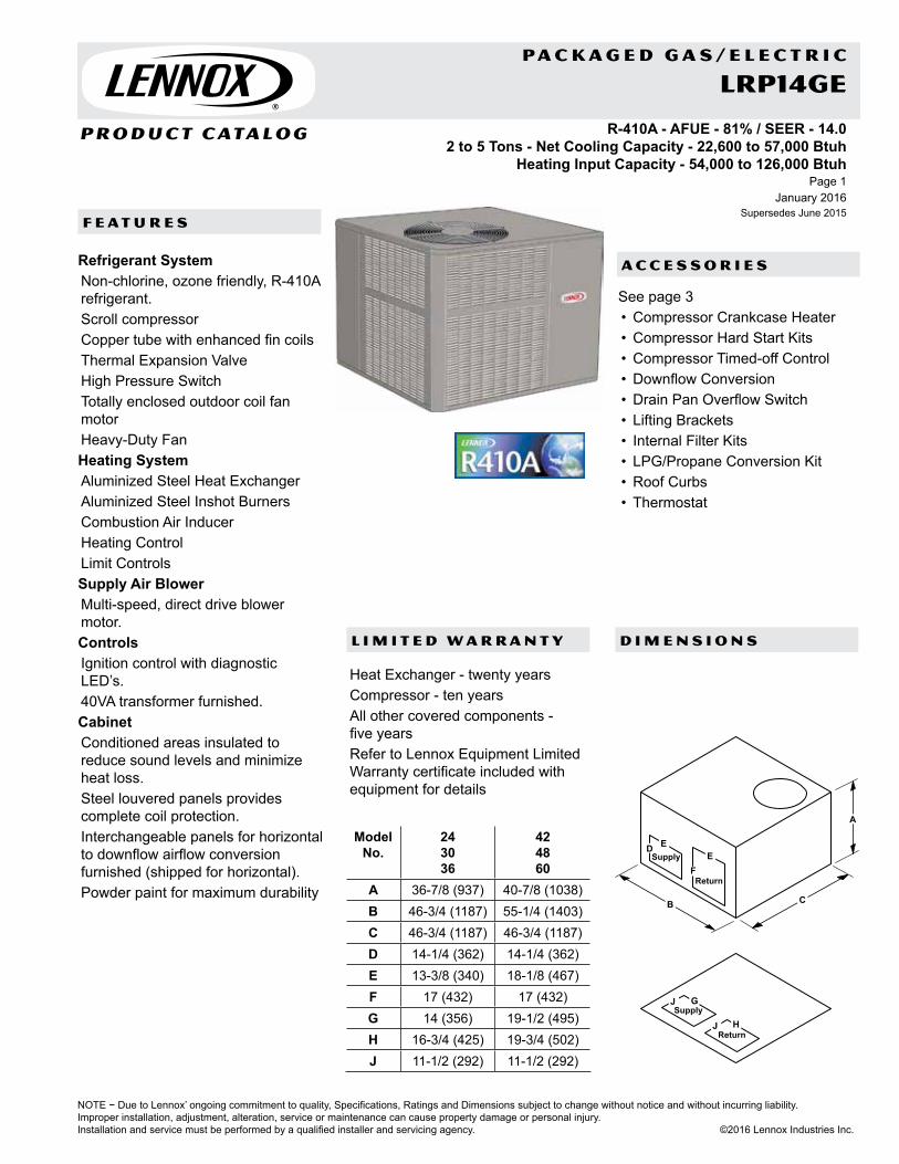
A C C E S S O R I E S
P R O D U C T C ATA L O G
NOTE − Due to Lennox’ ongoing commitment to quality, Specifications, Ratings and Dimensions subject to change without notice and without incurring liability.Improper installation, adjustment, alteration, service or maintenance can cause property damage or personal injury.Installation and service must be performed by a qualified installer and servicing agency. ©2016 Lennox Industries Inc.
D I M E N S I O N S
F E A T U R E S
January 2016Supersedes June 2015
Page 1
L I M I T E D W A R R A N T Y
P A C K A G E D G A S / E L E C T R I C
Refrigerant SystemNon-chlorine, ozone friendly, R-410A refrigerant.Scroll compressorCopper tube with enhanced fin coilsThermal Expansion ValveHigh Pressure SwitchTotally enclosed outdoor coil fan motorHeavy-Duty FanHeating SystemAluminized Steel Heat ExchangerAluminized Steel Inshot BurnersCombustion Air InducerHeating ControlLimit ControlsSupply Air BlowerMulti-speed, direct drive blower motor.ControlsIgnition control with diagnostic LED’s.40VA transformer furnished.CabinetConditioned areas insulated to reduce sound levels and minimize heat loss.Steel louvered panels provides complete coil protection.Interchangeable panels for horizontal to downflow airflow conversion furnished (shipped for horizontal).Powder paint for maximum durability
Heat Exchanger - twenty yearsCompressor - ten yearsAll other covered components - five yearsRefer to Lennox Equipment Limited Warranty certificate included with equipment for details
See page 3• Compressor Crankcase Heater• Compressor Hard Start Kits• Compressor Timed-off Control• Downflow Conversion• Drain Pan Overflow Switch• Lifting Brackets• Internal Filter Kits• LPG/Propane Conversion Kit• Roof Curbs• Thermostat
R-410A - AFUE - 81% / SEER - 14.02 to 5 Tons - Net Cooling Capacity - 22,600 to 57,000 Btuh
Heating Input Capacity - 54,000 to 126,000 Btuh
LRP14GE
Model No.
24 30 36
42 48 60
A 36-7/8 (937) 40-7/8 (1038)B 46-3/4 (1187) 55-1/4 (1403)C 46-3/4 (1187) 46-3/4 (1187)D 14-1/4 (362) 14-1/4 (362)E 13-3/8 (340) 18-1/8 (467)F 17 (432) 17 (432)G 14 (356) 19-1/2 (495)H 16-3/4 (425) 19-3/4 (502)J 11-1/2 (292) 11-1/2 (292)
Supply
ReturnF
E
Return
Supply
ED
J
J G
H
B C
A

NOTE − Due to Lennox’ ongoing commitment to quality, Specifications, Ratings and Dimensions subject to change without notice and without incurring liability. Improper installation, adjustment, alteration, service or maintenance can cause property damage or personal injury.Installation and service must be performed by a qualified installer and servicing agency. ©2016 Lennox Industries Inc.
January 2016Supersedes June 2015
Product Catalog - Packaged Gas/ ElectricPage 2
SPECIFICATIONSGeneral Data Model No. LRP14GE24 LRP14GE30 LRP14GE36 LRP14GE42 LRP14GE48 LRP14GE60
Nominal Tonnage 2 2 .5 3 3 .5 4 5Gas Heat Available - See Next Page -054(X),
-072-054(X),
-072054, -072(X),
-090-072(X),
-090-108(X),
-126-108(X),
-126Cooling Performance
Total cooling capacity - Btuh 22,600 28,400 34,000 40,000 46,000 57,000Total Unit Watts 2055 2580 3090 3635 4180 5180
1 SEER (Btuh/Watt) 14.00 14.00 14.00 14.00 14.00 14.00EER (Btuh/Watt) 11.00 11.00 11.00 11.00 11.00 11.00
2 Sound Rating Number (dB) 78 78 78 78 78 78Refrigerant Type R-410A R-410A R-410A R-410A R-410A R-410A
Charge 4 lbs. 6 oz. 4 lbs. 13 oz. 4 lbs. 15 oz. 6 lbs. 12 oz. 6 lbs. 10 oz. 7 lbs. 13 oz.Condensate drain size (fpt) - in. 3/4 3/4 3/4 3/4 3/4 3/4Outdoor Coil Fan
Motor horsepower 1/6 1/6 1/6 1/4 1/4 1/4Diameter - in. and No. of blades 22 - 4 22 - 4 22 - 4 24 - 3 24 - 3 24 - 3
Indoor Blower Blower wheel size dia. x width - in. 10 x 6 10 x 6 10 x 8 10 x 10 10 x 10 12 x 9Motor horsepower 1/4 1/4 1/3 1/3 1/2 1
Net weight of basic unit - lbs. 358 370 389 460 476 513Shipping weight of basic unit (1 Pkg.) - lbs. 421 433 452 533 549 586Electrical characteristics (60 hz) 208/230V-1ph-60hzELECTRICAL DATA
Line voltage data - 60hz 1 phase 208/230V 208/230V 208/230V 208/230V 208/230V 208/230V3 Maximum overcurrent protection (amps) 25 30 30 40 40 604 Minimum Circuit Ampacity 16.7 18.7 20.6 24.4 26.9 38.9Compressor Rated load amps 11.2 12.8 14.1 15.9 17.9 23.7Outdoor Coil Fan Motor Full load amps 1.0 1.0 1.0 1.7 1.7 1.7Indoor Blower Motor Full load amps 1.7 1.7 2.0 2.8 2.8 7.6NOTE-Extremes of operating range are plus and minus 10% of line voltage.1 AHRI Certified to AHRI Standard 210/240; 95°F outdoor air temperature, 80°F db/67°F wb entering evaporator air.2 Sound Rating Number rated in accordance with test conditions included in AHRI Standard 270.3 HACR type circuit breaker or fuse.4 Refer to National or Canadian Electrical Code manual to determine wire, fuse and disconnect size requirements.
SPECIFICATIONS - GAS HEATModel 24, 30, 36 24, 30 36, 42 36, 42 48, 60 48, 60
Heating Input -054 -072 -072 -090 -108 -126Heating Capacity Btuh
Input 54,000 72,000 72,000 90,000 108,000 126,000Output 43,800 58,400 58,400 72,900 87,500 102,100
1 AFUE 81% 81% 81% 81% 81% 81%Temperature Rise - °F 30-60 40-70 35-65 40-70 40-70 45-75Gas Supply Connection (FPT) - in. 1/2 1/2 1/2 1/2 1/2 1/2Min. Recommended Gas Supply Pressure 5 in. w.g. Natural Gas, 11 in. w.g. LPG/Propane
OPTIONAL ACCESSORIES - ORDER SEPARATELYLPG/Propane Conversion Kit 11U77 11U77 11U77 11U77 11U77 11U771 Annual Fuel Utilization Efficiency based on U.S. DOE test procedures and FTC labeling regulations.

P A C K A G E D G A S / E L E C T R I C
P R O D U C T C ATA L O G
NOTE − Due to Lennox’ ongoing commitment to quality, Specifications, Ratings and Dimensions subject to change without notice and without incurring liability.Improper installation, adjustment, alteration, service or maintenance can cause property damage or personal injury.Installation and service must be performed by a qualified installer and servicing agency. ©2016 Lennox Industries Inc.
January 2016Supersedes June 2015
Page 3
OPTIONAL ACCESSORIES
OPTIONAL ACCESSORIES - ORDER SEPARATELY
Model No. LRP14GE24 30 36 42 48 60
Compressor Crankcase Heater 11X27 • • • • • •Compressor Hard Start Kit 10J42 • • • •
88M91 • •Compressor Timed-Off Control 47J27 • • • • • •Downflow Conversion Kit (includes drain pan overflow switch)
11U80 • • •11U81 • • •
Drain Pan Overflow Switch 11U75 • • • • • •1 Internal Filter Kit (Required)
(1) 20 x 20 + (1) 14 x 20 11U73 • • •(2) 20 x 20 11U74 • • •
Lifting Brackets 11U76 • • • • • •Roof Curbs 14 in. Height 11U78 • • •
11U79 • • •CONTROLS - ORDER SEPARATELY
iComfort® S30 Thermostat 12U67 • • • • • •ComfortSense® 7500 Thermostat 13H14 • • • • • •2 Outdoor Air Temperature Sensor X2658 • • • • • •3 Discharge Air Temperature Sensor 88K38 • • • • • •1 Filters are not furnished and must be field provided. NOTE - Order two filters for 42, 48 and 60 size units.2 Remote Outdoor Temperature Sensor is used with residential packaged units. Allows the thermostat to display outdoor temperature.3 Used with the iComfort® S30 Thermostat for optional service diagnostics.


A C C E S S O R I E S
P R O D U C T C ATA L O G
NOTE − Due to Lennox’ ongoing commitment to quality, Specifications, Ratings and Dimensions subject to change without notice and without incurring liability.Improper installation, adjustment, alteration, service or maintenance can cause property damage or personal injury.Installation and service must be performed by a qualified installer and servicing agency. ©2016 Lennox Industries Inc.
D I M E N S I O N S
F E A T U R E S
January 2016Supersedes June 2015
Page 1
L I M I T E D W A R R A N T Y
P A C K A G E D E L E C T R I C / E L E C T R I C
Refrigerant SystemNon-chlorine, ozone friendly, R-410A refrigerant.Scroll compressorCopper tube with enhanced fin coilsThermal Expansion ValveTotally enclosed outdoor coil fan motorHeavy-Duty FanSupply Air BlowerMulti-speed, direct drive blower motorControls40VA transformerCabinetConditioned areas insulated to reduce sound levels and minimize heat loss.Steel louvered panels provides complete coil protection.Interchangeable panels for horizontal to downflow airflow conversion furnished (shipped for horizontal).Powder paint for maximum durability
Compressor - ten yearsAll other covered components - five yearsRefer to Lennox Equipment Limited Warranty certificate included with equipment for details
See page 3• Compressor Crankcase Heater• Compressor Hard Start Kit• Compressor Timed-Off Control• Electric Heat - 5 to 20 kW• Lifting Brackets• Internal Filter Kits• Roof Curbs• Single Point Power Kits• Thermostat
R-410ASEER - 14.0 - 2 to 5 Tons
Net Cooling Capacity - 22,600 to 57,000 Btuh
LRP14AC
Model No.
24 30 36
42 48 60
A 36-7/8 (937) 40-7/8 (1038)B 46-3/4 (1187) 55-1/4 (1403)C 46-3/4 (1187) 46-3/4 (1187)D 14-1/4 (362) 14-1/4 (362)E 13-3/8 (340) 18-1/8 (467)F 17 (432) 17 (432)G 14 (356) 19-1/2 (495)H 16-3/4 (425) 19-3/4 (502)J 11-1/2 (292) 11-1/2 (292)
Supply
ReturnF
E
Return
Supply
ED
J
J G
H
B C
A

NOTE − Due to Lennox’ ongoing commitment to quality, Specifications, Ratings and Dimensions subject to change without notice and without incurring liability. Improper installation, adjustment, alteration, service or maintenance can cause property damage or personal injury.Installation and service must be performed by a qualified installer and servicing agency. ©2016 Lennox Industries Inc.
January 2016Supersedes June 2015
Product Catalog - Packaged Electric / ElectricPage 2
SPECIFICATIONSGeneral Data Model No. LRP14AC24 LRP14AC30 LRP14AC36 LRP14AC42 LRP14AC48 LRP14AC60
Nominal Tonnage 2 2.5 3 3.5 4 5
Cooling Performance
Total cooling capacity - Btuh 22,600 28,400 34,000 40,000 46,000 57,000
Total unit watts 2055 2580 3090 3635 4180 51801 SEER (Btuh/Watt) 14.00 14.00 14.00 14.00 14.00 14.00
EER (Btuh/Watt) 11.00 11.00 11.00 11.00 11.00 11.002 Sound Rating Number (dB) 78 78 78 78 78 78
Refrigerant Type R-410A R-410A R-410A R-410A R-410A R-410A
Charge 4 lbs. 6 oz. 4 lbs. 13 oz. 4 lbs. 15 oz. 6 lbs. 12 oz. 6 lbs. 10 oz. 7 lbs. 13 oz.
Condensate drain size (fpt) - in. 3/4 3/4 3/4 3/4 3/4 3/4
Outdoor Coil Fan
Motor horsepower 1/6 1/6 1/6 1/4 1/4 1/4
Diameter - in. & No. of blades 22 - 4 22 - 4 22 - 4 24 - 3 24 - 3 24 - 3
Indoor Blower
Blower wheel size dia. x width - in. 10 x 6 10 x 6 10 x 8 10 x 10 10 x 10 12 x 9
Motor horsepower 1/4 1/4 1/3 1/3 1/2 1
Net weight of basic unit - lbs. 331 343 351 424 428 467
Shipping weight of basic unit (1 Pkg.) - lbs. 394 406 414 497 501 540
Electrical characteristics (60 hz) 208/230V-1ph-60hz1 AHRI Certified to AHRI Standard 210/240; 95°F outdoor air temperature, 80°F db/67°F wb entering evaporator air.2 Sound Rating Number rated in accordance with test conditions included in AHRI Standard 270.3 Filters are not furnished and must be field provided. NOTE - Order two filters for 42, 48 and 60 size units

P A C K A G E D E L E C T R I C / E L E C T R I C
P R O D U C T C ATA L O G
NOTE − Due to Lennox’ ongoing commitment to quality, Specifications, Ratings and Dimensions subject to change without notice and without incurring liability.Improper installation, adjustment, alteration, service or maintenance can cause property damage or personal injury.Installation and service must be performed by a qualified installer and servicing agency. ©2016 Lennox Industries Inc.
January 2016Supersedes June 2015
Page 3
OPTIONAL ACCESSORIES - ORDER SEPARATELY
Model No. LRP14AC24 30 36 42 48 60
Compressor Crankcase Heater 11X27 • • • • • •Compressor Hard Start Kit 10J42 • • • •
88M91 • •Compressor Timed-Off Control 47J27 • • • • • •Downflow Conversion Kit (includes drain pan overflow switch)
11U80 • • •11U81 • • •
Drain Pan Overflow Switch 11U75 • • • • • •Electric Heat Size - 208/240V-1ph
5 kW - PHK05BP 10W47 • • • • • •7.5 kW - PHK07BP 10W48 • • • • • •10 kW - PHK10BP 10W49 • • • • • •15 kW - PHK15BP 10W50 • • • •20 kW - PHK20BP 10W51 • • •
3 Internal Filter Kit (Filter Not Furnished)
(1) 20 x 20 + (1) 14 x 20 11U73 • • •
(2) 20 x 20 11U74 • • •Lifting Brackets 11U76 • • • • • •Roof Curbs 14 in. Height 11U78 • • •
11U79 • • •Single Point Power Kits
For 5 kW Electric HeatASPWR813-1
13W88 • • • • • •
For 7.5 kW Electric HeatASPWR814-1
13W89 • • • • • •
For 10 kW Electric HeatASPWR815-1
13W90 • • • • • •
For 15-20 kW Electric HeatASPWR816-1
13W91 • • • •
CONTROLS - ORDER SEPARATELYiComfort® S30 Thermostat 12U67 • • • • • •ComfortSense® 7500 Thermostat 13H14 • • • • • •2 Outdoor Air Temperature Sensor X2658 • • • • • •3 Discharge Air Temperature Sensor 88K38 • • • • • •3 Filters are not furnished and must be field provided. NOTE - Order two filters for 42, 48 and 60 size units.2 Remote Outdoor Temperature Sensor is used with residential packaged units. Allows the thermostat to display outdoor temperature.3 Used with the iComfort® S30 Thermostat for optional service diagnostics.


A C C E S S O R I E S
P R O D U C T C ATA L O G
NOTE − Due to Lennox’ ongoing commitment to quality, Specifications, Ratings and Dimensions subject to change without notice and without incurring liability.Improper installation, adjustment, alteration, service or maintenance can cause property damage or personal injury.Installation and service must be performed by a qualified installer and servicing agency. ©2016 Lennox Industries Inc.
D I M E N S I O N S
F E A T U R E S
January 2016Supersedes June 2015
Page 1
L I M I T E D W A R R A N T Y
P A C K A G E D H E A T P U M P S
Refrigerant SystemNon-chlorine, ozone friendly, R-410A refrigerant.Scroll compressorCopper tube with enhanced fin coilsCheck / Expansion ValveReversing ValveTotally enclosed outdoor coil fan motorHeavy-Duty FanSupply Air BlowerMulti-speed, direct drive blower motorControlsHigh Pressure SwitchLow Pressure SwitchDefrost Control with intregrated anti-short cycle40VA transformer furnished.CabinetConditioned areas insulated to reduce sound levels and minimize heat loss.Steel louvered panels provides complete coil protection.Interchangeable panels for horizontal to downflow airflow conversion furnished (shipped for horizontal).Powder paint for maximum durability
Compressor - ten yearsAll other covered components - five yearsRefer to Lennox Equipment Limited Warranty certificate included with equipment for details
See page 3• Compressor Crankcase Heater• Compressor Hard Start Kit• Compressor Timed-Off Control• Electric Heat - 5 to 20 kW• Internal Filter Kits• Lifting Brackets• Roof Curbs• Single Point Power Kits• Thermostat
R-410A - SEER - 14.0 - 2 to 5 TonsNet Cooling Capacity - 22,600 to 57,000 Btuh
Heating Capacity - 22,000 to 56,000 Btuh
LRP14HP
Model No.
24 30 36
42 48 60
A 36-7/8 (937) 40-7/8 (1038)B 46-3/4 (1187) 55-1/4 (1403)C 46-3/4 (1187) 46-3/4 (1187)D 14-1/4 (362) 14-1/4 (362)E 13-3/8 (340) 18-1/8 (467)F 17 (432) 17 (432)G 14 (356) 19-1/2 (495)H 16-3/4 (425) 19-3/4 (502)J 11-1/2 (292) 11-1/2 (292)
Supply
ReturnF
E
Return
Supply
ED
J
J G
H
B C
A

NOTE − Due to Lennox’ ongoing commitment to quality, Specifications, Ratings and Dimensions subject to change without notice and without incurring liability. Improper installation, adjustment, alteration, service or maintenance can cause property damage or personal injury.Installation and service must be performed by a qualified installer and servicing agency. ©2016 Lennox Industries Inc.
January 2016Supersedes June 2015
Product Catalog - Packaged Heat PumpsPage 2
SPECIFICATIONS
General Data Model No. LRP14HP24 LRP14HP30 LRP14HP36 LRP14HP42 LRP14HP48 LRP14HP60
Nominal Tonnage 2 2.5 3 3.5 4 5
Cooling / Heating Performance
Cooling Total capacity - Btuh 22,600 28,600 34,000 40,000 46,000 57,000
Total unit watts 2055 2600 3090 3635 4180 5180
1 SEER (Btuh/Watt) 14.00 14.00 14.00 14.00 14.00 14.00
EER (Btuh/Watt) 11.00 11.00 11.00 11.00 11.00 11.00
High Temp. Heat
Total capacity - Btuh 22,000 27,000 33,400 39,000 45,000 56,000
Total unit watts 1700 2140 2645 3175 3565 4440
COP 3.80 3.70 3.70 3.60 3.70 3.70
HSPF Region IV / Region V 8.00 / 6.95 8.00 / 6.95 8.00 / 6.95 8.00 / 6.95 8.00 / 6.95 8.00 / 6.95
Low Temp. Heat
Total capacity - Btuh 12,300 15,900 20,000 23,600 27,000 33,600
Total unit watts 1570 2025 2550 3010 3445 4105
COP 2.30 2.30 2.30 2.30 2.30 2.40
2 Sound Rating Number (dB) 78 78 78 78 78 78
Refrigerant Type R-410A R-410A R-410A R-410A R-410A R-410A
Charge 5 lbs. 11 oz. 6 lbs. 0 oz. 5 lbs. 12 oz. 10 lbs. 5 oz. 10 lbs. 3 oz. 10 lbs. 1 oz.
Condensate drain size (fpt) - in. 3/4 3/4 3/4 3/4 3/4 3/4
Outdoor Coil Fan
Motor horsepower 1/6 1/6 1/6 1/4 1/4 1/4
Diameter - in. 22 22 22 24 24 24
Number of blades 4 4 4 3 3 3
Indoor Blower Blower wheel size dia. x width - in. 10 x 6 10 x 6 10 x 8 10 x 10 10 x 10 12 x 9
Motor horsepower 1/4 1/4 1/3 1/3 1/2 1
Net weight of basic unit - lbs. 333 342 352 455 460 482
Shipping weight of basic unit (1 Pkg.) - lbs. 396 405 415 528 533 555
Electrical characteristics (60 hz) 208/230V-1ph-60hz1 AHRI Certified to AHRI Standard 210/240: Cooling Ratings - 95°F outdoor air temperature and 80°F db/67°F wb entering indoor coil air. High Temperature Heating Ratings - 47°F db/43°F wb outdoor air temperature and 70°F entering indoor coil air. Low Temperature Heating Ratings - 17°F db/15°F wb outdoor air temperature and 70°F entering indoor coil air.
2 Sound Rating Number rated in accordance with test conditions included in AHRI Standard 270.

P A C K A G E D H E A T P U M P S
P R O D U C T C ATA L O G
NOTE − Due to Lennox’ ongoing commitment to quality, Specifications, Ratings and Dimensions subject to change without notice and without incurring liability.Improper installation, adjustment, alteration, service or maintenance can cause property damage or personal injury.Installation and service must be performed by a qualified installer and servicing agency. ©2016 Lennox Industries Inc.
January 2016Supersedes June 2015
Page 3
OPTIONAL ACCESSORIES - ORDER SEPARATELYModel No. LRP14HP
24 30 36 42 48 60
Compressor Crankcase Heater 11X27 • • • • • •Compressor Hard Start Kit 10J42 • • • • •
88M91 •Downflow Conversion Kit (includes drain pan overflow switch)
11U80 • • •11U81 • • •
Compressor Timed Off Control 42J27 • • • • • •Electric Heat Size - 208/240V-1ph
5 kW - PHK05BP 10W47 • • • • • •7.5 kW - PHK05BP 10W48 • • • • • •10 kW - PHK05BP 10W49 • • • • • •15 kW - PHK05BP 10W50 • • • •20 kW - PHK05BP 10W51 • • •
1 Internal Filter Kit (Filter Not Furnished)
(1) 20 x 20 + (1) 14 X 20 11U73 • • •(2) 20 x 20 11U74 • • •
Lifting Brackets 11U76 • • • • • •Roof Curbs 14 in. Height 11U78 • • •
11U79 • • •Single Point Power Kits
For 5 kW Electric Heat ASPWR813-10
13W88 • • • • • •
For 7.5 kW Electric Heat ASPWR814-10
13W89 • • • • • •
For 10 kW Electric Heat ASPWR815-10
13W90 • • • • • •
For 15-20 kW Electric Heat ASPWR816-10
13W91 • • • •
CONTROLS - ORDER SEPARATELY
iComfort® S30 Thermostat 12U67 • • • • • •ComfortSense® 7500 Thermostat 13H14 • • • • • •2 Outdoor Air Temperature Sensor X2658 • • • • • •3 Discharge Air Temperature Sensor 88K38 • • • • • •1 Filters are not furnished and must be field provided. NOTE - Order two filters for 42, 48 and 60 size units.2 Remote Outdoor Temperature Sensor is recommended for heat pump balance point control and to lock out some of the the electric heating elements where two-stage
control is applicable. Also allows the thermostat to display outdoor temperature.3 Used with the iComfort® S30 Thermostat for optional service diagnostics.


A C C E S S O R I E S
P R O D U C T C ATA L O G
NOTE − Due to Lennox’ ongoing commitment to quality, Specifications, Ratings and Dimensions subject to change without notice and without incurring liability.Improper installation, adjustment, alteration, service or maintenance can cause property damage or personal injury.Installation and service must be performed by a qualified installer and servicing agency. ©2016 Lennox Industries Inc.
P A C K A G E D H E A T P U M P S
D I M E N S I O N S
F E A T U R E S
L I M I T E D W A R R A N T Y
Page 5January 2016
Supersedes June 2015
Dual-Fuel OperationIn the heating mode the unit operates the heat pump for 1st stage heating. If 1st stage is not satisfied, the 2nd stage will activate gas heating (secondary heat source).Refrigerant SystemNon-chlorine, ozone friendly, R-410A refrigerant.Scroll compressorCopper tube with enhanced fin coilsCheck / Expansion ValveReversing ValveTotally enclosed outdoor coil fan motorHeavy-Duty FanGas Heating SystemAluminized Steel Heat ExchangerAluminized Steel Inshot BurnersCombustion Air InducerHeating ControlLimit ControlsSupply Air BlowerMulti-speed, direct drive blower motorControlsHigh Pressure SwitchLow Pressure SwitchDefrost Control with intregrated anti-short cycle40VA transformer furnished.CabinetConditioned areas insulated to reduce sound levels and minimize heat loss.Steel louvered panels provides complete coil protection.Interchangeable panels for horizontal to downflow airflow conversion furnished (shipped for horizontal).Powder paint for maximum durability
Compressor - ten yearsHeat Exchanger - twenty yearsAll other covered components - five yearsRefer to Lennox Equipment Limited Warranty certificate included with equipment for details
See page 7• Compressor Crankcase Heater• Compressor Hard Start Kit• Compressor Timed-Off Control• Internal Filter Kits• Lifting Brackets• LPG/Propane Conversion Kit• Roof Curbs• Single Point Power Kits• Thermostat
R-410A - SEER - 14.0 - AFUE - 81% - 2 to 5 TonsNet Cooling Capacity - 22,600 to 57,000 Btuh
Heating Capacity - 22,000 to 56,000 Btuh / Input Gas Heating Capacity - 72,000 to 126,000 Btuh
DUAL-FUELLRP14DF
Model No.
24 30 36
42 48 60
A 36-7/8 (937) 40-7/8 (1038)B 46-3/4 (1187) 55-1/4 (1403)C 46-3/4 (1187) 46-3/4 (1187)D 14-1/4 (362) 14-1/4 (362)E 13-3/8 (340) 18-1/8 (467)F 17 (432) 17 (432)G 14 (356) 19-1/2 (495)H 16-3/4 (425) 19-3/4 (502)J 11-1/2 (292) 11-1/2 (292)
Supply
ReturnF
E
Return
Supply
ED
J
J G
H
B C
A

NOTE − Due to Lennox’ ongoing commitment to quality, Specifications, Ratings and Dimensions subject to change without notice and without incurring liability. Improper installation, adjustment, alteration, service or maintenance can cause property damage or personal injury.Installation and service must be performed by a qualified installer and servicing agency. ©2016 Lennox Industries Inc.
January 2016Supersedes June 2015
Product Catalog - Packaged Heat PumpsPage 6
SPECIFICATIONSGeneral Data Model No. LRP14DF24 LRP14DF30 LRP14DF36 LRP14DF42 LRP14DF48 LRP14DF60
Nominal Tonnage 2 2.5 3 3.5 4 5Cooling / Heating Performance
Cooling Total capacity - Btuh 22,600 28,600 34,000 40,000 46,000 57,000Total unit watts 2055 2580 3090 3635 4180 5180
1 SEER (Btuh/Watt) 14.00 14.00 14.00 14.00 14.00 14.00EER (Btuh/Watt) 11.00 11.00 11.00 11.00 11.00 11.00
High Temp. Heat
Total capacity - Btuh 22,000 27,000 33,400 39,000 45,000 56,000Total unit watts 1700 2140 2645 3175 3565 4440
COP 3.80 3.70 3.70 3.60 3.70 3.70HSPF Region IV / Region V 8.00 / 6.95 8.00 / 6.95 8.00 / 6.95 8.00 / 6.95 8.00 / 6.95 8.00 / 6.95
Low Temp. Heat
Total capacity - Btuh 12,300 15,900 20,000 23,600 27,000 33,600Total unit watts 1570 2025 2550 3010 3445 4105
COP 2.30 2.30 2.30 2.30 2.30 2.402 Sound Rating Number (dB) 78 78 78 78 78 78
Gas Heat Available - See Next Page -072(X) -072(X) -072(X), -090
-072(X), -090
-126(X) -126(X)
Refrigerant Type R-410A R-410A R-410A R-410A R-410A R-410ACharge 5 lbs. 11 oz. 6 lbs. 0 oz. 5 lbs. 12 oz. 10 lbs. 5 oz. 10 lbs. 3 oz. 10 lbs. 1 oz.
Condensate drain size (fpt) - in. 3/4 3/4 3/4 3/4 3/4 3/4Outdoor Coil Fan
Motor horsepower 1/6 1/6 1/6 1/4 1/4 1/4Diameter - in. 22 22 22 24 24 24
Number of blades 4 4 4 3 3 3Indoor Blower Blower wheel size dia. x width - in. 10 x 6 10 x 6 10 x 8 10 x 10 10 x 10 12 x 9
Motor horsepower 1/4 1/4 1/3 1/3 1/2 1Net weight of basic unit - lbs. 366 374 389 493 506 528Shipping weight of basic unit (1 Pkg.) - lbs. 429 437 452 566 579 601Electrical characteristics (60 hz) 208/230V-1ph-60hzELECTRICAL DATA
Line voltage data - 60hz 1 phase 208/230V 208/230V 208/230V 208/230V 208/230V 208/230V3 Maximum overcurrent protection (amps) 25 30 35 40 45 604 Minimum Circuit Ampacity 17.4 20.7 24.4 24.4 27 39.7Compressor Rated load amps 10.9 13.5 15.4 15.9 18 24.3Outdoor Coil Fan Motor Full load amps 1.0 1.0 1.0 1.7 1.7 1.7Indoor Blower Motor Full load amps 2.8 2.8 4.1 2.8 2.8 7.61 AHRI Certified to AHRI Standard 210/240:Cooling Ratings - 95°F outdoor air temperature and 80°F db/67°F wb entering indoor coil air.High Temperature Heating Ratings - 47°F db/43°F wb outdoor air temperature and 70°F entering indoor coil air.Low Temperature Heating Ratings - 17°F db/15°F wb outdoor air temperature and 70°F entering indoor coil air.
2 Sound Rating Number rated in accordance with test conditions included in AHRI Standard 270.3 Annual Fuel Utilization Efficiency based on U.S. DOE test procedures and FTC labeling regulations.4 Refer to National or Canadian Electrical Code manual to determine wire, fuse and disconnect size requirements.
SPECIFICATIONS - GAS HEATModel 24, 30, 36, 42 36, 42 48, 60
Heating Input -072 -090 -126Heating Capacity Btuh
Input 72,000 90,000 126,000Output 58,400 72,900 102,100
1 AFUE 81% 81% 81%Temperature Rise - °F 40-70 40-70 45-75Gas Supply Connection (FPT) - in. 1/2 1/2 1/2Min. Recommended Gas Supply Pressure 5 in. w.g. Natural Gas, 11 in. w.g. LPG/Propane
OPTIONAL GAS HEAT ACCESSORIES - ORDER SEPARATELYLPG/Propane Conversion Kit 11U77 11U77 11U771 Annual Fuel Utilization Efficiency based on U.S. DOE test procedures and FTC labeling regulations.

P A C K A G E D H E A T P U M P S
P R O D U C T C ATA L O G
NOTE − Due to Lennox’ ongoing commitment to quality, Specifications, Ratings and Dimensions subject to change without notice and without incurring liability.Improper installation, adjustment, alteration, service or maintenance can cause property damage or personal injury.Installation and service must be performed by a qualified installer and servicing agency. ©2016 Lennox Industries Inc.
January 2016Supersedes June 2015
Page 7
OPTIONAL ACCESSORIES - ORDER SEPARATELYModel No. LRP14DF
24 30 36 42 48 60Compressor Hard Start Kit 10J42 • • • • •
88M91 •Compressor Timed-Off Control 47J27 • • • • • •Downflow Conversion Kit (includes drain pan overflow switch)
11U80 • • •11U81 • • •
Drain Pan Overflow Switch 11U75 • • • • • •1 Internal Filter
Kit (required)(1) 20 x 20 + (1) 14 x 20 11U73 • • •
(2) 20 x 20 11U74 • • •Lifting Brackets 11U76 • • • • • •Roof Curbs 14 in. Height 11U78 • • •
11U79 • • •CONTROLS - ORDER SEPARATELY
iComfort® S30 Thermostat 12U67 • • • • • •ComfortSense® 7500 Thermostat 13H14 • • • • • •2 Outdoor Air Temperature Sensor X2658 • • • • • •3 Discharge Air Temperature Sensor 88K38 • • • • • •1 Filters are not furnished and must be field provided. NOTE - Order two filters for 42, 48 and 60 size units. 2 Remote Outdoor Temperature Sensor is used with residential packaged units. Allows the thermostat to display outdoor temperature.3 Used with the iComfort® S30 Thermostat for optional service diagnostics.


P R O D U C T C ATA L O G
NOTE − Due to Lennox’ ongoing commitment to quality, Specifications, Ratings and Dimensions subject to change without notice and without incurring liability.Improper installation, adjustment, alteration, service or maintenance can cause property damage or personal injury.Installation and service must be performed by a qualified installer and servicing agency. ©2016 Lennox Industries Inc.
D I M E N S I O N S
F E A T U R E S
January 2016Supersedes June 2015
Page 1
L I M I T E D W A R R A N T Y
I N D O O R A I R Q U A L I T Y
Multiple air purification technologies in a single, state-of-the-art unit.Easy to install.The UVA lights activate the catalyst on the PureAir™ Cartridge that destroys chemicals as they flow through the system, turning them into carbon dioxide and water vapor.The system uses light (UVA), which reacts with a titanium dioxide-based chemical catalyst as air passes through it. Contaminants are destroyed rather than transferred.No toxic chemicals are used.Pollutants are adsorbed on the surface of the catalyst and oxidized to carbon dioxide (CO2) and water (H2O).Rather than just absorbing gaseous pollutants (as in carbon systems), the PCO3 provides a reduction of absolute toxicity as the gaseous products from the complete photocatalytic oxidation of volatile organic compounds are carbon dioxide and water.MERV 16 Carbon Clean 16® media filter.Pre-painted steel cabinet.Front of unit is removable for service access.Three-prong, detachable 6-foot power cord for plug-in 120V electrical connection. Optional 230V cord and hard-wire kits are available.
All covered components - five yearsRefer to Lennox Equipment Limited Warranty certificate included with equipment for details,
PUREAIR® Air Purification SystemHEALTHY CLIMATE®
PCO3
PCO3-14-16 PCO3-16-16 PCO3-20-16A 21-1/8 (537) 17-1/2 (445) 21-1/8 (537)B 18-1/2 (470) 14-5/8 (371) 18-1/2 (470)C 20-1/4 (514) 23 (584) 23 (584)D 23-3/4 (603) 26-1/2 (673) 26-1/2 (673)
8-3/4(322)
BA
C
D
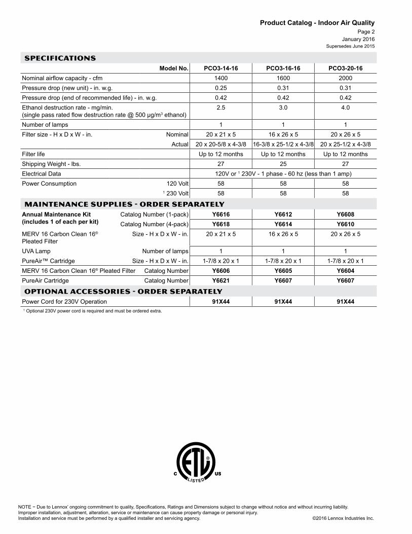
NOTE − Due to Lennox’ ongoing commitment to quality, Specifications, Ratings and Dimensions subject to change without notice and without incurring liability. Improper installation, adjustment, alteration, service or maintenance can cause property damage or personal injury.Installation and service must be performed by a qualified installer and servicing agency. ©2016 Lennox Industries Inc.
January 2016Supersedes June 2015
Product Catalog - Indoor Air QualityPage 2
SPECIFICATIONSModel No. PCO3-14-16 PCO3-16-16 PCO3-20-16
Nominal airflow capacity - cfm 1400 1600 2000Pressure drop (new unit) - in. w.g. 0.25 0.31 0.31Pressure drop (end of recommended life) - in. w.g. 0.42 0.42 0.42Ethanol destruction rate - mg/min. (single pass rated flow destruction rate @ 500 µg/m3 ethanol)
2.5 3.0 4.0
Number of lamps 1 1 1Filter size - H x D x W - in. Nominal 20 x 21 x 5 16 x 26 x 5 20 x 26 x 5
Actual 20 x 20-5/8 x 4-3/8 16-3/8 x 25-1/2 x 4-3/8 20 x 25-1/2 x 4-3/8Filter life Up to 12 months Up to 12 months Up to 12 monthsShipping Weight - lbs. 27 25 27Electrical Data 120V or 1 230V - 1 phase - 60 hz (less than 1 amp)Power Consumption 120 Volt 58 58 58
1 230 Volt 58 58 58
MAINTENANCE SUPPLIES - ORDER SEPARATELYAnnual Maintenance Kit (includes 1 of each per kit)
Catalog Number (1-pack) Y6616 Y6612 Y6608Catalog Number (4-pack) Y6618 Y6614 Y6610
MERV 16 Carbon Clean 16® Pleated Filter
Size - H x D x W - in. 20 x 21 x 5 16 x 26 x 5 20 x 26 x 5
UVA Lamp Number of lamps 1 1 1PureAir™ Cartridge Size - H x D x W - in. 1-7/8 x 20 x 1 1-7/8 x 20 x 1 1-7/8 x 20 x 1MERV 16 Carbon Clean 16® Pleated Filter Catalog Number Y6606 Y6605 Y6604PureAir Cartridge Catalog Number Y6621 Y6607 Y6607
OPTIONAL ACCESSORIES - ORDER SEPARATELYPower Cord for 230V Operation 91X44 91X44 91X441 Optional 230V power cord is required and must be ordered extra.

NOTE − Due to Lennox’ ongoing commitment to quality, Specifications, Ratings and Dimensions subject to change without notice and without incurring liability.Improper installation, adjustment, alteration, service or maintenance can cause property damage or personal injury.Installation and service must be performed by a qualified installer and servicing agency. ©2016 Lennox Industries Inc.
P R O D U C T C ATA L O G
I N D O O R A I R Q U A L I T Y
January 2016Supersedes June 2015
Page 3
D I M E N S I O N S
F E A T U R E S L I M I T E D W A R R A N T YF E A T U R E S L I M I T E D W A R R A N T Y
Cabinet has a five year limited warranty in residential applications, one year in non-residential applications.Filter media is not covered.Refer to Healthy Climate Equipment Limited Warranty certificate included with cabinet for specific details.
NOTE - Cabinet and Filter must be ordered separately.MERV 11 and Carbon Clean 16® (MERV 16) filters (Minimum Efficiency Reporting Value based on ASHRAE 52.2).High performance filtration with a narrow 7 in. cabinet.Pleated filter design allows maximum air flow and filtration efficiency.Multi-position cabinet is available for installation on the return air opening of gas, oil or electric forced, warm air furnaces and air handlers with cooling applications up to 5 tons. The unit can be installed in upflow, downflow or horizontal unit applications.Silent operation, requires no electrical component service, and generates no ozone.Constant blower operation will achieve the best air cleaning results.No duct transition needed for most furnace applications.Cabinet constructed of pre-painted galvanized steel. Cabinet will withstand 400 lbs. static weight, enough to support the weight of a typical furnace and indoor coil or air handler.Tool-less access door allows quick and easy replacement of filter media.Mounts in any position. Air flow direction through the cabinet can be changed by repositioning the filter. Arrows on filter indicate air flow direction.Cabinet is shipped compact and requires minimum field assembly. No tools required.Filter media is certified to UL 900 standard and UL/ULC classification - Class 2.Two Filter Types are available:Boxed Filters have double-wall beverage board frame for rigid construction.
HC11 / HC16
MERV 11 and Carbon Clean 16™ (MERV 16) Media Air CleanersHEALTHY CLIMATE®
HCC14-23 HCC16-28 HCC20-28A 21-1/4 17-1/4 21B 18-3/4 15 18-1/2C 23 28-1/2 28-1/2D 18-1/2 24 24
7
BA
C
D
Expandable Filter Kits consist of expandable filter media and reusable filter frame (MERV 16 kits include reusable filter spacers). Kits are shipped compact for field assembly.Carbon Clean 16™ (MERV 16) Box Filters50% first-pass reduction of ozone.Carbon coated fiber matrix reduces odors.Hospital inpatient care/general surgery level filtration.Removes over 95% of E1 (sub-micron) particles down to 0.3-1 microns.Removes over 99% of E2 particles down to 1-3 microns.Removes over 90% of ultra-fine particles down to 0.01 micron, including viruses and bacteria.
Filter Cabinet (With Filter in Place)
MERV 11 and Carbon Clean 16™ (MERV 16) Filters

NOTE − Due to Lennox’ ongoing commitment to quality, Specifications, Ratings and Dimensions subject to change without notice and without incurring liability. Improper installation, adjustment, alteration, service or maintenance can cause property damage or personal injury.Installation and service must be performed by a qualified installer and servicing agency. ©2016 Lennox Industries Inc.
January 2016Supersedes June 2015
Product Catalog - Indoor Air QualityPage 4
SPECIFICATIONSGeneral
DataCabinet Model No. HCC14-23 HCC16-28 HCC20-28 HCC14-23 HCC16-28 HCC20-28
Filter Model No. (Box Filter) HCF14-11 HCF16-11 HCF20-11 HCF14-16 HCF16-16 HCF20-16
Filter Model No. (Expandable Filter Kit) HCXF14-11 HCXF16-11 HCXF20-11 HCXF14-16 HCXF16-16 HCXF20-161 MERV (Minimum Efficiency Reporting Value) rating 11 11 11 16 16 16
Air Flow Air flow range - cfm 800 - 1400 800 - 1600 1400 - 2000 800 - 1400 800 - 1600 1400 - 2000
Rated air flow - cfm 1400 1600 2000 1400 1600 2000
Filter Data
Nominal Filter size - in. 20 x 20 x 5 16 x 25 x 5 20 x 25 x 5 20 x 20 x 5 16 x 25 x 5 20 x 25 x 5
Actual Filter size - in.20 x 19-3/4 x 4-3/8
15-3/4 x 24-3/4 x 4-3/8
19-3/4 x 24-3/4 x 4-3/8
20 x 19-3/4 x 4-3/8
15-3/4 x 24-3/4 x 4-3/8
19-3/4 x 24-3/4 x 4-3/8
Pressure drop @ rated flow in. w.c. - Initial
HCF - Initial 0.25 0.27 0.27 0.29 0.31 0.31
- Final 0.40 0.40 0.40 0.40 0.40 0.40
HCXF - Initial 0.27 0.30 0.27 0.29 0.31 0.31
- Final 0.40 0.40 0.40 0.40 0.40 0.402 Filter estimated service life (months) up to 12 months
Shipping weight - lbs. Cabinet 15 17 18 15 17 18
MAINTENANCE SUPPLIES - ORDER SEPARATELYReplacement filter media for Expandable Filter Kits X8311 X8309 X8310 X8314 X8312 X8313
Replacement filter media for Box Filter Kits X0585 X6670 X6673 X7935 X6672 X66751 Rated at 492 feet per minute2 Factors will influence the frequency of replacement of filter media, such as: the number of people in the home, activities, lifestyle, number of pets, and size of home.

NOTE − Due to Lennox’ ongoing commitment to quality, Specifications, Ratings and Dimensions subject to change without notice and without incurring liability.Improper installation, adjustment, alteration, service or maintenance can cause property damage or personal injury.Installation and service must be performed by a qualified installer and servicing agency. ©2016 Lennox Industries Inc.
P R O D U C T C ATA L O G
I N D O O R A I R Q U A L I T Y
January 2016Supersedes June 2015
Page 5
F E A T U R E S
Boxed FiltersHEALTHY CLIMATE®
CARBON CLEAN 16™ FILTERS
Disposable, pleated MERV 16 filters (Minimum Efficiency Reporting Value based on ASHRAE 52.2).50% first-pass reduction of ozone.Carbon coated fiber matrix reduces odors.Hospital inpatient care/general surgery level filtration.Removes over 95% of E1 (sub-micron) particles down to 0.3-1 microns.
Nominal Filter Size (in.)
Brand Replaces Filter for Air Cleaner Model:
Replaces Filter Media: Order No.
16 x 25 x 5 Lennox HCC16-28 HCF16-16, HCF16-11
X6672
Honeywell F25A1043, F25F1042, F35F1008, F100F1012, F150E1026, F200E1029
FC35A1001, FC100A1029, FC200E1029
Carrier EZXCAB016, MACA016, MPKA016, FILCAB016
EXPXXFIL0016, EXPXXUNV0016, EXPXXLMC0016, FILCCCAR0016
Trion Air Bear™ Supreme 1400 455602-119
255649-105
20 x 20 x 5 Lennox HCC14-23 HCF14-16, HCF14-11
X7935
Honeywell F25F1018, F35F1016, F100F1020
203721 FC35A1019 FC100A1011
20 x 25 x 5 Lennox HCC20-28 HCF20-16, HCF20-11
X6675
Honeywell F25A1068, F25F1067, F35F1024, F100F1038, F150E1034, F200E1037
FC35A1027, FC100A1037, FC200E1037, F35Expandapac
Carrier EZXCAB020, MACA020, MPKA020, FILCAB020
EXPXXFIL0020, EXPXXUNV0020, EXPXXLMC0020, FILCCCAR0020
Trion Air Bear™ 453000-001 Supreme 2000 455602-001, 447380-002
255649-102, 229990-002, 229990-102
Note - If Lennox Replacement filter does not fully engage top or bottom flanges in a competitor’s filter cabinet, weather stripping maybe added to the bottom of filter to properly position the filter and prevent bypass air leakage.
Removes over 99% of E2 particles down to 1-3 microns.Removes over 90% of ultra-fine particles down to 0.01 micron, including viruses and bacteria.Double-wall beverage board frame for rigid construction.Media is certified to UL 900 standard and UL/ULC classification - Class 2.

NOTE − Due to Lennox’ ongoing commitment to quality, Specifications, Ratings and Dimensions subject to change without notice and without incurring liability. Improper installation, adjustment, alteration, service or maintenance can cause property damage or personal injury.Installation and service must be performed by a qualified installer and servicing agency. ©2012 Lennox Industries Inc.
P R O D U C T C ATA L O G
I N D O O R A I R Q U A L I T Y
January 2016Supersedes June 2015
Page 6
F E A T U R E S
MERV 11 (Minimum Efficiency Reporting Value) − Based on ASHRAE 52.2Disposable, pleated filter media. Available for replacement of existing air cleaner filters.
Boxed FiltersHEALTHY CLIMATE®
MERV 11 FILTERS
Nominal Filter Size
(in.)
Brand Replaces Filter for Air Cleaner Model: Replaces Filter Media: Order No.
16 x 25 x 3 Lennox BMAC-12C X0581 X0581Trion Air Bear™ Air Bear™
16 x 20 x 5 Lennox X0582 X0582Honeywell F25F1075 F35F1032 F100F1004 209894 FC35A1035 FC100A1003
16 x 25 x 5 Lennox X0583 X0583Honeywell F25F1000 F35F1008 F100F1012 203719 FC35A1001 FC100A1029
16 x 25 x 5 Lennox HCC16-28 HCF16-11 X6670
Honeywell F25A1043 F25F1042
F35F1008 F100F1012
F150E1026 F200E1029
FC35A1001 FC100A1029 FC200E1029
Carrier EZXCAB016 MACA016
MPKA016 FILCAB016 EXPXXFIL0016 EXPXXUNV0016
EXPXXLMC0016 FILCCCAR0016
Trion Supreme 1400 455602-119 255649-10516 x 26 x 5 Lennox BMAC-14CE X0584 X0584
White Rodgers ACB1400 FR140020 x 20 x 5 Lennox HCC14-23 HCF14-11 HCF14-16 X0585 X0585
Honeywell F25A1018 F35F1016 F100F1020 203721 FC35A1019 FC100A101120 x 25 x 5 Lennox BMAC-20C X0586 X0586
Honeywell F25F1026 F35F1024 F100F1038 203720 FC35A1027 FC100A103720 x 25 x 5 Lennox HCC20-28 HCF20-11 X6673
Honeywell F25A1068 F25F1067
F35F1024 F100F1038
F150E1034 F200E103
FC35A1027 FC100A1037
FC200E1037 F35Expandapac
Carrier EZXCAB020 MACA020
MPKA020 FILCAB020
EXPXXFIL0020 EXPXXUNV0020
EXPXXLMC0020 FILCCCAR0020
Trion 453000-001 Supreme 2000
455602-001 447380-002
255649-102 229990-002 229990-102
20 x 25 x 5 Lennox 1 BMAC-20C MF1-20 X0586 X1152 92G07 X1152Trion 1 Trion Air Bear 229990-102
20 x 26 x 5 Lennox BMAC-20CE X0587 X0587White Rodgers ACB2000 FR2000
Note – If Lennox Replacement filter does not fully engage top or bottom flanges in a competitor’s filter cabinet, weather stripping maybe added to the bottom of filter to properly position the filter and prevent bypass air leakage. 1 Alternate filter replacement with higher dust holding capacity.

NOTE − Due to Lennox’ ongoing commitment to quality, Specifications, Ratings and Dimensions subject to change without notice and without incurring liability.Improper installation, adjustment, alteration, service or maintenance can cause property damage or personal injury.Installation and service must be performed by a qualified installer and servicing agency. ©2016 Lennox Industries Inc.
P R O D U C T C ATA L O G
I N D O O R A I R Q U A L I T Y
January 2016Supersedes June 2015
Page 7
F E A T U R E S
MERV 16 (Minimum Efficiency Reporting Value) - Based on ASHRAE 52.2Replaceable Expandable Filter Media in Reusable Filter Frame Disposable, expandable pleated filter media. Available for replacement of existing air cleaner filters. Shipped complete with reusable filter frame, expandable filter media and filter spacers. Some assembly required.
Expandable Filter KitsHEALTHY CLIMATE®
MERV 16 FILTERS
Nominal Filter Size
(in.)
Brand Replaces Filter for Air Cleaner Model:
Replaces Filter Media:
Complete Kit
Order No.
Replacement Filter Media Order No.
16 x 25 x 5 Lennox HCC16-28 HCF16-16HCF16-11
HCXF16-16HCXF16-11
X8306 X8312
Honeywell F25A1043F35F1008 F100F1012
F25F1042F200E1029F150E1026
FC35A1001FC100A1029
FC200E1029
Carrier EZXCAB016FILCAB016
MACA016MPKA016
EXPXXUNV0016EXPXXLMC0016
EXPXXFIL0016FILCCCAR0016
Trion Air Bear™ Supreme 1400 455602-119 255649-105
20 x 20 x 5 Lennox HCC14-23 HCF14-16HCF14-11
HCXF14-16 HCXF14-11
X8308 X8314
Honeywell F25F1018F100F1020
F35F1016 203721FC35A1019
FC100A1011
20 x 25 x 5 Lennox HCC20-28 HCF20-16HCF20-11
HCXF20-16HCXF20-11
X8307 X8313
Honeywell F25A1068F35F1024F150E1034
F25F1067F100F1038F200E1037
FC35A1027F35Expandapac
FC100A1037FC200E1037
Carrier EZXCAB020MPKA020
MACA020FILCAB020
EXPXXUNV0020EXPXXLMC0020
EXPXXFIL0020FILCCCAR0020
Trion Air Bear™ 453000-001Supreme 2000
455602-001447380-002
255649-102229990-002
229990-102
Note - If Lennox Replacement filter does not fully engage top or bottom flanges in a competitor’s filter cabinet, weather stripping maybe added to the bottom of filter to properly position the filter and prevent bypass air leakage.

NOTE − Due to Lennox’ ongoing commitment to quality, Specifications, Ratings and Dimensions subject to change without notice and without incurring liability. Improper installation, adjustment, alteration, service or maintenance can cause property damage or personal injury.Installation and service must be performed by a qualified installer and servicing agency. ©2012 Lennox Industries Inc.
P R O D U C T C ATA L O G
I N D O O R A I R Q U A L I T Y
January 2016Supersedes June 2015
Page 8
F E A T U R E S
MERV 11 (Minimum Efficiency Reporting Value) - Based on ASHRAE 52.2Replaceable Expandable Filter Media in Reusable Filter FrameDisposable, expandable pleated filter media. Available for replacement of existing air cleaner filters. Shipped complete with reusable filter frame and expandable filter media. Some assembly required.
Expandable Filter KitsHEALTHY CLIMATE®
MERV 11 FILTERS
Nominal Filter Size (in.)
Brand Replaces Filter for Air Cleaner Model:
Replaces Filter Media:
Complete Kit
Order No.
Replacement Filter Media Order No.
16 x 25 x 5 Lennox HCC16-28 HCF16-11, HCXF16-11 X8303 X8309Honeywell F25A1043
F25F1042F35F1008
F100F1012 F150E1026 F200E1029
FC35A1001FC100A1029
FC200E1029
Carrier EZXCAB016MACA016,
MPKA016FILCAB016
EXPXXFIL0016EXPXXUNV0016
EXPXXLMC0016FILCCCAR0016
Trion Supreme 1400 455602-119 255649-10520 x 20 x 5 Lennox HCC14-23 HCF14-11
HCXF14-11HCF14-16X0585
X8305 X8311
Honeywell F25A1018F35F1016
F100F1020 203721FC35A1019
FC100A1011
20 x 25 x 5 Lennox HCC20-28 HCF20-11 HCXF20-11 X8304 X8310Honeywell F25A1068
F25F1067F35F1024
F100F1038F150E1034F200E1037
FC35A1027FC100A1037
FC200E1037F35Expandapac
Carrier EZXCAB020MACA020
MPKA020FILCAB020
EXPXXFIL0020EXPXXUNV0020
EXPXXLMC0020FILCCCAR0020
Trion 453000-001Supreme 2000
455602-001447380-002
255649-102229990-002
229990-102
Note – If Lennox Replacement filter does not fully engage top or bottom flanges in a competitor’s filter cabinet, weather stripping maybe added to the bottom of filter to properly position the filter and prevent bypass air leakage.

NOTE − Due to Lennox’ ongoing commitment to quality, Specifications, Ratings and Dimensions subject to change without notice and without incurring liability.Improper installation, adjustment, alteration, service or maintenance can cause property damage or personal injury.Installation and service must be performed by a qualified installer and servicing agency. ©2016 Lennox Industries Inc.
P R O D U C T C ATA L O G
I N D O O R A I R Q U A L I T Y
January 2016Supersedes June 2015
Page 9 Pleated Filters
HEALTHY CLIMATE®MERV 8 FILTERS
Healthy Climate® MERV 8 pleated filterMERV 8 (Minimum Efficiency Reporting Value) - Based on ASHRAE 52.2
1 in. thick disposable, pleated filter media.
Sold in packages of 4.
Filter Size Catalog No.(Package of 4)in. mm
14 x 20 x 1 356 x 508 x 25 91X2315 x 20 x 1 381 x 508 x 25 91X2416 x 20 x 1 406 x 508 x 25 98N4620 x 20 x 1 508 x 508 x 25 98N4314 x 25 x 1 406 x 635 x 25 98N4516 x 25 x 1 406 x 635 x 25 98N4218 x 25 x 1 457 x 635 x 25 91X2520 x 25 x 1 508 x 635 x 25 98N4425 x 25 x 1 635 x 635 x 25 91X26
F E A T U R E S

NOTE − Due to Lennox’ ongoing commitment to quality, Specifications, Ratings and Dimensions subject to change without notice and without incurring liability. Improper installation, adjustment, alteration, service or maintenance can cause property damage or personal injury.Installation and service must be performed by a qualified installer and servicing agency. ©2012 Lennox Industries Inc.
P R O D U C T C ATA L O G
I N D O O R A I R Q U A L I T Y
January 2016Supersedes June 2015
Page 10
D I M E N S I O N S
F E A T U R E S
Designed for use in forced air systems or can be used independently.Three-stage filtration process:Stage one - the pre-filter removes large particulates.Stage two - HEPA filter captures 99.97% of particulates 0.3 micron and larger.Stage three - carbon filter captures chemicals and odors from the air.Cabinet is constructed of painted, heavy-gauge galvanized steel that is completely insulated.
All covered components - five yearsRefer to Lennox Equipment Limited Warranty certificate included with unit for specific details.
HEPA Bypass Air Filtration SystemHEALTHY CLIMATE®
HEPA
HEPA-20 HEPA-40 HEPA-60
A 17-7/8 (454)
28 (711)
B 14 (356) 16-1/8 (410)Connections
(dia.)Inlet 8 (203) 10 (254)
Outlet 6 (152) 8 (203)
SPECIFICATIONS
Model No. HEPA-20 HEPA-40 HEPA-60Nominal Air Flow at 120VAC and 0 in. w.g. external static pressure - cfm 180 320 500 Electrical characteristics 120V-60hz-1 phPower Consumption 125 watts 125 watts 225 wattsAmp Draw 1 1 1.8Connections - in. inlet - round 8 10 10
outlet - round 6 8 8 Operating Temperature Range 30 - 95°F 30 - 95°F 30 - 95°F Shipping weight lbs. - 1 package 30 44 49 OPTIONAL ACCESSORIES / MAINTENANCE ITEMS - ORDER SEPARATELY
Annual Maintenance Kits (charcoal filters, carbon pre-filter, O-ring) X5803 X5804 X5804Replacement Filter Media
HEPA 92X17 92X10 92X10Carbon Pre-filter 95X12 92X08 92X08
Carbon Inner Filter X2678 92X09 92X09Carbon Canister 94X98 98X75 98X75Interlock Kit X2680 X2680 X2680
B
AInlet
Outlet

NOTE − Due to Lennox’ ongoing commitment to quality, Specifications, Ratings and Dimensions subject to change without notice and without incurring liability.Improper installation, adjustment, alteration, service or maintenance can cause property damage or personal injury.Installation and service must be performed by a qualified installer and servicing agency. ©2016 Lennox Industries Inc.
P R O D U C T C ATA L O G
I N D O O R A I R Q U A L I T Y
Page 11
F E A T U R E S
D I M E N S I O N S
Ultraviolet Germicidal LightHEALTHY CLIMATE®
UVC
Lights are designed to fit into a wide variety of applications including indoor coils, air handlers and supply and return air duct work.Installation requires drilling a one inch diameter hole per lamp (two holes required for dual lamp model).The lamp emits C-Band ultra-violet (UVC) energy at 253.7 nanometers, which is proven to be effective in reducing microbes such as viruses, bacteria, yeasts, and molds. This process either destroys the organism or controls its ability to reproduce. UVC germicidal light greatly reduces the growth and proliferation of mold and other bioaerosols (bacteria and viruses) on illuminated surfaces (particularly coil and drain pan). Surfaces must be cleaned prior to UVC light being installed.Integrated safety interlock switch on lamp base prevents lamp operation when lamp is removed from lamp base for servicing.Waterproof power cord fitting on lamp base holder assembly.
SPECIFICATIONSModel No. UVC-24V UVC-41W-S UVC-41W-D
Number of Lamps 1 1 21 Microwatt/cm2 Output 320 670 (2) 670Shipping Data lbs. - 1 package 4 6 7Electrical Data Voltage - 50/60 hz - 1 phase 2 24V 110/230V-1 phase 110/230V-1 phase
Input Line Current (Amps) 1.0 1.3 1.3Input Power (W) 24 41 82
MAINTENANCE ITEMS / OPTIONAL ACCESSORIES - ORDER SEPARATELY
Replacement Lamp(s)
Blue Tip 16 in. Lamp Y0390 •Green Tip 16 in. Lamp Y0391 • 3 •
Shielding Baffle For 14 in. Lamp Y5172 • • •For 16 in. Lamp Y5171 •
Transformer 120V/24V 40VA 42J32 •120−240V/24V 75VA 12P61 •
1 Test conditions: new lamps, 500 fpm air velocity, 70°F air temperature, measured 12 in. from lamp.2 24VA capacity step-down transformer required (not furnished).3 Two lamps required.
UVC-24V UVC-41W-SUVC-41W-D
Ballast Length 4-3/4 (121) 11-3/4 (298)Width 2-1/4 (57) 2-3/4 (70)Height 2 (51) 1-5/8 (41)
Lamp + holder - Overall length
17-1/2 (445)
Light assembly consists of lamp holder sub-assembly (two for dual lamp model), enhanced ballast, lamp(s), and all necessary mounting hardware. Shielding baffle for lamp is available and must be ordered separately.Lamp base with tool-less (twist-lock) lamp removal for servicing and replacement.Low power consumption, high UVC output lamp(s).Electronic rapid-start ballast.Heavy-duty flexible 6 ft. power cord (18 AWG, SJT, UL rated) with in-line disconnect.LED status indicators on ballast.
January 2016Supersedes June 2015

NOTE − Due to Lennox’ ongoing commitment to quality, Specifications, Ratings and Dimensions subject to change without notice and without incurring liability. Improper installation, adjustment, alteration, service or maintenance can cause property damage or personal injury.Installation and service must be performed by a qualified installer and servicing agency. ©2012 Lennox Industries Inc.
P R O D U C T C ATA L O G
I N D O O R A I R Q U A L I T Y
January 2016Supersedes June 2015
Page 12
F E A T U R E S
Ultraviolet Germicidal LightHEALTHY CLIMATE®
UV
D I M E N S I O N S
Ultraviolet Light Destroys and Controls Micro-Organisms (Viruses, Bacteria, Yeasts and Molds)Low Power ConsumptionDetachable 8 ft., three-prong power cordLow power consumption, high UVC output lamp(s)High Output Electronic BallastLow MaintenanceAir Seal GasketExternal, UV-Proof Viewing Port Easily Installs in Return Air Duct or near Indoor Coil or Supply Air DuctLighted On/Off SwitchExternal Fuse
SPECIFICATIONS
General Data Model No. UV-1000 UV-2000Number of lamps 1 2
1 Microwatt/cm2 Output 1496 2138Shipping Data lbs. - 1 package 9 12 Electrical Data Voltage - 60 hz - 1 phase 120V 120V
Input Line Current (Amps) 0.46 0.9Input Power (W) 56 108
OPTIONAL ACCESSORIES - ORDER SEPARATELY
Remote Interlock Switch 64X53 StandardReplacement lamp(s) 64X56 64X56
2 required1 Test conditions: new lamps, 500 cfm air flow, 50°F air temperature, measured 12 in. from lamp.
15-1/2(394)
7(178)
2-1/2(64)
A
A
1000 11 (279)2000 17 (432)

NOTE − Due to Lennox’ ongoing commitment to quality, Specifications, Ratings and Dimensions subject to change without notice and without incurring liability.Improper installation, adjustment, alteration, service or maintenance can cause property damage or personal injury.Installation and service must be performed by a qualified installer and servicing agency. ©2016 Lennox Industries Inc.
P R O D U C T C ATA L O G
I N D O O R A I R Q U A L I T Y
January 2016Supersedes June 2015
Page 13
Two-year limited warranty in residential applications.Refer to Lennox Equipment Limited Warranty certificate included with unit for specific details.
Kit (X4141) includes Digital Ventilation Controller, motorized damper, outdoor temperature sensor, “time only” resistor, and 24 VAC transformer.Controller - Input: 22 to 30 VAC, 2.0VA nominalDamper Output: 18 to 30 VAC, 10VA nominalTemperature accuracy: ± 5°FRelative Humidity Accuracy: ±5% RHVentilation Time: 0-60 minutes (selectable)Must be installed at least 6 inches up-stream from fresh air intake duct, humidifier or humidifier bypass duct work.Indoor Humidity is measured in the return duct with a sensor built into the Controller.
L I M I T E D W A R R A N T Y
Lennox Ventilation Control SystemHEALTHY CLIMATE®
LVCS
o v e r v i e w
c o m p o n e n t s
Whole-house ventilation for improved indoor air quality and comfort.Automatic monitoring of outdoor temperature and indoor relative humidity.Compatible with any forced air HVAC system.Digital Ventilation Controller is installed in the return duct of a forced air HVAC system.Meets ASHRAE 62.22010 Standard for Ventilation.Working in conjunction with the supplied damper, the Ventilation Controller determines when and how long to ventilate. This is done through continuous monitoring of indoor relative humidity, outdoor temperature, and user-adjusted timer settings.Indoor relative humidity is monitored to help prevent high humidity conditions inside the house. The Digital Ventilation Controller will not open the damper to the outside air if there is a chance of raising the humidity inside the house to high levels.The Digital Ventilation Controller prevents ventilation operation when indoor relative humidity is above 55% and the outside temperature is above 50°F to prevent excess indoor humidity levels.The Digital Ventilation Controller operates in one of four available modes.• Mode A: Timer Controlled
Ventilation (no temperature or humidity limits)
• Mode B: Timer Controlled Ventilation (with temperature and humidity limits)
• Mode C: Timer Controlled Ventilation for Cold Climates (with temperature and humidity limits)
• Mode D: Timer Controlled Ventilation for Warm Climates (with temperature and humidity limits)
Controller Settings:Ventilation Time - Set by the knob on front exterior of controller. Unlimited settings from Off to 60 minutes.Test - “TEST” setting is all the way clockwise on the Ventilation Time knob. This setting is used to check the Controller at installation. In Test mode the Ventilation Controller activates the HVAC blower and opens the damper for one minute or until the knob is taken off the “Test” setting, whichever occurs first. After the minute has passed, the Ventilation Controller will not work until the knob is placed in the “off” position for several seconds then setting it to the desired ventilation time.Outdoor Temperature Sensor - Senses outdoor temperature and reports to the controller.Sensor should be installed in the fresh air intake hood (field provided) or in the intake duct, no more than three feet from the outside wall.If the outdoor temperature is above 100°F or below 0°F, the damper will not open.Damper - 6 in. diameter, 10-3/4 in. lengthNormally-closed, power-open24 VAC / 0.31 amp / Two-wireTransformer - 120V primary, 24 VAC secondary10VA output


NOTE − Due to Lennox’ ongoing commitment to quality, Specifications, Ratings and Dimensions subject to change without notice and without incurring liability.Improper installation, adjustment, alteration, service or maintenance can cause property damage or personal injury.Installation and service must be performed by a qualified installer and servicing agency. ©2016 Lennox Industries Inc.
P R O D U C T C ATA L O G
I N D O O R A I R Q U A L I T Y
D I M E N S I O N SD I M E N S I O N S
January 2016Supersedes June 2015
Page 15
F E A T U R E S
All covered components - Five year limited warranty in residential applications, one year in non-residential applications.Filter media is not covered.Refer to Healthy Climate Equipment Limited Warranty certificate included with cabinet for specific details.
L I M I T E D W A R R A N T Y
Corrosion Resistant Plastic HousingDistribution tray provides even water distribution.Large Evaporative Capacity24 Volt Brass Solenoid ValveSaddle ValveDuct MountManual Humidistat models provide manual control of room relative humidity.Automatic Humidifier Control models senses indoor relative humidity and outdoor temperature to adjusts humidity setpoint to provide optimum humidity levels within the space.Easy Service Access
Power Humidifier18 Gallons Per Day
HEALTHY CLIMATE®HCWP3
SPECIFICATIONSModel No. Manual Humidistat Control HCWP3-18
Automatic Humidifier Control HCWP3-18AType PowerPlenum Connection SupplyCapacity Air plenum temperature 120°F
US Gallons per day 18Connections in.
Plenum - H x W - in. 14-5/16 x 14-3/4Water supply 1/4 compression
Drain 1/2 I.D.Electrical Power cord w/ 3-prong plug
Evaporator pad size - in. 13 x 10 x 1-11/16Electrical characteristics 120V-60hz-1ph - 0.8 ampShipping weight - lbs. - 1 package 15 OPTIONAL ACCESSORIES
Healthy Climate® Digital Automatic Humidistat Y3760MAINTENANCE SUPPLIES
Replacement Media X2661
A B CHCWP3-18 HCWP3-18A
16 (406)
16 (406)
11-3/8 (288)
BA
C
Manual Humidistat(furnished with
standard Models)
Automatic Humidifier Control (furnished with
“A” Models)

NOTE − Due to Lennox’ ongoing commitment to quality, Specifications, Ratings and Dimensions subject to change without notice and without incurring liability. Improper installation, adjustment, alteration, service or maintenance can cause property damage or personal injury.Installation and service must be performed by a qualified installer and servicing agency. ©2012 Lennox Industries Inc.
P R O D U C T C ATA L O G
I N D O O R A I R Q U A L I T Y
D I M E N S I O N S
F E A T U R E S
D I M E N S I O N S
Page 16January 2016
Supersedes June 2015
By-Pass Humidifier12 to 17 Galllons Per Day
HEALTHY CLIMATE®HCWB3
Corrosion Resistant Plastic HousingRight or Left-Hand Air FlowBuilt-in DamperDistribution tray provides even water distribution.Large Evaporative Capacity24 Volt Brass Solenoid ValveSaddle ValveManual Humidistat models provide manual control of room relative humidity.Automatic Humidifier Control models sense indoor relative humidity and outdoor temperature to provide optimum humidity levels within the space.Easy Service Access
SPECIFICATIONSModel No. Manual Humidistat Control HCWB3-12 HCWB3-17
Automatic Humidifier Control HCWB3-12A HCWB3-17AWith Manual Humidistat Control and Installation Kit (Canada only) HCWB3-12K HCWB3-17K
With Automatic Humidifier Control and Installation Kit (Canada only) HCWB3-12AK HCWB3-17AKType By-Pass By-PassPlenum Connection Return ReturnCapacity Air plenum temperature 120°F 120°F
US Gallons per day 12 17Connections in.
Plenum - H x W - in. 9-1/2 x 9-1/2 12-3/4 x 10By-Pass Duct - in. 6 (round) 6 (round)
Water supply 1/4 compression 1/4 compressionDrain 1/2 I.D. 1/2 I.D.
Electrical Hard-wired Hard-wiredEvaporator pad size - in. 9-1/2 x 9-5/8 x 1-11/16 13 x 10 x 1-11/16Electrical characteristics 24V-60hz-1ph - 0.5 amp 24V-60hz-1ph - 0.5 ampShipping weight - lbs. - 1 package 8 9OPTIONAL ACCESSORIES
Healthy Climate® Digital Automatic Humidistat Y3760 Y3760MAINTENANCE SUPPLIES
Replacement Media X2660 X2661
A B CHCWB3-12 HCWB3-12A
12-7/8 (327)
12 (305)
10-1/4 (260)
HCWB3-17 HCWB3-17A
15-7/8 (403)
12 (305)
10-1/2 (267)
BA
C
Manual Humidistat(furnished with
standard Models)
All covered components - Five year limited warranty in residential applications, one year in non-residential applications.Filter media is not covered.Refer to Healthy Climate Equipment Limited Warranty certificate included with cabinet for specific details.
L I M I T E D W A R R A N T Y
Automatic Humidifier Control (furnished with
“A” Models)

NOTE − Due to Lennox’ ongoing commitment to quality, Specifications, Ratings and Dimensions subject to change without notice and without incurring liability.Improper installation, adjustment, alteration, service or maintenance can cause property damage or personal injury.Installation and service must be performed by a qualified installer and servicing agency. ©2016 Lennox Industries Inc.
P R O D U C T C ATA L O G
I N D O O R A I R Q U A L I T Y
F E A T U R E S
Thermally Conductive Patented Aluminum Core Transfers Heat (HRV)Enthalpic Core Transfers Moisture and Heat (ERV)ERV Models Recommended for Areas With High HumidityRecirculating Damper Defrost (HRV3-095, HRV3-150-TPD, HRV5-150, HRV5-200-TPD)Damper Defrost (HRV3-195, HRV3-300)Fan Defrost System (HRV3-150-TPF)Remote, Wall Mount Dehumidistat / Ventilation Control furnished (HRV)Digital 2 Speed / 4 Mode Control furnished (GDX Canada only)Remote, Ventilation Control Furnished (ERV)Capable of interlocking with indoor blowerDual, Centrifugal Type Direct Drive Blower with multi-speed PSC MotorSafety Interlock SwitchWashable, MERV 4 Air Filters in Exhaust and Supply Air StreamsAccess Panels With Quick Release CatchesFully Insulated Pre-painted Steel CabinetControl Box with control circuit board and transformer.Terminal stripFour Threaded Inserts Furnished for Hanging UnitCondensate drain (HRV models)3-prong 120VAC Plug-in Connection D I M E N S I O N S
HRV Core - Limited lifetimeERV Core - 5 yearsAll other covered components - 5 yearsRefer to Limited Warranty Certificate included with the equipment for more details.
L I M I T E D W A R R A N T Y
January 2016Supersedes June 2015
Page 17
Heat Recovery VentilatorEnergy Recovery Ventilator
HEALTHY CLIMATE®HRV/ERV
B
A
CERV3-150-200
HRV5-150
HRV3-095 HRV3-150 HRV5-150 ERV3-150 ERV3-200
A 24-1/2 (422) 17-1/4 (438) 19 (483)
B 19 (483) 14 (356) 14-3/4 (375)
C 19 (483 22-3/4 (578) 33-5/8 (854)
A C C E S S O R I E S
Controls• Five Speed Programmable
Controller• Two Speed, Four Mode Digital
Control• 20/40/60 Minute Fan Timer• 20 Minute Fan TimerAir Balancing Tools• Door Port Gauge Tube Set• Digital Handheld Manometer• Pitot Tubes• Butterfly Balancing Damper• Backdraft DamperDuctwork• Duct Heaters• Flexible Ducts• Hinged Kitchen Exhaust Grille• Round Diffusers• Weatherhood Kit
HRV3-150-TPD/TPF, HRV5-200-TPD
HRV3-095
HRV5-200 HRV3-195 HRV3-300
A 18-3/4 (476) 19 (483)
B 14 (356) 14-3/4 (375)
C 33-5/8 (854) 49 (1245)

NOTE − Due to Lennox’ ongoing commitment to quality, Specifications, Ratings and Dimensions subject to change without notice and without incurring liability. Improper installation, adjustment, alteration, service or maintenance can cause property damage or personal injury.Installation and service must be performed by a qualified installer and servicing agency. ©2016 Lennox Industries Inc.
January 2016Supersedes June 2015
Product Catalog - Indoor Air QualityPage 18
SPECIFICATIONS - HRVModel No. HRV3-095
1 HRV3-095-GDXHRV5-150
1 HRV5-150-GDXHRV3-150-TPD
1 HRV3-150-TPD-GDXHRV3-150-TPF
1 HRV3-150-TPF-GDXNo. of Cores Single Single Single Single
ENERGY STAR® Qualified (Canada Only) Yes Yes No NoPerformance Sensible effectiveness @ 32°F 88% (60 cfm) 84% (59 cfm) 74% (66 cfm) 75% (66 cfm)
Sensible efficiency (thermal) @ 32°F 75% (60 cfm) 75% (59 cfm) 61% (66 cfm) 66% (66 cfm)Sensible efficiency (thermal) @ -13°F 68% (61 cfm) 72% (64 cfm) 63% (76 cfm) 56% (76 cfm)
Blower Air Flow (cfm) vs. Static Pressure (high speed) (HVI Certified)
0.1 in. w.g. 76 184 169 1740.2 in. w.g. 73 163 156 1650.3 in. w.g. 70 146 149 1540.4 in. w.g. 66 132 136 1430.5 in. w.g. 60 115 126 1320.6 in. w.g. - - - 92 116 1200.7 in. w.g. - - - 60 103 1070.8 in. w.g. - - - - - - 89 95
Number of Speeds Available (with furnished control) 2 2 2 2Number of Speeds Available (with optional control) 5 5 5 5
Defrost type Recirculating Recirculating Recirculating FanDoor Port Balancing No Yes Yes YesBalancing Damper in Intake and Exhaust Collar No Yes Yes YesDuct Ports
Connections (No.) & diameter - inch (2) 5 outside (2) 6 inside
(2) 6 outside (2) 6 inside
(2) 5 outside (2) 5 inside
(2) 5 outside (2) 5 inside
Condensate drain (o.d.) - in. (includes tee) (2) 1/2 (2) 1/2 (2) 1/2 (2) 1/2Shipping weight - lbs. 56 73 54 54ELECTRICAL DATA
Voltage 120 volts - 60 hertz - 1 phaseBlower HP (PSC type) 1/20 1/10 1/20 1/20
Fan Watts - high speed @ 0.3 in. w.g. 150 118 110 118Fan Watts - low speed @ 0.3 in. w.g. 60 66 57 66
Amp Rating 0.9 1.4 1.3 1.4NOTE - Effectiveness is based on temperature difference between the 2 airstreams. Efficiency includes parasitic losses from fan operation.1 Canada ony.
SPECIFICATIONS - HRVModel No. HRV5-200-TPD
1 HRV5-200-TPD-GDXHRV3-195 HRV3-300
No. of Cores Single Dual DualENERGY STAR® Qualified (Canada Only) Yes Yes YesPerformance Sensible effectiveness @ 32°F 77% (100 cfm) 86% (114 cfm) 90% (117 cfm)
Sensible efficiency (thermal) @ 32°F 68% (100 cfm) 78% (114 cfm) 79% (117 cfm)Sensible efficiency (thermal) @ -13°F 68% (100 cfm) 72% (112 cfm) 70% (132 cfm)
Blower Air Flow (cfm) vs. Static Pressure (high speed) (HVI Certified)
0.1 in. w.g. 222 216 2320.2 in. w.g. 207 195 2120.3 in. w.g. 193 181 2020.4 in. w.g. 179 158 1830.5 in. w.g. 165 144 1630.6 in. w.g. 150 125 1440.7 in. w.g. 135 107 1230.8 in. w.g. 119 72 92
Number of Speeds Available (with furnished control) 2 2 2Number of Speeds Available (with optional control) 5 5 5
Defrost type Recirculating Damper DamperDoor Port Balancing Yes No NoBalancing Damper in Intake and Exhaust Collar Yes No NoDuct Ports
Connections (No.) & diameter - inch (2) 6 outside (2) 6 inside
(2) 6 outside (2) 7 inside (1) 6 defrost
(2) 6 outside (2) 7 inside (1) 6 defrost
Condensate drain (o.d.) - in. (includes tee) (2) 1/2 (2) 1/2 (2) 1/2Shipping weight - lbs. 67 108 108ELECTRICAL DATA
Voltage 120 volts - 60 hertz - 1 phaseBlower HP (PSC type) 1/10 1/10 1/4
Fan Watts - high speed @ 0.3 in. w.g. 96 173 333Fan Watts - low speed @ 0.3 in. w.g. 64 64 150
Amp Rating 1.4 1.5 2.9NOTE - Effectiveness is based on temperature difference between the 2 airstreams. Efficiency includes parasitic losses from fan operation.1 Canada ony.

January 2016Supersedes June 2015
Product Catalog - Indoor Air QualityPage 19
NOTE − Due to Lennox’ ongoing commitment to quality, Specifications, Ratings and Dimensions subject to change without notice and without incurring liability. Improper installation, adjustment, alteration, service or maintenance can cause property damage or personal injury.Installation and service must be performed by a qualified installer and servicing agency. ©2016 Lennox Industries Inc.
SPECIFICATIONSModel No. ERV3-150 ERV3-200
Number of Cores Single SinglePerformance Sensible effectiveness @ 32°F 81% (64 cfm) 76% (117 cfm)
Sensible efficiency (thermal) @ 32°F 69% (64 cfm) 69% (117 cfm)Latent efficiency (moisture) 95°F 37% (64 cfm) 41% (117 cfm)
Total efficiency 95°F 47% (64 cfm) 50% (117 cfm)Blower Air Flow (cfm)
vs. Static Pressure (high speed)
0.1 in. w.g. 151 1800.2 in. w.g. 140 1690.3 in. w.g. 131 1570.4 in. w.g. 123 1460.5 in. w.g. 107 1320.6 in. w.g. 98 1180.7 in. w.g. 81 1010.8 in. w.g. 60 82
Number of Speeds Available (with furnished control) 1 1Number of Speeds Available (with optional control) 5 5Door Port Balancing No NoBalancing Damper in Intake and Exhaust Collar Yes YesDuct Ports Connections (No.) & diameter - inch (2) 6 outside, (2) 6 inside (2) 6 outside, (2) 6 insideShipping weight - lbs. (kg) 70 (32) 70 (32)
ELECTRICAL DATA
Voltage 120 volts - 60 hertz - 1 phaseBlower HP (PSC type) 1/20 1/10
Fan Watts - high speed @ 0.3 in. w.g. 173 182Fan Watts - low speed @ 0.3 in. w.g. 63 70
Amp Rating 1.4 1.4NOTE - Effectiveness is based on temperature difference between the 2 airstreams.
Efficiency includes parasitic losses from fan operation.
Certain models have earned the ENERGY STAR® mark by meeting strict energy efficiency guidelines set by Natural Resources Canada and the US EPA. These models meet ENERGY STAR requirements only when used in Canada.

NOTE − Due to Lennox’ ongoing commitment to quality, Specifications, Ratings and Dimensions subject to change without notice and without incurring liability. Improper installation, adjustment, alteration, service or maintenance can cause property damage or personal injury.Installation and service must be performed by a qualified installer and servicing agency. ©2016 Lennox Industries Inc.
January 2016Supersedes June 2015
Product Catalog - Indoor Air QualityPage 20
OPTIONAL ACCESSORIES - ORDER SEPARATELY
Air Balancing ToolsModel No. HRV3-095 HRV3-150-
TPD/TPFHRV5-150 HRV5-200-
TPDHRV3-195 HRV3-300 ERV3-150 ERV3-200
Door Port Gauge Tube Set N/A Y2207 Y2207 Y2207 N/A N/A N/A N/ADigital Handheld Manometer Y6484 Y6484 Y6484 Y6484 Y6484 Y6484 Y6484 Y6484
Pitot Tube with Air Balancing Kit 56N82 56N82 56N82 56N82 56N82 56N82 56N82 56N82Pitot Tube Only 72X52 72X52 72X52 72X52 72X52 72X52 72X52 72X52
Backdraft Damper 5 in. diameter Y3728 Y3728 - - - - - - - - - - - - - - - - - -6 in. diameter - - - - - - Y3727 Y3727 Y3727 Y3727 Y3727 Y3727
Butterfly Damper 6 inch diameter 91X09 Furnished Furnished Furnished - - - - - - Furnished Furnished7 inch diameter - - - - - - - - - - - - Field
ProvidedField
Provided- - - - - -
Controls Five Speed PGM Controller Y2172 Y2172 Y2172 Y2172 Y2172 Y2172 Y2172 Y2172Two Speed, Four Mode Digital Control Y2171 Y2171 Y2171 Y2171 Y2171 Y2171 Y2171 Y2171
20/40/60 Minute Fan Timer Y2169 Y2169 Y2169 Y2169 Y2169 Y2169 Y2169 Y216920 Minute Fan Timer Y2168 Y2168 Y2168 Y2168 Y2168 Y2168 Y2168 Y2168
1 Dual Hood Y3813 Y3813 Y3813 Y3813 Y3813 N/A Y3813 Y3813Duct Heaters
6 in. diameter (1 kW) 97E73 97E73 97E73 97E73 97E73 97E73 97E73 97E736 in. diameter (2 kW) 20N16 20N16 20N16 20N16 20N16 20N16 20N16 20N167 in. diameter (2 kW) 97E74 97E74 97E74 97E74 97E74 97E74 97E74 97E74
Voltage/Phase (60 Hz) 120/1 120/1 120/1 120/1 120/1 120/1 120/1 120/1Amps - 1 kW Heater 8.3 8.3 8.3 8.3 8.3 8.3 8.3 8.3
Amps - 2 kW Heaters 16.7 16.7 16.7 16.7 16.7 16.7 16.7 16.72 Flexible Ducts - No. & dia. - in. (2) 5 (2) 5 (2) 6 (2) 6 (2) 6 (2) 6 (2) 6 (2) 6Hinged Kitchen Exhaust Grille 18N48 18N48 18N48 18N48 18N48 18N48 18N48 18N48Round Diffusers
4 in. diameter 92E54 92E54 92E54 92E54 92E54 92E54 92E54 92E545 in. diameter 92E55 92E55 92E55 92E55 92E55 92E55 92E55 92E556 in. diameter 92E56 92E56 92E56 92E56 92E56 92E56 92E56 92E568 in. diameter 56N81 56N81 56N81 56N81 56N81 56N81 56N81 56N81
3 Weatherhood Kit (2 per kit)
5 in. diameter 92E66 92E66 92E66 92E66 92E66 92E66 92E66 92E666 in. diameter 95P07 95P07 95P07 95P07 95P07 95P07 95P07 95P077 in. diameter 17N11 17N11 17N11 17N11 17N11 17N11 17N11 17N11
1 See Pressure Drop Charts below for application.2 Contact your Territory Manager for additional information.3 Two Required, one for fresh air intake, one for stale air exhaust.

P R O D U C T C ATA L O G
NOTE − Due to Lennox’ ongoing commitment to quality, Specifications, Ratings and Dimensions subject to change without notice and without incurring liability.Improper installation, adjustment, alteration, service or maintenance can cause property damage or personal injury.Installation and service must be performed by a qualified installer and servicing agency. ©2016 Lennox Industries Inc.
I N D O O R A I R Q U A L I T Y
D I M E N S I O N S
F E A T U R E S L I M I T E D W A R R A N T Y
Designed to control humidity throughout the home or in specific locations such as an attic or basement. Also used for air cycling and ventilation control.FilterIncludes washable, MERV 8 (Minimum Efficiency Reporting Value) filter.CompressorR-410A, rotary-type compressor.BlowerBlower assembly is a UL approved impeller type with backward curved centrifugal fan equipped with maintenance free ball bearings.Operates during both ventilation and dehumidification modes.CabinetConstructed of 22 gauge, pre-painted steel. Interior is lined with 1/2 in., foil-faced, expanded polystyrene to eliminate noise, condensation and air loss.The supply outlet is equipped with a built-in backflow damper.Duct start collars are included.Digital Onboard ControlFactory installed control handles operation of unit.
• Whole-Home Dehumidistat• Basement Kit• Ventilation and Zone Dampers• Outdoor Air Temperature Sensor• Transformer
A C C E S S O R I E S
• Drain Pan
R E Q U I R E D C O M P O N E N T S
D I M E N S I O N S
B
A
Inlet
C
All covered components − Limited five year warranty in residential applications, one year in non-residential applications.
Refer to Lennox Equipment Limited Warranty certificate included with equipment for details.
A B CHCWHD3-070 12-1/2
(318)15-1/8 (384)
25 (635)
HCWHD3-095 12-1/2 (318)
15-1/8 (384)
27-1/2 (699)
HCWHD3-130 19-1/2 (495)
18-3/4 (476)
30 (762)
Whole-Home DehumidifierNominal Capacity - 70 to 130 pints per day
HEALTHY CLIMATE®HCWHD
January 2016Supersedes June 2015
Page 21

NOTE − Due to Lennox’ ongoing commitment to quality, Specifications, Ratings and Dimensions subject to change without notice and without incurring liability. Improper installation, adjustment, alteration, service or maintenance can cause property damage or personal injury.Installation and service must be performed by a qualified installer and servicing agency. ©2016 Lennox Industries Inc.
January 2016Supersedes June 2015
Product Catalog - Indoor Air QualityPage 22
SPECIFICATIONSModel No. HCWHD3-070 HCWHD3-095 HCWHD3-130
Energy Star Qualified Yes No YesCapacity 1 70 pints per day 2 95 pints per day 3 130 pints per dayEnergy Factor 1 2.0 L/kW-h 2 2.2 L/kW-h 3 2.9L/kW-hCapacity in Non-Rating Conditions 70°F / 60% RH = 55 ppd 70°F / 60% RH = 74 ppd 70°F / 60% RH = 99 ppd
60°F / 60% RH = 40 ppd @ 155 cfm
60°F / 60% RH = 52 ppd @ 245 cfm
60°F / 60% RH = 72 ppd @310 cfm
Discharge Air Temperature Rise (°F) 10 - 30 10 - 30 10 - 30Refrigerant R-410A R-410A R-410ASound Level (dBA) Ducted/Unducted 47/51 54/58 50/54Connections - in. Drain diameter (PVC) 4 3/4 4 3/4 4 3/4
Duct diameter 10 10 10Operating Conditions (temperature, RH)
Inlet Air 50°F - 104°F, 40°F dewpoint minimum
50 - 104°F, 40° dewpoint minimum
50 - 104°F, 40°F dewpoint minimum
Installation (ambient) 40°F - 140°F, 0 - 99% (non-condensing)
40 - 140°F, 0 - 99% RH (non-condensing)
40 - 140°F, 0-99% RH (non-condensing)
Blower Data Air Flow (external static pressure - dry coil)
155 cfm @ 0.0 in. w.c. 245 cfm @ 0.0 in. w.c. 310 cfm @ 0.0 in. w.c.115 cfm @ 0.2 in. w.c. 215 cfm @ 0.2 in. w.c. 270 cfm @ 0.2 in. w.c.70 cfm @ 5 0.4 in. w.c. 185 cfm @ 0.4 in. w.c. 225 cfm @ 0.4 in. w.c.
- - - 150 cfm @ 5 0.6 in. w.c. 175 cfm @ 0.6 in. w.c.- - - - - - 160 cfm @ 5 0.7 in. w.c.
Filter Type (washable) - Size - in. MERV 8, 10 x 12 x 1 MERV 8, 10 x 12 x 1 MERV 8, 14 x 19 x 1Electrical General 120V - 60 hz - 1 ph 120V - 60 hz - 1 ph 120 V - 60 hz - 1 ph
Power Supply 15 Amps 15 Amps 15 AmpsRated Amperage 1 6.3 Amps 2 8 Amps 3 8.3 Amps
Connection 8 ft.,3-prong power cordShipping Weight - lbs. 76 79 122REQUIRED COMPONENTSDrain Pan - 36 x 36 in. (required for attic installations) 25P64 25P64 25P64OPTIONAL ACCESSORIESBasement Kit - includes 2-10 in. NO dampers, 2-10 in. NC dampers, one 24V, 40VA transformer.
Y6451 Y6451 Y6451
Dampers Ventilation - 6 in. Normally Closed (NC) X4152 X4152 X4152Ventilation - 10 in Normally Closed (NC) Y6483 Y6483 Y6483
Zone - 10 in. Normally Open (NO) X4211 X4211 X4211Damper Transformers
Damper Transformer 24V, 40VA (hardwired, operates 1 damper only)
22N03 22N03 22N03
Damper Transformer 24V, 40VA (plug in, operates up to 4 dampers)
Y7128 Y7128 Y7128
OPTIONAL CONTROLSiComfort® S30 Thermostat 12U67 12U67 12U67iComfort Wi-Fi® Thermostat 10F81 10F81 10F81Equipment Interface Module (EIM) NO Dual-Fuel capable non-comm. heat pumps
99W23 99W23 99W23
Equipment Interface Module (EIM) Dual-Fuel capable non-comm. heat pumps
10T50 10T50 10T50
6 Universal Bundle (EIM + iComfort Wi-Fi) 99W24 99W24 99W24Outdoor Air Temperature Sensor X2658 X2658 X2658Discharge Air Temperature Sensor 88K38 88K38 88K38ComfortSense® 7500 Thermostat 13H14 13H14 13H14Whole-Home Dehumidistat Y6456 Y6456 Y64567 Outdoor Air Temperature Sensor 58N66 58N66 58N66
1 Rated capacity, Energy Factor test and current draw measured in accordance with AHAM DH-1 2008 at 80°F/60% RH inlet air at 155 cfm.2 Rated capacity, Energy Factor test and current draw measured in accordance with AHAM DH-1 2008 at 80°F/60% RH inlet air at 245 cfm.3 Rated capacity, Energy Factor test and current draw measured in accordance with AHAM DH-1 2008 at 80°F/60% RH inlet air at 310 cfm.4 Adaptor for threaded connection or plastic hose is furnished.5 Maximum design external static.6 Universal Bundle is not for dual-fuel operation with a non-communicating heat pump outdoor unit.7 Required for Automatic Ventilation Modes. Connects directly to dehumidifier.

P R O D U C T C ATA L O G
NOTE − Due to Lennox’ ongoing commitment to quality, Specifications, Ratings and Dimensions subject to change without notice and without incurring liability.Improper installation, adjustment, alteration, service or maintenance can cause property damage or personal injury.Installation and service must be performed by a qualified installer and servicing agency. ©2016 Lennox Industries Inc.
I N D O O R A I R Q U A L I T Y
F E A T U R E S
January 2016Supersedes June 2015
Page 23
Five years limited warranty in residential applications. Refer to Lennox Equipment Limited Warranty certificate included with equipment for details.
L I M I T E D W A R R A N T Y
OVERVIEW
The EDA unit is installed in an HVAC system downstream from the indoor coil or air handler. In dehumidification mode, the coil becomes an extension of the outdoor coil and rejects heat into the indoor air stream. This dehumidification mode allows significantly improved control of the humidity in the conditioned space without overcooling the space. The EDA unit includes a set of three-way diverter valves which route refrigerant through the EDA coil (Dehumidification ON), or which cause the refrigerant to bypass the EDA coil (Dehumidification OFF). APPLICATIONS
The Humiditrol® Whole Home Dehumidification System is designed for use with Lennox R-410A outdoor units that are matched with either a furnace or air handler equipped with a variable speed blower motor. See EDA Match-up tables for specific matches available. Designed for R-410A expansion valve systems only. For indoor installations in either upflow or horizontal applications only. Height, space and air flow restrictions or the unit’s stability in a stacked configuration will limit the use of downflow applications. Refer to Installation Instructions supplement Installing Humiditrol® EDA Unit in Downflow Configuration for more details.Zoning ApplicationsThe EDA Humiditrol Whole-Home Dehumidification System can be used with the Harmony III™ Zoning System.A separate Humiditrol® Zoning Accessory must be used for proper operation. See Zoning section for additional information.
Humiditrol® Whole-Home Dehumidification SystemDAVE LENNOX SIGNATURE® COLLECTION
EDA
COMPONENTS
Dehumidification CoilDurable copper tubing. Ripple-edged aluminum fins. Lanced fins provide maximum exposure of fin surface to air stream. Rifled tubing provides superior refrigerant heat transfer. Twin coil construction assembled in an “A” configuration for large surface area (036C and 060D models). Single slab coil construction (024B model). Sweat connections. High pressure testing insures leakproof construction.Combination Check/Flow Limiting PistonFurnished with unit for field installation on the EDA unit. Prevents refrigerant from flowing into the inactive components when the EDA coil is inactive. Dual Refrigerant Diverter ValvesHeavy duty valves control refrigerant flow depending on mode.3-Way Diverter Valve ActuatorControls operation of refrigerant valves during EDA operation.24VAC.Three position actuator shaft for maintenance - Cooling, Evacuate or Bypass.Outdoor Fan Relay and Wiring HarnessRequired when EDA is used with outdoor units with multi-speed outdoor fans.
Insulation and Piping Kit Kit includes all necessary piping, fittings and insulation required for EDA installation.NOTE - Some model match-ups require a charge compensator to maintain the proper amount of refrigerant circulating in the system. The compensator stores excess refrigerant when the EDA coil is active and returns it to the system during normal cooling or heating operations. When the EDA coil is active, less charge is required to obtain the proper amount of subcooling because of the additional coil surface and the cooler air which passes over the EDA.Charge compensator and related piping and insulation is furnished with certain Insulation and Piping Kits depending on the system match-up.Transformer75VA, 24VAC indoor unit transformer is required when EDA unit is installed with a two-stage heat pump system.
C O N T R O L S
R E Q U I R E D C O M P O N E N T S
• ComfortSense® 7500 Thermostat 2 Heat/2 Cool, Universal
• iComfort® S30 Thermostat

NOTE − Due to Lennox’ ongoing commitment to quality, Specifications, Ratings and Dimensions subject to change without notice and without incurring liability. Improper installation, adjustment, alteration, service or maintenance can cause property damage or personal injury.Installation and service must be performed by a qualified installer and servicing agency. ©2016 Lennox Industries Inc.
January 2016Supersedes June 2015
Product Catalog - Indoor Air QualityPage 24
SPECIFICATIONSGeneral Data Model No. EDA-024B EDA-036C EDA-060DLine Connections (sweat)
Liquid to Indoor TXV o.d. - in. 3/8 3/8 3/8 Liquid from Outdoor Unit o.d. - in. 3/8 3/8 3/8
Check/Flow Restrictor to Vapor Line Tee o.d. - in.
3/8 3/8 3/8
Charge Compensator o.d. - in. 1/4 1/4 1/4 EDA Coil
Net face area - sq. ft. 2.0 3.0 4.0 Tube diameter - in. 3/8 3/8 3/8
Fins per inch 20 20 14 Number of rows 1 1 1
Shipping Data lbs. - 1 package 35 39 47
C
A
B22-1/4(565)
20-3/4(527)
D I M E N S I O N SModel
NumberA B C Inlet Air Opening
Width Depthinch mm inch mm inch mm inch mm inch mm
EDA-024B 12-1/4 311 17-1/2 445 16-1/8 422 16-1/8 422 20-1/8 511EDA-036C 12-1/4 311 21 533 19-5/8 498 19-5/8 498 20-1/8 511EDA-060D 14 356 24-1/2 622 23-1/8 597 21-1/8 597 20-1/8 511
REQUIRED COMPONENTS - ORDER SEPARATELYModel No. EDA-024B EDA-036C EDA-060D
ELECTRICAL4 Transformer 12P61 - 75VA, 120/208/240V primary, 24VAC secondaryREFRIGERATION
Insulation and Piping Kits See EDA Match-Up tables for usage4 Required when EDA unit is installed with two-stage heat pump system.
controls - ORDER SEPARATELYModel No. EDA-024B EDA-036C EDA-060D
iComfort® S30 Thermostat 12U67 12U67 12U671 Remote Outdoor Temperature Sensor
(for dual fuel, Humiditrol® and outdoor temperature display)X2658 X2658 X2658
2 Discharge Temperature Sensor 88K38 88K38 88K38ComfortSense® 7500 Thermostat (4 heat / 2 cool, universal) 13H14 13H14 13H143 Remote Outdoor Temperature Sensor (required for Humiditrol)
X2658 X2658 X2658
Relay Kit (for CBX27UH air handlers) 26W62 26W62 26W621 Remote Outdoor Sensor may be used with an iComfort®-enabled outdoor unit for a secondary (alternate) sensor reading. Sensor may also be used with a conventional
outdoor unit.2 Optional for service diagnostics.3 Remote Outdoor Temperature Sensor for ComfortSense 7500 Thermostat must be connected directly to the thermostat.

January 2016Supersedes June 2015
Product Catalog - Indoor Air QualityPage 25
NOTE − Due to Lennox’ ongoing commitment to quality, Specifications, Ratings and Dimensions subject to change without notice and without incurring liability. Improper installation, adjustment, alteration, service or maintenance can cause property damage or personal injury.Installation and service must be performed by a qualified installer and servicing agency. ©2016 Lennox Industries Inc.
EDA MATCH-UPS - AIR CONDITIONERS
Outdoor Unit Model No.
EDA Model No.
Sensible to Total Ratio
Litersper kWh
Litersper Day
EDA Insulation and Piping Kit Catalog No.
13ACXN018 EDA-024B 0.30 3.2 88 98M62
13ACXN024 EDA-024B 0.31 3.1 112 98M62
13ACXN030 EDA-036C 0.31 3.1 140 98M62
13ACXN036 EDA-036C 0.33 3.5 189 98M62
13ACXN042 EDA-060D 0.38 3.4 216 98M62
13ACXN048 EDA-060D 0.39 3.4 253 98M62
13ACXN060 EDA-060D 0.39 3.4 317 98M62
14ACX-018 EDA-024B 0.25 3.6 100 98M62
14ACX-024 EDA-024B 0.30 3.6 126 98M62
14ACX-030 EDA-036C 0.32 3.3 142 98M62
14ACX-036 EDA-036C 0.36 3.5 173 98M62
14ACX-042 EDA-060D 0.41 3.3 203 98M62
14ACX-048 EDA-060D 0.40 3.3 260 98M62
14ACX-060 EDA-060D 0.39 3.5 308 98M22
SSB036H4A EDA-036C 0.39 3.4 192 98M62
SSB048H4A EDA-060D 0.43 3.2 234 98M62
SSB060H4A EDA-060D 0.45 3.2 298 98M22
TSA036H4 EDA-036C 0.36 3.5 173 98M62
TSA042H4 EDA-060D 0.41 3.3 203 98M62
TSA048H4 EDA-060D 0.40 3.3 260 98M62
TSA060H4 EDA-060D 0.39 3.5 308 98M22
TSA036S4 EDA-036C 0.33 3.5 189 98M62
TSA042S4 EDA-060D 0.38 3.4 216 98M62
TSA048S4 EDA-060D 0.39 3.4 253 98M62
TSA060S4 EDA-060D 0.39 3.4 317 98M62SYSTEM MATCHES:Must be one of the furnace or air handler models listed in the decision tree (See page 11) and must be a valid AHRI rated match (refer to outdoor unit Product Specifications Bulletin).Upflow and Horizontal Coil + Furnace TransitionsField fabricated transition from coil to EDA is required when coil or furnace width is different from EDA unit matched with the outdoor unit.Air Handler TransitionsTransition is required with all air handler matches.ADDITIONAL NOTES:• The system is not equivalent to a dehumidifier and will not normally run continuously for 24 hours.• Approximate, based on 80°F Indoor Dry Bulb. 69.6°F Indoor Wet Bulb and 82°F Outdoor Air Temperature.• Actual will vary within ± 0.03 depending on final installation variables.• Typical unit S/T at this condition Without EDA is approximately 0.53 - 0.60.• Liters per kWh and liters per day are approximate instantaneous values at the specified condition.

NOTE − Due to Lennox’ ongoing commitment to quality, Specifications, Ratings and Dimensions subject to change without notice and without incurring liability. Improper installation, adjustment, alteration, service or maintenance can cause property damage or personal injury.Installation and service must be performed by a qualified installer and servicing agency. ©2016 Lennox Industries Inc.
January 2016Supersedes June 2015
Product Catalog - Indoor Air QualityPage 26
EDA MATCH-UPS - AIR CONDITIONERS
Outdoor Unit Model No.
EDA Model No.
Sensible to Total Ratio
Litersper kWh
Litersper Day
EDA Insulation and Piping Kit Catalog No.
XC13N018 EDA-024B 0.30 3.2 88 98M62
XC13N024 EDA-024B 0.31 3.1 112 98M62
XC13N030 EDA-036C 0.31 3.1 140 98M62
XC13N036 EDA-036C 0.35 3.1 171 98M62
XC13N042 EDA-060D 0.42 3.0 186 98M62
XC13N048 EDA-060D 0.45 2.8 215 98M62
XC13N060 EDA-060D 0.45 2.9 263 98M62
XC14-018 EDA-024B 0.25 3.6 100 98M62
XC14-024 EDA-024B 0.30 3.6 126 98M62
XC14-030 EDA-036C 0.32 3.3 142 98M62
XC14-036 EDA-036C 0.36 3.5 173 98M62
XC14-042 EDA-060D 0.41 3.3 203 98M62
XC14-048 EDA-060D 0.40 3.3 260 98M62
XC14-060 EDA-060D 0.39 3.5 308 98M22
XC16-024 EDA-024B 0.32 3.5 129 98M62
XC16-036 EDA-036C 0.39 3.4 192 98M62
XC16-048 EDA-060D 0.43 3.2 234 98M62
XC16-060 EDA-060D 0.45 3.2 298 98M22
XC17-024 EDA-024B 0.33 4.0 138 98M62
XC17-036 EDA-036C 0.32 3.8 195 98M62
XC17-042 EDA-060D 0.35 3.5 217 98M62
XC17-048 EDA-060D 0.44 3.4 246 98M62
XC17-060 EDA-060D 0.43 3.5 315 98M22
XC21-024 EDA-024B 0.28 3.2 123 94M44
XC21-036 EDA-036C 0.26 3.0 170 94M44
XC21-048 EDA-060D 0.30 2.9 226 94M44
XC21-060 EDA-060D 0.24 2.7 273 94M44SYSTEM MATCHES:Must be one of the furnace or air handler models listed in the decision tree (See page 11) and must be a valid AHRI rated match (refer to outdoor unit Product Specifications Bulletin).Upflow and Horizontal Coil + Furnace TransitionsField fabricated transition from coil to EDA is required when coil or furnace width is different from EDA unit matched with the outdoor unit.Air Handler TransitionsTransition is required with all air handler matches.ADDITIONAL NOTES:• The system is not equivalent to a dehumidifier and will not normally run continuously for 24 hours.• Approximate, based on 80°F Indoor Dry Bulb. 69.6°F Indoor Wet Bulb and 82°F Outdoor Air Temperature.• Actual will vary within ± 0.03 depending on final installation variables.• Typical unit S/T at this condition Without EDA is approximately 0.53 - 0.60.• Liters per kWh and liters per day are approximate instantaneous values at the specified condition.

January 2016Supersedes June 2015
Product Catalog - Indoor Air QualityPage 27
NOTE − Due to Lennox’ ongoing commitment to quality, Specifications, Ratings and Dimensions subject to change without notice and without incurring liability. Improper installation, adjustment, alteration, service or maintenance can cause property damage or personal injury.Installation and service must be performed by a qualified installer and servicing agency. ©2016 Lennox Industries Inc.
CBX27UH/CBX40UHV AIR HANDLER ADJUSTMENTS - AIR CONDITIONERS13ACX
13ACXN018 + CBX27UH-018 - Rating Adjustment: S/T +0.06, liters per day -1.4
13ACXN024 + CBX27UH-024 - Rating Adjustment: S/T +0.03, liters per day -1.0
13ACXN030 + CBX27UH-030 - Rating Adjustment: S/T +0.07, liters per day -2.0, liters per kWh -0.1
13ACXN036 + CBX27UH-036 - Rating Adjustment: S/T +0.04, liter per day -2.0
13ACXN036 + CBX27UH-042 or CBX40UHV-042 - Rating Adjustment: S/T +0.02
13ACXN042 + CBX27UH-042 or CBX40UHV-042 - Rating Adjustment: S/T +0.02
13ACXN042 + CBX27UH-048 - Rating Adjustment: S/T +0.03
13ACXN048 + CBX27UH-048 - Rating Adjustment: S/T +0.03
13ACXN048 + CBX27UH-060 - Rating Adjustment: S/T +0.02, liter per day -2.0, liters per kWh -0.1
13ACXN060 + CBX27UH-060 - Rating Adjustment: S/T +0.02, liter per day -2.0, liters per kWh -0.1
14ACX
14ACX-018 + CBX27UH-018 - Rating Adjustment: S/T +0.06, liters per day -1.4
14ACX-024 + CBX27UH-024 - Rating Adjustment: S/T +0.03, liters per day -1.0
14ACX-030 + CBX27UH-030 - Rating Adjustment: S/T +0.07, liters per day -2.0, liters per kWh -0.1
14ACX-036 + CBX27UH-036 - Rating Adjustment: S/T +0.04, liters per day -2.0
14ACX-042 + CBX27UH-042 or CBX40UHV-042 - Rating Adjustment: S/T +0.02
14ACX-048 + CBX27UH-048 - Rating Adjustment: S/T +0.03
14ACX-060 + CBX27UH-060 - Rating Adjustment: S/T +0.02, liters per day -2.0, liters per kWh -0.1
SSB
SSB036H4 + CBX27UH-036 - Rating Adjustment: S/T +0.04, liters per day -2.0
SSB048H4 + CBX27UH-048 - Rating Adjustment: S/T +0.03
SSB060H4 + CBX27UH-060 - Rating Adjustment: S/T +0.02, liters per day -2.0, liters per kWh -0.1
TSA*H4
TSA036H4 + CBX27UH-036 - Rating Adjustment: S/T +0.04, liters per day -2.0
TSA042H4 + CBX27UH-042 or CBX40UHV-042 - Rating Adjustment: S/T +0.02
TSA048H4 + CBX27UH-048 - Rating Adjustment: S/T +0.03
TSA060H4 + CBX27UH-060 - Rating Adjustment: S/T +0.02, liters per day -2.0, liters per kWh -0.1
TSA*S4
TSA036S4 + CBX27UH-036 - Rating Adjustment: S/T +0.04, liter per day -2.0
TSA036S4 + CBX27UH-042 or CBX40UHV-042 - Rating Adjustment: S/T +0.02
TSA042S4 + CBX27UH-042 or CBX40UHV-042 - Rating Adjustment: S/T +0.02
TSA042S4 + CBX27UH-048 - Rating Adjustment: S/T +0.03
TSA048S4 + CBX27UH-048 - Rating Adjustment: S/T +0.03
TSA048S4 + CBX27UH-060 - Rating Adjustment: S/T +0.02, liter per day -2.0, liters per kWh -0.1
TSA060S4 + CBX27UH-060 - Rating Adjustment: S/T +0.02, liter per day -2.0, liters per kWh -0.1

NOTE − Due to Lennox’ ongoing commitment to quality, Specifications, Ratings and Dimensions subject to change without notice and without incurring liability. Improper installation, adjustment, alteration, service or maintenance can cause property damage or personal injury.Installation and service must be performed by a qualified installer and servicing agency. ©2016 Lennox Industries Inc.
January 2016Supersedes June 2015
Product Catalog - Indoor Air QualityPage 28
CBX27UH/CBX40UHV AIR HANDLER ADJUSTMENTS - AIR CONDITIONERSXC13
XC13N018 + CBX27UH-018 - Rating Adjustment: S/T +0.06, liters per day -1.4
XC13N024 + CBX27UH-024 - Rating Adjustment: S/T +0.03, liters per day -1.0
XC13N030 + CBX27UH-030 - Rating Adjustment: S/T +0.07, liters per day -2.0, liters per kWh -0.1
XC13N036 + CBX27UH-036 - Rating Adjustment: S/T +0.04, liters per day -2.0
XC13N042 + CBX27UH-042 or CBX40UHV-042 - Rating Adjustment: S/T +0.02
XC13N048 + CBX27UH-048 - Rating Adjustment: S/T +0.03
XC13N060 + CBX27UH-060 - Rating Adjustment: S/T +0.02, liters per day -2.0, liters per kWh -0.1
XC14
XC14-018 + CBX27UH-018 - Rating Adjustment: S/T +0.06, liters per day -1.4
XC14-024 + CBX27UH-024 - Rating Adjustment: S/T +0.03, liters per day -1.0
XC14-030 + CBX27UH-030 - Rating Adjustment: S/T +0.07, liters per day -2.0, liters per kWh -0.1
XC14-036 + CBX27UH-036 - Rating Adjustment: S/T +0.04, liters per day -2.0
XC14-042 + CBX27UH-042 or CBX40UHV-042 - Rating Adjustment: S/T +0.02
XC14-048 + CBX27UH-048 - Rating Adjustment: S/T +0.03
XC14-060 + CBX27UH-060 - Rating Adjustment: S/T +0.02, liters per day -2.0, liters per kWh -0.1
XC16
XC16-024 + CBX27UH-024 - Rating Adjustment: S/T +0.03, liters per day -1.0
XC16-036 + CBX27UH-036 - Rating Adjustment: S/T +0.04, liters per day -2.0
XC16-048 + CBX27UH-048 - Rating Adjustment: S/T +0.03.
XC16-060 + CBX27UH-060 - Rating Adjustment: S/T +0.02, liters per day -2.0, liters per kWh -0.1
XC17
XC17-024 + CBX27UH-030 - Rating Adjustment: S/T +0.07, liters per day -2.0, liters per kWh -0.1
XC17-036 + CBX27UH-036 - Rating Adjustment: S/T +0.04, liters per day -2.0
XC17-042 + CBX27UH-042 - Rating Adjustment: S/T +0.02
XC17-048 + CBX27UH-048 - Rating Adjustment: S/T +0.03
XC17-060 + CBX27UH-060 - Rating Adjustment: S/T +0.02, liters per day -2.0, liters per kWh -0.1
XC21
XC21-024 + CBX27UH-024 - Rating Adjustment: S/T +0.03, liters per day -1.0
XC21-036 + CBX27UH-036 - Rating Adjustment: S/T +0.04, liters per day -2.0
XC21-048 + CBX27UH-048 - Rating Adjustment: S/T +0.03
XC21-060 + CBX27UH-060 - Rating Adjustment: S/T +0.02, liters per day -2, liters per kWh -0.1

January 2016Supersedes June 2015
Product Catalog - Indoor Air QualityPage 29
NOTE − Due to Lennox’ ongoing commitment to quality, Specifications, Ratings and Dimensions subject to change without notice and without incurring liability. Improper installation, adjustment, alteration, service or maintenance can cause property damage or personal injury.Installation and service must be performed by a qualified installer and servicing agency. ©2016 Lennox Industries Inc.
EDA MATCH-UPS - HEAT PUMPS
Outdoor Unit Model No.
EDA Model No.
Sensible to Total Ratio
Litersper kWh
Litersper Day
EDA Insulation and Piping Kit Catalog No.
14HPX-018 EDA-024B 0.26 3.5 96 94M44
14HPX-024 EDA-024B 0.36 3.6 130 98M22
14HPX-030 EDA-036C 0.34 3.3 145 98M22
14HPX-036 EDA-036C 0.41 3.3 165 94M44
14HPX-042 EDA-060D 0.39 3.5 218 94M44
14HPX-048 EDA-060D 0.44 3.5 250 98M22
14HPX-060 EDA-060D 0.40 3.5 304 94M44
SPB036H4A EDA-036C 0.34 2.7 127 94M44
SPB048H4A EDA-060D 0.46 3.2 244 98M22
SPB060H4A EDA-060D 0.43 3.1 299 98M22
TPA036H4 EDA-036C 0.41 3.3 165 94M44
TPA042H4 EDA-060D 0.39 3.5 218 94M44
TPA048H4 EDA-060D 0.44 3.5 250 98M22
TPA060H4 EDA-060D 0.40 3.5 304 94M44
TPA036S4 EDA-036C 0.33 3.3 176 94M44
TPA042S4 EDA-060D 0.39 3.2 211 94M44
TPA048S4 EDA-060D 0.41 2.9 230 94M44
TPA060S4 EDA-060D 0.39 3.3 316 98M22
XP14-018 EDA-024B 0.26 3.5 96 94M44
XP14-024 EDA-024B 0.36 3.6 130 98M22
XP14-030 EDA-036C 0.34 3.3 145 98M22
XP14-036 EDA-036C 0.41 3.3 165 94M44
XP14-042 EDA-060D 0.39 3.5 218 94M44
XP14-048 EDA-060D 0.44 3.5 250 98M22
XP14-060 EDA-060D 0.40 3.5 304 94M44
XP16-024 EDA-024B 0.33 3.2 125 94M44
XP16-036 EDA-036C 0.34 2.7 127 94M44
XP16-048 EDA-060D 0.46 3.2 244 98M22SYSTEM MATCHES:Must be one of the furnace or air handler models listed in the decision tree (See page 11) and must be a valid AHRI rated match (refer to outdoor unit Product Specifications Bulletin).Upflow and Horizontal Coil + Furnace TransitionsField fabricated transition from coil to EDA is required when coil or furnace width is different from EDA unit matched with the outdoor unit.Air Handler TransitionsTransition is required with all air handler matches.ADDITIONAL NOTES:• The system is not equivalent to a dehumidifier and will not normally run continuously for 24 hours.• Approximate, based on 80°F Indoor Dry Bulb. 69.6°F Indoor Wet Bulb and 82°F Outdoor Air Temperature.• Actual will vary within ± 0.03 depending on final installation variables.• Typical unit S/T at this condition Without EDA is approximately 0.53 - 0.60.• Liters per kWh and liters per day are approximate instantaneous values at the specified condition.

NOTE − Due to Lennox’ ongoing commitment to quality, Specifications, Ratings and Dimensions subject to change without notice and without incurring liability. Improper installation, adjustment, alteration, service or maintenance can cause property damage or personal injury.Installation and service must be performed by a qualified installer and servicing agency. ©2016 Lennox Industries Inc.
January 2016Supersedes June 2015
Product Catalog - Indoor Air QualityPage 30
EDA MATCH-UPS - HEAT PUMPS
Outdoor Unit Model No.
EDA Model No.
Sensible to Total Ratio
Litersper kWh
Litersper Day
EDA Insulation and Piping Kit Catalog No.
XP16-060 EDA-060D 0.43 3.1 299 98M22
XP17-024 EDA-024B 0.32 3.7 128 94M44
XP17-036 EDA-036C 0.38 3.7 196 98M22
XP17-042 EDA-060D 0.38 3.5 228 98M22
XP17-048 EDA-060D 0.41 3.6 260 98M22
XP17-060 EDA-060D 0.41 3.2 270 94M44
XP21-024 EDA-024B 0.26 2.8 120 94M44
XP21-036 EDA-036C -0.13 2.5 162 94M44
XP21-048 EDA-060D 0.22 2.9 229 94M44
XP21-060 EDA-060D 0.19 2.5 274 94M44SYSTEM MATCHES:Must be one of the furnace or air handler models listed in the decision tree (See page 11) and must be a valid AHRI rated match (refer to outdoor unit Product Specifications Bulletin).Upflow and Horizontal Coil + Furnace TransitionsField fabricated transition from coil to EDA is required when coil or furnace width is different from EDA unit matched with the outdoor unit.Air Handler TransitionsTransition is required with all air handler matches.ADDITIONAL NOTES:• The system is not equivalent to a dehumidifier and will not normally run continuously for 24 hours.• Approximate, based on 80°F Indoor Dry Bulb. 69.6°F Indoor Wet Bulb and 82°F Outdoor Air Temperature.• Actual will vary within ± 0.03 depending on final installation variables.• Typical unit S/T at this condition Without EDA is approximately 0.53 - 0.60.• Liters per kWh and liters per day are approximate instantaneous values at the specified condition.

January 2016Supersedes June 2015
Product Catalog - Indoor Air QualityPage 31
NOTE − Due to Lennox’ ongoing commitment to quality, Specifications, Ratings and Dimensions subject to change without notice and without incurring liability. Improper installation, adjustment, alteration, service or maintenance can cause property damage or personal injury.Installation and service must be performed by a qualified installer and servicing agency. ©2016 Lennox Industries Inc.
CBX27UH/CBX40UHV AIR HANDLER ADJUSTMENTS - HEAT PUMPS14HPX
14HPX-018 + CBX27UH-018 - Rating Adjustment: S/T +0.06, liters per day -1.4
14HPX-024 + CBX27UH-024 - Rating Adjustment: S/T +0.03, liters per day -1.0
14HPX-030 + CBX27UH-030 - Rating Adjustment: S/T +0.07, liters per day -2.0, liters per kWh -0.1
14HPX-036 + CBX27UH-036 - Rating Adjustment: S/T +0.04, liters per day -2.0
14HPX-042 + CBX27UH-042 or CBX40UHV-042 - Rating Adjustment: S/T +0.02
14HPX-048 + CBX27UH-048 - Rating Adjustment: S/T +0.03
14HPX-060 + CBX27UH-060 - Rating Adjustment: S/T +0.02, liters per day -2.0, liters per kWh -0.1
SPB
SPB036H4 + CBX27UH-036 - Rating Adjustment: S/T +0.04, liters per day -2.0
SPB048H4 + CBX27UH-048 - Rating Adjustment: S/T +0.03
SPB060H4 + CBX27UH-060 - Rating Adjustment: S/T +0.02, liters per day -2.0, liters per kWh -0.1
TPA*H4
TPA036H4 + CBX27UH-036 - Rating Adjustment: S/T +0.04, liters per day -2.0
TPA042H4 + CBX27UH-042 or CBX40UHV-042 - Rating Adjustment: S/T +0.02
TPA048H4 + CBX27UH-048 - Rating Adjustment: S/T +0.03
TPA060H4 + CBX27UH-060 - Rating Adjustment: S/T +0.02, liters per day -2.0, liters per kWh -0.1
TPA*S4
TPA036S4 + CBX27UH-036 - Rating Adjustment: S/T +0.04, liter per day -2.0
TPA036S4 + CBX27UH-042 or CBX40UHV-042 - Rating Adjustment: S/T +0.02
TPA042S4 + CBX27UH-042 or CBX40UHV-042 - Rating Adjustment: S/T +0.02
TPA042S4 + CBX27UH-048 - Rating Adjustment: S/T +0.03
TPA048S4 + CBX27UH-048 - Rating Adjustment: S/T +0.03
TPA048S4 + CBX27UH-060 - Rating Adjustment: S/T +0.02, liter per day -2.0, liters per kWh -0.1
TPA060S4 + CBX27UH-060 - Rating Adjustment: S/T +0.02, liter per day -2.0, liters per kWh -0.1
XP14
XP14-018 + CBX27UH-018 - Rating Adjustment: S/T +0.06, liters per day -1.4
XP14-024 + CBX27UH-024 - Rating Adjustment: S/T +0.03, liters per day -1.0
XP14-030 + CBX27UH-030 - Rating Adjustment: S/T +0.07, liters per day -2.0, liters per kWh -0.1
XP14-036 + CBX27UH-036 - Rating Adjustment: S/T +0.04, liters per day -2.0
XP14-042 + CBX27UH-042 or CBX40UHV-042 - Rating Adjustment: S/T +0.02
XP14-048 + CBX27UH-048 - Rating Adjustment: S/T +0.03
XP14-060 + CBX27UH-060 - Rating Adjustment: S/T +0.02, liters per day -2.0, liters per kWh -0.1

NOTE − Due to Lennox’ ongoing commitment to quality, Specifications, Ratings and Dimensions subject to change without notice and without incurring liability. Improper installation, adjustment, alteration, service or maintenance can cause property damage or personal injury.Installation and service must be performed by a qualified installer and servicing agency. ©2016 Lennox Industries Inc.
January 2016Supersedes June 2015
Product Catalog - Indoor Air QualityPage 32
CBX27UH/CBX40UHV AIR HANDLER ADJUSTMENTS - HEAT PUMPSXP16
XP16-024 + CBX27UH-024 - Rating Adjustment: S/T +0.03, liters per day -1.0
XP16-036 + CBX27UH-036 - Rating Adjustment: S/T +0.04, liters per day -2.0
XP16-048 + CBX27UH-048 - Rating Adjustment: S/T +0.03.
XP16-060 + CBX27UH-060 - Rating Adjustment: S/T +0.02, liters per day -2.0, liters per kWh -0.1
XP17
XP17-024 + CBX27UH-030 - Rating Adjustment: S/T +0.07, liters per day -2.0, liters per kWh -0.1
XP17-036 + CBX27UH-036 - Rating Adjustment: S/T +0.04, liters per day -2.0
XP17-042 + CBX27UH-042 - Rating Adjustment: S/T +0.02
XP17-048 + CBX27UH-048 - Rating Adjustment: S/T +0.03
XP17-060 + CBX27UH-060 - Rating Adjustment: S/T +0.02, liters per day -2.0, liters per kWh -0.1
XP21
XP21-036 + CBX27UH-036 - Rating Adjustment: S/T +0.04, liters per day -2.0
XP21-048 + CBX27UH-048 - Rating Adjustment: S/T +0.03
XP21-060 + CBX27UH-060 - Rating Adjustment: S/T +0.02, liters per day -2, liters per kWh -0.1

P R O D U C T C ATA L O G
NOTE − Due to Lennox’ ongoing commitment to quality, Specifications, Ratings and Dimensions subject to change without notice and without incurring liability.Improper installation, adjustment, alteration, service or maintenance can cause property damage or personal injury.Installation and service must be performed by a qualified installer and servicing agency. ©2016 Lennox Industries Inc.
L I M I T E D W A R R A N T Y
F E A T U R E S
iHarmony® Damper Control Module and In-Zone Thermostats - five year limited warranty.Refer to Lennox Equipment Limited Warranty certificate included with unit for specific details.
The iHarmony® Zoning System is capable of controlling up to four separate zones.Zone dampers are automatically controlled to supply air flow only to zones with a thermostat demand.Individual air volumes for heating or cooling are available to each zone.Round or rectangular dampers can be used.Zoning system allows temperature setback in unoccupied areas while maintaining comfort in occupied areas.Auto-changeover control from any zone thermostat or control heating/cooling mode to all zones from the iComfort® S30 zone 1 (master) thermostat.COMPONENTS AND EQUIPMENTSystem Components• iHarmony® Damper Control
Module (DCM)• iComfort® S30 Thermostat (Zone 1
master)• In-Zone Thermostats (one per
Zone, 2, 3 and 4)• Motorized Zone Dampers• Discharge Air Temperature Sensor
(furnished)NOTE - All components must be ordered separately.Damper Control Module and Zone Dampers are powered by a separate stand-alone transformer.Outdoor Units• SL18XC1/XC17 Single Stage Air
Conditioner (two zones)• SL18XP1/XP17 Single Stage Heat
Pump (two zones)• XC21 Two-Stage Air Conditioner
(up to four zones)• XP21 Two-Stage Heat Pump (up
to four zones)
Z O N I N G
January 2016Supersedes June 2015
Page 1
Zoning System for Residential Communicating,Variable Air Volume Heating/Cooling Systems
IHARMONY® ZONING SYSTEM
• XC20/C25 Variable Capacity Air Conditioner (up to four zones)
• XP20/XP25 Variable Capacity Heat Pump (up to four zones)
Variable Speed Furnaces• EL296V Two-Stage• SL280V Two-Stage• SLP98 Variable Capacity
Variable Speed Air Handlers• CBX32MV• CBX40UH
Damper Control Module Dimensions (H x W x D): 10-1/2 x 5 x 1-5/8 in. (267 x 127 x 41 mm)Shipping weight: 2 lbs.Power requirements: 24VAC (18-30VAC).In-Zone ThermostatsDimensions (H x W x D): 3 x 3 x 5/8 in. (76 x 76 x 16 mm)Power requirements: 12VDC
NOTE - The iHarmony Zoning System may be used with all iComfort®-enabled indoor/outdoor units shown. A conventional, non-communicating outdoor unit may also be used as long as the indoor unit is one of the iComfort®-enabled models shown.
DampersAny style 24VAC damper is compatible with the iHarmony® Zoning System.Spring-open/power-close dampers are the preferred; however, power-open/spring–close and power-open/power-close dampers can be used.At least one damper per zone is required.SEE SYSTEM COMPONENTS ORDERING - NEXT PAGE
Dual-Fuel OperationNOTE - Only iComfort®-enabled
communicating heat pump outdoor units may be used with a dual fuel system.

NOTE − Due to Lennox’ ongoing commitment to quality, Specifications, Ratings and Dimensions subject to change without notice and without incurring liability. Improper installation, adjustment, alteration, service or maintenance can cause property damage or personal injury.Installation and service must be performed by a qualified installer and servicing agency. ©2016 Lennox Industries Inc.
January 2016Supersedes June 2015
Product Catalog - ZoningPage 2
SYSTEM COMPONENTS ORDERINGDescription Catalog No.
iComfort® S30 Thermostat (Zone1 Master) 12U671 Optional Outdoor Air Temperature Sensor X2658Damper Control Module (DCM) (Discharge Air Temperature Sensor furnished) 10C16In-Zone Thermostat - One per zones 2, 3 and 4 10C17Transformers 120/208/240V primary / 24V secondary - 40VA (3 dampers) 10P17
120/208/240V primary / 24V secondary - 50VA (4 dampers) 10P87120/208/240V primary / 24V secondary - 75VA (6 dampers) 12P61
4 in. square Electrical Box 83P742 High Pressure Switch - Heat Pump only 27W13Freezestats - For use with Humiditrol system 3/8 in. (Open 29°F / Close 58°F) 93G35Dampers Zone Control Power Close / Spring Open
Round - Two Wire
6 in. Round X4207 10 in. Round X42117 in. Round X4208 12 in. Round X42138 in. Round X4209 14 in. Round X42149 in. Round X4210 16 in. Round X4215
Rectangular Bottom Mount - Two Wire
8 in. x 10 in. X4252 10 in. x 18 in. X42638 in. x 12 in. X4253 10 in. x 20 in. X42648 in. x 14 in. X4254 10 in. x 22 in. X42658 in. x 16 in. X4255 10 in. x 24 in. X42668 in. x 18 in. X4256 12 in. x 14 in. X42678 in. x 20 in. X4257 12 in. x 16 in. X42688 in. x 22 in. X4258 12 in. x 18 in. X42698 in. x 24 in. X4259 12 in. x 20 in. X4270
10 in. x 12 in. X4260 12 in. x 22 in. X427110 in. x 14 in. X4261 12 in. x 24 in. X427210 in. x 16 in. X4262
Rectangular Side Mount - Two Wire
8 in. x 8 in. X4216 20 in. x 10 in. X423310 in. x 8 in. X4217 22 in. x 10 in. X423412 in. x 8 in. X4218 24 in. x 10 in. X423514 in. x 8 in. X4219 26 in. x 10 in. X423616 in. x 8 in. X4220 30 in. x 10 in. X423818 in. x 8 in. X4221 12 in. x 12 in. X423920 in. x 8 in. X4222 14 in. x 12 in. X424022 in. x 8 in. X4223 16 in. x 12 in. X424124 in. x 8 in. X4224 18 in. x 12 in. X424226 in. x 8 in. X4225 20 in. x 12 in. X424328 in. x 8 in. X4226 22 in. x 12 in. X424430 in. x 8 in. X4227 14 in. x 14 in. X4246
10 in. x 10 in. X4228 16 in. x 14 in. X424712 in. x 10 in. X4229 18 in. x 14 in. X424814 in. x 10 in. X4230 20 in. x 14 in. X424916 in. x 10 in. X4231 22 in. x 14 in. X425018 in. x 10 in. X4232 24 in. x 14 in. X4251
1 The Optional Outdoor Air Temperature Sensor may be used with an iComfort®-enabled outdoor unit for a secondary (alternate) sensor reading. Optional Outdoor Air Temperature Sensor may also be ordered for use with a conventional outdoor unit.
2 Required for Heat Pump applications.

NOTE − Due to Lennox’ ongoing commitment to quality, Specifications, Ratings and Dimensions subject to change without notice and without incurring liability. Improper installation, adjustment, alteration, service or maintenance can cause property damage or personal injury.Installation and service must be performed by a qualified installer and servicing agency. ©2016 Lennox Industries Inc.
January 2016Supersedes June 2015
Product Catalog - ZoningPage 3
COMPONENT SELECTION
Lennox iComfort®-enabled Indoor Unit equipped with Variable Speed Blower
(Gas Furnace with Indoor Coil or Air Handler Unit)
Lennox iComfort®-enabled Single-Stage Air Conditioner or
Heat Pump Outdoor Unit(For system with two equal
size zones)
Lennox iComfort®-enabled Variable Capacity or Two-
Stage Air Conditioner or Heat Pump Outdoor Unit (For two, three or four zone systems)
START
iHarmony® Damper Control Module (10C16)
with Discharge Air Temperature Sensor
(furnished)
High Pressure Switch (Heat Pump
applications only)R-410A - (27W13)
iComfort®
S30 Thermostat(12U67) or
iComfort WI-FI® (10F81)(Zone 1 Master)
In-ZoneThermostat
(10C17)(one per zone)
Zone Dampers(at least
one per zone)
Transformer120/208/240V primary/
24V secondary40VA (10P17)50VA (10P87)75 VA (12P61)
STOPFreezestats
3/8 in. (93G35)
INDOOR UNITS
1 OUTDOOR UNITS
1 OUTDOOR UNITS
Two Zones
Two, Three or Four Zones
1 A conventional, non-communicating outdoor unit may also be used as long as the indoor unit is iComfort®-enabled. NOTE - Dual Fuel Systems - Only iComfort®-enabled communicating heat pump outdoor units may be used with a dual fuel system.


P R O D U C T C ATA L O G
NOTE − Due to Lennox’ ongoing commitment to quality, Specifications, Ratings and Dimensions subject to change without notice and without incurring liability.Improper installation, adjustment, alteration, service or maintenance can cause property damage or personal injury.Installation and service must be performed by a qualified installer and servicing agency. ©2016 Lennox Industries Inc.
Z O N I N G
F E A T U R E S
L I M I T E D W A R R A N T Y
January 2016Supersedes June 2015
Page 5
All covered components - two year limited warranty Refer to Lennox Equipment Limited Warranty certificate included with unit for specific details.
Harmony III™ Zone Control (X9953) is capable of controlling up to four separate zones.Panel is capable of controlling multi-stage equipment, 2 heat / 2 cool conventional heating/cooling systems and 3 heat / 2 cool heat pump and dual fuel systems.System consists of the Control Panel, discharge air sensor (furnished), field-supplied duct-mounted motorized zone dampers with a thermostat in each zone.Discharge Air Sensor (furnished) - sends information back to the zone control board so the board can control first and second stage heating and cooling based on discharge air temperature.Panel is powered by a separate stand-alone transformer.Zone dampers are automatically controlled to supply air flow only to zones with a thermostat demand.Individual air volumes for heating or cooling are available to each zone.Round or rectangular dampers can be used.Zoning system allows temperature setback in unoccupied areas while maintaining comfort in occupied areas.Auto-changeover control from any zone thermostat or control heating/cooling mode to all zones from the zone 1 thermostat.Compatible with standard heat/cool electronic thermostats (non-power robbing). See recommended thermostats.The Control Panel will control a dual fuel system. The dual fuel system is set up so that the first and second stage compressor operation turns off before the auxiliary heat is turned on. Dual fuel mode effects auxiliary heat operation only.
Zone Control for Residential, Variable Air VolumeHeating/Cooling Systems
HARMONY III™ ZONING SYSTEM
Microprocessor controlled panel contains all necessary relays and controls to operate the system.Automatic reset in case of operation error or power failure.Built-in time delay function (5 minutes) prevents short cycling of system.3A (slow-blow) fuse protects panel from shorts in the thermostat and damper field wiring. Spare 3A fuse included.Cabinet and removable cover constructed of high impact plastic.Holes for mounting are furnished and electrical inlets are provided in cabinet.Dimensions (H x W x D): 12 x 9-1/2 x 2-1/4 in.Shipping weight: 2 lbs.Power requirements: 24VAC (18-30VAC).
System Equipment DataFor furnace data, see Gas Furnaces section.For air handler unit data, see Air Handlers section.For air conditioning units data, see Air Conditioners section.For heat pump data, see Heat Pump Outdoor Units section.For add-on indoor coil unit data, see Indoor Coils section.
A C C E S S O R I E S
Balance Point Sensor - 56A87Used to lock out the heat pump at low ambient conditions (below the system balance point).Defrost Tempering Switch - 67M41For Dual-Fuel Heat Pump applications onlyTransformer24VAC transformer is required for operation of Zone Control Panel, thermostats and zone dampers.Transformer size is determined by the total power requirements of the control panel, thermostats and damper.
Whole Home Dehumidification Operation - Humiditrol® (39W67)Harmony III™ Zone Control can be used with the Humiditrol Whole Home Dehumidification System.A separate Humiditrol® Zoning Accessory must be used for proper operation.
ACCESSORIES CONTINUED ON NEXT PAGE
120/208/240V primary / 24V secondary - 40VA
10P17
120/208/240V primary / 24V secondary - 50VA
10P87
120/208/240V primary / 24V secondary - 75VA
12P61
4 in. square Electrical Box 83P74

NOTE − Due to Lennox’ ongoing commitment to quality, Specifications, Ratings and Dimensions subject to change without notice and without incurring liability. Improper installation, adjustment, alteration, service or maintenance can cause property damage or personal injury.Installation and service must be performed by a qualified installer and servicing agency. ©2016 Lennox Industries Inc.
January 2016Supersedes June 2015
Product Catalog - ZoningPage 6
DAMPERS
ZONE DAMPERS ROUND Power Close / Spring Open
6 in. Round X42077 in. Round X42088 in. Round X42099 in. Round X4210
10 in. Round X421112 in. Round X421314 in. Round X421416 in. Round X4215
ZONE DAMPERS RECTANGULAR Power Close / Spring OpenBottom Mount - Two Wire
8 in. x 10 in. X42528 in. x 12 in. X42538 in. x 14 in. X42548 in. x 16 in. X42558 in. x 18 in. X42568 in. x 20 in. X42578 in. x 22 in. X42588 in. x 24 in. X4259
10 in. x 12 in. X426010 in. x 14 in. X426110 in. x 16 in. X426210 in. x 18 in. X426310 in. x 20 in. X426410 in. x 22 in. X426510 in. x 24 in. X426612 in. x 14 in. X426712 in. x 16 in. X426812 in. x 18 in. X426912 in. x 20 in. X427012 in. x 22 in. X427112 in. x 24 in. X4272
ZONE DAMPERS RECTANGULAR Power Close / Spring OpenSide Mount - Two Wire
8 in. x 8 in. X42168 in. x 10 in. X42178 in. x 12 in. X42188 in. x 14 in. X42198 in. x 16 in. X42208 in. x 18 in. X42218 in. x 20 in. X42228 in. x 22 in. X42238 in. x 24 in. X42248 in. x 26 in. X42258 in. x 28 in. X42268 in. x 30 in. X4227
10 in. x 10 in. X422810 in. x 12 in. X422910 in. x 14 in. X423010 in. x 16 in. X423110 in. x 18 in. X423210 in. x 20 in. X423310 in. x 22 in. X423410 in. x 24 in. X423510 in. x 26 in. X423610 in. x 30 in. X423812 in. x 12 in. X423912 in. x 14 in. X424012 in. x 16 in. X424112 in. x 18 in. X424212 in. x 20 in. X424312 in. x 22 in. X424414 in. x 14 in. X424614 in. x 16 in. X424714 in. x 18 in. X424814 in. x 20 in. X424914 in. x 22 in. X425014 in. x 24 in. X4251
A C C E S S O R I E S
Pressure Switch - 27W13For R-410A systemsRequired for applications with a Lennox heat pump.Guards against high head pressures during first- and second-stage heating.Zone ThermostatsA single-stage, non-heat pump, non-power-robbing electronic thermostat is required for each zone. Recommended thermostats include ComfortSense® 7500 (13H14), ComfortSense® 5500 (13H13), ComfortSense® 3000 (51M34), 51M32) See Controls Section and Lennox Price Book for additional thermostats.Dampers - see Page 3Any style 24VAC damper is compatible with Harmony III™ Zoning System.Spring-open/power-close dampers are the preferred; however, power-open/spring–close and power-open/power-close dampers can be used.At least one damper per zone is required.

NOTE − Due to Lennox’ ongoing commitment to quality, Specifications, Ratings and Dimensions subject to change without notice and without incurring liability. Improper installation, adjustment, alteration, service or maintenance can cause property damage or personal injury.Installation and service must be performed by a qualified installer and servicing agency. ©2016 Lennox Industries Inc.
January 2016Supersedes June 2015
Product Catalog - ZoningPage 7
Pressure Switch(Heat Pump applications
Only)(27W13) − R-410A
STOP
START
ZONETHERMOSTATOne per zone(See previous
page)
TRANSFORMER(see previous
page)
ZONE DAMPERSat least one per zone(See following page)
Harmony IIIPanel withDischargeAir Sensor
(X4202)
Lennox Indoor UnitEquipped with Variable
Speed Blower(Gas Furnace with IndoorCoil or Air Handler Unit)
Lennox Single SpeedAir Conditioner or Heat Pump Outdoor UnitFor zone system with two equal size zones
Lennox Two-StageAir Conditioner or Heat Pump Outdoor Unit
For two, three or four, zone systems
Balance Point Sensor(Dual-Fuel Heat Pump
applications Only)(56A87)
Defrost TemperingSwitch (Optional for-Dual-Fuel Heat Pump
applications Only)(67M41)
TRANSFORMER
ZONEDAMPER
ZONE 2 ZONE 1
4 ENOZ3 ENOZ
ZONE 4 THERMOSTAT
ZONE 1 THERMOSTAT
ZONE 3 THERMOSTAT
ZONE 2 THERMOSTAT
HEATING/COOLING
UNIT
ZONECONTROL
PANEL
SUPPLY
AIR
RETURNAIR
ZONEDAMPER
ZONEDAMPER
ZONEDAMPER
DISCHARGEAIR SENSOR
COMPONENT SELECTION
TYPICAL SYSTEM LAYOUT


P R O D U C T C ATA L O G
NOTE − Due to Lennox’ ongoing commitment to quality, Specifications, Ratings and Dimensions subject to change without notice and without incurring liability.Improper installation, adjustment, alteration, service or maintenance can cause property damage or personal injury.Installation and service must be performed by a qualified installer and servicing agency. ©2016 Lennox Industries Inc.
Z O N I N G
A C C E S S O R I E SF E A T U R E S
January 2016Supersedes June 2015
Page 9
L I M I T E D W A R R A N T Y
Built-in time delay function (4 minutes) prevents short cycling of system.3A fuse protects panel from shorts in the thermostat and damper field wiring. Spare 3A fuse included.Cabinet and removeable cover constructed of high impact plastic.Holes for mounting are furnished and electrical inlets are provided in cabinet.Dimensions (H x W x D): 12 x 9-1/2 x 2 in.Shipping weight: 2 lbs.Power requirements: 24VAC (18-30VAC).Discharge Air Sensor (furnished)Field installed in supply air plenum.Senses discharge air temperature to control system based on low temperature and high temperature limit DIP switch settings on Zone Control Panel.
Limited WarrantyZone Control Panel - Two yearsRefer to Lennox Equipment Limited Warranty certificate included with unit for specific details.
Four Zone Control PanelFor Residential, Non-Variable Air Volume, Heating/Cooling Systems
TransformersZone Control Panel and thermostats require 10VA, dampers require 10VA each10P17 - 40VA Transformer, 120/208/240V primary, 24V secondary10P87 - 50VA Transformer, 120/208/240V primary, 24V secondary12P61 - 75VA Transformer, 120/208/240V primary, 24V secondary83P74 - Electrical Box, 4 in. square Dampers - see Page 2Zone ThermostatsAny single-stage, heating/cooling, digital, electronic thermostat with 24VAC common terminal may be used. Recommended thermostats:13H13 - ComfortSense® 5500 Touchscreen Thermostat - 1 Heat/1 Cool, Single stage gas/electric and single stage heat pumps51M34 - ComfortSense® 3000 Thermostat - 1 Heat/1 Cool, Single stage gas/electric51M35 - ComfortSense® 3000 Thermostat - 2 Heat/2 Cool, Single stage gas/electric51M37 - ComfortSense® 3000 Thermostat - 3 Heat/2 Cool heat pumpSee Controls Section and Lennox Price Book for additional thermostats.
Zoning SystemLZP-4 Zone Control Panel (X3786) is capable of controlling up to four separate zones.Panel is capable of controlling multi-stage equipment, 2 heat / 2 cool conventional heating/cooling systems and 3 heat, 2 cool heat pump and dual fuel systems.System consists of the LZP-4 Zone Control Panel, discharge air sensor (furnished), field supplied duct mounted motorized zone dampers with a thermostat in each zone and a field supplied bypass damper.Panel is powered by a separate stand-alone transformer.Zone dampers are automatically controlled to supply air flow only to zones with a thermostat demand.Individual air volumes for heating or cooling are available to each zone.Round or rectangular dampers can be used.Zoning system allows temperature setback in unoccupied areas while maintaining comfort in occupied areas.Auto-changeover control from any zone thermostat or control heating/cooling mode to all zones from the zone 1 thermostat.Compatible with standard heat/cool or heat pump electronic thermostats (non-power robbing). See recommended thermostats.Not for use with variable-speed gas furnaces or electro-mechanical thermostats.Zone Control PanelMicroprocessor controlled panel contains all necessary relays and controls to operate the system.Automatic reset in case of operation error or power failure.
LZP-4

A C C E S S O R I E SF E A T U R E S
January 2016Supersedes June 2015
Page 10
NOTE − Due to Lennox’ ongoing commitment to quality, Specifications, Ratings and Dimensions subject to change without notice and without incurring liability. Improper installation, adjustment, alteration, service or maintenance can cause property damage or personal injury.Installation and service must be performed by a qualified installer and servicing agency. ©2016 Lennox Industries Inc.
P R O D U C T C ATA L O G
Z O N I N G
A C C E S S O R I E S
L I M I T E D W A R R A N T Y
Zone Control Panel - Two yearsRefer to Lennox Equipment Limited Warranty certificate included with unit for specific details.
Zone Control PanelMicroprocessor controlled panel contains all necessary relays and controls to operate the system.Automatic reset in case of operation error or power failure.Built-in time delay function (4 minutes) prevents short cycling of system.3A fuse protects panel from shorts in the thermostat and damper field wiring. Spare 3A fuse included.Cabinet and removable cover constructed of high impact plastic.Holes for mounting are furnished and electrical inlets are provided in cabinet.Dimensions (H x W x D): 5 x 10⁻¹/2 x 2 in.Shipping weight: 2 lbs.Power requirements: 24VAC (18-30VAC).Discharge Air Sensor (furnished)Field installed in supply air plenum.Senses discharge air temperature to control system based on low temperature and high temperature limit jumper settings on Zone Control Panel.
TransformersZone Control Panel and thermostats require 10VA, dampers require 10VA each10P17 - 40VA Transformer, 120/208/240V primary, 24V secondary10P87 - 50VA Transformer, 120/208/240V primary, 24V secondary12P61 - 75VA Transformer, 120/208/240V primary, 24V secondary83P74 - Electrical Box, 4 in. squareDampers - see Page 2Zone ThermostatsAny single-stage, heating/cooling, digital, electronic thermostat with 24VAC common terminal may be used. Recommended thermostats:13H13 - ComfortSense® 5500 Thermostat - 1 Heat/1 Cool, Single stage gas/electric and single stage heat pumps51M34 - ComfortSense® 3000 Thermostat - 1 Heat/1 Cool, Single stage gas/electric and single stage heat pump
Zoning SystemLZP-2 Zone Control Panel (X3785) is capable of controlling up to two separate zones.Panel is coupled with a single, non-variable speed indoor unit (gas/oil) and a single stage air conditioning unit.Panel can be used with two-stage equipment when staging is controlled by the heating/cooling equipment.System consists of the LZP-2 Zone Control Panel, discharge air sensor (furnished), field supplied duct mounted motorized zone dampers with a thermostat in each zone, and a field supplied bypass damper.Panel is powered by a separate stand-alone transformer.Zone dampers are automatically controlled to supply air flow only to zones with a thermostat demand.Individual air volumes for heating or cooling are available to each zone.Round or rectangular dampers can be used.Zoning system allows temperature setback in unoccupied areas while maintaining comfort in occupied areas.Auto-changeover control from any zone thermostat.Compatible with standard heat/cool electronic thermostats (non-power robbing).Not for use with variable-speed gas furnaces, heat pump systems or electro-mechanical thermostats.
Dual Zone Control PanelFor Residential, Non-Variable Air Volume, Heating/Cooling Systems
Not for Heat Pump Systems
LZP-2

P R O D U C T C ATA L O G
NOTE − Due to Lennox’ ongoing commitment to quality, Specifications, Ratings and Dimensions subject to change without notice and without incurring liability.Improper installation, adjustment, alteration, service or maintenance can cause property damage or personal injury.Installation and service must be performed by a qualified installer and servicing agency. ©2016 Lennox Industries Inc.
January 2016Supersedes June 2015
Page 1
C O N T R O L S
Wi-Fi remote monitoring and adjustment through a home wireless network for desktop PCs, laptops and apps for smartphones or tablets. Service alerts and reminders.The free iComfort® Thermostat App and Mobile Setup App is available for use on iPhone®, iPad®, and Android™ devices.
F E A T U R E S
The iComfort® S30 Thermostat recognizes and connects to all iComfort®-enabled products to automatically configure and control the heating/cooling system (based on user-specified settings) for the highest level of comfort, performance and efficiency. Also recognizes model and serial number information for iComfort®-enabled products to simplify system setup.Advanced iComfort® controls in specific heating and cooling units communicate information about various operating parameters to the thermostat to constantly maintain the most efficient operating conditions possible. Additional conventional (not iComfort®-enabled) indoor air quality comfort products (PureAir™ Air Purification System, Healthy Climate® Humidifiers, Humiditrol® Enhanced Dehumidification Accessory, Healthy Climate® Energy/Heat Recovery Ventilators, Healthy Climate® Germicidal Lights) can be added to the system for a complete total-comfort system.Conventional outdoor units (not iComfort®-enabled) can easily be added and controlled by the iComfort® S30 Thermostat.A simple easy-to-use touchscreen allows complete system configuration. Scheduled maintenance alerts, system warnings and troubleshooting are also displayed on thermostat screen.One-Touch Away Mode - A quick and easy way to set the cooling and heating setpoints while away.Smart Away™ - Schedule IQ™ uses geo-fencing technology to determine when homeowner is within a predetermined distance from the home to operate system when leaving, away and arriving.Weather-On-Demand - Live up-to-date
weather data and five-day forecasts.Optional iComfort® Equipment Interface Module (EIM) allows operation with conventional HVAC systems.Applicable to the iHarmony® Zoning System.Easy to read 7 in. high definition color displayInstaller setup screens allow quick and simple system configuration without a manual.Installer can also run tests on complete system or individual components for easy maintenance and troubleshooting.Dealer Dashboard features online real-time monitoring of installed iComfort systems.Serial communications bus (RSBus), with less wiring than a conventional heating/cooling system, allows system communication. Uses 4-wire, 18-gauge standard thermostat wiring.High Definition Color Display, Mag-Mount, Smart Hub Controller, wallplate (for retrofit installations) furnished for easy installation.
ICOMFORT® S30
Wi-Fi Thermostat
M A T C H I N G P R O D U C T S
Air Condtioners/Heat Pumps• XC20, XC25 / XP20, XP25
Variable Capacity• XC21, XP21 Two-Stage• SL18XC1, XC17 / SL18XP1, XP17
Single-StageFurnaces• SLP98V Variable-Capacity,
Variable-Speed, SL280V/EL196V Two-Stage, Variable-Speed
Air Handlers• CBX40UHV/CBX32MV Variable-
Speed
CONTROL ORDERING INFORMATIONDescription Catalog No.iComfort® S30 Thermostat - Dimensions (H x W x D) - 5 x 7-1/2 x 1 in. 12U67Equipment Interface Module (EIM) 10T501 Optional Outdoor Air Temperature Sensor X26582 Discharge Air Temperature Sensor 88K381 The Optional Outdoor temperature Sensor may be used with an iComfort equipped outdoor unit for a second-
ary (alternate) sensor reading. Optional Outdoor Air Temperature Sensor may be ordered for use with a conventional outdoor unit.
2 Required with Air Handler applications when using EVENHEATER® option. Optional on all other applications for service diagnostics
L I M I T E D W A R R A N T YFive-year limited warranty in residential applications.Refer to Lennox Equipment Limited Warranty certificate included with unit for specific details.
R E M O T E A C C E S S
4 Heat / 2 Cool
(Click icon)
iComfort Thermostat App
iComfort Mobile Setup App

P R O D U C T C ATA L O G
NOTE − Due to Lennox’ ongoing commitment to quality, Specifications, Ratings and Dimensions subject to change without notice and without incurring liability.Improper installation, adjustment, alteration, service or maintenance can cause property damage or personal injury.Installation and service must be performed by a qualified installer and servicing agency. ©2016 Lennox Industries Inc.
C O N T R O L S
January 2016Supersedes June 2015
Page 2
Wi-Fi remote monitoring and adjustment through a home wireless network for desktop PCs, laptops and apps for smartphones or tablets. Service alerts and reminders.The free iComfort® app is available for use on iPhone®, iPad®, Android™ and Windows® 8 devices.
F E A T U R E S
The iComfort Wi-Fi® Thermostat recognizes and connects to all iComfort®-enabled products to automatically configure and control the heating/cooling system (based on user-specified settings) for the highest level of comfort, performance and efficiency. Also recognizes model and serial number information for iComfort®-enabled products to simplify system setup.Advanced iComfort® controls in specific heating and cooling units communicate information about various operating parameters to the thermostat to constantly maintain the most efficient operating conditions possible. Additional conventional (not iComfort®-enabled) indoor air quality comfort products (PureAir™ Air Purification System, Healthy Climate® Humidifiers, Humiditrol® Enhanced Dehumidification Accessory, Healthy Climate® Energy/Heat Recovery Ventilators, Healthy Climate® Germicidal Lights) can be added to the system for a complete total-comfort system.Conventional outdoor units (not iComfort®-enabled) can easily be added and controlled by the iComfort Wi-Fi® Thermostat.A simple easy-to-use touchscreen allows complete system configuration. Scheduled maintenance alerts, system warnings and troubleshooting are also displayed on thermostat screen.One-Touch Away Mode - A quick and easy way to set the cooling and heating setpoints while away.Weather-On-Demand - Live up-to-date weather data and five-day forecasts.Optional iComfort® Equipment Interface Module (EIM) allows operation with conventional HVAC systems.
Applicable to the iHarmony® Zoning System.Easy to read 7 in. color screen (measured diagonally).Installer setup screens allow quick and simple system configuration without a manual.Installer can also run tests on complete system or individual components for easy maintenance and troubleshooting.Dealer Dashboard features online real-time monitoring of installed iComfort systems.Serial communications bus (RSBus), with less wiring than a conventional heating/cooling system, allows system communication. Uses 4-wire, 18-gauge standard thermostat wiring.Subbase (with terminal strip) and all necessary mounting hardware is furnished for easy installation.See Product Specifications bulletin for complete user programming and installer setup information.
ICOMFORT WI-FI®
Wi-Fi Thermostat
M A T C H I N G P R O D U C T S
Air Condtioners/Heat Pumps• XC25/XC20 Variable Capacity,
XC21 Two-Stage, XC17/SL18XC1 Single-Stage
• XP25/XP20 Variable Capacity, XP21 Two-Stage, XP17 Single-Stage
Furnaces• SLP98V Variable-Capacity,
Variable-Speed, SL280V Two-Stage, Variable-Speed
• EL196V Two-Stage, Variable-Speed
Air Handlers• CBX40UHV/CBX32MV Variable-
Speed
CONTROL ORDERING INFORMATIONDescription Catalog No.iComfort W-Fi® Thermostat Dimensions (H x W x D) - 5 x 7-1/2 x 1 in. 10F81iComfort Wi-Fi® Flex Thermostat and Equipment Interface Module (EIM) 11U611 Optional Outdoor Air Temperature Sensor X26582 Discharge Air Temperature Sensor 88K381 The Optional Outdoor temperature Sensor may be used with an iComfort equipped outdoor unit for a second-
ary (alternate) sensor reading. Optional Outdoor Air Temperature Sensor may be ordered for use with a conventional outdoor unit.
2 Required with Air Handler applications when using EVENHEATER® option. Optional on all other applications for service diagnostics
L I M I T E D W A R R A N T YFive-year limited warranty in residential applications.Refer to Lennox Equipment Limited Warranty certificate included with unit for specific details.
R E M O T E A C C E S S
Available on the
Download from
Windows StoreDownload from
Windows Store
4 Heat / 2 Cool

P R O D U C T C ATA L O G
NOTE − Due to Lennox’ ongoing commitment to quality, Specifications, Ratings and Dimensions subject to change without notice and without incurring liability.Improper installation, adjustment, alteration, service or maintenance can cause property damage or personal injury.Installation and service must be performed by a qualified installer and servicing agency. ©2016 Lennox Industries Inc.
C O N T R O L S
January 2016Supersedes June 2015
Page 3
F E A T U R E S
The Equipment Interface Module (EIM) allows the iComfort® Thermostat to be used with most non-communicating HVAC systems.The EIM allows most conventional, non-communicating furnaces or air handlers (up to 3 stages heating and2 stages cooling) to emulate an iComfort®-enabled communicating indoor unit (with reduced communication features).NOTE - Most conventional outdoor/indoor unit and most iComfort®-enabled 1outdoor units can be used in the system.1 NOTE - Not for use with XC20/
XC25 or XP20/XP25 outdoor units.Additional conventional (not iComfort®-enabled) indoor air quality comfort products (PureAir™ Air Purification System, Healthy Climate® Humidifiers, Humiditrol® Enhanced Dehumidification Accessory, Healthy Climate® Energy/Heat Recovery Ventilators, Healthy Climate® Germicidal Lights) can be added for a complete total-comfort system.
EIM ModuleContains all necessary relays and controls to emulate an iComfort®-enabled indoor unit.Module has two green LEDS. One indicates status and aids in troubleshooting, a second LED indicates RSBus communication.Any system alerts/warnings are transmitted to the iComfort® Thermostat.Serial communications bus (RSBus), with less wiring than a conventional heating/cooling system, allows system communication. Uses 4-wire, 18-gauge standard thermostat wiring for connection to the iComfort® Thermostat.
iComfort® Equipment Interface Module (EIM)
EIM
L I M I T E D W A R R A N T Y
Five-year limited warranty in residential applications.Refer to Lennox Equipment Limited Warranty certificate included with unit for specific details.
ORDERING INFORMATIONDescription Catalog
No.iComfort Wi-Fi® Flex Thermostat and Equipment Interface Module (EIM) 11U61Equipment Interface Module (EIM) 10T501 Optional Outdoor Air Temperature Sensor X26582 Discharge Air Temperature Sensor 88K381 Remote Outdoor Air Temperature Sensor is used with conventional (non-iComfort®-enabled) outdoor units
(sensor is furnished with iComfort®-enabled outdoor units). Allows the thermostat to display outdoor tempera-ture. Required in dual-fuel and Humiditrol® applications.
2 Optional for indoor air service diagnostics.
Conventional thermostat wiring connects the EIM to the non-communicating indoor/outdoor unit equipment.Jumpers are furnished to configure type of indoor unit and heating stages.Terminal connections are furnished for the iComfort® thermostat, non-communicating conventional indoor/outdoor unit and dual-fuel non-communicating heat pump.Connections are also furnished for an Outdoor Air Temperature Sensor and Discharge Air temperature Sensor. Sensors must be ordered separately.CaseConstructed of high impact ABS plastic.Hinged cover with latching tabs prevents tampering.Can be mounted on the side of the indoor unit or a nearby stud or wall.Dimensions (H x W x D): 6-1/8 x 7-1/2 x 1-3/8 in. (156 x 191 x 35 mm)Weight: 1 lb.
ATTENTION - The Lennox iComfort® Thermostat with Equipment Interface Module (EIM) will work with most 24VAC fur-naces, air conditioners, air handlers and heat pumps (up to 3 stages of heat and 2 stages of cooling), EXCEPT it will NOT work with any brand of communicating HVAC equipment other than LENNOX®.

P R O D U C T C ATA L O G
NOTE − Due to Lennox’ ongoing commitment to quality, Specifications, Ratings and Dimensions subject to change without notice and without incurring liability.Improper installation, adjustment, alteration, service or maintenance can cause property damage or personal injury.Installation and service must be performed by a qualified installer and servicing agency. ©2016 Lennox Industries Inc.
C O N T R O L S
January 2016Supersedes June 2015
Page 4
F E A T U R E S
A C C E S S O R I E S
COMFORTSENSE® 7500
Touchscreen 7 Day Programmable Thermostat4 Heat / 2 Cool (Universal)
Electronic 7-day, universal, multi-stage, programmable, touchscreen thermostat.Enhanced capabilities including humidification / dehumidification / dewpoint measurement and control, Humiditrol® control, and equipment maintenance reminders.LCD display with backlight shows the current and set temperature, time, inside relative humidity, system status (operating mode and schedules) and outside temperature (if optional outdoor sensor is used).Menu-driven programming guides user through the scheduling process showing only necessary information on each screen.Touchscreen interaction.Ergonomic design.Smooth Setback Recovery starts system early to achieve setpoint at start of program period.Compressor short-cycle protection (5 minutes).Real-time clock keeps time during power failures and automatically updates to daylight savings.Maintenance reminders let user know when to service or replace filters, PureAir® metal insert, humidifier pads, ultraviolet lamps, plus two user or installer defined custom reminders.Up to three separate schedules for individual days of the week, week/weekend (5/2 day) or all 7-days the same with up to 4 time periods per day.Temporarily override the program schedule as desired by time.Programmable fan offers increased air quality when combined with a whole house air indoor air quality product.
Permanent memory storage of programs.Non-volatile memory maintains all programming in the event of a power outage.Factory preset program settings conform to EPA Energy Star® recommended setpoints.Temperature setpoint range: Heating - 45 to 90°F Cooling - 45 to 99°FHumidity Setpoint Range: Humidification mode:15 to 45% relative humidityDehumidification mode: 35 to 60% relative humidityPower Supply: 24VAC (18 to 30VAC maximum), 50/60HzClock Accuracy: ± 10 minutes per yearDimensions (H x W x D): 3-5/16 x 4-5/16 x 7/8 in. (84 x 110 x 22 mm)Wallp[late furnished
X2658 - Outdoor Temperature Sensor allows thermostat to display outdoor temperature.NOTE - Sensor is required in dual fuel applications, Humiditrol® applications and Humidity Settings / Humidity / Dewpoint operation (see Installer Settings).
L I M I T E D W A R R A N T Y
ORDERING INFORMATION
13H14 - 4 Heat/2 Cool, Universal Multi-Stage, for gas, oil, electric and heat pumps (includes dual fuel operation).Terminals: Tc, To, H, D, W2, Y2, O, B, C, G, W1, Y1, R
Five-year limited warranty in residential applications.Refer to Lennox Equipment Limited Warranty certificate included with unit for specific details.

P R O D U C T C ATA L O G
NOTE − Due to Lennox’ ongoing commitment to quality, Specifications, Ratings and Dimensions subject to change without notice and without incurring liability.Improper installation, adjustment, alteration, service or maintenance can cause property damage or personal injury.Installation and service must be performed by a qualified installer and servicing agency. ©2016 Lennox Industries Inc.
C O N T R O L S
January 2016Supersedes June 2015
Page 5
F E A T U R E S
COMFORTSENSE® 5500
Touchscreen 7 Day Programmable Thermostats1 Heat / 1 Cool (Conventional Cooling Only)
Electronic 7-day, single-stage, programmable, touchscreen thermostat with maintenance reminders.LCD display with backlight shows the current and set temperature, time and system status (operating mode and schedules).Menu-driven programming guides user through the scheduling process showing only necessary information on each screen.Touchscreen interaction.Ergonomic design.Smooth Setback Recovery starts system early to achieve setpoint at start of program period.Compressor short-cycle protection (5 minutes, adjustable).Real-time clock keeps time during power failures and automatically updates to daylight savings.Maintenance reminders let user know when to service or replace filters, PureAir® metal insert, humidifier pads, ultraviolet lamps, plus two user or installer defined custom reminders.Up to three separate schedules for individual days of the week, week/weekend (5/2 day) or all 7-days the same with up to 4 time periods per day.Temporarily override the program schedule as desired by time.Programmable fan offers increased air quality when combined with a whole house air indoor air quality product.Permanent memory storage of programs.Wallplate furnished
Temperature Setting Range: Heating, 45 to 90°F, Cooling, 45 to 99°FPower Supply: 24VAC (18 to 30VAC maximum), 50/60Hz.Dimensions (H x W x D) - 3-5/16 x 4-5/16 x 7/8 in. (84 x 110 x 22 mm)
L I M I T E D W A R R A N T Y
ORDERING INFORMATION
Five-year limited warranty in residential applications.Refer to Lennox Equipment Limited Warranty certificate included with unit for specific details.
13H13 - 1 heat / 1 cool control for use with conventional residential heating/cooling (non-heat pump) systems only.Terminals: C, G, W1, Y1, R

P R O D U C T C ATA L O G
NOTE − Due to Lennox’ ongoing commitment to quality, Specifications, Ratings and Dimensions subject to change without notice and without incurring liability.Improper installation, adjustment, alteration, service or maintenance can cause property damage or personal injury.Installation and service must be performed by a qualified installer and servicing agency. ©2016 Lennox Industries Inc.
C O N T R O L S
January 2016Supersedes June 2015
Page 6
F E A T U R E S
A C C E S S O R I E S
5-2 Day Programmable ThermostatsL3511C, L3522C, L3532H
COMFORTSENSE® 3000
Large, back-lit, easy-to-read LCD screen.Digital display offers more accurate control of temperature settings than mechanical controls.Large buttons are easy to push.Sleek, modern appearance works well with any decor.System status icons show when the HVAC system is running.Filter monitor displays when it is time to service the HVAC system filter.Service monitor indicates when the cooling system is not operating properly.Gradually changes room temperature to next program period for increased comfort.Hard-wired to the indoor unit power supply. No batteries to change.Heat pump model can be used in dual-fuel applications or applications with auxiliary heat lockout. Requires optional outdoor temperature sensor.Five-minute compressor short-cycle protection.Minimum cycle time of 6 minutes.5-2 day programming, four time periods per day.Day/Time button allows quick clock setting changes.Heat/Cool buttons simplify setting precise heating and cooling temperaturesFan button selects continuous or automatic blower operation.Programming button sets, reviews, or changes schedule.Hold features will permanently hold setpoints without changing the program.Maintains program in memory for 24-hours in the event of a power outage.
Day and time display will show current day and time.Program/Hold indicators show the current program and the program override (hold) status.Compressor stage indicators show if the first or second stage of the compressor is activated (if applicable).Filter reminder will be displayed when the filter reminder timer expires.Room - shows the current room temperatureSetpoint - shows the set point temperatureSystem selector indicators - shows the current selection of system control; COOL, OFF, HEAT, and EMG. HEAT (heat pump usage only).If heating is activated, the system status will show a flame animation.If cooling is activated, the system status will show a snowflake animation.Fan selection indicator shows the current selection of fan control which can be ON or AUTO.If the fan is activated, the fan status indicator will show a rotating fan animation.The service indicator will show a 1HZ blinking indicator when 24VAC is present at the L terminal and Y1 is on for five minutes.LCD backlight turns on for 30 seconds when any key is pressed.
X2658 - Outdoor Temperature Sensor allows thermostat to display outdoor temperature.NOTE - Sensor is required in dual fuel applications, Humiditrol® applications and Humidity Settings / Humidity / Dewpoint operation (see Installer Settings).Wall Plate - X2659
ORDERING INFORMATION
L3511C (51M34) - 1 Heat/1 Cool - Conventional Heat/coolTerminals: R, C, Y1, W1, G, LL3522C (51M35) - 2 Heat/2 Cool - Conventional Heat/cool Terminals: R, C, Y1, Y2, W1, W2, G, LL3532H (51M37) - 3 Heat/2 Cool - Universal Heat/Cool or Heat Pump SystemsTerminals: R, C, Y1, Y2, W1, E, O, B, G, L, T, T
Outdoor Sensor (optional for heat pump usage) is used to control balance points on multi-stage heat pumps.

P R O D U C T C ATA L O G
NOTE − Due to Lennox’ ongoing commitment to quality, Specifications, Ratings and Dimensions subject to change without notice and without incurring liability.Improper installation, adjustment, alteration, service or maintenance can cause property damage or personal injury.Installation and service must be performed by a qualified installer and servicing agency. ©2016 Lennox Industries Inc.
C O N T R O L S
January 2016Supersedes June 2015
Page 7
F E A T U R E S
A C C E S S O R I E S
COMFORTSENSE® 3000
Large, back-lit, easy-to-read LCD screen.Digital display offers more accurate control of temperature settings than mechanical controls.Large buttons are easy to push.Sleek, modern appearance works well with any decor.System status icons show when the HVAC system is running.Continuous or automatic fan/blower operation.Filter monitor displays when it is time to service the HVAC system filter.Service monitor indicates when the system compressor is not operating properly.Hard-wired to the indoor unit power supply. No batteries to change.Heat pump model can be used in dual-fuel applications or applications with auxiliary heat lockout. Requires optional outdoor temperature sensor.Equipped with overheat protection in heating mode, a bimetal switch will open Y1, W1 and E if room temperature exceeds 93°F.Screw terminals on removable sub-base.Five-minute compressor short-cycle protection.Minimum run time:
Gas or Electric Heat - 3 minutesHeat Pump Heating - 4 minutesCooling - 4 minutes
LCD backlight turns on for 8 seconds when any key is pressed.Room - shows the current room temperature.Setpoint - shows the set point temperature.
System selector indicators - shows the current selection of system control; COOL, OFF, HEAT, and EMG. HEAT (heat pump model only).If heating is activated, the system status will show a flame icon.If cooling is activated, the system status will show a snowflake icon.Fan selection indicator shows the current selection of fan control which can be ON or AUTO.If the fan is activated, the fan status will show a rotating fan icon.The service status will show a 1HZ blinking indicator when 24VAC or 0VAC is present at the L terminal and Y1 has been activated for at least five minutes.Temperature set range: 50°F to 90°FRoom temperature display range: 35°F to 99°FRoom temperature display: User selectable Fahrenheit or Celsius.Fan control: On/AutoUser selectable filter reminder: Off, 1, 3, 6, or 12 months.Power Supply: 18-30 VAC - 60hzMemory and filter counters maintained for 24 hours of power outage.Dimensions: 4-7/8 x 3-1/2 x 1-5/16 in. (125 x 90 x 33)
Non-Programmable ThermostatsL3011C, L3021H
X2658 - Outdoor Temperature Sensor (For heat pump model only)Provides balance point control for multi-stage heat pumps.Sensor uses 22AWG thermostat wire up to 150 ft. long.X2659 - Wall Plate
L I M I T E D W A R R A N T Y
ORDERING INFORMATION
Two-year limited warranty in residential applications.Refer to Lennox Equipment Limited Warranty certificate included with unit for specific details.
L3011C (51M32) - 1 Heat/1 Cool - Single stage gas/electricTerminals: R, C, Y1, W1, G, LL3021H (51M33) - 2 Heat/1 Cool - Heat pump systemsTerminals: R, C, Y1, W1, E, O, B, G, L, T, T

P R O D U C T C ATA L O G
NOTE − Due to Lennox’ ongoing commitment to quality, Specifications, Ratings and Dimensions subject to change without notice and without incurring liability.Improper installation, adjustment, alteration, service or maintenance can cause property damage or personal injury.Installation and service must be performed by a qualified installer and servicing agency. ©2016 Lennox Industries Inc.
C O N T R O L S
January 2016Supersedes June 2015
Page 8
F E A T U R E S
Digital Slimline Thermostats
System powered. Requires HOT and COMMON from 24 volt transformer.Easy-to-read vertical LCD that displays complete operation status.Selectable Fahrenheit or Celsius display.Fan selector for continuous fan operation.Maintains the last setpoint and mode of operation following power outages (no battery).Day/Night button for user selectable alternate setpoint for manual setback.Built-in anticipation and droop. Electronic circuitry replaces conventional mechanical anticipation.2 or 4 minute selectable minimum on/off times.High temperature thermal cut-off switch.Built-in short cycle protection.45-second fan-purge after cooling call.Keypad lockout option.Solid state electronic output.Plenum fan switch.Thermostat output using relays.Low profile ABS plastic case with lockable access cover.Heat pump models feature: selectable reversing valve outputs, auxiliary-heat light indicator, two user-defined lights and adjustable balance point outdoor temporary option. Automatic changeoverRemote clock terminalsElectrical Rating: 20 to 30 VACAmbient Temperature Range: 32 to 115°F
Cooling Temperature Setpoint Range: 61 to 104°FHeating Temperature Setpoint Range: 41 to 86°FMinimum Heat/Cool Setpoint Differential: 2°FDimensions: 4-1/2 H x 4 W x 7/8 D in.
DSL
ORDERING INFORMATION
32M06 - DSL-300LX - 1 Heat/1 Cool, Heat/Cool Systems, Terminals: W1, Y1, G, R, 24V, 24V(C), CLK1, CLK2, RS1, RS2, RSV32M07 - DSL-450LX - 2 Heat/1 Cool, Heat Pump Systems, Terminals: W1, Y1, G, O, B, R, 24V, 24V(C), LED1, LED2, CLK1, CLK2, RS1, RS2, RSV13K97 - DSL-600LX - 3 Heat/2 Cool, Heat Pump Systems, Terminals: W1, Y1, G, O, B, R, 24V, 24V(C), LED1, LED2, CLK1, CLK2, RS1, RS2, RSV

REVISIONSSections Description of Change
Air Conditioners • Added indoor unit expansion valve catalog number usage (if needed) to Air Conditioner Specifcations tables (January 2016)
Air Handlers • Added factory installed expansion valve catalog number information to Specifications tables (January 2016)
Gas Furnaces • High Altitude Pressure Switches updated for ML193UH 135 model (January 2016)• AFUE revised for SLP98 furnaces (January 2016)
Heat Pumps • Added indoor unit expansion valve catalog number usage (if needed) to Heat Pump Specifcations tables (January 2016)
Indoor Coils • Dimensions updated for C35 and CX35 coils to reflect current product offering (January 2016)• Added factory installed expansion valve catalog number information to Specifications tables (January 2016)