2015 Ducati Diavel Z-Fi TC Installation Instructions P/N T121
8
2015 Ducati Diavel Z-Fi TC Installation Instructions P/N T121 WARNING! USE ONLY IN RACE OR OTHER CLOSED COURSE APPLICATIONS AND NEVER ON PUBLIC ROADS Z-Fi products do not meet California CARB highway requirements Parts List: Z-Fi TC Control Unit Fuel Harness Coil Harness Shift Switch & Mounting Hardware Download Z-Fi Mapper Software and its Instructions from website O2 Eliminator (2) Scotchlok (4) Cable Ties USB Cable Velcro Swingarm Stickers Read through all instructions before beginning installation. This is not a replacement for the ECU. This document is intended for use by qualified technicians. For more specific stock component identifition and location information refer to a factory service manual. 15330 Fairfield Ranch Rd., Unit E, Chino Hills, CA 91709 Phone (909) 597-8300 Fax (909)597-5580 www.Bazzaz.net To create the ideal map(s) we recommend using the optional Z-AFM self-tuning module B4172
-
Upload
khangminh22 -
Category
Documents
-
view
1 -
download
0
Transcript of 2015 Ducati Diavel Z-Fi TC Installation Instructions P/N T121

2015 Ducati DiavelZ-Fi TC Installation Instructions
P/N T121
WARNING!USE ONLY IN RACE OR OTHER CLOSED COURSE APPLICATIONS AND NEVER ON PUBLIC ROADS
Z-Fi products do not meet California CARB highway requirements
Parts List:Z-Fi TC Control Unit
Fuel HarnessCoil Harness
Shift Switch & Mounting HardwareDownload Z-Fi Mapper Software and its Instructions from website
O2 Eliminator (2)Scotchlok (4)
Cable TiesUSB Cable
VelcroSwingarm Stickers
Read through all instructions before beginning installation. This is not a replacement for the ECU. This document is intended for use by qualified technicians. For more specific stock component identifition
and location information refer to a factory service manual.
15330 Fairfield Ranch Rd., Unit E, Chino Hills, CA 91709 Phone (909) 597-8300 Fax (909)597-5580 www.Bazzaz.net
To create the ideal map(s) we recommend using the optional Z-AFM self-tuning module
B4172
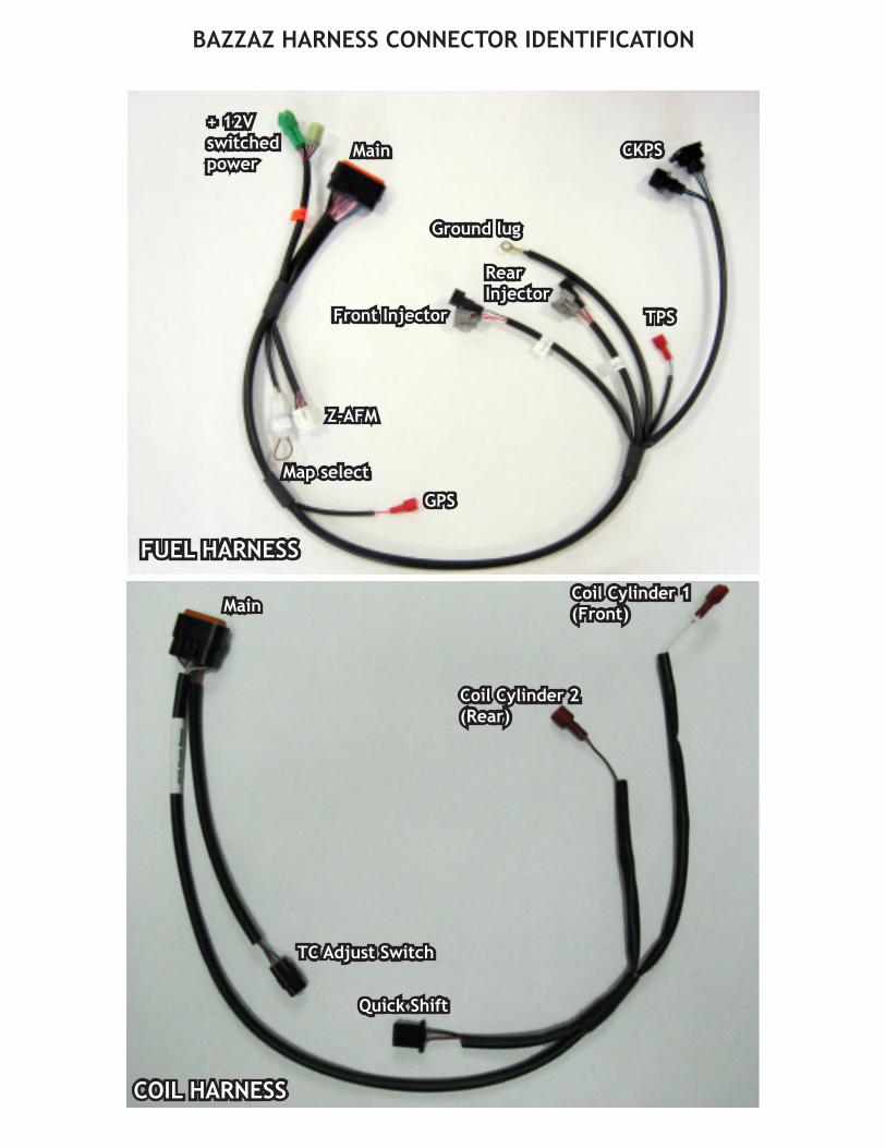
BAZZAZ HARNESS CONNECTOR IDENTIFICATION
Main
FUEL HARNESS
GPS
Map select
CKPS
+ 12V switched power
TPS
Z-AFM
Ground lug
Rear Injector
Front Injector
COIL HARNESS
Main
Quick Shift
Coil Cylinder 1(Front)
Coil Cylinder 2(Rear)
TC Adjust Switch
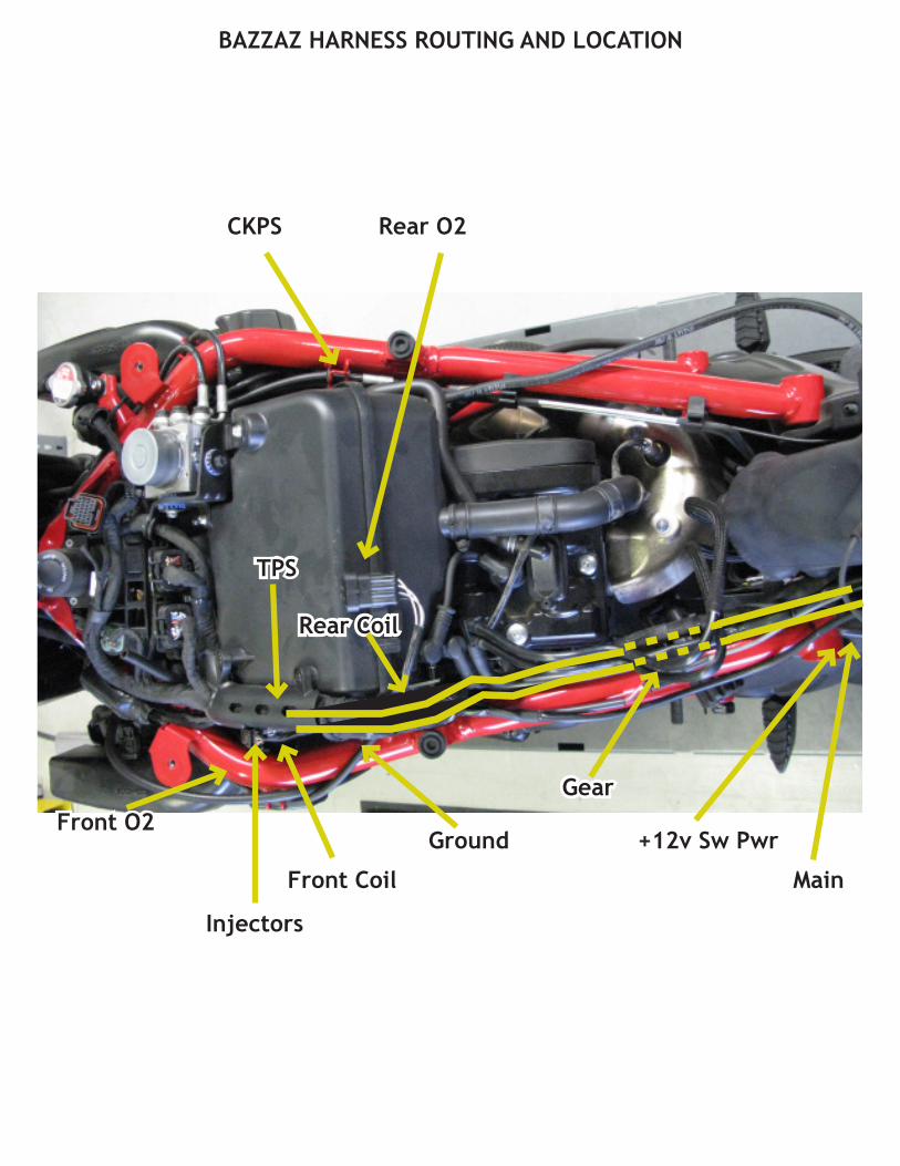
CKPS
Rear Coil
+12v Sw Pwr
Rear O2
Ground
Main
Gear
Injectors
TPS
Front Coil
Front O2
BAZZAZ HARNESS ROUTING AND LOCATION
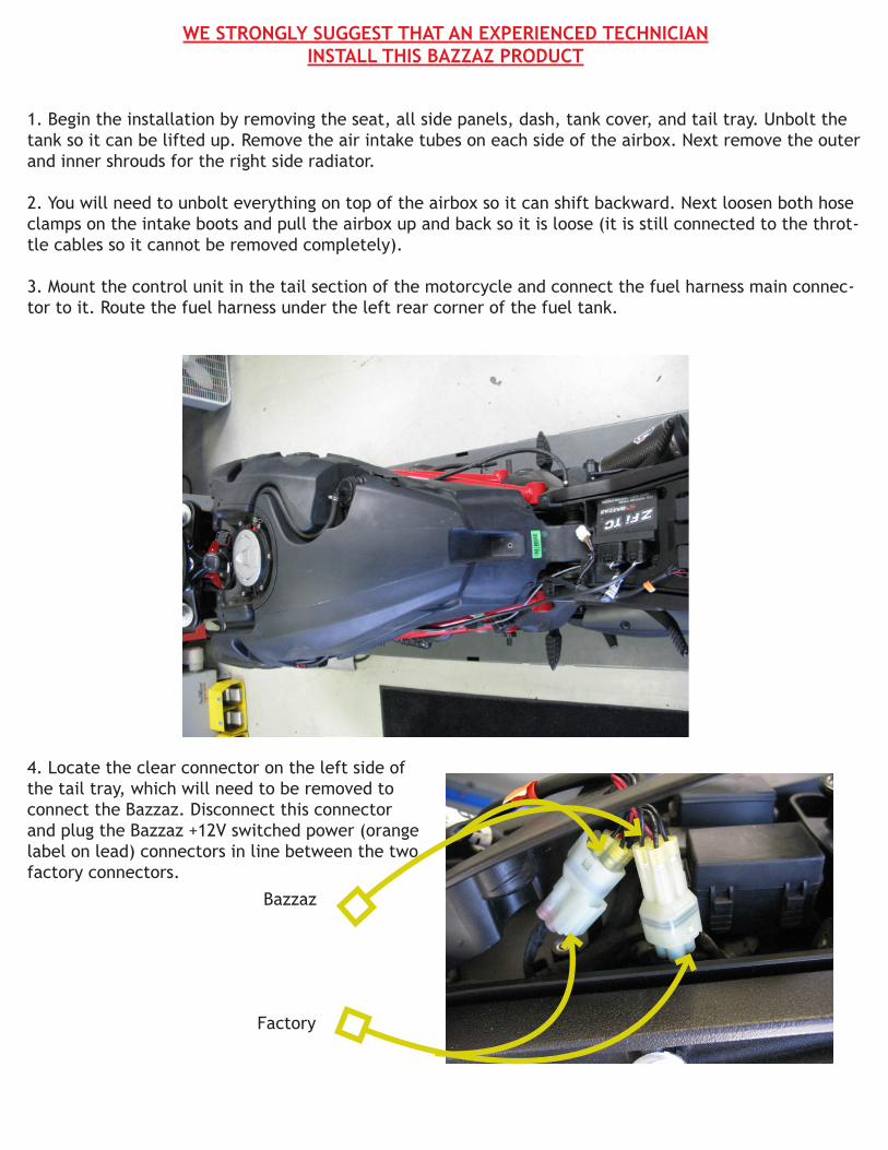
WE STRONGLY SUGGEST THAT AN EXPERIENCED TECHNICIANINSTALL THIS BAZZAZ PRODUCT
1. Begin the installation by removing the seat, all side panels, dash, tank cover, and tail tray. Unbolt the tank so it can be lifted up. Remove the air intake tubes on each side of the airbox. Next remove the outer and inner shrouds for the right side radiator.
2. You will need to unbolt everything on top of the airbox so it can shift backward. Next loosen both hose clamps on the intake boots and pull the airbox up and back so it is loose (it is still connected to the throt-tle cables so it cannot be removed completely).
3. Mount the control unit in the tail section of the motorcycle and connect the fuel harness main connec-tor to it. Route the fuel harness under the left rear corner of the fuel tank.
4. Locate the clear connector on the left side of the tail tray, which will need to be removed to connect the Bazzaz. Disconnect this connector and plug the Bazzaz +12V switched power (orange label on lead) connectors in line between the two factory connectors.
Bazzaz
Factory
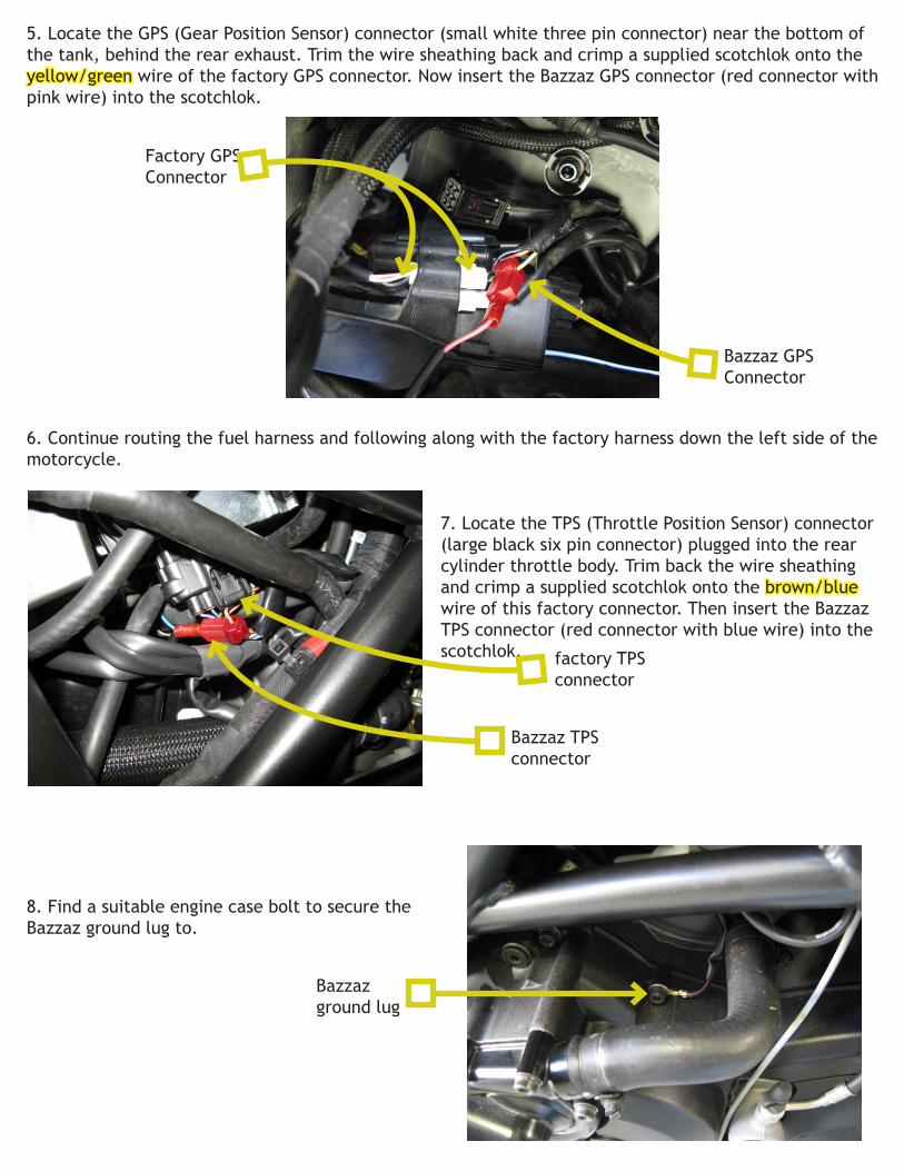
5. Locate the GPS (Gear Position Sensor) connector (small white three pin connector) near the bottom of the tank, behind the rear exhaust. Trim the wire sheathing back and crimp a supplied scotchlok onto the yellow/green wire of the factory GPS connector. Now insert the Bazzaz GPS connector (red connector with pink wire) into the scotchlok.
6. Continue routing the fuel harness and following along with the factory harness down the left side of the motorcycle.
7. Locate the TPS (Throttle Position Sensor) connector (large black six pin connector) plugged into the rear cylinder throttle body. Trim back the wire sheathing and crimp a supplied scotchlok onto the brown/blue wire of this factory connector. Then insert the Bazzaz TPS connector (red connector with blue wire) into the scotchlok.
8. Find a suitable engine case bolt to secure the Bazzaz ground lug to.
Factory GPS Connector
Bazzaz GPSConnector
factory TPSconnector
Bazzaz TPSconnector
Bazzaz ground lug

9. The remainder of the fuel harness now gets routed between the two cylinders, under the airbox.
10. Locate the factory CKPS (Crank Position Sensor) connector, on the right side of the bike under the rear of the airbox, and disconnect. Pull the Bazzaz CKPS connector through from the other side and connect the Bazzaz connectors in line between the factory connectors.
11. Now locate the factory injector & connectors on the inside of each throttle body; disconnect each of the factory connectors and plug the corresponding Bazzaz connectors (labeled “front” and “rear”) inline between the factory connector and injector.
12. The Diavel is equipped with two O2 sensors. These sensors must be bypassed through the use of O2 eliminators supplied with the kit. Disconnect the factory sensor connectors from each sensor. Install the Bazzaz O2 eliminators in place of the factory sensor connectors and attach the O2 eliminator ground lugs to a chassis ground. Be sure to secure the Bazzaz eliminators and factory sensor connectors away from any hot or moving components which could cause damage to the components.
Note: The rear sensor is located on the rear of the airbox next to the rear coil connector, and the front sensor is located down in the chin fairing, in front of the battery (this one will need to be grounded to the negative terminal of the battery).
Front
factory CKPSconnectors
Bazzaz CKPSconnectors
Bazzaz front injector connectors
factoryfront injectorconnector

13. Now connect the coil harness main connector to the Bazzaz control unit. Route the coil harness along with the Bazzaz fuel harness and then to the factory rear coil connectors on the rear of the airbox. Once removed, use the supplied scothchlok and crimp onto the factroy grey/green wire and connect the Bazzaz rear coil connector. Reinstall the factory ignition coil.
14. Route the front coil connector down the left hand side of the bike towards the factory TPS. Locate the factory coil connector. Disconnect the factory coil connector, and use the supplied scotchlok to crimp onto the factory grey/blue wire and connect the Bazzaz front coil connector. Reconnect the factory coil connector.
Bazzaz O2eliminator
factory O2 sensor connector unplugged
factory O2 sensor
factory O2 sensor
Bazzaz O2eliminator
factory O2 sensor connector unplugged
Rear Coil
Front Coil
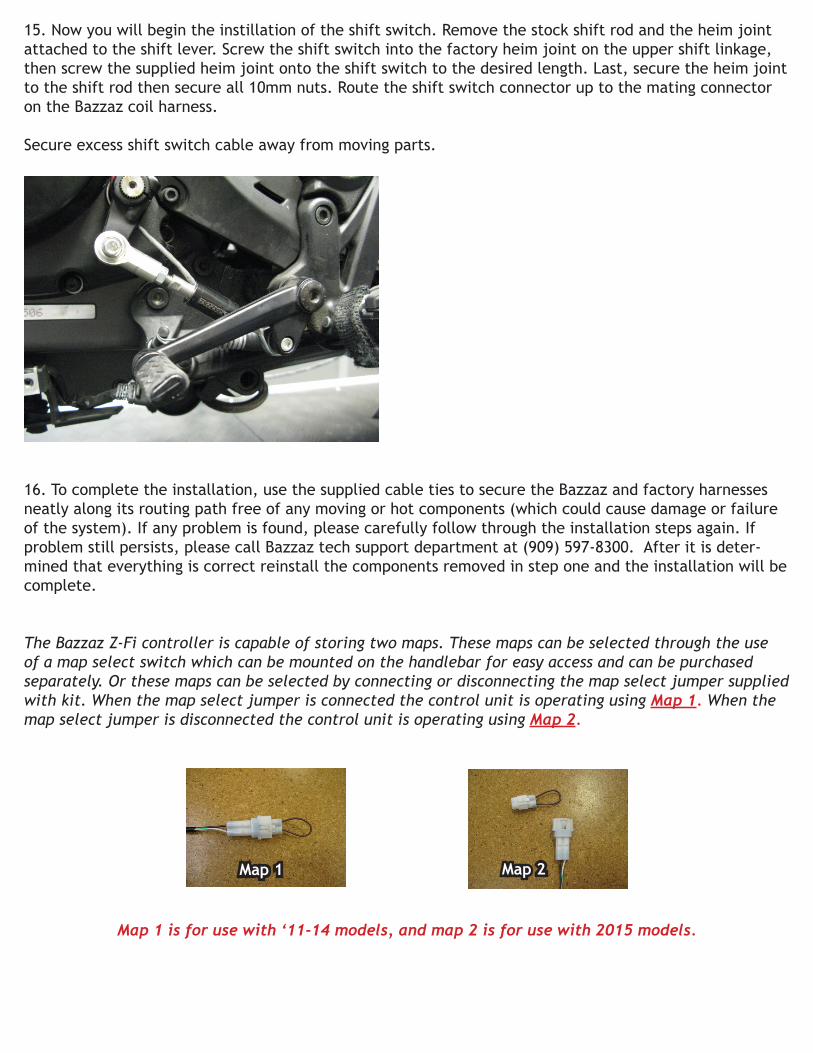
15. Now you will begin the instillation of the shift switch. Remove the stock shift rod and the heim joint attached to the shift lever. Screw the shift switch into the factory heim joint on the upper shift linkage, then screw the supplied heim joint onto the shift switch to the desired length. Last, secure the heim joint to the shift rod then secure all 10mm nuts. Route the shift switch connector up to the mating connector on the Bazzaz coil harness.
Secure excess shift switch cable away from moving parts.
16. To complete the installation, use the supplied cable ties to secure the Bazzaz and factory harnesses neatly along its routing path free of any moving or hot components (which could cause damage or failure of the system). If any problem is found, please carefully follow through the installation steps again. If problem still persists, please call Bazzaz tech support department at (909) 597-8300. After it is deter-mined that everything is correct reinstall the components removed in step one and the installation will be complete.
The Bazzaz Z-Fi controller is capable of storing two maps. These maps can be selected through the use of a map select switch which can be mounted on the handlebar for easy access and can be purchased separately. Or these maps can be selected by connecting or disconnecting the map select jumper supplied with kit. When the map select jumper is connected the control unit is operating using Map 1. When the map select jumper is disconnected the control unit is operating using Map 2.
Map 1 is for use with ‘11-14 models, and map 2 is for use with 2015 models.
Map 1 Map 2