Solitaire-International-Magazine-apr.pdf - Gem & Jewellery ...
Upload
khangminh22Category
view
3download
0
2013GEM e2 • GEM e4 • GEM e6® • GEM eS • GEM eL • GEM eLXD
SERVICE MANUAL
FOREWORD
The information printed within this publication includes the latest product information at time of print. The most recentversion of this Service Manual is available in electronic format at www.polarisdealers.com.
This Service Manual is designed primarily for use by certified GEM service technicians in a properly equipped shop andshould be kept available for reference. All references to left and right side of the vehicle are from the operator'sperspective when seated in a normal riding position.
Some procedures outlined in this manual require a sound knowledge of mechanical theory, tool use, and shopprocedures in order to perform the work safely and correctly. Technicians should read the text and be familiar with theservice procedures before starting any repair. Certain procedures require the use of special tools. Use only the propertools as specified. If you have any doubt as to your ability to perform any of the procedures outlined in this ServiceManual, contact an authorized dealer for service.
We value your input and appreciate any assistance you can provide in helping make these publications more useful.Please provide any feedback you may have regarding this manual. Authorized dealers can submit feedback using 'AskPolaris'. Click on 'Ask Polaris', and then click on 'Service Manual/Service Literature Question'.
Consumers, please provide your feedback in writing to: Polaris Industries Inc. ATTN: Service Publications Department,2100 Hwy 55, Medina, MN 55340.
Publication Printed August 2012 (PN 9924112)
© Copyright 2012 Polaris Sales Inc. All information contained within this publication is based on the latest product information at the time of publication. Due to constantimprovements in the design and quality of production components, some minor discrepancies may result between the actual vehicle and the information presented in thispublication. Depictions and/or procedures in this publication are intended for reference use only. No liability can be accepted for omissions or inaccuracies. Any reprintingor reuse of the depictions and/or procedures contained within, whether whole or in part, is expressly prohibited. Printed in U.S.A.

UNDERSTANDING MANUAL SAFETY LABELS AND DIRECTIONS
Throughout this manual, important information is brought to your attention by the following symbols:
SAFETY ALERT WARNING indicates a potential hazard that may result in severe injury or death to the operator,bystander or person(s) inspecting or servicing the vehicle.
SAFETY ALERT CAUTION indicates a potential hazard that may result in minor personal injury or damage to the vehicle.
NOTE:
NOTE provides key information by clarifying instructions.
IMPORTANT:
IMPORTANT provides key reminders during disassembly, assembly and inspection of components.
TRADEMARKS
All brand names and product names used in this guide are trademarks, registered trademarks or trade names of theirrespective holders.
Polaris Sales Inc. acknowledges the following products mentioned in this manual:
Loctite, Registered Trademark of the Henkel Corporation
Torx, Registered Trademark of Textron
Velcro, Registered Trademark of Velcro Industries, B.V.
Optimol Olistamoly, Trademark of Castrol Limited
WARNING
CAUTION

1INTRODUCTION
2SUSPENSION AND STEERING
3DRIVETRAIN
4BRAKES
5ELECTRICAL
6WHEELS AND TIRES
7BODY


Introduction
CHAPTER 1
Introduction1
VEHICLE IDENTIFICATION . . . . . . . . . . . . . . . . . . . . . . . . . . . . . . . . . . . . . . . . . . . . . . . 1.2MODEL NUMBER DESIGNATION . . . . . . . . . . . . . . . . . . . . . . . . . . . . . . . . . . . . . . . . . 1.2VEHICLE IDENTIFICATION NUMBER (VIN) DESIGNATION . . . . . . . . . . . . . . . . . . . . 1.2VEHICLE IDENTIFICATION NUMBER AND SAFETY CERTIFICATION . . . . . . . . . . . . 1.3
GENERAL INFORMATION . . . . . . . . . . . . . . . . . . . . . . . . . . . . . . . . . . . . . . . . . . . . . . . . 1.3INTRODUCTION . . . . . . . . . . . . . . . . . . . . . . . . . . . . . . . . . . . . . . . . . . . . . . . . . . . . . . . 1.3GENERAL WARNINGS. . . . . . . . . . . . . . . . . . . . . . . . . . . . . . . . . . . . . . . . . . . . . . . . . . 1.3
FASTENER USAGE. . . . . . . . . . . . . . . . . . . . . . . . . . . . . . . . . . . . . . . . . . . . . . . . . . . . . . 1.4DESCRIPTION . . . . . . . . . . . . . . . . . . . . . . . . . . . . . . . . . . . . . . . . . . . . . . . . . . . . . . . . 1.4
PARTS AND LUBRICANT . . . . . . . . . . . . . . . . . . . . . . . . . . . . . . . . . . . . . . . . . . . . . . . . . 1.4RECOMMENDATION . . . . . . . . . . . . . . . . . . . . . . . . . . . . . . . . . . . . . . . . . . . . . . . . . . . 1.4LUBRICANTS AND GREASE . . . . . . . . . . . . . . . . . . . . . . . . . . . . . . . . . . . . . . . . . . . . . 1.4DIFFERENTIAL . . . . . . . . . . . . . . . . . . . . . . . . . . . . . . . . . . . . . . . . . . . . . . . . . . . . . . . . 1.4BRAKE FLUID . . . . . . . . . . . . . . . . . . . . . . . . . . . . . . . . . . . . . . . . . . . . . . . . . . . . . . . . . 1.4
MAINTENANCE . . . . . . . . . . . . . . . . . . . . . . . . . . . . . . . . . . . . . . . . . . . . . . . . . . . . . . . . . 1.5MAINTENANCE SCHEDULE . . . . . . . . . . . . . . . . . . . . . . . . . . . . . . . . . . . . . . . . . . . . . 1.5HOISTING AND JACKING . . . . . . . . . . . . . . . . . . . . . . . . . . . . . . . . . . . . . . . . . . . . . . . 1.5
1.19924112 - 2013 GEM Service Manual
© 2012 Polaris Sales Inc.

Introduction
VEHICLE IDENTIFICATION
MODEL NUMBER DESIGNATION
Example: L13G2AGALA
VEHICLE IDENTIFICATION NUMBER (VIN) DESIGNATION
Example: 52CG2AGA0D3000000
GROUPMODEL YEAR
MODELBODY TYPE (SEATING)
BODY TYPE (CARGO)
ENGINE TYPE REGION OPTION
1st digit 2/3rd digit 4th digit* 5th digit* 6th digit* 7th/8th digit* 9th digit** 10th digit
L = LEV 13 G = GEM2 = Two Pass.4 = Four Pass.
A = StandardD = Heavy Duty Long BedL = Long BedS = Short Bed
GA = DC Electric, 72 Volt
L = North AmericaE = Europe
A
* = digits that would transfer to 17 digit VIN and are used in digits 4-8 respectively** = 9th digit will be used on color/featured versions of models (not including the base)First 3 digits and 9th digit are used in model number only. They are not used with the 17 digit VIN.
World Mfg. ID
Vehicle Descriptors Vehicle Identifiers
Mo
del
Bod
y Ty
pe (
Sea
ting)
Bod
y Ty
pe (
Car
go)
Eng
ine
Type
Che
ck D
igit
Mo
del Y
ear
*
Mfg
. Loc
atio
n
Individual Serial No.
1 2 3 4 5 6 7 8 9 10 11 12 13 14 15 16 17
5 2 C G 2 A G A 0 D 3 0 0 0 0 0 0
* Model Year: A = 2010; B = 2011; C = 2012; D = 2013
1.2 9924112 - 2013 GEM Service Manual© 2012 Polaris Sales Inc.

Introduction
1
VEHICLE IDENTIFICATION NUMBER AND SAFETY CERTIFICATIONA manufacturer’s label, containing the VehicleIdentification Number (VIN) and safety certification, islocated above the bench seat on underside of the rear roofpanel on the driver side. The VIN is also located on thelower-left driver side windshield and under passenger sidebench seat.
The information on the label includes:
• Vehicle Identification Number (VIN)
• Month and year of manufacture
• Gross Vehicle Weight Rating (GVWR)
• Gross Front and Rear Axle Ratings (GAWR)
• Wheel size
• Tire size
• Cold tire pressure
GENERAL INFORMATION
INTRODUCTION
Appropriate service methods and proper repairprocedures are essential for the safe, reliable operation ofyour vehicles, as well as the safety of the individual doingthe work. This service manual provides general directionsfor accomplishing service and repair work withrecommended techniques. Following them will helpensure reliability.
There are numerous variations in procedures, techniques,tools, and parts for servicing your vehicle, as well as in theskill levels of the individuals doing the work. This manualcannot possibly anticipate all such variations and provideadvice or cautions for each. Accordingly, anyone whodeparts from the instructions provided in this manual mustfirst establish that he/she compromises neither theirpersonal safety nor vehicle integrity by their choice ofmethods, tools, or parts.
GENERAL WARNINGS
Observe the following safety precautions whenever youare working on your vehicle:
NOTE: The terms right-hand (RH) and left-hand (LH)are relative to one sitting in the driver's seat.Therefore, right-hand refers to the passenger side,and left-hand refers to the driver's side of thevehicle.
WARNING
• Always wear safety glasses for eye protection.
• Use safety stands whenever a procedure requires you to be under the vehicle.
• Ensure the key switch is always in the OFF position and that the key is removed.
• Ensure to switch the 72-volt master disconnect to OFF.
• Set the parking brake and place wood blocks (4" x 4" or larger) to the front and rear surfaces of the
tires to restrain the vehicle from movement.
• Do not smoke while working on your vehicle.
• Batteries produce hydrogen gas that is extremely flammable and will explode upon exposure to any
ignition source.
• Remove rings, watches, loose jewelry, and loose clothing when working on your vehicle to avoid
injury.
1.39924112 - 2013 GEM Service Manual
© 2012 Polaris Sales Inc.

Introduction
FASTENER USAGE
DESCRIPTION
Fasteners and torque specifications references in thisService Manual are identified SAE format.
During any maintenance or repair procedure, it isimportant to salvage all fasteners (nuts, bolts, etc.) forreassembly. If the fastener is not salvageable, a fastenerof equivalent specification must be used.
NOTE: Nylon lock nuts must be replaced if removed.
PARTS AND LUBRICANT
RECOMMENDATION
When service is required, GEM recommends that onlyGEM replacement parts be used. GEM provides the best-engineered products for servicing GEM vehicles.
LUBRICANTS AND GREASE
Only lubricants bearing designations defined by TheSociety for Automotive Engineers (SAE) should be used toservice a GEM vehicle.
The National Lubricating Grease Institute (NLGI) rateslubricating grease for quality and usage. All approvedproducts have the NLGI symbol (shown below) on thelabel. At the bottom of the symbol is the usage and qualityidentification letters. The letter “G” identifies wheel-bearing lubricant. The letter “L” identifies chassislubricant. The letter following the usage letter indicates thequality of the lubricant. The following symbols indicate thehighest quality.
A. Wheel bearing lubrication
B. Chassis lubrication
C. Chassis and wheel bearing lubrication
DIFFERENTIAL
Use Full Synthetic AGL Plus (PN 2878068 - 1 Quart).
BRAKE FLUID
Use only DOT 4 brake fluid from an unopened containerwhen filling the master cylinder to prevent contaminantsfrom entering the brake system.
CAUTION
Use of an incorrect fastener may result in component damage or personal injury.
A B C
1.4 9924112 - 2013 GEM Service Manual© 2012 Polaris Sales Inc.

Introduction
1
MAINTENANCEMAINTENANCE SCHEDULE
Perform the following inspections and corrections asnecessary, on a monthly basis.
HOISTING AND JACKING
A vehicle can be lifted with:
• A single-post frame-contact hoist
• A twin-post, chassis hoist
• A ramp-type drive-on hoist
NOTE: When a frame-contact type hoist is used,verify that the lifting pads are positioned properly.
Item Description
1Check all six batteries for proper water levels (if applicable)
2Check battery terminals for tight connections
3 Check battery terminals for corrosion
4 Check tires for correct psi and wear
5 Check for proper operation of hand brake
6Check master cylinder for proper brake fluid levels
7 Check brake lines for leaks
8 Check seat belts for proper operation
9Check headlights, horn, turn signals, windshield wiper and brake lights for proper operation
10Check battery hold-downs to ensure batteries are tightly secured
11 Check for worn insulation and frayed wires
WARNING
Serious injury may result if machine tips or falls. Be sure machine is secure before hoisting or jacking.
WARNING
The hoisting and jack lifting points provided are for a complete vehicle. when a chassis or drivetrain
component is removed from a vehicle, the center of gravity is altered making some hoisting conditions unstable. properly support or secure vehicle to
hoisting device when these conditions exist.
CAUTION
Do not attempt to lift a vehicle with a floor jack positioned under an axle tube, body side panel or sill,
or front control arm. When properly positioned, a floor jack can be used to lift a GEM vehicle. Support the vehicle in the raised position with jack stands at
the locations indicated.
1.59924112 - 2013 GEM Service Manual
© 2012 Polaris Sales Inc.

Introduction
NOTES
1.69924112 - 2013 GEM Service Manual
© 2012 Polaris Sales Inc.

Suspension and Steering
CHAPTER 2
Suspension and Steering
2
WHEEL ALIGNMENT. . . . . . . . . . . . . . . . . . . . . . . . . . . . . . . . . . . . . . . . . . . . . . . . . . . . . 2.2INSPECTION - ALIGNMENT. . . . . . . . . . . . . . . . . . . . . . . . . . . . . . . . . . . . . . . . . . . . . . 2.2TOE-IN / TOE-OUT . . . . . . . . . . . . . . . . . . . . . . . . . . . . . . . . . . . . . . . . . . . . . . . . . . . . . 2.2
FRONT SUSPENSION . . . . . . . . . . . . . . . . . . . . . . . . . . . . . . . . . . . . . . . . . . . . . . . . . . . 2.3REAR SUSPENSION. . . . . . . . . . . . . . . . . . . . . . . . . . . . . . . . . . . . . . . . . . . . . . . . . . . . . 2.4SHOCK ASSEMBLY . . . . . . . . . . . . . . . . . . . . . . . . . . . . . . . . . . . . . . . . . . . . . . . . . . . . . 2.6
DESCRIPTION . . . . . . . . . . . . . . . . . . . . . . . . . . . . . . . . . . . . . . . . . . . . . . . . . . . . . . . . 2.6OPERATION . . . . . . . . . . . . . . . . . . . . . . . . . . . . . . . . . . . . . . . . . . . . . . . . . . . . . . . . . . 2.6DIAGNOSIS AND TESTING . . . . . . . . . . . . . . . . . . . . . . . . . . . . . . . . . . . . . . . . . . . . . . 2.6REMOVAL - FRONT SHOCK . . . . . . . . . . . . . . . . . . . . . . . . . . . . . . . . . . . . . . . . . . . . . 2.6INSPECTION - FRONT SHOCK . . . . . . . . . . . . . . . . . . . . . . . . . . . . . . . . . . . . . . . . . . . 2.6INSTALLATION - FRONT SHOCK . . . . . . . . . . . . . . . . . . . . . . . . . . . . . . . . . . . . . . . . . 2.6REMOVAL - REAR SHOCK . . . . . . . . . . . . . . . . . . . . . . . . . . . . . . . . . . . . . . . . . . . . . . 2.7INSPECTION - REAR SHOCK . . . . . . . . . . . . . . . . . . . . . . . . . . . . . . . . . . . . . . . . . . . . 2.7INSTALLATION - REAR SHOCK . . . . . . . . . . . . . . . . . . . . . . . . . . . . . . . . . . . . . . . . . . 2.7
CONTROL ARM ASSEMBLY . . . . . . . . . . . . . . . . . . . . . . . . . . . . . . . . . . . . . . . . . . . . . . 2.8BUSHING . . . . . . . . . . . . . . . . . . . . . . . . . . . . . . . . . . . . . . . . . . . . . . . . . . . . . . . . . . . . . 2.10BALL JOINT . . . . . . . . . . . . . . . . . . . . . . . . . . . . . . . . . . . . . . . . . . . . . . . . . . . . . . . . . . . 2.10REAR HUB AND BEARING / SPINDLE (E6, E6S, ELXD). . . . . . . . . . . . . . . . . . . . . . . . 2.13REAR HUB AND BEARING / SPINDLE (E2, E4, ES, EL) . . . . . . . . . . . . . . . . . . . . . . . . 2.14STEERING WHEEL . . . . . . . . . . . . . . . . . . . . . . . . . . . . . . . . . . . . . . . . . . . . . . . . . . . . . 2.15STEERING COLUMN ASSEMBLY . . . . . . . . . . . . . . . . . . . . . . . . . . . . . . . . . . . . . . . . . 2.16LOCKING STEERING COLUMN . . . . . . . . . . . . . . . . . . . . . . . . . . . . . . . . . . . . . . . . . . . 2.17STEERING WHEEL TILT. . . . . . . . . . . . . . . . . . . . . . . . . . . . . . . . . . . . . . . . . . . . . . . . . 2.17STEERING GEAR . . . . . . . . . . . . . . . . . . . . . . . . . . . . . . . . . . . . . . . . . . . . . . . . . . . . . . 2.18
DESCRIPTION . . . . . . . . . . . . . . . . . . . . . . . . . . . . . . . . . . . . . . . . . . . . . . . . . . . . . . . 2.18OPERATION . . . . . . . . . . . . . . . . . . . . . . . . . . . . . . . . . . . . . . . . . . . . . . . . . . . . . . . . . 2.18DIAGNOSIS AND TESTING . . . . . . . . . . . . . . . . . . . . . . . . . . . . . . . . . . . . . . . . . . . . . 2.18STEERING GEAR REMOVAL. . . . . . . . . . . . . . . . . . . . . . . . . . . . . . . . . . . . . . . . . . . . 2.18STEERING GEAR INSTALLATION. . . . . . . . . . . . . . . . . . . . . . . . . . . . . . . . . . . . . . . . 2.18
STEERING KNUCKLE . . . . . . . . . . . . . . . . . . . . . . . . . . . . . . . . . . . . . . . . . . . . . . . . . . . 2.19DESCRIPTION . . . . . . . . . . . . . . . . . . . . . . . . . . . . . . . . . . . . . . . . . . . . . . . . . . . . . . . 2.19OPERATION . . . . . . . . . . . . . . . . . . . . . . . . . . . . . . . . . . . . . . . . . . . . . . . . . . . . . . . . . 2.19STEERING KNUCKLE REMOVAL . . . . . . . . . . . . . . . . . . . . . . . . . . . . . . . . . . . . . . . . 2.19STEERING KNUCKLE INSTALLATION . . . . . . . . . . . . . . . . . . . . . . . . . . . . . . . . . . . . 2.19
OUTER TIE ROD END. . . . . . . . . . . . . . . . . . . . . . . . . . . . . . . . . . . . . . . . . . . . . . . . . . . 2.20BEARING AND RETAINING RING . . . . . . . . . . . . . . . . . . . . . . . . . . . . . . . . . . . . . . . . . 2.20TROUBLESHOOTING . . . . . . . . . . . . . . . . . . . . . . . . . . . . . . . . . . . . . . . . . . . . . . . . . . . 2.21
2.19924112 - 2013 GEM Service Manual
© 2012 Polaris Sales Inc.

Suspension and Steering
WHEEL ALIGNMENT
INSPECTION - ALIGNMENT
Front wheel alignment is essential for proper vehiclehandling and passenger safety. Front-end damage orreplacement of any steering or front suspensioncomponent will require inspection of the alignment todetermine if it is still within specifications.
TOE-IN / TOE-OUT
Toe is the only available adjustment in the front wheelalignment. Toe is the difference between the leadinginside edges and trailing inside edges of the front tires. Itshould be measured at a point above the ground equal toone-half the overall diameter of the wheel/tire assembly.The specification is + 1/16-inch toe-in.
Wheel toe position out of specification causes unstablesteering, uneven tire wear and steering wheel off-center.
MEASURING FRONT TOE
1. Park vehicle on level, flat surface.2. Center front wheels.
3. Roll car forward 6-8 feet and apply brake lever.
4. Measure distance from center tread at rear of rightfront tire to center tread at rear of left front tire.
5. Measure distance from center tread at front of rightfront tire to the center tread at the front of the left fronttire.
6. Subtract front measurement from rear measurement.
NOTE: If front measurement is less than rear,vehicle has toe-in, and is shown with a plus sign (+1/16 inch). If front measurement is greater than rear,vehicle has toe-out, and difference is shown with aminus sign (-1/16 inch).
ADJUSTING FRONT TOE
1. Center front wheels.
2. Inspect position of pinch bolt (A) joining steeringcolumn shaft (B) to steering gear (C). Ensure bolt (A)is horizontal and under shaft. If necessary, turnsteering wheel to position bolt. Remove and re-centersteering wheel if required. See Steering Wheel in thissection.
3. Lash steering wheel in centered position.
4. Loosen both jam nuts (D) on both tie rods (E).
5. Rotate tie rods (E) so front wheels have specified toe-in.
6. Tighten both jam nuts (D).
C
A
B
D E
2.2 9924112 - 2013 GEM Service Manual© 2012 Polaris Sales Inc.

Suspension and Steering
2
MEASURING REAR TOE
1. Park vehicle on level, flat surface.
2. Center front wheels forward.
3. Roll car forwards 6-8 feet and apply parking brakelever.
4. Measure distance from center tread at rear of rightrear tire to center tread at rear of left rear tire.
5. Measure distance from center tread at front of rightrear tire to center tread at front of left rear tire.
6. Subtract front measurement from rear measurement.
NOTE: If front measurement is less than rear,vehicle has toe-in, and is shown as a plus (+) sign(positive). If front measurement is greater than rear,vehicle has toe-out, and difference is shown as aminus (-) sign (negative).
7. Ensure rear tire/wheel toe measurement is set to 0.
ADJUSTING REAR TOE
There is no adjustment of the rear axle for toe alignmentand camber related issues. In the case of a rear axle outof specification, the axle may need to be replaced. Inspectbushing wear in shock assembly and trailing arms. Followtorque specs. See Rear Axle Removal and Installation in
this section.
FRONT SUSPENSION
A. Front suspension frame
B. Spring / shock absorber
C. Upper control arm
D. Knuckle
E. Lower control arm
DESCRIPTION
The front suspension is designed to allow each wheel toadapt to different road surfaces independently. Thewheels are mounted to rotor assemblies, which in turn aremounted to the steering components attached to controlarms that pivot up and down on bushings. Spring andshock absorber assemblies provide cushioning.
NOTE: Suspension components with rubber/urethane bushings should be tightened with thevehicle at normal ride height. It is important to havethe springs supporting the weight of the vehiclewhen the fasteners are tightened. This will maintainvehicle ride comfort and prevent premature bushingwear.
OPERATION
The front suspension frame provides a platform for thefront shocks, and acts as an axle for the front wheels andbrakes.
A
B
C
E D
2.39924112 - 2013 GEM Service Manual
© 2012 Polaris Sales Inc.

Suspension and Steering
REAR SUSPENSION
A. Rear suspension frame / axle
B. Spring / shock absorber
C. Upper trailing arms
D. Lower trailing arms
DESCRIPTION
The rear suspension is comprised of the rear axle, spring/shock absorbers, and trailing arms.
OPERATION
The rear suspension travels up and down, pivoting onbushings at the front and rear of each trailing arm. Reardrum brakes and wheels are mounted on flanges at eachend of the rear axle. Spring/shock absorber units controlthe movement, thereby maintaining contact of the tires onthe road.
NOTE: Suspension components with rubber/urethane bushings should be tightened with thevehicle at normal ride height. It is important to havethe springs supporting the weight of the vehiclewhen the fasteners are torqued. This will maintainvehicle ride comfort and prevent premature bushingwear.
REAR SUSPENSION FRAME / AXLE REMOVAL (e2, e4, eS, eL MODELS)
1. Remove rear tire and wheel assemblies. See Wheeland Tires section.
2. Remove rear drum brake assemblies. See Brakessection.
3. (Vehicles with spat only) Remove spat bracket. SeeBody section.
4. Ensure rear suspension frame/axle is properlysupported.
5. Remove three bolts securing brake lines to rearsuspension frame/axle.
6. Remove two lower mounting bolts, two flat washers(nut side), and two nuts from spring/shock absorbers.
7. Remove four bolts, four flat washers (nut side), andfour nuts from two upper and two lower trailing arms.
8. Remove rear suspension frame/axle.
REAR SUSPENSION FRAME / AXLE INSPECTION (e2, e4, eS, eL MODELS)
Inspect rear suspension frame/axle for damage and/orworn bushings. Bushings are not serviceable. Replace thebushings if worn or damaged, or replace each individualtrailing arm as needed.
REAR SUSPENSION FRAME / AXLE INSTALLATION (e2, e4, eS, eL MODELS)
1. Install rear suspension frame/axle onto vehicle rearframe.
2. Install four nuts, four flat washers (nut side), and fourbolts, into two upper and two lower trailing arms.
3. Install two nuts, two flat washers (nut side), and twolower mounting bolts into spring/shock absorbers.
4. Install three bolts to secure brake lines to rearsuspension frame/axle.
5. (Vehicles with spat only) Install the spat bracket. SeeBody section.
6. Install rear drum brake assemblies. See Brakessection.
7. Install rear tire and wheel assemblies. See Wheel andTires section.
B
A DC
2.4 9924112 - 2013 GEM Service Manual© 2012 Polaris Sales Inc.

Suspension and Steering
2
8. Torque two spring/shock absorber mounting bolts tospecification.
9. Torque two upper and two lower trailing arm bolts tospecification.
REAR SUSPENSION FRAME / AXLE REMOVAL (e6, e6S, eLXD MODELS)
1. Remove both rear tire and wheel assemblies. SeeWheel and Tires section.
2. Remove rear drum brake assemblies. See Brakessection.
3. (Vehicles with Spat). Remove spat bracket.
4. Ensure rear suspension frame/axle is properlysupported.
5. Remove three bolts securing brake lines to rearsuspension frame/axle.
6. Remove rear hub and bearing.
7. Remove rear spindles.
NOTE: Support the backing plate assemblies toprotect the brake lines and parking brake cables.
8. Remove two lower mounting bolts, two flat washers(nut side), and two nuts from spring/shock absorbers.
9. Remove four bolts, four flat washers (nut side), andfour nuts from trailing arms.
10. Remove rear suspension frame/axle.
REAR SUSPENSION FRAME / AXLE INSPECTION (e6, e6S, eLXD MODELS)
Inspect rear suspension frame/axle assembly for damageand/or worn bushings. Bushings are not serviceable.Replace the bushings if worn or damaged, or replace eachindividual trailing arm as needed.
REAR SUSPENSION FRAME / AXLE INSTALLATION (e6, e6S, eLXD MODELS)
1. Install rear suspension frame/axle.
2. Install four nuts, four flat washers (nut side), and fourbolts, into trailing arms.
3. Install two nuts, two flat washers (nut side), and twolower spring/shock bolts.
4. Install rear spindles and position backing plateassemblies. Apply thread sealer to bolts and torque tospecification.
5. Install hub and bearing. Torque to specification.
6. Install three bolts securing brake lines to axle.
7. (Vehicles with Spat). Install spat bracket. See Bodysection.
8. Install rear drum brake assemblies. See Brakessection.
9. Install tire and wheel assembly. See Wheel and Tiressection.
10. Torque two lower spring/shock absorber mountingbolts to specification.
11. Torque two upper and two lower trailing arm bolts tospecification.
= T
Lower Spring/Shock Absorber Mounting Bolts:60 ft-lbs (81 Nm)
= T
Upper and Lower Trailing Arms Bolts:60 ft-lbs (81 Nm)
= T
Lower Spring/Shock Absorber Mounting Bolts:60 ft-lbs (81 Nm)
= T
Upper and Lower Trailing Arms Bolts:60 ft-lbs (81 Nm)
2.59924112 - 2013 GEM Service Manual
© 2012 Polaris Sales Inc.

Suspension and Steering
SHOCK ASSEMBLY
DESCRIPTION
The GEM e-series vehicles combine a spring and shockabsorber into a single unit. They are used on both the frontand rear suspension. They are not serviceable, but mustbe replaced.
OPERATION
The shock absorbers dampen bounce and rebound of thevehicle over various road and terrain conditions.
DIAGNOSIS AND TESTING
Movement between mounting bushings, metal bracketsand attaching components may cause a knocking orrattling noise from a shock absorber/spring unit.Tightening the attaching nuts can usually stop thesenoises. If the noise persists, inspect for damaged andworn bushings and/or attaching components. Replace ifany of these conditions exist.
A squeaking noise from the shock absorber may becaused by the hydraulic valving and may be intermittent.This condition is not repairable and the shock absorbermust be replaced.
The shock absorbers are not refillable or adjustable. If amalfunction or leak occurs, the shock absorber/spring unitmust be replaced.
To test a shock absorber, hold it in an upright position andforce the piston in and out of the cylinder four or five times.The action throughout each stroke should be smooth andeven.
IMPORTANT: The shock absorber bushings do notrequire any type of lubrication. Do not attempt to stopbushing noise by lubricating them. Grease andmineral oil-based lubricants will deteriorate thebushing.
REMOVAL - FRONT SHOCK
1. Raise and support vehicle on suitable hoist.2. Remove two nuts and two mounting bolts (A).
3. Remove front shock (B).
INSPECTION - FRONT SHOCK
Check bolts and nuts for signs of wear and replace ifnecessary.
INSTALLATION - FRONT SHOCK
1. Install front shock.
2. Install two mounting bolts and two nuts.
3. Lower vehicle to ground.
4. Torque two mounting bolts to specification.
= T
Front Spring/Shock Absorber Mounting Bolts:70 ft-lbs (95 Nm)
A
B
2.6 9924112 - 2013 GEM Service Manual© 2012 Polaris Sales Inc.

Suspension and Steering
2
REMOVAL - REAR SHOCK
1. Raise and support vehicle on suitable hoist.2. Remove two nuts, two flat washers, and two mounting
bolts.
3. Remove rear shock.
INSPECTION - REAR SHOCK
Check bolts and nuts for signs of wear and replace ifnecessary.
INSTALLATION - REAR SHOCK
1. Install rear shock.
2. Install two mounting bolts, two flat washers (nut side),and two nuts.
3. Torque two mounting bolts to specification.
4. Lower vehicle to floor.
= T
Rear Spring/Shock Absorber Mounting Bolts:60 ft-lbs (81 Nm)
2.79924112 - 2013 GEM Service Manual
© 2012 Polaris Sales Inc.

Suspension and Steering
CONTROL ARM ASSEMBLY
DESCRIPTION
The upper and lower control arms connect the frontsuspension to the front frame support assembly. They areconnected to the front frame support by bolts passingthrough bushings that allow the control arm to pivot.
NOTE: The bushings and ball joints are serviceable.The control arm, bushings and ball joint can bereplaced separately or as needed. See procedures inthis section.
OPERATION
The upper and lower control arms allow the frontsuspension to move vertically over various road andterrain conditions.
UPPER CONTROL ARM REMOVAL
1. Remove front tire and wheel assembly. See Wheeland Tires section.
2. Remove lower shock absorber mounting nut and bolt(A).
3. Remove brake line retaining fastener (B) from uppercontrol arm.
4. Remove two nuts, two flat washers (nut side), and twobolts (C) retaining control arm to frame.
5. Remove nut, flat washer (nut side) and ball joint pinchbolt (D).
6. Remove control arm from vehicle.
UPPER CONTROL ARM INSTALLATION
1. Install upper control arm, ball joint pinch bolt, flatwasher (nut side), and nut.
2. Install two bolts, two flat washers (nut side), and twonuts retaining control arm to frame.
3. Install shock absorber lower mounting nut and bolt.
4. Install front tire and wheel assembly. See Wheel andTires section.
5. Torque two control arm mounting bolts tospecification.
6. Torque shock absorber lower mounting bolt tospecification.
7. Torque ball joint pinch bolt to specification.
8. Check front-end alignment toe-in. See Front-EndAlignment Toe-In in this section.
A
C
B D
= T
Control Arm Mounting Bolts: 70 ft-lbs (95 Nm)Lower Shock Mounting Bolt: 70 ft-lbs (95 Nm)
Ball Joint Pinch Bolt: 45 ft-lbs (61 Nm)
2.8 9924112 - 2013 GEM Service Manual© 2012 Polaris Sales Inc.

Suspension and Steering
2
LOWER CONTROL ARM REMOVAL
1. Remove front tire and wheel assembly. See Wheeland Tires section.
2. Remove two nuts, two flat washers (nut side), and twobolts (A) retaining control arm to frame.
3. Remove nut, flat washer (nut side) and ball joint pinchbolt (B).
4. Remove lower control arm.
LOWER CONTROL ARM INSTALLATION
1. Install lower control arm, ball joint pinch bolt, flatwasher (nut side), and nut.
2. Install two bolts (E), two flat washers (nut side), andtwo nuts retaining control arm to frame.
3. Install front tire and wheel assembly. See Wheel andTires section.
4. Torque two control arm mounting bolts tospecification.
5. Torque ball joint pinch bolt to specification.
6. Check front-end alignment toe-in. See Front-EndAlignment Toe-In in this section.
A B
= T
Control Arm Mounting Bolts: 70 ft-lbs (95 Nm)Ball Joint Pinch Bolt: 45 ft-lbs (61 Nm)
2.99924112 - 2013 GEM Service Manual
© 2012 Polaris Sales Inc.

Suspension and Steering
BUSHING
DESCRIPTION
The bushing is a metal sleeve surrounded by a rubber orpolyurethane center and a metal collar around its exterior.It is typically fitted in to a machined hole or opening ofcontrol arm assembly.
OPERATION
A bushing is used to act as a pivot point and take onminimal wear at that joint. It is primarily used at mountinglocations of travel as a bolt pass-through.
MAINTENANCE
The bushing is non-lubricated. Do not attempt to stopbushing noise by applying lubrication. Grease and mineraloil-based lubricants will deteriorate the bushing.
BUSHING REMOVAL
1. Remove applicable control arm assembly. SeeControl Arm Assembly in this section.
2. Using hydraulic press, remove bushing.
BUSHING INSTALLATION
1. Insert new bushing.2. Install applicable control arm assembly. See Control
Arm Assembly in this section.
BALL JOINT
DESCRIPTION
The ball joint is a spherical bearing that connects thecontrol arm to the steering knuckle. More specifically, aball joint is a steel bearing stud and socket enclosed in asteel casing. The bearing stud is tapered.
OPERATION
The ball joint assembly fits into a tapered hole in thesteering knuckle. A protective encasing prevents dirt fromgetting into the joint assembly. Ball joints serve as the pivotpoints between the tires and suspension. Ball joints alsosupport weight.
MAINTENANCE
The GEM uses “lubricated for life” ball joints that can't belubricated. Ball joints, along with other suspensioncomponents, should be inspected annually along with acomplete wheel alignment. The most common vehiclesymptoms associated with worn ball joints are wandering,uneven tire wear, and erratic steering. Ball joint inspectionmethods and specifications vary, so have your vehicleinspected by a qualified service professional.
BALL JOINT SERVICE
IMPORTANT: Do not reuse a ball joint if it has beenremoved. If removed, it must be replaced. Use thisremoval procedure only when replacing the ball joint.
NOTE: Ball joint tool PU-50506 will allow the upperand lower ball joints to be replaced with the A-arminstalled on the vehicle.
A. Spacer
B. Removal Adaptor
C. Press Assembly
D. Installation Adaptor
C
B
D
A
2.10 9924112 - 2013 GEM Service Manual© 2012 Polaris Sales Inc.

Suspension and Steering
2
1. Remove front tire and wheel assembly. See Wheeland Tires section.
2. To service upper ball joint:
- Remove and discard two front brake calipermounting bolts and remove caliper from brake disc(see Brakes section).
- Remove and discard upper ball joint pinch bolt.
- If necessary, remove lower front shock fastener fromA-arm to gain enough clearance to install ball joint tool(PU-50506) on upper ball joint.
3. To service lower ball joint:
- Remove and discard lower ball joint pinch bolt.
- If necessary, remove lower front shock fastener fromA-arm to gain enough clearance to install ball joint tool(PU-50506) on lower ball joint.
BALL JOINT REMOVAL
1. Remove applicable control arm assembly. SeeControl Arm Assembly in this section.
2. Remove retaining ring (E) from ball joint (F).
3. Install spacer (A) over top of ball joint face (G).
4. Place removal adaptor (I) over the ball joint shaft.
5. Install press assembly (J) onto A-arm (K) to engageremoval adapter (I).
IMPORTANT: Ensure the press assembly (J) openingis only contacting the spacer (A) and not the ball jointface (G).
6. Tighten press assembly screw and fully remove balljoint (F) from A-arm (K).
Ball Joint Tool:PU-50506
E
F
Reference Only
G
J
I
A
K
J
I
A
2.119924112 - 2013 GEM Service Manual
© 2012 Polaris Sales Inc.

Suspension and Steering
BALL JOINT INSTALLATION
1. By hand, install new ball joint (F) into A-arm (K).
2. Position installation adapter (L) over face of ball joint(F).
3. Position spacer (A) over shaft of ball joint (F) so it isagainst A-arm (K).
4. Install press assembly (C) onto A-arm (K) to engageinstallation adapter (D) and spacer (A).
5. Tighten press assembly screw and fully install balljoint (F) into A-arm (K).
6. After new ball joint is fully installed into A-arm (K),install a new retaining ring (E).
7. Repeat ball joint service procedure for any additionalA-arm ball joint (F) replacements.
8. Insert upper or lower A-arm ball joint end into bearingcarrier. Install new pinch bolts and nuts. Torque tospecification.
9. If needed, install new brake caliper mounting boltsand torque to specification.
10. Install front tire and wheel assembly. See Wheel andTires section.
= T
Front Ball Joint Pinch Bolts: 45 ft-lbs (61 Nm)
L
A
J
A
J
L
CAUTION
New bolts have a pre-applied locking agent which is destroyed upon removal. Always use new brake
caliper mounting bolts upon assembly.
2.12 9924112 - 2013 GEM Service Manual© 2012 Polaris Sales Inc.

Suspension and Steering
2
REAR HUB AND BEARING / SPINDLE (E6, E6S, ELXD)
REAR HUB AND BEARING / SPINDLE ASSEMBLY VIEW (E6, E6S, ELXD)
REAR HUB REMOVAL
1. Remove rear tire and wheel assembly. See Wheeland Tires section.
2. Remove brake drum.
3. Remove bearing dust cover.
4. Remove hub nut.
5. Remove rear hub assembly.
6. Remove four bolts, four lock washers, and rear brakeassembly.
7. Remove rear spindle.
NOTE: Support the backing plate assemblies toprotect the brake lines and parking brake cables.
REAR HUB INSTALLATION
1. Apply thread sealer to four spindle retaining bolts.
2. Install rear spindle, rear brake assembly, four lockwashers, and four spindle retaining bolts. Torque tospecification.
3. Install rear hub assembly.
4. Install hub retaining nut. Torque to specification.
5. Install bearing dust cover.
6. Install brake drum.
7. Install rear tire and wheel assembly. See Wheel andTires section.
H A
G FE
D
B
CA. Rear Brake AssmB. Brake DrumC. Dust CoverD. Hub NutE. Hub AssmF. Spindle BoltG. Lock WasherH. Spindle
= T
Spindle Retaining Bolts: 65 ft-lbs (88 Nm)
= T
Hub Bearing Retainer: 165 ft-lbs (224 Nm)
2.139924112 - 2013 GEM Service Manual
© 2012 Polaris Sales Inc.

Suspension and Steering
REAR HUB AND BEARING / SPINDLE (E2, E4, ES, EL)
REAR HUB AND BEARING / SPINDLE ASSEMBLY VIEW (E2, E4, ES, EL)
REAR HUB REMOVAL
1. Remove rear tire and wheel assembly. See Wheeland Tires section.
2. Remove two screws and brake drum.
3. Remove hub nut and washer.
4. Remove rear hub assembly.
5. Remove four bolts, rear brake assembly and rearspindle.
NOTE: Support the backing plate assemblies toprotect the brake lines and parking brake cables.
REAR HUB INSTALLATION
1. Apply thread sealer to four bolts.
2. Install rear spindle, rear brake assembly, and fourbolts. Torque to specification.
3. Install rear hub assembly.
4. Install hub nut and washer. Torque to specification.
5. Install brake drum and two retaining screws.
6. Install rear tire and wheel assembly. See Wheel andTires section.
F E
A
D
B
C
A. Rear Brake AssmB. Brake DrumC. Hub NutD. Hub AssmE. Spindle BoltF. Spindle
= T
Spindle Retaining Bolts: 75 ft-lbs (88 Nm)
= T
Hub Bearing Retainer: 165 ft-lbs (224 Nm)
2.14 9924112 - 2013 GEM Service Manual© 2012 Polaris Sales Inc.

Suspension and Steering
2
STEERING WHEEL
DESCRIPTION
The steering wheel assembly consists of two parts, thesteering wheel and the steering wheel cover.
OPERATION
Splines on the steering wheel mounting hole match tosplines on the steering shaft. These splines force thewheel and shaft to turn as a unit, thereby transmittingturning force to the steering gear.
STEERING WHEEL REMOVAL
1. Remove two mounting screws located on undersideof steering wheel and remove steering wheel cover(A).
2. Loosen the wheel retaining nut (B) and back it half wayoff the steering shaft.
3. Mark steering wheel and steering shaft end forreference when re-installing.
4. With a glove on your hand, place it under the steeringwheel. Lift upward on the inner portion of the steeringwheel while using a hammer to strike the steeringshaft nut.
IMPORTANT: If the steering wheel will not pop loose,proceed to Steering Column Removal in this section.
5. Once the steeing column pops loose, completelyremove the nut and lift the steering wheel off the shaft.
STEERING WHEEL INSTALLATION
1. Using reference marks, align steering wheel tosteering shaft and install.
2. Install washer and nut on steering shaft and tighten topress wheel completely on splines. Back off nut andtorque to specification.
3. Install steering wheel cover and two mounting screws.
A
B
= T
Steering Wheel Retaining Nut: 20 ft-lbs (27 Nm)
2.159924112 - 2013 GEM Service Manual
© 2012 Polaris Sales Inc.

Suspension and Steering
STEERING COLUMN ASSEMBLY
DESCRIPTION
The steering column consists of the steering column andsteering shaft. It is bolted to the dash frame and supportsthe upper end of the steering shaft and steering wheel.The steering shaft is connected to the steering gear by apinch bolt.
OPERATION
The steering column assembly receives turning inputsfrom the steering wheel and transmits these inputs to thesteering gear to direct the tie rods to their proper positions.
STEERING COLUMN REMOVAL
1. Ensure front wheels are in the straight-ahead positionand steering wheel is centered.
2. Remove upper dash assembly. See Upper Dash inBody section.
3. Remove lower dash assembly. See Lower Dash inBody section.
4. Remove pod covers. See Pod Covers in Body section.
5. Remove instrument pod. See Accessory SystemComponent Replacement section.
6. Remove steering wheel. See Steering Wheel in thissection.
7. Remove pinch bolt (A) and nut from steering shaft (B).
8. Remove steering shaft (B) from steering gear (C).
9. Remove three bolts (D) and steering column fromdash support frame.
STEERING COLUMN INSPECTION
Rotate steering shaft in bearing, feeling for roughness ofaction. If roughness is detected, replace steering shaft.Inspect steering shaft u-joints and pinion mating surfacefor wear or damage. Replace shaft if necessary.
STEERING COLUMN INSTALLATION
1. Install steering column and three mounting bolts.Torque mounting bolts to specification.
2. Ensure front wheels are straight and steering wheelis centered.
3. Install steering shaft onto steering gear.
4. Install nut and pinch bolt onto steering shaft. Torquepinch bolt to specification.
5. Install instrument pod. See Accessory SystemComponent Replacement section.
6. Install steering wheel. See Steering Wheel in thissection.
7. Install pod covers. See Pod Covers in Body section.
8. Install the lower dash panel. See Lower Dash Panelin Body section.
9. Install the upper dash panel. See Upper Dash Panelin Body section.
A
C
B
= T
Steering Column Mounting Bolts: 20 ft-lbs (27 Nm)
= T
Steering Column Pinch Bolt: 30 ft-lbs (40 Nm)
D
2.16 9924112 - 2013 GEM Service Manual© 2012 Polaris Sales Inc.

Suspension and Steering
2
LOCKING STEERING COLUMN
DESCRIPTION
The steering wheel lock, if equipped, prevents thesteering wheel from being turned for added securityagainst theft. It is assembled to the steering column of thevehicle. The locking mechanism consists of a key, lock,latch rod and latch.
OPERATION
Insert the key into the lock of the column. Turn the keyforward while turning the steering wheel until the latch rodinternally catches the latch. Once set in to place removethe key, the steering column is now locked.
STEERING WHEEL TILT
DESCRIPTION
The infinite position tilt steering, if equipped,accommodates different driver heights for improvedcomfort. It is a part of the steering column assembly. Theadjustable column consists of a pivoting spring loaded tiltmechanism and an adjustable height position lockinglever.
OPERATION
Using your left hand release the lever on the driver's sideof the column, pull toward driver. Adjust the steeringwheel to the desired ride height. To set desired height,push lever forward away from the driver to lock in toposition. The adjustable column can be selected to anydegree of tilt to fit your needs.
2.179924112 - 2013 GEM Service Manual
© 2012 Polaris Sales Inc.

Suspension and Steering
STEERING GEAR
DESCRIPTION
The GEM uses a rack and pinion steering gear withintegral tie rods.
OPERATION
Teeth on the pinion gear engage teeth on the rack. Turningmotion of pinion gear causes rack to move either right orleft.
DIAGNOSIS AND TESTING
If excessive play was detected during the driving testoutlined in Front Wheel Alignment in this section, raisevehicle off ground and support safely with jack stands.Grasp the lower half of steering shaft and rotate todetermine if play is in the steering gear. Also checksteering gear for loose mounting bolts.
• If the steering gear mounting bolts are loose, tighten to specification.
• If excessive play is found within the steering gear, it must be replaced.
STEERING GEAR REMOVAL
1. Remove front tire and wheel assemblies. See Wheeland Tires section.
2. Remove both tie rod ends. See Outer Tie Rod End inthis section.
3. Remove nut and pinch bolt from steering shaft.
4. Remove steering shaft from steering gear.
5. Remove four steering gear retaining bolts (A).
6. Loosen but do not remove bolts (B) retaining steeringbracket.
7. Remove steering gear from vehicle.
STEERING GEAR INSTALLATION
1. Install steering gear and four retaining bolts, throughsteering bracket. Torque to specification.
2. Ensure front wheels are straight and steering wheelis centered to equalize tie rod lengths.
3. Install steering shaft onto steering gear.
4. Install nut and pinch bolt onto steering shaft. Torquepinch bolt to specification.
5. Install both tie rod ends. See Outer Tie Rod End in thissection.
6. Install front tire and wheel assemblies. See Wheel andTires section.
7. Check front-end alignment toe-in. See Front-EndAlignment Toe-In in this section.
A
B
C
A
B
= T
Steering Gear Retaining Bolts: 18 ft-lbs (24 Nm)Steering Bracket Retaining Bolts: 18 ft-lbs (24 Nm)
= T
Steering Column Pinch Bolt: 30 ft-lbs (40 Nm)
2.18 9924112 - 2013 GEM Service Manual© 2012 Polaris Sales Inc.

Suspension and Steering
2
STEERING KNUCKLE
DESCRIPTION
The knuckle is a single casting with legs machined for theupper and lower ball joints. It also has a machined surfacefor mounting the front brake assembly.
OPERATION
The steering knuckle pivots between the upper and lowercontrol arms on the ball joints. Tie rods attached to theknuckle allow the vehicle to be steered.
STEERING KNUCKLE REMOVAL
1. Remove front tire and wheel assembly. See Wheeland Tires section.
2. Remove front brake assembly. See Front BrakeAssembly in Brake section.
3. Remove cotter pin and nut from stud (A).
4. Remove two nuts, two ball joint pinch bolts (C), twoball joints (D), and steering knuckle (B).
5. Separate stud (A) from steering knuckle (B).
STEERING KNUCKLE INSTALLATION
1. Install steering knuckle, two ball joints and two balljoint pinch bolts.
2. Install (2) new ball joint pinch bolt nuts and torque tospecification.
3. Insert stud into steering knuckle.
4. Install new nut onto stud. Torque nut to specificationand install new cotter pin.
5. Install front brake assembly. See Front BrakeAssembly in Brake section.
6. Install tire and wheel assembly. See Wheel and Tiressection.
7. Check front-end alignment toe-in. See Front-EndAlignment Toe-In in this section.
B
A
= T
Ball Joint Pinch Bolt: 45 ft-lbs (61 Nm)
= T
Tie Rod Stud Nut: 45 ft-lbs (61 Nm)
D
D
C
2.199924112 - 2013 GEM Service Manual
© 2012 Polaris Sales Inc.

Suspension and Steering
OUTER TIE ROD END
DESCRIPTION
The tie rod end provides the connection between thesteering gear rack (tie rod) and the knuckle on the frontwheel. Threads on the tie rod end allow adjustment ofoverall length and control toe-in. A jam nut maintains thetie rod end position relative to the tie rod.
NOTE: Tie rod ends are a serviceable replacementitem as needed.
TIE ROD END REMOVAL
1. Remove front tire and wheel assembly. See Wheeland Tires section.
2. Loosen tie rod jam nut (A).
3. Remove cotter pin and nut from stud (B).
4. Separate stud (B) from steering knuckle (C).
5. Remove outer tie rod end (D) from tie rod (E).
TIE ROD END INSTALLATION
1. Install outer tie rod end onto tie rod.
2. Insert stud into steering knuckle.
3. Install nut onto stud. Torque nut to specification andinstall new cotter pin.
4. Install front tire and wheel assemblies. See Wheel andTires section.
5. Check front-end alignment toe-in. See Front-EndAlignment Toe-In in this section.
BEARING AND RETAINING RING
DESCRIPTION
A bearing is a mechanical component that separatesmoving parts that spin and take on a load. A device thatpermits constrained relative motion between two movingparts, typically rotating or having linear movement.
A retaining ring is a mechanical device that helps to joinsystems or mechanisms together by preventing leakage,containing pressure, and/or excluding contamination.
OPERATION
The bearing rotates in a circular pattern around its axis ordevice it is mounted/mated with. It provides relative motionwhere its inner race will spin with its mating surface andthe outer race remaining idle.
The retaining ring seats against the device and bearingand prevents penetration of fluid, dirt, and debris fromentering the product it surrounds and keeps internal fluidsand grease from escaping.
BEARING AND RETAINING RING REMOVAL
1. Remove applicable steering knuckle. See SteeringKnuckle in this section.
2. Remove retaining ring.
3. Using hydraulic press, remove old bearing fromknuckle housing.
BEARING AND RETAINING RING INSTALLATION
1. Apply Loctite® 603 to outer surface of new bearing.
2. Insert new bearing into knuckle housing.
3. Install retaining ring.
4. Install re-assembled steering knuckle. See SteeringKnuckle in this section.
= T
Tie Rod Stud Nut: 45 ft-lbs (61 Nm)
C
B
AE
D
2.20 9924112 - 2013 GEM Service Manual© 2012 Polaris Sales Inc.

Suspension and Steering
2
TROUBLESHOOTING
SUSPENSION AND STEERING TROUBLESHOOTING
Condition Possible Causes Correction
Front end noise• Loose or worn wheel bearing• Loose or worn steering or suspension components
• Replace front knuckle assembly• Tighten or replace components as necessary
Excessive play in steering
• Loose or worn wheel bearing• Loose or worn steering or suspension
components• Loose or worn steering gear
• Replace front knuckle assembly• Tighten or replace components as necessary• Tighten or replace steering gear
Front wheels shimmy
• Loose or worn wheel bearing• Loose or worn steering or suspension
components• Tires worn or out of balance
• Replace front knuckle assembly• Tighten or replace components as necessary• Replace or balance tires
Vehicle instability
• Loose or worn wheel bearing• Loose or worn steering or suspension
components• Tire pressure• Alignment
• Replace front knuckle assembly or rear drum brake assembly
• Tighten or replace components as necessary.• Adjust tire pressure• Align vehicle to specifications
Excessive steering effort
• Loose or worn steering gear• Steering column u-joints binding• Tire pressure• Alignment
• Replace steering gear• Replace steering column• Adjust tire pressure• Align vehicle to specifications
Vehicle pulls to one side
• Tire pressure• Tire• Worn wheel bearings• Loose or worn ball joints• Weak or broken spring/shock absorber
assembly
• Adjust tire pressure• Rotate front tires side to side• Replace front knuckle assembly• Replace ball joints as necessary• Replace spring/shock/absorber• Check for proper front end alignment
Vehicle pulls to one side when braking
• Brakes worn or out of adjustment• Air in brake lines• Loose or worn steering or suspension
components• Worn wheel bearings• Wheel cylinder leaking (rear only)
• Adjust or replace brake components• Bleed brakes• Tighten or replace components as necessary• Replace front knuckle assembly• Replace wheel cylinder
Excessive tire wear at center of tire
• Toe out of specification• Tires over-inflated
• Reset toe to proper specification• Release park brake or adjust park brake cable
tension• Repair or replace brakes
Vehicle will not coast
• Toe out of specification• Park brake on or cables tensioned too tight• Brakes binding
• Reset toe to proper specification• Release park brake or adjust park brake cable
tension• Repair or replace brakes
Vehicle makes thumping sound on tight turns
• Toe out of specification.• CV boot cut or torn.
• Reset toe to proper specification• Replace CV boot
2.219924112 - 2013 GEM Service Manual
© 2012 Polaris Sales Inc.

Suspension and Steering
NOTES
2.229924112 - 2013 GEM Service Manual
© 2012 Polaris Sales Inc.

Drivetrain
CHAPTER 3
Drivetrain
3
DRIVETRAIN . . . . . . . . . . . . . . . . . . . . . . . . . . . . . . . . . . . . . . . . . . . . . . . . . . . . . . . . . . . 3.2DESCRIPTION . . . . . . . . . . . . . . . . . . . . . . . . . . . . . . . . . . . . . . . . . . . . . . . . . . . . . . . . 3.2OPERATION . . . . . . . . . . . . . . . . . . . . . . . . . . . . . . . . . . . . . . . . . . . . . . . . . . . . . . . . . . 3.2
HALF SHAFT . . . . . . . . . . . . . . . . . . . . . . . . . . . . . . . . . . . . . . . . . . . . . . . . . . . . . . . . . . . 3.2DESCRIPTION . . . . . . . . . . . . . . . . . . . . . . . . . . . . . . . . . . . . . . . . . . . . . . . . . . . . . . . . 3.2OPERATION . . . . . . . . . . . . . . . . . . . . . . . . . . . . . . . . . . . . . . . . . . . . . . . . . . . . . . . . . . 3.2HALF SHAFT DIAGNOSIS . . . . . . . . . . . . . . . . . . . . . . . . . . . . . . . . . . . . . . . . . . . . . . . 3.2HALF SHAFT REMOVAL . . . . . . . . . . . . . . . . . . . . . . . . . . . . . . . . . . . . . . . . . . . . . . . . 3.3HALF SHAFT INSPECTION . . . . . . . . . . . . . . . . . . . . . . . . . . . . . . . . . . . . . . . . . . . . . . 3.3HALF SHAFT INSTALLATION . . . . . . . . . . . . . . . . . . . . . . . . . . . . . . . . . . . . . . . . . . . . 3.3
DIFFERENTIAL . . . . . . . . . . . . . . . . . . . . . . . . . . . . . . . . . . . . . . . . . . . . . . . . . . . . . . . . . 3.4DESCRIPTION . . . . . . . . . . . . . . . . . . . . . . . . . . . . . . . . . . . . . . . . . . . . . . . . . . . . . . . . 3.4OPERATION . . . . . . . . . . . . . . . . . . . . . . . . . . . . . . . . . . . . . . . . . . . . . . . . . . . . . . . . . . 3.4DIFFERENTIAL REMOVAL. . . . . . . . . . . . . . . . . . . . . . . . . . . . . . . . . . . . . . . . . . . . . . . 3.4DIFFERENTIAL INSTALLATION. . . . . . . . . . . . . . . . . . . . . . . . . . . . . . . . . . . . . . . . . . . 3.4
3.19924112 - 2013 GEM Service Manual
© 2012 Polaris Sales Inc.

Drivetrain
DRIVETRAIN
DESCRIPTION
The drivetrain consists of a 72-volt motor, a gearbox/differential and two constant velocity drive shafts calledhalf shafts.
A. Differential
B. Motor
C. Wheel
D. Half Shaft
E. Accelerator
F. Controller
OPERATION
Batteries power the motor. The accelerator pedal(potentiometer) controls the motor speed. The motor isconnected to a differential. The power is transferred fromthe differential through two constant velocity (CV) driveshafts (half shaft) to the wheel hubs.
NOTE: For instructions on motor and acceleratorreplacement/repair, see Electrical section.
During straight-ahead driving, the differential pinion gearsdo not rotate on the pinion mate shaft. This occursbecause input torque applied to the gears is divided anddistributed equally between the two side gears.
When turning corners, the outside wheel must travel agreater distance than the inside wheel to complete a turn.The difference must be compensated to prevent the tiresfrom scuffing and skidding through turns. To accomplishthis, the differential allows the axle shafts to turn atunequal speeds.
HALF SHAFT
DESCRIPTION
The half shaft assembly consists of a shaft with rubberboots at each end for protection from dirt, etc. A splinedsocket on the inboard end of the shaft mates with a splinedshaft on the differential. The splines on the outboard endof the half shaft mate with the splines in the front wheelspindle assembly.
OPERATION
Rotating motion of differential side gear is transferred tofront wheel spindle by the half shaft.
HALF SHAFT DIAGNOSIS
Half shafts must be replaced if they exhibit any of thefollowing symptoms.
• A clicking noise in turns, which indicates that the outboard joint is damaged.
• A thump or clunk when accelerating from coasting, which points to a faulty inboard joint.
• Vibration or shuddering during acceleration, which may be caused by a damaged inboard or outboard joint, a sticking inboard joint, or an excessive operating angle.
The half shaft must be replaced as an assembly if the CVboots exhibit grease accumulating around the outside ofthe boot. This is caused either by a small hole or a tear inthe boot.
A B
D D
EF
C C
3.2 9924112 - 2013 GEM Service Manual© 2012 Polaris Sales Inc.

Drivetrain
3
HALF SHAFT REMOVAL
1. Remove front tire and wheel assembly. See Wheeland Tires section.
2. Remove cotter pin and retaining nut (A) and washerfrom outboard end of half shaft (B).
3. Remove upper shock absorber bolt (C) and nut fromfront shock (D).
4. Remove nut, washer (nut side), and ball joint pinchbolt (E), and separate lower control arm (F).
5. Using pair of short pry bars, gently pry inner end (G)from differential (H).
6. Remove outer end of half-shaft (B) from steeringknuckle (I).
HALF SHAFT INSPECTION
Inspect the half shaft spline and boot for wear or damage.If worn or damaged, replace the half shaft as an assembly.
HALF SHAFT INSTALLATION
1. Apply Optimol® Olistamoly 2 LN 584 LO grease orequivalent to splines at inner and outer end of halfshaft prior to installation.
2. Install outer end of half-shaft onto steering knuckle.
3. Ensure spring clip is still on splined shaft of differentialand is not damaged. If damaged, replace.
4. Install inner end onto differential. Press inward,toward differential, until spring clip snaps into place.
5. Apply Loctite® 242 to ball joint pinch bolt.
6. Attach lower control arm and install ball joint pinchbolt, washer (nut side), and nut. Torque tospecification.
7. Install and hand tighten upper shock absorber boltand nut onto front shock.
8. Install washer and hub bearing retaining nut. Torqueto specification and install new cotter pin.
9. Install front tire and wheel assembly. See Wheel andTires section.
10. Torque upper spring/shock absorber bolt tospecification.
CAUTION
Exercise caution to not damage the splined shaft during this procedure.
A
C
D
I
E
B FGH
Grease:Optimol® Olistamoly 2 LN 584 LO
= T
Ball Joint Pinch Bolt:45 ft-lbs (61 Nm)
= T
Hub Bearing Retainer:75 ft-lbs (102 Nm)
= T
Spring/Shock Absorber Mounting Bolt:70 ft-lbs (95 Nm)
3.39924112 - 2013 GEM Service Manual
© 2012 Polaris Sales Inc.

Drivetrain
DIFFERENTIAL
DESCRIPTION
The differential consists of a pinion gear and two sidegears in a cast aluminum case. The drive motor isattached to the pinion gear. The side gears are eachattached to half shafts
OPERATION
Rotation of the motor spindle is transferred to the piniongear. The pinion gear contacts the side gears, forcingthem to rotate, transferring power to the half shafts.
DIFFERENTIAL REMOVAL
1. Unlatch and open hood.
2. Remove half shafts. See Half Shaft in this section.3. Remove motor. See Motor in Electrical section.
4. Remove four bolts (A), four lock washers, and uppermounting bracket (B).
5. Remove four bolts (C), four lock washers, and lowermounting bracket (D).
6. Remove differential (E).
DIFFERENTIAL INSTALLATION
1. Add oil to new differential.
2. Ensure spring clips are on splined differential shafts.
3. Position differential between front suspension frameand mounting plate.
4. Install lower mounting bracket, four lock washers, andhand tighten four bolts.
5. Install upper mounting bracket, four lock washers, andhand tighten four bolts.
6. Torque eight mounting bolts to specification.
7. Install motor. See Motor in Electrical section.
8. Install half shafts. See Half Shaft in this section.
9. Close and latch hood.
A
BCD
E
=
Recommended Differential Lubricant:Full Synthetic AGL Plus (PN 2878068 - 1 Quart)
= T
Differential Mounting Bracket Bolts:20 ft-lbs (27 Nm)
3.4 9924112 - 2013 GEM Service Manual© 2012 Polaris Sales Inc.

Brakes
CHAPTER 4
Brakes
4
BRAKE SYSTEM . . . . . . . . . . . . . . . . . . . . . . . . . . . . . . . . . . . . . . . . . . . . . . . . . . . . . . . . 4.2MASTER CYLINDER ASSEMBLY. . . . . . . . . . . . . . . . . . . . . . . . . . . . . . . . . . . . . . . . . . . 4.3
OPERATION . . . . . . . . . . . . . . . . . . . . . . . . . . . . . . . . . . . . . . . . . . . . . . . . . . . . . . . . . . 4.3MASTER CYLINDER REMOVAL . . . . . . . . . . . . . . . . . . . . . . . . . . . . . . . . . . . . . . . . . . 4.3MASTER CYLINDER INSTALLATION . . . . . . . . . . . . . . . . . . . . . . . . . . . . . . . . . . . . . . 4.4
BRAKE PEDAL ASSEMBLY . . . . . . . . . . . . . . . . . . . . . . . . . . . . . . . . . . . . . . . . . . . . . . . 4.5BRAKE BLEEDING . . . . . . . . . . . . . . . . . . . . . . . . . . . . . . . . . . . . . . . . . . . . . . . . . . . . . . 4.6
PRESSURE BLEEDING . . . . . . . . . . . . . . . . . . . . . . . . . . . . . . . . . . . . . . . . . . . . . . . . . 4.6MANUAL BLEEDING - STANDARD . . . . . . . . . . . . . . . . . . . . . . . . . . . . . . . . . . . . . . . . 4.7
FRONT BRAKE PADS . . . . . . . . . . . . . . . . . . . . . . . . . . . . . . . . . . . . . . . . . . . . . . . . . . . . 4.9FRONT CALIPER SERVICE . . . . . . . . . . . . . . . . . . . . . . . . . . . . . . . . . . . . . . . . . . . . . . 4.12
CALIPER EXPLODED VIEW. . . . . . . . . . . . . . . . . . . . . . . . . . . . . . . . . . . . . . . . . . . . . 4.12CALIPER REMOVAL. . . . . . . . . . . . . . . . . . . . . . . . . . . . . . . . . . . . . . . . . . . . . . . . . . . 4.12CALIPER DISASSEMBLY . . . . . . . . . . . . . . . . . . . . . . . . . . . . . . . . . . . . . . . . . . . . . . . 4.13CALIPER INSPECTION . . . . . . . . . . . . . . . . . . . . . . . . . . . . . . . . . . . . . . . . . . . . . . . . 4.13CALIPER ASSEMBLY . . . . . . . . . . . . . . . . . . . . . . . . . . . . . . . . . . . . . . . . . . . . . . . . . . 4.14CALIPER INSTALLATION. . . . . . . . . . . . . . . . . . . . . . . . . . . . . . . . . . . . . . . . . . . . . . . 4.14
FRONT BRAKE DISC . . . . . . . . . . . . . . . . . . . . . . . . . . . . . . . . . . . . . . . . . . . . . . . . . . . 4.15REAR DRUM SERVICE (E2, E4, ES, EL) . . . . . . . . . . . . . . . . . . . . . . . . . . . . . . . . . . . . 4.17
REAR BRAKE REMOVAL . . . . . . . . . . . . . . . . . . . . . . . . . . . . . . . . . . . . . . . . . . . . . . . 4.17REAR BRAKE DISASSEMBLY . . . . . . . . . . . . . . . . . . . . . . . . . . . . . . . . . . . . . . . . . . . 4.17REAR BRAKE ASSEMBLY . . . . . . . . . . . . . . . . . . . . . . . . . . . . . . . . . . . . . . . . . . . . . . 4.17REAR BRAKE INSTALLATION . . . . . . . . . . . . . . . . . . . . . . . . . . . . . . . . . . . . . . . . . . . 4.18BRAKE SHOE REMOVAL. . . . . . . . . . . . . . . . . . . . . . . . . . . . . . . . . . . . . . . . . . . . . . . 4.18BRAKE SHOE INSTALLATION. . . . . . . . . . . . . . . . . . . . . . . . . . . . . . . . . . . . . . . . . . . 4.18
REAR DRUM SERVICE (E6, E6S, ELXD). . . . . . . . . . . . . . . . . . . . . . . . . . . . . . . . . . . . 4.19REAR BRAKE REMOVAL . . . . . . . . . . . . . . . . . . . . . . . . . . . . . . . . . . . . . . . . . . . . . . . 4.19REAR BRAKE INSTALLATION . . . . . . . . . . . . . . . . . . . . . . . . . . . . . . . . . . . . . . . . . . . 4.19BRAKE SHOE REMOVAL. . . . . . . . . . . . . . . . . . . . . . . . . . . . . . . . . . . . . . . . . . . . . . . 4.20BRAKE SHOE INSTALLATION. . . . . . . . . . . . . . . . . . . . . . . . . . . . . . . . . . . . . . . . . . . 4.20
PARKING BRAKE LEVER ASSEMBLY. . . . . . . . . . . . . . . . . . . . . . . . . . . . . . . . . . . . . . 4.21PARKING BRAKE LEVER REMOVAL (E2, ES, EL, ELXD) . . . . . . . . . . . . . . . . . . . . . 4.21PARKING BRAKE LEVER INSTALLATION (E2, ES, EL, ELXD) . . . . . . . . . . . . . . . . . 4.21PARKING BRAKE LEVER REMOVAL (E4, E6, E6S) . . . . . . . . . . . . . . . . . . . . . . . . . . 4.22PARKING BRAKE LEVER INSTALLATION (E4, E6, E6S) . . . . . . . . . . . . . . . . . . . . . . 4.23PARKING BRAKE CABLE TENSION ADJUSTMENT . . . . . . . . . . . . . . . . . . . . . . . . . 4.23
PARKING BRAKE CABLE ASSEMBLY. . . . . . . . . . . . . . . . . . . . . . . . . . . . . . . . . . . . . . 4.24DESCRIPTION . . . . . . . . . . . . . . . . . . . . . . . . . . . . . . . . . . . . . . . . . . . . . . . . . . . . . . . 4.24OPERATION . . . . . . . . . . . . . . . . . . . . . . . . . . . . . . . . . . . . . . . . . . . . . . . . . . . . . . . . . 4.24PARKING BRAKE CABLE REMOVAL (E2, ES, EL) . . . . . . . . . . . . . . . . . . . . . . . . . . . 4.24PARKING BRAKE CABLE INSTALLATION (E2, ES, EL) . . . . . . . . . . . . . . . . . . . . . . . 4.25PARKING BRAKE CABLE REMOVAL (E4) . . . . . . . . . . . . . . . . . . . . . . . . . . . . . . . . . 4.25PARKING BRAKE CABLE INSTALLATION (E4) . . . . . . . . . . . . . . . . . . . . . . . . . . . . . 4.26PARKING BRAKE CABLE REMOVAL (ELXD) . . . . . . . . . . . . . . . . . . . . . . . . . . . . . . . 4.27PARKING BRAKE CABLE INSTALLATION (ELXD) . . . . . . . . . . . . . . . . . . . . . . . . . . . 4.27PARKING BRAKE CABLE REMOVAL (E6, E6S) . . . . . . . . . . . . . . . . . . . . . . . . . . . . . 4.27PARKING BRAKE CABLE INSTALLATION (E6, E6S) . . . . . . . . . . . . . . . . . . . . . . . . . 4.28
TROUBLESHOOTING . . . . . . . . . . . . . . . . . . . . . . . . . . . . . . . . . . . . . . . . . . . . . . . . . . . 4.29
4.19924112 - 2013 GEM Service Manual
© 2012 Polaris Sales Inc.

Brakes
BRAKE SYSTEM
DESCRIPTION
The GEM car uses a hydraulic brake system with front disc and rear drum brakes. There is also a mechanical parkingbrake that activates the rear brakes only.
OPERATION
The Polaris front brakes consist of the following: brake pedal, master cylinder, hydraulic brake lines, brake calipers, brakepads, and brake discs which are secured to the drive line. The rear brakes consist of the following: spindle, wheel cylinder,parking brake actuator lever, drum and shoes. It is mounted on flanges at each end of the rear axle. The parking brakeactuator lever is connected by cables to the parking brake lever. When the parking brake lever is engaged, it pulls onthe cables to the parking brake actuator lever, which engages the two brake shoes. Movement of the parking brakeactuator forces the brake shoes to press against the brake drum.
When the foot activated brake lever is applied it applies pressure on the piston within the master cylinder. As the mastercylinder piston moves inward it closes a small opening (compensating port) within the cylinder and starts to build pressurewithin the brake system. As the pressure within the system is increased, the pistons located in the brake calipers moveoutward and apply pressure to the moveable brake pads. These pads contact the brake discs and move the calipers intheir floating bracket, pulling the stationary side pads into the brake discs. The resulting friction reduces brake disc andvehicle speed. For the rear brakes, The wheel cylinder has two pistons, each of which engage a brake shoe. Fluidpressure pushes the pistons out, causing the brake shoes to press against the brake drum.
The friction applied to the brake pads will cause the pads to wear. As these pads wear, the piston within the caliper movesfurther outward and becomes self adjusting. Fluid from the reservoir fills the additional area created when the caliperpiston moves outward. The friction of the rear brake shoes against the drum causes the drum and wheel to stop turning.
Located within the master cylinder is the compensating port which is opened and closed by the master cylinder pistonassembly. As the temperature within the hydraulic system changes, this port compensates for fluid expansion orcontraction. Due to the high temperatures created within the system during heavy braking, it is very important that themaster cylinder reservoir have adequate space to allow for fluid expansion. Never overfill the reservoir! Do not fill thereservoir beyond the MAX LEVEL line! Brake fluid level is critical to proper system operation. Too little fluid will allow airto enter the system and cause the brakes to feel spongy. Too much fluid could cause brakes to drag due to fluidexpansion. When servicing Polaris brake systems use only Polaris DOT 4 Brake Fluid (PN 2872189).
WARNING: Once a bottle of brake fluid is opened, use what is necessary and discard the rest in accordance withlocal laws. Do not store or use a partial bottle of brake fluid. Brake fluid is hygroscopic, meaning it rapidlyabsorbs moisture. This causes the boiling temperature of the brake fluid to drop, which can lead to early brakefade and the possibility of serious injury.
4.29924112 - 2013 GEM Service Manual
© 2012 Polaris Sales Inc.

Brakes
4
MASTER CYLINDER ASSEMBLY
OPERATION
Pressure from the brake pedal is transmitted by a push rodto a piston in the master cylinder, causing the piston tomove forward. Movement of piston forces brake fluid outof master cylinder into brake lines leading to the four brakeassemblies.
A. Reservoir
B. Cap
C. Maximum fluid level line
D. Minimum fluid level line
E. Master Cylinder
F. Brake pressure switch
MASTER CYLINDER REMOVAL
1. Remove upper dash panel. See Dash Panel Upper inBody section.
2. Remove lower dash panel. See Dash Panel Lower inBody section.
3. Remove pin (A) and locking clip to separate push rod(B) from brake pedal (C).
4. Place a container to catch brake fluid under themaster cylinder brake line banjo bolts.
NOTE: Make note of front and rear brake lineorientations to master cylinder.
5. Loosen and remove the brake line banjo bolts andallow fluid to drain.
NOTE: Dispose of fluid properly. Do not re-use.
6. Remove (2) mounting fasteners (D) that secure themaster cylinder to the frame..
A B
C
D
E
F
CAUTION
Brake fluid will damage finished surfaces. Do not allow brake fluid to come in contact with finished
surfaces.
AB
C
D
4.39924112 - 2013 GEM Service Manual
© 2012 Polaris Sales Inc.

Brakes
MASTER CYLINDER INSTALLATION
1. Install master cylinder and (2) mounting fasteners.Torque to specification.
2. Install brake lines and brake line banjo bolts beingsure to match brake line orientation noted duringremoval. Torque to specification.
3. Install pin and locking clip to attach master cylinder tobrake pedal.
4. Remove master cylinder cap and add DOT 4 brakefluid to master cylinder reservoir until MAX line on sideof reservoir is reached. Install cap.
5. Bleed brakes. See Brake Bleeding in this section.
6. Install lower dash panel. See Dash Panel Lower inBody section.
7. Install upper dash panel. See Dash Panel Upper inBody section.
CAUTION
Brake fluid will damage finished surfaces. Do not allow brake fluid to come in contact with finished
surfaces.
= T
Master Cylinder Mounting Bolts: 20 ft-lbs (27 Nm)Brake Line Banjo Bolts: 20 ft-lbs (27 Nm)
Polaris DOT 4 Brake Fluid:P/N 2872189
4.4 9924112 - 2013 GEM Service Manual© 2012 Polaris Sales Inc.

Brakes
4
BRAKE PEDAL ASSEMBLY
BRAKE PEDAL REMOVAL
1. Remove upper dash panel. See Dash Upper Panel inBody section.
2. Remove lower dash panel. See Dash Lower Panel inBody section.
3. Remove accelerator pedal. See Accelerator Pedal inElectrical section.
4. Remove locking clip and pin (A) to separate push rod(B) from brake pedal (C).
5. Remove cotter pin and washer from brake pedal shaft(D).
6. Slide brake pedal shaft (D) toward passenger side ofbrake pedal bracket (E) and remove brake pedalshaft, spring (F), and brake pedal.
BRAKE PEDAL INSTALLATION
IMPORTANT: Spring must be installed with long endpositioned into notch in brake pedal bracket.
1. Holding brake pedal (A) and spring (B) in place, slidebrake pedal shaft (C) into place from passenger sideof brake pedal bracket (D).
2. Install washer and cotter pin onto brake pedal shaft(C).
3. Install pin and clip to attach push rod to brake pedal.
4. Install accelerator pedal. See Accelerator Pedal inElectrical section.
5. Install lower dash panel. See Dash Lower Panel inBody section.
6. Install upper dash panel. See Dash Upper Panel inBody section.
AB
C
D
F
E
A
BC
D
4.59924112 - 2013 GEM Service Manual
© 2012 Polaris Sales Inc.

Brakes
BRAKE BLEEDING
Brakes must be bled to remove air from the systemwhenever the brake hoses or brake lines aredisconnected.
PRESSURE BLEEDING
NOTE: Proper brake bleeding requires anautomotive type pressure bleeder or vacuumbleeder. Good quality units are available fromreputable automotive tool companies.
NOTE: Always ensure that the brake fluid reservoirin the master cylinder is kept at the MAX fill linewhile bleeding.
1. Follow bleeder unit instructions for attachment andusage.
2. Bleed system at all four wheels, starting at right rear,then continue to left rear, right front, and left front.
3. After bleeding all four wheels, apply pressure to brakepedal ensuring firm feel and no floor contact withmaximum effort. If pedal feels mushy or makescontact with floor, repeat Steps 1-3.
4. Check bleeder screw (A) and hose/line connectionsfor leaks.
5. Check brake fluid level.
6. If necessary, remove reservoir filler cap (B) and fillmaster cylinder reservoir (C) with DOT 4 brake fluid.
7. Test drive vehicle to ensure brakes work properly andvehicle does not pull during braking.
WARNING
Brake fluid is toxic and must be disposed of properly. Follow instructions on brake fluid container
in the event of accidental contact or ingestion.
CAUTION
Use only DOT 4 brake fluid from an unopened container.
CAUTION
Brake fluid will damage finished surfaces. Do not allow brake fluid to come in contact with finished
surfaces.
Polaris DOT 4 Brake Fluid:P/N 2872189
A
A
C
B
4.6 9924112 - 2013 GEM Service Manual© 2012 Polaris Sales Inc.

Brakes
4
MANUAL BLEEDING - STANDARD
NOTE: When bleeding the brakes or replacing thefluid always start with the furthest caliper or cylinderfrom the master cylinder. This procedure should beused to change fluid or bleed brakes during regularmaintenance.
1. Clean master cylinder reservoir cover thoroughly andremove the cover.
2. If changing fluid, remove old fluid from reservoir witha Mity Vac™ pump or similar tool.
3. Add brake fluid to the indicated MAX level of reservoir.
4. Begin bleeding procedure with the caliper or cylinderthat is farthest from the master cylinder. Install a boxend wrench on bleeder screw (A). Attach a clean,clear hose to fitting and place the other end in a cleancontainer. Be sure the hose fits tightly on fitting.
5. Have an assistant slowly pump foot pedal untilpressure builds and holds.
6. Hold brake pedal down to maintain pedal pressure,and open bleeder screw. Close bleeder screw andrelease pedal.
NOTE: Do not release foot pedal before bleederscrew is tight or air may be drawn into mastercylinder.
7. Repeat procedure until clean fluid appears in bleederhose and all air has been purged. Add fluid asnecessary to maintain level in reservoir.
CAUTION
Always wear safety glasses.
CAUTION
Brake fluid will damage finished surfaces.Do not allow brake fluid to come in contact
with finished surfaces.
Mity Vac™: PN 2870975
Polaris DOT 4 Brake Fluid(PN 2872189)
RemoveCover
Master Cylinder
CAUTION
Maintain at least 1/2"(1.27 cm) of brake fluid in the reservoir to prevent air from
entering the master cylinder.
A
A
4.79924112 - 2013 GEM Service Manual
© 2012 Polaris Sales Inc.

Brakes
8. Tighten bleeder screw securely and remove bleederhose. Torque bleeder screw to specification.
9. Repeat steps 5 - 8 for the remaining calipers.
10. Add brake fluid to MAX level inside reservoir.
11. Install master cylinder reservoir cover.
12. Field test machine at low speed before putting intoservice. Check for proper braking action.
13. Check brake system for fluid leaks.
= T
Caliper and Cylinder Bleeder Screw:47 in-lbs (5.3 Nm)
Master Cylinder Fluid Level
Between MIN and MAX lines on reservoir.
4.8 9924112 - 2013 GEM Service Manual© 2012 Polaris Sales Inc.

Brakes
4
FRONT BRAKE PADS
Brake Pad Removal
1. Remove front tire and wheel assembly. See Wheeland Tires section.
2. Loosen pad adjuster screw (A) 2-3 turns.
3. Remove the upper and lower caliper mounting bolts(B) and brake caliper (C).
4. Push caliper piston into caliper bore slowly using a C-clamp or locking pliers with pads installed.
NOTE: Brake fluid will be forced throughcompensating port into master cylinder fluidreservoir when piston is pushed back into caliper.Remove excess fluid from reservoir as required.
5. Push mounting bracket inward and slip outer brakepad out between bracket and caliper.
6. Remove inner pad from bracket and caliper.
CAUTION
When removing caliper, use care not to damage brake line. Support caliper to avoid kinking or
bending brake line.
A
BC
4.99924112 - 2013 GEM Service Manual
© 2012 Polaris Sales Inc.

Brakes
Pad Inspection
1. Using caliper, measure thickness of pad. Replacepads if worn beyond service limit
Brake Pad Assembly / Installation
1. Lubricate mounting bracket pins (A) with a light film ofsilicone grease and install dust boots.
2. Compress mounting bracket and make sure dustboots are fully seated. Install pads with frictionmaterial facing each other.
3. Install caliper onto front hub and torque mountingbolts to specification.
4. Slowly pump brake pedal until pressure has been builtup. Maintain at least 1/2 in. (12.7 mm) of brake fluidin reservoir to prevent air from entering brake system.
5. Install pad adjuster screw (B) and turn clockwise untilstationary pad contacts disc, then back off 1/2 turn(counterclockwise).
6. Verify fluid level in reservoir is up to MAX line insidereservoir and install reservoir cap.
7. Install rear tire and wheel assembly. See Wheel andTires section.
IMPORTANT: It is required that a burnishingprocedure be performed after installation of newbrake pads to extend service life and reduce noise.
Front Brake Pad ThicknessNew: .297 ± .007” (7.56 ± .178 mm)
Service Limit: .180” (4.6 mm)
A
WARNING
If brake pads are contaminated with grease, oil, or liquid soaked do not use the pads.
Use only new, clean pads.
= T
Front Caliper Mounting Bolts:28 ft-lbs (38 Nm)
Master Cylinder Fluid:Up to MAX line inside reservoir
B
4.10 9924112 - 2013 GEM Service Manual© 2012 Polaris Sales Inc.

Brakes
4
Brake Burnishing Procedure
NOTE: It is required that a burnishing procedure beperformed after installation of new brake pads toextend service life and reduce noise.
1. Start machine and slowly increase speed to 25 mph.Gradually apply brakes to stop machine.
2. Repeat procedure 10 times.
CAUTION
Allow pads and disc to cool sufficiently during the procedure. Do not allow pads or disc to become hot
or warping may result. Do not make more than 3 stops per 1 mile (1.6 km)
4.119924112 - 2013 GEM Service Manual
© 2012 Polaris Sales Inc.

Brakes
FRONT CALIPER SERVICE
Caliper Exploded View
Caliper Removal
1. Remove front tire and wheel assembly. See Wheeland Tires section.
2. Clean caliper area before removal.
3. Place a container below caliper to catch brake fluidwhen removing line.
4. Remove brake line from caliper. Allow fluid to draininto container for disposal.
5. Loosen brake pad adjustment set screw (A) 2-3 turns.
6. Remove two mounting bolts (B) and brake caliper.
C
B
A
I
G
I
G
HF
EJ
D
A. Caliper Assy. G. Boots
B. Bleeder Screw H. Pistons
C. Brake Pad Adjust. Screw I. Square O-rings
D. Scraper Mounting Bolts J. Brake Scraper
E. Brake Pads
F. Caliper Mount
WARNING
Use care when supporting vehicle so that it does not tip or fall. Severe injury or death may occur. CAUTION
When removing or installing caliper, use care not to damage brake line. Support caliper to avoid kinking
or bending brake line.
B
A
4.12 9924112 - 2013 GEM Service Manual© 2012 Polaris Sales Inc.
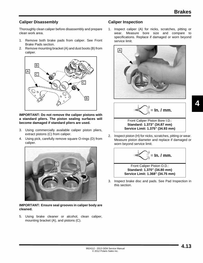
Brakes
4
Caliper Disassembly
Thoroughly clean caliper before disassembly and prepareclean work area.
1. Remove both brake pads from caliper. See FrontBrake Pads section.
2. Remove mounting bracket (A) and dust boots (B) fromcaliper.
IMPORTANT: Do not remove the caliper pistons witha standard pliers. The piston sealing surfaces willbecome damaged if standard pliers are used.
3. Using commercially available caliper piston pliers,extract pistons (C) from caliper.
4. Using pick, carefully remove square O-rings (D) fromcaliper.
IMPORTANT: Ensure seal grooves in caliper body arecleaned.
5. Using brake cleaner or alcohol, clean caliper,mounting bracket (A), and pistons (C).
Caliper Inspection
1. Inspect caliper (A) for nicks, scratches, pitting orwear. Measure bore size and compare tospecifications. Replace if damaged or worn beyondservice limit.
2. Inspect piston (H) for nicks, scratches, pitting or wear.Measure piston diameter and replace if damaged orworn beyond service limit.
3. Inspect brake disc and pads. See Pad Inspection inthis section.
A
B
B
C
C
D
= In. / mm.
Front Caliper Piston Bore I.D.:Standard: 1.373” (34.87 mm)
Service Limit: 1.375” (34.93 mm)
= In. / mm.
Front Caliper Piston O.D.:Standard: 1.370” (34.80 mm)
Service Limit: 1.368” (34.75 mm)
A
4.139924112 - 2013 GEM Service Manual
© 2012 Polaris Sales Inc.

Brakes
Caliper Assembly
IMPORTANT: Ensure seal grooves in caliper body arecleaned.
1. Install new square O-rings in caliper.
2. Coat pistons with clean Polaris DOT 4 Brake Fluid.Install pistons with twisting motion while pushinginward. Piston should slide in and out of boresmoothly, with light resistance.
3. Lubricate mounting bracket pins (A) with siliconegrease and install dust boots.
4. Install and compress mounting bracket and ensuredust boots are fully seated. Install brake pads.
5. Using brake parts cleaner or denatured alcohol, cleandisc and pads to remove any dirt, oil or grease.
Caliper Installation
1. Install caliper and torque mounting bolts tospecification.
2. If removed, install brake scraper.
3. Install brake lines. Torque banjo bolt to specification.
4. Tighten brake pad adjustment screw until stationarypad contacts disc, then back off 1/2 turn.
5. Perform brake bleeding. See Brake Bleeding in thissection.
6. Install front tire and wheel assembly. See Wheel andTires section.
7. Field test unit for proper braking action before puttinginto service. Inspect for fluid leaks and firm brakes.Ensure brake is not dragging when pedal is released.If brake drags, re-check assembly and installation.
8. If new brake pads are installed, perform brakeburnishing. See Brake Burnishing in this section.
Polaris DOT 4 Brake Fluid:P/N 2872189
A
CAUTION
When removing or installing caliper, use care not to damage brake line. Support caliper to avoid kinking
or bending brake line.
= T
Front Caliper Mounting Bolts:28 ft-lbs (38 Nm)
= T
Brake Line Banjo Bolt:20 ft-lbs (27 Nm)
4.14 9924112 - 2013 GEM Service Manual© 2012 Polaris Sales Inc.

Brakes
4
FRONT BRAKE DISC
Disc Runout
1. Mount dial indicator as shown. Slowly rotate the discand read total runout on the dial indicator. Replacedisc if runout exceeds specification.
Disc Inspection
1. Visually inspect disc for scoring, scratches orgouges. Replace the disc if any deep scratches areevident.
2. Using a 0 to 1-inch micrometer, measure discthickness at eight different points around pad contactsurface. Replace disc if worn beyond service limit.
= In. / mm.
Brake Disc Runout:Service Limit .010” (.254 mm)
= In. / mm.
Brake Disc Thickness:New .188” (4.78 mm)
Service Limit .170” (4.32 mm)
= In. / mm.
Brake Disc Thickness VarianceService Limit: .002” (.051 mm)
difference between measurements
4.159924112 - 2013 GEM Service Manual
© 2012 Polaris Sales Inc.

Brakes
Disc Removal / Replacement
1. Remove front brake caliper. See Front CaliperService in this section.
2. Remove cotter pin, retaining nut, and washer.
3. Remove wheel hub (A) from vehicle and remove fourmounting bolts (B) retaining disc to hub.
4. Clean wheel hub (A) mating surface and install newdisc on wheel hub. Torque four, new mounting bolts(B) to specification.
5. Install wheel hub, washer, and retaining nut. Torqueretaining nut to specification and install new cotter pin.
6. Install front brake caliper. See Front Caliper Servicein this section.
7. Field test unit for proper braking action before puttinginto service. Inspect for fluid leaks and firm brakes.Ensure brake is not dragging when pedal is released.If brake drags, re-check assembly and installation.
CAUTION
Always use new brake disc mounting bolts. The bolts have a pre-applied locking agent which is destroyed
upon removal.
= T
Front Brake Disc Mounting Bolts:18 ft-lbs (24 Nm)
= T
Front Wheel Hub Retaining Nut:75 ft-lbs (102 Nm)
AB
4.16 9924112 - 2013 GEM Service Manual© 2012 Polaris Sales Inc.

Brakes
4
REAR DRUM SERVICE(E2, E4, ES, EL)
REAR BRAKE REMOVAL
1. Remove rear tire and wheel assembly. See Wheeland Tires section.
2. Remove cotter pin and clevis pin attaching parkingbrake cable to actuator lever (J).
3. Remove parking brake cable from actuator lever (J).
4. Remove brake line from wheel cylinder (E) and allowfluid to drain into suitable container for disposal.
5. Remove four bolts attaching brake assembly to axleend flange.
6. Remove rear brake assembly.
REAR BRAKE DISASSEMBLY
1. Perform rear brake shoe removal. See Rear BrakeShoes in this section.
2. Remove two bolts (C), wheel cylinder (E), andactuator return (outer) spring (K).
3. Remove wheel cylinder (E), actuator return (lower)spring (O), and actuator lever (J).
REAR BRAKE ASSEMBLY
1. Install actuator lever (J), actuator return (lower)spring (O), and wheel cylinder (E).
2. Install wheel cylinder (E) and mounting bolt (C)furthest from actuator lever (J).
3. Position actuator lever spring (outer) K), ensuring itengages actuator lever (J) and is directly overmounting hole in wheel cylinder (E). Insert last bolt (C)and tighten.
A. Drum J. Actuator lever
B. Drum mounting bolts K. Actuator return spring (outer)
C. Wheel cylinder bolts L. Spacer
D. Bleeder screw M. Spacer mounting bolt / nut
E. Wheel cylinder N. Lower shoe retainer
F. Upper spring O. Actuator return spring (lower)
G. Mounting / backing plate P. Front Brake shoe
H. Retention pin clips Q. Spindle
I. Retention pins R. Rear Brake shoe
A
B
B
C
D
E
F
GR
H
IJ
K
M
L
N
O
I
H
PQ
4.179924112 - 2013 GEM Service Manual
© 2012 Polaris Sales Inc.

Brakes
REAR BRAKE INSTALLATION
NOTE: Ensure the correct (RH or LH) drum brakeassembly is present.
1. Install RH or LH rear brake assembly.
2. Install four bolts through rear axle end into spindle onrear of brake assembly. Torque bolts to specification.
3. Attach brake line to wheel cylinder. Torque tospecification.
4. Insert parking brake cable into actuator lever.
5. Insert clevis pin into parking brake actuator lever,ensuring parking brake cable is engaged securelywith cotter pin.
6. Install rear tire and wheel assembly. See Wheel andTires section.
7. Bleed brakes. See Brake Bleeding instructions in thissection.
8. Adjust parking brake cable. See Parking Brake CableTension Adjustment in this section.
BRAKE SHOE REMOVAL
1. Remove rear tire and wheel assembly. See Wheeland Tires section.
2. Remove two screws and drum from assembly.
3. Remove clips from retention pins at center of eachshoe and remove pins.
4. Remove bolt, retaining plate, and spacer at lowershoe pivot point.
5. Remove actuator return spring (inner).
6. Remove actuator return spring (outer).
7. Lift shoes away from wheel cylinder and off centerlocating post.
BRAKE SHOE INSTALLATION
NOTE: The shoes must properly engage wheelcylinder pistons.
1. Position trailing shoe on center of locating post andonto wheel cylinder.
2. Position leading shoe on center of locating post andonto wheel cylinder.
3. Install actuator return spring (outer).
4. Install actuator return spring (inner).
5. Install lower pivot point spacer with narrow side up,retainer (rounded side down), bolt, and nut.
6. Install pins and new clips onto retention pins at centerof each shoe.
7. Install drum and two screws onto assembly.
8. Install rear tire and wheel assembly. See Wheel andTires section.
= T
Bolts to Brake Assembly and Axle End Flange:20 ft-lbs (27 Nm)
= T
Brake Line to Wheel Cylinder:37 in-lbs (4 Nm)
WARNING
Use care when supporting vehicle so that it does not tip or fall. Severe injury or death may occur.
4.18 9924112 - 2013 GEM Service Manual© 2012 Polaris Sales Inc.

Brakes
4
REAR DRUM SERVICE(E6, E6S, ELXD)
REAR BRAKE REMOVAL
1. Remove rear tire and wheel assembly. See Wheeland Tires section.
2. Release tension at parking brake equalizer.
3. Remove drum.
4. Remove parking brake cable from actuator lever.
5. Remove brake line from wheel cylinder and allow fluidto drain into suitable container for disposal.
6. Remove four bolts attaching brake assembly to axleend flange.
7. Remove rear brake assembly.
REAR BRAKE INSTALLATION
1. Install rear brake assembly.
2. Install four bolts attaching brake assembly to axle endflange. Tighten bolts to specification.
3. Attach brake line to wheel cylinder. Torque tospecification.
4. Install parking brake cable into actuator lever.
NOTE: Ensure the correct (RH or LH) drum brakeassembly is present.
5. Install hub and torque retaining nut to specification.
6. Install drum.
7. Install rear tire and wheel assembly. See Wheel andTires section.
8. Bleed brakes. See Brake Bleeding instructions in thissection.
9. Adjust parking brake cable. See Parking Brake CableTension Adjustment in this section.
A. Wheel cylinder G. Actuator lever
B. Automatic adjuster screw assembly
H. Anchor spring
C. Return spring I. Front brake shoe
D. Hold down clip J. Brake anchor
E. Hold down clip K. Rear brake shoe
F. Automatic adjuster lever and spring
A
B
C
D E
F
G
H
I K
J
= T
Bolts to Brake Assembly and Axle End Flange:65 ft-lbs (88 Nm)
= T
Brake Line to Wheel Cylinder:37 in-lbs (4 Nm)
= T
Hub Retaining Nut:165 ft-lbs (224 Nm)
4.199924112 - 2013 GEM Service Manual
© 2012 Polaris Sales Inc.

Brakes
BRAKE SHOE REMOVAL
1. Remove rear tire and wheel assembly. See Wheeland Tires section.
2. Remove drum assembly.
3. Remove clips from retention pins at center of eachshoe and remove pins.
4. Remove lower anchor spring.
5. Remove upper return spring.
6. Remove automatic adjuster spring
7. Lift shoes away from wheel cylinder and off centerlocating post.
BRAKE SHOE INSTALLATION
NOTE: The shoes must properly engage wheelcylinder pistons.
1. Position trailing shoe on center of locating post andonto wheel cylinder.
2. Position leading shoe on center of locating post andonto wheel cylinder.
3. Install upper return spring.
4. Install lower anchor spring.
5. Install automatic adjuster spring.
6. Install pins and new clips onto retention pins at centerof each shoe.
7. Install drum assembly.
8. Install rear tire and wheel assembly. See Wheel andTires section.
WARNING
Use care when supporting vehicle so that it does not tip or fall. Severe injury or death may occur.
4.20 9924112 - 2013 GEM Service Manual© 2012 Polaris Sales Inc.

Brakes
4
PARKING BRAKE LEVER ASSEMBLY
PARKING BRAKE LEVER REMOVAL(e2, eS, eL, eLXD)
1. Chock wheels.
2. Remove lower seat. See Bench Seat in Body section.
3. Position master disconnect switch OFF.
4. Cover battery terminals to prevent electrical contact.
5. Release parking brake lever (A).
6. Locate threaded adjusting rod/cable assembly (B) atlever end.
7. Remove rear jam nut (C) and front jam nut (D) fromadjusting rod/cable assembly (B).
8. Disconnect parking brake switch wires (E) from switchterminals.
9. Remove two mounting bolts (F) from parking brakelever brackets.
10. Remove parking brake lever.
PARKING BRAKE LEVER INSTALLATION(e2, eS, eL, eLXD)
1. Position parking brake lever and install two mountingbolts (A) through parking brake lever brackets.
2. Connect parking brake switch wires (B) to properterminals on switch: Red/White on center terminal,and Tan on upper (most forward) terminal.
WARNING
Use caution when working near batteries. Always position master disconnect switch OFF and cover
battery terminals to prevent electrical shock. Accident contact with battery terminals can result in
damage or personal injury.
A
C
B
D
E
F
B
A
4.219924112 - 2013 GEM Service Manual
© 2012 Polaris Sales Inc.

Brakes
3. Insert adjusting rod/cable assembly (C) into parkingbrake cable equalizer (D).
4. Install front jam nut (E) and rear jam nut (F) onto fromadjusting rod/cable assembly (C).
5. Adjust tension on parking brake cables. See ParkingBrake Cable Tension Adjustment in this section.
6. Uncover battery terminals.
7. Install lower seat. See Bench Seat in Body section.
8. Position master disconnect switch ON.
PARKING BRAKE LEVER REMOVAL(e4, e6, e6S)
1. Remove parking brake lever boot.
2. Release parking brake lever (A).
3. Raise and support vehicle on suitable hoist.
4. Locate threaded adjusting rod/cable (B) at end ofparking brake lever.
5. Remove rear jam nut (C) and front jam nut (D) fromadjusting rod/cable assembly (B).
F
CD
E
WARNING
Use caution when working near batteries. Always position master disconnect switch OFF and cover
battery terminals to prevent electrical shock. Accident contact with battery terminals can result in
damage or personal injury.
A
C
B
D
4.22 9924112 - 2013 GEM Service Manual© 2012 Polaris Sales Inc.

Brakes
4
6. Disconnect parking brake switch wires (E) from switchterminals.
7. Lower vehicle.
8. Remove two mounting bolts (F) from parking brakelever brackets.
9. Remove parking brake lever.
PARKING BRAKE LEVER INSTALLATION(e4, e6, e6S)
1. Position parking brake lever assembly and install twomounting bolts through parking brake lever bracket.
2. Connect parking brake switch wires to properterminals on switch: Red/White on center terminal,and Tan on upper (most forward) terminal.
3. Insert adjusting rod/cable assembly (A) into parkingbrake cable equalizer (B).
4. Install front jam nut (C) and rear jam nut (D) ontoadjusting rod/cable assembly (A).
5. Adjust tension on parking brake cables. See ParkingBrake Cable Tension Adjustment in this section.
6. Install parking brake lever boot.
PARKING BRAKE CABLE TENSION ADJUSTMENT
1. Chock wheels.
2. Release parking brake lever.
3. Locate threaded adjusting rod/cable assembly (A) atend of lever.
4. Loosen rear jam nut (B) to release front jam nut (C).
5. Thread front jam nut (C) forward or backward asneeded to adjust tension.
6. Tighten rear jam nut (B) against front jam nut (C) tolock in place.
7. Unchock wheels.
8. Apply parking brake lever and test by attempting to rollvehicle forward by pushing it. If vehicle moves, repeatcable tension adjustment procedure.
NOTE: The vehicle will not drive with the parkingbrake lever set. Ensure release of lever beforeoperation.
E F
D
A
C
B
B
A
C
4.239924112 - 2013 GEM Service Manual
© 2012 Polaris Sales Inc.

Brakes
PARKING BRAKE CABLE ASSEMBLY
DESCRIPTION
Two cables are attached to the parking brake lever by atension equalizer and to the parking brake actuator leverson the rear brake assemblies.
A. Parking brake cables
B. Cable mounting bracket
C. Actuator lever
OPERATION
Pulling up on the parking brake lever causes the parkingbrake adjuster assembly to pull on the parking brakecables. A ratchet holds the parking brake lever in place,maintaining pressure on the cables. A push button on theend of the parking brake cable disengages the ratchet,allowing the lever to be returned to its normal position,thereby releasing the tension on the cables.
PARKING BRAKE CABLE REMOVAL (e2, eS, eL)
1. Chock both wheels.
2. Position master disconnect switch OFF.3. Remove lower portion of bench seat. See Bench Seat
in Body section.
4. Cover battery terminals to prevent electrical contact.
5. Release parking brake lever. 6. Release tension on parking brake cables. See Brake
Cable Tension Adjustment in this section.
7. Remove parking brake cable (A) from equalizer (B).
8. Remove retaining ring (C) from cable retainer (D) onframe.
9. Remove cotter pin (E), clevis pin (F), and cable end(G) from actuator lever (H).
10. Remove retaining ring (I) from cable mounting bracket(J).
11. Remove parking brake cable (A).
B
C
A
AB
C D
E
H
F G
JI
4.24 9924112 - 2013 GEM Service Manual© 2012 Polaris Sales Inc.

Brakes
4
PARKING BRAKE CABLE INSTALLATION (e2, eS, eL)
1. Install parking brake cable into front cable retainer (A)on frame and attach with retaining ring (B).
2. Install parking brake cable into cable mountingbracket (C) and attach with retaining ring (D).
3. Position cable end (E) over actuator lever (F).
4. Install clevis pin (G) and cotter pin (H) to attach cableend to actuator lever.
5. Insert parking brake cable (I) into equalizer (J).
6. Adjust tension on parking brake cable. See ParkingBrake Cable Tension Adjustment in this section.
7. Uncover battery terminals.
8. Install lower portion of bench seat. See Bench Seat inBody section.
9. Position master disconnect switch ON.
10. Unchock tires.
PARKING BRAKE CABLE REMOVAL (e4)
1. Raise and support vehicle on a suitable hoist.
2. Position master disconnect switch OFF.3. Remove lower portion of bench seat. See Bench Seat
in Body section.
4. Cover battery terminals to prevent electrical contact.
5. Release parking brake lever. 6. Release tension on parking brake cables. See Brake
Cable Tension Adjustment in this section.
7. Remove parking brake cable (A) from equalizer (B).
8. Remove retaining ring (C) from cable retainer (D) onframe.
B A
H
F
G E
CD
IJ
B
C
D
A
4.259924112 - 2013 GEM Service Manual
© 2012 Polaris Sales Inc.

Brakes
9. Remove cotter pin (E), clevis pin (F), and cable end(G) from actuator lever (H).
10. Remove retaining ring (I) from cable mounting bracket(J).
11. Using battery compartment area to access cablerouting, remove parking brake cable.
PARKING BRAKE CABLE INSTALLATION (e4)
1. Using battery compartment area, install and routeparking brake cable.
2. Install parking brake cable (A) into front cable retainer(B) on frame and attach with retaining ring (C).
3. Install cable into cable mounting bracket (D) andattach with retaining ring (E).
4. Position cable end (F) over actuator lever (G).
5. Install clevis pin (H) and cotter pin (I) to attach cableend (F) to actuator lever (G).
6. Insert parking brake cable (J) into equalizer (K).
7. Adjust tension on parking brake cable. See ParkingBrake Cable Tension Adjustment in this section.
8. Uncover battery terminals.
9. Install lower portion of bench seat. See Bench Seat inBody section.
10. Position master disconnect switch ON.
11. Lower vehicle.
E
H
F G
JI
C
B
A
I
G
H F
DE
K
J
4.26 9924112 - 2013 GEM Service Manual© 2012 Polaris Sales Inc.

Brakes
4
PARKING BRAKE CABLE REMOVAL (eLXD)
1. Position master disconnect switch OFF.2. Remove rear wheel and tire assembly. See Wheels
and Tires section.
3. Remove lower portion of bench seat. See Bench Seatin Body section.
4. Cover battery terminals.
5. Release parking brake lever.
6. Release tension on parking brake cables. See BrakeCable Tension Adjustment in this section.
7. Remove parking brake cable from actuator lever. SeeRear Brake Assembly in this section.
8. Remove cable from equalizer.
9. Remove retaining ring from front backing plate.
10. Remove parking brake cable.
PARKING BRAKE CABLE INSTALLATION (eLXD)
1. Install parking brake cable into front cable retainer onframe and attach with retaining ring.
2. Attach parking brake cable to actuator lever andassemble brakes. See Rear Brake Assembly in thissection.
3. Insert parking brake cable into equalizer.
4. Adjust tension on parking brake cable. See ParkingBrake Cable Tension Adjustment in this section.
5. Install rear wheel and tire assembly. See Wheels andTires section.
6. Uncover battery terminals.
7. Install lower portion of bench seat. See Bench Seat inBody section.
8. Position master disconnect switch ON.
9. Lower vehicle.
PARKING BRAKE CABLE REMOVAL (e6, e6S)
1. Remove rear wheel and tire assembly. See Wheelsand Tires section.
2. Release parking brake lever.
3. Release tension on parking brake cable. See BrakeCable Tension Adjustment in this section.
4. Remove parking brake cable from actuator lever. SeeRear Brake Assembly in this section.
5. Remove cable from equalizer (A).
6. Remove parking brake cable from front frame backingplate (B).
7. Using drill, remove three rivets per side (C).
8. Remove parking brake cable.
A
B
C
4.279924112 - 2013 GEM Service Manual
© 2012 Polaris Sales Inc.

Brakes
PARKING BRAKE CABLE INSTALLATION (e6, e6S)
1. Route parking brake cable and, using rivet gun,install three new rivets (A) per side.
2. Install parking brake cable to front frame backing plate(B).
3. Attach parking brake cable to actuator lever andassemble brakes. See Rear Brake Assembly in thissection.
4. Insert parking brake cable into equalizer (C).
5. Adjust tension on parking brake cable. See ParkingBrake Cable Tension Adjustment in this section.
6. Install rear wheel and tire assembly. See Wheels andTires section.
7. Uncover battery terminals.
8. Install lower bench seat. See Bench Seat in Bodysection.
9. Position master disconnect switch ON.
10. Lower vehicle.
C
B
A
4.28 9924112 - 2013 GEM Service Manual© 2012 Polaris Sales Inc.

Brakes
4
TROUBLESHOOTING
BRAKE DIAGNOSIS
• Check the condition of tires and wheels. Damaged wheels and worn, damaged, or under-inflated tires can cause pull, shudder, vibration, and a condition similar to grab.
• If complaint was based on noise when braking, check suspension components. Rock the front and rear of the vehicle and listen for noise that might be caused by loose, worn or damaged suspension or steering components.
• Inspect brake fluid level and condition. Note that the brake reservoir fluid level will decrease in proportion to normal lining wear.
NOTE: Brake fluid tends to darken over time. This isnormal and should not be mistaken forcontamination.
• If fluid level is abnormally low, look for evidence of leaks at caliper, drum assemblies, hoses and lines, and master cylinder.
• If fluid appears contaminated, drain out a sample to examine. System will have to be flushed if fluid is separated into layers, or contains a substance other than brake fluid. Use clean brake fluid to flush the system.
• Check parking brake operation. Verify free movement and full release of cables and lever. Also note if vehicle was being operated with parking brake partially applied.
• Check brake pedal operation. Verify that pedal does not bind and has adequate free play. If pedal lacks free play, check pedal for being loose or for binding condition. Do not road test until condition is corrected.
• If components checked appear OK, road test the vehicle.
• During the road test, make normal and firm brake stops in 10-20 mph range. Note faulty brake operation such as low pedal, hard pedal, fade, pedal pulsation, pull, grab, drag, noise, etc.
• Attempt to stop the vehicle with the parking brake only and note grab, drag, noise, etc.
PEDAL FALLS AWAY
A brake pedal that falls away under steady foot pressureis generally the result of a system leak. The leak pointcould be at a brake line, fitting, hose, calipers or wheelcylinder. If leakage is severe, fluid will be evident at oraround the leaking component. Internal leakage (seal by-pass) in the master cylinder caused by worn or damagedpiston cups, may also be the cause of the problem.
LOW PEDAL
If a low pedal is experienced, pump the pedal severaltimes. If the pedal comes back up, worn brake pads orbrake linings, rotors, drums, or rear brakes out ofadjustment are the most likely causes. The proper courseof action is to inspect and replace all worn component andmake the proper adjustments.
SPONGY PEDAL
A spongy pedal is most often caused by air in the system.However, thin brake rotors or brake drums or substandardbrake lines and hoses can also cause a spongy pedal. Theproper course of action is to bleed the system, and replacethe worn components and substandard quality brakehoses if suspected.
HARD PEDAL / HIGH PEDAL EFFORT
A hard pedal or high pedal effort may be due to brake padsor brake linings that are water soaked, contaminated,glazed, or badly worn. Pedal pulsation is caused bycomponents that are loose, or beyond tolerance limits.The primary cause of pulsation is out of round brake rotorsor brake drums. Other causes are loose wheel bearingsand worn, damaged tires.
BRAKE NOISES
Some brake noise is common during the first few stopsafter a vehicle has been parked overnight or stored. Thisis primarily due to the formation of trace corrosion (lightrust) on metal surfaces. This light corrosion is typicallycleared from the metal surfaces after a few brakeapplications causing the noise to subside.
4.299924112 - 2013 GEM Service Manual
© 2012 Polaris Sales Inc.

Brakes
BRAKE SQUEAK OR SQUEAL
Brake squeak or squeal may be due to linings that are wetor contaminated with brake fluid, grease, or oil. Glazedlinings and rotors with hard spots can also contribute tosqueak. Dirt and foreign material embedded in the brakelining will also cause squeak/ squeal. A very loud squeakor squeal is frequently a sign of severely worn brake padsand linings. If the pads or linings are worn through, metal-to-metal contact occurs. If the condition is allowed tocontinue, rotors and drums can become so scored thatreplacement is necessary.
BRAKE CHATTER
Loose or worn components, or glazed/burnt linings usuallycause brake chatter. Additional causes of chatter are rearbrake linings not securely attached to the shoes, loosewheel bearings and contaminated brake linings.
THUMP OR CLUNK NOISE
Thumping or clunking noises during braking are frequentlynot caused by brake components. In many cases, suchnoises are caused by loose or damaged steering,suspension, or engine components. However, worn out,improperly adjusted, or improperly assembled brake
shoes can also produce a thumping noise.
4.30 9924112 - 2013 GEM Service Manual© 2012 Polaris Sales Inc.

Electrical
CHAPTER 5
Electrical
5
ELECTRICAL SYSTEM . . . . . . . . . . . . . . . . . . . . . . . . . . . . . . . . . . . . . . . . . . . . . . . . . . . 5.3POWER SYSTEM . . . . . . . . . . . . . . . . . . . . . . . . . . . . . . . . . . . . . . . . . . . . . . . . . . . . . . . 5.4DRIVE SYSTEM. . . . . . . . . . . . . . . . . . . . . . . . . . . . . . . . . . . . . . . . . . . . . . . . . . . . . . . . . 5.5DRIVE AND POWER SYSTEM ERROR CODES . . . . . . . . . . . . . . . . . . . . . . . . . . . . . . . 5.6
DRIVE AND POWER SYSTEM ERROR CODES . . . . . . . . . . . . . . . . . . . . . . . . . . . . . . 5.7DRIVE AND POWER SYSTEM TROUBLESHOOTING DIAGRAMS . . . . . . . . . . . . . . 5.13DRIVE AND POWER SYSTEM TROUBLESHOOTING CHARTS . . . . . . . . . . . . . . . . 5.15
ACCELERATOR PEDAL . . . . . . . . . . . . . . . . . . . . . . . . . . . . . . . . . . . . . . . . . . . . . . . . . 5.20BATTERY. . . . . . . . . . . . . . . . . . . . . . . . . . . . . . . . . . . . . . . . . . . . . . . . . . . . . . . . . . . . . 5.22
DESCRIPTION . . . . . . . . . . . . . . . . . . . . . . . . . . . . . . . . . . . . . . . . . . . . . . . . . . . . . . . 5.22OPERATION . . . . . . . . . . . . . . . . . . . . . . . . . . . . . . . . . . . . . . . . . . . . . . . . . . . . . . . . . 5.23BATTERY CODES . . . . . . . . . . . . . . . . . . . . . . . . . . . . . . . . . . . . . . . . . . . . . . . . . . . . 5.23BATTERY CARBON PILE LOAD TEST . . . . . . . . . . . . . . . . . . . . . . . . . . . . . . . . . . . . 5.23POWER BRAKING LOAD TEST . . . . . . . . . . . . . . . . . . . . . . . . . . . . . . . . . . . . . . . . . . 5.23REMOVAL AND DISPOSAL . . . . . . . . . . . . . . . . . . . . . . . . . . . . . . . . . . . . . . . . . . . . . 5.24BATTERY SAFETY . . . . . . . . . . . . . . . . . . . . . . . . . . . . . . . . . . . . . . . . . . . . . . . . . . . . 5.25RECOMMENDED EQUIPMENT . . . . . . . . . . . . . . . . . . . . . . . . . . . . . . . . . . . . . . . . . . 5.25BATTERY TESTING . . . . . . . . . . . . . . . . . . . . . . . . . . . . . . . . . . . . . . . . . . . . . . . . . . . 5.26BATTERY WATERING . . . . . . . . . . . . . . . . . . . . . . . . . . . . . . . . . . . . . . . . . . . . . . . . . 5.29BATTERY CLEANING. . . . . . . . . . . . . . . . . . . . . . . . . . . . . . . . . . . . . . . . . . . . . . . . . . 5.29BATTERY STORAGE . . . . . . . . . . . . . . . . . . . . . . . . . . . . . . . . . . . . . . . . . . . . . . . . . . 5.30BATTERY CHARGING . . . . . . . . . . . . . . . . . . . . . . . . . . . . . . . . . . . . . . . . . . . . . . . . . 5.30
CHARGER . . . . . . . . . . . . . . . . . . . . . . . . . . . . . . . . . . . . . . . . . . . . . . . . . . . . . . . . . . . . 5.31DESCRIPTION . . . . . . . . . . . . . . . . . . . . . . . . . . . . . . . . . . . . . . . . . . . . . . . . . . . . . . . 5.31OPERATION . . . . . . . . . . . . . . . . . . . . . . . . . . . . . . . . . . . . . . . . . . . . . . . . . . . . . . . . . 5.31BATTERY CHARGE LEVEL . . . . . . . . . . . . . . . . . . . . . . . . . . . . . . . . . . . . . . . . . . . . . 5.31CHARGER REPLACEMENT. . . . . . . . . . . . . . . . . . . . . . . . . . . . . . . . . . . . . . . . . . . . . 5.32CHARGING WHEN BELOW MIN VOLTAGE . . . . . . . . . . . . . . . . . . . . . . . . . . . . . . . . 5.32OPERATING INSTRUCTIONS . . . . . . . . . . . . . . . . . . . . . . . . . . . . . . . . . . . . . . . . . . . 5.33CHECK/CHANGE CHARGE ALGORITHM . . . . . . . . . . . . . . . . . . . . . . . . . . . . . . . . . . 5.34
FAST CHARGING SYSTEM . . . . . . . . . . . . . . . . . . . . . . . . . . . . . . . . . . . . . . . . . . . . . . 5.35MOTOR CONTROLLER . . . . . . . . . . . . . . . . . . . . . . . . . . . . . . . . . . . . . . . . . . . . . . . . . 5.38
DESCRIPTION . . . . . . . . . . . . . . . . . . . . . . . . . . . . . . . . . . . . . . . . . . . . . . . . . . . . . . . 5.38OPERATION . . . . . . . . . . . . . . . . . . . . . . . . . . . . . . . . . . . . . . . . . . . . . . . . . . . . . . . . . 5.38DIAGNOSIS AND TESTING . . . . . . . . . . . . . . . . . . . . . . . . . . . . . . . . . . . . . . . . . . . . . 5.38MOTOR CONTROLLER REMOVAL . . . . . . . . . . . . . . . . . . . . . . . . . . . . . . . . . . . . . . . 5.38MOTOR CONTROLLER INSTALLATION . . . . . . . . . . . . . . . . . . . . . . . . . . . . . . . . . . . 5.38
DC / DC CONVERTER . . . . . . . . . . . . . . . . . . . . . . . . . . . . . . . . . . . . . . . . . . . . . . . . . . 5.39DESCRIPTION . . . . . . . . . . . . . . . . . . . . . . . . . . . . . . . . . . . . . . . . . . . . . . . . . . . . . . . 5.39OPERATION . . . . . . . . . . . . . . . . . . . . . . . . . . . . . . . . . . . . . . . . . . . . . . . . . . . . . . . . . 5.39DIAGNOSIS AND TESTING . . . . . . . . . . . . . . . . . . . . . . . . . . . . . . . . . . . . . . . . . . . . . 5.39DC / DC CONVERTER REMOVAL . . . . . . . . . . . . . . . . . . . . . . . . . . . . . . . . . . . . . . . . 5.39DC / DC CONVERTER INSTALLATION . . . . . . . . . . . . . . . . . . . . . . . . . . . . . . . . . . . . 5.39
MAIN CONTACTOR. . . . . . . . . . . . . . . . . . . . . . . . . . . . . . . . . . . . . . . . . . . . . . . . . . . . . 5.40MOTOR . . . . . . . . . . . . . . . . . . . . . . . . . . . . . . . . . . . . . . . . . . . . . . . . . . . . . . . . . . . . . . 5.41
DESCRIPTION . . . . . . . . . . . . . . . . . . . . . . . . . . . . . . . . . . . . . . . . . . . . . . . . . . . . . . . 5.41OPERATION . . . . . . . . . . . . . . . . . . . . . . . . . . . . . . . . . . . . . . . . . . . . . . . . . . . . . . . . . 5.42DIAGNOSIS AND TESTING . . . . . . . . . . . . . . . . . . . . . . . . . . . . . . . . . . . . . . . . . . . . . 5.42MOTOR REMOVAL. . . . . . . . . . . . . . . . . . . . . . . . . . . . . . . . . . . . . . . . . . . . . . . . . . . . 5.42MOTOR INSTALLATION. . . . . . . . . . . . . . . . . . . . . . . . . . . . . . . . . . . . . . . . . . . . . . . . 5.42
MOTOR MAGNET AND SPEED SENSOR (TACHOMETER) . . . . . . . . . . . . . . . . . . . . . 5.43LIQUID CRYSTAL DISPLAY (LCD) . . . . . . . . . . . . . . . . . . . . . . . . . . . . . . . . . . . . . . . . . 5.44
5.19924112 - 2013 GEM Service Manual
© 2012 Polaris Sales Inc.

Electrical
PSDM . . . . . . . . . . . . . . . . . . . . . . . . . . . . . . . . . . . . . . . . . . . . . . . . . . . . . . . . . . . . . . . 5.45PSDM REMOVAL. . . . . . . . . . . . . . . . . . . . . . . . . . . . . . . . . . . . . . . . . . . . . . . . . . . . . . 5.45PSDM INSTALLATION. . . . . . . . . . . . . . . . . . . . . . . . . . . . . . . . . . . . . . . . . . . . . . . . . . 5.45
ACCESSORY SYSTEM . . . . . . . . . . . . . . . . . . . . . . . . . . . . . . . . . . . . . . . . . . . . . . . . . 5.47ACCESSORY SYSTEM COMPONENT REPLACEMENT . . . . . . . . . . . . . . . . . . . . . . . 5.52
FUSE REPLACEMENT . . . . . . . . . . . . . . . . . . . . . . . . . . . . . . . . . . . . . . . . . . . . . . . . . 5.52HEADLIGHT REPLACEMENT . . . . . . . . . . . . . . . . . . . . . . . . . . . . . . . . . . . . . . . . . . . . 5.52FRONT TURN INDICATOR LAMP REPLACEMENT. . . . . . . . . . . . . . . . . . . . . . . . . . . 5.52REAR TURN INDICATOR LAMP REPLACEMENT . . . . . . . . . . . . . . . . . . . . . . . . . . . . 5.52WIPER MOTOR REPLACEMENT . . . . . . . . . . . . . . . . . . . . . . . . . . . . . . . . . . . . . . . . . 5.52INSTRUMENT POD REPLACEMENT . . . . . . . . . . . . . . . . . . . . . . . . . . . . . . . . . . . . . . 5.52LIGHT SWITCH REPLACEMENT . . . . . . . . . . . . . . . . . . . . . . . . . . . . . . . . . . . . . . . . . 5.53KEY SWITCH REPLACEMENT . . . . . . . . . . . . . . . . . . . . . . . . . . . . . . . . . . . . . . . . . . . 5.53ACCESSORY WIRING CHART . . . . . . . . . . . . . . . . . . . . . . . . . . . . . . . . . . . . . . . . . . . 5.53TURN SIGNAL SWITCH REPLACEMENT . . . . . . . . . . . . . . . . . . . . . . . . . . . . . . . . . . 5.53ROCKER SWITCH REPLACEMENT . . . . . . . . . . . . . . . . . . . . . . . . . . . . . . . . . . . . . . . 5.53
WIRING DIAGRAMS . . . . . . . . . . . . . . . . . . . . . . . . . . . . . . . . . . . . . . . . . . . . . . . . . . . . 5.54POWER DISTRIBUTION . . . . . . . . . . . . . . . . . . . . . . . . . . . . . . . . . . . . . . . . . . . . . . . . 5.55CHARGING SYSTEM. . . . . . . . . . . . . . . . . . . . . . . . . . . . . . . . . . . . . . . . . . . . . . . . . . . 5.56FAST CHARGING SYSTEM . . . . . . . . . . . . . . . . . . . . . . . . . . . . . . . . . . . . . . . . . . . . . 5.58PARK BRAKE CIRCUIT . . . . . . . . . . . . . . . . . . . . . . . . . . . . . . . . . . . . . . . . . . . . . . . . . 5.60DC/DC CONVERTER - INTEGRATED CHARGER . . . . . . . . . . . . . . . . . . . . . . . . . . . . 5.61MAIN CONTACTOR. . . . . . . . . . . . . . . . . . . . . . . . . . . . . . . . . . . . . . . . . . . . . . . . . . . . 5.62MOTOR CONTROLLER SYSTEM. . . . . . . . . . . . . . . . . . . . . . . . . . . . . . . . . . . . . . . . . 5.64DISPLAY. . . . . . . . . . . . . . . . . . . . . . . . . . . . . . . . . . . . . . . . . . . . . . . . . . . . . . . . . . . . . 5.65HORN / POWER OUTLET . . . . . . . . . . . . . . . . . . . . . . . . . . . . . . . . . . . . . . . . . . . . . . . 5.68HEATER / DEFOGGER . . . . . . . . . . . . . . . . . . . . . . . . . . . . . . . . . . . . . . . . . . . . . . . . . 5.69DASH FAN . . . . . . . . . . . . . . . . . . . . . . . . . . . . . . . . . . . . . . . . . . . . . . . . . . . . . . . . . . . 5.70SECURITY LIGHT BAR . . . . . . . . . . . . . . . . . . . . . . . . . . . . . . . . . . . . . . . . . . . . . . . . . 5.71AUDIO SYSTEM. . . . . . . . . . . . . . . . . . . . . . . . . . . . . . . . . . . . . . . . . . . . . . . . . . . . . . . 5.72FRONT LIGHTING - HI/LO BEAM . . . . . . . . . . . . . . . . . . . . . . . . . . . . . . . . . . . . . . . . . 5.73REAR LIGHTING . . . . . . . . . . . . . . . . . . . . . . . . . . . . . . . . . . . . . . . . . . . . . . . . . . . . . . 5.74TURN SIGNAL REMINDER . . . . . . . . . . . . . . . . . . . . . . . . . . . . . . . . . . . . . . . . . . . . . . 5.78WIPER / WASHER . . . . . . . . . . . . . . . . . . . . . . . . . . . . . . . . . . . . . . . . . . . . . . . . . . . . . 5.79
HARNESS AND CONNECTOR DRAWINGS . . . . . . . . . . . . . . . . . . . . . . . . . . . . . . . . . 5.80CONVERTER HARNESS. . . . . . . . . . . . . . . . . . . . . . . . . . . . . . . . . . . . . . . . . . . . . . . . 5.80HEADLIGHT HARNESS - STANDARD US DOMESTIC LOW BEAM . . . . . . . . . . . . . . 5.82FRONT HARNESS. . . . . . . . . . . . . . . . . . . . . . . . . . . . . . . . . . . . . . . . . . . . . . . . . . . . . 5.84INSTRUMENT PANEL HARNESS. . . . . . . . . . . . . . . . . . . . . . . . . . . . . . . . . . . . . . . . . 5.86CONTROLLER HARNESS. . . . . . . . . . . . . . . . . . . . . . . . . . . . . . . . . . . . . . . . . . . . . . . 5.88MAIN HARNESS . . . . . . . . . . . . . . . . . . . . . . . . . . . . . . . . . . . . . . . . . . . . . . . . . . . . . . 5.91TAIL LIGHT HARNESS . . . . . . . . . . . . . . . . . . . . . . . . . . . . . . . . . . . . . . . . . . . . . . . . . 5.94
DIGITAL WRENCH® OPERATION. . . . . . . . . . . . . . . . . . . . . . . . . . . . . . . . . . . . . . . . . 5.96DIGITAL WRENCH® DIAGNOSTIC SOFTWARE OVERVIEW. . . . . . . . . . . . . . . . . . . 5.96SPECIAL TOOLS . . . . . . . . . . . . . . . . . . . . . . . . . . . . . . . . . . . . . . . . . . . . . . . . . . . . . . 5.96DIAGNOSTIC SOFTWARE VERSION. . . . . . . . . . . . . . . . . . . . . . . . . . . . . . . . . . . . . . 5.96CONTROLLER REPLACEMENT . . . . . . . . . . . . . . . . . . . . . . . . . . . . . . . . . . . . . . . . . . 5.96DIGITAL WRENCH® COMMUNICATION ERRORS . . . . . . . . . . . . . . . . . . . . . . . . . . . 5.96COMMUNICATION CABLE CONNECTION. . . . . . . . . . . . . . . . . . . . . . . . . . . . . . . . . . 5.97DIGITAL WRENCH® SERIAL NUMBER LOCATION . . . . . . . . . . . . . . . . . . . . . . . . . . 5.97DIGITAL WRENCH® VERSION AND UPDATE ID . . . . . . . . . . . . . . . . . . . . . . . . . . . . 5.98DIGITAL WRENCH® UPDATES . . . . . . . . . . . . . . . . . . . . . . . . . . . . . . . . . . . . . . . . . . 5.98DIGITAL WRENCH® FEATURE MAP . . . . . . . . . . . . . . . . . . . . . . . . . . . . . . . . . . . . . 5.100VEHICLE SELECTION. . . . . . . . . . . . . . . . . . . . . . . . . . . . . . . . . . . . . . . . . . . . . . . . . 5.101DIAGNOSTIC TROUBLE CODES (DTCS) . . . . . . . . . . . . . . . . . . . . . . . . . . . . . . . . . 5.101SPECIAL TESTS / CONTROLLER PROGRAMMING . . . . . . . . . . . . . . . . . . . . . . . . . 5.101GEM PERSONALITY CONFIGURATION . . . . . . . . . . . . . . . . . . . . . . . . . . . . . . . . . . 5.101VEHICLE INFORMATION . . . . . . . . . . . . . . . . . . . . . . . . . . . . . . . . . . . . . . . . . . . . . . 5.102
5.29924112 - 2013 GEM Service Manual
© 2012 Polaris Sales Inc.

Electrical
5
ELECTRICAL SYSTEM
DESCRIPTION
The electrical system of the GEM car is shown in the blockdiagram above. For purposes of operational description,the system is divided into three groups the Power System,the Drive System and, the Accessory System.
NOTE: The master disconnect switch is located inthe lower dash unit of the fuse access panel.
WARNING
HIGH VOLTAGE - USE CAUTION. To reduce the risk of electrical shock, personal or property
damage, be sure to always turn off the Master Disconnect Switch. Allow a few minutes for the electrical system to discharge before attempting service to the vehicle. Disconnect any one of the battery cables from an accessible battery in the
battery compartment. This will totally disable all 72-volt HIGH VOLTAGE power from the electrical
system. Never wear loose jewelry, rings or watches. Use insulated tools to prevent shocking.
5.39924112 - 2013 GEM Service Manual
© 2012 Polaris Sales Inc.

Electrical
POWER SYSTEM
DESCRIPTION
The purpose of the power system is to provide primarypower for the drive and accessory systems. The powersystem consists of the batteries, battery charger, fuse, keyswitch, temperature sensor, and power harness (notshown in the block diagram). Six 12-volt or nine 8-volt(GEM e6®, GEM eL XD OPTION) series-wired lead-acidbatteries and provide a total power supply voltage of 72volts.
OPERATION
The battery charger automatically recharges the battery to100% charge when plugged into a standard 110-volt, 15-amp-breaker outlet. When the charger is active, itprevents the vehicle from being operated. The batterycharger monitors battery temperature by means of atemperature sensor. If the battery temperature reachesabove 122 degrees F (49 degrees C), the charger will shutdown.
DIAGNOSIS AND TESTING
Diagnosis and testing of the power system is integratedwith the diagnosis and testing of the drive system.
5.4 9924112 - 2013 GEM Service Manual© 2012 Polaris Sales Inc.

Electrical
5
DRIVE SYSTEM
DESCRIPTION
The drive system consists of the main contactor, motorcontroller, DC motor, state of charge indicator, tachometer,accelerator foot pedal, drive mode switch, main wiringharness and other associated wiring.
OPERATION
The drive system is powered by the 72 VDC generated bythe batteries. If the main contactor is closed, the motorcontroller provides drive voltage to the motor based oninputs from the drive mode switch, motor tachometer, andthe accelerator foot pedal position. The position of thedrive mode switch determines vehicle direction. Thevariable speed, reversible, DC motor supplies mechanicaldrive power. Power and drive system operation ismonitored by the motor controller; status information isdisplayed on the LCD display.
The basic operation procedures described in the Owner'sManual must be followed for the drive system to operateproperly. If the drive system does not operate, verify thefollowing steps have been completed:
• Master disconnect switch is in the ON position.
• Batteries are charged and the battery charger is not plugged in.
• Parking brake has been released.
• Key switch is in the ON position.
• After turning the key switch on, the vehicle drive mode switch has been placed in DRIVE LOW, DRIVE HIGH, or REVERSE.
A. Turn signal lever, windshield wiper switch, horn button
B. Light switch
C. LCD display
D. Trip reset button
E. Vehicle drive mode switch
F. Key switch
A B
C
DE
F
5.59924112 - 2013 GEM Service Manual
© 2012 Polaris Sales Inc.

Electrical
DRIVE SYSTEM DIAGNOSIS AND TESTING
The purpose of this section is to aid in the isolation ofproblems with the drive system and power system. Theprimary means of troubleshooting the drive and powersystem is via error codes displayed on the LCD display(A). If system problems cannot be isolated by use of errorcodes, refer to the Drive and Power SystemTroubleshooting Charts in this section.
NOTE: The information provided in this section is aguide only. There are numerous variations in theskill level of personnel that service this vehicle. Thismanual cannot possibly accommodate all skill levelsand provide advice for each. A basic understandingof electronics and troubleshooting techniques isrequired.
DRIVE AND POWER SYSTEM ERROR CODES
The motor controller monitors the drive system when thevehicle is powered up (key is in the ON position). Themotor controller reports any problems detected bydisplaying error codes on the multi-purpose LCD displaylocated in the center of the instrument pod. Error codes areexplained in the table below. Error codes are displayed bya service number and an illuminated wrench icon on theLCD display. See pages below for error code definitions.
WARNING
Whenever possible, service the vehicle with the master disconnect switch turned off. If the master disconnect switch is on, to measure voltage, use extreme caution. Dangerous voltage is present. Remove all jewelry such as rings, watches, or
necklaces that could contact electrical connections and conduct electricity. Severe injury, burns, or even death could occur if caution is not used.
A
5.6 9924112 - 2013 GEM Service Manual© 2012 Polaris Sales Inc.

Electrical
5
DRIVE AND POWER SYSTEM ERROR CODES
Error Code Fault Description Corrective Action
NoneDisplay on the liquid crystal display (LCD) is blank.
Verify that the following fuses have continuity through the fuses. With the key and the Master Disconnect Switch (MDS) in the ON position with a voltmeter make sure there is voltage present at both sides of the fuses using chassis ground as a reference. See fuse chart below.
05 Start switch failed to close.
Check start switch circuit from the Motor Controller to the start switch. Start switch may be defective. Refer to START SWITCH TESTING and the MOTOR CONTROLLER CIRCUIT diagram in this Section for troubleshooting the start switch circuit.
06
Accelerator Pedal was pushed and there is improper or no contact at the Drive Mode Switch (defective switch or not in the correct position between drive mode positions).
Refer to the ACCELERATOR POTENTIOMETER TESTING and the MOTOR CONTROLLER CIRCUIT diagram in this Section for troubleshooting the Drive Mode Switch circuit.
08
Accelerator voltage input is too high on power up after initial key switch closure. Open circuit at CH1 harness Pin 8. Open potentiometer wiper at CH1 harness Pin 7.
The Accelerator Pedal input to the Motor Controller, CH1 harness, Pin 7 should be less than 0.9 VDC before pressing the pedal. If the voltage is greater than 0.9 VDC, the Accelerator Pedal may be defective. Verify continuity between CH1 harness Pins 7 and 8.
Fuse Position Symptom
Fuse F5No displayVehicle Moves
Fuse F9No displayNo Movement
Fuse F10 (See also Park Brake Circuit)
Brake Light Icon ONNo Movement
Fuse F13No displayNo Movement
If OK, with a voltmeter check the following:
1. With the Master Disconnect Switch in the ON position, check for voltagebetween Display Connector IPS Harness, D2 Pin A (12 volt unswitched)and D2 pin G (12 volt ground).
2. Turn the key ON and check the voltage between D2 Pin K and D2 Pin G.
3. Both voltage checks for Steps 1 and 2 should indicate 12 volts DCpresent.
4. If no voltage is present, test or repair the circuit. Refer to Display Circuitdiagram in this Section.
5. If voltage is present at both locations on the connector to the Display,and there are no loose connections, then the LCD may need to bereplaced.
5.79924112 - 2013 GEM Service Manual
© 2012 Polaris Sales Inc.

Electrical
DRIVE AND POWER SYSTEM ERROR CODES (CONTINUED)
Error Code Fault Description Corrective Action
09
Improper contact at the Drive Mode Switch (defective switch as indicated by a short internally or not selected in the correct position between positions). Check for moisture in the switch.
Refer to the Motor Controller Circuit diagram for troubleshooting the Drive Mode Switch. Check for voltage present. See Drive Mode Switch chart below with Controller Connector unplugged.
11Accelerator Pedal was pushed when the car was first turned on. Code 11 sets while driving.
Release the accelerator pedal, select a drive mode and then push the accelerator pedal.Check accelerator circuit and pedal assembly. (See accelerator pedal diagnosis and testing.)Check parking brake lever microswitch – remove red/white and tan wires and connect these wires together to bypass this circuit. Check key switch. Unplug the 3-wire connector to the back side of the key switch. Put a jumper wire between the red/white and white wires to bypass this circuit.
14Rolling Radius or Gear Ratio or Top Speed parameters are out of limits for the motor.
Rolling Radius or Gear Ratio or Top Speed parameters are out of limits for the motor. Reprogram the Controller function settings to the proper values.
15Low battery pack voltage (less than 68.3 VDC).
Charge the car (see Charger in this section for instructions on charging the battery).
16Battery pack voltage is greater than 86 VDC.
Check the battery pack. Verify that the proper voltage is present (see Step 4 of the Drive System Troubleshooting Chart for instructions on checking battery voltage). If the voltage is over 86 VDC, try running the headlights for a little while to drain the battery charge. Position key switch OFF for ten seconds and re-position ON. If the voltage is below 86 VDC and the code still displays, there is a problem with the sensing circuit in the motor controller.
21Problem with the accelerator pedal wiring.
See Accelerator Pedal – Diagnosis and Testing
23Motor field current is too high when the start switch is closed and the reverse drive mode is selected.
Verify the controller outputs and the motor inputs are not shorted. Perform continuity checks between F1-F2 = 1.0-1.3 ohms, A1-A2 = 0.2-0.7 ohms, and A1 A2 F1 F2 have no continuity to the chassis or motor housing. If Motor tests ok, replace Controller. If Motor tests bad, replace Motor and retest operation.
24Motor field current is too high when the start switch is closed and the forward drive mode is selected.
Verify the controller outputs and the motor inputs are not shorted. Perform continuity checks between F1-F2 = 1.0-1.3 ohms, A1-A2 = 0.2-0.7 ohms, and A1 A2 F1 F2 have no continuity to the chassis or motor housing. If Motor tests ok, replace Controller. If Motor tests bad, replace Motor and retest operation.
Position Pin 4 Pin 5 Pin 6
HI 0 0 72V
LOW 72V 0 0
REV 0 72V 0
Verify the switch is bad.
5.8 9924112 - 2013 GEM Service Manual© 2012 Polaris Sales Inc.

Electrical
5
DRIVE AND POWER SYSTEM ERROR CODES (CONTINUED)
Error Code Fault Description Corrective Action
27The 12 volt bus voltage is too low from the controllers internal power supply.
Verify 72 volts to Pins 1 and 2 of 23-pin connector of controller.
POSSIBLE CAUSEDischarged Battery.- Check battery to insure proper state of charge. Voltage may be dropping below 15V under load. - Loose connection at P1. Insure the wire connection at P1 is tight.
Shorted Motor Tachometer:- Disconnect tachometer/speed sensor and run control. If status Code 27 does not appear, check tachometer. - Defective control. - Replace controller unit.
41
Open thermal protector or transistor over temperature. Voltage at thermal protector internal to controller is too low.
The Motor Controller is in thermal cutback. Allow cooling and the status code should disappear. If the problem persists after the Motor Controller has cooled, contact Technical Support at 1.866.764.0616.
POSSIBLE CAUSEControl is in thermal cut back.- Allow control to cool, status code should disappear.- Defective control.- Replace controller unit.
42Motor armature offset voltage is too high.
Verify the controller outputs and the motor inputs are not shorted. Perform continuity checks between F1-F2 = 1.0-1.3 ohms, A1-A2 = 0.2-0.7 ohms, and A1 A2 F1 F2 have no continuity to the chassis or motor housing. If Motor tests ok, replace Controller. If Motor tests bad, replace Motor and retest operation.
43Motor Armature offset voltage is too low internal to the controller.
Verify the controller outputs and the motor inputs are not shorted. Perform continuity checks between F1-F2 = 1.0-1.3 ohms, A1-A2 = 0.2-0.7 ohms, and A1 A2 F1 F2 have no continuity to the chassis or motor housing. If Motor tests ok, replace Controller. If Motor tests bad, replace Motor and retest operation.
5.99924112 - 2013 GEM Service Manual
© 2012 Polaris Sales Inc.

Electrical
DRIVE AND POWER SYSTEM ERROR CODES (CONTINUED)
Error Code Fault Description Corrective Action
44Armature transistor did not turn off properly internal to the controller.
Verify the controller outputs and the motor inputs are not shorted. Perform continuity checks between F1-F2 = 1.0-1.3 ohms, A1-A2 = 0.2-0.7 ohms, and A1 A2 F1 F2 have no continuity to the chassis or motor housing. If Motor tests ok, replace Controller. If Motor tests bad, replace Motor and retest operation.
45Armature transistor did not turn on properly internal to the controller.
Verify the controller outputs and the motor inputs are not shorted. Perform continuity checks between F1-F2 = 1.0-1.3 ohms, A1-A2 = 0.2-0.7 ohms, and A1 A2 F1 F2 have no continuity to the chassis or motor housing. Replace the motor controller. If Motor tests ok, replace Controller. If Motor tests bad, replace Motor and retest operation.
46“Look ahead” test for motor controller A2 voltage is less than 12.5% of battery voltage.
This status code will be displayed if the voltage at A2 is less than 12.5% of battery voltage and the current is greater than 52 amps when the controller is in the neutral state. This can be caused by a short circuit from motor armature to the frame. Test for a short by opening the main disconnect switch and using an ohmmeter to measure between motor controller A2 and ground; there should be an open circuit (greater than 5000 ohms.) If there is a short, check the wiring, and remove the short. If there is not a short, replace the motor controller.
49Motor field current is too low during the run mode.
This status code will be displayed if the current draw in the motor field is less then 1.3 amps and the armature current is greater than 100 amps for more than 1.27 seconds during the run mode. Check wiring between the motor controller and the motor field connections (F1 and F2). Check for an open field winding of the motor as well F1-F2 = 1.0-1.3 ohms (if so replace motor). Replace the motor controller.
51Motor controller is not getting 72 volts.
First go through the Drive and Power System Troubleshooting Chart A. If directed back to the Drive and Power System Error Code Chart perform the following procedure. Note: Between each step, if the code appears the code will need to be cleared. To clear the code turn the key and Master Disconnect switch (MDS) off for 15 minutes. Make sure Emergency Brake is on. Turn on MDS and then the key switch. Did Code 51 appear? If it does the motor controller has failed, which may be caused by a shorted motor. Replace the controller, remove and inspect motor for shorting or burnt windings, If the code 51 does not appear, check for burnt contactor points. One way is to do a voltage drop test across the points. There should not be any more than a few millivolt drop (or tenths of a volt). Next try driving the car in each mode Reverse, Low and High, Did the code set? If it did, clear the code. Make sure the key and the MDS are off. Remove and insulate the F1, F2, A1, and A2 wires from the motor. Turn on the MDS, key, and try driving the car in Reverse, Low, and High. Did the code 51 appear? If not, the motor is shorted and should be replaced. If the code 51 does appear the controller has failed because of a shorted motor. Replace both motor and controller. Perform continuity checks to Motor between F1-F2 = 1.0-1.3 ohms, A1-A2 = 0.2-0.7 ohms, and A1 A2 F1 F2 have no continuity to the chassis or motor housing.
5.10 9924112 - 2013 GEM Service Manual© 2012 Polaris Sales Inc.

Electrical
5
DRIVE AND POWER SYSTEM ERROR CODES (CONTINUED)
Error Code Fault Description Corrective Action
57Motor controller motor current sensor input is too low while running.
First go through the Drive and Power System Troubleshooting Chart A. If directed back to the Drive and Power System Error Chart perform the following procedure. Note: Between each step if the code appears, the code will need to be cleared. To clear the code, turn the key and Master Disconnect Switch (MDS) off for 15 minutes. Make sure Emergency Brake is on. Turn on MDS and then the key switch. Did Code 57 appear? If it does the motor controller has failed, which may be caused by a shorted motor. Replace the controller, remove, and inspect motor for shorting or burnt windings. If the Code 57 does not appear, check for burnt contactor points. One way is to do a voltage drop test across the points. There should be no more than a few mill-volt drop (or tenths of a volt). Next, try driving the car in each mode: Reverse, Low and High. Did the code set? If it did, clear the code. Make sure the key and the MDS are off. Remove and insulate the F1, F2, A1, and A2 wires from the motor. Turn on the MDS, key, and try driving the car in Reverse, Low, and High. Did the Code 57 appear? If not, the motor is shorted and should be replaced. If the Code 57 does appear the controller has failed because of a shorted motor. Replace both motor and controller. Perform continuity checks to Motor between F1-F2 = 1.0-1.3 ohms, A1-A2 = 0.2-0.7 ohms, and A1 A2 F1 F2 have no continuity to the chassis or motor housing.
64
Control detects that the line driver input (P2-P17) is less than 12% battery volts when the key switch is turned ON.
Open wire to Pin 17 primary winding of the Main Contactor. Shorted Line driver transistor. See Troubleshooting Diagram A.
65
Current limit in the line contactor coil is exceeded during run mode. The line contactor will drop out and the key switch will have to be recycled to reset the control.
Shorted line contactor coil.Short between the wires connected to the line contactor coil (wires between Pins 17 and 2 of the motor controller). See Troubleshooting Diagram A.If the line contactor coil resistance is correct, replace the motor controller unit.
66
Field transistor exceeds its current limit. The line contactor will drop out and the key switch will have to be recycled to reset the control.
Verify the controller outputs and the motor inputs are not shorted. Perform continuity checks between F1-F2 = 1.0-1.3 ohms, A1-A2 = 0.2-0.7 ohms, and A1 A2 F1 F2 have no continuity to the chassis or motor housing. If Motor tests ok, replace Controller.
76Capacitor voltage is too high during regenerative braking.
Stop vehicle. Shut off key switch and master disconnect switch. Wait several minutes turn back on. If code reappears replace the motor controller. If code appears while driving monitor voltage at Controller NEG and POS. If voltage exceeds 96 volts on deceleration or driving downhill with regenerative braking or batteries are fully charged, this may be normal until further discharge to battery pack.
5.119924112 - 2013 GEM Service Manual
© 2012 Polaris Sales Inc.

Electrical
DRIVE AND POWER SYSTEM ERROR CODES (CONTINUED)
Error Code Fault Description Corrective Action
77Capacitor voltage too high during motoring.
Stop vehicle. Position key switch and master disconnect switch OFF. Wait several minutes re-position ON. If code reappears, replace motor controller.
81 No tachometer signal is detected.
Defective wiring between tachometer and the motor controller.See Troubleshooting Diagram A.Replace tachometer.Motor armature sensor magnet may be fractured. Verify tachometer and controller wiring circuit. Replace tachometer/speed sensor or motor.
82
Armature current exceeds 280 amps for 3.5 seconds and the accelerator pedal is calling for maximum performance in the control mode.
Continued operation of vehicle in high motor current condition.Operating control at stall motor current for more than 3.5 seconds.Function 16 is incorrectly adjusted for control % on time.- Adjust function per OEM instructions.
See Troubleshooting Diagram C.Shut off key switch and set emergency parking brake. Turn master disconnect switch off for 60 seconds. Turn everything back on and verify operation.Load test batteries (see procedures in this section).
See Error Code 81. No input signal from tachometer (Speed Sensor) can cause Code 82.
5.12 9924112 - 2013 GEM Service Manual© 2012 Polaris Sales Inc.

Electrical
5
DRIVE AND POWER SYSTEM TROUBLESHOOTING DIAGRAMS
5.139924112 - 2013 GEM Service Manual
© 2012 Polaris Sales Inc.

Electrical
DRIVE AND POWER SYSTEM TROUBLESHOOTING DIAGRAMS (CONTINUED)
5.149924112 - 2013 GEM Service Manual
© 2012 Polaris Sales Inc.

Electrical
5
DRIVE AND POWER SYSTEM TROUBLESHOOTING CHARTS
The Drive and Power System Troubleshooting Chart A should be used as a guide to isolate electrical problems with thebatteries, master disconnect switch, main contactor, and motor controller that are not covered by the fault codes. Driveand Power System Troubleshooting Chart B should be used to as a guide to isolate problems with the motor, motormagnets, tachometer, and LCD. For problems with the lights, horn, heater, light bar, power outlet, radio, or wiper, referto the Accessory System Troubleshooting Chart.
DRIVE AND POWER SYSTEM TROUBLESHOOTING CHART A
NOTE: All DC voltage measurements should be taken with respect to motor controller NEG terminal (72 VDC)or chassis ground (12 VDC).
Step Action Yes No
1
Prior to turning the key switch to the ON position, verify the following:- Vehicle battery charger is not connected to AC power- Master disconnect switch is turned on- Accelerator pedal is not depressedAre all conditions met?
Proceed to Step 2.Make the necessary correction, and try operating the vehicle again.
2
Turn the key to the ON position. Apply the foot brake, release the parking brake, depress and release the accelerator pedal. Did you hear a clunk sound from the contactor under the dash?
Proceed to Step 3. Proceed to Step 4,
3 Are any error codes displayed on the LCD?Stop and use the DRIVE SYSTEM ERROR CODES to isolate the vehicle fault.
Proceed to Step 4.
5.159924112 - 2013 GEM Service Manual
© 2012 Polaris Sales Inc.

Electrical
DRIVE AND POWER SYSTEM TROUBLESHOOTING CHART A (CONTINUED)
Step Action Yes No
4
Remove the upper and lower dash panels and locate the power signal distribution module (PSDM). Measure the voltage on the PSDM at the measuring points indicated.
Is the voltage approximately 72 VDC?
Proceed to Step 5.
If voltage is present, but less than 70 VDC, charge the batteries.
If no voltage verify the Main fuse is not Open. (Main 250A fuse is located under the bench style seat toward the passenger side on the frame above the batteries.) Turn the Master Disconnect Switch OFF and ohm the fuse. If no voltage check voltage from Battery 1 negative to battery 6 positive (or Battery 9 positive for e6® option or eL XD Models).
If voltage is low check individual battery voltages and cabling.
5
Check Brake icon on Display; is icon illuminated with the Park Brake lever in the up position? Does the icon disappear when the Park Brake lever is down/released?
Proceed to Step 6.Test the Parking Brake relay circuit. See Main Contactor circuit diagram in this section.
6
Apply foot brake, turn the key ON, release emergency brake, momentarily step on accelerator pedal and measure the voltage between the white wire connected to the contactor coil and 72-volt negative terminal at PSDM. Is there approximately 72 VDC?
Proceed to Step 7. Proceed to Step 10.
5.16 9924112 - 2013 GEM Service Manual© 2012 Polaris Sales Inc.

Electrical
5
DRIVE AND POWER SYSTEM TROUBLESHOOTING CHART A (CONTINUED)
Step Action Yes No
7
Measure the voltage on the black/green wire on the contactor, turn the key on, apply foot brake, release parking brake, momentarily depress accelerator pedal.Does voltage go from 72 volts to 0 volts?
Replace the contactor.If voltage on the back/green wire stays at 72 volts proceed to Step 8.
8
Turn the master disconnect switch off. Use an ohmmeter and measure the resistance at the black/green wire connected to the main contactor coil and Pin 17 of the 23-pin connector on the top of the motor controller.Is the resistance approximately 0 ohm?
Proceed to Step 9.Replace controller wire harness.
9
Steps 9a through 9c will verify critical inputs to the motor controller. Each must be present before the motor controller will close the main contactor.Are all critical inputs good?
Replace the motor controller.Troubleshoot circuit(s) suggested in Steps 9a through 9c.
9a
With the key and the master disconnect switch in the ON position, measure the voltage between Pin 1 of the 23-pin connector on the top of the motor controller and the 72-volt negative terminal on the controller.Is the voltage approximately 72 VDC?
Proceed to Step 9b.
Use the Main Contactor Circuit Diagram to determine where the constant 72 VDC to the controller has been lost.
9bMeasure the voltage at Pin 2 of the 23-pin connector with the key switch in the ON position.Is the voltage approximately 72 VDC?
Proceed to Step 9c.
Use the Main Contactor Circuit Diagram to determine where the constant 72 VDC to the controller has been lost.
9c
Turn the master disconnect switch OFF. Use an ohmmeter, measure the resistance at the PSDM -72 VDC terminal and the motor controller 72 VDC ground.Is the resistance approximately 0 ohms?
All critical inputs (for contactor operation) are good.
Replace the wire between the PSDM -72 VDC terminal and the motor controller.
10Turn the key switch ON and measure the voltage at the PSDM connector J5 Pin A.Is the voltage approximately 72 VDC?
Replace the harness between the PSDM and the main contactor coil. Refer to the Main Contactor Circuit Diagram.
Proceed to Step 10a.
10aWith the master disconnect switch off, remove Fuse 13 and check for continuity. Does the fuse have continuity?
Proceed to Step 10b. Replace Fuse 13.
10b
With the Master Disconnect Switch ON, measure voltage at Pin H in the J5 harness connector of the PSDM. Refer to the Motor Control System circuit diagram in this section. Is voltage approximately 72 VDC?
Proceed to Step 10c. Replace the PSDM.
5.179924112 - 2013 GEM Service Manual
© 2012 Polaris Sales Inc.

Electrical
DRIVE AND POWER SYSTEM TROUBLESHOOTING CHART A (CONTINUED)
Step Action Yes No
10cWith master disconnect switch on, measure voltage at Pin 21 of the motor controller module.Is voltage approximately 72 VDC?
Replace the motor controller. Proceed to Step 10d.
10d
Measure resistance between Pin 21 of motor controller module and Pin A of motor temperature switch.Is the resistance approximately 0 ohms?
Proceed to Step 10e.Replace the wire harness between the motor controller and electric motor.
10eMeasure resistance between Pin A and B of the motor temperature switch.Is the resistance approximately 0 ohms?
Proceed to Step 10f. Replace motor.
10fMeasure resistance between Pin B of the motor temperature switch and Pin H of the PSDM.Is the resistance approximately 0 ohms?
Proceed to Step 11.Replace wire harness between the PSDM and electric motor.
11
Check Fuse 9 for continuity with the master disconnect switch OFF. Measure the voltage between Fuse 9 and ground with the master disconnect switch ON. Is the voltage approximately 12 VDC?
Proceed to Step 12.Check Key Switch wiring. Proceed to Step 11a.
11aWith the Master Disconnect Switch ON, check voltage at PSDM connector J4, Pin C to chassis ground. Is the voltage approximately 12 volts?
Replace PSDM. Proceed to Step 11b.
11b
With the Master Disconnect Switch ON, check voltage at main RED and BLACK wires coming from the charger. Is the voltage approximately 72 volts?
Replace DC/DC converter/charger assembly.
Check battery cabling and master disconnect switch.
12
Turn the master disconnect switch OFF and the key switch to ON. Use an ohmmeter and measure the resistance at PSDM connector J2, Pin J and PSDM connector J3, Pin A.Is the resistance approximately 0 ohms?
Replace PSDM. Replace the key switch.
5.18 9924112 - 2013 GEM Service Manual© 2012 Polaris Sales Inc.

Electrical
5
DRIVE AND POWER SYSTEM TROUBLESHOOTING CHART B
NOTE: All DC voltage measurements should be taken with respect to motor controller B- (72 VDC) or chassis ground(12 VDC).
Step Condition Diagnostic Correction
1LCD does not show MPH indications when the car is moving.
Check the Tachometer for loose connections.
Check for 12 volts at the Speed Sensor on the motor between the Red wire and the Black wire. Key switch and MDS turned On.If 12 volts is present, turn the Key and MDS Off. Unplug the 23-pin connector from the top of the controller. Check the Green wire, Pin 14 from the connector to the sensor for continuity.If good, go to Step 2.
2LCD does not show MPH indications when the car is moving. (continued)
Check the Tachometer for loose connections. (continued)
Remove the Speed Sensor. Inspect the magnet on the end of the Motor armature shaft for fractures. If the magnet is broken replace the magnetic assembly.If the magnet is Not broken, replace the Speed Sensor.
3
Vehicle operates properly, but there are no status indications or lights illuminated on the LCD.
Verify connections between the PSDM and the LCD.
Check Fuse 5 – if open; No display, but vehicle drives.Check Fuse 9 – if open; No display, vehicle does not drive.If there are tight connections and there is 12-volt and 72-volt, replace the LCD.
4Battery charger will not charge batteries.
Verify the voltage to the battery charger (110 VAC).
If voltage was not present, connect AC power and try charging the batteries again.If the batteries will not charge, go to Step 5.
5
Battery charger will not charge batteries and voltage to the battery charger (110 VAC) has been verified.
Observe the Indicator/Status lights on the side of the charger unit.
Refer to Charger Fault codes in this section.
6
Battery charger will not charge batteries, voltage to the battery charger (110 VAC) has been verified, and the Temperature Sensor has been verified.
Verify voltage of each battery is greater than 11.5 VDC for 12-volt batteries or 7.5 VDC for 8-volt batteries.
For any battery lower than recommended levels, turn OFF the MDS and charge each battery individually using an Alternate Charge Method. See CHARGING WHEN BELOW MINIMUM VOLTAGE in this Section.
7
The Power Cord plug icon on the LCD is illuminated with the car unplugged from charging. Car will not move.
With AC cord still unplugged, verify voltage on the Green wire at PSDM connector J1 Pin J. Check for 72 volts.
If there is No voltage present, check for 72 volts on the Green wire of the charger harness at the spade terminal connection.If 72 volts is present check resistance between the Green wire of J1 Pin J on PSDM to the Green wire on the charger harness spade connector. Repair or replace the wire harness if resistance is more than 5 Ohms.If 72 volts is not coming from the charger in the Green wire at the spade connector, replace the charger.
5.199924112 - 2013 GEM Service Manual
© 2012 Polaris Sales Inc.

Electrical
ACCELERATOR PEDAL
DESCRIPTION
The accelerator pedal is located on the floor, close to thecenter of the vehicle and is used to control vehicle speed.
A. Accelerator pedal OPERATION
Pressing down on the pedal will increase speed. Letting upon the pedal will reduce power to the electric motor andvehicle speed will slowly decrease.
ACCELERATOR PEDAL DIAGNOSIS AND TESTING
The accelerator pedal module consists of two electricalcomponents - the accelerator pedal position sensor andthe start switch. Testing for accelerator pedal positionsensor and the start switch are described separatelybelow. It may be helpful to reference the Motor Circuitelectrical diagram while testing these components.
Both the accelerator pedal position sensor and the startswitch are calibrated to the accelerator pedal from thefactory. If testing of either component indicates a fault, theentire accelerator pedal assembly must be replaced as aunit.
ACCELERATOR PEDAL POSITION SENSOR TESTING
1. Turn the key on to provide power to the acceleratorpedal position sensor.
2. Access the 23-pin connector located on the top of themotor controller (under the hood).
3. Use a voltmeter to measure the voltage at pin 7 withreference to the motor controller NEG. At idle with theaccelerator pedal fully released, voltage should read0.3-0.5 VDC. Push the accelerator pedal down; thevoltage at pin 7 should gradually increase. When theaccelerator pedal is completely down, the voltageshould reach approximately 4 VDC. If the voltagedoes not vary as described, replace the acceleratorpedal assembly.
START SWITCH TESTING
1. Turn the key on to provide power to the start switch.
2. Access the 23-pin connector located on the top of themotor controller (under the hood).
3. Use a voltmeter to measure the voltage at pin 3 withreference to the motor controller NEG. At idle with theaccelerator pedal fully released, voltage should read5.0 VDC. Push the accelerator pedal down; thevoltage at pin 3 should read 0 VDC at any position offidle. If the voltage does not vary as described, replacethe accelerator pedal assembly.
A
5.20 9924112 - 2013 GEM Service Manual© 2012 Polaris Sales Inc.

Electrical
5
ACCELERATOR PEDAL REMOVAL
1. Position key switch and master disconnect switchOFF.
2. Remove upper and lower dash panels. See Bodysection.
3. Disconnect foot pedal wire harness connector (A).
4. Remove two bolts (B), two flat washers, two nuts, andpedal (C).
ACCELERATOR PEDAL INSTALLATION
1. Install pedal, two nuts, two flat washers, and twobolts.
2. Connect foot pedal wiring harness connector.
3. Install upper and lower dash. See Body section.
4. Position key switch and master disconnect switch toON.
CAUTION
Exercise caution while working between dash frame supports. Wear protective gloves and clothing to
prevent cuts.
A
C
B
VIEW FROM UNDERNEATH
C
CAUTION
Exercise caution while working between dash frame supports. Wear protective gloves and clothing to
prevent cuts.
5.219924112 - 2013 GEM Service Manual
© 2012 Polaris Sales Inc.

Electrical
BATTERY DESCRIPTION
Six 12-volt lead acid (nine 8-volt 6-passenger & long backextra duty model option) batteries supply 72-volt power forthe vehicle. Two are located under the spat or under thebed of the vehicle. Four are located under the frontcushion on two-passenger models, and under the rearseat cushion on four-passenger models. Three undermiddle section bucket seat, 6-passenger models (option)and 6 batteries under the seat cushion on the 6-passengerand long back extra duty models.
The batteries supplied with the GEM electric vehicle aredeep cycle marine batteries. They are designed to handledischarges down to 20-30% of their rated capacity withoutdoing any internal damage. Since the batteries in theelectric vehicle must supply 100% of the energy requiredfor operation, they are subject to deep discharges andthen must be recharged to restore their capacity. Incomparison, the standard automotive battery is known asa starting, lighting, and ignition (SLI) battery. It is designedto supply a very high cranking current for a brief period andthen maintains the accessory loads on the car.
NOTE: Due to the different operating characteristicsof the two types of batteries, automotive typestarting batteries should never be substituted inplace of a deep cycle marine battery. PolarisIndustries Inc., recommends factory replacementcomponents for best vehicle performance.
BATTERY LIST
• DEKA DC31DT
• DEKA 8 G31 gel 12 volt
• DEKA 8G8VGC gel 8 volt
5.22 9924112 - 2013 GEM Service Manual© 2012 Polaris Sales Inc.

Electrical
5
OPERATION
The GEM car has a battery control and recharge systemspecially designed for electric vehicle usage. Thecharging system is designed to maximize the battery packlife while recharging the pack, in the shortest time, withavailable household current (110-volt, 15 amp, A/C outlet).The following guidelines will insure that you get themaximum battery life and performance out of your GEMelectric vehicle.
• New batteries will not deliver their full capabilities until they have been discharged and recharged 20 to 30 times. Batteries should be fully charged before first use of new vehicle and before releasing vehicle for daily use.
• Typical life cycles of the Gel batteries are 600 charge cycles at a 80% rate of discharge and flooded batteries are 200 charge cycles at a 80% rate of discharge (80% rate of discharge indicates 20% operating power left in vehicle battery pack). The charge life cycles will be doubled if the vehicle is only discharged to a 50% rate. This information should be taken in to consideration when determining battery state of health, current age and life span.
• When recharging, it is preferable to have the battery pack at close to room temperature. Do not have in direct sunlight, on hot pavement or in excess heat of 110 degrees F (43 degrees C) or higher.
• Batteries should be charged after each period of use.
• Lead acid batteries do not develop a memory and need not fully discharge before recharging.
BATTERY CODES
The number after the letter is the year in which the batterywas produced.
BATTERY CARBON PILE LOAD TEST
Test batteries at 1/2 CCA for 15 seconds. The voltageduring the load should not drop below 10.5 volts for 12 voltbatteries or 6.5 volts for 8 volt batteries, and with no morethan 1/2 (0.5) of a volt difference between batteries. Deka:8G31, Gel, sealed, CCA 550 @ 0 degrees F (-17 degreesC), CA 780 @ 32 degrees F (0 degrees C), 97.6 AH, BCIgroup 31, Test at 275 amps. Deka: 8G8VGC Gel, sealed,CCA 400, 165 AH Test at 200 amps.
POWER BRAKING LOAD TEST
NOTE: DO NOT STALL THE VEHICLE MORE THENONE TIME PER BATTERY TO ALLOW FOR COOLINGTIME OF THE MOTOR AND CONTROLLER.
8-Volt Battery Option GEM e6® & GEM eL XD
1. Block wheels, clear, and secure area in front andaround vehicle.
2. Set voltmeter to lowest scale above 15 volts.
3. Hook voltmeter to Battery 1 negative and positiveusing correct polarity.
4. Set drive mode switch to DRIVE HIGH.
5. Depress and hold brake pedal solid. Releaseemergency park brake handle.
6. While watching voltmeter, floor and hold acceleratordown.
7. In about 5 seconds, motor controller should cut offpower to motor.
8. Let up on accelerator pedal and record lowest readingobserved on voltmeter at or before the cut-off.
9. Position key switch to OFF.
10. Repeat Steps 3 through 9 for Batteries 2 through 9.
The batteries recorded voltages should not drop below 7 volts, and there should not be a difference of more then1/2 (0.5) of a volt between any of the batteries or the lowbatteries will need to be replaced.
12-Volt Battery Only
1. Block wheels, clear, and secure area in front andaround vehicle.
2. Set voltmeter to lowest scale above 15 volts.
3. Hook voltmeter to Battery 1 negative and positiveusing correct polarity.
4. Set drive mode switch to DRIVE HIGH.
5. Depress and hold brake pedal solid. Releaseemergency park brake handle.
6. While watching voltmeter, press accelerator to floorand hold.
A - January G - July
B- February H - August
C - March I - September
D - April J - October
E - May K - November
F - June L - December
5 - 2005 8 - 2008
6 - 2006 9 - 2009
7 - 2007 0 - 2010
5.239924112 - 2013 GEM Service Manual
© 2012 Polaris Sales Inc.

Electrical
7. In about 5 seconds, motor controller should cut offpower to motor.
8. Reduce pressure on accelerator pedal and recordlowest reading observed on voltmeter at or before cut-off.
9. Position key switch OFF.
10. Repeat Steps 3 through 9 for Batteries 2 through 6.
The batteries recorded voltages should not drop below11.5 volts, and there should not be a difference of morethan 1/2 (0.5) of a volt between any of the batteries or thelow batteries will need to be replaced.
REMOVAL AND DISPOSAL
1. Position master disconnect switch OFF.
2. Remove bench seat (see Bench Seats).
3. Remove the spat or utility bed. (See Spat or Utility Bedin Body section).
4. Remove floor access panel (e6 or e6S models).
5. Disconnect main negative battery cable.
6. Remove hold-downs.
7. Disconnect all cables for all front or rear batteriesnoting connections and locations.
8. Remove each battery.
9. Lift batteries out using proper lifting procedures orbattery lifting tools.
10. Reverse procedure to install.
11. Use ecologically sound procedures to dispose ofbatteries.
WARNING
Always wear safety glasses or approved eye protection when servicing the vehicle. Wear a full-
face shield when working with batteries. Always use insulated tools when working around batteries or
electrical connectors.
WARNING
Battery fluid is a corrosive acid solution and can burn or even blind you. Don’t allow battery fluid to contact eyes, skin or clothing. If acid splashes in
eyes or on the skin, flush the area immediately with large amounts of water. Battery gas is flammable
and explosive. Keep flame or sparks away from the battery or any other booster source with an output greater than 12 volts. Don’t allow cable clamps to
touch each other. Battery posts, terminals and related accessories contain lead and lead compounds. Wash hands after handling.
CAUTION
It is essential when replacing the cables on the battery that the positive cable is attached to the
positive post and the negative cable is attached to the negative post. Battery posts are marked positive
(+) and negative (-) and identified on the battery case. Cable clamps should be tight on the terminal
posts and free of corrosion.
5.24 9924112 - 2013 GEM Service Manual© 2012 Polaris Sales Inc.

Electrical
5
BATTERY SAFETY
Improper use and care of batteries can result in seriouspersonal injury or property damage. Always observe thefollowing safety precautions:
• The battery produces explosive gases. Keep sparks, flame or cigarettes away. Always wear safety goggles or face shield when working near battery.
• The battery contains toxic materials. Do not damage battery case. If case is broken or damaged, avoid contact with battery contents. Neutralize acid spills with baking soda and water solution. Properly dispose of a damaged or worn-out battery. Check with local authorities for proper disposal methods.
• Do not short circuit battery. Severe fumes and fire can result.
FIRST AID TREATMENTS
• External contact: Flush immediately with plenty of water.
• Internal: Call a physician immediately. Then drink large quantities of water or milk: Follow with milk of magnesia, beaten egg or vegetable oil.
• Eye contact: Flush with water for 15 minutes. Get prompt medical attention.
RECOMMENDED EQUIPMENT
There are many tools that may help in properly caring forand maintaining batteries. Below is a list of basic items thatPolaris Industries Inc. recommends for this task:
• Wrench • Post Cleaner • Distilled Water • Baking Soda • Voltmeter • Vaseline - Battery Terminal Protectant Spray• Hydrometer • Goggles & Gloves • Discharge Machine
Batteries should be carefully inspected on a regular basisin order to detect and correct potential problems beforethey can do harm. It is a great idea to start this routinewhen the batteries are first received.
1. Examine outer appearance of battery.
• Look for cracks in the container.
• The top of the battery, the posts, & connections should be clean, free of dirt, fluids, and corrosion. If batteries are dirty, refer to the Cleaning section for the proper cleaning procedure.
• Repair or replace any damaged batteries.
2. Fluids on or around the battery may be an indicationelectrolyte is spilling, leaching, or leaking out. Leakingbatteries must be repaired or replaced.
3. Check all battery cables and their connections.
• Look closely for loose or damaged parts.
• Battery cables should be intact. Broken or frayed cables can be extremely hazardous.
• Replace any cable that looks suspicious.
IMPORTANT: Do not over tighten terminals. Doing socan result in post breakage, post meltdown, andinternal battery damage.
4. Tighten all wiring connections to the properspecification (see below). Make certain there is goodcontact with the terminals.
WARNING
Explosive gasses, cigarettes, flames or sparks could cause battery to explode. Always shield eyes and face from battery. Do not charge or use booster
cables or adjust post connections without proper instructions or training. Keep vent caps tight and
level.
WARNING
Poison / acid causes severe burns. Batteries contain sulfuric acid. Avoid contact with skin, eyes or clothing. In the event of accident flush with water
and call a physician immediately.
WARNING
Always wear protective clothing, gloves and goggles when handling batteries and electrolyte.
Do not smoke near batteries.
= T
Deka 8V Gel Battery Terminals: 95 - 105 in-lbs (11-12 Nm)
Deka 12V Gel / DC31DT Battery Terminals: 120 - 180 in-lbs (14-20 Nm)
5.259924112 - 2013 GEM Service Manual
© 2012 Polaris Sales Inc.

Electrical
BATTERY TESTING
Visual inspection alone is not sufficient to determine theoverall health of the battery. Both open circuit voltage andspecific gravity readings can give a good indication of thebattery's charge level, age, and health. Routine voltageand gravity checks will not only show the state of chargebut also help spot signs of improper care, such asundercharging and over-watering, and possibly evenlocate a bad or weak battery. The following steps outlinehow to properly perform routine voltage and specificgravity testing on batteries.
NOTE: Temperature in the following section refers toelectrolyte temperature not ambient temperature.
SPECIFIC GRAVITY TEST FLOODED (WATER BASED) BATTERIES
NOTE: Do not add water at this time.
1. Fill and drain the hydrometer 2 to 4 times beforepulling out a sample.
NOTE: There should be enough sample electrolytesin the hydrometer to completely support the float.The float should be floating freely and not touchingthe sides of the cylinder.
2. Take reading of sample, record it, and returnelectrolyte back to cell.
3. Check all cells in battery by repeating Steps 1 and 2.
4. Replace vent caps and wipe off any electrolyte thatmight have been spilled.
5. Correct readings to 80° F:
• Add 0.004 to readings for every 10° above 80°F.• Subtract 0.004 for every 10° below 80° F.
6. Compare readings.
7. Check state of charge using Table below.
The readings should be within factory specification of1.277 ± 0.007. If not, follow the steps below.
1. Check and record voltage level(s)
2. Put battery(s) on complete charge.
3. Take specific gravity readings again.
If any specific gravity reading is still not within the factoryspecification, follow the steps below.
1. Check voltage level(s).
2. Perform equalization charge.
3. Take specific gravity readings again.
If any specific gravity reading is still not within the factoryspecification of 1.277 ± 0.007 then one or more of thefollowing conditions may exist:
1. The battery is old and approaching end of life.
2. The battery was left in a state of discharge too long.
3. Electrolyte was lost due to spillage or overflow.
4. A weak or bad cell is developing.
5. Battery was watered excessively previous to testing.
NOTE: Batteries in conditions 1-4 should be taken toa specialist for further evaluation or retired fromservice.
Percentage of Charge
Specific Gravity Corrected to 80° F
Open-Circuit Voltage
100 1.277 12.73
90 1.258 12.62
80 1.238 12.50
70 1.217 12.37
60 1.195 12.24
50 1.172 12.10
40 1.148 11.96
30 1.124 11.81
20 1.098 11.66
10 1.073 11.51
5.26 9924112 - 2013 GEM Service Manual© 2012 Polaris Sales Inc.

Electrical
5
OPEN CIRCUIT VOLTAGE TEST
For accurate voltage readings batteries must remain idle(no charging, no discharging) for at least 6 hours.Preferably for 24 hours.
1. Disconnect all loads from batteries.
2. Measure voltage using DC voltmeter.
3. Check state of charge with table below.
4. Charge battery if it registers 0% to 70% charged.
If battery registers below the table below values, thefollowing conditions may exist:
1. The battery was left in a state of discharge too long.
2. The battery has a bad cell.
Batteries in these conditions should be taken to aspecialist for further evaluation or retired from service.
DISCHARGE (LOAD) TEST
There are two reasons for using a discharge unit on abattery set:
1. To determine battery capacity.
2. To find defective cells or batteries in a battery set.
Battery energy is measured in minutes obtained upondischarging a fully charged battery set with a knownresistive load at a controlled temperature until a shut-offvoltage of 10.5 volts per battery for 12-volt batteries isreached, or 7 volts per battery for 8-volt batteries.
NOTE: Follow all manufacturer instructions whenoperating discharge units. A 72-volt discharge unitcan be acquired through the SPX website, partnumber PL-51019, 72-volt Lester discharge unit. Thedischarge units are intended for use on vehiclesequipped with the standard 6-12 volt batteryconfiguration below, though is capable of operationon vehicles equipped with 9-8 volt batteryconfiguration below. Procedure continued on nextpage.
6 - 12-Volt Battery Configuration
9 - 8-Volt Battery Configuration
Percentage of Charge
Specific Gravity Corrected to 80° F
Open-Circuit Voltage
100 1.277 12.73
90 1.258 12.62
80 1.238 12.50
70 1.217 12.37
60 1.195 12.24
50 1.172 12.10
40 1.148 11.96
30 1.124 11.81
20 1.098 11.66
10 1.073 11.51
5.279924112 - 2013 GEM Service Manual
© 2012 Polaris Sales Inc.

Electrical
1. Fully charge batteries.
2. Position master disconnect switch OFF.
3. Connect discharge unit(s) to main +72 volts and main-72 volts.
4. After all safety procedures specified by manufacturerhave been followed, start unit.
5. When unit shuts off, record discharge time.
CALCULATING BATTERY CAPACITY
Battery capacity is expressed by the percentage of timeuntil shut-off voltage is reached. In order to determine theaccurate capacity of a battery set, the manufacturer'srating at a 75-amp discharge rate must be known. Also,this value is only accurate for mature batteries, ones thathave 50-70 cycles on them.
EXAMPLE:
• Manufacturer's rating - 56 minutes @ 75 amp
• Discharger shuts down after 42 minutes
• Battery capacity is 42/56 * 100% = 75.0%
If capacity is below 50%, batteries may be nearing the endof their life and need to be replaced. Test for defectivecells.
NOTE: Manufacturer specified discharge rates arefor conditioned battery packs.
TESTING FOR DEFECTIVE CELLS
During a discharge, all cells in a battery set shoulddischarge at the same rate. If one or more of the cellsdecrease at a faster rate, the total discharge time mayindicate an unacceptable result. Therefore, the individualbatteries must be compared against the others to see ifone or more of the units need to be replaced.
1. After discharge unit has shut down from previoustest, start unit again.
2. Take voltage measurements across each batterywhile the discharger is running.
3. If one or two of the batteries differ in voltage from theother(s) by more than 0.5 volts, replace the ones withlow voltages.
4. Turn discharge unit off.
EXAMPLE:
• Battery 1: 11.0 volts
• Battery 2: 10.2 volts
• Battery 3: 10.3 volts
• Replace Batteries 2 and 3.
NOTE: Be sure to charge batteries after completingthe discharge test. Leaving batteries in a dischargedstate causes sulfating to occur which will reduce thelife of the batteries.
WARNING
If the battery leads are reversed, the discharge machine will not run. However, an electrical arc
could occur and result in an explosion.
BATTERY MODEL MFG RATING
DC31DT 40 min at 75 amp
8G31 48 min at 75 amps
8G8VGC 75 min at 75 amps
5.28 9924112 - 2013 GEM Service Manual© 2012 Polaris Sales Inc.
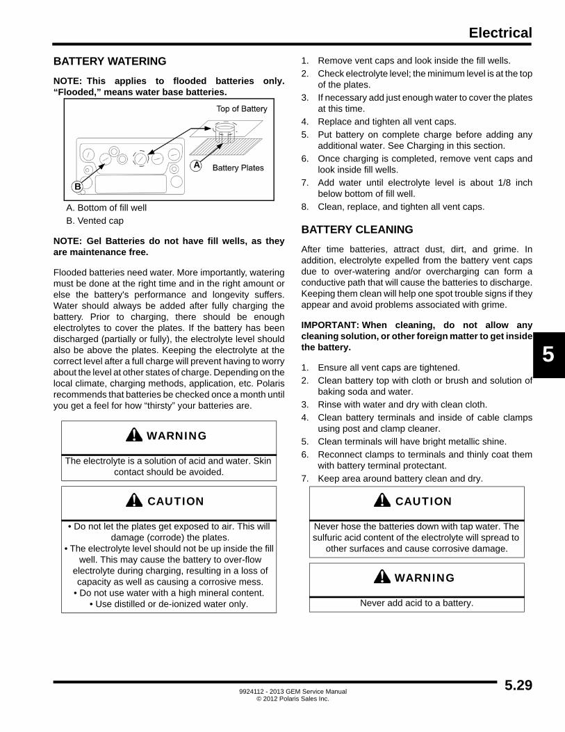
Electrical
5
BATTERY WATERING
NOTE: This applies to flooded batteries only.“Flooded,” means water base batteries.
A. Bottom of fill well
B. Vented cap
NOTE: Gel Batteries do not have fill wells, as theyare maintenance free.
Flooded batteries need water. More importantly, wateringmust be done at the right time and in the right amount orelse the battery's performance and longevity suffers.Water should always be added after fully charging thebattery. Prior to charging, there should be enoughelectrolytes to cover the plates. If the battery has beendischarged (partially or fully), the electrolyte level shouldalso be above the plates. Keeping the electrolyte at thecorrect level after a full charge will prevent having to worryabout the level at other states of charge. Depending on thelocal climate, charging methods, application, etc. Polarisrecommends that batteries be checked once a month untilyou get a feel for how “thirsty” your batteries are.
1. Remove vent caps and look inside the fill wells.
2. Check electrolyte level; the minimum level is at the topof the plates.
3. If necessary add just enough water to cover the platesat this time.
4. Replace and tighten all vent caps.
5. Put battery on complete charge before adding anyadditional water. See Charging in this section.
6. Once charging is completed, remove vent caps andlook inside fill wells.
7. Add water until electrolyte level is about 1/8 inchbelow bottom of fill well.
8. Clean, replace, and tighten all vent caps.
BATTERY CLEANING
After time batteries, attract dust, dirt, and grime. Inaddition, electrolyte expelled from the battery vent capsdue to over-watering and/or overcharging can form aconductive path that will cause the batteries to discharge.Keeping them clean will help one spot trouble signs if theyappear and avoid problems associated with grime.
IMPORTANT: When cleaning, do not allow anycleaning solution, or other foreign matter to get insidethe battery.
1. Ensure all vent caps are tightened.
2. Clean battery top with cloth or brush and solution ofbaking soda and water.
3. Rinse with water and dry with clean cloth.
4. Clean battery terminals and inside of cable clampsusing post and clamp cleaner.
5. Clean terminals will have bright metallic shine.
6. Reconnect clamps to terminals and thinly coat themwith battery terminal protectant.
7. Keep area around battery clean and dry.
WARNING
The electrolyte is a solution of acid and water. Skin contact should be avoided.
CAUTION
• Do not let the plates get exposed to air. This will damage (corrode) the plates.
• The electrolyte level should not be up inside the fill well. This may cause the battery to over-flow
electrolyte during charging, resulting in a loss of capacity as well as causing a corrosive mess.• Do not use water with a high mineral content.
• Use distilled or de-ionized water only.
A
B
CAUTION
Never hose the batteries down with tap water. The sulfuric acid content of the electrolyte will spread to
other surfaces and cause corrosive damage.
WARNING
Never add acid to a battery.
5.299924112 - 2013 GEM Service Manual
© 2012 Polaris Sales Inc.

Electrical
BATTERY STORAGE
Periods of inactivity can be extremely harmful to lead-acidbatteries. When placing a battery into storage, follow therecommendations below to make sure that the batteryremains healthy and ready for use.
NOTE: Storing, charging or operating batteries onconcrete is perfectly OK.
SMC - STORAGE MAINTENANCE CYCLE
NOTE: Your GEM car is equipped with a SMARTcharge capability. Simply leave the vehicle pluggedinto a standard 110 VAC 15 A power outlet. Thecharger unit will automatically power on once every2 weeks for gel batteries and once every 7 days forflooded, run a charge cycle and automatically shutdown. The charger will repeat this procedure 24times as long as power is not interrupted. Thisworks best for maintenance free sealed gel batteries.Water filled lead acid batteries may still require someattention to maintain proper fluid levels.
IMPORTANT: Avoid temperature extremes whenchoosing a storage area.
• Avoid locations where freezing temperature is expected. Keeping batteries at a high state of charge will also prevent freezing. Freezing results in irreparable damage to battery plates and container.
• Avoid direct exposure to heat sources, such as radiators or space heaters. Temperatures above 80 degrees F (27 degrees C) accelerate the battery's self-discharge characteristics.
1. Completely charge battery before storing.
2. Store vehicle in cool, dry location, protected fromelements.
3. During storage, monitor specific gravity or voltage.Batteries in storage should be given boost chargewhen they show 70% charge or less. See table in“Open Circuit Voltage Test”.
4. Completely charge battery before reactivating.
5. For optimum performance, equalize batteries beforeputting them back into service.
BATTERY CHARGING
Become familiar with the charger and follow theinstructions. See Charger in this chapter.
1. Batteries should be charged after each period of use.
2. Lead-acid batteries do not develop memory and neednot be fully discharged before recharging.
3. Check electrolyte level. See Watering in this section.
4. Tighten all vent caps before charging.
5. Do not undercharge batteries. Under charging causesstratification.
6. Do not charge a frozen battery.
7. Avoid charging at temperatures above 120 degrees F(49 degrees C).
WARNING
Charge batteries only in well-ventilated area. Keep sparks or flames away from charging battery.
5.30 9924112 - 2013 GEM Service Manual© 2012 Polaris Sales Inc.

Electrical
5
CHARGER
DESCRIPTION
The battery charger is located under the hood assemblyand is mounted to a plate above the motor/gear boxassembly, and is an integral part of the vehicle.
The battery charge receptacle is located on the front hoodassembly. It accepts a standard 3-wire (grounded)extension cord and should not exceed 25 feet in length 14gauge wire, or 50 feet in length for 12 gauge wire.
OPERATION
Insert the proper extension cord into the battery chargerreceptacle and into a standard 110-volt A/C, 15 amp-breaker outlet. (GFI is recommended). If using a GFIprotected charger cord, plug into a standard circuitbreaker that is NOT GFI protected.
NOTE: Make sure the master disconnect switch is inthe ON position.
When the battery charger is active, an integrated relay ofthe control circuit will enable and prevent further operationto the drive system of the vehicle, leaving it disabled. TheLCD (see further in this section) will illuminate and is onlyto be used as a guide. The indicator lights of the displaypanel on the left side of the charger will inform you of thecurrent battery charge status.
BATTERY CHARGE LEVEL
To ensure that your GEM car is 100% charged you canfollow these easy steps.
1. To properly charge GEM vehicle, plug car in and lookat display. Note charger cord icon and battery icon ofdisplay illuminate, along with battery percentageindicator.
2. When charging cycle is complete after 8 to 14 hours(depending on battery pack of 6-12 volt or 9-8 volt),battery percentage indicator will extinguish and onlycharger cord icon and bar graph will display.
CAUTION
Fully charge batteries before extended periods of use and/or storage. In extreme temperature (hot/
cold) climates, battery self-discharge will increase. Batteries will also freeze if not properly charged.
5.319924112 - 2013 GEM Service Manual
© 2012 Polaris Sales Inc.

Electrical
3. Determine 100% charge by looking at charger locatedunder hood. Kneel down beside left front wheel. Lookover tire toward center of vehicle. Locate yellow andblack charger unit. When left plugged in to charge,solid green light should appear on charger indicating100% charge cycle.
CHARGER REPLACEMENT
1. Position master disconnect switch OFF.
2. Remove upper and lower dash panels. See Bodysection.
3. Disconnect electrical connections, noting connectionand orientation.
4. Unlatch and open hood.
5. Disconnect charge receptacle wire from charger.
6. Raise and support the vehicle using suitable hoist.
7. Remove four mounting nuts from charger.
8. Reverse procedure to install.
CHARGING WHEN BELOW MIN VOLTAGE
The on-board charger has a safety feature, which does notallow it to turn on if the pack voltage is below 36 volts. If thebattery pack goes below this level an alternative chargingprocedure must be followed.
NOTE: Use the appropriate charger for theapplication. Failure to do so may result in injury orpersonal and property damage. Use a 12-voltcharger for 12-volt type batteries only. Charge onebattery at a time individually. Use a 24-volt chargerfor 8-volt and/or 12-volt type batteries; two 12-voltbatteries at one time or three 8-volt batteries at onetime.
1. Position master disconnect switch OFF.
2. Using automotive-type charger, charge each batteryindividually. Set charger on medium current level (10-30 Amps). Allow enough charge time so voltage oneach battery is at least 11.5 volts (30 minutes to 1 hourper battery).
3. After all batteries have been charged, remove chargerand position master disconnect switch ON. Measuretotal pack voltage. If pack voltage is above low voltagethreshold, plug in on-board charger. Allow on-boardcharger to run its complete cycle.
If a fault occurred anytime during charging, the red FAULTLED will flash with a code corresponding to the error.There are several possible conditions that will generateerrors. Some errors are serious and require humanintervention to first resolve the problem and then to resetthe charger by removing and then restoring AC power.Other errors will automatically recover when the faultcondition is eliminated. To determine which erroroccurred, the FAULT LED will flash a number of times atrate of one second, and then pause for 1.5 seconds andthen repeat.
5.32 9924112 - 2013 GEM Service Manual© 2012 Polaris Sales Inc.

Electrical
5
OPERATING INSTRUCTIONS
1. Always use grounded outlet. When using extensioncord, avoid excessive voltage drops by usinggrounded 3-wire 12 AWG cord.
2. The charger will automatically turn ON and go throughshort LED indicator self-test (all LED's will flash in up-down sequence for two seconds). If charger is usedwith master disconnect switch OFF and is waiting tobe connected to battery pack, charging algorithmnumber will be displayed for 11 seconds (see “Check/ Change Charging Algorithm”) before ultimatelydisplaying under-voltage fault until AC is cycled.
3. Once minimum battery voltage is detected, thecharger will enter the bulk charging constant-currentstage and current to the batteries will be displayed bythe LED light on the display of the charger unit. Thelength of charge time will vary by how large and howdepleted the battery pack is, the input voltage (thehigher, the better), and ambient temperatures (thelower, the better). If the input AC voltage is low (below104VAC), then the charging power will be reduced toavoid high input currents ('AC' LED extinguished). Ifthe ambient temperature is too high, then the chargingpower will also be reduced, attempting to lower theinternal temperature (charger display will flashYELLOW LED light but may become blank or “blackedout”).
4. When the battery is at approximately 80% state ofcharge, the bulk stage has completed and an > 80%charge indication is given by turning on the '80%' LED.In the next phase known as the absorption orconstant-voltage phase, the last 20% of charge is thenreturned to the battery. The charging could beterminated at this point if the vehicle requiresimmediate usage, however, it is highly recommendedto wait until 100% charge indication is given to ensuremaximum battery capacity and life.
5. A low current “finish-charge” phase is next applied toreturn and maintain maximum battery capacity (the'100%' LED will flash).
6. When the '100%' LED is continuously GREEN, thebatteries are completely charged. The charger maynow be unplugged from AC power (always pull on plugand not cord to reduce risk of damage to the cord). Ifleft plugged in, the charger will automatically restart acharge cycle after the interval time has elapsed (every7 days for flooded batteries; every 14 days for gelbatteries).
7. If a fault occurred anytime during charging, a faultindication is given by flashing RED with a codecorresponding to the error. There are several possibleconditions that generate errors. Some errors areserious and require human intervention to first resolvethe problem and them to reset the charger by
interrupting AC power for at least 30 seconds. Othersmay be simply transient and will automatically recoverwhen the fault condition is eliminated. To indicatewhich error occurred, a fault indication will Flash REDa number of times, pause, and then repeat.
[1 FLASH] Battery Temperature Out of Range: the batteryis too hot or cold to charge. Check temperature sensor foropen or shorted circuit.
[2 FLASH] Battery Voltage Out of Range: the batteryvoltage is too high or low to allow charging to proceed.
[3 FLASH] Charge Time out: the charge did not completein the allowed time. This may indicate a problem with thebattery pack) voltage not attaining the required level), orthat the charger output was reduced due to high ambienttemperatures.
[4 FLASH] AC Shutdown; auto-recover. Charger hasshutdown due to AC voltage going out of range (under 104VAC). Charger will restart when AC voltage comes back into range and the SMC interval has elapsed.
[5 FLASH] Over-Temperature: auto-recover. Charger hasshutdown due to high internal temperature which typicallyindicates there is not sufficient air flow for cooling - (seeInstallation Instruction 1). Charger will restart and chargeto completion if temperature is within accepted limits.
[6 FLASH] QuiQ Fault: an internal fault has beendetected. Verify location and connection of the chargermain RED and BLACK wires. Unplug AC power for 30seconds, then plug in again. If fault still remains, replacecharger.
5.339924112 - 2013 GEM Service Manual
© 2012 Polaris Sales Inc.

Electrical
CHECK/CHANGE CHARGE ALGORITHM
The charger comes pre-loaded with charge algorithms asdetailed in table below. Each time AC power is applied withthe battery pack NOT connected, the charger enters andalgorithm display mode for about 11 seconds. During thistime, the current algorithm number is indicated by thenumber of blinks of the '80%' LED and Remote LED. Asingle-digit algorithm number is indicated by the number ofblinks followed by a pause. A 2-digit algorithm number isindicated by the number of blinks for the 1st digit followedby a pause, then the number of blinks for the 2nd digitfollowed by a longer pause. To check/change the chargingalgorithm.
1. Disconnect the charger positive connect by flippingthe master switch. Start with the switch in the OFFposition. Apply AC power and after the LED test, thealgorithm number will display for 11 seconds.
2. To enter algorithm selection mode, flip the masterdisconnect switch ON during the 11 seconds displayperiod right after the first algorithm number isdisplayed for 1 second and then OFF. HINT: Countto 1 as 100.
3. To change algorithm, turn switch ON during the 2minute display period for 4 seconds and then OFF -the algorithm number will advance after 3 seconds.HINT: Count to 4 as 100, 200, 300, 400.
4. Repeat until desired algorithm number is displayed. A2-minute time out is extended for every increment.Incrementing beyond the last algorithm moves backto the first algorithm. After the desired algorithmnumber is displayed, turn the switch ON until theoutput relay is heard to click (10 seconds) - theselection is now stored in permanent memory.
NOTE: Pack recovery (PRC) algorithm selection isnot stored in permanent memory. After selecting thisalgorithm, connect the charger to the battery withoutinterrupting AC power. After about 10 seconds, thecharger will begin charging. Use of the PRCalgorithm is indicated by the '80%' and '100%' LEDsflashing together. When the PRC charge completes afull charge cycle, the charger will revert back to theprevious algorithm (i.e., Algorithm 15 will changeback to 14 and Algorithm 25 will change back to 24).
5. It is highly recommended to confirm a newly changedalgorithm selection by repeating Step 1.
ALG # Battery Type
13 Trojan flooded NC #30XHS/SCS225
14 DEKA gel 12V NC #8G31
15 DEKA gel 12V PRC #8G31
24 DEKA gel 8V NC #8G8VGC
25 DEKA gel 8V PRC #8G8VGC
32 DEKA flooded NC #DC31DT
5.34 9924112 - 2013 GEM Service Manual© 2012 Polaris Sales Inc.

Electrical
5
FAST CHARGING SYSTEM
DESCRIPTION
The Fast Charger is a battery charging system that allowsfor opportunity charging of an electric vehicle. The LSV-100 is a stand-alone unit that is externally isolated from thevehicle and secured to its own Pedestal style mount (soldseparately) or mounted to a wall.
The Convenience Charger is a unique battery chargingsystem that allows for opportunity charging of an electricvehicle. The LSV-2472 is ideally suitable for electricvehicles operating in applications such as campuses,commercial fleets, military bases and resorts. This unit isspecial as it is portable and easily transferrable from onelocation to another.
OPERATION
The charger is equipped with a large cabled harness thatneeds to be inserted to the battery charge receptacle,located under the hood of the vehicle. (“Accessory” optionwould have to be installed on each GEM vehicle to be usedwith Fast Charger or Convenience Charger.)
If using the LSV-100 be sure the main circuit breaker forthe unit is turned On for power to the Fast Charger. Onceit is plugged in to the vehicle it will automatically detectbattery voltage present and begin the charge cycle.
If using the LSV-2472 be sure to connect the AC powercord to the appropriate wall circuit for power. Once it isplugged in to the vehicle it will automatically detect batteryvoltage present and begin the charge cycle.
NOTE: Make sure the Master Disconnect Switch(MDS), located in the Access Panel of the whiteLower Dash, is turned ON.
When the charger is active, an integrated relay of thecontrol circuit will enable and prevent further operation tothe drive system of the vehicle, leaving it disabled. TheLCD (see further in this section) will illuminate and is onlyto be used as a guide. The indicator light of the displaypanel on the Fast Charger unit will inform you of thecurrent battery charge status.
5.359924112 - 2013 GEM Service Manual
© 2012 Polaris Sales Inc.

Electrical
The Fast Charger Receptacle is installed under the hoodof the GEM vehicle and comes with all of the majorcomponents necessary to charge from the LSV-100 FastCharger or the LSV-2472 Convenience Charger.Thecharger user interface consists of four (4) LED's (LSV-100only) on the front panel of the unit (from top to bottom):
White - The charger has been powered up and is ready foruse. The vehicle can then be connected to the charger.(This LED normally blinks)
Blue - Charging is underway. The speed at which the bluelight flashes indicates the rate of charge being supplied tothe batteries.
Green - Charging has completed and it is safe todisconnect the vehicle from the charger.
Red - A fault condition has been identified. Refer to theTroubleshooting section for assistance and explanation offault codes for the Fast Charge system.
FAST CHARGER TROUBLESHOOTING
The Fast Charge unit (LSV-100) is equipped with a redLED on the front panel. This LED will illuminate in theevent of an error. The LED will flash repeatedly a givennumber of times between 1 and 8 with a 2-second pausebetween a series of flashes. The number of flashes perseries corresponds to one of the following fault conditions:
[1 FLASH] Vehicle Detection Fault - Battery pack voltageout of range, too high/low.
[2 FLASH] Current Not Detected - Related battery packvoltage detection issue; no connection, control notresponding; Current less than 2 amps.
[3 FLASH] Unexpected High Current - Related batterypack voltage detection issue; Current in Step 3 jumpedgreater than 40 amps.
[4 FLASH] Over Current/Under Voltage - currentexceeded 108 amps for 0.3 seconds.
[5 FLASH] Under Current/Over Voltage - current less than2 amps or voltage greater than 118VDC; loss of currentcaused spike in voltage for more than 2 seconds;exceeded 115VDC in Step 3, possible Open circuit batterypack or dead pack.
[6 FLASH] Thermal Fault - Chargers Temperature sensoron vehicle or internal Module or Rectifier temperatureexceeded 122 degrees Fahrenheit.
[7 FLASH] Invalid Start Current/Programming Fault - Thecontrol failed to communicate with the module; Moduledisconnected or Controller defective.
[8 FLASH] Amp Hour Limit Reached - Maximum Amp/hour rate exceeded.
To clear any fault condition, disconnect the vehicle fromthe charger. Disconnect AC power if possible. Wait severalminutes. Reconnect AC power and then reconnect powerfrom the charger to the vehicle.
NOTE: Some faults may not reset. For moreinformation see table below.
5.36 9924112 - 2013 GEM Service Manual© 2012 Polaris Sales Inc.

Electrical
5
Fast Charger Troubleshooting Table
SYMPTOM POSSIBLE CAUSE
When I plug in the charger I do not see the charger current rise and the fan does not work.
1. The cable may not be fully seated in the charge receptacle. Try re-seating the plug into the vehicle.
2. Verify that the A/C receptacle has the proper voltage for the charger.
The charger will charge the batteries but the fan does not turn on.
1. The cable may not be fully seated in the charge receptacle. Try re-seating the plug into the vehicle.
2. Check the loop back wire between pins 3 & 4 on the charging receptacle.
The fan turns on but no current is delivered.1. Check for 24VAC between pins 1 & 2 on the charging plug with the
charger plugged into the AC receptacle.2. Verify that the A/C receptacle has the proper voltage for the charger.
After plugging in the charger the charger will suddenly stop charging and the fan will turn off as well.
Verify that the circuit breaker for the AC circuit is of the proper current for this charger. Also make sure that no other equipment is attached to the same circuit. If both of these conditions are met unplug the charger and contact GEM technical support.
The A/C plug will not fit into the wall outlet.
The charger is delivered with a typical A/C plug for a 220VAC, 15A circuit. Other receptacle configurations are available. Check with a local electrician to replace the wall receptacle, the charger plug or both. Ensure that the circuit is properly sized for the charger load.
The DC plug will not fit into the Electric Vehicle charge Receptacle.
1. Verify that the plug is properly oriented. A keyed divot should be facing up when inserting the plug into the charger.
2. Unplug the charger completely and inspect the DC charger cable and the charger receptacle for damage or obstructions. If any damage is present on the DC charging cable contact GEM technical support immediately.
During charging the fan will turn off or the fan does not turn at all.
If after checking to make sure that the DC cable is secure the fan still does not work unplug the charger and contact GEM technical support.
5.379924112 - 2013 GEM Service Manual
© 2012 Polaris Sales Inc.

Electrical
MOTOR CONTROLLER
DESCRIPTION
A. Motor controller
The motor controller, located under the hood assembly, isthe brain of the GEM vehicle. Based on inputs from theaccelerator pedal and the drive mode switch, the controllerconverts battery power into the appropriate drive power forthe vehicle's electric motor. The controller also generatesdrive system status information that is displayed on theliquid crystal display (LCD).
OPERATION
The controller functions automatically when the key switchis in the ON position. There are no other direct operatorinteractions with the motor controller module. Operation ofthe motor controller is accomplished by actuation of thedevices such as the accelerator pedal, and the drive modeswitch.
DIAGNOSIS AND TESTING
The motor controller function is critical to every aspect ofthe drive system. If a fault occurs with the motor controller,you should see an error code on the liquid crystal display(LCD). Use the Drive and Power System Error Codessection to help in isolating the fault.
MOTOR CONTROLLER REMOVAL
1. Turn master disconnect switch OFF.2. Unlatch and open hood.
3. Note connector locations and wire orientations onmotor controller (A), and disconnect all cables andconnectors.
4. Remove six bolts (B) and motor controller (A).
MOTOR CONTROLLER INSTALLATION
1. Install motor controller (A) and six bolts (B). Torquebolts to specification.
2. Connect all wires and connectors. Torque negativeand positive armature cables to specification.
3. Close and latch hood.
4. Turn master disconnect switch ON.
A
B
= T
Motor Controller Mounting Bolts:65 in-lbs (7 Nm)
= T
Negative And Positive Armature Cables:50 in-lbs (6 Nm)
5.38 9924112 - 2013 GEM Service Manual© 2012 Polaris Sales Inc.

Electrical
5
DC / DC CONVERTER
DESCRIPTION
A. DC/DC Converter
The DC/DC converter is located under the hood assembly.It is an integrated unit to the battery charger, previouslydiscussed in this section. The converter serves thefunction of converting the high voltage delivered by thebatteries (72 VDC) to lower voltage (12 VDC). The lowervoltage is used to power all the devices that are part of theaccessory system - key switch, headlights, taillights,directional indicators, brake lights, horn, heater, light bar,power outlet, radio and wiper. The DC/DC convertersupplies 30 amps.
OPERATION
The DC/DC converter functions automatically when themaster disconnect switch is in the ON position. An enablecircuit is controlled by the key switch and an internal timedelay for switched 12-volt power.
DIAGNOSIS AND TESTING
Diagnosis and testing of the DC/DC converter is coveredin the Accessory System Troubleshooting Chart. Thecircuit diagrams provided in this manual are also useful inisolation of problems associated with the DC/DCconverter.
DC / DC CONVERTER REMOVAL
1. Position master disconnect switch OFF.2. Remove upper and lower dash panels. See Body
section.
3. Unlatch and open hood.
4. Note connector locations and wire orientations, andremove electrical connections to DC/DC converter(A).
5. Disconnect charge receptacle wire from charger.
6. Remove four bolts and four nuts from charger withintegrated DC/DC converter (A) and remove unit.
DC / DC CONVERTER INSTALLATION
1. Install DC/DC converter (A), four bolts, and four nuts.Torque to specification.
2. Install charger and DC/DC converter connections.
3. Connect charge receptacle.
4. Install upper and lower dash panels. See Bodysection.
5. Close and latch hood.
6. Position master disconnect switch ON.
A
= T
DC/DC Converter Mounting Nuts:120 in-lbs (163 Nm)
5.399924112 - 2013 GEM Service Manual
© 2012 Polaris Sales Inc.

Electrical
MAIN CONTACTOR
DESCRIPTION
A. Main contactor
The main contactor is an electronically controlled switchthat provides a high-current connection between thebattery and the motor controller. It is located under thedash, and behind the PSDM.
OPERATION
The motor controller activates the main contactor if the keyswitch is on, and the motor controller determines highvoltage, high current power should be supplied to the drivemotor. The motor controller will not activate the maincontactor if an error condition exists. See Drive and PowerSystem Error Codes chart.
MAIN CONTACTOR REMOVAL
1. Position master disconnect switch OFF.2. Remove upper and lower dash. See Body section.
3. Remove electrical connections, noting connectionand orientation of each wire.
4. Remove screws that mount contactor to the frontbulkhead.
MAIN CONTACTOR INSTALLATION
1. Install contactor and screws to front bulkhead.Torque to specification.
2. Connect electrical connections, noting connectionand orientation for each wire.
3. Install upper and lower dash. See Body section.
4. Position master disconnect switch ON.
A
= T
Main Contactor Retaining Nuts:120 in-lbs (163 Nm)
5.40 9924112 - 2013 GEM Service Manual© 2012 Polaris Sales Inc.

Electrical
5
MOTOR
DESCRIPTION
Power to the drivetrain is supplied by a 72-volt electricmotor, which is attached to the differential. The motorspeed (RPM) is monitored by a small magnet and a speedsensor (tachometer) mounted to the center rear of themotor.
B
C
A
A. Motor armature 2 D. Motor armature 1 (below E)
B. Speed sensor (tach) E. Motor field 2
C. Motor temp switch F. Motor field 1
E
F
D
5.419924112 - 2013 GEM Service Manual
© 2012 Polaris Sales Inc.

Electrical
OPERATION
Motor activation and speed are controlled by the motorcontroller based on the signal from the potentiometerlocated in the accelerator pedal in the cab. A splined cupin the motor is connected to a splined shaft on the piniongear in the differential. Rotational motion of the motor'scup transmits that motion to the differential.
DIAGNOSIS AND TESTING
Refer to the Drive and Power System TroubleshootingChart A and B. The circuit diagrams provided in thismanual are also useful in isolation of problems.
MOTOR REMOVAL
1. Unlatch and open hood.
2. Position master disconnect switch OFF.
3. Remove front wheel and tire assemblies. See Wheeland Tire section.
4. If equipped, remove black plastic air scoop to gainaccess to motor (A).
5. Disconnect power wires from top and rear of motor (A)with, noting connections and locations.
6. Disconnect speed sensor (B).
7. Disconnect temp sensor (C).
8. While supporting 30-40 lbs. motor (A), remove threemotor/differential mounting bolts (D), flat washers,and motor (C).
9. Noting orientation of power posts for reassembly,remove motor (A) from differential (E) and pull straightout.
MOTOR INSTALLATION
NOTE: The cupped end of the bumper will faceoutward.
1. Install new resilient bumper inside motor splinesocket. Ensure bumper is completely installed inspline socket.
2. Lightly coat splined differential shaft (not necessary)with Valvoline Special Moly EP grease or equivalent(Too much grease will cause motor problems.)
3. Install motor, ensuring power posts face samedirection as before.
4. Add Loctite® 242 and install three motor/differentialmounting bolts and flat washers. Torque bolts tospecification.
5. Connect power wires to top and rear of motor. Torqueto specification.
6. Install air scoop if previously removed.
7. Install front wheel and tire assemblies. See Wheel andTire section.
8. Position master disconnect switch ON.
9. Close and latch hood.
B
C
A
D
E
Grease:Valvoline Special Moly EP or equivalent
= T
Motor/Differential Mounting Bolts:65 in-lbs (7 Nm)
= T
Terminals:40-60 in-lbs (5-7 Nm)
5.42 9924112 - 2013 GEM Service Manual© 2012 Polaris Sales Inc.

Electrical
5
MOTOR MAGNET AND SPEED SENSOR (TACHOMETER)
DESCRIPTION
A small circular magnet is mounted to the motor spindle.A sensor, attached to a pigtail, sits in close proximity to themagnet. Access to the magnet and sensor is gainedthrough a small plate in the center of the motor's endpanel.
A. Speed sensor (tachometer)
OPERATION
When the motor armature rotates the magnet rotates also.The sensor detects the magnet's motion, and transmits asignal through its pigtail to the motor controller.
DIAGNOSIS AND TESTING
The speed sensor carries a 12-volt signal through a businternal to the Motor Controller. Using a DC Voltmeter,unplug or back probe the red and black wires of the 3-wirespeed sensor pigtail harness and check for 12 volts.
The green wire is a signal wire. Turn the key on. From theMotor Controller 23-pin harness, locate Pin 14 and backprobe to the green wire of the 3-wire speed sensor pigtailharness and check for continuity.
Perform a visual inspection of the sensor and the internalMotor Magnet. Remove the Speed Sensor from the end ofthe motor. Inspect the magnet attached to the motorsarmature shaft for fractures.
Refer to Troubleshooting Diagram A.
Refer to the Drive and Power Systems TroubleshootingCharts A & B.
SPEED SENSOR REMOVAL
1. Disconnect sensor/pigtail assembly (A).
2. Remove two bolts (B) and sensor/pigtail assembly(A).
SPEED SENSOR INSTALLATION
1. Install sensor/pigtail assembly and two bolts.
2. Connect sensor/pigtail assembly.
A
A
B
5.439924112 - 2013 GEM Service Manual
© 2012 Polaris Sales Inc.

Electrical
LIQUID CRYSTAL DISPLAY (LCD)
DESCRIPTION
The liquid crystal display (LCD) is located in the center ofthe instrument pod and performs the following functions:
1. State of charge and charging indicator.
2. MPH/KPH speed indicator.
3. Accumulated miles/kilometers.
4. Drive mode indicator.
5. Fault code display.
6. Warning indicators and turn signal indicators.
7. E-meter/AC Power Consumption.
OPERATION
With key switch ON, the state of charge indicator displaysremaining battery capacity. The remaining batterycapacity is displayed in a bar type graph. There is one redbar, one yellow bar, and eight green bars for a total of tenbars. Each bar represents approximately 10% of batterycapacity. For example, one red bar, one yellow bar, andthree green bars would equal 50% battery capacity.
LCD REMOVAL
1. Remove upper dash panel. See Body section.
2. Remove lower dash panel. See Body section.
3. Remove RH and LH pod covers. See Pod Covers inBody section.
4. Disconnect two electrical connectors.
5. Remove two screws at back of LCD mounting bracket.
A. Electrical connectors
B. Mounting screws
LCD INSTALLATION
1. Install two screws into LCD.
2. Attach two connectors to back of LCD.
3. Install RH and LH pod covers. See Pod Covers inBody section.
4. Install lower dash panel. See Body section.
5. Install upper dash panel. See Body section.
LCD
B
A
B
5.44 9924112 - 2013 GEM Service Manual© 2012 Polaris Sales Inc.

Electrical
5
PSDM
DESCRIPTION
The Power Signal Distribution Module (PSDM) is anelectrical component that acts as a central hub for all 72and 12-volt power.
OPERATION
Both 72 and 12-volt inputs come into the PSDM and aredispersed through the fuses to the appropriate electricalcomponents.
PSDM REMOVAL
1. Position key switch and master disconnect switchOFF.
2. Remove upper and lower dash. See Body section.
3. Noting connection and orientation for each wire,remove all connectors and cables from PSDM (A).
4. Remove four mounting nuts (B) securing PSDM (A) tomounting plate.
5. Lightly pry around mounting studs working back andforth between all studs, and remove PSDM (A).
PSDM INSTALLATION
NOTE: Side of nut with star washer must bemounted to enclosure.
1. Install PSDM and four mounting nuts. Torquemounting nuts to specification.
2. Connect all connectors and cables noting connectionand orientation for each wire.
3. Install upper and lower dash. See Body section.
4. Position key switch and master disconnect switch ON.
BA
= T
PSDM Mounting Nuts:72 in-lbs (9 Nm)
= T
Cable Connection Studs (+72 stud, 72 GND stud, B- stud): 80 in-lbs (8 Nm)
MDS Cable Connections: 65 in-lbs (7 Nm)
5.459924112 - 2013 GEM Service Manual
© 2012 Polaris Sales Inc.

Electrical
5.469924112 - 2013 GEM Service Manual
© 2012 Polaris Sales Inc.

Electrical
5
ACCESSORY SYSTEM
DESCRIPTION
The standard accessory system components for the GEMare essential for safe driving and consist of the headlights,taillights, directional indicators, brake lights, horn, poweroutlet, and wiper. Some vehicles are equipped with aradio, light bar, and heater that are considered optionalequipment.
OPERATION
Standard accessories receive their 12-volt power from thefuse protected DC/DC converter. The DC/DC converterreceives 72-volt input power directly from the six batteriesand requires no user action for its operation. All othercomponents of the Accessory System function identical tothose devices in a standard automobile.
The two headlights are 12-volt single filamentincandescent bulbs. A rocker switch located on theinstrument pod activates headlights. (HI/LO beams arestandard and consist of dual-filament bulbs.)
Taillights and brake lights are 12-volt dual filamentincandescent bulbs. One filament is used for directionalindicators and brake lights. The second taillight filament isactivated when the headlights are turned on.
There are 4 directional indicators, left and right front, andleft and right rear. Turn signal lever located on the left sideof the instrument pod activates the directional indicators.The turn signal indicator has a built-in time delay relay andbuzzer set for 45 seconds as a reminder. As the turnindicators are selected and not switched off within the 45-second period a small beeping sound will omit as areminder to switch the turn signals off.
The horn provides a single continuous tone when the hornbutton is pressed. The horn button is located on the leftside of the instrument pod.
The heater operates by the heater switch located in thecenter lower dash panel. The heater blower motoroperates by receiving 12 VDC from the fuse protected DC/DC converter. The heater element runs on 72 VDC fuseddirect feed from the batteries through the heater contactor.
The light bar operates by the light bar switch located in thecenter lower dash. The light bar is powered by receiving 12VDC from the fuse protected DC/DC converter.
The power outlet is located in the center lower dash andis running on 12 VDC from the fuse protected DC/DCconverter.
5.479924112 - 2013 GEM Service Manual
© 2012 Polaris Sales Inc.

Electrical
The radio is located in the headliner and is running on 12VDC from the fuse protected DC/DC converter.
A single speed DC motor powers the wiper. The motorautomatically returns the wiper to the Parked positionwhen the wiper is turned off. The windshield washer isactivated using the multi-function turn signal lever switchlocated to the left of the instrument pod.
A. Heater switch
B. Light bar switch
C. Power outlet
DIAGNOSIS AND TROUBLESHOOTING
The purpose of this section is to aid in the isolation ofproblems with the accessory system. Unlike the drivesystem, the LCD does not provide any error codes to aidin troubleshooting problems with accessories. The mostcommon problems with the accessory system are an openlamp filament, a faulty switch, improper wiring connectionsand blown fuses. For problems that cannot be resolved bylamp and fuse replacement, refer to the AccessorySystem Troubleshooting Chart and the wiring diagramsprovided.
As was the case with the drive system, the informationprovided in this section is a guide only. There arenumerous variations in the skill level of personnel thatservice this vehicle. This manual cannot possiblyaccommodate all skill levels and provide advice for each.A basic understanding of electronics and troubleshootingtechniques is required.
A
C
B
5.48 9924112 - 2013 GEM Service Manual© 2012 Polaris Sales Inc.

Electrical
5
ACCESSORY SYSTEM TROUBLESHOOTING CHART
ConditionPossible Causes and Diagnostic
StepsCorrection
A single bulb (headlight, taillight or directional indicator) does not work.
Remove the bulb (see bulb removal replacement instructions below), Visual inspect the bulb or measure the filament with an ohmmeter.
If the filament is visibly open or the filament resistance is greater than 100 ohms, replace the bulb.
The head lamps, tail lamps, the front and rear directional indicators, horn, heater, light bar, power outlet, radio and wiper do not work.
Using a voltmeter with the key switch ON, test for voltage at the following locations:• 12 VDC at the PSDM J4, pins A
and B.• 72 VDC at the DC/DC converter/
charger, main RED and BLACK wires).
Verify the connectors on the DC/DC converter/charger and the PSDM J4 have not come loose.
If there is 72 VDC at the DC/DC converter/charger, RED and BLACK wires, and no voltage pins A and B at PSDM J4 with the key switch ON, replace the DC/DC converter/charger. If there is 12 VDC at the PSDM J4 pins A and B with the key switch ON, and the accessories are not working, verify fuses and then replace the PSDM as necessary.
Headlights and taillights do not work, but front and rear directional indicators do work.
Visually inspect the F1 fuse or measure with an ohmmeter to determine if it is open.Light switch.
Replace the F1 fuse if open (10A). If fuse is not open, use the Front Lighting Circuit Diagram (headlights and taillights share common circuitry) and a voltmeter to isolate the problem.
Rear brake lights do not work, but the rear directional indicators do work.
Brake pressure switch. Visually inspect fuse F6 or measure with an ohmmeter to determine if it is open.
Check for voltage at the brake lights when the brake pedal is pressed. If voltage is not present, check the brake pressure switch, voltage circuits, ground circuits, PSDM. Use the Rear Lighting Circuit Diagram and a voltmeter to isolate the problem. Replace the fuse if open.
Brake warning indicator staysIlluminated.
1. Check hand brake switch. Are there 12 volts at Red/White wire?
2. Check that switch has continently with hand brake released (handle down).
3. Check Circuit Diagram in this section.
1. If 12 volts is not present, check F10 fuse and Red/White wire at spade 6 in PSDM.
2. Replace or adjust switch as necessary.3. Use Display Circuit Diagram and a voltmeter to
isolate the problem.
The rear lamps do not work.
Verify tail light harness connection with rear harness.
If the connection is not loose, use the Rear Lighting Circuit Diagram and a voltmeter to isolate the problem.
5.499924112 - 2013 GEM Service Manual
© 2012 Polaris Sales Inc.
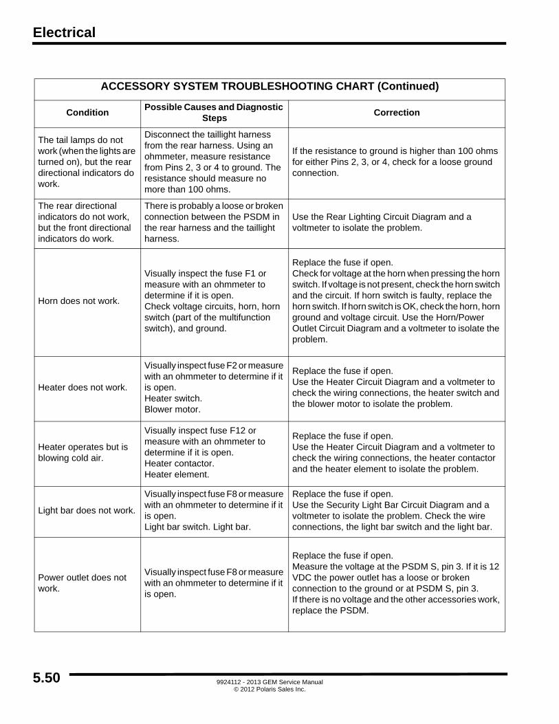
Electrical
ACCESSORY SYSTEM TROUBLESHOOTING CHART (Continued)
ConditionPossible Causes and Diagnostic
StepsCorrection
The tail lamps do not work (when the lights are turned on), but the rear directional indicators do work.
Disconnect the taillight harness from the rear harness. Using an ohmmeter, measure resistance from Pins 2, 3 or 4 to ground. The resistance should measure no more than 100 ohms.
If the resistance to ground is higher than 100 ohms for either Pins 2, 3, or 4, check for a loose ground connection.
The rear directional indicators do not work, but the front directional indicators do work.
There is probably a loose or broken connection between the PSDM in the rear harness and the taillight harness.
Use the Rear Lighting Circuit Diagram and a voltmeter to isolate the problem.
Horn does not work.
Visually inspect the fuse F1 or measure with an ohmmeter to determine if it is open.Check voltage circuits, horn, horn switch (part of the multifunction switch), and ground.
Replace the fuse if open.Check for voltage at the horn when pressing the horn switch. If voltage is not present, check the horn switch and the circuit. If horn switch is faulty, replace the horn switch. If horn switch is OK, check the horn, horn ground and voltage circuit. Use the Horn/Power Outlet Circuit Diagram and a voltmeter to isolate the problem.
Heater does not work.
Visually inspect fuse F2 or measure with an ohmmeter to determine if it is open.Heater switch.Blower motor.
Replace the fuse if open.Use the Heater Circuit Diagram and a voltmeter to check the wiring connections, the heater switch and the blower motor to isolate the problem.
Heater operates but is blowing cold air.
Visually inspect fuse F12 or measure with an ohmmeter to determine if it is open.Heater contactor.Heater element.
Replace the fuse if open.Use the Heater Circuit Diagram and a voltmeter to check the wiring connections, the heater contactor and the heater element to isolate the problem.
Light bar does not work.
Visually inspect fuse F8 or measure with an ohmmeter to determine if it is open.Light bar switch. Light bar.
Replace the fuse if open.Use the Security Light Bar Circuit Diagram and a voltmeter to isolate the problem. Check the wire connections, the light bar switch and the light bar.
Power outlet does not work.
Visually inspect fuse F8 or measure with an ohmmeter to determine if it is open.
Replace the fuse if open.Measure the voltage at the PSDM S, pin 3. If it is 12 VDC the power outlet has a loose or broken connection to the ground or at PSDM S, pin 3.If there is no voltage and the other accessories work, replace the PSDM.
5.50 9924112 - 2013 GEM Service Manual© 2012 Polaris Sales Inc.

Electrical
5
ACCESSORY SYSTEM TROUBLESHOOTING CHART (Continued)
ConditionPossible Causes and Diagnostic
StepsCorrection
Radio does not work.
Visually inspect fuses F10 and F3 or measure with an ohmmeter to determine if it is open.
Radio assembly (radio and speakers).
Replace the fuses if they are open.
Use the Audio System Circuit Diagram to check the wire connection and 12 VDC at PSDM S, pins 1 and 6.
If there is 12 VDC at PSDM S, pins 1 and 6 with the key switch ON and there are no loose or broken connections in the wiring, replace the radio.
If there is no voltage at PSDM S, pin 1 or pin 6 and the other accessories are working, replace the PSDM.
Wiper does not work.
The wiper motor has overload protection and may stop working for a short period of time if the windshield is very dry. Wait a moment and try operating the wipers again.
If the wipers fail to operate, visually inspect fuse F7 or measure with an ohmmeter to determine if it is open.
Wiper switch (part of the multifunction switch).
Wiper motor.
Replace the fuse if open.
Check for voltage at the wiper motor when the wiper switch is on. If voltage is not present, check the wiper switch (part of the multifunction switch), the voltage circuit, or the motor assembly.
Use the Wiper Circuit Diagram and a voltmeter to isolate the problem.
Wiper works but the windshield washer does not.
Windshield washer pump.
Windshield washer switch.
Loose or broken wiring connections.
Use the Wiper Circuit Diagram and a voltmeter to check the voltage at the washer switch and the voltage and ground connections at the washer pump.
5.519924112 - 2013 GEM Service Manual
© 2012 Polaris Sales Inc.

Electrical
ACCESSORY SYSTEM COMPONENT REPLACEMENT
FUSE REPLACEMENT
1. Open fuse panel access door.2. Locate blown fuse using volt/ohm meter.
3. Use fuse puller to remove fuse.
4. Replace with appropriate size fuse. See ECMtroubleshooting section for appropriate sizes.
5. Reverse the removal procedure to install.
HEADLIGHT REPLACEMENT
1. Unlatch and open hood.2. Disconnect black and violet wires and remove light
from mounting bracket.
3. Reverse procedure to reassemble.
4. Adjust headlight as follows: Position front of car aboutfive feet away from wall. Turn on headlights and adjustthem so center of beam on wall is about one inch lowerthan center of light on car.
FRONT TURN INDICATOR LAMP REPLACEMENT
1. Unlatch and open hood.
2. Remove lock nut from light and disconnect the red andblack wires.
3. Replace light assembly.
4. Reverse removal procedure to install.
REAR TURN INDICATOR LAMP REPLACEMENT
1. Remove two screws and lens.
2. Twist bulb counterclockwise to remove, noting type ofbulb, and replace. (2057/2067)
3. Reverse removal procedure to install.
WIPER MOTOR REPLACEMENT
1. Unlatch and open hood.2. Remove upper dash panel. See Body section.
3. Remove wiper arm and blade with 13mm socket; orfor the style without nut, gently pry off arm with a largescrewdriver.
4. Remove Tek screws from wiper bracket.
5. Disconnect yellow/blue and white/blue electrical wiresfrom wiper motor.
6. Remove capture nut, washer and rubber bushing fromwiper shaft. Remove wiper from windshield sill.
7. Reverse removal procedure to install.
INSTRUMENT POD REPLACEMENT
1. Remove upper and lower dash panels. See PodCovers in the Body section.
2. Remove Pod covers. See Pod Covers in Bodysection.
3. Remove steering wheel. See Steering Wheel inSteering and Suspension section.
4. Remove four self-tapping screws.
5. Reverse removal procedure to install.
F1 - Head/Tail Lights (10A)F8 - Power Outlet and Light Bar (10A)
F2 - Heater Switch (10A) F9 - Key Switch (1A)
F3 - Radio Switch (1A)F10 - Radio Memory/Power (10A)
F4 - Odometer Switch (1A) F11 - Spare
F5 - Display (1A)F12 - Heater Contactor (30A)
F6 - Blinkers/Brakes (10A) F13 - 72-Volt System (10A)
F7 - Window Wiper (10A)
5.52 9924112 - 2013 GEM Service Manual© 2012 Polaris Sales Inc.

Electrical
5
LIGHT SWITCH REPLACEMENT
1. Remove upper and lower dash panels. See Bodysection.
2. Remove steering column covers. See Body section.
3. Disconnect wire connections and note orientation.
4. Looking from rear, push tabs in and press out frontside.
5. To install new switch from front, insert switch in properorientation and press firmly. Switch will snap intoplace.
6. Connect wires and reassemble.
KEY SWITCH REPLACEMENT
1. Remove upper and lower dash panels. See Bodysection.
2. Remove RH and LH POD covers. See Pod Covers inBody section.
3. Disconnect electrical connector.
4. Loosen retaining nut and remove key switch.
5. Reverse removal procedure to install.
ACCESSORY WIRING CHART
NOTE: For electrical connections, refer to PSDM inthis section.
Switched 12-Volt:
S1=F3
S2=F2
S3=F8
S4=F6
S5=FLASHER HAZARD (JUMP TO S4)
Unswitched 12-Volt:
S6=F10
Switched 72-Volt:
SA=F12
SB=F11
TURN SIGNAL SWITCH REPLACEMENT
1. Remove upper and lower dash panels. See Bodysection.
2. Remove RH and LH POD covers. See Pod Covers inBody section.
3. Remove two screws.
4. Disconnect electrical connector and remove turnsignal switch.
5. Reverse removal procedure to install.
ROCKER SWITCH REPLACEMENT
1. Remove upper and lower dash panels. See Bodysection.
2. See Body Panels and Accessories.
3. Remove RH and LH POD covers. See Pod Covers inBody section.
4. Mark wires to aid in installation.
5. Disconnect wires from backside of rocker switch.
6. Release tabs and remove rocker switch.
7. Reverse removal procedure to install.
5.539924112 - 2013 GEM Service Manual
© 2012 Polaris Sales Inc.

Electrical
WIRING DIAGRAMS
HARNESS TYPE ABBREVIATION
DC/DC Converter Harness DCCH
Headlight Harness HH
Front Harness FH
Instrument Panel Harness IP
Controller Harness CH
Rear Harness RH
Tail Light Harness TLH
Charger Wiring C
Battery Temperature Sensor Wiring BTS
5.54 9924112 - 2013 GEM Service Manual© 2012 Polaris Sales Inc.

Electrical
5
POWER DISTRIBUTION
5.559924112 - 2013 GEM Service Manual
© 2012 Polaris Sales Inc.

Electrical
CHARGING SYSTEM
5.569924112 - 2013 GEM Service Manual
© 2012 Polaris Sales Inc.

Electrical
5
CHARGING SYSTEM (CONTINUED) GEM e6® & GEM eL XD
5.579924112 - 2013 GEM Service Manual
© 2012 Polaris Sales Inc.

Electrical
FAST CHARGING SYSTEM
5.589924112 - 2013 GEM Service Manual
© 2012 Polaris Sales Inc.

Electrical
5
FAST CHARGING SYSTEM (CONTINUED) GEM e6® & GEM eL XD
5.599924112 - 2013 GEM Service Manual
© 2012 Polaris Sales Inc.

Electrical
PARK BRAKE CIRCUIT
5.609924112 - 2013 GEM Service Manual
© 2012 Polaris Sales Inc.

Electrical
5
DC/DC CONVERTER - INTEGRATED CHARGER
5.619924112 - 2013 GEM Service Manual
© 2012 Polaris Sales Inc.

Electrical
MAIN CONTACTOR
5.629924112 - 2013 GEM Service Manual
© 2012 Polaris Sales Inc.

Electrical
5
MAIN CONTACTOR (CONTINUED) GEM e6® & GEM eL XD W/9-8 VOLT BATTERY OPTION
5.639924112 - 2013 GEM Service Manual
© 2012 Polaris Sales Inc.

Electrical
MOTOR CONTROLLER SYSTEM
5.649924112 - 2013 GEM Service Manual
© 2012 Polaris Sales Inc.

Electrical
5
DISPLAY
5.659924112 - 2013 GEM Service Manual
© 2012 Polaris Sales Inc.

Electrical
DISPLAY (CONTINUED)
5.669924112 - 2013 GEM Service Manual
© 2012 Polaris Sales Inc.

Electrical
5
DISPLAY (CONTINUED)
5.679924112 - 2013 GEM Service Manual
© 2012 Polaris Sales Inc.

Electrical
HORN / POWER OUTLET
5.689924112 - 2013 GEM Service Manual
© 2012 Polaris Sales Inc.

Electrical
5
HEATER / DEFOGGER
5.699924112 - 2013 GEM Service Manual
© 2012 Polaris Sales Inc.
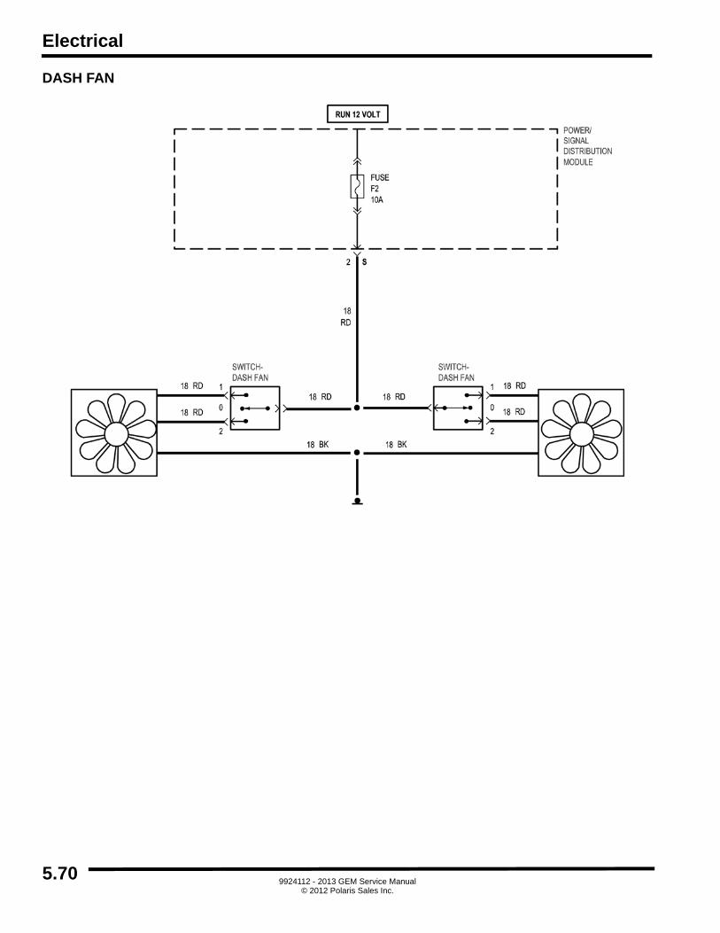
Electrical
DASH FAN
5.709924112 - 2013 GEM Service Manual
© 2012 Polaris Sales Inc.

Electrical
5
SECURITY LIGHT BAR
5.719924112 - 2013 GEM Service Manual
© 2012 Polaris Sales Inc.

Electrical
AUDIO SYSTEM
5.729924112 - 2013 GEM Service Manual
© 2012 Polaris Sales Inc.

Electrical
5
FRONT LIGHTING - HI/LO BEAM
5.739924112 - 2013 GEM Service Manual
© 2012 Polaris Sales Inc.

Electrical
REAR LIGHTING
5.749924112 - 2013 GEM Service Manual
© 2012 Polaris Sales Inc.

Electrical
5
REAR LIGHTING (CONTINUED)
5.759924112 - 2013 GEM Service Manual
© 2012 Polaris Sales Inc.

Electrical
REAR LIGHTING - EXCEPT NEW YORK
5.769924112 - 2013 GEM Service Manual
© 2012 Polaris Sales Inc.

Electrical
5
REAR LIGHTING - NEW YORK
5.779924112 - 2013 GEM Service Manual
© 2012 Polaris Sales Inc.

Electrical
TURN SIGNAL REMINDER
5.789924112 - 2013 GEM Service Manual
© 2012 Polaris Sales Inc.

Electrical
5
WIPER / WASHER
5.799924112 - 2013 GEM Service Manual
© 2012 Polaris Sales Inc.

Electrical
HARNESS AND CONNECTOR DRAWINGS
CONVERTER HARNESS
1 2
3
4
CONVERTER HARNESS CONNECTIONS
Connector Number Connects To Number of Pins in Connector
1 DC/DC Converter/Charger 12
2,3 72 Volt Ground, 12 Volt Ground 1
4 PSDM J4 6
5.80 9924112 - 2013 GEM Service Manual© 2012 Polaris Sales Inc.

Electrical
5
PIN LOCATIONS FOR CONVERTER HARNESS CONNECTORS
Connector IllustrationConnector
NumberConnects To
Number of Pins in Connector
1DC/DC
Converter12
2, 372 Volt Ground,12 Volt Ground
1
4 PSDM J4 6
5.819924112 - 2013 GEM Service Manual
© 2012 Polaris Sales Inc.

Electrical
HEADLIGHT HARNESS - STANDARD US DOMESTIC LOW BEAM
HEADLIGHT HARNESS CONNECTIONS
Connector Number Connects To Number of Pins in Connector
1 Headlight Harness 6
2 Head lamp-Left 1
3 Lamp-Turn-Left 1
4 Head lamp-Right 1
5 Lamp-Turn-Right 1
3 42 51
5.829924112 - 2013 GEM Service Manual
© 2012 Polaris Sales Inc.

Electrical
5
PIN LOCATIONS FOR CONVERTER HARNESS CONNECTORS
Connector IllustrationConnector
NumberConnects To
Number of Pins in Connector
1 Headlight Harness 6
2, 4 Headlights (Power) 1
3, 5 Turn Lamps (Power) 1
3, 5 Turn Lamps (Ground) 1
5.839924112 - 2013 GEM Service Manual
© 2012 Polaris Sales Inc.

Electrical
FRONT HARNESS
1
7
2
36
4 5
FRONT HARNESS CONNECTIONS
Connector Number Connects To Number of Pins in Connector
1 PSDM J1 10
2 (qty. 3) Motor-Wiper 1
3 (qty. 2) Horn 1
4 Front Harness 6
5 Switch-Brake Level Fluid 2
6 (qty. 2) Switch-Brake Pressure 1
7 12 Volt Ground 1
5.84 9924112 - 2013 GEM Service Manual© 2012 Polaris Sales Inc.

Electrical
5
PIN LOCATIONS FOR FRONT HARNESS CONNECTORS
Connector IllustrationConnector
NumberConnects To
Number of Pins in Connector
1 PSDM J1 10
2,3,4,5,6,9,10,11
Horn, Motor-WiperSwitch-Brake
Pressure,Charger
1
7Front
Harness6
8Switch-BrakeLevel Fluid
2
11 12 Volt Ground 1
5.859924112 - 2013 GEM Service Manual
© 2012 Polaris Sales Inc.
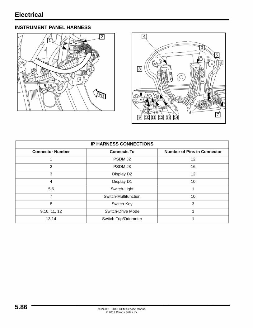
Electrical
INSTRUMENT PANEL HARNESS
12
3
5
6
7
8
9 10 11 12 13 14
4
IP HARNESS CONNECTIONS
Connector Number Connects To Number of Pins in Connector
1 PSDM J2 12
2 PSDM J3 16
3 Display D2 12
4 Display D1 10
5,6 Switch-Light 1
7 Switch-Multifunction 10
8 Switch-Key 3
9,10, 11, 12 Switch-Drive Mode 1
13,14 Switch-Trip/Odometer 1
5.86 9924112 - 2013 GEM Service Manual© 2012 Polaris Sales Inc.

Electrical
5
PIN LOCATIONS FOR IP HARNESS CONNECTORS
Connector Illustration Connector Number Connects ToNumber of Pins in
Connector
1,3Display D2,PSDM J2
12
2 PSDM J3 16
4 Display D1 10
5,6,9,10,11,12,13,14Switch-Drive Mode,
Switch-Trip Odometer,Switch-Light
1
7 Switch-Multifunction 10
8 Switch-Key 3
5.879924112 - 2013 GEM Service Manual
© 2012 Polaris Sales Inc.

Electrical
CONTROLLER HARNESS
1
2
4
3
CONTROLLER HARNESS CONNECTIONS
Connector Number Connects to Number of Pins in Connector
1 Module-Motor Controller 23
2 Switch-Accelerator Pedal 10
3 Tachometer 3
4 Sensor, Motor Temperature 2
5.88 9924112 - 2013 GEM Service Manual© 2012 Polaris Sales Inc.

Electrical
5
CONTROLLER HARNESS (CONTINUED)
5
6
7
8
CONTROLLER HARNESS CONNECTIONS
Connector Number Connector to Number of Pins in Connector
5, 6 Main Contactor (Coil) 1
7 PSDM 72 Volt Ground 1
8 PSDM J5 8
5.899924112 - 2013 GEM Service Manual
© 2012 Polaris Sales Inc.

Electrical
PIN LOCATIONS FOR CONTROLLER HARNESS CONNECTORS
Connector Illustration Connector Number Connects ToNumber of Pins in
Connector
1Module-Motor
Controller23
4Switch-Accelerator
Pedal10
5 Tachometer 3
6Switch-MotorTemperature
2
9PSDM 72 Volt
Ground1
10 PSDM J5 8
5.90 9924112 - 2013 GEM Service Manual© 2012 Polaris Sales Inc.

Electrical
5
MAIN HARNESS
2
1
5
45
6
3
7
8
PASSENGER REAR HARNESS CONNECTIONS
Connector Number Connects To Number of Pins in Connector
1 PSDM J6 8
2 72 Volt Ground 1
3 PSDM-Disconnect Switch 1
4 PSDM-BATT(-) 1
5 12 Volt Ground 1
6 Charger - Battery Temp Sensor 1
7,8 Switch-Park Brake 1
5.919924112 - 2013 GEM Service Manual
© 2012 Polaris Sales Inc.

Electrical
MAIN HARNESS (CONTINUED)
9
11
10
13
12
9
18
17
14
15
16
17
PASSENGER REAR HARNESS CONNECTIONS
Connector Number Connects To Number of Pins in Connector
9 Lamp-CHMSL 1
10 Lamp-CHMSL (Ground) 1
11 Lamp-License 1
12 Lamp-Back-Up 1
13 Taillight Harness 4
14,15 Battery Temperature Sensor 1
16 BATT (-) 1
17 BATT (+) 1
18 Main Harness 1
5.92 9924112 - 2013 GEM Service Manual© 2012 Polaris Sales Inc.

Electrical
5
PIN LOCATIONS FOR MAIN HARNESS CONNECTORS
Connector Illustration Connector Number Connects ToNumber of Pins in
Connector
1 PSDM J6 8
2,512 Volt Ground, 72
Volt Ground1
3,4,16,17
PSDM-Disconnect Switch, PSDM-
BATT(-), BATT 1(-), BATT 6(+)
1
6,7,8,9,10,11,12,14,15
Charger for BTS, Switch-Park Brake,
Lamp-CHMSL, Lamp-License,
Lamp- Back-Up, Lamp-License
(Ground), Battery Temperature Sensor
1
13 Taillight Harness 4
5.939924112 - 2013 GEM Service Manual
© 2012 Polaris Sales Inc.

Electrical
TAIL LIGHT HARNESS
TAIL LIGHT HARNESS CONNECTIONS
Connector Number Connects To Number of Pins in Connector
1 Rear Harness 4
2 Lamp-Taillight-Left 3
3 Lamp-Taillight-Right 3
32
1
5.949924112 - 2013 GEM Service Manual
© 2012 Polaris Sales Inc.

Electrical
5
PIN LOCATIONS FOR TAIL LIGHT HARNESS CONNECTORS
Connector Illustration Connector Number Connects ToNumber of Pins in
Connector
1 Rear Harness 4
2Lamp-Taillight-Left, Lamp-Taillight-Right
3
3Lamp-Taillight-Left, Lamp-Taillight-Right
3
5.959924112 - 2013 GEM Service Manual
© 2012 Polaris Sales Inc.

Electrical
DIGITAL WRENCH® OPERATION
DIGITAL WRENCH® DIAGNOSTIC SOFTWARE OVERVIEW
The Digital Wrench® diagnostic software allows the technician to perform the following tasks:
• View or clear trouble codes
• Review trouble code definitions and troubleshooting
• View or set the tire size
• View or set the odometer miles
Special Tools
DIAGNOSTIC SOFTWARE VERSION
Always use the most current version of the DigitalWrench® software to ensure you have the latest updatesor enhancements. New reprogramming files and guideddiagnostic procedures are added to these updates as theybecome available. For information on how to determine ifyou have the latest update available, refer to “DigitalWrench® Version and Update ID”.
CONTROLLER REPLACEMENT
Although the need for controller replacement is unlikely, aspecific replacement procedure is required to ensure thatthe new controller is programmed properly, and the correctodometer miles are entered.
When a new controller is being programmed for a vehicle,the appropriate tire size must be selected, and the "ApplySelection" button MUST be clicked. This will ensure thatthe controller is programmed for the proper configuration,per the vehicle selected.
DIGITAL WRENCH® COMMUNICATION ERRORS
If you experience problems connecting to a vehicle or anyDigital Wrench® related problem, visit the DigitalWrench® Knowledge Base for the most currenttroubleshooting information, FAQs, downloads andsoftware updates at: http://polaris.diagsys.com/.
DIGITAL WRENCH® DIAGNOSTIC SOFTWARE PART NUMBER
Digital Wrench® Software PU-48731
GEM Communication Cable with Power Adapter PL-51023
USB-Serial Adapter Cable PU-50621
Laptop or Desktop ComputerCommercially Available (refer to diagnostic software user manual or HELP section for minimum requirements)
5.96 9924112 - 2013 GEM Service Manual© 2012 Polaris Sales Inc.

Electrical
5
COMMUNICATION CABLE CONNECTION
Follow these steps to connect the communication cable toa controller installed in a vehicle to allow Digital Wrench®use:
1. Turn the Master Disconnect Switch to the OFFposition.
2. Locate and disconnect the 23-pin connector from themotor controller located under the hood.
3. Connect the 23-pin connector of the communicationcable to the vehicle's controller.
4. Remove the upper and lower dash assemblies, andconnect the alligator clip, from the long RED jumperwire of the communication cable, to the main 72 voltpositive terminal on the PSDM.
5. Turn the Master Disconnect Switch to the ON position,select the appropriate vehicle and wait for the statusto display ‘Connected’ in the lower left corner of thescreen.
6. Once connected, proceed with using DigitalWrench®.
Follow these steps to connect the communication cable toa controller not installed in a vehicle to allow DigitalWrench® use:
1. Connect the 23-pin connector of the communicationcable to the controller.
2. Connect the mating banana plug connectors from thepower adapter (included with communication cable),and the communication cable.
3. Connect the black alligator clip from the poweradapter to the main negative "NEG" terminal on thecontroller.
4. Plug the power adapter into a standard 110 volt ACwall outlet, select the appropriate vehicle and wait forthe status to display ‘Connected’ in the lower leftcorner of the screen.
5. Once connected, proceed with using DigitalWrench®.
DIGITAL WRENCH® SERIAL NUMBER LOCATION
Open the configuration screen by clicking on the wrenchicon. The serial number is located on the right side of thescreen.
5.979924112 - 2013 GEM Service Manual
© 2012 Polaris Sales Inc.

Electrical
DIGITAL WRENCH® VERSION AND UPDATE ID
Knowing what Digital Wrench® version and update isinstalled will help determine which updates are required.
NOTE: Versions and updates are subject to change.
1. Open the Digital Wrench® software. Locate theversion ID shown on the lower right side of the DigitalWrench® start-up screen.
2. Proceed to http://polaris.diagsys.com to see if anewer update is available.
3. If a newer update is available, it should bedownloaded before using Digital Wrench® (see“Digital Wrench® Updates”).
IMPORTANT: Always operate with the latest update.
DIGITAL WRENCH® UPDATES
Updates are released for Digital Wrench® via the Internetat: http://polaris.diagsys.com. The Digital Wrench®website can also be accessed through the dealer websiteat: www.polarisdealers.com.
NOTE: Only authorized Polaris dealers anddistributors can access the dealer website.
1. Log on to www.polarisdealers.com.2. Locate the “Service and Warranty” drop-down
menu.
3. Click on “Digital Wrench Updates”.
4. The Digital Wrench® portal website should appear ina new web browser.
5. Click on “Digital Wrench Version Updates”.
IMPORTANT: You must already have the currentversion installed before adding an update. Updateswill not install if you are using an older version loadedon your PC.
Version
Digital Wrench Update
5.98 9924112 - 2013 GEM Service Manual© 2012 Polaris Sales Inc.

Electrical
5
6. If the update file date listed is newer than your currentversion and update (see “Digital Wrench® Versionand Update ID”), download the file.
7. Click on the link shown above, save the file to yourhard disk and then double-click the icon to start theupdate process.
NOTE: Do not "run" or "open" the file from wherethey are. Select "save" and download them to yourPC before running the install.
8. When the update is complete, the version shown onthe right side of the Digital Wrench® start-up screenshould match the update you just downloaded.
NOTE: Versions and updates are subject to change.
Digital Wrench Update
Version
5.999924112 - 2013 GEM Service Manual
© 2012 Polaris Sales Inc.

Electrical
DIGITAL WRENCH® FEATURE MAP
5.100 9924112 - 2013 GEM Service Manual© 2012 Polaris Sales Inc.

Electrical
5
VEHICLE SELECTION
Click on the "Vehicle Selection" button to access thediagnostic menu for the vehicle. Use the drop-down boxesto select the year, product line and vehicle description.After selecting the vehicle, the connection status willchange from NOT CONNECTED to CONNECTED if thecommunications cable is connected to the laptop andmotor controller. If the status does not change, verify thecorrect vehicle is selected, and recycle the master on/offswitch.
DIAGNOSTIC TROUBLE CODES (DTCs)
Click on the DTC icon to display a list of current and activetrouble codes. Click on the "?" button to display the troublecode description. Click on the "Eraser" button to clear allof the trouble codes.
SPECIAL TESTS / CONTROLLER PROGRAMMING
Click on the "Red Toolbox" button to display the specialtests menu. Under this menu you can perform thefollowing tasks:
• View or set the tire size
• View or set the odometer miles
• Display vehicle information
GEM PERSONALITY CONFIGURATION
The Personality Configuration menu allows the technicianto review and program the motor controller settings.
• View or set the tire size
• View or set the odometer miles
NOTE: Every time a new controller is to beprogrammed for a vehicle, the appropriate tire sizeshould be selected, and the "Apply Selection"button MUST be clicked. This will ensure that thecontroller is programmed for the properconfiguration, per the vehicle selected. If theodometer miles were able to be read from the oldcontroller, they should be entered in the newcontroller by typing them in at the "Odometer Miles"section, and then clicking, "Set Odometer."
5.1019924112 - 2013 GEM Service Manual
© 2012 Polaris Sales Inc.

Electrical
VEHICLE INFORMATION
Click on the vehicle information button to display motorcontroller information such as software version number.
5.102 9924112 - 2013 GEM Service Manual© 2012 Polaris Sales Inc.

Wheels and Tires
CHAPTER 6
Wheels and Tires
6
GENERAL SPECIFICATIONS . . . . . . . . . . . . . . . . . . . . . . . . . . . . . . . . . . . . . . . . . . . . . . 6.2DESCRIPTION . . . . . . . . . . . . . . . . . . . . . . . . . . . . . . . . . . . . . . . . . . . . . . . . . . . . . . . . 6.2WHEEL CHART. . . . . . . . . . . . . . . . . . . . . . . . . . . . . . . . . . . . . . . . . . . . . . . . . . . . . . . . 6.2TIRE CHART . . . . . . . . . . . . . . . . . . . . . . . . . . . . . . . . . . . . . . . . . . . . . . . . . . . . . . . . . . 6.2
TIRES. . . . . . . . . . . . . . . . . . . . . . . . . . . . . . . . . . . . . . . . . . . . . . . . . . . . . . . . . . . . . . . . . 6.3DESCRIPTION . . . . . . . . . . . . . . . . . . . . . . . . . . . . . . . . . . . . . . . . . . . . . . . . . . . . . . . . 6.3RADIAL - PLY TIRES . . . . . . . . . . . . . . . . . . . . . . . . . . . . . . . . . . . . . . . . . . . . . . . . . . . 6.3INFLATION PRESSURES. . . . . . . . . . . . . . . . . . . . . . . . . . . . . . . . . . . . . . . . . . . . . . . . 6.3REPLACEMENT TIRES . . . . . . . . . . . . . . . . . . . . . . . . . . . . . . . . . . . . . . . . . . . . . . . . . 6.4DIAGNOSIS AND TESTING - PRESSURE GAUGES . . . . . . . . . . . . . . . . . . . . . . . . . . 6.4DIAGNOSIS AND TESTING - TREAD WEAR INDICATORS . . . . . . . . . . . . . . . . . . . . . 6.4DIAGNOSIS AND TESTING - TIRE WEAR PATTERNS . . . . . . . . . . . . . . . . . . . . . . . . 6.5DIAGNOSIS AND TESTING - TIRE NOISE AND VIBRATION . . . . . . . . . . . . . . . . . . . . 6.5REPAIRING LEAKS . . . . . . . . . . . . . . . . . . . . . . . . . . . . . . . . . . . . . . . . . . . . . . . . . . . . 6.5TIRE ROTATION. . . . . . . . . . . . . . . . . . . . . . . . . . . . . . . . . . . . . . . . . . . . . . . . . . . . . . . 6.6
WHEELS . . . . . . . . . . . . . . . . . . . . . . . . . . . . . . . . . . . . . . . . . . . . . . . . . . . . . . . . . . . . . . 6.6DESCRIPTION . . . . . . . . . . . . . . . . . . . . . . . . . . . . . . . . . . . . . . . . . . . . . . . . . . . . . . . . 6.6DIAGNOSIS AND TESTING - WHEEL INSPECTION. . . . . . . . . . . . . . . . . . . . . . . . . . . 6.6WHEEL REMOVAL . . . . . . . . . . . . . . . . . . . . . . . . . . . . . . . . . . . . . . . . . . . . . . . . . . . . . 6.7WHEEL INSTALLATION . . . . . . . . . . . . . . . . . . . . . . . . . . . . . . . . . . . . . . . . . . . . . . . . . 6.7
6.19924112 - 2013 GEM Service Manual
© 2012 Polaris Sales Inc.

Wheels and Tires
GENERAL SPECIFICATIONS
DESCRIPTION
The GEM e-series uses steel and aluminum wheels with a 4 bolt pattern, and tires in four different sizes as shown in thecharts below:
WHEEL CHART
TIRE CHART
Standard Turf (Option) Premium (Option)
Construction Steel Aluminum Aluminum
Diameter 12 12 14
Width 4 7 6
Backspace 2-1/8 3 ½ 3-3/4
Bolt Pattern 4 x 4 4 x 4 4 x 4”
Capacity 900 lbs 1200 lbs 1047 lbs
Torque (ft-lbs) 65 90 95
Standard Turf (Option) Premium (Option)
Tire Nankang NY 361 Innova Driver Duro
Size 165/70R12 77T 215/50 R12 185/60R14 82H
Construction Steel belt radial Nylon Steel belt radial
Ply Rating 4 2 4
Load Range B B B
Rim Width 4.5 8 6
Max Section Width 6.5 8.5 7.75
Overall Diameter 21 20.5 22.75
Maximum Load 795 lbs 910 lbs 1047 lbs
Approx. weight 13 lbs 12 lbs 18 lbs
Revs. Per Ml 942 985 880
Air Pressure 32 psi 30 psi 36 psi
6.2 9924112 - 2013 GEM Service Manual© 2012 Polaris Sales Inc.

Wheels and Tires
6
TIRES
DESCRIPTION
Tires are designed and engineered for each specificvehicle. They provide the best overall performance fornormal operation. The ride and handling characteristicsmatch the vehicle's requirements. With proper care theywill give excellent reliability, traction, skid resistance, andtread life.
Driving habits have more effect on tire life than any otherfactor. Careful drivers will obtain in most cases, muchgreater mileage than severe use or careless drivers. A fewof the driving habits, which will shorten the life of any tire,are:
• Rapid acceleration
• Severe brake applications
• Excessive speeds on turns
• Striking curbs and other obstacles
Radial-ply tires are more prone to irregular tread wear. Itis important to follow the tire rotation interval. This will helpto achieve a greater tread life.
RADIAL - PLY TIRES
Radial-ply tires improve handling, tread life and ridequality, and decrease rolling resistance. They must alwaysbe used in sets of four.
Radial-ply tires have the same load-carrying capacity asother types of tires of the same size. They also use thesame recommended inflation pressures.
The use of oversized tires, either in the front or rear of thevehicle, can cause vehicle drive train failure. The use oftires from different manufacturers on the same vehicle isnot recommended. The proper tire pressure should bemaintained on all four tires.
INFLATION PRESSURES
Proper tire inflation pressure is essential to the safe andsatisfactory operation of the vehicle. Under inflation willcause rapid shoulder wear, tire flexing, and possible tirefailure.
Over inflation will cause rapid center wear and loss of thetire's ability to cushion shocks. Both under and overinflation affect the stability of the vehicle and can producea feeling of sluggish response or over-responsiveness.
Unequal tire pressures can cause steering problems,resulting in loss of control of the vehicle. For proper tirepressure specification, refer to the VIN/Certification Labelat the left rear of the roof panel. The label also lists properwheel and tire size for the vehicle. (See VIN/CertificationLabel in Introduction section.)
Tire pressures have been chosen to provide safeoperation, vehicle stability, and a smooth ride. Tirepressure should be checked cold once a month. Tirepressure decreases as the ambient temperature drops.Checks tire pressure frequently when ambienttemperature varies widely.
Specified tire inflation pressures are cold inflationpressures. The vehicle must sit for at least 3 hours toobtain the correct cold inflation pressure reading, or bedriven less than one mile after sitting for 3 hours. Tireinflation pressures may increase from 2 to 6 pounds persquare inch (psi) during operation. Do not reduce thisnormal pressure build-up.
WARNING
Over or under inflated tires can affect vehicle handling and tread wear. This may cause the tire to
fail suddenly, resulting in loss of vehicle control.
6.39924112 - 2013 GEM Service Manual
© 2012 Polaris Sales Inc.

Wheels and Tires
REPLACEMENT TIRES
The original equipment tires provide a proper balance ofmany characteristics such as:
• Ride
• Noise
• Handling
• Durability
• Tread life
• Traction
• Rolling resistance
• Speed capability
It is recommended that tires equivalent to the originalequipment tires be used when replacement is needed.
DIAGNOSIS AND TESTING - PRESSURE GAUGES
A quality air pressure gauge is recommended to check tirepressure. After checking the air pressure, replace valvecap finger tight.
DIAGNOSIS AND TESTING - TREAD WEAR INDICATORS
Tread wear indicators are molded into the bottom of thetread grooves. When tread depth is 1.6 mm (1/16 in.), thetread wear indicators will appear as a 13 mm (1/2 in.)band.
Tire replacement is necessary when indicators appear intwo or more grooves or if localized balding occurs.
WARNING
Do not use a tire size other than that specified. Improper size tires can cause vehicle components
to wear out prematurely and may change the vehicle's ride, handling and steering behavior. In
addition, it may affect the accuracy of the speedometer/odometer. Using tire sizes other than
specified could cause loss of control, resulting in serious personal injury or death.
WARNING
Never use a tire smaller than the size specified. Using a smaller tire could result in tire overloading
and failure.
WARNING
Overloading the tires is dangerous. Like under inflation, overloading can cause tire failure. Use
tires of the recommended load capacity, and never overload the vehicle
6.4 9924112 - 2013 GEM Service Manual© 2012 Polaris Sales Inc.

Wheels and Tires
6
DIAGNOSIS AND TESTING - TIRE WEAR PATTERNS
DIAGNOSIS AND TESTING - TIRE NOISE AND VIBRATION
Radial-ply tires are sensitive to force impulses caused byimproper mounting, vibration, wheel defects, or possiblytire imbalance.
To find out if tires are causing the noise or vibration, drivethe vehicle over a smooth road at varying speeds. Note thenoise level during acceleration and deceleration. Themotor and differential noises will change as speed varies,while the tire noise will usually remain constant.
REPAIRING LEAKS
For proper repairing, a radial tire must be removed fromthe wheel. Repairs should only be made if the defect, orpuncture, is in the tread area. The tire should be replacedif the puncture is located in the sidewall.
Deflate tire completely before removing the tire from thewheel. Use lubrication such as a mild soap solution whendismounting or mounting tire. Use tools free of burrs orsharp edges that could damage the tire or wheel rim.
Before mounting tire on wheel, make sure all rust isremoved from the rim bead and repaint if necessary.
6.59924112 - 2013 GEM Service Manual
© 2012 Polaris Sales Inc.

Wheels and Tires
TIRE ROTATION
Tires on the front and rear operate at different loads andperform different steering, driving, and braking functions.For these reasons they wear at unequal rates and tend todevelop irregular wear patterns. Rotating the tires at 500miles or as needed. The benefits of tire rotation are:
• Increase tread life
• Maintain traction levels
• A smooth, quiet ride
The suggested method of tire rotation is shown below.Other rotation methods can be used, but they will notprovide all the tire longevity benefits.
WHEELS
DESCRIPTION
All models use stamped steel wheels. Every wheel hasraised sections between the rim flanges and rim drop wellcalled safety humps.
Initial inflation of the tire forces the bead over these raisedsections. In case of rapid loss of air pressure, the raisedsections help hold the tire on the wheel.
The wheel nuts are designed for this specific application.Do not use replacement nuts with a different design orlesser quality.
DIAGNOSIS AND TESTING - WHEEL INSPECTION
Inspect wheels for:
• Excessive run out
• Dents or cracks
• Damaged wheel lug nut holes
• Air leaks from any area or surface of the rim
NOTE: Do not attempt to repair a wheel byhammering, heating or welding.
If a wheel is damaged an original equipment replacementwheel should be used. When obtaining replacementwheels, they should be equivalent in load carryingcapacity. The diameter, width, offset and bolt circle of thewheel should be the same as the original wheel.
WARNING
Failure to use equivalent replacement wheels may adversely affect the safety and handling of the
vehicle. Used wheels are not recommended. The service history of the wheel may have included severe treatment or very high mileage. The rim
could fail without warning.
6.6 9924112 - 2013 GEM Service Manual© 2012 Polaris Sales Inc.
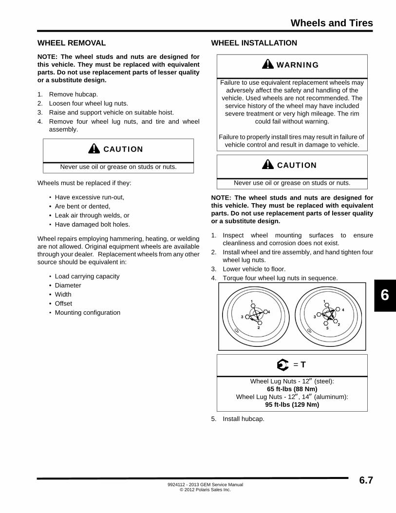
Wheels and Tires
6
WHEEL REMOVAL
NOTE: The wheel studs and nuts are designed forthis vehicle. They must be replaced with equivalentparts. Do not use replacement parts of lesser qualityor a substitute design.
1. Remove hubcap.
2. Loosen four wheel lug nuts.
3. Raise and support vehicle on suitable hoist.
4. Remove four wheel lug nuts, and tire and wheelassembly.
Wheels must be replaced if they:
• Have excessive run-out,
• Are bent or dented,
• Leak air through welds, or
• Have damaged bolt holes.
Wheel repairs employing hammering, heating, or weldingare not allowed. Original equipment wheels are availablethrough your dealer. Replacement wheels from any othersource should be equivalent in:
• Load carrying capacity
• Diameter
• Width
• Offset
• Mounting configuration
WHEEL INSTALLATION
NOTE: The wheel studs and nuts are designed forthis vehicle. They must be replaced with equivalentparts. Do not use replacement parts of lesser qualityor a substitute design.
1. Inspect wheel mounting surfaces to ensurecleanliness and corrosion does not exist.
2. Install wheel and tire assembly, and hand tighten fourwheel lug nuts.
3. Lower vehicle to floor.
4. Torque four wheel lug nuts in sequence.
5. Install hubcap.
CAUTION
Never use oil or grease on studs or nuts.
WARNING
Failure to use equivalent replacement wheels may adversely affect the safety and handling of the
vehicle. Used wheels are not recommended. The service history of the wheel may have included severe treatment or very high mileage. The rim
could fail without warning.
Failure to properly install tires may result in failure of vehicle control and result in damage to vehicle.
CAUTION
Never use oil or grease on studs or nuts.
= T
Wheel Lug Nuts - 12 (steel): 65 ft-lbs (88 Nm)
Wheel Lug Nuts - 12, 14 (aluminum): 95 ft-lbs (129 Nm)
6.79924112 - 2013 GEM Service Manual
© 2012 Polaris Sales Inc.

Wheels and Tires
NOTES
6.89924112 - 2013 GEM Service Manual
© 2012 Polaris Sales Inc.

Body
CHAPTER 7
Body
7
SEAT BELTS . . . . . . . . . . . . . . . . . . . . . . . . . . . . . . . . . . . . . . . . . . . . . . . . . . . . . . . . . . . 7.2BODY SIDE PANEL . . . . . . . . . . . . . . . . . . . . . . . . . . . . . . . . . . . . . . . . . . . . . . . . . . . . . . 7.3BODY SIDE PANEL (E6) . . . . . . . . . . . . . . . . . . . . . . . . . . . . . . . . . . . . . . . . . . . . . . . . . . 7.4SCUFF GUARDS . . . . . . . . . . . . . . . . . . . . . . . . . . . . . . . . . . . . . . . . . . . . . . . . . . . . . . . . 7.5BODY BACK PANEL . . . . . . . . . . . . . . . . . . . . . . . . . . . . . . . . . . . . . . . . . . . . . . . . . . . . . 7.6FLOOR PANELS (E6) . . . . . . . . . . . . . . . . . . . . . . . . . . . . . . . . . . . . . . . . . . . . . . . . . . . . 7.7BENCH SEAT . . . . . . . . . . . . . . . . . . . . . . . . . . . . . . . . . . . . . . . . . . . . . . . . . . . . . . . . . . 7.8BUCKET SEAT . . . . . . . . . . . . . . . . . . . . . . . . . . . . . . . . . . . . . . . . . . . . . . . . . . . . . . . . . 7.9MUD GUARD . . . . . . . . . . . . . . . . . . . . . . . . . . . . . . . . . . . . . . . . . . . . . . . . . . . . . . . . . . 7.10MUD FLAP . . . . . . . . . . . . . . . . . . . . . . . . . . . . . . . . . . . . . . . . . . . . . . . . . . . . . . . . . . . . 7.10HOOD. . . . . . . . . . . . . . . . . . . . . . . . . . . . . . . . . . . . . . . . . . . . . . . . . . . . . . . . . . . . . . . . 7.11HOOD LATCH ASSEMBLY . . . . . . . . . . . . . . . . . . . . . . . . . . . . . . . . . . . . . . . . . . . . . . . 7.12DASH UPPER PANEL . . . . . . . . . . . . . . . . . . . . . . . . . . . . . . . . . . . . . . . . . . . . . . . . . . . 7.13DASH LOWER PANEL . . . . . . . . . . . . . . . . . . . . . . . . . . . . . . . . . . . . . . . . . . . . . . . . . . 7.14POD COVERS . . . . . . . . . . . . . . . . . . . . . . . . . . . . . . . . . . . . . . . . . . . . . . . . . . . . . . . . . 7.15SPAT . . . . . . . . . . . . . . . . . . . . . . . . . . . . . . . . . . . . . . . . . . . . . . . . . . . . . . . . . . . . . . . . 7.16UTILITY BED . . . . . . . . . . . . . . . . . . . . . . . . . . . . . . . . . . . . . . . . . . . . . . . . . . . . . . . . . . 7.17TRUNKBACK™/LINKSBACK™/CLIP-IN STAKEBACK™. . . . . . . . . . . . . . . . . . . . . . . . 7.18PACK LATCH ASSEMBLY . . . . . . . . . . . . . . . . . . . . . . . . . . . . . . . . . . . . . . . . . . . . . . . 7.19TRUNKBACK™ / LINKSBACK™ /CLIP-IN STAKEBACK™ LEG POCKET . . . . . . . . . . 7.20MIRROR - CENTER REAR VIEW . . . . . . . . . . . . . . . . . . . . . . . . . . . . . . . . . . . . . . . . . . 7.21MIRROR - SIDE REAR VIEW . . . . . . . . . . . . . . . . . . . . . . . . . . . . . . . . . . . . . . . . . . . . . 7.21
7.19924112 - 2013 GEM Service Manual
© 2012 Polaris Sales Inc.

Body
SEAT BELTS
DESCRIPTION
Three-point automotive shoulder/lap belts are used withbench and bucket seats. The seat belt is anchored to aflange at the lower outboard end of the seat back supportframe. The seat belt passes through a D-ring mounted atthe upper outboard edge of the seat back support frame,into a retractor assembly mounted to the seat back frameapproximately six inches below the D-ring. A seat beltlatch assembly is mounted at the lower center of the seatback support frame.
Seat belts should be inspected monthly for the followingsigns of wear:
1. Frayed edges on web.
2. Scores across web.
3. Obvious signs of wear on web at buckle.
4. Corrosion of any of metal parts or fasteners. If any ofthese signs are present, locate and correct cause, andreplace seat belt assembly.
A. Seat belt anchor
B. Buckle assembly
C. D-ring
D. Retractor assembly
E. Locating tab
SEAT BELT REMOVAL
1. Position master disconnect switch OFF.
2. Remove lower seat cushion. See Bench Seats in thissection.
3. Remove seat back assembly. See Bench Seats in thissection.
4. Remove body back panel. See Body Back Panel inthis section.
5. Remove bolt from D-ring to seat back support.
6. Remove bolt attaching retractor assembly to seatback support.
7. Remove body foot bracket attaching seat backsupport and body support arm.
8. Remove seat belt assembly.
9. Remove bolt attaching seat belt latch assembly toseat back support.
10. Remove seat belt latch assembly.
SEAT BELT INSTALLATION
1. Attach seat belt latch assembly to seat back supportwith mounting bolt. Torque to specification.
2. Attach D-ring to seat back support, ensuring straightportion of D-ring faces forward. Torque mounting boltto specification.
3. Attach retractor assembly to seat back support.Torque mounting bolt to specification.
IMPORTANT: Tab on retractor assembly must engagelocating hole on seat back support.
4. Feed seat belt end through D-ring, back to front, andattach to flange at lower outboard end of seat backsupport. Torque mounting bolt to specification.
5. Install body back panel. See Body Back Panel in thissection.
6. Install body side panel. See Body Side Panel in thissection.
7. Install seat back assembly. See Bench Seats in thissection.
8. Install lower seat cushion. See Bench Seats in thissection.
9. Position master disconnect switch ON.
C
B
A
E
D
7.2 9924112 - 2013 GEM Service Manual© 2012 Polaris Sales Inc.

Body
7
BODY SIDE PANEL
DESCRIPTION
The body side panel is made of molded plastic and ismounted to the floor panel and back panel by Torx® boltswith nuts on the inside.
SIDE PANEL REMOVAL
1. Remove upper dash. See Dash in this section.
2. Remove lower dash. See Dash in this section.
3. Remove mudguards. See Mudguards in this section.
4. Remove rear bench seat and seat back. See BenchSeat in this section.
5. Remove spat or utility box. See Spat or Utility Box inthis section.
6. Remove front upper attaching screw, and three lowerattaching screws and speed nuts.
7. Remove scuff guard (sill plate) (if equipped). SeeScuff Guards in this section.
8. Remove seven bottom body side bolts.
9. Remove 10 Torx bolts, 10 nuts, and body back panel.
10. Remove side panel.
SIDE PANEL INSTALLATION
1. If replacing panel, remove front and rear trim locksand transfer them to new side panel.
2. Position side panel on tub/floor pan, ensure holesmatch up, and attach back trim lock to back panel.
3. Install side panel to body back panel with 10 Torx boltsand 10 nuts.
4. Install seven bottom body side bolts.
5. Install three lower screws and speed nuts on back/bottom, and front upper attaching screw.
6. Install scuff guard (sill plate), (if equipped). See ScuffGuards in this section.
7. Install front upper screws to hold body panel to frame.
8. Install spat or utility box. See Spat or Utility Box in thissection.
9. Install rear bench seat and seat back. See Bench Seatin this section.
10. Attach mudguards. See Mudguards in this section.
11. Install lower dash. See Dash in this section.
12. Install upper dash. See Dash in this section.
7.39924112 - 2013 GEM Service Manual
© 2012 Polaris Sales Inc.

Body
BODY SIDE PANEL (E6)
DESCRIPTION
The GEM car body side panel is molded of white plastic.
A. Front panel
B. Middle panel
C. Rear panel
FRONT PANEL
1. Remove upper dash. See Dash in this section.
2. Remove lower dash. See Dash in this section.
3. Remove mudguards. See Mudguards in this section.
4. Remove scuff guard (sill plate), (if equipped). SeeScuff Guards in this section.
5. Remove seven body side rivets.
6. Remove side panel. See Side Panel Removal in thissection.
7. To install reverse this procedure.
MIDDLE PANEL
1. Remove scuff guard (sill plate), (if equipped).
2. Remove 10 body side rivets.
3. Remove center side panels.
4. To install reverse this procedure.
REAR PANEL
1. Remove swivel pack or utility box. See Swivel Pak orUtility Box.
2. Remove rear bench seat cushion. See Bench Seat inthis section.
3. Remove scuff guard (sill plate), (if equipped). SeeScuff Guards in this section.
4. Using drill, remove five rivets from back body panel.
5. Using drill, remove seven body side rivets.
6. Remove side panel. See Side Panel Removal in thissection.
7. To install, reverse this procedure. Using rivet tool,install new rivets.
A
B
C
7.4 9924112 - 2013 GEM Service Manual© 2012 Polaris Sales Inc.

Body
7
SCUFF GUARDS
DESCRIPTION
The GEM car Scuff Guards are durable black plasticformed guards that will help protect the body panels onyour GEM vehicle from scuff marks and scratches.
A. Mounting bolts
SCUFF GUARD REMOVAL / INSTALLATION
GEM e6® MODELS:
1. Remove four Torx screws, four hex keps lock retainernuts, and scuff guard.
2. Install scuff guard, four retainer nuts, and four Torxscrews.
GEM e4 MODELS:
1. Remove three Torx screws, three hex keps lockretainer nuts, and scuff guard.
2. Install scuff guard, three retainer nuts, and three Torxscrews.
GEM e2, GEM eS, GEM eL, GEM eL XD MODELS:
1. Remove two Torx screws, two hex keps lock retainernuts, and scuff guard.
2. Install scuff guard, two retainer nuts, and two Torxscrews.
A
7.59924112 - 2013 GEM Service Manual
© 2012 Polaris Sales Inc.

Body
BODY BACK PANEL
DESCRIPTION
The body back panel is made of molded plastic. The two,four and six passenger models have a cut out toaccommodate the TrunkBack / LinksBack / Clip-InStakeBack latch assembly.
BACK PANEL REMOVAL
1. Remove spat or utility bed. See Spat or Utility Bed inthis section.
2. Remove TrunkBack / LinksBack / Clip-In StakeBackhandle (if equipped).
NOTE: Not available on GEM eS, GEM eL, GEMeLXD and e6® models. See TrunkBack / LinksBack /Clip-In StakeBack Handle in this section.
3. Using drill, remove rivets, or remove rear bolts (ifequipped).
4. Remove body side panels. See Body Side Panel inthis section.
5. Remove bench seat base and seat back. See BenchSeats in this section.
6. Remove two screws holding mounting brackets toback panel attached to frame rails.
7. Disconnect taillight/brake light electrical, if necessary,for brake chimsel light and taillights.
8. Remove body back panel.
BACK PANEL INSTALLATION
1. Install body back panel.
2. Connect taillight/brake light electrical, if necessary, forbrake chimsel light and taillights.
3. Install two screws holding mounting brackets to backpanel attached to frame rails.
4. Install bench seat base and seat back. See BenchSeats in this section.
5. Install body side panels. See Body Side Panel in thissection.
6. Install the TrunkBack / LinksBack / Clip-In StakeBackhandle and adjust as necessary. See TrunkBack /LinksBack / Clip-In StakeBack Handle Adjustment inthis section.
NOTE: Not available on GEM eS, GEM eL, GEMeLXD and e6® models. See TrunkBack / LinksBack /Clip-In StakeBack Handle in this section.
7. Install Spat. See Spat or Utility Box in this section.
8. Using rivet gun, install rivets, or install rear bolts (ifequipped).
7.6 9924112 - 2013 GEM Service Manual© 2012 Polaris Sales Inc.

Body
7
FLOOR PANELS (E6)
DESCRIPTION
The GEM car floor panels are molded of white plastic.
A. Front
B. Middle front
C. Middle rear
D. Rear
FRONT
1. Remove front side panels. See Body Side Panel inthis section.
2. Remove front floor mat.
3. Using drill, remove two rivets.
4. Remove two bolts.
5. Remove floor panel.
6. To install, reverse this procedure. Use rivet gun toinstall rivets.
MIDDLE FRONT
1. Remove lower bolts and position aside front sidepanels.
2. Remove center side panels.
3. Remove front and middle floor mats.
4. Remove bolt from seat belt D-Ring.
5. Remove front seats. See bucket Seat in this section.
6. Remove park brake lever assembly. See in BrakeSystem.
7. Using drill, remove four rivets.
8. Remove floor panel.
9. To install, reverse this procedure. Use rivet gun toinstall rivets.
MIDDLE REAR
1. Remove center side panels.
2. Remove middle and rear floor mats.
3. Remove bolt from seat belt D-ring.
4. Remove front seats. See Bucket Seat in this section.
5. Remove floor access panel.
6. Using drill, remove six rivets.
7. Remove floor panel.
8. To install, reverse this procedure. Use rivet gun toinstall rivets.
REAR
1. Remove rear side panels. See Body Side Panel inthis section.
2. Remove rear floor mat.
3. Remove rear seat. See Bench Seats in this section.
4. Using drill, remove four rivets.
5. Remove floor panel.
6. To install, reverse this procedure. Use rivet gun toinstall rivets.
CD B
A
7.79924112 - 2013 GEM Service Manual
© 2012 Polaris Sales Inc.

Body
BENCH SEAT
DESCRIPTION
The GEM car uses bench seats in all models. The four andsix passenger models have bucket seats in the driver andpassenger front and middle positions and the bench seatin the rear. The bench seat is comprised of a seat cushionand a seat back. The cushion is attached to the raisedportion of the floor panel by a friction latch consisting of amale probe mounted on the seat cushion that mates to afemale grommet mounted to the seat support. A hand holdis attached to each outboard end of the seat cushion. Theseat back is attached to the back panel and seat backsupport by screws through the bottom of the seat back.
A. Bench seat back
B. Bench seat cushion
C. Hand hold
D. Friction latch (female)
E. Friction latch (male)
F. Seat cushion
BENCH SEAT REMOVAL
1. Pull up on front edge of seat cushion until frictionlatch is disengaged.
2. Lift seat cushion up and away to remove.
3. Remove two screws (located on lower section of seatback).
4. Remove bench seat back, lift up, and pull away.
BENCH SEAT INSTALLATION
1. Position bench seat back against upper seat supportframe.
2. Install two screws through lower section of seat backinto seat back support frame.
3. Position bench seat cushion and push down to attach.
AF
E
D
CB
7.8 9924112 - 2013 GEM Service Manual© 2012 Polaris Sales Inc.
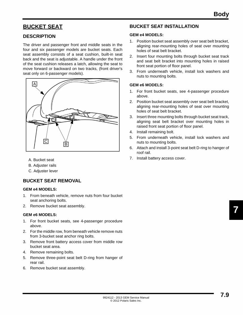
Body
7
BUCKET SEAT
DESCRIPTION
The driver and passenger front and middle seats in thefour and six passenger models are bucket seats. Eachseat assembly consists of a seat cushion, built-in seatback and the seat is adjustable. A handle under the frontof the seat cushion releases a latch, allowing the seat tomove forward or backward on two tracks, (front driver'sseat only on 6-passenger models).
A. Bucket seat
B. Adjuster rails
C. Adjuster lever
BUCKET SEAT REMOVAL
GEM e4 MODELS:
1. From beneath vehicle, remove nuts from four bucketseat anchoring bolts.
2. Remove bucket seat assembly.
GEM e6 MODELS:
1. For front bucket seats, see 4-passenger procedureabove.
2. For the middle row, from beneath vehicle remove nutsfrom 3-bucket seat anchor ring bolts.
3. Remove front battery access cover from middle rowbucket seat area.
4. Remove remaining bolts.
5. Remove three-point seat belt D-ring from hanger ofrear rail.
6. Remove bucket seat assembly.
BUCKET SEAT INSTALLATION
GEM e4 MODELS:
1. Position bucket seat assembly over seat belt bracket,aligning rear-mounting holes of seat over mountingholes of seat belt bracket.
2. Insert four mounting bolts through bucket seat trackand seat belt bracket into mounting holes in raisedfront seat portion of floor panel.
3. From underneath vehicle, install lock washers andnuts to mounting bolts.
GEM e6 MODELS:
1. For front bucket seats, see 4-passenger procedureabove.
2. Position bucket seat assembly over seat belt bracket,aligning rear-mounting holes of seat over mountingholes of seat belt bracket.
3. Insert three mounting bolts through bucket seat track,aligning seat belt bracket over mounting holes inraised front seat portion of floor panel.
4. Install remaining bolt.
5. From underneath vehicle, install lock washers andnuts to mounting bolts.
6. Attach and install 3-point seat belt D-ring to hanger ofroof rail.
7. Install battery access cover.
A
CB
7.99924112 - 2013 GEM Service Manual
© 2012 Polaris Sales Inc.

Body
MUD GUARD
DESCRIPTION
The mud guards are color keyed to match the hood. Theyare attached to the body side panel to form the trailingportion of the front fenders.
MUD GUARD REMOVAL
1. Remove four bolts and four speed nuts attachingmud guard to body side panel.
2. Remove mudguard.
MUD GUARD INSTALLATION
1. If installing new mudguard, using drill, drill four 1/4-inch holes through mud guard, if necessary. Use oldmud guard to determine hole locations.
2. With hood closed, position mud guard against bodyside panel to form clean line and fit with fender portionof hood assembly.
3. Install mud guard and install four speed nuts and fourbolts.
MUD FLAP
DESCRIPTION
The mud flaps are attached to the mudguards that arepositioned behind the front fenders. They help deflect roaddebris and add an attractive, sporty accent to the lowerbody of the vehicle.
MUD FLAP REMOVAL
Using drill, remove rivets (if equipped) and mud flap.
MUD FLAP INSTALLATION
1. Check fit of mud flap to vehicle.
2. Ensure mud flap fits with no gaps larger than 1/8 inch.Trim as necessary for proper fit.
3. Mark first hole one inch from top. Space remainingholes five inches apart starting from top hole.
4. Ensure all holes on mud flap are spaced evenly fromedge.
NOTE: If the vehicle originally had mud flaps, usethe existing holes in the vehicle to mark the mudflaps.
5. Using 3/16-inch drill bit, drill holes in mud flap.
6. Using suitable clamp, secure mud flap to vehicle.
7. Using drill, drill bottom hole.
8. Install bottom rivet from inside.
9. Drill and install remaining rivets working from bottomup, installing top rivet from front.
7.10 9924112 - 2013 GEM Service Manual© 2012 Polaris Sales Inc.

Body
7
HOOD
DESCRIPTION
The hood assembly forms the hood and upper part of thefront fenders. The head lamps and turn signal lamps aremounted in the hood. Hinges to the front suspensionsupport frame attach the hood. On newer models, a latchat the center of the upper edge of the hood holds it securedwhen hood is closed.
Exterior Hood Assembly:
Interior Hood Assembly:
HOOD REMOVAL
1. Unlatch and open hood.
2. Disconnect electrical connector.
3. Cut and remove tie strap from charge cord.
4. Disconnect charge cord.
5. While supporting hood, remove two bolts, two nylonwashers (bolt side), two regular washers (nut side),two nylock nuts, and two hinge brackets.
6. Remove hood.
HOOD INSTALLATION
NOTE: Bolts should be loose enough to allowadjustment of hood for fit, but tight enough to holdhood in adjusted position
1. While supporting hood, attach two hinge brackets tohood with two mounting bolts, two washers (nut side),and two nylock nuts.
2. Adjust hood latch mounting brackets until latch isproperly aligned with striker plate on hood. Carefullytighten two mounting bolts.
3. Close hood and latch.
NOTE: Alignment adjustment of hood for proper fitcan only be made at the lower hood bracket. Movehood brackets forward or back until proper fit ofhood is attained, then tighten the hood bracketmounting bolts. It may be necessary to performalignment of headlights after this procedure. SeeAccessory Component Replacement in ElectricalSection.
A. Turn signal assemblies C. Hood latch
B. Head lamp assemblies D. Charge Receptacle
E. Left turn signal lamp assembly
J. Charge receptacle
F. Left headlamp mounting bracket
K. Right headlamp assy
G. Left headlamp assy L. Right headlamp mounting bracket
H. Headlamp wire harness M. Right turn signal assy
I. Hood Latch
B
A
D
C
E F GK L M
I
JH
7.119924112 - 2013 GEM Service Manual
© 2012 Polaris Sales Inc.

Body
HOOD LATCH ASSEMBLY
DESCRIPTION
The hood latch assembly consists of a bracket, mountedto the center of the lower windshield support, holding astriker plate and an eccentrically pivoting latch handlemounted to the center of the hood trailing edge.
A. Hood latch
B. Hood latch mounting bracket
C. Torx screw
D. Striker plate
E. Hood latch plate
OPERATION
To unlatch the hood, pull up on leading end of latch handleto release tension on the striker plate, allowingdisengagement of the striker. To latch the hood, engagehandle on striker plate, then press down on leading end ofhandle to lock in place.
HOOD LATCH REMOVAL
1. Unlatch and open hood.
2. Noting location of longest screw, remove two screws,bushing, two lock washers, two nuts.
3. Remove the hood latch, and hood latch mountingbracket from hood.
HOOD LATCH INSTALLATION
1. Install hood latch mounting bracket and hood latch,two screws, bushing, two lock washers, and two nutsonto hood.
2. Close and latch hood.
STRIKER PLATE REMOVAL
1. Remove upper dash panel. See Dash in this section. 2. Remove Torx screw and striker plate.
STRIKER PLATE DISASSEMBLY
1. Remove two screws, two lock washers and two nutsretaining the hood latch plate to the striker plate.
2. To reassemble, reverse the disassembly procedure.
STRIKER PLATE INSTALLATION
1. Install striker plate and Torx screw.
2. Install upper dash panel. See Dash in this section.
A E
CDB
C
DA
7.12 9924112 - 2013 GEM Service Manual© 2012 Polaris Sales Inc.

Body
7
DASH UPPER PANEL
DESCRIPTION
The upper dash panel is constructed of molded plastic. Itcontains cup holders for both driver and passenger sides,and a locking glove compartment in the center. The panelis secured by two Torx® head screws through the lowerwindshield support, and by Velcro® strips where it mateswith lower dash panel.
A. Molded cup holder(s)
B. Locking glove box door
C. Storage tray
DASH UPPER REMOVAL
1. Unlatch and open hood. 2. Remove two screws located immediately below
windshield toward outer edges.
3. Slowly, lift upper dash assembly out and towardspassenger side, taking care to disconnect anyelectrical connections if applicable.
4. Disconnect heater ducts at heater assembly (ifequipped).
NOTE: Take care not to scratch steering column/instrument pod covers.
DASH UPPER INSTALLATION
1. Connect heater ducts at heater assembly (ifequipped).
2. Connect electrical connections if applicable.
3. Position upper dash assembly on lower dashassembly.
NOTE: Take care not to scratch steering column/instrument pod covers.
4. Attach upper dash to lower windshield support withtwo screws.
5. Close hood and latch.
A B
C
CAUTION
Take care not to cross-thread bolts, or jack nuts on dash panel will strip.
7.139924112 - 2013 GEM Service Manual
© 2012 Polaris Sales Inc.

Body
DASH LOWER PANEL
DESCRIPTION
The lower dash panel is constructed of molded plastic. Itis secured in place by tabs fitting into slots in the floorpanel, and three Tek screws into the dash support frame.
A. Lower dash panel
B. Upper mounting tabs
C. Floor tabs
DASH LOWER REMOVAL
1. Remove upper dash panel. See Dash Upper Panel inthis section.
2. Remove three screws on top surface mounting tabs.
3. Slowly lift lower dash panel out taking care to tag anddisconnect any electrical connections and heaterducts. Then up, until lower tabs are clear of the slotsin the floor pan.
NOTE: Take care not to scratch steering column/instrument pod covers.
DASH LOWER INSTALLATION
1. Insert panel lower tabs into slots in floor pan.2. Remove tags and connect any electrical connections,
then slowly rock lower panel forward into place.
NOTE: Take care not to scratch steering column/instrument pod covers.
3. Install three screws on top surface mounting tabs.
4. Install upper dash panel. See Dash Upper Panel inthis section.
BA
C
7.14 9924112 - 2013 GEM Service Manual© 2012 Polaris Sales Inc.

Body
7
POD COVERS
DESCRIPTION
The Pod Covers are used to protect and house thecomponents of the steering column. They are secured inplace by six screws, four on the RH side of the steeringcolumn and two on the front surface.
A. Cowl left hand
B. Cowl right hand
C. Screw
D. Plug, screw cover
POD COVER REMOVAL
1. Remove upper dash assembly. See Upper Dash inthis section.
2. Remove lower dash assembly. See Lower Dash inthis section.
3. Remove two screw covers on front of instrument pod.
4. Remove two front pod cover screws.
5. Remove four screws located on sides and removepod covers.
POD COVER INSTALLATION
1. Install four screws in located on sides and removepod covers.
2. Install two front pod cover screws.
3. Install two screw covers on front of instrument pod.
4. Install lower dash assembly. See Lower Dash in thissection.
5. Remove upper dash assembly. See Upper Dash inthis section.
A
B
C
DD
7.159924112 - 2013 GEM Service Manual
© 2012 Polaris Sales Inc.

Body
SPAT
DESCRIPTION
A Spat is an assembly that acts as fenders over the rearwheels of the GEM e2, GEM e4, GEM e6® vehicles. It iscolor keyed to match hood color.
A. Spat
B. Torx head mounting bolts (10)
SPAT REMOVAL
1. Remove TrunkBack™/LinksBack™ (if equipped).See TrunkBack™/LinksBack™ in this section.
2. If equipped with license plate light and tail lights,
• Remove bench seat cushion.
• Follow wires to connectors located under bench seat cushion, above rear batteries, and disconnect.
3. Remove 10 plastic caps from bolts.
4. Carefully remove 10 bolts and spat.
SPAT INSTALLATION
1. Carefully position spat on vehicle.
2. Install 10 bolts attaching spat assembly to mountingbrackets.
3. Install 10 plastic caps onto bolts.
4. If vehicle is equipped with license plate light and taillights,
• Route two wires over rear suspension frame to connectors above rear batteries and connect.
• Install bench seat cushion.
5. Install TrunkBack™/LinksBack™ (if equipped). SeeTrunkBack™/LinksBack™ in this section.
A B
B
7.16 9924112 - 2013 GEM Service Manual© 2012 Polaris Sales Inc.

Body
7
UTILITY BED
DESCRIPTION
GEM e4, GEM eS, GEM eL, GEM e6®:
The Utility Bed is an assembly designed to transportvarious objects from one location to another. It consists ofthree retaining rails, flat bed and a rear wiring harnessassembly.
A. Front bolts (4)
B. Utility bed support bracket bolts (6)
C. Rear tail light wire harness connector
UTILITY BED REMOVAL
1. Remove enclosed cargo carrier or bed cover (ifequipped).
2. Remove rear seat cushion if applicable. See BenchSeat in this section.
3. Disconnect rear tail light wire harness and licenseplate light.
4. Remove four front bolts from each side.
5. Remove three bolts from each side of utility bedsupport bracket.
6. With help of assistant, remove utility bed.
UTILITY BED INSTALLATION
1. With help of assistant, position utility bed.
2. Install three bolts into each side of utility bed supportbracket.
3. Install four front bolts into each side.
4. Connect rear tail light wire harness and license platelight.
5. Install rear seat cushion if applicable. See Bench Seatin this section.
6. Install enclosed cargo carrier or bed cover (ifequipped).
B C B
A
7.179924112 - 2013 GEM Service Manual
© 2012 Polaris Sales Inc.

Body
TRUNKBACK™/LINKSBACK™/ CLIP-IN STAKEBACK™
DESCRIPTION
The LinksBack™ is a unit designed to carry two sets of golfclubs. The TrunkBack™ is a molded plastic box with ahinged locking lid. The Clip-In StakeBack™ is a versatilebed unit designed with a hinged rear tailgate andacceptable of carrying loads up to 150 pounds. Allavailable back options can be used on the 2-, 4-, and 6-passenger models. They are not available on the shortbed or long bed utility models. All back units have two legsthat fit into pockets mounted on each frame rail. Eachattaches to a locking latch assembly mounted at the top ofthe body back panel.
REMOVAL
1. Using key, unlock latch handle.
2. Unlatch unit by turning handle counterclockwise.
3. Lift unit up to free legs from pockets and remove.
INSTALLATION
1. Install legs in pockets.
2. Apply the Velcro®, hook, or buckle-type safety strap.
3. Rock unit forward until latch is engaged, and pack issecured.
7.18 9924112 - 2013 GEM Service Manual© 2012 Polaris Sales Inc.

Body
7
PACK LATCH ASSEMBLY
DESCRIPTION
The pack latch assembly consists of a locking handleconnected to a latch by threaded rods and a turnbuckle.The handle is mounted to the back of the body back panel.The latch is mounted to a plate that, in turn, is mounted tothe bench seat back/body back panel support frame.
A. Turnbuckle bracket
B. Turnbuckle
C. Latch assembly
D. Latch striker
E. Latch striker bracket
OPERATION
The keyed locking mechanism in the handle preventsunauthorized unlatching of the pack unit for removal.When unlocked, turning the handle pulls on the threadedrods and turnbuckle to release the latch. Pushing the latchbracket on the pack unit into the latch mechanism causesit to close.
PACK LATCH ADJUSTMENT
When turning the latch handle, there should be little or noplay detected before the latching mechanism disengagesthe latch bar. Excessive play can result in the latchingmechanism failing to disengage when the handle isturned. If the latching mechanism is not properly lined upwith the latch bracket on the pack unit, it may be difficult orimpossible to engage and lock the unit in place.
To adjust the play in the latch handle:
1. Remove bench seat cushion and back. See BenchSeat in this section.
2. Rotate turnbuckle until play is sufficiently reduced.
To adjust latch alignment:
1. Remove bench seat cushion and back. See BenchSeat in this section.
2. Loosen two bolts attaching latching mechanism tomounting plate.
3. Adjust latch assembly from side to side until properalignment is attained.
4. Tighten mounting bolts.
5. Install bench seat.
A
B
C
D
E
7.199924112 - 2013 GEM Service Manual
© 2012 Polaris Sales Inc.

Body
PACK LATCH REMOVAL
1. Remove bench seat. See Bench Seat in this section.
2. Remove nut attaching turnbuckle assembly bracket tohandle, then disengage bracket from handle.
3. Remove two screws attaching handle assembly tobody back panel.
4. Remove handle.
5. Remove two self-drilling screws attaching latchmounting bracket to seat back/body back panelsupport frame. Remove latch assembly.
PACK LATCH INSTALLATION
1. Position latch mounting plate on seat back/body backpanel support frame and install two self-drillingscrews.
2. Insert latch handle into body back panel and installmounting screws.
3. Attach turnbuckle bracket to handle with nut.
NOTE: End of turnbuckle bracket (where threadedeye-bolt is attached) must be aligned towardlatching mechanism.
4. Adjust latch mechanism position for proper alignment.
5. Adjust turnbuckle for proper play in handle.
6. Install bench seat back and cushion.
TRUNKBACK™ / LINKSBACK™ /CLIP-IN STAKEBACK™ LEG POCKET
DESCRIPTION
The TrunkBack™/LinksBack™/Clip-In-StakeBack™ hastwo legs that fit into pockets mounted on each frame rail.
A. Mounting bolt
B. Pocket
C. Frame rail
LEG POCKET REMOVAL
1. Remove TrunkBack™ / LinksBack™ / Clip-InStakeBack™. See TrunkBack™ / LinksBack™ / Clip-In StakeBack™ in this section.
2. Remove two screws attaching pocket to upper rearframe rail.
3. Remove pocket.
LEG POCKET INSTALLATION
1. Position pocket on upper rear frame rail.
2. Install two screws.
3. Install TrunkBack™ / LinksBack™ / Clip-In StakeBack™. See TrunkBack™ / LinksBack™ / Clip-InStakeBack™ in this section.
B
C
A
7.20 9924112 - 2013 GEM Service Manual© 2012 Polaris Sales Inc.
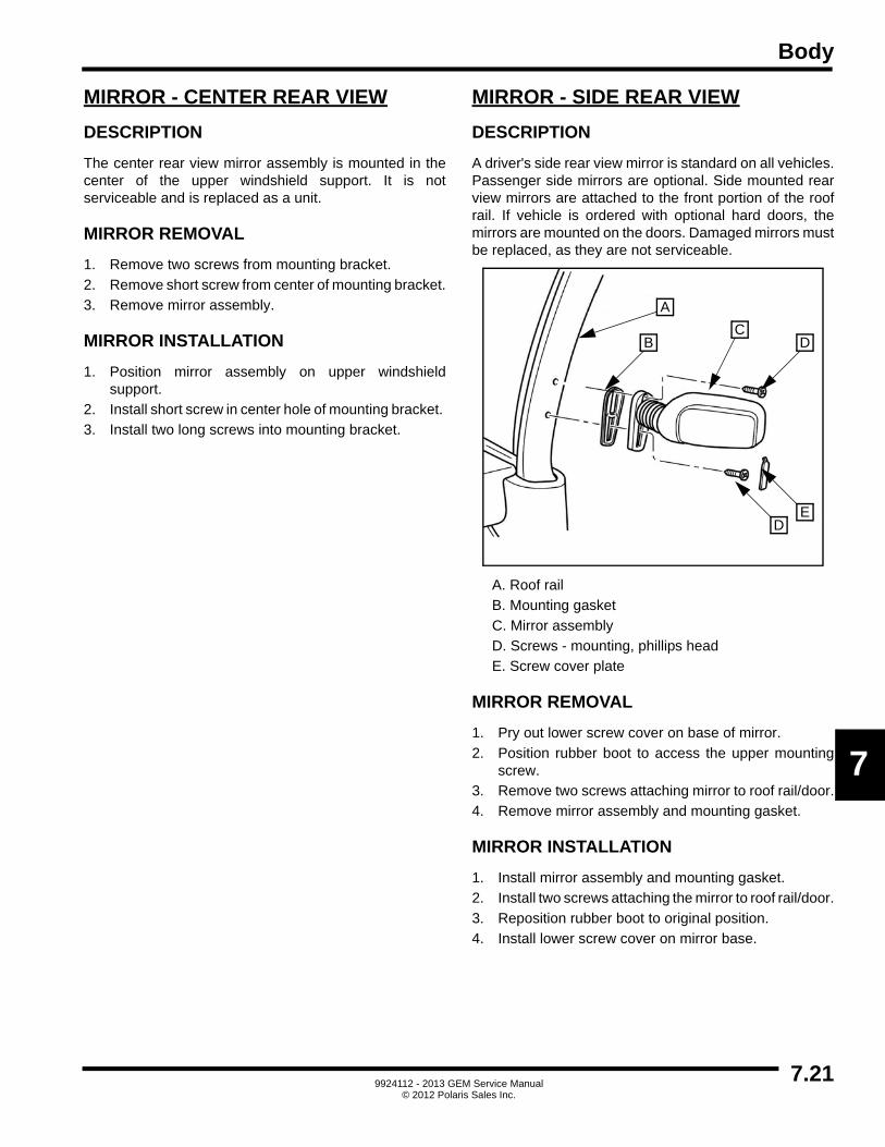
Body
7
MIRROR - CENTER REAR VIEW
DESCRIPTION
The center rear view mirror assembly is mounted in thecenter of the upper windshield support. It is notserviceable and is replaced as a unit.
MIRROR REMOVAL
1. Remove two screws from mounting bracket.
2. Remove short screw from center of mounting bracket.
3. Remove mirror assembly.
MIRROR INSTALLATION
1. Position mirror assembly on upper windshieldsupport.
2. Install short screw in center hole of mounting bracket.
3. Install two long screws into mounting bracket.
MIRROR - SIDE REAR VIEW
DESCRIPTION
A driver's side rear view mirror is standard on all vehicles.Passenger side mirrors are optional. Side mounted rearview mirrors are attached to the front portion of the roofrail. If vehicle is ordered with optional hard doors, themirrors are mounted on the doors. Damaged mirrors mustbe replaced, as they are not serviceable.
A. Roof rail
B. Mounting gasket
C. Mirror assembly
D. Screws - mounting, phillips head
E. Screw cover plate
MIRROR REMOVAL
1. Pry out lower screw cover on base of mirror.
2. Position rubber boot to access the upper mountingscrew.
3. Remove two screws attaching mirror to roof rail/door.
4. Remove mirror assembly and mounting gasket.
MIRROR INSTALLATION
1. Install mirror assembly and mounting gasket.
2. Install two screws attaching the mirror to roof rail/door.
3. Reposition rubber boot to original position.
4. Install lower screw cover on mirror base.
A
DE
DBC
7.219924112 - 2013 GEM Service Manual
© 2012 Polaris Sales Inc.

Body
NOTES
7.229924112 - 2013 GEM Service Manual
© 2012 Polaris Sales Inc.

X
IAAccelerator Pedal . . . . . . . . . . . . . . . . . . . . . . . . . 5.20Accelerator Pedal Diagnosis and Testing . . . . . . . 5.20Accelerator Pedal Installation . . . . . . . . . . . . . . . . 5.21Accelerator Pedal Removal . . . . . . . . . . . . . . . . . . 5.21Accelerator Potentiometer Testing . . . . . . . . . . . . 5.20Accessory System . . . . . . . . . . . . . . . . . . . . . . . . . 5.47Accessory System Diagnosis and Troubleshooting 5.48Accessory Wiring Chart . . . . . . . . . . . . . . . . . . . . . 5.53Adjusting Front Toe . . . . . . . . . . . . . . . . . . . . . . . . . 2.2Adjusting Rear Toe . . . . . . . . . . . . . . . . . . . . . . . . . 2.3Adjustment, Pack Latch . . . . . . . . . . . . . . . . . . . . . 7.19Alignment Inspection . . . . . . . . . . . . . . . . . . . . . . . . 2.2Assembly, Master Cylinder . . . . . . . . . . . . . . . . . . . 4.3Assembly, Parking Brake Cable . . . . . . . . . . . . . . . 4.24Assembly, Rear Brake . . . . . . . . . . . . . . . . . . . . . . 4.17
BBack Panel, Body . . . . . . . . . . . . . . . . . . . . . . . . . . 7.6Ball Joint Installation . . . . . . . . . . . . . . . . . . . . . . . 2.12Ball Joint Maintenance . . . . . . . . . . . . . . . . . . . . . 2.10Ball Joint Removal . . . . . . . . . . . . . . . . . . . . . . . . . 2.11Battery . . . . . . . . . . . . . . . . . . . . . . . . . . . . . . . . . . 5.22Battery Capacity, Calculating . . . . . . . . . . . . . . . . 5.28Battery Charge Level . . . . . . . . . . . . . . . . . . . . . . . 5.31Battery Charger . . . . . . . . . . . . . . . . . . . . . . . . . . . 5.31Battery Charging . . . . . . . . . . . . . . . . . . . . . . . . . . 5.30Battery Cleaning . . . . . . . . . . . . . . . . . . . . . . . . . . 5.29Battery Codes . . . . . . . . . . . . . . . . . . . . . . . . . . . . 5.23Battery Recommended Equipment . . . . . . . . . . . . 5.25Battery Removal and Disposal . . . . . . . . . . . . . . . 5.24Battery Safety . . . . . . . . . . . . . . . . . . . . . . . . . . . . 5.25Battery Storage . . . . . . . . . . . . . . . . . . . . . . . . . . . 5.30Battery Test . . . . . . . . . . . . . . . . . . . . . . . . . . . . . . 5.23Battery Testing . . . . . . . . . . . . . . . . . . . . . . . . . . . 5.26Battery Watering . . . . . . . . . . . . . . . . . . . . . . . . . . 5.29Battery, Discharge Test, Battery . . . . . . . . . . . . . . 5.27Battery, Open Voltage Test . . . . . . . . . . . . . . . . . . 5.27Battery, Specific Gravity Test . . . . . . . . . . . . . . . . 5.26Bearing and Seal Installation . . . . . . . . . . . . . . . . . 2.20Bearing and Seal Removal . . . . . . . . . . . . . . . . . . 2.20Bench Seat . . . . . . . . . . . . . . . . . . . . . . . . . . . . . . . 7.8Bench Seat Removal . . . . . . . . . . . . . . . . . . . . . . . . 7.8Bleeding, Brake -Pressure . . . . . . . . . . . . . . . . . . . . 4.6Body Back Panel . . . . . . . . . . . . . . . . . . . . . . . . . . . 7.6Body Back Panel Installation . . . . . . . . . . . . . . . . . . 7.6Body Back Panel Removal . . . . . . . . . . . . . . . . . . . 7.6Body, Dash Lower Panel . . . . . . . . . . . . . . . . . . . . 7.14Body, Floor Panels (6 Person) . . . . . . . . . . . . . . . . 7.7Body, Hood . . . . . . . . . . . . . . . . . . . . . . . . . . . . . . 7.11Body, Mudflap . . . . . . . . . . . . . . . . . . . . . . . . . . . . 7.10Body, Mudguard . . . . . . . . . . . . . . . . . . . . . . . . . . 7.10Body, Pod Covers . . . . . . . . . . . . . . . . . . . . . . . . . 7.15Body, Side Panel . . . . . . . . . . . . . . . . . . . . . . . . . . . 7.3Body, Side Panel - 6 Person . . . . . . . . . . . . . . . . . . 7.4Body, Spat . . . . . . . . . . . . . . . . . . . . . . . . . . . . . . . 7.16
Body, Utility Bed . . . . . . . . . . . . . . . . . . . . . . . . . . 7.17Brake Bleeding - Pressure . . . . . . . . . . . . . . . . . . . 4.6Brake Diagnosis . . . . . . . . . . . . . . . . . . . . . . . . . . 4.29Brake Fluid . . . . . . . . . . . . . . . . . . . . . . . . . . . . . . . 1.4Brake Pedal Installation . . . . . . . . . . . . . . . . . . . . . 4.5Brake Pedal Removal . . . . . . . . . . . . . . . . . . . . . . . 4.5Brake System . . . . . . . . . . . . . . . . . . . . . . . . . . . . . 4.2Brake System, Bleeding . . . . . . . . . . . . . . . . . . . . . 4.7Bucket Seat . . . . . . . . . . . . . . . . . . . . . . . . . . . . . . . 7.9Bucket Seat Installation . . . . . . . . . . . . . . . . . . . . . 7.9Bucket Seat Removal . . . . . . . . . . . . . . . . . . . . . . . 7.9Bushing Installation . . . . . . . . . . . . . . . . . . . . . . . . 2.10Bushing Maintenance . . . . . . . . . . . . . . . . . . . . . . 2.10Bushing Removal . . . . . . . . . . . . . . . . . . . . . . . . . 2.10
CCalculating Battery Capacity . . . . . . . . . . . . . . . . . 5.28Changing Below Minumum Voltage . . . . . . . . . . . 5.32Charge Algorithm . . . . . . . . . . . . . . . . . . . . . . . . . 5.34Charge Level, Battery . . . . . . . . . . . . . . . . . . . . . . 5.31Charger Operation . . . . . . . . . . . . . . . . . . . . . . . . 5.33Charger Replacement . . . . . . . . . . . . . . . . . . . . . . 5.32Charger, Battery . . . . . . . . . . . . . . . . . . . . . . . . . . 5.31Charging, Battery . . . . . . . . . . . . . . . . . . . . . . . . . 5.30Communication Problems, Digital Wrench . . . . . . 5.96Control Arm Installation . . . . . . . . . . . . . . . . . . .2.8, 2.9Control Arm Removal . . . . . . . . . . . . . . . . . . . .2.8, 2.9Controller Harness . . . . . . . . . . . . . . . . . . . . . . . . 5.88Controller, Motor . . . . . . . . . . . . . . . . . . . . . . . . . . 5.38Converter Harness . . . . . . . . . . . . . . . . . . . . . . . . 5.80
DDash Lower Panel . . . . . . . . . . . . . . . . . . . . . . . . . 7.14Dash Lower Panel Installation . . . . . . . . . . . . . . . 7.14Dash Lower Panel Removal . . . . . . . . . . . . . . . . . 7.14Dash Upper Panel . . . . . . . . . . . . . . . . . . . . . . . . . 7.13Dash Upper Panel Installation . . . . . . . . . . . . . . . 7.13Dash Upper Panel Removal . . . . . . . . . . . . . . . . . 7.13DC / DC Converter . . . . . . . . . . . . . . . . . . . . . . . . 5.39DC / DC Converter Diagnosis and Testing . . . . . . 5.39DC / DC Converter Installation . . . . . . . . . . . . . . . 5.39DC / DC Converter Removal . . . . . . . . . . . . . . . . . 5.39Defective Cell Testing . . . . . . . . . . . . . . . . . . . . . . 5.28Diagnosis and Testing, Accelerator Pedal . . . . . . 5.20Diagnosis and Testing, DC / DC Converter . . . . . 5.39Diagnosis and Testing, Drive System . . . . . . . . . . . 5.6Diagnosis and Testing, Motor . . . . . . . . . . . . . . . . 5.42Diagnosis and Testing, Motor Controller . . . . . . . . 5.38Diagnosis and Testing, Power System . . . . . . . . . . 5.4Diagnosis and Testing, Pressure Gauges . . . . . . . 6.4Diagnosis and Testing, Speed Sensor . . . . . . . . . 5.43Diagnosis and Testing, Steering Gear . . . . . . . . . 2.18Diagnosis and Testing, Tire Noise and Vibration . . 6.5Diagnosis and Testing, Tire Wear Patterns . . . . . . 6.5Diagnosis and Testing, Tread Wear Indicators . . . . 6.4Diagnosis and Testing, Wheel Inspection . . . . . . . . 6.6Diagnosis and Troubleshooting, Accessory System 5.48
IX.1

Diagnosis, Brake . . . . . . . . . . . . . . . . . . . . . . . . . . 4.29Diagnosis, Half Shaft . . . . . . . . . . . . . . . . . . . . . . . . 3.2Diagrams, Drive and Power System . . . . . . . . . . . 5.13Differential . . . . . . . . . . . . . . . . . . . . . . . . . . . . . . . . 3.4Differential Installation . . . . . . . . . . . . . . . . . . . . . . . 3.4Differential Lubricant . . . . . . . . . . . . . . . . . . . . . . . . 1.4Differential Removal . . . . . . . . . . . . . . . . . . . . . . . . 3.4Digital Wrench Communication Errors . . . . . . . . . 5.96Digital Wrench Diagnostic Software . . . . . . . . . . . 5.96Digital Wrench, Updates . . . . . . . . . . . . . . . . . . . . 5.98Disassembly, Rear Brake . . . . . . . . . . . . . . . . . . . . 4.17Discharge Test . . . . . . . . . . . . . . . . . . . . . . . . . . . 5.27Display . . . . . . . . . . . . . . . . . . . . . . . . . . . . . . . . . . 5.44Disposal and Removal, Battery . . . . . . . . . . . . . . . 5.24Drive and Power System Diagrams . . . . . . . . . . . 5.13Drive and Power System Error Codes . . . . . . . . . . 5.7Drive and Power System Troubleshooting . . . . . . 5.15Drive Systsem . . . . . . . . . . . . . . . . . . . . . . . . . . . . . 5.5Drive Systsem Diagnosis and Testing . . . . . . . . . . . 5.6Drivetrain . . . . . . . . . . . . . . . . . . . . . . . . . . . . . . . . . 3.2
EECU Replacement . . . . . . . . . . . . . . . . . . . . . . . . . 5.96Electrical System . . . . . . . . . . . . . . . . . . . . . . . . . . . 5.3Error Codes, Drive and Power System . . . . . . . . . . 5.7
FFast Charger Troubleshooting . . . . . . . . . . . . . . . . 5.36Fast Charging System . . . . . . . . . . . . . . . . . . . . . . 5.35Fastener Usage . . . . . . . . . . . . . . . . . . . . . . . . . . . . 1.4First Aid Treatments . . . . . . . . . . . . . . . . . . . . . . . 5.25Floor Panels (6 Person) . . . . . . . . . . . . . . . . . . . . . 7.7Front Harness . . . . . . . . . . . . . . . . . . . . . . . . . . . . 5.84Front shock Inspection . . . . . . . . . . . . . . . . . . . . . . 2.6Front shock Installaion . . . . . . . . . . . . . . . . . . . . . . 2.6Front shock Removal . . . . . . . . . . . . . . . . . . . . . . . 2.6Front Suspension . . . . . . . . . . . . . . . . . . . . . . . . . . 2.3Front Toe, Adjustment . . . . . . . . . . . . . . . . . . . . . . . 2.2Front Toe, Measurement . . . . . . . . . . . . . . . . . . . . . 2.2Front Turn Indicator Lamp Replacement . . . . . . . . 5.52Fuse Replacement . . . . . . . . . . . . . . . . . . . . . . . . 5.52
GGeneral Warnings . . . . . . . . . . . . . . . . . . . . . . . . . . 1.3
HHalf Shaft . . . . . . . . . . . . . . . . . . . . . . . . . . . . . . . . . 3.2Half Shaft Diagnosis . . . . . . . . . . . . . . . . . . . . . . . . 3.2Half Shaft Inspection . . . . . . . . . . . . . . . . . . . . . . . . 3.3Half Shaft Installation . . . . . . . . . . . . . . . . . . . . . . . 3.3Half Shaft Removal . . . . . . . . . . . . . . . . . . . . . . . . . 3.3Headlight Harness . . . . . . . . . . . . . . . . . . . . . . . . . 5.82Headlight Replacement . . . . . . . . . . . . . . . . . . . . . 5.52Hoisting and Jacking . . . . . . . . . . . . . . . . . . . . . . . . 1.5Hood . . . . . . . . . . . . . . . . . . . . . . . . . . . . . . . . . . . 7.11Hood Installation . . . . . . . . . . . . . . . . . . . . . . . . . . 7.11Hood Latch Assembly . . . . . . . . . . . . . . . . . . . . . . 7.12Hood Latch Installation . . . . . . . . . . . . . . . . . . . . . 7.12
Hood Latch Removal . . . . . . . . . . . . . . . . . . . . . . 7.12Hood Removal . . . . . . . . . . . . . . . . . . . . . . . . . . . 7.11
IInspection, Alignment . . . . . . . . . . . . . . . . . . . . . . . 2.2Inspection, Front Shock . . . . . . . . . . . . . . . . . . . . . 2.6Inspection, Half Shaft . . . . . . . . . . . . . . . . . . . . . . . 3.3Inspection, Rear Shock . . . . . . . . . . . . . . . . . . . . . . 2.7Inspection, Rear Suspension Frame / Axle . . .2.4, 2.5Inspection, Steering Column . . . . . . . . . . . . . . . . . 2.16Installation Back Panel, Body . . . . . . . . . . . . . . . . . 7.6Installation TrunkBack™/LinksBack™/ . . . . . . . . . 7.18Installation, Accelerator Pedal . . . . . . . . . . . . . . . 5.21Installation, Ball Joint . . . . . . . . . . . . . . . . . . . . . . 2.12Installation, Bearing and Seal . . . . . . . . . . . . . . . . 2.20Installation, Brake Pedal . . . . . . . . . . . . . . . . . . . . . 4.5Installation, Bucket Seat . . . . . . . . . . . . . . . . . . . . . 7.9Installation, Bushing . . . . . . . . . . . . . . . . . . . . . . . 2.10Installation, Center Rear View Mirror . . . . . . . . . . 7.21Installation, Control Arm . . . . . . . . . . . . . . . . . .2.8, 2.9Installation, Dash Lower Panel . . . . . . . . . . . . . . . 7.14Installation, Dash Upper Panel . . . . . . . . . . . . . . . 7.13Installation, DC / DC Converter . . . . . . . . . . . . . . 5.39Installation, Differential . . . . . . . . . . . . . . . . . . . . . . 3.4Installation, Front Shock . . . . . . . . . . . . . . . . . . . . . 2.6Installation, Half Shaft . . . . . . . . . . . . . . . . . . . . . . . 3.3Installation, Hood . . . . . . . . . . . . . . . . . . . . . . . . . 7.11Installation, Hood Latch Assembly . . . . . . . . . . . . 7.12Installation, LCD . . . . . . . . . . . . . . . . . . . . . . . . . . 5.44Installation, Main Contactor . . . . . . . . . . . . . . . . . 5.40Installation, Master Cylinder . . . . . . . . . . . . . . . . . . 4.4Installation, Motor . . . . . . . . . . . . . . . . . . . . . . . . . 5.42Installation, Motor Controller . . . . . . . . . . . . . . . . . 5.38Installation, Mud Flap . . . . . . . . . . . . . . . . . . . . . . 7.10Installation, Mudguard . . . . . . . . . . . . . . . . . . . . . 7.10Installation, Pack Latch . . . . . . . . . . . . . . . . . . . . . 7.20Installation, Park Brake Lever (e2, eS,eL, eLXD) . 4.21Installation, Park Brake Lever (e4, e6, e6S) . . . . . 4.23Installation, Parking Brake Cable (e2, eS, eL, e4, eLXD) . . . . . . . . . . 4.25, 4.26, 4.27Installation, Parking Brake Cable (e6, e6S) . . . . . 4.28Installation, Pod Cover . . . . . . . . . . . . . . . . . . . . . 7.15Installation, PSDM . . . . . . . . . . . . . . . . . . . . . . . . 5.45Installation, Rear Brake (e2, e4, eS, eL) . . . .4.18, 4.19Installation, Rear Hub . . . . . . . . . . . . . . . . . .2.13, 2.14Installation, Rear Shock . . . . . . . . . . . . . . . . . . . . . 2.7Installation, Rear Suspension Frame / Axle . . . . . . 2.4Installation, Rear Suspension Frame / Axle (e6, e6S, eLXD) . . . . . . . . . . . . . . . . . . . . . . . . . 2.5Installation, Scuff Guard . . . . . . . . . . . . . . . . . . . . . 7.5Installation, Seat Belt . . . . . . . . . . . . . . . . . . . . . . . 7.2Installation, Side Panel . . . . . . . . . . . . . . . . . . . . . . 7.3Installation, Side View Mirror . . . . . . . . . . . . . . . . 7.21Installation, Spat . . . . . . . . . . . . . . . . . . . . . . . . . . 7.16Installation, Speed Sensor . . . . . . . . . . . . . . . . . . 5.43Installation, Steering Column . . . . . . . . . . . . . . . . 2.16
IX.2

X
IInstallation, Steering Gear . . . . . . . . . . . . . . . . . . . 2.18Installation, Steering Knuckle . . . . . . . . . . . . . . . . 2.19Installation, Steering Wheel . . . . . . . . . . . . . . . . . . 2.15Installation, Tie Rod End . . . . . . . . . . . . . . . . . . . . 2.20Installation, TrunkBack/LinksBack/ Clip-in StakeBack Leg Pocket . . . . . . . . . . . . . 7.20Installation, Utility Bed . . . . . . . . . . . . . . . . . . . . . . 7.17Installation, Wheel . . . . . . . . . . . . . . . . . . . . . . . . . . 6.7Instrument Panel Harness . . . . . . . . . . . . . . . . . . . 5.86Instrument Pod Replacement . . . . . . . . . . . . . . . . 5.52Introduction . . . . . . . . . . . . . . . . . . . . . . . . . . . . . . . 1.3JJacking Locations . . . . . . . . . . . . . . . . . . . . . . . . . . 1.5
KKey Switch Replacement . . . . . . . . . . . . . . . . . . . . 5.53
LLCD Display . . . . . . . . . . . . . . . . . . . . . . . . . . . . . . 5.44LCD Installation . . . . . . . . . . . . . . . . . . . . . . . . . . . 5.44LCD Removal . . . . . . . . . . . . . . . . . . . . . . . . . . . . 5.44Light Switch Replacement . . . . . . . . . . . . . . . . . . . 5.53Liquid Crystal Display (LCD) . . . . . . . . . . . . . . . . . 5.44Locking Steering Column . . . . . . . . . . . . . . . . . . . 2.17Lubricants and Grease . . . . . . . . . . . . . . . . . . . . . . 1.4
MMain Contactor . . . . . . . . . . . . . . . . . . . . . . . . . . . 5.40Main Contactor Installation . . . . . . . . . . . . . . . . . . 5.40Main Contactor Removal . . . . . . . . . . . . . . . . . . . . 5.40Main Harness . . . . . . . . . . . . . . . . . . . . . . . . . . . . 5.91Maintenance Schedule . . . . . . . . . . . . . . . . . . . . . . 1.5Maintenance, Ball Joint . . . . . . . . . . . . . . . . . . . . . 2.10Maintenance, Bushing . . . . . . . . . . . . . . . . . . . . . . 2.10Master Cylinder Assembly . . . . . . . . . . . . . . . . . . . . 4.3Master Cylinder Installation . . . . . . . . . . . . . . . . . . . 4.4Master Cylinder Removal . . . . . . . . . . . . . . . . . . . . 4.3Measuring Front Toe . . . . . . . . . . . . . . . . . . . . . . . . 2.2Measuring Rear Toe . . . . . . . . . . . . . . . . . . . . . . . . 2.3Mirror - Center Rear View Installation . . . . . . . . . . 7.21Mirror - Center Rear View Removal . . . . . . . . . . . 7.21Mirror - Side Rear View . . . . . . . . . . . . . . . . . . . . . 7.21Mirror - Center Rear View . . . . . . . . . . . . . . . . . . . 7.21Model Number . . . . . . . . . . . . . . . . . . . . . . . . . . . . . 1.2Motor . . . . . . . . . . . . . . . . . . . . . . . . . . . . . . . . . . . 5.41Motor Controller . . . . . . . . . . . . . . . . . . . . . . . . . . . 5.38Motor Controller Diagnosis and Testing . . . . . . . . 5.38Motor Controller Installation . . . . . . . . . . . . . . . . . . 5.38Motor Controller Removal . . . . . . . . . . . . . . . . . . . 5.38Motor Diagnosis and Testing . . . . . . . . . . . . . . . . . 5.42Motor Installation . . . . . . . . . . . . . . . . . . . . . . . . . . 5.42Motor Magnet . . . . . . . . . . . . . . . . . . . . . . . . . . . . 5.43Motor Removal . . . . . . . . . . . . . . . . . . . . . . . . . . . 5.42Mud Flap Installation . . . . . . . . . . . . . . . . . . . . . . . 7.10Mud Flap Removal . . . . . . . . . . . . . . . . . . . . . . . . 7.10Mudflap . . . . . . . . . . . . . . . . . . . . . . . . . . . . . . . . . 7.10Mudguard . . . . . . . . . . . . . . . . . . . . . . . . . . . . . . . 7.10
Mudguard Installation . . . . . . . . . . . . . . . . . . . . . . 7.10Mudguard Removal . . . . . . . . . . . . . . . . . . . . . . . . 7.10
OOpen Voltage Test . . . . . . . . . . . . . . . . . . . . . . . . 5.27
PPack Latch Adjustment . . . . . . . . . . . . . . . . . . . . . 7.19Pack Latch Assembly . . . . . . . . . . . . . . . . . . . . . . 7.19Pack Latch Installation . . . . . . . . . . . . . . . . . . . . . 7.20Pack Latch Removal . . . . . . . . . . . . . . . . . . . . . . . 7.20Park Brake Lever Installation (e2, eS, eL, eLXD) . 4.21Park Brake Lever Installation (e4, e6, e6S) . . . . . 4.23Park Brake Lever Removal (e2, eS, eL, eLXD) . . 4.21Park Brake Lever Removal (e4, e6, e6S) . . . . . . . 4.22Parking Brake Cable Assembly (e2. eS, eL, e4, eLXD) . . . . . . . . . . . . . . . . . . . 4.24Parking Brake Cable Installation (e2, eS, eL, e4, eLXD) . . . . . . . . . . 4.25, 4.26, 4.27Parking Brake Cable Installation (e6, e6S) . . . . . . 4.28Parking Brake Cable Removal (e2, eS, eL, e4, eLXD) . . . . . . . . . . 4.24, 4.25, 4.27Parking Brake Cable Removal (e6, e6S) . . . . . . . 4.27Parking Brake Cable Tension Adjustment . . . . . . 4.23Pedal, Accelerator . . . . . . . . . . . . . . . . . . . . . . . . . 5.20Pod Cover Installation . . . . . . . . . . . . . . . . . . . . . . 7.15Pod Cover Removal . . . . . . . . . . . . . . . . . . . . . . . 7.15Pod Covers . . . . . . . . . . . . . . . . . . . . . . . . . . . . . . 7.15Potentiometer Testing, Accelerator . . . . . . . . . . . . 5.20Power Braking Load Test . . . . . . . . . . . . . . . . . . . 5.23Power Signal Distribution Module . . . . . . . . . . . . . 5.45Power System . . . . . . . . . . . . . . . . . . . . . . . . . . . . . 5.4Power System Diagnosis and Testing . . . . . . . . . . 5.4Pressure Gauges Diagnosis and Testing . . . . . . . . 6.4PSDM . . . . . . . . . . . . . . . . . . . . . . . . . . . . . . . . . . 5.45PSDM Installation . . . . . . . . . . . . . . . . . . . . . . . . . 5.45PSDM Removal . . . . . . . . . . . . . . . . . . . . . . . . . . 5.45
RRadial - Ply Tires . . . . . . . . . . . . . . . . . . . . . . . . . . . 6.3Rear Brake Assembly (e2, e4, eS, eL) . . . . . . . . . 4.17Rear Brake Disassembly (e2, e4, eS, eL) . . . . . . . 4.17Rear Brake Installation (e2, e4, eS, eL) . . . .4.18, 4.19Rear Brake Removal (e2, e4, eS, eL) . . . . . .4.17, 4.19Rear Hub Installation . . . . . . . . . . . . . . . . . .2.13, 2.14Rear Hub Removal . . . . . . . . . . . . . . . . . . . .2.13, 2.14Rear shock Inspection . . . . . . . . . . . . . . . . . . . . . . 2.7Rear Shock Installation . . . . . . . . . . . . . . . . . . . . . . 2.7Rear Shock Removal . . . . . . . . . . . . . . . . . . . . . . . 2.7Rear Suspension Frame / Axle Inspection . . . .2.4, 2.5Rear Suspension Frame / Axle Installation . . . . . . . 2.4Rear Suspension Frame / Axle Installation (e6, e6S, eLXD) . . . . . . . . . . . . . . . . . . . . . . . . . 2.5Rear Suspension Frame / Axle Removal (e2, e4, eS, eL) . . . . . . . . . . . . . . . . . . . . . . . . . 2.4Rear Suspension Frame / Axle Removal (e6, e6S, eLXD) . . . . . . . . . . . . . . . . . . . . . . . . . 2.5
IX.3

Rear Toe, Adjustment . . . . . . . . . . . . . . . . . . . . . . . 2.3Rear Toe, Measurement . . . . . . . . . . . . . . . . . . . . . 2.3Rear Turn Indicator Lamp Replacement . . . . . . . . 5.52Rear View Mirror . . . . . . . . . . . . . . . . . . . . . . . . . . 7.21Recommended Equipment, Battery . . . . . . . . . . . 5.25Removal Back Panel, Body . . . . . . . . . . . . . . . . . . . 7.6Removal TrunkBack™/LinksBack™/ . . . . . . . . . . 7.18Removal, Accelerator Pedal . . . . . . . . . . . . . . . . . 5.21Removal, Ball Joint . . . . . . . . . . . . . . . . . . . . . . . . 2.11Removal, Bearing and Seal . . . . . . . . . . . . . . . . . . 2.20Removal, Bench Seat . . . . . . . . . . . . . . . . . . . . . . . 7.8Removal, Brake Pedal . . . . . . . . . . . . . . . . . . . . . . . 4.5Removal, Bucket Seat . . . . . . . . . . . . . . . . . . . . . . . 7.9Removal, Bushing . . . . . . . . . . . . . . . . . . . . . . . . . 2.10Removal, Center Rear View Mirror . . . . . . . . . . . . 7.21Removal, Control Arm . . . . . . . . . . . . . . . . . . . 2.8, 2.9Removal, Dash Lower Panel . . . . . . . . . . . . . . . . . 7.14Removal, Dash Upper Panel . . . . . . . . . . . . . . . . . 7.13Removal, DC / DC Converter . . . . . . . . . . . . . . . . 5.39Removal, Differential . . . . . . . . . . . . . . . . . . . . . . . . 3.4Removal, Front Shock . . . . . . . . . . . . . . . . . . . . . . . 2.6Removal, Half Shaft . . . . . . . . . . . . . . . . . . . . . . . . 3.3Removal, Hood . . . . . . . . . . . . . . . . . . . . . . . . . . . 7.11Removal, Hood Latch Assembly . . . . . . . . . . . . . . 7.12Removal, LCD . . . . . . . . . . . . . . . . . . . . . . . . . . . . 5.44Removal, Main Contactor . . . . . . . . . . . . . . . . . . . 5.40Removal, Master Cylinder . . . . . . . . . . . . . . . . . . . . 4.3Removal, Motor . . . . . . . . . . . . . . . . . . . . . . . . . . . 5.42Removal, Motor Controller . . . . . . . . . . . . . . . . . . 5.38Removal, Mud Flap . . . . . . . . . . . . . . . . . . . . . . . . 7.10Removal, Mudguard . . . . . . . . . . . . . . . . . . . . . . . 7.10Removal, Pack Latch . . . . . . . . . . . . . . . . . . . . . . 7.20Removal, Park Brake Lever (e2, eS, eL, eLXD) . . 4.21Removal, Park Brake Lever (e4, e6, e6S) . . . . . . . 4.22Removal, Parking Brake Cable (e2, eS, eL, e4, eLXD) . . . . . . . . . .4.24, 4.25, 4.27Removal, Parking Brake Cable (e6, e6S) . . . . . . . 4.27Removal, Pod Cover . . . . . . . . . . . . . . . . . . . . . . . 7.15Removal, PSDM . . . . . . . . . . . . . . . . . . . . . . . . . . 5.45Removal, Rear Brake (e2, e4, eS, eL) . . . . 4.17, 4.19Removal, Rear Hub . . . . . . . . . . . . . . . . . . . 2.13, 2.14Removal, Rear Shock . . . . . . . . . . . . . . . . . . . . . . . 2.7Removal, Rear Suspension Frame / Axle (e2, e4, eS, eL) . . . . . . . . . . . . . . . . . . . . . . . . . . 2.4Removal, Rear Suspension Frame / Axle (e6, e6S, eLXD) . . . . . . . . . . . . . . . . . . . . . . . . . 2.5Removal, Seat Belt . . . . . . . . . . . . . . . . . . . . . . . . . 7.2Removal, Side Panel . . . . . . . . . . . . . . . . . . . . . . . . 7.3Removal, Side View Mirror . . . . . . . . . . . . . . . . . . 7.21Removal, Spat . . . . . . . . . . . . . . . . . . . . . . . . . . . . 7.16Removal, Speed Sensor . . . . . . . . . . . . . . . . . . . . 5.43Removal, Steering Column . . . . . . . . . . . . . . . . . . 2.16Removal, Steering Gear . . . . . . . . . . . . . . . . . . . . 2.18Removal, Steering Knuckle . . . . . . . . . . . . . . . . . . 2.19Removal, Steering Wheel . . . . . . . . . . . . . . . . . . . 2.15
Removal, Tie Rod End . . . . . . . . . . . . . . . . . . . . . 2.20Removal, TrunkBack/LinksBack/ Clip-in StakeBack Leg Pocket . . . . . . . . . . . . . 7.20Removal, Utility Bed . . . . . . . . . . . . . . . . . . . . . . . 7.17Repairing Tire Leaks . . . . . . . . . . . . . . . . . . . . . . . . 6.5Replacement Tires . . . . . . . . . . . . . . . . . . . . . . . . . 6.4Replacement, Charger . . . . . . . . . . . . . . . . . . . . . 5.32Rocker Switch Replacement . . . . . . . . . . . . . . . . . 5.53Rotation, Tire . . . . . . . . . . . . . . . . . . . . . . . . . . . . . 6.6
SSafety Certification . . . . . . . . . . . . . . . . . . . . . . . . . 1.3Schedule, Maintenance . . . . . . . . . . . . . . . . . . . . . 1.5Scuff Guard Installation . . . . . . . . . . . . . . . . . . . . . 7.5Scuff Guards . . . . . . . . . . . . . . . . . . . . . . . . . . . . . . 7.5Seal and Bearing Installation . . . . . . . . . . . . . . . . 2.20Seal and Bearing Removal . . . . . . . . . . . . . . . . . . 2.20Seat Belt Installation . . . . . . . . . . . . . . . . . . . . . . . . 7.2Seat Belt Removal . . . . . . . . . . . . . . . . . . . . . . . . . 7.2Seat Belt, Three Point . . . . . . . . . . . . . . . . . . . . . . . 7.2Seat Bench . . . . . . . . . . . . . . . . . . . . . . . . . . . . . . . 7.8Seat Bucket . . . . . . . . . . . . . . . . . . . . . . . . . . . . . . 7.9Shock Diagnosis . . . . . . . . . . . . . . . . . . . . . . . . . . . 2.6Side Panel - 6 Person, Body . . . . . . . . . . . . . . . . . . 7.4Side Panel Installation . . . . . . . . . . . . . . . . . . . . . . 7.3Side Panel Removal . . . . . . . . . . . . . . . . . . . . . . . . 7.3Side Panel, Body . . . . . . . . . . . . . . . . . . . . . . . . . . 7.3Side View Mirror . . . . . . . . . . . . . . . . . . . . . . . . . . 7.21Side View Mirror Installation . . . . . . . . . . . . . . . . . 7.21Side View Mirror Removal . . . . . . . . . . . . . . . . . . 7.21Spat . . . . . . . . . . . . . . . . . . . . . . . . . . . . . . . . . . . 7.16Spat Installation . . . . . . . . . . . . . . . . . . . . . . . . . . 7.16Spat Removal . . . . . . . . . . . . . . . . . . . . . . . . . . . . 7.16Specific Gravity Test . . . . . . . . . . . . . . . . . . . . . . . 5.26Speed Sensor . . . . . . . . . . . . . . . . . . . . . . . . . . . . 5.43Speed Sensor Diagnosis and Testing . . . . . . . . . 5.43Speed Sensor Installation . . . . . . . . . . . . . . . . . . . 5.43Speed Sensor Removal . . . . . . . . . . . . . . . . . . . . 5.43Start Switch Testing . . . . . . . . . . . . . . . . . . . . . . . 5.20Steering Column Inspection . . . . . . . . . . . . . . . . . 2.16Steering Column Installation . . . . . . . . . . . . . . . . . 2.16Steering Column Lock . . . . . . . . . . . . . . . . . . . . . 2.17Steering Column Removal . . . . . . . . . . . . . . . . . . 2.16Steering Gear Diagnosis and Testing . . . . . . . . . . 2.18Steering Gear Installation . . . . . . . . . . . . . . . . . . . 2.18Steering Gear Removal . . . . . . . . . . . . . . . . . . . . 2.18Steering Knuckle Installation . . . . . . . . . . . . . . . . 2.19Steering Knuckle Removal . . . . . . . . . . . . . . . . . . 2.19Steering Wheel Installation . . . . . . . . . . . . . . . . . . 2.15Steering Wheel Removal . . . . . . . . . . . . . . . . . . . 2.15Steering Wheel Tilt . . . . . . . . . . . . . . . . . . . . . . . . 2.17Storage, Battery . . . . . . . . . . . . . . . . . . . . . . . . . . 5.30Suspension Diagnosis . . . . . . . . . . . . . . . . . . . . . 2.21
IX.4

X
ITTachometer . . . . . . . . . . . . . . . . . . . . . . . . . . . . . . 5.43Tail Light Harness . . . . . . . . . . . . . . . . . . . . . . . . . 5.94Testing for Defective Cells . . . . . . . . . . . . . . . . . . . 5.28Testing, Battery . . . . . . . . . . . . . . . . . . . . . . . . . . . 5.26Testing, Start Switch . . . . . . . . . . . . . . . . . . . . . . . 5.20Three Point Seat Belt . . . . . . . . . . . . . . . . . . . . . . . 7.2Tie Rod End Installation . . . . . . . . . . . . . . . . . . . . 2.20Tie Rod End Removal . . . . . . . . . . . . . . . . . . . . . . 2.20Tire Chart . . . . . . . . . . . . . . . . . . . . . . . . . . . . . . . . . 6.2Tire Inflation Pressures . . . . . . . . . . . . . . . . . . . . . . 6.3Tire Noise and Vibration Diagnosis and Testing . . . 6.5Tire Rotation . . . . . . . . . . . . . . . . . . . . . . . . . . . . . . 6.6Tire Wear Patterns Diagnosis and Testing . . . . . . . 6.5Tire, Repairing Leaks . . . . . . . . . . . . . . . . . . . . . . . 6.5Tires . . . . . . . . . . . . . . . . . . . . . . . . . . . . . . . . . . . . . 6.3Tires and Wheels . . . . . . . . . . . . . . . . . . . . . . . . . . . 6.2Toe-In Definition . . . . . . . . . . . . . . . . . . . . . . . . . . . 2.2Tread Wear Indicators Diagnosis and Testing . . . . 6.4Troubleshooting, Drive and Power System . . . . . . 5.15Troubleshooting, Fast Charger . . . . . . . . . . . . . . . 5.36TrunkBack/LinksBack/Clip-in StakeBack Leg Pocket . . . . . . . . . . . . . . . . . . . . . . . . . . . . 7.20TrunkBack/LinksBack/Clip-in StakeBack Leg Pocket Installation . . . . . . . . . . . . . . . . . . . 7.20TrunkBack/LinksBack/Clip-in StakeBack Leg Pocket Removal . . . . . . . . . . . . . . . . . . . . 7.20TrunkBack™/LinksBack™ . . . . . . . . . . . . . . . . . . . 7.18Turn Signal Switch Replacement . . . . . . . . . . . . . 5.53
UUtility Bed . . . . . . . . . . . . . . . . . . . . . . . . . . . . . . . 7.17Utility Bed Installation . . . . . . . . . . . . . . . . . . . . . . 7.17Utility Bed Removal . . . . . . . . . . . . . . . . . . . . . . . . 7.17
VVehicle Identification . . . . . . . . . . . . . . . . . . . . . . . . 1.2Vehicle Identification Number . . . . . . . . . . . . . . . . . 1.2VIN . . . . . . . . . . . . . . . . . . . . . . . . . . . . . . . . . . . . . . 1.2VIN Location . . . . . . . . . . . . . . . . . . . . . . . . . . . . . . 1.3
WWarnings, General . . . . . . . . . . . . . . . . . . . . . . . . . . 1.3Wheel Chart . . . . . . . . . . . . . . . . . . . . . . . . . . . . . . . 6.2Wheel Inspection Diagnosis and Testing . . . . . . . . 6.6Wheel Installation . . . . . . . . . . . . . . . . . . . . . . . . . . 6.7Wheels . . . . . . . . . . . . . . . . . . . . . . . . . . . . . . . . . . . 6.6Wheels and Tires . . . . . . . . . . . . . . . . . . . . . . . . . . . 6.2Wiper Motor Replacement . . . . . . . . . . . . . . . . . . . 5.52Wiring Diagram, Audio System . . . . . . . . . . . . . . . 5.72Wiring Diagram, Charging System . . . . . . . . . . . . 5.56Wiring Diagram, Dash Fan . . . . . . . . . . . . . . . . . . 5.70Wiring Diagram, DC / DC Converter - Integrated Charger . . . . . . . . . . . . . . . . . . . . . . 5.61Wiring Diagram, Display . . . . . . . . . . . . . . . . . . . . 5.65Wiring Diagram, Fast Charging System . . . . . . . . 5.58Wiring Diagram, Front Lighting . . . . . . . . . . . . . . . 5.73
Wiring Diagram, Heater / Defogger . . . . . . . . . . . . 5.69Wiring Diagram, Horn / Power Outlet . . . . . . . . . . 5.68Wiring Diagram, Main Contactor . . . . . . . . . . . . . . 5.62Wiring Diagram, Motor Controller System . . . . . . 5.64Wiring Diagram, Park Brake Circuit . . . . . . . . . . . 5.60Wiring Diagram, Power Distribution . . . . . . . . . . . 5.55Wiring Diagram, Rear Lighting . . . . . . . . . . . . . . . 5.74Wiring Diagram, Security Light Bar . . . . . . . . . . . . 5.71Wiring Diagram, Turn Signal Reminder . . . . . . . . 5.78Wiring Diagram, Wiper / Washer . . . . . . . . . . . . . 5.79
IX.5

IX.6
Copyright © 2022 FDOKUMEN