biliktilikti arttyry' ulttyq ortalyg'y» AQ fi'li'aly Atyray' oblysy boi ...
Upload
khangminh22Category
view
2download
0
ASM E B PVC . X- 2 0 1 7
F i b e r - Re i n f o r c e d P l a s t i c
P r e s s u r e Ve s s e l s
SEC TI ON X
2 0 1 7A S M E B o i l e r a n d
P r e s s u r e V e s s e l C o d e
An I n t e r n a t i o n a l C o d e

Markings such as “ASME,” “ASME Standard,” or any other marking including “ASME,” ASME
logos, or the Certification Mark shal l not be used on any item that is not constructed in
accordance with al l of the appl icable requirements of the Code or Standard. Use of ASME’s name,
logos, or Certification Mark requires formal ASME certification; if no certification program is
available, such ASME markings may not be used. (For Certification and Accreditation Programs,
see https://www.asme.org/shop/certification‐accreditation.)
I tems produced by parties not formal ly certified by ASME may not be described, either expl icitly
or impl icitly, as ASME certified or approved in any code forms or other document.

XFIBER-REINFORCED PLASTICPRESSURE VESSELS
ASME Boiler and Pressure Vessel Committeeon Fiber-Reinforced Plastic Pressure Vessels
AN INTERNATIONAL CODE
2017 ASME Boiler &Pressure Vessel Code2017 Edition July 1, 2017
Two Park Avenue • New York, NY • 1 0016 USA
Date of Issuance: July 1, 2017
This international code or standard was developed under procedures accredited as meeting the criteria for
American National Standards and it is an American National Standard. The Standards Committee that approved
the code or standard was balanced to assure that individuals from competent and concerned interests have
had an opportunity to participate. The proposed code or standard was made available for public review and com-
ment that provides an opportunity for additional public input from industry, academia, regulatory agencies, and
the public-at-large.
ASME does not “approve,” “rate,” or “endorse” any item, construction, proprietary device, or activity.
ASME does not take any position with respect to the validity of any patent rights asserted in connection with any
items mentioned in this document, and does not undertake to insure anyone utilizing a standard against liability
for infringement of any applicable letters patent, nor assume any such liability. Users of a code or standard are
expressly advised that determination of the validity of any such patent rights, and the risk of infringement of such
rights, is entirely their own responsibility.
Participation by federal agency representative(s) or person(s) affiliated with industry is not to be interpreted as
government or industry endorsement of this code or standard.
ASME accepts responsibility for only those interpretations of this document issued in accordance with the es-
tablished ASME procedures and policies, which precludes the issuance of interpretations by individuals.
The endnotes and preamble in this document (if any) are part of this American National Standard.
ASME collective membership mark
Certification Mark
The above ASME symbol is registered in the U.S. Patent Office.
“ASME” is the trademark of The American Society of Mechanical Engineers.
No part of this document may be reproduced in any form, in an electronic
retrieval system or otherwise, without the prior written permission of the
publisher.
Library of Congress Catalog Card Number: 56-3934
Printed in the United States of America
Adopted by the Council of The American Society of Mechanical Engineers, 1914; latest edition 2017.
The American Society of Mechanical Engineers
Two Park Avenue, New York, NY 10016-5990
Copyright © 2017 by
THE AMERICAN SOCIETY OF MECHANICAL ENGINEERS
All rights reserved

TABLE OF CONTENTS
List of Sections . . . . . . . . . . . . . . . . . . . . . . . . . . . . . . . . . . . . . . . . . . . . . . . . . . . . . . . . . . . . . . . . . . . . . . . . . . . . . . xiii
Foreword . . . . . . . . . . . . . . . . . . . . . . . . . . . . . . . . . . . . . . . . . . . . . . . . . . . . . . . . . . . . . . . . . . . . . . . . . . . . . . . . . . . xv
Statement of Policy on the Use of the Certification Mark and Code Authorization in Advertising . . . . . . . . . . xvii
Statement of Policy on the Use of ASME Marking to Identify Manufactured Items . . . . . . . . . . . . . . . . . . . . . . xvii
Submittal of Technical Inquiries to the Boiler and Pressure Vessel Standards Committees . . . . . . . . . . . . . . . xviii
Personnel . . . . . . . . . . . . . . . . . . . . . . . . . . . . . . . . . . . . . . . . . . . . . . . . . . . . . . . . . . . . . . . . . . . . . . . . . . . . . . . . . . . xxi
Introduction . . . . . . . . . . . . . . . . . . . . . . . . . . . . . . . . . . . . . . . . . . . . . . . . . . . . . . . . . . . . . . . . . . . . . . . . . . . . . . . . . xl
Summary of Changes . . . . . . . . . . . . . . . . . . . . . . . . . . . . . . . . . . . . . . . . . . . . . . . . . . . . . . . . . . . . . . . . . . . . . . . . . xliv
List of Changes in Record Number Order . . . . . . . . . . . . . . . . . . . . . . . . . . . . . . . . . . . . . . . . . . . . . . . . . . . . . . . . l
Cross-Referencing and Stylistic Changes in the Boiler and Pressure Vessel Code . . . . . . . . . . . . . . . . . . . . . . . liii
Part RG General Requirements . . . . . . . . . . . . . . . . . . . . . . . . . . . . . . . . . . . . . . . . . . 1
Article RG-1 Scope and Jurisdiction . . . . . . . . . . . . . . . . . . . . . . . . . . . . . . . . . . . . . . . . . . 1
RG-100 Scope . . . . . . . . . . . . . . . . . . . . . . . . . . . . . . . . . . . . . . . . . . . . . . . . . . . . . . . . . . 1
RG-110 Application Limitations . . . . . . . . . . . . . . . . . . . . . . . . . . . . . . . . . . . . . . . . . . . 1
RG-120 Jurisdiction of Section X . . . . . . . . . . . . . . . . . . . . . . . . . . . . . . . . . . . . . . . . . . 2
Article RG-2 Organization . . . . . . . . . . . . . . . . . . . . . . . . . . . . . . . . . . . . . . . . . . . . . . . . . . . 3
RG-200 Organization of This Section . . . . . . . . . . . . . . . . . . . . . . . . . . . . . . . . . . . . . . 3
Article RG-3 Responsibilities and Duties . . . . . . . . . . . . . . . . . . . . . . . . . . . . . . . . . . . . . 4
RG-300 Responsibilities and Duties . . . . . . . . . . . . . . . . . . . . . . . . . . . . . . . . . . . . . . . 4
RG-310 User’s Responsibilities — Design Specification . . . . . . . . . . . . . . . . . . . . . . . 4
RG-320 Fabricator’s Responsibilities . . . . . . . . . . . . . . . . . . . . . . . . . . . . . . . . . . . . . . 4
RG-330 Inspector’s Duties . . . . . . . . . . . . . . . . . . . . . . . . . . . . . . . . . . . . . . . . . . . . . . . 6
Article RG-4 Fabrication Methods . . . . . . . . . . . . . . . . . . . . . . . . . . . . . . . . . . . . . . . . . . . . 7
RG-400 Fabrication Methods . . . . . . . . . . . . . . . . . . . . . . . . . . . . . . . . . . . . . . . . . . . . . 7
Part RM Material Requirements . . . . . . . . . . . . . . . . . . . . . . . . . . . . . . . . . . . . . . . . . 8
Article RM-1 General Requirements . . . . . . . . . . . . . . . . . . . . . . . . . . . . . . . . . . . . . . . . . . 8
RM-100 Laminate Materials . . . . . . . . . . . . . . . . . . . . . . . . . . . . . . . . . . . . . . . . . . . . . . 8
RM-110 Fiber System . . . . . . . . . . . . . . . . . . . . . . . . . . . . . . . . . . . . . . . . . . . . . . . . . . . 8
RM-120 Resin System . . . . . . . . . . . . . . . . . . . . . . . . . . . . . . . . . . . . . . . . . . . . . . . . . . . 8
RM-140 Use of Two or More Materials Specifications or Processes in Fabricating a
Class I Vessel . . . . . . . . . . . . . . . . . . . . . . . . . . . . . . . . . . . . . . . . . . . . . . . . . 10
RM-150 Mechanical Properties of Lamina for Class II Vessels . . . . . . . . . . . . . . . . . . 10
Article RM-2 Miscellaneous Pressure Parts . . . . . . . . . . . . . . . . . . . . . . . . . . . . . . . . . . . 11
RM-200 General Requirements . . . . . . . . . . . . . . . . . . . . . . . . . . . . . . . . . . . . . . . . . . . 11
RM-210 Miscellaneous Metallic Parts . . . . . . . . . . . . . . . . . . . . . . . . . . . . . . . . . . . . . . 11
Part RD Design Requirements . . . . . . . . . . . . . . . . . . . . . . . . . . . . . . . . . . . . . . . . . . . 12
Article RD-1 General . . . . . . . . . . . . . . . . . . . . . . . . . . . . . . . . . . . . . . . . . . . . . . . . . . . . . . . 12
RD-100 Scope . . . . . . . . . . . . . . . . . . . . . . . . . . . . . . . . . . . . . . . . . . . . . . . . . . . . . . . . . . 12
RD-110 Definitions . . . . . . . . . . . . . . . . . . . . . . . . . . . . . . . . . . . . . . . . . . . . . . . . . . . . . 12
RD-120 Loadings . . . . . . . . . . . . . . . . . . . . . . . . . . . . . . . . . . . . . . . . . . . . . . . . . . . . . . . 13
RD-130 Design Restrictions . . . . . . . . . . . . . . . . . . . . . . . . . . . . . . . . . . . . . . . . . . . . . . 14
RD-140 Design Allowances for Degradation . . . . . . . . . . . . . . . . . . . . . . . . . . . . . . . . 14
RD-150 Methods of Fabrication in Combination . . . . . . . . . . . . . . . . . . . . . . . . . . . . . 14
iii

RD-160 Proof of Design Adequacy . . . . . . . . . . . . . . . . . . . . . . . . . . . . . . . . . . . . . . . . 14
Article RD-2 Shells of Revolution Under Internal Pressure . . . . . . . . . . . . . . . . . . . . . 15
RD-200 General . . . . . . . . . . . . . . . . . . . . . . . . . . . . . . . . . . . . . . . . . . . . . . . . . . . . . . . . 15
Article RD-3 Shells of Revolution Under External Pressure . . . . . . . . . . . . . . . . . . . . . 16
RD-300 General . . . . . . . . . . . . . . . . . . . . . . . . . . . . . . . . . . . . . . . . . . . . . . . . . . . . . . . . 16
RD-310 Qualification of Vessels for External Pressure Service . . . . . . . . . . . . . . . . . 16
Article RD-4 Secondary Bonding . . . . . . . . . . . . . . . . . . . . . . . . . . . . . . . . . . . . . . . . . . . . . 17
RD-400 Design of Secondary Bonded Joints . . . . . . . . . . . . . . . . . . . . . . . . . . . . . . . . . 17
Article RD-5 Openings and Their Reinforcement . . . . . . . . . . . . . . . . . . . . . . . . . . . . . . 18
RD-500 General . . . . . . . . . . . . . . . . . . . . . . . . . . . . . . . . . . . . . . . . . . . . . . . . . . . . . . . . 18
RD-510 Qualification . . . . . . . . . . . . . . . . . . . . . . . . . . . . . . . . . . . . . . . . . . . . . . . . . . . . 18
RD-520 Restrictions for Class II Vessels . . . . . . . . . . . . . . . . . . . . . . . . . . . . . . . . . . . . 18
Article RD-6 Nozzles and Other Connections . . . . . . . . . . . . . . . . . . . . . . . . . . . . . . . . . . 19
RD-600 General . . . . . . . . . . . . . . . . . . . . . . . . . . . . . . . . . . . . . . . . . . . . . . . . . . . . . . . . 19
RD-610 Qualifications . . . . . . . . . . . . . . . . . . . . . . . . . . . . . . . . . . . . . . . . . . . . . . . . . . . 19
RD-620 Integral Flanged Nozzles for Class II Vessels . . . . . . . . . . . . . . . . . . . . . . . . . 19
Article RD-7 Bolted Connections . . . . . . . . . . . . . . . . . . . . . . . . . . . . . . . . . . . . . . . . . . . . . 27
RD-700 Flat Heads, Covers, and Blind Flanges . . . . . . . . . . . . . . . . . . . . . . . . . . . . . . 27
RD-710 Bolted Flanged Connections . . . . . . . . . . . . . . . . . . . . . . . . . . . . . . . . . . . . . . . 27
RD-720 Openings in Flat Metallic Heads, Metallic Covers, and Metallic Blind
Flanges . . . . . . . . . . . . . . . . . . . . . . . . . . . . . . . . . . . . . . . . . . . . . . . . . . . . . . 28
RD-730 Welded or Brazed Connections to Metal Flat Heads, Covers, or Blind
Flanges . . . . . . . . . . . . . . . . . . . . . . . . . . . . . . . . . . . . . . . . . . . . . . . . . . . . . . 28
Article RD-8 Quick‐Actuating Closures (for Class I Vessels Only) . . . . . . . . . . . . . . . . 29
RD-800 General Design Requirements . . . . . . . . . . . . . . . . . . . . . . . . . . . . . . . . . . . . . 29
Article RD-9 Attachments and Supports . . . . . . . . . . . . . . . . . . . . . . . . . . . . . . . . . . . . . . 30
RD-900 General . . . . . . . . . . . . . . . . . . . . . . . . . . . . . . . . . . . . . . . . . . . . . . . . . . . . . . . . 30
RD-910 Qualification . . . . . . . . . . . . . . . . . . . . . . . . . . . . . . . . . . . . . . . . . . . . . . . . . . . . 30
Article RD-10 Access and Inspection Openings . . . . . . . . . . . . . . . . . . . . . . . . . . . . . . . . . 31
RD-1000 General Requirements . . . . . . . . . . . . . . . . . . . . . . . . . . . . . . . . . . . . . . . . . . . 31
RD-1010 Equipment of Vessels Requiring Access or Inspection Openings . . . . . . . . 31
RD-1020 Size of Manhole Openings for Class I Vessels . . . . . . . . . . . . . . . . . . . . . . . . 31
RD-1030 Size of Manhole Openings for Class II Vessels . . . . . . . . . . . . . . . . . . . . . . . . 31
RD-1040 Minimum Gasket Bearing Widths for Manhole Cover Plates . . . . . . . . . . . . 32
RD-1050 Threaded Openings in Class I Vessels . . . . . . . . . . . . . . . . . . . . . . . . . . . . . . . 32
RD-1060 Threaded Openings in Class II Vessels . . . . . . . . . . . . . . . . . . . . . . . . . . . . . . 32
Article RD-11 Mandatory Design Rules for Class II Vessels . . . . . . . . . . . . . . . . . . . . . . 33
RD-1100 General . . . . . . . . . . . . . . . . . . . . . . . . . . . . . . . . . . . . . . . . . . . . . . . . . . . . . . . . 33
RD-1110 Design Basis . . . . . . . . . . . . . . . . . . . . . . . . . . . . . . . . . . . . . . . . . . . . . . . . . . . . 33
RD-1120 Design Limitations . . . . . . . . . . . . . . . . . . . . . . . . . . . . . . . . . . . . . . . . . . . . . . 33
RD-1130 Design Acceptability . . . . . . . . . . . . . . . . . . . . . . . . . . . . . . . . . . . . . . . . . . . . . 33
RD-1140 Loadings . . . . . . . . . . . . . . . . . . . . . . . . . . . . . . . . . . . . . . . . . . . . . . . . . . . . . . . 33
RD-1150 Vessel Parts Subject to Design Analysis . . . . . . . . . . . . . . . . . . . . . . . . . . . . . 33
RD-1160 Laminate Composition . . . . . . . . . . . . . . . . . . . . . . . . . . . . . . . . . . . . . . . . . . . 33
RD-1170 Design Rules — Method A . . . . . . . . . . . . . . . . . . . . . . . . . . . . . . . . . . . . . . . . 35
RD-1180 Discontinuity Analysis — Method B . . . . . . . . . . . . . . . . . . . . . . . . . . . . . . . . 49
Article RD-12 Laminate Stiffness Coefficients . . . . . . . . . . . . . . . . . . . . . . . . . . . . . . . . . . 54
RD-1200 Laminate Stiffness Coefficients . . . . . . . . . . . . . . . . . . . . . . . . . . . . . . . . . . . . 54
RD-1210 Stiffness Coefficients for Design by Method B Rules . . . . . . . . . . . . . . . . . . . 54
RD-1220 Nomenclature . . . . . . . . . . . . . . . . . . . . . . . . . . . . . . . . . . . . . . . . . . . . . . . . . . 54
RD-1230 Lamina Reduced Stiffness . . . . . . . . . . . . . . . . . . . . . . . . . . . . . . . . . . . . . . . . . 56
iv

RD-1240 Stiffness Coefficients for the Laminate . . . . . . . . . . . . . . . . . . . . . . . . . . . . . . 57
RD-1250 Procedure for Calculating the Stiffness Coefficients . . . . . . . . . . . . . . . . . . . 58
Part RF Fabrication Requirements . . . . . . . . . . . . . . . . . . . . . . . . . . . . . . . . . . . . . . 59
Article RF-1 General Requirements . . . . . . . . . . . . . . . . . . . . . . . . . . . . . . . . . . . . . . . . . . 59
RF-100 Scope . . . . . . . . . . . . . . . . . . . . . . . . . . . . . . . . . . . . . . . . . . . . . . . . . . . . . . . . . . 59
RF-110 Procedure Specifications . . . . . . . . . . . . . . . . . . . . . . . . . . . . . . . . . . . . . . . . . 59
Article RF-2 Special Fabrication Requirements for Bag‐Molding Process (for Class I
Vessels Only) . . . . . . . . . . . . . . . . . . . . . . . . . . . . . . . . . . . . . . . . . . . . . . . . 60
RF-200 Fiber Content . . . . . . . . . . . . . . . . . . . . . . . . . . . . . . . . . . . . . . . . . . . . . . . . . . . 60
RF-210 Form of Fiber Reinforcement . . . . . . . . . . . . . . . . . . . . . . . . . . . . . . . . . . . . . 60
RF-220 Molds . . . . . . . . . . . . . . . . . . . . . . . . . . . . . . . . . . . . . . . . . . . . . . . . . . . . . . . . . 60
RF-230 Liners . . . . . . . . . . . . . . . . . . . . . . . . . . . . . . . . . . . . . . . . . . . . . . . . . . . . . . . . . 61
RF-240 Openings in Vessels . . . . . . . . . . . . . . . . . . . . . . . . . . . . . . . . . . . . . . . . . . . . . . 61
RF-250 Molded‐in Fittings . . . . . . . . . . . . . . . . . . . . . . . . . . . . . . . . . . . . . . . . . . . . . . . 61
Article RF-3 Special Fabrication Requirements for Centrifugal‐Casting Process (for
Class I Vessels Only) . . . . . . . . . . . . . . . . . . . . . . . . . . . . . . . . . . . . . . . . . . 62
RF-300 Fiber Content . . . . . . . . . . . . . . . . . . . . . . . . . . . . . . . . . . . . . . . . . . . . . . . . . . . 62
RF-310 Form of Reinforcement . . . . . . . . . . . . . . . . . . . . . . . . . . . . . . . . . . . . . . . . . . . 62
RF-320 Mandrels . . . . . . . . . . . . . . . . . . . . . . . . . . . . . . . . . . . . . . . . . . . . . . . . . . . . . . . 62
RF-330 Liners . . . . . . . . . . . . . . . . . . . . . . . . . . . . . . . . . . . . . . . . . . . . . . . . . . . . . . . . . 62
RF-340 Openings in Vessels . . . . . . . . . . . . . . . . . . . . . . . . . . . . . . . . . . . . . . . . . . . . . . 62
Article RF-4 Special Fabrication Requirements for Filament‐Winding Process
(Classes I and II) . . . . . . . . . . . . . . . . . . . . . . . . . . . . . . . . . . . . . . . . . . . . . 63
RF-400 Fiber Content . . . . . . . . . . . . . . . . . . . . . . . . . . . . . . . . . . . . . . . . . . . . . . . . . . . 63
RF-410 Form of Reinforcement . . . . . . . . . . . . . . . . . . . . . . . . . . . . . . . . . . . . . . . . . . . 63
RF-420 Mandrels . . . . . . . . . . . . . . . . . . . . . . . . . . . . . . . . . . . . . . . . . . . . . . . . . . . . . . . 63
RF-430 Liners . . . . . . . . . . . . . . . . . . . . . . . . . . . . . . . . . . . . . . . . . . . . . . . . . . . . . . . . . 64
RF-440 Openings in Vessels . . . . . . . . . . . . . . . . . . . . . . . . . . . . . . . . . . . . . . . . . . . . . . 64
Article RF-5 Special Fabrication Requirements for Contact‐Molding Process
(Classes I and II) . . . . . . . . . . . . . . . . . . . . . . . . . . . . . . . . . . . . . . . . . . . . . 65
RF-500 Fiber Content . . . . . . . . . . . . . . . . . . . . . . . . . . . . . . . . . . . . . . . . . . . . . . . . . . . 65
RF-510 Form of Fiber Reinforcement . . . . . . . . . . . . . . . . . . . . . . . . . . . . . . . . . . . . . 65
RF-520 Molds . . . . . . . . . . . . . . . . . . . . . . . . . . . . . . . . . . . . . . . . . . . . . . . . . . . . . . . . . 65
RF-530 Liners . . . . . . . . . . . . . . . . . . . . . . . . . . . . . . . . . . . . . . . . . . . . . . . . . . . . . . . . . 65
RF-540 Openings in Vessels . . . . . . . . . . . . . . . . . . . . . . . . . . . . . . . . . . . . . . . . . . . . . . 66
Article RF-6 Special Fabrication Requirements for Matched Molded Heads (Used
for Closures for Centrifugally Cast Vessels — for Class I Vessels
Only) . . . . . . . . . . . . . . . . . . . . . . . . . . . . . . . . . . . . . . . . . . . . . . . . . . . . . . . 67
RF-600 Content . . . . . . . . . . . . . . . . . . . . . . . . . . . . . . . . . . . . . . . . . . . . . . . . . . . . . . . . 67
RF-610 Form of Fiber Reinforcement . . . . . . . . . . . . . . . . . . . . . . . . . . . . . . . . . . . . . 67
RF-620 Molds . . . . . . . . . . . . . . . . . . . . . . . . . . . . . . . . . . . . . . . . . . . . . . . . . . . . . . . . . 68
RF-630 Openings in Heads . . . . . . . . . . . . . . . . . . . . . . . . . . . . . . . . . . . . . . . . . . . . . . 68
Article RF-7 Special Fabrication Requirements for Joining Components . . . . . . . . . 69
RF-700 Procedure Specifications and Qualifications . . . . . . . . . . . . . . . . . . . . . . . . . 69
Part RQ Qualification Requirements . . . . . . . . . . . . . . . . . . . . . . . . . . . . . . . . . . . . . 70
Article RQ-1 Scope . . . . . . . . . . . . . . . . . . . . . . . . . . . . . . . . . . . . . . . . . . . . . . . . . . . . . . . . . 70
RQ-100 Responsibility for Qualification . . . . . . . . . . . . . . . . . . . . . . . . . . . . . . . . . . . . 70
RQ-110 Maintenance of Procedure Specification and Qualification Records . . . . . . 70
RQ-120 Procedure Specification Qualification Forms . . . . . . . . . . . . . . . . . . . . . . . . . 70
RQ-130 Means to Be Used in Qualifying Class I Designs and Fabricating Procedures 71
RQ-140 Means for Qualifying Class II Vessel Design and Fabrication . . . . . . . . . . . . 71
v

Article RQ-2 Special Requirements for Bag‐Molding Procedure Qualification (Class
I Vessels) . . . . . . . . . . . . . . . . . . . . . . . . . . . . . . . . . . . . . . . . . . . . . . . . . . . . 73
RQ-200 Essential Variables . . . . . . . . . . . . . . . . . . . . . . . . . . . . . . . . . . . . . . . . . . . . . . 73
Article RQ-3 Special Requirements for Centrifugal‐Casting Procedure Qualification
(Class I Vessels) . . . . . . . . . . . . . . . . . . . . . . . . . . . . . . . . . . . . . . . . . . . . . . 74
RQ-300 Essential Variables . . . . . . . . . . . . . . . . . . . . . . . . . . . . . . . . . . . . . . . . . . . . . . 74
Article RQ-4 Special Requirements for Filament‐Winding Procedure Qualification
(Class I Vessels) . . . . . . . . . . . . . . . . . . . . . . . . . . . . . . . . . . . . . . . . . . . . . . 75
RQ-400 Essential Variables . . . . . . . . . . . . . . . . . . . . . . . . . . . . . . . . . . . . . . . . . . . . . . 75
Article RQ-5 Special Requirements for Contact‐Molding Procedure Qualification
(Class I Vessels) . . . . . . . . . . . . . . . . . . . . . . . . . . . . . . . . . . . . . . . . . . . . . . 76
RQ-500 Essential Variables . . . . . . . . . . . . . . . . . . . . . . . . . . . . . . . . . . . . . . . . . . . . . . 76
Article RQ-6 Special Requirements for Class II Vessels . . . . . . . . . . . . . . . . . . . . . . . . . 77
RQ-600 Essential Design Variables . . . . . . . . . . . . . . . . . . . . . . . . . . . . . . . . . . . . . . . . 77
Part RR Pressure Relief Devices . . . . . . . . . . . . . . . . . . . . . . . . . . . . . . . . . . . . . . . . . 78
Article RR-1 General Requirements . . . . . . . . . . . . . . . . . . . . . . . . . . . . . . . . . . . . . . . . . . 78
RR-100 Protection Against Overpressure . . . . . . . . . . . . . . . . . . . . . . . . . . . . . . . . . . . 78
RR-110 Types of Overpressure Protection . . . . . . . . . . . . . . . . . . . . . . . . . . . . . . . . . . 78
RR-120 Set Pressure . . . . . . . . . . . . . . . . . . . . . . . . . . . . . . . . . . . . . . . . . . . . . . . . . . . . 78
RR-130 Permissible Overpressures . . . . . . . . . . . . . . . . . . . . . . . . . . . . . . . . . . . . . . . . 78
Article RR-2 Provisions in Vessels for Installation of Pressure Relief Devices . . . . 80
RR-200 Number, Size, and Location of Connections . . . . . . . . . . . . . . . . . . . . . . . . . . 80
RR-210 Stop Valves Between the Vessel and Pressure Relief Device . . . . . . . . . . . . 80
RR-220 Discharge Lines From Pressure Relief Devices . . . . . . . . . . . . . . . . . . . . . . . 80
Part RT Rules Governing Testing . . . . . . . . . . . . . . . . . . . . . . . . . . . . . . . . . . . . . . . . 81
Article RT-1 Testing Requirements . . . . . . . . . . . . . . . . . . . . . . . . . . . . . . . . . . . . . . . . . . 81
RT-100 Scope . . . . . . . . . . . . . . . . . . . . . . . . . . . . . . . . . . . . . . . . . . . . . . . . . . . . . . . . . . 81
RT-110 Fabricator’s Responsibility . . . . . . . . . . . . . . . . . . . . . . . . . . . . . . . . . . . . . . . . 81
RT-120 Inspector’s Duties . . . . . . . . . . . . . . . . . . . . . . . . . . . . . . . . . . . . . . . . . . . . . . . 81
Article RT-2 Design and Procedure Qualification Test Requirements for Class I
Vessels . . . . . . . . . . . . . . . . . . . . . . . . . . . . . . . . . . . . . . . . . . . . . . . . . . . . . . 82
RT-200 General . . . . . . . . . . . . . . . . . . . . . . . . . . . . . . . . . . . . . . . . . . . . . . . . . . . . . . . . 82
RT-210 Qualification Checks and Examinations . . . . . . . . . . . . . . . . . . . . . . . . . . . . . 82
RT-220 Qualification Tests . . . . . . . . . . . . . . . . . . . . . . . . . . . . . . . . . . . . . . . . . . . . . . . 83
Article RT-3 Quality Control Test and Examination Requirements for Class I
Vessels . . . . . . . . . . . . . . . . . . . . . . . . . . . . . . . . . . . . . . . . . . . . . . . . . . . . . . 86
RT-300 General . . . . . . . . . . . . . . . . . . . . . . . . . . . . . . . . . . . . . . . . . . . . . . . . . . . . . . . . 86
RT-310 Frequency of Cyclic Pressure and Qualification Pressure Tests . . . . . . . . . 86
RT-320 Frequency of Determination of Weight of Resin and Fiber . . . . . . . . . . . . . 86
RT-330 Frequency of Volumetric Expansion Tests . . . . . . . . . . . . . . . . . . . . . . . . . . . 86
RT-340 Frequency of Thickness Checks . . . . . . . . . . . . . . . . . . . . . . . . . . . . . . . . . . . . 86
Article RT-4 Production Test Requirements for Class I Vessels . . . . . . . . . . . . . . . . . 87
RT-400 General . . . . . . . . . . . . . . . . . . . . . . . . . . . . . . . . . . . . . . . . . . . . . . . . . . . . . . . . 87
RT-410 Visual Examination . . . . . . . . . . . . . . . . . . . . . . . . . . . . . . . . . . . . . . . . . . . . . . 87
RT-420 Thickness Check . . . . . . . . . . . . . . . . . . . . . . . . . . . . . . . . . . . . . . . . . . . . . . . . 88
RT-430 Vessel Weight . . . . . . . . . . . . . . . . . . . . . . . . . . . . . . . . . . . . . . . . . . . . . . . . . . 88
RT-440 Barcol Hardness Test . . . . . . . . . . . . . . . . . . . . . . . . . . . . . . . . . . . . . . . . . . . . 88
RT-450 Hydrostatic Leakage Test . . . . . . . . . . . . . . . . . . . . . . . . . . . . . . . . . . . . . . . . . 88
RT-460 Conditions Under Which Pneumatic Leakage Test May Be Used . . . . . . . . 88
vi

Article RT-5 Hydrostatic Testing Procedures and Equipment for Class I and Class II
Vessels . . . . . . . . . . . . . . . . . . . . . . . . . . . . . . . . . . . . . . . . . . . . . . . . . . . . . . 90
RT-500 Provision of Vents at High Points . . . . . . . . . . . . . . . . . . . . . . . . . . . . . . . . . . 90
RT-510 Test Gages . . . . . . . . . . . . . . . . . . . . . . . . . . . . . . . . . . . . . . . . . . . . . . . . . . . . . 90
RT-520 Calibration of Acoustic Emission Equipment . . . . . . . . . . . . . . . . . . . . . . . . . 90
Article RT-6 Acceptance Test Procedure for Class II Vessels . . . . . . . . . . . . . . . . . . . . 91
RT-600 General . . . . . . . . . . . . . . . . . . . . . . . . . . . . . . . . . . . . . . . . . . . . . . . . . . . . . . . . 91
RT-610 Acceptance Checks and Examinations . . . . . . . . . . . . . . . . . . . . . . . . . . . . . . 91
RT-620 Acceptance Tests . . . . . . . . . . . . . . . . . . . . . . . . . . . . . . . . . . . . . . . . . . . . . . . . 91
RT-630 Penetrant Examination . . . . . . . . . . . . . . . . . . . . . . . . . . . . . . . . . . . . . . . . . . . 92
Article RT-7 Determination of Mechanical Properties of Lamina for Use With Class
II Vessels . . . . . . . . . . . . . . . . . . . . . . . . . . . . . . . . . . . . . . . . . . . . . . . . . . . . 93
RT-700 Required Mechanical Properties of the Lamina . . . . . . . . . . . . . . . . . . . . . . . 93
Article RT-8 Test Methods for Determining Damage‐Based Design Criterion . . . . . 95
RT-800 Scope . . . . . . . . . . . . . . . . . . . . . . . . . . . . . . . . . . . . . . . . . . . . . . . . . . . . . . . . . . 95
RT-810 Referenced Documents . . . . . . . . . . . . . . . . . . . . . . . . . . . . . . . . . . . . . . . . . . . 95
RT-820 Apparatus, Loading Procedure, and Data Analysis . . . . . . . . . . . . . . . . . . . . 95
Part RI Inspection Requirements . . . . . . . . . . . . . . . . . . . . . . . . . . . . . . . . . . . . . . . 96
Article RI-1 General . . . . . . . . . . . . . . . . . . . . . . . . . . . . . . . . . . . . . . . . . . . . . . . . . . . . . . . 96
RI-100 Scope . . . . . . . . . . . . . . . . . . . . . . . . . . . . . . . . . . . . . . . . . . . . . . . . . . . . . . . . . . 96
RI-110 Qualification of Inspectors . . . . . . . . . . . . . . . . . . . . . . . . . . . . . . . . . . . . . . . . 96
RI-120 Access for Inspector . . . . . . . . . . . . . . . . . . . . . . . . . . . . . . . . . . . . . . . . . . . . . 96
RI-130 Inspector’s Duties . . . . . . . . . . . . . . . . . . . . . . . . . . . . . . . . . . . . . . . . . . . . . . . 96
RI-140 Inspection of Material . . . . . . . . . . . . . . . . . . . . . . . . . . . . . . . . . . . . . . . . . . . . 97
RI-150 Inspection During Fabrication . . . . . . . . . . . . . . . . . . . . . . . . . . . . . . . . . . . . . 97
RI-160 Alternative Inspection for Multiple, Duplicate Fabrication . . . . . . . . . . . . . 97
Article RI-2 Special Inspection Requirements for Bag Molding (Class I Vessels) . . 98
RI-200 Check of Bag‐Molding Procedure Specification Qualification . . . . . . . . . . . . 98
RI-210 Visual Inspection . . . . . . . . . . . . . . . . . . . . . . . . . . . . . . . . . . . . . . . . . . . . . . . . 98
Article RI-3 Special Inspection Requirements for Centrifugal Casting (Class I
Vessels) . . . . . . . . . . . . . . . . . . . . . . . . . . . . . . . . . . . . . . . . . . . . . . . . . . . . . 99
RI-300 Check of Centrifugal‐Casting Procedure Specification Qualification . . . . . . 99
RI-310 Visual Inspection . . . . . . . . . . . . . . . . . . . . . . . . . . . . . . . . . . . . . . . . . . . . . . . . 99
Article RI-4 Special Inspection Requirements for Filament Winding . . . . . . . . . . . . 100
RI-400 Check of Filament‐Winding Procedure Specification Qualification . . . . . . . 100
RI-410 Visual Inspection . . . . . . . . . . . . . . . . . . . . . . . . . . . . . . . . . . . . . . . . . . . . . . . . 100
Article RI-5 Special Inspection Requirements for Contact Molding . . . . . . . . . . . . . 101
RI-500 Check of Contact‐Molding Procedure Specification Qualification . . . . . . . . 101
RI-510 Visual Inspection . . . . . . . . . . . . . . . . . . . . . . . . . . . . . . . . . . . . . . . . . . . . . . . . 101
Part RS Marking, Stamping, and Reports . . . . . . . . . . . . . . . . . . . . . . . . . . . . . . . . . 102
Article RS-1 Contents, Methods, and Means of Marking . . . . . . . . . . . . . . . . . . . . . . . . 102
RS-100 Required Marking for Vessels . . . . . . . . . . . . . . . . . . . . . . . . . . . . . . . . . . . . . 102
RS-110 Application of Stamp to Vessel . . . . . . . . . . . . . . . . . . . . . . . . . . . . . . . . . . . . 102
RS-120 Part Marking . . . . . . . . . . . . . . . . . . . . . . . . . . . . . . . . . . . . . . . . . . . . . . . . . . . 103
RS-130 Nameplate . . . . . . . . . . . . . . . . . . . . . . . . . . . . . . . . . . . . . . . . . . . . . . . . . . . . . 103
Article RS-2 Use of Certification Mark Stamp . . . . . . . . . . . . . . . . . . . . . . . . . . . . . . . . . 104
RS-200 Certification Mark Stamp Bearing Official Mark . . . . . . . . . . . . . . . . . . . . . . 104
Article RS-3 Report Forms . . . . . . . . . . . . . . . . . . . . . . . . . . . . . . . . . . . . . . . . . . . . . . . . . . 105
RS-300 Fabricator’s Data Reports . . . . . . . . . . . . . . . . . . . . . . . . . . . . . . . . . . . . . . . . . 105
vii
Mandatory Appendix 1 Quality Control System . . . . . . . . . . . . . . . . . . . . . . . . . . . . . . . . . . . . . . . . . 106
1-100 General . . . . . . . . . . . . . . . . . . . . . . . . . . . . . . . . . . . . . . . . . . . . . . . . . . . . . . . . 106
1-110 Outline of some of the Features to Be Included in the Quality Control
System . . . . . . . . . . . . . . . . . . . . . . . . . . . . . . . . . . . . . . . . . . . . . . . . . . . . . . 106
Mandatory Appendix 2 Capacity Conversions for Safety Valves . . . . . . . . . . . . . . . . . . . . . . . . . . . 108
2-100 Requirements for Capacity Conversions . . . . . . . . . . . . . . . . . . . . . . . . . . . . . 108
Mandatory Appendix 4 Glossary of Terms Related to Fiber‐Reinforced Plastics . . . . . . . . . . . . 111
Mandatory Appendix 5 Specific Gravity of Liquid Resins . . . . . . . . . . . . . . . . . . . . . . . . . . . . . . . . . 120
5-100 Introduction . . . . . . . . . . . . . . . . . . . . . . . . . . . . . . . . . . . . . . . . . . . . . . . . . . . . 120
5-200 Apparatus . . . . . . . . . . . . . . . . . . . . . . . . . . . . . . . . . . . . . . . . . . . . . . . . . . . . . . 120
5-300 Safety Precautions . . . . . . . . . . . . . . . . . . . . . . . . . . . . . . . . . . . . . . . . . . . . . . . 120
5-400 Procedure . . . . . . . . . . . . . . . . . . . . . . . . . . . . . . . . . . . . . . . . . . . . . . . . . . . . . . 120
5-500 Calculations . . . . . . . . . . . . . . . . . . . . . . . . . . . . . . . . . . . . . . . . . . . . . . . . . . . . 120
5-600 Report . . . . . . . . . . . . . . . . . . . . . . . . . . . . . . . . . . . . . . . . . . . . . . . . . . . . . . . . . 120
Mandatory Appendix 6 Structural Laminate Visual Acceptance Criteria . . . . . . . . . . . . . . . . . . . 121
6-100 Structural Laminate Visual Acceptance Criteria . . . . . . . . . . . . . . . . . . . . . . 121
Mandatory Appendix 7 Standard Units for Use in Equations . . . . . . . . . . . . . . . . . . . . . . . . . . . . . 126
Mandatory Appendix 8 Class III Vessels With Liners for Gaseous Hydrogen in Stationary
Service . . . . . . . . . . . . . . . . . . . . . . . . . . . . . . . . . . . . . . . . . . . . . . . . . . . . . . 127
8-100 Scope . . . . . . . . . . . . . . . . . . . . . . . . . . . . . . . . . . . . . . . . . . . . . . . . . . . . . . . . . . 127
8-200 General . . . . . . . . . . . . . . . . . . . . . . . . . . . . . . . . . . . . . . . . . . . . . . . . . . . . . . . . 127
8-300 Materials . . . . . . . . . . . . . . . . . . . . . . . . . . . . . . . . . . . . . . . . . . . . . . . . . . . . . . . 128
8-400 Design . . . . . . . . . . . . . . . . . . . . . . . . . . . . . . . . . . . . . . . . . . . . . . . . . . . . . . . . . 130
8-500 Fabrication . . . . . . . . . . . . . . . . . . . . . . . . . . . . . . . . . . . . . . . . . . . . . . . . . . . . . 130
8-600 Examination . . . . . . . . . . . . . . . . . . . . . . . . . . . . . . . . . . . . . . . . . . . . . . . . . . . . 131
8-700 Testing . . . . . . . . . . . . . . . . . . . . . . . . . . . . . . . . . . . . . . . . . . . . . . . . . . . . . . . . 136
8-800 Stamping and Nameplates . . . . . . . . . . . . . . . . . . . . . . . . . . . . . . . . . . . . . . . . 141
8-900 Quality Program . . . . . . . . . . . . . . . . . . . . . . . . . . . . . . . . . . . . . . . . . . . . . . . . 141
8-1000 Retention of Data Reports . . . . . . . . . . . . . . . . . . . . . . . . . . . . . . . . . . . . . . . . 142
Mandatory Appendix 9 Establishing Governing Code Editions, Addenda, and Cases for FRP
Pressure Vessels . . . . . . . . . . . . . . . . . . . . . . . . . . . . . . . . . . . . . . . . . . . . . 149
9-100 General . . . . . . . . . . . . . . . . . . . . . . . . . . . . . . . . . . . . . . . . . . . . . . . . . . . . . . . . 149
9-200 Design . . . . . . . . . . . . . . . . . . . . . . . . . . . . . . . . . . . . . . . . . . . . . . . . . . . . . . . . . 149
9-300 Materials . . . . . . . . . . . . . . . . . . . . . . . . . . . . . . . . . . . . . . . . . . . . . . . . . . . . . . . 149
9-400 Fabrication . . . . . . . . . . . . . . . . . . . . . . . . . . . . . . . . . . . . . . . . . . . . . . . . . . . . . 149
9-500 Examination . . . . . . . . . . . . . . . . . . . . . . . . . . . . . . . . . . . . . . . . . . . . . . . . . . . . 149
9-600 Inspection . . . . . . . . . . . . . . . . . . . . . . . . . . . . . . . . . . . . . . . . . . . . . . . . . . . . . . 149
9-700 Testing . . . . . . . . . . . . . . . . . . . . . . . . . . . . . . . . . . . . . . . . . . . . . . . . . . . . . . . . 150
9-800 Overpressure Protection . . . . . . . . . . . . . . . . . . . . . . . . . . . . . . . . . . . . . . . . . 150
9-900 Field Assembly . . . . . . . . . . . . . . . . . . . . . . . . . . . . . . . . . . . . . . . . . . . . . . . . . . 150
9-1000 Certification . . . . . . . . . . . . . . . . . . . . . . . . . . . . . . . . . . . . . . . . . . . . . . . . . . . . 150
Mandatory Appendix 10 Laminates With Load-Sharing Metallic Shells for High Pressure
Service . . . . . . . . . . . . . . . . . . . . . . . . . . . . . . . . . . . . . . . . . . . . . . . . . . . . . . 151
10-100 Scope . . . . . . . . . . . . . . . . . . . . . . . . . . . . . . . . . . . . . . . . . . . . . . . . . . . . . . . . . . 151
10-200 General Requirements . . . . . . . . . . . . . . . . . . . . . . . . . . . . . . . . . . . . . . . . . . . 151
10-300 Materials . . . . . . . . . . . . . . . . . . . . . . . . . . . . . . . . . . . . . . . . . . . . . . . . . . . . . . . 152
10-400 Fabrication . . . . . . . . . . . . . . . . . . . . . . . . . . . . . . . . . . . . . . . . . . . . . . . . . . . . . 155
10-500 Examination and Testing Requirements . . . . . . . . . . . . . . . . . . . . . . . . . . . . . 156
10-600 Laminate Procedure Qualification . . . . . . . . . . . . . . . . . . . . . . . . . . . . . . . . . . 158
10-700 Inspector’s Duties . . . . . . . . . . . . . . . . . . . . . . . . . . . . . . . . . . . . . . . . . . . . . . . 162
viii

Nonmandatory Appendix AA Suggested Methods of Preliminary Design for Class I Vessels . . . . . . . 163
Article AA-1 General . . . . . . . . . . . . . . . . . . . . . . . . . . . . . . . . . . . . . . . . . . . . . . . . . . . . . . . 163
AA-100 Scope . . . . . . . . . . . . . . . . . . . . . . . . . . . . . . . . . . . . . . . . . . . . . . . . . . . . . . . . . . 163
Article AA-2 Shells of Revolution Under Internal Pressure . . . . . . . . . . . . . . . . . . . . . 164
AA-200 General . . . . . . . . . . . . . . . . . . . . . . . . . . . . . . . . . . . . . . . . . . . . . . . . . . . . . . . . 164
AA-210 Die‐Formed Heads, Pressure on Concave Side . . . . . . . . . . . . . . . . . . . . . . . 165
Article AA-3 Shells of Revolution Under External Pressure . . . . . . . . . . . . . . . . . . . . . 166
AA-300 General Requirements . . . . . . . . . . . . . . . . . . . . . . . . . . . . . . . . . . . . . . . . . . . 166
Article AA-4 Reinforcement of Openings in Vessels . . . . . . . . . . . . . . . . . . . . . . . . . . . . 167
AA-400 General Requirements . . . . . . . . . . . . . . . . . . . . . . . . . . . . . . . . . . . . . . . . . . . 167
AA-410 Reinforcement for Internal Pressure . . . . . . . . . . . . . . . . . . . . . . . . . . . . . . . 167
Article AA-5 Attachments and Supports . . . . . . . . . . . . . . . . . . . . . . . . . . . . . . . . . . . . . . 168
AA-500 General . . . . . . . . . . . . . . . . . . . . . . . . . . . . . . . . . . . . . . . . . . . . . . . . . . . . . . . . 168
AA-510 Attachments . . . . . . . . . . . . . . . . . . . . . . . . . . . . . . . . . . . . . . . . . . . . . . . . . . . . 168
AA-520 Supports . . . . . . . . . . . . . . . . . . . . . . . . . . . . . . . . . . . . . . . . . . . . . . . . . . . . . . . 168
Nonmandatory Appendix AB Installation and Operation . . . . . . . . . . . . . . . . . . . . . . . . . . . . . . . . . . . . . . 171
AB-100 Introduction . . . . . . . . . . . . . . . . . . . . . . . . . . . . . . . . . . . . . . . . . . . . . . . . . . . . 171
Nonmandatory Appendix AC Discontinuity Stresses for Class II, Method B Vessels . . . . . . . . . . . . . . 173
Article AC-1 Examples of Discontinuity Stresses . . . . . . . . . . . . . . . . . . . . . . . . . . . . . . 173
AC-100 Example Illustrating the Application of Discontinuity Analysis . . . . . . . . . . 173
Article AC-2 Examples of Stress Analysis of Cylindrical Shells . . . . . . . . . . . . . . . . . . 179
AC-200 Sign Convention and Nomenclature . . . . . . . . . . . . . . . . . . . . . . . . . . . . . . . . 179
AC-210 Principal Stresses and Stress Intensities Due to Internal Pressure . . . . . . . 179
AC-220 Bending Analysis for Uniformly Distributed Edge Loads . . . . . . . . . . . . . . . 180
AC-230 Displacements, Bending Moments, and Shearing Forces in Terms of Con-
ditions at Reference Edge, x = 0 . . . . . . . . . . . . . . . . . . . . . . . . . . . . . . . . . 180
AC-240 Principal Stresses Due to Bending . . . . . . . . . . . . . . . . . . . . . . . . . . . . . . . . . 181
Article AC-3 Examples of Stress Analysis of Spherical Shells . . . . . . . . . . . . . . . . . . . . 183
AC-300 Scope . . . . . . . . . . . . . . . . . . . . . . . . . . . . . . . . . . . . . . . . . . . . . . . . . . . . . . . . . . 183
AC-310 Nomenclature and Sign Convention . . . . . . . . . . . . . . . . . . . . . . . . . . . . . . . . 183
AC-320 Principal Stresses and Stress Intensities Resulting From Internal or Exter-
nal Pressure . . . . . . . . . . . . . . . . . . . . . . . . . . . . . . . . . . . . . . . . . . . . . . . . . . 184
AC-330 Bending Analysis for Uniformly Distributed Edge Loads . . . . . . . . . . . . . . . 185
AC-340 Alternate Bending Analysis of a Hemispherical Shell Subjected to Uniformly
Distributed Edge Loads . . . . . . . . . . . . . . . . . . . . . . . . . . . . . . . . . . . . . . . . 186
Article AC-4 Examples of Stress Analysis of Flat Circular Heads . . . . . . . . . . . . . . . . 187
AC-400 Scope . . . . . . . . . . . . . . . . . . . . . . . . . . . . . . . . . . . . . . . . . . . . . . . . . . . . . . . . . . 187
AC-410 Nomenclature and Sign Convention . . . . . . . . . . . . . . . . . . . . . . . . . . . . . . . . 187
AC-420 Pressure and Edge Loads on Circular Flat Plates . . . . . . . . . . . . . . . . . . . . . 187
AC-430 Flat Plate Pressure Vessel Heads . . . . . . . . . . . . . . . . . . . . . . . . . . . . . . . . . . . 188
AC-440 Geometry Constants . . . . . . . . . . . . . . . . . . . . . . . . . . . . . . . . . . . . . . . . . . . . . 189
AC-450 Stress Intensities in a Flat Plate . . . . . . . . . . . . . . . . . . . . . . . . . . . . . . . . . . . 190
Nonmandatory Appendix AD Laminate Theory . . . . . . . . . . . . . . . . . . . . . . . . . . . . . . . . . . . . . . . . . . . . . . . 191
AD-100 Scope . . . . . . . . . . . . . . . . . . . . . . . . . . . . . . . . . . . . . . . . . . . . . . . . . . . . . . . . . . 191
AD-200 Standard Notation . . . . . . . . . . . . . . . . . . . . . . . . . . . . . . . . . . . . . . . . . . . . . . . 191
AD-300 Basic Assumptions . . . . . . . . . . . . . . . . . . . . . . . . . . . . . . . . . . . . . . . . . . . . . . 191
AD-310 Nomenclature . . . . . . . . . . . . . . . . . . . . . . . . . . . . . . . . . . . . . . . . . . . . . . . . . . 191
AD-400 Lamina (Ply) Properties . . . . . . . . . . . . . . . . . . . . . . . . . . . . . . . . . . . . . . . . . . 191
AD-500 Illustrative Example . . . . . . . . . . . . . . . . . . . . . . . . . . . . . . . . . . . . . . . . . . . . . 192
AD-510 Strain‐Space Failure Envelopes . . . . . . . . . . . . . . . . . . . . . . . . . . . . . . . . . . . . 202
ix

Nonmandatory Appendix AF Examples for Design Rules for Class II Vessels . . . . . . . . . . . . . . . . . . . . 206
AF-100 General . . . . . . . . . . . . . . . . . . . . . . . . . . . . . . . . . . . . . . . . . . . . . . . . . . . . . . . . 206
AF-200 Cylindrical Shells Under Uniform Internal Pressure (See RD-1171.1) . . . . 206
AF-210 Spherical Shells Under Internal Pressure (See RD-1171.2) . . . . . . . . . . . . . 206
AF-300 Cylindrical Shells Under External Pressure (See RD-1172.1) . . . . . . . . . . . 206
AF-310 Spherical Shells Under Uniform External Pressure (See RD-1172.2) . . . . . 207
AF-400 Thickness of Heads Under Internal Pressure (See RD-1173.1) . . . . . . . . . . 207
AF-410 Thickness of Heads Under External Pressure (See RD-1173.2) . . . . . . . . . . 207
AF-420 Reinforcement of Openings and Nozzle Attachments (See RD-1174.2) . . . 207
AF-500 Head‐to‐Shell Joint Overlay Subject to Internal Pressure (See RD-1175.2) 208
Nonmandatory Appendix AG Guide to Information Appearing on Certificate of Authorization (See
Figure AG-1) . . . . . . . . . . . . . . . . . . . . . . . . . . . . . . . . . . . . . . . . . . . . . . . . . 209
Nonmandatory Appendix AH Guidance for the Use of U.S. Customary and SI Units in the ASME Boiler
and Pressure Vessel Code . . . . . . . . . . . . . . . . . . . . . . . . . . . . . . . . . . . . . 211
AH-100 Use of Units in Equations . . . . . . . . . . . . . . . . . . . . . . . . . . . . . . . . . . . . . . . . . 211
AH-200 Guidelines Used to Develop SI Equivalents . . . . . . . . . . . . . . . . . . . . . . . . . . 211
AH-300 Soft Conversion Factors . . . . . . . . . . . . . . . . . . . . . . . . . . . . . . . . . . . . . . . . . . 213
Nonmandatory Appendix AI Rigorous NASA SP‐8007 Solution for Lateral and Longitudinal
Pressure . . . . . . . . . . . . . . . . . . . . . . . . . . . . . . . . . . . . . . . . . . . . . . . . . . . . 214
AI-100 Buckling Example . . . . . . . . . . . . . . . . . . . . . . . . . . . . . . . . . . . . . . . . . . . . . . . 215
Nonmandatory Appendix AJ Forms Required by Section X . . . . . . . . . . . . . . . . . . . . . . . . . . . . . . . . . . . . 218
Nonmandatory Appendix AK Lamina Elastic Constants — Micromechanics . . . . . . . . . . . . . . . . . . . . . 254
AK-1 Lamina Elastic Constants . . . . . . . . . . . . . . . . . . . . . . . . . . . . . . . . . . . . . . . . . 254
AK-2 Nomenclature . . . . . . . . . . . . . . . . . . . . . . . . . . . . . . . . . . . . . . . . . . . . . . . . . . 254
AK-3 Preliminary Calculations . . . . . . . . . . . . . . . . . . . . . . . . . . . . . . . . . . . . . . . . . . 254
AK-4 Micromechanics Equations for a Unidirectional Layer . . . . . . . . . . . . . . . . . 256
AK-5 Micromechanics of a Randomly Distributed, Fiber-Reinforced Lamina . . . 257
Nonmandatory Appendix AL Fire and Excessive Heat Exposure Guidance . . . . . . . . . . . . . . . . . . . . . . 263
AL-100 General . . . . . . . . . . . . . . . . . . . . . . . . . . . . . . . . . . . . . . . . . . . . . . . . . . . . . . . . 263
AL-200 Suggested Methods to Mitigate Fire Exposure . . . . . . . . . . . . . . . . . . . . . . . . 263
FIGURESRD-620.3 Flange Tolerances . . . . . . . . . . . . . . . . . . . . . . . . . . . . . . . . . . . . . . . . . . . . . . . . . . . . . . . . . . . . . 23
RD-620.4(a) Plate‐Type Gussets . . . . . . . . . . . . . . . . . . . . . . . . . . . . . . . . . . . . . . . . . . . . . . . . . . . . . . . . . . . . 24
RD-620.4(b) Typical Cone‐Type Gusset . . . . . . . . . . . . . . . . . . . . . . . . . . . . . . . . . . . . . . . . . . . . . . . . . . . . . . 24
RD-620.5 Flush Nozzle Installation . . . . . . . . . . . . . . . . . . . . . . . . . . . . . . . . . . . . . . . . . . . . . . . . . . . . . . . 25
RD-620.6 Penetrating Nozzle Installation . . . . . . . . . . . . . . . . . . . . . . . . . . . . . . . . . . . . . . . . . . . . . . . . . . 26
RD-700.1 Acceptable Types of Flat Heads for Class I Vessels . . . . . . . . . . . . . . . . . . . . . . . . . . . . . . . . . . 27
RD-1120.1 Design Limitations for Class II Vessels . . . . . . . . . . . . . . . . . . . . . . . . . . . . . . . . . . . . . . . . . . . . 34
RD-1174.2 Dimensions of Reinforcing Pad and Nozzle Overlays . . . . . . . . . . . . . . . . . . . . . . . . . . . . . . . . 38
RD-1174.3 Stress Concentration Factors for a Circular Hole in a Pressurized Cylindrical Shell . . . . . . 40
RD-1175.2 Head/Shell or Shell/Shell Overlay Dimensions . . . . . . . . . . . . . . . . . . . . . . . . . . . . . . . . . . . . . 42
RD-1176.1 Design of Full‐Face Nozzle Flanges . . . . . . . . . . . . . . . . . . . . . . . . . . . . . . . . . . . . . . . . . . . . . . . 44
RD-1176.2 Values of V . . . . . . . . . . . . . . . . . . . . . . . . . . . . . . . . . . . . . . . . . . . . . . . . . . . . . . . . . . . . . . . . . . . 46
RD-1176.3 Values of F . . . . . . . . . . . . . . . . . . . . . . . . . . . . . . . . . . . . . . . . . . . . . . . . . . . . . . . . . . . . . . . . . . . 47
RD-1176.4 Values of f . . . . . . . . . . . . . . . . . . . . . . . . . . . . . . . . . . . . . . . . . . . . . . . . . . . . . . . . . . . . . . . . . . . 48
RD-1176.5 Values of T, Z , Y, and U . . . . . . . . . . . . . . . . . . . . . . . . . . . . . . . . . . . . . . . . . . . . . . . . . . . . . . . . 49
RD-1220.1 Moment Resultants . . . . . . . . . . . . . . . . . . . . . . . . . . . . . . . . . . . . . . . . . . . . . . . . . . . . . . . . . . . . 55
RD-1220.2 In‐Plane Force Resultants . . . . . . . . . . . . . . . . . . . . . . . . . . . . . . . . . . . . . . . . . . . . . . . . . . . . . . . 55
RD-1220.3 Coordinate Systems . . . . . . . . . . . . . . . . . . . . . . . . . . . . . . . . . . . . . . . . . . . . . . . . . . . . . . . . . . . . 56
RD-1250.1 Geometry of an N‐Layered Laminate . . . . . . . . . . . . . . . . . . . . . . . . . . . . . . . . . . . . . . . . . . . . . 58
RF-210.1 Fiber Side Wall Lay‐Up for Bag Molding . . . . . . . . . . . . . . . . . . . . . . . . . . . . . . . . . . . . . . . . . . 60
RF-210.2 Head or End Preform for Cylindrical Vessel . . . . . . . . . . . . . . . . . . . . . . . . . . . . . . . . . . . . . . . 61
x

RF-610.1 Fiber Preform and Insert for Head for Centrifugally Cast Vessel . . . . . . . . . . . . . . . . . . . . . . 67
RF-610.2 Fiber Head or End Preformed Inserts for Centrifugally Cast Vessel Heads . . . . . . . . . . . . . . 68
RS-100.1 Official Certification Mark to Denote the American Society of Mechanical Engineers ’
Standard . . . . . . . . . . . . . . . . . . . . . . . . . . . . . . . . . . . . . . . . . . . . . . . . . . . . . . . . . . . . . . . . . . . 102
RS-132.1 Form of Stamping and Marking . . . . . . . . . . . . . . . . . . . . . . . . . . . . . . . . . . . . . . . . . . . . . . . . . . 103
2-100.1 Constant C for Gas or Vapor Related to Ratio of Specific Heats . . . . . . . . . . . . . . . . . . . . . . . 109
2-100.1M Constant C for Gas or Vapor Related to Ratio of Specific Heats . . . . . . . . . . . . . . . . . . . . . . . 109
8-700.5.11.1-1 Pendulum Impact Test . . . . . . . . . . . . . . . . . . . . . . . . . . . . . . . . . . . . . . . . . . . . . . . . . . . . . . . . . 141
10-201-1 General Arrangement . . . . . . . . . . . . . . . . . . . . . . . . . . . . . . . . . . . . . . . . . . . . . . . . . . . . . . . . . . 152
10-201-2 Laminate Termination . . . . . . . . . . . . . . . . . . . . . . . . . . . . . . . . . . . . . . . . . . . . . . . . . . . . . . . . . 152
10-201-3 Laminate Step . . . . . . . . . . . . . . . . . . . . . . . . . . . . . . . . . . . . . . . . . . . . . . . . . . . . . . . . . . . . . . . . 153
AA-522.1 Saddle‐Type Supports . . . . . . . . . . . . . . . . . . . . . . . . . . . . . . . . . . . . . . . . . . . . . . . . . . . . . . . . . . 169
AA-523.1 Ring or Flange Support . . . . . . . . . . . . . . . . . . . . . . . . . . . . . . . . . . . . . . . . . . . . . . . . . . . . . . . . . 169
AA-524.1 Metal Attachment in Vessel End . . . . . . . . . . . . . . . . . . . . . . . . . . . . . . . . . . . . . . . . . . . . . . . . . 170
AA-524.2 Metal Attachments in Thickened Ends . . . . . . . . . . . . . . . . . . . . . . . . . . . . . . . . . . . . . . . . . . . . 170
AC-100.1 . . . . . . . . . . . . . . . . . . . . . . . . . . . . . . . . . . . . . . . . . . . . . . . . . . . . . . . . . . . . . . . . . . . . . . . . . . . . . 173
AC-100.2 . . . . . . . . . . . . . . . . . . . . . . . . . . . . . . . . . . . . . . . . . . . . . . . . . . . . . . . . . . . . . . . . . . . . . . . . . . . . . 173
AC-100.3 . . . . . . . . . . . . . . . . . . . . . . . . . . . . . . . . . . . . . . . . . . . . . . . . . . . . . . . . . . . . . . . . . . . . . . . . . . . . . 174
AC-100.4 . . . . . . . . . . . . . . . . . . . . . . . . . . . . . . . . . . . . . . . . . . . . . . . . . . . . . . . . . . . . . . . . . . . . . . . . . . . . . 175
AC-100.5 . . . . . . . . . . . . . . . . . . . . . . . . . . . . . . . . . . . . . . . . . . . . . . . . . . . . . . . . . . . . . . . . . . . . . . . . . . . . . 175
AC-200 Symbols and Sign Convention . . . . . . . . . . . . . . . . . . . . . . . . . . . . . . . . . . . . . . . . . . . . . . . . . . . 179
AC-310 . . . . . . . . . . . . . . . . . . . . . . . . . . . . . . . . . . . . . . . . . . . . . . . . . . . . . . . . . . . . . . . . . . . . . . . . . . . . . 184
AC-410 . . . . . . . . . . . . . . . . . . . . . . . . . . . . . . . . . . . . . . . . . . . . . . . . . . . . . . . . . . . . . . . . . . . . . . . . . . . . . 187
AC-421 . . . . . . . . . . . . . . . . . . . . . . . . . . . . . . . . . . . . . . . . . . . . . . . . . . . . . . . . . . . . . . . . . . . . . . . . . . . . . 188
AC-422 . . . . . . . . . . . . . . . . . . . . . . . . . . . . . . . . . . . . . . . . . . . . . . . . . . . . . . . . . . . . . . . . . . . . . . . . . . . . . 188
AC-430 . . . . . . . . . . . . . . . . . . . . . . . . . . . . . . . . . . . . . . . . . . . . . . . . . . . . . . . . . . . . . . . . . . . . . . . . . . . . . 188
AC-431 . . . . . . . . . . . . . . . . . . . . . . . . . . . . . . . . . . . . . . . . . . . . . . . . . . . . . . . . . . . . . . . . . . . . . . . . . . . . . 189
AD-201 . . . . . . . . . . . . . . . . . . . . . . . . . . . . . . . . . . . . . . . . . . . . . . . . . . . . . . . . . . . . . . . . . . . . . . . . . . . . . 192
AD-202 Reference Coordinates . . . . . . . . . . . . . . . . . . . . . . . . . . . . . . . . . . . . . . . . . . . . . . . . . . . . . . . . . 192
AD-500 . . . . . . . . . . . . . . . . . . . . . . . . . . . . . . . . . . . . . . . . . . . . . . . . . . . . . . . . . . . . . . . . . . . . . . . . . . . . . 193
AD-503 . . . . . . . . . . . . . . . . . . . . . . . . . . . . . . . . . . . . . . . . . . . . . . . . . . . . . . . . . . . . . . . . . . . . . . . . . . . . . 197
AD-505 . . . . . . . . . . . . . . . . . . . . . . . . . . . . . . . . . . . . . . . . . . . . . . . . . . . . . . . . . . . . . . . . . . . . . . . . . . . . . 197
AD-510 Failure Envelopes — Example Laminate in Strain Space . . . . . . . . . . . . . . . . . . . . . . . . . . . . . 203
AG-1 Sample Certificate of Authorization . . . . . . . . . . . . . . . . . . . . . . . . . . . . . . . . . . . . . . . . . . . . . . 210
Q-115.1 Schematic Views of Permissible Joint Designs for Adhesive‐Bonded Cylinder Joints for
Tensile Tests . . . . . . . . . . . . . . . . . . . . . . . . . . . . . . . . . . . . . . . . . . . . . . . . . . . . . . . . . . . . . . . 228
TABLES1.1 Referenced Standards in This Section . . . . . . . . . . . . . . . . . . . . . . . . . . . . . . . . . . . . . . . . . . . . . . xli
RM-120.1 Resin Systems Required Certification by Resin Manufacturer . . . . . . . . . . . . . . . . . . . . . . . . . . . 9
RM-120.2 Resin Systems Required Test by Vessel Fabricator . . . . . . . . . . . . . . . . . . . . . . . . . . . . . . . . . . . . 9
RD-620.1 Flange and Nozzle Dimensions for Hand Lay‐Up and Pressure-Molded Flanges . . . . . . . . . . . 21
RD-1173.2 Values of Spherical Radius Factor Ko for Ellipsoidal Heads With Pressure on Convex Side . . 37
RT-620.1 Evaluation Criteria . . . . . . . . . . . . . . . . . . . . . . . . . . . . . . . . . . . . . . . . . . . . . . . . . . . . . . . . . . . . . . 92
2-100.1 Molecular Weights of Gases and Vapors . . . . . . . . . . . . . . . . . . . . . . . . . . . . . . . . . . . . . . . . . . . . . 110
6-100.1 Structural Laminate Visual Acceptance Criteria for Class I Pressure Vessels . . . . . . . . . . . . . . 122
6-100.2 Structural Laminate Visual Acceptance Criteria for Class II Pressure Vessels . . . . . . . . . . . . . . 124
7-100.1 Standard Units for Use in Equations . . . . . . . . . . . . . . . . . . . . . . . . . . . . . . . . . . . . . . . . . . . . . . . . 126
8-300.4.1-1 Resin Systems: Required Certifications and Tests . . . . . . . . . . . . . . . . . . . . . . . . . . . . . . . . . . . . . 129
8-600.2 .1-1 Visual Acceptance Criteria for FRP Laminate (U.S. Customary Units) . . . . . . . . . . . . . . . . . . . . 132
8-600.2 .1-2 Visual Acceptance Criteria for FRP Laminate (SI Units) . . . . . . . . . . . . . . . . . . . . . . . . . . . . . . . . 133
8-700.2 .1-1 Qualification Tests . . . . . . . . . . . . . . . . . . . . . . . . . . . . . . . . . . . . . . . . . . . . . . . . . . . . . . . . . . . . . . . 138
8-900.3-1 Guide for Completing Fabricator’s Data Report CPV-1 . . . . . . . . . . . . . . . . . . . . . . . . . . . . . . . . . 145
10-305.1-1 Resin Supplier Certifications . . . . . . . . . . . . . . . . . . . . . . . . . . . . . . . . . . . . . . . . . . . . . . . . . . . . . . 154
10-305.1-2 Tests by Laminate Manufacturer . . . . . . . . . . . . . . . . . . . . . . . . . . . . . . . . . . . . . . . . . . . . . . . . . . . 154
10-307-1 Pre-Preg Supplier Certifications . . . . . . . . . . . . . . . . . . . . . . . . . . . . . . . . . . . . . . . . . . . . . . . . . . . 155
xi

10-307-2 Pre-Preg Systems Tests by CRPV Manufacturer . . . . . . . . . . . . . . . . . . . . . . . . . . . . . . . . . . . . . . 155
10-503-1 Visual Acceptance Criteria for FRP Laminate (U.S. Customary Units) . . . . . . . . . . . . . . . . . . . . 159
10-503-1M Visual Acceptance Criteria for FRP Laminate (SI Units) . . . . . . . . . . . . . . . . . . . . . . . . . . . . . . . . 160
10-503-2 Acoustic Emission Evaluation Criteria . . . . . . . . . . . . . . . . . . . . . . . . . . . . . . . . . . . . . . . . . . . . . . 161
AC-440.1 . . . . . . . . . . . . . . . . . . . . . . . . . . . . . . . . . . . . . . . . . . . . . . . . . . . . . . . . . . . . . . . . . . . . . . . . . . . . . . . 190
AD-500 Assumed Lamina Elastic and Strength Properties . . . . . . . . . . . . . . . . . . . . . . . . . . . . . . . . . . . . . 193
AD-501 Transformed Modulus Components, 106 psi . . . . . . . . . . . . . . . . . . . . . . . . . . . . . . . . . . . . . . . . . 195
AD-506 Matrices for Illustrative Example . . . . . . . . . . . . . . . . . . . . . . . . . . . . . . . . . . . . . . . . . . . . . . . . . . 198
AD-507.2 Off‐Axis Mechanical Strain . . . . . . . . . . . . . . . . . . . . . . . . . . . . . . . . . . . . . . . . . . . . . . . . . . . . . . . . 200
AD-507.3 On‐Axis Mechanical Strain . . . . . . . . . . . . . . . . . . . . . . . . . . . . . . . . . . . . . . . . . . . . . . . . . . . . . . . . 200
AD-510 Strain‐Space Envelope Coordinates . . . . . . . . . . . . . . . . . . . . . . . . . . . . . . . . . . . . . . . . . . . . . . . . . 204
AG-1 Guide to Information Appearing on Certificate of Authorization (See Figure AG-1) . . . . . . . . . 209
AJ-1 Latest Revision and Year Date of Forms Referenced in This Code . . . . . . . . . . . . . . . . . . . . . . . 218
AJ-2 Guide for Completing Form RP-1 . . . . . . . . . . . . . . . . . . . . . . . . . . . . . . . . . . . . . . . . . . . . . . . . . . 242
AJ-3 Guide for Completing Form RP-2 . . . . . . . . . . . . . . . . . . . . . . . . . . . . . . . . . . . . . . . . . . . . . . . . . . 245
AJ-4 Guide for Completing Form RP-3 . . . . . . . . . . . . . . . . . . . . . . . . . . . . . . . . . . . . . . . . . . . . . . . . . . 248
AJ-5 Guide for Completing Form RP-4 . . . . . . . . . . . . . . . . . . . . . . . . . . . . . . . . . . . . . . . . . . . . . . . . . . 251
AJ-6 Guide for Completing Form RP-5 . . . . . . . . . . . . . . . . . . . . . . . . . . . . . . . . . . . . . . . . . . . . . . . . . . 253
FORMSCPV-1 Fabricator’s Data Report for Composite Reinforced Pressure Vessels (Class III) . . . . . . . . . . . . . . . . 143
CPV-2 Recommended Form for Qualifying the Laminate Design and the Laminate Procedure Specification
Used in the Fabrication of Composite Reinforced Pressure Vessels (Class III) . . . . . . . . . . . . . . . . 146
Q-106 Recommended Form for Qualifying the Vessel Design and the Procedure Specification Used in
Fabricating Bag-Molded and Centrifugally Cast Fiber-Reinforced Plastic Pressure Vessels (Class I) 219
Q-107 Recommended Form for Qualifying the Vessel Design and the Procedure Specification Used in
Fabricating Filament-Wound Fiber-Reinforced Plastic Pressure Vessels (Class I) . . . . . . . . . . . . . 221
Q-108 Recommended Form for Qualifying the Vessel Design and the Procedure Specification Used in
Fabricating Contact-Molded, Fiber-Reinforced Plastic Pressure Vessels (Class I) . . . . . . . . . . . . . . 223
Q-115 Recommended Form for Qualifying the Design and the Procedure Specification Used in Adhesive
Bonding of Parts of Fiber-Reinforced Plastic Pressure Vessels (Class I) . . . . . . . . . . . . . . . . . . . . . 226
Q-120 Procedure Specification for Class II Vessels . . . . . . . . . . . . . . . . . . . . . . . . . . . . . . . . . . . . . . . . . . . . . . . 230
RP-1 Fabricator’s Data Report for Fiber-Reinforced Plastic Pressure Vessels (Class I) . . . . . . . . . . . . . . . . 240
RP-2 Fabricator’s Partial Data Report (Class I) . . . . . . . . . . . . . . . . . . . . . . . . . . . . . . . . . . . . . . . . . . . . . . . . . 243
RP-3 Fabricator’s Data Report for Class II Vessels . . . . . . . . . . . . . . . . . . . . . . . . . . . . . . . . . . . . . . . . . . . . . . 246
RP-4 Fabricator’s Partial Data Report for Class II Vessels . . . . . . . . . . . . . . . . . . . . . . . . . . . . . . . . . . . . . . . . 249
RP-5 Fabricator’s Data Report Supplementary Sheet . . . . . . . . . . . . . . . . . . . . . . . . . . . . . . . . . . . . . . . . . . . . 252
ENDNOTES . . . . . . . . . . . . . . . . . . . . . . . . . . . . . . . . . . . . . . . . . . . . . . . . . . . . . . . . . . . . . . . . . . . . . . . . . . . . . . . . . 265
xii

ð17ÞLIST OF SECTIONSSECTIONS
I Rules for Construction of Power Boilers
II Materials
• Part A — Ferrous Material Specifications
• Part B — Nonferrous Material Specifications
• Part C — Specifications for Welding Rods, Electrodes, and Filler Metals
• Part D — Properties (Customary)
• Part D — Properties (Metric)
III Rules for Construction of Nuclear Facility Components
• Subsection NCA — General Requirements for Division 1 and Division 2
• Appendices
• Division 1*
– Subsection NB — Class 1 Components
– Subsection NC — Class 2 Components
– Subsection ND — Class 3 Components
– Subsection NE — Class MC Components
– Subsection NF — Supports
– Subsection NG — Core Support Structures
• Division 2 — Code for Concrete Containments
• Division 3 — Containment Systems for Transportation and Storage of Spent Nuclear Fuel and High-Level
Radioactive Material
• Division 5 — High Temperature Reactors
IV Rules for Construction of Heating Boilers
V Nondestructive Examination
VI Recommended Rules for the Care and Operation of Heating Boilers
VII Recommended Guidelines for the Care of Power Boilers
VIII Rules for Construction of Pressure Vessels
• Division 1
• Division 2 — Alternative Rules
• Division 3 — Alternative Rules for Construction of High Pressure Vessels
IX Welding, Brazing, and Fusing Qualifications
X Fiber-Reinforced Plastic Pressure Vessels
XI Rules for Inservice Inspection of Nuclear Power Plant Components
XII Rules for Construction and Continued Service of Transport Tanks
* The 2015 Edition of Section III was the last edition in which Section III, Division 1, Subsection NH, Class 1 Components in Elevated Tem-
perature Service, was published. The requirements located within Subsection NH were moved to Section III, Division 5, Subsection HB, Subpart
B for the elevated temperature construction of Class A components.
xiii

INTERPRETATIONS
Interpretations are issued in real time in ASME ’s Interpretations Database at http://go.asme.org/Interpretations. His-
torical BPVC interpretations may also be found in the Database.
CODE CASES
The Boiler and Pressure Vessel Code committees meet regularly to consider proposed additions and revisions to the
Code and to formulate Cases to clarify the intent of existing requirements or provide, when the need is urgent, rules for
materials or constructions not covered by existing Code rules. Those Cases that have been adopted will appear in the
appropriate 2017 Code Cases book: “Boilers and Pressure Vessels” or “Nuclear Components.” Supplements will be sent
or made available automatically to the purchasers of the Code Cases books up to the publication of the 2019 Code.
xiv

FOREWORD*
In 1911, The American Society of Mechanical Engineers established the Boiler and Pressure Vessel Committee to for-
mulate standard rules for the construction of steam boilers and other pressure vessels. In 2009, the Boiler and Pressure
Vessel Committee was superseded by the following committees:
(a) Committee on Power Boilers (I)
(b) Committee on Materials (II)
(c) Committee on Construction of Nuclear Facility Components (III)
(d) Committee on Heating Boilers (IV)
(e) Committee on Nondestructive Examination (V)
(f) Committee on Pressure Vessels (VIII)
(g) Committee on Welding, Brazing, and Fusing (IX)
(h) Committee on Fiber-Reinforced Plastic Pressure Vessels (X)
(i) Committee on Nuclear Inservice Inspection (XI)
(j) Committee on Transport Tanks (XII)
(k) Technical Oversight Management Committee (TOMC)
Where reference is made to “the Committee” in this Foreword, each of these committees is included individually and
collectively.
The Committee ’s function is to establish rules of safety relating only to pressure integrity, which govern the
construction** of boilers, pressure vessels, transport tanks, and nuclear components, and the inservice inspection of nu-
clear components and transport tanks. The Committee also interprets these rules when questions arise regarding their
intent. The technical consistency of the Sections of the Code and coordination of standards development activities of the
Committees is supported and guided by the Technical Oversight Management Committee. This Code does not address
other safety issues relating to the construction of boilers, pressure vessels, transport tanks, or nuclear components, or
the inservice inspection of nuclear components or transport tanks. Users of the Code should refer to the pertinent codes,
standards, laws, regulations, or other relevant documents for safety issues other than those relating to pressure integ-
rity. Except for Sections XI and XII, and with a few other exceptions, the rules do not, of practical necessity, reflect the
likelihood and consequences of deterioration in service related to specific service fluids or external operating environ-
ments. In formulating the rules, the Committee considers the needs of users, manufacturers, and inspectors of pressure
vessels. The objective of the rules is to afford reasonably certain protection of life and property, and to provide a margin
for deterioration in service to give a reasonably long, safe period of usefulness. Advancements in design and materials
and evidence of experience have been recognized.
This Code contains mandatory requirements, specific prohibitions, and nonmandatory guidance for construction ac-
tivities and inservice inspection and testing activities. The Code does not address all aspects of these activities and those
aspects that are not specifically addressed should not be considered prohibited. The Code is not a handbook and cannot
replace education, experience, and the use of engineering judgment. The phrase engineering judgment refers to technical
judgments made by knowledgeable engineers experienced in the application of the Code. Engineering judgments must
be consistent with Code philosophy, and such judgments must never be used to overrule mandatory requirements or
specific prohibitions of the Code.
The Committee recognizes that tools and techniques used for design and analysis change as technology progresses
and expects engineers to use good judgment in the application of these tools. The designer is responsible for complying
with Code rules and demonstrating compliance with Code equations when such equations are mandatory. The Code
neither requires nor prohibits the use of computers for the design or analysis of components constructed to the
* The information contained in this Foreword is not part of this American National Standard (ANS) and has not been processed in accordance
with ANSI's requirements for an ANS. Therefore, this Foreword may contain material that has not been subjected to public review or a con-
sensus process. In addition, it does not contain requirements necessary for conformance to the Code.** Construction , as used in this Foreword, is an all-inclusive term comprising materials, design, fabrication, examination, inspection, testing,
certification, and pressure relief.
xv

requirements of the Code. However, designers and engineers using computer programs for design or analysis are cau-
tioned that they are responsible for all technical assumptions inherent in the programs they use and the application of
these programs to their design.
The rules established by the Committee are not to be interpreted as approving, recommending, or endorsing any pro-
prietary or specific design, or as limiting in any way the manufacturer’s freedom to choose any method of design or any
form of construction that conforms to the Code rules.
The Committee meets regularly to consider revisions of the rules, new rules as dictated by technological development,
Code Cases, and requests for interpretations. Only the Committee has the authority to provide official interpretations of
this Code. Requests for revisions, new rules, Code Cases, or interpretations shall be addressed to the Secretary in writing
and shall give full particulars in order to receive consideration and action (see Submittal of Technical Inquiries to the
Boiler and Pressure Vessel Standards Committees) . Proposed revisions to the Code resulting from inquiries will be pre-
sented to the Committee for appropriate action. The action of the Committee becomes effective only after confirmation
by ballot of the Committee and approval by ASME. Proposed revisions to the Code approved by the Committee are sub-
mitted to the American National Standards Institute (ANSI) and published at http://go.asme.org/BPVCPublicReview to
invite comments from all interested persons. After public review and final approval by ASME, revisions are published at
regular intervals in Editions of the Code.
The Committee does not rule on whether a component shall or shall not be constructed to the provisions of the Code.
The scope of each Section has been established to identify the components and parameters considered by the Committee
in formulating the Code rules.
Questions or issues regarding compliance of a specific component with the Code rules are to be directed to the ASME
Certificate Holder (Manufacturer) . Inquiries concerning the interpretation of the Code are to be directed to the Commit-
tee. ASME is to be notified should questions arise concerning improper use of an ASME Certification Mark.
When required by context in this Section, the singular shall be interpreted as the plural, and vice versa, and the fem-
inine, masculine, or neuter gender shall be treated as such other gender as appropriate.
xvi

STATEMENT OF POLICY ON THE USE OF THE CERTIFICATIONMARK AND CODE AUTHORIZATION IN ADVERTISING
ASME has established procedures to authorize qualified organizations to perform various activities in accordance
with the requirements of the ASME Boiler and Pressure Vessel Code. It is the aim of the Society to provide recognition
of organizations so authorized. An organization holding authorization to perform various activities in accordance with
the requirements of the Code may state this capability in its advertising literature.
Organizations that are authorized to use the Certification Mark for marking items or constructions that have been
constructed and inspected in compliance with the ASME Boiler and Pressure Vessel Code are issued Certificates of
Authorization. It is the aim of the Society to maintain the standing of the Certification Mark for the benefit of the users,
the enforcement jurisdictions, and the holders of the Certification Mark who comply with all requirements.
Based on these objectives, the following policy has been established on the usage in advertising of facsimiles of the
Certification Mark, Certificates ofAuthorization, and reference to Code construction. The American Society ofMechanical
Engineers does not “approve,” “certify,” “rate,” or “endorse” any item, construction, or activity and there shall be no state-
ments or implications that might so indicate. An organization holding the Certification Mark and/or a Certificate of
Authorization may state in advertising literature that items, constructions, or activities “are built (produced or per-
formed) or activities conducted in accordance with the requirements of the ASME Boiler and Pressure Vessel Code,”
or “meet the requirements of the ASME Boiler and Pressure Vessel Code.” An ASME corporate logo shall not be used
by any organization other than ASME.
The Certification Mark shall be used only for stamping and nameplates as specifically provided in the Code. However,
facsimiles may be used for the purpose of fostering the use of such construction. Such usage may be by an association or
a society, or by a holder of the Certification Mark who may also use the facsimile in advertising to show that clearly spe-
cified items will carry the Certification Mark. General usage is permitted only when all of a manufacturer’s items are
constructed under the rules.
STATEMENT OF POLICY ON THE USE OF ASME MARKING TOIDENTIFY MANUFACTURED ITEMS
The ASME Boiler and Pressure Vessel Code provides rules for the construction of boilers, pressure vessels, and nuclear
components. This includes requirements for materials, design, fabrication, examination, inspection, and stamping. Items
constructed in accordance with all of the applicable rules of the Code are identified with the official Certification Mark
described in the governing Section of the Code.
Markings such as “ASME,” “ASME Standard,” or any other marking including “ASME” or the Certification Mark shall not
be used on any item that is not constructed in accordance with all of the applicable requirements of the Code.
Items shall not be described on ASME Data Report Forms nor on similar forms referring to ASME that tend to imply
that all Code requirements have been met when, in fact, they have not been. Data Report Forms covering items not fully
complying with ASME requirements should not refer to ASME or they should clearly identify all exceptions to the ASME
requirements.
xvii

ð17Þ SUBMITTAL OF TECHNICAL INQUIRIES TO THE BOILER ANDPRESSURE VESSEL STANDARDS COMMITTEES
1 INTRODUCTION
(a) The following information provides guidance to Code users for submitting technical inquiries to the applicable
Boiler and Pressure Vessel (BPV) Standards Committee (hereinafter referred to as the Committee) . See the guidelines
on approval of new materials under the ASME Boiler and Pressure Vessel Code in Section II, Part D for requirements for
requests that involve adding new materials to the Code. See the guidelines on approval of new welding and brazing ma-
terials in Section II, Part C for requirements for requests that involve adding new welding and brazing materials (“con-
sumables”) to the Code.
Technical inquiries can include requests for revisions or additions to the Code requirements, requests for Code Cases,
or requests for Code Interpretations, as described below:
(1) Code Revisions. Code revisions are considered to accommodate technological developments, to address admin-
istrative requirements, to incorporate Code Cases, or to clarify Code intent.
(2) Code Cases. Code Cases represent alternatives or additions to existing Code requirements. Code Cases are writ-
ten as a Question and Reply, and are usually intended to be incorporated into the Code at a later date. When used, Code
Cases prescribe mandatory requirements in the same sense as the text of the Code. However, users are cautioned that
not all regulators, jurisdictions, or Owners automatically accept Code Cases. The most common applications for Code
Cases are as follows:
(-a) to permit early implementation of an approved Code revision based on an urgent need
(-b) to permit use of a new material for Code construction
(-c) to gain experience with new materials or alternative requirements prior to incorporation directly into the
Code
(3) Code Interpretations
(-a) Code Interpretations provide clarification of the meaning of existing requirements in the Code and are pre-
sented in Inquiry and Reply format. Interpretations do not introduce new requirements.
(-b) If existing Code text does not fully convey the meaning that was intended, or conveys conflicting require-
ments, and revision of the requirements is required to support the Interpretation, an Intent Interpretation will be issued
in parallel with a revision to the Code.
(b) Code requirements, Code Cases, and Code Interpretations established by the Committee are not to be considered
as approving, recommending, certifying, or endorsing any proprietary or specific design, or as limiting in any way the
freedom of manufacturers, constructors, or Owners to choose any method of design or any form of construction that
conforms to the Code requirements.
(c) Inquiries that do not comply with the following guidance or that do not provide sufficient information for the Com-
mittee’s full understanding may result in the request being returned to the Inquirer with no action.
2 INQUIRY FORMAT
Submittals to the Committee should include the following information:
(a) Purpose. Specify one of the following:
(1) request for revision of present Code requirements
(2) request for new or additional Code requirements
(3) request for Code Case
(4) request for Code Interpretation
(b) Background. The Inquirer should provide the information needed for the Committee ’s understanding of the In-
quiry, being sure to include reference to the applicable Code Section, Division, Edition, Addenda (if applicable) , para-
graphs, figures, and tables. Preferably, the Inquirer should provide a copy of, or relevant extracts from, the specific
referenced portions of the Code.
xviii
(c) Presentations. The Inquirer may desire to attend or be asked to attend a meeting of the Committee to make a for-
mal presentation or to answer questions from the Committee members with regard to the Inquiry. Attendance at a BPV
Standards Committee meeting shall be at the expense of the Inquirer. The Inquirer’s attendance or lack of attendance at
a meeting will not be used by the Committee as a basis for acceptance or rejection of the Inquiry by the Committee. How-
ever, if the Inquirer’s request is unclear, attendance by the Inquirer or a representative may be necessary for the Com-
mittee to understand the request sufficiently to be able to provide an Interpretation. If the Inquirer desires to make a
presentation at a Committee meeting, the Inquirer should provide advance notice to the Committee Secretary, to ensure
time will be allotted for the presentation in the meeting agenda. The Inquirer should consider the need for additional
audiovisual equipment that might not otherwise be provided by the Committee. With sufficient advance notice to the
Committee Secretary, such equipment may be made available.
3 CODE REVISIONS OR ADDITIONS
Requests for Code revisions or additions should include the following information:
(a) Requested Revisions or Additions. For requested revisions, the Inquirer should identify those requirements of the
Code that they believe should be revised, and should submit a copy of, or relevant extracts from, the appropriate require-
ments as they appear in the Code, marked up with the requested revision. For requested additions to the Code, the In-
quirer should provide the recommended wording and should clearly indicate where they believe the additions should be
located in the Code requirements.
(b) Statement ofNeed. The Inquirer should provide a brief explanation of the need for the revision or addition.
(c) Background Information. The Inquirer should provide background information to support the revision or addition,
including any data or changes in technology that form the basis for the request, that will allow the Committee to ade-
quately evaluate the requested revision or addition. Sketches, tables, figures, and graphs should be submitted, as appro-
priate. The Inquirer should identify any pertinent portions of the Code that would be affected by the revision or addition
and any portions of the Code that reference the requested revised or added paragraphs.
4 CODE CASES
Requests for Code Cases should be accompanied by a statement of need and background information similar to that
described in 3(b) and 3(c) , respectively, for Code revisions or additions. The urgency of the Code Case (e.g., project un-
derway or imminent, new procedure) should be described. In addition, it is important that the request is in connection
with equipment that will bear the Certification Mark, with the exception of Section XI applications. The proposed Code
Case should identify the Code Section and Division, and should be written as a Question and a Reply, in the same format
as existing Code Cases. Requests for Code Cases should also indicate the applicable Code Editions and Addenda (if ap-
plicable) to which the requested Code Case applies.
5 CODE INTERPRETATIONS
(a) Requests for Code Interpretations should be accompanied by the following information:
(1) Inquiry. The Inquirer should propose a condensed and precise Inquiry, omitting superfluous background infor-
mation and, when possible, composing the Inquiry in such a way that a “yes” or a “no” Reply, with brief limitations or
conditions, if needed, can be provided by the Committee. The proposed question should be technically and editorially
correct.
(2) Reply. The Inquirer should propose a Reply that clearly and concisely answers the proposed Inquiry question.
Preferably, the Reply should be “yes” or “no,” with brief limitations or conditions, if needed.
(3) Background Information. The Inquirer should provide any need or background information, such as described in
3(b) and 3(c) , respectively, for Code revisions or additions, that will assist the Committee in understanding the proposed
Inquiry and Reply.
If the Inquirer believes a revision of the Code requirements would be helpful to support the Interpretation, the In-
quirer may propose such a revision for consideration by the Committee. In most cases, such a proposal is not necessary.
(b) Requests for Code Interpretations should be limited to an Interpretation of a particular requirement in the Code or
in a Code Case. Except with regard to interpreting a specific Code requirement, the Committee is not permitted to con-
sider consulting-type requests such as the following:
(1) a review of calculations, design drawings, welding qualifications, or descriptions of equipment or parts to de-
termine compliance with Code requirements
xix

(2) a request for assistance in performing any Code-prescribed functions relating to, but not limited to, material
selection, designs, calculations, fabrication, inspection, pressure testing, or installation
(3) a request seeking the rationale for Code requirements
6 SUBMITTALS
(a) Submittal. Requests for Code Interpretation should preferably be submitted through the online Interpretation Sub-
mittal Form. The form is accessible at http://go.asme.org/InterpretationRequest. Upon submittal of the form, the In-
quirer will receive an automatic e-mail confirming receipt. If the Inquirer is unable to use the online form, the
Inquirer may mail the request to the following address:
Secretary
ASME Boiler and Pressure Vessel Committee
Two Park Avenue
New York, NY 10016-5990
All other Inquiries should be mailed to the Secretary of the BPV Committee at the address above. Inquiries are unlikely
to receive a response if they are not written in clear, legible English. They must also include the name of the Inquirer and
the company they represent or are employed by, if applicable, and the Inquirer’s address, telephone number, fax num-
ber, and e-mail address, if available.
(b) Response. The Secretary of the appropriate Committee will provide a written response, via letter or e-mail, as ap-
propriate, to the Inquirer, upon completion of the requested action by the Committee. Inquirers may track the status of
their Interpretation Request at http://go.asme.org/Interpretations.
xx
ð17ÞPERSONNELASME Boiler and Pressure Vessel Standards Committees,
Subgroups, and Working GroupsJanuary 1, 2017
TECHNICAL OVERSIGHT MANAGEMENT COMMITTEE (TOMC)
T. P. Pastor, Chair
S. C. Roberts , Vice Chair
J. S. Brzuszkiewicz , StaffSecretary
R. W. Barnes
R. J. Basile
T. L. Bedeaux
D. L. Berger
D. A. Canonico
A. Chaudouet
D. B. DeMichael
R. P. Deubler
P. D. Edwards
J. G. Feldstein
R. E. Gimple
T. E. Hansen
G. W. Hembree
J. F. Henry
R. S. Hill III
G. G. Karcher
W. M. Lundy
G. C. Park
M. D. Rana
R. F. Reedy, Sr.
B. W. Roberts
F. J. Schaaf, Jr.
B. F. Shelley
W. J. Sperko
D. Srnic
R. W. Swayne
C. Withers
J. E. Batey, Contributing Member
HONORARY MEMBERS (MAIN COMMITTEE)
F. P. Barton
T. M. Cullen
G. E. Feigel
O. F. Hedden
M. H. Jawad
A. J. Justin
W. G. Knecht
J. LeCoff
T. G. McCarty
G. C. Millman
R. A. Moen
R. F. Reedy, Sr.
ADMINISTRATIVE COMMITTEE
T. P. Pastor, Chair
S. C. Roberts , Vice Chair
J. S. Brzuszkiewicz , StaffSecretary
R. W. Barnes
T. L. Bedeaux
D. L. Berger
G. W. Hembree
J. F. Henry
R. S. Hill III
G. C. Park
M. D. Rana
B. F. Shelley
W. J. Sperko
MARINE CONFERENCE GROUP
H. N. Patel , Chair
J. S. Brzuszkiewicz , StaffSecretary
J. G. Hungerbuhler, Jr.
G. Pallichadath
N. Prokopuk
J. D. Reynolds
CONFERENCE COMMITTEE
D. A. Douin — Ohio , Secretary
M. J. Adams — Ontario, Canada
J. T. Amato — Minnesota
W. Anderson — Mississippi
R. D. Austin — Arizona
R. J. Brockman — Missouri
J. H. Burpee — Maine
M. Byrum — Alabama
C. B. Cantrell — Nebraska
S. Chapman — Tennessee
D. C. Cook— California
B. J. Crawford — Georgia
E. L. Creaser — New Brunswick,
Canada
J. J. Dacanay — Hawaii
C. Dautrich — North Carolina
R. Delury — Manitoba, Canada
P. L. Dodge— Nova Scotia, Canada
D. Eastman — Newfoundland and
Labrador, Canada
J. J. Esch — Delaware
A. G. Frazier — Florida
T. J. Granneman II — Oklahoma
D. R. Hannon — Arkansas
E. G. Hilton — Virginia
C. Jackson — City of Detroit,
Michigan
M. L. Jordan — Kentucky
E. Kawa, Jr. — Massachusetts
A. Khssassi — Quebec, Canada
J. Klug — City of Milwaukee,
Wisconsin
K. J. Kraft — Maryland
K. S. Lane — Alaska
L. C. Leet — City of Seattle,
Washington
J. LeSage, Jr. — Louisiana
A. M. Lorimor — South Dakota
M. Mailman — Northwest
Territories, Canada
D. E. Mallory — New Hampshire
W. McGivney — City of New York,
New York
S. V. Nelson — Colorado
A. K. Oda — Washington
M. Poehlmann — Alberta, Canada
J. F. Porcella — West Virginia
C. F. Reyes — City of Los Angeles,
California
M. J. Ryan — City of Chicago,
Illinois
D. Sandfoss — Nevada
M. H. Sansone — New York
A. S. Scholl — British Columbia,
Canada
T. S. Seime — North Dakota
C. S. Selinger — Saskatchewan,
Canada
J. E. Sharier — Ohio
N. Smith — Pennsylvania
R. Spiker — North Carolina
D. J. Stenrose — Michigan
R. J. Stimson II — Kansas
R. K. Sturm — Utah
S. R. Townsend — Prince Edward
Island, Canada
R. D. Troutt — Texas
M. C. Vogel — Illinois
T. Waldbillig — Wisconsin
M. Washington — New Jersey
INTERNATIONAL INTEREST REVIEW GROUP
V. Felix
Y.-G. Kim
S. H. Leong
W. Lin
O. F. Manafa
C. Minu
T. S. G. Narayannen
Y.-W. Park
A. R. R. Nogales
P. Williamson
xxi
COMMITTEE ON POWER BOILERS (BPV I)
D. L. Berger, Chair
R. E. McLaughlin , Vice Chair
U. D ’Urso , StaffSecretary
J. L. Arnold
D. A. Canonico
K. K. Coleman
P. D. Edwards
J. G. Feldstein
G. W. Galanes
T. E. Hansen
J. F. Henry
J. S. Hunter
G. B. Komora
W. L. Lowry
F. Massi
L. Moedinger
P. A. Molvie
Y. Oishi
E. M. Ortman
J. T. Pillow
M. Slater
J. M. Tanzosh
D. E. Tompkins
D. E. Tuttle
J. Vattappilly
R. V. Wielgoszinski
F. Zeller
Y. Li , Delegate
H. Michael , Delegate
B. W. Roberts , Contributing
Member
D. N. French , Honorary Member
T. C. McGough, Honorary Member
R. L. Williams , Honorary Member
Subgroup on Design (BPV I)
J. Vattappilly, Chair
D. I. Anderson, Secretary
D. Dewees
H. A. Fonzi, Jr.
J. P. Glaspie
G. B. Komora
P. A. Molvie
L. S. Tsai
M. Wadkinson
C. F. Jeerings , Contributing Member
S. V. Torkildson , Contributing
Member
Subgroup on Fabrication and Examination (BPV I)
J. L. Arnold, Chair
P. Becker
D. L. Berger
S. Fincher
G. W. Galanes
P. F. Gilston
J. Hainsworth
T. E. Hansen
C. T. McDaris
R. E. McLaughlin
R. J. Newell
Y. Oishi
J. T. Pillow
R. V. Wielgoszinski
Subgroup on General Requirements and Piping (BPV I)
E. M. Ortman , Chair
D. Tompkins , Vice Chair
F. Massi , Secretary
P. Becker
D. L. Berger
P. D. Edwards
G. W. Galanes
T. E. Hansen
M. Lemmons
W. L. Lowry
R. E. McLaughlin
B. J. Mollitor
J. T. Pillow
D. E. Tuttle
M. Wadkinson
R. V. Wielgoszinski
C. F. Jeerings , Contributing Member
S. V. Torkildson , Contributing
Member
R. Uebel , Contributing Member
Subgroup on Locomotive Boilers (BPV I)
L. Moedinger, Chair
S. M. Butler, Secretary
P. Boschan
J. R. Braun
R. C. Franzen, Jr.
G. W. Galanes
D. W. Griner
S. D. Jackson
M. A. Janssen
S. A. Lee
G. M. Ray
R. B. Stone
M. W. Westland
Subgroup on Materials (BPV I)
G. W. Galanes , Chair
J. F. Henry, Vice Chair
M. Lewis , Secretary
S. H. Bowes
D. A. Canonico
K. K. Coleman
K. L. Hayes
J. S. Hunter
O. X. Li
F. Masuyama
D. W. Rahoi
J. M. Tanzosh
J. Vattappilly
F. Zeller
M. Gold , Contributing Member
B. W. Roberts , Contributing
Member
Subgroup on Solar Boilers (BPV I)
E. M. Ortman , Chair
R. E. Hearne , Secretary
H. A. Fonzi, Jr.
G. W. Galanes
J. S. Hunter
P. Jennings
D. J. Koza
F. Massi
S. V. Torkildson , Contributing
Member
Germany International Working Group (BPV I)
H. Michael , Chair
H. P. Schmitz , Secretary
M. Bremicker
P. Chavdarov
B. Daume
J. Fleischfresser
E. Helmholdt
R. Kauer
S. Krebs
T. Ludwig
R. A. Meyers
F. Miunske
P. Paluszkiewicz
H. Schroeder
A. Spangenberg
M. Sykora
J. Henrichsmeyer, Contributing
Member
India International Working Group (BPV I)
U. Revisanakaran , Chair
A. J. Patil , Vice Chair
H. Dalal , Secretary
K. Asokkumar
M. R. Kalahasthi
I. Kalyanasundaram
A. R. Patil
G. V. S. Rao
M. G. Rao
N. Satheesan
G. U. Shanker
D. Shrivastava
S. Venkataramana
Task Group on Modernization of BPVC Section I
D. I. Anderson, Chair
U. D ’Urso , StaffSecretary
J. L. Arnold
D. Dewees
G. W. Galanes
J. P. Glaspie
T. E. Hansen
J. F. Henry
R. E. McLaughlin
P. A. Molvie
E. M. Ortman
J. T. Pillow
B. W. Roberts
D. E. Tuttle
J. Vattappilly
xxii

COMMITTEE ON MATERIALS (BPV II)
J. F. Henry, Chair
J. F. Grubb , Vice Chair
C. E. O ’Brien , StaffSecretary
F. Abe
A. Appleton
J. Cameron
D. A. Canonico
A. Chaudouet
D. B. Denis
J. R. Foulds
D. W. Gandy
M. H. Gilkey
J. A. Hall
K. M. Hottle
M. Ishikawa
O. X. Li
F. Masuyama
R. K. Nanstad
K. E. Orie
D. W. Rahoi
E. Shapiro
M. J. Slater
R. C. Sutherlin
R. W. Swindeman
J. M. Tanzosh
R. G. Young
F. Zeller
O. Oldani , Delegate
H. D. Bushfield , Contributing
Member
M. Gold , Contributing Member
W. Hoffelner, Contributing Member
M. Katcher, Contributing Member
M. L. Nayyar, Contributing Member
E. G. Nisbett, Contributing Member
D. T. Peters , Contributing Member
B. W. Roberts , Contributing
Member
E. Thomas , Contributing Member
E. Upitis , Contributing Member
T. M. Cullen, Honorary Member
W. D. Edsall , Honorary Member
G. C. Hsu , Honorary Member
R. A. Moen, Honorary Member
C. E. Spaeder, Jr. , Honorary
Member
A. W. Zeuthen, Honorary Member
Executive Committee (BPV II)
J. F. Henry, Chair
C. E. O ’Brien , StaffSecretary
A. Appleton
A. Chaudouet
J. R. Foulds
M. Gold
J. F. Grubb
R. W. Mikitka
B. W. Roberts
M. J. Slater
R. C. Sutherlin
R. W. Swindeman
Subgroup on External Pressure (BPV II)
R. W. Mikitka, Chair
D. L. Kurle , Vice Chair
J. A. A. Morrow, Secretary
L. F. Campbell
H. Chen
D. S. Griffin
J. F. Grubb
S. Guzey
J. R. Harris III
M. H. Jawad
C. R. Thomas
M. Wadkinson
M. Katcher, Contributing Member
C. H. Sturgeon , Contributing
Member
Subgroup on Ferrous Specifications (BPV II)
A. Appleton , Chair
K. M. Hottle , Vice Chair
P. Wittenbach , Secretary
H. Chen
B. M. Dingman
M. J. Dosdourian
O. Elkadim
J. D. Fritz
M. Gold
T. Graham
J. M. Grocki
J. F. Grubb
J. Gundlach
C. Hyde
D. S. Janikowski
L. J. Lavezzi
S. G. Lee
W. C. Mack
A. S. Melilli
K. E. Orie
J. Shick
E. Upitis
J. D. Wilson
R. Zawierucha
E. G. Nisbett, Contributing Member
Subgroup on International Material Specifications (BPV II)
A. Chaudouet, Chair
A. R. Nywening, Vice Chair
T. F. Miskell , Secretary
D. A. Canonico
H. Chen
A. F. Garbolevsky
D. O. Henry
M. Ishikawa
O. X. Li
W. M. Lundy
E. Upitis
F. Zeller
O. Oldani , Delegate
H. Lorenz , Contributing Member
Subgroup on Nonferrous Alloys (BPV II)
R. C. Sutherlin, Chair
M. H. Gilkey, Vice Chair
J. Calland
D. B. Denis
J. F. Grubb
T. Hartman
A. Heino
M. Katcher
J. A. McMaster
L. Paul
D. W. Rahoi
W. Ren
J. Robertson
E. Shapiro
M. H. Skillingberg
J. Weritz
R. Wright
S. Yem
D. T. Peters , Contributing Member
Subgroup on Physical Properties (BPV II)
J. F. Grubb , Chair
D. B. Denis , Vice Chair
E. Shapiro
H. D. Bushfield , Contributing
Member
Subgroup on Strength, Ferrous Alloys (BPV II)
M. J. Slater, Chair
S. W. Knowles , Secretary
F. Abe
D. A. Canonico
A. Di Rienzo
J. R. Foulds
J. A. Hall
J. F. Henry
K. Kimura
F. Masuyama
T. Ono
M. Ortolani
D. W. Rahoi
M. S. Shelton
R. W. Swindeman
J. M. Tanzosh
R. G. Young
F. Zeller
M. Gold , Contributing Member
M. Nair, Contributing Member
B. W. Roberts , Contributing
Member
Subgroup on Strength of Weldments (BPV II & BPV IX)
W. F. Newell, Jr. , Chair
S. H. Bowes
K. K. Coleman
M. Denault
P. D. Flenner
J. R. Foulds
D. W. Gandy
M. Ghahremani
K. L. Hayes
J. F. Henry
E. Liebl
J. Penso
D. W. Rahoi
B. W. Roberts
W. J. Sperko
J. P. Swezy, Jr.
J. M. Tanzosh
M. Gold , Contributing Member
Working Group on Materials Database (BPV II)
R. W. Swindeman , Chair
C. E. O ’Brien , StaffSecretary
F. Abe
J. R. Foulds
J. F. Henry
M. J. Slater
R. C. Sutherlin
D. Andrei , Contributing Member
J. L. Arnold, Contributing Member
J. Grimes , Contributing Member
W. Hoffelner, Contributing Member
T. Lazar, Contributing Member
D. T. Peters , Contributing Member
W. Ren , Contributing Member
B. W. Roberts , Contributing
Member
xxiii

Working Group on Creep Strength Enhanced Ferritic Steels (BPV II)
J. F. Henry, Chair
J. A. Siefert, Secretary
F. Abe
S. H. Bowes
D. A. Canonico
K. K. Coleman
P. D. Flenner
J. R. Foulds
G. W. Galanes
M. Gold
F. Masuyama
T. Melfi
W. F. Newell, Jr.
M. Ortolani
J. Parker
W. J. Sperko
R. W. Swindeman
J. M. Tanzosh
R. H. Worthington
R. G. Young
F. Zeller
G. Cumino , Contributing Member
B. W. Roberts , Contributing
Member
Working Group on Data Analysis (BPV II)
J. F. Grubb , Chair
F. Abe
J. R. Foulds
M. Gold
J. F. Henry
M. Katcher
F. Masuyama
W. Ren
M. Subanovic
M. J. Swindeman
R. W. Swindeman
B. W. Roberts , Contributing
Member
China International Working Group (BPV II)
B. Shou , Chair
A. T. Xu , Secretary
W. Fang
Q. C. Feng
S. Huo
F. Kong
H. Li
J. Li
S. Li
Z. Rongcan
S. Tan
C. Wang
J. Wang
Q.-J. Wang
X. Wang
F. Yang
G. Yang
H.-C. Yang
R. Ye
L. Yin
D. Zhang
H. Zhang
X.-H. Zhang
Yingkai Zhang
Yong Zhang
Q. Zhao
S. Zhao
J. Zou
COMMITTEE ON CONSTRUCTION OF NUCLEAR FACILITY
COMPONENTS (BPV III)
R. S. Hill III , Chair
R. B. Keating, Vice Chair
J. C. Minichiello , Vice Chair
A. Byk, StaffSecretary
T. M. Adams
A. Appleton
R. W. Barnes
W. H. Borter
C. W. Bruny
T. D. Burchell
R. P. Deubler
A. C. Eberhardt
R. M. Jessee
R. I. Jetter
C. C. Kim
G. H. Koo
V. Kostarev
K. A. Manoly
D. E. Matthews
R. P. McIntyre
M. N. Mitchell
M. Morishita
D. K. Morton
T. Nagata
R. F. Reedy, Sr.
I . Saito
S. Sham
C. T. Smith
W. K. Sowder, Jr.
W. J. Sperko
J. P. Tucker
K. R. Wichman
C. S. Withers
Y. H. Choi , Delegate
T. Ius , Delegate
H.-T. Wang, Delegate
M. Zhou, Contributing Member
E. B. Branch, Honorary Member
G. D. Cooper, Honorary Member
D. F. Landers , Honorary Member
R. A. Moen , Honorary Member
C. J. Pieper, Honorary Member
Executive Committee (BPV III)
R. S. Hill III , Chair
A. Byk, StaffSecretary
T. M. Adams
C. W. Bruny
P. R. Donavin
R. M. Jessee
R. B. Keating
R. P. McIntyre
J. C. Minichiello
M. Morishita
D. K. Morton
J. A. Munshi
C. A. Sanna
S. Sham
W. K. Sowder, Jr.
Subcommittee on Design (BPV III)
P. R. Donavin , Chair
D. E. Matthews , Vice Chair
G. L. Hollinger, Secretary
T. M. Adams
R. L. Bratton
C. W. Bruny
R. P. Deubler
R. I. Jetter
C. Jonker
R. B. Keating
K. A. Manoly
R. J. Masterson
M. N. Mitchell
W. J. O ’Donnell, Sr.
E. L. Pleins
S. Sham
J. P. Tucker
W. F. Weitze
K. Wright
T. Yamazaki
J. Yang
R. S. Hill III , Contributing Member
M. H. Jawad , Contributing Member
Subgroup on Component Design (SC-D) (BPV III)
T. M. Adams , Chair
R. B. Keating, Vice Chair
S. Pellet, Secretary
G. A. Antaki
S. Asada
J. F. Ball
C. Basavaraju
R. P. Deubler
P. Hirschberg
O.-S. Kim
R. Klein
H. Kobayashi
K. A. Manoly
R. J. Masterson
D. E. Matthews
J. C. Minichiello
D. K. Morton
T. M. Musto
T. Nagata
A. N. Nguyen
E. L. Pleins
I. Saito
G. C. Slagis
J. R. Stinson
G. Z. Tokarski
J. P. Tucker
P. Vock
C. Wilson
J. Yang
C. W. Bruny, Contributing Member
A. A. Dermenj ian , Contributing
Member
K. R. Wichman , Honorary Member
Working Group on Core Support Structures (SG-CD) (BPV III)
J. Yang, Chair
J. F. Kielb , Secretary
L. C. Hartless
D. Keck
T. Liszkai
H. S. Mehta
M. Nakajima
M. D. Snyder
A. Tsirigotis
R. Vollmer
R. Z. Ziegler
J. T. Land, Contributing Member
Working Group on Design of Division 3 Containment Systems
(SG-CD) (BPV III)
D. K. Morton , Chair
D. J. Ammerman
G. Bjorkman
V. Broz
S. Horowitz
D. W. Lewis
J. C. Minichiello
E. L. Pleins
C. J. Temus
X. Zhai
I. D. McInnes , Contributing Member
H. P. Shrivastava, Contributing
Member
xxiv

Working Group on HDPE Design of Components (SG-CD) (BPV III)
T. M. Musto , Chair
J. Ossmann , Secretary
T. M. Adams
T. A. Bacon
M. Brandes
D. Burwell
S. Choi
J. R. Hebeisen
P. Krishnaswamy
K. A. Manoly
M. Martin
J. C. Minichiello
D. P. Munson
F. J. Schaaf, Jr.
R. Stakenborghs
H. E. Svetlik
Working Group on Piping (SG-CD) (BPV III)
G. A. Antaki , Chair
G. Z. Tokarski , Secretary
T. M. Adams
T. A. Bacon
C. Basavaraju
J. Catalano
F. Claeys
C. M. Faidy
R. G. Gilada
N. M. Graham
M. A. Gray
R. J. Gurdal
R. W. Haupt
A. Hirano
P. Hirschberg
M. Kassar
J. Kawahata
R. B. Keating
V. Kostarev
D. Lieb
T. B. Littleton
Y. Liu
J. F. McCabe
J. C. Minichiello
I.-K. Nam
M. S. Sills
G. C. Slagis
N. C. Sutherland
C.-I. Wu
A. N. Nguyen , Contributing Member
N. J. Shah, Contributing Member
E. A. Wais , Contributing Member
E. C. Rodabaugh, Honorary
Member
Working Group on Pressure Relief (SG-CD) (BPV III)
J. F. Ball , Chair
K. R. May
D. Miller
A. L. Szeglin
D. G. Thibault
I. H. Tseng
Working Group on Pumps (SG-CD) (BPV III)
R. Klein , Chair
D. Chowdhury, Secretary
P. W. Behnke
R. E. Cornman, Jr.
X. Di
M. D. Eftychiou
A. Fraser
C. Gabhart
R. Ghanbari
M. Higuchi
R. Ladefian
W. Lienau
K. J. Noel
R. A. Patrick
J. Sulley
R. Udo
A. G. Washburn
Working Group on Supports (SG-CD) (BPV III)
J. R. Stinson, Chair
U. S. Bandyopadhyay, Secretary
K. Avrithi
T. H. Baker
F. J. Birch
R. P. Deubler
N. M. Graham
R. J. Masterson
S. Pellet
I. Saito
H. P. Srivastava
C. Stirzel
G. Z. Tokarski
P. Wiseman
C.-I. Wu
Working Group on Valves (SG-CD) (BPV III)
P. Vock, Chair
S. Jones , Secretary
M. C. Buckley
R. Farrell
G. A. Jolly
J. Klein
T. Lippucci
C. A. Mizer
J. O ’Callaghan
H. O ’Brien
K. E. Reid II
J. Sulley
I. H. Tseng
J. P. Tucker
Working Group on Vessels (SG-CD) (BPV III)
D. E. Matthews , Chair
C. Wilson , Secretary
C. Basavaraju
J. V. Gregg, Jr.
M. Kassar
R. B. Keating
D. Keck
J. Kim
O.-S. Kim
T. Mitsuhashi
M. Nair
T. J. Schriefer
M. C. Scott
P. K. Shah
J. Shupert
C. Turylo
D. Vlaicu
W. F. Weitze
T. Yamazaki
R. Z. Ziegler
A. Kalnins , Contributing Member
Subgroup on Design Methods (SC-D) (BPV III)
C. W. Bruny, Chair
S. McKillop , Secretary
K. Avrithi
W. Culp
P. R. Donavin
J. V. Gregg, Jr.
H. T. Harrison III
K. Hsu
C. Jonker
M. Kassar
D. Keck
M. N. Mitchell
W. J. O ’Donnell, Sr.
P. J. O ’Regan
W. D. Reinhardt
P. Smith
S. D. Snow
W. F. Weitze
K. Wright
Working Group on Design Methodology (SG-DM) (BPV III)
S. D. Snow, Chair
C. F. Heberling II , Secretary
K. Avrithi
C. Basavaraju
D. L. Caldwell
D. Dewees
C. M. Faidy
R. Farrell
H. T. Harrison III
P. Hirschberg
M. Kassar
R. B. Keating
J. Kim
H. Kobayashi
T. Liszkai
J. F. McCabe
S. McKillop
S. Ranganath
W. D. Reinhardt
D. H. Roarty
P. K. Shah
R. Vollmer
S. Wang
W. F. Weitze
J. Wen
T. M. Wiger
K. Wright
J. Yang
R. D. Blevins , Contributing Member
M. R. Breach, Contributing Member
Working Group on Environmental Effects (SG-DM) (BPV III)
C. Jonker, Chair
B. D. Frew, Secretary
W. Culp
P. J. Dobson
J. Kim
J. E. Nestell
M. Osterfoss
T. J. Schriefer
xxv

Working Group on Environmental Fatigue Evaluation Methods
(SG-DM) (BPV III)
K. Wright, Chair
M. A. Gray, Vice Chair
W. F. Weitze , Secretary
T. M. Adams
S. Asada
K. Avrithi
R. C. Cipolla
T. M. Damiani
C. M. Faidy
T. D. Gilman
S. R. Gosselin
Y. He
P. Hirschberg
H. S. Mehta
T. Metais
J.-S. Park
D. H. Roarty
I. Saito
D. Vlaicu
R. Z. Ziegler
Working Group on Fatigue Strength (SG-DM) (BPV III)
P. R. Donavin , Chair
M. S. Shelton , Secretary
T. M. Damiani
D. Dewees
C. M. Faidy
S. R. Gosselin
R. J. Gurdal
C. F. Heberling II
C. E. Hinnant
P. Hirschberg
K. Hsu
S. H. Kleinsmith
S. Majumdar
S. N. Malik
S. Mohanty
D. H. Roarty
A. Tsirigotis
K. Wright
H. H. Ziada
W. J. O'Donnell, Sr. , Contributing
Member
Working Group on Graphite and Composites Design
(SG-DM) (BPV III)
M. N. Mitchell , Chair
M. W. Davies , Vice Chair
T. D. Burchell , Secretary
A. Appleton
S. R. Cadell
S.-H. Chi
W. J. Geringer
S. T. Gonczy
M. G. Jenkins
Y. Katoh
J. Ossmann
M. Roemmler
S. Yu
G. L. Zeng
Working Group on Probabilistic Methods in Design
(SG-DM) (BPV III)
M. Golliet, Chair
T. Asayama
K. Avrithi
D. O. Henry
R. S. Hill III
M. Morishita
P. J. O'Regan
N. A. Palm
I. Saito
Special Working Group on Computational Modeling for Explicit
Dynamics (SG-DM) (BPV III)
G. Bjorkman, Chair
D. J. Ammerman , Vice Chair
V. Broz , Secretary
M. R. Breach
J. M. Jordan
S. Kuehner
D. Molitoris
W. D. Reinhardt
P. Y.-K. Shih
S. D. Snow
C.-F. Tso
M. C. Yaksh
U. Zencker
Subgroup on Elevated Temperature Design (SC-D) (BPV III)
S. Sham, Chair
T. Asayama
C. Becht IV
F. W. Brust
P. Carter
B. F. Hantz
A. B. Hull
M. H. Jawad
R. I. Jetter
G. H. Koo
S. Majumdar
J. E. Nestell
W. J. O'Donnell, Sr.
R. W. Swindeman
D. S. Griffin, Contributing Member
W. J. Koves , Contributing Member
D. L. Marriott, Contributing
Member
Working Group on Allowable Stress Criteria (SG-ETD) (BPV III)
R. W. Swindeman , Chair
R. Wright, Secretary
J. R. Foulds
C. J. Johns
K. Kimura
T. Le
M. Li
D. Maitra
S. N. Malik
J. E. Nestell
W. Ren
B. W. Roberts
M. Sengupta
S. Sham
Working Group on Analysis Methods (SG-ETD) (BPV III)
P. Carter, Chair
M. J. Swindeman , Secretary
M. R. Breach
M. E. Cohen
R. I. Jetter
T. Krishnamurthy
T. Le
S. Sham
D. K. Williams
Working Group on Creep-Fatigue and Negligible Creep (SG-ETD)
(BPV III)
T. Asayama, Chair
F. W. Brust
P. Carter
R. I. Jetter
G. H. Koo
T. Le
B.-L. Lyow
S. N. Malik
H. Qian
S. Sham
Working Group on Elevated Temperature Construction (SG-ETD)
(BPV III)
M. H. Jawad , Chair
A. Mann , Secretary
D. I. Anderson
R. G. Brown
D. Dewees
B. F. Hantz
R. I. Jetter
S. Krishnamurthy
T. Le
M. N. Mitchell
B. J. Mollitor
C. Nadarajah
P. Prueter
M. J. Swindeman
J. P. Glaspie , Contributing Member
D. L. Marriott, Contributing
Member
Working Group on High Temperature Flaw Evaluation (SG-ETD)
(BPV III)
F. W. Brust, Chair
N. Broom
P. Carter
T. Le
S. N. Malik
H. Qian
D. L. Rudland
P. J. Rush
D.-J. Shim
S. X. Xu
xxvi

Special Working Group on Inelastic Analysis Methods (SG-ETD)
(BPV III)
S. Sham , Chair
S. X. Xu, Secretary
R. W. Barnes
J. A. Blanco
B. R. Ganta
T. Hassan
G. H. Koo
B.-L. Lyow
M. J. Swindeman
G. L. Zeng
Subgroup on General Requirements (BPV III)
R. P. McIntyre , Chair
L. M. Plante , Secretary
V. Apostolescu
A. Appleton
S. Bell
J. R. Berry
J. DeKleine
J. V. Gardiner
J. W. Highlands
E. V. Imbro
K. A. Kavanagh
Y.-S. Kim
E. C. Renaud
J. Rogers
D. J. Roszman
C. T. Smith
W. K. Sowder, Jr.
R. Spuhl
G. E. Szabatura
D. M. Vickery
C. S. Withers
H. Michael , Delegate
G. L. Hollinger, Contributing
Member
Working Group on Duties and Responsibilities (SG-GR) (BPV III)
J. V. Gardiner, Chair
G. L. Hollinger, Secretary
D. Arrigo
S. Bell
J. R. Berry
P. J. Coco
M. Cusick
J. DeKleine
N. DeSantis
Y. Diaz-Castillo
K. A. Kavanagh
J. M. Lyons
L. M. Plante
D. J. Roszman
B. S. Sandhu
E. M. Steuck
J. L. Williams
Working Group on Quality Assurance, Certification, and Stamping
(SG-GR) (BPV III)
C. T. Smith , Chair
C. S. Withers , Secretary
V. Apostolescu
A. Appleton
O. Elkadim
S. M. Goodwin
J. Grimm
J. W. Highlands
Y.-S. Kim
B. McGlone
R. P. McIntyre
D. T. Meisch
R. B. Patel
E. C. Renaud
T. Rezk
J. Rogers
W. K. Sowder, Jr.
R. Spuhl
J. F. Strunk
G. E. Szabatura
D. M. Vickery
C. A. Spletter, Contributing Member
Special Working Group on General Requirements Consolidation
(SG-GR) (BPV III)
J. V. Gardiner, Chair
C. T. Smith , Vice Chair
S. Bell
M. Cusick
Y. Diaz-Castillo
J. Grimm
J. M. Lyons
B. McGlone
R. Patel
E. C. Renaud
T. Rezk
J. Rogers
D. J. Roszman
B. S. Sandhu
G. J. Solovey
R. Spuhl
G. E. Szabatura
J. L. Williams
C. S. Withers
S. F. Harrison, Contributing
Member
Subgroup on Materials, Fabrication, and Examination (BPV III)
R. M. Jessee , Chair
B. D. Frew, Vice Chair
S. Hunter, Secretary
W. H. Borter
T. D. Burchell
G. R. Cannell
P. J. Coco
M. W. Davies
R. H. Davis
D. B. Denis
G. B. Georgiev
S. E. Gingrich
M. Golliet
J. Grimm
L. S. Harbison
J. Johnston, Jr.
C. C. Kim
M. Lashley
T. Melfi
H. Murakami
J. Ossmann
J. E. O ’Sullivan
M. C. Scott
W. J. Sperko
J. R. Stinson
J. F. Strunk
R. Wright
S. Yee
H. Michael , Delegate
R. W. Barnes , Contributing Member
Working Group on Graphite and Composite Materials (SG-MFE)
(BPV III)
T. D. Burchell , Chair
M. W. Davies , Vice Chair
M. N. Mitchell , Secretary
A. Appleton
R. L. Bratton
S. R. Cadell
S.-H. Chi
A. Covac
S. W. Doms
S. F. Duffy
W. J. Geringer
S. T. Gonzcy
M. G. Jenkins
Y. Katoh
J. Ossmann
M. Roemmler
N. Salstrom
T. Shibata
S. Yu
G. L. Zeng
Working Group on HDPE Materials (SG-MFE) (BPV III)
M. Golliet, Chair
M. A. Martin, Secretary
W. H. Borter
G. Brouette
M. C. Buckley
J. Hakii
J. Johnston, Jr.
P. Krishnaswamy
D. P. Munson
T. M. Musto
S. Patterson
S. Schuessler
R. Stakenborghs
M. Troughton
B. Hauger, Contributing Member
Joint ACI-ASME Committee on Concrete Components for Nuclear
Service (BPV III)
J. A. Munshi , Chair
J. McLean , Vice Chair
A. Byk, StaffSecretary
K. Verderber, StaffSecretary
C. J. Bang
L. J. Colarusso
A. C. Eberhardt
F. Farzam
P. S. Ghosal
B. D. Hovis
T. C. Inman
C. Jones
O. Jovall
N.-H. Lee
N. Orbovic
C. T. Smith
J. F. Strunk
T. Tonyan
S. Wang
T. J. Ahl , Contributing Member
J. F. Artuso , Contributing Member
J.-B. Domage , Contributing Member
J. Gutierrez , Contributing Member
T. Kang, Contributing Member
T. Muraki , Contributing Member
B. B. Scott, Contributing Member
M. R. Senecal , Contributing
Member
xxvii
Working Group on Design (BPV III-2)
N.-H. Lee , Chair
M. Allam
S. Bae
L. J. Colarusso
A. C. Eberhardt
F. Farzam
P. S. Ghosal
B. D. Hovis
T. C. Inman
C. Jones
O. Jovall
J. A. Munshi
T. Muraki
S. Wang
M. Diaz , Contributing Member
S. Diaz , Contributing Member
A. Istar, Contributing Member
B. R. Laskewitz , Contributing
Member
B. B. Scott, Contributing Member
Z. Shang, Contributing Member
M. Sircar, Contributing Member
Working Group on Materials, Fabrication, and Examination
(BPV III-2)
P. S. Ghosal , Chair
T. Tonyan, Vice Chair
M. Allam
C. J. Bang
J.-B. Domage
A. C. Eberhardt
C. Jones
T. Kang
N. Lee
C. T. Smith
J. F. Strunk
D. Ufuk
J. F. Artuso , Contributing Member
J. Gutierrez , Contributing Member
B. B. Scott, Contributing Member
Z. Shang, Contributing Member
Special Working Group on Modernization (BPV III-2)
J. McLean , Chair
N. Orbovic, Vice Chair
A. Adediran
O. Jovall
C. T. Smith
M. A. Ugalde
S. Wang
S. Diaz , Contributing Member
J.-B. Domage , Contributing Member
F. Lin, Contributing Member
N. Stoeva, Contributing Member
Subgroup on Containment Systems for Spent Nuclear Fuel and
High-Level Radioactive Material (BPV III)
D. K. Morton , Chair
D. J. Ammerman , Vice Chair
G. R. Cannell , Secretary
G. Bjorkman
V. Broz
S. Horowitz
D. W. Lewis
E. L. Pleins
R. H. Smith
G. J. Solovey
C. J. Temus
W. H. Borter, Contributing Member
R. S. Hill III , Contributing Member
P. E. McConnell , Contributing
Member
A. B. Meichler, Contributing
Member
T. Saegusa, Contributing Member
N. M. Simpson, Contributing
Member
Subgroup on Fusion Energy Devices (BPV III)
W. K. Sowder, Jr. , Chair
D. Andrei, StaffSecretary
D. J. Roszman, Secretary
L. C. Cadwallader
B. R. Doshi
M. Higuchi
G. Holtmeier
M. Kalsey
K. A. Kavanagh
K. Kim
I. Kimihiro
S. Lee
G. Li
X. Li
P. Mokaria
T. R. Muldoon
M. Porton
F. J. Schaaf, Jr.
P. Smith
Y. Song
M. Trosen
C. Waldon
I. J. Zatz
R. W. Barnes , Contributing Member
Working Group on General Requirements (BPV III-4)
D. J. Roszman, Chair W. K. Sowder, Jr.
Working Group on In-Vessel Components (BPV III-4)
M. Kalsey, Chair Y. Carin
Working Group on Magnets (BPV III-4)
S. Lee , Chair K. Kim , Vice Chair
Working Group on Materials (BPV III-4)
M. Porton , Chair P. Mummery
Working Group on Vacuum Vessels (BPV III-4)
I. Kimihiro , Chair
L. C. Cadwallader
B. R. Doshi
Subgroup on High Temperature Reactors (BPV III)
M. Morishita , Chair
R. I. Jetter, Vice Chair
S. Sham, Secretary
N. Broom
T. D. Burchell
M. W. Davies
S. Downey
G. H. Koo
D. K. Morton
J. E. Nestell
G. L. Zeng
X. Li , Contributing Member
L. Shi , Contributing Member
Working Group on High Temperature Gas-Cooled Reactors
(BPV III-5)
J. E. Nestell , Chair
M. Sengupta, Secretary
N. Broom
T. D. Burchell
M. W. Davies
R. S. Hill III
E. V. Imbro
R. I. Jetter
Y. W. Kim
T. Le
T. R. Lupold
S. N. Malik
D. L. Marriott
D. K. Morton
S. Sham
G. L. Zeng
X. Li , Contributing Member
L. Shi , Contributing Member
Working Group on High Temperature Liquid-Cooled Reactors
(BPV III-5)
S. Sham, Chair
T. Asayama, Secretary
M. Arcaro
R. W. Barnes
P. Carter
M. E. Cohen
A. B. Hull
R. I. Jetter
G. H. Koo
T. Le
S. Majumdar
M. Morishita
J. E. Nestell
G. Wu , Contributing Member
xxviii

Argentina International Working Group (BPV III)
O. Martinez, StaffSecretary
A. Acrogliano
W. Agrelo
G. O. Anteri
M. Anticoli
C. A. Araya
J. P. Balbiani
A. A. Betervide
D. O. Bordato
G. Bourguigne
M. L. Cappella
A. Claus
R. G. Cocco
A. Coleff
A. J. Dall’Osto
L. M. De Barberis
D. P. Delfino
D. N. Dell’Erba
F. G. Diez
A. Dominguez
S. A. Echeverria
J. Fernández
E. P. Fresquet
M. M. Gamizo
A. Gomez
I. M. Guerreiro
I. A. Knorr
M. F. Liendo
L. R. Miño
J. Monte
R. L. Morard
A. E. Pastor
E. Pizzichini
A. Politi
J. L. Racamato
H. C. Sanzi
G. J. Scian
G. G. Sebastian
M. E. Szarko
P. N. Torano
A. Turrin
O. A. Verastegui
M. D. Vigliano
P. Yamamoto
M. Zunino
China International Working Group (BPV III)
J. Yan , Chair
W. Tang, Vice Chair
C. A. Sanna, StaffSecretary
Y. He , Secretary
L. Guo
Y. Jing
D. Kang
Y. Li
B. Liang
H. Lin
S. Liu
W. Liu
J. Ma
K. Mao
W. Pei
G. Sun
Z. Sun
G. Tang
L. Ting
Y. Tu
Y. Wang
H. Wu
X. Wu
S. Xue
Z. Yin
G. Zhang
W. Zhang
W. Zhao
Y. Zhong
Z. Zhong
Germany International Working Group (BPV III)
C. Huttner, Chair
H.-R. Bath, Secretary
B. Arndt
M. Bauer
G. Daum
R. Doring
L. Gerstner
G. Haenle
K.-H. Herter
R. E. Hueggenberg
E. Iacopetta
U. Jendrich
D. Koelbl
G. Kramarz
C. Krumb
W. Mayinger
D. Moehring
D. Ostermann
G. Roos
J. Rudolph
C. A. Sanna
H. Schau
R. Trieglaff
P. Völlmecke
J. Wendt
F. Wille
M. Winter
N. Wirtz
India International Working Group (BPV III)
B. Basu, Chair
G. Mathivanan , Vice Chair
C. A. Sanna, StaffSecretary
S. B. Parkash, Secretary
A. D. Bagdare
V. Bhasin
S. Kovalai
D. Kulkarni
M. Ponnusamy
R. N. Sen
K. R. Shah
A. Sundararajan
Korea International Working Group (BPV III)
G. H. Koo , Chair
S. S. Hwang, Vice Chair
O.-S. Kim, Secretary
H. S. Byun
G.-S. Choi
S. Choi
J. Y. Hong
N.-S. Huh
J.-K. Hwang
C. Jang
I. I. Jeong
H. J. Kim
J. Kim
J.-S. Kim
K. Kim
M.-W. Kim
Y.-B. Kim
Y.-S. Kim
D. Kwon
B. Lee
D. Lee
Sanghoon Lee
Sangil Lee
S.-G. Lee
H. Lim
I.-K. Nam
B. Noh
C.-K. Oh
C. Park
H. Park
J.-S. Park
T. Shin
S. Song
J. S. Yang
O. Yoo
Special Working Group on Editing and Review (BPV III)
D. E. Matthews , Chair
R. L. Bratton
R. P. Deubler
A. C. Eberhardt
J. C. Minichiello
D. K. Morton
L. M. Plante
R. F. Reedy, Sr.
C. Wilson
Special Working Group on HDPE Stakeholders (BPV III)
D. Burwell , Chair
S. Patterson , Secretary
T. M. Adams
M. Brandes
S. Bruce
S. Choi
C. M. Faidy
M. Golliet
J. Grimes
R. M. Jessee
J. Johnston, Jr.
D. Keller
M. Lashley
K. A. Manoly
D. P. Munson
T. M. Musto
J. E. O ’Sullivan
V. Rohatgi
F. J. Schaaf, Jr.
R. Stakenborghs
M. Troughton
Special Working Group on Honors and Awards (BPV III)
R. M. Jessee , Chair
A. Appleton
R. W. Barnes
D. E. Matthews
J. C. Minichiello
xxix
Special Working Group on Industry Experience for New Plants
(BPV III & BPV XI)
J. T. Lindberg, Chair
E. L. Pleins , Chair
J. Ossmann, Secretary
T. L. Chan
H. L. Gustin
P. J. Hennessey
D. O. Henry
J. Honcharik
E. V. Imbro
C. G. Kim
O.-S. Kim
Y.-S. Kim
K. Matsunaga
D. E. Matthews
R. E. McLaughlin
D. W. Sandusky
T. Tsuruta
R. M. Wilson
S. M. Yee
Special Working Group on International Meetings (BPV III)
C. T. Smith, Chair
A. Byk, StaffSecretary
T. D. Burchell
S. W. Cameron
R. L. Crane
R. S. Hill III
M. N. Mitchell
R. F. Reedy, Sr.
C. A. Sanna
Special Working Group on New Plant Construction Issues (BPV III)
E. L. Pleins , Chair
M. C. Scott, Secretary
A. Byk
A. Cardillo
P. J. Coco
J. Honcharik
E. V. Imbro
O.-S Kim
M. Kris
J. C. Minichiello
D. W. Sandusky
R. R. Stevenson
R. Troficanto
M. L. Wilson
J. Yan
Special Working Group on Regulatory Interface (BPV III)
E. V. Imbro , Chair
P. Malouines , Secretary
S. Bell
A. Cardillo
P. J. Coco
J. Grimm
J. Honcharik
K. Matsunaga
D. E. Matthews
B. McGlone
A. T. Roberts III
R. R. Stevenson
M. L. Wilson
COMMITTEE ON HEATING BOILERS (BPV IV)
J. A. Hall , Chair
T. L. Bedeaux, Vice Chair
G. Moino , StaffSecretary
B. Calderon
J. Calland
J. P. Chicoine
J. M. Downs
B. J. Iske
J. Klug
P. A. Molvie
G. Scribner
R. D. Troutt
M. Wadkinson
R. V. Wielgoszinski
H. Michael , Delegate
D. Picart, Delegate
A. Heino , Contributing Member
S. V. Voorhees , Contributing
Member
J. L. Kleiss , Alternate
Subgroup on Care and Operation of Heating Boilers (BPV IV)
M. Wadkinson , Chair
T. L. Bedeaux
J. Calland
J. M. Downs
J. A. Hall
P. A. Molvie
C. Lasarte , Contributing Member
Subgroup on Cast Boilers (BPV IV)
J. P. Chicoine , Chair
T. L. Bedeaux, Vice Chair
J. M. Downs
J. A. Hall
J. L. Kleiss
Subgroup on Materials (BPV IV)
M. Wadkinson , Chair
J. Calland
J. M. Downs
J. A. Hall
A. Heino
B. J. Iske
Subgroup on Water Heaters (BPV IV)
J. Calland , Chair
L. Badziagowski
J. P. Chicoine
C. Dinic
B. J. Iske
R. E. Olson
M. A. Taylor
T. E. Trant
R. D. Troutt
Subgroup on Welded Boilers (BPV IV)
P. A. Molvie , Chair
L. Badziagowski
T. L. Bedeaux
B. Calderon
J. Calland
C. Dinic
J. L. Kleiss
R. E. Olson
G. Scribner
R. D. Troutt
M. Wadkinson
R. V. Wielgoszinski
COMMITTEE ON NONDESTRUCTIVE EXAMINATION (BPV V)
G. W. Hembree , Chair
F. B. Kovacs , Vice Chair
J. S. Brzuszkiewicz , StaffSecretary
S. J. Akrin
J. E. Batey
P. L. Brown
M. A. Burns
B. Caccamise
C. Emslander
N. Y. Faransso
N. A. Finney
A. F. Garbolevsky
J. F. Halley
J. W. Houf
S. A. Johnson
R. W. Kruzic
C. May
A. B. Nagel
T. L. Plasek
F. J. Sattler
P. B. Shaw
G. M. Gatti , Delegate
X. Guiping, Delegate
A. S. Birks , Contributing Member
J. Bennett, Alternate
H. C. Graber, Honorary Member
O. F. Hedden , Honorary Member
J. R. MacKay, Honorary Member
T. G. McCarty, Honorary Member
Executive Committee (BPV V)
F. B. Kovacs , Chair
G. W. Hembree , Vice Chair
J. S. Brzuszkiewicz , StaffSecretary
J. E. Batey
B. Caccamise
N. Y. Faransso
N. A. Finney
S. A. Johnson
A. B. Nagel
Subgroup on General Requirements/Personnel Qualifications and
Inquiries (BPV V)
C. Emslander, Chair
J. W. Houf, Vice Chair
S. J. Akrin
J. E. Batey
N. Carter
N. Y. Faransso
N. A. Finney
G. W. Hembree
S. A. Johnson
F. B. Kovacs
D. I. Morris
A. B. Nagel
A. S. Birks , Contributing Member
J. P. Swezy, Jr. , Contributing
Member
xxx

Special Working Group on NDE Resource Support (SG-GR/PQ & I)
(BPV V)
N. A. Finney, Chair
D. Adkins
J. Anderson
D. Bajula
J. Bennett
C. T. Brown
T. Clausing
J. L. Garner
K. Hayes
R. Kelso
C. Magruder
J. W. Mefford, Jr.
K. Page
D. Tompkins
D. Van Allen
T. Vidimos
R. Ward
M. Wolf
Subgroup on Surface Examination Methods (BPV V)
S. A. Johnson, Chair
J. Halley, Vice Chair
S. J. Akrin
J. E. Batey
P. L. Brown
B. Caccamise
N. Carter
N. Y. Faransso
N. Farenbaugh
N. A. Finney
G. W. Hembree
R. W. Kruzic
B. D. Laite
C. May
L. E. Mullins
A. B. Nagel
F. J. Sattler
P. B. Shaw
G. M. Gatti , Delegate
A. S. Birks , Contributing Member
Subgroup on Volumetric Methods (BPV V)
A. B. Nagel , Chair
N. A. Finney, Vice Chair
S. J. Akrin
J. E. Batey
P. L. Brown
B. Caccamise
J. M. Davis
N. Y. Faransso
A. F. Garbolevsky
J. F. Halley
R. W. Hardy
G. W. Hembree
S. A. Johnson
F. B. Kovacs
R. W. Kruzic
C. May
L. E. Mullins
T. L. Plasek
F. J. Sattler
C. Vorwald
G. M. Gatti , Delegate
Working Group on Acoustic Emissions (SG-VM) (BPV V)
N. Y. Faransso , Chair
J. E. Batey, Vice Chair
S. R. Doctor
R. K. Miller
Working Group on Radiography (SG-VM) (BPV V)
B. Caccamise , Chair
F. B. Kovacs , Vice Chair
S. J. Akrin
J. E. Batey
P. L. Brown
C. Emslander
N. Y. Faransso
A. F. Garbolevsky
R. W. Hardy
G. W. Hembree
S. A. Johnson
R. W. Kruzic
B. D. Laite
C. May
R. J. Mills
A. B. Nagel
T. L. Plasek
B. White
Working Group on Ultrasonics (SG-VM) (BPV V)
N. A. Finney, Chair
J. F. Halley, Vice Chair
B. Caccamise
J. M. Davis
C. Emslander
N. Y. Faransso
P. T. Hayes
S. A. Johnson
R. W. Kruzic
B. D. Laite
C. May
L. E. Mullins
A. B. Nagel
F. J. Sattler
C. Vorwald
Working Group on Guided Wave Ultrasonic Testing (SG-VM) (BPV V)
N. Y. Faransso , Chair
J. E. Batey, Vice Chair
D. Alleyne
N. Amir
J. F. Halley
S. A. Johnson
G. M. Light
P. Mudge
M. J. Quarry
J. Vanvelsor
Italy International Working Group (BPV V)
P. L. Dinelli , Chair
A. Veroni , Secretary
R. Bertolotti
F. Bresciani
G. Campos
N. Caputo
M. Colombo
F. Ferrarese
E. Ferrari
M. A. Grimoldi
G. Luoni
O. Oldani
P. Pedersoli
A. Tintori
M. Zambon
G. Gobbi , Contributing Member
G. Pontiggia, Contributing Member
COMMITTEE ON PRESSURE VESSELS (BPV VIII)
R. J. Basile , Chair
S. C. Roberts , Vice Chair
E. Lawson , StaffSecretary
S. J. Rossi , StaffSecretary
G. Aurioles, Sr.
J. Cameron
A. Chaudouet
D. B. DeMichael
J. P. Glaspie
J. F. Grubb
L. E. Hayden, Jr.
G. G. Karcher
D. L. Kurle
K. T. Lau
M. D. Lower
R. Mahadeen
R. W. Mikitka
U. R. Miller
B. R. Morelock
T. P. Pastor
D. T. Peters
M. J. Pischke
M. D. Rana
G. B. Rawls, Jr.
F. L. Richter
C. D. Rodery
E. Soltow
J. C. Sowinski
D. B. Stewart
D. A. Swanson
J. P. Swezy, Jr.
S. Terada
E. Upitis
R. Duan , Delegate
P. A. McGowan , Delegate
H. Michael , Delegate
K. Oyamada, Delegate
M. E. Papponetti , Delegate
X. Tang, Delegate
M. Gold , Contributing Member
W. S. Jacobs , Contributing Member
K. Mokhtarian , Contributing
Member
C. C. Neely, Contributing Member
K. K. Tam , Honorary Member
Subgroup on Design (BPV VIII)
D. A. Swanson, Chair
J. C. Sowinski, Vice Chair
M. Faulkner, Secretary
G. Aurioles, Sr.
S. R. Babka
O. A. Barsky
R. J. Basile
M. R. Breach
F. L. Brown
D. Chandiramani
B. F. Hantz
C. E. Hinnant
C. S. Hinson
M. H. Jawad
D. L. Kurle
M. D. Lower
R. W. Mikitka
U. R. Miller
T. P. Pastor
M. D. Rana
G. B. Rawls, Jr.
S. C. Roberts
C. D. Rodery
T. G. Seipp
D. Srnic
S. Terada
J. Vattappilly
R. A. Whipple
K. Xu
K. Oyamada, Delegate
M. E. Papponetti , Delegate
W. S. Jacobs , Contributing Member
P. K. Lam, Contributing Member
K. Mokhtarian , Contributing
Member
S. C. Shah , Contributing Member
K. K. Tam , Contributing Member
xxxi

Working Group on Design-By-Analysis (BPV VIII)
B. F. Hantz , Chair
T. W. Norton , Secretary
R. G. Brown
D. Dewees
R. D. Dixon
Z. Gu
C. F. Heberling II
C. E. Hinnant
R. Jain
M. H. Jawad
S. Krishnamurthy
A. Mann
G. A. Miller
C. Nadarajah
P. Prueter
M. D. Rana
T. G. Seipp
M. A. Shah
S. Terada
D. Arnett, Contributing Member
Subgroup on Fabrication and Examination (BPV VIII)
J. P. Swezy, Jr. , Chair
D. I. Morris , Vice Chair
E. A. Whittle , Vice Chair
B. R. Morelock, Secretary
N. Carter
S. Flynn
S. Heater
O. Mulet
M. J. Pischke
M. J. Rice
C. D. Rodery
B. F. Shelley
P. L. Sturgill
E. Upitis
K. Oyamada, Delegate
W. J. Bees , Contributing Member
L. F. Campbell, Contributing
Member
W. S. Jacobs , Contributing Member
J. Lee , Contributing Member
R. Uebel , Contributing Member
Subgroup on General Requirements (BPV VIII)
M. D. Lower, Chair
J. P. Glaspie , Vice Chair
F. L. Richter, Secretary
R. J. Basile
D. T. Davis
D. B. DeMichael
M. Faulkner
F. Hamtak
L. E. Hayden, Jr.
K. T. Lau
T. P. Pastor
S. C. Roberts
J. C. Sowinski
P. Speranza
D. B. Stewart
D. A. Swanson
R. Uebel
C. C. Neely, Contributing Member
Task Group on Subsea Applications (BPV VIII)
R. Cordes , Chair
L. P. Antalffy
R. C. Biel
P. Bunch
J. Ellens
S. Harbert
X. Kaculi
K. Karpanan
F. Kirkemo
C. Lan
N. McKie
S. K. Parimi
M. Sarzynski
Y. Wada
D. T. Peters , Contributing Member
Task Group on UG-20(f) (BPV VIII)
S. Krishnamurthy, Chair
T. Anderson
K. Bagnoli
R. P. Deubler
B. F. Hantz
B. R. Macejko
J. Penso
M. Prager
M. D. Rana
Task Group on U-2(g) (BPV VIII)
G. Aurioles, Sr.
S. R. Babka
R. J. Basile
D. K. Chandiramani
R. Mahadeen
U. R. Miller
T. W. Norton
T. P. Pastor
R. F. Reedy, Sr.
S. C. Roberts
M. A. Shah
D. Srnic
D. A. Swanson
J. P. Swezy, Jr.
R. Uebel
K. K. Tam , Contributing Member
Subgroup on Heat Transfer Equipment (BPV VIII)
G. Aurioles, Sr. , Chair
S. R. Babka, Vice Chair
P. Matkovics , Secretary
D. Angstadt
M. Bahadori
J. H. Barbee
O. A. Barsky
L. Bower
A. Chaudouet
M. D. Clark
S. Jeyakumar
G. G. Karcher
D. L. Kurle
R. Mahadeen
S. Mayeux
U. R. Miller
D. Srnic
A. M. Voytko
R. P. Wiberg
I. G. Campbell , Contributing
Member
I. Garcia, Contributing Member
J. Mauritz , Contributing Member
T. W. Norton , Contributing Member
F. Osweiller, Contributing Member
J. Pasek, Contributing Member
R. Tiwari , Contributing Member
S. Yokell , Contributing Member
S. M. Caldwell , Honorary Member
Task Group on Plate Heat Exchangers (BPV VIII)
P. Matkovics , Chair
S. R. Babka
K. Devlin
S. Flynn
J. F. Grubb
F. Hamtak
R. Mahadeen
D. I. Morris
M. J. Pischke
C. M. Romero
E. Soltow
D. Srnic
Subgroup on High Pressure Vessels (BPV VIII)
D. T. Peters , Chair
G. M. Mital , Vice Chair
A. P. Maslowski , StaffSecretary
L. P. Antalffy
R. C. Biel
P. N. Chaku
R. Cordes
R. D. Dixon
L. Fridlund
R. T. Hallman
A. H. Honza
J. A. Kapp
J. Keltjens
A. K. Khare
N. McKie
S. C. Mordre
G. T. Nelson
E. A. Rodriguez
E. D. Roll
K. C. Simpson, Jr.
J. R. Sims
D. L. Stang
F. W. Tatar
S. Terada
J. L. Traud
R. Wink
K.-J. Young
R. M. Hoshman, Contributing
Member
D. J. Burns , Honorary Member
D. M. Fryer, Honorary Member
G. J. Mraz, Honorary Member
E. H. Perez , Honorary Member
xxxii
Subgroup on Materials (BPV VIII)
J. Cameron , Chair
P. G. Wittenbach, Vice Chair
K. Xu , Secretary
A. Di Rienzo
J. D. Fritz
J. F. Grubb
M. Kowalczyk
W. M. Lundy
J. Penso
D. W. Rahoi
R. C. Sutherlin
E. Upitis
G. S. Dixit, Contributing Member
M. Gold , Contributing Member
M. Katcher, Contributing Member
J. A. McMaster, Contributing
Member
E. G. Nisbett, Contributing Member
Subgroup on Toughness (BPV II & BPV VIII)
D. L. Kurle , Chair
K. Xu , Vice Chair
N. Carter
W. S. Jacobs
K. E. Orie
M. D. Rana
F. L. Richter
K. Subramanian
D. A. Swanson
J. P. Swezy, Jr.
S. Terada
E. Upitis
J. Vattappilly
K. Oyamada, Delegate
K. Mokhtarian , Contributing
Member
C. C. Neely, Contributing Member
Subgroup on Graphite Pressure Equipment (BPV VIII)
A. Viet, Chair
G. C. Becherer
F. L. Brown
C. W. Cary
E. Soltow
A. A. Stupica
China International Working Group (BPV VIII)
X. Chen , Chair
B. Shou , Vice Chair
Z. Fan, Secretary
Y. Chen
Z. Chen
J. Cui
R. Duan
W. Guo
B. Han
J. Hu
Q. Hu
H. Hui
D. Luo
Y. Luo
C. Miao
X. Qian
B. Wang
F. Xu
F. Xuan
K. Zhang
Y. Zhang
S. Zhao
J. Zheng
G. Zhu
Germany International Working Group (BPV VIII)
P. Chavdarov, Chair
A. Spangenberg, Vice Chair
H. P. Schmitz, Secretary
B. Daume
A. Emrich
J. Fleischfresser
A. Gastberg
R. Helmholdt
R. Kauer
D. Koelbl
S. Krebs
T. Ludwig
R. A. Meyers
H. Michael
P. Paluszkiewicz
H. Schroeder
M. Sykora
Italy International Working Group (BPV VIII)
G. Pontiggia, Chair
A. Veroni , Secretary
B. G. Alborali
P. Angelini
R. Boatti
A. Camanni
P. Conti
P. L. Dinelli
F. Finco
M. Guglielmetti
P. Mantovani
M. Massobrio
L. Moracchioli
C. Sangaletti
S. Sarti
A. Teli
I. Venier
G. Gobbi , Contributing Member
Special Working Group on Bolted Flanged Joints (BPV VIII)
R. W. Mikitka, Chair
W. Brown
H. Chen
W. J. Koves
J. R. Payne
G. B. Rawls, Jr.
M. S. Shelton
Working Group on Design (BPV VIII Div. 3)
E. D. Roll , Chair
C. Becht V
R. C. Biel
R. Cordes
R. D. Dixon
L. Fridlund
R. T. Hallman
K. Karpanan
J. Keltjens
N. McKie
G. M. Mital
S. C. Mordre
G. T. Nelson
D. T. Peters
K. C. Simpson
J. R. Sims
D. L. Stang
K. Subramanian
S. Terada
J. L. Traud
R. Wink
Y. Xu
F. Kirkemo , Contributing Member
D. J. Burns , Honorary Member
D. M. Fryer, Honorary Member
G. J. Mraz , Honorary Member
E. H. Perez , Honorary Member
Working Group on Materials (BPV VIII Div. 3)
F. W. Tatar, Chair
L. P. Antalffy
P. N. Chaku
J. A. Kapp
A. K. Khare
Task Group on Impulsively Loaded Vessels (BPV VIII)
E. A. Rodriguez , Chair
G. A. Antaki
J. K. Asahina
D. D. Barker
A. M. Clayton
J. E. Didlake, Jr.
T. A. Duffey
B. L. Haroldsen
K. Hayashi
D. Hilding
K. W. King
R. Kitamura
R. A. Leishear
P. O. Leslie
F. Ohlson
C. Romero
N. Rushton
J. H. Stofleth
Q. Dong, Contributing Member
H.-P. Schildberg, Contributing
Member
J. E. Shepherd , Contributing
Member
M. Yip , Contributing Member
xxxiii

Subgroup on Interpretations (BPV VIII)
U. R. Miller, Chair
E. Lawson, StaffSecretary
G. Aurioles, Sr.
R. J. Basile
J. Cameron
R. D. Dixon
M. Kowalczyk
D. L. Kurle
M. D. Lower
R. Mahadeen
G. M. Mital
D. I. Morris
D. T. Peters
S. C. Roberts
C. D. Rodery
D. B. Stewart
P. L. Sturgill
D. A. Swanson
J. P. Swezy, Jr.
J. Vattappilly
P. G. Wittenbach
T. P. Pastor, Contributing Member
COMMITTEE ON WELDING, BRAZING, AND FUSING (BPV IX)
D. A. Bowers , Chair
M. J. Pischke , Vice Chair
S. J. Rossi , StaffSecretary
M. Bernasek
M. A. Boring
J. G. Feldstein
P. D. Flenner
S. E. Gingrich
K. L. Hayes
R. M. Jessee
J. S. Lee
W. M. Lundy
T. Melfi
W. F. Newell, Jr.
D. K. Peetz
E. G. Reichelt
M. J. Rice
M. B. Sims
W. J. Sperko
M. J. Stanko
P. L. Sturgill
J. P. Swezy, Jr.
P. L. Van Fosson
E. W. Woelfel
A. Roza, Delegate
M. Consonni , Contributing Member
S. A. Jones , Contributing Member
A. S. Olivares , Contributing
Member
S. Raghunathan, Contributing
Member
R. K. Brown, Jr. , Honorary Member
M. L. Carpenter, Honorary Member
B. R. Newmark, Honorary Member
S. D. Reynolds, Jr. , Honorary
Member
Subgroup on Brazing (BPV IX)
M. J. Pischke , Chair
E. W. Beckman
L. F. Campbell
M. L. Carpenter
A. F. Garbolevsky
N. Mohr
A. R. Nywening
J. P. Swezy, Jr.
Subgroup on General Requirements (BPV IX)
P. L. Sturgill , Chair
E. W. Beckman
J. P. Bell
D. A. Bowers
G. Chandler
P. R. Evans
S. Flynn
P. Gilston
F. Hamtak
A. Howard
R. M. Jessee
D. Mobley
D. K. Peetz
J. Pillow
H. B. Porter
J. P. Swezy, Jr.
K. R. Willens
E. W. Woelfel
E. Molina, Delegate
B. R. Newmark, Honorary Member
Subgroup on Materials (BPV IX)
M. Bernasek, Chair
T. Anderson
J. L. Arnold
E. Cutlip
S. S. Fiore
S. E. Gingrich
L. S. Harbison
R. M. Jessee
T. Melfi
M. J. Pischke
A. Roza
C. E. Sainz
W. J. Sperko
M. J. Stanko
P. L. Sturgill
J. Warren
C. Zanfir
Subgroup on Plastic Fusing (BPV IX)
E. W. Woelfel , Chair
D. Burwell
M. Ghahremani
K. L. Hayes
R. M. Jessee
J. Johnston, Jr.
J. E. O ’Sullivan
E. G. Reichelt
M. J. Rice
S. Schuessler
M. Troughton
J. Wright
Subgroup on Welding Qualifications (BPV IX)
M. J. Rice , Chair
J. S. Lee , Vice Chair
M. Bernasek
M. A. Boring
D. A. Bowers
R. B. Corbit
P. D. Flenner
L. S. Harbison
K. L. Hayes
W. M. Lundy
T. Melfi
W. F. Newell, Jr.
B. R. Newton
S. Raghunathan
E. G. Reichelt
M. B. Sims
W. J. Sperko
S. A. Sprague
P. L. Sturgill
J. P. Swezy, Jr.
P. L. Van Fosson
T. C. Wiesner
A. D. Wilson
D. Chandiramani , Contributing
Member
M. Consonni , Contributing Member
M. Degan , Contributing Member
Italy International Working Group (BPV IX)
A. Camanni , Chair
A. Veroni , Secretary
P. Angelini
R. Boatti
P. L. Dinelli
F. Ferrarese
A. Ghidini
E. Lazzari
L. Lotti
N. Maestri
M. Mandina
M. Massobrio
L. Moracchioli
G. Pontiggia
S. Verderame
A. Volpi
G. Gobbi , Contributing Member
COMMITTEE ON FIBER-REINFORCED PLASTIC PRESSURE VESSELS
(BPV X)
D. Eisberg, Chair
B. F. Shelley, Vice Chair
P. D. Stumpf, StaffSecretary
A. L. Beckwith
D. Bentley
F. L. Brown
J. L. Bustillos
B. R. Colley
T. W. Cowley
I. L. Dinovo
M. R. Gorman
B. Hebb
M. J. Hendrix
D. H. Hodgkinson
L. E. Hunt
D. L. Keeler
B. M. Linnemann
D. H. McCauley
N. L. Newhouse
D. J. Painter
A. A. Pollock
G. Ramirez
J. R. Richter
D. O. Yancey, Jr.
P. H. Ziehl
xxxiv

COMMITTEE ON NUCLEAR INSERVICE INSPECTION (BPV XI)
G. C. Park, Chair
S. D. Kulat, Vice Chair
R. W. Swayne , Vice Chair
L. Powers , StaffSecretary
V. L. Armentrout
J. F. Ball
W. H. Bamford
S. B. Brown
T. L. Chan
R. C. Cipolla
D. R. Cordes
D. D. Davis
R. L. Dyle
E. V. Farrell, Jr.
M. J. Ferlisi
P. D. Fisher
E. B. Gerlach
T. J. Griesbach
J. Hakii
D. O. Henry
W. C. Holston
D. W. Lamond
D. R. Lee
G. A. Lofthus
E. J. Maloney
G. Navratil
S. A. Norman
J. E. O ’Sullivan
R. K. Rhyne
A. T. Roberts III
D. A. Scarth
F. J. Schaaf, Jr.
J. C. Spanner, Jr.
D. J. Tilly
D. E. Waskey
J. G. Weicks
H. D. Chung, Delegate
C. Ye , Delegate
R. E. Gimple , Contributing Member
R. D. Kerr, Contributing Member
B. R. Newton , Contributing Member
R. A. West, Contributing Member
R. A. Yonekawa, Contributing
Member
M. L. Benson , Alternate
J. T. Lindberg, Alternate
R. O. McGill, Alternate
C. J. Wirtz , Alternate
C. D. Cowfer, Honorary Member
F. E. Gregor, Honorary Member
O. F. Hedden, Honorary Member
P. C. Riccardella, Honorary Member
Executive Committee (BPV XI)
S. D. Kulat, Chair
G. C. Park, Vice Chair
L. Powers , StaffSecretary
W. H. Bamford
R. L. Dyle
M. J. Ferlisi
E. B. Gerlach
W. C. Holston
D. W. Lamond
J. T. Lindberg
R. K. Rhyne
J. C. Spanner, Jr.
R. W. Swayne
M. L. Benson , Alternate
Argentina International Working Group (BPV XI)
O. Martinez , StaffSecretary
D. A. Cipolla
A. Claus
D. Costa
D. P. Delfino
D. N. Dell’Erba
A. Dominguez
S. A. Echeverria
E. P. Fresquet
M. M. Gamizo
I. M. Guerreiro
M. F. Liendo
F. Llorente
R. J. Lopez
M. Magliocchi
L. R. Miño
J. Monte
M. D. Pereda
A. Politi
C. G. Real
F. M. Schroeter
G. J. Scian
M. J. Solari
P. N. Torano
O. A. Verastegui
P. Yamamoto
China International Working Group (BPV XI)
J. H. Liu , Chair
Y. Nie , Vice Chair
C. Ye , Vice Chair
M. W. Zhou , Secretary
J. F. Cai
D. X. Chen
H. Chen
H. D. Chen
Y. B. Guo
Y. Hou
D. M. Kang
S. W. Li
X. Y. Liang
S. X. Lin
L. Q. Liu
Y. Liu
W. N. Pei
C. L. Peng
G. X. Tang
Q. Wang
Q. W. Wang
Z. S. Wang
L. Wei
F. Xu
Z. Y. Xu
Q. Yin
K. Zhang
X. L. Zhang
Y. Zhang
Z. M. Zhong
Germany International Working Group (BPV XI)
H.-R. Bath
R. Doring
B. Erhard
M. Hagenbruch
B. Hoffmann
E. Iacopetta
U. Jendrich
H. Schau
H.-J. Scholtka
X. Schuler
J. Wendt
Special Working Group on Editing and Review (BPV XI)
R. W. Swayne , Chair
C. E. Moyer
K. R. Rao
J. E. Staffiera
D. J. Tilly
C. J. Wirtz
Task Group on Inspectability (BPV XI)
J. T. Lindberg, Chair
M. J. Ferlisi , Secretary
W. H. Bamford
A. Cardillo
D. R. Cordes
D. O. Henry
E. Henry
J. Honcharik
J. Howard
R. Klein
C. Latiolais
D. Lieb
G. A. Lofthus
D. E. Matthews
P. J. O ’Regan
J. Ossmann
R. Rishel
S. A. Sabo
P. Sullivan
C. Thomas
J. Tucker
Task Group on ISI of Spent Nuclear Fuel Storage and Transportation
Containment Systems (BPV XI)
K. Hunter, Chair
A. Alleshwaram , Secretary
D. J. Ammerman
W. H. Borter
J. Broussard
S. Brown
C. R. Bryan
T. Carraher
D. Dunn
N. Fales
R. C. Folley
B. Gutherman
S. Horowitz
M. W. Joseph
H. Jung
M. Liu
R. M. Meyer
B. L. Montgomery
M. Moran
T. Nuoffer
M. Orihuela
R. Pace
E. L. Pleins
R. Sindelar
H. Smith
J. C. Spanner, Jr.
C. J. Temus
G. White
X. J. Zhai
P.-S. Lam , Alternate
J. Wise , Alternate
xxxv

Subgroup on Evaluation Standards (SG-ES) (BPV XI)
W. H. Bamford , Chair
N. A. Palm, Secretary
H. D. Chung
R. C. Cipolla
R. L. Dyle
C. M. Faidy
B. R. Ganta
T. J. Griesbach
K. Hasegawa
K. Hojo
D. N. Hopkins
K. Koyama
D. R. Lee
Y. S. Li
R. O. McGill
H. S. Mehta
K. Miyazaki
R. Pace
J. C. Poehler
S. Ranganath
D. A. Scarth
T. V. Vo
K. R. Wichman
S. X. Xu
M. L. Benson , Alternate
T. Hardin, Alternate
Task Group on Evaluation of Beyond Design Basis Events (SG-ES)
(BPV XI)
R. Pace , Chair
K. E. Woods , Secretary
G. A. Antaki
P. R. Donavin
R. G. Gilada
T. J. Griesbach
H. L. Gustin
M. Hayashi
K. Hojo
S. A. Kleinsmith
H. S. Mehta
D. V. Sommerville
T. V. Vo
K. R. Wichman
G. M. Wilkowski
S. X. Xu
T. Weaver, Contributing Member
Working Group on Flaw Evaluation (SG-ES) (BPV XI)
R. C. Cipolla, Chair
S. X. Xu , Secretary
W. H. Bamford
M. L. Benson
B. Bezensek
M. Brumovsky
H. D. Chung
T. E. Demers
C. M. Faidy
B. R. Ganta
R. G. Gilada
H. L. Gustin
F. D. Hayes
P. H. Hoang
K. Hojo
D. N. Hopkins
Y. Kim
K. Koyama
V. Lacroix
D. R. Lee
Y. S. Li
M. Liu
H. S. Mehta
G. A. A. Miessi
K. Miyazaki
R. K. Qashu
S. Ranganath
P. J. Rush
D. A. Scarth
W. L. Server
D.-J. Shim
A. Udyawar
T. V. Vo
B. Wasiluk
K. R. Wichman
G. M. Wilkowski
D. L. Rudland , Alternate
Task Group on Crack Growth Reference Curves (BPV XI)
D. A. Scarth, Chair
H. I. Gustin, Secretary
W. H. Bamford
M. L. Benson
F. W. Brust
R. C. Cipolla
R. L. Dyle
K. Hasegawa
D. N. Hopkins
K. Kashima
K. Koyama
D. R. Lee
H. S. Mehta
K. Miyazaki
S. Ranganath
T. V. Vo
Task Group on Evaluation Procedures for Degraded Buried Pipe
(WG-PFE) (BPV XI)
R. O. McGill , Chair
S. X. Xu , Secretary
G. A. Antaki
R. C. Cipolla
K. Hasegawa
K. M. Hoffman
G. A. A. Miessi
M. Moenssens
D. P. Munson
R. Pace
P. J. Rush
D. A. Scarth
Working Group on Operating Plant Criteria (SG-ES) (BPV XI)
N. A. Palm, Chair
A. E. Freed , Secretary
V. Marthandam , Secretary
K. R. Baker
W. H. Bamford
M. Brumovsky
T. L. Dickson
R. L. Dyle
S. R. Gosselin
T. J. Griesbach
M. Hayashi
S. A. Kleinsmith
H. Kobayashi
H. S. Mehta
A. D. Odell
R. Pace
J. C. Poehler
S. Ranganath
W. L. Server
D. V. Sommerville
C. A. Tomes
A. Udyawar
T. V. Vo
D. P. Weakland
K. E. Woods
H. Q. Xu
T. Hardin, Alternate
Working Group on Pipe Flaw Evaluation (SG-ES) (BPV XI)
D. A. Scarth, Chair
G. M. Wilkowski , Secretary
K. Azuma
W. H. Bamford
M. L. Benson
M. Brumovsky
F. W. Brust
H. D. Chung
R. C. Cipolla
N. G. Cofie
J. M. Davis
T. E. Demers
C. M. Faidy
B. R. Ganta
S. R. Gosselin
C. E. Guzman-Leong
K. Hasegawa
P. H. Hoang
K. Hojo
D. N. Hopkins
E. J. Houston
R. Janowiak
S. Kalyanam
K. Kashima
V. Lacroix
Y. S. Li
R. O. McGill
H. S. Mehta
G. A. A. Miessi
K. Miyazaki
S. H. Pellet
H. Rathbun
P. J. Rush
D.-J. Shim
A. Udyawar
T. V. Vo
B. Wasiluk
S. X. Xu
A. Alleshwaram , Alternate
Subgroup on Nondestructive Examination (SG-NDE) (BPV XI)
J. C. Spanner, Jr. , Chair
D. R. Cordes , Secretary
T. L. Chan
S. E. Cumblidge
F. E. Dohmen
K. J. Hacker
J. Harrison
D. O. Henry
J. T. Lindberg
G. A. Lofthus
G. R. Perkins
S. A. Sabo
F. J. Schaaf, Jr.
R. V. Swain
C. J. Wirtz
C. A. Nove , Alternate
xxxvi
Working Group on Personnel Qualification and Surface Visual and
Eddy Current Examination (SG-NDE) (BPV XI)
J. T. Lindberg, Chair
J. E. Aycock, Secretary
C. Brown , Secretary
S. E. Cumblidge
A. Diaz
N. Farenbaugh
D. O. Henry
J. W. Houf
C. Shinsky
J. C. Spanner, Jr.
J. T. Timm
C. J. Wirtz
Working Group on Procedure Qualification and Volumetric
Examination (SG-NDE) (BPV XI)
G. A. Lofthus , Chair
J. Harrison , Secretary
G. R. Perkins , Secretary
M. T. Anderson
M. Briley
A. Bushmire
D. R. Cordes
M. Dennis
S. R. Doctor
F. E. Dohmen
K. J. Hacker
D. A. Kull
C. A. Nove
D. Nowakowski
S. A. Sabo
R. V. Swain
S. J. Todd
D. K. Zimmerman
Subgroup on Repair/Replacement Activities (SG-RRA) (BPV XI)
E. B. Gerlach, Chair
E. V. Farrell, Jr. , Secretary
J. F. Ball
S. B. Brown
R. Clow
P. D. Fisher
K. J. Karwoski
S. L. McCracken
B. R. Newton
J. E. O ’Sullivan
S. Schuessler
R. R. Stevenson
R. W. Swayne
D. J. Tilly
D. E. Waskey
J. G. Weicks
P. Raynaud , Alternate
Working Group on Welding and Special Repair Processes (SG-RRA)
(BPV XI)
D. E. Waskey, Chair
D. J. Tilly, Secretary
D. Barborak
S. J. Findlan
P. D. Fisher
M. L. Hall
K. J. Karwoski
C. C. Kim
M. Kris
S. L. McCracken
D. B. Meredith
B. R. Newton
J. E. O ’Sullivan
D. Segletes
J. G. Weicks
Working Group on Nonmetals Repair/Replacement Activities
(SG-RRA) (BPV XI)
J. E. O'Sullivan , Chair
S. Schuessler, Secretary
J. Johnston, Jr.
M. Lashley
M. P. Marohl
T. M. Musto
S. Patterson
A. Pridmore
P. Raynaud
F. J. Schaaf, Jr.
Task Group on Repair by Carbon Fiber Composites
(WGN-MRR) (BPV XI)
J. E. O'Sullivan , Chair
B. Davenport
M. Golliet
L. S. Gordon
M. P. Marohl
N. Meyer
R. P. Ojdrovic
D. Peguero
A. Pridmore
P. Raynaud
C. W. Rowley
V. Roy
J. Sealey
N. Stoeva
M. F. Uddin
J. Wen
T. Jimenez, Alternate
G. M. Lupia, Alternate
Working Group on Design and Programs (SG-RRA) (BPV XI)
S. B. Brown, Chair
A. B. Meichler, Secretary
O. Bhatty
R. Clow
R. R. Croft
E. V. Farrell, Jr.
E. B. Gerlach
H. Malikowski
M. A. Pyne
P. Raynaud
R. R. Stevenson
R. W. Swayne
R. Turner
Subgroup on Water-Cooled Systems (SG-WCS) (BPV XI)
D. W. Lamond , Chair
G Navratil , Secretary
J. M. Agold
V. L. Armentrout
J. M. Boughman
S. B. Brown
S. T. Chesworth
D. D. Davis
H. Q. Do
M. J. Ferlisi
K. W. Hall
P. J. Hennessey
K. Hoffman
S. D. Kulat
T. Nomura
T. Nuoffer
G. C. Park
H. M. Stephens, Jr.
M. J. Homiack, Alternate
Task Group on High Strength Nickel Alloys Issues (SG-WCS) (BPV XI)
R. L. Dyle , Chair
B. L. Montgomery, Secretary
W. H. Bamford
P. R. Donavin
K. Hoffman
K. Koyama
C. Lohse
H. Malikowski
S. E. Marlette
G. C. Park
G. R. Poling
J. M. Shuping
J. C. Spanner, Jr.
D. P. Weakland
Working Group on Containment (SG-WCS) (BPV XI)
H. M. Stephens, Jr. , Chair
S. G. Brown, Secretary
P. S. Ghosal
H. T. Hill
R. D. Hough
B. Lehman
J. McIntyre
J. A. Munshi
M. Sircar
S. Walden , Alternate
T. J. Herrity, Alternate
Working Group on Inspection of Systems and Components
(SG-WCS) (BPV XI)
M. J. Ferlisi , Chair
N. Granback, Secretary
J. M. Agold
R. W. Blyde
C. Cueto-Felgueroso
H. Q. Do
K. W. Hall
K. M. Hoffman
S. D. Kulat
A. Lee
G. J. Navratil
T. Nomura
J. C. Nygaard
R. Rishel
J. C. Younger
xxxvii

Working Group on Pressure Testing (SG-WCS) (BPV XI)
J. M. Boughman, Chair
S. A. Norman , Secretary
T. Anselmi
Y.-K. Chung
M. J. Homiack
A. E. Keyser
D. W. Lamond
J. K. McClanahan
B. L. Montgomery
C. Thomas
Task Group on Buried Components Inspection and Testing
(WG-PT) (BPV XI)
D. W. Lamond , Chair
J. M. Boughman, Secretary
M. Moenssens , Secretary
T. Anselmi
B. Davenport
A. Hiser
J. Ossmann
Working Group on Risk-Informed Activities (SG-WCS) (BPV XI)
M. A. Pyne , Chair
S. T. Chesworth , Secretary
J. M. Agold
C. Cueto-Felgueroso
R. Haessler
J. Hakii
K. W. Hall
M. J. Homiack
S. D. Kulat
D. W. Lamond
R. K. Mattu
A. McNeill III
G. J. Navratil
P. J. O ’Regan
N. A. Palm
D. Vetter
J. C. Younger
Working Group on General Requirements (BPV XI)
R. K. Rhyne , Chair
C. E. Moyer, Secretary
J. F. Ball
T. L. Chan
P. J. Hennessey
E. J. Maloney
R. K. Mattu
T. Nuoffer
Special Working Group on Reliability and Integrity Management
Program (BPV XI)
F. J. Schaaf, Jr. , Chair
A. T. Roberts III , Secretary
N. Broom
S. R. Doctor
S. Downey
J. D. Fletcher
J. T. Fong
T. Graham
N. Granback
J. Grimm
D. M. Jones
A. L. Krinzman
D. R. Lee
R. K. Miller
M. N. Mitchell
R. Morrill
T. Roney
R. W. Swayne
S. Takaya
JSME/ASME Joint Task Group for System-Based Code (SWG-RIM)
(BPV XI)
T. Asayama, Chair
S. R. Doctor
K. Dozaki
S. R. Gosselin
M. Hayashi
D. M. Jones
Y. Kamishima
A. L. Krinzman
D. R. Lee
H. Machida
M. Morishita
A. T. Roberts III
F. J. Schaaf, Jr.
S. Takaya
D. Watanabe
COMMITTEE ON TRANSPORT TANKS (BPV XII)
M. D. Rana, Chair
N. J. Paulick, Vice Chair
R. Lucas , StaffSecretary
A. N. Antoniou
P. Chilukuri
W. L. Garfield
G. G. Karcher
M. Pitts
T. A. Rogers
S. Staniszewski
A. P. Varghese
J. A. Byers , Contributing Member
R. Meyers , Contributing Member
M. R. Ward, Contributing Member
Executive Committee (BPV XII)
N. J. Paulick, Chair
R. Lucas , StaffSecretary
M. Pitts
M. D. Rana
S. Staniszewski
A. P. Varghese
Subgroup on Design and Materials (BPV XII)
A. P. Varghese , Chair
R. C. Sallash, Secretary
D. K. Chandiramani
P. Chilukuri
Y. Doron
R. D. Hayworth
G. G. Karcher
S. L. McWilliams
N. J. Paulick
M. D. Rana
T. A. Rogers
S. Staniszewski
K. Xu
A. T. Duggleby, Contributing
Member
T. J. Hitchcock, Contributing
Member
M. R. Ward, Contributing Member
J. Zheng, Contributing Member
Subgroup on Fabrication, Inspection, and Continued Service
(BPV XII)
M. Pitts , Chair
P. Chilukuri , Secretary
R. D. Hayworth
K. Mansker
G. McRae
O. Mulet
T. A. Rogers
M. Rudek
R. C. Sallash
L. Selensky
S. Staniszewski
S. E. Benet, Contributing Member
J. A. Byers , Contributing Member
A. S. Olivares , Contributing
Member
L. H. Strouse , Contributing Member
S. V. Voorhees , Contributing
Member
Subgroup on General Requirements (BPV XII)
S. Staniszewski , Chair
B. F. Pittel , Secretary
A. N. Antoniou
Y. Doron
J. L. Freiler
W. L. Garfield
O. Mulet
M. Pitts
T. Rummel
R. C. Sallash
L. Selensky
P. Chilukuri , Contributing Member
K. L. Gilmore , Contributing Member
T. J. Hitchcock, Contributing
Member
G. McRae , Contributing Member
S. L. McWilliams , Contributing
Member
T. A. Rogers , Contributing Member
D. G. Shelton , Contributing Member
L. H. Strouse , Contributing Member
M. R. Ward, Contributing Member
xxxviii

Subgroup on Nonmandatory Appendices (BPV XII)
N. J. Paulick, Chair
S. Staniszewski , Secretary
P. Chilukuri
R. D. Hayworth
K. Mansker
S. L. McWilliams
N. J. Paulick
M. Pitts
T. A. Rogers
R. C. Sallash
D. G. Shelton
S. E. Benet, Contributing Member
D. D. Brusewitz , Contributing
Member
T. J. Hitchcock, Contributing
Member
A. P. Varghese , Contributing
Member
M. R. Ward , Contributing Member
COMMITTEE ON OVERPRESSURE PROTECTION (BPV XIII)
D. B. DeMichael , Chair
C. E. O ’Brien , StaffSecretary
J. F. Ball
J. Burgess
S. Cammeresi
J. A. Cox
R. D. Danzy
J. P. Glaspie
S. F. Harrison
W. F. Hart
D. Miller
B. K. Nutter
T. Patel
M. Poehlmann
Z. Wang
J. A. West
COMMITTEE ON BOILER AND PRESSURE VESSEL CONFORMITY
ASSESSMENT (CBPVCA)
P. D. Edwards , Chair
L. E. McDonald , Vice Chair
K. I. Baron, StaffSecretary
M. Vazquez, StaffSecretary
J. P. Chicoine
D. C. Cook
T. E. Hansen
K. T. Lau
D. Miller
B. R. Morelock
J. D. O ’Leary
G. Scribner
B. C. Turczynski
D. E. Tuttle
R. Uebel
E. A. Whittle
R. V. Wielgoszinski
D. Cheetham, Contributing Member
T. P. Beirne , Alternate
J. B. Carr, Alternate
J. W. Dickson , Alternate
J. M. Downs , Alternate
B. J. Hackett, Alternate
B. L. Krasiun, Alternate
D. W. Linaweaver, Alternate
P. F. Martin , Alternate
I. Powell , Alternate
R. Rockwood , Alternate
L. Skarin , Alternate
R. D. Troutt, Alternate
S. V. Voorhees , Alternate
P. Williams , Alternate
A. J. Spencer, Honorary Member
COMMITTEE ON NUCLEAR CERTIFICATION (CNC)
R. R. Stevenson, Chair
J. DeKleine , Vice Chair
E. Suarez, StaffSecretary
G. Gobbi
S. M. Goodwin
J. W. Highlands
K. A. Huber
J. C. Krane
M. A. Lockwood
R. P. McIntyre
L. M. Plante
H. B. Prasse
T. E. Quaka
C. T. Smith
C. Turylo
D. M. Vickery
E. A. Whittle
C. S. Withers
S. F. Harrison , Contributing
Member
S. Andrews , Alternate
D. Arrigo , Alternate
J. Ball , Alternate
P. J. Coco , Alternate
P. D. Edwards , Alternate
D. P. Gobbi, Alternate
K. M. Hottle , Alternate
K. A. Kavanagh , Alternate
P. Krane , Alternate
D. Nenstiel , Alternate
M. Paris , Alternate
G. Szabatura, Alternate
A. Torosyan , Alternate
S. V. Voorhees , Alternate
S. Yang, Alternate
Subcommittee on Safety Valve Requirements (SC-SVR)
D. B. DeMichael , Chair
C. E. O ’Brien , StaffSecretary
J. F. Ball
J. Burgess
S. Cammeresi
J. A. Cox
R. D. Danzy
J. P. Glaspie
S. F. Harrison
W. F. Hart
D. Miller
B. K. Nutter
T. Patel
M. Poehlmann
Z. Wang
J. A. West
S. R. Irvin, Sr. , Alternate
Subgroup on Design (SC-SVR)
D. Miller, Chair
C. E. Beair
B. Joergensen
B. J. Mollitor
T. Patel
J. A. West
R. D. Danzy, Contributing Member
Subgroup on General Requirements (SC-SVR)
J. F. Ball , Chair
G. Brazier
J. Burgess
D. B. DeMichael
S. T. French
J. P. Glaspie
B. F. Pittel
M. Poehlmann
D. E. Tuttle
J. White
Subgroup on Testing (SC-SVR)
W. F. Hart, Chair
T. P. Beirne
J. E. Britt
J. Buehrer
S. Cammeresi
J. A. Cox
J. W. Dickson
A. Donaldson
G. D. Goodson
B. K. Nutter
C. Sharpe
Z. Wang
A. Wilson
S. R. Irvin, Sr. , Alternate
U.S. Technical Advisory Group ISO/TC 185 Safety Relief Valves
T. J. Bevilacqua, Chair
C. E. O ’Brien , StaffSecretary
J. F. Ball
G. Brazier
D. B. DeMichael
D. Miller
B. K. Nutter
T. Patel
J. A. West
xxxix

INTRODUCTION
1 GENERAL
The use of fiber-reinforced plastics for the manufacture of pressure vessels presents unique materials considerations
in the design, fabrication, and testing of these vessels. Metallic vessels, being made from materials which are normally
isotropic and ductile, are designed by using well-established allowable stresses based on measured tensile and ductility
properties. In contrast, fiber-reinforced plastics are usually anisotropic and the physical properties are dependent upon
the fabrication process, the placement and orientation of the reinforcement, and the resin matrix. It is the purpose of this
Introduction to describe in a general way the criteria that were used in preparing Section X, Fiber-Reinforced Plastic
Pressure Vessels. A list of standards referenced in this Section is provided in Table 1.1 .
2 MATERIALS
It is not possible to fabricate a reinforced plastic pressure vessel of a single basic material for which there is an ASTM
specification. The vessel parts are made up of various basic materials, such as fiber reinforcement and resin, which are
joined in the presence of a catalyst to create a composite material that is formed into a vessel or vessel part by a specified
process. The composite material will often have directional properties which shall be considered in design. General spe-
cifications for the basic materials (fiber reinforcement and resin) are stated, as are requirements for determination of
elastic properties for the composite material (laminate) produced. Elastic properties of specific laminates used in vessel
fabrication are required when mandatory rules are used for vessel design. Metallic materials, when used in conjunction
with reinforced fiber laminates, are required to meet ASME Boiler and Pressure Vessel Code specifications, Section VIII,
Division 1. That Section must be used for the design, fabrication, quality control, and inspection of such metallic parts.
However, for hydrostatic leakage testing, these metallic materials that complete the vessel are required to meet Section
X requirements.
3 DESIGN
3.1 GENERAL
3.1.1 Adequacy of specific designs shall be qualified by one of the following methods:1
(a) Class I Design — qualification of a vessel design through the pressure testing of a prototype.
(b) Class II Design — mandatory design rules and acceptable testing by nondestructive methods.
(c) Class III Design— qualification of a vessel design through the pressure testing of a prototype, other specified tests
of prototypes, mandatory design rules and acceptance testing by nondestructive methods.
3.1.2 Class I designs based on the qualification of a prototype vessel require that the minimum qualification pres-
sure of the prototype be at least six2 times the design pressure. The maximum design pressure is limited to 150 psi
(1 MPa) for bag-molded, centrifugally cast, and contact-molded vessels; 1 ,500 psi (10 MPa) for filament-wound vessels;
and 3,000 psi (20 MPa) for filament-wound vessels with polar boss openings.
3.1.3 Class II designs based on mandatory design rules and acceptance testing must comply with Article RD-11 and
Article RT-6. The maximum design pressure allowed under this procedure shall be as specified in RD-1120.
3.1.4 Class III designs include the qualification of a prototype with the minimum qualification pressure of the pro-
totype to be at 2.25 times the design pressure for carbon fiber vessels, and 3.5 times the design pressure for glass fiber
vessels. Hybrid designs using more than one type of fiber are covered in 8-400.7. The maximum design pressure is lim-
ited to 15,000 psi (103 MPa) . The minimum design pressure shall be not less than 3,000 psi (20.7 MPa) .
1 These three methods shall not be intermixed.2 An exception to this six times factor is applicable to vessels per (Filament Winding — Polar Boss Openings Only) .
xl

ð17ÞTable 1.1Referenced Standards in This Section
Title Number
Cast Iron Pipe Flanges and Flanged Fittings ASME B16.1
Pipe Flanges and Flanged Fittings ASME B16.5
Plain Washers ASME B18.22.1
Conformity Assessment Requirements ASME CA-1
Standard Test Method for Kinematic Viscosity and Opaque Liquids (the Calculation of Dynamic
Viscosity)
ASTM D445
Standard Test Method for Tensile Properties of Plastics ASTM D638
Standard Test Method for Compressive Properties of Rigid Plastics ASTM D695
Standard Test Methods for Density and Specific Gravity (Relative Density) of Plastics by Displacement ASTM D792
Standard Test Methods for Sampling and Testing Plasticizers Used in Plastics ASTM D1045
Standard Test Methods for Epoxy Content of Epoxy Resins ASTM D1652
Standard Test Method for Tensile Properties of Glass Strands, Yarns, and Rovings Used in Reinforced
Plastics
ASTM D2343
Standard Test Method for Short-Beam Strength of Polymer Matrix Composite Materials and Their
Laminates
ASTM D2344
Standard Test Method for Epoxy Resins and Related Components ASTM D2393
Standard Test Method for Gel Time and Peak Exothermic Temperature of Reacting Thermosetting
Resins
ASTM D2471
Standard Test Method for Indentation Hardness of Rigid Plastics by Means of Barcol Impressor ASTM D2583
Standard Test Method for Ignition Loss of Cured Reinforced Resins ASTM D2584
Standard Practice for Obtaining Hydrostatic or Pressure Design Basis for “Fiberglass” (Glass-
Fiber-Reinforced Thermosetting-Resin) Pipe and Fittings
ASTM D2992
Standard Test Method for Volatile Matter (Including Water) of Vinyl Chloride Resins ASTM D3030
Standard Test Method for Tensile Properties of Polymer Matrix Composite Materials ASTM D3039
Standard Test Method for Constituent Content of Composite Materials ASTM D3171
Standard Test Method for Compressive Properties for Polymer Matrix Composite Materials With
Unsupported Gage Section by Shear Loading
ASTM D3410
Standard Test Method for In-Plane Shear Strength of Reinforced Plastics ASTM D3846
Standard Test Method for Specific Gravity ASTM D4052
Standard Specification for Contact-Molded Glass-Fiber-Reinforced Thermoset Resin Corrosion-
Resistant Tanks
ASTM D4097
Standard Guide for Testing In-Plane Shear Properties of Polymer Matrix Composite Materials by the
Rail Shear Method
ASTM D4255
Standard Test Method for Inplane Shear Properties of Hoop Wound Polymer Matrix Composite
Cylinders
ASTM D5448
Standard Test Method for Transverse Compressive Properties of Hoop Wound Polymer Matrix
Composite Cylinders
ASTM D5449
Standard Test Method for Transverse Tensile Properties of Hoop Wound Polymer Matrix Composite
Cylinders
ASTM D5450
Standard Practice for Determining Damage-Based Design for Fiberglass Reinforced Plastic (FRP)
Materials Using Acoustic Emission
ASTM E2478
Recommended Practice for Personnel Qualification and Certification in Nondestructive Testing SNT-TC-1A
GENERAL NOTES:
(a) The most recently approved version of the above referenced standards apply.
(b) Additional standards referenced for Class III vessels are listed in 8-200.4.
xli
3.2 LOW MODULUS CHARACTERISTICS
Fiber-reinforced plastic laminates may have a modulus of elasticity as low as 1.0 × 10⁶ psi (6 900 MPa) , compared
with that of ferrous materials which may be of the order of 30 × 106 psi (2.1 × 10⁵ MPa). This low modulus characteristic
requires careful consideration of vessel profile in order to minimize bending and avoid buckling. Spherical heads or el-
liptical heads having an ellipse ratio not greater than 2:1 are suggested. Spherical heads are suggested when the material
has isotropic properties. Elliptical heads are preferred when the material has anisotropic properties.
3.3 FATIGUE
3.3.1 Like metallic materials, the composite material (laminate) of fiber-reinforced plastic vessels, when stressed at
sufficiently low levels, exhibits good fatigue life. However, its low modulus of elasticity provides a higher strain per unit
of stress than metals used for metallic vessels.
3.3.2 Section X, therefore, requires that a Class I design that is qualified by testing of a prototype vessel be pressure
cycled 100,000 times over a pressure range of atmospheric to the design pressure; after this, the test vessel must with-
stand a hydrostatic qualification test not less than six times the design pressure. An exception to this 100,000 cycle re-
quirement is applicable to vessels per RG-404.2 (Filament Winding — Polar Boss Openings Only) . That classification of
vessels is designed for a 5:1 factor of safety which requires cycling from atmospheric to the design pressure for 33,000
cycles; after this, the test vessel must withstand a hydrostatic qualification test not less than five times the design
pressure.
3.3.3 Class II vessels qualified using mandatory design rules and acceptance testing are not required to be subjected
to the above cyclic and qualification pressure test criteria.
3.3.4 Section X requires that a Class III design qualification include testing of a prototype vessel that is pressure
cycled for “N” cycles as prescribed in 8-700.5.4.1 over a pressure range of 10% of design pressure to 100% of design
pressure without leakage or rupture; then followed by additional cycles until the vessel leaks or a total of 2 times
“N” cycles have been reached.
3.4 CREEP, STRESS-RUPTURE, AND TEMPERATURE EFFECTS
Fiber-reinforced plastic composite material (laminate) is not subject to creep or failure due to low stress-to-rupture
characteristics as are some other materials. The material does, however, lose ultimate strength as the temperature is
increased and gains strength but becomes more brittle as the temperature is lowered. Its low thermal conductivity
and ablative properties are other factors significantly affecting the behavior of this material in the event of fire or other
high-temperature environment. The maximum design, operating, and test temperatures of Class I vessels are set as
follows:
(a) 150°F (65°C) for design temperatures less than or equal to 150°F (65°C) ;
(b) 250°F (120°C) or to within 35°F (19°C) of the glass transition temperature (whichever is lower) for design tem-
peratures in excess of 150°F (65°C) .
The maximum design, operating, and test temperatures of Class II vessels are limited to an inside wall temperature of
250°F (120°C) or to within 35°F (19°C) of the glass transition temperature of the resin (whichever is lower) . The max-
imum design temperature of Class III vessels shall be 35°F (19°C) below the maximum use temperature of the resin as
documented in the Manufacturing Specifications, but in no case shall it exceed 185°F (85°C) . The minimum design tem-
perature of Class I, Class II, and Class III vessels shall be −65°F (−54°C) (see RD-112) .
3.5 FABRICATION
3.5.1 Many processes are used in the fabrication of fiber-reinforced composite materials (laminates) . Class I vessels
are limited to four processes, namely, filament winding, bag molding, contact molding, and centrifugal casting. Class II
vessels are limited to two processes, namely, filament winding and contact molding.
3.5.2 The fabrication of more than one Class I vessel may be required to comply with the requirements for qualify-
ing a design using the prototype vessel3 method. Once a specific design has been qualified, the quality of subsequent
vessels of the same dimension and design is to be assured by carefully controlled fabrication procedures and rigid Qual-
ity Control Programs.
3.5.3 Every Class II vessel must be acceptance tested as specified in Article RT-6. Such tests must be documented as
having met the acceptance criteria of Article RT-6 and shall become part of the Fabricator’s Design Report.
3.5.4 Class III vessels are limited to filament-wound construction with polar loss openings.
3 Prototype vessels used to qualify a design shall not be stamped with the Certification Mark.
xlii
3.6 INSPECTION
3.6.1 The general philosophy of Section VIII, Division 1, regarding inspection during fabrication is continued in this
Section. Familiarity with the laminate production processes and the nature of vessel imperfections is required of the
Inspector. Reliance is placed upon careful auditing of the Fabricator’s Quality Control Program, close visual inspection
of completed vessels by both Fabricator personnel and the Inspector, and acceptance testing where required by this
Section.
3.6.2 This Section requires that all laminate and secondary bonding work be without use of pigments, fillers, or
resin putty mixtures except as permitted by the Procedure Specification used in fabricating the vessel or vessel part.
3.7 LINERS
Liners may be used in Section X vessels as a barrier between the laminate and the vessel contents. Such liners shall not
be considered part of the structural component of the vessel.
3.8 UNITS
3.8.1 Either U.S. Customary, SI, or any local customary units may be used to demonstrate compliance with all re-
quirements of this Edition (e.g., materials, design, fabrication, examination, inspection, testing, certification, and over-
pressure protection) .
3.8.2 In general, it is expected that a single system of units shall be used for all aspects of design except where un-
feasible or impractical. When components are manufactured at different locations where local customary units are dif-
ferent than those used for the general design, the local units may be used for the design and documentation of that
component. Similarly, for proprietary components or those uniquely associated with a system ofunits different than that
used for the general design, the alternate units may be used for the design and documentation of that component.
3.8.3 For any single equation, all variables shall be expressed in a single system of units. When separate equations
are provided for U.S. Customary units and SI units, those equations must be executed using variables in the units asso-
ciated with the specific equation. Data expressed in other units shall be converted to U.S. Customary units or SI units for
use in these equations. The result obtained from execution of these equations may be converted to other units.
3.8.4 Production, measurement and test equipment, drawings, welding procedure specifications, welding proce-
dure and performance qualifications, and other fabrication documents may be in U.S. Customary, SI, or local customary
units in accordance with the fabricator’s practice. When values shown in calculations and analysis, fabrication docu-
ments, or measurement and test equipment are in different units, any conversions necessary for verification of Code
compliance and to ensure that dimensional consistency is maintained, shall be in accordance with the following:
(a) Conversion factors shall be accurate to at least four significant figures.
(b) The results of conversions of units shall be expressed to a minimum of three significant figures.
3.8.5 Material that has been manufactured and certified to either the U.S. Customary or SI material specification
(e.g., SA-516M) may be used regardless of the unit system used in design. Standard fittings (e.g., flanges, elbows, etc.)
that have been certified to either U.S. Customary units or SI units may be used regardless of the units system used in
design.
3.8.6 Conversion of units, using the precision specified in para. 20, shall be performed to assure that dimensional
consistency is maintained. Conversion factors between U.S. Customary units and SI units may be found in the Nonman-
datory Appendix, Guidance for the Use of U.S. Customary and SI units in the ASME Boiler and Pressure Vessel Code.
Whenever local customary units are used, the Manufacturer shall provide the source of the conversion factors which
shall be subject to verification and acceptance by the Authorized Inspector or Certified Individual.
3.8.7 All entries on a Manufacturer’s Data Report and data for Code required nameplate marking shall be in units
consistent with the fabrication drawings for the component using U.S. Customary, SI, or local customary units. It is ac-
ceptable to show alternate units parenthetically. Users of this Code are cautioned that the receiving Jurisdiction should
be contacted to ensure the units are acceptable.
xliii

SUMMARY OF CHANGES
Errata to the BPV Code may be posted on the ASME Web site to provide corrections to incorrectly published items, or to
correct typographical or grammatical errors in the BPV Code. Such Errata shall be used on the date posted.
Information regarding Special Notices and Errata is published by ASME at http://go.asme.org/BPVCerrata.
Changes given below are identified on the pages by a margin note, (17) , placed next to the affected area.
The Record Numbers listed below are explained in more detail in “List of Changes in Record Number Order” following
this Summary of Changes.
Page Location Change (Record Number)
xiii List of Sections Updated
xviii Submi tta l o f Techn i ca l
Inquiries to the Boiler
and P re s s ure Ve s s e l
Standards Committees
Revised in its entirety (13-2222)
xxi Personnel Updated
xli Table 1.1 (1) “Year” column deleted (15-2631)
(2) Titles of ASTM D2344, ASTM D3171, and ASTM D4255 revised
(15-2631)
(3) ASTM D4052 added (15-2631)
(4) General Note (a) revised (15-2631)
2 RG-121 In first paragraph, first sentence revised (15-2032)
4 RG-320 Revised (15-2032)
4 RG-321 RG-321.1 and RG-321.2 revised (15-2032)
6 RG-323 In fourth paragraph, first line revised (15-2032)
6 RG-330 Subparagraph (a)(4) revised (15-2032)
8 RM-121 Second and last paragraphs revised (15-2032)
12 RD-100 In second paragraph, fifth line revised (15-2032)
12 RD-101 Subparagraphs (a) and (c) revised (15-2032)
14 RD-152 Penultimate line revised (15-2032)
15 RD-200 In second paragraph, fifth line revised (15-2032)
16 RD-300 Subparagraph (e) revised (15-2032)
18 RD-500 Last paragraph revised (15-2032)
18 RD-511 Subparagraph (b) revised (15-302)
19 RD-600 Penultimate line revised (15-2032)
19 RD-611 Subparagraph (b) revised (15-302)
19 RD-620.1 First sentence editorially revised
21 Table RD-620.1 Revised in its entirety (14-2065)
24 Figure RD-620.4(a) General Note revised (15-2032)
xliv
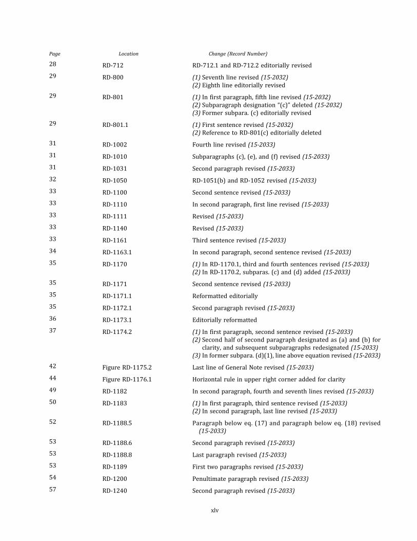
Page Location Change (Record Number)
28 RD-712 RD-712.1 and RD-712.2 editorially revised
29 RD-800 (1) Seventh line revised (15-2032)
(2) Eighth line editorially revised
29 RD-801 (1) In first paragraph, fifth line revised (15-2032)
(2) Subparagraph designation “(c)” deleted (15-2032)
(3) Former subpara. (c) editorially revised
29 RD-801.1 (1) First sentence revised (15-2032)
(2) Reference to RD-801(c) editorially deleted
31 RD-1002 Fourth line revised (15-2033)
31 RD-1010 Subparagraphs (c) , (e) , and (f) revised (15-2033)
31 RD-1031 Second paragraph revised (15-2033)
32 RD-1050 RD-1051(b) and RD-1052 revised (15-2033)
33 RD-1100 Second sentence revised (15-2033)
33 RD-1110 In second paragraph, first line revised (15-2033)
33 RD-1111 Revised (15-2033)
33 RD-1140 Revised (15-2033)
33 RD-1161 Third sentence revised (15-2033)
34 RD-1163.1 In second paragraph, second sentence revised (15-2033)
35 RD-1170 (1) In RD-1170.1, third and fourth sentences revised (15-2033)
(2) In RD-1170.2, subparas. (c) and (d) added (15-2033)
35 RD-1171 Second sentence revised (15-2033)
35 RD-1171.1 Reformatted editorially
35 RD-1172.1 Second paragraph revised (15-2033)
36 RD-1173.1 Editorially reformatted
37 RD-1174.2 (1) In first paragraph, second sentence revised (15-2033)
(2) Second half of second paragraph designated as (a) and (b) for
clarity, and subsequent subparagraphs redesignated (15-2033)
(3) In former subpara. (d)(1) , line above equation revised (15-2033)
42 Figure RD-1175.2 Last line of General Note revised (15-2033)
44 Figure RD-1176.1 Horizontal rule in upper right corner added for clarity
49 RD-1182 In second paragraph, fourth and seventh lines revised (15-2033)
50 RD-1183 (1) In first paragraph, third sentence revised (15-2033)
(2) In second paragraph, last line revised (15-2033)
52 RD-1188.5 Paragraph below eq. (17) and paragraph below eq. (18) revised
(15-2033)
53 RD-1188.6 Second paragraph revised (15-2033)
53 RD-1188.8 Last paragraph revised (15-2033)
53 RD-1189 First two paragraphs revised (15-2033)
54 RD-1200 Penultimate paragraph revised (15-2033)
57 RD-1240 Second paragraph revised (15-2033)
xlv

Page Location Change (Record Number)
59 RF-110 Subparagraph (c) and last paragraph revised (15-2034)
62 RF-301 Revised (15-2034)
62 RF-310 Revised (15-2034)
62 RF-312 Revised (15-2034)
63 RF-400 Revised (15-2034)
63 RF-401 Revised (15-2034)
63 RF-410 RF-410.2 and RF-410.3 revised (15-2034)
63 RF-412 Last sentence revised (15-2034)
63 RF-413 Subparagraphs (b) and (c) revised (15-2034)
63 RF-423 Revised (15-2034)
64 RF-440 Revised (15-2034)
65 RF-500 Revised (15-2034)
65 RF-501 Revised (15-2034)
65 RF-512 Revised (15-2034)
66 RF-540 Revised (15-2034)
67 RF-600 Revised (15-2034)
67 RF-601 Revised (15-2034)
68 RF-622 Revised (15-2034)
69 RF-700 Subparagraphs (a) , (c) , and (d) revised (15-2034)
70 RQ-102 Last paragraph revised (15-2035)
70 RQ-110 Revised (15-2035)
70 RQ-120 First paragraph revised (15-2035)
71 RQ-141 Subparagraphs (a)(1) , (b) , (c) , (d)(1) , and (d)(5) revised (15-2035)
72 RQ-142 Revised (15-789)
73 RQ-200 (1) First paragraph and subparas. (e) , (g) , (j ) , (k) , and (l) revised
(15-2035)
(2) Last paragraph added (16-107)
73 RQ-201 Revised (15-2035)
74 RQ-300 (1) First paragraph and subparas. (e) , (g) , (j ) , (k) , and (l) revised
(15-2035)
(2) Last paragraph added (16-107)
74 RQ-301 Revised (15-2035)
75 RQ-400 (1) First paragraph and subparas. (f) , (h) , (k) , (l) , and (m) revised
(15-2035)
(2) Last paragraph added (16-107)
75 RQ-401 Revised (15-2035)
76 RQ-500 (1) First paragraph and subparas. (d) and (f) through (i) revised
(15-2035)
(2) Last paragraph added (16-107)
xlvi
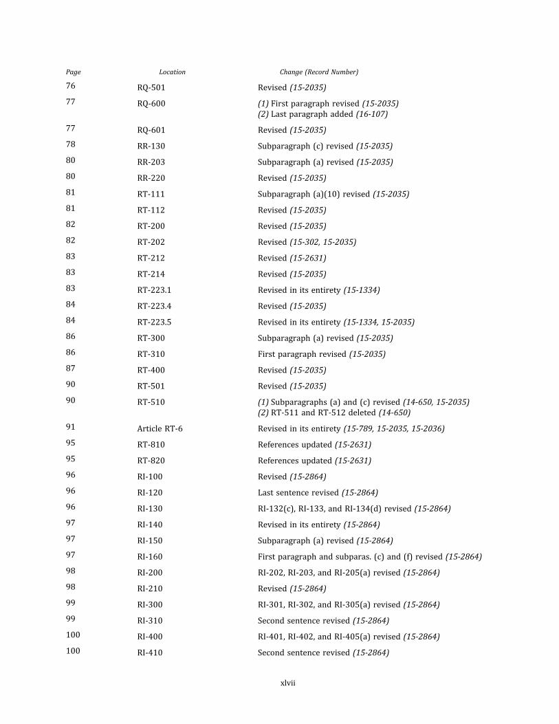
Page Location Change (Record Number)
76 RQ-501 Revised (15-2035)
77 RQ-600 (1) First paragraph revised (15-2035)
(2) Last paragraph added (16-107)
77 RQ-601 Revised (15-2035)
78 RR-130 Subparagraph (c) revised (15-2035)
80 RR-203 Subparagraph (a) revised (15-2035)
80 RR-220 Revised (15-2035)
81 RT-111 Subparagraph (a)(10) revised (15-2035)
81 RT-112 Revised (15-2035)
82 RT-200 Revised (15-2035)
82 RT-202 Revised (15-302, 15-2035)
83 RT-212 Revised (15-2631)
83 RT-214 Revised (15-2035)
83 RT-223.1 Revised in its entirety (15-1334)
84 RT-223.4 Revised (15-2035)
84 RT-223.5 Revised in its entirety (15-1334, 15-2035)
86 RT-300 Subparagraph (a) revised (15-2035)
86 RT-310 First paragraph revised (15-2035)
87 RT-400 Revised (15-2035)
90 RT-501 Revised (15-2035)
90 RT-510 (1) Subparagraphs (a) and (c) revised (14-650, 15-2035)
(2) RT-511 and RT-512 deleted (14-650)
91 Article RT-6 Revised in its entirety (15-789, 15-2035, 15-2036)
95 RT-810 References updated (15-2631)
95 RT-820 References updated (15-2631)
96 RI-100 Revised (15-2864)
96 RI-120 Last sentence revised (15-2864)
96 RI-130 RI-132(c) , RI-133, and RI-134(d) revised (15-2864)
97 RI-140 Revised in its entirety (15-2864)
97 RI-150 Subparagraph (a) revised (15-2864)
97 RI-160 First paragraph and subparas. (c) and (f) revised (15-2864)
98 RI-200 RI-202, RI-203, and RI-205(a) revised (15-2864)
98 RI-210 Revised (15-2864)
99 RI-300 RI-301, RI-302, and RI-305(a) revised (15-2864)
99 RI-310 Second sentence revised (15-2864)
100 RI-400 RI-401, RI-402, and RI-405(a) revised (15-2864)
100 RI-410 Second sentence revised (15-2864)
xlvii

Page Location Change (Record Number)
101 RI-500 RI-501, RI-502, RI-503, and RI-505(a) revised (15-2864)
101 RI-510 Second sentence revised (15-2864)
102 RS-100 (1) Subparagraph (i) deleted (15-2865)
(2) Note added (15-2865)
102 RS-101 Fifth line revised (15-2865)
102 RS-101.1 Third line revised (15-2865)
103 RS-120 Revised (15-2865)
103 RS-131 Note and subpara. (d) revised (15-2865)
104 RS-200 Revised (15-2865)
104 RS-202 RS-202 revised (15-2865)
104 RS-204 RS-204 revised (15-2865)
105 RS-301 Subparagraphs (a) , (b) , and (c) revised (15-2865)
106 1-100 Revised (16-177)
106 1-110 Subparagraphs (a) , (c) , and (d) revised (16-177)
111 Mandatory Appendix 4 Definitions of balanced design; compatibility; coupling agent; curing
agent; deformation; engineering constants; fiber content; gap; gel
time; geodesic isoten so id con tour; geodesic ova lo id; gross
structural discontinuity; hand lay-up; inelasticity; interlaminar
stresses; local structural discontinuity; netting analysis; ovaloid;
peak stress; ply group; winding pattern; and yield revised (16-178)
122 Table 6-100.1 (1) In second column, second, fi fth, and 15th entries revised
(16-179)
(2) In third column, 15th entry revised (16-179)
(3) Note (3) revised (16-179)
124 Table 6-100.2 (1) In second column, second, fi fth, and 15th entries revised
(16-179)
(2) In third column, 15th and 16th entries revised (16-179)
(3) Note (3) revised (16-179)
128 8-200.4 Revised (15-2631)
143 Form CPV-1 Revised (16-1875)
145 Table 8-900.3-1 Designation added
146 Form CPV-2 Revised (16-1875)
151 Mandatory Appendix 10 Added (13-667)
193 AD-501.2 In equation for Q 1 6 , the first operator changed from plus to minus
sign (16-2429)
206 AF-100 Definition of F revised (12-1869)
209 Table AG-1 (1) Designation added
(2) Editorially revised to reflect changes made to Figure AG-1
210 Figure AG-1 Updated by ASME Conformity Assessment
218 Table AJ-1 (1) Former Table Q-1 redesignated
(2) Second and third columns revised in their entirety (16-1875)
(3) Eleventh and 12th rows added (16-1875)
xlviii
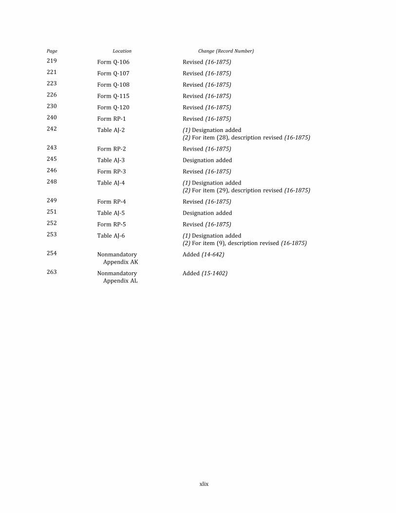
Page Location Change (Record Number)
219 Form Q-106 Revised (16-1875)
221 Form Q-107 Revised (16-1875)
223 Form Q-108 Revised (16-1875)
226 Form Q-115 Revised (16-1875)
230 Form Q-120 Revised (16-1875)
240 Form RP-1 Revised (16-1875)
242 Table AJ-2 (1) Designation added
(2) For item (28) , description revised (16-1875)
243 Form RP-2 Revised (16-1875)
245 Table AJ-3 Designation added
246 Form RP-3 Revised (16-1875)
248 Table AJ-4 (1) Designation added
(2) For item (29) , description revised (16-1875)
249 Form RP-4 Revised (16-1875)
251 Table AJ-5 Designation added
252 Form RP-5 Revised (16-1875)
253 Table AJ-6 (1) Designation added
(2) For item (9) , description revised (16-1875)
254 Nonmandatory
Appendix AK
Added (14-642)
263 Nonmandatory
Appendix AL
Added (15-1402)
xlix

LIST OF CHANGES IN RECORD NUMBER ORDER
Record Number Change
12-1869 Revised RD-1170.2 and AF-100, design factor “F.”
13-667 Added Mandatory Appendix 10.
13-2222 Revised the front guidance on interpretations in its entirety.
14-642 Added Nonmandatory Appendix AK.
14-650 Revised RT-510, RT-511, and RT-512.
14-2065 Revised Table RD-620.1.
15-302 Revised RT-202, RD-511, and RD-611.
15-789 Revised RT-6.
15-1334 Revised RT-223.1 and RT-223.5 to allow a test fluid temperature to be at least the maximum
design temperature of the vessel for the hydrostatic pressure qualification tests. Incorporated
the proposed Section X Code Case from Record 15-1240. Reformatted RT-223.1 and RT-223.5
for clarity of the requirements for the cyclic and hydrostatic pressure qualification tests.
15-1402 Added Nonmandatory Appendix AK. Redesignated Appendix to “AL” since it conflicts with the
micromechanics Nonmandatory Appendix AK already passed.
15-2032 Revised Part RG and RD-1 through RD-8. Deleted extra phrase from RG-101. Deleted unneces-
sary word from RG-320 by revising “the Society” to “ASME.” Replaced “his” with “the Fabrica-
tor’s” and deleted two extra phrases and other revisions for clarity in RG-321. Replaced “his”
with “the Fabricator’s” and made other revisions for clarity in RG-321.2 . Revised “must” to
“shall” in RG-323. Revised “will” to “shall” and “must” to “shall” in RG-330. Deleted one word
for clarity in RD-100. Revised one sentence for clarity and clearer requirement and “must”
to “shall” in RD-101 . Revised “need” to “shall” in RD-152 . Revised “must” to “shall” in
RD-200, RD-300, RD-500, and RD-600. Revised “are to” to “shall” and added “s ” to term in
Figure RD-620.4(a) . Deleted extra word in RD-800. Revised two sentences for clarity and better
placement in RD-801. Revised one sentence for clarity in RD-801.1.
15-2033 Revised RD-10, RD-11, and RD-12. Revised one sentence for clarity in RD-1002. Deleted word
twice and revised one sentence for clarity in RD-1010. Revised “must” to “shall” in RD-1031,
RD-1051, RD-1140, RD-1170, RD-1171, RD-1174.2 , Figure RD-1175.2 , RD-1182, RD-1182.1 ,
RD-1183 , RD-1188 .5 , RD-1188 .8 , RD-1189 , and RD-1240 . Deleted word for clarity in
RD-1052 . Deleted unnecessary phrase in RD-1100. Added “and” for clarity in RD-1111. Re-
placed word for clarity in RD-1161 . Added comma in RD-1163 . Deleted extra word in
RD-1171 . Revised “is” to “shall be” in RD-1172 .1 . Revised “can” to “may,” “will” to “shall,”
and sentence format for clarity in RD-1174.2 . Deleted unnecessary phrase in Figure
RD-1175.2 . Revised “can” to “may” and phrase for clarity in RD-1183. Revised “will” to “shall”
and replaced word for clarity in RD-1188.5. Revised “are” to “shall be” and added two commas
in RD-1188.6. Revised sentence format for clarity in RD-1189. Made grammatical changes in
RD-1200.
15-2034 Revised Part RF. Added a necessary word and revised “must” to “shall” in RF-100. Added a nec-
essary word and revised “conform” to “comply” in RF-301. Revised “conform” to “comply” in
RF-310. Revised “conform” to “comply” and deleted an unnecessary word in RF-312. Revised
“conform” to “comply” and added a necessary word in RF-400. Revised “conform” to “comply”
and added a necessary word in RF-401. Revised one sentence for clarity in RF-410.2 . Revised
“is” to “shall be” and added a necessary word in RF-410.3. Revised “conform” to “comply" in
RF-412 . Revised “conform” to “comply” and sentence format for clarity in RF-413 . Revised
“will” to “shall” in RF-423. Revised “must conform” to “shall comply” and sentence for clarity
in RF-440. Revised “conform” to “comply,” deleted extra phrase, and added necessary word
in RF-500. Revised “conform” to “comply” and added necessary word in RF-501. Revised “con-
form” to “comply” in RF-512. Revised “must conform” to “shall comply” and sentence for clarity
in RF-540. Revised “conform” to “comply,” deleted extra phrase, and added necessary word in
RF-500. Revised “conform” to “comply” and added necessary word in RF-601. Added “a” in
RF-622. Added necessary word, replaced one word, and revised “is” to “shall be” twice in RF-7.
l

Record Number Change
15-2035 Revised Parts RQ, RR, and RT. Revised “the Society” to “ASME” in RQ-102. Revised three sen-
tences for clarity and one sentence for clearer requirement in RQ-110. Deleted unnecessary
word in RQ-120. Revised “conform” to “comply” once and “must” to “shall” thrice and added
necessary word in four places in RQ-141. Deleted description of form, clarified procedure in
context, and added necessary word in five places in RQ-200. Clarified procedure in context
in RQ-201. Deleted description of form, clarified procedure in context, and added necessary
word in five places in RQ-300. Clarified procedure in context in RQ-301. Deleted description
of form, clarified procedure in context, and added necessary word in five places in RQ-400. Clar-
ified procedure in context in RQ-401. Deleted description of form, clarified procedure in con-
text, and added necessary word in five places in RQ-500. Clarified procedure in context in
RQ-501. Deleted description of form and revised “must” to “shall” in RQ-600. Revised “must”
to “shall” in RR-130. Revised sentence for clarity in RR-203 . Revised “will” to “shall,” added
missing “are,” and deleted unnecessary word in RR-220. Added “s ” at the end of the term in
RT-111(a) . Added “s ” at the end of the term and a necessary word and revised a sentence in
RT-112. Replaced words for clarity and added “as” and “shall” to make requirement clear in
RT-200. Revised “must” to “shall” in RT-202. Revised “conform” to “comply” twice in RT-214.
Deleted word for clarity in RT-222. Deleted two unnecessary words in RT-223.4. Added word
for clarity in RT-223 .5 . Deleted unnecessary word in RT-300. Revised “must” to “shall” in
RT-310. Revised “conform” to “comply” in RT-400. Added word for clarity in RT-501. Revised
“will” to “shall” in RT-510. Revised “shall” to “should” in RT-511.
Revised “conform” to “comply” and replaced words and phrases for clarity in RT-600. Revised
“must” to “shall” in RT-620.
15-2036 Added Note in RT-620.
15-2631 Updated ASTM references in Tables 1.1, RM-120.1, and RM-120.2; RT-212; and RT-702.
15-2864 Revised “conform to” to “comply with” and “given” to “provided” and deleted “respectively” in
RI-100. Revised “him” to “the Inspector” and “the Society” to “ASME” in RI-120. Revised “he” to
“the Inspector” and “assure” to “ensure” and split sentence into two parts in RI-133. Revised
“conform to” to “comply with” in RI-134. Revised “assure” to “ensure” and “far” to “much”
and changed fabrication to assembly in RI-140. Revised “he” to “the Inspector” and “assure”
to “ensure” in RI-150. Revised “his” to “the Inspector,” “It” to “This procedure,” and “AI” to
“the Authorized Inspector” in RI-160. Revised “conform to” to “comply with” in RI-202 and
RT-203 . Revised “satisfy himself” to “ensure” in RI-205. Revised “He” to “The Inspector” in
RI-210. Deleted “At his discretion” and capitalized “T” in RI-301. Revised “conform to” to “com-
ply with” in RI-302. Revised “satisfy himself“ to “ensure” in RI-305. Revised “He” to “The Inspec-
tor” in RI-310. Deleted “At his discretion” and capitalized “T” in RI-401. Revised “conform to” to
“comply with” in RI-402. Revised “satisfy himself” to “ensure” in RI-405. Revised “He” to “The
Inspector” in RI-410. Deleted “at his discretion” and capitalized “T” in RI-501. Revised “conform
to” to “comply with” in RI-502 and RI-503. Revised “satisfy himself” to “ensure” in RI-505. Re-
vised “He” to “The Inspector” in RI-510.
15-2865 Deleted subpara. (i) and added Note in RS-100. Deleted “so as” in RS-101 and RS-101.1. Revised
“the Society” to “ASME” and made deletion for clarity in RS-120. Revised “must” to “shall” thrice
and “assure” to “ensure” in RS-131. Revised “the Society” to “ASME” in RS-200, RS-202, and
RS-204. Revised sentence in RS-301.
16-107 Added a paragraph to the end of RQ-200, RQ-300, RQ-400, RQ-500, and RQ-600 to include spe-
cifications when requalification shall not be required, specifically when an essential variable
manufacturer’s name change is a result of a business merger, a corporate name change, or a
commercial event having no effect on the manufacturing process or material chemistry.
16-177 Revised 1-100 and 1-110 in Mandatory Appendix 1.
16-178 Revised terms “balanced design,” “compatibility,” “coupling agent,” “curing agent,” “deforma-
tion,” “engineering constants,” “fiber content,” “gap,” “gel time,” “geodesic ovaloid,” “gross struc-
tural discontinuity,” “hand lay-up,” “inelasticity,” “interlaminar stresses,” “lay-up,” “local
structure discontinuity,” “netting analysis,” “ovaloid,” “peak stress,” “ply group,” “winding pat-
tern,” and “yield” and moved an included definition of “geodesic line” into its own definition
in Mandatory Appendix 4.
16-179 Revised Tables 600.1 and 600.2 in Mandatory Appendix 6.
li

Record Number Change
16-1875 Revised Forms Q-106, Q-107, Q-108, Q-115, Q-120, RP-1, RP-2, RP-3 , RP-4, RP-5, CPV-1, and
CPV-2 and Guides for Forms RP-1, RP-3, and RP-5.
16-2429 Corrected errors in equations for transformed reduced stiffnesses in RD-1230 and Nonmanda-
tory Appendix AD.
lii

CROSS-REFERENCING AND STYLISTIC CHANGES IN THE BOILERAND PRESSURE VESSEL CODE
There have been structural and stylistic changes to BPVC, starting with the 2011 Addenda, that should be noted to aid
navigating the contents. The following is an overview of the changes:
Subparagraph Breakdowns/Nested Lists Hierarchy
• First-level breakdowns are designated as (a) , (b) , (c) , etc., as in the past.
• Second-level breakdowns are designated as (1) , (2) , (3) , etc., as in the past.
• Third-level breakdowns are now designated as (-a) , (-b) , (-c) , etc.
• Fourth-level breakdowns are now designated as (-1) , (-2) , (-3) , etc.
• Fifth-level breakdowns are now designated as (+a) , (+b) , (+c) , etc.
• Sixth-level breakdowns are now designated as (+1) , (+2) , etc.
Footnotes
With the exception of those included in the front matter (roman-numbered pages) , all footnotes are treated as end-
notes. The endnotes are referenced in numeric order and appear at the end of each BPVC section/subsection.
Submittal of Technical Inquiries to the Boiler and Pressure Vessel Standards Committees
Submittal ofTechnical Inquiries to the Boiler and Pressure Vessel Standards Committees has been moved to the front
matter. This information now appears in all Boiler Code Sections (except for Code Case books) .
Cross-References
It is our intention to establish cross-reference link functionality in the current edition and moving forward. To facil-
itate this, cross-reference style has changed. Cross-references within a subsection or subarticle will not include the des-
ignator/identifier of that subsection/subarticle. Examples follow:
• (Sub-)Paragraph Cross-References. The cross-references to subparagraph breakdowns will follow the hierarchy of
the designators under which the breakdown appears.
– If subparagraph (-a) appears in X.1(c)(1) and is referenced in X.1(c)(1) , it will be referenced as (-a) .
– If subparagraph (-a) appears in X.1(c)(1) but is referenced in X.1(c)(2) , it will be referenced as (1)(-a) .
– If subparagraph (-a) appears in X.1(c)(1) but is referenced in X.1(e)(1) , it will be referenced as (c)(1)(-a) .
– If subparagraph (-a) appears in X.1(c)(1) but is referenced in X.2(c)(2) , it will be referenced as X.1(c)(1)(-a) .
• Equation Cross-References. The cross-references to equations will follow the same logic. For example, if eq. (1) ap-
pears in X.1(a)(1) but is referenced in X.1(b) , it will be referenced as eq. (a)(1)(1) . If eq. (1) appears in X.1(a)(1) but
is referenced in a different subsection/subarticle/paragraph, it will be referenced as eq. X.1(a)(1)(1) .
liii

INTENTIONALLY LEFT BLANK

PART RGGENERAL REQUIREMENTS
ARTICLE RG-1SCOPE AND JURISDICTION
RG-100 SCOPE
(a) Section X establishes the requirements for the fabri-
cation of fiber‐reinforced thermosetting plastic pressure
vessels for general service, sets limitations on the permis-
sible service conditions, and defines the types of vessels
to which these rules are not applicable.
(b) To assure that vessels fabricated according to these
rules will be capable of safely withstanding the operating
conditions specified by the Design Specification, this
Section:
(1) gives minimum requirements for the materials of
fabrication;
(2) specifies test procedures for determining lami-
nate mechanical properties;
(3) Defines three methods of design qualification:
(-a) Class I Design — nondestructive qualification
test
(-b) Class II Design — mandatory design rules and
acceptance testing by nondestructive evaluation (NDE)
methods
(-c) Class III Design — qualification of a vessel de-
sign through the destructive test of a prototype
(4) suggests nonmandatory design procedures for
Class I vessels;
(5) provides mandatory design procedures and ac-
ceptance testing for Class II vessels;
(6) defines the general methods of fabrication which
may be used;
(7) limits the types of end closures, connections, and
attachments which may be employed and the means used
to join them to the vessels;
(8) stipulates the procedures to be used in proving
that prototype vessels will withstand specified operating
and test conditions;
(9) establishes rules under which fabricating proce-
dures used for fabricating Class I and Class III prototype
and production vessels are qualified, and defines what de-
viations from such procedures necessitate requalification;
(10) sets forth requirements to assure that no essen-
tial variation in qualified fabrication procedures has
occurred;
(11 ) establishes rules for acceptance testing, inspec-
tion, and reporting;
(12) gives requirements for stamping and marking.
(c) For vessels fabricated in accordance with these
rules, the provisions of Section X shall apply over any
other sections of the Code. When metallic components
are part of fiber‐reinforced plastic vessels, they shall meet
the provisions of Section VIII, Division 1.
(d) The fabricator shall establish the effective Code edi-
tion, addenda and Code Cases for pressure vessels and re-
placement parts in accordance with Mandatory Appendix
9.
RG-110 APPLICATION LIMITATIONS
RG-111 DESIGN PRESSURE
The internal design pressure of vessels fabricated un-
der this Section shall be limited as follows:
(a) Class I vessels shall not exceed 150 psi (1 MPa) for
bag‐molded, centrifugally cast, and contact‐molded ves-
sels; 1 ,500 psi (10 MPa) for filament‐wound vessels and
3,000 psi (20 MPa) for filament‐wound vessels with polar
boss openings.
(b) Class II vessels shall not exceed the limits specified
in RD-1120.
(c) C las s I I I ves s e l s shal l no t exceed 1 5 ,000 ps i
(103 .4 MPa) for filament-wound vessels with polar boss
openings.
RG-112 DESIGN TEMPERATURE
The design temperature of vessels fabricated under this
Section shall not exceed the lower of (a) or (b) .
(a) 250°F (120°C) for Class I and Class II , and 185°F
(85°C) for Class III
(b) 35°F (19°C) below the maximum use temperature
(see RM-1 2 1 ) o f the res in , nor be less than −65 °F
(−54°C) (see RD-112)
1
ASME BPVC.X-2017

ð17ÞRG-113 POTABLE WATER — SECTION IVAPPLICATIONS ONLY
Vessels fabricated under Section X intended for Section
IV use are limited to applications permitted therein. The
vessels are limited to internal pressure only with a max-
imum allowable working pressure of 160 psig [1 .1 MPa
(gage)] . The maximum allowable temperature used shall
be 210°F (99°C) . The provisions of this paragraph only
apply to vessels that are intended for use under Section
IV.
RG-114 LETHAL FLUIDS1
Vessels fabricated under this Section shall not be used
to store, handle, transport, or process lethal fluids.
RG-120 JURISDICTION OF SECTION X
The jurisdiction of this Section is intended to include
only the vessel and integral communicating chambers
and to terminate at the points defined in the following
subparagraphs (a) and (b) .
(a) Where external piping is connected to the vessel,
the jurisdiction shall terminate at:
(1) the face of the firs t flange in bo lted flange
connections;
(2) the first threaded joint in that type of connection;
(3) the first circumferential adhesive‐bonded joint in
that type of connection.
(b) Where lugs, skirts, or other supporting structures
are joined directly to a vessel, the jurisdiction shall termi-
nate at the first joint or connection beyond the vessel, but
shall include the attachment of such supporting struc-
tures to the vessel.
RG-121 CLASSES OF VESSELS OUTSIDE THEJURISDICTION OF THIS SECTION
The following classes of fiber‐reinforced plastic pres-
sure vessels are exempted from the Scope of this Section;
however, any pressure vessel within these classes which
meets all applicable requirements of this Section may be
stamped with the Certification Mark and RP Designator:
(a) pressure containers which are integral parts of
components of rotating or reciprocating mechanical de-
vices, such as pumps, compressors, turbines, generators,
engines, and hydraulic or pneumatic cylinders, where
the primary design considerations and/or stresses are de-
rived from the functional requirements of the device;
(b) piping systems whose primary function is the trans-
port of fluids from one location to another within a sys-
tem of which it is an integral part;
(c) piping components, such as pipe, flanges, bolting,
gaskets, valves, expansion joints, fittings, and pressure
containing parts of other components, such as strainers,
and devices which serve such purposes as mixing, separ-
ating, snubbing, distributing and metering, or controlling
flow, provided that the pressure containing parts of such
components are generally recognized as piping compo-
nents for accessories;
(d) vessels which have any part of the shell, heads, noz-
zles, fittings, or support laminates heated above the tem-
perature limits of RG-112;
(e) vessels having neither an internal nor an external
operating pressure exceeding 15 psi (100 kPa) with no
limitation on size;
(f) vessels having an inside diameter, or maximum in-
ternal cross ‐sectional dimension, not exceeding 6 in.
(152 mm) with no limitation on the length of vessel or
pressure;
(g) pressure vessels for human occupancy.2
2
ASME BPVC.X-2017
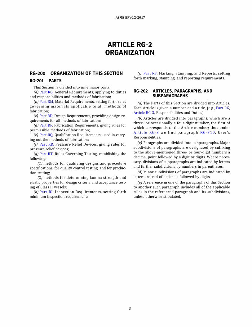
ARTICLE RG-2ORGANIZATION
RG-200 ORGANIZATION OF THIS SECTION
RG-201 PARTS
This Section is divided into nine major parts:
(a) Part RG, General Requirements, applying to duties
and responsibilities and methods of fabrication;
(b) Part RM, Material Requirements, setting forth rules
govern ing materia l s app l i cab l e to a l l methods o f
fabrication;
(c) Part RD, Design Requirements, providing design re-
quirements for all methods of fabrication;
(d) Part RF, Fabrication Requirements, giving rules for
permissible methods of fabrication;
(e) Part RQ, Qualification Requirements, used in carry-
ing out the methods of fabrication;
(f) Part RR, Pressure Relief Devices, giving rules for
pressure relief devices;
(g) Part RT, Rules Governing Testing, establishing the
following:
(1) methods for qualifying designs and procedure
specifications, for quality control testing, and for produc-
tion testing;
(2) methods for determining lamina strength and
elastic properties for design criteria and acceptance test-
ing of Class II vessels;
(h) Part RI , Inspection Requirements , setting forth
minimum inspection requirements;
(i) Part RS, Marking, Stamping, and Reports, setting
forth marking, stamping, and reporting requirements.
RG-202 ARTICLES, PARAGRAPHS, ANDSUBPARAGRAPHS
(a) The Parts of this Section are divided into Articles.
Each Article is given a number and a title, (e.g. , Part RG,
Article RG-3, Responsibilities and Duties) .
(b) Articles are divided into paragraphs, which are a
three‐ or occasionally a four‐digit number, the first of
which corresponds to the Article number; thus under
Arti c l e RG - 3 we fi nd p aragraph RG- 3 1 0 , U s e r ’ s
Responsibilities.
(c) Paragraphs are divided into subparagraphs. Major
subdivisions of paragraphs are designated by suffixing
to the above‐mentioned three‐ or four‐digit numbers a
decimal point followed by a digit or digits. Where neces-
sary, divisions of subparagraphs are indicated by letters
and further subdivisions by numbers in parentheses.
(d) Minor subdivisions of paragraphs are indicated by
letters instead of decimals followed by digits.
(e) A reference in one of the paragraphs of this Section
to another such paragraph includes all of the applicable
rules in the referenced paragraph and its subdivisions,
unless otherwise stipulated.
3
ASME BPVC.X-2017

ð17Þ
ð17Þ
ARTICLE RG-3RESPONSIBILITIES AND DUTIES
RG-300 RESPONSIBILITIES AND DUTIES
The various parties involved in specifying, fabricating,
and inspecting vessels under this Section have definite re-
sponsibilities or duties in meeting Code requirements.
The responsibilities and duties set forth hereinafter relate
only to Code compliance and are not to be construed as
involving contractual relationships or legal liabilities.
RG-310 USER’S RESPONSIBILITIES —DESIGN SPECIFICATION
The User, or an agent3 acting in his behalf, requiring
that a vessel be designed, fabricated, tested, and certified
to be a vessel complying with this Section, shall provide or
cause to be provided for such a vessel information as to
operating conditions, including intended use and material
compatibility with the contents, in such detail as will pro-
vide the basis for design, material selection, fabrication,
and inspection in accordance with this Section. This infor-
mation shall be designated hereinafter as the Design
Specification.
RG-320 FABRICATOR’S RESPONSIBILITIES
The structural integrity of a vessel or part thereof, in-
cluding the capability to contain pressure, and its compli-
ance with the Des ign Report (see RG-3 21 ) , are the
responsibility of the Fabricator. The Fabricator, complet-
ing any vessel to be marked with the Certification Mark
with RP Designator, has the responsibility of complying
with all the requirements of this Section and, through
proper certification, of assuring that any work done by
others also complies with all the requirements of this
Section.
When such parts are fabricated by an organization
other than the Fabricator responsible for the completed
vessel, they shall be fabricated by an organization having
a valid Certificate of Authorization from ASME and be re-
ported to the Fabricator of the completed vessel on Par-
tial Data Report Form RP-2 , which shall be certified by
both the parts fabricator and the Inspector.
RG-321 FABRICATOR’S DESIGN REPORT
RG-321.1 Class I Vessel Designs. Class I vessel de-
signs shall comply as follows:
(a) As a part of the Fabricator's responsibility for the
structural integrity of a Class I vessel, and vessel parts
fabricated by others as permitted in (g)(5) and RS-301,
and its capability to contain pressure, the Fabricator or
the design agent responsible to him shall make Design
Calculations of the type suggested in Nonmandatory
Appendix AA. Such Design Calculations shall constitute
only a tentative determination that the design, as shown
on the drawings, complies with the requirements of this
Section for the design conditions set forth in the Design
Specification.
(b) For vessels used for potable water, as described in
RG-113 (Section IV application) , the fabricator’s design
report shall indicate suitability for potable water use.
(c) It shall be the Fabricator’s responsibility to prove
that a vessel will safely withstand the service conditions
set forth in the Design Specification. The proof shall con-
sist of subjecting one or more prototype vessels to tests,
as required by the rules of this Section (see RT-223) ,
and using the procedures established therein. A report
of such tests, designated as the Qualification Test Report,
shall be prepared and certified by the Fabricator and the
Inspector.
Prototype vessels used to qualify a design shall not be
stamped with the Certification Mark.
(d) It shall be the Fabricator’s responsibility to prepare
and qualify a Procedure Specification that shall specify
the materials and the procedure employed to fabricate a
prototype vessel or vessels used to verify the capability
of such vessel or vessels to safely withstand the test
and service conditions set forth in the Design Specifica-
tion. The Procedure Specification shall provide, as a mini-
mum, all the information concerning the fabricating
procedure, recorded on the applicable Form Q-106, Form
Q-107, Form Q-108, or Form Q-115.
(e) It shall be the Fabricator’s responsibility to conduct
Quality Control Tests in accordance with the require-
ments of Article RT-3 and to record the results thereof
to permit verification that all other vessels, fabricated in
accordance with the qualified Procedure Specification,
comply with this Section.
4
ASME BPVC.X-2017

(f) It shall be the Fabricator’s responsibility to conduct
Production Tests as stipulated in Article RT-4 and to re-
cord the results to permit verification that such vessels
are in compliance with this Section and are acceptable
for marking with the Certification Mark.
(g) It shall be the responsibility of the Fabricator to
prepare a Fabricator’s Design Report consisting of the fol-
lowing documents:
(1) the Design Specification setting forth the service
conditions;
(2) the Design Drawings;
(3) the tentative Design Calculations;
(4) the material manufacturer’s specification sheets
for resin, fiber reinforcement, promoters, catalyst, and
other components used in laminate construction;
(5) a properly certified Form RP-2 for parts of the
vessel fabricated by other Fabricators;
(6) the Procedure Specification, providing the fabri-
cation procedures used to fabricate both the prototype
vessel(s) and all production vessels to be certified as com-
plying with this Section;
(7) the Qualification Test Report, which provides
data that the prototype vessel(s) conforming to the De-
sign Drawings will safely withstand the specified test
conditions;
(8) the records of the Quality Control Tests Report,
providing the results of the in‐process tests used to as-
sure that no essential variations from the requirements
of the Procedure Specification occurred;
(9) the Production Test Report of inspections, exam-
inations, and tests performed on each vessel to be marked
with the Certification Mark.
The preceding nine documents shall constitute the Fab-
ricator’s Design Report. It shall be certified by the Fabri-
cator. It shall be kept on file at the Fabricator’s place of
business or at a safe depository acceptable to the User
and shall be made available to the Inspector for at least
5 yr. When fabrication of specific mass‐produced vessels
occurs over an indefinite period of time, the Fabricator’s
Design Report on each specific design shall be kept on file
for at least 5 yr after production of such vessels has
ceased. Copies of the Design Drawings and Design Calcu-
lations shall be furnished to the User or his agent and,
when requested, a copy of the Test Report shall also be
furnished.
RG-321.2 Class II Vessel Designs. Class II vessel de-
signs shall comply as follows:
(a) As part of the Fabricator's responsibility for the
structural integrity of the vessel, and vessel parts fabri-
cated by others as permitted in (e)(5) and RS-301, and
its ability to contain pressure, the Fabricator of the vessel
shall be responsible for Design Calculations as specified in
Article RD-11. Such calculations shall constitute the basis
for thickness of parts subject to pressure, number of plies,
ply orientation, and other fabrication details specified on
drawings and other fabrication documents. Such calcula-
tions shall be part of the Design Report.
(b) It shall be the Fabricator’s responsibility to docu-
ment the elastic and strength constants of the laminate
or laminates used for Design Calculations. The lamina or
laminas used for vessel laminate construction shall be
the same as the lamina or laminas from which elastic
and strength constants were determined and which
served as a basis for Design Calculations and laminate
analysis. The number of laminas, stacking sequence, and
orientation of each lamina shall be the same as used on
the laminate analysis for design purposes. Determination
of laminate stiffness coefficients shall be in accordance
with Article RD-12. The determination of lamina elastic
and strength properties shall be in accordance with
Article RT-7. A report of such test, designated as the Ma-
terial Property Test Report, shall be part of the Fabrica-
tor’s Design Report and shall be made available to the
Inspector.
(c) It shall be the Fabricator’s responsibility to prepare
and certify a Procedure Specification that shall specify the
materials and fabrication procedures used to fabricate the
specified vessel. The Procedure Specification shall pro-
vide, as a minimum, all the information required by Form
Q-120, which shall verify that the vessel was fabricated
according to that specification.
(d) It shall be the Fabricator’s responsibility to subject
each vessel fabricated under this method to acceptance
testing as specified in Article RT-6. A report of such test,
designated as the Acceptance Test Report, shall be part
of the Fabricator’s Design Report and shall be made avail-
able to the Inspector.
(e) It shall be the Fabricator’s responsibility to prepare
and certify a Fabricator’s Design Report consisting of the
following documents:
(1) the Design Specification setting forth the design
conditions;
(2) the Design Drawings including Procedure Specifi-
cation number;
(3) the Design Calculations;
(4) the material manufacturer’s specification sheets
for all materials used in lamina testing and laminate
fabrication;
(5) a properly certified Form RP-4 for vessel parts
fabricated by other Fabricators;
(6) the Procedure Specification to which the vessel
was fabricated;
(7) the Acceptance Test results including the acoustic
emission report, to be designated as the Acceptance Test
Report;
(8) the documentation of the elastic and strength
properties of the lamina(s) as specified and determined
in Article RT-7, to be designated as the Material Property
Test Report.
5
ASME BPVC.X-2017
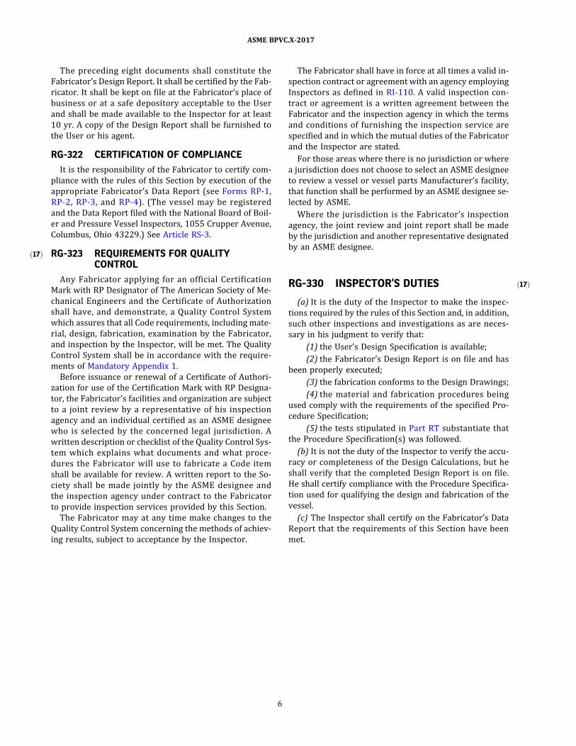
ð17Þ
ð17Þ
The preceding eight documents shall constitute the
Fabricator’s Design Report. It shall be certified by the Fab-
ricator. It shall be kept on file at the Fabricator’s place of
business or at a safe depository acceptable to the User
and shall be made available to the Inspector for at least
10 yr. A copy of the Design Report shall be furnished to
the User or his agent.
RG-322 CERTIFICATION OF COMPLIANCE
It is the responsibility of the Fabricator to certify com-
pliance with the rules of this Section by execution of the
appropriate Fabricator’s Data Report (see Forms RP-1 ,
RP-2 , RP-3 , and RP-4) . (The vessel may be registered
and the Data Report filed with the National Board of Boil-
er and Pressure Vessel Inspectors, 1055 Crupper Avenue,
Columbus, Ohio 43229.) See Article RS-3.
RG-323 REQUIREMENTS FOR QUALITYCONTROL
Any Fabricator applying for an official Certification
Mark with RP Designator of The American Society of Me-
chanical Engineers and the Certificate of Authorization
shall have, and demonstrate, a Quality Control System
which assures that all Code requirements, including mate-
rial, design, fabrication, examination by the Fabricator,
and inspection by the Inspector, will be met. The Quality
Control System shall be in accordance with the require-
ments of Mandatory Appendix 1.
Before issuance or renewal of a Certificate of Authori-
zation for use of the Certification Mark with RP Designa-
tor, the Fabricator’s facilities and organization are subject
to a joint review by a representative of his inspection
agency and an individual certified as an ASME designee
who is selected by the concerned legal jurisdiction. A
written description or checklist of the Quality Control Sys-
tem which explains what documents and what proce-
dures the Fabricator will use to fabricate a Code item
shall be available for review. A written report to the So-
ciety shall be made jointly by the ASME designee and
the inspection agency under contract to the Fabricator
to provide inspection services provided by this Section.
The Fabricator may at any time make changes to the
Quality Control System concerning the methods of achiev-
ing results, subject to acceptance by the Inspector.
The Fabricator shall have in force at all times a valid in-
spection contract or agreement with an agency employing
Inspectors as defined in RI-110. A valid inspection con-
tract or agreement is a written agreement between the
Fabricator and the inspection agency in which the terms
and conditions of furnishing the inspection service are
specified and in which the mutual duties of the Fabricator
and the Inspector are stated.
For those areas where there is no jurisdiction or where
a jurisdiction does not choose to select an ASME designee
to review a vessel or vessel parts Manufacturer’s facility,
that function shall be performed by an ASME designee se-
lected by ASME.
Where the jurisdiction is the Fabricator’s inspection
agency, the joint review and joint report shall be made
by the jurisdiction and another representative designated
by an ASME designee.
RG-330 INSPECTOR’S DUTIES
(a) It is the duty of the Inspector to make the inspec-
tions required by the rules of this Section and, in addition,
such other inspections and investigations as are neces-
sary in his judgment to verify that:
(1) the User’s Design Specification is available;
(2) the Fabricator’s Design Report is on file and has
been properly executed;
(3) the fabrication conforms to the Design Drawings;
(4) the material and fabrication procedures being
used comply with the requirements of the specified Pro-
cedure Specification;
(5) the tests stipulated in Part RT substantiate that
the Procedure Specification(s) was followed.
(b) It is not the duty of the Inspector to verify the accu-
racy or completeness of the Design Calculations, but he
shall verify that the completed Design Report is on file.
He shall certify compliance with the Procedure Specifica-
tion used for qualifying the design and fabrication of the
vessel.
(c) The Inspector shall certify on the Fabricator’s Data
Report that the requirements of this Section have been
met.
6
ASME BPVC.X-2017

ARTICLE RG-4FABRICATION METHODS
RG-400 FABRICATION METHODS4
For purposes of this Section, fiber‐reinforced plastic
pressure vessels are divided into four methods of fabrica-
tion. Class I vessels may be fabricated by any combination
of these methods. Class II vessels are restricted to the
contact‐molding and filament‐wound methods of fabrica-
tion or a combination of the two.
RG-401 BAG MOLDING5
In this method a pressurized bag is used to compress
pre‐rolled fiber cylinders and head preforms, which are
impregnated with the specified resin system, against an
outer heated mold.
RG-402 CENTRIFUGAL CASTING
In this method the sections of the vessel are formed
from chopped fiber strands and a resin system in a man-
drel, which is spun to produce a laminate, and heated to
effect a cure of the resin system.
RG-403 CONTACT MOLDING
In this method cylindrical sections, heads, and/or at-
tachments are fabricated by applying reinforcement fiber
and resin to a mandrel or mold. System cure is either at
room temperature or elevated temperature using a
catalyst–promoter system.
RG-404 FILAMENT WINDING
RG-404.1 General. In this method, continuous fila-
ments of fiber with the specified resin applied are wound
in a systematic manner under controlled tension and
cured on a mandrel or other supporting structure. Heads
and fittings fabricated by contact-molding methods may
be attached with suitable adhesive resins and secondary
reinforcement with cutting of filaments as required.
Opening(s) may be integral wound or with cutting of fila-
ments as required and need not be centered on the axis of
rotation.
RG-404.2 Polar Boss Openings Only. In this special
case which qualifies for reduced cycle and burst test re-
quirements per RT-223.5, heads shall be integrally wound
and satisfy the following criteria:
(a) opening(s) shall be centered on the axis of rotation:
(b) opening(s) shall be a polar boss type, wound in
place at the center of revolution;
(c) boss diameter shall not exceed one‐half vessel I.D.;
(d) no cutting of filaments is permitted to form the po-
lar boss opening.
7
ASME BPVC.X-2017
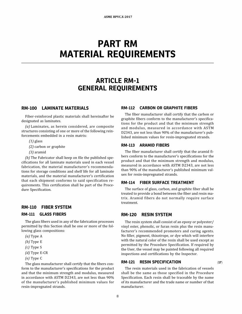
ð17Þ
PART RMMATERIAL REQUIREMENTS
ARTICLE RM-1GENERAL REQUIREMENTS
RM-100 LAMINATE MATERIALS
Fiber‐reinforced plastic materials shall hereinafter be
designated as laminates.
(a) Laminates, as herein considered, are composite
structures consisting of one or more of the following rein-
forcements embedded in a resin matrix:
(1) glass
(2) carbon or graphite
(3) aramid
(b) The Fabricator shall keep on file the published spe-
cifications for all laminate materials used in each vessel
fabrication, the material manufacturer’s recommenda-
tions for storage conditions and shelf life for all laminate
materials, and the material manufacturer’s certification
that each shipment conforms to said specification re-
quirements. This certification shall be part of the Proce-
dure Specification.
RM-110 FIBER SYSTEM
RM-111 GLASS FIBERS
The glass fibers used in any of the fabrication processes
permitted by this Section shall be one or more of the fol-
lowing glass compositions:
(a) Type A
(b) Type E
(c) Type S
(d) Type E‐CR
(e) Type C
The glass manufacturer shall certify that the fibers con-
form to the manufacturer’s specifications for the product
and that the minimum strength and modulus, measured
in accordance with ASTM D2343, are not less than 90%
of the manufacturer ’s published minimum values for
resin‐impregnated strands.
RM-112 CARBON OR GRAPHITE FIBERS
The fiber manufacturer shall certify that the carbon or
graphite fibers conform to the manufacturer’s specifica-
tions for the product and that the minimum strength
and modulus , measured in accordance with ASTM
D2343, are not less than 90% of the manufacturer’s pub-
lished minimum values for resin‐impregnated strands.
RM-113 ARAMID FIBERS
The fiber manufacturer shall certify that the aramid fi-
bers conform to the manufacturer’s specifications for the
product and that the minimum strength and modulus,
measured in accordance with ASTM D2343, are not less
than 90% of the manufacturer’s published minimum val-
ues for resin‐impregnated strands.
RM-114 FIBER SURFACE TREATMENT
The surface of glass, carbon, and graphite fiber shall be
treated to provide a bond between the fiber and resin ma-
trix. Aramid fibers do not normally require surface
treatment.
RM-120 RESIN SYSTEM
The resin system shall consist of an epoxy or polyester/
vinyl ester, phenolic, or furan resin plus the resin manu-
facturer’s recommended promoters and curing agents.
No filler, pigment, thixotrope, or dye which will interfere
with the natural color of the resin shall be used except as
permitted by the Procedure Specification. If required by
the User, the vessel may be painted following all required
inspections and certifications by the Inspector.
RM-121 RESIN SPECIFICATION
The resin materials used in the fabrication of vessels
shall be the same as those specified in the Procedure
Specification. Each resin shall be traceable by the name
of its manufacturer and the trade name or number of that
manufacturer.
8
ASME BPVC.X-2017
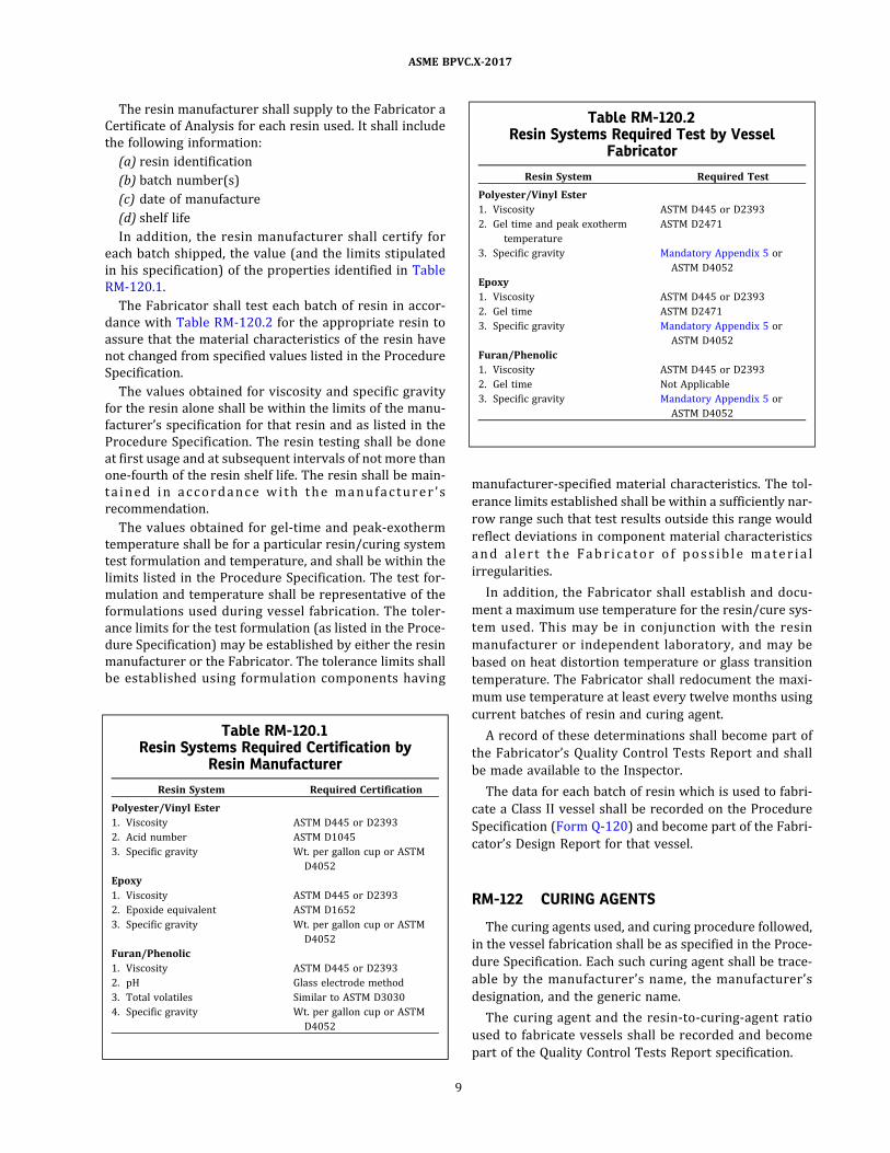
The resin manufacturer shall supply to the Fabricator a
Certificate of Analysis for each resin used. It shall include
the following information:
(a) resin identification
(b) batch number(s)
(c) date of manufacture
(d) shelf life
In addition, the resin manufacturer shall certify for
each batch shipped, the value (and the limits stipulated
in his specification) of the properties identified in Table
RM-120.1 .
The Fabricator shall test each batch of resin in accor-
dance with Table RM-120.2 for the appropriate resin to
assure that the material characteristics of the resin have
not changed from specified values listed in the Procedure
Specification.
The values obtained for viscosity and specific gravity
for the resin alone shall be within the limits of the manu-
facturer’s specification for that resin and as listed in the
Procedure Specification. The resin testing shall be done
at first usage and at subsequent intervals of not more than
one-fourth of the resin shelf life. The resin shall be main-
ta i n e d i n a c c o rd an c e wi th th e manu fa c tu r e r ’ s
recommendation.
The values obtained for gel‐time and peak‐exotherm
temperature shall be for a particular resin/curing system
test formulation and temperature, and shall be within the
limits listed in the Procedure Specification. The test for-
mulation and temperature shall be representative of the
formulations used during vessel fabrication. The toler-
ance limits for the test formulation (as listed in the Proce-
dure Specification) may be established by either the resin
manufacturer or the Fabricator. The tolerance limits shall
be established using formulation components having
manufacturer‐specified material characteristics. The tol-
erance limits established shall be within a sufficiently nar-
row range such that test results outside this range would
reflect deviations in component material characteristics
a n d a l e r t th e F a b r i c a to r o f p o s s i b l e m a te r i a l
irregularities.
In addition, the Fabricator shall establish and docu-
ment a maximum use temperature for the resin/cure sys-
tem used. This may be in conjunction with the resin
manufacturer or independent laboratory, and may be
based on heat distortion temperature or glass transition
temperature. The Fabricator shall redocument the maxi-
mum use temperature at least every twelve months using
current batches of resin and curing agent.
A record of these determinations shall become part of
the Fabricator’s Quality Control Tests Report and shall
be made available to the Inspector.
The data for each batch of resin which is used to fabri-
cate a Class II vessel shall be recorded on the Procedure
Specification (Form Q-120) and become part of the Fabri-
cator’s Design Report for that vessel.
RM-122 CURING AGENTS
The curing agents used, and curing procedure followed,
in the vessel fabrication shall be as specified in the Proce-
dure Specification. Each such curing agent shall be trace-
able by the manufacturer ’s name, the manufacturer ’s
designation, and the generic name.
The curing agent and the resin‐to‐curing‐agent ratio
used to fabricate vessels shall be recorded and become
part of the Quality Control Tests Report specification.
Table RM-120.1Resin Systems Required Certification by
Resin Manufacturer
Resin System Required Certification
Polyester/Vinyl Ester
1. Viscosity ASTM D445 or D2393
2. Acid number ASTM D1045
3. Specific gravity Wt. per gallon cup or ASTM
D4052
Epoxy
1. Viscosity ASTM D445 or D2393
2. Epoxide equivalent ASTM D1652
3. Specific gravity Wt. per gallon cup or ASTM
D4052
Furan/Phenolic
1. Viscosity ASTM D445 or D2393
2. pH Glass electrode method
3. Total volatiles Similar to ASTM D3030
4. Specific gravity Wt. per gallon cup or ASTM
D4052
Table RM-120.2Resin Systems Required Test by Vessel
Fabricator
Resin System Required Test
Polyester/Vinyl Ester
1. Viscosity ASTM D445 or D2393
2. Gel time and peak exotherm
temperature
ASTM D2471
3. Specific gravity Mandatory Appendix 5 or
ASTM D4052
Epoxy
1. Viscosity ASTM D445 or D2393
2. Gel time ASTM D2471
3. Specific gravity Mandatory Appendix 5 or
ASTM D4052
Furan/Phenolic
1. Viscosity ASTM D445 or D2393
2. Gel time Not Applicable
3. Specific gravity Mandatory Appendix 5 or
ASTM D4052
9
ASME BPVC.X-2017

RM-123 LAMINATE CURE
The Fabricator shall determine and document as part of
the Procedure Specification and the Quality Control Tests
Report that the laminate of each vessel and vessel part is
properly cured.
This shall normally be done using the Barcol Test in ac-
cordance with ASTM D2583 (see RQ-141 and RT-221) .
Barcol readings shall be within the tolerance specified
by the resin manufacturer as listed in the Procedure Spec-
ification. If the resin manufacturer does not provide Bar-
col specifications (for the resin/curing system used) , the
Fabricator shall establish Barcol specifications (for the re-
sin/curing system used) that have been documented by
independent third party testing that such Barcol readings
are indicative of complete resin cure. These shall become
part of the Procedure Specification.
If the Fabricator elects not to use the Barcol Test as a
measure of proper laminate cure, he shall define and
document the method used to assure that proper lami-
nate cure is attained. Such method(s) shall be acceptable
to the Inspector. The results thereof shall be part of the
Procedure Specification and Quality Control Tests Report
recorded in lieu of Barcol Test results on the various
forms.
RM-140 USE OF TWO OR MORE MATERIALSSPECIFICATIONS OR PROCESSES INFABRICATING A CLASS I VESSEL
Two or more Procedure Specifications may be used in
fabricating a pressure vessel, provided each Procedure
Specification is used in its entirety for the part of the ves-
sel fabricated with that procedure.
RM-150 MECHANICAL PROPERTIES OFLAMINA FOR CLASS II VESSELS
RM-151 EXAMPLES OF LAMINA
For the purposes of this Section, a lamina is defined as a
layer or multiple layers of the same material and same or-
ientation. An example of a lamina is a layer of thermoset
resin reinforced with chopped strand mat, unidirectional
reinforcement, or woven roving.
As a single exception and in the absence of thermal
stress , due to existing fabrication methods, alternate
layers of chopped strand mat and woven roving may be
considered as a lamina.
RM-152 LAMINA SPECIFICATION
The lamina, lamina stacking sequence, and orientation
shall be specified in the Procedure Specification.
RM-153 LAMINA PROPERTIES
The lamina properties shall be determined in accor-
dance with Article RT-7.
RM-154 LAMINATE ANALYSIS
The lamina properties shall be used to analyze the lami-
nate and determine effective laminate elastic constants in
accordance with Article RD-12.
10
ASME BPVC.X-2017
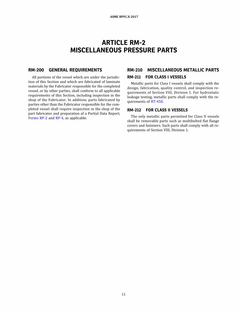
ARTICLE RM-2MISCELLANEOUS PRESSURE PARTS
RM-200 GENERAL REQUIREMENTS
All portions of the vessel which are under the jurisdic-
tion of this Section and which are fabricated of laminate
materials by the Fabricator responsible for the completed
vessel, or by other parties, shall conform to all applicable
requirements of this Section, including inspection in the
shop of the Fabricator. In addition, parts fabricated by
parties other than the Fabricator responsible for the com-
pleted vessel shall require inspection in the shop of the
part fabricator and preparation of a Partial Data Report,
Forms RP-2 and RP-4, as applicable.
RM-210 MISCELLANEOUS METALLIC PARTS
RM-211 FOR CLASS I VESSELS
Metallic parts for Class I vessels shall comply with the
design, fabrication, quality control, and inspection re-
quirements of Section VIII , Division 1 . For hydrostatic
leakage testing, metallic parts shall comply with the re-
quirements of RT-450.
RM-212 FOR CLASS II VESSELS
The only metallic parts permitted for Class II vessels
shall be removable parts such as multibolted flat flange
covers and fasteners. Such parts shall comply with all re-
quirements of Section VIII, Division 1.
11
ASME BPVC.X-2017

ð17Þ
ð17Þ
PART RDDESIGN REQUIREMENTS
ARTICLE RD-1GENERAL
RD-100 SCOPE
Section X provides two methods by which the thickness
of vessel parts subject to internal or external pressure
may be determined:
(a) Class I Design — qualification and testing of a pro-
totype vessel;
(b) Class II Design — mandatory design rules and ac-
ceptance testing.
For Class I vessels, tentative thickness of vessel parts
may be determined by the suggested design procedures
given in Nonmandatory Appendix AA or by other proce-
dures at the Fabricator’s option. Regardless of how the
thicknesses of vessel parts are determined, the adequacy
of the design of a vessel or vessels to be certified for spe-
cified service conditions shall be determined by testing
one or more prototype vessels in accordance with the re-
quirements of Article RT-2; all vessels to be so certified
shall be constructed in strict accordance with the Proce-
dure Specification utilized in fabricating the prototype
vessel or vessels (see Article RQ-1) .
For Class II vessels, thickness of vessel parts and other
fabrication details shall be determined by procedures
specified in Article RD-11. The number of plies and ply or-
ientation shall be as specified in the Procedure Specifica-
tion, Form Q-120.
RD-101 DESIGN BASIS
(a) The pressure of the fluid at the top of the vessel in
its normal operating position, with the laminate tempera-
ture for Class I vessels taken at 150°F (65°C) for design
temperatures less than or equal to 150°F (65°C) or at
the specified design temperature when the design tem-
perature exceeds 150°F (65°C) , shall be that on which
the design is based. The pressure of the fluid at the top
of the vessel in its normal operating position with the la-
minate temperature as specified in the Design Specifica-
tion for C lass I I vessels , shal l be that on which the
design is based. When applicable, static head shall be
included in establishing the design basis. The pressure
at the top of the vessel is also the basis for the pressure
setting of the pressure relief devices protecting the vessel.
(b) The design shall take into account the maximum dif-
ference in fluid pressure which can occur under the con-
ditions of operation specified in the Design Specification
(which may include pressure due to static head) between
the inside and outside of the vessel at any point or be-
tween two chambers of a combination unit.
(c) The design shall take into account all combinations
of loadings other than pressure (see RD-120) which may
occur, coincident with the specified operating pressure
and temperature. For Class I vessels, any additional thick-
ness required to withstand such supplementary loadings
shall be added to that required to withstand pressure
loading as determined by the requirements of Article
RT-2 . For Class II vessels, such supplementary loadings
shall be included in the Design Calculations.
(d) When liners, whether metallic or nonmetallic, are
installed in vessels covered by this Section, no credit shall
be given to the strength of the liner in establishing the de-
sign pressure. However, the weight of the liner shall be ta-
ken into account when determining loadings other than
pressure.
Applications that require a liner for corrosion resis-
tance purposes shall be so identified in the Design Speci-
fication. Any part of the laminate, such as an inner surface
and interior layer composition as described in ASTM
D4097, that is intended for corrosion resistance shall be
so designated in the Procedure Specification. The thick-
ness of this part of the laminate shall be in addition to that
required for pressure and other loading considerations.
RD-110 DEFINITIONS
The terms relating to design used throughout this Sec-
tion, together with limiting values, are defined in RD-111
through RD-116.
12
ASME BPVC.X-2017

RD-111 DESIGN PRESSURE
The design pressure is the pressure used in the design
of the vessel for the purposes of establishing minimum
thickness or minimum laminate requirements of the dif-
ferent zones of the vessel. Static head shall be included
in the design pressure to determine the minimum thick-
ness or minimum laminate requirements of any specific
zone of the vessel.
For Class I vessels, the design pressure at any point un-
der consideration shall not exceed the lower of 150 psi
(1 MPa) for bag‐molded, centrifugally cast, and contact‐
molded vessels , and 1 ,500 psi (10 MPa) for filament‐
wound vessels, or one‐sixth of the bursting pressure de-
termined in accordance with the rules of Article RT-2 .
The same design pressure at any point under considera-
tion shall not exceed the lower of 3 ,000 psi (20 MPa)
for filament‐wound vessels with polar boss openings or
one‐fifth of the bursting pressure determined in accor-
dance with the rules of Article RT-2.
For Class II vessels, the design pressure shall not ex-
ceed the limits specified in RD-1120.
RD-112 DESIGN TEMPERATURE6
RD-112.1 Maximum Design Temperature. For Class Ivessels, the maximum design temperature, even though a
lower operating temperature is specified in the Design
Specification, shall be taken as 150°F (65°C) for design
temperatures less than or equal to 150°F (65°C) , or at
the specified design temperature when the design tem-
perature exceeds 150°F (65°C) . When the design tem-
perature exceeds 150°F (65°C) on Class I vessels , the
specified design temperature shall not exceed 250°F
or 35°F (120°C or 19°C) below the maximum use tem-
perature (see RM-121) of the resin, whichever is lower.
The hydrostatic qualification pressure tests used to estab-
lish the permissible design pressure shall be conducted at
that temperature (see Article RT-2) . For Class II vessels,
the design temperature shall not be less than the interior
laminate wall temperature expected under operating con-
ditions for the part considered and shall not exceed,
250°F or 35°F (120°C or 19°C) below the maximum use
temperature (see RM-121) of the resin, whichever is
lower.
RD-112.2 Minimum Design Temperature. The mini-
mum permissible temperature to which a vessel con-
structed under this Section may be subjected is −65°F
(−54°C) (see RG-112) .
RD-113 MAXIMUM ALLOWABLE WORKINGPRESSURE
The Maximum Allowable Working Pressure (MAWP) is
the maximum pressure at the top of the vessel in its nor-
mal operating position at the coincident laminate tem-
perature. The MAWP for a vessel part is the maximum
internal or external pressure including static head
thereon.
RD-114 QUALIFICATION PRESSURE
The qualification pressure of a Class I vessel is the max-
imum hydrostatic pressure that has been attained by a
prototype vessel and an optional internal bladder (see
Mandatory Appendix 4) . This pressure serves as proof
of the adequacy of the vessel ’s design and fabrication
for the specified service conditions (see RT-223) .
RD-115 TEST PRESSURE
The test pressure is that pressure applied at the top of
the vessel. For Class I vessels see Article RT-4. For Class II
vessels see Article RT-6 on acceptance testing.
RD-116 SAFETY VALVE SETTING
The pressure for which safety or safety relief valves
shall be set to open is established in RR-120.
RD-120 LOADINGS
The loadings to be included in designing a vessel shall
include any expected combination of loads listed below
and stipulated in the Design Specification:
(a) internal and/or external design pressure as defined
in RD-111;
(b) impact loads;
(c) weight of the vessel and normal contents under op-
erating and test conditions (this includes additional pres-
sure due to static head of liquids) ;
(d) superimposed loads, such as other vessels, operat-
ing equipment, insulation, corrosion‐resistant or erosion‐
resistant linings, and piping;
(e) live loads due to personnel, which shall be a mini-
mum of 250 lb (1 100 N) in a 4 in. (100 mm) circle on
the top of the vessel;
(f) snow and ice loads;
(g) wind loads, and earthquake loads where required;
(h) reactions of supporting lugs, rings, saddles, and
other types of supports;
(i) l oads due to thermal expans ion and thermal
gradients.
RD-121 STRESS DUE TO COMBINED LOADINGS
The geometry and wall thickness of a vessel designed
under this Section shall be such that:
(a) for Class I vessels, the maximum direct (membrane)
s tress due to al l combinations of loadings l is ted in
RD-120 that are expected to occur simultaneously during
normal operation of the vessel shall not exceed one‐sixth7
of the maximum membrane stress value, as determined
from the qualification pressure test, and considering
any additional membrane stresses caused by other test
load ings in addi ti on to the pres sure load ing (see
RD-130 and RQ-132) ;
(b) for Class II vessels, the stress or strain distributions
shall be computed for all combinations of loadings listed
in RD-120 and in the Design Specification (RG-310) which
13
ASME BPVC.X-2017
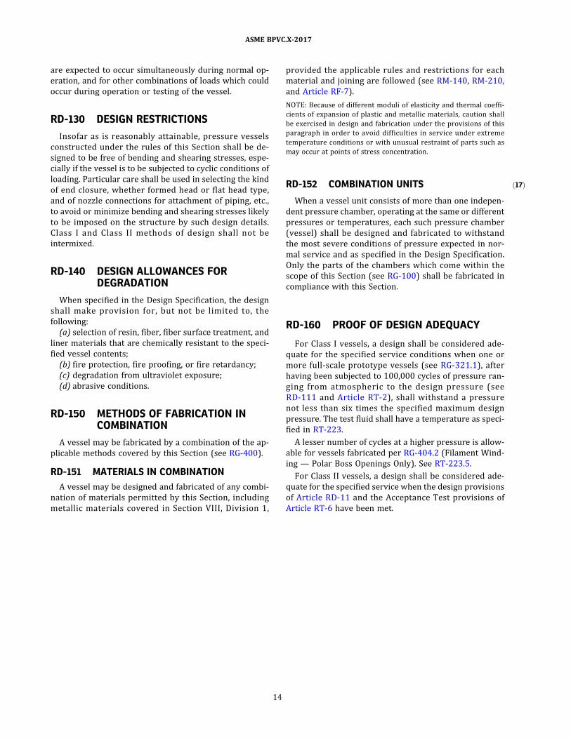
ð17Þ
are expected to occur simultaneously during normal op-
eration, and for other combinations of loads which could
occur during operation or testing of the vessel.
RD-130 DESIGN RESTRICTIONS
Insofar as is reasonably attainable, pressure vessels
constructed under the rules of this Section shall be de-
signed to be free of bending and shearing stresses, espe-
cially if the vessel is to be subjected to cyclic conditions of
loading. Particular care shall be used in selecting the kind
of end closure, whether formed head or flat head type,
and of nozzle connections for attachment of piping, etc. ,
to avoid or minimize bending and shearing stresses likely
to be imposed on the structure by such design details.
C lass I and C lass I I methods of des ign shal l not be
intermixed.
RD-140 DESIGN ALLOWANCES FORDEGRADATION
When specified in the Design Specification, the design
shal l make provis ion for, but not be l imited to , the
following:
(a) selection of resin, fiber, fiber surface treatment, and
liner materials that are chemically resistant to the speci-
fied vessel contents;
(b) fire protection, fire proofing, or fire retardancy;
(c) degradation from ultraviolet exposure;
(d) abrasive conditions.
RD-150 METHODS OF FABRICATION INCOMBINATION
A vessel may be fabricated by a combination of the ap-
plicable methods covered by this Section (see RG-400) .
RD-151 MATERIALS IN COMBINATION
A vessel may be designed and fabricated of any combi-
nation of materials permitted by this Section, including
metallic materials covered in Section VIII , Division 1 ,
provided the applicable rules and restrictions for each
material and joining are followed (see RM-140, RM-210,
and Article RF-7) .
NOTE: Because of different moduli of elasticity and thermal coeffi-
cients of expansion of plastic and metallic materials, caution shall
be exercised in design and fabrication under the provisions of this
paragraph in order to avoid difficulties in service under extreme
temperature conditions or with unusual restraint of parts such as
may occur at points of stress concentration.
RD-152 COMBINATION UNITS
When a vessel unit consists of more than one indepen-
dent pressure chamber, operating at the same or different
pressures or temperatures, each such pressure chamber
(vessel) shall be designed and fabricated to withstand
the most severe conditions of pressure expected in nor-
mal service and as specified in the Design Specification.
Only the parts of the chambers which come within the
scope of this Section (see RG-100) shall be fabricated in
compliance with this Section.
RD-160 PROOF OF DESIGN ADEQUACY
For Class I vessels, a design shall be considered ade-
quate for the specified service conditions when one or
more full‐scale prototype vessels (see RG-321.1) , after
having been subjected to 100,000 cycles of pressure ran-
ging from atmospheric to the des ign pressure (see
RD-111 and Article RT-2) , shall withstand a pressure
not less than six times the specified maximum design
pressure. The test fluid shall have a temperature as speci-
fied in RT-223.
A lesser number of cycles at a higher pressure is allow-
able for vessels fabricated per RG-404.2 (Filament Wind-
ing — Polar Boss Openings Only) . See RT-223.5.
For Class II vessels, a design shall be considered ade-
quate for the specified service when the design provisions
of Article RD-11 and the Acceptance Test provisions of
Article RT-6 have been met.
14
ASME BPVC.X-2017

ð17Þ
ARTICLE RD-2SHELLS OF REVOLUTION UNDER INTERNAL PRESSURE
RD-200 GENERAL
As indicated in RD-100, there are two methods per-
mitted in this Section for the design of shells of revolution
under internal pressure. In Nonmandatory Appendix AA
suggested procedures are given by which tentative thick-
nesses of Class I vessel parts may be determined for use in
fabricating prototype vessels for qualification of the de-
sign. The designer is free to use other equations to arrive
at such tentative thicknesses.
Design qualification of shells of revolution of Class II
vessels shall be in accordance with the design criteria of
Article RD-11 and the Acceptance Test criteria of Article
RT-6. Materials and laminate construction used in vessel
fabrication shall be in accordance with the Procedure
Specification (Form Q-120) for the specified vessel and
fabrication procedure(s) that meet the requirements of
Mandatory Appendix 1 which have been properly quali-
fied by the Fabricator.
15
ASME BPVC.X-2017

ð17Þ
ARTICLE RD-3SHELLS OF REVOLUTION UNDER EXTERNAL PRESSURE
RD-300 GENERAL
(a) As indicated in RD-100, this Section addresses two
methods by which shells of revolution under external
pressure may be designed.
(b) Vessels with heat transfer jackets are outside the
scope of this Section.
(c) Regardless of the design method used, the following
factors shall be included in establishing the design:
(1) the low modulus of elasticity of the material;
(2) the anisotropic character of the material;
(3) the lack of uniformity in centrifugal castings;
(4) the orientation of filaments in filament‐wound
vessels.
(d) While there are no mandatory equations for design
of Class I vessels, there are mandatory rules for testing
the prototype vessel thus constructed, as set forth in
RD-311 or RD-312.
(e) Class II vessels shall comply with Articles RD-11 ,
RD-12 , and RT-6 and the requirements set forth in
RD-313 and RD-314.
RD-310 QUALIFICATION OF VESSELS FOREXTERNAL PRESSURE SERVICE
(a) Class I vessels may be designed for either:
(1) external pressure only; or
(2) a combination of both internal and external pres-
sure service.
(b) Class II vessels may only be designed for external
pressure when the Design Specification includes both in-
ternal and external pressure design conditions. Class II
vessels designed for external pressure only are not
permitted.
Vessels for external pressure service shall be qualified
as required by RD-311, RD-312, or RD-313.
RD-311 CLASS I VESSELS FOR BOTH EXTERNALAND INTERNAL PRESSURE SERVICE
Class I vessels designed for both external and internal
pressure shall have their designs qualified as required
below.
(a) Prototype vessels shall be subjected to 100,000 cy-
cles of pressure ranging from the maximum external de-
s ign pressure , ps i (kPa) , to the maximum internal
design pressure, psi (kPa) , without failure. These external
and internal pressure tests may be carried out in two
steps (see RT-223) .
(b) Prototype vessels shall then withstand an external
pressure, psi (kPa) , of twice the maximum external design
pressure, or 29 in. of mercury (98.2 kPa) , whichever is
larger, without buckling.
(c) Prototype vessels shall then withstand a hydrostatic
qualification pressure of at least six times the maximum
internal design pressure.
RD-312 CLASS I VESSELS FOR EXTERNALPRESSURE SERVICE ONLY
Class I vessels designed for external pressure only shall
be designed for a minimum of 15 psi (100 kPa) internal
pressure in addition to the design requirement for exter-
nal pressure. The design shall be qualified by:
(a) subjecting a prototype vessel to an external pres-
sure of twice the maximum external design pressure, or
29 in. of mercury (98.2 kPa) , whichever is larger, without
buckling; and
(b) cyclic pressure and hydrostatic qualification pres-
sure tests in accordance with RD-160 based on 15 psi
(100 kPa) internal design pressure.
RD-313 CLASS II VESSELS FOR BOTH EXTERNALAND INTERNAL PRESSURE SERVICE
Class II vessels designed for both external and internal
pressure shall have Design Calculations made for both
conditions in accordance with Artic les RD -1 1 and
RD-12 . The most severe condition shall govern and be
the basis for design. The vessel shall then be acceptance
tested for both internal and external pressure in accor-
dance with Article RT-6 for both design conditions.
RD-314 CLASS II VESSELS FOR EXTERNALPRESSURE ONLY
Class II vessels designed for external pressure only are
not permitted.
16
ASME BPVC.X-2017
ARTICLE RD-4SECONDARY BONDING
RD-400 DESIGN OF SECONDARY BONDEDJOINTS
(a) Secondary bonded joints for Class I vessels may be
made by adhesive bonding or laminate overlay. Second-
ary bonded joints for Class II vessels shall be made by la-
minate overlay only.
(b) Secondary bonded joints of Class I vessels shall be
designed to withstand a minimum of six times the design
pressure of the vessel without leakage. The adequacy of
bonded joints shall be determined in accordance with
the requirements of RD-160.
(c) Secondary bonded joints of Class II vessels shall em-
ploy laminate overlays that are calculated in accordance
with Articles RD-11 and RD-12 and pass the Acceptance
Test criteria of Article RT-6.
(d) Parts to be joined by secondary bonding shall be
surface prepared as specified in the Procedure Specifica-
tion to enhance bond strength and reduce stress intensi-
fications caused by structural discontinuities.
17
ASME BPVC.X-2017

ð17Þ
ð17Þ
ARTICLE RD-5OPENINGS AND THEIR REINFORCEMENT
RD-500 GENERAL
As indicated in RD-100, there are two methods in this
Section for determining the design adequacy of openings
and their reinforcement.
Suggested procedures are given in Article AA-4 for de-
termining how to reinforce openings in Class I vessels.
The designer is free to use other procedures.
Reinforcement of openings in Class II vessels shall com-
ply with the procedures of Articles RD-11 and RD-12.
RD-510 QUALIFICATION
RD-511 QUALIFICATION OF CLASS I VESSELS
(a) The prototype vessel, complete with all openings
and their reinforcement as specified in the Design Draw-
ing, shall be qualified by cyclic pressure and hydrostatic
qualification pressure tests at the design temperature
and pressure in accordance with RT-223.
(b) Changes outside the scope of the Design Report in
the design of openings and their reinforcement shall be
considered as changes in the vessel design, and the vessel
shall be requalified, if required, as specified in RT-201
and RT-202.
RD-512 QUALIFICATION OF CLASS II VESSELS
(a) Vessels built in accordance with Design Calculations
as set forth in Articles RD-11 and RD-12 and as specified
in the Design Drawing and the Procedure Specification,
shall be pressure tested and nondestructively monitored
as specified in Article RT-6.
(b) Repairs and modifications to the vessel shall re-
quire it to be retested per Article RT-6.
RD-520 RESTRICTIONS FOR CLASS IIVESSELS
(a) Openings in Class II vessels shall be flanged nozzles
having a minimum diameter of 2 in. (50 mm).
(b) Screwed connections, or metal insert threaded con-
nections, in the vessel shell or head are not allowed.
18
ASME BPVC.X-2017

ð17Þ
ð17Þ
ð17Þ
ARTICLE RD-6NOZZLES AND OTHER CONNECTIONS
RD-600 GENERAL
As indicated in RD-100, there are two methods in this
Section for determining the design adequacy of nozzles
and other openings . The designer is referred to the
Articles AA-2 and AA-4 for general guidance for Class I
vessels. For Class II vessels the designer shall comply with
Articles RD-11 and RD-12.
RD-610 QUALIFICATIONS
RD-611 QUALIFICATION OF CLASS I VESSELS
(a) The prototype vessel shall be qualified by cyclic
pressure and hydrostatic qualification pressure tests at
the design temperature and pressure in accordance with
RT-223, with nozzles and other connections as specified
on the Design Drawings.
(b) Any change in the design of nozzles or other con-
nections shall be considered a change in the vessel design,
and the combinations shall be requalified, if required, as
specified in RT-201 and RT-202.
RD-612 QUALIFICATION OF CLASS II VESSELS
(a) Each specified vessel, including nozzles and other
connections, shall be pressure tested and nondestruc-
tively monitored as specified in Article RT-6.
(b) Repairs and modifications will require that the com-
plete vessel be retested per Article RT-6.
RD-613 RESTRICTIONS FOR CLASS II VESSELS
(a) Nozzles for C lass I I vessels shal l be l imited to
flanged nozzles that conform to the requirements of
RD-620 and have a minimum diameter of 2 in. (50 mm).
(b) Nozzles and other protrusions shall be capable of
supporting a 250 lb (1 000 N) vertical load.
RD-620 INTEGRAL FLANGED NOZZLES FORCLASS II VESSELS
RD-620.1 Integral Flange Physical Dimensions. Allintegral flanged nozzles shall have full‐face flanges and
be fabricated by the contact‐molding process. The flanges
and nozzles shall be of integral construction as shown in
Table RD-620.1, whereby the nozzle and flange are fabri-
cated in a single contact‐molding operation. For pressures
greater than 150 psi (1 MPa) and/or nozzles greater than
12 in. (DN 300) , see RD-1176 for nozzle design. The flange
physical dimensions (except thickness) shall be in accor-
dance with ASME B16.5 (Class 150 flanges) for NPS8 2 to
NPS 24 (DN 50 to DN 600) and in accordance with ASME
B16.1 (Class 125) for NPS over 24 (DN 600) unless other-
wise noted and specified in the Design Report. The nozzle
shall extend at least 6 in. (150 mm) from the shell outer
surface to the nozzle flange face unless otherwise per-
mitted in the Procedure Specification and specified in
the Design Report.
RD-620.2 Flange Bolt Holes. All bolt holes shall be
spot faced for ASME B18.22.1, Type A washers as shown
in Table RD-620.1, unless another size is permitted in the
Procedure Specification and specified in the Design Re-
port. Overall machine facing of the back of flanges is not
permitted.
RD-620.3 Flange Faces. Flange face drawback and
waviness shall not exceed 1/32 in. (0.8 mm) as measured
at or inside the bolt circle. No reverse drawback is per-
mitted. See Figure RD-620.3 sketches (a) , (b) , and (c) .
RD-620.4 Gussets. All nozzles of 6 in. nominal dia-
meter (DN 150) and smaller shall be provided with gus-
s e t s . G u s s e t s s h a l l b e p l a te typ e [ s e e F i g u r e
RD-620.4(a) ] or conical [see Figure RD-620.4(b) ] . Plate
gussets, if used, shall be evenly spaced around the nozzle.
Gussets shall be added after complete assembly of the
nozzle on the shell and shall not interfere with bolting
or seating of the washer into the spot face.
RD-620.5 Nozzle Installation. Nozzles shall be in-
stalled per Figure RD-620.5 or Figure RD-620.6 as speci-
fied in the Procedure Specification. Nozzle opening
reinforcement (reinforcing pad) and secondary bonding
to secure the nozzle to the vessel shall be calculated per
RD-1174.2 . If specified in the Procedure Specification,
the secondary overlay necessary to bond nozzles to the
shell may be evenly divided inside and outside the vessel
as shown in Figures RD-620.5 and RD-620.6. An inside
overlay consisting only of a corrosion‐resistant liner per
RD-101 shall not be considered as part of the secondary
overlay.
RD-621 FLANGE DESIGN FOR CLASS II VESSELS
Flange design shall be in accordance with RD-1176.
The allowable stress shall be 0.001 times the lower of
the longitudinal or transverse modulus of the flange lami-
nate as determined by Article RT-7.
19
ASME BPVC.X-2017

Flange thicknesses based on an allowable stress of
2 ,500 psi (17 MPa) are precalculated for nozzles sizes
2 in. to 48 in. (DN 50 to DN 1200) for internal hydrostatic
pressures of 25 psi to 150 psi (170 kPa to 1 MPa) and are
listed in Table RD-620.1 .
20
ASME BPVC.X-2017

ð17Þ Table RD-620.1Flange and Nozzle Dimensions for Hand Lay-Up and Pressure-Molded Flanges
U.S. Customary Units, in. and psi
Size,
in.
Out-
side
Dia.,
A
Bolt
Circle,
B
Bolt
Hole
Dia.,
C
Dia.
Spot
Facing
Bolts,
Size
Dia.
No. of
Bolts
Flange and Nozzle Thickness, in., for Pressure, psi
Gusset
Spacing
25 50 75 100 125 150
FT NT FT NT FT NT FT NT FT NT FT NT
2 6 4.75 0.75 1.75 0.63 4 0.5 0.25 0.5 0.25 0.63 0.25 0.63 0.25 0.69 0.25 0.75 0.25 12
3 7.5 6 0.75 1.75 0.63 4 0.5 0.25 0.56 0.25 0.69 0.25 0.75 0.25 0.81 0.31 0.88 0.31 13.5
4 9 7.5 0.75 1.75 0.63 8 0.5 0.25 0.63 0.25 0.75 0.25 0.88 0.31 1 0.31 1 0.31 15
6 11 9.5 0.88 2 0.75 8 0.56 0.25 0.69 0.25 0.81 0.31 1 0.31 1 0.38 1.13 0.44 17
8 13.5 11.75 0.88 2 0.75 8 0.625 0.25 0.81 0.31 1 0.38 1 0 1.31 0.44 1.31 0.5 19.5
10 16 14.25 1 2.25 0.88 12 0.75 0.25 1 0.31 1.13 0.38 1.25 0.4375 1.38 0.5 1.5 0.56 19.5
12 19 17 1 2.25 0.88 12 0.81 0.25 1 0.31 1.31 0.44 1.5 0.5 1.69 0.56 1.88 0.69 19.5
14 21 18.75 1.13 2.5 1 12 0.88 0.313 1.13 0.38 1.38 0.44 1.56 0.56 1.81 0.69 (1) (1) 19.5
16 23.5 21.25 1.13 2.5 1 16 1 0.313 1.25 0.38 1.5 0.5 1.69 0.63 2 0.75 (1) (1) 19.5
18 25 22.75 1.25 2.75 1.13 16 1 0.313 1.38 0.41 1.56 0.56 (1) (1) (1) (1) (1) (1) 19.5
20 27.5 25 1.25 2.75 1.13 20 1.13 0.313 1.5 0.41 1.69 0.56 (1) (1) (1) (1) (1) (1) 19.5
24 32 29.5 1.38 3 1.25 20 1.25 0.313 1.63 0.5 2 0.69 (1) (1) (1) (1) (1) (1) 19.5
30 38.75 36 1.38 3 1.25 28 1.5 0.375 2 0.56 2.38 0.81 (1) (1) (1) (1) (1) (1) 19.5
36 46 42.75 1.63 3.5 1.5 32 2 0.438 2.25 0.69 (1) (1) (1) (1) (1) (1) (1) (1) 19.5
42 53 49.5 1.63 3.5 1.5 36 2.13 0.438 2.63 0.81 (1) (1) (1) (1) (1) (1) (1) (1) 19.5
48 59.5 56 1.63 3.5 1.5 44 2.25 0.5 3 0.88 (1) (1) (1) (1) (1) (1) (1) (1) 19.5
21
ASMEBPVC.X-2017

Table RD-620.1Flange and Nozzle Dimensions for Hand Lay-Up and Pressure-Molded Flanges (Cont'd)
SI Units, mm and kPa
Size,
mm
Outside
Dia.,
A
Bolt
Circle, B
Bolt
Hole
Dia.,
C
Dia.
Spot
Facing
Bolts,
Size
Dia.
No. of
Bolts
Flange and Nozzle Thickness, mm, for Pressure, kPa
Gusset
Spacing
170 kPa 340 kPa 510 kPa 690 kPa 860 kPa 1 000 kPa
FT NT FT NT FT NT FT NT FT NT FT NT
50 152 121 19 44 16 4 13 6 13 6 14 6 16 6 17 6 19 6 305
76 191 152 19 44 16 4 13 6 14 6 17 6 19 6 21 8 22 8 343
102 229 191 19 44 16 8 13 6 16 6 19 6 22 8 24 8 25 8 381
152 279 241 22 51 19 8 14 6 17 6 21 8 25 10 43 10 29 11 432
203 343 298 22 51 19 8 16 6 21 8 24 10 27 11 30 11 33 13 495
254 406 362 25 57 22 12 19 6 24 8 29 10 32 13 35 13 38 14 495
305 483 432 25 57 22 12 21 6 27 8 33 11 38 14 43 14 48 17 495
356 533 476 29 64 25 12 22 8 29 10 35 11 40 16 46 17 (1) (1) 495
406 597 540 29 64 25 16 24 8 32 10 38 13 43 17 51 19 (1) (1) 495
457 635 578 32 70 29 16 25 8 35 11 40 14 (1) (1) (1) (1) (1) (1) 495
508 699 635 32 70 29 20 29 8 38 11 43 14 (1) (1) (1) (1) (1) (1) 495
610 813 749 35 76 32 20 32 8 41 13 51 17 (1) (1) (1) (1) (1) (1) 495
762 984 914 35 76 32 28 38 10 51 14 60 21 (1) (1) (1) (1) (1) (1) 495
914 1 168 1 086 38 89 38 32 51 11 57 17 (1) (1) (1) (1) (1) (1) (1) (1) 495
1 067 1 346 1 257 38 89 38 36 54 11 67 21 (1) (1) (1) (1) (1) (1) (1) (1) 495
1 219 1 511 1 422 38 89 38 44 57 13 75 22 (1) (1) (1) (1) (1) (1) (1) (1) 495
GENERAL NOTES:
(a) Hub reinforcement equals T/2; R = 1/4 in. min. (6 mm min.) .
(b) Above table is based on an alternate chopped strand mat/woven roving laminates.
(c) Integral flange required for sizes up to 24-in. (600-mm) diameter.
(d) Gaskets shall be 1/8-in.-thick (3-mm-thick) , full-face elastomeric material with a hardness of Shore A60 ±5.
NOTE:
(1) The flange outside diameter and bolt circle must be modified for the design of these flanges. Flanges are to be calculated according to RD-1176.
22
ASMEBPVC.X-2017

Figure RD-620.3Flange Tolerances
23
ASME BPVC.X-2017

ð17Þ Figure RD-620.4(a)Plate-Type Gussets
Fil l voids with
resin putty
60 deg
Reinforced
plastic
gusset
X ply of 1 1 /2 oz (450 gr)
mat overlay
B
Y
1 /4 in .
(6 mm)
1 1 /2 in .
(38 mm)
1 1 /2 in .
(38 mm)
2
3
4
6
50
75
1 00
1 50
300
340
375
450
3
3
3
3
4
4
4
4
1 2
1 31 /2
1 5
1 8
Size
B,
in. mm
No. of
Pl ies,
X
No. of
Gussets
Y,
in. mm
GENERAL NOTE: Gussets shall be evenly spaced around nozzle. Gussets shall be added after complete assembly of nozzle on shell. Gussets
are not required on nozzles over 6 in. (150 mm).
Figure RD-620.4(b)Typical Cone-Type Gusset
60 deg
3/1 6 in .
(5 mm)
24
ASME BPVC.X-2017

Figure RD-620.5Flush Nozzle Installation
d
tb
hi
6tb
Lb
tp
Lp
hi6ti
6tp
6ti
ti
Legend:
d = inside diameter of nozzle
h i = inside shear bond length
L b = shear length
L p = length of pad
tb = overlay thickness on nozzle
ti = inside overlay thickness
tp = thickness of reinforcing pad
25
ASME BPVC.X-2017

Figure RD-620.6Penetrating Nozzle Installation
Lp
hi
d
6ti
tb
hi
ti
6tb
Lb
6tp
6ti
tp
Legend:
d = inside diameter of nozzle
h i = inside shear bond length
L b = shear length
L p = length of pad
tb = overlay thickness on nozzle
ti = inside overlay thickness
tp = thickness of reinforcing pad
26
ASME BPVC.X-2017

ARTICLE RD-7BOLTED CONNECTIONS
RD-700 FLAT HEADS, COVERS, AND BLINDFLANGES
Flat heads, covers, and blind flanges shall be made of
either
(a) laminate materials covered in Article RM-1; or
(b) one of the metals listed in Section VIII , Division 1,
for plates, forgings, or castings.
RD-700.1 For Class I Vessels. Some acceptable types
of flat heads for Class I vessels are shown in Figure
RD-700.1 .
RD-700.2 For Class II Vessels. The only acceptable
types of bolted connection for Class II vessels shall be
the types listed in RD-620.
RD-700.3 Nomenclature. The symbols used in this
Article and Figure RD-700.1 are defined as follows:
C = factor depending upon the method of attachment of
head, cover, or flange, dimensionless (see Figure
RD-700.1)
d = diameter as shown in Figure RD-700.1, in. (mm)
P = design pressure (see RD-111) , psi (MPa)
S = allowable stress, psi (MPa) . For metal flat heads, use
applicable table of maximum allowable stress values
in Section VIII , Division 1. For flat heads fabricated
from laminated materials covered in Article RM-1,
use allowable stress of the specified laminate as
specified in the Procedure Specification and which
will satisfy the specified design conditions in accor-
dance with RD-160.
t = minimum required thickness of flat head, cover, or
flange, exclusive of corrosion allowance, in. (mm)
RD-701 MINIMUM REQUIRED THICKNESS
The minimum required thickness of flat, unstayed, cir-
cular heads, covers, and blind flanges shall be calculated
by the following equation:
ð1Þ
RD-710 BOLTED FLANGED CONNECTIONS
RD-711 FLANGES AND FLANGED FITTINGSCONFORMING TO ANSI B16.5 AND B16.1
The dimensional requirements of flanges (except thick-
ness) used in bolted flange connections to external piping
shall conform to ANSI B16.5‐1981, Steel Pipe Flanges and
Flanged Fittings, or ANSI B16.1 , Cast Iron Pipe Flanges
and Flanged Fittings, for nozzles over NPS 24, unless
otherwise specified in the Design Report. Thickness of
flanges shall be determined in accordance with RD-100
and RD-160.
Figure RD-700.1Acceptable Types of Flat Heads for Class I Vessels
27
ASME BPVC.X-2017

ð17Þ RD-712 FLANGES NOT CONFORMING TO ANSIB16.5-1981
RD-712.1 For Class I Vessels. Flanges used for join-
ing sections of shells or for similar purposes shall be de-
signed using full-face gaskets or self‐energizing types,
such as o‐rings. Such flange designs may be used provided
they are proven adequate for the specified design condi-
tions in accordance with RD-160.
RD-712.2 For Class II Vessels. Flanges used for join-
ing sections of shells or for similar purposes shall be de-
signed using full-face gaskets or self‐energizing types,
such as o‐rings.
RD-720 OPENINGS IN FLAT METALLICHEADS, METALLIC COVERS, ANDMETALLIC BLIND FLANGES
Openings in flat heads, covers, and blind flanges shall
conform to the requirements of RD-721 for reinforcement
for all openings, except that single openings in flat heads,
covers, and blind flanges do not require reinforcement
other than that inherent in the construction under the fol-
lowing conditions:
(a) welded or brazed connections to metal heads at-
tached in accordance with the applicable rules of Section
VIII, Division 1, and not larger than
(1) NPS 3 (DN 80) heads 3/8 in. (10 mm) thick or less;
(2) NPS 2 (DN 50) heads over 3/8 in. (10 mm) thick;
(b) threaded, studded, or expanded connections in
Class I vessels only in which the hole cut in the head is
not greater than NPS 2 (DN 50) .
RD-721 REINFORCEMENT REQUIREMENTS
(a) Flat heads that have an opening with a diameter
that does not exceed one‐half of the head diameter d shall
have a total cross‐sectional area of reinforcement not less
than that given by the equation
where B is the diameter of the finished opening in its cor-
roded condition and t is as defined in RD-700.3 .
(b) Flat heads that have an opening with a diameter
that exceeds one‐half of the head diameter, as defined
in RD-700.3 , shall be restricted to a metal material and
shall be designed in accordance with the rules for bolted
flange connections in Section VIII, Division 1, Mandatory
Appendix 2.
(c) As an alternative to (b) above, the thickness of flat
heads may be increased to provide the necessary opening
reinforcement by using 2C in place of C in eq. RD-701(1) .
RD-730 WELDED OR BRAZED CONNECTIONSTO METAL FLAT HEADS, COVERS,OR BLIND FLANGES
(a) Connections to metallic flat heads, covers, or blind
flanges attached by welding shall meet the requirements
of Section VIII, Division 1, Part UW.
(b) Connections to metallic flat heads, covers, or blind
flanges attached by brazing shall meet the requirements
of Section VIII, Division 1, Part UB.
28
ASME BPVC.X-2017
ð17Þ
ð17Þ
ð17Þ
ARTICLE RD-8QUICK-ACTUATING CLOSURES (FOR CLASS I VESSELS ONLY)
RD-800 GENERAL DESIGN REQUIREMENTS
Closures other than the multibolted type designed to
provide access to the contents space of a pressure vessel
shall have the locking mechanism or locking device so de-
signed that failure of any one locking element or compo-
nent in the locking mechanism cannot result in the failure
of all other locking elements and the release of the clo-
sure. Quick‐actuating closures shall be designed and in-
stalled so that it may be determined by visual external
observation that the holding elements are in good condi-
tion and that their locking elements, when the closure is
in the closed position, are in full engagement. Such clo-
sures shall be limited to Class I vessels and shall meet
the requirements of RD-100 and RD-160.
RD-801 SPECIFIC DESIGN REQUIREMENTS
Quick‐actuating closures that are held in position by
positive locking devices, and that are fully released by
partial rotation or limited movement of the closure itself
or the locking mechanism, and any closure that is other
than manually operated, shall be designated so that when
the vessel is installed, the following conditions are met:
(a) the closure and its holding elements are fully en-
gaged in their intended operating position before pres-
sure can be built up in the vessel;
(b) pressure tending to force the closure clear of the
vessel will be released before the closure can be fully
opened for access;
In the event that compliance with (a) and (b) above is
not inherent in the design of the closure and its holding
elements, provision shall be made so that devices to ac-
complish this can be added when the vessel is installed.
It is recognized that it is impractical to write detailed
requirements to cover the multiplicity of devices used
for quick access or to prevent negligent operation or
the circumventing of safety devices. Any device or devices
that will provide the safeguards broadly described in (a) ,
(b) , and this paragraph will meet the intent of the Code.
The design of the closure shall be verified as part of the
prototype qualification.
RD-801.1 Permissible Design Deviations for Manu-ally Operated Closures. Quick‐actuating closures that
are held in position by a locking device or mechanism that
requires manual operation and are designated so that
there will be leakage of the contents of the vessel prior
to disengagement of the locking elements and release of
closure need not satisfy RD-801(a) and RD-801(b) . How-
ever, such closures shall be equipped with an audible
and/or visible warning device that will serve to warn
the operator if pressure is applied to the vessel before
the closure and its holding elements are fully engaged
in their intended position and, further, will serve to warn
the operator if an attempt is made to operate the locking
mechanism or device before the pressure within the ves-
sel is released.
RD-802 REQUIRED PRESSURE-INDICATINGDEVICES
All vessels having quick‐actuating closures shall be pro-
vided with a pressure‐indicating device visible from the
operating station.
RD-803 QUALIFICATION
Quick‐actuating closures shall meet the proof of design
adequacy requirements of RD-160.
29
ASME BPVC.X-2017
ARTICLE RD-9ATTACHMENTS AND SUPPORTS
RD-900 GENERAL
There are no mandatory rules in this Section governing
the design of attachments and supports for Class I vessels.
The designer is referred to Article AA-5 for suggested pro-
cedures to be followed in establishing prototype design.
Design of attachments and supports for Class II vessels
shall be in accordance with Article RD-11 and shall be cer-
tified by a registered Professional Engineer in accordance
with RD-1111.
RD-910 QUALIFICATION
(a) For Class I vessels, a prototype vessel complete with
attachments and supports designed for it shall be quali-
fied by cyclic pressure and hydrostatic qualification pres-
sure tests at the design pressure and temperature in
accordance with RT-223.
(b) Class II vessels, complete with attachments and sup-
ports, shall be tested as specified in Article RT-6.
(c) Any change in the design of the attachments and
supports shall be considered a change in the vessel de-
sign, and the combination shall be requalified.
30
ASME BPVC.X-2017

ð17Þ
ð17Þ
ð17Þ
ARTICLE RD-10ACCESS AND INSPECTION OPENINGS
RD-1000 GENERAL REQUIREMENTS
All pressure vessels subject to internal corrosion or
having parts subject to erosion or mechanical abrasion
shall be provided with suitable manhole, handhole, or
other inspection openings for examination and cleaning.
RD-1001 REQUIREMENTS FOR VESSELS 12 in.(300 mm) IN DIAMETER9 AND SMALLER
For Class I vessels 12 in. (300 mm) or less in diameter,
openings for inspection only may be omitted if there are
at least two removable pipe connections not less than
NPS 3/4 (DN 20) that can be utilized for adequate internal
inspection. Inspection openings for Class II vessels shall
comply with RD-520.
RD-1002 REQUIREMENTS FOR VESSELS OVER12 in. (300 mm) BUT NOT OVER 16 in.(400 mm) IN INSIDE DIAMETER
Class I vessels over 12 in. (300 mm) but not over 16 in.
(400 mm) in diameter, that are to be installed so that they
must be disconnected from an assembly to permit inspec-
tion, need not be provided with additional openings for
inspection only, if there are at least two removable pipe
connections not less than NPS 11/2 (DN 40) , provided such
openings are so located that adequate internal inspec-
tions can be made. Inspection openings for Class II vessels
shall comply with RD-520.
RD-1010 EQUIPMENT OF VESSELSREQUIRING ACCESS ORINSPECTION OPENINGS
Vessels that require access or inspection openings shall
be equipped as follows:9
(a) Class I vessels less than 18 in. (450 mm) and over
16 in. (400 mm) inside diameter shall have at least two
handholes or two plugged, threaded inspection openings
of not less than NPS 11/2 (DN 40) .
(b) Class I vessels 18 in. (450 mm) to 36 in. (920 mm),
inclusive, inside diameter shall have a manhole or at least
two handholes or two threaded pipe‐plug inspection
openings of not less than NPS 2 (DN 50) .
(c) Class I vessels over 36 in. (900 mm) inside diameter
shall have a manhole [see RD-1020(a) ] , except those ves-
sels whose shape or use makes one impracticable shall
have at least two handho les 4 in . × 6 in . (100 mm
× 150 mm) or two equal openings of equivalent area.
(d) When handholes or pipe‐plug openings are per-
mitted for Class I vessels inspection openings in place of
a manhole, one handhole or one pipe‐plug opening shall
be in each head or in the shell near each head.
(e) Openings with removable heads or cover plates in-
tended for other purposes may be used in place of the re-
quired inspection openings, provided they are equal to at
least the size of the required inspection openings and pro-
vided they are located so that adequate internal inspec-
tion can be made.
(f) A single opening with removable head or cover
plate may be used in place of all the smaller inspection
openings, provided it is of such size and location to afford
at least an equal view of the interior.
(g) Accesses or inspection openings for Class II vessels
shall comply with RD-520 and RD-1174.
RD-1020 SIZE OF MANHOLE OPENINGS FORCLASS I VESSELS
When inspection or access openings are required, they
shall comply with at least the following requirements:
(a) Type and Minimum Size ofManhole. An elliptical or
obround manhole shall be not less than 12 in. × 16 in.
(300 mm × 400 mm). A circular manhole shall be not less
than 16 in. (400 mm) in inside diameter.
(b) Minimum Size of Handholes. A handhole opening
shall be not less than 2 in. × 3 in. (50 mm × 75 mm) ,
but should be as large as is consistent with the size of
the vessel and the location of the opening.
RD-1030 SIZE OF MANHOLE OPENINGS FORCLASS II VESSELS
When inspection or access openings are required for
Class I I vessels , they shall comply with RD-520 and
RD-1174.
RD-1031 DESIGN OF ACCESS AND INSPECTIONOPENINGS IN SHELLS AND HEADS
All access and inspection openings in a shell or un-
stayed head of a Class I vessel shall be designed in accor-
dance with the suggested procedures of Nonmandatory
Appendix AA or their equivalent and shall be fabricated
into the prototype vessel or vessels used to qualify the de-
sign in accordance with RD-160.
31
ASME BPVC.X-2017

ð17Þ
All access and inspection openings in Class II vessels
shall comply with the procedures of Article RD-11.
RD-1040 MINIMUM GASKET BEARINGWIDTHS FOR MANHOLE COVERPLATES
Manholes of the type in which the internal pressure
forces the cover plate against a flat gasket shall have a
minimum gasket bearing width of 11/16 in. (17 mm).
RD-1050 THREADED OPENINGS IN CLASS IVESSELS
RD-1051 MATERIALS FOR THREADED PLUGSAND CAPS
(a) When a threaded opening is to be used for inspec-
tion or cleaning purposes, the closing plug shall be de-
s igned with due cons ideration of the re lationships
between the moduli of elasticity of the materials of the
vessel and the plug and between the thermal coefficients
of expansion of those materials.
(b) A Class I vessel, with the threaded opening and clo-
sure in place, shall be qualified by cyclic pressure and hy-
drostatic qualification pressure tests in accordance with
RT-223.
(c) Any change in the design of openings shall be con-
sidered a change in the design of the vessel, and the vessel
with new opening or openings shall be requalified.
RD-1052 PERMISSIBLE TYPES OF THREADS
The thread for threaded openings shall be a standard
taper pipe thread, except a straight thread of equal
strength may be used if additional sealing means to pre-
vent leakage are provided.
RD-1060 THREADED OPENINGS IN CLASS IIVESSELS
Threaded openings are not permitted in any pressure‐
containing component of a Class II vessel. The only excep-
tion is a threaded opening, not to exceed 2 NPT (DN 50) ,
in a metallic flat cover for a flanged manway or nozzle.
32
ASME BPVC.X-2017

ð17Þ
ð17Þ
ð17Þ
ð17Þ
ð17Þ
ARTICLE RD-11MANDATORY DESIGN RULES FOR CLASS II VESSELS10
RD-1100 GENERAL
Class II vessels and vessel parts shall be designed using
the stress analysis methods given in this Article. Class II
vessels are those whose designs are qualified by adher-
ence to the mandatory design rules of this Article and
are acceptance tested individually as specified in Article
RT-6. The engineering constants for laminates used in
the design and fabrication of Class II vessels shall be de-
termined in accordance with Article RD-12.
RD-1110 DESIGN BASIS
Two methods of des ign are permitted under this
Article:
(a) Method A — Design Rules: RD-1170
(b) Method B — Discontinuity Analysis: RD-1180
Specific design by either method shall be qualified by
acceptance testing as specified in Article RT-6. The maxi-
mum strain theory of failure is used for Method A, and the
quadratic interaction criterion is used for Method B.
RD-1111 CERTIFICATION OF DESIGN
A Professional Engineer knowledgeable in the design of
reinforced plastics and registered in one or more of the
states of the United States or provinces of Canada shall
certify that the calculations contained in the Fabricator’s
Design Report are in compliance with the rules of this
Article and that the vessel design complies with this Sec-
tion for Class II vessels.
RD-1120 DESIGN LIMITATIONS
The maximum design pressure and inside diameter of
Class II vessels shall be restricted as follows (see Figure
RD-1120.1) .
(a) Vessels designed shall have pressure and diameter
restrictions as follows:
(1) the algebraic product of the internal pressure [psi
(kPa)] and the inside diameter [in. (mm)] shall not exceed
14,400 lb/in. (for Customary units, PD = 14,400 lb/in.; for
SI units, PD = 2 522 kPa·m);
(2) the maximum internal pressure shall not exceed
250 psi (1 724 kPa) ;
(3) the maximum inside diameter shall not exceed
192 in. (4.88 m).
(b) Vessels with diameters greater than 144 in. may be
designed using a combination of Methods A and B.
(c) Vessels designed by either Method A or B shall be
limited to an external pressure of 15 psi (100 kPa) .
(d) Design temperature shall be as limited by RD-112.
(e) Vessels may be designed in their entirety by Method
B (discontinuity analysis) .
RD-1130 DESIGN ACCEPTABILITY
Design acceptability shall be demonstrated by compar-
ing design stress and strain values with calculated buck-
ling values, allowable strain values, and the mechanical
properties obtained from the physical test defined in
Article RT-7. The appropriate comparison will depend
on the governing criterion and is specified in RD-1170
through RD-1189.
RD-1140 LOADINGS
Loadings that shall be considered in the design of spe-
cific vessels under this Article are specified in RD-120.
RD-1150 VESSEL PARTS SUBJECT TODESIGN ANALYSIS
Design Calculations shall be provided for pressure‐
containing components and support members to include
but not be limited to:
(a) vessel shell;
(b) vessel heads;
(c) openings and their reinforcement;
(d) secondary bonds joining two or more vessel parts;
(e) internal and external attachments (e.g. , packing
supports, vessel skirts, hold‐down lugs, support rings,
etc.) .
RD-1160 LAMINATE COMPOSITION
RD-1161 SCOPE
Laminates acceptable under the Code for Class II ves-
sels are limited to those made from resin and fiber speci-
fied in RM-100 and RM-120 by either contact‐molded or
filament‐wound methods. No restrictions are placed on
the fiber form, the ply sequence, or ply orientations. How-
ever, laminates used in Class II vessels shall satisfy the
above rules and the Fabricator’s Procedure Specification
regarding fabrication of both vessel parts and test cou-
pons for determination of engineering constants.
33
ASME BPVC.X-2017

ð17Þ
RD-1162 FABRICATION METHODS
Class II vessels using Method A or B as the design cri-
teria shall be limited to contact‐molded construction,
filament‐wound construction, or a combination of the
two.
RD-1163 ENGINEERING CONSTANTS
Elastic constants for Class II vessel design shall be de-
termined for the specific laminate specified in the Proce-
dure Specification. Elastic constants for the laminate shall
be determined by means of laminate theory using the
orthotropic properties of the individual lamina in accor-
dance with Article RD-12. The lamina elastic and strength
constants shall be determined in accordance with Article
RT-7.
Laminate theory (Article RD-12) shall be used to deter-
mine the elastic constants of both contact‐molded and
filament‐wound laminates.
RD-1163.1 Laminate Theory. Laminate theory is a
mathematical treatment of the mechanics governing the
behavior of a unidirectional orthotropic lamina, and the
interrelation of multiple lamina forming a multidirec-
tional laminate. Laminate theory requires that four elastic
constants and five strength constants for the orthotropic
lamina be determined. The elastic constants are longitudi-
nal, transverse, and shear modulus, and the major Pois-
son’s ratio. The five strength constants are longitudinal
tension and compression, transverse tension and com-
pression, and the in‐plane shear strength. Test methods
for elastic and strength constants of the unidirectional la-
mina are specified in Article RT-7. The mathematical
treatment to calculate the resulting stiffness coefficients
is specified in Article RD-12. An example of laminate the-
ory is given in Nonmandatory Appendix AD.
Method A requires that the laminate be treated as
homogeneous and, therefore, possessing effective lami-
nate engineering properties. For balanced, symmetric la-
minates, it is possible to express the effective engineering
properties as a function of the stiffness constants A i j and
the laminate thickness. If the laminate is not symmetric,
the determination of effective engineering properties is
more complex, requiring the inversion of the stiffness ma-
trix to allow expression of the laminate effective con-
s tants in terms of compl iance (see Nonmandatory
Appendix AD) .
Figure RD-1120.1Design Limitations for Class II Vessels
280 1 600
1 000
800
Design Pressure, kPa
Design Pressure, psig
1 00
0
250
220
Method A or Method B
PD ? 1 4,400 lb/in. (2 522 kPa m)
Method A and Method B
1 90
1 60
1 30
1 00
70
40
1 0
0 20 40 60 80
0 1 2 3 4 5
1 00 1 20
Diameter, in.
Diameter, m
1 40 1 60 1 80 200
?20
< 1 44 in .
34
ASME BPVC.X-2017
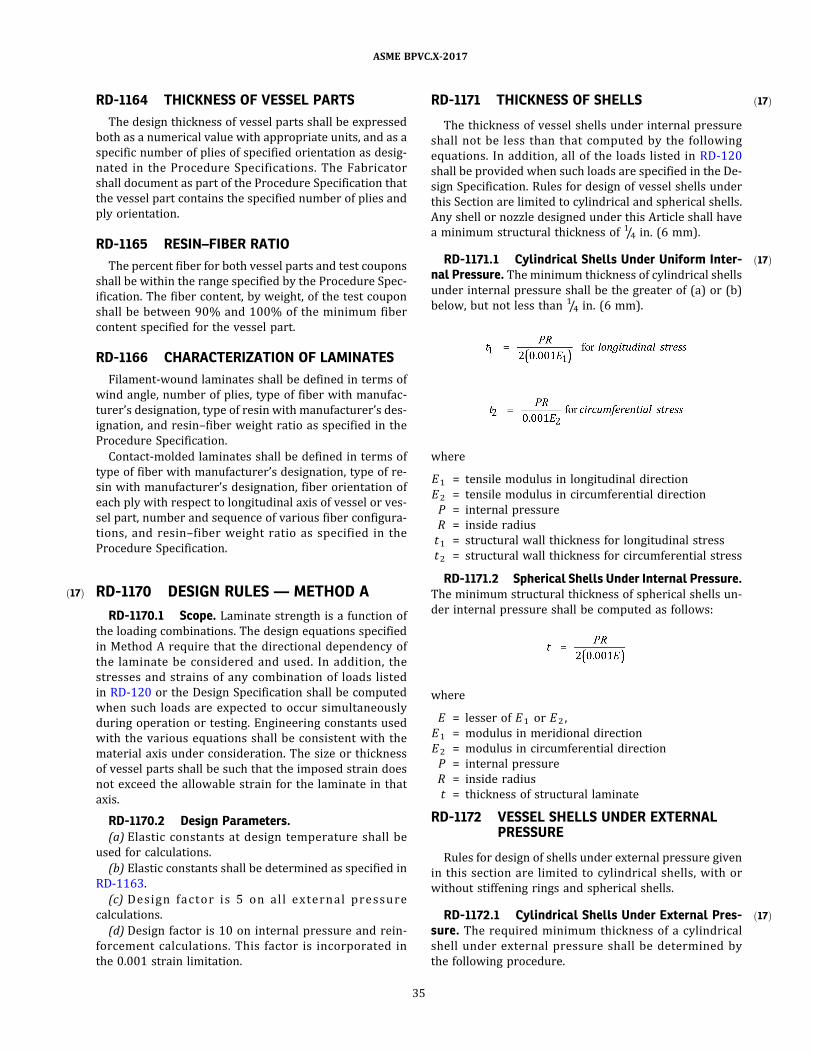
ð17Þ
ð17Þ
ð17Þ
ð17Þ
RD-1164 THICKNESS OF VESSEL PARTS
The design thickness of vessel parts shall be expressed
both as a numerical value with appropriate units, and as a
specific number of plies of specified orientation as desig-
nated in the Procedure Specifications. The Fabricator
shall document as part of the Procedure Specification that
the vessel part contains the specified number of plies and
ply orientation.
RD-1165 RESIN–FIBER RATIO
The percent fiber for both vessel parts and test coupons
shall be within the range specified by the Procedure Spec-
ification. The fiber content, by weight, of the test coupon
shall be between 90% and 100% of the minimum fiber
content specified for the vessel part.
RD-1166 CHARACTERIZATION OF LAMINATES
Filament‐wound laminates shall be defined in terms of
wind angle, number of plies, type of fiber with manufac-
turer’s designation, type of resin with manufacturer’s des-
ignation, and resin–fiber weight ratio as specified in the
Procedure Specification.
Contact‐molded laminates shall be defined in terms of
type of fiber with manufacturer’s designation, type of re-
sin with manufacturer’s designation, fiber orientation of
each ply with respect to longitudinal axis of vessel or ves-
sel part, number and sequence of various fiber configura-
tions, and resin–fiber weight ratio as specified in the
Procedure Specification.
RD-1170 DESIGN RULES — METHOD A
RD-1170.1 Scope. Laminate strength is a function of
the loading combinations. The design equations specified
in Method A require that the directional dependency of
the laminate be considered and used. In addition, the
stresses and strains of any combination of loads listed
in RD-120 or the Design Specification shall be computed
when such loads are expected to occur simultaneously
during operation or testing. Engineering constants used
with the various equations shall be consistent with the
material axis under consideration. The size or thickness
of vessel parts shall be such that the imposed strain does
not exceed the allowable strain for the laminate in that
axis.
RD-1170.2 Design Parameters.(a) Elastic constants at design temperature shall be
used for calculations.
(b) Elastic constants shall be determined as specified in
RD-1163.
(c) Des i gn fac to r i s 5 on a l l e xte rna l p re s s u re
calculations.
(d) Design factor is 10 on internal pressure and rein-
forcement calculations. This factor is incorporated in
the 0.001 strain limitation.
RD-1171 THICKNESS OF SHELLS
The thickness of vessel shells under internal pressure
shall not be less than that computed by the following
equations. In addition, all of the loads listed in RD-120
shall be provided when such loads are specified in the De-
sign Specification. Rules for design of vessel shells under
this Section are limited to cylindrical and spherical shells.
Any shell or nozzle designed under this Article shall have
a minimum structural thickness of 1/4 in. (6 mm).
RD-1171.1 Cylindrical Shells Under Uniform Inter-nal Pressure. The minimum thickness of cylindrical shells
under internal pressure shall be the greater of (a) or (b)
below, but not less than 1/4 in. (6 mm).
where
E1 = tensile modulus in longitudinal direction
E2 = tensile modulus in circumferential direction
P = internal pressure
R = inside radius
t1 = structural wall thickness for longitudinal stress
t2 = structural wall thickness for circumferential stress
RD-1171.2 Spherical Shells Under Internal Pressure.The minimum structural thickness of spherical shells un-
der internal pressure shall be computed as follows:
where
E = lesser of E1 or E2 ,
E1 = modulus in meridional direction
E2 = modulus in circumferential direction
P = internal pressure
R = inside radius
t = thickness of structural laminate
RD-1172 VESSEL SHELLS UNDER EXTERNALPRESSURE
Rules for design of shells under external pressure given
in this section are limited to cylindrical shells, with or
without stiffening rings and spherical shells.
RD-1172.1 Cylindrical Shells Under External Pres-sure. The required minimum thickness of a cylindrical
shell under external pressure shall be determined by
the following procedure.
35
ASME BPVC.X-2017

ð17Þ
The maximum allowable external pressure between
stiffening elements shall be computed by the following:
where
D o = outside diameter of shell, in.
Ea t = axial tensile modulus, psi
Eh f = hoop flexural modulus, psi
F = design factor = 5
KD = 0.84, a knockdown factor to cover all data points
using the rigorous equations
L = design length of a vessel section, in., taken as the
largest of the following:
(a) the distance between head‐tangent lines plus
one‐third the depth of each formed head, if there
are no stiffening rings (excluding conical heads
and sections) ;
(b) the distance between cone‐to‐cylinder junc-
tions for vessels with cone or conical heads, if
there are no stiffening rings;
(c) the greatest center‐to‐center distance be-
tween any two adjacent stiffening rings;
(d) the distance from the center of the first stif-
fening ring to the formed head tangent line plus
one‐third the depth of the formed head (excluding
conical heads and sections) , all measured parallel
to the axis of the vessel;
(e) the distance from the first stiffening ring in
the cylinder to the cone‐to‐cylinder junction.
Pa = allowable external pressure, psi
t = wall thickness, in. (nominal)
vx = flexural Poisson’s ratio in the axial direction
vy = flexural Poisson’s ratio in the hoop direction
γ = reduction factor developed to better correlate the-
oretical predictions and test results
(a) γ = 1 − 0.001Zp , if Zp ≤ 100,
(b) γ = 0.9, if Zp > 100
where
where Ea f is the axial flexural modulus, psi
NOTE: The use of lamination theory for the prediction of νx
and νy is acceptable.
For alternative rules, see Nonmandatory Appendix AI.
RD-1172.1.1 The required moment of inertia Is of a
circumferential stiffener ring for cylindrical shells under
external pressure shall not be less than that determined
by the following equation:
where
D o = outside diameter
E2 = hoop tensile modulus
F = design factor = 5
L s = one‐half the distance from the center line of the
stiffening ring to the next line of support on one
side, plus one‐half the center line distance to the
next line of support on the other side of the stiffen-
ing ring, both measured parallel to the axis of the
cylinder. A line of support is:
(a) a stiffening ring that meets the requirements
of this paragraph;
(b) a circumferential line on a head at one‐third
the depth of the head from the head tangent line.
Po = external pressure
RD-1172.2 Spherical Shells Under Uniform ExternalPressure. The minimum thickness of spherical shells un-
der external pressure shall be computed as follows.
Step 1 . Assume a value of t for the structural wall thick-
ness and compute the allowable pressure:
where
E = smaller of E1 and E2 ,
E1 = effective tensile modulus in meridional direction
E2 = effective tens i l e modulus in ci rcumferentia l
direction
F = design factor = 5
PA = allowable external pressure
R o = outside spherical radius
t = structural wall thickness
ν1 = Poisson’s ratio in major direction
ν2 = Poisson’s ratio in minor direction
Step 2. Assume successive values of t until PA equals or
exceeds the design external pressure.
RD-1173 THICKNESS OF HEADS
RD-1173.1 Thickness of Heads Under Internal Pres-sure. The required thickness of vessel heads under inter-
nal pressure shal l be computed by the appropriate
equation below.
36
ASME BPVC.X-2017

ð17Þ
where
D = inside diameter
Eh d = design modulus for the head
P = internal pressure
R s = inside spherical radius
t = head wall thickness
RD-1173.2 Thickness of Heads Under External Pres-sure. Rules for design of end closures with pressure on
the convex side given in this Section are limited to: hemi-
spherical heads, or ellipsoidal heads with major‐to‐minor
axis ratios not to exceed 2 to 1.
(a) Hemispherical Heads. The required thickness of a
hemispherical head having pressure on the convex side
shall be determined in the same manner as outlined in
RD-1172 .2 for determining the thickness of a spherical
shell.
(b) Ellipsoidal Heads. The procedure for determining
the required thickness of an ellipsoidal head under exter-
nal pressure is based on the analogy between the maxi-
mum allowable compressive stress in the crown region
of a head having an equivalent crown radius R o , and the
maximum allowable compressive stress in a sphere of
the same radius. The radius of curvature of an ellipsoidal
head varies along the meridian, allowing an average or
equivalent radius based on the major‐to‐minor axis ratio
to be used. A table of factors Ko for determining the
equivalent spherical radius is given in Table RD-1173.2 .
The required thickness of an ellipsoidal head under ex-
ternal pressure shall be determined in the same manner
as outlined in RD-1172.2 using the following equation:
where
D o = outside radius of crown portion of head
F = design factor = 5
Ko = factor depending on ellipsoidal head proportions
RD-1174 OPENINGS IN SHELLS AND HEADS
RD-1174.1 General. Openings in shells and heads of
Class I I vessels designed using Method A shall be re-
stricted to those formed by the intersection of the shell
or head with a circular cylindrical nozzle neck. The ratio
of the longest chord length of the opening to the shortest
chord length shall not exceed 2.
(a) For vessel diameters 48 in. (1 200 mm) and less,
openings shall not exceed 50% of the vessel diameter.
(b) F o r ve s s e l d i ame te r s g r e a te r th an 4 8 i n .
(1 200 mm), openings shall not exceed 24 in. (600 mm).
RD-1174.2 Reinforcement of Openings and NozzleAttachments. Attachment of nozzles to vessel shell or
head requires that consideration be given to both (c)
the reinforcement of the opening and (d) the secondary
overlay that attaches the nozzle to the shell. The require-
ments for both these considerations may be incorporated
into the same overlay provided the laminate comprising
the cutout reinforcement on the shell is projected onto
and becomes part of the secondary overlay attaching
the nozzle to the shell or head.
The reinforcing pad around a nozzle opening and the
proj ection of this overlay onto the nozzle serve two
purposes
(a) It provides a reinforcing pad of sufficient thickness
and length to reduce the stresses at the opening to an ac-
ceptable level.
(b) It provides sufficient shear area to secure the nozzle
to the vessel.
NOTE: The secondary bond strength in shear for design purposes
shall not exceed 1,000 psi (7 MPa) .
Reference is made to Figure RD-1174.2 . For the reinfor-
cing pad and the nozzle overlay to be fully defined, criter-
ia (c) through (f) below shall be met.
(c) Length ofSecondary Overlay on Nozzle. The second-
ary bond length L b on the nozzle shall be sufficient to
withstand the internal pressure acting against the cross‐
sectional area of the nozzle.
where
F = design factor = 10
L b = shear length
P = internal pressure
r = inside radius of nozzle
Ss = secondary bond strength in shear [ 1 ,000 ps i
(6.995 MPa) max.]
Table RD-1173.2Values of Spherical Radius Factor Ko forEllipsoidal Heads With Pressure on Convex
Side
Major‐to‐Minor Axis Ratio Ko
2.0 0.9
1.8 0.81
1.6 0.73
1.4 0.65
1.2 0.57
1.0 0.50
37
ASME BPVC.X-2017

(d) Thickness of Secondary Overlay on Nozzle. The sec-
ondary overlay thickness tb on the nozzle shall be suffi-
cient to withstand the nozzle internal pressure.
where
E1 = effective tensile modulus of secondary laminate
parallel to nozzle axis
E2 = effective tensile modulus of secondary laminate cir-
cumferential to nozzle
P = internal pressure
r = nozzle internal radius
Sa = allowable stress of secondary overlay, defined as
the lower of 0.001E1 or 0.001E2tb = overlay thickness on nozzle
(e) Thickness ofReinforcement Pad on Shell or Head. The
thickness tp of the reinforcing pad shall be the greater of
(1) and (2) below:
(1) a thickness of secondary overlay with strength
equivalent to the tensile strength in the circumferential
direction of the shell thickness removed:
where
E2 = effective tensile modulus of secondary overlay in
circumferential direction
P = internal pressure
R = radius of shell
tp = thickness of reinforcing pad
(2) a thickness of secondary overlay, which when
added to the shell thickness, will reduce the bending
stress at the opening to an allowable level. The allowable
Figure RD-1174.2Dimensions of Reinforcing Pad and Nozzle Overlays
Lb
6tb
Lp
tp
6tp
tb
Interior laminate (see Figures
RD-620.5 and RD-620.6)
Legend:
d = inside diameter of nozzle
h i = inside shear bond length
L b = shear length
L p = length of pad
tb = overlay thickness on nozzle
ti = inside overlay thickness
tp = thickness of reinforcing pad
38
ASME BPVC.X-2017

bending stress shall be defined as 0.1% of the flexural
modulus of the reinforcing laminate in its circumferential
direction. Compute as follows:
Step 1 . Compute Beta factor
where
R = radius of shell
r = radius of nozzle
t = thickness of shell
β = Beta factor
ν1 = Poisson’s ratio in major direction
ν2 = Poisson’s ratio in minor direction
Step 2. From Figure RD-1174.3 , determine the stress
concentration factor Kt for membrane plus bending.
Step 3. Compute maximum stress at opening
where
E2 = effective tensile modulus of the shell laminate in
the circumferential direction
S2 = allowable stress for the shell laminate in the cir-
cumferential direction, defined as 0.001E2
Step 4. Determine the moment M associated with the
stress Smax being applied at the edge of the opening. As-
sume a moment beam 1 in. (25 mm) wide and having a
thickness equal to the shell thickness, with the stress de-
creasing away from the edge of the opening. These as-
supmtions are not valid for SI units.
where
t = vessel shell thickness
Step 5. Determine the thickness of reinforcement that
will reduce the stress imposed by the moment M to the
allowable Sf, defined as 0 .001Ef. Assume an effective
equivalent moment to be M/2.
where
Ef = flexural modulus of reinforcing laminate in the cir-
cumferential direction
Sf = allowable stress, defined as 0.001Ef,
t = thickness of vessel shell
tp = thickness of reinforcing pad
The thickness of the reinforcing pad shall be the greater
of the thicknesses computed for (1) and (2) above.
(f) Length ofReinforcing Pad. The reinforcing pad shall
project a distance L p from the edge of the opening and en-
compass a 360 deg arc around the opening. The distance
L p shall be at least as great as the greater of (1) and (2)
below. The pad shall terminate in a taper over an addi-
tional distance six times the thickness of the pad.
(1) A secondary bond area on the shell shall provide
sufficient shear area to resist the internal pressure force
on the nozzle. By convention this area will be expressed
in terms of a distance L p that the reinforcing pad will ex-
tend out from the nozzle and shal l be computed as
follows:
where
F = design factor = 10
L c = longest chord length of opening
L p = length of pad
P = internal pressure
Ss = secondary bond shear strength
(2) Minimum Reinforcing Pad Requirements
(-a) For nozzles 6 in. (150 mm) diameter and less,
L p shall be at least as great as L c .
(-b) For nozzles greater than 6 in. (150 mm) dia-
meter, but less than or equal to 12 in. (300 mm) diameter,
L p = 6 in. (150 mm) or 1/2L c , whichever is greater.
(-c) For nozzles greater than 12 in. (300 mm) dia-
meter, L p shall be at least as great as 1/2L c . See Figure
RD-1174.2 .
RD-1175 JOINING VESSEL PARTS
RD-1175.1 General. Joining of two or more vessel
parts by use of secondary overlay requires that the over-
lay laminate meet two criteria:
(a) the thickness of the overlay shall be sufficient to
withstand the stresses incurred by the stronger part; and
(b) the length of the overlay shall be sufficient to pro-
vide a secondary bond shear strength equal to the longi-
tudinal tensile modulus of the weaker part.
RD-1175.2 Head-to-Shell Joint Overlay Subject toInternal Pressure (See Figure RD-1175.2).
(a) Thickness ofOverlay. The thickness of the overlay toshall be sufficient to withstand the circumferential stress
imposed on the shell due to internal pressure and speci-
fied hydrostatic loading.
39
ASME BPVC.X-2017

Figure RD-1174.3Stress Concentration Factors for a Circular Hole in a Pressurized Cylindrical Shell
GENERAL NOTE: This figure is reprinted by permission of John Wiley & Sons, Inc., from Stress Concentration Factors by R. E. Peterson, Copyright © 1974 by John Wiley & Sons, Inc.
40
ASMEBPVC.X-2017

where
E2 = effective tensile modulus of secondary laminate in
circumferential direction
R = radius of shell
t = thickness of shell
to = thickness of overlay
(b) Length ofOverlay. The length of the secondary over-
lay L o shall be at least that given below. The total length
of the overlay extending on both sides of the joint shall be
at least 2L o . The overlay shall terminate as a taper over
an additional distance at least four times the thickness
of the pad.
Sufficient secondary shear bond strength to resist in-
ternal and hydrostatic pressure is given by:
where
F = design factor = 10
L o = length of overlay on each side of joint
P = internal pressure at joint
R = radius of vessel at joint
Ss = secondary bond strength in shear
= 1,000 psi (7 MPa) max.
RD-1176 DESIGN OF FLANGES
RD-1176.1 Nomenclature. The following symbols are
used in the equations for the design of flat nozzle flanges
employing a full‐face gasket:
A = outside diameter of flange, in. (mm)
A B = total cross‐sectional area of bolts at root dia-
meter of thread or section of least diameter un-
der stress, in. (mm)
Am = total required cross‐sectional area of bolts, the
greater of Wm 1 /Sb or Wm 2 /Sa , in.2 (mm2)
B = inside diameter of flange, in. (mm)
b = effective gasket width or joint‐contact‐surface
seating width, in. (mm)
C = diameter of bolt circle, in. (mm)
d = shape factor for integral type flanges
= (U/V) h ogo2
d1 = bolt hole diameter
e = shape factor
= F/h o
F = shape factor (Figure RD-1176.3)
f = hub stress correction factor (Figure RD-1176.4)
= 1 for calculated values less than 1
G = diameter of gasket load reaction
g0 = thickness of hub at small end
g1 = thickness of hub at back of flange
H = hydrostatic end force
h = length of hub, in.
HD = hydrostatic end force on area inside of flange
h D = radial distance from bolt circle to circle on which
HD acts
HG = difference between bolt load and hydrostatic end
force
h G = radial distance from bolt circle to circle on which
HG acts
h ′G = radial distance from bolt circle to gasket load
reaction
h ″G = flange lever arm
HGy = bolt load for gasket yielding
= bπGy
H′Gy = compression load required to seat gasket outside
G diameter
Hp = total joint‐contact‐surface compression load
= 2bπGm p
Hp ′ = total adjusted joint‐contact‐surface compression
for full‐face gasketed flange, lb
=
HT = difference between total hydrostatic end force
and the hydrostatic end force area inside of
flange
= H − HD
h T = radial distance from bolt circle to circle on which
HT acts
K = ratio of inside flange diameter to outside flange
diameter
M = unit load, operating, lb
= Mmax/B
m = gasket factor
Ma = moment under bolt‐up conditions
MD = component of moment due to HD
MG = component of moment due to HG
Mo = total moment
MT = component of moment due to HT
N = number of bolts
p = design pressure
Sa = allowable bolt stress at ambient temperature
Sb = allowable bolt stress at design temperature
SFa = allowable flange stress at ambient temperature
SFo = allowable flange stress at design temperature
SH = longitudinal hub stress
SR = radial flange stress
SRAD = radial stress at bolt circle
ST = tangential flange stress
T = shape factor (Figure RD-1176.5)
t = flange thickness
U = shape factor (Figure RD-1176.5)
V = shape factor (Figure RD-1176.2)
Wa = flange design bolt load
Wm 1 = minimum bolt loading for design conditions
Wm 2 = minimum bolt loading for bolt‐up conditions
Y = shape factor (Figure RD-1176.5)
y = gasket unit seating load
Z = shape factor (Figure RD-1176.5)
41
ASME BPVC.X-2017

ð17Þ Figure RD-1175.2Head/Shell or Shell/Shell Overlay Dimensions
4th
4to
Lo
Lo
th
4th
Shel l
toffset
4to
ts
tgap
Head or shel l
Legend:
L o = overlay length
tga p = ≤0.375 in. (10 mm)
tn = structural head or shell thickness
to = overlay thickness
to ffs e t = ≥ ts/3
ts = structural shell thickness
GENERAL NOTE: The interior of the joint shall be sealed to prevent infusion of the vessel contents into the joint. In the case of a vessel with an
RTP liner and where possible, it is recommended that a seal bond of a minimum of 3 in. (75 mm) (not including the taper) be used of the same
construction as the RTP liner in the vessel components. In those cases where it is not possible to install a seal bond on the interior of an RTP
lined vessel, the joint shall be sealed.
42
ASME BPVC.X-2017

RD-1176.2 Allowable Flange Stress. The flange
thickness shall be designed such that the allowable stress
does not exceed 0.001 times the modulus of the laminate
used to fabricate the flange. The design modulus shall be
the lower of the longitudinal and transverse moduli of the
flange laminate as determined by Article RT-7.
RD-1176.3 Calculation Procedure (See FiguresRD-1176.1 through RD-1176.5).
(a) Determine design conditions, material properties,
and dimensions of flange, bolts, and gasket.
(b) Determine the lever arms of the inner and outer
parts of the gasket.
(c) Determine the gasket dimensions
y = __________ (seating load)
m = __________ (gasket factor)
(d) Determine loads
(e) Determine the bolting requirements
Am = greater of A 1 and A 2
A B = sum of cross‐sectional areas of bolts
(f) Determine flange load, moments, and lever arms
(g) Determine fl ange moment at gaske t s eating
condition
(h) Assume a flange thickness t .
(i) Calculate stress and compare to allowable stress
where
M = Mmax/B
43
ASME BPVC.X-2017
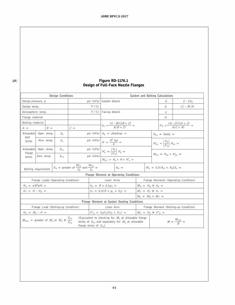
ð17Þ Figure RD-1176.1Design of Full-Face Nozzle Flanges
H H
A C
C B
gnitloBdnateksaGsnoitidnoCngiseD Calculations
Design pressure, p psi (kPa) Gasket detai l s G – 2hG
)C˚( F˚.pmetngiseD b ( –
–
–
–
) /4
sliatedgnicaF)C˚( F˚.pmetcirehpsomtA y
Flange material m
Bol ting materialhG
(C B) (2B + C)
6(B + C)h ′G
( ) (2A + C)
6(C + A)A B C
Al lowable Oper. temp. S b psi (kPa) H p 2b Gmp
bol tH Gy b Gy
Atm. temp. S a psi (kPa)stress HG 2 p
4
Al lowabl e Oper. temp. SFo psi (kPa)
H ′Gy
hG
h ′GH Gy
fl angeH ′p
hG
h ′GH p
Atm. temp SFa psi (kPa)stressWm 2 H Gy + H ′Gy
Wm 1 H p + H + H ′p
Am greater ofWm 1
S band
Wm 2
S aAB Wa 0.5(Am + AB)S aBol ting requirement
Flange Moment at Operating Conditions
Flange Loads (Operating Condi tion) Lever Arms Flange Moments (Operating Condi tion)
H D B 2p /4 hD R + 0.5g 1 M D H D hD
H T D hT 0.5(R + g 1 + hG) M T H T hT
M o M D + M T
Flange Moment at Gasket Seating Conditions
Flange Load (Bol ting-up Condi tion) Lever Arm Flange Moment (Bol ting-up Condi tion)
H G Wa H h ′ ′G hGh ′G /(hG + h ′G) M G H G h ′′G
(Equival ent to checking for M o at al l owabl e flangeM max greater of M o or M a
SFo
SFa stress of SFo and separatel y for M a at al l owabl e MM max
Bfl ange stress of SFa)
C
–
44
ASME BPVC.X-2017

Figure RD-1176.1Design of Full-Face Nozzle Flanges (Cont'd)
C N
Stress Calculation Shape Constants
Longi tudinal hub stress SH p fM /?g12
K p A /B p ho p ?Bgo pRadial fl ange stress SR p ?M /?t 2 T p p h/ho p
Tangential fl ange stress ST p (MY /t 2) ZSR Z p p F p
Greater of 0.5 (SH + SR ) or 0.5(SH + ST) Y p p V p
U p p f pRadial stress at bol t circl e SRAD p
6
–
M G
t 2(? d1) g1/go p e p F/ho
d p p
U
Vhogo
2
h
g0 =
hD
hThGh'G
HD
HT
H'G HG
g1 =
B =
C =
G =
W
A =
R
t
t (assumed)
? p te + 1
? p 4/3te + 1
? p ? /T
? p t 3/d
? p ? + ?
N p No. bol ts p
d1p Dia. bol t holes p
45
ASME BPVC.X-2017

Figure RD-1176.2Values of V
(Integral Flange Factor)
46
ASME BPVC.X-2017

Figure RD-1176.3Values of F
(Integral Flange Factor)
47
ASME BPVC.X-2017
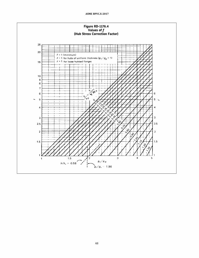
Figure RD-1176.4Values of f
(Hub Stress Correction Factor)
48
ASME BPVC.X-2017

ð17Þ
RD-1180 DISCONTINUITY ANALYSIS —METHOD B
RD-1180.1 Scope. Design to Method B requires de-
tailed stress analysis and evaluation of the results of this
analysis against the quadratic interaction strength criter-
ion or the quadratic interaction damage criterion. The
stress analysis and evaluation shall include the direc-
tional properties of the laminate and individual lamina
and shall take into account primary and secondary stres-
ses caused by gross structural discontinuities.
RD-1180.2 Design Parameters.(a) Elastic constants at design temperature(s) shall be
used for calculations.
(b) Elastic constants of the laminate for use in Method B
shall be determined as specified in RD-1163.
(c) The lamina elastic and strength constants shall be
determined in accordance with Article RT-7.
RD-1181 DEFINITIONS
(a) Gross structural discontinuity is defined as a source
of stress or strain intensification which affects a relatively
large portion of a structure and has a significant effect on
the overall stress or strain pattern or on the structure as a
whole.
Examples of gross structural discontinuities are head‐
to‐shell and flange‐to‐shell junctions, nozzles, and junc-
tions between shells of different diameters or thickness.
(b) Local structural discontinuity is defined as a source
of stress or strain intensification which affects a relatively
small volume of material and does not have a significant
effect on the overall stress or strain pattern or on the
structure as a whole.
Examples are small fillet radii and small attachments.
RD-1182 STRESS ANALYSIS
A detailed stress analysis is required for all vessels de-
signed to Method B. The linear elastic stress analysis shall
include the effect of gross structural discontinuities. Pri-
mary and secondary, normal and shear, and general and
Figure RD-1176.5Values of T, Z, Y, and U(Terms Involving K)
49
ASME BPVC.X-2017

ð17Þ
local thermal stress shall be calculated for all lamina. The
effect of local structural discontinuities need not be con-
sidered provided that all fillet radii are 1/2 in. (13 mm)
or greater.
Analysis of the vessel under internal pressure is re-
quired. In addition, the stresses and strains caused by
any combination of the loads listed in RD-120 and in
the Design Specification shall be computed when such
loads are expected to occur simultaneously during normal
operation or testing of the vessel. All possible load combi-
nations shall be considered. Stresses and strains shall be
determined from an analysis of the vessel under com-
bined loads or by superposition of results from analyses
of specific load combinations. Stress analysis of pressure
vessels is complex and will normally require the use of a
general‐purpose computer program. Such programs will
typically be based on finite element, finite difference, or
stiffness analysis techniques. Such programs shall take
into account the anisotropic properties of the laminate.
RD-1182.1 Discontinuity Analysis.(a) The analysis of pressure vessels containing discon-
tinuity areas shall be performed in a standard manner
similar to the analysis of any statically indeterminate
structure. The analysis is initiated by separating the ves-
sel into shell elements of simple geometry (such as rings,
cylinders, etc.) of which the structural behavior is known.
The pressure, mechanical, and thermal loads acting on the
structure shall be applied to the shell elements with a sys-
tem of forces required to maintain the static equilibrium
of each element. These loads and forces cause individual
element deformations, which in general are not equal at
the adjoining edges. The deformations at an element’s
edge are defined as:
(1) radial displacement
(2) rotation of meridian tangent
A redundant moment and shear force must exist on the
edges of the elements in order to have compatibility of de-
formations and restore continuity in the structure.
(b) At each juncture discontinuity, two equations shall
be written which express the equality of the combined de-
formations due to all the applied loads and the redundant
forces and moments.
One equation expresses the equality of rotation; the
other equation expresses the equality of displacement
of the adjacent elements. The resulting system of simulta-
neous equations shall be solved to obtain the redundant
moment and shear force at each juncture.
RD-1182.2 Procedure for Discontinuity Analysis.The following are the basic steps to follow for determin-
ing the redundant shear and moment that may exist at
a pressure vessel discontinuity.
(a) Separate the vessel into individual shell elements at
locations of discontinuity.
(b) Calculate the edge deformations of each element
caused by a unity shear force and a unit moment at each
edge. These values are known as influence coefficients.
The deformations due to local discontinuity shall be in-
cluded in the calculation of these coefficients as follows:
(c) Calculate the edge deformations of each element
caused by loads other than redundant loads.
(d) Calculate the edge deformations of each element
caused by the temperature distributions.
(e) At each juncture of two elements, equate the total
radial displacements and the total rotations of each
element.
(f) Solve the final system of simultaneous equations for
the redundant shears and moments.
RD-1182.3 Examples of Discontinuity Analysis. Ex-amples of discontinuity stress analysis for general and
specific geometries are contained in Articles AC-1
through AC-4. These examples are for vessels without
openings and fabricated from a single lamina of isotropic
material. For vessels with openings, complex geometries,
or anisotropic materials of construction, hand calcula-
tions become extremely difficult and computer-based
analysis methods are normally used.
RD-1183 EXTERNAL PRESSURE AND BUCKLING
The stress distributions resulting from external pres-
sure or from loads which cause compressive stresses shall
satisfy the criteria of RD-1187 through RD-1189. In addi-
tion, the calculated minimum buckling pressure or load of
the vessel shall be at least five times the design external
pressure or design load. The buckling pressure shall be
calculated using elastic properties at the maximum speci-
fied operating temperature which may occur when the ex-
terna l p res sure i s app l i ed . Fo r domed heads and
cylindrical and spherical shells fabricated of isotropic la-
minates, the minimum buckling requirement shall be
met by using the rules of RD-1172 and RD-1173.
Many vessels are fabricated with anisotropic laminates.
Anisotropy has a strong influence on elastic stability and
shall be considered in Design Calculations.
RD-1184 OPENINGS AND JOINTS OF VESSELPARTS
Method B requires stress analysis of openings, nozzles,
and joints of vessel parts. Overlaps and reinforcing pads
shall be included in such analysis. Particular care shall
be taken to accurately determine shear stresses between
the vessel and overlaps, and between the vessel and rein-
forcing pads.
Reinforcement and overlays for nozzles and openings
may be des i gned acco rd ing to the ru l e s given in
RD-1174, provided that the openings meet the require-
ments ofRD-1174.1 and the design strain criteria require-
ments o f Method A. In thi s case the provis ions of
RD-1120(b) shall apply.
50
ASME BPVC.X-2017

RD-1185 THERMAL STRESSES
(a) Thermal stresses occur in a vessel, or part of a ves-
sel, when thermal displacements (expansions or contrac-
tions) which would otherwise freely occur are partially or
completely restrained.
(b) Thermal displacements may be induced by tem-
perature distributions caused by heat transfer and inter-
nal heat generation.
The modulus of elasticity and the coefficient of thermal
expansion for each lamina may be taken as constant at
their instantaneous values for the average temperature
range under consideration.
If the lower limit of the temperature range is ambient,
the instantaneous value of the coefficient of thermal ex-
pansion for the average temperature coincides with the
mean coefficient of thermal expansion.
During transient conditions, the temperature distribu-
tion and thermal stresses vary with time. The analysis,
therefore, requires consideration of the thermal stresses
as a function of time during the transient conditions.
RD-1186 ATTACHMENTS
Internal and external attachments [RD-1150(e) ] shall
be designed by stress analysis. The effect of local structur-
al discontinuities due to small attachments need not be
included in the stress analysis of the vessel if in the opi-
nion of the registered Professional Engineer they are
not significant.
RD-1187 DESIGN ACCEPTABILITY
The requirements for an acceptable design are:
(a) the design shall be such that the stress at any point
in the ves se l shal l no t exceed the l imits s tated in
RD-1189;
(b) for configurations where compressive stress occurs,
design shall meet the requirements of RD-1183;
(c) the average shear stress between the vessel and
overlays (reinforcing pads, nozzle overlays, overlays join-
ing vessel parts, etc.) shall not exceed 200 psi (1.5 MPa) ;
(d) interlaminar shear between shell lamina need not
be considered.
RD-1188 BASIS FOR DETERMINING STRESSES
RD-1188.1 Quadratic Interaction Strength Criterionand Quadratic Interaction Damage Criterion. The quad-
ratic interaction criteria are used with the stiffness coeffi-
cients calculated according to Article RD-12 and the
s tress resultants calculated according to RD-1180
through RD-1186. The criteria determine whether the
stress intensities at a point are within the permissible
range.
Details of the quadratic interaction strength criterion
are given in RD-1188.2 through RD-1188.5 , and details
of the quadratic interaction damage criterion are given
in RD-1188.6 through RD-1188.8.
RD-1188.2 Mathematical Statement of the Quadra-tic Interaction Strength Criterion. In general, a lamina
has five independent uniaxial ultimate strengths: tensile
and compressive strengths in the principal direction of
greater strength, tensile and compressive strengths in
the direction of lesser strength, and shear strength with
respect to a pure shear stress in the principal directions.
All mat lamina are treated as isotropic and the strengths
in all directions are the same. In laminates containing uni-
directional continuous roving, the principal direction of
greater strength is aligned with the continuous roving,
and the principal direction of lesser strength is perpendi-
cular to the roving. Further, the five strength values may
be unequal.
The quadratic interaction criterion defines the interac-
tions between the five strengths in cases when more than
one component of stress is applied to the lamina, and it
defines allowable stress states in terms of the strengths.
The criterion is applied to each lamina separately, and
if one or more lamina fail the criterion, the corresponding
load on the vessel is not allowed. The criterion is applied
separately to each combination of stress or stresses and
moment resultants calculated by the rules of RD-1182 .
In the following paragraphs it is assumed that the lami-
nate stiffness coefficients and stress and moment resul-
tants have already been calculated for all sections and
load combinations under consideration.
RD-1188.3 Nomenclature. In addition to the nomen-
clature defined in Article RD-12 , the following symbols
are used:
Fxx , Fxy ,
Fyy , Fs s ,
Fx , Fy = strength parameters defined in terms of the
five strengths
R = strength criterion stress ratio = 6
S = ultimate shear strength with respect to shear
stress in the x–y plane
S i j = the i j component of the compliance matrix
(the compliance matrix is the inverse of the
stiffness matrix)
w = parameter which equals 1 for the upper sur-
face of a lamina and −1 for the lower
X = ultimate tensile strength of a lamina in the x
(strong) direction
Xc = ultimate compressive strength of a lamina in
the x direction
Y = ultimate tensile strength of a lamina in the y
(weak) direction
Yc = ultimate compressive strength of a lamina in
the y direction
RD-1188.4 Lamina Stresses and Strains. The first
step in using the quadratic interaction criterion is to com-
pute the upper and lower surface strains in each lamina.
51
ASME BPVC.X-2017

ð17Þ
The strains are computed from the reference surface
strains and curvatures, which are obtained from the force
and moment resultants by eqs. (1) through (6) .
ð1Þ
ð2Þ
ð3Þ
ð4Þ
ð5Þ
ð6Þ
The upper and lower surface strains in the vessel coor-
dinate system are then obtained from:
ð7Þ
ð8Þ
ð9Þ
Equations (7) , (8) , and (9) give strains at the upper sur-
face of the lamina when w = 1, and lower surface strains
when w = −1. The corresponding stresses are then calcu-
lated from the strains and the reduced stiffnesses in the
vessel coordinates, as follows:
ð10Þ
ð11Þ
ð12Þ
The final step in calculating the stresses is to express
the vessel coordinate lamina stress components in terms
of the principal material coordinate, in each of the lamina.
The so‐called on‐axis components of stress are given by
the usual transformation equations:
ð13Þ
ð14Þ
ð15Þ
RD-1188.5 The Quadratic Interaction Strength Cri-terion. The quadratic interaction criterion required by
this Section is:
ð16Þ
where
Fs s = 1/S2
Fx = 1/X − 1/Xc
Fxx = 1/XXc
Fxy = , with taken to be −1/2
Fy = 1/Y − 1/Yc
Fyy = 1/YYc
If the applied stress components lead to R = 1, then the
lamina will fail. IfR > 1, the lamina will not fail. In the case
of a laminate isotropic in both strength and stiffness, R re-
duces to the “safety factor” or the “design factor.”
The terms in the parentheses in eq. (16) contain the
five strength properties and the on‐axis stress compo-
nents of a lamina, which are known, and thus eq. (16)
can be solved for R . Let
Then the solution for R is the positive of the two values
given by
ð17Þ
For each stress state under consideration, R shall be
equal to or greater than the value required by RD-1189.
52
ASME BPVC.X-2017
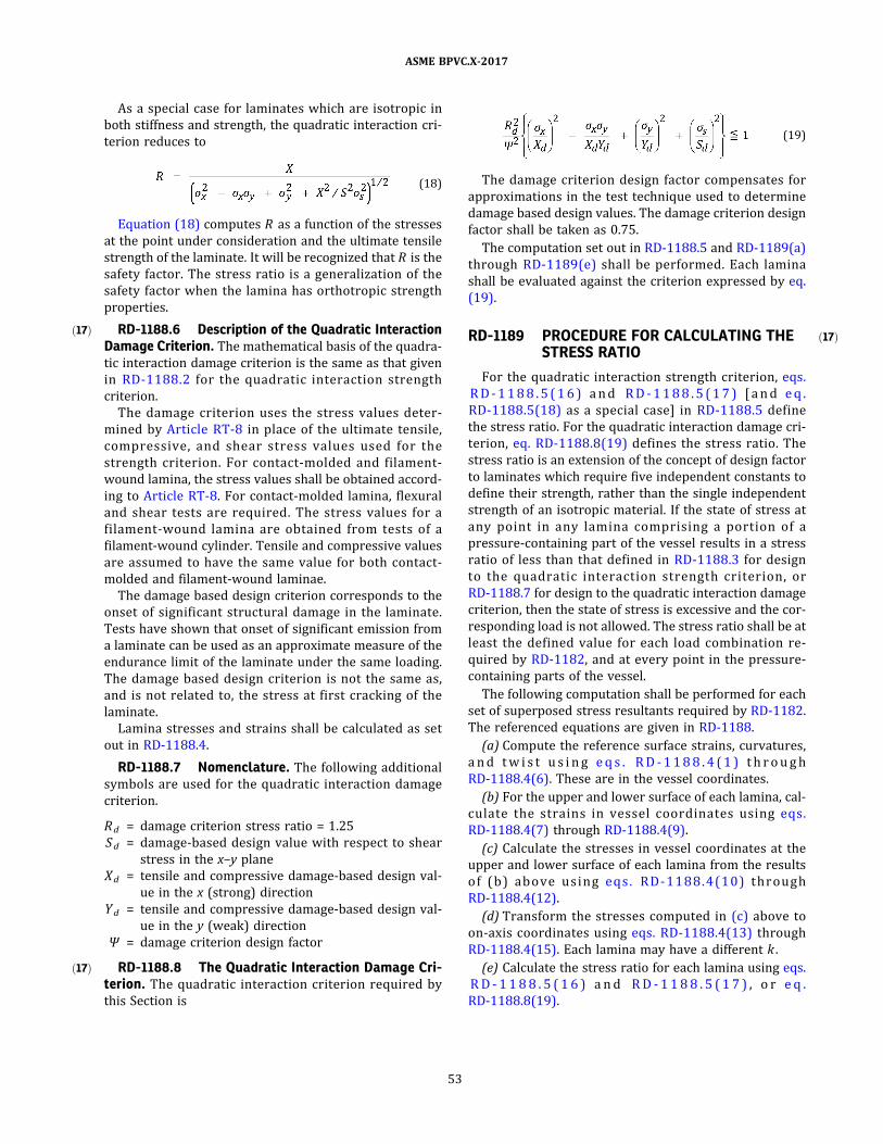
ð17Þ
ð17Þ
ð17Þ
As a special case for laminates which are isotropic in
both stiffness and strength, the quadratic interaction cri-
terion reduces to
ð18Þ
Equation (18) computes R as a function of the stresses
at the point under consideration and the ultimate tensile
strength of the laminate. It will be recognized that R is the
safety factor. The stress ratio is a generalization of the
safety factor when the lamina has orthotropic strength
properties.
RD-1188.6 Description of the Quadratic InteractionDamage Criterion. The mathematical basis of the quadra-
tic interaction damage criterion is the same as that given
in RD-1188 .2 for the quadratic interaction strength
criterion.
The damage criterion uses the stress values deter-
mined by Article RT-8 in place of the ultimate tensile,
compress ive , and shear s tress values used for the
strength criterion. For contact-molded and filament-
wound lamina, the stress values shall be obtained accord-
ing to Article RT-8. For contact-molded lamina, flexural
and shear tests are required. The stress values for a
fi lament-wound lamina are obtained from tests of a
filament-wound cylinder. Tensile and compressive values
are assumed to have the same value for both contact-
molded and filament-wound laminae.
The damage based design criterion corresponds to the
onset of significant structural damage in the laminate.
Tests have shown that onset of significant emission from
a laminate can be used as an approximate measure of the
endurance limit of the laminate under the same loading.
The damage based design criterion is not the same as,
and is not related to, the stress at first cracking of the
laminate.
Lamina stresses and strains shall be calculated as set
out in RD-1188.4.
RD-1188.7 Nomenclature. The following additional
symbols are used for the quadratic interaction damage
criterion.
Rd = damage criterion stress ratio = 1.25
Sd = damage-based design value with respect to shear
stress in the x–y plane
Xd = tensile and compressive damage-based design val-
ue in the x (strong) direction
Yd = tensile and compressive damage-based design val-
ue in the y (weak) direction
Ψ = damage criterion design factor
RD-1188.8 The Quadratic Interaction Damage Cri-terion. The quadratic interaction criterion required by
this Section is
ð19Þ
The damage criterion design factor compensates for
approximations in the test technique used to determine
damage based design values. The damage criterion design
factor shall be taken as 0.75.
The computation set out in RD-1188.5 and RD-1189(a)
through RD-1189(e) shall be performed. Each lamina
shall be evaluated against the criterion expressed by eq.
(19) .
RD-1189 PROCEDURE FOR CALCULATING THESTRESS RATIO
For the quadratic interaction strength criterion, eqs.
RD - 1 1 8 8 . 5 ( 1 6 ) a n d RD - 1 1 8 8 . 5 ( 1 7 ) [ a n d e q .
RD-1188.5(18) as a special case] in RD-1188.5 define
the stress ratio. For the quadratic interaction damage cri-
terion, eq. RD-1188.8(19) defines the stress ratio. The
stress ratio is an extension of the concept of design factor
to laminates which require five independent constants to
define their strength, rather than the single independent
strength of an isotropic material. If the state of stress at
any po int in any lamina compris ing a portion of a
pressure‐containing part of the vessel results in a stress
ratio of less than that defined in RD-1188.3 for design
to the quadratic interaction s trength cri terion , o r
RD-1188.7 for design to the quadratic interaction damage
criterion, then the state of stress is excessive and the cor-
responding load is not allowed. The stress ratio shall be at
least the defined value for each load combination re-
quired by RD-1182, and at every point in the pressure‐
containing parts of the vessel.
The following computation shall be performed for each
set of superposed stress resultants required by RD-1182.
The referenced equations are given in RD-1188.
(a) Compute the reference surface strains, curvatures,
a n d tw i s t u s i n g e q s . RD - 1 1 8 8 . 4 ( 1 ) t h r o u g h
RD-1188.4(6) . These are in the vessel coordinates.
(b) For the upper and lower surface of each lamina, cal-
culate the s trains in vesse l coordinates us ing eqs .
RD-1188.4(7) through RD-1188.4(9) .
(c) Calculate the stresses in vessel coordinates at the
upper and lower surface of each lamina from the results
o f (b ) ab o ve us i ng eq s . RD - 1 1 8 8 . 4 (1 0 ) th rough
RD-1188.4(12) .
(d) Transform the stresses computed in (c) above to
on‐axis coordinates using eqs. RD-1188.4(13) through
RD-1188.4(15) . Each lamina may have a different k .
(e) Calculate the stress ratio for each lamina using eqs.
R D - 1 1 8 8 . 5 ( 1 6 ) a n d RD - 1 1 8 8 . 5 ( 1 7 ) , o r e q .
RD-1188.8(19) .
53
ASME BPVC.X-2017

ð17Þ
ARTICLE RD-12LAMINATE STIFFNESS COEFFICIENTS
RD-1200 LAMINATE STIFFNESSCOEFFICIENTS
For purposes of this Section, laminate theory is a math-
ematical treatment of the mechanics of laminate con-
structed of plies with unidirectional fiber reinforcement,
plies of isotropic material, or an arbitrary combination
of the two.
Article RD-12 provides a set of equations, derived by la-
minate theory, which shall be used to compute the elastic
stiffness coefficients needed to perform design by stress
analysis, as specified in RD-1163.
Other valid statements of laminate theory may be used
in place of the equations herein, but it is the responsibility
of the registered Professional Engineer to show that the
equations reduce to the equations below.
The laminate analysis method consists of determining
the physical and mechanical properties of each layer of
a laminate and uses weighted averaging techniques to de-
termine the physical and mechanical properties of the to-
tal laminate.
Calculation of laminate properties according to Article
RD-12 is required.
RD-1210 STIFFNESS COEFFICIENTS FORDESIGN BY METHOD B RULES
This Article gives the equations required for calculating
the stiffness coefficients needed to design vessel parts ac-
cording to Method B design rules.
Other valid statements of laminate analysis may be
used in place of the equations herein, but it is the respon-
sibility of the registered Professional Engineer to show
that they can be mathematically derived from the equa-
tions herein.
RD-1220 NOMENCLATURE
The symbols used in this Article are defined below.
(Q i j)k = transformed reduced stiffness of the k ‐th
layer
A i j = extensional stiffness coefficients defined by
eq. RD-1240(28) ; i, j = 1, 2, 6
B i j = coupling stiffness coefficients defined by eq.
RD-1240(30) ; i, j = 1, 2, 6
D i j = bending stiffness coefficients defined by eq.
RD-1240(29) ; i, j = 1, 2, 6
Ef1 = effective flexural modulus of the laminate in
the longitudinal off‐axis direction
Ef2 = effective flexural modulus of the laminate in
the transverse (hoop) off‐axis direction
Es = shear modulus of an orthotropic lamina in the
principal coordinates
Ex = Young’s modulus of an orthotropic lamina in
the principal direction of the greater modulus
Ey = Young’s modulus of an orthotropic lamina in
the principal direction of the lesser modulus
Kx = midplane curvature in the x direction
Kxy = midplane twist
Ky = midplane curvature in the y direction
M1 = moment resu l tant about x axi s (F i gure
RD-1220.1)
M2 = moment resu l tant about y axi s (F i gure
RD-1220.1)
M6 = twisting resultant (Figure RD-1220.2)
N1 = fo rce re s u l tan t i n x d i re c t i o n (F i gu re
RD-1220.2)
N2 = fo rce re s u l tan t i n y d i re c ti o n (F i gu re
RD-1220.2)
N6 = in ‐p l ane s hear fo rce re su l tan t (F i gure
RD-1220.2)
Q i j = reduced stiffness transformed to the vessel
(x–y) axes (off‐axes directions) ; i, j = 1, 2, 6
Q xx , Q xy ,
Q yy , Q s s = reduced stiffness in the principal material di-
rection, defined by eqs. RD-1230(4) through
RD-1230(8) (on‐axis directions)
tk = thickness of the k‐th layer
Zk = distance from the reference surface to the
center of the k‐th layer
θ = angle between the x coordinate axis and the 1
coordinate axis (see Figures RD-122 0 .1 ,
RD-1220.2 , and RD-1220.3)
νx = principal Poisson’s ratio of a lamina. It is the
negative of strain in the 2 direction from
stress in the 1 direction.
σ i = normal stress in the i direction
σ s , σ6 = shear stress in the i–j coordinate system
ϵ i = normal strain of a layer in the i direction
= midplane normal strain in direction i of the
laminate
ϵ6 , ϵs = shear strain in the i–j coordinate system of a
layer
= midplane shear strain of the laminate
54
ASME BPVC.X-2017

Figure RD-1220.1Moment Resultants
Figure RD-1220.2In-Plane Force Resultants
55
ASME BPVC.X-2017

RD-1230 LAMINA REDUCED STIFFNESS
The stress–strain relations in the principal material di-
rections of an orthotropic lamina are as follows:
ð1Þ
ð2Þ
ð3Þ
The reduced stiffnesses of a lamina are calculated from
the elastic properties, Ex , Ey , ν x , and E s . These may be
measured values or calculated by the semigraphical pro-
cedure below. The required input information for each
layer is the fiber weight per unit area, the tensile modulus
of the resin matrix, the type of roving, and the fiber
density.
A step‐by‐step procedure for lamina with unidirec-
tional roving is as follows:
ð4Þ
ð5Þ
ð6Þ
ð7Þ
ð8Þ
where νy = νx Ey/Ex .
In an isotropic lamina, Ex = Ey = E and ν x = ν y = ν .
Then
ð9Þ
Figure RD-1220.3Coordinate Systems
GENERAL NOTES:
(a) The 1–2 coordinates are called off-axis or vessel coordinates.
(b) The x–y coordinates are called on-axis or principal material coordinates.
56
ASME BPVC.X-2017
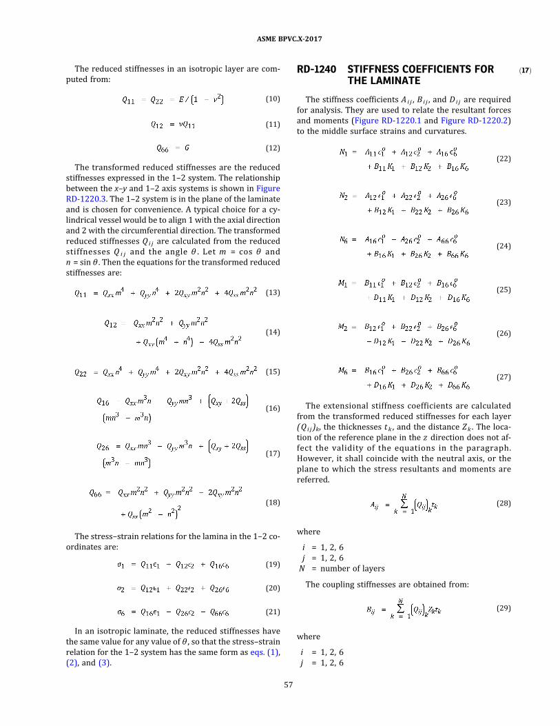
ð17ÞThe reduced stiffnesses in an isotropic layer are com-
puted from:
ð10Þ
ð11Þ
ð12Þ
The transformed reduced stiffnesses are the reduced
stiffnesses expressed in the 1–2 system. The relationship
between the x–y and 1–2 axis systems is shown in Figure
RD-1220.3 . The 1–2 system is in the plane of the laminate
and is chosen for convenience. A typical choice for a cy-
lindrical vessel would be to align 1 with the axial direction
and 2 with the circumferential direction. The transformed
reduced stiffnesses Q i j are calculated from the reduced
stiffnesses Q i j and the angle θ . Let m = cos θ and
n = sin θ . Then the equations for the transformed reduced
stiffnesses are:
ð13Þ
ð14Þ
ð15Þ
ð16Þ
ð17Þ
ð18Þ
The stress–strain relations for the lamina in the 1–2 co-
ordinates are:
ð19Þ
ð20Þ
ð21Þ
In an isotropic laminate, the reduced stiffnesses have
the same value for any value ofθ , so that the stress–strain
relation for the 1–2 system has the same form as eqs. (1) ,
(2) , and (3) .
RD-1240 STIFFNESS COEFFICIENTS FORTHE LAMINATE
The stiffness coefficients A i j , B i j , and D i j are required
for analysis. They are used to relate the resultant forces
and moments (Figure RD-1220.1 and Figure RD-1220.2)
to the middle surface strains and curvatures.
ð22Þ
ð23Þ
ð24Þ
ð25Þ
ð26Þ
ð27Þ
The extensional stiffness coefficients are calculated
from the transformed reduced stiffnesses for each layer
(Q i j )k, the thicknesses tk , and the distance Zk . The loca-
tion of the reference plane in the z direction does not af-
fect the val idity of the equations in the paragraph.
However, it shall coincide with the neutral axis, or the
plane to which the stress resultants and moments are
referred.
ð28Þ
where
i = 1, 2, 6
j = 1, 2, 6
N = number of layers
The coupling stiffnesses are obtained from:
ð29Þ
where
i = 1, 2, 6
j = 1, 2, 6
57
ASME BPVC.X-2017
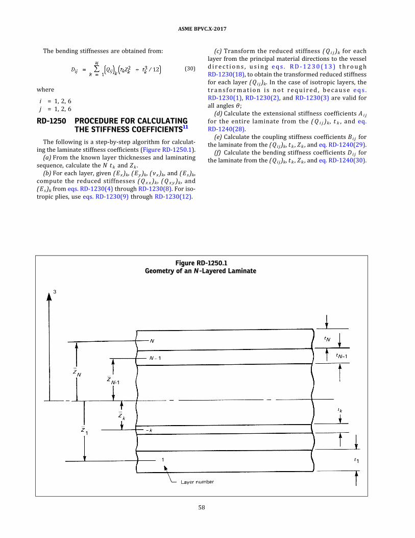
The bending stiffnesses are obtained from:
ð30Þ
where
i = 1, 2, 6
j = 1, 2, 6
RD-1250 PROCEDURE FOR CALCULATINGTHE STIFFNESS COEFFICIENTS11
The following is a step‐by‐step algorithm for calculat-
ing the laminate stiffness coefficients (Figure RD-1250.1) .
(a) From the known layer thicknesses and laminating
sequence, calculate the N tk and Zk .
(b) For each layer, given (Ex)k, (Ey )k, (νx)k, and (Es )k,
compute the reduced stiffnesses (Q x x )k, (Q x y )k, and
(Es)k from eqs. RD-1230(4) through RD-1230(8) . For iso-
tropic plies, use eqs. RD-1230(9) through RD-1230(12) .
(c) Transform the reduced stiffness (Q i j )k for each
layer from the principal material directions to the vessel
d i r e c t i o n s , u s i n g e q s . RD - 1 2 3 0 ( 1 3 ) t h r o u gh
RD-1230(18) , to obtain the transformed reduced stiffness
for each layer (Q i j )k. In the case of isotropic layers, the
tr a n s fo rm a t i o n i s n o t r e q u i r e d , b e c a u s e e q s .
RD-1230(1) , RD-1230(2) , and RD-1230(3) are valid for
all angles θ ;
(d) Calculate the extensional stiffness coefficients A i j
for the entire laminate from the (Q i j )k, t k , and eq.
RD-1240(28) .
(e) Calculate the coupling stiffness coefficients B i j for
the laminate from the (Q i j)k, tk , Zk , and eq. RD-1240(29) .
(f) Calculate the bending stiffness coefficients D i j for
the laminate from the (Q i j)k, tk , Zk , and eq. RD-1240(30) .
Figure RD-1250.1Geometry of an N -Layered Laminate
58
ASME BPVC.X-2017

ð17Þ
PART RFFABRICATION REQUIREMENTS
ARTICLE RF-1GENERAL REQUIREMENTS
RF-100 SCOPE
This Part provides rules governing the fabrication of
fiber‐reinforced plastic pressure vessels. The fabrication
processes are limited to the bag‐molding, centrifugal‐
casting, contact‐molding, and filament‐winding processes
for Class I vessels, and limited to contact molding and fi-
lament winding for Class II vessels.
RF-110 PROCEDURE SPECIFICATIONS
(a) For every combination of fabrication method, De-
sign Specification, and material variation employed in
fabricating vessels to be marked with the Certification
Mark, the Fabricator shall prepare a Procedure Specifica-
tion which shall be qualified in accordance with Part RQ
of this Section before it is used to fabricate vessels to be
so marked.
(b) Any essential variation from the Procedure Specifi-
cation for Class I vessels (see RQ-200, RQ-300, RQ-400,
and RQ-500) shall require that the Procedure Specifica-
tion be rewritten and requalified before being used to fab-
ricate vessels to be marked with the Certification Mark.
(c) The Procedure Specification for Class I I vessels
(Form Q-120) requires that the Fabricator establish the
design of the vessel in accordance with Article RD-11
based on the elastic and strength constants for the specif-
ic combinations of fiber, resin, ply sequence, and ply or-
ientations used for the vessel laminate. Any variation in
materials used to fabricate the vessel or vessel part from
those materials used to determine the elastic and strength
constants upon which the Design Calculations were based
shall require that new elastic constants be obtained and
new Design Calculations made. Any variation in the ply
sequence or ply orientation made in the fabrication of
the vessel or vessel part that differs from the ply sequence
and orientation specified in the qualified Procedure Spec-
ification and upon which the Design Calculations were
based shall require that new calculations be made.
The new calculations shall satisfy the User’s Design
Specification and the requirements of this Section. The
Procedure Specification shall be amended to reflect the
actual fabrication and the Design Report amended to re-
flect the design basis.
59
ASME BPVC.X-2017

ARTICLE RF-2SPECIAL FABRICATION REQUIREMENTS FOR BAG-MOLDING
PROCESS (FOR CLASS I VESSELS ONLY)
RF-200 FIBER CONTENT
The composite structure shall consist of random short
length12 fiber filaments in a resin matrix. The weight of
the fiber reinforcement shall conform to that set forth
in the Procedure Specification (see Form Q-106) within
a tolerance of + 20% and −0%. Supplementary pads used
to give greater wall thickness at openings and attach-
ments shall have a fiber content not less than 35% by
weight.
RF-201 FIBER COMPOSITION
One or more of the fiber types stipulated in RM-110
and specified in the Procedure Specification shall be used
for reinforcement.
RF-210 FORM OF FIBER REINFORCEMENT
(a) The fiber reinforcement shall consist ofmats or pre-
forms made from chopped fiber strands. The percentage
of resin binder shall not exceed 10% by weight in mat
or preform.
(b) The flat mats for cylindrical reinforcement shall be
laid up in a staggered pattern and rolled on a mandrel
prior to assembly into the mold (see Figure RF-210.1) .
(c) The head or end preforms shall be made by depos-
iting chopped fiber from an airstream with one of the re-
sin systems specified in RM-120 dispersed in the fiber
(see Figure RF-210.2) .
RF-211 RESIN SYSTEM
The resin system shall be one of the resin systems spe-
cified in RM-120 and as required for the particular service
conditions specified in the Design Specification and by the
qualified Procedure Specification. No filler, pigment, or
dye additions shall be used which will interfere with the
natural color of the resin except as permitted by the Pro-
cedure Specification.
RF-212 CURE
If other than ambient temperature cure is required, the
design and operation of the curing equipment shall assure
uniform heating over the entire surface of the pressure
vessel and vessel parts. The curing time and temperature
shall conform to those stipulated in the qualified Proce-
dure Specification (see Form Q-106) .
RF-220 MOLDS
RF-221 MOLD MATERIAL
The molds for pressure bag molding of pressure vessels
and vessel parts may be fabricated of any material or
combination of materials. The molds shall have sufficient
dimensional stability to withstand the bag pressure loads
during the forming and cure cycles.
RF-222 MOLD RELEASE AGENT
The surface of the mold in contact with the vessel or
vessel part shall be treated with a suitable release agent
to facilitate removal of the vessel or part from the mold.
Such release agent shall not be detrimental to the vessel
or part.
RF-223 MOLD REMOVAL
The mold may be removed from the vessel, or vice ver-
sa, by any technique which will not damage the vessel.
Figure RF-210.1Fiber Side Wall Lay-Up for Bag Molding
60
ASME BPVC.X-2017
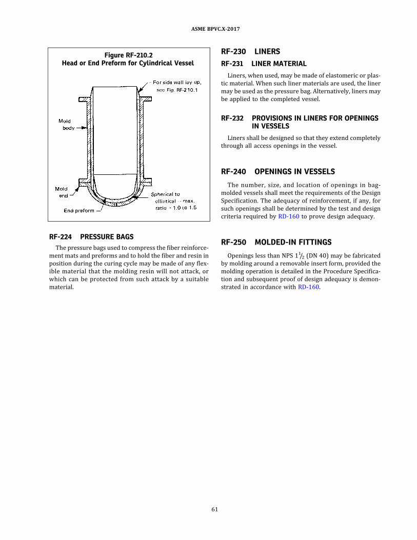
RF-224 PRESSURE BAGS
The pressure bags used to compress the fiber reinforce-
ment mats and preforms and to hold the fiber and resin in
position during the curing cycle may be made of any flex-
ible material that the molding resin will not attack, or
which can be protected from such attack by a suitable
material.
RF-230 LINERS
RF-231 LINER MATERIAL
Liners, when used, may be made of elastomeric or plas-
tic material. When such liner materials are used, the liner
may be used as the pressure bag. Alternatively, liners may
be applied to the completed vessel.
RF-232 PROVISIONS IN LINERS FOR OPENINGSIN VESSELS
Liners shall be designed so that they extend completely
through all access openings in the vessel.
RF-240 OPENINGS IN VESSELS
The number, s ize, and location of openings in bag‐
molded vessels shall meet the requirements of the Design
Specification. The adequacy of reinforcement, if any, for
such openings shall be determined by the test and design
criteria required by RD-160 to prove design adequacy.
RF-250 MOLDED-IN FITTINGS
Openings less than NPS 11/2 (DN 40) may be fabricated
by molding around a removable insert form, provided the
molding operation is detailed in the Procedure Specifica-
tion and subsequent proof of design adequacy is demon-
strated in accordance with RD-160.
Figure RF-210.2Head or End Preform for Cylindrical Vessel
61
ASME BPVC.X-2017

ð17Þ
ð17Þ
ð17Þ
ARTICLE RF-3SPECIAL FABRICATION REQUIREMENTS FOR
CENTRIFUGAL-CASTING PROCESS (FOR CLASS I VESSELS ONLY)
RF-300 FIBER CONTENT
The composite structure shall consist of random short
length12 fiber filaments in a resin matrix. The weight of
the fiber reinforcement shall conform to that set forth
in the Procedure Specification (see Form Q-106) within
a tolerance of +10% and −0%. Supplementary pads used
to give greater wall thickness at openings and attach-
ments shall have a fiber content not less than 35% by
weight.
RF-301 FIBER COMPOSITION
One or more of the fiber types complying with the com-
position stipulated in RM-110 and specified in the quali-
fi e d P ro c e du re S p e c i fi c a t i o n s h a l l b e u s e d fo r
reinforcement.
RF-310 FORM OF REINFORCEMENT
The fiber reinforcement for centrifugally cast cylinders
shall consist of chopped fiber strands or rovings. Fabrica-
tion of heads shall comply with RF-210(c) .
RF-311 RESIN SYSTEM
The resin system shall be one of the resin systems spe-
cified in RM-120 and as required for the particular service
conditions specified in the Design Specification and by the
Procedure Specification. No filler, pigment, or dye addi-
tions shall be used which will interfere with the natural
color of the resin except as permitted by the Procedure
Specification.
RF-312 CURE
If other than ambient temperature cure is employed,
the design and operation of the curing equipment shall as-
sure uniform heating over the entire cylinder. The curing
times and temperatures shall comply with the qualified
Procedure Specification (see Form Q-106) .
RF-320 MANDRELS
RF-321 MANDREL MATERIAL
The mandrel shall be fabricated of any material or com-
bination of materials of sufficient rigidity and dimen-
s ional stabi l ity to withstand the centrifugal ‐casting
loads and the curing cycle.
RF-322 MANDREL RELEASE AGENT
The mandrel shall be treated with a suitable release
agent to facilitate removal of the cured cylinder. Such re-
lease agent shall not be detrimental to the cylinder.
RF-323 MANDREL REMOVAL
The cylinder may be removed from the mandrel, or vice
versa, by any technique which wil l not damage the
cylinder.
RF-324 MATCHED-DIE-MOLDED HEADS
Matched‐die‐molded heads used as closures for centri-
fugally cast cylinders shall be fabricated in accordance
with the requirements of Article RF-6.
RF-330 LINERS
RF-331 LINER MATERIAL
Liners, when used, may be made of elastomeric or plas-
tic material. The liner may be applied to the centrifugally
cast cylinder after its heads are attached by adhesive
bonding.
RF-332 PROVISIONS IN LINERS FOR VESSELOPENINGS
Liners shall be designed so that they extend completely
through all access openings in the vessel.
RF-340 OPENINGS IN VESSELS
The number, size, and location of openings in centrifug-
ally cast cylinders and attached heads shall meet the re-
quirements of the User’s Design Specification and this
Section. The adequacy of reinforcement, if any, for such
openings shall be determined by the tests required by
RD-160 to prove design adequacy.
62
ASME BPVC.X-2017

ð17Þ
ð17Þ
ð17Þ
ð17Þ
ð17Þ
ð17Þ
ARTICLE RF-4SPECIAL FABRICATION REQUIREMENTS FOR
FILAMENT-WINDING PROCESS (CLASSES I AND II)
RF-400 FIBER CONTENT
The composite structure shall consist of fiber strands in
a resin matrix. The weight of the fiber reinforcement shall
comply with the qualified Procedure Specification (see
Form Q-107 for Class I vessels and Form Q-120 for Class
II vessels) with a tolerance of +10% and −0%.
RF-400.1 Fiber Content in Supplementary Pads.Supplementary pads used to give greater wall thickness
at openings and attachments shall have a fiber content
not less than 35% by weight.
RF-401 FIBER COMPOSITION
One or more of the fiber types complying with the com-
position stipulated in RM-110 and specified in the quali-
fi e d P ro c e du re S p e c i fi c a t i o n s h a l l b e u s e d fo r
reinforcement of filament‐wound pressure vessels.
RF-410 FORM OF REINFORCEMENT
RF-410.1 Patterns. Specific winding patterns for the
continuous fiber strands shall be used as defined in the
qualified Procedure Specification (see Form Q-107 for
Class I vessels and Form Q-120 for Class II vessels) . Any
winding pattern which places the filaments in the desired
orientation and is designated in the Procedure Specifica-
tion may be used.
RF-410.2 Alignment With Stresses. The patterns
shall be arranged so that the stressed fi laments are
aligned to resist the principal stresses which result from
internal pressure and other loadings.
RF-410.3 Wall Thickness. The wall thickness shall be
governed by the number of layers of wound strands of fi-
laments specified in the qualified Procedure Specification
for the particular vessel.
RF-411 RESIN SYSTEM
The resin system shall be one of the resin systems spe-
cified in RM-120 and as required for the particular service
conditions specified by the Design Specification and qual-
ified Procedure Specification. No filler, pigment, or dye
additions shall be used which will interfere with the nat-
ural color of the resin except as permitted by the Proce-
dure Specification.
RF-412 CURE
If other than ambient temperature cure is employed,
the design and operation of the curing equipment shall
provide uniform heating over the entire surface of the
vessel. Heating may be done from the inside or outside
of the pressure vessel or from both inside and outside.
The cure times and temperatures shall comply with those
stipulated in the qualified Procedure Specification (see
Form Q-107 for Class I vessels and Form Q-120 for Class
II vessels) .
RF-413 FILAMENT WINDING
(a) Tensioning . Tension on the strands of filaments dur-
ing the winding operation shall be controlled to assure
uniformly stressed filaments in the composite wall.
(b) Winding Speed. The speed of winding shall be lim-
ited only by the ability to
(1) meet the tensioning requirements
(2) comply with the specified winding pattern
(3) ensure adequate resin impregnation
(c) Bandwidth and Spacing. The bandwidth and spacing
shall comply with those specified in the qualified Proce-
dure Specification.
RF-420 MANDRELS
RF-421 MANDREL MATERIAL
The mandrel may be fabricated of any material or com-
bination of materials with sufficient rigidity and dimen-
s ional s tab i l i ty to res is t the winding loads and the
compressive loads on the mandrel which occur during
the cure cycle.
RF-422 MANDREL RELEASE AGENT
The mandrel, if removed, may be treated with a suita-
ble release agent to facilitate its removal from the cured
pressure vessel. Such release agent shall not be detrimen-
tal to the finished vessel.
RF-423 MANDREL REMOVAL
The mandrel shall be removed by any technique which
shall not damage the filament‐wound composite or the
liner, if one is present.
63
ASME BPVC.X-2017

ð17Þ
RF-430 LINERS
RF-431 LINER MATERIAL
Liners, when used, may be made of elastomeric, plastic,
or metallic materials . The liner may be applied to the
mandrel prior to the start of the winding operation.
(a) If applied to the mandrel before the winding opera-
tion begins, the thickness and hardness of the liner mate-
rial shall be such that the filament orientation and tension
will not be adversely affected by deflection or “flow” of
the liner material.
(b) Alternatively, the liner may be applied to the com-
pleted filament‐wound pressure vessel, in which case
the restrictions on thickness and hardness do not apply.
(c) If the liner is required to be bonded to the filament‐
wound composite, the outer liner surface shall be treated
to facilitate such bonding.
(d) The design of metallic liners shall take into account
the pronounced difference in the modulus of elasticity of
the laminate and the metallic liner.
(e) For vessels used for potable water, as described in
RG-113 (Section IV Application) , the liner materials may
be those listed in Section IV, HLW‐200 or shall be suitable
for potable water applications as demonstrated by ap-
proval of the material by the National Sanitation Founda-
tion (NSF) in accordance with NSF Standard 14.
RF-432 PROVISIONS IN LINERS FOR VESSELOPENINGS
Liners shall be designed so that they extend completely
through all access openings in the vessel.
RF-440 OPENINGS IN VESSELS
The number, size, and location of openings in filament‐
wound pressure vessels classified by RG-404.1 shall meet
the requirements of the User’s Design Specification. If any
opening reinforcement is used, the design adequacy shall
be determined by RD-160 for Class I vessels. For Class II
vessels the reinforcement shall comply with the design
criteria of Article RD-11 and acceptance testing criteria
of Article RT-6.
64
ASME BPVC.X-2017

ð17Þ
ð17Þ
ð17Þ
ARTICLE RF-5SPECIAL FABRICATION REQUIREMENTS FOR
CONTACT-MOLDING PROCESS (CLASSES I AND II)
RF-500 FIBER CONTENT
The composite structure shall consist of random short
length12 fiber filaments and roving (or biaxial fabric, sin-
gular or in combination) in a resin matrix. The weight of
the fiber reinforcement shall comply with the qualified
Procedure Specification (see Form Q-108 for Class I ves-
sels and Form Q-120 for Class II vessels) within a toler-
ance of + 10% and −0%. Supplementary pads used to
give greater wall thickness at openings and attachments
shall have a fiber content not less than 35% by weight.
RF-501 FIBER COMPOSITION
One of the fiber types complying with the composition
stipulated in RM-110 and as specified in the qualified Pro-
cedure Specification shall be used for reinforcement.
RF-510 FORM OF FIBER REINFORCEMENT
(a) The fiber reinforcement shall consist of random
short length fiber filaments and roving (or biaxial fabrics)
as specified in RF-501.
(b) Flat mats for cylindrical reinforcement shall be laid
up as separate layers and overlapped in a staggered pat-
tern. Resin shall be applied to each layer in such a manner
as to wet out completely.
(c) On cylindrical components, the orientation of the
warp and weft fiber stands of woven roving (or biaxial
fabrics) shall be defined with respect to the circumferen-
tial (hoop) and longitudinal (axial) axis of the cylindrical
component.
(d) On elliptical or hemispherical shapes, the orienta-
tion of the warp and weft fiber stands of woven roving
(or biaxial fabrics) shall be defined with respect to the
meridional and circumferential axis.
RF-511 RESIN SYSTEM
The resin system shall be one or more of the resins spe-
cified in RM-120 and as required for the particular service
conditions specified in the Design Specification and by the
qualified Procedure Specification. No filler, pigment, or
dye additions shall be used which will interfere with the
natural color of the resin except as permitted by the Pro-
cedure Specification.
RF-512 CURE
The cure procedure and post cure if required shall com-
ply with those stipulated in the qualified Procedure Spec-
ification (see Form Q-108 for Class I vessels and Form
Q-120 for Class II vessels) .
RF-520 MOLDS
RF-521 MOLD MATERIAL
The molds for contact molding of pressure vessels may
be fabricated of any material or combination ofmaterials.
The molds shall have sufficient dimensional stability to
withstand the contact‐molding operation and cure or post
cure procedures.
RF-522 MOLD RELEASE AGENT
The surface of the mold in contact with the vessel shall
be treated with a suitable release agent to facilitate re-
moval from the mold. Such release agent shall not be det-
rimental to the finished vessel.
RF-523 MOLD REMOVAL
The mold may be removed from the vessel, or vice ver-
sa, by any technique which will not damage the vessel.
RF-530 LINERS
RF-531 LINER MATERIAL
Liners, when used, may be made of either thermoset or
thermoplastic materials.
RF-532 PROVISIONS IN LINERS FOR OPENINGSIN VESSELS
Liners shall be designed so that they extend completely
through all access openings in the vessel.
65
ASME BPVC.X-2017

ð17Þ RF-540 OPENINGS IN VESSELS
The number, size, and location of openings in contact‐
molded vessels shall meet the requirements of the User’s
Design Specification. If any opening reinforcement is
used , the des ign adequacy shal l be determined by
RD-160 for Class I vessels. For Class II vessels the rein-
forcement shall comply with the design criteria of Article
RD-11 and the acceptance criteria of Article RT-6.
66
ASME BPVC.X-2017

ð17Þ
ð17Þ
ARTICLE RF-6SPECIAL FABRICATION REQUIREMENTS FOR MATCHED MOLDED
HEADS (USED FOR CLOSURES FOR CENTRIFUGALLY CASTVESSELS — FOR CLASS I VESSELS ONLY)
RF-600 CONTENT
The composite structure shall consist of random short
length12 fiber filaments in a resin matrix. The weight of
the fiber reinforcement shall comply with the qualified
Procedure Specification (see Form Q-106) within a toler-
ance of +20% and −0%. Supplementary pads used to give
greater wall thickness at openings and attachments shall
have a fiber content not less than 35% by weight.
RF-601 FIBER COMPOSITION
One or more of the fiber types complying with the com-
position stipulated in RM-110 and as specified in the qual-
i fi e d P ro ce dure S p e c i fi c a t i o n s ha l l b e u s ed fo r
reinforcement.
RF-610 FORM OF FIBER REINFORCEMENT
(a) The fiber reinforcement shall consist of preforms or
preforms and inserts made from chopped fiber strands.
The percentage of resin shall not exceed 10% by weight
in the preforms or inserts.
(b) Inserts, if used, shall be tapered to a feather edge to
blend smoothly into the preform (see Figure RF-610.1) .
(c) The head or end preforms shall be made by depos-
iting chopped fibers from an airstream with a suitable re-
sin binder dispersed in the fiber.
(d) The insert may consist of one or more preforms to
obtain the required thickness. These inserts may or may
not be on the axis of the vessel, depending on port or
opening requirements (see Figure RF-610.2) .
(e) Rings of continuous rovings molded into heads to
reinforce holes are permissible.
RF-611 RESIN SYSTEM
The resin system shall be one of the resin systems spe-
cified in RM-120 and as required for the particular service
conditions specified in the Design Specification and by the
qualified Procedure Specification. No filler, pigment, or
dye additions shall be used which will interfere with the
natural color of the resin except as permitted by the Pro-
cedure Specification.
RF-612 CURE
If other than ambient temperature cure is employed,
the design and operation of the curing equipment shall as-
sure uniform heating over the entire surface of the head.
The curing times and temperatures shall conform to those
stipulated in the qualified Procedure Specification (see
Form Q-106) .
Figure RF-610.1Fiber Preform and Insert for Head for
Centrifugally Cast Vessel
67
ASME BPVC.X-2017
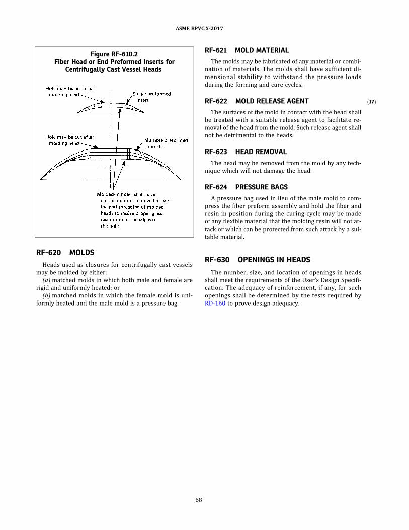
ð17Þ
RF-620 MOLDS
Heads used as closures for centrifugally cast vessels
may be molded by either:
(a) matched molds in which both male and female are
rigid and uniformly heated; or
(b) matched molds in which the female mold is uni-
formly heated and the male mold is a pressure bag.
RF-621 MOLD MATERIAL
The molds may be fabricated of any material or combi-
nation of materials. The molds shall have sufficient di-
mensional stab il ity to withstand the pressure loads
during the forming and cure cycles.
RF-622 MOLD RELEASE AGENT
The surfaces of the mold in contact with the head shall
be treated with a suitable release agent to facilitate re-
moval of the head from the mold. Such release agent shall
not be detrimental to the heads.
RF-623 HEAD REMOVAL
The head may be removed from the mold by any tech-
nique which will not damage the head.
RF-624 PRESSURE BAGS
A pressure bag used in lieu of the male mold to com-
press the fiber preform assembly and hold the fiber and
resin in position during the curing cycle may be made
of any flexible material that the molding resin will not at-
tack or which can be protected from such attack by a sui-
table material.
RF-630 OPENINGS IN HEADS
The number, size, and location of openings in heads
shall meet the requirements of the User’s Design Specifi-
cation. The adequacy of reinforcement, if any, for such
openings shall be determined by the tests required by
RD-160 to prove design adequacy.
Figure RF-610.2Fiber Head or End Preformed Inserts for
Centrifugally Cast Vessel Heads
68
ASME BPVC.X-2017

ð17Þ
ARTICLE RF-7SPECIAL FABRICATION REQUIREMENTS FOR JOINING
COMPONENTS
RF-700 PROCEDURE SPECIFICATIONS ANDQUALIFICATIONS
(a) When the fabricating process includes joining of
parts such as heads, or when it is desired to join two or
more cylinders to produce a long shell, the Procedure
Specification shall include full details of the joining pro-
cess . Any variation in the design of the j o ints being
bonded, outside of those inherent in the process of form-
ing the surfaces to be bonded, and any variation in the
method used as set forth in the qualified Procedure Spec-
ification, shall require requalification of the design and
the Procedure Specification.
(b) Longitudinal seams made by any joining method are
prohibited.
(c) Adhesive bonding of the type whereby mating sur-
faces of two parts are joined by a thin adhesive or glue
joint shall be limited to Class I vessels (see Form Q-115) .
(d) Joining of Class II vessel parts shall be limited to
secondary overlay bonding as described in Article RD-11.
69
ASME BPVC.X-2017

ð17Þ
ð17Þ
ð17Þ
PART RQQUALIFICATION REQUIREMENTS
ARTICLE RQ-1SCOPE
RQ-100 RESPONSIBILITY FORQUALIFICATION
Each Fabricator shall be responsible for qualifying the
designs and the Procedure Specifications used in fabricat-
ing fiber‐reinforced plastic pressure vessels and parts of
vessels.
RQ-101 FABRICATION PROCESSES
The fabrication processes which may be used under
this Section shall be restricted to bag molding,5 centrifu-
gal casting, contact molding, and filament winding for
Class I vessels, and contact molding and filament winding
for Class II vessels.
RQ-102 PRODUCTION WORK WITHOUTQUALIFICATIONS
No fabrication shall be undertaken on vessels to be
stamped with the Certification Mark until a written Proce-
dure Specification has been prepared and qualified by the
Fabricator. For Class I vessels the Procedure Specification
shall be qualified by the test of one or more prototype
vessels in accordance with RD-160.
For Class II vessels the Procedure Specification shall be
qualified in accordance with RF-110(c) and by subjecting
each vessel design to the mandatory stress analysis re-
quired by Article RD-11 . Both Design Calculations and
the fabrication of the specific vessel shall be for the spe-
cific materials, ply sequence, and ply orientation detailed
in the Procedure Specification (Form Q-120) .
Furthermore, no Code fabrication shall be undertaken
until the Fabricator has obtained a Certificate of Author-
ization from ASME.
RQ-110 MAINTENANCE OF PROCEDURESPECIFICATION ANDQUALIFICATION RECORDS
The Fabricator shall maintain records of the proce-
dures used in fabricating vessels and vessel parts and in
bonding vessel parts together. For Class I vessels, the Fab-
ricator shall also maintain records of the tests and their
results by which the Procedure Specifications were qual-
ified for use in fabrication. For Class II vessels, the Fabri-
cator shall maintain the records of Design Calculations,
coupon tests from which elastic and strength constants
were obtained, the Procedure Specifications that detail
the materials used and the laminate ply sequence and
ply orientation, fabrication procedures and quality con-
trol records, and the test results per Article RT-6. Such re-
cords shal l b e dated and shal l b e certi fied by the
Fabricator and verified by the Inspector (see RI-110) .
The Fabricator shall keep these records on file for at least
5 yr and in the case of mass‐produced Class I vessels, the
Fabricator shall keep these records on file for at least 5 yr
after the production of such vessels has ceased.
RQ-120 PROCEDURE SPECIFICATIONQUALIFICATION FORMS
Recommended forms showing the information re-
quired for qualifying the design and the Procedure Spec-
ification are as follows:
(a) Form Q-106 for fabrication by bag molding and cen-
trifugal casting — Class I vessels;
(b) Form Q-107 for fabrication by filament winding —
Class I vessels;
(c) Form Q-108 for fabrication by contact molding —
Class I vessels;
(d) Form Q-115 for fabrication by adhesive bonding —
Class I vessels;
(e) Form Q-120 for fabrication and assembly procedure
— Class II vessels.
70
ASME BPVC.X-2017

ð17Þ
RQ-130 MEANS TO BE USED IN QUALIFYINGCLASS I DESIGNS AND FABRICATINGPROCEDURES
In qualifying Class I vessel designs and fabrication pro-
cedures, the qualification checks listed in RQ-131 and the
Qualification Tests listed in RQ-132 shall be used.
RQ-131 QUALIFICATION CHECKS13
The following checks (see Articles RQ-2 , RQ-3 , and
RQ-4 for special requirements) shall be applied to the
prototype vessels.
(a) The vessel shall be visually checked for imperfec-
tions in the laminate.
(1) The structural laminates shall conform to the vi-
sual acceptance criteria given in Table 6-100.1 .
(2) The criterion for inspection of the liner, if used,
shall be established by mutual agreement between the
Fabricator and the User.
(b) The thickness of the vessels at a minimum of 12
points shall be checked by mechanical gages and/or ultra-
sonic equipment (see RT-340) .
(c) The percent of fiber and resin by weight, constitut-
ing the laminate, shall be determined (see RT-212) .
(d) The weight (mass) of the whole vessel shall be de-
termined and shall not be less than 95% of that stated
in the Procedure Specification.
RQ-132 QUALIFICATION TESTS13
The following tests shall be applied to the prototype
vessel or vessels or parts thereof:
(a) Barcol hardness test (see RT-221) , to verify that the
laminate has been cured in accordance with the Proce-
dure Specification;
(b) volumetric expansion test, to verify that the lami-
nate used has a modulus of elasticity within the range
specified by the designer;
NOTE: In lieu of measuring the volumetric change of the vessel by
determining the difference in volumes of fluid it will contain at the
design pressure and at atmospheric pressure, it is permissible to
check the circumference of the vessel at a minimum of three points
evenly spaced along its length. The distance between such reference
points shall not exceed 5 ft (1.5 m). The measurement shall be made
at both atmospheric pressure and design pressure and shall show no
permanent distortion.
(c) cyclic pressure plus hydrostatic qualification pres-
sure test (see RT-223) ;
(d) hydrostatic qualification pressure test, by which the
design pressure is determined [one‐sixth of qualification
pressure for all vessel types, except one‐fifth for filament‐
wound vessels with uncut filaments (RG-404.2) ] ;
(e) suitable tests , utilizing loads simulating the ex-
pected loadings of vessels subject to bending and shear-
ing caused by any expected combination of loadings
listed in RD-120.
RQ-140 MEANS FOR QUALIFYING CLASS IIVESSEL DESIGN AND FABRICATION
In qualifying Class II vessel designs and fabrication pro-
cedures utilized, the qualification checks listed in RQ-141
and the Acceptance Test listed in RQ-142 shall be used.
RQ-141 QUALIFICATION CHECKS
The following checks shall be applied to each vessel de-
signed in accordance with the mandatory design rules of
Article RD-11.
(a) Visual Checks. The vessel shall be visually checked
for imperfections in the laminate.
(1) The structural laminates shall comply with the vi-
sual acceptance criteria given in Table 6-100.2 .
(2) The criterion for inspection of the liner, if used,
shall be established by mutual agreement between the
Fabricator and the User.
(b) Thickness and Dimensional Checks. All stressed and
load bearing members shall be thickness checked in at
least 12 places to assure conformance with Design Calcu-
lations and Drawings. Thickness measurement shall be
consistent with the fiber–resin ratio and number and
thickness of individual lamina specified in the qualified
Procedure Specification.
Diameters, length, nozzle size and orientation, and
other physical dimensions shall be checked for compli-
ance with the drawings as listed in the Design Report.
(c) Barcol Hardness Test. Barcol hardness tests shall be
taken on each separately fabricated laminate part to as-
sure proper cure. Tests shall be in accordance with ASTM
D2583. Results shall be within the tolerance specified by
the resin manufacturer as listed in the qualified Proce-
dure Specification. Both the results and the tolerance shall
be recorded in the qualified Procedure Specification.
(d) Thermoplastic Liner Integrity. I f a thermoplastic
liner is used:
(1) the liner material shall be as specified in the qual-
ified Procedure Specification;
(2) the liner shall be securely bonded to the vessel
structural part;
(3) the liner shall not show evidence of excessive
heating;
(4) all seams and joints shall have a conductive mate-
rial between the liner material and the fiber–resin struc-
tural component to allow spark testing of the completed
vessel;
(5) all liner seams and joints shall be tested with a
20,000 V tester for imperfections. Any location that al-
lows electrical arcing between the voltage tester and
the conductive material under the liner shall be repaired.
71
ASME BPVC.X-2017

ð17Þ RQ-142 ACCEPTANCE TEST
The vessel shall be hydrostatically tested in such a
manner as to impose stress equal to at least 1 .1 times
the design stress. Acoustic emissions from the vessel shall
be determined in accordance with Article RT-6 of this
Section.
72
ASME BPVC.X-2017

ð17Þ
ð17Þ
ARTICLE RQ-2SPECIAL REQUIREMENTS FOR BAG-MOLDING PROCEDURE
QUALIFICATION (CLASS I VESSELS)
RQ-200 ESSENTIAL VARIABLES14
Essential variables listed in Form Q-106, deviation from
which shall require requalification of the bag-molding
procedure, are:
(a) fiber (manufacturer and designation) ;
(b) fi b e r s urface tre a tment (manufac ture r and
designation) ;
(c) resin (type, manufacturer, and designation) ;
(d) curing agent (manufacturer and designation) ;
(e) curing schedule (i.e. , time, temperature, or pres-
sure) , outside range specified in the qualified Procedure
Specification;
(f) post cure (time and temperature) ;
(g) percent of fiber (outside range specified in the qual-
ified Procedure Specification) ;
(h) initial bag pressure;
(i) final bag pressure;
(j) weight of vessel (outside range specified in the
qualified Procedure Specification) ;
(k) Barcol hardness (outside range specified in the
qualified Procedure Specification) ;
(l) volumetric expansion (outside range specified in
the qualified Procedure Specification) .
Requalification of a procedure shall not be required
when an essential variable manufacturer's name change
is a result of a business merger, a corporate name change,
or a commercial event having no effect on the manufac-
turing process or material chemistry. No other changes
in the material shall be permitted, including manufactur-
ing location. Material certificates shall be identical, with
the exception of the manufacturer's name, and material
traceability shall remain intact. It shall be the Fabricator's
responsibility to certify that these requirements have
been satisfied and notify the Authorized Inspector of
the name change. The Procedure Specification and Form
Q-106 shall be revised to document the manufacturer's
name change.
RQ-201 NONESSENTIAL VARIABLES
Changes in variables other than those listed in RQ-200
are considered nonessential. They may be made without
requalification of the bag-molding procedure, provided
the Procedure Specification is modified to show the
changes.
73
ASME BPVC.X-2017

ð17Þ
ð17Þ
ARTICLE RQ-3SPECIAL REQUIREMENTS FOR CENTRIFUGAL-CASTING
PROCEDURE QUALIFICATION (CLASS I VESSELS)
RQ-300 ESSENTIAL VARIABLES14
Essential variables listed in Form Q-106, deviation from
which shall require requalification of the centrifugal-
casting procedure, are:
(a) fiber (manufacturer and designation) ;
(b) fi b e r s urface tre a tment (manufac ture r and
designation) ;
(c) resin (type, manufacturer, and designation) ;
(d) curing agent (manufacturer and designation) ;
(e) curing schedule (i.e. , time, temperature, or pres-
sure) , outside range specified in the qualified Procedure
Specification;
(f) post cure (time and temperature) ;
(g) percent of fiber (outside range specified in the qual-
ified Procedure Specification) ;
(h) initial bag pressure;
(i) final bag pressure;
(j) weight of vessel (outside range specified in the
qualified Procedure Specification) ;
(k) Barcol hardness (outside range specified in the
qualified Procedure Specification) ;
(l) volumetric expansion (outside range specified in
the qualified Procedure Specification) ;
(m) mandrel speed.
Requalification of a procedure shall not be required
when an essential variable manufacturer's name change
is a result of a business merger, a corporate name change,
or a commercial event having no effect on the manufac-
turing process or material chemistry. No other changes
in the material shall be permitted, including manufactur-
ing location. Material certificates shall be identical, with
the exception of the manufacturer's name, and material
traceability shall remain intact. It shall be the Fabricator's
responsibility to certify that these requirements have
been satisfied and notify the Authorized Inspector of
the name change. The Procedure Specification and Form
Q-106 shall be revised to document the manufacturer's
name change.
RQ-301 NONESSENTIAL VARIABLES
Changes in variables other than those listed in RQ-300
are considered nonessential. They may be made without
requalification of the centrifugal-casting procedure, pro-
vided the Procedure Specification is modified to show
the changes.
74
ASME BPVC.X-2017

ð17Þ
ð17Þ
ARTICLE RQ-4SPECIAL REQUIREMENTS FOR FILAMENT-WINDING PROCEDURE
QUALIFICATION (CLASS I VESSELS)
RQ-400 ESSENTIAL VARIABLES14
Essential variables listed in Form Q-107, deviation from
which shal l require requal ification of the fi lament-
winding procedure, are:
(a) fiber (manufacturer and designation) ;
(b) fi b e r s urface tre a tment (manufac ture r and
designation) ;
(c) resin (type, manufacturer, and designation) ;
(d) curing agent (manufacturer and designation) ;
(e) manner of impregnation;
(f) percent of fiber in composite (outside range speci-
fied in the qualified Procedure Specification) ;
(g) variables of winding process;
(h) curing schedule (i.e., time or temperature) , outside
range specified in the qualified Procedure Specification;
(i) liner (manufacturer, designation, thickness) ;
(j) pole pieces (material) ;
(k) weight (mass) of vessel (outside range specified in
the qualified Procedure Specification) ;
(l) Barcol hardness (outside range specified in the
qualified Procedure Specification) ;
(m) volumetric expansion (outside range specified in
the qualified Procedure Specification) .
Requalification of a procedure shall not be required
when an essential variable manufacturer's name change
is a result of a business merger, a corporate name change,
or a commercial event having no effect on the manufac-
turing process or material chemistry. No other changes
in the material shall be permitted, including manufactur-
ing location. Material certificates shall be identical, with
the exception of the manufacturer's name, and material
traceability shall remain intact. It shall be the Fabricator's
responsibility to certify that these requirements have
been satisfied and notify the Authorized Inspector of
the name change. The Procedure Specification and Form
Q-107 shall be revised to document the manufacturer's
name change.
RQ-401 NONESSENTIAL VARIABLES
Changes in variables other than those listed in RQ-400
are considered nonessential. They may be made without
requalification of the filament-winding procedure, pro-
vided the Procedure Specification is modified to show
the changes.
75
ASME BPVC.X-2017

ð17Þ
ð17Þ
ARTICLE RQ-5SPECIAL REQUIREMENTS FOR CONTACT-MOLDING PROCEDURE
QUALIFICATION (CLASS I VESSELS)
RQ-500 ESSENTIAL VARIABLES14
Essential variables listed in Form Q-108, deviation from
which shall require requalification of the contact-molding
procedure, are:
(a) fiber (type, form, manufacturer, and designation) ;
(b) resin (type, manufacturer, and designation) ;
(c) curing agent (manufacturer and designation) ;
(d) curing schedule (i.e. , time, temperature, or pres-
sure) , outside range specified in the qualified Procedure
Specification;
(e) post cure (time and temperature) ;
(f) percent of fiber (outside range specified in the qual-
ified Procedure Specification) ;
(g) weight of vessel (outside range specified in the
qualified Procedure Specification) ;
(h) Barcol hardness (outside range specified in the
qualified Procedure Specification) ;
(i) volumetric expansion (outside range specified in
the qualified Procedure Specification) ;
(j) total number of plies;
(k) ply sequence and orientation;
(l) surface preparation method and distance for sec-
ondary overlays;
(m) length of secondary overlay.
Requalification of a procedure shall not be required
when an essential variable manufacturer's name change
is a result of a business merger, a corporate name change,
or a commercial event having no effect on the manufac-
turing process or material chemistry. No other changes
in the material shall be permitted, including manufactur-
ing location. Material certificates shall be identical, with
the exception of the manufacturer's name, and material
traceability shall remain intact. It shall be the Fabricator's
responsibility to certify that these requirements have
been satisfied and notify the Authorized Inspector of
the name change. The Procedure Specification and Form
Q-108 shall be revised to document the manufacturer's
name change.
RQ-501 NONESSENTIAL VARIABLES
Changes in variables other than those listed in RQ-500
are considered nonessential. They may be made without
requalification of the contact-molding procedure, pro-
vided the Procedure Specification is modified to show
the changes.
76
ASME BPVC.X-2017

ð17Þ
ð17Þ
ARTICLE RQ-6SPECIAL REQUIREMENTS FOR CLASS II VESSELS
RQ-600 ESSENTIAL DESIGN VARIABLES15
Essential design variables listed in Form Q-120 shall be
established during the design of the vessel. Any deviation
during fabrication in either materials, laminate fabrica-
tion, or method shall require that new Design Calculations
be made. The new calculations shall satisfy the User’s De-
sign Specification and the requirements of this Section
(see RF-110) . Deviation during fabrication from any of
the following shall require requalification of the design.
(a) Part I — Fabrication
(1) fiber (manufacturer, designation, type, and form)
(2) resin (manufacturer, designation, and type)
(3) liner (material, manufacturer, designation, and
thickness)
(4) laminate fabrication (each separately fabricated
vessel part)
(-a) number of plies
(-b) ply orientation
(-c) ply sequence
(5) cure method
(6) Barcol hardness
(7) percent of fiber
(8) filament winding (bandwidth and spacing)
(9) use of fi l lers or pigments (material , use, and
location)
(b) Part II — Assembly
(1) fiber reinforcement (manufacturer, designation,
type, and form)
(2) resin system (manufacturer, designation, and
type)
(3) surface preparation details for secondary overlay
(method and length)
(4) secondary overlay laminate construction
(-a) number of plies
(-b) ply orientation
(-c) ply sequence
(5) percent of fiber
(6) Barcol hardness
Requalification of a procedure shall not be required
when an essential variable manufacturer's name change
is a result of a business merger, a corporate name change,
or a commercial event having no effect on the manufac-
turing process or material chemistry. No other changes
in the material shall be permitted, including manufactur-
ing location. Material certificates shall be identical, with
the exception of the manufacturer's name, and material
traceability shall remain intact. It shall be the Fabricator's
responsibility to certify that these requirements have
been satisfied and notify the Authorized Inspector of
the name change. The Procedure Specification and Form
Q-120 shall be revised to document the manufacturer's
name change.
RQ-601 NONESSENTIAL VARIABLES
Changes in variables other than those listed in RQ-600
are considered nonessential. They may be made without
requalification of the design, provided the Procedure
Specification is modified to show the changes.
77
ASME BPVC.X-2017

ð17Þ
PART RRPRESSURE RELIEF DEVICES
ARTICLE RR-1GENERAL REQUIREMENTS
RR-100 PROTECTION AGAINSTOVERPRESSURE
(a) All pressure vessels within the scope of this Section
shall be provided with protection against overpressure in
accordance with the requirements of this Article.
(b) Heat exchangers and similar vessels shall be pro-
tected against overpressure in case of an internal failure.
RR-110 TYPES OF OVERPRESSUREPROTECTION
Protection against overpressure shall be provided by
one or a combination of the following devices:
(a) direct spring‐loaded safety or safety relief valves.
(b) indirectly operated safety or safety relief valves,
such as pilot‐operated valves. Design of pilot‐operated
valves or other indirectly operated valves shall be such
that the main unloading valve will open automatically at
the set pressure and will discharge its full rated capacity
if some essential part of the pilot or auxiliary device
should fail.
(c) rupture disks.
(d) breaking pin devices.
(e) open flow paths or vents.
(f) overpressure protection by system design.
RR-111 PROTECTION AGAINST EXTERNALPRESSURE
Vessels used for potable water, as described in RG-113
(Section IV application) , shall be equipped with a breath-
er valve directly connected to the inside of the vessel.
RR-112 DESIGN, CONSTRUCTION,CERTIFICATION MARKING, ANDINSTALLATION
The design construction, testing, certification, marking,
and installation of pressure relief devices required by this
Article shall meet the applicable requirements of Section
IV, Article 4 or Section VIII , Division 1, UG‐125 through
UG‐140, unless otherwise specified in this Article.
RR-120 SET PRESSURE
When a single pressure relieving device is used, it shall
be set to operate 16 at a pressure not exceeding the design
pressure of the vessel. When the required capacity is pro-
vided in more than one pressure relieving device, only
one device need be set at or below the design pressure,
and the additional devices may be set to open at higher
pressures but in no case at a pressure higher than
105% of the design pressure.
RR-121 PRESSURE EFFECTS TO BE INCLUDED INSETTING
The pressure at which any device is set to open shall in-
clude the effects of static head and back pressure.
RR-130 PERMISSIBLE OVERPRESSURES
The combined capacity of the pressure relief devices
shall be sufficient to prevent overpressure in excess of
those specified below when the pressure relief devices
are discharging at full capacity:
(a) when the overpressure protection is provided by a
single pressure relief device, 110% of the design pressure
or 3 psi (20 kPa) above design pressure, whichever is
greater;
78
ASME BPVC.X-2017

(b) when the overpressure protection is provided by
multiple pressure relief devices, 116% of the design pres-
sure or 4 psi (28 kPa) above design pressure, whichever
is greater;
(c) for Class II vessels the overpressure protection pro-
vision shall be established in the Design Specification.
79
ASME BPVC.X-2017

ð17Þ
ð17Þ
ARTICLE RR-2PROVISIONS IN VESSELS FOR INSTALLATION OF PRESSURE
RELIEF DEVICES
RR-200 NUMBER, SIZE, AND LOCATION OFCONNECTIONS
RR-201 NUMBER OF CONNECTIONS
Vessels shall have at least one connection for mounting
pressure relief devices directly on the vessel, or for con-
necting piping to pressure relief devices.
RR-202 SIZE OF OPENINGS AND NOZZLES
(a) Openings and nozzles constituting the connections
specified in RR-201 shall be designed to provide direct
and unobstructed flow between the vessel and its pres-
sure relief devices.
(b) The area through the opening or nozzles and all
pipe fittings between a pressure vessel and its pressure
relief device shall be at least equal to the area of the pres-
sure relief device(s) inlet and in all cases shall have suffi-
cient area so as not to restrict the flow to the pressure
device.
(c) When two or more required pressure relief devices
are placed on one connection, the inlet internal cross‐
sectional area of this connection shall be at least equal
to the combined inlet areas of the safety devices con-
nected to it and in all cases shall be sufficient to not re-
strict the combined flow of the attached devices.
(d) Connections for liquid relief valves shall be at least
NPS 1/2 (DN 15) .
RR-203 LOCATION OF OPENINGS ANDCONNECTIONS
(a) Openings and connections for pressure relief pur-
poses shall be located so that the nature of the vessel ’s
contents will not hinder flow through such openings
and connections.
(b) Connections for vapor pressure relief devices shall
be located in the vapor space.
(c) Connections for liquid relief valves shall be below
the normal liquid level.
RR-210 STOP VALVES BETWEEN THEVESSEL AND PRESSURE RELIEFDEVICE
There shall be no intervening stop valves between the
vessel and its pressure relief device or devices, or be-
tween the pressure relief device or devices and the point
of discharge, except:
(a) when the stop valves are so constructed or posi-
tively controlled that the closing of the maximum number
of stop valves possible at one time will not reduce the
pressure relief capacity provided by the unaffected reliev-
ing devices below the required relieving capacity; or
(b) under the conditions set forth in Nonmandatory
Appendix AB.
RR-220 DISCHARGE LINES FROM PRESSURERELIEF DEVICES
Discharge lines from pressure relief devices shall be de-
signed to facilitate drainage or shall be fitted with an open
drain to prevent liquid lodging in the discharge side of the
safety device, and such lines shall lead to a safe place of
discharge. The size of the discharge lines shall be such
that any pressure that may exist or develop shall not re-
duce the relieving capacity of the relieving devices below
that are required to protect the vessel (see Mandatory
Appendix 2) .
80
ASME BPVC.X-2017

ð17Þ
ð17Þ
PART RTRULES GOVERNING TESTING
ARTICLE RT-1TESTING REQUIREMENTS
RT-100 SCOPE
This Part specifies the requirements for tests to be
made during and after fabrication. For Class I vessels ,
such tests shall consist of a Qualification Test (Article
RT-2) , Quality Control Test (Article RT-3) , and Production
Test (Article RT-4) . For Class II vessels, such tests shall
consist of an Acceptance Test as specified in Article
RT-6 and the Material Property Test specified in Article
RT-7 to determine the elastic and strength constants that
serve as a basis for design.
Hydrostatic tests for both Class I and Class II vessels
shall be as specified in Article RT-5.
RT-110 FABRICATOR’S RESPONSIBILITY
The Fabricator completing a vessel or vessel part has
the responsibility for conducting the tests stipulated in
this Part. The purpose of these tests is to assure that such
vessel or part is designed for the service condition speci-
fied in the Design Specification and that the procedure for
fabricating it is adequate.
RT-111 CERTIFICATION OF COMPETENCY FORNONDESTRUCTIVE EXAMINATIONPERSONNEL
(a) The Fabricator shall certify that each examiner per-
forming acoustic emission testing under this Article has
attended a dedicated training course on the subj ect,
passed a written examination, and has the recommended
experience level. The training course shall be appropriate
for specific NDT Level II qualification according to Recom-
mended Practice No. SNT‐TC‐1A17 of the American So-
ciety for Nondestructive Testing and should include, as
a minimum, the following general topics:
(1) basic technology and terminology of acoustic
emission;
(2) fi b e r ‐ re i n fo r c e d p l a s t i c p re s s u re ve s s e l
construction;
(3) failure mechanisms of reinforced plastics;
(4) acoustic emission instrumentation;
(5) instrument checkout;
(6) vessel filling requirements;
(7) the provisions of Section V, Article 11;
(8) characteristics of spurious emission;
(9) data collection and interpretation;
(10) test reports.
The experience level shall be that recommended by
SNT‐TC‐1A for Level II certification in acoustic emission
testing.
(b) Personnel who have attended the training pre-
scribed above, and passed a Level I examination but not
a Level II examination, may perform the test but only to
the instructions of, and with adequate supervision from,
a person who meets the requirements of (a) above.
RT-112 TEST REPORTS
For Class I vessels, the Fabricator has the responsibility
of preparing and keeping on file for at least 5 yr (see
RG-321) a detailed report of the tests that were con-
ducted to prove the design of each vessel in order to be
marked with the Certification Mark, together with the
qualified Procedure Specification under which the proto-
type vessel was fabricated. For Class II vessels, the Accep-
tance Test Report shall be kept for 10 yr. This Acceptance
Test Report shall be certified by the Fabricator and veri-
fied by the Inspector.
RT-120 INSPECTOR’S DUTIES
See RI-130.
81
ASME BPVC.X-2017

ð17Þ ð17Þ
ARTICLE RT-2DESIGN AND PROCEDURE QUALIFICATION TEST
REQUIREMENTS FOR CLASS I VESSELS
RT-200 GENERAL
The tests and examinations stipulated in this Article are
intended to qualify both the design of a prototype vessel
and the Procedure Specification in accordance with which
it has been fabricated. Production vessels, which conform
in design to the prototype vessel and which are fabricated
in accordance with the same qualified Procedure Specifi-
cation, may be marked with the Certification Mark after
the Inspector has ensured that the provisions of this Code
have been complied with (see RG-321 and RI-130) . The
report of these tests shall be designated as the Qualifica-
tion Test Report and shall become part of the Fabricator’s
Design Report.
RT-201 ALTERNATIVE REQUIREMENTS
When a number of Class I vessels are identical in every
detail of design, materials, and fabrication except for a dif-
ference in shell length, the entire group or series may be
qualified for RT-212 Weight of Resin and Fiber and
RT-223 Cyclic Pressure and Hydrostatic Pressure Qualifi-
cation Tests by subjecting only the longest and shortest
length vessels in the series to these tests.
To qualify for this alternative method, every vessel in
the series shall be identical in all essential variables
(see Part RQ) with the exception of vessel weight and vo-
lumetric expansion which may vary with shell length.
A vessel series that contains nozzles, or openings, or
both may also qualify for this alternative method. To qua-
lify as identical in axial position, nozzles or openings lo-
cated along the longitudinal axis of the shel l shal l
remain a fixed distance from the nearest vessel end for
all vessels in the series.
To qualify a vessel series for RT-223 Cyclic Pressure
and Hydrostatic Pressure Qualification Tests, the vessels
tested shall be supported so as to create the worst case
of loadings expected for the entire vessel series (see
RD-120) . If the worst case nozzle/opening placement is
not tested with the longest and shortest length vessels,
additional vessels shall be tested.
Each vessel in the series shall have its own Fabricator’s
Design Report (RG-321.1) and shall be qualified individu-
ally with the exception of RT-212 and RT-223. Qualifica-
tion to RT-212 and RT-223 for all vessels in the series
will be by reference to the lengths tested.
RT-202 OMITTED OR REDUCED-IN-SIZENOZZLES OR OPENINGS FORFILAMENT-WOUND VESSELS
Class I filament-wound vessels for internal pressure
uses only can be designed and qualified with any combi-
nation of nozzles or openings as allowed in the Code. This
does not apply to polar boss openings . To qualify a
reduced-in-size nozzle, the design of the reduced-in-size
nozzle shall be a scaled version of that used in the quali-
fied vessel, using the identical material, and proper size
opening for the reduced-in-size nozzle. No changes to
the winding pattern or structure are permitted. The Fab-
ricator can omit or reduce in size any of these nozzles or
openings in production vessels. Fabrication of the produc-
tion vessels shall be identical to the qualified vessel in
every way, with the exception of the nozzles or openings
that are omitted or reduced in size. Weight allowances for
each nozzle or opening that qualifies for omission or re-
duction in size, inclusive of such items as pad reinforce-
ments that make up omitted or reduced-in-size nozzles
or openings, shall be added to the weight determined in
accordance with the requirements of RT-213 . This total
weight, inclusive of the sum of weight reductions for all
omitted or reduced-in-size nozzles or openings, shall be
at least 95% of the weight specified and recorded in the
Production Test Requirements.
RT-210 QUALIFICATION CHECKS ANDEXAMINATIONS
Each prototype vessel shall be checked, examined, and
inspected in accordance with the requirements of RT-211
through RT-214, and the results shall be recorded in the
Fabricator’s Design Report.
RT-211 VESSEL THICKNESS
The thickness of each prototype vessel and vessel part
shall be determined at a minimum of three points along
its length on each of its four quadrants. When vessels
are longer than 5 ft (1.5 m) , one additional determination
shall be made for each additional 5 ft (1.5 m) or portion
thereof. The thickness determinations shall be made with
mechanical gages, ultrasonic gages, or other devices hav-
ing an accuracy of ±2% of true thickness.
82
ASME BPVC.X-2017

ð17Þ
ð17Þ
ð17Þ
Where visual indication of deviation from design thick-
ness exists at points other than those at which measure-
ments are requ i red , th i cknes s de te rminati ons in
sufficient number to properly locate and define the devi-
ant area shall be made.
RT-212 WEIGHT OF RESIN AND FIBER
The percentage by weight of resin and fiber in each pro-
totype vessel or part shall be determined by means of an
ignition test per ASTM D2584 or matrix digestion per
ASTM D3171 of a sample taken from an undamaged por-
tion of the vessel used for the pressure qualification test.
RT-213 VESSEL WEIGHT
Each prototype vessel shall be weighed within an accu-
racy of ±1%. The weight shall be recorded on the applic-
able Form Q-106, Form Q-107, or Form Q-108.
RT-214 VISUAL EXAMINATION OF VESSELS
The vessel shall be visually checked for imperfections
in the laminate. Classification and acceptance level of im-
perfections shall be according to Table 6-100.1 . Fiberglass
laminates exposed to corrosive process fluids shall com-
ply with Table 6-100.1 for the pressure side, while struc-
tural laminates shall comply with Table 6-100.1 for the
nonpressure side.
RT-220 QUALIFICATION TESTS
Qualification tests shall be performed as required by
RT-221 through RT-223.
RT-221 BARCOL HARDNESS TESTS
(a) Each prototype vessel and vessel part shall have at
least three Barcol hardness determinations made along
its length on each of its four quadrants. When vessels
are longer than 5 ft (1.5 m), one additional set of determi-
nations shall be made for each additional 5 ft (1.5 m) or
portion thereof. A series of readings shall be taken at each
quadrant on smooth surfaces, properly oriented, in accor-
dance with ASTM D2583.
(b) The Barcol hardness values thus determined shall
be recorded in the Qualification Test Report and on the
applicable Form Q-106, Form Q-107, or Form Q-108,
and shall be used as reference values in subsequent Pro-
duction Tests (see RT-440) .
RT-222 VOLUMETRIC EXPANSION TESTS
(a) Each prototype vessel shall be subjected to a volu-
metric expansion test using water or other appropriate li-
quid, and the results recorded on the applicable Form
Q-106, Form Q-107, or Form Q-108.
(b) The volume of liquid used to fill the vessel at atmo-
spheric pressure and temperature shall be compared with
that required to fill it at the design pressure and at the
same temperature.18 Care shall be taken to eliminate air
pockets to ensure accuracy. The volume of liquid used
in each instance shall be determined by any appropriate
means, such as a weigh tank which has been calibrated
to an accuracy of ±0.2%. The results of this test shall be
documented as part of the Qualification Test Report, re-
corded on the applicable Form Q-106, Form Q-107, or
Form Q-108, and subsequently used in the quality control
volumetric expansion test.
(c) Alternatively, the volumetric expansion may be de-
termined by measuring the overall length of the vessel
and its circumference at 5 ft (1 .5 m) intervals along its
length, with a minimum of three such determinations
being made; all measurements shall be made with instru-
ments that have been calibrated to an accuracy of ±0.05%.
These measurements shall be taken with the vessel filled
with liquid at atmospheric pressure and at design pres-
sure, both at the same temperature. The measurements
thus made shall be documented as part of the Qualifica-
tion Test Report, recorded on the app l icab le Form
Q-106, Form Q-107, or Form Q-108, and subsequently
used in the quality control volumetric expansion test.
RT-223 CYCLIC PRESSURE AND HYDROSTATICPRESSURE QUALIFICATION TESTS
RT-223.1 Vessels Intended for Internal PressureOnly. (See RT-223.5 for filament‐wound vessels with un-
cut filaments.) At least one prototype vessel, intended for
internal pressure service only, shall be subjected to the
following tests:19
(a) A cyclic pressure test shall be performed in accor-
dance with the following procedures:
(1) The test fluid shall be water or other appropriate
liquid.
(2) For vessels without liners, the pressure shall be
cycled from minimum20 pressure to the design pressure
and back 100,000 times (except for vessels per RG-404,
refer to RT-223.5) . The temperature of the test fluid shall
be at least 150°F (65°C) or the maximum design tempera-
ture of the vessel, whichever is higher. Leakage during
cyclic testing is prohibited.
(3) For vessels with a liner, whether integral or not,
the pressure shall be cycled from minimum20 pressure
to the design pressure and back 10,000 cycles at the mini-
mum design temperature and for 90,000 cycles at the
maximum design temperature (except for vessels per
RG-404, refer to RT-223.5) . Leakage during cyclic testing
is prohibited
(4) For potable water usage, as described in RG-113
(Section IV application) , the pressure shall be cycled
10,000 cycles at the minimum design temperature and
80,000 cycles at the maximum design temperature fol-
lowed by a final 10,000 cycles during which the vessel
is thermally shocked by flushing 80°F (27°C) or less water
so that the vessel reaches at least 90°F (32°C) at the com-
pletion of the 10,000 cycles. Leakage during cyclic testing
is prohibited.
83
ASME BPVC.X-2017
ð17Þ
ð17Þ
(b) After the cyclic pressure test, a hydrostatic pressure
test shall be performed, and the qualification pressure of
the vessel shall be determined in accordance with the fol-
lowing procedures:
(1) The test fluid shall be water or other appropriate
liquid. The test fluid temperature shall be at least the
maximum design temperature of the vessel.
(2) The test pressure shall be applied at a uniform
rate so that six times the design pressure is reached in
not less than 1 min.
(3) The maximum pressure reached during the test is
called the qualification pressure. The qualification pres-
sure shall be at least six times the design pressure. The
use of a flexible bladder to enable attainment of the qua-
lification pressure is permissible. However, if the first ves-
sel tested fails to reach six times the design pressure, but
does reach 90% of this value, the Fabricator may test at
least two more vessels which have been subjected to cyc-
lic pressure tests in accordance with (a) and (b) above.
The average of the qualification pressures of these addi-
tional vessels, including that of the first vessel, shall be
at least six times the design pressure, and no others than
the first shall have a qualification pressure of less than six
times the design pressure.
RT-223.2 Vessels Intended for Both Internal andExternal Pressure. At least one prototype vessel intended
for both internal and external pressure service shall be
subjected to the following tests:
(a) A cyclic pressure test shall be performed in accor-
dance with the requirements of RT-223 .1 , except that
the pressure shall be cycled from the external design
pressure to the internal des ign pressure and back
100,000 times. During the cyclic testing no leakage shall
occur. At the Fabricator’s option, the cyclic pressure test
may be carried out in two steps, as follows:
(1) the pressure shall be cycled from the external de-
sign pressure to atmospheric pressure and back 100,000
times without leakage;
(2) the pressure shall be cycled from atmospheric
pressure to the internal des ign pressure and back
100,000 times without leakage.
(b) The prototype vessel with any internal liner in-
stalled shall be subjected to an external hydrostatic pres-
sure test, as follows:
(1) the test fluid shall be water or other appropriate
liquid;
(2) the temperature of the test fluid shall be 150°F
(65°C) , minimum;
(3) the external hydrostatic test pressure shall be
twice the external design pressure;
(4) the prototype vessel shall show no evidence of
buckling.
(c) The prototype vessel, after being subjected to the
external hydrostatic pressure test required in (b) above
and to the cyclic pressure test required in (a) above, shall
then be subjected to a hydrostatic qualification pressure
te s t i n a c c o r d a n c e w i th th e r e q u i r em e n t s o f
RT-223.1(a)(3) .
RT-223.3 Vessels Intended for External PressureOnly. At least one prototype vessel intended for external
pressure service only shall be tested in accordance with
RT-223 .2 , except that the internal design pressure shall
be not less than 15 psig (100 kPa gage) .
RT-223.4 Vessels Having Bending and Shear Stres-ses Inherent in Their Design. At least one prototype ves-
sel of types having bending and shear stresses inherent in
their design shall be subjected to a cyclic pressure test
and a hydrostatic qualification pressure test in accor-
dance with RT-223.1 , RT-223.2 , or RT-223.3 , whichever
is applicable , except that, in addition, the prototype
vessel(s) shall be loaded to create the magnitude of bend-
ing and shear stresses expected to occur under service
conditions.
RT-223.5 Vessels Fabricated per RG-404.2 (Fila-ment Winding— Polar Boss Openings Only) That Are In-tended for Internal Pressure Only. At least one prototype
vessel shall be subjected to the following tests19 :
(a) A cyclic pressure test shall be performed in accor-
dance with the following procedures:
(1) The test fluid shall be water or other appropriate
liquid.
(2) For vessels without liners, the pressure shall be
cycled from minimum20 pressure to the design pressure
and back 33,000 times. The temperature of the test fluid
shall be at least 150°F (65°C) or the maximum design
temperature of the vessel, whichever is higher. Leakage
during cyclic testing is prohibited.
(3) For vessels with a liner, whether integral or not,
the pressure shall be cycled from minimum20 pressure
to the design pressure and back 3,000 cycles at the mini-
mum design temperature and for 30,000 cycles at the
maximum design temperature. Leakage during cyclic test-
ing is prohibited.
(b) After the cyclic pressure test, a hydrostatic pressure
test shall be performed, and the qualification pressure of
the vessel shall be determined in accordance with the fol-
lowing procedures:
(1) The test fluid shall be water or other appropriate
liquid. The test fluid temperature shall be at least the
maximum design temperature of the vessel.
(2) The test pressure shall be applied at a uniform
rate so that 5 times the design pressure is reached in
not less than 1 min.
(3) The maximum pressure reached during the test is
called the qualification pressure. The qualification pres-
sure shall be at least 5 times the design pressure. The
use of a flexible bladder to enable attainment of the qua-
lification pressure is permissible. However, if the first ves-
sel tested fails to reach five times the design pressure, but
does reach 90% of this value, the Fabricator may test at
least two more vessels which have been subjected to
84
ASME BPVC.X-2017

cyclic pressure tests in accordance with (a) and (b) above.
The average of the qualification pressures of these addi-
tional vessels, including that of the first vessel, shall be
at least five times the design pressure, and no other ves-
sels than the first shall have a qualification pressure of
less than five times the design pressure.
85
ASME BPVC.X-2017

ð17Þ
ð17Þ
ARTICLE RT-3QUALITY CONTROL TEST AND EXAMINATION REQUIREMENTS
FOR CLASS I VESSELS
RT-300 GENERAL
(a) The tests and examinations stipulated in this Article
are intended to provide evidence that the Procedure
Specification, previously qualified in accordance with
Article RT-2, is being accurately followed and that no de-
viations have been introduced.
(b) The results of the tests and examinations stipulated
in this Article shall be designated as Quality Control Tests
and shall be recorded and kept on file [see RG-321.1(f) ] .
They shall be made available to the Inspector for review
and acceptance.
RT-301 REQUALIFICATION OF PROCEDURESPECIFICATION
If a qualified Procedure Specification has not been uti-
lized within the time frames detailed in RT-310, it shall be
requalified in accordance with the rules of Article RT-2
before use in fabricating vessels to be marked with the
Certification Mark.
RT-310 FREQUENCY OF CYCLIC PRESSUREAND QUALIFICATION PRESSURETESTS
There are three ways for determining the frequency of
cyclic pressure and qualification pressure tests. All ves-
sels sub j ect to requalification tests shal l fo l low the
requirements of RT-223. All vessels subject to requalifica-
tion testing shall be selected at random by the Inspector.
(a) Regardless of the time frequency, one vessel per
1,000 duplicate stamped with the Certification Mark pres-
sure vessels shall be subjected to a cyclic pressure and hy-
drostatic qualification pressure test.
(b) When a fabricator of Class I vessels stamps with the
Certification Mark at least 24 vessels per year, the Fabri-
cator, in collaboration with the Inspector, may increase
the time between the requalification of the Procedure
Specification, Qualification Cyclic Pressure, and Qualifica-
tion Pressure Tests, from once a year up to every 3 yr.
(c) If a Fabricator does not stamp with the Certification
Mark at least 24 vessels per year, then one vessel per year
shall be subjected to a cyclic pressure and hydrostatic
qualification pressure test.
RT-320 FREQUENCY OF DETERMINATIONOF WEIGHT OF RESIN AND FIBER
At least one determination of the weight of resin and fi-
ber shall be made for every 1,000 duplicate vessels, and at
least once a year. The determination shall be made in ac-
cordance with RT-212, and the weight of the fiber shall be
that specified in the Procedure Specification and within
the range specified in RF-2 00 , RF-3 00 , RF-400 , or
RF-500, as applicable. The vessel to be used for this test
shall be selected at random by the Inspector.
RT-330 FREQUENCY OF VOLUMETRICEXPANSION TESTS
For duplicate vessels a volumetric expansion test in ac-
cordance with the requirements of RT-222 shall be per-
formed on one of every 10 vessels and at least once a
year. The results of these tests shall not be greater than
105% of the values recorded in the original Qualification
Test Report and Procedure Specification. The vessel to be
used for this test shall be selected at random by the
Inspector.
RT-340 FREQUENCY OF THICKNESSCHECKS
Every vessel and vessel part shall be visually examined,
and when there is visual evidence of variation in thick-
ness from that specified in the Fabricator’s Design Report,
the areas in question shall be explored and their thick-
nesses determined as required by RT-211 . The under
thickness deviation shall not exceed 10% for a maximum
distance of from the center of the area which is
below the thickness specified in the Fabricator’s Design
Report, where R is the radius of the shell or head and t
is the nominal specified thickness.
86
ASME BPVC.X-2017
ð17Þ
ARTICLE RT-4PRODUCTION TEST REQUIREMENTS FOR CLASS I VESSELS
RT-400 GENERAL
Each vessel shall be subjected to the inspections, exam-
inations, and tests stipulated in this Article and shall com-
p ly with the speci fi ed requirements , wi th resu l ts
recorded in Production Test Reports. The hydrostatic tests
shall not be conducted until other tests stipulated in this
Article have been conducted.
RT-410 VISUAL EXAMINATION
Each vessel shall be visually examined, using a suitable
light source, to determine whether there are any imper-
fections of the type specified in Table 6-100.1 . This exam-
ination shall be carried out both before and after the
hydrostatic leakage test required by RT-450.
RT-411 ACCEPTANCE STANDARDS
RT-411.1 Design Dimensions. Vessels shall be in-
spected for conformance with dimensions and tolerances
shown on the Design Drawings. Any dimension falling
outside the specified limits shall be cause for rejection.
RT-411.2 Classification of Imperfections. Classifica-tion of visual imperfections in critical areas of fiberglass
laminates shal l be made in accordance with Tab le
6-100.1 for the pressure side.
RT-411.3 Imperfections in Noncritical Areas. Imper-
fections in noncritical areas which by nature, content, or
frequency do not affect the serviceability of the vessel
shall not exceed the levels for the nonpressure side in
Table 6-100.1 .
RT-411.4 Inserts, Nuts, Studs, and Lugs. Inserts,nuts, studs, and lugs shall not be damaged in any way
nor be coated with laminate material in such a way as
to impair function or mechanical fit. Threads in molded‐in
inserts shall be clean, smooth, and free of nicks, tears, or
other damage. There shall be no laminate material or
flash on the threads. Molded‐ in threads or cored holes
shall be free of visible defects such as chips, cracks, shorts,
etc.
RT-411.5 Repairable Imperfections. Imperfections
which can be repaired without affecting the serviceability
of the vessel may be repaired unless prohibited by the
Fabricator’s Design Report.
RT-412 REPAIRS OF IMPERFECTIONS
RT-412.1 Bag-Molded Vessels and CentrifugallyCast Vessels. The Inspector shall first verify that all re-
quirements of Article RI-2 or Article RI-3 , as applicable,
are met before permitting repair of imperfections.
(a) When required by the Fabricator’s Design Report,
all cut edges shall be coated with catalyzed resin and
cured so that no fibers are exposed and all voids are filled.
(b) When required by the Fabricator’s Design Report,
crevices between joined pieces shall be filled with cata-
lyzed resin or thixotropic catalyzed resin paste and cured,
leaving a relatively smooth surface.
(c) If leaks or weeps are detected during the hydro-
static leakage test (see RT-450 and RT-451) , the vessel
shall be dried completely before repairing. Catalyzed re-
sin or catalyzed thixotropic resin paste shall be applied
on the surface of the vessel over the area which leaked
and forced into the microvoids by air at pressure no more
than the working pressure of the vessel. Initial repair
shall be followed as soon as practicable21 by complete
curing. A retest shall be made for leakage.
(d) Superficial damage to exterior of vessels subse-
quent to testing may be repaired by patching with rein-
forced resin, which shall be adequate to restore the
original strength. The surface layer of resin shall be
ground to a dull finish over the entire area to be repaired
and extending a minimum of 2 in. (50 mm) beyond the
imperfection. Fiber reinforcement may be in the form of
chopped strand mat, woven fiber cloth, or woven roving.
Where more than one layer of fiber cloth or woven roving
is to be used, a layer of chopped strand mat shall be
placed as alternate layers. The repaired area shall be
cured to the Barcol hardness established in the Fabrica-
tor’s Design Report (see RT-221 and RT-440) .
The repaired vessel shall be tested as per RT-450 or
RT-461 , as applicable, and a record of the repair shall
be included in the Fabricator ’s Design Report, and in
the Fabricator’s Data Report under remarks.
RT-412 .2 Fi lament-Wound Vessels [ 1,500 psi(10 MPa) Maximum Operating Pressure; See RT-412.3].
(a) When required by the Fabricator’s Design Report,
all cut edges shall be coated with catalyzed resin and
cured so that no fibers are exposed and all voids are filled.
(b) When required by the Fabricator’s Design Report,
crevices between joined pieces shall be filled with cata-
lyzed resin or thixotropic catalyzed resin paste and cured,
leaving a relatively smooth surface.
87
ASME BPVC.X-2017

RT-412.3 Filament-Wound Vessels (For Both Gener-al Vessels and Vessels With Polar Boss Openings Only).The Inspector shall first verify that all requirements of
Article RI-4 are met before accepting repair of imperfec-
tions. Repair of imperfections shall be done in accordance
with RT-412.1(c) and/or RT-412.1(d) , as applicable, with
the provision that after the repair is cured, the vessel shall
be pressurized to the required hydrostatic leakage test
(see RT-450.1 and RT-450.2) pressure and the repaired
a re a e xam i n e d fo r an y e v i d e n c e o f c r a z i n g o r
delamination.
RT-412.4 Contact-Molded Vessels. The Inspector
shall first verify that all requirements of Article RI-5 are
met before permitting repair of imperfections. Repair of
imperfe cti o ns s ha l l b e done in acco rdance wi th
RT-412.1(c) and/or RT-412.1(d) , as applicable, with the
provision that after the repair is cured, the vessel shall
be pressurized to the required hydrostatic leakage test
(see RT-450.1 and RT-450.2) pressure and the repaired
area examined for any evidence of leakage, crazing, or
delamination.
RT-413 VISUAL EXAMINATION OF REPAIREDAREAS
Each repaired area shall be examined visually without
the aid of magnification. The repaired area shall have
translucency and surface finish comparable to the re-
mainder of the vessel.
RT-420 THICKNESS CHECK
Each vessel shall be subjected to a thickness check in
accordance with the requirements of RT-340.
RT-430 VESSEL WEIGHT
Each vessel shall be weighed in accordance with the
weight requirements ofRT-213. The weight of each vessel
shall be at least 95% of the weight specified and recorded
in the Fabricator’s Qualification Test Report for the proto-
type vessels, after subtracting the weights associated with
those nozzles , or openings , or both as described in
RT-202.
RT-440 BARCOL HARDNESS TEST
Each vessel shall be subjected to a Barcol hardness test
in accordance with the requirements of RT-221. The Bar-
col hardness value shall be within the range specified by
the resin manufacturer and recorded in the Qualification
Test Report and the Procedure Specification.
RT-450 HYDROSTATIC LEAKAGE TEST
RT-450.1 Vessels Without Welded Metal Compo-nents. Each completed vessel including production heads
shall be subj ected to a hydrostatic leakage test using
water or other suitable liquid as the test fluid. The test
pressure at ambient temperature shall be 1 .1 times the
design pressure, whether internal or external, and shall
be maintained for at least one minute. The vessel shall
then be carefully examined for leakage, at design pres-
sure. Vessels that leak shall be rejected unless they can
be repaired in accordance with RT-412 and provided that
they then pass the stipulated hydrostatic test without
leakage.
RT-450.2 Vessels With Welded Metal Components.Each completed vessel including production heads shall
be subjected to a hydrostatic leakage test using water
or other suitable liquid as the test fluid. The test pressure
at ambient temperature shall be 1 .3 times the design
pressure, whether internal or external, and shall be main-
tained for at least one minute. The vessel shall then be
carefully examined for leakage, at design pressure. Ves-
sels that leak shall be rejected unless they can be repaired
in accordance with RT-412 and provided that they then
pass the stipulated hydrostatic test without leakage.
When welded metal components can be isolated from
the rest of the vessel, it is permitted to test the welded
metal components and the rest of the vessel separately.
In this specific case, the welded metal components may
be tested using RT-450.2 (1.3 times the design pressure)
and the rest of the vessel may be tested using RT-450.1
(1.1 times the design pressure) .
RT-451 VESSELS WITH LINERS
Vessels having liners shall be tested with liners in place.
RT-452 EXCESSIVE HYDROSTATIC LEAKAGETEST PRESSURE
When pressurizing vessels during hydrostatic tests, the
pressure shall not exceed the required hydrostatic leak-
age test (see RT-450.1 and RT-450.2) pressure by more
than 10%. Exceeding this maximum pressure during the
test shall be cause for rejection. To avoid this condition,
it is recommended that a properly set safety relief valve
be installed on the vessel or in the line supplying the test
fluid to it during the test.
RT-460 CONDITIONS UNDER WHICHPNEUMATIC LEAKAGE TEST MAYBE USED
The pneumatic test described herein may be used in
l ieu of the hydrostatic leakage tests prescribed in
RT-450 only if the conditions of RT-460.1 or RT-460.2
apply.
88
ASME BPVC.X-2017

NOTE: Air and gas are hazardous as testing media. It is recommend-
ed, therefore, that special precautions be taken when air or gas is
used for test purposes.
RT-460.1 When Vessels Cannot Be Safely FilledWith Water. Pneumatic testing may be used for vessels
which are so designed and/or supported that they cannot
be safely filled with water. The tests of such vessels may
be made with the vessels partially filled with water, if spe-
cified in the Fabricator’s Design Report.
RT-460.2 When Traces of Test Fluid Cannot Be Tol-erated. Pneumatic testing may be used for vessels not
readily dried which are designed for use in services
where traces of testing liquid cannot be tolerated.
RT-461 REQUIRED PNEUMATIC TEST PRESSUREAND HOLDING TIME
(a) The test pressure at ambient temperature shall be
at least 1.3 times the design pressure and shall be main-
tained for at least 1 min.
(b) When the test medium is air or gas instead of water
or other liquid, the requirements of RT-450 regarding
liners, repair of leaks, excessive test pressure, and rejec-
tion shall also apply.
RT-461.1 When Vessels Are Pneumatically TestedUnder Water.
(a) Leakage determination shall be made by testing the
vessels while totally submerged in water.
(b) The pressure shall be applied to the vessels only
while they are completely submerged in water.
(c) The pressure may be applied gradually in one incre-
ment or in increments at the Fabricator’s option.
(d) The test pressure shall be maintained for sufficient
time to permit examination for leakage of the entire sur-
faces of the vessels. To accomplish this examination, the
vessels shall be slowly rotated so that the entire vessel
surfaces can be inspected.
RT-461.2 When Vessel Is Freestanding (Not UnderWater).
(a) The pressure in the vessel shall be gradually in-
creased to not more than one‐half the test pressure, after
which the pressure shall be increased in increments of
one‐tenth the test pressure until the required test pres-
sure has been reached.
(b) After the test pressure has been maintained for at
least 1 min, it shall be reduced to three‐fourths of the de-
sign pressure and maintained at that pressure for suffi-
cient time to permit examination for leakage of the
entire surface of the vessel and its attachments by means
of soapsuds applied thereto.
89
ASME BPVC.X-2017
ð17Þ
ð17Þ
ARTICLE RT-5HYDROSTATIC TESTING PROCEDURES AND EQUIPMENT FOR
CLASS I AND CLASS II VESSELS
RT-500 PROVISION OF VENTS AT HIGHPOINTS
Vents shall be provided at all high points of the vessel in
the test position to purge possible air pockets while the
vessel is being filled with the test fluid.
RT-501 EXAMINATION OF TEST EQUIPMENT
Before applying pressure, the test equipment shall be
examined to see that it is leak tight and that all low-
pressure filling lines and other appurtenances that should
not be subjected to the test pressure have been discon-
nected or isolated by valves or other suitable means.
RT-502 RATE OF APPLYING TEST PRESSURE
The pressure in Class I vessels shall be gradually in-
creased to not more than one‐half the test pressure, after
which the pressure shall be increased in steps of one‐
tenth of the test pressure until the required test pressure
has been reached. Class II vessels shall be pressurized in
accordance with Article RT-6.
RT-510 TEST GAGES
(a) An indicating pressure gage shall be connected di-
rectly to the vessel. If the indicating gage is not readily
visible to the operator controlling the pressure applied,
an additional indicating gage shall be provided where it
shall be visible to the operator throughout the duration
of the test. For large vessels, it is recommended that a re-
cording gage be used in addition to indicating gages.
(b) Dial indicating pressure gages used in testing shall
be graduated over a range of about double the intended
maximum test pressure, but in no case shall the range
be less than 11/2 nor more that 4 times that pressure. A di-
gital reading pressure gage having a wider range of pres-
sure may be used provided the readings give the same or
greater degree of accuracy as obtained with a dial pres-
sure gage which meets the above range requirement of
11/2 to 4 times the maximum test pressure.
(c) All gages shall be calibrated against a standard
deadweight tester or a calibrated master gage. Gages shall
be recalibrated once every 6 months or at any time that
there is reason to believe that they are in error.
RT-520 CALIBRATION OF ACOUSTICEMISSION EQUIPMENT
Acoustic emission equipment used for acceptance tests
of Class II vessels shall be calibrated per Section V, Article
11 , Acoustic Emission Examination of Fiber‐Reinforced
Plastic Vessels.
90
ASME BPVC.X-2017

ð17ÞARTICLE RT-6ACCEPTANCE TEST PROCEDURE FOR CLASS II VESSELS
RT-600 GENERAL
The tests stipulated in this Article are intended to verify
that a vessel that was designed and fabricated according
to Article RD-11 is free of structural defects and is suita-
ble for the pressure and temperature for which it was de-
signed. Such tests are nondestructive and are intended to
verify individual vessels for specific services . Vessels
which comply with the Design Specification and pass
the Acceptance Test may be marked with the Certification
Mark after the Inspector has ensured that the provisions
of this Code have been satisfied.
RT-610 ACCEPTANCE CHECKS ANDEXAMINATIONS
Each Class II vessel shall be checked and examined in
accordance with the requirements of RQ-140, and the re-
sults recorded in the Acceptance Test Report, which shall
become part of the Fabricator’s Design Report.
(a) The acoustic emission examination shall be in ac-
cordance with the requirements of this Article and ASTM
E1067. Where the provisions of this Article differ from
those of ASTM E1067, the provisions of this Article shall
govern.
(b) Vessel Conditioning. The internal pressure in the
vessel shall not exceed 10% of the test pressure for
12 hr prior to the acoustic emission examination and
110% of the test pressure any time before the acoustic
emission examination.
(c) I nstrumentation shal l be as detai led in ASTM
E1067, paragraph 7. The recommended and preferred in-
strument features listed in paragraph 7.2 are required.
Peak‐amplitude detection for each input channel is re-
quired. Time of arrival shall be measured to an accuracy
of 1 µsec. All test data, including time and pressure, shall
be recorded for post‐test playback and analysis. The data
acquisition threshold shall be at or below the threshold of
detectability defined in ASME E1067, paragraph A2.2.
(d) Sensor locations and spacing shall be according to
ASTM E1067, paragraph 9.3 . The attenuation characteri-
zation shall be performed in the hoop and longitudinal di-
rections and at 45 deg to the axis of the vessel. Additional
lead breaks may be necessary to accurately determine the
maximum sensor spacing in each direction. The require-
ment that the attenuation characterization be performed
above the liquid line shall not apply to vessels. Regardless
of vessel size, at least two sensors shall be used so that
electromagnetic interference is easily detected by simul-
taneity of arrival.
(e) Data Acquisition. Test data shall be recorded for the
entire pressurization cycle. Data acquired during pressur-
ization from 50% to 100% of the test pressure and from
the final 30-min pressure hold shall be recorded and used
to evaluate the vessel.
RT-620 ACCEPTANCE TESTS
Each Class II vessel shall be subjected to programmed
increasing stress levels to 1 .1 times the internal design
pressure while being monitored by sensors that detect
acoustic emission (stress waves) caused by growing
structural imperfections.
(a) The test fluid shall be water or other appropriate
liquid.
(b) The temperature of the test fluid shall be in the fol-
lowing range:
(1) Minimum Value . The temperature that is suffi-
cient to ensure that the vessel wall temperature is not less
than 40°F (5°C) .
(2) Maximum Value. The design temperature. If the
design temperature is less than 100°F, the maximum val-
ue shall be 100°F (38°C) .
(c) External test pressure shall be 1.0 times the exter-
nal design pressure.
NOTE: Attainment of external pressure as full vacuum by reducing
the pressure inside of a vessel is not possible due to the limitations
of evacuation equipment. Where vacuum tests are required, the User
or User’s Agent, the Authorized Inspector, and the Fabricator shall
agree on the maximum allowable absolute pressure to be achieved
during the test. Such agreement shall be reached prior to the start
of fabrication and shall be documented in the User's Design Specifi-
cation and the pressure test report.
(d) The loadings in RD-120(a) and RD-120(c) shall be
applied as part of the Acceptance Test procedure. Stres-
sing to simulate external loads as per RD-120 should be
agreed upon by the User or User's Agent, the Authorized
Inspector, and the Fabricator prior to fabrication.
(e) Pressurization shall not exceed a rate of 2% of the
maximum test pressure per minute.
(f) The acoustic emission examination procedure shall
be in accordance with ASTM E1067.
(g) Evaluation and acceptance criteria shall be in accor-
dance with Table RT-620.1 of this Section. An acceptable
vessel shall meet all the criteria listed in Table RT-620.1.
91
ASME BPVC.X-2017
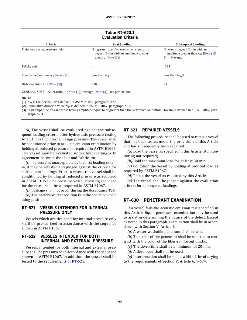
(h) The vessel shall be evaluated against the subse-
quent loading criteria after hydrostatic pressure testing
to 1.1 times the internal design pressure. The vessel shall
be conditioned prior to acoustic emission examination by
holding at reduced pressure as required in ASTM E1067.
The vessel may be evaluated under first loading with
agreement between the User and Fabricator.
(i) If a vessel is unacceptable by the first loading criter-
ia, it may be retested and judged against the criteria for
subsequent loadings. Prior to retest, the vessel shall be
conditioned by holding at reduced pressure as required
in ASTM E1067. The pressure vessel stressing sequence
for the retest shall be as required in ASTM E1067.
(j) Leakage shall not occur during the Acceptance Test.
(k) The preferable test position is in the specified oper-
ating position.
RT-621 VESSELS INTENDED FOR INTERNALPRESSURE ONLY
Vessels which are designed for internal pressure only
shall be pressurized in accordance with the sequence
shown in ASTM E1067.
RT-622 VESSELS INTENDED FOR BOTHINTERNAL AND EXTERNAL PRESSURE
Vessels intended for both internal and external pres-
sure shall be pressurized in accordance with the sequence
shown in ASTM E1067. In addition, the vessel shall be
tested to the requirements of RT-621.
RT-623 REPAIRED VESSELS
The following procedure shall be used to retest a vessel
that has been tested under the provisions of this Article
and has subsequently been repaired.
(a) Load the vessel as specified in this Article (AE mon-
itoring not required) .
(b) Hold the maximum load for at least 30 min.
(c) Condition the vessel by holding at reduced load as
required by ASTM E1067.
(d) Retest the vessel as required by this Article.
(e) The vessel shall be judged against the evaluation
criteria for subsequent loadings.
RT-630 PENETRANT EXAMINATION
If a vessel fails the acoustic emission test specified in
this Article, liquid penetrant examination may be used
to assist in determining the nature of the defect. Except
as noted in this paragraph, examination shall be in accor-
dance with Section V, Article 6.
(a) A water‐washable penetrant shall be used.
(b) The color of the penetrant shall be selected to con-
trast with the color of the fiber‐reinforced plastic.
(c) The dwell time shall be a minimum of 20 min.
(d) A developer shall not be used.
(e) Interpretation shall be made within 1 hr of drying
to the requirements of Section V, Article 6, T‐674.
Table RT-620.1Evaluation Criteria
Criteria First Loading Subsequent Loadings
Emissions during pressure hold Not greater than five events per minute
beyond 2 min with an amplitude greater
than AM [Note (1)]
No events beyond 2 min with an
amplitude greater than AM [Note (1) ]
EH = 0 events
Felicity ratio … 0.95
Cumulative duration, ND [Note (2)] Less than ND Less than ND/2
High amplitude hits [Note (3) ] ≤10 ≤5
GENERAL NOTE: All criteria in [Note (1) ] through [Note (3)] are per channel.
NOTES:
(1) AM is the decibel level defined in ASTM E1067, paragraph A2.5.
(2) Cumulative duration value ND is defined in ASTM E1067, paragraph A2.5.
(3) High amplitude hits are those having amplitude equal to or greater than the Reference Amplitude Threshold defined in ASTM E1067, para-
graph A2.3 .
92
ASME BPVC.X-2017
ARTICLE RT-7DETERMINATION OF MECHANICAL PROPERTIES OF LAMINA
FOR USE WITH CLASS II VESSELS
RT-700 REQUIRED MECHANICALPROPERTIES OF THE LAMINA
There are four elastic constants (Ex , Ey , Es , ν x ) and five
strength constants (X, Xc , Y, Yc , S) to be determined for a
lamina.
Es = in‐plane longitudinal shear modulus
Ex = modulus along the fiber direction
Ey = modulus transverse to the fiber direction; for a mat
layer, Ey is taken to be Ex
S = in‐plane shear strength
X = tensile strength along the fiber direction
Xc = compressive strength along the fiber direction
Y = tensile strength transverse to the fiber direction
Yc = compress ive s trength transverse to the fiber
direction
νx = major Poisson’s ratio (it is the negative of the strain
transverse to the fiber direction divided by the
strain along the fiber direction when a uniaxial
stress is applied along the fiber direction)
RT-701 LAMINA TEST
Test coupons for contact‐molded lamina shall be cut
from flat plate laminates of resin and fiber combinations
that represent the orthotropic lamina under considera-
tion. Test coupons for filament‐wound lamina shall be
made from hoop‐wound filament cylinders. The test cou-
pons shall be made from the same materials (or combina-
tion of materials) so as to define each of the different
types of lamina specified in the Procedure Specification.
The test coupons shall be of sufficient thickness to give re-
presentative test results from the specified ASTM proce-
dures . The fiber content of the test coupon shall be
between 90% and 100% by weight of the minimum fiber
content of the vessel or vessel part laminate as specified
in the Procedure Specification. Test methods for determi-
nation of engineering properties are specified in RT-703
and RT-704.
The results of the test shall be documented in a report
designated as the Material Property Test Report, which
shall become part of the Fabricator’s Design Report.
RT-702 LAMINATE ELASTIC PROPERTIES
Elastic properties of the laminate used to fabricate a
Class II vessel part shall be determined by the mathema-
tical treatment of the individual lamina in accordance
with Article RD-12.
Longitudinal tensile strength X for a filament‐wound
layer shall be determined either by test of a flat plate cou-
pon in accordance with ASTM D3039 or by continuing the
pressure test of a filament‐wound cylinder per ASTM
D1180 (as described in RT-703.1) to fracture.
RT-703 ELASTIC AND STRENGTH CONSTANTSFOR MAT, KNITTED FABRIC, OR WOVENROVING REINFORCED LAMINA
RT-703.1 Modulus, Ex , and Tensile Strength, X .Modulus and tensile strength shall be determined by per-
forming a tensile test to failure on a tensile coupon ac-
cording to ASTM D3039 or ASTM D638. The coupon
shall have a thickness variation not exceeding 15% of
the mean of the thickest and thinnest parts of the coupon.
The coupon shall have a degree of flatness such that no
straight‐line deviation of more than 0.020 in. per 12 in.
(0.55 mm per 305 mm) length shall occur.
RT-703.2 Compressive Strength, Xc . Compressive
strength shall be determined on a flat coupon according
to ASTM D3410 or ASTM D695.
RT-703.3 Modulus, Ey , and Transverse TensileStrength, Y. Modulus and transverse tensile strength
shall be determined by performing a tensile test on a flat
coupon according to ASTM D3039 or ASTM D638.
RT-703.4 Transverse Compressive Strength, Yc .Transverse compressive strength shall be determined
on a flat coupon according to ASTM D3410 or ASTM D695.
93
ASME BPVC.X-2017

RT-703.5 Shear Modulus, Es , and Shear Strength, S .Shear modulus for an all mat lamina shall be obtained
either from the longitudinal modulus and Poisson’s ratio
by the equation:
or according to ASTM D4255.
Shear modulus for a knitted matrix fabric or a woven
roving lamina shall be determined according to ASTM
D4255.
Shear strength for an all mat lamina shall be deter-
mined according to ASTM D3846 or ASTM D4255.
Shear strength for a knitted matrix fabric or a woven
roving lamina shall be determined according to ASTM
D4255.
RT-703.6 Flexural Modulus, E f , and FlexuralStrength, S f. These shall be determined according to
ASTM D790.
RT-703.7 Major Poisson ’s Ratio, vx . The major Pois-
son’s ratio shall be determined by measuring longitudinal
and transverse s train during the tes t speci fi ed in
RT-703.1.
RT-703.8 Minor Poisson ’s Ratio, vy . The minor Pois-
son’s ratio shall be determined by measuring longitudinal
and transverse s train during the tes t speci fi ed in
RT-703.3 , or from the equation νy = Eyνx/Ex .
RT-704 ELASTIC AND STRENGTH CONSTANTSFOR FILAMENT-WOUND LAMINA
RT-704.1 Modulus, Ex , and Tensile Strength, X .Modulus and tensile strength for a filament‐wound lami-
na shall be determined by performing a pressure test to
failure on a hoop‐wound cylinder in a manner similar to
that specified in ASTM D2992 and the underlying test
methods. The following stipulations and additions shall
apply:
(a) At least five specimens shall be tested for each test
condition.
(b) All specimens shall be hoop‐wound (approximately
90 deg) with a single tow and enough layers to meet the
minimum thickness criterion.
(c) The hoop‐wound cylindrical portion of the speci-
mens shall meet the fiber content criteria of RT-701.
(d) Specimen end closures shall be restrained ends as
defined in 1.4.1 of ASTM D2992.
(e) The internal diameter of the cylinder shall be not
less than 4 in.
(f) The clear length of the cylinder between the struc-
tural buildup at the ends of the cylinder shall be not less
than five times the outside diameter of the cylinder.
(g) The thickness of the hoop‐wound portion of the cyl-
inder shall be at least 0.1 in.
(h) The hoop‐wound cylindrical portion of the speci-
mens shall have a thickness variation not exceeding
15% of the mean of the thickest and thinnest parts of
the cylinder.
(i) The cylinder shall be instrumented with three hoop
oriented unidirectional strain gages on the external sur-
face at the mid‐ length of the cylinder. The three strain
gages shal l be mounted 12 0 deg apart around the
circumference.
(j) In order to obtain a measure of the lamina tensile
strength, the final failure of the cylinder must be due to
fracture of the hoop‐wound fibers. To ensure that this
type failure occurs, the closures shall be designed so that
they do not cause failure of the specimen. This can be ac-
complished by adding a tapered buildup of mat, knitted
fabric, or woven roving to the end of the specimens.
(k) A flexible internal corrosion barrier may be used to
prevent circumferential cracking and failure in the cir-
cumferential direction.
(l) A corrosion barrier or an elastomeric bladder may
be used to prevent excessive leakage that would prevent
application of pressure to a level that would cause frac-
ture of the hoop fibers.
(m) The contribution of a bladder or corrosion barrier
to the hoop strength of the cylinder shall be no more than
2%. The thickness of the corrosion barrier shall be ig-
nored in determination of the modulus.
RT-704.2 Compressive Strength, Xc . Compressive
strength for filament‐wound lamina along the fiber direc-
tion shall be taken as equal to the tensile strength.
RT-704.3 Modulus, Ey , and Transverse TensileStrength, Y. Modulus and transverse tensile strength
shall be determined by performing a tensile test on a
hoop‐wound cylinder according to ASTM D5450.
RT-704.4 Transverse Compressive Strength, Yc .Transverse compressive strength shall be determined
on a hoop‐wound cylinder according to ASTM D5449.
RT-704.5 Shear Modulus, Es , and In-Plane ShearStrength, S . Shear modulus and shear strength shall be
determined on a hoop‐wound cylinder loaded in torsion
according to ASTM D5448.
RT-704.6 Major Poisson ’s Ratio, vx . The major Pois-
son’s ratio shall be determined according to ASTM D5450.
94
ASME BPVC.X-2017
ð17Þ
ð17Þ
ARTICLE RT-8TEST METHODS FOR DETERMINING DAMAGE-BASED DESIGN
CRITERION
RT-800 SCOPE
This Article details the test methods for establishing the
direct stress and shear stress damage‐based design val-
ues for use in the damage‐based design criterion. The
method uses data derived from acoustic emission moni-
toring of four‐point beam bending tests and in‐plane
shear tests.
The onset of lamina damage is indicated by the pres-
ence of significant acoustic emission during the reload
portion of load/reload cycles. “Significant emission” is de-
fined with historic index.
RT-810 REFERENCED DOCUMENTS
ASTM D790, Standard Test Methods for Flexural Proper-
ties of Unreinforced and Reinforced Plastics and Elec-
trical Insulating Materials
ASTM D4255, Standard Test Method for In‐Plane Shear
Properties of Polymer Matrix Composite Materials by
the Rail Shear Method
ASTM E1316, Standard Terminology for Nondestructive
Examinations
ASTM E2478, Standard Practice for Determining Damage-
Based Design Stress for Glass Fiber Reinforced Plastic
(GFRP) Materials Using Acoustic Emission.
RT-820 APPARATUS, LOADINGPROCEDURE, AND DATA ANALYSIS
ASTM E2478 is adopted in its entirety.
95
ASME BPVC.X-2017

ð17Þ
ð17Þ
ð17Þ
PART RIINSPECTION REQUIREMENTS
ARTICLE RI-1GENERAL
RI-100 SCOPE
The inspection and examination of all pressure vessels
and vessel parts shall comply with the general require-
ments set forth in this Article. The special requirements
for vessels made by the bag molding, centrifugal casting,
filament winding, and contact-molding processes are pro-
vided in Articles RI-2, RI-3, RI-4, and RI-5.
RI-101 FABRICATOR’S RESPONSIBILITY
The Fabricator who completes any ves se l to be
stamped with the Certification Mark (see RS-110) has
the responsibility of complying with all the requirements
of this Code and, through proper certification, of assuring
that any work performed by others also complies with all
requirements of this Code including the required inspec-
tions by an Authorized Inspector.
RI-110 QUALIFICATION OF INSPECTORS
All references throughout this Section to Inspector
mean Authorized Inspector as defined in this paragraph.
The inspection required by this Article shall be carried
out by an Inspector employed by an ASME accredited
Authorized Inspection Agency, as defined in QAI-1 . The
Inspector shall not be in the employ of the Fabricator.
RI-120 ACCESS FOR INSPECTOR
The Fabricator of the vessel shall arrange for the In-
spector to have free access to such parts of all plants as
are concerned with the manufacture of materials for the
vessel, when so requested. The Inspector shall be per-
mitted free access, at all times while work on the vessel
is being performed, to all parts of the Fabricator’s shop
that concern the fabrication of the vessel, during the per-
iod of assembly and testing of the vessel. The Fabricator
shall keep the Inspector informed of the progress of the
work and shall notify the Inspector, reasonably in ad-
vance, when vessels will be ready for any required tests
or inspections.
RI-130 INSPECTOR’S DUTIES
RI-131 INSPECTOR’S DUTY RELATIVE TOQUALIFICATION TESTS OF PROTOTYPEVESSELS
The Inspector shall verify the cyclic pressure tests and
witness the hydrostatic qualification pressure tests (see
RT-223) of the prototype vessels by means of which the
vessel design and the fabrication procedure are qualified.
RI-132 INSPECTOR’S DUTY RELATIVE TO THEFABRICATOR’S DESIGN REPORT
The Inspector shall determine that the Fabricator’s De-
sign Report is on file and shall examine it to verify that:
(a) the vessel conforms to the Design Drawings in all
respects;
(b) the materials being used and the fabrication proce-
dures being employed are in strict compliance with the
requirements of the Procedure Specification;
(c) the Quality Control Program which was accepted by
ASME prior to issuance of the Certificate of Authorization
is being followed routinely and that the tests required by
it confirm that the Procedure Specification requirements
are being met;
(d) the vessel design, as demonstrated by the Test Re-
port for Class I vessels or by Design Calculations and Ac-
ceptance Test for Class II vessels, meets the requirements
of this Code.
96
ASME BPVC.X-2017
ð17Þ
ð17Þ
ð17Þ
RI-133 INSPECTOR’S DUTY RELATIVE TOSPECIFIC VESSELS
The Inspector of vessels to be marked with the Certifi-
cation Mark has the duty to ensure that all requirements
of this Section have been met. The Inspector shall make all
required inspections and other such inspections as the In-
spector deems necessary in carrying out these duties.
RI-134 INSPECTOR’S DUTY RELATIVE TOACCEPTANCE TESTING OF CLASS IIVESSELS
The Inspector shall verify that
(a) the materials (resin, reinforcements, etc.) used to
fabricate the vessel laminate are as specified in the re-
quired Procedure Specification;
(b) the laminates used for vessel fabrication meet the
same specifications as the laminates from which mechan-
ical properties were determined for Design Calculations;
(c) the thickness of vessel parts and other fabrication
detai l s conform to Des ign Calcu lations and vesse l
drawings;
(d) the hydrostatic stressing sequence and acoustic
emission response during stressing comply with the re-
quired specifications.
RI-140 INSPECTION OF MATERIAL
(a) The Inspector shall ensure that all materials used in
the fabrication of the vessel comply with the require-
ments of this Section and the Design Specification.
(b) All parts to be incorporated into the completed
pressure vessel, whether or not produced by the Fabrica-
tor, shall be inspected before assembly into the completed
vessel for the purpose of detecting, as much as possible,
any imperfections which would not meet the require-
ments of this Code.
RI-150 INSPECTION DURING FABRICATION
(a) The Inspector shall make inspections, including
making measurements, of each pressure vessel at such
stages of fabrication as are required plus such other in-
spections as the Inspector deems are necessary to ensure
that fabrication is in accordance with the requirements of
this Section.
(b) When conditions permit entry into the vessel, as
complete an examination as possible shall be made before
final closure.
(c) An inspection shall be made at the time of the hy-
drostatic leakage test or its permissible equivalent.
(d) The Inspector shall verify that the required stamp-
ing (or permitted marking) is applied to the nameplate
and that the nameplate is attached to the proper vessel.
RI-160 ALTERNATIVE INSPECTION FORMULTIPLE, DUPLICATEFABRICATION
Dur i n g th e fab r i c a t i o n o f mu l t i p l e , dup l i c a te
mass‐produced pressure vessels, it may become impracti-
cal for the Inspector to personally perform each of the re-
qu i red in sp ecti o ns . Fo r the s e sp ec i fi c cas e s , the
Fabricator, in collaboration with the Inspector, may pre-
pare an alternative inspection and quality control proce-
dure, set forth in complete detail , and the method by
which the requirements of this Section are maintained.
To qualify for this alternative method of inspection, the
following criteria shall be met:
(a) This procedure shall be included in the Fabricator’s
written quality control system (see RG-323) .
(b) This procedure shall be submitted to and shall have
received the acceptance of the Authorized Inspection
Agency.
(c) This procedure shall then be submitted by the
Authorized Inspection Agency for written acceptance
from the local jurisdiction concerned (see RG-323) and
from the ASME Designee.
(d) The joint review required by RG-323 shall include
an ASME Designee.
(e) The inspection procedure shall be used in the plant
of the named Fabricator by the Authorized Inspection
Agency submitting it, and shall be carried out by an In-
spector in the employ of that Authorized Inspection
Agency.
(f) The degree of the Authorized Inspector's involve-
ment shall be as defined during the joint review. Any
change requires another joint review.
(g) Any changes in this inspection and quality control
procedure that affect the requirements of this Section
are subject to review and acceptance by the parties re-
quired for a joint review.
(h) The Data Report for such a vessel shall include un-
der “Remarks” the statement: “Constructed under the
provisions of RI-160.”
97
ASME BPVC.X-2017
ð17Þ
ð17Þ
ARTICLE RI-2SPECIAL INSPECTION REQUIREMENTS FOR BAG MOLDING
(CLASS I VESSELS)
RI-200 CHECK OF BAG-MOLDINGPROCEDURE SPECIFICATIONQUALIFICATION
The Inspector shall examine the Fabricator’s Procedure
Specification and shall verify that the procedure for the
bag‐molding process has been properly qualified as re-
quired by Part RQ.
RI-201 ADDITIONAL TESTS
At his discretion, the Inspector shall have the right to
call for and witness additional tests of the bag‐molding
procedure and of the vessel as work progresses.
RI-202 CHECK OF FIBER WEIGHT
The Inspector shall verify that the fiber weight of pre-
forms and of side wall mats complies with the require-
ments of RF-200 and RT-320.
RI-203 CHECK OF FORM OF REINFORCEMENT
The Inspector shall verify that the form of fiber rein-
forcement used in the shell and in the heads complies
with the requirements of RF-210.
RI-204 CHECK OF FABRICATION PROCEDURES
The Inspector shall verify that the resin injection pres-
sure, processing temperatures during lay‐up, and pump-
ing procedures correspond to those stipulated in the
qualified Procedure Specification used.
RI-205 CHECK OF CURE
(a) The Inspector shall ensure by suitable hardness
tests or by other means that the bag‐molded composite
structure has been properly cured.
(b) A post cure, after removal of the vessel from the
mold, if required, shall be for the time and temperature
specified in the qualified Procedure Specification (see
Form Q-106) and shall be verified by the Inspector.
RI-206 CHECK OF UNIFORMITY OF HEATINGFOR CURE OF VESSEL
The Inspector may require the Fabricator to demon-
strate that operation of the heating system provides uni-
form heating over the entire surface of the vessel during
curing. The temperature shall not differ by more than
±10°F (±6°C) from the cure temperature specified in the
qualified Procedure Specification used (see Form Q-106) .
RI-210 VISUAL INSPECTION
Where possible, the Inspector shall inspect both the in-
side and outside of the bag‐molded pressure vessel. The
Inspector shall examine the vessel for the following de-
fects: indentations, cracks, porosity, air bubbles, exposed
fibers, lack of resin, excess resin, thin areas, wrinkling,
uniformity of seal surface , and de lamination (see
RT-411, RT-412, and RT-413) .
RI-211 TESTS AND RETESTS
The physical property tests of specimens of material,
hydrostatic or pneumatic leakage tests, cyclic pressure
and hydrostatic qualification pressure tests, and any per-
mitted retests, all stipulated in Part RT, shall be documen-
ted and certified by the Fabricator and verified by the
Inspector.
98
ASME BPVC.X-2017

ð17Þ
ð17Þ
ARTICLE RI-3SPECIAL INSPECTION REQUIREMENTS FOR CENTRIFUGAL
CASTING (CLASS I VESSELS)
RI-300 CHECK OF CENTRIFUGAL-CASTINGPROCEDURE SPECIFICATIONQUALIFICATION
The Inspector shall examine the Procedure Specifica-
tion and shall determine that the procedure for the
centrifugal‐casting process has been properly qualified
as required by Part RQ.
RI-301 ADDITIONAL TESTS
The Inspector shall have the right to call for and wit-
ness additional tests of the centrifugal‐casting procedure
and of the vessel as fabrication progresses.
RI-302 CHECK OF FIBER WEIGHT
The Inspector shall verify that the fiber weight of the
composite of fiber and resin complies with the require-
ments of RF-300 and RT-320.
RI-303 CHECK OF FORM OF REINFORCEMENT
The Inspector shall verify that the filament length of the
chopped strand is not less than 1 in. or more than 4 in., as
required by RF-300.
RI-304 CHECK OF FABRICATION PROCEDURES
The Inspector shall verify that the speed ofmandrel ro-
tation during buildup of the wall corresponds to that sti-
pulated in the qualified Procedure Specification (see
Form Q-106) .
RI-305 CHECK OF CURE
(a) The Inspector shall ensure by suitable hardness
tests or by other means that the centrifugally cast cylin-
der has been properly cured.
(b) A post cure, after removal of the vessel from the
mandrel, if required, shall be for the time and tempera-
ture specified in the qualified Procedure Specification
(see Form Q-106) and verified by the Inspector.
RI-306 CHECK OF UNIFORMITY OF HEATINGFOR CURE OF THE VESSEL
The Inspector may require the Fabricator to demon-
strate that the mandrel heating system provides uniform
heating of the entire surface of the vessel during cure. The
temperature shall not differ by more than ±10°F (±6°C)
from the cure temperature specified in the qualified Pro-
cedure Specification (see Form Q-106) .
RI-307 CHECK OF ATTACHMENT OF HEADS TOCYLINDER
RI-307.1 Heads Attached by Adhesive Bonding. TheInspector shall verify that the adhesive used, the prepara-
tion of the surfaces to be joined, and the application of the
adhesive conform to the Procedure Specification for qua-
lification of adhesive bonding (Form Q-115) .
RI-307.2 Cylinders Centrifugally Cast Into or OntoHeads. If the alternative procedure of centrifugally cast-
ing cylinders directly into or onto the head skirt is used,
the Inspector shall verify that it follows the qualified pro-
cedure for such attachment.
RI-310 VISUAL INSPECTION
Where possible, the Inspector shall inspect both the in-
side and outside of the centrifugally cast cylinder and the
bag‐ or matched‐die‐molded heads before assembly. The
Inspector shall examine the cylinder and head for the fol-
lowing defects: surface crazing or cracking, lack of resin,
excess resin, thin areas , air bubbles , exposed fibers ,
wrinkling, uniformity of sealing surface, and delamination
(see RT-411, RT-412, and RT-413) .
RI-311 TESTS AND RETESTS
The physical property tests of specimens of material,
laminate hydrostatic or pneumatic leakage tests, cyclic
pressure and hydrostatic qualification pressure tests,
and any permitted retests, all stipulated in Part RT, shall
be documented and certified by the Fabricator and veri-
fied by the Inspector.
99
ASME BPVC.X-2017

ð17Þ
ð17Þ
ARTICLE RI-4SPECIAL INSPECTION REQUIREMENTS FOR FILAMENT WINDING
RI-400 CHECK OF FILAMENT-WINDINGPROCEDURE SPECIFICATIONQUALIFICATION
The Inspector shall examine the Fabricator’s Procedure
Specification and shall verify that the procedure for the
filament‐winding process has been properly qualified as
required by Part RQ.
RI-401 ADDITIONAL TESTS
The Inspector shall have the right to call for and wit-
ness additional tests of the filament‐winding process.
RI-402 CHECK OF FIBER WEIGHT
The Inspector shall verify that the fiber weight of the
combined fiber filaments and resin complies with re-
quirements of RF-400 and RT-320.
RI-403 CHECK OF MATERIALS
The Inspector shall verify that the fiber, resin, and cur-
ing agent being used are as described in the Procedure
Specification (see Form Q-107) .
RI-404 CHECK OF FABRICATION PROCEDURES
The Inspector shall verify that the speed of winding,
uniformity of tension, and adherence to the predeter-
mined patterns of the qualified Procedure Specification
(see Form Q-107) are closely followed.
RI-405 CHECK OF CURE
(a) The Inspector shall ensure by suitable hardness
tests, or by other means, that the filament‐wound struc-
ture has been properly cured.
(b) A post cure, if required, after removal of the man-
drel, shall be for the time and temperature specified in
the qualified Procedure Specification (see Form Q-107)
and shall be verified by the Inspector.
RI-406 CHECK OF UNIFORMITY OF HEATINGFOR THE CURE OF THE VESSEL
The Inspector may require the Fabricator to demon-
strate that operation of the heating system provides uni-
form heating over the entire surface of the vessel during
cure. The temperature shall not differ by more than
±10°F (±6°C) from the cure temperature specified in the
qualified Procedure Specification (see Form Q-107) .
RI-410 VISUAL INSPECTION
Where possible, the Inspector shall inspect both the in-
side and outside of the filament‐wound pressure vessel.
The Inspector shall examine the vessel for the following
defects: indentations, cracks, porosity, air bubbles, ex-
posed fibers, lack of resin, excess resin, thinned areas,
wrinkling, pattern deviations , and delamination (see
RT-411, RT-412, and RT-413) .
RI-411 TESTS AND RETESTS
The physical property tests of specimens of material,
hydrostatic or pneumatic leakage tests, cyclic pressure
and hydrostatic qualification pressure tests, and any per-
mitted retests, all stipulated in Part RT, shall be documen-
ted and certified by the Fabricator and verified by the
Inspector.
100
ASME BPVC.X-2017
ð17Þ
ð17Þ
ARTICLE RI-5SPECIAL INSPECTION REQUIREMENTS FOR CONTACT MOLDING
RI-500 CHECK OF CONTACT-MOLDINGPROCEDURE SPECIFICATIONQUALIFICATION
The Inspector shall examine the Fabricator’s Procedure
Specification and shall determine that the procedure for
the contact‐molding process has been properly qualified
as required by Part RQ.
RI-501 ADDITIONAL TESTS
The Inspector shall have the right to call for and wit-
ness additional tests of the contact‐molding procedure
and of the vessel as fabrication progresses.
RI-502 CHECK OF FIBER WEIGHT
The Inspector shall verify that the fiber weight of the
composite structure and supplementary pads at openings
complies with the requirements of RF-500.
RI-503 CHECK OF FORM OF REINFORCEMENT
The Inspector shall verify that the fiber reinforcement
used in the shell and in the heads complies with the re-
quirements of RF-510.
RI-504 CHECK OF FABRICATION PROCEDURES
The Inspector shall verify that the laminating sequence,
cure system, method of component attachments, and
overall quality correspond to those stipulated in the qual-
ified Procedure Specification.
RI-505 CHECK OF CURE
(a) The Inspector shall ensure by suitable hardness
tests or by other means that the contact‐molded compo-
site structure has been properly cured.
(b) A post cure, after removal of the vessel from the
mold, if required, shall be for the time and temperature
specified in the qualified Procedure Specification (see
Form Q-108) and shall be verified by the Inspector.
RI-506 CHECK OF UNIFORMITY OF HEATINGFOR POST CURE OF VESSEL IF REQUIRED
The Inspector may require the Fabricator to demon-
strate that operation of the heating system provides uni-
form heating over the entire surface of the vessel during
cure. The temperature shall not differ by more than
±10°F (±6°C) from the cure temperature specified in the
qualified Procedure Specification (see Form Q-108) .
RI-510 VISUAL INSPECTION
Where possible, the Inspector shall inspect both the in-
side and outside of the pressure vessel. The Inspector
shall examine the vessel for the following imperfections:
indentations, cracks, porosity, air bubbles, exposed fibers,
lack of resin, excess resin, thin areas, wrinkling, unifor-
mity of seal surface, and delamination (see RT-411 ,
RT-412, and RT-413) .
RI-511 TESTS AND RETESTS
The physical property tests of specimens of material,
hydrostatic or pneumatic leakage tests, cyclic pressure
and hydrostatic qualification pressure tests, and any per-
mitted retests, all stipulated in Part RT, shall be documen-
ted and certified by the Fabricator and verified by the
Inspector.
101
ASME BPVC.X-2017

ð17Þ
ð17Þ
ð17Þ
PART RSMARKING, STAMPING, AND REPORTS
ARTICLE RS-1CONTENTS, METHODS, AND MEANS OF MARKING
RS-100 REQUIRED MARKING FOR VESSELS
Each pressure vessel shall be marked, by means other
than stamping directly on the vessel (see RS-130) , with
the following:
(a) the official Certification Mark as shown in Figure
RS-100.1 with the RP Designator directly under the Certi-
fication Mark;
(b) the words “Class I,” “Class II,” or “Class III,” as applic-
able, followed by the type of fabricating process, indicated
by the letters BM, CC, CM, or FW;
(c) the Fabricator’s name, preceded by “Certified by”;
(d) the maximum allowable working pressure at
maximum allowable temperature ;
(e) m a x i m u m a l l o w a b l e e x t e r n a l w o r k i n g
pressure22 at maximum allowable temperature ;
(f) the minimum allowable temperature [not less than
−65°F (−54°C)] ;
(g) the Fabricator’s serial number;
(h) the year built.
NOTE: Section IV vessels that use reinforced polymer parts shall be
marked with the letters HLW, in accordance with Code Case 2411 or
2725.
RS-101 METHODS OF MARKING VESSELS WITHTWO OR MORE INDEPENDENTCHAMBERS
Either of the arrangements specified in RS-101.1 and
RS-101.2 may be used in marking vessels having two or
more independent pressure chambers designed for the
same or different operating conditions. Each detachable
chamber shall be marked to identify it positively with
the combined unit.
RS-101.1 Markings Grouped in One Location. Themarkings may be grouped in one location on the vessel,
provided they are arranged to indicate clearly the data
applicable to each chamber, including the maximum dif-
ferential pressure for the common elements, when this
pressure is less than the higher pressure in the adjacent
chambers.
RS-101.2 Marking Each Independent Chamber. Thecomplete required marking may be applied to each inde-
pendent pressure chamber, provided additional marking,
such as stock space, jacket, tubes, or channel box, is used
to indicate clearly to which chamber the data applies.
RS-110 APPLICATION OF STAMP23 TOVESSEL
The Fabricator who completes the fabrication of the
vessel, or vessel parts, shall have a valid Certificate of
Authorization for the use of the Certification Mark with
RP Des ignator. Except when the nameplate is to be
molded in, the Certification Mark shall be applied by the
Manufacturer only with the acceptance of the Inspector
after the hydrostatic or pneumatic leakage test for Class
I or Class III vessels and the acoustic emission Acceptance
Test for Class II vessels has been satisfactorily made and
any other required inspection and testing have been
Figure RS-100.1Official Certification Mark to Denote the
American Society of Mechanical Engineers’
Standard
102
ASME BPVC.X-2017
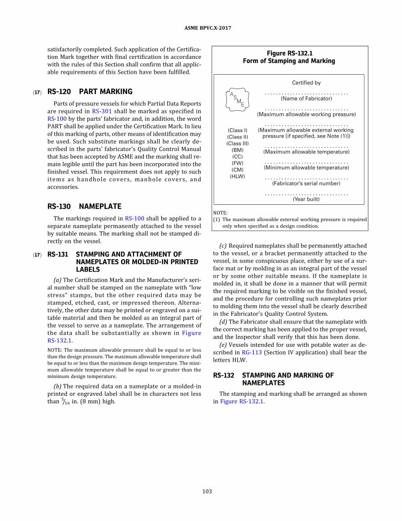
ð17Þ
ð17Þ
satisfactorily completed. Such application of the Certifica-
tion Mark together with final certification in accordance
with the rules of this Section shall confirm that all applic-
able requirements of this Section have been fulfilled.
RS-120 PART MARKING
Parts of pressure vessels for which Partial Data Reports
are required in RS-301 shall be marked as specified in
RS-100 by the parts ’ fabricator and, in addition, the word
PART shall be applied under the Certification Mark. In lieu
of this marking of parts, other means of identification may
be used. Such substitute markings shall be clearly de-
scribed in the parts ’ fabricator’s Quality Control Manual
that has been accepted by ASME and the marking shall re-
main legible until the part has been incorporated into the
finished vessel. This requirement does not apply to such
i tems as handho l e co ve rs , manho l e co ve rs , and
accessories.
RS-130 NAMEPLATE
The markings required in RS-100 shall be applied to a
separate nameplate permanently attached to the vessel
by suitable means. The marking shall not be stamped di-
rectly on the vessel.
RS-131 STAMPING AND ATTACHMENT OFNAMEPLATES OR MOLDED-IN PRINTEDLABELS
(a) The Certification Mark and the Manufacturer’s seri-
al number shall be stamped on the nameplate with “low
stress ” stamps , but the other required data may be
stamped, etched, cast, or impressed thereon. Alterna-
tively, the other data may be printed or engraved on a sui-
table material and then be molded as an integral part of
the vessel to serve as a nameplate. The arrangement of
the data shal l be substantial ly as shown in Figure
RS-132.1 .
NOTE: The maximum allowable pressure shall be equal to or less
than the design pressure. The maximum allowable temperature shall
be equal to or less than the maximum design temperature. The mini-
mum allowable temperature shall be equal to or greater than the
minimum design temperature.
(b) The required data on a nameplate or a molded‐in
printed or engraved label shall be in characters not less
than 5/16 in. (8 mm) high.
(c) Required nameplates shall be permanently attached
to the vessel, or a bracket permanently attached to the
vessel, in some conspicuous place, either by use of a sur-
face mat or by molding in as an integral part of the vessel
or by some other suitable means. If the nameplate is
molded in, it shall be done in a manner that will permit
the required marking to be visible on the finished vessel,
and the procedure for controlling such nameplates prior
to molding them into the vessel shall be clearly described
in the Fabricator’s Quality Control System.
(d) The Fabricator shall ensure that the nameplate with
the correct marking has been applied to the proper vessel,
and the Inspector shall verify that this has been done.
(e) Vessels intended for use with potable water as de-
scribed in RG-113 (Section IV application) shall bear the
letters HLW.
RS-132 STAMPING AND MARKING OFNAMEPLATES
The stamping and marking shall be arranged as shown
in Figure RS-132.1 .
Figure RS-132.1Form of Stamping and Marking
(Class I )
(Class I I )
(Class I I I )
(BM)
(CC)
(FW)
(CM)
(HLW)
Certified by
. . . . . . . . . . . . . . . . . . . . . . . . . . . . . .(Name of Fabricator)
. . . . . . . . . . . . . . . . . . . . . . . . . . . . . .(Maximum al lowable working pressure)
. . . . . . . . . . . . . . . . . . . . . . . . . . . . . .(Maximum al lowable external working pressure [ i f specified, see Note (1 )])
. . . . . . . . . . . . . . . . . . . . . . . . . . . . . .(Maximum al lowable temperature)
. . . . . . . . . . . . . . . . . . . . . . . . . . . . . .(Minimum al lowable temperature)
. . . . . . . . . . . . . . . . . . . . . . . . . . . . . .(Fabricator’s serial number)
. . . . . . . . . . . . . . . . . . . . . . . . . . . . . .(Year bui l t)
NOTE:
(1) The maximum allowable external working pressure is required
only when specified as a design condition.
103
ASME BPVC.X-2017

ð17Þ
ð17Þ
ð17Þ
ARTICLE RS-2USE OF CERTIFICATION MARK STAMP
RS-200 CERTIFICATION MARK STAMPBEARING OFFICIAL MARK
Authorization to use the stamp bearing the official Cer-
tification Mark shown in Figure RS-100.1 will be granted
by ASME pursuant to the provisions of ASME CA-1, Con-
formity Assessment Requirements.
RS-201 APPLICATION FOR CERTIFICATIONMARK STAMP
Application for the Certification Mark stamp shall be in
accordance with ASME CA-1 , Conformity Assessment
Requirements.
RS-202 AUTHORIZATION TO USECERTIFICATION MARK STAMP
Authorization to use the Certification Mark stamp may
be granted, renewed, suspended, or withheld by ASME in
accordance with ASME CA-1 , Conformity Assessment
Requirements.
RS-203 REGULATIONS CONCERNING ISSUANCEAND USE OF STAMPS
ASME may at any time make regulations concerning the
issuance and use of Certification Marks as it deems appro-
priate, and all such regulations become binding upon the
holders of any valid Certificates of Authorization. The reg-
ulation and use of stamps shall be in accordance with
ASME CA-1, Conformity Assessment Requirements.
RS-204 OBTAINING STAMPS
All stamps for applying the Certification Mark shall be
obtained from ASME.
104
ASME BPVC.X-2017
ð17Þ
ARTICLE RS-3REPORT FORMS
RS-300 FABRICATOR’S DATA REPORTS
A Fabricator’s Data Report shall be filled out on Figure
RP-1 or Figure RP-3, as applicable (sample forms are in-
cluded at the end of this Section) , by the Fabricator and
shall be signed by the Fabricator and the Authorized In-
spector for each pressure vessel.
Same-day production of vessels may be reported on
Figure RP-1 or Figure RP-3, provided all of the following
requirements are met:
(a) Ve s s e l s s h a l l b e i d e n t i c a l i n d e s i g n a n d
manufacture.
(b) Vessels shall be manufactured for stock or for the
same user or his designated agent.
(c) Serial numbers shall be in uninterrupted sequence.
(d) The Fabricator’s written Quality Control System
shall include procedures to control the development, dis-
tribution, and retention of the data reports.
RS-301 PARTIAL DATA REPORTS
(a) Partial Data Reports for those parts of a pressure
vessel requiring inspection under this Section, which
are furnished by other than the shop of the Fabricator re-
sponsible for the completed vessel, shall be executed by
the parts ’ Fabricator and the Inspector in the parts ’ Fab-
ricator’s shop, in accordance with the requirements of
this Section, and shall be forwarded, in duplicate, to the
Fabricator of the finished vessel. These Partial Data Re-
ports, together with the Inspector's own inspection, shall
constitute the requirements for the Inspector to authorize
and witness the application of a Certification Mark to the
finished vessel (see RS-110) . When Figure RP-2 or Figure
RP-4 is used, it shall be attached to the associated Figure
RP-1 or Figure RP-3 by the Fabricator of the vessel to be
marked with the Certification Mark.
(b) Data Reports for those parts of a pressure vessel
that are furnished by a parts ’ Fabricator to the user of
an existing Code vessel as replacement or repair parts
shall be executed on Figure RP-2 or Figure RP-4 by the
parts ’ Fabricator and his Inspector in accordance with
the requirements of this Section. A copy of the parts ’ Fab-
ricator’s Partial Data Report shall be furnished to the user
or his designated agent and maintained in accordance
with RS-302.
(c) The parts ’ Fabricator shall indicate under “Re-
marks” the extent he has performed any or all of the de-
sign functions. When the parts ’ Fabricator performs only
a portion of the design, he shall state which portions of
the design he performed.
(d) Same day production of vessel parts may be re-
ported on a single Figure RP-2 or Figure RP-4, provided
all of the following are met:
(1) Vessel parts shall be identical.
(2) Fabricator’s serial numbers shall be in uninter-
rupted sequence.
(3) The Fabricator’s written Quality Control System
shall include procedures to control the development, dis-
tribution, and retention of the Partial Data Reports.
(e) For guidance in preparing Partial Data Reports, see
Nonmandatory Appendix AI.
Sample Data Report Figure RP-2 and Figure RP-4 are
included at the end of this Section.
RS-302 RETENTION OF DATA REPORTS
The Fabricator shall either keep a copy of the Data Re-
port on file for at least 5 yr for Class I vessels and 10 yr
for Class II vessels, or register the vessel with the National
Board of Boiler and Pressure Vessel Inspectors, 1055
Crupper Avenue, Columbus, Ohio 43229. A copy of the
Data Report shall be sent to the User, Inspector, and jur-
isdiction upon request.
105
ASME BPVC.X-2017
ð17Þ
ð17Þ
MANDATORY APPENDIX 1QUALITY CONTROL SYSTEM
1-100 GENERAL
The Fabricator shall have and maintain a Quality Con-
trol System which will establish that all Code require-
men ts , i n c l u d i n g ma te r i a l , d e s i gn , fa b r i c a t i o n ,
examination by the Fabricator, and inspection (by the In-
spector) , will be met. The System may include provisions
for satisfying any requirements by the Fabricator or User
which exceed minimum Code requirements and may in-
clude provisions for quality control of non‐Code work.
In such systems, the Fabricator may make changes in
parts of the system which do not affect the Code require-
ments without securing acceptance by the Inspector. Be-
fore implementation, revisions to Quality Control Systems
shall have been found acceptable to the ASME Designee if
such revisions affect Code requirements.
The system that the Fabricator uses to meet the re-
quirements of this Section shall be suitable for his own
circumstances. The necessary scope and detail of the sys-
tem shall depend on the complexity of the work per-
fo rmed and o n th e s i z e an d comp l e x i ty o f th e
Fabricator’s or Assembler’s organization. A written de-
scription of the system the Fabricator will use to produce
a Code item shall be available for review.
The written description may contain information of a
proprietary nature relating to the Fabricator’s processes.
Therefore, the Code does not require any distribution of
this information except for the Authorized Inspector
and ASME Designee as covered by 1-110(l) . It is intended
that information learned about the system in connection
with the evaluation shall be treated as confidential and
that all loaned descriptions shall be returned to the Fab-
ricator upon completion of the evaluation.
1-110 OUTLINE OF SOME OF THE FEATURESTO BE INCLUDED IN THE QUALITYCONTROL SYSTEM
(a) Authority and Responsibility. The authority and re-
sponsibility of those in charge of the Quality Control Sys-
tem shall be clearly established. Persons performing
quality control functions shall have sufficient and well‐
defined responsibility, the authority and the organiza-
tional freedom to identify quality control problems and
to initiate, recommend, and provide solutions.
(b) Organization . An organization chart shall be in-
cluded, showing the relationship between engineering,
quality control, purchasing, production, testing, inspec-
tion, and management.
(c) Drawings, Design Calculations, and Specifications.
The Quality Control System shall include procedures that
will ensure that the latest applicable drawings, design cal-
culations, specifications, and instructions required by this
Section as well as authorized changes are used for fabri-
cation, inspection, and testing. For Class II and Class III
vessels, the system shall also include reference to the de-
sign documents prepared and certified by a Professional
Engineer, and shall also ensure that all changes to such
documents are approved by a Professional Engineer.
(d) Production Flow and In‐Plant Inspection and Check‐
Off. A basic production flow procedure, including in‐plant
inspection and check‐off points and a means of recording
them, shall be included. These steps shall also ensure that
the Procedure Specifications specified on the drawings
are used for fabrication.
(e) Material Receiving Control and Identity. Prior to and
during fabrication operations, a system of material con-
trol shall be maintained to ensure that material used com-
plies with the applicable specification.
(f) Nonconforming Material and Repairs. All noncon-
forming material and components (including fabrication
errors) shall be identified and recorded. Components that
fail to meet the required standards may be repaired if the
proposed repair is approved by the Design Engineer and
accepted by the Inspector prior to beginning the repair.
The system shall describe the location of the repair and
how the repair is controlled to meet Code requirements,
or the item shall be rejected.
(g) Resin Control. The system shall describe the control
of
(1) specification and mixing procedures;
(2) storage, issuance, handling, and disposal of re-
sins, catalysts, fillers, and pigments;
(3) method used to maintain identification of resins
during fabrication.
(h) Assembly, Fit‐Up, and Dimensions Control. The sys-
tem shall describe the control of
(1) assembly and fit‐up of the pressure vessel and
vessel parts to ensure compliance with fabrication
drawings;
(2) adhesive bonding and secondary lay‐up of com-
ponents to ensure compliance with fabrication drawings;
ASME BPVC.X-2017
106

(3) dimensional checks as specified by the Code and
to ensure compliance with fabrication drawings.
(i) Calibration ofMeasurement and Test Equipment. Es-
tablish and maintain a system for the calibration of all ex-
amination , measuring, and test equipment used in
fulfillment of Code requirements. A written description
of this system shall be maintained and made available
to the Inspector upon request.
(j) Forms. Appropriate forms shall be included and
cross ‐referenced with the items of this Appendix as
applicable:
(1) process or traveler’s sheets;
(2) in‐plant inspection and check‐off forms;
(3) procedures and performance qualification forms;
(4) Data Report Forms;
(5) Other appropriate forms.
(k) Self‐Auditing . Management shall regularly review
the status and adequacy of the Quality Control System.
(l) Authorized Inspector. The Quality Control System
shall include reference to the Authorized Inspector as de-
fined in RI-110. The Fabricator shall make available to the
Inspector a copy of the written Quality Control System,
and also all design documents and all other data neces-
sary for the Inspector to perform his duties in accordance
with this Section.
(m) Nondestructive Examination . The system shall de-
scribe all nondestructive examinations and the proce-
dure s to b e us ed by the Fab r i cato r to fu l fi l l the
requirements of this Section.
(n) Records Retention . The Fabricator shall have a sys-
tem for the maintenance of Data Reports and other re-
cords as required by this Section.
(o) Sample Forms. The forms used in the Quality Con-
trol System and any detailed descriptions of their use
shall be available for review. The written description shall
make necessary reference to such forms.
ASME BPVC.X-2017
107

MANDATORY APPENDIX 2CAPACITY CONVERSIONS FOR SAFETY VALVES
2-100 REQUIREMENTS FOR CAPACITYCONVERSIONS
(a) The capacity of a safety or relief valve in terms of a
gas or vapor other than the medium for which the valve
was officially rated may be determined by application of
the following equations.24
For steam:
where
CN = 51.5 for calculations of U.S. Customary units
= 5.25 for SI units calculations, P (MPa)
For air:
where
C = 356 for U.S. Customary units calculations
= 27.03 for SI units calculations
M = 28.97 mol. wt. for both U.S Customary and SI units
calculations
T = 520 when Wa is the rated capacity for U.S. Custom-
ary units calculations
= 288 when Wa is the rated capacity for SI units
calculations
For any gas or vapor:
where
A = actual discharge area of the safety valve , in .2
(mm2)
C = constant for gas or vapor which is a function of the
ratio of specific heats k = c p /c v [see Figure
2-100.1 (Figure 2-100.1M)]
K = coefficient of discharge (see RR-112)
M = molecular weight
P = (set pressure × 1.10) plus atmospheric pressure,
psia [MPA (absolute) ]
T = absolute temperature at inlet, °F plus 460 (K)
W = flow of any gas or vapor, lb/hr (kg/h)
Wa = rated capacity, converted to lb of air/hr at 60°F
(20°C) , inlet temperature
Ws = rated capacity, lb of steam/hr
These equations may also be used when the required
flow of any gas or vapor is known and it is necessary to
compute the rated capacity of steam or air.
(b) Molecular weights of some of the common gases
and vapors are given in Table 2-100.1 .
(c) For hydrocarbon vapors, where the actual value ofk
is not known, the conservative value k = 1.001 has been
commonly used and the equation becomes:
where
C = 315 for U.S. Customary units calculations
= 23.95 for SI units calculations
(d) When desired, as in the case of light hydrocarbons,
the compressibility factor Z may be included in the equa-
tions for gases and vapors as follows:
Example 1 :
Given : A safety valve bears a certified capacity rating of
3,020 lb of steam/hr for a pressure setting of 200 psi.
Problem : What is the relieving capacity of that valve in
terms of air at 100°F for the same pressure setting?
Solution :
For steam:
For air:
ASME BPVC.X-2017
108

Figure 2-100.1Constant C for Gas or Vapor Related to Ratio of Specific Heats
(k = cp/cv )
Figure 2-100.1MConstant C for Gas or Vapor Related to Ratio of Specific Heats
(k = cp/cv )
1 .0011 .02 1 .041 .061 .081 .1 0 1 .1 21 .1 41 .1 61 .1 81 .20 1 .221 .24
23.9524.1 224.3024.4724.6424.8124.9725.1 325.2925.4525.6025.7625.91
1 .261 .281 .301 .321 .341 .361 .381 .401 .421 .441 .461 .481 .50
26.0526.2026.3426.4926.6326.7626.9027.0327.1 727.3027.4327.5527.68
1 .521 .541 .561 .581 .601 .621 .641 .661 .681 .702.002.20 . . .
27.8027.9328.0528.1 728.2928.4028.5228.6328.7428.8630.3931 .29. . .
k
Constant,C k
Constant,C k
Constant,C
32
31
30
29
28
27
26
25
24
Constant, C
1 .0 1 .2 1 .4 1 .6
k
1 .8 2.0 2.2
? ?
Flow Formula Calculations
W ? K (CAP M/T )
C ? 39.48 2
k ? 1k
k ? 1
k ? 1
ASME BPVC.X-2017
109
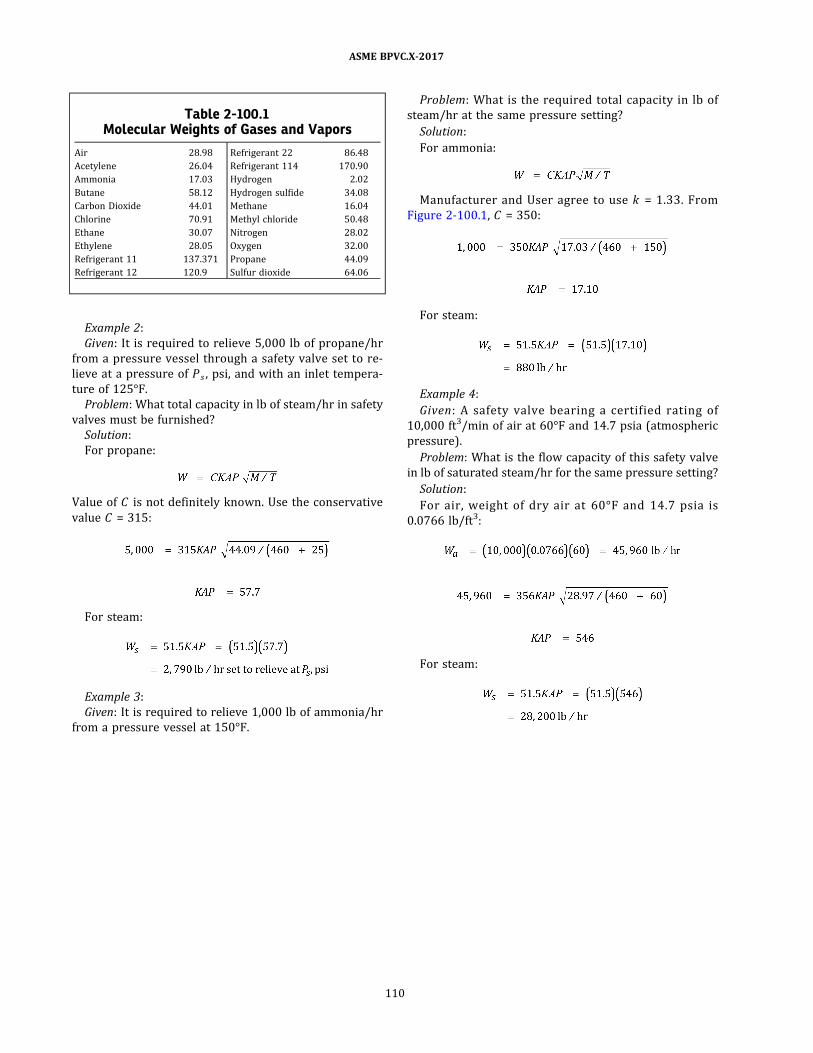
Example 2:
Given : It is required to relieve 5,000 lb of propane/hr
from a pressure vessel through a safety valve set to re-
lieve at a pressure of P s , psi, and with an inlet tempera-
ture of 125°F.
Problem : What total capacity in lb of steam/hr in safety
valves must be furnished?
Solution :
For propane:
Value of C is not definitely known. Use the conservative
value C = 315:
For steam:
Example 3:
Given : It is required to relieve 1,000 lb of ammonia/hr
from a pressure vessel at 150°F.
Problem : What is the required total capacity in lb of
steam/hr at the same pressure setting?
Solution :
For ammonia:
Manufacturer and User agree to use k = 1 .33 . From
Figure 2-100.1 , C = 350:
For steam:
Example 4:
Given : A safety valve bearing a certified rating of
10,000 ft3/min of air at 60°F and 14.7 psia (atmospheric
pressure) .
Problem : What is the flow capacity of this safety valve
in lb of saturated steam/hr for the same pressure setting?
Solution :
For air, weight of dry air at 60°F and 14.7 psia is
0.0766 lb/ft3 :
For steam:
Table 2-100.1Molecular Weights of Gases and Vapors
Air 28.98
Acetylene 26.04
Ammonia 17.03
Butane 58.12
Carbon Dioxide 44.01
Chlorine 70.91
Ethane 30.07
Ethylene 28.05
Refrigerant 11 137.371
Refrigerant 12 120.9
Refrigerant 22 86.48
Refrigerant 114 170.90
Hydrogen 2.02
Hydrogen sulfide 34.08
Methane 16.04
Methyl chloride 50.48
Nitrogen 28.02
Oxygen 32.00
Propane 44.09
Sulfur dioxide 64.06
ASME BPVC.X-2017
110
ð17ÞMANDATORY APPENDIX 4GLOSSARY OF TERMS RELATED TO FIBER-REINFORCED
PLASTICS
accelerator: a material which, when mixed with a cata-
lyzed resin, will speed up the chemical reaction between
the catalyst and resin.
adhesive : substance capable of holding two surfaces
together.
ambient conditions: prevailing environmental conditions,
such as the surrounding temperature, pressure, and rela-
tive humidity.
angle ply laminate: possessing equal plies with positive
and negative angles. This bidirectional laminate is ortho-
tropic. Typical examples of an angle ply laminate would
be cross‐ply [0/90] or [±45] .
anisotropy: material properties that vary with the orienta-
tion or direction of the reference coordinates. Having dif-
ferent material properties in all directions.
aramid fiber: an aromatic nylon fiber having a high mod-
ulus and strength.
A‐stage: an early stage in the reaction of certain thermo-
setting resins, in which the material is still soluble in cer-
tain liquids and fusible.
axial winding: in filament‐wound composites, a winding
with the filaments parallel to the longitudinal axis (0
deg helix angle) .
balanced design : in filament‐wound reinforced plastics, a
winding pattern designed to have equal stresses in all
filaments.
balanced‐in ‐plane contour: in a filament‐wound part, a
head contour in which the filaments are oriented within
a plane and the radii of curvature are adjusted to balance
the stresses along the filaments with the pressure loading.
balanced laminate: where plies with positive angles are
balanced by equal plies with negative angles. A balanced
laminate is orthotropic in in‐plane behavior but anisotro-
pic in flexural behavior.
band density: in filament winding, the quantity of fiber re-
inforcement per inch of bandwidth, expressed as strands
(or filaments) per inch.
band thickness: in filament winding, the thickness of the
reinforcement as it is applied to the mandrel.
bandwidth : in filament winding, the width of the rein-
forcement as it is applied to the mandrel.
batch : a quantity of material produced in a single, sepa-
rate production run which is identifiable by a unique
number.
biaxial load: a loading condition whereby a laminate is
stressed in at least two different directions in the plane
of the laminate. The loading condition of a pressure vessel
under internal pressure and with unrestrained ends.
biaxial winding : a type of winding in which the helical
band is laid in sequence, side by side, eliminating cross-
over of the fibers.
bidirectional laminate: a reinforced plastic laminate with
the fibers oriented in various directions in the plane of
the laminate (see also unidirectional laminate) .
bladder: a flexible liner with independent burst strength
not greater than 10% of the vessel design pressure, tem-
porarily installed in a fiber‐reinforced pressure vessel
prototype in order to prevent leakage through the wall
(to facilitate attainment of the required qualification
pressure) .
bleedout: in filament‐wound composites, the excess liquid
resin that migrates to the surface of a winding.
B‐stage: an intermediate stage in the reaction of certain
thermosetting resins in which the material swells when
in contact with certain liquids and softens when heated,
but may not entirely dissolve or fuse. The resin in an un-
cured prepreg or premix is usually in this stage.
bulk molding compound: a blend of resin and chopped fi-
bers used for compression and injection molding.
catalyst: see initiator.
catenary: the tendency of some strands in a taut horizon-
tal roving to sag lower than the others; a measure of the
evenness of length (of winding tension indirectly) of
strands in a specified length of roving. The distance be-
tween the strands at the midpoint of a roving draped in
a catenary in a specified manner (see also strand length
differential) .
circs: see circumferential winding.
ASME BPVC.X-2017
111
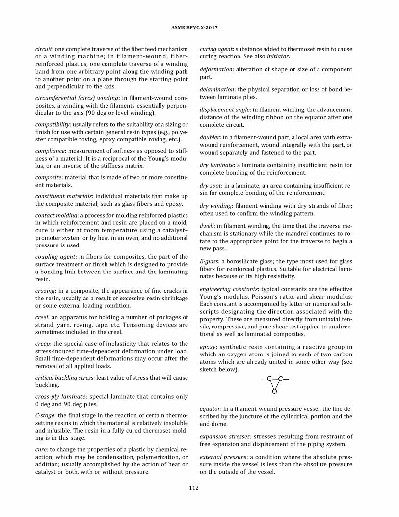
circuit: one complete traverse of the fiber feed mechanism
of a wind ing mach ine ; i n fi l ament ‐wound , fi b e r ‐
reinforced plastics, one complete traverse of a winding
band from one arbitrary point along the winding path
to another point on a plane through the starting point
and perpendicular to the axis.
circumferential (circs) winding : in filament‐wound com-
posites, a winding with the filaments essentially perpen-
dicular to the axis (90 deg or level winding) .
compatibility: usually refers to the suitability of a sizing or
finish for use with certain general resin types (e.g., polye-
ster compatible roving, epoxy compatible roving, etc.) .
compliance: measurement of softness as opposed to stiff-
ness of a material. It is a reciprocal of the Young’s modu-
lus, or an inverse of the stiffness matrix.
composite: material that is made of two or more constitu-
ent materials.
constituent materials: individual materials that make up
the composite material, such as glass fibers and epoxy.
contact molding: a process for molding reinforced plastics
in which reinforcement and resin are placed on a mold;
cure is either at room temperature using a catalyst–
promoter system or by heat in an oven, and no additional
pressure is used.
coupling agent: in fibers for composites, the part of the
surface treatment or finish which is designed to provide
a bonding link between the surface and the laminating
resin.
crazing: in a composite, the appearance of fine cracks in
the resin, usually as a result of excessive resin shrinkage
or some external loading condition.
creel: an apparatus for holding a number of packages of
strand, yarn, roving, tape, etc. Tensioning devices are
sometimes included in the creel.
creep : the special case of inelasticity that relates to the
stress‐induced time‐dependent deformation under load.
Small time‐dependent deformations may occur after the
removal of all applied loads.
critical buckling stress: least value of stress that will cause
buckling.
cross‐ply laminate: special laminate that contains only
0 deg and 90 deg plies.
C‐stage: the final stage in the reaction of certain thermo-
setting resins in which the material is relatively insoluble
and infusible. The resin in a fully cured thermoset mold-
ing is in this stage.
cure: to change the properties of a plastic by chemical re-
action, which may be condensation, polymerization, or
addition; usually accomplished by the action of heat or
catalyst or both, with or without pressure.
curing agent: substance added to thermoset resin to cause
curing reaction. See also initiator.
deformation : alteration of shape or size of a component
part.
delamination : the physical separation or loss of bond be-
tween laminate plies.
displacement angle: in filament winding, the advancement
distance of the winding ribbon on the equator after one
complete circuit.
doubler: in a filament‐wound part, a local area with extra‐
wound reinforcement, wound integrally with the part, or
wound separately and fastened to the part.
dry laminate: a laminate containing insufficient resin for
complete bonding of the reinforcement.
dry spot: in a laminate, an area containing insufficient re-
sin for complete bonding of the reinforcement.
dry winding: filament winding with dry strands of fiber;
often used to confirm the winding pattern.
dwell: in filament winding, the time that the traverse me-
chanism is stationary while the mandrel continues to ro-
tate to the appropriate point for the traverse to begin a
new pass.
E‐glass: a borosilicate glass; the type most used for glass
fibers for reinforced plastics. Suitable for electrical lami-
nates because of its high resistivity.
engineering constants: typical constants are the effective
Young’s modulus, Poisson ’s ratio, and shear modulus.
Each constant is accompanied by letter or numerical sub-
scripts designating the direction associated with the
property. These are measured directly from uniaxial ten-
sile, compressive, and pure shear test applied to unidirec-
tional as well as laminated composites.
epoxy: synthetic resin containing a reactive group in
which an oxygen atom is joined to each of two carbon
atoms which are already united in some other way (see
sketch below).
equator: in a filament‐wound pressure vessel, the line de-
scribed by the juncture of the cylindrical portion and the
end dome.
expansion stresses: stresses resulting from restraint of
free expansion and displacement of the piping system.
external pressure: a condition where the absolute pres-
sure inside the vessel is less than the absolute pressure
on the outside of the vessel.
ASME BPVC.X-2017
112

fabric: a planar structure produced by interlacing yarns,
rovings, etc.
fiber: single filament, rolled or formed in one direction,
and used as the principal constituent of woven and non-
woven composite materials . Most common fibers are
glass and graphite.
fiber content: percent by volume, or percent by weights, of
the fiber component in a composite material. See also
loss‐on‐ignition .
fiber stress: in a filament‐wound part, usually a pressure
vessel, the stress calculated using the load and the cross‐
sectional area of the reinforcement only.
filament winding : a process for fabricating a composite
structure in which continuous reinforcements (filament,
tape, or other) , either previously impregnated with a ma-
trix material or impregnated during winding, are placed
over a rotating and removable form or mandrel in a pre-
viously prescribed way to meet certain stress conditions.
Generally, the shape is a surface of revolution and may or
may not include end closures.
filler: a relatively inert nonfibrous material added to a
plastic to modify its strength, permanence, working prop-
erties, or other qualities, or to lower costs.
finish : a material applied to the surface of fibers used to
reinforce plastics and intended to improve the physical
properties of such reinforced plastics over that obtained
using glass reinforcement without finish (see surface
treatment) .
free end displacement: the relative motions that would oc-
cur between an attachment and connected structure or
equipment if the two members were separated. Examples
of such motions are those that would occur because of re-
lative thermal expansion of piping, equipment, and equip-
ment supports, or because of rotations imposed upon the
equipment by sources other than piping.
fuzz: accumulation of short broken filaments after passing
fiber strands, yarns, or rovings over a contact point. Often
weighted and used as an inverse measure of abrasion
resistance.
gap: in filament winding, the space between successive
windings, where windings are usually intended to lie next
to each other.
gel: the initial jellylike solid phase that develops during
the cure of a thermosetting resin.
gel coat: a resin applied to the surface of a mold and gelled
prior to lay‐up. The gel coat becomes an integral part of
the finished laminate and is usually used to improve sur-
face appearance, etc.
gel time: time lapsed as read on the actual exotherm curve
between 150°F and 10°F above the 180°F bath tempera-
ture (190°F) . This definition applies for any desired refer-
ence (bath) temperature.
geodesic: the shortest distance between two points on a
surface.
geodesic isotensoid: see geodesic ovaloid. Isotensoid refers
to constant stress level in any given filament at all points
in its path.
geodesic isotensoid contour: in filament‐wound, fiber‐
reinforced plastic pressure vessels, a dome contour in
which the filaments are placed on geodesic paths so that
the filaments will exhibit uniform tensions throughout
their length under pressure loading.
geodesic line: the shortest distance between two points on
a surface of revolution.
geodesic ovaloid: a contour for end domes, the fibers
forming a geodesic line. The forces exerted by the fila-
ments are proportioned to match the hoop and meridio-
nal stresses at any point.
geodesic ovaloid contour: see geodesic isotensoid contour.
glass fiber: a glass filament that has been cut to a measur-
able length. Staple fibers of relatively short length and
suitable for spinning into yarn.
glass filament: a form of glass that has been drawn to a
small diameter and extreme length.
graphite filament: made from organic precursor filament
after h igh temperature exposure and mechan ica l
stretching.
gross structural discontinuity: a source of stress or strain
intensification which effects a relatively large portion of
a structure and has a significant effect on the overall
stress or strain pattern or on the structure as a whole
(e.g., head‐to‐shell and flange‐to‐shell junctions, nozzles,
and junctions between shells of different diameters or
thicknesses) .
hand lay‐up: the process of placing and working succes-
sive plies of the reinforcing material or resin‐impregnated
reinforcement in position on a mold by hand. See also con-
tact molding.
hardener: see curing agent.
head: the end closure(s) of a cylindrical container.
helical winding: in filament‐wound composites, a winding
in which a filament band advances along a helical path,
not necessarily at a constant angle, except in the case of
a cylinder.
high pressure molding : a molding process in which the
pressure used is greater than 200 psi.
ASME BPVC.X-2017
113

hoop winding: see circumferential winding .
hybrid: composite with more than two constituents, such
as a graphite/glass/epoxy composite hybrid.
impregnate: in fiber‐reinforced plastics, saturation of the
reinforcement with a resin.
inelasticity: a general characteristic of material behavior
in which material does not return to its original (unde-
formed) shape and size after removal of all applied loads.
inhibitor: a material added to a catalyzed resin to slow
down cure at approximately room temperature. Usually
used in prepreg or premix resins.
initiator: a material which, when mixed with a resin, will
react chemical ly with the res in to produce a cured
thermoset.
interface: on fibers, the contact area between fiber and
surface treatment (or finish) . In a laminate, the contact
area between the fiber surface treatment, or finish, and
the laminating resin.
interlaminar shear strength : the maximum shear stress
existing between layers of a laminated material.
interlaminar stresses: the three stress components asso-
ciated with the thickness direction of a plate. Interlaminar
stresses are significant if the thickness is greater than
10% of the length or width of the plate. These stresses
can also be significant in areas of concentrated loads
and abrupt change in material and geometry. The effects
of these stresses are difficult to assess because three‐
dimensional stress analysis and the failure criterion are
not well understood.
invariant: constant values for all orientations of the coor-
dinate axis. Components of stress, strain, stiffness, and
compliance all have linear and quadratic invariants. For
composite materials they represent directionally inde-
pendent properties , and the bounds of stiffness and
strength of multidirectional laminates.
isotensoid: constant tension.
isotropic laminate: a laminate in which the strength prop-
erties are equal in all directions.
knitted matrix fabric: a structure produced by inserting
reinforcing fibers into a knitted matrix. The matrix fibers
are non‐reinforcing and serve only to hold the reinforcing
fibers in place.
knuckle area : the area in an end dome region near the
juncture with the cylindrical portion; in a filament‐wound
part, the area of transition between different general
shapes, e.g., the transition from a central cylindrical por-
tion to the end dome.
lamina: ply or layer of unidirectional composite or fabric.
laminate: a product made by bonding together two or
more layers of material or materials.
laminate ply: one layer of a product made by bonding to-
gether two or more layers of material.
lamination theory: the most common method for the ana-
lysis and design of composite laminates; each ply or ply
group is treated as a quasi‐homogeneous material. Linear
strain across the thickness is assumed.
lap: in filament winding, the amount of overlay between
success ive windings , usual ly intended to minimize
gapping.
lay: in filament winding, the orientation of the ribbon with
some reference, usually the axis of rotation.
lay‐up: see below
(a) a laminate that has been assembled, but not
cured
(b) a description of the component materials, geometry,
etc., of a laminate
level winding: see circumferential winding.
liner: in a pressure vessel, the continuous, usually flexible,
coating on the inside surface of the vessel used to protect
the laminate from chemical attack or to prevent leakage
under stress.
load stress: the stress resulting from the application of a
load, such as internal pressure or the effects of gravity,
as distinguished from thermal stress.
local primary membrane stress: a membrane stress pro-
duced by pressure or other mechanical loading and asso-
ciated with a primary and/or a discontinuity effect which
would, if not limited, produce excessive distortion in the
transfer of load to other portions of the structure. Conser-
vatism requires that such a stress be classified as a local
primary membrane stress even though it has some char-
acteristics of a secondary stress. An example of a local pri-
mary membrane stress is the membrane stress in a shell
produced by external load and moment at a permanent
support or at a nozzle connection.
local structural discontinuity: a source of stress or strain
intensification which affects a relatively small volume of
material and does not have a significant effect on the
overall stress or strain pattern or on the structure as a
whole (e.g., small fillet radii and small attachments) .
longitudinal modulus: elastic constant along the fiber di-
rection in a unidirectional composite, such as longitudinal
Young’s modulus.
longos: low‐angle helical or longitudinal windings.
loops and snarls: a place in a roving where one or more
short lengths of strand have doubled back on themselves.
ASME BPVC.X-2017
114

loss‐on‐ignition : weight loss, usually expressed in percent
of total, after burning off an organic surface treatment
from fibers or an organic resin from a fiber laminate.
low‐pressure molding: molding or laminating in which the
pressure used is between 15 psi and 200 psi.
mandrel: in filament winding, the mold on which the lami-
nating material is wound.
mat: a fiber material for composite laminates consisting
of randomly oriented chopped strands or swirled strands
with a binder and available in blankets of various widths
and lengths.
mat binder: a resin which is applied to fiber strands and
cured during the manufacture of a mat to hold strands
in place and maintain the shape of the mat.
matrix: see resin .
matrix: mathematical entity, consisting of rows and col-
umns of numbers. In two dimensions, stress and strain
are 1 × 3 matrices , and stiffness and compliance are
3 × 3 matrices.
matrix inversion : algebraic operation to obtain compli-
ance matrix from stiffness matrix, or vice versa. It is ana-
logous to obtaining the reciprocal of a number.
membrane stress: the component of normal stress which
is uniformly distributed and equal to the average value
of stress across the thickness of the section under
consideration.
midplane: middle surface of a laminate thickness; usually
the z = 0 plane.
modulus: elastic constants such as the Young’s modulus or
shear modulus.
moment: stress couple that causes a plate or beam to bend
or twist.
multicircuit winding : in filament‐wound composites, a
winding that requires more than one circuit before the
band repeats by laying adjacent to the first band.
multidirectional: having multiple ply orientations in a
laminate.
netting analysis: the analysis of filament‐wound struc-
tures which assumes that the stresses induced in the
structure are carried entirely by the filaments, and the
strength of the resin is not taken into account. Also, the
filaments possess no bending or shearing stiffness and
carry only axial loads.
nol ring: a parallel filament‐wound test specimen used for
measuring various mechanical strength properties of the
material by testing the entire ring, or segments of it. The
ring is usually 5.750 in. (146 mm) in inside diameter by
0.250 in. (6 mm) wide by either 0.060 in. (1 .52 mm) or
0.125 in. (3.18 mm) in wall thickness.
normal stress: the component of stress normal to the
plane of reference (this is also referred to as direct stress) .
Usually the distribution of normal stress is not uniform
through the thickness of a part, so this stress is consid-
ered to be made up in turn of two components, one of
which is uniformly distributed and equal to the average
value of stress across the thickness of the section under
consideration, and the other of which varies with the lo-
cation across the thickness.
off‐axis: not coincident with the symmetry axis ; also
called off‐angle.
orthotropy: having three mutually perpendicular planes
of symmetry. Unidirectional plies, fabric, cross‐ply, and
angle‐ply laminates are all orthotropic.
ovaloid: a surface of revolution symmetrical about the po-
lar axis which forms the end closure for a filament‐wound
cylinder (e.g., an elliptical head closure) .
part: a portion of a vessel that is fabricated by an opera-
tion or process requiring inspection by the Inspector.
peak stress: a stress that may or may not be highly loca-
lized and does not cause noticeable distortions. Examples
of peak stress are:
(a) the thermal stress in the wall of a vessel or pipe
caused by a rapid change in temperature of the contained
fluid;
(b) the stress at a local structural discontinuity.
phenolic: synthetic condensation resins of aldehyde and
phenols. The common reactants are formaldehyde, phe-
nol, and cresol.
planar helix winding: a winding in which the filament path
on each dome lies on a plane which inersects the dome,
while a helical path over the cylindrical section is con-
nected to the dome paths.
planar winding: a winding in which the filament path lies
on a plane which intersects the winding surface.
plasticizer: a material added to a resin to facilitate com-
pounding and improve flexibility and other properties
of the finished product.
plied yarn : a yarn formed by twisting together two or
more single yarns in one operation.
ply group : a group formed by contiguous plies with the
same angle.
ply strain : those components in a ply which, by the lami-
nate plate theory, are the same as those in the laminate.
ply stress: those components in a ply which vary from ply
to ply depending on the materials and angles in the
laminate.
ASME BPVC.X-2017
115
polar piece: in a pressure vessel, the metal reinforcements
placed at both ends of the major axis of the vessel. Their
exten s i o n i n to the end dome depends on s tre s s
conditions.
polar winding : a winding in which the fi lament path
passes tangent to the polar opening at one end of the
chamber, and tangent to the opposite side of the polar
opening at the other end. A one‐circuit pattern is inherent
in the system.
polyester: see below
(a) basically a class of thermosetting resins produced
by esterification of polybasic organic acids (or anhy-
drides) with polyhydric alcohols;
(b) for Code purposes, polyester may be any type of li-
quid resin which comprises a mixture of polymerizable
unsaturated ester and a copolymerizable monomeric sub-
stance that contains at least one active ethylene double
bond; this liquid resin shall be capable of gelling and cur-
ing to infusible polymer by free radical initiation at ordin-
ary temperatures with negligible change in weight;
(c) commonly, the unsaturated ester is a polymer of
maleic anhydride, phthalic anhydride, and glycol; the co-
polymerizable monomer (which also serves as solvent)
is styrene, and the free radical initiator is an organic
peroxide;
(d) any resin which is handled and cured in a similar
manner can be considered acceptable as polyester.
post cure: additional oven cure, usually without pressure,
after initial cure to improve final properties of reinforced
plastic laminates.
pot life: the length of time a resin system retains a viscos-
ity low enough to be used in laminating.
preform : a matlike structure of chopped fibers bonded to-
gether and approximating the shape of the structure.
preform binder: a resin applied to the chopped strands of
a preform, usually during its formation, and cured so that
the preform will retain its shape and can be handled.
premix: see bulk molding compound.
prepreg: in reinforced plastics, the mixture of resin, cata-
lyst, reinforcements, fillers, etc. , in web or filamentous
form, to provide a complete mix ready for molding.
pressure: unless otherwise defined, means gage pressure.
pressure bag molding: a process for molding reinforced
plastics in which a tailored flexible bag is placed over
the contact lay‐up on the mold, sealed, and clamped in
place. Fluid pressure (usually compressed air) is placed
against the bag, and the part is cured.
primary stress: a normal stress or a shear stress devel-
oped by the imposed loading which is necessary to satisfy
the simple laws of equilibrium of external and integral
forces and moments. The basic characteristic of a primary
stress is that it is not self‐limiting. Primary stresses which
considerably exceed the stress at onset of cracking will re-
sult in failure or, at least, in gross distortion. A thermal
stress is not classified as a primary stress. Examples of
primary stress are:
(a) general membrane stress in a circular cylindrical or
a spherical shell due to internal pressure or to distributed
live loads;
(b) bending stress in the central portion of a flat head
due to pressure.
principal direction : specific coordinate axes orientation
when stress and strain components reach maximum
and minimum for the normal components and zero for
the shear.
principal stress: the stress component normal to the plane
on which the shearing stress is zero.
promoter: see accelerator.
random pattern : a winding with no fixed pattern. If a large
number of circuits is required for the pattern to repeat, a
random pattern is approached.
reinforced plastic: see composite.
reinforcement: material which is applied to a resin matrix
in order to strengthen and improve the properties of the
resin.
release agent: material which is applied in a thin film to
the surface of a mold to keep the laminating resin from
bonding to the mold.
resin : in composites, the material used to bind together
the reinforcement material; also known as matrix.
resin applicator: in filament winding, the device which de-
posits the liquid resin onto the reinforcement band.
resin content: the amount of resin in a laminate, expressed
as a percent of either total weight or total volume.
resin flexibilizer: see plasticizer.
ribbonization : the degree of flattening of a sized roving,
expressed as the ratio of ribbon width to thickness.
ribbon width : see bandwidth .
ring punchout shear strength : the interlaminar shear
strength of a filament‐wound cylinder at a predetermined
shear plane.
roving : an assemblage of a number of strands or ends,
roughly parallel and with very little twist.
roving ball: package, usually cylindrically wound, of con-
tinuous roving.
roving ball build: the geometry of a roving ball, including a
description of the waywind.
ASME BPVC.X-2017
116

roving integrity: the degree of bond between strands in a
roving.
S‐glass: magnesia–alumina–silicate glass, especially de-
s igned to provide very high tens i le s trength glass
filaments.
secondary bonding: the joining of two or more FRP subas-
semblies by adhesive bonding, laminate overlay, or other
suitable means to form a larger component.
secondary stress: a normal stress or a shear stress devel-
oped by the constraint of adj acent parts or by self‐
constraint of a structure. The basic characteristic of a sec-
ondary stress is that it is self‐limiting. Local inelastic de-
fo rmati o n and mino r d i s to rti o ns can s ati s fy the
conditions which cause the stress to occur. Examples of
secondary stress are:
(a) general thermal stress;
(b) bending stress at a gross structural discontinuity.
sequential winding: see biaxial winding.
shakedown : in a structure, occurs during the first few cy-
cles of load application. The subsequent structural re-
sponse is elastic, and progressive incremental inelastic
deformation is absent. Elastic shakedown is the case in
which the subsequent response is elastic.
shear stress: the component of stress tangent to the plane
of reference.
shelf life: length of time a material can be stored under
specified environmental conditions without failure to
meet specifications.
shelling: a term applied to loops of roving falling to the
base of a roving ball as the roving is payed out from the
ball on end.
short beam shear strength : the interlaminar shear
strength of a parallel composite as determined by three‐
point flexural loading of a short segment cut from a ring‐
type specimen.
silicone: semiorganic polymers made up of a skeleton
structure of alternate silicon and oxygen atoms with var-
ious organic groups attached to the silicon.
single circuit winding: winding in which the filament path
makes a complete traverse of the chamber, after which
the following traverse lies immediately adjacent to the
previous one.
size: to apply compounds to a strand, which compounds
form a more or less continuous film around the strand
and individual fibers.
sizing content: the percent of the total strand weight made
up by the sizing, usually determined by burning off the or-
ganic sizing (see also loss‐on‐ignition) .
sizing extractables: the percent of the total sizing weight
that can be extracted with acetone or some other applic-
able solvent, measured primarily on certain reactive siz-
ings to determine degree of cure.
skein : a continuous strand, yarn, roving, etc., wound up to
some measurable length and usually used to measure var-
ious physical properties of the material.
skirt: a nonpressurized shell of revolution supporting a
pressure vessel.
splice: the joining of two ends of glass fiber yarn or strand,
usually by means of an air drying glue.
spray‐up : a process for laying up reinforced plastics in
which a special “gun” chops fiber roving and sprays resin
and a curing agent or catalyst–accelerator on the mold.
The lay‐up is then usually worked by hand (see contact
molding) .
stacking sequence: ply ordering in a laminate. Stacking se-
quence does not affect the in‐plane properties of a sym-
metric laminate. Only the ply number and ply angles are
important. But stacking sequence becomes critical for
the flexural properties, and the interlaminar stresses for
any laminate, symmetric or not. Stacking sequence is im-
portant for asymmetric and hybrid laminates.
stiffness: ratio between the applied stress and the result-
ing strain. Young’s modulus is the stiffness of a material
subjected to uniaxial stress. For composite materials, stiff-
ness and other properties are dependent on the orienta-
tion of the material.
strain : geometric measurement of deformation.
strand: an assembly of continuous filaments, without
twist. A loosely bonded assemblage of fibers or filaments;
the immediate product of the multifiber forming process.
Also known as tow.
strand count: the number of strands in a plied yarn; the
number of strands in a roving.
strand integrity: degree of bond between the filaments in
a strand.
strand length differential: similar to catenary, a measure
of the difference in length of the strands or yarns in a rov-
ing, the difference being caused by uneven tension, way-
wind, etc. (see also catenary)
strand tensile strength : tensile strength of a fiber strand,
yarn, or roving, when tested as a straight specimen.
strength : maximum stress that a material can sustain. Like
the stiffness of a composite material, strength is highly
dependent on the direction and s ign of the appl ied
stress , such as axial tensile as opposed to transverse
compression.
ASME BPVC.X-2017
117

strength ratio: useful measure related to margin of safety.
Failure occurs when the ratio is unity. Safety margin is a
factor of two, for example, if the strength ratio is two. The
ratio is particularly easy to obtain if the quadratic failure
criterion is used.
stress: intensity of forces within a body.
stress concentration : increased ratio of a local stress over
the average stress.
stress intensity: the equivalent intensity of combined
stress, or in short, the stress intensity, is defined as twice
the maximum shear stress. In other words, the stress in-
tensity is the difference between the algebraically largest
principal stress and the algebraically smallest. Tension
stresses are considered positive and compression stres-
ses are considered negative.
stress–strain relationship: a linear relation is usually as-
sumed for calculating stress from strain or strain from
stress. For multidirectional laminates, it can be general-
ized to include in‐plane stress–strain and flexural stress–
strain relations. All anisotropic relations are simple ex-
tensions of the isotropic relation. Young’s modulus is
the quotient of stress divided by strain.
surface mat: a very thin mat, usually 7 mils (0.18 mm) to
20 mils (0.51 mm) thick, or highly filamentized fiber.
surface treatment: on fibers, the compounds which, when
applied to filaments at forming, provide a loose bond be-
tween the filaments, and provide various desired hand-
ling and processing properties. For reinforcing plastics,
the surface treatment will also contain a coupling agent.
Also known as sizing.
symmetric laminate: possessing midplane symmetry.
tack: with special reference to prepreg materials, the de-
gree of stickiness of the resin.
thermal stress: a self‐balancing stress produced by a non-
uniform distribution of temperature or by differing ther-
mal coefficients of expansion. Thermal stress is developed
in a solid body whenever a volume of material is pre-
vented from assuming the size and shape that it normally
would under a change in temperature.
Two types of thermal stress are recognized, depending
on the volume or area in which distortion takes place, as
follows.
(a) General thermal stress, which is associated with
distortion of the structure in which it occurs. Examples
of general thermal stress are:
(1) stress produced by an axial temperature distribu-
tion in a cylindrical shell;
(2) stress produced by the temperature difference
between a nozzle and the shell to which it is attached.
(b) Local thermal stress, which is associated with al-
most complete suppression of the differential expansion
and thus produces no significant distortion. Examples of
local thermal stress are:
(1 ) stress in a small hot spot in a vessel wall;
(2) thermal stress in layers of material which have
different coefficients of expansion.
thermoplastic: a plastic which is capable of being repeat-
edly softened by increase of temperature and hardened
by decrease of temperature.
thermoset: a plastic which, when cured by application of
heat or chemical means, changes into a substantially infu-
sible and insoluble material.
thixotropic: the capacity of a liquid material to have high
static shear strength (viscosity) and at the same time low
dynamic shear strength. Such a material can be mixed
(stirred) , but will not flow under the force of gravity.
tow: an untwisted group of continuous fibers (see roving)
transformation : variation of stiffness, strength, stress,
strain, and other material properties due to the coordi-
nate transformation or rotation of the reference coordi-
nate axes. Transformation follows strict mathematical
equations. The study of composite materials relies heavily
on these transformation equations to correctly describe
the directional dependency of the materials.
uniaxial load: a loading condition whereby a laminate is
stressed in only one direction.
unidirectional composite: having parallel fibers in a com-
posite. Compare with unidirectional laminate.
unidirectional laminate: a composite laminate in which all
the fibers are oriented in the same direction.
veil: see surface mat.
vinyl ester: a thermoset resin with epoxy backbone, but
which cures by peroxide initiation like a polyester.
voids: air pockets that have been trapped and cured into a
laminate.
volatiles: materials in a roving sizing or a resin formula-
tion which are capable of being driven off as a vapor at
room or slightly elevated temperature.
wall stress: in a filament‐wound part, usually a pressure
vessel, the stress calculated using the load and the entire
laminate cross‐sectional area (see also fiber stress)
waywind: the number of wraps or turns that roving or
yarn make from one side of the wound package back to
the same side.
wet lay‐up: a reinforced plastic which has liquid resin ap-
plied as the reinforcement is being laid up.
ASME BPVC.X-2017
118
wet‐out: the condition of an impregnated roving or yarn
wherein substantially all voids between sized strands
and filaments are filled with resin.
wet‐out rate: the time required for a plastic to fill the in-
terstices of a reinforcement material and wet the surface
of the reinforcement fibers, usually determined by optical
or light transmission means.
wet winding: filament‐winding reinforced plastics when
the fiber reinforcement is coated with liquid resin just
prior to wrapping on the mandrel.
winding pattern : the total number of individual circuits
required for a winding path to begin repeating by laying
down immediately adjacent to the initial circuit; a regu-larly recurring pattern of the filament path after a certainnumber of mandrel revolutions, leading to the eventualcomplete coverage of the mandrel.
winding tension : in filament winding, the amount of ten-
sion on the reinforcement as it makes contact with a
mandrel.
yardage: see yield.
yield: the number of yards of yarn, roving strand, etc., per
pound of glass fibers; the reciprocal of weight per yard.
ASME BPVC.X-2017
119
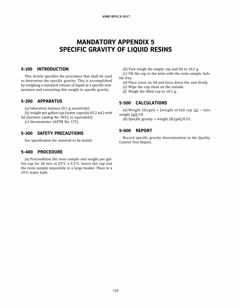
MANDATORY APPENDIX 5SPECIFIC GRAVITY OF LIQUID RESINS
5-100 INTRODUCTION
This Article specifies the procedure that shall be used
to determine the specific gravity. This is accomplished
by weighing a standard volume of liquid at a specific tem-
perature and converting this weight to specific gravity.
5-200 APPARATUS
(a) laboratory balance (0.1 g sensitivity)
(b) weight per gallon cup (water capacity 83.2 mL) with
lid (Gardner catalog No. 9652 or equivalent)
(c) thermometer (ASTM No. 17C)
5-300 SAFETY PRECAUTIONS
See specification for material to be tested.
5-400 PROCEDURE
(a) Precondition the resin sample and weight per gal-
lon cup for 20 min at 25°C ± 0.1°C. Insert the cup and
the resin sample separately in a large beaker. Place in a
25°C water bath.
(b) Tare weigh the empty cup and lid to ±0.1 g.
(c) Fill the cup to the brim with the resin sample, bub-
ble free.
(d) Place cover on lid and force down the seat firmly.
(e) Wipe the cup clean on the outside.
(f) Weigh the filled cup to ±0.1 g.
5-500 CALCULATIONS
(a) Weight (lb/gal) = [weight of full cup (g) − tare
weight (g)]/10.
(b) Specific gravity = weight (lb/gal)/8.33.
5-600 REPORT
Record specific gravity determination in the Quality
Control Test Report.
ASME BPVC.X-2017
120

MANDATORY APPENDIX 6STRUCTURAL LAMINATE VISUAL ACCEPTANCE CRITERIA
6-100 STRUCTURAL LAMINATE VISUALACCEPTANCE CRITERIA
For Class I pressure vessels , see Table 6-100.1 . For
Class II pressure vessels, see Table 6-100.2 .
ASME BPVC.X-2017
121
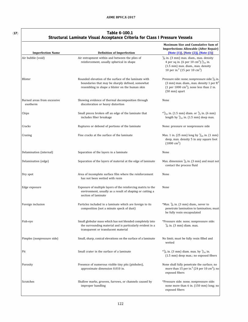
ð17Þ Table 6-100.1Structural Laminate Visual Acceptance Criteria for Class I Pressure Vessels
Imperfection Name Definition of Imperfection
Maximum Size and Cumulative Sum of
Imperfections Allowable (After Repair)
[Note (1)] , [Note (2)] , [Note (3)]
Air bubble (void) Air entrapment within and between the plies of
reinforcement, usually spherical in shape
1/8 in. (3 mm) max. diam., max. density
4 per sq in. (6 per 10 cm2) ;1/16 in.
(1 .5 mm) max. diam., max. density
10 per in.2 (15 per 10 cm2)
Blister Rounded elevation of the surface of the laminate with
boundaries that may be sharply defined, somewhat
resembling in shape a blister on the human skin
Pressure side: none; nonpressure side:1/8 in.
(3 mm) max. diam., max. density 1 per ft2
(1 per 1000 cm2) , none less than 2 in.
(50 mm) apart
Burned areas from excessive
exotherm
Showing evidence of thermal decomposition through
discoloration or heavy distortion
None
Chips Small pieces broken off an edge of the laminate that
includes fiber breakage
*1/16 in. (1.5 mm) diam. or 1/4 in. (6 mm)
length by 1/16 in. (1.5 mm) deep max.
Cracks Ruptures or debond of portions of the laminate None: pressure or nonpressure side
Crazing Fine cracks at the surface of the laminate Max. 1 in. (25 mm) long by 1/64 in. (1 mm)
deep, max. density 5 in any square foot
(1000 cm2)
Delamination (internal) Separation of the layers in a laminate None
Delamination (edge) Separation of the layers of material at the edge of laminate Max. dimension 1/8 in. (3 mm) and must not
contact the process fluid
Dry spot Area of incomplete surface film where the reinforcement
has not been wetted with resin
None
Edge exposure Exposure of multiple layers of the reinforcing matrix to the
environment, usually as a result of shaping or cutting a
section of laminate
None
Foreign inclusion Particles included in a laminate which are foreign to its
composition (not a minute speck of dust)
*Max. 1/8 in. (3 mm) diam., never to
penetrate lamination to lamination; must
be fully resin encapsulated
Fish‐eye Small globular mass which has not blended completely into
the surrounding material and is particularly evident in a
transparent or translucent material
*Pressure side: none; nonpressure side:1/8 in. (3 mm) diam. max.
Pimples (nonpressure side) Small, sharp, conical elevations on the surface of a laminate No limit; must be fully resin filled and
wetted
Pit Small crater in the surface of a laminate *1/8 in. (3 mm) diam. max. by 1/16 in.
(1.5 mm) deep max.; no exposed fibers
Porosity Presence of numerous visible tiny pits (pinholes) ,
approximate dimension 0.010 in.
None shall fully penetrate the surface; no
more than 15 per in.2 (24 per 10 cm2) ; no
exposed fibers
Scratches Shallow marks, grooves, furrows, or channels caused by
improper handling
*Pressure side: none; nonpressure side:
none more than 6 in. (150 mm) long; no
exposed fibers
ASME BPVC.X-2017
122

Table 6-100.1Structural Laminate Visual Acceptance Criteria for Class I Pressure Vessels (Cont'd)
Imperfection Name Definition of Imperfection
Maximum Size and Cumulative Sum of
Imperfections Allowable (After Repair)
[Note (1)] , [Note (2)] , [Note (3)]
Wrinkles and creases Generally linear, abrupt changes in surface plane caused by
laps of reinforcing layers, irregular mold shape, or
polyester film overlap
Filament wound: none; others: max.
deviation 20% of wall or 1/8 in. (3 mm),
whichever is less
Band width gap (filament winding) The space between successive winding fiber bands which
are intended to lay next to each other
None
Band width overlap (filament
winding)
An area where the edge of a fiber band has laid on top of a
previous fiber band, although intended to lay next to
each other
2 strands max.
Band width splaying (filament
winding)
An unintended space between individual fibers in a fiber
band that results in a gap between fibers
None [Note (4)]
Strand drop-out (filament winding) When one or more strands of a fiber band ceases to be
applied to the vessel shell being wound due to breakage
or inadequate supply
None
Allowable cumulative sum of
imperfections denoted by an
asterisk (*)
Maximum allowable in any square foot 5
Maximum allowable in any square yard (square meter) 30 (36)
Maximum percent repairs The maximum allowable area of repairs made in order to
pass visual inspection
3% to structural
GENERAL NOTE: Unless specifically called out, acceptance criteria applies to pressure and nonpressure sides.
NOTES:
(1) Above acceptance criteria apply to condition of laminate after repair and hydrotest.
(2) Noncatalyzed resin is not permissible to any extent in any area of the laminate.
(3) Imperfections subject to cumulative sum limitations are highlighted with an asterisk (*) .
(4) Except as allowed by the manufacturing procedure specification and qualification test record to include gap spacing between fibers.
ASME BPVC.X-2017
123

ð17Þ Table 6-100.2Structural Laminate Visual Acceptance Criteria for Class II Pressure Vessels
Imperfection Name Definition of Imperfection
Maximum Size and Cumulative Sum of
Imperfections Allowable (After Repair)
[Note (1)] ,[Note (2)] ,[Note (3)]
Air bubble (void) Air entrapment within and between the plies of
reinforcement, usually spherical in shape
1/8 in. (3 mm) max. diam., max. density
4 per in.2 (6 per 10 cm2) ; 1/16 in. (1.5 mm)
max. diam., max. density 10 per in.2
(15 per 10 cm2)
Blister (nonpressure side) Rounded elevation of the surface of the laminate with
boundaries that may be sharply defined, somewhat
resembling in shape a blister on the human skin
1/4 in. (6 mm) max. diam. by 1/8 in. (3 mm)
high max., max. density 1 per ft2
(1 per 1000 cm2) , none less than 2 in.
(50 mm) apart
Burned areas from excessive
exotherm
Showing evidence of thermal decomposition through
discoloration or heavy distortion
None
Chips Small pieces broken off an edge of the laminate that
includes fiber breakage
*1/4 in. (6 mm) diam. or 1/2 in. (13 mm)
length by 1/16 in. (1.5 mm) deep max.
Cracks Ruptures or debond of portions of the laminate None
Crazing (nonpressure side) Fine cracks at the surface of the laminate Max. 1 in. (25 mm) long by 1/64 in. (0.4 mm)
deep, max. density 5 in any square foot
(1000 cm2)
Delamination (internal) Separation of the layers in a laminate None
Delamination (edge) Separation of the layers of material at the edge of laminate Max. dimension 1/8 in. (3 mm) and must not
contact the process fluid
Dry spot Area of incomplete surface film where the reinforcement
has not been wetted with resin
None
Edge Exposure Exposure of multiple layers of the reinforcing matrix to the
environment, usually as a result of shaping or cutting a
section of laminate
None
Foreign inclusion Particles included in a laminate which are foreign to its
composition (not a minute speck of dusk)
*Max. 3/8 in. (10 mm) diam., never to
penetrate lamination to lamination; must
be fully resin encapsulated
Fish‐eye Small globular mass which has not blended completely into
the surrounding material and is particularly evident in a
transparent or translucent material
*1/8 in. (3 mm) diam. max.
Pimples (nonpressure side) Small, sharp, conical elevations on the surface of a laminate No limit; must be fully resin filled and
wetted
Pit (nonpressure side) Small crater in the surface of a laminate *1/4 in. (6 mm) diam. max. by 1/16 in.
(1.5 mm) deep max.; no exposed fibers
Porosity (nonpressure side) Presence of numerous visible tiny pits (pinholes) ,
approximate dimension 0.010 in.
None shall fully penetrate the surface; no
more than 15 per in.2 (24 per 10 cm2) ; no
exposed fibers
Scratches (nonpressure side) Shallow marks, grooves, furrows, or channels caused by
improper handling
*None shall be more than 6 in. long
(150 mm); no exposed fibers
ASME BPVC.X-2017
124

Table 6-100.2Structural Laminate Visual Acceptance Criteria for Class II Pressure Vessels (Cont'd)
Imperfection Name Definition of Imperfection
Maximum Size and Cumulative Sum of
Imperfections Allowable (After Repair)
[Note (1)] ,[Note (2)] ,[Note (3)]
Wrinkles and creases Generally linear, abrupt changes in surface plane caused by
laps of reinforcing layers, irregular mold shape, or
polyester film overlap
Filament wound: none; others: max.
deviation 20% of wall or 1/8 in. (3 mm),
whichever is less
Band width gap (filament winding) The space between successive winding fiber bands which
are intended to lay next to each other
None
Band width overlap (filament
winding)
An area where the edge of a fiber band has laid on top of a
previous fiber band, although intended to lay next to
each other
2 strands max.
Band width splaying (filament
winding)
An unintended space between individual fibers in a fiber
band that results in a gap between fibers
None
Strand drop-out (filament winding) When one or more strands of a fiber band ceases to be
applied to the vessel shell being wound due to breakage
or inadequate supply
None
Allowable cumulative sum of
imperfections denoted by an
asterisk (*)
Maximum allowable in any square foot 5
Maximum allowable in any square yard (square meter) 30 (36)
Maximum percent repairs The maximum allowable area of repairs made in order to
pass visual inspection
3% to structural
NOTES:
(1) Above acceptance criteria apply to condition of laminate after repair and hydrotest.
(2) Noncatalyzed resin is not permissible to any extent in any area of the laminate.
(3) Imperfections subject to cumulative sum limitations are highlighted with an asterisk (*) .
ASME BPVC.X-2017
125

MANDATORY APPENDIX 7STANDARD UNITS FOR USE IN EQUATIONS
Table 7-100.1Standard Units for Use in Equations
Quantity U.S. Customary Units SI Units
Linear dimensions (e.g., length, height, thickness, radius, diameter) inches (in.) millimeters (mm)
Area square inches (in.2) square millimeters (mm2)
Volume cubic inches (in.3) cubic millimeters (mm3)
Section modulus cubic inches (in.3) cubic millimeters (mm3)
Moment of inertia of section inches4 (in.4) millimeters4 (mm4)
Mass (weight) pounds mass (lbm) kilograms (kg)
Force (load) pounds force (lbf) newtons (N)
Bending moment inch‐pounds (in.‐lb) newton‐millimeters (N·mm)
Pressure, stress, stress intensity, and modulus of elasticity pounds per square inch (psi) megapascals (MPa)
Energy (e.g., Charpy impact values) foot‐pounds (ft-lb) joules (J)
Temperature degrees Fahrenheit (°F) degrees Celsius (°C)
Absolute temperature Rankine (°R) kelvin (K)
Fracture toughness ksi square root inches ( ) MPa square root meters ( )
Angle degrees or radians degrees or radians
Boiler capacity Btu/hr watts (W)
ASME BPVC.X-2017
126
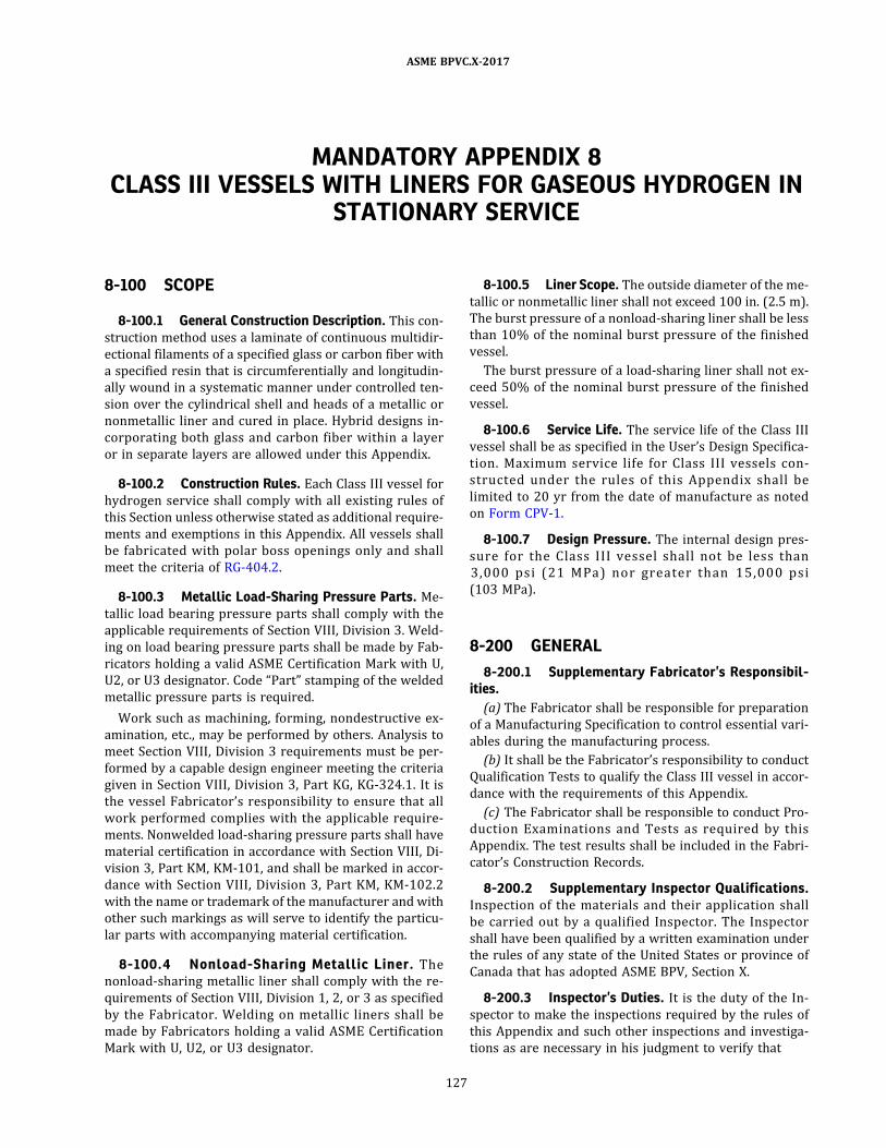
MANDATORY APPENDIX 8CLASS III VESSELS WITH LINERS FOR GASEOUS HYDROGEN IN
STATIONARY SERVICE
8-100 SCOPE
8-100.1 General Construction Description. This con-
struction method uses a laminate of continuous multidir-
ectional filaments of a specified glass or carbon fiber with
a specified resin that is circumferentially and longitudin-
ally wound in a systematic manner under controlled ten-
sion over the cylindrical shell and heads of a metallic or
nonmetallic liner and cured in place. Hybrid designs in-
corporating both glass and carbon fiber within a layer
or in separate layers are allowed under this Appendix.
8-100.2 Construction Rules. Each Class III vessel for
hydrogen service shall comply with all existing rules of
this Section unless otherwise stated as additional require-
ments and exemptions in this Appendix. All vessels shall
be fabricated with polar boss openings only and shall
meet the criteria of RG-404.2 .
8-100.3 Metallic Load-Sharing Pressure Parts. Me-
tallic load bearing pressure parts shall comply with the
applicable requirements of Section VIII, Division 3. Weld-
ing on load bearing pressure parts shall be made by Fab-
ricators holding a valid ASME Certification Mark with U,
U2, or U3 designator. Code “Part” stamping of the welded
metallic pressure parts is required.
Work such as machining, forming, nondestructive ex-
amination, etc. , may be performed by others. Analysis to
meet Section VIII , Division 3 requirements must be per-
formed by a capable design engineer meeting the criteria
given in Section VIII , Division 3, Part KG, KG-324.1 . It is
the vessel Fabricator’s responsibility to ensure that all
work performed complies with the applicable require-
ments. Nonwelded load-sharing pressure parts shall have
material certification in accordance with Section VIII, Di-
vision 3, Part KM, KM-101, and shall be marked in accor-
dance with Section VIII , Division 3 , Part KM, KM-102 .2
with the name or trademark of the manufacturer and with
other such markings as will serve to identify the particu-
lar parts with accompanying material certification.
8-100.4 Nonload-Sharing Metallic Liner. The
nonload-sharing metallic liner shall comply with the re-
quirements of Section VIII, Division 1, 2 , or 3 as specified
by the Fabricator. Welding on metallic liners shall be
made by Fabricators holding a valid ASME Certification
Mark with U, U2, or U3 designator.
8-100.5 Liner Scope. The outside diameter of the me-
tallic or nonmetallic liner shall not exceed 100 in. (2.5 m).
The burst pressure of a nonload-sharing liner shall be less
than 10% of the nominal burst pressure of the finished
vessel.
The burst pressure of a load-sharing liner shall not ex-
ceed 50% of the nominal burst pressure of the finished
vessel.
8-100.6 Service Life. The service life of the Class III
vessel shall be as specified in the User’s Design Specifica-
tion. Maximum service l ife for Class I I I vessels con-
s tructed under the rules o f this Appendix shal l be
limited to 20 yr from the date of manufacture as noted
on Form CPV-1.
8-100.7 Design Pressure. The internal design pres-
sure for the C lass I I I vesse l shal l not be les s than
3 , 0 0 0 p s i (2 1 MPa) no r greate r than 1 5 , 0 0 0 p s i
(103 MPa) .
8-200 GENERAL
8-200.1 Supplementary Fabricator’s Responsibil-ities.
(a) The Fabricator shall be responsible for preparation
of a Manufacturing Specification to control essential vari-
ables during the manufacturing process.
(b) It shall be the Fabricator’s responsibility to conduct
Qualification Tests to qualify the Class III vessel in accor-
dance with the requirements of this Appendix.
(c) The Fabricator shall be responsible to conduct Pro-
duction Examinations and Tests as required by this
Appendix. The test results shall be included in the Fabri-
cator’s Construction Records.
8-200.2 Supplementary Inspector Qualifications.Inspection of the materials and their application shall
be carried out by a qualified Inspector. The Inspector
shall have been qualified by a written examination under
the rules of any state of the United States or province of
Canada that has adopted ASME BPV, Section X.
8-200.3 Inspector’s Duties. It is the duty of the In-
spector to make the inspections required by the rules of
this Appendix and such other inspections and investiga-
tions as are necessary in his judgment to verify that
ASME BPVC.X-2017
127
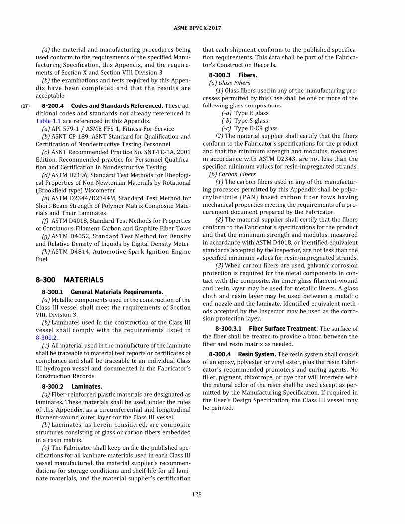
ð17Þ
(a) the material and manufacturing procedures being
used conform to the requirements of the specified Manu-
facturing Specification, this Appendix, and the require-
ments of Section X and Section VIII, Division 3
(b) the examinations and tests required by this Appen-
dix have been comp leted and that the resu l ts are
acceptable
8-200.4 Codes and Standards Referenced. These ad-
ditional codes and standards not already referenced in
Table 1.1 are referenced in this Appendix.
(a) API 579-1 / ASME FFS-1, Fitness-For-Service
(b) ASNT-CP-189, ASNT Standard for Qualification and
Certification of Nondestructive Testing Personnel
(c) ASNT Recommended Practice No. SNT-TC-1A, 2001
Edition, Recommended practice for Personnel Qualifica-
tion and Certification in Nondestructive Testing
(d) ASTM D2196, Standard Test Methods for Rheologi-
cal Properties of Non-Newtonian Materials by Rotational
(Brookfield type) Viscometer
(e) ASTM D2344/D2344M, Standard Test Method for
Short-Beam Strength of Polymer Matrix Composite Mate-
rials and Their Laminates
(f) ASTM D4018, Standard Test Methods for Properties
of Continuous Filament Carbon and Graphite Fiber Tows
(g) ASTM D4052 , Standard Test Method for Density
and Relative Density of Liquids by Digital Density Meter
(h) ASTM D4814, Automotive Spark-Ignition Engine
Fuel
8-300 MATERIALS
8-300.1 General Materials Requirements.(a) Metallic components used in the construction of the
Class II I vessel shall meet the requirements of Section
VIII, Division 3.
(b) Laminates used in the construction of the Class III
vessel shal l comply with the requirements l isted in
8-300.2.
(c) All material used in the manufacture of the laminate
shall be traceable to material test reports or certificates of
compliance and shall be traceable to an individual Class
III hydrogen vessel and documented in the Fabricator’s
Construction Records.
8-300.2 Laminates.(a) Fiber-reinforced plastic materials are designated as
laminates. These materials shall be used, under the rules
of this Appendix, as a circumferential and longitudinal
filament-wound outer layer for the Class III vessel.
(b) Laminates, as herein considered, are composite
structures consisting of glass or carbon fibers embedded
in a resin matrix.
(c) The Fabricator shall keep on file the published spe-
cifications for all laminate materials used in each Class III
vessel manufactured, the material supplier’s recommen-
dations for storage conditions and shelf life for all lami-
nate materials, and the material supplier’s certification
that each shipment conforms to the published specifica-
tion requirements. This data shall be part of the Fabrica-
tor’s Construction Records.
8-300.3 Fibers.(a) Glass Fibers
(1 ) Glass fibers used in any of the manufacturing pro-
cesses permitted by this Case shall be one or more of the
following glass compositions:
(-a) Type E glass
(-b) Type S glass
(-c) Type E-CR glass
(2) The material supplier shall certify that the fibers
conform to the Fabricator’s specifications for the product
and that the minimum strength and modulus, measured
in accordance with ASTM D2343 , are not less than the
specified minimum values for resin-impregnated strands.
(b) Carbon Fibers
(1 ) The carbon fibers used in any of the manufactur-
ing processes permitted by this Appendix shall be polya-
crylonitri le (PAN) based carbon fiber tows having
mechanical properties meeting the requirements of a pro-
curement document prepared by the Fabricator.
(2) The material supplier shall certify that the fibers
conform to the Fabricator’s specifications for the product
and that the minimum strength and modulus, measured
in accordance with ASTM D4018, or identified equivalent
standards accepted by the inspector, are not less than the
specified minimum values for resin-impregnated strands.
(3) When carbon fibers are used, galvanic corrosion
protection is required for the metal components in con-
tact with the composite. An inner glass filament-wound
and resin layer may be used for metallic liners. A glass
cloth and resin layer may be used between a metallic
end nozzle and the laminate. Identified equivalent meth-
ods accepted by the Inspector may be used as the corro-
sion protection layer.
8-300.3.1 Fiber Surface Treatment. The surface of
the fiber shall be treated to provide a bond between the
fiber and resin matrix as needed.
8-300.4 Resin System. The resin system shall consist
of an epoxy, polyester or vinyl ester, plus the resin Fabri-
cator’s recommended promoters and curing agents. No
filler, pigment, thixotrope, or dye that will interfere with
the natural color of the resin shall be used except as per-
mitted by the Manufacturing Specification. If required in
the User’s Design Specification, the Class III vessel may
be painted.
ASME BPVC.X-2017
128

8-300.4.1 Resin Material Requirements.
(a) The resin materials used in the manufacture of the
Class II I vessel shall be the same as those specified in
the Manufacturing Specification. Each resin shall be trace-
able by the name of its supplier and the trade name or
number of that supplier. The resin supplier shall supply
to the Fabricator a Certificate of Analysis for each resin
used. It shall include the following information:
(1) resin identification
(2) batch number(s)
(3) date of manufacture
(4) shelf life
(b) The res in supplier shall certify, for each batch
shipped, the value and the limits required by the specifi-
cation of the properties identified in Table 8-300.4.1-1 .
Resin material outside the shelf life shall be either re-
tested by the resin manufacturer and certified to the ori-
ginal properties or rejected. The values obtained for
viscosity and specific gravity for the resin alone shall be
within the limits of the supplier’s specification for that re-
sin and as listed in the Manufacturing Specification. The
values obtained for gel time and peak exotherm tempera-
ture shall be for a particular resin/curing system test for-
mulation and temperature, and shall be within the limits
listed in the Manufacturing Specification. The test formu-
lation and temperature shall be representative of the for-
mulations used during Class III vessel manufacture. These
test results shall be certified by the Fabricator and shall
be included in the Fabricator’s Construction Records.
(c) The tolerance limits for the test formulation, as
listed in the Manufacturing Specification, may be estab-
lished by either the resin supplier or the Fabricator. The
tolerance limits shall be established using formulation
components having Fabricator-specified material charac-
teristics. The tolerance limits established shall be within a
sufficiently narrow range such that test results outside
this range would reflect deviations in component material
characteristics and alert the Fabricator of possible mate-
rial irregularities.
(d) The Fabricator shall establish a maximum use tem-
perature for the resin/cure system used. This may be in
conjunction with the resin supplier or independent labo-
ratory, and may be based on heat distortion temperature
or glass transition temperature. The Fabricator shall rees-
tablish and redocument the maximum use temperature at
least every twelve months using current batches of resin
and curing agent. The maximum use temperature shall be
recorded on the Manufacturing Specification. A record of
these determinations shall become part of the Fabrica-
tor’s Construction Records.
8-300.5 Curing Agents. The curing agents used, the
resin-to-curing-agent ratio and the curing procedure fol-
lowed in the Class III vessel manufacture shall be as spe-
cified in the Manufacturing Specification. Each curing
agent shall be traceable by the supplier’s name, the sup-
plier’s designation, and the generic name.
8-300.5.1 Laminate Cure. The Fabricator shall en-
sure that the resin applied to the Class III vessel is prop-
erly cured using a test specimen. Proper cure shall be
demonstrated by using the Barcol test in accordance with
ASTM D2583 or other appropriate method. Barcol read-
ings shall be within the tolerance specified by the resin
supplier. If the resin supplier does not provide Barcol spe-
cifications for the resin/curing system used, the Fabrica-
to r s ha l l e s tab l i s h B arco l s p e c i fi ca ti o n s . B arco l
specifications established by the Fabricator shall be docu-
mented. Barcol specifications shall become part of the
Fabricator’s Construction Records.
8-300.6 Interlaminar Shear Strength. The laminates
used in manufacturing Class III vessel shall have mini-
mum in te r l am inar s hear s trength s o f 2 , 0 0 0 p s i
(13.8 MPa) for all resins, determined in accordance with
ASTM D2344. The test shall be performed following the
boiling of the test sample in water for 24 hr. The test re-
sults shall be included in the Fabricator’s Construction
Records. The measured interlaminar shear strength shall
be recorded on Form CPV-2.
Table 8-300.4.1-1Resin Systems: Required Certifications and Tests
Resin System
Required
Certifications and
Tests
Applicable ASTM
Specification
Polyester/vinyl ester Viscosity ASTM D445/D2196
Acid number ASTM D1045
Specific gravity Wt. per gallon cup or ASTM
D4052
Epoxy Viscosity ASTM D445/D2196
Epoxide equivalent ASTM D1652
Specific gravity Wt. per gallon cup or ASTM
D4052
ASME BPVC.X-2017
129

8-300.6.1 Nonmetallic Liner Materials. All non-metallic liners shall be considered nonload sharing. The
liner shall be manufactured from a material suitable for
hydrogen service. The liner material supplier shall verify
that each batch of liners have the specified material chem-
istry and mechanical properties and provide a certificate
of conformance to the Class III vessel Fabricator docu-
menting the verification.
8-400 DESIGN
8-400.1 Allowable Stress Rules. Stress analysis shallbe carried out and documented in the Fabricator’s Con-
struction Records. The stresses in the laminate and in
the liner shall be calculated using appropriate analytical
methods that address the nonlinear behavior. The mini-
mum thickness and minimum material properties shall
be used in the stress calculations.
The circumferential and longitudinal stresses gener-
ated in the laminate layer shall be used to resist loads
due to internal pressure, thermal expansion, and all other
circumferential and longitudinal loads.
The maximum fiber stress at any location in the lami-
nate shall not exceed 67% of the tensile strength of the fi-
ber during the autofrettage pressure load for vessels with
load-sharing liners.
The maximum fiber stress at any location in the lami-
nate layer shall not exceed 28.5% for glass fibers and
44.4% for carbon fibers of the tensile strength of the fiber
at design conditions.
The calculation of stresses shall consider the least fa-
vorable effects of geometric irregularities (e.g. , out-
of-roundness) , weld peaking, reinforcement, and offsets
as well as mismatches of Categories A and B welded
liners.
8-400.2 Design Pressure. The design pressure of the
Class I I I vessel shall be specified in the User’s Design
Specification. The maximum design pressure for Class
II I vessel shall not be less than 3 ,000 psi (21 MPa) or
greater than 15,000 psi (103 MPa) .
8-400.3 Maximum Design Temperature. The Maxi-
mum Design Temperature of the laminate shall be the
same as the Maximum Design Temperature of the Class
III vessel and shall be specified in the User’s Design Spec-
ification. The Maximum Design Temperature shall be at
least 35°F (19°C) below the maximum use temperature
of the resin as documented in the Manufacturing Specifi-
cation, but in no case shall it exceed 185°F (85°C) .
8-400.4 Minimum Design Temperature. The Mini-
mum Design Temperature to which a Class I I I vessel
may be constructed under this Appendix shall not be
colder than −65°F (−54°C) .
8-400.5 Vessel Supports. Vessel supports shall be
designed to function without damaging the vessel consid-
ering al l l o ads resu l ting from transportation and
operation.
8-400.6 Protective Layer. An optional external layer
of laminate may be provided for protection of the struc-
tural laminate layer from damage due to impact, ultravio-
let radiation, or other environmental exposure, fire or
abrasive conditions, and in-service degradation of the la-
minate for the life of the Class III vessel under the service
conditions as specified in the User’s Design Specification.
This layer shall not be considered in the calculation on the
stress levels in the vessel and shall not be applied to the
vessel used for the qualification testing.
8-400.7 Hybrid Designs. Hybrid construction (using
more than one type of reinforcing fiber) is permitted. The
strength of the individual types of fibers used in hybrid
construction may be verified by testing of vessels rein-
forced with a single type of fiber. The test can be per-
formed on subscale vessels . In a hybrid construction,
the applicable Stress Ratio requirements must be met in
one of the two following ways:
(a) If load sharing between the various fiber reinforcing
materials is considered a fundamental part of the design,
e a c h fi b e r mu s t m e e t th e s ta te d S tr e s s Ra t i o
requirements.
(b) If load sharing between fibers is not considered as a
fundamental part of the design, then one of the reinfor-
cing fibers must be capable ofmeeting the Stress Ratio re-
quirements even if all other fiber reinforcing materials
are removed.
8-500 FABRICATION
8-500.1 Manufacturing Specification.(a) The Manufacturing Specification shall specify, as a
minimum, all pertinent material properties data, the
means by which the laminate is applied to the liner, and
all other significant process data associated with the lami-
nate and the Class III vessel design. The Manufacturing
Specification shall include tolerance limits for all appro-
priate material properties, process conditions such as
time and temperature, acceptable test result values, com-
positions of resins , fibers , and curing agents , etc. , as
further defined by the rules of this Appendix. The Manu-
facturing Specification shall form part of the Fabricator’s
Construction Records.
(b) As a minimum, the essential variables provided be-
low shall be held within tolerances as specified in the
Manufacturing Specification.
(1) Essential variables for liner and nozzles
(-a) materia l (s ) including l imits o f chemical
analysis
(-b) dimensions, minimum thickness, straightness,
and out-of-roundness with tolerances
(-c) process and specification of manufacture
ASME BPVC.X-2017
130

(-d) heat-treatment, temperatures, duration, and
tolerances
(-e) i n s p e c t i o n p r o c e d u r e s ( m i n i m u m
requirements)
(-f)material properties
(-g) dimensional details of nozzle threads and any
other permanent features
(-h) method of sealing nozzle to nonload-sharing
liner for bonded bosses
(-i) autofrettage procedure for metal l ic l ined
vessels
(2) Essential variables for laminate materials
(-a) fiber material, specification, and mechanical
properties requirements
(-1 ) the fiber content in the laminate shall con-
form to that set forth in the Specification
(-b) resin system, components, curing agent, and
accelerators
(-c) laminate construction including the number
of strands used, the allowable gap between bands, the al-
lowable gap within bands, overlap in the laminate, and
details of prestressing where applicable
(-d) curing process, temperatures, duration, and
tolerances
(-1 ) If other than ambient temperature cure is
employed, the design and operation of the curing equip-
ment shall provide uniform heating over the entire sur-
face of the vessel. Heating may be done from the inside
or outside of the vessel, or from both inside and outside.
The cure times and temperatures shall conform to those
required by the Manufacturing Specification. Heat up
and cool down times shall be excluded.
(3) Essential variables for laminate manufacture
(-a) Patterns. Specific winding patterns for the
continuous fiber strands shall be used as defined in the
qualified Manufacturing Specification. Any winding pat-
tern that places the filaments in the desired orientation
and is designated in the Manufacturing Specification
may be used.
(-b) Filament Winding
(-1 ) Tensioning. Tension on the strands of fila-
ments during the winding operation shall be controlled
to ensure a uniform application of the composite rein-
forcement onto the liner.
(-2) Winding Speed. The speed of winding shall
be limited only by the ability to meet the tensioning re-
quirements, to conform to the specified winding pattern,
and to ensure adequate resin impregnation.
(-3) Bandwidth and Spacing. The bandwidth and
spacing shall conform to those specified in the Manufac-
turing Specification.
8-500.2 Variation From Manufacturing Specifica-tion. Any variation in the essential variables from the tol-
erances provided in the Manufacturing Specification shall
result in rejection of the Class III vessel.
8-600 EXAMINATION
8-600.1 Qualification of Nondestructive Examina-tion Personnel. The Fabricator shall certify that each ex-
aminer performing visual tests according to the Appendix
has been qualified to the requirements of Section V,
Article 9.
8-600.2 Supplementary Examination Requ ire-ments.
(a) The Fabricator completing a Class III vessel or ves-
sel part shall be responsible for conducting the examina-
tions required by this paragraph. Examination shall be
carried out after the hydrostatic test.
(b) Each Class III vessel shall be subjected to the exam-
inations required by this paragraph and shall conform to
the specified requirements, with results recorded in Pro-
duction Test Reports. The Class III vessel Production Test
Report shall become part of the Fabricator’s Construction
Records.
8-600.2.1 Visual Examination. Each Class III ves-
sel shall be visually examined, using a suitable light
source, to determine whether there are any imperfections
of the type specified in Table 8 -600 .2 .1 -1 or Tab le
8-600.2 .1-2 . If an external protective layer or paint is ap-
plied, the laminate shall be examined as required during
winding, or prior to application of the protective layer
or paint, to ensure that there are no unacceptable defects.
8-600.2.2 Design Dimensions Examination. EachClass III vessel shall be examined for conformance with
d imens ions and to l e rance s s hown on the des i gn
drawings.
8-600.2.3 Repair of Imperfections. In the event
that any of the unacceptable imperfections listed in Table
8-600.2 .1-1 or Table 8-600.2.1-2 extend into the structur-
al layer or the structural fibers are cut or in any way dam-
aged, the imperfection shall be deemed unrepairable and
the Class III vessel shall be rejected. If the unacceptable
imperfections l i s ted in Tab le 8 -600 .2 . 1 -1 or Tab le
8-600.2 .1-2 extend only into the nonstructural, protective
layer of the laminate, the layer may be repaired, unless
prohibited by the Manufacturing Specification. The re-
paired area shall maintain the minimum thickness, fiber
content, and protective capabilities of the unrepaired pro-
tective layer.
8-600.2.4 Visual Examination of Repaired Areas.Each repaired area shall be examined visually and shall
mee t a l l th e ac ce p tan ce requ i remen ts o f Tab l e
8-600.2 .1-1 or Table 8-600.2 .1-2 . The repaired area shall
have translucency and surface finish comparable to the
remainder of the vessel.
8-600.2.5 Thickness Check. Visual evidence of
variation in thickness shall be explored and the thickness
shall be verified to meet the minimum required thickness
ASME BPVC.X-2017
131
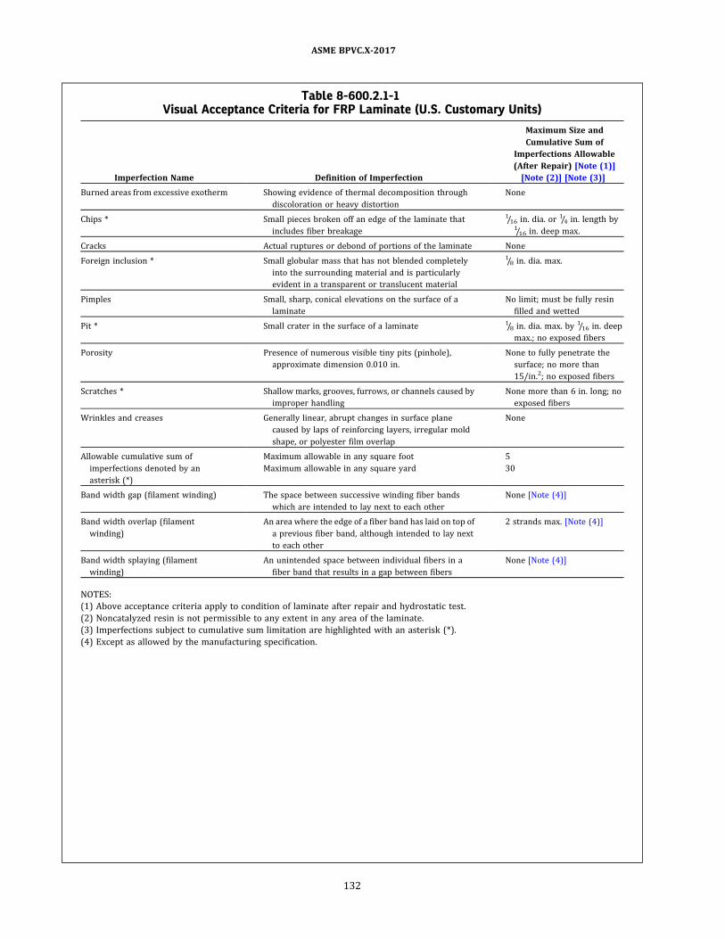
Table 8-600.2.1-1Visual Acceptance Criteria for FRP Laminate (U.S. Customary Units)
Imperfection Name Definition of Imperfection
Maximum Size and
Cumulative Sum of
Imperfections Allowable
(After Repair) [Note (1)]
[Note (2)] [Note (3)]
Burned areas from excessive exotherm Showing evidence of thermal decomposition through
discoloration or heavy distortion
None
Chips * Small pieces broken off an edge of the laminate that
includes fiber breakage
1/16 in. dia. or 1/4 in. length by1/16 in. deep max.
Cracks Actual ruptures or debond of portions of the laminate None
Foreign inclusion * Small globular mass that has not blended completely
into the surrounding material and is particularly
evident in a transparent or translucent material
1/8 in. dia. max.
Pimples Small, sharp, conical elevations on the surface of a
laminate
No limit; must be fully resin
filled and wetted
Pit * Small crater in the surface of a laminate 1/8 in. dia. max. by 1/16 in. deep
max.; no exposed fibers
Porosity Presence of numerous visible tiny pits (pinhole) ,
approximate dimension 0.010 in.
None to fully penetrate the
surface; no more than
15/in.2; no exposed fibers
Scratches * Shallow marks, grooves, furrows, or channels caused by
improper handling
None more than 6 in. long; no
exposed fibers
Wrinkles and creases Generally linear, abrupt changes in surface plane
caused by laps of reinforcing layers, irregular mold
shape, or polyester film overlap
None
Allowable cumulative sum of
imperfections denoted by an
asterisk (*)
Maximum allowable in any square foot 5
Maximum allowable in any square yard 30
Band width gap (filament winding) The space between successive winding fiber bands
which are intended to lay next to each other
None [Note (4)]
Band width overlap (filament
winding)
An area where the edge of a fiber band has laid on top of
a previous fiber band, although intended to lay next
to each other
2 strands max. [Note (4)]
Band width splaying (filament
winding)
An unintended space between individual fibers in a
fiber band that results in a gap between fibers
None [Note (4)]
NOTES:
(1) Above acceptance criteria apply to condition of laminate after repair and hydrostatic test.
(2) Noncatalyzed resin is not permissible to any extent in any area of the laminate.
(3) Imperfections subject to cumulative sum limitation are highlighted with an asterisk (*) .
(4) Except as allowed by the manufacturing specification.
ASME BPVC.X-2017
132

Table 8-600.2.1-2Visual Acceptance Criteria for FRP Laminate (SI Units)
Imperfection Name Definition of Imperfection
Maximum Size and
Cumulative Sum of
Imperfections Allowable
(After Repair) [Note (1)]
[Note (2)] [Note (3)]
Burned areas from excessive exotherm Showing evidence of thermal decomposition through
discoloration or heavy distortion
None
Chips * Small pieces broken off an edge of the laminate that
includes fiber breakage
1.6 mm dia. or 6.4 mm length
by 1.6 mm deep max.
Cracks Actual ruptures or debond of portions of the laminate None
Foreign inclusion * Small globular mass that has not blended completely
into the surrounding material and is particularly
evident in a transparent or translucent material
3.2 mm dia. max.
Pimples Small, sharp, conical elevations on the surface of a
laminate
No limit; must be fully resin
filled and wetted
Pit * Small crater in the surface of a laminate 3.2 mm dia. max. by 1.6 mm
deep max.; no exposed fibers
Porosity Presence of numerous visible tiny pits (pinhole) ,
approximate dimension 0.25 mm
None to fully penetrate the
surface; no more than15/650 mm2 ; no exposed
fibers
Scratches * Shallow marks, grooves, furrows, or channels caused by
improper handling
None more than 15.2 cm long;
no exposed fibers
Wrinkles and creases Generally linear, abrupt changes in surface plane
caused by laps of reinforcing layers, irregular mold
shape, or polyester film overlap
None
Allowable cumulative sum of
imperfections denoted by an
asterisk (*)
Maximum allowable in any 930 cm2 5
Maximum allowable in 0.84 m2 30
Band width gap (filament winding) The space between successive winding fiber bands
which are intended to lay next to each other
None [Note (4)]
Band width overlap (filament
winding)
An area where the edge of a fiber band has laid on top of
a previous fiber band, although intended to lay next
to each other
2 strands max. [Note (4)]
Band width splaying (filament
winding)
An unintended space between individual fibers in a
fiber band that results in a gap between fibers
None [Note (4)]
NOTES:
(1) Above acceptance criteria apply to condition of laminate after repair and hydrostatic test.
(2) Non-catalyzed resin is not permissible to any extent in any area of the laminate.
(3) Imperfections subject to cumulative sum limitation are highlighted with an asterisk (*) .
(4) Except as allowed by the manufacturing specification.
ASME BPVC.X-2017
133

in the Fabricator’s Design Report. Thickness less than the
value specified in the Fabricator’s Design Report shall not
be permitted.
8-600.2.6 Surface Examination. After the produc-
tion hydrotest, the metallic pressure parts meeting the re-
quirements of Section VIII, Division 3 shall be subject to a
surface exam in accordance with Section VIII, Division 3,
Part KE, KE-400 by the vessel Fabricator. Only the acces-
sible portions of these parts shall be examined by liquid
penetrant or magnetic particle examination with accep-
tance criteria per Section VI I I , D ivis ion 3 , Part KE ,
KE-233.2 .
8-600.2.7 Acoustic Emission Examination.8-600.2.7.1 Use and Test Objectives. All Class
III production and qualification vessels shall be subject
to an acoustic emission examination to detect hidden
flaws in the laminate and to provide an initial signature
of the vessel. This method may be used in conjunction
with the initial hydrostatic pressure test per 8-700.5 .1
and volumetric expansion test per 8-700.5.2 of the vessel,
including an autofrettage pressurization.
All analysis shall be done on the waveforms. The wave-
forms of interest are the E (extensional mode) and F (flex-
ural mode) plate waves. The velocities of the earliest
arriving frequency in the E wave and the latest arriving
frequency in the Fwave shall be measured in the circum-
ferential direction in order to characterize the material
and set the sample time (the length of the wave window).
The E and F waves must be digitized and stored for ana-
lysis. The test pressure shall be recorded simultaneously
with the AE events. Permanent storage of the waveforms
is required.
All personnel conducting the examination shall be cer-
tified per the guidelines of ASNT SNT-TC-1A or CP-189 AE
Level II or Level II I . An inspector performing this test
should have training in and experience with measuring
the extensional and flexural velocities, Ce and Cf, in com-
posites and identifying wave modes.
8-600.2.7.2 Test Procedure. Couple sensors to
vessel and connect to the testing equipment per Section
V, Article 11. Connect pressure transducer to the record-
er. Conduct sensor performance checks prior to test to
verify proper operation and good coupling to the vessel.
The E and F waveforms shall be observed by breaking
pencil lead at approximately 8 in. (20 cm) and 16 in.
(40.6 cm) from a sensor along the fiber direction. All cali-
bration data shall be recorded.
(a) When an autofrettage is not conducted, pressurize
vessel to hydrostatic test pressure, hold at test pressure
for 30 min, depressurize to design pressure and hold
for 10 min to check for leaks per 8-700.5.1 . After the leak
test, depressurize to 10% of test pressure and hold for a
minimum of 30 min, repressurize to 98% of the test pres-
sure and hold for 10 min, and then depressurize to zero
pressure. Record events for 2 min at zero pressure and
save the data. Then conduct a post-test performance
check and save data. The rate of pressurization shall not
exceed 20 psi/sec (138 kPa/s) nor be less than 2 psi/sec
(13 .8 kPa/s) . Test temperature shall be between 50°F
(10°C) and 120°F (49°C) .
For the first pressurization during the initial hydro-
static test, use a threshold of 80 dBAE (0 dB = 1 μV at
the sensor) . The repressurization at 98% of hydrostatic
test pressure and load hold shall use a threshold of 60
dBAE. Record waveforms during all pressurizations, pres-
sure holds, and depressurizations. Recording shall be sus-
pended during the time personnel and inspectors are in
contact with the vessel during the hydraulic expansion
test per 8-700.5.2 and the leak test per 8-700.5.8.
(b) When an autofrettage pressurization is conducted,
pressurize the vessel to the autofrettage pressure, hold
at this pressure for 30 min., then depressurize to the de-
sign pressure and hold for 10 min. to check for leaks per
8-700.5.1 . After the leak test, depressurize to 10% of the
hydrostatic test pressure and hold for 30 min, repressur-
ize to the hydrostatic test pressure and hold for 30 min.,
then depressurize to zero pressure. Record events for
2 min. at zero pressure and save the data. Then conduct
a post-test performance check and save data. The rate
of pressurization shal l not exceed 20 ps i/sec (1 38
kPa/s) nor be less than 2 psi/sec (13.8 kPa/s) . Test tem-
perature shall be between 50°F (10°C) and 120°F (49°C) .
For the first pressurization during the initial autofret-
tage pressurization, use a threshold of 80 dBAE (0 dB =
1 V at the sensor) . The repressurization at the hydrostatic
test pressure and load hold shall use a threshold of
50 dBAE . Record waveforms during all pressurizations,
pressure holds, and depressurizations. Recording shall
be suspended during the time personnel and inspectors
are in contact with the vessel during the hydraulic expan-
sion test per 8-700.5.2 and the leak test per 8-700.5.8.
(c) Additional Requirements: First and Second Loading
(1) The first loading is defined as the first pressuriza-
tion of the vessel to a pressure greater than 80% of the
required first loading test pressure. A preload is not
permitted.
(2) The second loading is defined as the pressuriza-
tion of the vessel to a pressure greater than 80% of the
required section loading test pressure.
(3) The second loading shall follow the first loading
without any intermediate loadings. An intermediate load-
ing is defined as any pressurization of the vessel to a pres-
sure greater than 80% of the required second loading test
pressure. A second autofrettage loading is not permitted.
(4) Except as noted below, if the first and second
loading conditions as defined in (1) and (2) are not met,
the vessel shall be considered to have failed the test.
(d) Interruption in Pressurization or Load Hold on First
Loading. During the first loading it may be necessary to
halt pressurization, if the pressure has not exceeded
80% of the test pressure, a temporary suspension of data
acquisition is permissible. The pressure may be reduced
or held constant during the pressurization hold. If the
ASME BPVC.X-2017
134
pressure has exceeded 80% of test pressure, data acquisi-
tion shall not be suspended for more than 15 min. If a
longer suspension of data acquisition is required, the ves-
sel shall be unloaded and held for 12 hr or longer at less
than 10% of test pressure. The vessel shal l then be
retested.
(e) Interruption in Pressurization or Load Hold on Sec-
ond Loading
(1) During the second loading, data acquisition shall
not be suspended for more than 2 min during loading
and during the thirty minute pressure hold.
(2) If (1) is violated, the second loading shall be re-
peated after the vessel has been unloaded and held for
12 hr or longer at 10% or less of the second loading test
pressure. This provision applies to all second loading, re-
gardless of whether the first loading is an autofrettage
load or the hydrostatic test load.
(3) When an autofrettage load is applied to a vessel,
the hydrostatic load is the second loading and under (1)
the AE test cannot be suspended. Accordingly, the volu-
metric expansion test shall be delayed until after the
30 min pressure hold.
(4) The first loading is not as critical as the second
loading and it is not necessary to wait until the end of
the 30 min hold if the volumetric expansion test is con-
ducted as part of the firs t loading (autofrettage or
hydrostatic) .
8-600.2.7.3 Equipment.8-600.2.7.3.1 Testing System. A testing sys-
tem shall consist of
(a) sensors
(b) preamplifiers
(c) high pass and low pass filters
(d) amplifier
(e) A/D (analog-to-digital) converters
(f) a computer program for the collection of data
(g) computer and monitor for the display of data
(h) a computer program for analysis of data
Examination of the waveforms event by event must al-
ways be possible and the waveforms for each event must
correspond precisely with the pressure and time data
during the test. The computer program shall be capable
of detecting the first arrival channel. This is critical to
the acceptance criteria below.
Sensors and recording equipment shall be checked for a
current calibration sticker or a current certificate of
calibration.
8-600.2.7.3.2 Sensor and Sensor Calibration.Calibration shall be in volts/meter of displacement over a
specified frequency range. This shall be done by the man-
ufacturer with a Michelson interferometer setup such as
that used at National Institute of Standards and Technol-
ogy. Sensors shall have at least 100 V/μm sensitivity over
about 300 kHz bandwidth. See sensor spacing guidelines
for high frequency sensors in Section V, Article 11. At least
two sensors shall be used in any AE test regardless of ves-
sel size so that EMI is easily detected by simultaneity of
arrival.
8-600.2.7.3.3 Preamplifiers and Amplifiers.See ASME Section V, Article 11.
8-600.2.7.3.4 Filters. A high pass filter of
5 kHz shall be used. A low pass filter shall be applied to
prevent digital aliasing that occurs if frequencies higher
than the Nyquist frequency (half the Sampling Rate) are
in the signal.
8-600.2.7.3.5 A/D. The sampling speed and
memory depth (wave window length) are dictated by
the test requirements and calculated as follows:
Use CE = 0.2 in./μs (5 080 m/s) and CF = 0.05 in./μs
(1 270 m/s) , the speeds of the first arriving frequency
in the E wave and last arriving frequency in the F wave,
respectively, as a guide. The actual dispersion curves for
the material shall be used if available.
L/CE = T1 μs is when the first part of the direct Ewave
will arrive.
L /CF = T2 μs is when the last part of the direct Fwave
will arrive.
(T2 − T1) × 1.5 is the minimum waveform window time
and allows for pretrigger time.
The recording shall be quiescent before front end of the
Ewave arrives. This is called a “clean front end.” “Clean” is
defined in 8-600.2 .7.4.2(b) below.
The sampling rate, or sampling speed, shall be such that
aliasing does not occur.
8-600.2.7.4 Analysis.8-600.2.7.4.1 Theory of AE Monitoring of
High Pressure Composite Pressure Vessels. A stable ves-
sel will exhibit cumulative curves with exponentially de-
caying curvature. The shape of the cumulative events
curve is similar for pressure vessels made of fiberglass,
aramid, and carbon fiber that exhibit a fiber dominated
failure mode. This is essentially a shakedown test that de-
monstrates the composite is not progressing to failure at
the hold pressure.
8-600.2.7.4.2 Analysis Procedure. Data will
include matrix splits, matrix cracks, fiber breaks, and ma-
tr i x ch i rp s due to frac ture s urface fre tti ng , and
fiber/matrix debonding.
(a) Filter data to eliminate any external noise such as
electromagnetic interference (EMI) , mechanical rubbing,
flow noise, etc. Identify noise events by their shape, spec-
tral characteristics, or other information known about the
test such as a temporally associated disturbance due to
the pressurization system or test fixturing. EMI is charac-
terized by a lack of any mechanical wave propagation
characteristics, particularly a lack of dispersion being ap-
parent. EMI can be further identified by simultaneity of
arrival on more than one channel. The two criteria shall
ASME BPVC.X-2017
135

be considered together to ensure it is not simply an event
that happened to be centered between the sensors. Me-
chanical rubbing frequencies are usually very low and
can be determined by experiment. There should be no
flow noise. If the vessel, or a fitting, leaks, this will com-
promise the data as AE is very sensitive to leaks. Leak
noise is characterized by waves that look uniform across
the entire length of the waveform window. If a leak occurs
during the load hold, the test must be redone. Flow noise
is characterized by waves that fill the waveform window.
It can be filtered out by setting a pre-trigger/post-trigger
energy ratio.
(b) Use only events that have clean front ends (defined
above in 8-600.2 .7.3.5) and in which first arrival channel
can be determined. Clean means having a pre-trigger en-
ergy of less than 0.01 V2/μsec. Energy is computed by the
integral of the voltage squared over time.
(c) Plot first arrival cumulative events versus time.
Plots shall always show the pressure data.
(d) Apply exponential fits by channel for pressure hold
time and display both data and fit. The values are deter-
mined by the fit to
The B value is the shape factor of the cumulative
curves. C is an intercept and A is a scale factor. The time
t shall be equal intervals during the hold with events
binned by time interval. Record exponents and goodness
of fit (R 2) . Plot energy decay curves. One-third or one-
fourth of hold time shall be used for event energy binning
(cumulative energy) . The equation is
The sequence of energy values must monotonically de-
crease. This is similar to using other energy criteria, such
as Historic Index. A sequence that is not properly decreas-
ing will be indicated by a low R 2 value.
(e) Save all plots (all channels) to report document.
(f) Repeat plots for second pressure hold and save to
report document.
(g) Record exponents and R2 values.
(h) Vessel B values shall be tracked and compiled in or-
der to develop a statistically significant database.
(1) B is the critical value that measures the fre-
quency of occurrence of events during pressure hold.
(2) Not every vessel will have the exact same B value.
(3) Data on B values should cluster.
8-600.2.7.5 Acceptance Criteria. The qualifica-
tion vessel provides the initial B values for events and en-
e r gy fr om th e l o a d h o l d d a ta fr om th e i n i t i a l
pressurization and the repressurization, if the vessel
burst pressure is satisfactory. The criteria are as follows:
Criterion Pass
Cumulative Event Decay Rate −0.1 < B < −0.0001, R 2≥ 0.80
Cumulative Energy Decay Rate −0.2 < B < −0.0001, R 2≥ 0.80
If these criteria are not met, the vessel does not pass.
The vessel may be retested. An AE Level II I inspector
must review the data from the initial testing and the sub-
sequent loading test before the vessel can be passed. Ret-
est loadings shall follow the original pressurization rates
and pressures and use a threshold of 60 dBAE. If the vessel
fails the criteria again, the vessel shall not be certified by
the Inspector as meeting the provisions of this Section.
8-700 TESTING
The Fabricator completing a Class III vessel or vessel
part shall be responsible for conducting the tests required
by this Appendix.
8-700.1 Production Testing Requirements. EachClass III vessel shall be subjected to the tests required
by this paragraph and shall conform to the specified re-
quirements, with results recorded on Production Test Re-
ports. The Class III vessel Production Test Report shall
become part of the Fabricator’s Construction Records.
A hydraulic pressure test and a hydraulic volumetric
expansion test as defined in 8-700.5.1 and 8-700.5.2 shall
be performed on each vessel . Both tests may be per-
formed during one pressurization cycle of the vessel. An
acoustic emission examination per 8-600.2 .7 shall be
done during the hydraulic pressure test and subsequent
repressurization. During the time the hydraulic volu-
metric expansion test is performed during the initial pres-
surization, the AE examination shall be suspended due to
personnel coming into contact with the vessel during the
required measurements.
8-700.2 Qualification Testing.8-700.2.1 General Requirements.
(a) It shall be the Fabricator’s responsibility to qualify
the Class III vessel design. The vessels shall be fabricated
per the requirements of the Manufacturing Specification
and the design.
(b) The results of the testing and examinations re-
quired in this paragraph shall be documented in the Qua-
lification Test Report. The Qualification Test Report shall
be prepared and certified by the Fabricator and accepted
by the Inspector. The results of these tests shall be docu-
mented on Form CPV-2 and together with all test docu-
ments shall be designated the Qualification Test Report
and shall be included in the Fabricator’s Construction
Records.
(c) The Class III vessel subject to these tests and exam-
inations shall be designated as “Class III Hydrogen Proto-
type Vessels.” Class III Prototype Vessels that are used for
qualification testing shall meet all the requirements of
this Case but shall not be Code stamped. For new designs,
a sufficient number of prototype vessels shall be fabri-
cated to complete the qualification testing. For Class III
vessels with allowable design variant to the original de-
sign, as provided in Table 8-700.2 .1-1, a reduced number
of qualification tests as outlined in Table 8-700.2.1-1 are
ASME BPVC.X-2017
136
acceptable for vessel qualification with the Inspector’s ap-
proval. For design variations in diameter and design pres-
sure, the wall thickness must be scaled in proportion to
the diameter and pressure change increase to achieve a
stress ratio equal to or less than the original design.
(d) Each Class III Hydrogen Prototype Vessel used for
qualification testing shall be fabricated and examined in
accordance with the Manufacturing Specification, the de-
sign, and the additional specific requirements below, and
the results shall be documented in the Qualification Test
Report. The Class III vessel used for qualification testing
shall not have a protective layer.
8-700.2.2 Specific Requirements.
(a) Weight ofResin and Fiber. The percentage by weight
of resin and fiber in each Class III Prototype Vessel shall
be determined. The weight of resin and fiber may be de-
termined by calculation following the measurement of the
laminate and used fiber weights or by means of an igni-
tion test using ASTM D2584 or ASTM D3171 on a sample
taken from an undamaged portion of the CPV used for
qualification testing.
(b) Imperfections in the Laminate. Each prototype Class
III vessel shall be visually checked for imperfections in the
laminate. Classification and acceptance level of imperfec-
tions shall be according to Table 8-600.2 .1-1 or Table
8-600.2 .1-2 .
(c) Resin Cure. The resin cure shall be determined on a
sample taken from an undamaged portion of the Class III
vessel used for qualification testing. The resin cure may
be verified by a glass transition test using differential
scanning calorimetry or dynamic mechanical analysis.
8-700.3 Production Testing of Completed Vessel.The Fabricator shall, as a minimum, burst test the first
Class III vessel in accordance with 8-700.5 .3 from each
production run of the same geometry. The vessel used
for production testing shall not have a protective layer.
One vessel per every 200 finished vessels shall be sub-
jected to a burst test in accordance with 8-700.5 .3 . The
Fabricator, as a minimum, shall burst test one vessel
per year in accordance with 8-700.5.3 if production rates
are less then 200 vessels per year.
One vessel per every 200 finished vessels shall be sub-
jected to a fatigue test to the requirements of 8-700.5 .4.
All pressure cycles may be at ambient temperature for
the production testing. The Fabricator, as a minimum,
shall fatigue test one vessel per year in accordance with
8-700.5 .4 if production rates are less then 200 vessels
per year.
8-700.4 Failure of Production Tests. In the event of
failure to meet test requirements during a production
run, an investigation into the cause of failure and retest-
ing shall be carried out.
If there is evidence of a fault in carrying out a test, or an
error of measurement, a second test shall be performed
on a vessel selected at random from the production run.
If the results of this test are satisfactory, the first test shall
be ignored.
If the test has been carried out in a satisfactory manner,
the cause of failure shall be identified and the vessel Fab-
ricator shall take corrective action, up to removal from
service, of all vessels manufactured since the previous
production test.
8-700.5 Qualification and Production Tests.8-700.5.1 Hydraulic Proof Pressure Test.8-700.5.1.1 Procedure. This test requires that
the hydraulic pressure in the vessel be increased gradu-
ally and regularly to 1.25 times design pressure. The ves-
sel test pressure shall be held for 30 min followed by a
reduction to the design pressure and held for 10 min to
ascertain that there are no leaks and no failure. If leakage
occurs in the piping or fittings, the vessels may be re-
tested after repair of such leakages.
8-700.5.1.2 Criteria. The vessel shall be rejected
if there are leaks, failure to hold pressure, or visible per-
manent deformation after the vessel is depressurized.
8-700.5.2 Hydraulic Volumetric Expansion Test.8-700.5.2.1 Procedure. This test requires that
the hydraulic pressure in the vessel increase gradually
and regularly to 1.25 times design pressure. The elastic
expansion shall be measured between 10% of the test
pressure and the full test pressure and recorded.
8-700.5.2.2 Criteria.
(a) For qualification testing, the vessel shall be rejected
if it shows an elastic expansion in excess of 110% of the
elastic expansion for the most recent qualification burst
test.
(b) For production testing, the vessel shall be rejected if
it shows an elastic expansion in excess of 110% of the
elastic expansion for the most recent production burst
test.
8-700.5.3 Burst Test.8-700.5.3.1 Procedure. Three vessels shall be
tested hydraulically, to destruction, by pressurizing at a
rate of no more than 70 psi/sec (5 bar/s) . The test shall
be carried out under ambient conditions. Prior to the
commencement of the test, it is recommended that no
air is trapped within the system.
8-700.5.3.2 Parameters to Monitor and Record.
(a) burst pressure
(b) pressure/time curve
8-700.5.3.3 Criteria. The burst pressure or pres-
sure at failure shall be not less than
(a) 3.5 × Design Pressure: Glass Fiber
(b) 2.25 × Design Pressure: Carbon Fiber
ASME BPVC.X-2017
137

Table 8-700.2.1-1Qualification Tests
Test
New
Design
Design Variant Changes
Length
[Note (1)]
Diameter Liner
Thickness or
Manufacture
Equivalent
Fiber
[Note (2)]
Design Pressure Composite
Thickness or
Pattern Nozzle
Equivalent
Matrix
[Note (3)] Threads
≤ 20%
[Note (1)]
> 20%
≤ 50%
≤ 20%
[Note (1)]
> 20%
≤ 60%
8-700.5.1 Hydraulic pressure
[Note (4)]
X X X X X X X X X X X
8-700.5.2 Hydraulic expansion
[Note (4)]
X X X X X X X X X X X
8-700.5.3 CPV burst X X X X L X X X X X X
8-700.5.4 Fatigue X X X X X X X X X X [Note (5)]
8-700.5.5 Creep [Note (6) ] X X X [Note (7)] X
8-700.5.6 Flaw X X L X [Note (7)]
8-700.5.7 Permeability X X X
8-700.5.9 Torque [Note (9) ] X X [Note (8)] X
8-700.5.10 Penetration X X L X X
8-700.5.11 Environmental X
Legend:
(X) = Tests required for nonload-sharing and load-sharing liners.
(L) = Test required for load-sharing liners only
NOTES:
(1) These tests may be performed with one prototype vessel.
(2) Fiber manufactured from the same nominal raw materials, using the same process of manufacture and having the same physical structure and the same nominal physical properties,
and where the average tensile strength and modulus is within ±5% of the fiber properties in an approved vessel design.
(3) Matrix material (i.e., resin, curing agent) are different but are chemically equivalent to the original.
(4) The acoustic emission examination per 8-600.2.7 shall be performed during the hydraulic pressure test and hydraulic expansion test, and any autofrettage procedure.
(5) Required if nozzle/liner interface changes.
(6) Leak test per 8-700.5.8 and burst test per 8-700.5.3 shall follow creep test.
(7) Not required for wind pattern changes.
(8) Required if nozzle/liner/composite interface changes.
(9) The torque test is not required for CPVs having a seamless metallic liner and port openings with straight threads.
ASMEBPVC.X-2017
138

8-700.5.4 Fatigue Test.8-700.5.4.1 Procedure. Multiple vessels shall be
subjected to a hydraulic pressure cycle test between no
greater than 10% of design pressure to the design pres-
sure for N pressure cycles as defined below. The total
number of required test cycles is a function of the number
of tests. The frequency of reversals shall not exceed 0.25
Hz (15 cycles/min) . The temperature on the outside sur-
face of the vessel shall not exceed 120°F (50°C) during
the test. It is recommended that no air be trapped within
the system prior to the commencement of the test. As a
minimum, 10% of the cycles shall be performed at the
minimum design temperature and the remaining cycles
may be at ambient conditions.
N = required test cycles
= Kn × service life × C
where
C = required cycles per year as defined in the UDS
Kn = fatigue design margin (minimum value = 2.6)
n = number of fatigue test (minimum value = 2.0)
n Kn
2 4
3 3.5
4 3
5 2.6
8-700.5.4.2 Parameters to Monitor and Record.(a) temperature of the vessel
(b) number of cycles achieving upper cyclic pressure
(c) minimum and maximum cyclic pressures
(d) cycle frequency
(e) test medium used
(f) mode of failure, if appropriate
8-700.5.4.3 Criteria.(a) The vessel shall withstand N pressurization cycles
to design pressure without failure by burst or leakage.
(b) The test shall continue for an additional N cycles, or
until the vessel fails by leakage, whichever is sooner. In
either case, the vessel shall be deemed to have passed
the test. However, should failure during this second part
of the test be by burst, then the vessel shall have failed
the test.
8-700.5.5 Temperature Creep Test.8-700.5.5.1 Procedure. Two vessels shall be hy-
draulically pressurized to 1.25 times Design Pressure and
shall be maintained at this pressure for 2,000 hr. The test
shall be conducted at 185°F (85°C) of the vessel and a re-
lative humidity of less than 50%. After this test, the ves-
sels shall be subj ected to the leak test in accordance
with 8-700 .5 .8 and the burst test in accordance with
8-700.5.3 . This test may be conducted on a subscale ves-
sel that is the same diameter and wall construction, but
shorter in length. A minimum length to diameter ratio
of 2:1 shall be used for the subscale vessel.
8-700.5.5.2 Parameters to Monitor and Record.(a) measurement of the water capacity before and after
testing
(b) temperature and relative humidity at least twice a
day
(c) vessel pressure at least twice a day
8-700.5.5.3 Criteria.(a) The vessel shall not exhibit any visible deformation
or loose fibers (unraveling) .
(b) The vessel shall satisfy the criteria of the Leak Test
and the Burst Test.
8-700.5.6 Flaw Test.8-700.5.6.1 Procedure. Two vessels shall be
tested in accordance with the following procedure:
(a) One longitudinal flaw is cut into each vessel, in the
mid-length of the cylindrical wall of the vessel. The flaw
shall be made with a 0.039 in. (1 mm) thick cutter to a
depth equal to at least 0.050 in. (1.27 mm) or as defined
in the Manufacturing Specification of the composite thick-
ness and to a length between the centers of the cutter
equal to five times the composite thickness.
(b) A second transverse flaw of the same dimensions is
cut into each vessel in the midlength of the cylindrical
wall approximately 120 deg around the circumference
from the other flaw.
(c) One vessel shall be subjected to the burst test spe-
cified in 8-700.5.3 .
(d) The other vessel shall be subjected to the fatigue
test specified and the test shal l be suspended after
5,000 cycles if the vessel has not failed.
(e) This test may be conducted on a subscale vessel that
is the same diameter and wall construction, but shorter in
length. A minimum length to diameter ratio of 2:1 shall be
used for the subscale vessel.
8-700.5.6.2 Parameters to Monitor and Record.(a) dimensions of flaws
(b) temperature of the vessel
(c) number of cycles achieving upper cyclic pressure
(d) minimum and maximum cyclic pressures
(e) cycle frequency
(f) test medium used
(g) mode of failure, if appropriate
8-700.5.6.3 Criteria.(a) First vessel: burst pressure shall be equal to or
greater than 2 × Design Pressure.
(b) Second vessel: the vessel shall withstand at least
1 ,000 pressure cycles to the Design Pressure without
leakage. If the vessel fails by leakage after 1,000 cycles,
it shall be deemed to have passed the test. However,
should failure during this second half of the test be by
burst, then the vessel shall have failed the test.
8-700.5.7 Permeability Test.8-700.5.7.1 General. This test is only required
for Class III vessels with nonmetallic liners or welded me-
tallic liners.
ASME BPVC.X-2017
139

8-700.5.7.2 Procedure. One vessel shall be pre-
conditioned with the boss subjected to twice the installa-
tion torque specified for the fittings. The container shall
then be filled with the 5% hydrogen/95% nitrogen mix-
ture to the design pressure, placed in an enclosed sealed
container at ambient temperature, and monitored for 500
hr to establish a steady state permeation rate. Acceptable
test methods include the use of mass spectrometer test-
ing, or other appropriate methods accepted by the
inspector.
8-700.5.7.3 Parameters to Monitor and Record.Environmental temperatures at least twice a day.
8-700.5.7.4 Criteria. The steady state permea-
tion rate for hydrogen from this mixture shall be less than
0.15 standard cc per hour per liter water capacity of the
vessel.
8-700.5.8 Leak Test.8-700.5.8.1 Procedure.
(a) Leak testing shall be conducted on the completed
vessel.
(b) Acceptable methods for leakage testing include, but
are not limited to, bubble testing using dry air or gas or
measurement of trace gases using a mass spectrometer.
(c) Leak testing of completed vessels shall be per-
formed at the design pressure.
8-700.5.8.2 Criteria. No leakage in excess of the
permeation rate specified in 8-700.5.7 shall be permitted.
8-700.5.9 Torque Test on Vessel Nozzle Neck.8-700.5.9.1 Procedure.
(a) The body of the vessel shall be held in such a man-
ner as to prevent it from rotating except where the Fabri-
cator specifies that the vessel is to be held by the neck for
valve insertion. In this case, the Fabricator’s directions
shall be used.
(b) The vessel shall be fitted with a corresponding valve
and tightened to 150% of the maximum torque recom-
mended by the Fabricator.
(c) The valve shall be removed after the first installa-
tion and the neck thread and boss inspected. The valve
shall then be reinstalled as specified above.
(d) A test for leaks (bubble test) in the vessel neck area
or the permeability test in 8-700.5.7 shall be conducted.
(e) A test for leaks (bubble test) shall be conducted as
follows:
(1) pressurize the vessel to the design pressure with
air or nitrogen
(2) maintain pressure in the vessel at the design
pressure for no less than 2 hr
(3) conduct a bubble leak test for at least 10 min
(f) This test may be conducted on a subscale vessel that
is the same diameter and wall construction, but shorter in
length. A minimum length to diameter ratio of 2:1 shall be
used for the subscale vessel.
8-700.5.9.2 Parameters to Monitor and Record.
(a) type of valve/plug material
(b) valving procedure
(c) applied torque
8-700.5.9.3 Criteria.
(a) The neck thread and boss shall show no significant
deformation and shall remain within drawing and gauge
tolerance.
(b) Leakage greater than 1 bubble/2 min in the bubble
leak test or failure of the permeability test described in
8-700.5.7 shall constitute a failure of the test.
8-700.5.10 Penetration Test.8-700.5.10.1 Procedure. A vessel pressurized to
design pressure with nitrogen or the contained gas shall
be penetrated by an armor piercing bullet with a diameter
of 0.3 in. (7.62 mm) or greater. The projectile shall impact
the sidewall at an approximate angle of 45 deg. Full pene-
tration of the sidewall is not required. This test may be
conducted on a subscale vessel that is the same diameter
and wall construction, but shorter in length. A minimum
length to diameter ratio of 2:1 shall be used for the sub-
scale vessel.
8-700.5.10.2 Criteria. The cylinder shall not
rupture.
8-700.5.11 Environmental Test.8-700.5.11.1 Procedure.
(a) One vessel shall be tested, including coating and
protective layer if applicable. The upper section of the
vessel is to be divided into five distinct areas and marked
for pendulum impact preconditioning and fluid exposure
as shown in Figure 8-700.5 .11 .1 -1 . The areas shall be
nominally 4 in. (100 mm) in diameter. While convenient
for testing, the areas need not be oriented along a single
line but shall not overlap.
(b) Although preconditioning and other fluid exposure
is performed on the cylindrical section of the vessel, all
of the vessel should be as resistant to the exposure envi-
ronments as the exposed areas.
(c) The impact body of the pendulum shall be of steel
and have the shape of a pyramid with equilateral triangle
faces and a square base, the summit and the edges being
rounded to a radius of 0.12 in. (3 mm). The center of per-
cussion of the pendulum shall coincide with the center of
gravity of the pyramid, its distance from the axis of rota-
tion of the pendulum shall be 39.37 in. (1 m) . The total
mass of the pendulum referred to, its center of percussion
shall be 33 lb (15 kg) . The energy of the pendulum at the
moment of impact shal l be not less than 22 .1 ft- lb
(30 N·m) and as close to that value as possible.
(d) During pendulum impact, the vessel shall be held in
position by the end bosses or by the intended mounting
brackets . Each of the five areas identified in Figure
8-700.5 .11 .1-1 shall be preconditioned by impact of the
pendulum body summit at the center of the area. The con-
tainer shall be unpressurized during preconditioning.
ASME BPVC.X-2017
140

(e) Each marked area is to be exposed to one of five so-
lutions. The five solutions are
(1) sulfuric acid — 19% solution by volume in water
(2) sodium hydroxide — 25% solution by weight in
water
(3) methanol/gasoline — 5%/95% concentration of
M5 fuel meeting the requirements of ASTM D4814, Auto-
motive Spark-Ignition Engine Fuel
(4) ammonium nitrate—28% by weight in water
(5) windshield washer fluid (50% by volume solu-
tion of methyl alcohol and water)
(f) When exposed, the test sample will be oriented with
the exposure area uppermost. A pad of glass wool ap-
proximately 1/64 in. (0.5 mm) thick and between 3.5 in.
and 4.0 in. (90 mm and 100 mm) in diameter is to be
placed on the exposure area. Apply an amount of the test
fluid to the glass wool sufficient to ensure that the pad is
wetted evenly across its surface and through its thickness
for the duration of the test, and to ensure that the concen-
tration of the fluid is not changed significantly during the
duration of the test.
(g) Vessels shall be hydraulically pressure cycled be-
tween less than or equal to 10% of design pressure and
125% of design pressure for a total of 3 ,000 cycles. The
max imum p re s s u r i z a t i o n ra te s h a l l b e 4 0 0 p s i
(2 .75 MPa) per second. After pressure cycling, vessels
shall be pressurized to 125% of design pressure, and held
at that pressure until the elapsed exposure time (pressure
cycling and pressure hold) to the environmental fluids
equals 48 hr.
(h) This test may be conducted on a subscale vessel that
uses the same materials and is tested to the same stress
levels as the Class III Hydrogen Prototype Vessels.
8-700.5.11.2 Criteria. Vessels shall not leak or
rupture during the test.
8-800 STAMPING AND NAMEPLATES
8-800.1 Stamping Requirements. Stamping require-
ments are as follows:
(a) The year of vessel expiration shall be shown on the
Fabricator’s Data Report and the vessel nameplate.
(b) The nameplate shall be marked per Part RS of Sec-
tion X with “RP Class III” designating Section X, Class III
construction type.
(c) Nameplates may be attached to the composite rein-
forcement portion of the vessel. Nameplates attached to
the composite reinforcement portion of the vessel shall
be attached in accordance with the requirements of
RS-130.
8-900 QUALITY PROGRAM
8-900.1 Fabricator’s Certifications.
(a) The Fabricator shall prepare, implement, and use a
quality program that includes the specific technical issues
related to the manufacture of Class III vessels. The level of
detail shall be sufficient to satisfy all requirements listed
in Mandatory Appendix 1.
(b) The Fabricator shall be accredited to apply the
ASME Certification Mark with RP Designator (Section X) .
8-900.2 Records. The Fabricator’s Construction Re-
cords supplied to the User shall also include
(a) material supplier’s certifications and specification
sheets for resin, fiber reinforcement, promoters, catalyst,
and other components used in laminate construction
(b) the records of the laminate material tests
8-900.3 Report Forms.
(a) a Fabricator’s Data Report shall be completed for
each Class III vessel constructed under this Appendix on
Form CPV-1 , instead of Form RP-1 , and shall be signed
by the Fabricator and the Authorized Inspector. A sample
Form CPV-1 and instructions for completing the form are
included in the Forms section.
(b) a Qualification Test Report Form CPV-2 shall be
used for the record of qualification (or requalification)
for the laminate design and Laminate Procedure Specifi-
cation as part of the Qualification Test Report.
(c) the latest applicable Qualification Test Report shall
be referenced on the Data Report and Form CPV-1 for
each Class III vessel constructed per this Appendix.
Figure 8-700.5.11.1-1Pendulum Impact Test
ASME BPVC.X-2017
141

8-1000 RETENTION OF DATA REPORTS
The Fabricator shall keep a copy of the Fabricator’s
Data Report until the date of expiration of the Class III
vessel or register the vessel with the National Board of
Boiler and Pressure Vessel Inspectors, 1055 Crupper Ave-
nue, Columbus, Ohio 43229. See RS-302.
ASME BPVC.X-2017
142

ð17Þ
F 1
F 2
F 3
F 5 F 6 F 7 F 4
F 8 F 9
F 1 0
F 1 1
F 1 4
F 1 5
F 1 7
F 22
F 27
F 32
F 33
F 1 8 F 1 9 F 20 F 21
F 23 F 24 F 25 F 26
F 1 6
F 1 3
F 1 2
F 28
F 29 F 29
F 31 F 31
F 30 F 30 F 30
F 28
FORM CPV-1
FABRICATOR’S DATA REPORT FOR COMPOSITE REINFORCED PRESSURE VESSELS (CLASS III)
(Revision A — 201 7)
As Required by the Provisions of the ASME Boiler and Pressure Vessel Code
1 . Fabricated and Certified by (Name and Address of Fabricator)
2. Fabricated for (Name and Address of Purchaser)
3. Location Operating (Name and Address)
4. Type
(Edition and Addenda Date, i f Appl icable)
(National Board No.) (Year Bui l t)
(Code Case No.)
( ID) (Length) (Thickness) (Shape)
(CRN) (Horiz. or Vertical )
5. User’s Design Specification No.
7. Qual ification Report No.
8. ASME Section X
9. Service
Date 6. Procedure Specification No.
1 4. Fabrication for MAWP psi (kPa) at Maximum Al lowable Temperature
1 5. Minimum Al lowable Temperature
(Manufacturer’s Serial No.)
(07/1 7)
Drawing No. Prepared by
Date Latest Requal ification Date
Date
1 0. Restrictions and Warnings
1 1 . Shel l : Construction
1 2. Heads : Construction
1 3. Liner Construction, Thickness and Material
1 8. Connections or Provisions for Overpressure Rel ief
1 9. Supports and Attachments
Size and Configuration
( ID) (Attachment)
(Hydro./Pneum./Combination)
(Horizontal /Vertical) (Fluid(s) Used in the Test)
(Thickness) (Shape)
ºF (ºC)
ºF (ºC) at
Size and Configuration
psi (kPa)
1 7. Performed in the position using
1 6. Test Pressure psi (kPa) ºF (ºC) at
ASME BPVC.X-2017
143

F 42
F 41
F 39
F 38
F 40 F 40
F 34
F 37
F 35
F 36
(National Board Authorized Inspector Number)
FORM CPV-1 (Back)(Revision A — 201 7)
CERTIFICATE OF SHOP COMPLIANCE
CERTIFICATE OF SHOP INSPECTION
20. Reinforcement Type and Resin for Structural Laminate
24. Remarks
Date
Commissions
(Authorized Inspector)
(Fabricator) (Authorized Representative)
(Date) ,
Date
Signed
We certify that the statements in th is Data Report to be correct and that al l detai ls of design, material , construction, and
workmanship of this vessel conform to the ASME BOILER AND PRESSURE VESSEL CODE, Section X.
Co. Name Signed
Expires RP Certification of Authorization No.
I , the undersigned, holding a val id commission issued by the National Board of Boi ler and Pressure Vessel
Inspectors and/or the State or Province of and employed by
of , have inspected the vessel described in this Fabricator’s Data
Report on , , and state that, to the best of my knowledge and bel ief, the
Manufacturer has constructed this part in accordance with the ASME BOILER AND PRESSURE VESSEL CODE, Section X,
Class I I I . By signing th is certificate, neither th is inspector nor h is employer makes any warranty, expressed or impl ied,
concerning the part described in this Fabricator’s Data Report. Furthermore, neither the Inspector nor h is employer shal l
be l iable in any manner for any personal in jury or property damage or a loss of any kind arising from or connected with
th is inspection.
25. Year of Expiration of Vessel
23. Manufacturer’s Partial Data Reports, properly identified and signed by commissioned inspectors, have been
furnished for the fol lowing components
21 . Barcol Hardness
22. Nozzles Reinforcement
Purpose Size Type Material Thickness Material How Attached
(07/1 7)
ASME BPVC.X-2017
144

ð17ÞTable 8-900.3-1Guide for Completing Fabricator’s Data Report CPV-1
Reference to
Circled
Numbers in
the Form Description
(1) Name and street address of Fabricator (i.e., maker of all components not covered by Partial Data Reports) .
(2) Name and address of Purchaser and/or Owner.
(3) Name and street address of USER, where the vessel is to be installed. If not known, so indicate: e.g., not known—built for
stock.
(4) Type of vessel, such as vertical or horizontal vessel, including method of support.
(5) Fabricator’s serial number (one vessel on one report) .
(6) Canadian registration number where applicable.
(7) Where applicable, National Board Number from Fabricator's Series of National Board Numbers. National Board Number
shall not be used for owner-inspected vessels.
(8) Indicate drawing numbers, including revision numbers, which cover general assembly and list of materials. For Canadian
registration, also include the number of the drawing approved by Provincial authorities.
(9) Organization that prepared the drawing.
(10) To be completed by the Fabricator to show the number of the User's Design Specification.
(11) To be completed by the Fabricator to show the number of the laminate procedure qualification.
(12) To be completed by the Fabricator to show the number and date for the qualification test record for the vessel and date of
any requalification.
(13) ASME Code, Section X, Edition (e.g., 2007) and Addenda (e.g., A09, A10, etc., if applicable) used for fabrication.
(14) Describe contents or service of the vessel.
(15) Additional comments, including any Code restrictions on the vessel or any unusual Code or jurisdictional requirements
that have been met.
(16) Show need for start-up or shutdown temperature and/or controlled rate of heating or cooling, maximum temperature of
any part.
(17) Specify method of shell laminate application such a filament winding or centrifugal casting.
(18) State inner diameter of the structural portion of the shell excluding any liner (e.g., liner outer diameter would be the inner
diameter of a lined vessel) .
(19) State tangent length of the cylindrical portion of the shell.
(20) State nominal thickness of the structural portion of the shell excluding any outer protective layer.
(21) State principal shape of vessel shell such as cylindrical or spherical.
(22) State the method of head laminate application such as filament winding or resin transfer molding.
(23) State the inner diameter of the structural portion of the heads excluding any liner.
(24) Indicate the attachment method for the head to the shell, such as integrally wound.
(25) State the nominal thickness of the structural portion of the head excluding any outer protective layer.
(26) State shape of the head such as hemispherical or elliptical.
(27) State method of construction of the liner such as welded, cast, forged, swaged, thickness, and material of construction.
(28) State the maximum allowable working pressure at the maximum allowable temperature for which the vessel is
constructed and is marked on the nameplate.
(29) Show minimum allowable temperature at coincident pressure. List if more than one set.
(30) State the test pressure, type of test such as hydrostatic or pneumatic, test temperature.
(31) Indicate position of the vessel during the pressure test and test fluid.
(32) Indicate nozzle or other opening that is designated for pressure relief.
(33) Indicate provisions for support of the vessel and any attachments for superimposed equipment.
(34) Indicate reinforcement type such as glass or graphite and manufacturer's resin type and specification.
(35) Record the average Barcol hardness of the shell and heads.
(36) Show nozzles by size, type, and purpose.
(37) List any part such as nozzles for which another manufacturer has furnished partial data reports. Provide the part name,
name of the manufacturer, and the serial number of the part.
(38) Under “Remarks”, list any pertinent information not otherwise provided for in the rest of the data report. Information such
as outer protective layer type and thickness, and operating and service conditions stated by the purchaser.
(39) Indicate the year of expiration for the vessel based on the qualification tests performed on the prototype vessel.
(40) The Certificate of Compliance block is to show the name of the Fabricator as shown on the ASME Certificate of
Authorization. This should be signed by the chief inspector, Manager of Quality Control, or a like person.
(41) The Certificate of Shop Inspection is to be completed by the Fabricator and signed by the Authorized Inspector who
performs the shop inspection.
(42) The Authorized Inspector's National Board commission number must be shown when the vessel is stamped “National
Board”, otherwise show only this State or Province commission number.
GENERAL NOTE: Any quantity to which units apply shall be entered on the Fabricator’s Data Report with the chosen units.
ASME BPVC.X-2017
145

ð17Þ
(07/1 7)
Qual ification Test Report No.
Laminate Procedure Specification No.
A change in any of the essential variables denoted by an asterisk below requires a new Laminate Procedure Specification.
*Fiber
*Sizing or Finish
*Resin
*Curing Agent
Curing Agent/Resin Ratio
Viscosity of Resin System cP (min.) to cP (max.) @ °F (°C)
*Manner of Impregnation
*Percent Fiber by Weight in Composite
*Variables of Winding Process [See Note (2)]
Hel ix Angle (Measured on Cyl inder Between Axis and Band Path)
Circumferential Band Density end/in. (mm)
Circumferential Band Width in . (mm)
Tension: Per Strand (End), Roving, or Band (Specify Which) lb. (kg) per
Method of Control Program
Layer Sequence
*Primer
Primer Appl ication Method
*Primer Curing Schedule °F (°C) for hr min
NOTES:
(1 ) Where a range of values or a tolerance appl ies, state the appl icable range or tolerance.
(2) Use “O” to indicate fu l l layer of circumferential windings (down and back), include number of passes.
Use “o” to indicate half layer of circumferential windings (single pass).
FORM CPV-2
RECOMMENDED FORM FOR QUALIFYING THE LAMINATE DESIGN
AND THE LAMINATE PROCEDURE SPECIFICATION USED IN THE FABRICATION
OF COMPOSITE REINFORCED PRESSURE VESSELS (CLASS III)
(Revision A — 201 7)
As required by the Provisions of the ASME Boiler and Pressure Vessel Code
(Manufacturer and Designation)
(Manufacturer and Designation)
(Type, Manufacturer, and Designation)
(Type, Manufacturer, and Designation)
(Type, Manufacturer, and Designation)
(Prepregnation, Wet Wind, Postpregnation)
[See Note (1 )]
[See Note (2)]
ASME BPVC.X-2017
146
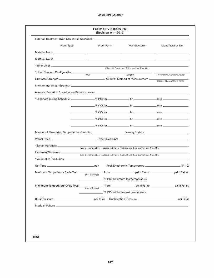
(07/1 7)(07/1 7)
Exterior Treatment (Non-Structural , Describe)
Fiber Type Fiber Form Manufacturer Manufacturer No.
Material No. 1
Material No. 2
* Inner Liner
*Liner Size and Configuration
Laminate Strength psi (kPa) Method of Measurement
Interlaminar Shear Strength
Acoustic Emission Examination Report Number
*Laminate Curing Schedule °F (°C) for hr min
°F (°C) for hr min
°F (°C) for hr min
°F (°C) for hr min
°F (°C) for hr min
Manner of Measuring Temperature: Oven Air Wrong Surface
Vessel Head Other (Describe)
*Barcol Hardness
Laminate Thickness
*Volumetric Expansion
Gel Time min Peak Exothermic Temperature °F (°C)
Minimum Temperature Cycle Test: from psi (kPa) to psi (kPa) at
°F (°C) maximum test temperature
Maximum Temperature Cycle Test: from psi (kPa) to psi (kPa) at
°F (°C) minimum test temperature
Burst Pressure psi (kPa) Qual ification Pressure psi (kPa)
Mode of Fai lure
FORM CPV-2 (CONT’D)(Revision A — 201 7)
( I f Other Than ASTM D 2290)
(OD) (Length) (Cyl indrical , Spherical , Other)
(Use a separate sheet to record individual readings and their location [see Note (1 )] . )
(Use a separate sheet to record individual readings and their location [see Note (1 )] . )
(Material , Grade, and Thickness [see Note (1 )] . )
(No. of Cycles)
(No. of Cycles)
ASME BPVC.X-2017
147
ASME BOILER AND PRESSURE VESSEL CODE, Section X
We certify that the statements in th is Specification are correct:
Date , Signed
By
Certificate of Authorization Number Expires
Laminate Procedure Specification of at
For process of fabricating vessel (s) described in
User’s Design Specification Number and
Fabricator’s Design Report Number
I , the undersigned, holding a val id commission issued by the National Board of Boiler and Pressure Vessel Inspectors
and/or the State or Province of and employed
by of
have inspected the pressure vessel and witnessed tests described in the Qual ification Test Report of the Laminate Design
and Procedure Specification and state that to the best of knowledge and bel ief, the Fabricator has constructed this part in
accordance with the ASME BOILER AND PRESSURE VESSEL CODE, Section X, Class I I I and the Laminate Design and
Procedure Specification being qual ified. By signing this certificate, neither the inspector nor h is employer makes any
warranty, expressed or impl ied, concerning the design or procedure covered by th is Qual ification Test Report.
Furthermore, neither the inspector nor h is employer shal l be l iable in any manner for any personal injury or property
damage or loss of any kind arising from or connected with this inspection.
Date Signed Commissions
(07/1 7)
CERTIFICATION BY SHOP INSPECTOR
OF QUALIFICATION OF LAMINATE DESIGN AND LAMINATE PROCEDURE SPECIFICATION
(Authorized Inspector)
(Year) [Addenda ( if appl icable) Date] (Case No.)
(Fabricator)
FORM CPV-2 (CONT’D)(Revision A — 201 7)
(National Board Authorized
Inspector Number)
ASME BPVC.X-2017
148

MANDATORY APPENDIX 9ESTABLISHING GOVERNING CODE EDITIONS, ADDENDA, AND
CASES FOR FRP PRESSURE VESSELS
9-100 GENERAL
After Code revisions are approved by ASME, they may
be used beginning with the date of issuance shown on
the Code. Except as noted below, revisions become man-
datory 6 months after the date of issuance. Code Cases are
permissible and may be used beginning with the date of
approval by ASME. Only Code Cases that are specifically
identified as being applicable to this Section may be used.
At the time a Code Case is applied, only the latest revision
may be used. Code Cases that have been incorporated into
this Section or have been annulled may not be used.
Changes to the Code and Code Cases related to design,
material, fabrication, examination, inspection, testing,
overpressure protection and field assembly made prior
to completion of the pressure vessel or replacement part
may be critical to the intended service conditions of the
pressure vessel. These changes must be considered by
the Fabricator. Application of such changes shall be a mat-
ter of agreement between the Fabricator and the user.
As used in this Appendix, the term “Inspector” shall be
considered to include “Authorized Inspector,” “Qualified
Inspector,” and “Certified Individual,” as applicable.
9-200 DESIGN
The Fabricator of the completed pressure vessel shall
establish the Code Edition, Addenda and Code Cases to
be used for design of a pressure vessel, including parts
thereof, or a replacement part to be stamped with the
ASME certification mark required by this Section.
(a) Except as provided in (b) and (c) , the Code Edition
and Addenda used to design a pressure vessel , parts
thereof, and replacement parts shall be either those that
are mandatory on the date the vessel or replacement part
is contracted, or those that have been approved and is-
sued by ASME prior to the contract date but are not yet
mandatory (refer to 9-100 above) .
(b) Existing pressure parts that have been stamped and
certified to an earlier or later Edition and Addenda than
those used for design, and that have never been placed
in service, (i.e., placed in stock for future use) may be used
provided they are acceptable to the Manufacturer.
(c) It is permitted to provide a replacement part “in
kind” (i.e., identical in fit and material to the part being re-
placed) for an existing pressure vessel and to certify the
part as meeting the Code Edition and Addenda to which
the existing pressure vessel is certified. The material
may be produced in accordance with the material specifi-
cation revision referenced in the Code Edition and Adden-
da to which the existing pressure vessel is certified or to
any subsequent revision to that material specification.
9-300 MATERIALS
For pressure-containing parts, the Fabricator shall use
material conforming to the Procedure Specification meet-
ing the qualification requirements of the Edition and Ad-
denda specified for design.
Also the material specification edition must be listed as
approved for use in Section II, Part A, Mandatory Appen-
dix II, Table II-100 or Table II-200; or Section II , Part B,
Mandatory Appendix II, Table II-100 or Table II-200.
For replacement parts provided “in kind,” the material
shall be produced in accordance with the material speci-
fication revision listed in Section II as described above at
the time the part is certified.
9-400 FABRICATION
The Edition and Addenda used to govern fabrication
shall be either those governing design or the Edition
and Addenda approved and issued at the time the activity
is performed.
9-500 EXAMINATION
Examination refers to activities performed by the Fab-
ricator that include nondestructive examination. The Edi-
tion and Addenda used to govern examination shall be
either those governing design or the Edition and Addenda
approved and issued at the time the activity is performed.
9-600 INSPECTION
Inspection refers to activities performed by the Inspec-
tor. The Code Edition and Addenda used to govern inspec-
tion shall be the same as those governing design.
ASME BPVC.X-2017
149

9-700 TESTING
The Code Edition and Addenda used to govern testing
of the item shall be the same as those governing design.
9-800 OVERPRESSURE PROTECTION
The Code Edition and Addenda used to govern over-
pressure protection shall be the same as those governing
design.
9-900 FIELD ASSEMBLY
The Edition and Addenda used to govern field assembly
shall be either those governing design or the Edition and
Addenda approved and issued at the time the activity is
performed.
9-1000 CERTIFICATION
The Edition and Addenda used to govern Code certifica-
tion shall be the same as those governing design.
ASME BPVC.X-2017
150

ð17ÞMANDATORY APPENDIX 10LAMINATES WITH LOAD-SHARING METALLIC SHELLS FOR HIGH
PRESSURE SERVICE
10-100 SCOPE
10-101 GENERAL DESCRIPTION
Composite Reinforced Pressure Vessels (CRPVs) are
metall ic vessels (Section VII I , D ivision 3 ) with fiber-
reinforced plastic laminate wrapped around the cylindri-
cal shell and are designed to contain fluids at high pres-
sure. A laminate of continuous filaments of a specified
glass or carbon fiber with a specified resin system is cir-
cumferentially wound on the shell in a systematic manner
under controlled tension and cured in place. The heads
are not wrapped, and openings are not permitted in the
laminate.
Each completed vessel shall comply with the require-
ments of Section VIII, Division 3, except the laminate shall
comply with the requirements of this Appendix.
10-102 GENERAL REQUIREMENTS
This Appendix defines the requirements for the materi-
als, design (composite properties) , fabrication, qualifica-
tion, examination, and testing of laminates to be applied
as part of the construction of a Section VIII , Division 3
composite pressure vessel. Design of the vessel, including
the laminate, shall be performed by the Section VIII, Divi-
sion 3 Manufacturer.
10-200 GENERAL REQUIREMENTS
General requirements for the manufacture of CPRVs are
specified in 10-201 through 10-203.
10-201 SCOPE
CRPVs consist of a laminate of continuous unidirec-
tional filaments of a specified glass or carbon fiber with
a specified resin circumferentially wound in a systematic
manner under controlled tension over a cylindrical metal-
lic shell and cured in place. Openings are not permitted in
the laminate. Metallic ends and nozzles complete the con-
s truc ti o n (s e e F i gure s 1 0 - 2 0 1 - 1 , 1 0 - 2 0 1 - 2 , and
10-201-3) .
10-202 PROTECTIVE LAYER
(a) The User’s Design Specification shall state if a pro-
tective layer for the laminate is needed and, if so, shall
specify the performance requirements for that layer.
The User’s Design Specification shall state if the CRPV will
be exposed to sunlight in service. If so, the Manufacturer
shall apply a UV barrier coating to the laminate.
(b) In addition to (a) , all laminates shall be sealed with
a waterproof barrier as required in 10-408.
10-203 MANUFACTURER’S RESPONSIBILITIES
(a) The Manufacturer shall be responsible for prepara-
tion and qualification of a Laminate Procedure Specifica-
tion to apply the laminate. The Laminate Procedure
Specification shall specify all pertinent material proper-
ties data, the means by which the laminate is applied to
the metallic shell, and all other significant process data as-
sociated with the laminate on the completed CRPV. It shall
include tolerance limits for all appropriate material prop-
erties; process conditions such as time and temperature;
acceptable test result values; and compositions of resins,
fibers, and curing agents, etc. , as further defined by the
rules of this Appendix. It shall make provisions for protec-
tion of the structural laminate from damage due to im-
pact; ultravio let radiation; or other environmental
exposure, fire, abrasive conditions, and in-service degra-
dation of the laminate for the life of the CRPV under the
service conditions as specified in the User’s Design Spec-
ification. The Laminate Procedure Specification shall be
qualified per the requirements of this Appendix and shall
be part of the Manufacturer’s Design Report.
(b) It shall be the Manufacturer’s responsibility to con-
duct Laminate Qualification Tests to qualify and re-qualify
the Laminate Procedure Specification per the require-
ments of this Appendix and to record the result thereof.
Using the procedures established in this Appendix, a re-
port of tests contained in 10-600, Laminate Procedure
Qualification, shall be prepared and certified by the Man-
ufacturer and the Inspector. The results of these tests
shall be documented on Section VII I , Division 3 Form
CRPV-2A and, together with all test documents, shall be
designated the Qualification Test Report and be included
in the Manufacturer’s Construction Records.
(c) The Manufacturer shall be responsible for conduct-
ing laminate production examinations and tests as re-
quired by 10-400. The test results shall be included in
the Manufacturer’s Construction Records.
ASME BPVC.X-2017
151

10-300 MATERIALS
10-301 GENERAL MATERIALS REQUIREMENTS
(a) Laminates used in the construction of a CRPV shall
comply with the requirements listed in 10-302.
(b) All materials used in the manufacture of the lami-
nate shall be traceable to material test reports, or certifi-
cates of compliance; shall be traceable to an individual
CRPV vessel; and shall be documented in the Manufac-
turer’s Construction Records.
(c) Materials used in fabricating laminates shall be
(1) fibers and a resin system (combined by vessel
manufacturer at time of application to the metallic shell) .
(2) fibers pre- impregnated with resin by a third
party before shipping to vessel manufacturer (pre-preg) .
Only epoxy resin shall be used for fiber pre-impregnation.
10-302 LAMINATES
(a) Fiber-reinforced plastic materials are designated as
laminates. These laminates, which are used as the outer
structural layer of CRPVs, shall be fabricated in accor-
dance with the requirements of this Appendix.
(b) Laminates are composite structures consisting of
glass or carbon fibers embedded in a resin system.
(c) The Manufacturer shall retain the published specifi-
cations for all materials used in the laminate of each
CRPV, the material supplier’s recommendations for sto-
rage conditions, shelf life, and the material supplier’s cer-
tification that each shipment conforms to the published
specification requirements. These data shall be part of
the Manufacturer’s Construction Records.
(d) The maximum design temperature of the laminate
shall be the same as the design temperature of the CRPV
and shall be specified in the User’s Design Specification,
but in no case shall it exceed 150°F (66°C) .
(e) The laminate minimum design temperature shall
not be colder than −65°F (−54°C) (see Section VIII, Divi-
sion 3, Part KD, KD-1313) .
10-303 FIBERS
10-303.1 Glass Fibers.(a) Glass fibers shall be one or more of the following
glass compositions:
(1) Type S glass
(2) Type E-CR glass
Figure 10-201-1General Arrangement
Wear protection
materialLaminate stops
Metal l ic shel l
Metal l ic head
Vessel support
Laminate layer
Figure 10-201-2Laminate Termination
Metal l ic shel l
Metal l ic head
Laminate layer
ASME BPVC.X-2017
152
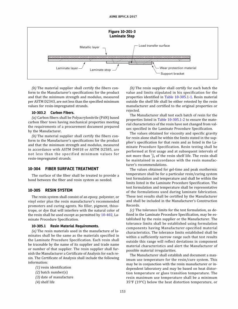
(b) The material supplier shall certify the fibers con-
form to the Manufacturer’s specifications for the product
and that the minimum strength and modulus, measured
per ASTM D2343, are not less than the specified minimum
values for resin-impregnated strands.
10-303.2 Carbon Fibers.
(a) Carbon fibers shall be Polyacrylonitrile (PAN) based
carbon fiber tows having mechanical properties meeting
the requirements of a procurement document prepared
by the Manufacturer.
(b) The material supplier shall certify the fibers con-
form to the Manufacturer’s specifications for the product
and that the minimum strength and modulus, measured
in accordance with ASTM D4018 or ASTM D2585 , are
no t l e s s than the s p e c i fi ed m in imum va l ue s fo r
resin-impregnated strands.
10-304 FIBER SURFACE TREATMENT
The surface of the fiber shall be treated to provide a
bond between the fiber and resin system as needed.
10-305 RESIN SYSTEM
The resin system shall consist of an epoxy, polyester, or
vinyl ester plus the resin manufacturer’s recommended
promoters and curing agents. No filler, pigment, thixo-
trope, or dye that will interfere with the natural color of
the resin shall be used except as permitted by 10-402, La-
minate Procedure Specification.
10-305.1 Resin Material Requirements.
(a) The resin materials used in the manufacture of la-
minates shall be the same as the materials specified in
the Laminate Procedure Specification. Each resin shall
be traceable by the name of its supplier and trade name
or number of that supplier. The resin supplier shall fur-
nish the Manufacturer a Certificate ofAnalysis for each re-
sin. The Certificate of Analysis shall include the following
information:
(1) resin identification
(2) batch number(s)
(3) date of manufacture
(4) shelf life
(b) The resin supplier shall certify for each batch the
value and limits stipulated in his specification for the
properties identified in Table 10-305.1-1 . Resin material
outside the shelf life shall be either retested by the resin
manufacturer and certified to the original properties or
rejected.
The Manufacturer shall test each batch of resin for the
properties listed in Table 10-305.1-2 to ensure the mate-
rial characteristics of the resin have not changed from val-
ues specified in the Laminate Procedure Specification.
The values obtained for viscosity and specific gravity
for resin alone shall be within the limits stated in the sup-
plier’s specification for that resin and as listed in the La-
minate Procedure Specification. Resin testing shall be
performed at first usage and at subsequent intervals of
not more than 1/4 of the resin shelf life. The resin shall
be maintained in accordance with the resin manufac-
turer’s recommendations.
The values obtained for gel-time and peak exothermic
temperature shall be for a particular resin/curing system
test formulation and temperature and shall be within the
limits listed in the Laminate Procedure Specification. The
test formulation and temperature shall be representative
of the formulations used during laminate fabrication.
These test results shall be certified by the Manufacturer
and shall be included in the Manufacturer’s Construction
Records.
(c) The tolerance limits for the test formulation, as de-
fined in the Laminate Procedure Specification, may be es-
tablished by the resin supplier or the Manufacturer. The
tolerance limits shall be established using formulation
components having Manufacturer-specified material
characteristics. The tolerance limits established shall be
within a sufficiently narrow range such that test results
outside this range will reflect deviations in component
material characteristics and alert the Manufacturer of
possible material irregularities.
The Manufacturer shall establish and document a max-
imum use temperature for the resin/cure system. This
may be in conjunction with the resin manufacturer or in-
dependent laboratory and may be based on heat distor-
tion temperature or glass transition temperature. The
resin maximum use temperature shall be a minimum
35°F (19°C) below the heat distortion temperature, or
Figure 10-201-3Laminate Step
Metal l ic layer
Laminate layerLaminate stop
Wear protection material
Support bracket
Load transfer surface
ASME BPVC.X-2017
153

the glass transition temperature, but shall be equal to
higher than the laminate design temperature. The Manu-
facturer shall re-establish and redocument the maximum
use temperature at least every 12 months using current
batches of resin and curing agent. The maximum use tem-
perature shall be recorded in the Laminate Procedure
Specification. A record of these determinations shall be
included in the Manufacturer’s Construction Records.
10-306 CURING AGENTS
The curing agents used, the resin-to-curing-agent ratio,
and the curing procedure used for laminate fabrication
shall be as specified in the Laminate Procedure Specifica-
tion. Each curing agent shall be traceable by the supplier’s
name, supplier’s designation, and generic name.
10-307 PRE-IMPREGNATED FIBERS
(a) Fibers used for making pre-impregnated fibers shall
be one of the fibers listed in 10-303, and the resin shall be
limited to epoxy.
(b) Fiber Requirements
(1 ) The pre-preg supplier shall certify the fibers con-
form to the Manufacturer’s specifications for the product
and that the minimum strength and modulus, measured
per ASTM D2343, are not less than the specified minimum
values for resin-impregnated strands.
(2) Carbon fibers shall be Polyacrylonitrile (PAN)
based carbon fiber tows having mechanical properties
meeting the requirements of a procurement document
prepared by the Manufacturer.
(3) The pre-preg supplier shall certify the fibers con-
form to the Manufacturer’s specifications for the product
and that the minimum strength and modulus, measured
in accordance with ASTM D4018 or ASTM D2585 , are
no t l e s s than the s p e c i fi e d min imum va lue s fo r
resin-impregnated strands.
(c) Resin Material Requirements. The epoxy resin used
in the pre-preg shall be the same as the resin specified
in the Laminate Procedure Specification. Each epoxy resin
shall be traceable by the name of its supplier and trade
name or number of that supplier. The pre-preg supplier
shall furnish the Manufacturer a Certificate of Analysis
for each epoxy resin. The Certificate of Analysis shall in-
clude the following information:
(1) resin identification including separate curing
agents, if applicable
(2) batch number(s) for each pre-preg lot
(3) date of manufacture
(4) pre-preg is within resin shelf life. Pre-preg not
within the resin shelf life shall be rejected.
(d) The pre-preg supplier shall certify for each batch
the value and limits required by the specification of the
properties identified in Table 10-307-1 . The values ob-
tained for viscosity and specific gravity for the resin alone
shall be within the limits of the supplier’s specification for
that resin and as listed in the Laminate Procedure Speci-
fication. The values obtained for gel time shall be for a
particular resin curing system test formulation and tem-
perature and shall be within the limits listed in the Lami-
nate Procedure Specification.
(e) The Manufacturer shall test each batch of pre-preg
per Table 10-307-2 to ensure the material characteristics
of the pre-preg resin have not changed from specified val-
ues listed in the Laminate Procedure Specification. The
test formulation and temperature shall be representative
of the formulation used during CRPV fabrication. These
test results shall be certified by the Manufacturer and
shall be included in the Manufacturer’s Construction Re-
cords. The pre-preg supplier shall specify pre-preg shelf
life requirements and storage temperature and include
a copy of the fiber certification from the fiber manufac-
turer as part of the pre-preg certification package.
10-308 LAMINATE CURE
The Manufacturer shall ensure the resin used in fabri-
cating laminate is correctly cured. The degree of cure
shall be demonstrated by the Barcol hardness test per
ASTM D2583. Barcol hardness readings shall be within
the tolerance specified by the resin supplier. If the resin
supplier does not provide Barcol hardness specifications
for the resin/curing system used, the Manufacturer shall
Table 10-305.1-1Resin Supplier Certifications
Resin System Required Certifications
Polyester/vinyl ester
Viscosity ASTM D445 or D2116
Specific gravity Section X, Mandatory Appendix 5
Epoxy
Viscosity ASTM D445 or D2196
Epoxide equivalent ASTM D1652
Specific gravity Section X, Mandatory Appendix 5
Table 10-305.1-2Tests by Laminate Manufacturer
Resin System Required Tests
Polyester/vinyl ester
Viscosity ASTM D445 or D2196
Gel time and peak exothermic
temperature
ASTM D2471
Specific gravity Section X, Mandatory Appendix 5
Epoxy
Viscosity ASTM D445 or D2196
Gel time ASTM D2471
Specific gravity Section X, Mandatory Appendix 5
ASME BPVC.X-2017
154

establish Barcol hardness specifications. Barcol hardness
specifications established by the Manufacturer shall be
documented in the Manufacturer’s Construction Records.
10-309 LAMINATE TENSILE STRENGTH
(a) The Manufacturer shal l determine the tens i le
strength and modulus of elasticity of the laminate used
in the manufacture of a CRPV.
(b) ASTM D2343 shall be used to determine the tensile
strength and modulus of elasticity of the laminate.
(c) The measured laminate tensile strength and modu-
lus of elasticity shall be part of the Laminate Procedure
Specification and shall be recorded on Form CRPV-2A as
part of the Laminate Procedure Qualification Record.
10-310 INTERLAMINAR SHEAR STRENGTH
(a) The laminates used in manufacturing a CRPV shall
have minimum interlaminar shear strengths of 3,000 psi
(20.7 MPa) for vinyl ester, 2,000 psi (13.8 MPa) for polye-
ster, and 5,000 psi (34 MPa) for epoxy resins as deter-
mined by ASTM D2 3 44 . The tes t re su l ts s ha l l b e
included in the Construction Records. The interlaminar
shear strength shall be part of the Laminate Procedure
Specification and shall be recorded on Form CRPV-2A as
part of the Laminate Procedure Qualification Record.
(b) The interlaminar shear strength shall be deter-
mined for each laminate before initial use. Subsequent de-
terminations of interlaminar shear strength are required
only when there is a change in the laminate formulation.
10-400 FABRICATION
10-401 SCOPE
This item provides rules governing the fabrication of
fiber-reinforced plastic laminates for use in the construc-
tion of CRPVs. The fabrication process is limited to cir-
cumfe ren ti a l (ho o p - o r i e n ted ) fi l amen t-wi nd i ng
processes with a winding angle deviation of no more than
10 deg from the circumferential direction.
10-402 LAMINATE PROCEDURE SPECIFICATION
(a) For every combination of fabrication method, De-
sign Specification, and material variation employed in
fabricating laminate for a CRPV, the Manufacturer shall
prepare a Laminate Procedure Specification that shall
be qualified in accordance with 10-600 before it is used
for laminate fabrication in the construction of CRPVs.
The Laminate Procedure Specification shall provide, as a
minimum, all information concerning material properties
and manufacturing procedures as required on Form
CRPV-2A. The Qual i fication Test Report and Form
CRPV-2A shall be part of the Manufacturer’s Construction
Records. A new Laminate Qualification Test Report shall
be prepared whenever qualification is required by this
Appendix.
(b) Any variation in the essential variables from the La-
minate Procedure Specification for CRPVs shall require
the Laminate Procedure Specification to be rewritten,
the design analysis to be reperformed, and the specifica-
tion to be requal i fi ed befo re us ing i t to fabricate
laminates.
(c) Production laminates shall be fabricated per a La-
minate Procedure Specification. As a minimum, the fol-
lowing essential variables shall be within tolerances as
specified in the Laminate Procedure Specification:
(1) fiber (manufacturer and designation)
(2) fiber mechanical properties
(3) fiber surface treatment (manufacturer and
designation)
(4) resin (type, manufacturer, and designation)
(5) curing agent (manufacturer and designation)
(6) method of impregnation
(7) percent of fiber in laminate (outside range speci-
fied in Procedure Specification)
(8) variables of winding process
(9) curing schedule
(10) weight (mass) of laminate (outside range speci-
fied in Procedure Specification)
(11 ) Barcol hardness (outside range specified in Pro-
cedure Specification)
10-403 PRODUCTION LAMINATEREQUIREMENTS
10-403.1 Fiber Content. The laminate shall consist of
fiber strands in a resin matrix. The weight percent of fiber
in the laminate shall conform to that denoted in the Lami-
nate Procedure Specification with a tolerance of +6% and
Table 10-307-1Pre-Preg Supplier Certifications
Item Required Certifications
Resin Viscosity: ASTM D445 or D2196
Gel time: ASTM D2471
Specific gravity: Section X, Mandatory
Appendix 5
Pre-preg Resin content: D3529
Resin flow: D3531
Table 10-307-2Pre-Preg Systems Tests by CRPV
Manufacturer
Item Required Tests
Resin content ASTM D3529
Resin flow ASTM D3531
ASME BPVC.X-2017
155

−0%. The weight percent of fiber in the laminate shall be
determined for 1 of every 300 CRPVs produced. The
weight (mass) of laminate applied to the metallic shell
shall be determined for 1 of every 100 CRPVs produced.
The Inspector shall select the CRPV for examination.
10-403.2 Fiber Application. In general, winding pat-
terns shall be so arranged that stressed fibers are aligned
to resist circumferential stress. Specific winding patterns
for the continuous fiber strands shall be used as defined
in the Laminate Procedure Specification. Any winding
pattern that places the filaments in the circumferential or-
ientation (maximum 10-deg deviation from the circum-
ferential direction) and is designated in the Laminate
Procedure Specification may be used.
10-403.3 Resin System. The resin system shall be
one of the systems specified in 10-300 and is appropriate
for the particular service conditions specified in the
User’s Design Specification.
10-403.4 Cure. If other than ambient temperature
cure is employed, the design and operation of the curing
equipment shall provide uniform heating over the entire
surface of the CRPV. Heating may be done from inside
or outside of the CRPV or from inside and outside. The
cure times and temperatures shall conform to those spe-
cified in the Laminate Procedure Specification. The sur-
face of the laminate shall be at the cure temperature for
the minimum time required for post cure. Heat-up and
cool-down times shall be excluded.
10-403.5 Filament Winding Process.10-403.5.1 Tensioning. Tension on the strands of
filaments during the winding operation shall be con-
trolled to ensure a uniform application of the composite
reinforcement onto the metallic shell and shall be as spe-
cified in the Laminate Procedure Specification.
10-403.5.2 Winding Speed. Winding speed shall be
limited only by the ability to
(a) meet the tensioning requirements
(b) conform to the specified winding pattern
(c) ensure adequate resin impregnations
The winding speed shall be as specified in the Laminate
Procedure Specification.
10-403.5.3 Bandwidth and Spacing. The band-
width and spacing shall conform to those specified in
the Laminate Procedure Specification.
10-404 VARIATION FROM LAMINATEPROCEDURE SPECIFICATION
A variation in any essential variable from the toler-
ances stated in the Laminate Procedure Specification shall
result in rejection of the CRPV.
10-405 GALVANIC CORROSION
When carbon fibers are used, the outer surface of the
metallic shell shall be protected from any galvanic corro-
sion that may occur due to dissimilar materials (steel or
aluminum) in contact with carbon fibers . Acceptable
methods for this purpose include a suitable polymer coat-
ing, a glass-fiber/epoxy composite layer, or a polymer
film wrap that separates the galvanically dissimilar mate-
rials interface surfaces.
10-406 REPAIRS OF IMPERFECTIONS
In the event any of the unacceptable imperfections
listed in Table 10-503-1 or Table 10-503-1M extends into
the structural layer, or the structural fibers are cut or
damaged, the imperfections or damaged fibers shall be
deemed not repairable and the CRPV rejected. If the unac-
ceptable imperfections listed in Table 10-503-1 or Table
10-503-1M are contained in the nonstructural, protective
layer of the laminate, the layer may be repaired, unless
prohibited by the Laminate Procedure Specification. The
minimum thickness, fiber content, and protective capabil-
ities of the repaired protective layer shall be the same as
the unrepaired protective layer.
10-407 REPLACEMENT OF LAMINATE
If a CRPV is rejected because the structural layer is
damaged, or there is an unacceptable variation in any es-
sential variable, the laminate may be completely removed
from the metallic shell before there is any pressure test-
ing of the vessel. Care shall be taken to ensure the metal
shell outside diameter surface is not damaged during la-
minate removal. Damage to the metallic shell, caused by
removal of the laminate, shall be repaired per the require-
ments of Section VIII , Division 3, Part KE. Laminate may
then b e re ap p l i e d p e r th e Lam i na te P ro ce du re
Specification.
10-408 SEALING OF LAMINATE
The exterior surface of the laminate and the laminate/
metallic interface shall be sealed with a waterproof bar-
rier after all testing and examinations of the laminate
are completed. The Manufacturer shall include the life ex-
pectancy of the waterproof barrier in the Design Report.
10-409 PAINTING OF LAMINATE
If specified in the User Design Specification, the lami-
nate may be painted following all required inspections
and certifications by the Inspector.
10-500 EXAMINATION AND TESTINGREQUIREMENTS
10-501 SCOPE
The following paragraphs provide examination and
testing requirements for laminates.
ASME BPVC.X-2017
156

10-502 QUALIFICATION OF NONDESTRUCTIVEEXAMINATION PERSONNEL
(a) The Manufacturer shall certify that each examiner
performing visual tests per this Appendix has been qual-
ified to the requirements of Section V, Article 9.
(b) The Manufacturer shall certify that each examiner
performing acoustic emission testing per this Appendix
has attended a dedicated training course on the subject,
passed a written examination, and has the recommended
experience. The training course shall be appropriate for
specific NDT Level II qualification per ASNT SNT-TC-1A.
10-503 EXAMINATIONS AND TESTS
(a) Each laminate shall be subjected to the examina-
tions required by this Appendix and shall conform to
the specified requirements with results recorded in Pro-
duction Test Reports . Examinations detai led in (1 )
through (5) shall be performed before the hydrostatic test
detailed in (6) . A final visual examination, in accordance
with (1) , shall follow the acoustic emission examination.
The laminate Production Test Report shall become part
of the Manufacturer’s Construction Records.
(1) Visual Examination . Each laminate shall be vi-
sually examined with a suitable light source to the speci-
fied requirements in Table 10-503-1 or Table 10-503-1M.
(2) Design Dimensions Examination . Each CRPV shall
be examined for conformance to dimensions and toler-
ances shown on the design drawings.
(3) Visual Examination of Repaired Areas. Each re-
paired area shall be visually examined and shall comply
with all acceptance requirements of Table 10-503-1 or
Table 10-503-1M. The repaired area shall have translu-
cency and surface finish comparable to the remainder of
the laminate.
(4) Thickness Check. The thickness of each produc-
tion laminate shall be determined at a minimum of three
points along its length on each of four quadrants. When
laminates are longer than 5 ft (1.5 m), one additional de-
termination shall be made for each additional 5 ft (1.5 m)
or portion thereof. The thickness determinations shall be
made with mechanical gages, ultrasonic gages, or other
devices having an accuracy of ±2% of true thickness.
(5) Visual Thickness Check. Where visual indications
of deviation from design thickness exist at points other
than those at which measurements are required, thick-
ness determinations shall be made in sufficient quantity
to correctly locate and define the deviant areas. Thick-
nesses less than the value specified in the Manufacturer’s
Design Report are prohibited.
(6) Hydrostatic Pressure Test. For vessels that are
subjected to hydrostatic pressurization that is designed
to provide an initial stress in the metallic shell and lami-
nate, the initial pressure shall be applied before the hy-
drostatic test and acoustic emission examination.
(7) Acoustic Emission Examination .
(-a) An acoustic emission examination shall be
performed during pressurization of each CRPV. The ex-
amination shall follow the hydrostatic test and shall be
in accordance with the requirements of this Appendix
and ASTM E1067. Where the provisions of this Appendix
differ from those of ASTM E1067, the provisions of this
Appendix shall govern.
(-b) Vessel Conditioning . The internal pressure in
the vessel shall not exceed 10% of the hydrostatic test
pressure for 1 2 hr prio r to the acousti c emis s ion
examination.
(-c) The test fluid shall be water or another appro-
priate liquid. The minimum liquid temperature shall be
sufficient to ensure that the vessel wall temperature is
not less than 40°F (5°C) and not greater than the lesser
of the design temperature or 100°F (38°C) .
(-d) Instrumentation shall be as detailed in ASTM
E1067, paragraph 7. The recommended and preferred in-
strument features listed in ASTM E1067, paragraph 7.2
are required. Peak-amplitude detection for each input
channel is also required. Time of arrival shall be mea-
sured to an accuracy of 1 μsec. All test data, including time
and pressure, shall be recorded for post-test playback and
analysis. The data acquisition threshold shall be at or be-
low the threshold of detectability defined in ASTM E1067,
paragraph A2.2.
(-e) Sensor locations and spacing shall be accord-
ing to ASTM E1067, paragraph 9.3. The attenuation char-
acte r i zati on sha l l b e perfo rmed in the hoop and
longitudinal directions and at 45 deg to the axis of the
vessel. Additional lead breaks may be necessary to accu-
rately determine the maximum sensor spacing in each di-
r e c t i o n . Th e re qu i r emen t th a t th e a tte nu a t i o n
characterization be performed above the liquid line shall
not apply to vessels. Regardless of vessel size, at least two
sensors shall be used so that electromagnetic interference
is easily detected by simultaneity of arrival.
(-f) Pressurization Cycle. The pressure shall be held
at 10% of the hydrostatic test pressure for a minimum of
10 min, then raised to 98% of the hydrostatic test pres-
sure, and held constant for 30 min. The initial hold period
and pressurization from 10% to 50% of the hydrostatic
test pressure shall be used to identify and eliminate back-
ground noise. The last 5 min of the initial hold period shall
not begin until evaluation and minimization of back-
ground have been completed. In order to assess the effect
of fill rate on background noise, the pressurization rate
specified in ASTM E1067, paragraph 11.1 .1, may be var-
ied for the pressurization from 10% to 50% of the hydro-
static test pressure. For pressurization above 50% of the
hydrostatic test pressure, the provisions of ASTM E1067,
paragraph 11.1.1, shall apply.
(-g) Data Acquisition . Test data may be recorded
for the entire pressurization cycle. Data acquired during
the las t 5 min of the ini tia l p ressure ho ld , during
ASME BPVC.X-2017
157

pressurization from 50% to 98% of the hydrostatic test
pressure, and from the final 30-min pressure hold shall
be recorded and used to evaluate the vessel.
(-h) Evaluation and acceptance criteria shall be in
accordance with ASTM E1067. An acceptable vessel shall
meet all of the criteria listed in Table 10-503-2 . Back-
ground noise shall be discounted when applying accep-
tance criteria.
(b) Records. The results of the preceding examinations
shall be included in the Manufacturer ’s Construction
Records.
10-600 LAMINATE PROCEDUREQUALIFICATION
10-601 GENERAL
The tests and examinations required in this paragraph
are intended to qualify the design of a prototype laminate
as applied to a Section VIII, Division 3 shell and the Pro-
cedure Specification to which it was fabricated. The re-
port of these tests shall be designated the Laminate
Qualification Test Report and shall become part of the
Manufacturer’s Design Report.
10-602 RESPONSIBILITY FOR QUALIFICATION
Each Manufacturer shall be responsible for qualifying
the Procedure Specifications used in fabricating laminates
for Section VIII , Division 3 vessels. The fabrication pro-
cess is limited to circumferential filament-winding pro-
cesses with a winding angle of no more than 10 deg
from the circumferential direction.
10-603 PRODUCTION WORK WITHOUTQUALIFICATIONS
No fabrication shall be undertaken on vessels to be
stamped with the Certification Mark before a written Pro-
cedure Specification has been prepared and qualified by
the Manufacturer. The Procedure Specification shall be
qualified by testing one or more prototype vessels as de-
fined in 10-614, 10-615, and 10-616. A single prototype
vessel shall meet the requirements of all tests and exam-
inations specified in 10-600.
10-604 MAINTENANCE OF QUALIFICATIONRECORDS
The Manufacturer shall maintain records of procedures
employed in fabricating laminates. The Manufacturer
shall also maintain records of the tests and their results
by which his Procedure Specifications were qualified for
use in fabrication. The Manufacturer shall keep these re-
cords on file for a minimum of 5 yr after production of la-
minates has ceased.
10-605 ESSENTIAL VARIABLES
The Procedure Specification shall address each of the
essential variables listed in 10-402(c) . The prototype la-
minate(s) shall be fabricated within the tolerances speci-
fied in the Procedure Specification.
10-606 NONESSENTIAL VARIABLES
Changes in variables other than those listed in 10-605
are considered nonessential. Changes may be made to
nonessential variables without requalification of the pro-
cedure provided the Procedure Specification is revised to
show the changes.
10-607 ALTERNATIVE REQUIREMENTS
When a number of laminates are identical in every de-
tail of design, materials, and fabrication except for a dif-
ference in shell length, the entire group or series may
be qualified by subjecting the longest and shortest length
laminates to these tests. To qualify for this alternative
method, every laminate in the series shall be identical
in all essential variables.
10-608 LAMINATE THICKNESS
The thickness of each prototype laminate shall be de-
termined as required in 10-503(a)(4) .
10-609 WEIGHT OF RESIN AND FIBER
The percentage ofweight of resin and fiber in each pro-
totype laminate shall be determined by means of an igni-
tion test per ASTM D2584-68 (1985) or matrix digestion
per ASTM D3171 of a sample taken from an undamaged
portion of the laminate used for the pressure qualification
test.
10-610 WEIGHT
Each prototype laminate shall be weighed within an ac-
curacy of ±1% and the results recorded on the Qualifica-
tion Test Report.
10-611 VISUAL EXAMINATION
Each prototype laminate shall be visually examined for
imperfections. Classification and acceptance level of im-
perfections shal l b e per Tab le 1 0 -5 03 -1 or Tab le
10-503-1M.
10-612 BARCOL HARDNESS TESTS
(a) Each prototype laminate shall have a minimum of
three Barcol hardness determinations made along its
length on each of its four quadrants. When the laminate
length exceeds 5 ft (1.5 m), one additional set of determi-
nations shall be made for each additional 5 ft (1 .5 m) or
portion thereof. A series of readings shall be taken at each
quadrant on smooth, correctly oriented surfaces per
ASTM D2583.
ASME BPVC.X-2017
158

10-503-1Visual Acceptance Criteria for FRP Laminate (U.S. Customary Units)
Imperfection Maximum Size and Cumulative Sum of
Imperfections Allowed After Repair [Note (1)] ,
[Note (2)]Type Definition
Air bubble (void) Air entrapped within and between piles of reinforcement,
usually spherical in shape
For maximum diameter of 1/8 in., maximum density 4
per square inch
For maximum diameter 1/16 in., maximum density 10
per square inch
Blister Rounded elevation of laminate surface with boundaries that
may be sharply defined, resembles blister on human skin
For maximum diameter of 1/8 in., density 1 per square
foot
Burned areas from
excessive exotherm
Shows evidence of thermal decomposition through
discoloration or heavy distortion
None
Chips Small pieces broken off an edge of the laminate that includes
fiber breakage
Maximum diameter 1/16 in., or maximum length 1/4 in.
and maximum depth 1/16 in. [Note (3)]
Cracks Actual rupture or debond of portions of laminate None, except circumferential through thickness cracks
in the laminate are acceptable. Cracks shall not
deviate from wind angle by more than 2 deg, and
crack width shall not exceed 1/32 in.
Crazing Fine cracks at the surface of the laminate For maximum length of 1 in. and maximum depth of1/64 in., maximum density 5 in any square foot
Delamination (edge) Separation of layers in laminate None
Dry spot Area of incomplete surface film where the reinforcement was
not wetted with resin
None
Edge exposure Exposure of multiple layers of reinforcing matrix to the
environment, usually the result of shaping or cutting a section
of laminate
None
Fish-eye Particles included in laminate that are foreign to its composition
(not a minute speck of dust)
Maximum diameter 1/8 in., never to penetrate
lamination to lamination; must be fully resin
encapsulated [Note (3)]
Foreign inclusion Small globular mass that has not blended completely into the
surrounding material and is particularly evident in a
transparent or translucent material
Maximum 1/8 in. diameter [Note (3)]
Pimples Small, sharp, conical elevations on the surface of laminate No limit; must be fully resin filled and encapsulated
Pit Small crater in surface of laminate Maximum diameter 1/8 in. and maximum depth 1/16 in.;
no exposed fibers [Note (3)]
Porosity Presence of numerous visible tiny pits (pinholes) , approximate
dimension 0.010 in.
None to fully penetrate surface; no more than 15 per
square inch; no exposed fibers
Scratches Shallow marks, grooves, furrows, or channels caused by
improper handling
None more than 6 in. long; no exposed fibers [Note
(3)]
Wrinkles and creases Generally linear, abrupt changes in surface plane caused by laps
of reinforcing layers, or polyester film overlap
None
Band width gap The space between successive winding fiber bands that are
intended to lay next to each other
None
Band width overlap An area where the edge of a fiber band has laid on top of a
previous fiber band, although intended to lay next to each
other
2 strands max.
Band width splaying An unintended space between individual fibers in a fiber band
that results in a gap between fibers
None
Strand dropout [Note (4) ] When one or more strands of a fiber band ceases to be applied
to the CRPV shell being wound due to breakage or inadequate
supply
<2% of strands
NOTES:
(1) Above acceptance criteria apply to condition of laminate after repair and hydrostatic test.
(2) Noncatalyzed resin is not permissible to any extent in any area of the laminate.
(3) This type of imperfection is subject to cumulative sum limitations as follows:
(a) Maximum number allowable in any square foot is 5.
(b)Maximum number allowable in any square yard is 30.
(4) In the filament winding process, it is common practice to wind many fiber strands simultaneously. These strands are gathered together
side-by-side to form the band of fiber that is wound around the metallic shell. As the shell is rotated, these strands are run through a resin
bath, fiber placement guides, and rollers that may cause a strand to break; called strand dropout. Many times, strand dropout is corrected
before continuing, but it may be desirable to complete the winding pattern with the dropped fiber strands.
ASME BPVC.X-2017
159

10-503-1MVisual Acceptance Criteria for FRP Laminate (SI Units)
Imperfection Maximum Size and Cumulative Sum of
Imperfections Allowed After Repair [Note (1)] ,
[Note (2)]Type Definition
Air bubble (void) Air entrapped within and between piles of reinforcement,
usually spherical in shape
For maximum diameter of 3.2 mm, maximum density
4 per 650 mm2
For maximum diameter of 1.6 mm, maximum density
10 per 650 mm2
Blister Rounded elevation of laminate surface with boundaries that
may be sharply defined, resembles blister on human skin
For maximum diameter of 3.2 mm, density 1 per
930 cm2
Burned areas from
excessive exotherm
Shows evidence of thermal decomposition through
discoloration or heavy distortion
None
Chips Small pieces broken off an edge of the laminate that includes
fiber breakage
Maximum diameter 1.6 mm, or maximum length
6.4 mm and maximum depth 1.6 mm [Note (3)]
Cracks Actual rupture or debond of portions of laminate None, except circumferential through thickness cracks
in the laminate are acceptable. Cracks shall not
deviate from wind angle by more than 2 deg, and
crack width shall not exceed 0.794 mm
Crazing Fine cracks at the surface of the laminate For maximum length of 0.25 mm and maximum depth
of 0.4 mm, maximum density 5 in. any 930 cm2
Delamination (edge) Separation of layers in laminate None
Dry spot Area of incomplete surface film where the reinforcement was
not wetted with resin
None
Edge exposure Exposure of multiple layers of reinforcing matrix to the
environment, usually the result of shaping or cutting a section
of laminate
None
Fish-eye Particles included in laminate that are foreign to its composition
(not a minute speck of dust)
Maximum diameter 3.2 mm, never to penetrate
lamination to lamination; must be fully resin
encapsulated [Note (3)]
Foreign inclusion Small globular mass that has not blended completely into the
surrounding material and is particularly evident in a
transparent or translucent material
Maximum diameter 3.2 mm [Note (3)]
Pimples Small, sharp, conical elevations on the surface of laminate No limit; must be fully resin filled and encapsulated
Pit Small crater in surface of laminate Maximum diameter 3.2 mm and maximum depth
1.6 mm; no exposed fibers [Note (3) ]
Porosity Presence of numerous visible tiny pits (pinholes) , approximate
dimension 0.254 mm
None to fully penetrate surface; no more than 15 per
650 mm2 ; no exposed fibers
Scratches Shallow marks, grooves, furrows, or channels caused by
improper handling
None more than 15.2 cm long; no exposed fibers [Note
(3)]
Wrinkles and creases Generally linear, abrupt changes in surface plane caused by laps
of reinforcing layers or polyester film overlap
None
Band width gap The space between successive winding fiber bands that are
intended to lay next to each other
None
Band width overlap An area where the edge of a fiber band has laid on top of a
previous fiber band, although intended to lay next to each
other
Maximum two strands
Band width splaying An unintended space between individual fibers in a fiber band
that results in a gap between fibers
None
Strand dropout [Note (4) ] When one or more strands of a fiber band ceases to be applied
to the CRPV shell being wound due to breakage or inadequate
supply
<2% of strands
NOTES:
(1) Above acceptance criteria apply to condition of laminate after repair and hydrostatic test.
(2) Noncatalyzed resin is not permissible to any extent in any area of the laminate.
(3) This type of imperfection is subject to cumulative sum limitations. Maximum number allowable in any square meter is 36.
(4) In the filament winding process, it is common practice to wind many fiber strands simultaneously. These strands are gathered together
side-by-side to form the band of fiber that is wound around the metallic shell. As the shell is rotated, these strands are run through a resin
bath, fiber placement guides, and rollers that may cause a strand to break; called strand dropout. Many times, strand dropout is corrected
before continuing, but it may be desirable to complete the winding pattern with the dropped fiber strands.
ASME BPVC.X-2017
160
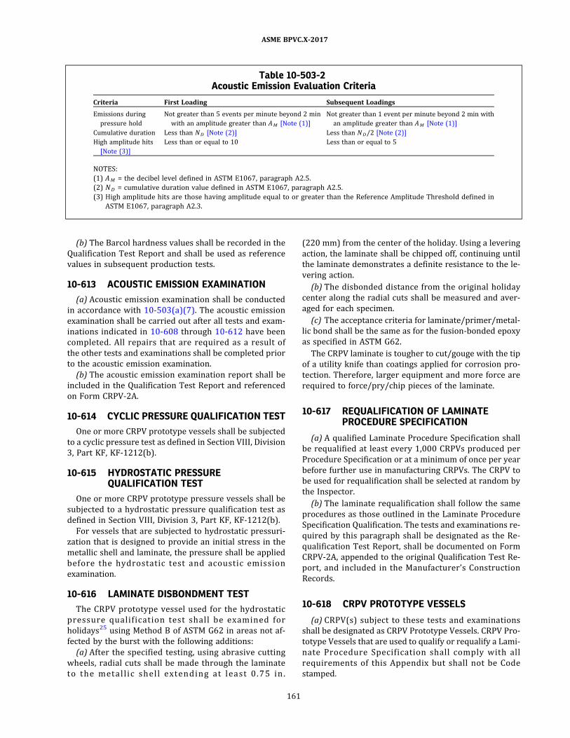
(b) The Barcol hardness values shall be recorded in the
Qualification Test Report and shall be used as reference
values in subsequent production tests.
10-613 ACOUSTIC EMISSION EXAMINATION
(a) Acoustic emission examination shall be conducted
in accordance with 10-503(a)(7) . The acoustic emission
examination shall be carried out after all tests and exam-
inations indicated in 10-608 through 10-612 have been
completed. All repairs that are required as a result of
the other tests and examinations shall be completed prior
to the acoustic emission examination.
(b) The acoustic emission examination report shall be
included in the Qualification Test Report and referenced
on Form CRPV-2A.
10-614 CYCLIC PRESSURE QUALIFICATION TEST
One or more CRPV prototype vessels shall be subjected
to a cyclic pressure test as defined in Section VIII, Division
3, Part KF, KF-1212(b) .
10-615 HYDROSTATIC PRESSUREQUALIFICATION TEST
One or more CRPV prototype pressure vessels shall be
subjected to a hydrostatic pressure qualification test as
defined in Section VIII, Division 3, Part KF, KF-1212(b) .
For vessels that are subjected to hydrostatic pressuri-
zation that is designed to provide an initial stress in the
metallic shell and laminate, the pressure shall be applied
before the hydro s tatic tes t and acous ti c emis s ion
examination.
10-616 LAMINATE DISBONDMENT TEST
The CRPV prototype vessel used for the hydrostatic
p res sure qua l i fi cation tes t shal l b e examined for
holidays25 using Method B of ASTM G62 in areas not af-
fected by the burst with the following additions:
(a) After the specified testing, using abrasive cutting
wheels, radial cuts shall be made through the laminate
to the meta l l i c s h e l l e xtend i ng a t l e a s t 0 . 7 5 i n .
(220 mm) from the center of the holiday. Using a levering
action, the laminate shall be chipped off, continuing until
the laminate demonstrates a definite resistance to the le-
vering action.
(b) The disbonded distance from the original holiday
center along the radial cuts shall be measured and aver-
aged for each specimen.
(c) The acceptance criteria for laminate/primer/metal-
lic bond shall be the same as for the fusion-bonded epoxy
as specified in ASTM G62.
The CRPV laminate is tougher to cut/gouge with the tip
of a utility knife than coatings applied for corrosion pro-
tection. Therefore, larger equipment and more force are
required to force/pry/chip pieces of the laminate.
10-617 REQUALIFICATION OF LAMINATEPROCEDURE SPECIFICATION
(a) A qualified Laminate Procedure Specification shall
be requalified at least every 1,000 CRPVs produced per
Procedure Specification or at a minimum of once per year
before further use in manufacturing CRPVs. The CRPV to
be used for requalification shall be selected at random by
the Inspector.
(b) The laminate requalification shall follow the same
procedures as those outlined in the Laminate Procedure
Specification Qualification. The tests and examinations re-
quired by this paragraph shall be designated as the Re-
qualification Test Report, shall be documented on Form
CRPV-2A, appended to the original Qualification Test Re-
port, and included in the Manufacturer’s Construction
Records.
10-618 CRPV PROTOTYPE VESSELS
(a) CRPV(s) subject to these tests and examinations
shall be designated as CRPV Prototype Vessels. CRPV Pro-
totype Vessels that are used to qualify or requalify a Lami-
nate Procedure Specification shal l comply with al l
requirements of this Appendix but shall not be Code
stamped.
Table 10-503-2Acoustic Emission Evaluation Criteria
Criteria First Loading Subsequent Loadings
Emissions during
pressure hold
Not greater than 5 events per minute beyond 2 min
with an amplitude greater than AM [Note (1) ]
Not greater than 1 event per minute beyond 2 min with
an amplitude greater than AM [Note (1) ]
Cumulative duration Less than ND [Note (2)] Less than ND/2 [Note (2)]
High amplitude hits
[Note (3)]
Less than or equal to 10 Less than or equal to 5
NOTES:
(1) AM = the decibel level defined in ASTM E1067, paragraph A2.5.
(2) ND = cumulative duration value defined in ASTM E1067, paragraph A2.5.
(3) High amplitude hits are those having amplitude equal to or greater than the Reference Amplitude Threshold defined in
ASTM E1067, paragraph A2.3 .
ASME BPVC.X-2017
161
(b) Each CRPV Prototype Vessel used for qualifying or
requalifying the Laminate Procedure Specification shall
be fabricated and examined in accordance with the re-
quirements above, and the results shall be documented
in a separate Form CRPV-2A and Qualification Test
Report.
10-700 INSPECTOR’S DUTIES
10-701 INSPECTOR’S DUTIES RELATIVE TOQUALIFICATION TESTS OF PROTOTYPELAMINATE
The Inspector shall verify the cyclic pressure and
acoustic emission tests and witness the hydrostatic quali-
fication pressure tests of the prototype laminate by
means of which the laminate procedure qualification pro-
cedure is qualified.
10-702 INSPECTOR’S DUTIES RELATIVE TOSPECIFIC LAMINATES
The Inspector has the duty of making all required in-
spections, plus such other inspections he deems neces-
sary to assure himself compliance with all requirements
of this Appendix.
10-703 INSPECTION OF MATERIAL
The Inspector shall assure himself that all materials
used in the fabrication of the laminate comply with the re-
quirements of this Appendix and the Design Specification.
10-704 INSPECTION DURING FABRICATION
The Inspector shall make inspections, including making
measurements of each laminate at such stages of fabrica-
tion as are required, plus such other inspections as he
deems necessary to assure himself that fabrication is in
accordance with the requirements of this Appendix.
10-705 SPECIFIC INSPECTION REQUIREMENTS
(a) Check ofLaminate Weight. The Inspector shall verify
that the weight of the combined fiber filaments and resin
conforms to requirements of 10-610.
(b) Check ofFabrication Procedures. The Inspector shall
verify that the speed of winding, uniformity in tension,
and adherence to the predetermined pattern of the qual-
ified Procedure Specification is followed (see 10-503) .
(c) Check ofCure. The Inspector shall satisfy himself by
suitable hardness tests, or by other means, the laminate
has been properly cured (see 10-612) .
(d) Visual Inspection . The Inspector shall examine the
laminate for indentations, cracks, porosity, air bubbles,
exposed fibers, lack of resin, excess resin, thinned areas,
wrinkling, pattern deviations, and delaminations. Results
shall be documented as required in 10-503(b) . Accep-
tance criteria are defined in Table 10-503-1 or Table
10-503-1M.
(e) The physical property tests of specimens of materi-
al, hydrostatic tests, cyclic pressure and hydrostatic qua-
lification pressure tests, and any permitted retests shall
be verified by the Inspector.
ASME BPVC.X-2017
162

NONMANDATORY APPENDIX AASUGGESTED METHODS OF PRELIMINARY DESIGN FOR CLASS I
VESSELS
ARTICLE AA-1GENERAL
AA-100 SCOPE
(a) Section X provides two basic methods for qualifying
the design adequacy of a fiber‐reinforced plastic pressure
vessel. To assist the designer in establishing the thickness
of Class I vessels, the design ofwhich must be qualified by
test of prototype vessels (see Article RT-2) , this Appendix
gives suggested methods of arriving at a tentative thick-
ness for principal pressure parts of Class I vessels. Addi-
ti ona l ly, th i s Append ix ind i cate s the type o f end
closures which have been found satisfactory when fabri-
cated of or attached to fiber‐reinforced plastic pressure
vessels.
(b) Design procedures other than those given in this
Appendix may be used at the Fabricator’s option, as there
are no mandatory design rules for Class I vessels.
(c) The suggested methods in this Appendix are not
sufficient for the design of Class II vessels.
AA-101 CAUTIONS TO BE USED IN DESIGN
Since fiber‐reinforced plastic laminates may fail when
subjected to cyclic bending stresses, the designer is cau-
tioned to avoid design details in which bending stresses
will be developed by internal or external pressure or
other loadings.
ASME BPVC.X-2017
163

ARTICLE AA-2SHELLS OF REVOLUTION UNDER INTERNAL PRESSURE
AA-200 GENERAL
The tentative thicknesses and design pressures of cy-
lindrical and spherical shells under internal pressure
may be estimated by means of the equations given in
Article AA-2.
AA-200. 1 Nomenclature. The symbo ls used in
Article AA-2 are defined as follows:
D = inside diameter of a head skirt or inside length of
the major axis of an ellipsoidal head, in. (mm)
Nα = required number of layers of laminates in which
the filaments are oriented in the direction of the
helix angle α
NH = required number of layers of laminates in which
the filaments are oriented in the hoop direction
P = design pressure, psi (kPa)
R = inside radius of cylinder or sphere, or inside sphe-
rical or crown radius of a hemispherical head
S = tentative design stress in a circumferential direc-
tion in the wall of a bag‐molded or centrifugally
cast cylinder or sphere. May be approximated by
dividing the stress at the qualification pressure of
a similarly constructed pressure vessel by 6.
Sα = allowable design stress of the helix‐oriented fila-
ments, psi (kPa) [normally less than the allowable
design stress for hoop‐oriented filaments due to
unavoidable crossovers, discontinuities, etc.; with
400,000 psi (2 760 MPa) E‐glass filaments, using
the one‐sixth design factor required by this Section
and applying an efficiency of 70%, Sα would be
47,000 psi (324 MPa)]
SH = allowable design stress in hoop‐oriented filaments,
psi (kPa) [with 400,000 psi (2 760 MPa) E‐glass fi-
laments, using the one‐sixth design factor required
by this Section and applying an efficiency of 90%,
SH would be 60,000 psi (410 MPa)]
t = required thickness, in. (mm)
tα = thickness of the required number of layers of lami-
nates in which the filaments are oriented in the
plus and minus α direction, in. (mm)
tα′ = equivalent thickness of the helix‐oriented filaments
per unit of width of a layer of bands at plus and
minus α , in. (mm)
tH = thickness of the required number of layers of lami-
nates in the hoop direction, in. (mm)
tH′ = equivalent thickness of the hoop ‐oriented fila-
ments per unit of width of a layer composed of
two band thicknesses, in. (mm) [for a typical band
density of 6 strands of 225 yield26 fiberglass rov-
ings per in . , tH ′ = 2 × 1 .1 25 × 6/2 2 5 = 0 .06 in .
(1 .5 mm) at 70% glass content using 1 .2 sp gr
resin]
Vα = volume fraction of helix‐oriented filaments. [This
may range from about 0.45 for low (small) helix an-
gles wound at low tension with high viscosity resin
on large diameter mandrels to about 0.65 for high
(e.g., above 25 deg) helix angles wound at high ten-
sion with low viscosity resin on small diameter
mandrels.]
α = filament helix angle for filament‐wound vessels,
measured relative to a line on the shell surface par-
allel to the axial center line, deg
AA-201 BAG-MOLDED, CENTRIFUGALLY CAST,AND CONTACT-MOLDED SHELLS
AA-201.1 Cylindrical Shells. The thicknesses of bag‐
molded, centrifugally cast, and contact‐molded cylindrical
shells may be estimated by the following equations:27
AA-201.2 Spherical Shells. The thicknesses of bag‐
molded, centrifugally cast, and contact‐molded spherical
shells may be estimated by the following equations:27
AA-202 FILAMENT-WOUND SHELLS
AA-202.1 Cylindrical Shells. The thicknesses of
filament‐wound cylindrical shells may be estimated by
the following equations:
where
ASME BPVC.X-2017
164

and
NOTE: The above equations are based on the netting analysis which
assumes that the resin carries no load. This is a workably correct as-
sumption of the actual condition in filament‐wound composites,
highly stressed in tension. For more rigorous analyses, refer to:
(a) “Structural Behavior of Composite Materials,” 1964 NASA Con-
tract 7‐215, S. Tsai, available from the Office of Technical Services,
Dept. of Commerce, Washington, D.C. 20230.
(b) Journal of Composite Materials, Technical Publishing Co., Stam-
ford, CT 06902.
AA-210 DIE-FORMED HEADS, PRESSURE ONCONCAVE SIDE
The thickness at the thinnest point of an ellipsoidal or
hemispherical head under pressure on the concave side
(plus heads) may be estimated by the equations in
AA-210.1 or AA-210.2 .
AA-210.1 Ellipsoidal Heads. The thickness and the
design pressure of a 11/2 :1 ratio head may be estimated
by the following equations:27
AA-210.2 Hemispherical Heads. The thickness and
the design pressure of a hemispherical head, in which t
does not exceed 0.356R or P does not exceed 0.665S ,
may be estimated by the following equations:27
ASME BPVC.X-2017
165

ARTICLE AA-3SHELLS OF REVOLUTION UNDER EXTERNAL PRESSURE
NOTE: Jacketed vessels are excluded from this Section.
AA-300 GENERAL REQUIREMENTS
No firm rules or equations can be given for vessels un-
der external pressure. However, the following must be
considered in the design of the vessel:
(a) the low modulus of elasticity of the material;
(b) the fact that the material is not isotropic;
(c) the orientation of fi laments in fi lament‐wound
vessels;
(d) lack of uniformity in centrifugal castings and the dif-
ferent distributions and concentrations of glass fibers at-
tainable in centrifugal castings, some of which are not
suitable for external pressure.
ASME BPVC.X-2017
166
ARTICLE AA-4REINFORCEMENT OF OPENINGS IN VESSELS
AA-400 GENERAL REQUIREMENTS
(a) All openings in fiber‐reinforced plastic pressure
vessels should have additional reinforcement in the form
of mats, pads, etc.
(b) Opening reinforcement should be provided in
amount and distribution such that the area requirements
for adequate reinforcement are satisfied for all planes
through the center of the opening and normal to the ves-
sel surface. For a circular opening in a cylindrical shell,
the plane containing the axis of the shell is the plane of
greatest loading due to pressure.
AA-410 REINFORCEMENT FOR INTERNALPRESSURE
Suggested methods of predetermining the required re-
inforcement are given in AA-411 through AA-415.
AA-411 REQUIRED CROSS-SECTIONAL AREA OFREINFORCEMENT
The total cross‐sectional area of reinforcement A re-
quired in any given plane for a vessel under internal pres-
sure should be not less than
where
d = diameter in the given plane of the opening in the re-
inforced plastic structure
tr = estimated thickness of a seamless shell or head
computed in accordance with Article AA-2
AA-412 LIMITS OF REINFORCEMENT
The limits of wall thickness reinforcement, measured
parallel to the vessel wall, should be at a distance on each
side of the axis of the opening equal to the diameter of the
opening in the reinforced plastic structure.
AA-413 AVAILABLE REINFORCEMENT IN WALL
Extra thickness in the vessel wall over and above the
thickness estimated to be required for a shell in accor-
dance with Article AA-2 may be considered as reinforce-
men t . Th e a re a i n th e ve s s e l wa l l a va i l a b l e a s
reinforcement is given by the equation
where
A 1 = area in excess thickness in the vessel wall available
for reinforcement, in.2 (mm2)
d = diameter of the opening in the reinforced plastic
wall, in. (mm)
t = actual thickness of the reinforced plastic wall, in.
(mm)
tr = required thickness of shell, in. (mm)
AA-414 ADJUSTMENT FOR LOWER STRENGTHOR LOWER MODULUS REINFORCEMENTMATERIAL
(a) Material used for reinforcement, if of lower strength
than the material in the vessel wall, shall have its area in-
creased in inverse proportion to the ratio of the minimum
strength values of the two materials to compensate for its
lower strength. The strain should be compatible with the
material having the lower modulus of elasticity.
(b) Where reinforcement material is attached to the
vessel wall by an adhesive bonding rather than being
cured integral with the vessel, the adhesive‐bonded area
shall be sufficient to develop the full tensile strength of
the element of reinforcement.
AA-415 REINFORCEMENT OF MULTIPLEOPENINGS
(a) When two adjacent openings are spaced less than
two times their average diameter, so that their limits of
reinforcement overlap, the two openings should be rein-
forced as required by RD-510 with a combined reinforce-
ment that has a strength equal to the combined strength
of the reinforcement that would be required for the sepa-
rate openings. No portion of the cross section should be
considered as applying to more than one opening or be
evaluated more than once in the combined area.
(b) Any change in which the size of openings is in-
creased or in which the spacing of openings is decreased
should be considered a change in the design of the vessel,
which, so modified, should be requalified.
ASME BPVC.X-2017
167
ARTICLE AA-5ATTACHMENTS AND SUPPORTS
AA-500 GENERAL
(a) Attachments and supports invariably impose loca-
lized stresses in tension, torsion, shear, bending, or com-
pression at their point or line of contact with the shell of a
pressure vessel.
(b) Because of the low modulus of elasticity and shear-
ing strengths of fiber–resin structures, they are especially
vulnerable to localized compressive flexural buckling, tor-
sion, and shear stresses.
(c) Hence, the designer should use special care to avoid
as much as possible any unnecessary attachments and to
ensure that supports apply the least possible restraint to
the pressure vessel (see Article RD-9) .
AA-510 ATTACHMENTS
The practice of using a pressure vessel as a structural
member to support related auxiliary equipment, piping,
etc., should be avoided.
AA-511 ATTACHMENTS REQUIRINGREINFORCEMENT
Where a nozzle or the vessel wall must be used for at-
tachments, local reinforcement should be provided to dis-
tribute the consequent applied stresses to provide the
required safety. This reinforcement should be such as to
minimize the total resulting stress. The extra material of
the reinforcement should be smoothly blended into the
surrounding area.
AA-520 SUPPORTS
Exact rules for the design of supports are not given here
due to the very large range of essential variables that
must be considered. Details should conform to good
structural practice and be carefully analyzed for stresses.
AA-521 AVOIDANCE OF DIRECT CONTACT WITHMETAL SUPPORTS
Direct contact of metal supports with highly stressed
areas of a fiber‐reinforced plastic pressure vessel should
be avoided, as dangerously high, local , flexural , and
shearing stresses may be generated in the wall of the ves-
sel when it expands or contracts upon changes in its pres-
sure or temperature.
AA-522 SUPPORTS FOR HORIZONTAL VESSELS
(a) When horizontal vessels must be supported by a
saddle‐type support (see Figure AA-522 .1 ) , the vessel
wall thickness may be increased at the point of contact,
blending this thicker section smoothly and gradually into
the more highly stressed adjacent area. This increased
thickness should extend uniformly around the complete
circumference. The vessel should preferably be isolated
from rigid supporting saddles by a very low modulus‐
of‐elasticity cushioning material. If two or more such sad-
dles are required for a long vessel, special provision for
avoiding restraint of sliding due to longitudinal expansion
and contraction may be required at all except one of the
supports.
(b) Increasing the bearing area of the supports so that
the weight per square foot imposed by the vessel on the
supports is low may eliminate the need to reinforce the
vessel wall.
AA-523 VERTICAL VESSELS SUPPORTED BY ARING OR FLANGE
When a ring‐ or flange‐type support is used to support
a vertical vessel, the vessel wall at the base of the ring or
flange should be blended in gradually with a smooth taper
to a thickened section and generous fillet radius at the
trans i tion to the fl ange section i ts e l f (see F igure
AA-523.1) .
AA-524 VESSELS SUPPORTED BY METALATTACHMENT IN VESSEL END
Vessels may often be supported by metal attachments
embedded in a thickened material at the axial center line
of the heads (see Figures AA-524.1 and AA-524.2) .
AA-525 PROVISION FOR EXTERNAL FORCES
Due consideration must be given to wind, earthquake,
snow, and any other external forces when designing
supports.
ASME BPVC.X-2017
168

Figure AA-522.1Saddle-Type Supports
Figure AA-523.1Ring or Flange Support
ASME BPVC.X-2017
169

Figure AA-524.1Metal Attachment in Vessel End
Figure AA-524.2Metal Attachments in Thickened Ends
ASME BPVC.X-2017
170

NONMANDATORY APPENDIX ABINSTALLATION AND OPERATION
AB-100 INTRODUCTION
(a) The rules in this Appendix are for general informa-
tion only, because they pertain to the installation and op-
eration of pressure vessels, which are the prerogative and
responsibility of the law enforcement authorities in those
states and municipalities which have made provision for
the enforcement of Section X.
(b) It is permissible to use any deviations suggested
herein from provisions in the mandatory parts of this Sec-
tion when granted by the authority having legal jurisdic-
tion over the installation of pressure vessels.
AB-101 ACCESS FOR INSPECTION
(a) Vesse l s sub j ect to external degradation (see
RD-140) should be so installed that there is sufficient ac-
cess to all parts of the exterior to permit proper inspec-
tion of the exterior, unless adequate protection against
degradation is provided or unless the vessel is of such size
and is so connected that it may be readily removed from
its permanent location for inspection.
(b) Vessels having manholes, handholes, or cover plates
to permit inspection of the interior should be so installed
that these openings are accessible.
(c) In vertical cylindrical vessels subject to chemical
degradation from their contents , the bottom head, if
dished, should preferably be concave to pressure to en-
sure complete drainage.
AB-102 MARKING ON THE VESSEL
The marking required by the Code should be so located
that it will be accessible after installation, and when in-
stalled should not be covered with insulation or other ma-
terial that is not readily removable (see Article RS-1) .
AB-103 PRESSURE RELIEVING SAFETY DEVICES
The general provisions for the installation of pressure
relieving devices are fully covered in Part RR. The follow-
ing paragraphs contain details in arrangement of stop
valves for shutoff control of safety pressure relief devices
that are sometimes necessary for the continuous opera-
tion of processing equipment of such a complex nature
that the shutdown of any part of it is not feasible. There
are also rules in regard to the design of discharge piping
from safety and relief valves, which can only be general in
nature because the Design Engineer must fit the arrange-
ment and proportions of such a system to the particular
requirements of the operation of the equipment involved.
AB-104 STOP VALVES BETWEEN PRESSURERELIEVING DEVICE AND VESSEL
(a) A vessel, in which pressure can be generated be-
cause of service conditions, may have a full‐area stop
valve between it and its pressure relieving device for in-
spection and repair purposes only. When such a stop
valve is provided, it should be so arranged that it can be
locked or sealed open, and it should not be closed except
by an authorized person who should remain stationed
there during that period of the vessel’s operation within
which the valve remains closed, and who should again
lock or seal the stop valve in the open position before
leaving the station.
(b) A vessel or system (see RR-111) for which the pres-
sure originates from an outside source exclusively may
have individual pressure relieving devices on each vessel,
or connected to any point on the connecting piping, or on
any one of the vessels to be protected. Under such an ar-
rangement, there may be a stop valve between any vessel
and the pressure relieving devices, and this stop valve
need not be locked open, provided it also closes off that
vessel from the source of pressure.
AB-105 STOP VALVES ON THE DISCHARGE SIDEOF A PRESSURE RELIEVING DEVICE (SEERR-210)
A full‐area stop valve may be placed on the discharge
side of a pressure relieving device when its discharge is
connected to a common header with other discharge lines
from other pressure relieving devices on nearby vessels
that are in operation, so that this stop valve when closed
will prevent a discharge from any connected operating
vessels from backing up beyond the valve so closed. Such
a stop valve should be so arranged that it can be locked or
sealed in either the open or closed position, and it should
be locked or sealed in either position only by an author-
ized person. When it is to be closed while the vessel is
in operation, an authorized person should be present,
and he should remain stationed there; he should again
lock or seal the stop valve in the open position before
leaving the station. Under no condition should this valve
be closed while the vessel is in operation, except when
a stop valve on the inlet side of the safety relieving device
is installed and is first closed.
ASME BPVC.X-2017
171

AB-106 DISCHARGE LINES FROM SAFETYDEVICES
(a) Where it is feasible, the use of a short discharge
pipe or vertical riser, connected through long‐radius el-
bows from each individual device, blowing directly to
the atmosphere, is recommended. Such discharge pipes
should be at least of the same size as the valve outlet.
Where the nature of the discharge permits, telescopic
(sometimes called “broken”) discharge lines, whereby
condensed vapor in the discharge line, or rain, is collected
in a drip pan and piped to a drain, are recommended.28
(b) When discharge lines are long, or where outlets of
two or more valves having set pressures within a compar-
able range are connected into a common line, the effect of
the back pressure that may be developed therein when
certain valves operate must be considered (see RR-220) .
The sizing of any section of a common‐discharge header
downstream from each of the two or more pressure re-
lieving devices that may reasonably be expected to dis-
charge simultaneously should be based on the total of
their outlet areas, with due allowance for the pressure
drop in all downstream sections. Use of specially designed
valves suitable for use on high or variable back‐pressure
service should be considered.
(c) All discharge lines should be run as direct as is prac-
ticable to the point of final release for disposal. For the
longer lines, due consideration should be given to the
advantage of long‐radius elbows, avoidance of close‐up
fittings, and the minimizing of excessive line strains by ex-
pansion joints and well known means of support to mini-
mize line‐sway and vibration under operating conditions.
NOTE: It is recognized that no simple rule can be applied generally to
fit the many installation requirements, which vary from simple short
lines that discharge directly into the atmosphere to the extensive
manifolded discharge piping systems where the quantity and rate
of the product to be disposed of requires piping to a distant safe
place.
AB-107 GENERAL ADVISORY INFORMATION ONTHE CHARACTERISTICS OF SAFETYRELIEF VALVES DISCHARGING INTO ACOMMON HEADER
Because of the wide variety of types and kinds of safety
relief valves, it is not considered advisable to attempt a
description in this Appendix of the effects produced by
discharging them into a common header. Several different
types of valves may conceivably be connected to the same
discharge header, and the effect of back pressure on each
type may be radically different. Data compiled by the
Manufacturers of each type of valve used should be con-
sulted for information relative to its performance under
the conditions anticipated.
ASME BPVC.X-2017
172

NONMANDATORY APPENDIX ACDISCONTINUITY STRESSES FOR CLASS II, METHOD B VESSELS
ARTICLE AC-1EXAMPLES OF DISCONTINUITY STRESSES
AC-100 EXAMPLE ILLUSTRATING THEAPPLICATION OF DISCONTINUITYANALYSIS
Given
A pressure vessel as shown in Figures AC-100.1 and
AC-100.2 . It is constructed of all mat RTP and subjected
to an internal pressure of 15 psi at 300°F. The vessel con-
sists of:
(a) a hemispherical head
inside radius R = 30 in.
thickness t = 0.5 in.
(b) a cylindrical shell
inside radius R = 30 in.
thickness t = 0.5 in.
length L = 10 in.
(c) a flat head
outside radius R = 30.5 in.
thickness t = 6 in.
Material properties assumed:
E = 106 psi
ν = 0.3
Required
To calculate the discontinuity stresses at the locations
of structural discontinuity.
Solution
Step 1 . Separate the vessel at locations of discontinuity
into individual elements.
Step 2. Calculate the influence coefficients.
(a) Element A, Hemispherical Head:
From Article AC-3 , the lateral displacement and rota-
tion at juncture O due to edge loads Q o and Mo are given
as:
Figure AC-100.1
Figure AC-100.2
ASME BPVC.X-2017
173
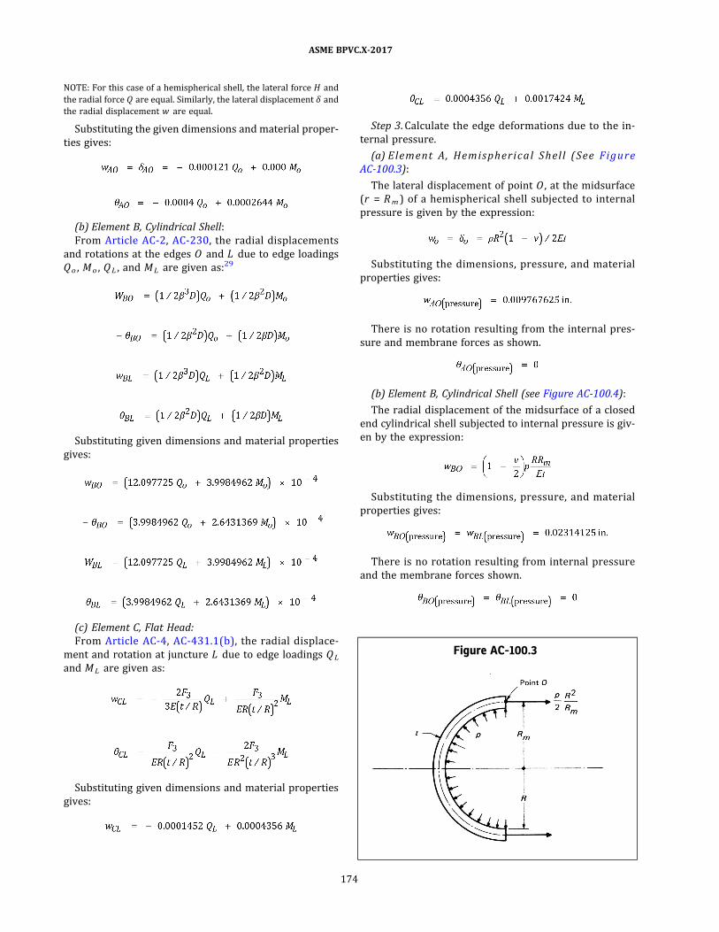
NOTE: For this case of a hemispherical shell, the lateral force H and
the radial force Q are equal. Similarly, the lateral displacement δ and
the radial displacement w are equal.
Substituting the given dimensions and material proper-
ties gives:
(b) Element B, Cylindrical Shell:
From Article AC-2 , AC-230, the radial displacements
and rotations at the edges O and L due to edge loadings
Q o , Mo , Q L , and ML are given as:29
Substituting given dimensions and material properties
gives:
(c) Element C, Flat Head:
From Article AC-4, AC-431 .1(b) , the radial displace-
ment and rotation at juncture L due to edge loadings Q L
and ML are given as:
Substituting given dimensions and material properties
gives:
Step 3. Calculate the edge deformations due to the in-
ternal pressure.
(a) Elem en t A , Hem isph erica l Sh e ll (See Figu re
AC-100.3) :
The lateral displacement of point O , at the midsurface
(r = Rm ) of a hemispherical shell subjected to internal
pressure is given by the expression:
Substituting the dimensions, pressure, and material
properties gives:
There is no rotation resulting from the internal pres-
sure and membrane forces as shown.
(b) Element B, Cylindrical Shell (see Figure AC-100.4) :
The radial displacement of the midsurface of a closed
end cylindrical shell subjected to internal pressure is giv-
en by the expression:
Substituting the dimensions, pressure, and material
properties gives:
There is no rotation resulting from internal pressure
and the membrane forces shown.
Figure AC-100.3
ASME BPVC.X-2017
174

(c) Element C, Flat Head (See Figure AC-100.5) :
In Article AC-4, AC-431.1 , the rotation of a flat head at
point L due to internal pressure is given by AC-431.1(a) :
Substituting the dimensions, pressure, and material
properties gives:
The radial disp lacement at j uncture L is given by
AC-431.1(b) :
Step 4. Calculate the free deformations of the edges of
each element caused by temperature distributions.
In this example all parts of the vessel are at the same
temperature and are of the same material; therefore, tem-
perature deformations need not be considered.
Step 5. Equate the total lateral displacements and rota-
tions of adjacent elements at each juncture.
(a) Juncture O
ð1Þ
ð2Þ
(b) Juncture L
ð3Þ
ð4Þ
Combining like terms and multiplying through by 104
results in the following system of simultaneous equations
which express compatibility at the junctures:
ð5Þ
ð6Þ
ð7Þ
ð8Þ
Step 6. Solve the above equations for Q o , Mo , Q L , and
ML . The results are:
Figure AC-100.4
Figure AC-100.5
ASME BPVC.X-2017
175

NOTE: A negative sign indicates that the actual direction of the load-
ing is opposite to that chosen in Step 1.
Step 7. Compute the discontinuity stresses at each junc-
ture due to the redundants Q o , Mo , Q L , and ML .
To illustrate the procedure, these stresses will be com-
puted in the cylindrical shell (element B) at both junc-
tures O and L .
From AC-240:
(a) Juncture O . At juncture O , M(x) = Mo and w(x)
= wo .
NOTE: When computing σ t(x) only the radial displacement due to
the redundant shear forces and moments should be used. The free
displacements from Steps 3 and 4 should not be included.
(1) Inside surface
(2) Outside surface
(b) Juncture L . At j uncture L , M(x) = M L and w(x)
= wL .
(1) Inside surface
(2) Outside surface
NOTE: E = 106 psi.
(c) The discontinuity stresses in the hemispherical
shell may be computed by using the expressions given
in AC-331 and AC-333.
(d) The discontinuity stresses in the flat head may be
computed using the expressions given in AC-431.2 .
Step 8. Compute the total stresses. The total stresses
may be computed in any element at any juncture by com-
bining the stresses due to the redundant shear forces and
moments, as computed in Step 7, with the stresses result-
ing from all other loadings. In this case the stresses in the
cylindrical shell, hemispherical shell, and flat head due to
internal pressure may be computed by the expressions
given in AC-211, AC-321, and AC-431.2 , respectively. To
illustrate the procedure, the total stresses in the cylindri-
cal shell at junctures O and L will be computed.
The stresses in the cylindrical shell due to internal
pressure may be computed from the expressions given
in AC-211.
ASME BPVC.X-2017
176
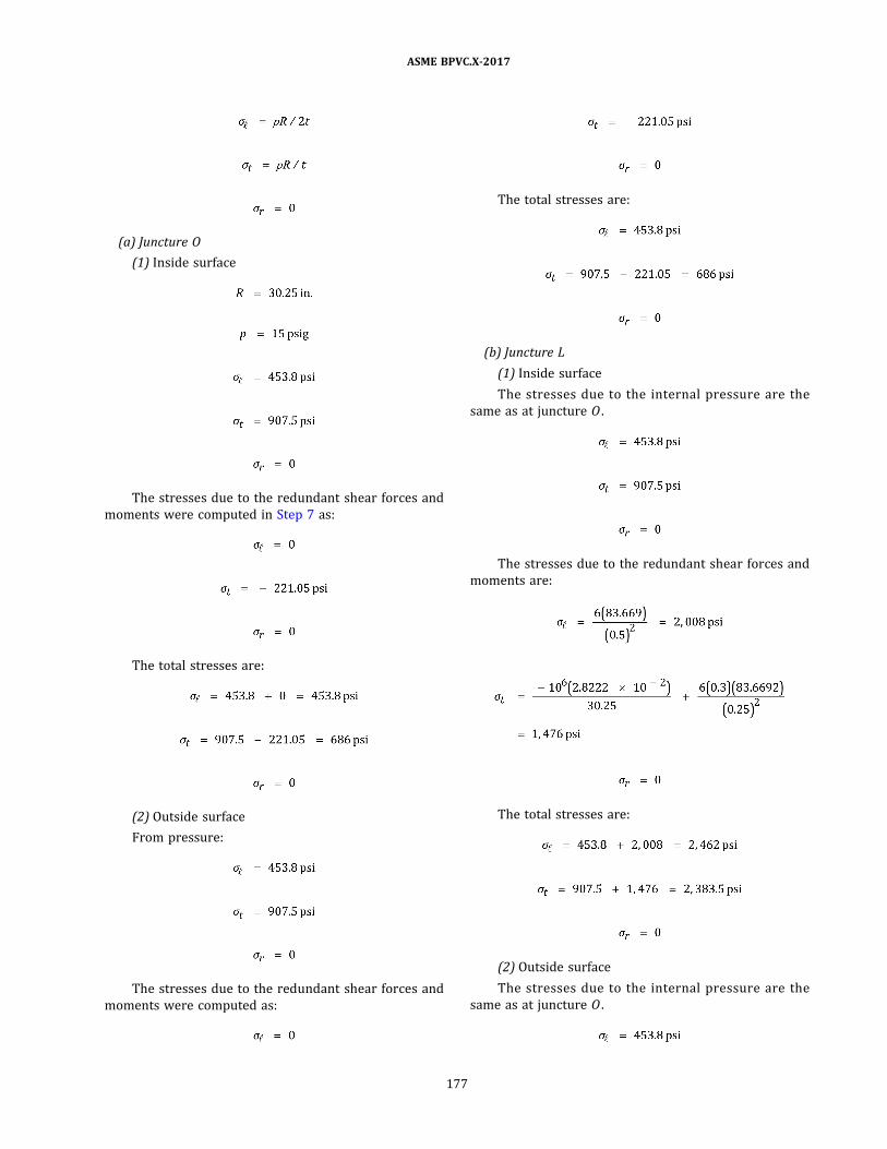
(a) Juncture O
(1) Inside surface
The stresses due to the redundant shear forces and
moments were computed in Step 7 as:
The total stresses are:
(2) Outside surface
From pressure:
The stresses due to the redundant shear forces and
moments were computed as:
The total stresses are:
(b) Juncture L
(1) Inside surface
The stresses due to the internal pressure are the
same as at juncture O .
The stresses due to the redundant shear forces and
moments are:
The total stresses are:
(2) Outside surface
The stresses due to the internal pressure are the
same as at juncture O .
ASME BPVC.X-2017
177

The stresses due to the redundant shear forces and
moments are:
The total stresses are:
Step 9. When evaluating the stresses in accordance with
RD-1188.2 , the stress intensities at each location should
be computed from the total principal stresses determined
in Step 8.
ASME BPVC.X-2017
178
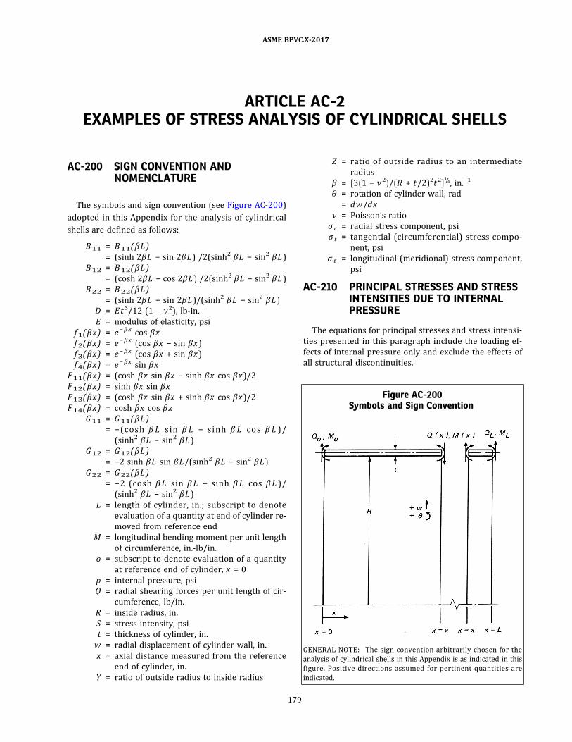
ARTICLE AC-2EXAMPLES OF STRESS ANALYSIS OF CYLINDRICAL SHELLS
AC-200 SIGN CONVENTION ANDNOMENCLATURE
The symbols and sign convention (see Figure AC-200)
adopted in this Appendix for the analysis of cylindrical
shells are defined as follows:
B11 = B11(βL )
= (sinh 2βL − sin 2βL ) /2(sinh2 βL − sin2 βL )
B12 = B12(βL )
= (cosh 2βL − cos 2βL ) /2(sinh2 βL − sin2 βL )
B22 = B22(βL )
= (sinh 2βL + sin 2βL )/(sinh2 βL − sin2 βL )
D = Et3/12 (1 − ν2) , lb-in.
E = modulus of elasticity, psi
f1(βx) = e − βx cos βx
f2(βx) = e − βx (cos βx − sin βx )
f3(βx) = e − βx (cos βx + sin βx )
f4(βx) = e − βx sin βx
F11(βx) = (cosh βx sin βx − sinh βx cos βx )/2
F12(βx) = sinh βx sin βx
F13(βx) = (cosh βx sin βx + sinh βx cos βx )/2
F14(βx) = cosh βx cos βx
G11 = G11(βL )
= − ( co s h β L s i n β L − s i nh β L co s β L ) /
(sinh2 βL − sin2 βL )
G12 = G12(βL )
= −2 sinh βL sin βL/(sinh2 βL − sin2 βL )
G22 = G22(βL )
= −2 (cosh β L s in β L + s inh β L cos β L ) /
(sinh2 βL − sin2 βL )
L = length of cylinder, in. ; subscript to denote
evaluation of a quantity at end of cylinder re-
moved from reference end
M = longitudinal bending moment per unit length
of circumference, in.-lb/in.
o = subscript to denote evaluation of a quantity
at reference end of cylinder, x = 0
p = internal pressure, psi
Q = radial shearing forces per unit length of cir-
cumference, lb/in.
R = inside radius, in.
S = stress intensity, psi
t = thickness of cylinder, in.
w = radial displacement of cylinder wall, in.
x = axial distance measured from the reference
end of cylinder, in.
Y = ratio of outside radius to inside radius
Z = ratio of outside radius to an intermediate
radius
β = [3(1 − ν2)/(R + t/2)2t2]1/4, in.−1
θ = rotation of cylinder wall, rad
= dw/dx
ν = Poisson’s ratio
σ r = radial stress component, psi
σ t = tangential (circumferential) stress compo-
nent, psi
σℓ = longitudinal (meridional) stress component,
psi
AC-210 PRINCIPAL STRESSES AND STRESSINTENSITIES DUE TO INTERNALPRESSURE
The equations for principal stresses and stress intensi-
ties presented in this paragraph include the loading ef-
fects of internal pressure only and exclude the effects of
all structural discontinuities.
Figure AC-200Symbols and Sign Convention
GENERAL NOTE: The sign convention arbitrarily chosen for the
analysis of cylindrical shells in this Appendix is as indicated in this
figure. Positive directions assumed for pertinent quantities are
indicated.
ASME BPVC.X-2017
179

AC-211 PRINCIPAL STRESSES
The principal stresses developed at any point in the
wall of a cylindrical shell due to internal pressure are giv-
en by the equations:
ð1Þ
ð2Þ
ð3Þ
AC-212 STRESS INTENSITIES
(a) The general primary membrane stress intensity de-
veloped across the thickness of a cylindrical shell due to
internal pressure is given by the equation:
ð1Þ
(b) The maximum value of the primary‐plus‐secondary
stress intensity developed at any point across the thick-
ness of a cylindrical shell due to internal pressure occurs
at the inside surface and is given by the equation:
ð2Þ
(c) Note that in evaluating the general primary mem-
brane stress intensity, the average value of the radial
stress has been taken as (−p /2) . This has been done to ob-
tain a result consistent with burst pressure analyses. On
the other hand, the radial stress value used in (b) is
(−p ) , the value at the inner surface, since the purpose of
that quantity is to control local behavior.
AC-220 BENDING ANALYSIS FORUNIFORMLY DISTRIBUTED EDGELOADS
The equations in this paragraph describe the behavior
of a cylindrical shell when subjected to the action of bend-
ing moments M , in.-lb/in. of circumference, and radial
shearing forces Q , lb/in. of circumference, uniformly dis-
tributed at the edges and acting at the mean radius of the
shell. The behavior of the shell due to all other loadings
must be evaluated independently and combined by
superposition.
AC-230 DISPLACEMENTS, BENDINGMOMENTS, AND SHEARING FORCESIN TERMS OF CONDITIONS ATREFERENCE EDGE, x = 0
(a) The radial displacementw(x) , the angular displace-
ment or rotation θ(x) , the bending moments M(x) , and
the radial shearing forces Q(x) at any axial location of
the cylinder are given by the following equations in terms
of wo , θ o , Mo , and Q o :
ð1Þ
ð2Þ
ð3Þ
ð4Þ
(b) In the case of cylinders of sufficient length, the
equations in (a) above reduce to those given below. These
equations may be used for cylinders characterized by
lengths not less than 3/β . The combined effects of load-
ings at the two edges may be evaluated by applying the
equations to the loadings at each edge, separately, and
superposing the results.
ð1Þ
ð2Þ
ASME BPVC.X-2017
180
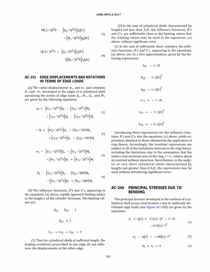
ð3Þ
ð4Þ
AC-231 EDGE DISPLACEMENTS AND ROTATIONSIN TERMS OF EDGE LOADS
(a) The radial displacements wo and wL and rotations
θ o and −θ L developed at the edges of a cylindrical shell
sustaining the action of edge loads Q o , Mo , Q L , and ML
are given by the following equations:
ð1Þ
ð2Þ
ð3Þ
ð4Þ
(b) The influence functions, B ’s and G ’s, appearing in
the equations, (a) above, rapidly approach limiting values
as the length L of the cylinder increases. The limiting val-
ues are:
(1) Thus for cylindrical shells of sufficient length, the
loading conditions prescribed at one edge do not influ-
ence the displacements at the other edge.
(2) In the case of cylindrical shells characterized by
lengths not less than 3/β , the influence functions, B ’s
and G ’s, are sufficiently close to the limiting values that
the limiting values may be used in the equations, (a)
above, without significant error.
(c) In the case of sufficiently short cylinders, the influ-
ence functions, B ’s and G ’s, appearing in the equations,
(a) above, are, to a first approximation, given by the fol-
lowing expressions:
Introducing these expressions for the influence func-
tions, B ’s and G ’s, into the equations, (a) above, yields ex-
pressions identical to those obtained by the application of
ring theory. Accordingly, the resultant expressions are
subject to all of the limitations inherent in the ring theory,
including the limitations due to the assumption that the
entire cross‐sectional area of the ring, t × L , rotates about
its centroid without distortion. Nevertheless, in the analy-
s is of very short cylindrical shel ls characterized by
lengths not greater than 0.5/β , the expressions may be
used without introducing significant error.
AC-240 PRINCIPAL STRESSES DUE TOBENDING
The principal stresses developed at the surfaces of a cy-
lindrical shell at any axial location x due to uniformly dis-
tributed edge loads (see Figure AC-200) are given by the
equations:
ð1Þ
ð2Þ
ð3Þ
ASME BPVC.X-2017
181

In these equations, where terms are preceded by a dou-
ble sign (±) , the upper sign refers to the inside surface of
the cylinder and the lower sign refers to the outside
surface.
ASME BPVC.X-2017
182

ARTICLE AC-3EXAMPLES OF STRESS ANALYSIS OF SPHERICAL SHELLS
AC-300 SCOPE
(a) In this Article, equations are given for stresses and
deformations in spherical shells subjected to internal or
external pressure.
(b) Equations are also given for bending analysis of par-
tial spherical shells under the action of uniformly distrib-
uted edge forces and moments.
AC-310 NOMENCLATURE AND SIGNCONVENTION
The symbols and sign convention adopted in this
Article are defined as follows:
A o =
B(a t α) = [(1 + ν2)(K1 + K2) − 2K2 ]
C(a t α) =
D = flexural rigidity, in.-lb
= Et3/12(1 − ν2)
E = modulus of elasticity, psi
F(a t α) =
H = force per unit length of circumference, per-
pendicular to center line of sphere, lb/in.
K1 =
k1 =
K2 =
k2 =
M = meridional bending moment per unit length
of circumference, in.-lb/in.
N = membrane force, lb/in.
o = subscript to denote a quantity at reference
edge of sphere
p = uniform pressure, internal or external, psi
Q = radial shearing force per unit of circumfer-
ence, lb/in.
R = inside radius, in.
Rm = radius of midsurface of spherical shell, in.
S = stress intensity, psi
t = as a subscript, used to denote circumferential
direction
t = thickness of spherical shell, in.
U = ratio of ins ide radius to an intermediate
radius
w = radial displacement of midsurface, in.
x = length of arc for angle α , measured from re-
ference edge of hemisphere
= Rmα , in.
Y = ratio of outside radius to inside radius
Z = ratio of outside radius to an intermediate
radius
ℓ = subscript to denote meridional direction
α = meridional angle measured from the refer-
ence edge, rad
β = , 1/in.
γo = tan−1 (−k1) , rad
δ = lateral displacement of midsurface, perpendi-
cular to center line of spherical shell, in.
θ = rotation of midsurface, rad
λ = βRm
ν = Poisson’s ratio
σ r = radial stress component, psi
σ t = tangential (circumferential) stress compo-
nent, psi
σℓ = longitudinal (meridional) stress component,
psi
ϕ = meridional angle measured from center line
of sphere, rad
ϕ L = meridional angle of second edge, rad
ϕ o = meridional angle of reference edge where
loading is applied, rad
The sign convention is l isted below and shown in
Figure AC-310 by the positive directions of the pertinent
quantities.
H, Ho = force perpendicular to Ⱡ, positive outward
M, Mo = moment, positive when causing tension on the
inside surface
Nt , Nℓ = membrane force, positive when causing tension
p = pressure, positive radially outward
δ = lateral displacement, perpendicular to Ⱡ of
sphere, positive outward
θ = rotation, positive when accompanied by an in-
crease in the radius or curvature, as caused
by a positive moment
ASME BPVC.X-2017
183
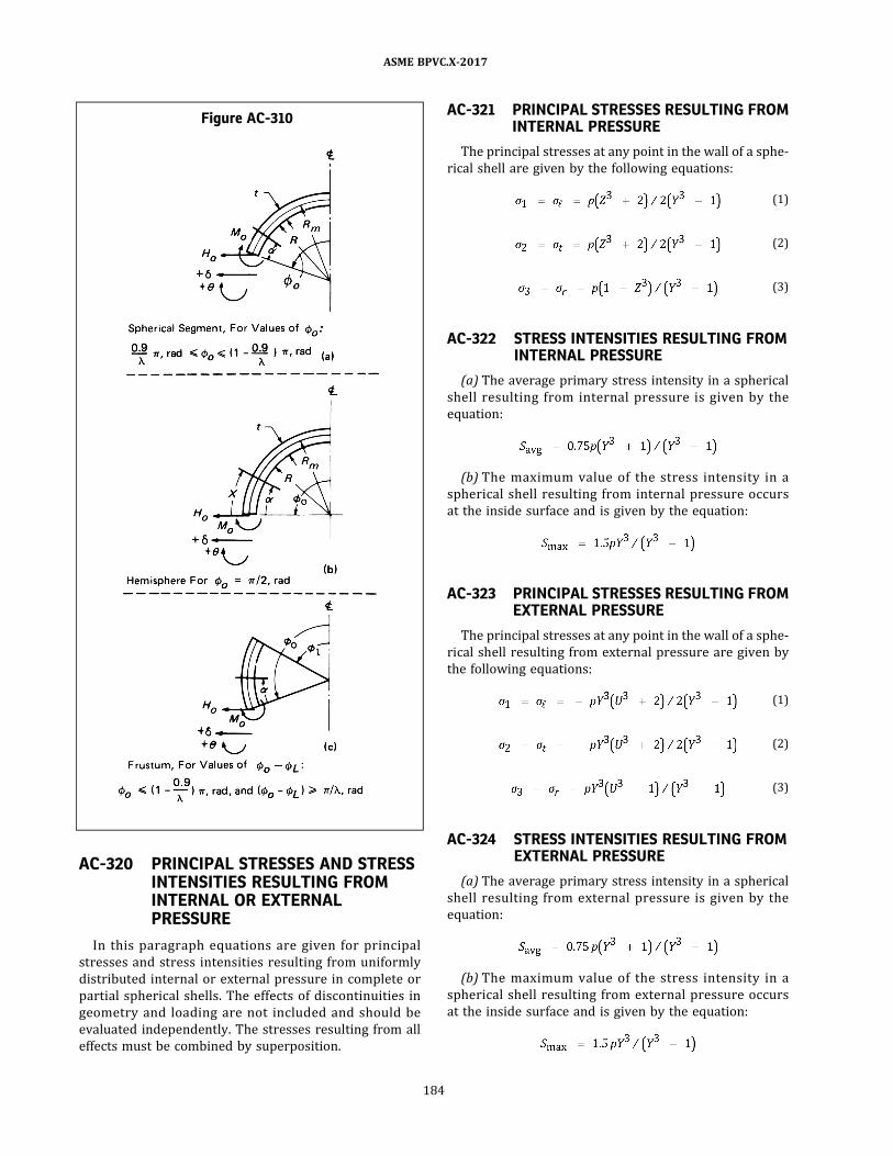
AC-320 PRINCIPAL STRESSES AND STRESSINTENSITIES RESULTING FROMINTERNAL OR EXTERNALPRESSURE
In this paragraph equations are given for principal
stresses and stress intensities resulting from uniformly
distributed internal or external pressure in complete or
partial spherical shells. The effects of discontinuities in
geometry and loading are not included and should be
evaluated independently. The stresses resulting from all
effects must be combined by superposition.
AC-321 PRINCIPAL STRESSES RESULTING FROMINTERNAL PRESSURE
The principal stresses at any point in the wall of a sphe-
rical shell are given by the following equations:
ð1Þ
ð2Þ
ð3Þ
AC-322 STRESS INTENSITIES RESULTING FROMINTERNAL PRESSURE
(a) The average primary stress intensity in a spherical
shell resulting from internal pressure is given by the
equation:
(b) The maximum value of the stress intensity in a
spherical shell resulting from internal pressure occurs
at the inside surface and is given by the equation:
AC-323 PRINCIPAL STRESSES RESULTING FROMEXTERNAL PRESSURE
The principal stresses at any point in the wall of a sphe-
rical shell resulting from external pressure are given by
the following equations:
ð1Þ
ð2Þ
ð3Þ
AC-324 STRESS INTENSITIES RESULTING FROMEXTERNAL PRESSURE
(a) The average primary stress intensity in a spherical
shell resulting from external pressure is given by the
equation:
(b) The maximum value of the stress intensity in a
spherical shell resulting from external pressure occurs
at the inside surface and is given by the equation:
Figure AC-310
ASME BPVC.X-2017
184

NOTE: The equations in AC-323 and AC-324 may be used only if the
applied external pressure is less than the critical pressure which
would cause instability of the spherical shell. The value of the critical
pressure must be evaluated in accordance with the rules given in
Article RD-3.
AC-330 BENDING ANALYSIS FORUNIFORMLY DISTRIBUTED EDGELOADS
(a) The equations in this paragraph describe the beha-
vior of partial spherical shells of the types shown in
Figure AC-310, when subjected to the action ofmeridional
bending moment Mo (in.- lb/in. of circumference) and
forces Ho (in.-lb/in. of circumference) , uniformly distrib-
uted at the reference edge and acting at the mean radius
of the shell. The effects of all other loading must be eval-
uated independently and combined by superposition.
(b) The equations listed in this paragraph become less
accurate and should be used with caution when Rm /t is
less than 10 and/or the opening angle limitations shown
in Figure AC-310 are exceeded.
AC-331 DISPLACEMENT, ROTATION, MOMENT,AND MEMBRANE FORCE IN TERMS OFLOADING CONDITIONS AT REFERENCEEDGE
The displacement δ , rotation θ , bending moments Mℓ
and Mt , and membrane forces Nℓ and Nt at any location
of sphere are given in terms of the edge loads Mo and Ho
by the following equations:
ð1Þ
ð2Þ
ð3Þ
ð4Þ
ð5Þ
AC-332 DISPLACEMENT AND ROTATION OFREFERENCE EDGE IN TERMS OFLOADING CONDITIONS AT REFERENCEEDGE
(a) At the reference edge α = 0, and ϕ = ϕ o . The equa-
tions for the displacement and rotation (see AC-331) sim-
plify to those given below:
ð1Þ
ð2Þ
(b) In the case where the shell under consideration is a
full hemisphere, eqs. (a)(1) and (a)(2) above reduce to
those given below:
ð1Þ
ð2Þ
ASME BPVC.X-2017
185

AC-333 PRINCIPAL STRESSES IN SPHERICALSHELLS RESULTING FROM EDGE LOADS
The principal stresses at the inside and outside surfaces
of a spherical shell at any location, resulting from edge
loads Mo and Ho , are given by the following equations:
ð1Þ
ð2Þ
ð3Þ
In these equations, where terms are preceded by a dou-
ble sign (±) , the upper sign refers to the inside surface of
the shell and the lower sign refers to the outside surface.
AC-340 ALTERNATE BENDING ANALYSIS OFA HEMISPHERICAL SHELLSUBJECTED TO UNIFORMLYDISTRIBUTED EDGE LOADS
If a less exacting but more expedient analysis of hemi-
spherical shells is required, equations derived for cylind-
rical shells may be used in a modified form. The equations
listed in this paragraph describe the behavior of a hemi-
spherical shell as approximated by a cylindrical shell of
the same radius and thickness when subjected to the ac-
tion of uniformly distributed edge loads Mo and Ho at
α = 0, x = 0, and ϕ o = 90 deg = π/2 rad.
AC-341 DISPLACEMENT ROTATION, MOMENT,AND SHEAR FORCES IN TERMS OFLOADING CONDITIONS AT EDGE
ð1Þ
ð2Þ
ð3Þ
ð4Þ
ð5Þ
ð6Þ
where f1 , f2 , f3 , and f4 are defined in Article AC-2 and
AC-342 PRINCIPAL STRESSES IN AHEMISPHERICAL SHELL DUE TO EDGELOADS
The principal stresses in a hemispherical shell, due to
edge loads Mo and Ho , at the inside and outside surfaces
of a hemispherical shell at any meridional location, are
given by the equations:
ð1Þ
ð2Þ
ð3Þ
In these equations, where terms are preceded by a dou-
ble sign (±) , the upper sign refers to the inside surface of
the hemisphere and the lower sign refers to the outside
surface.
AC-343 LAYERED SPHERICAL SHELL AND HEADFORMULAS
The equations developed for solid wall spherical shells
or heads as expressed in this Article may be applied to
layered spherical shells or heads provided that the shell
or head is constructed to prevent slip between the layers
in the area of discontinuity.
ASME BPVC.X-2017
186

ARTICLE AC-4EXAMPLES OF STRESS ANALYSIS OF FLAT CIRCULAR HEADS
AC-400 SCOPE
(a) In this Article, equations are given for stresses and
displacements in flat circular plates used as heads for
pressure vessels.
(b) Equations are also given for stresses and displace-
ments in these heads due to forces and edge moments
uniformly distributed along the outer edge and uniformly
distributed over a circle on one face. The radius of this cir-
cle is intended to match the mean radius of an adjoining
element such as a cylinder, cone, or spherical segment.
AC-410 NOMENCLATURE AND SIGNCONVENTION
The symbols and sign conventions adopted in this
Article are defined as follows:
E = elastic modulus, psi
F = geometry constant given in Table AC-440.1
M = radial bending moment, in.-lb/in. of circumference
p = pressure, psi
Q = radial force, lb/in. of circumference
R = outside radius of plate, in.
r = radial distance from center of plate, in.
t = thickness of plate
ts = thickness of connecting shell at the head junction,
in.
w = radial displacement, in.
x = longitudinal distance from midplane of plate, in.
θ = rotation, rad
ν = Poisson’s ratio
σr = radial stress, psi
σ t = tangential (circumferential) stress, psi
σℓ = longitudinal stress, psi
Tensile stresses are positive. The positive directions of
the coordinates, radial forces, moments, and displace-
ments are shown in Figure AC-410. The pressure is as-
sumed to act on the surface where x = −t/2.
AC-420 PRESSURE AND EDGE LOADS ONCIRCULAR FLAT PLATES
In the following paragraphs equations are given for the
principal stress and the deformations of flat plates under
axisymmetric loading conditions.
AC-421 PRESSURE LOADS ON SIMPLYSUPPORTED FLAT PLATES
The principal stresses and deformations for a flat plate,
simply supported at its periphery and loaded in the man-
ner shown in Figure AC-421, are given for a radial loca-
ti on r at any po int x i n the cro s s s e cti on by the
following equations.
Radial bending stress
ð1Þ
Tangential bending stress
ð2Þ
Longitudinal stress
ð3Þ
Rotation of the midplane
ð4Þ
Rotation of the midplane at the outer edge
ð5Þ
Figure AC-410
ASME BPVC.X-2017
187
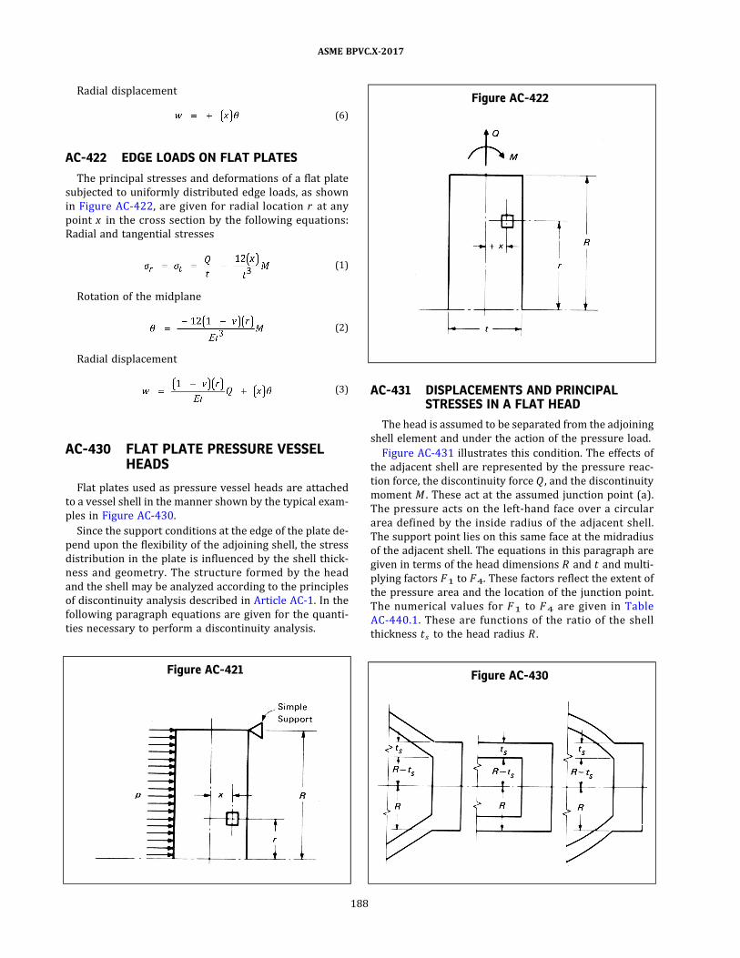
Radial displacement
ð6Þ
AC-422 EDGE LOADS ON FLAT PLATES
The principal stresses and deformations of a flat plate
subjected to uniformly distributed edge loads, as shown
in Figure AC-422 , are given for radial location r at any
point x in the cross section by the following equations:
Radial and tangential stresses
ð1Þ
Rotation of the midplane
ð2Þ
Radial displacement
ð3Þ
AC-430 FLAT PLATE PRESSURE VESSELHEADS
Flat plates used as pressure vessel heads are attached
to a vessel shell in the manner shown by the typical exam-
ples in Figure AC-430.
Since the support conditions at the edge of the plate de-
pend upon the flexibility of the adjoining shell, the stress
distribution in the plate is influenced by the shell thick-
ness and geometry. The structure formed by the head
and the shell may be analyzed according to the principles
of discontinuity analysis described in Article AC-1. In the
following paragraph equations are given for the quanti-
ties necessary to perform a discontinuity analysis.
AC-431 DISPLACEMENTS AND PRINCIPALSTRESSES IN A FLAT HEAD
The head is assumed to be separated from the adjoining
shell element and under the action of the pressure load.
Figure AC-431 illustrates this condition. The effects of
the adjacent shell are represented by the pressure reac-
tion force, the discontinuity force Q , and the discontinuity
moment M . These act at the assumed junction point (a) .
The pressure acts on the left‐hand face over a circular
area defined by the inside radius of the adjacent shell.
The support point lies on this same face at the midradius
of the adjacent shell. The equations in this paragraph are
given in terms of the head dimensions R and t and multi-
plying factors F1 to F4. These factors reflect the extent of
the pressure area and the location of the junction point.
The numerical values for F1 to F4 are given in Table
AC-440.1 . These are functions of the ratio of the shell
thickness ts to the head radius R .
Figure AC-421
Figure AC-422
Figure AC-430
ASME BPVC.X-2017
188
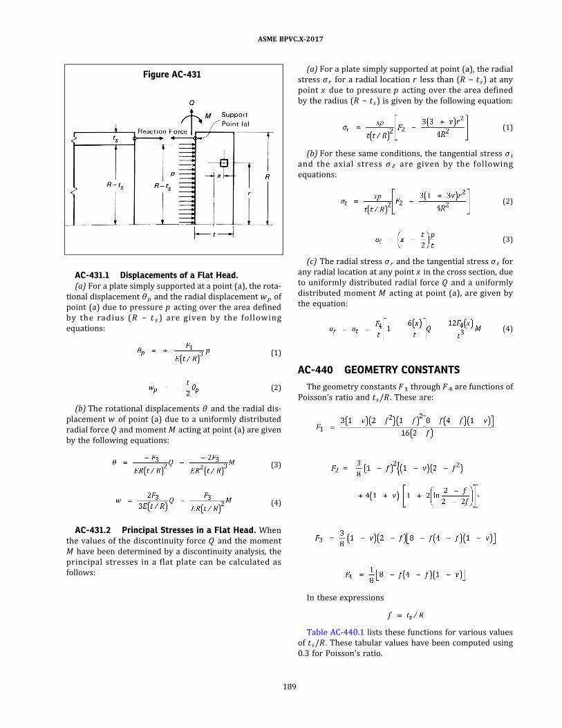
AC-431.1 Displacements of a Flat Head.(a) For a plate simply supported at a point (a) , the rota-
tional displacement θ p and the radial displacement wp of
point (a) due to pressure p acting over the area defined
by the radius (R − t s ) are given by the fo l l owing
equations:
ð1Þ
ð2Þ
(b) The rotational displacements θ and the radial dis-
placement w of point (a) due to a uniformly distributed
radial force Q and momentM acting at point (a) are given
by the following equations:
ð3Þ
ð4Þ
AC-431.2 Principal Stresses in a Flat Head. When
the values of the discontinuity force Q and the moment
M have been determined by a discontinuity analysis, the
principal stresses in a flat plate can be calculated as
follows:
(a) For a plate simply supported at point (a) , the radial
stress σ r for a radial location r less than (R − ts ) at any
point x due to pressure p acting over the area defined
by the radius (R − ts ) is given by the following equation:
ð1Þ
(b) For these same conditions, the tangential stress σ t
and the axial s tress σ ℓ are given by the fo l lowing
equations:
ð2Þ
ð3Þ
(c) The radial stress σ r and the tangential stress σ t for
any radial location at any point x in the cross section, due
to uniformly distributed radial force Q and a uniformly
distributed moment M acting at point (a) , are given by
the equation:
ð4Þ
AC-440 GEOMETRY CONSTANTS
The geometry constants F1 through F4 are functions of
Poisson’s ratio and ts/R . These are:
In these expressions
Table AC-440.1 lists these functions for various values
of ts/R . These tabular values have been computed using
0.3 for Poisson’s ratio.
Figure AC-431
ASME BPVC.X-2017
189

AC-450 STRESS INTENSITIES IN A FLATPLATE
The principal stresses due to pressure p , discontinuity
force Q , discontinuity moment M , and other coincident
loadings should be combined algebraically and the stress
differences determined according to the procedures of
RD-1182 . The calculated stress intensity values should
not exceed the allowable values given in RD-1187.
Table AC-440.1
ts/R F1 F2 F3 F4
0.00 1.0500 2.4750 4.2000 1.0000
0.02 1.0113 2.4149 4.1290 0.9930
0.04 0.9730 2.3547 4.0589 0.9861
0.06 0.9350 2.2943 3.9897 0.9793
0.08 0.8975 2.2339 3.9214 0.9726
0.10 0.8604 2.1734 3.8538 0.9659
0.12 0.8238 2.1129 3.7872 0.9593
0.14 0.7878 2.0524 3.7213 0.9527
0.16 0.7523 1.9920 3.6563 0.9462
0.18 0.7174 1.9316 3.5920 0.9398
0.20 0.6831 1.8713 3.5286 0.9335
ASME BPVC.X-2017
190
NONMANDATORY APPENDIX ADLAMINATE THEORY
AD-100 SCOPE
Laminate theory is defined as a mathematical treat-
ment of the mechanics governing the behavior of a unidir-
ectional ortho trop ic lamina , and the interre lation
between multiple lamina as they act together to form a
multidirectional laminate. As addressed in this Appendix,
laminate theory shall be used to:
(a) determine the in‐plane and flexural modulus com-
ponents that define the stress–strain and moment–
curvature relationships for laminates;
(b) examine the strength of the laminate based on the
strain state of individual lamina reacting to imposed mo-
ment and stress resultants;
(c) determine the effective engineering constants of the
laminates.
As an illustrative example, a twelve ply laminate, hav-
ing the lamina properties, ply orientation, stacking se-
quence, and imposed loads shown in Figure AD-500 ,
shall be examined.
AD-200 STANDARD NOTATION
The following conventions are observed for ply num-
bering and reference axis.
AD-201 LOCATION AND NUMBERING OF PLIES
A multidirectional general laminate is represented dia-
grammatically in Figure AD-201. Ply numbering is from
Z = −h /2 to Z = h /2, with ply No. 1 at the bottom.
AD-202 REFERENCE AXIS
Coordinate reference axis designation is illustrated in
Figure AD-202.
on‐axis: refers to the principal orientation of the fibers of
a specific laminate and is referenced as the x–y axis: x
being parallel to the fibers, y being transverse to the
fibers.
off‐axis: refers to the principal material axis of the lami-
nate and is referenced as the 1–2 axis. As referenced in
this Appendix, the 1 axis is the vessel or nozzle longitudi-
nal axis, and the 2 axis is the hoop or circumferential axis.
AD-300 BASIC ASSUMPTIONS
In the application of laminate theory as used in this Sec-
tion, certain assumptions are made:
(a) interlaminar or transverse shear is not addressed;
(b) laminate stress resultants and moment resultants
are taken as averages of ply stresses across the thickness
of the laminate;
(c) ply stress is based on homogeneity within each ply
where the fiber and matrix are not recognized as distinct
phases;
(d) the laminate is assumed to consist of perfectly
bonded lamina, i.e., displacements are continuous across
laminate boundaries and no lamina slips relative to
another;
(e) since the stress distribution across a multidirec-
tional laminate is not constant due to the variation in
ply modulus, the stress–strain relationship is defined in
terms of an average stress.
AD-310 NOMENCLATURE
Refer to Article RD-12.
AD-400 LAMINA (PLY) PROPERTIES
Laminate theory as applied in this Section requires that
four elastic constants and five strength constants be de-
termined for the orthotropic lamina. These shall be deter-
mined by the appropriate ASTM standard listed in Article
RT-7. For the illustrative example, they shall be assumed
to be as shown in Table AD-500.
(a) Elastic constants required are:
Es = longitudinal shear modulus
Ex = longitudinal tensile modulus
Ey = transverse tensile modulus
νx = longitudinal Poisson’s ratio
(b) Strength constants required are:
S = longitudinal shear strength
X = longitudinal tensile strength
Xc = longitudinal compressive strength
Y = transverse tensile strength
Yc = transverse compressive strength
(c) Physical constants required are:
h = laminate thickness
tk = thickness of each layer
Zk = distance from laminate midplane to ply surface
ASME BPVC.X-2017
191
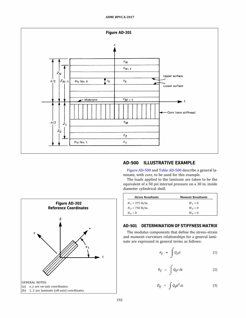
AD-500 ILLUSTRATIVE EXAMPLE
Figure AD-500 and Table AD-500 describe a general la-
minate, with core, to be used for this example.
The loads applied to the laminate are taken to be the
equivalent of a 50 psi internal pressure on a 30 in. inside
diameter cylindrical shell.
Stress Resultants Moment Resultants
N1 = 375 lb/in. M1 = 0
N2 = 750 lb/in. M2 = 0
N6 = 0 M6 = 0
AD-501 DETERMINATION OF STIFFNESS MATRIX
The modulus components that define the stress–strain
and moment–curvature relationships for a general lami-
nate are expressed in general terms as follows:
ð1Þ
ð2Þ
ð3Þ
Figure AD-201
Figure AD-202Reference Coordinates
GENERAL NOTES:
(a) x, y are on-axis coordinates.
(b) 1, 2 are laminate (off-axis) coordinates.
ASME BPVC.X-2017
192

ð17Þ
The following outline may be used to solve for the inte-
grals and determine the modulus components of an aniso-
trop i c l aminate from the o rtho trop i c p ropertie s ,
orientation, and stacking sequence of the individual
lamina.
AD-501.1 Determine On-Axis Modulus Componentsof the Lamina. From the lamina elastic constants:
ð4Þ
ð5Þ
ð6Þ
ð7Þ
ð8Þ
AD-501.2 Determination of Transformed ModulusComponents. Based on the orientation of each ply, calcu-
late the transformed modulus components of each lamina
using the transformation equations shown below and the
on‐axis modulus components determined in AD-501.1 .
The transformed modulus components in terms of their
power functions and on‐axis components are shown
below.
Figure AD-500
Table AD-500Assumed Lamina Elastic and Strength
Properties
Property Assumed Value
Ex 5.100 × 10⁶ psi
Ey 1.525 × 10⁶ psi
Es 0.439 × 10⁶ psi
νx 0.281
tk 0.020 in.
X 119,000 psi
Y 10,000 psi
XC 119,000 psi
YC 10,000 psi
S 5,220 psi
νy [Note (1)] 0.084
NOTE:
(1) νy = Eyνx/Ex
ASME BPVC.X-2017
193
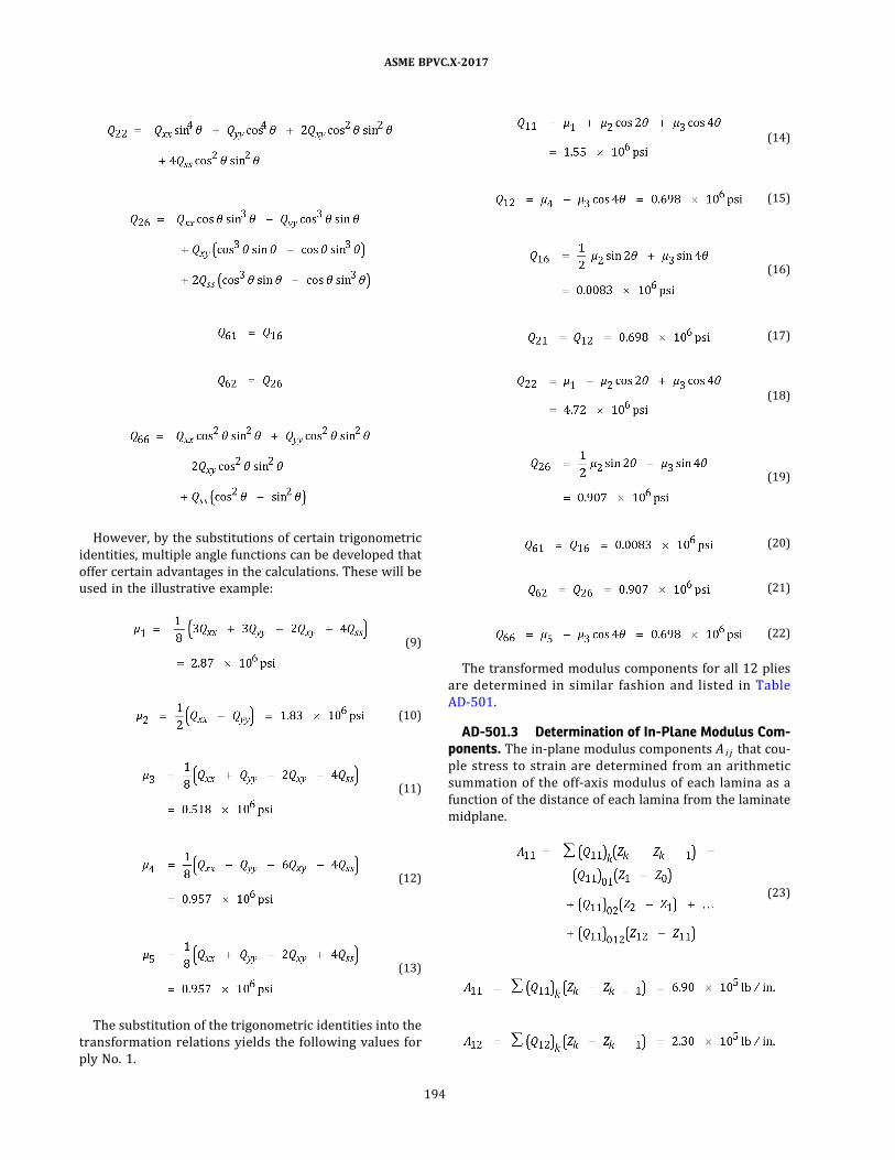
However, by the substitutions of certain trigonometric
identities, multiple angle functions can be developed that
offer certain advantages in the calculations. These will be
used in the illustrative example:
ð9Þ
ð10Þ
ð11Þ
ð12Þ
ð13Þ
The substitution of the trigonometric identities into the
transformation relations yields the following values for
ply No. 1.
ð14Þ
ð15Þ
ð16Þ
ð17Þ
ð18Þ
ð19Þ
ð20Þ
ð21Þ
ð22Þ
The transformed modulus components for all 12 plies
are determined in similar fashion and listed in Table
AD-501.
AD-501.3 Determination of In-Plane Modulus Com-ponents. The in‐plane modulus components A i j that cou-
ple stress to strain are determined from an arithmetic
summation of the off‐axis modulus of each lamina as a
function of the distance of each lamina from the laminate
midplane.
ð23Þ
ASME BPVC.X-2017
194

AD-501.4 Determination of Coupling Modulus Com-ponents. The coupling modulus components B i j that cou-
p le moment to s train and s tres s to curvature are
determined from a summation of the off‐axis modulus
of the individual lamina as a function of the square of
the distance of the lamina from the laminate midplane.
ð24ÞAD-501.5 Determination of Flexural Modulus Com-
ponents. The flexural modulus components D i j that cou-
p le moments to curvature are determined from a
summation of the off‐axis modulus of the individual lami-
na as a function of the cube of the distance of the lamina
from the laminate midplane.
Table AD-501Transformed Modulus Components, 106 psi
Ply No. Q11 Q12 Q16 Q21 Q22 Q26 Q61 Q62 Q66
1 1.547 0.698 0.0083 0.698 4.718 0.907 0.0083 0.907 0.698
2 1.547 0.698 −0.0083 0.698 4.718 −0.907 −0.0083 −0.907 0.698
3 4.718 0.698 0.907 0.698 1.547 0.0083 0.907 0.0083 0.698
4 4.718 0.698 −0.907 0.698 1.547 −0.0083 −0.907 −0.0083 0.698
5 2.354 1.476 0.915 1.476 2.354 0.915 0.915 0.915 1.476
6 2.354 1.476 −0.915 1.476 2.354 −0.915 −0.915 −0.915 1.476
7 2.354 1.476 −0.915 1.476 2.354 −0.915 −0.915 −0.915 1.476
8 2.354 1.476 0.915 1.476 2.354 0.915 0.915 0.915 1.476
9 4.718 0.698 −0.907 0.698 1.547 −0.0083 −0.907 −0.0083 0.698
10 4.718 0.698 0.907 0.698 1.547 0.0083 0.907 0.0083 0.698
11 1.547 0.698 −0.0083 0.698 4.718 −0.907 −0.0083 −0.907 0.698
12 1.547 0.698 0.0083 0.698 4.718 0.907 0.0083 0.907 0.698
ASME BPVC.X-2017
195
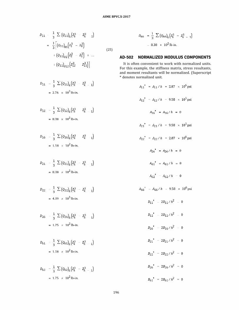
ð25Þ
AD-502 NORMALIZED MODULUS COMPONENTS
It is often convenient to work with normalized units.
For this example, the stiffness matrix, stress resultants,
and moment resultants will be normalized. (Superscript
* denotes normalized unit.
ASME BPVC.X-2017
196
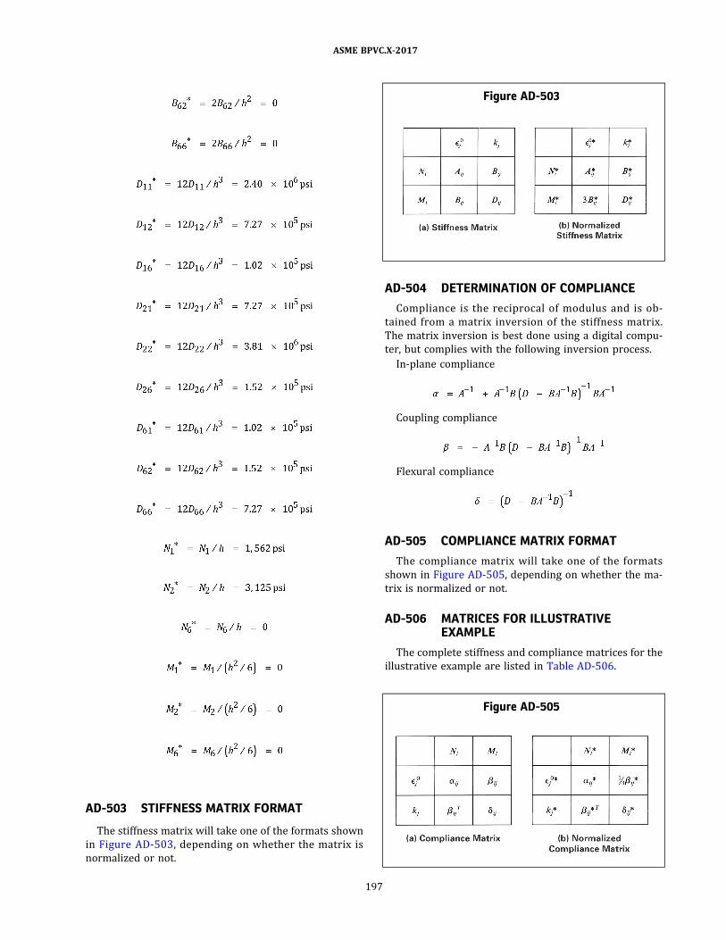
AD-503 STIFFNESS MATRIX FORMAT
The stiffness matrix will take one of the formats shown
in Figure AD-503 , depending on whether the matrix is
normalized or not.
AD-504 DETERMINATION OF COMPLIANCE
Compliance is the reciprocal of modulus and is ob-
tained from a matrix inversion of the stiffness matrix.
The matrix inversion is best done using a digital compu-
ter, but complies with the following inversion process.
In‐plane compliance
Coupling compliance
Flexural compliance
AD-505 COMPLIANCE MATRIX FORMAT
The compliance matrix will take one of the formats
shown in Figure AD-505, depending on whether the ma-
trix is normalized or not.
AD-506 MATRICES FOR ILLUSTRATIVEEXAMPLE
The complete stiffness and compliance matrices for the
illustrative example are listed in Table AD-506.
Figure AD-503
Figure AD-505
ASME BPVC.X-2017
197

Table AD-506Matrices for Illustrative Example
Normalized Stiffness Matrix, psi
A* B*
3B* D*
2.874 E+06 9.578 E+05 0.000 E+00 7.830 E−10 2.711 E−10 2.823 E−18
9.578 E+05 2.874 E+06 0.000 E+00 2.711 E−10 7.228 E−10 −1.506 E−11
0.000 E+00 0.000 E+00 9.579 E+05 2.823 E−12 −1.506 E−11 2.485 E−10
2.349 E−09 8.132 E−10 8.470 E−18 2.400 E+06 7.272 E+05 1.022 E+05
8.132 E−10 2.168 E−09 −4.518 E−11 7.272 E+05 3.809 E+06 1.521 E+05
8.470 E−12 −4.518 E−11 7.454 E−10 1.022 E+05 1.521 E+05 7.273 E+05
Normalized Compliance Matrix, 1/psi
α* 1/3β*
β*T δ*
3.915 E−07 −1.305 E−07 −2.297 E−39 −3.976 E−23 6.424 E−24 3.341 E−24
−1.305 E−07 3.915 E−07 −6.279 E−39 6.173 E−24 −2.311 E−23 6.668 E−24
−1.546 E−39 −6.466 E−39 1.044 E−06 3.020 E−24 5.610 E−24 −1.205 E−22
−1.192 E−22 1.933 E−23 8.485 E−24 4.438 E−07 −8.292 E−08 −4.500 E−08
1.850 E−23 −6.935 E−23 2.052 E−23 −8.292 E−08 2.802 E−07 −4.696 E−08
1.037 E−23 1.659 E−23 −3.616 E−22 −4.500 E−08 −4.696 E−08 1.391 E−06
Stiffness Matrix
A (lb/in.) B (lb)
B (lb) D (lb-in.)
6.897 E+05 2.299 E+05 0.000 E+00 2.255 E−11 7.806 E−12 8.132 E−20
2.299 E+05 6.897 E+05 0.000 E+00 7.806 E−12 2.082 E−11 −4.337 E−13
0.000 E+00 0.000 E+00 2.299 E+05 8.132 E−14 −4.337 E−13 7.156 E−12
2.255 E−11 7.806 E−12 8.132 E−20 2.764 E+03 8.377 E+02 1.177 E+02
7.806 E−12 2.082 E−11 −4.337 E−13 8.377 E+02 4.388 E+03 1.752 E+02
8.132 E−14 −4.337 E−13 7.156 E−12 1.177 E+02 1.752 E+02 8.378 E+02
Compliance Matrix
α (in./lb) β (1/lb)
βT (1/lb) δ (1/lb-in.)
1 .631 E−06 −5.437 E−07 −2.871 E−38 −1.242 E−20 2.008 E−21 1.044 E−21
−5.437 E−07 1.631 E−06 −7.848 E−38 1.929 E−21 −7.223 E−21 2.084 E−21
−1.932 E−38 −8.083 E−38 4.350 E−06 9.437 E−22 1.753 E−21 −3.765 E−20
−1.242 E−20 2.013 E−21 8.838 E−22 3.852 E−04 −7.198 E−05 −3.906 E−05
1.927 E−21 −7.224 E−21 2.137 E−21 −7.198 E−05 2.433 E−04 −4.076 E−05
1.080 E−21 1.728 E−21 −3.766 E−20 −3.906 E−05 −4.076 E−05 1.208 E−03
ASME BPVC.X-2017
198
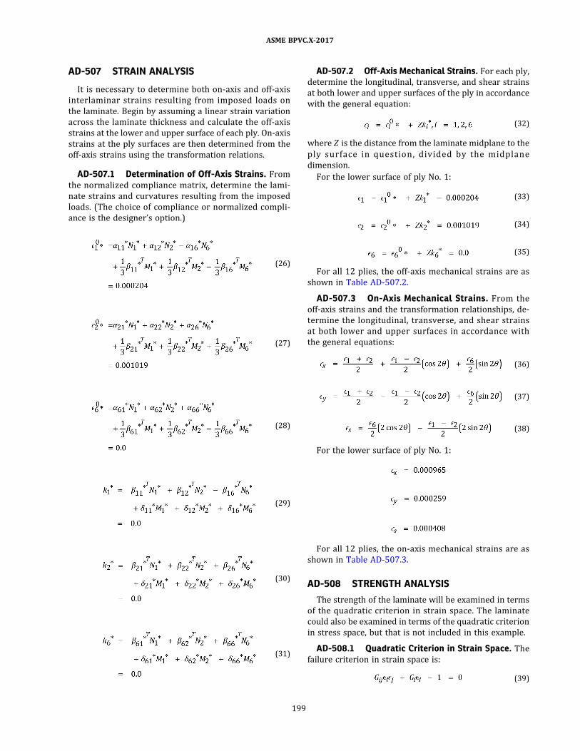
AD-507 STRAIN ANALYSIS
It is necessary to determine both on‐axis and off‐axis
interlaminar strains resulting from imposed loads on
the laminate. Begin by assuming a linear strain variation
across the laminate thickness and calculate the off‐axis
strains at the lower and upper surface of each ply. On‐axis
strains at the ply surfaces are then determined from the
off‐axis strains using the transformation relations.
AD-507.1 Determination of Off-Axis Strains. Fromthe normalized compliance matrix, determine the lami-
nate strains and curvatures resulting from the imposed
loads. (The choice of compliance or normalized compli-
ance is the designer’s option.)
ð26Þ
ð27Þ
ð28Þ
ð29Þ
ð30Þ
ð31Þ
AD-507.2 Off-Axis Mechanical Strains. For each ply,
determine the longitudinal, transverse, and shear strains
at both lower and upper surfaces of the ply in accordance
with the general equation:
ð32Þ
where Z is the distance from the laminate midplane to the
p ly surface in ques tion , d ivided by the midp lane
dimension.
For the lower surface of ply No. 1:
ð33Þ
ð34Þ
ð35Þ
For all 12 plies, the off‐axis mechanical strains are as
shown in Table AD-507.2.
AD-507.3 On-Axis Mechanical Strains. From the
off‐axis strains and the transformation relationships, de-
termine the longitudinal, transverse, and shear strains
at both lower and upper surfaces in accordance with
the general equations:
ð36Þ
ð37Þ
ð38Þ
For the lower surface of ply No. 1:
For all 12 plies, the on‐axis mechanical strains are as
shown in Table AD-507.3.
AD-508 STRENGTH ANALYSIS
The strength of the laminate will be examined in terms
of the quadratic criterion in strain space. The laminate
could also be examined in terms of the quadratic criterion
in stress space, but that is not included in this example.
AD-508.1 Quadratic Criterion in Strain Space. Thefailure criterion in strain space is:
ð39Þ
ASME BPVC.X-2017
199
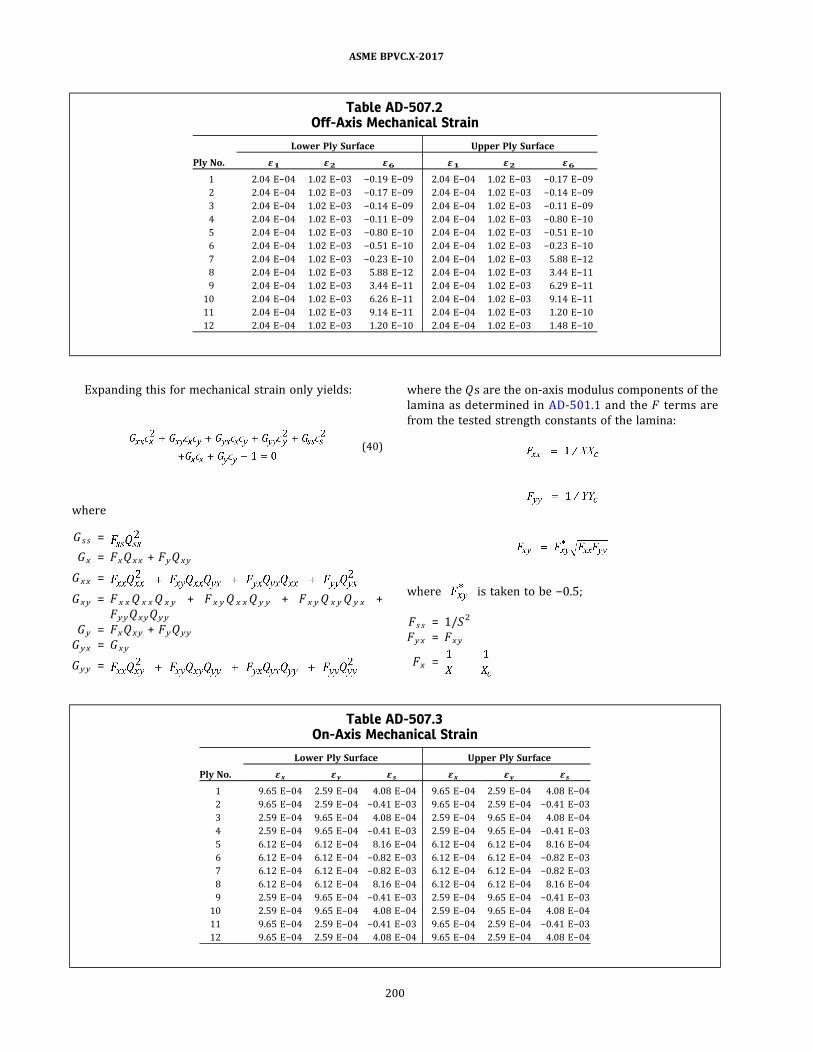
Expanding this for mechanical strain only yields:
ð40Þ
where
G s s =
Gx = FxQ xx + FyQ xy
G xx =
Gxy = F x xQ x xQ x y + F x yQ x xQ y y + F x yQ x yQ y x +
FyyQ xyQ yy
Gy = FxQ xy + FyQ yy
G yx = Gxy
Gyy =
where the Q s are the on‐axis modulus components of the
lamina as determined in AD-501.1 and the F terms are
from the tested strength constants of the lamina:
where is taken to be −0.5;
Fs s = 1/S2
Fyx = Fxy
Fx =
Table AD-507.2Off-Axis Mechanical Strain
Ply No.
Lower Ply Surface Upper Ply Surface
ε1 ε2 ε6 ε1 ε2 ε6
1 2.04 E−04 1.02 E−03 −0.19 E−09 2.04 E−04 1.02 E−03 −0.17 E−09
2 2.04 E−04 1.02 E−03 −0.17 E−09 2.04 E−04 1.02 E−03 −0.14 E−09
3 2.04 E−04 1.02 E−03 −0.14 E−09 2.04 E−04 1.02 E−03 −0.11 E−09
4 2.04 E−04 1.02 E−03 −0.11 E−09 2.04 E−04 1.02 E−03 −0.80 E−10
5 2.04 E−04 1.02 E−03 −0.80 E−10 2.04 E−04 1.02 E−03 −0.51 E−10
6 2.04 E−04 1.02 E−03 −0.51 E−10 2.04 E−04 1.02 E−03 −0.23 E−10
7 2.04 E−04 1.02 E−03 −0.23 E−10 2.04 E−04 1.02 E−03 5.88 E−12
8 2.04 E−04 1.02 E−03 5.88 E−12 2.04 E−04 1.02 E−03 3.44 E−11
9 2.04 E−04 1.02 E−03 3.44 E−11 2.04 E−04 1.02 E−03 6.29 E−11
10 2.04 E−04 1.02 E−03 6.26 E−11 2.04 E−04 1.02 E−03 9.14 E−11
11 2.04 E−04 1.02 E−03 9.14 E−11 2.04 E−04 1.02 E−03 1.20 E−10
12 2.04 E−04 1.02 E−03 1.20 E−10 2.04 E−04 1.02 E−03 1.48 E−10
Table AD-507.3On-Axis Mechanical Strain
Ply No.
Lower Ply Surface Upper Ply Surface
εx εy εs εx εy εs
1 9.65 E−04 2.59 E−04 4.08 E−04 9.65 E−04 2.59 E−04 4.08 E−04
2 9.65 E−04 2.59 E−04 −0.41 E−03 9.65 E−04 2.59 E−04 −0.41 E−03
3 2.59 E−04 9.65 E−04 4.08 E−04 2.59 E−04 9.65 E−04 4.08 E−04
4 2.59 E−04 9.65 E−04 −0.41 E−03 2.59 E−04 9.65 E−04 −0.41 E−03
5 6.12 E−04 6.12 E−04 8.16 E−04 6.12 E−04 6.12 E−04 8.16 E−04
6 6.12 E−04 6.12 E−04 −0.82 E−03 6.12 E−04 6.12 E−04 −0.82 E−03
7 6.12 E−04 6.12 E−04 −0.82 E−03 6.12 E−04 6.12 E−04 −0.82 E−03
8 6.12 E−04 6.12 E−04 8.16 E−04 6.12 E−04 6.12 E−04 8.16 E−04
9 2.59 E−04 9.65 E−04 −0.41 E−03 2.59 E−04 9.65 E−04 −0.41 E−03
10 2.59 E−04 9.65 E−04 4.08 E−04 2.59 E−04 9.65 E−04 4.08 E−04
11 9.65 E−04 2.59 E−04 −0.41 E−03 9.65 E−04 2.59 E−04 −0.41 E−03
12 9.65 E−04 2.59 E−04 4.08 E−04 9.65 E−04 2.59 E−04 4.08 E−04
ASME BPVC.X-2017
200
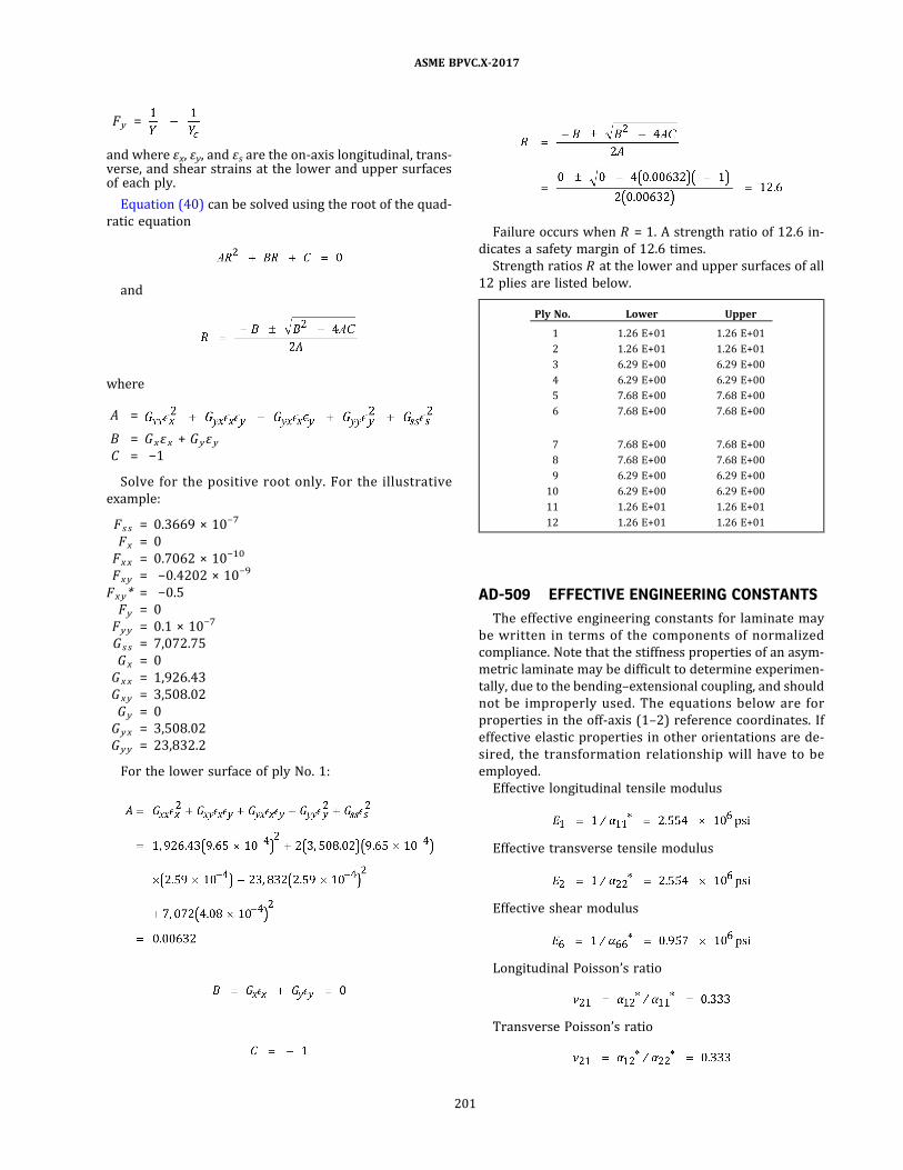
Fy =
and where εx, εy, and εs are the on‐axis longitudinal, trans-verse, and shear strains at the lower and upper surfacesof each ply.
Equation (40) can be solved using the root of the quad-
ratic equation
and
where
A =
B = Gxεx + Gyε yC = −1
Solve for the positive root only. For the illustrative
example:
Fs s = 0.3669 × 10⁻⁷
Fx = 0
Fxx = 0.7062 × 10⁻¹⁰
Fxy = −0.4202 × 10⁻⁹
Fxy* = −0.5
Fy = 0
Fyy = 0.1 × 10⁻⁷
G s s = 7,072.75
Gx = 0
Gxx = 1,926.43
Gxy = 3,508.02
Gy = 0
Gyx = 3,508.02
Gyy = 23,832.2
For the lower surface of ply No. 1:
Failure occurs when R = 1. A strength ratio of 12.6 in-
dicates a safety margin of 12.6 times.
Strength ratios R at the lower and upper surfaces of all
12 plies are listed below.
Ply No. Lower Upper
1 1.26 E+01 1.26 E+01
2 1.26 E+01 1.26 E+01
3 6.29 E+00 6.29 E+00
4 6.29 E+00 6.29 E+00
5 7.68 E+00 7.68 E+00
6 7.68 E+00 7.68 E+00
7 7.68 E+00 7.68 E+00
8 7.68 E+00 7.68 E+00
9 6.29 E+00 6.29 E+00
10 6.29 E+00 6.29 E+00
11 1.26 E+01 1.26 E+01
12 1.26 E+01 1.26 E+01
AD-509 EFFECTIVE ENGINEERING CONSTANTS
The effective engineering constants for laminate may
be written in terms of the components of normalized
compliance. Note that the stiffness properties of an asym-
metric laminate may be difficult to determine experimen-
tally, due to the bending–extensional coupling, and should
not be improperly used. The equations below are for
properties in the off‐axis (1–2) reference coordinates. If
effective elastic properties in other orientations are de-
sired, the transformation relationship will have to be
employed.
Effective longitudinal tensile modulus
Effective transverse tensile modulus
Effective shear modulus
Longitudinal Poisson’s ratio
Transverse Poisson’s ratio
ASME BPVC.X-2017
201

Longitudinal flexural modulus
Transverse flexural modulus
AD-510 STRAIN-SPACE FAILUREENVELOPES
If desired, the laminate may be examined in terms of
overlapping failure envelopes. To accomplish this, it is
necessary to transform the quadratic strength parameter
of AD-508 to the on‐axis orientation of the plies to be ex-
amined. This transformation can be accomplished using a
procedure similar to the transformation of modulus
components.
Multiple angle functions in terms of the quadratic
strength parameter are calculated:
Transformation of the quadratic strength parameters
in strain space in multiple angle functions is accomplished
by:
To determine the coordinates for the strain‐space en-
velope for a particular ply orientation, assume values of
either ϵ1 or ϵ2 and calculate the positive and negative
values of the corresponding strain from the equation
using the quadratic equation as in AD-508.
For the illustrative example, strain‐space envelopes are
calculated for ply orientations of 75 deg, 15 deg, and
45 deg. Values of longitudinal strengths were assumed,
and the positive and negative roots of the quadratic equa-
tion, +ϵ2 and −ϵ2 , were calculated.
The coordinates for each orientation are shown in
Table AD-510, and the failure envelope plots are shown
in Figure AD-510.
ASME BPVC.X-2017
202

Figure AD-510Failure Envelopes — Example Laminate in Strain Space
? 75 deg
0.01
0.01
0.02
0.02
?0.01
?0.02
? ?2
? ?10
?1
0?2
?0.02 ?0.01
? 1 5 deg
? 45 deg
ASME BPVC.X-2017
203
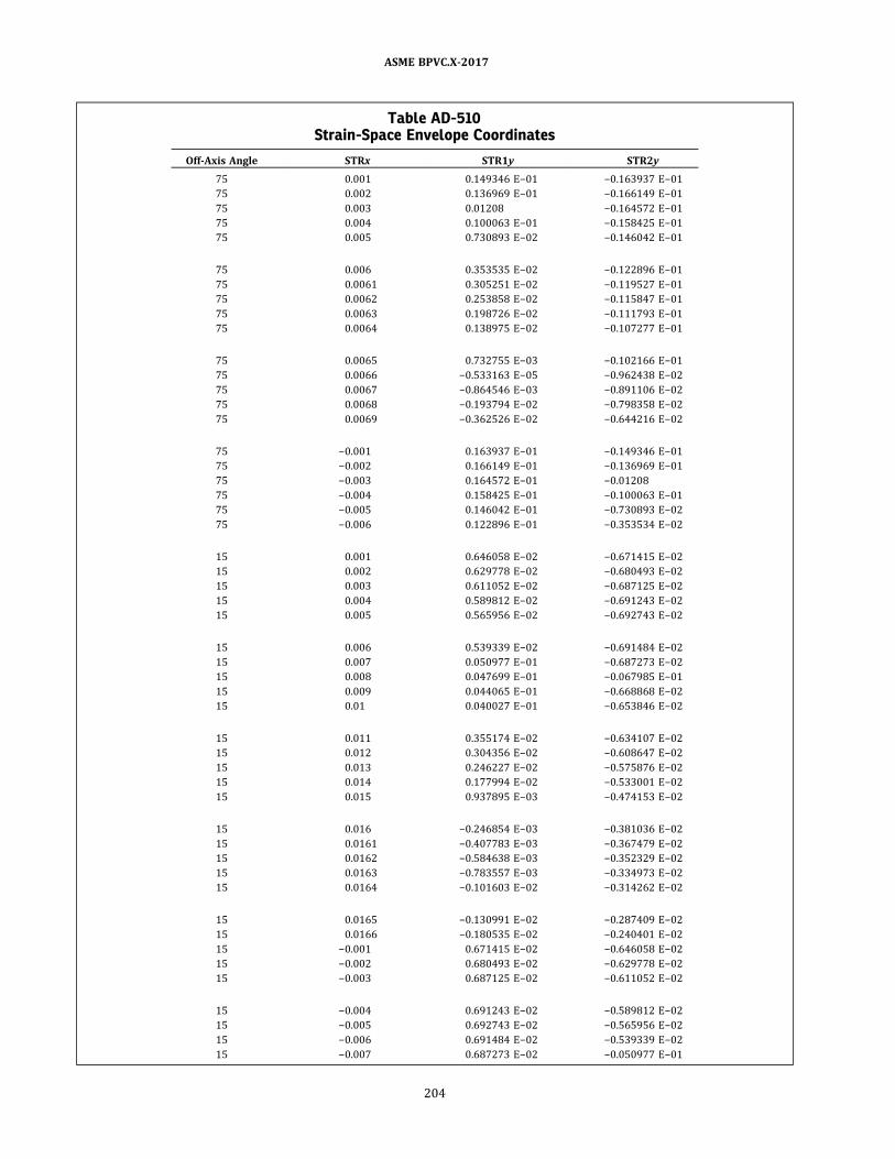
Table AD-510Strain-Space Envelope Coordinates
Off‐Axis Angle STRx STR1y STR2y
75 0.001 0.149346 E−01 −0.163937 E−01
75 0.002 0.136969 E−01 −0.166149 E−01
75 0.003 0.01208 −0.164572 E−01
75 0.004 0.100063 E−01 −0.158425 E−01
75 0.005 0.730893 E−02 −0.146042 E−01
75 0.006 0.353535 E−02 −0.122896 E−01
75 0.0061 0.305251 E−02 −0.119527 E−01
75 0.0062 0.253858 E−02 −0.115847 E−01
75 0.0063 0.198726 E−02 −0.111793 E−01
75 0.0064 0.138975 E−02 −0.107277 E−01
75 0.0065 0.732755 E−03 −0.102166 E−01
75 0.0066 −0.533163 E−05 −0.962438 E−02
75 0.0067 −0.864546 E−03 −0.891106 E−02
75 0.0068 −0.193794 E−02 −0.798358 E−02
75 0.0069 −0.362526 E−02 −0.644216 E−02
75 −0.001 0.163937 E−01 −0.149346 E−01
75 −0.002 0.166149 E−01 −0.136969 E−01
75 −0.003 0.164572 E−01 −0.01208
75 −0.004 0.158425 E−01 −0.100063 E−01
75 −0.005 0.146042 E−01 −0.730893 E−02
75 −0.006 0.122896 E−01 −0.353534 E−02
15 0.001 0.646058 E−02 −0.671415 E−02
15 0.002 0.629778 E−02 −0.680493 E−02
15 0.003 0.611052 E−02 −0.687125 E−02
15 0.004 0.589812 E−02 −0.691243 E−02
15 0.005 0.565956 E−02 −0.692743 E−02
15 0.006 0.539339 E−02 −0.691484 E−02
15 0.007 0.050977 E−01 −0.687273 E−02
15 0.008 0.047699 E−01 −0.067985 E−01
15 0.009 0.044065 E−01 −0.668868 E−02
15 0.01 0.040027 E−01 −0.653846 E−02
15 0.011 0.355174 E−02 −0.634107 E−02
15 0.012 0.304356 E−02 −0.608647 E−02
15 0.013 0.246227 E−02 −0.575876 E−02
15 0.014 0.177994 E−02 −0.533001 E−02
15 0.015 0.937895 E−03 −0.474153 E−02
15 0.016 −0.246854 E−03 −0.381036 E−02
15 0.0161 −0.407783 E−03 −0.367479 E−02
15 0.0162 −0.584638 E−03 −0.352329 E−02
15 0.0163 −0.783557 E−03 −0.334973 E−02
15 0.0164 −0.101603 E−02 −0.314262 E−02
15 0.0165 −0.130991 E−02 −0.287409 E−02
15 0.0166 −0.180535 E−02 −0.240401 E−02
15 −0.001 0.671415 E−02 −0.646058 E−02
15 −0.002 0.680493 E−02 −0.629778 E−02
15 −0.003 0.687125 E−02 −0.611052 E−02
15 −0.004 0.691243 E−02 −0.589812 E−02
15 −0.005 0.692743 E−02 −0.565956 E−02
15 −0.006 0.691484 E−02 −0.539339 E−02
15 −0.007 0.687273 E−02 −0.050977 E−01
ASME BPVC.X-2017
204
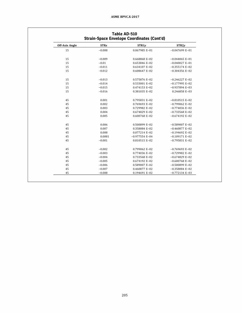
Table AD-510Strain-Space Envelope Coordinates (Cont'd)
Off‐Axis Angle STRx STR1y STR2y
15 −0.008 0.067985 E−01 −0.047699 E−01
15 −0.009 0.668868 E−02 −0.044065 E−01
15 −0.01 0.653846 E−02 −0.040027 E−01
15 −0.011 0.634107 E−02 −0.355174 E−02
15 −0.012 0.608647 E−02 −0.304356 E−02
15 −0.013 0.575876 E−02 −0.246227 E−02
15 −0.014 0.533001 E−02 −0.177995 E−02
15 −0.015 0.474153 E−02 −0.937894 E−03
15 −0.016 0.381035 E−02 0.246858 E−03
45 0.001 0.795831 E−02 −0.810515 E−02
45 0.002 0.769693 E−02 −0.799062 E−02
45 0.003 0.729982 E−02 −0.774036 E−02
45 0.004 0.674829 E−02 −0.733568 E−02
45 0.005 0.600768 E−02 −0.674192 E−02
45 0.006 0.500899 E−02 −0.589007 E−02
45 0.007 0.358084 E−02 −0.460877 E−02
45 0.008 0.077214 E−02 −0.194692 E−02
45 0.0081 −0.977554 E−04 −0.109171 E−02
45 −0.001 0.810515 E−02 −0.795831 E−02
45 −0.002 0.799062 E−02 −0.769693 E−02
45 −0.003 0.774036 E−02 −0.729982 E−02
45 −0.004 0.733568 E−02 −0.674829 E−02
45 −0.005 0.674192 E−02 −0.600768 E−02
45 −0.006 0.589007 E−02 −0.500899 E−02
45 −0.007 0.460877 E−02 −0.358084 E−02
45 −0.008 0.194691 E−02 −0.772134 E−03
ASME BPVC.X-2017
205

ð17Þ
NONMANDATORY APPENDIX AFEXAMPLES FOR DESIGN RULES FOR CLASS II VESSELS
AF-100 GENERAL
Nonmandatory examples of calculations required un-
der RD-1150, Vessel Parts Subject to Design Analysis .
Symbols and values defined below are used in these
examples.
D o = outside diameter
E1 = 1.35 × 106
= tensile modulus in the longitudinal (axial) direc-
tion, psi
E2 = 3.15 × 106
= tensile modulus in the circumferential (hoop) di-
rection, psi
F = design factor: 5 for all external pressure calcula-
tions and 10 for all internal pressure and reinforce-
ment calculations
L = 60 in.
= length of cylinder
P = 50 psi
= internal pressure
PA = allowable external pressure
R = 24 in.
= inside radius, shell or head
r = 4 in.
= inside radius, nozzle (in.)
Ss = 1,000 psi
= secondary bond shear strength
t = thickness, in.
ν1 = 0.27
= Poisson’s ratio, longitudinal (axial) direction
ν2 = 0.23
= Poisson’s ratio, circumferential (hoop) direction
AF-200 CYLINDRICAL SHELLS UNDERUNIFORM INTERNAL PRESSURE(SEE RD-1171.1)
Select the greater of (a) or (b) below:
(a) Longitudinal Stress
(b) Circumferential Stress
Therefore let t = t1 = 0.45 in.
NOTE: Both t1 and t2 are greater than 0.25 in., the minimum lami-
nate thickness allowed.
AF-210 SPHERICAL SHELLS UNDERINTERNAL PRESSURE (SEERD-1171.2)
Assume hand lay‐up sphere with E1 = E2 = 2.2 × 10⁶
psi:
AF-300 CYLINDRICAL SHELLS UNDEREXTERNAL PRESSURE (SEERD-1172.1)
Assume: Ea t = 1.35 × 10⁶, Ea f = 1.39 × 10⁶, t = 0.275, Vx
= 0.18, Vy = 0.32, D o = 48.55, L = 60, F = 5
Calculate γ
γ = 0.9
ASME BPVC.X-2017
206

AF-310 SPHERICAL SHELLS UNDERUNIFORM EXTERNAL PRESSURE(SEE RD-1172.2)
Assume hand lay‐up sphere with E1 = E2 = 2.2 × 10⁶
psi. Therefore, let E = 2.2 × 10⁶ psi and F = 10. Also, as-
sume: t = 0.25 in. Therefore, R o = R + t = 24.25 in.
Allowable pressure:
AF-400 THICKNESS OF HEADS UNDERINTERNAL PRESSURE (SEERD-1173.1)
Assume hand lay‐up head with E1 = E2 = 2.2 × 10⁶ psi.
Therefore, let E = 2 .2 × 106 and let D = 2R = inside
diameter = 48 in.
(a) Ellipsoidal Head
(b) Hemispherical Head
AF-410 THICKNESS OF HEADS UNDEREXTERNAL PRESSURE (SEERD-1173.2)
Assume hand lay‐up head with E1 = E2 = 2.2 × 10⁶ psi.
Therefore, let E = 2.2 × 10⁶ psi, and F = 10. Also, assume:
t = 0.25 in. so: D o = 2R + t = 48.25 in. and Ko = 0.9 for 2:1
ellipsoidal heads, per Table RD-1173.2 .
AF-420 REINFORCEMENT OF OPENINGSAND NOZZLE ATTACHMENTS (SEERD-1174.2)
(a) Length ofSecondary Overlay on Nozzle. For internal
pressure, let F = 10; also, let r = 4 in. = inside radius of
nozzle.
Therefore, let Lb = 3 in.
(b) Thickness of Secondary Overlay on Nozzle. Assume
s e c o n d a r y l am i n a t e m o d u l u s E = E 1 = E 2 =
2 .2 × 106 psi. Therefore, let E = 2 .2 × 106 psi and Sa
= 0.001E = 2.2 × 10³ psi = allowable stress of secondary
overlay.
Therefore, let tb = 0.25 in.
ASME BPVC.X-2017
207

NOTE: In both (a) and (b) above, the minimum allowable dimension
governs.
(c) Thickness ofReinforcement Pad on Shell or Head. As-
sume secondary laminate modulus E = E 1 = E2 =
2 . 2 × 1 0 6 p s i . The re fo re , l e t E 2 = 2 . 2 × 1 0 6 and
t = 0.25 in. = shell thickness. Select the greater of (1)
and (2) below:
(1) Compute
(2) Compute as follows.
Step 1 . Compute Beta factor
Step 2. D e termine K t from Figure RD -1 1 74 . 3 fo r
β = 1.06. Kt = 8.8.
Step 3. C ompute maximum stres s at opening. Let
S2 = 0.001E2 = 2.2 × 10³ psi = allowable stress for the la-
minate in the circumferential direction. Smax = S2Kt
= 1.94 × 10⁴ psi.
Step 4. Determine the moment M associated with
Smax:
Step 5. Determine reinforcement pad thickness. Let Ef
= 2.25 × 10⁶ psi = flexural modulus of reinforcing lami-
nate in the circumferential direction. S f = 0.001Ef =
2.25 × 10³ psi = allowable stress.
Therefore let tp = tp 1 = 0.55 in.
(d) L e n g t h o f R e i n fo r c i n g P a d . A s s u m e L c
= 2r = 8 in. = longest chord length of opening.
according to the requirements of RD-1174.2(f) (2) (-b) ,
therefore, let L p = 6 in.
AF-500 HEAD-TO-SHELL JOINT OVERLAYSUBJECT TO INTERNAL PRESSURE(SEE RD-1175.2)
(a) Thickness ofOverlay
(b) Length ofOverlay
ASME BPVC.X-2017
208

ð17Þ
NONMANDATORY APPENDIX AGGUIDE TO INFORMATION APPEARING ON CERTIFICATE OF
AUTHORIZATION (SEE FIGURE AG-1)
Table AG-1Guide to Information Appearing on Certificate of Authorization (See Figure AG-1)
Item Description
(1) Certification Mark granted by the Society, with RP Designator.
(2) – The name of the Manufacturer; this description could include “doing business as” (DBA) or an
abbreviation of the name.
– The full street address or physical location, city, state or province, country, and zip code.
(3) This entry describes the scope and limitations, if any, on use of the Certification Mark and Designator, as
illustrated below.
RP Designator
– Manufacture of Class I reinforced plastic pressure vessels at the above location only.
– Manufacture of Class II reinforced plastic pressure vessels at the above location only.
– Manufacture of Class I and Class II reinforced plastic pressure vessels at the above location only.
– Manufacture of Class II reinforced plastic pressure vessels at field sites controlled by the above
location.
– Manufacture of Class I and Class II reinforced plastic pressure vessels at the above location and Class
II reinforced plastic pressure vessels only at field sites controlled by that location.
– Manufacture of Class II reinforced plastic pressure vessels at the above location only and at field sites
controlled by that location.
– Manufacture of Class III reinforced plastic pressure vessels at the above location only.
– Manufacture of Class I and Class III reinforced plastic pressure vessels at the above location only.
– Manufacture of Class I, Class II, and Class III reinforced plastic pressure vessels at the above location
only.
– Manufacture of Class I and Class III reinforced plastic pressure vessels at the above location only and
Class II reinforced plastic pressure vessels at the above location only and at field sites controlled by
that location.
(4) The date authorization was granted by the Society to use the Certification Mark stamp indicated.
(5) The date authorization to use the Certification Mark stamp will expire.
(6) A unique Certificate number assigned by the Society.
(7) ,(8) The signatures of the current chair and managing director.
ASME BPVC.X-2017
209
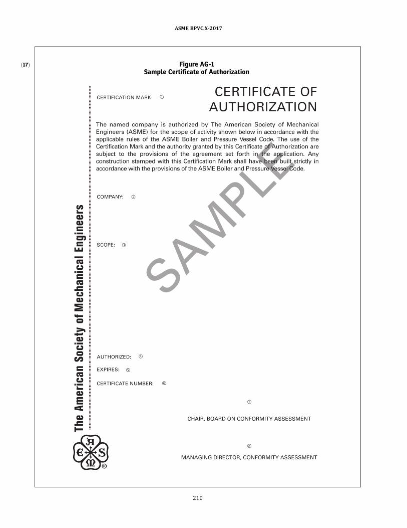
ð17Þ Figure AG-1Sample Certificate of Authorization
SAMPLE
CERTIFICATE OF
AUTHORIZATIONCERTIFICATION MARK
The named company is authorized by The American Society of Mechanical
Engineers (ASME) for the scope of activity shown below in accordance with the
applicable rules of the ASME Boiler and Pressure Vessel Code. The use of the
Certification Mark and the authority granted by this Certificate of Authorization are
subject to the provisions of the agreement set forth in the application. Any
construction stamped with this Certification Mark shall have been built strictly in
accordance with the provisions of the ASME Boiler and Pressure Vessel Code.
COMPANY:
SCOPE:
AUTHORIZED:
EXPIRES:
CERTIFICATE NUMBER:
CHAIR, BOARD ON CONFORMITY ASSESSMENT
MANAGING DIRECTOR, CONFORMITY ASSESSMENT
ASME BPVC.X-2017
210
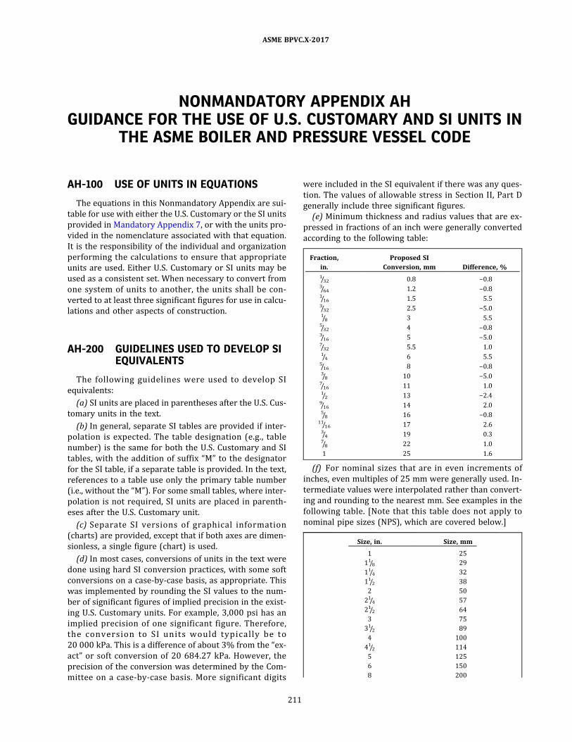
NONMANDATORY APPENDIX AHGUIDANCE FOR THE USE OF U.S. CUSTOMARY AND SI UNITS IN
THE ASME BOILER AND PRESSURE VESSEL CODE
AH-100 USE OF UNITS IN EQUATIONS
The equations in this Nonmandatory Appendix are sui-
table for use with either the U.S. Customary or the SI units
provided in Mandatory Appendix 7, or with the units pro-
vided in the nomenclature associated with that equation.
It is the responsibility of the individual and organization
performing the calculations to ensure that appropriate
units are used. Either U.S. Customary or SI units may be
used as a consistent set. When necessary to convert from
one system of units to another, the units shall be con-
verted to at least three significant figures for use in calcu-
lations and other aspects of construction.
AH-200 GUIDELINES USED TO DEVELOP SIEQUIVALENTS
The following guidel ines were used to develop SI
equivalents:
(a) SI units are placed in parentheses after the U.S. Cus-
tomary units in the text.
(b) In general, separate SI tables are provided if inter-
polation is expected. The table designation (e.g. , table
number) is the same for both the U.S. Customary and SI
tables, with the addition of suffix “M” to the designator
for the SI table, if a separate table is provided. In the text,
references to a table use only the primary table number
(i.e., without the “M”) . For some small tables, where inter-
polation is not required, SI units are placed in parenth-
eses after the U.S. Customary unit.
(c) Separate S I vers ions of graphical information
(charts) are provided, except that if both axes are dimen-
sionless, a single figure (chart) is used.
(d) In most cases, conversions of units in the text were
done using hard SI conversion practices, with some soft
conversions on a case‐by‐case basis, as appropriate. This
was implemented by rounding the SI values to the num-
ber of significant figures of implied precision in the exist-
ing U.S. Customary units. For example, 3 ,000 psi has an
implied precision of one significant figure. Therefore,
the convers i on to S I un i ts wou ld typ i ca l l y b e to
20 000 kPa. This is a difference of about 3% from the “ex-
act” or soft conversion of 20 684.27 kPa. However, the
precision of the conversion was determined by the Com-
mittee on a case‐by‐case basis . More significant digits
were included in the SI equivalent if there was any ques-
tion. The values of allowable stress in Section II, Part D
generally include three significant figures.
(e) Minimum thickness and radius values that are ex-
pressed in fractions of an inch were generally converted
according to the following table:
Fraction,
in.
Proposed SI
Conversion, mm Difference, %
1/32 0.8 −0.83/64 1.2 −0.81/16 1.5 5.53/32 2.5 −5.01/8 3 5.55/32 4 −0.83/16 5 −5.07/32 5.5 1.01/4 6 5.55/16 8 −0.83/8 10 −5.07/16 11 1.01/2 13 −2.49/16 14 2.05/8 16 −0.8
11/16 17 2.63/4 19 0.37/8 22 1.0
1 25 1.6
(f) For nominal sizes that are in even increments of
inches, even multiples of 25 mm were generally used. In-
termediate values were interpolated rather than convert-
ing and rounding to the nearest mm. See examples in the
following table. [Note that this table does not apply to
nominal pipe sizes (NPS) , which are covered below.]
Size, in. Size, mm
1 25
11/8 29
11/4 32
11/2 38
2 50
21/4 57
21/2 64
3 75
31/2 89
4 100
41/2 114
5 125
6 150
8 200
ASME BPVC.X-2017
211
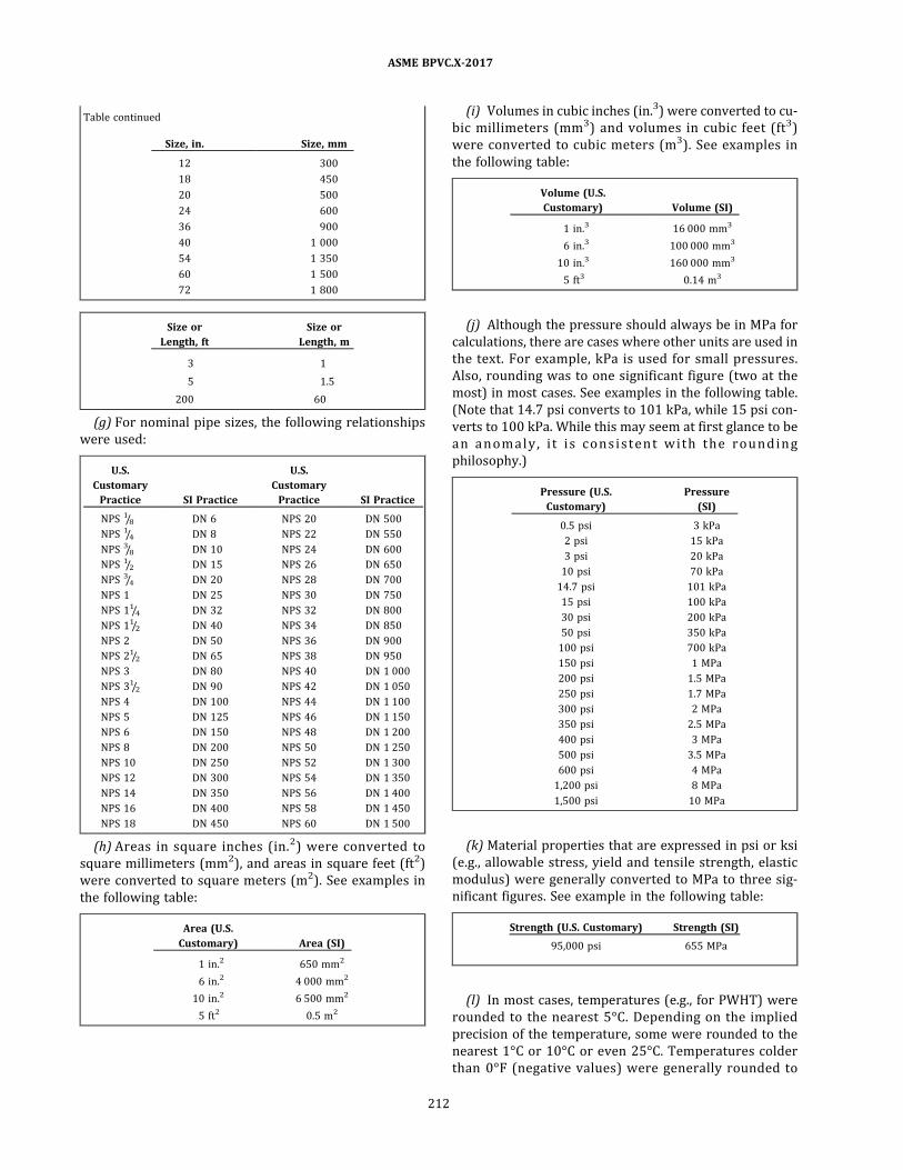
Table continued
Size, in. Size, mm
12 300
18 450
20 500
24 600
36 900
40 1 000
54 1 350
60 1 500
72 1 800
Size or
Length, ft
Size or
Length, m
3 1
5 1.5
200 60
(g) For nominal pipe sizes, the following relationships
were used:
U.S.
Customary
Practice SI Practice
U.S.
Customary
Practice SI Practice
NPS 1/8 DN 6 NPS 20 DN 500
NPS 1/4 DN 8 NPS 22 DN 550
NPS 3/8 DN 10 NPS 24 DN 600
NPS 1/2 DN 15 NPS 26 DN 650
NPS 3/4 DN 20 NPS 28 DN 700
NPS 1 DN 25 NPS 30 DN 750
NPS 11/4 DN 32 NPS 32 DN 800
NPS 11/2 DN 40 NPS 34 DN 850
NPS 2 DN 50 NPS 36 DN 900
NPS 21/2 DN 65 NPS 38 DN 950
NPS 3 DN 80 NPS 40 DN 1 000
NPS 31/2 DN 90 NPS 42 DN 1 050
NPS 4 DN 100 NPS 44 DN 1 100
NPS 5 DN 125 NPS 46 DN 1 150
NPS 6 DN 150 NPS 48 DN 1 200
NPS 8 DN 200 NPS 50 DN 1 250
NPS 10 DN 250 NPS 52 DN 1 300
NPS 12 DN 300 NPS 54 DN 1 350
NPS 14 DN 350 NPS 56 DN 1 400
NPS 16 DN 400 NPS 58 DN 1 450
NPS 18 DN 450 NPS 60 DN 1 500
(h) Areas in square inches (in.2 ) were converted to
square millimeters (mm2) , and areas in square feet (ft2)
were converted to square meters (m2) . See examples in
the following table:
Area (U.S.
Customary) Area (SI)
1 in.2 650 mm2
6 in.2 4 000 mm2
10 in.2 6 500 mm2
5 ft2 0.5 m2
(i) Volumes in cubic inches (in.3) were converted to cu-
bic millimeters (mm3) and volumes in cubic feet (ft3 )
were converted to cubic meters (m3) . See examples in
the following table:
Volume (U.S.
Customary) Volume (SI)
1 in.3 16 000 mm3
6 in.3 100 000 mm3
10 in.3 160 000 mm3
5 ft3 0.14 m3
(j) Although the pressure should always be in MPa for
calculations, there are cases where other units are used in
the text. For example, kPa is used for small pressures.
Also, rounding was to one significant figure (two at the
most) in most cases. See examples in the following table.
(Note that 14.7 psi converts to 101 kPa, while 15 psi con-
verts to 100 kPa. While this may seem at first glance to be
an anoma l y , i t i s c o n s i s te n t wi th the ro und i ng
philosophy.)
Pressure (U.S.
Customary)
Pressure
(SI)
0.5 psi 3 kPa
2 psi 15 kPa
3 psi 20 kPa
10 psi 70 kPa
14.7 psi 101 kPa
15 psi 100 kPa
30 psi 200 kPa
50 psi 350 kPa
100 psi 700 kPa
150 psi 1 MPa
200 psi 1.5 MPa
250 psi 1.7 MPa
300 psi 2 MPa
350 psi 2.5 MPa
400 psi 3 MPa
500 psi 3.5 MPa
600 psi 4 MPa
1,200 psi 8 MPa
1,500 psi 10 MPa
(k) Material properties that are expressed in psi or ksi
(e.g. , allowable stress, yield and tensile strength, elastic
modulus) were generally converted to MPa to three sig-
nificant figures. See example in the following table:
Strength (U.S. Customary) Strength (SI)
95,000 psi 655 MPa
(l) In most cases, temperatures (e.g., for PWHT) were
rounded to the nearest 5°C. Depending on the implied
precision of the temperature, some were rounded to the
nearest 1°C or 10°C or even 25°C. Temperatures colder
than 0°F (negative values) were generally rounded to
ASME BPVC.X-2017
212

the nearest 1°C. The examples in the table below were
created by rounding to the neares t 5 °C , wi th one
exception:
Temperature,
°F
Temperature,
°C
70 20
100 38
120 50
150 65
200 95
250 120
300 150
350 175
400 205
450 230
500 260
550 290
600 315
650 345
700 370
750 400
800 425
850 455
900 480
925 495
950 510
1,000 540
1,050 565
1,100 595
1,150 620
1,200 650
1,250 675
1,800 980
1,900 1 040
2,000 1 095
2,050 1 120
AH-300 SOFT CONVERSION FACTORS
The following table of “soft” conversion factors is pro-
vided for convenience. Multiply the U.S. Customary value
by the factor given to obtain the SI value. Similarly, divide
the SI value by the factor given to obtain the U.S. Custom-
ary value. In most cases it is appropriate to round the an-
swer to three significant figures.
U.S.
Customary SI Factor Notes
in. mm 25.4 …
ft m 0.3048 …
in.2 mm2 645.16 …
ft2 m2 0.09290304 …
in.3 mm3 16,387.064 …
ft3 m3 0.02831685 …
U.S. gal. m3 0.003785412 …
U.S. gal. liters 3.785412 …
psi MPa (N/mm2) 0.0068948 Used exclusively in
equations
psi kPa 6.894757 Used only in text and
for nameplate
psi bar 0.06894757 …
ft-lb J 1.355818 …
°F °C 5/9 × (°F −32) Not for temperature
difference
°F °C 5/9 For temperature
differences only
R K 5/9 Absolute temperature
lbm kg 0.4535924 …
lbf N 4.448222 …
in.-lb N·mm 112.98484 Use exclusively in
equations
ft-lb N·m 1.3558181 Use only in text
1.0988434 …
Btu/hr W 0.2930711 Use for boiler rating
and heat transfer
lb/ft3 kg/m3 16.018463 …
ASME BPVC.X-2017
213

NONMANDATORY APPENDIX AIRIGOROUS NASA SP-8007 SOLUTION FOR LATERAL AND
LONGITUDINAL PRESSURE
where
A , B , D = values from the classical ABD matrix
n , m = integers varied to obtain the combination that gives the lowest buckling pressure
R = D o/2
ASME BPVC.X-2017
214
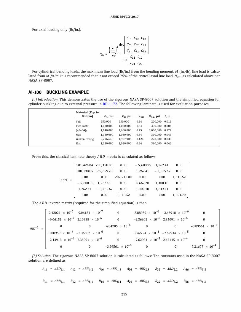
For axial loading only (lb/in.) ,
For cylindrical bending loads, the maximum line load (lb/in.) from the bending moment, M (in.-lb) , line load is calcu-
lated from M /πR 2 . It is recommended that it not exceed 75% of the critical axial line load, Nxa , as calculated above per
NASA SP‐8007.
AI-100 BUCKLING EXAMPLE
(a) Introduction . This demonstrates the use of the rigorous NASA SP‐8007 solution and the simplified equation for
cylinder buckling due to external pressure in RD-1172. The following laminate is used for evaluation purposes:
Material (Top to
Bottom) E1 , psi E2 , psi ν12 G12 , psi t , in.
Veil 550,000 550,000 0.34 200,000 0.013
Two mats 1,030,000 1,030,000 0.34 390,000 0.086
(+/−54)3 1,140,000 1,600,000 0.45 1,000,000 0.127
Mat 1,030,000 1,030,000 0.34 390,000 0.043
Woven roving 2,296,640 1,957,986 0.124 270,000 0.039
Mat 1,030,000 1,030,000 0.34 390,000 0.043
From this, the classical laminate theory ABD matrix is calculated as follows:
The ABD inverse matrix (required for the simplified equation) is then
(b) Solution . The rigorous NASA SP‐8007 solution is calculated as follows: The constants used in the NASA SP‐8007
solution are defined as
ASME BPVC.X-2017
215
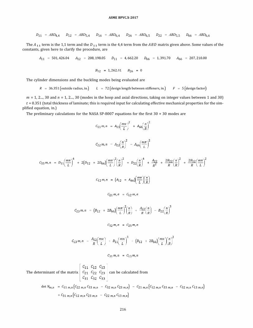
The A 11 term is the 1,1 term and the D11 term is the 4,4 term from the ABD matrix given above. Some values of the
constants, given here to clarify the procedure, are
The cylinder dimensions and the buckling modes being evaluated are
m = 1, 2 ... , 30 and n = 1, 2 .. . , 30 (modes in the hoop and axial directions, taking on integer values between 1 and 30)
t = 0.351 (total thickness of laminate; this is required input for calculating effective mechanical properties for the sim-
plified equation, in.)
The preliminary calculations for the NASA SP‐8007 equations for the first 30 × 30 modes are
The determinant of the matrix can be calculated from
ASME BPVC.X-2017
216
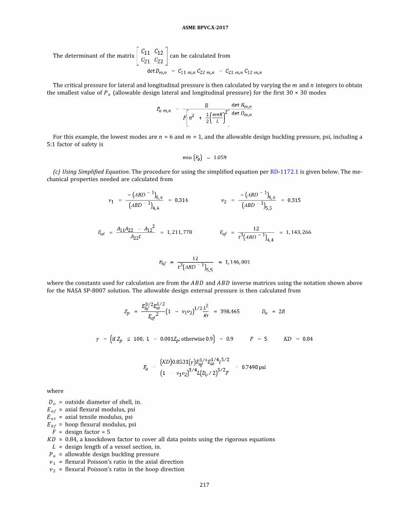
The determinant of the matrix can be calculated from
The critical pressure for lateral and longitudinal pressure is then calculated by varying the m and n integers to obtain
the smallest value of Pa (allowable design lateral and longitudinal pressure) for the first 30 × 30 modes
For this example, the lowest modes are n = 6 and m = 1, and the allowable design buckling pressure, psi, including a
5:1 factor of safety is
(c) Using Simplified Equation . The procedure for using the simplified equation per RD-1172.1 is given below. The me-
chanical properties needed are calculated from
where the constants used for calculation are from the ABD and ABD inverse matrices using the notation shown above
for the NASA SP‐8007 solution. The allowable design external pressure is then calculated from
where
D o = outside diameter of shell, in.
Ea f = axial flexural modulus, psi
Ea t = axial tensile modulus, psi
Eh f = hoop flexural modulus, psi
F = design factor = 5
KD = 0.84, a knockdown factor to cover all data points using the rigorous equations
L = design length of a vessel section, in.
Pa = allowable design buckling pressure
ν1 = flexural Poisson’s ratio in the axial direction
ν2 = flexural Poisson’s ratio in the hoop direction
ASME BPVC.X-2017
217

ð17Þ
NONMANDATORY APPENDIX AJFORMS REQUIRED BY SECTION X
Table AJ-1Latest Revision and Year Date of Forms Referenced in This Code
Title Revision Year
Form Q-106 C 2017
Form Q-107 C 2017
Form Q-108 C 2017
Form Q-115 C 2017
Form Q-120 C 2017
Form RP-1 D 2017
Form RP-2 D 2017
Form RP-3 E 2017
Form RP-4 D 2017
Form RP-5 C 2017
CP-1 A 2017
CP-2 A 2017
Figure Q-115.1 A 1998
ASME BPVC.X-2017
218
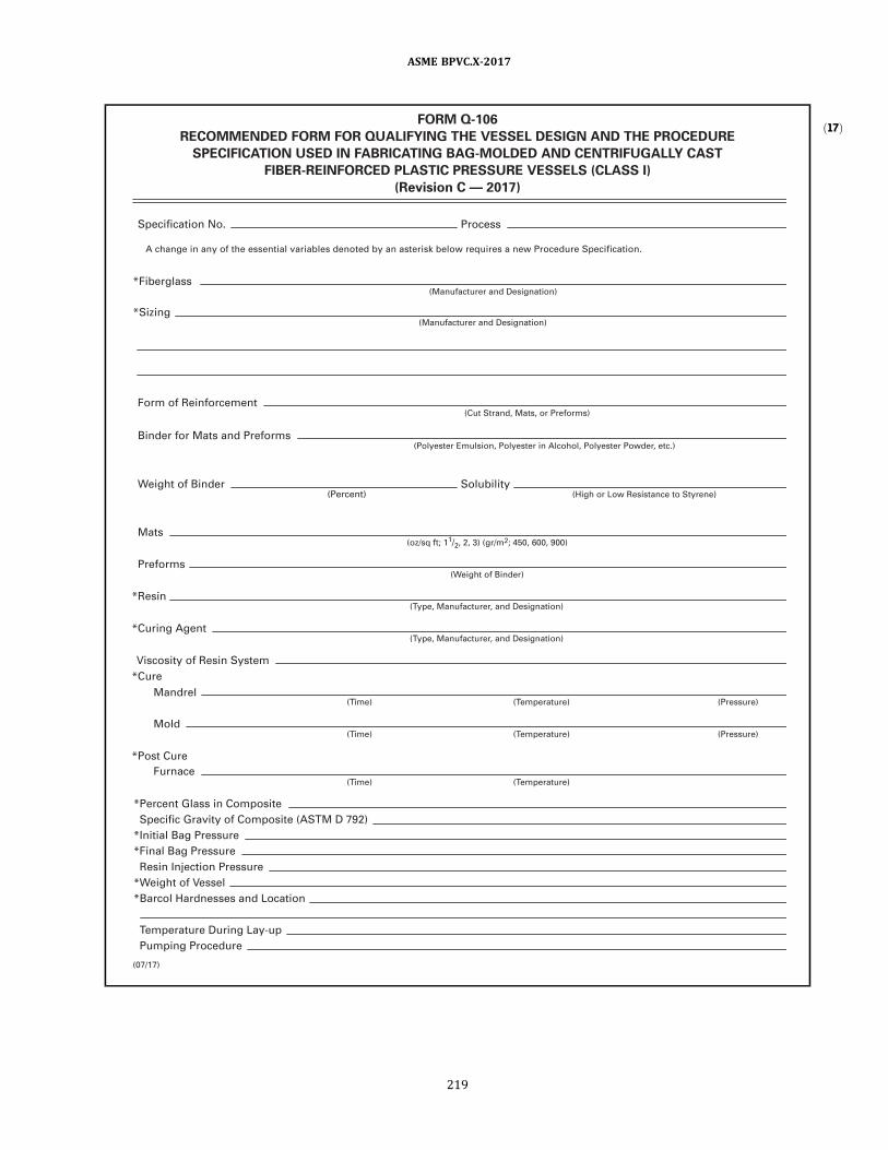
ð17ÞFORM Q-1 06
RECOMMENDED FORM FOR QUALIFYING THE VESSEL DESIGN AND THE PROCEDURE
SPECIFICATION USED IN FABRICATING BAG-MOLDED AND CENTRIFUGALLY CAST
FIBER-REINFORCED PLASTIC PRESSURE VESSELS (CLASS I)
(Revision C — 201 7)
Specification No.
Form of Reinforcement
A change in any of the essential variables denoted by an asterisk below requires a new Procedure Specification.
*Fiberglass
Process
Weight of Binder Solubi l i ty
(Manufacturer and Designation)
*Sizing (Manufacturer and Designation)
(Percent)
Mats (oz/sq ft; 1 1 /2, 2, 3) (gr/m
2; 450, 600, 900)
Preforms (Weight of Binder)
(Temperature)
(Temperature)
(Temperature)
(Time)
(Time)
(Pressure)
(Pressure)
(Time)
*Resin (Type, Manufacturer, and Designation)
*Curing Agent
*Cure
*Post Cure
(Type, Manufacturer, and Designation)
Viscosity of Resin System
Mandrel
Furnace
*Percent Glass in Composite
Specific Gravity of Composite (ASTM D 792)
*Initial Bag Pressure
*Final Bag Pressure
Resin Injection Pressure
*Weight of Vessel
*Barcol Hardnesses and Location
Temperature During Lay-up
Pumping Procedure
Mold
(High or Low Resistance to Styrene)
(Cut Strand, Mats, or Preforms)
Binder for Mats and Preforms (Polyester Emulsion, Polyester in Alcohol , Polyester Powder, etc. )
(07/1 7)
ASME BPVC.X-2017
219

have wi tnessed the tests by wh i ch th e design of th e vessel (s) and the fabri ca tion procedu re h ave been qua l i fi ed and
sta te that, to the best of my knowledge and bel ief, these tests of the prototype vessel (s) and the fabrication procedure
employed in constructing the vessel (s) satisfy the requirements of Section X of the ASME BOILER AND PRESSURE VESSEL
CODE, Fiber-Reinforced Plastic Pressure Vessels.
B y s i g n i n g th i s cert i fi ca te , n e i th er th e I n spector n or h i s empl oyer m akes a n y wa rra n ty, expressed o r imp l i ed ,
concerning the design or procedure covered by the Fabricator's Design Report. Furthermore, neither the Inspector nor h is
employer sha l l be l i abl e i n any manner for any persona l i n j u ry or property damage or l oss of any kind a ri s ing from or
connected with th is inspection.
FORM Q-1 06 (CONT'D)
(Revision C — 201 7)
*Volumetric Expansion
Qual ification
Vessel (s) Serial Number(s)
Design Report Number
Test Report Number
ASME Section X
We certify that the statements made in th is Specification are correct.
Date Signed
By
Expires Certificate of Authorization No.
*Mandrel Rotation, rpm (Centrifugal Casting)
Liner (Material )
Edition and Addenda ( if appl icable) Date
(Thickness)
(Fabricator)
Code Case No.
in.3 (mm3)
CERTIFICATION BY SHOP INSPECTOR
OF QUALIFICATION OF DESIGN AND FABRICATION PROCEDURE
Procedure Specification of at
for process of fabricating vessel (s) described in
Design Specification and (User) (Fabricator)
Design Report Number
I , the undersigned, holding a val id commission issued by the National Board of Boi ler and Pressure Vessel Inspectors
and employed by of
Date Commission (National Board Authorized Inspector Number)
(Authorized Inspector's Signature)
(07/1 7)
ASME BPVC.X-2017
220
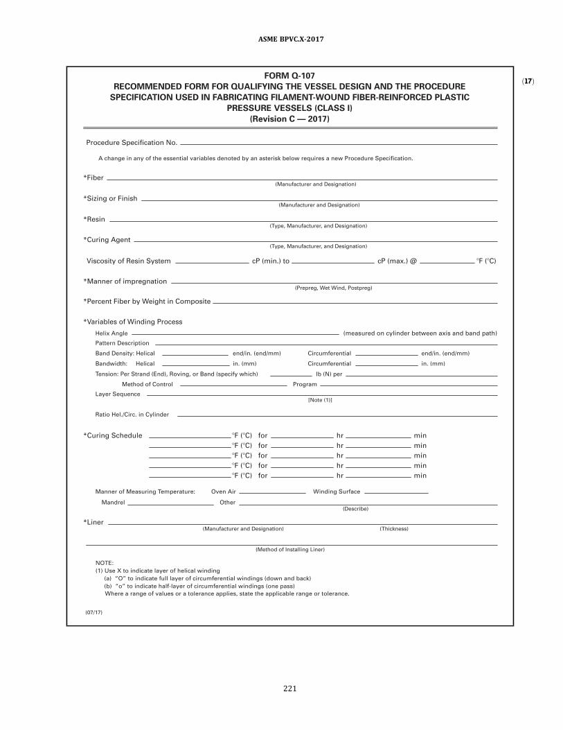
ð17ÞFORM Q-1 07
RECOMMENDED FORM FOR QUALIFYING THE VESSEL DESIGN AND THE PROCEDURE
SPECIFICATION USED IN FABRICATING FILAMENT-WOUND FIBER-REINFORCED PLASTIC
PRESSURE VESSELS (CLASS I)
(Revision C — 201 7)
Procedure Specification No.
A change in any of the essential variables denoted by an asterisk below requires a new Procedure Specification.
Hel ix Angle (measured on cyl inder between axis and band path)
*Fiber (Manufacturer and Designation)
*Sizing or Finish (Manufacturer and Designation)
*Manner of impregnation
Pattern Description
Band Density: Hel ical
Bandwidth : Hel ical
Layer Sequence
Manner of Measuring Temperature: Oven Air
Mandrel Other
Tension: Per Strand (End), Roving, or Band (specify which) lb (N) per
Method of Control Program
end/in. (end/mm)
in . (mm)
end/in. (end/mm)
in . (mm)
Circumferential
Circumferential
*Percent Fiber by Weight in Composite
(Prepreg, Wet Wind, Postpreg)
*Liner (Manufacturer and Designation)
(Method of Instal l ing Liner)
(Thickness)
(Describe)
Ratio Hel . /Circ. in Cyl inder
[Note (1 )]
*Resin (Type, Manufacturer, and Designation)
*Curing Agent
*Variables of Winding Process
*Curing Schedule
NOTE:
(1 ) Use X to indicate l ayer of hel ical winding
(a) “O” to indicate fu l l l ayer of ci rcumferential windings (down and back)
(b) “o” to indicate half-layer of ci rcumferential windings (one pass)
Where a range of values or a tolerance appl ies, state the appl icable range or tolerance.
?F (?C) for hr min
?F (?C) for hr min
?F (?C) for hr min
?F (?C) for hr min
Winding Surface
?F (?C) for hr min
Viscosity of Resin System cP (min.) to cP (max.) @ ?F (?C)
(Type, Manufacturer, and Designation)
(07/1 7)
ASME BPVC.X-2017
221

FORM Q-1 07 (CONT’D)
(Revision C — 201 7)
CERTIFICATION BY SHOP INSPECTOR
OF QUALIFICATION OF DESIGN AND FABRICATION PROCEDURE
*Pole Pieces
*Weight of Vessel
*Barcol Hardnesses and Location
*Volumetric Expansion
(Material )
(Method of Instal l ing: Wound-in, Bonded, etc.)
(Auxi l iary Uses)
Manner of Reinforcing Openings (Describe)
Head Contour
Qual ification:
(Describe)
Type of Mandrel
Procedure Specification of
for process of fabricating vessel (s) described in
at
Date Signed
Certification of Authorization No. Expires
By
(Describe)
Type of Winding Machine (Describe)
(Fabricator)
Design Specification and (Fabricator)
Design Report Number
I , the undersigned, holding a val id commission issued by the National Board of Boi ler and Pressure Vessel Inspectors
and employed by of
(User)
Date Commission (National Board Authorized Inspector Number)
(Authorized Inspector’s Signature)
Edition and Addenda ( if appl icable) Date Code Case No.
Vessel (s) Serial Number(s)
Design Report Number
Test Report Number
We certify that the statements made in th is Specification are correct.
ASME Section X
(07/1 7)
have witnessed the tests by which the design of the vessel (s) and the fabrication procedure have been qual i fied and
state that, to the best of my knowledge and bel ief, these tests of the prototype vessel (s) and the fabrication procedure
employed in constructing the vessel (s) satisfy the requirements of Section X of the ASME BOILER AND PRESSURE
VESSEL CODE, Fiber-Reinforced Plastic Pressure Vessels.
By signing this certificate, neither the Inspector nor h is employer makes any warranty, expressed or impl ied, concern-
ing the design procedure covered by the Fabricator’s Design Report. Furthermore, neither the Inspector nor h is
employer shal l be l iable in any manner for any personal in jury or property damage or loss of any kind arising from or
connected with th is inspection .
ASME BPVC.X-2017
222

ð17ÞFORM Q-1 08
RECOMMENDED FORM FOR QUALIFYING THE VESSEL DESIGN AND THE PROCEDURE
SPECIFICATION USED IN FABRICATING CONTACT-MOLDED, FIBER-REINFORCED PLASTIC
PRESSURE VESSELS (CLASS I)
(Revision C — 201 7)
(A change in any of the essential variables denoted by an asterisk below requires a new Procedure Specification. )
I .
I I .
I I I .
Procedure Specification Number
Vessel or Vessel Part Identification
Materials for Vessel/Vessel Part or Secondary Overlay
IV. Laminate Construction for Vessel or Vessel Part (Use separate sheet for each part)
V. Assembly of Vessel Parts
1 . Materia l No. 1
2 . Materia l No. 2
3. Materia l No. 3
4. Materia l No. 4
Reinforcements *Fiber Type
*1 . Resin
*Cure Method
*Design Barcol Hardness ? /?
*Design Fiber by Weight
Bond to Join Vessel Part A to Vessel Part B
% %
*Method of Surface Preparation for Secondary Overlay
*Distance of S.P. From Mating Joint: Part A in . in . Part B
Overlay Construction — Interior Surface ( i f appl icable)
*Number of Pl ies *Overlay Length Th ickness
? /?
*Post Cure hr ?F (?C)
*Total Number of Pl ies
*Ply Sequence and Orientation (Ply No. 1 next to process)
Resin System
Ply No. Fiber Material No. Fiber Orientation Reference Axis
Material Type
*2. Catalyst
*3. Promoter
Manufacturer Manufacturing No.
Total Thickness
*Fiber Form *Manufacturer *Manufacturing No.
(Use separate sheet for each separate part or component)
(Use additional sheets i f necessary)
(Use separate sheet for each Joint)
(07/1 7)
ASME BPVC.X-2017
223

FORM Q-1 08 (CONT’D)
(Revision C — 201 7)
*Ply Sequence and Orientation (Ply No. 1 next to joined parts)
*Ply Sequence and Orientation (Ply No. 1 next to joined parts)
(Use additional sheets i f necessary)
(Use additional sheets i f necessary)
VI. Summary
Overlay Construction — Exterior Surface
Component/Part Fabrication
No.
1
Part Identi fication
2
3
4
5
6
Procedure Specification
Ply No. Fiber Material No. Fiber Orientation Reference Axis
Ply No. Fiber Material No. Fiber Orientation Reference Axis
*Design Barcol Hardness
*Cure Method *Post Cure hr ?F (?C)
? /?
*Design Fiber by Weight % % ? /?
*Design Barcol Hardness
*Cure Method *Post Cure hr ?F (?C)
? /?
*Design Fiber by Weight %
*Number of Pl ies Th ickness *Overlay Length
% ? /?
(07/1 7)
ASME BPVC.X-2017
224

FORM Q-1 08 (CONT’D)
(Revision C — 201 7)
No.
Component/Part Assembly
1
2
3
4
5
6
Part A To Part B
Code Case No.
(Fabricator)
Edi tion and Addenda ( if appl icable) Date
Procedure Specification No.
*Vessel Volumeric Expansion in .3 (mm3)
*Vessel Weight
Date
Certificate of Authorization No.
Signed
Expires
By
Vessel (s) Serial Number(s)
Design Report Number
Test Report Number
ASME Section X
Qual ification
We certify that the statements made in th is Specification are correct.
(07/1 7)
CERTIFICATION BY SHOP INSPECTOR
OF QUALIFICATION OF DESIGN AND FABRICATION PROCEDURE
Procedure Specification of
for process of fabricating vessel (s) described in
at
Design Specification and (Fabricator)
Design Report number
I , the undersigned, holding a val id commission issued by the National Board of Boi ler and Pressure Vessel Inspectors
of and employed by have
(User)
Date Commission (National Board Authorized Inspector Number)
(Authorized Inspector’s Signature)
inspected the components described in Part I of the Procedure Specification and have examined the Qual i ty
Control records documenting i ts fabrication and state that, to the best of my knowledge and bel ief, the Fabricator
has fabricated the vessel component(s) in accordance with th is Procedure Specification and the requirements of
Section X of the ASME BOILER AND PRESSURE VESSEL CODE, Fiber-Reinforced Plastic Pressure Vessels.
By sign ing th is certi ficate nei ther the Inspector nor h is employer makes any warranty, expressed or impl ied,
concern ing the design procedure covered by the Fabricator’s Design Report. Furthermore, nei ther the Inspector nor
h is employer shal l be l iable in any manner for any personal in jury or property damage or loss of any kind arising
from or connected with th is inspection.
ASME BPVC.X-2017
225

ð17ÞFORM Q-1 1 5
RECOMMENDED FORM FOR QUALIFYING THE DESIGN AND THE PROCEDURE SPECIFICATION USED IN
ADHESIVE BONDING OF PARTS OF FIBER-REINFORCED PLASTIC PRESSURE VESSELS (CLASS I)
(Revision C — 201 7)
Procedure Specification Number
A change in any of the essential variables denoted by an asterisk below requires a new Procedure Specification.
∗ Adhesive (Manufacturer and Designation)
∗ Curing Agent (Type, Manufacturer, and Designation)
∗ Preparation of Surfaces (Machining, Grinding, Degreasing)
∗ Appl ication of Adhesive (Dip) (Brush)
∗ Cur e (Time) (Temperature)
Laminate Used in Test
(a) From Cyl indrical Shel l : Outside Diameter Wal l Thickness
Length of Lap † L Fiber Content Other Information
(b) From Fabricated Flat Laminate: Thickness Fiber Content
Length of Lap† L Other Information
†As required for tensi le test per Fig. Q-1 1 5.1 .
REDUCED SECTION TENSION SPECIMEN OF BONDED JOINT DIMENSIONED SAME AS TYPE 1 SPECIMEN OF ASTM D 638
U .S. Customary U nits
Thickness Reduced Width Overal l
of Wal l , in. Width, in. Grip, in. Length, in.
1⁄4 or under 1 ⁄ 2
3 ⁄ 4 8.5
Over 1⁄4 to 1⁄2 , i ncl .
3 ⁄ 4 1 1⁄8 9.7
Over 1⁄2 to 1 , i ncl . 1 1 1 ⁄ 2 12
CONDITION OF SPECIMEN
Specimen shal l be wiped dry; no other conditioning is required.
RECORD OF SPECIMENS TESTED
Length Area Total
Specimen Reduced of Bond of Load, Shear
No. Thickness Width Overlap Bond lb Stress
1
2
3
SI U nits
Thickness Reduced Width Overal l
of Wal l , mm Width, mm Grip, mm Length, mm
6 o r l ess 13 19 216
Over 6 to 13, i ncl . 19 28 246
Over 13 to 25, i ncl . 25 38 305
(07/1 7)
ASME BPVC.X-2017
226
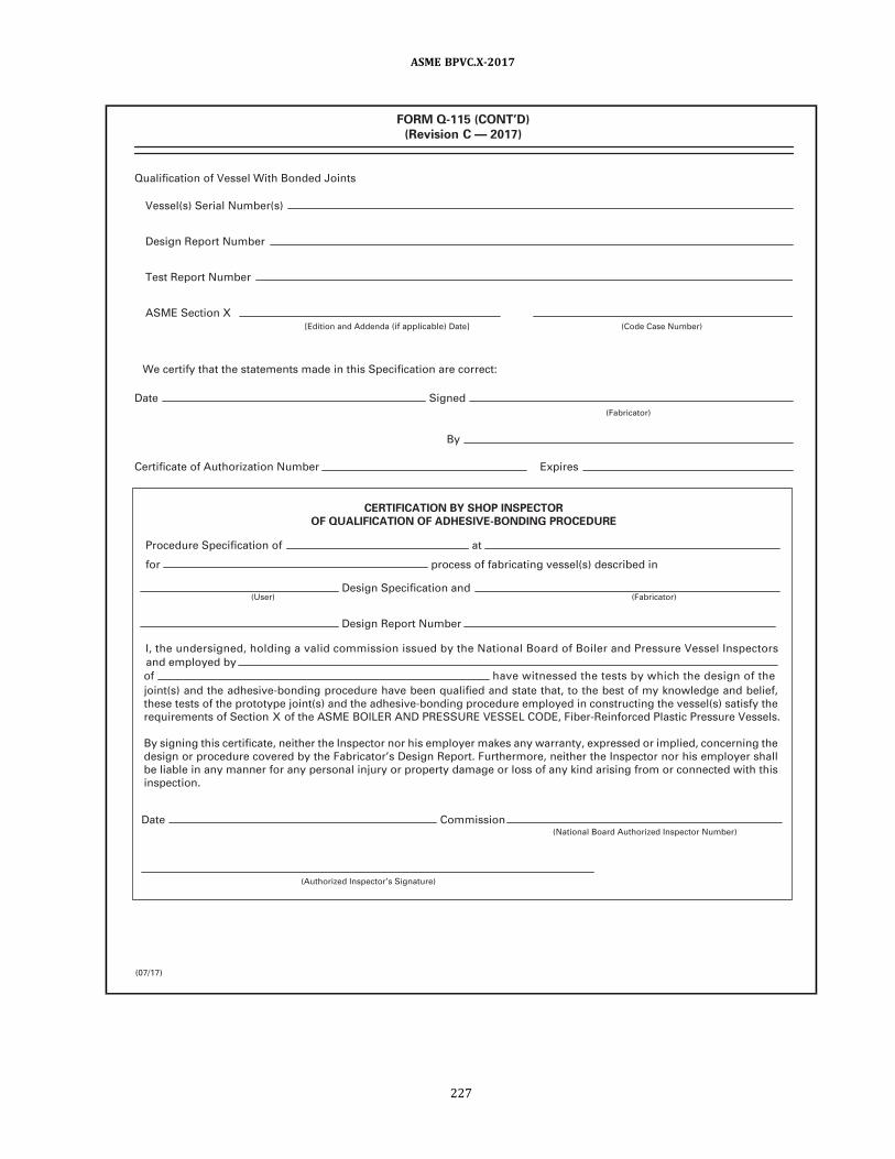
FORM Q-1 1 5 (CONT’D)
(Revision C — 201 7)
Qual ification of Vessel With Bonded Joints
Vessel (s) Serial Number(s)
Design Report Number
Test Report Number
ASME Section X [Edition and Addenda ( i f appl icable) Date] (Code Case Number)
We certify that the statements made in this Specification are correct:
Date Signed
(Fabricator)
By
Certificate of Authorization Number Expires
CERTIFICATION BY SHOP INSPECTOR
OF QUALIFICATION OF ADHESIVE-BONDING PROCEDURE
Procedure Specification of at
for process of fabricating vessel(s) described in
Design Specification and (User) (Fabricator)
Design Report Number
I , the undersigned, holding a va l id commission i ssued by the National Board of Boi ler and Pressure Vessel I nspectors
and employed by
of have wi tnessed the tests by wh ich the design of the
Date Commission (National Board Authorized Inspector Number)
(Authorized Inspector’s Signature)
joint(s) and the adhesive-bonding procedure have been qual ified and state that, to the best of my knowledge and bel ief,
these tests of the prototype joint(s) and the adhesive-bonding procedure employed in constructing the vessel (s) satisfy the
requirements of Section X of the ASME BOILER AND PRESSURE VESSEL CODE, Fiber-Reinforced Plastic Pressure Vessels.
By signing th is certificate, neither the Inspector nor h is employer makes any warranty, expressed or impl ied, concerning the
design or procedure covered by the Fabricator’s Design Report. Furthermore, neither the Inspector nor h is employer shal l
be l iable in any manner for any personal in jury or property damage or loss of any kind arising from or connected with th is
inspection.
(07/1 7)
ASME BPVC.X-2017
227

Figure Q-115.1Schematic Views of Permissible Joint Designs for Adhesive-Bonded Cylinder Joints for Tensile Tests
(Revision A— 1998)
ASME BPVC.X-2017
228
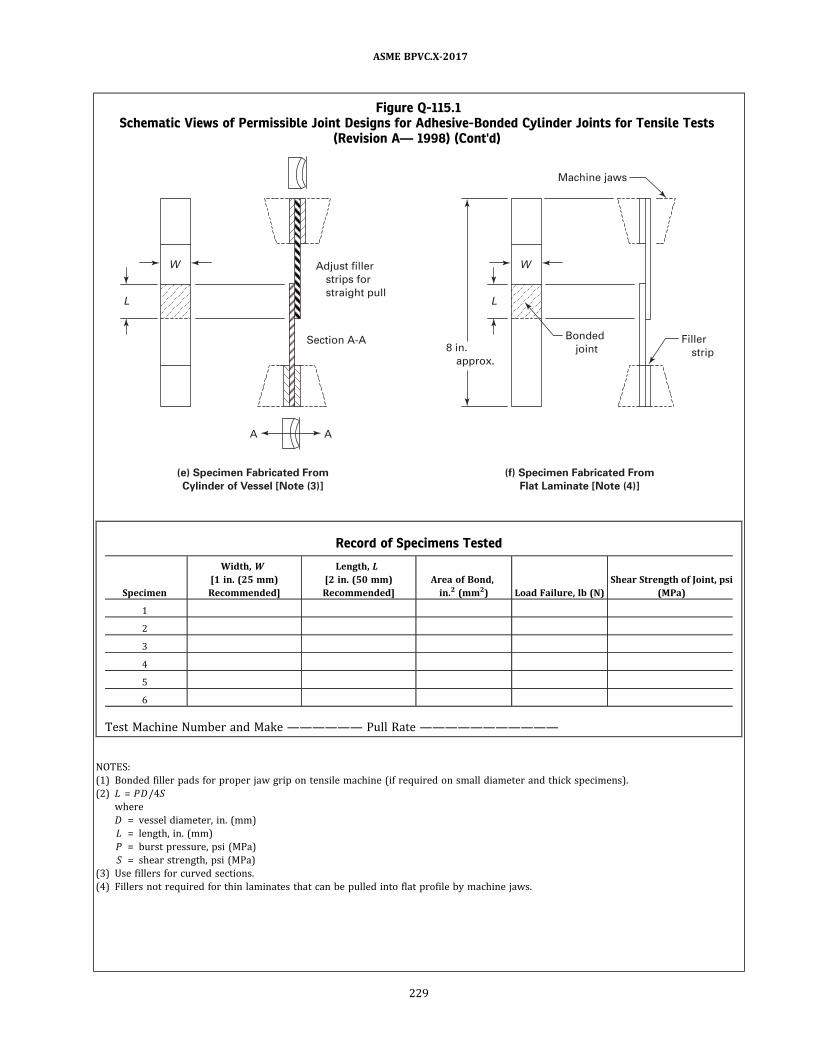
Figure Q-115.1Schematic Views of Permissible Joint Designs for Adhesive-Bonded Cylinder Joints for Tensile Tests
(Revision A— 1998) (Cont'd)
Adjust fi l ler
strips for
straight pul l
A
Section A-A
A
Machine jaws
Bonded
joint 8 in.
approx.
(e) Specimen Fabricated From
Cylinder of Vessel [Note (3)]
(f) Specimen Fabricated From
Flat Laminate [Note (4)]
Fil ler
strip
L
W
L
W
Record of Specimens Tested
Specimen
Width, W
[1 in. (25 mm)
Recommended]
Length, L
[2 in. (50 mm)
Recommended]
Area of Bond,
in.2 (mm2) Load Failure, lb (N)
Shear Strength of Joint, psi
(MPa)
1
2
3
4
5
6
Test Machine Number and Make —————— Pull Rate ———————————
NOTES:
(1) Bonded filler pads for proper jaw grip on tensile machine (if required on small diameter and thick specimens) .
(2) L = PD/4S
where
D = vessel diameter, in. (mm)
L = length, in. (mm)
P = burst pressure, psi (MPa)
S = shear strength, psi (MPa)
(3) Use fillers for curved sections.
(4) Fillers not required for thin laminates that can be pulled into flat profile by machine jaws.
ASME BPVC.X-2017
229

ð17Þ
FORM Q-1 20
PROCEDURE SPECIFICATION FOR CLASS II VESSELS
(Revision C — 201 7)
Part I — Fabrication
PROCEDURE SPECIFICATION NUMBER:
NOTE: Procedure Specification Form Q-1 20 for Class I I vessels consists of three parts. Part I , Fabrication, shal l be completed
for each separately fabricated reinforced plastic vessel part. I t shal l specify the materials, ply sequence, ply orientation,
and procedure used to fabricate the part. Part I must be accompanied by Parts I I and I I I .
Essential design variables shal l be establ ished during design. Any deviation during fabrication must be so noted and
qual ified by the Design Engineer.
I . FABRICATION IDENTIFICATION DATA
A. Vessel Identification
I I . ESSENTIAL DESIGN VARIABLES (To be establ ished during design)
A. Materials for Vessel Part
Fabricator Name:
Name of User:
Fabricator Vessel No. :
User Vessel Number:
B. Vessel Part Identification
B. Part Fabrication
C. Registered Engineer Certifying the Design
Part Name or Number:
Fabricator Procedure No.:
(Ref. RQ-1 1 0 and Appendix 1 , 1 -1 00)
Date Fabricated:
Procdure Date:
Fiber Reinforcements
1 . Material No. 1
2. Material No. 2
3. Material No. 3
Manufacturer Mfg. No. Material Type
(Glass, etc.)
1 . Resin
2. Catalyst
3. Promoter
Manufacturer Mfg. No. Material Type
(Epoxy, etc.)
Material Form
(Mat, etc.)
Resin System
1 . Liner ( if appl icable)
a . Composite Liner ( if appl icable)
Ply No.
Th ickness
b. Thermoplastic Liner ( if appl icable)
Material
Th ickness
to Ply No.
Manufacturer Mfg. No.
Bonding Method
(07/1 7)
ASME BPVC.X-2017
230

(07/1 7)
2. Laminate Construction: (fi lament wound, contact molded, or both)
Number of Pl ies Total Thickness
Ply Sequence and Orientation (No. 1 ply is next to joined parts)
Ply No. Fiber Material No. Fiber Orientation Reference Axis
(Use additional sheets i f necessary)
3. Cure Method Post Cure °F (°C) hr
4. Design Barcol Hardness ±
5. Design Percent Fiber by Weight (Fi lament Wound) % ± %
6. Design Percent Fiber by Weight (Contact Molded) % ± %
7. Fi lament Winding: Bandwidth Spacing
8. Fi l lers/Pigments: Material Use Location
I I I . ENGINEERING CONSTANTS
Documentation of Lamina Properties: Material Property Data Report No .
IV. QUALIFICATIO N
Part for Vessel No .
Date Fabricated: Date Tested:
Design Report No. :
Acceptance Test Report No.:
ASME Section X Edition and Addenda ( i f appl icable) Date Code Case No.
FORM Q-1 20 (CONT’D)
PROCEDURE SPECIFICATION FOR CLASS II VESSELS
(Revision C — 201 7)
Part I — Fabrication (Cont’d)
ASME BPVC.X-2017
231

(07/1 7)
FORM Q-1 20 (CONT’D)
PROCEDURE SPECIFICATION FOR CLASS II VESSELS
(Revision C — 201 7)
Part I — Fabrication (Cont’d)
A. Identification of Materials Used in Fabrication
1 . Reinforcements
a . Material No. 1
b. Material No. 2
c. Material No. 3
2. Resin
3. Catalyst
4. Promoters
B. Resin Data (for each batch number)
1 . Batch No.
2. Resin Viscosity
3. Promotion Rate (ppm)
4. Catalyst Rate (ppm)
5. Gel Time (min.)
C. Fabrication Compl iance [see RF-1 1 0(c)]
Li st and expla in any variations from the essentia l design variables l i sted in Section I I above. The Fabricator sha l l
document as part of h is Qual ity Control System (Appendix 1 ) that the essential variables establ ished for design are
compl ied with during fabrication.
1 .
2 .
3.
1 . Vi sua l check per ASME Section V, Articl e 28
2 . Th ickness and Dimensiona l Checks
3. Barcol Hardness Check
4. Thermoplastic Liner I n tegri ty
(Use addi tional sheets i f necessary)
D. Results of Qual ity Checks (RQ-1 40)
Batch Number
ASME BPVC.X-2017
232

(07/1 7)
FORM Q-1 20 (CONT’D)
PROCEDURE SPECIFICATION FOR CLASS II VESSELS
(Revision C — 201 7)
Part I — Fabrication (Cont’d)
Procedure Specification of at
for process of fabricating vessel (s) described in
Design Specification and
Design Report number
I , the undersigned, holding a val id commission issued by the National Board of Boi ler and Pressure Vessel Inspectors
and employed by of
have inspected the components described in Part I of the Procedure Specification and have examined the Qual ity Control
records documenting i ts fabrication and state that, to the best of my knowledge and bel ief, the Fabricator has fabricated
the vessel component(s) in accordance with th is Procedure Specification and the requirements of Section X of the ASME
Boi ler and Pressure Vessel Code, Fiber-Reinforced Plastic Pressure Vessels.
By signing th is certificate neither the Inspector nor h is employer makes any warranty, expressed or impl ied, concerning
the design or procedure covered by the Fabricator’s Design Report. Furthermore, neither the Inspector nor h is employer
shal l be l iable in any manner for any personal injury or property damage or loss of any kind arising from or connected with
this inspection.
CERTIFICATION BY SHOP INSPECTOR
OF QUALIFICATION OF DESIGN AND FABRICATION PROCEDURE
Commission (National Board Authorized Inspector Number)
(Authorized Inspector’s signature)
(User) (Fabricator)
E . Qual ification Test (Attach Acceptance Test Report)
Passed:
F. Certification
We certify that the statements made in Part I of th is Specification are correct.
Date:
Certificate of Authorization No.:
Signed:
Expires:
By:
(Fabricator)
Fai led:
Date
ASME BPVC.X-2017
233
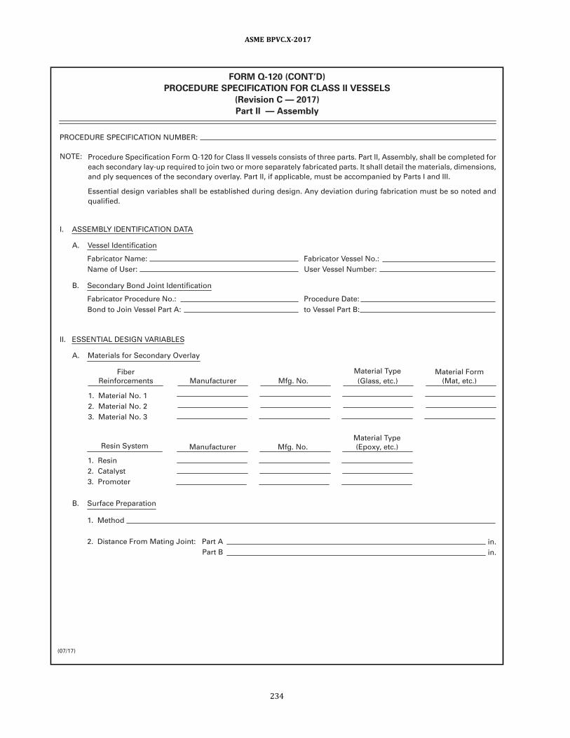
(07/1 7)
FORM Q-1 20 (CONT’D)
PROCEDURE SPECIFICATION FOR CLASS II VESSELS
(Revision C — 201 7)
Part II — Assembly
PROCEDURE SPECIFICATION NUMBER:
NOTE: Procedure Specification Form Q-1 20 for Class I I vessels consists of three parts. Part I I , Assembly, shal l be completed for
each secondary lay-up required to join two or more separately fabricated parts. I t shal l detai l the materials, dimensions,
and ply sequences of the secondary overlay. Part I I , i f appl icable, must be accompanied by Parts I and I I I .
Essential design variables shal l be establ ished during design. Any deviation during fabrication must be so noted and
qual ified.
I . ASSEMBLY IDENTIFICATION DATA
A. Vessel Identification
I I . ESSENTIAL DESIGN VARIABLES
A. Materials for Secondary Overlay
Fabricator Name:
Name of User:
Fabricator Vessel No. :
User Vessel Number:
B. Secondary Bond Joint Identification
B. Surface Preparation
Fabricator Procedure No.:
Bond to Join Vessel Part A:
Procedure Date:
to Vessel Part B:
1 . Material No. 1
2. Material No. 2
3. Material No. 3
Manufacturer Mfg. No.
Material Type
(Glass, etc.)
1 . Resin
2. Catalyst
3. Promoter
Manufacturer Mfg. No.
Material Type
(Epoxy, etc.)
Material Form
(Mat, etc.)
Resin System
1 . Method
2. Distance From Mating Joint: Part A
Part B
Fiber
Reinforcements
in .
in .
ASME BPVC.X-2017
234
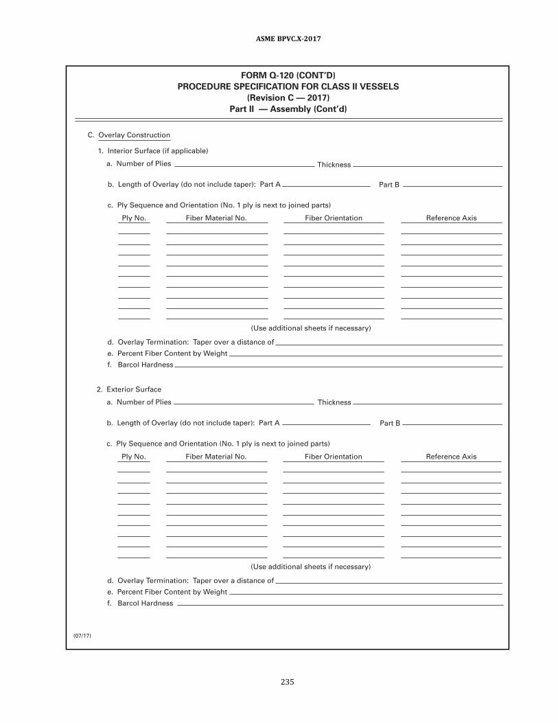
(07/1 7)
FORM Q-1 20 (CONT’D)
PROCEDURE SPECIFICATION FOR CLASS II VESSELS
(Revision C — 201 7)
Part II — Assembly (Cont’d)
C. Overlay Construction
1 . Interior Surface ( if appl icable)
a . Number of Pl ies
b. Length of Overlay (do not include taper): Part A
c. Ply Sequence and Orientation (No. 1 ply is next to joined parts)
Ply No. Fiber Material No. Fiber Orientation Reference Axis
(Use additional sheets i f necessary)
d. Overlay Termination: Taper over a distance of
e. Percent Fiber Content by Weight
f. Barcol Hardness
2. Exterior Surface
a . Number of Pl ies
b. Length of Overlay (do not include taper): Part A
c. Ply Sequence and Orientation (No. 1 ply is next to joined parts)
Ply No. Fiber Material No. Fiber Orientation Reference Axis
(Use additional sheets i f necessary)
d. Overlay Termination: Taper over a distance of
e. Percent Fiber Content by Weight
f. Barcol Hardness
Thickness
Part B
Thickness
Part B
ASME BPVC.X-2017
235

(07/1 7)
FORM Q-1 20 (CONT’D)
PROCEDURE SPECIFICATION FOR CLASS II VESSELS
(Revision C — 201 7)
Part II — Assembly (Cont’d)
A. Identification of Materials Used in Assembly
1 . Reinforcements
a . Material No. 1
b. Material No. 2
c. Material No. 3
2. Resin
3. Catalyst
4. Promoters
B. Resin Data (for each batch number)
1 . Batch No.
2. Resin Viscosity
3. Promotion Rate (ppm)
4. Catalyst Rate (ppm)
5. Gel Time (min.)
C. Fabrication Compl iance [see RF-1 1 0(c)]
List and expla in any variations from the essentia l design variables l i sted in Section I I of th is form (Part I I ) . The
Fabricator sha l l document as part of h is Qual ity Control System (Appendix 1 ) that the essential variables establ ished for
design are compl ied with during fabrication.
1 .
2 .
3.
(Use addi tiona l sheets i f necessary)
D. Certification
Batch Number
I I I . QUALIFICATION
Secondary Overlay to Join Part A:
Design Report No.
ASME Section X Edition and Addenda ( i f appl icable) Date Code Case No.
Signed:
Expires:
By:
(Fabricator)
We certify that the statements made in Part I I of th is Specification are correct.
Date:
Certificate of Authorization No.:
to Part B:
Test Report No.
ASME BPVC.X-2017
236

(07/1 7)
FORM Q-1 20 (CONT’D)
PROCEDURE SPECIFICATION FOR CLASS II VESSELS
(Revision C — 201 7)
Part II — Assembly (Cont’d)
Procedure Specification of at
for process of fabricating vessel (s) described in
I , the undersigned, holding a val id commission issued by the National Board of Boi ler and Pressure Vessel Inspectors
of
Specification and have examined the Qual i ty Control records documenting th is assembly and state that, to the best of
my knowledge and bel ief, the Fabricator has assembled the components to satisfy the requirements of Section X of the
ASME Boi ler and Pressure Vessel Code, Fiber-Reinforced Plastic Pressure Vessels.
By signing th is certificate neither the Inspector nor h is employer makes any warranty, expressed or impl ied, concerning
the design or procedure covered by the Fabricator’s Design Report. Furthermore, neither the Inspector nor h is employer
shal l be l iable in any manner for any personal in jury or property damage or loss of any kind arising from or connected with
th is inspection.
Date
CERTIFICATION BY SHOP INSPECTOR
OF QUALIFICATION OF DESIGN AND FABRICATION PROCEDURE
Commission (National Board Authorized Inspector Number)
(Authorized Inspector’s signature)
(User) (Fabricator)
Design Report number
and employed by
have inspected the assembly joint of the components described in Part I I of the Procedure
Design Specification and
ASME BPVC.X-2017
237

(07/1 7)
FORM Q-1 20 (CONT’D)
PROCEDURE SPECIFICATION FOR CLASS II VESSELS
(Revision C — 201 7)
Part II I — Summary
PROCEDURE SPECIFICATION NUMBER:
NOTE: Procedure Specification Form Q-1 20 for Class I I vessels consists of three parts. Part I I I , Summary, shal l compile the
various fabrication procedures used to fabricate the individual parts of the vessel and then join them into a completed
vessel assembly. Part I I I must be accompanied by Parts I and I I .
A. VESSEL IDENTIFICATION
Fabricator Name:
Name of User:
Fabricator Vessel No. :
User Vessel Number:
B. SUMMARY OF FABRICATION PROCEDURES (Part I )
No.
1
2
3
4
5
6
Part Identification Fabricator’s Procedure No.
C. SUMMARY OF ASSEMBLY PROCEDURES (Part I I )
No.
1
2
3
4
5
6
Part A Fabricator’s Procedure No.
D. QUALIFICATION
Signed:
Expires:
By:
(Fabricator)
We certify that the statements made in Part I I I of this Specification are correct.
Date:
Certificate of Authorization No.:
ASME Section X
Code Case No. Edition and Addenda ( i f appl icable) Date
Part B to
ASME BPVC.X-2017
238

(07/1 7)
FORM Q-1 20 (CONT’D)
PROCEDURE SPECIFICATION FOR CLASS II VESSELS
(Revision C — 201 7)
Part III — Summary (Cont’d)
Procedure Specification of at
for process of fabricating vessel (s) described in
Design Specification and
Design Report number
I , the undersigned, holding a val id commission issued by the National Board of Boi ler and Pressure Vessel Inspectors
of
have witnessed the tests by which the design of the vessel (s) and the fabrication procedure have been qual ified and state
that, to the best of my knowledge and bel ief, these tests and the fabrication procedure employed in constructing the
vessel (s) satisfy the requirements of Section X of the ASME Boi ler and Pressure Vessel Code, Fiber-Reinforced Plastic
Pressure Vessels.
By signing th is certificate neither the Inspector nor h is employer makes any warranty, expressed or impl ied, concerning
the design or procedure covered by the Fabricator’s Design Report. Furthermore, neither the Inspector nor h is employer
shal l be l iable in any manner for any personal in jury or property damage or loss of any kind arising from or connected with
th is inspection.
Date
CERTIFICATION BY SHOP INSPECTOR
OF QUALIFICATION OF DESIGN AND FABRICATION PROCEDURE
Commission (National Board Authorized Inspector Number)
(Authorized Inspector’s signature)
(User) (Fabricator)
and employed by
ASME BPVC.X-2017
239
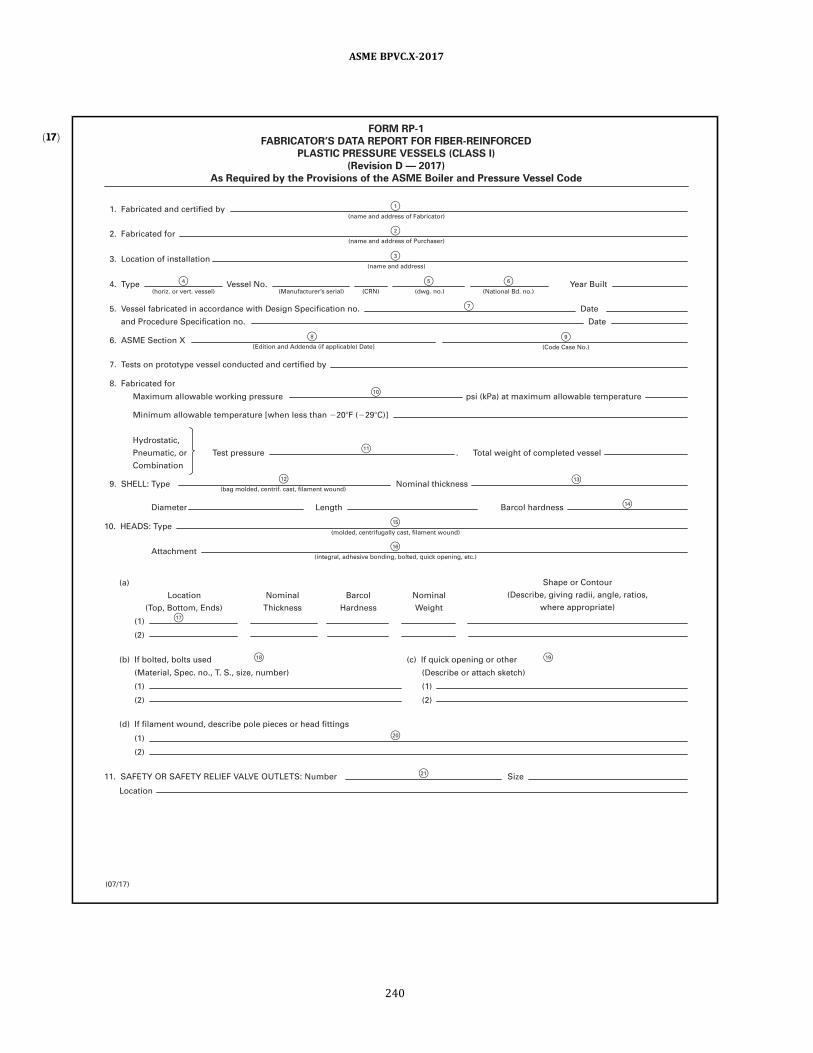
ð17Þ
F 1
F 2
F 3
F 5 F 6
F 7
F 4
F 9
F 1 2
F 1 5
F 1 6
F 8
F 1 0
F 1 1
F 1 3
F 1 4
F 1 7
F 20
F 1 9 F 1 8
F 21
FORM RP-1
FABRICATOR’S DATA REPORT FOR FIBER-REINFORCED
PLASTIC PRESSURE VESSELS (CLASS I)
(Revision D — 201 7)
As Required by the Provisions of the ASME Boiler and Pressure Vessel Code
1 . Fabricated and certified by (name and address of Fabricator)
2. Fabricated for (name and address of Purchaser)
3. Location of instal lation (name and address)
4. Type Vessel No. Year Bui l t (dwg. no. )
[Edition and Addenda ( i f appl icable) Date]
(National Bd. no. )
(Code Case No.)
(bag molded, centrif. cast, fi lament wound)
(molded, centrifugal ly cast, fi lament wound)
( integral , adhesive bonding, bolted, quick opening, etc.)
(CRN) (horiz. or vert. vessel)
5. Vessel fabricated in accordance with Design Specification no.
6. ASME Section X
7. Tests on prototype vessel conducted and certified by
8. Fabricated for
9. SHELL: Type Nominal th ickness
Diameter Length Barcol hardness
(a)
(1 )
(2)
(1 )
(Material , Spec. no. , T. S. , size, number)
(2)
(1 )
(2)
(b) I f bolted, bol ts used
(1 )
(Describe or attach sketch)
(2)
(c) I f qu ick opening or other
Location
(Top, Bottom, Ends)
Nominal
Thickness
Barcol
Hardness
Nominal
Weight
Shape or Contour
(Describe, giving radi i , angle, ratios,
where appropriate)
(d) I f fi lament wound, describe pole pieces or head fi ttings
Location
Attachment
1 0. HEADS: Type
1 1 . SAFETY OR SAFETY RELIEF VALVE OUTLETS: Number Size
and Procedure Specification no.
Date
Date
Maximum al lowable working pressure psi (kPa) at maximum al lowable temperature
Minimum al lowable temperature [when less than ?20?F (?29?C)]
Hydrostatic,
Pneumatic, or Test pressure Total weight of completed vessel .
Combination
(Manufacturer’s serial )
(07/1 7)
ASME BPVC.X-2017
240

F 26
F 27
F 25
F 22
F 23
F 24
F 28
FORM RP-1 (Back)
(Revision D — 201 7)
CERTIFICATE OF COMPLIANCE
CERTIFICATE OF SHOP INSPECTION
1 2. NOZZLES:
1 3. INSPECTION OPENINGS:
1 4. SUPPORTS: Skirt Lugs Legs Other
1 5. REMARKS
(Brief description of purpose of the vessel , such as a i r tank, water tank, LPG storage, etc. If description of the purpose of the vessel does not clearly indicate the contents of the vessel, state what the contents are to be. Describe any unusual features of design or construction not covered by i tems 3 to 1 4 i nclusive. )
Date
Commission (Authorized Inspector’s signature) (National Board Authorized Inspector Number)
(Fabricator) (authorized representative)
(date)
Date
We certi fy the statements in th is Data Report to be correct.
Signed by
of
have inspected the pressure vessel described in th is Fabricator’s Data Report on and state that, to the best of
Vessel made by
I , the undersigned, holding a val id commission issued by the National Board of Boi ler and Pressure Vessel Inspectors and employed by
at
Our Certificate of Authorization No. to use the Certification Mark with RP Designator expires
(describe) (number)
(where and how)
(where and how)
(number) (yes or no)
Attached
Attached
Manholes: No.
Purpose ( Inlet,
Outlet, Drain)
Diameter
or Size
Reinforcement
Material Number Type Material Thickness How Attached
Size Location
Handholes: No. Size Location
Threaded: No. Size Location
my knowledge and bel ief, the Fabricator has constructed th is pressure vessel in accordance with the appl icable Sections of the ASME BOILER
AND PRESSURE VESSEL CODE.
By signing th is certificate, nei ther the Inspector nor h is employer makes any warranty, expressed or impl ied, concerning the pressure vessel
described in th is Fabricator's Data Report. Furthermore, neither the Inspector nor h is employer shal l be l iable in any manner for any personal
in jury or property damage or loss of any kind arising from or connected with th is inspection.
(07/1 7)
(date)
ASME BPVC.X-2017
241

ð17Þ Table AJ-2Guide for Completing Form RP-1
(Revision E — 2017)
Reference to
Circled
Numbers in the
Form Description
(1) Name and street address of Fabricator, i.e., maker of all components not covered by Partial Data Reports.
(2) Name and address of Purchaser and/or Owner.
(3) Name and street address of USER, where vessel is to be installed. If not known, so indicate; e.g., not known — built for stock.
(4) Type of vessel, such as vertical or horizontal vessel, including method of support.
(5) Fabricator’s serial number (one vessel on one report) . CRN lines are for Canadian Registration Number and the number of the
drawing approved by the Provincial Authorities.
(6) National Board number from Fabricator’s series of N.B. numbers or State number if User inspected vessel. If USER vessel, strike out
National Board and show name of State.
(7) (10) These are the Fabricator’s Specification numbers.
(8) ASME Code, Section X, Edition (e.g., 1998) and Addenda (e.g., A98, A99, etc., if applicable) used for fabrication.
(9) All Code Case numbers and revisions used for fabrication must be listed. Where more space is needed, use Remarks section or list on
a supplemental page.
(11) Test Pressure must conform to RT-450 or RT-460, depending on type of test method used.
(12) Specify bag molded, centrifugally cast, or filement wound, or a combination of these, as bag molded and helically wound or
centrifugally cast plus level (or circle) wound, if the design is a combination.
(13) The thickness of the laminate. Spell out liner thickness (if used) as a separate item.
(14) The Barcol hardness is required for qualification vessels (RT-221) and recorded.
(15) State the process or a combination of the processes along with the shape, as elliptical, spherical, etc., and list the ratio of major to
minor axis if elliptical. If heads are flat (Article RD-7) , list material and thickness.
(16) The details of adhesive bonding, bolted, or quick opening to be recorded in the Data Report.
(17) The top and bottom heads for vertical vessels and ends for horizontally mounted vessels.
(18) Bolts used to secure removable head or heads of vessel.
(19) Safety precautions to be spelled out for quick opening design (Article RD-8) .
(20) Show design of pole pieces wound in on axis of rotation. Show design of fittings and method of holding the fittings in place if located
other than on axis of rotation (not permitted for 3,000 psi [20 MPa] operation design) . In all cases, design adequacy is mandatory.
(21) Indicate nozzle or other opening which is designated for pressure relief device.
(22) Show other nozzles and openings and design of attachment.
(23) Show openings designated for inspection and design of attachment.
(24) Indicate provisions for vessel support. If attached, show design; vessels must be qualified on the vessel support listed in the Data
Report.
(25) It is important under Remarks to be very complete in listing concentration temperature of contents of the vessel along with surface
of the vessel used to prevent corrosion. The Fabricator of the vessel line or resin along with Specification number and type is
important for future reference, as vessel may be used for contents other than the contents for which the original design was
intended. For attached Partial Data Reports, list the part name, the name of the Fabricator, and the serial number of the part.
(26) Certificate of Compliance block is to show name of Fabricator as shown on the ASME Certificate of Authorization. This should be
signed by chief Inspector, Manager of Quality Control, or a like person.
(27) Certificate of Shop Inspection is to be completed by the Fabricator and signed by the Authorized Inspector who performs the shop
inspection.
(28) The National Board Authorized Inspector number shall be shown.
GENERAL NOTE: Any quantity to which units apply shall be entered on the Fabricator’s Data Report with the chosen units.
ASME BPVC.X-2017
242

ð17Þ
F 1
F 1 2
F 1 3
F 1 5
F 3
F 7 F 8
F 9
F 1 0
F 1 1
F 4 F 5
F 2
F 1 6
F 1 7
F 6
F 1 4
FORM RP-2
FABRICATOR’S PARTIAL DATA REPORT (CLASS I)
A Part of a Fiber-Reinforced Plastic Pressure Vessel Fabricated by
One Manufacturer for Another Manufacturer
(Revision D — 201 7)
As Required by the Provisions of the ASME Boiler and Pressure Vessel Code
1 . (a) Fabricated and certified by (name and address of Fabricator of part)
(a)
(b) I f bol ted, bol ts used
(Material , Spec. no. , T. S. , size, number)
(1 )
(2)
Location
(Top, Bottom, Ends)
Nominal
Thickness
Barcol
Hardness
Nominal
Weight
Shape or Contour
(Describe, g iving radi i , angle, ratios,
where appropriate)
(07/1 7)
2. Identification—Fabricator’s serial no. of part
4. Part fabricated in accordance with Procedure Specification no. Date
5. ASME Section X
6. SHELL: Type Nominal th ickness
7. HEADS: Type
3. (a) Constructed according to Drawing no. Dwg. prepared by
(b) Fabricated for (name and address of Purchaser of vessel)
(Edition and Addenda ( i f appl icable) Date) (Code Case No.)
(molded, centrifugal ly cast, fi lament wound)
9. SAFETY VALVE OUTLETS: Number Location Size
8. Fabricated for
(bag molded, centrifugal ly cast, fi lament wound)
( integral , adhesive bonding, bolted, quick opening, etc.)
Nominal weight Diameter
Attachment
Length Barcol hardness
(b) Description of part fabricated and inspected
(1 )
(2)
(c) I f qu ick opening or other
(Describe or attach sketch)
(1 )
(2)
(d) I f fi lament wound, describe pole pieces or head fi ttings
(1 )
(2)
Maximum al lowable working pressure
1 0. NOZZLES
Purpose ( Inlet,
Outlet, Drain)
Diameter
or Size
Reinforcement
Material Number Type Material Thickness How Attached
at maximum al lowable temperature
Minimum al lowable temperature [when less than ?20?F (?29?C)]
ASME BPVC.X-2017
243

F 21
F 22
F 20
F 1 8
F 1 9
FORM RP-2 (Back)
(Revision D — 201 7)
CERTIFICATE OF COMPLIANCE
CERTIFICATE OF SHOP INSPECTION
1 1 . INSPECTION OPENINGS
1 2. SUPPORTS: Skirt Lugs Legs Other
1 3. REMARKS
Date
Commission (Authorized Inspector’s signature) (National Board Authorized Inspector Number)
(Fabricator) (representative) Date Signed
of
have inspected the part of a pressure vessel described in th is Fabricator’s Partial Data Report on and state that,
I , the undersigned, holding a val id commission issued by the National Board of Boi ler and Pressure Vessel Inspectors and employed by
Certificate of Authorization no. Expires
by
(describe) (number)
(where and how)
(number) (yes or no)
Attached
Manholes: No. Size Location
Handholes: No. Size Location
Threaded: No. Size Location
to the best of my knowledge and bel ief, the Fabricator has constructed th is part in accordance with the appl icable Sections of the ASME BOILER
AND PRESSURE VESSEL CODE.
By signing this certificate, neither the Inspector nor h is employer makes any warranty, expressed or impl ied, concerning the part described in th is
Fabricator's Partial Data Report. Furthermore, neither the Inspector nor h is employer shal l be l iable in any manner for any personal injury or
property damage or loss of any kind arising from or connected with th is inspection.
We certi fy that the statements in th is Fabricator's Partial Data Report are correct and that a l l detai ls of materials, construction, and workmanship
of th is vessel conform to Section X of the ASME BOILER AND PRESSURE VESSEL CODE, Fiber-Reinforced Plastic Pressure Vessels.
(date)
(07/1 7)
ASME BPVC.X-2017
244

ð17ÞTable AJ-3Guide for Completing Form RP-2
(Revision C — 2013)
Reference to
Circled
Numbers in the
Form Description
(1) Name and street address of Fabricator, i.e., maker of the vessel part covered in this report.
(2) Name and address of Fabricator who will use the vessel part in making a complete vessel.
(3) An identifying serial number marked on the vessel part by the part Fabricator (RS-120) . This is not to be a National Board number.
CRN line is for Canadian Registration Number and the number of the drawing approved by the Provincial Authorities.
(4) Drawing to which vessel part is fabricated.
(5) Organization that prepared drawing.
(6) Description of vessel part, i.e., fitting, flat steel head, attached support bracket, etc.
(7) ASME Code, Section X, Edition (e.g., 1998) and Addenda (e.g., A98, A99, etc., if applicable) used for fabrication.
(8) All Code Case numbers and revisions used for fabrication must be listed. Where more space is needed, use Remarks section or list on
a supplemental page.
(9) Specify bag molded, centrifugally cast, or filament wound, or a combination of these, as bag molded and helically wound or
centrifugally cast plus level (or circle) wound, if the design is a combination.
(10) State the process or a combination of the processes along with the shape, as elliptical, spherical, etc., and list the ratio of major or
minor axis if elliptical. If heads are flat (Article RD-7) , list material and thickness.
(11) The details of adhesive bonding, bolted, or quick opening to be recorded in the Data Report.
(12) The top and bottom heads for vertical vessels and ends for horizontally mounted vessels.
(13) Bolts used to secure removable head or heads of vessel.
(14) Safety precautions to be spelled out for quick opening design (Article RD-8) .
(15) Show design of pole pieces wound in on axis of rotation. Show design of fittings and method of holding the fittings in place if located
other than on axis of rotation (not permitted for 3,000 psi [20 MPa] operation design) . In all cases, design adequacy is mandatory.
(16) Indicate nozzle or other opening which is designated for pressure relief device.
(17) Show other nozzles and openings and design of attachment.
(18) Show openings designated for inspection and design of attachment.
(19) Indicate provisions for vessel support. If attached, show design; vessels must be qualified on the vessel support listed in the Data
Report.
(20) It is important under Remarks to be very complete in listing concentration temperature of contents of the vessel along with surface
of the vessel used to prevent corrosion. The Fabricator of the vessel line or resin along with Specification number and type is
important for future reference, as vessel may be used for contents other than the contents for which the original design was
intended.
(21) Certificate of Compliance block is to show name of Fabricator of the vessel part and the Certification Mark authorization number,
and expiration date. This should be signed by chief Inspector, Manager of Quality Control, or a like person.
(22) Certificate of Shop Inspection is to be completed by the Fabricator and signed by the Authorized Inspector who performs the shop
inspection.
GENERAL NOTE: Any quantity to which units apply shall be entered on the Fabricator’s Partial Data Report with the chosen units.
ASME BPVC.X-2017
245
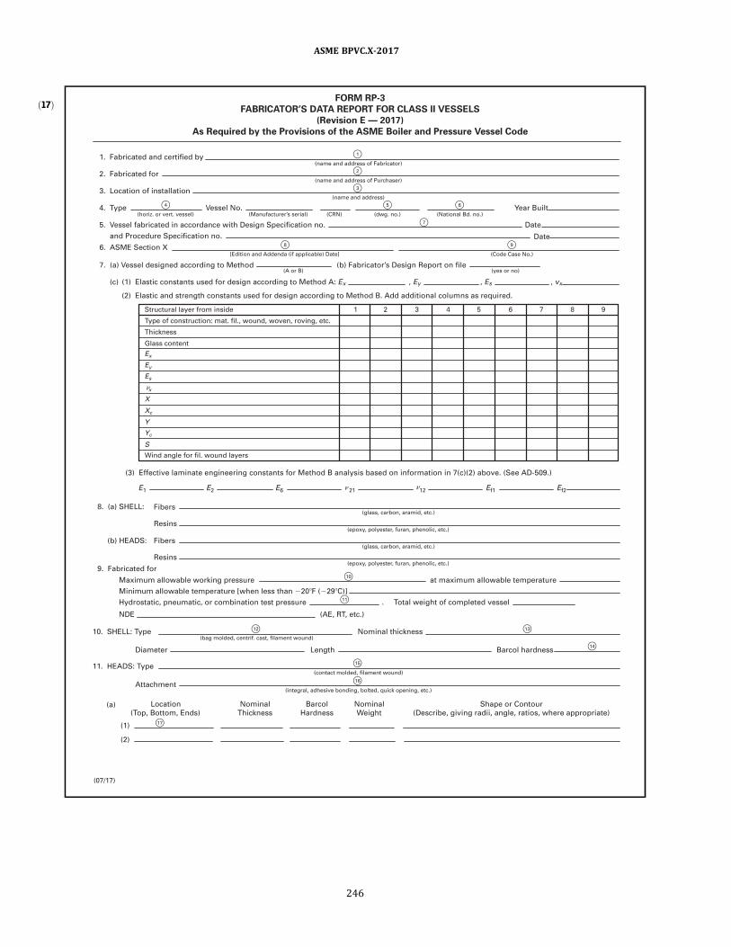
ð17Þ
F 1
F 2
F 3
F 8
F 1 6
F 1 5
F 1 0
F 1 1
F 1 2
F 1 7
F 1 3
F 1 4
F 4 F 5
F 7
F 6
F 9
FORM RP-3
FABRICATOR’S DATA REPORT FOR CLASS II VESSELS
(Revision E — 201 7)
As Required by the Provisions of the ASME Boiler and Pressure Vessel Code
1 . Fabricated and certified by (name and address of Fabricator)
(07/1 7)
2. Fabricated for (name and address of Purchaser)
3. Location of instal lation (name and address)
[Edition and Addenda ( i f appl icable) Date]
(A or B) (yes or no)
( integral , adhesive bonding, bolted, quick opening, etc.)
(contact molded, fi lament wound)
(bag molded, centrif. cast, fi lament wound)
(epoxy, polyester, furan, phenol ic, etc. )
(glass, carbon, aramid, etc.)
(epoxy, polyester, furan, phenol ic, etc. )
(glass, carbon, aramid, etc.)
4. Type
5. Vessel fabricated in accordance with Design Specification no. Date
Date
8. (a) SHELL:
9. Fabricated for
Maximum al lowable working pressure at maximum al lowable temperature
Minimum al lowable temperature [when less than ?20?F (?29?C)]
Hydrostatic, pneumatic, or combination test pressure Total weight of completed vessel .
NDE (AE, RT, etc.)
1 0. SHELL: Type
Diameter Length Barcol hardness
Attachment
Nominal th ickness
1 1 . HEADS: Type
(b) HEADS: Fibers
Resins
Fibers
E1 E2 E6 21 1 2 Ef1 Ef2
Resins
(a)
(1 )
Location
(Top, Bottom, Ends)
Nominal
Thickness
Barcol
Hardness
Nominal
Weight
Shape or Contour
(Describe, g iving radi i , angle, ratios, where appropriate)
(2)
and Procedure Specification no.
(c) (1 ) E lastic constants used for design according to Method A: Ex , Ey , Es , vx
(2) Elastic and strength constants used for design according to Method B. Add additional columns as required.
(3) Effective laminate engineering constants for Method B analysis based on information in 7(c)(2) above. (See AD-509.)
6. ASME Section X
7. (a) Vessel designed according to Method (b) Fabricator’s Design Report on fi le
Structural layer from inside 1 2 3 4 5 6 7 8 9
Type of construction: mat. fi l . , wound, woven, roving, etc.
Thickness
Wind angle for fi l . wound layers
S
Yc
Y
Xc
Es
Ex
Ey
x
X
Glass content
Vessel No. Year Bui l t (horiz. or vert. vessel) (dwg. no.) (National Bd. no. )
(Code Case No.)
(Manufacturer’s serial ) (CRN)
? ?
?
ASME BPVC.X-2017
246

F 26
F 25
F 27
F 24
F 23
F 21
F 28
F 29
F 22
F 20
F 1 8 F 1 9
FORM RP-3 (Back)
(Revision E — 201 7)
CERTIFICATE OF DESIGN
CERTIFICATE OF SHOP INSPECTION
1 4. INSPECTION OPENINGS:
1 5. SUPPORTS:
1 3. NOZZLES
1 2. SAFETY OR SAFETY RELIEF VALVE OUTLETS: Number Size
Skirt Lugs Legs Other
1 7. REMARKS
Commission (Authorized Inspector’s signature) (National Board Authorized Inspector Number)
(Fabricator) (authorized representative)
(date)
Date Signed
Date
of
have inspected the pressure vessel described in th is Fabricator’s Data Report on and state that, to the best of
I , the undersigned, holding a val id commission issued by the National Board of Boi ler and Pressure Vessel Inspectors and employed by
Fabricator’s Design Report on fi le at
Fabricator’s Design Report certified by PE State Reg. no.
We certify the statements in th is Data Report to be correct.
Our Certificate of Authorization no. to use the Certification Mark with RPDesignator expires
by
(describe) (number)
(where and how)
(where and how)
(number) (yes or no)
Attached
Attached
Purpose ( Inlet,
Outlet, Drain)
Diameter
or Size
Reinforcement
Material
How Attached
(Bonded or
Integral ly
Attached)
Number Type Material Thickness
Location
(d) I f fi lament wound, describe pole pieces or head fi ttings
(1 )
(2)
(b) I f bol ted, bolts used (Material , Spec. no. , T.S., size, number)
(1 )
(2)
(c) I f qu ick opening or other (describe or attach sketch)
(1 )
(2)
1 6. VESSEL FABRICATED FOR STORAGE OF
Manholes: No. Size Location
Handholes: No. Size Location
my knowledge and bel ief, the Fabricator has constructed th is pressure vessel in accordance with the appl icable Sections of the ASME BOILER
AND PRESSURE VESSEL CODE.
By signing th is certificate, neither the Inspector nor h is employer makes any warranty, expressed or impl ied, concerning the pressure vessel
described in th is Fabricator's Data Report. Furthermore, nei ther the Inspector nor h is employer shal l be l iable in any manner for any personal
in jury or property damage or loss of any kind arising from or connected with th is inspection.
(date)
(07/1 7)
(Brief description of purpose of the vessel , such as a i r tank, water tank, LPG storage, etc. If description of the purpose of the vessel does not clearly indicate the contents of the vessel state what the contents are to be. Describe any unusua l features of design or construction not covered by i tems 3 to 1 6 inclusive. )
ASME BPVC.X-2017
247

ð17Þ Table AJ-4Guide for Completing Form RP-3
(Revision F — 2017)
Reference to
Circled
Numbers in the
Form Description
(1) Name and street address of Fabricator, i.e., maker of all components not covered by Partial Data Reports.
(2) Name and address of Purchaser and/or Owner.
(3) Name and street address of USER, where vessel is to be installed. If not known, so indicate; e.g., not known — built for stock.
(4) Type of vessel, such as vertical or horizontal vessel, including method of support.
(5) Fabricator’s serial number (one vessel on one report) . CRN lines are for Canadian Registration Number and the number of the
drawing approved by the Provincial Authorities.
(6) National Board number from Fabricator’s series of N.B. numbers or State number if User inspected vessel.
(7) (10) These are the Fabricator’s Specification numbers.
(8) ASME Code, Section X, Edition (e.g., 1998) and Addenda (e.g., A98, A99, etc., if applicable) used for fabrication.
(9) All Code Case numbers and revisions used for fabrication must be listed. Where more space is needed, use Remarks section or list on
a supplemental page.
(11) Test Pressure must conform to RT-450 or RT-460, depending on type of test method used.
(12) Specify contact molded, centrifugally cast, or filament wound, or a combination of these, as contact molded and helically wound, if
the design is a combination.
(13) The thickness of the laminate. Spell out liner thickness (if used) as a separate item.
(14) The Barcol hardness is required for qualification vessels (RT-221) and recorded.
(15) State the process or a combination of the processes along with the shape, as elliptical, spherical, etc., and list the ratio of major to
minor axis if elliptical. If heads are flat (Article RD-7) , list material and thickness.
(16) The details of adhesive bonding, bolted, or quick opening to be recorded in the Data Report.
(17) The top and bottom heads for vertical vessels and ends for horizontally mounted vessels.
(18) Bolts used to secure removable head or heads of vessel.
(19) Safety precautions to be spelled out for quick opening design (Article RD-8) .
(20) Show design of pole pieces wound in on axis of rotation. Show design of fittings and method of holding the fittings in place if located
other than on axis of rotation [not permitted for 3,000 psi (20 MPa) operation design] . In all cases, design adequacy is mandatory.
(21) Indicate nozzle or other opening which is designated for pressure relief device.
(22) Show other nozzles and openings and design of attachment.
(23) Show openings designated for inspection and design of attachment.
(24) Indicate provisions for vessel support. If attached, show design; vessels must designed with support listed in the Data Report.
(25) It is important under Remarks to be very complete in listing concentration temperature of contents of the vessel along with surface
of the vessel used to prevent corrosion. The Fabricator of the vessel line or resin along with Specification number and type is
important for future reference, as vessel may be used for contents other than the contents for which the original design was
intended. For attached Partial Data Reports, list the part name, the name of the Fabricator, and the serial number of the part.
(26) This certificate is to be completed by the Fabricator to show the disposition of the Fabricator’s Design Report and to identify the
registered Professional Engineer who certifies it.
(27) State of the U.S.A.; or province of Canada, if applicable.
(28) Certificate of Shop Inspection is to be completed by the Fabricator and signed by the Authorized Inspector who performs the shop
inspection of the completed vessel.
(29) The National Board Authorized Inspector number shall be shown.
GENERAL NOTE: Any quantity to which units apply shall be entered on the Fabricator’s Data Report with the chosen units.
ASME BPVC.X-2017
248

ð17Þ
F 1
F 1 2
F 1 3
F 1 5
F 3
F 7 F 8
F 9
F 1 0
F 1 1
F 4 F 5
F 2
F 1 6
F 1 7
F 6
F 1 4
FORM RP-4
FABRICATOR’S PARTIAL DATA REPORT FOR CLASS II VESSELS
A Part of a Fiber-Reinforced Plastic Pressure Vessel Fabricated by
One Fabricator for Another Fabricator
(Revision D — 201 7)
As Required by the Provisions of the ASME Boiler and Pressure Vessel Code
1 . (a) Fabricated and certified by (name and address of Fabricator of part)
(a)
(b) I f bol ted, bol ts used
(Material , Spec. no. , T. S. , size, number)
(1 )
(2)
Location
(Top, Bottom, Ends)
Nominal
Thickness
Barcol
Hardness
Nominal
Weight
Shape or Contour
(Describe, g iving radi i , angle, ratios,
where appropriate)
(07/1 7)
2. Identification—Fabricator’s serial no. of part
4. Part fabricated in accordance with Procedure Specification no. Date
5. ASME Section X
6. SHELL: Type Nominal th ickness Fibers Resin
7. HEADS: Type
3. (a) Constructed according to Drawing no. Dwg. prepared by
(b) Fabricated for (name and address of Purchaser of vessel )
(Edition and Addenda ( i f appl icable) Date) (Code Case No.)
(contact molded, centrifugal ly cast, fi lament wound)
1 0. SAFETY VALVE OUTLETS: Number Location Size
8. Fabricated for
9. NDE (AE, RT, etc.)
(contact molded, fi lament wound) (glass, etc. ) (epoxy, etc.)
( integral , adhesive bonding, bol ted, quick opening, etc.)
Nominal weight Diameter
Attachment
Length Barcol hardness
(b) Description of part fabricated and inspected
(1 )
(2)
(c) I f qu ick opening or other
(Describe or attach sketch)
(1 )
(2)
(d) I f fi lament wound, describe pole pieces or head fi ttings
(1 )
(2)
Maximum al lowable working pressure
1 1 . NOZZLES
Purpose ( Inlet,
Outlet, Drain)
Diameter
or Size
Reinforcement
Material Number Type Material Thickness How Attached
at maximum al lowable temperature
Minimum al lowable temperature [when less than ?20?F (?29?C)]
ASME BPVC.X-2017
249
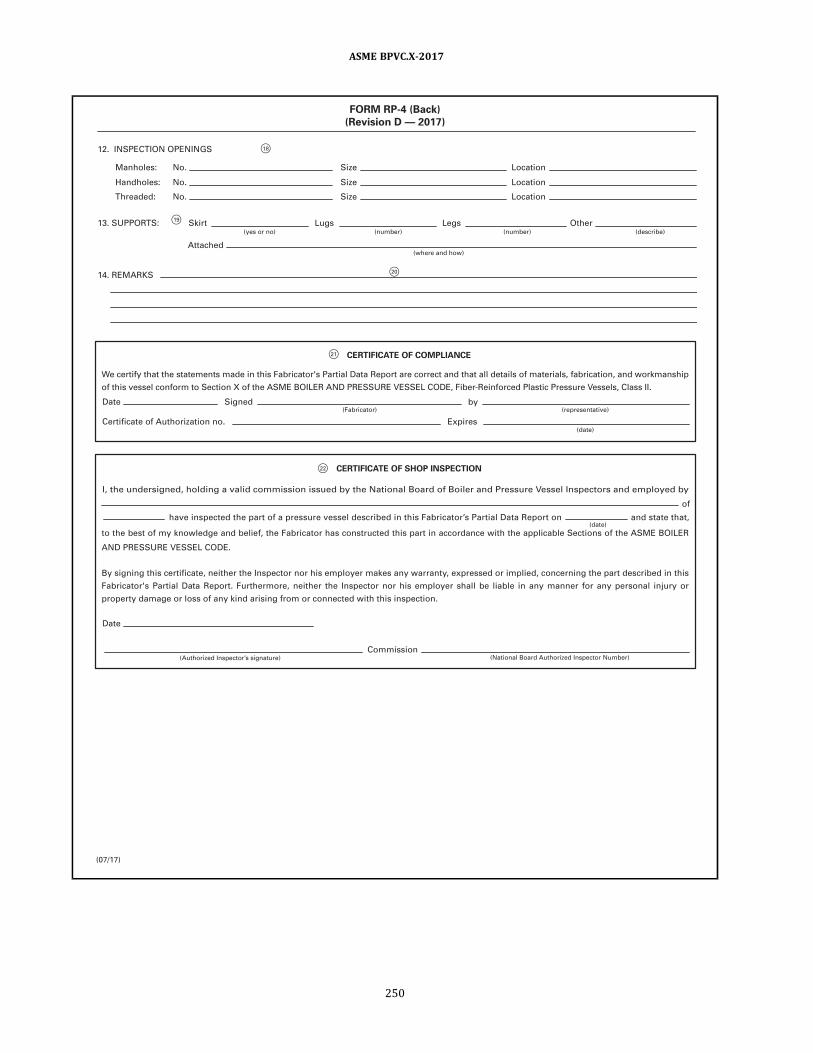
F 21
F 20
F 1 8
F 1 9
F 22
FORM RP-4 (Back)
(Revision D — 201 7)
CERTIFICATE OF COMPLIANCE
CERTIFICATE OF SHOP INSPECTION
1 2. INSPECTION OPENINGS
1 3. SUPPORTS: Skirt Lugs Legs Other
1 4. REMARKS
Commission (Authorized Inspector’s signature) (National Board Authorized Inspector Number)
(Fabricator) (representative)
(date)
Date Signed
Date
of
have inspected the part of a pressure vessel described in th is Fabricator’s Partial Data Report on and state that,
I , the undersigned, holding a val id commission issued by the National Board of Boi ler and Pressure Vessel Inspectors and employed by
Certificate of Authorization no. Expires
by
(describe) (number)
(where and how)
(number) (yes or no)
Attached
Manholes: No. Size Location
Handholes: No. Size Location
Threaded: No. Size Location
to the best of my knowledge and bel ief, the Fabricator has constructed th is part in accordance with the appl icable Sections of the ASME BOILER
AND PRESSURE VESSEL CODE.
By signing th is certificate, neither the Inspector nor h is employer makes any warranty, expressed or impl ied, concerning the part described in th is
Fabricator's Partial Data Report. Furthermore, neither the Inspector nor h is employer shal l be l iable in any manner for any personal in jury or
property damage or loss of any kind arising from or connected with th is inspection.
We certify that the statements made in this Fabricator's Partial Data Report are correct and that al l detai ls of materials, fabrication, and workmanship
of th is vessel conform to Section X of the ASME BOILER AND PRESSURE VESSEL CODE, Fiber-Reinforced Plastic Pressure Vessels, Class I I .
(date)
(07/1 7)
ASME BPVC.X-2017
250

ð17ÞTable AJ-5Guide for Completing Form RP-4
(Revision C — 2013)
Reference to
Circled
Numbers in the
Form Description
(1) Name and street address of Fabricator, i.e., maker of the vessel part covered in this report.
(2) Name and address of Fabricator who will use the vessel part in making a complete vessel.
(3) An identifying serial number marked on the vessel part by the part Fabricator (RS-120) . This is not to be a National Board number.
CRN line is for Canadian Registration Number and the number of the drawing approved by the Provincial Authorities.
(4) Drawing to which vessel part is fabricated.
(5) Organization that prepared drawing.
(6) Description of vessel part, i.e., fitting, flat steel head, attached support bracket, etc.
(7) ASME Code, Section X, Edition (e.g., 1998) and Addenda (e.g., A98, A99, etc., if applicable) used for fabrication.
(8) All Code Case numbers and revisions used for fabrication must be listed. Where more space is needed, use Remarks section or list on
a supplemental page.
(9) Specify contact molded or filament wound, or a combination of these, as contact molded and helically wound, if the design is a
combination.
(10) State the process or a combination of the processes along with the shape, as elliptical, spherical, etc., and list the ratio of major or
minor axis if elliptical. If heads are flat (Article RD-7) , list material and thickness.
(11) The details of adhesive bonding, bolted, or quick opening to be recorded in the Data Report.
(12) The top and bottom heads for vertical vessels and ends for horizontally mounted vessels.
(13) Bolts used to secure removable head or heads of vessel.
(14) Safety precautions to be spelled out for quick opening design (Article RD-8) .
(15) Show design of pole pieces wound in on axis of rotation. Show design of fittings and method of holding the fittings in place if located
other than on axis of rotation [not permitted for 3,000 psi (20 MPa) operation design] . In all cases, design adequacy is mandatory.
(16) Indicate nozzle or other opening which is designated for pressure relief device.
(17) Show other nozzles and openings and design of attachment.
(18) Show openings designated for inspection and design of attachment.
(19) Indicate provisions for vessel support. If attached, show design; vessels must be qualified on the vessel support listed in the Data
Report.
(20) It is important under Remarks to be very complete in listing concentration temperature of contents of the vessel along with surface
of the vessel used to prevent corrosion. The Fabricator of the vessel line or resin along with Specification number and type is
important for future reference, as vessel may be used for contents other than the contents for which the original design was
intended.
(21) Certificate block is to show name of Fabricator of the vessel part and the Certification Mark, authorization number, and expiration
date. This should be signed by chief Inspector, Manager of Quality Control, or a like person.
(22) Certificate of Shop Inspection is to be completed by the Fabricator and signed by the Authorized Inspector who performs the shop
inspection.
GENERAL NOTE: Any quantity to which units apply shall be entered on the Fabricator’s Partial Data Report with the chosen units.
ASME BPVC.X-2017
251

ð17Þ
F1
F2
F3
F4 F5
F6
F7
F9
F8
FORM RP-5 FABRICATOR'S DATA REPORT SUPPLEMENTARY SHEET
(Revision C — 201 7)
As Required by the Provisions of the ASME Code Rules, Section X
1 . Fabricated and certified by (Name and address of Fabricator)
2. Fabricated for (Name and address of Purchaser)
3. Location of instal lation (Name and address)
4. Type (Horiz. , vert. , or sphere) (Fabricator's Serial No.)
CRN (Drawing No.) (Nat’l . Board No.) (Year bui l t)
Data Repor t I tem Numbe r Remarks
Date Name Signed (Fabricator) (Representative)
Date Name Commission (Authorized Inspector) (National Board Authorized Inspector Number)
(Tank, separator, etc.)
Type No. Expires Certificate of Authorization:
(07/1 7)
ASME BPVC.X-2017
252
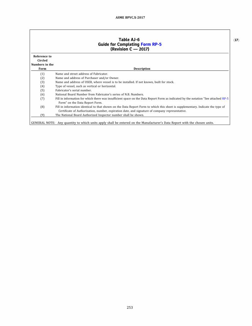
ð17ÞTable AJ-6Guide for Completing Form RP-5
(Revision C — 2017)
Reference to
Circled
Numbers in the
Form Description
(1) Name and street address of Fabricator.
(2) Name and address of Purchaser and/or Owner.
(3) Name and address of USER, where vessel is to be installed. If not known, built for stock.
(4) Type of vessel, such as vertical or horizontal.
(5) Fabricator’s serial number.
(6) National Board Number from Fabricator’s series of N.B. Numbers.
(7) Fill in information for which there was insufficient space on the Data Report Form as indicated by the notation “See attached RP-5
Form” on the Data Report Form.
(8) Fill in information identical to that shown on the Data Report Form to which this sheet is supplementary. Indicate the type of
Certificate of Authorization, number, expiration date, and signature of company representative.
(9) The National Board Authorized Inspector number shall be shown.
GENERAL NOTE: Any quantity to which units apply shall be entered on the Manufacturer’s Data Report with the chosen units.
ASME BPVC.X-2017
253

ð17Þ NONMANDATORY APPENDIX AKLAMINA ELASTIC CONSTANTS — MICROMECHANICS
AK-1 LAMINA ELASTIC CONSTANTS
The laminate analysis method detailed in Article RD-12 includes the use of the five elastic constants of each lamina
(layer) of a laminate. The elastic constants of each lamina are required for determination of the laminate stiffness coeffi-
cients in accordance with Article RD-12. The elastic constants of each lamina can be determined by testing in accordance
with Article RT-7. Alternatively, the elastic constants of each lamina may be determined in accordance with this Non-
mandatory Appendix. The procedures detailed in this Article are commonly referred to as micromechanics.
The five elastic constants that must be determined for each lamina are the longitudinal modulus, transverse modulus,
shear modulus, major Poisson’s ratio, and minor Poisson's ratio.
AK-2 NOMENCLATURE
The symbols used in this Article are defined below.
Ef = tensile modulus of the fiber
Em = tensile modulus of the resin matrix
Ex = Young’s modulus of an orthotropic lamina in the principal direction of the greater modulus
Ey = Young’s modulus of an orthotropic lamina in the principal direction of the lesser modulus
Gf = shear modulus of the fiber
Gm = shear modulus of the matrix
G s = shear modulus of an orthotropic lamina in the principal coordinates
SGf = relative density of fiber
SGr = relative density of resin matrix
t = thickness of the lamina, in. (mm)
Vf = volume fraction of fiber
vf = volume of fiber per unit area, in.3/ft2 (m3/m2)
Vm = volume fraction of matrix
vm = volume of resin matrix per unit area, in.3/ft2 (m3/m2)
W = fiber weight of the lamina per unit area, oz/ft2 (kg/m2)
Wf = weight fraction of fiber
Δ = factor related to Poisson’s ratios = 1 − νxνyν f = Poisson’s ratio of the fiber
νm = Poisson’s ratio of the matrix
νx = principal Poisson’s ratio of a lamina. It is the negative of strain in the y direction from the stress in the x direction
νy = minor Poisson’s ratio of a lamina. It is the negative of strain in the x direction from the stress in the y direction
= ν x × Ey/Ex
ρ c = density of the composite
ρ f = density of the fiber, lb/in.3 (kg/m3)
ρm = density of the resin matrix
AK-3 PRELIMINARY CALCULATIONS
Typically, the weight per unit area of the fiber reinforcement is known, as are the densities of the fiber and resin ma-
trix. If the laminate physically exists, the layer thickness can be measured. If the laminate does not physically exist, then
either the thickness or the fiber weight fraction of the lamina is assumed and verified after fabrication.
ASME BPVC.X-2017
254

Note that the thickness and fiber weight fraction of the lamina are related by:
(U.S. Customary Units)
ð1aÞ
(SI Units)
ð1bÞ
(U.S. Customary Units)
ð2aÞ
(SI Units)
ð2bÞ
(U.S. Customary Units)
ð3aÞ
(SI Units)
ð3bÞ
ð4Þ
ð5Þ
ð6Þ
ð7Þ
ð8Þ
ð9Þ
ASME BPVC.X-2017
255

AK-4 MICROMECHANICS EQUATIONS FOR A UNIDIRECTIONAL LAYER
The following micromechanics equations apply to a unidirectional layer:
ð10Þ
ð11Þ
ð12Þ
ð13Þ
ð14Þ
ð15Þ
ð16Þ
ð17Þ
ð18Þ
ð19Þ
ð20Þ
ð21Þ
ð22Þ
ASME BPVC.X-2017
256
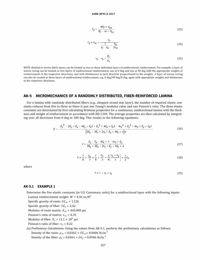
ð23Þ
ð24Þ
ð25Þ
NOTE: Knitted or woven fabric layers can be treated as two or three individual layers of unidirectional reinforcement. For example, a layer of
woven roving can be treated as two layers of unidirectional reinforcement, one at 0 deg and one at 90 deg with the appropriate weights of
reinforcement in the respective directions, and with thicknesses in each direction proportioned to the weights. A layer of woven roving
can also be treated as three layers of unidirectional reinforcement, e.g., 0 deg/90 deg/0 deg, again with appropriate weights and thicknesses
in the respective directions.
AK-5 MICROMECHANICS OF A RANDOMLY DISTRIBUTED, FIBER-REINFORCED LAMINA
For a lamina with randomly distributed fibers (e.g., chopped strand mat layer) , the number of required elastic con-
stants reduces from five to three as there is just one Young’s modulus value and one Poisson’s ratio. The three elastic
constants are determined by first calculating fictitious properties for a continuous, unidirectional lamina with the thick-
ness and weight of reinforcement in accordance with RD-1330. The average properties are then calculated by integrat-
ing over all directions from 0 deg to 180 deg. This results in the following equations:
ð26Þ
ð27Þ
ð28Þ
where
ð29Þ
AK-5.1 EXAMPLE 1
Determine the five elastic constants (in U.S. Customary units) for a unidirectional layer with the following inputs:
Lamina reinforcement weight: W = 4.36 oz/ft2
Specific gravity of resin: SGm = 1.126
Specific gravity of fiber: SGf = 2.62
Modulus of resin matrix: Em = 465,000 psi
Poisson’s ratio of matrix: νm = 0.35
Modulus of fiber: Ef = 11.1 × 10⁶ psi
Poisson’s ratio of fiber: νf = 0.22
(a) Preliminary Calculations. Using the values from AK-5.1, perform the preliminary calculations as follows:
Density of the resin: ρm = 0.0361 × SGm = 0.0406 lb/in.3
Density of the fiber: ρ f = 0.0361 × SGf = 0.0946 lb/in.3
ASME BPVC.X-2017
257

Lamina thickness in inches (assume Wf = 0.70) :
Volume of fiber:
Volume of resin:
Volume fraction of the fiber:
Volume fraction of the resin:
Density of the composite:
(b) Fiber and Matrix Properties. Use values from (a) and AK-5.1 to determine fiber and matrix properties.
Shear modulus of matrix:
Shear modulus of fiber:
(c) Micromechanics Equations for a Unidirectional Composite
ASME BPVC.X-2017
258

Modulus in fiber direction:
Major Poisson’s ratio:
where
Transverse shear modulus:
Transverse modulus:
In-plane shear modulus:
ASME BPVC.X-2017
259
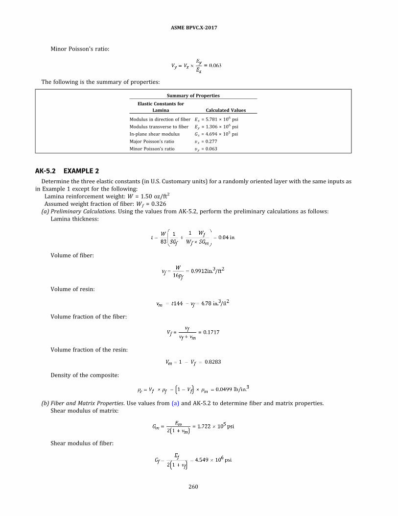
Minor Poisson's ratio:
The following is the summary of properties:
Summary of Properties
Elastic Constants for
Lamina Calculated Values
Modulus in direction of fiber Ex = 5.781 × 10⁶ psi
Modulus transverse to fiber Ey = 1.306 × 10⁶ psi
In-plane shear modulus G s = 4.694 × 10⁵ psi
Major Poisson’s ratio υ x = 0.277
Minor Poisson’s ratio υ y = 0.063
AK-5.2 EXAMPLE 2
Determine the three elastic constants (in U.S. Customary units) for a randomly oriented layer with the same inputs as
in Example 1 except for the following:
Lamina reinforcement weight: W = 1.50 oz/ft2
Assumed weight fraction of fiber: Wf = 0.326
(a) Preliminary Calculations. Using the values from AK-5.2 , perform the preliminary calculations as follows:
Lamina thickness:
Volume of fiber:
Volume of resin:
Volume fraction of the fiber:
Volume fraction of the resin:
Density of the composite:
(b) Fiber and Matrix Properties. Use values from (a) and AK-5.2 to determine fiber and matrix properties.
Shear modulus of matrix:
Shear modulus of fiber:
ASME BPVC.X-2017
260
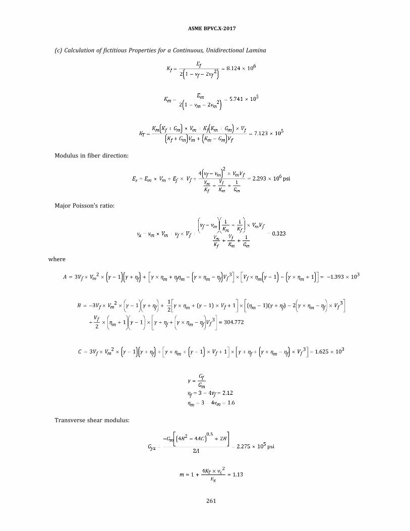
(c) Calculation of fictitious Properties for a Continuous, Unidirectional Lamina
Modulus in fiber direction:
Major Poisson’s ratio:
where
Transverse shear modulus:
ASME BPVC.X-2017
261

Transverse modulus:
In-plane shear modulus:
Minor Poisson’s ratio:
(d) Properties for a randomly oriented fiber layer:
The following is the summary of properties:
Summary of Properties
Elastic Constants for
Lamina Calculated Values
Modulus E = 1.18 × 10⁶ psi
Shear modulus G s = 4.449 × 10⁵ psi
Poisson’s ratio υ x = 0.326
ASME BPVC.X-2017
262

ð17ÞNONMANDATORY APPENDIX ALFIRE AND EXCESSIVE HEAT EXPOSURE GUIDANCE
AL-100 GENERAL
This Appendix provides guidance to Owners or Users of
fiber-reinforced plastic (FRP) pressure vessels to mitigate
the effects of fire and exposure to excessive heat on FRP
vessels covered by this Section. Composite laminates ra-
p idly lose strength at temperatures above 250°F to
400°F (121°C to 204°C) , depending on the resin used or
if they are burning. In addition, the insulating properties
of laminates reduce the temperature increase of the ves-
sel contents. Hence, the vessel pressure may not increase
sufficiently to actuate a relief device before there is a
through-wall leak or, worse, a sudden failure of the vessel
wall. For these reasons, it is recommended that owners of
FRP equipment take all precautions necessary to prevent
fire exposure or excessive heat to the structural wall of
the vessel. While the vessel itself may not contain a flam-
mable substance, it could be sited in an area in which a
fire may start due to leakage of a flammable fluid result-
ing in a pool fire, electrical fire, or chemical fire or could
be struck by lightning. A massive release is the worst-case
scenario that could damage nearby equipment and injure,
with possible death, nearby personnel. This situation re-
quires that exposure of FRP vessels to fire or excessive
heat be minimized. The National Board Inspection Code
provides guidance on continued use and repair of FRP
vessels exposed to excessive heat or fire.
AL-200 SUGGESTED METHODS TOMITIGATE FIRE EXPOSURE
AL-201 ISOLATION FROM FIRE OR EXCESSIVEHEAT SOURCES
If possible, the vessel shall be sited away from any po-
tential fire or excessive heat source, such as from flam-
mable fluids that may leak and catch fire , electrical
equipment that can catch fire due to shorts or overloads,
and reactive chemicals that can cause excessive heat, and
shall be properly grounded against lightning strikes if si-
ted outdoors.
AL-202 PROTECTIVE COATINGS ANDINSULATION
The simplest method of mitigating fire or excessive
heat exposure is to coat or insulate the exposed surfaces
with either an intumescent coating or a heat- or fire-
resistant insulation jacket. These shall be added after
the ve s s e l i s i n s p ec ted and marked wi th the RP
Certification Mark; otherwise, such coatings and insula-
tion will interfere with the final inspection of the vessel.
The thickness and type of coating and/or insulation are
dependent on the type of fire or level of heat exposure,
and the duration of exposure; the thickness and type of
coating and/or insulation shall be specified by a qualified
insulation and coatings specialist. (This is outside the
scope of Section X.) There are fire-retardant resins that
are available, but they only retard the spread of the fire
and do not increase the resistance of the vessel wall to de-
gradation from exposure to a fire.
Where vessels are fully buried underground or leak de-
tection is also desired, a double-walled insulated vessel
can be constructed.
Any vessel potentially exposed to fire shall have the
supports (skirt, legs, lugs, saddles, etc.) fireproofed. For
skirts made of the same material as the vessel wall, both
the inside and outside shall be fireproofed. Such fire-
proofing methods shall meet federal , state, and local
building codes.
AL-203 AUTOMATIC SPRINKLER OR DELUGESYSTEMS
If it is expected that fire exposure will be of a long dura-
tion outlasting the protective ability of a coating or insu-
lation, or there are no insulation or coating systems, then
an automatically actuated sprinkler or deluge system
should be added to cool the vessel wall. Design shall meet
the requirements of the NFPA 13 or other local building
codes.
AL-204 BELOW-GRADE INSTALLATION
Any vessel that contains a heavier than air flammable
fluid shall be installed below grade in a concrete vault
or else be buried with a double wall. In addition, any bur-
ied flammable fluid piping shall also be double walled in
such cases. Where vessels and piping are buried, they
shall be designed to resist any external loads, earth loads,
and high water table buoyancy loads, if any. This shall ap-
ply only to horizontal vessels or very short vertical ves-
sels . The vault or double wall shall be equipped with
leak detection instrumentation. The National Board In-
spection Code currently recommends installation above
ground or below grade in a vault for high pressure gas-
eous hydrogen composite storage vessels. Above-ground
installation for other lighter than air gaseous flammable
ASME BPVC.X-2017
263

fluids can also be considered. However, all such above-
ground vessels shall be protected by an automatic sprink-
ler or deluge system.
AL-205 BLOW-DOWN VENTING
During exposure to fire, there could be a localized hot
spot in the vessel wall that could fail despite the applica-
tion of fire protection coatings, insulation, and devices.
For this reason and the fact that the relief device may
not actuate because the MAWP has not been reached, it
is advisable in some cases to install an automatically actu-
ated vent valve on the vessel to blow the contents down to
a safe area in the event of a fire. If the pressure in the ves-
sel is released prior to a failure of the wall, there is less
likelihood of a sudden release of the contents.
ASME BPVC.X-2017
264

ENDNOTES
1 By lethal fluids is meant poisonous gases or liquids of such a nature that a very small amount of the gas or of the
vapor of the liquid, mixed or unmixed with air, is dangerous to life when inhaled. For purposes of the Code, this class
includes substances of this nature which are stored under pressure or may generate a pressure if stored in a closed
vessel.
2 Requirements for pressure vessels for human occupancy are covered by ASME PVHO‐1.
3 Wherever the word User appears in this Section, it shall be considered to include an agent acting in his behalf. The
agent may be the Fabricator when multiple duplicate vessels are being fabricated.
4 A glossary of terms used in fiber‐reinforced plastic pressure vessel fabrication is given in Mandatory Appendix 4.
5 Matched‐die‐method parts are acceptable under this Section as being equivalent to bag‐molded parts when using
the same type of fiber reinforcement and the same resin system.
6 Sudden cyclic changes in temperature shall be part of the design consideration.
7 An exception to this one‐sixth value is permitted for vessels per RG-404.2 (Filament Winding — With Uncut Fila-
ments) , where the maximum combined stress value may be one‐fifth of maximum membrane stress.
8 Nominal pipe size (NPS) is a designation assigned for the purpose of convenient specification of pipe size. The actual
inside and outside dimensions are listed in ANSI B36.10M.
9 Diameters of vessels and sizes of openings are nominal.
10 The governing principle in the design and fabrication of a Class II vessel is the establishment of the Procedure Spec-
ification (Form Q-120) at the time of design and the strict observance of the Procedure Specification during fabrica-
tion. The engineering constants of laminate materials upon which the design is based, and from which fabrication
will occur, are determined using a mathematical treatment known as laminate theory. Laminate theory utilizes the
orthotropic properties of the individual lamina (based on the specific resin–fiber combination) , ply sequence, and
ply orientations identified in the Procedure Specification to determine the stiffness coefficients and effective elastic
properties of the resultant laminate.
The Procedure Specification is qualified by observance of the mandatory design rules of this Article and strict ob-
servance of the Procedure Specification during fabrication (as documented by quality control records) to assure that
the combinations of resin, reinforcement, ply sequence, and ply orientation upon which the design was based are
followed during fabrication.
The structural integrity of the vessel is confirmed by individual acceptance testing of each vessel using acoustic
emission monitoring.
11 An example of these calculations appears in Nonmandatory Appendix AD.
12 Random short length is that produced by cutter blades with not less than 1 in. (25 mm) nor more than 4 in.
(100 mm) spacing.
13 See Article RT-2 for detailed requirements governing the conducting of these checks and tests.
14 Essential variables shall be held within tolerances established in the Procedure Specification.
15 Essential variables shall be held within tolerances established elsewhere in this Section.
16 Set to operate means the set pressure of a pressure relief valve or a spring‐loaded nonreclosing device, the bursting
pressure of a rupture disk device, or the breaking pressure of a breaking pin device.
17 SNT‐TC‐1A‐1992 Edition, Recommended Practice for Personnel Qualification and Certification in Nondestructive
Testing.
ASME BPVC.X-2017
265

18 The water jacket method described in pamphlet C‐1, published by the Compressed Gas Association, Inc., 1235 Jef-
ferson Davis Highway, Arlington, VA 22202, may be used.
19 In the case of vessel designs that have not been previously qualified, it is recommended that a preliminary hydro-
static qualification pressure test in accordance with RT-223.1(a)(3) be carried out before the cyclic pressure and
qualification pressure test of a prototype vessel is conducted.
20 During the cyclic pressure test, the minimum presure shall be the lower of 20% of design pressure or 30 psig
(0.270 MPa) .
21 If polyester is being used, the surface of the repaired area may be covered with cellophane or other suitable non-
permeable film to retard evaporation of monomer.
22 The maximum allowable external working pressure is required only when specified as a design condition.
23 Wherever the word “stamp” or “stamping,” referring to the Certification Mark to be applied to the vessel (but not to
safety or safety relief devices) , appears in this Section, it may be construed to mean marking the vessel nameplate
with the Certification Mark with RP Designator by means other than a steel stamp (see RS-130 and RS-131) .
24 Knowing the official rating capacity of a safety valve that is stamped on the valve, it is possible to determine the
overall value of KA in either of the following equations in cases where the value of these individual terms is not
known:
Official Rating in Steam Official Rating in Air
This value for KA is then substituted in the above equations to determine the capacity of the safety valve in terms of
the new gas or vapor.
25 Holiday is defined as a discontinuity, such as a pinhole, void, crack, thin spot, foreign inclusion, or contaminant in the
laminate.
26 Yield is measured in yards per pound and is furnished by the fiber producer. The constant (1.125) in the equation is
a function of the reinforcement content and the resin specific gravity. The normal variation of fiberglass content in
filament winding is from 60% to 75% by weight.
27 The equations in Article AA-2 are for isotropic materials only. Any deviation from such materials will require mod-
ifications of the equations.
28 This construction has the further advantage of not transmitting discharge‐pipe strains to the valve. In these types of
installations, the back‐pressure effect will be negligible, and no undue influence upon normal valve operation can
result.
29 Note that 3/β = 9.07 in. , which is less than the length L = 10 in.; by AC-231(b) , B11 = B12 = 1 , B22 = 2 , and
G11 = G12 = G22 = 0, which have been used above.
ASME BPVC.X-2017
266

ASME B o i l e r a n d
P r e s s u r e Ve s s e l C o d e
A N I N T E R N A T I O N A L C O D E
• referen ced sta n d a rd s
• re la ted sta n d a rd s a n d g u id el in es
• con formity a ssessm en t prog ra m s
• tra in in g a n d d evelopmen t cou rses
• ASME Press books
You gain unrivaled insight direct from the BPVC source,
along with the professional quality and real-world
solutions you have come to expect from ASME.
For a d d ition a l in forma tion a n d to ord er:
Ph on e: 1 .800.TH E.ASME
( 1 .800.843.2763)
Ema i l : cu stomerca re@a sme.org
Website: g o.a sme.org /bpvc1 7
Th e ASME Boi ler a n d Pressu re Vessel Cod e (BPVC) is “An
I n tern a tion a l H istoric Mech a n ica l En g in eerin g La n d ma rk,”
wid ely recog n ized a s a mod el for cod es a n d sta n d a rd s
world wid e. I ts d evelopmen t process rem a in s open a n d
tra n spa ren t th rou gh ou t, yie ld in g “ l ivin g d ocu men ts” th a t h a ve
improved pu bl ic sa fety a n d fa ci l i ta ted tra d e a cross g loba l
ma rkets a n d ju risd iction s for a cen tu ry. ASME a l so provid es
BPVC u sers with in teg ra ted su ites of re la ted offerin g s:
2 01 7
Copyright © 2022 FDOKUMEN