
2005-01 - OIML BULLETIN
58
ISSN 0473-2812 OIML BULLETIN VOLUME XLVI • NUMBER 1 J ANUARY 2005 Quarterly Journal Twelfth International OIML Conference, Berlin: Decisions and Resolutions Organisation Internationale de Métrologie Légale 2 2 0 0 0 0 5 5 1 1 9 9 5 5 5 5
-
Upload
khangminh22 -
Category
Documents
-
view
2 -
download
0
Transcript of 2005-01 - OIML BULLETIN

ISSN
047
3-28
12OIML
BULLETINVOLUME XLVI • NUMBER 1
JANUARY 2005
Quarterly Journal
Twelfth International OIML Conference, Berlin: Decisions and Resolutions
Organisation Internationale de Métrologie Légale
2222 0000 0000 5555
1111 9999 5555 5555

T H E O I M L B U L L E T I N I S T H E
Q U A RT E R LY J O U R N A L O F T H E
O R G A N I S AT I O N I N T E R N AT I O N A L E
D E M É T R O L O G I E L É G A L E
The Organisation Internationale de Métrologie Légale(OIML), established 12 October 1955, is an inter-governmental organization whose principal aim is toharmonize the regulations and metrological controlsapplied by the national metrology services of itsMembers.
EDITOR-IN-CHIEF: Jean-François Magaña
EDITOR: Chris Pulham
2005 SU B S C R I P T I O N RAT E
60 €
I S S N 0473-2812
P R I N T E D I N F R A N C E
G R A N D E I M P R I M E R I E D E T R O Y E S
130, R U E G É N É R A L D E G A U L L E
10000 T R O Y E S
OIML PR E S I D I U M
A N D PR E S I D E N T I A L CO U N C I L
AC T I N G PR E S I D E N T
Manfred Kochsiek (GE R M A N Y)
PR E S I D E N T EL E C T
Alan E. Johnston (CA N A D A)
VI C E-PR E S I D E N T
Lev K. Issaev (RU S S I A N FE D E R AT I O N)
ME M B E R S
Wang Qinping (CH I N A)Mitsuru Tanaka (JA PA N)
Stuart Carstens (SO U T H AF R I C A)Ghaïet-El-Mouna Annabi (TU N I S I A)
Charles D. Ehrl ich (UN I T E D STAT E S)
Jean-François Magaña (DIRECTOR OF BIML)
OIML SE C R E TA R I AT
BU R E A U IN T E R N AT I O N A L
D E MÉ T R O L O G I E LÉ G A L E (BIML)
11 R U E TU R G O T – 75009 PA R I S – FR A N C E
TE L: 33 (0)1 4878 1282FA X: 33 (0)1 4282 1727IN T E R N E T: www.oiml.org or www.oiml. int
BIML TE C H N I C A L AG E N T S
DI R E C T O R
Jean-François Magaña ([email protected])
AS S I S TA N T DI R E C T O R S
Atti la Szi lvássy ([email protected])Ian Dunmil l ( [email protected])
ED I T O R
Chris Pulham ([email protected])
EN G I N E E R S
Régine Gaucher ([email protected])Edouard Weber ([email protected])
Jean-Christophe Esmiol ( [email protected])
AD M I N I S T R AT O R
Phil ippe Leclercq ([email protected])
OF F I C E MA N A G E R
Patricia Saint-Germain ([email protected])
AL B A N I A
AL G E R I A
AU S T R A L I A
AU S T R I A
BE L A R U S
BE L G I U M
BR A Z I L
BU L G A R I A
CA M E R O O N
CA N A D A
P. RE P. O F CH I N A
CR O AT I A
CU B A
CY P R U S
CZ E C H RE P U B L I C
DE N M A R K
EG Y P T
ET H I O P I A
FI N L A N D
FR A N C E
GE R M A N Y
GR E E C E
HU N G A RY
IN D I A
IN D O N E S I A
IS L A M I C RE P U B L I C O F IR A N
IR E L A N D
IS R A E L
ITA LY
JA PA N
KA Z A K H S TA N
KE N YA
DE M. P. RE P. O F KO R E A
RE P. O F KO R E A
MA C E D O N I A , TH E FO R M E R YU G O S L AV RE P U B L I C O F
MO N A C O
MO R O C C O
NE T H E R L A N D S
NE W ZE A L A N D
NO RWAY
PA K I S TA N
PO L A N D
PO RT U G A L
RO M A N I A
RU S S I A N FE D E R AT I O N
SA U D I AR A B I A
SE R B I A A N D MO N T E N E G R O
SL O VA K I A
SL O V E N I A
SO U T H AF R I C A
SPA I N
SR I LA N K A
SW E D E N
SW I T Z E R L A N D
TA N Z A N I A
TU N I S I A
UN I T E D KI N G D O M
UN I T E D STAT E S O F AM E R I C A
VI E T N A M
O I M LM E M B E R S T A T E S
O I M L C O R R E S P O N D I N G
M E M B E R S
AR G E N T I N A
BA H R A I N
BA N G L A D E S H
BA R B A D O S
BE N I N
BO S N I A A N D HE R Z E G O V I N A
BO T S WA N A
BU R K I N A FA S O
CA M B O D I A
CO M O R E S, IS L A M I C FE D. RE P. O F
CO S TA RI C A
ES T O N I A
FI J I
GA B O N
GH A N A
GU AT E M A L A
HO N G KO N G, CH I N A
IC E L A N D
JO R D A N
KU WA I T
LAT V I A
LI B YA
LI T H U A N I A
LU X E M B U R G
MA D A G A S C A R
MA L AY S I A
MA LTA
MA U R I T I U S
ME X I C O
MO L D O VA
MO N G O L I A
MO Z A M B I Q U E
NE PA L
NI C A R A G U A
OM A N
PA N A M A
PA P U A NE W GU I N E A
PA R A G U AY
PE R U
QATA R
RWA N D A
SE Y C H E L L E S
SI N G A P O R E
SY R I A
CH I N E S E TA I P E I
TA J I K I S TA N
TH A I L A N D
TR I N I D A D A N D TO B A G O
TU R K E Y
UK R A I N E
UR U G U AY
UZ B E K I S TA N
B U L L E T I NVO L U M E XLVI • NU M B E R 1
JA N U A RY 2005

K t e c h n i q u e
5 Metrological surveillance in public utilities measurementsPaul Dârvariu
12 Vehicle for dynamic calibration of a multiple sensor weigh-in-motion systemBoudewijn Hoogvelt, Nol van Asseldonk, Ronald Henny, Hans van Loo and Gerben Visser
K e v o l u t i o n s
23 Conformity assessment and metrology: Where to go in the future?Pavel Klenovsky
32 Dreams about legal gas meteringJos G.M. van der Grinten
K u p d a t e
37 OIML Certificate System: Certificates registered by the BIML, 2004.08 – 2004.10
42 In memoriam: Knut Birkeland, 1929–2004
44 Decisions and Resolutions: 12th International Conference39th CIML MeetingDevelopment Council Meeting
51 OIML TC 8/SC 8 Working Group Meeting
52 Forum: Metrology - Trade facilitator
53 OIML Awards made in Berlin
54 Lyon 2005: Press Release
56 New Members; OIML Meetings; Committee Drafts received by the BIML
TWELFTH INTERNATIONAL OIML CONFERENCE, BERLIN:DECISIONS AND RESOLUTIONS
OIML BULLETIN
VOLUME XLVI • NUMBER 1
JANUARY 2005
K Contents

K t e c h n i q u e
5 Surveillance métrologique des mesurages sur les réseaux publics de distribution Paul Dârvariu
12 Véhicule pour l’étalonnage dynamique d’un système de pesage en mouvement, à capteurs multiples Boudewijn Hoogvelt, Nol van Asseldonk, Ronald Henny, Hans van Loo et Gerben Visser
K é v o l u t i o n s
23 Évaluation de conformité et métrologie: Quelle direction prendre? Pavel Klenovsky
32 Idées concernant le contrôle légal des compteurs de gazJos G.M. van der Grinten
K i n f o r m a t i o n s
37 Système de Certificats OIML: Certificats enregistrés par le BIML, 2004.08 – 2004.10
42 En mémoire: Knut Birkeland, 1929–2004
44 Décisions and Résolutions: 12ème Conférence Internationale 39ème Réunion du CIML Réunion du Conseil de Développement
51 Réunion du Groupe de Travail du OIML TC 8/SC 8
52 Forum: Métrologie - Facilitateur de commerce
53 Distinctions OIML décernées à Berlin
54 Lyon 2005: Communiqué
56 Nouveaux Membres; Réunions OIML; Projets de Comité reçus par le BIML
K Sommaire BULLETIN OIML
VOLUME XLVI • NUMÉRO 1
JANVIER 2005

K Editorial
A period of transition Une période de transition
Iwould like to thank all of you for your support inelecting me as the next CIML President, and it is withgreat pride that I accept this new challenge. As well,
I would like to take this opportunity to recognize theleadership provided by Manfred Kochsiek over the pastyear.
One of the many benefits of being the President-elect isthe transition period between the election in Berlin and theJune 2005 CIML Meeting in Lyon when I will assume theduties of President. While I am already involved in theimplementation of the Decisions and Resolutions of the 12th
OIML Conference, this transition period will allow me thetime to gain valuable insight and experience as I take on thisnew role.
As I stated in my acceptance speech in Berlin, I hope tofocus my attention on the Long-term Policy and Action Plan,the continued implementation of the MAA, and theacceleration of technical work. In addition, discussions areunderway with Jean-François Magaña to streamline theagendas when the Conference and CIML Meeting are heldconcurrently. This, of course, is not a major issue but onethat warrants attention nonetheless.
And let’s not forget the 50th Anniversary of the OIMLthat will be held in conjunction with the CIML Meeting inLyon in 2005, during which we will also be hoping to elect anew CIML First Vice-president. It is important that we takethe time next year to celebrate the past, present, and futureachievements of the OIML. I hope you will be able to join inthe festivities.
It only remains for me to wish all our Members andReaders a very happy, prosperous New Year on behalf ofmyself and all the Staff at the BIML. K
Je voudrais vous remercier tous de l’appui que vousm’avez démontré en m’élisant Président du CIML, etc’est avec fierté que j’accepte de relever ce nouveau défi.
J’aimerais aussi profiter de l’occasion pour souligner leleadership dont a fait preuve Manfred Kochsiek au cours dela dernière année.
L’un des nombreux avantages d’être Président désignéest la période de transition dont je tirerai profit entrel’élection à Berlin et la Réunion du CIML à Lyon, en juin2005, moment auquel j’entrerai en fonction. Bien que jeparticipe déjà à la mise en œuvre des Décisions etRésolutions de la 12ème Conférence de l’OIML, cette périodede transition me permettra d’obtenir un bon aperçu de monnouveau rôle et d’acquérir une expérience valable.
Comme je l’ai mentionné dans mon discours d’accepta-tion à Berlin, je désire concentrer mes efforts sur laPolitique à long terme et le Plan d’action, la mise en œuvrecontinue de l’Arrangement d’Acceptation Mutuelle (MAA) etl’accélération des travaux techniques. En outre, desdiscussions sont actuellement en cours avec Jean-FrançoisMagaña en vue de simplifier les ordres du jour lorsque laConférence et la Réunion du CIML ont lieu simultanément.Bien sûr, ce dernier point n’est pas un enjeu capital, mais ilmérite toutefois qu’on s’y attarde.
Il ne faudrait surtout pas oublier le 50ème Anniversairede l’OIML qui se tiendra conjointement avec la Réunion duCIML à Lyon en 2005, et pendant laquelle nous espéronsaussi pouvoir élire un Premier Vice-président du CIML. Ilest important que nous prenions le temps, l’an prochain, decélébrer les réalisations passées, présentes et futures del’OIML. J’espère que vous pourrez participer aux festivités.
Il ne me reste plus qu’à souhaiter à tous nos Membres etLecteurs une bonne et heureuse Nouvelle Année de la partde moi-même et tout le Staff du BIML. K
ALAN JOHNSTON

Foreword
The International Vocabulary of Terms in Legal Metrologydefines metrological surveillance as a “control exercisedin respect of the manufacture, import, installation, use,maintenance and repair of measuring instruments,performed in order to check that they are used correctly asregards the observance of metrology laws and regulations”[1]. On first reading this definition appears contra-dictory: how can one obtain information on the correctuse of a measuring instrument by exercising controlsover its manufacturer or importer? In fact though, thedefinition becomes clear when metrological surveillanceis perceived as an overall activity performed aftermeasuring instruments have been placed on the market,including both market surveillance and surveillance ofinstruments in service. There is a distinction between thetwo components: since the aim of market surveillance isto be sure that manufacturers and importers have onlyplaced instruments on the market which meet legalrequirements, in service surveillance is essentiallytargeted at the user, who is responsible for the suitabilityof the instrument to the process, its installation andmaintenance, data acquisition, processing and use intransactions involving the public [2] [3].
However, sometimes feedback to the manufactureror importer is necessary, for instance when themeasuring instrument is not suitable for its intended use(taking normal operating conditions into account).Despite the distinction between the two kinds ofactivities, there is a smooth passage from marketsurveillance to surveillance in service. Although theMeasuring Instruments Directive 2004/22/EC (MID) [4]deals only with market surveillance, it does also containsome prescriptions that can be extended to in servicesurveillance. For instance, in all the four Annexesspecific to instruments destined for public utilitiesmeasurements (MI-001, MI-002, MI-003 and MI-004),there is a requirement that obliges the distributor or theinstaller of a meter to determine the range of operating
conditions (flow rate, temperature, pressure, current,etc.), “so that the meter is appropriate for the accuratemeasurement of consumption that is foreseen orforeseeable”.
Market surveillance is performed in order to checkthat instruments intended for regulated use have beenplaced on the market and put into service on the basis ofappropriate conformity assessment procedures andappropriate markings. For instruments not intended forregulated use, only the correctness of markings ischecked. It is not the intention of this paper to go intomarket surveillance in depth, though in servicesurveillance of some instruments used in the field ofpublic utilities will be detailed here. In this particularfield, in service surveillance consists essentially inchecking that:
K The instrument was properly chosen according to:
J Current practice and the manufacturer’s instruc-tions;
J Required accuracy and the estimated errors inpractical working conditions;
J Actual ranges of fluid parameters (flow rate,temperature, pressure, etc.);
J Ambient conditions (temperature, pressure,humidity, etc.);
J The particular physical and chemical properties ofthe fluid (composition, viscosity, corrosiveness,etc.);
K The instrument was properly installed, maintainedand used according to current practice and in linewith the manufacturer’s instructions;
K There are no features likely to facilitate fraudulentuse or unintentional misuse;
K The measurement values are properly collected,processed and handled in commercial transactions;
K The customer can check the relation between themeasurement results and the price to pay;
K The instrument was subjected to legal metrologicalcontrols and is properly marked.
Free movement of measuring instruments in theglobal market will dramatically reduce the activities oflegal metrology services in the stages before placing onthe market and putting into use [4]. Generally speakingin those countries that import measuring instruments,the workload relating to type evaluations and initialverifications will substantially decrease. On the otherhand the increase in utilities costs and new develop-ments in measuring technologies (most of which aresoftware-based) will lead to the temptation for the userto manipulate the instruments - or at least the measure-ment results. These factors create new responsibilities
SURVEILLANCE
Metrological surveillance in public utilitiesmeasurements
PAUL DÂRVARIU
Romanian Bureau of Legal Metrology (BRML)
5
t e c h n i q u e
O I M L B U L L E T I N V O L U M E X LV I • N U M B E R 1 • J A N U A R Y 2 0 0 5
6
t e c h n i q u e
O I M L B U L L E T I N V O L U M E X LV I • N U M B E R 1 • J A N U A R Y 2 0 0 5
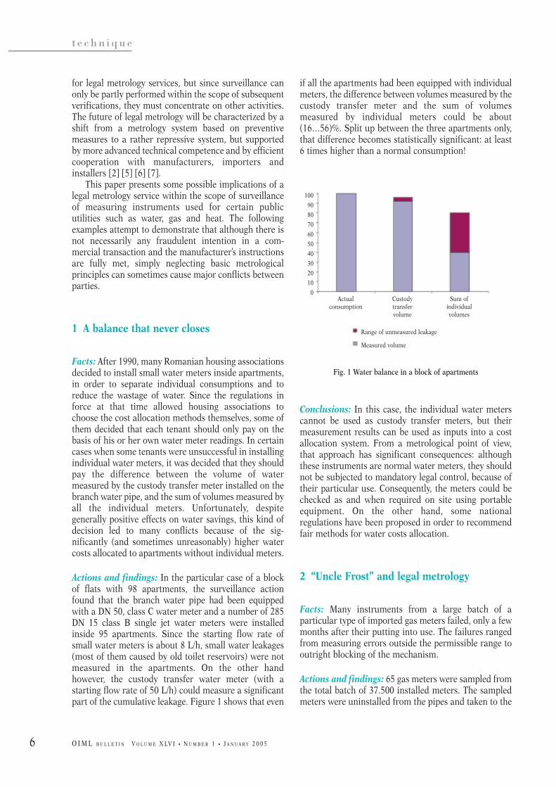
if all the apartments had been equipped with individualmeters, the difference between volumes measured by thecustody transfer meter and the sum of volumesmeasured by individual meters could be about(16…56)%. Split up between the three apartments only,that difference becomes statistically significant: at least6 times higher than a normal consumption!
Fig. 1 Water balance in a block of apartments
Conclusions: In this case, the individual water meterscannot be used as custody transfer meters, but theirmeasurement results can be used as inputs into a costallocation system. From a metrological point of view,that approach has significant consequences: althoughthese instruments are normal water meters, they shouldnot be subjected to mandatory legal control, because oftheir particular use. Consequently, the meters could bechecked as and when required on site using portableequipment. On the other hand, some nationalregulations have been proposed in order to recommendfair methods for water costs allocation.
2 “Uncle Frost” and legal metrology
Facts: Many instruments from a large batch of aparticular type of imported gas meters failed, only a fewmonths after their putting into use. The failures rangedfrom measuring errors outside the permissible range tooutright blocking of the mechanism.
Actions and findings: 65 gas meters were sampled fromthe total batch of 37.500 installed meters. The sampledmeters were uninstalled from the pipes and taken to the
for legal metrology services, but since surveillance canonly be partly performed within the scope of subsequentverifications, they must concentrate on other activities.The future of legal metrology will be characterized by ashift from a metrology system based on preventivemeasures to a rather repressive system, but supportedby more advanced technical competence and by efficientcooperation with manufacturers, importers andinstallers [2] [5] [6] [7].
This paper presents some possible implications of alegal metrology service within the scope of surveillanceof measuring instruments used for certain publicutilities such as water, gas and heat. The followingexamples attempt to demonstrate that although there isnot necessarily any fraudulent intention in a com-mercial transaction and the manufacturer’s instructionsare fully met, simply neglecting basic metrologicalprinciples can sometimes cause major conflicts betweenparties.
1 A balance that never closes
Facts: After 1990, many Romanian housing associationsdecided to install small water meters inside apartments,in order to separate individual consumptions and toreduce the wastage of water. Since the regulations inforce at that time allowed housing associations tochoose the cost allocation methods themselves, some ofthem decided that each tenant should only pay on thebasis of his or her own water meter readings. In certaincases when some tenants were unsuccessful in installingindividual water meters, it was decided that they shouldpay the difference between the volume of watermeasured by the custody transfer meter installed on thebranch water pipe, and the sum of volumes measured byall the individual meters. Unfortunately, despitegenerally positive effects on water savings, this kind ofdecision led to many conflicts because of the sig-nificantly (and sometimes unreasonably) higher watercosts allocated to apartments without individual meters.
Actions and findings: In the particular case of a blockof flats with 98 apartments, the surveillance actionfound that the branch water pipe had been equippedwith a DN 50, class C water meter and a number of 285DN 15 class B single jet water meters were installedinside 95 apartments. Since the starting flow rate ofsmall water meters is about 8 L/h, small water leakages(most of them caused by old toilet reservoirs) were notmeasured in the apartments. On the other handhowever, the custody transfer water meter (with astarting flow rate of 50 L/h) could measure a significantpart of the cumulative leakage. Figure 1 shows that even
100
90
80
70
60
50
40
30
20
10
0
Range of unmeasured leakage
Measured volume
Actualconsumption
Custodytransfervolume
Sum ofindividualvolumes

7
t e c h n i q u e
O I M L B U L L E T I N V O L U M E X LV I • N U M B E R 1 • J A N U A R Y 2 0 0 5
circuits. In that case, the very warm and wet air from thethermal substations was absorbed into the cold bodiesof the meters, where condensation occurred on theelectronic circuits. A simulation test (cold body inside awarm, wet room) subsequently confirmed that assump-tion.
Conclusions: Although the manufacturer’s instructionswere followed and the specific tests were passed, boththe user and the manufacturer must observe all thespecific on site conditions that could affect the instru-ment. In the case under consideration, the manufacturerhad to withdraw all the meters and improve theirwaterproof qualities.
4 A strange “perpetuum mobile”
Facts: The housing associations of 6 blocks ofapartments fed from a thermal substation claimed thatevery month the sum of the heat metered at the buildinginlets was about equal to or even higher than the heatmeasured at the level of the thermal substation. Theyasked for an explanation for this strange “perpetuummobile” that resulted in unfair over-billing of their heatconsumption.
Actions and findings: The surveillance over five years ofalmost 6000 heat meters led to some interestingconclusions concerning the operating conditions insidethe blocks’ basements. The first conclusion is that thepoor conditions at the place of installation usuallyreduce the measurement accuracy and sometimesjeopardize the integrity of the meters. For example, thefilling of the installations through the return pipe, thepoor quality of the hot water as well as the negligence inrepairing broken pipes, caused a build-up of solids in theflow meters, eventually blocking them. Generallyspeaking, the older buildings were not ready to “receive”heat-metering systems. Moreover, the working condi-tions in the basements (high levels of humidity andtemperature, floods, rodents, insects, etc.) were notappropriate for the correct operation of such accurateinstruments. All these negative factors increased themeasurement uncertainties, making both the main-tenance and metrological surveillance too laborious andexpensive.
The surveillance action finally established thatalthough in both primary and secondary heating circuitsthere were similar metering solutions, the accuracy inthe secondary circuit was substantially worse.
laboratory, where they were verified. The verificationresults (shown in Figure 2) were obviously unsuitable.Checking the instruments and the pattern approvalcertificate, the inspectors found that these gas meterswere not designed to work in a such a very large ambienttemperature range as that commonly found on theexternal walls of houses (usually – 20 ºC ... + 60 ºC).Therefore, strong winter frosts combined with some ofthe liquid components in the gas (water, hydrocarbons)irretrievably damaged most of the meters.
Fig. 2 Verification results of a sample from a batch of gas meters
Conclusions: From the point of view of ambienttemperature and gas composition, the type of gas meterwas not suitable. Since for security reasons the preciseinstallation location cannot usually be changed, the onlyproposed measure was to ban the use of the whole batchof instruments.
3 “Wet” breathing
Facts: A large number of big heat meters installed inthermal substations failed very soon after their puttinginto use. In fact, their electronic circuits becamedamaged, although the instruments were apparentlyinstalled and used according to the manufacturer’sinstructions.
Actions and findings: Since drops of water were foundinside the waterproof cases of the electronic circuits,three meters were subjected to complete climatic tests.Although all three instruments successfully passed thetests, poor waterproofing was still assumed to be theproblem. Checking the working conditions, theinspectors found that the thermal substation operatorsusually pumped only cold water into the heating
Meters with E>mpe37 %
Blocked meters2 %
Higher pressure loss
6 %
Meters withE<mpe55 %

8
t e c h n i q u e
O I M L B U L L E T I N V O L U M E X LV I • N U M B E R 1 • J A N U A R Y 2 0 0 5
measurement uncertainties in that particular case, mostof the conclusions could be extrapolated to the wholeheat distribution system in Bucharest or even in thewhole country.
a) Errors in the temperature difference measurement
In Romania, in the secondary heating circuits, theenergy is delivered at relatively low temperatures. Figure4 shows that about one third of the heat is suppliedduring one year at low flow temperatures (lower than 50°C). Consequently, inside old buildings the temperaturedifference will have very low values (less than 6 K); thisleads to serious problems in heat metering accuracy.
Fig. 4 Typical heat distribution chart
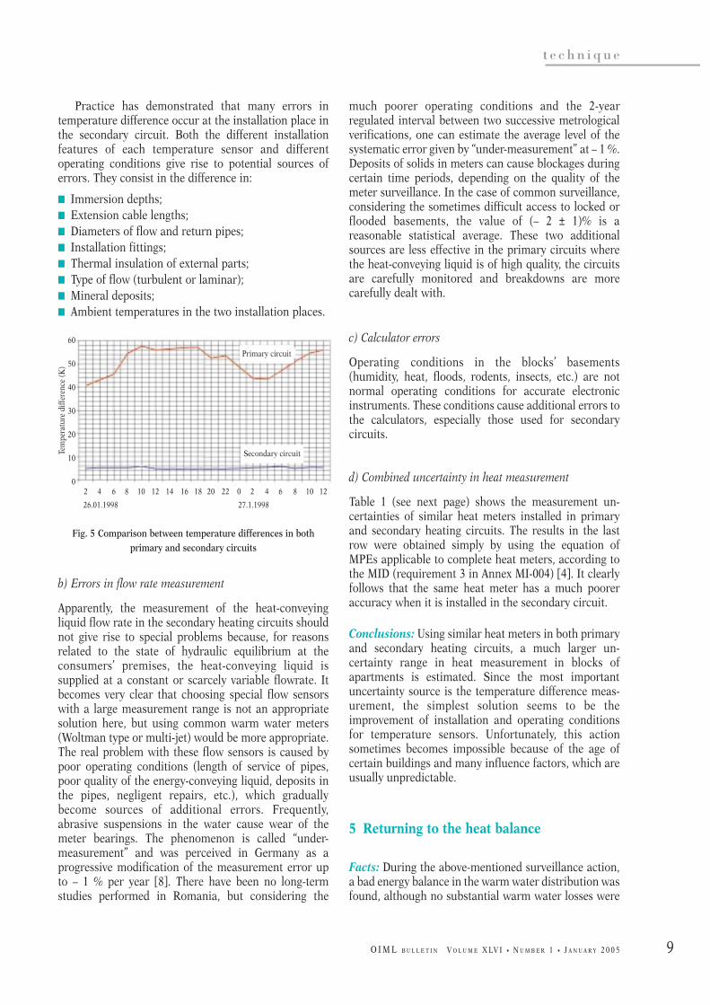
Our study confirmed the theoretical diagram,showing that during 35 consecutive days the temper-ature difference in the secondary circuit remainedwithin the interval (4.2…5.8) K, for temperaturedifferences in the primary circuit of (40…60) K. Thecurves in Figure 5 show the simultaneous variation ofthe primary/secondary temperature differences within agiven interval (34 hours, on January 26 and 27, 1998,external temperatures between – 10 ºC and – 3 ºC) forone of the blocks of apartments under consideration.A simple analysis of the two curves leads to theconclusion that the same error in measuring thedifferential temperature gives heat measurement errorsin the secondary circuit 10 times higher than in theprimary circuit. This contributes to the lower accuracyof the integrating calculator and the pair of temperaturesensors, at low values of temperature difference.
A heat meter consists of a flow sensor (in principle,a hot water meter with a pulse generator), a pair oftemperature sensors to measure the difference betweentemperatures at the inlet and the outlet of the energy-conveying liquid and a calculator, which solves theequation:
Q = V × ρ × c × ∆Θ
where Q is the consumed heat, V is the volume of theenergy-conveying liquid passed through flow sensor, ∆Θis the temperature difference, c is the specific thermalcapacity and ρ is the density of the energy-conveyingliquid.
In order to evaluate the measurement uncertaintiesin the above-mentioned heat distribution case, a studywas performed, monitoring for relatively long times allthe heat meters installed at the thermal substation andall 6 blocks of apartments. Additionally to the scheme inFigure 3, two heat meters were installed on both theheat and hot water outputs of the thermal substation.Also, the 15 calculators were inter-connected in an M-Bus net assisted by a PC. The system was permanentlymonitored for 35 days during January - February 1998.75 000 values were measured and recorded hourly for 6different parameters (energy, volume, flow rate, flowtemperature, return temperature and temperaturedifference). Although the study identified the sources of
Fig. 3 Solution to meter heat and warm water at blocks of apartments
Flow
Return
Primary
Thermal substation
Cold water
Secondary
6 blocks of apartments
80
70
60
50
40
30
20
10
0
7 %
22 %
35 %
Flow
Return
External temperature (°C)
15 10 5 0 -5 -10 -15
Conv
eyin
g liq
uid
(°C)
21 %
9 %6 %
9
t e c h n i q u e
O I M L B U L L E T I N V O L U M E X LV I • N U M B E R 1 • J A N U A R Y 2 0 0 5
much poorer operating conditions and the 2-yearregulated interval between two successive metrologicalverifications, one can estimate the average level of thesystematic error given by “under-measurement” at – 1 %.Deposits of solids in meters can cause blockages duringcertain time periods, depending on the quality of themeter surveillance. In the case of common surveillance,considering the sometimes difficult access to locked orflooded basements, the value of (– 2 ± 1)% is areasonable statistical average. These two additionalsources are less effective in the primary circuits wherethe heat-conveying liquid is of high quality, the circuitsare carefully monitored and breakdowns are morecarefully dealt with.
c) Calculator errors
Operating conditions in the blocks’ basements(humidity, heat, floods, rodents, insects, etc.) are notnormal operating conditions for accurate electronicinstruments. These conditions cause additional errors tothe calculators, especially those used for secondarycircuits.
d) Combined uncertainty in heat measurement
Table 1 (see next page) shows the measurement un-certainties of similar heat meters installed in primaryand secondary heating circuits. The results in the lastrow were obtained simply by using the equation ofMPEs applicable to complete heat meters, according tothe MID (requirement 3 in Annex MI-004) [4]. It clearlyfollows that the same heat meter has a much pooreraccuracy when it is installed in the secondary circuit.
Conclusions: Using similar heat meters in both primaryand secondary heating circuits, a much larger un-certainty range in heat measurement in blocks ofapartments is estimated. Since the most importantuncertainty source is the temperature difference meas-urement, the simplest solution seems to be theimprovement of installation and operating conditionsfor temperature sensors. Unfortunately, this actionsometimes becomes impossible because of the age ofcertain buildings and many influence factors, which areusually unpredictable.
5 Returning to the heat balance
Facts: During the above-mentioned surveillance action,a bad energy balance in the warm water distribution wasfound, although no substantial warm water losses were
Practice has demonstrated that many errors intemperature difference occur at the installation place inthe secondary circuit. Both the different installationfeatures of each temperature sensor and differentoperating conditions give rise to potential sources oferrors. They consist in the difference in:
K Immersion depths;K Extension cable lengths;K Diameters of flow and return pipes;K Installation fittings; K Thermal insulation of external parts;K Type of flow (turbulent or laminar);K Mineral deposits;K Ambient temperatures in the two installation places.
Fig. 5 Comparison between temperature differences in bothprimary and secondary circuits
b) Errors in flow rate measurement
Apparently, the measurement of the heat-conveyingliquid flow rate in the secondary heating circuits shouldnot give rise to special problems because, for reasonsrelated to the state of hydraulic equilibrium at theconsumers’ premises, the heat-conveying liquid issupplied at a constant or scarcely variable flowrate. Itbecomes very clear that choosing special flow sensorswith a large measurement range is not an appropriatesolution here, but using common warm water meters(Woltman type or multi-jet) would be more appropriate.The real problem with these flow sensors is caused bypoor operating conditions (length of service of pipes,poor quality of the energy-conveying liquid, deposits inthe pipes, negligent repairs, etc.), which graduallybecome sources of additional errors. Frequently,abrasive suspensions in the water cause wear of themeter bearings. The phenomenon is called “under-measurement” and was perceived in Germany as aprogressive modification of the measurement error upto – 1 % per year [8]. There have been no long-termstudies performed in Romania, but considering the
Primary circuit
Secondary circuit
2 4 6 8 10 12 14 16 18 20 22 0 2 4 6 8 10 12
26.01.1998 27.1.1998
60
50
40
30
20
10
0
Tem
pera
ture
diff
eren
ce (K
)

10
t e c h n i q u e
O I M L B U L L E T I N V O L U M E X LV I • N U M B E R 1 • J A N U A R Y 2 0 0 5
cooling of warm water between the thermal substationand the consumer (about 6.5 °C, giving energy losses ofup to 20 %). Therefore, the uncertainties in the heatmeasurement caused by the errors in the temperaturedifference are not very significant.
b) Errors in the warm water volume measurement
“Under-measurement” and temporary blocking ofmechanical water meters exist in this case, too.Additionally, a new uncertainty source appears: theinsensitiveness of flow sensors to water leakages.Statistics demonstrate that this additional error is (– 9 ± 6)%.
c) Calculator errors
Similar values to those revealed in a heating circuit canbe estimated.
d) Combined uncertainty in the measurement of heatused to produce warm water
Table 2 (see next page) shows significant uncertainties ofmeasurements performed with a heat meter installed ona domestic warm water inlet.
Conclusions: Most energy losses in the monitored warmwater distribution were given by the cooling of warmwater between the thermal substation and the blocks ofapartments. As for the measurement accuracy, the most
detected. A low accuracy of measurement wasincriminated.
Actions and findings: The accuracy of warm watermetering was also monitored. Figure 3 shows themethod used for metering warm water in Bucharest.The meter consists in a typical heat meter that measuresboth the volume of consumed water and the heatconsumed to produce that volume of warm water.Although the volume metering is quite simple, the heatmetering requires some special precautions. Since thewarm water is supplied through an open circuit, thetemperature of the cold water pipe, present in everybasement, is taken to simulate the return temperature atthe entry of the heat meter. The method is, apparently,quite accurate: in fact the warm water meter installed inthe thermal substation uses the same cold water as inblocks of apartments. However, in practice, there aremany uncertainty sources that deserve careful analysis,as detailed below.
a) Errors in the temperature difference measurement
Contrary to the heat metering in a secondary heatingcircuit, the temperature difference has higher values(20…30) K, that puts to advantage the measurement ofthe heat used to prepare domestic warm water. The onlysource of significant additional errors is the differencebetween the cold water temperatures measured in thethermal substation and in the block’s basement,respectively. In the present case study, the mean dailyvariation was + 0.35 °C, which is much lower than the
Intrinsic error of the pair of temperature sensors ± 0.68 % ± 2.3 %
Additional error of temperature sensors given by operating conditions (± 0.5 K) ± 1 % ± 10 %
Intrinsic error of the flow sensor ± 3 % ± 3 %
“Under-measurement” error – 1 % – 1 %
Flow disturbances - ± 1 %
Temporary blocking of the flow sensor - (– 2 ± 1) %
Intrinsic error of the calculator ± 0.56 % ± 1.1 %
Additional calculator error given by operating conditions - ± 1.5 %
Temporary blocking of the calculator - (– 1.5 ± 0.75) %
Combined uncertainty (– 1 ±± 5.2) % (– 4.5 ±± 20.7) %
Primary(∆Θmed = 50 K)
Where the measurement is performed
Sources of uncertainty Secondary(∆Θmed = 5 K)
Table 1 Combined uncertainty in heat measurement

11
t e c h n i q u e
O I M L B U L L E T I N V O L U M E X LV I • N U M B E R 1 • J A N U A R Y 2 0 0 5
OIML Bulletin Volume XLV, Number 2, April 2004[4] Directive 2004/22/EC of the European Parliament
and of the Council of 31 March 2004 onMeasuring Instruments
[5] Hartmut Apel, European Directive for MeasuringInstruments - A new challenge to industry and tothe state OIML Bulletin Volume XLI, Number 4,October 2000
[6] Bruno Vaucher, Towards total approach in legalmetrology, OIML Bulletin Volume XLIV, Number 3,July 2003.
[7] Wilfried Schulz, Changes in consumer protectionin legal metrology as a result of new technologies,OIML Bulletin Volume XLV, Number 2, April 2004
[8] Hansruedi Lingg, “Wie die Wahl des Wärme-zählerparks die Ökonomie des Fernwärme-unternehmens beeinflußt”, Euroheat & Power Jg.24 (1995)
important source of uncertainty is the insensitiveness offlow sensors to water leakages. Only using better flowsensors and having a larger flow rate range couldsubstantially improve the measurement accuracy. K
References
[1] International Vocabulary of Terms in LegalMetrology, Edition 2000
[2] Manfred Kochsiek and Wilfried Schulz -Modernization of legal metrology in Germany,OIML Bulletin Volume XLV, Number 4, October2004
[3] Gerard Lagauterie, The evolution of themetrological control of measuring instruments inFrance (The new professions in legal metrology),
Sources of uncertainty Values
Intrinsic error of the pair of temperature sensors ± 0.95 %
Additional error because of the change in cold water temperature (+ 0.35 K) (– 0.7 ± 0.7)%
Intrinsic error of the flow sensor ± 3 %
“Under-measurement” error – 1 %
Flow disturbances ± 1 %
Temporary blocking of the flow sensor (– 2.5 ± 1.5)%
Insensitiveness to water leakages (– 9 ± 6)%
Intrinsic error of the calculator ± 0.6 %
Additional calculator error given by operating conditions ± 1.5 %
Temporary blocking of the calculator (– 1.5 ± 0.75)%
Combined uncertainty (– 14.7 ±± 16)%
Table 2 Combined uncertainty in warm water metering
The Author welcomes comments to his article and can be contacted as below:
Paul DarvariuRomanian Bureau of Legal Metrology (BRML)Technical DepartmentSos. Vitan Barzesti nr. 11 Sector 4042122 Bucuresti, RomaniaE-mail: [email protected]

12
t e c h n i q u e
O I M L B U L L E T I N V O L U M E X LV I • N U M B E R 1 • J A N U A R Y 2 0 0 5
This article is an abstract of two papers presented inMarch 2004 at the 8th International Symposium onHeavy Vehicle Weights and Dimensions, JohannesburgSouth Africa. It deals with the building and use of aspecial calibration vehicle by Kalibra International B.V.
1 Background
1.1 Introduction
International and domestic goods transportation byroad is an important part of the Dutch economy;173,000 trucks transport 600 million tonnes annually[CBS, 2000]. Truck traffic in particular is burdening theinfrastructure. The number of trucks and the truck axleloads are the major determinant for the degree ofmaintenance required, as there is a progressive (4thorder) relationship between an axle load and thedamage that this axle load causes to the road surface. Adisproportionately large percentage of the damage to theinfrastructure is caused by trucks with axle loads higherthan the legal maximums. The direct costs for additionalasphalt maintenance are roughly estimated at aroundEuro 17 million per annum for Dutch highways alone.This excludes the costs resulting from additionalhindrance to traffic (including traffic jams) caused by
road works. Moreover, the policy of the Ministry ofTransport, Public Works and Water Management is alsoaimed at stimulating fair competition betweencompanies. Finally, overloading of one or more axles ofa truck or the whole vehicle is also likely to have anegative effect on traffic safety.
To reduce the negative effects of overloading, theDirectorate General Goods Transportation of the DutchMinistry of Transport, Public Works and WaterManagement has started the project ‘Overloading’. Aspart of this project the Road and Hydraulic EngineeringDivision (DWW) of the Ministry of Transport is workingon two projects involving Weigh-in-Motion - WIM-NLand WIM-Hand. The WIM-NL project concerns theinstallation of six WIM+ Video-systems in TheNetherlands [Saan, 2002]. The systems are used byenforcement agencies as a tool for pre-selection and pro-active controls. As static weighing remains necessary,these methods of enforcement are extremely labor-intensive. Therefore, in parallel, the WIM-Hand projectwas started. WIM-Hand stands for Weigh-In-Motion forautomatic enforcement or, in Dutch, ‘Handhaving’. Thisproject investigates whether existing technology can beused for building an axle load measuring system thatcan be employed for automatic enforcement ofoverloading by heavy goods vehicles. Automaticenforcement means that a citation will be directly basedon the measurement of the WIM-system.
1.2 WIM-Hand project
As a part of the WIM-Hand project a multi-sensor WIMtest site has been built at the A12/A50 highway nearArnhem in the East of The Netherlands. The choice ofthe multi-sensor approach and the design of the sensorarray was based on [Gillespie, 1996], [Dolcemascolo,1998], [Cebon, 1999], [WAVE, 2001] and others. The testsite consists of sixteen rows of sensors, each rowconsisting of four Kistler Lineas Piezo Quartz sensors[Kunz, 1999]. The length of each of the Kistler sensors is1.0 m, the spacing between each row of sensors is 1.5 m(see Figure 1). A full description of the design andinstallation of the test site can be found in [van Loo,2001]. The system measures the wheel loads of allpassing vehicles and stores the measured data from eachsensor per vehicle in a database. Along with themeasured data a number of video images of the vehicleare also stored.
The measurement part of a WIM-system consists ofthe combination of the WIM-sensors and the surround-ing pavement. As a result, a WIM-system can only becalibrated when the sensors are installed in the roadpavement. The basic idea of a multiple sensor WIM-system is that by taking sufficient samples of the
WEIGHING IN MOTION
Vehicle for dynamiccalibration of a multiplesensor weigh-in-motionsystem
BOUDEWIJN HOOGVELT, TNO AutomotiveNOL VAN ASSELDONK, Kalibra InternationalRONALD HENNY, Road and Hydraulic Eng. InstituteHANS VAN LOO, Road and Hydraulic Eng. InstituteGERBEN VISSER, Kalibra International

13
t e c h n i q u e
O I M L B U L L E T I N V O L U M E X LV I • N U M B E R 1 • J A N U A R Y 2 0 0 5
[Hutala, 1998]. However these vehicles are either basedon outdated computer technology or not available forlong periods of time in The Netherlands. That is why thepossibilities were investigated to build a WIM-calibration vehicle in The Netherlands.
The dynamic calibration of a WIM-system can bedone in several ways: at low speed with standard trucksor at high speed with an instrumented vehicle. In thecase of low speed calibration it is assumed that thedynamic part of the axle loads is negligible. Then theWIM-system can be calibrated to the axle loads that aremeasured when the vehicle is stationary. However, whenthe operational range of the WIM-system is tested atconsiderably higher speeds with such a standard truck,then the system is in effect not calibrated for thisoperational range. Since the speeds at the test site varyby around 80 km/h, high speed calibration is preferred.
2.1 Vehicle specifications
The key functional specifications for the instrumentedvehicle for the WIM-Hand system include:
J The vehicle has to measure and store the dynamicforces that are exercised by the measurement axle onthe WIM-system;
dynamic axle loads of the passing trucks the static axleloads can be calculated. The accuracy of most calcula-tion algorithms is sensitive to the measurement error inthe sampled axle load, except the neural networktechnique [Gonzalez, 2003]. That is why it is importantthat each sensor measures the exact value of thedynamic axle load at the moment the axle passes overthat sensor. This can be achieved if each individualsensor is dynamically calibrated. Dynamic calibrationmeans that the sensor will be calibrated to the dynamicforce measured by the measurement axle of theinstrumented vehicle the moment it passes the sensor.As part of the WIM-Hand project an instrumentedvehicle has been built to perform the dynamic calibra-tion of the sensors of the WIM-Hand test site.
2 Design of the vehicle
During the last decades several instrumented vehicleshave been built and used for calibration and testing ofWIM-systems. For example the vehicles from theTransport Road Research Laboratory in the UK [Cebon,1999], the National Research Council of Canada [WAVE,2001] and the Technical Research Centre of Finland
Figure 1 The WIM-Hand test system
14
t e c h n i q u e
O I M L B U L L E T I N V O L U M E X LV I • N U M B E R 1 • J A N U A R Y 2 0 0 5
subcontractor for the development of the measurementsystem was TNO Automotive in Delft, the Netherlands.The subcontractor for the building of the custom-builttrailer was Nooteboom Trailers BV in Wychen, theNetherlands. Furthermore, there were a number ofother subcontractors for specific parts of the project, e.g.the axles and the tyres.
In order to minimize costs for both Kalibra andDWW and to allocate the costs fairly, the contractnegotiations were conducted in an open atmosphere.Both parties were fully open about which costs wereexpected to be carried by Kalibra and which would befair to be accepted by the DWW. Despite the risksinvolved in building a prototype the contract betweenDWW and Kalibra was a fixed price contract.
4 Use of the vehicle
4.1 Measurement principle
To be able to compare the measured signal from theWIM-system with the data measured by the vehicle,both systems must be synchronized. This is done usingthe exact time of the GPS-signal as a time reference forboth systems. At first a DCF-77 receiver was considered.However, the time signal was not accurate enough(± 25 ms) to be used for synchronization. With the GPS-receiver the maximum difference in the time synchro-nization is less than 10 µs. At the maximum speed of100 km/h with a length of the tyre/road contact surfaceof 30 cm, the contact time of the wheel on the sensor(width of 5 cm) is 12.6 ms. The sample frequency of thevehicle is 8 kHz and of the WIM-test system 8192 Hz(0.12 ms). This amounts to approximately 100 samplesper axle load measurement.
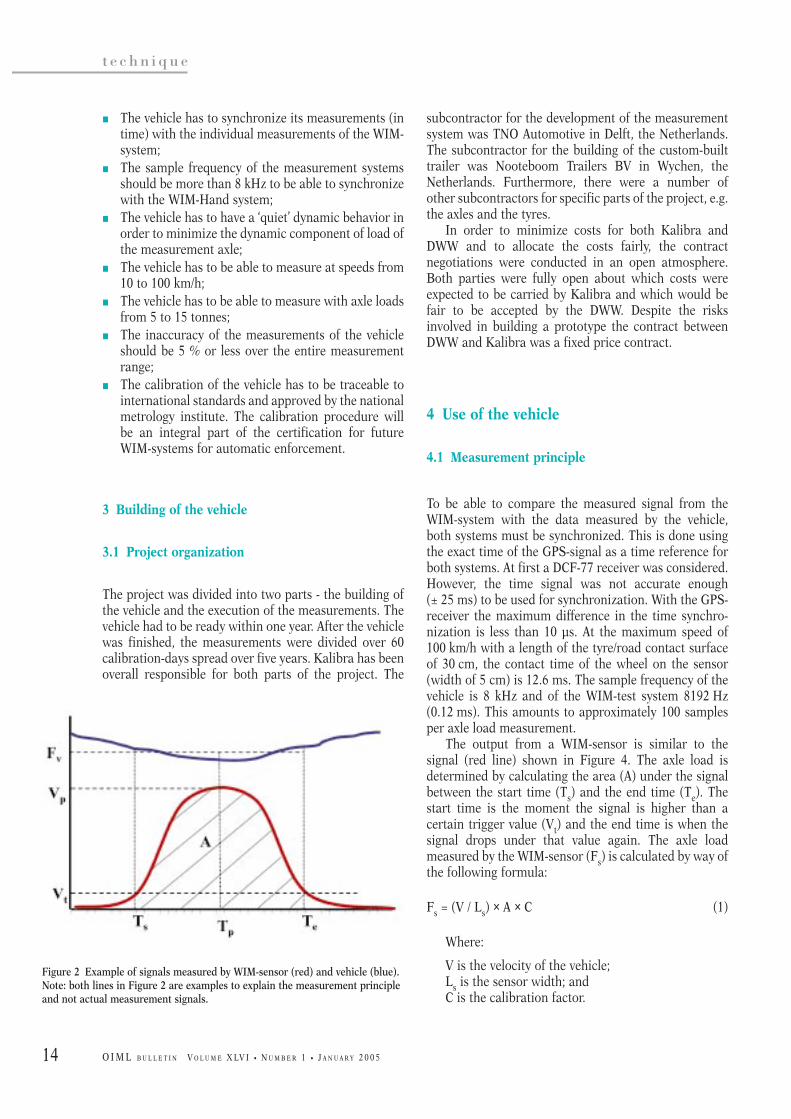
The output from a WIM-sensor is similar to thesignal (red line) shown in Figure 4. The axle load isdetermined by calculating the area (A) under the signalbetween the start time (Ts) and the end time (Te). Thestart time is the moment the signal is higher than acertain trigger value (Vt) and the end time is when thesignal drops under that value again. The axle loadmeasured by the WIM-sensor (Fs) is calculated by way ofthe following formula:
Fs = (V / Ls) × A × C (1)
Where:
V is the velocity of the vehicle;Ls is the sensor width; and C is the calibration factor.
J The vehicle has to synchronize its measurements (intime) with the individual measurements of the WIM-system;
J The sample frequency of the measurement systemsshould be more than 8 kHz to be able to synchronizewith the WIM-Hand system;
J The vehicle has to have a ‘quiet’ dynamic behavior inorder to minimize the dynamic component of load ofthe measurement axle;
J The vehicle has to be able to measure at speeds from10 to 100 km/h;
J The vehicle has to be able to measure with axle loadsfrom 5 to 15 tonnes;
J The inaccuracy of the measurements of the vehicleshould be 5 % or less over the entire measurementrange;
J The calibration of the vehicle has to be traceable tointernational standards and approved by the nationalmetrology institute. The calibration procedure willbe an integral part of the certification for futureWIM-systems for automatic enforcement.
3 Building of the vehicle
3.1 Project organization
The project was divided into two parts - the building ofthe vehicle and the execution of the measurements. Thevehicle had to be ready within one year. After the vehiclewas finished, the measurements were divided over 60calibration-days spread over five years. Kalibra has beenoverall responsible for both parts of the project. The
Figure 2 Example of signals measured by WIM-sensor (red) and vehicle (blue).Note: both lines in Figure 2 are examples to explain the measurement principleand not actual measurement signals.

15
t e c h n i q u e
O I M L B U L L E T I N V O L U M E X LV I • N U M B E R 1 • J A N U A R Y 2 0 0 5
4.2 Standard operational procedure
The load on the trailer is 44 tonnes, consisting of 44mass pieces of 1000 kg each and a fork-lift truck for theon and off loading of the mass pieces. This way everyaxle load between 3 tonnes and 15 tonnes may berealized on the measurement axle. All mass pieces arecertified and traceable to international standards. Thelifting of the measurement axle is also used tocompensate eventual off-set of the force sensors. This‘zero-setting’ of the axle is done at the beginning of eachmeasurement day. The lifting of one or more axlescauses a change in the ‘driving height’ of the trailer. Thischange is detected and displayed, so the driver canadjust it electronically. The vehicle has a set of specialpermits to be allowed to drive with 70 tonnes at 100 km/hwith axle loads of up to 15 tonnes. Nevertheless, the
In the currently used post-processing standard, thestart time (Ts) is considered to be the measurement timeof the axle load measured by the WIM-sensor [Helg,2000].
The output from the measurement axle is similar tothat of the blue line in Figure 2. The axle load is calcu-lated by taking the weighed (Wi) average of themeasured samples from start to end time:
Fv = (2)
The weighing factor Wi may be used to adjust for thevariation of the load exerted on the WIM-sensor whenthe wheel rolls over the sensor. Depending on themagnitude of this variation the weighing factor can be 1(no variation) or for example ‘Bell-shaped’ similar to thesignal measured by the WIM-sensor.
Figure 3 The instrumented vehicle in action

16
t e c h n i q u e
O I M L B U L L E T I N V O L U M E X LV I • N U M B E R 1 • J A N U A R Y 2 0 0 5
J Under varying weather conditions, i.e. differenttemperatures, rainy spells, over dry or wet surfaces,etc.
Which tests are deemed necessary for the typeapproval test is determined in cooperation with theNMi. The time interval between two calibrations will bedetermined based on the results of the type approvaltest. An example of the measurement results from theinstrumented vehicle is shown in Figure 4. The differ-ence in the amplitude of the axle-hop frequency betweenthe right and left wheel was caused by a difference in thepressure in the tyres. The blue lines only indicate therelative position of the sensors within in the WIM-Handtest-site. The absolute position of the sensors of the testsite can not be given since the test site is not operationalyet.
5 The vehicle itself
5.1 The measurement system
The calibrating vehicle is a tractor semi-trailer combi-nation with a maximum total vehicle weight of 78tonnes. The tractor is a DAF 95XF530 (6x4) and the five-axle semi-trailer is manufactured by Nooteboom. Thefirst axle of the semi-trailer is fixed and the others aresteered hydraulically. All axles except the third axle areliftable. The first axle is the ‘instrumented’ axle formeasuring the dynamic wheel loads. The total vehicleweight is derived from the unloaded vehicle mass andfrom 44 stainless steel blocs of 1000 kg each. In combi-nation with the liftable axles any static load on the firstaxle from 30 to 150 kN can be arranged within anaccuracy of 50 daN. Lifting of the first axle is used tozero the load sensors. The dynamic axle load ismeasured by strain gauges. The SAF axle is hollow withan outside diameter of 127 mm and an inside diameterof 77 mm. The part of the axle between of the groundplate of the braking system and the fixation points forthe hydraulic suspension system at each end of the axleis used to measure the wheel loads. This part is small,
vehicle is detected as being overweight by the WIM-NLsystems, the systems used by the enforcement agencies(see Figure 5).
The type approval test of the WIM-Hand test site willconsist of a large number of different runs by theinstrumented vehicle. The runs differ in the followingaspects:
J Different axle loads on the measurement axle, i.e. 5, 10 and 15 tonnes;
J Different speeds, i.e. 40, 60, 80 and 100 km/h;J Different axles configurations, i.e. is axles 2 and 4
lifted, or axles 4 and 5 lifted;J Different ways of driving over the WIM-system,
i.e. accelerating, braking, and zigzagging;
Figure 5 DAF 95XF530 (6x4) tractor and five axle semi-trailer. Left to right: irP.H.A. Hoogweg, Managing Director, Oad and Hydrolic Engineering Division ofthe Dutch Ministry of Transport; Mr. G. Faber, Immediate Past President of theCIML and ir. M.J.J. Vernooij, Managing Director of Kalibra International B.V. Figure 6 Mechanical stress/strain amplifier
Figure 4 Measurement results

17
t e c h n i q u e
O I M L B U L L E T I N V O L U M E X LV I • N U M B E R 1 • J A N U A R Y 2 0 0 5
section the strain gauges are fixed. Two of theseelements are configured to form a full strain gaugebridge in a 90° cross (see Figure 7). The cross is placedas one element on the axle between the hub and theconnection point to the suspension system (see Figure 9).
The center of the cross is placed exactly on theneutral line of the axle. Special fixation elements areused to make it possible to (de)mount the set whenneeded (see Figures 8 and 9). The sensor set is coveredwith a stainless steel box for protection against water,dirt, etc.
5.2 Correction for inertia
The requested level of accuracy of the measuring systemis so high that it was decided to correct the measureddata from the strain gauge for the influence of theinertia of the wheels, the hub and the braking system byaccelerometers mounted on the axle (see Figure 10).L + m ⋅ zc – V = 0
Where:
L = wheel loadm = wheel mass, including bearing and hubzc = vertical accelerationV = measured shear force in the strain gauge bridge
but wide enough to mount the sensor. The bendingstress at the upper and lower part of the axle can not beused to quantify the vertical wheel load, because thebending moment is not only related to the wheel loaditself, but also to the lateral position of the wheel load.Because of e.g. uneven roads it may vary by up to 25 %.Also lateral wheel forces will contribute to the bendingmoment. The shear stress in the neutral line of the axleis not related to the lateral position of the wheel loadand lateral wheel forces and is therefore an accuraterepresentation of the vertical wheel load on each side ofthe axle. But the problem is that this strain signal is veryweak.
TNO developed a mechanic strain amplifier. It is a‘bar’ with a thin section in the middle. The stiffness ofthis part is an order smaller than the rest to concentrateall the stress in the middle part (see Figure 6). In this
Figure 7 Set of mechanical strain amplifiers in a full bridge set-up
Figure 9 Location of the set on the axle
Figure 8 Mounting points for the set on the axle

18
t e c h n i q u e
O I M L B U L L E T I N V O L U M E X LV I • N U M B E R 1 • J A N U A R Y 2 0 0 5
In both data acquisition systems the data is sampledwith 8196 Hz. The contact time between the individualWIM-sensor and the passing tyre is a function of thelength of the wheel-print (approx 20 cm) and the vehiclespeed. With a vehicle speed of 105 km/h (≈ 30 m/s) thisequals to a time frame of 7 ms during which about 56wheel load samples will be recorded.
We considered using the PTB DCF77 (Braunsch-weig) atom clock pulse for synchronization, being veryaccurate for long time periods with 10-13 per week. Butthe time stamp in each measuring system may vary from5 to 25 ms because of the fact that the time signal istransported using a radio signal of 77.5 kHz. Thisvariation of 20 ms makes this PTB DCF77 time signalinaccurate and unacceptable.
A more accurate time signal is generated by the GPSworld clock (GPS-UTC). The accuracy of this signal is250 ns - about 15 times better than required - when the
6 Data acquisition system
6.1 Data processing
The data-acquisition system is based on the NationalInstruments PXI-1010 hardware and LABVIEW soft-ware. The signals of the two strain-gauge full bridge setsand the two accelerometers are recorded using the samesample frequency as used by the MSWIM system itself(8196 Hz). The time signal is derived from the GPS timegenerator.
Before the actual calibration experiments the firstaxle is lifted from the ground and data is recorded,defining the zero. The measured data from the strain-gauge sensors during the calibration run is corrected inreal-time for zero and for wheel inertia using the datafrom the accelerometers. The calibration measurementis controlled by a laptop computer in the cabin via awireless link. After each run the calculated dynamicwheel load data is transferred to the MSWIM system,and the MSWIM data of each WIM sensor (time andload) is compared with the time history of the wheelload from the vehicle.
Time stamping
The wheel load data from the calibration vehicle and theMSWIM system are compared. A trigger point is neededfor an accurate comparison of the data generated by twostand alone systems. Another option is to synchronizethe time base of both data series.
Figure 10 Left axle side
Figure 11 Hydraulic cylinders underneath the first axle
Figure 12 Leveled semi-trailer in the Lab for calibrating themeasurement system
19
t e c h n i q u e
O I M L B U L L E T I N V O L U M E X LV I • N U M B E R 1 • J A N U A R Y 2 0 0 5
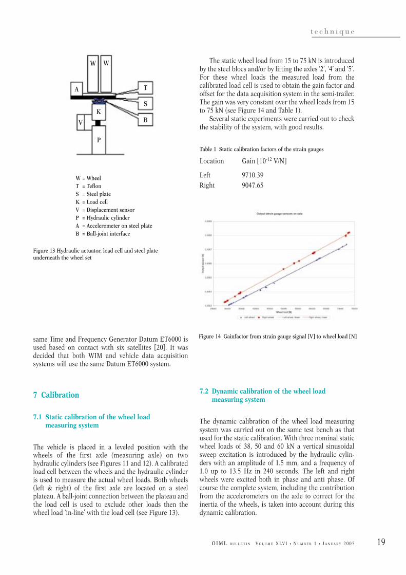
The static wheel load from 15 to 75 kN is introducedby the steel blocs and/or by lifting the axles ‘2’, ‘4’ and ‘5’.For these wheel loads the measured load from thecalibrated load cell is used to obtain the gain factor andoffset for the data acquisition system in the semi-trailer.The gain was very constant over the wheel loads from 15to 75 kN (see Figure 14 and Table 1).
Several static experiments were carried out to checkthe stability of the system, with good results.
Table 1 Static calibration factors of the strain gauges
Location Gain [10-12 V/N]
Left 9710.39Right 9047.65
7.2 Dynamic calibration of the wheel loadmeasuring system
The dynamic calibration of the wheel load measuringsystem was carried out on the same test bench as thatused for the static calibration. With three nominal staticwheel loads of 38, 50 and 60 kN a vertical sinusoidalsweep excitation is introduced by the hydraulic cylin-ders with an amplitude of 1.5 mm, and a frequency of1.0 up to 13.5 Hz in 240 seconds. The left and rightwheels were excited both in phase and anti phase. Ofcourse the complete system, including the contributionfrom the accelerometers on the axle to correct for theinertia of the wheels, is taken into account during thisdynamic calibration.
same Time and Frequency Generator Datum ET6000 isused based on contact with six satellites [20]. It wasdecided that both WIM and vehicle data acquisitionsystems will use the same Datum ET6000 system.
7 Calibration
7.1 Static calibration of the wheel load measuring system
The vehicle is placed in a leveled position with thewheels of the first axle (measuring axle) on twohydraulic cylinders (see Figures 11 and 12). A calibratedload cell between the wheels and the hydraulic cylinderis used to measure the actual wheel loads. Both wheels(left & right) of the first axle are located on a steelplateau. A ball-joint connection between the plateau andthe load cell is used to exclude other loads then thewheel load ‘in-line’ with the load cell (see Figure 13).
Figure 13 Hydraulic actuator, load cell and steel plate underneath the wheel set
Figure 14 Gainfactor from strain gauge signal [V] to wheel load [N]
W = WheelT = TeflonS = Steel plateK = Load cellV = Displacement sensorP = Hydraulic cylinderA = Accelerometer on steel plateB = Ball-joint interface
W
A
V
K
P
T
S
B
W

20
t e c h n i q u e
O I M L B U L L E T I N V O L U M E X LV I • N U M B E R 1 • J A N U A R Y 2 0 0 5
Accuracy of the system according to EA-4/02
The total accuracy of the measuring system was derivedfrom the contribution of each and every element used inthe calibration, according to EA-4/02.
The deviation in the measured load and the ‘real’load is:
∆F = Fi – Fd + δFd,dev + δFd,unc + δFd,repro + δFd,drift + δFd,temp
Where:
∆F deviation in reading value at the measuringsystem (indicator)
Fi load, measured with the measuring system(indicator)
Fd load, measured with the calibrated load cellδFd,dev deviation of the load cell mentioned in the
certificateδFd,unc deviation in the uncertainty of the load cell
according to the certificateδFd,repro deviation from the reproducibilityδFd,drift deviation from the drift of the systemδFd,temp deviation from the temperature drift of the
system
The standard uncertainty ‘u’ of the deviation in ∆F isderived from the uncertainty in each element. Table 2shows the uncertainty contribution of the elements.
According to the certificates the deviation of the leftload cell ‘δFd,dev,(left)’ differs from the deviation of rightload cell ‘δFd,dev,(right)’.
Deviation from the reproducibility ‘δFd,repro’ wasderived from the dynamic measurements on the testbench.
Deviation from the drift of the system ‘δFd,drift’ wasderived from a 24-hour static load to the system.
Accelerometers were mounted on the steel plateau tocorrect the measured load from the load cells for theinertia of the steel plate.
An example of the corrected data of the loadmeasuring system underneath the wheels and thecorrected data from the axle sensors is shown inFigure 15. The data is analyzed for uncertainty factorsthrough the bandwidth of 1.0 to 13.5 Hz.
Figure 15 Right wheel, sinusoidal sinus sweep at 38 kN left and right wheel in phase
Parameter Standard uncertainty [N] Sensitivity Uncertainty participation [N]
Fi 3 / √12 1 0.87
Fd 3 / √12 1 0.87
δFd,dev,(right) 0.8 ⋅ 10-2 ⋅ F / √12 1 0.23 ⋅ 10-2 ⋅ F
δFd,dev,(left) 0.9 ⋅ 10-2 ⋅ F / √12 1 0.26 ⋅ 10-2 ⋅ F
δFd,unc 0.25 ⋅ 10-2 ⋅ F / 2 1 0.125 ⋅ 10-2 ⋅ F
δFd,repro R ⋅ 10-2 ⋅ F / 2 1 0.5 ⋅ R ⋅ 10-2 ⋅ F
δFd,drift (62.5 – (– 62.5)) / √12 1 36.1
δFd,temp NIHIL 1 0
Table 2 Uncertainty contribution of the elements at 38 kN
21
t e c h n i q u e
O I M L B U L L E T I N V O L U M E X LV I • N U M B E R 1 • J A N U A R Y 2 0 0 5
8 References
[1] CBS, (2000), Centraal Bureau voor de Statistiek,‘Kerncijfers 2000’, Cat. Verkeer, Vervoer enCommunicatie, www.cbs.nl/nl/cijfers/kerncijfers
[2] Cebon, D. (1999), ‘Handbook of Vehicle-RoadInteraction’, Part 2 ‘Vehicle Dynamics’, Chapter 8,ISBN 9026515545, Swets & Zeitlinger BV, Lisse,The Netherlands
[3] Dolcemascolo, V. and Jacob, B., (1998), ‘MultipleSensor Weigh-in-Motion: Optimal Design andExperimental Study, COST 323, 2nd EuropeanConference, Lisbon
[4] EA-4/02 (1999), ‘Expression of the Uncertainty ofMeasurement and Calibration’, Publication fromthe European Co-operation for Accreditation,www.european-accreditaion.org
[5] Huhtala, M., Halonen, P. and Miettinen, V., ‘ColdEnvironmental Test at Lulea: Calibration of WIM-systems using an instrumented Vehicle, COST 323,2nd European Conference, Lisbon
[6] Gillespie, T.D. and Karamikas, S.M., (1996),‘Feasibility of Multiple sensor Weighing forincreased Accuracy of WIM’, University ofMichigan Transport Research Institute, USA
[7] Gonzalez, A., Papagiannakis, A.T. and O’Brien,E.J., ‘Evaluation of an Artificial Neural NetworkTechnique Applied to Multiple-Sensor Weigh-in-Motion Systems’, University College Dublin,Ireland
[8] Helg, C. and Pfohl, L., (2000), ‘Signal ProcessingRequirements for WIM-Lineas type 9195’, KistlerInstrumente AG, Winterthur, Switzerland
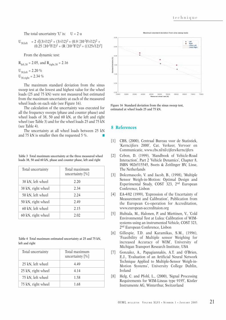
The total uncertainty ‘U’ is: U = 2 u
U38,left = 2 √[(3/√12)2 + (3/√12)2 + (0.9 ⋅ 10-2F/√12)2 +(0.25 ⋅ 10-2F/2)2 + (R ⋅ 10-2F/2)2 + ((125√12)2]
From the dynamic test:
Rleft,38 = 2.05, and Rright,38 = 2.16
U38,left = 2.20 % U38,right = 2.34 %
The maximum standard deviation from the sinussweep test at the lowest and highest value for the wheelloads (25 and 75 kN) were not measured but estimatedfrom the maximum uncertainty at each of the measuredwheel loads on each side (see Figure 16).
The calculation of the uncertainty was executed forall the frequency sweeps (phase and counter phase) andwheel loads of 38, 50 and 60 kN, at the left and rightwheel (see Table 3) and for the wheel loads 25 and 75 kN(see Table 4).
The uncertainty at all wheel loads between 25 kNand 75 kN is smaller then the requested 5 %. K
Total uncertainty Total maximum uncertainty [%]
38 kN, left wheel 2.20
38 kN, right wheel 2.34
50 kN, left wheel 2.24
50 kN, right wheel 2.49
60 kN, left wheel 2.15
60 kN, right wheel 2.02
Table 3 Total maximum uncertainty at the three measured wheelloads 38, 50 and 60 kN, phase and counter phase, left and right
Table 4 Total maximum estimated uncertainty at 25 and 75 kN,left and right
Total uncertainty Total maximum uncertainty [%]
25 kN, left wheel 4.49
25 kN, right wheel 4.14
75 kN, left wheel 1.58
75 kN, right wheel 1.68
Figure 16 Standard deviation from the sinus sweep test, estimated at wheel loads 25 and 75 kN.
22
t e c h n i q u e
O I M L B U L L E T I N V O L U M E X LV I • N U M B E R 1 • J A N U A R Y 2 0 0 5
[15] WAVE, (2001), Report on Work package 1.1‘Multiple Sensor WIM’, DG VII – Transport 4th
Framework Programme, RTD-project, RO-96-SC,403
[16] Loo, F.J. van; Visser, G., ‘Instrumented Vehicle forDynamic Calibration of a Multi Sensor Weigh-in-Motion System’
[17] 8th ISHVWD, March 2004[18] KALIBRA International B.V.; ‘Overeenkomst
betreffende de bouw van apparatuur t.b.v. dekalibratie van het WIM/Hand-systeem van deDienst Weg- en Waterbouwkunde (DWW)’; (InDutch) KAL/GV/14_05
[19] Hoogvelt, RBJ; Ruijs, PAJ; Zanten, RW van;Evendinck, C van, ‘Meetsysteem ten behoeve vanhet WIM-Hand Kalibratievoertuig’; (In Dutch)TNO-rapport 03.OR.VD.042.1/RH; August 4, 2003
[20] Jong, Gerrit de; ‘De selectie van een GPSdisciplined Time Code Generator voor een movingplatform’ (In Dutch)
[21] NMI-rapport GPSTimeGenRprt_R1.doc; NMi VanSwinden Laboratorium; November 19, 2002
[9] Hoogvelt, B., (2004), ‘Measurement Technology fora Calibration Vehicle for Weigh-in-Motionsystems’, 8th International Symposium on HeavyVehicle Weights and Dimensions, South Africa
[10] Kuiper, E. (2000), ‘WIM-Hand Kalibratie’, TNO-report 00.OR.VD.043.1/EK, TNO Automotive, inDutch
[11] Kunz, J. (1999), ‘Crystal Clear Quartz Based WIM-sensors’, Article in Traffic TechnologyInternational Aug/Sept 1999
[12] Loo van, F.J., (2001), ‘Project WIM-Hand, 1stinterim report’, DWW-Publication: IB-R-01-09,Road and Hydraulic Engineering Institute, DGRijkswaterstaat
[13] Loo van, F.J., (2003), ‘Project WIM-Hand, 2ndinterim report’, DWW-Publication: IB-R-03-57,Road and Hydraulic Engineering Institute, DGRijkswaterstaat
[14] Saan, J.G., and Loo van, F.J. (2002), ‘Weigh-in-Motion projects in the Netherlands’, 3rd
International Conference on Weigh-in-Motion,Orlando, Florida, USA
Author contact details
Boudewijn Hoogvelt TNO Automotive, Delft, The NetherlandsPhone: +31 (15) 269 6411; Email: [email protected]
Nol van Asseldonk Kalibra International B.V., Delft, The NetherlandsPhone: +31 (413) 293 592; Email: [email protected]
Ronald Henny Road and Hydraulic Engineering Institute of the Dutch Ministry of Transport,Public Work and Water Management (DWW), Delft, The NetherlandsPhone: +31 (15) 251 8381; Email: [email protected]
Hans van Loo Road and Hydraulic Engineering Institute of the Dutch Ministry of Transport,Public Work and Water Management (DWW), Delft, The NetherlandsPhone: +31 (15) 251 8381; Email: [email protected]
Gerben Visser Kalibra International B.V., Delft, The NetherlandsPhone: +31 (15) 2780111; Email: [email protected]

23
e v o l u t i o n s
O I M L B U L L E T I N V O L U M E X LV I • N U M B E R 1 • J A N U A R Y 2 0 0 5
Abstract
A couple of years ago ISO CASCO launched a majorproject of transforming all the existing ISO Guides onconformity assessment into a comprehensive series ofISO 17000 standards, which are now at various stages ofdevelopment. As the concept of traceability under-pinning all measurements has been a basic mission ofmetrology, a number of these standards have a directbearing on metrology. The series is logically based on adefinition standard, ISO 17000, giving, among others,guidance as to which activities fall under conformityassessment. The fact that calibration does not mighthave important consequences which must yet beassessed.
A controversial discussion on some issues has beenin progress concerning ISO 17011 on accreditationbodies which touches both on national metrologyinstitutes (NMIs) with an accreditation function and oncalibration laboratories at large. ISO 17040 on peerreview could be used with an advantage to supportmutual recognition arrangements among a limitednumber of bodies of a specialized expertise (e.g. CIPMMRA among NMIs under the Metre Convention). ISO17025 has been the most important standard for themetrology community and it is now undergoing a majoroverhaul taking on board the uncovered requirementsfrom ISO 9001:2000. These changes might have a greatimpact on quality systems in laboratories. ISO9001:2000 can be easily cross-referenced with ISO 17025but accreditors, in pursuance of their business interests,would prevent it from happening. The author is amember of the corresponding ISO CASCO WG 25responsible for this revision. We are now confrontedwith a proliferation of ISO 9000:2000-based standards
(clones), some of them requiring accreditation as nearlythe only way to demonstrate technical competence (e.g.ISO TS 16949). This paper will discuss alternative waysto achieve that.
In general, the paper will give up-to-date informationon the developments outlined above and discuss theconsequences and further steps from the viewpoint ofmetrology.
1 Introduction
Progress in metrology has always been largely driven byresearch and development of new solutions andtechnologies in relation to methods and instrumen-tation. In maintenance of measurement infrastructure,traceability of measurement results and relatedcalibration of measuring instruments used play a crucialeven if sometimes underestimated role: they provide along-term information on metrological characteristicsof instruments, enable their fitness for the given purposeto be assessed and to maintain various processes undercontrol. Recently, due to globalization, internationallyaccepted uniformity in measurement and equipmentcalibration to globally accepted norms is gainingimportance. By a rather broad definition of conformityassessment in ISO Guide 2:1996, calibration (and testingas well) was included among conformity assessmentactivities (CAA) and it is therefore essential for themetrology community to keep an eye on the develop-ment in this area. A couple of years ago, ISO CASCOlaunched a major project to cover all the CAAs by full-fledged ISO International Standards and thus toovercome the existing fragmentation in terms of variousguides of an inferior status. The paper aims at providingup-to-date information on the status of work within thisproject from the viewpoint of metrology.
2 Conformity assessment and management systems
Initially, it is important to highlight the relation betweenconformity assessment and management systems(sometimes wrongly reduced to quality managementsystems only). The whole conformity assessmenthierarchy is schematically given in Figure 1. The basicprinciple here is that technical competence of variouscertification bodies which is most important for theircorrect performance should be assessed by (mostlynational) accreditation bodies (NABs) - the processcalled accreditation. These certification bodies in turn
CONFORMITY ASSESSMENT
Conformity assessment andmetrology: Where to go in the future?
PAVEL KLENOVSKY
CIML Member, Czech Republic

24
e v o l u t i o n s
O I M L B U L L E T I N V O L U M E X LV I • N U M B E R 1 • J A N U A R Y 2 0 0 5
bodies for QMS acting through their national sub-sidiaries. The situation is more complicated in relationto calibration and testing (includes also variouschemical analyses). These activities were includedamong CAAs by way of ISO Guide 2:1996, a guide ondefinitions of conformity assessment related terms,where the following definition was given in par. 12.2:“Conformity assessment is any activity concerned withdetermining directly or indirectly that relevant require-ments are fulfilled” (see also Annex 1). Whereascalibration and testing are typical determinationactivities they do not include, by definition, anydecision-making (see below). The direct result of thisunnecessarily broad definition is inclusion of calibrationand testing laboratories among CABs subject toaccreditation.
As far as the coverage of CAAs by standards isconcerned, it is still done by a number of fragmenteddocuments not possessing the status of an internationalstandard (mainly ISO Guides) or by regional standardsnot harmonized worldwide. A couple of years ago, thiswas identified by ISO CASCO as a major deficiency anda large project was launched to transfer all therequirements to full-fledged ISO/IEC standards.Currently, the following main standards are at variousstages of development under ISO CASCO:J ISO/IEC 17000: Conformity assessment –
Fundamentals and vocabularyJ ISO/IEC 17011: Conformity assessment – General
requirements for bodies providing assessment andaccreditation of conformity assessment bodies
should then assess various objects of conformityassessment, such as management systems (qualitymanagement systems - QMS, environmental manage-ment systems - EMS, occupational health and safety -OH&S), personnel, products etc. - the process calledcertification (in the USA called registration, at least inrelation to QMS). Formerly, the way of making thisassessment could be described as an analysis ofconformance to specified requirements; nowadays, afterthe major revision of the ISO 9000 series of standards,the focus here should be better described as customersatisfaction. Both the above processes are basicallyaimed at demonstration as to whether specifiedrequirements are fulfilled (should be finalized by astatement to this effect), i.e. they fall among CAAs. ACAA should therefore contain the following threephases:
J Selection (preparatory phase);
J Determination (development of complete informa-tion on the object);
J Review and attestation (evaluation of the informa-tion and making a decision).
There is no question that accreditation and variouscertification bodies fall among conformity assessmentbodies (CABs). i.e. bodies performing CAAs - all of thesethree phases are present. All the CABs with theexception of accreditation bodies should therefore beaccredited - this is unfortunately not always the case,especially in the case of some globalized certification
NABs
Conformity assessment bodies
Objects of conformity assessment(e.g. management systems - QMS, EMS)
Certification
Accreditation
Basic aim
Technical competence
Customer satisfaction(formerly conformance
to requirements)
Figure 1 Current structure of conformity assessment and its relation to management systems

25
e v o l u t i o n s
O I M L B U L L E T I N V O L U M E X LV I • N U M B E R 1 • J A N U A R Y 2 0 0 5
role as service-oriented activities with customersatisfaction as a main priority. Namely, no decisions aretaken and no assessments are by definition made whencarrying out these activities in the majority of cases andno standard against which to assess conformity is oftenavailable (especially in calibration), not to mention theambiguity generated by uncertainties always attached tothe results of both the processes (see the definition ofcalibration in VIM - Annex 1). Therefore the concept ofimpartiality has no real sense at least in relation tocalibration - no conflicting interests can be attached toitems under calibration in a vast majority of cases (incontrast to verification of legally controlled measuringinstruments which is CAA).
The representative of ILAC on the correspondingISO CASCO working group WG 5 has kept to argueotherwise and the wording has gone back and forthseveral times as it is demonstrated in sequential order inAnnex 1. In final stages the definition in the “non-flexible” version remains unchallenged and in the FDISversion calibration is not included in the note under thisterm (NOTE 1). But it does not prevent WG 18 of ISOCASCO from making an attempt to extend conformityassessment by calibration in ISO/IEC FDIS 17011 -eventually, it was concluded at the joint meeting of bothWG in July 2004 that ISO FDIS 17000 remains as it isand ISO FDIS 17011 will be editorially changed to be inline with the definition of CAA in ISO 17000 (calibrationis only an associated activity). In this relation it has to bepointed out that at the 22nd General Conference ofWeights and Measures in 2003 the official Governmentdelegations agreed to note in Resolution N thatcalibration is not a conformity assessment activity - thisclearly demonstrates the position of the metrologycommunity on this issue. The target date for publicationof this standard is February 2005.
There is another point to be made in this context. Onthe one hand, accreditors argue that due to the reason ofimpartiality accreditation bodies have to be set up asnational monopolies and on the other hand accredita-tion of laboratories forms ca. 80 % of their capacity andrepresents a huge number of bodies (in Europe well over10 000). At the same time calibration and testing arenormal business activities, to a great deal outside anyregulatory framework (as to calibration, 100 % outside).Firstly, under the circumstances, it is difficult to imaginea totally impartial attitude of accreditors towards anyissues connected with (quality) management systems inlaboratories. The opposition to a straightforward defini-tion of conformity assessment without any technicalreason, as described above, might serve as evidence ofsuch an approach. Secondly, a sheer number of bodies,largely small and medium enterprises, find their accessto the market being quite sensitive to quality-relatedissues through this highly monopolized arrangement -obviously something next to a new barrier to trade.
J ISO/IEC 17020: Conformity assessment – Generalrequirements for bodies performing certification ofproducts
J ISO/IEC 17021: Conformity assessment – Generalrequirements for bodies providing assessment andcertification for management systems
J ISO/IEC 17024: Conformity assessment – Generalrequirements for bodies operating certification ofpersons
J ISO/IEC 17025:1999 General requirements for thecompetence of testing and calibration laboratories
J ISO/IEC 17040: Conformity assessment – Generalrequirements for peer assessment of conformityassessment bodies
As decision-making should be present in CAAs it isimportant to formulate some rules for impartiality ofCABs - the first attempt was made in 2003 through draftISO PAS 17001. In the process of development of thesestandards it is crucial, on the part of ISO CASCO, toensure, to a maximum extent, an impartial approach aspotential vested interests (already present) of variousparties involved could negatively influence the outcome.All the standards should also be properly inter-relatedand cross-referenced consistently using the terminologygiven by ISO/IEC 17000.
From the view point of metrology, the mostimportant ones are 17000, 17011, 17025 and 17040.
2.1 ISO/IEC 17000
This basic definition standard has eventually reached afinal, FDIS, stage whereas a part of the controversy hasbeen centered around the pivotal term “conformityassessment”. It has been argued from the beginning thata broad, flexible definition like “any activity concerned”in line with that given above is not consistent with anyreasonable rules of procedure and with the generallyaccepted understanding of this term as outlined inAnnex A (informative) “Principles of conformity assess-ment”, i.e. the three phases given above. As a result,calibration and testing should cease to formally be CAAsand the term “calibration” would not be mentionedamong CAAs in the note attached to this term. Theoutcome has a comparatively large bearing on calibra-tion (and testing) because it will set down the relation-ship of these activities to accreditation for a number ofyears to come, especially whether their managementsystem will be subject to accreditation following theirinclusion among CAAs or to certification stressing their
26
e v o l u t i o n s
O I M L B U L L E T I N V O L U M E X LV I • N U M B E R 1 • J A N U A R Y 2 0 0 5
The calibration part of their scope can be covered byaccreditation against ISO/IEC 17025 but the rest of theactivities should be covered by the ISO 9000 series ofstandards. This de facto implies operation of two qualitysystems in one body, independently audited andindependently paid if the body needs to cover all theactivities by a quality system. To overcome this problemthe standard is structured as follows:
J Management requirements (in fact qualitymanagement requirements from ISO9001/9002:1994 + a requirement of impartiality);
J Technical requirements (typical metrologicalrequirements).
In that way, the requirements of the ISO 9000:1994series of standards form a sub-set of all the requirementsof ISO 17025 and a full alignment can justifiably beclaimed.
However, just after the standard was implemented bylabs the necessity arose to align it with the majorrevision of the ISO 9000 series of standards released in2000 with a transition period by the end of 2003. That iswhy the responsible CASCO/WG 25 launched, at the endof 2001, a project of aligning ISO 17025 with ISO9001:2000, ideally to finalize it by the end of the ISO9000 transition period. It has to be pointed out here thatthe project could wait for a regular revision of ISO17025 planned, according to the ISO rules, for 2004 (5years after the publication of the current version) - theproject was mainly accelerated by accreditors beingafraid that the market of labs, so to speak, would betapped by certifiers of QMS if the alignment was notachieved in time.
First of all, it has to be pointed out here that bothstandards can be easily cross-referenced: ISO 9001 canstipulate that when the process of calibration or testingis present the requirements of ISO 17025 shall befulfilled, ISO 17025 having been stripped to contain onlythe technical requirements. This is perfectly in line withthe fact mentioned above that both activities are not realCAAs - only that accreditors will not make it happen atany cost.
Just at the beginning the WG adopted the followingprinciples for the alignment:
J ISO/IEC 17025 is not a sector specific applicationstandard of ISO 9001;
J ISO/IEC 17025 should be a stand-alone standard;J ISO/IEC 17025 should not adopt the ISO 9001:2000
wording as it is;J The reference to ISO 9001 should not be lost in
ISO/IEC 17025;J The changes in ISO/IEC 17025 should be as
minimal as possible;
2.2 ISO PAS 17001
In April 2003 CASCO/WG 23 released this special type ofa normative document (PAS - Publicly Available Specifi-cation), often an infant stage of an internationalstandard, on impartiality and related bodies, i.e. bodieslinked in a specified way to a body whose impartiality isunder consideration. According to the draft, e.g. differ-ent Government agencies are related bodies and inClause 5.2.3 it was required that in the absence ofcomplete legal and ownership separation of consultancyand conformity assessment functions, the body shall notprovide conformity assessment services to customers towhich itself or a related body has provided consultancyrelated to the object of conformity assessment withinthe past 2 years. This limitation on parallel provision ofconsultancy and a CAA, apart from not being able to bereasonably implemented in practice, can e.g. preventnational metrology institutes from doing what they havebeen set up to do, i.e. to provide consultancy to industryfor the purposes of technology transfer if calibration isconsidered a CAA. Due to strong opposition the drafthad to be amended but this example clearly demon-strates the importance of the whole matter: the inclusionof calibration among CAAs has the unacceptableconsequence that bodies with a calibration functioncould potentially be subject, by way of various ISOCASCO normative documents, to a number of require-ments that are totally inappropriate for them - and theprocess can easily pass by totally unnoticed by themetrology community. The target date for publication ofthis normative document was May 2004.
2.3 ISO/IEC 17025
This important standard for laboratories was actuallythe first in the whole 17000 series, released in 1999 andovercoming the then existing fragmentation of relatedstandards worldwide. Apart from harmonization, anadditional benefit was its alignment with the corres-ponding quality management standards at that time(ISO 9000:1994 series). Indeed, there is a problem in thefact that the current structure of quality-relatedstandards does not correspond to typical scopes ofbodies with a calibration function in real life which areas follows:
J National metrology bodies: maintenance anddevelopment of national standards + correspondingcalibrations;
J Manufacturers of measuring instruments or of anyother products (manufacture + calibrations);
J Repairs + calibrations of measuring instruments.

27
e v o l u t i o n s
O I M L B U L L E T I N V O L U M E X LV I • N U M B E R 1 • J A N U A R Y 2 0 0 5
As a result, the statement of alignment with ISO9001:2000 (clause 1.6) had to be changed as well, from afull alignment (with the 1994 version) in the currentstandard to mere “meeting the principles” of ISO9001:2000. But again, confusion has been generated bydoing that: the process approach happens to be one ofthe eight main principles of the ISO 9000:2000 series ofstandards so that even this weaker statement aboutprinciples can be challenged (and confusion is generatedhere) as the process approach happens to be one of theeight main principles of the major revision. This isarguably the worst possible outcome to arrive at: nearlyall the important requirements from ISO 9001:2000which are not easily implemented by labs were taken onboard but still the standard will explicitly state that thisis not a full harmonization with ISO 9001. For stand-alone labs the whole project is completely unwanted(they will probably have to be reaccredited afterwards)and larger organizations will probably not be sparedmultiple assessments, exactly as apprehended by someassociations of labs (EUROLAB). It is basically the resultof the approach enforced by accreditors to keep bothstandards as far as possible from each other - in such away the alignment fell victim to the self interests ofaccreditors. The only problem is that labs may sufferfrom such attitudes.
The schedule of next steps was as follows: the finalWG draft had gone right away to the DAM stage whichwas in November 2003 presented for comments andvoting to national standards bodies (NSB) with adeadline of April 2004. In June the WG met to settle thecomments received - due to a largely positive voting theproject went to the FDAM stage in summer 2004 withoutmajor changes even if some confusions still persist (e.g.the claim of meeting “the principles” of ISO 9001:2000,QMS, etc.). In an attempt to win positive votes ISO DIS17025 was presented as an interim solution before a fullalignment. But at the same time WG 25 decided topropose it to the ISO General Secretary as a regularrevision of the standard due in 2004 (see above) - theproposal has been finally approved. The result is that afull harmonization with ISO 9001:2000 can be expectedsometimes in 2011-2012 (the regular revision shouldstart in 2009), i.e. a standard based on the 1994 versionof ISO 9000 and presented as an interim solution willstill be around nearly 10 years after the 1994 versionexpires.
In summary, the WG was instructed (or decided) toachieve the following goals:
J To align ISO 17025 with ISO 9001:2000;J To make only minimal changes in ISO 17025.
The proposed changes to be implemented by labs arenot at all minimal and a full alignment is not achievedeven if an attempt is made to cover it up. As both these
J No changes should be made to the technicalrequirements of ISO/IEC 17025.
These principles are fully in line with the interests ofaccreditors themselves - representatives of accreditationbodies have more or less dominated the attendance ofthe WG. They claimed that it was the opinion oflaboratories as well - maybe rightly so but it was takenfor granted by labs that the full alignment would beachieved (see e.g. the standpoint of EUROLAB).Moreover, the terms of reference set up in this way areby themselves internally controversial: it is difficult toimagine how a full alignment with the major revision ofISO 9000 could be achieved by only minimal changes.
Furthermore, a discussion took place regarding theuse of the term “quality management system” from ISO9000 in ISO 17025. The convenor (Mr. van de Leemputof RvA, the accreditation body of The Netherlands)explained that the management system in labs is notonly about quality requirements but also someadministrative and technical requirements are involved,i.e. that it is not exactly what is meant by ISO 9001:2000so that the term cannot be used in ISO 17025. Thisstandpoint can be challenged: these additionalrequirements can be viewed as an extension or moredetailed specification of general generic requirementscontained in ISO 9001:2000 in application to a specialsituation of labs.
The main point of discussions in WG 25 was theextensive expression of views on the crucial statement inthe “Introduction” which, after a lengthy discussionbetween ISO TC 176 (responsible for ISO 9000) and theWG 25 convenor and ISO CASCO Secretariat, before thefinal meeting on the DAM (Draft Amendment) of thisstandard read:
Conformity of the quality management system withinwhich the laboratory operates to the requirements ofISO 9001 does not of itself demonstrate thecompetence of the laboratory to produce technicallyvalid data and results. Nor does demonstratedconformity to this international standard implyconformity of the quality management system withinwhich the laboratory operates to all the requirementsof ISO 9001. For this reason, this internationalstandard may be used in conjunction with, but notto substitute certification of the quality managementsystem within which the laboratory operates.WG 25 members tried to persuade the TC 176 (Mr.
Chris Cox was present) that the second and thirdsentences be removed. Eventually, the third sentencewas removed while TC 176 firmly stood on the inclusionof the second one: namely, it is in line with the currentISO/IEC rules for technical work as the alignment is notcompletely full (e.g. the process approach has not beenaddressed) - it is the unhappy result of the “minimalchanges” approach (see above).

28
e v o l u t i o n s
O I M L B U L L E T I N V O L U M E X LV I • N U M B E R 1 • J A N U A R Y 2 0 0 5
and similar but less dismal results have been achievedrepeatedly in the long-term. It is under the circum-stances when accreditation is around for more than 10years and no demand for any urgent corrective actionshere seems to be imminent. The conclusion from here isthat while accreditation is an acceptable way to formallytake care of the technical competence of a huge numberof bodies (on behalf of regulatory bodies) its technicaladded value is arguably rather doubtful, at least atpresent. The target day for publication of this standardis March 2005.
2.5 ISO/IEC 17040
Lets us start with the definitions of related terms takenfrom ISO CD 17040:
peer group (3.3) – group pf conformity assessmentbodies with rules of membership of the group (further referred to as PG).
NOTE A peer group could form an agreement groupas defined in ISO/IEC Guide 68.
peer assessment (3.4) – evaluation of a body, againstspecified requirements, by representatives of otherbodies in, or candidates for, a peer group (furtherreferred to as PA).
NOTE “Candidates” are included to cater for thesituation where a new group is being formed, at which time there would be no bodies in the group.
The ISO CD 17040 uses, strictly speaking, the term“peer assessment”, not “peer review” which is frequentlyused in this context.
The core of the problem in the scope of applicationof peer assessment (peer review) to quality systempractice consists in achieving a reasonable compromisebetween impartiality and expertise. Third partyassessment bodies in a broader sense (accreditation +certification bodies or simply quality audit providers)have a potential to be highly impartial in technicalmatters (but, on the other hand, they seem to beexcessively dependent on revenues collected from theircustomers) but often have a tendency to lose expertise inunderlying technical fundamentals of the activity underauditing. That is arguably the reason why they arerelying more and more on external experts who are oftenattached to similar and competing businesses. On theother hand, among peers, as the name indicates (=“equals”), the mutual confidence in their expertise isnaturally very high but the PG performance andcompetence might be challenged on the grounds ofimpartiality driven by excessive competition amongthem (e.g. trying to deny access to newcomers, etc.). It
objectives have obviously not been met (as explainedabove) it would be in the best interest of laboratories ifsuch a proposal receives a negative voting and a fullalignment is made during the regular revision of thestandard. The target day for publication of thisamendment is August 2005 but it could be expectedsooner (during the first half of 2005) - a transitionalperiod for its implementation is foreseen by ILAC.
2.4 ISO/IEC 17011
This standard, being in the final FDIS stage, should laydown the requirements for accreditation bodiesthemselves. In the initial stages of development aproposal was made by accreditors to put a requirementin the standard that accreditation bodies shall benational monopolies. This motion was rejected but it isan important concept to discuss - it may actuallyunderpin the attitudes and positions made byaccreditors in public. The reasons for this concept areeither securing a necessary impartiality in carrying outthis type of conformity assessment (an argument goingrather to an extreme - there are other situations, e.g. inlegal metrology, where decisions have to be made underconflicting interests) or that it is simply a requirement ofregulatory bodies (with which e.g. calibration hasnothing in common). Whatever the official reasons are,accreditation bodies are now set up as national mono-polies in all the ILAC member countries with theexception of the USA. Apart from apparent disad-vantages for their customers a monopoly position atleast gives accreditation bodies an ideal position forimpartial decision-making which should subsequentlyimply a major improvements in real technicalcompetence of laboratories. This effect can be assessedby an evaluation of results in interlaboratory com-parisons (ILCs) in the calibration area or proficiencytesting (PT) in the testing area achieved in the long-term. If this experience is anything to go by then thesituation in physical metrology (calibration labs) is quitegood, as it always has been, and the situation inmetrology in chemistry (a number of testing labs) is stillrather unsatisfactory, as it always has been (mainly dueto persistent problems with traceability, calculation ofuncertainties etc.) - no major improvement can beidentified. This can be demonstrated e.g. on the resultsof the so-called IMEP (International MeasurementEvaluation Program) comparisons having beenorganized by one of the EU research institutes IRMM inthe area of analytical chemistry where a number of labsfrom all across Europe regularly take part. Theinterpretation of this and other results simply is that ca.50 % of labs in this particular comparison failed and outof those who failed ca. 50 % were accredited labs - such

29
e v o l u t i o n s
O I M L B U L L E T I N V O L U M E X LV I • N U M B E R 1 • J A N U A R Y 2 0 0 5
will guarantee quality of experts, what are the costs ofaccreditation, etc., as it is already known from theimplementation of the CIPM MRA. Let us assume forthe moment that the MAA has been drawn up asmembership rules of the corresponding peer groupbased on peer assessment only. Then we should considerthe following:
J The necessary technical standard is available to beused by everybody interested (ISO/IEC 17025);
J The quality system experts and especially un-questionable technical experts are available as wellwithin the PG;
J The system could be made extremely cheapcompared with accreditation (reciprocity principle,subsequent assessments reduced in scope and time,taking into account the results of intercomparisons,etc.);
J The PG can in principle solve the problem of inter-national recognition within itself;
J The system will be simple, even-handed, transparent,streamlined, inexpensive and based on an inter-national standard (ISO 17040).
After the system is established accredited bodiescould enter membership on relaxed terms and couldthen stop seeking re-accreditations in future. Even theargument often given by accredited bodies that they arenot allowed by NABs to recognize external test reports issimply not valid - ISO/IEC 17025 in paragraph 4.5permits subcontracting of tests and calibrations onterms being in line with the PG rules of membership. Ofcourse, some additional work on necessary documentsshould have been undertaken in this respect but with aninfrastructure provided by the correspondingsupporting bodies (BIPM, BIML) it is manageable. Butsurely the uncertainty and confusion in the final stagesof the approval or during the implementation of thesearrangements in relation to quality systems should havebeen avoided. Therefore, there is a clear potential for awider application of peer assessment in the quality-related issues in metrology on the basis of this standard,maybe in a more simplified form. The target date forpublication of this standard is August 2005.
As to the use of the concepts of peer assessments andself-declaration/self-assessment in today’s practice thefollowing, to my knowledge, can be summarized:
J Peer assessment in the technical, not formal, sense isnow extensively used in practice of NABs in relationto the technical part of ISO/IEC 17025 whenaccrediting labs, even if there may be an impartialityconcern (the experts are often from competing labs).
J The same is basically applicable to the practice ofcertification bodies for QMS and this trend will bestrengthened by increased focus on real processes
may place a limit on the rate of their use in practice,especially in the environment generated by quality auditproviders against any use of PAs as it is sharply againsttheir vested interests. On the other hand, the externalexperts used by quality audit providers are often nothingless than people from competing businesses (very oftenmentioned to be the case in relation to laboratories) sothat, essentially, peers.
Nowadays, the main application of PAs is for NABsthemselves and in the field of CAAs in those cases whichare characterized by a very narrow and unique expertise.In the field of metrology the following are goodexamples of such a situation:
J Pattern evaluations and approvals of legallycontrolled measuring instruments as performed bynational legal metrology authorities (the corres-ponding mutual acceptance arrangement - OIMLMAA);
J Equivalence of and calibration to national standardsas performed by NMIs (the corresponding mutualrecognition arrangement - CIPM MRA).
A case study in itself is the situation around therecognition of pattern evaluation certificates worldwideinitiated some time ago in the OIML. The OIML hasundertaken, to that effect, to draw up a correspondingmutual recognition agreement called the MAA (MutualAcceptance Arrangement) under which test reportsissued by those national responsible bodies that arenotified as OIML Issuing Authorities, as a basis to issuecertificates, will be recognized by other countries andsubsequently used to issue their own certificates (thisslightly complex arrangement is necessary as in somecountries like the USA and Brazil, direct recognition ofcertificates is forbidden by law). Unlike the CIPM MRA,the MAA has not been implemented up to now1 - one ofthe crucial points is the assessment of the technicalcompetence of those labs. As is basically the case in theCIPM MRA, two options have been proposed: peerassessment (originally self-declaration) and accredita-tion. To form a PG or an agreement group was notconsidered at the beginning under pressure fromauthorities which testing labs were accredited (thereason: why prepare a dedicated procedure when asystematic accreditation tool is available and can, at thesame time, arrange for mutual recognition through theILAC MLA). Since the beginning, the CIML has beenembroiled in seemingly never ending discussionsconcerning what the meaning of peer-assessment or self-declaration is, the quality system issue as a whole, who
1 Editor’s note: This article was written when the FrameworkDocument on the OIML MAA (OIML B 10-1) had just beenpublished.

30
e v o l u t i o n s
O I M L B U L L E T I N V O L U M E X LV I • N U M B E R 1 • J A N U A R Y 2 0 0 5
accreditors and certifiers for a so to speak “laboratorymarket” is going on. To face this challenge ILAC, IAFand ISO CASCO even issued in 2003 a jointcommuniqué on their position towards the applicabilityof accreditation and certification to laboratories. Analternative position to the same problem from theviewpoint of a laboratory can be formulated on the basisof the facts and arguments given above.
It has been demonstrated above that crucialactivities in metrology are now subject, by way of ISOCASCO, to standardization which is influenced byvarious vested interests. Especially accreditors are quiteactive regarding standards of highest priority to them:ISO/IEC 17011, ISO/IEC 17025 - they dominate theattendance of the corresponding working groups, thedraft standards are simply written by them. ISO CASCOis unfortunately not able to guarantee a reasonabledegree of impartiality here. It is therefore in the bestinterest of the metrology community to closely pursuethe work in ISO CASCO and try to formulate and pressahead with its own agenda on these issues. The presentsituation when accreditors are in the habit of speakingon behalf of the metrology (laboratory) communityshould be challenged. Otherwise it can easily happenthat one day labs will wake up to a hostile environmentin which they will not be able to carry out their usualwork or pursue their missions.
As it is demonstrated above calibration (and testing,strictly speaking, as well) is not a true CAA. Therefore,accreditation is a legitimate approach to demonstratingthe technical competence of labs but it is not the onlyapplicable approach here. The other approaches can besummarized as follows:
J Client audits;
J Extensive participation in ILCs or PT schemes;
J Self-declaration supported by evidence from PT andILC programs with openly accessible results (furthersupported by e.g. client audits and by making openlyavailable a part of the QMS documentation, e.g. onthe internet);
J Peer assessment on the basis of ISO 17040 (e.g.within national associations of calibration and/ortesting labs, especially suitable for mutualrecognition arrangements among NMIs - CIPMMRA, OIML MAA);
J Certification against ISO/IEC 17025 or cross-referenced ISO 9001:2000 and ISO/IEC 17025 or ISO9001:2000 + ISO 10012.
At present accreditation is dominant here even ifthere are legitimate grudges against some aspects of itspractical implementation. Future developments willdepend on the overall price versus performance (addedvalue) ratio for laboratories. K
performed by certified bodies (without the properknowledge about them it will be difficult to auditthem).
J Big companies consider self-declaration of theirQMS as a viable alternative for the future (see theconclusions of the ILAC seminar in Germany in2002) as a response to the ever growing “certificationindustry” which annoys them (see the parallel to theglobal approach in Europe: it was forced through bybig companies like Philips being annoyed by multiplere-testing in all the countries). Such pressure exertedby big companies has eventually led to somethingcalled one-stop testing - similarly, what we now needin the calibration/testing area is (at least) one-stopcertification (all the existing processes certified atonce by one body).
J Self-declaration of manufacturers of products (withsome conditions attached like damage liability +market surveillance) lies in the core of the EU globalapproach to conformity assessment in the regulatedsafety area. Following this concept, we can imaginethat the technical competence of a calibration/testinglaboratory could be demonstrated by a certified QMS+ successful participation in PT or ILC schemes.
J Quality prize awards schemes like EFQM andBaldrige are based on self-assessment by way ofaccumulating an extensive amount of informationagainst given criteria (together with various objectivesurveys, studies and analyses) followed by anevaluation by a panel of experts (and this pool ofexperts consists of peers - equals - in a technicalsense, to a large extent).
As shown above, peers in the technical sense lie atthe core of QMS auditing performed by certifiers andself-declaration/self-assessment schemes are as wellrelatively extensively used with a potential of widerapplication in practice.
3 Summary
In general, bodies subject to certification/accreditationare now more and more concerned by the followingissues:J A real added value of any third party assessment in
the present mature situation;J An excessive dependence of certifiers/accreditors on
the financial side of the business sidelining thetechnical content;
J A hostile environment for small and mediumenterprises (SMEs) created by certifiers/accreditors. The experience from ISO CASCO working groups
indicates that behind the scene a fierce struggle between

31
e v o l u t i o n s
O I M L B U L L E T I N V O L U M E X LV I • N U M B E R 1 • J A N U A R Y 2 0 0 5
Annex 1: Definitions of terms - Conformity assessment and calibration
Conformity assessment (ISO/IEC Guide 2:1996, par. 12.2):
“Conformity assessment is any activity concerned with determining directly or indirectly that relevant requirements are fulfilled.”
Conformity assessment ( original ISO CD 17 000):
“Conformity assessment is the generic term used nowadays to mean any activity concerned in any way with checking or givingassurance that relevant requirements have been met.” After comments objecting to such a form of a definition being unnecessarily broad (see the words in bold) - it can therefore cover e.g.manufacture and repair of measuring instruments, special SW, etc. - it was argued that calibration (and “pure” testing labs making nodecisions) labs should not be a part of CABs. The Preliminary Draft of this standard then followed:
Conformity assessment (Preliminary draft ISO/IEC CD 17000, par. 3.1.1):
“Conformity assessment is development of information, comparison with specified requirements, decision on fulfillment ofrequirements by the object of conformity assessment (3.1.4) and communication of the decision.”During the WG 5 meetings the representative of accreditation bodies which are always present (Mr. Squirrel, ILAC) strongly argued thatif calibration is not a CA activity then the definition in the VIM should be changed (!). Due to the fact that other WG 5 members are notexperts in metrology the position of Mr. Squirrel has prevailed resulting in a new definition, basically going back to the original one:
Conformity assessment (ISO/IEC CD 17000, October 2001, par. 3.1.1):
“Activity or activities related to demonstrating whether or not an object of conformity assessment (3.1.2) fulfils or continues tofulfill specified requirements.”
3.1.2 Object of conformity assessment
“Product (including service), process, system, person or organization.”This definition has apparently not been accepted in voting by ISO CASCO members on a national level so that the wording has basicallyreverted to that of the Preliminary draft:
Conformity assessment (ISO/IEC CD 17000, May 2002, par. 3.1.1, DIS, February 2003, FDIS, December 2003, par. 2.1.1):
“Activity that provides demonstration that specified requirements relating to a product, process, system, person or body arefulfilled.”The last definition of CA is absolutely correct and clearly contradicts that of the term “calibration” in the VIM:
Calibration (VIM under 6.11):
“Calibration is a set of operations that establish, under specified conditions, the relationship between values of quantities indicatedby a measuring instrument, or values represented by a material measure or a reference material, and the corresponding valuesrealized by standards.”It is clear from this definition that during calibration:No requirements, especially in terms of limits or tolerances, are in most cases available (also no written standards are available);No decisions are made in the process or in the calibration certificate;No assessment whatsoever is made during the process.Then, calibration was mentioned in NOTE 1 only - maybe that everything put in notes might anyhow be virtually disregarded as inthe case of the ISO 9000 series of standards. In the DIS version calibration was not included in this note, on pressure from accreditorsit was included in the FDIS version as a related activity. As a matter of course, verification of measuring instruments in legal metrology as defined in the VIML:
Verification of legally controlled measuring instruments (VIML under 2.13):
“Verification of a measuring instrument is a procedure which includes the examination and marking and/or issuing of a verificationcertificate, that ascertains and confirms that the measuring instrument complies with the statutory requirements.”is a conformity assessment activity.Pure testing labs confined to issuing a test report only and not involved in any decisions should not be a CA activity as well - see thedefinitions:
Testing, test, testing laboratory (ISO Guide 2) in par. 13:
“Testing is an action of carrying out one or more tests.”“Test - technical operation that consists of the determination of one or more characteristics of a given product, process or serviceaccording to a specified procedure.”“Testing lab - laboratory that performs tests.”
32
e v o l u t i o n s
O I M L B U L L E T I N V O L U M E X LV I • N U M B E R 1 • J A N U A R Y 2 0 0 5
Abstract
The future of gas metering is determined by past,present and future developments in the areas ofmetrology, the economy and metering technology. Foreach of these areas, this paper will show currentdevelopments and also those that are likely to occur, orwhich users would like to see in the future. Thisoverview will cover metrological, economical andtechnological aspects.
Terminology related to measurement results can bedivided into two categories representing availableinformation and missing information, respectively. In thefirst catogory the reference value and deviation arefound and the latter category includes everthing thatleads to measurement uncertainty. Economically, thesupply of natural gas will be metered on an energy basis.New miniaturized, fast responding and cheap gascomposition measurements will contribute to thismarket demand.
Not only the development of new metering principlesand the improvement of existing principles areimportant, but also the measurement of flow profile,swirl, pulsations, acoustic noise, vibration and thethermodynamic properties of natural gases play a keyrole.
In the future, research on flow meters, energymeasurement, natural gas properties, disturbancetesting and new metrological phenomena will remaininteresting and challenging.
Introduction
Legal gas metering is the activity whereby gas meters areused to measure the amount of gaseous fuel orindustrial gases for custody transfer purposes, i.e.financial transactions for gas supplies and fiscalpurposes: taxes, levies and duties. Many counties havelegal requirements for gas meters that are based oncurrent OIML Recommendations R 6 [1], R 31 [2] andR 32 [3]. In most European countries these Recom-mendations were implemented in the context of weightsand measures legislation. In countries such as e.g. Japanand Australia, OIML Recommendations are imple-mented via standards that are compulsory for custodytransfer measurements. Countries that signed the OIMLtreaty have the moral obligation to implement OIMLRecommendations in their national legislation, theobjective being to establish coherent metrology legisla-tion, which renders trade between countries easier.
The current OIML Recommendations are technologyoriented: diaphragm meters R 31 [2], rotary piston andturbine gas meters R 32 [3], supported by generalprovisions R 6 [1]. For other technologies (e.g. ultra-sonic and coriolis) no Recommendations currently exist.Today, under Dutch legislation only diaphragm, rotarypiston and turbine meters are allowed for custodytransfer. Other meter types are possible but only via adispensation procedure, which takes approximately sixweeks longer to complete than a regular type approval.
With technology changing at an increasing pace itwill serve market interests if legislation is technologyindependent, a development that was recognized as oneof the key issues of the new Measurement InstrumentDirective (MID) [4] in the European Union. To this endthe current OIML Recommendations for gas meters areunder revision, which has resulted in a first CommitteeDraft [5], which is technology independent. Gas metersare generally part of an entire installation and so a newRecommendation for gas metering systems is beingdeveloped [6]. These new Recommendations necessarilyform a compromise between the dreams of experts andthe interests of participating countries. However, weknow that these are going to be revised in the future. Sotoday is an excellent starting point to dream about legalgas metering.
Walt Disney, famous for his creations of MickeyMouse and Donald Duck, used a method for his creativework that was later called the “Disney strategy”. Anyproblem is viewed from three different perspectives: thedreamer, the critic and the realist. The dreamer thinks ofanything that would be nice. Even the sky is not a limit.The critic tells why the new ideas are not possible or whythey are actually bad ideas. The realist looks at what canbe achieved and how problems can be solved. Whenchanging his perspective Walt Disney actually changed
GAS METERING
Dreams about legal gasmetering
JOS G.M. VAN DER GRINTEN
NMi Certin B.V., The Netherlands
This paper was originally given at the 4th InternationalSymposium on Ultrasonic Doppler Methods for Fluid Mechanicsand Fluid Engineering in Sapporo, on 6–8 September 2004. Theeditors of the OIML Bulletin and the author wish to thank theorganizers of the 4th ISUD for their kind permission to reprint it.

33
e v o l u t i o n s
O I M L B U L L E T I N V O L U M E X LV I • N U M B E R 1 • J A N U A R Y 2 0 0 5
vocabularies a number of terms exist that are notdefined in a quantitative way: accuracy, inaccuracy,precision, repeatability, reproducibility.
Some terms actually demonstrate the opposite oftheir intention. For example if we look at repetitivemeasurements for repeatability or reproducibility we willfind that the instrument shows small readingfluctuations that makes it not entirely repeatable orreproducible. In fact our search for repeatability leads tothe opposite. Consequently, repeatability and reproduci-bility are nowadays treated as uncertainty sources.
In this information era it is an idea to divide allterms into two categories. One group of termsrepresents available information. Here we have measuredvalue, reference value and deviation. The other group ofterms refers to missing information, i.e. measurementuncertainty. Here we can include all the terminologythat results in measurement uncertainty: repeatability,reproducibility, drift and uncertainty. Now it is also clearthat if a correction is not applied for a known deviation,this will result in an additional uncertainty. Terms suchas accuracy and inaccuracy have a little of bothcategories, which make them confusing. On one handaccuracy expresses a small deviation, on the other handan accurate instrument also has a low uncertainty. Theterm inaccuracy has the same ambiguity.
The concept of uncertainty as a measure of missinginformation has proven to be a very useful instrument tohelp people to master the basic concepts of metrology.An illustration of this idea with examples can be foundin a paper by the author [11].
Uncertainties cannot be avoided and that means thatthese play a role when taking measurement baseddecisions [12]. Examples are speeding tickets for peoplethat drive too fast and approval of instruments withrespect to legal tolerances. The probability that adecision is taken correctly is called confidence level. Theprobability of taking an erroneous decision is called risk,which is 1 – confidence level. If the instrument deviationequals the tolerance, then the probability of taking acorrect decision is 50 %. So the point of standardizationin legal metrology is the minimum confidence level (e.g.95 %) required for metrological decisions.
The economy
Apart from any metrological and technologicaldevelopments, the gas markets are liberalized in somecountries. As a result the trade and transport res-ponsibilities are split up into different companies. Gastransportation and gas distribution companies will notown the gas and receive only a fee for transporting the
seats and body posture in order to stimulate the new lineof approach in his thinking. For the purpose of thispaper we will concentrate on dreaming, criticism andrealism being left to one side for the time being. Sincegas metering is a combination of metrology, economyand technology, we will focus on our dreams concerningthese three areas.
Metrology
The first field of developments to be mentioned here ismetrological. Metrology is the science of takingmeasurements. In scientific metrology metrologistsfocus on the development of new standards or theimprovement of existing standards. Here, scientists aredreaming of a couple of new quantum phenomena thatwill contribute to the development of standards basedon fundamental physical constants. In industrialmetrology people working in research and developmentneed measurement standards to test the equipmentdeveloped. The focus here is the development of moreaccurate instruments. Legal metrologists focus not onlyon the application of measuring methods for custodytransfer purposes but also on the regulations requiredfor fair trade, health, safety, the environment andconsumer protection. A concise overview of the differentmetrology areas can be found in Metrology – in short [7],a publication issued by DFM, the Danish NationalMetrology Institute.
In the past decades metrology has undergone aparadigm shift, leading to the publication in 1993 of theGuide to the expression of Uncertainty in Measurement(GUM) [8]. The major implication of the GUM is thatuncertainties are part of the measurement results.Instead of saying the length of the table is 1.80 m, werepresent the length of the table by (1.80 ± 0.01) m,0.01 m being the measurement uncertainty.
Also terminology has changed. Terms like true valueand error have lost their practical significance inmetrology. Instead of error the word deviation is usedand true value is changed to value. The best-knownestimate of the value of a quantity is the reference valueobtained from a standard, which is used to determinethe deviation of an instrument reading. Maximumpermissible error is now better replaced by tolerance.
Terminology is an important aspect of the languagein which we communicate measurement results. Inmetrology there are currently two dictionaries thatcontain terminology and definitions that are currentlyagreed on in metrology. The Vocabulaire International deMétrologie (VIM) [9] is general to metrology; the other isthe Vocabulaire International de Métrologie Légale (VIML)[10], which is specific to legal metrology. In these

34
e v o l u t i o n s
O I M L B U L L E T I N V O L U M E X LV I • N U M B E R 1 • J A N U A R Y 2 0 0 5
Technology
The last decade has shown rapid technologicaldevelopments in the field of gas metering. Compared tothe existing diaphragm, rotary piston and turbine gasmeters a range of new metering technologies has beendeveloped. Ultrasonic meters and coriolis meters arenow used for custody transfer purposes, the lattermeasuring gas quantities in mass units. New meteringprinciples are being developed that have potential forcustody transfer measurements and existing mechanicalmeasurement principles will be upgraded with elec-tronics to add diagnostic and telemetric functions.Velocity based gas meters, such as the turbine gas meterand the ultrasonic meter will be able to compensateasymmetric velocity profiles and even swirl. Clamp-onmeters have been developed that are able to measure theflow rate from the vortex noise of the gas flowing in thepipeline [13].
Recently, manufacturers have endeavored to developcompact equipment to measure gas in energy units.Although the response time of miniaturized gas chro-matographs is much better than the existing process gaschromatographs [14], further miniaturization is to beexpected with almost real time determination of the gascomposition. From the gas composition the calorificvalue of the natural gas can be determined using the ISO6976 algorithm [15].
The technological and metrological challengesassociated with these developments are numerous. Asmany gas meters are sensitive to flow disturbances,velocity profiles, pulsations and acoustic disturbancesadequate tests need to be developed and standardized.Currently, only standardized tests exist for flow dis-turbances [3], [5]. Laser Doppler velocity profilemeasurements for these disturbance tests under high-pressure conditions are described in [16]. The objectiveof this study is to find flow conditioning methods. Thesemethods can be used to provoke in a straight pipe thevelocity profile and swirl corresponding to two out ofplane 90° bends. Such devices will actually reduce thecost of full-scale tests of large diameter gas meters underhigh-pressure conditions. Ultrasonic Doppler methodsare already used for instant determination of velocityprofiles in liquids [17].
The influence of pulsating flows [18] and pipevibrations [19] was investigated by TNO in TheNetherlands. These tests are not yet performed on aroutine basis as part of the product certification of flowmeters, but this is likely to change in the future.
A special chapter in technology is the determinationof the thermodynamic properties of natural gases. Todaythere are several standards to calculate the real gasfactors of natural gases from the full gas composition[20] or some components and the calorific value [21].
gas to the end user. As a result the gas balance of thesecompanies will obtain more attention, requiring moreaccurate gas meters.
Another consequence of the liberalized market isthat gas will be supplied from many more differentsources than today. As each source has a different gasquality with different calorific values there will be atendency to bill the supplied gas on an energy basis.However, normal gas appliances such as stoves andcentral heating boilers are not capable of handlingentirely different gas qualities. A stove manufactured fora calorific value of 35 MJ/m3 will be damaged if gas of42 MJ/m3 is used. So a constant gas quality is of import-ance to domestic users of natural gas. The solution hereis an intelligent pressure regulator that reduces the gaspressure on the appliances if a higher quality of gas issupplied. This will be possible after the development ofa new and miniaturized measurement method fordetermining the gas composition, which will be alsouseful for gas metering on an energy basis.
The prices of energy are expected to rise in the nearfuture and this will stimulate market demand for moreaccurate meters, new measurement principles, gasmeters that meter on an energy basis, automatic readingor telemetry via the internet, and gas meters withmultiple tariff registers.
However, there is another development that willrequire new metrological methods. The person thatmanufactures a product or provides services has todemonstrate that his products or services comply withregulations, standards and consumer specifications.Quality systems have been accepted as a means tocontrol design, production, and final product inspec-tion. Product malfunction will lead more and more toliability lawsuits, which involves high costs of lawyersand possible compensation payments. These paymentshave increased over the past decades and there is noindication that this tendency will change in the nextyears. Especially, the new economies will implementlegislation on liability according to principles that areused in other countries. The manufacturer wants toknow the risk he runs. Statistical and metrologicalmethods will be further developed to assist themanufacturer to maintain his risk at the preset level.
Manufacturers will act on a global market with localneeds. Language support will be of vital importance, notonly for documentation but also in interpreting errormessages that are transmitted in case of instrumentmalfunction or maintenance requests.
Consumers that are offered a free choice of gassupplier may become the owners of the gas meter, inwhich case they will become much more interested inpossible meter deviations and measurement uncertainty.Consumers will appreciate more and more clearinvoices based on transparent measurement systemsthat measure gas quantities traceably in energy units.

35
e v o l u t i o n s
O I M L B U L L E T I N V O L U M E X LV I • N U M B E R 1 • J A N U A R Y 2 0 0 5
[3] OIML R 32 (1989): Rotary piston gas meters andturbine gas meters, OIML, Paris, 1989.
[4] Measurement Instrument Directive, Directive2004/22/EC on measuring instruments, OfficialJournal of the European Union L135/1, 30 April2004.
[5] OIML TC 8/SC 8 (2004): Gas meters, FirstCommittee Draft of a Recommendation to replacethe existing R 6, R 31 and R 32, Secretariat TheNetherlands.
[6] OIML TC 8/SC 7 (2004): Measuring Systems forGaseous Fuel, Third Committee Draft of a newRecommendation, Secretariat: Belgium andFrance.
[7] BNM, CEM, CMI, DFM, IPQ, OFMET, PTB,SMIS, SMU, SP (2000): Metrology – in short,edited by Preben Howarth, DFM, Euromet projectno. 595, Lyngby Denmark, first edition 2000.
[8] BIPM, IEC, IFCC, ISO, IUPAC, IUPAP and OIML(1993): Guide to the expression of uncertainty inmeasurement (GUM), second edition,International Organization for Standardization,Geneva, 1995.
[9] BIPM, IEC, IFCC, ISO, IUPAC, IUPAP and OIML(1993): International Vocabulary of Basic andGeneral Terms in Metrology, VocabulaireInternational de Métrologie (VIM), bilingualedition, International Organization forStandardization, Geneva, 1993.
[10] OIML V 1 (2000): International vocabulary ofterms in legal metrology, Vocabulaire Internationalde Métrologie Légale (VIML), bilingual edition,OIML, Paris, 2000.
[11] Jos G.M. van der Grinten (1997): Recentdevelopments in the uncertainty analysis of flowmeasurement processes, 13th North Sea FlowMeasurement Workshop, Kristiansand, Norway,October 1997.
[12] Jos G.M. van der Grinten (2003): Confidencelevels of measurement based decisions, OIMLBulletin Volume XLIV, Number 3, July 2003.
[13] Daniel L. Gysling and Douglas H. Loose (2003):Sonar-based, clamp-on flow meter for gas andliquid applications, ISA Expo 2003 TechnicalConference, October 2003, Houston, Texas, USA.
[14] Johan Bats (2003): The application of MEMStechnology to on-line analyzers for natural gas,Proceedings of Flomeko XIII, 13-15 May 2003,Groningen, The Netherlands.
[15] ISO 6976 (1995): Natural gas, calculation ofcalorific values, density, relative density, Wobbeindex from composition, ISO, Geneva, 1995.
Also for the speed of sound a standard is available [22].However, traceability is still poorly documented despitethe many computer programs that determine theviscosity and the isentropic coefficient, etc. from the gascomposition, pressure and temperature. Especially, fordifferential pressure devices the accuracy of the meas-urement is dependent on the uncertainty of thecalculated values of thermodynamic properties.
Conclusion
At the end of this overview of the metrological,economical and technological aspects our dreams aresummarized as below.
As new insights in metrology become clearer tometrologists, developers and users of instruments, thiswill give an impulse to the improvement of instru-mentation and the quality of products will improve. Theintroduction of the concept of available information(deviation, measured value) and missing information(uncertainty) helps people to find their way in theterminology that exists in metrology today.
In a competitive liberalized market consumers willbe more aware of value for money. As a result there willbe a market demand for metering the energy of gassupplied. Also gas meter accuracy will attract moreattention, certainly if energy prices increase.
Technologically gas meters will be developed that arebased on new techniques such as pulsations, vibrationsand acoustic noise. Disturbance tests of flow profile andswirl generation can be performed with devices that canbe installed in straight pipe lengths, thus avoiding thecosts of full-scale tests with large diameter gas metersunder high-pressure conditions. The thermodynamicproperties of natural gases need to be known in atraceable way in order to improve metering accuracy.
The research on gas metering and adjacent areas willcertainly be very interesting for the future meteringprinciples. Also energy meters will be developed.Instrumentation to measure gas composition willbecome much smaller in size, faster in response andcheaper. For prototype testing of new gas meters,standardized tests will be introduced.
References
[1] OIML R 6 (1989): General provisions for gasvolume meters, OIML, Paris, 1989.
[2] OIML R 31 (1995): Diaphragm gas meters, OIML,Paris, 1995.
36
e v o l u t i o n s
O I M L B U L L E T I N V O L U M E X LV I • N U M B E R 1 • J A N U A R Y 2 0 0 5
vortex flow meter under operating conditions,paper presented at 4th International Symposiumon Fluid Flow Measurement, June 1999, Denver,Colorado, USA.
[20] ISO 12213-2 (1997): Natural gas - Calculation ofcompression factor - Part 2: Calculation usingmolarcomposition analysis, ISO, Geneva, 1997.
[21] ISO 12213-3 (1997): Natural gas - Calculation ofcompression factor - Part 3: Calculation usingphysical properties, ISO, Geneva, 1997.
[22] AGA Report No. 10 (2003): Speed of sound innatural gas and other hydrocarbon gases,American Gas Association, Washington DC, USA,2003.
[16] Gabriel Moniz Pereira, Bodo Mickan, RainerKramer, Dietrich Dopheide and Ernst von Lavante(2003): Investigation of flow conditioning inpipes, Proceedings of Flomeko XIII, 13-15 May2003, Groningen, The Netherlands.
[17] Yasushi Takeda (1995): Instantaneous velocityprofile measurement by ultrasonic Dopplermethod, JSME International Journal, Series B,Vol. 38, No. 1, 1995, pp. 8-16.
[18] M.C.A.M. Peters, E. van Bokhorst and C.H.L.Limpens (1998): Impact of pulsations on vortexflow meters, paper presented at the Flomeko ’98,Lund, Sweden, 15 – 17 June 1998.
[19] E. van Bokhorst, M.C.A.M. Peters and C.H.L.Limpens (1998): Impact of pipe vibrations on
To contact the author:
Jos G.M. van der Grinten
NMi Certin B.V.P.O. Box 394
NL-3300 AJ DordrechtThe Netherlands
E-mail: [email protected]
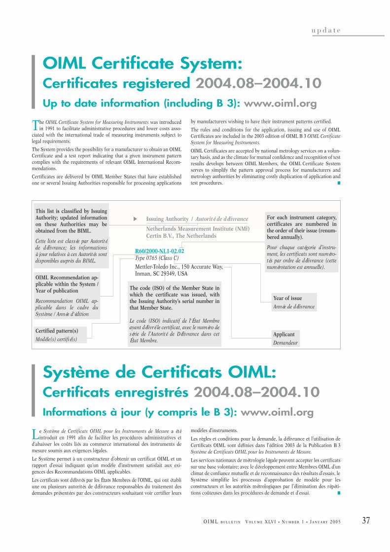
37
u p d a t e
O I M L B U L L E T I N V O L U M E X LV I • N U M B E R 1 • J A N U A R Y 2 0 0 5
E Issuing Authority / Autorité de délivrance
Netherlands Measurement Institute (NMi)Certin B.V., The Netherlands
R60/2000-NL1-02.02Type 0765 (Class C)
Mettler-Toledo Inc., 150 Accurate Way, Inman, SC 29349, USA
This list is classified by IssuingAuthority; updated informationon these Authorities may beobtained from the BIML.
Cette liste est classée par Autoritéde délivrance; les informations à jour relatives à ces Autorités sontdisponibles auprès du BIML.
OIML Recommendation ap-plicable within the System /Year of publication
Recommandation OIML ap-plicable dans le cadre duSystème / Année d'édition
Certified pattern(s)
Modèle(s) certifié(s)Applicant
Demandeur
The code (ISO) of the Member State inwhich the certificate was issued, withthe Issuing Authority’s serial number inthat Member State.
Le code (ISO) indicatif de l'État Membreayant délivré le certificat, avec le numéro desérie de l’Autorité de Délivrance dans cetÉtat Membre.
For each instrument category,certificates are numbered inthe order of their issue (renum-bered annually).
Pour chaque catégorie d’instru-ment, les certificats sont numéro-tés par ordre de délivrance (cettenumérotation est annuelle).
Year of issue
Année de délivrance
The OIML Certificate System for Measuring Instruments was introducedin 1991 to facilitate administrative procedures and lower costs asso-
ciated with the international trade of measuring instruments subject tolegal requirements.
The System provides the possibility for a manufacturer to obtain an OIMLCertificate and a test report indicating that a given instrument patterncomplies with the requirements of relevant OIML International Recom-mendations.
Certificates are delivered by OIML Member States that have establishedone or several Issuing Authorities responsible for processing applications
by manufacturers wishing to have their instrument patterns certified.
The rules and conditions for the application, issuing and use of OIMLCertificates are included in the 2003 edition of OIML B 3 OIML CertificateSystem for Measuring Instruments.
OIML Certificates are accepted by national metrology services on a volun-tary basis, and as the climate for mutual confidence and recognition of testresults develops between OIML Members, the OIML Certificate Systemserves to simplify the pattern approval process for manufacturers andmetrology authorities by eliminating costly duplication of application andtest procedures. K
Le Système de Certificats OIML pour les Instruments de Mesure a étéintroduit en 1991 afin de faciliter les procédures administratives et
d’abaisser les coûts liés au commerce international des instruments demesure soumis aux exigences légales.
Le Système permet à un constructeur d’obtenir un certificat OIML et unrapport d’essai indiquant qu’un modèle d’instrument satisfait aux exi-gences des Recommandations OIML applicables.
Les certificats sont délivrés par les États Membres de l’OIML, qui ont établiune ou plusieurs autorités de délivrance responsables du traitement desdemandes présentées par des constructeurs souhaitant voir certifier leurs
modèles d’instruments.
Les règles et conditions pour la demande, la délivrance et l’utilisation deCertificats OIML sont définies dans l’édition 2003 de la Publication B 3Système de Certificats OIML pour les Instruments de Mesure.
Les services nationaux de métrologie légale peuvent accepter les certificatssur une base volontaire; avec le développement entre Membres OIML d’unclimat de confiance mutuelle et de reconnaissance des résultats d’essais, leSystème simplifie les processus d’approbation de modèle pour lesconstructeurs et les autorités métrologiques par l’élimination des répéti-tions coûteuses dans les procédures de demande et d’essai. K
Système de Certificats OIML:Certificats enregistrés 2004.08–2004.10Informations à jour (y compris le B 3): www.oiml.org
OIML Certificate System:Certificates registered 2004.08–2004.10Up to date information (including B 3): www.oiml.org
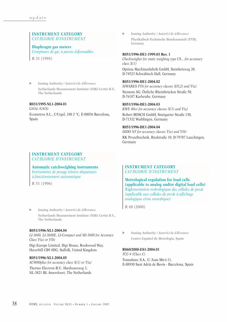
38
u p d a t e
O I M L B U L L E T I N V O L U M E X LV I • N U M B E R 1 • J A N U A R Y 2 0 0 5
E Issuing Authority / Autorité de délivrance
Netherlands Measurement Institute (NMi) Certin B.V.,The Netherlands
R031/1995-NL1-2004.01G4(A) /G4(S)
Ecometros S.L., C/Urgel, 240 2 °C, E-08036 Barcelona,Spain
E Issuing Authority / Autorité de délivrance
Netherlands Measurement Institute (NMi) Certin B.V.,The Netherlands
R051/1996-NL1-2004.04LI-3600, LI-3600E, LI-Compact and MI-3600 for AccuracyClass Y(a) or Y(b)
Digi Europe Limited, Digi House, Rookwood Way,Haverhill CB9 8DG, Suffolk, United Kingdom
R051/1996-NL1-2004.05AC9000plus for accuracy class X(1) or Y(a)
Thermo Electron B.V., Hardwareweg 3, NL-3821 BL Amersfoort, The Netherlands
E Issuing Authority / Autorité de délivrance
Physikalisch-Technische Bundesanstalt (PTB),Germany
R051/1996-DE1-1999.03 Rev. 1Checkweigher for static weighing type CS... for accuracyclass X(1)
Optima Machinenfabrik GmbH, Steinbeisweg 20, D-74523 Schwäbisch Hall, Germany
R051/1996-DE1-2004.02SIWAREX FTA for accuracy classes X(0,2) and Y(a)
Siemens AG, Östliche Rheinbrücken Straße 50, D-76187 Karlsruhe, Germany
R051/1996-DE1-2004.03KWE 40xx for accuracy classes X(1) and Y(a)
Robert BOSCH GmbH, Stuttgarter Straße 130, D-71332 Waiblingen, Germany
R051/1996-DE1-2004.04DIDO NT for accuracy classes Y(a) and Y(b)
RK Prozeßtechnik, Riedstraße 10, D-79787 Lauchingen,Germany
E Issuing Authority / Autorité de délivrance
Centro Español de Metrologia, Spain
R060/2000-ES1-2004.01TCC-4 (Class C)
Transdutec S.A., C/ Joan Miró 11, E-08930 Sant Adrià de Besós - Barcelona, Spain
INSTRUMENT CATEGORYCATÉGORIE D’INSTRUMENT
Metrological regulation for load cells (applicable to analog and/or digital load cells)Réglementation métrologique des cellules de pesée(applicable aux cellules de pesée à affichage analogique et/ou numérique)
R 60 (2000)
INSTRUMENT CATEGORYCATÉGORIE D’INSTRUMENT
Automatic catchweighing instrumentsInstruments de pesage trieurs-étiqueteursà fonctionnement automatique
R 51 (1996)
INSTRUMENT CATEGORYCATÉGORIE D’INSTRUMENT
Diaphragm gas metersCompteurs de gaz à parois déformables
R 31 (1995)
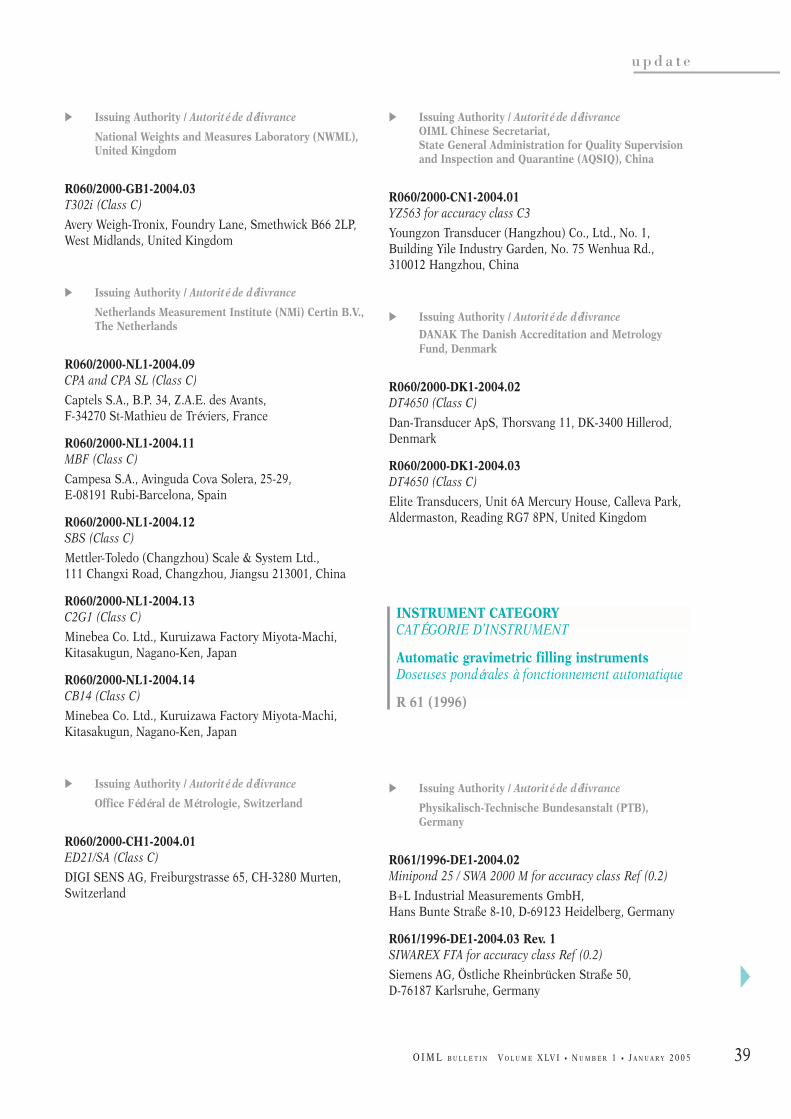
39
u p d a t e
O I M L B U L L E T I N V O L U M E X LV I • N U M B E R 1 • J A N U A R Y 2 0 0 5
E Issuing Authority / Autorité de délivrance
National Weights and Measures Laboratory (NWML),United Kingdom
R060/2000-GB1-2004.03T302i (Class C)
Avery Weigh-Tronix, Foundry Lane, Smethwick B66 2LP,West Midlands, United Kingdom
E Issuing Authority / Autorité de délivrance
Netherlands Measurement Institute (NMi) Certin B.V.,The Netherlands
R060/2000-NL1-2004.09CPA and CPA SL (Class C)
Captels S.A., B.P. 34, Z.A.E. des Avants, F-34270 St-Mathieu de Tréviers, France
R060/2000-NL1-2004.11MBF (Class C)
Campesa S.A., Avinguda Cova Solera, 25-29, E-08191 Rubi-Barcelona, Spain
R060/2000-NL1-2004.12SBS (Class C)
Mettler-Toledo (Changzhou) Scale & System Ltd., 111 Changxi Road, Changzhou, Jiangsu 213001, China
R060/2000-NL1-2004.13C2G1 (Class C)
Minebea Co. Ltd., Kuruizawa Factory Miyota-Machi,Kitasakugun, Nagano-Ken, Japan
R060/2000-NL1-2004.14CB14 (Class C)
Minebea Co. Ltd., Kuruizawa Factory Miyota-Machi,Kitasakugun, Nagano-Ken, Japan
E Issuing Authority / Autorité de délivrance
Office Fédéral de Métrologie, Switzerland
R060/2000-CH1-2004.01ED21/SA (Class C)
DIGI SENS AG, Freiburgstrasse 65, CH-3280 Murten,Switzerland
E Issuing Authority / Autorité de délivranceOIML Chinese Secretariat, State General Administration for Quality Supervisionand Inspection and Quarantine (AQSIQ), China
R060/2000-CN1-2004.01YZ563 for accuracy class C3
Youngzon Transducer (Hangzhou) Co., Ltd., No. 1,Building Yile Industry Garden, No. 75 Wenhua Rd.,310012 Hangzhou, China
E Issuing Authority / Autorité de délivrance
DANAK The Danish Accreditation and MetrologyFund, Denmark
R060/2000-DK1-2004.02DT4650 (Class C)
Dan-Transducer ApS, Thorsvang 11, DK-3400 Hillerod,Denmark
R060/2000-DK1-2004.03DT4650 (Class C)
Elite Transducers, Unit 6A Mercury House, Calleva Park,Aldermaston, Reading RG7 8PN, United Kingdom
E Issuing Authority / Autorité de délivrance
Physikalisch-Technische Bundesanstalt (PTB),Germany
R061/1996-DE1-2004.02Minipond 25 / SWA 2000 M for accuracy class Ref (0.2)
B+L Industrial Measurements GmbH, Hans Bunte Straße 8-10, D-69123 Heidelberg, Germany
R061/1996-DE1-2004.03 Rev. 1SIWAREX FTA for accuracy class Ref (0.2)
Siemens AG, Östliche Rheinbrücken Straße 50, D-76187 Karlsruhe, Germany
INSTRUMENT CATEGORYCATÉGORIE D’INSTRUMENT
Automatic gravimetric filling instrumentsDoseuses pondérales à fonctionnement automatique
R 61 (1996)
A
40
u p d a t e
O I M L B U L L E T I N V O L U M E X LV I • N U M B E R 1 • J A N U A R Y 2 0 0 5
R061/1996-DE1-2004.05SpeedAC NXT for accuracy class Ref (0.2)
Chronos Richardson GmbH, Reutherstr. 3, D-53773 Hennef, Germany
E Issuing Authority / Autorité de délivrance
International Metrology Cooperation Office, National Metrology Institute of Japan (NMIJ)National Institute of Advanced Industrial Science and Technology (AIST), Japan
R076/1992-JP1-2004.01AUW-D / AUW / AUX / AUY series (Class I)
Shimadzu Corporation, 1, Nishinokyo-Kuwabara-cho,Nakagyo-ku, 604-8511, Kyoto, Japan
E Issuing Authority / Autorité de délivrance
National Weights and Measures Laboratory (NWML),United Kingdom
R076/1992-GB1-2004.07IX Series (Class III)
Avery Weigh-Tronix, Foundry Lane, Smethwick B66 2LP,West Midlands, United Kingdom
R076/1992-GB1-2004.08GM Series (Class III)
Avery Weigh-Tronix, Foundry Lane, Smethwick B66 2LP,West Midlands, United Kingdom
R076/1992-GB1-2004.09E1005/E1010 (Class III)
Avery Weigh-Tronix, Foundry Lane, Smethwick B66 2LP,West Midlands, United Kingdom
E Issuing Authority / Autorité de délivrance
Netherlands Measurement Institute (NMi) Certin B.V.,The Netherlands
R076/1992-NL1-2004.13DS-980 (Class III)
Shanghai Teraoka Electronic Co., Ltd., Tinglin IndustryDevelopmental Zone, Jinshan District, Shanghai 201505,China
R076/1992-NL1-2004.14SB, SB530 and SB730 (Class III)
Bright Advance Corporation, N° 3217 Hong Mei Road,201103 Shangai, China
R076/1992-NL1-2004.15POScale (Class III)
CAS Corporation, CAS Factory # 19 Kanap-ri, Kwangjeok-myon, Yangju-kun Kyungki-do, Korea (R.)
R076/1992-NL1-2004.16ER-series (Class III)
CAS Corporation, CAS Factory # 19 Kanap-ri, Kwangjeok-myon, Yangju-kun Kyungki-do, Korea (R.)
R076/1992-NL1-2004.17DB-II (Class III)
CAS Corporation, CAS Factory # 19 Kanap-ri, Kwangjeok-myon, Yangju-kun Kyungki-do, Korea (R.)
R076/1992-NL1-2004.18FX, MC, B, G, BK, HL or S-series (Class III)
Avery Weigh-Tronix, Foundry Lane, Smethwick B66 2LP,West Midlands, United Kingdom
R076/1992-NL1-2004.19CW-11 / CD-11 / CKW55 (Class III)
Ohaus Corporation, 19A Chapin Road, Pine Brook, New Jersey 07058, United States
R076/1992-NL1-2004.20DB-II (Class III) - 6 kg <= Max <= 150 kg
CAS Corporation, CAS Factory # 19 Kanap-ri, Kwangjeok-myon, Yangju-kun Kyungki-do, Korea (R.)
E Issuing Authority / Autorité de délivrance
Physikalisch-Technische Bundesanstalt (PTB),Germany
R076/1992-DE1-2004.02MCD10-3000-EBR210-L (Class III)
PESA Waagen AG, Witzbergstr. 25, CH-8330 Pfäffikon,Switzerland
INSTRUMENT CATEGORYCATÉGORIE D’INSTRUMENT
Nonautomatic weighing instrumentsInstruments de pesage à fonctionnement non automatique
R 76-1 (1992), R 76-2 (1993)

41
u p d a t e
O I M L B U L L E T I N V O L U M E X LV I • N U M B E R 1 • J A N U A R Y 2 0 0 5
R076/1992-DE1-2004.03WD-KDS (Class III)
Ditting Maschinen AG, Bramenstrasse 11, CH-8184 Bachenbülach, Switzerland
R076/1992-DE1-2004.04XP…S (Classes I and II)
Mettler-Toledo A.G., Im Langacher, CH-8606 Greifensee,Switzerland
E Issuing Authority / Autorité de délivranceOIML Chinese Secretariat, State General Administration for Quality Supervisionand Inspection and Quarantine (AQSIQ), China
R076/1992-CN1-2004.02XK3190-A9 (Class III)
Shanghai Yaohua Weighing System Co., Ltd, No. 4059,Shangnan Road, 200124 Shanghai, China
R076/1992-CN1-2004.03PA8101S (Class III)
Yuyao Pacific Auto-Control Engineering Co., Ltd, 285 Tanjialing East Road, Yuyao, Zhejiang Province,China
E Issuing Authority / Autorité de délivrance
DANAK The Danish Accreditation and MetrologyFund, Denmark
R076/1992-DK1-2004.01Scanvaegt System 410 (Classes III and IIII)
Scanvaegt International A/S, P.O. Pedersens Vej 18, DK-8200 Aarhus N, Denmark
E Issuing Authority / Autorité de délivrance
Physikalisch-Technische Bundesanstalt (PTB),Germany
R107/1997-DE1-2004.02 Rev. 1SIWAREX FTA for accuracy class 0.2
Siemens AG, Östliche Rheinbrücken Straße 50, D-76187 Karlsruhe, Germany
E Issuing Authority / Autorité de délivrance
Russian Research Institute for Metrological Service(VNIIMS) of Gosstandart of Russian Federation,Russian Federation
R117/1995-RU1-2003.01 Rev. 1MIDCO Fuel Dispensing Pump (MEB/MPD/MMS series) foraccuracy class 0.5
Mercantile & Industrial Development Company Ltd.,39/44, Scheme 6, Road 2, Sion (East), 400022 Mumbai,India
R117/1995-RU1-2003.02 Rev. 1MIDCO Flow meter for Fuel Dispensing Pump for accuracyclass 0.5
Mercantile & Industrial Development Company Ltd.,39/44, Scheme 6, Road 2, Sion (East), 400022 Mumbai,India
INSTRUMENT CATEGORYCATÉGORIE D’INSTRUMENT
Discontinuous totalizing automatic weighinginstruments (Totalizing hopper weighers)Instruments de pesage totalisateurs discontinusà fonctionnement automatique (Peseuses totalisa-trices à trémie)
R 107 (1997)
INSTRUMENT CATEGORYCATÉGORIE D’INSTRUMENT
Fuel dispensers for motor vehiclesDistributeurs de carburant pour véhicules à moteur
R 117 (1995) + R 118 (1995)
Updated information on OIML certificates:
www.oiml.org

42
u p d a t e
O I M L B U L L E T I N V O L U M E X LV I • N U M B E R 1 • J A N U A R Y 2 0 0 5
In memoriam
Knut Birkeland, 1929–2004
CIML President, 1980–1994
Our former CIML President passed away on 12September 2004 from the sequels of a brain tumor.
Knut Birkeland was born in Stavanger on 27 January1929, but his family soon moved away to Svolvær, a smalltown in the Lofoten whose principle resource was fishing.He spent some ten years there, which no doubt goes toexplain why certain regional metrology meetings that Knutwould later go on to organize in Norway in the frameworkof NORMET, NORJUST or even AELE, would generallyculminate in fishing expeditions in his childhood islands.
For some time he lived in Bergen and in 1958 he grad-uated in applied physics (metrology of very high frequen-cies) from the Norwegian Institute of Technology.
After obtaining his degree, he worked for two years etNERA Bergen SA, an electronics manufacturer, then forfour years at P.A. Madshus, a geophysics consultancy firm,before joining the Norwegian Metrology Service,Justervesenet, in 1964 where he would spend the rest of hiscareer.
At that time Justervesenet was principally orientatedtowards legal metrology, but was also Norway’s primarylaboratory with standards directly linked to the BIPM’sinternational standards.
This goes to explain why Knut very soon sharpened hisskills in a number of metrological fields: legal metrologyand the measurement of lengths, quantities of liquids andmasses, and scientific metrology with length, temperatureand electricity standards. From 1967 to 1973 he madenumerous trips to France and to the United Kingdom tostudy interferometry and thermometry.
He very soon came to realize the importance of both
international and regional cooperation and as early as in1965 he participated in a large number of OIML workinggroups; he also became heavily involved in the activities ofthe CGPM and in ILAC right from its outset, as well as inthe work of the regional organizations that existed at thattime, namely NORMET, AELE, WEMC and WECC.
In 1974 he took over from Sture Koch as Director ofJustervesenet and became the CIML Member for Norway,and it was in June 1980 on the occasion of the OIML meet-ings held in Washington D.C. that he was elected CIMLPresident - a mandate that was renewed in 1986 and againin 1992 for a duration of two years corresponding to histerm of national office.
These fourteen years represented a period of intenseactivity at national, international and regional levels forKnut. His primary concern was always to see his countryendowed with a top level national metrology service, and inparallel he developed scientific metrology, legal metrologyand accreditation activities. In May 1994 his efforts culmi-nated in the laying of the foundations of the newNorwegian Metrology Service laboratories and buildingssome twenty kilometers north of Oslo. At regional level hesaw to it that Norway participated in all the cooperationforums (mainly those of EUROMET, WELMEC and theEA) and that Norway was in a position to follow the workof the European Union, even though his country was not amember. At international level, his primary objective was topromote OIML activities alongside the other internationalmetrology organizations (Metre Convention), accreditationorganizations (ILAC), standardization organizations (ISOand the IEC) or economic cooperation organizations(GATT), not forgetting those involved in development assis-tance. For the OIML, these same fourteen years duringwhich Knut presided the CIML were years of stronggrowth, the impetus of which we are still seeing today.
May Knut Birkeland’s family and past colleagues find inthese words a testimony of the OIML’s deepest appreciationfor his outstanding achievements. K
BA

43
u p d a t e
O I M L B U L L E T I N V O L U M E X LV I • N U M B E R 1 • J A N U A R Y 2 0 0 5
In memoriam
Knut Birkeland, 1929–2004
Président du CIML, 1980–1994
Notre ancien Président s’est éteint le 12 septembre der-nier, des suites d’une tumeur au cerveau.
Il était né à Stavanger le 27 janvier 1929, mais rapide-ment sa famille partit pour Svolvær, une petite ville desLofoten dont la principale ressource était la pêche. Il ypassa une dizaine d’années, ce qui explique sans doute quecertaines réunions régionales de métrologie que Knut orga-nisa plus tard en Norvège dans les cadres de NORMET,NORJUST ou encore l’AELE, se soient terminées par desparties de pêches dans les îles de son enfance.
Il vécut ensuite à Bergen et termina ses études en 1958avec un diplôme de physique appliquée (métrologie destrès hautes fréquences) de l’Institut Norvégien deTechnologie.
Il travailla alors deux ans à NERA Bergen SA, un fabri-cant d’électronique, puis quatre ans à P.A. Madshus, socié-té conseil en géophysique, avant d’intégrer en 1964 leService Norvégien de Métrologie, Justervesenet, où il pas-sera le reste de sa carrière.
Justervesenet était alors un service principalementtourné vers la métrologie légale, mais constituait aussi lelaboratoire primaire de Norvège, avec des étalons directe-ment rattachés aux étalons internationaux du BIPM.
Cela explique que, très vite, Knut développa ses compé-tences dans de nombreux aspects de la métrologie, métro-logie légale avec les mesurages de longueurs, quantités deliquides et masses, métrologie scientifique avec les étalonsde longueur, température et électricité. Entre 1967 et 1973il fit de nombreux séjours en France et au Royaume-Unipour étudier l’interférométrie et la thermométrie.
Il prit également très rapidement conscience de l’im-portance de la coopération tant internationale que régiona-
le et dès 1965 participa à de nombreux groupes de travailde l’OIML; il s’impliqua aussi fortement dans les activitésde la CGPM et, dès sa création, de ILAC, ainsi que dans cel-les d’organismes régionaux de l’époque, NORMET, AELE,WEMC et WECC.
En 1974 il succéda à Sture Koch comme Directeur deJustervesenet et comme Membre du CIML pour la Norvègeet c’est en juin 1980, à l’occasion des réunions OIML tenuesà Washington D.C., qu’il fut élu Président du CIML, man-dat dans lequel il fut reconduit en 1986 puis en 1992 pourune durée de deux ans correspondant au terme de ses fonc-tions nationales.
Ces quatorze années ont été pour Knut une périoded’intense activité tant au niveau national que régional etinternational. Soucieux de voir son pays doté d’un servicenational de métrologie de haut niveau, il développa enparallèle les activités de métrologie scientifique, de métro-logie légale et d’accréditation et ses efforts aboutirent, enmai 1994, par la pose de la première pierre des nouveauxlaboratoires et bâtiments du Service Norvégien deMétrologie à une vingtaine de kilomètres au nord d’Oslo.Sur le plan régional il veilla à ce que la Norvège participe àtous les forums de coopération, principalement EURO-MET, WELMEC et EA, et puisse suivre les travaux del’Union Européenne, bien que son pays n’en fisse pas par-tie. Sur le plan international enfin, ses efforts visèrent àpromouvoir l’action de l’OIML au côté des autres organis-mes internationaux de métrologie (Convention du Mètre),d’accréditation (ILAC), de normalisation (ISO et CEI) ou decoopération économique (GATT), sans oublier l’aide audéveloppement. Pour l’OIML, ces mêmes quatorze ans pen-dant laquelle il présida le CIML ont été une période de fortecroissance qui se poursuit toujours.
Que la famille de Knut Birkeland et ses anciens collè-gues trouvent ici le témoignage de profonde reconnaissan-ce que l’OIML tient à marquer à l’égard de son ancienPrésident. K
BA

44 O I M L B U L L E T I N V O L U M E X LV I • N U M B E R 1 • J A N U A R Y 2 0 0 5
u p d a t e
1 Organization of the Meeting
1.1 The Conference took note of opening andwelcome addresses delivered by Dr. Tacke,Vice-Minister of the Federal Ministry ofEconomics and Labour, Dr. Röhling, Pr.Göbel, President of the PTB, and Pr.Kochsiek, CIML Acting President.
1.2 The roll of Delegates was called and it wasfound that 54 Member States were presentout of a total of 59; the statutory quorum oftwo-thirds was therefore reached.
The Conference also noted the participationof Observers from certain OIMLCorresponding Members, observer countriesand International and Regional LiaisonOrganizations, the CIML Immediate Past-President, one CIML Honorary Member andmembers of BIML Staff.
1.3 Information concerning voting proceduresduring Conference sessions was given.
1.4 The Conference unanimously elected Dr.Röhling as Conference President with Pr.Kochsiek (Germany) standing in as and whenrequired, and Mrs. Annabi and Dr. Zhagora asConference Vice-Presidents.
1.5 The Conference adopted the proposed agen-da without modification.
1.6 The Conference established two WorkingCommissions, one for Financial Matters andone for Technical Work.
1.7 The Conference adopted the proposed sched-ule.
1.8 The Conference approved the Minutes of theEleventh Conference without modification.
1.9 The Conference took note of a report pre-sented by the President of the InternationalCommittee of Legal Metrology describing theactivities of the Organization for the period2001–2004.
DECISIONS & RESOLUTIONS
Twelfth International Legal MetrologyConference
Berlin, Germany
26–29 October 2004

45
u p d a t e
O I M L B U L L E T I N V O L U M E X LV I • N U M B E R 1 • J A N U A R Y 2 0 0 5
2 Member States and CorrespondingMembers
2.1 New Members - Expected accessions
The Conference noted that the number ofOIML Members had significantly increasedsince the Eleventh Conference, although anumber of Corresponding Members had beendelisted for not having paid their subscrip-tions for over three years. The Conferencenoted that certain Corresponding Memberswere envisaging joining as Member Statesand that a number of countries/economieswere expected to join as CorrespondingMembers.
2.2 The situation of certain Members
The Conference noted that Zambia had beenstruck off the list of Member States for nothaving complied with the requirements laiddown by the Eleventh Conference.
It was also noted that the situation of twoMember States would first be examined bythe Finance Commission, which would thenreport to the Conference under Item 8.2.
3 Long-term policy
3.1 Report on actions carried out since theEleventh Conference
The Conference took note of a report pre-sented by the BIML Director.
3.2 Guidelines for the period 2005–2008
The Conference noted that most of the infor-mation concerning the actions carried outsince the Eleventh Conference, including thedevelopment of an Action Plan for 1999–2002with extension to 2004, had been given in thereport on activities delivered by the CIMLActing President. The Conference also notedthat the Long-Term Policy and the ActionPlan shall be revised under the supervision ofthe newly elected CIML President, andrequested the CIML to monitor its implemen-tation.
4 Liaisons with international and regional institutions
4.1 Report on liaisons
The Conference took note of a report pre-sented by the BIML Director.
4.2 Addresses by Representatives of Institutions
The Conference also noted the reports pre-sented by the representatives of:
- ILAC/IAF, Mr. Pierre- UNIDO, Dr. Loesener-Diaz- Metre Convention, Dr. Castelazo- WELMEC, Mr. Freistetter- APLMF, Dr. Ooiwa- EMLMF, Mr. Lagauterie- SADCMEL, Mr. Carstens- CCE, DG Enterprise, Mrs. Höke- CECIP, Mr. Anthony.
4.3 The Conference took note of a report pre-sented by the BIML Director concerning themain aspects of cooperation between theOIML and certain International and RegionalOrganizations. It was noted that a number ofmatters should be considered in order toglobally improve OIML activities in fieldsconnected with, for example, market surveil-lance, increased use of the work of otherinternational or regional bodies, etc.
The Conference expressed its appreciationfor the work carried out jointly with otherOrganizations.
The Conference invited the CIML Presidentand BIML Director to work actively towardsan even closer cooperation with the MetreConvention and a common presentation ofinternational metrology to the public.
As a conclusion, the Conference requestedthe CIML to duly consider all the commentsand proposals put forward during theConference and to take appropriate measuresin order to implement those that are consid-ered as being most appropriate to improveOIML activities.

46
u p d a t e
O I M L B U L L E T I N V O L U M E X LV I • N U M B E R 1 • J A N U A R Y 2 0 0 5
- R 75-1 Heat meters. Part 1: General require-ments (Edition 2002)
- R 75-2 Heat meters. Part 2: Type approvaltests (Edition 2002)
- R 133 Liquid-in-glass thermometers (Edition2002)
Recommendations approved in 2002:
- R 84 Platinum, copper, and nickel resistancethermometers (for industrial and commer-cial use) (Edition 2003)
- R 134-1 Automatic instruments for weighingroad vehicles in motion. Total vehicle weigh-ing (Edition 2003)
Recommendations approved in 2003:
- R 48 Tungsten ribbon lamps for the calibra-tion of radiation thermometers (Edition2004)
- R 49-1 Water meters intended for the meter-ing of cold potable water. Part 1:Metrological and technical requirements(Edition 2003)
- R 49-2 Water meters intended for the meter-ing of cold potable water. Part 2: Test meth-ods (Edition 2004)
- R 52 Hexagonal weights - Metrological andtechnical requirements (Edition 2004)
- R 61-1 Automatic gravimetric filling instru-ments. Part 1: Metrological and technicalrequirements - Tests (Edition 2004)
- R 87 Quantity of product in prepackages(Edition 2004)
- R 135 Spectrophotometers for medical labo-ratories (Edition 2004)
Recommendation approved in 2004 by CIMLpostal approval:
- R 111-1 Weights of classes E1, E2, F1, F2,M1, M1-2, M2, M2-3 and M3. Part 1:Metrological and technical requirements(Edition 2004)
5 Work of OIML Technical Committeesand Subcommittees
5.1 Work undertaken - State of progress
The Conference took note of a report con-cerning the activities of OIML TechnicalCommittees and Subcommittees and request-ed the CIML to continue to monitor the situ-ation and to find solutions in order to ensurea better distribution of technical responsibil-ities amongst OIML Member States.
5.2 Implementation of Recommendations by OIML Members
The Conference took note of informationgiven by the Bureau concerning the imple-mentation of OIML Recommendations innational regulations or voluntary standards.It noted that due to the low level of respons-es, no comprehensive report could be given.
Member States that had not yet replied to theBIML inquiry were requested to do so urgent-ly. The Conference encouraged the Bureau toconvert this information and inquiries into apermanent interactive facility on the OIMLweb site.
5.3 Formal sanction of Recommendations alreadyapproved by the Committee in 2001, 2002,2003 and 2004
The Conference decided that OIML TestReport Formats, which are of an informativenature concerning their implementation innational regulations, shall be approved by theCIML according to the rules applicable toInternational Documents, without having tobe sanctioned by the Conference.
The Conference sanctioned those new orrevised Recommendations already approvedby the Committee in 2001, 2002, 2003 and2004.
Recommendations approved in 2001:
- R 16-1 Mechanical non-invasive sphygmo-manometers (Edition 2002)
- R 16-2 Non-invasive automated sphygmo-manometers (Edition 2002)

47
u p d a t e
O I M L B U L L E T I N V O L U M E X LV I • N U M B E R 1 • J A N U A R Y 2 0 0 5
5.4 Draft Recommendations directly presented forsanctioning by the Conference
The Conference sanctioned one newRecommendation Instruments for measuringthe area of leathers (R 136).
The Conference also decided to withdrawOIML Recommendations R 33 and R 62.
6 OIML Certificate System for MeasuringInstruments
6.1 Report on the situation of the System
The Conference took note of a report describ-ing progress made with this activity since theestablishment of the System in general andsince the 11th Conference in particular,including the results of recent inquiries car-ried out among OIML Members and manu-facturers.
6.2 Mutual Acceptance Arrangement (MAA)
The Conference expressed its appreciation tothe CIML for the setting up of the MutualAcceptance Arrangement, and took note thatthis System will be implemented in 2005.
The Conference took note of proposals con-cerning the operation of the MAA and of theCertificate System. The Conference instruct-ed the Committee to take appropriate deci-sions on these proposals and to begin a revi-sion of this document once experience hasbeen gained following its implementation.
6.3 Other developments
The Conference took note of a report con-cerning the results of various inquiries car-ried out by the BIML in order to ascertain theviews of manufacturers and CIML Membersconcerning advisable developments of theSystem.
The Conference confirmed the urgency ofaddressing the problem of conformity to typeof measuring instruments.
7 Developing Countries
7.1 Report on activities for the period 2001–2004
The Conference took note of a report con-cerning the Development Council meetingheld on 25 October and expressed its appreci-ation to the Chairperson for the work accom-plished.
The Conference noted in particular the reportconcerning the Forum: Metrology – TradeFacilitator held on 25 October 2004 andexpressed its appreciation to the GermanAuthorities for having organized this event.
7.2 Guidelines for future activity
The Conference noted the Committee’s reportthat, notwithstanding Resolution 7.2 of the6th International Conference of LegalMetrology which established the OIMLDevelopment Council, the OIML’s work onDeveloping Country matters could be moreefficiently managed by the establishment of aPermanent Working Group on DevelopingCountries (PWGDC), which would replacethe Development Council.
The Conference therefore approved the deci-sion of the 38th CIML Meeting to create aPWGDC, the terms of reference of whichshall be established by the Committee. ThisPermanent Working Group shall act as anadvisory body to the President of theCommittee on aspects of the OIML’s workrelating to Developing Countries.
The Conference also decided to cease theactivities of the current DevelopmentCouncil.
8 Administrative and financial matters
8.1 Examination of the management of the budget from 2000 to 2003 and the estimates for 2004
The International Conference of LegalMetrology,
HAVING EXAMINED the report on the man-agement of the budget for the years 2000,2001, 2002 and 2003;

48
u p d a t e
O I M L B U L L E T I N V O L U M E X LV I • N U M B E R 1 • J A N U A R Y 2 0 0 5
* The outstanding contribution of Spainrelated to the year 1992 is considered tohave been paid by this country.
* Zambia will be permitted to become anOIML Corresponding Member providingthat:
- its current Corresponding Member feesare paid, and
- its arrears are progressively reimbursedover 10 years.
The conditions for the readmission ofZambia as a full Member State will bereconsidered when its arrears amount toless than 3 years’ contributions.
The International Committee of LegalMetrology is requested to annually exam-ine the situation of this country and takeappropriate action in the event that theseconditions are not met.
* The International Committee of LegalMetrology is requested to annually exam-ine the situation of any other MemberState which might become more than threeyears late in the payment of its contribu-tions and to report back about this at theThirteenth Conference.
8.3 Revision of the OIML Financial Regulations
The Conference approved the revised OIMLFinancial Regulations as established by theCommittee.
8.4 Bureau staff and Retirement scheme
The Conference took note of a report given bythe BIML Director on this issue.
The Conference noted that the OIMLRetirement scheme will be balanced for theperiod 2005–2008 without an additionalendowment from the Organization being nec-essary.
The Conference noted that additional studiesare necessary for assessing the rights of theStaff and the commitments of theOrganization concerning the Retirementscheme and for examining how these com-mitments must be recorded in theOrganization’s accounts.
NOTING that the budget was managed inconformity with the expenses necessary forcarrying out the work of the Bureau and thatthe accuracy of the report has been certifiedby annual audits;
NOTING that the respective functionsassigned by the Convention to the Presidentof the International Committee of LegalMetrology and to the Director of theInternational Bureau of Legal Metrologyhave been fulfilled;
GIVES ITS DEFINITIVE DISCHARGE to thePresident of the Committee and to theDirector of the Bureau for their managementof the budget during the years mentionedabove.
8.2 Decisions related to the debts of certain countries
The Conference adopted the followingResolution:
The International Conference of LegalMetrology,
HAVING EXAMINED the report on the man-agement of the budget for the years 2000,2001, 2002 and 2003;
NOTING that a large part of the holdings onDecember 31, 2003 consisted of debts owedby Member States;
URGENTLY REQUESTS that those MemberStates that are in arrears with their contribu-tions pay their debts as soon as possible;
HAVING NOTED a report by the Director ofthe Bureau on the situation of certainMember States in arrears with their contri-butions,
MAKES the following decisions:
* D.P.R of Korea is permitted to remain a fullMember of the OIML providing that:
- its current contributions are paid, and
- its arrears are progressively reimbursedover 10 years.
The International Committee of LegalMetrology is requested to annually exam-ine the situation of this Member State andtake appropriate action in the event thatthese conditions are not met.

49
u p d a t e
O I M L B U L L E T I N V O L U M E X LV I • N U M B E R 1 • J A N U A R Y 2 0 0 5
The Conference instructed the CIML toundertake these studies and to report andmake proposals to the Thirteenth Confer-ence.
8.5 Budget for the financial period 2005–2008
The Conference accepted (with one absten-tion) to consider the budgetary proposals as awhole and not in separate components.
The Conference adopted the followingResolution:
The International Conference of LegalMetrology,
ACCEPTING the budgetary proposals of theDirector of the International Bureau of LegalMetrology for the financial period beginningJanuary 1, 2005 and ending December 31,2008;
APPROVES the fee structure and the budgetfor the Organization’s expenses annexed tothese Decisions and Resolutions;
INSTRUCTS the International Committee ofLegal Metrology:
- to annually review the MAA fee structureapproved above, and
- to amend it as necessary in order to ensurea fair implementation of the MAA, withoutcompromising the balance of implementa-tion costs and income.
INSTRUCTS the International Committee ofLegal Metrology to take the necessary meas-ures (such as calling for voluntary additionalcontributions or amending certain elementsof the budget - with the exception of theMember State base contributory share andthe Corresponding Member lump sum sub-scription fee) in the event that the inflationrate in France differs in a significant mannerfrom the value used for determining thebudget (i.e. 2 %) or in the event that otherfactors render a revision of the acceptedbudget appropriate;
INSTRUCTS the International Committee ofLegal Metrology to annually review the situa-tion of those Member States that benefit froma lower contributory class and requests theCommittee to reallocate those Member Statesconcerned to their normal contributory classas soon as their economic situation permitsit.
8.6 Status of OIML Publications
The Conference approved the proposal tomake all OIML Publications, except thosewhich are published jointly with otherOrganizations, available free of charge inelectronic format on the OIML web site andto cease publishing them on paper.
9 Other business
10 Closure
10.1 Adoption of the Decisions and Resolutions ofthe Conference
A second roll call of delegates was called andit was found that 53 Member States werepresent; the statutory quorum of two-thirdsas fixed by the Convention was thereforereached.
The Twelfth International Conference adopt-ed the above-mentioned Decisions andResolutions (Note: the sanctioning ofInternational Recommendations and theadoption of Resolution 8 were made throughnominal votes).
10.2 Date and place of the next Conference
The Conference decided that it would wait fora period of up to two years, i.e. until 2006, toestablish whether any Member State waswilling to host the Thirteenth Conference in2008. If no Member State was forthcoming,then the BIML would organize theConference in France. K
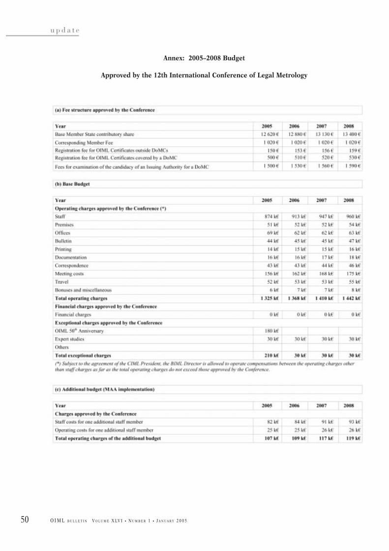
50
u p d a t e
O I M L B U L L E T I N V O L U M E X LV I • N U M B E R 1 • J A N U A R Y 2 0 0 5
Annex: 2005–2008 Budget
Approved by the 12th International Conference of Legal Metrology

51O I M L B U L L E T I N V O L U M E X LV I • N U M B E R 1 • J A N U A R Y 2 0 0 5
u p d a t e
The TC 8/SC 8 Working Group for the combinedrevision of the International Recommendations onGas meters (OIML R 6, R 31 and R 32) held a one-
day meeting on 11 October 2004 in Dordrecht, TheNetherlands. Thirty delegates from eleven countries(9 P-Members and 2 O-Members) attended the meeting,which was kindly hosted by NMi Certin.
The draft of the Recommendation on Gas meters isintended to replace the existing R 6, R 31 and R 32 andthis First Committee Draft aims to modernize theexisting Recommendations with respect to technologyand metrology, taking into account the increasing paceof technological developments and the liberalization ofthe gas markets in the different parts of the world.
In May 2004 the 1 CD on Gas meters was sent out forcomments; by early September more than 250comments had been received from 23 countries.
The meeting was split into two parts. First thephilosophy of the 1 CD was explained in a presentationby Jos van der Grinten. The contents of this presentationcan be found in the paper Dreams about legal gasmetering, published in this issue. This presentationclarified a number of remarks made by the variouscountries.
The second part of the meeting was devoted to themost important comments on the draft and thefollowing issues were agreed upon:
J Implementation of technology independence,allowing electronics and new meter principles to becovered by the scope of the Recommendation;
J Remote displays are allowed under the conditionthat metering data is stored in the gas meter and thatthe consumer can access this data;
J Gas quantities can also be expressed in mass and
energy units;J Modernization of metrological terminology in a way
that is compatible with the uncertainty approach ofthe VIM and the GUM; and
J Addition of a class 0.5.
In scientific and industrial metrology it is customaryto correct for all known deviations. When this procedureis applied to an instrument there is no deviation left andonly uncertainty remains. Due to uncertainty aninstrument may deviate, but it is not possible to tell inwhich direction.
Applying corrections for known deviations to aninstrument for legal metrology purposes would result ina “class 0” instrument. Although participants appreciatethe added value of correcting for known deviations,many had reservations towards the “class 0”designation. It was decided to keep the “class 0” in thenext draft for further discussion.
Discussions both during the meeting and during thebreaks were vivid and constructive, and attendees learntfrom each other’s viewpoints. Once again the OIMLTC 8/SC 8 Secretariat would like to thank theparticipants, CIML Members and technical experts fortheir many useful comments. Further activities willinclude a new meeting between the Secretariats ofTC 8/SC 7 and TC 8/SC 8 to harmonize the scopes of thedrafts of the Recommendations Measuring systems forgaseous fuels and Gas meters in order to avoid anyunnecessary overlap.
The detailed comments received by the TC 8/SC 8Secretariat before and after the meeting will certainlylead to an improved 2 CD, which it is planned to publishin December 2004 or early January 2005. Comments onthis 2 CD are welcomed before 31 March 2005.
The next meeting is scheduled to be held in June2005 at a venue still to be decided. K
TC/SC NEWS
OIML TC 8/SC 8 WorkingGroup Meeting
Dordrecht, The Netherlands
11 October 2004JOS G.M. VAN DER GRINTEN
NMi Certin, The Netherlands
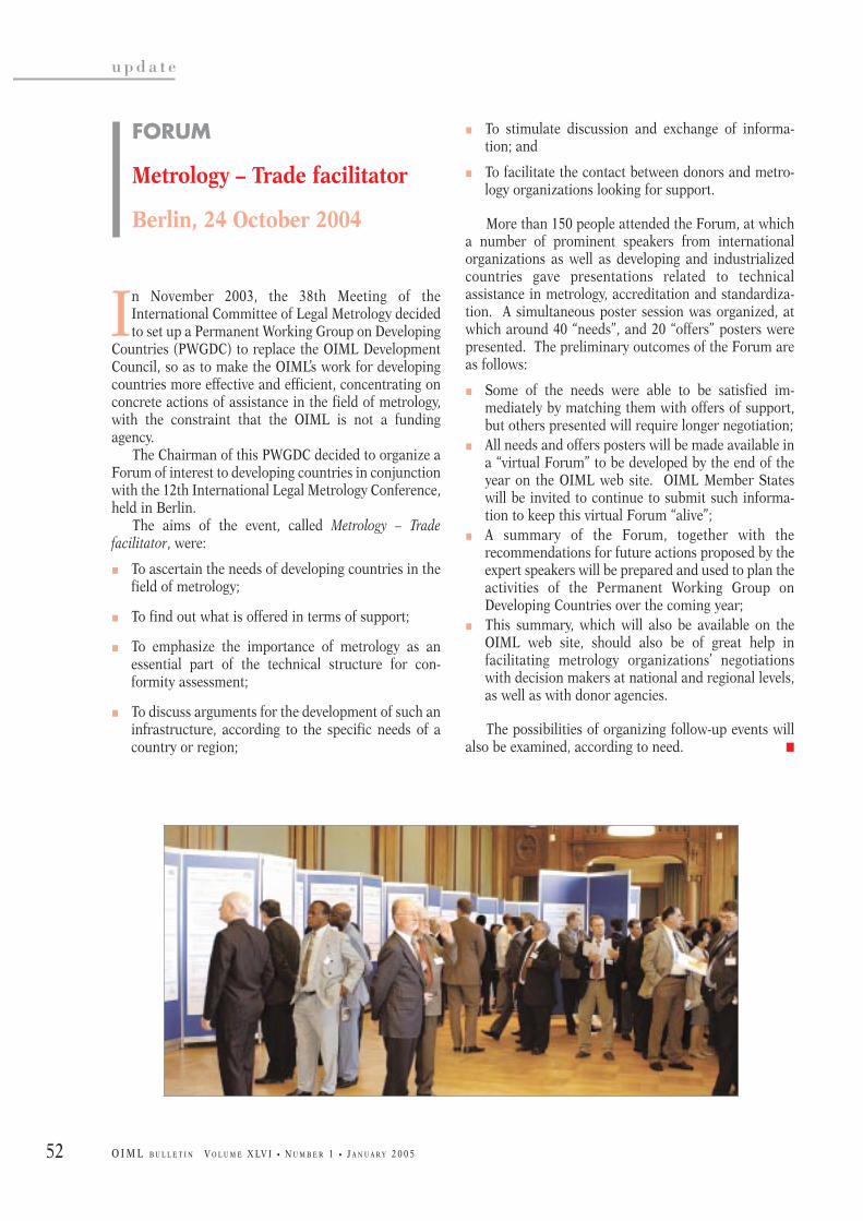
52
u p d a t e
O I M L B U L L E T I N V O L U M E X LV I • N U M B E R 1 • J A N U A R Y 2 0 0 5
J To stimulate discussion and exchange of informa-tion; and
J To facilitate the contact between donors and metro-logy organizations looking for support.
More than 150 people attended the Forum, at whicha number of prominent speakers from internationalorganizations as well as developing and industrializedcountries gave presentations related to technicalassistance in metrology, accreditation and standardiza-tion. A simultaneous poster session was organized, atwhich around 40 “needs”, and 20 “offers” posters werepresented. The preliminary outcomes of the Forum areas follows:
J Some of the needs were able to be satisfied im-mediately by matching them with offers of support,but others presented will require longer negotiation;
J All needs and offers posters will be made available ina “virtual Forum” to be developed by the end of theyear on the OIML web site. OIML Member Stateswill be invited to continue to submit such informa-tion to keep this virtual Forum “alive”;
J A summary of the Forum, together with therecommendations for future actions proposed by theexpert speakers will be prepared and used to plan theactivities of the Permanent Working Group onDeveloping Countries over the coming year;
J This summary, which will also be available on theOIML web site, should also be of great help infacilitating metrology organizations’ negotiationswith decision makers at national and regional levels,as well as with donor agencies.
The possibilities of organizing follow-up events willalso be examined, according to need. K
In November 2003, the 38th Meeting of theInternational Committee of Legal Metrology decidedto set up a Permanent Working Group on Developing
Countries (PWGDC) to replace the OIML DevelopmentCouncil, so as to make the OIML’s work for developingcountries more effective and efficient, concentrating onconcrete actions of assistance in the field of metrology,with the constraint that the OIML is not a fundingagency.
The Chairman of this PWGDC decided to organize aForum of interest to developing countries in conjunctionwith the 12th International Legal Metrology Conference,held in Berlin.
The aims of the event, called Metrology – Tradefacilitator, were:
J To ascertain the needs of developing countries in thefield of metrology;
J To find out what is offered in terms of support;
J To emphasize the importance of metrology as anessential part of the technical structure for con-formity assessment;
J To discuss arguments for the development of such aninfrastructure, according to the specific needs of acountry or region;
FORUM
Metrology – Trade facilitator
Berlin, 24 October 2004
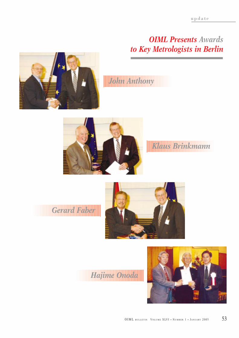
53
u p d a t e
O I M L B U L L E T I N V O L U M E X LV I • N U M B E R 1 • J A N U A R Y 2 0 0 5
OIML Presents Awardsto Key Metrologists in Berlin
John Anthony
Klaus Brinkmann
Gerard Faber
Hajime Onoda

54
u p d a t e
O I M L B U L L E T I N V O L U M E X LV I • N U M B E R 1 • J A N U A R Y 2 0 0 5
J An exhibition of 70 stands with professional firms inthe voluntary or regulated measurements domains.
Fees: Between 350 and 700 euros (VAT not included)according the number of participation days (reductionfor CFM members).
Information, details of the program, registration, CFMmembership:
Tel.: +33 (0)4 67 06 20 36
Web site: www.cfmetrologie.com
E-mail: [email protected]
The 40th CIML Meeting will be held from 17–20June 2005 in conjunction with the 12th Inter-national Metrology Congress in Lyon, France,
organized with the support of the “Bureau National deMétrologie” and N-MERA (Nordic Metrology ResearchArea). The OIML, which is also participating in theorganization of this Congress, will celebrate its 50thAnniversary on this occasion.
This Congress, which will address a number of issuesconcerning legal metrology, represents:
J A meeting place for exchanges between 800 to 1000industrialists and specialists through:
J 200 oral and poster conferences, 4 round tablesdedicated to industrialists’ questions, and 5 technical visits.
40th CIML Meeting
International Metrology Congress
Lyon (France), 17–23 June 2005
Monday 20 June Tuesday 21 June Wednesday 22 June Thursday 23 June
Congress Program
Oral Sessions
J Legal metrologyJ Fluids flow & volumeJ Round Table Salle Blanche
Poster Sessions
J Chemical metrologyJ UncertaintiesJ Health
Oral Sessions
J EurometJ OIML
Closing of the CIML and Opening of the Congress
Reception offered by the OIML on the occasion of its
50th Anniversary
Poster Sessions
J MaterialsJ Hydraulic unitsJ Legal metrology
Poster Sessions
J DimensionalJ Mass & mechanical unitsJ Metrology organization
Closing of the Congress
Oral Sessions
J Traceability & uncertaintyin chemistry
J Fluids flow & speedJ UncertaintiesJ Round Table Health
Oral Sessions
J Quality of measuresJ Electricity
Oral Sessions
J Data processingJ MaterialsJ Time-frequency
Poster Sessions
J Thermal unitsJ ElectricityJ Time-Frequency
Poster Sessions
J Optics, TrainingJ Data processingJ Process monitoring
Oral Sessions
J DimensionalJ MassJ Round Table Environment
Oral Sessions
J Sensorial & immaterialmetrology
J MaterialsJ TemperatureJ RT Metrology function

55
u p d a t e
O I M L B U L L E T I N V O L U M E X LV I • N U M B E R 1 • J A N U A R Y 2 0 0 5
La 40ème Réunion du CIML se tiendra du 17 au 20juin 2005 en conjonction avec le CongrèsInternational de Métrologie à Lyon, qui est
organisé cette année avec avec le support du BureauNational de Métrologie (France) et du N-MERA (NordicMetrology Research Area). L’OIML, qui participeégalement à l’organisation de ce Congrès, célèbrera àcette occasion son 50ème Anniversaire.
Ce Congrès, qui abordera un certain nombre desujets concernant la métrologie légale, représente:
J Un carrefour d’échanges entre 800 à 1000 industrielset spécialistes autour:
J de 200 conférences orales et affichées, de 4 tables rondes dédiées aux questions des
industriels, et de 5 visites techniques d’entre-prises de la région.
J Une exposition de 70 stands avec un grand nombrede professionnels de la mesure du domaine volon-taire et du domaine réglementé.
Tarifs: Entre 350 et 700 euros HT (+ TVA 19.6 %) selonle nombre de jours (réduction pour les adhérents duCFM).
Renseignements, détails du programme, inscription,adhésion au CFM:
Tél.: +33 (0)4 67 06 20 36
Site web: www.cfmetrologie.com
E-mail: [email protected]
40ème Réunion du CIML
Congrès International de Métrologie
Lyon (France), 17–23 juin 2005
Lundi 20 juin Mardi 21 juin Mercredi 22 juin Jeudi 23 juin
Programme du Congrès
Sessions orales
J Métrologie légaleJ Débit et volume des fluidesJ Table Ronde Salle Blanche
Conférences Affichées
J ChimieJ IncertitudesJ Santé
Sessions orales
J EurometJ OIML
Clôture du CIML etOuverture du Congrès
Réception offerte par l’OIML pour son
50ème Anniversaire
Conférences Affichées
J MatériauxJ Grandeurs hydrauliquesJ Métrologie légale
Conférences Affichées
J DimensionnelJ Masse et grandeurs mécaniquesJ Organisation métrologie
Clôture du Congrès
Sessions orales
J Traçabilité et Incertitudes en chimie
J Débit et vitesse des fluidesJ IncertitudesJ Table Ronde Santé
Sessions orales
J Qualité des mesuresJ Electricité
Sessions orales
J Traitement des donnéesJ MatériauxJ Temps-fréquence
Conférences Affichées
J Grandeurs thermiquesJ ElectricitéJ Temps-fréquence
Conférences Affichées
J Optique, FormationJ Traitement des donnéesJ Maîtrise des processus
Sessions orales
J DimensionnelJ MasseJ Table Ronde Environnement
Sessions orales
J Métrologie sensorielle et immatérielle
J MatériauxJ TempératureJ TR Fonction métrologie

56
u p d a t e
O I M L B U L L E T I N V O L U M E X LV I • N U M B E R 1 • J A N U A R Y 2 0 0 5
K OIML Meetings
21–22 April 2005 - ViennaTC 8/SC 1 Static volume measurementRevisions of R 71, R 80 and R 85
9–10 May 2005 - ParisTC 17/SC 7 Breath testersRevision of R 126
June 2005 - Date & venue to be confirmedTC 8/SC 8 Gas metersCombined revision of R 6, R 31 and R 32
17–20 June 2005 - LyonTC 8/SC 1 Static volume measurement40th CIML Meeting
The OIML is pleased to welcome the following new
K CorrespondingMembers
K Qatar
K Tajikistan
www.oiml.orgStay informed
K Committee Drafts
Received by the BIML, 2004.08 – 2004.11
Vessels used for sale to the public E 1 CD TC 8 CH(Combined revision of R 4, R 29, R 45 and R 96)
Revision of R 49 (+ R 72): Water meters for metering E 1 CD TC 8/SC 5 UKcold potable water and hot water - Part 2
General requirements for software controlled E 2 WD TC 5/SC 2 DE + FRmeasuring instruments (Pre-draft)
Revision of R 126: Breath alcohol analyzers E 1 CD TC 17/SC 7 FR
Call for papers
K Technical articles on legal metrology related subjects
K Features on metrology in your countryK Accounts of Seminars, Meetings, ConferencesK Announcements of forthcoming events, etc.
ISSN
047
3-28
12OIML
BULLETINVOLUME XLVI • NUMBER 1
JANUARY 2005
Quarterly Journal
Twelfth International OIML Conference, Berlin: Decisions and Resolutions
Organisation Internationale de Métrologie Légale
2222 0000 0000 5555
1111 9999 5555 5555
OIML MembersRLMOs
Liaison InstitutionsManufacturers’ Associations
Consumers’ & Users’ Groups, etc.
The OIML Bulletin is a forum for the publication oftechnical papers and diverse articles addressing metrologicaladvances in trade, health, the environment and safety - fieldsin which the credibility of measurement remains achallenging priority. The Editors of the Bulletin encourage thesubmission of articles covering topics such as national,regional and international activities in legal metrology andrelated fields, evaluation procedures, accreditation andcertification, and measuring techniques and instrumentation.Authors are requested to submit:
• a titled, typed manuscript in Word or WordPerfect eitheron disk or (preferably) by e-mail;
• the paper originals of any relevant photos, illustrations,diagrams, etc.;
• a photograph of the author(s) suitable for publicationtogether with full contact details: name, position,institution, address, telephone, fax and e-mail.
Note: Electronic images should be minimum 150 dpi, preferably 300 dpi.
Papers selected for publication will be remunerated at therate of 23 € per printed page, provided that they have notalready been published in other journals. The Editors reservethe right to edit contributions for style, space and linguisticreasons and author approval is always obtained prior topublication. The Editors decline responsibility for any claimsmade in articles, which are the sole responsibility of theauthors concerned. Please send submissions to:
The Editor, OIML BulletinBIML, 11 Rue Turgot, F-75009 Paris, France
ISSN
047
3-28
12
OIML BULLETIN
VOLUME XLV • NUMBER 4
OCTOBER 2004
Quarterly Journal
Online traffic surveillance: How safe are the data transmission systems?
Organisation Internationale de Métrologie Légale
ISSN
047
3-28
12
OIML BULLETIN
VOLUME XLV • NUMBER 3
JULY 2004
Quarterly Journal
New method and instrument for heat metering and billing
Organisation Internationale de Métrologie Légale
ISSN
047
3-28
12
OIML BULLETIN
VOLUME XLV • NUMBER 2
APRIL 2004
Quarterly Journal
38th CIML Meeting, Kyoto: Full Accounts
Organisation Internationale de Métrologie Légale