2000 Volkswagen Passat GLX
235
2000 ENGINES 1.8L 4-Cylinder Turbo, AUG & AWM Engines ENGINE IDENTIFICATION Engine identification number is stamped on a machined pad on left rear side of engine block, below cylinder head. Engine code may also be found, stamped on the ear of cylinder head. A sticker with this information may also be placed at the timing belt cover or the cylinder head cover. See Fig. 1 and Fig. 2 . ENGINE CODES NOTE: For engine repair procedures not covered in this article, see ENGINE OVERHAUL PROCEDURES - GENERAL INFORMATION article in the GENERAL INFORMATION section. Application Code Audi A4 2001 AWM Volkswagen Passat 2001 (1) AUG 2002 AWM (1) Some late 2001 models may be equipped with AWM engine. 2000 Volkswagen Passat GLX 1.8L 4-CYLINDER TURBO 5-VALVE 2 января 2005 г. 0:11:28 Page 1 © 2004 Mitchell Repair Information Company, LLC.
-
Upload
khangminh22 -
Category
Documents
-
view
1 -
download
0
Transcript of 2000 Volkswagen Passat GLX
2000 ENGINES
1.8L 4-Cylinder Turbo, AUG & AWM Engines
ENGINE IDENTIFICATION
Engine identification number is stamped on a machined pad on left rear side of engine block, below cylinder head. Engine code may also be found, stamped on the ear of cylinder head. A sticker with this information may also be placed at the timing belt cover or the cylinder head cover. See Fig. 1 and Fig. 2 .
ENGINE CODES
NOTE: For engine repair procedures not covered in this article, see ENGINE OVERHAUL PROCEDURES - GENERAL INFORMATION article in the GENERAL INFORMATION section.
Application Code Audi
A4 2001 AWM
Volkswagen Passat
2001 (1) AUG 2002 AWM
(1) Some late 2001 models may be equipped with AWM engine.
2000 Volkswagen Passat GLX 1.8L 4-CYLINDER TURBO 5-VALVE
2 января 2005 г. 0:11:28 Page 1 © 2004 Mitchell Repair Information Company, LLC.

Fig. 1: Locating Engine Identification Code & Serial Number Courtesy of VOLKSWAGEN UNITED STATES, INC.
2000 Volkswagen Passat GLX 1.8L 4-CYLINDER TURBO 5-VALVE
2 января 2005 г. 0:11:29 Page 2 © 2004 Mitchell Repair Information Company, LLC.

Fig. 2: Locating Engine Identification Code Courtesy of VOLKSWAGEN UNITED STATES, INC.
PROGRAMMING
After any repair which required that the battery be disconnected, the following should be performed. Refer to owners manual for additional information.
1. Ensure ignition switch is in OFF position. Reconnect battery positive cable first then connect the negative ground strap.
2. After connecting battery, enter anti-theft code for radio (if equipped). 3. Fully close all power windows, operate each window door switch in up position for at least one
NOTE: When battery is disconnected, vehicle computer and memory systems may lose memory data. Driveability problems may exist until computer systems have completed a relearn cycle.
2000 Volkswagen Passat GLX 1.8L 4-CYLINDER TURBO 5-VALVE
2 января 2005 г. 0:11:29 Page 3 © 2004 Mitchell Repair Information Company, LLC.

second (windows closed) to activate "one touch" opening/closing function (if equipped). 4. Set clock to correct time.
ADJUSTMENTS
ACCELERATOR PEDAL
For testing and matching engine electronics control module to throttle valve control module. See appropriate SELF-DIAGNOSTICS article in ENGINE PERFORMANCE.
VALVE CLEARANCE
Engine is equipped with non-adjustable, non-serviceable hydraulic valve adjusters. Irregular valve adjuster noise during cranking is normal. If valve adjuster(s) are noisy under any other condition inspect valve adjusters. See HYDRAULIC VALVE ADJUSTERS .
HYDRAULIC VALVE ADJUSTERS
Checking
1. Start engine and run until cooling fan cycles at least once. Increase engine speed to 2500 RPM for 2 minutes or test drive vehicle and observe valve train noise. If valve train noise is still considered noisy, go to next step.
2. Turn engine off. Remove cylinder head cover. Rotate crankshaft until camshaft lobes point upward on lifter being checked. Using a wooden or plastic wedge, push down on top of lifter. See Fig. 3 . Try inserting a .20 mm (0.008") feeler gauge between top of lifter and camshaft. If feeler gauge fits between top of lifter and camshaft, replace faulty lifter.
NOTE: A drive by wire throttle system is used on this model vehicle. No throttle cable adjustment required.
WARNING: ALWAYS release fuel pressure before disconnecting fuel injection related component. DO NOT allow fuel to contact engine or electrical components. See FUEL PRESSURE RELEASE .
CAUTION: DO NOT start engine for about 30 minutes after installing camshafts. Hydraulic valve lifters must bleed down or valves may strike pistons. Rotate crankshaft by hand 2 full revolutions before starting engine to ensure valves do not strike pistons.
NOTE: Valve lifters are not repairable or adjustable. Replace faulty lifters. Irregular valve train noise is normal when starting engine.
2000 Volkswagen Passat GLX 1.8L 4-CYLINDER TURBO 5-VALVE
2 января 2005 г. 0:11:29 Page 4 © 2004 Mitchell Repair Information Company, LLC.

Fig. 3: Placement Of Wedge On Lifter (Push Down) Courtesy of VOLKSWAGEN UNITED STATES, INC.
TROUBLESHOOTING
To trouble shoot mechanical engine components, see appropriate table in TROUBLE SHOOTING article in GENERAL INFORMATION.
REMOVAL & INSTALLATION
CAUTION: Radio/cassette or radio/CD player is equipped with an anti-theft protection circuit. Whenever battery is disconnected, radio will go into anti-theft mode. When battery is reconnected, radio will display CODE, and will be inoperative until proper code number is entered. Obtain security code before
2000 Volkswagen Passat GLX 1.8L 4-CYLINDER TURBO 5-VALVE
2 января 2005 г. 0:11:29 Page 5 © 2004 Mitchell Repair Information Company, LLC.

FUEL PRESSURE RELEASE
Remove fuel pump relay from fuse/relay block under left side of instrument panel. Start engine. Allow engine to run until it stops. Turn ignition off. Disconnect negative battery cable. Install fuel pump relay. Slight pressure may remain in system. Before disconnecting any fuel system line, cover connector with a clean shop towel.
Fig. 4: Locating Fuel Pump Relay (A4 - Micro Central Electric, Behind Left Side Of Dash) Courtesy of AUDI OF AMERICA, INC.
disconnecting battery.
NOTE: When battery is disconnected, vehicle computer and memory systems may lose memory data. Driveability problems may exist until computer systems have completed a relearn cycle.
NOTE: For reassembly reference, label all electrical connectors, vacuum hoses and fuel lines before removal. Place mating marks on other major assemblies before removal.
2000 Volkswagen Passat GLX 1.8L 4-CYLINDER TURBO 5-VALVE
2 января 2005 г. 0:11:29 Page 6 © 2004 Mitchell Repair Information Company, LLC.

Fig. 5: Locating Fuel Pump Relay (Passat - Relay Panel, Under Left Side Of Dash) Courtesy of VOLKSWAGEN UNITED STATES, INC.
COOLING SYSTEM BLEEDING
1. Ensure coolant all hoses are secure. 2. Remove seal from plenum chamber cover in direction of arrow. See Fig. 6 . Remove plenum chamber
cover (1) from front.
2000 Volkswagen Passat GLX 1.8L 4-CYLINDER TURBO 5-VALVE
2 января 2005 г. 0:11:29 Page 7 © 2004 Mitchell Repair Information Company, LLC.

Fig. 6: Identifying Seal & Plenum Chamber Cover (Access To Heater Hoses) Courtesy of AUDI OF AMERICA, INC.
3. Install fill adaptor to coolant expansion tank. See Fig. 7 and Fig. 8 . If special tools are not used, loosen expansion tank and raise about 4 INCHES. Keep in this position while filling.
2000 Volkswagen Passat GLX 1.8L 4-CYLINDER TURBO 5-VALVE
2 января 2005 г. 0:11:30 Page 8 © 2004 Mitchell Repair Information Company, LLC.

Fig. 7: Installing Fill Adaptor To Coolant Expansion Tank With Large Cap Courtesy of AUDI OF AMERICA INC.
2000 Volkswagen Passat GLX 1.8L 4-CYLINDER TURBO 5-VALVE
2 января 2005 г. 0:11:30 Page 9 © 2004 Mitchell Repair Information Company, LLC.

Fig. 8: Installing Fill Adaptor To Coolant Expansion Tank With Small Cap
4. Expose vent hole on heater pipe at firewall connection by pulling back heater hose. See Fig. 9 . Fill cooling system through expansion tank until coolant comes out of vent hole. Tighten heater hose and bleed screw.
2000 Volkswagen Passat GLX 1.8L 4-CYLINDER TURBO 5-VALVE
2 января 2005 г. 0:11:30 Page 10 © 2004 Mitchell Repair Information Company, LLC.

Fig. 9: Locating Heater Hose Vent Hole Courtesy of AUDI OF AMERICA, INC.
5. Fill expansion tank to proper level. Install expansion tank cap. Put heater controls in hot position. Start engine and raise engine speed to 2000 RPM for about 3 minutes. Ensure cooling fan operates. Return engine to idle. Check coolant level in expansion tank. Fill as necessary.
6. With engine at normal operating temperature, coolant should be at the Max mark indicated on expansion tank. Once engine has completely cooled, coolant should be at the low mark. Add coolant as necessary.
DRAINING COOLING SYSTEM
2000 Volkswagen Passat GLX 1.8L 4-CYLINDER TURBO 5-VALVE
2 января 2005 г. 0:11:30 Page 11 © 2004 Mitchell Repair Information Company, LLC.

Removal & Installation (A4)
1. Open cap on engine coolant expansion tank. Remove lower engine shield (noise insulator). Remove lower radiator hose (1). Drain coolant from radiator and hose. See Fig. 11 .
2. With bumper and air duct in front of charge air cooler removed, the coolant can also be drained from the radiator via the drain screw. See Fig. 12 . If necessary attach an auxiliary hose when draining coolant. Drain coolant into clean container if coolant is in good condition and is going to be reused.
3. Disconnect lower coolant hose on oil cooler, and drain off remaining coolant from cylinder block. See Fig. 13 .
4. To fill cooling system, see COOLING SYSTEM BLEEDING .
WARNING: The cooling system is pressurized when the engine is warm. When opening the expansion tank, wear gloves and other appropriate protection, cover the cap with a cloth and open carefully to relieve system pressure slowly.
NOTE: For help in identifying components and component locations, refer to illustration. See Fig. 10 and Fig. 11 .
2000 Volkswagen Passat GLX 1.8L 4-CYLINDER TURBO 5-VALVE
2 января 2005 г. 0:11:30 Page 12 © 2004 Mitchell Repair Information Company, LLC.

2000 Volkswagen Passat GLX 1.8L 4-CYLINDER TURBO 5-VALVE
2 января 2005 г. 0:11:30 Page 13 © 2004 Mitchell Repair Information Company, LLC.

Fig. 10: Coolant Hose Connection & Routing Diagram (A4) Courtesy of AUDI OF AMERICA, INC.
Fig. 11: Identifying Lower Radiator Coolant Hose & Retaining Clip (A4) Courtesy of AUDI OF AMERICA, INC.
2000 Volkswagen Passat GLX 1.8L 4-CYLINDER TURBO 5-VALVE
2 января 2005 г. 0:11:30 Page 14 © 2004 Mitchell Repair Information Company, LLC.

Fig. 12: Identifying Location Of Coolant Drain Plug At Front Of Radiator With Bumper Removed (A4) Courtesy of AUDI OF AMERICA, INC.
2000 Volkswagen Passat GLX 1.8L 4-CYLINDER TURBO 5-VALVE
2 января 2005 г. 0:11:30 Page 15 © 2004 Mitchell Repair Information Company, LLC.

Fig. 13: Draining Coolant From Engine Block At Oil Cooler(A4) Courtesy of VOLKSWAGEN UNITED STATES, INC.
Removal & Installation (Passat)
1. Open cap on engine coolant expansion tank. Remove lower engine shield (noise insulator). Remove lower radiator hose (1). Drain coolant from radiator and hose. See Fig. 15 and Fig. 16 .
WARNING: The cooling system is pressurized when the engine is warm. When opening the expansion tank, wear gloves and other appropriate protection, cover the cap with a cloth and open carefully to relieve system pressure slowly.
NOTE: For help in identifying components and component locations, refer to illustrations. See Fig. 14 and Fig. 15 .
2000 Volkswagen Passat GLX 1.8L 4-CYLINDER TURBO 5-VALVE
2 января 2005 г. 0:11:30 Page 16 © 2004 Mitchell Repair Information Company, LLC.

2000 Volkswagen Passat GLX 1.8L 4-CYLINDER TURBO 5-VALVE
2 января 2005 г. 0:11:30 Page 17 © 2004 Mitchell Repair Information Company, LLC.

Fig. 14: Coolant Hose Connection & Routing Diagram (Passat) Courtesy of VOLKSWAGEN UNITED STATES, INC.
2000 Volkswagen Passat GLX 1.8L 4-CYLINDER TURBO 5-VALVE
2 января 2005 г. 0:11:30 Page 18 © 2004 Mitchell Repair Information Company, LLC.

2000 Volkswagen Passat GLX 1.8L 4-CYLINDER TURBO 5-VALVE
2 января 2005 г. 0:11:30 Page 19 © 2004 Mitchell Repair Information Company, LLC.

Fig. 15: Coolant Hose Connection & Routing Diagram (Passat) Courtesy of VOLKWAGEN OF AMERICA INC.
2. Drain coolant into clean container if coolant is in good condition and is going to be reused. Disconnect coolant hose from thermostat housing.
3. Remove housing and thermostat, and drain off remaining coolant from cylinder block. See Fig. 17 . 4. To fill cooling system, see COOLING SYSTEM BLEEDING .
2000 Volkswagen Passat GLX 1.8L 4-CYLINDER TURBO 5-VALVE
2 января 2005 г. 0:11:30 Page 20 © 2004 Mitchell Repair Information Company, LLC.

Fig. 16: Identifying Lower Radiator Coolant Hose & Retaining Clip (Passat) Courtesy of VOLKSWAGEN UNITED STATES, INC.
2000 Volkswagen Passat GLX 1.8L 4-CYLINDER TURBO 5-VALVE
2 января 2005 г. 0:11:30 Page 21 © 2004 Mitchell Repair Information Company, LLC.

Fig. 17: Draining Coolant From Cylinder Block (Passat) Courtesy of VOLKSWAGEN UNITED STATES, INC.
THERMOSTAT
Removal & Installation (A4)
WARNING: The cooling system is pressurized when the engine is warm. When opening the expansion tank, wear gloves and other appropriate protection, cover the cap with a cloth and open carefully to relieve system pressure slowly.
2000 Volkswagen Passat GLX 1.8L 4-CYLINDER TURBO 5-VALVE
2 января 2005 г. 0:11:31 Page 22 © 2004 Mitchell Repair Information Company, LLC.

1. Raise vehicle. Remove lower engine shield (noise insulator). See Fig. 18 . Drain coolant. See DRAINING COOLING SYSTEM .
Fig. 18: Identifying Lower Engine Shield (Noise Insulator) Mounting Points(A4 & Passat) Courtesy of AUDI OF AMERICA, INC.
2. Thermostat is located at front side of engine behind generator. See Fig. 19 . Disconnect battery ground cable. Remove the generator drive belt. Remove viscous fan, see VISCOUS FAN .
NOTE: Obtain radio code before disconnecting battery. Remove engine, without transmission, through front of engine compartment.
2000 Volkswagen Passat GLX 1.8L 4-CYLINDER TURBO 5-VALVE
2 января 2005 г. 0:11:31 Page 23 © 2004 Mitchell Repair Information Company, LLC.

2000 Volkswagen Passat GLX 1.8L 4-CYLINDER TURBO 5-VALVE
2 января 2005 г. 0:11:31 Page 24 © 2004 Mitchell Repair Information Company, LLC.

Fig. 19: Identifying Location Of Thermostat & Thermostat Housing (A4& Passat) Courtesy of VOLKSWAGEN UNITED STATES, INC.
3. Remove generator. Remove intake manifold support bracket (2). See Fig. 19 and Fig. 88 . 4. Remove bolts from thermostat housing cover, note positioning of thermostat (reinforcement vertical).
Remove thermostat. 5. Clean mating surfaces. Lube new O-ring gasket with coolant. Install thermostat (if equipped, bleed
hole at top). Tighten thermostat housing bolts to specification. See TORQUE SPECIFICATIONS . 6. To complete installation, reverse removal procedure. Fill and bleed cooling system. See COOLING
SYSTEM BLEEDING .
Removal & Installation (Passat)
1. Raise vehicle. Remove lower engine shield (noise insulator). See Fig. 18 . Drain coolant. See DRAINING COOLING SYSTEM .
2. Thermostat is located at front side of engine behind generator. See Fig. 19 . Disconnect battery ground cable. Remove the generator drive belt. Remove viscous fan, see VISCOUS FAN . Remove generator. Remove intake manifold support bracket (2). See Fig. 19 and Fig. 88 .
3. Remove bolts from thermostat housing cover, note positioning of thermostat (reinforcement vertical). Remove thermostat.
4. Clean mating surfaces. Lube new O-ring gasket with coolant. Install thermostat (if equipped, bleed hole at top). Tighten thermostat housing bolts to specification. See TORQUE SPECIFICATIONS .
5. To complete installation, reverse removal procedure. Fill and bleed cooling system. See COOLING SYSTEM BLEEDING .
RADIATOR
WARNING: The cooling system is pressurized when the engine is warm. When opening the expansion tank, wear gloves and other appropriate protection, cover the cap with a cloth and open carefully to relieve system pressure slowly.
NOTE: For help in identifying components and component locations, refer to illustration. See Fig. 20 .
2000 Volkswagen Passat GLX 1.8L 4-CYLINDER TURBO 5-VALVE
2 января 2005 г. 0:11:31 Page 25 © 2004 Mitchell Repair Information Company, LLC.

Fig. 20: Identifying Cooling Fan & Radiator Components (Passat Shown; A4 Similar) Courtesy of VOLKSWAGEN UNITED STATES, INC.
1. Drain coolant. See DRAINING COOLING SYSTEM . 2. Remove front bumper. See FRONT BUMPER and LOCK CARRIER . 3. Pull radiator hoses from radiator. Disconnect harness connectors from fan(s) and thermoswitch.
Remove cowls from intercoolers. Unbolt the fasteners for the power steering line cooler from the radiator and body frame. See Fig. 43 .
4. Remove ATF lines from radiator, if equipped. To prevent fluid lose, plug lines or point lines upward and secure. Remove radiator fasteners (retaining pins) and take out radiator. See Fig. 21 .
2000 Volkswagen Passat GLX 1.8L 4-CYLINDER TURBO 5-VALVE
2 января 2005 г. 0:11:31 Page 26 © 2004 Mitchell Repair Information Company, LLC.

Fig. 21: Releasing Retaining Pins At Top Of Radiator (One On Each Side) Courtesy of VOLKSWAGEN UNITED STATES, INC.
5. To install, reverse removal procedure, tighten bolts to specification. See TORQUE SPECIFICATIONS . Fill and bleed cooling system. See COOLING SYSTEM BLEEDING .
CORE PLUG (CYLINDER HEAD)
Removal
Removal procedure of core plug not provided by manufacturer.
CAUTION: Ensure core plug (sealing cap) is installed in cylinder head.
2000 Volkswagen Passat GLX 1.8L 4-CYLINDER TURBO 5-VALVE
2 января 2005 г. 0:11:31 Page 27 © 2004 Mitchell Repair Information Company, LLC.

Installation
Coat outside circumference of core plug (sealing cap) with sealant (AMV 188 001 02). Using needle bearing drift (VW295), drive in core plug until outside rim is flush with end of chamfer in cylinder head. See Fig. 22 .
Fig. 22: Identifying Installed Depth Of Core Plug (Sealing Cap) Courtesy of VOLKSWAGEN UNITED STATES, INC.
LOCK CARRIER
Placing In Service Position (A4)
1. Remove lower engine shield (noise insulation). See Fig. 18 . 2. Drain coolant. See DRAINING COOLING SYSTEM . 3. Disconnect intake air ducting located near radiator support. Disconnect headlight and turn signal
electrical connectors. Disconnect harness connectors at horns. See Fig. 41 . 4. Disconnect coolant fan thermal switch. Remove fasteners from power steering cooling coil. 5. Remove front bumper. See FRONT BUMPER . 6. Unscrew bolt (No. 3) and replace with Support Tool (Part No. 3369) onto right and left-hand
longitudinal member (chassis). Remove bolts securing front of body (lock carrier) to vehicle. See Fig. 23 and Fig. 24 .
NOTE: Lock carrier is slid forward onto alignment tools. This will allow servicing of front engine components. Lock carrier can be removed at technicians discretion.
2000 Volkswagen Passat GLX 1.8L 4-CYLINDER TURBO 5-VALVE
2 января 2005 г. 0:11:31 Page 28 © 2004 Mitchell Repair Information Company, LLC.

Fig. 23: Identifying Lock Carrier (Front Of Body) Courtesy of AUDI OF AMERICA, INC.
2000 Volkswagen Passat GLX 1.8L 4-CYLINDER TURBO 5-VALVE
2 января 2005 г. 0:11:31 Page 29 © 2004 Mitchell Repair Information Company, LLC.

Fig. 24: Identifying Support Tool (Part No. 3369) Courtesy of VOLKSWAGEN UNITED STATES, INC.
7. Slide lock carrier forward, moving it into service position. After lock carrier is slid forward, secure by installing bolts at front of fender. See Fig. 25 . To return, reverse procedure.
2000 Volkswagen Passat GLX 1.8L 4-CYLINDER TURBO 5-VALVE
2 января 2005 г. 0:11:31 Page 30 © 2004 Mitchell Repair Information Company, LLC.

Fig. 25: Securing Lock Carrier In Service Position Courtesy of AUDI OF AMERICA, INC.
Placing In Service Position (Passat)
1. To move lock carrier (First design) into service position. See Fig. 26 . If vehicle is equipped with Second design, go to step 11 . See Fig. 27 .
NOTE: Lock carrier is slid forward onto alignment tools. This will allow servicing of front engine components. Lock carrier can be removed at technicians discretion.
2000 Volkswagen Passat GLX 1.8L 4-CYLINDER TURBO 5-VALVE
2 января 2005 г. 0:11:31 Page 31 © 2004 Mitchell Repair Information Company, LLC.

2000 Volkswagen Passat GLX 1.8L 4-CYLINDER TURBO 5-VALVE
2 января 2005 г. 0:11:31 Page 32 © 2004 Mitchell Repair Information Company, LLC.

Fig. 26: Identifying Lock Carrier Components (First Design, Before 10/2000) Courtesy of VOLKSWAGEN UNITED STATES, INC.
2. Remove lower engine shield (noise insulation). See Fig. 18 . 3. Unbolt air guide between lock carrier and air cleaner on lock carrier. Remove bolt (No. 3) from left
and right longitudinal frame member. Screw Support Tool (3369) into frame member. See Fig. 24 and Fig. 26 .
4. Remove remaining fasteners, pull and slide lock carrier forward on Support Tool (3396). 5. To remove lock carrier (First design) perform these additional steps. Drain coolant. See DRAINING
COOLING SYSTEM . Disconnect headlight and turn signal electrical connectors. 6. Disconnect harness connectors at horns. See Fig. 42 . Disconnect coolant fan thermal switch. 7. Disconnect power steering cooling coil. Remove front bumper. 8. Remove side mounted guide from fenders. Disconnect intake air and charge air cooling ducting
located near radiator support (components may vary). 9. Remove hood latch and cable. Remove condenser from lock carrier (DO NOT open A/C system).
10. Disconnect coolant hoses. Remaining coolant will drain at this time. 11. To move lock carrier (Second design) into service position. See Fig. 27 .
2000 Volkswagen Passat GLX 1.8L 4-CYLINDER TURBO 5-VALVE
2 января 2005 г. 0:11:31 Page 33 © 2004 Mitchell Repair Information Company, LLC.

Fig. 27: Identifying Lock Carrier & Front Bumper Components (Second Design, 10/2000 Up) Courtesy of VOLKSWAGEN UNITED STATES, INC.
12. Remove lower engine shield (noise insulation). See Fig. 18 . Remove front bumper cover. 13. Unbolt air guide between lock carrier and air cleaner on lock carrier. Unscrew and replace with
Remove bolt (No. 5) from left and right longitudinal frame member. 14. Screw Guide Rods (3411) into frame member. 15. Remove remaining fasteners, pull and slide lock carrier forward on Guide Rods (3411). Lock carrier
2000 Volkswagen Passat GLX 1.8L 4-CYLINDER TURBO 5-VALVE
2 января 2005 г. 0:11:31 Page 34 © 2004 Mitchell Repair Information Company, LLC.

can be pulled forward about 4". See Fig. 28 -Fig. 29 .
Fig. 28: Identifying Guide Rods (Part No. 3411) Courtesy of VOLKSWAGEN UNITED STATES, INC.
2000 Volkswagen Passat GLX 1.8L 4-CYLINDER TURBO 5-VALVE
2 января 2005 г. 0:11:31 Page 35 © 2004 Mitchell Repair Information Company, LLC.

Fig. 29: Identifying Installed Location Of Guide Rods (Part No. 3411) Courtesy of VOLKSWAGEN UNITED STATES, INC.
16. To remove lock carrier perform these additional steps. Remove lower engine shield (noise insulation). See Fig. 18 .
17. Remove hood latch and cable. Disconnect headlight and turn signal electrical connectors. Disconnect harness connectors at horns. See Fig. 41 .Remove the front bumper cover.
18. Disconnect coolant fan thermal switch. Disconnect power steering cooling coil. 19. Remove front bumper. Remove sideway bracket bolts from fenders. 20. Disconnect intake air and charge air cooling ducting located near radiator support (components may
vary). Drain coolant and disconnect coolant hoses. See DRAINING COOLING SYSTEM .
2000 Volkswagen Passat GLX 1.8L 4-CYLINDER TURBO 5-VALVE
2 января 2005 г. 0:11:32 Page 36 © 2004 Mitchell Repair Information Company, LLC.

21. Remove condenser from lock carrier. It is NOT necessary to open the A/C system.
FRONT BUMPER
Removal & Installation
1. Raise vehicle. Remove lower front engine shield (noise insulator). Loosen appropriate front bumper fasteners at this time. See Fig. 30 -Fig. 34 . Lower vehicle.
2. Separate hood release lever from hood lock. Disconnect any wiring harness that attach to the front bumper, remove front bumper cover. See Fig. 30 -Fig. 34 . Remove bumper cover carrier from impact absorbers.
3. To install, reverse removal procedure. To move lock carrier into service position. See LOCK CARRIER .
Fig. 30: Exploded View Of Front Bumper Assembly (Passat Up To Sept. 2000)
2000 Volkswagen Passat GLX 1.8L 4-CYLINDER TURBO 5-VALVE
2 января 2005 г. 0:11:32 Page 37 © 2004 Mitchell Repair Information Company, LLC.

Courtesy of VAG. OF AMERICA
2000 Volkswagen Passat GLX 1.8L 4-CYLINDER TURBO 5-VALVE
2 января 2005 г. 0:11:32 Page 38 © 2004 Mitchell Repair Information Company, LLC.

2000 Volkswagen Passat GLX 1.8L 4-CYLINDER TURBO 5-VALVE
2 января 2005 г. 0:11:32 Page 39 © 2004 Mitchell Repair Information Company, LLC.

Fig. 31: Exploded View Of Front Bumper Assembly (Passat From Oct. 2000) Courtesy of VOLKSWAGEN UNITED STATES, INC.
Fig. 32: Identifying Front Bumper (Up To VIN 8DXA20000; Late Models Similar) Courtesy of AUDI OF AMERICA, INC.
2000 Volkswagen Passat GLX 1.8L 4-CYLINDER TURBO 5-VALVE
2 января 2005 г. 0:11:32 Page 40 © 2004 Mitchell Repair Information Company, LLC.

Fig. 33: Removing Inner End Of Air Inlet Grill (To Gain Access To Bumper Fasteners) Courtesy of AUDI OF AMERICA, INC.
2000 Volkswagen Passat GLX 1.8L 4-CYLINDER TURBO 5-VALVE
2 января 2005 г. 0:11:32 Page 41 © 2004 Mitchell Repair Information Company, LLC.

Fig. 34: Identifying Front Bumper Carrier (Passat From Oct. 2000) Courtesy of VOLKSWAGEN UNITED STATES, INC.
ACCESSORY DRIVE BELTS
Removal & Installation (A/C Belt)
1. Raise vehicle, remove lower engine shield (noise insulator), if equipped. Move lock carrier to service position. See LOCK CARRIER . Loosen 2 mounting bolts at A/C belt tensioner. Release tension from belt. Remove belt. See Fig. 35 .
CAUTION: If reusing old serpentine or other accessory drive belt(s), mark the running direction of belt with crayon or marker. Reinstalling a used belt in reversed direction could damage the belt, and cause component(s) or engine damage.
2000 Volkswagen Passat GLX 1.8L 4-CYLINDER TURBO 5-VALVE
2 января 2005 г. 0:11:32 Page 42 © 2004 Mitchell Repair Information Company, LLC.

Fig. 35: Identifying Accessory Drive Belts & Accessory Components Courtesy of VOLKSWAGEN UNITED STATES, INC.
2. To install, reverse removal procedure. Ensure pulleys are free of debris. Attach a torque wrench to the
2000 Volkswagen Passat GLX 1.8L 4-CYLINDER TURBO 5-VALVE
2 января 2005 г. 0:11:32 Page 43 © 2004 Mitchell Repair Information Company, LLC.

hex on the A/C belt tensioner. Place torque wrench at 7 o'clock position. Apply 22 ft. lbs. (30 N.m) torque to tensioner in clockwise direction. While holding tensioner in this position, tighten tensioner mounting bolts to 15 ft. lbs. (20 N.m).
3. Start engine and check belt running condition. 4. Secure lock carrier to body. See LOCK CARRIER .
Removal & Installation (Serpentine Belt)
1. For models with A/C, remove A/C belt. See REMOVAL & INSTALLATION (A/C BELT - Passat) .
2. Place an open end wrench on the machined tab on the top of the serpentine belt tensioner. Move tensioner in a clockwise direction to relieve belt tension. Remove serpentine drive belt. See Fig. 35 .
3. To install serpentine drive belt, reverse removal procedure. Start engine. Ensure drive belt is properly seated in pulleys.
VISCOUS FAN (ENGINE COOLING)
Removal & Installation
1. Raise vehicle. Remove lower engine shield (noise insulator). See Fig. 18 . 2. Move lock carrier to service position. See LOCK CARRIER . Remove accessory drive belts. See
ACCESSORY DRIVE BELTS . 3. Use a drift punch to lock up the viscous fan pulley (1). See Fig. 36 . Using an 8 mm hex wrench (2),
remove viscous fan coupling-to-bearing bolt. Remove viscous fan. The belt pulley can now be removed from the viscous fan clutch.
CAUTION: If reusing old serpentine or other accessory drive belt(s), mark the running direction of belt with crayon or marker. Reinstalling a used belt in reversed direction could damage the belt, and cause component(s) or engine damage.
2000 Volkswagen Passat GLX 1.8L 4-CYLINDER TURBO 5-VALVE
2 января 2005 г. 0:11:32 Page 44 © 2004 Mitchell Repair Information Company, LLC.

Fig. 36: Removing Viscous Fan, Coupling & Pulley Courtesy of AUDI OF AMERICA INC.
4. To remove viscous fan bearing. See VISCOUS FAN BUSHING (BEARING) , or go to next step. 5. To install viscous fan, reverse removal procedure. Ensure pulleys are free of debris. Tighten viscous
fan coupling-to-bearing bolt to specification. See TORQUE SPECIFICATIONS . 6. Start engine and check viscous fan and belt running condition.
VISCOUS FAN BUSHING (BEARING)
Removal & Installation
1. Raise vehicle, remove lower engine shield (noise insulator). See Fig. 18 . Move lock carrier to service position. See LOCK CARRIER .
2. Release tension off serpentine belt. See ACCESSORY DRIVE BELTS . Remove viscous fan and pulley. See VISCOUS FAN (ENGINE COOLING) .
3. With fan and pulley removed, remove circlip (1) from bracket. See Fig. 37 . Pull bearing out of bracket using (VAG 3367/3, 3350, and 3301). See Fig. 38 .
2000 Volkswagen Passat GLX 1.8L 4-CYLINDER TURBO 5-VALVE
2 января 2005 г. 0:11:32 Page 45 © 2004 Mitchell Repair Information Company, LLC.

Fig. 37: Identifying Location of Viscous Fan Bearing & Circlip In Bracket Courtesy of AUDI OF AMERICA, INC.
2000 Volkswagen Passat GLX 1.8L 4-CYLINDER TURBO 5-VALVE
2 января 2005 г. 0:11:32 Page 46 © 2004 Mitchell Repair Information Company, LLC.

Fig. 38: Removing Viscous Fan Bearing From Bracket Courtesy of AUDI OF AMERICA, INC.
4. Press bearing back into bracket using (VAG 3367/1, 3367/2, 3367/3, and 3301). See Fig. 39 .
2000 Volkswagen Passat GLX 1.8L 4-CYLINDER TURBO 5-VALVE
2 января 2005 г. 0:11:32 Page 47 © 2004 Mitchell Repair Information Company, LLC.

Fig. 39: Installing Viscous Fan Bearing Into Bracket Courtesy of AUDI OF AMERICA, INC.
5. To complete install, reverse removal procedure. Ensure pulleys are free of debris. Install viscous fan. Tighten viscous fan coupling-to-bearing bolt to specification. See TORQUE SPECIFICATIONS .
6. Using a torque wrench tighten fan (blade) to viscous coupling to 10 N.m (89 INCH lbs.). 7. Start engine and check viscous fan and belt running condition.
ENGINE
WARNING: The cooling system is pressurized when the engine is warm. When opening the expansion tank, wear gloves and other appropriate protection, cover the cap with a cloth and open carefully to relieve system pressure slowly.
NOTE: Obtain radio code before disconnecting battery. Remove engine, without transmission, through front of engine compartment.
NOTE: To gain access to rear fastener on Motronic Engine Control Module (E-Box)
2000 Volkswagen Passat GLX 1.8L 4-CYLINDER TURBO 5-VALVE
2 января 2005 г. 0:11:32 Page 48 © 2004 Mitchell Repair Information Company, LLC.

Removal
1. Release fuel pressure. ALWAYS release fuel pressure before disconnecting fuel injection related component. DO NOT allow fuel to contact engine or electrical components. See FUEL PRESSURE RELEASE .
2. Remove battery. Remove lower engine shield (noise insulator). See Fig. 18 . Drain engine oil. Drain coolant, see DRAINING COOLING SYSTEM .
3. Remove seal from plenum chamber cover, pull forward. See Fig. 6 . Remove plenum chamber cover. 4. Remove cover for fuel injectors. Disconnect fuel supply (1) and return lines (2) at fuel rail. See Fig.
40 . Remove fasteners from air duct at radiator support. Disconnect intake air ducting located near radiator support. Remove air box cover.
Fig. 40: Identifying Fuel Lines, Brake Booster Vacuum Hose & Vacuum Reservoir Vacuum Line Courtesy of AUDI OF AMERICA, INC.
5. Disconnect headlight and turn signal electrical connectors. Disconnect harness connectors at horns. See Fig. 41 and Fig. 42 .
carrier cover. Turn ignition on, operate windshield wipers till wiper arms are in the vertical position (pointing up), turn off ignition. See Fig. 51 . Other option is to remove wiper arm.
2000 Volkswagen Passat GLX 1.8L 4-CYLINDER TURBO 5-VALVE
2 января 2005 г. 0:11:33 Page 49 © 2004 Mitchell Repair Information Company, LLC.

Fig. 41: Identifying Horn & Turn Signal Harness Connectors (A4) Courtesy of AUDI OF AMERICA, INC.
2000 Volkswagen Passat GLX 1.8L 4-CYLINDER TURBO 5-VALVE
2 января 2005 г. 0:11:33 Page 50 © 2004 Mitchell Repair Information Company, LLC.

Fig. 42: Identifying Horns Harness connectors (Passat) Courtesy of AUDI OF AMERICA
6. Remove front bumper. See FRONT BUMPER . Unbolt bracket for sound insulation. Remove air cowl in front of charge air cooler (intercooler). Disconnect harness connector to Charge Pressure sensor at charge air cooler (intercooler).
7. With front bumper removed, unclip temperature sensor for ambient temperature display from bracket, at lower left of radiator. Unbolt power steering hydraulic oil cooling line, ensure cooling coil is free (DO NOT open hydraulic oil circuit). See Fig. 43 . Place drip tray below engine. Turn drain screw on radiator counterclockwise. If necessary, install a drain hose on connection. Drain residual coolant.
2000 Volkswagen Passat GLX 1.8L 4-CYLINDER TURBO 5-VALVE
2 января 2005 г. 0:11:33 Page 51 © 2004 Mitchell Repair Information Company, LLC.

Fig. 43: Identifying Power Steering Cooler Line Mounting Points Courtesy of AUDI OF AMERICA, INC.
8. Remove air duct hose to bottom left charge air cooler from lock carrier. Remove air duct hose to bottom right charge air cooler from lock carrier. Place drip tray underneath to collect oil. Detach ATF lines. Remove bracket for ATF lines from left side of engine.
9. Remove hood latch and cable. Remove cover of power steering reservoir and disconnect connectors (1) to (5). See Fig. 44 . Secure wiring harness aside. Remove upper coolant hose from radiator.
2000 Volkswagen Passat GLX 1.8L 4-CYLINDER TURBO 5-VALVE
2 января 2005 г. 0:11:33 Page 52 © 2004 Mitchell Repair Information Company, LLC.

Fig. 44: Identifying Harness Connectors Located Under Power Steering Reservoir Cover (A4) Courtesy of AUDI OF AMERICA, INC.
10.
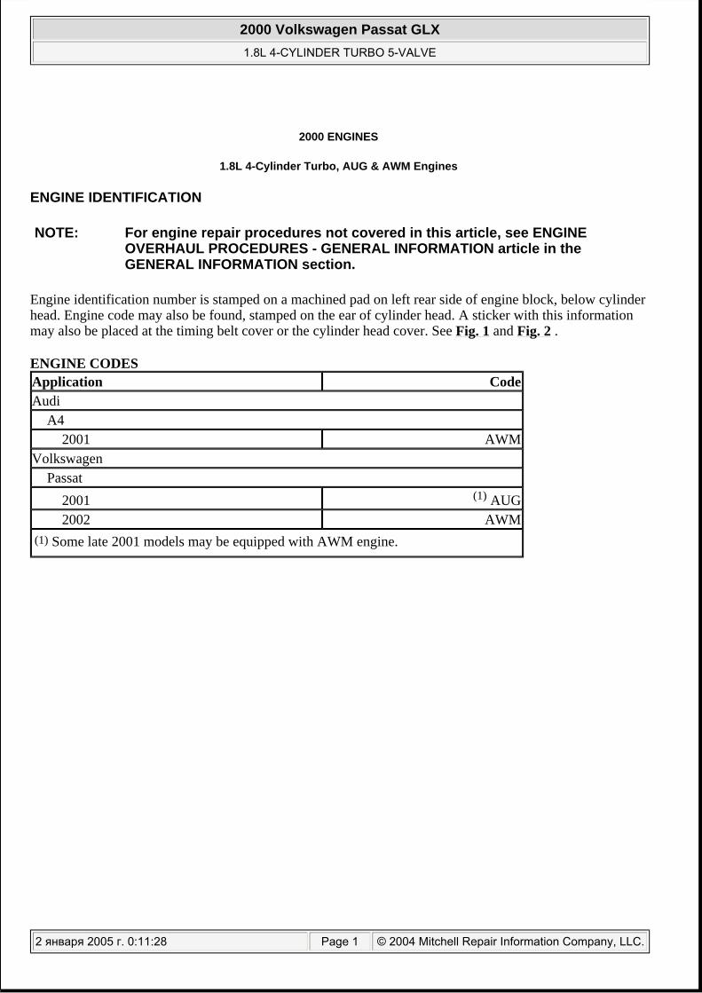
Disconnect green electrical connector to A/C compressor. See Fig. 45 . Disconnect A/C refrigerant line brackets at support points only. After A/C compressor is removed from bracket, support with heavy wire and set A/C compressor carefully aside, avoid damage from bending or kinking refrigerant lines.
NOTE: DO NOT open the air conditioning refrigerant lines.
2000 Volkswagen Passat GLX 1.8L 4-CYLINDER TURBO 5-VALVE
2 января 2005 г. 0:11:33 Page 53 © 2004 Mitchell Repair Information Company, LLC.
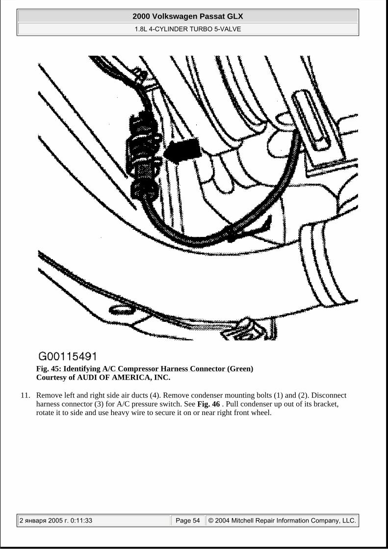
Fig. 45: Identifying A/C Compressor Harness Connector (Green) Courtesy of AUDI OF AMERICA, INC.
11. Remove left and right side air ducts (4). Remove condenser mounting bolts (1) and (2). Disconnect harness connector (3) for A/C pressure switch. See Fig. 46 . Pull condenser up out of its bracket, rotate it to side and use heavy wire to secure it on or near right front wheel.
2000 Volkswagen Passat GLX 1.8L 4-CYLINDER TURBO 5-VALVE
2 января 2005 г. 0:11:33 Page 54 © 2004 Mitchell Repair Information Company, LLC.

Fig. 46: Identifying Location Of A/C Pressure Switch Courtesy of AUDI OF AMERICA, INC.
12. On A4, unbolt lock carrier, secure in service position. On Passat, remove lock carrier. See LOCK CARRIER .
13. On A4, proceed with this step. For Passat, go to next step. At air filter box, disconnect harness connectors from ACF valve, Air Mass Meter, and Wastegate Bypass Regulator Valve. Disconnect turbocharger air intake and throttle valve control module ducts and hoses. Remove ACF valve from air filter box. Disconnect harness connectors from Secondary Air Injection Pump, disconnect secondary air inlet hose, both located under the air box. Disconnect cables and hoses that would interfere with engine removal. See Fig. 47 and Fig. 48 .
2000 Volkswagen Passat GLX 1.8L 4-CYLINDER TURBO 5-VALVE
2 января 2005 г. 0:11:33 Page 55 © 2004 Mitchell Repair Information Company, LLC.

2000 Volkswagen Passat GLX 1.8L 4-CYLINDER TURBO 5-VALVE
2 января 2005 г. 0:11:33 Page 56 © 2004 Mitchell Repair Information Company, LLC.

Fig. 47: Identifying Components At Air Filter Box Courtesy of AUDI OF AMERICA, INC.
Fig. 48: Identifying Secondary Air Injection Harness Connector Courtesy of AUDI OF AMERICA, INC.
14. Disconnect vacuum hoses to brake booster, ACF valve and vacuum reservoir. See Fig. 40 . 15. On Passat, disconnect pressure hose for Secondary Air Injection (AIR) pump at connecting tube.
Remove tube for crankcase housing ventilation (1). Disconnect pressure tube (2) at combination valve
2000 Volkswagen Passat GLX 1.8L 4-CYLINDER TURBO 5-VALVE
2 января 2005 г. 0:11:33 Page 57 © 2004 Mitchell Repair Information Company, LLC.

and unbolt from cylinder head cover. Unbolt combination valve with mount (3) and move to side. Remove T-piece (5) of crankcase housing ventilation. See Fig. 49 . Disconnect required connecting and vacuum hoses from engine.
Fig. 49: Identifying Secondary Air Injection Connection Components (Passat) Courtesy of VOLKSWAGEN UNITED STATES, INC.
16. On all A4 and Passat, disconnect all coolant and heater hoses. Remove coolant system expansion reservoir and set aside. See Fig. 50 . Remove heater hoses at cylinder head connection.
2000 Volkswagen Passat GLX 1.8L 4-CYLINDER TURBO 5-VALVE
2 января 2005 г. 0:11:33 Page 58 © 2004 Mitchell Repair Information Company, LLC.

Fig. 50: Identifying Coolant Expansion Tank (Location Of Coolant Level Sensor Connector Not Shown) Courtesy of AUDI OF AMERICA, INC.
17. Remove Motronic Engine Control Module (E-Box) carrier cover and disconnect harness connectors. See Fig. 51 and Fig. 52 .
2000 Volkswagen Passat GLX 1.8L 4-CYLINDER TURBO 5-VALVE
2 января 2005 г. 0:11:33 Page 59 © 2004 Mitchell Repair Information Company, LLC.

Fig. 51: Identifying Motronic Engine Control Module (E-Box) Cover Fasteners Courtesy of AUDI OF AMERICA, INC.
2000 Volkswagen Passat GLX 1.8L 4-CYLINDER TURBO 5-VALVE
2 января 2005 г. 0:11:33 Page 60 © 2004 Mitchell Repair Information Company, LLC.

2000 Volkswagen Passat GLX 1.8L 4-CYLINDER TURBO 5-VALVE
2 января 2005 г. 0:11:33 Page 61 © 2004 Mitchell Repair Information Company, LLC.

Fig. 52: Identifying Motronic Engine Control Module (E-Box) With Harness Connectors Removed Courtesy of AUDI OF AMERICA, INC.
18. Release locks on additional relay carrier, located at the rear of the ECM/Relay protective box. Disconnect harness connectors on rear of console. See Fig. 53 . Kickdown switch harness connector. See Fig. 54 .
Fig. 53: Identifying Addition Relays Found At Rear Of ECM Carrier Box Courtesy of AUDI OF AMERICA, INC.
2000 Volkswagen Passat GLX 1.8L 4-CYLINDER TURBO 5-VALVE
2 января 2005 г. 0:11:33 Page 62 © 2004 Mitchell Repair Information Company, LLC.

Fig. 54: Identifying Kickdown Switch Harness Connector Courtesy of AUDI OF AMERICA, INC.
19. Disconnect oxygen sensors harness connectors, remove fasteners to harness connector bracket also remove ground wires at firewall. Set harness bracket aside. See Fig. 55 and Fig. 56 .
2000 Volkswagen Passat GLX 1.8L 4-CYLINDER TURBO 5-VALVE
2 января 2005 г. 0:11:34 Page 63 © 2004 Mitchell Repair Information Company, LLC.

Fig. 55: Identifying Oxygen Sensor Harness Connector Courtesy of AUDI OF AMERICA, INC.
2000 Volkswagen Passat GLX 1.8L 4-CYLINDER TURBO 5-VALVE
2 января 2005 г. 0:11:34 Page 64 © 2004 Mitchell Repair Information Company, LLC.

Fig. 56: Identifying Harness Connector Bracket Courtesy of AUDI OF AMERICA, INC.
20. Disconnect front exhaust pipe from catalytic converter. Remove front catalytic converter from turbocharger. See Fig. 57 and Fig. 58 .
2000 Volkswagen Passat GLX 1.8L 4-CYLINDER TURBO 5-VALVE
2 января 2005 г. 0:11:34 Page 65 © 2004 Mitchell Repair Information Company, LLC.

Fig. 57: Identifying Front Exhaust Pipe Front Exhaust Hanger Courtesy of AUDI OF AMERICA, INC.
2000 Volkswagen Passat GLX 1.8L 4-CYLINDER TURBO 5-VALVE
2 января 2005 г. 0:11:34 Page 66 © 2004 Mitchell Repair Information Company, LLC.

Fig. 58: Identifying Catalytic Converter & Turbocharger Junction Courtesy of AUDI OF AMERICA, INC.
21. Disconnect Leak Detection Pump (LDP) vacuum lines. See Fig. 59 .
2000 Volkswagen Passat GLX 1.8L 4-CYLINDER TURBO 5-VALVE
2 января 2005 г. 0:11:34 Page 67 © 2004 Mitchell Repair Information Company, LLC.

Fig. 59: Identifying Leak Detection Pump Hose, Remove From Intake Courtesy of AUDI OF AMERICA, INC.
22. Disconnect Vehicle Speed Sensor (VSS). On Manual Transmission (M/T) disconnect harness connector from transmission (backup lights). Disconnect Anti-Lock Brake System (ABS) harness connectors. See Fig. 60 .
2000 Volkswagen Passat GLX 1.8L 4-CYLINDER TURBO 5-VALVE
2 января 2005 г. 0:11:34 Page 68 © 2004 Mitchell Repair Information Company, LLC.

Fig. 60: Identifying Anti-Lock Brake System Harness Connectors Courtesy of AUDI OF AMERICA, INC.
23. Remove serpentine (ribbed) accessary drive belt. See ACCESSORY DRIVE BELTS . Remove viscous fan. See VISCOUS FAN . Remove power steering pump and position to the side and secure (DO NOT open power steering lines).
24. Remove support bracket between starter and cylinder block, disconnect wiring harness from starter. Remove starter from transmission. See Fig. 61 .
2000 Volkswagen Passat GLX 1.8L 4-CYLINDER TURBO 5-VALVE
2 января 2005 г. 0:11:34 Page 69 © 2004 Mitchell Repair Information Company, LLC.

Fig. 61: Identifying Starter Motor and Support Bracket Courtesy of AUDI OF AMERICA, INC.
25.
Remove upper engine-to-transmission bolts. Mark positions of left and right engine mount locating sleeves from bottom. See Fig. 62 . Remove lower left and right engine mount nuts. If equipped with automatic transmission, raise vehicle, remove 3 torque converter bolts accessed through starter pinion hole at bell housing. See Fig. 63 .
NOTE: Different mounting holes are provided for the different engine versions.
2000 Volkswagen Passat GLX 1.8L 4-CYLINDER TURBO 5-VALVE
2 января 2005 г. 0:11:34 Page 70 © 2004 Mitchell Repair Information Company, LLC.

Fig. 62: Identifying Location Of Locating Sleeves (Mark Sleeves For Reinstallation) Courtesy of AUDI OF AMERICA, INC.
2000 Volkswagen Passat GLX 1.8L 4-CYLINDER TURBO 5-VALVE
2 января 2005 г. 0:11:34 Page 71 © 2004 Mitchell Repair Information Company, LLC.

Fig. 63: Identifying Access To Torque Converter Bolts Courtesy of AUDI OF AMERICA, INC.
26.
2000 Volkswagen Passat GLX 1.8L 4-CYLINDER TURBO 5-VALVE
2 января 2005 г. 0:11:34 Page 72 © 2004 Mitchell Repair Information Company, LLC.

For A4 A4, proceed with this step. For Passat, go to next step. Lift engine and transmission slightly using Workshop Crane (VAG 1202 A) to allow lower engine/transmission connecting bolts to be removed. See Fig. 64 . Remove lower engine/transmission connecting bolts.
Fig. 64: Using Hoist Crane (VAG 1202 A) To Raise Engine & Transmission Courtesy of AUDI OF AMERICA, INC.
27.
On Passat, raise vehicle, remove stop from front of engine at oil pan. See Fig. 66 . Position Pole jack (VAG 1383A) under engine and fasten Adaptor Mount (T10062) to oil pan. USE one of the bolts from the stop bracket with 3 washers (each 4 mm thick), and put bolt and washers through Adaptor Mount (T10062) to bolt hole in oil pan. Tighten bolts to 30 N.m (22 ft. lbs.). See Fig. 67 . Lift engine and transmission slightly to allow lower engine/transmission connecting bolts to be removed. Lift
CAUTION: When lifting engine, ensure crankcase housing ventilation tube does not contact the firewall (bulkhead) and that no lines get pinched.
NOTE: Adaptor Mount (T10062) may need to be modified. VAG instructs to: Drill an additional hole centered in height of the lower bore if not yet present. Dimension "A" equals 8.5 mm. Refer to Fig. 65 .
2000 Volkswagen Passat GLX 1.8L 4-CYLINDER TURBO 5-VALVE
2 января 2005 г. 0:11:34 Page 73 © 2004 Mitchell Repair Information Company, LLC.

engine only high enough to remove bolts.
Fig. 65: Modifying Adaptor Mount (T10062) For Passat Oil Pan Courtesy of VOLKSWAGEN UNITED STATES, INC.
2000 Volkswagen Passat GLX 1.8L 4-CYLINDER TURBO 5-VALVE
2 января 2005 г. 0:11:34 Page 74 © 2004 Mitchell Repair Information Company, LLC.

Fig. 66: Identifying Engine Stop Bracket At front of Oil Pan Courtesy of VOLKSWAGEN UNITED STATES, INC.
2000 Volkswagen Passat GLX 1.8L 4-CYLINDER TURBO 5-VALVE
2 января 2005 г. 0:11:34 Page 75 © 2004 Mitchell Repair Information Company, LLC.

Fig. 67: Using Pole Jack (VAG 1383 A) & Adaptor Mount (T10062) To Raise Engine Courtesy of VOLKSWAGEN UNITED STATES, INC.
28.
On A4 and Passat, install Engine Support Bracket (10-222A) and Hooks (10-222A/2) to engine. Install Transmission Support (3147) to transmission bellhousing bolt hole. See Fig. 68 -Fig. 70 .
CAUTION: When lifting engine, ensure crankcase housing ventilation tube does not contact the firewall (bulkhead) and that no lines get pinched.DO NOT allow torque converter to fall out of bell housing.
2000 Volkswagen Passat GLX 1.8L 4-CYLINDER TURBO 5-VALVE
2 января 2005 г. 0:11:35 Page 76 © 2004 Mitchell Repair Information Company, LLC.

2000 Volkswagen Passat GLX 1.8L 4-CYLINDER TURBO 5-VALVE
2 января 2005 г. 0:11:35 Page 77 © 2004 Mitchell Repair Information Company, LLC.

Fig. 68: Installing Support Bridge (10-222A) & Trans Support Adaptor (3147) (A4) Courtesy of AUDI OF AMERICA, INC.
Fig. 69: Installing Support Bridge (10-222A) & Trans Support Adaptor (3147) (Passat) Courtesy of AUDI OF AMERICA, INC.
2000 Volkswagen Passat GLX 1.8L 4-CYLINDER TURBO 5-VALVE
2 января 2005 г. 0:11:35 Page 78 © 2004 Mitchell Repair Information Company, LLC.

Fig. 70: Installing Engine Sling (2024) & Hoist Crane (VAG 1202 A) Courtesy of AUDI OF AMERICA, INC.
29. Carefully raise engine out of vehicle. Install engine to Support Clamp (VW 313) using engine/transmission Bracket (VW 540). See Fig. 71 .
2000 Volkswagen Passat GLX 1.8L 4-CYLINDER TURBO 5-VALVE
2 января 2005 г. 0:11:35 Page 79 © 2004 Mitchell Repair Information Company, LLC.

Fig. 71: Installing Engine Onto Engine/transmission Support Bracket (VW 540) Courtesy of AUDI OF AMERICA, INC.
Installation
1. To install, reverse removal procedure. Always replace self-locking nuts. Ensure engine-to-transmission locating sleeves are properly installed in cylinder block. For manual transmission, go to next step. For automatic transmission, go to step 3 .
2.
For manual transmission, ensure dowel sleeves and intermediate plate are installed on block before installing transmission. Clean and lubricate transmission input shaft splines with lubricant (G 000100)
NOTE: Manufacturer recommends using NEW pressure plate-to-flywheel bolts on installation.
2000 Volkswagen Passat GLX 1.8L 4-CYLINDER TURBO 5-VALVE
2 января 2005 г. 0:11:35 Page 80 © 2004 Mitchell Repair Information Company, LLC.

or equivalent. Make sure clutch disc and pressure plate are properly installed. See TORQUE SPECIFICATIONS . Make sure pilot needle bearing is installed. For more information on transmission servicing, see appropriate article in CLUTCHES. Go to step 5 .
3.
For automatic transmission, when mounting torque converter to drive plate, use only bolts specified for this use. Before installing engine, align torque converter and drive plate so that one hole in torque converter and one hole in drive plate are level with opening for starter. See Fig. 63 .
4.
Check installation position of torque converter. If the torque converter is installed correctly, the distance between contact surfaces at the mounting holes on the torque converter and contact surface of the bell housing flange (transmission 01V) will be approximately 23 mm (7/8"). If the torque converter was not completely installed, this distance will be approximately 11 mm (7/16 in.). See Fig. 72 .
NOTE: Always replace seals and O-rings.
CAUTION: If the torque converter is not installed correctly the torque converter, drive plate or the ATF pump will be seriously damaged when the transmission is attached to the engine.
2000 Volkswagen Passat GLX 1.8L 4-CYLINDER TURBO 5-VALVE
2 января 2005 г. 0:11:35 Page 81 © 2004 Mitchell Repair Information Company, LLC.

Fig. 72: Identifying Placement Of Measuring Tool For Checking Torque Converter InstallationCourtesy of AUDI OF AMERICA, INC.
5. On all models, align engine to transmission bellhousing and install proper length bolts. Torque to specifications. See Fig. 73 and Fig. 74 .
2000 Volkswagen Passat GLX 1.8L 4-CYLINDER TURBO 5-VALVE
2 января 2005 г. 0:11:35 Page 82 © 2004 Mitchell Repair Information Company, LLC.

2000 Volkswagen Passat GLX 1.8L 4-CYLINDER TURBO 5-VALVE
2 января 2005 г. 0:11:35 Page 83 © 2004 Mitchell Repair Information Company, LLC.

Fig. 73: Identifying Transmission To Engine Bolt Length Reference (Automatic Transmission) Courtesy of AUDI OF AMERICA, INC.
2000 Volkswagen Passat GLX 1.8L 4-CYLINDER TURBO 5-VALVE
2 января 2005 г. 0:11:35 Page 84 © 2004 Mitchell Repair Information Company, LLC.

2000 Volkswagen Passat GLX 1.8L 4-CYLINDER TURBO 5-VALVE
2 января 2005 г. 0:11:35 Page 85 © 2004 Mitchell Repair Information Company, LLC.

Fig. 74: Identifying Transmission To Engine Bolt Length Reference (Manual Transmission) Courtesy of AUDI OF AMERICA, INC.
6. Engine alignment adjustment is necessary whenever engine is removed or mounts are loosened. To adjust, loosen through-bolt on engine mounts. Lightly rock engine and transaxle to shift as necessary. Tighten mount bolts. Align exhaust so components are free of stress. Tighten all bolts and nuts to specification. See TORQUE SPECIFICATIONS .
7. With the engine settled, adjust the front engine mount. Loosen front engine mount stop bracket, adjust so "stop" comes to rest on "stop buffer" under its own weight. Tighten fastener bolts to 30 N.m (22 ft. lbs.). See Fig. 75 .
2000 Volkswagen Passat GLX 1.8L 4-CYLINDER TURBO 5-VALVE
2 января 2005 г. 0:11:35 Page 86 © 2004 Mitchell Repair Information Company, LLC.

2000 Volkswagen Passat GLX 1.8L 4-CYLINDER TURBO 5-VALVE
2 января 2005 г. 0:11:35 Page 87 © 2004 Mitchell Repair Information Company, LLC.

Fig. 75: Identifying Front Engine Mount Courtesy of VOLKSWAGEN UNITED STATES, INC.
8. Verify engine fluid levels are filled to proper levels. Adjust clutch pedal (if equipped). For more information on transmission servicing, see appropriate article in CLUTCHES for manual transmission.
9. Refill and bleed air from cooling system. See COOLING SYSTEM BLEEDING . 10. Perform a test drive and check memory for Diagnostic Trouble Codes (DTC). See appropriate SELF-
DIAGNOSTICS article in ENGINE PERFORMANCE. 11. Match engine electronics control module to throttle valve control module.
For 2001 Passat, see THROTTLE VALVE CONTROL MODULE (J338) in SELF-DIAGNOSTICS article in ENGINE PERFORMANCE. For 2002 Passat, see THROTTLE VALVE CONTROL MODULE (J338) in SELF-DIAGNOSTICS article in ENGINE PERFORMANCE. For 2001 A4, see FUNCTION 04 -- BASIC SETTING article in SELF-DIAGNOSTICS article in ENGINE PERFORMANCE.
12. Read Readiness Codes. For 2001 Passat, see SELF-DIAGNOSTICS -- 1.8L TURBO article in ENGINE PERFORMANCE. For 2002 Passat, see SELF-DIAGNOSTICS -- 1.8L TURBO article in ENGINE PERFORMANCE. For 2001 A4, see SELF-DIAGNOSTICS -- A4 1.8L TURBO article in ENGINE PERFORMANCE.
13. If DTC memory has been erased or engine control module separated from permanent positive, readiness code must be generated again.
DRIVE PLATE (A/T)
Removal
1. Mark the position of the drive plate relative to the engine. Also mark positions of the washer (1) and the shim (2) between the drive plate and the crankshaft flange. See Fig. 76 .
NOTE: The following procedure is given assuming the transmission has been removed or the engine has been removed for servicing.
2000 Volkswagen Passat GLX 1.8L 4-CYLINDER TURBO 5-VALVE
2 января 2005 г. 0:11:36 Page 88 © 2004 Mitchell Repair Information Company, LLC.

Fig. 76: Identifying Washer, Driveplate & Shim Courtesy of VOLKSWAGEN UNITED STATES, INC.
2. Using appropriate counter hold tool, loosen the bolts in a cross pattern. Remove drive plate. See Fig. 77 and Fig. 78 .
2000 Volkswagen Passat GLX 1.8L 4-CYLINDER TURBO 5-VALVE
2 января 2005 г. 0:11:36 Page 89 © 2004 Mitchell Repair Information Company, LLC.

Fig. 77: Locking Drive Plate In Position Using Counter Hold Tool (VW 558) Courtesy of AUDI OF AMERICA, INC.
2000 Volkswagen Passat GLX 1.8L 4-CYLINDER TURBO 5-VALVE
2 января 2005 г. 0:11:36 Page 90 © 2004 Mitchell Repair Information Company, LLC.

Fig. 78: Identifying Location Of Bearing Bushing For Torque Converter Courtesy of VOLKSWAGEN UNITED STATES, INC.
2000 Volkswagen Passat GLX 1.8L 4-CYLINDER TURBO 5-VALVE
2 января 2005 г. 0:11:36 Page 91 © 2004 Mitchell Repair Information Company, LLC.

Installation
1. Install driveplate with shim. See Fig. 76 . Using 3 of the old bolts inserted into flange, evenly spaced torque to 30 N.m (22 ft. lbs.).
2. Check dimension "A" at 3 pointsto milled surface of cylinder block. See Fig. 79 . Dimension should be:
A4 18.9-20.5 mm (0.744-0.807")
Passat 26-28 mm (1.023-1.102")
NOTE: Manufacturer recommends using NEW bolts on installation.
2000 Volkswagen Passat GLX 1.8L 4-CYLINDER TURBO 5-VALVE
2 января 2005 г. 0:11:36 Page 92 © 2004 Mitchell Repair Information Company, LLC.
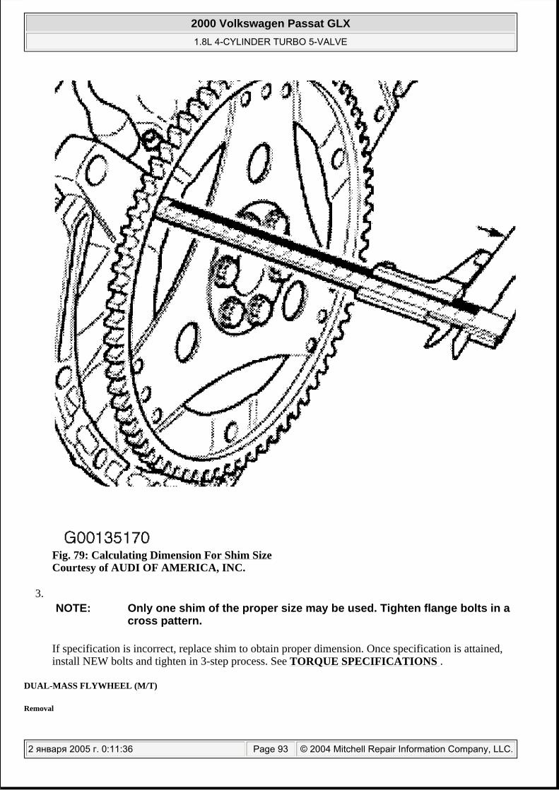
Fig. 79: Calculating Dimension For Shim Size Courtesy of AUDI OF AMERICA, INC.
3.
If specification is incorrect, replace shim to obtain proper dimension. Once specification is attained, install NEW bolts and tighten in 3-step process. See TORQUE SPECIFICATIONS .
DUAL-MASS FLYWHEEL (M/T)
Removal
NOTE: Only one shim of the proper size may be used. Tighten flange bolts in a cross pattern.
2000 Volkswagen Passat GLX 1.8L 4-CYLINDER TURBO 5-VALVE
2 января 2005 г. 0:11:36 Page 93 © 2004 Mitchell Repair Information Company, LLC.

1. Mark the position of the flywheel relative to the engine. 2. Using appropriate counter hold tool, loosen the bolts in a cross pattern. See Fig. 80 . Remove
flywheel.
Fig. 80: Locking Flywheel In Position Using Counter Hold Tool (VAG 10 201) Courtesy of AUDI OF AMERICA, INC.
Installation
NOTE: The following procedure is given assuming the transmission has been removed or the engine has been removed for servicing.
NOTE: For flywheel (M/T) pilot needle bearing inspection . See PILOT NEEDLE BEARING (M/T) .
2000 Volkswagen Passat GLX 1.8L 4-CYLINDER TURBO 5-VALVE
2 января 2005 г. 0:11:36 Page 94 © 2004 Mitchell Repair Information Company, LLC.

Install flywheel in reverse order of removal using NEW bolts. Tighten bolts to specification in a crisscross pattern. See TORQUE SPECIFICATIONS .
PILOT NEEDLE BEARING (M/T)
Removal & Installation
1. Remove transmission. See appropriate article in CLUTCHES. Remove flywheel. 2. Using Puller (Kukko 22/1) and Bearing Extractor (Kukko 21/1), remove pilot needle bearing. See Fig.
81 .
Fig. 81: Removing Pilot Needle Bearing Courtesy of VOLKSWAGEN UNITED STATES, INC.
NOTE: Manufacturer recommends using NEW bolts on installation.
2000 Volkswagen Passat GLX 1.8L 4-CYLINDER TURBO 5-VALVE
2 января 2005 г. 0:11:36 Page 95 © 2004 Mitchell Repair Information Company, LLC.

3. Use Bearing Driver (VW 207C) to install pilot needle bearing. See Fig. 82 and Fig. 83 . For flywheel installation. See DRIVE PLATE (A/T) & FLYWHEEL (M/T) .
Fig. 82: Installing Pilot Needle Bearing Using (VW 207C) Courtesy of VOLKSWAGEN UNITED STATES, INC.
2000 Volkswagen Passat GLX 1.8L 4-CYLINDER TURBO 5-VALVE
2 января 2005 г. 0:11:36 Page 96 © 2004 Mitchell Repair Information Company, LLC.

Fig. 83: Pilot Needle Bearing Insertion Depth (A=1.5 mm) Courtesy of VOLKSWAGEN UNITED STATES, INC.
INTAKE MANIFOLD
Removal & Installation
1. Remove battery. Remove lower engine shield (noise insulator). See Fig. 18 . Drain coolant, see DRAINING COOLING SYSTEM .
2. Remove cover for fuel injectors. Remove bolts securing fuel rail to intake manifold. Remove fuel injectors and rail together and rest aside on a clean shop towel. See Fig. 84 .
NOTE: Obtain radio code before disconnecting battery. Remove engine, without transmission, through front of engine compartment.
WARNING: The cooling system is pressurized when the engine is warm. When opening the expansion tank, wear gloves and other appropriate protection, cover the cap with a cloth and open carefully to relieve system pressure slowly.
2000 Volkswagen Passat GLX 1.8L 4-CYLINDER TURBO 5-VALVE
2 января 2005 г. 0:11:36 Page 97 © 2004 Mitchell Repair Information Company, LLC.

Fig. 84: Identifying Intake Manifold & Fuel Rail Components Courtesy of AUDI OF AMERICA, INC.
3. Disconnect vacuum lines (1) through (4) from around intake manifold. Disconnect harness connector (5) from throttle body. Remove air intake tube (6) from throttle body. See Fig. 85 .
2000 Volkswagen Passat GLX 1.8L 4-CYLINDER TURBO 5-VALVE
2 января 2005 г. 0:11:36 Page 98 © 2004 Mitchell Repair Information Company, LLC.

Fig. 85: Disconnecting Components For Intake Manifold Removal Courtesy of AUDI OF AMERICA, INC.
4. At rear of manifold on bottom side, unbolt the 3 fasteners and move solenoid retainer plate aside
2000 Volkswagen Passat GLX 1.8L 4-CYLINDER TURBO 5-VALVE
2 января 2005 г. 0:11:37 Page 99 © 2004 Mitchell Repair Information Company, LLC.

(vacuum lines and harness connectors can remain connected). See Fig. 86 . Disconnect vacuum lines from brake booster. Disconnect Cam Position (CMP) Sensor. See Fig. 135 .
Fig. 86: Identifying Location Of Solenoid Valve Retainer Plate Courtesy of AUDI OF AMERICA, INC.
5. Disconnect coolant hoses at upper coolant line. See Fig. 84 . Disconnect upper coolant line at intake line and rear coolant flange at rear of cylinder head. See Fig. 87 .
2000 Volkswagen Passat GLX 1.8L 4-CYLINDER TURBO 5-VALVE
2 января 2005 г. 0:11:37 Page 100 © 2004 Mitchell Repair Information Company, LLC.

Fig. 87: Identifying Coolant Pipe Connection At Rear Of Cylinder Head Courtesy of AUDI OF AMERICA, INC.
6. Disconnect crank case ventilation hose (1) at manifold. Remove brace (2). See Fig. 88 . Remove oil dipstick and remove dipstick guide line bracket.
2000 Volkswagen Passat GLX 1.8L 4-CYLINDER TURBO 5-VALVE
2 января 2005 г. 0:11:37 Page 101 © 2004 Mitchell Repair Information Company, LLC.

2000 Volkswagen Passat GLX 1.8L 4-CYLINDER TURBO 5-VALVE
2 января 2005 г. 0:11:37 Page 102 © 2004 Mitchell Repair Information Company, LLC.

Fig. 88: Identifying Brace & Hose Connected To Intake Manifold Courtesy of AUDI OF AMERICA, INC.
7. Unbolt intake manifold at flange and remove manifold. Block intake ports in cylinder head with clean shop towels. To install, reverse removal procedure. Tighten bolts to specification. See TORQUE SPECIFICATIONS .
8. Refill and bleed air from cooling system. See COOLING SYSTEM BLEEDING .
EXHAUST MANIFOLD
Removal and installation procedures are not available from manufacturer. See TURBOCHARGER . On installation, tighten bolts to specification. See TORQUE SPECIFICATIONS .
TURBOCHARGER
Removal & Installation
1. Remove battery. Remove engine cover(s). Raise vehicle, remove lower engine shield (noise insulator). See Fig. 18 . Drain coolant, see DRAINING COOLING SYSTEM .
2.
Unbolt A/C compressor. Move compressor aside and support with wire. 3. Unbolt turbo support bracket (2), disconnect oil return line (1) from turbo and move aside. Remove
ducting from turbo (4 and 5). Remove pressure line banjo fitting (3). See Fig. 89 .
WARNING: The cooling system is pressurized when the engine is warm. When opening the expansion tank, wear gloves and other appropriate protection, cover the cap with a cloth and open carefully to relieve system pressure slowly.
NOTE: Obtain radio code before disconnecting battery. Remove engine, without transmission, through front of engine compartment. Always replace gaskets and self locking nuts.
NOTE: For help in identifying components and component locations, refer to illustrations. See Fig. 91 - Fig. 97 .
NOTE: DO NOT let A/C compressor hang by hoses, do not open the A/C system.
2000 Volkswagen Passat GLX 1.8L 4-CYLINDER TURBO 5-VALVE
2 января 2005 г. 0:11:37 Page 103 © 2004 Mitchell Repair Information Company, LLC.

Fig. 89: Removing Turbocharger Support Bracket & Oil Return Line Courtesy of AUDI OF AMERICA, INC.
4. Disconnect hose from support for charge air pressure regulator valve. Unbolt bracket for coolant supply line at charge air pressure regulator valve. Remove air intake duct between cowl and air cleaner housing.
5. Disconnect harness connectors from around air cleaner box. Remove air cleaner box. See Fig. 47 . 6. Unbolt crankcase ventilation hose (1). Unbolt oil supply line bolts (3) at heat shield. Remove heat
shield (4). Remove sleeve (2) from coolant return hose. Remove turbo return hose at line to turbo. The line remains bolted to turbocharger. Unbolt the oil supply line (7) from turbo. See Fig. 90 .
2000 Volkswagen Passat GLX 1.8L 4-CYLINDER TURBO 5-VALVE
2 января 2005 г. 0:11:37 Page 104 © 2004 Mitchell Repair Information Company, LLC.

Fig. 90: Removing Turbocharger Oil Supply Line & Heat Shield Courtesy of AUDI OF AMERICA, INC.
7. Unbolt catalytic converter from turbocharger. Remove bolts from exhaust manifold. Position turbocharger to gain access to coolant supply line banjo fitting. Remove banjo fitting. Remove turbocharger.
8.
To complete installation, reverse removal procedure. Tighten bolts to specification. See TORQUE SPECIFICATIONS . For help in identifying intake ducting components, vacuum line routing and component locations, refer to Fig. 93 -Fig. 97 .
9. Refill and bleed air from cooling system. See COOLING SYSTEM BLEEDING .
NOTE: Before tightening turbocharger, loosely bolt coolant supply line to vacuum diaphragm for air pressure regulator valve. Tighten banjo fitting, then tighten mounting bolts for bracket to proper torque.
2000 Volkswagen Passat GLX 1.8L 4-CYLINDER TURBO 5-VALVE
2 января 2005 г. 0:11:37 Page 105 © 2004 Mitchell Repair Information Company, LLC.

2000 Volkswagen Passat GLX 1.8L 4-CYLINDER TURBO 5-VALVE
2 января 2005 г. 0:11:37 Page 106 © 2004 Mitchell Repair Information Company, LLC.

Fig. 91: Identifying Exhaust Manifold & Turbocharger Components (A4) Courtesy of AUDI OF AMERICA, INC.
2000 Volkswagen Passat GLX 1.8L 4-CYLINDER TURBO 5-VALVE
2 января 2005 г. 0:11:37 Page 107 © 2004 Mitchell Repair Information Company, LLC.

2000 Volkswagen Passat GLX 1.8L 4-CYLINDER TURBO 5-VALVE
2 января 2005 г. 0:11:37 Page 108 © 2004 Mitchell Repair Information Company, LLC.

Fig. 92: Identifying Exhaust Manifold & Turbocharger Components (Passat) Courtesy of VOLKSWAGEN UNITED STATES, INC.
2000 Volkswagen Passat GLX 1.8L 4-CYLINDER TURBO 5-VALVE
2 января 2005 г. 0:11:37 Page 109 © 2004 Mitchell Repair Information Company, LLC.

2000 Volkswagen Passat GLX 1.8L 4-CYLINDER TURBO 5-VALVE
2 января 2005 г. 0:11:38 Page 110 © 2004 Mitchell Repair Information Company, LLC.

Fig. 93: Identifying Intake Ducting & Components (A4 & Passat) Courtesy of AUDI OF AMERICA, INC.
2000 Volkswagen Passat GLX 1.8L 4-CYLINDER TURBO 5-VALVE
2 января 2005 г. 0:11:38 Page 111 © 2004 Mitchell Repair Information Company, LLC.

2000 Volkswagen Passat GLX 1.8L 4-CYLINDER TURBO 5-VALVE
2 января 2005 г. 0:11:38 Page 112 © 2004 Mitchell Repair Information Company, LLC.

Fig. 94: Identifying Intake Ducting & Components With Charge Air Cooler (A4) Courtesy of AUDI OF AMERICA, INC.
2000 Volkswagen Passat GLX 1.8L 4-CYLINDER TURBO 5-VALVE
2 января 2005 г. 0:11:38 Page 113 © 2004 Mitchell Repair Information Company, LLC.

2000 Volkswagen Passat GLX 1.8L 4-CYLINDER TURBO 5-VALVE
2 января 2005 г. 0:11:38 Page 114 © 2004 Mitchell Repair Information Company, LLC.

Fig. 95: Identifying Intake Ducting & Components With Charge Air Cooler (Passat) Courtesy of VOLKSWAGEN UNITED STATES, INC.
2000 Volkswagen Passat GLX 1.8L 4-CYLINDER TURBO 5-VALVE
2 января 2005 г. 0:11:38 Page 115 © 2004 Mitchell Repair Information Company, LLC.

2000 Volkswagen Passat GLX 1.8L 4-CYLINDER TURBO 5-VALVE
2 января 2005 г. 0:11:38 Page 116 © 2004 Mitchell Repair Information Company, LLC.

Fig. 96: Identifying Charge Air Pressure Control System Components & Vacuum Line Routing (A4) Courtesy of AUDI OF AMERICA, INC.
Fig. 97: Identifying Charge Air Pressure Control System Components & Vacuum Line Routing
2000 Volkswagen Passat GLX 1.8L 4-CYLINDER TURBO 5-VALVE
2 января 2005 г. 0:11:38 Page 117 © 2004 Mitchell Repair Information Company, LLC.

(Passat) Courtesy of VOLKSWAGEN UNITED STATES, INC.
CYLINDER HEAD COVER
Removal & Installation
1. Remove fasteners securing air duct. See Fig. 98 . Remove air ducts to air filter box.
2000 Volkswagen Passat GLX 1.8L 4-CYLINDER TURBO 5-VALVE
2 января 2005 г. 0:11:38 Page 118 © 2004 Mitchell Repair Information Company, LLC.

2000 Volkswagen Passat GLX 1.8L 4-CYLINDER TURBO 5-VALVE
2 января 2005 г. 0:11:38 Page 119 © 2004 Mitchell Repair Information Company, LLC.

Fig. 98: Identifying Air Duct Securing Fasteners Courtesy of AUDI OF AMERICA, INC.
2. Disconnect crankcase vent lines (1) and (2) from combination valve and cylinder head cover. Remove fasteners from head shield (if equipped). See Fig. 99 . Carefully move secondary air inlet line to the side.
Fig. 99: Removing Crankcase Vent Lines Courtesy of AUDI OF AMERICA, INC.
3. Disconnect ground wire, remove ignition coils and remove fasteners securing upper timing belt cover to the cylinder head cover. See Fig. 100 . Remove cover fasteners (nuts) in small amounts, in several steps. See Fig. 101 .
2000 Volkswagen Passat GLX 1.8L 4-CYLINDER TURBO 5-VALVE
2 января 2005 г. 0:11:38 Page 120 © 2004 Mitchell Repair Information Company, LLC.

Fig. 100: Identifying Ground Wire & Ignition Coils Courtesy of AUDI OF AMERICA, INC.
2000 Volkswagen Passat GLX 1.8L 4-CYLINDER TURBO 5-VALVE
2 января 2005 г. 0:11:39 Page 121 © 2004 Mitchell Repair Information Company, LLC.

Fig. 101: Identifying Cylinder Head Cover Securing Fasteners Courtesy of AUDI OF AMERICA, INC.
4. Clean sealing surfaces on cylinder head. To install, reverse removal procedure. Before installation of cylinder head cover apply a thin layer of sealer (D 454 300 A2) at the points of cylinder head cover where leakage may occur. See Fig. 102 . To prevent oil leaks, replace old gaskets.
2000 Volkswagen Passat GLX 1.8L 4-CYLINDER TURBO 5-VALVE
2 января 2005 г. 0:11:39 Page 122 © 2004 Mitchell Repair Information Company, LLC.

2000 Volkswagen Passat GLX 1.8L 4-CYLINDER TURBO 5-VALVE
2 января 2005 г. 0:11:39 Page 123 © 2004 Mitchell Repair Information Company, LLC.

Fig. 102: Identifying Location To Apply Sealer Before Cylinder Head Cover Installation Courtesy of AUDI OF AMERICA, INC.
5. Tighten cylinder head cover nuts in several steps. First tighten inner nuts, then tighten the outer nuts diagonally to specification. See TORQUE SPECIFICATIONS .
CYLINDER HEAD
Removal
1. Release fuel pressure. See FUEL PRESSURE RELEASE . Disconnect negative battery cable. 2. Label and disconnect electrical connectors and vacuum hoses. Drain coolant. See DRAINING
COOLING SYSTEM . 3. Remove cover for fuel injectors, wrap a rag around fuel supply and fuel return lines. Disconnect fuel
lines at fuel rail connector. See Fig. 40 . Seal fuel line to prevent dirt entry. 4. Disconnect power steering cooling coil located at lower left of radiator. Drain coolant from radiator
(by disconnecting lower radiator hose). See Fig. 11 . 5. Disconnect intake air ducting located near radiator support. See Fig. 93 , Fig. 94 and Fig. 95 . 6. Disconnect headlight and turn signal electrical connectors. Disconnect coolant fan thermal switch
located near lower coolant hose on left side of radiator. 7. Disconnect both horn connectors. See Fig. 42 . 8. Remove bolts securing front of body (lock carrier) to vehicle. See LOCK CARRIER . Slide front of
body (lock carrier) forward onto alignment tool. This will allow servicing of front engine components and facilitate removal of cylinder head.
9. Disconnect Mass Airflow (MAF) sensor electrical connector. Disconnect ignition coil power output stages harness connectors. Remove intake air duct between air cleaner and turbocharger. Disconnect
CAUTION: DO NOT start engine for about 30 minutes after installing camshafts. Hydraulic valve lifters must settle or valves may strike pistons. Rotate crankshaft by hand 2 revolutions before starting engine to ensure valves do not strike pistons.
NOTE: When installing an exchange cylinder head with the camshafts installed, the contact surfaces between bucket tappet and cam running surface must be oiled after installation of the cylinder head.
NOTE: When installing a new cylinder head or cylinder head gasket, drain off all the old coolant and refill with new coolant.
CAUTION: ALWAYS REPLACE the cylinder head bolts. When performing repairs, replace seals, gaskets, self-locking nuts and bolts which have a specified tightening angle. DO NOT reuse torque to yield bolts.
NOTE: Cylinder heads which have cracks between the valve seats or the valve seat inserts and the spark plug thread can be used further without reducing service life, provided the cracks do not exceed a maximum of 0.3 mm in width, or when no more than the first 4 turns of the spark plug threads are cracked.
2000 Volkswagen Passat GLX 1.8L 4-CYLINDER TURBO 5-VALVE
2 января 2005 г. 0:11:39 Page 124 © 2004 Mitchell Repair Information Company, LLC.

crankcase breather hose at wastegate. See Fig. 96 and Fig. 97 . 10. Disconnect engine coolant temperature sensor and the valve timing adjuster electrical connectors at
back of cylinder head. See Fig. 103 .
Fig. 103: IdentifyingLocation Of Engine Coolant Temperature Sensor & Valve Timing Adjuster Connectors Courtesy of AUDI OF AMERICA, INC.
11. Remove upper timing belt cover. Place crankshaft at Top Dead Center (TDC) with No. 1 cylinder on compression stroke. See Fig. 116 .
12. Remove tension from timing belt. See TIMING BELT . With tension removed, lift belt off of camshaft sprocket. Take pistons off Top Dead Center (TDC) by turning crankshaft back slightly.
13. Disconnect Camshaft Position (CMP) sensor on front of cylinder head. See Fig. 135 . Disconnect ignition coils and ground wire from cylinder head cylinder head cover and set aside. Cut cable tie on cylinder head cylinder head cover and set wiring aside.
14. Disconnect coolant expansion tank. Disconnect hoses from left coolant line over intake manifold. Release retainers and remove coolant lines at back of cylinder head. Also at the back of cylinder head,
2000 Volkswagen Passat GLX 1.8L 4-CYLINDER TURBO 5-VALVE
2 января 2005 г. 0:11:39 Page 125 © 2004 Mitchell Repair Information Company, LLC.

disconnect vacuum line from combination valve. Remove bolt (1) and remove bracket for oil feed line. Remove bolts (2) and (3), remove coolant flange. See Fig. 104 .
2000 Volkswagen Passat GLX 1.8L 4-CYLINDER TURBO 5-VALVE
2 января 2005 г. 0:11:39 Page 126 © 2004 Mitchell Repair Information Company, LLC.
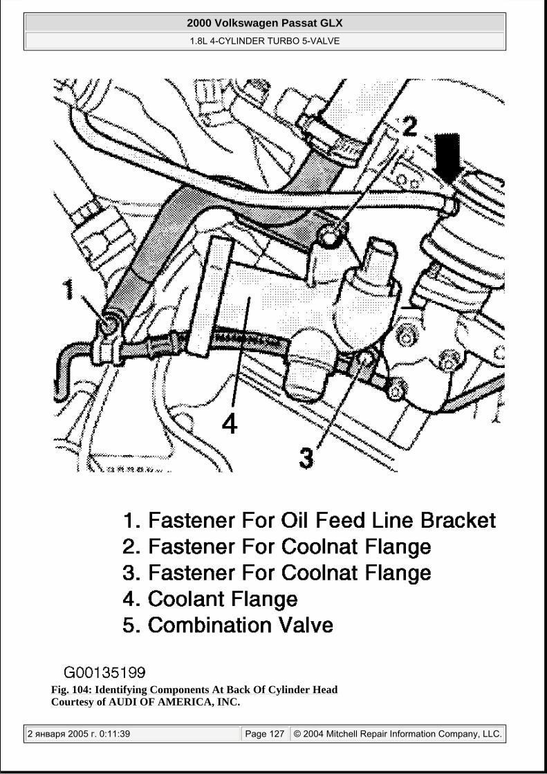
Fig. 104: Identifying Components At Back Of Cylinder Head Courtesy of AUDI OF AMERICA, INC.
2000 Volkswagen Passat GLX 1.8L 4-CYLINDER TURBO 5-VALVE
2 января 2005 г. 0:11:39 Page 127 © 2004 Mitchell Repair Information Company, LLC.

15. Remove intake manifold support. Disconnect heated oxygen sensor connector at left side of plenum and set aside.
16. Remove bolts of oil feed line. Remove the exhaust manifold to turbocharger bolts. See Fig. 105 .
Fig. 105: Identifying Oil Feed Line & Turbocharger Bolts For Removal
2000 Volkswagen Passat GLX 1.8L 4-CYLINDER TURBO 5-VALVE
2 января 2005 г. 0:11:39 Page 128 © 2004 Mitchell Repair Information Company, LLC.

Courtesy of AUDI OF AMERICA, INC.
17. Remove cylinder head cover. See CYLINDER HEAD COVER . 18.
Loosen head bolts in sequence, in small amounts, until all bolts are loose. See Fig. 106 . Remove cylinder head from vehicle.
Fig. 106: Cylinder Head Bolt Loosening Sequence Courtesy of AUDI OF AMERICA, INC.
Inspection
Thoroughly clean all gasket mating surfaces. Check cylinder head for warpage. Maximum warpage is 0.100 mm. (004"). Check minimum cylinder head height and replace cylinder head (if necessary). See
NOTE: When cylinder head cover has been removed, take note of oil deflector positioning. On Polydrive cylinder head bolts, use tool (3452).
2000 Volkswagen Passat GLX 1.8L 4-CYLINDER TURBO 5-VALVE
2 января 2005 г. 0:11:39 Page 129 © 2004 Mitchell Repair Information Company, LLC.

CYLINDER HEAD under OVERHAUL. See CYLINDER HEAD under ENGINE SPECIFICATIONS.
Installation
1. If using original equipment cylinder head gasket, ensure part number on cylinder head gasket faces up and is readable from the intake side of cylinder block. Install gasket on cylinder block. DO NOT use any type of sealant.
2. Align camshaft timing marks and position crankshaft at Top Dead Center (TDC). See Fig. 116 . Ensure pistons are not at TDC. If necessary turn crankshaft backwards slightly.
3. Loosen the bolts on turbocharger support bracket. This will allow slight movement at the turbocharger, which should aid in installing cylinder head.
4.
Carefully position cylinder head on cylinder block. Install NEW head bolts finger tight. Tighten cylinder head bolts (in several steps) in sequence to specification. See Fig. 107 . See TORQUE SPECIFICATIONS .
CAUTION: If cam followers or camshaft have been removed and followers are charged with oil, allow 30 minutes for followers to bleed down before starting engine. Pistons may strike valves, resulting in bent valves.
NOTE: DO NOT reuse antifreeze after replacing cylinder block, cylinder head, head gasket, radiator and/or heater core.
CAUTION: ALWAYS REPLACE the cylinder head bolts. When performing repairs, replace seals, gaskets, self-locking nuts and bolts which have a specified tightening angle. DO NOT reuse torque to yield bolts.
NOTE: Remove all coolant or oil from cylinder head bolt threaded holesin cylinder block.
NOTE: When torquing down head bolts, DO NOT use torque wrench on the final 1/4 turn on the head bolts.
2000 Volkswagen Passat GLX 1.8L 4-CYLINDER TURBO 5-VALVE
2 января 2005 г. 0:11:39 Page 130 © 2004 Mitchell Repair Information Company, LLC.

Fig. 107: Cylinder Head Bolt Tightening Sequence Courtesy of AUDI OF AMERICA, INC.
5. Before installation of cylinder head cover apply a thin layer of sealer (D 454 300 A2) at the points of cylinder head cover where leakage may occur. See Fig. 102 .
6. Install timing belt. See TIMING BELT . 7. Install new seal between turbocharger and exhaust manifold. To complete installation, reverse
removal procedure. 8. Refill and bleed air from cooling system. See COOLING SYSTEM BLEEDING . 9. Secure lock carrier to body. See LOCK CARRIER .
CRANKSHAFT FRONT OIL SEAL
NOTE: For help in identifying components and component locations, refer to illustration. See Fig. 108 .
2000 Volkswagen Passat GLX 1.8L 4-CYLINDER TURBO 5-VALVE
2 января 2005 г. 0:11:40 Page 131 © 2004 Mitchell Repair Information Company, LLC.

Fig. 108: Identifying Crankshaft Oil Seals & Front & Rear Sealing Flanges Courtesy of VOLKSWAGEN UNITED STATES, INC.
Removal
1. Remove timing belt. See TIMING BELT . 2. Remove crankshaft timing belt sprocket, by counter-holding sprocket with Holding Tool (3415) tool.
2000 Volkswagen Passat GLX 1.8L 4-CYLINDER TURBO 5-VALVE
2 января 2005 г. 0:11:40 Page 132 © 2004 Mitchell Repair Information Company, LLC.

See Fig. 109 . To guide oil seal extractor, screw center bolt as far into crankshaft as possible, by hand. See Fig. 110 .
Fig. 109: Removing Crankshaft Timing Belt Sprocket Using Holding Tool (3415) Courtesy of VOLKSWAGEN UNITED STATES, INC.
2000 Volkswagen Passat GLX 1.8L 4-CYLINDER TURBO 5-VALVE
2 января 2005 г. 0:11:40 Page 133 © 2004 Mitchell Repair Information Company, LLC.

Fig. 110: Installing Crankshaft Center Bolt Into Crank With Belt Sprocket Removed Courtesy of VOLKSWAGEN UNITED STATES, INC.
3. Unscrew inner part of oil seal extractor 9 turns (about 20 mm) out of the outer section, and lock with knurled screw. Lubricate threaded head of Oil Seal Extractor (3203), place in position and while exerting firm pressure, screw as far as possible into oil seal. See Fig. 111 .
2000 Volkswagen Passat GLX 1.8L 4-CYLINDER TURBO 5-VALVE
2 января 2005 г. 0:11:40 Page 134 © 2004 Mitchell Repair Information Company, LLC.

Fig. 111: Removing Front Crankshaft Seal Using Oil Seal Extractor (3203) Courtesy of VOLKSWAGEN UNITED STATES, INC.
4. Loosen knurled screw and turn inner part against crankshaft until oil seal is pulled out.
Installation
1. Place Guide Sleeve (T10053/1) onto crankshaft journal. Push oil seal over guide sleeve. Using center bolt (T10053/2, M16 x 1.4 x 60), press seal completely into position with Press Sleeve (T10053). See Fig. 112 and Fig. 113 .
NOTE: Replace crankshaft center bolt with a NEW bolt (DO NOT reuse torque to yield bolt).
NOTE: DO NOT lube threads or shoulder of NEW bolt, install dry.
NOTE: If using a new PTFE oil seal, DO NOT lubricate sealing lip or outer circumference of new oil seal. PTFE oil seal can be identified by a sealing lip with a wider design and there is no annular spring. PTFE sealing surface has a thread-like design. PTFE seals MUST be aligned to rotation direction of shaft. There is an arrow marking direction of rotation on face of PTFE sealing ring. Installing in wrong rotation direction will cause oil leakage.
2000 Volkswagen Passat GLX 1.8L 4-CYLINDER TURBO 5-VALVE
2 января 2005 г. 0:11:40 Page 135 © 2004 Mitchell Repair Information Company, LLC.

Fig. 112: Installing Guide Sleeve (T10053/1) Over Crank Journal Courtesy of VOLKSWAGEN UNITED STATES, INC.
2000 Volkswagen Passat GLX 1.8L 4-CYLINDER TURBO 5-VALVE
2 января 2005 г. 0:11:40 Page 136 © 2004 Mitchell Repair Information Company, LLC.

Fig. 113: Installing Crankshaft Front Oil Seal With Press Sleeve (T10053) Courtesy of VOLKSWAGEN UNITED STATES, INC.
2. Reinstall crankshaft timing belt sprocket, by holding sprocket with Holding Tool (3415). Install NEW bolt and tighten to specification. See TORQUE SPECIFICATIONS . See Fig. 109 . To complete installation, reverse removal procedure.
CRANKSHAFT FRONT OIL SEAL FLANGE
Removal & Installation
1. Remove timing belt. See TIMING BELT . 2. Drain engine oil. Remove oil pan. See OIL PAN . 3. Remove flange from block, to loosen tap lightly with a rubber hammer. Remove old sealant from
block using a flat scraper. Using a plastic wheel remove old sealant from flange mating surface. See Fig. 114 . Ensure mating surface is not damaged during cleaning.
2000 Volkswagen Passat GLX 1.8L 4-CYLINDER TURBO 5-VALVE
2 января 2005 г. 0:11:40 Page 137 © 2004 Mitchell Repair Information Company, LLC.

Fig. 114: Cleaning Crankshaft Front Oil Seal Flange Mating Surface Using Plastic Wheel Courtesy of VOLKSWAGEN UNITED STATES, INC.
4.
Apply silicone sealant in a 3 mm (0.1") bead along flange mating surface. See Fig. 115 . With seal already installed in flange, DO NOT lubricate lip of NEW seal. Place Guide Sleeve (T10053/1) onto crankshaft journal. See Fig. 112 .
NOTE: If using a new PTFE oil seal, DO NOT lubricate sealing lip or outer circumference of new oil seal. PTFE oil seal can be identified by a sealing lip with a wider design and there is no annular spring. PTFE sealing surface has a thread-like design. PTFE seals MUST be aligned to rotation direction of shaft. There is an arrow marking direction of rotation on face of PTFE sealing ring. Installing in wrong rotation direction will cause oil leakage.
2000 Volkswagen Passat GLX 1.8L 4-CYLINDER TURBO 5-VALVE
2 января 2005 г. 0:11:40 Page 138 © 2004 Mitchell Repair Information Company, LLC.

Fig. 115: Apply Silicone Sealant To Crankshaft Front Oil Seal Flange Mating Surface As ShownCourtesy of VOLKSWAGEN UNITED STATES, INC.
5. Push oil seal over guide sleeve. Slide flange over crank journal, lightly tighten all flange bolts by hand. In a crisscross pattern, tighten bolts to specification. See TORQUE SPECIFICATIONS .
6. If oil seal is not installed, install flange and in a crisscross pattern tighten bolts to specification. See TORQUE SPECIFICATIONS . Install crankshaft oil seal. See CRANKSHAFT FRONT OIL SEAL . Allow 30 minutes for sealant on flange to dry before adding oil to engine.
7. Continue installation in reverse removal procedure. Tighten bolts to specification. See TORQUE SPECIFICATIONS .
TIMING BELT
CAUTION: DO NOT turn crankshaft or camshaft with timing belt removed. Valve damage may result.
NOTE: Hydraulic plunger type timing belt tensioners are oil filled, when compressing the plunger it must be pressed back in slowly and with even pressure. With plunger completely extended this procedure can take up to 5 minutes. Excessive force during compression can damage the tensioner. Testing of hydraulic tensioner not provided by manufacturer. Replace
2000 Volkswagen Passat GLX 1.8L 4-CYLINDER TURBO 5-VALVE
2 января 2005 г. 0:11:40 Page 139 © 2004 Mitchell Repair Information Company, LLC.
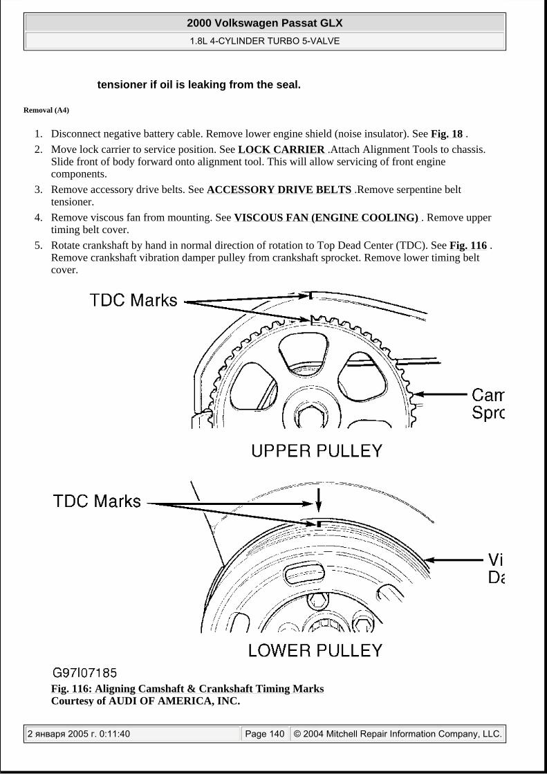
Removal (A4)
1. Disconnect negative battery cable. Remove lower engine shield (noise insulator). See Fig. 18 . 2. Move lock carrier to service position. See LOCK CARRIER .Attach Alignment Tools to chassis.
Slide front of body forward onto alignment tool. This will allow servicing of front engine components.
3. Remove accessory drive belts. See ACCESSORY DRIVE BELTS .Remove serpentine belt tensioner.
4. Remove viscous fan from mounting. See VISCOUS FAN (ENGINE COOLING) . Remove upper timing belt cover.
5. Rotate crankshaft by hand in normal direction of rotation to Top Dead Center (TDC). See Fig. 116 . Remove crankshaft vibration damper pulley from crankshaft sprocket. Remove lower timing belt cover.
Fig. 116: Aligning Camshaft & Crankshaft Timing Marks Courtesy of AUDI OF AMERICA, INC.
tensioner if oil is leaking from the seal.
2000 Volkswagen Passat GLX 1.8L 4-CYLINDER TURBO 5-VALVE
2 января 2005 г. 0:11:40 Page 140 © 2004 Mitchell Repair Information Company, LLC.

Fig. 117: Exploded View Of Timing Belt Components (A4) Courtesy of VOLKSWAGEN UNITED STATES, INC.
6. If timing belt is to be reused, mark direction of rotation on belt. Socket Head Fastener (T10092) or a threaded stud onto timing belt tensioner. Screw (T10092) or threaded stud M5 x 55 (1) into timing
2000 Volkswagen Passat GLX 1.8L 4-CYLINDER TURBO 5-VALVE
2 января 2005 г. 0:11:41 Page 141 © 2004 Mitchell Repair Information Company, LLC.

belt tensioner. See Fig. 118 . If using threaded stud M5 x 55, fit a hexagon nut with large washer onto threaded stud. Align tensioner pressure piston so holes in the piston line up with hole in housing. Install Locking Pin (T40011) or a suitable pin through hole to lock piston in place. See Fig. 118 .
Fig. 118: Releasing Tension Off Timing Belt & Locking Tensioner Piston In Place Courtesy of VOLKSWAGEN UNITED STATES, INC.
7. Remove timing belt.
Installation (A4)
1. Align mark on camshaft sprocket with mark on cylinder head cover and/or timing belt guard. See Fig. 116 . Install timing belt on crankshaft timing belt sprocket. Install lower timing belt cover.
2. Install vibration damper pulley in original location with one old bolt. 3. Put crankshaft at Top Dead Center (TDC) mark. See Fig. 116 . Install timing belt in the order of
coolant pump, tightening roller, and camshaft sprocket (taking up slack in belt). DO NOT let crankshaft rotate as belt is installed.
4. With timing marks aligned, and very little slack on the water pump side of the belt, unscrew Socket Head Fastener (T10092) or threaded stud on timing belt tensioner. Remove locking pin from auto-tensioner. See Fig. 118 .
5. Allow tensioner to stabilize wait 1 minute. Turn crankshaft 2 full revolutions in normal direction of rotation using crankshaft sprocket center bolt. Ensure camshaft and crankshaft sprockets align with their reference marks. Repeat timing belt procedure if marks are out of alignment. Once again, rotate crankshaft 2 revolutions in running direction and stop on TDC and recheck.
6. Install vibration damper pulley to crankshaft timing sprocket using NEW bolts. Tighten bolts to specification. See TORQUE SPECIFICATIONS . Install timing belt covers.
7. Install viscous fan. See VISCOUS FAN (ENGINE COOLING) .
CAUTION: When turning camshaft, crankshaft must NOT be at TDC of any cylinder. This is an interference engine, damage to valves and pistons may occur.
2000 Volkswagen Passat GLX 1.8L 4-CYLINDER TURBO 5-VALVE
2 января 2005 г. 0:11:41 Page 142 © 2004 Mitchell Repair Information Company, LLC.

8. Install accessary drive belt. See ACCESSORY DRIVE BELTS . Install lock carrier to original position. See LOCK CARRIER . To complete installation, reverse removal procedure.
Removal (Passat Up To 7/2000)
1. Disconnect negative battery cable. Remove lower engine shield (noise insulator). See Fig. 18 . 2. Move lock carrier to service position. See LOCK CARRIER . Attach Alignment Tools to chassis.
Slide front of body forward onto alignment tool. This will allow servicing of front engine components.
3. Rotate serpentine belt tensioner clockwise and remove serpentine belt. See ACCESSORY DRIVE BELTS . Remove serpentine belt tensioner.
4. Remove upper timing belt cover. Rotate crankshaft by hand to Top Dead Center (TDC). See Fig. 116 . Remove crankshaft vibration damper pulley. Remove lower timing belt cover.
5. If timing belt is to be reused, mark direction of rotation on belt. Socket Head Fastener (T10092) or a threaded stud onto timing belt tensioner. Screw (T10092) or threaded stud M5 x 55 (1) into timing belt tensioner. See Fig. 118 . If using threaded stud M5 x 55, fit a hexagon nut with large washer onto threaded stud. Align tensioner pressure piston so holes in the piston line up with hole in housing. Install locking pin (T40011) or a suitable pin through hole to lock piston in place. See Fig. 118 .
6.
Remove timing belt from engine. Turn crankshaft back slightly.
CAUTION: When turning camshaft, crankshaft must NOT be at TDC of any cylinder. This is an interference engine, damage to valves and pistons may occur.
2000 Volkswagen Passat GLX 1.8L 4-CYLINDER TURBO 5-VALVE
2 января 2005 г. 0:11:41 Page 143 © 2004 Mitchell Repair Information Company, LLC.
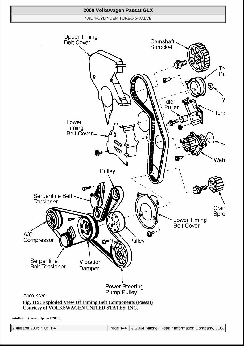
Fig. 119: Exploded View Of Timing Belt Components (Passat) Courtesy of VOLKSWAGEN UNITED STATES, INC.
Installation (Passat Up To 7/2000)
2000 Volkswagen Passat GLX 1.8L 4-CYLINDER TURBO 5-VALVE
2 января 2005 г. 0:11:41 Page 144 © 2004 Mitchell Repair Information Company, LLC.

1. Align mark on camshaft sprocket with mark on cylinder head cover and/or timing belt guard. Install timing belt on crankshaft timing belt sprocket. Install lower timing belt cover.
2. Install vibration damper pulley using NEW bolts. Tighten bolts to specification. See TORQUE SPECIFICATIONS . Put crankshaft at Top Dead Center (TDC) mark. See Fig. 116 .
3. Install timing belt in the order of water pump, tensioner pulley and camshaft sprocket (taking up slack in belt). DO NOT let crankshaft rotate as belt is installed.
4. With timing marks aligned, and very little slack on the water pump side of the belt, unscrew Socket Head Fastener (T10092) or threaded stud on timing belt tensioner. Remove locking pin from auto-tensioner. See Fig. 118 .
5. Allow tensioner to stabilize wait 1 minute. Turn crankshaft 2 full revolutions in normal direction of rotation. Ensure camshaft and crankshaft sprockets align with their timing marks. Repeat timing belt procedure if marks are out of alignment. Once again, rotate crankshaft 2 revolutions in running direction and stop on Top Dead Center (TDC) and recheck.
6. Install timing belt covers. Install serpentine drive belt tensioner and tighten to specification. See TORQUE SPECIFICATIONS .
7. Install accessary drive belt. See ACCESSORY DRIVE BELTS . Install lock carrier to body. See LOCK CARRIER . To complete installation, reverse removal procedure. See TORQUE SPECIFICATIONS .
Removal (Passat After 8/00)
1. Disconnect negative battery cable. Remove lower engine shield (noise insulator). See Fig. 18 . 2. Move lock carrier to service position. See LOCK CARRIER . Attach alignment tools to chassis.
Slide front of body forward onto alignment tool. This will allow servicing of front engine components.
3. Remove accessory (serpentine) drive belts. See ACCESSORY DRIVE BELTS .Remove serpentine drive belt tensioner from engine block.
4. Rotate crankshaft by hand to Top Dead Center (TDC). See Fig. 116 . Remove upper timing belt covers.
5. Remove crankshaft vibration damper pulley. Remove lower timing belt cover. 6.
Insert an hex wrench into hex socket up to stop. Press tensioner pulley in counterclockwise direction with uniform (non-excessive) force until timing belt tensioner can be aligned using Locking Plate (T10008). See Fig. 120 .
CAUTION: When turning camshaft, crankshaft must NOT be at TDC of any cylinder. This is an interference engine, damage to valves and pistons may occur.
CAUTION: Timing belt tensioner is an oil damper device and can only be compressed slowly and with equal force. Excessive force during compression can damage tensioner.
2000 Volkswagen Passat GLX 1.8L 4-CYLINDER TURBO 5-VALVE
2 января 2005 г. 0:11:41 Page 145 © 2004 Mitchell Repair Information Company, LLC.

Fig. 120: Releasing Tension From Timing Belt (With Adjustable Type Roller) Courtesy of VOLKSWAGEN UNITED STATES, INC.
7.
To loosen toothed belt, loosen nut (1) of tightening roller and turn Pin Wrench (3387) clockwise. See Fig. 121 . Remove timing belt. Rotate crankshaft back slightly.
NOTE: Impact tab "A" of pin wrench must not be bent. See Fig. 121 .
2000 Volkswagen Passat GLX 1.8L 4-CYLINDER TURBO 5-VALVE
2 января 2005 г. 0:11:41 Page 146 © 2004 Mitchell Repair Information Company, LLC.

Fig. 121: Removing Timing Belt (With Adjustable Type Roller) Courtesy of VOLKSWAGEN UNITED STATES, INC.
Installation (Passat After 8/00)
1. Align mark on camshaft sprocket with mark on timing belt guard. See Fig. 116 . 2. Install timing belt on crankshaft timing belt sprocket. Install lower timing belt cover.
CAUTION: When turning camshaft, crankshaft must NOT be at TDC of any cylinder. This is an interference engine, damage to valves and pistons may occur.
NOTE: If the timing belt tensioner is completely extended, it must be pressed back in installed position. This procedure can take up to 5 minutes. Excessive force during compression can damage tensioner.
2000 Volkswagen Passat GLX 1.8L 4-CYLINDER TURBO 5-VALVE
2 января 2005 г. 0:11:41 Page 147 © 2004 Mitchell Repair Information Company, LLC.

3. Install vibration damper pulley using NEW bolts. Tighten bolts to specification. See TORQUE SPECIFICATIONS .
4. Put crankshaft at Top Dead Center (TDC) mark. See Fig. 116 . Install timing belt in the order of water pump, tightening roller and camshaft sprocket (taking up slack in belt). DO NOT let crankshaft rotate as belt is installed.
5. To correctly tension timing belt, turn pin wrench counterclockwise (tab of pin wrench must not be bent) using pin wrench (3387) pin wrench until Locking Plate (T10008) can be removed without tension. See Fig. 122 .
Fig. 122: Removing Tensioner Locking Plate (T10008) Courtesy of VOLKSWAGEN UNITED STATES, INC.
6. Turn pin wrench to the right in clockwise direction (direction of arrow) until an 8 mm drill bit can be pulled through tightening lever and tensioner housing. See Fig. 123 . Hold tensioner pulley in this position, and tighten securing nut to 20 ft. lbs.(27 N.m).
2000 Volkswagen Passat GLX 1.8L 4-CYLINDER TURBO 5-VALVE
2 января 2005 г. 0:11:41 Page 148 © 2004 Mitchell Repair Information Company, LLC.

Fig. 123: Adjusting Timing Belt Tension (With Adjustable Type Roller) Courtesy of VOLKSWAGEN UNITED STATES, INC.
7. Turn crankshaft 2 full revolutions in normal direction of rotation and check that camshaft and crankshaft sprockets align with their reference marks. Repeat timing belt procedure if marks are out of alignment. Once again, rotate crankshaft 2 revolutions in running direction. Stop at TDC and recheck all timing marks.
8. Recheck clearance between tightening lever and tensioner housing. See Fig. 123 . Clearance should be 6-10 mm (.24-.40").If clearance is not correct, readjusting timing belt tension.
9. Install timing belt covers. Install serpentine drive belt tensioner and tighten bolt to specification. See TORQUE SPECIFICATIONS . Install serpentine drive belt. See ACCESSORY DRIVE BELTS .
10. Install lock carrier to body. See LOCK CARRIER . To complete installation, reverse removal procedure.
CAMSHAFTS
CAUTION: If camshaft needs to be turned, crankshaft must NOT be at TDC of any cylinder. This is an interference engine, damage to valves and pistons may occur.
NOTE: For help in identifying components and component locations, refer to Fig. 124 .
2000 Volkswagen Passat GLX 1.8L 4-CYLINDER TURBO 5-VALVE
2 января 2005 г. 0:11:41 Page 149 © 2004 Mitchell Repair Information Company, LLC.

Fig. 124: Exploded View Of Cylinder Head Components Courtesy of VOLKSWAGEN UNITED STATES, INC.
Removal (A4)
1. Gain access to camshaft sprocket. Remove upper timing belt cover. Remove cylinder head cover. See CYLINDER HEAD COVER . Place crankshaft at Top Dead Center (TDC) with No. 1 cylinder on compression stroke. See Fig. 116 .
2. Remove tension from timing belt. See TIMING BELT . With tension removed, lift belt off of camshaft sprocket. Using Camshaft Holder (3036), remove camshaft sprocket bolt. Remove camshaft sprocket. Remove Camshaft Position (CMP) sensor housing and its components.
3. Mark installation position on bearing caps with a colored marker. See Fig. 125 .
2000 Volkswagen Passat GLX 1.8L 4-CYLINDER TURBO 5-VALVE
2 января 2005 г. 0:11:41 Page 150 © 2004 Mitchell Repair Information Company, LLC.

Fig. 125: Identifying Camshafts Bearing Caps 1-5 & Double Bearing Cap Courtesy of VOLKSWAGEN UNITED STATES, INC.
4. Secure chain tensioner by installing Chain Tensioner (3366). Tighten to keep slight pressure on chain between camshafts. DO NOT overtighten chain tensioner. See Fig. 126 . Mark on camshafts must be in line with arrows on bearing caps. See "A" and "B" in Fig. 127 .
2000 Volkswagen Passat GLX 1.8L 4-CYLINDER TURBO 5-VALVE
2 января 2005 г. 0:11:42 Page 151 © 2004 Mitchell Repair Information Company, LLC.

Fig. 126: Identifying Camshaft Chain Adjuster Retainer Tool Courtesy of VOLKSWAGEN UNITED STATES, INC.
2000 Volkswagen Passat GLX 1.8L 4-CYLINDER TURBO 5-VALVE
2 января 2005 г. 0:11:42 Page 152 © 2004 Mitchell Repair Information Company, LLC.

2000 Volkswagen Passat GLX 1.8L 4-CYLINDER TURBO 5-VALVE
2 января 2005 г. 0:11:42 Page 153 © 2004 Mitchell Repair Information Company, LLC.

Fig. 127: New Camshaft Drive Chain Install Dimensions Courtesy of AUDI OF AMERICA, INC.
5. Clean camshaft drive chain and chain sprockets. Align the marks on the cam sprocket with arrows on the bearing caps. Using paint, mark chain and sprockets opposite arrows on bearing caps. Distance between both arrows (and between paint markings) is 16 rollers on the chain. See Fig. 128 .
Fig. 128: Identifying Marks On Cam Chain Gears & Arrows On Cam Caps Courtesy of VOLKSWAGON UNITED STATES INC.
6. Remove camshaft intake and exhaust bearing caps No. 3 and No. 5. Loosen bolts in small amounts evenly in a crisscross manner. See Fig. 125 .
7. Remove double bearing cap. Remove both bearing caps at chain sprockets on intake and exhaust camshafts.
8. Remove chain tensioner securing bolts. 9. Remove intake and exhaust camshaft 2nd and 4th bearing caps using alternate and cross-over
sequence. 10. Remove intake and exhaust camshafts with chain tensioner and retainer for Chain Tensioner (3366)
from cylinder head.
2000 Volkswagen Passat GLX 1.8L 4-CYLINDER TURBO 5-VALVE
2 января 2005 г. 0:11:42 Page 154 © 2004 Mitchell Repair Information Company, LLC.

Inspection
Check camshaft bearing oil clearance. See CAMSHAFT table under ENGINE SPECIFICATIONS. If oil clearance is not within specification, install new camshaft and recheck clearance. If clearance still exceeds specification, replace cylinder head. Check camshaft end play. See VALVE TRAIN under OVERHAUL.
Installation (A4)
1. Replace chain tensioner rubber/metal gasket and coat shaded area lightly with sealant (AMV 188 001 02). See Fig. 129 . Slide chain tensioner between drive chain.
Fig. 129: Applying Sealant (AMV 188 001 02 Or D 454 300 A2) To Chain Tensioner Mounting Surface Courtesy of VOLKSWAGEN UNITED STATES, INC.
2. Place camshafts in cylinder head. Ensure lobes for No. 1 cylinder are pointed upward. See Fig. 124 . Fit drive chain onto both camshafts relative to the marks.
3. Install drive chain on camshaft sprockets. When old chain is being reused, check position of marks made on camshafts sprockets relative to one another (positioning should be close to prior to removal).
CAUTION: If cam followers are charged with oil, allow 30 minutes for followers to bleed down before starting engine. Pistons may strike valves, resulting in bent valves.
2000 Volkswagen Passat GLX 1.8L 4-CYLINDER TURBO 5-VALVE
2 января 2005 г. 0:11:42 Page 155 © 2004 Mitchell Repair Information Company, LLC.

See Fig. 128 . If a new chain is being installed, distance between Notch "A" and "B" must equal 16 drive chain rollers. Notch "A" is slightly off set inward toward drive chain roller (1). See Fig. 127 .
4. Push camshaft adjuster between drive chain (2 technicians required). 5.
Oil running surfaces of camshafts. Place camshafts with drive chain in cylinder head. Tighten chain tensioner to 10 N.m (89 INCH lbs.). Tighten camshaft bearing caps No. 2 and No. 4 evenly to 10 N.m (89 INCH lbs.). Install both bearing caps at chain sprockets for intake and exhaust camshafts. Tighten bearing caps to 10 N.m (89 INCH lbs.). Ensure camshafts are positioned correctly. Remove retainer for chain tensioner (3366).
6. Lightly coat hatched area of double bearing cap with sealant (AMV 188 001 02). See Fig. 130 . Ensure dowel sleeves are installed. Install double bearing cap. Tighten bolts to 10 N.m (89 INCH lbs.).
Fig. 130: Applying Sealant (AMV 188 001 02 Or D 454 300 A2) To Double Bearing Cap Courtesy of VOLKSWAGEN UNITED STATES, INC.
7. Install remaining bearing caps and tighten to 10 N.m (89 INCH lbs.). Ensure dowel sleeves are installed.
8. Install timing belt cam sprocket, ensure timing mark for No. 1 is facing outward and visible from the front. Install securing bolt for cam sprocket, torque to 88 N.m (65 ft. lbs). Install Camshaft Position Sensor (CMP).
9. To complete installation, reverse removal procedure. If cam followers are charged with oil, allow 30 minutes for followers to bleed down before starting engine. Before starting engine, manually turn crankshaft 2 complete turns. Ensure valves do not make contact pistons.
Removal (Passat)
1. Gain access to camshaft sprocket. Remove upper timing belt cover. Remove cylinder head cover. See CYLINDER HEAD COVER . Place crankshaft at Top Dead Center (TDC) with No. 1 cylinder on compression stroke. See Fig. 116 .
2. Remove tension from timing belt. See TIMING BELT . With tension removed, lift belt off of camshaft sprocket. Turn crankshaft back slightly. Using Camshaft Holder (3036), remove camshaft sprocket bolt. Remove camshaft sprocket. Remove Camshaft Position (CMP) sensor housing and its components.
NOTE: When installing the bearing caps, ensure that the cap markings can be read from the intake side of the cylinder head. Take note of dowel sleeves for bearing caps and camshaft adjuster. Ensure dowels are in cylinder head.
2000 Volkswagen Passat GLX 1.8L 4-CYLINDER TURBO 5-VALVE
2 января 2005 г. 0:11:42 Page 156 © 2004 Mitchell Repair Information Company, LLC.

3. Clean camshaft drive chain and chain sprockets. Moving only the cams, align the marks on the cam sprocket with arrows on the bearing caps. Using paint, mark chain and sprockets opposite arrows on bearing caps. Distance between both arrows (and between paint markings) is 16 rollers on the chain. See Fig. 128 . If a new chain is being installed, distance between Notch "A" and "B" must equal 16 drive chain rollers. Notch "A" is slightly off set inward toward drive chain roller (1). See Fig. 127 .
4. Mark installation position on bearing caps with a colored marker. Secure chain tensioner, install Chain Tensioner (3366). Tighten tensioner to keep slight pressure on chain between camshafts. DO NOT overtighten chain tensioner. See Fig. 126 .
5. Remove intake and exhaust camshafts with chain tensioner and retainer for chain tensioner (3366) from cylinder head.
6. Remove camshaft intake and exhaust bearing caps No. 3 and 5. Loosen bolts in small amounts evenly in a crisscross manner. See Fig. 125 .
7. Remove double bearing cap. Remove both bearing caps at chain sprockets on intake and exhaust camshafts. Remove chain tensioner securing bolts. Remove intake and exhaust camshaft 2nd and 4th bearing caps using alternate and cross-over sequence.
Inspection
Check camshaft bearing oil clearance. See CAMSHAFT table under ENGINE SPECIFICATIONS. If oil clearance is not within specification, install new camshaft and recheck clearance. If clearance still exceeds specification, replace cylinder head. Check camshaft end play. See VALVE TRAIN under OVERHAUL.
Installation (Passat)
1. Place camshafts in cylinder head. Ensure lobes for No. 1 cylinder are pointed upward. See Fig. 124 . Fit drive chain onto both camshafts relative to the marks. Replace chain tensioner rubber/metal gasket and coat shaded area lightly with sealant (D 454 300 A2). See Fig. 129 . Slide chain tensioner between drive chain.
2.
Oil running surfaces of camshafts. Place camshafts with drive chain in cylinder head. Tighten chain tensioner to 10 N.m (89 INCH lbs.). Tighten camshaft bearing caps No. 2 and No. 4 evenly to 10 N.m (89 INCH lbs.). Install both bearing caps at chain sprockets for intake and exhaust camshafts. Ensure camshafts are positioned correctly. Tighten bearing caps to 10 N.m (89 INCH lbs.). Remove retainer for Chain Tensioner (3366).
3. Lightly coat hatched area of double bearing cap with sealant (D 454 300 A2). See Fig. 130 . Install and tighten double bearing cap bolts to 10 N.m (89 INCH lbs.). Ensure dowel sleeves are installed correctly.
4. Install remaining bearing caps and tighten to 10 N.m (89 INCH lbs.). Ensure dowel sleeves are installed correctly. When old chain is being reused, check position of marks made on camshafts sprockets relative to one another (positioning should be close to prior to removal). See Fig. 128 . If a
CAUTION: If cam followers are charged with oil, allow 30 minutes for followers to bleed down before starting engine. Pistons may strike valves, resulting in bent valves.
NOTE: When installing the bearing caps, ensure that the cap markings can be read from the intake side of the cylinder head.
NOTE: Take note of dowel sleeves installed position.
2000 Volkswagen Passat GLX 1.8L 4-CYLINDER TURBO 5-VALVE
2 января 2005 г. 0:11:42 Page 157 © 2004 Mitchell Repair Information Company, LLC.

new chain is being installed, distance between notch "A" and "B" must equal 16 drive chain rollers. Notch "A" is slightly off set inward toward drive chain roller. See Fig. 127 .
5. Install timing belt camshaft sprocket. Ensure timing mark for No. 1 is facing outward and visible from the front. Install securing bolt for camshaft sprocket and tighten to specification. See TORQUE SPECIFICATIONS . Install Camshaft Position Sensor (CMP).
6. To complete installation, reverse removal procedure. If cam followers are charged with oil, allow 30 minutes for followers to bleed down before starting engine. Before starting engine, manual turn crankshaft 2 complete turns. Ensure valves do not make contact pistons.
CAMSHAFT DRIVE CHAIN
For camshaft drive chain removal and installation procedures, see CAMSHAFTS .
CAMSHAFT OIL SEALS
Removal (Exhaust Camshaft)
1. Place lock carrier in service position. See LOCK CARRIER . On A4, remove engine cover. 2. On all models, remove upper timing belt cover. Place crankshaft at Top Dead Center (TDC) with No.
1 cylinder on compression stroke. Ensure crankshaft and camshaft timing marks are aligned. See Fig. 116 .
3. Turn crankshaft back slightly. Remove tension from timing belt. See TIMING BELT . 4. Using Camshaft Holder (3036) to hold camshaft sprocket stationary, remove camshaft sprocket bolt.
Remove camshaft sprocket. Install camshaft sprocket bolt and washer until bolt comes to a stop (hand tight) against camshaft. See Fig. 131 .
CAUTION: DO NOT turn crankshaft or camshaft with timing belt removed. Valve damage may result.
CAUTION: DO NOT allow camshaft to turn when removing camshaft sprocket bolt.
2000 Volkswagen Passat GLX 1.8L 4-CYLINDER TURBO 5-VALVE
2 января 2005 г. 0:11:42 Page 158 © 2004 Mitchell Repair Information Company, LLC.

Fig. 131: Camshaft Sprocket Bolt Installed In Camshaft Courtesy of AUDI OF AMERICA, INC.
5. Unscrew inner part of (2085) oil seal extractor 2 turns (about 3 mm) out of the outer section and lock with knurled screw. See Fig. 132 . Lubricate threaded head of oil seal extractor, place in position and while exerting firm pressure, screw as far as possible into oil seal.
2000 Volkswagen Passat GLX 1.8L 4-CYLINDER TURBO 5-VALVE
2 января 2005 г. 0:11:42 Page 159 © 2004 Mitchell Repair Information Company, LLC.

Fig. 132: Installing Seal Puller (2085) Courtesy of AUDI OF AMERICA, INC.
6. Loosen knurled screw and turn inner part against crankshaft until oil seal is pulled out.
Installation (Exhaust Camshaft)
1. Using Guide Sleeve (T 10071/1), slide seal until flush with head. See Fig. 133 .
NOTE: If using a new PTFE oil seal, DO NOT lubricate sealing lip or outer circumference of new oil seal. PTFE oil seal can be identified by a sealing lip with a wider design and there is no annular spring. PTFE sealing surface has a thread-like design. PTFE seals MUST be aligned to rotation direction of shaft. There is an arrow marking direction of rotation on face of PTFE sealing ring. Installing in wrong rotation direction will cause oil leakage.
2000 Volkswagen Passat GLX 1.8L 4-CYLINDER TURBO 5-VALVE
2 января 2005 г. 0:11:43 Page 160 © 2004 Mitchell Repair Information Company, LLC.
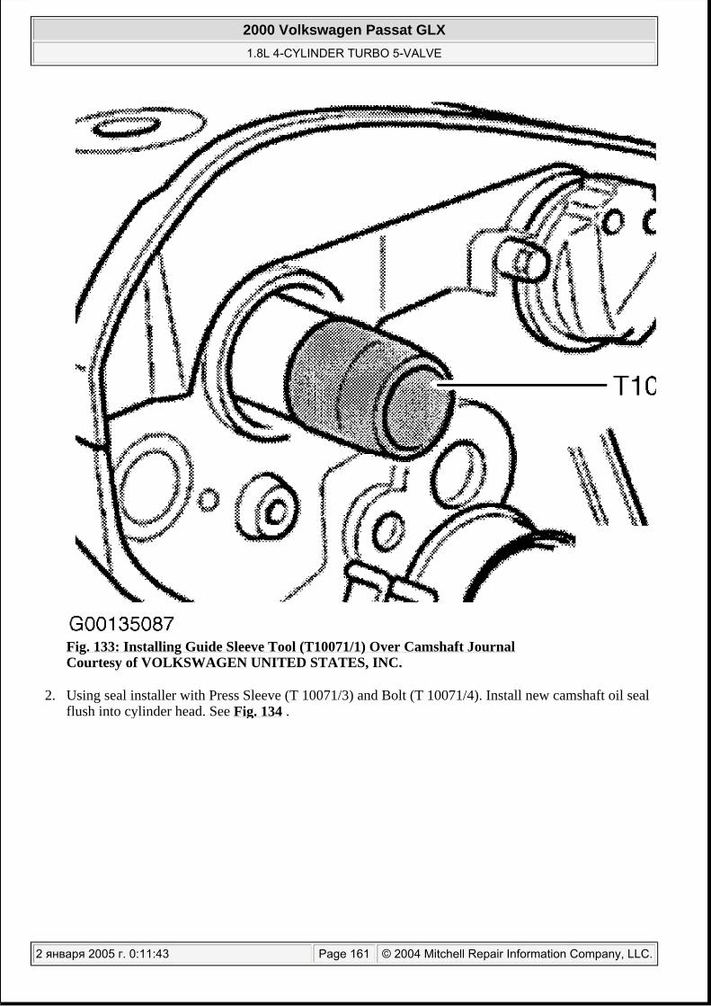
Fig. 133: Installing Guide Sleeve Tool (T10071/1) Over Camshaft Journal Courtesy of VOLKSWAGEN UNITED STATES, INC.
2. Using seal installer with Press Sleeve (T 10071/3) and Bolt (T 10071/4). Install new camshaft oil seal flush into cylinder head. See Fig. 134 .
2000 Volkswagen Passat GLX 1.8L 4-CYLINDER TURBO 5-VALVE
2 января 2005 г. 0:11:43 Page 161 © 2004 Mitchell Repair Information Company, LLC.

Fig. 134: Installing Camshaft Oil Seal Using Press Sleeve (T10071/3) & Bolt (T10071/4) Courtesy of VOLKSWAGEN UNITED STATES, INC.
3. Install camshaft sprocket. Camshaft sprocket is correctly installed when narrow web of sprocket faces outward (toward from of car). Camshaft timing mark should be visible. Install and tighten camshaft sprocket bolt. See TORQUE SPECIFICATIONS .
4. Install timing belt. See TIMING BELT . 5. Install lock carrier to body. See LOCK CARRIER .
To complete installation, reverse removal procedure. Tighten all bolts and nuts to specification. See TORQUE SPECIFICATIONS .
Removal (Intake Camshaft)
1. Place lock carrier in service position. See LOCK CARRIER . 2. Remove upper timing belt cover. 3. Disconnect electrical connector from Camshaft Position (CMP) sensor. See Fig. 135 .
2000 Volkswagen Passat GLX 1.8L 4-CYLINDER TURBO 5-VALVE
2 января 2005 г. 0:11:43 Page 162 © 2004 Mitchell Repair Information Company, LLC.

Fig. 135: Identifying Cam Position (CMP) Sensor Harness Connector Courtesy of AUDI OF AMERICA, INC.
4. Unbolt Camshaft Position (CMP) sensor. See Fig. 124 . Remove CMP sensor hood (shutter wheel) bolt and lift off shutter wheel.
5. Screw Oil Seal Extractor (2058/1 bolt) into camshaft. See Fig. 136 . Unscrew inner part of Oil Seal Extractor (2085/1) 2 turns (about 3 mm or 0.118") out of outer part, and lock with knurled screw. See Fig. 137 .
2000 Volkswagen Passat GLX 1.8L 4-CYLINDER TURBO 5-VALVE
2 января 2005 г. 0:11:43 Page 163 © 2004 Mitchell Repair Information Company, LLC.

Fig. 136: Installing Oil Seal Extractor (2085/1) Into Intake Camshaft Courtesy of AUDI OF AMERICA, INC.
2000 Volkswagen Passat GLX 1.8L 4-CYLINDER TURBO 5-VALVE
2 января 2005 г. 0:11:43 Page 164 © 2004 Mitchell Repair Information Company, LLC.

Fig. 137: Installing Seal Puller (2085) Courtesy of AUDI OF AMERICA, INC.
6. Lubricate thread head of oil seal extractor, place it in position while applying firm pressure screw it as far as into oil seal. Loosen knurled screw and turn inner part of extractor against camshaft until oil seal has been extracted.
Installation (Intake Camshaft)
1. Check edge chamfer end of camshaft for burrs or sharp edges. If necessary, smooth edge with an oil stone.
2. Place new oil seal carefully onto end of camshaft by hand. Using Guide Sleeve (3241/2), slide seal until flush with head. See Fig. 138 .
NOTE: If using a new PTFE oil seal, DO NOT lubricate sealing lip or outer circumference of new oil seal. PTFE oil seal can be identified by a sealing lip with a wider design, and there is no annular spring. PTFE sealing surface has a thread-like design. PTFE seals MUST be aligned to rotation direction of shaft. There is an arrow marking direction of rotation on face of PTFE sealing ring. Installing in wrong rotation direction will cause oil leakage.
2000 Volkswagen Passat GLX 1.8L 4-CYLINDER TURBO 5-VALVE
2 января 2005 г. 0:11:43 Page 165 © 2004 Mitchell Repair Information Company, LLC.

Fig. 138: Installing Guide Sleeve (3241/2) Over Intake Camshaft Courtesy of AUDI OF AMERICA, INC.
3. Using seal installer with Press Sleeve (3241/1) and Bolt (3241/3), install new camshaft oil seal flush into cylinder head. See Fig. 139 .
2000 Volkswagen Passat GLX 1.8L 4-CYLINDER TURBO 5-VALVE
2 января 2005 г. 0:11:43 Page 166 © 2004 Mitchell Repair Information Company, LLC.

Fig. 139: Installing Seal Using Press Sleeve (3241/1) & Bolt (3241/3) Courtesy of AUDI OF AMERICA, INC.
4. Install CMP sensor hood (shutter wheel) and bolt. Insert tab in notch in end of camshaft. Tighten hood (shutter wheel) bolt to 25 N.m (18 ft. lbs.). Install Camshaft Position (CMP) sensor housing bolts to 10 N.m (89 INCH lbs.).
5. To complete installation, reverse removal procedure. Tighten all bolts and nuts to specification. See TORQUE SPECIFICATIONS .
CAMSHAFT SOLENOID VALVE
Some models of this are equipped with variable valve timing. For testing of the camshaft solenoid and camshaft adjustment circuit, see:
A4(2001) SELF-DIAGNOSTICS - 1.8L TURBO article in ENGINE PERFORMANCE.
2000 Volkswagen Passat GLX 1.8L 4-CYLINDER TURBO 5-VALVE
2 января 2005 г. 0:11:43 Page 167 © 2004 Mitchell Repair Information Company, LLC.

Passat VARIABLE VALVE TIMING SYSTEM in SYSTEM & COMPONENT TESTING article in ENGINE PERFORMANCE.
CRANKSHAFT REAR OIL SEAL
Removal & Installation
1. Remove transmission. For M/T, see appropriate article in CLUTCHES. For A/T, see TRANSMISSION REMOVAL & INSTALLATION article in TRANSMISSION SERVICING. Remove drive plate (A/T) or dual-mass flywheel (M/T). See DRIVE PLATE (A/T) or DUAL-MASS FLYWHEEL (M/T) .
2. Remove crankshaft oil seal carrier bolts and remove carrier (flange) with oil seal. DO NOT add any additional oil or grease to seal lip.
3. Install NEW oil seal with carrier using supplied sleeve. Tighten crankshaft oil seal carrier bolts to specification. See TORQUE SPECIFICATIONS . Remove supplied sleeve after the flange and seal assembly has been slid onto the crankshaft.
WATER PUMP
Removal & Installation
1. Raise vehicle, remove lower engine shield (noise insulator), if equipped. See Fig. 18 . 2. Place front lock carrier assembly into service position. See LOCK CARRIER . Disconnect all
necessary electrical connectors from front of vehicle. 3. Drain engine coolant. See DRAINING COOLING SYSTEM . 4. Remove engine cover if equipped. Remove accessory drive belts. See ACCESSORY DRIVE
BELTS . 5. Remove viscous fan and fan pulley. See VISCOUS FAN . 6. Remove timing belt upper and center cover, ensure all bolts are removed. Turn crankshaft and align
timing marks. See Fig. 116 . 7.
Release tensioner, using Screw (T10092) or a threaded stud. Turn Screw (T10092) or threaded stud M5 x 55 (1) into timing belt tensioner. See Fig. 118 . If using threaded stud M5 x 55, fit a hexagon nut (2) with large washer (3) onto threaded stud (1). Align pressure piston using pointed pliers or wire
NOTE: Crankshaft rear oil seal and carrier are serviced as an assembly.
NOTE: For help in identifying components and component locations, refer to Fig. 108 .
CAUTION: Coolant and water mixture should be used at all times. Use only ethylene glycol based (phosphate-free) coolant.
NOTE: Water pump is driven by timing belt.
NOTE: Timing belt does not have to be completely removed from engine. Lower portion of belt will stay installed to crankshaft sprocket.
2000 Volkswagen Passat GLX 1.8L 4-CYLINDER TURBO 5-VALVE
2 января 2005 г. 0:11:43 Page 168 © 2004 Mitchell Repair Information Company, LLC.

before tensioning (turning piston to match hole in tensioner housing). Tension the lever so holes in the piston line up with hole in housing. Install Locking Pin (T40011) or a suitable pin through hole to lock piston in place. Slide timing belt off camshaft and water pump sprockets. Timing belt should remain in contact with crankshaft timing sprocket.
8.
With timing belt removed from water pump, remove fasteners and pull water pump away from block. See Fig. 140 . Clean sealing surface, lube NEW seal (O-ring) with coolant.
NOTE: Place clean shop towels under water pump, to protect timing belt from residual coolant that may come from block. Keep timing belt free of coolant and grease. Change shop towels for dry ones when necessary. Remove shop towel after water pump is installed.
2000 Volkswagen Passat GLX 1.8L 4-CYLINDER TURBO 5-VALVE
2 января 2005 г. 0:11:43 Page 169 © 2004 Mitchell Repair Information Company, LLC.

2000 Volkswagen Passat GLX 1.8L 4-CYLINDER TURBO 5-VALVE
2 января 2005 г. 0:11:44 Page 170 © 2004 Mitchell Repair Information Company, LLC.

Fig. 140: Identifying Water Pump Assembly Courtesy of AUDI OF AMERICA, INC.
9. Install O-ring and water pump. Tighten water pump bolts to specification. See TORQUE SPECIFICATIONS .
10. To complete installation, reverse removal procedure. For timing belt installation, see TIMING BELT . Install front lock carrier assembly to body. See LOCK CARRIER .
11. Fill and bleed cooling system. See COOLING SYSTEM BLEEDING .
OIL PAN (A4)
NOTE: For help in identifying components and component locations, refer to Fig. 141 .
2000 Volkswagen Passat GLX 1.8L 4-CYLINDER TURBO 5-VALVE
2 января 2005 г. 0:11:44 Page 171 © 2004 Mitchell Repair Information Company, LLC.

2000 Volkswagen Passat GLX 1.8L 4-CYLINDER TURBO 5-VALVE
2 января 2005 г. 0:11:44 Page 172 © 2004 Mitchell Repair Information Company, LLC.

Fig. 141: Identifying Engine Oiling System Components Courtesy of AUDI OF AMERICA, INC.
Removal
1. Move lock carrier into service position. See LOCK CARRIER . 2. Raise vehicle. Remove bracket for sound insulation. Remove air ducts from front engine area at air
charge cooler (intercooler). Raise vehicle. Remove center engine shield (noise insulators). See Fig. 18 . Drain engine oil.
3. Lower vehicle. Remove engine cover from top of engine. 4. Remove seal from plenum chamber cover, pull forward. See Fig. 6 . Remove plenum chamber cover
from front. 5. Remove nut from top of left engine mount. See Fig. 142 .
2000 Volkswagen Passat GLX 1.8L 4-CYLINDER TURBO 5-VALVE
2 января 2005 г. 0:11:44 Page 173 © 2004 Mitchell Repair Information Company, LLC.

Fig. 142: Identifying Left Side Engine Mount Courtesy of AUDI OF AMERICA, INC.
6. Setup Support Bar (10-222 A) on fender panel flanges. See Fig. 143 .
2000 Volkswagen Passat GLX 1.8L 4-CYLINDER TURBO 5-VALVE
2 января 2005 г. 0:11:44 Page 174 © 2004 Mitchell Repair Information Company, LLC.

Fig. 143: Installing Engine Support Bar (10-222 A) On Fender Panel Flanges Courtesy of AUDI OF AMERICA, INC.
7. Remove lifting eye from Lifting Tackle (2024 A). Replace pin (1) in center hole on lifting tackle and secure with locking pin. Engage pin on Lifting Tackle (2024 A) on spindle of Support Bar (10-222 A). See Fig. 144 .
2000 Volkswagen Passat GLX 1.8L 4-CYLINDER TURBO 5-VALVE
2 января 2005 г. 0:11:44 Page 175 © 2004 Mitchell Repair Information Company, LLC.

Fig. 144: Setting Pins On Engine Support Bar Courtesy of AUDI OF AMERICA, INC.
8.
Engage lifting tackle (2024 A) in front and rear lifting eyes on engine. Pretension engine with spindle of support bar, do not lift.
9. Remove oil return line of exhaust turbocharger from oil pan. Disconnect electrical connector from oil level sender located at the bottom of oil pan.
10. On vehicles with automatic transmission, remove bolt and disconnect ATF cooler lines from transmission. See Fig. 145 . Remove bracket for ATF lines from engine. Move ATF lines aside.
CAUTION: The hooks and locating pins of the lifting tackle must be secured with locking pins.
2000 Volkswagen Passat GLX 1.8L 4-CYLINDER TURBO 5-VALVE
2 января 2005 г. 0:11:44 Page 176 © 2004 Mitchell Repair Information Company, LLC.

Fig. 145: Removing Automatic Transmission Fluid Line From Engine & Transmission Courtesy of AUDI OF AMERICA, INC.
11. On all models, remove stop for torque reaction support from oil pan. See Fig. 66 . 12. If equipped, unclip operating rod of vehicle level sender from lower transverse link. See Fig. 146 .
Cut through cable ties. Open retainer for starter cable and take out electrical wiring. See Fig. 147 .
2000 Volkswagen Passat GLX 1.8L 4-CYLINDER TURBO 5-VALVE
2 января 2005 г. 0:11:44 Page 177 © 2004 Mitchell Repair Information Company, LLC.

Fig. 146: Remove Clip From Vehicle Level Sender Transverse Link Courtesy of AUDI OF AMERICA, INC.
2000 Volkswagen Passat GLX 1.8L 4-CYLINDER TURBO 5-VALVE
2 января 2005 г. 0:11:44 Page 178 © 2004 Mitchell Repair Information Company, LLC.

Fig. 147: Identifying Starter Cable Wiring Harness Retainer Courtesy of AUDI OF AMERICA, INC.
13.
Mark positions of mountings (1) and locating sleeves (2) on left and right engine mountings (lower). Remove nut (1) from lower right of engine mounting. Completely remove left engine mounting. See Fig. 62 .
14. Support subframe with Workshop Crane (VAG 1202 A). See Fig. 148 .
NOTE: Different mounting holes are provided for the different engine versions.
2000 Volkswagen Passat GLX 1.8L 4-CYLINDER TURBO 5-VALVE
2 января 2005 г. 0:11:45 Page 179 © 2004 Mitchell Repair Information Company, LLC.

Fig. 148: Supporting Subframe With Workshop Crane (VAG 1202 A) Courtesy of AUDI OF AMERICA, INC.
15.
Remove front subframe bolts (2) and (3) left and right side and loosen bolts (1). See Fig. 149 .
CAUTION: Support subframe, and DO NOT let hang by remaining bolts.
NOTE: The subframe should be disconnected and lowered at the front only, otherwise it will be necessary to check the wheel alignment.
2000 Volkswagen Passat GLX 1.8L 4-CYLINDER TURBO 5-VALVE
2 января 2005 г. 0:11:45 Page 180 © 2004 Mitchell Repair Information Company, LLC.

Fig. 149: Identifying Front Subframe Bolts Courtesy of AUDI OF AMERICA, INC.
16. On vehicles with Automatic Transmission (A/T), go to 17 . On vehicles with Manual Transmission (M/T), loosen nut (1) on left transmission mounting until it is flush with end of bolt (about four turns on the thread). See Fig. 150 .
2000 Volkswagen Passat GLX 1.8L 4-CYLINDER TURBO 5-VALVE
2 января 2005 г. 0:11:45 Page 181 © 2004 Mitchell Repair Information Company, LLC.

Fig. 150: Identifying Left Transmission Mounting Nut (Manual Transmission) Courtesy of AUDI OF AMERICA, INC.
17. On vehicles with automatic transmission, loosen rear bolt (2) on left transmission mounting a few turns. Remove front bolt (1) on left transmission mounting. See Fig. 151 .
2000 Volkswagen Passat GLX 1.8L 4-CYLINDER TURBO 5-VALVE
2 января 2005 г. 0:11:45 Page 182 © 2004 Mitchell Repair Information Company, LLC.
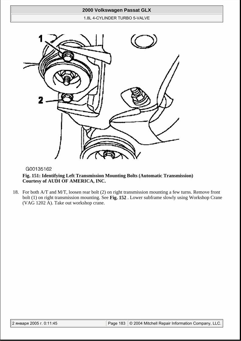
Fig. 151: Identifying Left Transmission Mounting Bolts (Automatic Transmission) Courtesy of AUDI OF AMERICA, INC.
18. For both A/T and M/T, loosen rear bolt (2) on right transmission mounting a few turns. Remove front bolt (1) on right transmission mounting. See Fig. 152 . Lower subframe slowly using Workshop Crane (VAG 1202 A). Take out workshop crane.
2000 Volkswagen Passat GLX 1.8L 4-CYLINDER TURBO 5-VALVE
2 января 2005 г. 0:11:45 Page 183 © 2004 Mitchell Repair Information Company, LLC.

Fig. 152: Identifying Right Transmission Mounting Bolts Courtesy of AUDI OF AMERICA, INC.
19.
Remove the M10 bolts from oil pan/transmission. See Fig. 153 . Loosen bolts No. 1 to No. 18 in a diagonal pattern.
NOTE: Additional steps are required, to remove bolts No. 17 and No. 18 from oil pan with manual transmission. See step 20 .
2000 Volkswagen Passat GLX 1.8L 4-CYLINDER TURBO 5-VALVE
2 января 2005 г. 0:11:45 Page 184 © 2004 Mitchell Repair Information Company, LLC.

Fig. 153: Identifying Oil Pan M10 Fastener Bolts & Fastener Installation & Removal SequenceCourtesy of AUDI OF AMERICA, INC.
20. On vehicles with manual transmission, turn flywheel (3) until the notch in flywheel is aligned with the bolt at the rear of oil pan. Unscrew both rear oil pan bolts (1) and (2) with extension attachment tool
2000 Volkswagen Passat GLX 1.8L 4-CYLINDER TURBO 5-VALVE
2 января 2005 г. 0:11:45 Page 185 © 2004 Mitchell Repair Information Company, LLC.

(3249). See Fig. 154 and Fig. 155 .
Fig. 154: Identifying Location Of Bolts At Rear Of Oil Pan & Notched Flywheel Courtesy of VAG OF AMERICA
2000 Volkswagen Passat GLX 1.8L 4-CYLINDER TURBO 5-VALVE
2 января 2005 г. 0:11:45 Page 186 © 2004 Mitchell Repair Information Company, LLC.

Fig. 155: Identifying Rear Oil Pan Bolt Removal Tool (3249) Courtesy of AUDI OF AMERICA, INC.
21. On all models, remove oil pan bolts. Remove oil pan. If necessary loosen it by striking lightly with a rubber hammer. Carefully remove sealant residues from cylinder block (remove baffle plate). Remove remaining sealant from oil pan with a rotating plastic brush. Clean sealing surfaces, ensure they are free of oil and grease. See Fig. 156 .
2000 Volkswagen Passat GLX 1.8L 4-CYLINDER TURBO 5-VALVE
2 января 2005 г. 0:11:45 Page 187 © 2004 Mitchell Repair Information Company, LLC.

Fig. 156: Cleaning Sealing Mating Surface Using Plastic Wheel Courtesy of VOLKSWAGEN UNITED STATES, INC.
Installation
1. Apply silicone sealant (D 176 404 A2) in a 3 mm (0.1") bead along flange mating surface. See Fig. 157 and Fig. 158 .
NOTE: Always replace seals and gaskets.
2000 Volkswagen Passat GLX 1.8L 4-CYLINDER TURBO 5-VALVE
2 января 2005 г. 0:11:46 Page 188 © 2004 Mitchell Repair Information Company, LLC.

Fig. 157: Apply Sealant (D 176 404 A2) To Oil Pan Courtesy of VOLKSWAGEN UNITED STATES, INC.
2000 Volkswagen Passat GLX 1.8L 4-CYLINDER TURBO 5-VALVE
2 января 2005 г. 0:11:46 Page 189 © 2004 Mitchell Repair Information Company, LLC.

Fig. 158: Applying Silicone Sealer (D 176 404 A2) To Clean Oil Pan Flange Courtesy of AUDI OF AMERICA, INC.
2.
Place oil pan against block, ensuring pan is flush with block. Install and tighten fasteners in sequence. See Fig. 153 . Tighten bolts as follows:
Insert vertical M10 bolts into oil pan before installing the oil pan. Tighten pan-to-block bolts 1 to 18 diagonally to 5 N.m (44 INCH lbs.). Tighten bolts securing oil pan to transmission at this time to 45 N.m (33 ft. lbs.). Tighten M10 bolts to 40 N.m (29 ft. lbs.) Tighten pan-to-block bolts 1 to 18 diagonally to 15 N.m (11 ft. lbs.).
NOTE: When installing the oil pan with the engine removed from the vehicle, ensure that the oil pan (3) is positioned flush with the intermediate plate (1) at the flywheel end (oil pan should protrude dimension "a". Dimension "a" equals 0.8 mm from cylinder block with respect to the cylinder block (2). See Fig. 159 .
2000 Volkswagen Passat GLX 1.8L 4-CYLINDER TURBO 5-VALVE
2 января 2005 г. 0:11:46 Page 190 © 2004 Mitchell Repair Information Company, LLC.

Fig. 159: Identifying Oil Pan Installation Engine Out Of Vehicle
2000 Volkswagen Passat GLX 1.8L 4-CYLINDER TURBO 5-VALVE
2 января 2005 г. 0:11:46 Page 191 © 2004 Mitchell Repair Information Company, LLC.

Courtesy of AUDI OF AMERICA, INC.
3. Install subframe using Workshop Crane (VAG 1202 A).
Fig. 160: Removing & Installing Subframe (A4 & S4) Courtesy of AUDI OF AMERICA, INC.
4. Tighten subframe bolts No. 1 and No. 2 to 75 N.m (55 ft. lbs.). See Fig. 149 . Tighten subframe bolt No. 3 to 110 N.m (81 ft. lbs.), then turn bolt an additional 1/4 turn (90 degrees).
5. On vehicles with automatic transmission, secure ATF lines. 6. On all models, secure lock carrier to body. See LOCK CARRIER . 7. Allow 30 minutes for sealant on oil pan to dry before adding oil to engine. Fill engine with oil. To
complete installation, reverse removal procedure. Tighten bolts to specification. See TORQUE SPECIFICATIONS .
2000 Volkswagen Passat GLX 1.8L 4-CYLINDER TURBO 5-VALVE
2 января 2005 г. 0:11:46 Page 192 © 2004 Mitchell Repair Information Company, LLC.

OIL PAN (PASSAT)
Removal
1. Move lock carrier into service position. See LOCK CARRIER . 2. Raise and support vehicle. Drain engine oil. 3. Unbolt stop for torque reaction support from oil pan. See Fig. 66 . 4. Cut through cable ties. Open retainer for starter cable and take out electrical wiring. See Fig. 147 . 5. Remove bolt from turbocharger oil return line at oil pan. 6. For vehicles with automatic transmission, remove bracket securing ATF cooler lines. 7. On all vehicles. Unplug connector from oil level thermal sensor in oil pan. 8. Mark positions of mountings (1) and locating sleeves (2) on left and right engine mountings (lower).
Remove nut (1) from lower right of engine mounting. Completely remove left engine mounting. See Fig. 62 .
9. Setup support bar (10-222 A) on fender panel flanges. See Fig. 143 . 10. Remove lifting eye from Lifting Tackle (2024 A). Replace pin (1) in center hole on lifting tackle and
secure with locking pin. Engage pin on Lifting Tackle (2024 A) on spindle of Support Bar (10-222 A). See Fig. 144 .
11.
Engage Lifting Tackle (2024 A) in front and rear lifting eyes on engine. Pretension engine with spindle of support bar, do not lift.
12. Support subframe with workshop crane (VAG 1202 A). See Fig. 148 . 13.
Remove front subframe bolts (2) and (3) left and right side and loosen bolts (1). See Fig. 149 . 14. On vehicles with Automatic Transmission (A/T), go to step 15 . On vehicles with Manual
Transmission (M/T), loosen nut (1) on left transmission mounting until it is flush with end of bolt (about four turns on the thread). See Fig. 150 .
15. On vehicles with automatic transmission, loosen rear bolt (2) on left transmission mounting a few turns. Remove front bolt (1) on left transmission mounting. See Fig. 151 .
16. For both A/T and M/T, loosen rear bolt (2) on right transmission mounting a few turns. Remove front bolt (1) on right transmission mounting. See Fig. 152 . Lower subframe slowly using Workshop Crane (VAG 1202 A). Take out Workshop Crane (VAG 1202 A).
17.
Remove the M10 bolts from oil pan/transmission. See Fig. 153 . Loosen bolts 1 to 18 in a diagonal pattern.
CAUTION: The hooks and locating pins of the lifting tackle must be secured with locking pins.
CAUTION: Support subframe, and DO NOT let hang by remaining bolts.
NOTE: The subframe should be disconnected and lowered at the front only, otherwise it will be necessary to check the wheel alignment.
NOTE: Additional steps are required, to remove bolts No. 17 and No. 18 from oil pan with manual transmission. See step 18 .
2000 Volkswagen Passat GLX 1.8L 4-CYLINDER TURBO 5-VALVE
2 января 2005 г. 0:11:46 Page 193 © 2004 Mitchell Repair Information Company, LLC.

18. On vehicles with manual transmission, turn flywheel (3) until the notch in flywheel is aligned with the bolt at the rear of oil pan. Unscrew both rear oil pan bolts (1) and (2) with extension attachment tool (3249). See Fig. 154 and Fig. 155 .
19. On all models, remove oil pan bolts. Remove oil pan. If necessary loosen it by striking lightly with a rubber hammer. Carefully remove sealant residues from cylinder block (remove baffle plate). Remove remaining sealant from oil pan with a rotating plastic brush. Clean sealing surfaces, ensure they are free of oil and grease. See Fig. 156 .
Installation
1. Apply silicone sealant (D 176 404 A2) in a 3 mm (0.1") bead along flange mating surface. See Fig. 157 and Fig. 158 .
2.
Place oil pan against block, ensuring pan is flush with block. Install and tighten fasteners in sequence. See Fig. 153 . Tighten bolts as follows:
Insert vertical M10 bolts into oil pan before installing the oil pan. Tighten pan-to-block bolts 1 to 18 diagonally to 5 N.m (44 INCH lbs.). Tighten bolts securing oil pan to transmission at this time to 45 N.m (33 ft. lbs.). Tighten M10 bolts to 40 N.m (29 ft. lbs.) Tighten pan-to-block bolts 1 to 18 diagonally to 15 N.m (11 ft. lbs.).
3. Install subframe using Workshop Crane (VAG 1202 A). 4. Tighten subframe bolts No. 1 and No. 2 to 75 N.m (55 ft. lbs.). See Fig. 149 . Tighten subframe bolt
No. 3 to 110 N.m (81 ft. lbs.), then turn bolt an additional 1/4 turn (90 degrees). 5. On all models, secure lock carrier to body. See LOCK CARRIER . 6. Allow 30 minutes for sealant on oil pan to dry before adding oil to engine. Fill engine with oil. To
complete installation, reverse removal procedure. Tighten bolts to specification. See TORQUE SPECIFICATIONS .
CHAIN SPROCKET (CRANKSHAFT)
Removal
1. Remove oil pan. See OIL PAN . 2. Remove front oil seal flange. See CRANKSHAFT FRONT OIL SEAL FLANGE . 3. Remove the bolt from the oil pump drive sprocket. Remove chain tensioner and the chain. 4.
With suitable washer in place (1), use a 2 jaw puller (2) to pull chain sprocket off crankshaft. See Fig. 161 .
NOTE: When installing the oil pan with the engine removed from the vehicle, ensure that the oil pan (3) is positioned flush with the intermediate plate (1) at the flywheel end (oil pan should protrude dimension "a". Dimension "a" equals 0.8 mm from cylinder block with respect to the cylinder block (2). See Fig. 159 .
NOTE: Place a suitable washer at end of crankshaft to protect the snout from damage.
2000 Volkswagen Passat GLX 1.8L 4-CYLINDER TURBO 5-VALVE
2 января 2005 г. 0:11:46 Page 194 © 2004 Mitchell Repair Information Company, LLC.

Fig. 161: Removing Chain Sprocket From Crankshaft Using 2-Jaw Puller Courtesy of AUDI OF AMERICA, INC.
Installation
1. To install reverse removal procedure. Heat chain sprocket in heating appliance for approximately 15 minutes to 428° F (220° C).
2.
Position on crankshaft with wide collar on sprocket facing the engine block. Use Drift Sleeve (30-100) to drive sprocket onto seat at end of snout. See Fig. 162 .
WARNING: Chain sprocket will be hot, wear protective gloves.
2000 Volkswagen Passat GLX 1.8L 4-CYLINDER TURBO 5-VALVE
2 января 2005 г. 0:11:46 Page 195 © 2004 Mitchell Repair Information Company, LLC.

Fig. 162: Installing Chain Sprocket Onto Crankshaft Using Drift Sleeve (30-100) Courtesy of AUDI OF AMERICA, INC.
OVERHAUL
CYLINDER HEAD
CAUTION: DO NOT start engine for about 30 minutes after installing camshafts. Hydraulic valve lifters must bleed down or valves may strike pistons. Rotate crankshaft by hand 2 full revolutions before starting engine to ensure valves do not strike pistons.
2000 Volkswagen Passat GLX 1.8L 4-CYLINDER TURBO 5-VALVE
2 января 2005 г. 0:11:46 Page 196 © 2004 Mitchell Repair Information Company, LLC.

Cylinder Head Resurfacing
1. Measure cylinder head warpage, measure at several points along gasket surface using straight edge and feeler gauge. See Fig. 163 . If warpage exceeds specification, machine cylinder head. See CYLINDER HEAD table under ENGINE SPECIFICATIONS.
Fig. 163: Checking Cylinder Head For Warpage Courtesy of VOLKSWAGEN UNITED STATES, INC.
2. If machining causes cylinder head height to be less than specification, replace cylinder head. When checking dimensions for cylinder head height, measure at (A) through the holes for the head bolts. See Fig. 164 . Cylinder head height is measured from head gasket sealing surface to cylinder head cover surface.
NOTE: For view of cylinder head components, see Fig. 124 .
2000 Volkswagen Passat GLX 1.8L 4-CYLINDER TURBO 5-VALVE
2 января 2005 г. 0:11:47 Page 197 © 2004 Mitchell Repair Information Company, LLC.

Fig. 164: Checking Cylinder Head Height Courtesy of VOLKSWAGEN UNITED STATES, INC.
Valve Guides Checking
1. To measure valve guide wear, attach dial indicator to cylinder head. Insert valve into guide until valve stem tip is even with top end of guide.
2. Lightly push edge of valve head against dial indicator tip. Zero dial indicator. Push valve away from dial indicator, in direction opposite of camshaft axis.
3. Maximum allowable deflection is 0.8 mm (.032") on intake or exhaust valve. If deflection does not exceed specification, guide is okay. If deflection exceeds specification, recheck using new valve. If deflection still exceeds specification, replace worn guides. See Fig. 165 .
NOTE: Intake valve stem diameter differs from exhaust valve stem diameter. Use appropriate valve when measuring valve guide wear.
NOTE: Manufacturer does not give specific procedure for replacing valve guides.
2000 Volkswagen Passat GLX 1.8L 4-CYLINDER TURBO 5-VALVE
2 января 2005 г. 0:11:47 Page 198 © 2004 Mitchell Repair Information Company, LLC.

Fig. 165: Checking Valve Guide Wear Courtesy of VOLKSWAGEN UNITED STATES, INC.
Valves Stem Seals Replacement (Cylinder Head Installed)
1. Remove camshafts. See CAMSHAFTS under REMOVAL & INSTALLATION. 2. Remove valve lifters and place them with contact surface downward. During removal note installed
position of lifters, and make sure lifters are not interchanged. 3. Remove spark plugs. 4. Set piston of relevant cylinder to Bottom Dead Center (BDC). 5. Screw Pressure Hose (653/3) into spark plug thread. See Fig. 166 .
2000 Volkswagen Passat GLX 1.8L 4-CYLINDER TURBO 5-VALVE
2 января 2005 г. 0:11:47 Page 199 © 2004 Mitchell Repair Information Company, LLC.

Fig. 166: Installing Air Pressure Hose (653/3) Into Spark plug Hole & Valve Spring Compressor (3362) Onto Cylinder Head. Courtesy of VOLKSWAGEN UNITED STATES, INC.
6.
Secure (3362) valve spring compressor to cylinder head with tool securing bolt. Position installing tool for compressing valve springs to following positions.
Outer intake valves: lower position Center intake valve: upper position
NOTE: DO NOT remove valve springs at this time.
2000 Volkswagen Passat GLX 1.8L 4-CYLINDER TURBO 5-VALVE
2 января 2005 г. 0:11:47 Page 200 © 2004 Mitchell Repair Information Company, LLC.

Exhaust valve: lower position See Fig. 166 .
7. Connect pressure hose to compressed air system supplying at least 6 bar (87 psi) and remove valve springs.
8. Remove valve stem seals with Valve Stem Seal Puller (3364) for valve shaft seal. See Fig. 167 .
2000 Volkswagen Passat GLX 1.8L 4-CYLINDER TURBO 5-VALVE
2 января 2005 г. 0:11:47 Page 201 © 2004 Mitchell Repair Information Company, LLC.

2000 Volkswagen Passat GLX 1.8L 4-CYLINDER TURBO 5-VALVE
2 января 2005 г. 0:11:47 Page 202 © 2004 Mitchell Repair Information Company, LLC.

Fig. 167: Identifying Valve Stem Seal Puller (3364) Courtesy of VOLKSWAGEN UNITED STATES, INC.
Installing Valves Stem Seals
1. Slide plastic sleeve (A) supplied over valve stem. This will prevent the new valve stem seal (B) from being damaged. See Fig. 168 .
Fig. 168: Identifying Plastic Sleeve Placement, Valve Stem Seal & Installation Tool (3365) Courtesy of VOLKSWAGEN UNITED STATES, INC.
2. Place new valve stem seal into Installation Tool (3365). 3. Oil valve stem seal sealing lip and press carefully onto the valve guide. See Fig. 168 .
2000 Volkswagen Passat GLX 1.8L 4-CYLINDER TURBO 5-VALVE
2 января 2005 г. 0:11:47 Page 203 © 2004 Mitchell Repair Information Company, LLC.

Valve Seats
When repairing engines with leaking valves, it is not sufficient to replace or renew valve seats and valves. It is also necessary to check the valve guides for wear. This is particularly important on high mileage engines. The valve seats should only be refaced just enough to produce a perfect seating pattern.
The maximum permissible refacing dimension must be calculated before beginning refacing. If the refacing dimension is exceeded, the function of the hydraulic valve lifters can no longer be guaranteed and the cylinder head should be replaced. If the valve is to be replaced as part of a repair, use a new valve for the calculation.
1. Insert valve into guide. Press valve tightly against valve seat. Lay a straightedge across top of cylinder head. Measure distance between valve stem tip and bottom of straightedge. See Fig. 169 . This is valve installed height. If a new valve is going to be installed, use new valve to make this measurement.
Fig. 169: Measuring Valve Installed Height Courtesy of VOLKSWAGEN UNITED STATES, INC.
CAUTION: DO NOT start engine for about 30 minutes after installing camshafts. Hydraulic valve lifters must bleed down or valves may strike pistons. Rotate crankshaft by hand 2 full revolutions before starting engine to ensure valves do not strike pistons.
2000 Volkswagen Passat GLX 1.8L 4-CYLINDER TURBO 5-VALVE
2 января 2005 г. 0:11:47 Page 204 © 2004 Mitchell Repair Information Company, LLC.

2. Determine maximum allowable refacing dimension by subtracting minimum valve installed height from distance measured in previous step. See MINIMUM VALVE INSTALLED HEIGHT table. For example: if measured distance is 31.4 mm and minimum dimension is 31.0 mm, maximum allowable refacing dimension will be 0.4 mm. See Fig. 170 .
MINIMUM VALVE INSTALLED HEIGHT Application In. (mm) Intake Valve
Outer 1.220 (31.0) Center 1.268 (32.2)
Exhaust Valve 1.256 (31.9)
2000 Volkswagen Passat GLX 1.8L 4-CYLINDER TURBO 5-VALVE
2 января 2005 г. 0:11:47 Page 205 © 2004 Mitchell Repair Information Company, LLC.

Fig. 170: Calculating Stem Height & Valve Seat Refacing Dimensions Courtesy of VOLKSWAGEN UNITED STATES, INC.
2000 Volkswagen Passat GLX 1.8L 4-CYLINDER TURBO 5-VALVE
2 января 2005 г. 0:11:48 Page 206 © 2004 Mitchell Repair Information Company, LLC.

3. If valve stem height measurement is still less than specification, replace cylinder head. If valve stem height exceeds specification, seat can be machined; however, DO NOT machine enough material away from seat to cause valve stem height to be less than minimum specification.
VALVE TRAIN
Lifters (Cam Followers)
Test lifters for correct operation. See VALVE LIFTERS under REMOVAL & INSTALLATION. If lifter(s) can be pushed down more than .007" (.20 mm), replace lifters.
Camshaft Axial Play (A4)
Measure camshaft axial play (intake and exhaust) with lifter and camshaft chain removed. Measure with chain side camshaft bearing caps and cam sprocket side double bearing cap installed. See Fig. 171 . Remove all other caps, note their locations for reassemble. See Fig. 172 . Maximum wear limit .20 mm(.008").
CAUTION: If lifters are charged with oil, allow 30 minutes to bleed down before starting engine. Pistons may strike valves, resulting in bent valves.
CAUTION: DO NOT start engine for about 30 minutes after installing camshafts. Hydraulic valve lifters must bleed down or valves may strike pistons. Rotate crankshaft by hand 2 full revolutions before starting engine to ensure valves do not strike pistons.
2000 Volkswagen Passat GLX 1.8L 4-CYLINDER TURBO 5-VALVE
2 января 2005 г. 0:11:48 Page 207 © 2004 Mitchell Repair Information Company, LLC.

2000 Volkswagen Passat GLX 1.8L 4-CYLINDER TURBO 5-VALVE
2 января 2005 г. 0:11:48 Page 208 © 2004 Mitchell Repair Information Company, LLC.

Fig. 171: Setting Up To Measure Axial Play Intake & Exhaust Camshaft Courtesy of AUDI OF AMERICA, INC.
Fig. 172: Identifying Camshaft Bearing Caps Courtesy of VOLKSWAGEN UNITED STATES, INC.
Camshaft Axial Play (Passat)
Measure camshaft axial play (intake and exhaust) with lifter and camshaft chain removed. Camshaft bearing caps No. 2. and No. 4. installed. Remove all other caps, note their locations for reassemble. See Fig. 172 . Maximum wear limit .20 mm (.008"). See Fig. 173 .
2000 Volkswagen Passat GLX 1.8L 4-CYLINDER TURBO 5-VALVE
2 января 2005 г. 0:11:48 Page 209 © 2004 Mitchell Repair Information Company, LLC.

Fig. 173: Checking Camshaft Axial Play Courtesy of VOLKSWAGEN UNITED STATES, INC.
Valves
Measure valve stem diameter and valve margin. If not within specification, replace valves. Replace as necessary. See VALVES & VALVE SPRINGS table under ENGINE SPECIFICATIONS.
Valves must not be refaced by grinding. Hand lap only. If lapping does not produce proper sealing, check
CAUTION: Sodium-filled exhaust valves must not be disposed of until they have been properly treated as follows: By HAND (no air tools), saw the valves into two sections using a metal saw at a point between the center of the valve stem and the valve head. The valves must not come into contact with water when this is done. Throw the valves into a bucket of water (not more than ten at a time) and step back. A sudden chemical reaction will occur during which the sodium filling burns. After this treatment the valves can be disposed of as normal scrap.
2000 Volkswagen Passat GLX 1.8L 4-CYLINDER TURBO 5-VALVE
2 января 2005 г. 0:11:48 Page 210 © 2004 Mitchell Repair Information Company, LLC.

valve seat. See VALVE SEATS .
Valve Springs
Information is not available from manufacturer.
CYLINDER BLOCK ASSEMBLY
Piston & Rod Assembly
1. Ensure piston, connecting rod and rod caps are marked with matching cylinder number prior to removal. Ensure engine front arrow is marked on top of piston and front mark "A" exists on rod and cap. See Fig. 174 . Pistons and rods are to be replaced in sets of 4. Connecting rod cap bolts MUST be replaced after removing or loosening.
2000 Volkswagen Passat GLX 1.8L 4-CYLINDER TURBO 5-VALVE
2 января 2005 г. 0:11:48 Page 211 © 2004 Mitchell Repair Information Company, LLC.

2000 Volkswagen Passat GLX 1.8L 4-CYLINDER TURBO 5-VALVE
2 января 2005 г. 0:11:48 Page 212 © 2004 Mitchell Repair Information Company, LLC.

Fig. 174: Assembling Piston & Rod Courtesy of VOLKSWAGEN UNITED STATES, INC.
2. Mark piston in relation to pin. Remove circlips from ends of pin bore. Use Piston Pin Replacer/Installer (VW 222A) to remove and install piston pin. If pin is too tight, heat piston to60°C (140° F ). Ensure rod is properly positioned with piston. See Fig. 174 .
3. When installing pistons, ensure "A" marks on connecting rods face front (crankshaft pulley end) of engine. Ensure arrow on piston crown points to front (crankshaft pulley end) of engine.
4. If reinstalling old bearing shells, Do NOT interchange used bearing shells.
Fitting Pistons
1. Measure piston diameter about 10 mm from lower edge of skirt, at 90 degrees to piston pin axis. 2. Check clearance of piston-to-cylinder bore. Piston diameter is stamped on top of piston in millimeters.
See CYLINDER BLOCK under ENGINE SPECIFICATIONS.
Piston Rings
1. To measure ring end gap, place ring squarely in bore about 15 mm (.591") from bottom. Use a piston without rings to seat ring in bore. See Fig. 175 .
2000 Volkswagen Passat GLX 1.8L 4-CYLINDER TURBO 5-VALVE
2 января 2005 г. 0:11:48 Page 213 © 2004 Mitchell Repair Information Company, LLC.

Fig. 175: Checking Piston Ring End Gap Courtesy of VOLKSWAGEN UNITED STATES, INC.
2. Clean piston ring grooves before checking side clearance. Measure ring side clearance to piston ring groove. See Fig. 176 .
2000 Volkswagen Passat GLX 1.8L 4-CYLINDER TURBO 5-VALVE
2 января 2005 г. 0:11:48 Page 214 © 2004 Mitchell Repair Information Company, LLC.

Fig. 176: Checking Piston Ring Side Clearance Courtesy of VOLKSWAGEN UNITED STATES, INC.
3. If not within specification, replace parts as necessary. See PISTONS, PINS & RINGS table under ENGINE SPECIFICATIONS.
4. Install rings on piston with TOP mark facing upward toward crown. Position ring gaps on piston at 120 degree intervals. See Fig. 174 .
Rod Bearings
1. Mark rod caps for reinstallation in original position. Use Plastigage to measure bearing oil clearance. Do NOT interchange used bearing shells, if reusing old bearings.When installing bearing shells, ensure they are centered in connecting rod or bearing cap.
2. When measuring connecting rod oil clearance or side play, install old bolts. Tighten old bolts to 30 N.m (22 ft. lbs.), but do not tighten any further. See CRANKSHAFT, MAIN & CONNECTING ROD BEARINGS table under ENGINE SPECIFICATIONS.
3. Lubricate bolt threads when installing NEW connecting rod cap bolts. Do not reuse old bolts. Tighten evenly to specification in several steps. See TORQUE SPECIFICATIONS .
Crankshaft & Main Bearings
Manufacturer recommends replacing sender wheel (RPM sensor) and mounting bolts, if they are removed from crankshaft.The mounting holes for the sensor wheel are asymmetrically spaced, so it is only possible to install the sensor wheel in one position. If the mounting bolts are installed a second time, the countersunk seats for the bolts in the sensor wheel will be distorted so that the bolt heads will come in contact with the
2000 Volkswagen Passat GLX 1.8L 4-CYLINDER TURBO 5-VALVE
2 января 2005 г. 0:11:49 Page 215 © 2004 Mitchell Repair Information Company, LLC.

crankshaft. The result will be the sensor wheel will fit loosely on the crankshaft and not be properly positioned. See SENSOR WHEEL (ENGINE RPM) .
1. Main bearing caps are marked with matching journal for installation in original position. See Fig. 177 . Use Plastigage(R) to measure oil clearance. Measure crankshaft end play. See Thrust Washer .
2000 Volkswagen Passat GLX 1.8L 4-CYLINDER TURBO 5-VALVE
2 января 2005 г. 0:11:49 Page 216 © 2004 Mitchell Repair Information Company, LLC.

Fig. 177: Exploded View Of Crankshaft Assembly Courtesy of VOLKSWAGEN UNITED STATES, INC.
2000 Volkswagen Passat GLX 1.8L 4-CYLINDER TURBO 5-VALVE
2 января 2005 г. 0:11:49 Page 217 © 2004 Mitchell Repair Information Company, LLC.

2.
The upper bearing shell (engine block side) are color coded at the factory. Color dots are used to mark the thickness of the bearing shells.The position of each bearing thickness is marked with letters on the oil pan sealing area of the engine block. See Fig. 178 .
CAUTION: Do NOT interchanged used bearings.Keep in original position, if reusing.
2000 Volkswagen Passat GLX 1.8L 4-CYLINDER TURBO 5-VALVE
2 января 2005 г. 0:11:49 Page 218 © 2004 Mitchell Repair Information Company, LLC.

2000 Volkswagen Passat GLX 1.8L 4-CYLINDER TURBO 5-VALVE
2 января 2005 г. 0:11:49 Page 219 © 2004 Mitchell Repair Information Company, LLC.

Fig. 178: Identifying Main Bearings (Arrow Points To Crankshaft Pulley End Of Engine) Courtesy of AUDI OF AMERICA, INC.
3. The letter codes relate to the color of the bearing shell installed. See MAIN BEARING COLOR CODING . The lower main bearing shells (main bearing cap side) are always supplied with a Yellow color coding.
MAIN BEARING COLOR CODING
Thrust Washer
Insert feeler gauge between No. 3 main bearing and crankshaft thrust face to measure end play. Replace thrust washer as necessary. See CRANKSHAFT, MAIN & CONNECTING ROD BEARINGS table under ENGINE SPECIFICATIONS.
Cylinder Block
1. Measure cylinder bore diameter in 3 places: at center of bore and 10 mm(.39") from top and bottom of bore. See Fig. 179 .
Letter On Engine Block Bearing Color S Black R Red G Yellow
CAUTION: Cylinder bore must not be measured with engine block secured to engine stand or readings will not be accurate.
2000 Volkswagen Passat GLX 1.8L 4-CYLINDER TURBO 5-VALVE
2 января 2005 г. 0:11:49 Page 220 © 2004 Mitchell Repair Information Company, LLC.

2000 Volkswagen Passat GLX 1.8L 4-CYLINDER TURBO 5-VALVE
2 января 2005 г. 0:11:49 Page 221 © 2004 Mitchell Repair Information Company, LLC.

Fig. 179: Identifying Locations For Checking Cylinder Bore Courtesy of VOLKSWAGEN UNITED STATES, INC.
2. If cylinder bore diameter is not within specification, hone cylinder bore until diameter meets first oversize specification. See CYLINDER BLOCK under ENGINE SPECIFICATIONS.
SENSOR WHEEL (ENGINE RPM)
Sensor Wheel Precautions
Manufacturer recommends replacing sender wheel (RPM sensor) and mounting bolts, if they are removed from crankshaft.The mounting holes for the sensor wheel are asymmetrically spaced, so it is only possible to install the sensor wheel in one position. If the mounting bolts are installed a second time, the countersunk seats for the bolts in the sensor wheel will be distorted so that the bolt heads will come in contact with the crankshaft. The result will be the sensor wheel will fit loosely on the crankshaft and not be properly positioned.
Removal & Installation
1. Remove transmission. For M/T, see appropriate article in CLUTCHES. For A/T, see TRANSMISSION REMOVAL & INSTALLATION article in TRANSMISSION SERVICING.
2. Remove drive plate (A/T) or dual-mass flywheel (M/T). See DRIVE PLATE (A/T) or DUAL-MASS FLYWHEEL (M/T) .
3.
Remove sensor wheel. Discard mounting bolts.
NOTE: For help in identifying components and component locations, refer to Fig. 108 .
NOTE: Sensor wheel can only be installed once, installation distorts the plate. Once sensor wheel is removed, the sensor wheel and its fasteners must be replaced. See Fig. 180 .
2000 Volkswagen Passat GLX 1.8L 4-CYLINDER TURBO 5-VALVE
2 января 2005 г. 0:11:49 Page 222 © 2004 Mitchell Repair Information Company, LLC.

Fig. 180: Identifying Sensor Wheel Securing Bolts Courtesy of AUDI OF AMERICA, INC.
4. To complete installation, reverse removal procedure. Tighten NEW bolts to 10 N.m (89 INCH lbs.) plus an additional 1/4 turn (90°). See TORQUE SPECIFICATIONS .
5. For drive plate or flywheel installation. See DRIVE PLATE (A/T) or DUAL-MASS FLYWHEEL (M/T) .
2000 Volkswagen Passat GLX 1.8L 4-CYLINDER TURBO 5-VALVE
2 января 2005 г. 0:11:50 Page 223 © 2004 Mitchell Repair Information Company, LLC.

ENGINE OILING
ENGINE LUBRICATION SYSTEM
Crankcase Capacity
See CRANKCASE CAPACITY table.
CRANKCASE CAPACITY
Oil Pressure
Check oil pressure with engine at normal operating temperature. Oil pressure at idle should be not less than 1.3 bar (18.9 psi ). Oil pressure at 2000 RPM should be 3.5-4.5 bar(50.8-65.3 psi).
Oil Spray Jet (For Piston Cooling)
Oil spray jet bolt contains a pressure relief valve. See Fig. 181 . The opening pressure for the pressure relief valve is 1.6-1.8 bar (23-26 psi). Do not substitute standard bolt for pressure relief valve.
Application Qts. (L) Without Filter Replacement 3.7 (3.4) With Filter Replacement 4.3 (3.9)
2000 Volkswagen Passat GLX 1.8L 4-CYLINDER TURBO 5-VALVE
2 января 2005 г. 0:11:50 Page 224 © 2004 Mitchell Repair Information Company, LLC.

Fig. 181: Identifying Oil Spray Jet & Pressure Relief Valve Courtesy of AUDI OF AMERICA, INC.
OIL PRESSURE SWITCH
Oil pressure switch is on oil filter housing. See Fig. 182 . The switch contacts should open at 1.2-1.6 bar(19-23 psi).
2000 Volkswagen Passat GLX 1.8L 4-CYLINDER TURBO 5-VALVE
2 января 2005 г. 0:11:50 Page 225 © 2004 Mitchell Repair Information Company, LLC.

Fig. 182: Identifying Oil Filter Bracket & Components Courtesy of AUDI OF AMERICA, INC.
2000 Volkswagen Passat GLX 1.8L 4-CYLINDER TURBO 5-VALVE
2 января 2005 г. 0:11:50 Page 226 © 2004 Mitchell Repair Information Company, LLC.

OIL PUMP
Removal & Installation
Remove oil pan. See OIL PAN . Remove oil pump sprocket bolt (1). Remove oil pump to cylinder block attaching bolts (2) and remove oil pump assembly. See Fig. 183 . To install, reverse removal procedure.
Inspection
Check chain, tensioner, drive gear and oil pump sprocket for wear or damage (chips or nicks). Inspect oil pump, if running surfaces or gears are scored, replace oil pump assembly. Ensure oil pickup (suction pipe) is clean and unrestricted. Ensure oil cooler is not contaminated. Ensure oil pressure relief is not scored. Replace faultycomponent(s).
NOTE: For help in identifying components and component locations, refer to Fig. 141 .
2000 Volkswagen Passat GLX 1.8L 4-CYLINDER TURBO 5-VALVE
2 января 2005 г. 0:11:50 Page 227 © 2004 Mitchell Repair Information Company, LLC.

Fig. 183: Removing Oil Pump From Cylinder Block Courtesy of AUDI OF AMERICA, INC.
TORQUE SPECIFICATIONS
TORQUE SPECIFICATIONS Application Ft. Lbs. (N.m) A/C Belt Tensioner (1) 15 (20) A/C Compressor-To-Bracket 18 (24) A/C Condenser-To-Radiator 7 (10)
2000 Volkswagen Passat GLX 1.8L 4-CYLINDER TURBO 5-VALVE
2 января 2005 г. 0:11:50 Page 228 © 2004 Mitchell Repair Information Company, LLC.

Belt Pulley-To-Viscous Fan Clutch Bolt 22 (30) Camshaft Adjuster-To- Cylinder Head 7 (10) Camshaft Bearing Caps-To- Cylinder Head 7 (10) Camshaft Timing Belt Sprocket Bolt 65 (88) Camshaft Position Sensor Rotor-To-Camshaft Bolt 18 (25) Catalytic Converter-To-Turbocharger 22 (30) Crosspiece For Underbody-To-Body 15 (20) Connecting Rod Bearing Cap Bolt (2)
Step 1 22 (30) Step 2 Additional 90 Degrees
Crankshaft Front Oil Seal Flange -To-Cylinder Block 11 (15) Crankshaft Main Bearing Cap Bolt (2)
Step 1 48 (65) Step 2 Additional 90 Degrees
Crankshaft Rear Sealing Flange -To-Cylinder Block 11 (15) Crankshaft Timing Sprocket Bolt (2)
Step 1 66 (90) Step 2 Additional 90 Degrees
Cylinder Head Bolt (2)
Audi Step 1 30 (40) Step 2 Additional 90 Degrees Step 3 Additional 90 Degrees
Passat Step 1 30 (40) Step 2 44 (60) Step 3 Additional 90 Degrees Step 4 Additional 90 Degrees
Driveplate-To-Crankshaft Bolt (Auto. Trans.) (2)
Step 1 44 (60) Step 2 Additional 90 Degrees
Driveplate-To-Torque Converter (2) 63 (85)
Dual-Mass Flywheel-To-Crankshaft Bolt (Man. Trans.) (2)
43 mm Bolt Length Step 1 44 (60) Step 2 Additional 180 Degrees
Turn 25.5 mm Bolt Length
Step 1 44 (60) Step 2 Additional 90 Degrees Turn
Engine Mount-To-Subframe Bolt 18 (25)
2000 Volkswagen Passat GLX 1.8L 4-CYLINDER TURBO 5-VALVE
2 января 2005 г. 0:11:50 Page 229 © 2004 Mitchell Repair Information Company, LLC.

Engine Mount-To-Engine Support Bolt 18 (25) Exhaust Manifold-To-Cylinder Head 22 (30) Front Exhaust Pipe -To-Catalytic Converter 30 (40) Generator-To-Bracket Bolts
M8 Bolt 17 (23) M10 Bolt 34 (46)
Heated Oxygen Sensor 36 (50) Heat Shield-To-Transmission 17 (23) Intake Manifold Bracket Bolt 15-18 (20-25) Oil Jet Bolt (Piston Cooling) 20 (27) Oil Feed Line-To-Cylinder Head 17 (23) Oil Pan Bolt (3)
Oil Pump-To-Cylinder Block Bolt 11 (15) Oil Pump Drive Sprocket Bolt (5) 15 (20) Oil Pan Drain Plug 22 (30) Oil Return Line Turbo (Both Ends) 7 (10) Piston Oil Pressure Relief Valve 20 (27) Power Steering Pump-To-Bracket 17 (23) Power Steering Pump Pulley-To-Power Steering Pump 17 (23) Pressure Plate-To-Flywheel Bolt (2)
Step 1 22 (30) Step 2 44 (60) Step 3 Additional 90 Degrees
Sender Wheel-To-Crankshaft Bolts (Sensor Trigger) (2)(4)
Step 1 7 (10 Nm) Step 2 Additional 90 Degrees
Serpentine Belt Tensioner-To-Engine Bolt 18 (25) Starter Mount Bolt 48 (65) Stop/Torque Reaction Bracket-To-Oil Pan 22 (30) Tensioner/Accessory Drive Belt-To-Bracket 17 (23) Thermostat Housing Bolt 11 (15) Timing Belt Tensioner Nut 20 (27) Torque Converter-To-Driveplate 63 (85) Transmission Mount-To-Frame Bolt 18 (25) Transmission Bell Housing-To-Engine Block (6)
Transmission Support-To-Subframe 18 (25) Transmission Support-To-Transmission Mount 30 (40) Turbocharger-to-Exhaust Manifold (2) 26 (35) Turbocharger Support Bracket-to-Cylinder Block 18 (25) Turbocharger Support Bracket-to-Turbocharger
Audi 22 (30)
2000 Volkswagen Passat GLX 1.8L 4-CYLINDER TURBO 5-VALVE
2 января 2005 г. 0:11:50 Page 230 © 2004 Mitchell Repair Information Company, LLC.

ENGINE SPECIFICATIONS
GENERAL SPECIFICATIONS
GENERAL SPECIFICATIONS
CRANKSHAFT, MAIN & CONNECTING ROD BEARINGS
CRANKSHAFT, MAIN & CONNECTING ROD BEARINGS
Passat 7 (10)) Water Pump Bolt 11 (15) Vibration Dampener Pulley-To-Crankshaft (2)
Step 1 7 (10) Step 2 Additional 90 Degrees
Viscous Fan Couple-To-Bearing Bolt 33 (45) INCH Lbs. (N.m)
Camshaft Bearing Cap Bolt 89 (10) Camshaft Position Sensor Housing-To-Cylinder Head Bolt
89 (10)
Cylinder Head Cover Nut 89 (10) Intake Manifold-To-Cylinder Head Bolt 89 (10) Timing Belt Upper Cover (5) 89 (10 Nm) Timing Belt Center Cover (5) 89 (10 Nm) Timing Belt Lower Cover (5) 89 (10 Nm) Transaxle/Engine Cover Plate Bolt 89 (10) Valve Cover Retaining Nut 89 (10) (1) Tighten A/C belt tensioner bolt with 22 ft. lbs. (30 N.m) clockwise torque applied
to tensioner (with belt in place).(2) Use NEW bolts.(3) Several steps are required to install oil pan. See OIL PAN under REMOVAL &
INSTALLATION.(4) Sender wheel must be replaced. One time usage distorts the mounting points. See
SENDER WHEEL under OVERHAUL.(5) Install with thread locking fluid (D000 600 A2).(6) Several bolts lengths are used. For bolt installation and torque specification. See
Fig. 73 and Fig. 74 .
Application Specification Displacement 110 Cu. In. (1.8L) Bore 3.189 (81.01) Stroke 3.40" (86.4 mm) Compression Ratio 9.5:1 Fuel System Motronic SFI
2000 Volkswagen Passat GLX 1.8L 4-CYLINDER TURBO 5-VALVE
2 января 2005 г. 0:11:50 Page 231 © 2004 Mitchell Repair Information Company, LLC.

CONNECTING RODS
CONNECTING RODS
Application In. (mm) Crankshaft End Play
Standard .003-.009 (.07-.23) Service Limit .011 (.30)
Main Bearings Journal Diameter
Standard Nominal 2.1260 (54.000)
1st Undersize Nominal 2.1161 (53.750)
2nd Undersize Nominal 2.1063 (53.500)
3rd Undersize Nominal 2.0965 (53.250)
Journal Out-Of-Round (1)
Journal Taper (1)
Oil Clearance Standard .0008-.0024 (.020-.060) Service Limit .005 (.12)
Connecting Rod Bearings Journal Diameter
Standard Nominal 1.8819 (47.800)
1st Undersize Nominal 1.8720 (47.550)
2nd Undersize Nominal 1.8622 (47.300)
3rd Undersize Nominal 1.8524 (47.050)
Journal Out-Of-Round (1)
Journal Taper (1)
Oil Clearance Standard .0004-.00236 (.01-.06) Service Limit .005 (.12)
(1) Information is not available from manufacturer.
Application In. (mm) Bore Diameter
Pin Bore (1)
2000 Volkswagen Passat GLX 1.8L 4-CYLINDER TURBO 5-VALVE
2 января 2005 г. 0:11:51 Page 232 © 2004 Mitchell Repair Information Company, LLC.

PISTONS, PINS & RINGS
PISTONS, PINS & RINGS
Crankpin Bore (1)
Center-To-Center Length (1)
Side Play Standard .002-.012 (.05-.31) Service Limit .015 (.37)
(1) Information is not available from manufacturer.
Application In. (mm) Pistons
Standard Diameter (1)
A4 3.187 (80.950) Passat 3.188 (80.965)
1st Oversize (1)
A4 3.2066 (81.450) Passat 3.207 (81.460)
Pins Diameter (2)
Piston Fit (2)
Rod Fit (2)
Rings No. 1 & 2
End Gap Standard .007-.016 (.20-.40) Service Limit .031 (.80)
Side Clearance Standard (3) .002-.003 (.06-.09) Service Limit .007 (.20)
No. 3 (Oil) End Gap
Standard .010-.020 (.25-.50) Service Limit .031 (.80)
Side Clearance Standard .001-.002 (.03-.06) Service Limit .006 (.15)
(1) Measurement does not include graphite coating, thickness of .02 mm (.0008"). Graphite coating wears away.
(2) Information is not available from manufacturer.
Audi specification for the second compression ring, is specified as .002-
2000 Volkswagen Passat GLX 1.8L 4-CYLINDER TURBO 5-VALVE
2 января 2005 г. 0:11:51 Page 233 © 2004 Mitchell Repair Information Company, LLC.

CYLINDER BLOCK
CYLINDER BLOCK
VALVES & VALVE SPRINGS
VALVES & VALVE SPRINGS
CYLINDER HEAD
CYLINDER HEAD
(3) .003" (.05-.08 mm). Service Limit stays the same.
Application In. (mm) Standard 3.189 (81.01) 1st Oversize 3.209 (81.51) Maximum Taper .003 (.08)
Application (1) Specification Intake Valves
Face Angle 45° Head Diameter 1.059" (26.9 mm) Length 4.127-4.147" (104.84-105.34 mm) Minimum Margin (2)
Stem Diameter .234" (5.96 mm) Valve Stem Installed Height (Minimum)
Center 1.32 (33.7) Outer 1.29 (34.0)
Exhaust Valves Face Angle 45° Head Diameter 1.177" (29.9 mm) Length 4.080-4.100" (103.64-104.14 mm) Minimum Margin (2)
Stem Diameter .233" (5.94 mm) Valve Stem Installed Height (3)
(1) DO NOT machine valves; hand lap only.(2) Information not available from manufacturer.(3) To calculated valve stem installed height or maximum allowable valve seat
refacing. See Valve Seats under CYLINDER HEAD.
Application Specification Cylinder Head Height (Minimum) 5.480" (139.2 mm) Maximum Warpage .004" (.10 mm) Valve Seats
Intake Valve
2000 Volkswagen Passat GLX 1.8L 4-CYLINDER TURBO 5-VALVE
2 января 2005 г. 0:11:51 Page 234 © 2004 Mitchell Repair Information Company, LLC.

CAMSHAFT
CAMSHAFT
Seat Angle 45° Seat Width .059-070" (1.50-1.80 mm)
Exhaust Valve Seat Angle 45° Seat Width .070" (1.80 mm)
Valve Guides Intake Valve
Valve Stem-To-Guide Oil Clearance (1) .031" (.80 mm) Exhaust Valve
Valve Stem-to-Guide Oil Clearance (1) .031" (.80 mm) (1) New valve installed in cylinder head. Dial indicator used to measure valve
wobble in guide.
Application In. (mm) Journal Diameter
Standard (1)
Undersize (1)
End Play (Maximum) .007 (.20) Runout .0004 (.010) Oil Clearance (Maximum) .004 (.10) (1) Information is not available from manufacturer.
2000 Volkswagen Passat GLX 1.8L 4-CYLINDER TURBO 5-VALVE
2 января 2005 г. 0:11:51 Page 235 © 2004 Mitchell Repair Information Company, LLC.