Pemberian teknik Door in the Face dan Foot in the Door untuk ...
Upload
khangminh22Category
view
1download
0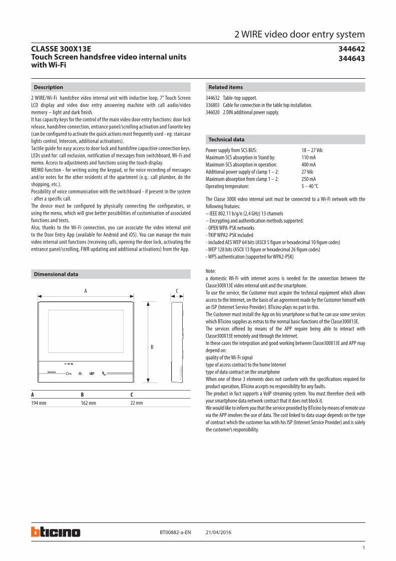
1
344642 344643
21/04/2016BT00882-a-
B
A B C194 mm 162 mm 22 mm
A C
EN
2 WIRE/Wi-Fi handsfree video internal unit with inductive loop, 7” Touch Screen LCD display and video door entry answering machine with call audio/video memory – light and dark finish.It has capacity keys for the control of the main video door entry functions: door lock release, handsfree connection, entrance panel/scrolling activation and Favorite key (can be configured to activate the quick actions most frequently used - eg: staircase lights control, Intercom, additional activations).Tactile guide for easy access to door lock and handsfree capacitive connection keys.LEDs used for: call exclusion, notification of messages from switchboard, Wi-Fi and memo. Access to adjustments and functions using the touch display.MEMO function - for writing using the keypad, or for voice recording of messages and/or notes for the other residents of the apartment (e.g.: call plumber, do the shopping, etc.).Possibility of voice communication with the switchboard - if present in the system - after a specific call.The device must be configured by physically connecting the configurators, or using the menu, which will give better possibilities of customisation of associated functions and texts.Also, thanks to the Wi-Fi connection, you can associate the video internal unit to the Door Entry App (available for Android and iOS). You can manage the main video internal unit functions (receiving calls, opening the door lock, activating the entrance panel/scrolling, FWR updating and additional activations) from the App.
Description
344632 Table-top support.336803 Cable for connection in the table top installation.346020 2 DIN additional power supply.
Related items
2 WIRE video door entry systemCLASSE 300X13ETouch Screen handsfree video internal units with Wi-Fi
Power supply from SCS BUS: 18 – 27 VdcMaximum SCS absorption in Stand by: 110 mAMaximum SCS absorption in operation: 400 mAAdditional power supply of clamp 1 – 2: 27 VdcMaximum absorption from clamp 1 – 2: 250 mAOperating temperature: 5 – 40 °C
The Classe 300X video internal unit must be connected to a Wi-Fi network with the following features:– IEEE 802.11 b/g/n (2,4 GHz) 13 channels– Encrypting and authentication methods supported:- OPEN WPA-PSK networks- TKIP WPA2-PSK included - included AES WEP 64 bits (ASCII 5 figure or hexadecimal 10 figure codes)- WEP 128 bits (ASCII 13 figure or hexadecimal 26 figure codes)- WPS authentication (supported for WPA2-PSK)
Note:a domestic Wi-Fi with internet access is needed for the connection between the Classe300X13E video internal unit and the smartphone.To use the service, the Customer must acquire the technical equipment which allows access to the Internet, on the basis of an agreement made by the Customer himself with an ISP (Internet Service Provider). BTicino plays no part in this.The Customer must install the App on his smartphone so that he can use some services which BTicino supplies as extras to the normal basic functions of the Classe300X13E.The services offered by means of the APP require being able to interact with Classe300X13E remotely and through the Internet.In these cases the integration and good working between Classe300X13E and APP may depend on:quality of the Wi-Fi signaltype of access contract to the home Internettype of data contract on the smartphone When one of these 3 elements does not conform with the specifications required for product operation, BTicino accepts no responsibility for any faults.The product in fact supports a VoIP streaming system. You must therefore check with your smartphone data network contract that it does not block it.We would like to inform you that the service provided by BTicino by means of remote use via the APP involves the use of data. The cost linked to data usage depends on the type of contract which the customer has with his ISP (Internet Service Provider) and is solely the customer’s responsibility.
Technical data
Dimensional data
2
21/04/2016BT00882-a-
344642 344643
EN
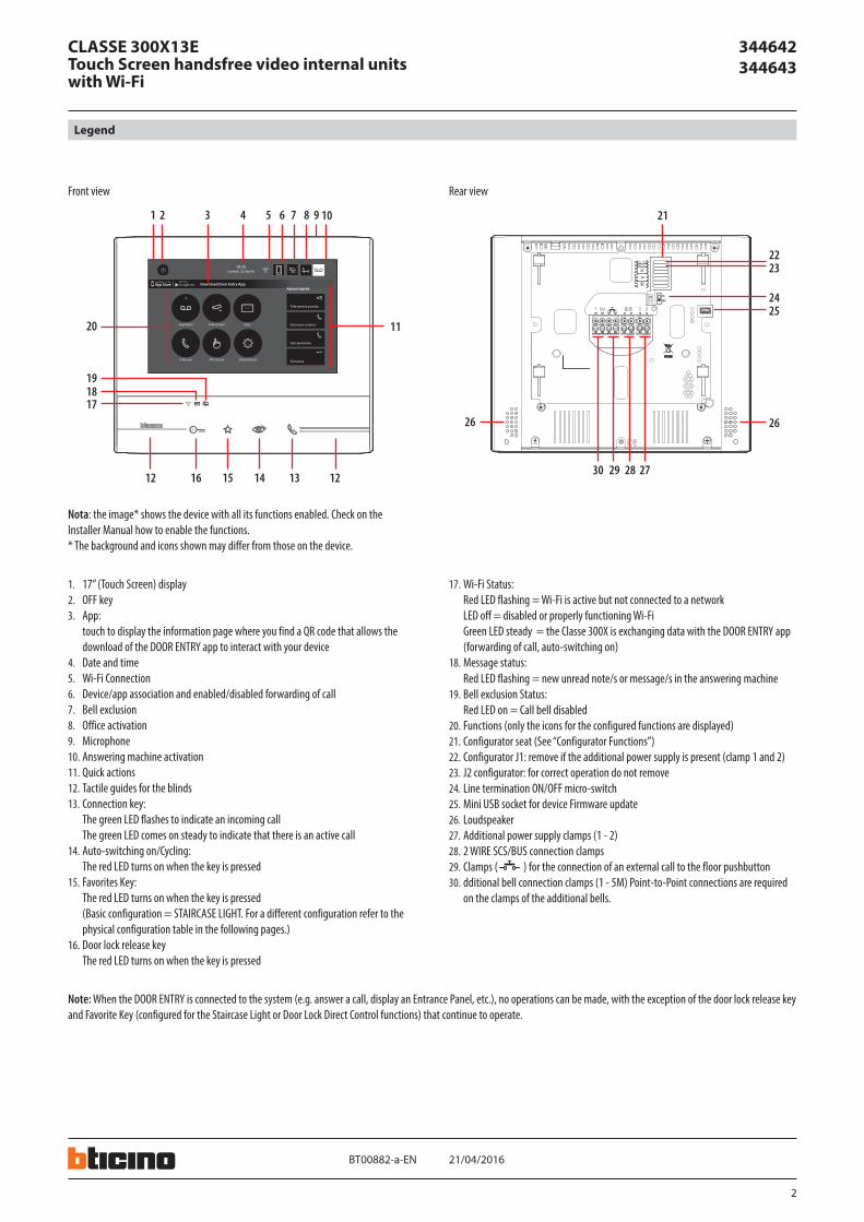
Legend
CLASSE 300X13ETouch Screen handsfree video internal units with Wi-Fi
1. 17” (Touch Screen) display2. OFF key3. App:
touch to display the information page where you find a QR code that allows the download of the DOOR ENTRY app to interact with your device
4. Date and time5. Wi-Fi Connection6. Device/app association and enabled/disabled forwarding of call7. Bell exclusion8. Office activation9. Microphone10. Answering machine activation11. Quick actions12. Tactile guides for the blinds13. Connection key:
The green LED flashes to indicate an incoming call The green LED comes on steady to indicate that there is an active call
14. Auto-switching on/Cycling: The red LED turns on when the key is pressed
15. Favorites Key: The red LED turns on when the key is pressed (Basic configuration = STAIRCASE LIGHT. For a different configuration refer to the physical configuration table in the following pages.)
16. Door lock release key The red LED turns on when the key is pressed
21
2425
2626
2223
27282930
Azioni rapide
10:36 Lunedì, 22 Aprile
Attivazioni
Segreteria Telecamere Note
ImpostazioniIntercom
Telecamera privata
Serratura
Intercom esterno
Cercapersone
1
Download Door Entry App
1 2 4 5 6 3 7 8 10 9
191817
20
121314151612
11
Nota: the image* shows the device with all its functions enabled. Check on the Installer Manual how to enable the functions.* The background and icons shown may differ from those on the device.
Front view Rear view
Note: When the DOOR ENTRY is connected to the system (e.g. answer a call, display an Entrance Panel, etc.), no operations can be made, with the exception of the door lock release key and Favorite Key (configured for the Staircase Light or Door Lock Direct Control functions) that continue to operate.
17. Wi-Fi Status: Red LED flashing = Wi-Fi is active but not connected to a network LED off = disabled or properly functioning Wi-Fi Green LED steady = the Classe 300X is exchanging data with the DOOR ENTRY app (forwarding of call, auto-switching on)
18. Message status: Red LED flashing = new unread note/s or message/s in the answering machine
19. Bell exclusion Status: Red LED on = Call bell disabled
20. Functions (only the icons for the configured functions are displayed)21. Configurator seat (See “Configurator Functions”)22. Configurator J1: remove if the additional power supply is present (clamp 1 and 2)23. J2 configurator: for correct operation do not remove24. Line termination ON/OFF micro-switch25. Mini USB socket for device Firmware update26. Loudspeaker27. Additional power supply clamps (1 - 2)28. 2 WIRE SCS/BUS connection clamps29. Clamps ( ) for the connection of an external call to the floor pushbutton30. dditional bell connection clamps (1 - 5M) Point-to-Point connections are required
on the clamps of the additional bells.
3
344642 344643
21/04/2016BT00882-a-
BUS
J1 J2 N P M
EN
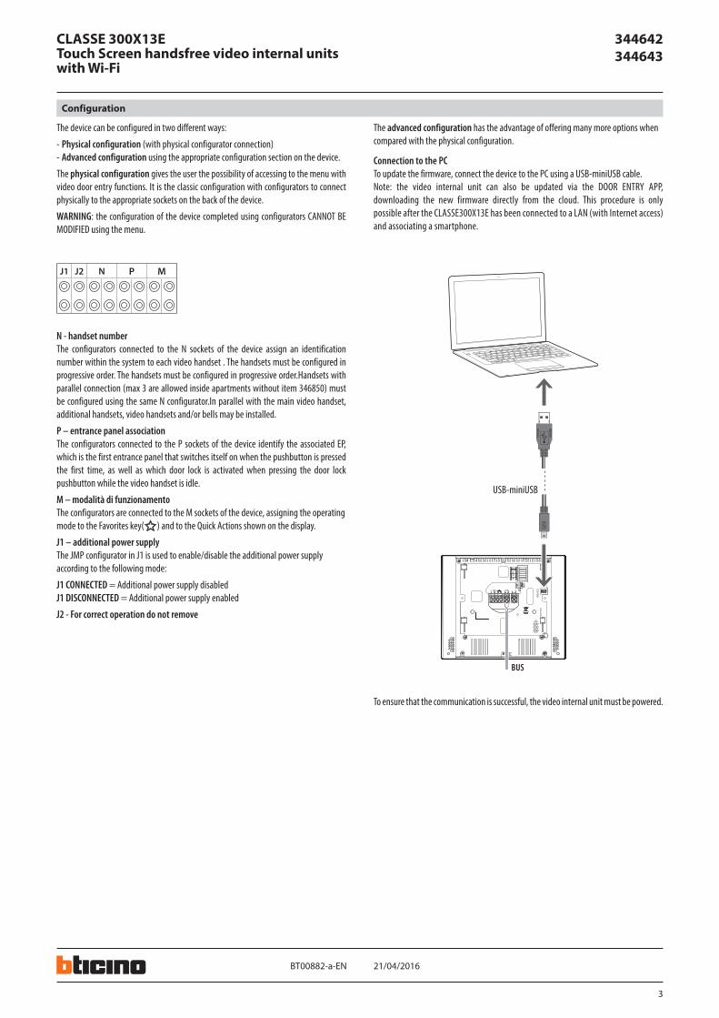
The device can be configured in two different ways:
- Physical configuration (with physical configurator connection)- Advanced configuration using the appropriate configuration section on the device.
The physical configuration gives the user the possibility of accessing to the menu with video door entry functions. It is the classic configuration with configurators to connect physically to the appropriate sockets on the back of the device.
WARNING: the configuration of the device completed using configurators CANNOT BE MODIFIED using the menu.
N - handset numberThe configurators connected to the N sockets of the device assign an identification number within the system to each video handset . The handsets must be configured in progressive order. The handsets must be configured in progressive order.Handsets with parallel connection (max 3 are allowed inside apartments without item 346850) must be configured using the same N configurator.In parallel with the main video handset, additional handsets, video handsets and/or bells may be installed.
P – entrance panel associationThe configurators connected to the P sockets of the device identify the associated EP, which is the first entrance panel that switches itself on when the pushbutton is pressed the first time, as well as which door lock is activated when pressing the door lock pushbutton while the video handset is idle.
M – modalità di funzionamentoThe configurators are connected to the M sockets of the device, assigning the operatingmode to the Favorites key( ) and to the Quick Actions shown on the display.
J1 – additional power supplyThe JMP configurator in J1 is used to enable/disable the additional power supplyaccording to the following mode:
J1 CONNECTED = Additional power supply disabledJ1 DISCONNECTED = Additional power supply enabled
J2 - For correct operation do not remove
The advanced configuration has the advantage of offering many more options whencompared with the physical configuration.
Connection to the PCTo update the firmware, connect the device to the PC using a USB-miniUSB cable.Note: the video internal unit can also be updated via the DOOR ENTRY APP, downloading the new firmware directly from the cloud. This procedure is only possible after the CLASSE300X13E has been connected to a LAN (with Internet access) and associating a smartphone.
To ensure that the communication is successful, the video internal unit must be powered.
Configuration
USB-miniUSB
CLASSE 300X13ETouch Screen handsfree video internal units with Wi-Fi
4
344642 344643
21/04/2016BT00882-a-
J1 J2 N P M J1 J2 N P M
EN
CLASSE 300X13ETouch Screen handsfree video internal units with Wi-Fi
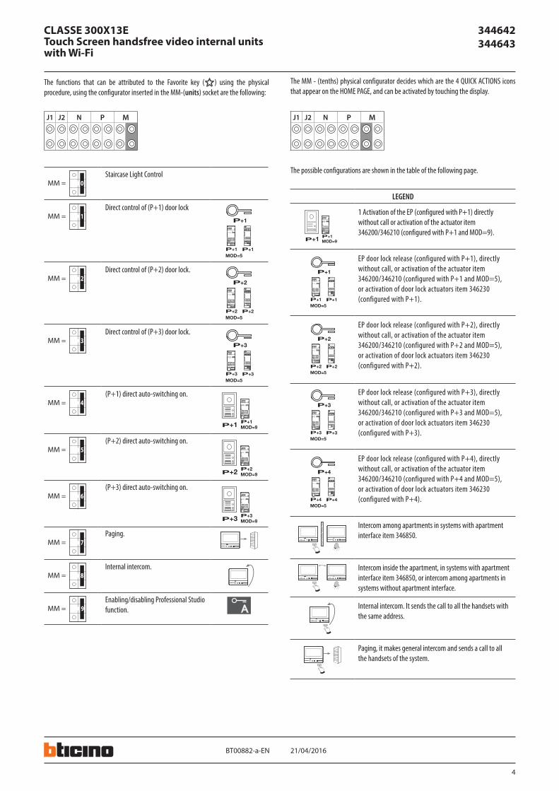
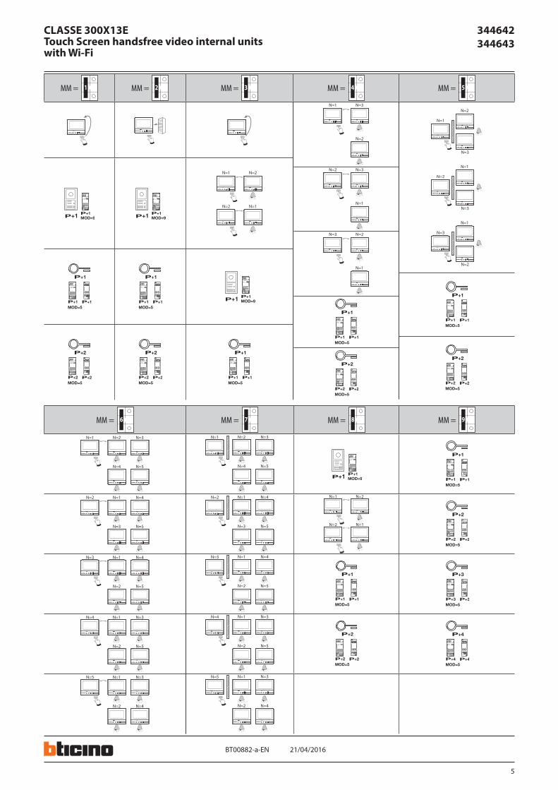
The possible configurations are shown in the table of the following page.
LEGEND
P+1 MOD=9P+1
P+2 MOD=9P+2
P
P+1
MOD=5P+1 P+1
2 3
1 32
346210
1
P+2
MOD=5P+2 P+2
2 3
1 32
346210
1
P+3
MOD=5P+3 P+3
2 3
1 32
346210
1
P+4
MOD=5P+4 P+4
2 3
1 32
346210
1
1–+ 23 4
P+3 MOD=9P+3
1–+ 23 4
2 3
1 32
346210
1
1 Activation of the EP (configured with P+1) directly without call or activation of the actuator item 346200/346210 (configured with P+1 and MOD=9).
P+1 MOD=9P+1
P+2 MOD=9P+2
P
P+1
MOD=5P+1 P+1
2 3
1 32
346210
1
P+2
MOD=5P+2 P+2
2 3
1 32
346210
1
P+3
MOD=5P+3 P+3
2 3
1 32
346210
1
P+4
MOD=5P+4 P+4
2 3
1 32
346210
1
1–+ 23 4
1–+ 23 4
P+3 MOD=9P+3
1–+ 23 4
EP door lock release (configured with P+1), directly without call, or activation of the actuator item 346200/346210 (configured with P+1 and MOD=5), or activation of door lock actuators item 346230 (configured with P+1).
P+1 MOD=9P+1
P+2 MOD=9P+2
P
P+1
MOD=5P+1 P+1
2 3
1 32
346210
1
P+2
MOD=5P+2 P+2
2 3
1 32
346210
1
P+3
MOD=5P+3 P+3
2 3
1 32
346210
1
P+4
MOD=5P+4 P+4
2 3
1 32
346210
1
1–+ 23 4
1–+ 23 4
P+3 MOD=9P+3
1–+ 23 4
EP door lock release (configured with P+2), directly without call, or activation of the actuator item 346200/346210 (configured with P+2 and MOD=5), or activation of door lock actuators item 346230 (configured with P+2).
P+1 MOD=9P+1
P+2 MOD=9P+2
P
P+1
MOD=5P+1 P+1
2 3
1 32
346210
1
P+2
MOD=5P+2 P+2
2 3
1 32
346210
1
P+3
MOD=5P+3 P+3
2 3
1 32
346210
1
P+4
MOD=5P+4 P+4
2 3
1 32
346210
1
1–+ 23 4
1–+ 23 4
P+3 MOD=9P+3
1–+ 23 4
EP door lock release (configured with P+3), directly without call, or activation of the actuator item 346200/346210 (configured with P+3 and MOD=5), or activation of door lock actuators item 346230 (configured with P+3).
P+1 MOD=9P+1
P+2 MOD=9P+2
P
P+1
MOD=5P+1 P+1
2 3
1 32
346210
1
P+2
MOD=5P+2 P+2
2 3
1 32
346210
1
P+3
MOD=5P+3 P+3
2 3
1 32
346210
1
P+4
MOD=5P+4 P+4
2 3
1 32
346210
1
1–+ 23 4
1–+ 23 4
P+3 MOD=9P+3
1–+ 23 4
EP door lock release (configured with P+4), directly without call, or activation of the actuator item 346200/346210 (configured with P+4 and MOD=5), or activation of door lock actuators item 346230 (configured with P+4).
Intercom among apartments in systems with apartment interface item 346850.
Intercom inside the apartment, in systems with apartment interface item 346850, or intercom among apartments in systems without apartment interface.
Internal intercom. It sends the call to all the handsets with the same address.
Paging, it makes general intercom and sends a call to all the handsets of the system.
The functions that can be attributed to the Favorite key ( ) using the physical procedure, using the configurator inserted in the MM-(units) socket are the following:
The MM - (tenths) physical configurator decides which are the 4 QUICK ACTIONS icons that appear on the HOME PAGE, and can be activated by touching the display.
MM = 0Staircase Light Control
MM = 1Direct control of (P+1) door lock
P+1 MOD=9P+1
P+2 MOD=9P+2
P+1
MOD=5P+1 P+1
2 3
1 32
346210
1
P+2
MOD=5P+2 P+2
2 3
1 32
346210
1
P+3
MOD=5P+3 P+3
2 3
1 32
346210
1
P+3 MOD=9P+3
MM = 2Direct control of (P+2) door lock.
P+1 MOD=9P+1
P+2 MOD=9P+2
P+1
MOD=5P+1 P+1
2 3
1 32
346210
1
P+2
MOD=5P+2 P+2
2 3
1 32
346210
1
P+3
MOD=5P+3 P+3
2 3
1 32
346210
1
P+3 MOD=9P+3
MM = 3Direct control of (P+3) door lock.
P+1 MOD=9P+1
P+2 MOD=9P+2
P+1
MOD=5P+1 P+1
2 3
1 32
346210
1
P+2
MOD=5P+2 P+2
2 3
1 32
346210
1
P+3
MOD=5P+3 P+3
2 3
1 32
346210
1
P+3 MOD=9P+3
MM = 4(P+1) direct auto-switching on.
P+1 MOD=9P+1
P
2 3
1 32
346210
1
P+2 MOD=9P+2
2 3
1 32
346210
1
P+3 MOD=9P+3
2 3
1 32
346210
1
MM = 5(P+2) direct auto-switching on.
P+1 MOD=9P+1
P
2 3
1 32
346210
1
P+2 MOD=9P+2
2 3
1 32
346210
1
P+3 MOD=9P+3
2 3
1 32
346210
1
MM = 6(P+3) direct auto-switching on.
P+1 MOD=9P+1
P
2 3
1 32
346210
1
P+2 MOD=9P+2
2 3
1 32
346210
1
P+3 MOD=9P+3
2 3
1 32
346210
1
MM = 7Paging.
MM = 8Internal intercom.
MM = 9Enabling/disabling Professional Studio function.
5
344642 344643
21/04/2016BT00882-a-
MM = 1 MM = 2 MM = 3 MM = 4 MM = 5
P+1 MOD=9P+1
2 3
1 32
346210
1
P+1 MOD=9P+1
2 3
1 32
346210
1
N=2
N=1
N=1
N=2
P+1
MOD=5P+1 P+1
2 3
1 32
346210
1
P+1
MOD=5P+1 P+1
2 3
1 32
346210
1
P+1 MOD=9P+1
2 3
1 32
346210
1
P+2
MOD=5P+2 P+2
2 3
1 32
346210
1
P+2
MOD=5P+2 P+2
2 3
1 32
346210
1
P+1
MOD=5P+1 P+1
2 3
1 32
346210
1
N=3
N=2
N=1
N=3
N=1
N=2
N=2
N=1
N=3
P+1
MOD=5P+1 P+1
2 3
1 32
346210
1
P+2
MOD=5P+2 P+2
2 3
1 32
346210
1
N=1
N=2
N=3
N=2
N=1
N=3
N=3
N=1
N=2
P+1
MOD=5P+1 P+1
2 3
1 32
346210
1
P+2
MOD=5P+2 P+2
2 3
1 32
346210
1
MM = 6 MM = 7 MM = 8 MM = 9
N=2 N=3
N=4 N=5
N=1
N=1 N=4
N=3 N=5
N=2
N=1 N=4
N=2 N=5
N=3
N=1 N=3
N=2 N=5
N=4
N=1 N=3
N=2 N=4
N=5
N=2 N=3
N=4 N=5
N=1
P+1 MOD=9P+1
2 3
1 32
346210
1
P+1
MOD=5P+1 P+1
2 3
1 32
346210
1
N=1 N=4
N=3 N=5
N=2 N=2
N=1
N=1
N=2
P+2
MOD=5P+2 P+2
2 3
1 32
346210
1
N=1 N=4
N=2 N=5
N=3
P+1
MOD=5P+1 P+1
2 3
1 32
346210
1
P+3
MOD=5P+3 P+3
2 3
1 32
346210
1
N=1 N=3
N=2 N=5
N=4
P+2
MOD=5P+2 P+2
2 3
1 32
346210
1
P+4
MOD=5P+4 P+4
2 3
1 32
346210
1
N=1 N=3
N=2 N=4
N=5
EN
CLASSE 300X13ETouch Screen handsfree video internal units with Wi-Fi
6
344642 344643
BT00882-a- 21/04/2016
2
1CLAK
3
25-35 cm
40 cm
ENEN
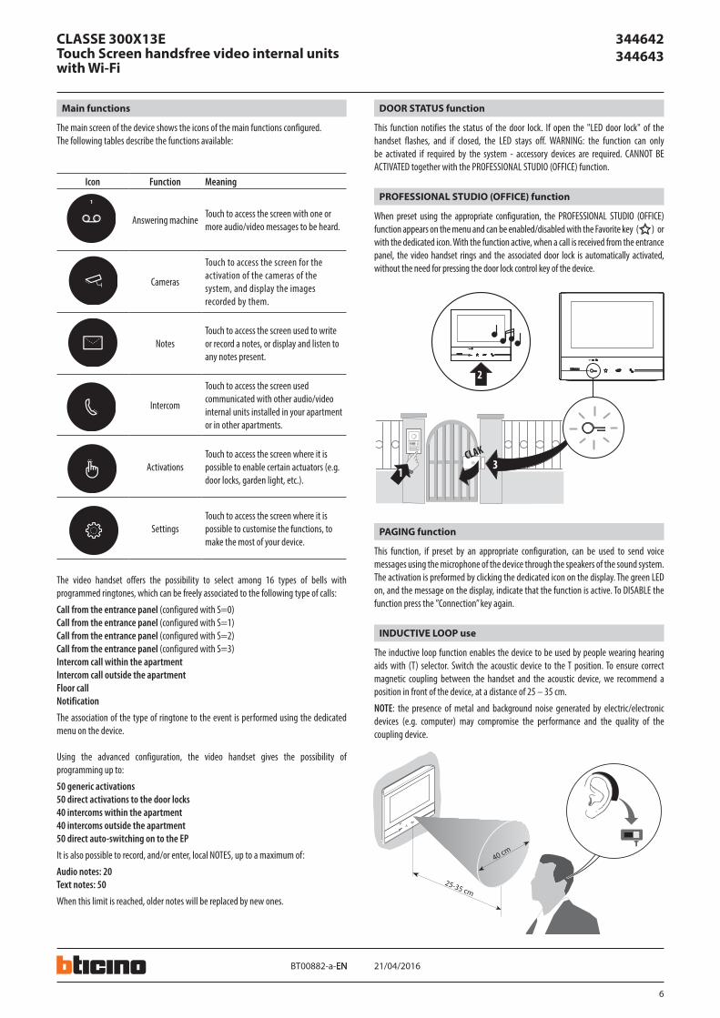
The main screen of the device shows the icons of the main functions configured.The following tables describe the functions available:
The video handset offers the possibility to select among 16 types of bells with programmed ringtones, which can be freely associated to the following type of calls:
Call from the entrance panel (configured with S=0)Call from the entrance panel (configured with S=1)Call from the entrance panel (configured with S=2)Call from the entrance panel (configured with S=3)Intercom call within the apartmentIntercom call outside the apartmentFloor callNotification
The association of the type of ringtone to the event is performed using the dedicated menu on the device.
Using the advanced configuration, the video handset gives the possibility of programming up to:
50 generic activations50 direct activations to the door locks40 intercoms within the apartment40 intercoms outside the apartment50 direct auto-switching on to the EP
It is also possible to record, and/or enter, local NOTES, up to a maximum of:
Audio notes: 20Text notes: 50
When this limit is reached, older notes will be replaced by new ones.
When preset using the appropriate configuration, the PROFESSIONAL STUDIO (OFFICE) function appears on the menu and can be enabled/disabled with the Favorite key ( ) or with the dedicated icon. With the function active, when a call is received from the entrance panel, the video handset rings and the associated door lock is automatically activated, without the need for pressing the door lock control key of the device.
PROFESSIONAL STUDIO (OFFICE) function
Main functions
This function notifies the status of the door lock. If open the "LED door lock" of the handset flashes, and if closed, the LED stays off. WARNING: the function can only be activated if required by the system - accessory devices are required. CANNOT BE ACTIVATED together with the PROFESSIONAL STUDIO (OFFICE) function.
DOOR STATUS function
Icon Function Meaning
1
Answering machineTouch to access the screen with one or more audio/video messages to be heard.
1
Cameras
Touch to access the screen for the activation of the cameras of the system, and display the images recorded by them.
1
NotesTouch to access the screen used to write or record a notes, or display and listen to any notes present.
1
Intercom
Touch to access the screen used communicated with other audio/video internal units installed in your apartment or in other apartments.
1
ActivationsTouch to access the screen where it is possible to enable certain actuators (e.g. door locks, garden light, etc.).
1
SettingsTouch to access the screen where it is possible to customise the functions, to make the most of your device.
The inductive loop function enables the device to be used by people wearing hearing aids with (T) selector. Switch the acoustic device to the T position. To ensure correct magnetic coupling between the handset and the acoustic device, we recommend a position in front of the device, at a distance of 25 – 35 cm.
NOTE: the presence of metal and background noise generated by electric/electronic devices (e.g. computer) may compromise the performance and the quality of the coupling device.
INDUCTIVE LOOP use
This function, if preset by an appropriate configuration, can be used to send voice messages using the microphone of the device through the speakers of the sound system. The activation is preformed by clicking the dedicated icon on the display. The green LED on, and the message on the display, indicate that the function is active. To DISABLE the function press the ”Connection” key again.
PAGING function
CLASSE 300X13ETouch Screen handsfree video internal units with Wi-Fi
7
344642 344643
21/04/2016BT00882-a-EN
CLASSE 300X13ETouch Screen handsfree video internal units with Wi-Fi
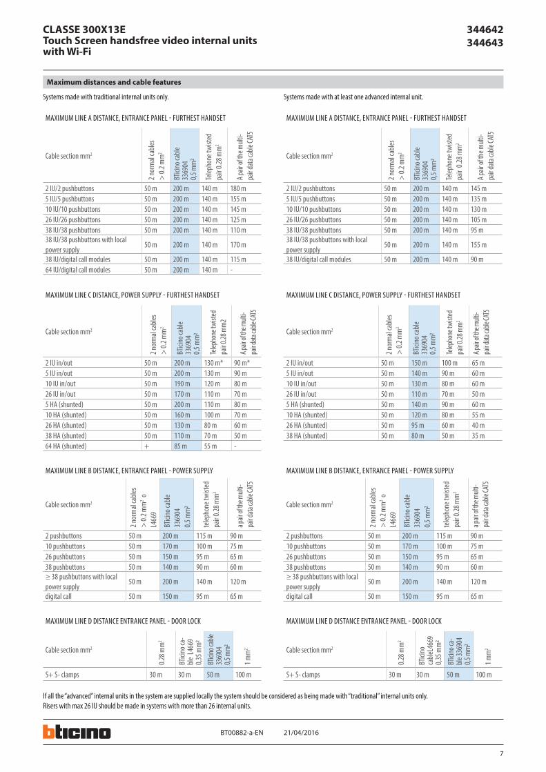
Systems made with traditional internal units only.
MAXIMUM LINE A DISTANCE, ENTRANCE PANEL - FURTHEST HANDSET
Cable section mm22 n
orm
al ca
bles
> 0.
2 mm
2
BTici
no ca
ble
3369
04
0,5 m
m2
Telep
hone
twist
ed
pair 0
.28 m
m2
A pair
of th
e mult
i-pa
ir data
cable
CAT5
2 IU/2 pushbuttons 50 m 200 m 140 m 180 m5 IU/5 pushbuttons 50 m 200 m 140 m 155 m10 IU/10 pushbuttons 50 m 200 m 140 m 145 m26 IU/26 pushbuttons 50 m 200 m 140 m 125 m38 IU/38 pushbuttons 50 m 200 m 140 m 110 m38 IU/38 pushbuttons with local power supply
50 m 200 m 140 m 170 m
38 IU/digital call modules 50 m 200 m 140 m 115 m64 IU/digital call modules 50 m 200 m 140 m -
MAXIMUM LINE C DISTANCE, POWER SUPPLY - FURTHEST HANDSET
Cable section mm2
2 nor
mal
cable
s >
0.2 m
m2
BTici
no ca
ble
3369
04
0,5 m
m2
Telep
hone
twist
ed
pair 0
.28 m
m2
A pair
of th
e mult
i-pa
ir data
cable
CAT5
2 IU in/out 50 m 200 m 130 m* 90 m*5 IU in/out 50 m 200 m 130 m 90 m10 IU in/out 50 m 190 m 120 m 80 m26 IU in/out 50 m 170 m 110 m 70 m5 HA (shunted) 50 m 200 m 110 m 80 m10 HA (shunted) 50 m 160 m 100 m 70 m26 HA (shunted) 50 m 130 m 80 m 60 m38 HA (shunted) 50 m 110 m 70 m 50 m64 HA (shunted) + 85 m 55 m -
MAXIMUM LINE D DISTANCE ENTRANCE PANEL - DOOR LOCK
Cable section mm2
0.28 m
m2
BTici
no ca
-ble
L46
69
0,35 m
m2
BTici
no ca
ble
3369
04
0,5 m
m2
1 mm
2
S+ S- clamps 30 m 30 m 50 m 100 m
If all the “advanced” internal units in the system are supplied locally the system should be considered as being made with “traditional” internal units only.Risers with max 26 IU should be made in systems with more than 26 internal units.
Systems made with at least one advanced internal unit.
MAXIMUM LINE A DISTANCE, ENTRANCE PANEL - FURTHEST HANDSET
Cable section mm2
2 nor
mal
cable
s >
0.2 m
m2
BTici
no ca
ble
3369
04
0,5 m
m2
Telep
hone
twist
ed
pair
0.28 m
m2
A pair
of th
e mult
i-pa
ir data
cable
CAT5
2 IU/2 pushbuttons 50 m 200 m 140 m 145 m5 IU/5 pushbuttons 50 m 200 m 140 m 135 m10 IU/10 pushbuttons 50 m 200 m 140 m 130 m26 IU/26 pushbuttons 50 m 200 m 140 m 105 m38 IU/38 pushbuttons 50 m 200 m 140 m 95 m38 IU/38 pushbuttons with local power supply
50 m 200 m 140 m 155 m
38 IU/digital call modules 50 m 200 m 140 m 90 m
MAXIMUM LINE C DISTANCE, POWER SUPPLY - FURTHEST HANDSET
Cable section mm2
2 nor
mal
cable
s >
0.2 m
m2
BTici
no ca
ble
3369
04
0,5 m
m2
Telep
hone
twist
ed
pair 0
.28 m
m2
A pair
of th
e mult
i-pa
ir data
cable
CAT5
2 IU in/out 50 m 150 m 100 m 65 m5 IU in/out 50 m 140 m 90 m 60 m10 IU in/out 50 m 130 m 80 m 60 m26 IU in/out 50 m 110 m 70 m 50 m5 HA (shunted) 50 m 140 m 90 m 60 m10 HA (shunted) 50 m 120 m 80 m 55 m26 HA (shunted) 50 m 95 m 60 m 40 m38 HA (shunted) 50 m 80 m 50 m 35 m
MAXIMUM LINE B DISTANCE, ENTRANCE PANEL - POWER SUPPLY
Cable section mm2
2 nor
mal
cable
s>
0.2 m
m2 o
L4
669
BTici
no ca
ble
3369
04
0,5 m
m2
telep
hone
twist
ed
pair 0
.28 m
m2
a pair
of th
e mult
i-pa
ir data
cable
CAT5
2 pushbuttons 50 m 200 m 115 m 90 m10 pushbuttons 50 m 170 m 100 m 75 m26 pushbuttons 50 m 150 m 95 m 65 m38 pushbuttons 50 m 140 m 90 m 60 m≥ 38 pushbuttons with local power supply
50 m 200 m 140 m 120 m
digital call 50 m 150 m 95 m 65 m
MAXIMUM LINE D DISTANCE ENTRANCE PANEL - DOOR LOCK
Cable section mm2
0.28 m
m2
BTici
no
cable
L466
9 0,3
5 mm
2
BTici
no ca
-ble
3369
04
0,5 m
m2
1 mm
2
S+ S- clamps 30 m 30 m 50 m 100 m
MAXIMUM LINE B DISTANCE, ENTRANCE PANEL - POWER SUPPLY
Cable section mm2
2 nor
mal
cable
s>
0.2 m
m2 o
L4
669
BTici
no ca
ble
3369
04
0,5 m
m2
telep
hone
twist
ed
pair 0
.28 m
m2
a pair
of th
e mult
i-pa
ir data
cable
CAT5
2 pushbuttons 50 m 200 m 115 m 90 m10 pushbuttons 50 m 170 m 100 m 75 m26 pushbuttons 50 m 150 m 95 m 65 m38 pushbuttons 50 m 140 m 90 m 60 m≥ 38 pushbuttons with local power supply
50 m 200 m 140 m 120 m
digital call 50 m 150 m 95 m 65 m
Maximum distances and cable features
8
344642 344643
21/04/2016BT00882-a-
1 - 2
PR I
1 - 2
346020PRI: 220 - 240V~
175-165mA 50/60Hz
1-2: 27Vdc 600mA
BUS 1 - 2
BUS 1 - 2
BUS 1 - 2 1 - 2
ON
ON
ON
PR I
1 - 2
346020PRI: 220 - 240V~
175-165mA 50/60Hz
1-2: 27Vdc 600mA
1 - 2
PR I
1 - 2
346020PRI: 220 - 240V~
175-165mA 50/60Hz
1-2: 27Vdc 600mA
EN
CLASSE 300X13ETouch Screen handsfree video internal units with Wi-Fi
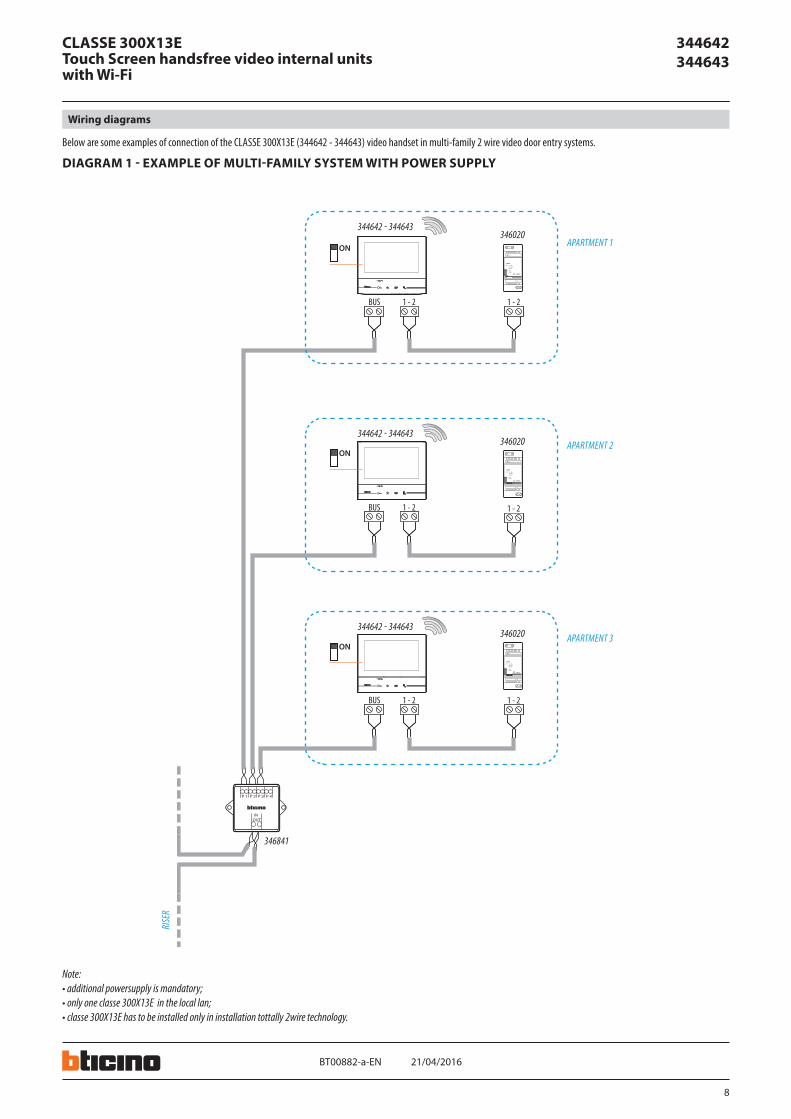
Wiring diagrams
Below are some examples of connection of the CLASSE 300X13E (344642 - 344643) video handset in multi-family 2 wire video door entry systems.
DIAGRAM 1 - EXAMPLE OF MULTI-FAMILY SYSTEM WITH POWER SUPPLY
346841
346020344642 - 344643
346020344642 - 344643
346020344642 - 344643
APARTMENT 1
RISE
R
APARTMENT 2
APARTMENT 3
Note:• additional powersupply is mandatory;• only one classe 300X13E in the local lan;• classe 300X13E has to be installed only in installation tottally 2wire technology.
9
344642 344643
BUS
BUS
BUS
BUS
BUS
BUS
OFF
OFF
BUS
ON
BUS
ON
BUS
1 - 2 1 - 2
PR I
1 - 2
346020PRI: 220 - 240V~
175-165mA 50/60Hz
1-2: 27Vdc 600mA
ON
OFF
OFF
1 - 2 1 - 2
PR I
1 - 2
346020PRI: 220 - 240V~
175-165mA 50/60Hz
1-2: 27Vdc 600mA
ON
OFF
OFF
1 - 2 1 - 2
PR I
1 - 2
346020PRI: 220 - 240V~
175-165mA 50/60Hz
1-2: 27Vdc 600mA
ON
346020
344642344643
346841
344612 - 344613
344612 - 344613
344642344643
344612 - 344613
344612 - 344613
344642344643
344612 - 344613
344612 - 344613
346020
346020
21/04/2016BT00882-a-EN
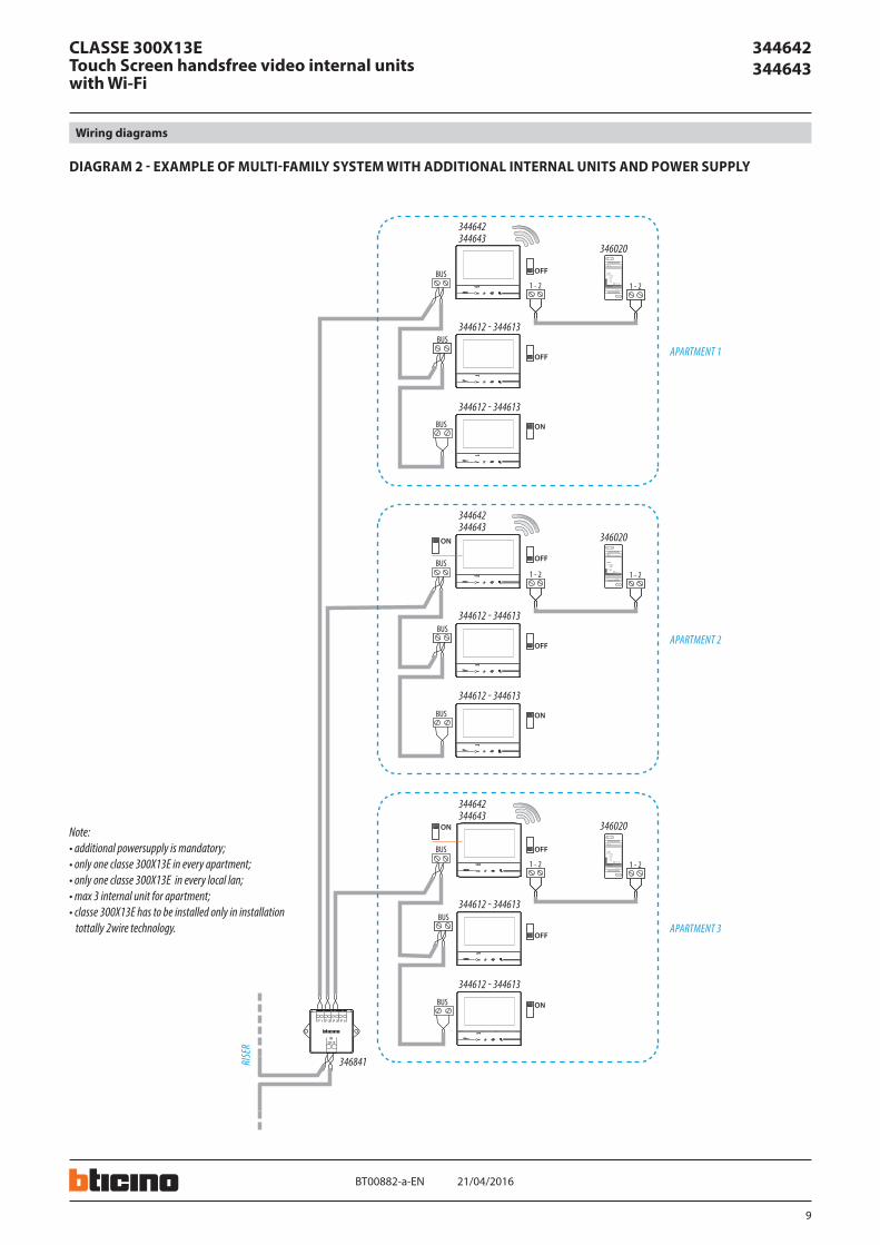
CLASSE 300X13ETouch Screen handsfree video internal units with Wi-Fi
Wiring diagrams
DIAGRAM 2 - EXAMPLE OF MULTI-FAMILY SYSTEM WITH ADDITIONAL INTERNAL UNITS AND POWER SUPPLY
APARTMENT 1
RISE
R
APARTMENT 2
APARTMENT 3
Note:• additional powersupply is mandatory;• only one classe 300X13E in every apartment; • only one classe 300X13E in every local lan;• max 3 internal unit for apartment;• classe 300X13E has to be installed only in installation
tottally 2wire technology.
10
344642 344643
ON
346850INT
EXT
ON OFF
BUS 2 1
IP30
PRI
PRI 230 V~ 50 - 60 Hz 260 mA346000
}BUS2 - 1 27V 1,2A
CEBEC
N N F
ON
BUS
ONOFF
ON
BUS
BUS
ON
BUS BUS
BUS
ON
346850INT
EXT
ON OFF
BUS 2 1
IP30
PRI
PRI 230 V~ 50 - 60 Hz 260 mA346000
}BUS2 - 1 27V 1,2A
CEBEC
N N F
ON
BUS
ONOFF
ON
BUS
BUS
ON
BUS BUS
BUS
ON
346850INT
EXT
ON OFF
BUS 2 1
IP30
PRI
PRI 230 V~ 50 - 60 Hz 260 mA346000
}BUS2 - 1 27V 1,2A
CEBEC
N N F
ON
BUS
ONOFF
ON
BUS
BUS
ON
BUS BUS
BUS
346841
344642344643
344612344613
344612344613
344612344613
344612344613
346000346850F441
344642344643
344612344613
344612344613
344612344613
344612344613
346000346850F441
344642344643
344612344613
344612344613
344612344613
344612344613
346000346850F441
21/04/2016BT00882-a-EN
CLASSE 300X13ETouch Screen handsfree video internal units with Wi-Fi
Wiring diagrams
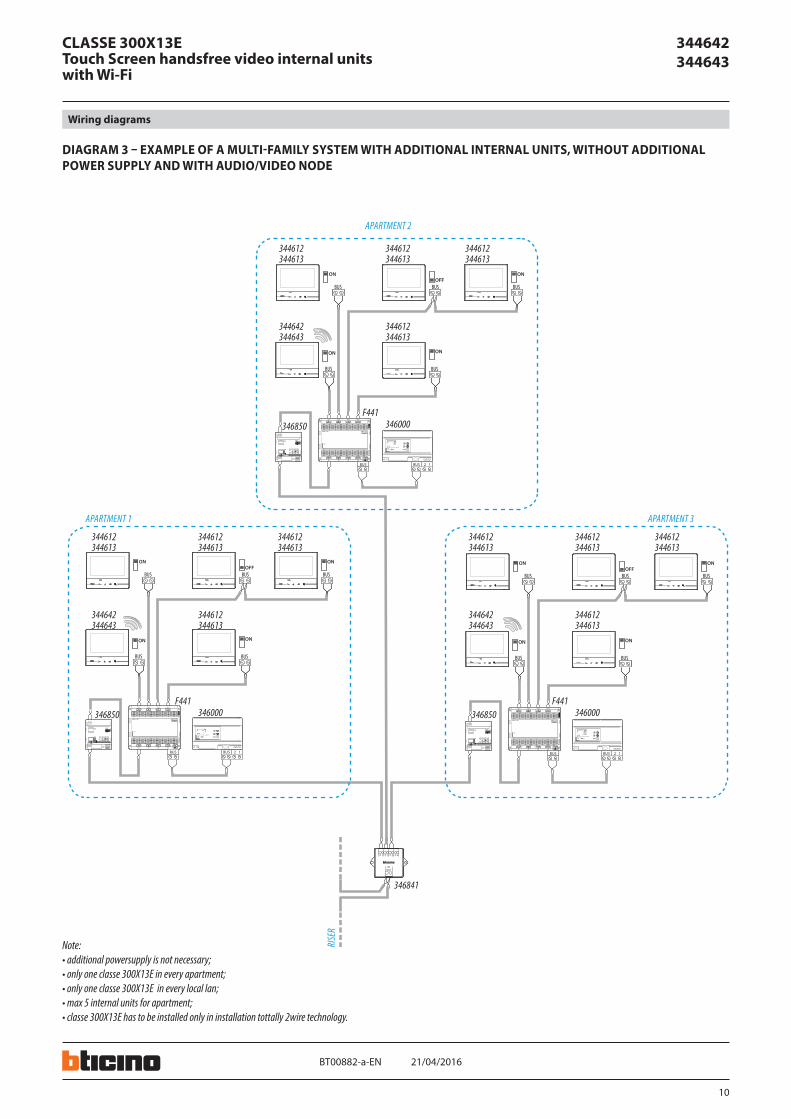
DIAGRAM 3 – EXAMPLE OF A MULTI-FAMILY SYSTEM WITH ADDITIONAL INTERNAL UNITS, WITHOUT ADDITIONAL POWER SUPPLY AND WITH AUDIO/VIDEO NODE
RISE
R
APARTMENT 2
APARTMENT 3APARTMENT 1
Note:• additional powersupply is not necessary;• only one classe 300X13E in every apartment; • only one classe 300X13E in every local lan;• max 5 internal units for apartment;• classe 300X13E has to be installed only in installation tottally 2wire technology.

11
21/04/2016BT00882-a-
344642 344643
DIAGRAM 4 - EXAMPLE OF SINGLE-FAMILY DIAGRAM
EN
CLASSE 300X13ETouch Screen handsfree video internal units with Wi-Fi
Wiring diagrams
DIAGRAM 5 - EXAMPLE OF TWO-FAMILY DIAGRAM
BUSOFF
BUS 2 1
IP30
PRI
PRI 230 V~ 50 - 60 Hz 260 mA346000
}BUS2 - 1 27V 1,2A
CEBEC
N N F
BUSPI
BUSTK
PS
BUS BUSOFF
BUS
BUSOFF OFF
BUSBUS ON
ON
344642344643
344612344613
346000
344612344613
346830
343081343091
344642344643
344612344613
344612344613
VILLA 2
VILLA 1
Note:• additional powersupply is not necessary;• only one classe 300X13E in every apartment;• only one classe 300X13E in every local lan;• max 3 internal units for apartment;• classe 300X13E has to be installed only in installation tottally 2wire technology.
BUSOFF
BUS 2 1
IP30
PRI
PRI 230 V~ 50 - 60 Hz 260 mA346000
}BUS2 - 1 27V 1,2A
CEBEC
N N F
BUSPI
BUSTK
PS
BUS BUS BUS BUS BUSOFF OFF OFF
ON
344642344643
344612344613
346000
344612344613
344612344613
344612344613
346830
343081343091
Note:• additional powersupply is not necessary• max 5 internal units for apartment• classe 300X13E has to be installed only in installation tottally 2wire technology
Copyright © 2022 FDOKUMEN