
2. Project Description - Mornington Peninsula Shire
36
Mornington Safe Harbour Environment Effects Statement Volume 1 – Main Report Page 28 2. Project Description 2.1. Project Overview The proposed development being assessed in this EES involves the creation of a Safe Harbour at Mornington for all users. The proposed Mornington Safe Harbour will include the following components: A north facing harbour wavescreen, to be located east of the existing Mornington Pier, approximately 210m in length and along the 7m depth contour; A north west facing wavescreen along the full length of Mornington Pier and a pier extension, approximately 20m in length; Approximately 170 floating berths arranged as marina pens, generally orientated in a north- south arrangement; ‘Fore and aft’ moorings (eight) to the south of the third marina arm; Swing moorings (12) to the east of the first, second and third marina arms; A number of short term public (10) and emergency and police berths (10) along the new public jetty and adjacent areas, in addition to the marina berths; A new public jetty parallel to the south of the existing Mornington Pier to provide access to the marina berths and a public walkway and viewing platform above the harbour wavescreen; Provision for disabled access via the low level public jetty; A travel lift combined with a new wash down facility to replace the existing slipway; A public pump out facility for onboard wastewater tanks; A public re-fuelling facility; Marina Manager’s Office, within the existing MYC clubhouse; and Parking and access improvements. No new commercial uses or structures are proposed for the Mornington foreshore area. The Concept Design is shown in Figure 2-1 and Figure 2-2.
-
Upload
khangminh22 -
Category
Documents
-
view
0 -
download
0
Transcript of 2. Project Description - Mornington Peninsula Shire

Mornington Safe Harbour Environment Effects Statement Volume 1 – Main Report
Page 28
2. Project Description 2.1. Project Overview
The proposed development being assessed in this EES involves the creation of a Safe Harbour at Mornington for all users.
The proposed Mornington Safe Harbour will include the following components:
A north facing harbour wavescreen, to be located east of the existing Mornington Pier, approximately 210m in length and along the 7m depth contour;
A north west facing wavescreen along the full length of Mornington Pier and a pier extension, approximately 20m in length;
Approximately 170 floating berths arranged as marina pens, generally orientated in a north-south arrangement;
‘Fore and aft’ moorings (eight) to the south of the third marina arm;
Swing moorings (12) to the east of the first, second and third marina arms;
A number of short term public (10) and emergency and police berths (10) along the new public jetty and adjacent areas, in addition to the marina berths;
A new public jetty parallel to the south of the existing Mornington Pier to provide access to the marina berths and a public walkway and viewing platform above the harbour wavescreen;
Provision for disabled access via the low level public jetty;
A travel lift combined with a new wash down facility to replace the existing slipway;
A public pump out facility for onboard wastewater tanks;
A public re-fuelling facility;
Marina Manager’s Office, within the existing MYC clubhouse; and
Parking and access improvements.
No new commercial uses or structures are proposed for the Mornington foreshore area.
The Concept Design is shown in Figure 2-1 and Figure 2-2.

Mornington Safe Harbour Environment Effects Statement Volume 1 – Main Report
Page 29
Figure 2-1: Safe Harbour Concept Plan

Mornington Safe Harbour Environment Effects Statement Volume 1 – Main Report
Page 30
Figure 2-2: Concept Layout Plan, Proposed Works overlaid on aerial photo

Mornington Safe Harbour Environment Effects Statement Volume 1 – Main Report
Page 31
Figure 2-3 shows the footprint of the existing moorings in Mornington Harbour compared with moorings being proposed as a part of this EES. This indicates the difference in area between the moorings proposed as a part of the proposed Safe Harbour and the existing moorings.
Figure 2-3 Footprint of Existing and Future Moorings
A description of each of the elements of the proposed Safe Harbour is provided below. The design and construction of the Safe Harbour will be undertaken in accordance with the Guidelines for Design of Marinas (AS 3962-2001).
2.1.1. The Proposed Safe Harbour Development
2.1.1.1. Harbour Wavescreen
The harbour wavescreen will extend to the sea bed and be approximately 210m in length and located along the 7m depth contour. It will have an approximate height of +4m CD above high water mark. A public viewing platform is proposed on the western end of the wavescreen and a 2.5 m wind public walkway is to extend its entire length.
A range of options for the structural arrangement of the wavescreen were investigated, with the chosen wavescreen concept consisting of reinforced concrete panels supported on a frame of tubular steel piles and crossheads. Each panel is supported by a pair of piles, one vertical and

Mornington Safe Harbour Environment Effects Statement Volume 1 – Main Report
Page 32
one raking, at each panel edge. A cross section of the proposed wavescreen and marina is shown in Figure 2-4.
In 2004 SKM was commissioned by MYC to carry out a feasibility study of the maritime engineering aspects for a safe harbour at Mornington. This included an analysis of potential locations for a harbour wavescreen. Preliminary wavescreen designs were developed at three potential locations, at the -5.0mCD, -6.0m CD and -7.0m CD level contours. The preliminary structural analysis provided indicative pile sizes and panel thicknesses. It was found that while locating the wavescreen further offshore at greater depths allows for more berths to be accommodated, the size of piling, wavescreen panel thickness and panel area are correspondingly increased for the greater depth. Therefore, an economic assessment was undertaken of the total cost of the wavescreen and floating marina versus the number of berths. This indicated that that the location of the wavescreen at around the -7.0m contour and provision of approximately 200 berths provides the lowest cost per berth (SKM, 2004).
The wavescreen has been designed to have a design life of 50 years. The wavescreen is to be designed to provide protection for one in 200 year waves and to allow for anticipated climate change impacts, in particular an anticipated sea level rise (including storm surge effects) of 0.4m over the next 50 years. More information about how the precautionary principle has been applied in considering potential climate change impacts is provided in Section 7.1.4.1

Mornington Safe Harbour Environment Effects Statement Volume 1 – Main Report
Page 33
Figure 2-4 Cross-section of Harbour Wavescreen and Public Jetty

Mornington Safe Harbour Environment Effects Statement Volume 1 – Main Report
SINCLAIR KNIGHT MERZ
PAGE 34
2.1.1.2. Mornington Pier Wavescreen and Extension
Mornington Pier is managed by Parks Victoria. Parks Victoria has previously announced its intention to undertake restoration works on the middle portion of Mornington Pier to repair damage from numerous storm events and to provide enhanced protection within the harbour by construction of a full depth wavescreen. These works are therefore considered as part of the base case for this EES.
This EES has assessed the implications of a wavescreen along the full length of the pier combined with the harbour wavescreen. Technical assessments undertaken for this EES have identified that a wavescreen along the full length of the pier and a pier extension (including a wavescreen) are needed in conjunction with the harbour wavescreen in order to achieve a ‘good wave climate’ within the harbour, including adjacent to the pier, in all weather conditions (Water Technology, 2008a). Both the pier wavescreen and pier extension form part of the proposed Safe Harbour and are included in this EES. Neither of these developments on their own would provide the Safe Harbour which MBHL is aiming to achieve. Parks Victoria as the Committee of Management for Mornington Pier and harbour has provided consent to MBHL to lodge a planning permit application for the proposed Safe Harbour development.
It is proposed that a full depth wavescreen be constructed on the seaward end of the pier extending from the middle to the end of the pier. The pier wavescreen will be a similar structure to the harbour wavescreen and consist of reinforced concrete panels supported on a frame of tubular steel piles and crossheads. Each panel will be supported by a pair of piles, one vertical and one raking, at each panel edge. As for the harbour wavescreen, the pier wavescreen would consist of reinforced concrete panels that extend to the seabed.
In the Wave Investigation Assessment undertaken as a part of this EES (Section 7.1of the EES) Water Technology identified a perpendicular extension as the preferred orientation of the pier extension due to its ability to improve protection to public berthing areas. The extension will be approximately 20m in length. The precise orientation and length of the extension will be optimised during detailed design.
The pier extension will be a full depth structure constructed of reinforced concrete panels supported on tubular steel piles and concrete crossheads framework. It will be of a similar design to the harbour wavescreen and pier wavescreen. Timber decking will cover the extension creating a walkway.

Mornington Safe Harbour Environment Effects Statement Volume 1 – Main Report
SINCLAIR KNIGHT MERZ PAGE 35
(Source Parks Victoria)
Figure 2-5 Cross-section of the Pier Wavescreen
2.1.1.3. Public Jetty
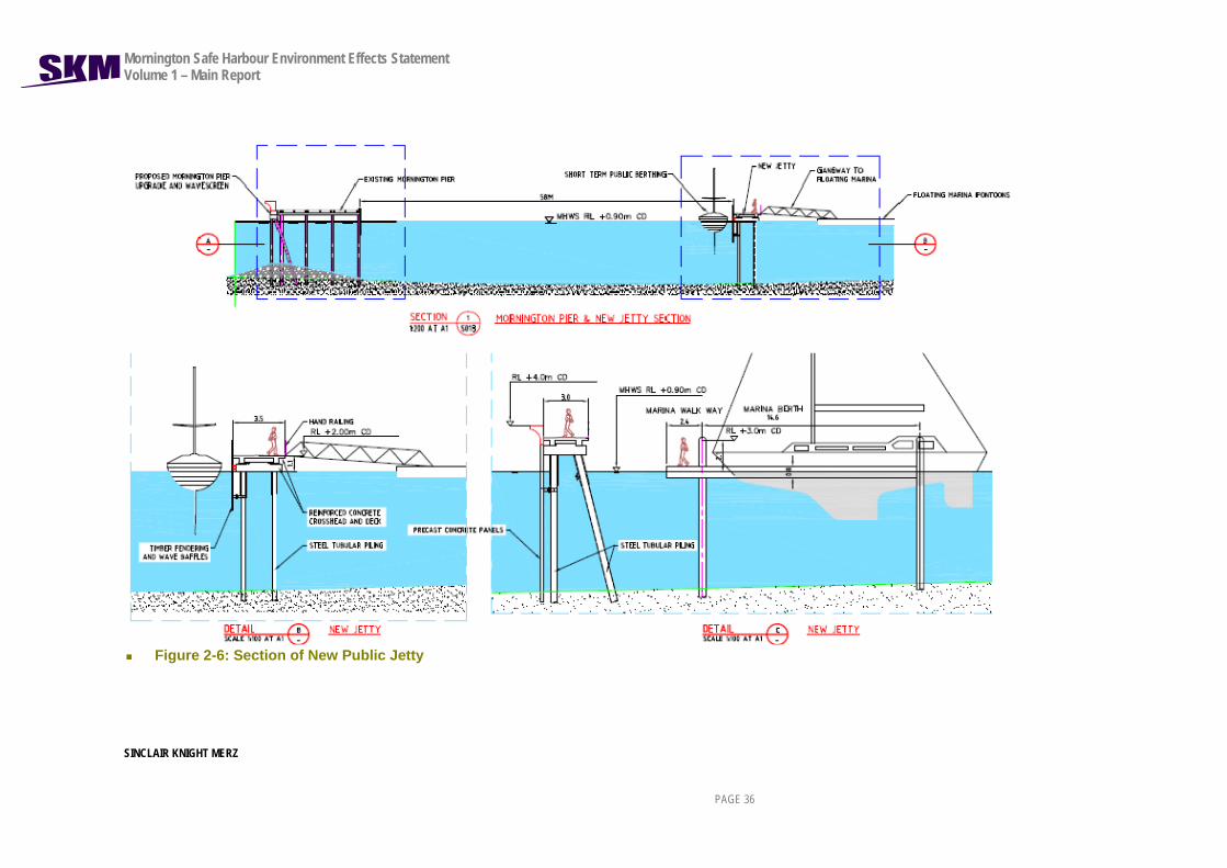
A cross-section of the public jetty is shown in Figure 2-6. The public jetty will run parallel to the south of the existing Mornington Pier and extend two thirds of the existing pier’s length. It will have an approximate width of 3m. The public jetty will be open to the public to walk along and include a viewing platform which leads onto the wavescreen. Public visitor berthing (4) and emergency refuge berthing (3) will be provided adjacent the public jetty.
Mornington Safe Harbour Environment Effects Statement Volume 1 – Main Report
SINCLAIR KNIGHT MERZ
PAGE 36
Figure 2-6: Section of New Public Jetty

Mornington Safe Harbour Environment Effects Statement Volume 1 – Main Report
SINCLAIR KNIGHT MERZ
PAGE 37
2.1.1.4. Berths and Mooring
The proposal is to construct three marina arms south of the harbour wavescreen, with approximately 170 floating pen berths to be installed in stages. The two outer marina arms will connect to the foreshore via a new public jetty, while the existing Fisherman’s Jetty will be retained and used to provide access to the third marina arm. There will be a gated entrance to each of the marina arms. The marina arms will be 2.4m wide floating concrete pontoons 400mm above sea level with low level lights 700mm above the pontoon deck. Access to the pontoons from the jetty will be by 1.8m wide gang planks.
The proposed berth schedule is as follows:
17 berths to accommodate boats of 18m in length;
10 berths to accommodate boats of 15m in length;
88 berths to accommodate boats of 12m in length; and
54 berths to accommodate boats 10m in length.
The proposed distribution of berths is shown in the Concept Plan Figure 2.1-1.
The berths will be comprised of concrete encased polystyrene filled pontoons with steel mooring piles. The mooring piles will have high-density polyethylene sleeves to provide a minimum design life of 50 years.
The indicative proposed leasing arrangement for pen berths is as follows:
Not less than 85 pen berths will be made available for lease to members of MYC;
Not less than 55 pen berths will be leased to members of the public;
Up to 30 pen berths will be retained by MYC and leased on a short term basis to interested members of MYC and the public.
Modelling undertaken as a part of this EES (refer to Section 7.1) has shown that all of the proposed pen berths included as a part of the proposed Safe Harbour will experience a good wave climate.
In addition to the pen berths, the proposal includes substitution of some of the existing swing moorings with ‘fore and aft’ moorings to the south of the third marina arm for approximately eight boats and swing mooring to the east of the first, second and third marina arms for approximately 12 boats (see Figure 2-3). ‘Fore and aft’ moorings are a type of mooring where a boat is attached by both the bow and stern lines to an anchor or pile. These moorings would offer a low cost option for interested members of the public and MYC. Due to their location, the fore and aft moorings will also experience a good wave climate. The swing moorings will

Mornington Safe Harbour Environment Effects Statement Volume 1 – Main Report
SINCLAIR KNIGHT MERZ PAGE 38
experience a wave climate that is similar to existing conditions. Boats on the swing moorings will need to continue to be stored in the dry storage area during winter to avoid impacts from northerly storm conditions.
The swing moorings installed as a part of the proposed Safe Harbour will be environmentally friendly and designed to protect the marine environment from the effects of anchor damage caused by traditional swing moorings. Environmentally friendly swing moorings include a short pile driven into the seabed that support mooring rope and buoy. The moorings will clearly display the limits and conditions of use on each buoy, including vessel size limits. Conditions relating to the use of the moorings will also be contained in the proposed Safe Harbour Operation Plan.
Where suitable, existing swing mooring tackle in the harbour will be used for anchoring construction equipment. Boats will be moved to the dry storage area during construction. Following construction, the existing swing moorings will be removed from the harbour.
It is proposed that both the swing moorings and fore and aft moorings will be managed by MBHL.
In addition to the pen berths that will be available for leasing by members of the public, 10 public visitor berths will be created along the Mornington Pier side of the new public jetty and adjacent areas. Ten emergency services and police berths will also be created along the new public jetty and adjacent areas to accommodate rescue boats, police boats and other boats requiring emergency refuge.
Table 2-1 provides a comparison of the number and types of berths for the proposed Safe Harbour and the current Harbour. This shows that approximately 145 additional berths will be provided for in the Safe Harbour, including short term public berths and emergency berths. Unlike the existing Harbour which only provides swing moorings, the proposed Safe Harbour will also provide pen berths and fore and aft moorings.

Mornington Safe Harbour Environment Effects Statement Volume 1 – Main Report
SINCLAIR KNIGHT MERZ PAGE 39
Table 2-1: Indicative Numbers of Berths to be Provided Under the Proposed Safe Harbour compared with the Existing Harbour
Proposal Indicative number of berths Comments Present Number of Berths 65, largely swing moorings Current Safe Harbour Design 170 floating berths, 12 swing
moorings, 8 fore and aft moorings, 10 public short term berths, 10 emergency berths
Assumed boat sizes for floating berths 10m: 32% 12m: 52% 15m: 6% 18m: 10%
2.1.1.5. Fairways
The fairways shown in the Concept Plan at Figure 2.1 mark the navigable water within the Safe Harbour. The fairways have been designed in accordance with Australian Standard 3962 Guidelines for Design of Marinas. This recommends a minimum entrance channel width of 30m or 6 times the beam of boats using the fairway. This will accommodate over 90% of the boats. The exact width of the fairways will be adjusted during detailed design to ensure that they are of a suitable width for boats using the harbour.
The fairway will be available at all times to public boating to provide access to public berths, the Fisherman’s Jetty and public boat ramp. The Safe Harbour design also ensures that there is a navigable fairway along the harbour side of Mornington Pier.
The fairway is proposed to be marked by buoys and will not cause any visual impact. No other markers are proposed for the fairway. Installation of the buoys will only create a minimal disturbance to the sea bed where they are anchored which will be similar in impact to boat anchoring. No excavation or dredging of the seabed will be required for construction of the wave screen and supporting infrastructure or for the fairway. The travel lift would require a small amount of sand excavation required of approximately 450 cubic metres. This would not result in any significant disturbance to the sea bed due to the small volume of material proposed to be removed.
2.1.1.6. Offshore Reef Management Option
A number of options for managing potential changes in coastal processes associated with the proposed Safe Harbour have been considered as a part of the Coastal Processes Assessment for this EES (as discussed in Section 7.3). Of these, the preferred option is to monitor any changes in the beach alignment for the first 12 months that the Safe Harbour is in operation and relocate sand as required. At the end of the 12 month period, the monitoring results would be assessed with the view to either continue the yearly relocation of beach sand or construct an offshore reef

Mornington Safe Harbour Environment Effects Statement Volume 1 – Main Report
SINCLAIR KNIGHT MERZ PAGE 40
to restrict the area of annual sediment deposition to a more confined zone (Water Technology, 2008a). The offshore reef would only be constructed should the monitoring results indicate that such a management measure is required to contain the westerly movement of sand, eliminate any potential build up at the boat launching channel and facilitate sand removal. Other options considered for restricting the area of annual sediment deposition are discussed in Section 7.3.
The offshore reef would assist in controlling the alongshore transport of sand by providing an area sheltered from waves where sand would build up. It would be located approximately 30m offshore from the low water line of Scout Beach, north of the existing reef. The reef would be approximately 30m in length and have a crest of approximately 1m AHD making it just visible at high tide. The offshore reef would have no physical presence on the shoreline (Water Technology, 2008a). During the analysis and definition of marine management safety issues associated with this structure, Marine Safety Victoria will be consulted to ensure compliance with the Marine Act 1988. If required, the reef would be constructed from local rock or brown granite from gabions filled with local or some other similar rock. A photomontage of the offshore reef is presented in the Landscape and Visual Amenity Assessment in Section 7.10.
The potential for the ‘offshore reef’ to present a hazard to boating activities has been considered. Even though the reef will protrude just above the high water mark and should be visible at most times, it could present a danger at times of low visibility. However, it will be located in an area of low boating activity, close to the existing natural rock reef on Scout Hall Beach, and will also act as a trap for littoral sand that moves along the beach, again discouraging boat users from the area. The reef could present a hazard to wind-surfers, who would be more likely to use the shallow water where the reef will be located and as such a pair of timber pile markers could be installed at each end of the reef to mark its extents.
Details of the proposed offshore reef are provided in Section 7.3.6.1 and Section 7.3.7.
2.1.1.7. Exact Construction Materials
The materials and finishes will complement those of the existing structures within Mornington Harbour including the heritage section of Mornington Pier. The materials proposed for the various structures which form part of this proposal are summarised in Table 2-2 below.
Table 2-2: Construction Materials of proposed structures
Component Materials
Floating marina
Visible surfaces of the floating pontoons will be concrete (grey / white in colour). Marina piling (to restrain the pontoons) will be steel but will be encased in a HDPE (high density polyethylene) casing for corrosion protection.

Mornington Safe Harbour Environment Effects Statement Volume 1 – Main Report
SINCLAIR KNIGHT MERZ PAGE 41
HDPE is usually black in colour. The marina piling will be topped with conical shaped pile caps which will be white in colour. Gangways leading to the pontoons from the fixed structures will be made of aluminium. These are not usually coloured in any way but left with the raw aluminium finish. The decks of the gangways are usually made from marine grade plywoods which will be painted with a non-slip coating and is usually coloured to match with the surface colour of the pontoons. Secure gateway entrances to the marina will be located at certain locations. These usually take the form of a locked gate at the top or bottom of the gangways and are made of ‘expanded metal’ panels, like those used in domestic security doors. These can be coloured an unobtrusive colour.
Wavescreen Steel piling will be sleeved in black HDPE. Wavescreen panels will be precast concrete – grey / white colour. Superstructure will be precast concrete - grey / white colour. Walking surface would be concrete but could be covered in timber (but this would be entirely cosmetic). Handrailing will be either galvanised steel (Monowills type) – could be painted if required or fabricated steel hand-railing - painted (any colour) – like those on the floating bike path on the Yarra River.
Public Jetty Steel piling will be sleeved in black HDPE. Structural members will be reinforced concrete – grey / white colour. Walking surface would be concrete but could be covered in timber (but this would be entirely cosmetic). Handrailing will be either galvanised steel (Monowills type) – could be painted if required or fabricated steel hand-railing - painted (any colour) – like those on the floating bike path on the Yarra River.
Fuelling / Pump-out Pontoon
As per general floating marina but with petrol bowser type attachments.
2.1.2. Land Based Facilities
The following land based facilities are also proposed as a part of the proposed Safe Harbour.
2.1.2.1. Public Access
Figure 2-1 shows areas marked in green on the plan, which comprise new works accessible to the public. The areas shown in pink on this plan will be subject to restricted access to maintain safety to boat owners. However, boats will still be able to access these areas from the sea.
Mornington Safe Harbour Environment Effects Statement Volume 1 – Main Report
SINCLAIR KNIGHT MERZ PAGE 42
The proposed marina managers office and toilets will not be open to the general public as described in section 13 of this letter. In addition, the area around the underground fuel storage tank within the MYC yard will not be accessible to the public.
2.1.2.2. Disabled Access
Existing disabled access is provided at Mornington Harbour via a MYC boat ramp and will be retained. As a part of the proposed Safe Harbour, low level access for people with a disability and/or limited mobility will also be provided to small and larger boats via the floating pontoons leading from the new public jetty to the second marina arm.
Figure 2-1 shows areas marked in green which are proposed to be accessible to members of the public as a result of this proposal. This includes the proposed new jetty and wavescreen with public walkway which will both be wide enough for wheelchair access. Both the jetty and the walkway will comprise timber decking which will be suitable for wheelchair access. Low level access for people with a disability and/or limited mobility will also be provided to small and larger boats via the floating pontoons leading from the new public jetty to the second marina arm.
Proposed upgrades to Mornington Pier by Parks Victoria will also improve wheelchair access to Mornington Pier as these works include replacement of existing timber decking which is currently uneven and difficult to navigate.
2.1.2.3. Travel Lift and Finger Piers
The proposed safe harbour includes a travel lift and new washdown facility within the extent of the existing MYC yard. Figure 2-1 and Figure 2-2 show the proposed location of the travel lift and boat wash down facility. The location of these facilities is indicative as the travel lift will move along tracks transporting boats into the water. When not used to transport boats, the travel lift will be stored within the MYC yard nestled against the MYC building which will minimise the visual and amenity impact of the travel lift on the coastal environment.
The travel lift will ultimately replace the slipway. It is intended that operation of the slipway will continue as a short term measure, with a travel lift to be installed in the future.
A precise travel lift design has not been selected at this stage as travel lifts are typically custom design. The travel lift is likely to be similar to the lift shown in Figure 2-7. Photomontages contained in Volume 2 - Landscape and Visual Assessment report show a travel lift of a similar scale in order to represent the visual impact of a travel lift. However, the lift will be either painted or manufactured in a light colour in order to minimise the visual impact of the lift.

Mornington Safe Harbour Environment Effects Statement Volume 1 – Main Report
SINCLAIR KNIGHT MERZ PAGE 43
Consultation has been undertaken with the Sandringham Yacht Club and site visits made to view the club’s 40 tonne capacity travel lift and gain an increased understanding of the key design features of the lift and its operational requirements. The travel lift is proposed to have an outside width of approximately 7.8 m and an overall height of approximately 7m including the attached mast crane. It is proposed to have a capacity of approximately 40 tonnes although it is expected that lifts of individual boats would not exceed 20 tonnes, or even less. However, there is very little difference in cost and size between a 20 tonne and 40 tonne capacity travel lift and both require a similar amount of manoeuvring space.
The travel lift will not extend as far into the water as the current slipway and therefore improve navigation in this part of the Harbour. Installation of the travel lift to replace the slipway may require that a small volume of sediment (~1,600 m3) be excavated from an area adjacent to the existing slipway. This is discussed further in Section 2.2.4. An alternative to a travel lift is mobile crane removal but more excavation would be required. The introduction of a travel lift at MYC will require yard space dedicated to maintenance boat storage (at least 4 bays) and associated space for the manoeuvring the travel lift.
The Construction Environmental Management Plan and Operational Environmental Management Plan will contain additional details about the location and operation of travel lift facilities. It is anticipated that the travel lift would need an experienced driver assisted by a second person to guide the boat. The approximate time required to slip a boat is only in the order of half an hour.
Figure 2-7 Typical Travel Lift

Mornington Safe Harbour Environment Effects Statement Volume 1 – Main Report
SINCLAIR KNIGHT MERZ PAGE 44
2.1.2.4. Sewage Pump-Out
A standard sewage pump-out facility will be provided for onboard wastewater tanks. This will be located on a floating jetty alongside the public jetty and connected to the existing sewer system and a power supply.
The sewerage pump facility unit has not been selected. However, it is anticipated to consist of a stainless steel cabinet approximately 1m in height, 600mm wide and 800mm in depth similar to the tank shown in Figure 2-8. The facility will also contain a suction hose and suction pump to extract waste from boat holding tanks. This facility will operate in accordance with the Best Practice Guidelines for Waste Reception Facilities at Ports, Marinas and Boat Harbours (ANZECC 1997) and the EPA Guidelines for Protecting Victoria’s Marinas (1998).
Figure 2-8 Typical Sewage Pump-Out Facility
2.1.2.5. Boat Wash Down Facility
A boat wash down area is proposed within the MYC yard in the general location indicated on the Figure 2-1 and Figure 2-2. The travel lift would suspend the boat over the wash down area immediately after leaving the water. The wash down area would generally comprise concrete hardstand with a sump graded similar to a shower base with a grating at its centre.
This facility would be used for the first wash down of the boat which would be undertaken with a high pressure washer. The fouling from the boat would then pass through the grating and large pieces would be trapped in a basket. The remainder would pass into an underground holding/settling tank and would then be pumped to the sewerage system. It is anticipated that a trade waste licence agreement would be required as the Sandringham Yacht Club has this type of agreement for its boat washdown facility.

Mornington Safe Harbour Environment Effects Statement Volume 1 – Main Report
SINCLAIR KNIGHT MERZ PAGE 45
Rain and other run off from the rest of the yard would be collected in an underground tank and then pumped to a tank farm. This water would then be used for the first boat wash down as well as other washing uses around the yard including boats. Any yard run off not would pass through settling tanks and a sand filter and into the storm water. The sand filter would be regularly backwashed to the sewerage system. The only discharge of rain from the yard would be when the capacity of the system is exceeded. MBHL would charge fees for use of the travel lift and boat wash down facility which would be consistent with fees charged by other boating facilities.
2.1.2.6. Refuelling Facility
It is proposed that a refuelling facility (Figure 2-1) be located in the car parking area between the head of Mornington Pier and the Schnapper Point Kiosk. This location will minimise risk to public safety and is in a location that is readily accessible in the event of a spill or damage, as it is separated from the pen berths and other public facilities. The location has also been selected to ensure that any potential spills can be easily contained. Alternatively, the underground storage tank could be located within Mornington Yacht Club’s leased area.
Figure 2-1 shows the preferred location for the underground fuel storage tank on the area currently leased by MYC to the south-west of the MYC building. This site has been selected for the underground storage tank so that it can be refuelled by a tanker without disruption to access to the adjacent car parking areas.
It is intended that fuel will be stored in a double skinned underground storage tank that meets the specifications of the Victorian Environment Protection Authority (2003) Guidelines on the Design, Installation and Management Requirements for Underground Petroleum Storage Systems. The capacity of the underground storage tank will be approximately 5 m x 5 m x 2.5 m. Excavation to approximately 2.5 m in depth would be required to accommodate the underground storage tank. The underground storage tank will be located such that it can be refuelled by tanker without disruption to access to the adjacent car parking areas.
The above ground fuel bowser will be co-located with the sewage pump out facility and designed to be consistent with AS 3692-2001. It will comprise double containment fuel lines over water and equipment which can be used to contain and clean up any fuel spillage should this occur. It will also comprise durable materials which are able to withstand the marine environment including the effects of salt spray.
The refuelling facility will be managed as part of the broader Safe Harbour and will be accessible to the public. It is likely that the Marina Manager will administer the payment and lock-up of the fuel facility. Further details regarding access to the refuelling facility will be provided as part of the Safe Harbour Operation Plan proposed to be prepared following approval of the Safe Harbour.
Mornington Safe Harbour Environment Effects Statement Volume 1 – Main Report
SINCLAIR KNIGHT MERZ PAGE 46
The ‘Guidelines for the Design, Installation, and Management Requirements for Underground Petroleum Storage Systems‘ Publication 888.1 January 2009 (UPSS Guidelines) provide information to owners/operators on the level of performance required for Underground Petroleum Storage Systems.
MBHL understands that risks associated with leakage from underground petroleum storage systems (UPSSs) including spills, overfills and leaking tanks or piping may cause significant environmental and safety impacts including fire, explosion and contamination of soil and groundwater.
MBHL are committed to complying with the UPSS Guidelines for the design, installation and management of the proposed underground fuel storage tank and AS4897–2008, The design, installation and operation of underground petroleum storage systems. MBHL are also aware that underground fuel storage facilities must comply with the provisions of the Environment Protection Act 1970 and subordinate legislation including Clause 12 of the State Environment Protection Policy (Groundwaters of Victoria) which requires that all practicable measures be taken to prevent pollution of groundwater.
Section 8.1.5 of this EES contains a Framework EMP which provides an operating framework for the environmental management measures outlined in this EES. This section refers to a hazardous material and fuel management plan which is proposed to be developed in accordance with State legislative controls and guidelines to address risks associated with the design, installation, operation and monitoring of the underground fuel storage tank. The proposed hazardous material and fuel management plan will be prepared prior to construction and is considered likely to be a condition of the planning permit.
The Hazardous Material and Fuel Management Plan will respond to the regulatory framework for underground fuel storage tanks. It will also outline the following details regarding design, installation, monitoring for leak detection and spill response and emergency management procedures:
Site classification and equipment selection process in accordance with the UPSS Guidelines. This will provide a detailed consideration of the site characteristics and will include consideration of design measures to address any issues required to protect the environment.
The installation of the underground fuel storage tank. This will be conducted in accordance with a quality assurance system by a qualified and experienced installation contractor, who is trained under a scheme acceptable to EPA and who operates under health and safety measures in accordance with the relevant measures required by the Occupational Health and Safety Act 1985. The installation contractor will be required to certify compliance of the installation with relevant legislation and the manufacturers’

Mornington Safe Harbour Environment Effects Statement Volume 1 – Main Report
SINCLAIR KNIGHT MERZ PAGE 47
specification for the facility and complete equipment integrity test in accordance with Section 6.4.4 and 8.5 of AS 4897–2008.
Management system for the underground fuel storage tank including systems and procedures for preventing spills and leaks during tank filling, plans for response in the event of a spill or leakage, and maintenance and record keeping required in accordance with obligations under the Environment Protection Act 1970, the Dangerous Goods Act 1985, AS4897–2008 The design, Installation and Operation of Underground Petroleum Storage Systems and manufacturers specifications.
Preparation of a framework document on site which includes details regarding ownership and occupation of both the site and the underground fuel storage facility including specific contractual/franchise arrangements, responsibilities (and contact details) for activities associated with the management of the underground fuel storage facility, details (e.g. size and location) of all underground fuel storage facility infrastructure (including tanks, pipes and fill parts).
Training required for staff with responsibilities associated with a UPSS to ensure awareness of each of the elements of the management system.
2.1.2.7. Car Park
It is proposed that the existing car parking layout at Mornington Harbour be redesigned, as indicated in Figure 2-9 and Figure 2-10 , to improve conditions for pedestrians and for those wanting to park, especially on peak summer days. Sketch options for the redesign of the car parking area are also presented in the Traffic and Parking Report Supplement (see EES Volume 2, Appendix H).
The proposed strategy is to combine Option 3 (the Peninsula Option), as shown in Figure 2-9, with a modified version of Option 2 (Parking opposite the Yacht Club). This strategy will:
improve search patterns for those looking for a vacant parking space;
improve safety for pedestrians;
enable the strip of space adjacent to the seawall to be used for walking and promenading, rather than parking;
improve visibility for drivers in the car park; and
result in a net increase in car parking numbers of up to eleven spaces.
Other measures to manage potential increases in car parking include the operation of a limited shuttle bus service for Mornington Yacht Club race days, introduction of a 2 hour parking limit during the summer months on the lower parking areas north of the intersection of Schnapper Point Drive and Flinders Drive and improvements to the walking network. Option 3 (Figure 2-9) achieves the following:

Mornington Safe Harbour Environment Effects Statement Volume 1 – Main Report
SINCLAIR KNIGHT MERZ PAGE 48
The walkway beside the seawall would be widened by about 2 metres.
The awkward right and left turns at the foot of the ramp down to the lower area would be eliminated.
The main pedestrian conflict points with vehicles would be controlled by zebra crossings.
The conflict points would no longer involve turning vehicles approaching pedestrians from behind.
The level difference in the area behind the head of the pier has been assumed to be smoothed to enable a more efficient parking layout.
The shuttle bus could be accommodated adjacent to the turning area at the seawall or on the new area created outside the existing toilet.
The parking area at the head of the pier would be more orderly and it would be easier to search for a vacant space.
Illegal parking blocking manoeuvring areas could still be expected on peak days because the area has such a high demand for parking. It would still remain a ‘blind aisle’ with only one way in and one way out.
This option would reduce the number of car parking spaces by about 12.

Mornington Safe Harbour Environment Effects Statement Volume 1 – Main Report
SINCLAIR KNIGHT MERZ PAGE 49
Figure 2-9: Option 3 Sketch Plan
Option 2 (Figure 2.10) achieves the following: A low retaining wall adjacent to the road would enable an additional row of parallel
parking to be added to the lower level. This parking would partly depend on the present restrictions of the washing down boats
becoming a permanent restriction. This would free up the existing formal wash down area.
Additional right angle parking could also be provided and would be accessed from the existing aisle way.
This option would increase the number of car parking spaces by up to 23. Given the concern expressed by officers from the Department of Planning and Community Development, this
Mornington Safe Harbour Environment Effects Statement Volume 1 – Main Report
SINCLAIR KNIGHT MERZ PAGE 50
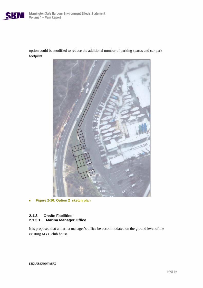
option could be modified to reduce the additional number of parking spaces and car park footprint.
Figure 2-10: Option 2 sketch plan
2.1.3. Onsite Facilities 2.1.3.1. Marina Manager Office
It is proposed that a marina manager’s office be accommodated on the ground level of the existing MYC club house.

Mornington Safe Harbour Environment Effects Statement Volume 1 – Main Report
SINCLAIR KNIGHT MERZ PAGE 51
2.1.3.2. Amenities
Five public toilets, one urinal and five showers are currently provided within the MYC building. These facilities are proposed to be refurbished and are intended to meet the needs of Safe Harbour users and visitors to the MYC boating facilities. They are currently connected to the sewage system and electricity supply. These facilities are intended to be available at all times (24 hours per day, 7 days per week) under MYC controlled and secured conditions. Refurbishment of these amenities represents the only change to MYC facilities included in this EES.
Cycle facilities are currently provided for members at the boat storage yard area. No additional cycle facilities are proposed.
Figure 2-11 and Figure 2-12 show the existing conditions of the MYC site.
Figure 2-11: MYC Site Plan, existing conditions
Figure 2-12: MYC Ground and First Floor existing and proposed conditions

Mornington Safe Harbour Environment Effects Statement Volume 1 – Main Report
SINCLAIR KNIGHT MERZ
PAGE 52

Mornington Safe Harbour Environment Effects Statement Volume 1 – Main Report
SINCLAIR KNIGHT MERZ PAGE 53

Mornington Safe Harbour Environment Effects Statement Volume 1 – Main Report
SINCLAIR KNIGHT MERZ
PAGE 54
2.1.3.3. Existing MYC Building
Figure 2-11 above shows the proposed alterations to the MYC building, which contains the club house and the restaurant. It also shows the location of the proposed toilets and marina manager’s office. These facilities are proposed to be located within the existing building footprint by filling in a currently open section of the building underneath the restaurant deck currently used for boat storage and screened with a shade cloth type material
Figure 2-12 show the proposed new marina managers office (14m2) and the increased amount of toilets and change facilities for males, female and disabled users. This area is approximately 80m2 and will be closed in with painted weatherboard materials and window to complement the existing building. This plan also shows building elevations which are unaffected by the proposed changes.
The MYC building and lease area is located on Crown land which is reserved for public purposes. The existing lease contains a requirement which is to make available to the general public a category of membership of the MYC which entitles the special member to use the slipway and the grounds of the MYC. The right of the general public to use the slipway and MYC facilities will not be affected by the proposed development. However, as specified in Section 5.6.13 of the planning report, the toilets are proposed to be available to Safe Harbour users and visitors to the MYC and would be available at all times (24 hours per day, 7 days per week) under MYC controlled and secured conditions.
2.2. Construction Activities
It is anticipated that the construction of the proposed Safe Harbour will take approximately 18 months. A detailed Construction Environmental Management Plan (CEMP) will be developed prior to the commencement of any works. This will set out management measures to minimise any impacts on the environment during the construction processes. The CEMP will also include requirements to ensure that construction works that have the potential to significantly disrupt harbour users, such as the trucking in of construction materials occurs outside of holiday periods. The Plan will also specify that construction materials will be stored within MYC’s site where possible.
The construction works will be as follows:
Mobilise plant to contractor’s yard area and berth;
Construction of public jetty;
Construction of harbour wavescreen;
Construction of pier wavescreen and extension;

Mornington Safe Harbour Environment Effects Statement Volume 1 – Main Report
SINCLAIR KNIGHT MERZ PAGE 55
Installation of marina berths;
Construction of land based facilities including the refuelling facility and sewage pump out facility;
Clean up and restore site.
Construction of key elements of the proposed Safe Harbour including the public jetty, wavescreens and marina berths, will be carried out offshore using marine based plant such as barges, pile driving jack up platforms and work boats. Each of these is discussed further below.
Section 5.6.23 of the planning report outlines the anticipated construction timeframe. It states that construction of the proposed Safe Harbour would take approximately 18 months.
An EMP which contains a Construction Management Plan (CMP) is proposed to be developed prior to the commencement of any works. This would set out management measures to minimise any impacts on the environment during the construction processes. The CMP would also include requirements to ensure that construction works that have the potential to significantly disrupt harbour users, such as the trucking in of construction materials occurs outside of holiday periods including the Christmas and New Year periods.
A Framework for Environment Management Plan is provided in Appendix U of the planning report and in Section 8 of this EES. Once finalised, the EMP will include a Construction Management Plan (CMP).
The majority of construction will occur from the sea rather than from land with major prefabricated construction materials transported to the site by sea on a barge. Any temporary road closures required would be outlined in the final CMP which would typically be expected to be prepared as a condition of the planning permit.
A Draft Beach Management Plan has not been prepared at this stage. It would typically be prepared as part of the EMP following consideration of the EES. However, the various technical reports including the Hydrodynamic Assessment contained in Volume 2 of the EES report does consider the impact of the proposed safe harbour on local beaches.
2.2.1. Construction of Public Jetty
Construction of the Public Jetty will involve pre casting the deck units and preparing timber fender and screen panels. These components will then be trucked to the site. Piles will be driven into the seabed and high density polyethylene (HDPE) sleeves will be installed to provide a minimum life of 50 years. Pre cast crossheads and in-situ concrete will be put in place followed by the deck units and timber fender panels and handrails.

Mornington Safe Harbour Environment Effects Statement Volume 1 – Main Report
SINCLAIR KNIGHT MERZ PAGE 56
2.2.2. Construction of Harbour and Pier Wavescreens
The SKM Feasibility study considered options for locating the wavescreen at the three potential locations based on the findings of a preliminary wave climate developed by Professor Hinwood of Monash University. After examining alternative depth options the seven metre contour provided the best cost benefit outcome relative to project feasibility, scope and hydrodynamic requirements. Further information about this process is summarised in Section 2.1.1.
Construction of the harbour and pier wavescreens will involve driving piles into the seabed at approximately 5-6m centres.
High density polyethylene (HDPE) sleeves will be installed to provide a design life of greater than 50 years. The materials for the wavescreens will be barged to the site where cranes will be used to transfer the materials from the barges to the jack up work platforms as shown in Figure 2-13 below.
Figure 2-13 Likely Construction Activities During Wavescreen Construction
Pre-cast pile caps will be installed with in-situ connections. The steel piles will support the in-situ concrete longitudinal beam. This longitudinal beam will then connect to the precast wavescreen panels.

Mornington Safe Harbour Environment Effects Statement Volume 1 – Main Report
SINCLAIR KNIGHT MERZ PAGE 57
2.2.3. Installation of Marina Berths
The berths are comprised of concrete encased polystyrene filled pontoons with steel mooring piles. The mooring piles will have HDPE sleeves to provide a design life greater than 50 years.
The pontoons will be trucked to the site and then towed to the appropriate berth locations. The walkways and fingers will then be assembled and services installed.
2.2.4. Construction of Travel Lift Structure
Initially it is intended that operation of the slipway will continue as a short term measure, with a travel lift to be installed in the future.
The process of installing the travel lift structure will initially involve demolishing the slipway, timber piled dolphins, concrete slab and timber jetties. Provision of a travel lift may require that a relatively small volume of sediment (~1,600 m3) be excavated from an area adjacent to the existing slipway. Due to the small volume of potential sediment to be excavated, this would most likely be land based and undertaken by an excavator and truck rather than by barge. The approximate quantity of 1,600 m3 of sediment could be removed from the site over a 10 day period.
The sheet pile retaining wall will then be driven into the seabed and runway piles and beams installed. The travel lift gantry would be transported to the site and then assembled on site.
2.2.5. Construction of Land Based Facilities
The sewage pump out facility will be placed on the public jetty and connected to the sewer via a pipe.
Installation of the refuelling facility will involve excavation work under the north east of the car parking area (in the area between the head of Mornington Pier and the Schnapper Point Café) to enable the underground storage tank to be put in place. Alternatively, the refuelling facility could be sited within land leased by the Mornington Yacht Club Installation will be undertaken in accordance with the Victorian EPA Guidelines on the Design, Installation and Management Requirements for Underground Petroleum Storage Systems (2003).
No construction works are proposed as a part of the redesign of the car parking layout, apart from grading between the current split levels of the car park near the foot of Mornington Pier. It is proposed that the redesign of the car parking layout to allow for a simpler search pattern. On-going Operation and Maintenance

Mornington Safe Harbour Environment Effects Statement Volume 1 – Main Report
SINCLAIR KNIGHT MERZ PAGE 58
2.2.6. Operation
2.2.6.1. Operation of existing facilities
The ongoing operation of the Safe Harbour will be similar to the operation of the current Mornington Harbour. A Safe Harbour Operation Plan is proposed to guide overall management of the proposed Safe Harbour and MBHL would have responsibility for the management of Safe Harbour facilities.
The key difference is that the proposed Safe Harbour will provide all weather and all year round safe conditions within Mornington Harbour as the main harbour area will be protected from storm waves from the north and north-west. This will enable boating and many other water activities such as kayaking to be undertaken throughout the year. While all boats are currently stored on land during the winter months, the Safe Harbour will ensure that boats are able to remain in the Harbour all year round.
The safe conditions will also enable vessels to seek refuge within the Harbour during severe storms and enable the launch of rescue craft from the public boat ramp in all storm conditions.
The existing public boat ramp will continue to operate. A travel lift will be provided to lift boats that have received maintenance work back into the water.
Section 2.7.4 of the planning report advises that there are approximately 90 existing moorings within the Harbour. Parks Victoria currently manages agreements for 30 berths along the Mornington Pier and Fisherman’s Jetty. A further 60 swing moorings are provided for recreational boats within the Harbour and are managed by MYC under an agreement with Parks Victoria. Most of these moorings are leased by MYC members and members of the public. Leesees of the swing moorings pay a nominal fee to Parks Victoria as mooring agent for use of the seabed and the leesees own their own mooring tackle.
Scandia has a mooring agreement with Parks Victoria which neither MBHL or MYC is a party to. The proposed safe harbour would not affect this mooring agreement. Chartered and commercial fishing boats also have similar agreements with Parks Victoria. Parks Victoria may wish to retain their control of these agreements or seek MBHL to manage on their behalf subject to their guidelines. Parks Victoria has not provided any information to MBHL about their position on this matter.
2.2.6.2. Operation and pricing structure of new facilities
A number of additional facilities will be provided as a part of the Safe Harbour. These include moorings for the public, MYC members, rescue boats, Victorian Water Police boats and emergency refuge. In addition to providing swing and ‘fore and aft’ moorings as is currently

Mornington Safe Harbour Environment Effects Statement Volume 1 – Main Report
SINCLAIR KNIGHT MERZ PAGE 59
available, the Safe Harbour will provide for approximately 170 floating pen berths. The proposed public jetty, public viewing platform and public walkway along the harbour wavescreen will provide the public with access to additional areas of the Harbour.
Prices for each type of berth/mooring will be set at a later date following further work on design, staging and establishing construction and operating costs and the contribution by the State Government towards the public infrastructure components of the Safe Harbour.
The exact number of berths available for public use and the associated pricing structure has not been determined as yet but it is intended that the following principles will apply:
Public berths alongside New Public Jetty, short stay – market-based rates per day/overnight (approx 10)
Emergency services, rescue, police berths (pens) – provided at no cost for casual use, unless the pens are used on a medium/long term basis for storage of such vessels in which case the rate would be 50% of the market-based rate.
Public berths (pens) – market-based rates for either purchase of leasehold/licence interest or annual fee as applicable, made available to the public and members of MYC who are not donors (approx 80)
MYC berths (pens) –leased at market-based rates to members and the public for a mix of short term and annual use (approx 35)
Swing and trot moorings – market based rates for annual terms (approx 20).
As far as possible the above principles endeavour to offer alternative levels and forms of tenure and payments and to recognise the position of existing mooring holders and impact and benefits of the Safe Harbour development. The following principles are expected to be adopted for management of the Safe Harbour:
General Responsibilities
Under the terms of a long-term ground lease, a single entity, MBHL/MYC, will be responsible for all investment, development, management, maintenance and operations of the Marina, consistent with standard practices at other marinas. The extent of the lease will not include the Main Pier and waterway between the Main Pier and Marina Access Jetty.
Services/Outgoings Charges

Mornington Safe Harbour Environment Effects Statement Volume 1 – Main Report
SINCLAIR KNIGHT MERZ PAGE 60
MBHL/MYC will recover from pen/mooring sub-lessees all actual ground lease costs, rates, taxes, service fees, utility charges, outgoings, management costs and the like on a per lineal metre of pen basis with a reconciliation on an annual basis.
Sub-leasing of pens
Pen lessees may sub-lease pens and request that MBHL/MYC manage the same including locating a sub-lessee and collection of payments. The pen lessee will remain responsible for payment of Maintenance Levies.
Maintenance Levies
Sub-lessees of pens will be required to pay a Management Levy on a per lineal metre basis (rate to be determined) to cover routine and preventative maintenance and provide for major planned replacement and refurbishment works in the future. It is proposed that MBHL/MYC will have the ability to impose an additional levy on pen sub-lessees in the event of major unplanned repairs arising from storm or other unexpected damage.
2.2.7. Maintenance
The Safe Harbour has a design life of approximately 50 years. A maintenance plan will be prepared to ensure that the Safe Harbour is kept well maintained. As a part of normal wear and tear it is expected that minor maintenance work such as the replacement of bolts, cleats and timber walers on pontoons and cleats will be undertaken on a periodic basis. No replacement of infrastructure is anticipated. The wavescreens will be coated in a concrete protection agent to minimise deterioration.
The safe harbour has been located and designed to ensure that it is located in water which is deep enough to be accessed by boats. Buoys are proposed to mark the fairway and no other active management (such as dredging or other relocation of sand) is proposed to maintain the fairway. The only maintenance required of the fairway would amount to the repair of buoys to ensure that the fairway is marked.
The safe harbour has been designed to a 50 year design life. Detailed maintenance procedures will be provided in an Operational Environmental Management Plan which is expected to be a condition on any planning permit and is not proposed to be prepared at this stage of the application process. This will include details regarding a program of inspections proposed to audit asset conditions and for safety purposes.
Section 5.8 of the planning report refers to on-going operation and maintenance of the safe harbour and Section 8.1 of this EES refers to a framework EMP. Any noise arising from

Mornington Safe Harbour Environment Effects Statement Volume 1 – Main Report
SINCLAIR KNIGHT MERZ PAGE 61
maintenance activities will be managed through the OEMP based on the guidelines contained in the Framework EMP.
Impacts on residential amenity arising from maintenance are anticipated to be minimal. Maintenance is likely to be related primarily to repair of timber decking, repair and maintenance of the building, repair and maintenance associated with the refuelling and sewerage pumping facility, the travel lift and the underground fuel tank. Repairs to this infrastructure are likely to comprise of tradespeople and small vehicles. Any maintenance or repair to maritime structures is likely to be undertaken from the jetty or marina berths or via barges from the sea. However, no major replacement of infrastructure is anticipated during this period and maintenance is considered likely to comprise replacement of bolts, cleats and timber walers on pontoons and cleats.

Mornington Safe Harbour Environment Effects Statement Volume 1 – Main Report
SINCLAIR KNIGHT MERZ PAGE 62
3. EES Process 3.1. Requirement for an EES
On 1 August 2005, the Minister for Planning determined that the proposed Mornington Safe Harbour required an EES under the Environment Effects Act 1978 to assess potentially significant environmental impacts associated with the proposal. Issues relating to coastal processes, water quality, marine ecology and cultural heritage were identified by the Minister as key areas of focus for the EES.
The EES Assessment Guidelines broadly outline the process for considering the combined planning permit and planning scheme amendment application required under the Planning and Environment Act 1987 with the EES and the coastal consent required under the Coastal Management Act 1995. The relationship between the different approval processes is discussed further in Section 4.5.
3.2. EES Assessment Guidelines
The DSE (now DPCD) released draft EES Assessment Guidelines for public comment in 2005. Six submissions were received on the draft Guidelines, one from the Mornington Environment Association and five from individuals. Final Assessment Guidelines for the proposed Safe Harbour were released in May 2006. These guidelines outline matters to be addressed in the EES.
Table 1-1 of this EES provides a summary of topics covered in the EES against the EES Assessment Guidelines.
3.3. Technical Reference Group
DPCD established a TRG to advise both DPCD and the proponent on the preparation of the EES. Specifically, the role of the TRG was to:
Review the draft EES Assessment Guidelines;
Review the EES technical studies;
Provide advice on the proponent’s consultation program; and
Review the draft EES Main Report.
The TRG consists of representatives from MPSC, DPCD, Parks Victoria, Heritage Victoria, DSE, Environment Protection Authority (EPA), MBHL and its consultants.

Mornington Safe Harbour Environment Effects Statement Volume 1 – Main Report
SINCLAIR KNIGHT MERZ PAGE 63
All of the specialist assessments being undertaken as a part of this EES and the draft EES main report have been presented to the TRG for comment.
The TRG met eight times between 2005 and 2008.
3.4. Next Steps
The EES will be publicly exhibited with the proposed planning scheme amendment and planning permit application for a period of six weeks. Members of the public and authorities will be invited to make a submission during this period. As outlined in Section 6.3 of this EES, an EES summary report has also been prepared and will be made widely available.
The EES will be exhibited at the Mornington Peninsula Shire Council Library and Mornington Peninsula Shire Offices at Mornington, at the Mornington Information Centre, the Mornington Yacht Club, and Department of Transport (DoT) offices. The availability of the EES, details of exhibition venues, how to obtain a copy and how to make a submission on the EES will be advertised in local papers and the metropolitan press.
Following the exhibition period, it is likely that the Minister for Planning will appoint an inquiry under the Environment Effects Act 1978 to consider submissions and report to him. The Minister for Planning will then prepare his assessment which will be issued to the appropriate decision makers for consideration.
Section 4.5 details the EES and statutory approvals processes.