1998 Prediction of mandibular autorotation. JOMFS
7
J Oral Maxillofac Surg 56.1241 1247, 1998 Prediction of Mandibular Autorotation Nasser Nadjmi, LDS, MD, *Maurice IT Mommaerts, LOS, MD, DMD, f J&an KS. Abeloos, MD, LDS, DMD,+ and Calix A.S. De Clercq, MD, LDSJ Purpose: The purpose of this investigation was to test the hypothesis that the mandible rotates around the same point during maxillary impaction surgery as during initial jaw opening. This point, called the center of mandibular autorotation (CAR), could then be used to predict mandibular position and to decide whether only maxillary impaction would be needed to correct the occlusion and the facial profile. Patients and Methods: Preoperatively, two lateral cephalograms were obtained from a consecutive series of 20 patients who underwent maxillary impaction without concomitant mandibular ramus osteotomy. One cephalogram was taken with the mandible in centric relation using a wax bite wafer and another with a jaw opening of 10 mm using a fabricated acrylic bite block with the mandible manipulated to its most retruded position. The CAR was calculated before and after jaw opening using the Rouleaux method on the lower incisor and gonion point. A third lateral cephalogram was taken within 2 days postoperatively. The postoperative lower incisal point was then transferred to the first cephalogram using cranial base superimposition. Results: When the preoperative and postoperative distances between CAR and incisal point were compared, there was no significant difference between these distances, proving the hypothesis. Conclusions: The method used is a practical and precise way to determine the center of mandibular autorotation on an individual basis. The center of rotation during initial jaw opening is the same as during impaction surgery. Accurate determination of the center of mandibular autorotation (CAR) allows prediction of the sdgittal position of the maxilla after impaction surgery and, hence, some of the soft-tissue changes in the midface. Concurrently, autorotation of the mandible is a most prominent phenomenon observed after a Le Fort I-type maxillary osteotomy. This mandibular reposi- tioning contributes to a great extent to the integumen- tal changes in the lower face.*-* Schendel et al5 investigated soft-tissue changes result- ing from maxillary impactions in 30 patients and concluded that all mandibular skeletal structures ro- Received from the Division of Maxilla-Facial Surgery, Department of Surgery, General Hospital St John, Bruges, Belgium. *Senior Resident. tConaultant. iConsultant. ~Consultant. Presented at the Jubilee Congress of the European Association for Cranio-Maxillofacial Surgery, Zurich, Switzerland, September 1996. Presented at the First Meeting of the Austrian Association of Oral and Maxillofacial Surgery, Schladming, Austria, January 1997. Address correspondence and reprint requests to Dr Mommaerts: Division of Maxilla-Facial Surgery, AZ St. Jan, Ruddershove 10, 8000 Brugge, Belgium. o 1998 American Associubn uf Orul ut~d MuxlllofuLIu Swyeuw 0278-2391/98/.561 l-0004$3.00/O tate around the condyle. However, the lower lip fell somewhat posterior to the arc of mandibular autorota- tion. Many other studies disagree with CAR being consistently located in the condylar area.G8 An errone- ous recording of CAR can cause a signilicant sagittal malpositioning of the maxilla9 and a wrong image of the integumental prolile. The aim of this study was to test prospectively the hypothesis that the center of mandibular rotation during initial jaw opening is the same as during impaction surgery. If so, individual dctcrmination of this center would provide a simple method to predict the final morphology of the nasal tip, upper lip, lower lip, chin, and cervicomental profile. This would aid in deciding preoperatively whether nasal tip surgery, total mandibular surgery, a genioplasty, or submental liposuction should complement the maxillary impac- tion procedure. Determination of the Center of Mandibular Autorotation Preoperatively, two lateral cephalograms are taken, one in centric relation stabilized by a wax bite wafer (Ceph 1) (Fig l), and another with a jaw opening of 10 mm determined by a fabricated acrylic bite block (Unifast, G.C. [Tokyo, Japan] and wooden tongue blades) with the mandible manipulated into its most retruded position (Ceph 2) (Fig 2). Both the wax bite 1241
Transcript of 1998 Prediction of mandibular autorotation. JOMFS

J Oral Maxillofac Surg 56.1241 1247, 1998
Prediction of Mandibular Autorotation Nasser Nadjmi, LDS, MD, *Maurice IT Mommaerts, LOS, MD, DMD, f
J&an KS. Abeloos, MD, LDS, DMD,+
and Calix A.S. De Clercq, MD, LDSJ
Purpose: The purpose of this investigation was to test the hypothesis that the mandible rotates around the same point during maxillary impaction surgery as during initial jaw opening. This point, called the center of mandibular autorotation (CAR), could then be used to predict mandibular position and to decide whether only maxillary impaction would be needed to correct the occlusion and the facial profile.
Patients and Methods: Preoperatively, two lateral cephalograms were obtained from a consecutive series of 20 patients who underwent maxillary impaction without concomitant mandibular ramus osteotomy. One cephalogram was taken with the mandible in centric relation using a wax bite wafer and another with a jaw opening of 10 mm using a fabricated acrylic bite block with the mandible manipulated to its most retruded position. The CAR was calculated before and after jaw opening using the Rouleaux method on the lower incisor and gonion point. A third lateral cephalogram was taken within 2 days postoperatively. The postoperative lower incisal point was then transferred to the first cephalogram using cranial base superimposition.
Results: When the preoperative and postoperative distances between CAR and incisal point were compared, there was no significant difference between these distances, proving the hypothesis.
Conclusions: The method used is a practical and precise way to determine the center of mandibular autorotation on an individual basis. The center of rotation during initial jaw opening is the same as during impaction surgery.
Accurate determination of the center of mandibular autorotation (CAR) allows prediction of the sdgittal position of the maxilla after impaction surgery and, hence, some of the soft-tissue changes in the midface. Concurrently, autorotation of the mandible is a most prominent phenomenon observed after a Le Fort I-type maxillary osteotomy. This mandibular reposi- tioning contributes to a great extent to the integumen- tal changes in the lower face.*-*
Schendel et al5 investigated soft-tissue changes result- ing from maxillary impactions in 30 patients and concluded that all mandibular skeletal structures ro-
Received from the Division of Maxilla-Facial Surgery, Department of
Surgery, General Hospital St John, Bruges, Belgium.
*Senior Resident.
tConaultant.
iConsultant.
~Consultant.
Presented at the Jubilee Congress of the European Association for
Cranio-Maxillofacial Surgery, Zurich, Switzerland, September 1996.
Presented at the First Meeting of the Austrian Association of Oral
and Maxillofacial Surgery, Schladming, Austria, January 1997.
Address correspondence and reprint requests to Dr Mommaerts:
Division of Maxilla-Facial Surgery, AZ St. Jan, Ruddershove 10, 8000
Brugge, Belgium.
o 1998 American Associubn uf Orul ut~d MuxlllofuLIu Swyeuw
0278-2391/98/.561 l-0004$3.00/O
tate around the condyle. However, the lower lip fell somewhat posterior to the arc of mandibular autorota- tion. Many other studies disagree with CAR being consistently located in the condylar area.G8 An errone- ous recording of CAR can cause a signilicant sagittal malpositioning of the maxilla9 and a wrong image of the integumental prolile.
The aim of this study was to test prospectively the hypothesis that the center of mandibular rotation during initial jaw opening is the same as during impaction surgery. If so, individual dctcrmination of this center would provide a simple method to predict the final morphology of the nasal tip, upper lip, lower lip, chin, and cervicomental profile. This would aid in deciding preoperatively whether nasal tip surgery, total mandibular surgery, a genioplasty, or submental liposuction should complement the maxillary impac- tion procedure.
Determination of the Center of Mandibular Autorotation
Preoperatively, two lateral cephalograms are taken, one in centric relation stabilized by a wax bite wafer (Ceph 1) (Fig l), and another with a jaw opening of 10 mm determined by a fabricated acrylic bite block (Unifast, G.C. [Tokyo, Japan] and wooden tongue blades) with the mandible manipulated into its most retruded position (Ceph 2) (Fig 2). Both the wax bite
1241

1242 PREDICTION OF MANDIBULAR AUTOROTATION
FIGURE 1. A, lateral photograph of a patient with the mandible in centric relation. 6, Lateral cephalogram of the patient in A
wafer and the bite block are made with the patient laying relaxed in the horizontal position. The patient was asked to curl the tip of the tongue into the oropharynx while the investigator gently pushed the mandible dorsally during these registrations.
Determination of CAR takes place in four consecu- tive steps. During the first step, two landmarks, lower incisal edge (Ill) and Gonion (Gol) are determined on Ceph 1 (Fig 3). During the second step, lower incisal edge on Ceph 2 012) is determined. Ill is then superimposed on 112. Go1 is transferred to Ceph 2 using superimposition of the mandibular structures (Fig 4). This leaves Ceph 2 with two point locations, 112 and Go2.
112 and Go2 are subsequently transferred from Ceph 2 to Ceph 1 during the third step, using cranial base
structure superimposition (Fig 5). This leaves four points on Ceph 1: lower incisal edge point and gonion, before and after the jaw opening. CAR is determined on Ceph 1 using the method of Rou- leaux.‘O The point at which the perpendicular bisec- tors of lines 111112 and GolGo2 intersect is considered the instantaneous center of rotation OCR). The perpen- dicular bisectors are determined by the conventional method with a compass (Fig 6). The bisector of Ill and 112 is determined by points Ia and Ib and the bisector of Go1 and Go2 by points Ga and Gb.
Patients and Methods
Records were obtained from 20 consecutive pa- tients, consisting of eight men or boys (mean age, 17.6
FIGURE 2. A, lateral photograph of the patient with the jaw opening of 10 mm using a fabricated bite block with the mandible manipulated into its most retruded position. 5, Lateral cephalogram of the patient in A.

NADJMI ET AL 1243
PO
FIGURE 3. Determining rimary landmarks on Ceph 1 Orbitale (Or), Sella (S], Porion (PO) de ine the Cartesian coordinate system. Ill - P incisal point of the lower incisor (centric relation); Go1 -Gonion [centric relation].
Ceph 1: -
Ceph 2: _______
FIGURE 4. Determining Go2 on Ceph 2. II2 is determined and pin-pricked on Ceph 2 in the same way as Ill on Ceph 1. Ill is superimposed on 112 and Ceph 1 rotated in such a way that the mandibular structures on Ceph 2 are superimposed. Go2 is then pin-pricked on Ceph 2 through Go1 on Ceph 1.
Go2
Ceph l:-
Ceph 2: _-_____
FIGURE 5. Transfer of II2 and Go2 on Ceph 1 with cranial base superimposition.
years; range, 16.1 to 20.8 years) and 12 women or girls (mean age, 20 years; range, 14 to 38.1 years) who underwent maxillary impaction by a Le Fort I-type osteotomy with concomitant mandibular autorotation in the Division of MaxilIo-Facial Surgery, A.Z. Sint-Jan Brugge, Belgium, in 1995 and 1996 (Table 1).
All subjects presented with functional and aesthetic indications for surgical correction of frontal open bite (five patients), vertical maxillary excess (12 patients), or a combination of both (three patients). None of the patients had mandibular ramus surgery, but 16 pa-
FIGURE 6. Determining the perpendicular bisectors and the center of rotation (CAR). la and lb represent the perpendicular bisector of II 1112. Ga and Gb represent the perpendicular bisector of Go1 Go2. la, lb, Ga and Gb are constructed on Ceph 1 by the compass method. CAR IS at the intersection of the IWO bisectors.
1244 PREDICTION OF MANDIBULAR AUTOROTATION
No. Sex
Upper Overbite Gingival Incisor Iinterlabial Surgical
When OB Angle Smile Show Distance Impaction Genioplasty
VMELOB (mm> Class (mm) (mm> (mm> (mm) (mm)
1 M 17.9
2 F 25.3 3 F 38.1
4 F 16.5
2 M F 16.1 16.1 7 M 18.3 8 M 16.1 9 F 17.2
10 F 17
11 M 18.6
12 F 16.4 13 F 21.5 14 M 20.8 15 M 16.3
16 M 16.6
17 F 19.3 18 F 14 19 F 15.8 20 F 22.2
VME II, 2 VME I
VME III
VME + OB 0 I OB -3 I
OB -2.5 I VME III
OB -4 I VME + OB -1 I OB -3 I
VME I OB -3 II
VME I
VME II VME I VME + OB -2 I
VME I
VME I VME I
VME I
9
7 8 8
10
7
z 8 2 8
2
z 8 7 9
13 12
8 12 14 10 11
A9, p7 A5, p3
2 Al, p3 4 6 ~6 A6, P4 p3 A5, p3 P2 Ar6, p4 Ar8, p6 A7, P5 A7, P4.5 A6, p3.5 AS, P6.5 AS, P5 AlO, P8
VR4, Ad3
X
tR4, Ad7
VR5, Ad5 Ad8 6
t&5 Ad6
VR3: Ad4
VR5, Ad5 Ad4 vR5, Ad3 Ad5 vR5, Ad3 Ad6 VR5, Ad6
vR5 vR5 X
Abbreviations: OB, open bite; VME, vertical maxillary excess; A, anteriorly; P, posteriorly; VR, vertical reduction; Ad, advancement.
tients underwent a chin osteotomy. The maxilloman- dibular fixation was released after osteosynthesis with four mesh plates (Titamed, Antwerp, Belgium) was completed.
The cephalograms were standardized by a focus- median plane distance of 4.00 m and a film-median plane distance of 0.17 m. They were contact-copied on Agfa Curix Duplicating II films (Agfa Gevaert N.V., Antwerp, Belgium). All landmark identifications were done by one investigator (N.N.). The points were perforated on the copies and recorded with an Accu- grid digitizer (Numonics Co, Montgomeryville, PA).ll The software for cephalometric analysis was devel- oped in the Department of Orthodontics and Pedodon- tics of the University of Zurich Dental Institute.
Determination of CAR took place in four consecu- tive steps, as explained previously. During the first step, five landmarks (sella, orbitale, porion [PO], lower incisal edge [Ill], and gonion [Gal]) were deter- mined. Sella, Orbitale, and PO were used in this study for the determination of the coordinate system.
A third lateral cephalogram was taken with the mandible in centric relation within 2 days postopera- tively in all 20 cases (Ceph 3). The postoperative lower incisal edge (Ilp) was then pin-pricked on Ceph 3 and transferred to Ceph 1 using cranial base struc- ture superimposition.
Our hypothesis was that the mandible rotates around the same point (CAR) during the initial jaw opening as during the maxillary impaction surgery. Ilp should
than be located on the same arc of rotation as 111 and 112; in other words, the radiuses CAR-Ill, CAR-112, and CAR-Ilp should be equal (Fig 7).
STATISTICAL METHOD AND METHODOLOGIC ERROR
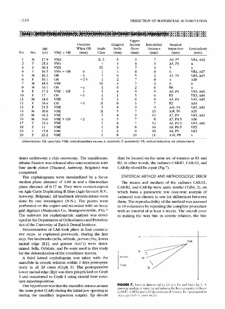
The means and medians of the radiuses CAR-Ill, CAR-112, and CAR-Ilp were quite similar (Table 2), on which basis a parametric test (one-way analysis of variance) was chosen to test for differences between them. The reproducibility of the method was assessed in 10 volunteers by repeating the complete procedure with an interval of at least 4 weeks. The overall error in making the wax bite in centric relation, the bite
CAR
FIGURE 7. X-axis is determined by Or and PO and Y-axis by S. A one-way analysis of variance test between the three computed radiuses (CAR-II 1 , CAR-112 and CAR-lip) h s ows no difference. Ilp-posioperative lncisal point of the lower incisor.
CAR-Ill CAR-112 CAR-111,
Mean SD Median
104.25 13.33 103.85 104.42 13.41 103.95 104.33 13.43 103.85
block with the mandible in its most retruded position, determining the head position in the cephalostat, copying of the films, determining of primary and secondary parameters, and performing the digitizing process was determined by applying the mean square error test to the duplicate measurements. l2
Results
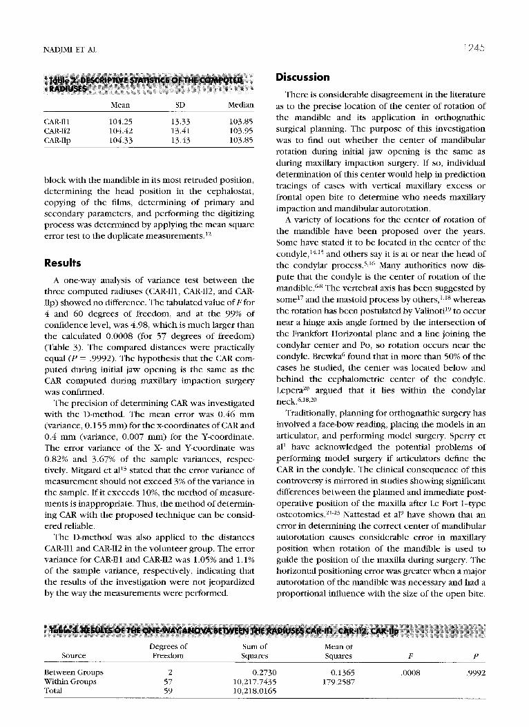
A one-way analysis of variance test between the three computed radiuses (CAR-Ill, CAR-112, and CAR- Ilp) showed no difference. The tabulated value of Ffor 4 and 60 degrees of freedom, and at the 99% of confidence level, was 4.98, which is much larger than the calculated 0.0008 (for 57 degrees of freedom) (Table 3). The compared distances were practically equal (P = .9992). The hypothesis that the CAR com- puted during initial jaw opening is the same as the CAR computed during maxillary impaction surgery was confirmed.
The precision of determining CAR was investigated with the D-method. The mean error was 0.46 mm (variance, 0.155 mm) for the x-coordinates of CAR and 0.4 mm (variance, 0.007 mm) for the Y-coordinate. The error variance of the X- and Y-coordinate was 0.82% and 3.67% of the sample variances, respec- tively. Mitgard et all3 stated that the error variance of measurement should not exceed 3% of the variance in the sample. Ifit exceeds lo%, the method of measure- ments is inappropriate. Thus, the method of determin- ing CAR with the proposed technique can be consid- ered reliable.
The D-method was also applied to the distances CAR-Ill and CAR-112 in the volunteer group. The error variance for CAR-Ill and CAR-112 was 1.05% and 1.1% of the sample variance, respectively, indicating that the results of the investigation were not jeopardized by the way the measurements were performed.
1245
Discussion
There is considerable disagreement in the literature as to the precise location of the center of rotation of the mandible and its application in orthognathic surgical planning. The purpose of this investigation was to find out whether the center of mandibular rotation during initial jaw opening is the same as during maxillary impaction surgery. If so, individual determination of this center would help in prediction tracings of cases with vertical maxillary excess or frontal open bite to determine who needs maxillary impaction and mandibular autorotation.
A variety of locations for the center of rotation of the mandible have been proposed over the years. Some have stated it to be located in the center of the condyle,‘*,‘j and others say it is at or near the head of the condylar process. j,16 Many authorities now dis- pute that the condyle is the center of rotation of the mandible.GS The vertebral axis has been suggested by somel’ and the mastoid process by others,‘,‘* whereas the rotation has been postulated by Valinoti’9 to occur near a hinge axis angle formed by the intersection of the Frankfort Horizontal plane and a line joining the condylar center and PO, so rotation occurs near the condyle. Brewka6 found that in more than 50% of the cases he studied, the center was located below and behind the cephalometric center of the condyle. LeperazO argued that it lies within the condylar neck,61%20
Traditionally, planning for orthognathic surgery has involved a face-bow reading, placing the models in an articulator, and performing model surgery. Sperry et al’ have acknowledged the potential problems of performing model surgery if articulators define the CAR in the condyle. The clinical consequence of this controversy is mirrored in studies showing significant differences between the planned and immediate post- operative position of the maxilla after Le Fort I-type osteotomies.21-23 Nattestad et a19 have shown that an error in determining the correct center of mandibular autorotation causes considerable error in maxillary position when rotation of the mandible is used to guide the position of the maxilla during surgery. The horizontal positioning error was greater when a major autorotation of the mandible was necessary and had a proportional influence with the size of the open bite.
Source Degrees of Freedom
Sum of Squares
Mean of Squares
Between Groups 2 0.2730 0.1365 .ooos .9992 Within Groups 57 10,217.7435 179.2587 Total 59 10,218.0165
1246 PREDICTION OF MANDIBULAR AUTOROTATION
A retrospective computerized analysis of 10 Le Fort I impaction osteotomies without concomitant mandibu- lar ramus osteotomies showed that if the CAR was chosen to be the center of the condyle, an error range of 0.4 to 10.4 mm occurred in the determination of the final horizontal postsurgical position of the max- illa?
The accuracy of the kinematic method of determin- ing of center of rotation of the mandible has been questioned by Winstanley, who has found an error of up to 2.4 mm with an interincisal opening of 10 mm. This method requires the mounting of an exten- sive apparatus on the moving mandible.
With all of these misgivings, focus has turned on methods of more accurately determining the location of the center of rotation for purposes of autorotation in maxillary impaction surgery. 18s2* PanjabiZ6 de- scribed an algorithm to determine the center of rotation and the angle of rotation of human body joints from the coordinates of two points on a bone at two different positions with respect to a fixed refer- ence. This is based on locating the center of rotation by Rouleaux’s method.‘O PanjabiZ6 states that for documentation of motion of a body relative to another body or a fixed coordinate system, at least three independent measurements are required, two orthogo- nal coordinates of the center of rotation and an angle of rotation about this center. The center of rotation is obtained as the point of intersection of perpendicular bisectors of the two lines joining the initial and final positions of two points on the plane as determined by Rouleaux’s method.lO The ICR is defined as a point on the plane having zero velocity at the instant consid- ered. In biomechanical concepts, center of rotation (CR) and ICR may be used interchangeably because the differences in the actual location of the CR and ICR of a joint are probably small, and the differences between ICR and CR decrease with the number of intervals into which the total range of motion is divided. The center of rotation therefore describes the kinematic characteristics of a body joint undergoing planar motion.
The Rouleaux method for calculating the center of mandibular rotation has already been applied by Rekow et all8 and shown to be acceptable. An error in positioning of the landmark on the postrotation radio- graph from either misidentification of the landmark or changes in the radiographic image as a result of head rotation can occur.*’ An error in coordinate measure- ment produces an error in locating the same landmark in its original and rotated position.28 An error in constructing or calculating the perpendicular bisec- tors produces a large error in location of the CAR.29 In this study, the Rouleaux method was used taking all measures into account to minimize the associated
errors. We tried to eliminate the error of misidentifica- tion of the landmarks by using the most superior and anterior point of the lower incisor or the orthodontic bracket fixed on the incisor as the most anterior point of the mandible. This point is easy to recognize and is not subject to significant alterations in different radio- graphs.
Panjabi26 states that for the optimal experimental design to determine CR, the two markers should subtend an angle as close to 90” as possible at the estimated location of the CR, and they should be situated far away from the CR. Therefore, to maximize the accuracy of the determination of the center of rotation of the mandible, we used gonion as the second landmark. As the angle between the points increases, the precision in locating the CR improves, but there is little clinical freedom in manipulating the amount of rotation because physiologic constraints determine this value.is Rekow et all8 concluded that the rotation angles must be at least 6”. Preoperatively we obtained two lateral cephalograms. One cephalo- gram was taken with the mandible in centric relation using a waxbite wafer (Ceph l), and the other was taken with a jaw opening in the range of exclusive rotation of the mandible using a fabricated bite block with the mandible manipulated in its most retruded position (Ceph 2). The bite block had a thickness of 10 mm and was positioned between the front teeth. The mean amount of jaw opening was 8.5”, ranging from 7” to 10”. To prevent changes in the radio- graphic image, the cephalograms were standardized by a focus median plane distance of 4.00 m and a film-median plane distance of 0.17 m, and positioning of the patients in the cephalostat was standardized. The perpendicular bisectors were constructed using the pair of compasses technique.
The technique described in the section entitled “Determination of the Center of Mandibular Autorota- tion” was used in making the prediction tracing of 20 consecutive patients who underwent maxillary impac- tion with concomitant mandibular autorotation. Using the calculated CAR, we were able to predict whether mandibular ramus surgery was necessary to obtain optimal occlusion and integumental profile. It was correctly predicted whether impaction would be accompanied with a setback, causing interference between the tuberosity and the pterygoid plates, and leading to premature facial aging. In none of the cases were difticulties encountered in positioning the max- illa after performing the calculated impaction. One can determine the amount of intrusion in the molar region by knowing the needed intrusion in front and calculated CAR when treating patients with vertical maxillary excess or frontal open bite.

THOMAS P. SPERRY 1247
References
1. Sperry TP, Steinberg MJ, Gans BJ: Mandibular movement during autorotation as a result of maxillary impaction surgery. Am J Orthod Dentofac Orthop &1:116, 1982
2. Tanne K, Sachdeva R, Sakima T, et al: Association between hard and soft tissue changes resulting from Le Fort I total maxillary osteotomy. J Osaka Univ Dent Sch 27:31, 1987
3. Sakima T, Sachdeva R: Soft tissue response to Le Fort I maxillary impaction surgery. Int J Adult Orthod Orthog Surg 2:221, 1987
4. Nanda R, Sugawa J, Topazian RG: EfTect of maxillary osteotomy on subsequent craniofacial growth in adolescent monkeys. Am J Orthod 83:391,1983
5. Schendel SA, Eisenfeld JH, Bell WH, et al: Superior repositioning of the maxilla: Stability and soft tissue osseous relations. Am J Orthod 70:663,1976
6. Brewka RE: Pantographic evaluation of cephalometric hinge axis. Am J Orthod 79:1, 1981
7. Baragar FA, Osbomm: A model relating patterns of human jaw movement to biomechanical constraints. J Biomech 17:757, 1984
8. Torii K: Analysis of rotation centers of various mandibular closures. J Prosthet Dent 61:285, 1989
9. Nattestad A, Vedtofte P, Mosekilde E: The significance of an erroneous recording of the centre of mandibular rotation in orthognathic surgery. J Craniomaxillofac Surg 19:254, 1991
10. Rouleaux F: The Kinematics of Machinery: Outline of a Theory of Machines (translated by A.B.W. Kennedy). London, England, The Macmillan Company, 1876
11. Mommaerts MY: Reliability and validity of a back-lighted digitizer when used for craniofacial measurements. J Craniofac Surg 81222, 1997
12. Dahlberg G: Statistical Methods for Medical and Biological Students. New York, NY, Interscience Publications, 1940
13. Mitgard J, Bjiirk G, Linder-Aronson S: Reproducibility of cepha- lometric landmarks and errors of measurement of cephalomet- ric cranial distances. Angle Orthod 44:56, 1974
14. Bell WH, Profitt WR, White RP: Surgical Correction of Dentofa- cial Deformities. Philadelphia, PA, Saunders, 1980, p 171
J Oral Maxiilofac Surg 56.1247-l 248, 1998
15. Turvey TA, Hall DJ, Fish LC, et al: Surgical orthodontic treatment plating for simultaneous mobilisation of the maxilla and mandible in correction of dentofacial deformity. J Oral Surg 54:491, 1982
16. Radney LJ, Jacobs JD: Soft tissue changes associated with surgical total maxillary intrusion. Am J Orthod 80:191, 1981
17. Hillyer E: The development of the anatomical articulator. Dent Cosmos 55~989, 1913
18. Rekow ED, Speidel TM, Koenig RA: Location of the mandibular centre of autorotation in maxillary impaction surgery. Am J Orthod Dentofac Orthoped 103:530, 1990
19. Valinoti JR: The hinge-axis angle. J Clin Orthod 11:551, 1977 20. Lepera F: Determination of the hinge axis clutches on condyle
position. J Prosthet Dent 8:260, 1958 21. Pospisil OA: Reliability and feasibility of prediction tracing in
orthognathic surgery. J Craniomaxillofac Surg 15:79, 1987 22. Polido WD, Ellis E, Sinn JP: An assessment of predictability of
maxillary surgery. J Oral 1MaxiUofac Surg 48:697, 1990 23. Kahnberg KE, Sunzel B, Astrand P: Planning and control of
vertical dimension in Le Fort I osteotomies. J Craniomaxillofac Surg 18:267, 1990
24. Nattestad A, Vedtofte P: IMandibular autorotation in orthognatic surgery: A new method of locating the centre of mandibular rotation and determining its consequence in orthognathic surgery. J Craniomaxillofac Surg 20:163, 1992
25. Winstanley RB: Hinge axis location on the articulator. J Pro&et Dent 42:135, 1979
26. Panjabi MM: Centers and angles of rotation of body joints: A study of errors and optimization. J Biomech 12:911, 1979
27. Soudan K, Van Audekercke R, Martens M: Methods, difficulties and inaccuracies in the study of human joint kinematics and pathokinematics by the instant axis concept. Example: The knee joint. J Biomech 12:27, 1979
28. Dimnet J, Carret JP, Gonon G, et al: A technique for joint center analysis using a stored program calculator. J Biomech 10:659, 1974
29. Nave&i K: An analysis of mandibular movement from rest to occlusal position. Acta Odontol Stand Suppl14:129, 1956
Discussion
Prediction of Mandibular Autorotation
Thomas P. Sperry, DDS, MS, MSDf Associate Clinical Professor, Department of Orthodoniics, University of Illinois, Chicago, Illinois
How many of us have been honest enough to feel queasy about the placement of the representation of the instanta-
neous center of rotation for the purpose of rotating a mandible when vertical maxillary change is incorporated into the treatment plan? The carefully constructed precision of all of the elements of treatment planning is at the mercy of this “lowest common denominator” issue. It makes a difference. Take a compass and scribe different arcs based
tDeceased.
on different centers of rotation, but with equal radii, to simulate vertical change of the transpositioned mandible. Then measure the vertical and horizontal legs of triangles created by two points on each arc traveling the same distance and discover that the difference can be measured in several millimeters in many circumstances.1-3
This issue has been addressed before, as indicated by the extensive reference list provided by the authors. But one wonders about the practical application of determining the center of rotation by clinicians across the country, and about the impact of this “vulnerable” variable buried deep inside the multidimensional geometric treatment planning exercise. Determining the proper instantaneous center of rotation is fundamentally essential to the accurate transposi- tion of bone fragments in space.
The authors of this article have made a meaningful contribution to the literature by providing us with a practi- cal method of resolving this dilemma. They have attempted