16-mm sound motion pictures, a manual for the professional ...
602
W. H. OFFENHAUSER, Jr. mm SOUND MOTION OiO PICTURES a Tftanual FOR THE PROFESSIONAL AND THE AMATEUR INTERSCIENCE PUBLISHERS
-
Upload
khangminh22 -
Category
Documents
-
view
0 -
download
0
Transcript of 16-mm sound motion pictures, a manual for the professional ...
W. H. OFFENHAUSER, Jr.
mmSOUND MOTION
OiO
PICTURES
a Tftanual FOR THEPROFESSIONALAND THEAMATEUR
INTERSCIENCE PUBLISHERS

I. K. MEUiN!- MOTK IGam.
>80i 14. D.C

Scanned from the collection of
Jeff Joseph
Coordinated by the
Media History Digital Library
www.mediahistoryproject.org
Funded by a donation from
Jeff Joseph


c
^71^7, 'W
^^^^^y^^^C^

Digitized by the Internet Archive
in 2012 with funding from
Media History Digital Library
http://archive.org/details/16mnnsoundmotionp00will

16-Mm Sound Motion Pictures
A Manual for the Professional and the Amateur

16-Mm Sound Motion Pictures
A MANUALfor the Professional
and the Amateur
WILLIAM H. OFFENHAUSER, Jr.
Andre DeBrie of America, Inc., New York
INTERSCIENCE PUBLISHERS, INC., NEW YORKINTERSCIENCE PUBLISHERS LTD., LONDON

To My Wife
Copyright, 1949, by INTERSCIENCE PUBLISHERS, INC.
First printing, 1949
Second printing (with revisions), 1953
ALL RIGHTS RESERVED.—This book or any part thereof must not be
reproduced without permission of the publisher in writing. This applies spe-
cifically to photostat and microfilm reproductions.
INTERSCIENCE PUBLISHERS, INC., 250 Fifth Avenue, New York 1, N. Y.
For Great Britain and Northern Ireland:
Interscience Publishers Ltd., 2a Southampton Row, London, W.C.I
Printed in the United States of America
Preface
Within the last two decades the term 16-mm has become something
more than the mere designation of a film width ; it is now almost symbolic
of all non-theatrical films. With little fanfare, the 16-mm film—which
may be loosely called the film of fact—was catapulted into the leading
position in the United States as a consumer of raw stock because of its
use as a medium of teaching, training, and persuading in the same World
War that proved the 35-mm film—the film of fancy—so valuable to the
military and civilian populations in the maintenance of morale.
At the turn of the period about two decades ago, the entertainment
motion picture industry was in the process of a technological revolution
—
the introduction of sound. Sound was unfamiliar and costly ; its recep-
tion in the industry was mixed. Some firms gambled their all on it : its
failure would wipe them out, its success would be their success. Others,
seeing the mad rush of the public to their competitor's box office for
pictures that talked, embraced it but said publicly that sound was a fad
whose disappearance would be as rapid as its rise had been meteoric.
Still others felt that sound would never acquire public acceptance ; they
installed it only when the signs became all too evident that the earnings
future of the silent films stored on their shelves was very dim indeed.
Some others just died. It was in such an environment that 16-mm as
a vital force was born.
During the first decade, at the time when budgets were minute ac-
cording to present day standards, and obstacles were seemingly insur-
mountable, the groundwork of the 16-mm film as it is known today was
laid. It was during this period too that 16-mm sound recording equip-
ment and 16-mm sound projectors began to be a factor to be reckoned
with in the photographic market, due not so much to their accomplish-
ments, but to their potentialities. Some viewed the growing baby with
alarm, and shunned it as a dangerous potential competitor for the public's
time and purse ; a very few felt that it should be watched—much as one
might watch the approach of an inevitable tornado that would leave a
wide path of destruction in its wake. Others ignored it.
vi PEEFACE
A decade later the groundwork of the 16-mm had been quietly com-
pleted. Hollywood was then deep in the throes of providing wide-range
and high-fidelity sound ; the question of the sound vs. the silent film had
been answered by the public at the box office. The influence of the
British documentary movement spearheaded by Grierson had already
made itself felt in the United States. "The Kiver" and "The Plow
that Broke the Plains" of Pare Lorenz had established themselves as
qualified American descendents of Robert Flaherty's "Nanook of the
North," one of our earliest and best documentaries. The theory and
practice of the training film had been lucidly and accurately set forth
in a U. S. Army "Memorandum to G-3 : Factors in Training Film Pro-
duction and Use" dated February, 1936; this document had been pre-
pared by Melvin E. Gillette within the Army. Gillette, like his Armyassociates, Hoorn, Jervey, and Stodter, had been trained in the mechanics
of film production through the auspices of the Academy of Motion Picture
Arts and Sciences ; their study in Hollywood had been the culmination of
the efforts of Prosser, Fox, Lewis, and others to make such training
possible. Like all documents that live beyond the short life span of their
authors, this one is timeless ; it defines the place of the training film and
of other films in relation to the national military establishment, and
describes in straightforward language the principles that guide their pro-
duction and use.
During the same period, the U. S. Navy laid the groundwork for the
sound slide film; the work of Byron McCandless of the Bureau of
Navigation will not be forgotten in Navy records. The names of Reif-
snider and Fraser made their appearance a short while later in the Navyroster in the development of sound films for Navy recruiting. The U. S.
Air Corps had also been active in training films. Hagemeyer, a civilian
at Wright Field, will be remembered for his continued devotion and
accomplishments over the same two decades. In 1931, a short series
of films on pilot training had been turned out experimentally at Wright
Field with the cooperation of RCA Photophone Inc. ; these films were
later sent to England to the R. A. F. The Department of Agriculture,
through its Extension Service Office of Motion Pictures, had acquired
sound equipment in 1930, and soon produced simple, effective, and low-
cost factual sound films under the expert guidance of Raymond Evans,
its Chief, and his associate, Chester Lindstrom. The films are considered
models by which agricultural films are made everywhere today. Mean-
while, the amateur ranks, already large, swelled noticeably because of the
PREFACE vii
ready availability of Kodachrome and of cheaper and better cameras and
projectors, and because of the availability of sound projectors and sound
films for the home. Many amateurs became professionals in the 16-mm
field ; many professionals became amateurs.
Despite its age of over 40 years, the technical literature of the motion
picture is surprisingly sparse and spotty. It is found almost entirely in
short papers published in the journal of a single society : the Society of
Motion Picture Engineers. A scientifically trained person with no prior
knowledge of the industry would find these papers as many small curi-
ously shaped pieces of a large jig-saw puzzle for which there is no
over-all guide by which the pieces may be put together, or from which it
would be possible to determine whether all the essential pieces are pres-
ent. This book is the author's attempt to provide the first such technical
guide. It has drawn liberally upon the Journal of the Society of Motion
Picture Engineers for its material and its illustrations; the author
wishes to express his sincere thanks to the Society and its officers and to
the many authors of its papers for permission to use them. It is the
author's considered opinion that an integrated and rationalized explana-
tion of the processes of the 16-mm film would hardly be practicable with-
out them.
It is hoped that the entire book will prove helpful to the newcomer to
films. To the specialist in film technology its value may lie primarily in
fields outside his immediate specialty. Its major usefulness, however,
will be to that large segment of intelligent inquiring people making and
using films, who believe that 16-mm has a tremendous impact uponnational—and international—life, and yet find that some of its techno-
logical nuances seem to be a hazy puzzling mystery, rather than a rational
and logical engineering and businesslike process.
Maxfield, a venerable of the sound film, once described the sound
motion picture as ".. . the application of engineering equipment to an
art ..." Since the primary emphasis of the past has been upon the
art and not upon the science, it is not a surprise to find that the nomen-
clature and terms used as its language are primarily non-scientific.
There are many coined terms; a number of accepted definitions have
several shades of meaning included in the American Standards Associa-
tion nomenclature. Still other specialized terms are not industry-wide,
and are used only in special places in special instances; many of these
are unknown to the industry at large. It took almost 50 years before
the first American Standard Nomenclature for motion pictures came into
viii PEEFACE
existence; this listing, which is reproduced in toto in Appendix A, in-
cludes terms that have acquired wide acceptance, but does not include
the specialised terms previously described. Even this excellent nomen-
clature can be improved; should the reader have specific suggestions,
they will be sincerely welcomed by ASA and by the Society of Motion
Picture Engineers, the sponsors of ASA motion picture standardization
activities. Letters should be addressed to the secretaries of the respective
organizations. It is respectfully urged by the author that universal use
of this nomenclature be encouraged.
In view of its rapid growth, it was thought desirable to discuss tele-
vision in a short separate chapter, and include numerous references.
Right now, television and motion pictures are closely interlinked, as
over 25% of the average 48 hours per week station operating time comes
from film; in addition, a large volume of 16-mm film originates as
live television shows that are photographed from the face of a television
station monitor tube during a transmitted performance. Although
television is being embraced by all concerned, there are many obvious
indications of mixed feelings about it. So far there have been no
Horatio Alger financial success stories to encourage the plunges of those
faced with the decision. Radio broadcasters have to some extent viewed
it as an expensive prestige-making offshoot of the sound broadcasting
industry whose increased budgets will be borne by national advertisers
about as they are in sound broadcasting. Some motion picture interests
have viewed it as a potential supplement to theater programs; a small
few view it as that inevitable destructive tornado. Few, however, are
ignoring it. Dynamic television, like 16-mm motion pictures, cannot be
successfully ignored. At the present stage there is only one safe pre-
diction; the American public has many new and wondrous things in
store—if the public wants them.
Acknowledgments
The author gratefully acknowledges the courtesy of the following companies, asso-
ciations, and individuals in granting permission to publish illustrations:
Academy of Motion Picture Arts and Sciences (Fig. 34), Altec-Lansing Corp.
(Fig. 114A), American Standards Association (Figs, 8, 9, 10, 11, 13, 19, 76, 78A),
The Ampro Corp. (Figs. 108, 111), D. Appleton-Century Co. (Figs. 1, 1A, IB), Bell
and Howell Co. (Figs. 23, 24, 85, 88, 88A, 94, 103, 109, 112, 112A), Oscar F. Carlson
Co. (Figs. 93, 102, 102A), Cinema Arts-Crafts (Fig. 101), Eastman Kodak Co. (Figs.
22, 84),Electronic Development Associates and Balph Batcher (Figs. 38, 39), Fonda
Division, Solar Aircraft Corp. (Figs. 92, 92A), The Houston Company (Fig. 91),
PREFACE ix
Jensen Eadio Manufacturing Co. (Figs. 27, 28, 28A, 105A, 115), Journal of the
Society of Motion Picture Engineers (Figs. 7, 12, 30, 31, 32, 50, 53, 54, 59, 60, 61, 65,
66, 68, 69, 70, 74, 75, 89, 90, 98, 107, 117-123), J. A. Maurer, Inc. (Figs. 7 A, 7B, 25,
52, 58, 61A, 63, 63A, 63B, 71B, 71C, 80, 97, 99), Mitchell Camera Corp. (Fig. 26),
Moviola Manufacturing Co. (Fig. 86), National Association of Broadcasters (Fig. 33),
National Bureau of Standards (Figs. 116, 116A, 116B, 116C, 116D), Neumade Prod-
ucts Corp. (Figs. 77, 78, 79, 81, 82, 83, 87), Photographic Instruments, Inc. (Figs. 95,
96, 104), ECA-Victor Division, ECA (Figs. 44, 44A, 44B, 46, 46A, 46B, 48, 48A, 48B,
49B, 49C, 49D, 51, 64, 67, 71A, 100, 113), Shure Brothers, Inc. (Figs. 49, 49A),
E. I. Sponable (Fig. 57), U. S. Navy (Fig. 110), I). Van Nostrand Co. (Figs. 34, 35,
36, 37, 40, 41, 42, 55), Western Electric Co: (Figs. 43, 43A, 43B, 45, 45A, 47, 47A,
47B, 55A, 62, 71, 114), Weston Electrical Instruments Corp. (Figs. 2, 3, 72, 72A, 73).
Thanks are also due to the Society of Motion Picture Engineers for permission to
reprint in modified form material that appears in Chapters V, VI, IX, XI, XIV,and XV. Much of this material was previously published in its Journal by the author
in the form of Society papers.
Although it is impossible to list all who have contributed professionally to the data
in this book, special mention must be made of my fellow-engineer of many years, Dr.
E. W. Kellogg. His influence as a catalyst in improving the quality and quantity
of the work of all those with whom he comes in contact can be matched only by his
own outstanding achievements in the field of sound recording. Special mention must
also go to my old friend from Columbia student days, Hugh Knowles of Jensen. For
years we have discussed 16-mm and what can be done to improve it. He is to be
congratulated particularly for the excellent series of Jensen Technical Monographs
that make loudspeakers and their performance comprehensible to engineers at large.
Mention must also be made of my friend and associate during the War, Lloyd T.
Goldsmith of Warner Brothers, who in his continuous survey of the Hollywood scene
is so keenly aware of the unusual things that are quietly being done there on the day-
to-day job by the unsung scientific heroes of the picture production and equipment
manufacturing industry.
The author is indebted to Harry Smith, Jr., former Secretary of the Society of
Motion Picture Engineers for providing the spark that started this book. He also
wishes to express his deep appreciation to Interscience Publishers, Inc., and especially
to Mr. Allen Kent of their staff for understanding counsel and aid in producing
this book.
Acknowledgment must also go to my good friend H. E. White of Eastman Kodakand to William Deacy, Jr., of the Society of Motion Picture Engineers in that neces-
sary and taxing chore of going over the galley proof, and to my sister Marie for
checking the page proof.
William H. Offenhauser, Jr.
New Canaan, Connecticut
September, 1949

CONTENTS
I. 16-Mm Film and Its Relation to Other Sizes 1
Early History. Film Sizes. Sound. Color. Military
Uses. Present Status.
II. Making a 16-Mm Picture 11
Subject Matter. Taking the Picture. Recording the Sound.
Developing and Printing for Editing. Release Printing.
III. 16-Mm Film and Its Characteristics 19
Silver-Emulsion Films. Physical Characteristics. Sensi-
tometric Characteristics. Types of Available Film.
IV. Making 16-Mm Originals 58
Size of Originals for Release Prints. Prospective Volume of
Films. Direct Production. Picture Original. Black-and-
White Reversal Materials. Color Reversal. Exposure of
Original Reversal. Measurement and Actinic Value of Ex-
posure. Exposure Time and Camera Speed. Lenses and
Lens Aperture Markings. Exposure Tests. The Film. SoundOriginal. Standardization of Exposure for Sound Record-
ing and Direct Sound Positives. Standardization of Emul-sion Speed. Lamp Life and Lamp Conservation. SoundTrack Fog and Its Sources.
V. Dimensions and Standards in 16-Mm 105
VI. The Problem of 16-Mm Emulsion Position 132
Emulsion Position in 35-Mm Practice. Early History of
16-Mm Reversal Film. Reversal and Color Reversals—WhatThey Are. Early History of 35-Mm and 16-Mm Sound Film.
Current Status of Direct 16-Mm Sound. Kodachrome SoundDuplicating and Its Implications. Emulsion Position in
16-Mm. Emulsion Positions of Prints and How They Occur.
VII. Cameras, Camera Equipment, and Cinematography 146
Cameras: General Functions; Spring-Driven; Magazine;
Larger Spring-Driven; Professional; Choice; Mechanism;
Adjuncts; Design. Synchronization of Picture with Sound.
Cinematography.
x

CONTENTS xi
VIII. Sound, Sound Recording, and Sound-RecordingCharacteristics
, 169
General Nature of the Sound to Be Recorded. Fidelity of
the Recorded Sound. Frequency Range and Hearing Per-
ception. Influence of Noise. Speech and Music Reproduc-
tion. Low-Frequency Cutoff of a System. Frequency
Range and Volume Range of Reproduced Sound. Actual
Performance—Past, Present, and Future. Production Im-
plications of Performance Range Requirements. Response-
Frequency Characteristics in 16-Mm Sound Recording.
Transfer Steps. Making Release Prints and Effect on
Sound. General Recording Procedures. Practical MethodSuggestions.
IX. Sound-Recording Equipment and Its Arrangement .... 204
History. General Requirements for Modern 16-Mm Sound-
Recording Equipment. Transfer Losses and Their Correc-
tion. Recommended Ranges of Response-Frequency Over-
all Characteristic. Pre- and Post-Equalizing. Recording
Equipment Details. Physical Placement of Equipment in
Recording. Re-recording.
X. Editing and Assembly 328
Editing—Creative and Physical. Equipment and Tools of
Editing. Cutting the Original. Preparing for SoundRecording.
XI. Preservation and Storage 355
XII. Processing and Release Printing 364
Development. Printing: the Printer. Technical Control.
Practical Laboratory Operation. Performance Limitations
of Recorded Sound. Fine-Grain Film and Its Applications.
XIII. Projection and Projectors 437
Visual-Audio Media of a Classroom. The Projector. Pic-
ture Projection and the Audience. Sound Projection and the
Audience. Practical Projector Performance.
XIV. Duplication of Tri-pack Color Films 501
Kodachrome Processing and Duplicating. Available Types
of Kodachrome. Competitive Positions of Present-Day
16-Mm Color Methods. Some Limitations of the Duplicating
Process.
XV. Industrial Applications of Current 16-Mm Sound MotionPicture Equipment 521
Interdepartmental Organization. Safety Promotion and
xii CONTENTS
Health Conservation. Job Technic Training. EmployeeRelations. Employee Advancement.
XVI. Television and Film 533
Film Scanning. Apertures and Shapes. Resolving Power.
Special Transmission Characteristics. Density and Contrast
Characteristics. Photographing Television Images andTransmitting Film Images. Sound. Standardization.
Appendix A. Nomenclature for Motion Picture Film Used in Studios andProcessing Laboratories. Index of ASA Standards Revised as of
February, 1953 547
Appendix B. Symbols Proposed for Motion Picture Equipment 557
Appendix C. Percent Transmission vs. Photographic Density 558
Appendix D. Comparison of Emulsion Speed Values 560
Appendix E. Decibels Gain or Loss vs. Voltage and Current Ratio andPower Ratio 561
Appendix F. ASA Standards vs. Government Specifications 562
Subject Index 566
CHAPTER I
16-Mm Film and Its Relation to Other Sizes
Early History
About dO years ago when Edison was getting his "peep-hole" Kineto-
scope ready for the Chicago World's Fair of 1893, he chose 35-millimeters
as the width for the film that he was going to use. The Kinetoscope,
showing photographs in motion, was to be seen at the World's Fair for
a nickel—and the nickel show which involved forty feet of film lasted
all of 30 seconds. It is interesting to note that the 35-mm film used had
substantially the same dimensions as the 35-mm film of today ; it had the
customary rectangular-shaped sprocket holes, and there were, on each
side of the film, four per frame. 35-mm film is today well standardized;
and 35-mm film made anywhere, when exposed in any camera made any-
where, and developed and printed in any equipment made anywhere,
will project in any projector made anywhere in the world if the inter-
national standards that are in effect are observed.
International standardization of motion picture films and equipment,
although informal at the very beginning, arose from a very natural desire
of people to demand the widest potential use for any motion picture that
might be made. Pioneers in various countries of the world used different
film dimensions, but it was soon discovered by the showmen who bought
the variegated machines that the different sizes were not interchangeable.
Since Edison had produced most of the films, it was only natural for
showmen to demand that their machines be capable of projecting Edison
pictures. Thus, even prior to 1900 there was a strong demand for the
standardization of film sizes that made itself strongly felt in the countries
where the motion picture saw early and rapid growth—the United
States. France, and England.
Quigley and Talbot reported that among those who bought Kineto-
scopes were two Greek visitors from London. George Georgiades and
George Trajedis; these men recognized the potentialities of the magic
shadows. One was a green grocer, the other a toy maker ; they saw an
opportunity to make a fortune in England as showmen. The two Greeks
acquired Edison machines in Xew York, brought them to London, and
l
2 I. 16-MM FILM AND ITS RELATION TO OTHER SIZES
sought out Robert Paul to duplicate the machine for them. Paul as-
sumed that Edison had patented his machine in England and refused,
pointing out that both he and they would expose themselves to patent
litigation and heavy damages. The Greeks were dismayed, and departed,
taking their Kinetoscope with them.
Paul then looked into the patent situation more thoroughly and found
that Edison had not filed British patents upon his invention. Accord-
ingly he was free to set to work and to build machines—and he did so
for the two Greek entrepreneurs and others. Since only Edison films
were widely available, Paul's Kinetoscopes were made for the Edison 35-
mm film. When Edison's representatives Maguire and Baucus became
aware of this, however, they took steps to cut off the supply of Edison
films to Paul's machines. In the meantime, Paul who had recognized the
limitations of the "peep-hole" viewing arrangement, set about building
a projector which he called the Animatograph ; this was Paul's design
that resulted from a suggestion of Birt Acres, who at the time was in the
employ of a firm manufacturing dry plates and bromide papers. In the
early months of 1895 the Animatograph was built and first tested ; this
machine was probably the first to use a picture gate as we now know it
and an intermittent movement. Since Paul's customers for the Kineto-
scope had stretched from England to New Zealand, Paul was now forced
to arrange for a supply of film to keep the machines running that he
had sold. With his source of films cut off, Paul was forced to build a cam-
era and to produce the films himself. It was at this point that Edison's
agents decided to withdraw from England because of the ingenuity and
persistence of Robert Paul.
Lumiere, a French firm manufacturing photographic apparatus and
dry plates, was seemingly attracted to motion pictures by the Edison
Kinetoscope as was Paul. Upon seeing the Edison machine in 1894 in Paris
they recognized the drawbacks of (1) too many frames per second (the
number was about 48), and (£) no opportunity for audience viewing.
Lumiere set about building a camera, and a projector (called a cinemato-
graph). Lumiere film was 35-mm wide and had just one round hole on
either side of the frame ; the holes were spaced 20 mm apart. The Lu-
miere machines and film represented excellent mechanical design, and in
the earlier versions utilized a film strip 17 meters long rather than the
Edison length of 40 ft. Progress was made very rapidly; in the
autumn of 1896 a Lumiere projector introduced in the United States by
a Mr. Hurd, agent for the Lumieres, projected a picture 22 by 16 ft.
FILM SIZE 3
As a result of this demonstration, Mr. Hollaman, manager of Eden
Musee, signed a contract for its installation as a permanent feature.
The motion picture industry owes much to the daring showmanship of
Mr. Hollaman, since he was an outstanding pioneer in recognizing the
possibilities of new motion picture equipment and films and in putting
them into almost immediate commercial use.
Unfortunately for the Lumieres, Kinetoscopes had been sold more
generally than had at first been supposed—many of these by Paul. It
seems that both Paul and the Lumieres were mutually unaware of each
other's activities, and the Lumieres were soon faced with a demand from
their customers to alter their apparatus to accommodate the Edison film.
When this was done, the first practical international (although informal)
standardization of motion pictures was accomplished prior to 1900.
After 1900* the motion picture grew very rapidly all over the world.
It would seem that the strong public demand could not be long restricted
to the very narrow channels that even farsighted and enterprising pro-
moters and entrepreneurs had charted for it.
To some extent history has repeated itself with 16-mm. Although it
started as an amateur medium, it far outgrew its early swaddling clothes
when it came into a real popularity with its extensive use as training and
similar films devoted to military purposes.
Film Size
As the technology of the motion picture advanced from its enthusi-
astic yet humble beginnings, it was only natural to expect manufac-
turers of films and equipment to attempt to reduce costs to the point
where films would be practicable for amateur and personal movies—en-
larging the scope of motion pictures tremendously. One of the early
stepsf taken to satisfy that desire was the manufacture of smaller film,
* Early motion picture history is shrouded in a haze that is a combination of
fact and fancy—with the latter predominating in the more popular works. Thanks
are due to Mr. Terry Eamsaye of New Canaan, Connecticut, for his most generous
suggestions in the location of reliable sources, and to Mr. E. F. Kerns of the Museumof Modern Art, 11 West 53rd Street, New York City, for his aid in locating the
references cited at the end of this chapter. All references cited are to be found in the
library of the Museum. An excellent source of accurate history is '' Testimony of
Witnesses for the Petitioners, in the District Court of the United States: The
United States of America, petitioners, vs. Motion Picture Patents Company < 1 al.}
defendants.
t A much earlier small film that acquired popularity but has since disappeared is
28mm, sponsored by Willard I>. Cook, an early pioneer. Home movie projectors were
made by Pathescope (Cook) and Victor Animatograph • reduction printers by
Pathescope; raw film was made by Eastman.
4 I. 16-MM FILM AND ITS RELATION TO OTHER SIZES
arbitrarily selected at 16 millimeters. It was not until about 1923, how-
ever, that the big step in making films really suitable for the amateur was
made when the.Eastman Kodak Company introduced reversal film on
the 16-mm market. Prior to that time, all motion pictures—whether 35-
mm or 16-mm—required two strips of raw film to produce the single
strip used in the projector. When developed, the exposed original film
provided a negative image that was dark in the bright portions of the
scene and light in the dark portions. In order to obtain a positive image
suitable for projection a copy had to be made on a second strip of film,
with the bright portions of the scene being light and the dark portions
dark. The process is quite similar to that used for film from simple
still cameras.
Reversal Film. Obviously, if the original film could be developed
directly into a positive image suitable for projection, the amount of
raw film required would be cut in half, and the printing and the second de-
veloping operations eliminated. Reversal film processing accomplishes
just this, and is today used almost exclusively for black-and-white orig-
inal film of 16 millimeters and all lesser widths. This type of film is
still unknown as original film in the 35-millimeter width ; all such original
film is negative—just as it was some fifty years ago when motion pic-
tures were born.
Common Film Sizes
As time passed, attempts were made to broaden the market by reduc-
ing the cost of amateur motion pictures still further. In the United
States, 8-mm film provided the answer; it was first introduced by East-
man Kodak in about 1934. 17.5-mm, made by splitting 35-mm in two,
found a few specialized uses; original sound recording for Hollywood
films was one example.
In France, 9.5-mm film had been introduced somewhat earlier, being
used quite widely for educational as well as amateur purposes, and prov-
ing a strong competitor of 16-mm in popularity. Later, 9.5-mm equip-
ment and films were imported into England, but have become of lesser
importance since the fall of France in the early part of World War II.
Since 9.5-mm did not make headway in the United States, it is unlikely
that it will become a major factor now that World War II is over. Only
35-mm, 16-mm, and 8-mm need be given serious consideration for the
future, since any other possible film width subsequently proposed for
standardization will need a very strong case for adoption before it can
be seriously considered.
SOUND 5
Wide Film. Films larger than 35-mm wore run in theaters for a
limited period about 1930; among the better known were the 62-mm(RKO Spoor-Berggren), 65-mm
I Paramount-DeBrie), and 70-mm*IFox-
Grandeur). None of these widths was standardized, and since 1933 none
has been used commercially to any extent. It is interesting to note that
these larger sizes had larger aspect ratios, since a wider picture in
comparison with picture height was considered desirable.
Sound"When sound was introduced commercially into films in 1928 and
1929, it regenerated the motion picture industry and caused very rapid
expansion and technical growth. At that time, sound recording equip-
ment was used almost exclusively for 35-mm film, in view of unsuccess-
ful earlier attempts at commercial recording directly on 16-mm film.
Within a few years, 16-mm sound prints were being made commercially
by optical reduction from 35-mm negatives (a picture negative for the
picture original, and a sound negative for the sound original), and the
availability of commercial entertainment pictures in the 16-mm film
width enhanced its popularity. One of the earliest 16-mm sound pro-
jectors was designed by R. P. May of RCA in 1930. It was compact,
light, and gave surprisingly good performance in comparison with the
35-mm portable sound projectors marketed at the time. Almost a decade
passed before the performance of this machine was surpassed.
With the availability of such films and projectors in the 16-mm size,
amateur and other nontheatrical film users began to think in terms of
sound films rather than silent films, and a potential demand was created
for 16-mm sound recording equipment.
t
During the period from 1932 to 1936, 16-mm sound-recording equip-
ment was marketed, but the quantity was small, and its usefulness
handicapped by poor quality of the projected pictures and sound
in that they did not compare favorably with the quality of pictures seen
at local theaters.
During this same period, the edge had worn off the novelty of sound
in the 35-mm entertainment motion picture theater, and serious efforts
were made to improve the technical quality of the picture as well as of the
sound. It was then that "wide range" and "high fidelity " became by-
* The dimensions of 70-mm film have been standardized for still camera purposes.
t Important among the nontheatrical users were educators. The advantages of
films in education had been formally recognized as early as li»14 in an address i<>
the National Education Association at St. Paul and in 1915 at a University of
Minnesota Summer Session where scholastic credit was granted principals of con-
solidated rural schools who qualified as projector operators.
6 I. 16-MM FILM AND ITS EELATION TO OTHER SIZES
words for sound, and improvement was seen in all phases of recording
and reproduction. By the end of 1936 there was a fair degree of con-
sistency in the technical quality of entertainment films shown in 35-mmmovie houses.
From 1936 onward represented a period of further improvement in
35-mm films and of both improvement and rapid growth in 16-mm films.
When new developments in films or apparatus occurred in 35-mm film
technique, it was not long before the new developments were adapted
(where suitable) in 16-mm films—each size exerting strong technical
influences upon the other.
Color
The presence of Kodachrome for motion pictures in the 16-mm film
width and its equally notable absence in the 35-mm film width provided
still further impetus to an already interested and active industrial and
educational motion picture market. Almost immediately, this market
began to demand color duplicates
—
with sound. Kodachrome made it
possible to " shoot" in color and make a small number of copies at very
low cost (when compared with available 35-mm methods, such as Techni-
color). No special camera was needed, no special camera crew, and no
long contract negotiations were required to obtain a desired color film.
It was necessary merely to use Kodachrome in a good 16-mm camera
to obtain the picture, with sound being recorded in much the usual man-
ner. With this ready availability of both color and sound, the techno-
logical millenium of color and sound in educational films as envisioned
by Edison had become a reality within but 50 years of the birth of the
motion picture itself.
Military Uses of Film
World War I saw the use of motion pictures to some degree by
every large nation of the world. The amount of 35-mm film used for
record purposes ran into millions of feet. For training, the United
States Army had prepared 52 reels of a series called "Training of the
Soldier" and about 13 reels called "Elements of the Automobile." The
Germans had their films too; it was remarked by one German general
that in modern warfare the nation with the most complete photographic
intelligence would be the likely victor. Even at that early time films
were made for propaganda purposes (Germany and Russia) as well as
for training. When World War II arrived, the motion picture, in princi-
ple, had been accepted as a training tool, although the amount of material
PRESENT STATUS 7
available was quite limited. The United States Army, Navy, and Air
Forces had chosen 16-mm as the width best suited to their needs. Since
there was a large quantity of 35-mm production equipment available
such as cameras, sound recorders, editing equipment, etc., and a rela-
tively large pool of personnel trained to handle this equipment, it was
logical to assign to 35-mm the major part of the production burden.
The 16-mm projection prints were obtained from the 35-mm films by
optical reduction from special picture and sound duplicates copied from
the edited negatives.
The volume of 16-mm prints made for training and similar purposes
in World War II was measured in millions of feet per day. Such wide
use resulted in even greater and more insistent demands for better tech-
nical quality in the projected films. In order to meet these demands,
much technological improvement was needed in every stage of the
process. As each improvement was made, it was crystallized into an
American War Standard wherever possible. Standardization is being
continued as a normal peace-time activity, and its accumulated effects
cannot help but be felt throughout the world in the form of more and
better films for more people—and at a lower cost.
Present Status
Today, 35-mm prints are used almost exclusively in the entertainment
motion picture theater. 16-mm prints are now used almost exclusively
by the Armed Forces of the United States in the training of military
personnel. 16-mm prints are already widely used for educational and
industrial purposes. 8-mm is now reserved almost exclusively for ama-
teur and personal purposes.
So far, the optical reduction* of 35-mm to 16-mm has accounted for
the largest percentage of prints released in the 16-mm size.
In a small number of newsreel theaters, 16-mm sound projectors
have been installed beside 35-mm projectors to project 16-mm film uponThe same theater screen. Andre DeBrie has made a 16-mm attachment for
a 35-mm theater arc projector which projects a Kodachrome image on a 40
ft. screen with brightness and detail roughly equal to that from the best
35-mm color print. With very good control of film quality; the projected
16-mm films compare very favorably with 35-mm prints that may be used
for comparison.
* As will be described in a later chapter, the picture for 16-mm prints is now-
obtained from dupes from the original negative; the sound is re-recorded on a 16-mmsound negative and contact-printed for the release print.
8 I. 16-MM FILM AND ITS RELATION TO OTHER SIZES
Another overlap of interest in recent years is the " blowing up" of
8-mm to 16-mm, and of 16-mm to 35-mm films. Much of the combat warmaterial shown in the entertainment theaters was originally taken on
16-mm film. Typical examples have been the many air combat scenes
photographed with the GSAP (Gun Sight Aiming Point) camera, a
16-mm camera designed to take pictures of an enemy target when the
machine guns or other guns of the combat plane were fired. Whereoriginals were well exposed, well handled, and well processed, the results
were satisfactory.
Up to the present, no serious commercial attempts have been made
to record sound on 8-mm film. Without sound, it is unlikely that any
large portion of the present interest in 16-mm film will be transferred
to the 8-mm size. It is unlikely that 8-mm sound can be handled com-
mercially with sufficient quality and uniformity that it need be given
serious thought in the immediate future for educational and similar uses.
For the next several years we can expect much attention to be concen-
trated on the 16-mm size for still further improvement in quality and
broadening of scope and use.
It would be impracticable to set forth in a volume of this kind any-
thing more than a few of the rudiments of 16-mm technology. At the
end of each chapter is a short bibliography. Most of the data on the
motion picture is recorded in current technical journals and similar
publications and is not available in texts. References to such publica-
tions when pertinent are at the end of each chapter. Only a limited
amount of data will be given concerning equipment and methods used
in producing 16-mm prints from original films or other widths, such as
35-mm. These data are already available from other sources, such as the
Journal of the Society of Motion Picture Engineers and the Journal of
the British Kinematograph Society.
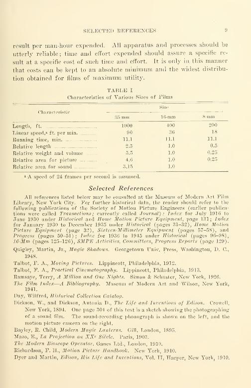
The comparative table (Table I) indicates the relative sizes, weights,
and like characteristics of 35-mm, 16-mm, and 8-mm.
16-mm was originally intended to be simple and low in cost. It is
not reasonable to expect 16-mm apparatus and methods merely to be
scaled-down, 35-mm apparatus and methods. Simplicity, reliability,
operating convenience, small size, and economy are still essential require-
ments—without these, 16-mm film fails its real purpose.
For educational and similar low-cost films, the need for simplicity
dictates the elimination of all time-consuming practices (whether in
production, processing, or utilization) that do not deliver the maximum
SKLK(TKI) [{KFKRKNCKS
result per man-hour expended. All apparatus and processes should be
utterly reliable; time and effort expended should assure a specific re-
sult at a specific cost of such time and effort. It is only in this manner
that costs can be kept to an absolute minimum and the widest distribu-
tion obtained for films of maximum utility.
TABLE I
Characteristics of Various Sizes of Films
Size
Characteristic35-mm 16-mm 8-mm
Length, ft 1000 400 200
Linear speed/ ft. per min. 90 36 18
Running time, min 11.1 11.1 11-1
Relative length 2.5 1.0 0.5
Relative weight and volume 5.5 1.0 0.25
Relative area for picture 4.6 1.0 0.25
Relative area for sound 3.15 1.0
a A speed of 24 frames per second is assumed.
Selected References
All references listed below may be consulted at the Museum of Modern Art FilmLibrary, New York City. For further historical data, the reader should refer to the
following publications of the Society of Motion Picture Engineers (earlier publica-
tions were called Transactions ; currently called Journal) : Index for July 1916 to
June 1930 under Historical and Home Motion Picture Equipment, page 131; Indexfor January 1930 to December 1935 under Historical (pages 31-32), Home MotionPicture Equipment (page 32), Sixteen-Millimeter Equipment (pages 57-58), andProgress (pages 50-51) ; Index for 1936 to 1945 under Historical (pages 96-98),16-Mm (pages 125-126), SMPE Activities, Committees, Progress Reports (page 129).
Quigley, Martin, Jr., Magic Shadows. Georgetown Univ. Press, Washington, D. C,
1948.
Talbot, F. A., Moving Pictures. Lippincott, Philadelphia, 1912.
Talbot, F. A., Practical Cinematography. Lippincott, Philadelphia, 1913.
Ramsaye, Terry, A Million and One Nights. Simon & Schuster, New York, 1926.
The Film Index—A Bibliography. Museum of Modern Art and Wilson, New York,1941.
Day, Wilfred, Historical Collection Catalog.
Dickson, W., and Dickson, Antonia D., The Life and Inventions of Edison. Crowell,
New York, 1894. One page 304 of this text is a sketch showing the photographing
of a sound film. The sound-recording phonograph is shown on the left, and the
motion picture camera on the right.
Bayley, R. Child, Modern Magic Lanterns. Gill, London, 1895.
Mazo, E., La Projection au XX* Siecle. Paris, 1903.
The Modern Bioscope Operator. Ganes Ltd., London, 1910.
Richardson, F. H., Motion Picture Handboolc. New York, 1910.
Dyer and Martin, Edison, His Life and Inventions, Vol. II, Harper, New York31910.

10 I. 16-MM FILM AXD ITS RELATION' TO OTHER SIZES
Niewenglowski, G. H., TraiU Pratique des Projections Limineuses Speciales. Paris,
1912.
Manuel Pratique les Projections Anim-ees. Edition du Courrier Cinematographique,
Paris, 1913.
Horstman and Tousley, Motion Picture Operator. Drake, Chicago, 1914.
Sloane, T. O'Connor, Motion Picture Projection, New York, 1922.
Sinclair, Upton, Upton Sinclair Presents William Fox. Los Angeles, 1933.
Victor, Alexander, "The History and Origin of 16-Mm. " Am. Cinematographer,
26, No. 11, p. 376, 384, 396, November 1945.
Dickson, R. W., "The Development of 16-Mm Sub-Standard Film," British Film
Yearbook, 1947-1948, 193-197, 197-200.
Krows, A., Motion Pictures—Not for Theaters, a Series. Educational Screen, Chicago,
cir. 1939.
The Central Information Bureau for Educational Films Ltd., A National Encyclopedia
of Educational Films and 16-Mm Apparatus Available in Great Britain. London,
.1935, 1937.

CHAPTER II
Making a 16-Mm Picture
Subject Matter
Before procedure and equipment for making a 16-mm picture can be
considered, there must be subject matter to be portrayed. This subject
matter is usually prepared in the form of script that not only describes
in detail that which is to be portrayed, but also breaks down the material
into the specific settings, actors, properties (" props"), action, and
sound required for each scene. The script is customarily prepared so
that the scenes will have the sequence planned for the edited picture.
jScript. It is beyond the scope of this book to discuss the script, the
actors, the settings, and other elements related to the subject matter to be
portrayed. It must be stated at this point, however, that the script should
be written with such care and in such detail that the activities of all
persons connected with the production of the picture are clearly and
completely specified or implied. In the absence of such clear and
detailed information, the picture when finished cannot help but reveal
any inherent uncertainty of the script. The script is the specification
for the picture. A good picture can be made from a good script ; a good
picture cannot be made from a poor script.
Taking the Picture
Let us assume that a simple sound film is to be made ; this requires
both camera equipment and sound equipment. If the film is to portray
the operation of a certain piece of machinery, for example, it is necessary
to have the machinery available, lighting equipment to illuminate it,
camera equipment to photograph it, and sound equipment to record
whatever accompanying sound is required.
Lighting. The amount and kind of lighting equipment required de-
pends primarily upon the size of the area to be photographed—the
greater the area the larger the equipment. Many 16-mm subjects are
fairly small—no larger than the shoulders of an individual.* For such
* Souther, H. T., "The Theory and Practice of Lighting for the Camera,"JSMPE, 46, 254. (Apr. 1946).
11

12 II. MAKING A 16-MM PICTURE
small areas, three reflectors equipped with Photoflood lamps are usually
sufficient. Generally.speaking, the average subject requires front light-
ing, cross lighting, and high lighting. A #4 Photoflood is often used
in the reflector for front lighting and a #2 Photoflood in each of the
other reflectors. Should the subject be darker than average (a black
velvet cloth, for example) more light is required; if the subject is
lighter than average (a white sheet), less light is necessary. The amountof light available is measured with an exposure meter. From the calcu-
lator on the exposure meter is determined the / stop or lens aperture
setting required on the camera for the film used.
If required by the script, the picture may be photographed under
natural daylight ; in such a case the Photofloods and their reflectors are
not required. Photographing in daylight often presents production
problems not encountered within the studio ; clouds cannot be controlled
nor can rain be stopped with the same ease involved in turning on the
switch energizing the Photoflood bulbs for artificial lighting.
The Camera. The motion picture camera photographs the scene. It
has a lens through which light is focused on the film to record the image.
Two settings must be made on the camera lens; one, for the distance
of the camera from the subject, called the focus setting; the other, for
the amount of light admitted to expose the film, called the aperture, /
stop, or opening setting.
Lenses are made in different focal lengths; for the same image size
on the film, a shorter focal length means a shorter camera-to subject
distance, while a longer focal length means a longer camera-to-subject
distance. Lenses are commonly available in focal lengths of approxi-
mately 15-mm (3/5 in.), 1-in., 2-in., 3-in., and 4-in. sizes. As the camera-
to-subject distance is often determined by some characteristic of the
space in which the picture is taken (e.g., a wall may be near the machine
to be photographed) lenses of different focal lengths are ordinarily re-
quired in the making of a given picture.
The perspective of the photographed picture is altered when lenses
of different focal lengths are used on the camera. For a viewer located
approximately in the center of an audience watching a 16-mm film, per-
spective is approximately correct when a camera lens of 1-in. focal
length has been used. For this reason the 1-in. lens should be used
whenever it gives a satisfactory picture; lenses of other focal lengths
should be used only if the image with a 1-in. lens is either too large or
too small.

TAKING THE PICTURE 13
The Camera Motor. The camera is usually driven by a -
alternatimr-current motor that drives the camera with little on »g
cant speed variation.
Speed variation of the camera would result in an inaccurately exposed film where
the image density or blackness would not be uniform from one frame of the film to an-
other.
Tin Camera Tripod. To avoid a "jiggling" picture, the camera must
be mounted od a camera tripod. This is merely a very steady three-
legged stand on which the camera r sts Since the magnification of the
picture increases with an increase in the focal length of the camera ob-
jective lens used, the tripod should be increasingly steadier when lenses
of longer focal length are used if the same amount of "picture jiggle" is
to be tolerated. When lenses of 4 inches and longer focal length are used,
the tripod should be very rigid and steady. A gyro-head tripod makes
smooth lateral movement (called "panning") and smooth tilting|
ss
ble : this type of tripod is very widely used for newsreel and similar pic-
tures. For studio-made pictures a simpler friction-head type is usually
used because the gyro head is too noisy indoors when sound is being re-
corded. The noise is produced by the gyroscope gear train during
panning and tilting.
Film for the Picture. The film to be used in the camera is made in
rolls of standard lengths of 50. 100. 200, and 400 ft. The film is placed
in a light-tight compartment known as a magazine. When the camera
is running, the film leaves the feed spool of the magazine, goes thr
the camera, and returns to the magazine on the take-up spool. A single
magazine usually has the feed and take-up compartments within a sin-
gle housing.
The film for the 16-mm motion-picture camera is customarily either
black-and-white reversal or color reversal. After a reversal film is ex-
posed in the camera, it is usually developed in a laboratory owne
provided by the film manufacturer. The sale price of the reversal film
customarily includes the cost of developing. When developed, a rever-
sal film has the highlights and shadows in proper relationship for the
scene photographed, and not interchanged as they are in the negative of
film used for a still camera.
Recording the Sound
Simultaneity. Sound may be recorded either at the same time that
the picture is taken or at some other time. With the exception of Holly-
14 II. MAKING A 16-MM PICTURE
wood entertainment pictures and the like, most 16-mm pictures have the
sound track made at some different time.
Single vs. Double System. When sound is recorded at the same time
that the picture is taken, it may be recorded on the same strip of film
that holds the picture (single sj^stem recording), or synchronously on a
separate strip of film (double system recording). Because picture film
is not usually suitable for sound recording purposes, almost all 16-mmsound films are made with double system recording.
Sound-Production Crew. Sound recording requires a separate group
of operators (a sound crew), consisting in the simplest case of one addi-
tional man. It is impracticable to have one man attend to both camera
and sound recorder, since he could not concentrate properly upon either.
When time is an important production factor, the camera crew and the
sound crew will each consist of at least two men.
The director is the manager of the entire production crew. It is his
responsibility to turn out the product (the picture) according to the
specification (the script).
Sound-Recording Equipment
The Microphone. The sound-recording equipment starts with a
microphone that picks up the sound and converts it into minute elec-
trical currents. A microphone may be a nondirectional condenser or
dynamic microphone and pick up sound substantially uniformly from all
directions ; these types are usually the lightest and smallest. A microphone
may be a bidirectional ribbon microphone and pick up sound from front
and rear but not from the sides ; this type is quite large and heavy but
has excellent fidelity. A microphone may be a unidirectional cardioid-
type microphone and may pick up sound from a wide angle in front
but not from the sides or rear; this type is intermediate in size and
weight. The unidirectional microphone is rapidly displacing other types
because it can discriminate to some extent against noises that originate
from directions other than that of the sound to be recorded.
Directional microphones have three great advantages: (1) they can
reduce to some extent the noise made by a running camera, (2)
they can reduce the effect of reverberation (echo and blurring) caused
by the reflection of the sound from walls, floor, ceiling, and other hard
surfaces, and (3) they pick up sound at somewhat greater distances.
The Microphone Boom. The microphone must be so immersed within
the sound field that it will pick up sound of the proper quality and

EECORDING THE SOUND 15
volume. This is usually accomplished by hanging the microphone at
the end of a fishpole-like arrangement known as the microphone boom.
The weight of the microphone determines the weight and size of the
boom. The lightest microphones weigh a pound or less and the
heaviest about 8 pounds. A boom for a heavy microphone, being long,
is really quite a massive affair ; the larger booms usually have cranks for
twisting the microphone on a swivel, cranks for turning the boom, and
cranks for shifting the microphone along the boom. Recording sound
is definitely more than a one-man job when a large boom is required to
follow the voices of actors moving around a set.
The Amplifier. A cable from the microphone runs to the amplifier
where the minute currents from the microphone are amplified and other-
wise altered to actuate the sound-recording machine. A pair of head-
phones or a monitor loudspeaker is provided so that the recordist mayhear the sound that he is recording; there is also a visual meter called
a volume indicator. Some form of power supply is needed to energize
the recording amplifier; this may be a set of batteries, or, more likely,
an arrangement to adapt current from the power line to the amplifier.
The Sound-Recording Machine. Two sets of wires run from the
sound-recording machine. One, connected to the power line, supplies
power to the motor that runs the film through the machine ; the second,
connected to the amplifiers, supplies the currents that are translated
into photographic images by the light modulator of the sound-record-
ing machine. Sound may also be recorded on magnetic tape.
The Magazine. The sound-recording machine, like the camera, has a
two-compartment magazine in a single housing. When the sound re-
corder is running, the film leaves the feed spool of the magazine, goes
through the sound-recording machine, and winds onto the takeup spool
in the magazine. The film used is customarily in standard lengths of 400
ft. ; most magazines are designed for a roll of this size.
The Film. The film (raw stock) for the sound-recording machine is
quite different from that for the camera. In the case of a variable area
recorder a special film is used that has been designed and manufactured
especially for sound recording*. (Eastman Kodak 5372 is a film of this
* Prior to 1946, most 16-mm sound recording machines sold on the open market
were of Maurer manufacture; these were variable-area machines. The few 16-mmmachines made by BCA, although convertible for variable-density recording, have
been used almost entirely for variable-area recording. Western Electric Co., the major
manufacturer of variable-density machines, had only a half-dozen or so in use. Al-
though most modern machines are now designed to provide either variable area or
variable density at will, most 16-mm machines are still recording variable-area track.
16 II. MAKING A 16-MM PICTUEE
type.) Fortunately, these films are much cheaper than picture film andare admirably suited to their intended purposes. The price of soundfilm does not include the cOst of developing, but there are several inde-
pendent commercial film laboratories that will develop the sound track.
However, since something more than "just developing" is usually
wanted, it is necessary to be specific in telling the laboratory just whatis wanted and how they are to go about doing it.
The Exposure Lamp. To expose the film, light is needed; this is
supplied by an incandescent lamp mounted in the recording machine.
The exposure is adjusted by a rheostat that changes the lamp bright-
ness. An ammeter is customarily used in the lamp circuit to measure
the current ; the brightness of the lamp is measured in terms of the am-
meter reading.
The Light Modulator. Interposed between the exposure lamp and
the film is the light modulator. This alters the amount of light reach-
ing the film in strict accordance with the sound currents fed to it by the
amplifier.
Developing and Printing for Editing
Picture Developing and Picture Work Print
The reversal or color picture film is sent to the film manufacturer's
laboratory for developing. When ready, a frame-by-frame copy of the
original picture is made (called a work print). For identification pur-
poses, the original picture is often edge-numbered with sequential foot-
age numbers; these edge numbers are copied on the picture work print
along with the picture image.
Sound Track Developing and Sound Track Work Print
The sound track is sent to a commercial laboratory for developing
When ready, a copy called the sound work print is made. Again, for
identification purposes, the original sound track is often edge-num-
bered with sequential footage numbers ; these numbers are copied on the
sound work print along with the sound image.
Rough Assembly of Work Print
Temporarily, the original picture film and the original sound track
are set aside for safe-keeping. The picture work print is cut into
sections, rearranged into the sequence called for in the script, and spliced
DEVELOPING AND PRINTING FOR EDITING 17
together. The result is a rough-assembly edited picture work print.
Simultaneously, the sound work print is cut into sections, rearranged
into the same sequence, and spliced together. The result is a rough-
assembly edited sound track work print. The master guide throughout
all editing is the script.
Rough-Cut Work Print. At this point in the editing, each scene is
trimmed to approximately its desired length and content. Although
picture is on one strip of film and sound on another, both may be run
in synchronism on a special editing machine to judge the effect of the
combination. The result of this editing is a rough-cut ; there are now on
hand a rough-cut picture work print and a rough-cut sound track work
print.
Final-Cut Work Print. We are now ready for the finishing touches
of the final cut. The synchronism of the picture and the sound track
is checked and re-checked, and the film is viewed in the projection room
for approval for release. Last-minute alterations are made where needed,
and the film is approved.
Cutting the Originals
In the editing process just completed, many pieces of film remaining
in the final picture have been handled again and again. During this
handling, the film becomes scratched and marred as well as dirty. The
work prints were made to avoid all handling of the original until the exact
arrangement of the final film was determined.
The original picture with the original sound track and the edited
picture and sound work prints are turned over to a " negative cutter.'
' In
this work, order rather than chaos is the rule when the edited film is edge-
numbered and otherwise identified accurately. A negative cutter is
trained to handle the film only with gloves. He cuts apart the original
films, removes the portions to be deleted, and splices the remaining pieces
to match the work prints exactly. He then splices on suitable leaders and
their synchronization and printing marks, and the films are ready
for release printing. The negative cutter is the fine jeweler of film
handlers; his workmanship, neatness, and efficiency are the pride and joy
of the whole film craft. When he makes a splice, no trace of smear of
film cement appears to mar any part of any frame that he has handled
;
film that he has assembled is just as clean, bright, and new as it was whenit first came from the developing machine.
18 II. MAKING A 16-MM PICTURE
Release Printing
First and Subsequent Trial Composite Prints. The originals, nowcomplete, are sent to the laboratory for the making of release prints.
The laboratory makes a first trial composite of picture and sound as a
sample. The owner or producer studies it and reports to the laboratory
the printing corrections desired. The laboratory then makes a second
trial composite, incorporating the printing corrections specified. This
time things should be the way they are wanted, and the laboratory is
given the order for the production run if a small number of prints (say,
25 or less) is required.
Duplicates and Masters. If a large number of prints is required or
if the owner plans to preserve the original so that more copies may be
made at a later time, the laboratory is not given an order for release
prints at this time ; it is instructed to make up a duplicate of the picture
and to use a re-recording (an electrically-made copy) of the sound track
provided by the owner. These intermediate copies are used to make the
release prints. From the intermediate copies the laboratory is in-
structed to make a first trial composite release print. Once again the
owner or producer studies the print just made and reports his wishes
to the laboratory; in this case he compares the trial composite release
print just made from the duplicates and masters with the trial composite
print that he approved before the intermediate copies were made.
Quality of Release Prints. The quality of the picture and sound of
a release print made from duplicates and masters will be poorer than
that of the trial composite print made directly from the originals be-
cause of the losses added in the additional steps. If the difference is
small, the duplicating work has been good ; if the difference is large, the
duplicating work has been poor. A good set of originals deserves good
release prints, since the audience that the owner wishes to reach will never
see the originals. The laboratory can turn out good release prints if the
owner demands them, and will pay just a little more to get them.
The foregoing is a simplified description of the procedure and equip-
ment used to bring a 16-mm sound film into being. Each portion maybe modified or expanded to suit the needs of a particular situation. Howwell the job has been done shows up at the end of the process : the pro-
jection of the release print before an audience.
CHAPTER III
16-Mm Film and Its Characteristics
"Motion picture film* is a thin flexible ribbon of transparent material
having perforations along one or both edges and bearing a sensitized layer
or other coating capable of producing photographic images." This
definition confines motion picture film to a film in which the image-
bearing portion is on the surface ; the definition bars the use of the term
in connection with Ozaphane and similar films that utilize a light-sen-
sitive diazo dyestuff distributed uniformly throughout the film.
Although this chapter will deal almost entirely with silver-emulsion-
type films, the diazo dyestuff film type should be mentioned, since it holds
future promise for commercial use in certain conditions of application.
Diazo dyestuffs may be manufactured inexpensively; many show re-
solving power in excess of the best that has been obtained with silver-
emulsion films. With the dyestuff distributed uniformly throughout the
base, the films are not as seriously affected by surface scratching and
abrasions as are silver-emulsion films. Diazo films are photographically
slow; they require great exposure to provide the photographic image.
Since the image is developed in ammonia gas, there is no need for alter-
nate wetting and drying of the film ; better dimensional stability can be
obtained with the same base material. Copying with a single exposure
results in a photographic image of the same highlight-shadow aspect as
the material being copied; a positive copy image is produced from a
positive image in single development. Most diazo films have high con-
trast. Although early diazo films gave poor reproduction of highlights
and shadows, newer diazo films are being devised that show promise of
overcoming many of the early reproduction handicaps.
Silver-Emulsion Films
Although silver-emulsion films have been in use for more than 50
years, very little has been published on many important phases of film
* According to definition 1.1 of American Standard Nomenclature for Motion
Picture Film Used in Studios and Processing Laboratories—ASA Z22.56-1947, the
term "film" may be applied to unexposed film, to exposed but unprocessed film, and
to exposed and processed film.
1&
20 III. 16-MM FILM AND ITS CHARACTERISTICS
manufacture and use. Emulsion-making is one such phase; manufac-
turers have usually considered this to belong to the practice rather than
the theory of photography. With the technical voids in the literature
that this attitude produced, it is difficult for a new student to obtain a
balanced over-all view that can be expanded as needed for specific spe-
cialized applications. As in any other field of technology, motion pic-
tures require an understanding of the raw material (the film) in order to
understand properly the finished product.
There are two basic parts of a light-sensitive film: (i) the support
(called the base) ;and (£) the photosensitive material (called the emul-
sion). There are two kinds of base material in general use in motion
pictures, nitrate base (essentially cellulose nitrate), and safety base
(essentially cellulose "high-acetyl"). Nitrate film base is never used for
16-mm film since it is barred from interstate commerce in the United States.
Nitrate film is combustible and a fire hazard ; safety base is slow-burning
and is no more combustible than an equal volume of paper. 16-mm safety
base is 0.005 in. thick (in manufacture the thickness is quite uniform).
The emulsion is usually made in the form of two or more layers of
silver halides suspended in gelatin; it is coated on one side of the base.
The total thickness of the emulsion is about 0.001 in. ; emulsion thickness
is very uniform. The emulsion is bonded to the base by a solvent-cement
that usually contains cellulose nitrate ; the weight of nitrate, however, is
but a fraction of one per cent of the total weight of the film.
Film Manufacture
The manufacture of 16-mm film consists of the following main steps
:
(1) Base manufacture.
(2) Emulsion manufacture.
(3) Coating the base with the emulsion.
(4) Slitting and perforating.
Base Manufacture
A liquid mixture that is essentially cotton and acetic and other
acids together with solvents is fed continuously into a narrow hopper
several feet long. The long narrow orifice through which the liquid
emerges by gravity provides mixture flow at a very uniform rate to the
periphery of a slowly rotating drum (usually made of stainless steel) that
is several feet in diameter and several feet wide. As the drum rotates, the
solvents evaporate and a film of base material forms on the drum. After
FILM MANUFACTURE 21
rotation through a portion of a revolution, the film is peeled off in a con-
tinuous sheet. It is usually necessary to trim the edges of the sheet
as they are not of uniform thickness. The sheet is then rolled up into a
suitable length for coating. A typical length is 2000 ft. ; a typical width
might be 6 ft. After rolling, the base material is stored until needed for
coating.
The composition of base mixture is not fixed ; it differs in wide degree
from one manufacturer to another for presumably equivalent products.
It may differ in appreciable degree from one group of products of a par-
ticular manufacturer to another group of products of the same manufac-
turer. It differs also to a lesser yet important degree from one batch
of manufactured material to another made by the same manufacturer.
The exact mixture used for a particular batch of base material is deter-
mined by the performance that the film manufacturer desires and expects
to obtain. Users should expect to find measurable and important differ-
ences in physical characteristics (such as shrinkage, flexibility, toughness,
etc.) for example, between Eastman fine-grain positive, #5302, and
DuPont fine-grain positive, #605A. We should not be surprised to find
important differences in characteristics between two batches of a par-
ticular material; such differences are inherent in any manufacturing
process and product.
Users should look for good performance in a test sample of a product
and also make certain that the batch-to-batch uniformity is good, so that
good performance can be maintained in the finished product as a routine
operating matter.
Emulsion Manufacture*
Since gelatin holds the silver halides in suspension, the preparation
of the gelatin is very important in the process. Gelatin has several
chemical functions as well as physical ones ; some of these follow.
(1) It acts as a protective colloid to maintain the dispersion of the silver halides
and to protect them from reduction by a developer without exposure.
{2) In solution it enables a stable suspension of silver halide particles to be
formed.
(3) In the jelly state it supports mechanically the microscopic particles of silver
halide and silver and permits soluble materials to act upon them.
(4) It affects the sensitivity of the silver halide.
(5) It combines with, and thus removes, the halogen liberated by the action of
light.
The physical functions that are just as important are as follows.
* Mees, C. E. K., The Theory of the Photographic Process. Macmillan, NewYork, 1944.

22 III. 16-MM FILM AND ITS CHARACTERISTICS
(a) It acts to adhere to and cooperates mechanically with the base.
(b) It shows minimum mechanical distortion when swelled (as during developing)
and shrunk (as during drying and subsequent use). Not only must it suffer minimumdistortion itself during such swelling and shrinking, but it must also cause the halide
crystals and their corresponding silver nuclei to suffer minimum distortion and shift
in orientation.
Gelatin is usually made from selected clippings of calf hide and ears,
and cheek pieces and pates. For photographic purposes, all pieces must
be free of bacterial infection. Two common processes are used in refining
gelatin ; they are known as the lime-acid process and the soda process.
Both processes require soaking of the pieces for an extended period
(several months) ; as the character of the gelatin has a marked effect upon
the sensitometric characteristics of a finished emulsion, the particular
process used to refine the gelatin depends upon the effects desired in the
emulsion to be manufactured.
Emulsion Preparation Stages. There are three important stages in the
preparation of an emulsion
:
(a) Emulsification and the initial ripening;
(b) Removal of excess soluble salts;
(c) After-ripening and the sensitizing.
(a) Emulsification and Initial Ripening. Emulsions are usually
prepared by mixing solutions of 10% or more of soluble halides with
silver nitrate solution. (Silver bromide is one of the common halides
in most emulsions whether of the negative or of the positive type ; most
negative types also contain some silver iodide.) To prepare the emulsion,
a small amount of relatively inactive gelatin is swelled in cold water and
then heated to form a melted gelatin solution ; this gelatin is only a small
percentage of the total required for the finished emulsion.
The alkali halides are then added ; an excess of potassium bromide is
always used. Silver nitrate solution is then added while the gelatin solu-
tion is continuously stirred ; it is necessary that there be an excess of bro-
mide even locally where the nitrate enters the gelatin solution. The
halide precipitates formed are always microcrystalline; the crystals when
first formed are so fine that when viewed by transmitted light, the solution
appears deep red. When more nitrate is added, some of the precipitate
forms around the fine crystals already present—increasing their size
—
while the remainder of the precipitate forms small new crystals.
Upon completion of the addition of the nitrate solution, there is still
an excess of bromide; under this condition the emulsion is ripened by
FILM MANUFACTURE 23
heating. In the ripening process, the larger crystals become still larger
and the smaller crystals smaller ; this is called initial ripening, digestion,
or Ostwald ripening of an emulsion. During heating, the gelatin part-
ially decomposes causing minute silver sulfide specks to form on the halide
crystals. Although these silver sulfide specks (called sensitivity specks)
play a very important part in the formation of the latent image, the exact
nature of the very complex physicochemistry involved is just beginning
to be understood.
In general, coarse-grained, higher speed emulsions result from the
slow addition of the nitrate to the potassium bromide solution in addition
to ripening for a relatively long time at a relatively high temperature.
Finer grained, lower speed emulsions (such as process emulsions) result
from more rapid addition of the nitrate together with ripening at lower
temperatures. It is interesting to note that at this early stage of man-
ufacture, the grain distribution of the finished emulsion is established and
continues substantially unchanged throughout the remainder of the
manufacturing process, and to a degree, during subsequent developing
after exposure. After the initial ripening, gelatin of the chemically
active type is added to bring the gelatin content of the heated mixture to
approximately 10%. This step is very important since the subsequent
sensitometric effects to be obtained depend upon the properties of the
gelatins so added. After this gelatin is thoroughly dissolved, the emulsion
is set in a cool place. In a few hours it sets to a stiff, jelly-like mass. At
this point, the emulsion has low contrast and low sensitivity.
(b) Removal of Excess Soluble Salts. The emulsion at this point still
contains the soluble potassium nitrate that was formed with the silver
halide and an excess of potassium bromide. It is washed to remove these
soluble salts; if this were not done, they would crystallize out during
drying when the emulsion was being coated on the base. The presence of
these salts would also interfere with proper second ripening. Water is or-
dinarily used ; washing is controlled by the rate of flow and by the tem-
perature of the wash water used. In order to make washing easier, some
emulsions are shredded into "noodles" by forcing the gelatinous mass
through a wire screen or perforated die or plate. During the washing
process, the halide crystals, being insoluble in water, are held mechanically
in position by the gel structure and remain unaffected.
(c) After-Ripening and Sensitizing. After washing is completed,
the emulsion is drained and then melted for the after-ripening; the
remainder of the gelatin required for the finished emulsion is added at

24 III. 16-MM FILM AND ITS CHARACTERISTICS
this point. The second ripening results in a very considerable increase
in sensitivity without a serious increase in grain size ; this is especially
true of negative-type emulsions. As in the case of the first ripening, the
increase in sensitivity is due in appreciable measure to the sulfides pro-
duced as a result of the partial decomposition of the gelatin. The tem-
perature and time of heating depend upon the gelatin used and the effect
desired.
Over-ripening results in a serious increase in fog; under-ripening
results in a slow continuation of the ripening process during subsequent
storage, which continues even after the emulsion is coated on the base.
Proper ripening is indicated by maximum sensitivity and minimum fog
;
over-ripening results in an unstable emulsion that fogs rapidly in storage,
under-ripening results in an unstable emulsion whose sensitivity in-
creases during storage. As has been mentioned previously, after-ripen-
ing is extremely important for high-speed negative types of emulsions ; it
is of far less importance with positive emulsions—especially those of the
process type.
At the conclusion of the second ripening stage, the emulsion is chilled
and stored until needed. Such an emulsion may serve as the basis for
several products depending upon the nature of the sensitizing dyes and
other ingredients that are added just prior to coating. Up to this point,
variations in the individual steps of the process determine the essential
character of the emulsion as to speed, contrast, graininess, and latitude.
Coating the Base with the Emulsion
Just prior to coating, the emulsion is treated for color sensitivity,
keeping quality, fog, and—to a degree—speed, by the addition of very
small quantities of other substances, including sensitizers. The ma-
terials used and the manner of application and treatment are closely
guarded secrets of the film manufacturers ; very little has been published
on the subject. The natural color sensitivity of silver halide emulsions
centers in the region 350 to 450 millimicrons; positive-type emulsions
such as fine-grain printing positive and raw film for sound negatives for
variable-area recording are of this type that we may call blue sensitive.
The addition of small quantities of absorbing dyes (as small as 1 part
in 100,000 parts of water or dilute alcohol solution equivalent) will cause
an emulsion to show color sensitivity for other colors in addition to blue.
Even though the dye used must actually stain the silver halide crystals
in order to be effective, yet, of dyes that stain, only a comparatively few

FILM MANUFACTURE 25
are sensitizers. Some sensitizers are extremely unstable to light, others
quite stable. The exact nature of the sensitizing action is still obscure.
although numerous theories have been evolved to explain many of its
aspects.
Positive-type emulsions intended for duplicating purposes usually
have a relatively large quantity of yellow dye mixed into the emulsion
;
the effect of this dye is more physical than chemical since it tends to pre-
vent or reduce intercrystal reflection and diffusion and the reflection of
light to the emulsion from the base after the light has passed through the
emulsion during exposure. The use of the yellow dye materially in-
creases the resolving power of an emulsion at the expense of sensitivity
;
more incident light is needed to produce the same density. Yellow-dyed
and similar emulsions have been used satisfactorily for sound negatives
for 16-mm where high resolving power is needed for good sound records.
A finished liquid negative emulsion contains about 6% gelatin (dry
weight) and 4% silver halides. This mixture is coated upon one side
of the base after an extremely thin under coat or "subbing" coat has
been applied to the base to cause the emulsion to adhere to the base. The
emulsion is warm when applied and is chilled as it passes over a chilled
roll after coating on the base. The emulsion is then dried. A typical
coating in liquid form might be 1/100 in. in depth ; this dries to something
like one-tenth its application depth. Modern emulsion coating techniques
usually include multiple coatings for even black-and-white films; multiple
coatings are absolutely essential in integral tripack color films such as
Kodachrome and AnscoColor. The total emulsion thickness for all layers
of color film is but little more than that of the simplest black-and-white
films.
Slitting and Perforating
Film is usually slit and perforated just prior to shipment. It is slit
into appropriate widths (in this case 16-mm in width) and perforated.
Both the slitting and perforating operations must be performed very
carefully ; film manufacturers are meticulous about maintaining the me-
chanical tolerances of the finished film. The film is cut to typical lengths
of 50, 100, 200, 400, 800, 1000. 1200, 1600, and 2000 ft. Upon cutting, the
film is mounted upon cores or spools (as required) and packed and pre-
pared for shipment.
50, 100, 200, and 400-ft. lengths are in common use in 16-mm cameras.
400-ft lengths are usually used in sound recording machines, although
some amateur-type and special equipment may use 100 and 200-ft. lengths.

26 III. 16-MM FILM AND ITS CHARACTERISTICS
Television cameras and recording machines, especially those for recording
from video monitor tubes, often use film in 1200 foot rolls. 400, 800,
1000, and. 1200 ft. are common lengths in use in film laboratories where
copies of films are made ; 1600 and 2000 ft. are lengths that are used in-
freqently even in film laboratories.
Although extreme care is used in manufacture and in supervision and
inspection during manufacture, it must be realized that the quality of
perforating and slitting varies from manufacturer to manufacturer and,
for a particular manufacturer, varies from time to time. The tools and
dies used are subject to wear; the quality delivered depends to a great
degree not only on how well the tools were designed and made but also
on how wTell they are maintained. To make it possible to check mechani-
cal variations, manufacturers of film maintain accurate manufacturing
logs and also mark each can of film shipped with sufficient identifying
code numbers to aid in tracking down any possible deviation from stand-
ard deviation in manufacture.
General Comment on Emulsions
The control of emulsion quality exercised by film manufacturers is
of a high order; it is quite rare that defective or inferior emulsions of
regularly manufactured products such as Kodachrome, reversal film,
duplicating negative, duplicating positive, and release fine-grain positive
raw film get into circulation. This does not mean that all lots of a par-
ticular type of emulsion are alike ; emulsions vary from lot to lot to an
even greater extent than does film base. The sensitometric character-
istics of a particular lot depends not only upon its characteristics at the
time of manufacture and test by the manufacturer, but also upon the
changes in characteristics as a result of storage during the interval be-
tween manufacture and use. Temperature is a very important storage
condition; generally speaking, a constant temperature of approximately
50° F. is most suitable for most films. As a result of improved manu-
facturing processes, the storage characteristics of films have been im-
proved greatly in the last few years. Not only has there been consider-
able improvement in the base, but also in the length of time that a film
may be stored before use (as measured by a predetermined permissable
change in sensitometric characteristics, such as fog, etc.) has been in-
creased to the point at which manufacturers can safely guarantee their
products for a period of at least one year even on high-speed, negative-
type films.

FILM MANUFACTURE 27
In buying film it is well to ascertain that the film purchased is fresh, a
particularly important consideration in the case of high-speed emulsions
and in color film. Good commercial practice dictates that film shall not
be used when it is old. In the case of low-speed materials such as yellow-
dyed duplicating positive, this is not so important if the film has been
stored properly.
In general, it is necessary to make test exposures and to gather other
sensitometric data to ascertain the operating characteristics of film ma-
terials that are to be used for commercial purposes. If this procedure
is followed regularly, old material is readily detected. Should it
be used subsequently, its limitations are known beforehand and its un-
usual characteristics taken into account. If the probable quality is at
all doubtful, special care should be taken in the preparation and inter-
pretation of such test data.
Although 16-mm raw film is a complex product, it is an excellent
product under good control as it is now manufactured. The control
exercised in its use, however, is rarely of an order that compares with
that of manufacturing control. Both exposure and processing are in
need of close watching ; it is indeed rare that the results obtained in re-
lease prints even begin to approach the capabilities of the raw film.
Roll-to-roll variations in the characteristics of raw film of the same emul-
sion lot are quite small; special pains are taken by film manufacturers
in storing film materials and manufactured raw film to assure that the
variation from roll to roll will be a minimum. Such storage involves
keeping temperature and humidity constant; the variations permitted
are minute when compared to the variations found in places where the
film is subsequently handled.
When storage conditions in the interval between manufacture and
use are uniform (as is the case in film manufacturers' plants) it is
reasonable to expect but a small roll-to-roll variation in the same emul-
sion lot even when the storage period has been as long as several months
;
the conditions, however, must also have been optimum. Obviously, the
variation increases as the storage period becomes longer.
It is definitely unreasonable to expect two rolls of film of the same
emulsion lot to show similar characteristics if one has been stored for a
long period near a heated radiator or steam pipe and the other under
more normal conditions. In any case, the temperature of a storage place
for raw film should not exceed 70° F. The importance of reasonable
care in the storage of film can hardly be overemphasized.

28 III. 16-MM FILM AND ITS CHARACTERISTICS
Physical Characteristics
Shrinkage
The continued evaporation of solvents and of moisture tends to shrink
processed and raw film with storage time. This evaporation is acceler-
ated by heat and low humidity; the heat from a projection lamp is a
typical source of accelerated drying. Usually, film will reabsorb mois-
ture if it is rehumidified, but cannot reabsorb the solvents that have
evaporated, leaving a brittle product. When film absorbs moisture, it
swells and becomes enlarged ; as it dries, it shrinks. Shrinkage is usually
expressed as the percentage difference between the measured length of
a 100-sprocket hole interval and its nominal length of 30.00 in. (The nomi-
nal distance between two adjacent sprocket holes is 0.300 in.)
With such films as sound-recording positive (Eastman Kodak 5372) an
ultimate shrinkage of 0.5% is the maximum to be expected. Somewhat
less than this shrinkage should be found if the film is stored in an air-
conditioned laboratory where such negatives are printed. Raw film
(when it is removed from the can) should not exceed 0.20 r
/ ; more com-
mon values lie between 0.05 and 0.15 r/< • If 16-mm raw film used for
sound recording should exceed 0.20% , it should be looked upon with sus-
picion. With some release fine-grain positive films (DuPont 605A) a
shrinkage of 0.9% is the maximum to be expected. Somewhat less than
this (approximately 0.6% ) should be the maximum in one-year-old films
in film libraries and similar services.
Within the next few years—as soon as manufacturing conditions per-
mit—all 16-mm base material will be of low-shrinkage types. This is but
one example of the upward trend of raw film quality that has been going
on without fanfare for almost a decade.
The shrinkage of reversal film and of color film will also lie in the same
range. Most investigations of shrinkage have shown that the emulsion of
a film as manufactured is quite elastic ; the measured shrinkage appears
to be controlled almost entirely by the characteristics of the base. For a
number of years it was tacitly assumed that the physical characteristics
of safety base would be inherently inferior to those of nitrate base, espec-
ially with regard to toughness, flexibility, and shrinkage. Very impor-
tant improvements have been made within the last few years; continued
improvement seems highly probable because of the tremendous increase in
demand for safety base for 16-mm film. The improvement in perform-
ance has now reached the point where the American film manufacturers

SENSITOMETRIC CHARACTERISTICS 29
plan to discontinue the manufacture of nitrate base film for use in 35-mm,
and to substitute the new safety bases. This step will do much to remove
the fire hazard always present where nitrate base films arc used.
Emulsion Hardness
Emulsions are hardened during manufacture by a process similar to
the process for tanning leather; this treatment reduces the tendency of
the emulsion to soften and stick at high temperatures and humidities.
Release print fine-grain films are especially hardened during manufacture
to provide maximum service in use. Hardening agents may be intro-
duced at quite a number of points in the film manufacture and use cycle
;
hardening is often introduced at more than one point. Some of the
points where hardeners may be introduced are
:
(1) Prior to coating of the emulsion upon the base.
{2) Before development or during development.
(3) Between development and fixation.
(4) In the fixing bath.
(5) After fixation.
Hardening is especially important if film is to be processed at ele-
vated temperatures (above 70° F.) or if the film is run in a camera,
printer, sound recorder, projector, or other machine at high tempera-
tures and humidities.
Sensitometric Characteristics
To evaluate the properties of photographic materials requires numeri-
cal measurement; the analysis by means of suitable measurements is
known as sensitometry. For convenience in analysis, the relation be-
tween the blackness of the developed silver image and the illumination
used to provide the exposure is measured by means of the relationship
of the common logarithm of the opacity of the image to the commonlogarithm of the exposure. These functions are defined as follows
:
1Density = log10 Opacity = log 10
Transmittance
Transmittancewhere
:
Transmitted flux
Incident flux
Because of the variations in the amount of light diffusion that occur
in practice, measurement of the transmitted flux and of the incident flux
is not a simple matter. The incident flux may be diffuse, semi-diffuse,
30 III. 16-MM FILM AND ITS CHARACTERISTICS
or it may be a parallel beam incident upon the film at an angle. Some of
the incident flux is absorbed, some reflected—the remainder transmitted.
In the case of a film, the transmitted flux must be "collected" in some
manner as it is scattered by the film emulsion which is microcrystalline
in structure. If numerical measurements are to have meaning, measure-
ment variables must be reduced to a minimum; this is accomplished by
the "American Standard Method of Determining Transmission Den-
sity of Motion Picture Films" ASA Z22.27-1947. American Standard
diffuse density designates densities determined under the practical geo-
metric conditions provided by any one of three standard means and
methods. These conditions approach the ideal conditions for totally
diffuse density given in Section 3.1.1 of the Standard as closely as prac-
tical equipment and methods permit. As the subject is extensive and
involved, reference should be made directly to the American Standard
for details.
Practical densitometers other than the specified standard types must
be calibrated. As most commercial densitometers are not standard types,
calibration consists in the measurement of density samples with a stand-
ard densitometer and comparison of the results with the practical den-
sitometer under test. If the conditions under which the practical den-
sitometer are used are consistent, measurements are ordinarily reliable.
Practical densitometers are designed to measure density values directly
on a density scale of the instrument ; they are also designed for conveni-
ence in operation. The type of practical densitometer used depends
upon the accuracy with which the results are to be determined. For
ordinary measurements in the range of 0.1-3.0, the Eastman 2A den-
sitometer, a direct-reading optical wedge type instrument manufactured
by Eastman Kodak, is satisfactory and low in price (approximately
$100.00). For the measurement of fog (the density of unexposed but
developed and fixed-out film) where the values are less than 0.1, a more
accurate densitometer is required, particularly in measurements of fine-
grain positive film developed in good developers. Common fog values
for fine-grain positive are in the order of 0.01. For measurements in
this range, the Martens polarizing-head densitometer (obtainable through
Ansco) and the Western Electric RA-1100 photoelectric densitometer
(obtainable from the ERP Division of Western Electric) are suitable
and reliable instruments. The Eastman 2A densitometer is quite
rugged; the Martens and the Western Electric instruments require care
in handling similar to that required by a good compound microscope.
SENSITOMETRIC CHARACTERISTICS 31
Exposure is measured in terms of the meter-candle-second (that ex-
posure produced by a standard candle for a period of one second at a
distance of one meter). Standardized exposures for routine test pur-
poses are usually obtained from test sensitometers such as the Eastman
lib. Photometrically calibrated lamps are provided with this instrument
for standardizing purposes. Other standardized exposures may be pro-
vided in operating equipment such as cameras, sound recorders, printers,
etc. ; these are often working standards that are referred to the lib ex-
posure as a reference. The Eastman lib, although a time-scale device
that is obsolete and no longer manufactured, is used; no other instru-
ment has such wide use and acceptance despite the real need for other
sensitometers.
When film characteristics are graphically plotted, the result is an
H&D curve—so called because it was first described by Hurter and Drif-
feld. An H&D curve (Fig. 1) is similar to a single sweep of a hysteresis
loop (B-H magnetization curve) or of a stress-strain curve. It shows
the relationship between density plotted as the ordinate, and log ex-
posure, as the abscissa. The slope or gradient of the curve—called the
gamma—indicates the relationship between the change in density and
the change in log exposure. This may be more simply defined as
:
~ A DensitvGamma = -x~=
=A logio Exposure
The value given for gamma is the value at the center of the straight-line
portion of the H&D curve.
When used in connection with development, "gamma" refers only
to development contrast. Development contrast is not related to subject
contrast since it is dependent upon the character of the photosensitive
material, upon an arbitrary series of exposures, and upon the develop-
ment. As the numerical value of the gamma obtained depends upon the
conditions under which it is measured, comparisons among similar ma-
terials may be made in terms of the gamma measured with a lib sensitom-
eter. In this case, the color temperature of the light source is 3000 K.,
the exposure is changed from one step to another by changing the ex-
posure time and maintaining the light intensity constant. There are 21
exposure steps; the maximum exposure time is 4.16 second, the minimumexposure time is 0.00406 second, and the midstep exposure time is 0.130
second. Each step is related to the next adjacent in the ratio of \/2
:
1.
The gamma determined with this sensitometer is usually referred to as
the lib gamma.Within a limited range, gamma can be varied by changing developing

32 III. 16-MM FILM AND ITS CHAEACTERISTICS
32
2 e
24
2.0
16
I 2
0.8
0.4
Curve plotted from data
of fable below
~d2
b v^*^
~d|
E 2
a>
E,
en vf> CM t CD CM <T on CD CVJ CO IP 00CM m 01 CD ro h- on f«- m n
CVJ o n O ro r- XT) o CM m tnCM ^r a> CD m _~ cm r-
ro cr>CVJ
CMlO o q
<T>
RELATIVE EXPOSURE
3.5 20 .0 10 2
LOG ACTUAL EXPOSURE, m c s
Test Data for Fast Negative Film Developed 7 Minutes in a Tray at 65 Fin a Negative Developer Bath
CD
3 Cfi w 13 mcv o o V O V
a s £a _ =
o eS « 0J a -
© <v 0> Sg 6 CD<u Si >>
CV2
3 O
<3 o>
U 3
a
a
55
2*tcH.
'35
c
s
1 0.003802 1 3.580 0.12 13 15.56 4,096 1.192 2.71
2 0.007603 o 3.881 0.16 14 31.12 8,192 1.493 2.81
3 0.01521 4 2.182 0.29 15 62.23 16,384 1.794 2.88
4 0.03041 8 2.483 0.50 16 124.5 32,768 2.095 2.95
5 0.06081 16 2.784 0.78 17 248.9 65,536 2.396 3.00
6 0.1216 32 1.085 1.08 18 497.7 131,072 2.697 3.03
7 0.2432 64 1.386 1.38 19 995.4 262,144 2.998 3.06
8 0.4864 128 1.687 1.68 20 1991. 524,288 3.299 3.08
9 0.9728 256 1.988 1.99 21 3981. 1,048,516 3.600 3.08
10 1.945 512 0.289 2.24 22 7962. 2,097,152 3.901 3.05
11 3.890 1024 0.590 2.41 23 15920. 4,194,304 4.202 3.00
12 7.780 2048 0.891 2.58
Fig. 1. Characteristic H & D curve for fast negative film shown in table
above. This curve, named after Hurter and Driffeld, is obtained by plotting
density as ordinate vs. multiples of exposure (logarithmic scale) as abscissa.
(Exposure is measured in meter candle seconds.)
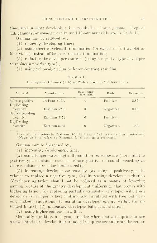
SKXSITOMETKIC CHARACTERISTIC - 33
time used; a short developing time results in a lower gamma. Typical
lib gammas for gome generally used 16-mm materials are in Table II.
Gamma may be reduced by:
(1) reducing developing time;
(2) using short-wavelength illumination for exposure (ultraviolet or
blue-violet) instead of heteroehromatic illumination;
(«?) reducing the developer contrast (using a negative-type developer
to replace a positive type);
(4) using yellow-dyed film or lower contrast raw film.
TABLE II
Development Gammas (lib) of Widely Used 16-Mm Raw Films
Material Manufacturer ^Se^in8 Bath lib gamma
Release positive DuPont 605A 4 Positive* 2.85
Duplicating
negative Eastman 5203 3 Xegative ,J 0.45
Sound-recording
negative Eastman 5372 6 Positive*
Duplicating
positive Eastman 5365 9 Negative 1* 1.40
a Positive bath refers to Eastman D-16 bath (with 1/3 less water) as a reference.b Negative bath refers to Eastman D-7G bath as a reference.
Gamma may be increased by
:
(1) increasing development time;
(2) using longer wavelength illumination for exposure (not suited to
positive-type emulsions such as release positive or sound recording as
these emulsions are color blind to red);
(3) increasing developer contrast by (a) using a positive-type de-
veloper to replace a negative type, (b) increasing developer agitation
(developer agitation should not be reduced as a means of lowering
gamma because of the greater development uniformity that occurs with
higher agitation, (c) replacing partially exhausted developer with fresh
developer (developer is best continuously circulated with frequent peri-
odic makeup (additions) to maintain developer energy within the in-
tended limits), (d) increasing developer bath concentration;
(4) using higher contrast raw film.
Generally speaking, it is good practice when first attempting to use
a new material, to develop it at standard temperature and near the center
34 III. 16-MM FILM AND ITS CHARACTERISTICS
of its development time vs. density range. Should an increase or a de-
crease in gamma be indicated from the first tests, process readjustments
can be readily made. (Such readjustments might be a change in de-
veloping time or a change in the developer bath concentration or com-
position.) The values given in the foregoing table of lib gammas have
been found satisfactory in one commercial laboratory for the materials
specified when picture is step-contact printed throughout in providing
16-mm release prints from 16-mm reversal or Kodachrome originals
through the means of a black-and-white, fine-grain intermediate dupli-
cate negative.
It must be remembered that the brightness range of an average out-
door scene is quite beyond the maximum reproduction range of a 16-mmrelease print; the photographic process must compress this brightness
range and reduce the mid-range brightness quite materially. In the
various processing and duplicating steps between the original film and
the release print, the curvature of the toe (the lower exposure portion of
the H&D curve) and the curvature of the shoulder (the higher exposure
portion of the H&D curve) should be checked carefully to produce the
most pleasing tonal scale in the release print. "While the differences in
the shoulder characteristics of competitive black-and-white release print
materials are quite small, there are considerable differences among the
toe characteristics. Improvement in picture quality can often be made
by careful choice of release-print raw film most suitable with regard to
toe characteristic.
Grain, Grain Size, and Graininess
Silver halide crystals in an emulsion are always microcrystalline. Astudy of the grain characteristics of emulsions indicates that grain-size
distribution follows quite closely the usual probability distribution in the
case of fine-grain materials. Until the advent of the electron microscope,
it was impossible to photograph small-size emulsion grains ; in fine-grain
film the emulsion grains are so small that the usual optical microscope
will not resolve them. In the finest grained emulsion known, the Lipp-
man emulsion, the average grain diameter is approximately 30 milli-
microns; the smallest grains are of the order of 10 to 15 millimicrons,
and the largest 45 to 50 millimicrons. The grain size distribution is
very uniform and follows the normal probability distribution accurately.
In fast negative emulsions, the average grain diameter is much larger
—
of the order of 2 microns. In coarser grained emulsions, grain-size dis-
GRAIN, GRAIX SIZE, AND GRAIXIXESS 35
tribution is usually decidedly "skewed"* due to the clumping of grains;
in the Lippman-type emulsion, there is little or no skewing.
Routine comparison inspections of grain can be made with optical
microscopes; a convenient arrangement is photographing at 2500 diam-
eters and projecting with an enlargement of x 4. Although the grain
outlines are fuzzy because a magnification of 10,000 diameters is beyond
the resolving power limit of the optical microscope, the technique is still
useful, since grain areas can be measured and emulsions compared despite
the fuzzy outlines of the images produced.
The limit of the usual optical microscope is of the order of 0.13 micron
with light of 365 millimicrons wavelength (near ultraviolet) . The limit
of the electron microscope is of the order of 4 or 5 millimicrons. Grain
size and physical characteristics of emulsions were the subjects of much
conjecture until the electron microscope made the smaller grains clearly
visible. After photographic film is exposed and developed, the developed
grains are found to occupy approximately the same position as the unde-
veloped halide grains. Developed silver grains do not, as a rule, have
the same shape as the undeveloped halide grains from which they are
derived; they are particles composed of masses of twisted filaments of
metallic silver. The similarity of grain position and size between the
halide grain and the developed silver grain seems greatest for low-speed,
fine-grain emulsions (such as the Lippman) where the halide grains are
most uniform in size and in size distribution and do not clump.
Graininess in prints is influenced markedly by the graininess of the
original. The best duplicating films are fine-grained and photographi-
cally slow compared with the best negative materials (relatively coarse
grained and fast). Graininess is always aggravated by copying; the
increase in graininess is least when the finest grained duplicating ma-
terials are used; and most when coarsest grained materials are used.
Since the conditions under which an original is photographed are often
subject to control, the photographer should make certain that his original
has minimum practicable graininess.
Graininess of an original increases with
:
(1) Degree of development—which may be measured as development gamma; a
particular film will be more grainy when developed to a higher gamma than Avhen de-
veloped to a lower gamma.
* Skewed distribution (statistics). The state or quality of a frequency distribu-
tion (of grain sizes) of being distorted by lack of symmetry, e.g., being bunched
together on one side of the average and of tailing out on the other side.

36 III. 16-MM FILM AND ITS CHARACTERISTICS
(£) An increase in processing temperature above normal—graininess increases
very rapidly with even small increases in developer temperature.
Much research has been clone by Eastman Kodak and DuPont in recent
years to find new emulsions of physical and sensitometric characteristics
suited to high-speed (developing time less than 1 minute) and high tem-
perature (about 120° F.) processing. It is expected that the same gen-
eral considerations will hold among new materials that may be evolved
despite the fact that the new emulsions have to function under condi-
tions of greatly accelerated chemical activity.
When a process has a negative-positive step as is the case in making
black-and-white release prints from a release dupe negative printed from
a reversal original, it is possible to reduce release print graininess ma-
terially without change of picture contrast by reducing the development
gamma of the dupe negative and increasing the development gamma of
the release print; the different and (not too well understood) graininess
vs. gamma characteristics of negative and positive materials provide the
opportunity. Although graininess in a negative over small ranges of
gamma change increases somewhat linearly when negative gamma is in-
creased, graininess in a positive quickly reaches a "plateau" value at a
relatively low positive gamma and there is very little increase in graini-
ness with increase in gamma beyond the point at which the plateau is
reached. It is therefore possible to increase the positive gamma materi-
ally without sensible graininess increase, and to offset the gamma increase
in the print by a corresponding reduction in dupe negative gamma to
obtain a material reduction in graininess of the dupe negative. Sur-
prising improvements in release print quality are obtainable in this man-
ner. Incidentally, there is considerable variation in the graininess-
gamma characteristics of different developer solutions; the appearance
of developed silver grains as viewed under a microscope varies according
to the developer used.
Graininess is a subjective effect; to a great extent it results from the
nonuniformity of distribution* of the emulsion grains. Projected pic-
* Within the last decade, a very large part of the improvement in the graininess
characteristics of negative and other films has been effected not so much by a reduc-
tion of the size of the average grain, but by improving the grain size distribution
characteristics, making them approach more accurately a normal probability distribu
tion of size rather than a skewed distribution as was common in earlier emulsions.
Much undisclosed progress has already been made in the application of ultrasonics
and like modern methods to effect the very real improvement that has already occurred,
and still further progress can be expected in the future.

RESOLVING POWER 37
tures appear grainy long before individual grains or clumps of grains can
be distinguished. Graininess is more noticeable with high-speed coarse-
grained emulsions than with fine-grained emulsions. Visual graininess
appears at a maximum for relatively large areas of uniform density at a
density of about 0.4. Since either an increase or a decrease in density re-
sults in a different graininess value, comparisons between films mean little
unless both the density and the area to be compared are the same. If the
comparison is one of films alone, it is obvious that films to be compared
should be developed under the same developing conditions and viewed or
measured under the same conditions. Such conditions preferably should
be typical of the conditions of use.
While there has been little investigation of graininess in connection
with sound recording, it does not seem likely that substantially different
considerations hold for sound than for picture reproduction. Fine-grain
materials usually produce a reduction in distortion and noise when used
for sound films. These reductions are quite large ; in general, it is good
practice to use the finest grained materials available for the intended
purpose.
Resolving Power
The ability of an emulsion to record fine detail is called the resolving
power of an emulsion. A test pattern is photographed or copied to deter-
mine the numerical value of the resolving power ; this is a set of parallel
lines in which the width of the lines is equal to the width of the spaces
between them. The numerical value of the resolving power is usually ex-
pressed in lines per millimeter for the just-distinguishable lines.
As customarily used, the term is rather loose; film manufacturers
usually mean the maximum number of lines per millimeter that can be
distinguished visually with the particular film exposed and developed
under conditions optimum for the emulsion, and measured under the
optimum viewing conditions (adequate illumination and magnification)
using "white" (heterochromatic) light of daylight or of mazda quality.
It is apparent that the term as used by film manufacturers is not a direct
measure of the resolving power obtained under actual conditions of use,
as every operating condition encountered in practice is different from its
corresponding test condition; resolving power measurements made in
practice with a motion picture projector projecting the test images on a
screen always fall quite short of manufacturers' ratings. Despite this,
manufacturers' values are an indication of the comparative ability of
various emulsions to record fine detail and are reasonablv reliable for
38 III. 16-MM FILM AND ITS CHARACTERISTICS
comparing similar types of films, but less reliable for comparing different
types. For ordinary purposes, resolving power ratings provide a reason-
able index of over-all performance if it is recognized that small dif-
ferences (of the order of 5 to 10% or less) are not likely to be significant.
In the practical measurement of resolving power, there are a numberof factors which should be considered that affect the numerical values
obtained
:
(1) The line to space ratio of the test object.
(2) The test object contrast. (A relatively high contrast of constant value will
introduce least error in measurement.)
(3) Level of illumination (not especially important).
(4) The chromatic characteristics of the light used for the exposure. (An in-
crease in resolving power at the blue and at the red ends of the spectrum usually
occurs.)
(5) Development conditions: (a) developer—some developers improve the re-
solving power of some emulsions; (b) development time—as development time is
increased, resolving power reaches a maximum and then drops off somewhat; (c)
developer concentration—an increase in concentration of a customary metol-hydro-
quinone developer produces an effect similar to an increase in development time with
a lower concentration; and (d) developer temperature—a loss of resolving power can
usually be expected as a result of temperature increase of a developer.
(6) Dyes in the emulsion. The use of yellow dye can double the resolving power
of an emulsion. (There is a serious loss in sensitivity, however, and the development
contrast is reduced appreciably. When yellow dye is incorporated in an emulsion, it
is usually a water-soluble dye that is removed during developing.)
(7) Grain characteristics. With small grain size and a correspondingly large
number of grains, much better resolution is obtained.
Tables III to IX, which will be found later in this chapter, list the re-
solving power ratings along with other data.
From a user 's standpoint, the resolving power ratings currently pro-
vided by film manufacturers are little more than a qualitative guide, as
the specific test conditions under which a published value is obtained are
rarely if ever explicitly stated in published technical data. Almost in-
variably, the measurement tolerances of stated values are not stated ex-
plicitly; in the absence of such information, published data is of little
quantitative value to a user in connection with a specific problem with
which he may be faced. The user is forced to make tests under his spe-
cific conditions of use, and to forego any practical evaluation of his tests
in terms of the percentage of the theoretical maximum realized by the
manufacturer.
It would seem that the amount of film in commercial use is now suffici-
ently large and its application sufficiently varied to justify some serious
RESOLVING POWER 39
attention to the standardization of resolving power measurements from
the user's standpoint. Manufacturers evaluate different materials in
different ways ; as the testing- of film by a manufacturer may be con-
sidered part of the manufacturing process, it is of no interest per se to
the user. But the application of the film in such a manner as to obtain
the largest percentage of its quality potential at minimum cost is of un-
questioned interest to users. The absence of "utilization efficiency" has
for a long time given rise to inexcusable economic waste in the film in-
dustry. There are few large fabricating industries within the United
States that know as little about their raw materials as the film utilization
industry.
16-mm sound films are used for two primary purposes: the reproduc-
tion of picture and the reproduction of sound. Both are evaluated by
an audience from the user's standpoint when a release print is projected.
There should be available means of evaluating the performance of a film
with respect to its reproduction capabilities before it reaches the final
testing ground of projection before an audience. The methods should
be standardized through the American Standards Association even
though they may be empirical, and even though use may indicate a need
for modifying them as more experience is gained in measurement.
As a beginning, there would seem to be need for two different evalua-
tions—one for picture and one for sound. A single visual method might
be agreed upon for picture evaluation; this might follow the general
methods used by film manufacturers with such modifications as will make
them practicable for use with a minimum of specialized apparatus, test-
ing conditions, and personnel. For evaluating the sound film, a differ-
ent test might be applicable ; this would take into account the greater
collimation of the illumination, and the linear response of the photoelec-
tric cell, and might even take into account the movement of the film.
(During projection of the picture, the picture image is ordinarily sta-
tionary in the projector aperture.) The sound evaluation might take
the form of a sound optical system ; a simple evaluation means is sorely
needed for comparing the performance of black-and-white with other
films such as color integral tri-packs.
In copying films it should be remembered that every photographic
step has a significant copying loss. The cumulative effect of these losses
is considerable ; the loss in each step should be reduced to a minimum by
the use of the raw film with the very best resolving power characteristics
obtainable under the conditions of application. The importance of re-

40 III. 16-MM FILM AND ITS CHARACTERISTICS
ducing the loss at each step to a minimum can be appreciated if it is
recognized that resolving power losses of 30% or more are quite commonin a single copying step with good materials under good control.
Diffusion, Turbidity, Sharpness, Image Spread, and the EberhardEffect
When the grain size of an emulsion is very small (such as in a Lipp-
man* emulsion) there is relatively little effect during development of
developed grains that had been exposed, upon adjacent grains that had
received no exposure. As the grain size increases, the effect of exposed
and developed grains upon adjacent unexposed grains tends to increase.
The effects are of two types—physical, due to light-scattering effects
among the crystals of the emulsion, and chemical, due to the retarding
action upon development caused by the products of development. These
terms do not include halation in their meaning, since halation is not an
emulsion characteristic but is rather the spurious reflection at the back
surface of the emulsion support.
f
By reason of diffusion that results from reflection, refraction, diffrac-
tion, and light scattering at the halide grains, the image of a knife edge
has a diffuse rather than a sharp boundary. Sharpness is defined as the
rate of change of density with respect to distance into the shadow of a
knife-edge image. It is usually determined by means of a microdensitom-
eter trace showing the transparency variation across a knife-edge image
on a film under test. As photoelectric cells respond linearly to incident
light flux, sharpness is ordinarily evaluated at the midpoint between
maximum and minimum transparency. If a slit with parallel knife
edges is in contact with an emulsion, the developed image will usually
* Lippman made extremely fine-grained emulsions by mixing together quickly,
and at as low a temperature as possible (about 35° C), solutions of silver nitrate and
potassium bromide, to each of which half the necessary gelatin had been added. These
emulsions are transparent when first mixed, the precipitated particles being sub-
microscopic in size. If they are allowed to stand (at 35 to 40° C), they become
opalescent and, finally, opaque. (Liippo-Cramer and Eder Eder's Handbuch, 3 Aufl.,
1927, Band II, Teil 1: 7.)
t Halation is evidenced as a spurious image that degrades the quality of the in-
tended image because of stray exposing light that has passed once through the emul-
sion and is reflected back to the emulsion by the clear base of a film and/or other
partially reflecting support. Such spurious light rays are ordinarily absorbed by a
light-absorbing dye located between the emulsion and the base, or by a dye incorpo-
rated in the base itself. Reflected or refracted light rays causing halation degrade
the image very materially because of the many passages of such rays past boundaries
between media of different indices of refraction.
TYPES OF AVAILABLE FILM 41
be wider than the slit. An emulsion is said to have Low turbidity when
the image size approaches that of tin- test object. A Lippman emulsion
has zero turbidity for all exposure levels. Other emulsions show an
increase in turbidity with an increase in exposure above a specific ex-
posure value for a specific material. Turbidity is usually defined as the
amount of spreading per unit increase in logic exposure.
Generally speaking, the numerical evaluation of turbidity is con-
sidered by film manufacturers to be in the province of the research lab-
oratory of the film manufacturer and of no concern to the film user.
This is presumed to be the case because of the difficulties encountered in
evaluating the test results, which are usually in the form of a micro-
densitometer trace. Comparative tests are more feasible for film users;
they are made by photographing a slit with an optical wedge placed
against it to attenuate the light logarithmically from one end to the
other. Photomicrographs are then made and compared visually.
If a number of small circular areas are exposed with a certain ex-
posure and a number of large areas are likewise exposed with the same
exposure, it will be found that in customary developers the density of
the large areas is smaller than the density of the small areas. This
effect, called the Eberhard effect, is attributed to the retarding action
upon development caused by the products of development.
Another manifestation of the same effect is a somewhat higher density
at the outer edge of a uniform exposure area; the density at the center
will be a minimum. Developing machines are usually designed to sweep
away the products of development rapidly, keeping the Eberhard effect
to a minimum.
Types of Available Film
In 1924, when reversal film was first marketed, the number of avail-
able types of 16-mm films were few ; they consisted merely of one reversal
type, one negative type, and one positive type. The volume of 16-mmfilm manufactured has since grown to the point where it is significantly
large compared with 35-mm raw stock production. The increase in
quantity has been accompanied by an increase in the number of types
available. These are :*
* Most terms used in this chapter are in accordance with "American Standard
Nomenclature for Motion Picture Film Used in Studios and Processing Laboratories'
'
—ASA Z22.56-1947. On the whole, the nomenclature used in films is likely to be con-
fusing because there are many ambiguities. Alteration of standard definitions where
made is for the purpose of reducing ambiguity.
42 III. 16-MM FILM AND ITS CHAEACTEEISTICS
Original Film Materials
(1) Reversal film (black-and-white) for original photographing.
(I?) Color reversal for original photographing.
(3) Positive-type dyed film for variable-area sound originals.
(4) Negative film for special purposes (rarely used commercially).
Duplicating Film Materials
(5) Dupe negative—fine grain.
(6) Master (dupe) positive—fine grain.
Release Print Materials
(7) Black-and-white release positive—fine grain.
(8) Color-reversal print stock.
(9) Reversal (black-and-white) print stock.
Original Film Materials
(1) Black-and-White Reversal Film
"Reversal film is a film which after exposure is processed to produce
a positive image on the same film rather than the customary negative
image. If exposure is made by printing from a negative, a negative
image is produced directly."
Reversal films may be either panchromatic black-and-white or color, and either
sound or silent, and they are usually 16-mm and narrower in width. As currently
manufactured, most reversal films are of high contrast suited to projection.
As has already been mentioned, the film used in the 16-mm camera is
customarily a reversal film. Like most other modern film for picture
taking, black-and-white reversal film is usually made in two or more
emulsion layers. The top layer usually has higher speed (and coarser
grain) than the layer below it; this layer arrangement materially im-
proves the exposure latitude. Figure 1A is a photomicrograph of the
cross section of a modern two-layer film.
Reversal film is given reversal processing.* The film first enters a de-
veloper bath where the larger emulsion grains are developed, being most
sensitive to light. The film next enters a bleach bath that bleaches out
the larger film grains just developed, leaving the remainder of the film
unaffected. The film is next given a second exposure or "fogging" over
its entire surface, exposing the finer emulsion grains that were unaffected
by either the original exposure and by the first developer. The film next
enters a second developer bath in which the finer emulsion grains are de-
veloped and produce the blacks of the final image that appears on the film.
* Reversal processing is described more completely in Chapter XII.

BLACK AND WHITE REVERSAL 43
As the blacks (shadows) and the whites (highlights) have been changed
from their inverse relationship such as is found in a still camera negative,
the film is known as reversal film and the development method as reversal
processing.
Reversal films are manufactured in two general types, universal re-
versal, which may be developed as either a negative or as a reversal at
will, and regular reversal, which may be developed only as a reversal
Generally speaking, universal reversal films, being intended primarily
Gelatin abrasion- resistant
coating (D)
Fast emulsion (B)~
Siow emulsion (A)
Film base (E)
Anti-curl gelatin backing (non-halationdye incorporated) (C) — —
i
Fig. 1A. Photomicrograph of the cross section of a modern black-and-white film.
This shows (A) the slow emulsion layer adjacent to the base, (B) the fast emulsion
layer on top of the slow layer, (C) the anti-curl gelatin backing that contains a dye
or a silver deposit to minimize halation, (D) the gelatin protective overcoating that
prevents abrasion marks in the emulsion proper and resists abrasion because of its
physical hardness, (E) the film base. Negative films and duplicating negative often
have the anti-halation dye in the film base rather than in the gelatin backing. The
film base is clear if the film is to be used for projection. Duplicating positive films
often have a water-soluble yellow dye in the emulsion that is dissolved out of the
emulsion when the film is developed.
for duplication and not for direct projection, utilize an anti-halation dyed
base; regular reversal films, being intended primarily for direct projec-
tion and not for duplication, utitize a silver anti-halation undercoating
that is removed during development. Reversal films are manufactured
in different photographic speeds (exposure indices);common values are
group 100 and group 50. These are ASA speed ratings given in accord-

44 III. 16-MM FILM AXD ITS CHARACTEBISTICS
TABLE III
Reversal Films
Universal Type3
Manufacturer Code # Trade name Base
ASAex-
posureindex(as
nega-tive)
Lines/mmratedresolv-ing
power
EastmanKodak
5277 Super XX Panchro-matic Safety-
Blue 100 60
EastmanKodak
5275 Super X PanchromaticSafety
Blue 50 55
Dupont 301 Superior II
Safety NegativeBlue 50 70
Dupont 314 Safety PanchromaticNegative
Blue 25 80
Dupont 323 OrthochromaticMonitorTube Recording
Negative
Blue 50 80
Regular Type
Manufacturer Code # Trade name BaseAnti-
halationbacking
ASAex-
posureindex(day)
Lines/mm
resolv-ing
power
EastmanKodak
5261 Super XX ReversalPanchromaticSafety
Clear Silver 100 60
EastmanKodak
5256 Super X ReversalPanchromaticSafety
Clear Silver 25 75
Dupont 324 Telefilm ReversalPanchromaticNegative
Clear Silver 40 80
Dupont 330A Rapid ReversalPanchromatic
Blue None 50 80
Ansco 1826-001 Hypan (200 ft.) Clear Silver 40 75
Ansco 1826-004 SSS Pan (200 ft.) Clear Silver 100 60
a The term Universal Reversal, encouraged by the Armed Forces during WorldWar II, does not necessarily meet with the full approval of some film manufacturers
{e.g., Eastman Kodak) for commercial use.
COLOR-REVERSAL 45
ance with Z38.21-1947 "American Standard Method for Determining
Photographic Speed and Exposure Index."
Table III is a listing of some of the available reversal films and their
characteristics.
(Z) Color-Reversal Film
The 16-mm color film that may be purchased in almost any photo-
graphic supply store is really a remarkable product. Although it is
quite simple as far as the user is concerned, much accuracy is required
in a large number of manufacturing and developing steps. Like black-
and-white film, it is merely necessary for the user to load the color film
in the camera magazine and give it the appropriate exposure.
Since the price of color reversal film customarily includes the cost of
developing, the exposed color film is sent to the manufacturer for
color developing. When the film is returned, the color is in the film
itself. For projection, it is merely necessary to thread the film in a
projector in the same way that black-and-white film is threaded.
At the present time only two manufacturers are marketing color re-
versal film in the United States—Eastman and Ansco. Both have been
marketing color reversal film with the high direct-positive contrast char-
acteristics suited to direct projection for a number of years ; two types are
available, one for use in daylight, the other for use in artificial light. More
recently Eastman has marketed Kodachrome Commercial, a color posi-
tive original film not suited to direct projection that has low-positive con-
trast compared with Kodachrome Regular. The contrast characteristics
of a Kodachrome color print from a Kodachrome Commercial original
are quite similar to those of an original on Kodachrome Regular. Gen-
erally speaking, the list prices of competitive products are about the same
;
the professional user will not find the products interchangeable, however.
Xo doubt many new processes and manufacturers will enter the com-
petitive market in years to come, since the market is large and is growing
rapidly.
The results obtained with both Kodachrome and AnscoColor are good
when the films are correctly exposed. Because of the differences in
manufacture and in processing, a side-by-side comparison of the two
competitive films that have been used to photograph the identical subject
matter under identical conditions will show marked differences in color
rendering even though the detail-rendering ability of the two will be
quite similar. The difference in color rendering will be particularly
noticeable when subjects are photographed by daylight.
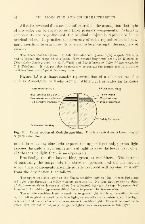
46 III. 16-MM FILM AND ITS CHARACTERISTICS
All color-reversal films are manufactured on the assumption that light
of any color can be analyzed into three primary components. When the
components are resynthesized, the original subject is reproduced in its
original color. In practice, the accuracy of color reproduction is know-
ingly sacrificed to create results believed to be pleasing to the majority of
viewers.
The theoretical background for color film and color photography is quite extensive
and is beyond the scope of this book. Two outstanding texts are: The History of
Three Color Photography, by E. J. Wall; and The History of Color Photography, by
J. S. Friedman. It will probably be necessary to consult the former text in a library
as it has been out of print for some time.
Figure IB is a diagrammatic representation of a color-reversal film
such as AnscoColor or Kodachrome. White light provides an exposure
UNEXPOSED FILM
Blue-sensitive emulsion
Green-sensitive emulsion
Red-sensitive emulsion
PROCESSED FILM
Yellow image
Magenta image
Blue-green image
Safety film support
Antihalation backing
Fig. IB. Cross section of Kodachrome film. This is a typical multi layer integral
tri-pack color film.
in all three layers ; blue light exposes the upper layer only;green light
exposes the middle layer only ; and red light exposes the lower layer only.
(If there is no light there is no exposure.)
Practically, the film has no blue, green, or red filters. The method
of analyzing the image into the three components and the manner in
which these components are individually recorded will become apparent
from the description that follows.
The upper emulsion layer of the film is sensitive only to blue. Green light and
red light pass through it readily without affecting it. No blue light passes to either
of the lower emulsion layers; a yellow dye is located between the top (blue-sensitive)
layer and the middle (green-sensitive) layer to prevent its transmission.
The middle emulsion layer is sensitive to green light but is not sensitive to red
light. Although it is sensitive to blue light, as are all silver emulsions, no blue light
reaches it and there is therefore no exposure from blue light. Since it is sensitive to
green light but not to red, only the green light causes an exposure in this layer.
COLOR-REVERSAL 47
The lower emulsion layer is sensitive to red light but is not sensitive to green
light. Although like all emulsions, this layer is also sensitive to blue light, there is no
exposure caused by blue light, since none reaches it. Thus, the lower emulsion layer
registers only from the exposure by red light,
Color-reversal film has the customary antihalation backing on the base of the film
and a hard gelatin antiabrasion layer over the top emulsion layer.
Color Developing. The film passes through a first developer in a
manner similar to black-and-white reversal. Here all the emulsions are
developed and images appear in each layer as negative black and white.
A bleach dissolves the image formed by the first development and some
fine-grained emulsion remains unaffected just as in black-and-white re-
versal processing. The film is given a second exposure (sometimes called
re-exposure) in a manner quite similar to the re-exposure given to black-
and-white reversal film.
In the second development, a dye of predetermined color appears
along with the silver in each layer. The film is then put through a bath
in which the silver is dissolved away, leaving only the dye images.
The top layer is now an image in a yellow* dye ; the middle layer is an
image in a magenta 1" dye; the lower layer is an image in a cyan* dye.
Thus each layer provides a dye image in a color that is the complement of
the color that exposed the layer. Where there was no exposure, all layers
have the maximum quantity of dye and the film appears black. In the
case in which a very bright white light provided the exposure, all layers
have the minimum quantity of dye, and the film appears clear.
Color Reproduction. The film projector throws white light on the
film. If blue light was the only light used for exposure of the film when
it was placed in the camera, the top layer of the film is clear. The middle
layer, being unexposed, is dyed magenta. The lower layer of the film,
also unexposed, is dyed cyan. When the white light from the projector
traverses the film, green rays are absorbed by the magenta (minus green)
dye, and red rays are absorbed by the cyan (minus red) dye. The
only portion of this white light that remains unaffected is the blue ; in
this manner the blue light used to photograph the original scene is re-
produced by the film that is run in the projector.
The reproduction of green is accomplished in a manner similar to that
for blue. If green light was the only light used for exposure of the film
when it was placed in the camera, the middle layer is clear. The top
* Minus blue : yellow.
t Minus green : magenta.
t Minus red : cyan.

is III. 16-MM FILM AND ITS CHARACTERISTICS
and lower layers, being unexposed, are dyed yellow and cyan, respec-
tively. When the wThite light from the projector traverses the film, the
blue rays are absorbed by the yellow (minus blue) dye, and the red rays
are absorbed by the cyan (minus red) dye. The only portion of the
white light that remains unaffected is green; in this manner the green
light used to photograph the original scene is reproduced by the film that
is run in the projector.
The reproduction of red is accomplished in a similar manner. If
only red light was used to expose the film when it was placed in the
TABLE IV
Color Reversal Films for Original Photographing
For Direct Projection
Manufacturer Code# Trade nameK
colortemp.
Lines/mmresolvingpower
EastmanKodak
EastmanKodak
Ansco
Ansco
5263
5264
2827-004
2827-007
Kodachrome DaylightType
Safety color film
Kodachrome Type ASafety color film
AnscoColor DaylightType (200 ft.)
AnscoColor TungstenType (200 ft.)
6100
3450
75
75
Not For Direct Projection
EastmanKodak
5268 Kodachrome Com-mercial
Safety color film
3200 75
camera, the lower layer of the film is clear. The top and middle layers,
being unexposed, are dyed yellow and magenta, respectively. When the
white light from the projector traverses the film, the blue rays are
absorbed by the yellow (minus blue) dye, and the green rays are absorbed
by the magenta (minus green) dye. The only portion of the white light
remaining unaffected is red ; in this way the red light used to photograph
the original scene is reproduced by the film that is run in the projector.
Since all colors are made up of these three components in varying
degrees, any color appearing in nature can theoretically be reproduced.
Table IV is a list of some common color reversal films for original
photographing.
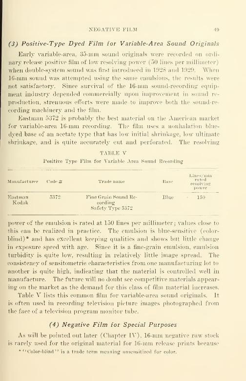
NEGATIVE FILM 49
(3) Positive-Type Dyed Film for Variable-Area Sound Originals
Early variable-area, 35-mm sound originals were recorded on ordi-
nary release positive film of low resolving power (50 lines per millimeter)
when double-system sound was first introduced in 1928 and 1929: When16-mm sound was attempted using the same emulsions, the results were
not satisfactory. Since survival of the 16-mm sound-recording equip-
ment industry depended commercially upon improvement in sound re-
production, strenuous efforts were made to improve both the sound-re-
cording machinery and the film.
Eastman 5:372 is probably the best material on the American market
for variable-area 16-mm recording. The film uses a nonhalation blue-
dyed base of an acetate type that has low initial shrinkage, low ultimate
shrinkage, and is quite accurately cut and perforated. The resolving
TABLE VPositive Type Film for Variable Area Sound Recording
Manufacturer Code # Tradename Baseresolving
Lines/mmrated'solvin:
power
Eastman 5372 Fine Grain Sound Ee- Blue • 150Kodak cording
Safety Type 5372
power of the emulsion is rated at 150 lines per millimeter ; values close to
this can be realized in practice. The emulsion is blue-sensitive (color-
blind)* and has excellent keeping qualities and shows but little change
in exposure speed with age. Since it is a fine-grain emulsion, emulsion
turbidity is quite low, resulting in relatively little image spread. The
consistency of sensitometric characteristics from one manufacturing lot to
another is quite high, indicating that the material is controlled well in
manufacture. The future will no doubt see competitive materials appear-
ing on the market as the demand for this class of film material increases.
Table V lists this common film for variable-area sound originals. It
is often used in recording television picture images photographed from
the face of a television program monitor tube.
(4) Negative Film for Special Purposes
As wTill be pointed out later (Chapter IV), 16-mm negative raw stock
is rarely used for the original material for 16-mm release prints because
* "Color-blind" is a trade term meaning unscnsitized for color.
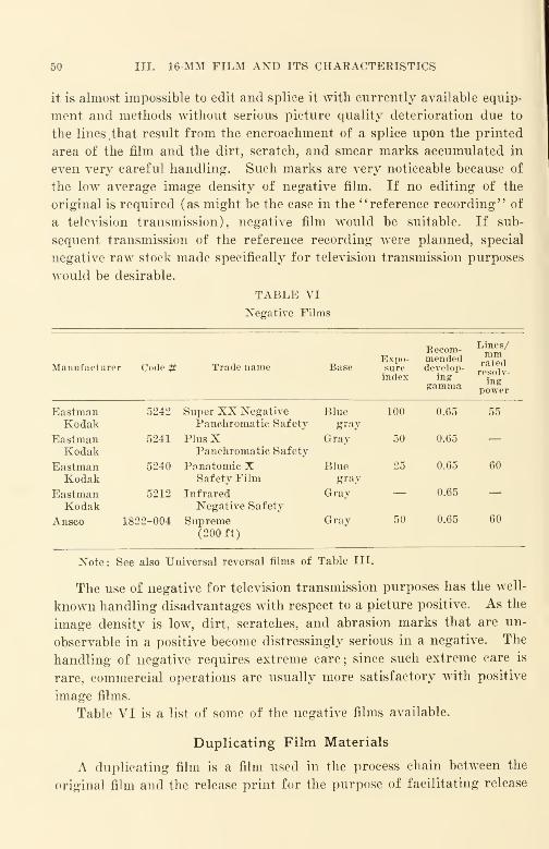
50 III. 16-MM FILM AND ITS CHARACTERISTICS
it is almost impossible to edit and splice it with currently available equip-
ment and methods without serious picture quality deterioration due to
the lines,that result from the encroachment of a splice upon the printed
area of the film and the dirt, scratch, and smear marks accumulated in
even very careful handling. Such marks are very noticeable because of
the low average image density of negative film. If no editing of the
original is required (as might be the case in the "reference recording" of
a television transmission), negative film would be suitable. If sub-
sequent transmission of the reference recording were planned, special
negative raw stock made specifically for television transmission purposes
would be desirable.
TABLE VI
Negative Films
Manufacturer Code # Trade name Base
Recom "Lmm
S/
Expo- mended ™™sure develop- rpsn i vindex ing re
££v"
gamma po/erEastman 5242 Super XX Negative Blue 100 0.65 55Kodak Panchromatic Safety gray
Eastman 5241 PlusX Gray 50 0.65 —Kodak Panchromatic Safety
Eastman 5240 Panatomic X Blue 25 0.65 60
Kodak Safety Film gray
Eastman 5212 Infrared Gray — 0.65 —Kodak Negative Safety
Ansco 1822-004 Supreme(200 ft)
Gray 50 0.65 60
Note: See also Universal reversal films of Table III.
The use of negative for television transmission purposes has the well-
known handling disadvantages with respect to a picture positive. As the
image density is low, dirt, scratches, and abrasion marks that are un-
observable in a positive become distressingly serious in a negative. The
handling of negative requires extreme care; since such extreme care is
rare, commercial operations are usually more satisfactory with positive
image films.
Table VI is a list of some of the negative films available.
Duplicating Film Materials
A duplicating film is a film used in the process chain between the
original film and the release print for the purpose of facilitating release
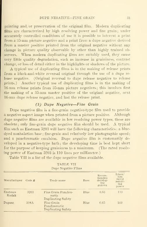
DUPE NEGATIVE—FIXE GRAIN 51
printing and or preservation of the original film. Modern duplicating
films are characterized by high resolving power and fine grain; under
accurately controlled conditions of use it is possible to intercut a print
from a 35-mm picture negative and a print from a dupe negative derived
from a master positive printed from the original negative without any
change in picture quality observable by other than highly trained ob-
servers. "When modern duplicating films are suitably used, they cause
very little quality degradation, such as increase in graininess, contrast
change, or loss of detail either in the highlights or shadows of the picture.
A typical use of duplicating films is in the making of release prints
from a black-and-white reversal original through the use of a dupe re-
lease negative. (Original reversal to dupe release negative to release
prints.) Another typical use of duplicating films is in the making of
16-mm release prints from 35-mm picture negatives; this involves first
the making of a 35-mm master positive of the original negative, next
16-mm dupe release negative, and last the release print.
(5) Dupe Negative—Fine Grain
Dupe negative film is a fine-grain negative-type film used to provide
a negative aspect image when printed from a picture positive. Although
dupe negative films are available in low resolving power types, these are
obsolete ; only fine-grain dupe negative film should be used. A typical
film such as Eastman 5203 will have the following characteristics : a blue-
dyed nonhalation base ; fine-grain and relatively low photographic speed
;
and a panchromatic emulsion. Dupe negative film is customarily de-
veloped in a negative-type bath ; the developing time is best kept short
for the purpose of keeping graininess to a minimum. (The rated resolv-
ing power of Eastman 5203 is 110 lines per millimeter.)
Table VII is a list of the dupe negative films available.
TABLE VII
Dupe Negative Films
Manufacturer Code # Trade name Base
Recom-mendeddevelop-
inggramma
Lines/mmratedresolv-ing
power
Eastman 5203 Fine Grain Panchro- Blue 0.65 110Kodak matic
Duplicating Safety
Dupont 30 8A Fine GrainPanchromaticDuplicating Safety
Blue 0.65 160
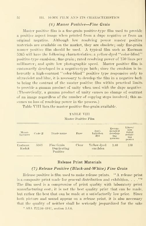
52 III. 16-MM FILM AND ITS CHARACTERISTICS
(6) Master Positive—Fine Grain
Master positive film is a fine-grain positive-type film used to provide
a positive aspect image when printed from a dupe negative or from an
original negative. Although low resolving power master positive
materials are available on the market, they are obsolete ; only fine-grain
master positive film should be used. A typical film such as Eastman
5365 will have the following characteristics: a yellow-dyed "color-blind"
positive-type emulsion; fine-grain; rated resolving power of 150 lines per
millimeter; and quite low photographic speed. Master positive film is
customarily developed in a negative-type bath ; since the emulsion is in-
herently a high-contrast "color-blind" positive type responsive only to
ultraviolet and blue, it is necessary to develop the film in a negative bath
to bring the contrast of the master positive film within practical limits
to provide a gamma product of unity when used with the dupe negative.
(Theoretically, a gamma product of unity causes no change of contrast
of an image regardless of the number of copying steps involved ; this as-
sumes no loss of resolving power in the process.)
Table VIII lists the master positive fine-grain available.
TABLE VIII
Master Positive Film
Manu-facturer
Code # Trade name BaseAnti-
halationdye
Recom-mendeddevelop-
inggamma
Lines/mmratedresolv-ing
power
EastmanKodak
5365 Fine GrainDuplicatingPositive
Clear Yellow-dyedemulsion
1.40 150
Release Print Materials
(7) Release Positive (Black-and-White) Fine Grain
Release positive is film used to make release prints. "A release print
is a composite print made for general distribution and exhibition. . .
."*
The film used is a compromise of print quality with laboratory print
manufacturing cost; it is not the best quality print that can be made,
but rather the best that can be made at a satisfactorily low price. Since
both picture and sound appear on a release print, it is also necessary
that the quality of neither shall be seriously jeopardized for the sake
* ASA Z22.56-1947, section 3.4.6.

COLOR-REVERSAL PRTXT STOCK 53
of the other. Release print materials presently used are called fine grain
and are rated at 90 lines per millimeter resolving power. Although it
is recognized that improved picture and sound quality can be obtained
by the use of finer-grained release print stock, e.g., 150 lines per mm, sig-
nificant increases with presently available materials would be quite
• •ostly because of the low photographic speed of such materials. Proc-
essing would require an increase in film exposure and a reduction in
developing machine speed and or printing machine speed. At the
moment it may be doubtful if the increase in print cost caused by the
reduction in quantity output can be justified by the amount of quality
improvement realized in projection. In all likelihood, newer films will be
evolved intermediate in speed and in resolving power between the present
raw stock rated at 90 lines per millimeter and duplicating positive rated
at 150 lines per millimeter. Although ordinary positive raw stock rated
at 50 lines per millimeter resolving power is still manufactured, it should
not be used for 16-mm release prints, since its detail-rendering ability
is inferior. Typical fine-grain release print films are DuPont 605A and
Eastman 5302.
Table IX is a list of the release print films available.
TABLE IXRelease Positive Fine Grain Black-and-White Films
Manufacturer Code # Trade name Baso
Recom-mended,develop-
inggamma
Lines/mmratedresolv-ing
power
EastmanKodak
Dupont
5302
605A
Fine Grain Release
Positive
Fine Grain ReleasePositive
Clear
Clear
2.5
2.4
90
100
(8) Color-Reversal Print Stock
Color-reversal print stock is film used to make copies ; in most cases
the copies are used as release prints. Color reversal prints are often
referred to as dupes (or duplicates); in a strict sense the term duplicate
is used only in connection with intermediate films to facilitate release
printing. At present there is only one general grade of color reversal
print stock on the market ; this has a rated resolving power of 75 lines
per millimeter and a resolving power realizable in practice of about 40
lines per millimeter. Generally speaking, there are broad color filter
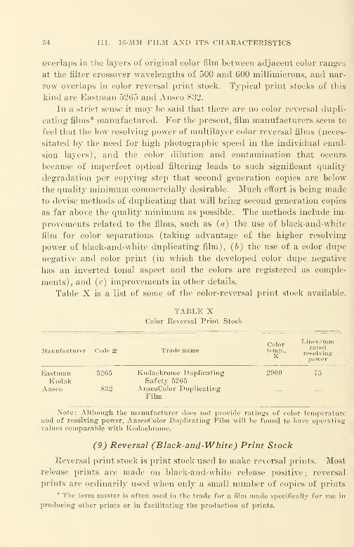
54 III. 16-MM FILM AND ITS CHARACTERISTICS
overlaps in the layers of original color film between adjacent color ranges
at the filter crossover wavelengths of 500 and 600 millimicrons, and nar-
row overlaps in color reversal print stock. Typical print stocks of this
kind are Eastman 5265 and Ansco 832.
In a strict sense it may be said that there are no color reversal dupli-
cating films* manufactured. For the present, film manufacturers seem to
feel that the low resolving power of multilayer color reversal films (neces-
sitated by the need for high photographic speed in the individual emul-
sion layers), and the color dilution and contamination that occurs
because of imperfect optical filtering leads to such significant quality
degradation per copying step that second generation copies are below
the quality minimum commercially desirable. Much effort is being made
to devise methods of duplicating that will bring second generation copies
as far above the quality minimum as possible. The methods include im-
provements related to the films, such as (a) the use of black-and-white
film for color separations (taking advantage of the higher resolving
power of black-and-white duplicating film), (b) the use of a color dupe
negative and color print (in which the developed color dupe negative
has an inverted tonal aspect and the colors are registered as comple-
ments), and (c) improvements in other details.
Table X is a list of some of the color-reversal print stock available.
TABLE XColor Reversal Print Stock
Color Lines/mmrated
Manufacturer Code # Trade name temp.K resolving
power
Eastman 5265 Kodachrome Duplicating 2900
Kodak Safety 5265Ansco 832 AnscoColor Duplicating
Film
Note: Although the manufacturer does not provide ratings of color temperatureand of resolving power, AnscoColor Duplicating Film will be found to have operatingvalues comparable with Kodachrome.
(9) Reversal (Black-and-White) Print Stock
Reversal print stock is print stock used to make reversal prints. Most
release prints are made on black-and-white release positive ; reversal
prints are ordinarily used when only a small number of copies of prints
* The term master is often used in the trade for a film made specifically for use in
producing other prints or in facilitating the production of prints.

MISCELLANEOUS 55
without sound is required. Reversal print stock (often called reversal
duping stock) is consumed mostly by film manufacturers' laboratories
and their agent laboratories; reversal work prints are often made with
positive stock to reduce cost. The picture quality from reversal prints
made on positive stock is ordinarily not as good as that made on reversal
stock. A typical positive often used for reversal work prints is Ansco
2250, a positive film originally intended for variable-area sound record-
ing. There is only one grade of reversal print stock regularly supplied
by either Eastman or Ansco ; Dupont does not market this material.
Table XI is a list showing the reversal print stock available.
TABLE XI
Black-ancl-White Reversal Print Stock
Manufacturer Code # Trade name
Ansco 198 Reversal Duping Stock
Note: At present there is little call for reversal duping stock on the open market.
(10) Miscellaneous
At the moment, television is having a marked accelerating effect upon
the introduction of new film materials. The contrast, tonal scale, and
resolving power characteristics of present-day television systems are
markedly different from the comparable characteristics of motion picture
systems. In brief, the contrast is different, the tonal scale shorter, and
the resolving power relatively poor.
As the exposure and the processing procedures for films may be
altered to fit any reasonable system condition of tonal scale and con-
trast, many successful efforts have been made to use available materials
differently, as well as to provide completely new materials for television
purposes. Both negative and reversal films are used to photograph
original events for television, and television transmission of the original
film or (more usual) prints derived from the original is now very com-
mon. It would be well for motion-picture-minded persons to remember
that television systems are very versatile, and permit changes of system
contrast by turning a knob, and also permit a change from positive tele-
vision transmission to negative transmission by snapping a switch.
Reference recording of television transmissions is now quite common.
In one method capable of a fair quality result, fine-grain sound recording
safety film (EK 5373) is exposed by a cathode-ray monitor tube. Such
56 III. 16-MM FILM AND ITS CHARACTERISTICS
reference recording arrangements are capable of providing a film with
either a negative or a positive image aspect with processing in a single
positive bath. The use of a material of 150 lines per mm resolving power
in a suitable manner does much to limit the image degredation that occurs
in the transfer of the image from the electrical television system to the
fixed image on a film.
Television film procedures are in a state of flux, and methods have not
become sufficiently stabilized commercially to warrant detailed descrip-
tion. Users who are concerned would do well to keep in close touch with
the professional film departments of film manufacturers if they wish to
be kept abreast currently of the rapid changes in this dynamic field.
Since 1952 there has been a marked increase in the use of color nega-
tive-color positive materials. Although color negative, color positive,
separation positive, color dupe negative and color reversal internegative
materials are available for 35-mm film, only color positive film has been
widely available in 16-mm. As manufacturing and processing control
improves, such materials will become available in the 16-mm width.
General Comments on Available Films
Film emulsions are today of good and consistent quality. Their free-
dom from dirt and other occluded extraneous matter is remarkable ; al-
most all the dirt and foreign matter found on today's films are acquired
during developing and use. Not only is improvement in the film itself
desirable, but also improvement in the processing, so that a much greater
percentage of the quality potential will be realized. Much progress can
be made in improving print quality if the characteristics of films are
studied and processes of exposure and development accurately controlled
to make best use of the quality potential of the films used.
Selected References1
1
Photography '', Encyclopedia Americana, Vol. 22, 1-7 (1947).
Mees, C. E. K., The Theory of the Photographic Process. Macmillan, New York,
1944.
James and Higgins, Fundamentals of Photographic Theory. Wiley, New York, 1948.
Roebuck and Staehle, Photography Its Science and Practice. Appleton-Century,
New York, 1942.
Clark, W., " Cellulose—Photographic Film", Dictionary of Applied Photograph y.
Vol. 2,4th eel., p. 446 (1938).
Matthews, G. E., "Chemistry of Photography/ 5 The Complete Photographer, Issue 11,
pp. 702-718 (1941).
Corbin, Simmons, and Hyndman, "Two New Eastman Fine-Grain Sound Recording
Films," JSMPE, 45, 265 (Oct. 1945).
SELECTED REFERENCES 57
Moyse, H. W., "Dupont Fine-Grain Sound Films Types 232 and 236," JSMPE,
45, 285 (Oct. 1945).
Goetz and Brown, "Light-Scattering and the Graininess of Photographic Emul-
sions," JSMPE, 39, 375 (Dec. 1942).
Talbot, R. H., "The Projection Life of Film," JSMPE, 45, 78 (Aug. 1945).
Calhoun, J. M., "The Physical Properties and Dimensional Behavior of Motion
Picture Film," JSMPE, 43, 227 (Oct. 1944).
Fordyce, C. R., "Improved Safety Motion Picture Film Support," JSMPE, 51,
331-350 (Oct. 1948).
Physioc, L. W., "Photographic Emulsions," JSMPE, 19, 913 (July 1932).
Additional references may be found in the following JSMPE indexes:
July 1916 to June 1930
"Film Manufacture," page 127.
"Film, Photographic Characteristics," page 127.
"Film, Physical Characteristics," page 127.
"Gelatin," page 129.
" Sensitometry, Methods and Instruments," page 145.
January 1930 to December 1935
"Film, History of," page 25.
"Film, Photographic Characteristics," page 25.
"Film, Physical Characteristics," page 26.
"Gammagraph," page 27.
" Gammameters, " page 27.
"Publications of the Motion Picture Industry," page 54.
"Sensitometry," page 56.
Index 1936 to 1945
"Film, Fine Grain," page 90.
"Film, General," pages 90-93.
"Film, Wear," page 94.
"Densitometry," page 84.
CHAPTER IV
Making 16-Mm Originals
Size of Originals for 16-Mm Release Prints
As mentioned earlier, 16-mm release prints may be manufactured
from a variety of different film sizes as originals. Dimensions have been
standardized to the point where it is possible to make 16-mm release prints
from three sizes of picture (35-mm, 16-mm, and 8-mm), and from either
of two sizes for sound (35-mm or 16-mm). Up to the present there is
no commercially satisfactory 8-mm sound available.
The greatest volume of release prints has been produced by optical
reduction from duplicates of 35-mm originals. Since the production of
35-mm films has been described at some length in other texts and in en-
gineering journals, such as the Journal of the Society of Motion Picture
Engineers, such data will not be repeated here.
A smaller yet important volume of release prints has been produced
from 16-mm originals. Kodachrome has played an important part in en-
couraging 16-mm growth for industrial, education, and other non-amateur
purposes ; no integral tri-pack color film of this kind has been available
for equivalent 35-mm use. The combination of 16-mm Kodachrome
picture with 35-mm negative sound track has been fairly common, but
the inconvenience of handling 35-mm film (which is inflammable as well
as clumsy) simultaneously with 16-mm film (which is compact and slow
burning) will mitigate against further rapid growth—especially when
16-mm sound-recording apparatus of good reliability becomes more
widely available in the near future.
While 8-mm picture has often been used for special purposes to pro-
vide 16-mm release prints, such use is the exception rather than the rule.
The emphasis of war standardization concentrated heavily upon 16-mm,
and it is only logical to expect that such standardization will have far-
reaching effects in further expanding the use of the 16-mm size. Rapid
improvement of quality in 8-mm picture and very wide amateur use can
be reasonably expected, but the far lesser extent of 8-mm standardization
compared with that of 16-mm will act as a handicap in its growth for
professional uses.
58
DIRECT PRODUCTION 59
Prospective Volume of 16-Mm Films
Major increases in the volume of 16-mm release prints made from
16-mm originals can be confidently expected. The vicious circle of "nn
films, no projectors" has been broken by the training and other film
activities of the Armed Forces in the United States and also in other
parts of the world. During World War II, along with Lend-Lease de-
liveries of American-made P-39 Airacobra fighter planes to the Russians,
sound films describing their servicing and maintenance were supplied.
Although the earlier films were merely copies of the films delivered to
the American Air Forces, later films used Russian sound tracks and other
editing modifications to produce a Russian version.
Conservative estimates indicate roughly a fourfold increase in the
number of 16-mm sound projectors in use in the United States as a result
of World War II. The number of hours' use per year per projector has
also risen markedly. Well over 500 million feet of 16-mm film was manu-
factured and used in a single year during the war interval. Although
much film and many projectors are worn out or are obsolete and should
be scrapped now that their war uses have been satisfied, the volume of
such material remaining is still far larger than that of all films and all
projectors in existence prior to the war. Efficient utilization of such
material is desirable if the nation is to realize the maximum benefit from
its large war investment.
Even though most efficient utilization of the surplus films and projec-
tors may be made, large gaps will still remain in our civilian educational
and training system. Production of a large number of subjects as parts
of integrated teaching and training programs is still badly needed, as are
improved projectors to show such new films. Technology was acceler-
ated by the War to a greater extent than at any other time in our earlier
history. An urgent need now exists to spread rapidly and widely the
knowledge gained from this growth and to capitalize upon the techno-
logical advances made.
Direct 16-Mm Production
Single System vs. Double System Sound Recording
As in 35-mm, 16-mm sound film may be made by either the single sys-
tem or double system method. In the single system method, the sound
is usually recorded at the same time that the picture is taken and re-
corded photographically upon the sound track area of the same film
60 IV. MAKING 16-MM OEIGINALS
Single system recording is rarely used for professional 16-mm production
because
:
(a) It is rarely necessary or even desirable to record the sound which actually
forms part of the action being photographed. This is especially true of 16-mm non-
entertainment films.
(fo) It is impracticable to edit single system film in a satisfactory manner.
(c) Sound quality is decidedly inferior because the resolving power of picture
original film is usually much lower than that of film designed especially for sound re-
cording.
In the double system method, the sound is recorded on a separate
film, and usually not at the time at which the picture is taken. The
double system method permits the use of the best available raw films for
both picture and for sound without serious sacrifice of quality for either.
It is for this reason that the double system method is used almost ex-
clusively for all theatrical 35-mm films as well as for commercial 16-mmfilms.
Combinations of both the single and double system methods are oc-
casionally used. These combinations are intended for special purposes
and account for an insignificant fraction of all film consumed.
The 16-Mm Picture Original
Film for the 16-Mm Picture Original
While 16-mm film has much in common with 35-mm theatrical film,
there are certain features which have no counterpart in the larger size.
The 16-mm picture original is an excellent example.
When a 35-mm black-and-white positive is desired, it can be obtained
from a 35-mm original only by printing from a negative, since there is no
35-mm reversal film commercially available. In 16-mm, however, direct
positives such as black-and-white reversal and color reversal are the rule
rather than the exception. The attempt to use the terms original and neg-
ative interchangeably in the 16-mm medium is not only confusing but
definitely in error although the terms are quite correct in 35-mm where
they are customarily so used.
While the apparently obvious means of obtaining a 16-mm black-and-
white print would seem to be the printing of a 16-mm negative, this
method is usually the least satisfactory when good quality prints are
required from assembled (edited) originals. The dirt and scratches
accumulated in even meticulous handling of 16-mm original film are quite
objectionable when negative is used. In addition, annoying light flashes
appear in the print wherever a splice occurs in the negative.
THE PICTURE ORIGINAL 61
Where best over-all print quality is the objective, the most suitable
materials for 16-mm originals are reversal materials. Reversal materials
when handled carefully show little or no evidence of dirt, scratches, and
light flashes that are almost unavoidable even with carefully handled
negative. Reversal always produces a reduction of grain size ; it is in-
herently a fine grain process. In black-and-white reversal, the larger
grains of the film emulsion, being most sensitive to light, are most affected
by the first or negative exposure. These larger grains are then removed
in the bleaching operation that follows the initial development, leaving
the smaller grains of the emulsion exposed by the second or positive ex-
posure to make up the final image on the film. In color reversal, the final
image is made up essentially of dyes which are, to a major degree, grain-
less ; the initial development and bleaching operations are essentially the
same as for black and white.
The advantages of direct positive materials are now so pronounced
that negative-type materials have been abandoned in most applications
where a large number of print copies from an edited original is required.
Some independent laboratories are reversing positive film for the making
of work prints and duplicates but the volume of this work at the present
time is not large when compared with release printing.
Consistency of Picture Quality for the Picture Original
Consistency in picture quality is extremely important for an individ-
ual, group, or organization engaged in the making of motion pictures.
Since a copy can never be any better than the original from which it was
made, deviations in quality in the original are ordinarily aggravated by
the release print manufacturing process ; the result is poor quality on the
projection screen.
Strangely enough, the importance of consistency of quality seems to
be little recognized before the original is photographed ; too often the film
laboratory is called upon to "save" an original because of lack of care or
knowledge in the making of the original. "Saving" a film is really a
thankless proposition; the result at best is only marginal. Every time
an owner views a release print from a "saved" film, he wonders what he
might have done to avoid his dilemma and wishfully thinks about "the
film that might have been." Such experiences on the part of film pro-
ducers or makers point out quite forcibly that a laboratory cannot bring-
out detail in the copying process that does not exist on the original film.
If that were accomplished, it would be magic and not film processing.
02 IV. MAKING 16-MM ORIGINALS
To accomplish consistency in the picture original requires consistency
in three important particulars:
(1) Consistency in the film.
(£) Consistency in its exposure.
{3) Consistency in its processing.
Film and Its Consistency. Film and its consistency has been discussed
in some detail in an earlier chapter. The most consistent original mate-
rials today for 16-mm are integral tri-pack color films ; this is true of both
Eastman and Ansco products. As a practical matter it is difficult for a
user to be concerned with film consistency without being concerned with
processing consistency ; on this count also the integral tri-pack color films
are definitely superior.
In general, manufacturers of films do not release information to users
on variations in quality from lot to lot of manufactured raw film ; they do,
however, keep accurate and extensive records of such variations together
with data on the practical effects of such variations upon the usefulness of
of the finished product. As described in the previous chapter on film,
normal manufacturing variations do occur; there is no magic in the
manufacture of sensitized materials that would exempt film from the laws
governing the statistical quality variations of manufactured products.
For most purposes, the variation in quality within a roll of film, or the
variation in quality from roll to roll of film of a particular lot number is
not important, while the difference from one lot to another is quite impor-
tant. For this reason an accurate picture film test exposure and log book
is just as important for maintaining picture quality as a similar log book
is for maintaining sound quality. Fortunately, the variation from roll
to roll and the variation from lot to lot of Kodachrome, for example, is
relatively so small that if picture exposure variations would be of like
order, there would be no such thing as a really bad original in conven-
tional films. Unfortunately, most of the inconsistency occurs in the ex-
posure of the original film.
Exposure Consistency. Exposure and its consistency depends upon
consistency in the readings of a measuring light meter, consistency in the
manner of its use, and consistenc}^ of the judgement used in transferring
the data so obtained into the aperture setting for the lens used. For most
uses, calibration of the light meter once a month is sufficient to detect any
loss in sensitivity. When such meters are calibrated, all previous cal-
ibration data should be available so that the magnitude of the loss in
sensitivity can be judged relative to the previous calibrations.
BLACK-AND-WHITE KEVEKSAL MATERIALS 63
Consistency in the manner of use depends upon the training and
habits of the photographer. Generally speaking, if the photographer
consistently measures highlight areas of the picture and keeps the shadow
illumination contrast not greater than 4 to 1 with respect to the highlighl
illumination, the result should be acceptable, and with a little experience,
should be good. In practice, the measurement should be made of light
reflected from a reference test object which may be a piece of new bristol
board free of dust, smudges, etc. Consistency in the judgment used in
transferring data so obtained into the aperture setting is probably the
largest potential source of error. Corrections are required for changes
in film speed, in camera speed, and in differences between the actual light
transmission of the lens and the theoretical light transmission calculated
from the "/" stop markings on it, and other factors. In many cases in
which results are inconsistent, flagrant causes are usually to be found in
lens transmission differences and in errors in iris adjustment as well as in
camera speed differences and deviations.
Processing Consistency. Processing accounts for another potentially
serious source of variation. The processing of Kodachrome is probably
the most consistent processing service available. Despite its excellent
control, noticeable differences will be apparent in the side-by-side projec-
tion of pieces of the same film developed in different laboratories or in
the same laboratory at different times. Fortunately, side-by-side com-
parisons are rarely required. The processing of reversal films is not so
consistent; too often factors other than sensitometric control (such as ex-
cessive hypo and poor film drying, etc.) complicate matters and further
encourage a decided preference for the color film.
Black-and-White Reversal Materials
Present-day reversal materials still give the impression that they are
intended for the amateur, who, according to a current fallacy, likes his
film "as fast as possible and as hard as nails." In original reversal mate-
rials today there is still a big need for a low-contrast, Long-reproduction-
scale material, since there is no such thing on the photographic market
and we have been struggling along without it for ten years or more.
Ansco did manufacture a film called "Old Type Superpan." which was
a long-scale material of beautifully low contrast, but it was unfortunately
withdrawn from the market when the faster emulsions of the "Supreme"type apeared. The film manufacturer who supplies such material and
incorporates in it the new emulsion improvements of recent years as to

64 IV. MAKING 16-MM ORIGINALS
grain reduction and speed will not only earn the blessings of a long-
suffering professional market by reopening wide fields of usefulness, but
should also find it profitable. All finer grained reversal emulsions today
of the high-contrast type.
"When reversal films were first marketed, their users were almost
entirely amateurs. Since many of the amateur films received by the
manufacturer's laboratory for development were underexposed, it was
felt that a sacrifice of gradation for the sake of photographic speed was
well justified. At the time the "Old Type Superpan" was withdrawn
from the market, the number of professional users of 16-mm film was
quite small compared with other users. The vocal complaints received
from casual amateurs concerning the absence of "snap" (contrast) were
impressive in number and effectively drowned out the more studied
praises of a relatively small body of quality-conscious amateur and
professional users.
With only high-contrast reversal materials left on the market, it was
necessary for the serious amateur and professional photographers to re-
duce materially the lighting contrast customarily used for studio photo-
gaphing with 35-mm negative. To avoid production difficulties, labora-
tories recommend flat lighting with high-light to low-light ratios in the
photographed scene no greater than 3 or 4 to 1. Most reversal materials
today are of the short-scale, high-contrast type.
Regular Type Reversal
Both Eastman and Ansco operate company-owned or contract proces-
sing stations to develop reversal film. These reversal films are somewhat
different from negative ; not only is the emulsion slightly thicker, but a
silver undercoating is used that remains on the film as a black scum whenthe film is developed as a negative, but which is removed during the
bleaching operation when the film is developed as a reversal. A film
intended for reversal developing that is not suitable for negative develop-
ing is called a regular reversal.
Universal Type Reversal
Since DuPont preferred to market film for developing by laboratories
that were not company-owned or under company contract, the sale price
of DuPont film ordinarily does not include developing. Accordingly,
that firm found it advantageous to market film of the universal reversal
type; this is designed for use either as a reversal or as a 16-mm negative.
BLACK-AND-WHITE REVERSAL MATERIALS 65
When universal film is to be used as a reversal, the exposure is increased
(usually 2x) compared with the exposure it would be given as a negative.
Fortunately, a convenient system of speed ratings known as the ASA(American Standards Association) Exposure Index* simplifies the man-
ner of expressing photographic film speed.
Since the advent of World War II. the importance of the universal
type of reversal film has grown at a very rapid rate. For special pur-
poses, such as the gun-sight-aiming-point (GSAP) cameras that were
used to record the firing of machine guns and other weapons of an air-
plane, there are occasions when the developing of film as a negative had
decided advantages. Interchangeability is effected and warehousing
problems greatly simplified if the universal type of reversal replaces
regular reversal and negative types in such applications.
Generally speaking, reversal materials of the smallest exposure index
practicable should be used as orginal materials, because they are the least
grainy. Even with the very best processing at all steps, graininess in
prints is always a factor that must be kept to an absolute minimum.
Graininess in an original is always aggravated by the release printing
operation ; for this reason materials with a reversal exposure index of the
order of 25 or lower are definitely preferred. Materials of higher index
should not be used if it is at all possible to avoid them since their grain-
iness is usually noticeable in the original and becomes quite objectionable
in the release prints produced from such originals.
Simple graininess comparisons can readily be made with a conven-
tional high-quality projector, with a 750-watt lamp projecting test pic-
tures upon a good, clean matte screen approximately four feet wide. All
tests viewed should be observed from the center of the screen at a distance
equal to 2x screen width. Any new commercial projector with a good
gate and a good lens is suitable. Such graininess tests should never be
conducted with production film, because of the scratching and other
damage that would be certain to result from handling. Tests should be
original photographs of identical subject matter, properly exposed anddeveloped, and projected for comparison at a single showing. Better
graininess comparisons can of course be made with more elaborate
arrangements, such as two interconnected identical machines projecting
images side by side on the same screen ; for most purposes the more elabo-
rate arrangements are not justified.
*ASA Z38.2.1—1947, "Photographic Speed and Exposure Index, Method for
Determining. '
'
66 IV. MAKING 16-MM ORIGINALS
Color Reversal
The first successful color reversal 16-mm material to appear on the
American market was Koda chrome—introduced commercially by the
Eastman Kodak Company in 1935. Since its introduction, its use has
grown by leaps and bounds.
Multi-layer color film with three separately sensitized emulsions
coated in succession on to the same support was the subject of intensive
study for many years ; it was first described by Schinzel in 1905. At that
time there were no sensitizing- dyes available which would remain in only
one of the layers, nor was a means known for forming a satisfactory dye
image in each layer separately. In 1913 Fischer patented the coupling
development process, but he also found it difficult to keep the couplers in
their separate layers.
Years later Mamies and Godowsky disclosed how to develop the sep-
arate layers to give differently colored dye images, and with the invention
of improved "non-wandering" optical sensitizers, the Kodachrome pro-
cess was developed. I. G. Farben (Agfa) in Germany invented color-
forming couplers that could be placed in an emulsion and would not
wander to an adjacent layer; such couplers are used in AnscoColor film.
Because the color separations that are effected in an integral tri-pack
film such as Kodachrome or AnscoColor result in a considerable loss of
light, individual emulsions of very high speed (and consequently coarse
grain) are required to obtain a film of even relatively low speed. Thus,
individual emulsions of exposure index of the order of 50 are needed
to obtain an integral tri-pack of effective exposure index of 10 or 12.
However, if exposure is controlled accurately, excellent results can be
obtained with either Kodachrome or AnscoColor film due to the excel-
lence of manufacture and of processing control exercised by their respec-
tive manufacturers despite significant color differences between them.
Unfortunately the dyes in Kodachrome and AnscoColor are fugitive to
some degree.
The fact that such integral tri-packs make excellent original materi-
als for black-and-white release prints has been insufficiently recognized
in the past. Critical professional film users have become aware of this
and are turning to color reversal film as the original material for their
black-and-white prints. Color reversal film as marketed has appreciably
lower contrast than any finer grain reversal films now on the market and
its users find it well worthwhile despite its higher cost and lower speed.
The contrast and gradation of the Daylight (regular) and of the Mazda(Type A) color reversal films are similar; the contrast of Kodachrome

COLOR REVERSAL 67
Commercial* is appreciably lower and provides excellent low-gamma
gradation. Comparative tests should be made with all possible types
using- the daylight type film as the reference. From a production
viewpoint, the slower speed of color tri-pack films is a serious handicap
because of the appreciably larger amount of lighting equipment neces-
sary. However, its users point out that the excellence of emulsion con-
trol and of processing control of color reversals is relatively so high that
consistently better black-and-white prints can be obtained from Koda-
chrome or AnscoColor originals than from black-and-white reversal
original materials. The advantages inherent in black-and-white reversal
materials are not realizable in practice at present, due mostly to incon-
sistent processing control. The differences in production costs due to
the higher price of color raw stock can be ignored in view of the proces-
sing control advantages obtained.
Color Film Classes
In general, there are two classes of integral tri-pack color films ; one
class that is intended primarily for projection after the film is processed,
and the second class that is not intended for projection after processing
but rather as a master film to be used for the printing of copies. The
latter class is comparatively new—introduced by Eastman Kodak in
1946.
In the former class, there are two types of integral tri-pack films
:
the daylight type that is intended for use in daylight (color temperature
6100 K) and the artificial light type intended for use with #2 Photo-
floods (color temperature 3450 K). The difference between the two is
one of color balance; as daylight has appreciably more blue light (in
the 400-to-500-millimicron range) and somewhat more green light (in
the 500-to-600-millimicron range), it is apparent that compensating
changes are made in the relative speeds of the three emulsion layers.
Thus, the sensitivity of the blue-sensitive upper layer is appreciably
lower for daylight film than for artificial light film, and the sensitivity
of the middle green-sensitive layer is somewhat lower for daylight film
* It is usually advantageous to underexpose Daylight Kodaehrome and Typo AKodachrome about one-half light stop for the purpose of obtaining better shadow
detail in commercial duplicates. Underexposure of Kodachrome Commercial cannot
be similarly recommended as it becomes noticeably grainy when it is appreciably
underexposed. The increase in graininess with underexposed Daylight Kodachromeand Type A Kodachrome, if it occurs, is usually imperceptible.

68 IV. MAKING 16-MM ORIGINALS
than for artificial light film. If the same subject could be photographed
on both types of film with correct lighting for each, the result would be
substantially the same in projection.
Because of the higher blue-sensitivity and the higher green-sensi-
tivity of the artificial light film as compared with the daylight film, it
it possible to reduce the incident light in the blue and green ranges by
the correct amounts with a filter when photographing subjects in day-
light with artificial light type film in the camera. Since a Kodak Wrat-
ten #85 filter is intended to do just this by merely reducing the effective
color temperature, the exposure index for the film remains the same as
for photographing with artificial light without a filter. This simple
expedient is quite satisfactory for conventional photographing; where
more accurate rather than pleasing color rendition is required, more in-
volved corrections may be needed. These usually comprise a set of
relative intensity measurements in the blue, green, and red color ranges
and the selection of suitable filters indicated by the measurements.
Scenes photographed on cloudy days at high altitudes, distant scenes
with haze, and snow scenes usually have excessive blue and often ap-
preciable ultraviolet present in the light. Since ultraviolet records as
blue on the film (adding to the excessive blue already present), a filter
is needed to remove the ultraviolet, and, in extreme cases, some of the
blue. The Kodak Wratten #1A Skylight Filter is useful with daylight
type color film outdoors in open shade under a clear blue sky where pic-
tures without a filter would be too bluish ; occasionally it may be useful on
an overcast day for distant scenes, sunlit snow scenes, aerial photos, and
mountain views. The Kodak Wratten #2B absorbs radiation shorter than
390 m/x ; it is useful for the bluest of such scenes.
If a distant scene is photographed with a Kodak Wratten #85 filter,
and. artificial light type film is exposed with daylight, no filter similar to
the Kodak Wratten #1A is needed, since the Kodak Wratten #85 effec-
tively absorbs rays shorter than 380 millimicrons.
In general, it is preferable to use daylight-type color film in day-
light and artificial light type film (type A) with photoflood illumination.
Because Wratten #85 filter with artificial light type film does not
alter the color temperature relationship in the exact manner that natural
light changes, daylight-type color film will usually give better color ren-
dition than a Kodak Wratten #85 filter with artificial light type film,
particularly when photographing on overcast days. Daylight-type film
is also preferred, because its dyes are somewhat less fugitive than those
COLOE EEVEESAL 69
of Type A. Should the Kodak Wratten #85 filter be used from time to
time, it is a good idea to check it, since the dyes used in its manufacture
are only moderately stable.
"While is is possible to use daylight-type film in artificial light if Kodak
Wratten #80 filter is used over the camera lens, this arrangement is not
recommended because the effective film exposure index of the combina-
tion is reduced to less than half of its usual rating without any com-
pensating advantages.
A great deal of experience has been gained in duplicating Koda-
chrome and AnscoColor within the last 10 years; most originals used
have been of the type intended for projection rather than for duplicat-
ing. Recently, the second class of material was introduced by Eastman
Kodak; this is known as Kodachrome Commercial, and is designed for
a color temperature of 3200 K. This new film is designed for appreci-
ably lower contrast in addition to the different color temperature. W7hen
duplicated in a continuous contact printer on Eastman Color Duplicat-
ing Film (code #5265). it is designed to provide a copy with color and
contrast characteristics quite similar to an original made on Type AKodachrome (code #5264).
Although photoflood and photospot illumination is adequate for the
amateur and for noncritical professional uses, it is often not satisfactory
for critical professional users because of the lack of constancy of color
temperature during the normal lamp life. Broadly speaking, as a pho-
toflood or photospot burns, there is not only a material change in color
temperature due to filament evaporation, but there is also a change in
spectral distribution characteristic caused by bulb blackening. This is
especially noticeable if the lamps are used to burn-out.
Kodachrome Commercial is intended for 3200 K illumination; this
is best obtained from 3200 K type lamps which are manufactured in the
United States by the major lamp manufacturers especially for photo-
graphic purposes. Filters are commercially available for use with these
lamps to increase the color temperature from 3200 K to 3450 K for il-
lumination of subjects to be photographed with either Kodachrome TypeA (indoor type), or AnscoColor (indoor type). Filters are ordinarily
considered unnecessary with Mazda CP lamps (3380 K) ; for critical
work, correction to the 3450 K rating of the Type A film may be re-
quired. Data on such filters may be obtained from both lamp manu-facturers and from film manufacturers. The manufacturers of lampscan ordinarily supply suitable holders for the use of such filters.

70 IV. MAKING 16-MM OEIGINALS
Color Negative Film
For conventional uses, color negative has not been available in the
United States in the 16-mm size despite the fact that it was widely used
in Germany prior to World War II (Agfacolor, 35-mm size). It is
probable that it will not be marketed since negative can not be recom-
mended because of the excessive splice marks, dirt, and scratches ap-
pearing in the release print as a result of negative editing, this handicap
also occurs with black-and-white negative.
Color Duplicate Negative Film
The use of the direct-positive, dupe-negative, release print technique
so common in 16-mm black-and-white film copying, has not yet acquired
commercial acceptance in color copying, partly due to the relatively
large order of magnitude of the resolving power losses encountered with
multi-layer integral tri-pack color films. Ansco will undoubtedly offer
such materials to the 16-mm market as it has to the 35-mm market; whenthe market is ready, it is likely that other manufacturers such as Kodakand Dupont will do likewise. It should not be very long before the
many advantages of the duplicate negative technique can be utilized in
color as it is in black and white. Although it will call for a considerable
"tightening up" of processing control, it will be well worth the effort,
and laboratories that are progressive enough to grasp the opportunity
to do an excellent job should reap generous rewards for their efforts.
For the present, the resolving power losses of the over-all copying process
are considered excessive, and film manufacturers are not encouraging
such duplication in 16-mm.
Exposure of Original Reversal
The instructions for properly exposing both black-and-white re-
versal film and color reversal film are alike in many respects. Over-
exposure is to be studiously avoided ; when there is doubt, it is preferable
to deliberately underexpose by an additional one-half light stop. Re-
versal originals that are slightly underexposed (approximately one-half
light stop) provide the maximum tonal range in release prints regardless
of whether or not they are in color, or whether the release prints are to
be made in color or in black-and-white. An original that is even slightly
overexposed or one that is underexposed by more than 1J light stops
should be discarded as unsuitable for high-grade duplication; there will
MEASUREMENT OF EXPOSURE 71
be excessive loss of highlight or of shadow detail if such an original is
used for release printing.
In order to keep exposure within these relatively narrow limits there
must be an understanding of the limitations of film and of equipment;
results of the sort required cannot be achieved with the haphazard
methods that were common in many picture-making circles before WorldWar II. All variables in the process must be known and taken into ac-
count; it is not safe to assume any given element of the photographic
process to be satisfactory. (Exposure accuracy and a limited highlight-
to-lowlight brightness ratio are especially important with all reversal
films designed for direct projection.)
Measurement of Exposure
Correct exposure is usually the result of good judgment tempered by
experience and used in connection with a reliable instrument or instru-
ments whose limitations are known and understood. There is no expo-
sure meter or other generally available instrument that automatically
indicates correct exposure in the absence of an intelligent interpretation
of the results.
Exposure-indicating and measuring devices are wide in variety; of
these, the photoelectric type is not only the most widely used but also
the most reliable and subject to the least amount of error. All photo-
electric types consist essentially of:
(1) A light collector.
(2) A photoelectric cell—usually of the barrier or the photovoltaic
type.
(3) An indicating microammeter calibrated in either light units or
equivalent photographic exposure data.
For photographing in the outdoors, the American Emergency Stand-
ard Photographic Exposure Computer ASA Z38. 2.2-1949 is a useful
rough guide. It is designed to apply to negative films used in land,
marine, and aerial photography, and utilizes to a considerable ex-
tent the rather wide exposure latitude available in negative film. The
computer relies on the judgment of the user in properly classifying the
scene to be photographed, and with a certain amount of experience can
be satisfactory for even the more limited latitudes of reversal films.
When first used, however, it should be checked against a photoelectric
type of exposure meter when the scene is photographed, with the de-
veloped film to be viewed as a check. Even a few frames of the test at

72 IV. MAKING 16-MM ORIGINALS
the end of the roll will be of invaluable assistance in aiding the photog-
rapher to judge future exposures, but viewing all the material photo-
graphed is still better.
Photoelectric exposure meters are of two general types
:
(1) The reflected-light type, which includes the General Electric,
Weston, and most other photoelectric meters.
(2) The incident light type, of which the Norwood photoelectric
meter is typical.
Since the amount of light reflected from each object in the photo-
graphic field is different, the amount of exposure required is determined
by which object or portion of the field is to be emphasized.
More words have been written about correct exposure and how to
obtain it than possibly any other aspect of photography.
Although films have been improved tremendously in all respects in recent years,
the latitude of the best material still falls far short of that of the eye. The eye has
one feature that has never been applied to cameras with equivalent success: as the
mean brightness of the scene changes, the iris of the eye automatically changes the
total light flux admitted.
In outdoor photographing it is not unusual for the brightness contrast
range of a scene to exceed by a wide margin the exposure range of the
film. In general, an attempt is made to reduce the brightness contrast
range by increasing the brightness in the shadows with reflectors or
booster lights. Beyond this point, the brightness contrast range of the
scene and the exposure range of the film are made to coincide by adjust-
ment of the iris diaphragm of the camera lens. Other refinements of this
basic procedure depend on the number of light measurements and the
manner in which they are made. A further minor adjustment of re-
flectors or booster lights may be required to accomplish the desired
effects.
In indoor photographing, lighting should be so arranged that the
brightness contrast range of each scene is well within the exposure range
of the film. For reversal films—both color and black and white—it is a
safe procedure to limit this range to about 4 to 1 to avoid the necessity
of later discarding film because of washed-out highlights or blocked-in
shadows. Experience will no doubt indicate that a slight increase in
range is permissible; the extent of this increase will probably depend
more upon the photographer's control of the lighting than upon any
other variable factor.
It is well known that all camera lenses cover an angular field that is
very narrow with respect to the angular field of the eye ; a 1-in. lens, for
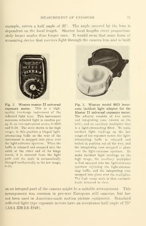
MEASUREMENT OF EXPOSURE 73
example, covers a half angle of 22°. The angle covered by the lens is
dependent on the focal length. Shorter focal lengths cover proportion-
ately larger angles than longer ones. It would seem that some form of
measuring device that receives light through the camera lens and is built
Fig. 2. Weston master II universal
exposure meter. This is a high-
quality two-range instrument of the
reflected light type. This instrument
measures reflected light in candles per
sq. ft. on two instrument scales, 0-1600
and 0-50. The scale shown is the high
range ; in this position a hinged light-
attenuating baffle on the rear of the
instrument is snapped into place over
the light-entrance aperture. When the
baffle is released and snapped into the
catch at the other end of its hinge
travel, it is removed from the light
path and the scale is automatically
changed mechanically to the low range,
0-50.
Fig. 3. Weston model 9925 inver-
cone incident light adapter for the
Master II universal exposure meter.
The adapter consists of two parts,
and integrating cone (shown on the
left), and an auxiliary multiplier that
is a light-attenuating filter. To makeincident light readings on the low
range of the exposure meter, the light-
attenuating baffle is released and
locked in position out of the way, and
the integrating cone snapped in place
over the light-entrance aperture. Tomake incident light readings on the
high range, the auxiliary multiplier
is first snapped into the light-entrance
aperture replacing the light-attenua-
ting baffle, and the integrating cone
snapped into place over the multiplier.
The high range scale is then automat-
ically returned to view.
as an integral part of the camera might be a suitable arrangement. This
arrangement was common in pre-war European still cameras, but has
not been used in American-made motion picture equipment. Standard
reflected light type exposure meters have an acceptance half angle of 25°
(ASAZ38.2.6-1948).

74 IV. MAKING 16-MM ORIGINALS
Both reflected light t}rpe and incident light type exposure meters
have their respective advantages and disadvantages ; a good cameraman
can form the habit of using either with consistent results of superior
quality. The lower priced, reflected light type is to be preferred for
reasons quite apart from theoretical considerations. Prior to World WarII, exposure meters were fragile instruments that had to be handled very
delicately ; since such meters were neither rugged nor reliable enough for
military use, the ASA War Committee on Photography and Cinemato-
graphy (Z52) standardized an improved instrument to correct the short-
comings of the older meter. The calibration reliability and ruggedness
of the War Standard Exposure Meter is now so high that each instrument
may be bounced around in a tumbling barrel with little or no change in
readings as a result of this rough treatment. (ASA Z52.30-1944 de
scribes the Abuse Testing Mechanism.) Such mechanical ruggedness
and calibration reliability over periods of time measured in years rather
than in hours or days are prerequisites to correct exposure measurements.
Any meter used should be guaranteed by the manufacturer to meet the
tests of Z52.30 or its equivalent ; instruments not so guaranteed may be
considered nonstandard and should be avoided as unreliable. Because of
the distinct advantages to both reflection and incident readings, a single
compact instrument to provide both in a simple yet accurate manner
would be a boon to the serious cameraman. Figure 2 is a photograph of a
Weston Master II Universal Exposure Meter. As a step in the direction
of supplying both functions in a single instrument at reasonable cost,
Weston now has available an incident light adapter called the Invercone
Model 9925 that may be used with any Weston Master Universal Ex-
posure Meter such as the Model 715 Master or the Model 735 Master II.
The adapter consists of two parts, an integrating cone and an auxiliary
multiplier. The price of this adapter is only some 10% of the cost of the
meter proper. Figure 3 shows the Weston Invercone Light Adapter.
General Electric has recently marketed a combination instrument ; in this
instrument all components are built as integral parts.
Actinic Value of Exposure
Although it has been pointed out repeatedly in the past, the warning
that lights of different color temperature should never be mixed when
photographing in color still bears emphatic repetition. For all indoor
lighting it is well to assume that the subject is being lighted for color
photographing. In this manner the cameraman and his associates get
ACTINIC VALUE OF EXPOSURE 75
into the habit of lighting for color ; should black-and-white be desired, it
is then necessary merely to reduce the exposure level used.
Color reversal as original film is to be preferred to black-and-white
reversal because of the more precise control exercised in developing ; this
practical advantage far outweighs the possible theoretical advantage of
somewhat better grain characteristics. The graininess advantage of
reversal is likely to remain unrealized commercially because of the far
wider tolerances customary in black-and-white reversal developing and
because of the large haphazard nonprofessional interest that still exists.
Another advantage of photographing the original with color reversal
film is that much subject matter has additional significance when seen in
color. Once the color original exists, it is possible to make a small per-
centage of release prints in color if desired, while the remaining prints
can be made in black-and-white.
As one example, a picture on first aid may be used in black-and-white for general
study, but in a limited number of cases where greater realism is needed for clinical
study, color prints may be used.
When photographing the original with black-and-white reversal film,
uniform actinic quality is still desirable, since variations in color temper-
ature of the lights give rise to variations in contrast of the original film
because of the variations in film gamma with actinic quality of the ex-
posure. Another important consideration also is the fact that exposure
meters do not register equal amounts of all colors equally. The effective
exposure on the film can vary rather widely in that the color sensitivity
of the film may not match the color sensitivity of the exposure meter.
New meters better adapted for color photographing will doubtless be
marketed in the near future.
"When lamps, receptacles, and cables are made up for use in indoor
photographing, it is always good practice to provide at each fixture or
lamp a test outlet into which a reliable test voltmeter may be plugged
for testing the voltage across the lamp. If the difference between the
rated lamp voltage and the voltage as indicated by a reliable meter is
greater than 3 to 5 volts with all lamps turned on, steps should be taken
to correct the difficulty before photographing is attempted, since serious
disturbances of the color balance will otherwise result. The adjustment
can be made by means of a voltage regulator or an adjustable trans-
former such as a Variac. Tn measuring the voltage, the meter used
should be a rugged long-scale instrument (7 inches or so) with accuracy
guaranteed by the manufacturer in the order of 2%. The full-scale
76 IV. MAKING 16-MM ORIGIXALS
reading of the voltmeter should not be greater than the voltage at which
the instrument is used by more than 15% if the usual advantages of
meter-scale accuracy are to be realized.
lo v
Exposure Time and Camera Speed
It must be recognized at the outset that control of exposure time in a
16-mm camera operating at the nominal sound speed of 24 frames per
second cannot be maintained accurately without suitable power drive.
As of the time of writing, the only suitable power drives commercially
available are two types of electric motor: (1) an alternating current syn-
chronous motor energized from a central station line or other line of
good frequency regulation and (2) a governor-controlled, direct-current
motor of the Lee governor type. Good central station frequency regu-
lation is usually better than 0.5%. Good governor-controlled, direct-
current motors are guaranteed for 1% and can maintain 0.5 to 0.75%
with properly designed associated equipment.
There has been no camera marketed so far with other than electric
drive that is capable of propelling as little as 30 feet of film at 24 frames
per second ± 1%. Since the mechanical load presented by a camera
to a motor or other source of driving force varies over rather wide limits,
especially when the ambient temperature changes, any form of drive
other than electric may be subject to suspicion when accurate exposure
control is desired. In the case of motor drive, a suitable manufacturer's
guarantee of speed regulation should be a prerequisite to purchase. Ad-
mittedly, it is not simple to maintain a speed tolerance of 0.5% but it
may be accomplished with an adequately large synchronous motor ener-
gized from the alternating-current mains. Unfortunately, there are
many situations in which the recommended camera speed deviation can-
not be maintained even with an adequate synchronous motor energized
from an adequate central station mains supply. This would occur in
certain cases of operation at low temperatures.
A camera should be expected to function consistently and properly
under the worst combination of adverse circumstances found in practice.
A safety factor of 1.5-2 to 1 in torque required should be considered es-
sential for the worst condition to be encountered with the largest roll of
film placed in the camera, and the lowest temperature under which the
equipment will function. Should the camera fail to come up to speed
properly, it is quite likely that an improper grade of camera oil was
used. Unless special oils are used for camera lubrication, the increased
LENSES AND LENS APERTURE MARKI N11
mechanical load at low temperatures becomes so great due to oil "stiffen-
ing" that it is not possible to find a suitable motor to run the camera.
It would be undesirable to try to run the camera under Nii<-h conditions,
since delicate parts would probably be ruined by improper lubrication.
Suitable camera oils are generieally quite similar to the aircraft instru-
ment oils supplied by all the large oil companies in accordance with JANspecifications. Snch oils are essentially acid-free, light, petroleum-base
oils with added viscosity-extenders.* M<>»t camera manufacturer^ >upply
small quantities of quite similar oils under their private brand names—at very high prices. Unfortunately, the catalog descriptions of such
lubricants are vague and provide no engineering information whatever:
it is usually said or implied that the oil supplied is simply wonderful for
any camera bearing the same brand name. Despite this undesirable
trade practice, such branded oils are usually infinitely better than any
of the ordinary automobile engine oil> sold at gas stations and are still
better than the ''miscellaneous" oils (such as "3-in-l") that are sold so
widely for use in the home. Automobile engine oils should be especially
avoided because of unfavorable viscosity-temperature characteristic,
and miscellaneous oils should be avoided because of a tendency t<» "gum"unfavorable viscosity-temperature characteristics, doubtful lubricating
powers, high acid content, or for one or more of a combination of meas-
urable characteristics that can be quantitatively evaluated in accordance
with ASTM and other standard test procedures.
One suitable camera oil of the general class describe-! is Esso Aviation Instrument
Oil WS-429 made by the Standard Oil Company of Xew Jersey. There are numerous
similar products available from other major oil refining compan: -
Lenses and Lens Aperture Markings
When the photographer sets the iris diaphragm of the lens on
his camera, often he does not realize that the lens manufacturer's "/ "-
Many viscosity extenders are organic compounds that are subject to bacterial
and fungal attack under tropical conditions of use.
t According to ASA Z3S.4.7-U»43
:
1. The symbol for relative aperture of a lens shall lowed by the num-
erical value of the quotient of the focal length divided by the effective aperture, as
in the example / S. Where preferable, the symbol f: may be used.
2. The measured diameter of the maximum aperture, as seen from the front of
the lens, shall be at leas: 95 I the quotient obtained on dividing the engraved focal
length by the engraved /-number.
3. The standard series of diaphragm markings shall be f 0.7, 1.". 1.4. _
8, 11. 16, 22. 32. 45, 64, 90, 128
(Footnote continued on p.
78 IV. MAKING 16-MM ORIGINALS
(relative aperture) stop markings are not actual light transmission mark-
ings at all, but are merely markings derived from calculations related to
the theoretical light transmission geometry of the lens. Such markings
ignore entirely the losses due to absorption, reflection, refraction, and
the like that always occur when a light ray passes from one medium to
another.
The actual transmission (t) of a lens is always less than its relative
aperture (//) rating. Since a loss of 2% to 5% can always be expected
for each surface traversed by a light ray, it is apparent that the trans-
mission loss of a lens which may be thought of as the per cent difference
between the "t" and the "//" depends upon two factors: (i) the light
loss at each surface—which depends upon the design and the coating (if
any), and (2) the number of surfaces involved. Since in lenses of long
focal length, such as the two-element Petzval design in which the number
of elements is small and the design is good, the transmission loss may be
even less than 10%. In a multi-element design, such as the Tessar which
is one of the finest designs ever produced, the transmission loss for an
uncoated lens will ordinarily be about 25%. If that good Tessar lens
is coated, the transmission loss at each surface may be reduced to one-
half of its uncoated transmission loss. It is unfortunate that a relatively
large number of lens elements is necessary for lenses of short focal length
and of wide aperture if proper color correction and good field flatness
are to be achieved. It is obvious that the increase in transmission of a
multi-element lens such as a Tessar is much greater than the increase in
transmission of a Petzval-type lens when such lenses are coated. Lens
coating is especially desirable in both cases despite the relatively small
improvement in transmission in the case of the Petzval-type lens. In
both cases there is a material increase in lens definition ("crispness")
that in itself is very desirable. Strange as it may seem, the improve-
ment in definition is appreciably greater for a lens of good design than
for one of poor design. Lenses of poor design show improvement pri-
marily in transmission—still less improvement in definition.
It will be found that a good 102-mm Eastman coated lens of //2.7
rating will show greater light transmission than a good 1-inch Taylor-
4. The maximum relative aperture marked on a lens need not be selected from
the above series but should be followed by the above series of stop openings beginning
with the next larger number whenever practical and progressing as far as required in
flic individual application. Example: An f/1.9 lens might be engraved f/1.9, 2.8, 4,
5.6, 8, etc., if it were felt that to mark it f/1.9, 2.0, 2.8, 4.0, 5.6, etc., would confuse the
markings at the f/1.9 end of the scale.
LENSES AND LENS APEETURE MARKINGS 79
Hobson-Cooke uncoated lens of f/1.8 rating- when both lenses are set
for f/2.8 aperture. If the latter lens would be coated, its transmission
loss would be reduced. Because of the relatively large number of ele-
ments used in its design, it will still show lower transmission at the f/2.8
marking than the 102-mm Eastman lens even though the coating is
equally good on both lenses. Incidentally, the calibration of most photo-
electric exposure meters assumes the arbitrary value of 76% for lens
transmission.
It is only within very recent years that the interest in measuring lens
transmission has reached the point where the methods of making such
measurements in a truly scientific manner have been evolved and used
outside the research laboratory. What is more appropriate for the
individual photographer than scientific transmission measurement as
such is to have at hand a precalibrated reference lens with which other
lenses that he uses may be compared. This reference lens is used as a
secondary standard for rating all other lenses ; it should be measured for
transmission by a reputable testing laboratory (e.g., the Electrical Test-
ing Laboratories of New York).* Since the Eastman 102-mm f/2.7 lens
is well constructed and has clearly marked //stop engraved lines, and
is a simple coated lens of good design, it can be recommended for this
purpose. Since a 102-mm lens is needed but occasionally in ordinary
photographing, it can be used for comparison calibrations when not
actually needed for photographing.
Many arrangements can be suggested for making "f"\ measurements
and for making comparison calibrations. All require the following
:
(1) A light source.
(2) A lens mount with suitable detecting apparatus. This may consist of a
photoelectric cell or cells that are stable (relatively unaffected by temperature, aging,
or other uncontrolled variation)
.
(3) An indicating meter. This may be a microammeter that is stable.
The actual exposure of film is not used in making a "t 9i calibration
since it would introduce additional unrelated variables. The apparatus
should be built up ruggedly with all parts that are not moved for ad-
justment purposes fixed in location with respect to one another. An old
* Reputable testing laboratories are found in most large cities throughout the
United States. Information concerning them can be obtained from the Society of
Motion Picture Engineers and from the American Standards Association, Inc.
t The tl t-number '' of a lens is the /-number of a fictitious lens having 100%
transmittance and a circular aperture, which would give the same central-image il-
lumination as the actual lens at the specified opening.

80 IV. MAKING 16-MM ORIGINALS
lathe bed makes an excellent foundation for this kind of apparatus just
as it does in similar applications such as title and effects cameras. Such
a rugged base avoids shifting of the parts with respect to the optical
axis due to vibration and similar causes.
In the calibration scale, //4.0 is a convenient center reference. Areasonably practical and complete scale would include a series of calibrat-
ing points from f/0.7 to f/128 in steps of one light stop—a light stop
representing an area ratio of 2 to 1. Since the //stop is numerically
equal to the focal length of the lens measured in inches or millimeters
divided by the diameter of the iris or other diaphragm opening, the
series of light step calibrations will include the following: 0.7, 1.0, 1.4,
2.0, 2.8, 4.0, 5.6, 8., 11., 16., 22., 32., 45., 64., 90., 128.
These calibration points are specified as the standard series of markings in the
American Standard Z38.4.7-1943 in item 3 of American Standard Lens Aperture
Markings.
A serious practical difficulty encountered in setting exposure cor-
rectly with many lenses is the confused and inaccurate manner in which
the index markings are made on the lens. Some time ago it was the gen-
eral practice of manufacturers to mark the //stop numbers and their
corresponding index lines on the periphery of the small iris adjusting
ring of the lens. Since the iris adjusting ring of the lens is small and
the number of points to be marked is quite large, the manufacturer was
faced with the choice of making his markings and index lines too small
to be legible or to make them larger and too crowded and confused.
The first big step in correcting this difficulty was taken in American
Standard Z38.4.7-1943 when the standard series of diaphragm mark-
ings was approved. Still other improvements in marking have been
suggested and tried and further standards will no doubt be promul-
gated when the matter has been studied more thoroughly.
For the calibration of lens transmission a rigid mounting is usually
needed for the lens to be tested so that the conditions will be similar
mechanically to the camera mount on which it will be used. It must be
recognized that interchangeability of lenses on a camera can be accom-
plished only when dimensions of the lens mounting and of the cooperat-
ing mounting hole in the lens turret are made to the same basic dimen-
sion of the distance from the registration shoulder of the lens to the
surface of the image plane—0.690 in. The dimensions are shown in ASAZ52.50/474-1944* for the conventional Type "C" lens mount (which is
* A revision is under way in ASA Z22 committee as Z22.70.
THE FILM 81
the trade name for the camera lens of 1.000-in. major diameter of
mounting thread). Thai standard specifies that ".. . all registration
distances shall be measured from the lens scat to the center of the pic-
ture aperture in the film plane." As will be pointed out later, errors
in registration distance of 0.002 to 0.007 in. are quite common; since
the error is usually made in the "full" direction, it may be corrected
by milling off the appropriate amount of metal from the lens shoulder.
Back* has suggested a relatively simple arrangement that can be
constructed by a person with some training in physics. This apparatus,
which checks absolute transmission, is an embodiment of the concepts
of Berlant, Gardner, and others. If the reference apparatus is too
costly or too complicated for the individual photographer, it is possible
to have a reference lens measured at a commercial testing laboratory
on some apparatus like that which Back suggested, and to make com-
parisons among the lenses at hand using the tested lens as a reference.
Such organizations as Electrical Testing Laboratories have the neces-
sary "knoAY-how," and the charges for their services are very small in-
deed in terms of the services rendered.
Exposure Tests
When using lenses for making comparative exposure tests, the iden-
tical group of lens // stop and focus settings should be used in all cases.
These should be carefully and accurately set to clearly defined markings
in the recommended series of values. If such markings do not exist, it
will pay to have them engraved. The lens should be returned to its
manufacturer for this work.
The Film
Last but not least in importance is the film itself. As pointed out
in Chapter 2, no two lots of manufactured film are sufficiently alike to
permit indiscriminate interchangeability in use. As a practical matter,
the variations in base characteristics are usually of little importance
;
it is the variations of sensitometric characteristics that require attention.
A convenient starting point is to provide sufficient film of the same
emulsion-lot number for the complete production picture. Obviously, in
an estimate of the film required, due allowance must be made for re-
takes and exposure tests. Every manufacturer of motion-picture film
keeps complete and accurate data concerning the sensitometric charac-
* JSMPE, 49. (Aug. 1947)—several papers including that of Back.
82 IV. MAKING 16-MM ORIGINALS
teristics of each lot of film manufactured. This data is often utilized
when an appreciable quantity of film arrives at the manufacturer's proc-
essing laboratory in a single batch for processing; this is done to mini-
mize picture quality variations due to the film and its development.
Before production is begun, a test scene should be photographed to
check the reading of the exposure meter against the exposure actually
obtained. In photographing the test scene, several exposures are madein sequence; each is sufficiently long (a few feet) to make certain that
the camera is operating at correct speed. A typical series of exposures
would be
:
Take 1
:
1 stop overexposed.
Take 2: 1/2 stop overexposed.
Take 3
:
Correct exposure.
Take 4: 1/2 stop underexposed.
Take 5: 1 stop underexposed.
Take 6: 1 1/2 stops underexposed.
This complete test should be made with the lens to be most frequently
used. A shorter test with only takes 1, 3, and 5 can be made on each of
the other lenses that will be used if it is felt that the saving of time
justifies this shortened procedure ; the longer test is preferable.
It should be possible to duplicate the test exposure at any desired
time; a test chart is therefore a convenient subject.* Exposure may be
measured with an exposure meter and checked with a Macbeth Illumi-
nometer.t When the exposed test film is ready to be shipped to the
laboratory, a log sheet describing the test should be taped to the outside
of the sealed film can in which the film is packed. In addition to the log
sheet there should be suitable instructions such as
:
"This is a picture exposure test on Kodachrome 5264 emulsion lot #982 per log
sheet herewith. Please develop at standard time. View these tests and advise which
take most closely approximates correct exposure for duplicating. This test will be
used as the basis for the exposure of (6000) ft. of film of the same lot number. Please
return this test with the log and your comments."
For convenience in record keeping, only a single roll of exposed
film should be packed in a can. Each can sent to a laboratory should
* For convenience in measuring, two subjects should be photographed for each
exposure ; one, a test chart, the second, a grey card of the same size made of the same
material as that used for taking reflection exposure readings with the exposure meter.
The grey frame may readily be measured for density with a densitometer, thereby
permitting calibration of the exposures actually obtained.
t Manufactured by Leeds and Northrup, Philadelphia, Pa.

THE FILM 83
be identified by a can number; it is desirable to serially number the
cans for each particular manufacturer's laboratory.
Because of the high order of accuracy in developing control exer-
cised, it is recommended that the initial exposure tests be made with
Kodachrome that is shipped to Eastman Kodak for processing. It is
suggested also that about 5 feet of unexposed film be Left on the outside
of the test roll; in the developing instructions accompanying the log
sheet it is desirable to request that the unexposed film be exposed with
a IIB sensitometer strip and other suitable standardized exposures.
When the test is returned from Kodak, the projection of the test
will indicate whether the lens //stop markings are seriously in error
and what setting corrections should be made. This exposure test supple-
ments the lens transmission test previously described and should con-
firm the findings of the transmission test. In general, the production ex-
posure chosen should be J light stop underexposed as determined by
these tests. (It is better to underexpose than to overexpose; if in doubt
—underexpose.)
If the laboratory is located sonic distance from location, it is usually
good practice to ship exposure tests to the laboratory some two weeks
before production shooting is scheduled to begin. A time interval is
usually necessary to check and correct minor difficulties that might
otherwise arise unnoticed. Should doubt ever arise concerning the con-
trol of exposure, it is usually best to make a complete new series of tests.
Since the shooting of the picture may extend over a month or more,
a schedule for developing the exposed film should be arranged with the
film manufacturer's laboratory. Although it is customarily good prac-
tice to develop film within 24 hours of exposure, in the case of color
film it is actually preferable to accumulate all the film exposed during
a week, for example, or for the duration of all shooting, and to ship it
to the laboratory for developing in a single lot. This procedure is espe-
cially advantageous for developing Kodachrome or AnscoColor because
a shift in color balance from one day to another does occur in developing.
while the drift in color balance that occurs during a single day is muchsmaller. To make such a scheduling procedure workable requires suit-
able cooled storage for the accumulated film and identification of the cans
for the date of exposure. To get the most from the arrangement, the
developing instructions accompanying the film should refer to the lab-
oratory identification number and the date that the reference test was
developed.
84 IV. MAKING 16-MM OEIGINALS
It is presumed that film will be placed in a can and sealed with
Kodatape or other sealing tape shortly after exposure. In the event that
only a portion of a roll has been exposed at the time a day's shooting- is
ended, the exposed portion will be placed in a sealed can and set aside
for processing. The word "EXPOSED" and the length of the piece
should be marked on the log sheet taped to the can. The unexposed re-
mainder of the roll should be placed in an identified sealed can and
remain there until needed for shooting.
In storing film, rapid changes in temperature should be avoided.
General notes on storage and preservation will be found in chapter XT.
The 16-Mm Sound Original
Historical Background
In recent years most attention has been concentrated upon variable-
area sound recording for 16-mm films; few 16-mm variable-density re-
cording machines of commercial reliability have been manufactured and
used. Most variable-density sound tracks that appear on 16-mm release
prints in the United States are made by optical reduction from 35-mmvariable-density negatives.
To obtain consistent and satisfactory 16-mm sound on release prints
requires good laboratory processing control regardless of the method of
recording used. Since most laboratories handling 16-mm film originally
considered 16-mm processing merely as a sideline in connection with
their 35-mm business, the competitive practices common in 35-mm proc-
essing were merely carried over to 16-mm in aggravated form. In ex-
treme cases, where the Government considered low price the most im-
portant factor in awarding certain processing contrasts in World WarII, some release prints were made that were of doubtful value. The lack
of projector standardization was a further handicap; the fact that a
sound track was intelligible on one projector did not assure its intel-
ligibility on any other. The situation became so acute that quality im-
provement and standardization was the basic assignment of the Z52
War Committee on Photography and Cinematography of the American
Standards Association.
The lead in the solution of these problems was taken, to a consider-
able extent, by manufacturers and film producers (together with their
associated film processing laboratories), whose primary business was
direct 16-mm. Since these groups had for some time been marketing
prints made almost entirely from 16-mm originals, the integration of
THE SOUXD ORIGINAL 85
equipment characteristics with production and laboratory procedures
had been a pressing problem. It was fortunate that this reservoir of
knowledge and experience in coordination was available because it
played an important role in the rapid formulation and adoption of a
large number of war standards. It is also interesting to note that before
World War II, the larger sound equipment manufacturers such as RCAand "Western Electric—who had been responsible for many advances in
35-mm recording—did not take an active part in the intensive develop-
ment of 16-mm recording.
When 16-mm sound-recording equipment was first manufactured,
the quality of release prints made from originals produced by such
equipment was so inconsistent and unreliable that it proved a serious
handicap to equipment sales. There was one obvious solution : techno-
logical control of laboratory processing operations as an integral part
of film production operations. This could only be accomplished by hav-
ing processing laboratories and equipment manufacturers combining
forces. In effect, the manufacturer of 16-mm equipment was required
to guarantee not only the performance of the production equipment
itself, but also the end product resulting from its operation. It was
under such conditions that variable-area sound recording came into
widespread use in direct 16-mm almost to the exclusion of variable
density.
Present Status of 16-Mm Variable-Area Sound
Since 16-mm film has a linear speed of only 36 feet per minute as
compared with 90 feet per minute for 35-mm every precaution must
be observed to maintain the maximum resolving power practicable in
order to provide release prints of satisfactory quality. Conventional
35-mm ordinary positive film emulsions show inferior resolving power;
an increase in resolving power in the ratio of the linear film speeds
(90/36) is necessary to maintain comparable performance.
The first film on the market that approached this design objective
was Agfa 250 (later known as Ansco 2250) .* This is a film with a yellow-
dyed emulsion of appreciably higher resolving power than the ordinary
positive previously used ; it is coated on a clear base. To take maximumadvantage of the emulsion sensitizing, a blue filter (Jena BG-12), is used
in the light beam of the optical system of the recording machine. This
film was suitable not only for sound negatives but also for sound prints
* This film has since been discontinued as a stock item.
86 IV. MAKING 16-MM ORIGINALS
and for direct positives. The distortion resulting from image spread and
similar undesirable photographic characteristics is quite small compared
to conventional printing positive materials, and the resolving power is ap-
preciably greater. Although there are emulsion types that have greater
resolving power (e.g., panchromatic microcopy), there are none that have
sufficient photographic speed and other required characteristics to makethem suitable for variable-area 16-mm sound recording with either existing
recording machines or with machines likely to be designed and manufac-
tured in the near future.
A more recent material designed for the same purpose is Eastman
Code 5372, introduced in 1943. This film is coated on an anti-halation
blue-dyed safety base of the sort commonly used for the universal types of
16-mm reversal picture films. Since it is the emulsion density that is
important in sensitometric control, all measurements of sound track
density must take into account the density of the base (0.26) by adding
this density to the emulsion density to obtain the total density of the
dark area of the sound track as measured by an Eastman densitometer.
The emulsion density found desirable for Eastman 5372 is of the same
order as that for Ansco 2250.
After the initial'
' bugs '
' had been ironed out during the early stages
of its marketing in the 16-mm width on safety base, this excellent East-
man material was offered for sale in the 35-mm width. Its use is increas-
ing rapidly in 35-mm quite as it did in 16-mm.
The 16-mm product is now under excellent manufacturing control
and represents probably the finest film ever offered on the market for
16-mm variable-area sound uses. It has been manufactured for some
time on a low-shrinkage safety base ; the combination of excellent phys-
ical and sensitometric characteristics together with good aging proper-
ties make it an outstanding product. It may be used as
:
(1) Sound negative for recording and re-recording.
{2) Sound direct positive for recording and re-recording.
(3) Sound printing positive.
It can be recommended for all film uses where the blue-dyed base is
not a disadvantage. The manufacturer has coated the same emulsion
upon a clear safety base for sound uses where the dyed base would be
a disadvantage ; the test films supplied by the Society of Motion Picture
Engineers were produced on this film which was guaranteed to have a
shrinkage of 0.5% or less.*
* In accordance with the War Standard test for shrinkage as described in Ap-
STANDAKIZATION OF EXPOSURE FOR SOUND RECORDING, 87
Up to the present time, most 16-mm variable-area originals have
been recorded and developed as negatives. The instructions for the
standardization of sound exposure for such originals, recorded with a
Maurer sound recorder using a 2 ampere lamp, are given in tic sect inn
following. The instructions for exposing and standardizing direct posi-
tives made with equipment of similar manufacture are similar except
for the emulsion density recommendations ; a density of approximately
1.5 is used instead of one of 1.9. Further data is given later in this
chapter.
Standardization of Exposure for Sound Recording
Production Test Exposure
In the recording of variable area sound on 16-mm film, both accurately
controlled exposure and accurately controlled development are essential
for consistent high-quality results. With coordinated control of both,
the sound quality regularly obtained should be substantially equal to that
found in neighborhood entertainment theatres which use 35-mm film.
Experience indicates that sound should be recorded only upon high-
resolving-power film (such as Kodak 5372) exposed through a blue
filter (such as the Jena BG-12). All recent Maurer sound recorders
have a suitable filter installed ; maximum resolving power consistent
with adequate exposure is ordinarily obtained with the arrangement
specified by the manufacturer. Experience also indicates that for the
best sound negative the density of the exposed portion of the film should
be approximately 1.9 at standard development time. Proper exposure
is, therefore, that which provides a density of 1.9 at standard develop-
ment time. The density referred to is the emulsion density, and does
not include the density of the nonhalation tinted base. Thus, the density
read upon Ansco 2250 would be 1.9, since the base of the film is clear;
the density read upon Kodak 5372 film is 1.9 plus 0.26 (the average
density reading for the blue-tinted base), which equals 2.16.
Xo two lamps, no two recording optical systems, or no two emulsion
lots of the same kind of film are identical in speed. The general method
of control is to calibrate each lamp, optical system, or emulsion lot of
film in terms of a reference lamp calibration difference current. These
pendix V and other appendices of Joint Army-Navy Specification JAN-P-49 dated
31 May 1944. (An equivalent specification was issued by the American Standards
Association.)
88 IV. MAKING 16-MM ORIGINALS
calibration difference currents are determined by test before placing
the new lamp, machine, or lot number of film in service for production.
The density, or blackness, of sound tracks is usually measured on
an Eastman 2A densitometer* or other suitable densitometer described
in the earlier chapter on film. Although most film processing labora-
tories can be relied on to read sound-track densities properly when re-
quested, it is good practice for the sound recordist to get into the habit
of regularly checking the sound negatives that he exposes.
The Eastman densitometer requires a uniformly exposed circular area
on the sound track of at least 0.035-in. diameter, and should prefer-
ably be even larger. An exposure test suited for checking with this
densitometer should appear on the end of every roll of sound film
recorded. Since the width of an unbiased sound track is only one-half
the full track width of 0.060 in., a test without bias is unsatisfactory
in that it produces a track width less than the minimum required. Bias
should therefore be applied to the galvanometer so that the exposed
width exceeds the required 0.035 in. This can be conveniently accom-
plished, when, at the end of the last "take" on a roll, the "inic" and
other signal imput keys are turned off, and the bias key is switched
from "decrease" to "increase." In this interval the exposure lamp
current remains unchanged and should be read. After 7 to 10 feet of
film have passed through the machine with the bias key in the reverse
position, the motor switch may be snapped off. This test will provide an
exposed width of 0.055 in. or more.
A bound notebook used as a log book is essential for keeping com-
plete, accurate, and regular records of all film exposed. With a log
book conscientiously kept, it has been possible to obtain excellent co-
ordination between laboratory and equipment user. With such coopera-
tion and forethought, emergency telephone and telegraph messages can
be virtually eliminated, and all necessary information can be conveyed
with complete understanding in either direction without the need for
verbal instructions.
Initial Standardization of Exposure: Lamp Standardization
In order to make the method of calibration practicable, it is neces-
sary to reduce all calibration differences to a common denominator.
The simplest and most suitable is lamp current. The first step is to keep
all other factors constant (e.g., film, recording machine, and processing
* Made by the Eastman Kodak Company of Rochester, N.Y.

STANDAE1ZATI0N OF EXPOSURK FOB SOUND RECORDING 89
bath) while standardizing the exposure lamps. In the discussion that
follows, it is assumed that the exposure lamp used has. a aomina! rating
of 8 volts—2 amperes; the envelope of this lamp is tubular. These lamps
as supplied by Maurer* are prefocused and require no special adjust-
ment to align them properly in the optical system of the sound-record-
ing machine.
The materials on hand must be properly checked and identified. In
the average case, this implies a stock of 6 recording lamps and a month's
supply of raw film all of the idt ntical emulsion lot number. The lamps
should be numbered consecutively (beginning with #1) by scratching
the number with a scriber on the prefocus base of each lamp to be
identified. The label of each can or carton of raw film should be stamped
with the date of receipt from the film supplier. A permanent record of
this and other relevant exposure data may be kept in an exposure data
log book.
Recording the Exposure Test
(1) With all switches "OFF," insert lamp #1 in the recording machine. Seat
the lamp properly in the socket by turning it firmly into position to make certain
that the filament is in the proper location. (Use the lamp originally installed in the
machine as lamp #1.)
(i?) Thread the film in the recording machine. With all input switches ("mic"and "non-sync") "OFF," turn off the AGX (bias) amplifier. Turn on the power
supply. Make up a log sheet. Specify the emulsion lot number of the film.
(a) Record 5 feet of film at 1.95 amps. Enter on log sheet.
(b) Record 5 feet of film at 2.00 amps. Enter on log sheet.
(c) Record 5 feet at 2.05 amps. In the middle of this recording, snap the bias
key back and forth quickly once. Enter on log sheet.
(d) Record 5 feet at 2.10 amps. Enter on log sheet.
(e) Record 5 feet at 2.15 amps. Enter on log sheet.
(3 j Turn off the power at the power supply. Open the recorder door momentarily
—fogging the film for identification. Enter on log sheet. Remove lamp #1 and in-
sert lamp #2 into the socket.
Record 5 feet at 2.00 amps. During this recording, snap the bias key back and
forth twice to identify this test for lamp #2. At the end of the recording, open the
recorder door momentarily. Enter on log sheet.
(4) Repeat the procedure in (3) for each additional lain}), snapping the bias key
back and forth quickly for the number of times required to identify the particular
lamp. Make the proper entries on the log sheet.
(5) Complete the log sheet. Make a note on the log sheet for the developing
laboratory: "Please read the densities of the exposures indicated and note these beside
* J. A. Maurer, Inc., Long Island City, New York.
90 IV. MAKING 16-MM ORIGINALS
the exposures indicated. Develop standard time (6 minutes)*, return original log
sheet, retain carbon copy in the Laboratory file.'
'
If the lamp originally installed in the machine was burned out prior
to this test, it is advisable to follow the recording procedure of section
(2) above for at least two lamps.
Send the film to the laboratory with the original and first carbon
copy of the log sheet taped across the film can. Mark the folded sheets
"Exposure Test." Retain the second carbon copy. In sending written
instructions to a laboratory, it is good practice to make them so clear,
concise, and complete that the laboratory man can follow the written
instructions with no other knowledge of the conditions under which the
films were exposed.
Developing the Exposure Test
Upon receipt of the exposure test film, the laboratory, following your
instructions, develops it at the standard time* of 6 minutes. After de-
velopment, the film is turnd over to the laboratory control depart-
ment where the log sheets and instructions are checked against the
film and the necessary density measurements made. The data is then
entered on the original log sheet for return to you; the film is ordi-
narily not returned unless you ask for it, since it is of no further value.
The carbon copy of the log sheet may be retained in the laboratory
technical file for future reference in connection with your work.
Plotting the Results of the Exposure Test
From the densities marked on the log sheet for lamp #1, prepare
a curve sheet of lamp current vs. density as per Figure 4; the scale
shown is the smallest that should be used.
Plot the points for lamp #1 first; the plotted points should form a
straight line. Draw the straight line with a ruler. The point at which
this diagonal line intersects the 1.90 density line is the Reference LampCalibration Current for the emulsion number and the lot number of the
film used. Place a piece of white adhesive tape across the left half of the
black case of the lamp ammeter located on the amplifier (just below the
meter scale) ; mark this current reading on the tape together with the
word "REFERENCE" and the emulsion and lot number of the film used.
On the same curve sheet, plot the point for lamp #2. Through this
* '' Standard '
' development time will have a different value for each developer in
each laboratory.

STAXDARIZAT10X OF KXI'OSFRE FOR SOUND RECORDING :<i
point draw a straight line parallel to the diagonal line for lamp #1.This new line will intersect the 1.90 density line at the correct lamp cur-
rent for lamp #2; the difference between this current and the ReferenceLamp Calibration Current is the Lamp Difference Current for lamp #2.On a piece of tape of similar size to that previously attached to the am-meter, mark the words: "LAMP #2-ADD (or SUBTRACT) 0—xAMP"
; the lamp difference current. Attach this tape to the base of the
lamp concerned. Repeat this procedure for each lamp, being certain
2
1.9-
Current Li Lz Lj L4
1.80 1001.85 1241.90 1481.95 1.72
2.00 1.96 1.78 2.05 1.85
2.05 2222.10 2.44
2.15 256
Lamp Current for
19 Density
DifferenceCurrent
1.98a
2 2025a Add 0045a3 I97a Subtract O.Ola
4 20la fldd 003a
1.90 I 95 2.00
EXPOSURE LAMP CURRENT
Fig. 4. Characteristic curves obtained by plotting density vs. currents for fourrecording exposure lamps on Eastman 5372 sound recording positive film exposed in aMaurer sound recording machine. The film was developed 6 minutes ("standard"time) at "standard'' temperature (68 F) in a concentrated Eastman D-16 type bath.Note 1: Add 0.28 to the emulsion density shown on the curve to obtain total density ascustomarily reported by laboratories. Note 2: For blue-base stock such as EK 5372,add 0.28 to emulsion densitv for total density.
Enter all the data in the permanentto number each one correctly
exposure log book.
The lamps are now calibrated and are ready for production re-
cording. On a piece of tape such as described above, mark the words"LAMP #1—NO CORRECTION"; attach this tape to the ammeterbeside the Reference Lamp Calibration Cum at tape. Install lamp #1
;

92 IV. MAKING 16-MM ORIGINALS
during its life, use the Reference Lamp Calibration Current, since there
is no correction for this lamp. Lamp #1 may be used until it burns out.
When a new lamp is to be installed, remove the old lamp from the
machine and attach it to the Lamp Difference Current tape located on the
right side of the ammeter (unless of course this is lamp #1, in which
case it would be the No Correction tape instead) ; mark this tape "BO"(burned out). Remove the tape from the base of the new lamp, attach-
ing it in place on the right side of the ammeter, and install the new lamp.
When recording, use the sum of the currents marked on the two tapes
now on the ammeter, and identify the new lamp on the log sheet. Donot detach the Reference Lamp Calibration Current tape unless a com-
pletely new calibration is made. If the test is carefully made and rec-
ords kept properly, this is unnecessary.
If ammeter readings are carefully made and the system outlined
studiously followed, there should be little reason for an over-all density
variation of more than 0.1 from the reference of 1.9; this represents good
control for this type of sound film negative.
It is good practice to check the density measurements made by the
laboratory. If discrepancies are noted as a result of these measurement
checks, the measuring densitometers should be calibrated to detect the
source of the error. It should be remembered that the optical wedge
used for measuring purposes in the Eastman wedge densitometer is a
photographic wedge ; it is not to be relied on over long periods without
calibration. Good practice dictates that it shall be checked on the aver-
age of once a month. To make certain that calibration is done properly,
refer the request for calibration to the manufacturer of the densitometer.
Standardization of Exposure of Direct Sound Positives
It is not practicable to attempt to record a direct sound positive witli
a sound-recording machine designed to record only sound negatives.
While at first glance it may seem possible to record a negative image and
develop the film by the reversal process, this has been found impractica-
ble, since the distortion produced in such variable-area records is ex-
cessive.
Merely reversing the bias key on a recording machine designed for
negative recording, while capable of producing a record that is not dis-
torted, does produce a record that is excessively noisy. The reason for
this becomes apparent when it is seen that the standard width of a scan-
ning beam in a 16-mm sound projector is 0.071 in. while the standard
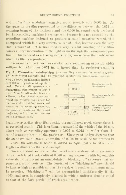
DIRECT SOUND POSITIVES 93
width of a fully modulated negative sound track is only 0.060 in. Asthe space on the film represented by the difference between the 0.071 in.
scanning beam of the projector and the 0.060-in. sound track produced
by the recording machine is transparent because it is not exposed by the
recording machine designed to produce a sound negative record, this
unexposed width is a very serious source of noise, because even the very
small amount of dirt accumulated in very careful handling of the films
causes a large modulation of the light beam through the transparent por-
tion. This is heard as a hissing and scratchy noise from the loudspeaker
when the film is reproduced.
To record a direct positive satisfactorily requires an exposure width
sufficiently wider than 0.071 in. to insure that the projector scanning
Fig. 5. Dimensional relationships: (A) recording aperture for sound negative.
(B) reproducing aperture, and (C) recording aperture for direct sound positive.
Xote 1 : 100% modulation is limited
to 0.060 in. regardless of aperture
used. Xote 2: All apertures are
symmetrical with respect to center
line. Xote 3: All center lines are
colinear. (The shaded areas rep-
resent the overlaps that allow for
the mechanical guiding errors and
weaves of the recording machines,
the printing machines, the sound
projector, and all other interme-
diate apparatus used.)
beam never strikes clear film outside the modulated track where there is
no recorded sound. This is ordinarily assured if the width of the 16-mm,
direct-positive recording aperture is 0.006 to 0.012 in. wider than the
sound-scanning beam of the projector. Since good design dictates that
the standard sound track center line of 0.058 in. shall be maintained in
all cases, the additional width is added in equal parts to either end.
Figure 5 illustrates the relationships.
Since standard sound-recording machines are designed to accommo-
date a modulated track width of 0.060 in., any exposed width beyond this
value should represent an unmodulated "blaeking-in" exposure that ap-
pears on a sound positive. The density of the "blacking-in" area should
be kept as high as possible so that the track will produce minimum noise.
In practice, "blaeking-in" will be accomplished satisfactorily if the
additional area is completely blacked-in with a uniform density equal
to that of the dark portion of track area proper.
u)
IB)
(C)
( •
1 1
!*— o.c
i
60"^
v/A V/A
imm v//m*
1 r- OO77"— 1 H
Recording aperture for
sound negative
Reproducing aperture for
sound positive
Recording aperture for
direct sound positive
(not standardized)
94 IV. MAKING 16-MM ORIGINALS
The smaller dimension of 0.077 in. may be nsed satisfactorily if the
direct-positive sound record will be used on a film phonograph or for
other purposes in which the cumulative weave and the mechanical guid-
ing errors are of small magnitude. The larger dimension of 0.083 in.
should be used when the cumulative weave and mechanical guiding
errors are of. larger order, as is the case if the direct positive is to be used
for printing sound on a Koclachrome release print that will be projected
with a conventional 16-mm sound projector.
For machines that are designed to provide a direct-positive sound
track, a density of approximately 1.50 will be optimal for direct play-
back for EK 5372 under the same developing conditions as those of a
sound negative. The exact value will depend to some extent upon the
developer bath and the developing machine used ; a tolerance of ± 0.10
in density for measurements in the order of 1.0 to 2.0 is practicable for
consistent sound quality. The minimum distortion obtainable will also
depend upon the developer bath no reliable rule-of-thumb data can be
confidently given, since the distortion can vary over a very wide range.
Distortion can be checked by means of a test recording made at several
test exposures; although the method is empirical, it is a good guide to
the result to be expected from the cross-modulation test specified in
American Standard Z22.52-1946 "Cross-Modulation Tests on Variable-
Area 16-Mm Sound Picture Prints." A good test sentence is the old
"chestnut": Sister Susie's sewing shirts for soldiers." Because the
most serious form of distortion encountered in variable-area processing
is envelope distortion, a sentence with a plethora of sibilant sounds makes
a good test. The subject of distortion and distortion testing and meas-
urement is discussed in detail in the chapter on sound recording.
The optimal density of a direct positive that is to be used for printing
a Kodachrome duplicate depends upon a large number of factors that
include
:
(1) Printer contrast factor and degree of collimation of the exposing illumination.
{2) Color temperature and spectral quality of the exposing illumination; the
illuminant may be of the continuous spectrum type or of the band spectrum type.
{3) Turbidity and "image spread" in the direct positive.
(4) Turbidity and "image spread" in the Kodachrome sound track.
Since it is believed that with certain conditions the image spread in
the Kodachrome duplicate can be offset by controlled overexposure and
resulting image spread in the direct positive, more widely differing den-
sity requirements exist for a direct positive that is printed on Koda-

DIRECT SOUND POSITIVES 95
chrome with a continuous contact printer than for Kodachrome printed
with an optical printer. A total density of 2.5 to 3.0 lias been found
advantageous with EK 5372 printed on printers such as the Depue and
the Bell and Howell Model J continuous contact types with conventional
heterochromatic (white light from an incandescent lamp) illumination.
With these conditions, a Kodachrome sound track has been obtained that
sounds somewhat better on commercial projectors than is ordinarily ob-
tained by printing EK 5372 of lower density (found to be optimal em-
pirically) with an older type Maurer optical one-to-one sound printer
using heterochromatic or other continuous spectrum type illumination.
It must be recalled that the names Kodachrome and Ansco Color are trade
names and do not represent specific products. Because of the process
changes that are continually taking place in an effort to reduce cost and
to improve quality, no flat and unequivocal statement concerning rule-of-
thumb handling of sound on Kodachrome or on AnscoColor can be valid
for any considerable period of time. This is the case because the current
design criteria for good sound on color films (or other films for that
matter) have never been explicitly stated by the film manufacturers.
Under such conditions it must be expected that objective and subjective
measurements of the quality level of sound from color prints must con-
tinue to jump about from one statistical universe to another as each
manufacturing process change is introduced. While it is probable
that the magnitude of the "jumps" in quality, and the consequent im-
practicability of correlating statistically the objective and the subjective
tests, will be much smaller in the future because of the lesser dislocations
of the market, improvement and c
' tightening-up " can be expected
if the market demand for quality improvement is insistent, and if
there is willingness to pay a slightly higher price for the higher quality.
Direct-Positive Exposure Test Procedure
The operating procedure for making an exposure test at the end of
a roll of film that has been recorded as a direct positive is the same as
that described for a negative—with but one exception : it is not necessary
to shift the bias key of the recording amplifier from the "wide" track
position. The exposed track width provided by unmodulated track that
is recorded with bias is greater than 0.071 in. (the width of the projector
aperture). Since this value is wider than the 0.035-in. minimum re-
quired for an Eastman Densitometer, it will be practicable to measure
track density with this commonly available instrument. Most density
96 IV. MAKING 16-MM ORIGINALS
measurements in film laboratories are made with an Eastman densitometer
or equivalent.
Standardization of Emulsion Speed
No two emulsion lots of even the same kind of film are of the same
speed. To be effective, a control method for density must take this fac-
tor into account. When film emulsions are manufactured, it is not pos-
sible to predict with absolute accuracy just what the speed and other
sensitometric characteristics of a particular mix are going to be. For
this reason it is common practice among sound recordists to discuss sen-
sitometric characteristics of films in terms of their specific applications.
Thus, in the case of EK 5372, for example, the speed of a particular lot
of film is said to be so many milliamperes faster or slower than the
reference emulsion lot.
Check the materials on hand and identify them properly. In the
average case, this means that a stock of 6 recording lamps is on hand
together with the month's supply of the new emulsion lot number, as
well as at least one full unopened can of the emulsion lot number being
retired. Load the recording machine magazine with this roll of the old
emulsion lot number of film. Make a recording following the procedure
outline in "Recording the Exposure Test/' steps (1) and (2). At the
conclusion of this recording turn off the power supply. Remove the ex-
posed film from the magazine and place it in the original container.
Complete the log sheet. Make a note on the log sheet :
'
' This is an emul-
sion test. Please read the densities of the exposures indicated and note
these beside the exposures. Develop (for direct positive—3 minutes).
Return the original log sheet ; retain the carbon copy for the laboratory
file.', Remove the unexposed film from the magazine; seal it in a can
in the usual manner ; and identify the can with the proper emulsion lot
number and other identification so that the test may be repeated at a
later date if necessary.
Do the same for a test roll of the new emulsion lot. When storing
the unused part of the test roll, make certain that the identification is
correct and complete. Send the films to the laboratory.
Upon return of the completed lop: sheets from the laboratory, plot a
curve for each of the two lot numbers of film in the same manner as for
two new lamps. The difference between the lamp currents at density
1.50 is the Direct Positive Film Difference Current. If the new film re-
quires more current than the older one, enter in the log book: "Add film

LAMP LIFE AND LAMP CONSERVATION 97
difference current 0.— amp."; if the new film requires less lamp cur-
rent, enter in the log book :
'
' Subtract direct positive film difference cur-
rent 0.— amp."
This procedure applies only to films of the same type but of different
lot numbers. Films of different types cannot be properly compared by
this method, since the slopes of density-exposure curves will not be alike.
Lamp Life and Lamp Conservation
In order to obtain sufficient exposure for high-resolving-power sound-
recording films such as EK 5372, it is often necessary for lamp currents
of 2.25 amps, or more to be used with a 2-amp. lamp. An accompanying
result of high exposure currents is short lamp life; occasional com-
ments have been made by users of recording equipment that short life
has been an annoying maintenance problem.
When an original is recorded, it is essential that the effective width of
the recording light beam be exceptionally small and that the film used be
of the highest resolving power practicable. In everyday language, the
recording line of light that is focused on the film shall operate like a
very fine pencil point that is drawing the details of the sound waves
being recorded. Similarly, the film used shall be capable of clearly ren-
dering the very fine lines which the optical system of a good sound re-
corder can draw. The fidelity of the recorded sound is directly depen-
dent upon the narrowness of the line of light in the sound recorder and
upon the resolving power of the sound-recording film used.
The lamp used in the new Maurer sound-recording machine is rated
at 8 volts-2 amps. ; it has a nominal life at this rating of over 25 hours.
If the lamp is operated above 2.25 amps, it is obvious that its life
is correspondingly reduced. The estimated life of the lamp may be
readily calculated by a lamp engineer from the above data. Even at
such short life as that encountered with 2.25 amps., a single lamp is still
capable of recording several reels of film; the cost of the lamp per reel
is still but a fraction of the cost of the film itself.
There is a very simple method of increasing effective lamp life: win n
not actually recording, reduce the lamp current by turning the lamp
rheostat to the lowest position {counter clockwise). Do not turn the
lamp completely out; burning it at reduced current causes far less shock
to the filament than turning it off and on. Turning the lamp down as a
matter of habit will result in a great economy of lamp life ; by doing so
98 IV. MAKING 16-MM ORIGINALS
the lamp will burn at the high and costly recording current only whenactually necessary for recording purposes.
In the new Maurer sound-recording machine that uses the 2a lamp,
lamp operation is more conservative—with the result that lamp life at
the customary operating current is about 5 times as great as that of the
1-amp. lamp used in the earlier Model D. Despite this large increase, it
is still good operating routine to reduce the lamp current approxi-
mately 80% of rated current when not actually recording.
Sound Track Fog and Its Sources
In the prior section on exposure standardization, no mention was
made of sound track fog. In variable-area films, fog is a very important
factor that receives little or no attention in most cases, and far less than
it deserves in others.
Fog may originate in a number of ways
:
(1) The film may be old, defective, or of an incorrect type.
(2) The developer may be poor or exhausted; the film may be overdeveloped.
(3) Stray light may reach the film; a common source is the stray light produced
in the optical system of the sound-recording machine itself.
(1) Films for variable-area sound recording such as Eastman 5372
are designed to provide high resolving power, high contrast, and low
chemical fog. With the manufacturing control exercised today, defec-
tive film is rare when film is fresh; it is only when the material is old
or has been improperly stored that excessive fog and related defects are
encountered. At present, no other type of film can be recommended for
16-mm variable-area sound recording; fog and other difficulties such as
low resolving power are to be expected with film other than the type
mentioned.
(2) Developing difficulties are common. The better developing
agents such as Elon (Eastman Kodak) and its commercial equivalents,
such as Rhodol (DuPont) Metol (Mallinkrodt and others) and Pictol
(Ansco) are expensive, the cost being several dollars per pound. It is
not at all uncommon for low concentrations of these excellent developing
agents to be used in commercial developers together with high concen-
trations of alkali activators such as sodium carbonate to effect the re-
quired developer energy. Since the cost of sodium carbonate is meas-
ured in cents per pound, one reason for the substitution is obvious. Ob-
viously, developer baths of different compositions will produce different
characteristics in the sound track.
SOUXD TRACK FOG AXD ITS SOURCES 99
As a rule, commercial laboratories are reluctanl to disclose for pub-
lication or to their customers specific information about the developer
compositions used. Most commercial developers used for 16-mm sound
negatives, 16-mm direct positives, and 16-mm release prints are essen-
tially of the Eastman D-16 variety, using both Elon and hydroquinone.
The major difference from laboratory to laboratory is in the Elon con-
tent and in the concentration and balance of the developer.
Actually, exact knowledge of the constituents of a given developer
is of little value in a quantitative way without complete data on the oper-
ating characteristics of the machines and full knowledge of the control
methods actually used. This latter information is customarily of little
interest or concern to a buyer of processing laboratory services because
he cannot interpret it properly ; even if he could, it is not available out-
side the processing laboratory organization itself. For this reason the
buyer's best check upon the laboratory services that are offered is meas-
urement of the quality of the finished product. This is best accom-
plished quantitatively by means of test strips handled as part of the
processed film. Such strips may be measured and evaluated. Although
most laboratories have had considerable experience in reading densities
and taking sensitometric data based on Eastman IIB sensitometer read-
ings, their readings of fog and their numerical evaluations of other test
strip data cannot be relied upon to the same degree. Such measurements
and numerical evaluations should be checked independently by the user
if intended for process or other control. Checking laboratory read-
ings as a matter of routine is good procedure, since the measuring toler-
ances for laboratory readings are often unknown and usually have large
ratios of variation from one laboratory to another.
Incorrect film density can be expected if the exposure used in the
sound recorder is not set correctly for the standard developing time of
the developing machine. Developing machines often require long thread-
ing that is measured in yards of threading leader; Figure 6 is a
typical commercial machine. It is obvious that if your sound film
is spliced to another film going through the machine directly ahead
of it (as will invariably be the case in the interest of economy of
handling time and cost) both pieces of film will have the same developing
time. It is not unusual for some 30 to 45 minutes to elapse between the
time your sound film is attached to the head end of the developing ma-
chine and the time it emerges from the dryer at the tail end. To change
developing time on a production developing machine between rolls very
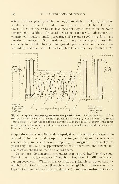
100 IV. MAKING 16-MM ORIGINALS
often involves placing leader of approximately developing machine
length between your film and the one preceding it. If both films are
short, 400 ft. of film or less is developed for, say, a mile of leader going
through the machine. At usual prices, no commercial laboratory can
operate with such a small percentage of revenue-producing film—and
remain in business. The remedy is obvious : always expose sound film
correctly for the developing time agreed upon as standard between the
laboratory and the user. Even though a laboratory may develop a test
I -Feed reel
2 -Head end3- Developer
A -Wash5- Hypo tank
elevator
tank
6- Wash7- 1st stage dryb
2nd sfoge dryboxtail end elevator
9- Takeup reel
Fig. 6. A typical developing machine for positive film. The sections are: 1, feed
reel ; 2, head-end elevator ; 3, developing section ; 4, wash ; 5, hypo ; 6, wash ; 7, drybox
(first section) ; 8, drybox and takeup elevator; 9, takeup reel. Protective and lubri-
cating coatings for release prints are occasionally applied in a special section placed
between sections 8 and 9.
strip before the whole film is developed, it is unreasonable to expect the
laboratory to alter the developing time for your strip of film merely to
correct for your carelessness in exposing the original. Incorrectly ex-
posed originals are a disappointment to both laboratory and owner, and
every effort should be made to avoid them.
In modern photographic equipment that is used intelligently, stray
light is not a major source of difficulty. But there is still much room
for improvement. While it is a well-known principle in optics that the
number of optical surfaces through which a light beam passes should be
kept to the irreducible minimum, designs for sound-recording optics are
SIGNIFICANCE OF SOUND TRACK FOG 101
still complex, and involve many surfaces through which light must pass
from the lamp source to the film to be exposed. There is no substitute
for really good optical design. Where rays are to be transmitted through
an element of a system, it is still a fundamental principle to control the
geometry of the system so that the spurious reflected ray is directed out
of the way. This has been done well in such multi-element picture lens
designs as the Tessar; the effectiveness of such excellent design is ap-
preciated only when the performance of a coated Tessar lens is compared
with that of a similarly coated lens of the same number of elements but
of different design.
On the whole, the optical systems of 16-mm sound-recording machines
manufactured to date have been of reasonably good design. Only within
the last few years has any serious attempt been made to coat the lenses
used; large and significant improvements in image contrast can be ob-
tained by further refinement of the present basic designs and by lens
coating refinements.
Significance of Sound Track Fog
From the foregoing section it is apparent that the density measured
as sound track fog is different from the density measured as chemical
fog. In general, sound track fog is equal to chemical fog plus the fog
due to the imperfect image contrast of the optics of the sound-recording
machine. The importance of maintaining low sound track fog can
hardly be overestimated. Theoretically, an ideal variable-area sound
track would have 100% transmission through the clear portion of the
film and zero transmission through the black portion of the film. It is
obvious that if we consider the output of such a sound track as 100%, the
output of an actual sound track will be less than 100% because the clear
portion absorbs some light and the opaque portion transmits some light.
Viewing actual sound tracks by eye is misleading because the eye
responds logarithmically to light changes, whereas the reproducing
photocell responds linearly. It is for this reason that a sound track that
appears but slightly fogged when viewed by eye has a low output whenreproduced. The loss in output of a sound track with low fog, whose
opaque portion seems gray instead of black, is not as great as the loss
in a dense film with high fog. The percent output of an actual sound
track can be determined quickly if the density of the opaque portion and
the density of the sound track fog are known. The percent output equals
100% minus the sum of the per cent output loss due to the imperfect
opacity and the per cent output loss due to imperfect transmittance re-
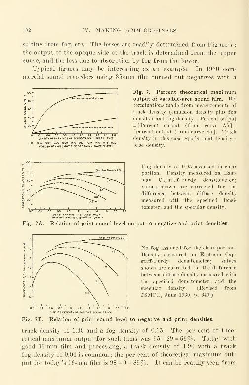
102 IV. MAKING 16-MM OEIGINALS
suiting from fog, etc. The losses are readily determined from Figure 7
;
the output of the opaque side of the track is determined from the uppercurve, and the loss due to absorption by fog from the lower.
Typical figures may be interesting as an example. In 1930 com-
mercial sound recorders using 35-mm film turned out negatives with a
OENSITY OF DARK SIDE OF SOUND TRACK (UPPER CURVE)
0.02 Q04 0.06 0.08 10 012 0.14 0.16 0.18 020FOG OENSITY ON LIGHT SIDE OF TRACK (LOWER CURVE)
Fig. 7. Percent theoretical maximumoutput of variable-area sound film. De-
terminations made from measurements of
track density (emulsion density plus fog
density) and fog density. Percent output
= [Percent output (from curve A)]-
[percent output (from curve B)]. Track
density in this case equals total density
-
base density.
5 80 - Negative Den ity 20
</>—
.]
O 60 _ -->— " " "--*.
O
< 40
<-» °" --»»«^ ^\-^ ~°"^°"^°^ \ G\
£ ?o
/'*>0«^ °®VvN.
gi i i i i i i i i
06~~»
0.6 0.8 1.0 1.2 14 1.6 18 2.0 2.2
DENSITY OF POSITIVE SOUND TRACK(Measured on Purdy-Capstoff Instrument)
Fog density of 0.05 assumed in clear
portion. Density measured on East-
man Capstaff-Purdy densitometer;
values shown are corrected for the
difference between diffuse density
measured with the specified densi-
tometer, and the specular density.
Fig. 7A. Relation of print sound level output to negative and print densities.
: <=ZNegative Density 20
I " 2
! -4 y^—
^
N 11
"6
o-' -8
0- rx oe\
o -io
z
tf> -12
i . i . i . i . i
6\V
No fog assumed for the clear portion.
Density measured on Eastman Cap-
staff-Purdy densitometer ; values
shown are corrected for the difference
between diffuse density measured with
the specified densitometer, and the
specular density. (Revised from
JSMPE, June 1930, p. 640.)
DIFFUSE DENSITY OF POSITIVE SOUNDTRACK
Fig. 7B. Relation of print sound level to negative and print densities.
track density of 1.40 and a fog density of 0.15. The per cent of theo-
retical maximum output for such films was 95-29 = 66%. Today with
good 16-mm film and processing, a track density of 1.90 with a track
fog density of 0.04 is common ; the per cent of theoretical maximum out-
put for today's 16-mm film is 98 - 9 = 89%. It can be readily seen from

MEASUREMENT OF SOUND TRACK FOG 103
these figures that the major improvement has come from reducing fog,
and that there is still room for appreciable further improvement in this
direction.
Soon after sound films were first introduced commercially, it was
quickly recognized that the sound level output of a print depended upon
the density and fog of the negative, and upon the density and fog of the
print. What was not as well recognized, however, was the fact that com-
mercially available densitometers did not measure density in identical
terms. The more common instruments used for control were the diffuse
densitometers of which the Eastman Capstaff-Purdy was a typical ex-
ample, and of which the Eastman Model 1A Densitometer is a modern
counterpart. The monumental work of E. D. Cook that provided the
first rigorous mathemetical analysis of the aperture effect appeared in
the June 1930 issue of the Journal of the Society of Motion Picture
Engineers; it showed a disparity between the output level values calcu-
lated by Cook's method and those obtained in practice. It has taken
some two decades to ascertain with reasonable certainty the sources of
the disparity and to make it possible to determine the physical signifi-
cance of the terms of Cook's equations. One source of difficulty is the
fact that density in Cook's equations must be measured as specular
density and not as some unknown density that is mostly diffiuse, yet has
uncertain portion of specular density involved. Figures 7A and 7B,
showing the relation of sound level output of a print to the density of
the negative and of the print, are revised accordingly.
Measurement of Sound Track Fog
Since some films have dyed bases and other films do not, it is usually
necessary to specify just what densities are to be measured if confusion
of terms is to be avoided.
A starting point in measurement is the density of the base together
with the base dye (if any) . This is referred to as D baS e and can be meas-
ured merely by clearing the film emulsion (from unexposed film taken
directly from a film can) with hypo and reading the cleared film with a
suitable densitometer. If a base is clear, the symbol D c iear base can be
used ; if a base is dyed, the symbol Ddyed base can be used. It is not
usually necessary, however, to specify whether the base is clear or dyed,
since the density values will indicate this ; the symbol Db can therefore
be used for base density.
Chemical fog can be determined by developing a strip of unexposed
film in the manner in which regular film is developed, and then measuring
104 IV. MAKING 16-MM ORIGINALS
the film with a suitable densitometer. The reading thus obtained repre-
sents base density plus chemical fog density. To obtain the chemical
fog density it is necessary to subtract the value of the base density previ-
ously determined. Df0g ( chem) is a convenient symbol for the result.
Sound track fog arises from low exposure contrast and from chemical
fog. If normal current is passed through the lamp of the sound re-
corder and normal bias current applied in the decrease position in order
to provide the thin exposure line obtained on an unmodulated negative,
the density of the unexposed portion of the sound track will be found
to be higher than the chemical fog density. If such a film is developed
and a densitometer reading made, the sound track fog is equal to the
indicated reading minus the base density. Thus, track fog density (Df)
results from chemical fog and exposure contrast fog.
The density of the developed silver of a sound track is determined by
measuring the opaque part of the film and subtracting from the value
obtained the base density and the track fog density. This value obtained
from a film with a dyed base (such as EK 5372) is expressed as Ds+f+b;
the density of the track fog and the density of the base must be sub-
tracted to provide the correct value of silver density. To the recom-
mended silver density of 1.90 for a sound track negative, the track fog
density and the base density must be added to obtain the total track den-
sity. It is total track density that is measured by commercial laboratories
and reported to the customer who requests density information.
As can be appreciated after a study of the factors that affect sound
track output, reliable, consistent, and periodically calibrated densitom-
eters are necessary for good control. The Eastman Kodak densi-
tometer, while quite reliable for measuring densities in the range
of 0.4 to 2.0, is not suited to the reliable measurement of densities
lower than 0.15. Other types of densitometers that are more accurate
at low density values are required; suitable densitometers are the Mar-
tens polarizing-head densitometer (Ansco), the Ansco photoelectric den-
sitometer (Ansco), and the Western Electric KA-1100 photoelectric
densitometer (Electrical Research Products Division of Western Elec-
tric Company, New York City). These more accurate instruments are
more costly and require careful handling comparable to that accorded
a high-grade compound microscope. The Western Electric RA-1100
photoelectric densitometer is to be particularly recommended not only
because of its reliability but also because readings may be made rap-
idly with little fatigue of the operator. The price of this instrument
is over $1000.
CHAPTER V
Dimensions and Standards in 16-Mm
Introduction
The work of pioneers in any engineering field leaves behind inerad-
icable evidences of many of the early solutions to the various design
problems encountered by these pioneers. Time usually tends to mini-
mize the magnitude and extent of the difficulties faced by the pioneers
that are taken for granted by later designers. The 16-mm motion pic-
ture is no exception in this broad generalization.
Fifty years ago at about the same time that Edison was working on
the motion picture in the United States, Lumiere was working on it in
France. In Lumiere 's early film (35-mm in width) the sprocket hole ar-
rangement was far simpler than that of Edison. At either side of the
center of each photographed frame Lumiere provided a single circular
hole by which the film was registered and propelled in the projector.
Years later when 16-mm film was first made in the LTnited States, one
sprocket hole per frame was provided along each edge of the film for
registration and propulsion. The significant changes of the 16-mm film
compared with Lumiere 's film were in the shape of the perforation
(rectangular with rounded corners) and in the location of the sprocket
hole (equidistant vertically between two adjacent photographed frames).
The silent 16-mm film of today is made in just that manner.
Both 35-mm and 16-mm films have been formally standardized di-
mensionally through an international standards organization. Compo-
nent groups keep the international organization continuously informed
of all changes in national standards made or contemplated. Such inter-
national cooperation makes world-wide acceptance and use of motion
pictures possible.
Film Dimensions
When sound was added to 16-mm film in 1930-1931 it was decided
that no essential dimensional differences between cameras made for silent
films and those For sound films were necessary if the sound track could
be accommodated by omitting one of the two rows of sprocket holes.
16-mm sound films made throughout the world today are now made in
105
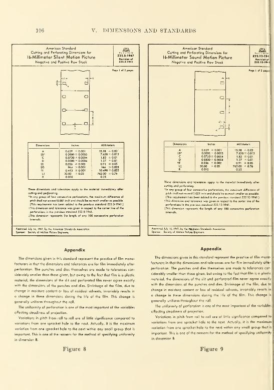
106 V. DIMENSIONS AND STANDARDS
American Standard
Cutting and Perforating Dimensions for
16-Millimeter Silent Motion Picture
Negative and Positive Row Stock
172 J- 1947Revision of
Dim.n.ion, Inches Millimeters
A 0.629 ± 0.001 15.98 =0.03'
t>* 0.3000 - 0.0005 7.620 * 0.013
C 0.0720 = 0.0004 1.83 =0.01D 0.0500 ± 0.0004 1.27 =0.01
tE 0.036 * 0.002 0.91 =0.05to Not > 0.001 Not > 0.025
tl 0.413 * 0.001 10.490 * 0.025
14 30.00 ± 0.03 762.00 =0.76R 0.010 0.25
These dimensions ond tolerances apply to the material
cutting and perforating.
•In any group of (our consecutive perforation!, the maximum difference of
pitch shall not exceed 0.001 inch and should be as much smaller as possible
(This requirement has been added to the previous standard Z22.5-1941.)
fThis dimension and tolerance was given in respect to the center line of the
perforations in the previous standard Z22. 5-1941.
JThu dimension represents the length of any 100 consecutive perforation
intervals.
July 16, 1947, by the American Standard! Anociotion,
Society of Motion Picture Engine**.
Appendix
The dimensions given in this standard represent the practice of film manu-
facturers in that the dimensions and tolerances are for film immediately after
perforation. The punches and dies themselves are made to tolerances con-
siderably smaller than those given, but owing to the fact that film is a plastic
material, the dimensions of the slit and perforated film never agree exactly
with the dimensions of the punches ond dies. Shrinkage of the fiilm, due to
change in moisture content or loss of residual solvents, invariably results in
a change in these dimensions during the life of the film. This change is
generally uniform throughout the roll.
The uniformity of perforation is one of the most important of the variables
affecting steadiness of projection.
Variations in pitch from roll to roll are of little significance compared to
variations from one sprocket hole to the next. Actually, it is the maximum
variation from one sprocket hole to the next within ony small group tjtat is
important. This is one of the reasons for the method of specifying uniformity
in dimension B.
Figure 8
American Standard
Cutting and Perforating Dimensions for
16-Millimeter Sound Motion Picture
Negative and Positive Raw Stock
Z22.11-.94JRevision efMJ.IJ.ie.l
Pago I of 2 pog.i
Dimension, Inches Millimeters
A 0.629 ± 0.001 15.98 =0.03tB* 0.3000 ± 0.0005 7.620 = 0.013
C 0.0720 = 0.0004 1.83 =0.01D 0.0500 ± 0.0004 1.27 =0.01
tE 0.036 * 0.002 0.91 =0.054 30.00 ± 0.03 762.00 = 0.76R 0.010 0.25
These dimensions and tolerances apply to the moteriol immediately after
cutting and perforating.
*ln any group of four consecutive perforations, the maximum difference of
pitch shall not exceed 0.001 inch and should be as much smaller as possible.
(This requirement has been odded to the previous standard Z22. 12-1 941 .)
fThis dimension and tolerance was given in respect to the center line of the
perforations in the previous standard Z22. 12-1941.
fThis dimension represents the length of any 100 consecutive perforation
intervals.
Approved July 16, 1947, by tht AȣilCon Standard! Aiiociatic
Spamor: Society of Motion Picture Engineers.
Appendix
The dimensions given in this standard represent the practice of film manu-
facturers in that the dimensions and tolerances ore for film immediately after
perforation. The punches and dies themselves are made to tolerances con-
siderably smaller than those given, but owing to the fact that film is a plastic
material, the dimensions of the slit and perforated film never agree exactly
with the dimensions of the punches and dies. Shrinkage of the film, due to
change in moisture content or loss of residual solvents, invariably results in
a change in these dimensions during the life of the film. This change is
generally uniform throughout the roll.
The uniformity of perforation is one of the most important of the variables
affecting steadiness of projection.
Variations in pitch from roll to roll are of little significance compared to
variations from one sprocket hole to the next. Actually, it is the maximum
variation from one sprocket hole to the next within any small group that is
important. This is one of the reasons for the method of specifying uniformity
in dimension B.
Figure 9
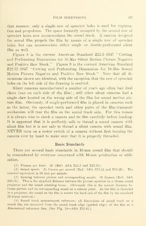
FILM DIMENSIONS 107
that manner; only a single row of sprocket holes is used for registra-
tion and propulsion. The space formerly occupied by the second row of
sprocket holes now accommodates the sound track. A camera designed
for sound film propels the film by means of a single row of sprocket
holes, but can accommodate either single or double-perforated silent
film as well.
Figure 8 is the current American Standard Z22.5-1947 ''Cutting
and Perforating Dimensions for 16-Mm Silent Motion Picture Negative
and Positive Raw Stock." Figure 9 is the current American Standard
Z22.12-1947 "Cutting and Perforating Dimensions for 16-Mm Sound
Motion Picture Negative and Positive Raw Stock." Note that all di-
mensions shown are identical, with the exception that the row of sprocket
holes on the left side of the drawing is omitted.
Silent cameras manufactured a number of years ago often had dual
claws (one on each side of the film) ; still other silent cameras had a
single claw located on the wrong side of the film for sound motion pic-
ture film. Obviously, if single-perforated film is placed in cameras such
as the latter, the sprocket teeth and other parts of the film-transport
mechanism will tear the film on the sound track side. For this reason
it is always wise to check a camera and its film carefully before loading.
It is apparent that it is perfectly safe to thread a sound camera with
silent film but it is not safe to thread a silent camera with sound film.
NEVER turn on a motor switch of a camera without first turning the
camera over by hand to make sure that it is properly threaded.
Basic Standards
There are several basic standards in 16-mm sound film that should
be remembered by everyone concerned with 16-mm production or utili-
zation.
(i) Frames per foot: 40 (Ref: ASA Z22.5 and Z22.12).
{2) Sound speed: 24 frames per second (Ref: ASA Z22.15 and Z22.16). Thenominal equivalent is 36 feet per minute.
(3) Spacing between picture and corresponding sound: 26 frames (Ref: ASAZ22.16). This is the standard distance between the picture aperture in a 16-mm sound
projector and the sound scanning beam. (Obviously this is the correct distance be-
tween picture and its corresponding sound on a release print. As the film is threaded
in a projector, the sound on the film is nearer the head end of the film by the standard
26-frame interval.)
(4) Sound track measurement reference: all dimensions of sound track on a
sound film are measured from the sound track edge (guided edge) of the film as a
dimensional reference line. (See Fig. 10—ASA Z22.41.)
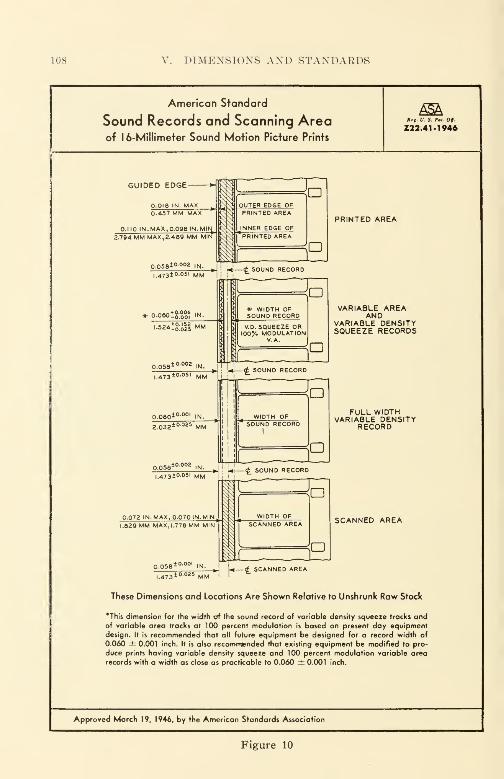
108 V. DIMENSION'S AND STANDARDS
American Standard
Sound Records and Scanning Areaof 1 6-Millimeter Sound Motion Picture Prints
£5kRri. V. S. Pat. Of.
Z22.41-1946
GUIDED EDGE
PRINTED AREA
VARIABLE AREAAND
VARIABLE DENSITYSQUEEZE RECORDS
FULL WIDTHVARIABLE DENSITY
RECORD
SCANNED AREA
<£ SCANNED AREA
These Dimensions and Locations Are Shown Relative to Unshrunk Raw Stock
'This dimension for the width of the sound record of variable density squeeze tracks andof variable area tracks at 100 percent modulation is based on present day equipmentdesign. It is recommended that all future equipment be designed for a record width of
0.060 ± 0.001 inch. It is also recommended that existing equipment be modified to pro-
duce prints having variable density squeeze and 100 percent modulation variable area
records with a width as close as practicable to 0.060 ± 0.001 inch.
Approved March 19, 1946, by the American Standards Association
Figure 10
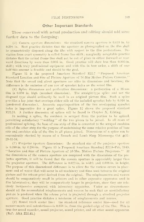
FILM DIMENSIONS 109
Other Important Standards
Those concerned with actual production and editing should add some
further data to the foregoing:
(J) Camera aperture dimensions: the standard camera aperture is 0.410 in. by
0.29-4 in. Best practice dictates that the aperture as photographed on the film shall
be symmetrically disposed along the film with respect to the film perforations. De-
viation from exact symmetry is called frame line shift; marginally acceptable practice
dictates that the actual frame line shall not be out of place in either forward or rear-
ward directions by more than 0.005 in. Good practice will show less than 0.003-in.
shift; with truly professional equipment and with film in best order, a shift of one-
half this amount is feasible and should be the goal.
Figure 11 is the proposed American Standard Z22.7 "Proposed American
Standard Location and Size of Picture Aperture of 16-Mm Motion Picture Cameras."
Note that the sound and silent apertures are alike in dimensions and location; the
difference is the omission of one row of sprocket holes on the sound film.
(6) Splice dimensions and perforation dimensions: a perforation of a 16-mm
film is 0.050 in. high (nominal dimension). The straight-type splice and not the
diagonal type should ordinarily be used in an original picture film. Such a splice
provides a lap joint that overlaps either side of the included sprocket hole by 0.010 in.
(preferred dimension). Accurate superimposition of the two overlapping sprocket
holes is imperative for a good splice. Figure 12 shows the proposed standard
Z22.24. A further discussion of splices will be found in Chapter X, Editing.
In making a splice, the emulsion is scraped from the portion to be spliced,
permitting satisfactory "welding" of the two pieces to be joined. In all cases of
professional splicing, the base of one strip of film is cemented to the scraped emulsion
side of the other strip for the purpose of maintaining the same relative position of base
side and emulsion side of the film in all pieces joined. Dimensions of a splice can be
conveniently checked by means of a Bausch and Lomb Shop Microscope Cat #31-29-33-34.
(7) Projector aperture dimensions: the standard size of the projector aperture
is 0.380-in. by 0.284-in. Figure 13 is Proposed American Standard Z22.8-Feb. 1949.
"Location and Size of Picture Aperture of 16-Mm. Motion Picture Projectors." If
the dimensions of the camera aperture are compared with the dimensions of the pro-
jector aperture, it will be found that the camera aperture is appreciably larger than
the projector aperture. The difference is 0.022-in. in width and 0.008-in. in height.
The purpose of this dimensional difference is to allow for the various errors in place-
ment and of weave that will occur in all machinery and films used between the original
picture and the release print derived from the original. The misplacements and weaves
should be comparatively small in printers and in other expensive apparatus used in
film laboratories; they will be comparatively larger in projectors, since they are rela-
tively inexpensive compared with laboratory apparatus. Under no circumstances
should all the accumulated misplacements and weaves be such that an unsatisfactory
picture is produced when the release print is projected through a standard projector
aperture. Good practice dictates a minimum of misplacements and weaves.
(8) Sound track center line: the standard reference center line—used for all
measurements and calculations—is 0.058 in. from the guided edge of the film. This is
true for sound recorder, sound projector, sound printer, and all other sound apparatus.
(Bef: ASA Z22.41.)
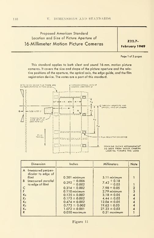
110 V. DIMENSIONS AND STANDARDS
Proposed American Standard
Location and Size of Picture Aperture of
16-Millimeter Motion Picture CamerasZ22.7-
February 1 949
Page 1 of 3 pages
This standard applies to both silent and sound 16-mm. motion picture
cameras. It covers the size and shape of the picture aperture and the rela-
tive positions of the aperture, the optical axis, the edge guide, and the film
registration device. The notes are a part of this standard.
-j-4_THROUGH APERTURE ANDOPTICAL AXI5 OF CAMERA
Film REGISTRATION DEVICE
DRAWING SHOWS ARRANGEMENTAS SEEN FROM INSIDE CAMERALOOKING TOWARD THE LENS
Dimension Inches Millimeters Note
A (measured perpen-
dicular to edge of
film) 0.201 minimum 5.1 1 minimum 1
B (measured parallel292
+ 0006u/y/ - 0.002
2+ 0.18
' ,4 -0.05to edge of film) 1
C 0.314 ±0.002 7.98 ± 0.05 2F 0.1 10 minimum 2.79 minimum 3Ko 0.1 25 ±0.002 3.18 ±0.05 4Ki 0.175 ±0.002 4.44 ± 0.05 4K2 0.474 ± 0.002 1 2.04 ± 0.05 4K 3 0.773 ± 0.002 19.63 ±0.05 4K4 1.072 ±0.001 27.23 ± 0.03 4R 0.020 maximum 0.51 maximum 1
Figure 11
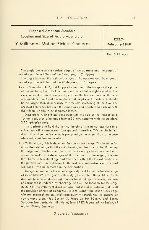
FILM DIMENSIONS 111
Proposed American Standard
Location and Size of Picture Aperture of
16-Millimeter Motion Picture Cameras222.7-
February 1949
Page 2 of 3 pages
The angle between the vertical edges of the aperture and the edges of
normally positioned film shall be degrees, ± Vi degree.
The angle between the horizontal edges of the aperture and the edges of
normally positioned film shall be 90 degrees, ± V2 degree.
Note 1 : Dimensions A, B, and R apply to the size of the image at the plane
of the emulsion; the actual picture aperture has to be slightly smaller. The
exact amount of this difference depends on the lens used and on the sep-
aration (dimension G) of the emulsion and the physical aperture. G should
be no larger than is necessary to preclude scratching of the film. The
greatest difference between the image size and aperture size occurs with
short focal-length, large diameter lenses.
Dimensions A and B are consistent with the size of the images on a
16-mm. reduction print made from a 35-mm. negative with the standard
2.1 5 reduction ratio.
It is desirable to hold the vertical height of the actual aperture to a
value that will insure a real (unexposed) frameline. This results in less
distraction when the frameline is projected on the screen than is the case
when adjacent frames overlap.
Note 2: The edge guide is shown on the sound-track edge. This location for
it has the advantage that the rails bearing on the face of the film along
this edge and also between the sound track and picture area can be of
adequate width. Disadvantages of this location for the edge guide are
that, because film shrinkage and tolerances affect the lateral position of
the perforations, the pulldown tooth must be comparatively narrow and
will not always be centered in the perforation.
The guide can be on the other edge, adjacent to the perforated edge
of sound film. With the guide at this edge, the width of the pulldown tooth
does not have to be decreased to allow for shrinkage. However, because
of variations introduced by shrinkage of film, this location for the edge
guide has the important disadvantage that it makes extremely difficult
the provision of rails of adequate width to support the sound-track edge
without encroaching on, and consequently scratching, the picture or
sound-track area. (See Section 3, Proposals for 16-mm. and 8-mm.
Sprocket Standards, Vol. 48, No. 6, June 1 947, Journal of the Society of
Motion Picture Engineers).
Figure 11 (continued)
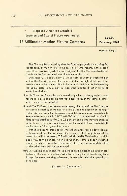
112 V. DIMENSIONS AND STANDAEDS
Proposed American Standard
Location and Size of Picture Aperture of
16-Millimeter Motion Picture CamerasZ22.7-
February 1949
Page 3 of 3 pages
The film may be pressed against the fixed edge guide by a spring, by
the tendency of the film to tilt in the gate, or by other means. In the second
case, there is a fixed guide for each edge of the film. The important point
is to have the film centered laterally on the optical axis.
Dimension C is made slightly less than half the width of unshrunk film
so that the film will be laterally centered if it has a slight shrinkage at the
time it is run in the camera. This is the normal condition. As indicated by
the above discussion, C may be measured in either direction from the
vertical centerline.
Note 3: Dimension F must be maintained only when a photographic sound
record is to be made on the film that passes through the camera; other-
wise F may be disregarded.
Note 4: The K dimensions are measured along the path of the film from the
horizontal centerline of the aperture to the stopping position of the regis-
tration device. Both the dimensions and tolerances were computed to
keep the frameline within 0.002 to 0.005 inch of the centered position for
films having shrinkages of 0.0 to 0.5 per cent at the time they are exposed
in the camera. For any given camera, use the value of K corresponding to
the location of the registration device.
If the film does not stop exactly where the film registration device leaves
it, because of coasting or some other cause, a slight adjustment of the
value of K will be necessary. This will be indicated if film that has a shrink-
age of 0.2 to 0.3 per cent when it is run in the camera does not show a
properly centered frameline. From such a test, the amount and direction
of the adjustment can be determined.
Note 5: "Optical axis of camera" is defined as the mechanical axis or cen-
terline of the sleeve or other device for holding the picture-taking lens.
Except for manufacturing tolerances, it coincides with the optical axis
of the lens.
Figure 11 (concluded)

FILM DIMENSIONS 113
Proposed American Standard
FOR SPLICE
9
FOR 16-.MILLIMETER MOTION PICTURE FILM3FOR PROJECTION
(Third Draft)
SMPE 62Kay
, 19^9
Z22.2^
DIAGONAL SPLICEPage 1 of 3 Pages
SILENT FILMHAS
PERFORATIONSALONG THISEDGE ALSO
STRAIGHT SPLICE
SILENT FILMHAS
]^PERFORATIONS^ ALONG THISEDGE ALSO
Diagonal Splice Straight Splice
Inches Millimeters Inches Millimeters
+0.000 +0.00A 0.070 -0.005 1.7S -O.I3
+0.000H 0.100 -0.005
+0.002.54 -0.13
+0.001 +0.025B 0.546 -0.001 13.92 -0.025
+0.001E 0.54-5 -0.001
+0.02513.92 -0.025
+0.000 +0.00C 0.210 -0.003 5.33 -O.OS
+0.000F O.32+ -0.003
+0.00s.23 -O.OS
+0.000 +0.00D 0.4-11 -0.003 10.4-4 -O.OS
+0.000G 0.324- -0.003
+0.00s.23 -O.OS
NOT APPROVED
Figure 12
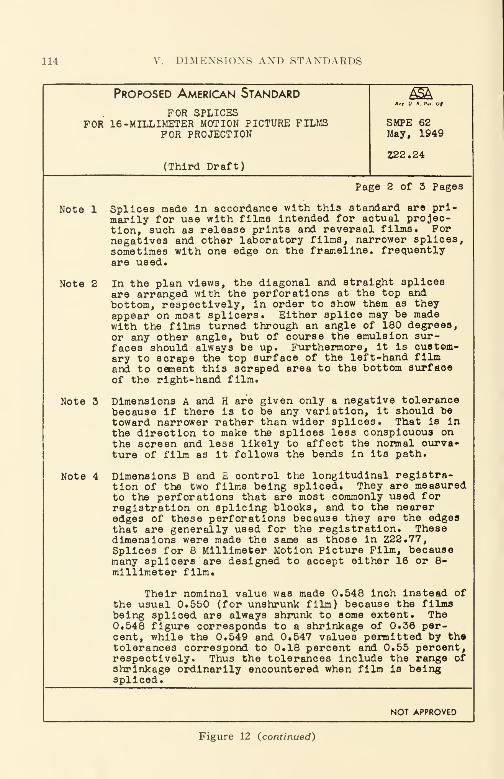
114 DIMENSIONS AND STANDAEDS
Proposed American Standard
for splicesFOR 16 -MILLIMETER MOTION PICTURE FILMS
FOR PROJECTION
(Third Draft)
*»,. V. S. I'*i. Of.
SMPEMay,
621949
Z22.24
Page 2 of 3 Pages
Note 1 Splices made In accordance with this standard are pri-marily for use with films intended for actual projec-tion, such as release prints and reversal films. Fornegatives and other laboratory films, narrower splices,sometimes with one edge on the frameline. frequentlyare used.
Note 2 In the plan views, the diagonal and straight splicesare arranged with the perforations at the top andbottom, respectively, in order to show them as theyappear on most splicers. Either splice may be madewith the films turned through an angle of 180 degrees,or any other angle, but of course the emulsion sur-faces should always be up. Furthermore, it is custom-ary to scrape the top surface of the left-hand filmand to cement this scraped area to the bottom surfaceof the right-hand film.
Note 3 Dimensions A and H are given only a negative tolerancebecause if there is to be any variation, it should betoward narrower rather than wider splices. That is inthe direction to make the splices less conspicuous onthe screen and less likely to affect the normal ourva-ture of film as it follows the bends in its path.
Note 4 Dimensions B and E control the longitudinal registra-tion of the two films being spliced. They are measuredto the perforations that are most commonly used forregistration on splicing blocks, and to the neareredges of these perforations because they are the edgesthat are generally used for the registration. Thesedimensions were made the same as those in Z22.77,Splices for 8 Millimeter Motion Picture Film, becausemany splicers are designed to accept either 16 or 8-millimeter film*
Their nominal value was made 0.548 inch instead ofthe usual 0.550 (for unshrunk film) because the filmsbeing spliced are always shrunk to some extent. The0.548 figure corresponds to a shrinkage of 0.36 per-cent, while the 0.549 and 0.547 values permitted by thetolerances correspond to 0.18 percent and 0.55 percent,respectively. Thus the tolerances include the range ofshrinkage ordinarily encountered when film is beingspliced.
NOT APPROVED
Figure 12 (continued)
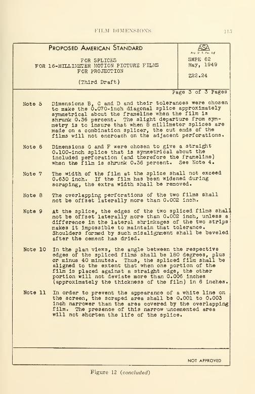
FILM DIMENSIONS 1 15
Proposed American Standard
for splicesFOR 16-MILLIMETER MOTION PICTURE FILMS
FOR PROJECTION
(Third Draft)
*»f U. .«. /'.< Of
SMPE 62May, 1949
Z22.24
Page 3 of 3 Pages
Note 5 Dimensions B, C and D and their tolerances were chosento make the 0.070-inch diagonal splice approximatelysymmetrical about the frameline when the film is
shrunk 0.36 percent. The slight departure from sym-metry Is to insure that when 8 millimeter splices aremade on a combination splicer, the cut ends of the
films will not encroach on the adjacent perforations.
Note 6 Dimensions G and F were chosen to give a straight0.100-Inch splice that is symmetrical about theincluded perforation (and therefore the frameline)when the film is shrunk 0.36 percent. See Note 4.
Note 7 The width of the film at the splice shall not exceed0.630 inch. If the film has been widened duringscraping, the extra width shall be removed.
Note 8 The overlapping perforations of the two films shallnot be offset laterally more than 0.002 inch.
Note 9 At the splice, the edges of the two spliced films shal]not be offset laterally more than 0.002 inch, unless a
difference in the lateral shrinkages of the two stripsmakes it Impossible to maintain that tolerance.Shoulders formed by such misalignment shall be beveledafter the cement has dried*
Note 10 In the plan views, the angle between the respectiveedges of the spliced films shall be 180 degrees, plusor minus 40 minutes. Thus, the spliced film shall bealigned to the extent that when one portion of thefilm is placed against a straight edge, the otherportion will not deviate more than 0.006 inches(approximately the thickness of the film) in 6 inches.
Note 11 In order to prevent the appearance of a white line onthe screen, the scraped area shall be 0.001 to 0.003inch narrower than the area covered by the overlappingfilm. The presence of this narrow uncemented areawill not shorten the life of the splice.
NOT APPROVED
Figure 12 (concluded)
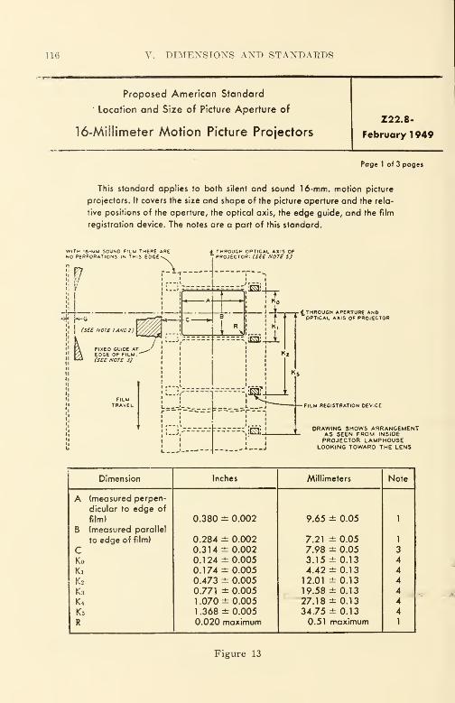
116 V. DIMENSIONS AND STANDARDS
Proposed American Standard
Location and Size of Picture Aperture of
16-Millimeter Motion Picture Projectors
Z22.8-
February 1 949
Page 1 of 3 pages
This standard applies to both silent and sound 16-mm. motion picture
projectors. It covers the size and shape of the picture aperture and the rela-
tive positions of the aperture, the optical axis, the edge guide, and the film
registration device. The notes are a part of this standard.
t THROUGH OPTICAL AXIS OFPROJECTOR: (SEE NOTE i)
^.THROUGH APERTURE ANDOPTICAL AXIS OF PROJECTOR
FILM REGISTRATION DEVICE
DRAWING SHOWS ARRANGEMENTAS SEEN FROM INSIDEPROJECTOR LAMPHOUSE
LOOKING TOWARD THE LENS
Dimension Inches Millimeters Note
A (measured perpen-
dicular to edge of
film) 0.380 ± 0.002 9.65 ± 0.05 1
B (measured parallel
to edge of film) 0.284 ± 0.002 7.21 ± 0.05 1
C 0.314 ±0.002 7.98 ± 0.05 3
Ko 0.124 ±0.005 3.15 ±0.13 4
Ki 0.174 ±0.005 4.42 ±0.13 4
K2 0.473 ± 0.005 12.01 ±0.13 4
K3 0.771 ± 0.005 19.58 ±0.13 4
K4 1 .070 ± 0.005 27.18 ±0.13 4
K5 1 .368 ± 0.005 34.75 ±0.13 4
R 0.020 maximum 0.51 maximum 1
Figure 13

FILM DIMENSIONS 117
Proposed American Standard
Location and Size of Picture Aperture of
16-Millimeter Motion Picture Projectors
Z22.8-
February 1949
Page 2 of 3 pages
The angle between the vertical edges of the aperture and the edges of
normally positioned film shall be degrees, ± Vi degree.
The angle between the horizontal edges of the aperture and the edges of
normally positioned film shall be 90 degrees, — V2 degree.
Note 1 : Dimensions A, B, and R apply to the portion of the image on the film
that is to be projected; the actual opening in the aperture plate has to be
slightly smaller. The exact amount of this difference depends on the lens
used and on the separation (dimension G) of the emulsion and the physical
aperture. To minimize the difference in size and make the image of the
aperture as sharp as practicable on the screen, G should be no larger
than is necessary to preclude scratching of the film. When the reduction
in size from the image to the actual aperture is being computed, it is sug-
gested a 2-inch f/1.6 lens be assumed unless there is reason for doing
otherwise.
Note 2: The limiting aperture is shown as being between the film and the
light source so that it will give the maximum protection from heat. If other
factors are more important, it may be on the other side of the film.
Note 3: The edge guide is shown on the sound-track edge. This location for
it has the advantage that the rails bearing on the face of the film along
this edge and also between the sound track and picture area can be of
adequate width. Disadvantages of this location for the edge guide are
that, because film shrinkage and tolerances affect the lateral position of
the perforations, the pulldown tooth must be comparatively narrow and
will not always be centered in the perforation. Also, in some prints the
sound-track edge is slit after processing, in which case there is likely to
be some lateral weave between this edge and the pictures.
The guide can be on the other edge, adjacent to the perforated edge
of sound film. With the guide at this edge, the width of the pulldown tooth
does not have to be decreased to allow for shrinkage. Also, slitting the
sound-track edge after processing will not introduce lateral unsteadiness.
However, because of variations introduced by shrinkage of film, this
location for the edge guide has the important disadvantage that it makes
extremely difficult the provisibn of rails of adequate width to support the
Figure 13 (continued)

118 V. DIMENSIONS AND STANDARDS
Proposed American Standard
Location and Size of Picture Aperture of
16-Millimeter Motion Picture Projectors
Z22.8-
February 1949
Page 3 of 3 pages
sound-track edge without encroaching on, and consequently scratching,
the picture or sound-track area. (See Section 3, Proposals for 1 6-mm. and
8-mm. Sproket Standards, Vol. 48, No. 6, June 1947, Journal of the
Society of Motion Picture Engineers).
The film may be pressed against the fixed edge guide by a spring,
by the tendency of the film to tilt in the gate, or by other means. In the
second case, there is a fixed guide for each edge of the film. The important
point is to have the film centered laterally on the optical axis.
Dimension C is made slightly less than half the width of unshrunk film
so that the film will be laterally centered if it has a slight shrinkage at
the time it is run in the projector. This is the normal condition. As indicated
by the above discussion, C may be measured in either direction from the
vertical centerline.
Note 4: The K dimensions are measured along the path of the film from the
horizontal centerline of the aperture to the stopping position of the regis-
tration device. It is customary to provide a framing movement of 0.025
inch above and below this nominal position. For any given projector, use
the value of K corresponding to the location of the registration device.
If the film does not stop exactly where the film registration device leaves
it, because of coasting or some other cause, a slight adjustment of the
value of K will be necessary.
Note 5: "Optical axis of projector" is defined as the mechanical axis or
centerline of the sleeve for holding the projection lens. Except for manu-
facturing tolerances it coincides with the lens axis.
Figure 13 (concluded)
CHECKING SOUND TRACK DIMENSIONS 119
(9) Negative sound track width (fully modulated) : the width of a fully
modulated variable-area negative sound track is 0.060 in. This width is symmetrically
disposed about the sound track center line specified above. (Eef. : ASA-Z22.41.)
(10) Projector scanning beam for sound track: the Btandard projector scanning
beam for sound is 0.071 in.; this too is symmetrically disposed about the sound track
center line of 0.058 in. Note that the scanning beam width is greater than the nega-
tive sound track width; the purpose of the dimensional difference is to allow for the
various errors in placement and in weave that will occur in all machinery used between
the original sound record and the release print derived from it. (Eef.: ASA-Z22.41.)
(11) Printed area for sound track of a release print: the standard printed area
for printing a sound release print from a variable-area negative is 0.080 in. (mini-
mum) ; this area is symmetrically disposed about the 0.058 in. center line. Additional
printing area is permitted toward the picture, up to 0.012 in. The relations between
these dimensions are shown in ASA-Z22.41. Note that the printer aperture width is
greater than the scanning beam width of the projector; the purpose of this dimensional
difference is to allow for the various errors in placement and in weave that will occur
in all machinery used between the original sound record and the release print derived
from it.
(12) Direct positives—picture and sound: it should be noted that although the
formally adopted standards for the picture portion of the film have taken direct posi-
tives into account in addition to negatives, no standards have yet been adopted that
take into account direct positives of sound. Only sound by means of negative-positive
processing has been anticipated up to this point. The guiding rule for sound effective-
ness is: "Will the finished product—the print—project properly in a standard 16-mmprojector?" Just as long as that is accomplished, the objectives of the recording,
printing, and processing processes are being attained.*
Checking Sound Track Dimensions
Introduction
The checking of dimensions on motion picture films can clear up
many practical difficulties that might otherwise remain quite obscure.
With a knowledge of current standards and with relatively simple test
apparatus, such as the Bausch and Lomb Shop Microscope mentioned
previously, most dimensional difficulties arising from the picture and
its handling can be readily tracked down. Since sound and its han-
dling often seems somewhat more obscure to many people, a more de-
tailed treatment of the checking of sound-track dimensions seems
worthwhile.
If sound is to be recorded satisfactorily, it must be recorded cor-
rectly with respect to dimensions. This means that aperture widths, aper-
ture locations, and film weaves must be checked. Sound originals should
* Data on new arrangements that are in use but have not been standardized
should be promptly transmitted by anyone interested to the Engineering Secretary of
the Society of Motion Picture Engineers at 40 West 40 St., New York, N. Y., for
suitable consideration in connection with standardizaton.
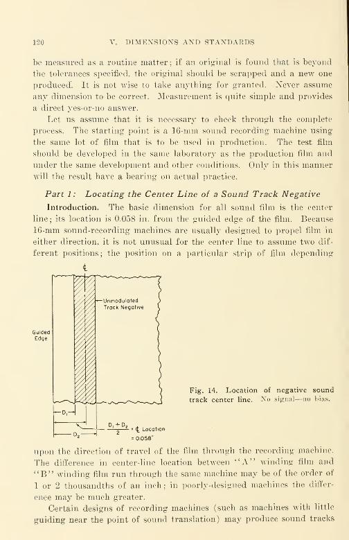
120 DIMENSIONS AND STANDARDS
be measured as a routine matter; if an original is found that is beyond
the tolerances specified, the original should be scrapped and a new one
produced". It is not wise to take anything for granted. Never assume
any dimension to be correct. Measurement is quite simple and provides
a direct yes-or-no answer.
Let us assume that it is necessary to check through the complete
process. The starting point is a 16-mm sound recording machine using
the same lot of film that is to be used in production. The test film
should be developed in the same laboratory as the production film and
under the same development and other conditions. Only in this manner
will the result have a bearing on actual practice.
Part 1 : Locating the Center Line of a Sound Track Negative
Introduction. The basic dimension for all sound film is the center
line ; its location is 0.058 in. from the guided edge of the film. Because
16-mm sound-recording machines are usually designed to propel film in
either direction, it is not unusual for the center line to assume two dif-
ferent positions; the position on a particular strip of film depending
Fig. 14. Location of negative sound
track center line. No signal—no bias.
upon the direction of travel of the film through the recording machine.
The difference in center-line location between "A" winding film andU B" winding film run through the same machine may be of the order of
1 or 2 thousandths of an inch ; in poorly-designed machines the differ-
ence may be much greater.
Certain designs of recording machines (such as machines with little
guiding near the point of sound translation) may produce sound tracks

CHECKING SOI'Mi TRACK DIMENSIONS 121
that weave badly until the machine is up to speed and "settled down":
other designs may produce sound tracks that are badly out of Location
at the start and drift into place over various lengths of film. These are
all defects that can be quickly detected by measurement.
Checking the Center Line. Record a few feet of unmodulated nega-
tive track; it is convenient to make this record with the noise-reduction
(AGX) bias turned off. After having the film developed in the cus-
tomary way, measure the distance D x from the edge of the film to the
closer trace of the sound track as shown in Figure 14. Measure the
distance I)2 from the edge of the film to the far trace of the sound track.
The center line is (D 1 + D 2 )/2 from the edge of the film. To reduce
error, it is desirable to make at least four sets of such measurements
and to use the arithmetric average as the basic dimension in further
calculations. As measured, the center line should be not less than 0.057
in. nor more than 0.059 in. from the edge of the film. It is wise to check
the recording machine with both "A" and "B" winding film; the best
center-line setting is the setting in which one location is just as muchover the 0.058-in. nominal dimension as the other location is under the
0.058-in. nominal dimension. ASA-Z22.75 is the applicable standard for
"A" and "B" winding. (See Chap. VI.)
General Notes on the Center Line. It should be obvious that the
center line of a negative sound track should coincide with the center line
of the projector scanning beam, and also with the center line of the
sound track print made from that negative. This is true not only of
direct 16-mm films but also of 16-mm prints made by optical reduction
from 35-mm originals. The general method described can be applied to
any center-line measurement of sound film.
Measuring Instruments. The instruments chosen should depend upon
the required accuracy and convenience of operation. For occasional
checking, the Bausch and Lomb Shop Microscope (Cat. #31-29-33-34,
code word Ahupo) is an excellent instrument; its price is about $50.
For more accurate measurement, the B & L Toolmaker's Microscope is
distinctly better, but usually too high in price to justify the relatively
small improvement in usefulness.
Conclusion. Generally speaking, if the center line of the recording
machine was properly set at the factory, it is likely that there will be
but little change if the machine receives normal maintenance and care.
All rollers should turn freely, just as when the machine was new. The
machine should always be protected from dust and dirt ; the door should
be fully closed and a dust cover placed over the machine when not in
use. The surface of rollers should be cleaned lightly with carbon tetra-
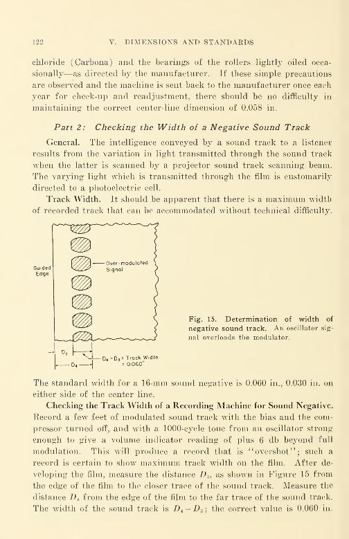
122 V. DIMENSIONS AND STANDARDS
chloride (Carbona) and the bearings of the rollers lightly oiled occa-
sionally—as directed by the manufacturer. If these simple precautions
are observed and the machine is sent back to the manufacturer once each
year for check-up and readjustment, there should be no difficulty in
maintaining the correct center-line dimension of 0.058 in.
Part 2: Checking the Width of a Negative Sound Track
General. The intelligence conveyed by a sound track to a listener
results from the variation in light transmitted through the sound track
when the latter is scanned by a projector sound track scanning beam.
The varying light which is transmitted through the film is customarily
directed to a photoelectric cell.
Track Width. It should be apparent that there is a maximum width
of recorded track that can be accommodated without technical difficulty.
Fig. 15. Determination of width of
negative sound track. An oscillator sig-
nal overloads the modulator.
D 3= Track Width= 0060"
The standard width for a 16-mm sound negative is 0.060 in., 0.030 in. on
either side of the center line.
Checking the Track Width of a Recording Machine for Sound Negative.
Record a few feet of modulated sound track with the bias and the com-
pressor turned off, and with a 1000-cycle tone from an oscillator strong
enough to give a volume indicator reading of plus 6 db beyond full
modulation. This will produce a record that is "overshot"; such a
record is certain to show maximum track width on the film. After de-
veloping the film, measure the distance D3 , as shown in Figure 15 from
the edge of the film to the closer trace of the sound track. Measure the
distance D4 from the edge of the film to the far trace of the sound track.
The width of the sound track is D4 -D3 ; the correct value is 0.060 in.
CHECKING SOUND TRACK DIMENSIONS 123
It is wise to check this dimension because certain older machines have
appreciably wider apertures. Certain RCA recording machines bad
apertures 0.064 in. wide; it was agreed in the War Committee on
Photography and Cinematography (Z52) and further continued in the
Z22 Committee dealing with post-war standards that maximum modu-
lation width should be limited to 0.060 in. in all new equipment manu-
factured, and that existing equipment be modified to meet the 0.060-in.
dimension. (See asterisk note on Z22.41-1946.) Track width should not
be less than 0.059 in. and not greater than 0.061 in. Prints made from
a 35-mm sound original by optical reduction or by any other means are
expected to have such dimensional characteristics that they might have
been made from an equivalent 16-mm sound negative of ASA standard
dimensions.
Part 3 : Initial Bias Setting for a Sound Negative
General. The initial bias setting is an adjustment of the noise-re-
duction equipment (called variously AGX—anti-ground-noise, GXR
—
ground-noise-reduction, NR—noise-reduction or noiseless-recording, or
"bias" equipment) that is necessary to effect "noiseless recording.''
The light transmission through a print made from a properly recorded
"noiseless" negative is at a minimum when there is no signal; the
average transmission of the print when a signal is present is made ap-
proximately proportional to the amplitude of the signal.
Since the bias that controls the average transmission of the film is
customarily derived from the signal itself, it is evident that the bias
current is produced slightly later than the time at which the signal
is applied ; the time interval can be called the actuating delay time.
Other current terms describing the same time interval are : attack time,
opening time, unlocking time, etc. The actuating delay time of a bias
amplifier is in the order of a thousandth of a second. If a sound signal
is suddenly applied (a pistol shot, for example) the signal would arrive
at the recording galvanometer before the bias current; if the initial
bias setting were made for zero track width, distortion would result be-
cause the recorded waves arriving before a millisecond had passed
would be cut off and distortion would result. If, however, the track
width at zero signal were set for some arbitrary value such as 0.005 in.
on conventional equipment, an operating "margin" would be provided
that would permit most ordinary sounds to be recorded without the
serious distortion that results from "chopping off the waves." In a

124 DIMENSIONS AND STANDARDS
sense, the initial bias setting of 0.005 in. would provide the approxi-
mate equivalent of the actuating delay time of the signal.
The best initial bias setting depends upon the character of the sound
to be recorded. Experience has indicated that the setting of 0.005 in. is
satisfactory for most kinds of recorded sound recorded upon most kinds
of sound-recording equipments.
Checking the Initial Bias Setting of a Recording Machine. With the
microphone and other input keys turned off, and with the gain controls
and other signal controls set for zero signal, record a few feet of nega-
tive (3 to 5 ft.) at rated bias current as well as at several settings
above and below rated current. (In the case of a Maurer Model Dequipment, settings at 24, 26, 28, 30, 32, and 34 milliamperes are suit-
t
0007'
0002"
Fig. 16. Measuring the
unmodulated . noise-reduc-
tion negative track widths
obtained with various bias
currents. Current values
shown are typical of Maurer
sound recording machines.
A width of 0.005 in. is recom-
mended.
able.) Keep a log sheet so that each test recording may be identified
quickly. After having the film developed, indicate the width of each
section of track so produced in the appropriate place on the log sheet.
Select the AGN current that provides an initial bias track width of
0.005 in. See Figure 16. Widths are measured on the recommended
microscope or equivalent measuring device. Initial bias track width is
not critical ; if the initial bias setting is once measured and noted, there
will be little need for change in the milliampere setting during the nor-
mal machine life. If the setting is maintained within plus or minus one
milliampere, there should be little cause for concern about this adjustment.
Part 4A : Measuring the Scanning Beam of a Projector for
Center Line and Width
General. The design of a good sound-translating system in a sound
projector brings an engineer-designer face to face writh a dilemma. For
CHECKING SOUND TRACK DIMENSION^ L25
Locating the film accurately with respect to the scanning beam, a guide
should be placed where the scanning beam impinges on the film. On the
other hand, the requirement of best film motion dictates that the guide
shall be as far as possible from the point where the light beam impinges
upon the film. It is for such reasons that the standards take the possi-
bility of weave into account and have allowed for greater weave in
sound projectors than in other machinery involved in the making and
reproducing of 16-mm sound film.
The recommended width of a projector scanning beam is 0.071 in.
The center line of this beam should be located 0.058 in. from the edge
of the film, as described in Part 1. A quick qualitative check of a ma-
chine may be made by playing back an SMPE Buzz Track Test Film
;
this film has a tone of one frequency recorded beyond one limit of the
sound track scanning beam, and a tone of different frequency recorded
beyond the other limit of the sound track scanning beam. For measure-
ment, however, the following procedure is suitable.
Checking the Projector Sound-Scanning Beam. The general method
is to expose fine-grain positive film in the projector, develop the film,
and to measure the track so produced. Obviously, all operations that
involve exposing the film must be conducted in a dark room. Turn on
the projector; run it without film for a few minutes. While it is run-
ning, extinguish all lights except the exciter lamp. The lights to be ex-
tinguished include all pilot lights, the picture projection lamp, etc.
Shut off the machine. Wind approximately 100 ft. of fine-grain positive
film on a reel in such a manner that when the reel is placed on the
feed arm of the projector, the emulsion will face the screen. Make cer-
tain that the sound optics are correctly set for this emulsion position.
Most machines do not provide an adjustment for nonstandard emulsion
position films. Thread the projector. Turn on the amplifier so that the
exciter lamp is lit. (If your machine is one of the older models that
alters the brightness of the exciter lamp to effect volume control, set
the volume control at the setting ordinarily used for ordinary black-
and-white prints.) Run the film through the projector. After takeup,
rewind the film on a core, wrap it. put it in a sealed film can. and send
it to a film laboratory for development. An explanatory note should
be sent with it explaining just what the film is and how it is to be de-
veloped. In most cases, developing at ''standard" release print positive
developing time will be satisfactory.
On the developed film, measure D h from the edge of the film to the

126 V. DIMENSIONS AND STANDARDS
nearer trace of the track. Measure the distance D 6 from the edge of the
film to the far trace of the track. The Avidth of the track (D 6 -D 5 )
should be 0.071 in., if the machine is built within the standards, the
track width will fall between 0.070-0.072 in. The distance of the center
line from the edge of the film should be 0.058 in. ; the method of meas-
uring is described in Part 1 of this chapter. See Figure 17.
If the traces are quite fuzzy due to overexposure, it may be wise to
use EK 5365 (fine-grain duplicating positive film) for the test, or some
other relatively slow film of high resolving power. Other films that maybe suitable are EK 5372 and Eastman or DuPont microcopy (nonpan-
chromatized). Incidentally, some microcopy film is panchromatized to
increase its effective speed; because panchromatic emulsions fog under
Fig. 17. Measuring width of
projector scanning beam. Film is
measured after exposing raw stock
in the projector and developing it.
D-D. : 0.071 in. (nominal)
red light, positive-type emulsions without color sensitizing are best
suited to the purpose. A really desirable film would be a chromatically
unsensitized microcopy emulsion coated on a clear base. It may be
difficult to obtain such a film commercially; if it is, other types some-
what less desirable may have to be used. At least 16 sets of readings
of D 5 and D6 should be made along the central 50-ft. portion of the
100-ft. roll, both readings being made at the same point along the film.
The center-line reading is the arithmetic average obtained from the
16 sets.
In general, it is a good plan to take a relatively large number of
readings, since the probable error of the average is proportional to the
square root of the number of observations. Generally speaking, the
number of reading sets should be 4, 9, 16, 25, 36, 49, 64, etc. ; the actual
number taken being dependent upon the probable error desired. For
most purposes, 16 sets will usually be sufficient.
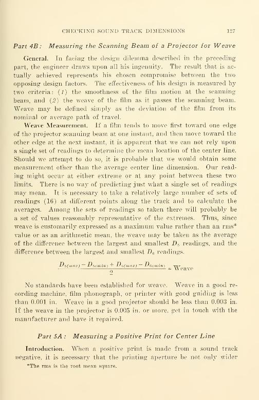
CHECKING SOUND TRACK DIMENSIONS 127
Part 4B : Measuring the Scanning Beam of a Projector for Weave
General. In facing the design dilemma described in the preceding
part, the engineer draws upon all his ingenuity. The result that is ac-
tually achieved represents his chosen compromise between the two
opposing design factors. The effectiveness of his design is measured by
two criteria: (1) the smoothness of the film motion at the scanning
beam, and (2) the weave of the film as it passes the scanning beam.
Weave may be defined simply as the deviation of the film from its
nominal or average path of travel.
Weave Measurement. If a film tends to move first toward one edge
of the projector scanning beam at one instant, and then move toward the
other edge at the next instant, it is apparent that we can not rely upon
a single set of readings to determine the mean location of the center line.
Should we attempt to do so, it is probable that we would obtain some
measurement other than the average center line dimension. Our read-
ing might occur at either extreme or at any point between these two
limits. There is no way of predicting just what a single set of readings
may mean. It is necessary to take a relatively large number of sets of
readings (16) at different points along the track and to calculate the
averages. Among the sets of readings so taken there will probably be
a set of values reasonably representative of the extremes. Thus, since
weave is customarily expressed as a maximum value rather than an rms*
value or as an arithmetic mean, the weave may be taken as the average
of the difference between the largest and smallest D 5 readings, and the
difference between the largest and smallest D fi readings.
JJ?>(max) ~ iJ^(min-) + -Lf&(rnax) ~ J^6(min)= Weave
No standards have been established for weave. Weave in a good re-
cording machine, film phonograph, or printer with good guiding is less
than 0.001 in. Weave in a good projector should be less than 0.003 in.
If the weave in the projector is 0.005 in. or more, get in touch with the
manufacturer and have it repaired.
Part 5A : Measuring a Positive Print for Center Line
Introduction. When a positive print is made from a sound track
negative, it is necessary that the printing aperture be not only wider
*The rms is the root mean square.

128 DIMENSIONS AND STANDAEDS
than the track width of the sound negative (see Part 2), but also wider
than the scanning beam of the projector (see Part 4A). The accepted
dimension for track width of a positive print is 0.080 in. ; the center line
of the track is 0.058 in. from the reference edge of the film.
Most laboratories use a printer aperture wider than 0.080 in. In one
laboratory, for example, a printing aperture of 0.105 in. is used; the
0.025 in. of additional width is provided only on the side of the aperture
toward the picture. This wider aperture is considered necessary because
of the inaccuracies in the scanning beams of certain of the older sound
projectors that are still in use. Although the maximum value for the
scanning beam width is 0.072 in., some of the early machines such as
Fig. 18. Sound track of positive print. Measured for (a) center line, (b)
printer aperture, and (c) weave. Center line= (D+D„)/2 = 0.058 in.; Printer
aperture := D10
in. ) ; Weave -
D9= 0.105 in. (Common values are : D
10= 0.117 in., D
g= 0.012
(Max. D10-Min. D
10 ) + (Max. Dg- Min. D
g)]/2.
the old Victor Animatograph Sound Projectors had beams as wide as
0.085 in.
The use of a printer aperture wider than 0.080 in. represents an at-
tempt on the part of a laboratory to reduce the noise produced when
good prints are run on nonstandard projection machines. When all
projectors in use will have the standard width scanning beam properly
located, laboratories will be able to reduce the printer aperture width
to 0.080 in.
Measuring the Center Line. It will be observed that a bilateral sound
track print from a negative has two black areas separated by a white
area. Measure the distance D7from the edge of the film to the far
boundary of the near black area. Measure the distance D 8 from the edge
of the film to the near boundary of the far black sound track area (see
Fig. 18). The center line dimension is equal to one-half the sum of D 7
CHECKING SOUND TRACK DIMENSIONS 129
and D 8 . Use the average of 16 readings of D 7 and the average of 16
readings for D 8 . In a good printer the misplacement should not be
more than 0.001 in. Needless to say, the misplacement error of no two
printers is alike ; misplacement error cannot be considered the same in
all prints made on all printers in any particular laboratory or in different
laboratories. Machines with positive guiding means, such as optical
one-to-one sound printers, will ordinarily show but little guiding error;
the guiding error in continuous contact printers is appreciably larger.
If printer misplacement exceeds 0.002 in., the offending machine should
be taken out of service and readjusted.
Part 5B : Measuring a Positive Print for Printer Aperture
and Weave
General. The design of a good printer requires the same sort of de-
sign compromise as does a projector; generally speaking, the result to
be expected in a sound printer is appreciably better than from a sound
projector, since the price is much higher.
Checking Printer Aperture Width. The printer aperture width is
D 10 -D 9 (Pig. 18). 16 sets of readings are taken, and the averages of
the D10 and the D 9 readings are used. On much equipment, D 10 is 0.117
in. and D 9 is 0.012 in. for black-and-wdiite prints made from a sound
negative. As mentioned in Part 5A, printer aperture Avidth will prob-
ably be reduced at some time in the future when all nonstandard pro-
jectors have been retired from service or have been repaired and
corrected.
Checking Print Weave. Print weave may be considered to be the
arithmetic average of the difference between the largest and smallest
D l0 readings, and the difference between the largest and smallest D 9 read-
ings. If the weave found in the print is compared with the weave found
in the negative, the difference represents the weave in the printer.
Conclusion. Since the weave found in a really good sound-recording
machine is quite small (usually less than 0.0005 in.), a sound negative
of good quality can ordinarily be used to check weave in other machinery,
such as projectors and printers. Unfortunately, the high order of ac-
curacy of location and the low order of weave found in good sound-re-
cording machines is rarely found in other kinds of sound-film equipment.
Poor equipment maintenance often complicates the problem of accurate
location and low weave, for this reason it is usually a good rule to check
dimensions of all available films and machines to make certain that they
130 V. DIMENSIONS AND STANDARDS
are dimensionally correct. If printer weave exceeds 0.001 in., the source
should be traced and the difficulty corrected.
Part 6: Measuring the Sound Track of a Color Reversal Print
(Kodachrome Duplicate)
General. It must be remembered that a Kodachrome duplicate is a
direct positive that has been derived in most cases by printing on Koda-
chrome from a positive. If there were no misplacements or weavings in
the printers, projectors, or other machines used to make, copy, and re-
produce the film, the printer aperture required for a Kodachrome dupli-
cate would be exactly the width of the aperture of the sound recorder.
Unfortunately, this ideal state of affairs does not exist ; allowance must be
made for the various misplacements and weave that occur in all the ma-
chines used to produce and project the film. If the misplacements and
weaves to be expected are small, only small allowance need be made ; if
the misplacements and weaves are large, correspondingly large allowance
must be made. Since the sound track should be completely scanned by
the scanning beam of the projector, the total misplacement plus weave
should be not more than the difference between the projector scanning-
beam width and the recorder light-beam width. Thus for Kodachrome
printing, the printer aperture should be larger than 0.060 in. yet smaller
than 0.071 in. Since some RCA and other sound-recording machines
may not have been modified from 0.064-in. recording-machine aperture
width to the standard value of 0.060 in., a possible suitable value for
printer aperture width in this case might be 0.0675 in., which value could
be reduced in the near future to 0.0655 in. or even smaller. Many optical
reduction films will have an equivalent 0.064-in. sound track because the
original 35-mm sound track has a 0.076-in. width, and the uncorrected
optical reduction sound printer has a reduction ratio of 7 to 6.
The use of a printer aperture wider than the minimum necessary
causes the introduction of unnecessary noise in reproduction. The pro-
jector scanning beam scans a portion of the film on which no sound has
been recorded;yet the density of that added portion is low enough to
cause modulation of the transmitted light beam by dirt, grain, irregulari-
ties, and other noise-producing elements. As in the case of all other
similar apertures, the printer aperture for printing sound on Koda-
chrome or AnscoColor should be symmetrical with respect to the center
line of the film.
Checking Dimensions. Measure D 7 and Z) 8 on the color duplicate.
SELECTED REFERENCES 131
The center line (D 7 + 2> 8 )/2. Measure D 12 in the manner of D 10 . Meas-
ure 2>n in the manner of D 9 . The aperture width is D 12 minus Du .
The weave is the difference of the extreme values; as previously, it is
taken as the arithmetic average.
Reasonable values for these measurements are : center line—0.058 in.
;
aperture width—0.067 in. : weave—0.001 in.
The difference between the weave found in the Kodachrome duplicate
and that found in a sound positive from which the duplicate was printed
represents the weave of the printer as well as the weave introduced in
printing the duplicate.
Selected References
American Standards Association, "Price List of American Standards", currentissue, see listings for Z22 (motion pictures), Z38 (photography other than cinema-tography), and Z52 (photography and cinematography—American "War Standards).
Additional references may be found in the following JSMPE indexes:
July 1916 to June 1930
"Standardization," page 149.
"Standards and Nomenclature," page 150.
January 1930 to December 1933
"Standardization," page 65.
"Standards and Nomenclature," page 65.
"Standard Test Reels," page 65.
1936 to 1945
"American Standards Association," page 73.
"SMPE Activities," page 128.
"Standards," page 148.
"War Committee on Photography Z52," page 155.

CHAPTER VI
The Problem of 16-Mm Emulsion Position
Introduction
As pointed out in Chapter III, a conventional 16-mm motion picture
film consists essentially of an image-recording emulsion approximately
0.001 in. thick, coated upon a mechanical support—called the base
—
which is approximately 0.005 in. thick and is usually clear. Thus, the
image is confined to the emulsion which is only one-sixth or so of the total
thickness of the film.
What is more important is that the image is located on only one
of the two surfaces of the film base. This almost obvious fact which is
implicitly presupposed and rarely stated explicitly is the crux of the
emulsion position problem despite the fact that there are other knownconsiderations that are not presupposed. One such consideration relates
to the use of a form of light-sensitive film called Ozaphane* (one of manytrade names) in which the light-sensitive, color-forming, diazo dyestuffs
are mixed with the base-material components prior to their manufacture
into sensitized-sheet photographic film. Since these dyestuffs are uni-
formly distributed throughout the base, it would be advantageous from
the optical engineer's point of view if the base material could be made
very thin, about 0.001 in., so that for practical purposes the photographic
image would be located in a thin plane rather than spread out through a
relatively thick solid as it would be viewed by a light beam that traverses
the image-registering film. From the optical engineer's point of view,
the coated emulsion of the conventional film is already only about 0.001
in. thick, and the design advantage of reducing either the emulsion thick-
* It is interesting to note in passing that Ozaphane films are developed in am-
monia gas. Such development has a number of advantages which include:
(1) A positive is made directly from a positive without need for chemical reversal.
{2) Since no water is used for developing solutions, the dimensional changes due
to development are small compared with conventional silver film developing methods.
(3) The image is a colored dye that is substantially grainless and has a high
resolving power.
(4) Sensitometrically, one of the films has a shoulder but no toe to its density
— log exposure curve.
132
HISTORY 133
ness or the base thickness is somewhat problematical in view of the manypractical machine design and manufacturing problems that would be
raised by such a change. Current commercial practice is "frozen" to
the use of coated films of roughly 0.006-in. thickness for 16-mm sound
motion picture purposes.
History
When the original emulsion position problem was first considered in
connection with 16-mm standardization a number of years ago, it was
the belief of the majority concerned that reversal original films of ama-
teur and related origins used for direct projection would be of primary
importance in 16-mm. Accordingly the present standard emulsion posi-
tion was agreed upon. Since, in a camera, the emulsion on the film faces
the lens of the camera, the emulsion would face in the same direction
(toward the lens of the projector) because the identical piece of film was
used in the projector that was exposed in the camera.
Original reversal film failed to materialize as the sole source of 16-mm
films, and when sound made its appearance in 16-mm films optically re-
duced from 35-mm entertainment and like films, all reduction printing
equipment for copying 35-mm to 16-mm was adjusted to produce only
prints of standard emulsion position. A relatively large volume of
optically reduced prints appeared, and, since the time of their first ap-
pearance, almost all such prints have had the standard emulsion position
because all optical reduction printing equipment and processes since used
have been similarly adjusted.
As films were improved and the costs of 8-mm films and equipment
progressively lowered, the cost of 16-mm film and equipment seemed high
for strictly casual amateur uses. 8-mm film and equipment quality has
since advanced to such a degree that amateur interests have to an im-
portant extent transferred to this medium, while 16-mm today is de-
veloping as a professional medium. We must, therefore, consider the ques-
tion of emulsion position in the light of the fact that most 16-mm sound
films produced from 16-mm originals are of nonamateur origin.
Emulsion Position in 35-Mm Practice
When 35-mm negative is threaded in a camera, the emulsion of the
film faces the camera lens. After development, when the negative is
contact-printed, the emulsion of the print stock is exposed to the print-
134 VI. EMULSION POSITION
ing light in contact with the emulsion of the developed negative. Whenthe developed print is threaded in a 35-mm projector, the emulsion on the
print is on the side opposite that of the negative, and therefore the emul-
sion of the print faces the light source of the projector. This emulsion
position is called the 35-mm standard emulsion position. When 35-mmfilm is used, its application, so far as emulsion position is concerned, is
quite simple. All original 35-mm black-and-white picture is taken as
negative, and all prints are made by contact-printing or the equivalent
upon positive raw film. Despite the rapid and continued growth of the
industry—including, even, the introduction of sound and color—the
35-mm medium still remains a typically negative-positive medium just
as it has been for some forty years or more. Where optical printing and
other special processes have been used with 35-mm film as in Technicolor,
for example, all these have been so designed and arranged as to conform
with the requirements of negative-positive handling.
American and international standards recognize the 35-mm standard
emulsion position as the one and only emulsion position to be used in
35-mm release prints. Once a projector has been installed in a theater
and adjusted to give the proper size picture, and to scan the sound track
in proper manner, no further adjustment is required except for main-
tenance. Almost any 35-mm film received for projection—regardless of
whether it is in color or in black and white—will automatically be in
proper focus for both the picture and the sound ; there are very few non-
standard emulsion position 35-mm films released for commercial use.
Since negative-positive processing always has been the only processing
generally available for 35-mm, it was only natural that the jargon of the
industry would take acount of that fact. It is not uncommon, therefore,
for the terms "original" and "negative" to be used interchangeably in
35-mm "slang." Many who are beginning to work in both the 16-mm
and the 35-mm media after having worked previously only in the 35-mm
medium, attempt to carry over the interchangeability of terms to 16-mm
even when the use in that manner is definitely in error.
Early History of 16-Mm Reversal Film
In about 1924, the Eastman Kodak Company first marketed 16-mm
reversal film. To encourage amateur movie making, it was necessary to
reduce the cost of the product to the user by eliminating if possible the
second piece of film, the print, that was formerly needed for projection
Previously all 16-mm film had been negative-positive.
REVERSAL AND COLOR REVERSALS—WHAT THEY ARE 135
Reversal had two important commercial advantages. (1) The iden-
tical piece of film that was exposed by the customer was returned to him
for projection. This avoided misunderstandings when unexposed or
underexposed films were shipped to the film manufacturer for processing.
{2) No print was needed for projection. Eliminating the need for the
print saved the cost of the raw film for the print, the cost of printing,
and the cost of developing the print. This represents a very important
saving.
Reversal was recognized in our 16-mm standards by the caption
:
''In the projector, the base (not emulsion) side of the positive made . . .
by the reversal process . . . faces the light source. " It is worthy of note
that reversal dupe prints began to be commercially important as early
as 1931; their importance increased with the marketing of color dupe
prints and composite color dupe prints a few years later. Several years
had passed, however, before they were given attention in standardization.
Since the standardization problems associated with direct positives have
not been solved as yet, the subject of 16-mm emulsion position is due for
considerable attention now because of the very rapid growth in the vol-
ume and dollar value of nonstandard emulsion position prints—both in
motion pictures and in television.
Reversal and Color Reversals—What They Are
In the broadest sense, a reversal may be most simply defined as a
direct positive. A study of the relative graininess of optical reduction
prints from 35-mm negatives in comparison with step-contact prints from
16-mm original reversal appeared in November, 1940. This comparison
shows reversal original materials at least equal to 35-mm negative for the
making of 16-mm prints.
As has been mentioned previously, Kodachrome has several further
advantages as an original film material for 16-mm picture that can
hardly be overlooked. Not the least of these advantages is that good com-
posite color dupe prints may be turned out in a laboratory concurrently
with excellent black-and-white prints derived from the same originals.
This is possible because the composite color dupe prints are manufac-
tured from either the color positive picture original (or an intermediate
master color duplicate) and from a positive sound track, while the black-
and-white prints are being manufactured from a black-and-white dupli-
cate negative of the picture and a black-and-white sound negative.
136 VI. EMULSION POSITION
Early History of 35-Mm Sound Film
When sound film was commercially introduced in 1929, it was forced
to adapt itself to the current negative-positive procedure of the 35-mmpicture. It is obvious that if the sound is to appear on the same piece of
film with the picture in the composite print, both picture and sound must
ordinarily be developed in the same developer bath. Thus, sound-record-
ing procedure in 35-mm was pinned down to a negative-positive procedure
to conform with the processing of the picture. Making release prints
from original sound negatives was satisfactory only as long as the individ-
ual scenes in the sound negative were quite long, requiring but few
splices in a reel.
In the earlier sound films, scenes were quite long—often as much as
two minutes. As the sound motion picture developed, the length of the
average scene became shorter and shorter until now it is considerably less
than one-tenth of its length in 1929. For this and other reasons, a de-
mand for re-recording and for lip-synchronization grew. This implied
a large number of scenes per reel, and, consequently, a large number of
splices in the original sound negative. It was only logical to expect that
the industry would attempt to produce some form of direct 35-mm sound
positive which, when re-recorded, would eliminate one copying step be-
tween the original sound track and the release print.
In the case of sound, however, reversal film did not come to the rescue
as it did for the 16-mm picture in 1924. The turbidity of the film emul-
sion produced serious distortion when the film was reversal-processed.
In the literature are to be found numerous papers on the subject of en-
velope and other types of distortion in which turbidity plays an impor
tant part. This distortion effect in a negative has been overcome to a
great extent commercially by attempting to produce an equal and op-
posite effect in the print by the choice of suitable exposure and of suitable
development of the print. This procedure has been more or less suc-
cessful and is preferred today regardless of the materials used. It is
most desirable to select emulsions of least turbidity for sound ; in practice
this means the selection of the material of highest resolving power consis-
tent with the available exposure.
An attempt was made to record directly on positive film with the re-
cording system optics and the electrical circuits so modified as to produce
a direct positive by development of the film in a positive bath such as
that used for release prints. The distortion in the direct positive so made
on the best available raw stock was low enough to be satisfactory. For
CURRENT STATUS OF DIRECT L6-MM SOUND 137
purposes of identification we shall call this form of direct-positive sound
recording ''optical reversal" to distinguish it from chemical reversal
While the term is not strictly correct, it will be assumed to include vari-
able-density direct positives such as variable-density toe-recorded sound
film.
The really successful direct positives require film of the finest grain
and highest resolving power. For various reasons which include the
difficulty of obtaining sufficient exposure, direct positives* had not been
widely adopted. The customary procedure is to record the original
sound as a negative, edit it, make a 35-mm positive print, and then re-
record, making a 35-mm sound release negative from which the release
prints are made.
Early History of 16-Mm Sound Film
After the initial failure in 1930 of 16-mm sound negatives made by
re-recording from a 35-mm print, direct 16-mm sound remained dormant
for a number of years. A 16-mm sound camera put in its appearance
in 1932; it was operated by the single-system method. As far as the
sound was concerned, this unit fell heir to the poor resolution encoun-
tered in the commercially unsuccessful re-recording attempts of 1930.
The film used did not have sufficiently high resolution since it was a nega-
tive type best suited to the picture and poorly suited for variable-area
sound recording.
It became evident that the only practicable solution in 16-mm would
be double-system recording—just as it had been the solution in 35-mmsound recording. It was not long afterward that 16-mm double-system
sound recorders were put on the market. Plans were formulated for
their marketing as early as 1936.
Current Status of Direct 16-Mm Sound
By far the largest volume of direct 16-mm sound is produced by the
double-system method with negative-positive processing of the sound
track. Studies have been made of the application of reversal processing
to sound, but it has been the accepted opinion so far that emulsion tur-
bidity and the difficulty of simultaneous control of picture and of sound
quality prevents any straightforward use of the distortion-cancellation
* Since the advent of television, however, this long-neglected procedure has re-
ceived much impetus due to the recent improvements in films for sound recording, and
in sound-recording machines.
138 VI. EMULSION POSITION
technic that we daily find so valuable in variable-area negative-positive
16-mm commercial operations. This factor becomes increasingly impor-
tant as the number of copying operations between the original and the
release print increases. For the present, the foregoing may be considered
true of variable-area sound with which there has been more commercial
experience in the 16-mm film. Reversal processing has had some degree
of technical success for 16-mm variable-density sound although it is not
widely used.
Direct positive 16-mm sound records are becoming increasingly im-
portant since the demands for better sound quality are becoming more
insistent. As will be pointed out in Chapter VIII, the direct positive
form makes possible the elimination of a transfer step in the copying
process, and can result in improved performance because the losses due
to the extra transfer step are avoided.
Kodachrome Sound Duplicating and Its Implications
At the present, sound to be duplicated on Kodachrome is still often
recorded as a negative—a black-and-white print is made from that nega-
tive—and the print used as the sound track positive for printing the
composite color dupe print. For the purposes of this discussion, it makes
little difference whether the original sound track is recorded on 35-mmfilm or on 16-mm film.
It is possible that one of the reasons for so few direct sound positives
used for Kodachrome printing of composites in the past has been the
excessive turbidity of generally available emulsions. Not all positive
materials have this handicap ; Eastman 5372, being fine-grain, shows this
effect to a pleasantly small degree. Much research and development
work is being carried on by the film manufacturers to design even better
types of film. The results obtained so far hold much promise for the
future.
Emulsion Position in 16-Mm
It can be seen from the foregoing that the 16-mm emulsion position
problem cannot be adequately dealt with in a casual manner. Reversal
and color reversal which are practically nonexistent in 35-mm motion pic-
tures are used almost to the exclusion of negative for 16-mm picture
originals. Kodachrome composite color dupe prints, of which there are
possibly a million feet or more used per week in 16-mm do not exist at all
in 35-mm.
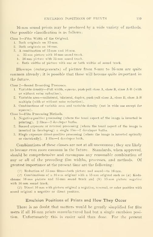
EMULSION POSITIONS OF PRINTS 139
16-mm sound prints may be produced by a wide variety of methods.
One possible classification is as follows
:
Class 1—Film Width of the Original.
1. Both originals on 35-mm.
2. Both originals on 16-mm.
3. A combination of 35-mm and 16-mm.
a. 35-mm picture with 16-mm sound track.
b. 16-mm picture with 35-mm sound track.
c. Both widths of picture with one or both widths of sound track.
Blowups (enlargements) of picture from 8-mm to 16-mm are quite
common already ; it is possible that these will become quite important in
the future.
Class 2—Sound Recording Processes.
1. Variable density—Full width, squeeze, push-pull class A, class B, class A-B (with
or without noise reduction).
2. Variable area—unilateral, bilateral, duplex, push-pull class A, class B, class A-Bmultiple (with or without noise reduction).
3. Combinations of variable area and variable density (not in wide use except for
squeeze).
Class 3—Film Processing Methods.
1. Negative-positive processing (where the tonal aspect of the image is inverted in
printing). 2 films—2 developer baths.
2. Second exposure or reversal processing (where the tonal aspect of the image is
inverted in developing) a single film—2 developer baths.
3. Single exposure direct-positive processing (where the image is inverted optically
or electrically). 1 film—1 developer bath.
Combinations of these classes are not at all uncommon ; they are likely
to become even more common in the future. Standards, when approved,
should be comprehensive and encompass any reasonable combination of
any or all of the preceding film widths, processes, and methods. Of
greatest importance at the present time are the following
:
(1) Reduction of 35-mm films—both picture and sound—to 16-mm.
{2 ) Combinations of a 16-mm original with a 35-mm original such as (a) Koda-
chrome 16-mm picture and 35-mm sound track and (b) 35-mm picture negative
with 16-mm sound track.
(3) Direct 16-mm with picture original a negative, reversal, or color positive with
sound original a negative or direct positive.
Emulsion Positions of Prints and How They Occur
There is no doubt that matters would be greatly simplified for film
users if all 16-mm prints manufactured had but a single emulsion posi-
tion. Unfortunately this is easier said than done. For the present
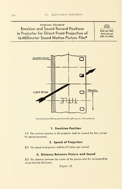
140 VI. EMULSION POSITION
American Standard
Emulsion and Sound Record Positions
in Projector for Direct Front Projection of
16-Millimeter Sound Motion Picture Film*
ASAReg. V. S. Hoi. OS.
Z22.16-1947Revision of
Z22. 16-1941
Drawing shows film as seen from the light-source in the projector.
1. Emulsion Position
1.1 The emulsion position in the projector shall be toward the lens, except
for special processes.
2. Speed of Projection
2.1 The speed of projection shall be 24 frames per second.
3. Distance Between Picture and Sound
3.1 The distance between the center of the picture and the corresponding
sound shall be 26 frames.
Figure 19

TWIN-INT STATI'S OK 1«; MM 14 1
there is no simple method of accomplishing this most desirable objective
without discriminating- in some important manner against certain rela-
tively large groups of film users.
The major difficulty stems from the facts that (a) the cheapest and
simplest method of picture printing- is contact printing, (b) with even
the best equipment it is not possible to add extra steps in processing
without serious losses in picture quality in the release print, and (c) al-
though optical release printing of the picture is capable of correcting the
emulsion position, suitable printers are very costly, require a great deal
of maintenance, and operate at relatively very slow speeds. All this maybe summed up simply by saying that it can be done, but someone will
have to be prepared to pay the extra costs. It is difficult to convince
direct 16-mm film users that optical printing of the picture has great
advantages beyond that of emulsion position; their argument is: "If
optical release printing- of picture is as good as it seems, why is it that
not one single major Hollywood studio prints black-and-white 35-mm film
in that manner? Certainly Hollywood can afford it if they think it is
good." That argument is a difficult one to refute.
Figure 19 is the current ASA emulsion position standard. Figure
'20 shows common processes involving 16-mm contact printing that result
in prints with the standard emulsion position. Figure 21 shows the com-
mon processes involving 16-mm contact printing that result in prints
with the nonstandard emulsion position.
A well-planned picture takes into account the emulsion position of
the release print and how it is to be obtained quite as much as it does the
photographic images to be recorded on the film. For this reason it is wise
for persons concerned with distribution especially to familiarize them-
selves with laboratory operations in order that they will understand the
problems and processes in obtaining the best result from a given set of
films.
Current Status of 16-Mm with Regard to Emulsion Position
Most 16-mm composite release prints in black-and-white of any
origin occur in the standard emulsion position ; during World War II
standard emulsion position release prints went well over a hundred million
feet per year. It seems reasonable to believe that most composite 16-mmcolor dupe prints have the nonstandard emulsion position
;the total out-
put at the present time probably exceeds fifty million feet per year.
When it is remembered that the cost of a composite color d\\\)c print is
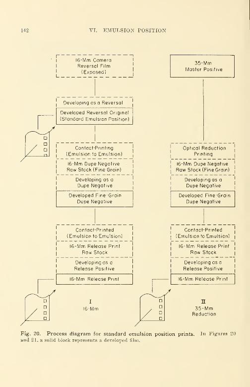
142 VI. EMULSION POSITION
f
1
1
1
L
I6-Mm CameraReversal Film
(Exposed)
—
i
l
1
1
1
Developing as a Reversal
Developed Reversal Original
(Standard Emulsion Position)
Contact-Printing
(Emulsion to Emulsion!
16-Mm Dupe Negative
Raw Stock (Fine Grain)
Developing as a
Dupe Negative
Developed Fine-Grain
Dupe Negative
Contact-Printed
(Emulsion to Emulsion]
I6-Mm Release Print.
Raw Stock
Developing as a
Release Positive
16-Mm Release Print
I
I6-Mm
35-MmMaster Positive
Optical Reduction
Printing
I6-Mm Dupe Negative
Raw Stock (Fine Grain)
Developing as a
Dupe Negative
Developed Fine-Grain
Dupe Negative
Contact-Printed
(Emulsion to Emulsion)
I6-Mm Release Print
Raw Stock
Developing as a
Release Positive
I6-Mm Release Print
n35-Mm
Reduction
Fig. 20. Process diagram for standard emulsion position prints. In Figures 20
and 21, a solid block represents a developed film.
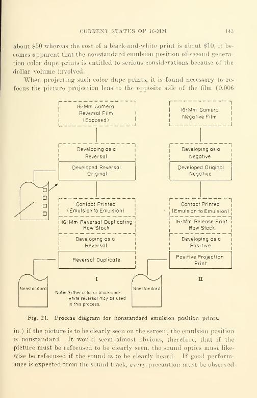
CURRENT STATUS OF 16-MM L43
about $50 whereas the cost of a black-and-white print is about $10, it be-
comes apparent that the nonstandard emulsion position of second genera-
tion color dupe prints is entitled to serious considerations because of the
dollar volume involved.
When projecting such color dupe prints, it is found necessary to re-
focus the picture projection lens to the opposite side of the film (0.006
n
Nonstandard
I6-Mm CameraReversal Film
(Exposed)
Developing as a
Reversal
Developed Reversal
Original
Contact Printed
(Emulsion to Emulsion)
I6-Mm Reversal Duplicating
Raw Stock
Developing as a
Reversal
Reversal Duplicate
Note: Either color or black-and-
white reversal may be used
in this process.
Nonstandard
II6-Mm Camera
Negative Film
'
I
I1
Developing as ai
Negative
Developed Original
Negative
Contact Printed
(Emulsion to Emulsion]
I6-Mm Release Print
Raw Stock
I 1
Developing as a
Positive
Positive Projection
Fig. 21. Process diagram for nonstandard emulsion position prints.
in.) if the picture is to be clearly seen on the screen ; the emulsion position
Is nonstandard. It would seem almost obvious, therefore, that if the
picture must be refocused to be clearly seen, the sound optics must like-
wise be refocused if the sound is to be clearly heard. If good perform-
ance is expected from the sound track, every precaution must be observed
144 VI. EMULSION POSITION
to preserve fidelity which is easily degraded by even the slightest relax-
ing of care and vigilance in sound track focusing. The quality losses in
the copying of films are so great that every precaution possible should be
exercised to make certain that the images on the film that do appear are
accurately translated. Although the maximum resolution of the picture
image of a commercial print is rarely greater at the center than 40 lines
per millimeter, the American War Standard Specification for the Mili-
tary Model 16-Mm Sound Motion Picture Projector (issued as JAN-P-49)
called for a resolving power of the projection objective lens of 90 lines
per millimeter at the center [Par. E-lm (6)]. Since the resolution of
the picture as measured on the screen would be reduced to possibly one-
lialf of its maximum value if the emulsion of the film were on one surface
and the projection lens were focused on the opposite surface, it is neces-
sary to refocus the picture objective lens to restore the resolving power
lost by the incorrect location of the plane of the image. A simple twist
of the wrist corrects picture objective focusing by the required 0.006 in.
The surprising feature of 16-mm sound projectors is that they are
ordinarily adjusted for standard emulsion position prints only, and it is
impracticable if not impossible to refocus, with no interruption in a show,
the sound optics for the proper projection of composite color dupe prints
made by contact printing directly from an original Kodachrome or
AnscoColor picture. Although the large majority of films to be pro-
jected by a 16-mm sound projector are black-and-white which require
the standard emulsion position, there is a very considerable dollar volume
of color prints with nonstandard emulsion position that demand sound
refocusing to overcome the inherent disadvantages of the use of the in-
tegral layer tri-pack for the sound record without incurring the addi-
tional penalty of being out of focus. With present-day optics, there is no
satisfactory compromise fixed adjustment suitable for both emulsion
positions. The usual adjustment is in the form of a small lever associated
with the sound optical system ; this lever has two definite settings—one
for each emulsion position. On any really good film reproduced on any
really good machine with really good optics, the shifting of the lever from
one position to another will immediately identify the correct emulsion
position to any normal listening ear.
Only Eastman Kodak has supplied such an adjustment on certain of
their sound projector models as standard equipment. Bell and Howell
makes this adjustment available on certain projector models at extra
charge. Other manufacturers make no provision at all for the adjust-
SELECTED EEFERENCES 145
ment. The sound optics of most of the latter machines are not amoii^ the
best on the market.
It should be mentioned that all sound projectors can be adjusted by
the manufacturer to project either emulsion position satisfactorily; this
is accomplished by merely focusing the sound optics on the desired side.
Generally speaking, when no adjustment is provided, the projector is se1
for standard emulsion position films.
For the present it seems clear that neither emulsion position can be
successfully ignored. The dollar value of composite color dupe prints is
already sufficiently high in comparison with black-and-white prints to
prevent their needs from being ignored. If the higher budget costs of
the 16-mm color film is also taken into consideration, it seems an anomaly
that projector manufacturers have chosen to concentrate upon the satis-
factory reproduction of cheap black-and-white prints and have chosen to
penalize the costly color films which really need the best in reproduction
that is possible. It should be noted in this connection that due recogni-
tion was given to the nonstandard emulsion position in the War Com-
mittee on Photography and Cinematography Z52 of the American Stan-
dards Association. In the projector specification previously referred to
in section E-2c(7) : "Provision for focus of scanning beam—An adjust-
ment shall be provided for focusing the scanning light beam upon either
surface of the film. Positive means shall be provided for holding sepa-
rately the adjustment in each of these 2 positions of focus. ..."
There are two sides to the emulsion position problem and to the film
—
and the quality of sound reproduction depends materially on "which side
is up." Until some significant changes of widespread magnitude have
been completed that eliminate prints with the nonstandard emulsion
position from circulation and use, provision for focusing at will of the
sound-optical system on either side of the film will remain just as impor-
tant for the sound track as it does for the picture. For the present,
print buyers, being price-conscious, will no doubt continue to purchase
contact-prints as the "best buy for their money." Should this be so,
it appears that the emulsion position problem will remain with us for a
while longer despite the desires of many equipment manufacturers and
others to eliminate nonstandard emulsion position prints.
Selected References
Offenhauser, W. II., "Review of the Question of L6-Mm Emulsion Position/'
JSMPE, 39, 123, (Aug. 1942).
CHAPTER VII
Cameras, Camera Equipment, andCinematography
Introduction
It has been said that motion pictures are produced by projecting on
a screen in rapid succession a series of pictures each of which differs
slightly from the preceding one. The screen is dark during the interval
required for changing from one frame to the next, but, because of the
persistence of vision, the dark interval is not observed. One picture fol-
lows another in such rapid succession that the illusion of a single moving
picture is produced.
General Functions of a Camera
The prime function of a camera is to place a series of photographed
pictures along a roll of film in such manner that the pictures after edit-
ing and copying are suitable for projection on a 16-mm silent or sound
projector. To accomplish this, the camera must meet a number of im-
portant requirements. One of the first requirements is that of proper
operating speed. Since the film produced must be suited to projection
on a sound projector at a speed of 24 frames per second plus or minus
0.75%, it is obvious that for synchronized sound recording the speed
of the camera must have the same nominal value. In this event both
camera and sound-recording machine must run in accurate synchronism.
The camera speed tolerance should be appreciably closer than the pro-
jector speed tolerance specified; since suitable cameras are customarily
driven by a synchronous motor from the alternating-current central sta-
tion mains, the speed tolerance need be but little more than that due to the
frequency regulation of the power supply. In the case of central sta-
tion supply in a large city, a tolerance as small as 0.1 cycle in 60 cycles
is not uncommon. If synchronized sound is not a problem, and the
picture will be scored with sound after editing, the important require-
ment of camera speed is that it be constant and that the photographing
rate be chosen to portray the desired action at the desired rate (as viewed
146
SPRING-DRIVEN CAMERAS 147
on the 24-frames-per-second projector). At the chosen photographing
rate, the individual pictures along the film should be unmarred by the
blurring that occurs in a still picture when the still camera is set for an
exposure time of 1/25 second and the subject moves his head suddenly
just as the photographer presses the button.
Presentation of a sharp and clear picture with a motion picture
camera is the same fundamental problem as with a still camera because
the motion picture film is, in one sense, merely a strip with a succession
of still pictures photographed upon it. Most 16-mm cameras do not
have adjustable shutters; since the customary shutter opening is 170
degrees, the exposure time of most 16-mm cameras is slightly less than
one-half of that implied by the camera speed. In the case of a camera
photographing at the rate of 24 frames per second, for example, the
exposure time per frame is approximately 1/50 sec. For cameras with
other shutters, fixed or adjustable, the exposure time may be estimated
roughly as:
Degrees opening of shutter 1x
360 Frames per second
= Exposure time (in seconds)
Spring-Driven Cameras
Most of the readily available 16-mm cameras are spring-driven; this
includes the various Eastman, Bell and Howell, Victor, DeVry, Zeiss,
Stewart Warner, Keystone, Bolex, and others. There is no spring-
driven camera on the market that is capable of running even 30 feet of
film with one winding of the camera spring (at a speed of 24 frames per
second plus or minus 0.5%). Certain of these cameras are suited for
motor drive with a synchronous motor; the more important are the
Eastman Cine-Kodak Special (Fig. 22) and the Bell and Howell Model
70 DA (Fig. 23). A synchronous motor drive for the Special may be
obtained from a number of sources; essentially, the motor used is a
single-phase synchronous motor made by Bodine or similar motor manu-facturer and adapted by a number of camera equipment manufacturers.
The best source of a synchronous motor drive for the Bell and Howell
70 camera is the camera manufacturer.
As a practical matter it is wise to buy a camera that can be motor-
driven even though the camera will be used primarily as a spring-driven
hand camera. With motor drive readily available, it is possible to check
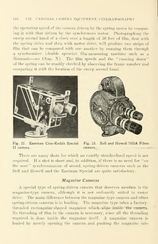
148 VII. CAMERAS, CAM KR A KgUI IWI ENT, CINEMATOGEAPHY
the operating speed of the camera driven by the spring motor by compar-
ing it with that driven by the synchronous motor. Photographing the
sweep second hand of a clock over a length of 50 feet of film, first with
the spring drive and then with motor drive, will produce two strips of
film that can be compared with one another by running them through
a synchronizer (double sprocket film-measuring machine such as a
Neumade—see Chap. X). The film speeds and the "running down"of the spring can be readily checked by observing the frame number andcomparing it with the location of the sweep second hand.
Fig. 22. Eastman Cine-Kodak Special
II camera.
Fig. 23.
camera.
Bell and Howell 70DA Filmo
There are many shots for which an exactly standardized speed is not
required. If a shot is short and, in addition, if there is no need for "on
the nose" synchronization of sound, spring-driven cameras such as the
Bell and Howell and the Eastman Special are quite satisfactory.
Magazine Cameras
A special type of spring-driven camera that deserves mention is the
magazine-type camera, although it is not ordinarily suited to motor
drive. The main difference between the magazine-type camera and other
spring-driven cameras is in loading. The magazine type takes a factory-
threaded rectangular-shaped magazine which slips inside the camnra.
No threading of film in the camera is necessary, since all the threading
required is done inside the magazine itself. A magazine camera is
loaded by merely opening the camera and pushing the magazine into
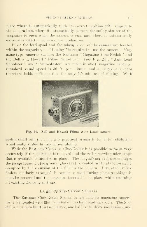
SPRING DRIVEN CAMERAS I 19
place where it automatically finds its correct posit ion with respect to
the camera lens, where it automatically permits the safety shutter of the
magazine to open when the camera is run, and where it automatically
cooperates with the camera drive mechanism.
Since the feed spool and the takeup spool of the camera are located
within the magazine, no "fussing" is required to use the camera. Mag-
azine-type cameras such as the Eastman "Magazine Cine-Kodak" and
the Bell and Howell "Filmo Auto-Load" (see Fig. 24), "Auto-Load
Speedster," and " Anto-Master " are made in 50- ft. magazine capacity.
Standard sound speed is 36 ft. per minute, and a magazine camera
therefore holds sufficient film for only 1.5 minutes of filming. With
Fig. 24. Bell and Howell Filmo Auto-Load camera.
such a small roll, the camera is practical primarily for cut-in shots and
is not really suited to production filming.
With the Eastman Magazine Cine-Kodak it is possible to focus very
accurately if the magazine is removed and the reflex viewing microscope
that is available is inserted in place. The magnifying eyepiece enlarges
the image found on the ground glass that is located in the plane formerly
occupied by the emulsion of the film in the camera. Like other reflex
finders similarly arranged, it cannot be used during photographing; it
must be removed and the magazine inserted in its place, while retaining
all existing focusing settings.
Larger Spring-Driven Cameras
The Eastman Cine-Kodak Special is not called a magazine camera,
for it is threaded with film mounted on daylight loading spools. The Spe-
cial is a camera built in two halves; one half is the drive mechanism, and

150 VII. CAMERAS, CAMERA EQUIPMENT, CINEMATOGRAPHY
the other half—which is separable—is called the film chamber. Film
chambers are made in two sizes: 100 and 200 ft. The smaller is the
same size as the mechanism portion of the camera, the larger is larger
than the mechanism portion of the camera. Since the Special is a form
of magazine camera, the pull-down claw for the film is located in the
film chamber. This is a disadvantage because the photographed frame
line shifts appreciably due to film shrinkage ; the amount of shift is de-
pendent upon the percentage of film shrinkage multiplied by the number
of frames distance between the photographing aperture and the claw.
In older models of this camera the separation of gate and claw was as
much as 9 frames; newer cameras have a much smaller separation
—
about 4 frames. Frame line shift is particularly annoying when maga-
zines are to be interchanged; it is obvious that the magazines have to
be "fitted" to the camera to make certain that the claw arrangement
makes satisfactory allowance for the distance between gate and claw in
the particular camera at hand. Kodak is prepared to fit the chambers.
Eastman lenses (16-mm) are not equipped with the "Type C" lens
mount employed by most all other manufacturers; they use a special
bayonet type of mount found in Eastman cameras only. In general,
the Eastman lenses are among the best on the 16-mm market; to
use them on other cameras requires an Eastman adapter that reconciles
the bayonet Eastman mount and the customary Type C mount.
It should not be assumed that the film plane taken by the film at all
the various speeds possible with the Special is identical; most factory
adjustments and tests are customarily made at the common speeds, such
as 16 or 24 frames per second. At higher speeds (such as 64 frames per
second), the location of the actual film plane is somewhat different from
its location at the more customary speeds; this is a result of the gate
construction. For ordinary purposes, where best image definition is
not imperative, this class of gate is considered preferable, since there is
less difficulty with film scratches that occur because of dirt picked up
by the camera.
The Special is one of the most versatile cameras made. Some of its
features are
:
(1) Adjustable shutter opening with stops at full, I, \, and closed. There is a
warning buzz when the camera runs with the shutter closed.
{2) A number of camera speeds from 8 to 64 frames per second can be obtained
from the spring motor. An electric camera motor may be connected to the camera,
either synchronous or "wild." (A "wild" motor is a variable-speed motor.)

SPRING-DRIVEN CAMERAS 151
(S) A two-lens turret. (Lenses are Eastman bayonet mount only.)
(4) The camera may be hand cranked; one crank is for 8 frames per turn, the
other is for one frame per turn. To expose a single frame, it is also possible to use
the spring motor by pressing the single frame exposure button ; this is useful for time
exposures for animation and the like.
(5) Each chamber has its own footage meter. The mechanism portion of the
camera provides a footage counter and a frame counter.
(6) The film may be wound back. Dissolves, etc., may be made by winding back;
generally speaking, however, effects should be made in the laboratory and not in the
camera.
(7) A reflex finder—it is possible with the reflex finder to check focus through
the photographing lens as in a still camera of the reflex type. A reflex finder image
magnifier which enlarges the image can be used with the 100-ft. film chamber; this
magnifier is often desirable, since the image in the regular reflex finder is too small to
show the detail to be photographed satisfactorily. Since the reflex finder cannot be
used when photographing, an optical finder, which may be set to account for parallax
of the different lenses to be used, can be used instead of the regular finder wThich has
parallax error. The optical finder is fitted with a scale for parallax correction at 2,
3, 4, 6, 10, and 100 ft.
(8) Attachments for motion photomicrography, and for other specialized motion
picture work may be obtained for the Special.
The Bell and Howell Filmo Model 70DA is another of the larger
16-mm spring-driven cameras. The Special is rectangular in shape, the
Filmo has rounded top and bottom portions which conform generally
to the film spools used. The choice between the Special and the Filmo
is primarily one of personal convenience. The Filmo 70-H can ac-
commodate either 200-ft. or 400-ft. magazines ; the convenience of the
larger magazine is especially appreciated if the camera is motor-driven
and if production time delays incurred by changing magazines are ex-
tensive. Most of the Filmos of the 70 series (other than the 70-H)
take only the 100-ft. daylight loading spool as the maximum.The Filmo is an excellent hand camera; it is matched in popularity
with professional photographers only by its 35-mm hand-held counter-
part, the Eyemo. The gate construction of this camera is especially
good; it is of the so-called " tight gate" type that has the movementclaw located at, or very close to, the aperture and is designed to accom-
modate a maximum thickness of film of but little more than twice the
actual film thickness. For this reason, it will not show the shift in film
plane found in the Special at different speeds. It will, on the other
hand, cause more serious film scratches if it is not kept scrupulously
clean, since "chunks" of foreign matter will become jammed in the gate
rather than cause a releasing of the gate spring as in the case of a
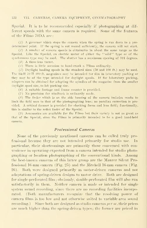
152 VII. CAMERAS, CAMERA EQUIPMENT, CINEMATOGRAPHY
Special. It is to be recommended especially if photographing at dif-
ferent speeds with the same camera is required. Some of the features
of the Filmo 70DA are
:
(1) A governor which stops the camera when the spring is run down to a pre-
determined point. If the spring is not wound sufficiently, the camera will not start.
(2) A number of camera speeds is obtainable in about the same range as the
Special. Like the Special, an electric motor of either the "wild" type or of the
synchronous type may be used. The shutter has a maximum opening of 204 degrees.
(3) A three-lens turret.
(4) There is little occasion to hand-crank a Filmo ordinarily.
(J) Daylight loading spools in the standard sizes (50 and 100 ft.) may be used.
The B&H 70-H 400-ft. magazines may be intended for film in laboratory packing or
they may be of the type intended for daylight spools. If for laboratory packing,
adapters can be obtained for adapting the spindles of the magazine from the smaller
daylight spool size, to lab packing size.
(6) A suitable footage and frame counter is provided.
(7) No provision for windback is ordinarily made.
(8) The finder which is on the side housing of the camera includes masks to
limit the field seen to that of the photographing lens ; no parallax correction is pro-
vided. A critical focuser is provided for checking focus and lens field; functionally,
this is similar to the reflex finder of the Special.
(9) Accessories are available for the Filmo but their variety is not as great as
that of the Special, since the Filmo is primarily intended to be a good hand-held
camera.
Professional Cameras
None of the previously mentioned cameras can be called truly pro-
fessional because they are not intended primarily for studio use. In
particular, their shortcomings are primarily those concerned with con-
venience in operating expected from a camera intended for studio photo-
graphing or location photographing of the conventional kinds. Amongthe best-known cameras of this latter group are the Maurer Silent Pro-
fessional 16-mm camera (Fig. 25) and the Mitchell 16-mm camera (Fig.
26). Both were designed primarily as motor-driven cameras and not
adaptations of spring-driven designs to motor drive. Both are designed
for single-perforated film ; obviously, double-perforated film will also run
satisfactorily in them. Neither camera is made or intended for single
system sound recording, since there are no recording facilities incorpo-
rated. (Both manufacturers recognize that the resolving power of
camera films is too low and not otherwise suited to variable-area sound
recording.) Since both are designed as studio cameras per se, their prices
are much higher than the spring-driven types; the former are priced in

PEOFESSIONAL CAMERAS 1 53
thousands of dollars, the latter in hundreds. Both are capable of meet-
ing the exacting speed requirement of 24 frames per second ±0.5$;
both are of the "tight gate" type which holds the film quite flat in the
aperture at any conventional operating speed. Both use detachable
camera magazines, the Maurer using a gear-driven magazine and the
Mitchell, a belt-driven magazine. Both provide a multi-lens turret.
\ jdM^^^
Fig. 25. Maurer 16-mm silent profes-
sional camera. Special movement and
claw; no registration pin. In the newmovement, the claw performs registering
function more accurately than a pin, by
having the claw stationary for an instant
before being withdrawn from the per-
foration. Camera has 3-lens turret, 235°
shutter, and view finder providing erect
image 2|" by 3" for both the 15-mm and
25-mm focal length lenses. Camera is
racked over for focusing as with Mitchell
35-mm.
Fig. 26. Mitchell 16-mm professional
camera. Has the conventional Mitchell
movement claw and registration pin move-
ment that has proved so satisfactory in
35-mm Hollywood studios. It also has a
4-lens turret, and a 175° shutter.
The choice between them is primarily one of price and of operating con-
venience; the performance of both is good, although differing slightly
in some particulars.
Choice of a Camera
There is no straightforward answer to the question: "What is the
best 16-mm camera.1 "; the question can only be answered if another

]54 VII. CAMERAS, CAMERA EQUIPMENT, CINEMATOGRAPHY
question is asked in response, "What do you wish to photograph with
the camera you propose to purchase?"
Several factors must be given consideration in purchasing a camera
;
it must be remembered that every camera built has been designed as an
engineering compromise of a large number of contributing factors, not
the least important of which was cost. For the "average" situation, it
is likely that neither the cheapest nor the most expensive camera is best
suited to the work to be done. It is quite possible that no single camera
can accomplish all that is desired ; several may be needed to photograph
the desired film or films. Should high-speed photography be needed
for a desired film, possibly none of the cameras mentioned would be
suitable, and it would be necessary to use either a Western Electric high-
speed Fastax camera, an Eastman high-speed camera, or even one of the
Edgerton flashing-light cameras made by the General Radio Companyof Cambridge, Mass.
The Mechanism
A camera is a mechanism for photographing motion pictures, con-
sisting of a film-transport system that moves film: (a) from a feed spool;
(&) to a feed sprocket (which may be a combination sprocket);
(c)
thence by means of a loop to the picture gate where it is propelled by
the camera movement; (d) thence by means of a second loop to a takeup
sprocket (which may be combined with the feed sprocket) ; and (e)
finally to a takeup spool.
In the usual cameras, a rotating disc shutter is synchronized with
the film movement to admit light from the camera lens to the film while
the film is stationary in the film gate ; the shutter cuts off the light whenthe film is being transported past the film gate. The shutter opening
may be fixed or adjustable.
Camera Adjuncts
For convenience in operation, a camera has a number of other ad-
juncts—some essential, some optional. These include
:
(1) A means of film propulsion—a spring motor, an electric motor, a hand crank.
{2) A film housing called a magazine that holds both feed and takeup spools.
(3) Some form of film-footage meter, oftentimes measuring in feet and frames,
showing how much film remains unused in the camera, and/or how much film has been
run through the camera.
(4) A finder mounted near the optical axis of the camera so that the action being
photographed may be watched. (The field covered by the photographing lens should
CAMERA ADJUNCTS 155
be similar in shape and size to the field of view in the finder. Parallax correction for
the finder should be provided.)
(5) A means of optically checking the accuracy of the lens focus setting: this
may be in the form of a viewing microscope, a reflex finder, or a critical focuser.
(The lower priced cameras are " blind" and do not have this feature.)
(6) A shift-over mechanism by means of which the main box containing the
film transport mechanism and the photographing aperture is moved to one side,
placing a second aperture of the same size as the photographing aperture on the lens
axis; the lens turret of the camera remains in its original position. This second
aperture is provided with a glass reticle cover that carries engraved lines showing the
size of the projector aperture which is smaller than the photographing aperture, and,
in addition, showing a pair of crossed hair lines locating the exact center of the
aperture. These markings are an aid in properly composing the picture within
the frame. (This feature is usually found only on higher priced, professional
cameras.)
(7) A tripod—this is a very rigid three-legged support, adjustable in height,
that is made as light as possible consistent with rigidity. Tripods usually have mov-
able heads for panoram and tilt movement of the camera ; it may be in the form of
a gyroscope-like gear-train control for smooth "pan" and tilt movement (called a
gyro-head tripod, such as the one made by Akeley*), or it may be in the form of a
friction-head arrangement for pan and tilt control as made by most manufacturers.
When panning and tilting is important in a picture, the Akeley Gyro tripod is excel-
lent. It has one disadvantage other than its greater bulk and weight; its gear train is
too noisy for use in studio photographing with synchronized sound.
Tripods are usually made in two common sizes, the baby tripod and the regular.
The difference between the two is in the length of the tripod legs, the baby having
legs about one-half the length of the regular. Tripod legs are sometimes available in
two different weights; the Akeley Gyro, for example, may be purchased with either
the regular legs or the light legs. Regardless of the weight of the tripod, it should
be remembered that a tripod is intended to be a very rigid mounting ; in general, the
greater the focal length of the lens used on the camera, the more rigid the mounting
shall be.
(8) A lens turret—this is a mounting integral with the camera, capable of ac-
commodating two pr more lenses. The Eastman Special has a two-lens turret ; the
70DA Filmo has a three-lens turret. A lens turret can save much production time whenit is necessary to change from a lens of one focal length to one of another. It is ex-
tremely rare that a single lens is sufficient for photographing professional films, since
each filming sequence of a script theoretically calls for a sequence of shots of suc-
cessively longer focal length; first, a shot to "establish" the location of the action,
next, a medium shot to act as a transition, and last, a closeup to portray the detail
of interest and to exclude other detail not directly related to the subject. To photo-
graph sequences, it may be more convenient to move the camera and to change
lenses between shots, or to use two or even more cameras. The actual decision ordi-
narily depends upon the requirements of the script and upon the production shooting
schedule. The shots of the average sequence are quite short, and the importance of
* Akeley Camera Co., 175 Varick St., New York, N. Y.
156 VII. CAMERAS, CAMERA EQUIPMENT, CINEMATOGRAPHY
rapid shifting of lenses and of the rapid changing of the finder adjustments to match
is therefore especially important when only a single camera is available.
Other Camera Features
Cameras may have a number of other features, important or other-
wise, depending upon just what is to be photographed.
(9) Provision for numerous speeds: 8, 16, 24, 32, and 64 frames per second. Anote of warning should be sounded ; many cameras do not provide the 24 frames-per-
second speed. 16, 32, and 64 frames per second is a common combination of speeds.
(10) Provision for single-frame exposure—either with mechanically controlled
exposure time and/or by hand cranking from a one-frame-per-turn camera shaft.
(11) Provision of an eight-frames-per-turn shaft.
(12) Provision for film wind-back (for producing certain effects in the camera).
Either manually adjustable, automatic, or both, shutter aperture arrangements are
customarily also available. (In some cases, provision is also made for the insertion
of a mask to cut out part of the camera field in order that the film may later be
wound back and the unexposed portion of the field then exposed for the purpose of
obtaining a desired split-field effect.)
(13) Provision for accurately matching the field of the viewfinder and its loca-
tion to the field of the camera lens in use. (Oftentimes the finder matches the field of
view of a single lens and does not match others. In cases where lenses of longer focal
length are used, masking the finder field makes an already small viewing field
so very small that it is of very little value in observing and following action.)
Should the release print be projected, let us say, on a 12-ft. screen, it would be nec-
essary for the cameraman to focus the original picture accurately enough to assure
him that the picture, when so projected, will not be even slightly fuzzy or indistinct
when vieAved by anyone in the audience. This would seem to demand microscopic
examination of the focus adjustment of the camera by some means, such as a viewing
microscope, in addition to providing a viewfinder image of sufficiently large size for
good and accurate composition.
Design of Cameras
It should be obvious that a camera should leave no%
scratch marks
on a film that has been run through it for photographing. Most of the
better-grade cameras are provided with an aperture plate of ground
and very highly polished stainless steel, others use a very smooth
and highly polished chromium plating over the support metal of which
the aperture plate is made. All points in the film paths where the film
touches a part of the camera mechanism are highly polished, in order to
avoid any possibility of scratching the image-carrying areas of the film.
Generally speaking, aperture plates, guides, sprockets, rollers, and other
parts of the film transport mechanism are relieved so that no part of
the image area of the film comes into physical contact with the camera
DESIGN OF CAMERAS L57
mechanism. AVith such care in manufacture, and with a camera in good
condition, the major source of scratch marks is dust, dirt, and metal
chips. A camera cannot give truly satisfactory service unless it is kept
microscopically clean. Since fine dust is bound to find its way into
the camera, it is most essential that the camera be cleaned regularly.
The camera manufacturer will provide detailed instructions on what to
do and how to do it if the customer will ask him.
Aperture Plate
The camera aperture plate is that plate within a camera against
which the film rides to establish accurately the plane of the film with
respect to the photographing objective lens. If the camera aperture
plate is very accurately made, very smooth, and properly aligned with
respect to a well-designed and accurately made camera claw or move-
ment and with respect to the camera lens mount, there should be no
difficulty with it. A pressure plate is required to press the film firmly
but gently against the camera aperture plate ; this too must be very ac-
curately made, very smooth, and properly aligned. The cost of a camera
depends to a degree upon the costs of the aperture plate and the pressure
plate; some manufacturers make these plates by stamping, then polish-
ing and chromium plating ; other manufacturers make them from a solid
bar of stainless steel. What is really important is how accurately the
pressure plate controls the position of the film, and how free the film is
from scratch marks after it has passed through the camera. In most
cameras, the aperture plate may be removed readily for cleaning and
inspection. It should be needless to remark that the camera must pro-
vide the standard aperture. (See ASA—Z22.7.)
Lens Mount-'
The lens mount should preferably accommodate the standard "TypeC" lens. This mount has a mounting thread 1.000 in. in diameter and a
registration distance of 0.690 ± 0.001 in. or better. The registration dis-
i ance is the distance along the optical axis from the plane of the seat for the
lens mount to the plane of the film emulsion at the center of the aperture.
It will be found that many cameras do not have the standard registra
tion distance ; some cameras that have the standard registration distance
at one speed setting of the camera do not have it at other speed settings.
It is well to obtain from the camera manufacturer either a guarantee
* ASA—Z22.76 is the pertinent standard.
158 VII. CAMERAS, CAMERA EQUIPMENT, CINEMATOGRAPHY
that the camera purchased meets this standard requirement, or to have
the camera manufacturer modify the camera to meet it. Certain de-
signs of camera gate, particularly those in which the film is not strictly
limited by the pressure plate in its movement along the optical axis, can
hardly be expected to meet the standard requirement. Since a really
good fitting of the lenses to the lens mount requires a total variation of
lens and lens mount of 0.001 in. or less, it is usually necessary for a
camera manufacturer to match the turret holes for the lenses quite ac-
curately (to better than 0.0005 in.) and to hold all lenses within com-
parable limits. Lenses purchased at random in the open market
may be in error by as much as 0.007 in. The registration distance for
every lens to be used must therefore be measured before its distance
calibration can be trusted ; this is best done by the camera manufacturer.
The importance of accurate measurement and fitting will be particu-
larly appreciated if lenses are to be used interchangeably in the various
holes in the turret of one camera, and are also to be used interchangeably
on other cameras.
Camera Movement
The camera movement is a combination of a film-propelling and a
film-registering means. Some cameras such as the Mitchell Pro 16 have
a claw for propulsion and a cooperating registration pin for registering
;
other cameras such as the Maurer 16 Silent Professional rely upon a
claw that fits the perforation accurately and that enters the perfora-
tion and leaves it in an angular direction accurately normal (per-
pendicular) to the plane of the film. Although the latter form of con-
struction would probably have been impracticable some ten years ago,
the great improvement in dimensional stability of present-day films
makes such an arrangement advantageous, since the "dwell" time of
the film just prior to exposure may be increased to allow the film to re-
gain the flatness that is lost as a result of rapid deceleration as it ap-
proaches the gate prior to exposure.
There are so many interrelated variables involved in the moving of
a piece of film in a camera that it it almost impossible to make an un-
equivocal statement concerning the relative desirability of one type of
camera movement with respect to another. A camera with a 180-degree
shutter and a short movement time may provide a much sharper picture
than the same camera with a 240-degree shutter; during the additional
60 degrees, it is conceivable that the film is "bouncing around" prior to

LENS AND THE PHOTOGRAPHED FRAME 159
coming to rest in the aperture and is therefore neither stationary nor
flat during a considerable portion of the exposure interval. The theo-
retical optimum in a film movement is one which moves the film very
quickly and then permits almost immediate exposure of the film with
the same order of flatness and absence of motion that is found in the
finest still cameras. Because of the "bouncing around" referred to, it
is quite conceivable that a camera with a somewhat longer movement
time may be better than one with a shorter movement time. There is
only one criterion—what kind of pictures does the camera take?
Many low-priced cameras use a claw to perform the functions of
moving and registering ; cameras such as the Eastman Model E do rather
well considering the simplicity of construction. Others with more costly
parts but with poorer design are not as satisfactory from the perform-
ance standpoint. Registration accuracy with respect to the location
of the perforations cannot be expected to be as good in poor cameras as
it is in cameras such as the Bell and Howell Filmo, the Mitchell, or
Maurer cameras.
It is desirable that frame-line shift from the nominal due to all
causes shall not exceed 0.003 in., and that frame-line "jiggle" (unsteadi-
ness of the picture due to the differences in frame-line location from
one frame to the next) be less than 0.001 in. With really good move-
ments, these errors may be reduced to one-half and even less. Fortu-
nately, Kodak film particularly is quite stable dimensionally, and, in ad-
dition, is accurately perforated. If unsteadiness of a photographed pic-
ture occurs, the reason is usually to be found elsewhere than in the film.
Camera Lens and the Photographed Frame
The problem of exacting control of the location of all points within
the frame being photographed with respect to the "ideal" flat plane is
a problem little appreciated by camera users—unless their pictures seem
out of focus in one portion of the frame and are in focus at another
portion. Ordinarily, it is not possible to place a mechanical supporting
member at the back of the film at the center of the aperture—and, un-
fortunately, the designer is "up against it" because it is an axiom of
mechanical design that a flat plate is the weakest possible mechanical
section. To add to the complexities of the design problem, the film has
a tendency to curl. The base and the emulsion of a film act as the twometals of a bimetallic strip, the emulsion having a much larger
expansion coefficient than the base. The amount of curl changes with
160 vii. cameras, cameea equipment, cinematography
the film shrinkage ; for this reason best pictures are taken on film that
has shrunk least and is the flattest.
Unfortunately, even if film were kept perfectly flat, many pictures
would still be in focus in one portion of the frame and out of focus in
another portion. In the case of a simple single lens, such as that used
on the simplest box cameras, lens field curvature is present; to provide
a satisfactorily sharp image over the entire picture area, the film is
placed at the distance for best "average" focus and a small relative
aperture is used to increase definition and depth of focus. In indoor
photographing on Kodachrome with a 16-mm motion picture camera
however, it is inconvenient and impracticable to provide the amount of
light required for photographing with such a simple lens even should
one be available. It is the purpose of a good lens to operate at relatively
large openings, and at the same time to exhibit a minimum of aberra-
tions such as spherical aberration, coma, astigmatism, field curvature,
distortion, chromatic aberration, or lateral color. Flatness of field (ab-
sence of field curvature) is one feature to be expected of every lens
sold as a good lens.
Some designers have sought to "match" the curvature of the lens
used to the curl of the film in the camera gate. This procedure has not
been successful in the main because of the variation in film shrinkage
and the consequent uncontrollable variation in curl. It would seem that
a good design procedure is to make a film gate to hold the film as flat as
possible (taking advantage of the film curl to stiffen the film somewhat
and to control its location at the center of the aperture more accurately)
and to use lenses with as flat a field as possible.
Lenses themselves do not provide the same definition at all iris dia-
phragm settings. A good lens (one with good resolving power all
over the field) may show a slight improvement of definition at the center
when stopped down 1 light stop {e.g., from //1.8 to //2.6). For good
modern lenses, the limitation is in the film and not in the lens. It should
be remarked at this point that the physical appearance of a lens mount
has no bearing on lens quality; lens quality is best determined by bench
testing and actual photographing.
Good test charts suitable for lens testing are supplied with the National Bureau
of Standards Circular C428 "A Test of Lens Resolution for the Photographer."
This is obtainable from the Superintendent of Documents, Government Printing Office,
Washington, D. C, for 40 cents.
As has been stated before, lens coating can improve a good lens
FOCUSING AMi VIEWING 161
measurably, but it cannol make up for the defects of a poor one. Since
lenses of shorter foeal Length require a larger number of elements for a
good design than do lenses of long foeal lengths, aberrations are more
likely to be noticeable in lenses of 15-mm and 25-mm foeal lengths than
in 100-mm and larger foeal lengths. It should be noted, incidentally,
that the difference between the lens "/" rating and its actual light
transmissiontl t" will be considerably greater in the lenses of short Focal
length.
In the long run. it will be found an economy to use only the best
lenses available. It is good practice to ask the camera manufacturer
to provide you with the data that he has obtained in testing the lenses
that he is to adjust to standard registration distance and to fit to your
camera. In certain sizes (such as the 2-in. focal length) there are few
16-mm lenses of large opening with small aberrations ; one manufacturer
in the past has used an Ektar (Eastman) lens intended for the Ektra
camera and fitted it with a "Type C" mount. The result was quite
satisfying. Although there are now a number of good lenses on
the market, some ingenuity is still needed to obtain a set of excellent
lenses for 16-mm cameras, particularly in the shorter focal lengths. Un-
fortunately, it is impossible for a prospective purchaser to select a lens
for his particular purpose without making resolving power and similar
bench and photographing tests on the particular lens offered for sale.
Manufacturers do not provide bench-test data with a lens offered for
sale ; their brochures and advertising deal too often in glittering superla-
tives coined by the advertising departments rather than in numerical data
provided by the engineering departments. The only protection that
a professional photographer can enjoy under such marketing conditions
is to buy every lens subject to test approval with the clear-cut under-
standing that the lens can be returned for creditIpreferably full credit,
if it is found unsatisfactory within a stated period.
Focusing and Viewing Arrangements
.Manufacturers of cameras have vied with one another to provide the
best possible focusing and viewing arrangements; yet. with all their
efforts, there is no camera that can be considered ideal. Even in the
most expensive cameras such as the Mitchell and the Maurer, there is
much left to be desired. Coupled view finders of the kind common in
pre-war German still cameras of the twin-lens reflex type are still un-
known in 16-mm motion picture cameras; in certain quarters, it is con-
162 VII. CAMERAS, CAMERA EQUIPMENT, CINEMATOGRAPHY
sidered doubtful whether the advantages of such construction would be
sufficiently worthwhile to enough people to justify the design expense
and the probable complexity, particularly for cameras using lenses of
different focal lengths.
Although the manufacturers of the better-grade cameras can justifi-
ably boast about the provisions for accurate picture composition and
focusing, and about the small amount of parallax error and the brightness
of the erecting-prism-type view finders, and how well the finder matches
the fields of certain selected lenses, none will say that his arrangement is
"the last word" and that the problem needs no further study. The
importance of good viewing and focusing arrangements can hardly be
overemphasized, and even the best arrangements available today are not
as convenient and accurate as is possible. The best procedure in choosing
a camera is to examine all cameras commercially available and compare
them for the intended purpose. It should not be long before still newer
solutions to the focusing and viewing problem will appear in 16-mm
motion picture cameras; good solutions will demand a great deal of in-
genuity on the part of the designers.
Camera Feed and Takeup Arrangements
If daylight spools are used in a camera, the takeup arrangement can
be quite simple, utilizing the usual spring belt for camera takeup drive.
In properly designed arrangements of this kind the spring belt is quite
satisfactory ; it appears to function quite well if the inertia of the film on
the takeup spool is relatively low and if the maximum ratio of outside
diameter of the film on the takeup spool to the inside diameter is not large.
Both 50- and 100-ft. daylight spools have an inside diameter of 1.5 in.
;
the outside diameter of a 50-ft. spool is 2 13/16 in., the outside diameter
of a 100-ft. spool is 3f in. In the case of a camera using film mounted
on a core, the inside diameter of the film is only 1.969 in., while the outside
diameter of a 400-ft. roll would be approximately 6| in. and the outside
diameter of 1200-ft. roll would be approximately 10f in. In the case of
both the 400-ft. roll and the 1200-ft. roll, core mounted, the inertia of the
film becomes quite large and the ratio of outside diameter to inside
diameter becomes quite large, especially in the case of the 1200-ft, roll.
Maurer, in providing a 1200-ft. magazine, does not rely upon a spring
belt to provide the necessary clutch action required for the takeup, but
uses instead a gear-driven magazine driven by a clutch. All Maurer
CONCLUSION" 163
equipment—camera, sound recorders, and film phonographs—uses gear-
driven takeups driven through a clutch.
Regardless of design, a camera takeup should provide a smooth, com-
pact roll of film in the takeup side of the magazine, free of cinch marks
due to the slipping of one layer of film upon another that is caused by
excessive takeup tension. The roll of film in the takeup side of the
magazine should be just as smooth and free from cinch marks and
scratches throughout the length of the roll as it is at either end. This
has been well provided for in all the better-grade cameras.
Conclusion
As in any manufactured product, the final design of a particular
camera chosen by its designer is the result of numerous compromises.
Performance requirements are dictated by the intended conditions of use
;
since many design features of a camera are mutually contradictory in
their design requirements, no camera regardless of its price can be con-
sidered theoretically ideal for all photographing applications. The prac-
tical problem of selecting a camera, therefore, resolves itself into the
selection of that particular camera whose intended conditions of use most
closely approximate the needs of the intended user.
The camera to be chosen must depend upon what is to be photo-
graphed;in every case the choice will involve a compromise in which cer-
tain features be sacrificed—internationally or otherwise—for the sake of
others. In the beginning, before the requirements become fully known,
it is a good rule not to buy the most expensive equipment available, but,
rather, equipment of moderate price that will find a ready resale market.
Good lenses can be used with any camera if the mounts are of the right
kind. When purchasing, it may be a good idea to inquire what the trade
in value of the camera may be one year after the date of purchase. If it
is found that the camera first chosen is not best for the intended purpose,
it may be traded in, and a camera better suited to the intended application
may be purchased. It is often difficult to determine just what a partic-
ular camera will do and what it will not do, without actually using it for
its intended purpose.
One feature for which this is true is the noise produced by the camera
when it is running. All cameras make noise when running; for manyuses the noise may be of little or no importance. If the camera is to be
operated simultaneously with a sound recorder for synchronized dialogue,
the noise made by the camera is very important, particularly if the scene

164 VII. CAMERAS, CAMERA EQUIPMENT, CIXEMATOGRAPHY
to be recorded requires soft voices or whispering'. There is a standard
method of measuring the noise level of cameras ; it is American Standard
(War) Z52.60-1945. Progressive camera manufacturers can and
should provide noise level data especially if the camera concerned is in-
tended for simultaneous synchronous sound recording. Such noise data
should be available for the camera when used without a blimp; compar-
ative noise data should also be available for the same camera used
with typical approved blimps. A blimp (a housing for silencing a
camera by enclosing it) may be quite satisfactory with some cameras;
with others it may be a nuisance and quite undesirable because it
is clumsy and interferes with the camera focusing and viewing arrange-
ments to such an extent as to defeat the designer's purpose in providing
them. It may be well to put up with a blimp because it is needed but
rarely, and does accomplish the degree of noise reduction desired. In the
case of the Eastman Cine Kodak Special, for example, there are several
different designs of blimps available ; all interfere in some important
degree with the focusing and viewing arrangements of the camera
proper. In some, the acoustical design is very poor; it represents little
more than a box of arbitrary size lined with some arbitrary material. In
others, the acoustical design may be fair, but little thought was
given to the location and functioning of the camera controls. The useful-
ness of a particular blimp for a particular camera is best determined by
trial under actual conditions of application. The acoustical effective-
ness of a blimp can be determined witli the method of ASA—Z52.60.
Synchronization of Picture with Sound
There are two methods in use in theatrical 35-mm and in 16-mmmotion pictures for recording sound-on-film in synchronism with motion
pictures: the "single system," in which picture and sound are recorded
upon the film used for taking the picture, and the "double system," in
which picture and sound are recorded upon two separate films. The
single system of recording is used mostly in connection with newsreel
production and is never used for feature production; the double system
is used occasionally for newsreel production and always used in connec-
tion with feature picture production.
Single System
Single-system equipment has been used to a limited extent for 16-mm.
but the sound quality available is so inconsistent and so poor compared

SYNCHRONIZATION OF PICTURE WITH SOUND 165
with the quality from double-system sound recording that it is doubtful
that the total sound footage of single-system 16-mm professional sound is
as great as a small fraction of one per cent. On some occasions when
double-system recording is inconvenient because the equipment is too
bulky, single-system sound may be recorded. Customarily, however, such
sound is re-recorded so that is appears in the same kind of separate film as
the remainder of the sound record for the picture, which is almost invar-
iably recorded by the double-system method. "When the sound is so re-
recorded, it is possible to edit the original picture in just the same manner
as the remainder of the picture original, with no regard for the original
sound track that happens to be along the unperforated edge of the
original film.
Double System
The double system is used in 16-mm wherever it is desired to have the
best sound quality practicable in the release print. Because double-
system picture and sound are on separate films, each can be given the most
appropriate photographic treatment, and each can be edited conveniently
without affecting the other. W^ords and even syllables or objectionable
noises can be removed from the sound track without affecting the conti-
nuity of the picture.
In double-system recording, the sound track is recorded on the
comparatively slow single-perforated, positive-type, sound-recording film.
This film is not very light-sensitive when compared with Kodachrome, and
is far superior in resolving power. Not the least of its advantages is that
its cost is near le per foot, while Kodachrome costs about 9c per foot.
Most 16-mm double-system recording equipment is equipped with
synchronous motors for operation from a conventional single phase power
line; Maurer equipment can be operated from a conventional 115-v.. 60-
cycle. single-phase, a.-c. central station lighting circuit. There are per-
formance advantages to three-phase synchronous motor operation, but
the relative convenience of the ordinary lighting circuit usually weighs
heavily in the choice of equipment for the single-phase supply. All that
is necessary is a similar synchronous motor drive for the camera a><
mentioned in Chapter II.
If a scene is to be photographed with simultaneous synchronized pic-
ture and sound, it is only necessary to start both machines, and whenthey reach synchronous speed (within 2 or 3 seconds after starting), to
provide some form of synchronization mark. This is often accomplished

166 VII. CAMERAS, CAMERA EQUIPMENT, CINEMATOGRAPHY
by clapping together once a pair of hinged sticks, called clap sticks. The
scene can be set for synchronism by matching up the picture frame
showing the meeting of the sticks with the sound track at the point where
the noise of the sticks is recorded. With synchronous motors, the scene
is in correct synchronism from that point onward.
Another synchronizing method is to flash bloop lights. A bloop light
is a small lamp located within a camera or a sound-recording machine that
exposes the film on the outside of the sprocket holes when the bloop light
button is momentarily pressed. The sound film and the camera film are
then matched up as with clap stick marks.
If sound is "post recorded" or "scored," there is no need to run the
camera simultaneously with the sound recorder. "Post recording" is the
adding of sound after the picture has been photographed, processed, and
edited. Sound for this purpose usually takes the form of a speech com-
mentary that explains or is otherwise related to the action portrayed
;
such sound may include effects or music if appropriate to the subject
matter of the film.
Sound is recorded photographically; although there are other
methods of recording sound with good quality, photographic recording
and reproducing will no doubt continue to be the primary source of sound
for composite 16-mm release prints.
Post-recorded sound is usually prepared from a sound script. After
the picture has been edited into its final form, a detailed shot list is pre-
pared;this is merely a list that shows the footage and frames reading of a
footage counter from the start of the picture to the start of each scene,
together with a description of the scene (see Chapter X). With in-
formation concerning the subject matter and this shot list, a sound
script is prepared, with time cues indicating exactly when the first worddescribing each scene is to be spoken. With such a script, scoring can
then be accomplished by reading the script, cueing each sentence or para-
graph with a stop watch.
Cinematography
In the broad sense, cinematography may be said to include not only
the mere placing of an image upon the film in the best possible physical
manner, but also with the best possible composition, lighting, movement
of the subjects within the film frame, and with the best possible relation-
ships between the subject matter to be photographed and the manner of

SELECTED REFERENCES 167
its presentation on the screen for the intended audience. Tins subjed is
too vast to be discussed adequately in anything less than a separate book.
To photograph a scene properly requires an adequate knowledge of
the theory of art and film. The literature is quite extensive in the former
and much can be found in books, papers, and periodicals concerning the
static representation of things and events in pictures. Unfortunately,
the literature is not extensive concerning the dynamic representation of
things and events.
One of the finest books on the subject is Film Technique by Pudovkin ; this was
translated by Ivor Montagu in England and published by Gollancz of London a decade
ago. Although the book was originally written before sound was introduced into
films, the text is profound in spite of its somewhat "ethereal" theoretical approach.
A report worthy of detailed study is that of the Luchaire Committee on Intel-
lectual Cooperation of the League of Nations written in 1924. The teachings of this
report are clear and straightforward.
During World War II a number of papers were published in the Journal of the
Society of Motion Picture Engineers written by various authors in the Training Film
Division, Bureau of Aeronautics, U. S. Navy. These are among the finest published to
date in the field of training films, and '' tie down '
' in practical form the theoretical
concepts of Pudovkin and others, in addition to providing a very big push forward to
the theoretical and practical frontiers of training film production that are ordinarily
so slow-moving.
For those interested in the broader aspects of the film, one of the finest publica-
tions is The Film in National Life published in London in 1932 by Allen and UnwinLtd. at a price of 1 shilling. This publication is a report of a commission on the
cultural and educational aspects of all films, entertainment and educational; the re-
port was financed by the Carnegie UK Trust. The several appendices are especially
valuable, since they summarize the organization and control of the various film
services in the major nations of the world.
There is still a great deal of room for books dealing with the transla-
tion, so to speak, of concepts into actual strips of edited film. The
entertainment film industry of America has applied these principles very
effectively in the production of Hollywood films, but many of the prin-
ciples are considered trade secrets. The need for production guide
books for educational, industrial, and similar films is now very acute, and
the vacuum needs to be filled very soon.
Selected References
For bibliographic material the reader is referred to the following indexes to the
Journal of the Society of Motion Picture Engineers.
July 1916-June 1930"Cameras and Camera Mechanisms," page 119.
"Cameras with Camera Mechanisms," page 119.
168 VII. CAMERAS, CAMERA EQUIPMENT, CINEMATOGRAPHY
January 1930-Decetnber 1933
''Cameras," page 11.
'' Cinematogr'aphy, '
' page 12.
' ' Cinephotomicrography, " page 12.
"Color Cinematography," page 12.
"Composite Photography," page 20.
'' Photography, '
' page 46.
1936-1945
' * Cameras, '' pages 78-80.
"Cinematography," pages 80-83.
CHAPTEK VIII
Sound, Sound Recording, and Sound-RecordingCharacteristics
Introduction
Sound may be recorded upon a large number of different media, such
as films, disks, cylinders, wires, and even on magnetic iron dust that is
coated upon the surface of a strip of filmlike material 16-mm wide and
perforated like motion picture film. Only photographic recording will
be discussed in this chapter. Although other media may find wide appli-
cation in making original recordings and for purposes other than the asso-
ciation with pictures in a sound film, such media will be compelled to
show markedly superior performance at appreciably lower cost before
they will become serious competitors to the photographic recording and
reproduction of 16-mm sound in release prints.
Although this book will deal almost entirely with photographic record-
ing and reproduction, some mention must be made of magnetic tape and
recording and the strides it is making in attempting to establish a place
for itself in the production of sound films. As the cost of release printing
must be kept low, it seems doubtful that photographic release printing of
sound will be displaced by some other foreseeable copying method in the
near future. In the making of the original record, however, the same
condition does not hold and it is conceivable that magnetic tape
recording may displace photographic recording because of quality supe-
riority and lower operating costs. In the present stage, experimental
magnetic tape records running at the same linear speed as the commercial
35-mm photographic record show measurably lower distortion and better
signal-to-noise ratio. Recording machines have been modified to run
either photographic or magnetic records. As there is almost invariably a
re-recording step between the edited original and the release negative,
it makes little difference functionally whether the synchronized original
is made by photographic or other means if the distortion of the recording
is a minimum and the signal-to-noise ratio a maximum. Should the
operating reliability of magnetic recorders prove of the same high order
169
170 VIII. SOUND, SOUND RECORDING, AND CHARACTERISTICS
as commercial disk and high-quality film recording machines, magnetic
recording on tape has a good chance of displacing photographic record-
ing in the making of original records. Such magnetic tape records maybe played back immediately, and there is the saving of the cost of photo-
graphic development of the original. Many of the features of magnetic
recording and its relation to the making of original recordings will be
found in a series of papers in the Jan., 1947 (Vol. 48) issue of the
JSMPE.Sound is recorded lengthwise along the film; the distance along the
film that represents a wave length for a particular frequency can be cal-
culated readily from the film speed—36 ft. per min. It will be assumed
in the figures shown in the table that the film is unshrunk ; the distance
between the centers of adjacent film perforations will be assumed to be
exactly 0.300 in.
In order to determine frequency in a practical case, it is necessary to
measure the length along the film of a single wave, and to correct the
measurement by the ratio of the nominal distance between sprocket holes
to the measured distance between sprocket holes
:
wave length (corrected) in. = wave length
, , N. 0.300 in.
(measured) m. x r—
—
measured distance
The frequency is then calculated from the relationship V = n\, where
V = 7.2 in./sec. and A is the wave length (corrected) in inches.
It is apparent that a film speed of 36 ft. per min. is the equivalent oi
7.2 in. per second. A frequency of one cycle per second, therefore, will
TABLE XII
Frequency Versus Film Length"
Frequency,Frequency, cycles per Length per cycles per Length per cycle,
second cycle, inches second inches
1 7.2000 4,000 0.0018
24 0.3000 5,000 0.00144
50 0.1440 6,000 0.00120
100 0.0720 7,000 0.00103
200 0.0360 10,000 0.00072
500 0.01440 12,000 0.00060
1,000 0.0072 15,000 0.00048
2,000 0.0036 20,000 0.00036
3,000 0.0024
o Standard 16-mm sound speed, 36 ft. per min.
FIDELITY OF THE RECORDED SOUND 171
spread out lengthwise a distance of 7.200 in. The lengthwise distance for
a single cycle of a tone of any particular frequency is therefore equal to
7.200 in. divided by the frequency. Table XII is convenient as a refer-
ence in discussing' recording frequency ranges, and serves to make the
problems of good sound recording on 16-mm film more apparent. In-
spection of the table shows quite clearly that, if sound up to 6000 cycles
per second is to be recorded, microscopic accuracy is a "must."
General Nature of the Sound to Be Recorded
To simplify the thought sequence in this chapter, a simple type of re-
corded sound will be assumed. The assumption is reasonable, since the
recorded sound in teaching films and the like often consists merely of a
commentary voice. The voice may, on occasion, be accompanied by a
background of sound effects, and, if appropriate, music.
Music as often used is not appropriate but rather diverting, reducing the attention
potential that the film might otherwise reach.
More complex types of sound, such as re-recorded synchronous dia-
logue and effects that are common in the Hollywood entertainment films
are seldom used in 16-mm films because of their lack of suitability and
their high production costs. A detailed discussion of such sound tracks
and the manner in which they are produced is outside the scope of this book
and should be sought in other references. Apart from the cost, simple
sound tracks are much more desirable than complicated ones for teaching
and related films. The visual impressions conveyed should on the average
supply more than three-fourths of the information found in the film. For
this reason a well-timed sound track with fewer words is more effective
than a wordy one. Momentary silence provides emphasis in a sound
track just as it does in a lecture delivered by a good public speaker.
Fidelity of the Recorded SoundIt may seem trite to state that the desideratum is recorded sound that
has optimal fidelity when projected with the picture. This self-evident
fact is often lost in the maze of process intricacies in which the film be-
comes involved before it is projected as a release print in a 16-mm pro-
jector for an audience for which the film was made.
It would seem obvious that for a particular film subject there should
be little difference in quality, except for wear and tear, between any two
release prints—regardless of whether the prints being compared are out

172 VIII. SOUND, SOUND RECORDING, AND CHARACTERISTICS
of the first production run or whether the first and, say, the 1000th are
being compared. This is readily accomplished with adequate planning
and knowledge ; Walt Disney has re-issued Fantasia to the theaters
several times after intervals of several years. The picture and sound
quality is not noticeably deteriorated from what it was the first time
it appeared on theater screens some years ago. With reasonable care
in preservation of the originals and masters, there would seem to be little
reason why Disney should not release Fantasia again and again after
suitable time periods. Unfortunately, with most 16-mm subjects and
with most nontheatrical 35-mm subjects, it has not been uncommon for
two prints of the same subject made at different times to bear little if
any relation to one another in sound quality. In many such cases, a
glaring lack of planning of the print manufacturing process and its
coordination with the requirements of storage, preservation, circulation.
and exhibition is all too evident. Too often not only the losses in each
transfer step are unknown, but also the number of steps between the
edited original film and the particular release print is likewise unknown.
As the quality of the final product—the release print—depends upon
the quality of the sound original and upon the accumulated quality
degradations of all steps between the edited original and the release
print, it is not surprising that a particular release print is often un-
satisfactory when projected upon an unknown specific machine before
an audience in an unknown auditorium or viewing space. All of the
components of the complete system from the very beginning through the
very end affect or degrade the quality of the sound heard by the audience.
The over-all characteristics of the complete chain are the characteristics
that control the final result ; the achievement of any particular character-
istic in the system must take into account all parts of the system.
Before a discussion of the individual elements of the complete
recording system can be undertaken, there must be an evaluation of the
desired over-all sytem characteristic. A reasonable starting point is the
required frequency range.
General Requirements as to Frequency Range.Hearing Perception
The requirements with regard to frequency range are determined by
the perception range of the listeners. It is only in recent years that suffi-
cient data have been collected from which statistical studies could be
made to define the response-frequency range for an average listener and
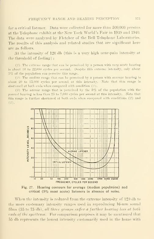
PEEQUENCT RANGE AND BEAEING PERCEPTION 173
for a critical listener. Data were collected for more than 500,000 persons
at the Telephone exhibit at the New Fork World's Fair in 1939 and 1940.
The data were analyzed by Fletcher of the Bell Telephone Laboratories.
The results of this analysis and related studies that are significant here
are as follows.
At the intensity of 120 db (this is a very high near-pain intensity at
the threshold of feeling) :
(1) The extreme range that can be perceived by a person with very acute hearing
is about l»i to 22,000 eycles per second. Despite this extreme intensity, only about
5% of the population can perceive this range.
The median range that can he perceived by a person with average hearing is
about 20 to 15.000 cycles per second at this intensity. Xote that this range is
shortened at both ends when compared with condition (1).
(3) The narrow range that is perceived by the 5% of the population with the
poorest hearing is less than 2~> to 7,000 cycles per second at this intensity. Xote that
this range is further shortened at both ends when compared with conditions (2) and
"1 60
P 20z
V
n\\V\
C\\\ i
\> v
,\ /
,
^AVERAGE LISTENER //
/ /
a*ITICAI_ USTENE^^ y,11
1 _. ,,
lO 20 50 IOO 200 500 1000 2000 5000 iOOOO 20,000
FREQUENCY. CYCLES PER SECOND
Fig. 27. Hearing contours for average (median population) and
critical (5% most acute) listeners in absence of noise.
When the intensity is reduced from the extreme intensity of 120 db to
the more customary intensity ranges used in reproducing 16-mm sound
films (55 to 75 db), all thra groups suffer a further hearing loss at both
i nds of the spt drum. For comparison purposes it may be mentioned thai
55 db represents the lowest intensity customarily used in the home with
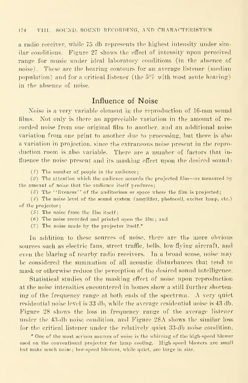
174 VIII. SOUND, SOUND RECORDING, AND CHARACTERISTICS
a radio receiver, while 75 db represents the highest intensity under sim-
ilar conditions. Figure 27 shows the effect of intensity upon perceived
range for music under ideal laboratory conditions (in the absence of
noise). These are the hearing contours for an average listener (median
population) and for a critical listener (the 5% with most acute hearing)
in the absence of noise.
Influence of Noise
Noise is a very variable element in the reproduction of 16-mm sound
films. Not only is there an appreciable variation in the amount of re-
corded noise from one original film to another, and an additional noise
variation from one print to another due to processing, but there is also
a variation in projection, since the extraneous noise present in the repro-
duction room is also variable. There are a number of factors that in-
fluence the noise present and its masking effect upon the desired sound
:
(1) The number of people in the audience;
{2) The attention which the audience accords the projected film—as measured by
the amount of noise that the audience itself produces;
(3) The "liveness" of the auditorium or space where the film is projected;
(4) The noise level of the sound system (amplifier, photocell, exciter lamp, etc.)
of the projector;
(5) The noise from the film itself;
(6) The noise recorded and printed upon the film; and
(7) The noise made by the projector itself.*
In addition to these sources of noise, there are the more obvious
sources such as electric fans, street traffic, bells, low-flying aircraft, and
even the blaring of nearby radio receivers. In a broad sense, noise may
be considered the summation of all acoustic disturbances that tend to
mask or otherwise reduce the perception of the desired sound intelligence.
Statistical studies of the masking effect of noise upon reproduction
at the noise intensities encountered in homes show a still further shorten-
ing of the frequency range at both ends of the spectrum. A very quiet
residential noise level is 33 db, while the average residential noise is 43 db.
Figure 28 shows the loss in frequency range of the average listener
under the 43-db noise condition, and Figure 28A shows the similar loss
for the critical listener under the relatively quiet 33-db noise condition.
* One of the most serious sources of noise is the whirring of the high-speed blower
used on the conventional projector for lamp cooling. High-speed blowers are small
but make much noise ; low-speed blowers, while quiet, are large in size.
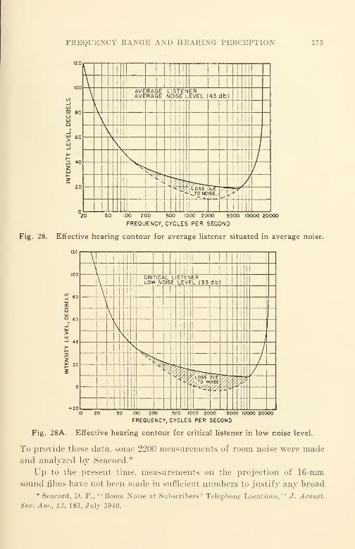
FREQUENCY RANGE AND HEARING PERCEPTION 175
UJ
5 80oUJQ
\\
AVERAGE LISTENERAVERAGE NOISE LEVEL (43 db)
i
\\
s, Nv
s
1
1
s
/
X- /s>Kfe /
//
1
VJ5Hf^TO NOISE
1!
i
100 200 500 1000 2000 5000 10000 20000
FREQUENCY, CYCLES PER SECOND
Fig. 28. Effective hearing contour for average listener situated in average noise.
UJ
UJO 60
_TUJ>UJ-J 40
-20
\\
1 Mil
\CRITICAL LISTENERLOW NOISE LEVEL (33 db)
\\\
\V\\
*^
/y
3K\/
V
<t' 77} LOSS 551
J1SEy
r
>/ss
4ty. '/± 72 -J
1
50 100 200 500 1000 2000 50O0 10000 200OO
FREQUENCY, CYCLES PER SECOND
Fig. 28A. Effective hearing contour for critical listener in low noise level.
To provide these data, some 2200 measurements of room noise were made
and analyzed by Seacord.*
Up to the present time, measurements on the projection of 16-mm
sound films have not been made in sufficient numbers to justify any broad
* Seacord, D. F., "Room Noise at Subscribers' Telephone Locations,'' J. Acoust.
Soc. Am., 12, 183, July 1940.
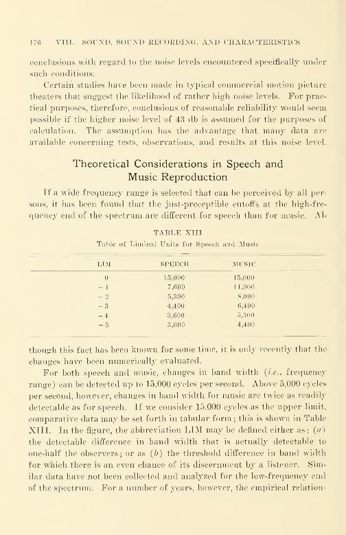
176 VIII. SOUND, SOUND RECORDING, AND CHARACTERISTICS
conclusions with regard to the noise levels encountered specifically under
such conditions.
Certain studies have been made in typical commercial motion picture
theaters that suggest the likelihood of rather high noise levels. For prac-
tical purposes, therefore, conclusions of reasonable reliability would seem
possible if the higher noise level of 43 db is assumed for the purposes of
calculation. The assumption has the advantage that many data are
available concerning tests, observations, and results at this noise level.
Theoretical Considerations in Speech and
Music Reproduction
If a wide frequency range is selected that can be perceived by all per-
sons, it has been found that the just-preceptible cutoffs at the high-fre-
quency end of the spectrum are different for speech than for music. Al-
TABLE XIII
Table of Liminal Units for Speech and Music
LTM SPEECH MUSIC
15,000 15,000
-1 7.600 11.000
_ 2 5,300 8,000
-3 4,400 6,400
-4 3,600 5,300
-5 3,000 4,400
though this fact has been known for some time, it is only recently that the
changes have been numerically evaluated.
For both speech and music, changes in band width (i.e., frequency
range) can be detected up to 15,000 cycles per second. Above 5,000 cycles
per second, however, changes in band width for music are twice as readily
detectable as for speech. If we consider 15,000 cycles as the upper limit,
comparative data may be set forth in tabular form ; this is shown in Table
XIII. In the figure, the abbreviation LIM may be defined either as: (a)
the detectable difference in band width that is actually detectable to
one-half the observers; or as (b) the threshold difference in band width
for which there is an even chance of its discernment b}T a listener. Sim-
ilar data have not been collected and analyzed for the low-frequency end
of the spectrum. For a number of years, however, the empirical relation-
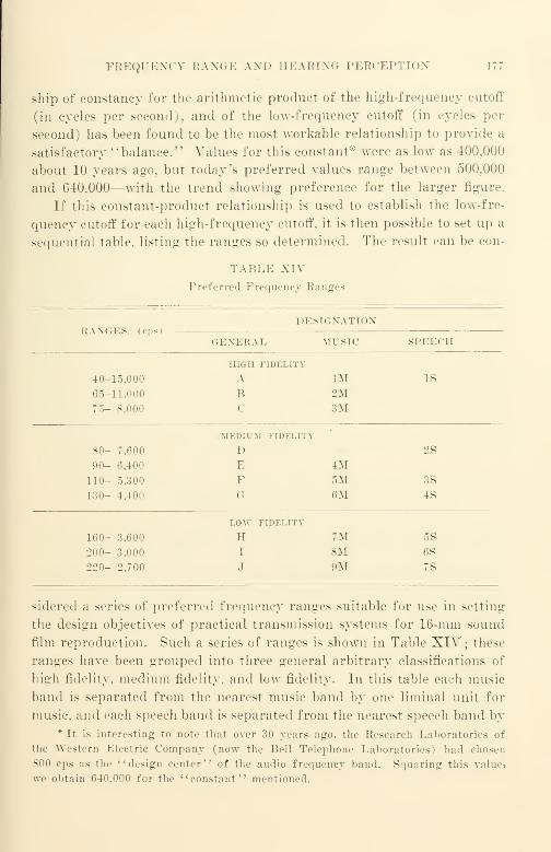
FREQUENCY RANGE AND BEARING PERCEPTION
ship of constancy for the arithmetic product of the high-frequency cutoff
(in cycles per second), and of the low-frequency cutoff (in cycles per
second) has been found to be the most workable relationship to provide a
satisfactory "balance." Values for this constant* were as low as 400,000
about 10 years ago. but today's preferred values range between 500.000
and 640.000—with the trend showing preference for the larger figure.
If this constant-product relationship is used to establish the low-fre-
quency cutoff for each high-frequency cutoff, it is then possible to set up a
sequential table, listing the ranges so determined. The result can be con-
TABLE XIV
Preferred Frequency Ranges
DESIGNATION
GENERAL MUSIC SPEECH
HIGH FIDELITY
40- 15.000 A 1M IS
65- 11.000 B 2M75- 8,000 <' 3M
MEDIUM FIDELITY
80- 7,600 D 2S
90- 6,400 E 4M110- 5,300 F 5M 3S
130- 4,400 G 6M 4S
LOW FIDELITY
160- 3.600 H 7M 5S
200-
220-
3,000
2.700
I
J
8M9M
6S
7S
sidered a series of preferred frequency ranges suitable for use in setting
the design objectives of practical transmission systems for 16-mm sound
film reproduction. Such a series of ranges is shown in Table XIV ; these
ranges have been grouped into three general arbitrary classifications of
high fidelity, medium fidelity, and low fidelity. In this table each music
band is separated from the nearest music band by one liminal unit for
music, and each speech band is separated from the nearest speech band by* It is interesting to note that over 30 years ago. the Research Laboratories of
the Western Electric Company (now the Bell Telephone Laboratories) had chosen
800 cps as the "design center" of the audio frequency band. Squaring this valuej
we obtain 640.000 for the "constant'' mentioned.

178 VIII. SOUND, SOUND RECORDING, AND CHARACTERISTICS
one liminal unit for speech. For convenience in assessing the perform-
ance of 16:mm sound projectors, both tables have been combined into one.
In the high-fidelity ranges, range A is assumed as the complete spec-
trum. Range B affords as complete perception fidelity for a critical lis-
tener under the quietest noise conditions (for 5% of the population with
the most acute hearing at a 33-db noise level). Range C affords as com-
plete perception for an average listener under average noise conditions
(for median population at 43-db noise level).
It is evident from the table, for example, that for a speech-reproducing
system with a cutoff of 5300 cycles per second (range 3$), an extension
of the response to 7600 cycles per second (range 2$) would be required
for a change of one liminal unit for speech. If the same system were
used only for music reproduction, however, the range would need to be
extended a different amount—one liminal unit for music—to provide the
just-perceptible difference. The upper limit would then be only 6400
cycles per second (range 43/ ). As an extension of the frequency range
means increased cost, depending upon the amount of the frequency-range
increase, it is important to know whether music or speech, or both, are
to be transmitted—if the frequency range desired in a particular case
is to be a matter of careful economic selection.
Practical Considerations Affecting the Low-Frequency
Cutoff of a System
If the low-frequency cutoff for the next adjacent shorter range is
substituted for that of a designated range, it has been found that the
"balance" of the reproduced sound does not seem noticeably affected.
Thus, in reproducing range F, for example (110-5300 cps), the quality
of reproduction and the balance is not noticeably affected for the average
listener should the cutoff frequency of 130 cps be substituted for the rated
cutoff of 110 cps. Since the cost of loudspeakers and of amplifiers de-
signed to cover specified frequency ranges increases fairly rapidly as the
low-frequency cutoff is lowered, the increase in cost of the additional low-
frequency range is usually distinctly greater than the added subjective
result is worth. For this reason, extension of the low-frequency range
is rarely justified commercially. As a practical matter, the extension of
the low-frequency range below 75 or 80 cps is rarely worth while in any
commercial system regardless of the high-frequency cutoff ; this is true for

FREQUENCY AND VOLUME RAXGE OF REPRODUCED SOUND 179
reproduction from 16-mm film quite as much as for other reproduction
uses (such as broadcast reception, etc.).
Practical Considerations Concerning Frequency Range
and Volume Range of Reproduced Sound*
It must be recognized at the outset that the very wide frequency range
and the very wide volume range to which the unaided human ear is
responsive is quite beyond the capabilities not only of the best commer-
cial 16-mm films and equipment, but also beyond the capabilities of the
best 35-mm commercial theatrical films and equipments. Wide ranges
approximating 40 to 15,000 cps in frequency and 60 db in volume range
have been demonstrated experimentally with the best possible film-record-
ing techniques; public demonstration of such recording was made in
1940 by the Bell Telephone Laboratories with 35-mm film running at 90
ft, per min. The demonstration equipment incorporated almost every
known arrangement for maintaining the widest frequency range and
volume range—with minimum noise—with little regard (according to
16-mm standards) to cost and complexity of the equipment involved. The
result was outstanding, but the cost of a single demonstration unit was
about half a million dollars, putting it far beyond commercial reach for
35-mm as well as 16-mm sound film purposes.
Actual Performance—Past, Present, and Future
For the immediate future, it is hardly reasonable to expect 16-mmperformance of the best 5% of projectors and films to go beyond range
F (110 to 5300 cps) under average noise conditions. Median performance
in the near future will probably be in range G (130 to 4400 cps) and
poor performance in range H (160 to 3600 cps). These estimates assume
new projectors with new films under improved conditions of machine
and film manufacture and use.
At the present time, 16-mm sound film performance occurs almost
entirely in the low-fidelity range. The median performance is probably
in range H (160 to 3600 cps);the performance of the poorest 5% may
be as low as range J (220 to 2700 cps) . On the whole 16-mm performance
has not been good ; during World War II, for example, some prints de-
*The general conclusions drawn in this chapter are based upon conventional
single-channel (monaural) reproducing systems and do not anticipate stereophonic or
other binaural systems.

180 VIII. SOUND, SOUND EECORDING, AND CHARACTERISTICS
livered by contractors to the Government were so poor that they were
unintelligible on any projector. It is doubtful that these could meet even
the very low requirements of range J. It was such performance of a
relatively large number of prints on a relatively large number of projec-
tors that was a prime factor in the formation of the American Standards
Association Z52 "War Committee on Photography and Cinematography at
the joint request of all U.S. Armed Forces in 1943.
Production Implications of Performance RangeRequirements
For the sake of eliminating one major variable in the evaluation of
film performance, let us assume playback of all sound film upon a single
military Model Projector* (Joint Army-Navy Specification JAN-P-49)
of average performance as specified. When the specification for this pro-
jector was drafted, it was recognized that the highest level of perform-
ance commercially feasible was needed for military purposes. Such level
of performance is appreciably better than that of any machine commer-
cially marketed up to the time the specification was written. A projector
as specified may be considered to have the most desirable design objective
performance for a modern 16-mm sound projector.
Despite our assumption of a single machine to eliminate projector
variation, large-order variations will be found to occur. As will be
pointed out later, variations in performance from one release print to
another occur not only for different subjects .having different sound
originals, but also for different release prints made from a different re-
lease master or release negative, for any release prints or other copies
made at different times, and even for different release prints made at the
same time. It should be apparent that the quality variations are of
different orders of magnitude; as in all other cases of manufacture of
mass-produced product when quality is statistically in control, the vari-
ations among release prints made from the same release master or nega-
tive at the same time should be of lowest and minor order of magnitude.
To determine the magnitude of the variation statistically requires
measurement in accordance with the methods of statistical quality control
(ASA Zl.l, Z1.2, and Z1.3). To know what to do about it requires
knowledge and analysis of the process of making the release prints. The
very first step prior to an analysis of this kind is to remove from the re-
* A machine of comparable design is being manufactured for the Armed Forces
by DeVry of Chicago ; another by Bell and Howell.

IMPLICATIONS OF PERFORMANCE REQUIREMENTS 181
lease print manufacturing process all unnecessary transfer steps; every
transfer step in the manufacturing process introduces a loss of major
magnitude. Although statistical quality control is intensively used to
measure the quality of motion picture film during manufacture, analysis
of even a rudimentary kind in the utilization of the film is the exception
rather than the rule. The inevitable result is poor utilization of the
quality potential of the raw film.
To predict the performance of a print requires a knowledge of the
operating characteristics of each and every step in the production pro-
re^ from the raw material (the raw stock for the original) to the finished
product (the release print). Despite this, it is not unusual for a buyer of
release prints to have no knowledge whatever of the processes involved
in turning out the product he is buying—release prints. Since there are
no standards by which the quality of release prints can be accurately
measured objectively, the result is no better than a -jrab-bag filled with
items of unpredictable and probably poor quality. It is next to impos-
sible to predict or guarantee performance within specified limits—such
as the frequency ranges previously described—without accurate knowl-
edge. Since the processes in 35-mm theatrical films are less varied in
type and likewise better stabilized, more data concerning over-all charac-
teristics are available for the large size.
Over-all Characteristics
It should be recognized at the outset that the over-all characteristics
of the recording and reproducim; system are of paramount importance.
We must be concerned with the performance of the particular print
that we may be using quite as much as with the performance of the par-
ticular sound projector we are using, or. for that matter, of the amplifier
used to record the sound original. It is apparent that the recording and
reproducing processes as a whole must be designed to anticipate the losses
known to exist, and to take into account the tolerances of each of the
processes between the time the sound enters the microphone of the
recording equipment and the time the reproduced sound issues forth
from the loudspeaker of the sound projector. If consistent performance
is desired, all factors should be known;if they are not known they should
be determined before production recording is attempted.
Distortion
It is unfortunate that no single measurement will define the excellence
of sound reproduction or of the degradation of sound reproduction.

182 VIII. SOUND, SOUND RECORDING, AND CHARACTERISTICS
Forms of audio distortion are customarily divided into three primary
classes: frequency discrimination, tonal distortion consisting of harmonic
and amplitude distortion, and phase distortion.
In the past the most advantageous balance among these characteristic
forms of distortion has not been maintained; this is the case not only
of 16-mm sound, but also of all other forms of sound transmission and
sound recording such as broadcast transmission, commercial phonograph
recording and reproducing, and the recording and reproducing of elec-
trical transcriptions for broadcast sound transmission.
Frequency Discrimination. Frequency discrimination is the most
easily measured of all forms of audio distortion. Although the measure-
ment of the response-frequency characteristics of certain parts of the
system (such as the recording amplifier) may be a routine matter, the
measurement of the over-all response-frequency characteristic is very
rare regardless of the purpose of such measurement. Such measurement
as a routine quality control measure holds much promise not only as a
yardstick for quickly determining whether or not the process remains in
control, but is also capable of disclosing quickly when the system has been
subjected to major disorders. It is very annoying and costly to find bad
sound on a large number of new prints, and to find that the cause is a
defective printing master that went by unnoticed because of the absence
of a print-through test strip that would have quickly revealed the defect
as a part of the routine check of the over-all response-frequency charac-
teristic. Strangely enough, despite the frequency of occurrence of this
kind of defect, it is remarkable how often the same error will be made by
the same people.
Although frequency discrimination is by no means the only important
form of distortion, a routine over-all check will often point out unmis-
takably just where the process deviated from its intended path. Most
of the discussion that follows in this chapter deals with this easily meas-
ured characteristic.
Tonal Distortion. Unfortunately, tonal distortion is difficult to meas-
ure, since it is not entirely a simple distortion of either the harmonic
or amplitude type ; it also includes forms of distortion that are emphasized
because of the operating peculiarities of the recording method itself.
Thus, a primary distortion introduced by improper processing and re-
lated causes in the case of variable density sound track is harmonic dis-
tortion. To measure and to control this in processing, an intermodulation
IMPLICATIONS OF PERFORMANCE REQUIREMENTS 183
test may be made in accordance with American Standard Z22.51-
1946 " Method of Making Intermodulation Test on Variable-Density
16-Mm Sound Motion Picture Prints." The tones used for the inter-
modulation test are 60 cps and 1000 cps.
In the case of variable-area sound track, the major distortion intro-
duced by improper processing- is envelope distortion. A somewhat simi-
lar testing method called the cross-modulation test is used ; different test
frequencies have been selected due to the difference in the character of
the distortion produced. This test may be made in accordance with
American Standard Z22.52-1946 "Method of Making Cross-Modu-
lation Tests on Variable-Area 16-Mm Sound Motion Picture Prints."
The test frequencies selected for variable-area testing are 400 cps and
4000 cps.
The data collected on intermodulation distortion tests and on cross-
modulation distortion tests for 16-mm prints are too sketchy as yet to
establish good correlation with the more customary listening tests, or to
determine the relative amounts of subjective distortion when measure-
ments by both methods yield the same numerical values. Such correla-
tions must of necessity be established if we are to continue that desirable
practice of altering the form from variable-area to variable-density or
vice versa by re-recording*—as was very common during World War II.
The practice, which has a number of operating advantages, will no doubt
become more common in the near future, since Maurer, RCA, and Western
Electric market equipment capable of turning out either form. It is also
possible that the manufacturers of laboratory sound printers will market
machines capable not only of copying the form of the sound track sup-
plied, but also, by the simple shifting of a lever or similar adjustment,
to alter the form in printing from variable-area to variable-density and
vice versa. Such printers have already been described in some detail in
patents issued and applied for.
Over-all distortion characteristics do not receive the attention they
deserve. Such characteristics often will indicate a strong preference for
one particular method of accomplishing a specific result over alternate
methods. A typical example would be the re-recording of a negative
* Re-recording presumes a high-quality film phonograph that translates a high-
quality print or other sound-positive record into electrical currents suitable for elec-
trically actuating an input channel of a recording equipment (replacing a microphone)
for the purpose of obtaining a duplicate sound record, usually modified in response-
frequency characteristic, of the high-quality print or record.
184 VIII. SOUND, SOUND RECORDING, AND CHARACTERISTICS
from a fine-grain, re-recording positive in preference to making a pho-
tographically copied negative from a master positive. Assuming that
each is optimally processed for its intended purpose, the distortion
present in the print from the re-recorded negative should be of appre-
ciably lower order than that present in the print from the photograph-
icalty copied duplicate negative. Oftentimes the difference is so large
that one method can be termed acceptable and the other unsatisfactory
;
the result will depend upon the control actually exercised rather than
upon the nominal control that is theoretically possible in the process.
(As a crude example, photographic copying, despite all its shortcomings,
would be preferable to a re-recording if a bad microphonic and noisy
electron tube were used in the re-recording equipment, especially in the
pre-amplifier associated with the film phonograph.)
Phase or Delay Distortion. If a signal of 400 cps is suddenly applied
to the microphone of a 16-mm sound recorder, it will be found that there
is an appreciable transmission time delay (of the order of a millisecond)
between the time that the signal is applied and the time the film is actually
exposed by the light beam of the recording machine.
If a signal of 60 cps, for example, is suddenly applied to the same
system, it will be found that the transmission time delay is many times its
400-cps value in most 16-mm sound film recording equipment commer-
cially manufactured. If a signal of about 5000 cps is likewise suddenly
applied, it will be found that the delay is several times the 400-cps value,
but customarily less than its 60-cps value. The variation in transmission
time delay in the working frequency range is called phase distortion or
delay distortion.
Phase distortion is not limited to electrical circuits ; film processing
is a source that is usually quite uncontrolled because film laboratories are
not generally familiar with electrical measurement methods and rarely if
ever attempt to measure the delay distortion or its variations introduced
by their processing. Since a delay of a millisecond is roughly the equiva-
lent (in time) of a placement change of the sound source at the micro-
phone of one foot, the importance of large delay differences* between the
* The effect upon the reproduction of a plucked string bass violin in a dance
orchestra is a case in point. The frequency range of fundamental and significant
overtones is from about 40 to well over 7500 cps. When the sound of such an in-
strument is recorded and reproduced with equipment of conventional phase distortion
characteristics, the low range frequencies and the high range frequencies produced by
the instrument are markedly delayed with respect to the mid-range frequencies. In
reproduction, this causes a "confusion" of sound as the range extremity tones are

SIGNAL-TO-NOISE RATIO 185
low-frequency delay and the high-frequency delay becomes apparent when
compared with the 400-cps value. In commercial equipment of reputedly
good manufacture, the ratio between the 30-cps value and the 400-cps
value may be as high as 20 to 1.
For the present there is very little that can be suggested for the
routine measurement and control of phase distortion and for correction of
major defects in present-day 16-mm recording systems other than to
suggest a more intensive stud\r of the problem by all concerned. In the
past, phase distortion and its control has been very important in long-
distance telephone transmission where appreciable time delay occurs.
Although the maximum transmission time delay for 16-mm recording is
but a small fraction of that encountered in a cross-country telephone line,
the importance of phase distortion in the high-quality recording and
reproduction of 16-mm sound films cannot be ignored, because of the
subjective importance of transient and other sounds of sharp attack
characteristics. The difference between a high-quality system with low
phase distortion and an ordinary system is obvious to even a casual
untrained observer when transient sounds such as dancing taps are
recorded. Unfortunately there are no simple standard methods available
for measuring phase distortion and for correcting it ; very little analysis
of film processing as a source has been made although it has become more
common in recent years for equipment manufacturers to investigate and
measure phase distortion in their amplifiers. Much progress should be
made toward improving sound recording and reproduction in 16-mmsound-films as a result of the more intensive efforts to analyze and measure
phase distortion that will be made in the years to come.
Signal-to-Noise Ratio
The signal-to-noise ratio of a system is another important over-all
characteristic. It should be obvious that the best signal-to-noise ratio
available is that of the original event being recorded, since each sub-
sequent step in the process reduces the signal-to-noise ratio because noise
is added. This ratio of the final result (the sound projected into the
auditorium from the release print) is usually very much smaller than that
of the original event. The noise in the auditorium itself reduces the
subjectively localized in space at points distant from the mid-range frequencies ; such
reproduction with excessive phase shift is quite harsh despite the fact that the meas-
ured distortion of the recording and of the reproducing systems may be quite low.
(From Offenhauser and Israel, "A Study of the Advantages of Quasi-Binaural Re-
production Systems," 1940, unpublished.)

186 VIII. SOUND, SOUND RECORDING, AND CHARACTERISTICS
signal-to-noise ratio of the sound emitted by the loudspeakers of the re-
producing equipment.
Well-designed equipment is capable of a signal-to-noise ratio of 30 db
or more ; this is somewhat better than is obtained with the better quality
commercial 78-rpm phonograph disk records (shellac pressings) re-
produced upon a high-grade electric phonograph in the quiet of a well-
furnished living room ((33-db noise level). Most projectors now in use
are not capable of reproducing that range ; many are reproducing with a
signal-to-noise ratio no better than 15-db. Such performance is inferior to
a low-priced ($9.00) pre-war midget radio set.
The standard method of measuring signal-to-noise ratio of 16-mm
sound motion picture prints is described in American War Standard
Z52.38—1945. The reference for this test is a tone of 400 cps recorded
at approximately 80% modulation ; this reference tone is used for either
variable-density or variable-area recording.
Every step in the complete process of recording and reproducing 16-
mm sound film is characterized by the noise and by the distortion that it
introduces ; the aggregate effect is cumulative. An excellent final product
results not only from excellent equipment, but also from an applied
knowledge of the characteristics of the process that permit the func-
tioning of adjacent steps in complementary (for example, distortion-
cancelling) fashion. A typical example is the relation of a conventional
variable-density sound negative to its complementary print. Such a
negative will seem badly distorted when played back on a conventional
reproducer ; as is to be expected, this is no surprise to one familiar with
the variable-density recording process. The negative itself is neither
intended for, nor suited to, playback on conventional equipment; if
negative playback is required for any reason, a special type of logarithmic
playback amplifier is required. The print, on the other hand, is normal
and does not require an unconventional amplifier.
Controlled quality of the release print projected is a result not only
of care and constant vigilance in each step of the process, but also of the
integration of all steps into a unified whole. A successful process is one
in which all transfer characteristics are known and anticipated.
Factors Influencing Response-Frequency Characteristics
in 16-Mm Sound Recording
Introduction
In the early stages of the art of 16-mm sound, when films and process-
ing were poor, sound for 16-mm film was often recorded on 33 1/3-rpm
RESPONSE-FREQUENCY CHARACTERISTICS 187
disks and reproduced from a mechanically-coupled reproducing turn-
table. Sound-on-disk continued to be used for several years after it had
disappeared from 35-mm entertainment theaters; it took longer for prog-
ress in 16-mm film materials and in 16-mm processing to result in suffi-
ciently improved projection sound quality in the slower-moving 16-mm
film to provide commercially satisfactory performance.
The sound-on-film recording method which has superseded sound-on-
disk always consists of:
(1) A microphone to translate sound energy into electrical energy;
{2) An amplifier and associated equipment to amplify the energy from the micro-
phone, and to control the energy supplied to the recording machine
;
(<?) A sound-recording machine (often called a sound recorder) to translate the
electrical energy from the amplifier into corresponding light variations that are
utilized to expose the continuously moving film and to produce the latent image of the
recorded sound on it.
The starting point, of course, is the microphone that first converts
sound energy into electrical energy at the recording studio; the end
point is the sound projector that translates the light transmitted through
the moving photographic image of the release print into electrical energy
that is used to drive the reproducing loudspeaker, reconverting the elec-
trical energy back into sound in the auditorium.
Numerous factors affect the manner in which the original recording
should be made to assure that the release print is of optimal quality. Anacceptable film is almost certain if all factors are properly anticipated;
an unsatisfactory film is almost certain if any or all factors are disre-
garded.
Reproducing vs. Recording Level
Sound from 16-mm motion pictures is usually reproduced at a muchhigher volume level than that of the original event. This is especially
true in the case of voice recording ; for every difference in level between
that of the original sound and that of the reproduced recorded sound,
there is an optimal response-frequency characteristic correction that
should be applied to the "ideal" flat response-frequency characteristic if
the optimal tonal balance is to be maintained.
The correction is primarily an attenuation of the lower frequencies;
for large level differences, slight attenuation of the high frequencies is
also required. The magnitude of the attenuations is dependent upon the
magnitude of the level difference, the customary level difference being
about 10 to 20 db. Data have been accumulated by a number of investi-
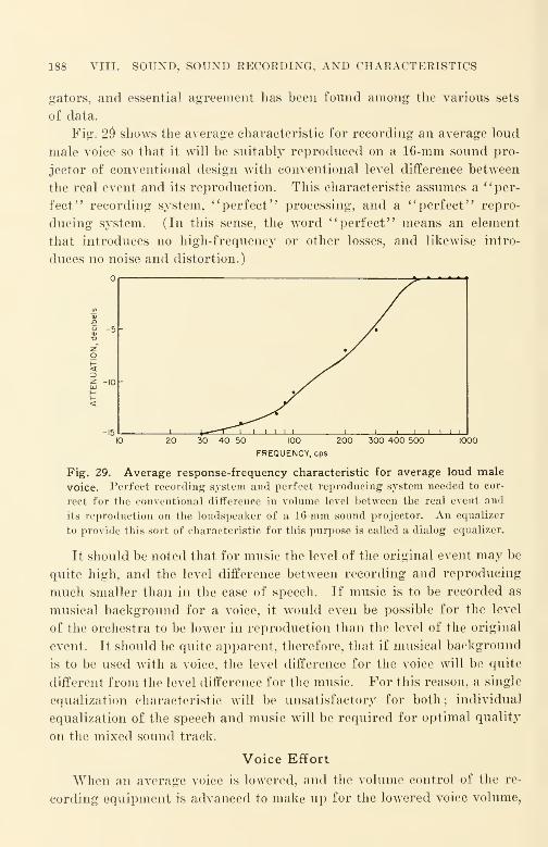
188 VIII. SOUND, SOUND RECORDING, AND CHARACTERISTICS
gators, and essential agreement has been found among the various sets
of data.
Fig. 2$ shows the average characteristic for recording an average loud
male voice so that it will be suitably reproduced on a 16-mm sound pro-
jector of conventional design with conventional level difference between
the real event and its reproduction. This characteristic assumes a "per-
fect" recording system, "perfect" processing, and a "perfect" repro-
ducing system. (In this sense, the word "perfect" means an element
that introduces no high-frequency or other losses, and likewise intro-
duces no noise and distortion.)
40 50 300 400 500 1000100
FREQUENCY.eps
Fig. 29. Average response-frequency characteristic for average loud male
voice. Perfect recording system and perfect reproducing system needed to cor-
rect for the conventional difference in volume level between the real event and
its reproduction on the loudspeaker of a 16-mm sound projector. An equalizer
to provide this sort of characteristic for this purpose is called a dialog equalizer.
It should be noted that for music the level of the original event may be
quite high, and the level difference between recording and reproducing
much smaller than in the case of speech. If music is to be recorded as
musical background for a voice, it would even be possible for the level
of the orchestra to be lower in reproduction than the level of the original
event. It should be quite apparent, therefore, that if musical background
is to be used with a voice, the level difference for the voice will be quite
different from the level difference for the music. For this reason, a single
equalization characteristic will be unsatisfactory for both; individual
equalization of the speech and music will be required for optimal quality
on the mixed sound track.
Voice Effort
When an average voice is lowered, and the volume control of the re-
cording equipment is advanced to make up for the lowered voice volume,

RESPONSE-FREQUENCY CHARACTERISTICS 189
the recorded voice quality deteriorates because of the predominance of
the chest tones in the speaker's voice. Thus, a changed voice effort on
the part of an announcer or speaker requires a further correction of the' 'ideal" flat response-frequency characteristic. In the customary post-
recorded film using an off-stage voice, the declamatory voice requires
least correction and is usually preferred—especially when there is no
psychological or other reason for a different type of voice.
As in the case of level difference correction, the magnitude of the
correction required for voice effort depends upon the magnitude of the
voice effort difference. Figure 30 shows typical corrections for average
voice effort differences of 3, 6, 9, 12, and 15 db.
CD
°.20z
b inr>
5°
-3DB-6 OB -n9DBUJ
> 10^
^X" NNI5DB<uj 20
20 30 100 200 500 1000 2000 5000 10000 20000
FREQUENCY.eps
Fig. 30. Dialog equalization corrections required for voice effort
differences of 3, 6, 9, 12, and 15 db.
Voice Quality
It should be obvious that all male voices are not alike even at the
same energy levels. Since'
' the proof of the pudding is in the eating,'
'
the final test is the playback of the release print.
The various corrections described in the preceding sections and in
this section are little more than rough approximations of the differences
involved. Thus it will be found that the correction required for a par-
ticular loud male voice will be slightly different from the average malevoice ; the precise correction is ordinarily determined by critical listening
tests. For recording the particular male voice at a medium level, the
correction given in the section on voice effort should make a good first
approximation.
If the optimum correction is to be determined for a specific case, it
is obtained through critical listening tests and should be found to differ
190 VIII. SOUND, SOUND RECORDING, AND CHARACTERISTICS
from the indicated corrections in only minor degree. In making such
tests, it cannot be blindly assumed that significant differences do not
occur in the projectors used or in the films and their processings. Rela-
tively large differences can and do occur; with regard to films, for ex-
ample, there are relatively large differences in different emulsion lots of
the same type of film ; smaller, yet possibly significant roll-to-roll differ-
ences occur within the same emulsion lot of film, especially if different
rolls have been stored under different storage conditions in the period
between manufacture and use. (Storage of raw film is always assumed
in unopened taped cans—as supplied by the film manufacturer.)
Since even larger variations are to be expected in the processing of
the film, it can be seen that critical listening tests can be of quantitative
value only when proper process controls are applied. The responsibility
for setting up these controls rests squarely on the shoulders of those
making the tests. This requires an appreciation of the performance of
film under the different conditions of processing to which it may be sub-
jected, just as much as it implies a good knowledge of the electrical per-
formance of the microphone, amplifiers, sound recording machine, and
other electrical components.
Transfer Steps
A transfer step is a step in the process of making sound films in which
energy is transferred from one form to another, or images are transferred
from one medium to another. It is apparent that there is no "perfect"
transfer step ; every transfer step results in a transfer loss. A transfer
loss ordinarily means a loss of high frequencies, an increase in noise with
a consequent reduction in signal-to-noise ratio, and an increase in distor-
tion; the absolute magnitudes of these losses and their relative magni-
tudes with respect to each other depend upon the character of the trans-
fer step and the manner in which it is actually accomplished. Over-all
transfer losses can be kept to a minimum by reducing to the irreducible
minimum the number of transfer steps between the original and the
release print, and by keeping the losses in each and every transfer step
to a minimum. Much can be accomplished in the latter direction by
vigilant maintenance of well-designed equipment. Quite often the loss
in a particular transfer step is excessive not because the equipment is
inadequate for the intended purpose, but rather because the equipment is
poorly maintained and not kept at the peak of its operating efficiency.

TRANSFER STEPS 191
The result depends upon the control actually exercised, and not upon
the theoretical limits contemplated in the original design.
The sound that enters the microphone has less distortion and noise
than it ever has in any later stage of the process ; every subsequent step
increases high-frequency loss, noise, and distortion. This applies to the
very start of the transfer process—to the microphone itself—quite as
much as it does at subsequent steps in the process. The sound actuating
the microphone should be as clear as possible and as free of distortion,
noise, and unrelated sounds as it is possible to provide. Should there be
a quality defect in a commentator's voice such as hoarseness, a wheeze,
poor enunciation, poor diction, a whistling noise (such as accompanies
sibilants spoken through false teeth), poor breath control, or any other
related defect, it is almost certain that the defect will be accentuated by
the transfer losses encountered. Under no circumstances should unre-
lated sounds and noises or other extraneous sounds be present. It should
be possible to run a silent portion of the sound track under the quietest
auditorium conditions with the best sound projector available and find no
sound even when the print is reproduced at the maximum gain setting.
Xoise and distortion are added by the equipment ; these effects should
be small if the equipment is good. High-frequency losses in well-designed
amplifier equipment are small ; customarily the response-frequency char-
acteristic of the amplifier equipment is intentionally equalized (altered)
to compensate not for high-frequency losses inherent in the amplifier,
but rather for the high-frequency losses encountered throughout the re-
mainder of the recording and processing procedure. Since equalizing
of the electrical amplifier circuits offers the only convenient means for
adjusting the over-all response-frequency characteristic of the release
print that is run in the projector for the intended audience, the quality
of the sound projected with the picture is a measure of how accurately
the sound recordist knew the characteristics of the recording and of the
processing procedure, and what he did to anticipate its shortcomings and
losses. As there is no standardization of procedures and of transfer losses
in any step of a procedure, each specific application problem must be
studied as an individual case if satisfactory end results are to be obtained.
Noise and distortion are added by the sound-recording machine. Dis-
tortion is introduced by the light modulator, and noise by mechanical
vibration of the exposure lamp with respect to the optical axis of the re-
cording optical system and by lamp current variations arising from humand other disturbances in the exposure lamp current supply. A loss of
192 VIII. SOUND, SOUND RECORDING, AND CHARACTERISTICS
high frequencies occurs because the light beam pencil that traces the
sound waves on the film is not infinitely fine despite its unusual narrow-
ness ; the loss is called slit loss. Distortion is also introduced by irregu-
larities in the movement of the film past the exposing light beam; the
result is a frequency and amplitude modulation of the recorded sound.
Speed variations introduce flutter; slower speed variations are referred
to as wows. Fortunately the sum total of distortion and noise introduced
in a good recording machine—while noticeable—is not very serious.
The recording film has limited resolving power, and, in devel-
oping, both noise and distortion are introduced together with a loss of
high frequencies, the latter being called film loss. Film developing also
introduces noise; one important source is the dirt and other foreign
matter found in all developing and fixing baths. Another important and
oftentimes serious source is the dust carried in the drying air in the dry-
box of the developing machine.
From this point onward, every step increases noise and distortion as
well as losses of high frequencies. Assuming that the original is a sound
track negative from which a release print is to be made, the sound printer
used will introduce noise, distortion and a loss of high frequencies; the
latter is known as printer loss. The raw stock for the release print will
introduce more noise and distortion and show a greater loss of high fre-
quencies than the EK Code #5372 film used for making the sound track
original. In developing the release print, noise, distortion, and a loss of
high frequencies is to be expected once again. Transfer in this manner
of the photographic image from the sound track original to the release
print is called photographic transfer. Photographic transfer always re-
sults in a loss of high frequencies, and in an increase of noise and distor-
tion. A serious increase in distortion can be expected unless considerable
effort is expended in choosing the operating parameters of copy exposure
and development to minimize the distortion increase by causing the pho-
tographic distortion occurring in the print to offset to some degree the
distortion occurring in the negative. In the processing of variable-area
film this is known as the distortion-cancelling technique.
Should we assume that the original was a direct positive, it would be
preferable to re-record the original rather than to print it photographi-
cally. Electrical transfer steps such as re-recording are customarily ar-
ranged to alter the response-frequency characteristic in a desired manner(usually to offset high-frequency losses occurring in other transfer
steps);this equalizing of the response-frequency characteristic is accom-
TRANSFER STEPS 193
plished at the cost of an increase in both noise and distortion which is
even greater than the increase that would occur if no response-frequency
alteration took place. The choice of suitable operating parameters will
keep the increase in noise and distortion to a practicable minimum. Gen-
erally speaking, electrical transfer methods are in a higher state of de-
velopment than are photographic methods. The increase in distortion
and noise to be expected in good re-recording should be considerably
smaller than the comparable increase resulting from photographic trans-
fer methods such as good printing. A 16-mm negative produced by re-
recording from an optimal fine-grain print of an original sound negative
should have appreciably better quality than one obtained from a 16-mm
sound negative that has been photographically printed from the optimal
fine-grain print of the same original sound negative.
The number of transfer steps as well as the loss characteristics of
each step in a production process must be known if the quality of the
release prints is to be predetermined. It is the lack of such knowledge
that accounts for most of the unsatisfactory 16-mm sound that appears
today. The number of transfer steps in a process should be kept to an
irreducible minimum ; if additional steps must be introduced, electrical
re-recording will undoubtedly be necessary to provide optimal equaliza-
tion of the additional process losses introduced with the minimum possible
increase of distortion and noise. Photographic* copying will usually re-
sult not only in an increase of distortion and noise, but also in an ex-
cessive loss of high frequencies. As a practical matter, well-designed and
well-maintained re-recording equipment, competently operated, is capable
of making a re-recorded copy that has no greater noise than a photo-
graphic copy, and yet equalizes the transfer losses without a serious in-
crease in distortion. Such process advantages can hardly be overempha-
sized.
Most recording systems are arranged to anticipate the losses of but a
single transfer step beyond the original sound record ; this is usually the
making of a photographic print directly from the original sound track
negative. If all films were actually manufactured in accordance with this
more or less customarily assumed idea, there would be little cause for
dissatisfaction with the sound quality of 16-mm films. One of the most
serious sources of loss of sound quality is the arrangement of the record-
ing equipment for the making of what lias been aptly termed "second
generation prints" (such as release black-and-white prints directly from
194 VIII. SOUND, SOUND RECORDING, AND CHARACTERISTICS
the sound track negative original) and the actual use of that identical
original for photographic copying of an unknown number of "print
generations, '
' in which the loss characteristics beyond the second genera-
tion are neither known nor taken into account. It is the loss in the ag-
gregate that must be anticipated and corrected for by equalization ; ac-
cordingly, such "many-generation" prints are definitely bad.
It is more often the rule rather than the exception that correction of
such process losses does not occur. Since all stages in the process of
making a release print are interdependent, and the losses in each stage
are of major magnitude, the importance of knowing the exact number
of stages in the process and their characteristics can hardly be over-
estimated. Without close working arrangements among producers, sound-
recording organizations, processing laboratories, and distribution organi-
zations, consistency and satisfaction with the sound quality of the
projected picture cannot occur.
Process of Making Release Prints and Effect on Sound
The purpose of an original (sound negative or other) is to provide
a method of obtaining release prints by means of a copying process, usu-
ally photographic printing. If a small number of copies is required, the
simplest and best procedure is to make each release print directly from
the original negative. In this process of making copies, the original nega-
tive becomes progressively poorer in quality due to wear and tear result-
ing from handling and aging. The quality of each successive print,
despite excellent control of the printing process, likewise becomes poorer.
Although the differences between two successive prints made at the same
time wTill hardly be observable in a well-controlled process, the difference
in quality* due to normal wear and tear on the original and due to the
difference in printing and processing conditions—however slight—will
usually be distinctly noticeable between two prints made several months
apart. In the case of poor laboratory process control (and this is all too
common), there may seem to be little relation between two such prints
other than their common origin.
When sound film is photographically copied in a film laboratory, a
continuous contact printer is customarily used because of its relatively
high operating speed and correspondingly low operating cost. The losses
*The difference in quality referred to is that arising from handling, and is due
to scratches, abrasions, and dust. The major variation that occurs as a result is
noise.

PROCESS OF MAKING RELEASE PRINTS 195
in even a single copying step are very high; it has been stated that the
printer loss when measured as a loss of resolving power in a single step
is 30% or greater. The loss due to the film is not inconsiderable; even
films of the highest resolving power commercially practicable (150
lines/mm) show significant losses; films of low resolving power (55
lines/mm) are relatively so poor that they should never be used.
Assuming that the film loss is negligible, the maximum possible resolv-
ing power of a print from a negative, when printed with a continuous
contact printer, is only in the order of 70%. For a large number of
copies, duplicate sound negatives might be photographically copied from
a master sound print that was likewise printed on a continuous contact
printer; release prints would be made from the third generation dupe
negatives. Assuming the same printer throughout, the maximum possible
resolving powers of fourth and fifth generation prints must be of low
order.
Case 1 : If the original is a sound negative and a positive release print is
desired, the process involves copying at three successive steps.
100% x 0.7 x 0.7 x 0.7 = 34 %>
originalsoundnegative
Generations: 1st 2nd 3rd 4th
The prospect of good sound from such a procedure is slim.
Case 2: If this procedure is carried to a fifth generation, with the origi-
nal, a sound positive, and a release print desired, the maximum possible
resolving power drops further.
100% x 0.7 x 0.7 x 0.7 x 0.7 =24%original sound sound sound releasesound dupe master dupe printpositive negative positive negative positive
Generations: 1st 2nd 3rd 4th 5th
Each time the film goes through the printer, only some 70% of the re-
solving power remains; it is certainly reasonable to believe that fifth
generation 16-mm photographic prints made on a continuous contact
printer are of little commercial value. In practice, even fourth genera-
tion photographic 16-mm sound prints are usually of doubtful quality.
Although the foregoing is not rigidly exact because resolving power
is used as the sole index of the quality of a print and for numerous other
reasons, it is convenient for quickly estimating roughly the possibilities
sound sound releasemaster dupe printpositive negative positive
196 VIII. SOUND, SOUND RECORDING, AND CHARACTERISTICS
of a particular procedure. Actually, degradation of sound quality, as
mentioned before, appears as:
(1) A loss of high frequencies;
(I?) An increase in noise;
(3) An increase in distortion.
As the relationship of the subjective effect of degradation has not
been statistically determined with respect to objective effects, it is impos-
sible to establish at this time a quantitative factor of merit that could be
accepted generally without major qualifications. Since resolving power
is a single objective measure that in some degree encompasses all three
specified effects, its use as a qualitative measure for comparison seems
reasonable.
Loss of High Frequencies
When a release print is photographically copied directly from a sound
negative, the loss of high frequencies resulting from the transfer step is
usually equalized in the recording of the negative. Actually, however,
there is an upper limit to the amount of electrical equalizing for transfer
losses that can be tolerated, since every increase in high-frequency re-
sponse effected by equalizing produces a noticeable increase in distortion
and in noise. Since the original signal being recorded has the least
amount of distortion and noise, and has the best signal-to-noise ratio of
any stage in the process, it is this point that will " stand'* most equalizing
—minimum distortion and noise will be added for a specified amount of
equalizing.
As has been previously described, a direct positive on EK 5372 that
has been optimally processed in an enriched D-16 developer bath has an
optimal density of approximately 1.5, representing the best compromise
between distortion and noise for the purpose. As the density is increased
or decreased from this value by changing the exposure, there is an in-
crease in distortion that changes more rapidly as the density deviates from
the specified value. If the density is increased, the noise decreases some-
what, but both the distortion and the loss of high frequencies increase
;
this is caused to some degree by a filling-in of the vallej'S of the wave
pattern recorded upon the film. (Beyond a certain value, the filling-in
of the valleys becomes so serious that the output of the film drops due to
fog.)
In making a sound print from a sound negative, the optimal density
of the negative is approximately 2.00 (emulsion density). This negative.

LOSS OF HIGH FREQUENCIES 197
if closely examined under a microscope, will show a slight filling-in of
the valleys of the recorded wave pattern. When such a negative is
printed on DuPont 605A or Eastman 5302 under best conditions, and a
print is developed in a good developer (such as an enriched D-16;, there
is a complementary filling-in of the valleys of the wave pattern on the
print that introduces an essentially equal and opposite distortion to that
found in the negative. Optimal print density for a negative of density
2.00 will be approximately 1.5. Optimal print density depends upon the
film, the printing machine, the exposure, and upon the developer and the
developing method used. It may be determined by empirical tests (by
making a series of test prints from the identical negative over a range of
print densities and selecting the test that sounds best) or by means of
the cross-modulation test.* Because of the lack of standardization of
procedures and of losses in transfer steps, the empirical test will be found
more reliable as a production control method. Should a large number of
films be handled by substantially the same procedure with the same ap-
paratus, statistical correlation between the empirical and the cross-modu-
lation tests is recommended so that the cross-modulation test may be
used routinely because measurement with instruments requires less
production time.
Because of the complex nature of emulsion behavior, the density for minimumdistortion of a single frequency as recorded by the variable-area method depends upon
the harmonic order for which minimum distortion is desired as well as upon the fre-
quency. For complex waves, such as speech, music, etc., the density for minimumdistortion depends not only upon the sensitometric characteristics of the materials used
and their processing (including printing) but also upon the nature of the sounds re-
corded. For this reason it would seem that any conventional form of cross-modula-
tion test such as ASA Z22.52 can not hope to be better than a good approxima-
tion; the accuracy and the reliability of the approximation can. in a sense, be con-
sidered a measure of the reliability of the statistical sampling of the recorded sound.
Generally speaking, if the photographic speed of a film is within the
exposure range of the machinery used, highest resolving power and lowest
image spread are the characteristics most desired for raw film for vari-
able-area sound uses. By these criteria EK 5372 is the best material avail-
able for any variable-area sound purposes but it is not suited for release
printing of pictures because it has a blue-dyed antihalation base. At the
present time, the widespread use of the readily available present-day good
materials under optimal conditions is capable of producing a major im-
*' 'Cross-Modulation Tests on Variable-Area 16-Mm Sound Motion Picture
Prints," American Standard Z22.52-1946.
198 VIII. SOUND, SOUND EECOEDING, AND CHAEACTERISTICS
provement in the over-all performance of present-day 16-mm sound films.
The quality potential of today's materials and processes is not being re-
alized and considerable room for improvement still remains.
Increase of Noise
If a negative of density 1.5 is used to make optimal print on release
print film such as DuPont 605A or Eastman 5302, it will be found that a
print so made will be lower in density and have a measurably higher
noise level than an optimal print made from a negative of density of ap-
proximately 2.00. When the two prints are compared, the print from the
less dense negative will show somewhat better high-frequency response
;
despite this, the print from the denser negative is preferred because of
its appreciably lower noise level.
As the density of the negative is increased beyond 2.00 (emulsion
density) the exposure latitude becomes progressively smaller and the
high-frequency losses and the distortion become greater. A practicable
operating range for negative densities (with good control) is plus or
minus 0.1, and a good print can usually be made consistently if the nega-
tive density is in this range. Similar tolerances apply to the optimal
direct positive density of 1.5. The changes in distortion and noise are
relatively small within a density variation of plus or minus 0.1 if all
other factors remain the same.
The American War Standard : " Method of Measuring Signal-to-Noise
Ratio of Sound Motion Picture Prints," ASA Z52.38-1944,* is considered
the most acceptable numerical method available despite the fact that the
amount of experience accumulated with it is limited.
Increase of Distortion
Every transfer step introduces distortion in some form or other.
Generally, the distortion introduced by an optimal electrical re-recording
step is lower than that of an optimal photographic step. Therefore, elec-
trical re-recording should be used in as many transfer steps as practicable
when third or later generation prints are to be made.
An optimal print from a sound negative causes an increase in distor-
tion and in noise in addition to a loss of high frequencies. Equalizing
during electrical re-recording can offset to some degree the excessive high-
frequency losses ; the cost is an increase in noise and in distortion in the
equalized film. Since the quality degradation per step is quite large in
* Under revision.
INCREASE OF DISTORTION 199
photographic transfer steps, the total number of steps permitted between
the 16-mm sound original and the release print must be held to the ir-
reducible minimum. With good processing control, intelligible sound can
survive on a release print after even three transfer steps; with poor
processing control, even a single step is hazardous.
Since it is difficult to specify distortion limits in numerical terms,
the primary test should continue to be the empirical test ; the routine test
may be the ASA cross-modulation test specified. In view of the fact that
the relationship between the subjective distortion and the distortion
measured objectively by this method has not been definitely established,
a combination of listening tests and cross-modulation tests made under
identical exposure and processing conditions will probably indicate de-
sirable control limits as measured by the values determined from cross-
modulation tests.
General Recording Procedures
AVith present-day methods and equipment it is difficult to specify
rule-of-thumb procedures that do not seem to have many exceptions.
This arises from the lack of standardization of the over-all performance of
a sound film, components, methods, and of the materials used. At the
present time the only over-all requirement that can be stated explicitly
is that regardless of how produced, a release print shall be clear, intelli-
gible, and pleasing when projected on an average projector made in ac-
cordance with American AVar Standard Specification JAX-P-49 for a
Military Model Projector. The Bell and Howell sound projector cur-
rently manufactured is a widely available commercial equivalent per-
formance approximation.
If a small number of black-and-white release prints (less than 50) is
to be made at one time, and if there is no need to preserve the original,
the best procedure is to record the sound track original as a negative and
to make the release prints by photographically copying from the original.
Most commercial sound recording equipment is designed to accomplish
this kind of recording satisfactorily.
There would seem to be little to choose from among 16-mm negatives
recorded upon different makes of good, up-to-date equipment (e.g., RCA,Western Electric, and Maurer). "When side-by-side test recordings are
made in connection with standardization efforts, the optimal density of
a print made on DuPont 605A from similar negatives recorded upon
200 VIII. SOUND, SOUND RECORDING, AND CHARACTERISTICS
Eastman 5372 proves to be quite similar under identical processing con-
ditions; prints are excellent in quality and low in noise. Slight differ-
ences are observable when the two prints are played back on a 16-mmreproducer system consisting of a film phonograph, a low-noise and low-
distortion amplifier, and a two-way theatrical-type loudspeaker system;
no difference is observable when the prints are reproduced on a run-of-
the-mill commercial projector.
Unfortunately, such high quality is extremely rare in commercially
produced release prints. Not only do such tests represent better record-
ing technique, together with better exposure control and better processing
control resulting from extra care at each stage, but also the number of
transfer steps anticipated and their characteristics in the aggregate are
in close accordance with the conventional design objective of the record-
ing equipment. Even with a median level of control, results of such
operation would still be of a superior order compared with conventional
commercial films because of the use of but one transfer step between the
original sound record and the release print.
Unfortunately, most release prints are not made in that simple and
straightforward manner. The number of prints required is often far in
excess of the maximum number that can be copied from a single piece
of film ; the physical wear-and-tear on the original accumulated in print-
ing will result in damage and ultimately in mechanical breakdown of
the original. What happens in an unplanned procedure is that at some
indeterminate time prior to complete breakdown, when the evidences of
breakdown are already all too apparent, a duplicate negative is photo-
graphically copied from one of the last release prints made from the
original negative ; then fourth generation prints are made from the du-
plicate negative. The result is usually poor ; in most cases it can hardly
be called even marginal.
Practical Method Suggestions
Even with the very best 16-mm machinery, materials, and methods not
even third generation prints can be called wide range or high fidelity
—
the transfer losses are too great. With very good process control, a third
generation print made from a re-recorded negative can be made quite
satisfactory for conventional projection. To do this successfully de-
mands that every portion of the process be supervised carefully and the
losses in each stage must be kept to an absolute minimum. To limit the

SELECTED BIBLIOGRAPHY 201
distortion added by the extra transfer steps the following procedures
will be necessary.
(1) Equalize only partially for the high-frequency losses introduced by re-record-
ing with response-frequency characteristics that are "boosted" at the high-frequency
end of the spectrum. The frequency of maximum amplification will customarily lie
located somewhat lower than the upper frequency cutoff ; the practicable amount is
limited to some 12 db. It is not practicable ordinarily to equalize more than this
amount because of the excessive noise and excessive distortion that would occur as a
result.
(2) When re-recording, reduce the frequency range by the use of appropriate
band-pass filters. The range should be reduced in full steps in accordance with Table
XIV. If excellent control of processing is present, a reduction of one full step maybe sufficient; for more conventional control, a reduction of two or three steps will be
needed. (For example, if the original was recorded with range F—110-5300 cps
—
the range would be limited to range G—130-4400 cps—for excellent control, to range
H—160-3600 cps—or ranges / or J for more conventional control.) Much depends
upon the intermodulation distortion present.
(•>» Limit the working signal-to-noise ratio by introducing compression of the
volume range. Assuming a 25-db signal-to-noise ratio for an original 16-mm speech
sound record, a compression of some 5 db will usually be sufficient for excellent process
control with projection of the print under excellent acoustical conditions, with an ex-
cellent sound projector ; and some 10 db for more conventional control with projection
of the print under more conventional acoustical conditions with more conventional
sound projectors.
In considering the corrections to be applied, it is reasonable to ask
how the optimal amounts of each of the above corrections may be de-
termined. Unfortunately, no simple rule-of-thumb is available, since
the relationships between the objective factors and the subjective factors
have not been determined statistically. For this reason the criterion
must be subjective; it is merely "the method that produces the most
pleasing print for the reference projector used under the reference pro-
jection conditions." Even if this criterion were satisfied accurately, the
variation in performance of commercial projectors and the variations in
auditorium characteristics (such as size, noise, reverberation, etc.) are
often large enough to preclude satisfactory operation over such wide
ranges.* Satisfactory operation presumes modern, well-maintained pro-
jectors together with an auditorium where ordinary conversation can
be maintained at typical loudspeaker-to-listener distances.
Selected BibliographyFletcher, H., Speech and Hearing. Van Nostrand, Xew York, 1929.
Pender-Mcllwain, Electrical Engineers' Handbook— I', Electrical Communication and
Electronics. Wiley, New York, 1936.
*The acoustic performance characteristics of 6 commercial projectors are shown
at the end of Chapter XIII.

202 VIII. SOUND, SOUND RECORDING, AND CHARACTERISTICS
Society of Motion Picture Engineers, The Technique of Motion Picture Production.
Interscience, New York, 1943.
Academy of. Motion Picture Arts and Sciences, Recording Sound for Motion Pictures.
McGraw-Hill, New York, 1931.
Research Council, Academy of Motion Picture Arts and Sciences, Motion Picture
Sound Engineering. Van Nostrand, New York, 1938.
Wood, A., Acoustics. Interscience, New York, 1946.
Beranek, L., Acoustic Measurements. Wiley, New York, 1949.
Olson, H., Elements of Acoustical Engineering. 2nd ed., Van Nostrand, New York,
1949.
Batcher and Moulic, Electronic Engineering Handbook. Electronic Development As-
sociates, New York, 1944.
Henney, K., Eadio Engineering Handbook. McGraw-Hill, New York, 1935.
Frayne and Wolfe, Elements of Sound Recording. Wiley, New York, 1949.
Jensen Radio Manufacturing Company, Technical Monographs No. 1 to 5. Chicago,
1945.
Steinberg et al., "The Stereophonic Sound-Film System," JSMPE, 37, 366 (Oct.
1941).
Durst and Shortt, "Characteristics of Film Reproducer Systems (35-mm)," JSMPE,32, 169 (Feb. 1939).
Loye and Morgan, "Sound Picture Recording and Reproducing Characteristics
(35-mm)," JSMPE, 32, 631 (June 1939); 33, 107 (July 1939).
Scott, H. H., "Audible Audio Distortion," Proc. Natl. Electronics Conference (Il-
linois Institute of Technology), 1, 138 (Oct. 1944).
Olson, H. F., "Extending The Range of Acoustic Reproducers," Proc. Radio Club
Am., (N. F.), 18, 1 (Jan. 1941).
Frayne and Scoville, "Analysis and Measurement of Distortion in Variable Density
Recording," JSMPE, 32, 648 (June 1939).
Hilliard, J., "Distortion Tests by the Intermodulation Method," Proc. I. R. E., 29,
614 (Dec. 1941).
Albin, F. G., "Intermodulation Distortion of Low Frequencies in Sound Film Re-
cording," JSMPE, 46, 4 (Jan. 1946).
Sandvik and Hall, "Wave-Form Analysis of Variable-Density Sound Recording,"
JSMPE, 19, 346 (Oct. 1932).
Sandvik et al., "Wave-Form Analysis of Variable-Width Sound Records," JSMPE,
31, 323 (Oct. 1932).
Evans and Lovick, "Zero-Shift Test for Determining Optimum Density in Variable-
Width Sound Recording," JSMPE, 52, 522 (May 1949).
SMPE Committee on Sound, "Proposed Standard Specifications for Flutter or Wowas Related to Sound Records," JSMPE, 49, 147 (August 1947).
Baker and Robinson, "Modulated High-Frequency Recording as a Means of Deter-
mining Conditions for Optimal Processing," JSMPE, 30, 3 (Jan. 1938).
Livadary and Twining, "Variable Area Release from Variable Density Original
Sound Tracks," JSMPE, 45, 383 (Nov. 1945).
Reiches, S. L., "Volume Distortion," JSMPE, 38, 457 (May 1942).
Bruno, M., "Maps on Microfilm," JSMPE, 41, 421 (Nov. 1943).
SELECTED BIBLIOGRAPHY 203
National Bureau of Standards, Circular C439, Acoustic Performance of 16-Mm Sound
Motion Picture Projectors. Supt. of Documents, Washington, D. C, 1942.
Johnson, W., "Analyzing Sweep Frequency Transcriptions, '' Audio Eng. (N. Y.)
}
31, 18 (Oct. 1947).
Haynes, N. M., "Factors Influencing Studies of Audio Reproduction Quality," Audio
Eng., 31, 15 (Oct. 1947).
Minter, J., "Audio Distortion," Radio Club Am., Dec. 1944.
Tanner, R., "Audio Technique in Television Broadcasting," Audio Eng., 33, 9, (Mar.
1949).
Offenhauser and Israel, "Some Production Aspects of Binaural Recording for Sound
Motion Pictures," JSMPE, 32, 139 (Feb. 1939).
For further bibliographic material the reader should refer to the following in-
dexes to the Journal of the Society of Motion Picture Engineers.
July 1916-June 1930
'Sound as a Science," page 146.
'Sound Film Projection," pages 146-147.
'Sound Installations in Theaters," page 147.
'Sound Pictures, General," page 147.
'Sound Reproduction, Disk," page 147.
'Sound Reproduction, General Information Concerning," page 147.
'Sound Reproduction, Studio Installations," page 148.
'Sound Reproduction, Variable Density Method," page 148.
'Sound Reproduction, Variable Width Method," page 148.
'Sound Scoring and Re-recording," page 148.
January 1930-December 1933' Committee Reports, Sound, '
' page 18.
'Sound as an Art," page 58.
'Sound Installations in Theaters," page 58.
'Sound Pictures, Applications," page 59.
' Sound Recording, with Color, '' page 59.
'Sound Recording, Disk," page 59.
'Sound Recording, General Information," page 59.
'Sound Recording, Portable," page 60.
'Sound Recording, Studio Installations," page 60.
'Sound Recording, Variable Density Method," page 61.
'Sound Recording, Variable Width Method," page 61.
'Sound Reproduction, Disk," page 61.
'Sound Reproduction, General Information," page 62.
'Sound Reproduction, Studio Installations," page 64.
'Sound Reproduction, Variable Density Method," page 64.
'Sound Reproduction, Variable Width Method," page 64.
'Sound Scoring and Re-recording," page 64.
1936-1945'Sound Recording," pages 134-142.
'Sound Reproduction," pages 143-147.
'Sound Waves Produced by Explosions," page 147.
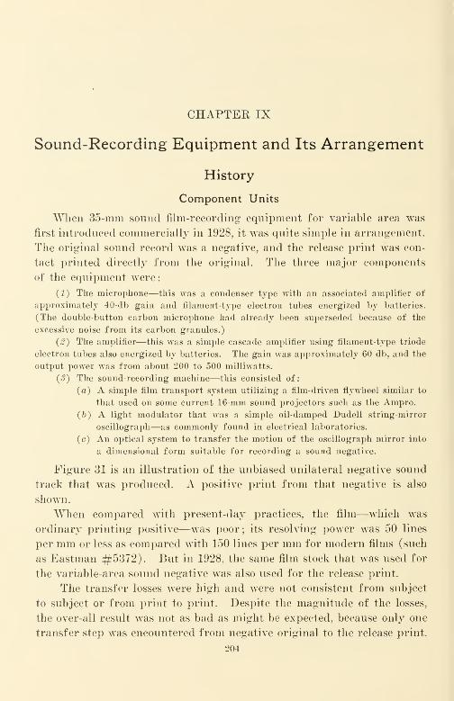
CHAPTER IX
Sound-Recording Equipment and Its Arrangement
History
Component Units
When 35-mm sound film-recording equipment for variable area was
first introduced commercially in 1928, it was quite simple in arrangement.
The original sound record was a negative, and the release print was con-
tact printed directly from the original. The three major components
of the equipment were
:
(1) The microphone—this was a condenser type with an associated amplifier of
approximately 40-db gain and filament-type electron tubes energized by batteries.
(The double-button carbon microphone had already been superseded because of the
excessive noise from its carbon granules.)
{2) The amplifier—this was a simple cascade amplifier using filament-type triode
electron tubes also energized by batteries. The gain was approximately 60 db, and the
output power was from about 200 to 500 milliwatts.
(3) The sound-recording machine—this consisted of:
(a) A simple film transport system utilizing a film-driven flywheel similar to
that used on some current 16-mm sound projectors such as the Ampro.
(&) A light modulator that was a simple oil-damped Dudell string-mirror
oscillograph—as commonly found in electrical laboratories,
(c) An optical system to transfer the motion of the oscillograph mirror into
a dimensional form suitable for recording a sound negative.
Figure 31 is an illustration of the unbiased unilateral negative sound
track that was produced. A positive print from that negative is also
shown.
When compared with present-day practices, the film—which was
ordinary printing positive—was poor; its resolving power was 50 lines
per mm or less as compared with 150 lines per mm for modern films (such
as Eastman #5372). But in 1928, the same film stock that was used for
the variable-area sound negative was also used for the release print.
The transfer losses were high and were not consistent from subject
to subject or from print to print. Despite the magnitude of the losses,
the over-all result was not as bad as might be expected, because only one
transfer step was encountered from negative original to the release print.
204
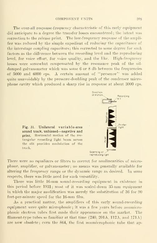
COMPONENT UNITS 205
The over-all response-frequency characteristic of this early equipment
did anticipate to a degree the transfer losses encountered; the intent was
correction to the release print. The low-frequency response of the ampli-
fier was reduced by the simple expedient of reducing the capacitance of
the interstage coupling capacitors ; this corrected to some degree for such
factors as the difference between the recording level and the reproducing
level, for voice effort, for voice quality, and the like. High-frequency
losses were somewhat compensated by the resonance peak of the oil-
damped galvanometer which was some 6 or 8 db between the frequencies
of 5000 and 6000 cps. A certain amount of "presence" was added
quite unavoidably by the pressure-doubling peak of the condenser micro-
phone cavity which produced a sharp rise in response at about 3000 cps.
Fig. 31. Unilateral variable-area
sound track, unbiased—negative and
print. Horizontal motion of the rec-
tangular recording light beam across
the slit provides modulation of the
track.
Scanning or
reproducing light
There were no equalizers or filters to correct for nonlinearities of micro-
phone, amplifier, or galvanometer; no means was generally available for
altering the frequency range or the dynamic range as desired. In some
respects, there was little need for such versatility.
There was little 16-mm sound-recording equipment in existence in
this period before 1931 ; most of it was scaled-down 35-mm equipment
in which the major modification was merely the substitution of 36 for 90
feet-per-minute speed for the 16-mm film.
As a practical matter, the amplifiers of this early sound-recording
equipment were quite microphonic ; it Avas a few years before nonmicro-
phonic electron tubes first made their appearance on the market. The
filament-type tubes so familiar at that time (240, 201A, 112A, and 171A)
are now obsolete ; even the 864, the first nonmicrophonic tube that ap-
206 IX. SOUND-RECORDING EQUIPMENT AND ARRANGEMENT
peared in 1928 is now no longer nsed in commercial sound film recording
equipment. The preamplifiers associated with condenser microphones
were shock mounted and acoustically insulated ; on the whole, the designs
were effective in materially overcoming the very serious handicaps of the
microphonic tubes.
General Requirements for Modern 16-MmSound-Recording Equipment
Modern 16-mm sound-recording equipment should be capable of re-
cording sound in whatever manner is required to accomplish the specific
objective of the particular film being produced. As far as sound record-
ing is concerned, desired objectives range over very wide limits. One
limit may be the recording of a direct positive of highest fidelity and
widest dynamic volume range practicable on 16-mm film for direct play-
back in a very quiet and acoustically well-treated review room with the
film run on a high-quality film phonograph and reproduced through a
wide-range amplifier and speaker system. The other limit may be the
recording of a sound negative from which release prints will be derived
by means of, say, four transfer steps, and the release print projected
in an ordinary untreated schoolroom with a run-of-the-mill sound pro-
jector. To accomplish the former satisfactorily requires equipment of
the highest fidelity and of the widest practicable dynamic volume range
;
the latter requires the same basic equipment with the frequency range
altered by suitable corrective networks and the dynamic volume range
limited by suitable volume compressors or limiters. The reverse situa-
tion will not work; it is impossible to take basic equipment of limited
frequency range and of limited dynamic volume range and record high
quality sound film with it.
Equipment that is wide in range has the great advantage that any
ordinary change of frequency range, volume range, or both requires little
more than the change of a corrective network and an adjustment for the
dynamic range. This is simpler than the purchase of a completely new
recording equipment for each new range or condition. Wide-range
equipment is not cheap ; its cost is measured in thousands of dollars rather
than in hundreds. Such equipment must have day-to-day reliability
without drift or sensible change in its wide frequency range, in its low
noise content, and in its low distortion; its performance must be as con-
sistent as the best high-fidelity broadcast station for frequency modula-
tion sound transmission.

MODERN SOUND-RECORDING EQUIPMENT 207
When corrective networks, equalizers, compressors, limiters, or any
other arrangements are used to modify the frequency range or the dy-
namic volume range, it must be ascertained that each such arrangement
does not of itself introduce appreciable noise or distortion—at least not
more than actually expected. In practice, serious noise and distortion
can creep in almost unnoticed because of the hum and other noise induced
in poorly shielded coils of the inductors used in niters and equalizers.
Such coils should never be placed in the strong stray magnetic fields of
power transformers and power reactors; the influence of such fields mayoften be minimized by orienting the coil or transformer with respect
to the disturbing field. Manufacturers of commercial filters and equal-
izers customarily shield them magnetically against hum pickup and
likewise make the inductors as small as physically possible to limit the
noise voltages induced. Unfortunately there is no standard method
of rating the effectiveness of such shielding; as a result it is nearly im-
possible to distinguish between the presumably equivalent products of
different manufacturers, or, in fact, to distinguish between good and
bad on the basis of published data.
It is always good practice to check the increase in noise and distortion
in a sound circuit when a corrective network is introduced. Every pre-
caution possible should be exercised to avoid the introduction of noise,
since it is not uncommon for an otherwise excellent network to introduce
sufficient hum to make it worthless as a practical device.
Corrective networks are introduced to provide "the most pleasing
release print for the reference projector used under the reference pro-
jection conditions." Since it is impossible to divorce the over-all char-
acteristics of the system from the component characteristics of any and
all links in the process chain, some of the important factors in the chain
should be listed for reference. These are
:
(1) The character of the original sound to be recorded.
(£) The dramatic and other effects to be introduced.
{3) The noise, the reverberation, and the other acoustic characteristics of the
space surrounding the pickup microphone.
(4) The response characteristics of the microphone—frequency and directional re-
sponse.
(5) The performance of all amplifiers and other equipment located between the
microphone and the light modulator or galvanometer.
(6) The properties of the light modulator, the noise reduction system, the com-
pressor or limiter, and all related equipment.
(7) The performance of the film upon which the original sound track is recorded.
(Performance variations may be very large due to variations in exposure and process-
ing as well as to the film.)
208 IX. SOUND-KECOKDING EQUIPMENT AND AEEANGEMENT
(8) The number and variety of transfer steps actually used between the original
sound record and the release print, and the over-all characteristic of the steps used.
(Performance variations are particularly large at this point because of (a) differ-
ences in the number of transfer steps used, (b) variations of a particular step from
time to time, as well as (c) variations due to different printing machines and dif-
ferent processing baths, and variations in performance of such printing machines and
baths from time to time.)
(9) The performance of the projector upon which the release print is run. (The
same print will sound very different when run on projectors of different makes and
models. A Kodachrome or other color reversal duplicate with the nonstandard emul-
sion position will sound very different when projected upon a projector that has sound
optics focused on the correct side of the film as compared with the same optics focused
on the opposite side.) The performance of the loudspeaker used is very important.
(10) The noise and reverberation characteristics of the auditorium or other listen-
ing space within which the audience listens to the film.
(11) The difference in volume level between the original sound and the reproduced
sound.
(12) The mechanical noise made by the projector—where the projector is located
with respect to the audience (preferably, it should be located in a booth outside of the
projection auditorium where it cannot be heard).
(13) The noise emitted by the projector loudspeaker resulting from the hum, hiss,
microphonic jangle of the electron tubes and of the exciter lamp (the light source of
the scanning beam), and similar noises. In a sound projector, all sound issuing from
the loudspeaker should theoretically result from the light variation caused solely by
the passage of the intended record on the film past the sound-scanning beam. Practi-
cally, however, the noise level of disturbances produced within commercial optical and
amplifier systems is usually of significant order compared with the noise found in the
film itself. One common source of noise that is overlooked or seriously underestimated
is that produced by the exciter lamp. Hum often occurs due to incomplete filtering
of the current supply; the thermal lag of the average lamp is small because its fila-
ment is small in cross section. Although the lamp filament is under tension, the
natural vibratory period of the lamp drops considerably when the lamp is heated.
Microphonic noise is caused by a " wriggling '' of the lamp filament with respect to
the optical axis and is caused by mechanical vibration. In many cases the disturbance
frequencies are in substantially the same frequency range as the disturbance fre-
quencies produced by flutter and other speed irregularities. (A microphonic exciter
lamp thus seriously aggravates the disagreeable audible effects of speed irregularities.)
A quick qualitative evaluation of the amount of noise contributed by the exciter lamp
can be made by listening to the noise from the loudspeaker with the motor turned off,
and with a card temporarily blocking the light beam—preventing it from entering the
photocell. The noise heard is compared with the noise produced when the motor is
running and the light beam entering the photocell without any object in its path.
(It is customary for measurement puposes to use a neutral density filter of density 0.3
in the light beam; for qualitative purposes this refinement is not necessary.) In both
cases the gain setting of the amplifier and its tone control setting and other adjust-
ments should be the same; these should preferably be the settings used when the pro-
jector is running films in a large auditorium. The difference between the two condi-
tions will be noticeable in all commercial projectors, and quite marked in some.

TRANSFER LOSSES AND CORRECTION 209
In general, commercial projectors made in the largest quantities are designed so
that the performance of one part of the sound system, e.g., the sound-scanning system,
is just about "matched" economically to the other parts, such as the amplifier and
the loudspeaker. To obtain significant improvement in performance in such "eco-
monically matched" designs would require an improvement in all portions of the
sound-reproducing system from the scanning system to the loudspeaker. In certain
of the higher grade sound projectors such as the Bell and Howell, the loudspeaker
represents the "quality bottleneck," and significant improvement can be obtained by
merely replacing it with one of better grade, such as the W.E. Co. 755A, in an ap-
propriate baffle.
{14) The fidelity of the sound projector—its frequency response and its dynamic
range.
Unfortunately there has been no standardization of the performance
of even one of the foregoing factors. A direct result of the absence of
such standardization is the relatively high cost of sound recording and its
poor uniformity and quality in performance. Strenuous efforts should
be made by organizations concerned to "tie down" the performance of
release prints and of projectors; from this performance, the required
standardization of recording equipment and its components can be
evolved.
Transfer Losses and Their Correction
It may well be asked : "Why is there so much emphasis on the subject
of electrical response-frequency equalizers, and why are such equalizers
suggested when shortcomings are found in other portions of the recording,
processing, and reproducing processes?"
In general, in any transmission system, the mid-range system losses
(such as those that occur at approximately 800 cps) are lower than
those occurring at either of the range extremities. It is difficult and
often impossible to design components of the system with a theoretical
zero-loss characteristic; this is especially true of transducers, such as
microphones, light modulators, and loudspeakers. As has already been
pointed out, loudspeakers and amplifiers become larger and more costly
when the frequency range is extended downward; the high-frequency
losses become greater and the noise factor becomes more serious as the
frequency range is extended upward.
Amplifiers are far easier to control in response-frequency character-
istics than are other components. Equalizers that are relatively inex-
pensive and easy to design and build are capable of readily altering the
response-frequency characteristic of an amplifier with which they are
associated. On the other hand, if the response-frequency characteristic
210 IX. SOUND-RECOBDING EQUIPMENT AND ARRANGEMENT
of a recording galvanometer is different from that desired, there is nothing
a user can do to alter its characteristics to the need of the moment. Gen-erally speaking, it is recording practice to use equalizers that more or
less exaggerate, at the time of recording, the amplitudes of the high-fre-
quency components of the sound to be recorded. The purpose is to com-
pensate for the high-frequency losses anticipated in the remainder of the
developing, copying, and reproducing process. Unfortunately the
greater the losses encountered, the more variable they usually are, andthe more difficult it is to compensate satisfactorily for them. The intro-
duction of equalizers for the correction of transfer losses is in reality an
expedient adopted for the sake of obtaining a commercially acceptable
over-all result at low cost rather than a fundamental solution for elimi-
nating or reducing transfer losses. Such equalizing is accomplished only
at the cost of an increase in distortion and in noise ; one should ascertain
that the best compromise among the three factors has been obtained for
the particular conditions to be met. The only fundamental corrections
for a transfer loss are improved equipment, improved material, and im-
proved operating techniques.
Recommended Ranges of Response-Frequency
Over-all Characteristic
The quality of the best commercial 16-mm recording has improved
markedly since 1930. This improvement has been the result not only
of modifications and improvements of the elements present in the early
equipment of more than a decade ago, but also of the introduction of
entirely new elements. Most of the additional complexity has been
electronic ; it has had as its purpose the extension of the frequency range
and the reduction of noise and distortion. More electron tubes have been
added together with more controls; because of the limitations of manual
control, the added controls have had pre-set adjustments and are to a
great extent automatic.
Now that recording equipment and film have been improved to the
point where desired performance can be obtained within the limitations
of the best available sound projectors, it would seem practicable to specify
the frequency ranges within which the recording equipment should oper-
ate; these are selected from the table of preferred frequency ranges listed
in an earlier chapter. These recommendations presume single-channel
transmission.
Ranges F, G, and H will probably be used most frequently. Ranges
D and E in the better fidelity region and range I in the poorer fidelity

RESPONSE-FREQUENCY OVER-ALL CHARACTERISTICS 211
region will probably be used infrequently. Range C in the high fidelity
region and range J in the low fidelity region will probably be used but
rarely. When release prints are to be projected under varying conditions
that are not known precisely, or where processing is not under very close
supervision and control, it will probably be preferable to use filters for
the narrower range rather than for the wider if there is a choice between
two adjacent ranges. The figures in the table may be used as the
basis of the design for the band-pass or equivalent filters in limiting the
frequency range of the recording equipment. In addition to the range-
limiting filters, equalizers will be needed to correct for the transfer losses
and other transmission defects.
TABLE XV
Range Frequency, cps Range Frequency, cps
C 75-8000 G 130-4400
B 80-7600 H 160-3600
E 90-6400 I 200-3000
F 110-5300 J 220-2700
Figure 32 shows some typical equalizer and correction characteristics
together with their functions. The band-pass filter (which may also
be called a range-limiting filter) merely consists of two filters connected
in tandem ; a low-pass filter that limits high-frequency response, and a
high-pass filter that limits low-frequency response.
Pre- and Post-Equalizing
Pre- and post-equalizing deserves special mention because it is capable
of extending the useful signal-to-noise ratio by about 5 db beyond that
usually possible. Essentially, this involves recording with the higher
frequencies accentuated further, and, correspondingly, intentionally at-
tenuating the higher frequencies in reproduction. This recording tech-
nique, which was first used commercially by Electrical Research Products
Division of Western Electric in their equipment for hill-and-dale (verti-
cal) cut transcription records for broadcasting and for wired music
service, has since been universally adopted for broadcast transcription
use on all the 33 1/3-rpm lateral cut records. Figure 33 shows the char-
acteristics and constants of the NAB-RMA pre- and post-equalizers.
Pre- and post-equalizing has since been adopted for original 35-mmsound track for Hollywood-produced films. Figure 34 shows the constants
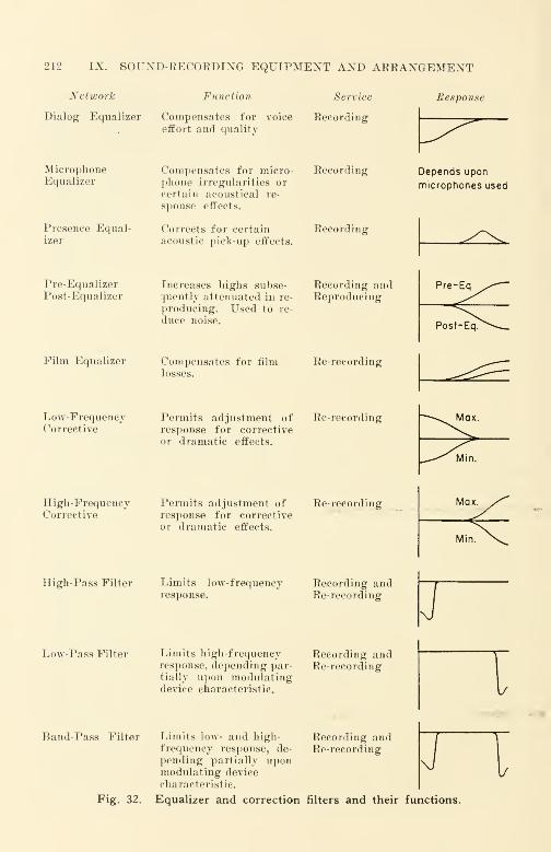
212 IX. SOUND-RECORDING EQUIPMENT AND ARRANGEMENT
Network Function Service Response
Dialog Equalizer Compensates for voice Recordingeffort and quality
MicrophoneEqualizer
Presence Equal-izer
Pre-EqualizerPost-Equalizer
Film Equalizer
Low-FrequencyCorrective
High-FrequencyCorrective
Compensates for micro-phone irregularities or
certain acoustical re-
sponse effects.
Increases highs subse-quently attenuated in re-
producing. Used to re-
duce noise.
Compensates for film
Recording
Corrects for certain Recordingacoustic pick-up effects.
Recording andReproducing
Re-recording
Permits adjustment of Re-recordingresponse for correctiveor dramatic effects.
Permits adjustment of Re-recordingresponse for correctiveor dramatic effects.
Depends upon
microphones used
High-Pass Filter Limits low-frequencyresponse.
Recording andRe-recording
Low-Pass Filter Limits high-frequencyresponse, depending par-tially upon modulatingdevice characteristic.
Recording andRe-recording
I
Band-Pass Filter Limits low- and high-frequency response, de-
pending partially uponmodulating device
characteristic.
Recording andRe-recording
Fig. 32. Equalizer and correction filters and their functions.
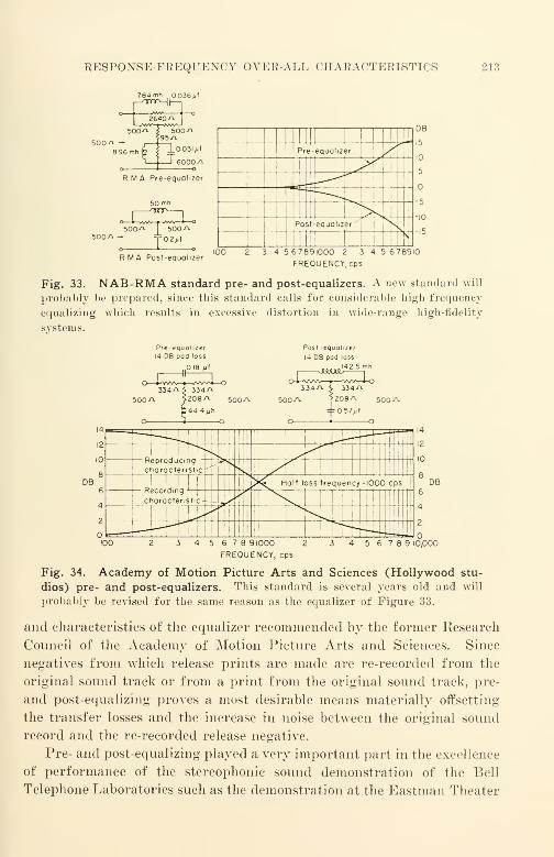
RESPONSE-FKEQUENCY OVER-ALL CHARACTERISTICS 2 1
3
784mh 0036/if
500^-8 96mh
__-
II 1
F3 re-equalizer\ /
^>
^
Post-equalizer' NV
DB
RMA Posr-equolizer3 4 5 67891000 2 3 4 5 678910
FREQUENCY.eps
Fig. 33. NAB-RMA standard pre- and post-equalizers. A new standard will
probably be prepared, since this standard calls for considerable high-frequency
equalizing which results in excessive distortion in wide-range high-fidelity
systems.
Pfe-equohzer14 OB pod loss
.018 fit
Post-equohzer
14 DB pod loss
.1425
DB
14i
r—
-
--A—
'
-^10
8
v
L c laractensr c'
II._.-,-.
cps6
4
2
?cordmg -
laractenscr h -?> y 1
^ "*. ~^--—^-r-r—
DB
5 6 7 8 91000
FREQUENCY, cps
14
12
10
8
6
4
2
5 6 7 8 9 10,000
Fig. 34. Academy of Motion Picture Arts and Sciences (Hollywood stu-
dios) pre- and post-equalizers. This standard is several years old and will
probably be revised for the same reason as the equalizer of Figure 33.
and characteristics of the equalizer recommended by the former Research
Council of the Academy of Motion Picture Arts and Sciences. Since
negatives from which release prints are made are re-recorded from the
original sound track or from a print from the original sound track, pre-
and post-equalizing proves a most desirable means materially offsetting
the transfer losses and the increase in noise between the original sound
record and the re-recorded release negative.
Pre- and post-equalizing played a very important part in the excellence
of performance of the stereophonic sound demonstration of the Bell
Telephone Laboratories such as the demonstration at the Eastman Theater
214 IX. SOUND-RECORDING EQUIPMENT AND ARRANGEMENT
in Rochester, New York, on May 7, 1941. Although the complexity and
high cost of the equipment used puts it far out of reach for day-to-day
commercial use, the performance was of such high caliber that the con-
siderations prompting the system and equalizer designs are worthy of
very careful study by those who wish to make the best use of available
facilities.
As yet, little serious thought has been given to pre- and post-equalizers
for 16-mm recording. The recent improvements in competitive methods
of sound recording, such as magnetic recording and recording on disk,
and the recent improvements in available films, will no doubt bring this
and any other means of improving sound quality quickly to the attention
of manufacturers' designers.
Much has been written on the subject of equalizer design and theory.
The Bell System and its affiliates have made notable contributions to the
theoretical background as well as to practical structures ; it has been said
that the transmission of a telephone conversation for more than 100
miles would be impossible without equalizers. At the end of this chapter
are a number of references on the subject.
Because of the somewhat involved nature of equalizers, the most
practicable procedure for an owner of recording equipment who needs
equalizers is to consult the manufacturer of the recording equipment
that he uses. A number of manufacturers supply equalizers of more or
less standardized designs; other equalizers are made to specifications.
Some of the manufacturers are
:
Cinema Engineering Company, Burbank, Calif.
United Transformer Corp., New York, N. Y.
Audio Development Corp., Minneapolis, Minn.
The Langevin Company, New York, N. Y.
Altec-Lansing, New York, N. Y.
General Radio Company, Cambridge, Mass.
The mailing addresses of the above companies may be obtained from any one of
a number of yearly electronics directories such as Electronics, McGraw-Hill Publishing
Company, or Electronic Industries, Caldwell-Clements Publishing Company, or from
any commercial directory. Ordinarily, RCA and Western Electric will supply equal-
izers only to their licensees; their equalizers are usually not for sale in the open
market.
Characteristic Impedance
The impedance for which a device or circuit is designed is one that
will provide the transmission characteristics for which the device or
THE MICROPHONE 215
circuit is designed. Ordinarily, the use of a device or circuit at an
impedance different from its characteristic impedance will be unsatisfac-
tory. As a general rule the circuit impedance in which a device is used
is satisfactory if it is within 5 to 10[i of the rated impedance.
A variety of designs is available for connection in lines of 600 ohms
characteristic impedance (600 ohms input impedance, 600 ohms output
impedance). The number of types stocked by manufacturers for other
characteristic impedances is smaller than those stocked for 600 ohms;
most manufacturers can supply niters designed for other impedances at
higher cost or as made-to-order items. So far the trend has been in
the direction of 600 ohms as the preferred impedance; it is expected,
however, that a connection impedance of 150 ohms may be nationally
standardized for broadcasting and similar purposes as the suitable im-
pedance for audio circuits of higher fidelity. At present many manu-
facturers design amplifiers for a circuit impedance of 550 ohms ; ordinarily
such amplifiers will function satisfactorily with equalizers and attenua-
tion pads of either 500- or 600-ohms rating.
A variety of connection impedances has been used by manufacturers,
and despite the urgent need, there has been no national standardization.
Western Electric uses 30 ohms as the common connection impedance for
microphones, and 600 ohms for other circuits. RCA, on the other hand,
uses 250 ohms as the common connection impedance for microphones
and 250 and 500 ohms for other circuits. When purchasing audio equip-
ment of any kind, it is important to pay special attention to the imped-
ances for which it is designed to make certain that it may be connected
directly to equipment in service.
Recording Equipment Details
The Microphone
A microphone has been defined as a device that transfers power from
an acoustic system to an electrical system. Since sound is a series of
alternating compression and rarefaction waves that occur in the air, a
microphone is a device that is placed in a sound field to produce an elec-
trical wave that closely resembles the sound wave in form. When a
microphone is placed in a sound field, a small portion of the energy
of the sound wave actuates the microphone.
Ajiy convenient form of voltage generating electrical arrangement
can be used for a microphone. Among the more common are
:
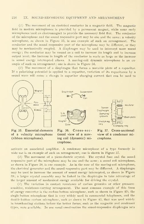
216 IX. SOUND-RECORDING EQUIPMENT AND ARRANGEMENT
(1) The movement of an electrical conductor in a magnetic field. The magnetic
field in modern microphones is provided by a permanent magnet, while some early
microphones used an electromagnet to provide the necessary field flux. The conductor
of the microphone and the sound responsive part may be one and the same : a velocity
microphone, as shown in Figure 35, is one example of such an arrangement. Theconductor and the sound responsive part of the microphone may be different, or they
may be mechanically coupled. A diaphragm may be used to intercept more sound
energy; the conductor may be wound as a coil to increase its length and to increase
output level; the increase in length of the conductor is made as large as the increase
in sound energy intercepted allows. A moving-coil dynamic microphone is an ex-
ample of such an arrangement; one is shown in Figure 36.
(#) The movement of a diaphragm that forms a movable plate of a capacitor.
If a polarizing potential is applied to a capacitor, variation of its capacitance by a
sound wave will cause a change in capacitor charging current that can be used to
Diaphragr Suspension
&^~^tc
Back plate
Fig. 35. Essential elements
of a velocity microphone(ribbon microphone).
Fig. 36. Cross-sec-tional view of a mov-ing coil (dynamic) mi-
crophone.
Clamping ring
Fig. 37. Cross-sectional
view of a condenser mi-
crophone.
activate an associated amplifier. A condenser microphone of a type formerly in
wide use is an example of such an arrangement; one is shown in Figure 37.
{3) The movement of a piezo-electric crystal. The crystal face and the sound
responsive part of the microphone may be one and the same ; a sound cell microphone,
as shown in Figure 38, is one example. As in the case of the moving-coil microphone,
the electrical generator and the sound responsive part may be different. A diaphragm
may be used to increase the amount of sound energy intercepted, as shown in Figure
39 ; a larger crystal assembly may be linked to the diaphragm to take advantage of
the larger amount of mechanical energy available for driving the crystal.
(4) The variation in contact resistance of carbon granules or other pressure-
sensitive, resistance-varying arrangement. The most common example of this form
of energy converter is the carbon-button microphone, such as shown in Figure 40 ; the
single-button microphone that is very widely used in commercial telephones, and the
double-button carbon microphone, such :is shown in Figure 41, that was used widely
in broadcasting stations before the better forms, such as the magnetic and condenser
types, were available. In one usual construction the sound-responsive diaphragm acts
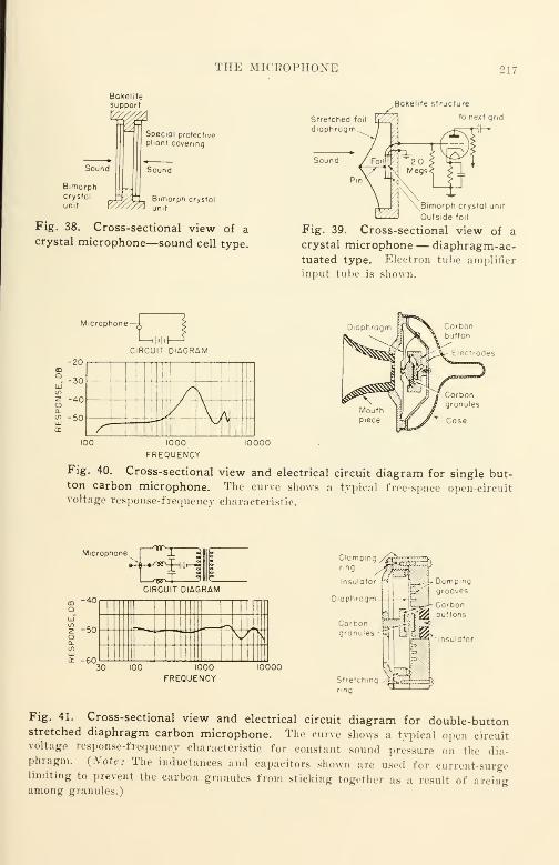
THE MICEOPHONE 217
Bakelitesupport
Sound
Bimorphcrystal
unit ?7Z
Speciol protectivepliant covering
Sound
VABimorph crystal
unit
Fig. 38. Cross-sectional view of acrystal microphone—sound cell type.
Stretched fo
,Bakehte structure
to next grid
Bimorph crystal unit
Outside foi
Fig. 39. Cross-sectional view of a
crystal microphone — diaphragm-ac-tuated type. Electron tube amplifier
input tube is shown.
Microphone—i- <
L—ihhl—
^
-20CD
°--30UJto
2 -40Ouo -50
rr
CIRCUIT DIAGRAM
// \ \
ff» / \f
1000
FREQUENCY10000
Carbonbutton
Fig. 40. Cross-sectional view and electrical circuit diagram for single but-ton carbon microphone. The curve shows a typical free-space open-circuitvoltage response-frequency characteristic.
Microphone
-40
b4-»^«^H'|^J
CIRCUIT DIAGRAM
z -50O
<r -60 1100 1000 10000
FREQUENCY
Clamping /Inr*
ring
Insulator
Diaphragm-
//Sir HI ^--tDampm
£>j
groove;
~L__J- Carbon
St
ring
ibtfretching ^^<; }; ;
--*),
Fig. 41. Cross-sectional view and electrical circuit diagram for double-buttonstretched diaphragm carbon microphone. The curve shows a typical open circuitvoltage response-frequency characteristic for constant sound pressure on the dia-phragm. {Note: The inductances and capacitors shown are used for current-surgelimiting to prevent the carbon granules from sticking together as a result of arcingamong granules.)

218 IX. SOUND-RECORDING EQUIPMENT AND ARRANGEMENT
Fig. 42. Cross-sectional view and electrical
circuit diagram of an electronic microphone.
also as one contact plate of the carbon button; in another, the sound responsive
diaphragm is mechanically linked to the movable plate of the carbon button.
(5) The physical movement of an electrode of an electron tube. As in other gen-
erator forms, a diaphragm may effect the physical movement of a control electrode.
This form of generator is relatively new and is not widely used; it is shown in
Figure 42.
The low-impedance, moving-conductor, magnetic-type microphone has
displaced almost all others for sound pickup ; carbon and crystal micro-
Fig. 43. Western Electric 633A micro-
phone with 8B microphone attachment
(baffle)—mounted on 24A stand.
Specifications
Frequency response: See Figures 43A and B. Power output level: When terminated
by a resistance of 20 ohms the power output level is -59 dbm (0 level calibration 1
milliwatt 10 dynes/cm2),- 79 dbm (1 dyne/cm2). Sensitivity: Open circuit terminal
voltage 90 db below 1 volt/dyne/cm2 which is equivalent to 70 db below 1 volt/10
dynes/cm2. Output impedance: Voice coil 20 ± 2 ohms. Dimensions: %\" long by 2"
diameter. Finish: Dark aluminum gray. Directional properties: See Figures 43
A
and B.
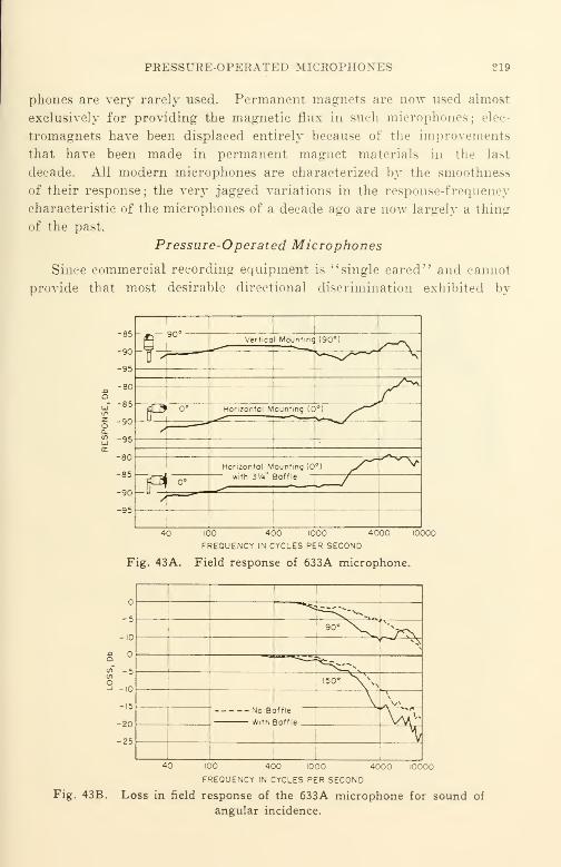
PRESSURE-OPERATED MICROPHON ES 219
phones are very rarely used. Permanent magnets are now used almost
exclusively for providing the magnetic flux in such microphones; elec-
tromagnets have been displaced entirely because of the improvements
that have been made in permanent magnet materials in the last
decade. All modern microphones are characterized by the smoothness
of their response ; the very jagged variations in the response-frequency
characteristic of the microphones of a decade ago are now largely a thing
of the past.
Pressure-Operated Microphones
Since commercial recording equipment is ''single eared" and cannot
provide that most desirable directional discrimination exhibited by
-85—
-95
100 400 1000 4000
FREQUENCY IN CYCLES PER SECOND
Fig. 43A. Field response of 633A microphone.
^*cz^-^900 ^J>N
1 ^s;c^Nr>.50' X\N
1 \ *" v
Mo Baffle
With Boffie IW-*\
-5
-10
S °
s- 5
S-,o
-15
-20
-25
40 100 400 1000 4000 lOOOO
FREQUENCY IN CYCLES PER SECOND
Fig. 43B. Loss in field response of the 633A microphone for sound of
angular incidence.
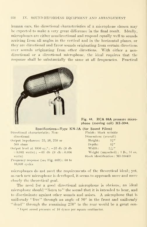
220 IX. SOUND-RECORDING EQUIPMENT AND ARRANGEMENT
human ears, the directional characteristics of a microphone chosen maybe expected to make a very great difference in the final result. Ideally,
microphones are either nondirectional and respond equally well to sounds
arriving from all angles in the vertical and in the horizontal planes, or
they are directional and favor sounds originating from certain directions
over sounds originating from other directions. With either a non-
directional or a directional microphone, the ideal requires that the
response shall be substantially the same at all frequencies. Practical
11 Fig. 44. RCA 88A pressure micro-
ti phone (moving coil) M 1-3044.
Specifications—Type KN-2A (for Sound Films)
Directional characteristic: Non- Finish: black wrinkle
directional Dimensions (overall)
Output impedances: 25, 50, 250 or Height: 31"
500 ohms Depth: 4J"
Output level at 1000 cy.*: -55 db (0 db Width: 2^"= 0.001 watts); -63 db (0 db = 0.006 Weight (unpacked): 1 lb., 14 oz.
watts) Stock identification: MI-3044D
Frequency response (see Fig. 44B) : 60 to
10,000 cycles
microphones do not meet the requirements of the theoretical ideal; yet,
as each new microphone is developed, it seems to approach more and more
closely the theoretical goal.
The need for a good directional microphone is obvious; an ideal
microphone should " listen to" the sound that it is intended to hear, and
to discriminate against other sounds and noises. A microphone that is
uniformly "live" through an angle of 90° in the front and uniformly
"dead" through the remaining 270° to the rear would be a great con-
* Input sound pressure of 10 dynes per square centimeter.
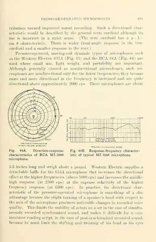
PRESSUKE-OPETCATED MICEOPHON ES 221
tribution toward improved sound recording-. Such a directional char-
acteristic would be described by the general term cardioid although its
use is incorrect in a strict sense. (The true cardioid has a y = 1 +
cos 6 characteristic. There is wider front-angle response in the true
cardioid and a smaller response to the rear.)
Pressure-operated, moving-coil dynamic types of microphones such
as the Western Electric 633A (Fig. 43) and the RCA 88A (Fig. 44) are
used where small size, light weight, and portability are important.
Although generally classed as nondirectional microphones, such mi-
crophones are nondirectional only for the lower frequencies ; they become
more and more directional as the frequency is increased and are quite
directional above approximately 2000 cps. These microphones are about
Xf u^ \y
-
—
l
1
FREQUENCY RESPONSEOF A TYPICAL MI-J044PRESSURE MICROPHONE
lRECT|ONAL CHARACTERISTIC*J044 PRESSURE MICROPHONE
FREQUENCY IN CYCLES PER SECOND
Fig. 44A. Direction-response
characteristics of RCA M 1-3044
microphone.
Fig. 44B. Response-frequency character-
istic of typical M 1-3044 microphone.
3.5 inches long and weigh about a pound. Western Electric supplies a
detachable baffle for the 633A microphone that increases the directional
effect at the higher frequencies (above 1000 cps) and increases the middle-
high response (at 2500 cps) at the expense relatively of the higher
frequency response (at 6500 cps). In practice, the directional char-
acteristic of the pressure-operated microphone is something of a dis-
advantage because the slight turning of a speaker's head with respect to
the axis of the microphone produces noticeable changes in recorded voice
quality. This limits the mobility of actors on a set in the case of simulta-
neously recorded synchronized sound, and makes it difficult for a com-
mentator reading script, in the case of post-synchronized recorded sound,
because he must limit the shifting and twisting of his head as his eyes

222 IX. SOUND-RECORDING EQUIPMENT AND ARRANGEMENT
Fig. 45. Western Electric 640AAcondenser microphone and RA-1095
amplifier. Frequency characteristic:
Free-field response : see Figure 45A.
Output level: Approximately 49.5 db
below 1 volt (open circuit) per
dyne/cm 2 with 200 volts d.-c. polariz-
ing potential. Output impedance:
Essentially that due to its capacitance
which is approximately 50 mmf. to 60
mmf. Operates into: Grid circuit of
closely associated vacuum tube ampli-
fier (such as Western Electric RA-1095
amplifier). Polarizing voltage: 220
volts d.-c. maximum from well regulated
quiet supply. (Caution: polarizing
voltage exceeding 220 volts should not
be applied as higher voltages maydamage the instrument.) Dimensions
:
Cylindrical shape approximately 1"
i diameter and 1" long. Weight: Ap-
proximately l 1/^ ounces. Mounting:
For optimum signal-to-noise the micro-
phone should be closely associated with
the first stage of amplification and
preferably mounted in the structure
" containing this amplifier. External
connection : The 640AA microphone is especially designed to mount on the RA-1095amplifier. It has a spring mounted plunger and male base threads for providing
connection to the amplifier. When associated with another type of amplifier, the
microphone should be connected to the grid of the vacuum tube by means of a short,
well-shielded, low capacitance lead to the center contact at rear of instrument. The
cylindrical shell of the microphone should be connected to the grounded side of the
grid circuit thereby serving as a shield for the inner components. Protection: Pro-
vided with a dust cap for each end of the cylinder when instrument is not in use.
RA-1095 Amplifier—Typical Electrical Characteristics
Frequency characteristic: See curve, Figure 45A (microphone and amplifier in com-
bination). Output level: Approximately -29.5 dbm with the 640AA microphone in
a sound field of 10 dynes/cm2 or -49.5 dbm in a 1 dyne/cm2 sound field. Signal-to-
noise ratio: Approximately 40 db at an output level of -49.5 dbm (0-15,000 cyele
band). Distortion: Less than one percent at -3 dbm output level. Operates from:
640AA condenser microphone. Output impedance : Designed to be used with equip-
ment having rated source impedance of 25-50 or 150-250 ohms. Power supply: Quiet
sources required for both filament and plate power, (neater': 6.3 volts, 150 milli-
amperes, direct current. Plate: 220 volts maximum, 3 milliamperes, direct current.
Caution: Plate voltages exceeded 220 volts should not be applied when the 640 type
microphone is attached, as higher voltages may damage the microphone). Dimensions
:
Approx. 1%" long, 2 1/£" diameter. Weight: Approx. 1% pounds. External connec-
tions: Through 6 prong socket in base of amplifier. (Use Cannon 6 hole female plug
P6-11). Mounting: Suspend from socket cord or use shock mounting hanger to fit
user's microphone boom or other suspension mounting.
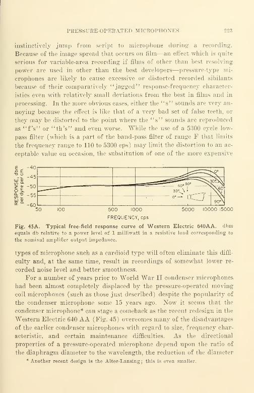
PRESSURE-OPERATED MICROPHON ES 223
instinctively jump from script to microphone during a recording.
Because of the image spread that occurs on film—an effect which is quite
serious for variable-area recording if films of other than best resolving
power are used in other than the best developers—pressure-type mi-
crophones are likely to cause excessive or distorted recorded sibilants
because of their comparatively "jagged" response-frequency character-
istics even with relatively small deviations from the best in films and in
processing. In the more obvious cases, either the "s" sounds are very an-
noying because the effect is like that of a very bad set of false teeth, or
they may be distorted to the point where the "s" sounds are reproduced
as "fV or "th's" and even worse. While the use of a 5300 cycle low-
pass filter (which is a part of the band-pass filter of range F that limits
the frequency range to 110 to 5300 cps) may limit the distortion to an ac-
ceptable value on occasion, the substitution of one of the more expensive
£ . -40
'.£ -45
Q- "OCO i_
-50
-55
-60
50°b\a0<s^^^ ^i3°V\ *
ccj-S\60°
ou—9cA
50 100 5000 10000 15000500 1000
FREQUENCY, cps
Fig. 45A. Typical free-field response curve of Western Electric 640AA. dbmequals db relative to a power level of 1 milliwatt in a resistive load corresponding to
the nominal amplifier output impedance.
types of microphone such as a cardioid type will often eliminate this diffi-
culty and, at the same time, result in recordings of somewhat lower re-
corded noise level and better smoothness.
For a number of years prior to World War II condenser microphones
had been almost completely displaced by the pressure-operated moving
coil microphones (such as those just described) despite the popularity of
the condenser microphone some 15 years ago. Now it seems that the
condenser microphone* can stage a comeback as the recent redesign in the
Western Electric 640 AA (Fig. 45) overcomes many of the disadvantages
of the earlier condenser microphones with regard to size, frequency char-
acteristic, and certain maintenance difficulties. As the directional
properties of a pressure-operated microphone depend upon the ratio of
the diaphragm diameter to the wavelength, the reduction of the diameter
* Another recent design is the Altec-Lansing; this is even smaller.
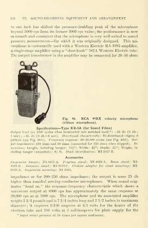
224 IX. SOUND-EECOEDING EQUIPMENT AND AEEANGEMENT
to one inch has shifted the pressure-doubling peak of the microphone
beyond 5000 cps from its former 3000 cps value; the performance is nowso smooth and consistent that the microphone is very well suited to sound
pressure measurement—for which it was originally designed. This mi-
crophone is customarily used with a Western Electric KA-1095 amplifier,
a single-stage amplifier using a "door-knob" 382A Western Electric tube.
The output transformer in the amplifier may be connected for 30-50 ohms
Fig. 46. RCA 44BX velocity microphone
(ribbon microphone).
Specifications—Type KB-5A (for Sound Films)
Output level (at 1000 cycles when terminated into matched load)*: -55 db (0 db =
1 mw) ; -63 db (0 db = 6 mw). Directional characteristic: Bi-directional—figure 8
pattern (see Fig. 46A). Frequency response: 30-10,000 cycles (see Fig. 46B). Out-
put impedances: 250 ohms and 50 ohms (connected for 250 ohms when shipped). Di-
mensions: Length, including hanger: 10^"; Width: 4f"; Depth: 3§"; Weight, in-
cluding hanger (unpacked): 8^ lb. StocTc identification: MI-3027-E.
Accessories
Suspension hanger: MI-4076-A. Program stand: MI-4090-A. Boom stand: MI-
4094-B . Announce stand: MI-4058-C. Cushion adaptor for stand mounting: MI-
3033-A. Suspension mounting : MI-3065.
impedance or for 200-250 ohms impedance; the output is some 25 db
higher than unaided moving conductor microphones. When sound orig-
inates "head on," the response-frequency characteristic which shows a
maximum output at 8000 cps has approximately the same response at
20,000 cps as at 1000 cps. The microphone and its associated amplifier
weighs 1 3/4 pounds and is 7 3/4 inches long and 2 1/2 inches in maximumdiameter; it requires 0.150 amperes at 6.3 volts for the heater of the
electron tube and 180 volts at 3 milliamperes for plate supply for the
* Input sound pressure of 10 dynes per square centimeter.
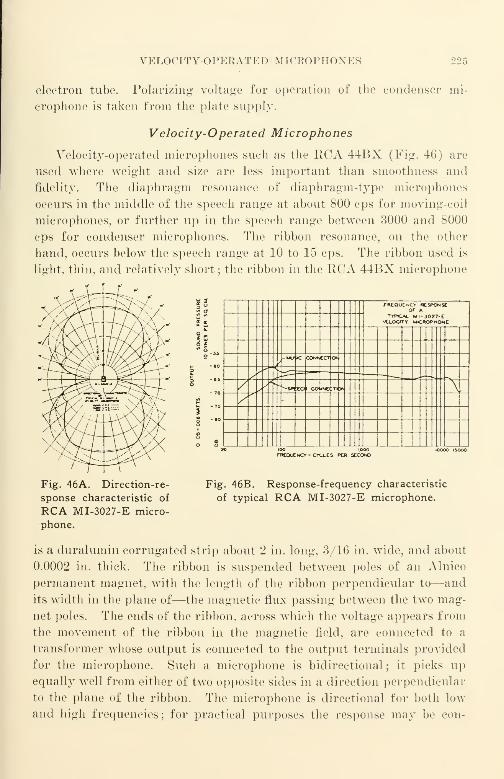
VELOCITY-OP FAl ATK I) M ICROPHONKS 225
electron tube. Polarizing- voltage for operation of the condenser mi-
crophone is taken from the plate supply.
Velocity-Operated Microphones
Velocity-operated microphones such as the RCA 44BX (Fig. 46) are
used where weight and size are less important than smoothness and
fidelity. The diaphragm resonance of diaphragm-type microphones
occurs in the middle of the speech range at about 800 cps for moving-coil
microphones, or further up in the speech range between 3000 and 8000
cps for condenser microphones. The ribbon resonance, on Hie other
hand, occurs below the speech range at 10 to 15 cps. The ribbon used is
light, thin, and relatively short ; the ribbon in the RCA 44BX microphone
T
81
FAEOUCNCirOf
(espouse
TYPICAL MI-3027-C•JOjOCITf UCHOPHOiC
r-UWWc Q0N»CCTK*
/ ^Wto COI*HE :n *
f'
1
rwnuENor-CYtt.es per secondk>ooo tyxx>
Fig. 46A. Direction-re-
sponse characteristic of
RCA MI-3027-E micro-
phone.
Fig. 46B. Response-frequency characteristic
of typical RCA MI-3027-E microphone.
is a duralumin corrugated strip about 2 in. long, 3/16 in. wide, and about
0.0002 in. thick. The ribbon is suspended between poles of an Alnico
permanent magnet, with the length of the ribbon perpendicular to—and
its width in the plane of—the magnetic flux passing between the two mag-
net poles. The ends of the ribbon, across which the voltage appears from
the movement of the ribbon in the magnetic field, are connected to a
transformer whose output is connected to the output terminals provided
for the microphone. Such a microphone is bidirectional; it picks upequally well from either of two opposite sides in a direction perpendicular
to the plane of the ribbon. The microphone is directional for both low
and high frequencies; for practical purposes the response may be con-

226 IX. SOUND-RECORDING EQUIPMENT AND ARRANGEMENT
sidered proportional to the cosine of the angle between the plane of the
ribbon and the direction of approach, with maximum response occurring
normal to the plane of the ribbon. There is very little frequency dis-
crimination with change in angle of incidence of the approaching sound
;
the directional characteristics of the ribbon microphone are quite uniform
for all frequencies in its design range. The 44BX microphone is capable
of substantial output to 20,000 cps; its weight is about 8 1/2 pounds
and its length (including the cushion mounting) is about 12 inches.
As the energy response of the ribbon microphone to randomly re-
flected sound is but one-third that of a nondirectional microphone, it is
possible to increase the distance between the sound source and the micro-
phone for the same ' 'quality" (ratio of direct sound to randomly reflected
sound) as that obtained with a nondirectional microphone. The ribbon
microphone is excellent for the recording of music because of its smooth-
ness; it is also very good for the recording of speech—provided the
speaker is at least 2 feet from the microphone. When the speaker-to-
microphone distance is less than 2 feet, the recorded speech sounds un-
natural and tubby; ordinarily no simple form of equalizing is capable
of satisfactorily correcting for the deterioration in quality that results.
Some RCA 44 type microphones are provided with a voice tap connection
at the microphone terminal board; when the voice tap is connected, the
response of the microphone is attenuated in the low-frequency range by
some 6 db at 100 cps.
Cardioid Types of Microphones
For years designers have been trying to make a unidirectional micro-
phone that is as small and light as the smaller pressure-operated micro-
phones (about 3 inches long and weighing not more than 1 pound);such
a microphone should have the sensitivity of a pressure-operated type
such as the Western Electric 633A, it should pick up sound from one side
only, and it should be equally directional for low and for high frequen-
cies. Such a microphone would make it possible to discriminate against
noise and extraneous sound such as camera noise that originate in a direc-
tion different from that of the sound source to be recorded ; in addition,
the ratio of the direct sound picked up by the microphone to the reflected
sound could be increased, thereby materially improving the quality of the
recording. Small size is desired because a microphone casts a shadow
when it is used on an illuminated set, and the smaller the microphone,
the smaller is the shadow. Light weight is desired because the micro-
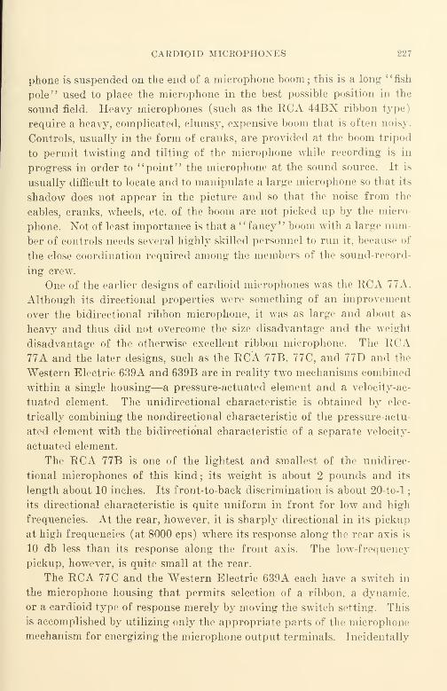
CARDIOID MICEOPHONES 227
phone is suspended on the end of a microphone boom; this is a long "fish
pole" used to place the microphone in the best possible position in the
sound field. Heavy microphones (such as the RCA 44BX ribbon type)
require a heavy, complicated, clumsy, expensive boom that is often noisy.
Controls, usually in the form of cranks, are provided at the boom tripod
to permit twisting and tilting of the microphone while recording is in
progress in order to "point" the microphone at the sound source. It is
usually difficult to locate and to manipulate a large microphone so that its
shadow does not appear in the picture and so that the noise from the
cables, cranks, wheels, etc. of the boom are not picked up by the micro-
phone. Not of least importance is that a "fancy" boom with a large num-
ber of controls needs several highly skilled personnel to run it, because of
the close coordination required among the members of the sound-record-
ing crew.
One of the earlier designs of cardioid microphones was the RCA 77A.
Although its directional properties were something of an improvement
over the bidirectional ribbon microphone, it was as large and about as
heavy and thus did not overcome the size disadvantage and the weighl
disadvantage of the otherwise excellent ribbon microphone. The RCA77A and the later designs, such as the RCA 77B, 77C, and 77D and the
Western Electric 639A and 639B are in reality two mechanisms combined
within a single housing—a pressure-actuated element and a velocity-ac-
tuated element. The unidirectional characteristic is obtained by elec-
trically combining the nondirectional characteristic of the pressure-actu-
ated element with the bidirectional characteristic of a separate velocity-
actuated element.
The RCA 77B is one of the lightest and smallest of the unidirec-
tional microphones of this kind; its weight is about 2 pounds and its
length about 10 inches. Its front-to-back discrimination is about 20-to-l
;
its directional characteristic is quite uniform in front for low and high
frequencies. At the rear, however, it is sharply directional in its pickup
at high frequencies (at 8000 cps) where its response along the rear axis is
10 db less than its response along the front axis. The low-frequency
pickup, however, is quite small at the rear.
The RCA 77C and the Western Electric 639A each have a switch in
the microphone housing that permits selection of a ribbon, a dynamic,
or a cardioid type of response merely by moving the switch setting. This
is accomplished by utilizing only the appropriate parts of the microphone
mechanism for energizing the microphone output terminals. Incidentally
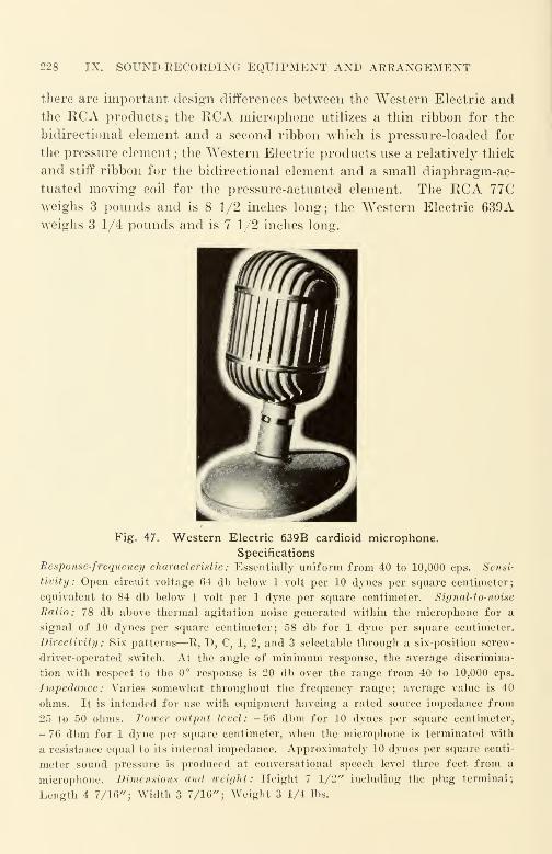
228 IX. SOUND-RECOEDING EQUIPMENT AND ARRANGEMENT
there are important design differences between the Western Electric and
the RCA products; the RCA microphone utilizes a thin ribbon for the
bidirectional element and a second ribbon which is pressure-loaded for
the pressure element ; the Western Electric products use a relatively thick
and stiff ribbon for the bidirectional element and a small diaphragm-ac-
tuated moving coil for the pressure-actuated element. The RCA 77
C
weighs 3 pounds and is 8 1/2 inches long; the Western Electric 639
A
weighs 3 1/4 pounds and is 7 1/2 inches long.
Fig. 47. Western Electric 639B cardioid microphone.
Specifications
Response-frequency characteristic : Essentially uniform from 40 to 10,000 cps. Sensi-
tivity: Open circuit voltage 64 db below 1 volt per 10 dynes per square centimeter;
equivalent to 84 db below 1 volt per 1 dyne per square centimeter. Signal-to-noise
Ratio: 78 db above thermal agitation noise generated within the microphone for a
signal of 10 dynes per square centimeter; 58 db for 1 dyne per square centimeter.
Directivity : Six patterns—R, D, C, 1, 2, and 3 selectable through a six-position screw-
driver-operated switch. At the angle of minimum response, the average discrimina-
tion with respect to the 0° response is 20 db over the range from 40 to 10,000 cps.
Impedance: Varies somewhat throughout the frequency range; average value is 40
ohms. It is intended for use with equipment haveing a rated source impedance from
25 to 50 ohms. Power output level : - 56 dbm for 10 dynes per square centimeter,
- 76 dbm for 1 dyne per square centimeter, when the microphone is terminated with
a resistance equal to its internal impedance. Approximately 10 dynes per square centi-
meter sound pressure is produced at conversational speech level three feet from a
microphone. Dimensions and weight : Height 7 1/2" including the plug terminal
;
Length 4 7/16"; Width 3 7/16"; Weight 3 1/4 lbs.
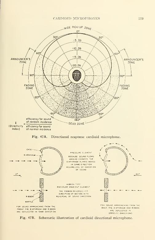
CAEDIOID MICEOPHONES
^\oe pick-up ^0/V£.
229
ANNOUNCER'SZONE
ANNOUNCER'SZONE
(Directivity efficiency for soundIndex) of normal incidence
DEAD ZONE
Fig. 47A. Directional response cardioid microphone.
PRESSURE ELEMENT
BECAUSE SOUND FLOWSAROUND CORNERS THE
DIAPHRAGM ALWAYS MOVESIN SAME DIRECTION
REGARDLESS OF DIRECTION
OF SOUND
RIBBON TYPE
PRESSURE GRADIENT ELEMENT
THE RIBBON REVERSES ITS
DIRECTION OF MOTION WITH
REVERSAL OF SOUND OlRECTlON
FOR SOUNO APPROACHING FROM THE
FRONT THE DIAPHRAGM AND RIBBONARE OEFLECTED IN SAME DIRECTION
u
for souno approaching from the
Back the Diaphragm ano ribbonARE DEFLECTED IN
OPPOSITE DIRECTIONS
Fig. 47B. Schematic illustration of cardioid directional microphone.
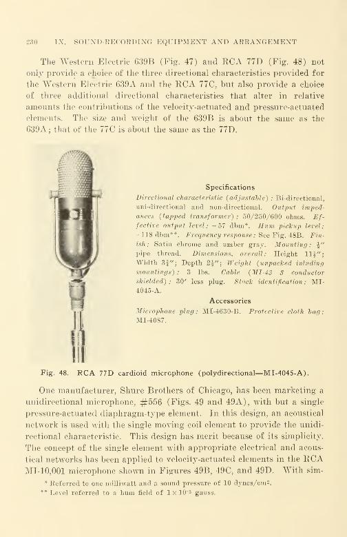
230 IX. SOUND-RECORDING EQUIPMENT AND ARRANGEMENT
The Western Electric 639B (Fig. 47) and RCA 77D (Fig. 48) not
only provide a choice of the three directional characteristics provided for
the Western Electric 639A and the RCA 77C, but also provide a choice
of three additional directional characteristics that alter in relative
amounts the contributions of the velocity-actuated and pressure-actuated
elements. The size and weight of the 639B is about the same as the
639A; that of the 77C is about the same as the 77D.
^
Specifications
Directional characteristic (adjustable) : Bi-directional,
uni-directlonal and non-directional. Output imped-
ances (tapped transformer) : 50/250/600 ohms. Ef-fective output level: -57 dbm*. Hum pickup level:
- 118 dbm**. Frequency response: See Fig. 48B. Fin-
ish: Satin chrome and umber gray. Mounting: \"
pipe thread. Dimensions, overall: Height 11$"j
Width 35"; Depth 2i"; Weight (unpacked inluding
mountings) : 3 lbs. Cable (MI-43 3 conductor
shielded): 30' less plug. Stock identification: MI-4045-A.
Accessories
Microphone plug: MI-4630 B. Protective cloth bag:
MI-4087.
Fig. 48. RCA 77D cardioid microphone (polydirectional—MI-4045-A).
One manufacturer, Shure Brothers of Chicago, has been marketing a
unidirectional microphone, #556 (Figs. 49 and 49A), with but a single
pressure-actuated diaphragm-type element. In this design, an acoustical
network is used with the single moving coil element to provide the unidi-
rectional characteristic. This design has merit because of its simplicity.
The concept of the single element with appropriate electrical and acous-
tical networks has been applied to velocity-actuated elements in the RCAMI-10,001 microphone shown in Figures 49B, 49 C, and 49D. With sim-
* Keferred to one milliwatt and a sound pressure of 10 dynes/cm2.** Level referred to a hum field of 1 x 10~3 gauss.
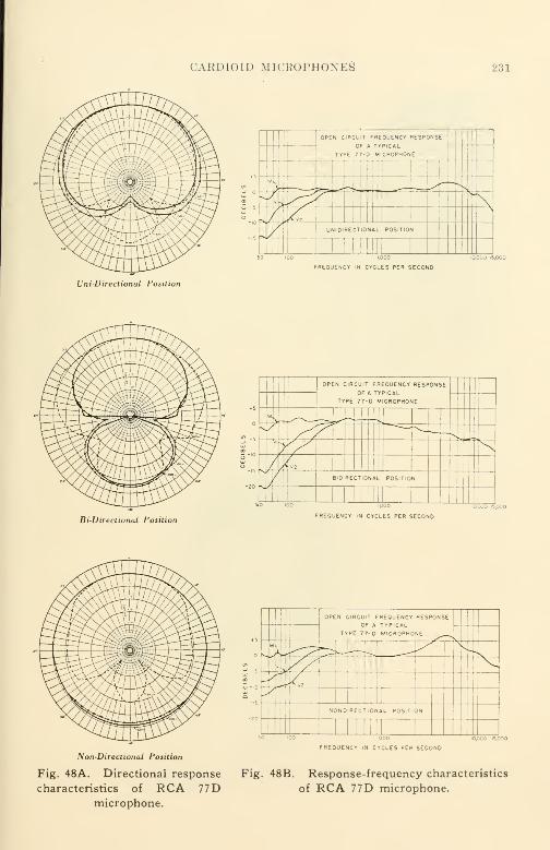
CAEDIOID MICROPHONES 231
50 100 1,000
FREQUENCY IN CYCLES PER SECOND
OPEN CIRCUIT FREQUENCY RESPONSE
TYPE 77-D MICROPHONE
••'
\
. .-y \, / /.
s
'UNIDIRECTIONAL POSITION
llllllll 1
io.ooj ij.ooo
Uni-Directionut Position
OPEN CIRCUIT FREQUENCY RESPONSE
5
TYPE 77-0 MICROPHONE
\ 1
v/
00 y/ Xo l0
o/
Xvz
-20 /BIDIRECTIONAL POSITION
llllllll 1
Bi-Directionul Position
50 ipoo
FREQUENCY IN CYCLES PER SECOND
FREQUENCY IN CYCLES PER SECOND
:.-- woo
Non-Directional Position
Fig. 48A. Directional response Fig. 48B. Response-frequency characteristics
characteristics of RCA 77D of RCA 77D microphone,
microphone.
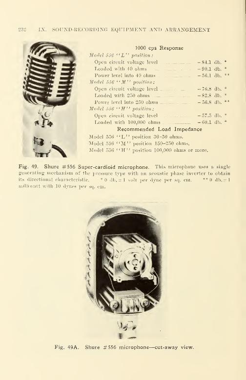
232 IX. SOUXD-RECORDIXG EQUIPMENT AND ARRAXGEMEXT
1000 cps Response
Model 556 " L" position:
Open circuit voltage level - 84.1
Loaded with 40 ohms - 90.1
Power level into 40 ohms - 56.1
Model 556 "M" position:
Open circuit voltage level - 76.8
Loaded with 250 ohms -82.8
Power level into 250 ohms - 56.8
Model 556 "H" position:
Open circuit voltage level - 57.5
Loaded with 100,000 ohms - 60.1
Recommended Load Impedance
Model 556 "L," position 30-50 ohms.
Model 556 "M" position 150-250 ohms.
Model 556 '' H " position 100,000 ohms or more.
Fig. 49. Shure #556 Super-cardioid microphone. This microphone uses a single
generating mechanism of the pressure type with an acoustic phase inverter to obtain
its directional characteristic. *0 db. = 1 volt per dyne per sq. cm. ** db. = 1
milliwatt with 10 dynes per sq. cm.
db. *
db. *
db. **
db. *
db. *
db. **
db. *
db. *
Fig. 49A. Shure #556 microphone—cut-away view.

CARDIOII) MK'KOIMIOXKS 233
Specifications
Output impedance: 30, 150, 250 ohms. Con-
nected for 250 ohms when shipped. Load im-
pedance: Open circuit (unterminated trans-
former). Effective output level at 1000 cycles:
- 51 dbm at 150 and 250 ohm output impedance;
- 49 dbm at 30 ohm output impedance. Fre-
quency response: See Figure 49D. Directional
characteristic: See Figure 49C. Mounting: Asuitable resilient mounting is essential. ECAMI-10055 microphone hanger is designed for
this application. External connection: Type
"P" 3-pin Cannon Connector. Finish: Flat
two-tone umber-grey. Dimensions : Length 8";
Width 3"; Depth 3%"j Weight (less suspen-
sion mounting) 2};j pounds. Stock identifica-
tion, microphone: MI-10001. Stock identifica-
tion, suspension mounting: MI-10055.
Fig. 49B. RCA unidirectional microphone (MI-10,001) with resilient mounting
microphone hanger (MI-10,055).
Pig. 49C. Directional response characteristics of RCA MI-10,001 microphone.
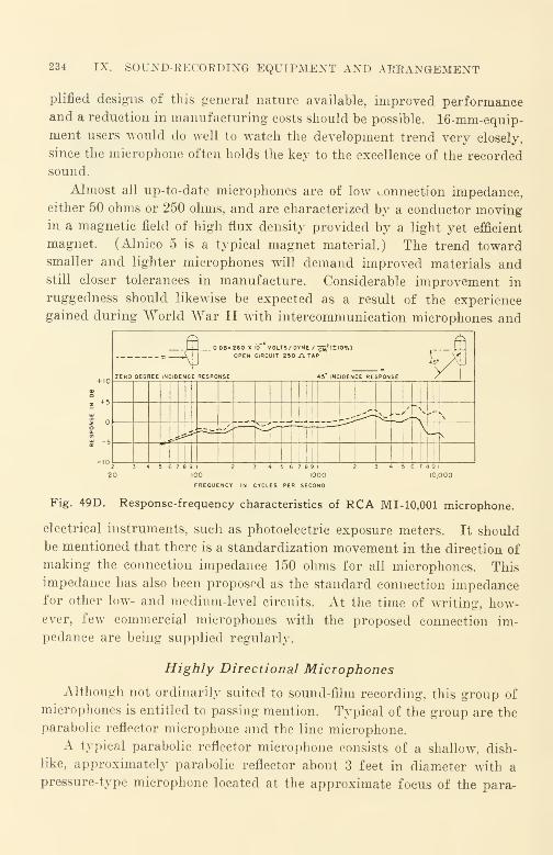
234 IX. SOUND-EECOEDING EQUIPMENT AND AEEANGEMENT
plified designs of this general nature available, improved performanceand a reduction in manufacturing costs should be possible. 16-mm-equip-ment users would do well to watch the development trend very closely,
since the microphone often holds the key to the excellence of the recorded
sound.
Almost all up-to-date microphones are of low connection impedance,
either 50 ohms or 250 ohms, and are characterized by a conductor movingin a magnetic field of high flux density provided by a light yet efficient
magnet. (Alnico 5 is a typical magnet material.) The trend towardsmaller and lighter microphones will demand improved materials andstill closer tolerances in manufacture. Considerable improvement in
ruggedness should likewise be expected as a result of the experience
gained during World War II with intercommunication microphones and
-(
s
DB = 280 X I0~ VOLTS/ DY^E / ^'(±10%)OPEN CIRCUIT 250 Jl TAP r
5*~MZERO DEGREE INCIDENCE RESPONSE 45* INCIDENCE RESPONSE
,,'• \ .- ,'* \
^
1 2
003 4 5 6 7 8 9 1
10002 3 4 5 6 7 8 9 1
10,000
FREQUENCY IN CYCLES PER SECOND
Fig. 49D. Response-frequency characteristics of RCA MI-10,001 microphone.
electrical instruments, such as photoelectric exposure meters. It should
be mentioned that there is a standardization movement in the direction of
making the connection impedance 150 ohms for all microphones. This
impedance has also been proposed as the standard connection impedancefor other low- and medium-level circuits. At the time of writing, how-ever, few commercial microphones with the proposed connection im-
pedance are being supplied regularly.
Highly Directional Microphones
Although not ordinarily suited to sound-film recording, this group of
microphones is entitled to passing mention. Typical of the group are the
parabolic reflector microphone and the line microphone.
A typical parabolic reflector microphone consists of a shallow, dish-
like, approximately parabolic reflector about 3 feet in diameter with a
pressure-type microphone located at the approximate focus of the para-

MICROPHONE EQUALIZERS 235
bola. The directivity of this microphone is practically nil at 200 cps
and increases with increasing frequency—becoming very sharp at 8000
cps. Although sound can be picked up over a distance of 50 to 100 feet
with such a microphone, the variation of directivity with frequency causes
serious changes in quality to occur when the location of the sound source
is shifted during recording with respect to the axis of the parabola.
Since most dialogue recording for sound films usually involves movement
of the actors, parabolic reflector microphones are rarely used today.
The line microphone is essentially a bundle of small tubes of different
length, open at one end and coupled at the other end to a pressure-type
microphone. A line microphone can be designed that does overcome to
some degree the serious azimuth-frequency discrimination of the para-
bolic reflector microphone; such a microphone is complex and is neither
small in size nor light in weight. In use, a line microphone is " aimed"
at a sound source.
Other Forms of Microphones
Many other forms of microphones have been proposed and used. Of
these, one group that is commercially and scientifically important al-
though little used in 16-mm sound recording is the crystal microphone.
This microphone uses a Rochelle salt crystal to convert the sound energy
into electrical potentials ; a voltage is produced by mechanically deform-
ing a cemented assembly. Generally speaking, crystal microphones
—
whether diaphragm-actuated, sound-cell actuated, etc.—are used very
little commercially in 16-mm sound recording because of the unfavorable
temperature-response characteristics of the Rochelle salt crystal. The
crystal becomes permanently damaged wThen the temperature exceeds
140 °F. Crystals that are not hermetically sealed—and most are not
—show a continual exchange of moisture with the surrounding atmosphere
when the relative humidity and the temperature of the atmosphere
changes. With each such change in temperature and in moisture occurs
a change in response characteristics.
Microphone Equalizers
It should be apparent that it is not possible merely to substitute one
type of microphone for another without making some allowance for the
differences in response-frequency characteristic from one microphone to
another. Fortunately, the differences between different microphones of
the same make and type are often sufficiently small that no provision need
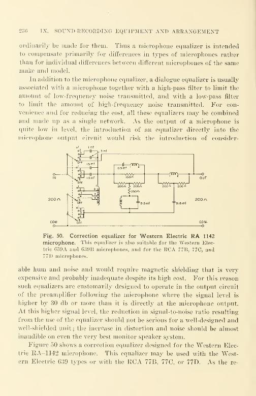
236 IX. SOUND-RECORDING EQUIPMENT AND ARRANGEMENT
ordinarily be made for them. Thus a microphone equalizer is intended
to compensate primarily for differences in types of microphones rather
than for individual differences between different microphones of the samemake and model.
In addition to the microphone equalizer, a dialogue equalizer is usually
associated with a microphone together with a high-pass filter to limit the
amount of low-frequency noise transmitted, and with a low-pass filter
to limit the amount of high-frequency noise transmitted. For con-
venience and for reducing the cost, all these equalizers may be combined
and made up as a single network. As the output of a microphone is
quite low in level, the introduction of an equalizer directly into the
microphone output circuit would risk the introduction of consider-
Fig. 50. Correction equalizer for Western Electric RA 1142
microphone. This equalizer is also suitable for the Western Elec-
tric 639A and 639B microphones, and for the RCA 77B, 77C, and77D microphones.
able hum and noise and would require magnetic shielding that is very
expensive and probably inadequate despite its high cost. For this reason
such equalizers are customarily designed to operate in the output circuit
of the preamplifier following the microphone where the signal level is
higher by 30 db or more than it is directly at the microphone output.
At this higher signal level, the reduction in signal-to-noise ratio resulting
from the use of the equalizer should not be serious for a well-designed andwell-shielded unit; the increase in distortion and noise should be almost
inaudible on even the very best monitor speaker system.
Figure 50 shows a correction equalizer designed for the Western Elec-
tric RA-1142 microphone. This equalizer may be used with the West-
ern Electric 639 types or with the RCA 77B, 77C, or 77D. As the re-

SOUXD-EECOEDIXG MACHINE 237
sponse of the RA-1142 cardioid microphone is quite flat and smooth
throughout the frequency range, the correction equalizer shown is pri-
marily intended as a voice-effort equalizer. As is the case with velocity
microphones, cardioid microphones require that a speaker be no closer
to the microphone than about 2 feet; if the distance should be less, the
recorded speech will be unnatural and tubby.
All microphones described have sufficient high-frequency response for
good recording ; all have substantial response beyond 10,000 cps. Should
high-fidelity recording be practicable, these microphones are capable of
providing it if used properly and if associated with suitable equalizers.
The Sound-Recording Machine
Since the amplifiers and their equalizers and adjuncts are intended
to correct for the transmission losses in all other parts of the recording
and reproducing system, it is well to consider the recording machine
before discussing the characteristics of the amplifier equipment.
In the last decade the sound-recording machine has seen major
changes. The film-transport system—although still simple—has been
improved to the point where flutter and wows audible to the average ear
are practically unknown. Xo commercial 16-mm sound-recording ma-
chine now uses a rigidly coupled film-driven flywheel ; all machines use
more complex filtering arrangements and are manufactured to surpris-
ingly close tolerances. To take advantage of the excellence of these
machines, film manufacturers now supply sound-recording film of high
resolving power (150 lines per mm) on base material that can be guar-
anteed to have less than 0.5% shrinkage (Eastman 5372).
Film Transport
The RCA PR32 16-mm sound-recording machine (Fig. 51) has a film-
transport mechanism that is a modification of the RCA 35-mm machines.
The film moves past the exposure light beam on the surface of a smooth
drum; on the other end of the shaft which carries the drum is a large fly-
wheel. The film transport system may be described briefly as a tight
loop film path using a solid type flywheel on the drum shaft. This basic
design, although historically finite old. was pioneered commercially about
a decade ago by Maurer in the Model D Sound Recording Machine. Its
performance with regard to flutter is surprisingly good; it represents a
simple yet effective solution to the very difficult design problems that
must be solved for a machine that is to be designed for satisfactory opera-
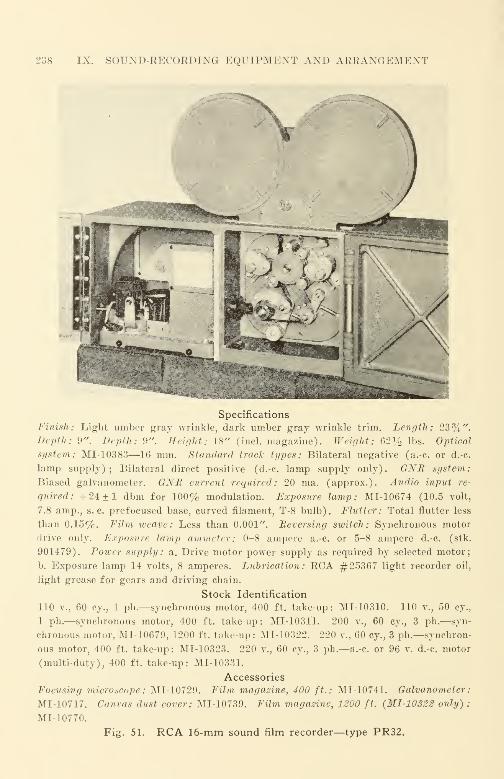
238 IX. SOUND-EECOEDING EQUIPMENT AND AEEANGEMENT
Specifications
Finish: Light umber gray wrinkle, dark umber gray wrinkle trim. Length: 23%".Depth: 9". Depth: 9". Height: 18" (incl. magazine). Weight: 62% lbs. Optical
system: MI-10383—16 mm. Standard track types: Bilateral negative (a.-c. or d.-c.
lamp supply); Bilateral direct positive (d.-c. lamp supply only). GNB system:
Biased galvanometer. GNB current required: 20 ma. (approx.). Audio input re-
quired: + 24±1 dbm for 100% modulation. Exposure lamp: MI-10674 (10.5 volt,
7.8 amp., s. c. prefocused base, curved filament, T-8 bulb). Flutter: Total flutter less
than 0.15%. Film weave: Less than 0.001". Reversing switch: Synchronous motor
drive only. Exposure lamp ammeter: 0-8 ampere a.-c. or 5-8 ampere d.-c. (stk.
901479). Power supply: sl. Drive motor power supply as required by selected motor;
b. Exposure lamp 14 volts, 8 amperes. Luorication : ECA #25367 light recorder oil,
light grease for gears and driving chain.
Stock Identification
110 v., 60 cy., 1 ph.—synchronous motor, 400 ft. take-up: MI-10310. 110 v., 50 cy.,
1 ph.—synchronous motor, 400 ft. take-up: MI-1031'1. 200 v., 60 cy., 3 ph.—syn-
chronous motor, MI-10679, 1200 ft. take-up : MI-10322. 220 v., 60 cy., 3 ph.—synchron-
ous motor, 400 ft. take-up: MI-10323. 220 v., 60 cy., 3 ph.—a.-c. or 96 v. d.-c. motor
(multi-duty), 400 ft. take-up: MI-10331.
Accessories
Focusing microscope : MI-10729. Film magazine, 400 ft.: MI-10741. Galvanometer
:
MI-10717. Canvas dust cover: MI-10739. Film magazine, 1200 ft. (MI-10322 only) :
MI-10770.
Fig. 51. RCA 16-mm sound film recorder—type PR32.
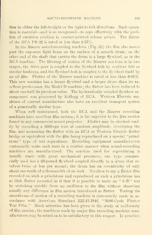
SOUND-EECORDING MACHINE 239
tion in either the left-to-right or the right-to-left directions. Such opera-
tion is essential—and is so recognized—to cope effectively with the prob-
lem of emulsion position in contact-printed release prints. The flutter
of the RCA PR-32 is rated at less than 0.15%.
In the Maurer sound-recording machine (Fig. 52) the film also moves
past the exposure light beam on the surface of a smooth drum; on the
other end of the shaft that carries the drum is a large flywheel, as in the
RCA machine. The filtering of motion of the Maurer machine is in two
stages; the drive gear is coupled to the flywheel hub by resilient felt or
similar bushings, and the flywheel hub is coupled to the flywheel itself by
an oil film. Flutter of the Maurer machine is rated at less than 0.05%.
This new machine has a larger flywheel and a larger drum than its ex-
cellent predecessor, the Model D machine ; the flutter has been reduced to
about one-half its previous value. The hydraulically-coupled flywheel ar-
rangement was pioneered by Kellogg of RCA. "Western Electric ma-
chines of current manufacture also have an excellent transport system
of a generically similar type.
When well maintained, both the RCA and the Maurer recording
machines have excellent film motion; it is far superior to the film motion
found in any commercial sound projector. ' Flutter may be checked read-
ily by recording a 3000-cps tone at constant amplitude, developing the
film, and measuring the flutter with an RCA or Western Electric flutter
bridge or equivalent with the film being reproduced on a special ' * grind-
stone" type of test reproducer. Recording equipment manufacturers
customarily make such tests in a routine manner when sound-recording
machines are manufactured. The machine used for reproducing is
usually made with great mechanical precision; one type commer-
cially used has a 60-pound flywheel coupled directly to a drum that re-
volves twice or less per second; the drum has an eccentricity of only
about one-tenth of a thousandth of an inch. Needless to say a flutter film
recorded on such a grindstone and reproduced on such a grindstone has
so little flutter recorded in it that it is possible to make an "A-B" test
by switching quickly from an oscillator to the film without observing
aurally any difference in film motion introduced as flutter. Testing the
smoothness of motion of a recording machine is customarily made in ac-
cordance with American Standard Z22.43-1946, "3000-Cycle Flutter
Test Film." Much attention has been given to the study of uniformity
of film motion ; the machines made by major film recording machine man-
ufacturers may be relied on to be satisfactory in this respect. In practice,
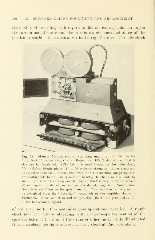
240 IX. SOUND-RECORDING EQUIPMENT AND ARRANGEMENT
the quality of recording with regard to film motion depends more upon
the care in manufacture and the care in maintenance and oiling of the
particular machine than upon advertised design features. Periodic check
Fig. 52. Maurer 16-mm sound recording machine. (Fitted to the
lower half of its carrying case.) Magazines: 400 ft size shown, 1200 ft
size can be furnished. (The latter is used frequently for television.)
Motor drive: Single phase 117 v. 60 cycle synchronous. Other types can
be supplied as needed. Propulsion direction: The machine can propel film
from either left to right or from right to left; the changeover is made by
snapping a motor reversing switch. Sound track forms: Variable area
—
either negative or direct positive variable density negative. Noise reduc-
tion: Electrical bias of the galvanometer. This machine is designed to
be energized from the '' recorder '
' receptacle of the amplifier shown in
Figure 63. Noise reduction and compression (fixed) are provided in ad-
dition to the audio signal.
of any machine for film motion is good operations' practice. A rough
check may be made by observing with a microscope the motion of the
sprocket holes of the film at the drum or other index while illuminated
from a stroboscopic light source such as a General Radio Strobotac.

FILM GUIDING 241
Film Guiding
Theoretically, when a film is guided in a sound recorder, it should
move with absolutely uniform velocity in a fixed plane past the exposing
light beam; it should be properly located with respect to dimensions in
its relation to the light beam, moving without side weave. By moving
in such a manner only the sound represented by the light beam variations
will be recorded. If the plane of the film is not fixed, and the film moves
in a direction along the optical axis, there will be an in-and-out-of-focus
effect produced, since the depth of focus of the objective lens is usually
small. If the plane of the film is not fixed, and the film moves in a direc-
tion perpendicular to the optical axis, small variations in distortion mayoccur due to the slight nonuniformity of the intensity of the exposure
light beam and due to the slight nonuniformity of the sensitivity of the
film. Large variations in distortion may occur if there is excessive weave,
since the tops of the recorded wave peaks may be cut off when the print
from the film is run through a sound projector.
As in the sound projector, the design engineer is faced with a dilemma.
since the requirements for ideal film motion and the requirements for
ideal film guiding are mutually contradictory in a good sound-recording
machine. For accurately guiding the film with respect to the scanning
beam, the film guide should be placed where the light beam impinges upon
the film. For best motion, the film guide should be placed as far away as
possible from the point where the light beam impinges upon the film. The
result actually achieved represents the success of the chosen compromise
of the design engineer; it is measured by the amount of flutter and by
the amount of weave or misplacement present in the film.
35-mm sound recorders have been designed to propel film in only one
direction; 16-nim machines, which recognize the commercial need for the
recording at will of sound records for either standard or nonstandard
emulsion position, are designed to propel film through the machine in
either direction. In machines that provide for guiding in only one direc-
tion, a guide located ahead of the recording drum represents, theoreti-
cally, a good design compromise. Inasmuch as the 16-mm film is pro-
pelled by a single row of sprocket holes, propulsion thrust occurs which
acts in the manner of a lateral-pressure edge guide. In practice, this
design can be relied upon to guide satisfactorily when the machine is up
to speed and running smoothly: track location may be inaccurate when
the film is accelerating or decelerating. Appreciable difficulty in track

242 IX. SOUND-RECORDING EQUIPMENT AND ARRANGEMENT
location will be encountered if the edge-guide roller bearings are not kept
scrupulously clean and properly lubricated.
It is apparent that with 16-mm machines such an edge-guiding ar-
rangement is unsuitable, since the film must be guided regardless of the
direction of travel through the machine. Because of this the edge guides
on the Maurer machine are located symmetrically on either side of the
translation point on the recording drum. To reduce the motion-dis-
turbing effects of edge friction and for the sake of simplicity, Maurer
has chosen to use a " channel-type " guide in preference to an "edge-
pressure" guide. In general, a channel-type guide is satisfactory when
the width of the guide is but slightly larger than the widest film to be
encountered, and when the length of the guide channel is large compared
with the film width. Although, theoretically, the film may "wobble
about '
' between the two guiding limits, the amount of friction introduced
in practice is sufficient to damp out most oscillatory side motion. The
"drift" in track location during the "settling-down" interval when the
machine is coming up to speed is quite small in the Maurer design com-
pared with 35-mm RCA design. Deterioration in film motion resulting
from guiding at the translation point is so small that it is difficult to
measure ; the penalty paid for this form of edge guiding is a slight dif-
ference (about 0.001 in.) in track location between propulsion in one
direction as compared with propulsion in the other direction. It is
possible that the track-location difference could be reduced if all film
manufactured were slit more accurately for width ; inaccurate slitting is
more likely to occur on certain non-American-made film than upon film
made by the major American film manufacturers. The dimensional
accuracy and dimensional stability of such films as EK 5372 are to be
admired by sound-recording machine designers.
The Light Modulator
The light modulator of a sound recording optical system is a device
that transfers power from an electrical system into movement or into
intensity change of a light beam of a character than can produce a sound
film record when these light variations are transmitted through the optical
system to the film. There are several common types of light modulators
in use.
(1) A string oscillograph type of galvanometer—such as the Einthoven or the
Duddell—in which a current passing through a conductor loop upon which a small
mirror is cemented causes the mirror to twist due to the reaction of current upon the
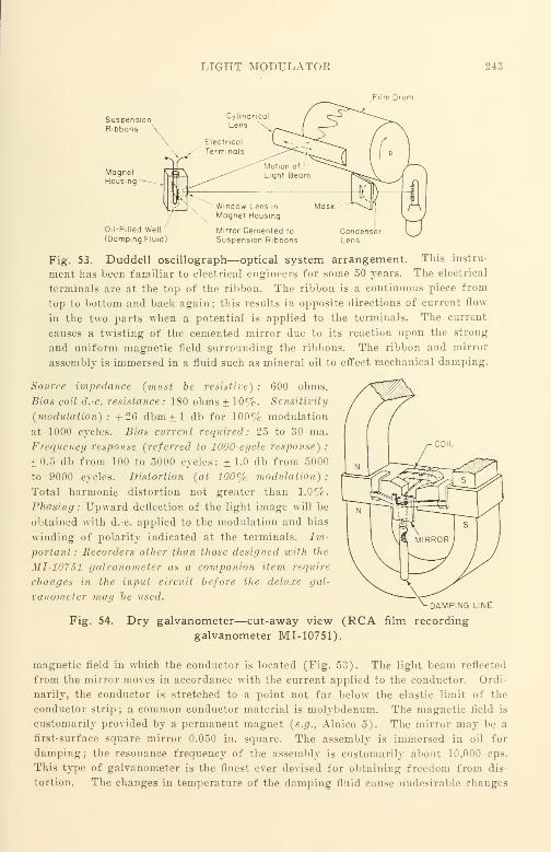
LIGHT MODULATOE 243
Film Drum
Oil-Filled Well
(Damping Fluid)
Mirror Cemented to
Suspension Ribbons
Fig. 53. Duddell oscillograph—optical system arrangement. This instru-
ment has been familiar to electrical engineers for some 50 years. The electrical
terminals are at the top of the ribbon. The ribbon is a continuous piece from
top to bottom and back again; this results in opposite directions of current flow
in the two parts when a potential is applied to the terminals. The current
causes a twisting of the cemented mirror due to its reaction upon the strong
and uniform magnetic field surrounding the ribbons. The ribbon and mirror
assembly is immersed in a fluid such as mineral oil to effect mechanical damping.
Source impedance (must be resistive) : 600 ohms.
Bias coil d.-c. resistance: 180 ohms ±10%. Sensitivity
(modulation): + 26 dbm ± 1 db for 100% modulation
at 1000 cycles. Bias current required: 25 to 30 ma.
Frequency response (referred to 1000-cycle response)
:
±0.5 db from 100 to 5000 cycles; ±1.0 db from 5000
to 9000 cycles. Distortion (at 100% modulation)
:
Total harmonic distortion not greater than 1.0%.
Phasing : Upward deflection of the light image will be
obtained with d.-c. applied to the modulation and bias
winding of polarity indicated at the terminals. Im-
portant: Recorders other than those designed with the
MI-10751 galvanometer as a companion item require
changes in the input circuit before the deluxe gal-
vanometer may be used. v DAMPING LINE
Fig. 54. Dry galvanometer—cut-away view (RCA film recording
galvanometer MI-10751).
magnetic field in which the conductor is located (Fig. 53). The light beam reflected
from the mirror moves in accordance with the current applied to the conductor. Ordi-
narily, the conductor is stretched to a point not far below the elastic limit of the
conductor strip ; a common conductor material is molybdenum. The magnetic field is
customarily provided by a permanent magnet (e.g., Alnico 5). The mirror may be a
first-surface square mirror 0.050 in. square. The assembly is immersed in oil for
damping; the resonance frequency of the assembly is customarily about 10,000 cps.
This type of galvanometer is the finest ever devised for obtaining freedom from dis-
tortion. The changes in temperature of the damping fluid cause undesirable changes

244 IX. SOUND-RECORDING EQUIPMENT AND ARRANGEMENT
in damping due to the changes in fluid viscosity. The oil-damped galvanometer was
widely used in the United States prior to 1933 for RCA equipment for variable area
;
it was most widely used in Germany after 1933.
{2) A dry galvanometer—an iron armature is located in a magnetic field and is
caused to move by the application of the electrical signal to a coil wound on the field
poles of the magnet (Fig. 54). The construction of the dry galvanometer is theo-
retically quite similar to that of electromagnetic phonograph pickups with high arma-
ture stiffness; one design (RCA) used the mechanical advantage of leverage to increase
the motion of a relatively large mirror mechanically connected to the armature by thin
flat metallic strips, other designs (Maurer and Western Electric) have a smaller
mirror cemented directly to the armature. Although the early dry galvanometers
Fig. 55. Diagrammatic sketch showing
how light valve string moves under influ-
ence of audio current.
Fig. 55A. Modern Western Elec-
tric light valve.
were of poor fidelity, modern dry galvanometers are of good fidelity. There are dis-
tinctive design differences in the damping arrangements used by different manufac-
turers. The freedom from distortion of a particular light modulator depends far more
upon the choice of suitable materials and upon the care taken in galvanometer manu-
facture than upon theoretical considerations. Dry galvanometers have displaced
string oscillograph galvanometers almost entirely in the United States ; they are widely
used for variable-area sound recording.
(3) A light valve—a pair of "strings" that are caused to move toward and awayfrom one another when a signal currant is passed through them, the signal current
reacting upon a magnetic field provided by a permanent magnet (Fig. 55). The
strings of a light valve—also called ribbons—are flat metallic strips made of molyb-
denum or other metal of high tensile strength. The light valve is the modulator
furnished by Western Electric ; it is usually associated with variable-density recording.
The movement of the ribbons of a light valve changes the amount of light transmitted
between them. Strings always have high tensile strength and low mass.

LIGHT MODULATOE 24.1
CELL FILLED WITHNITROBENZENE,
FILLER HOLE
Fig. 56. Kerr (Karolus) cell.
Fig. 57. Fox-case movietone aeolight—a sound recording glowlamp. Glow lamps are rarely used in 16-mm recording today; they
have given way to the dry galvanometer and to the light valve.
(4) A Kerr (Karolus) cell—the application of signal currents to its plates causes
a change in the amount of polarized light transmitted through the cell because of a
twist in the plane of polarization (Fig. 56). Nitrobenzene is the fluid commonly
used as the medium. This type of light modulator was ordinarily associated with
variable-density recording and is very little used today.
(5) A glow lamp—the application of signal current to a glow discharge lamp of
suitable type causes a change in the intensity of the glow (Fig. 57). When the light
is transmitted through a suitable optical system, a variable-density record is produced.
This type of light modulator is little used today; ' 'flashover" of the lamp usually
changes the lamp output seriously, making accurate exposure control difficult. Byappropriate optical design, any of the foregoing modulators may be used to provide
either variable-density or variable-area recording. In the past, light valves were
ordinarily associated with variable-density recording and galvanometers were associ-

l>46 IX. SOUND-RECORDING EQUIPMENT AND ARRANGEMENT
ated with variable-area recording. Recently, however, both Western Electric and RCAmake either form of recording available.
Measuring the distortion of a light modulator is a difficult matter,
since the modulator would have to be removed from its associated optical
system. Ordinarily, the single-frequency distortion at full amplitude
at the frequency of maximum distortion can be kept under 2% in good
commercial designs. So far little data has been published by manu-
facturers concerning distortion and its measurement in their light modu-
lators, or, for that matter, to be expected in their complete recording
systems. Intermodulation tests for studying the distortion character-
istics of variable-density recording systems (American Standard Z22.51-
1946) and cross-modulation tests for variable-area systems (American
War Standard Z22.52-1946) have no doubt already been applied to the
10
1-5
n
1— III J i I I l l l I l i l 1 1
1
' A '
-5
\
o oo oo o
CYCLES PER SECOND
o ooooo o oo ooooo o oo ooooo o om ip r-cocno c\j ^
Fig. 58. Response-frequency characteristic of galvanometer used
in Maurer sound recording machine of Figure 52.
study of light modulators and to their testing just as they have been
applied in the study of distortion arising from film processing. This
subject will no doubt receive much attention in the future.
Ordinarily it is not practicable for a user to remove a light modulator
from its machine for the checking of its distortion; the difficulties en-
countered in readjusting the machine for correct optical and mechanical
alignment in reassembly are almost insurmountable for the ordinary user
because of the need for highly specialized alignment test techniques and
equipment. The most practicable procedure is to test the sound-record-
ing machine as a complete unit by recording on film whatever tests are
necessary ; the film should be of the same emulsion number and lot num-
ber as that used for production recording. A great deal can be learned
by the inspection of such developed film as viewed under a microscope.
The trend in light-modulator design is toward higher primary-reso-
nance frequencies. The new Maurer machine has a tuning point for its
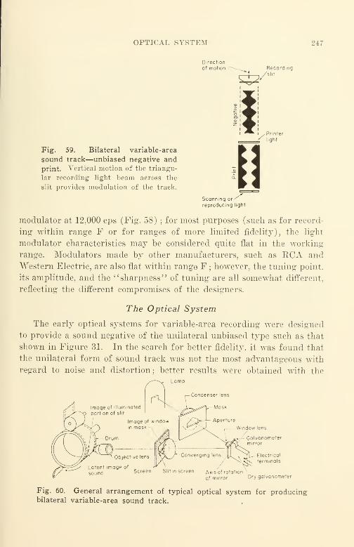
OPTICAL SYSTEM 247
Direction
of motion Recording-L_ /slit
Fig. 59. Bilateral variable-area
sound track—unbiased negative and
print. Vertical motion of the triangu-
lar recording light beam across the
slit provides modulation of the track.
Scanning or
reproducing light
modulator at 12,000 cps (Fig. 58) ;for most purposes (such as for record-
ing within range F or for ranges of more limited fidelity), the light
modulator characteristics may be considered quite flat in the working
range. Modulators made by other manufacturers, such as RCA and
Western Electric, are also flat within range F ; however, the tuning point,
its amplitude, and the "sharpness" of tuning are all somewhat different,
reflecting the different compromises of the designers.
The Optical System
The early optical systems for variable-area recording were designed
to provide a sound negative of the unilateral unbiased type such as that
shown in Figure 31. In the search for better fidelity, it was found that
the unilateral form of sound track was not the most advantageous witli
regard to noise and distortion ; better results were obtained with the
Condenser lens
Galvanometermirror
., Electrical
terminals
Screen Slit in screen Axis of rotation
of mirror Dry galvanometer
Fig. 60. General arrangement of typical optical system for producingbilateral variable-area sound track.

248 IX. SOUND-RECORDING EQUIPMENT AND ARRANGEMENT
bilateral form as shown in Figure 59. The general arrangement of an
optical system to accomplish this is shown in Figure 60.
The Slit and Its Effects. Ideally, sound is recorded and repro-
duced with a pencil of light that has—figuratively speaking—a very fine
point. Ideally also, the film upon which the light beam acts is made
up of sensitized particles that are also very fine. In addition, the light
slit or pencil edge (similar to the flat edge of a carpenter's pencil) is
located exactly at right angles with respect to the direction of travel of
the film both in recording and in reproducing.
Unfortunately, these idealized conditions are not met in practice.
The light slit or aperture has finite size and is not infinitely small. It is
not located exactly at right angles to the direction of travel of the film
in either the recording machine or in the sound projector. Also, the
film structure is not infinitely fine, since the sensitized particles are finite
in size.
In recording it is, of course, necessary to transmit sufficient light
through the optical system to provide adequate exposure of the film. Asthe effective slit size is made smaller, the amount of light that can be
transmitted through the optical system becomes smaller. Thus, the de-
sign problem is a compromise between the amount of exposure available
and the slit width; to achieve good exposure with a sufficiently small
width of slit requires design ingenuity—and increased cost. In record-
ing, a relatively wide slit (such as 0.001 in.) causes both high-frequency
loss and serious harmonic distortion ; in practice, the distortion is the
limiting factor because of the very objectionable quality of the sound
that results.
In reproducing, a relatively wide slit causes primarily high-frequency
loss and some harmonic distortion. Generally speaking, most 16-mm
sound projectors have used slits that are too wide to permit good sound
reproduction.
Slit tilt (or azimuth error as it is often called—deviation of the slit
from exact perpendicularity to the direction of travel of the film) intro-
duces really serious harmonic distortion in both recording and reproduc-
tion. For a particular slit tilt, the percentage of distortion climbs rapidly
as the recorded frequency increases. In general, the azimuth error in
recording machines is of a much lower order than the error in sound
projectors ; in modern recording machines, such as RCA, Western Elec-
tric, and Maurer, azimuth errors are quite small. In some sound pro-
jectors it is not uncommon to find a slit tilt of the order of one degree

OPTICAL SYSTEM 249
and no provision for readily adjusting and correcting it. The error
may vary appreciably from one projector to another and from one make
to another; in general, machines with better sound optics are usually
adjusted for azimuth more accurately than machines with poorer optics
because increases in the high-frequency response of a projector markedly
reveals azimuth deviation errors as harsh distortion. In recent years
projector manufacturers have been quite conscious of this factor and
measurable improvement has been made. The distortion resulting from
azimuth deviation error in a projector is very annoying since it is harsh
and raspy and there is very little that a projector user can do to over-
come it except to return the offending machine to the manufacturer for
proper adjustment.
Much study has been given to the relationship of the slit geometry
to the film ; the relationship with respect to width is usually referred to
as the aperture effect. The slit width for a 35-mm sound projector run-
ning at the standard speed of 90 ft. per minute has been established at
0.0013 in. For an equal aperture loss with 16-mm film running at its
standard speed of 36 feet per minute, the slit width would be propor-
tional to the film speed; the calculated width would be about 0.0005 in.
Only Eastman Kodak and DeYry have supplied 16-mm projectors with a
slit as fine as this; all other manufacturers have supplied projectors with
coarser slits and correspondingly poorer high-frequency response. The
Bell and Howell projectors provide slits of about 0.0007-in. width and are
correspondingly better than other machines that use still wider slits
—
some as wide as 0.001 in. Figure 61* and the following table show the
theoretical output of a uniformly illuminated slit that is exactly normal
(perpendicular) to the direction of film travel. The data is given in terms
of the ratio of the wavelength on the film to the slit width. Figure 61Ashows the approximate slit-loss characteristics for a 0.0005-in. slit (with
16-mm film running at the standard speed of 36 ft. per minute), and for
a 0.00012-in. slit.
* Data for this curve is taken from the analysis of E. D. Cook Avhich appeared
in the JSMPE under the titles "The Aperture Effect (JSMPE, June 1930, p. 650) ;
and "The Aperture Alignment Effect (JSMPE, Nov. 1933, p. 390). The full sig-
nificance of this fundamental and profound analysis is only now beginning to be
appreciated some two decades later. A modern interpretation was presented in 1949
at the Spring Convention of the SMPE in New York by J. A. Maurer; it is to be
published later in the Journal. In the light of the recent demands for improved
sound quality that are now being made, another paper by Cook should be of in-
terest: "The Technical Aspects of the High-Fidelity Keproducer" (JSMPE, Oct.
1935, p. 289). Despite the absence of fanfare in its presentation, Cook's work in
motion pictures is worthy of close study.

250 IX. SOUND-RECORDING EQUIPMENT AND ARRANGEMENT
16-mm sound-recording machines use slits appreciably narrower than
those used on 16-mm sound projectors. The width of the slit in a
Maurer machine, for example, is of the order of 0.00012 in. From the
curve shown it can be seen that the loss of a Maurer recording slit is
less than 1 db at 6000 cps. For practical purposes this loss is negligible
;
it is the distortion produced on the film that dictates the use of this very
narrow slit.
lOO
wavelength of fundamental
Theoretical Output of a Uniformly Illuminated Slit Exactly Perpendicular to
Direction of Eilm Travel 3
linear width of slit
wavelength of fundamentalPercent output Db attenuation
0.0 100 0.0
0.1 94 0.5
0.2 82 1.7
0.3 67 3.5
0.4 48 6.5
0.5 32 10.
0.6 18 15.
0.7 8 22.
0.8 3 31.
0.9 1 40.
1.0 co
Note : Maximum second harmonic due to scanning occurs at ratio 0.32.
Maximum third harmonic due to scanning occurs at ratio 0.5.
3 For complete opacity on opaque side and complete transmission on transparent
side of film.
Fig. 61. Theoretical output of slit in relation to recorded wavelength.
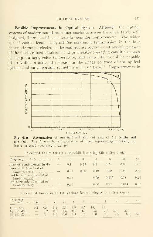
OPTICAL SYSTEM 251
Possible Improvements in Optical System. Although the optical
systems of modern sound-recording machines are on the whole fairly well
designed, there is still considerable room for improvement. The wider
use of coated lenses designed for maximum transmission in the best
chromatic range selected as the compromise between best resolving power
of the finer grained emulsions and practicable operating conditions, such
as lamp wattage, color temperature, and lamp life, would be capable
of providing a material increase in the image contrast of the optical
system and an important reduction in lens " flare." Improvements in
'
' ***^£
a
\
zo
2UJt-
£ 5tn_i
CD
Q
10 , , . !..,,50 5000 10000100 500 1000
FREQUENCY, cps
Fig. 61A. Attenuation of one-half mil slit (a) and of 1.2 tenths mil
slit (b). The former is representative of good reproducing practice; the
latter of good recording practice.
Calculated Values for 1.2 Tenths Mil Eecording Slit (after Cook)
Frequency in kc/s 1 2 3 4 G 8 10
Loss of fundamental in db — 0.1
Zero shift (decimal of
fundamental) — 0.06
2nd harmonic (decimal of
fundamental) — 0.04
3rd harmonic (decimal of
fundamental) — 0.00
0.15 0.3 0.5 0.9 1.2
0.08 0.12 0.20 0.28 0.32
0.09 0.135 0.18 0.20
0.00 0.01 0.014 0.02
Calculated Losses in db for Various Reproducing Slits (after Cook)
Frequencyin kc/s .... 0.5 in
1 mil slit 0.1 0.3 1.1 2.6 4.9
% mil slit — 0.2 0.6 1.5 2.6
% mil slit — 0.1 0.3 0.6 1.1
4.3
1.8
14.
6.5
2.6
31.
9.7
3.7
14.
4.9
23.
6.5 8.5

252 IX. SOUND-RECORDING EQUIPMENT AND ARRANGEMENT
design such as the directing of unwanted reflections out of the work-
ing optical path are also capable of providing worthwhile results.
Although present-day systems are not very complex, efforts to reduce
the number of surfaces traversed in a system are also capable of providing
worthwhile improvements. In general, systems with a small number
of optical surfaces are preferable to systems with a larger number. Asin the case of objective lenses for cameras, lens coating can provide a
very material improvement in the performance of a well-designed multi-
element lens system for sound optics just as it does for a Tessar; the
improvement in performance with lens coating in a poor design is not
great, since lens coating is in no sense a substitute for good design.
In general, all modern 16-mm sound-recording machines use filtered
light for film exposure ; as has been mentioned previously, Chapter III,
an increase in resolving power of the film occurs for exposure at the
blue and red ends of the spectrum. Since sound-recording film (as
manufactured) is not sensitized for exposure to red light, its sensitivity
to light at the blue end of the spectrum is important. For this reason
all commercial machines provide exposure for wavelengths shorter than
500 m/x in the blue region (Maurer) or in the near ultraviolet region
400 nut (RCA). Performance of a recording optical system can be im-
proved materially by correcting the system for only the primary wave-
length of interest, and by designing the lens coatings accordingly; this
has been recognized by recording equipment manufacturers, and further
improvements in design may be expected as a result of their progress
along these lines.
Film Loss
At this point something should be said about film losses, since they
are a controlling factor in the over-all response-frequency characteristic
actually obtained, and therefore should exert a very strong influence on
the manner in which the original sound record is equalized and the ac-
curacy of control with which the film-laboratory copying and processing
is accomplished. For years it has been the more-or-less vaguely implied
objective of designers of sound-recording equipment to provide equip-
ment to have a response-frequency characteristic that is "flat to the
print." This means merely that all losses and corrections in the record-
ing and reproducing systems must be anticipated up to and including
the making of the release print, and, in addition, to correct for such pro-
jection conditions as the level difference between the original event and
FILM LOSS 253
the reproduction level during projection. This objective does not antici-
pate the losses found in the reproducing of the film by the sound pro-
jector; at present, such losses are presumed to be anticipated by the
designer of the sound projector when he designs that machine.
Film loss in a projector may be measured by comparing the response
of the projector when constant modulated light from a galvanometer
strikes the reproducer photocell with its response when a constant-
amplitude film is scanned by the projector scanning beam. The dif-
ference between the two characteristics is usually called film loss. Film
loss is usually difficult to evaluate for comparison purposes because dif-
ferences in processing that are dictated by different recording methods
and by the variety of processing methods actually used, result in dif-
ferent performance in terms of the character and amount of the distor-
tion produced and in terms of the amount of noise produced.
Designers of sound projectors have had this situation in mind when
designing their machines despite the fact that there never has been
specific agreement among designers of sound-recording equipment and
of sound projectors as to just where one stops and where the other begins.
The practice as it now exists is followed because of the not-too-applicable
precedent set in the design of 35-mm recording and reproducing equip-
ment. Fortunately for the 35-mm industry a "standard" slit width
of 0.0013 in. was selected by the Research Council of the Academy of Mo-
tion Picture Arts and Sciences for 35-mm reproducing equipment, and
commercial equipment manufactured meets this'
' standard. '
' This width
represented the best compromise between cost and response character-
istics. Designers of 16-mm projectors have not been fortunate enough
to have a "standard" slit width for their machines; in addition, 16-mmfilm losses are much greater in magnitude than for 35-mm film. 16-mmfilm losses are much more variable in practice because a relatively muchhigher degree of control is required for 16-mm than for 35-mm if the
same order of variation in the over-all result is to be expected. This
is primarily a result of the fact that the film speed of 16-mm film is
only 40% that of 35-mm; the recording is crowded linearly into only
40% of the space along the film. For such reasons, accuracy and extreme
attention to detail must be the guide to successful 16-mm sound quality.
To accomplish the objective of designing a sound projector to
be "flat to the print," most early 16-mm sound projectors, being de-
ficient in high-frequency response because of a coarse slit in the pro-
jector sound-scanning beam, used a "peaked" (equalized) amplifier to
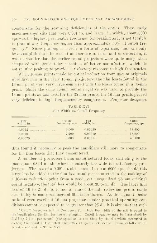
254 IX. SOUND-RECORDING EQUIPMENT AND ARRANGEMENT
compensate for the scanning deficiencies of the optics. These early
machines used slits that were 0.001 in. and larger in width ; about 3000
cps was the highest practicable frequency for peaking as it is not feasible
to peak at any frequency higher than approximately 50% of cutoff fre-
quency.* Since peaking is merely a form of equalizing and can only
be accomplished at the cost of an increase in noise and in distortion, it
was no wonder that the earlier sound projectors were quite noisy when
compared with present-day machines of better manufacture, which do
not require peaking to provide satisfactory response to high frequencies.
When 16-mm prints made by optical reduction from 35-mm originals
were first run in the early 16-mm projectors, the film losses found in the
16-mm print were very large compared with the losses found in a 35-mm
print. Since the same 35-mm sound negative was used to provide the
16-mm prints as was used for the 35-mm prints, the 16-mm prints proved
very deficient in high frequencies by comparison. Projector designers
TABLE XVISlit Width vs. Cutoff Frequency
Slit Cutoff Slit Cutoffwidth, in. frequency, cps width, in. frequency, cps
0.0012 6,000 0.00050 14,400
0.0010 7,200 0.00040 18,000
0.00075 9,600 0.00014 51,400
thus found it necessary to peak the amplifiers still more to compensate
for the film losses that they encountered.
A number of projectors being manufactured today still cling to the
inadequate 0.001-in. slit which is entirely too wide for satisfactory pro-
jection. The loss of a 0.001-in. slit is some 14 db at 6000 cps ; should this
large loss be added to the film loss usually encountered in the making of
a 16-mm reduction print from a good, yet unequalized 35-mm original
sound negative, the total loss would be about 30 to 35 db. The large film
loss of 16 to 21 db is found in run-of-the-mill reduction prints madeeven today in many commercial film laboratories. As the signal-to-noise
ratio of even excellent 16-mm projectors under practical operating con-
ditions cannot be expected to be greater than 25 db, it is obvious that such
* Cutoff frequency is that frequency for which the width of the slit is equal to
the length along the film for one Avavelength. Cutoff frequency may be determined by
dividing 7.2 in. per second (the speed of 16-mm film) by the slit width measured in
inches; the result is the cutoff frequency in cycles per second. Some cutoffs of in-
terest are found in Table XVI.

FILM LOSS 255
prints run on such projectors cannot possibly produce any useful signal
in the loudspeaker of the sound projector at 6000 cps. Incidentally,
equally poorly controlled 16-mm prints made from a good, yet un-
equalized, 16-mm sound negative may be expected to show similar losses.
A good 16-mm release print made directly from a good 16-mm sound
negative in accordance with good current commercial practice shows a
loss of 8 or 9 db at 6000 cps. The scanning loss of a projector with a
0.0005-in. slit (such as in some of the Eastman Kodak projectors) is only
some 3.5 db. As the total loss in this case would only be about 12 db,
it is possible to produce some useful signal at 6000 cps by such operation.
With the large processing losses that are common, however, it is almost
impossible to deliver a useful 6000-cps signal, on any projector regard-
less of its slit loss and other characteristics if poor processing of sound
film is used.
The better present-day sound projectors (such as the Bell and Howell)
use a slit of 0.0007 in. ; this slit width shows a scanning loss of 7 to 8 db
at 6000 cps. The "loss to the release print" of a good 16-mm print
printed directly from a good 16-mm sound negative in accordance with
the best commercial practices is of similar order. It is apparent
that as quality demands are pushed farther upward, projection equip-
ment, recording equipment, and processing will have to be improved.
A conventional post-war Bell and Howell Model 179 sound projector
together with such excellent prints from a suitable equalized 16-mm sound
negative would prove a revelation to the average user of 16-mm equip-
ment.
It should be quite apparent from the foregoing that the quality which
appears on a release print can be predicted fairly accurately if the con-
ditions under which the films are to be recorded, processed, and pro-
jected are known and taken into account. If the conditions are not
known, it is quite certain that the results will be poor and definitely in-
ferior to that which was expected. It has been truly said that the "cards
are always stacked against the haphazard film handler.
"
As there has been no standardization of 16-mm projector slit widths
or, for that matter, of any 16-mm response-frequency characteristic* for
* The Subcommittee on 16-Mm Sound Reproduction of the SMPE has been at-
tempting to establish empirically a reproducing system electrical characteristic in the
same general manner as that used for establishing the "Standard Electrical Charac-
teristics for Two-Way Reproducing Systems in Theatres" recommended by the Re-
search Council of the Academy of Motion Picture Arts and Sciences on October 10,
1938. To eliminate the hopeless variable introduced by the very wide disparity in
otnote continued on page 256)
256 IX. SOUND-RECORDING EQUIPMENT AND ARRANGEMENT
a projector, it is almost impossible to anticipate the wide variety of pro-
jector response-frequency characteristics that are in commercial use. Agood commercial procedure is to select a particular make and model
projector as a reference and to equalize all recordings so that they are
run with the projector controls of the reference machine in the " normal"
position. The selection of the reference projector must be made with
great care; its characteristics should remain constant from day-to-day
and month-to-month ; its specifications should deviate but the least prac-
ticable from those of the American "War Standard Z52.1-1944 " Projec-
tion Equipment, Sound Motion Picture, 16-Mm Class 1." Should it be
possible to specify the projectors to be used for the projection of the film
to be produced, all should be preferably of the some make and model
as the reference machine.
For the protection of the purchaser and for the mutual benefit of
all concerned, it seems that standardization of the slit-loss response-
frequency characteristic and standardization of either the system re-
sponse-frequency characteristic up to the amplifier output or standard-
ization of the over-all response-frequency characteristic of 16-mm sound
projectors is sorely needed. Effective standardization has existed for
35-mm projection for more than a decade and the time for similar stand-
ardization in 16-mm is long overdue.
To compensate for film loss, it is first necessary to know the actual
film loss. Therefore, a decision must be made as to just how films are to be
processed and copied, and no deviation can be permitted from the pro-
cedure so established. It is possible to keep this loss to as low as 8 db
per step if great care is exercised ; a loss of 20 db or even more can occur
in the single step from the original sound negative to the release print
under poor laboratory conditions ; unfortunately, such losses are not rare.
Some recent Maurer 16-mm recording equipment provides equaliza-
tion for film losses in three steps of 3 db, 6 db, and 9 db occurring at about
5500 cps. Whether this equalizing or, for that matter, any other equal-
izing is satisfactory will depend upon the film losses to be encountered and
the characteristics of the sound projectors to be used. The outlook for
good sound quality would seem hopeful for the better 16-mm sound pro-
performance of commercial loudspeakers supplied with 16-Mm projectors, the Sub-
committee has chosen to make its test with two-way reproducing systems such as are
used in theatres. Although there is some difficulty in establishing the correlations of
pre-war two-way loudspeaker systems with the larger number of post-war two-way
systems of somewhat different performance, the progress made is very encouraging.

FILM LOSS 257
jectors with the very best commercial film processing control; it would
seem hopeless for the poorest of present-day projectors and uncontrolled
run-of-the-mill processing.
Manufacturers now build their latest equipment capable of recording
a direct positive as well as a negative sound track, and of recording vari-
able density as well as variable area. In the case of the Maurer machine
these changes are made by merely turning a control knob or by moving
a lever. By recording a direct positive it is possible to eliminate the
losses attendant to the printing of an extra intermediate film. The ar-
rangement of the optical system is quite similar to that already shown
in Figure 60. The significant differences are : (1) the noiseless recording
bias is reversed so that the maximum exposure width is provided when no
modulation is present and (2) an inverted mask wider than the negative
mask is used; the maximum width is about 0.080 in. rather than the
negative width of 0.060 in. Modulation occurs, however, only to a maxi-
mum of 0.060 in. in accordance with current standards.
At present there are two common forms of variable-area sound track
in commercial use, bilateral variable area, as used in Maurer equipment
and obtained by applying the noiseless recording bias current to the
mirror galvanometer armature, and duplex variable area, as used in
earlier RCA equipment and obtained by applying the noiseless recording
bias current to a pair of shutters cooperating with the galvanometer
in limiting the width of the light beam transmitted by the recording
machine optical system to the film. Recent RCA recorders are returning
to the biased galvanometer arrangement.
Up to the present there has been no serious attempt to use push-pull
either on 16-mm film or on 35-mm film for release purposes. Although
16-mm push-pull sound tracks are not used commercially despite the fact
that 35-mm push-pull sound tracks have been in use for about a decade
in Hollywood for making original sound tracks that are later used for
re-recording in Hollywood studios, it cannot be safely said that 16-mmdirect positive push-pull recording will never be made. The demandsfor improved quality in 16-mm sound are ever growing and whether
16-mm direct positive push-pull sound tracks come into wide use maydepend upon how forcibly those demands are made.
A push-pull sound track is a sound track in which there is a septum dividing twoparts that are equal in width; these parts record the signal in opposite phase to one
another. As in amplifier classifications, there are class B sound tracks and Class A-Bsound tracks. In class B, compression waves are recorded upon one half, and rare

i8 IX. SOUND-RECORDING EQUIPMENT AND ARRANGEMENT
faction waves are recorded upon the other half; the signal when applied to a push-
pull photocell by means of a divided light beam acts in a manner comparable with that
of the output'of a pair of electron tubes operating under class B conditions. In a
litUNILATERAL
VARIABLE AREA
BILATERAL
VARIABLE AREA
IPUSH-PULL
VARIABLE AREA
CLASS A
SINGLE
VARIABLE DENSITY
llllCOMPREX
BILATERAL AREA
100 SIGNAL - 100 CONTROL
COMPREX DUPLEX AREA
DENSITY SPROCKET HOLE
00 signal - ioo control CONTROL TRACK
SINGLE
VARIABLE DENSITY
SQUEEZE
COMPREX
UNILATERAL AREA
50 SIGNAL - 50 CONTROL
COMPREX
DENSITY
50 SIGNAL - 50 CONTROL
ERPI
CONTROL TRACK
5 MIL
PUSH-PULL
VARIABLE DENSITY
II
ERPI
PUSH-PULL
AREA- 200 MIL
MGM PUSH-PULL
DENSITY -200 MIL
171/2 mm r.LM
CONTROL TRACK
OUTSIDE SPROCKET
HOLES
DUPLEX PUSH-PULL PUSH-PULL PUSH-PULL PUSH-PULL
VARIABLE AREA VARIABLE DENSITY VARIABLE AREA DENSITY VARIABLE AREA
SQUEEZE CLASS B 200 MIL CLASS A-B
iil 111 IIPUSH-PULL
CLASS A
DIRECT POSITIVE
FANTASOUNDTHREE SIGNALS -ONE CONTROL
BELL TEL LABS -AREASTEREOPHONIC
THREE SIGNALS - ONE CONTROL
ERPI DENSITY
STEREOPHONIC
MOVIETONE
Fig. 62. Sound track types and their accepted names.
class A-B sound track, the light transmitted through one part of the track increases,
while the light through the other part decreases ; the action is quite similar to that of
a class A-B amplifier. A noise-reduction (bias) amplifier is used to provide unidirec-
PEICE VS. PERFOBMANCE IN RECORDING EQUIPMENT 259
tional bias current for noise-reduction recording with the class A-B sound track; no
bias equipment is required with the class B equipment. Either type may be variable
area or variable density ; variable density class B has not been used however. Figure
62 illustrates a number of types of sound tracks used commercially and gives their ac-
cepted names.
Price vs. Performance in Recording Equipment
The manufacture of 16-mm sound-recording equipment has not been
a lucrative business in the past; the quality required for successful
competition has been high and the market small. In a sense, the manu-
facture of such equipment has been a proposition more for a model shop
than for a production line, and the prices charged and the sales policies
have reflected it. New companies have not hurried to get into the busi-
ness ; rather, those already in it have to a considerable degree been figur-
ing ways and means of staying in it without sacrificing equipment qual-
ity.
Small-quantity production of unrelated material results in such high
unit costs that an item such as a recording machine may be priced out
of the market. To avoid this dilemma to an extent, companies have been
manufacturing sound-recording equipment with as many interchange-
able parts as possible. As an example, to obtain low flutter, the record-
ing drum of one sound-recording machine is of such large diameter that
the eccentricity-introduced flutter rate is only 1 3/4 per second. This
and numerous other parts are then used interchangeably in the film
phonograph and in the optical one-to-one sound printer also manufac-
tured. Such use of the same parts in several machines increases mate-
rially the size of the "production run" possible for individual parts and
reduces the cost per part.
The quality of modern sound-recording machines, film phonographs,
and sound printers of such manufacture is high by competitive stand-
ards. When this equipment is used under the best laboratory-controlled
conditions, reproduction of films upon a film phonograph with a good am-
plifier and loud-speaker show distortion of almost similar low order to
that found in pre-war, well-controlled Hollywood studio recordings with
one exception—there is a somewhat higher noise level. The theoretical
limitation for such reproduction at present appears to be in the film.
The slit image provided in one recording machine (as set for variable-
area recording) is about 0.00012 in.; stray light in the optical system
has been materially reduced by decreasing the number of optical surfaces
that a ray must pass, and by utilizing anti-reflection coatings. All lenses

260 IX. SOUND-RECORDING EQUIPMENT AND ARRANGEMENT
are coated to provide maximum transmission in the violet (400 imx) end
of the spectrum. The lens system is also corrected for the red end of the
spectrum so that the machines may be used for exposing sound track on
Kodachrome and other integral tri-packs such as Ansco Color. The same
general optical design is used for the film phonograph and for the
sound printer as these machines may also be called upon to run integral
tri-pack films as well as black-and-white films.
Recording machines are focussed at 15,000 cps in production; every
machine shipped has made a reasonably clear-cut record at this fre-
quency. The galvanometer used in the machine resonates at 12,000 cps
;
the resonance amplitude is about 7 decibels. A small dip occurs in the
response-frequency characteristic at 4500 cps. This is corrected by a
resistance-capacitance equalizer. With good commercial processing, a
print on Eastman 5302 film is about 15 1/2 decibels down at 10.000 cps
when made from a "flat" negative recorded upon Eastman 5372 film.
This performance is now as good at 10,000 cps as was the performance
of 1939 at 6000 cps. The recording machine can provide either nega-
tive sound track or direct positive sound track at will. Depressing
and rotating a knob changes the type of recording from variable-
area to variable-density by removing one of a crossed pair of cylindrical
lenses from the optical train where they act as an objective.
A new film phonograph using as many parts as possible in commonwith the film-recording machine has a reproducing slit width of about
0.0003 in. The slit loss of this machine is quite small at 10,000 cps ; the
photocell and its coupling circuit account for a considerable portion of the
over-all loss. As the intermodulation distortion can be made quite
low on the film, it has been practicable in a production machine used for
test to equalize the associated preamplifier so that the over-all response
of the film phonograph is "flat" to 10,000 cps. The over-all quality ob-
tained with a print compares quite favorably with that obtained using
a 35-mm Hollywood product in a well-maintained neighborhood enter-
tainment theater. Widespread use of film of such quality is a possibility
for the foreseeable future when projection of such films on good pro-
jectors under suitable acoustical environment will enable the 16-mmsound film to be an even bigger and better tool than it is today.
The Recording Amplifier
Functional Components
Although the physical forms and arrangements for recording ampli-
fiers vary widely, modern equipment is characterized not so much by
ELECTRON TUBES 261
outward appearances as by measurable performance characteristics
such as the excellence of signal-to-noise ratio, low distortion, and a wide
frequency range that is limited only by the band-pass filters (Fig. 32
intentionally introduced to limit the transmission to the desired frequency
range. Thus it is now common practice to make all amplifiers used in
modern 16-mm recording equipment with good fidelity to 15,000 cps ; in
fact, manufacturers recognize that the wider the frequency range of the
recording system in comparison with the frequency ranges actually em-
ployed in commercial recording, the more predictable and reliable will
be the final result. Thus, although it may be rare to employ commercially
in a film recording any range wuder than range F (110 to 5300 cps), the
basic equipment supplied by the major manufacturers has good response
in the range from 50 to 15.000 cps and low intermodulation distortion
throughout. As demands for range increases are made, they can be
met by providing new band-pass filters rather than completely newequipment.
The cascade amplifier, although no longer composed of filament-type
triode tubes, invariably has heater-cathode type electron tubes in all
audio circuits between the microphone and the recording machine. For
convenience in audio mixing and in using equalizers at the most suitable
audio levels, amplifiers are now made in three portions
:
(1) A preamplifier—used to increase the level from the microphone about 25 to
50 db before the signal is applied to the attenuator ("mixer pot") of the mixer panel.
If used, the output of a re-recording film phonograph may be connected to a second
attenuator of the mixer panel to effect mixing with the microphone output.
{2) An intermediate level amplifier—sometimes called a main amplifier—used to
increase the level from the mixer panel output some 40 to 70 db more. At this higher
level the signal passes through the equalizers to the output amplifier to the noiseless
recording ("bias") amplifier and to the compressor.
(3) An output amplifier—the output is connected to the light modulator of the
sound-recording machine.
Electron Tubes. Rugged tubes of low microphonic sensitivity (such
as the 160331620, and 5879 types) are usually found in all preamplifier
and low-level stages such as those immediately following the microphone
and the re-recording film phonograph. The importance of well-selected
electron tubes is hard to overemphasize, since the loss of a few minutes
of recording time will more than offset the cost of even the most expensive
electron tube used in the equipment. Over-all performance depends in
great measure upon the performance of the electron tubes used.
The performance of an electron tube in a circuit arrangement de-
pends upon the permissible variation of the tube for which the circuit
262 IX. SOUND-RECORDING EQUIPMENT AND ARRANGEMENT
is designed and the permissible variations of the circuit arrangement
constants. . JAN (Joint Army-Navy) specifications prescribe specific
limits for electron tubes, and no tube outside the limits is permitted to
carry the JAN marking. Unfortunately, published characteristics of
commercial electron tubes represent " average" characteristics, and, al-
though certain tolerances are expressed or implied, such tolerances are
''nominal" and do not constitute a representation by the manufacturer
that all tubes sold are within the published tolerances. Since an efficient
design requires that both tube variations and circuit variations be known
and taken into account, the performance of an efficient design is likely
to be "out of limits" if random tubes are used because there is no cer-
tainty that a randomly selected tube will be within prescribed tube
variations. Where tolerances are too wide, the performance of the
electronic device is relatively poor and/or it will have too many compo-
nents, making it too costly for the performance obtained.
During World War II, it was American military practice to require
that the performance of any electronic device be within specification
limits with any electron tube of correct JAN type chosen at random.
Unfortunately this excellent practice does not carry over into civilian
equipment; it is necessary to inquire of the manufacturer of sound-
recording equipment whether the claimed performance is obtained with
run-of-the-mill commercial tubes, whether special tubes are required, or
whether special selection of commercial or special tubes is required.
In the latter case inquiry should be made as to the selection criteria and
the "go" and "no-go" limits for each type involved. This is valuable
practical information needed to obtain the most satisfactory operation of
the equipment in service.
If the product of one particular tube manufacturer {e.g., Sylvania)
would be better than that of another manufacturer {e.g., RCA) for a
particular type {e.g., the 6P5G which is used occasionally as a selected
preamplifier tube), this should be specified by the manufacturer of the
recording equipment. The manufacturer should be expected to keep
satisfactory replacements in stock for delivery to the customer. It is well
to remember that in electron tube manufacture, just as in other com-
petitive manufacture, the suitability of a particular type for a specific
specialized purpose may vary over wide limits from one manufacturer
to another.
To reduce to a reasonable minimum the wide range of performance
variability due to electron tube variations, recording equipment manu-
ELECTRON TUBES 263
facturers often stock replacement tubes for their apparatus. The per-
formance claimed for the apparatus can be obtained not only with the
tubes supplied as original equipment, but also with those supplied as
manufacturer-furnished replacements. Selected tubes carry a higher
price than unselected tubes ; the price difference customarily reflects the
additional cost of selection.
In some instances equipment manufacturers may offer special elec-
tron tubes for sale that provide appreciably better performance com-
pared with the run-of-the-mill commercial product. Typical examples
are the Western Electric 348A and 350B ; these are quite superior to the
commercial 6J7 and the commercial 6L6—their respective equivalents.
Oftentimes as in the case of "Western Electric equipment such special
tubes are subject to sale restrictions and are not available for 16-mm
sound-on-film recording purposes except as part of a piece of equipment
leased by Western Electric or RCA on a royalty basis.
Where long life is important as in industrial tubes, RCA markets
special tubes known as the "red-top" types. The 5691 (equivalent to
the 6SL7GT) and the 5692 (equivalent to the 6SX7GT) are rugged and
can withstand shocks of 500 g for short- periods, and 2.5 g for hundreds
of hours continuously; these tubes require 0.6 ampere for the heater.
The 5693 (equivalent to the 6SJ7) is a long-life rugged tube using
the same heater current as its commercial equivalent ; apparently its out-
standing characteristic is low gas current, since under prescribed condi-
tions it is capable of operating with as much as 40 megohms in the
circuit of grid #1.Should a recording equipment manufacturer supply selected tubes
for his equipment, the selection criteria are not at all mysterious. Selec-
tion in usually made for
:
1. Tube noises—such as hiss, hum, and random "pop" noises.
2. Microphonic sensitivity—the "bong'' or howl sound heard when a susceptible
tube is mechanically tapped.
3. Special electrical tests—these are dictated by the specific need—they may be
such tests as uniformity of u (amplification factor), Gm (mutual conductance), Zp
(plate impedance), "drift," grid circuit gas current, etc.
The Tube Department, RCA Victor Division, Harrison, X. J. advises as follows:
"Types such as the 1603 and 1620 which are sold as non-microphonic types are spe-
cially tested for such items as hum, noise, and microphonics. Other items such as gmtrp , mu, and heater-cathode voltage rating are held to the same limits as the prototypes.
"The special tests include hum measured with a low-frequency amplifier, and hiss,
noise, microphonics, and pops all measured with a wideband amplifier. Limits on
each of these items have been established to correlate as well as practical with the
results obtained in commercial high-gain, high-quality audio amplifiers. In general,
heater-cathode insulation tends to improve with age.

264 IX. SOUND-RECOKDING EQUIPMENT AND ARRANGEMENT
"So far as pops are concerned, the test permits with a 30 to 10,000 cycle-per-
second amplifier tAvo pops per minute. If more pops than this show up, the test is
continued for -a second minute and the tube rejected if the second test repeats thefirst. ... So far as the life of the 1603 and 1620 versus the prototypes is concerned,I would expect little inherent difference between the two classes of tubes in this re-
spect. . . . The demand . . . for tubes of this kind is relatively small and does notjustify very much expansion in the number of tubes (types) at the present time."
Responsible manufacturers are prepared to supply such data to cus-
tomers who are interested.
To obtain outstanding performance of sound-recording equipment
it is necessary for the recording engineer to have available tube-testing
equipment and facilities, and to know how to use them. Tube "hiss"
is the noise that should be predominant in a monitor loudspeaker whenthe gain of the system is advanced, say, 30 or 40 db above normal operat-
ing gain. To keep the hiss to a minimum, tubes should be selected for the
low-level stages, and more particularly for the first stage. Practically
speaking, tube hiss is a function of two factors primarily: (1) the gain
of the tube measured as amplification factor (/x) or as mutual conductance
(6rm ) and (2) the gas current in the control grid circuit of the tube.
All other factors being equal, the best tube for minimum hiss is the tube
with the highest gain and with the least gas. Gain can be measured on
test sets such as those made by General Radio and by Weston; gas can
be measured by setting up an equivalent circuit (a circuit to simulate
the circuit actually used, using the same kinds and values of condensers,
resistors, and coils) and connecting a microammeter (range 0-5 micro-
amperes) in series in the grid return circuit to the cathode of the tube.
If, say, a dozen 1603 tubes are checked in this manner, individual differ-
ences will be quite significant, and the "best" tube of the lot can be
selected. The tube to be placed in the socket of the first amplifier stage
of the equipment is the tube that shows the least sensitivity to micro-
phonics and is the best under the above gas test.
Among commercial-output electron tubes, the 6V6GT/G is one of the
most satisfactory. After being turned on, it "settles down" in a matter
of a minute or so and stays quieter for a longer time than most other
similar types. Even in this excellent type, however, there is a wide
variation with respect to random "pops" from tube to tube of a single
manufacturer and from one manufacturer's product to that of another.
Some of these "pops" occur as a result of expansion of internal parts due
to heating. Commercial 6L6 tubes (both metal and glass) have had a
reputation for variability and high noise level, the metal type seeming
to be the worse offender. Should an output tube of such power be re-

ELECTRON TUBES 265
quired, either the directly interchangeable Western Electric 350B, the
commercial 1622, or the mechanically different 807 are definitely pre-
ferred. Fortunately there are few if any points in a sound-film recording
system where the maximum power delivered by a pair of such tubes in
push-pull is ever required.
In the case of electron tubes that operate in high impedance circuits,
glass tubes are usually more satisfactory than their metal counterparts
despite higher interelectrode capacitances. This seems especially true in
circuits in which the impedance exceeds about 1/2 megohm. Although
metal tubes may provide equal performance with regard to tube noise
when new, they usually become more noisy more rapidly and show
appreciably higher noise levels at the end of as little as 200 hours of
operation. A 6H6G, for example, would be a better choice than a 6H6as a diode rectifier in a compressor, noiseless recording, or other signal-
controlled circuits.
Electron tubes of high mutual conductance designed for television
purposes such as the 6AC7 are not ordinarily applicable to sound-film
recording equipment. Despite the advantage of high mutual conduct-
ance, their microphonic sensitivity is relatively so high that they repre-
sent a poor design choice under usual circumstances of application.
In preamplifiers, where signal level is low and leakage and noise must
be kept to a minimum, electron tubes with the grid connection at a grid
cap are preferable to single-ended tubes where the grid connection ap-
pears at the base. If a glass tube is used, not only is the physical
separation of the grid from other tube elements great, but also the path
external to the tube is of high resistance. Thus, a 6J7 would be a better
selection than a 6SJ7 ; a 6J7G would be still better.
Special tubes are available in both metal and glass that are designed
for low sensitivity to microphonics (noise resulting from the mechanical
movement of the tube elements caused by vibration) and for low internal
noise such as hiss, hum, and random "pops." The most common are the
1603 (glass) and the 1620 (metal);these are electrically equivalent to
the 6C6 (glass) and the 6J7 (metal), respectively. The 6J7, 6J7G, and
the 1620 are octal-base tubes; the 1603, like the 6C6, has a six-pin base.
All five have similar electrical characteristics except for noise and for
differences in interelectrode capacitances. In designing a preamplifier
to use one of these five tubes in the first stage, the choice would be the
1603. Oftentimes, two-stage preamplifiers make use of a 1603 in the
first stage and a 1620 in the second stage; because the 1603 type tube
266 IX. SOUND-EECOEDING EQUIPMENT AND ABEANGEMENT
is not available in an octal base, users are forced to keep unnecessarily
large stocks of spare tubes on hand for replacements. It would be a
great advantage to the user if the 1603 type could be made available in
the octal base, since it would then be possible to design equipment with
but a single type of electron tube socket for amplifier tubes.
All of these pre-amplifier tubes are designed for 6.3 v., 0.3-ampere
heater operation; to make matters still more complicated for the user,
most of the 12 v., 0.15-ampere nonmicrophonic tubes that are available
have neither the octal nor the six-pin base but use instead a third type
of tube base, the Loktal. For most purposes the use of three types of
bases in this manner is most wasteful and tube manufacturers should be
urged to "clean up" this unhealthy situation through the Radio Manu-
facturers' Association or other industry-standardizing body.
Unfortunately, there are too few special low-noise tubes available.
The only other low-level tube worthy of mention is the 1612 (metal);
this is electrically equivalent to the 6L7 (metal). Generally speaking,
the variation from one tube to another is smaller for special tubes
than it is for their commercial equivalents. Despite this, appreciable
variations will still be found in the performance of special tubes when
they are tested for critical applications such as in the first stage of a
microphone preamplifier. Important variations are found not only in
electrical characteristics, such as mutual conductance, etc., but also in
noise output such as microphonic rattles, howls, random pops, hiss, hum,
etc. The average of a group of special tubes such as the 1620, for ex-
ample, is considerably better than the average for a group of commercial
equivalents such as the 6J7. Even with special tubes it is good practice
to have several pre-tested spares on hand so that it is possible to select the
outstanding tube from the group for the most critical application. The
best test for microphonics is the testing of a special tube in the particular
socket of the particular amplifier (or prototype) in which it is to func-
tion. The absence of special tubes in a preamplifier can be considered
a mark of inferior design. Any preamplifier that does not use non-
microphonic tube types should be looked upon with suspicion regardless
of the excellence of the design of the shock mounts for its tubes. The
best nonmicrophonic 6.3 v. tube now available for use in the first stage
of the microphone preamplifier or in the preamplifier associated with a
film phonograph or other low-level input is the 1603. The absence of
a 1603 tube in the preamplifier may be considered an unnecessary handi-
cap in the attainment of good noise-free performance of the recording
equipment that fails to use it.
ELECTRON TUBES 267
If a recording system is to provide the highest practicable signal-to-
noise ratio, it can not be accomplished with line frequency alternating
current applied to the heaters of the low-level tubes even if special tubes
are used. Appreciable hum due to emission and to magnetic induction
as well as leakage occurs between cathode and heater of even the best
special tubes; accordingly, all low-level amplifiers should be heated from
a unidirectional current source such as a storage battery or from a good
low-voltage rectifier and associated filter. The performance of an alter-
nating-current energized rectifier-filter type of low-voltage power supply
that is properly designed is every bit as satisfactory as a storage
battery and is far less of an operating nuisance. All modern 16-mm
sound recording equipment uses unidirectional heater-current supply
energized from the mains at least for its low-level amplifiers; still
better design uses unidirectional heater-current supply in all equip-
ment between the microphone and the sound recorder. The perform-
ance of preamplifiers in which the signal level is minus 20 db* or less
can be improved materially if the noise-vs.-life characteristics of practical
tubes are understood, and suitable design precautions taken. Almost
invariably the first tube in such an amplifier should be a 1603 connected
as a triode ; almost invariably too its heater voltage should be about 5.3 v.
and the voltage at its plate (not the supply voltage) about 40 to 50 v.
The tube should have the customary shield can ; if a-c. fields are nearby,
a thin permalloy shield should be wound inside the shield can. Heater
current should be unidirectional ; either a rectified and well-filtered supply
energized from the a.-c. mains or a storage battery will suffice. Operating
the first tube under these conditions will result in materially lowered
tube "rush" noise and tube hum, not only when the tube is first placed
in service, but also with increasing tube age. A further advantage is
that the 1603 has its grid cap quite distant from its heater terminals;
under unfavorable humidity conditions, the glass envelope of the tube
still provides a long path of high resistance and of low capacitance be-
tween the control grid and other terminals.
Amplifiers using alternating current for tube heaters can often be
improved by operating the cathodes at a negative potential with respect
to their heaters ; this reduces the effect of hum due to emission. If the
operating level of the input stage is low and but a small space current is
required, the heater voltage may be dropped from its rated voltage of
6.3 to about 5.3. Generally speaking, biasing of the heaters with re-
* With respect to 1 milliwatt in 600 ohms (reference level).

268 IX. SOUND-RECORDING EQUIPMENT AND ARRANGEMENT
spect to the cathodes may be accomplished with a tap from the plate
supply bleeder; a positive voltage of about 50% greater than the peak
voltage of the a.-c. heater voltage is usually satisfactory. In such an
arrangement, the cathodes are at the most negative potential; the
heaters are then positive with respect to the heaters by the amount of
voltage at the bleeder tap.
Manufacturers have been aware of the potential increase in demandfor electron tubes of long life and of consistent performance.
Such tubes have been made available on the open market only recently
despite the fact that electron tubes with 50,000-hours-life performance
have been common for years among the Western Electric tubes manu-
factured for American Telephone and Telegraph Co. telephone repeater
service. RCA has available a "red tube" series previously mentioned
that is intended to be more rugged than the usual commercial tube of
1000-hour rated life; the rated life of this new series is 10,000 hours.
Sylvania has recently been marketing tubes of the 1603 type with a 12-v.,
150-mil heater and with an Loktal-type base. There is real need for such
new tubes due to the increase in the quantity of electronic control equip-
ment used in industry ; ordinarily, the failure of a tube in a continuous
manufacturing process is a serious matter that results in losses far
greater than the cost of the best tube in the market.
Amplifier Component Parts. World War II taught manufacturers
and their engineers a great deal about the manufacture of amplifiers and
their component parts. Prior to the war, equipment was expected to per-
form consistently only indoors where the temperature and humidity
variations were quite small. The war in the Pacific made it necessary
to manufacture equipment that would perform in both the Arctic regions
as well as in the tropics, since aircraft were required to fly missions in
both areas and to transfer their operations from one area to another
as the tactics required. Altitudes of 40,000 feet became common ; equip-
ment was required to function in any climatic conditions and at any
altitude. There were many equipment failures when the first equipment
manufactured was placed in service.
Transformers, coils, and condensers had to be hermetically sealed.
Many materials formerly used for insulation of coils such as paper and
cotton had to be eliminated in favor of non-nutrient materials such as
spun glass, acetate, Vinylite, and similar synthetic sheetings and tubings.
More recently, about 900 pounds of electronic equipment was installed in the war-
head of a V-2 rocket that Avas fired at White Sands, New Mexico, where the equipment
AMPLIFIER COMPONENT PARTS 269
functioned quite satisfactorily under extraordinary conditions of temperature, pres-
sure, and acceleration.
The war also brought about the development of rugged glass-envelope
vacuum tubes capable of withstanding 20,000 g linear acceleration and
5000 g radial acceleration*; these were used in tremendous quantities
in the manufacture of the proximity fuze—a shell fuze that contained
a miniature radio transmitter and receiver for controlling the detonation
of the shell. Many of these war-learned lessons have been carried over
into peace-time manufacture.
For most ordinary purposes, it is considered desirable but not neces-
sary for sound-film recording equipment to meet the rigid performance
requirements set for military amplifiers and the like. The latter was excel-
lent in performance consistency; it was. however, quite costly and quite
bulky. Engineers all agree that it is " the right way to build equipment. '
'
but their sales engineers feel that a competitive market is not prepared
to pay the high prices that its construction involves. Unfortunately,
too, the quantity in which 16-mm sound-film recording equipment is
built is minute when compared with the quantity of military equipment
built during the war. On a comparative basis, accordingly, recording
equipment will be less reliable and less consistent as well as more costly
per pound, because of the absence of the economies resulting from mass
production.
Noise may originate in a number of sources in component parts. The
first source to be suspected is a defective tube ; hum may also be present
because of insufficient filtering of the high- or low-voltage supply, but it
may also be due to magnetic induction caused by stray magnetic fields
"sprayed" by transformers, reactors, motors, and the like. In good
equipment, power transformers and reactors are designed to operate at
low flux densities and with special features of magnetic circuit design
to reduce stray flux to a minimum. Special magnetic shields made of
nickel-iron alloys such as permalloy, Allegheny metal, Mu metal, Numetal, Hipernik, etc., are placed around audio transformers and other
inductive circuit components such as reactors and equalizer coils to
minimize the voltages induced by stray fields that may occur. Generally
speaking, the stray fields produced by alternating current motors (such
as the motor on the sound-recording machine) are the worst offenders
in "spraying" stray flux about; reactors and power transformers come* The term tl
g,fi when used in connection with acceleration, refers to the accelera-
tion of gravity: vis., 32.2 ft. per second per second (ft./sec.

270 IX. SOUND-RECORDING EQUIPMENT AND ARRANGEMENT
next, particularly if they do not have both the specialized magnetic cir-
cuit design such as is found in modern Western Electric, Langevin, and
Altec-Lansing units that also operate at low flux densities.
Hum induction in heater-cathode circuits of amplifiers is best con-
trolled by eliminating the source of the disturbance ; unidirectional heater
supply is the only complete answer—as has been pointed out.
Special mention should be made of the resistors used in low-level
circuits such as in preamplifiers. There is a wide range of variation of
noise among the presumably similar products of different manufac-
turers; the high price of a composition (" firecracker ") resistor is not
an assurance of satisfactory performance. Usually, composition resistors*
used in plate circuits and in grid circuits which are of the 1/2- and
1-watt rating are quite consistent in performance in the Allen-Bradley
make. For consistent performance in low-level circuits over long periods
of time, there is no substitute for wire-wound resistors such as the IRCWW-4 type.
Coupling condensers in preamplifiers and other low-level amplifiers
should always be of the best moulded mica types** ; the performance
demanded of a preamplifier cannot possibly justify the use of poorly
sealed conventional tubular paper condensers for such operation. By-
pass paper condensers are best and most costly in the hermetically sealed
typesf, as used in military equipment; just how far a designer goes
in this regard is controlled by the market price of the finished equipment
and by the service expected from it. For permanently installed rack-
type equipment of long life expectancy, they are quite necessary ; for port-
able equipment where performance must be sacrificed somewhat to achieve
light weight, lighter types may be used. Ordinarily, equipment designed
for long life will be appreciably heavier than equipment designed for
shorter life due to the extra weight of the hermetic seals and the special
cans or cases used, in addition to the more generous design. Generally
speaking equipment of reputable manufacture is well designed and
can be relied upon to have good component parts. Under ordinary
operating conditions, a thorough check of all equipment (condensers in
particular) several times each year is sufficient to detect defective compo-
nents before interruption in service or actual breakdown occurs. In gen-
eral, electron tubes are not as consistent with regard to noise as are other
* American War Standards C75.7. and C75.17.** American War Standard C75.3.
t American War Standard C75.16.

ROUTINE AMPLIFIER CHECKING 271
components ; regular checking-—especially for noise— is required at rela-
tively frequent intervals. This is especially true of tubes of the com-
mercial variety.
Routine Amplifier Checking. Since modern equipment is designed
for good transmission to 15,000 cps, there is no need for any equalizer to
correct for transmission deficiencies of the amplifier. Should the range-
limiting filters of a recording equipment be temporarily disconnected,
the frequency range of the equipment would be "wide open." This
condition is very useful when checking a system for noise, since the human
ear becomes increasingly critical of noise and distortion as the frequency
range is increased.
In most cases the disconnecting of the range-limiting filters of a
recording equipment will more than double the frequency range of the
sound heard on the monitor loudspeaker. Since the ''rush" noise heard
in the monitor speaker is appreciable when the frequency range is'
' wide
open," day-to-day variations in channel noise can be plainly heard or
otherwise observed. One simple check that can be made quickly as a
routine matter is to replace the microphone of the system temporarily
by a shielded wire-wound resistor of equivalent resistance, increasing
the gain setting of the equipment about 20 to 30 db above customary
operating gain setting during the listening interval. This test will point
out changes in noise, and with a little experience, serious noises can be
distinguished by ear from "tube rush." Electrically noisy and micro-
phonic tubes will usually account for most of the maintenance time in
equipment of good commercial manufacture.
When equipment is in everyday use, it is customary to make a "chan-
nel check* '
' before the start of each day 's work ; a more thorough check
is customarily made at less frequent intervals, such as once each week.
In a channel check, it is customary to run a rapid response-frequency
characteristic test using an audio frequency oscillator source such as a
Hewlett-Packard Type 200 Oscillator. The ordinary procedure is to
make a number of measurements throughout the frequency range at se-
* Channel check is an ambiguous yet useful term that customarily refers to a
response-frequency characteristic and other checks of the complete channel. It would
usually involve a test with an audio oscillator in which the test signal is fed into the
input of a preamplifier or other convenient low-level point in the recording channel, and
the electrical output of the channel observed on a volume indicator, cathode ray oscillo-
graph, or other convenient instrument. The test usually consists of a single quickly-
run response-frequency characteristic test for the purpose of locating noticeable dif-
ferences between the test being made and the previous tests.

272 IX. SOUND-EECOEDING EQUIPMENT AND AEEANGEMENT
lected frequencies, measuring the various outputs throughout the sys-
tem. In most cases defective components will cause a noticeable (al-
though not serious) change in response-frequency characteristic before
actual breakdown or other serious interruption in service occurs. With
suitable engineering personnel available, it is possible to check equipment
still more thoroughly and to make routine noise and distortion measure-
ments, as well as to make cross-modulation and square-wave tests and to
correlate such tests with the subjective distortion produced. Processing
as well as transmission defects can be detected, traced, and corrected,
and performance improvements pointed out through such routine check-
ing. Due to the absence of quality performance standards throughout
16-mm recording, processing, and reproducing, such continuous testing
is imperative if consistent quality is to be obtained in all 16-mm prints.
It must be admitted frankly that channel checks have been very
time consuming in the past and have cut severe inroads into very costly
production time when they have been made. Where recording studios
have been very busy and their managers much concerned wTith the opera-
tions costs (as most of them are), the natural result has been the infre-
quent use of channel checks—and then only at the insistence of the
recording engineer for the purpose of avoiding equipment breakdown
or other serious trouble. The inevitable result has been the gradual yet
steady degradation of the quality of recorded sound and of prints con-
siderably below the point to be expected with recording equipment of the
design involved.
New test methods arising from radar and similar techniques are be-
ginning to make their appearance, and equipment manufacturers would
do well to embrace them by incorporating test provisions into their equip-
ment to make it possible for an equipment operator to check a channel
both thoroughly and quickly. One example of such techniques is em-
bodied in the Clarkstan Sweep Frequency Transcription, a Vinylite disk
record used for checking audio systems and components.* Two types
* There are two types of disk record cuts, lateral cut and vertical cut. Lateral
cut is a type of record cut in which the groove depth and width are substantially
constant, and the groove modulation is in the lateral plane of the record, appearing
as ''wiggles" in the helical trace of the recording groove. Vertical cut is a type of
record cut—also known as "hill-and-dale"—in which the groove modulation is in the
vertical plane of the record, appearing as variations in groove depth and groove width.
In this type of cut there are no "wiggles" in the helical trace of the recording groove.
Since the stylus used for cutting is essentially triangular in cross section, variations
in depth of the groove cause variations in groove width.
ROUTINE AMPLIFIER CHECKING
of lateral-cut records are available: a 12-inch 78-rpm Vinylite disk for
the range of 70 to 10,000 cps, and a 16-inch 33 1/3-rpm Vinylite disk for
the range of 60 to 10,000 cps. Both are recorded as logarithmic sweeps
from the low to the high frequency: the repetition rate (20 per second)
makes viewing on a cathode-ray oscilloscope practicable. The 78-rpm
disk is recorded with a 500-cps crossover* frequency ; below 500 cps the
recording is constant amplitude, above 500 cps the recording is constant
velocity. The 33 1/3-rpm disk is recorded with the NAB (National
Association of Broadcasters) preequalized characteristic. For fre-
quency identification, marker "pips"' are located at convenient fre-
quencies such as 1. 335. 7, and 10 kilocycles ; these are of 200-microsecond
duration. When these records are reproduced on a good turntable,
such as the Western Electric 1304 Type with a reproducer of the Picker-
ing. GE Reluctance, RCA transcription, or Western Electric types, and
adjusted to provide a flat frequency characteristic, the electrical signals
produced are convenient for testing amplifiers, galvanometers, or other
similar equipment. In testing amplifiers a frequency scale may be
superimposed on the face of a cathode-ray oscillograph to show the fre-
quency characteristic directly on the face of the tube, thereby avoiding
the time consuming and laborious point-by-point plotting of response-
frequency characteristics. As the phenomenon is repetitive, a still
camera may be used to photograph the image shown on the face of tube
if a record is to be placed in permanent file as is usually desired. The
traces of this sweep on the face of the cathode-ray tube will also show to
some extent dynamic axis shift, harmonic distortion, transient distortion,
and a number of other factors that remain obscured when the conven-
tional point-by-point response-frequency characteristic is taken with a
sine-wave oscillator.
* Constant velocity recording in a disk record is recording in which the amplitude
of the groove is inversely proportional to frequency. For a constant level of signal,
the groove amplitude is small at high frequencies and comparatively large at low
frequencies. Since the spacings between adjacent grooves is limited, it is necessary to
attenuate the low-frequency amplitudes to prevent "cutting over" (the cutting of one
groove into another). The point in the frequency range where this change occurs is
called the crossover frequency or turnover point : below this point the recording is
customarily made at constant amplitude. Constant amplitude recording in a disk
record is recording in which the amplitude of the groove is constant for all frequencies.
For a constant level of signal, the groove amplitude would be independent of frequency.
Reproducing equipment is customarily equalized to correct for the recording char-
acteristics used.

274 IX. SOUND-RECORDING EQUIPMENT AND ARRANGEMENT
The Clarkstan Corporation is also marketing a signal generator that
generates the same form of signal as that produced with the Clarkstan
records, thereby eliminating the phonograph and pickup as a source of
disturbance in the test signal. Photographs of oscilloscope traces ob-
tained in testing a pickup, and an explanation of the significance of the
traces can be found in Audio Engineering, October 1947, p. 18, " Analyz-
ing Sweep Frequency Transcriptions, '
' by Wayne R. Johnson.
It must be admitted quite frankly that commercial distortion-meas-
uring equipment is by no means adequate for channel checking, since
testing is very laborious and time-consuming and the parameters that
are checked are too few, and not related in a sufficiently close manner
to the distortion produced by the system when speech, music, or other
sounds are recorded. For this reason the most practical test is the
recording of test material (such as unrelated words, sounds, noises, etc.)
that are similar to some of the sounds that the system is expected to
record. Words with sibilants and consonants are most useful for check-
variable-area systems ; sounds such as piano notes are useful for checking
wows and lower speed flutter ; and sounds such as violin notes are useful
in checking higher speed flutter. Unfortunately the results of such tests
are difficult to evaluate numerically.
Among manufacturers of test equipment, there are numerous "over-
lappings" of apparatus; but, since the design objectives of different
manufacturers vary in detail, it is necessary to determine just what
a particular instrument was designed to measure in order to interpret the
numerical readings obtained from it. For this reason it is rare that the
instruments of two different manufacturers of the same apparent type
will give equal readings; the differences in readings reflect differences
in instrument design quite as much as differences in performance. Since
all of these instruments use some form of artificially produced tone
which cannot be an accurate simulation of whatever sound is to be re-
corded, the significance of one instrument in one case may be better than
the significance of another; in another case, when music rather than
speech is recorded, the reverse may be true. While it may seem trite,
it is necessary to repeat that the best test for a system intended to record
sound is to record the intended or similar sound. Unfortunately no
specific kind of artificially produced tone can accurately simulate all kinds
of natural sounds that are to be recorded. Unfortunately, too, the dis-
tortion products of practical systems such as variable area, variable
density, disk recording, magnetic recording, etc., are quite different in
ROUTINE AMPLIFIER CHECKING 275
character and in magnitude. Since the objective of the measuring of
distortion is to "show up" the distortion rather than to "hide" it, a
method which is designed specifically for "showing up" the distortion
produced by one specific recording system will ordinarily become less
and less adapted to other systems as it is made more sensitive to the distor-
tion produced by the system for which it was designed. Recommenda-
tions should be obtained from the manufacturer; emphasis should be
laid upon the time taken by the test and the explicitness of the test results
in terms of practical system operation.
Some of the firms manufacturing test equipment and some of their
products are
:
Hewlett-Packard, Palo Alto, Cal. Sine-wave audio oscillator
Square-wave generator
Secondary standard frequency
assembly with frequency dividing
(for reference frequencies)
RCA, Camden, N. J. Flutter bridge
Cross-modulation test oscillator
Altec-Lansing, Los Angeles, Cal. Intermodulation test equipment
General Radio Co., Cambridge, Mass. Harmonic analyzer
Standard resistors, capacitors,
inductances
Western Electric Co., New York, N. Y. Intermodulation test equipment,
E.R.P. Division Noise-measuring equipment,
band filters, etc.
Allen B. Dumont, Passaic, N. J. Cathode ray oscilloscope
Distortion measurement is certain to advance very rapidly and im-
prove materially in the near future ; the American Standards Association
has authorized the establishment of a new Sectional Committee (Z57)
for Sound Recording. The sponsors of the committee are the SMPEand the Institute of Radio Engineers ; the scope of the work covers stan-
dards for interchangeability and performance of sound records and
sound-recording and reproducing equipment, including, for example
:
(1) the dimensional standards and physical properties of the recording
media and the speeds at which they are operated; (£) the frequency char-
acteristics and noise and distortion limits of records and recording ap-
paratus; and (3) such definitions, terms, symbols, and methods of test
as are found desirable. Subcommittee 2 of the Committee has as its
scope the development of standard methods for the measurement of
recording media ; this scope includes methods of evaluating or measuring
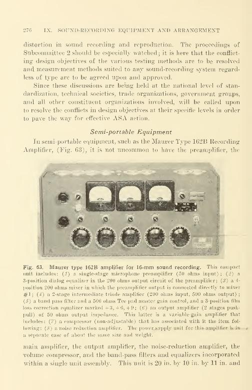
276 IX. SOTJND-KECOKDING EQUIPMENT AND ARRANGEMENT
distortion in sound recording and reproduction. The proceedings of
Subcommittee 2 should be especially watched ; it is here that the conflict-
ing design objectives of the various testing methods are to be resolved
and measurement methods suited to any sound-recording system regard-
less of type are to be agreed upon and approved.
Since these discussions are being held at the national level of stan-
dardization, technical societies, trade organizations, government groups,
and all other constituent organizations involved, will be called upon
to resolve the conflicts in design objectives at their specific levels in order
to pave the way for effective ASA action.
Semi-portable Equipment
In semi-portable equipment, such as the Maurer Type 162B Recording
Amplifier, (Fig. 63), it is not uncommon to have the preamplifier, the
/
• ®
Wf 1W 1W tW twwiiMWit.-ttaf
Fig. 63. Maurer type 162B amplifier for 16-mm sound recording. This compact
unit includes: (1) a single-stage microphone preamplifier (50 ohms input); {2) a
3-position dialog equalizer in the 200 ohms output circuit of the preamplifier; (3) a 4-
position 200 ohms mixer in which the preamplifier output is connected directly to mixer
#1; (4) a 2-stage intermediate triode amplifier (200 ohms input, 500 ohms output);
(5) a band-pass filter and a 500 ohms Tee pad master gain control, and a 3-position film
loss correction equalizer marked +3, +6, +9; (6) an output amplifier (2 stages push-
pull) of 50 ohms output impedance. This latter is a variable-gain amplifier that
includes: (7) a compressor (non-adjustable) that has associated with it the item fol-
lowing: (8) a noise reduction amplifier. The power supply unit for this amplifier is in
a separate case of about the same size and weight.
main amplifier, the output amplifier, the noise-reduction amplifier, the
volume compressor, and the band-pass filters and equalizers incorporated
within a single unit assembly. This unit is 20 in. by 10 in. by 11 in. and

SEMI-PORTABLE EQUIPMENT l't;
weighs 60 lb. The power supply is in a separate case that is connected
to it by a cable. The two units are separated to reduce the "stray"
hum fields "sprayed" about by the power transformers and by the re-
actors of the power supply. The maximum over-all gain of the amplifier
from the microphone input to the recording machine galvanometer
input is in the order of 100 db. The power output is in the order of
250 milliwatts. The total harmonic distortion under operating conditions
is well below 2% at full modulation level of the galvanometer. Figures
63A and 63B describe the over-all electrical performance of the Maurer
amplifier with different control settings. Figure 64 is the RCA MI-
10238 (PA-142) amplifier; this unit is somewhat comparable. The cap-
tions associated with the figures provide the pertinent characteristics;
the design differences will become apparent when the legends are com-
pared.
CYCLES PER SECOND CYCLES PER SECOND
Fig. 63A. Over-all electrical response- Fig. 63B. Over-all electrical response-
frequency characteristic of Maurer 162B frequency characteristic of Maurer 162B
amplifier. Film equalizer is on '' + 3 "
;amplifier. Low frequency equalizer is on
the three different settings of the low fre- "high"; the three different settings of
quency equalizer are shown. the film equalizer are shown.
General Characteristics of Amplifiers
It must be recognized that the more versatile an equipment is intended
to be, the more costly it will be. Two general classes of equipment are
available commercially : permanently installed equipment and semi-
portable equipment. In the former, portability and compactness are
sacrificed for versatility and superior performance ; in the latter, ver-
satility, and—to a degree—performance, are sacrificed for portability
and compactness.
Both classes of equipment have many circuit elements in common;in fact, a block diagram representing one is usually applicable to the
other. It should be noted, however, that mere size and complexity of
itself is no assurance of either versatility or of superior performance in
terms of the attributes such as:

278 IX. SOUND-RECORDING EQUIPMENT AND ARRANGEMENT
1. Signal-to-noise ratio.
2. Absence of distortion.
3. Frequency range (with and without niters).
4. Tonal fidelity.
5. Tonal balance.
Fig. 64. RCA film recording amplifier MI-10238 (type PA-142) main re-
cording amplifier.
The MI-10238 main recording amplifier incorporates the facilities of a main-gain
voltage amplifier, an electronic mixer, high- and low-pass filters, a dialog and film-
loss equalizer, a ground-noise-reduction amplifier, and a recording power amplifier in
a single unit. A telephone jack and associated press-to-talk switch is provided for
use of a sound-powered phone. A jack is provided for monitoring with a high-im-
pedance crystal headset. Normally associated equipment (PH-51) : MI-10221-C mixer
amplifier "A" and "B" DC power supplies PR-32 or PR-33 recorder. Overall
characteristics : Input impedance, 500 or 250 ohms; PA output impedance, 500 ohms;
Source impedance, 500 or 250 ohms; PA load impedance, 500 ohms; Overall gain
(input and galvo gain controls max., GNR gain min.), 69 db ± 1 db (may be increased
6 db—see compressor section gain) ; Overall frequency characteristics, in accordance
with current Hollywood recording techniques (+0, - 1 db overall from 60 to 10,000
cycles without filters); Power supply requirements: 250 volts dc at 160 ma (MI-
10501-A regulated power supply or equivalent regulated power supply of low internal
impedance is essential). 6.4 volts de at 5.8 amperes.. Physical characteristics : Length,
26% inches; Width, 19% inches; Height, 10% inches; Weight, 88 pounds
(approx.) ; Finish, light-umber-gray wrinkle case, reverse-etched nickel-silver control
panel. Metering : Internal metering is provided for "A" and '*B " voltage and
GNR current. Voltage amplifier and compressor section: The compressor offers either
linear operation or two electronic positions. The "De-ess off" position offers a flat
frequency characteristic and the "De-ess on" position provides a response in the
control circuit which corrects for sibilants (elimination of spectral energy distortion)
to provide more natural response for dialogue recording.
GENEEAL CHARACTERISTICS OF AMPLIFIERS 279
All these can be determined only by measurement. Performance
claims for apparatus, the performance of which has not been measured,
are sheer guesswork and have little meaning. Reputable manufacturers
customarily measure every piece of equipment offered for sale for each
performance characteristic claimed. Such production test records are
accumulated for extended periods by the manufacturer. These data are
usually available on the request of the equipment user.
Noise Reduction Principles
If a piece of clear film is run in a sound projector, noise due to dust,
dirt, irregularities, and scratches on the film is heard in the loudspeaker.
If film is used regularly in projection, it is found that the noise produced
increases with wear, becoming very annoying as the film acquires more
scratches and dirt in its many trips through the projector. If the clear
film is kept stationary in the projector, and the amplifier turned up to its
maximum gain, considerable hiss is heard from the loudspeaker of the
projector ; if the light beam of the projector is blocked with an opaque
card, the hiss previously heard is reduced materially. The hiss that was
eliminated was due to the light falling on the photocell and its effect upon
the input circuit of the reproducing amplifier ; the noise remaining is
substantially the noise produced by the amplifier itself.
With good amplifier design, it is possible to reduce the amplifier hiss
to a negligible amount when reproducing good sound film; however, to
reduce the hiss from the photocell circuit and the noise resulting from the
random dust, dirt, irregularities, etc. requires masking of the film. Since
the noise produced is a function of the light transmitted to the photocell,
it is apparent that this light flux should be reduced to a minimum.
Because the variations in light cause the electrical output of the photocell,
it is apparent that the problem is to keep the light variations at a maxi-
mum while keeping to a minimum the average light transmitted. This is
accomplished by a process identified by a number of different names, such
as noise reduction, noiseless recording, ground-noise reduction, anti-
ground noise system, etc.
The principles of noise reduction in photographic recording were
appreciated early. Patents were issued to Adsit, an independent
inventor, by the U. S. Patent Office shortly after World War I ; this was
several years before sound film was commercially introduced successfully
in 1928 by Warner Brothers. Subsequently, patents were issued to Sacia
of Western Electric on an early form of control track (predecessor to the
control tracks used in Fantasia and in the Bell Telephone Laboratories

280 IX. SOUND-RECORDING EQUIPMENT AND ARRANGEMENT
stereophonic demonstration). Still later, nnmerons patents were issued
in different.countries of the world ; some of those filed in the United States
gave rise to much expensive litigation in which the fate of many millions
of dollars depended upon the outcome.
Today all modern recording equipment utilizes the noise reduction
principle; in all arrangements the average transmittance of the positive
film is made approximately equal to the modulation. This is accom-
plished by automatically "blacking-in" the sound track area not used for
modulation in a variable-area film. Thus, on a positive, the sound track
is almost entirely opaque when there is no modulation as only a small
portion of the width is needed for the modulation ; when full modulation
occurs, the sound track has maximum transmittance as full width is
needed for the modulation. At modulation levels between these two
limits, the average transmittance is kept approximately proportional to
the modulation by means of the noise-reduction amplifier (often called a
bias amplifier) and its adjuncts.
If the signal-recording and noise-reduction functions are thought of
as two separate functions, one means is used to record the signal and the
other to record the noise-reduction current. The wave form of the signal
should be undistorted; the wave form of the noise-reduction current is
altered by rectification. The rectifier is connected to a filter circuit, with
the charging characteristics of the filter determining the attack time of
the noise-reduction system, and the discharge characteristics of the filter
determining the decay time. Mathematically, the bias current provided
at the output of the bias amplifier is a rectified envelope of the signal
current. In the design of practical equipment, the input to the bias
amplifier " bridges" the signal circuit, being connected in such manner
that it does not appreciably alter the transmission characteristics of the
circuit, and draws a negligible amount of energy from it, e.g., 5% or less.
A typical commercial design would include: (1) an amplifier portion
to increase the audio frequency energy level to a convenient point, (2) an
audio rectifier, (3) a filter circuit for the control of charge and discharge
times, and (4) an output d.-c. amplifier tube. In such a commercial
design it is customary to provide maximum d.-c. output from the bias
amplifier when no signal is present, and minimum d.-c. output when
maximum signal is present. In this manner, failure of the bias amplifier
will cause merely the omission of bias but will not distort the recorded
signal.
The bias amplifier is usually actuated by the signal being recorded.
The unidirectional current output of the noise-reduction amplifier may

NOISE REDUCTION PRINCIPLES 281
be applied to the galvanometer itself (Maurer equipment) or to a pair of
cooperating shutters (older RCA equipment). In both cases the signal
proper is applied to the light modulator. Figure 65 shows the bias form
of bilateral sound track i Maurer I, and Figure 66 shows the shutter form
of duplex sound track (RCA). For convenience, both the negative and
the positive forms of sound track are shown.
Direction
of motion Recording
b/sli '
Recording
El
.Printer
light
Scanning or /reproducing light
Fig. 65. Bilateral variable-area soundtrack—galvanometer biased for noise
reduction. Vertical motion of the tri-
angular light beam across the slit due to
signal current in the galvanometer pro-
vides modulation of the track. Pulsating
bias current also applied to the galva-
nometer alters the average light trans-
mission by shifting the mean position of
the triangular light beam upward or
downward in accordance with the signal
amplitude.
Scanning or
reproducing light
Fig. 66. Duplex variable-area sound
track—shutter biased for noise reduc-
tion. Vertical motion of the triangular
recording light beam across the slit due
to the signal current in the galvanometer
provides modulation of the sound track.
Horizontal motion of the shutter vanes
(opening and closing) across the slit due
to the pulsating bias current alters the
mean light transmission in accordance
with the signal amplitude.
If a direct-positive sound track is to be recorded, the transmittance
of the sound track must be made a minimum for zero modulation ; this is
accomplished by reversing the direction of the bias current flow through
the galvanometer or shutters by means of a reversing key or switch and
by making certain other adjustments, such as changing from the negative-
recording aperture to the positive-recording aperture. Most 16-mmequipment made prior to World War II docs not have provision for
direct-positive sound tracks.

282 IX. SOUND-RECORDING EQUIPMENT AND ARRANGEMENT
If a negative sound track is to be recorded, the transmittance of the
sound track must be made a maximum for zero modulation ; this is accom-
plished by moving the bias key or switch in the direction opposite to that
used for direct-positive recording in order to reverse current polarity,
and by changing to the negative aperture in the recording machine.
Noise Reduction Design Considerations. When a signal is sud-
denly applied to a recording system, the amplified signal appears at the
galvanometer before the bias current appears. The time of transmission
of the bias is longer than the time of transmission of the signal proper
because of the delay introduced by the bias amplifier.
The starting-time delay is known as the bias opening, attack time, or
bias unlocking time. Although this time delay may be the source
of audible distortion for steep wavefront sounds (such as pistol shots),
commercial equipment used to record conventional sounds will show little
audible distortion. The attack time of a bias amplifier depends upon the
designer 's choice ; wide differences of opinion exist among designers as to
the optimum time. One commercial design has an attack time of 20 milli-
seconds ; many designers think this time rather long.
When the signal actuating a bias amplifier ceases, the bias current
decays. To avoid audible distortion, the bias closing (or decay) time
is made quite long compared with the opening time ; it is 70 milliseconds
for the unit whose attack time is 20 milliseconds. Since the closing time
for a noise-reduction system is not critical, it is not made adjustable.
The amplifier portion of the "front end" of a bias amplifier is cus-
tomarily designed with a maximum gain in excess of that actually re-
quired. A gain control in the form of a screwdriver slot arrangement,
is provided to reduce the gain to the desired amount. The attack time of
the bias amplifier depends upon the slope of the signal voltage -bias
current curve and upon the gain of the "front end" of the bias amplifier.
The slope of the signal voltage - bias current curve depends upon the
design constants of the unit; the gain of the amplifier is usually set by
means of the screwdriver slot gain control so that full unlocking is effected
when a sine wave tone of 60% modulation at 1000 cps is applied. The
relationship of bias voltage to applied signal voltage is quite linear up to
complete unlocking. Ordinarily, the gain-setting adjustment is madeduring bias amplifier manufacture and need not be altered during use,
since the amplifiers are quite stable in operation and the recording
machines with which they are used are quite consistent in sensitivity of
both the galvanometer and of the cooperating shutters—if used.
NOISE KEDUCTION DESIGN CONSIDERATIONS 283
An initial bias or margin adjustment is also provided. This adjust-
ment may be the resistance variation of a cathode bias resistor on the out-
put tube ; it is customarily set so that when no modulation is present, the
d.-c. output current through the biasing shutter or galvanometer will
provide a transparent track width of about 0.003 in. to 0.005 in. as seen
on a positive film. Margin is provided to offset the starting-time delay
of the bias amplifier when an actuating signal appears in the system.
Ordinarily, once the milliammeter reading for the desired margin is
determined, it is merely necessary to set the margin control for the cor-
rect current; readjustment is rarely required.
In the design of bias amplifiers, some engineers prefer half-wave
rectification of the audio signal, while others prefer full-wave rectification.
Since it is well known among design engineers concerned with sound film
recording that the pressure wave of the average sound wave shows a muchsharper rate of pressure rise that the rarefaction wave, half-wave rec-
tification is theoretically preferable despite a more difficult filtering
problem, because of the more rapid rate of rise in bias current that can be
obtained when the microphone and the amplifiers are properly poled
throughout the recording system. Other engineers take the view that
such poling is difficult if not impracticable, and therefore prefer the full-
wave rectifier with a simpler filter ; this viewpoint is valid when, as is
often the case, the phase distortion in the system is quite large.
The shortcomings of bias amplifier designs were appreciated early, and
many efforts have been made to overcome them. Generally speaking, the
improvements have been made in two general directions, one to speed up
the action of the bias amplifier attack and the other to compensate in some
fashion for the delay that inherently exists. The improvement in the
former direction has led to more complex filters, to better regulation of the
plate voltage supply energizing the bias amplifier circuits, and to the use
of an ultrasonic carrier that is modulated by the applied signal. The use
of the ultrasonic carrier reduces the size and the time constants of the
filter needed ; other advantages, such as altering the slope of the signal
current - bias voltage curve at the starting threshold can be derived from
the modulating and demodulating functions. No doubt the future will
see the application to this problem of the gate and the pulse techniques,
principles that proved so valuable to the performance of radar equip-
ment during the recent war.
There is one fundamental method to compensate for bias delay:
that is to eliminate the effect of the delay either by (a) delaying the
284 IX. SOUND-EECOEDING EQUIPMENT AND AEEANGEMENT
signal, or (b) providing bias anticipation. Filters and other artificial
delay networks can delay a signal for short periods. Unfortunately,
such networks usually result in the noticeable distortion of transient
sounds (such as dancing taps) when even relatively short delay times are
involved. Other forms of temporary recording with a small storage
time may also be used, the signal being, in effect, re-recorded to the
film recorder after the required delay interval. Such temporary methods
usually involve a noticeable loss of quality. Continued progress is being
made in these directions.
Within recent years, when even steep wavefront sounds are expected
to be recorded with no audible distortion, bias anticipation has been
used with quite successful test results. One effective yet complex method
has been to set up a separate microphone for the anticipation circuit;
this microphone is located between the recording microphone and the
sound source. In this manner, the sound from the source strikes the
anticipation microphone the desired number of milliseconds before it
reaches the signal-recording microphone. The chosen anticipation time
is just a little larger than the delay occurring in the bias amplifier circuit.
In practice, both microphones are suspended on the same microphone
boom. As has been indicated, the anticipation microphone and its am-
plifiers serve to energize only the bias amplifier, the recording microphone
providing the signal to the light modulator in the usual manner. Antici-
pation has not been widely used; the disadvantage of the additional
complication in the making of the original sound record can only be
overcome when the "normal" distortion of commercial photographic
printing is reduced to the point where the excellence of such records can
be appreciated by being heard.
With conventional 16-mm noise reduction equipment the improve-
ment in signal-to-noise ratio that is obtained is from 5 to 10 db. Asis apparent, the actual results depend upon how well the film is
processed quite as much as on how well the noise-reduction equipment
functions electrically. Noise-reduction equipment aids primarily in
reducing the noise effects of dust, dirt, oil, and light scratches picked upby the release print during projection ; it does not alter in any way the
noise recorded upon the film or the noise of the film itself.
Distortion Testing of Noise-Reduction Equipment. Since no
two noise-reduction equipment designers make the same assumptions and
compromises in their designs, the primary test of the equipment rests
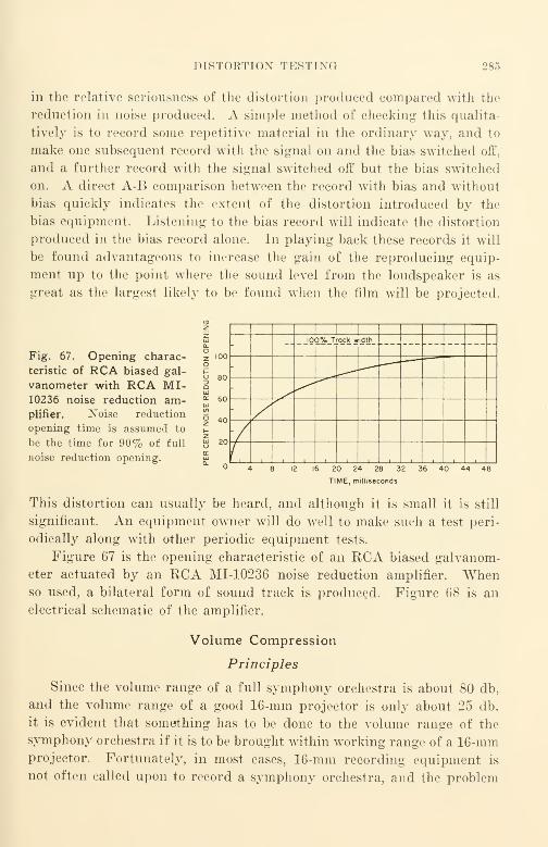
DISTORTION TESTING 285
in the relative seriousness of the distortion produced compared with the
reduction in noise produced. A simple method of checking this qualita-
tively is to record some repetitive material in the ordinary way, and to
make one subsequent record with the signal on and the bias switched off,
and a further record with the signal switched off but the bias switched
on. A direct A-B comparison between the record with bias and without
bias quickly indicates the extent of the distortion introduced by the
bias equipment. Listening to the bias record will indicate the distortion
produced in the bias record alone. In playing back these records it will
be found advantageous to increase the gain of the reproducing equip-
ment up to the point where the sound level from the loudspeaker is as
great as the largest likely to be found when the film will be projected.
Fig. 67. Opening charac-
teristic of RCA biased gal-
vanometer with RCA MI-10236 noise reduction am-plifier. Noise reduction
opening time is assumed to
be the time for 90% of full
noise reduction opening.
11 1
100% Track width
00
80
60
40
20
i_ i
20 24 28 32
TIME, milliseconds
36 40 44 48
This distortion can usually be heard, and although it is small it is still
significant. An equipment owner will do well to make such a test peri-
odically along with other periodic equipment tests.
Figure 67 is the opening characteristic of an RCA biased galvanom-
eter actuated by an RCA MI-10236 noise reduction amplifier. Whenso used, a bilateral form of sound track is produced. Figure 68 is an
electrical schematic of the amplifier.
Volume Compression
Principles
Since the volume range of a full symphony orchestra is about 80 db,
and the volume range of a good 16-mm projector is only about 25 db,
it is evident that something has to be done to the volume range of the
symphony orchestra if it is to be brought within working range of a 16-mmprojector. Fortunately, in most cases, 16-mm recording equipment is
not often called upon to record a symphony orchestra, and the problem
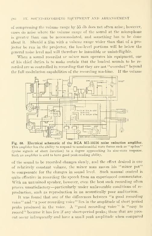
286 IX. SOTJND-KECOKDING EQUIPMENT AND AKKAXGEMEXT
of compressing the volume range by 55 db does not often arise ; however,
cases do arise where the volume range of the sound at the microphone
is greater than can be accommodated, and something has to be done
about it- Should a film with a volume range wider than that of a pro-
jector be run in the projector, the low-level portions will be below the
general noise level and will therefore be inaudible or unintelligible.
When a sound recordist or mixer man operates his equipment, one
of his chief duties is to make certain that the loudest sounds to be re-
corded are so controlled in recording that they are not "overshot" beyond
the full modulation capabilities of the recording machine. If the volume
Fig. 68. Electrical schematic of the RCA MI- 10236 noise reduction amplifier.
This amplifier has the ability to respond to nonsinusoidal wave forms such as l' spikes '
'
(pulse signals of short duration) to a degree approaching its sine-wave response.
Such an amplifier is said to have good peak-reading ability.
of the sound to be recorded changes slowly, and the effect desired is one
of relatively constant volume, the mixer man moves his "mixer pot"
to compensate for the changes in sound level. Such manual control is
quite effective in recording the speech from an experienced commentator.
With an untrained speaker, however, even the best such recording often
proves unsatisfactory—particularly under unfavorable conditions of re-
production, such as reproduction in an acoustically poor auditorium.
It was found that one of the differences between "a good recording
voice" and "a poor recording voice" lies in the amplitude of short period
peaks produced in the voice. A "good recording voice" is "easy to
record" because it has few if any short-period peaks; those that are pres-
ent occur infrequently and have a small peak amplitude when compared
VOLUME COMPRESSION 287
to the average of the speech wave. It is also an important fact that a
voice with short-period high-amplitude peaks is not as clear and in-
telligible and does not carry as well as a well-trained voice that is rela-
tively free of such peaks; such short-period peaks actually reduce the
effectiveness of the speaker and occur so rapidly and are of such short dura-
tion that the reaction time of the mixer man is too slow to catch them ; also,
they happen so quickly that the mechanical mixer controls could not
respond quickly enough to the changes. For most voices, certain definite
improvements in quality and in the reduction of noise can be obtained
by providing an amplifier that will automatically reduce the volume
range. The principle of volume compression is now so well established
that it is provided for in all modern 16-mm recording equipment. Con-
ventional volume-indicator meters, such as the American Standard VUmeter, do not indicate short-period peaks of very short duration; for
this reason, films recorded without volume compression either "sound low
in volume" despite the fact that the peaks are either 100% modulated
or "overshot" because the peaks are overmodulated and therefore dis-
torted. Short-period peaks add little or nothing to the expressive dy-
namics of speaking, but are, rather, caused by a lack of breath control or
other shortcomings on the part of a speaker.
The manner in which volume compression should take place depends
upon the over-all overload characteristics of the recording system.
Ideally, it might seem desirable to reduce the system amplification sud-
denly just before the overload point is reached. Practically, however,
the compression characteristic chosen depends upon the kind of sound
to be recorded and upon how "gracefully" the recording system to which
it is to be applied overloads. In variable-density recording—in which
overload is more gradual than in variable area—compression may be set
to begin at a higher relative modulation level ; there is some curvature at
the extreme ends of the exposure vs. print-transmission characteristic,
which makes the overload characteristic more gradual and more "grace-
ful." In certain respects the overload characteristics of variable-density
recording may be considered similar to the gradual overload character-
istics of a triode class A-Bj amplifier, whereas the overload character-
istics of variable-area recording are more similar to a beam-power tetrode
push-pull amplifier of the same wattage rating with appreciable inverse
feedback. The overload characteristic of the latter "breaks" more
sharply. It is often said that a limiting amplifier is used for variable-
density recording while a compression amplifier is used for variable area.
288 IX. SOUND-RECORDING EQUIPMENT AND ARRANGEMENT
A well-designed limiting or compression amplifier should merely
limit or compress. It should not change the "balance" of the recorded
sound if the recording is compared with a recording made without
limiting or compression. An audible change in balance is a change in
spectral sound energy balance; such a change is referred to as spectral
energy distortion. Since recording equipment is customarily equalized
in a definite manner, the use of limiting or compression amplifiers should
not alter the equalization. Customary equalizing attenuates bass tones
appreciably and accentuates high frequencies. As has been pointed out,
the response-frequency characteristic of a recording is'
' tipped upward '
'
rather than being flat.
In practice there is little difference between a limiting amplifier and
a compressor amplifier other than the threshold volume at which the
TABLE XVII
Optimal Compressor Characteristics (RCA;
Attack time 0.7 millisecond
Release time 0.5 second
Threshold volume 10 db (under full modulation of
the light modulator
Compression ratio 20 db into 10 db
limiting or compressing action begins. The important characteristics
of a compressor amplifier are
:
1. Attack time—the time required to reduce the gain.
2. Release time—the time required to restore the gain to normal.
3. Threshold volume at which the action begins.
4. Shape of the input-i;s.-output curve after compression begins.
Because of the sharper overload characteristics of the variable-area
recording method, the threshold level at which compression begins is
customarily set appreciably lower than with variable density.
As is the case with the design parameters for noise reduction, there
are as many selections as there are designers. Some recent data on
optimal characteristics as a result of listening tests on RCA equipment
are shown in Table XVII.
Figure 69 shows a compression curve as used in a typical compressor.
This characteristic will give substantially greater average modulation
on most voices that may be recorded. (Further data may be found in
the references indicated at the end of this chapter.)
Compressors are used wherever a limitation in volume range can pro-
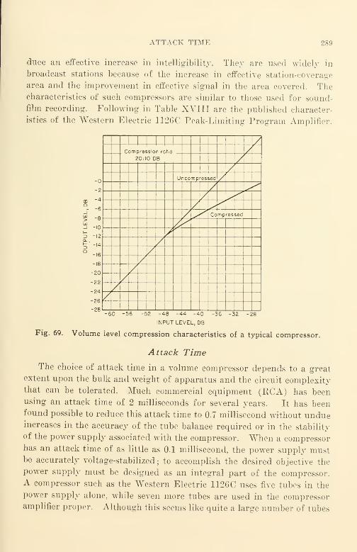
ATTACK TIME 289
duce an effective increase in intelligibility. They are used widely in
broadcast stations because of the increase in effective station-coverage
area and the improvement in effective signal in the area covered. Thecharacteristics of such compressors are similar to those used for sound-
film recording. Following in Table XVIII are the published character-
istics of the Western Electric 1126C Peak-Limiting Program Amplifier.
-10
-12
-14
-16
-18
-20
-22
-24
-26
-28
1
1
1 1 1 /Compression ratio
20:10 DB/
'
//
Uncompressed /
Compressed
-56 -48 -44 -40
INPUT LEVEL, DB
-36 32 -28
Fig. 69. Volume level compression characteristics of a typical compressor.
Attack Time
The choice of attack time in a volume compressor depends to a great
extent upon the bulk and weight of apparatus and the circuit complexitythat can be tolerated. Much commercial equipment (RCA) has beenusing an attack time of 2 milliseconds for several years. It has beenfound possible to reduce this attack time to 0.7 millisecond without undueincreases in the accuracy of the tube balance required or in the stability
of the power supply associated with the compressor. When a compressorhas an attack time of as little as 0.1 millisecond, the power supply mustbe accurately voltage-stabilized; to accomplish the desired objective the
power supply must be designed as an integral part of the compressor.A compressor such as the Western Electric 1126C uses five tubes in the
power supply alone, while seven more tubes are used in the compressoramplifier proper. Although this seems like quite a large number of tubes

290 IX. SOUND-RECORDING EQUIPMENT AND ARRANGEMENT
for just a volume compressor, the results of its use are so evident, that
its desirability cannot be questioned.
When a compressor is connected in a transmission circuit, such as
in 16-mm recording equipment, it has the tendency to "flatten out" the
TABLE XVIII
Characteristics of Western Electric 1126C Amplifier
Maximum gain 51.5 db
Source impedance 600 ohms (circuit not balanced to ground)
Load impedance 600 ohms (circuit not balanced to ground)
Output power + 25 db maximum when gain reduction starts
(output attenuators omitted)
Output noise 69 db below output level when gain reduction
starts
Input-level range - 26 dbm to + 24 dbm (single frequency tone)
Output-level range -4 dbm to + 25 dbm (single frequency tone)
Output distortion
For program Less than 1% for all operating conditions up
to 5 db compressionFor single frequency tone .... Below compression, less than 1%; for 5 db
compression, less than 1% for frequencies
above 200 cps and not more than 1.75%
for frequencies as low as 50 cps
Frequency response Flat within ±1 db over the range 50 to
15,000 cpsCompression ratio 10: 1 (10 db input increase results in 1 db
output increase above the point at which
gain reduction starts)
Attack time Approximately 0.1 millisecond
Recovery time Variable in 5 steps of 0.2 second each from
0.2 to 1 second. Optional adjustment
permits variation from 0.1 to 0.5 second
Weight 49 pounds
Power supply 105 to 125 volts, 0.7 ampere, 50-60 cycles
alternating current
Dimensions, inches 19 1/4 wide, 19 1/4 high, and 6 3/4 deep
(for 19-inch relay rack)
Price About $500
signals transmitted, since it tends to limit or compress only those com-
ponents that are above its threshold. One operating result of this flat-
tening effect is that if a portion of the transmission range is equalized
ahead of the compressor by cutting the lows for dialogue equalization, for
example, the compressor would have the effect of reducing the low-fre-
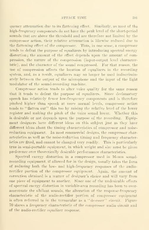
ATTACK TIME 291
quency attenuation due to its flattening effect. Similarly, as most of the
high-frequency components do not have the peak level of the short-period
sounds that are above the threshold and are therefore not limited by the
compressor action, their relative attenuation is likewise reduced due to
the flattening effect of the compressor. Thus, in one sense, a compressor
tends to defeat the purpose of equalizers by introducing spectral energy
distortion; the amount of the effect depends upon the amount of com-
pression, the nature of the compression (input-output level character-
istic), and the character of the sound compressed. For that reason, the
use of compression affects the location of equalizers in the recording
system, and. as a result, equalizers may no longer be used indiscrimin-
ately between the output of the microphone and the input of the light
modulator of the sound-recording machine.
Compressor action tends to alter voice quality for the same reason
that it tends to defeat the purpose of equalizers. Since declamatorj-
speech has relatively fewer low-frequency components and is therefore
pitched higher than speech at more normal levels, compressor action
tends to "flatten out" this too by raising the relative level of the lower
register and making the pitch of the voice sound lower. Whether this
is desirable or not depends upon the purpose of the recording. Equip-
ment designers have different ideas on this subject just as they have
different ideas about the timing characteristics of compressor and noise-
reduction equipment. In most commercial designs, the compressor char-
acteristics as well as the noise-reduction timing and frequency character-
istics are fixed, and cannot be changed very readily. This is particularly
true in semi-portable equipment, in which weight and size must be given
preference over theoretically desirable performance characteristics.
Spectral energy distortion in a compressor used in 16-mm sound-
recording equipment, if allowed for in the design, usually takes the form
of reducing both the low- and high-frequency responses of the audio-
rectifier portion of the compressor equipment. Again, the amount of
correction obtained is a matter of designer's choice and will vary from
one piece of equipment to another. Since one of the undesirable effects
of spectral energy distortion in variable-area recording has been to over-
accentuate the sibilant sounds, the alteration of the response-frequency
characteristic of the audio-rectifier portion of compressor equipment
is often referred to in the vernacular as a "de-esser" circuit. Figure
70 shows a frequency characteristic of the compressor audio circuit and
of the audio-rectifier equalizer response.
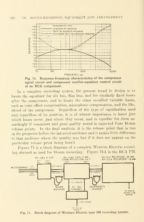
292 IX. SOUXD-KECORDIXG EQUIPMENT AND ARRANGEMENT
+ 16Compre ssion ratio ,'n ssion response ^
+ 12
+ 10
+ 8
+ 6
+ 4+ 2
-2
-4-6-8
-10
-12
Rectifier equalizer response ^;Calculated rectifier equal zer responsey
N sfiV
<t
.' ,
-i^K
\30 10,000100 1000
FREQUENCY, cps
Fig. 70. Response-frequency characteristics of the compressor
signal circuit and compressor rectifier-equalizer control circuit
of an RCA compressor.
In a complete recording system, the present trend in design is to
locate the equalizer for slit loss, film loss, and for similarly fixed losses
after the compressor, and to locate the other so-called variable losses,
such as voice effort compensation, microphone compensation, and the like,
ahead of the compressor. Regardless of the type of equalization used
and regardless of its position, it is of utmost importance to know just
which losses occur, just where they occur, and to equalize for them ac-
cordingly if consistent and good quality sound is expected from 16-mm
release prints. In the final analysis, it is the release print that is run
in the projector before the intended audience and it makes little difference
to that audience where the quality was lost if it does not appear on the
particular release print being heard.
Figure 71 is a block diagram of a complete Western Electric record-
ing channel as used for 16-mm recording. Figure 71A is the RCA PM-
RA-1283 MIXER RA-1282 AMPLIFIER-NOISE REDUCTION UNIT
600" 600"
RA-I23I REC0RDER-35 MMRA-I23IA RECORDER- 16 MM
MICROPHONES CA g LEO
RA - 1284POWER UNIT
IWJ----I
VRECORDIST SHEADSET
T
TO POWERSUPPLY FORMOTOR
Fig. 71. Block diagram of Western Electric type 300 recording system.
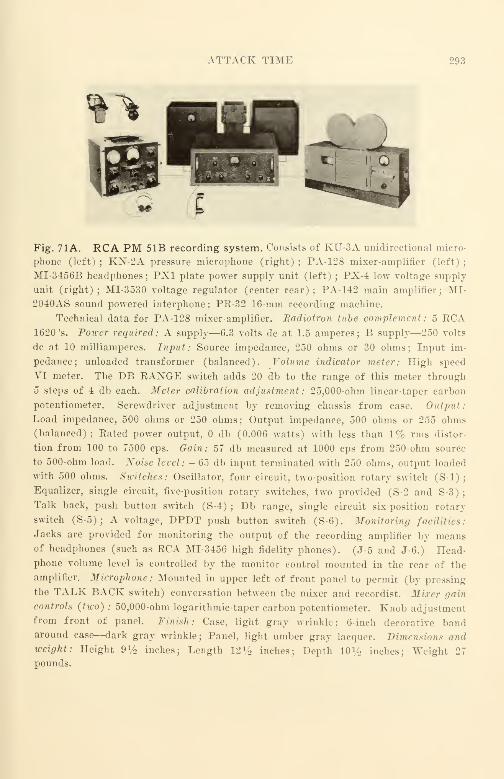
ATTACK TIME 293
Fig. 71A. RCA PM 51B recording system. Consists of KU-3A unidirectional micro-
phone (left) ; KN-2A pressure microphone (right); PA-128 mixer-amplifier (left)
;
MI-3456B headphones; PX1 plate power supply unit (left) ; PX-4 low voltage supply
unit (right); MI-3530 voltage regulator (center rear); PA-142 main amplifier; MI-
2040AS sound powered interphone; PR-32 16-mm recording machine.
Technical data for PA-128 mixer-amplifier. Badiotron tube complement: 5 RCA1620 's. Power required: A supply—6.3 volts dc at 1.5 amperes; B supply—250 volts
dc at 10 milliamperes. Input: Source impedance, 250 ohms or 30 ohms; Input im-
pedance; unloaded transformer (balanced). Volume indicator meter: High speed
VI meter. The DB RANGE switch adds 20 db to the range of this meter through
5 steps of 4 db each. Meter calibration adjustment : 25,000-ohm linear-taper carbon
potentiometer. Screwdriver adjustment by removing chassis from case. Output:
Load impedance, 500 ohms or 250 ohms; Output impedance, 500 ohms or 255 ohms(balanced); Rated power output, db (0.006 watts) with less than 1% rms distor-
tion from 100 to 7500 cps. Gain: 57 db measured at 1000 cps from 250-ohm source
to 500-ohm load. Noise level : - 65 db input terminated with 250 ohms, output loaded
with 500 ohms. Switches: Oscillator, four circuit, two-position rotary switch (S-l);
Equalizer, single circuit, five-position rotary switches, two provided (S-2 and S-3);
Talk back, push button switch (S-4) ; Db range, single circuit six-position rotary
switch (S-5);A voltage, DPDT push button switch (S-6). Monitoring facilities:
Jacks are provided for monitoring the output of the recording amplifier by meansof headphones (such as RCA MI-3456 high fidelity phones). (J-5 and J-6.) Head-phone volume level is controlled by the monitor control mounted in the rear of the
amplifier. Microphone : Mounted in upper left of front panel to permit (by pressing
the TALK BACK switch) conversation between the mixer and recordist. Mixer gain
controls (two) ; 50,000-ohm logarithmic-taper carbon potentiometer. Knob adjustmentfrom front of panel. Finish: Case, light gray wrinkle; 6-inch decorative bandaround case—dark gray wrinkle; Panel, light umber gray lacquer. Dimensions andweight: Height 9V2 inches; Length 12% inches; Depth 10% inches; Weight 27
pounds.
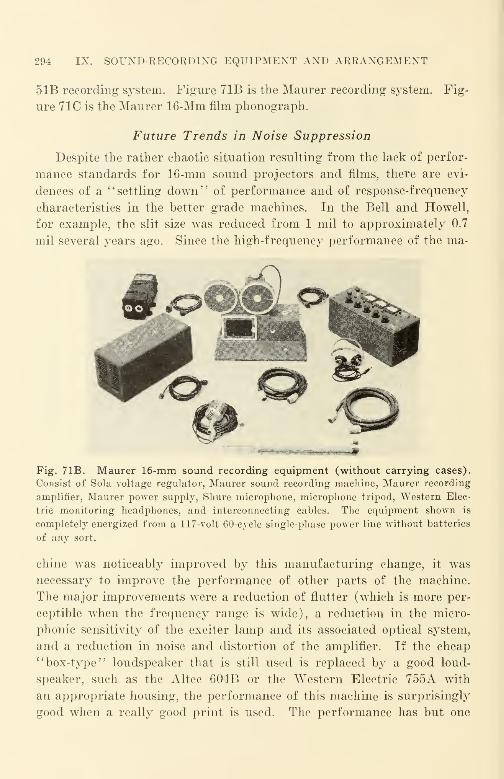
294 IX. SOUND-RECORDING EQUIPMENT AND ARRANGEMENT
51B recording system. Figure 71B is the Maurer recording system.
ure 71C is the Maurer 16-Mm film phonograph.
Fig-
Future Trends in Noise Suppression
Despite the rather chaotic situation resulting from the lack of perfor-
mance standards for 16-mm sound projectors and films, there are evi-
dences of a "settling down" of performance and of response-frequency
characteristics in the better grade machines. In the Bell and Howell,
for example, the slit size was reduced from 1 mil to approximately 0.7
mil several years ago. Since the high-frequency performance of the ma-
Fig. 71B. Maurer 16-mm sound recording equipment (without carrying cases).
Consist of Sola voltage regulator, Maurer sound recording machine, Maurer recording
amplifier, Maurer power supply, Shure microphone, microphone tripod, Western Elec-
tric monitoring headphones, and interconnecting cables. The equipment shown is
completely energized from a 117-volt 60-cycle single-phase power line without batteries
of any sort.
chine was noticeably improved by this manufacturing change, it was
necessary to improve the performance of other parts of the machine.
The major improvements were a reduction of flutter (which is more per-
ceptible when the frequency range is wide), a reduction in the micro-
phonic sensitivity of the exciter lamp and its associated optical system,
and a reduction in noise and distortion of the amplifier. If the cheap11box-type" loudspeaker that is still used is replaced by a good loud-
speaker, such as the Altec 604B or the Western Electric 755A with
an appropriate housing, the performance of this machine is surprisingly
good when a really good print is used. The performance has but one
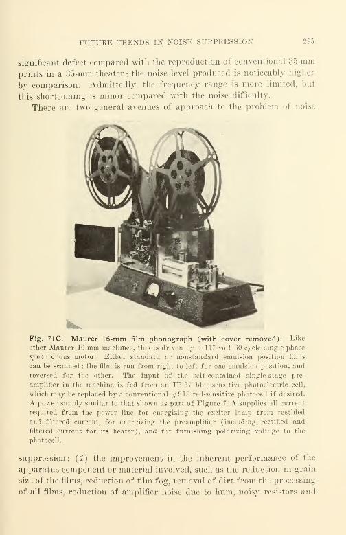
FUTUEE TRENDS IN NOISE SUPPRESSION 295
significant defect compared with the reproduction of conventional 35-mm
prints in a 35-mm theater : the noise level produced is noticeably higher
by comparison. Admittedly, the frequency range is more limited, but
this shortcoming is minor compared with the noise difficulty.
There are two general avenues of approach to the problem of noise
Fig. 71C. Maurer 16-mm film phonograph (with cover removed). Like
other Maurer 16-mm machines, this is driven by a 117-volt 60-cycle single-phase
synchronous motor. Either standard or nonstandard emulsion position films
can be scanned; the film is run from right to left for one emulsion position, and
reversed for the other. The input of the self-contained single-stage pre-
amplifier in the machine is fed from an IP-37 blue-sensitive photoelectric cell,
which may be replaced by a conventional #918 red-sensitive photocell if desired.
A power supply similar to that shown as part of Figure 71A supplies all current
required from the power line for energizing the exciter lamp from rectified
and filtered current, for energizing the preamplifier (including rectified and
filtered current for its heater), and for furnishing polarizing voltage to the
photocell.
suppression: (1) the improvement in the inherent performance of the
apparatus component or material involved, such as the reduction in grain
size of the films, reduction of film fog, removal of dirt from the processing
of all films, reduction of amplifier noise due to hum, noisy resistors and
296 IX. SOUND-RECORDING EQUIPMENT AND ARRANGEMENT
capacitors, noisy microphonic tubes, and the like, and (2) the modifica-
tion of the recording and reproducing systems to "fit in" the sound to
be recorded with hearing-perception characteristics such as those de-
scribed in the preceding chapter.
In the recent past, the major changes in equipment have been related
more to the first avenue than to the second. We are now beginning to
reach the point of diminishing returns, however, and large increases in
effort produce far smaller increases in quality improvement. For this
reason much more attention may now be given to the second avenue of
attack. This trend will no doubt continue into the future since it is
here that the possible results can be justified by the effort required to
obtain them.
One of the first such successful steps was the introduction of com-
pression and limiting. In the commercial equipment that was manufac-
tured, the small increase in distortion that resulted from the use of the
compressors and limiters was more than offset by the improvement in
intelligibility of the intended signal. It cannot yet be unequivocally
stated that the application of compression to 16-mm sound recording has
been an unmixed blessing. A source of primary magnitude appears to
be the intermodulation of the variable spectral energy distortion with
the variable distortion encountered in the photographic steps of the
process, especially in developing. In variable-area 16-mm recording,
excessive sibilant distortion has occurred especially when pressure-type
microphones with "un-smooth" response-frequency characteristics have
been used. in practice, this problem has often been sidestepped by the
use of a ribbon-type microphone. In certain extreme cases, serious dis-
tortion has occurred with, e.g. an RCA 77D microphone connected for
either dynamic or cardioid pickup; the distortion was reduced merely
by connecting the same microphone for ribbon (bidirectional) pickup.
When this difficulty is encountered in practice, dynamic microphones
seem to be the worst offenders, hybrid types such as the commercial
cardioids seem to be lesser, and ribbon types seem to be the least. The
relative location of high-frequency response peaks and of the smoothness
of recording galvanometer, microphone, and of the cutoff characteristics
of equalizers appear to be significant factors. When all factors are
working smoothly, in equipment with very low intermodulation products,
compression is quite advantageous, especially when films are projected
under a wide variety of acoustic conditions.
Fortunately, the recent war has accelerated the collection and appli-
FUTURE TRENDS IN NOISE SUPPRESSION 297
cation of hearing-perception data that arose from the truly remarkable
improvements in hearing aids, intercommunication systems, and battle-
announce systems. All such equipment was not only mechanically
rugged and quite consistent in performance, but the transmitted sounds
were intelligible and very useful under the very adverse high noise
level ambients common in such services. It is only reasonable to expect
to see such data utilized in the sound transmission systems in 16-mmsound films ; the methods no doubt will be characterized by a wide variety
of principles.
A recent development that is likely to leave its mark is the dynamic
noise suppressor of II. II. Scott.* As now manufactured, this electronic
arrangement provides dj^namic adjustment of the audio pass-band from
approximately 2 1/2 octaves minimum to the full audio range as a
maximum. It can be readily redesigned specifically for 16-mm sound
film uses and can be applied to recording amplifiers as well as to repro-
ducing amplifiers. With this arrangement, another step is made in
the direction of limiting the amplifier passband to that dictated by the
signal itself, thereby eliminating such response of the amplifier at either
end of the audio spectrum where no useful signal is being transmitted.
Such methods take account of the fact that the transmission range should
be narrow when the signal level is low, and that the transmission range
may be widened as the signal level rises. Similar developments have
occurred in the design of radio receivers; in one by Farrington,** for ex-
ample, the width of the audio pass-band in the intermediate frequency
amplifier was made dependent upon the strength of the signal. The
ability of such a radio receiver to reduce "monkey chatter" caused by
intermodulation of radio signals on adjacent channels is truly remark-
able when the receiver is tuned to a weak distant station with an adjacent-
channel local station operating. Similarly surprising reductions in
intermodulation distortion should result from the application of similar
audio techniques to 16-mm films and equipment. Where the Scott dy-
namic noise suppression arrangement might be used in re-recording
a release sound negative, for example, the maximum frequency range
would still be limited by a fixed bandpass filter such as one of those
specified for the preferred frequency ranges. The particular preferred
range chosen would still represent the widest range practicable for the
* Scott, H. H., 385 Putnam Ave., Cambridge, Mass.** Farrington, J. F., " Receiver with Automatic Selectivity Control Responsive
to Interference." Proc. I. R. E., April 1939, p. 239.

298 IX. SOUND-RECORDING EQUIPMENT AND ARRANGEMENT
average acoustic condition under which a print would be projected.
Dynamic noise suppression in the recording might be a sufficient im-
provement for all but the very worst cases ; in such cases dynamic noise
suppression might also be used in the projector amplifier.
More recently, a number of studies have been reported in the Journal
of the Acoustical Society of America* on the subject of "peak clipping"
of speech and its effect upon intelligibility and distortion. From the
results reported, it would appear that the amount of "peak clipping''
that would be desirable in a practical case will depend upon the rela-
tionship of quality and intelligibility. From data presented up to this
point, it would appear that "peak clipping" to the extent of 10 db
might be suitable for cases where intelligibility is at a premium; 6 db
might be applicable in other cases.
Another development reported by Westmijze** of Holland seems to
show promise where noise levels are particularly high from the film.
The method is an outgrowth of the pulse techniques common in radar;
in its application to reproducing 16-mm films it may be said to "sample"
the recorded trace at a (relatively) very rapid rate and to discriminate
against noise by the techniques of wave-shape control also commonin radar. The effects of gross occlusions of dirt, scratches, and similar
irregularities can be reduced by this method; for minor occlusions the
distortion, which is similar to that produced by peak clipping seems
somewhat high.
It is essential that the best practicable signal-to-noise ratio be obtained
when a film is projected for an audience because of the improvement in
the attention potential when extraneous noise is made a minimum. In
the future it may be desirable to use some kind of waveform control in
addition to pass-band control. It is difficult to predict at the momentwhat the forms may be. The problem will probably resolve itself into
a comparison of the relative costs of incorporating such controls in pro-
jectors, of improving sound optical systems, amplifiers, etc, or of in-
corporating equivalent improvements in the recording equipment in such
manner that the optimal results will occur on the films. Since the num-ber of sound projectors in use is quite large and machines are low in
price compared with recording equipment which is limited in supply and* Kryter et al,
1
1
Premodulation Clipping in AM Voice Communication. '
'
JASA, Jan. 1947, p. 125.
'* Westmijze, W. K., "A New Method of Counteracting Noise in Sound Film
Reproduction.
'
' JSMPE, Nov. 1946, p. 426.
MONITORING 299
high in price, it would seem the better part of wisdom to incorporal
possible improvements into the sound-recording channel. No doubt
some inexpensive electronic improvements will find their way into sound
projectors; to be worthwhile, the ratio of result to cost must necessarily
be high.
Monitoring
It is apparent that sound recording as it is actually practiced for
16-mm sound films requires accurate control for determining just what
is being recorded on the film and just how it is being recorded. To
determine what is being recorded, the recordist listens to a monitoring
loudspeaker when in a studio, or to a pair of head telephones when on
location away from the studio. To determine how the sound is being
recorded, the recordist uses a volume indicator which may take a variety
of forms. In a sense, the recordist uses his ears to determine what is
being recorded and his eyes to determine how it is being recorded.
Head Telephones
Monitoring with head telephones* cannot help but be a compromise
with quality, ^ince monitoring is done by the mixer man. the mere
presence of a telephone cord connecting his pair of head telephones to
a table, panel, or other point where the current is fed to the telephone,
is a physical and psychological handicap which prevents the mixer manfrom responding very rapidly to the sound he has seen or heard, and
which requires some movement of a mixer "pot" or some preparation
on his part for the moving of a mixer '"pot" or control. Despite this.
much dialogue recording in 35-niin entertainment films is done with the
mixer man located right on the set where shooting is taking place ; under
these conditions only head-telephone monitoring is practicable. A num-
ber of types of head telephones have been used for the purpose; they
vary in size, weight, performance, and in degree of comfort for the
wearer. The Western Electric 1002F headset is a very common sight
around recording studios because of its sturdinr>s and its consistency
of performance ; its high-frequency response is rather poor, however. AWestern Electric 714C headset has also been used; its frequency char-
acteristic is quite good and it is small and light, being one of the plug-in-
the-ear variety (on the style of heariiiL: aids). Both Western Electric
* Such monitoring is quite misleading in the judgment of sound quality, as a
binaural effect is presented to the mixer man that is entirely absent for the ulti-
mate audience.

300 IX. SOUND-RECORDING EQUIPMENT AXD ARRANGEMENT
and RCA have marketed moving-coil headsets of the more conventional
variety, using rubber cushions over the earpieces. This type of headset
usually has" good fidelity, but it is quite uncomfortable to wear partic-
ularly when it is warm. Moving-coil headsets are not rugged, being
put out of order easily if they are dropped. When so damaged, they
usually require expensive repairs.
Loudspeakers
Monitoring with a loudspeaker is more satisfactory, although it does
require a good noise-free monitor room that is acoustically good and is
acoustically well insulated from the studio and other sources of sound
and noise. For best monitoring, it is usually necessary to place the
sound-recording machine in a different room from the monitor room,
since the mechanical noise made by the sound-recording machine is a
serious source of noise—masking the intended signal. It should be un-
necessary to mention that the loudspeaker should be so placed that there
is no obstruction between its mouth and the ears of the mixer man.
A monitoring amplifier is needed to raise the level from that at the
recording bus* to that required for the loudspeaker. The monitoring
amplifier should be excellent in its response-frequency characteristic, it
should have a high signal-to-noise ratio, and should have low distortion
at the operating level. It should also be flat within 1 db from 50 to 15,000
cps and show not more than 1/2 to 1% total harmonic distortion at its
operating level. Such amplifiers are fairly widely available at prices
ranging upward from about $100 (including tubes).
Loudspeaker performance varies very widely. Unfortunately, the
art of measurement of loudspeaker performance has not advanced to the
point where the performance of a loudspeaker can be exactly and accu-
rately described by characteristic curves. In the case of the more ex-
pensive divided-range loudspeakers that use metallic or plastic dia-
phragms for the upper portion of the frequency range, the performance
variation from one unit to another is fortunately small. In the case of
the cheaper single-diaphragm loudspeakers, the performance variation
* The term '' recording bus '
' is used to indicate a point in the electrical circuits
of a recording equipment where a number of devices are connected for simultaneous
operation. A point often used is the output of the main amplifier ; from the bus fed
by the main amplifier are connected such units as the input to the power amplifier for
the sound-recording machine, the power amplifier for the monitor loudspeaker, the
volume indicator, and power amplifiers for energizing auxiliary recording apparatus
such as wire or tape magnetic recorders for direct playback, etc.
MONITORING 301
from one unit to another is very large and the high-frequency output
quite small and inconsistent, varying to an important degree with vari-
ations in the relative humidity of the atmosphere. Since good per-
formance and consistent performance must be demanded from a monitor
loudspeaker, and since the judgment of the sound quality being recorded
is to be trustworthy, the best loudspeaker available should be used. Per-
formance should be good and consistent over the full range of the moni-
tor amplifier. Unless this is so, sounds may be transmitted to the record-
ing light modulator for recording that may not be heard in the monitor
loudspeaker, causing the loudspeaker to fail in one of its major purposes
—that of permitting a critical evaluation of the sound being recorded.
The loudspeaker should have good transient response as determined
by a square wave test. It should have uniform angular distribution
within an angle of not less than 30 degrees on either side of the loud-
speaker axis ; this uniform angular distribution should be maintained not
only in the range to 5000 cps, but also in the remainder of the range.
To accomplish all of these objectives in a loudspeaker of reasonable
size and cost usually requires a divided-range type of loudspeaker ; this
type of loudspeaker is the only one that is capable of meeting such re-
quirements at the present time. A number of manufacturers are sup-
plying loudspeakers which meet these general requirements; as in the
case of any other sort of manufacture, there are individual differences
noted among different types. Fortunately, manufacturing control is
quite good and the performance differences between loudspeakers of the
same type are accordingly quite small. Manufacturers make both the
loudspeaker mechanisms and the enclosures in which such mechanisms
are mounted. In general, the enclosures are of two types, one called a
Utility, which is primarily functional, and the second called a DeLuxe
(or some similar name), which is ornamental as well as functional.
Prices begin at a little over $80 for a mechanism ; they begin at a little
over $30 for an enclosure. It is usually good practice to buy the en-
closure from the same manufacturer as the mechanism, so that mount-
ing difficulties will not be experienced.
One of the better "buys" of this kind is in the lower end of the
price range—the Jensen H-510. As in other products, price is not
always a reliable index of quality. It is not practicable at this time to
recommend any loudspeaker unequivocally, since there may be manufac-
turing changes contemplated for the near future. It can safely be said,
however, that the performance of any one of the following loudspeakers

302 IX. SOUND-KECORDING EQUIPMENT AND ARRANGEMENT
can be relied upon for effective day-to-day monitoring at relatively low
cost.
All speakers are of the divided-range type; the first three are
competitive coaxial types; the last an excellent two-way type. The
low range (below the electrical filter crossover frequency that is between
1200 cps and 2000 cps—depending upon the design) is provided by a
cone-type loudspeaker enclosed in a ported* bass-reflex cabinet, and the
high range (above the filter crossover frequency) is provided by a short
straight-axis horn whose axis is coaxial with the low-frequency cone.
Since there is very keen competition among loudspeaker manufacturers
in trying to provide really superior performance at the lowest possible
price consistent with rugged yet low-cost design, these loudspeakers
TAIJLE XIXGood Loudspeakers
15-in eh Utility De luxe
Manufacturermechanism cabinet cabinet
Type No. Price" Type No. Price" Type No. Price"
Jensen H-510 $ 79.38 B-151 $34.47 D-151 $ 50.64
Altec-Lansing 604B $143.00 Util $46.50 DeLuxe $135.00
Stephens 409 $117.60 52U $35.28 52D $105.64
Western Electric 757A (two-way) About $300 complete
a Current prices
represent excellent values. A number of compromise types have already
appeared on the market; from a design standpoint they may be said to
be variants of the general idea of two diaphragms in one—the larger
is coupled to the smaller by a compliance. As electrical dividing crossover
networks are costly, manufacturers have used this mechanical means to
reduce the manufacturing cost. Altec-Lansing, RCA, Stephens,
and others have manufactured such loudspeakers. Their perfor-
mance up to the present has been inferior to the recommended loud-
speakers and they cannot be recommended for really high-quality
monitoring without some qualifications.
* A ported bass-reflex cabinet is an enclosure for a loudspeaker mechanism that
has a hole or port so located on the front of the cabinet near the speaker opening that
the back wave produced by the rear side of the large loudspeaker diaphragm tends to
reinforce the wave produced by the front side, thereby extending the frequency range
of the loudspeaker approximately an octave at the low end of the frequency range.
MONITORING 303
A small single-diaphragm type of loudspeaker worthy of special
mention is the Western Electric 755A which has a market price of about
$30.00. The performance of this loudspeaker is surprisingly good when
used in a small enclosure of only 1 1/2 to 2 cubic feet and it can be
recommended where space is at such a premium that bass performance
sacrifice can be made. It may well be used as a standard by which the
performance of "more fancy" types can be compared.
Visual Monitoring
A variety of arrangements is available for the visual monitoring of
speech and program waves; each has its advantages and disadvantages.
Each design is based upon certain design considerations; an important
consideration is that the ear and the eye are expected to be coordinated
during the monitoring process.
Most sound to be recorded on 16-mm film consists primarily of tran-
sients, with steady-state tones occurring less frequently. In speech, for
example, many important transients die away before the eye can react
to their presence. If all the transients are recorded as they might be
with a continuous-level recorder, it would be almost impossible for the
average eye to encompass and to appreciate the waveform detail at the
rate at which the sound is to be recorded. For this reason all designs
of visual monitoring systems represent a compromise between opposing
factors; in many cases the factors are not explained.
In general, the visual monitor is used to establish the average level
of the sound envelope being controlled; the ear establishes the con-
ditions at which the high-speed or transient sounds are to be controlled.
Many visual monitoring indicators integrate over a period of time some-
what greater than the average reaction time of the ordinary human be-
ing; one example is the electrical volume indicator (VU) meter com-
monly used in broadcasting. Other forms integrate in other ways; the
over-all result is a visual representation that conveys a quick yet de-
tailed impression of the nature of the waves being recorded.
A good monitoring volume indicator* should have the following
among its attributes:
(1) Ease of reading with a minimum of eye fatigue. This usually means that
the movement of the indicator needle, light image, etc., should not be too fast.
{2) The movement should be slightly less than critically damped ; this is especially
true of the indicating pointer of a meter.
* Electrical instruments should conform to ASA Standard C39.1—1949.
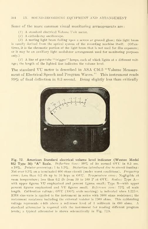
304 IX. SOUND-RECORDING EQUIPMENT AND ARRANGEMENT
Some of the more common visual monitoring arrangements are
:
(I) A standard electrical Volume Unit meter.
{2) A cathode-ray oscilloscope.
(«?) A moving light beam falling upon a screen or ground glass; this light beamis usually derived from the optical system of the recording machine itself. (Often-
times, it is the chromatic portion of the light beam that is not used for film exposure
;
or it may be an auxiliary light modulator arrangement used for monitoring purposes
only.)
(4) A line of gas-tube ''trigger" lamps, each of which lights at a different volt-
age; the length of the lighted line indicates the volume level.
The standard VU meter is described in ASA C16.5 "Volume Measure-
ment of Electrical Speech and Program Waves. '
' This instrument reads
99% of final deflection in 0.3 second. Being slightly less than critically
Fig. 72. American Standard electrical volume level indicator (Weston Model862 Type 30) "A" Scale. Deflection time: 99% of its normal OVU in 0.3 sec.
±10%. Pointer overswing : 1 to 1.5%. Distortion introduced due to circuit loading:
Not over 0.3% on a terminated 600 ohms circuit (under worst conditions). Frequency
error: Less than 0.2 db up to 10 kcps at OVU. Temperature error: Negligible at
room temperature; less than 0.2 db from 50 to 100 F at OVU. Scales: Type A
—
with upper figures VU emphasized and percent figures small ; Type B—with upper
percent figures emphasized and VU figures small. Reference zero: 72% of scale
length. Calibration voltage: OVU (100% scale marking) is indicated when 1.225-v.
EMS sine-wave is applied to the instrument in series with 3600 ohms resistance; the
instrument resistance including the external resistor is 7500 ohms. This calibrating
voltage represents + 4db above a reference level of 1 milliwatt in 600 ohms. Astandard attenuator is required with the instrument for reading different program
levels; a typical attenuator is shown schematically in Fig. 72A.
MONITOEING 305
damped, the needle is not "jittery" as with critically damped or
slightly overdamped meters. Figure 72 is an illustration of the instru-
ment and its scale. The sensitivity does not depart from its 1000-cps
value by more than 0.2 db between 35 and 10,000 cps, nor more than
0.5 db between 25 and 16,000 cps. As commercially manufactured by
Weston Electrical Instrument Corp. and others, it is a 4-inch instru-
ment with large readable figures on its scale and a plainly visible pointer.
To reduce eyestrain, it can be furnished with internally mounted lamps
for scale illumination. In accordance with the ASA specification, two
types of scale are available. These are identical except that in one
instance the large figures are percentage figures and the small figures
are VU figures; in the other, the opposite arrangement is used. The
standard instrument is designed for circuits of 600-ohms characteristic
impedance. One of the greatest virtues of this instrument is that it is
in very wide use, and because of its consistency in indication even over
extended periods of time, different persons using the instrument to read
indications on the same program waves will arrive at substantially the
same readings. This is a feature that is not enjoyed by any other instru-
ment in current use. Figure 72A is the schematic of its attenuator.
mm wvw »600OHM
'SOURCEI
600OHMLOAD
Fig. 72A. Electrical schematic for attenuator for Weston VU meter. A typical
attenuator designed for the VU meter of Figure 72 is the Daven TA-1000-2. This
is a variable ''Tee" pad attenuator with a built-in 3600 ohms series resistor. This
attenuator has a low level limit of 1 milliwatt: steps from + 4VU upward in 2 VUsteps up to a maximum of -f 40VU are provided. This attenuator also provides an off
position at the extreme clockwise detent stop of the control knob. The following table
shows the resistance value for each arm. As indicated in the schematic, the 3600 ohmsresistor is not included in the table of values. (Each arm A has the value shown in
the table.)
Level Ann A, Ann B, Level Ann A. Ann B, . Level Ann A. Ann B.vr ohms ohms VI ohms ohms vr ohms ohms
4 0. Open 18 2603. 1621. 32 3601. 311.06 447.1 16788. 20 2833. 1268. 34 3661. 246.98 882.5 8177. 22 3028. 997.8 36 3708. 196.1
10 1296. 5221. 24 3191. 787.8 38 .•.74 7. 155.712 1679. 3690. 26 3326. 623.5 40 3778. 123.714 2026. 2741. 28 3437. 494.116 2334. 2091. 30 3528. 391.9
306 IX. SOUND-RECORDING EQUIPMENT AND ARRANGEMENT
There has been no standardization of any of the other three forms
of visual volume indicator ; accordingly, there will be greater differences
in interpretation for different kinds of program waves as well as greater
differences among different observers for the same program waves. This
variability in interpretation is a serious handicap, since a volume indi-
cator must be used at every point in a recording system at which sound
level must be controlled. Despite the shortcomings of volume indicators,
any one method will in all likelihood prove satisfactory if the same kind
of sound is recorded day after day by the same operator and with the
same equipment. If the character of the program waves is changed,
or if the characteristics of the recording channel are changed in compari-
son with the way they ordinarily look and sound to the mixer man, it
is necessary for him to reorient himself to the altered conditions. For
this reason, once a monitor loudspeaker and a volume indicator have
been installed, they should not be changed in any way without an ade-
quate reason.
Because of the large element of quick judgment and guesswork that
is invariably a part of the sound-recording process, it is not reasonable
to expect an operator who has been recording only one form of sound
(e.g., dialogue) to record an unfamiliar type of sound (e.g., a ping-pong
match) without making test recordings—regardless of the equipment
at his disposal. Each type of visual monitor is better suited to the indi-
cation of one specific kind of program wave than to any other. As the
operating characteristics of all different types are different, and there
is substantial difference between presumably similar indicators of the
same type due to the lack of standardization, it is no surprise to learn
that if all were connected to the same channel and adjusted to give like
indications for dialogue, there will be as many different indications as
there are instruments when the sound of the ping-pong ball is trans-
mitted. Fortunately, equipment operators are not called upon fre-
quently to record unfamiliar sounds.
Auxiliary Recording Apparatus
With photographic sound-film recording equipment it is impossible
to playback the sound immediately after recording, since the films must
first be developed. For production reasons it is not unusual that some
form of direct playback is needed immediately after a recording to de-
termine whether or not lines have been "flubbed" (improperly read or
spoken) or if other sounds have been produced properly. To do this re-
AUXILIARY RECORDING APPARATUS 307
quires some form of recording machine other than the sound-film record-
ing machine.
A variety of machines suitable for this purpose is available at a wide
range of prices. The machine to be used should be synchronous in its
operation with the film-recording machine; in this way, the record pro-
duced by the auxiliary machine, if of sufficiently high quality, may be
used as a "protection record," a record from which a re-recording maybe made in the event that the sound-film original is unsatisfactory be-
cause of improper exposure, or other similar causes. If a synchronous
high-quality record is desired, so-called acetate disks are suitable ; suit-
able machines are made by Presto Recording Corp. of Xew York and by
Fairchild Camera and Instrument Corp. of Jamaica, Long Island, XewYork. The price of such equipment is around $1000. Although only
a small quantity of magnetic recording equipment is available commer-
cially that is exactly synchronous, it is probable that such recording
equipment of the sprocket-hole perforated coated-tape type will soon be
manufactured in larger quantity and variety. Sufficient strides have
been made with oxide-coated tapes to indicate that there need be no
great concern about the fidelity available at equal or greater film speeds
;
the particular quality level required can be met as desired. It should
be noted that most sound-recording equipment available is of the non-
synchronous type ; most commonly available disk recorders, for example,
are friction driven between the motor shaft and the rim of the turntable.
The rubber, or other soft material used, permits appreciable slip ; this is
the price paid for the relatively good yet simple and cheap flutter-attenu-
ating drive arrangement.
Control Adjuncts and Auxiliary Apparatus
If film recording is to prove satisfactory, it must be accomplished
with microscopic accuracy. Thus, when a measurement of any sort is
to be made, it must be made with consistently performing instruments
of the required accuracy. This general observation applies to any in-
strument used—regardless of whether it be electrical, optical, mechanical,
or other. One type of instrument to which it is especially applicable is
the lamp-current ammeter used for the measurement of exposure lamp
current. Most instruments supplied with most recording equipment
are entirely too small and have a scale too short to be either accurate or
convenient for the operator; this applies especially to the otherwise ex-
cellent 3-inch instruments that are so widely used.
308 IX. SOUND-RECORDING EQUIPMENT AXD ARRANGEMENT
Generally speaking, ammeters are guaranteed by their manufac-
turers to have an accuracy of a specified percentage of full-scale reading
at any point of the instrument scale. The usual value for such instru-
ments as the Weston 3-inch types is 2%. Despite their excellence, these
instruments do not provide the requisite control—not because the instru-
ment is inaccurate, but because it is improperly applied. The instru-
ment scale is short, its figures small, its divisions light (because they
must be narrow), and it has no knife-edge pointer and mirror scale to
minimize parallax error. The instrument must be read in a bright light
at a short distance and with no shift of the observer's head position be-
tween one reading and the next. In the commercial recording of 16-mm
sound films, it is almost impossible to meet these requirements with a
3-inch instrument. The fundamental solution is the use of an adequate
instrument with suitable viewing conditions.
The very widely-used 3-inch instrument is difficult to read; it
is selected because its price is low (about $6.00) and because it is rugged
and reliable. Such attributes, although praiseworthy, are not sufficient
to justify what amounts to faulty engineering judgment in instrument
selection.
Broadly speaking, the usefulness of an ammeter for measuring lamp
current depends upon the accuracy of the meter movement and the re-
producibility of its indications, and also upon the ability of the user to
read the indications on the scale of the instrument. All these factors are
taken into account when an instrument manufacturer specifies an accu-
racy rating for an instrument. Such ratings are customarily expressed
in terms of the percent of full scale reading at any point on the instru-
ment scale. The absolute error, therefore, is a minimum at full scale
reading, and increases relative to the current measured at lower values.
It is an accepted empirical rule that ammeters are customarily operated
at about 80% of full scale reading; for an instrument that is expected
to read 2 amperes, the full scale reading of the chosen instrument should
be about 2.5 amperes.
The accuracy of the meter movement and the reproducibility of its
indications are a matter of instrument design and of manufactured
quality. Just as in other manufactured products.. there are differences
in the quality level among the presumably equivalent products of dif-
ferent manufacturers. It is informative to connect a dozen ammeters
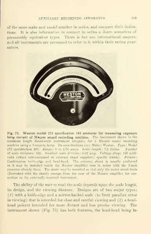
AUXILIARY RECORDING APPARATUS 309
of the same make and model number in series, and compare their indica-
tions. It is also informative to conned in series a dozen ammeters of
presumably equivalent types. There is but one international ampere,
and all instruments are presumed to refer to it within their rating guar-
antees.
Fig. 73. Weston model 273 specification 195 ammeter for measuring exposure
lamp current of Maurer sound recording machine. The instrument shown is the
minimum length linear-scale instrument adequate for a Maurer sound recording
machine using a 2-ampere lamp. Its specifications are: Make: Weston. Type: Model
273 specification 195. Range: to 2.50 amps. Scale length: 7.3 inches. Number
of scale divisions: 125. Smallest scale division: 0.02 amp. Voltage drop: 100 milli-
volts (either self-contained or external shunt supplied; specify which). Pointer:
Combination knife-edge and bead-head. The external shunt is usually preferred
as it may be installed inside the Maurer amplifier case in series with the 3-inch
ammeter already there. The shunt may be mounted so that only the meter shunt leads
(furnished with the shunt) emerge from the case of the Maurer amplifier for con-
nection to the externally-mounted instrument.
The ability of the user to read the scale depends upon the scale length,
its design, and the viewing distance. Designs are of two major types:
(1) with a knife-edge and a mirror-backed scale (to limit parallax error
in viewing) that is intended for close and careful viewing and (2) a bead-
head pointer intended for more distant and less precise viewing. The
instrument shown (Fig. 73) has both features, the bead-head being lo-
310 IX. SOUND-RECORDING EQUIPMENT AND ARRANGEMENT
cated below the knife-edge portion to limit pointer bending resulting
from the sudden forces of meter overload. In practice the operator must
be close to the instrument and directly view the scale perpendicularly
when setting the lamp current; this is necessary to cause the image of
the knife-edge appearing in the mirror to coincide accurately with the
knife-edge itself. For momentary checking of the lamp current from
time to time while recording is in progress, the operator glances at the
meter, observing the location of the pointer by noting quickly the bead-
head portion. He subconciously compares the new observation with the
prior observations to determine whether any change in current has taken
place.
It is recommended that the density of the original sound track be
controllable within db 0.1. With the recommended instrument, it is
possible to estimate current within one-half scale division, or 0.01 ampere.
Since the smallest scale division (0.02) represents a density change of
about 0.1 under average commercial processing conditions, the accuracy
of the instrument is properly related to the operating requirements.
Under such circumstances, the recording machine operator can feel con-
fident that film exposure is properly controlled, and that gross exposure
deviations are not due to an inadequate exposure lamp current ammeter.
Should such deviations occur, the accuracy of exposure lamp current
control is sufficient to permit the source or sources to be tracked down
methodically.
For most 16-mm sound recording, 2% accuracy of lamp-current con-
trol as limited by the ammeter is marginal; better control is required
and a reproducibility in the order of 1% would seem to be a more suitable
choice. Such control can be obtained ordinarily with the Weston 7-inch
instruments shown. Internal instrument illumination to provide ade-
quate light for viewing the instrument scale is also quite desirable
;
good instrument manufacturers can advise on the scale color and on the
illumination level required for optimal viewing at the viewing distance
specified. Although the rated accuracy of the 7-inch instrument shown
is only 1%, performance of the instrument will be satisfactory because
the rated instrument accuracy is realized in practice, and because the
reproducibility of the readings of the 7-inch instrument is appreciably
higher than that of the 3-inch instrument because of the manner in
which the instrument is used. It is self-evident that such instruments
should be calibrated at regular intervals if the instruments are to be
AUXILIAEY KECORDING APPARATUS 311
relied upon for controlling exposure. As an operating procedure it maybe advantageous to use two lamp-current ammeters, one located at the
mixer desk and one at the sound-recording machine. Such an arrange-
ment makes it possible for the mixer man and the recording-machine
operator to check one another.
Progressive instrument manufacturers such as the Weston Electrical
Instrument Corp. have recognized for some time the need of increasing
the useful scale length of their instruments, and now supply on special
order the suppressed-zero feature in many catalog instruments. Sup-
pressed-zero instruments are available in two designs; mechanical sup-
pression and electrical suppression. Both instruments are currently
available in a maximum of about 60 rc suppression for d.-c. instruments;
in the instrument shown, the lowest scale reading would be 1.50 amperes
rather than ampere, and the full scale reading would remain the same
—2.50 amperes. The effective scale length would be more than doubled
for such an instrument as it is not used below 1.50 amperes.
Mechanical suppression is accomplished in the instrument shown by
the use of a special design of armature restraining spring. Electrical
suppression is accomplished through the use of two separate current coils
in the armature suspension saddle instead of the customary single coil.
Mechanically suppressed zero instruments* are cheaper: the electrically
suppressed type retains its calibration better over long periods oi time.
Two good densitometers, one of the Eastman type and the other of
the \Yestern Electric type, are desirable. The former is needed for the
less accurate production measurement of densities of the order of 1.0.
and the latter is needed especially for the measurement of fog and of
other densities of the order of one-tenth of the former and for more ac-
curate high-density measurements. It must be remembered that film
laboratories customarily make a minimum of density readings of the
films they turn out. and rarely make accurate readings of fog. Thus,
the equipment operator should make readings on all his film—some read-
ings to check the laboratory, and other readings for control purposes
and for process improvement purposes. It will be necessary for the
equipment operator to make his own readings and interpret thein rather
than attempt to ''pass the buck" for this routine examination and re-
sponsibility to someone else, if the quality of the recorded sound is to
be maintained, and if the data necessary to determine just where and
how much improvement should be made is to be collected.
If good control of sound quality is to be achieved, da a concerning
* Such instruments become inaccurate with lack of use.

312 IX. SOUND-RECORDING EQUIPMENT AND ARRANGEMENT
process variations from day to day must be accumulated—a laborious
and time-consuming process. What is invariably bound to happen in
the absence of such data is a downhill trend in recorded sound quality
that is so gradual that it slips by the inspection of the original and is
detected in aggravated form in an unsatisfactory release print.
Koutine tests should be made at the end of every roll of film re-
corded. Further routine tests should be made periodically {e.g., weekly)
to check the change in characteristics of the equipment and processing
with time. Such tests need not consume appreciable quantities of film
;
informative tests can be run with little more than the amount of film
ordinarily wasted as short ends. Transmission, flutter, and cross-modu-
lation tests should be made as frequently as possible not only to deter-
mine average conditions, but also to determine the magnitude and the
causes of day-to-day variations.
The Society of Motion Picture Engineers sells a series of excellent
test films that may be used for checking equipment performance. The
multi-frequency test reel, for example, may be used in a re-recording
film phonograph to check the over-all characteristics of the re-recording
channel. It may be sent to the laboratory for 16-mm prints; a print
may be made on either black and white or color film. Differences be-
tween re-recording and photographic printing can be quickly estimated
by comparing the films produced. Although the test conditions are not
exactly equivalent to commercial operating conditions, the results will
still be sufficiently close to indicate the order of the similarity or differ-
ence. Much valuable operating data can be gathered quickly by such
simple tests. Practical production problems will indicate numerous
other uses for these most valuable test films.
Data concerning availability, methods of test, and suggestions for further uses
can be obtained from the Engineering Secretary, Society of Motion Picture Engineers,
342 Madison Ave., New York, N. Y.
Physical Placement of Equipment in Recording
It must be remembered that the gain of an amplifying system used
for recording is quite high ; 100 db is a common value between the micro-
phone input and the output feeding the monitor. Because of the high
gain the following conditions should be met
:
(1) When no intended sound originates within the studio, no sound other than
system hiss should be henrd when the monitor gain is advanced above normal. It must
be kept in mind that the original record shall be as free of noise as possible because

PHYSICAL PLACEMENT OF EQUIPMENT IN RECORDING 313
every succeeding step of processing, printing, and handling increases the noise level.
To make a simple test, merely increase the monitor gain at least 20 db above normal
operating gain and listen critically. If any extraneous noise or sound is heard, take
steps to eliminate it. Listen particularly for the noise of machines (such as the scor-
ing projector or the camera), extraneous conversation carried on in distant rooms,
elevator noise, etc.
(£) The acoustic insulation between the studio and the monitor room should be
high if headphones are used for monitoring, and much higher if a loudspeaker is used
for monitoring. The acoustic isolation between the monitor-produced sound and the
microphone is good when headphones of the hearing-aid type such as Western Electric
714C are used, since very little sound escapes into the monitor room from the head-
phones, and the insulation between the monitor room and the microphone is quite large.
On the other hand, acoustic isolation between the monitor-produced sound and the
microphone is comparatively very poor when a loudspeaker is used for monitoring,
since the sound level produced by the monitor speaker is very much higher than that
of the monitoring headphones, and the path between the mouth of the loudspeaker and
the ears of the mixer is neither enclosed nor restricted. The sound from the loud-
speaker impinging upon the multiple glass panel between the mixer room and the
studio provides a low-impedance '' feedback howl '
' path, wTith the glass panel as the
primary attenuator in its path. To make the attenuation a maximum, the attenuation
per unit area is made a maximum by using two or even three pieces of thick plate glass'
' floated '' acoustically and with dead air spaces between them, and with the area of
the panel a minimum. Generally speaking, sound-insulating walls provide apprecia-
bly more insulation for a certain dollar cost of construction than glass observation
panels.
(3) The acoustic insulation betwreen the mixer room and other sources of noise
such as the noise produced in the machinery room by the recording machines, film
phonographs, scoring projectors, and the like should be very high. Here again the
isolation is quite high when headphones are used, since the noise is excluded from the
ears of the mixer man by the headphones themselves. With complete silence in the
monitor room, it should not be possible for the keenest pair of ears to tell whether any
machinery is running in an adjacent machinery room, or whether any performance is
taking place in the studio proper.
It is evident from the foregoing that there are two primary classifications: one
for monitoring with headphones, and another for monitoring with a loudspeaker. Theformer is quite advantageous from the standpoint of noise because less expensive
studio wrall construction is required. It is possible with headphones monitoring to have
the mixer man right on the set or stage and to pipe* the signals to a more remote
point where the recording machine is located. Unfortunately, most headphones have
a decidedly poor response-frequency characteristic, are uncomfortable to wear, and
interfere with the physical freedom of the mixer man. When recording is in progress,
freedom to move arms unhampered together with utter, convenience of all operating
controls and instruments make for a better sound track.
Headphones are also misleading in sound quality because the mask-
ing effects of extraneous noise heard in the headphones are much less
* Colloquial expression meaning i
i
to transmit. '
'
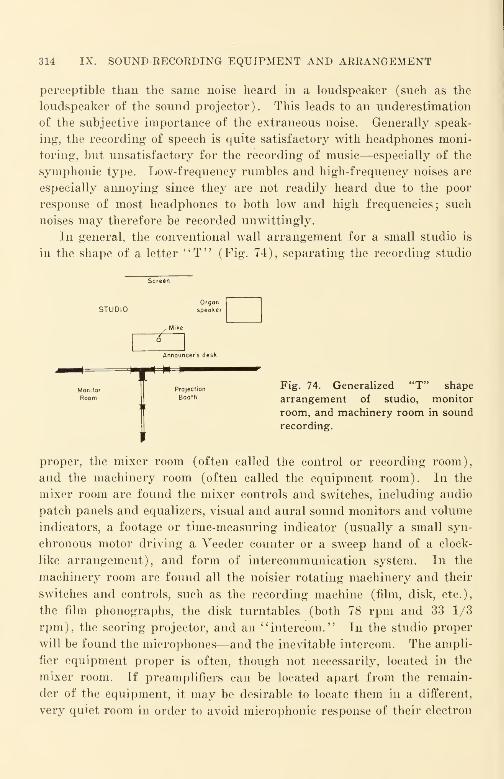
314 IX. SOUND-RECORDING EQUIPMENT AND ARRANGEMENT
perceptible than the same noise heard in a loudspeaker (such as the
loudspeaker of the sound projector). This leads to an underestimation
of the subjective importance of the extraneous noise. Generally speak-
ing, the recording of speech is quite satisfactory with headphones moni-
toring, but unsatisfactory for the recording of music—especially of the
symphonic type. Low-frequency rumbles and high-frequency noises are
especially annoying since they are not readily heard due to the poor
response of most headphones to both low and high frequencies; such
noises may therefore be recorded unwittingly.
In general, the conventional wall arrangement for a small studio is
in the shape of a letter "T" (Fig. 74), separating the recording studio
Screen
STUDIOOrganspeaker
/M ike
6
Annour
Pro
B
cer's desk
Monitor
Room
jection
30th
Fig. 74. Generalized "T" shape
arrangement of studio, monitor
room, and machinery room in sound
recording.
proper, the mixer room (often called the control or recording room),
and the machinery room (often called the equipment room). In the
mixer room are found the mixer controls and switches, including audio
patch panels and equalizers, visual and aural sound monitors and volume
indicators, a footage or time-measuring indicator (usually a small syn-
chronous motor driving a Veeder counter or a sweep hand of a clock-
like arrangement), and form of intercommunication system. In the
machinery room are found all the noisier rotating machinery and their
switches and controls, such as the recording machine (film, disk, etc.),
the film phonographs, the disk turntables (both 78 rpm and 33 1/3
rpm), the scoring projector, and an "intercom." In the studio proper
will be found the microphones—and the inevitable intercom. The ampli-
fier equipment proper is often, though not necessarily, located in the
mixer room. If preamplifiers can be located apart from the remain-
der of the equipment, it may be desirable to locate them in a different,
very quiet room in order to avoid microphonic response of their electron
PHYSICAL PLACEMENT OF EQUIPMENT IN RECOEDING 315
tubes to sounds such as those produced by the monitor loudspeaker, by
the noise of rotating machinery, by the vibration of such machinery
transmitted to the electron tubes, or by building or other vibration simi-
larly transmitted. As has been pointed out, multiple glass panels (not
less than two thicknesses of plate glass) between adjacent rooms should
be kept as small as possible in area to reduce the total energy of sound
transmitted from one room to another. As the effectiveness of the acous-
tic isolation actually obtained depends upon suitably isolating the panels
acoustically from their supports, construction design is very important.
Basic information concerning such design may be obtained from manu-
facturers of acoustic materials such as Johns-Manville. In the interest
of providing the most effective use of the materials manufactured, manyof these firms provide advisory services for materials users.
In general, when cost is to be kept to a minimum, monitoring with
headphones is most practicable—especially if only a commentary voice is
to be recorded. However, loudspeaker monitoring is definitely preferred
for re-recording. When the purpose of the re-recording is to "mix"sound tracks prior to the making of a re-recorded sound negative or
sound positive for release printing, the mixer room where original re-
cording is accomplished is quite satisfactory and convenient. Whenthe purpose of the re-recording is to prepare a sound negative or sound
positive for release printing, the re-recording console and its controls
are best located at the rear of a small simulated auditorium. To im-
prove the illusion for the mixer man, a screen of 4 to 6 feet wide maybe set up at the forward end. The mixer man should be located at a
distance of 5 w from the screen;* this position should assure that the
listener at the rear of an auditorium has been considered when the
sound was re-recorded. To check the probable effectiveness of the re-
recording qualitatively, a loudspeaker of the type ordinarily used with
the commercial sound projector on which the films are to be run can be
substituted for the monitor loudspeaker by switching back and forth
during a rehearsal preceding the "take." (This comparison by switch-
ing is referred to as an A-B test.) If the sound heard from either loud-
speaker is not crisp and bright, and free from harshness, distortion, and
noticeable noise, it is likely that the re-recording will not be satisfactoiw.
One or two preliminary test re-recordings will aid in establishing the
mental reference required for production re-recording; the release print
* w represents the width of the screen. Perspective of viewing is fixed when the
distance from the screen is specified in terms of screen widths. (See chapter XIII).
316 IX. SOUND-RECORDING EQUIPMENT AND ARRANGEMENT
prepared from the test should be compared directly with the monitor
sound of the re-recording channel to indicate the losses encountered in
production.
Technique of Sound Recording
When an event occurs that we wish to record, there are several condi-
tions as yet unaccounted for that require consideration. The effective-
ness of the compromises decided upon as a result of these conditions may"make or break" the final result despite the very best equipment, proces-
sing, film, and technical facilities.
One factor is that all 16-mm commercial sound recording is monaural
or "single-eared" while all human hearing is binaural or "two-eared."
The brain has the faculty of discriminating against noises that it chooses
to disregard, and concentrating on sounds that it chooses to hear; this
faculty is quite apart from the purely physical and physiological factors
that are a result of the construction of the ears and their location in the
head. Unconsciously, we turn our heads to discriminate against noise
that originates in a direction different from that of the sound we choose
to hear.
Conventional recording systems, being single-channel arrangements,
do not provide the noise discrimination and the directional discrimination
that is common to binaural hearing ; in effect they act somewhat in the
manner of one useful ear and one plugged-up ear. With such systems,
therefore, the twisting of the head does not provide the accustomed correc-
tive effect bcause the extraneous noise originates (as far as the listener is
concerned) from the identical point in space—the loudspeaker—as that
of the sound of interest.
To correct this effect to some extent, it is essential to reduce extraneous
sounds to a minimum. Directional microphones are used to limit the
noise introduced into the recording channel. To limit the effect of the
noise introduced by the remainder of the process, noise reduction, volume
compression, etc. are used. Efforts are constantly being made to improve
the signal-to-noise ratio of recording systems, since a particular level of
noise in a conventional 16-mm reproducing system is much more dis-
concerting and attention-diverting than the same amount of noise ex-
perienced in natural listening.
Usually, a directional microphone should be used at a relatively short
distance from the sound source. In this manner the greater portion of
the sound reaching the microphone is received directly from the source
with no reflection at all. The lesser and intentionally small portion of
TECHNIQUE OF SOUND RECORDING 317
the sound is randomly reflected from the boundaries or walls of the pickup
space or set, and from objects within the space. To reduce the ratio of
reflected sound to direct sound still further, sets are made less reverberant
than normal by the use of considerable quantities of strategically placed
sound-absorbing material on the walls and other flat surfaces. Unfor-
tunately, 16-mm projectors are often run in highly reverberant rooms;
recorded reverberation must be kept to a minimum on the film if the over-
all result is to be intelligible under such unsatisfactory reproducing condi-
tions, as the reverberation (echo) effect of projection is added to that of
recording.
Another important factor is the degree of mobility of the sound source
with respect to the microphone. Since pressure-type microphones are
nondirectional at low frequencies and quite directional at high fre-
quencies, the "wiggling about" of a speaker's head translates itself into
objectionable changes in voice quality due to the changes in the amount
of high frequencies arriving at the microphone. If more uniformly
directional microphones—such as the cardioid or the velocity types—are
used, the effect of "head wiggling" is less noticeable. Such microphone
types do not discriminate as seriously wTith respect to frequency ; accord-
ingly, the primary effect of "head wiggling" is to produce small changes
in volume rather than serious changes in quality.
The problem of quality variation due to source mobility is far more
serious when it is necessary for actors to move about a set to provide the
desired pictorial action. Although sound pickup is not simple under
these conditions, the final result does not suffer if adequate equipment
and personnel are used. Most 16-mm films cannot afford the high costs
that such production entails; to accomplish such recording requires the
duplication of the complicated and expensive equipment and numerous
personnel used for a Hollywood production.
Since many 16-mm films are recorded with a single off-stage voice, the
problem of mobility of the sound source does not arise. It is usually
sufficient to record within a relatively small space (the space may be as
small as 600 cubic feet), making certain by attentive listening to the
monitor speaker that satisfactory sound pickup is being obtained. It is
especially important in the case of a small space that the length-to-width-
to-height relationships be of the order of 1 : 1.25 : 1.5 or multiple? thereof
;
this dimensional relationship among the three axes of the room is neces-
sary to provide "randomness" to sound reflected from the room sur-
faces. Further data in condensed form may be obtained from the excel-
318 IX. SOUND-RECORDING EQUIPMENT AND ARRANGEMENT
lent Engineering Handbook issued by International Telephone and Tele-
graph Company in the section dealing with room acoustics.
One of the very common causes of unsatisfactory sound pickup is aptly
illustrated by undesirable short-path reflections that result when sound
is "bounced off" the top of an uncovered wooden desk when a com-
mentator reads from text that rests on the desk, and the microphone is
suspended directly above it. An alert mixer man with good hearing,
listening to the sound through a high-quality monitoring loudspeaker
system can instantly recognize this condition and quickly instruct the
commentator to correct the sound defect. The table top will be covered
and reflection from its top '
' broken up '
' by placing various items on it
;
the microphone placement will be altered so that the primary contribution
to the sound at the microphone will be made by the direct sound of the
announcer's voice—with a minimum contribution by the sound directly
reflected from the nearby top of the desk. All this is done before the
mixer man permits a recording to be made; it is essential that he be
satisfied with the sound quality before a "take" is actually made. Gen-
erally speaking, an attempt to correct a defective sound track in re-
recording is foredoomed to failure ; it is far simpler and more satisfactory
to record the sound track properly when the original recording is under
way.
A third contributing factor related to the differences between mon-
aural and binaural listening as they affect recording quality is the envi-
ronment of the recording microphone. Sound travels from its origin or
origins to the microphone. Even though it may not be impeded by
objects between the sound source and the microphone, still, the dimen-
sional and surface characteristics of the surfaces of the recording space,
such as the walls, the ceiling, floor, etc., that reflect sound, and their dis-
tances relative to the sound origin and to the microphone, play an impor-
tant part in determining not only the reverberation time (which depends
upon the distances) but also the relative intensity of the reflected sound
with respect to the directly received sound. The distance relations of the
reflecting surfaces determine the reverberation time and the "random-
ness" of the reflection. Even the ear itself plays an important and often
unrecognized part; if two sounds of equal pressure are heard that have
different ratios of reflected to direct sound, the sound with the larger re-
flection component will seem appreciably louder subjectively than the
sound with the smaller reflection component.
At present, the day-to-day variations in sound quality are so large due
TECHNIQUE OF SOUND EECOEDING 319
to processing and other variations such as projection acoustics, that the
introduction of appreciable intentional reverberation is usually undesir-
able because of the very limited useful dynamic volume range found in
16-mm prints as customarily projected. Too often the introduction of
reverberation also introduces large unexpected noise components that
will further seriously limit an already small signal-to-noise ratio that is
little better than marginal.
Much could be written about the technique of sound pickup for 16-mm
recording. None would be of any value whatever if the ''man at the
controls" does not have good hearing provided by "balanced" ears, a
good memory, and intelligence, together with the habit of being metic-
ulously careful in everything that he does. Sound recording is not just
a mechanical process; the result depends upon how accurately "the manat the controls" has weighed his problem. If the result as projected on
the reference projector in the reference auditorium is good, he has done it
well. The difference between what is expected and what actually
happens is a measure of his judgment, and of the control of the process
of making a release print from a recording of an original event.
As in any other field of scientific activity, the man will keep accurate
records of everything that he records and does, and he will consult his
records and recordings regularly to evaluate for himself whether the
present recording shows steady improvement over his earlier work, and
where and how to make future recordings even better than the present
ones. At regular intervals he will call in trained associates to listen to
samples of recording made for different pictures at different times;
broadly speaking, his evaluations should be confirmed by those of his
associates. At such times, samples of the best quality recordings made
by others should be included in the review; by direct comparison, it is
possible to evaluate the sound quality he is providing relative to that of
the competitive market. Shortcomings, when detected, should be tracked
down and corrected with minimum delay. It is only with such regular
review that the sound recordings produced may be used confidently.
Re-recording
Since the optimal use of re-recording can result in such a high level of
improvement in quality, attention may justifiably be given to some of its
applications.
There are several general requirements for the projection of sound
320 IX. SOUND-RECORDING EQUIPMENT AND ARRANGEMENT
films in the accomplishment of which re-recording can play a controlling
part.
(1) During projection there should be no need to "diddle" or otherwise alter
either the volume control setting or the tone control setting between the beginning of
a reel or subject and the end of the reel or subject. Sound quality and sound volume
should be just as consistent throughout a release print as the picture is expected to be.
Since no "diddling" of picture brightness or tone is required, there should be no
"diddling" of sound volume or "brightness" of tone.
{2) All portions of the film, whether of speech, music, sound effects, or any
combination of them shall be intelligible and pleasing to all in the audience who can
satisfactorily view the screen. In this regard it should be remembered that the sound
radiated to the sides and to the back row of the theater is usually seriously deficient
in high frequencies when the conventional box-type '' portable '
' flat-baffle type loud-
speaker is used for sound projection. (Most sound projectors are equipped with this
inadequate type of loudspeaker because it is the cheapest available.) To compensate
somewhat for this defect, it is necessary to equalize even beyond the amount dictated
by other considerations.
(3) The sound shall be in keeping with the pictorial content of the picture both
in quality and in aspect. Should voice quality be disconcerting for some reason, it
should be possible to do something about it rather than to permit all audiences to suffer
through a carelessly done job. (The 4031B Cinema Engineering Program Equalizer
is useful for this purpose.)
(4) Should a reasonable increase in sound output above an arbitrary "normal"be required to "override" increased auditorium noise (for example, due to an in-
crease in the size of the audience during the showing), such change should be possible
without a noticeable increase in distortion and noise, or change in sound quality.
(5) Release prints should be consistent in quality, noise, and distortion from
one print to another of the same subject and should show but minor variations from
one subject to another.
These requirements are not easily met. The final result obtained is a
compromise that involves the cost to an important degree. Technical
factors involved relate to hearing perception, recording technique, lab-
oratory processing and release print manufacture, the recording process
itself, and even to psychological factors—such as the attention accorded
the film by the audience.
Obviously, the original record should be the best that we know how to
turn out. It is even more important that the quality throughout the
original recording be consistent ; if correction is required, then the same
correction can be applied to the complete film rather than a large series
of special corrections for different pieces.
When off-stage voice (commentary) is to be recorded, obtaining a good
sound record would seem to be quite simple. Unfortunately it is not as
easy as it looks ; even a trained announcer does not find it easy to speak
RE-RECORDING 321
with the same voice quality continuously throughout the 11 minutes re-
quired for the recording of a single reel. The difficulty with an un-
trained speaker is accentuated; he may begin a recording session sat-
isfactorily, but is usually incapable of "following through" for the full
period. Before the end of a single reel is reached, an appreciable change
in delivery (such as tempo, pitch, emphasis, inflection, and even diction
and intelligibility) occurs merely because the effort is tiring. The un-
trained speaker is usually unaware that a change in voice quality is
occurring; he does not realize what is happening because his effort- are
concentrated upon the mere mechanics of reading and speaking.
With thoroughly professional voicing and recording, it should be pos-
sible to shift phrases or sentences from their original positions in a
sound track to some other position if dictated by the editorial need of the
picture. AVhen the altered film is projected, there should be no notice-
able change in sound quality to an average listener who may hear the film.
Such sound "cutting" may often prove impractical because of sound
blooping difficulties ; it will be much easier to record the original properly.
If synchronized dialogue and similar sound is recorded, photographing
is done scene by scene. As a total of some 70 to 150 scenes is customary
in a typical edited reel of 11 minutes length, each scene averages only
5 to 10 seconds. Since each scene requires a different camera view, it
also requires a different location and orientation of the recording micro-
phone. The success of the illusion that the film is a continuous story
and a unified whole rather than merely a collection of "bits and pieces,"
depends upon the uniformity with which the individual scenes have been
recorded. Because the quality of each scene is judged individually by
the ear of the recordist when the recording is made, a successful sound
track of this kind represents a feat of memory quite as much as it repre-
sents a trained ear. In any event, the viewing audience expects—and
customarily receives—a result that is smooth and free from noticeable
quality departures not only from scene to scene but also throughout the
complete reel or subject. This result can be accomplished by suitably
skilled personnel as a regular day-to-day occurrence wThen they have the
proper facilities at their disposal and when they receive the active coop-
eration of laboratory, editing, and other production personnel. Anylesser result should be discarded as substandard.
Again it must be pointed out that the quality losses in each trans-
fer step of 16-mm film handling are quite large and vary over an un-
necessarily wide range from one lot of release prints to another, and even

322 IX. SOUND-RECORDING EQUIPMENT AND ARRANGEMENT
from one release print to another within a single lot of release prints.
It is evident that the losses which cause these changes must be known
if they are* to be anticipated and their adverse effects limited. As
sound recording men are often the only production men trained to
appreciate and understand these variations, it is evident that they must
listen to several release prints derived from the same original and com-
pare the prints directly with the original or with the final trial com-
posite print or appropriate sound check print. This should be a routine
follow-up matter if any serious attempt to produce consistent sound
quality is made. It is well to remember that the mere recording of an
original that "sounds good" to an untrained observer in the mixer room
is no assurance that release prints derived from the original will have
any commercial value. Under certain circumstances the losses of the
anticipated procedure may be so great that the result will be unsatis-
factory because the original record was made with a frequency range or
with a dynamic volume range that was too large. Sound records from
which release prints are derived must be "geared" to the release prints
they are to produce.
It is impracticable in many cases to expect the original sound record
to anticipate satisfactorily all the subsequent process variables and to
correct for them. A reasonable requirement is a noise-free and dis-
tortion-free sound record—preferably pre-equalized—that may be sub-
sequently re-recorded to provide the optimal characteristics for the pre-
print material used in printing the release prints.
It is reasonable to expect that release prints will be made by printing
directly from a re-recorded release negative should black-and-white prints
be required. It is also reasonable to expect that composite color duplicate
prints will be made by printing directly from a re-recorded release direct
positive. It is only in this manner that the unknown variables can be
kept to a minimum consistent with reasonable cost.
If a relatively large number of transfer steps must be anticipated
between the original sound record and the re-recorded release negative
or positive, there is cause for concern in meeting the competitive quality
requirements because of the magnitude of the film losses. For such
special cases it may be necessary to make the original record at a linear
speed appreciably greater than the standard 16-mm speed of 36 feet per
minute ; a 2-to-l speed ratio would seem to be an appropriate minimum.Generally speaking, if the recording is photographic, it will be better
to make such a higher speed record on 16-mm equipment than on
RE-RECORDING 323
35-mm equipment as the losses of commercially available 35-mm equip-
ment under comparable conditions are greater than 16-mm equipment;
further advantage is also obtained from the higher quality of specialized
16-mm film processing. In general, all steps prior to the release nega-
tive itself should be processed at the higher film speed if losses are to
be kept to a minimum. Possibly high-speed (18 in. per sec.) magnetic
tape recording may be the answer of the future for all stages prior to
the release sound negative.
Since each particular recording method and transfer process has dis-
tortion characteristics that are peculiar to it, the evaluation of distortion
comparisons among the various methods in other than a qualitative man-
ner is still difficult. Despite this difficulty, a generalization can be made
that holds true in a sufficiently large number of cases: if an original
record is made by one recording method (e.g., variable-density), the
over-all distortion of a copy will be smaller if the re-recording method is
of a different kind (variable-area). (This generalization presumes
complementary recording of negative and positive for both variable area
and variable density where such recording is applicable.) It has been
found empirically that under "average" conditions, distortion produced
by using the same recording method several times in succession is more
disagreeable aurally than if different methods are used. Apparently
there is a "piling up" of similar distortion products that does not occur
when different methods are used ; the ear is seemingly more tolerant when
distortion products are "spread out" over the spectrum than when dis-
tortion products occur at the same "spots" in the spectrum. If a high-
quality original recording were made on an up-to-date Western Electric
variable-density 35-mm channel on DuPont 225 negative, and a good
35-mm print made on DuPont 226 (to be used to provide a re-recorded
16-mm variable-area release negative on EK 5372), less distortion will
ordinarily appear on the release print than if the high-quality original
recording were made on a modern RCA variable-area 35-mm channel.
If the re-recorded release negative were to be of the variable-density
type, the reverse might be expected to be true.
At the present time, the losses in 16-mm films and processing are so
large that re-recording from 16-mm to 16-mm must be very accurately
controlled if "elbow room" for convenient operation is to be provided.
Unfortunately, very accurate control cannot usually be accomplished for
numerous reasons, and other means must be used to provide the much-
needed "elbow room." For the present, such means will imply a better

324 IX. SOUND-RECORDING EQUIPMENT AND ARRANGEMENT
quality original record with lower noise and lower intermodulation dis-
tortion. In. photographic recording the avenues are clearly indicated
:
they may include push-pull recording, variable-density recording using
higher film speeds, and possibly, wider sound tracks ; these avenues have
already been utilized in 35-mm recording. Perforated magnetic tape
recorders with tape speeds of 12 to 18 in. per second seem to have dis-
tinct possibilities; the tapes (suitable for original records) may be of the
16-mm safety-film-base type perforated with one row of sprocket holes,
or they may be of the paper type (similarly perforated), suitable for
editing. In any event the result should be quality equal to present
original 35-mm motion picture recordings. This quality is necessary
in any recording subsequently re-recorded and used as part of the re-
lease, or any recording which is used as a playback quality check of
original material.
Blooping
Since two strips of film, when spliced together with the customary
lap joint, cause a very irritating and rather loud noise as they pass the
scanning beam of a sound reproducer, masking or other silencing of the
splice is required; such masking or silencing is known as blooping. In
general, release negatives and release positives are made in one continuous
piece without splices of any sort; the problem of blooping is therefore
one of controlling the noise produced when the spliced re-recording print
is run through the re-recording film phonograph. Many forms of
punches, patches, and paint-outs have been used successfully with 35-mm
films, but the use of comparable methods has not been equally successful
in 16-mm. Fortunately, blooping is not a problem in many films, since
the sound is merely a commentary that has been recorded in one single
continuous piece. For the very specialized case of 16-mm films of the
synchronized dialogue type where the number of splices in a 400-ft. reel
may be as high as 150, the use of such mechanical blooping methods is not
very satisfactory in performance and is very time consuming. A sug-
gestion has been made by Lewin in the Journal of the Society of Motion
Picture Engineers* that the output of the preamplifier of the re-record-
ing film phonograph may be short circuited or otherwise disconnected
during the interval that the splice passes the sound-scanning beam,
thereby silencing the splice noise electrically. The method utilizes a
microswitch to effect the short circuit; the microswitch is actuated me-
* Lewin, G., "A New Blooping Device." JSMPE, 48, Apr. 1947, p. 343.
SELECTED BIBLIOGRAPHY 325
chanically by permitting the microswitch lever to drop as the film
—
which has been punched at an appropriate point—passes by. With a
film re-recorded in that manner, the noise of passing splices is eliminated
just as effectively as if the mixer channel key were automatically turned
off during the required interval. It is truly strange to relate that sound
re-recording had been a commercial process for some 15 years before the
appearance of this fundamental yet utterly simple solution to the problem
of sound blooping for re-recording. The long delay in the appearance
of this simple technique would appear to suggest very strongly that there
are probably many other first-order problems awaiting similarly simple
solutions. Such problems and their solutions will appear in the every-
day job of providing better sound on prints with a minimum of man-
hours of labor and a maximum of effectiveness ; every person engaged in
or interested in the job of recording, re-recording, processing, printing,
projection, and all other operations has an opportunity to recognize a
need and to find a solution. The job of improving the performance of
equipment can be left to the engineers in the field ; their efforts should be
directed, however, to improving the performance in the general direc-
tions indicated by those engaged in the everyday job of sound-film pro-
duction—and especially the operating sound engineer.
Selected Bibliography
Begun, S. J., Magnetic Recording. Murray Hill, New York, 1949.
Kellogg, E. W., "The ABC of Photographic Sound Recording," JSMPE, 44, 151
(March 1945).
Kellogg, E. W., "A Review of the Quest for Constant Speed," JSMPE, 28, 337
(April 1937).
Kellogg and Drew, "Filtering Factors of the Magnetic Drive," JSMPE, 35, 138
(Aug. 1940).
Albersheim and MacKenzie, "Analysis of Sound-Film Drives," JSMPE, 37, 452
(Nov. 1941).
Wente and Muller, "Internally-Damped Rollers," JSMPE, 37, 406 (Oct. 1941).
Hopper et ah, "A Light-Weight Sound Recording System," JSMPE, 33, 449 (Oct.
1939).
Hopper and Moody, "A Simplified Recording Transmission System," JSMPE, 47,
132 (Sept. 1946).
Kellogg and Morgan, "Measurement of Speed Fluctuations in Sound Recording and
Reproducing Equipment," J. Acous. Soc. Am., 7, 271 (April 1936).
Scoville, R. R., "A Portable Flutter-Measuring Instrument," JSMPE, 25, 416
(Nov. 1935).
Strock, R. O., "Some Practical Accessories for Motion Picture Recording," JSMPE,32, 189 (Feb. 1939).
326 IX. SOUND-RECORDING EQUIPMENT AND ARRANGEMENT
Kellogg, E. W., "A New Recorder for Variable Area Recording,' ' JSMPE, 28, 653
(Nov. 1930).
Goehner, W. R., "A New Mirror Light-Modulator," JSMPE, 36, 488 (May 1941).
Frayne, J. G., " Noise Reduction Anticipation Circuits," JSMPE, 43, 313 (Nov.
1944).
Scoville and Bell, l ' The Design and Use of Noise Reduction Bias Systems, '' JSMPE,
38, 125 (Feb. 1942).
Snow and Soffel, '' Electrical Equipment for the Stereophonic Sound-Film System, '
'
JSMPE, 37, 388 (Oct. 1941).
Hilliard, J. K., "The Variable-Density Film Recording System Used at MGMStudios," JSMPE, 40, 148 (Mar. 1943).
Aalberg and Stewart, "Application of Non-Linear Volume Characteristics to Dialog
Recording," JSMPE, 31, 248 (Sept. 1938).
Drew and Sachtleben, "Recent Laboratory Studies of Optical Reduction Printing,"
JSMPE, 41, 505 (Dec. 1943).
Maurer, J. A., "The Present Technical Status of 16-Mm Sound Film," JSMPE, 33,
315 (Sept. 1939).
Miller, W. C, "Preliminary Report of Academy Research Council Committee on
Rerecording Methods for 16-Mm Release of 35-Mm Features," JSMPE, 45,
135 (Aug. 1945).
Pettus and Sachtleben, "A New Variable-Area Recorder Optical System," JSMPE,50, 14 (Jan. 1948).
Denney, B. H., '' Cathode-Ray-Oscillograph Images of Noise-Reduction Envelopes, '
'
JSMPE, 50, 37 (Jan. 1948).
Thayer, W., "A Multi-Section Rerecording Equalizer," JSMPE, 45, 333 (Nov. 1945).
Mueller and Groves, "Magnetic Recording in the Motion Picture Studio," JSMPE,52, 605 (June 1949).
Gunby, O. B., "Portable Magnetic-Recording System," JSMPE, 52, 613 (June 1949).
Crane, G. R., "Studio 16-Mm Re-Recording Machine," JSMPE, 52, 662 (June 1949).
Singer, K., "Preselection of Variable-Gain Tubes for Compressors," JSMPE, 52,
684 (June 1949).
Keith and Pagliarulo, "Direct-Positive Variable-Density Recording with the Light
Valve," JSMPE, 52, 690 (June 1949).
Singer, K., "Versatile Noise-Reduction Amplifier," JSMPE, 50, 562 (June 1948).
Singer, K., "High-Quality Electronic Mixer," JSMPE, 52, 676 (June 1949).
Collins, M. E., "A De Luxe Film Recording Machine," JSMPE, 48, 148 (Feb. 1947).
Miller, B. F., "Elimination of Spectral Energy Distortion in Electronic Compres-
sors," JSMPE, 39, 317 (Nov. 1942).
Rettinger and Singer, "Factors Governing the Frequency Response of a Variable-
Area Film Recording Channel," JSMPE, 47, 299 (Oct. 1946).
LaGrande et al., "16-Mm Release Printing Using 35- and 32-Mm Film," JSMPE,52, 211 (Feb. 1949).
Livadary and Twining, "Variable Area Release from Variable Density Original
Sound Tracks," JSMPE, 45, 380 (Nov. 1945).
Kellogg, E. W., "Ground-Noise Reduction System," JSMPE, 36, 157 (Feb. 1941).

SELECTED BIBLIOGRAPHY 327
Kreuzer, B., "Noise Reduction with Variable Area Recording," JSMPE, 16, 671
(June 1931).
Hansen and Faulkner, "Mechanical Reversed-Bias Light Valve Recording," JSMPE,26, 117 (Feb. 1936).
Silent and Frayne, "Western Electric Noiseless Recording," JSMPE, 18, 551 (May
1932).
Hopper, F. L., "Electrical Networks for Sound Recording," JSMPE, 31, 443 (Nov.
1938).
Hopper, F. L., "Corrective Networks," JSMPE, 48, 253 (Mar. 1947).
Miller and Kimball, "A Rerecording Console, Associated Circuits, and Constant BEqualizers," JSMPE, 44, 187 (Sept. 1944).
Grignon, L., "A Three-Band Variable Equalizer," JSMPE, 46, 64 (Jan. 1946).
Hilliard, J., "Report on Recent Activities of the Research Council Committee on
Standardization of Theater Sound Projection Equipment Characteristics,"
JSMPE, 32, 610 (June 1939).
Frommer, G., "The Optimum Width of Illumination of the Sound Track in Sound
Reproducing Optics," JSMPE, 49, 361 (Oct. 1947).
Foster, D., "Effect of Orientation of the Scanning Image on the Quality of the
Sound Reproduced from Variable-Width Records," JSMPE, 33, 502 (Nov. 1939).
Jacobs, A., "Practical Problems of 16-Mm Sound," JSMPE, 48, 116 (Feb. 1947).
Goldsmith, L. T., "Preliminary Report of Research Council Photocell Subcommit-
tee," JSMPE, 48, 145 (Feb. 1947).
Groves, G. R., "The Soundman," JSMPE, 48, 220 (Mar. 1947\
CHAPTER X
Editing and Assembly
Introduction
Editing and assembly are loose and broad terms customarily used to
describe the processes that occur between the original records and the
release prints. The term editorial process is somewhat more precise ; it
encompasses the combining, cutting, editing, and other preparation of
material obtained from the original film material to make the finished
motion picture. Since the editorial process is an integral part of the
production of a motion picture, planning for it is anticipated in the
very beginning—in the script. Precise and detailed instructions
—
either expressed or implied—are to be found in the script because of the
important interrelationships that exist between the original film records
and the various copies made from them for the purpose of making the
printing masters used for release printing. Although a detailed dis-
cussion of the script per se is beyond the scope of this book, its tech-
nological implications should be mentioned to assure proper dovetailing
of all steps in the production of the motion picture.
A script calls for a camera to photograph scenes. A photographed
scene is a series of individual pictures corresponding to an uninterrupted
sequence of exposures made by a particular camera of some part of the
action to be portrayed. For many cases a single camera is used to
photograph a scene, since most scenes may be repeated for a "retake"
should the action or other factor in the first take be unsatisfactory.
Retakes are impracticable in certain kinds of scenes; for example, it
would be impracticable to stop a ship in the middle of its launching ways
merely because of some photographing difficulty. Such scenes would be
" covered" by additional cameras; two cameras similarly placed and with
lenses of the same focal length may be used to obtain complete coverage
from a particular angle, one camera shooting Avhile the other is being
reloaded. Additional cameras may be placed at different locations to
obtain closeups : shots taken to show a small area of the subject in great
detail ; or medium shots : shots that show a larger area than a closeup
but smaller area than a long shot. Closeups particularly may be used
328

EDITING—CREATIVE AND PHYSICAL 329
as cut-ins : short scenes used to show important detail at a particular
stage in the action being portrayed, after which the edited scene returns
to the long shot or medium shot portraying the action continuity. In
the case of a ship launching, a cut-in might show the breaking of the
water and the resulting waves; the story of the ship's gliding to the
center of the stream might then be taken up by a medium shot from
another vantage point near the end of the ways. In the edited film of
a ship launching, the story might start with an establishing shot, a long
shot of only a few feet in length that is intended to show where the
action takes place. The edited film is a selected assembly of many"bits and pieces" of all kinds, each of which is in itself quite short; to
the audience, however, the result is a smooth-flowing continuity in which
there is no hint of the many little jerky bits that make up the integrated
whole.
Editing—Creative and Physical
There are two aspects to editing: creative and physical. The term
creative editing implies all the artistic elements, encompassing a thor-
ough understanding of static composition, dynamic composition, color,
and their relationships to audience psychology quite as much as an
intimate knowledge of the complete physical process of making a motion
picture. The term physical editing implies the primarily mechanical
steps involved in handling the physical materials.
Into creative editing goes the responsibility for selecting not only the
"o.k. takes," but also the particular take that will be used in the edited
picture. The take chosen will be the one that best expresses the desired
interpretation of the scene. The creative part of the process must go
still farther, it must select the particular frames from each scene that
are to appear in the edited film. The magnitude of the job can be
appreciated if it is recognized that a single 400-ft. reel contains about
16,000 individual pictures; each frame must be studied to ascertain
that it contains just what the editor wants it to contain, and that it does
not contain anything that he does not want. A film editor may accom-
plish this job upon an edited reel in about a week, while the average user
of a still picture camera ordinarily does not critically evaluate that manypictures in a lifetime. The result of this herculean effort is unreeled in
just a little over 11 minutes.
Since the viewing angle of the motion picture camera is much nar-
rower than that of the human eyes, filmic representation of an event

330 X. EDITING AND ASSEMBLY
requires a larger number of scenes than would be required for direct
viewing of the event. In general, the representation involves an em-
pirical sequence of shots: first, the establishing shot or long shot, then
the medium shot or transition that provides a not-too-abrupt change
between the establishing shot and the close-up, and finally, the closeup
that shows the detail of interest in the sequence. Additional intermediate
shots, such as a medium close-up or an intermediate long shot, may be
required if the detail to be portrayed is very small compared with the
subject. An example might be the fastenings of a porthole of a steam-
ship where the details of the fastenings are of great importance to the
story or subject matter to be portrayed. A full understanding of such
matters is implicit in creative editing.
The physical part of the process involves all the physical film handling
required to complete the picture. This must be done without sensible
damage to the priceless original. Since a large amount of even the most
careful handling cannot fail to scratch and abrade film seriously, it is
obvious that the original should not be handled during editing; rather,
the original should be stored under the best physical conditions possible
while a copy of the original is used for cutting. A frame-by-frame copy
of the original is made (called a work print or answer print). The work
print is usually marred seriously, since the job of selecting the desired
frames and of placing them in the correct relationship to one another
along the film usually requires some " cut-and-try '
' insertion and removal
of frames and very short strips to accomplish the over-all effect in the
best possible manner.
Editing Statistics
If a hypothetical subject is to be photographed in color, a color posi-
tive original is probably the best original material available. For an
average subject, it will be shot 4 or 5 to 1. This ratio represents the
relationship of the number of feet used to photograph the original to the
number of feet appearing in the release print. Thus, there are about
2000 ft. of film to be viewed, inspected, handled, etc., to provide the 400
ft. that are to appear in the edited reel. To avoid complication in this
discussion, it will be assumed that the sound has not been recorded and
that it will be done after the picture has been edited.
Since the editor must select particular frames and series of frames
from a work print, it will be necessary later to select the exact original
frames from which the chosen work-print frames were printed, and to
EDITING STATISTICS 331
put them together in the manner required to provide the edited release
original. To reduce handling to a minimum, the process ordinarily in-
volves selecting the correct strip from the unedited film and adding it to
the end of edited original film that has already been assembled.
Since the work-print cutter's task is to select about 16,000 frames out
of 80,000 frames for each reel, it is apparent that the identification and
selection of the identical frames from the original by the original-cutter
for the purpose of cutting the original into release form will be very dif-
ficult and time consuming unless there is positive means of identification
of the frame to be selected. Just what the identification system may be
and how meticulous and detailed it is depends upon how " tight" the
editing is expected to be. If a number of short-length strips are to be
used, e.g., 5 to 10 frames, some form of accurate mechanically copied
identification is essential, particularly if the original-cutter is someone
other than the photographer. "Flash scenes"—abrupt changes in scene
of 5 to 10 frames length—are effective in dramatic sequences particularly
when used as "cut-ins."
An edited original will probably have about 80 scenes in a 400-ft. roll
;
a minimum number of scenes might be about 70 and a maximum about
150. The increased tempo of modern living has been reflected in the in-
crease in the number of scenes per reel for Hollywood entertainment films
from 20 to well over 100 scenes per reel during the last 20 years. If weconsider the average of 80 scenes per reel, the average length of a scene is
5 ft. To edit the film, therefore, it is necessary to select about 80 pieces
of an average length of 5 ft. each from some 2000 ft. of original material
and to arrange those pieces in correct viewing sequence. The remainder
—the discards—are carefully assembled and catalogued for future use
elsewhere than in the edited original; some of them may be used for a
"stock-shot" library, a library from which background and setting film
material may be drawn for future films.
If the edited film has good tempo, it is obvious that some scenes will
be quite short and others quite long compared with the average length
of 5 feet. The exact length and content of each scene is determined by
the editor (or by a cutter working under the direction of the editor) in
accordance with the editor's interpretation of the script.
Identification of the Original
If the work print is to be identified in a manner identical to that of
the original, markings must appear on the original that can be mechani-
332 X. EDITING AND ASSEMBLY
cally copied on the work print when it is made. The identification char-
acters should be easy to read and to interpret ; if possible they should be
legible to the unaided eye. The identification markings are customarily
placed along the perforated edge of the single-perforated film, or along
the similar edge of the double-perforated film. The most usual form of
identification is edge-numbering.
To facilitate the editing of the picture, it is possible to'
' footage-num-
ber" in the sound track area of a single-perforated film; such markings
can be copied on a work print by printing through the sound aperture
of a printer. When release prints are to be made from the edited original,
no change in procedure is required, since the footage markings appearing
in the sound track area are merely ignored. It is apparent that this mark-
ing suggestion will function only if single-perforated film is used in the
photographing camera, and if no sound is to be recorded on the photo-
graphing film.
Edge Numbering
There are two ways to obtain edge-numbered film for an original: (1)
to purchase raw stock from the film manufacturer so marked, and (2) to
have the film laboratory edge-number the original by running it through
an edge-numbering machine before a work print is made. In both cases
the edge-numbers are then printed from the original to the work print.
Edge-numbering* requires consecutive numeral markings at each foot
along the film. Since there are 40 frames per foot, this interval may be
too long without interim indentification ; such interim identification maybe accomplished at 10-frame intervals with suitable marks such as a line,
an asterisk, a carat, or other index. It is customary to keep records of
editing in terms of feet and frames. If the same person who photographs
the film edits it, identification and record keeping can be simpler than in
the more usual case in which a different person does the editing.
Edge-numbered raw stock is not bought over the counter; it must be
ordered in advance. Although film manufacturers customarily edge-
number film (when ordered) without extra charge, the numbering opera-
tion is an additional and special one that is accomplished after the film
has been manufactured but before it is packed and marked for shipment.
The order placed with the film supplier customarily specifies the emulsion
type desired, the sizes and the mounting of the film rolls, whether the
* Some persons interested in 35-mm optical reduction prefer edge-numbering in
intervals of 16 frames (16 frames equals 1 foot in 35-mm film).
EDGE NUMBEKING 333
film is "single-perforated for sound," or "double-perforated for silent,"
and that all film shall be of one single emulsion lot number or of lots of
closely related and specified lot-difference characteristics. Thus, if an
order were placed for 2000 ft., of which 1200 ft. would be provided in
"lab packing" in 400-ft. rolls, and the remainder in 200-ft. daylight load-
ing spools, the order might specif}* : "EK5264-mazda-single perf : 1200 ft.
in 400-ft, rolls lab packing; remainder on 200-ft. daylight-loading
spools. Total—2000 ft." The order should be written in very clear
language, since it is general trade custom that special orders are not
subject to return for credit or subject to caneellation.
Film purchases should be planned and orders placed as far ahead as
possible. Although film deliveries are usually quite prompt in times of
SHOT LIST
NOTE TO CUTTER:
Cutter. Date-
Please fill in first and last columns only. Measure
footages from head of title or head of first scene to
start of each individual scene.
Ftg. to Start
of Scene
Scene Scene
Ftg. TimeTimeCue Scene Description
1 ;
Fig. 75. Shot list for noting scene lengths and scene descriptions of a film.
normal supply, delays of even several months may be expected in fill-
ing special orders in times of short supply. Film manufacturers are
usually very cooperative in attempting to meet any reasonable delivery
schedule.
Many commercial film laboratories do not have facilities for edge-
numbering or for printing edge-numbers. For this reason it is quite im-
portant to determine whether such facilities are available and just what
they are before production of a film is begun. Such preparation will
avoid or at least anticipate difficulties encountered in editing. Such
difficulties almost invariably result in a costly waste of time, or an infe-
rior editing job, or both.
When the work print is received from the laboratory, a shot list (Fig.
75) is usually prepared with the exact footage and frame numbers marked
334 X. EDITING AND ASSEMBLY
beside a description of the scene ; this is cross-checked with the photo-
graphing log that was prepared by the cameraman, and with the shooting
script. The finished shot list should be accurate to the frame for each
and every scene within the film. A film-measuring machine is usually
used by the editor for making scene length measurements and for check-
ing the accuracy of the edge-numbering.
One of the most serious mistakes made by the uninitiated film maker
is that his identifications are neither complete nor accurate. The im-
portance of accurate identification is "driven home" when the "editor-to-
be" remembers that a particular scene and take is among his material,
yet he "just can't put his hands on it." Since the piece in question must
be found, he winds back and forth through all 2000 ft. of each reel, scruti-
nizing the frames as they are viewed, to locate the missing scene. This
process is wasteful and time-consuming, to say nothing of the wear and
tear that it puts upon the disposition of a temperamental would-be editor.
Without exacting organization of work procedures, editing would rep-
resent almost endless irritating labor, with an unsatisfying and unsatis-
factory end product as a result.
Slating
Original photography is often identified by slating. This is merely
the photographing of a few frames of an identifying slate before the start
of each scene. A slate has identifying information on it, such as the pro-
duction number, the scene number, the take number, the date, the camera-
man's name, etc. All writing is as large as possible consistent with the
size of the frame. The slate is photographed so that it appears full frame
in height and is readily readable on a film viewer. It would be prefer-
able to have the data legible to the naked eye if possible, but the amount
of information within the frame is usually too great to permit this.
The Work Print
A work print or answer print is an exact frame-by-frame copy of an
original film with material neither added nor deleted. This is not a com-
plete description of a work print, however, since it does not suggest the
picture quality of the work print or give any inkling as to its cost. Inci-
dentally, too, the definition of a work print does not say anything about
edge-numbering.
Before the first camera exposes the first foot of film, make certain that
THE WORK PRINT 335
whatever identifying means is used on the original will be copied onto
the work print.
Work prints vary in quality and in cost. The prime purpose of a
work print is to provide an inexpensive frame-by-frame copy of the orig-
inal. Since the cheapest copy that can be made is one printed at a single
printer light setting on positive stock and developed in a regular positive
developer bath, this is a form occasionally used by commercial editors.
On such a one-light work copy, the tonal scale is inverted—highlights ap-
pearing dark and shadows appearing light—and the picture quality is
poor because the contrast of the work print is far higher than would be
normal for a good release print. If the picture quality of all cameramen
on a production is utterly reliable with regard to all factors, such as ex-
posure consistency and accuracy, color fidelity and lighting, composition,
and action, this cheap form of black-and-white work copy may be satis-
factory for an editor familiar wTith the appearance of negative images.
Such work prints are made by commercial laboratories, and not by film
manufacturers' laboratories (such as those of Eastman, DuPont or
Ansco). The price of a one-light work print of this kind is about 2^
per foot.
A one-light work print of the above kind is not convenient because of
its inverted tonal aspect. The next step upward in the cost ladder is
the one-light reversal dupe print : a black-and-white print made in the
same general manner as the above print except that it is printed on re-
versal stock and developed by the reversal process. Reversal dupe prints
may be made on yellow-dyed other positive-type films as well as on
reversal duping stocks. The quality obtained varies with the film used,
the developers used, and the processing control. Prices vary too; the
average is in the neighborhood of 5^ per foot. Reversal dupe prints
on reversal stock are made by film manufacturers' laboratories.
Some commercial laboratories have used Ansco 2250 yellow-dye, high-
resolving-power recording stock for making reversal dupes for work
prints. The film is developed by the reversal process in much the same
manner as reversal duping stock. Since the cost of this stock is one-half
or less than the cost of reversal duping stock, the cost of the reversal
work print made in this manner represents a material saving. The pic-
ture quality obtained is inferior to that obtained with reversal duping
stock, but the differences are not important for many editing purposes.
The next step upward in the cost ladder is the one-light color dupe
work print. In this work print (more costly but also more convenient)
336 X. EDITING AND ASSEMBLY
the copy is not only in color but is printed on color reversal duplicating
(duping) stock that provides the correct direction of the picture tonal
scale with respect to highlights and shadows. In this print, the density
will be correct only for a scene in the original that is correctly exposed ; all
other scenes will deviate from correct exposure to a greater degree than
they did in the assembled original. This class of print is sold both by
film manufacturers' laboratories and by commercial laboratories. In
general, the film manufacturers' laboratories color-develop all such film
because commercial laboratories do not ordinarily operate color film de-
veloping machines. The price of this class of print and its quality de-
pends upon where you buy it (a common price is about 12^ per foot).
Within the years to come, it is likely that manufacturers will encourage
color-film processing by commercial laboratories to an extended degree.
At present, however, such processing accounts for a small percentage of
the total color film volume.
Generally speaking, work prints are not timed to correct for exposure
variations of the original ; ordinarily, timing involves notching the origi-
nal. Such notching is customarily avoided until the original is edited
and ready for release printing.
At this point it is evident that motion pictures are not cheap. It is
also evident that there is a significant price difference between a one-light
work print on positive stock that was developed in a positive bath and
a one-light color dupe work print. (For a one-reel picture, shot 5 to 1,
the difference is about $200.) This is usually a big hurdle for the pro-
spective film user because he would like to have the price of the former
with the convenience of the latter. A warning should be given at this
point: it doesn't pay to cut corners here.
Shipping the Original to Film Manufacturer for Developing
It is apparent from the foregoing that preparations and decisions
must be made before the exposed original film is placed in the ship-
ping package for dispatch for developing. The film manufacturer's de-
veloping plant is usually very well run. The film manufacturer has
learned the importance of utter cleanliness in his manufacturing opera-
tions and carries over his experience very deliberately in his 16-mm proc-
essing. Variations occur here from time to time and from plant to
plant ; as in all commercial manufacture, the usual variations character-
istic of a manufacturing process are just as evident to a keen observer of
film handling as they are in any other manufacturing process. If you
THE WORK PRINT 337
instruct the film manufacturer to make the work print for you, your
original can be set aside for storage without opening the shipping cans
until you are ready to cut it. From that point on the film manufacturers'
laboratories will do little more than make untimed release prints. Tim-
ing, cutting, and all sorts of other odd jobs that are needed to finish the
picture are in the province of the commercial film laboratory. In many
cases commercial laboratories will even do "creative" editing, but usu-
ally at rather high prices.
The instructions for developing the original should be quite explicit.
Several persons in the film manufacturer's plant will handle your film,
and they will know only what you tell them on the attached log
sheets and instruction sheets. Instructions particularly should be typed
if possible, since handwritten instructions often turn out to be illegible.
Shipping instructions should be plainly marked.
The costs of shipment other than ordinary parcel post are borne by the customer.
This includes air express or special delivery charges as well as insurance. The one
exception is Kodachrome Commercial film, which is customarily sent via special delivery
at no extra charge.
It has been found convenient to splice original rolls together into
400-ft. rolls after processing. It is essential to reduce the amount of han-
dling, particularly in the printing room where the film must be handled
mostly by means of the sense of touch. It is customary to make up the
rolls in numerical sequence ; with such arrangement, the location of par-
ticular sequences and sections should not be too difficult when the original
film is cut at a later time. Explicit instructions for assembling the orig-
inal into suitable rolls must be given the film manufacturer's laboratory if
camera film rolls shorter than 400 ft. were used.
When the original (which was photographed on Kodachrome Com-
mercial) is returned by the manufacturer, it will be found that the film
is mounted on a core and placed in a film can that was sealed with a piece
of adhesive sealing tape. Figure 76 is a drawing of the standard core
;
this is ASA Z22.38-1944. The can used has no holes; the tape effectively
seals it and prevents moisture exchange with the outside atmosphere. If
the film is to be stored for an extended period of time, the cans should be
flat and the film located in a place where the temperature is constant
—
preferably at about 50 °F. When stored in this manner, deterioration is
quite slow, and even if the original will not be ready for cutting for as
long as 6 months, there need be no cause for concern.

338 X. EDITING AND ASSEMBLY
American Standard
Raw Stock Cores
For 16-Millimeter Motion Picture Film
ASAAte v s r.,i os
Z22.38-1944
Millimeters Inches
A
B
C
25.90 ± 0.20
50.00 ± 0.25
15.50 ± 0.50
1 .020 ± 0.008
1 968 ±0.010
0.610 — 0.020
Recommended Practice
R
S
16.70 ± 0.30
4.00 ± 0.20
0.657 ±0.012
0.157 ± 0.008
Bore A to fit freely to hub 25.40 ± 0. 1 mm or
1 .000 ± 0.004-inch diameter
NOTE: Reprinted August 1 946, without change.
Approved May 15, 1944, by the American Standards Association
Sponsor: Society of Motion Picture Engineers
Figure 76

EQUIPMENT AND TOOLS 339
Equipment and Tools of Editing
When the work print arrives, it is first checked to make certain that all
material is present and in good order. Should there be any shortages,
errors, or film of unsatisfactory picture quality, this is the point at which
all such matters are corrected. Ordinarily, if the instructions given are
explicit, there is no difficulty on that score. The original is checked and
placed in suitable storage.
The problem is now to take the work print—2000 ft. of it that is as-
sembled in 400-ft. rolls, select the 80-odd strips desired, delete from each
strip the excess that will not be used, and then assemble the 80 desired
sections of strips in the sequence desired for the release print.
Another warning must be given at this point : do not assume that
some piece of apparatus that you decide you would like to use is avail-
able. In the matter of apparatus for editing, the editor seems to be the
forgotten man of the motion picture industry. There are no "standard"
methods or apparatus for editing a 16-mm motion picture. Many of the
"tools" that the editor decides upon he will build himself—or do with-
out. There are certain items, however, that are used at almost every
place that films are edited.
Space
To begin with, space is required. For each individual editing a single
film subject, a small room is convenient. This may be as small as 10-ft.
square. The room should have painted walls and a painted ceiling;
under no circumstances should paint finishes be used that "flake," since
dust is a very serious problem with motion pictures. The floor can like-
wise be painted with a good floor enamel, or it may have a good grade of
linoleum. In either event the surface should be smooth so that it maybe regularly washed and polished to prevent the collection of even a
trace of dust. This first requirement for a cutting room, then, is meticu-
lous cleanliness.
The walls should preferably be painted with a soft pastel shade that
will be as easy on the eyes as possible. The editor will be using his eyes
all the time in viewing the film ; restful wall coloring will not only be a
great help physically by easing eyestrain, but will also have a good
psychological influence. Light green is one of the most restful colors.
The Work Table
Within the work space, a work table is needed. This may be a make-
shift, or it may be one of a variety made for the purpose. The prime re-
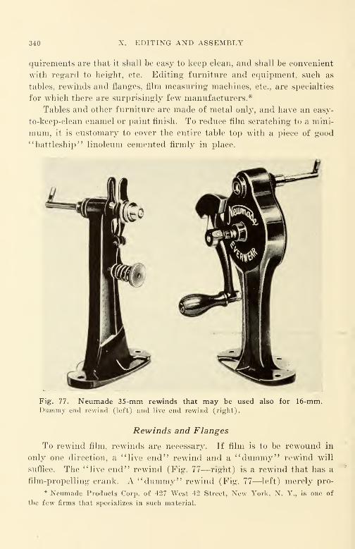
340 X. EDITING AND ASSEMBLY
quirements are that it shall be easy to keep clean, and shall be convenient
with regard to height, etc. Editing furniture and equipment, such as
tables, rewinds and flanges, film measuring machines, etc., are specialties
for which there are surprisingly few manufacturers.*
Tables and other furniture are made of metal only, and have an easy-
to-keep-clean enamel or paint finish. To reduce film scratching to a mini-
mum, it is customary to cover the entire table top with a piece of good
"battleship" linoleum cemented firmly in place.
Fig. 77. Neumade 35-mm rewinds that may be used also for 16-mm.Dummy end rewind (left) and live end rewind (right).
Rewinds and Flanges
To rewind film, rewinds are necessary. If film is to be rewound in
only one direction, a "live end" rewind and a "dummy" rewind will
suffice. The "live end" rewind (Fig. 77—right) is a rewind that has a
film-propelling crank. A "dummy" rewind (Fig. 77—left) merely pro-
* Neumade Products Corp. of 427 West 42 Street, New York, N. Y., is one of
the few firms that specializes in such material.
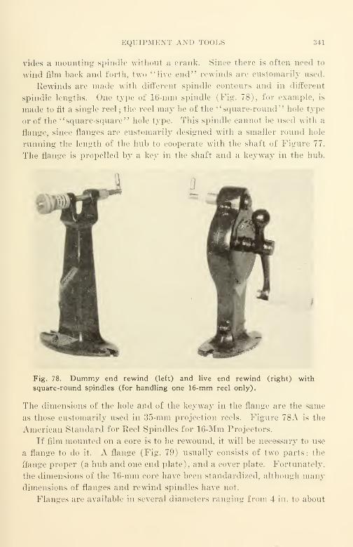
EQUIPMENT AND TOOLS 34]
vides a mounting spindle without a crank. Since there is often need to
wind film hack and forth, two "live end" rewinds are customarily used.
Rewinds arc made with different spindle contours and in different
spindle lengths. One type of 16-mm spindle (Fig. 78), for example, is
made to fit a single reel ; the reel may be of the " square-round" hole type
or of the "square-square" hole type. This spindle cannot he used with a
flange, since flanges are customarily designed with a smaller round hole
running the length of the hub to cooperate with the shaft of Figure 77.
The flange is propelled by a key in the shaft and a keyw7ay in the hub.
.-. ,\$
Fig. 78. Dummy end rewind (left) and live end rewind (right) with
square-round spindles (for handling one 16-mm reel only).
The dimensions of the hole and of the keyway in the flange are the same
as those customarily used in 35-mm projection reels. Figure 78A is the
American Standard for Reel Spindles for 16-Mm Projectors.
If film mounted on a core is to be rewound, it will be necessary to use
a flange to do it. A flange (Fig. 79) usually consists of two parts: the
ftange proper (a hub and one end plate), and a cover plate. Fortunately.
the dimensions of the 16-mm core have been standardized, although manydimensions of flanges and rewind spindles have not.
Flanges are available in several diameters ranging from 4 in. to about
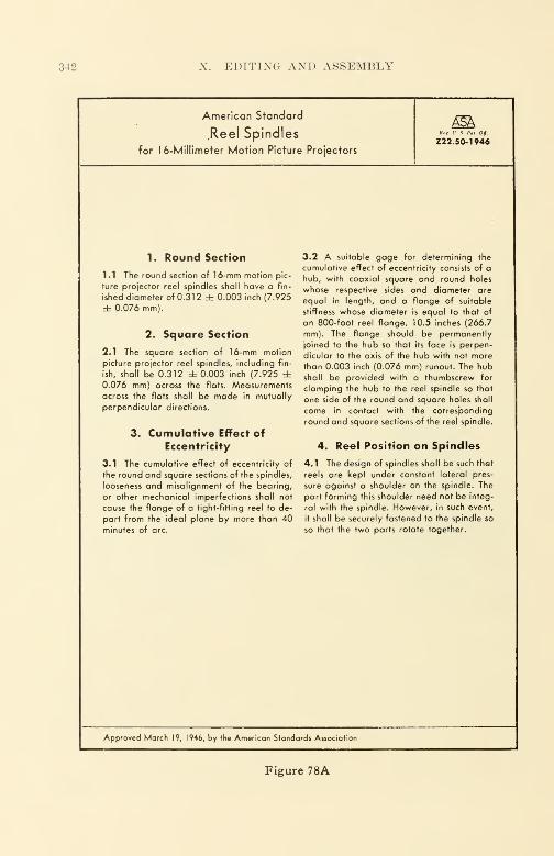
342 X. EDITING AND ASSEMBLY
American Standard
Reel Spindles
for 16-Millimeter Motion Picture ProjectorsZ2 2. 50- 1946
1. Round Section
1.1 The round section of 16-mm motion pic-
ture projector reel spindles shall have a fin-
ished diameter of 0.312 ± 0.003 inch (7.925
± 0.076 mm).
2. Square Section
2.1 The square section of 16-mm motion
picture projector reel spindles, including fin-
ish, shall be 0.312 db 0.003 inch (7.925 ±0.076 mm) across the flats. Measurements
across the flats shall be made in mutually
perpendicular directions.
3. Cumulative Effect of
Eccentricity
3.1 The cumulative effect of eccentricity of
the round and square sections of the spindles,
looseness and misalignment of the bearing,
or other mechanical imperfections shall not
cause the flange of a tight-fitting reel to de-
part from the ideal plane by more than 40minutes of arc.
3.2 A suitable gage for determining the
cumulative effect of eccentricity consists of a
hub, with coaxial square and round holes
whose respective sides and diameter are
equal in length, and a flange of suitable
stiffness whose diameter is equal to that of
an 800-foot reel flange, 10.5 inches (266.7
mm). The flange should be permanently
joined to the hub so that its face is perpen-
dicular to the axis of the hub with not morethan 0.003 inch (0.076 mm) runout. The hubshall be provided with a thumbscrew for
clamping the hub to the reel spindle so that
one side of the round and square holes shall
come in contact with the corresponding
round and square sections of the reel spindle.
4. Reel Position on Spindles
4.1 The design of spindles shall be such that
reels are kept under constant lateral pres-
sure against a shoulder on the spindle. The
part forming this shoulder need not be integ-
ral with the spindle. However, in such event,
it shall be securely fastened to the spindle so
so that the two parts rotate together.
Approved March 19, 1946, by the American Standards Association
Figure 78A
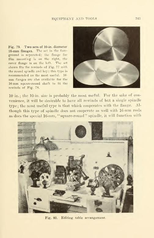
EQUIPMENT AND TOOLS 343
Fig. 79. Two sets of 10-in. diameter
16-mm flanges. The sot in the fore-
ground is separated; the flange for
film mounting is on the right, the
cover flange is on the left. The set
shown fits the rewinds of Fig. 77 with
the round spindle and key ; this type is
recommended as the most useful. 16-
mm flanges are also available for the
16-mm square-round shaft to fit the
rewinds of Fig. 78.
10 in. ; the 10-in. size is probably the most useful. For the sake of con-
venience, it will be desirable to have all rewinds of but a single spindle
type ; the most useful type is that which cooperates with the flange. Al-
though this type of spindle does not cooperate as well with 16-mm reels
as does the special 16-mm, "square-round" spindle, it will function with
Fig. 80. Editing table arrangement.
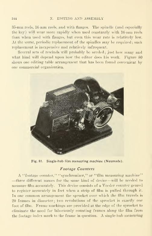
344 X. EDITING AND ASSEMBLY
35-mm reels, 16-mm reels, and with flanges. The spindle (and especially
the key) will wear more rapidly when used constantly with 16-mm reels
than when used with flanges, but even this wear rate is relatively low.
At the worst, periodic replacement of the spindles may be required ; such
replacement is inexpensive and relatively infrequent.
Several sets of rewinds will probably be needed;just how many and
what kind will depend upon how the editor does his work. Figure 80
shows one editing table arrangement that has been found convenient by
one commercial organization.
Fig. 81. Single-hub film measuring machine (Neumade).
Footage Counters
A i 'footage counter," "synchronizer,
—three different names for the same kind of device—will be needed to
measure film accurately. This device consists of a Veecler counter geared
to register accurately in feet when a strip of film is pulled through it.
In one common arrangement the sprocket over which the film travels is
20 frames in diameter; two revolutions of the sprocket is exactly one
foot of film. Frame markings are provided at the edge of the sprocket to
eliminate the need for laboriously counting frames along the film from
the footage index mark to the frame in question. A single-hub measuring
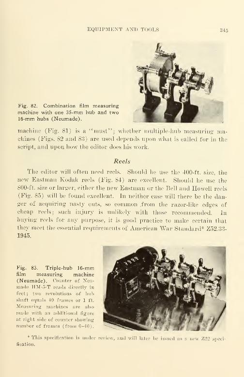
EQUIPMENT AND TOOLS 345
Fig. 82. Combination film measuring
machine with one 35-mm hub and two16-mm hubs (Neumade).
machine (Fig. 81) is a "must"; whether multiple-hub measuring ma-chines (Figs. 82 and 83) are used depends upon what is called for in the
script, and upon how the editor does his work.
Reels
The editor will often need reels. Should he use the 400-ft. size, the
new Eastman Kodak reels (Fig. 84) are excellent, Should he use the
800-ft. size or larger, either the new Eastman or the Bell and Howell reels
(Fig. 85) will be found excellent. In neither case will there be the dan-
ger of acquiring nasty cuts, so common .from the razor-like edges of
cheap reels; such injury is unlikely with those recommended. In
buying reels for any purpose, it is good practice to make certain that
they meet the essential requirements of American War Standard* Z52.33-
1945.
Fig. 83. Triple-hub 16-mmfilm measuring machine(Neumade). Counter of Neu-made IIM-5-T reads direct 1\ in
feet; two revolutions of hubshaft equals 40 frames or 1 ft.
Measuring machines are also
made with an additional figure
at right side of counter showing
number of frames (from 0-40).
* This specification is under review
fication.
md will later be issued as a new 7,22 speci-
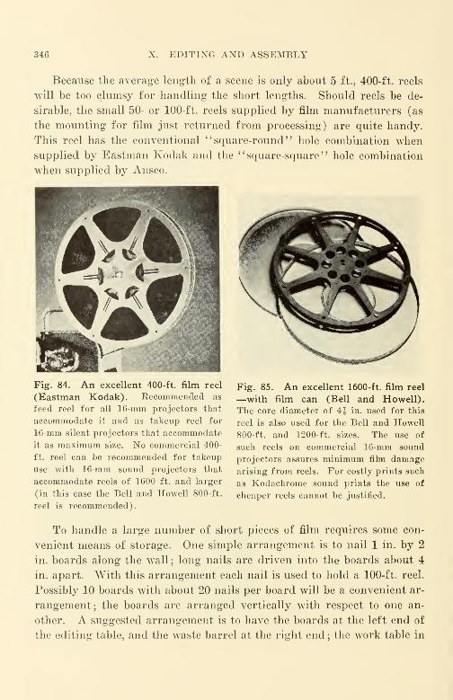
346 X. EDITING AND ASSEMBLY
Because the average length of a scene is only about 5 ft., 400-ft. reels
will be too clumsy for handling the short lengths. Should reels be de-
sirable, the small 50- or 100-ft. reels supplied by film manufacturers (as
the mounting for film just returned from processing) are quite handy.
This reel has the conventional " square-round " hole combination whensupplied by Eastman Kodak and the " square-square " hole combination
when supplied by Ansco.
Fig. 84. An excellent 400-ft. film reel
(Eastman Kodak). Eecomrnended as
feed reel for all 16-mm projectors that
accommodate it and as takeup reel for
16-mm silent projectors that accommodate
it as maximum size. No commercial 400-
ft. reel can be recommended for takeup
use with 16-mm sound projectors that
accommodate reels of 1600 ft. and larger
(in this case the Bell and Howell 800-ft.
reel is recommended).
Fig. 85. An excellent 1600-ft. film reel
—with film can (Bell and Howell).
The core diameter of 4| in. used for this
reel is also used for the Bell and Howell
800-ft. and 1200-ft. sizes. The use of
such reels on commercial 16-mm sound
projectors assures minimum film damagearising from reels. For costly prints such
as Kodachrome sound prints the use of
cheaper reels cannot be justified.
To handle a large number of short pieces of film requires some con-
venient means of storage. One simple arrangement is to nail 1 in. by 2
in. boards along the wall ; long nails are driven into the boards about 4
in. apart. With this arrangement each nail is used to hold a 100-ft. reel.
Possibly 10 boards with about 20 nails per board will be a convenient ar-
rangement; the boards are arranged vertically with respect to one an-
other. A suggested arrangement is to have the boards at the left end of
the editing table, and the waste barrel at the right end ; the work table in
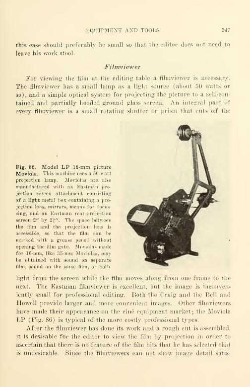
EQUIPMENT AND TOOLS 347
this case should preferably be small so that the editor does not need to
leave his work stool.
Filmviewer
For viewing the film at the editing table a filmviewer is necessary.
The filmviewer has a small lamp as a light source (about 50 watts or
so), and a simple optical system for projecting the picture to a self-con-
tained and partially hooded ground glass screen. An integral part of
every filmviewer is a small rotating shutter or prism that cuts off the
Fig. 86. Model LP 16-mm picture
Moviola. This machine uses a 50-watt
projection lamp. Moviolas are also
manufactured with an Eastman pro-
jection screen attachment consisting
of a light metal box containing a pro-
jection lens, mirrors, means for focus-
sing, and an Eastman rear-projection
screen 2" by 2 J". The space between
the film and the projection lens is
accessible, so that the film can be
marked with a grease pencil without
opening the film gate. Moviolas madefor 16-mm, like 35-mm Moviolas, maybe obtained with sound on separate
film, sound on the same film, or both.
light from the screen while the film moves along from one frame to the
next. The Eastman filmviewer is excellent, but the image is inconven-
iently small for professional editing. Both the Craig and the Bell and
Howell provide larger and more convenient images. Other filmviewers
have made their appearance on the cine equipment market ; the Moviola
LP (Fig. 86) is typical of the more costly professional types.
After the filmviewer has done its work and a rough cut is assembled,
it is desirable for the editor to view the film by projection in order to
ascertain that there is no feature of the film bits that he has selected that
is undesirable. Since the filmviewers can not show image detail satis-
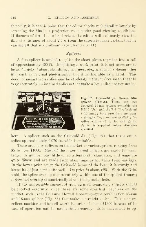
348 X. EDITING AND ASSEMBLY
factorily, it is at this point that the editor checks such detail minutely by
screening the film in a projection room under good viewing conditions.
If fineness of detail is to be checked, the editor will ordinarily view the
film at a distance of about 2.5 w from the screen to make certain that he
can see all that is significant (see Chapter XIII).
Splicers
A film splicer is needed to splice the short pieces together into a roll
of approximately 400 ft. In splicing a work print, it is not necessary to
be as "finicky" about cleanliness, neatness, etc., as it is in splicing other
film such as original photography, but it is desirable as a habit. This
does not mean that a splice may be carelessly made ; it does mean that the
very accurately maintained splicers that make a hot splice are not needed
Fig. 87. Griswold Jr. 16-mm film
splicer (HM-6). There are two
Griswold 16-mm splicers available, the
HM-6 (Jr.) and the R-3 (Professional
8-16 mm) ; both provide a non-sym-
metrical splice ; and are available for
splice widths of to in - and TV in.
iV in. is supplied unless otherwise
specified.
here. A splicer such as the Griswold Jr. (Fig. 87) that turns out a
splice approximately 0.070 in. wide is suitable.
There are many splicers on the market at various prices, ranging from
$5 to over $1000. Most of the lower priced splicers are made for ama-
teurs. A number pay little or no attention to standards, and some are
quite flimsy and are made from stampings rather than from castings.
In the lower price range the Griswold is one of the best ; it is sturdy and
keeps its adjustment quite well. Its price is about $20. With the Gris-
wold, the splice overlap occurs entirely within one of the spliced frames
;
it does not overlap symmetrically about the sprocket hole.
If any appreciable amount of splicing is contemplated, splicers should
be checked carefully, since there are some excellent machines on the
market, such as the Bell and Howell laboratory-type combination 35-mm
and 16-mm splicer (Fig. 88) that makes a straight splice. This is an ex-
cellent machine and is well worth its price of about $1 300 because of its
ease of operation and its mechanical accuracy. It is convenient to op-
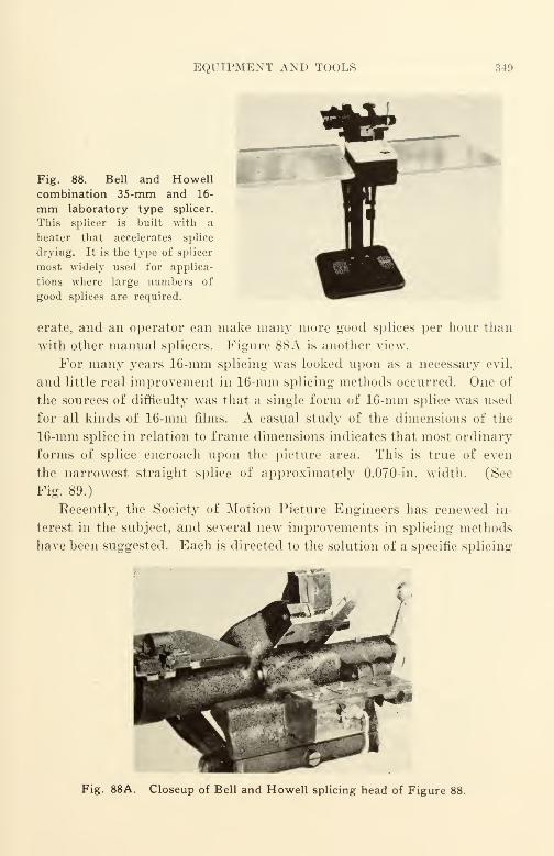
EQUIPMENT AND TOOLS 349
Fig. 88. Bell and Howellcombination 35-mm and 16-
mm laboratory type splicer.
This splicer is built with a
heater that accelerates splice
drying. It is the type of splicer
most widely used for applica-
tions where large numbers of
good splices are required.
erate, and an operator can make many more good splices per hour than
with other manual splicers. Figure 88A is another view.
For many years 16-mm splicing was looked upon as a necessary evil,
and little real improvement in 16-mm splicing methods occurred. One of
the sources of difficulty was that a single form of 16-mm splice was used
for all kinds of 16-mm films. A casual study of the dimensions of the
16-mm splice in relation to frame dimensions indicates that most ordinary
forms of splice encroach upon the picture area. This is true of even
the narrowest straight splice of approximately 0.070-in. width. (See
Fig. 89.)
Recently, the Society of Motion Picture Engineers has renewed in-
terest in the subject, and several new improvements in splicing methods
have been suggested. Each is directed to the solution of a specific splicing
Fig. 88A. Closeup of Bell and Howell splicing head of Figure 88.
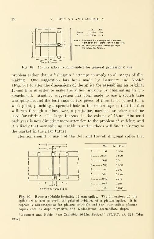
350 EDITING AND ASSEMBLY
A(max) 0070 178
B.... 0.600 15.24
Note A. Dimension A is moxirsum and a narrower
width splice of adequate strength is desirable.
Note B. The straight splice is symmetrical about
the included perforation.
Straight Splice
Fig. 89. 16-mm splice recommended for general professional use.
problem rather than a ''shotgun" attempt to apply to all stages of film
making. One suggestion has been made by Baumert and Noble*
(Fig. 90) to alter the dimensions of the splice for assembling an original
16-mm film in order to make the splice invisible by eliminating its en-
croachment. Another suggestion has been made to use a scotch tape
wrapping around the butt ends of two pieces of films to be joined for a
work print, punching a sprocket hole in the scotch tape so that the film
will run through a filmviewer, a projector, moviola, or other machine
used for editing. The large increase in the volume of 16-mm film used
each year is now directing more attention to the problem of splicing, and
it is likely that new splicing machines and methods will find their way to
the market in the near future.
Mention should be made of the Bell and Howell diagonal splice that
ffl
fr- -ml -¥-
^ E-d Ab F^Splice area - 023 sq. in.
Mm. Inch Equiv
A__. 1.99 0.079
B-_. 15.24 0.600
C— 9.42 0.31
D___— 7.82 308
E— - 7-41 292
F___ 5.81 0.229
6— 0.40 0.016
H 9,67 0.381
J___ 3.16 0.1245
Fig. 90. Baumert-Noble invisible 16-mm splice. The dimensions of this
splice are chosen to avoid the printed evidence of a picture splice. It is
especially advantageous for picture originals and for intermediate picture
copies such as dupe negatives and Kodachrome intermediate dupes.
•Baumert and Noble "An Invisible 16-Mm Splice," JSMPE, 49, 232 (Mar.
1947).

CUTTING THE ORIGINAL 351
is made by certain of the Bell and Howell laboratory splicing machines.
This splicer has found some favor for 35-mm sound track, but not equally
for 16-mm sound track. A diagonal splice should never be used in an
original film ; opinion as to its use in release prints is divided, since the
splice appears diagonally across the frame of the picture and causes a
"flash" on the screen as it passes through the picture gate of the pro-
jector. The present trend seems to be away from diagonal splices in
16-mm.
Film Cement
To splice film requires film cement. Because of the differences in
chemical composition and properties, film-base materials made by differ-
ent manufacturers do not adhere equally well when cemented with differ-
ent film cements. Eastman safety film cement should be used for East-
man film ; for other films, information may be obtained by writing the
manufacturer.*
Cutting the Original
Cutting the original to match the edited work print is done with
gloves—in both the figurative and in the literal sense. The original is
never handled with bare hands because of the dirt, oil, and other con-
taminants always found on even the cleanest hands ; a pair of clean, soft,
washable, cotton gloves is used. An active editor will use several pairs
of gloves in a day, making certain that the gloves are carefully laundered
once they have been used. Needless to say gloves should be lint-free so
that there will be no foreign matter present which may affect the original
film. If all editing has been very carefully done and all film in the work
print and all related film in the original can be identified, it is better
practice for the inexperienced not to touch the original at all. It should
be taken to the commercial film laboratory for assembly and cutting of
the original. It is customary to charge for such labor at a cost of several
dollars per hour, but it is well worth it. Experience in handling film maybe acquired by watching the laboratory personnel, who are active and
quick and who have through experience worked out a number of rule-of-
thumb methods of handling film with the least effort and with the least
film damage. Care should be exercised that the film is left only in a
spotless plant that has spic-and-span personnel.
* The excellent Eastman booklet The Handling, Repair, and Storage of 16-MmFilms (KP 2-45) should he in the hands of anyone who has occasion to make splices.
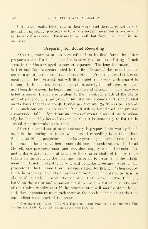
352 X. EDITING AND ASSEMBLY
Cutters especially take pride in their work, and there need not be any
hesitation in asking questions as to why a certain operation is performed
in the way it was done. Their neatness in all that they do is legend in the
industry.
Preparing for Sound Recording
After the work print has been edited into its final form, the editor
prepares a shot list.* The shot list is merely an accurate listing of each
scene in the film arranged in correct sequence. The length measurement
in feet and frames accumulated to the first frame of the scene listed is
noted in addition to a brief scene description. From this shot list a com-
mentary can be prepared that will fit the picture exactly with regard to
timing. In this listing, the scene length is merely the difference in meas-
ured length between the beginning and the end of a scene. The time cue
listed is merely the time equivalent to the measured length at the begin-
ning of a scene ; it is indicated in minutes and seconds and is calculated
on the basis that there are 40 frames per foot and 24 frames per second.
Since such conversions are made often, it will be found useful to prepare
a conversion table. Synchronism errors of even 0.1 second can occasion-
ally be detected by keen observers, so that it is customary to list tenth-
second time intervals in the table.
After the sound script or commentary is prepared, the work print is
used in the scoring projector when sound recording is to take place.
Since most 16-mm projectors do not have geared synchronous motor drive,
they cannot be used without some addition or modification. Bell and
Howell, one projector manufacturer, does supply a small synchronous
motor drive that can be attached to the shutter shaft of the projector
that is on the front of the machine. In order to assure that the attach-
ment will function satisfactorily it will often be necessary to return the
projector to the Bell and Howell service station for fitting. When record-
ing is in progress, it will be unnecessary for the commentator to turn his
glance alternately between the script and the screen. The time cue
listed on the script and a convenient stop watch satisfactorily take care
of the timing requirement if the commentator will merely start the de-
scription or comment upon each scene at the precise moment that the time
cue indicates the start of the scene.
* Clemenger and Wood, "16-Mm Equipment and Practice in Commercial Film
Production, JSMPE, 34, 555 (June 1940) (see Fig. 75).

PREPARING FOR SOUND RECORDING 353
When recording is under way, it is well to remember that it is usually
far easier to get the film timing correct during the recording session than
it is to attempt to correct it by " juggling* ' the sound track later on.
16-mm sound cutting is unsatisfactory at best ; not only is good blooping
a serious problem if the editor must rely upon paint-outs (as he usually
does), but also the relatively long spacing between sprocket holes makes it
next to impossible to alter syllables as can be done occasionally with
35-mm film.
Synchronizing Sound and Picture
To avoid confusion, a standard system of marking the picture film and
the sound film for synchronism has been established.* The editor is
responsible for the synchronization of the picture film and of the sound
film, and when synchronization has been established, the standard marks
should appear on the work print of the picture and the work print of
the sound track. Once these marks have been transferred to the cut
originals no difficulty with synchronization should be experienced, since
errors in printing and other laboratory operations (should they occur)
can be traced readily.
No pre-view head arrangement for checking the ''syncing" of sepa-
rate picture and track is as yet available on the open market. Several ar-
rangements are workable ; a good suggestion is to check with the com-
mercial film laboratory that will do your release printing. They may not
have the equipment that you need, but they can make a number of useful
suggestions.
In the foregoing, the subject of titles for the film and effects for the
film (should they be needed) has not been discussed. Titles can be quite
"arty" and expensive, and they can also be simple and inexpensive. Agood title requires good art work and good title camera work. There are
numerous specialists in most every locality.
In conclusion, a remark made earlier in this chapter bears repetition
:
the editor is the forgotten man of motion pictures. There are no stand-
ard methods or apparatus for editing a motion picture. Many of the
things that the editor needs, he will have to build himself or have someone
else build for him ; if he doesn't, he'll do without. Manufacturers would
do well to hearken to the needs of this no-man's land of motion pictures;
the equipment of the cutting room needs scrutinizing—and improvement.
* American War Standard Z52.53-1945.

354 X. EDITING AND ASSEMBLY
Selected Bibliography
1936-19451
< Editing, '' pages 85 and 86.
Collected Papers on Navy Training Films, Goldner, Eoberts, Dresser et dl. JSMPE,43 (Nov. 1944).
For additional references the reader should refer to the following indexes to the
Journal of the Society of Motion Picture Engineers.
January 1930-December 1935
"Editing," page 23.

CHAPTER XI
Preservation and Storage
Introduction
If past experience may be considered a guide, most film makers under-
estimate the usefulness of the films they have made. On the whole, the
film maker customarily thinks only in terms of an immediate need for a
particular film. The result of this lack of foresight is the lack of avail-
ability of prints of good technical quality from older subjects. In too
many cases the result is the lack of any prints whatsoever because of the
loss of the original or because the original is so badly damaged that it will
not even go through a printer. Frantic and unsuccessful hunting for an
unmarred print of a subject as little as two years after the date of its
completion has been all too common an occurrence in 16-mm films. It
has been somewhat less common in 35-mm films, in all likelihood because
35-mm are nitrate-base films that must be stored in fireproof vaults.
Many 35-mm films would probably also receive the'
' out of sight, out of
mind" treatment if the fire laws did not demand storage with suitable
protection against fire.
It has been said that the maturity of an age can be judged quickly
by the amount of recorded material that is purposefully preserved for a
future time. The very rapid growth of the use of photography and its
familiarity to almost every citizen through the still camera, through the
motion picture camera, or through the commercial movies, is beginning
to usher in a new era in the recording of history, an era of purposefully
recording in films the ideas that we wish to convey to others of our owngeneration and to generations to come. Even family histories are nowbeginning to be recorded in home color movies—supplementing the fa-
miliar family photograph album.
Often a film starts out as a personal thing and concerns but a single
person or a very small group. If the film records information of interest
to a large number (as is often the case, e.g., in hobby films), it should be
available to a larger group. If it is of scientific interest, for example,
there is a British organization, the Scientific Film Association, that is
355
356 XI. PRESERVATION AND STORAGE
interested in reviewing it and in obtaining a copy for free distribution
to its members through its central library regardless of the country of
origin. More recently, a Canadian Scientific Film Association was
founded, and an international association was recently established.
Present Status
If material is to be preserved, there must be a plan to accomplish the
preservation. Ordinarily, we are so concerned with matters of the mo-
ment that seem so much more pressing, that the question of preservation
of the original receives little attention that results in beneficial action.
The major national preservation efforts in the United States are those
of the Museum of Modern Art and of the National Archives ; both have
been in operation for more than a decade. More recently, the Library
of Congress has instituted an acquisition program to broaden the scope
of the Government collection and its functions. With regard to special-
ized films made by individual investigators, however, no solution is being
considered in these organizations, not only because of meager budgets,
but also because they have not yet been able to concern themselves with
films that have a specialized and limited scope of interest. Such films are
but one of a large variety of nontheatrical films with long-term value.
Preservation over long periods of time is a subject beyond the scope
of this book. Preservation over shorter periods of 5 to 10 years, for ex-
ample, can be accomplished with relatively simple measures. These will
be described in broad outline.
Preservation of the Original
Handling of the original should be kept to an absolute minimum.
The original should never be run in a projector. A film that is handled
carelessly will not last even six months; too often an original has been
torn to shreds before it has outlived its usefulness. The primary cause
is that the deterioration caused in each handling is uncontrolled and often
even unknown.
Too often the owner of an original places the priceless original in the
custody of a film laboratory or other nominal caretaker, where each
handling causes deterioration the extent of which is unknown. Too often
the accumulated effect of individual handlings only becomes evident when
an attempt is made to project a newly made print on a screen somewhat
larger and brighter than usual, or under other more critical projection

THEEE STAGES OF STORAGE 357
conditions. At this point, however, nothing can be done about it and the
projection is not as satisfactory as it should be.
Three Stages of Storage
Webster's dictionary defines "preservation" as the act or process of
preserving or keeping from injury or decay. In terms of a 16-mm film.
the objective, therefore, is "to keep and save the originals from injury
and decay" and, at the same time, provide copies for use that are derived
from the originals. It therefore follows that the release prints shall be
made from intermediate copies during the period when the originals are
in suitable storage.
Th e general method is not new; a modification of it has been used for
years by the entertainment motion picture industry. Briefly, there are
three stages of storage.
Stage 1. The originals (in the custody of the owner) are in "dead" storage
under suitable conditions. (Temperature constant—maintained in the range from
40° to 50° F.)
Stage 2. The intermediate copies (in the custody of the laboratory or other
processor) are in "live" storage under the most suitable conditions practicable, yet
assuring their ready availability for the making of release prints. The intermediate
copies are used to provide release prints.
Stage 3. The release prints are available for ready use for distribution yet stored
under the most suitable conditions practicable 1—consistent with ready availability.
(Temperature changes above room temperature, especially, to be avoided where pos-
sible.)
In each stage listed, responsibility for storage falls upon the indi-
viduals logically responsible. The owners are responsible for the origi-
nals, the laboratory is responsible for the intermediate copies, and the
library or other user is responsible for the prints. This arrangement has
all the advantages of the customary handling of "protection prints," with
the further advantage that possible damage or loss is anticipated.
Mechanics of the Method
The mechanics of the method are simple. Once each year the orig-
inals are withdrawn from storage. The film owner at that time advises
the laboratory or processor of the probable requirements for release prints
for the forthcoming year. The laboratory is then asked to make up all
intermediate copies required for a full year's operation; these are printed
or otherwise derived directly from the originals. All intermediate copies
are made up at one time.
338 XI. PRESERVATION AND STORAGE
As soon as the intermediate copies are completed, the originals are
returned to the owner for Stage 1 storage for the forthcoming year. This
storage presumes the best conditions possible, but are rarely assured
merely by the appearance of a warehouse bill once each month. For16-mm originals, storage may be quite simple, and suitable conditions will
be described later in this chapter. The important feature of the method
is that the originals shall remain in dead storage for a very long time
compared with the time that they are in use. Storage for 51 weeks of
a year and use during one week of the year would represent a typical
schedule.
It may Avell happen that the owner of a film will underestimate (or
overestimate) his probable need for prints during a particular year.
This does not void the usefulness of the method if the film remains in dead
storage for a large percentage of the time. If accurate records are kept
for a year or two, it will be surprising how accurately the need for a par-
ticular film may be estimated.
Print Quality
It should be obvious that consistent quality should be' expected in all
prints manufactured, not merely good prints in the sample first lot.
With the original suitably preserved and with one acceptable reference
print of the subject on hand in the library, it should be an easy matter to
check the quality of release prints made by one laboratory with those of
another, or to check the quality obtained at one time with that obtained
at another. Because an original is often edge-notched* for release print-
ing and there is no standardization of either the size or of the relative lo-
cation of a printing notch, it is wise to select, and remain with, the best
possible film laboratory for your work.
As has been pointed out in an earlier chapter, there is a serious loss
of print quality in every step in making a release print. The sug-
gested method of preservation implies two additional generations of
prints, the intermediate copy made directly from the original, the second
generation, and the release print, the third generation. Unless good
practices and control are used, the quality of a third generation print is
likely to be poor. Even though the minimum losses in each copying and
processing step are quite high, good print quality can still be obtained
* An original film is edge-notched in release printing for the purpose of actuating
a sensitive switch, controlled by a roller that rides the edge of the film, which switch
causes the light-change mechanism of the printing machine to function.
PRINT QUALITY 359
if the original was of excellent quality and if fine-grain films are used
under optimal conditions; good print quality cannot be obtained if there
is carelessness or poor control. The importance of control is especially
important in making third generation color prints ; it must be quite pre-
cise to obtain satisfactory prints. Not only is the resolving power of color
film appreciably less than that of the black-and-white film, but also the
human eye has greater sensitivity to small color differences than it has
to small intensity differences. Since the only step in the print-making
process under the control of the commercial laboratory is the exposure of
the copy, every step must be taken to reduce resolving power losses in
color printing to a minimum and to obtain accurate exposure control both
as to intensity and as to chromatic quality. Good, or even acceptable,
third generation color prints are quite rare. Where they are obtained,
good control has been exercised, and in all likelihood the colors to be dif-
ferentiated are well separated in the spectrum, and located somewhat
centrally in the three color band ranges.
If the duplicating process is not under very close day-to-day control,
it may not be possible to produce satisfactory third generation prints.
Should this be the case, it would then be necessary to make all the prints
desired at one time for the yearly period, storing the original for the
remainder of the year under proper conditions as soon as printing is
completed.
Number of Copies from an Original
Before determining the number of copies that can be made from any
particular original, it is well to review what determines the end point
in the life of an original film, and how it is affected by printing or other
copying procedures.
One of the sources of film deterioration is the deterioration that will
occur while the film lies unused on the shelf. This deterioration, although
cumulative, is very slow with present-day safety films that have been
stored properly. The major source of deterioration of a film in constant
demand and use is wear and tear that results from handling. This is the
important source in the average case in which a large number of prints
is required.
When a film is handled for editing and splicing, it acquires minute
scratches and abrasions that are likely to be serious if the film has
been handled carelessly. In addition, every time the film is removed
from its can for printing it acquires further scratches and abrasions.
360 XI. PRESERVATION AND STORAGE
Before it is actually printed, it should be cleaned. Cleaning consists of
wiping away the surface dust and dirt with very good facial tissue (simi-
lar in quality to lens tissue) soaked in carbon tetrachloride. The tissue
is usually folded in a piece of silk velvet to prevent the hand of the cleaner
from touching the film. When the film has been satisfactorily cleaned in
this manner, it is rubbed once more with the silk velvet to remove traces
of lint that may have been left behind by the tissue.
Each such handling adds additional tiny scratches and abrasions to
the film. Some laboratories do not bother to clean the film before it is
printed, and the dirt accumulated by the original is copied onto all sub-
sequent prints. Other laboratories try to use machine cleaning, but, un-
fortunately, there are very few cleaning machines that do not add
scratches and abrasions far more quickly than the laborious and more ex-
pensive hand cleaning. In any event, every handling adds deterioration
;
the amount of deterioration varies with the cleanliness of the place in
which the film is handled and the skill and care of its personnel.
The operations of the laboratory—particularly in the printing room
—
add their important share to the scratches and abrasions added to the
film. If the film path is not kept scrupulously clean and the hardened
stainless steel gate or chromium-plated film path with which the film is
in contact is not kept mirror-smooth, still more scratches and abrasions
are added. A particle of dirt lodged in the film gate of a printer does
just as much damage as a like particle of dirt lodged in the gate of a
camera; it scratches the film as a diamond cuts a piece of glass. If the
machine starts with a jerk or has been improperly threaded, a large
amount of damage is done in a single trip through the printer.
The printing room can add still more mars by its manner of handling
the precious film. In some laboratories the printers run in only one direc-
tion. When the end of a reel is reached, the film must be rewound—usu-
ally in the dark—in order to make the next print. Rewinding is done by
hand or by machine. Hand rewinding is slow and tedious if it is well done,
and is costly in terms of labor. Rewinding by machine is usually faster
and less costly, but is usually considerably more damaging than the
printing operation itself. Although printer operators are quite careful,
the amount of scratching and abrasion added to the film by a rewinding,
however accomplished, and by the threading of the machine is ordinarily
appreciably greater than that added when the film is run through the
printer several times. If a machine runs at high speed, it is far
PRINT QUALITY 361
more likely to mar the film, all other things being equal, than if it runs
at low speed. High-speed operation of printers is very common today
as will be noted in the next chapter; this is usually necessary to bring
down print prices.
It is apparent from the foregoing that the cumulative deterioration
that occurs with each step of film handling is most important. Generally
speaking, the end-point of a film is reached when it is scratched, abraded,
and otherwise physically damaged to a certain arbitrary point beyond
which it is not suitable for making prints. The deterioration per unit
handling varies over very wide ranges from laboratory to laboratory and
often varies over wide ranges at different times. Unfortunately, there is
no simple standard measure by which this deterioration can be measured.
Because it is cumulative and gradual, its presence is rarely appreciated
until too late.
Some laboratories have made 50 copies of a particular piece of film
before deterioration began to be noticeable and the end-point was reached.
More recently, as many as 200 to 300 copies have been made under similar
conditions. With really good care and with the elimination of almost
every possible source of avoidable deterioration, as many as 700 to 800
copies of a particular piece have been made. If the picture quality on
test prints proves satisfactory, it is obvious in the first ease that for a
third generation print, 50 times 50 or 2500 prints would be possible.
For the laboratory where 250 copies were made, 250 times 250 or 62,500
prints would be possible. In that very, very rare laboratory under rare
conditions where 800 prints were made, 800 times 800 or 640,000 prints
would be possible. AVhat is extremely important is to keep the quality
loss at an absolute minimum between the original and the intermediate
copies, so that third generation prints are satisfactory for release prints.
In this manner, any ordinary film, if the original is properly preserved,
can be expected to provide all the release prints that may be required of it
during its ordinary useful life. This is in sharp distinction to the too-
frequent situation in which valuable originals are irretrievably ruined in
as little as six months of their useful life. In practice, almost any labora-
tory should be able to turn out 50 copies from a particular piece of newfilm without reaching the life end-point. How much farther a particular
laboratory can go depends in great measure upon how important care in
film handling is considered, and how much time and effort are spent to
obtain the desired result,
362 XI. PRESERVATION AND STORAGE
Storage Recommendations
It is advisable to follow the recommendations of film manufacturers
closely. For Kodachrome, it is first necessary to clean the film lightly
yet thoroughly; carbon tetrachloride (Carbona) applied sparingly is
probably the best cleaning agent. After cleaning, the film should be
wound firmly and smoothly on a core without cinching, and placed in an
ordinary metal film can. Cleaning and packing is best done in a dust-
free air-conditioned room where the temperature is near 65° or 70°F.
and the relative humidity near 40%.The film cans are identified and then sealed ; an adhesive tape is good
for the purpose, since it will seal the can quite thoroughly. A suggested
sealing would be two turns of "Scotch tape" on the underside and two
turns of Kodatape or similar adhesive over the "Scotch tape." It is
preferable to use film cans that do not have any holes; should holes be
present, it is necessary to seal them so that no moisture exchange mayoccur between the outside atmosphere and the atmosphere within the can.
The more thorough the seal, the slower the deterioration of the Koda-
chrome under the conditions specified. After sealing, the cans are placed
in an electric refrigerator or other cooled space where the temperature
can be maintained at 45° to 50°F. ; the temperature should be as nearly
constant as possible.
For the sound track original more elaborate precautions may need
to be employed ; this depends upon how well the original was developed.
Fortunately, the shrinkage and loss of flexibility with age of Eastman
5372 are not very serious if the film is kept well sealed. The major de-
terioration to be avoided is image deterioration which is aggravated byexcess residual hypo that results from insufficient and improper washing
of the film after developing and fixing. Another result of "cheap devel-
oping" to be avoided is improper drying. The most obvious cure for this
kind of situation is to have the film properly developed, washed, anddried when it is first developed in the laboratory.
The sound film should first be permitted to become moisture-stabilized
with the surrounding atmosphere of 65° or 70° F. and 40% relative
humidity. Film that is loosely wound and left in an unsealed can will
become moisture-stabilized in about 24 hours. When ready, the film
should be identified, and sealed* in the manner similar to that used for
Kodachrome.* These instructions do not apply to nitrate-base films. Under no circumstances
should nitrate base films be sealed, since the by-products of nitrate film deterioration
are toxic and explosive.

SELECTED BIBLIOGRAPHY 363
Even such a simple storage technique is adequate for safety-base
films such as 16-mm, since the additional effectiveness of further measures
is doubtful and costly. Until such time as the more complicated pro-
cedures justify their high costs, they may be looked upon with suspicion.
In storing color films such as Kodachrome and AnscoColor it should
be noted that the dyes of these films are fugitive. Deterioration is quite
slow if stored as recommended. In the event that long-term preservation
is needed, separation negatives may be made on a black-and-white film
such as Eastman 5203. Further information may be obtained directly
from the film manufacturer. It is usually a good plan to provide such
information as the emulsion lot number and emulsion number, and any
processing numbers that will establish the date on which the film was
processed and the particular color-developing laboratory concerned.
Manufacturers keep accurate manufacturing and processing logs of their
operations and can provide special suggestions should it become neces-
sary to compensate for some slight deviation from the theoretical norm.
Preservation plans should be made before the first camera exposes
the first frame of film. When this is done, the disappointment that
comes from the rapid and uncontrolled deterioration of the original is
avoided, and print consistency, usually next to impossible without suit-
able planning, becomes practicable. Preservation for a period of -5 to
10 years under the suggested conditions is practicable with present-day
materials. Should preservation over longer periods be desired, great
care in all handling and storage of the film will be required. Suggestions
on preservation should be sought in such cases from the manufacturers
of the film materials concerned.
Selected Bibliography
For bibliographic material the reader is referred to the following indexes to the
Journal of the Society of Motion Picture Engineers.
July 191 6-June 1930
"Film Preservation," page 128.
January 1930-December 1935
"Film Preservation," page 26.
"Film, Storage," page 26.
1936-1945
"Film, Storage and Preservation," page 92.
"SMPE Activities, Film Preservation Reports," page 128.
CHAPTER XII
Processing and Release Printing
Introduction
A reasonable way to think of the subject of processing and release
printing is to consider it as consisting of everything between that which
is on hand, the original picture and the original sound track, and that
which is wanted, the release prints.
The modern motion picture processing machine* is a device to trans-
port continuous lengths of motion picture film through the several chemi-
cal and physical operations that produce a permanent visible image
from the latent image impressed on the film during exposure.
In general, a laboratory represents the investment of a goodly sum of
money and also involves high fixed charges and overhead; therefore, it
is usually "geared up" for repetitive processes such as the making of
large numbers of release prints. Other activities are, for the most part,
merely aids in the manufacture of these release prints. Printing ma-
chines for release printing as well as developing machines usually op-
erate at high speed. To reduce handling, some laboratories have special
printing machines which will print forward and, after the film has run
through, will run rearward—thereby eliminating the need for rewinding
the films being copied. To reduce manual handling still further, another
feature is added; the special printer is also designed to print picture at
one aperture and sound at another aperture during a single operation.
In the mass release printing of 35-mm composite sound prints, labora-
tories have gone even farther; directionally reversible printers of com-
posite prints feed developing machines directly, and the developed prints
are inspected by high-speed inspection projectors which project the film
just developed. Over a decade ago the operating speed of one installa-
tion was about 150 ft. per minute for the developing machine which ran
at substantially constant speed; the printer ran at 180 ft. per minute
as did the inspection projector. The higher running speeds of the
printer and of the projector were necessary to allow for the removal of
printed rolls of film, and the installing of fresh rolls of raw stock in the
•Definition furnished by J. Stott.
364
PROCESSING AND RELEASE PRINTING 365
printer, and for the removal of inspected rolls of printed and developed
film from the inspection projector. This kind of operation is common in
the larger laboratories. Some of its features are now being adapted to
high-speed 16-mm release printing.
To increase machine output for the purpose of cutting printing costs
still further, one laboratory has built within its own organization special
multihead printers. One such machine causes the preprint film to run
successively through 7 different printing heads, at each of which a roll of
raw stock is printed; thus 7 prints are exposed in a single trip of the
preprint material through the printing machine.
Another expedient employed by the same laboratory is to make two
combined 16-mm dupe negatives side-by-side on the same film, using the
32-mm width to make a 32-mm release print. After the print comes off
the developing machine the 32-mm film is slit, providing two 16-mm
prints with the handling of but a single strip of film during the 32-mm
portions of the manufacturing process.
The trend in this direction is being accelerated by the relatively great
increase in film laboratory wages that has taken place in the last decade.
The price of release print raw stock for black-and-white printing has
changed relatively little during the last decade; more recently, prices
have moved upward. As competition tends to drive down print prices,
it is obvious that the saving must be made by sharply cutting the man-
hours of labor needed to produce release prints. 16-mm release prints
in bulk are now sold at lower prices than those of a decade ago despite
the large increases in labor cost and relatively smaller increases in the
costs of film, chemicals, electric power, water, and machinery. The ef-
fectiveness of the improved production efficiency due to methods and
equipment improvements, can hardly be challenged.
Because of the large number of operations that must be performed
in the making of a release print, it is imperative that manual handling be
reduced to an absolute minimum. This has reached the point where
price differences reflect strongly the amount of "can-carrying" or other
internal manual transport that goes on inside the laboratory.
Since laboratories are so cost-conscious, it is obvious that a film must
be completely and meticulously prepared for developing and printing
before it enters the release-printing operation proper. Errors must be
eliminated beforehand, because once the film is on its way, it becomes al-
most impossible to catch an error, because of the speed with which labora-
tory mechanical operations are performed. Thus, if a film has started
366 XII. PEOCESSING AND RELEASE PRINTING
through a developing machine, it is as good as developed; if it has
started through a printer, it is as good as printed. In the former case
it is not practicable to stop the machine to remove film that has
started through ; in the latter, while it is less difficult, it is still imprac-
ticable. In either case, no laboratory manager will permit an interrup-
tion of that extent in his production schedule.
A discussion of film manufacturers' laboratories and their internal
operations is beyond the scope of this book. Suffice it to say that they
are customarily very efficient organizations with facilities at their com-
mand that are the envy of the independent commercial laboratory. That
they are kept remarkably clean is evident in the cleanliness of the film
that they return to the owner after processing.
Despite their excellent facilities, significant differences occur among
presumably similar laboratories; smaller, yet important, differences oc-
cur from week to week for the same laboratory ; still smaller differences
occur from day to day, and still smaller yet measurable and noticeable
differences occur during a single day's run. The laboratory-to-laboratory
differences can be observed by photographing a single test scene (with no
change in view or other change during the scene), and sending a piece of
this test scene to each of the laboratories in which you are interested. Asingle test does not mean very much, however, if the purpose is to accom-
plish control, since the magnitude and the character of the differences
are, of course, independently variable.
Basic Functions of a Laboratory
Possibly the simplest way to determine what is needed in a laboratory
is to trace the movement of film around a plant. The film is received
in the receiving department where an entry is made in the plant records.
The planning department determines just what shall be done and the
manner in which it is to be done ; this is scheduled in accordance with the
order placed by the customer and by the needs of the film. The prepa-
ration department handles the film itself, and makes certain that all iden-
tifying marks needed to accomplish the required work are provided on
the film and that it has the necessary leaders, etc. ; this work closely
follows the instructions of the planning department. The developing
department develops the film ; the instructions of the film owner and the
supplementary instructions of the planning department usually specify
in writing just how the film is to be developed. If the film handled in the
preparation department was a negative or other film to be printed, the
BASIC FUNCTIONS OF A LABORATORY 367
preparation department provides the necessary printing marks and spe-
cial instructions to the printing department. The printing department
makes the copies as specified by the instructions of the planning depart-
ment ; should deviations from the normal procedure be required, the nec-
essary instructions are provided by the technical control department
which is responsible for technical coordination of the operation of the
plant. If the film printed is black and white, it goes to the developing
department where it is developed. After this, the film goes to the in-
spection department where it is inspected to make certain that the result
specified by the planning department has been obtained. If all has gone
well, the printed film then goes to the shipping department from which
point it is sent to the customer.
If the laboratory has made a Kodachrome or AnscoColor dupe print
—either silent or sound—it is shipped to one of the film manufacturer's
laboratories for color developing. From there it is returned to the com-
mercial laboratory for inspection prior to delivery to the customer.
Last but not least is the accounting department of the laboratory.
The bills for the work accomplished are prepared from the data accumu-
lated in the travels of the film through the plant.
Development
In almost all commercial laboratories, developing is done by machine
;
the laborious operations of developing by the rack-and-tank method are
too slow and costly in terms of lack of uniformity of product and high
labor costs. Recently (1953) Andre DeBrie began to market self-con-
tained self-threading developing machines for 35 mm and 16 mm for
about $5000. These arc about the size of a 7 cu. ft. electric refrigerator
and merely require connection to a hot water line, a cold water line, and
an electric outlet. Quality is excellent; solutions arc always fresh, as
exhausted solution is not circulated back into the fresh solution.
For developing sound track at 6-min. developing time, the output of
a Houston Model 22 machine would be less than 20 ft. per minute. Since
film in the recording machine runs at a speed of 36 ft. per minute, it
would take longer to develop a sound negative than it would to record it.
The labor cost of developing film at this slow speed would be prohibitive
for a commercial laboratory where present speeds range from a minimumof about 50 ft. to 200 or more ft. per minute. Needless to say, the length
of a developing machine is approximately proportional to its operating
speed ; machines that run at 200 ft. per minute are usually more than 100
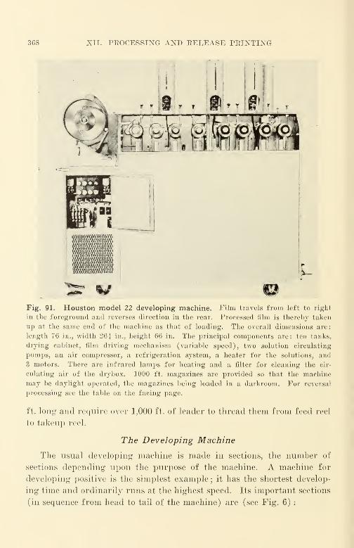
368 XII. PROCESSING AND RELEASE PRINTING
f f f t * T
&fe4. Staffs
L00m W
Fig. 91. Houston model 22 developing machine. Film travels from left to right
in the foreground and reverses direction in the rear. Processed film is thereby taken
up at the same end of the machine as that of loading. The overall dimensions are:
length 76 in., width 261 in., height 66 in. The principal components are: ten tanks,
drying cabinet, film driving mechanism (variable speed), two solution circulating
pumps, an air compressor, a refrigeration system, a heater for the solutions, and
3 motors. There are infrared lamps for heating and a filter for cleaning the cir-
culating air of the drybox. 1000 ft. magazines are provided so that the machine
may be daylight operated, the magazines being loaded in a darkroom. For reversal
processing see the table on the facing page.
ft. long and require over 1,000 ft. of leader to thread them from feed reel
to takeup reel.
The Developing Machine
The usual developing machine is made in sections, the number of
sections depending upon the purpose of the machine. A machine for
developing positive is the simplest example; it has the shortest develop-
ing time and ordinarily runs at the highest speed. Its important sections
(in sequence from head to tail of the machine) are (see Fig. 6) :

THE DEVELOPING MACHINE
Specifications and Reversal Processing Speeds for Houston Model 22
Developing Machine
Specifications
TankNo.
Function GallonsFt intank
TankNo.
Function Gallons Ft intank
1 Loading
elevator Dry
2 First de-
veloper 9
3 Wash 4.5
4 Bleach 9
5 Wash 4.5
Total machine leader
20
26
52
26
Clear 4.5
505 ft.
26
7
7 Second
developer 9 52
8 Stop bath 4.5 26
9 Hypo 4.5 26
10 Wash dry- Running
box water 52
Reversal Processing Speeds
Film
Ft perniin.
machinespeed
Filmspeedrating*
Film
v;,r i ,
speed
Dupont 301 8 50
Eastman XX 8 100
Ansco Tri-SS 8 100
Dupont 324 20 32
Ansco Hypan 20 32
Eastman Panatomic 20 32
'Dupont 314 -2:> 32
Eastman Super-X 25 32
Dupont 330 32 32
\<>t> : Developer formulas suitable for the various typos are found in the operat-
ing instructions for the machines.
a When developed as recommended.
(1) A feed reel—where the film to be developed is placed on the feed hub of the
machine.
{2) An " elevator"—where the length of the film loop between the feed reel and
the developing tank is permitted to diminish when the feed reel is stopped for the
purpose of putting on the next roll of film, the speed of the machine proper remaining
constant so that developing time may remain constant. The length of the loop of film
in the elevator decreases when the feed reel is stopped for reloading; it increases a
predetermined amount at a predetermined rate when the feed reel is permitted to
rotate again after loading, and runs at constant speed with the loop length unchanged
after the predetermined loop length has been attained.

370 XII. PROCESSING AND RELEASE PRINTING
(3) The developing tank*—where the film is developed and the exposed emulsion'
' develops up, '' becoming dark in the process. The usual developer tank is one in
which the film is completely submerged in the developer bath. Since development is
more uniform and development rate (development gamma) is rapid with a high degree
of agitation ("stirring"), various arrangements are used to increase developer agita-
tion. Some of these arrangements include the circulation of developer in thin streams
in the bath by introducing the developer at the bottom of the tank and removing de-
veloper at the top. Another arrangement introduces air jets at the bottom of the tank
to increase agitation. In all cases the film passes alternately downward and upward
in a developing tank; directional development effects (such as streaking caused by
unidirectional flow of the developer past floAv-disturbance-producing parts of the film,
such as sprocket holes) are reduced.
Since the by-products of development tend to retard development and reduce
development gamma, and since it is the very thin film of developer immediately ad-
jacent to the surface of the film that effects development, it seemed reasonable to
believe that a spray jet arrangement might be worked out that would require less de-
veloper solution, and yet develop the film in a manner more nearly approaching the
theoretical optimum. Such an arrangement is in commercial use at DeLuxe Lab-
oratories in New York where it was designed and built by E. Bertram. This machine
is very economical of space ; it provides a high rate of development without any meas-
urable directional development effect and with a very high degree of uniformity. Asthe spray jet concept seemed fundamental from the viewpoint of theoretical hydraulics,
the Bertram machine utilizes spray jets throughout rather than liquid immersion. Un-
fortunately, no description of the machine or of its operation has been published
despite the fact that the machine has been in commercial use for several years.
(4) The wash tank—where traces of the developing solution remaining on the film
are washed away with water prior to the entry of the film into the hypo tank. Often-
times there is an air squeegee for removing excess developer solution from the surface
of the film before it enters the wash tank. A squeegee is a means of removing excess
water or liquid ; it usually consists of two blasts of air, one on each side of the film, to
blow off the excess liquid. The film is usually completely submerged in water during
its passage through the wash tank; it emerges between tanks.
(5) The hypo and the hardener tank—where unexposed emulsion is "cleared"
from the film and where formaldehyde or other emulsion-hardening chemicals may be
added to the hypo bath if desired.
(6) Another wash tank—to remove traces of the fix bath.
(7) Tho first stage drybox—where the film, after passing a squeegee, is slowly and
partially dried by a steady blast of warm dry air which is usually fed into the bottom
of the first-stage drybox and exhausted from the top. The squeegee is especially im-
portant at this point, since the film would be badly water-streaked if the water were
* Eastman Kodak and Dupont have been evolving film emulsions suitable for high-
temperature processing. Recent types of emulsion can be developed as a negative in
less than half a minute; the development time for a comparable commercial emulsion
would bo about 15 minutes. It is well known that the chemical activity of substances
increases rapidly with increase in temperature, and it is indeed a portent of things to
come in the near future to find that the development time has been reduced to such a
great degree and yet development fog and graininess have been retarded so materially.
THE DEVELOPING MACHINE 371
permitted to dry without it. Usually there is a flannel-covered roller rotating within
the cabinet against which the base side of the film gently rides as it goes through
;
this is known as a polishing roller.
(8) The second stage drybox—where the film is slowly and finally dried by a
steady blast of warm air that is cooler than the air in the first stage. The second-stage
drybox may be more than twice as long as the first-stage drybox. Film is dried best
if the surface is not dried too rapidly with respect to the rate of diffusion of the mois-
ture from the inside of the film to the outside. Moisture diffuses quite slowly from
inside to outside compared with surface evaporation under common drying conditions.
Theoretically, the drying air temperature should be a maximum where the film
enters the drybox, and should drop to approximately ambient air temperature.
Staging is a practical means of accomplishing the objective.
Drying is a very important function, and many commercial machines dry both
improperly and insufficiently. The common error is to apply air that is too hot for too
short a time, leaving the surface excessively dried and the body of the film with an
excessive moisture content. After such a film is removed from the developing machine,
the internal moisture diffuses to the surface making it sticky. Such a film is known
in the trade as '' green film. '
' The physical distortions suffered by the minute picture
and sound images can be imagined when it is realized that the thermal coefficient of
linear expansion of the emulsion is some 8 times that of the film base.
The Eesearch Council of the Academy of Motion Picture Arts and Sciences of
Hollywood issued a Technical Bulletin "Report on Film Preservative Tests" (Apr. 14,
1939) that described green film and the subsequent treatment it sometimes receives to
counteract it:
1
1 Treatment given to release-print film after it has been printed, developed,
and dried is commonly called ' film preserving, ' and the processes by which this treat-
ment is given are known as ' film preservative ' processes.'
' The gelatin of freshly developed film carries a high percentage of moisture
in its pores and as long as this condition prevails is known as a 'green' emulsion.
A so-called 'green' emulsion is quite soft and the slightest abrasion will cause a
scratch. These scratches widen out as the gelatin dries, and cause the 'rainy'
effects occasionally seen on the screen in the theater when old films are run.
"As film with 'green' or soft emulsion passes through a projector, it leaves
small deposits of emulsion on the tension shoes at either the aperture plate or the
sound-gates, unless the tension shoes are kept thoroughly lubricated. Such deposits
build up resistance to free passage of the film over them, and scratch the film during
projection.
"When the moisture in a 'green' emulsion is withdrawn too quickly, the gelatin
shrinks and the film warps or buckles. If too great an amount of moisture is
withdrawn from the gelatin, the film becomes brittle, loses its pliability, and is easily
torn while being projected."
The subject of "green" film is usually considered "delicate"; it is too often ex-
plained away rather than investigated and corrected. Many film preservative proces-
ses are to some extent processes that attempt to correct improper drying by other
means such as emulsion hardening. Such processes do not correct improper drying;
the treated film would be even better if the film were dried properly. Oftentimes
"film preservatives" are applied a day or two after the film has been developed,
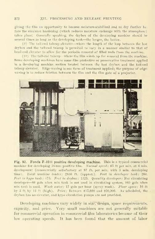
372 XII. PROCESSING AND RELEASE PRINTING
giving the film an opportunity to become moisture-stabilized and to dry further be-
fore the emulsion hardening (which reduces moisture exchange with the atmosphere)
takes place: Generally speaking, the drybox of the developing machine should be
several times as long as the developing tank—the longer, the better.
(9) The tail-end takeup elevator—where the length of the loop between the last
drybox and the tail-end takeup is permited to vary in a manner similar to that of
head-end elevator to allow for the periodic removal of filled reels from the machine.
(10) The tail-end takeup—where the film winds up for removal from the machine.
Some developing machines have some film protective or preservative treatment applied
in a developing machine section located between the last drybox and the tail-end
takeup elevator. Edge-waxing is one form of treatment applied ; the purpose of edge-
waxing is to reduce friction between the film and the film gate of a projector.
Fig. 92. Fonda F-1011 positive developing machine. This is a typical commercial
machine for developing 16-mm positive film. Normal speed: 65 ft per min. at 4 min.
development (commercially satisfactory at 87 ft. per min. with 3 min. developing
time). Total machine leader: 2800 ft. (approx.). Feet in developer tank: 260.
Feet in hypo tank: 475. Feet in drybox: 1325. Quantity developer : For circulating
developer—80 gals when mix tank is not used in circulating system, 160 gals whenmix tank is used. Wash water: 17 gals per hour (spray wash). Floor space: 16 ft
by 3 ft by 12 ft (high). Price: Between $15,000 and $20,000. As scheduled, the
drybox has no elevator, and hypo circulation pumps are not provided.
Developing machines vary widely in size, design, space requirements,
capacity, and price. Very small machines are not generally suitable
for commercial operation in commercial film laboratories because of their
low operating speeds. It has been found that the amount of labor
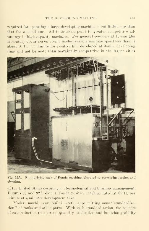
THE DEVELOPING MACHINE 373
required for operating- a large developing machine is but little more than
that for a small one. All indications point to greater competitive ad-
vantage in high-capacity machines. For general commercial 16-mm film
laboratory operation on even a modest scale, a machine speed less than of
about 50 ft. per minute for positive film developed at 3-min. developing
time will not be more than marginally competitive in the larger cities
Fig. 92A.
cleaning.
Film driving rack of Fonda machine, elevated to permit inspection and
of the United States despite good technological and business management.
Figures 92 and 92A show a Fonda positive machine rated at 65 ft. per
minute at 4 minutes development time.
Modern machines are built in sections, permitting some "standardiza-
tion" of tanks and other parts. With such standardization, the benefits
of cost reduction that attend quantity production and interchangeability
374 XII. PROCESSING AND RELEASE PRINTING
of parts make for flexibility of machine design as -well as lower cost.
Thus, if a machine were to be altered to provide a development
time of 6 minutes (e.g., for sound track originals), it would be necessary
to add but one developing tank to a machine that is operating satisfac-
torily at a development time of 3 minutes when used for release prints.
Thus, the output of the machine in feet of film per hour would be the
same when developing 6-min. sound film as it is in developing 3-min.
release prints. Without the extra tank, it would be necessary to reduce
the machine speed to one-half, thereby reducing its film output per unit
time to one-half.
In general, machine drive is of two kinds : friction and sprocket.
Different makes of film "stretch" different amounts when wet with solu-
tion; the increase in length is quite large (it may be as large as 0.5%).
"Overdrive" is provided in the case of friction-driven machines; it is
important that the machine compensate automatically for the increase in
the desired amount. In the case of sprocket drive, the sprockets used
must be designed for the proper "stretch" and for the proper shrinkage
ranges. Fortunately, there has been great improvement in the dimen-
sional stability of films and smaller dimensional change during develop-
ment and there is promise for still better stability in the films of the
future. At present, most catalog developing machines offered for sale are
of the friction-drive type.
Developing
It is impracticable in a single chapter to cover the many important
factors in developing machine design or operation. Suffice it to say that
among positive developer baths the Eastman D-16 is widely used although
in a variety of concentrations and with minor variations that depend
upon specific conditions of use and, in too many cases, upon the whimof the man in charge. A developer bath usually consists of:
(1) Reducing agents—Elon, Metol, Hydroquinone, Paraphenylenediamine, Glycin,
Pyrogallate, and others. Metol (monomethylparaaniinophenol sulfate) is sold under
a variety of trade names; these include Rhodol and Pictol. The reducing agent re-
duces the exposed emulsion to metallic silver without affecting the unexposed emulsion.
{2) An alkali—sodium carbonate. This is needed because most developing
agents are relatively inactive except in alkaline solution. In addition, the alkali aids
in swelling the gelatin to permit action by the reducing agent upon the emulsion.
(3) A preservative—sodium sulfite or potassium metabisulfite. This is used to
prevent oxidation of the reducing agents.

FIXING 375
(4) A restrainer—potassium bromide. This is used to restrain very active solu-
tions from reducing unexposed as well as exposed emulsion.
(5) A solvent—water.
The developer bath is rapidly circulated through the machine by
pumps ; temperatures of developer and fixing baths are usually controlled
within zb 0.25° F. Ordinarily, a fairly large storage tank is used as a
reservoir ; the bath is circulated from the tank through the machine and
back to the tank. The flow of fluid in the machine is opposite to the
direction of travel of the film where practicable. Fluid usually enters
the developer tank at the bottom and overflows at the top, returning to
the storage tank.
Fixing
A fixing bath is an acid hardening bath that " clears" the film of un-
exposed emulsion. The principal constituent is hypo (sodium thiosul-
fate)—the clearing agent. For proper action in fixing and hardening, the
time allowed for the fixing bath should not be less than twice the time
just necessary to clear the film.
Hardeners are usually chrome alum or potassium alum. The harden-
ing agent chosen depends upon the degree of hardening desired. To
prevent precipitation of free sulfur which occurs in acid solution, sodium
sulfite is added. The acids in the bath are usually acetic acid and boric
acid.
Published Formulas. Photographic chemicals cannot tolerate certain
impurities common in u.s.p. chemicals. It is necessary to make certain
that the chemicals purchased are of photographic grade* to avoid
difficulties that arise from such impurities. Table XX lists commonsolution formulas.
For release prints, little variation in the Eastman D-16 formula (ex-
cept possibly for concentration) is ordinarily justified. There may be a
change in the balance between the Elon and the Hydroquinone, but in
relatively few cases are the changes significant.
For the development of negative, however, changes in the bath from
the Eastman D-76 reference bath listed are very common. Many such
changes show significant improvement in picture quality or in "adjust-
ing the bath to the machine" with regard to middle-range machine de-
* Specifications for chemicals of photographic grade may be obtained from the
American Standards Association. 70 E. 45 St., New York. X. Y. ; there is a specifica-
tion for each of the many common photographic chemicals, including all those listed
in the above formulas.
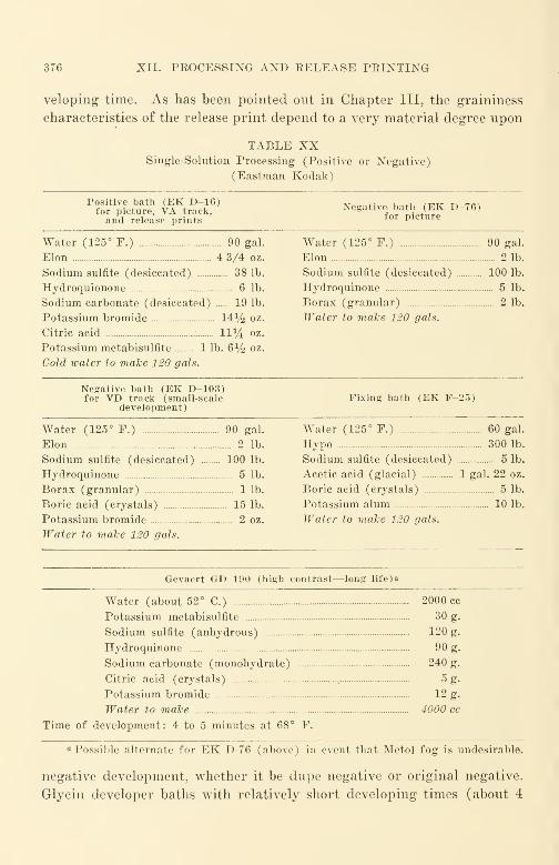
376 XII. PROCESSING AND RELEASE PRINTING
veloping time. As has been pointed out in Chapter III, the graininess
characteristics of the release print depend to a very material degree npon
TABLE XXSingle-Solution Processing (Positive or Negative)
(Eastman Kodak)
Positive bath (EK D-16)for picture, VA track,and release prints
Negative bath (EK D-76)for picture
Water (125° F.) 90 gal.
Elon 4 3/4 oz.
Sodium sulfite (desiccated) 38 lb.
Hydroquionone 6 lb.
Sodium carbonate (desiccated) 19 lb.
Potassium bromide 14% oz.
Citric acid 11^4 oz.
Potassium metabisulfite 1 lb. 6% oz.
Cold water to make 120 gals.
Water (125° F.) 90 gal.
Elon 2 lb.
Sodium sulfite (desiccated) 100 lb.
Hydroquinone 5 lb.
Borax (granular) 2 lb.
Water to make 120 gals.
Negative bath (EK D-103)for VD track (small-scale
development)Fixing bath (EK F-25)
Water (125° F.) 90 gal.
Elon 2 lb.
Sodium sulfite (desiccated) 100 lb.
Hydroquinone 5 lb.
Borax (granular) 1 lb.
Boric acid (crystals) 15 lb.
Potassium bromide 2 oz.
Water to make 120 gals.
Water (125° F.) 60 gal.
Hypo 300 lb.
Sodium sulfite (desiccated) 5 lb.
Acetic acid (glacial) 1 gal. 22 oz.
Boric acid (crystals) 5 lb.
Potassium alum 10 lb.
Water to make 120 gals.
Gevaert GD-190 (high contrast—long life)
a
Water (about 52° C.) 2000 cc
Potassium metabisulfite 30 g.
Sodium sulfite (anhydrous) 120 g.
Hydroquinone 90 g.
Sodium carbonate (monohydrate) 240 g.
Citric acid (crystals) 5 g.
Potassium bromide 12 g.
Water to make 4000 cc
Time of development: 4 to 5 minutes at 68° F.
a Possible alternate for EK D-76 (above) in event that Metol fog is undesirable.
negative development, whether it be dupe negative or original negative.
Glycin developer baths with relatively short developing times (about 4
TWO SOLUTION PEOCESSING 377
minutes) have been quite advantageous with EK 5203 dupe negative
film for making intermediate dupe negatives between the original reversal
and the fine-grain release print. Other reducing agents also will be
found advantageous. Graininess is reduced materially by selecting the
right kind of developer bath and by reducing the developing time (with
compensating increase of dupe negative exposure) thereby taking
advantage of the difference between the graininess - developing time
characteristics of negatives and positives. There is still much to be done
in reducing the graininess of release prints; the dupe negative will
provide much of the opportunity.
Two Solution (Reversal) Processing
For reversal developing, a few more processing steps must be added.
A typical procedure would be
:
1. A pre-hardener
2. A developer
3. A water rinse
4. A bleach
•1. A clearing bath
6. A second exposure—provided by a relatively bright lamp (not
controlled)
7. A second developer
8. A water rinse
9. A fixing bath
10. A wash
11. Drybox
Typical formulas used are listed in Table XXI.
The fixing bath (9) may be the same as that used with negative or
positive development ; the EK F-25 bath listed previously is suitable.
As a practical matter, laboratories that can afford to do so use separate
developing machines for the different kinds of processing. Where this is
not possible the developer and the hypo (or other chemicals such as those
used for reversal development) are pumped out of the machine to storage
tanks for future use. The machine is then cleaned out and the different
developer or other chemicals pumped in. The practicability of this
method depends upon the design of the machine itself. The problem of
draining is similar to that of draining an automobile radiator. If the
drain is not at the lowest point in the system with sufficient grade to cause

378 XII. PROCESSING AND RELEASE PRINTING
TABLE XXITwo-Solution Formulas
Tre-hardener (1)
Water 6 gal.
Calgon _ 0.5 oz.
Sodium bisulfite 3 oz., 80 gr.
Sodium sulfate (anhyd.) 3 lb. 5.5 oz.
Sodium carbonate (anhyd.) 4.5 oz., 24 gr.
Paraformaldehyde 4 oz., 120 gr.
6-Nitrobenzimidazole nitrate (0.5% solution) 5 fl. oz., 4 fl. dr.
First Developer (2)
Water 3 gal.
Calgon 0.5 oz., 130 gr.
Metol 1 oz.
Sodium sulfite (anhyd.) 5 lb.
Hydroquinone 2 lb.
Potassium bromide 12.5 oz., 140 gr.
Sodium thiocyanate 4 oz.
Sodium hydroxide 2 lb.
Water to 12 gal.
Bleach (4)
Water 6 gal.
Potassium bichromate 12 oz.
Sulfuric acid 18.5 fl. oz.
Water to 8 gal.
Clearing Bath (5)
Water 4 gal.
Calgon 146 gr.
Sodium sulfite (anhyd.) 3 lb.
Water to 5 gal.
Second Developer (7)
Water 10 gal.
Calgon 0.5 oz., 130 gr.
Metol 1.5 oz.
Sodium sulfite (anhyd.) 5 lb.
Hydroquinone 2 lb.
Potassium bromide 8 oz.
Sodium hydroxide 1.5 lb.
Water to 12 gal.
DuPont 314, Eastman Super X (5256) and Eastman Super XX (5261) can be
processed like Universal films in the above baths. For Ansco Hypan Reversal, Triple-
S Reversal, and DuPont 301, add sodium thiocyanate to the first developer. The
black nonhalation silver backing on Eastman Super X (5256) and Super XX (5261)
may be removed by a sponge in the first developer tank.
TWO SOLUTION PROCESSING 379
thorough draining to that point, contamination of the newly pumpeddeveloper occurs. This is undesirable, since it may result in an unde-
sirable increase in "-raininess or in other characteristic that cannot be
corrected by merely changing the speed of the machine.
In general, the bath that is richest in reducing agents (such as those
listed) provides the best photographic quality. To a great degree devel-
oping is a matter of how much one can afford to spend on the reducing
agents used in the bath. Although increasing the alkali and decreasing
the reducing agents in a bath may produce like development contrasts.
the major penality is a marked increase in graininess. The price of
alkalis is but a fraction of a dollar per pound, whereas reducing agents
cost several dollars per pound, and it is not uncommon to find developer
baths in commercial laboratories using excess alkali and insufficient
reducing agents.*
Printing: The Printer
A printer has been defined as a machine that forms a latent image in
the photographic emulsion of raw film with light modulated by an image
carried on a separate film. Printers may be classified in accordance with
the relationship of the two emulsions concerned: (1) contact—where the
emulsion of the film to be copied and the emulsion of the raw stock are
in intimate physical contact, and (2) projection—where the image of the
film to be copied is projected by suitable optical means upon the emulsion
of the rawT stock. Projection printers may be classed as : (a) enlarging
—
where the projected image is larger than the image on the film to be
copied; (b) reducing—where the projected image is smaller than the
image on the film to be copied; and (c) one-to-one—where the projected
image is of the same size as the image on the film to be copied.
A printer requires (1) a light source—often an incandescent lamp.
(2) a printer gate or aperture—the portion of the machine where the
image is transferred. (3) a light control—this may be an iris diaphragm
similar to that used with a camera lens or other aperture control and or it
may be a rheostat connected in the lamp circuit for suitably dimming the
lamp, (4) a motor—usually a synchronous a.-c. motor to avoid changes
of speed resulting from slight changes of mechanical load, (5) feed and
takeup reel arms—for accommodating both the film to be copied and the
* For details as to solution mixing procedure, etc., the reader is referred to
Photographic Chemicals and Solutions by Crabtree and Matthews (American Photo-
graphic Publishing Company, 1939).
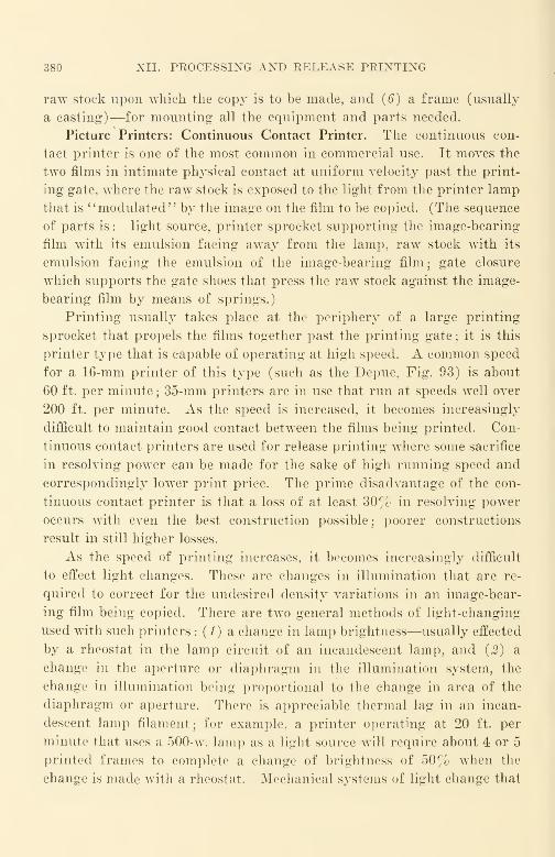
380 XII. PROCESSING AND RELEASE PRINTING
raw stock upon which the copy is to be made, and (6) a frame (usually
a casting)—for mounting all the equipment and parts needed.
Picture Printers: Continuous Contact Printer. The continuous con-
tact printer is one of the most common in commercial use. It moves the
two films in intimate physical contact at uniform velocity past the print-
ing gate, where the raw stock is exposed to the light from the printer lamp
that is ''modulated" by the image on the film to be copied. (The sequence
of parts is : light source, printer sprocket supporting the image-bearing
film with its emulsion facing away from the lamp, raw stock with its
emulsion facing the emulsion of the image-bearing film; gate closure
which supports the gate shoes that press the raw stock against the image-
bearing film by means of springs.)
Printing usually takes place at the periphery of a large printing
sprocket that propels the films together past the printing gate ; it is this
printer type that is capable of operating at high speed. A common speed
for a 16-mm printer of this type (such as the Depue, Fig. 93) is about
60 ft. per minute ; 35-mm printers are in use that run at speeds well over
200 ft. per minute. As the speed is increased, it becomes increasingly
difficult to maintain good contact between the films being printed. Con-
tinuous contact printers are used for release printing where some sacrifice
in resolving power can be made for the sake of high running speed and
correspondingly lower print price. The prime disadvantage of the con-
tinuous contact printer is that a loss of at least 30% in resolving power
occurs with even the best construction possible; poorer constructions
result in still higher losses.
As the speed of printing increases, it becomes increasingly difficult
to effect light changes. These are changes in illumination that are re-
quired to correct for the undesired density variations in an image-bear-
ing film being copied. There are two general methods of light-changing
used with such printers : (1) a change in lamp brightness—usually effected
by a rheostat in the lamp circuit of an incandescent lamp, and (2) a
change in the aperture or diaphragm in the illumination system, the
change in illumination being proportional to the change in area of the
diaphragm or aperture. There is appreciable thermal lag in an incan-
descent lamp filament; for example, a printer operating at 20 ft. per
minute that uses a 500-w. lamp as a light source will require about 4 or 5
printed frames to complete a change of brightness of 50% when the
change is made with a rheostat. Mechanical systems of light change that

PICTURE PRINTERS: CONTINUOUS CONTACT PBINTEB 381
Fig. 93. Depue double head continuous contact combination 16-mmprinter. This machine can print one combination print from separate picture
and sound pre-print films. This is accomplished by providing two printing
heads, one for the picture and one for the sound. Printing speed is in the range
from 60 to 110 ft. per min., the lower speed being required for films requiring
high exposure levels. The picture printing lamp is rated at 100 watts (pro-
jection type used at line voltage), and the sound printing lamp is rated at
115 volts, 25 watts (tubular type). A separate 25-watt lamp with its rheostat
is provided for printing edge numbers. All hubs designed to hold a maximum of
1200 ft. For printing Kodachrome, the color temperature of the 100-watt lamp
is ordinarily too low;provision is made for substituting a 10-volt 7.5-ampere
exciter lamp for picture printing. Like most conventional printers, this ma-
chine runs in one direction only.

382 XII. PROCESSING AND RELEASE PRINTING
effect control by means of a change in area of an aperture or diaphragm
often have appreciable inertia, and the mass in the mechanism must be
moved quickly to effect the change. With certain arrangements it is
difficult if not impossible to effect the change completely between two
adjacent printed frames. Where quantity prints are to be made with
scene density changes at high speed, a traveling matte may be used. This
is merely a film interposed at the gate between the light source and the
image-bearing film that alters the light intensity in the manner of a
Fig. 94. Bell and Howell, model
J, 16-mm combination printer.
Adjustable width aperture is used
to effect changes in print ex-
posure. It has a single printing
head and lamp with separate aper-
tures for picture and for sound
printing. Can make a silent pic-
ture print or a sound print in a
single trip through the printer; it
can also make a combination print
from a combination negative. To
make a combination print from
separate picture and sound nega-
tives requires two trips of the raw
stock through the printer; one trip
to print picture, and the other to
print sound.
neutral density filter. Traveling mattes are rarely used in 16-mm re-
lease printing; it is more practicable to make the timing corrections in
the dupe negative in such manner that the release prints may be printed
at a single printer light setting.
Typical commercial printers available are the Bell and Howell Model
J (Fig. 94) and the Depue Combination. The Depue (Fig. 93) has the
advantage that it provides three sets of feed and takeup reel arms, one
for accommodating the picture image-bearing film, the second for ac-
commodating the sound image-bearing film, and the third for accommo-
dating the raw stock to be printed; a combination print may be made
STEP-CON TACT PRINTER 383
from separate picture and sound films in a single trip through the printer.
As may be expected, there is a wide range of performance of continuous
printers both in regard to picture and sound quality and in regard to
price. Continuous contact printers must be checked regularly to make
certain that proper contact is maintained and that they do not introduce
excessive flutter into printed sound. This latter can be done by making
test prints periodically, using an SMPE flutter test film ASA Z22.43 or
its equivalent as the film to be copied. The SMPE test film is then com-
pared with the test print by running the films on a film phonograph and
observing the wave form of first one and then the other as seen on a
cathode ray oscillograph. Tests for picture contact can be made by
making periodic test prints of film bearing resolving-power test charts
and viewing the tests by projecting them.
Step-Contact Printer. Another type of picture printer in common
use is the step-contact printer. In this machine, the film, instead of
moving past the film gate at uniform velocity, moves into and out of the
gate with an intermittent motion similar to that of a camera. Just as
with the camera, a shutter cuts off the light from the light source during
the interval that the film is being moved from one frame to the next.
Because the film is stationary in the aperture during the exposure in-
terval, the quality loss (measured as resolving power loss) is usually
measurably less than that of a continuous contact printer. Commonoperating speeds of such printers are often about 20 ft. per minute
;
some of the newer machines have the speed increased to 60 ft. per minute.
Most good printers of this type have some form of gate pressure control
that automatically applies appreciable pressure to the films to improve
their contact during the exposure interval ; the pressure is released during
the interval when the film is being moved. With machines maintained in
best order, the step-contact printer is a "standard of comparison" by
which the performance of other printers may be judged. The quality
should approximate very closely the "ideal" of a printing frame used
for still pictures. Test prints in a still picture contact printing frame
can be made for comparison; ASA Z38.7.10-1944 and Z38.7. 11-1944 and
related specifications provide test information and methods.
Although many equipment manufacturers have marketed step-con-
tact printers from time to time. DeBrie ( Prance Ilias been the most con-
sistent manufacturer of this type of machine. Earlier machines (before
World War IT) were equipped with rheostat-type light changers; newer
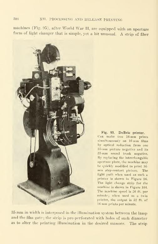
384 XII. PROCESSING AND RELEASE PRINTING
machines (Fig. 95), after World War II, are equipped with an apertureform of light changer that is simple, yet a bit unusual. A strip of fiber
Fig. 95. DeBrie printer.
Can make two 16-mm prints
simultaneously on 16-mm films
by optical reduction from one
35-mm picture negative and its
35-mm sound track negative.
By replacing the intercliangable
aperture plate, the machine maybe quickly modified to print 16-
mm step-contact picture. Thelight path when used as such a
printer is shown in Figure 96.
The light change strip for the
machine is shown in Figure 104.
The machine speed is 26 ft. per
minute; when used as a twin
printer, the output is 52 ft. of
16-mm prints per minute.
35 mm in width is interposed in the illumination system between the lampand the film gate ; the strip is pre-perforated with holes of such diameteras to alter the printing illumination in the desired manner. The strip

STEP-CONTACT PRINTER 385
moves from one hole to the next while the film is being moved from one
frame to the next at the point where a change in printing illumination is
desired. The change occurs during the time when the shutter is closed
between frames; there is no change in lamp output in the interim.
Fig. 96. Schematic of light path in
DeBrie step contact printer. Thelight change strip shown in Figure 104
may be used to transport a filter holder
with special filters for color correc-
tion of individual scenes when the
machine is used for color printing.
(See Figs. 95 and 104.) ^NEUTRAL DENSITYFILTER
TABLE OF PICTURE ILLUMINATION(Printing Lamp Rheostat Set at 108 Volts)
Lightchange bandhole number
Light change
Inches
band hole size
MmFoot candles Lux
20 0.710 18.00 4180 45,000
19 0.603 15.30 3740 40,200
18 0.567 14.40 3335 35,900
17 0.530 13.45 2970 32,000
16 0.496 12.6 2660 28,600
15 0.482 12.25 2370 25,500
14 0.443 11.25 2120 22,800
13 0.418 10.60 1892 20,400
12 0.402 10.20 1690 18,200
11 0.382 9.70 1506 16,200
10 0.362 9.20 1347 14,500
9 0.335 8.50 1200 12,900
8 0.311 7.90 1072 11,550
7 0.299 7.60 958 10,300
6 0.290 7.35 855 9,200
5 0.272 6.90 762 8,200
4 0.260 6.60 683 7,350
3 0.248 6.30 608 6,550
2 0.236 6.00 543 5,850
1 0.224 5.70 485 5,220
Figure 96 is a schematic of the light path. This arrangement is con-
venient for the printing of integral tripack color films where changes in
the color balance of particular scenes are desired.
The latest DeBrie step contact printer is a three-color additive machine

386 XII. PROCESSING AND RELEASE PRINTING
deriving its green, red and blue components from a single light source.
A triple photographic grating with 40 steps for each color attenuates each
component individually; 64,000 colors are thus available.
Projection Printer (Optical: One-to-One). The projection printer
is one that projects an image from the image-bearing film to be copied to
the emulsion surface of the raw stock upon which the exposure is to be
made. There are two separate film gates in this printer, one for the
image-bearing film, and the other for the raw stock. Both films are
moved simultaneously by claw movements that are geared to function
together and to cause the two films to move in like manner.
A light source—usually an incandescent lamp—is used with an ap-
propriate condensing lens system to illuminate the image-bearing film
that is located in one of the two printer gates. A high-quality projection
objective lens focuses the illuminated image upon the emulsion surface
of the raw stock located in the second film gate. A shutter admits light
through the optical system when the films are stationary in their respec-
tive gates; the shutter cuts off the light while the films are moving be-
tween exposures. The shutter action is quite like that of a camera.
A typical commercial printer of this type that has been on the market
for some time is the Bell and Howell ; this has a top speed of 18 ft. per
minute. There have been numerous designs evolved in recent years,
mostly directed to increasing running speed, and to providing special
features to facilitate the printing of integral tri-pack color films such as
Kodachrome. Such features include the making of fades, wipes, dis-
solves, and other effects while the print is being made, and the correction
of color balance and of scene density from scene to scene where required.
Several organizations have constructed or are constructing a small num-
ber of printers of this general type for their own use or for the use of
affiliated film laboratories. In many cases the printer has been set up to
provide a ''standard" emulsion position print from a "standard" emul-
sion position original. The poor quality of sound heard in the loud-
speaker of an ordinary 16-mm sound projector (set up—as most are—for
the projection of "standard" emulsion position prints only) has been an
incentive quite as much as the need for re-focusing the picture on a
projector when "non-standard" emulsion position films are to be shown.
Many printers such as the Acme (Hollywood) are designed to provide
automatic fades in the printer of the more-or-less accepted lengths of
40 or 48 frames ; some are able to provide fades of any length that may
be desired.
BOUND PRINTER (CONTACT)
An optica] printer is difficult to adjust, to maintain and to keep in
adjustment, and to keep clean. It is quite expensive it' the optics are
really good; it is not worthwhile if the optics are no1 good. An optical
printer should have a coated main objective lens of relative aperture
preferably not narrower than f/2.0; it should be well corrected both geo-
metrically and chromatically, and have resolving power all over its field
of not less than 100 lines per millimeter. Such lens.s are rare in appro-
priate focal lengths. Should they become more plentiful later on. it is
unlikely that they will be low in price. Special lenses have been manu-
factured that are excellent, but very few suitable lenses are manufactured
as stock items or catalog items.
The first cost and the operating costs of a good projection printer are
quite high compared with contact types of printers. Operating costs will
have to be cut by increasing machine speeds and by improving machine
control, and possibly first cost reduced materially before this ela>^ of
printer comes into universal use. For such reasons it is likely that the
less costly types will continue in use for some time despite their somewhat
inferior picture quality when compared with a very good—and expen-
sive—projection printer.
Sound Printer (Contact)
All sound printers are continuous printers, the films moving at con-
stant velocity. The most common form of sound printer is the contact
printer, which is the same as the continuous contact printer used for
picture, with the exception that the printing aperture limits the light-
causing exposure to the sound area rather than to the picture area. ( Jon-
tinuous contact printers such as the Bell and Howell Model J use a shut-
ter arrangement that is made of two portions, one for shutting off or
admitting printing light to the picture area, and the other for similar
control of light to the sound track area. Both may be opened at the
same time if desired, to make a combination print from a combination
negative. The area of the aperture formed by the shutter is altered to
effect changes in exposure of the copy being made.
Imperfect contact in such a printer p;ives rise to a loss of resolving
power; tin 1 most noticeable effect is a loss of high frequencies. Unfortu-
nately, this loss is not constant; it varies more or less regularly with the
approach and departure of each of the sprocket teeth that propel the
films. When film speed is high, a layer of air may become trapped be-
tween the image-bearing film and the raw stock, giving rise t«» a separa-

388 XII. PROCESSING AND RELEASE PRINTING
tion of the films, and reducing the effectiveness of the contact. This sepa-
ration varies, since the trapped air alternately'
' leaks out '
' and becomes
trapped.
A critical feature in the design of contact printers of the continuous
type is the design of the printing sprocket. This is designed for a spe-
cific shrinkage relationship between the image-bearing film and the raw
stock. Since the image-bearing film is relatively old and shrunk to a
greater degree than the relatively new raw stock, its actual length per
100-sprocket-hole interval is shorter. The difference in length between
Fig. 97. Maurer 16-mm shrinkage gauge.
the image-bearing film and the raw stock is accounted for by the diameter
of the printing sprocket and the pitch of its teeth. In the " ideal" case,
the difference in length is exactly accounted for by the difference between
the smaller mean diameter of the image-bearing film and the larger mean
diameter of the raw stock as the films are curved about the sprocket.
When engaged, the sprocket teeth in this'
' ideal'
' case can locate in the
exact center of the sprocket holes of both films. Another consideration
in the design of the sprocket is the range of shrinkage that the sprocket
is designed to accommodate. Since the shrinkage of 16-mm films has been
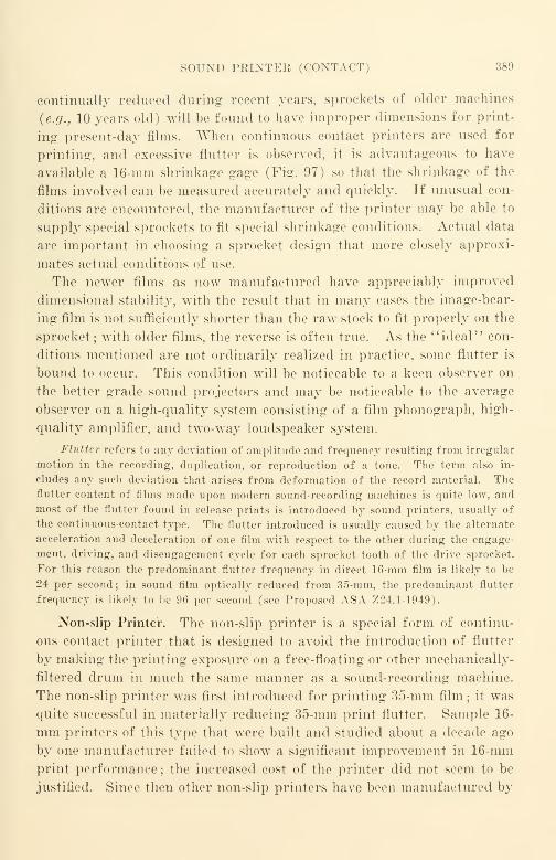
SOUND PRINTER (CONTACT) 389
continually reduced during recent years, sprockets of older machines
(e.g., 10 years old) will be found to have improper dimensions for print-
ing present-day films. When continuous contact printers are used for
printing, and excessive flutter is observed, it is advantageous to have
available a 16-mm shrinkage gage (Fig. 97) so that the shrinkage of the
films involved can be measured accurately and quickly. If unusual con-
ditions are encountered, the manufacturer of the printer may be able to
supply special sprockets to fit special shrinkage conditions. Actual data
are important in choosing a sprocket design that more closely approxi-
mates actual conditions of use.
The newer films as now manufactured have appreciably improved
dimensional stability, with the result that in many cases the image-bear-
ing film is not sufficiently shorter than the raw stock to fit properly on the
sprocket ; with older films, the reverse is often true. As the "ideal" con-
ditions mentioned are not ordinarily realized in practice, some flutter is
bound to occur. This condition will be noticeable to a keen observer on
the better grade sound projectors and may be noticeable to the average
observer on a high-quality system consisting of a film phonograph, high-
quality amplifier, and two-way loudspeaker system.
Flutter refers to any deviation of amplitude and frequency resulting from irregular
motion in the recording, duplication, or reproduction of a tone. The term also in-
cludes any such deviation that arises from deformation of the record material. The
flutter content of films made upon modern sound-recording machines is quite low, and
most of the flutter found in release prints is introduced by sound printers, usually of
the continuous-contact type. The flutter introduced is usually caused by the alternate
acceleration and deceleration of one film with respect to the other during the engage-
ment, driving, and disengagement cycle for each sprocket tooth of the drive sprocket.
For this reason the predominant flutter frequency in direct 16-mm film is likely to be
24 per second; in sound film optically reduced from 35-mm, the predominant flutter
frequency is likely to be 96 per second (see Proposed ASA Z24.1-1949).
Non-slip Printer. The non-slip printer is a special form of continu-
ous contact printer that is designed to avoid the introduction of flutter
by making the printing exposure on a free-floating or other mechanically-
filtered drum in much the same manner as a sound-recording machine.
The non-slip printer was first introduced for printing 35-mm film ; it was
quite successful in materially reducing 35-mm print flutter. Sample 16-
mm printers of this typo that were built and studied about a decade ago
by one manufacturer failed to show a significant improvement in 16-mmprint performance ; the increased cost of the printer did not seem to be
justified. Since then other non-slip printers have been manufactured by

390 XII. PROCESSING AND RELEASE PRINTING
other organizations; although the performance of. projectors with regard
to flutter has been materially improved, there is still no consensus of
opinion in favor of non-slip printers for 16-mm. Figure 98 is a sketch
of the film path for a non-slip printer.
Optical One-to-One Sound Printer. In an attempt to reduce the losses
in sound printing and to improve film motion to minimize flutter, J. A.
Maurer, Inc.* has been manufacturing a projection sound printer. Withthis form of printer it is possible to adjust the optics readily in order to
focus on either surface of the image film. Prints of either emulsion posi-
tion can be produced. The machine as manufactured for a decade has
been able to provide sufficient illumination to expose fine-grain film (90
lines per millimeter) at a speed of 72 ft. per minute through the custom-
ary blue-violet filters with only a 32 c.p. automobile-type headlamp as a
AGuide
^>~i(o'-Voller Negative
\-f]~7 Optical
Drum/ ~\LJ system
Fig. 98. Sketch of the film path of a non-slip printer.
light source. This fundamentally good mechanism has recently been re-
designed and now not only provides appreciably better film motion than
its predecessor, but also has improved color correction of its optical sys-
tem that is essential for obtaining good resolving power in the red end
of the spectrum when heterochromatic exposure is used for present-day
integral tri-pack and similar color films.
Since the optical one-to-one printer provides a separate film travel
path for each of the films being printed, it is possible to adjust each path
for the average shrinkage of the films run in that path. Thus, the path
of the machine that runs the image-bearing film can be set for the some-
what greater average shrinkage of such films than the side of the machine
that runs the raw stock. The translation points of both the image-bear-
ing film and of the raw stock are ordinarily in fixed relationship to one
another because there is a common shaft or equivalent arrangement sup-
* Maurer, J. A., "Optical Sound-Track Printing," JSMPE, 50, 458 (May 1948).
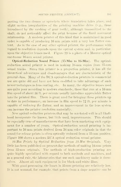
SOUND PBINTEB CONTACT 39]
porting the two drums or sprockets where translation takes place, and
slight motion irregularities of the printing machine drive {e.g., those
introduced by the meshing of gear teeth , although transmitted to the
shaft, do not noticeably affect the print because of the fixed movement
relationship. A modern printer of this kind that is maintained in good
order is capable of producing 16-mm prints with a very low flutter con-
tent. As in the case of any other optical printer, the performance with
regard to resolution depends upon the optical system and. in particular,
upon the objective Lenses used. Figure 99 is a photo of a Maurer optical
one-to-one 16-mm sound printer.
Optical-Reduction Sound Printer (35-Mm to 16-Mm). The optical-
reduction sound printer is used in making 16-mm copies from 35-mm
sound tracks. Since this printer is a projection printer, it has all the
theoretical advantages and disadvantages that are characteristic of the
general class. Many of the RCA optical-reduction printers in commercial
use are quite old and have not been modified to take advantage of such
newer techniques as lens coating, etc. In many, the objective lenses used
are quite poor according to modern standards ; those that run at a 16-mm
film speed of about 36 ft. per minute usually introduce appreciable flutter
into the printed film. There is great need for bringing these printers up
to date in performance; an increase in film speed to 72 ft. per minute is
capable of reducing the flutter, and an improvement in the lens system
can increase the printer resolution materially.
New optical reduction printers that may be marketed will in all likeli-
hood incorporate the known, but little used, improvements. This should
be especially true of manufacturers that have been marketing such equip-
ment for a number of years. Optical-reduction sound printing is im-
portant to 16-mm prints derived from 16-mm color originals in that the
sound for release prints is often optically reduced from a 35-mm positive.
Figure 100 shows a modern RCA optical reduction sound printer.
16-Mm Prints by Optical Reduction from 35-Mm Originals. Very
little has been published on present-day methods of making 16-mm prints
from 35-mm originals. The methods of high-production printing are
quite highly specialized with regard to both methods and machines, and
as a general rule, the laboratories that use such machinery make it them-
selves. Almost all such equipment is for black-and-white films.
With good processing, the losses in 35-mm printing are relatively low.
It is not unusual, for example, that prints from a dupe negative ran be
392 XII. PROCESSING AND RELEASE PRINTING
cut into a print from an original negative without an observable change
in picture quality. It has been many years since a release print for a
Hollywood picture was made from an original negative; release prints
are now made almost entirely from dupe negatives. Since the film emul-
sions commercially available have exactly the same characteristics regard-
less of whether the base material is slit to a width of 35-mm or to 16-mm,
Fig. 99. Maurer optical one-to-one Fig. 100. Modern RCA optical reduc-
sound printer. tion sound printer, PB-177. (35-mm to
16-mm).
there is a smaller loss in picture detail in a single copying step with
35-mm film than with 16-mm film if all other conditions are the same
because the detail-rendering ability of the 35-mm film frame is greater
in the ratio of the area of the 35-mm film frame to the 16-mm film frame.
A master positive (on Eastman #1365 developed in a negative bath)
is made from the original 35-mm negative. From this master positive
PRINTER PERFORMANCE CHARACTERISTICS 393
is made a dupe negative, which is usually 16-mm in size (Eastman #5203
is a suitable material). Contact prints are made on fine-grain 16-mm
(DuPont 605A is a suitable material). The contrast of the 16-mm print
can be controlled by controlling the development of the dupe negative.
There are several noteworthy arrangements to speed up output and
lower the labor cost per print ; one of these is the use of 32-mm film. From
the 35-mm master positive, two 16-mm combination dupe negatives are
printed side by side on 32-mm film. From this point on the 32-mm film
can be handled as a single strip;prints being made by contact printing
and developing in the customary manner. After the 32-mm prints leave
the developing machine, they are slit to provide two 16-mm prints.
Another arrangement that is used is the multiple head printer. In
this machine, multiple prints—seven prints in the case of one machine
—
are turned out by a single machine from a single image-bearing film.
The machine has a number of printer apertures in which the raw stock
is fed to each and taken up from it after exposure. The image-bearing
film runs through the printing machine from the feed reel, through each
of the printing apertures in turn, and to the takeup reel. The number
of man-hours of printing labor per print is materially reduced by this
arrangement: 7 prints are exposed with a labor cost per print that is
probably less than one-fourth the labor cost of exposing one print at a
time. This arrangement has also been used with 32-mm film, doubling
the number of prints made.
There are many other possible arrangements, and the usual objective
in each case is to cut costs without appreciable sacrifice in product quality.
In the making of black-and-white prints, for example, another procedure
is to make a combination dupe negative for the release printing of a com-
bination print with both sound and picture images. This is practicable
for variable-density sound if the sensitometric control is well planned;
it is not practicable for variable-area sound in most cases. The combina-
tion master positive or the combination dupe negative is often used in
laboratories to cut costs. Oftentimes, either picture quality or sound
quality (or both) suffer, since the use of the combination is often in-
judicious.
Printer Performance Characteristics
From the user's point of view, the quality obtained on the release
print and cost are the really important items. If preservation is impor-
tant, and intermediate printing copies are desired, the best quality ob-

394 XII. PEOCESSING AND EELEASE PRINTING
tainable and the most careful handling" is desirable. Unfortunately, there
is no simple, single, quantitative measure of picture quality or of picture
quality degradation, and the same is true of sound quality and sound
quality degradation. Since printers are responsible for quality degrada-
tion and quality variation, some of their characteristics that are respon-
sible should be mentioned.
Loss of Resolution. One of the more obvious characteristics is loss of
image resolution. This loss may arise from many causes. In a contact
printer, for example, it may be due to the fact that the image-bearing film
and the raw stock are not in good physical contact, or that they shift with
respect to each other during exposure. The usual continuous contact
printer is designed for a specific shrinkage condition of the image-bearing
film and of the raw stock. With ideal conditions, the length of the outer
surface of the image-bearing film (the emulsion surface) just matches the
length of the inner surface of the raw stock (the emulsion surface). For
film dimensions other than ideal, the raw stock is either too long or too
short to fit the sprocket exactly, and the image-bearing film is likewise too
short or too long. In either event the result is a slipping of the raw
stock with respect to the image-bearing film during exposure. This slip-
ping is evident as a "smearing" of the fine detail of the image. The mag-
nitude of the smearing depends upon the differences between the films
being printed and the films for which the machine was designed.
The effect can be measured for the picture area by printing a good test
film bearing resolving power test charts. The results are evaluated by
checking visually to determine the just-visible lines with a microscope
having a magnification of 40 diameters. A resolution test film that has
been recommended is described in "Specification for 16-Mm Motion Pic-
ture Release Prints," ASA Z52.3-1944*; this was issued as a War Stan-
dard by the American Standards Association. In the test leader recom-
mended, the effect in sound printing is measured by observing visually
the frequency at which the "smear" begins on a constant-amplitude
variable-frequency test.
Loss of resolution occurs in all forms of printers. It may be checked
in other printers by substantially the same method. In the testing of
projection picture printers, it will be found that lens aberrations, par-
ticularly geometric distortion, will be quite common. The resolving
power of a lens cannot be taken for granted ; when it is measured, illu-
sions as to lens performance are likely to be shattered.
* The film described in this War Standard was not completed.
PRINTER PEEFOEMANCE CHARACTERISTICS 395
A reference test Leader should be printed with every print made, and
picture test leader should be attached to the edited picture original film,
and a sound leader attached to the edited sound original film. These
leaders should be printed through every transfer step up to and including
the release prints. A check of such leaders makes it possible to measure
the quality losses and deviations at every step in the intermediate process.
With these data the magnitude of the losses and their origins can be deter-
mined, and steps to correct gross deviations can be planned and taken.
Contrast Increase. Printers alter the contrast of an original, increas-
ing it in different amounts depending upon the type of printer used. Acontact printer with a diffuse light source causes a material increase in
contrast even though the increase is a minimum. Contact printers that
have a light source somewhat distant from the aperture and use a con-
densing lens system to project the light to the aperture, although still
fairly low in contrast, show an increase over the contact printer with the
diffuse light source. Projection printers increase the contrast consider-
ably, the greatest increase occurring with systems where the light is most
nearly specular. This is the case where the light incident upon the film
to be copied is approximately parallel, much as in an optical system hav-
ing condenser lenses that image a small, distant light source in the pro-
jection lens. An intermediate case—which is most common, since con-
trast increase is usually undesirable—uses condenser lenses and elliptical
reflectors combined with moderate diffusion such as that provided by a
sheet of ground glass. Where maximum diffusion is desired to reduce
contrast increase to a minimum, the image-bearing film may actually he
placed in close proximity to a sheet of ground glass.
Commercial machines generally avoid the use of the specular optical
system arrangements for picture printing because such systems accentu-
ate very markedly scratches and abrasion marks that are located on the
base side of the film. These defects are far less noticeable with diffuse
illuminating systems. The commercial preference for the contact printer
for picture printing can be easily understood because it has very few
parts, it operates at high speed, it does not get out of order easily, it is
inexpensive and its diffuse illumination system discriminates markedly
against scratches and abrasions that are located on the base side of the
image-bearing film.
"Smearing" due to printer slip can be avoided in contact printing of
picture by using the step-contact picture printer. The step-contact
396 XII. PROCESSING AND RELEASE PRINTING
printer is widely used, and, when well maintained, is capable of provid-
ing good copies with a relatively simple machine.
The simplest way to check prints for contrast is to project them on a
reference projector. It is usually possible for a laboratory to make
release prints in black and white to any practical value of contrast
desired. Contrast should be checked before release printing is author-
ized ; a satisfactory trial composite print should first be produced. If a
sensitometer strip is attached to the picture original and printed through
all stages of release printing, it is a relatively simple matter to cheek
contrast routinely by checking the printed strips. The correlation be-
tween visual contrast and the print-through gamma is sufficiently close
for practical purposes despite the absence of an absolute correlation.
In some commercial projection printers, stray light is often so high
in level that the contrast increase resulting from specular illumination is
to some degree offset by the diffusion caused by the stray light. This
stray light (often called flare light) has the same generic origin as in a
camera objective lens ; it is mostly a result of internal reflections caused
by poor optical design and/or by the absence of the well-known but in-
sufficiently used designers' trick of controlling flare light wTith masks or
diaphragms, and by using reflection-reducing coatings on lenses and
stray-light-absorbing coatings on surfaces where undesired reflections
occur. In many commercial machines the theoretical optical design is
acceptable, but optical performance is inferior due to the absence of these
simple remedies for flare light. Generally speaking, the presence of flare
light in a printer optical system is indicative of serious loss of image
detail.
In black-and-white processing it is customary to reduce the develop-
ment gamma (usually in the dupe negative) to offset the increase in con-
trast that occurs with projection printing.
Contrast Increase in Color Printing. The development contrast of
integral tri-pack color film is not varied to alter picture contrast. This
would not be practicable without considerable complication in the process
since a change in development contrast gives rise to color-balance changes
due to the variation in development contrast from one color component
with respect to another, and for related reasons. Most AnscoColor and
all Kodachrome is developed by film laboratories owned or under con-
tract to the film manufacturer ; at present it is believed by film manufac-
turers that more consistent color films can be manufactured by " tying
down" the color development even at the known sacrifices than would be
PRINTER PERFORMANCE CHARACTERISTICS 397
the case if the added variable of variable film development were per-
mitted.
Kodachrome—now accounting for the bulk of the 16-mm color dupli-
cate film—is presumably processed on the assumption that there will be
but a single generation of film copies made from an original, and that the
copy will be made upon a continuous contact printer such as the Depue
printers used in the various Kodak processing plants. Under most cir-
cumstances, a copy will suffer from excessive contrast in the amount of
the increase in printer contrast factor over that of the arbitrary reference
Depue printer; projection-printed copies will be particularly contrasty.
Just what the design objectives of the tri-pack duplicating process may be
has not been explicitly stated, giving rise to much wasteful and avoid-
able test-film printing. At present, the most practicable procedure for a
laboratory is to make test prints upon machines whose characteristics are
to be determined, and to compare them with test prints made on a Depue
printer.
Because of the many compromises involved in getting the present
color processes to work well commercially, it is doubtful that contrast
control in color developing is likely to be considered practicable with
integral tri-pack films in the near future. Physical methods such as
masking seem to show more promise than chemical and developing meth-
ods; these methods may include masks that are optically superimposed as
well as masking tape that is physically attached to the image-bearing film.
Increased diffusion in the illumination system is also likely. For the
present, exposure control and color temperature control is still rather
poor in most color printing, and it is likely that there will be little effort
expended in the nuances of contrast control until exposure control has
been improved materially. Control improvement is under way, however,
and seems to be promising. When its results show up in improved films,
attempts to control contrast can be expected. The return to normal
business competition will accelerate the improvement. Further data on
the subject of color-film duplication will be found in a later chapter.
Printer Exposure. Since raw stock of the finest grain and of the
highest resolving power practicable should be used in every step of the
film-making and copying processes, the exposure required for such films
in printing is of higher order than the ordinary coarse-grained films for
which most printers are customarily designed. Oftentimes the increase
in exposure that is readily obtained by simple modification of the illumi-
nation system of a printer is alone insufficient to compensate for the lower

398 XII. PROCESSING AND RELEASE PRINTING
photographic speed, and an increase in developer energy obtained by in-
creasing the concentration of developer agents is necessary to obtain suit-
able printing densities. In the case of positive developer such as the
Eastman D-16, a reduction in the amount of water by one-third has been
used successfully commercially.
In order to obtain an increase in exposure of a conventional continu-
ous-contact printer,* a mirror may be placed back of the lamp to re-direct
the light rays from the rear back to the printing aperture. It will be
necessary that the mirror be concave and that it be of approximately the
correct focal length and located correctly with respect to the lamp and
the printing aperture. A further increase in exposure may be obtained
if a larger lamp is used, but if the illumination system of the printer
images the filament on or near the aperture, an increase in lamp size
may produce little or no increase in exposure since no additional light
source areas may be effective in the system if the same condenser lens is
used. Lamps of different wattage but of the same general design other-
wise, differ from one another primarily in the area of the lamp filament.
If an increase in illumination were to be provided by an optical system
from a light source of a specified area, the intrinsic brightness of the
source would have to be increased. Such an increase would be evident
as an increase in the color temperature at which the lamp functions. The
color temperature differences for lamps of similar design but of different
wattage are relatively small. Where material increases in exposure are
desired for the release printing of black-and-white films, high-pressure
mercury vapor arcs with appropriate controls have been used. Such
lamps provide a material increase in intrinsic source brightness and have,
as well, that other desirable theoretical attribute, a relatively small source
size. In all changes—regardless of the nature—it is essential to utilize
every designer's trick to keep stray light to a minimum. This means
reflection-reducing coatings for lenses, protective coatings for mirrors,
and light-absorbing coatings and diaphragms for those portions of the
optical systems where only stray light will be found. When such changes
are planned, it is of course also essential that the uniformity of illumina-
tion at the printing aperture be very good if full advantage is to be taken
of the improvements.
Printer exposure can be measured conveniently with a photovoltaic
cell and microammeter. It will be necessary to arrange some form of
mounting to fit the aperture accurately without shift in location when it
* Kunz, Goldberg, and Ives, "Improvement in Illumination Efficiency of Motion
Picture Printers," JSMPE, 42, 294 (May 1944).
PEINTER PERFORMANCE CHARACTERISTICS 399
is attached and detached, and to transmit accurately the lighl to the cell.
Lueite is quite useful for this purpose.
Light Changes. A printer light change is a change in printer illumi-
nation required to correct for the undesired density variations of the
image-bearing film being copied. In conventional printers the illumina-
tion change is effected by either (1) a change in lamp brightness
usually effected by a variable resistance in the lamp circuit, or (2) a
change in area effected by a change in aperture or diaphragm size, the
illumination change being proportional to the change in area.
There is no standardization of either light-change methods or appa-
ratus at all, since each manufacturer of equipment has selected some
purely arbitrary way of accomplishing what he considered necessary,
without giving much thought to its relation to other methods. One factor
is known as printer " scale"; this is the relationship of printer-aperture
illumination for adjacent steps of the light change. Most commercial
printers provide 20 lights on the printing scale; a "low light" provides
low illumination, and a "high light" high illumination. The "middle
light, #11" is customarily adjusted to a "normal" scene with "normal"exposure and results in a "normal" print. The ends of the printing
scale are adjusted to provide maximum highlight brightness and maxi-
mum shadow density, respectively; in conventional printing it is rare
that the ends of the scale, #1 and #2, and #19 and #20, are used.
Different emulsion lots of film have different photographic speeds and
slightly different contrasts, and a compensation adjustment for "middle
light" illumination must therefore be made. If the light change of the
machine is a rheostat, the compensation adjustment is an auxiliary rheo-
stat, usually calibrated in printer steps, or it may be an auxiliary dia-
phragm similarly calibrated. It has been customary recently for film
manufacturers to indicate the relative speed of release-print emulsion
with a marking on the film can indicating the speed of the film with
respect to an arbitrary reference ; the marking is so many points slow or
fast, and refers to the Bell and Howell scale. In practice, such print
stock speed markings are only guides; a commercial laboratory custom-
arily makes test exposures, as such relative film speed ratings are deter-
mined at the manufacturer's plant and do not take into account the
changes in speed that occur due to aging and storage.
To effect a change* in a printer light, it was customary in the past
* More recently, photoelectric and magnetic arrangements have been finding
widespread favor. Details will be found in JSMPE since the Inst index was issued
(1945).
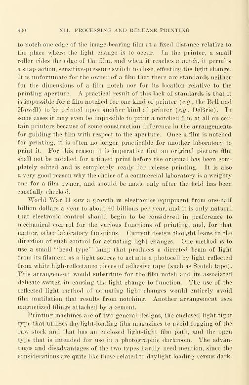
400 XII. PEOCESSING AND EELEASE PEINTING
to notch one edge of the image-bearing film at a fixed distance relative to
the place where the light change is to occur. In the printer, a small
roller rides the edge of the film, and when it reaches a notch, it permits
a snap-action, sensitive-pressure switch to close, effecting the light change.
It is unfortunate for the owner of a film that there are standards neither
for the dimensions of a film notch nor for its location relative to the
printing aperture. A practical result of this lack of standards is that it
is impossible for a film notched for one kind of printer (e.g., the Bell and
Howell) to be printed upon another kind of printer (e.g., DeBrie). In
some cases it may even be impossible to print a notched film at all on cer-
tain printers because of some construction difference in the arrangements
for guiding the film with respect to the aperture. Once a film is notched
for printing, it is often no longer practicable for another laboratory to
print it. For this reason it is imperative that an original picture film
shall not be notched for a timed print before the original has been com-
pletely edited and is completely ready for release printing. It is also
a very good reason why the choice of a commercial laboratory is a weighty
one for a film owner, and should be made only after the field has been
carefully checked.
World War II saw a growth in electronics equipment from one-half
billion dollars a year to about 40 billions per year, and it is only natural
that electronic control should begin to be considered in preference to
mechanical control for the various functions of printing, and, for that
matter, other laboratory functions. Current design thought leans in the
direction of such control for actuating light changes. One method is to
use a small "bead type" lamp that produces a directed beam of light
from its filament as a light source to actuate a photocell by light reflected
from white high-reflectance pieces of adhesive tape (such as Scotch tape).
This arrangement would substitute for the film notch and its associated
delicate switch in causing the light change to function. The use of the
reflected light method of actuating light changes would entirely avoid
film mutilation that results from notching. Another arrangement uses
magnetized filings attached by a cement.
Printing machines are of two general designs, the enclosed light-tight
type that utilizes daylight-loading film magazines to avoid fogging of the
raw stock and that has an enclosed light-tight film path, and the open
type that is intended for use in a photographic darkroom. The advan-
tages and disadvantages of the two types hardly need mention, since the
considerations are quite like those related to daylight-loading versus dark-
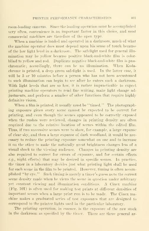
PRINTER PERFORM A N< IE CHARACTERISTICS 401
room-loading cameras. Since the Loading operation must be accomplished
very often, convenience is an important factor in this choice, and most
commercial machines are therefore of the open type.
When a machine is loaded and operated in a darkroom, much of what
the machine operator does must depend upon his sense of touch because
of the low light level in a darkroom. The safelight used for general illu-
mination may be yellow because positive black-and-white film is color-
blind to yellow and red. Duplicate negative black-and-white film is pan-
chromatic ;accordingly, there can be no illumination. When Koda-
chrome is printed, a deep green safelight is used. In the latter case, it
will be 5 or 10 minutes before a person who has not been accustomed
to such illumination can begin to see after he enters such a darkroom.
With light levels that are so low. it is rather impracticable to expect
printing machine operators to read fine writing, make light change ad-
justments, and perform a number of other functions that require highly
definitive vision.
When a film is printed, it usually must be "timed." The photograph-
ing exposure given every scene cannot be expected to be correct for
printing, and even though the scenes appeared to be correctly exposed
when the rushes were reviewed, changes in printing density are often
required due to the relative location of scenes within the edited film.
Thus, if two successive scenes were to show, for example, a large expanse
of clear sky, and then a large expanse of dark woodland, it would be nec-
essary to reduce the printing exposure somewhat on one and to increase
it on the other to make the naturally great brightness changes less of a
visual shock to the viewing audience. Changes in printing density are
also required to correct for errors of exposure, and for certain effects
e.g., night effects) that may be desired in specific scenes. In practice,
the timer in a laboratory decides just what printing light shall be used
for each scene in the film to be printed. However, timing is often accom-
plished "by eye." Such timing is merely a timer's guess as to the correct
scene density made when he views the scene in question under arbitrary
yet constant viewing and illumination conditions. A Cinex machine
(Fig. 101) is often used for making test prints at different densities of
important scenes when a large print run is to be made. The Cinex ma-chine makes a graduated series of test exposures that are designed to
correspond to the printer lights used in the particular laboratory.
The printing operation, in essence, is the exposure of the raw stock
in the darkroom as specified by the timer. There are three general ar-
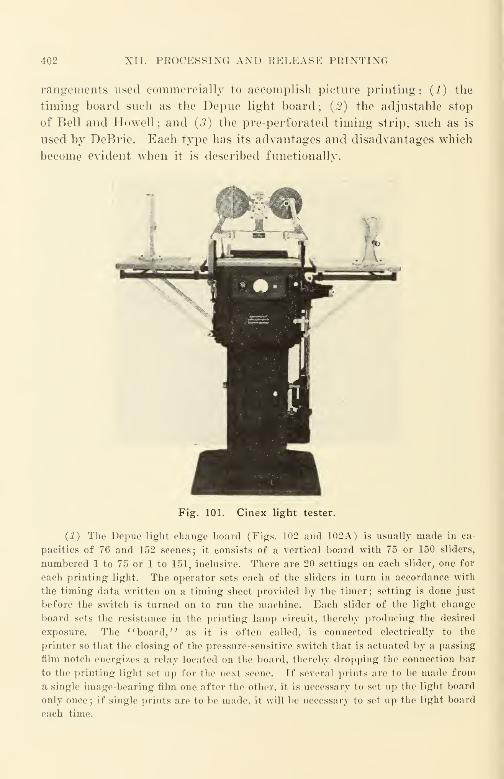
402 XII. PROCESSING AND RELEASE PRINTING
rangements used commercially to accomplish picture printing: (1) the
timing board such as the Depue light board; {2) the adjustable stop
of Bell and Howell; and (3) the pre-perforated timing strip, such as is
used by DeBrie. Each type has its advantages and disadvantages which
become evident when it is described functionally.
Fig. 101. Cinex light tester.
(1) The Depue light change board (Figs. 102 and 102A) is usually made in ca-
pacities of 76 and 152 scenes; it consists of a vertical board with 75 or 150 sliders,
numbered 1 to 75 or 1 to 151, inclusive. There are 20 settings on each slider, one for
each printing light. The operator sets each of the sliders in turn in accordance with
the timing data written on a timing sheet provided by the timer; setting is done just
before the switch is turned on to run the machine. Each slider of the light change
board sets the resistance in the printing lamp circuit, thereby producing the desired
exposure. The "board," as it is often called, is connected electrically to the
printer so that the closing of the pressure-sensitive switch that is actuated by a passing
film notch energizes a relay located on the board, thereby dropping the connection bar
to the printing light set up for the next scene. If several prints are to be made from
a single image-bearing film one after the other, it is necessary to set up the light board
only once; if single prints are to be made, it will be necessary to set up the light board
each time.
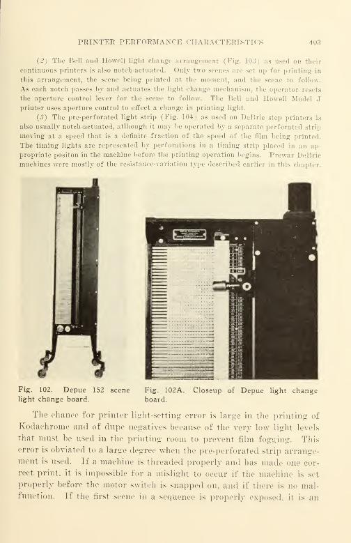
PRINTER PERFORMAXCI-: CHABACTERISTK - 403
The Bell and Howell light change arrangemenlIPig. 1'
i on their
continuous printers is also notch-actuated. Only t\\<> scenes are Bel op for printing in
this arrangement, the scene being printed at the moment, and the scene to follow.
As each notch passes by and actuates the light change mechanism, the operator resets
the aperture control lever for the scene to follow. The Bell and Howell Model J
printer uses aperture control to effect a change in printing light.
(3) The pre-perforated light strip (Fig. 104) as used on DeBrie step printers is
also usually notch-actuated, atlhough it may be operated by a separate perforated strip
moving at a speed that is a definite fraction of the speed of the film being printed.
The timing lights are represented by perforations in a timing strip placed in an ap-
propriate positon in the machine before the printing operation begins. Prewar DeBrie
machines were mostly of the resistance-variation type described earlier in this chapter.
Fig. 102. Depue 152 scene
light change board.
Fig. 102A. Closeup of Depue light changeboard.
The chance for printer light-setting error is large in the printing of
Kodachrome and of dupe negatives because of the very low light levels
that must be used in the printing room to prevent film fogging. This
error is obviated to a large degree when the pre-perforated strip arrange-
ment is used. If a machine is threaded properly and lias made one cor-
rect print, it is impossible for a mislight to occur if the machine is set
properly before the motor switch is snapped on. and if there is no mal-
function. If the first scene in a sequence is properly exposed, it is an

404 XII. PROCESSING AND RELEASE PRINTING
indication that the timing strip has been threaded properly. Without
machine malfunction, it is impossible for the timing of a particular scone
to be different from that indicated by the punch-mark in the timing strip.
AVhere the cost of raw film is high—as is the case with 16-mm color film
—
such arrangements that reduce mislights reduce the need for costly re-
prints.
Fig. 103. Closeup of Bell and Howell light change arrangement.
There is no " ideal" light-change mechanism in commercial use. The
widely used rheostat type that changes the lamp current has the dis-
advantage—often quite serious—that the color temperature of the lamp
changes every time the current changes. The diaphragm type of light
change has a more limited light-variation range than the more widely
used rheostat type ; although the color temperature of the lamp may be
kept constant, the specular quality of the light changes with diaphragm
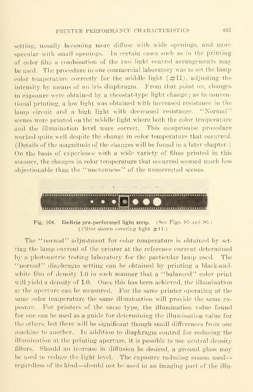
PRINTER PERFORMANCE CHARACTERISTICS 405
setting, usually becoming more diffuse with wide openings, and more
specular with small openings. In certain eases such as in the printing
of color film a combination of the two light control arrangements may
be used. The procedure in one commercial laboratory was to set the lamp
color temperature correctly for the middle light (#11), adjusting the
intensity by means of an iris diaphragm. From that point on, changes
in exposure were obtained by a rheostat-type light change ; as in conven-
tional printing, a low light was obtained with increased resistance in the
lamp circuit and a high light with decreased resistance. " Normal"
scenes were printed on the middle light where both the color temperature
and the illumination level were correct. This compromise procedure
worked quite well despite the change in color temperature that occurred.
(Details of the magnitude of the changes will be found in a later chapter.)
On the basis of experience with a wide variety of films printed in this
manner, the changes in color temperature that occurred seemed much less
objectionable than the "unevenness" of the uncorrected scenes.
• • • [#]
Fig. 104. DeBrie pre-perforated'light strip. (See Figs. 95 and 96.)
(Filter shown covering light #11.)
The "normal" adjustment for color temperature is obtained by set-
ting the lamp current of the printer at the reference current determined
by a photometric testing laboratory for the particular lamp used. The
"normal" diaphragm setting can be obtained by printing a black-and-
white film of density 1.0 in such manner that a "balanced" color print
will yield a density of 1.0. Once this has been achieved, the illumination
at the aperture can be measured. For the same printer operating at the
same color temperature the same illumination will provide the same ex-
posure. For printers of the same type, the illumination value found
for one can be used as a guide for determining the illumination value for
the others, but there will be significant though small differences from one
machine to another. In addition to diaphragm control for reducing the
illumination at the printing aperture, it is possible to use neutral density
filters. Should an increase in diffusion be desired, a ground glass maybe used to reduce the light level. The exposure reducing means used
—
regardless of its kind—should not be used in an imaging part of the illu-
406 XII. PROCESSING AND RELEASE PRINTING
mination system, since a reduction in print-resolving power is likely to
occur.
In conventional printers using incandescent lamps for light sources,
it is possible to utilize simultaneously a diaphragm change and a rheostat
change to obtain scene-by-scene color balance change, using, e.g., 3 light
sources limited to the particular color bands that the particular sources
are to print. Going another step farther, it would be convenient to con-
trol contrast. This can be done by reducing the exposure time and in-
creasing the intensity of the exposure, and by masking (or its equivalent)
.
If all the desirable features of control were incorporated, the printing
machines would be quite different in appearance at least from that which
we have today. Due to the great growth in the use of electronics, evi-
dence of such activity is already to be found, and it should not be manyyears before a color-printing machine will be more of a maintenance
problem for an electronics technician than for a mechanic.
Printer Exposure Consistency. It is even more important to attain
consistency in printing than in exposure of the original. In original
photographing, there are many variables not within the realm of accurate
control, and correction for most of these must be applied at the labora-
tory. In outdoor photographing, for example, the cameraman has no
control over the brightness of the source (the sun), he can merely adjust
the iris diaphragm of his camera lens, etc. In the laboratory, however,
it is possible to adjust brightness characteristics as well as spectral char-
acteristics, and to exercise some measure of control over printer light
diffusion. The ability to repeat conditions accurately is most essential
to the production of good prints, just as it is essential to the making of
tests.
It is just as important for constant running speed to be maintained
in a printer as it is in a camera. The present trend in printer design
is to supply only synchronous motors—preferably three phase—for
printer drive. Such drive provides theoretically constant motor torque
throughout the alternation cycle of the supply current, and if the three-
phase motor is resiliency mounted on the customary rubber mounts and
coupled to the printer through a resilient coupling (such as a Lord
coupling), the design can mean a very material reduction in ma-
chine vibration. The rather large order of machine vibration often en-
countered in printers is particularly objectionable in the case of sound
printers, where it introduces noise because of the' 'wiggling " of the
exposure lamp filament with respect to the axis of the optical system.
TECHNICAL CONTKOL 407
Iii the case of a picture printer, a similar "smearing" effect occurs tend-
ing to reduce the resolving power of the print produced.
It would seem to be wasted effort to use an excellently balanced
three-phase motor in a resilient mount and resiliently coupled to a
printer if any portion of the main printer drive that moves the film past
the printer aperture or other exposure aperture is belt-driven. Flexible
drives such as belt drives and rim drives provide excellent mechanical
smoothing and filtering in the case of good designs for turntables for
disk recording. Unfortunately, the big disadvantage of belt drive in a
printer is that the slip is not constant and varies in an uncontrolled
way over too great a slip range for really high-grade performance.
The importance of constant supply voltage to the printer exposure
lamp can hardly be overestimated. In order to avoid stroboscopic ef-
fects, it is usually necessary to use only direct current for the picture
printer exposure lamp. The use of alternating current causes varia-
tions in density from frame to frame along the film. Only direct current
is, of course, suitable for the exposure lamp of the sound printer. " Rip-
ples " in the supply of current to the exposure lamp of the sound printer
will show up as additional hum and noise. If the "ripples" are due to
insufficient filtering in a rectifier used to supply the lamp, or if they are
due to a large commutator ripple of a generator that is insufficiently
filtered, they will show up as hum in the first case and as the whine of
the commutator in the second case. Since it is desirable to maintain
all variable-area sound track densities within 0.1 of the nominal density,
the density variation in a single 400-ft. reel should be minute, preferably
one-fourth of the permissable variation. Where it is possible to use
low-voltage lamps for printing, such as is the case with many sound
printers, the lead storage battery is a really good source because of its
excellent regulation. If a battery of large size is used (200 amp.-hr. or
larger), the storage battery proves to be an inexpensive as well as re-
liable source of well-regulated current.
Technical Control
Technical control has as its prime function the maintenance of con-
sistency of quality of the film processed; its secondary function is to de-
termine what is needed in an individual case to obtain the best practi-
cable result with the materials and methods used. To accomplish these
objects it lias tost equipment and test procedures, and—just as impor-
tant—it has the authority to order changes in production procedure to
accomplish its objects.
408 XII. PROCESSING AND RELEASE PRINTING
One of the first problems is the consistency of developing. Some cans
of film of a single emulsion and lot number are set aside for reference.
Each day—usually several times a day—a piece of the test emulsion is
exposed with a reference exposure, and developed at "standard time";
the results of the exposure are read on a densitometer. More often than
not, the reference exposure is provided by an Eastman lib Sensitometer.
Eastman Kodak provides accurately calibrated lamps for the sensi-
tometer to make it possible to hold the exposure variation within the
required range. "Standard time" is merely the reference developing
time for the particular developing machine under the particular set of
conditions, and usually refers to the developing time at which most film
is processed in a specific laboratory.
The exposures provided by the reference exposure device (such as
the Eastman lib Sensitometer) are compared with the exposure pro-
vided by a reference setting of each printer to be operated. This com-
parison provides a means of determining the amount and the nature of
the "drift" of the exposure in a particular printer compared with the
reference. An auxiliary rheostat or auxiliary diaphragm adjustment
is made on each printer to return it to the operating "norm" from which
it has deviated. Day-to-day checking is necessary for many reasons,
not the least of which is that no two lamps are ever alike, and because
the output of a particular lamp drops off with age as the lamp bulb
blackens. In optical systems where the lamp filament is imaged—as in
the case of an optical printer and certain contact printers where the
light source is an appreciable distance away from the printer aperture
or gate—the lamp filament may sag when the lamp is heated. In this
event, the illumination field becomes uneven and the output of the opti-
cal system drops off markedly. Fortunately, when lamp filament sag-
ging takes place, the filament does not ordinarily drop suddenly but
tends to sag gradually.
Technical control also has as its function the production planning
needed to obtain the desired result in particular cases. A particular
print contrast can be obtained in an almost infinite variety of ways.
An increase in developing time can be offset by a decrease in exposure,
while a decrease in developing time can be offset by an increase in ex-
posure. Printers operate ordinarily at a single speed for a particular
kind of film (it is neither practicable nor desirable to change the printer
speed while the printer is running), and prints are therefore often
"saved" in laboratories by reducing the developing time in the event

PRINT INSPECTION 409
of overexposure in printing. For relatively small changes in developing
time, the reduction in contrast is not evident—particularly to the un-
initiated. For reasons already given, it is usually the practice of com-
mercial laboratories to "standardize" on a reference developing time
for a developing machine and to make all other corrections (such as the
correction for the speed difference between the reference emulsion lot
of film and a particular lot being printed) in the auxiliary exposure ad-
justment of the particular printer used.
Print Inspection. The subject of print inspection is usually ap-
proached with trepidation; it is one of the "delicate" subjects encount-
ered in the motion picture industry. The reason for this attitude is
related to price;good inspection is costly while prints are usually cheap.
No laboratory cares to admit that its inspection is inadequate or faulty.
If a customer wants good inspection of the films that he has ordered
from a laboratory, he must be prepared to pay the price. Good inspec-
tion is very valuable, yet, what has been aptly said in connection with
other products applies equally to film; "Nobody can inspect quality into
a product; it has to be built into it." All that inspection can be ex-
pected to do is to reject that which is bad; it cannot improve any prod-
uct already manufactured.
It must be frankly admitted that statistical quality control, although
very widely used to very good advantage in so many industries (notably
the manufacture of telephones), is almost unknown as a routine pro-
cedure in the manufacture of release prints. Statistical quality control
is very widely used in the manufacture of raw film by film manufac-
turers. They use this most valuable mathematical tool to keep their
product quality at a maximum level and their inspection costs at a mini-
mum. The remarkable reliability of such a complex material as raw
film is a tribute to the film manufacturers' use of statistical quality con-
trol to make an excellent product at a low price to the user.
To get the most out of statistical quality control requires the collec-
tion of test data. These data are collected by inspecting each and every
print for a short period of time at least. As has been pointed out before,
film users are at a serious disadvantage because there is no single stand-
ard measure of quality for either picture or sound, nor is there any single
standard measure for quality degradation steps for either picture or
sound. Thus, a very serious problem that confronts any progressive
laboratory manager is to determine just which attributes should be
checked and which should not. The nature and extent of the checking
410 XII. PROCESSING AND RELEASE PRINTING
of quality attributes is very closely related to the cost of the inspection
just as it is in any other manufacturing process.
There has been no universal agreement upon the attributes for which
tests should be made, nor has there been agreement upon the relative
importance of those known to be important. The first major step in the
direction of resolving this question occurred when the American Stand-
ards Association War Committee on Photography and CinematographyZ52 was set up at the joint request of all American Armed Forces during
World War II. An all-too-common attitude in laboratory managementis that quality standards for prints and how they are established andmaintained is of no concern to a purchaser. It must be admitted that
the measurement of quality and of quality degradation is a complex
matter with many variables, the effects of which have not been statisti-
cally related to the over-all quality, or to the over-all quality degradation
in a release print. This is a challenge to progressive managements.
An agreement upon a specification and upon methods of testing was ultimately
reached during the last war; this was American War Standard Z52.3-1944 ll Specifica-
tion for 16-Mm Motion Picture Release Prints' ' which was approved May 29, 1944.
Like all War Standards, this standard expired with the end of the War.
At this point, a few remarks may be made concerning print inspec-
tion and print quality in general ; these remarks are merely an extrapo-
lation of the widely accepted theory of quality control as it applies to
any manufactured product.
Theoretically, when a product is manufactured, it is offered for sale
to a prospective buyer. It matters little whether the buyer be an in-
dividual, a corporation, a government, etc. Once the product is manu-
factured, it is a fait accompli; the quality is what it is, and nothing but
further work can change it. Thus inspection can make the product
neither better nor worse.
If the purchaser has had no prior experience with the seller, it is
reasonable that the purchaser shall be more concerned about accepting
something that is defective than he is about rejecting something that is
good. If the product is not similar to that made for others or if the
product made for others is not subjected to the identical inspection de-
sired for the product being purchased, the experience record of the seller
with other customers is of no advantage whatever to the purchaser.
Statisticians consider this the lowest of the three orders of control; it
is very costly, since all items must be inspected for all attributes. This
is called 100% inspection.
PEINT INSPECTION 411
If over a period of time, the seller has been delivering items to the
purchaser, and the purchaser's inspection shows that all items delivered
are satisfactory in every print, it becomes apparent that such 100%inspection on the part of the purchaser will result in a waste of man-
hours because of duplication that serves no useful purpose. It is rea-
sonable to believe that in a short time it should be possible for the pur-
chaser to reduce the amount of inspection to an intermediate stage, and
later on possibly to reduce the inspection still further to a final inspec-
tion stage where only a small percentage of the product is inspected.
The mathematical criteria for these three stages of inspection are found
by calculation in accordance with the methods outlined in the American
Standards Association references mentioned earlier.
The "quality" of the product should determine the amount of time
and money to be spent on inspection by the purchaser. Regardless of
the manufacturing quality level, inspection of prints by the purchaser is
still necessary. There are few situations where projection once by the
purchaser of each complete reel is not fully justified and distinctly ad-
vantageous. It is usually "penny wise and pound foolish" to think
that the purchaser cannot afford it.
Print inspection by the laboratory has a double objective, one of
which is to make reasonably certain that the customer will have no rea-
son to reject the print offered for sale. The other objective is to measure
the quality of the particular print and its quality deviation from thev'norm," and from the design objective of the print-making process. It
should be assumed that the customer's inspection is critical and will
result in rejection for just cause. The laboratory inspection, however,
should be even more critical in order to ascertain that a defective print
is not offered for sale, and that a particular kind of defect does not recur.
No commercial laboratory can make a profit if the reprint percentage
due to poor control, errors, carelessness, and other related causes of de-
fective prints is not kept to an absolute minimum.The simplest form of inspection is projection of the print under test
on a good 16-mm sound projector used under suitable conditions. Atrained inspector looks at the projected picture and listens to the pro-
jected sound without interruption throughout the complete reel to be
checked. The screen should be similar to that described in AmericanWar Standard Z52.5G ; the projector should have all the features pos-
sible specified in American War Standard Z52.1. Although these stand-
ards are no longer in force, their requirements describe products that
412 XII. PROCESSING AND RELEASE PRINTING
can be manufactured, and may be used as a guide in the choice of avail-
able equipment despite the fact that few commercial products can be
expected to meet all the requirements.
The print should be inspected at the standard sound speed of 36 ft.
per minute and should be viewed and heard with the same equipment
and from the same observation position at all times. The equipment
used should be kept in good condition at all times and should not be
altered nor controls re-set unless improvement is very important. Such
changes should only be made after the inspectors have had the oppor-
tunity to make a large number of "A-B" tests on the ''before" and
"after" conditions. Since the performance of commercial 16-mm sound
projectors varies over a very wide range from one make to another and
from one model of a particular maker to another, it is desirable that all
machines for routine inspection be of the same make and model, of cur-
rent manufacture, and tone controls set in the same manner. For such
service Bell and Howell projectors seem to be as well suited as any.
Such machines should always be operated with the same tone control
setting on all machines at all times ; the proper setting is best determined
by running an SMPE multi-frequency test reel. Data concerning per-
formance variation of different commercial machines may be obtained
from Bureau of Standards Circulars C437 and C439. Although the
data found in these bulletins are several years old, they show quite
clearly the range of variability, which does not appear to have been
materially reduced in the intervening years (see Chapter XIII).
On the average it requires 15 minutes to run one reel of film. With
present wages of inspectors at over $1.50 per hour, 40^ per reel is
needed to pay for the inspector alone. If to this cost is added the over-
head (which includes the cost of inspection space, projection equipment,
electric current, lamps, and general overhead), the cost of inspecting a
single 400-ft. reel can easily reach $1.00 or more. If the print is one of
a very large number of mass-produced 16-mm black-and-white prints
that sell for about 1.5^ per foot, an inspection cost of $1.00 would rep-
resent 16% of the print cost. If, however, the film to be inspected is a
Kodachrome dupe print which costs about 10^ per foot, an inspection
cost of $1.00 represents but 2.5% of the print cost. In the former case,
a customer could hardly expect a laboratory to perform a complete pro-
jection inspection of every print; in all likelihood the laboratory would
inspect one print in every 10 or 20. In the latter case (as for Koda-
chrome), however, a customer should expect a laboratory to perform a
PICTURE INSPECTION 413
complete projection inspection of every color print—and the smart
customer will inspect it himself to make certain that the print is every-
thing it is supposed to be.
Picture Inspection. An important characteristic of a release print
is picture detail, and it is important that the inspector view the screen
in such relation that he is capable of seeing it. The theoretical resolving
ability of the eye is 100 lines per millimeter at a distance of 2 w (where
w is the width of the screen). At any other distance, the resolving
ability of the eye is inversely proportional to the distance. At 4 w, for
example, the resolving ability of the eye is only 50 lines per millimeter.
Inspectors should be critical of detail quality and should always view
the test screen from a single distance so that mental comparisons of one
print with another can quickly and readily be made with no need for
"weighting" the results as would be necessary if pictures were viewed
from different distances. This is best accomplished by placing a chair
for the inspector in the proper place—preferably at a distance of about
2.5 w from the screen—and directly in line (as nearly as practicable)
with the center of the screen. The inspector should be expected to use
the fixed chair during all inspections. It should be pointed out that
most projection lenses supplied commercially are definitely inferior to
the resolving ability of the eye when a screen is viewed from a distance
of 2.5 w. It can be readily determined if the lens used for inspection
is poor ; a poor lens will not provide a sharp picture in the corners whenthe picture is sharp in the center. Although no lens made commercially
will meet a resolving power requirement of 100 lines per millimeter at
the corners as well as at the center of the picture, good lenses can ap-
proach this figure at the center and show a resolving power of 50 to 60
lines per millimeter at the corners of the picture. These resolving power
values represent good performance in commercial lenses, and are
measured without change of focus adjustment between best adjustment
for the center of the picture and best adjustment for the corners. Toobtain a lens of this kind usually requires correspondence with the en-
gineering department of the projector manufacturing company; East-
man Kodak is, in all likelihood, in the best position to supply lenses
approaching such- stringent requirements by selection from among the
best production lenses that they manufacture. Other manufacturers
such as Bausch and Lomb can also supply high-grade lenses on special
order, but, because the demand for high quality lenses has been neither
insistent nor widespread, prolonged negotiation with manufacturers'
agents may be needed to obtain test lenses of the desired quality.

414 XII. PROCESSING AND RELEASE PRINTING
Sound Inspection. Sound inspection of release prints is—or should
be—a little- more involved. If we can assume that one of the purposes
of inspection is to obtain information that can be used to'
' tighten up '
'
the quality of processing so that improvements can be made properly,
sound inspection is something more than a mere audition of the sound
track. In this regard, sound is no different from picture; inspection
of both should provide not only data as to the acceptability of the print,
but should also serve as a positive quality index in providing suggestions
for future improvements. Anticipating improvement in release print
quality requires the collection of data that costs money; it is an invest-
ment in the future that deserves much more attention than it has been
accorded.
For routine inspection of sound, a good quality sound projector of
current manufacture such as the Bell and Howell is a good commercial
reference. For the more thorough inspection of sound, the test equip-
ment should be of such high quality and precision that a user can justi-
fiably have unquestioning confidence in it. This can only be obtained
if the equipment is of higher quality than the films that it inspects, so
that performance deviations noted can be correctly attributed to the film
and not to the sound testing and measuring equipment. The equipment
should be good enough to show up differences in the quality of even ac-
ceptable prints made during a single run as a single batch. Such equip-
ment does exist on the market, and no progressive film laboratory can
afford to be without it even though most do not have it. This equipment
is also used for inspecting fine-grain sound-track prints to be used for
re-recording and for other critical sound films.
In essence, the equipment consists of a high-quality film phonograph,
a wide-range amplifier, and a wide-range loudspeaker. Despite the low
level of the air-borne noise that it makes while running, the film phono-
graph should be located in a room other than the listening space. The
listening space should be acoustically good, and as free of extraneous
noise as possible. Each item of equipment should be consistent in per-
formance over long periods of time, and with ordinary maintenance
and inspection the recommended items are capable of furnishing such
performance.
The film phonograph may be a Maurer unit of current manufac-
ture, factory-equalized for "output flat to 10,000 eps." This machine
has very good film motion and has a good chromatically-corrected opti-
cal system providing a slit of approximately 0.3-mil width.. The optics
SOUND INSPECTION 415
of the machine* may be adjusted at will to scan either the near surface
or the far surface of the film; the adjustment shift of 0.006 in. (which
accounts for the film thickness) is obtained by two preadjusted limiting
stops. An exciter lamp of 2-amp. rating is used; since the cross-section
of this lamp is quite large compared with the 3/4- or 1-amp. lamps
widely used in sound projectors, the microphonic noise generated by
exciter lamp vibration is materially lower than that in a sound projector.
A preamplifier, feeding an output transformer, is mounted in the base
of the machine. The Maurer output impedance is 200 ohms; Western
Electric uses 600/150, RCA 250/500. (Standardization of performance
measurement and of impedance is urgently needed.) A power supply
provides all d.-c. current required by the machine ; this includes exciter
lamp current, heater current for the preamplifier, and high voltage for
the preamplifier plate circuit and polarizing voltage for the photocell.
The film phonograph uses a single-phase synchronous motor for film
propulsion. The mechanical vibration that occurs is quite low yet it is
greater than would be the case if an equally well-balanced three-phase
motor might be used. A selected nonmicrophonic tube type such as the
1603 would be a better choice for the first stage than the commercial elec-
tron tubes that are used. The performance of the machine as supplied is
quite good with regard to microphonics despite this lack, chiefly because
of the good gears which generate a relatively low level of vibration, and
because of the tube suspension mounting that is used to attenuate the
disturbances reaching the tube.
A suitable amplifier combination which has sufficient gain and
output power is the "Western Electric 142B. It also has a reasonably low
noise level and a wide frequency range extending to 20 kc. The input
should be connected for 200 ohms to match the impedance of the film
phonograph, while the output should be connected for 4 ohms to feed
a W. E. Company 757A loudspeaker. Instructions for making imped-
ance-adjusting connections in the amplifiers are found in the instruc-
tion book supplied by the manufacturer. A ''tee" attenuation pad maybe used betwreen the film phonograph output and the 141 amplifier input
for volume control.
As it is convenient and useful to be able to check the response-fre-
* The newer Maurer film phonographs do not provide for focus shift.
In these machines it is necessary to turn the film over and run it in the opposite direc-
tion in order to have the sound track in focus.

416 XII. PROCESSING AND RELEASE PRINTING
quency characteristics of the film phonograph and its associated ampli-
fier, an output control box should be connected between the output* of
the 142B amplifier and the loudspeaker. This box may contain a stand-
ard VU meter (Weston) with its associated Daven TA-1000-2 attenu-
ator, a double-pole double-throw toggle switch, a 600-ohms resistor to
be used as a dummy load, and the necessary interconnections. When the
toggle switch is in one direction, the volume indicator is connected across
the dummy load for measurement purposes; when the toggle switch is
in the other direction, the volume indicator is connected across the loud-
speaker. Meter readings are more steady and consistent when taken
across a dummy load rather than across a loudspeaker ; all readings that
are entered in a log should be made in this manner. Figure 105 is a
schematic diagram of the connections using a Jensen HNP-51 loud-
speaker which is of correct impedance for direct connection.
600 wINPUT Double
Telephone
Jack
!
WestonVU Meter
DavenAttenuator
600
resistor 600 w OUTPUTto Speoker
Fig. 105. Audio output control box.
ioc unrii
jA/W^-|
O—>/WV •—vJUJUULy—•—
O
17.5 ohm 2.1 mh
Values within ± 10% of obovewill be satisfactory
Fig. 105A. Jensen
loudspeaker HNP-51 woofer-simulating
network.
As ordinarily used, the loudspeaker should have its high-frequency
response control switch in the "wide open'' position. The hiss anddistortion produced will be clearly audible, and variations from one
print to another should be evident to some extent. To make the dif-
ferences more pronounced, a woofer-simulating load (Fig. 105A) maysubstitute for the low-frequency cone by connecting it through a double-
pole, double-throw, toggle switch. This removes the low frequencies
(below the crossover frequency of the speaker), leaving only the high
frequencies being reproduced. Such removal of the low frequencies
in reproduction removes the sounds that mask the noise and distortion,
thereby making it more evident. Routine listening would be done with
the full range of the loudspeaker ; only critical cases would require low-
frequency removal by switching. Such testing and listening can be
considered analogous in a sense to the use of low magnification for rou-
* A Western Electric 18A autotransformer is needed to adjust the output im-
pedance to the 600 ohms input value of the control box.

sorXD INSPECTION 417
tine examination with a microscope, and higher magnification for de-
tailed examination.
It must be recognized that the above equipment is not i
'front parlor"
equipment as it attempts to show up noise and distortion rather than
to conceal it as is customary when high frequency response is cut off
by low-pass filters or by amplifiers and loudspeakers* of limited fre-
quency range. If it is desired to operate this equipment under "front
parlor" conditions, it will be necessary to use an appropriate low-pass
filter to limit the high frequency response to the useful range, the range
where the noise level is not excessive. The performance of high grade
16-mm sound tracks on such equipment proves quite an agreeable sur-
prise when heard for the first time.
It is possible with the Bell and Howell sound projector to install a
special photocell input preamplifier that is similar to that in the film
Film
Phonograph#1
O OFilm
Phonograph
#2Hewlett-PackardModel 500A
Fig. 106. Print comparison sound measurement schematic.
phonograph. This will make it possible to listen to a combination print
with the same high-quality amplifier and loudspeaker system as used
with the film phonograph. Although the over-all quality will not be as
good as that from the film phonograph due to higher flutter, poorer
high-frequency response, and a poorer signal-to-noise ratio, the degra-
dation suffered is not excessive and, accordingly, the arrangement is
quite useful in checking more accurately the sound quality of prints.
Oftentimes it is advantageous to be able to make "A-B" comparison
tests. To accomplish this, provision can be made for switching between
two film phonographs or between two Bell and Howell projectors ar-
ranged with photocell input preamplifiers (Fig. 106). If the projectors
are used, it will probably be desirable to have synchronous motor drives.
so that comparison testing can be accomplished in synchronism since
commercial sound projectors are ordinarily equipped with governor-
controlled or induction motors which do not run at synchronous speed.
* See pages 300-303.

418 XII. PROCESSING AND RELEASE PRINTING
Practical Laboratory Operation
A commercial film laboratory is primarily a business, and like any
other business it is operated for the purpose of making a profit. The
product of the business —prints—must be competitive in quality and
in price with similar products made by others. If a higher-than-av-
erage quality is desired, it should and does command a higher price.
The increase in price above average is related to the increase in utility
of the better product to the user; this may or may not conform
to the increase in cost necessary to produce it. In most cases a large
increase in quality does not command a large increase in price because
the market usually cannot justify such an increase. Despite this, there
are special cases where a large increase in quality will command a sub-
stantial increase in price ; there are even a very few cases where the best
quality obtainable commercially is so badly needed that the high cost is
justified almost regardless of where it may fall (assuming efficient plant
operation).
The practical process of buying prints is complicated by the fact
that there are no hard-and-fast standards by which the quality of the
prints can be measured accurately. The customary procedure that is
followed in making prints in large quantities is that a trial composite
print is prepared by the laboratory, examined critically by the buyer,
and corrections suggested. If the suggestions are feasible, the laboratory
prepares a second trial composite print for the buyer's inspection. Or-
dinarily no further corrections are required beyond this stage, but if
they are, the buyer deals directly with the laboratory's responsible rep-
resentative and decides just what to do. As soon as a fully acceptable
trial composite print is made, the buyer authorizes the laboratory to
proceed with his order. The laboratory often retains the final trial
composite print as a reference sample so that questions regarding specifi-
cations may be settled easily by direct A-B comparison with the refer-
ence.
Although this practice for quantity production of prints is almost
universal in the film industry in the United States, practical variations
of it occur where small quantities of prints are made. On the whole,
these variations make an attempt to recognize the realities of the situa-
tion in that it would be impractical, for example, for a laboratory to
make :\ trial composite prints if only a single release print were to be
ordered. In practice, only one print would be made in a case of this
kind, with a second one being made only if the first were quite wide of

PEACTICAL LABORATORY OPERATION 419
the desired mark. Laboratory business policies are as widely different
as people are different. The general rule that is applicable governs all
business transactions; if the manufacturer's product is defective in ma-
terial or workmanship, he repairs or replaces the defective component.
In a film, this may mean the replacement of a "section" (a portion of
the film or it may mean the making of a completely new print. Or-
dinarily print replacement policies are most liberal where the print
quality is highest. There are no fixed rules, either for the 16-mm labo-
ratory industry as a whole, or for particular laboratories in it. Much
depends upon the buyer's knowing the laboratory, and the laboratory
knowing the buyer ; in many laboratories each order represents a specific
negotiation between laboratory and customer.
Since there are no hard-and-fast rules governing the handling of
small print orders, it is necessary that the buyer make his wishes per-
fectly clear to the laboratory with regard to how his prints are to be
made. In some rare cases, it is possible that the exposure of the picture
original is quite "even" and needs little correction, and the improve-
ment by timing would not be worth the increase in price ; a one-light
print would then be ordered. In most cases, however, timing will be
required, and the buyer should tell the laboratory the special require-
ments to be met—if any; it is often a good idea to provide a "shot list*"
with notations as to special scene density requirements, etc. If the
printing requirements are at all critical, the buyer may request the
laboratory to check with him when the film is to be timed. Such pro-
cedures can aid in removing uncertainty in the dealings between the
buyer and the laboratory, and, in doing so, make possible a material
improvement in print quality as desired by the buyer.
In a business as competitive as a film laboratory, considerable capital
investment is required in the machinery necessary to do the work well.
Although the turnover is far more rapid than in heavy industry, and
the investment required is much smaller per dollar of sales, the business
is dynamic—constantly changing and improving. A small segment of
the buying market can be relied upon to be interested in the best quality
product commercially feasible, and is prepared to pay the extra cost
that the better quality involves. The large segment of the market is
interested in the high quality product but feels that the price is cur-
rently "out of line" with the value received; eventually, however, the
better quality is available to this market at little or no increase in price
as the general quality level rises.
* See Figure 75.
420 XII. PEOCESSING AND EELEASE PEINTING
The core of the average laboratory's business is release prints. Al-
though the variety of other services is quite wide, almost all of these
services are- "feeders" of the release print business. The reason is quite
simple; it is in release printing that the economy of mass production
can make itself felt in terms of lower prices, better quality, and better
profits (even though the unit profit is small). Limiting waste and
errors is very important ; this is one of the reasons why all laboratories
abhor "reprints." A reprint is merely a job done over again at labora-
tory expense because the laboratory inspector finds the quality of the
film he has tested unsatisfactory for shipment to the customer. In a
well-run laboratory, reprints account for but a small percentage of the
total laboratory output. Release print raw film is an appreciable part
of the price of a print; it costs the laboratory about 0.6^ or more per foot
for black-and-white positive film, and about 5^ per foot for color dupli-
cating film. With such high material costs and with continually rising
labor costs, no laboratory can afford many reprints.
Production operations are performed in a routine manner. If
specific instructions are not provided, the laboratory will use its best
judgment in accomplishing the work to be done. Laboratory personnel
are called upon to make a large number of "snap decisions" every day,
mostly associated with the immediate aspects of making prints. A buyer
of laboratory services should acquaint himself with the processes of the
laboratory so that he knows and understands what the processes are,
even though he may not understand their technology. The laboratory
representative, in turn, should be acquainted with the production and
other facilities at the command of the buyer, as well as with his purposes.
With this knowledge, much closer cooperation and better prints should be
possible to the mutual benefit of both parties.
Printing 16-Mm Picture from 16-Mm Originals. In making 16-mm
black-and-white release prints from 16-mm original picture film such as
black-and-white reversal or color tri-packs such as Kodachrome and
AnscoColor, the most practicable procedure is to make one intermediate
film, a black-and-white duplicate negative, from which release prints are
made. For best quality uniformity of release prints with lowest price,
the edited original film is timed to provide the duplicate negative; the
timing shall be accomplished in such manner that the release prints can
be made at a single printer light setting. With this procedure, the print-
to-print uniformity of the release prints should be very high, the speed
of printing may be high, and the cost of the release prints relatively
low.
PKACTICAL LABORATORY OPERATION 42]
A good duplicate negative requires raw stock of the highest resolving
power practicable. It should be the very best intermediate film copy
that we know how to make—almost regardless of cost. Since it may be
used to make several hundred prints, it would seem practical to spend
almost as much money to correct a deviation in the dupe from that which
is considered ideal as can be spent to correct that same deviation in each
and every print to be made. In a sense the relationship of a dupe to a
film laboratory is similar to that of special production dies, jigs, and
tools to a mechanical factory. The automobile industry long ago pointed
out the business wisdom of buying costly but accurate tools for the
mass production of products of high mechanical quality. Where the
mass production of high quality prints is the objective, it would seem
to be similar business wisdom to determine what is the best dupe that
can be made almost regardless of cost—and to go ahead and make it.
Should an error or deviation be found in a dupe that has just been
made, it is wise to scrap the defective dupe and to make another that
eliminates the defect.
The raw film most suitable at present is Eastman 5203 duplicating
negative. A good procedure is to print this film on a step-contact
printer. Although such a printer is slow when compared with commer-
cial continuous printers, the quality improvement should be observable
in the release prints. As used commercially in one laboratory, the film
is developed in a glycin developer at a relatively low gamma, yielding
quite high-speed developing (compared with negative developing times)
.
The cost of the dupe negative is correspondingly low and the resolving
power and graininess quite low compared with the more customary 6-min.
developing time in Kodak SD-21 developer at a development gamma of
about 0.65. Because the effective speed of the film is materially reduced
by the reduction in development gamma, appreciably more light is re-
quired in the printer for proper dupe negative exposure and the running
speed of the film is comparatively slow in the printer.
Only fine-grain release print raw film should be used. The dupe nega-
tive has been made for one-light printing, and no light changes are re-
quired during the release printing operation. If high printing speed
is required to obtain low printing cost, a continuous contact printer maybe used. If somewhat better picture quality is required, a step-contact
printer may be used, resulting in lower speed and somewhat higher print
cost. At present, DuPont 605A would seem to be the preferred raw stock
due to a difference in the shape of the toe of the H and D curve; East-

422 XII. PROCESSING AND EELEASE PRINTING
man 5302 appears to have slightly better grain characteristics. Both
films have a rated resolving power of about 90 lines per millimeter.
Only one grade of release-print, color-reversal, raw stock is generally
available; the resolving power of both the Kodachrome and the Ansco-
Color is about the same despite the marked differences in color reproduc-
tion. There is no special intermediate duplicating film available, since
both manufacturers have felt that it would be a mistake to encourage
anything beyond two generations of prints with the relatively simple
methods and inaccurate control now common in most integral tri-pack
color film printing. Intermediate duplicate color reversal copies have
been successfully made in the past, but a much higher order of control
was necessary to make such operation possible. In the absence of special
intermediate materials, comparative tests should be made upon all prac-
tical materials available, including raw film for original photographing
as well as for duplicating. If an intermediate color reversal duplicate
is made, it should be possible to effect all off-balance color corrections and
all timing corrections in the intermediate duplicate ; once more it should
be possible to make all release prints at one printer light setting with
neither color change nor intensity change in printing. Much trial-and-
error work will be required since film manufacturers do not provide
transmission-characteristic data for any of their color filters or of the
filter dyes that they use in the films they sell. Since it is generally under-
stood that the filter dyes used in films for original photographing are of
the broad overlap type, and the filter dyes used in the duplicating-type
films are of the narrow overlap type, combinations of original-type film
with sharp-cut filters should show different results from duplicating film
with wide-band filters. All special color filtering should be done in the
intermediate duplicate if used; the release-printing operation should be
one-light printing with no color correction from one scene to another in
the reel. Surprising results can be obtained with special exposure
techniques, particularly if the exposure level is accurately controlled.
and overexposure is studiously avoided. Overexposure is to be avoided
in the original as well as in the duplicate. While better quality can usu-
ally be obtained by underexposing the original approximately 1/2 light
stop and increasing printer illumination by the corresponding amount,
caution must be observed when Kodachrome Commercial is the original.
Further details concerning color and color duplication of integral tri-
pack films will be found in Chapter XIV.Printing 16-Mm Picture from 35-Mm Originals. To make good 16-mm
release prints from 35-mm originals requires similar procedures. Among
PRACTICAL LABORATORY OPERATION* 423
the additional factors to be taken into consideration is that the original
negative will be exposed and developed in the manner customary for the
making of 35-mm contact prints. Within the past decade or so it has
been rare that 35-mm release prints were made from the original negative.
Ordinarily, dupes are made not only for the purpose of permitting simul-
taneous printing of a particular subject at different laboratories located at
widely separated points, but also for the purpose of preservation, for the
introduction of effects such as fades, wipes, dissolves, etc., for the prepa-
ration of foreign versions of films, and for the preparation for 16-mm
release printing. If this large variety of purposes is to be served from
the same original negative material, it can only be accomplished with
dupes. To obtain the best release print quality for each particular pur-
pose, the duping process in each instance takes into account the projec-
tion conditions for the release prints quite as much as it allows for the
increase in contrast caused by the additional printing steps involved.
In general, printing increases picture contrast; the increase is a mini-
mum when diffuse printer illumination is used, and a maximum when
specular illumination is used. "Printer factor" is a common trade term
used to express the ratio of the contrast of a copy to the contrast of the
film being copied, under the theoretical condition that the development
gamma is unity. (Printer factors are always greater than unity.) To
offset the contrast increase due to the printer, development contrast is
reduced. The increase in contrast of a good projection printer such as
a 35-mm to 16-mm optical reduction printer is appreciable, and the de-
velopment gamma of the dupe negative is ordinarily reduced to compen-
sate for the contrast increases due to printing, since it is also possible
to reduce print graininess materially in this manner. Fortunately, a
slight increase in contrast of 16-mm prints is required as compared with
35-mm prints, and is desirable because of the lower color temperature
and the lower illumination level of the average 16-mm projector compared
with the average 35-mm projector. This contrast increase is quite small,
however, compared witli the contrast "picked up" during the extra
printing steps.
Assuming that no effects such as fades, wipes, dissolves, etc.. are re-
quired in the edited original negative, the procedure for making 16-mmprints in the conventional manner (not specialized for quantity produc-
tion) is a three-step procedure. The first step is to make a one-light
35-mm master positive of the picture on Eastman 1365 duplicating posi-
tive 35-mm film. This film can be printed on a step printer if best
424 XII. PROCESSING AND RELEASE PRINTING
quality is to be preserved, and developed in a negative-type bath such as
Eastman SjD-21. From this 35-mm master positive is made a 16-mmreduction dupe negative, on Eastman 5203 stock, which is timed to make
the corrections in scene density required to permit the dupe negative to
be printed at a single printer light setting. The dupe negative bath
should have as low a gamma as possible—consistent with the desired re-
lease print contrast—in order to provide 16-mm release prints of mini-
mum graininess. It should be remembered that the master positive ma-
terial is " color blind," being responsive only to blue and shorter wave
lengths; the dupe negative material is panchromatic and responsive to
all visible wave lengths. Gamma may be reduced somewhat in the dupe
negative if the illumination is limited to the blue and near ultraviolet
region of the spectrum. This can be accomplished readily by use of
suitable color filters. In general, in the process of duplicating and copy-
ing, it is the gamma product from the original film through all steps to
the release print that determines the over-all contrast. Two different
printing setups will provide substantially the same print contrast when
the over-all gammas of the setups are the same. Since contrast is but
one of the important characteristics of a print, two prints from the same
original made by setups providing the same over-all gamma will be
equivalent only in contrast; there may be very significant differences in
such other important characteristics as the average scene density, the
rendition of the highlights and shadows, and the resolving power of the
prints.
Sound Printing. Unfortunately, the problem of sound printing is not
as simple to analyze and to solve as is picture printing. As has been
pointed out, one of the serious problems is the differences in sound per-
formance even among modern 16-mm sound projectors. It is usually a
surprise—and a serious disappointment—to listen to the identical film
as played on different machines ; many of the differences pointed out in
Bureau of Standards Circular C439 published before World War II still
persist.
Over a decade ago the Academy of Motion Picture Arts and Sciences,
an organization composed of representatives of Hollywood producing
organizations, when faced with a similar problem connected with 35-mm
entertainment theaters, initiated a program of standardization of theater
equipment characteristics which has since removed the gross variability
of performance that now plagues 16-mm sound projection. All producers
that plan on having products shown in 35-mm entertainment theaters
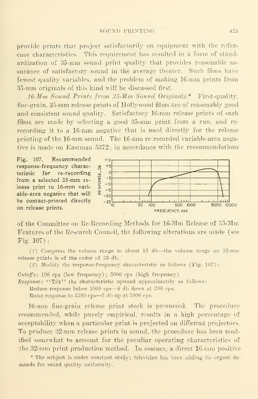
sor.M) PRINTING 425
provide prints that project satisfactorily on equipment with the refer-
ence characteristics. This requirement has resulted in a form of stand-
ardization of 35-mm sou ml print quality that provides reasonable as-
surance of satisfactory sound in the average theater. Such films have
fewest quality variables, and the problem of making 16-mm prints from
35-mm originals of this kind will be discussed first.
16-Mm Sound Prints from 35-Mm Sound Originals* First-quality,
fine-grain, 35-mm release prints of Hollywood films are of reasonably good
and consistent sound quality. Satisfactory 16-mm release prints of such
films are made by selecting a good 35-mm print from a run, and re-
recording it to a 16-mm negative that is used directly for the release
printing of the 16-mm sound. The 16-mm re-recorded variable-area nega-
tive is made on Eastman 5372; in accordance with the recommendations
Fig. 107. Recommendedresponse-frequency charac-
teristic for re-recording
from a selected 35-mm re-
lease print to 16-mm vari-
able-area negative that will
be contact-printed directly
on release prints.
+ 10
+ 5
-5
-10
-15
-20
-25
\
\\
/ \, ,
1 1 11 , L1_LI
50 100 500 1000
FREQUENCY, cds
5000 10000
of the Committee on Re-Recording Methods for 16-Mm Release of 35-Mm
Features of the Research Council, the following alterations are made (see
Fig. 107) :
(1) Compress the volume range to about 15 db—the volume range on 35-mm
release prints is of the order of 35 db.
{2) Modify the response-frequency characteristic as follows (Fig. 107) :
Cutoffs: 100 cps (low frequency); 5000 cps (high frequency)
Response: "Tilt" the characteristic upward approximately as follows:
Eeduce response below 1000 cps—6 db down at 200 cps.
Raise response to 3500 cps—3 db up at 3000 cps.
16-mm fine-grain release print stock is presumed. The procedure
recommended, while purely empirical, results in a high percentage of
acceptability when a particular print is projected on different projectors.
To produce 32-mm release prints in sound, the procedure has been mod-
ified somewhat to account for the peculiar operating characteristics of
the 32-mm print production method. In essence, a direct 16-mm positive
* The subject is under constant study; television has been adding its urgent de-
mands for sound quality uniformity.

426 XII. PROCESSING AND RELEASE PRINTING
is re-recorded from the selected 35-mm release print or fine-grain, non-
slip sound print. This direct positive is printed on Eastman 5302 as a
sound dupe negative ; release prints are made on Eastman 5302.
This procedure is described in some detail in the Journal of the Society of Motion
Picture Engineers of March 1946 "An Application of Direct-Positive Sound Track in
16-Mm Release Processing by Duplication Method" by G. C. Misener and G. Lewin
of the Signal Corps Photograhpic Center, Long Island City, N. Y.
16-Mm Sound Prints from 16-Mm Sound Originals. The case for
16-mm sound prints from 16-mm sound originals, is, unfortunately, not
as simple as 16-mm sound prints from 35-mm originals by means of re-
recording. There is no standardization of 16-mm sound projection equip-
ment characteristics; accordingly there is no single objective toward
which 16-mm sound originals are directed. This variability in objective
as measured by the wide variations in response-frequency characteristic
found on original films is a very serious handicap when it is accompanied
by the customary variability in films and film processing as measured
by variations in intermodulation and cross-modulation distortion. Thus,
while published data on printer loss may show a high-frequency loss at
6000 cps as small as 4 db, it is not uncommon to find losses as great as 14
db in a print. The difference of 10 db represents quite a large percentage
variation if the 4-db loss is used as a reference ; it is no wonder that the
sound quality of prints is variable with such a large element of variabil-
ity in print losses. The existence of such variability makes it imperative
that the number of photographic copying steps used for 16-mm sound
shall be kept to an absolute minimum in the chain between the original
film and the release print.
Under the very best practical conditions, the best dynamic volume
range to be expected from a 16-mm sound original is about 35 db ; with
pre- and postequalization, range E (90-6400 cps) represents the widest
practical frequency range. For a very quiet listening room, a dynamic
range of about 30 db may be utilized if an inspection-type reproducer
such as a Maurer film phonograph is used with an associated high-quality
amplifier and loudspeaker. Although this frequency range is not high
fidelity (the minimum for high fidelity is 75-8000 cps), the performance
will be surprisingly good as it is appreciably better than ever experi-
enced by most users of 16-mm films. To accomplish this result not only is
it necessary to use the best fHm equipment available, but it is also neces-
sary to use well-filtered dirt-free processing solutions, water, and drying
air. To assure cleanliness of the surface of the film, it is necessary that
SOUND PRINTING 427
it be cleaned with carbon tetrachloride after processing. Under the
best conditions, there is little practical difference in available dy-
namic volume range or in frequency range between a film recorded as a
negative or one recorded as a direct positive. When a direct positive
film made in this manner is reproduced on such film phonograph equip-
ment as that suggested, almost all of the noise heard in the loudspeaker
should Ix' the "hiss" produced by the photocell of the equipment and by
the grain of the film. If it is not, either the equipment is at fault, or the
film has become contaminated by dirt or other foreign matter during or
after processing. To check the equipment, it is merely necessary to op-
erate the amplifier at normal gain (amplification) with no film in the
machine and with the motor of the film phonograph running. A com-
parison is made of the noise heard when the light beam from the exciter
lamp is blocked to prevent light falling on the photocell, and the noise
heard when the light obstruction is removed.
Unfortunately, the full dynamic volume and the full frequency ranges
that can be recorded are beyond the capabilities of even the best com-
mercial sound projector. The extension of either range beyond the re-
spective capability of the sound projector as further limited by the
acoustics of the listening space has- the effect merely of increasing the
noise and distortion heard by the audience; it is necessary to provide
pre-print material that has both the dynamic and the frequency ranges
intentionally limited in accordance with the reproducing limitations to
be encountered when release prints are projected. This usually means a
limitation of dynamic range to a maximum of 25 db and of frequency
range to range F (110-5300 cps) for best projectors under best conditions,
and to a dynamic range of only 15 db, and of frequency range to range
H (160-3600 cps) for good projectors operated under adverse acoustic
conditions or for poorer grade yet commercially acceptable projectors
under average conditions. If the original recording has been made with
a wider dynamic or wider frequency range, re-recording will be neces-
sary to accomplish range-limiting.
Unfortunately, re-recording has not been handled as a regular part of
16-mm laboratory operations despite the fact that the need for it con-
nection with range-limiting arises to a considerable degree within the
laboratory and in projection. Re-recording has in the past been consid-
ered a part of production operations, especially in the re-recording of
35-mm Hollywood features for 16-mm release. Xo doubt one of the
strong reasons for this has been the fact that comprehensive facilities for

428 XII. PROCESSING AND RELEASE PRINTING
re-recording are required in 35-mm commercial re-recording operations
involved in preparing the 35-mm films, and the preparation of a re-
recorded 16-mm release negative or release direct positive merely repre-
sents another job that can be accomplished readily with available, highly
versatile equipment whose capital costs are accounted for within the pro-
duction budgets of the 35-mm films that are produced. It must be ad-
mitted frankly that very little of this kind of re-recording has been done
with 16-mm, primarily due to a lack of high-quality facilities and per-
sonnel. The trend in the future should be strong in this direction as
quality demands of users become louder and more insistent.
In general, black-and-white printing is best accomplished with most
suitable films when the light source in the printer is filtered to remove
the longer wave lengths ; in some printing near ultraviolet is used. Sound
print quality for variable-area recording is judged almost entirely by
listening. Although cross-modulation tests may be used, the correlation
with listening tests is not ordinarily close enough for commercial opera-
tion. A common procedure in connection with variable-area recording
is to make a test record of a sentence with many sibilants in it, such as
:
"Sister Susie's sewing shirts for soldiers," and make test prints at
different exposures. The print exposure selected is the one that pro-
vides the most natural reproduced sound. The results of this test are
followed by a cross-modulation test, since measurement of the latter test
results depends upon meter readings rather than upon a listener's aural
judgment. Once the objective has been determined, it is simpler to check
variations with meters even though it is clearly recognized that the cor-
relation may not be close. It is possible that the correlation between inter-
modulation testing of variable-density recording may show a closer corre-
lation, but this has not been definitely established with 16-mm film because
variable area is used far more widely.
Performance Limitations of Recorded Sound
Photographic printing of sound should always be accomplished on
films of the highest possible resolving power, and processed with maximumcleanliness. In this manner the raw film itself does not seriously limit
either the dynamic range or the frequency range of the finished print.
The recorded dynamic range should be well within the signal-to-noise
ratio of the film stock, and should never be greater than the dynamic
range of the projector or reproducer on which the film is played. Should

PERFORMANCE LIMITATIONS OF RECORDED SOUND 429
the recorded dynamic range in the print exceed the range of the pro-
jector by even a small margin, the low level passages of the film will be
inaudible, since they will be drowned out by noise. To avoid the addition
of an appreciable amount of distortion and of noise—which reduces the
useful dynamic and frequency ranges, all printing machinery must be
maintained in best operating condition. This means making certain that
the light field of the printer illumination system shall be as uniform as
possible throughout the printed area, both as to intensity and chromatic
quality. When the printer is running, there should be a minimum of
vibration of the printer lamp with respect to the optical axis of the illu-
mination system in order to avoid the introduction of audible noise. The
propulsion system of the printer must be maintained, and sprockets and
gates must remain properly aligned. Because of propulsion irregulari-
ties, measurable flutter is introduced in even the best contact printer and
can be observed by reproducing a print of, e.g., the 5000-cycle SMPEfocus test film on a film phonograph, meanwhile observing on a cathode
ray oscillograph the waveform of the wave envelope caused by flutter.
Unfortunately, most commercial film laboratories do not routinely
make such tests on their equipment;printer performance maintenance
measurement is still quite crude in practice. Quite often, published data
found in technical journals represent the performance of an isolated piece
of equipment under noncommercial operating conditions. It represents,
rather, what a particular piece of equipment is capable of doing under
certain limited idealized conditions rather than what its counterparts
do in practice.
The noise and distortion introduced in each transfer step is quite
large and varies over rather wide limits from one laboratory to another.
It varies for different machines within the same laboratory and for the
same machine at different times, though to a lesser degree. It is a com-
mon experience of film users to find that there is a significant difference
in sound quality between the averages of two different lots of prints madeat different times from the same release negative or other preprint ma-terial.
Printer loss characteristics may be checked by printing a calibrated
film such as American War Standard Film Z22.44-1946. This, with its
calibration, may be obtained from the Society of Motion Picture En-
gineers. A comparison between the standard film and the print with both
run on similar film phonographs in an A-B test with a cathode ray oscil-
lograph used for checking waveforms will quickly show up significant
430 XII. PROCESSING AND RELEASE PRINTING
differences. Level differences can be measured with a standard VUmeter; the measurement arrangement was shown in Figure 106.
Fine-Grain Film and Its Application
When a new 16-mm print is removed from its shipping container
for the first time, there is a momentary silence as a professional audience
sees the picture on the screen and hears the sound from the loud-
speaker. During this moment, the quality of the projected picture and
sound is evaluated. As matters stand today, a user has no way of know-
ing beforehand just what quality can be expected from a print in an
unopened package, since there is no quality standard by which 16-mm
prints—or any other prints for that matter—are graded. It is no longer
true that the output of 16-mm prints is so small and the distribution so
restricted that quality standards of some sort would not be welcome.
Steps have been made in the direction of attempting to standardize the
16-mm projector. The efforts are continuing, although it has been diffi-
cult so far for manufacturers and users to'
' get together. '
'
With regard to prints, there is no distinction between a print suited
for an audience of three or four that is not critical and a print for a
critical audience of 1000—unless we accept the term fine-grain. The dis-
tinction is vague; it is used for release prints made upon raw stock of
higher resolving power (90 lines per millimeter), and usually implies
vaguely the use of fine-grain films for duplicating. We have no term at
all to describe prints made on poorer materials. There is no precise ex-
planation as to what "fine-grain" means or how "fine" a film must be
to merit suitability for a critical audience of 1000.
A reasonable starting point is a modern, well-maintained, 35-mm
entertainment theater of 1000 seats. It is rare for picture or sound to
be so poor today as to interfere in any material way with the enjoyment
of the picture. Screens are designed to deliver the best picture prac-
ticable to the audience ; sound equipment is as carefully designed to cover
the complete audience with sound as the projection equipment and screen
is designed to serve the audience with the picture.
If the raw film used for release prints for the 1000-seat, 35-mm theater
is satisfactory for its purpose, the raw film used for 16-mm films to
provide approximately equivalent picture and sound quality sound have
2.5 times the resolving power used for 35-mm. It is only in this waythat the same detail, whether picture or sound, can be adequately ren-
dered. The ratio represents the inverse ratio of the speeds of 90 ft. per
FINE-GRAIN FILM AND ITS APPLICATION 431
minute to 36 ft. per minute. Since the rated resolving power of 35-mm
ordinary positive is 55 lines per millimeter, the resolving power required
for equivalent performance in 16-mm would be 55 times 2.5 or 137.5 lines
per millimeter. If practicable, this resolving power value should be con-
sidered the minimum to be used; every effort should be made to use mate-
rials of the highest resolving power available for the specific application.
Eastman Kodak has published a welcome book," Properties and Per-
formance of Eastman 35-Mm and 16-Mm Films for Professional Use,"
which aids in the selection of the various Eastman materials. The out-
standing materials for black-and-white duplicating are Eastman 5203 for
dupe negative and Eastman 5365 for master positive. Although 5203
seems somewhat shy of the objective of 137.5 lines per millimeter it is the
best Eastman material available and it may be used to good advantage
by using a rich, fresh developer.
Cost Factors in Use of Fine-Grain Film. Most 16-mm black-and-white
prints today are being made on fine-grain film of rated resolving power
of 90 lines per millimeter. These materials are slow photographically
with respect to ordinary positive materials that were commonly used
in the United States before World War II. "When fine-grain materials
were first introduced, DuPont, in referring to their 605 type 16-mm, fine-
grain film, stated: " To date it has been impossible to get sufficient light
for reduction printers to use this slow film for prints from 35-mm nega-
tives." Such exposure problems have since been overcome for 90-lines-
per-millimeter films, but they still remain if 150-lines-per-millimeter mate-
rials such as Eastman 5365 are to be used for release printing.
For commercial laboratory use at the present time, the use of a mate-
rial such as Eastman 5365—a yellow-dyed master positive—for release
printing in accordance with published data would be impracticable since
it requires a developing time of 9.5 minutes in the recommended negative-
type developing bath. The average commercial film laboratory cannot
afford a developing time for release prints greater than approximately 4
minutes because of competitive pressure. In many laboratories, the cus-
tomary developing time for release positive is about 3 minutes and mayin extreme cases run as low as 2 minutes. As a matter of cost calculation,
if we add the additional cost of the raw film to the additional processing
cost, the resulting price increase would represent such a large percentage
of present costs that most customers would prefer the 90-lines-per-milli-
meter material despite its technical shortcomings.
432 XII. PROCESSING AND RELEASE PRINTING
The problem of printing such materials as 150-lines-per-millimeter
duplicating, positive is more an economic than a technical one. As a
temporary commercial measure, it is possible to use the same expedients
as were used when the step was first made from 55- to 90-lines-per-milli-
meter materials. The following compensating steps must be taken in the
proper amounts.
(1) Increasing the energy of the developer.
(£) Increasing the intensity of the light source of the illumination system and/or
improving the efficiency of the system. This may mean the installation of a mirror at
the rear of the lamp to re-direct the light flux from the rear to the aperture, or even
the installation of a new type lamp such as a high-pressure mercury arc. Details of
such changes are found in technical journals such as that of the SMPE.(3) Reducing the linear speed of the film through the printing machine to increase
the exposure by the proper amount.
Just how the compensating steps are to be apportioned is a matter of
designer's choice. Regardless of the balance finally chosen, the cost of
fine-grain printing and developing is going to be higher than that for the
handling of coarser grained materials.
In general, it is desirable to keep the speed of printing sound track
above 60 ft. per minute, if possible, even when very fine-grain films are
printed. At higher printing speeds flutter is reduced compared to lower
printing speeds in the same machine. If a step printer is used for print-
ing picture, a reduction of the linear speed will not be a handicap to print
detail but may actually improve it. It will be necessary in both cases to
make certain that the air blasts used for cooling are adequate to remove
heat sufficiently rapidly to keep film and machine temperatures at reason-
able values.
Other Factors in Use of Fine-Grain Film. To get the most from fine-
grain film requires "tightening up" of all operations. Not the least im-
portant of these is the reduction of the amount of dust, dirt, and foreign
matter accumulated during processing. If 35-mm film can tolerate so
many pounds of muck per thousand gallons of water or solution used,
16-mm fine-grain of equivalent quality can tolerate only 40% of that
amount. If 35-mm can tolerate so many pounds of dirt per million cubic
feet of drying air in the drybox of the developing machine, 16-mm fine-
grain can tolerate only 40% of that amount, It is necessary to be meticu-
lous in handling 16-mm, whereas ordinary care was satisfactory for
35-mm ; it is necessary to be extremely careful in 16-mm if something morethan ordinary care is needed in comparable 35-mm handling. The mag-
FINE-GRAIN FILM AND ITS APPLICATION 433
nification at which 16-mm projectors operate in practice is appreciably
greater than the magnification of 35-mm projectors, and dictates this need
for greater care.
It should be remembered that the characteristics of human vision are
such that normal eyes are accustomed to sharp and well-defined images
;
the 16-mm film will perform its function most satisfactorily when the
images provided by the film are comparable in sharpness with natural
images. Today, we are using film materials with resolving power com-
parable to that of lenses of better grade 16-mm projectors, i.e., 80 lines
per millimeter at the center. The trend in projection is toward lenses
with still better definition. To keep pace, the resolving power of release
print materials must be increased still further. Experimental films with
100-lines-per-millimeter resolving power were available in 1931 when
we were using 50-lines-per-millimeter materials ; today 150-lines-per-milli-
meter materials are available now that we are using 90-lines-per-milli-
meter materials for release printing.
The technique of manufacture of the better materials is fairly well
known. The problem is to prepare to process the material commercially,
and to bring the price to lower levels, by making use of such materials
the rule rather than the exception. This, it seems, is the next hurdle for
the film manufacturers to overcome by providing less expensive materials,
and for the progressive laboratories to overcome by adapting their meth-
ods to such materials.
There would seem to be little point to put forth a great amount of
effort and go to great expense in the manufacture of fine-grain, dirt-free,
raw film materials if their potentialities were not realized during subse-
quent processing. A very material quality loss due to loss of definition
and an increase in dirt due to processing occurs when the average fine-
grain film is processed today. These factors should be under continual
observation and control. Much can be learned if a short test strip, such
as that recommended in American War Standard Z52.3-1944, is attached
to every edited original for control purposes. If this test strip is printed
through in every duplicating and copying process so that it not only
appears on the release print but also on every intermediate film, it be-
comes possible to obtain a qualitative idea if not a quantitative one as to
the magnitude of the quality losses at each copying step. The collection
of such data and their proper interpretation is capable of revealing just
where "process tightening up" is required, and by what amount it is
practicable. The result of such quality inspection in control improvement
434 XII. PROCESSING AND RELEASE PRINTING
cannot help but result in better prints at lower cost to the user with a
better profit to the laboratory : the true objectives of any well-run, mass-
production process.
It is impossible in a chapter as short as this to do little more than
outline very briefly a few of the many important factors involved in lab-
oratory operation. Each item of machinery alone would require manywords and many illustrations to describe it and to show how the design
compromises selected appear to be the most practicable for the intended
application. The integration of the machinery and the personnel into a
workable organization capable of turning out a good product at a com-
petitive price is a subject that would require individual treatment for
each specific situation. Broad generalizations would require too manyqualifying limitations to be of great value.
Film laboratory machinery, while quite highly specialized, has all the
disadvantages from the purchaser's viewpoint of any product that is not
mass-produced. When purchasing, it is always necessary for a purchaser
to rely upon his arrangements with a manufacturer's representative, since
most of the literature describing machines is out-of-date, inaccurate, and
incomplete. The purchaser must look into every small detail to assure
himself that the machine or equipment that he proposes to order will fit
his specific need. Even if equipment appears to fit the need quite ac-
curately when first installed, it will often be found that modifications are
required after it has been put into service. In addition, the equipment
will need service and maintenance. For this reason, it will usually be
necessary to have the facilities of a small machine shop available in the
plant. In the larger laboratories there is also an engineering depart-
ment with the specific function of designing and supervising the manu-
facture of the specialized machinery required in the laboratory. In this
latter case, the machine shop may be large enough to manufacture, install,
service, and repair substantially all the machinery used in the plant.
The quality of the release print is often determined in the film lab-
oratory. To serve its purpose best, the release print, like any other
manufactured product, should be made of the best materials and by the
best processes. Only when it is so made is its attention potential—latent
in the edited original—fully realized.
Selected Bibliography
For bibliographic material the reader is referred to the following indexes in theJournal of the Society of Motion Picture Engineers.
July 1916-June 1930"Animation," page 117.

SELECTED BIBLIOGRAPHY
'Camera Accessories," page 119.
'Color Rendering in Blaek and White.'' page 120.
'Defects in Film Resulting from Processing," page 123.
'Development of Motion Picture Film," page 123.
'Drying of Motion Picture Film," page 124.
'Duplication of Motion Picture Film," page 124.
'Electrical Machinery and Equipment," page 12.".
'Film, Damage to, in Use," page 127.
'Film Manufacture," page 127.
'Film, Photographic Characteristics,
'
5 page 127.
'Film, Physical Characteristics," page 127.
'Film, Reels," page 128.
'Fixing of Motion Picture Film," page 128.
'Gelatin," page 129.
'Incandescent Lamp for Projection," page 134.
'Laboratories for Processing Motion Picture Film," page 134.
'Laboratory Apparatus," page 135.
'Lubrication of Motion Picture Film," page 135.
'Mechanical Accessories," page 135.
'Miniatures," page 136.
'Optics," page 137.
'Perforation," page 138.
'Photometry," page 139.
'Printers," page 140.
'Printing, page 140.
' Sensitometry, Methods, and Instruments, '' page 145.
silver Recovery.'" page 145.
'Sound Film Processing," page 146.
' Splicing, '' page 149.
'Static," page 150.
'Stills," page 150.
'Technical Motion Picture Photography," page 151.
'Tinting and Toning," page 152.
'Titles and Title Making," page 153.
'Trick Photography," page 153.
'Viewing Devices," page 153.
'Washing of Motion Picture Film," page 153.
January 1930-December 1935"Animation," page 7.
"Apparatus," page 7.
"Applied Motion Picture Photography," page 9.
"Background Projection," page 10.
"Cleaning Motion Picture Film," page 12.
"Committee Reports, Laboratory Practice," page 14.
"Composite Photography," page 20.
436 XII. PROCESSING AND RELEASE PRINTING
"Defects in Film Resulting from Processing," page 21.
"Densitometry," page 21.
"Development, Photographic," page 21.
"Directional Effects," page 22.
"Drying Motion Picture Film," page 22.
"Dunning Process," page 23.
"Duplication of Motion Picture Film," page 23.
"Fades," page 25.
"Film, Development of," page 25.
"Film, Photographic Characteristics," page 25.
"Film, Physical Characteristics," page 26.
"Fixing Motion Picture Film," page 27.1
' Gammagraph, '' page 27.
" Gammameters, " page 27.
1' Hypersensitization, '
' page 32.
"Illumination in Printing," page 32.
"Instruments," page 35.
"Intensification," page 36.
"Laboratory Apparatus," page 36.'
' Lubrication of Motion Picture Film, '' page 39.
"Microdensitometers, " page 40.'
' Miniatures, '' page 41.
"Moviola," page 41.
'' Optical Reduction, '
' page 44.
"Optics," page 44.
"Perforation," page 46.
"Splicing," page 65.
"Tinting and Toning," page 68.
"Tone Reproduction," page 68.
"Trick Photography," page 69.
"Viewing Devices," page 69.
"Washing Motion Picture Film," page 70.
1936-1945"Fixing Baths," page 94.
"Instruments," page 102.
"Laboratory Practice," page 103.
"Optics," page 111.
"Photometry," page 113.
"Printing," page 114.
"Processing," page 115.
"SMPE Activities—Laboratory Practice Report," page 12S.
" Sensitometry, " page 134.
"Special Effects," page 147.
"Splicing," page 148.
CHAPTER XIII
Projection and Projectors
Introduction
It is difficult to treat the subject of projection and 16-mm projectors
without some definite use objective in mind. The needs of projection in
schools, for example, are different from the needs of projection as may be
carried on in church halls, YMCA, and other semi-public and public
buildings. Projection is in reality a means to an end and not an end in
itself. In the case of the school classroom, the projection of 16-mm motion
pictures must coordinate with other visual and audio media implying an
integration with the school curriculum in general and with other visual-
audio media.
Fortunately, the projection requirements of most forms of projection
other than motion pictures tie in quite well with motion pictures. Amatte-surface reflective screen should be used for maximum utility. As
in motion pictures, the minimum distance of the nearest observer from
the screen should be not less than 2.5 times screen width (2.5 w) and the
maximum distance of the farthest observer about 5.5 times. The maxi-
mum distance that any observer may be located off the projection axis
to either side is equal to his distance from the screen. As will be men-
tioned later in this chapter, these projection conditions will be found
most satisfactory for motion pictures under reasonable conditions of
room darkening.
Visual-Audio Media of a Classroom
Although the visual-audio media of a classroom are quite beyond the
scope of this book, some mention must be made of them. The importance
of the interlocking of their relationships is very great not only because of
their number and variety, but also because the schoolroom affords an al-
most ideal opportunity for the useful employment of every kind of me-
dium. All media are tools, and not ends in themselves ; all are measuredin terms of the improvements in learning rates that result from their use.
As in any other situation in which tools are used, some tools are extremely
437
438 XIII. PROJECTION AND PROJECTORS
valuable in some cases, while the same tools may prove a handicap in
others. The best tools for a particular case are those that provide the
quickest and best results in terms of increased learning at the lowest cost.
Visual-audio media may be divided into two broad classes, nonpro-
jection and projection. The older—and better known media—are the
nonprojection media. These include :
(1) The blackboard—probably the best known and requiring no explanation.
(£) The display area—where charts, pictures, maps, posters, etc., are placed.
(3) The exhibit—material brought into the classroom. This may be a small-
scale model of a machine being studied, or it may be merely samples of coffee, wheat,
barley, rice, etc., should the classroom discussion revolve about such grains and food-
stuffs of the world. An exhibit may be either permanent or temporary.
(4) The demonstration—a workshop adapted to the classroom. Typical are the
first experiments in chemistry and physics performed by the instructor to acquaint
the students with the techniques of handling such apparatus before they perform their
own experiments in the school laboratory.
The projection media are newer than the nonprojection media; manyof them received much impetus in the various war training programs of
the U. S. Armed Services and of war production industries. The projec-
tion media include
:
(5) The "stills" projection program—an extension of the blackboard, which, in
turn, includes:
A. Transparency slides—usually 2x2 in. and 3 1/4x4 in.
B. Slidefilm—with or without sound—35-mm film usually about 100 frames
long (7 ft.).
C. Opaque material—usually newspaper clippings, paper prints of pictures,
etc., usually 6 x 6 in.
Projection of " stills' can be accomplished on the same matte surface
screen used for motion picture projection as previously described. Sound
slidefilms are now very common ; a 33 1/3-rpm, disk-reproducing turn-
table with associated amplifier and loudspeaker is part of the typical
machine. At the end of the word commentary on a particular scene in
the slidefilm, a recorded tone such as a gong sound or oscillator tone is
provided. This tone may be utilized to effect a scene change automatically
by advancing the film one frame, or it may act as an audible warning tone
to the machine operator to advance the film manually. Where a recorded
tone is used to effect automatic advance, the preferred tone is one of low
frequency, e.g., 30 cps, which is below the normal response range of the
audio amplifier and loudspeaker used and is therefore inaudible to the
audience.
VISUAL-AUDIO MEDIA OF A CLASSROOM 439
An important advantage of the slidefilm over transparencies quite
apart from its low cost is that the scenes of the film are certain to be pro-
jected in correct sequence.
To reduce the number of machines needed, a number of manufacturers
have sought to combine two or more of these projection functions in a
single mechanism. The most common combination is that of the 35-mm
slidefilm and the 2 x 2 in. slide. Although this compromise need not in-
volve a serious loss of optical efficiency because the image areas to be pro-
jected are not greatly different, the compromises that must be made if
design simplicity is to be maintained become serious when an attempt is
made to include the larger 3 1/4 x 4 in. transparency. The compromises
become very serious when the 6x6 in. opaque material function is also
included.
When there is a material difference in the size of the transparency or
opaque material to be projected, not only the projection objective lens but
also the condenser lens must be changed in focal length if good light
efficiency is to be achieved with all sizes. In the optical system, the light
source is imaged near the aperture where the transparency or opaque
material is located; the condensing lens system should adequately and
uniformly illuminate the material without serious waste of illumination
beyond its boundaries. The area of the light source is fixed, and a
change in the focal length of the condenser system is required, just as
is a change in focal length of the projection objective lens.
Admittedly, it is undesirable for a classroom to "bristle" with pro-
jection machines and audio aids when only one facility can be used at a
time. Thus, as a practical matter, it is usually justified for the sake of
operational convenience and simplicity to sacrifice illumination efficiency
to some degree in a combination machine if the screen brightnesses of the
facilities so furnished are not too widely different from one another.
The real problem, however, goes deeper. There is still much room for
improvement not only in providing apparatus integrated with the teach-
ing program (as well as the integration of the apparatus components with
each other), but also there is a far more serious need for the improvement
of teaching techniques by providing visual-audio materials using the
most effective facilities integrated as a part of the teaching method and
fitted accurately to the specific teaching need.
As one example, it is well known that the amount of "dwell" time
needed for the contemplation of an important point varies from one audi-
ence group to another. One possible arrangement that can take this into
440 XIII. PROJECTION AND PROJECTORS
account is a composite 16-mm motion picture and slide or slidefilm ma-
chine which would be a "gearing-together" of the two mechanisms.
When a "dwell" point is reached with such an apparatus, the motion
picture projector would be cut off automatically, turning on the slide
machine. When the instructor felt that the point had "sunk in" ade-
quately, the push of a button would shut off the slide and continue the
motion picture projector on its way once more.
There is no coordination or standardization among available mecha-
nisms ;this applies quite as much to audio aids as it does to visual aids.
Fittings, connectors, loudspeakers, amplifiers, etc., are all made to per-
form as components of the specific machine or device only, with no at-
tempt to eliminate duplicate functions among complementary machines.
Visual-audio aids are very much needed ; lack of integration is a serious
factor in retarding their natural growth.
(6) Specialized projection which includes microprojection and the projection of
vectographs in stereo projection.
Microprojection includes the projection of microscope slides illumi-
nated by transmitted light and also the projection of dark-field illumi-
nated objects by reflected light. For the teaching of subjects such as
biology, slides may be prepared with familiar insects, flowers, etc., and
shown with transmitted light. Rock samples and metal structure samples
are commonly illuminated with reflected light. In general, microprojec-
tion should be used in every instance possible where the student will later
use a microscope. The screen used for microprojection may be the same
matte screen used for motion pictures.
Stereo projection, which made tremendous strides during World WarII, is an invaluable aid in the visualization of objects in space. The
teaching of geography, and especially topography, solid geometry, as-
tronomy, navigation, map interpretation, and a host of other subjects is
made more efficient and practicable and results in very material savings
in learning time, and in increase of depth of comprehension. Stereo pro-
jection should be started at an early stage in a school career in order to
familiarize the student with the visualization of things in space.
Since stereo projection is specialized, it requires an aluminum-coated
screen (specularly reflecting rather than the more usual diffusing matte
surface) that sharply limits the andience to a very narrow viewing angle,
but a small fraction of that customary with the matte screen used for
other kinds of projection. The viewing angle for stereo projection maybe but one-third of the customary viewing angle.
DEFINITION 441
(7 | The motion picture projection program—which includes silent film as well as
sound film. The primary need is for 16-mm. 35-mm is unsuitable because it is ordi-
narily hazardous, and the machines are bulky and complicated. 8-mm is rarely used
except for locally produced films, since commercial teaching films are released almost
entirely in the 16-mm size.
(8) Audio projection—which includes facilities for radio (conventional broadcast
and frequency modulation . for playing disk and other records and transcriptions
(78 rpm and 33 1/3 rpm* >. for making and playing back local recordings (disk, wire,
magnetic tape. etc. I, and interconnection among classrooms such as in a centralized
sound distribution system.
(5) Television projection—in color, and in black and white when such facilities
become widely available commercially.
Xo attempt will be made in this chapter to go into detail with regard
to the needs and functions of the eight media other than motion picture
projection. Suffice it to say that all are specialized, and the integration
of the apparatus and the functions into a minimum of apparatus and ac-
cessories is a study that requires and deserves much attention. The Com-
mittee on 16-Mm and 8-Mm Motion Pictures of the Society of Motion Pic-
ture Engineers is presently engaged with the problem of 16-mm film
projection as a continuing matter and reports its findings on this subject
from time to time. At present there is no technical or other responsible
body that is charged with the responsibility of the integration and coor-
dination of visual-audio aids into teaching programs in the manner in
which the SMPE Committee is concerned with the 16-mm film projec-
tion problem.
Definition
A motion picture projector may be defined as a machine that appears
to make images move when a suitable strip of film with a succession of
suitable images is projected through it. Of course, the recorded images
themselves do not move at all. but rather it is the eye of the observer that
provides the illusion of movement when a succession of individually sta-
tionary images slightly different from one another is presented to the eye.
Movement appears to occur because of the small differences from frameto frame along the film. Each individual frame must be clear and dis-
tinct and free from any trace of blur because it will be enlarged several
hundred times when it is viewed. The film itself may be thought of
merely as a series of sequential photographs spaced one twenty-fourth
second apart if the film is projected at sound speed. A practical pro-
jector for this film does not merely project one frame after another; the
projection cycle which will be described later is more involved so that
* And possibly 45 rpm.
442 XIII. PROJECTION AND PROJECTORS
flicker may be reduced to a minimum and picture brightness increased to
a maximum.
Frame Size of Picture to Be Projected
There are 40 frames per foot of 16-mm film. As there is but one
sprocket hole per frame, the nominal distance between adjacent frames
is 12.000 in. per foot divided by 40 frames per foot, or 0.300 in. per frame.
Because film is dimensionally unstable and shrinks and swells during
the various stages of its processing and use, and because of the errors in
placement of the images and the weaves introduced by the various ma-
chines used that occur as a result of the inaccuracies of the guiding and
propelling mechanisms in cameras, in recording machines, in printing
machines, and in projectors, it is necessary to limit the height of the
frame to be projected to some arbitrary value less than 0.300 in. This is
accomplished in the projector by the use of an aperture at the film gate
where light is transmitted through the film to the objective lens that
focuses the image in the gate to the screen. The width of the frame is
similarly limited for similar reasons.
The standard dimensions for the 16-mm projector aperture are
0.380 x 0.284 in. These dimensions are shown in Proposed American
Standard Z22.8-1949 issued by the American Standards Association under
the sponsorship of the Society of Motion Picture Engineers (Fig. 13).
All American Standards in motion pictures are similarly issued and simi-
larly sponsored.
Shape of Projected Picture
The shape of the picture projected on the screen depends upon the
shape of the projector aperture. The standard aperture is rectangular
;
the aspect ratio (the ratio of width to height) is approximately 4 to 3.
This picture aspect ratio is very widely used ; it is used for
:
(1) 35-mm motion pictures.
(2) 16-mm motion pictures.
{3) 35-mm slide films.
(4) Transparencies.
(5) Television—whether live pickup or transmission from still or
motion pictures.
Size of Projected Picture
The size of the projected picture depends upon the working magni-
fication provided by the projection machine under its actual conditions
PERSPECTIVE 4t::
of use. The working magnification in turn depends upon the focal length
of the objective lens used in the projector and the distance of the pro-
jector aperture from the screen.
When an ordinary scene is photographed, the area of interest of the
scene is reduced in size to fit within the camera aperture (Fig. 11 —0.405x0.295 in. (Proposed ASA Z22.7-1949.) Only a portion of
this area—0.380x0.284 in.—is projected through the projector aper-
ture ;the remainder is cut off from view. The transmitted portion is en-
larged in projection to several feet in width. With even a well-designed
machine, an enlargement to 6 ft. in width, for example, requires an effi-
cient optical system using an incandescent lamp of at least 750-w. rating
if adequate illumination is to he provided for even the best matte screen.
Most 16-mm sound projectors such as the Eastman. Bell and Howell.
Ampro, Victor. DeYry, etc.. use a lamp of 750-w. rating.
Even though provision is especially made to assure that the terminal
voltage of each lamp is in strict accordance with its voltage rating, it will
be found that significant differences in brightness and in image detail on
the screen occur from one manufacturer's projector to that of another,
and there are noticeable differences among apparently equivalent prod-
ucts of even a single manufacturer. In this regard. 16-mm projectors
—
whether silent or sound—are no different from any other manufactured
product in their variability characteristics.
Perspective Considerations of Projected Picture
The perspective considerations of this section are applicable to the
projection of 16-mm motion picture whether by reflection from a conven-
tional screen, or by transmission through a translucent screen as is used
in Trans-Lux and Panoram Soundies projection. The former type is in
widest use, and most direct reference will be made to it.
It is usually assumed that the "average" 16-mm motion picture scene
lias been photographed with a lens of 1-in. focal length. The angular
width (half-angle) of the scene is about 22°. When the conventional
2-in. projection objective lens is used, the correct distance of the observer
from the screen is a little greater than 2.5 iv and the projector distance
from the screen is about 5.25 w* Only at this position are both the fore-
ground and the background of the picture seen in correct perspective;
neither is foreshortened or elongated.
" is the distance from the screen measured in screen widths.

444 XIII. PROJECTION AND PROJECTORS
It is rare that a lens of focal length shorter than 1 in. is used to pho-
tograph a 16-mm scene. Generally speaking, the 1-in. lens is used for
the "establishing" or long shot that sets the locale for the action being
portrayed. Lenses of longer focal length are often used for photograph-
ing the detail that appears in the medium shots and in the closeups. It
cannot be blindly assumed that perspective considerations were thought
of primary importance in the photographing of all scenes in an edited film.
It is impossible to determine merely by screening a picture whether other
practical considerations such as physical restrictions due to the nearness
of a wall or other obstruction may have been the deciding factor in a
particular scene. Very often a cameraman is influenced strongly by the
fact that the commercial lenses of 1-in. focal length that he has on hand
are of poor quality compared with his lenses of 2-in. focal length ; he mayrightfully prefer a "sharp" 2-in. lens to a "fuzzy" 1-in. lens. In addi-
tion he may feel that perspective is not of much importance.
Proper perspective cannot always be achieved even if its needs are
known; under certain circumstances it must be definitely sacrificed if a
picture is to be taken at all. In photographing wild animals, for example,
one explorer has used a 9-in. lens simply because the animals would be
frightened if the camera were at closer range. It is doubtful that these
pictures were ever viewed with correct perspective by any audience.
When a film is edited that has shots taken with the 9-in. lens cut into the
same roll as establishing shots taken with a 1-in. lens, it becomes a ques-
tion of definition as to what the "average" perspective of such a film maybe. Valid arguments may be presented in favor of greater "weighting"
of the scenes of long focal length ; such scenes provide most of the detail.
Other valid arguments may be presented in favor of "weighting" of the
scenes in accordance with the length of the scenes. This might tend to
lean in the direction of a shorter focal length as the "average." Such
cases are special, however, and need be given small consideration. Whatis more important is consideration of more representative films. Muchpresent-day photographing is accomplished with 1-, 2-, and 4-in. lenses;
there seems to be a trend toward emphasis of the 2-in. lens over the 1-in.
lens. It is difficult to determine the reason, but it is reasonable to hazard
a guess.
The differences between that photographing for 35-mm entertainment
films and for 16-mm films that are mostly of the nonentertainment vari-
ety, are often considered minor, yet a gap seems to be growing in photo-
graphing techniques. The change has been in 16-mm, with 35-mm films

PERSPECTIVE 445
remaining about the same with regard to perspective. In 35-mm films
most of the scenes deal with people and have about the same kind of back-
ground with regard to size. 16-mm films, on the other hand, have been
dealing more and more with small objects and less with people. The
result with regard to perspective is a shift in the "average" scene from
the 1- to the 2-in. lens shot. It is not unlikely that the shift will be even
more pronounced in the future when the need for showing more and more
detail of smaller and smaller objects occurs. It is not uncommon even
now to fill a 6-ft. screen with the image of a 1-in. long 6-32 machine screw
projected from a 16-mm print. This represents quite a magnification
ratio and implies a long focal length for the photographing lens.
The "average" viewing distances found in 35-mm entertainment mo-
tion picture theaters seem to tend to be shorter than the "average" dis-
tances for 16-mm projection when measured in terms of screen widths.
The maximum viewing range recommended by the Society of Motion
Picture Engineers in the Non-Theatrical Committee Report of July 1941
was from 2 w as a minimum to 6 w as a maximum. In an incomplete
study reported by another SMPE Committee, it was found that viewers
seemed to prefer the range from 2 w to 4 w in a 35-mm entertainment
theater of only 4.85 w in length.
During World War II, American troops who viewed 16-mm reduction
prints of the Hollywood entertainment pictures apparently tended to-
ward appreciably longer "average" distances, with reported audiences
as large as 2000. With an audience of that size, it is probable that the
most distant spectators were appreciably more than 6 w from the screen.
It seems reasonable to believe that the influence of peripheral images
around the screen was probably appreciably less in such projection than
in the case of the average motion picture theater, giving due recognition
of course to the fact that under such war conditions much larger attend-
ances are common.
It is well known that the acuity of vision depends upon the angular
location of the object being viewed with respect to the optical axis of the
eye. For convenience, the field of view of the eye may be considered to be
divided arbitrarily into a central portion where acute vision occurs, and
the side portions where peripheral vision takes place. If attention is
to be concentrated upon a central field of view, such as a motion picture
screen, any movement of an object within the peripheral field will cause
a viewer to turn his head instinctively in the direction of the movingobject. A similar distraction occurs if dimly lighted stationary objects
446 XIII. PEOJECTIOX AND PROJECTORS
are present within the peripheral field of view. The distractions caused
by such images in the peripheral field will usually cause an observer
to select a seat closer to the screen to reduce their effects. This pre-
vents a choice of a location based upon the perception of perspective.
the strongest link between the motion picture image and the reality that
it represents.
In a planetarium, all sense of distance is lost to an observer because
the objects viewed are for all practical purposes point sources in space
that have no dimensions, and being dimensionless, can have no perspec-
tive. The illusion in a planetarium is lost if the dome of the planetarium
from which the points of light emerge is noticeably illuminated with stray
light.
In viewing- a diorama, the sense of distance communicated to the ob-
server is given by the perspective of the painting or photograph; the
lighting of the surrounding wall and other space is nil or substantially
so. This is accomplished by painting such surfaces with a dull black
paint that absorbs stray light. When properly illuminated, there is noth-
ing visible in the foreground between the diorama and the observer, and
all sense of perspective can originate only with the painting. If other
objects were revealed by stray light, or images wrere shown that "clashed"
in perspective with that conveyed by the diorama itself, the viewing il-
lusion would be impaired or destroyed.
To one who has seen dioramas and planetariums, it is difficult to un-
derstand why so little attention seems to be given to the perspective pos-
sibilities of the motion picture when it is often feasible to do so. In a
planetarium or in a diorama, the field of the images of interest extends
beyond the limits of the peripheral field of view of the eye, and the illu-
sion of the continuity of the observed space is retained. The width of the
motion picture screen, on the other hand, is quite limited, and yet it is
possible to retain the illusion to a considerable degree if viewing condi-
tions enable "knothole" viewing. The effect of such viewing can be
gaged exerimentally if the observer will view a motion picture screen
through a projection port of a motion picture booth in such manner that
the port masks the screen image slightly on all sides. This simple experi-
ment indicates quite forcibly the importance of peripheral viewing in the
aiding or destroying of the perspective illusion.
In "knothole" viewing, the plane in which the distraction occurs,
namely, the plane of the masked projection room port, is close to the
observer's eye, while the plane of the screen is far from the observer's
PERSPECTIVE 447
eye. The distraction that may occur at the masked port is far out of
the range of accommodation focus of the average eye, and the observer
makes no instinctive attempt to slightly alter eye focus to determine
what the exact nature of the distraction may be, since he realizes that
to do so would necessitate putting the screen far out of focus. Since
he chooses to concentrate on the screen, such a change in focus would re-
quire a conscious effort, rather than merely a subconscious readjustment
—
and therefore such minor distractions are ignored.
In the ordinary 35-mm motion picture theater, the screen is merely
placed upon the stage adjacent to the plane of the proscenium arch, and
neither far forward nor behind. The diffused light from the screen il-
luminates the area surrounding the screen, revealing details of form,
color, etc., of such objects as the curtains and their ruining, the stage
floor, the proscenium arch, the decorations, and the side-stage lighting.
The result of this arrangement is distracting, and tends to destroy the
illusion conveyed by the film since the observer tends to select a shorter
distance from the screen to reduce the distracting effects upon his peri-
pheral field of view. The selection of the shorter viewing distance tends
further to destroy the perspective illusion available in the film.
TVhere ruffled curtains and the like are dimly illuminated close to the
plane of the screen, only a small change in focus and a slight twisting of
the eyes or head are required to bring the attention-diverting activity
into sharp view. As the eye is always watchful for movement within its
peripheral field, the slight ruffling of a draped curtain caused by an air
gust will cause a quick shift of the center of attention from the screen
to the area of movement. Under such projection conditions, projected
films lose much of their perspective potential and of their attention po-
tential in the conventional theater, since the viewers' eyes tend to be-
come jittery in anticipation of suspected movement within the dimly-lit
peripheral field of view.
When 16-mm entertainment films were projected for troops during
World War IT, the screen was often set up in a cleared area with nothing
visible near the screen on either side or to the rear beyond the screen.
Under these conditions there were few distractions within the peripheral
field of view, and the perspective portrayed on the screen was not seri-
ously altered by its surroundings. Under these conditions, observers
would tend to select a viewing location suggested by the correct viewing
perspective, all other conditions being equal. It would seem that sur-
roundings and their illumination play a very important part in the de-

448 XIII. PROJECTION AND PROJECTORS
gree with which the perspective portrayed in the film is conveyed to the
audience.
A dark gray border should surround the screen ; the use of a colored
border should be avoided, particularly if color films are to be shown.
As far as possible, there should be nothing distracting at the sides or to
the rear of the screen. Admittedly, this is very difficult to accomplish
in the extreme. Most motion picture projection is capable of material
improvement, however, if these elementary considerations are taken into
account and simple precautions observed.
In arranging facilities for projection—whether temporary or perma-
nent—it is a theoretical objective to locate the audience uniformly about
the center of correct perspective. Very few published studies have ap-
peared that deal with viewing distances and their relations to perspective,
TABLE XXII
Viewing Distance for Correct Perspective vs. Focal Length of the Projection
Objective Lens
Focal leneth inViewing distance for Focal length in
Viewing distance forv ocai lengrn, in.
correct perspective, w * ocai ie"stn >in - correct perspective, w
1 1.8 3 5.3
1.5 2.6 3.5 6.1
2 3.5 4 7.0
2.5 4.4
except where entertainment films are shown. Calculations that maybe made at present cannot be considered reliable except in a very general
way due to the wide tolerances probably present in most pertinent mea-
surements. A thoroughgoing analysis of 35-mm entertainment films and
of 16-mm films of various kinds is needed to reduce the large element
of uncertainty now present. This would seem to be an excellent oppor-
tunity for the very practical application of theoretical statistics when
sufficient data have been collected.
In its report of July 1941, the Non-Theatrical Equipment Committee
of the Society of Motion Picture Engineers recommended 6 w as the max-
imum distance of an observer from the screen. Further studies indicate
that it is likely that the maximum distance will be reduced in future rec-
ommendations, and may be as low as 5 if to permit better viewing of de-
tail. The recommendation in the same report of 2 w as the minimum dis-
tance from a matte surface screen and 2.5 w for a beaded screen will
probably be changed to not less than 2.5 for both cases for the purpose of
MAGNIFICATION 449
reducing the eyestrain that results from short viewing distances when a
projector with the customary single-direction shutter is used. If a 2-in.
projection lens is used, it is not unreasonable to believe that the viewing
distance for correct perspective for 16-mm films of nonentertainment vari-
ety will will be nearer 3.5 w than 2.5 w. Based on this assumption, Table
XXII indicates the viewing distance for correct perspective when projec-
tion objective lenses of different focal lengths are used.
For most uses, the 2-in. projection lens should be used, since the per-
spective that results is best fitted to the audience distances recommended.
Unfortunately, many 2-in. projection lenses are of poor quality; the
images are rarely sharp all over the projected field. The common defect
is that the image is fuzzy at the corners when it is set for sharp focus at
the center, and vice versa. To test such a lens, project a film of knownquality. Suitable films are available through the SMPE.
Picture Detail and Its Relation to Observer
At conventional screen brightnesses, the average eye is capable of dis-
tinguishing detail represented by 1 part in 2000, or approximately 1.7
minutes of arc. At the distance w from the screen, the just discernible
detail is 2000 lines per millimeter divided by 10 mm (the approximate
width of the film gate) or 200 lines per millimeter. At other distances
from the screen, the detail observable is equal to 200 lines per millimeter
divided by the distance measured in screen widths. This data may be
set up conveniently in table form (Table XXIII).
TABLE XXIII
Observable Detail vs. Viewing Distance
Distance fromobserver toscreen, w
Average maximumobservabledetail"
Distance fromobserver toscreen, w
Avera.ue maximumobservabledetail"
2 100 4.5 44
2.5 80 5 40
3 67 5.5 36 (working limit)
3.5 57 6 33
4 50
fl Measured in lines per millimeter at the film gate.
Magnification
When a scene is photographed on 16-mm film, the area of interest is
reduced in size so that it may be properly accommodated within the pro-
450 XIII. PEOJECTION AND PROJECTORS
jector aperture. When an image so photographed is projected, the image
is enlarged, resulting, very often, in a projected image appreciably larger
than the original object. This is particularly true of many closeups.
A 16-mm image is so small that the average unaided eye is incapable
of distinguishing the fine detail in it. To make such small images con-
venient to view, they are enlarged in projection. In the case of a screen
6 ft. wide (a common size) the magnification in projection is equal to the
screen width (in inches) divided by the projector aperture width (in
inches), or 72 divided by 0.384; the ratio is 190. Such magnification is
common with 16-mm projectors using a 750-w. lamp. (The screen illumi-
nation will be somewhat low when this magnification is used with the
average projector.)
When a projector with a suitable light source such as an arc lamp is
used, a screen 12 ft. wide can be filled comfortably. Ordinarily, such
projection requires approximately 35 to 50 amps, for the arc to provide
adequate light output with an efficient arc lamp. This latter case rep-
resents twice the magnification of the previously cited example, or 380.
With really high-grade lenses, film, equipment, and operation, the qual-
ity of projected picture leaves very little to be desired in comparison
with conventional 35-mm picture projection under comparable conditions
of screen illumination.
Screen Brightness
If a motion picture is to be viewed properly, the screen must have the
correct level of illumination in foot-candles in order to provide the correct
level of reflected light in foot-lamberts. For 35-mm motion pictures, the
ASA Standard Z22.39-1944 "Screen Brightness for 35-Mm Motion Pic-
tures" requires that "the brightness at the center of a screen for 35-mm
motion pictures shall be 10 plus 4 minus 1 foot-lamberts when the pro-
jector is running with no film in the gate." A conventional projector
using a 750-w., 25-hour-life lamp should have a light output, if excel-
lently designed, of 275 lumens; the minimum acceptable should be 200
lumens. At this light level and efficiency, the projector will have 10-foot-
lamberts output if the reflection factor of the screen used is about 70%with the screen about 5 ft. wide. If a 1000-w lamp of 10-hr. life is used
to replace the 750-w. lamp in a properly designed system, the light output
of the projector will be increased to 385 lumens and the screen width may
be increased to about 6 feet. To determine the lumens output required
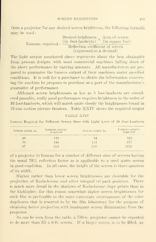
SCREEN BRIGHTNESS 451
from a projector for any desired screen brightness, the following formula
may be used:
Desired brightness Area of screen
T (in foot-lamberts) (in square feet)Lumens required = —_ „ —^-.—
, ^Reflection coefficient of. screen
(expressed as a decimal)
The light output mentioned above represents about the best obtainable
from present designs, with most commercial machines falling short of
the above performance by varying amounts. All manufacturers are pre-
pared to guarantee the lumens output of their machines under specified
conditions. It is well for a purchaser to obtain the information concern-
ing the machine he proposes to purchase as a part of the manufacturer's
guarantee of performance.
Although screen brightnesses as low as 5 foot-lamberts are consid-
ered passable, really good performance requires brightness in the order of
10 foot-lamberts, which will match quite closely the brightnesses found in
35-mm motion picture theaters. Table XXIV shows the required output
TABLE XXIV
Lumens Required for Different Screen Sizes with Light Level of 10 Foot-Lamberts
Screen width, in. ^l^T' Screen "Idth, 1°. ^^eT*40 119 84 525
50 186 114 977
67 334 138 1410
of a projector in lumens for a number of different sizes of screens having
the usual 70% reflection factor as is applicable to a used matte screen
in good condition. In all cases, the height of the screen is three-quarters
of its width.
Higher rather than lower screen brightnesses are desirable for the
projection of Kodachrome and other integral tri-pack positives. There
is much more detail in the shadows of Kodachrome dupe prints than in
the highlights; for this reason somewhat higher screen brightnesses for
such film is preferable to the more customary overexposure of the color
duplicates that is resorted to by the film laboratory for the purpose of
obtaining better projection with inadequate screen illumination from the
projector.
As can be seen from the table, a 750-w. projector cannot be expected
to do more than fill a 6-ft. screen. If a larger screen is to be filled, an
452 XIII. PROJECTION AND PROJECTORS
arc projector is required. Properly designed arc projectors are avail-
able that can deliver over 1000 lumens, and are suitable for a screen of
approximately 10 ft. in width.
Projection Objective Lenses. The subject of lenses is an extensive one
that usually requires many words and many figures if it is covered thor-
oughly. As the subject will be discussed here, no attempt will be made
to cover lens design per se, the practical considerations concerning lenses
available on the open market are more useful to most who will read this
book.
There are numerous properties of a lens that should be checked by a
purchaser. For all properties except resolving power there is no simple
accepted standard method of testing. Fortunately, resolving power is
the one property that needs most careful checking. The following are
the other properties
:
Chromatid Aberrations. This may be detected by the presence of a colored
haze visible in the details over the whole field. Fortunately this is not a commondefect.
Lateral Color. This is detected by the presence of one-sided color fringes ap-
pearing in the outer parts of the field and disappearing completely in the center.
Distortion. This is detected by straight lines in the outer part of the field ap-
pearing as curved lines on the screen. The straight sides of the picture gate of the
projector itself make a good test.
Haze. This is detected by the presence of a misty haze of light covering the
image without seriously interfering with the resolution. This is evidence of a large
amount of spherical aberraton ; lenses showng this defect should not be used.
The tests for all these is the projection of a good reference film. If
any one of the defects as described is apparent to a person viewing the
screen, the lens should be rejected.
Most 16-mm projection objective lenses—especially those of 2-in. focal
length and of //1.6 relative aperture—have a decidedly curved field, and
the amount of curvature varies markedly among different manufacturers
and among different lens types. Unfortunately, the manufacturers that
make the most desirable machines do not ordinarily supply the best lenses.
Resolving power measurements may be used as a criterion of the detail-
rendering quality of a lens and of its flatness of field in a manner similar
to the resolving power measurements of film. To obtain data for com-
parison, it is necessary to decide upon a specific procedure for testing,
since the setting of the lens along the optical axis for best focus at the
center of the picture is very often different from its setting for best focus
at the corners. Ordinarily, it is desirable to focus for best sharpness at

SCREEN BRIGHTNESS 153
the center of the picture ami to make no readjustments when readings
are made in the corners or elsewhere.
In all likelihood, 70% or more of the 16-mm projection objective lenses
in use are of the 2-in., / 1.6 variety. In a typical lens of this class (made
by Bell and Howell and tested in 1!'41 I, the resolving power measured
100 lines per millimeter at the center of the field, and was less than 20
lines per millimeter in the corners of the field. Such a lens, when sharply
focused at the center, is very fuzzy at the corners; when rotated slightly
to focus sharply at the corners, the center loses a major percentage of its
resolving power. Operators using such a lens "split the focus" (as they
call it) and focus most sharply at some indeterminate point intermediate
between the two settings. Such a lens is bad, since the quality of the
projected image varies over an excessively wide range because the op-
erator cannot focus twice at the same point. Slight changes in focus ad-
justment are usually required with even the best projectors after the
machines have warmed up. and although the picture may be satisfactorily
sharp at the start, it will be very difficult to make readjustments of focus
setting satisfactorily while the film is running.
It is not necessary for lenses to have such bad geometric distortion.
A very good lens type such as the Bausch and Lomb 35-mm Super Cine-
phor projection objective lens is quite satisfactory at all parts of its
field ; it is quite large in diameter compared with 16-mm projection lenses
of comparable rating. Incidentally, its price is about $150. while the
price of the Bell and Howell lens previously mentioned was only about
$15. Needless to say there have been considerable improvements in the
quality of 2-in. / 1.6 Bell and Howell projection objective lenses, but it
is still imperative for a purchaser to test a lens carefully before accept-
ing it.
Designing a good 2-in. lens of wide aperture is not a simple matter
and manufacturers have chosen different design compromises resulting in
price differences and performance differences. One group of manufac-
turers has chosen to retain the same number of lens elements and to in-
crease the resolving power in the corners by lowering it somewhat in the
center; this has been characteristic of many of the lenses supplied byAmpro, Victor, and RCA. Other manufacturers such as Eastman have
added an extra lens element, a field flattener, which materially improves
the flatness with relatively little sacrifice of resolving power at the center.
As an illustration of the differences in resolving power (in lines per
millimeter) to be expected when different focus adjustments are made or
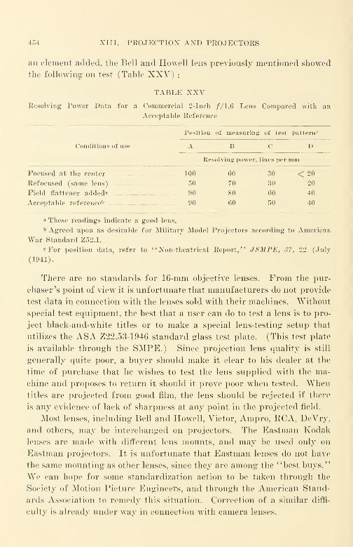
454 XIII. PROJECTION AND PROJECTORS
an element added, the Bell and Howell lens previously mentioned showed
the following on test (Table XXV) :
TABLE XXVResolving Power Data for a Commercial 2-Inch //1.6 Lens Compared with an
Acceptable Reference
Position of measuring of test pattern<"
Conditions of use A B C D
Resolving power, lines per mm
Focused at the center 100 60 30 < 20
Refocused (same lens) 50 70 30 20
Field flattener added* 90 80 60 40
Acceptable referenceb 90 60 50 40
a These readings indicate a good lens.
b Agreed upon as desirable for Military Model Projectors according to American
War Standard Z52.1.
cFor position data, refer to "Non-theatrical Report," JSMPE, 37, 22 (July
(1941).
There are no standards for 16-mm objective lenses. From the pur-
chaser's point of view it is unfortunate that manufacturers do not provide
test data in connection with the lenses sold with their machines. Without
special test equipment, the best that a user can do to test a lens is to pro-
ject black-and-white titles or to make a special lens-testing setup that
utilizes the ASA Z22.53-1946 standard glass test plate. (This test plate
is available through the SMPE.) Since projection lens quality is still
generally quite poor, a buyer should make it clear to his dealer at the
time of purchase that he wishes to test the lens supplied with the ma-
chine and proposes to return it should it prove poor when tested. Whentitles are projected from good film, the lens should be rejected if there
is any evidence of lack of sharpness at any point in the projected field.
Most lenses, including Bell and Howell, Victor, Ampro, KCA, DeVry,
and others, may be interchanged on projectors. The Eastman Kodak
lenses are made with different lens mounts, and may be used only on
Eastman projectors. It is unfortunate that Eastman lenses do not have
the same mounting as other lenses, since they are among the "best buys."
We can hope for some standardization action to be taken through the
Society of Motion Picture Engineers, and through the American Stand-
ards Association to remedy this situation. Correction of a similar diffi-
culty is already under way in connection with camera lenses.
SCREEN BRIGHTNESS 455
Projection Systems. There are two systems of 16-mm projection in
current use, projection by reflection from a screen, and projection by
transmission through a ground glass screen or equivalent. The former
is most common, representing most commercial projection equipment. In
this system of projection, the projector is located near the rear of the
projection space, with the light beam from the machine passing over the
heads of those along the center line of the audience until it impinges upon
a reflective screen. The arrangement is quite like that used in most con-
ventional motion picture theaters.
The latter system of projection involves projecting directly on a
ground glass screen or its equivalent from a projector located behind the
screen. In an auditorium set up for this system of projection (as is found
in certain Trans-Lux theaters) the audience views one side of the ground
glass screen while the projector throws light on the other. This system
of projection is used in 16-mm film "jukeboxes" such as the Panoram
Soundies machines made by the Mills Novelty Company.
Although the reflective system is used almost to the exclusion of the
transmission system in most applications except jukeboxes at the present
time, some attention should be given the transmission system because of
its excellent possibilities in retaining viewing contrast of the subject mat-
ter despite high ambient illumination levels. Although most of the prac-
tical problems in transmission projection still remain to be solved,
operation with high ambient light levels may be accomplished with a
screen that absorbs most of the light incident upon it. The general
method that has been used experimentally in television receivers where
a similar problem of high ambient illumination is encountered utilizes
a neutral density filter with, e.g., 90% absorption. The light transmitted
from the projector is then 90% absorbed and 10% transmitted; the am-
bient light must pass through the filter twice in order to be reflected and
is accordingly cut down to less than 1% of its incident value. The over-
all result is remarkable, particularly at the high ambient illumination
levels often present in a classroom. Some form of polarizing filter maybe used to supplement or replace the neutral density filter in the projec-
tion system to reduce the light losses. In addition, the screen may be
designed to provide a certain amount of specularity if the projection
angle required is narrower than usual. The principle of projection by
transmission has been widely used in many of the "daylight" signs found
in railroad terminals, etc. In the development of improved arrange-
ments, methods should be used that will not be color-selective;projectors
456 XIII. PROJECTION AND PROJECTORS
must be designed to function satisfactorily with both black-and-white
and color films. Much aggressive investigation of the screen problem
is going on in television, and, when the results are directly applicable
to motion picture projection, there is little doubt that such screens and
arrangements will be marketed.
Reflective Screens. The purpose of a reflective screen is to reflect the
light projected upon it by the projector. Screens, like anything else,
become dirty and lose efficiency very rapidly with even an almost imper-
ceptible coating of soot or dirt. The worst conditions that may be en-
countered are found in schools in smoke-ridden areas such as Manhattan
in New York or the Mill district of Pittsburgh. The rate at which
soot, dirt, and dust are deposited is really alarming to anyone who lives
in a nonindustrial section of the country. When soot filters into a class-
room, the motion picture screen, of course, acquires its full share.
There are two practical measures that may be taken to limit the loss
of efficiency of a screen due to dirt collection
:
(a) Wash the screen.
(b) Use a screen mounted on spring rollers, pulling it down when
it is to be used, and keeping it rolled up when not in use.
Although both measures are quite simple, it is surprising how often
these simple precautions are ignored, or their purposes defeated. The
starting point is the purchase of the correct screen type. There are
three broad classes of reflective screen
:
(1) The diffusive or flat-white.
(2) The semidiffusive.
(3) The beaded or specular.
The semidiffusive and the beaded types ordinarily cannot be washed
readily ; the greasy sootlike deposit that collects on the screen infiltrates
among the glass beadlike particles and cannot be removed without injury
to the screen. The diffusive type can be made washable, but many dif-
fusive screens are not washable. All three types can be spring-roller
mounted without much difficulty, but it is necessary to make certain that
frequent rolling and unrolling of the screen does not cause the screen to
crease or streak, or to cause coating material to be removed or marked.
A vacuum cleaner is effective in removing ordinary dust, but is rarely
effective against greasy, sootlike dirt.
Screen makers can provide data concerning the washability of their
products; without specific information, it is well to assume that a screen
is not washable. All screens yellow with age; the amount and rate of
SCKEEN BRIGHTNESS 457
yellowing and spotting varies from manufacturer to manufacturer and
from product to product. Screens are coated with paintlike materials,
and the yellowing and spotting is comparable to that of paints. An ex-
cellent guide in the purchase of a screen is ASA AVar Standard Z52.56-
19-45 that was dropped at the end of the war.
A screen that appears dark when compared with a sheet of clean
white paper should be replaced, since it is wasting one-quarter or more
of the light incident upon it. A yellowish screen should not be used, es-
pecially for color films. It is also bad practice to continue to use a screen
after it has acquired a mottled appearance. It is impossible to view a
motion picture with satisfaction when a splotchy pattern of lights and
shades due to the mottling is superimposed on the lights and shadows of
every scene.
A definition of screen "whiteness" is found in American War Stand-
ard Z52.45-1945, and specifies that the ratio of the lowest to the highest
reflection factor for any wave length between 420 and 700 m/x shall be at
least 85% ;it also specifies among other things the performance require-
ments for a screen after aging as well as the method for making the ar-
tificial aging test.
The choice among the diffusive, semidiffusive, and beaded types of
screens depends upon conditions of use. When the ambient room illumi-
nation is low (below 0.1 foot-lambert). and there are no sources of ex-
traneous light, such as light "leaking" in through a doorway, between a
drawn shade and a window frame, stray light bulbs, and the like, the dif-
fusive or flat-white screen is without doubt the most satisfactory. This
is a matte-type surface obtained by painting a wall with flat white paint
or treating a fabric or rubber base material to reflect light in a similar
manner. Such screens reflect the light that falls upon them in such
manner that their brightnesses at all angles of view are approximately
the same. A picture projected on such a screen is almost as bright whenviewed from an angle of 30°, or even from an angle of 60°, as it is whenviewed along the perpendicular to the screen. The reflecting ability of
screens in different directions is customarily expressed in terms of a
theoretical screen which reflects all light falling upon it in such a man-
ner as to be equally bright at all viewing angles. Taking the coefficient
of such an ideal screen as 100% in every direction, a good matte surface
screen will have a reflection coefficient of about 85% along the axis per-
pendicular to the screen and 75-85% at an angle of 30°. The matte or
diffusive screen is the type that should be used for the largest audience
;
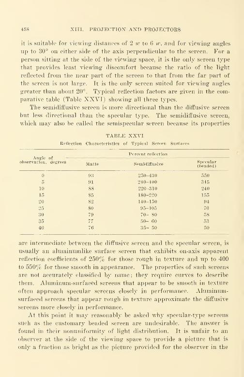
458 XIII. PROJECTION AND PROJECTORS
it is suitable for viewing distances of 2 w to 6 w, and for viewing angles
up to 30° on either side of the axis perpendicular to the screen. For a
person sitting at the side of the viewing space, it is the only screen type
that provides least viewing discomfort because the ratio of the light
reflected from the near part of the screen to that from the far part of
the screen is not large. It is the only screen suited for viewing angles
greater than about 20°. Typical reflection factors are given in the com-
parative table (Table XXVI) showing all three types.
The semidiffusive screen is more directional than the diffusive screen
but less directional than the specular type. The semidiffusive screen,
which may also be called the semispecular screen because its properties
TABLE XXVIReflection Characteristics of Typical Screen Surfaces
Angle ofPercent reflection
observation, degrees Matte Semidiffusive beaded)
93
5 91
10 88
15 85
20 82
25 80
30 79
35 77
40 76
250-430 550
240-400 345
220-310 240
180-220 155
140-150 94
95-105 70
70- 80 58
50- 60 53
35- 50 50
are intermediate between the diffusive screen and the specular screen, is
usually an aluminumlike surface screen that exhibits on-axis apparent
reflection coefficients of 250% for those rough in texture and up to 400
to 550% for those smooth in appearance. The properties of such screens
are not accurately classified by name; they require curves to describe
them. Aluminum-surfaced screens that appear to be smooth in texture
often approach specular screens closely in performance. Aluminum-
surfaced screens that appear rough in texture approximate the diffusive
screens more closely in performance.
At this point it may reasonably be asked why specular-type screens
such as the customary beaded screen are undesirable. The answer is
found in their nonuniformity of light distribution. It is unfair to an
observer at the side of the viewing space to provide a picture that is
only a fraction as bright as the picture provided for the observer in the
SCREEX BRIGHTNESS 459
center aisle. It is undesirable for a single observer to see the top of the
screen with appreciably lower brightness than he sees the bottom of the
screen. It is similarly undesirable to see one side of the screen with ap-
preciably lower brightness than the opposite side of the screen. Al-
though no standard has been promulgated with regard to brightness
ratios, it has been suggested by the Non-Theatrical Committee of the
Society of Motion Picture Engineers in their July 1041 report that the
ratio between the brightest part of the screen and the darkest part of
the screen should be not greater than 3 to 1.
A practical working standard for comparing apparent reflection
coefficients is a freshly scraped block of pure magnesium carbonate,
which is used very widely as a reference not only in connection with the
measurement of apparent reflection, but also in connection with measur-
ing the whiteness of screens and as the working standard material for
photoelectric spectrophotometers. Blocks of this material may be ob-
tained from scientific supply firms such as Central Scientific, Eimer and
Amend, and others.
American War Standard Z52.46-1945 for "Brightness Characteris-
tics of Projection Screens (Semi-Diffusing Reflecting Surface)" speci-
fies that the brightness ratio at a viewing angle of 1.5° shall not be less
than S0 r[ . and not less than 6o r'( at any viewing angle between 1.5°
and 60°. Although the specification describes this screen as semidiffus-
ing. its characteristics approach the diffusive screen much more closely
than either the specular or the beaded screens.
The beaded screen has a surface covered with small glass beads or
glasslike particles which reflect light internally, and at the same time
direct the light back by refraction in such a manner that the largest
proportion of the light is sent back in the direction from which it came.
This is true even when the light strikes the screen at an angle. Since
the beaded screen sends most of the light back toward the projector,
that part of the audience sitting along the centerline of the viewing
space sees a much brighter picture than would be provided by even the
perfectly reflecting theoretical screen described previously. Values as
high as 550 rc are common for such screens; a value of 180^ (3 to 1
brightness ratio) is reached at an angle of only 12° or 13°; this repre-
sents the maximum viewing angle recommended. The performance dif-
ferences among beaded screens of different makes are quite small.
Screens of the metallic type are nol recommended for conventional
projection, being suited primarily for stereoscopic projection with polar-
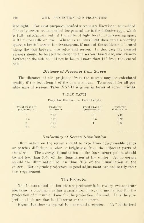
460 XIII. PKOJECTIOX AXD PKOJECTORS
ized light. For most purposes, beaded screens are likewise to be avoided.
The only screen recommended for general use is the diffusive type, which
is fully satisfactory only if the ambient light level in the viewing space
is 0.1 foot-candle or less. Where extraneous light does enter a viewing
space, a beaded screen is advantageous if most of the audience is located
along the axis between projector and screen. In this case the nearest
viewers should be located no closer to the screen than 2.5 w, and viewers
farthest to the side should not be located more than 12° from the central
axis.
Distance of Projector from Screen
The distance of the projector from the screen may be calculated
readily if the focal length of the lens is known. To account for all pos-
sible sizes of screens, Table XXVII is given in terms of screen widths.
TABLE XXVII
Projector Distance vs. Focal Length
Focal length ofprojector, in.
Projectordistance, w
Focal length ofprojector, in.
Projectordistance, w
1 2.65 3 7.95
1.5 3.98 3.5 9.28
2 5.30 4 10.60
2.5 6.66
Uniformity of Screen Illumination
Illumination on the screen should be free from objectionable bands
or patches differing in color or brightness from the adjacent parts of
the screen. The average illumination at the four corner points should
be not less than 65% of the illumination at the center. At no corner
should the illumination be less than 50% of the illumination at the
center. Better grade projectors in good adjustment can ordinarily meet
this requirement.
The Projector
The 16-mm sound motion picture projector is in reality two separate
mechanisms combined within a single assembly, one mechanism for the
projection of picture and one for the projection of sound. It is the pro-
jection of picture that is of interest at the moment.
Figure 108 shows a typical 16-mm sound projector. "A" is the feed

THE PRO.JKCTOR 461
reel upon which the unused portion of the film is carried. "B" is the
feed sprocket which rotates at constant speed while pulling film fromthe supply reel and also maintains a free loop of film just ahead of the
picture gate "C". At the picture gate the film is held in proper posi-
tion for projection; within the film gate is the projector aperture through
which light passes on its way to the screen via "D" the projection ob-
jective lens after passing through the picture image of the film. Thefilm leaves the picture gate below the movement claw located near the
aperture, and another free loop is formed before the film enters tie-
Fig. 108. Typical 16-mm sound projector (Ampro).
transport system of the sound translating portion of the machine. Part
way through the sound transport system, the sound track on the film
intercepts the sound light beam at "E". The modulated light beam is
directed to the surface of a photoelectric cell for the translation of light
variations into electrical currents and for subsequent amplification and
translation into sound by a loudspeaker. "F" is the takeup sprocket
which rotates at constant speed just as the feed sprocket does, and pulls
the film through the sound transport system. "G" is the takeup reel
on which the film is wound after it has passed through the machine. A
750-w. incandescent lamp is the customary light source for picture pro-
462 XIII. PROJECTION AND PROJECTORS
jection in most machines; a 6-v., 1-amp. lamp or a 4-v., 3/4-amp. lamp
is the common light source for the sound light beam. The 750-w. lamp
is customarily energized directly from the mains, either alternating or
direct current. The sound exciter lamp is usually energized from a
supersonic electron tube oscillator that is built as a part of the audio
amplifier assembly. The oscillator operates at a frequency of about 15
to 25 kilocycles. This arrangement of the supply for the sound exciter
lamp minimizes a.-c. hum without the expense of heavy rectifiers and
filters, or batteries.
The film is moved through the film gate by the movement claw wTith
an intermittent motion, and a new frame of film enters the projector
gate every 1/24 second when the machine is running at sound speed.
In the optical system of the picture portion of the projector, a lamp
(usually 750 watts) directs light to the aperture of the gate through a
set of condenser lenses. To the rear of the lamp in the lamp house is
a small mirror that redirects the light falling on it to the aperture, in-
creasing the aperture illumination. The projection objective focuses
the film image in the aperture to the screen. All optical elements are
customarily aligned along a straight-line optical axis. Lenses, the
mirror, and the gate should all be accessible for ready cleaning because
the efficiency of the projector is seriously impaired by even small amounts
of dust and dirt that are picked up in a short time by the projector.
Projector Mechanism
In a modern 16-mm projector, the motion of changing from one frame
of film to another at sound speed takes but one-ninth* of a movement
cycle of 1/24 second. 1/24 second includes both the periods of film
movement and of rest. Some of the older models of projectors had a
longer movement period amounting to one-sixth of a movement cycle,
but were not capable of as bright a picture as the one-ninth movement
cycle machines due to the fact that light could be theoretically available
on the screen for a maximum of five-sixths of a cycle, whereas with the
one-ninth movement cycle type the light could be theoretically available
for eight-ninths of a cycle.
The intermittent motion is accomplished in most machines by a 2- or
3-toothed claw that enters the perforations of the film and withdraws
from them, moving the film through the gate one frame at a time. The
motion of the claw is usually produced hy two synchronized cams. One* Approximate value.
PROJECTOR MECHANISM 463
of these moves the claw in and out of the perforations, and the other
advances the film one sprocket hole spacing—about 0.300 in.—at a time.
The intermittent mechanism of the projector is a critical part, since im-
perfect functioning may cause pictures to jump on the screen, excessive
wearing of the film, tearing of the perforations, and losing of the loop be-
low the picture gate with consequent serious film mutilation. A 3-toothed
claw is to be preferred to a 2-toothed claw because of the better chance
of a film with a damaged perforation going through the film gate with-
out interruption. Because of the complexity of the motions of the inter-
mittent parts of the machine, such parts may wear very rapidly and lose
their accuracy of movement if poorly designed, poorly manufactured, or
made of unsuitable materials.
It is necessary that the light beam from the projector be cut off while
the film is moving through the film gate. This is accomplished by a
simple rotating sectored disk, called a shutter,* that is rotated by the
projector gear train in synchronism with the movement claw of the film
gate. Most shutters cut off the light between the projection lamp and
the film gate, thereby eliminating heating of the film while it is in motion.
The shutter interrupts the light beam not only while the film is being
moved through the gate, but also when the film is stationary in the aper-
ture. This latter interruption occurs for the purpose of reducing flicker,
which would be intolerable if the additional light interruption did not
occur. At conventional brightness, machines designed for sound pro-
jection speed (24 frames per second) and for combinations of sound
speed with silent speeds provide two interruptions per frame, one during
the film-moving period and the second during the period when the film
is stationary in the aperture. Machines designed for silent speed alone
(16 frames per second) are preferably designed with three interruptions
per frame, one during the film-moving period, and two during the period
when the film is stationary in the aperture. To obtain the maximumamount of light from the projector lamp, manufacturers seek to keep
the light on the screen as long as possible consistent with minimum
flicker. Incidentally, when the film is stationary in the aperture but
the light is cut off, the movement claw moves downward, being actuated
* To reduce flicker still further, 35-mm machines of recent design such as the
Simplex E-7 have two rotating shutters, one between the lamp house and the aper-
ture, and the other between the objective lens and the screen. With such shutters,
the image may be said to be swept on the screen in one direction, and off the screen
in the other. Light efficiency is improved and flicker reduced compared with the
single-blade shutter type.

464 XIII. PROJECTION AND PROJECTORS
by one cam, but the second cooperating cam does not permit the entry
of the claw into the perforations. As a result the film does not move.
This type of claw movement is referred to in the trade as a "skip" move-
ment.
The single-blade shutter used in 16-mm machines harks back some
40 years or more in its design; no doubt the study given to the flicker
and the brightness characteristics of television systems should soon begin
to react favorably upon the design of 16-mm projection transport sys-
tems. Flicker and brightness characteristics of 16-mm projectors are
deserving of much intensive study, since, as one possible means of im-
proving light efficiency and reducing flicker, it would seem that the
fade-in and fade-out dissolving technique might be applied in shutter
designs to eliminate the abrupt light interruption that occurs while the
film is stationary in the aperture. Something of this sort has been ac-
complished with continuous projectors. These machines of the rotating
prism type have been best suited to projection with objective lenses where
long focal lengths are necessary. Appreciable increases in illumination
and reductions in flicker are possible with a fade-in fade-out design. Ascommercial 16-mm sound quality improves, it should be possible to ob-
tain relatively high light efficiencies and very low flicker with reduced
film speeds (say, 16 frames per, second) should this seem desirable as a
cost-reducing measure in the future ; this would seem applicable, espe-
cially to high-quality silent projectors.
The sprockets, sprocket guards, and rollers of the projector should be
designed to cause minimum wear and tear on the film. One important
requirement is that the film shall be supported at all points in its path
through a machine only at the safety areas of the film. A safety area
is any portion of the surface of the film that does not bear picture image
that is projected or sound image that is scanned. One safety area oc-
curs at the sound track edge of a sound film, another occurs between
the sound track and the picture, and the third occurs around the sprocket
holes. When film wraps around a sprocket, it may either be pulled
around or it may be kept in place by a film guard. The pulling method
appears to produce the least film damage in commercial designs.
The film gate usually consists of two main plates, one attached to the
body of the machine near the lamp and the other a movable pressure plate
that is pressed against the body plate by means of springs. Gate pres-
sure is usually adjustable ; incorrect gate pressure either materially re-
duces film life or it results in a jumpy picture. Gate pressure should
PROJECTOR MECHANISM 465
be great enough to hold the film flat in the aperture when it is stationary,
yet small enough to permit the film to be moved readily when the claw
propels the film through the gate. The surfaces of the body plate and
of the pressure plate are relieved or undercut so that only the safety
areas of the film bear upon the cooperating plates. A good projector
has all support parts {e.g., sprockets, rollers, transport parts) relieved
so that the film is supported only at the safety areas. A loop of film
will go through a well-designed projector as much as 5000 times when a
good machine is in good order, but less than 100 times in the case of a
reputable machine that is poor by comparison. After 1000 times, such
a loop should show little or no scratch or abrasion marks at those parts
of the picture that are projected and at those parts of the sound track
that are scanned by the sound light beam. To reduce wear to a mini-
mum on the working parts of the surfaces of the sprockets, gates, and
rollers the parts are made either of materials with excellent resistance
to abrasion, such as stainless steel, or of softer materials such as brass or
steel and are chrome-plated. In either event the parts are highly pol-
ished to reduce wear and abrasion of the projected film to a minimum.
All rollers should turn very freely, since a roller that binds causes more
film damage than no roller at all.
The sound translation system, although usually relatively simple,
deserves special discussion and will be treated later.
The takeup reel is rotated either by the projector motor through a
belt drive or by a separate motor. In either case there is some form of
friction clutch or variable-speed drive between the takeup spindle that
holds the takeup reel and the member from which the spindle is driven.
There is no fully satisfactory takeup drive on any regular commercial
machine that takes up very smoothly and with neither excessive tension
nor too slack tension for all portions of all commercial reels from the
inside of a 200-ft. American War Standard reel of 2-in. inside diameter
to the outside of a 2000-ft. American "War Standard reel of 15-in. out-
side diameter. It is entirely too much to expect of a simple friction
clutch that is to be reliable and cheap to manufacture, to operate over
a torque radius range from 2 to 15 in. With almost any commercial
projector that uses 400-ft. reel—even the American \Yar Standard 400-
ft. reel—cinching will always be present on the first 25 to 50 ft. be-
cause of excessive takeup tension. The practical solution to takeup dif-
ficulties on commercial projectors is to use only reels with an inside di-
ameter not less than about 4-7 8 in.: this dimension is maintained on all
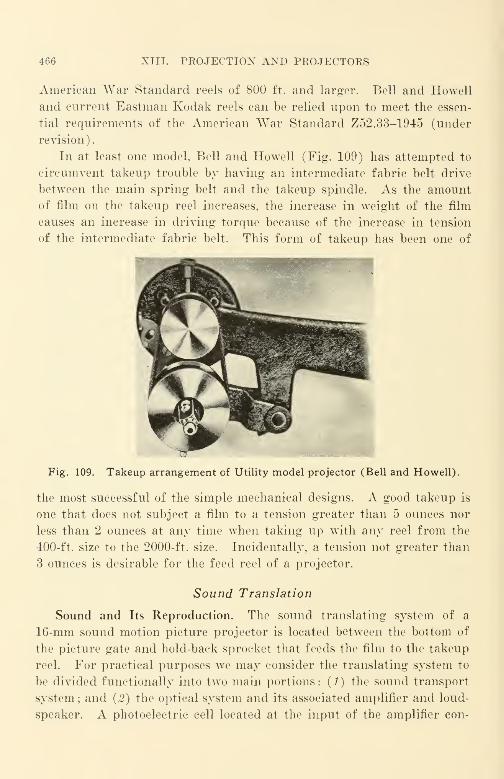
466 XIII. PROJECTION AXD PROJECTORS
American War Standard reels of 800 ft. and larger. Bell and Howell
and current Eastman Kodak reels can be relied upon to meet the essen-
tial requirements of the American War Standard Z52.33-1945 (under
revision).
In at least one model, Bell and Howell (Fig. 109) has attempted to
circumvent takeup trouble by having an intermediate fabric belt drive
between the main spring belt and the takeup spindle. As the amountof film on the takeup reel increases, the increase in weight of the film
causes an increase in driving torque because of the increase in tension
of the intermediate fabric belt. This form of takeup has been one of
Fig. 109. Takeup arrangement of Utility model projector (Bell and Howell).
the most successful of the simple mechanical designs. A good takeup is
one that does not subject a film to a tension greater than 5 ounces nor
less than 2 ounces at any time when taking up with any reel from the
400-ft. size to the 2000-ft. size. Incidentally, a tension not greater than
3 ounces is desirable for the feed reel of a projector.
Sound Translation
Sound and Its Reproduction. The sound translating system of a
16-mm sound motion picture projector is located between the bottom of
the picture gate and hold-back sprocket that feeds the film to the takeup
reel. For practical purposes we may consider the translating system to
be divided functionally into two main portions: (1) the sound transport
system; and (2) the optical system and its associated amplifier and loud-
speaker. A photoelectric cell located at the input of the amplifier con-
SOUND TRANSLATION 467
verts the light modulation produced by the movements of the film pasl
the light beam into electrical currents. The associated amplifier ampli-
fies the currents to a level suited to the loudspeaker which, in turn, radi-
ates sound directly to the ears of the audience viewing the film.
Sound Transport. Sound transport systems vary widely in design
and in performance. Theoretically, the objective of the design is to
transport the film past the sound light beam in a fixed plane with con-
stant velocity. Practically, however, all transport systems deviate from
this ideal, having spurious speed variations introduced by mechanical
and other irregularities and eccentricities that modulate the theoretically
constant film velocity. To some degree, all systems have an in-and-out-
of-focus effect that arises from the shift of the film from the theoretical
fixed plane. In the former case, the speed modulation causes a like
modulation of the signal derived from the film. This spurious signal
modulation is called flutter. In the latter case, the in-and-out-of-focus
effect that arises from the shifting of the actual plane that the film takes
as it moves past the sound-scanning beam produces the equivalent of a
flutter modulation of the effective width of the scanning beam slit. This
latter effect is quite pronounced in several makes of 16-mm sound pro-
jectors, but there has been no attempt made so far to measure it sepa-
rately in order to determine its magnitude, or to set limits for acceptable
performance.
Flutter in Transport Systems. The human ear is quite sensitive to
frequency modulation of a sine-wave, 3000-cps tone. The sensitivity
depends not only upon the amplitude of the variation, but also upon its
frequency. Since 3000 cps is a frequency to which the human ear is
particularly sensitive to both amplitude and pitch variations, it was
chosen as the frequency for flutter testing with test films. The film is
recorded at constant amplitude on a machine that has but a small frac-
tion of the flutter to be expected in the best machine to be tested with the
film. The American Standard 3000-cycle, Flutter Test Film Z22.43, ob-
tainable from the Society of Motion Picture Engineers, meets this re-
quirement. A flutter bridge for measuring flutter is manufactured by
RCA and others; the RCA flutter bridge is widely used. Different
flutter-measuring instruments such as the ERP* or the Altec provide
different readings for the same phenomenon. The instrument used and
the method of test should always be specified when the results of flutter
tests are reported.
*EKP division of Western Electric Company.
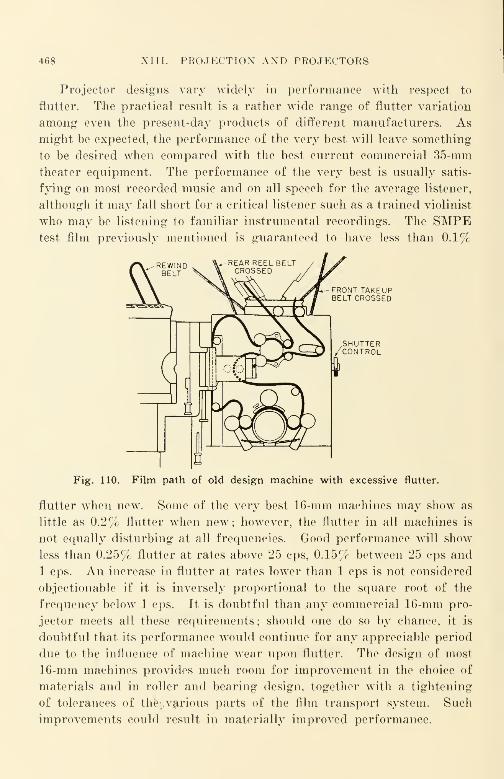
468 XIII. PROJECTION AND PROJECTORS
Projector designs vary widely in performance with respect to
flutter. The practical result is a rather wide range of flutter variation
among even the present-day products of different manufacturers. Asmight be expected, the performance of the very best will leave something
to be desired when compared writh the best current commercial 35-mm
theater equipment. The performance of the very best is usually satis-
fying on most recorded music and on all speech for the average listener,
although it may fall short for a critical listener such as a trained violinist
who may be listening to familiar instrumental recordings. The SMPEtest film previously mentioned is guaranteed to have less than 0.1%
FRONT TAKEUPBELT CROSSED
.SHUTTER/CONTROL
Fig. 110. Film path of old design machine with excessive flutter.
flutter when new. Some of the very best 16-mm machines may show as
little as 0.2% flutter when new; however, the flutter in all machines is
not equally disturbing at all frequencies. Good performance will show
less than 0.25% flutter at rates above 25 cps, 0.15% between 25 cps and
1 cps. An increase in flutter at rates lower than 1 cps is not considered
objectionable if it is inversely proportional to the square root of the
frequency below 1 cps. It is doubtful than any commercial 16-mm pro-
jector meets all these requirements; should one do so by chance, it is
doubtful that its performance would continue for any appreciable period
due to the influence of machine wear upon flutter. The design of most
16-mm machines provides much room for improvement in the choice of
materials and in roller and bearing design, together with a tightening
of tolerances of the;.various parts of the film transport system. Such
improvements could result in materially improved performance.

SOUND TRANSLATION K»!»
Passable 16-mm performance can be considered twice the flutter
limits mentioned above. Although most machines now in use will notcome within this limit, many new machines of better grade such as Belland Howell, Eastman and the DeVry Military Model can meet this re-
quirement when new. Unfortunately, many projectors that are satisfac-
tory when new suffer quick degradation in performance due to such verycommon causes as failures in the bearings of rollers and idler rollers.
Fig. 111. Assembly of rigidly coupled film-driven drum towell-balanced flywheel (Ampro).
Most film transport systems rely on the holdback sprocket to providethe driving force for the length of film between the intermittent sprocketand the holdback sprocket. One of the poorest transport systems interms of flutter was that used in the old Victor Animatographs (Fig.
110) more than a decade ago which had a simple chromium-platedfixed gate over which the film was pulled as it passed the light beam fromthe exciter lamp. When the film was pulled over the fixed gate by theholdback sprocket, the gate friction never seemed to act twice in the same
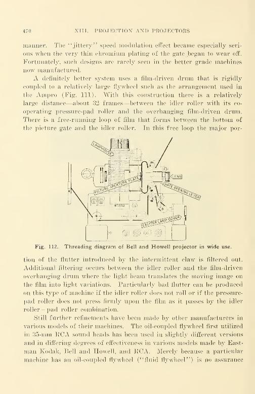
XIII. PROJECTION AND PROJECTORS
manner. The "jittery" speed modulation effect became especially seri-
ous when the very thin chromium plating of the gate began to wear off.
Fortunately, such designs are rarely seen in the better grade machines
now manufactured.
A definitely better system uses a film-driven drum that is rigidly
coupled to a relatively large flywheel such as the arrangement used in
the Ampro (Fig. 111). With this construction there is a relatively
large distance—about 32 frames—between the idler roller with its co-
operating pressure-pad roller and the overhanging film-driven drum.
There is a free-running loop of film that forms between the bottom of
the picture gate and the idler roller. In this free loop the major por-
Fig. 112. Threading diagram of Bell and Howell projector in wide use.
tion of the flutter introduced by the intermittent claw is filtered out.
Additional filtering occurs between the idler roller and the film-driven
overhanging drum where the light beam translates the moving image on
the film into light variations. Particularly bad flutter can be produced
on this type of machine if the idler roller does not roll or if the pressure-
pad roller does not press firmly upon the film as it passes by the idler
roller - pad roller combination.
Still further refinements have been made by other manufacturers in
various models of their machines. The oil-coupled flywheel first utilized
in 35-mm RCA sound heads has been used in slightly different versions
and in differing degrees of effectiveness in various models made by East-
man Kodak, Bell and Howell, and RCA. Merely because a particular
machine has an oil-coupled flywheel ("fluid flywheel") is no assurance
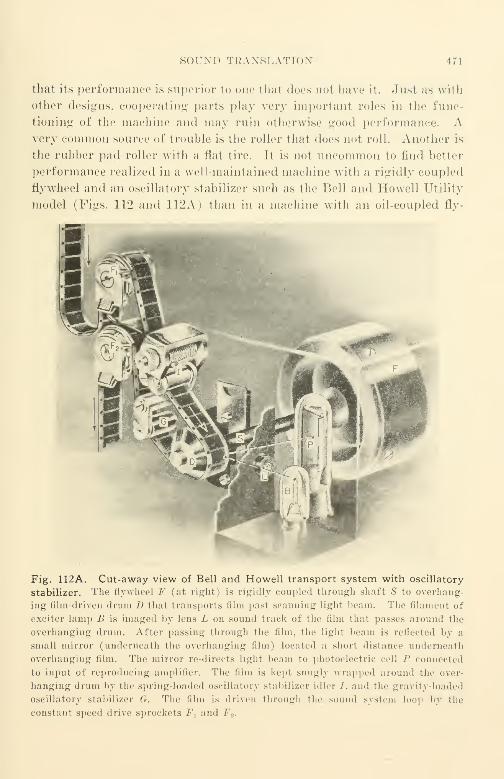
SOUND TRANSLATION 471
that its performance is superior to one thai docs no1 have it. -lust as with
other designs, cooperating parts play very importanl roles in the func-
tioning of the machine and may ruin otherwise good performance. Avery common source of trouble is the roller that does not roll. Another is
the rubber pad roller with a flat tire. It is not uncommon to find better
performance realized in a well-maintained machine with a rigidly coupled
flywheel and an oscillatory stabilizer such as the Bell and Howell Utility
model (Figs. 112 and 112A) than in a machine with an oil-coupled fly-
Fig. 112A. Cut-away view of Bell and Howell transport system with oscillatory
stabilizer. The flywheel F (at right) is rigidly coupled through shaft S to overhang-
ing film-driven drum J) that transports film pasl scanning li^ht beam. The filament of
exciter lamp B is imaged by lens L on sound track of the film that passes around the
overhanging drum. After passing through the film, the light beam is reflected by a
small mirror (underneath the overhanging film) located a short distance underneath
overhanging film. The mirror re-directs light beam to photoelectric cell P connected
to input of reproducing amplifier. The film is kept snugly wrapped around the over-
hanging drum by the spring-loaded oscillatory stabilizer idler /. and the gravity loaded
oscillatory stabilizer G. The film is driven through the sound system loop by the
constant speed drive sprockets F x and /•'.
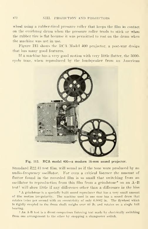
472 XIII. PROJECTION AND PROJECTORS
wheel using a rubber-tired pressure roller that keeps the film ki contact
on the overhung drum when the pressure roller tends to stick or whenthe rubber tire is flat because it was permitted to rest on the drum whenthe machine was not in use.
Figure 113 shows the RCA Model 400 projector, a post-war design
that has many good features.
If a machine has a very good motion with very little flutter, the 3000-
cycle tone, when reproduced by the loudspeaker from an American
Fig. 113. RCA model 400—a modern 16-mm sound projector.
Standard Z22.43 test film, will sound as if the tone were produced by an
audio-frequency oscillator. For even a critical listener the amount of
flutter found in the recorded film is so small that switching from an
oscillator to reproduction from this film from a grindstone* on an A-Btestf will show little if any difference other than a difference in the hiss
* A grindstone is a specially built sound reproducer that has a very small amount
of film motion irregularity. The machine used in one case has a sound drum that
rotates twice per second with an eccentricity of only 0.0002 in. The flywheel which
Is rigidly coupled to the drum shaft weighs over 60 lb. and rotates on a single ball
bearing.
t An A-B test is a direct-comparison listening test made by electrically switching
from one arrangement to the other by snapping a changeover switch.
SOUND OPTICAL SYSTEM 173
noise that accompanies the reproduction of the film. Most commercial
machines will show definite tone waver; on a better-grade machine the
waver should be almost imperceptible to the average Listener. It would
be good practice to run a short length of about 50 ft. of the 3000-cycle
flutter test film as a test every day before a machine is used. This would
spare many trained ears from the horror of projectors that wow* and
flutter, defects that are all too common and to a considerable degree nn
necessary among many machines in everyday use.
Sound Optical System, Amplifier, and Loudspeaker
The Optical System. In most projectors the optical system is quite
simple in design and consists essentially of a small helical coiled filament
lamp of 6-v., 1-amp. or 4-v., %-amp. rating, the filament of which is
imaged on the moving film by a simple cylindrical lens.f The light beam
emerges from this lens and impinges upon the sound track as a thin line of
light perpendicular to the direction of travel of the film.
The light beam is between 0.070 and 0.072 in. long and 0.001 to 0.0005
in. thick; its center is adjusted to scan the film at a distance of 0.058 in.
from the unperforated edge of the film. After passing through the film
and being modulated by its movement, the light beam is directed to a
photoelectric cell where it causes changes in current that arc amplified by
an amplifier and reproduced by a loudspeaker.
The thickness of the slit image depends upon the optical reduction
ratio at which the cylindrical lens is worked. A relatively wide slit will
* Wow represents flutter of dominant rate less than approximately 5 per second.
t This simple system, called the focused filament type, is very efficient in terms
of the amount of light flux delivered to the photocell compared with the amount of
light flux emitted by the exciter lamp. Because of its simplicity, it does not afford
much opportunity for effective color correction;for this reason it is not unusual for
the effective slit width to vary markedly from the geometrically calculated slit width.
Effective operation with low distortion demands that when variable-area films are
scanned, the photocell used shall be very uniform in surface sensitivity. As commer-
cial photocells are not checked accurately for surface sensitivity uniformity, it is
possible that occasional cells may show intermodulation distortion as high as 50% if
by chance a non-uniformly sensitive cell is chosen. Since the light from a variable
density sound track always covers substantially the same portions of the cell sur-
face, this distortion effect does not occur with variable density films. Gross non-
uniformity of surface sensitivity of a photoelectric cell may he detected by using a
"snake" track test film, ASA Z."2.7 that is available through the Society of Mo-
tion Picture Engineers. An output meter connected across a dummy load substi-
tuted for the loudspeaker will reveal output level variations if a poor cell is in the
machine.
474 XIII. PROJECTION AND PROJECTORS
pass a relatively large amount of light and provide a relatively large
signal for a photocell actuating the amplifier. The wide slit, however,
attenuates the high frequencies appreciably with respect to the lower
frequencies. To obtain ''balanced" reproduction without excessive bass
tones, both variable and fixed amplifier equalization is provided that is
capable of suitably attenuating the bass. In selecting slit-thickness and
amplifier characteristics, each manufacturer selects what he considers the
best compromise for his particular machine and his concept of'
' average '
'
film quality. In a large number of cases, the basic optical design was
accomplished over a decade ago and little significant modification—muchless fundamental re-design—has been made despite the fact that raw
stock and prints have improved very materially in the interim.
For performance equivalent in response-frequency characteristic to
35-mm performance in a well-maintained neighborhood theater, an effec-
tive slit width of 0.5 mil would be required. This value is determined by
multiplying the standard 35-mm slit thickness of 1.3 mils by the ratio of
the film speeds. Only one manufacturer* (Eastman Kodak) has so far
manufactured a commercial sound projector with a slit of this small size.
Projector users owe Eastman a debt of thanks for having pioneered in the
attempt to accomplish the lens improvement inexpensively in mass pro-
duction. Most machines were originally designed to provide a slit of 1
mil,f but since chromatic correction was absent, manufacturing toler-
ances proved wide in practice, and lens inspection in machine assembly
was not particularly good, effective widths of V/4 mils were not unusual.
Some lens system modifications proved quite good; an example is Bell
and Howell. In their case, improvements in amplifiers and in transport
systems made the improvement of the optical system evident in terms of
improved sound from the loudspeaker. The lens improvement consisted
of a change in the focal length of the cylindrical lens for the purpose of
increasing its optical reduction ratio, and/or a change in the size of the
small mask at the end of the optical assembly facing the exciter lamp.
With all manufacturers, there was a tightening of tolerances, the extent
of which varied from manufacturer to manufacturer. Despite these im-
provements, still further improvement is seriously needed in sound opti-
cal and film transport S3rstems; full advantage should also be taken of
the recent advances in electronics to reduce the noise and distortion pro-
duced in the amplifiers and to widen their frequency range.
* The De Vry and the Bell and Howell Models are not widely available com-
mercially.
t Mil—colloquial term for 0.001 inch.
THE EXCITEB LAMP 475
Most manufacturers today think in terms of a slil of roughly % mil.
If the tone control of a machine to be tested is se1 to provide unequalized
reproduction, it is not unusual to find the slit-loss characteristic as meas-
ured with a standard frequency film such as ASA-Z22.44 poorer than
that expected for a %-mil slit. The variation thai one is ap1 to find
from the producl of one manufacturer to that of another is quite Large,
and. although the variation from one machine to another of a particular
manufacturer is smaller, it is still larger than should be expected with
first-grade quality control and inspection in manufacture. One source
of difficulty is that there is no standard method of defining slit thickness
despite the fact that it is tacitly assumed that slit loss will be expressed in
terms of the equivalent theoretical slit. In practice, the slit thickness is
always larger by a considerable percentage than the value given by the
filament diameter of the lamp multiplied by the lens reduction ratio.
The diffusion, the lack of color correction, and numerous other factors
vary over such a wide range that any simple geometric estimate of this
simple nature is almost meaningless.
Accurate focus and azimuth adjustments are almost as important in
sound projectors as in sound recording machines. This is especially
true of present optical systems, which are usually little better than
marginal in performance. There have been too few improvements in the
mechanical design of many machines to make possible more accurate
adjustment of azimuth and focus. The combination of marginal optical
systems and poor adjustment arrangements in so many machines gives
rise to entirely too many cases of submarginal performance in machines
in day-to-day use. The situation is especially acute when Kodachrome
combination duplicates are projected that have the non-standard emul-
sion position; the sound track is out of focus by the thickness of the film
and in most of the poorer machines there is no provision for altering the
focus to correct for the serious losses that are present. Color duplicates
are growing daily in commercial importance, and. although steps are
being taken in a few laboratories to eliminate non-standard emulsion posi-
tion color films, it appears that they will still be with us for some tine- to
colli.'.
The Exciter Lamp. The most common form of power supply for the
exciter lamp is a super-audible oscillator operating at about "JO 25 kes;
its electron tube is fed from the power supply of the amplifier. Alter-
nating current of mains frequency is not used in commercial equipment,
since the hum produced would be excessi\
476 XIII. PROJECTION AXD PROJECTORS
Unfortunately, the small exciter lamps that are used are quite micro-
phonic. The mechanical vibration of the lamp caused by machine vibra-
tion results in a significant vibration of the exciter lamp with respect to
the optical axis of the optical system—introducing a ringing noise. As
the performance demands for 16-mm sound projection are pushed up-
ward, there should be a marked trend toward more rugged lamps with
short, thick, rugged filaments ; one possibility is the 6-v., 2-amp. lamp that
has a more favorable ratio of diameter to coil length. For really satis-
factory^ performance from existing sound projectors, it is usually neces-
sary to select exciter lamps for low microphonic response just as it is
necessary to select electron tubes for use in recording preamplifiers. Twoor three better-grade lamps are usually found in a box of ten.
Coupling the Photocell to Amplifier. In the design of a sound pro-
jector, a design engineer is usually faced with a choice between two
undesirable situations; one is to make the electrical connection between
the photocell and the amplifier short and direct with the disadvantage
of a long optical path, usually involving a mirror, or to make the optical
path short and direct and suffer the disadvantage of a long electrical
connection. Although the arguments for both sides seem equally valid,
the choice from the user's standpoint should be governed by the per-
formance obtained. On this basis the design with the short electrical
path and long optical path provides better performance when measured
in terms of the signal-to-noise ratio of commercial equipment. Bell and
Howell and Eastman machines are typical of the long optical path, while
the Ampro is typical of the short optical path.
Most 16-mm sound projector manufacturers make little attempt to
minimize the adverse effects of the high coupling impedance and the low
signal level in the link circuit between the photocell and the first tube of
the amplifier. The adverse effects are, of course, particularly noticeable
in the machine with the long electrical path. Although design precau-
tions, such as the use of a cathode follower circuit for the input tube,
and inverse feedback applied to the photocell circuit are theoretical
possibilities, additional electron tubes would be needed, since most ampli-
fier tubes now in use are already "squeezed" to their operating limits in
gain (amplification). Electrical redesign would be expensive, and
therefore is not likely to be undertaken without strong consumer or
competitive demand for such improvement. As more films and more
projectors of better quality become available on the market, the demand
will begin to assert itself and to bring improvement with it.
THE AMPLIFIER 477
The Amplifier. Most amplifiers in 16-mm sound projectors provide
more than 90-db gain, and the electron tubes* used in the earlier amplifier
stages preferably should be of the low-noise, non-microphonic types. The
best available type is the 1603 ; the reasons for its superiority in a pro-
jector amplifier are the same as in preamplifiers of recording equipment.
Most manufacturers, however, do not supply non-microphonic tubes in
their machines. In several, a 6J7 is used in the first stage; it may be
removed, and replaced with a 1620 without ehange of electrical con-
nections. In a few others, a 6C6 is used; it may be replaced in similar
manner with a 1603. In many machines the choice of the input tube
and its circuit represents poor design, particularly when judged by the
criterion of noise ; either major modification of the design or replacement
by a better amplifier is the only solution for improved performance. In
all commercial machines, appreciable improvement in noise level may be
obtained by replacing ordinary commercial tubes with non-microphonic
and other selected types.
In the case of machines using 750-w. projection lamps, most audio
amplifiers of recent design provide sufficient undistorted power for ordi-
nary purposes. If measured at a single frequency in midrange {e.g.,
1000 eps). the maximum output available is usually in the range between
5 and 10 watts at .V < total harmonic distortion. Unfortunately, the
intermodulation distortion in most amplifiers is far too high. Most audio
output, transformers, for example, follow the undesirable design practices
of ordinary home radio sets and are entirely too small for the power they
are rated to transmit. Even in the most expensive machines, the output
transformer usually weighs less than 1 lb., while an adequately designed
transformer should weigh about 5 lbs. if intermodulation distortion is
to be kept to a reasonably low level. Because the output transformer is
often the only audio transformer in the amplifier, the small increase in
weight and in cost would seem to be a very small price to pay for the
improvement in performance. The reduction of hum intermodulation
products alone will justify the improvement to any critical user of good
film and a good loudspeaker.
The design of the amplifiers found in many current machines is
inadequate and decidedly out of date. In entirely too many, little or no
inverse feedback is used to reduce distortion, since there is no reserve of
gain from which feedback might be applied. Although it has been recog-
nized for a number of years in engineering circles that beam power tubes
should not be fed to box-enclosed dynamic cone loudspeakers without
* See page 261.
478 XIII. PEOJECTIOX AND PROJECTORS
some 10 db or more of feedback around the output tubes, such machines
are still being sold in large numbers despite the lack of this simple yet
effective design requirement. If sufficient inverse feedback is judiciously
used with the customary tetrode amplifier, using output tubes such as the
conventional 6V6 in push-pull, or, better, if a triode output push-pull
stage such as a 6AS7G driven by a suitable cathode follower or other low-
distortion driver is used, the over-all performance of good film with a
good loudspeaker would surpass even the optimistic hopes of the average
16-mm film user. It is a sad commentary that many present-day 16-mm
audio systems have excessive intermodulation when compared with the
16-mm triode-output amplifiers used over 15 3*ears ago in the very first
commercial 16-mm machines.
Most machines have both a volume and a tone control. In some
machines, the volume control is an interstage control in the amplifier
;
in a few others, it is a rheostat in the exciter lamp circuit. A disad-
vantage of the rheostat type is that the signal-to-noise ratio becomes poor
when the lamp current is cut down to reduce volume ; however, the exciter
lamps last longer. In a few cases the tone control is merely a variable
resistor-condenser combination that reduces high frequencies in the
manner of similar tone controls in radio sets. In most cases, the tone
control is a variety of inverse feedback control that alters the low fre-
quency end of the spectrum when turned in one direction, and the high
frequency end when turned in the other direction.
The Loudspeaker.* The almost universal use of the direct-radiator
type of loudspeaker—known often as the dynamic cone loudspeaker—is
due to the simplicity of its construction and to its low cost. Because of
the influence of price-competitive home radio set design, even the loud-
speaker supplied today is not as satisfactory from the standpoint of
distortion as the heavy loudspeakers of 15 years ago or more. The
efficiency of a loudspeaker, like any other form of electric motor, depends
upon the flux density in the air gap, the length of the conductor in the
gap, and the current through it. To reduce cost in electrodynamic
loudspeakers, the amount of copper used in the field structure was re-
duced from several pounds to a fraction of a pound; when permanent
magnets were substituted for electromagnets, there was no attempt to
provide the large field flux of the earlier heavy electromagnets. To off-
set the loss in loudspeaker efficiency due to the reduction in magnetic
flux density in the air gap, the power output of the amplifier had to be
increased. Unfortunately, high power output was obtained only with
* See pages 300-303.
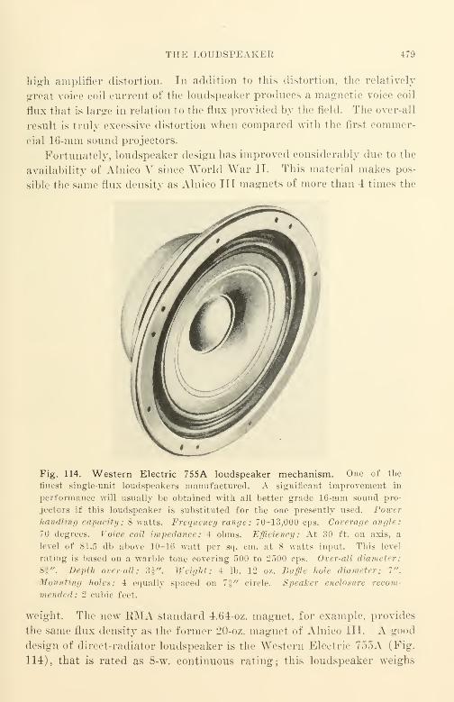
THE LOUDSPEAKER 479
high amplifier distortion. In addition to this distortion, the relatively
great voice coil current of the loudspeaker produces a magnetic voice coil
flux that is large in relation to the flux provided by the field. The over-all
result is truly excessive distortion when compared with the first commer-
cial 16-mm sound projectors.
Fortunately, loudspeaker design has improved considerably due to the
availability of Alnico V since World War II. This material makes pos-
sible the same flux density as Alnico III magnets of more than 4 times the
Fig. 114. Western Electric 755A loudspeaker mechanism. One of the
finest single-unit loudspeakers manufactured. A significant improvement in
performance will usually be obtained with all better grade 16-mm sound pro-
jectors if this loudspeaker is substituted for the one presently used. Powerhandling capacity: 8 watts. Frequency range: 70-13,000 cps. Coverage angle:
70 degrees. Voice coil impedance : 4 ohms. Efficiency: At 30 ft. on axis, a
level of 81.5 db above 10-16 watt per sq. em. at 8 watts input. This level
rating is based on a warble tone covering 500 to 2500 cps. Over-all diameter:
8f". Depth over-all: 3£". Weight: 4 lb. 12 oz. Baffle hole diameter: 7".
Mounting holes: 4 equally spaced on 7f" circle. Speaker enclosure recom-
iii > n <h 1 1 : 2 cubic feet.
weight. The new RMA standard 4.64-oz. magnet, for example, provides
the same flux density as the former 20-oz. magnet of Alnico III. A good
design of direct-radiator loudspeaker is the AVestern Electric 755A (Fig.
114), that is rated as 8-w. continuous rating; this loudspeaker weighs
480 XIII. PROJECTION AND PROJECTORS
4 3/4 pounds, and functions remarkably well in an enclosure of only
2 cu. ft. Since most of the weight of this loudspeaker is in its Alnico Vmagnet, it is highly efficient, and is quite free of distortion, including
that due to interaction of field flux and excessive flux due to the voice
coil. Incidentally, the voice coil impedance of the 755A is 4 ohms,
the current KMA standard. Voice coil impedances in 16-mm projectors
are often in the same range as in 35-mm equipment, from 10 to 20 ohms
—
averaging about 16 ohms. To use a "Western Electric 755A loudspeaker
ordinarily requires a separate transformer to couple between the amplifier
and the loudspeaker. Ideally, in a dynamic cone loudspeaker, low fre-
quencies are most efficiently radiated from a large diaphragm (18 in. is
often used) with a fairly large and heavy voice coil usually wound with
heavy copper wire. High frequencies are most efficiently radiated from
a small diaphragm (as small as an inch or two) with a small and light
voice coil usually wound with aluminum wire of rectangular cross section
to avoid " waste space." The Western Electric 755A loudspeaker repre-
sents one of the best compromise designs in a single-diaphragm mechanism
for these conflicting design requirements of both low frequency and high
frequency radiation in a dynamic cone type mechanism.
Unfortunately, the performance of the box-enclosed, cheap dynamic*
cone loudspeaker furnished with the average 750-w. projector is very poor
compared with the quality of the Western Electric 755A. The magnet is
usually small, providing a small field flux. Many amplifiers used to drive
such speakers have very little damping ;* their internal impedance is high
rather than low.
To add still more dissatisfaction, most dynamic cone speakers provide
very little high frequency response (response above 3500 cps), and, what
little there is, is poorly distributed about the axis of the loudspeaker.
Because of its low cost the design is very simple, and a single diaphragm
—relatively large—is used with no serious attempt to eliminate the
characteristic defect that the radiation angle of the loudspeaker becomes
more and more narrow as the frequency of the transmitted tone increases.
Typical loudspeaker characteristics of commercial machines are shown at
the end of this chapter.
From the use point of view, it is logical to expect that a loudspeaker
* Suitable damping can be provided by using triode output tubes suitably loaded
electrically, and by using inverse feedback especially around the driver and the voltage-
amplifying portion of the amplifier. Output tetrodes such as the 6V6 and 6L6 mayalso be used with feedback as previously mentioned. For details see chapter on loud-
speakers in Radiotron Designer's Handbook by F. Langsford Smith published by RCA.
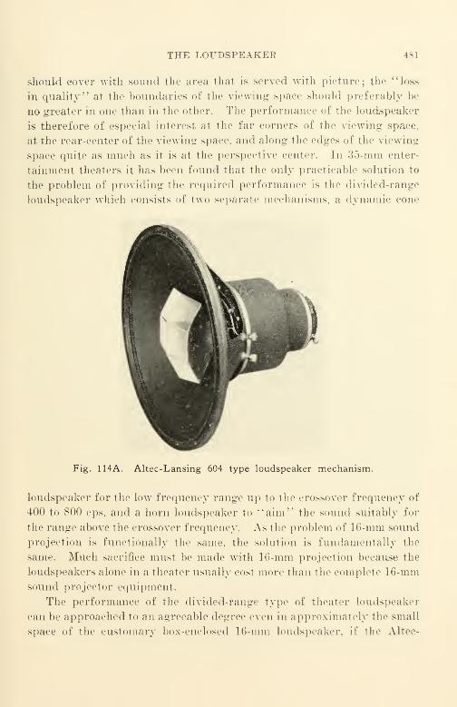
THE LOUDSPEAKER 481
should cover with sound the area thai is served with picture; the "loss
in quality" at the boundaries of the viewing space should preferably be
no greater in one than in the other. The performance of the loudspeaker
is therefore of especial interesl at t lie far corners of the viewing space,
at the rear-center of the viewing space, and along- the edges of the viewing
space quite as much as it is at the perspective center. In 35-mm enter-
tainment theaters it lias been found that the only practicable solution to
the problem of providing the required performance is the divided-range
loudspeaker which consists of two separate mechanisms, a dynamic cone
Fig. 114A. Altec-Lansing 604 type loudspeaker mechanism.
loudspeaker for the low frequency range up to the crossover frequency of
400 to 800 cps, and a horn loudspeaker to "aim" the sound suitably for
the range above the crossover frequency. As the problem of 16-mm sound
projection is functionally the same, the solution is fundamentally the
same. Much sacrifice must be made with 16-mm projection because the
loudspeakers alone in a theater usually cost more than the complete 16-mmsound projector equipment.
The performance of the divided-range type of theater loudspeaker
can be approached to an agreeable degree even in approximately the small
space of the customary box-enclosed 16-mm loudspeaker, if the Altec-

482 XIII. PROJECTION AND PROJECTORS
Lansing' 604 type (Fig. 114A) is used. This unit, when properly placed
with respect to the space to be covered with sound, can cover not only the
perspective center but also the boundaries. Other loudspeakers with
sacrifices in performance of varying kinds may be obtained at lower cost.
In comparing these, it would be well to use the Western Electric 755A as
a performance reference if the price for the unit in question is between
these two.
The horn-type loudspeaker should preferably be used especially for
the speech intelligibility frequencies that lie above 1000 cps. This type
provides: (1) good efficiency (20% is not uncommon compared with 3 or
4% common for ordinary dynamic cones); (2) good and reasonably
uniform directional radiation (over 60° is easily accomplished at 6000
cps compared with as little as 10° for the conventional dynamic cone);
(3) good transient response on speech sounds, a result of good damping
and uniform impedance characteristics (the horn-type design is almost
ideal for the speech range, the single dynamic cone is one of the poorest,
especially if it has the large diaphragm and the large-mass voice coil
essential to good radiation of low frequencies); (4) a much smaller dif-
ference in sound pressure at the front row center compared with the last
row at the extreme sides. (Sound from the horn-type should be almost as
clear and distinct as up front, whereas the sound from the dynamic cone
type will probably be low in volume and possibly unintelligible.) The
advantages can be readily observed if the loudspeaker of a current model
Bell and Howell sound projector is replaced with an Altec-Lansing 604
speaker in its box enclosure, or, should the additional bulk be no dis-
advantage, replaced by such speakers as the Bell and Howell Orchestricon
(made for Bell and Howell by Jensen) or similar divided-range speakers
made by Jensen, Stephens, Altec-Lansing, Klipsch, Western Electric,
RCA, and others.
Since the recent advent of Alnico V and other improved materials,
manufacturers have been vying with one another in the design of loud-
speakers that may be satisfactorily applied to 16-mm sound projection.
The cost of Alnico V is but a small percentage more per pound than its
predecessor Alnico III ; as the size and weight of the slug necessary to
provide a specified flux is reduced to about one-fourth, a reduction in
magnetic leakage has also been possible resulting in still better loud-
speaker performance. Despite these improvements, the cost of a really
satisfactory loudspeaker for 16-mm sound projection still represents a
very appreciable percentage of the cost of the complete machine, and,
PICTURE PROJECTION AND THE AUDIENCE
although design competition in the near future will drive prices down-
ward and performance upward Toward the desired goal, the prospects of
obtaining a good loudspeaker for the present manufacturing cost of $3 or
$4 still seems remote. It would seem reasonable to believe that the cost of
a loudspeaker for 16-mm projection should be higher than that for a home
radio set due to the greater importance of its more stringent requirements.
The importance of these requirements is not often consciously realized,
and the availability of means to correct them seems still less often appre-
ciated. A wide variety of loudspeakers is already available at a variety
of prices—from about $30 and upward (less enclosure); any one of the
better-grade units will show a significant improvement in performance
over the speaker supplied as regular equipment if the amplifier distortion
is not excessive.
Picture Projection and the Audience
Reflective projection is most widely used in 16-mm projection, and
some essential conditions for satisfactory operation should be mentioned.
The widely used sound projector of the 750-w. lamp type (equipped with
a 2-in. lens) will be presumed as a reference. The projector is custom-
arily placed near the rear-center of the projection space, the screen is in
front, The audience views the picture that is reflected by the screen.
A matte screen (also called diffusive or flat-white) should be used in
every instance possible, since it provides the widest angle of satisfactory
viewing. A screen is considered dirty if it appears dark in comparison
with a clean sheet of writing paper, and should be replaced for it is
wasting from one-quarter to as much as one-half of the light thrown upon
it by the projector.
An efficient projector can provide about 250 lumens with a 750-w.
lamp operated at rated voltage at its terminals; with good condenser
system design in the projector, a 1000-w. lamp of the 10 hour (short life)
type can provide about :!.")() lumens with rated voltage at its terminals.
The light output of many commercial machines will fall short of
these values, and data on lumens output of a particular make and
model of a machine should be obtained from its manufacturer. It* 225
lumens is taken as representative value, 10 ft.-lamberts* is obtained if
the s.-reen is 5 ft. wide. 10 ft.-lamberts is the value of screen brightness
ordinarily sought as a reference standard in 35-mm motion picture
theater projection; ASA standard Z22.39-1944 calls for not less than 9
* Assuming a very efficient optical system.

484 XIII. PROJECTION AXD PROJECTORS
nor more than 14. If the 10-hour, 1000-w. lamp is used, and the projector
emits the expected increase in light, a screen 5 1/2 ft. wide may be used at
approximately the same screen brightness.
Good tonal quality of the picture is impossible if the room in which
the audience is situated is not adequately darkened. A general room
light of about 1/10 ft.-candle is not harmful ; this is the illumination level
at which it is difficult but not impossible to read ordinary newspaper type.
If the walls of the room are light-colored and the room is small, this
general level of illumination may be reached by the light " sprayed
about" by the screen itself during projection. Aside from making pro-
visions for excluding light from the room until the general level of
illumination is of the order indicated, it is particularly necessary to make
sure that no narrow beams of light (such as sunlight) enter the room to
produce bright spots on the walls near the screen or strike other objects
in the room from which noticeable reflections may be obtained. For
audience comfort, the screen should be by far the brightest object in the
room. It is also preferable for the screen to be placed at least several feet
away from a nearby wall so that the light "sprayed about" by the screen
does not reveal nearby wall detail.
The Non-Theatrical Equipment Committee of the Society of Motion
Picture Engineers published a report in the Journal of the Society in
July 1941 that provides specific and authentic recommendations relating
to the use of 16-mm projectors in classrooms. Much of the data presented
is applicable to any kind of 16-mm projection and may be used as a guide
to equipment selection and use. One very important point discussed is
the location of the audience relative to the screen; for convenience,
audience location is described in terms of screen widths. In the case
of a machine with a 750-w. lamp, the proper screen width is 5 ft. for 10 ft.-
lamberts screen brightness.
(1) The nearest toav of seats shall be no closer than 2 w from the screen; a
preferred minimum distance is 2.5 iv. (In terms of the 5-ft. screen, the first row of
seats should be not less than 10 ft. away, with 12.5 ft. as the preferred minimum.)
(I?) The farthest row of seats shall be no farther than 6 w from the screen ; a
preferred maximum distance is 5.5 w. (In terms of the 5-ft. screen, the last row of
seats should be not more than 30ft. away, with 27.5 ft. as the preferred maximum.)
(3) No seat shall be farther away from the line between the projector and the
screen than its distance from the screen. This is equivalent to an angle of 30° on
either side of the projection axis.
Although it is definitely undesirable to do so, many screens are operat-
ing considerably below the 10 ft.-lambert brightness level. In a number

SOUND PROJECTION AND THE A.UDIENCE 485
of cases the screen chosen is entirely too large for the projector. In other
cases, improvement can be made by making certain thai the terminal
voltage of the lamp is in strict accordance with the lamp voltage rating.
Projection lamps can be obtained in rated voltages from 1').") to 130 in 5-v.
steps; it is very desirable that the correct lamp be used in all projection,
especially in the projection of color film. Should the screen brightness
level drop below 6 ft.-lamberts, the cause should be determined and the
condition corrected.
The recommended value of 10 ft.-lamberts should not be considered
inflexible. Some films may warrant a somewhat higher value because the
prints are dense, while others may warrant a somewhat lower value be-
cause the prints are light. Many prints are made light intentionally to
attempt to compensate in some degree for the poor screen brightness of
the projector ; such prints are poor in pictorial quality in that much of the
shadow detail is lost. If some degree of deviation is unavoidable, it is
preferable that it shall be in the direction of greater rather than lesser
screen brightness.
Sound Projection and the Audience
The selection of a loudspeaker that is best suited to 16-mm sound
projection at a reasonable price is not a very simple matter. Unfortu-
nately, too, the problem has been underestimated by projector manu-
facturers; the loudspeaker too often appeals as an afterthought rather
than a performance-integrated part of the machine. In extreme cases
it almost appears as if performance is completely subordinated to low
price.
Good sound reproduction involves two major characteristics: the
volume of the sound, and its clarity and freedom from distortion. With
a good film on a good machine, the volume can be controlled by the volume
control ; the quality or tonal balance by means of the tone control. Both
are partly dependent upon the acoustical conditions of the room or pro-
jection space. The volume of sound needed for most comfortable and
satisfactory reproduction depends upon several factors other than room
size. One of the most important is the reverberation characteristics of
the room, which are dependent to a considerable degree upon the amount
and the kind of sound-absorbing material present.
A room in which the walls, ceiling, and floor are all of hard materials
(cement, plaster, or wood) requires relatively little sound energy from the
loudspeaker to produce a loud effect. A particular sound being reflected
486 XIII. PROJECTION AXD PROJECTORS
and re-reflected numerous times loses some of its energy with each re-
flection and finally becomes inaudible. A prior sound has not ceased
before a subsequent sound appears ; sound heard under these conditions
does not have the pleasing clearness that occurs in the well-furnished
living room of a home where there are curtains, rugs, overstuffed furni-
ture, and cushioning materials that absorb sound to a considerable degree.
Such sound may be described as "blurred."
A reasonable starting point for sound projection is a room in which
it is easy for two persons—one at either end—to converse in an ordinary
tone of voice without difficulty when they are not looking directly at one
another. (This avoids lip reading.)
If a room is used frequently for projection, it will pay to obtain expert
advice on the best manner to treat it acoustically. Manufacturers of
sound insulation materials such as Johns-Manville maintain staffs for
the purpose of advising prospective users on how to get the best results
per dollar invested. Where the expense of permanent treatment is
beyond the budget of the user, less permanent treatments can be made.
In the simplest cases, the placing of a few temporary panels of sound-
absorbing wallboard may suffice for a very material improvement at very
low cost.
It would seem obvious that when sound films are projected the audi-
ence should be as well served with sound as it is with picture. To
accomplish this requires the right kind of loudspeaker placed properly
with respect to the audience in the right kind of room. There are two
simple rules that will aid sound reproduction materially.
(1) There should be no obstruction between the mouth of the loudspeaker and the
ears of each listener in the audience. This is best accomplished by elevating the
loudspeaker above the heads of the audience ; in this position there will be least ob-
struction by the heads of persons in the forward portion of the audience.
A location that is suitable is at the top center of the screen with the loudspeaker
mouth pointing at the center of the audience. In 35-mm entertainment theaters, a
perforated screen is used with the loudspeaker behind it at approximately % screen
height. Although this is also a good arrangement, it is not often applicable, since
perforated screens are rarely used for 16-mm projection because of the light loss of a
perforated screen. Another good location is on a stand at the side of the screen with
the center of the horn mouth located at about % screen height and ''pointed" at the
center of the audience. In placing the loudspeaker, it should be remembered that
when a loudspeaker is not along a line of sight, the listener cannot hear it properly.
{2) In the acoustical arrangement of a room, parallel hard surfaces should be
avoided by coating one surface of each pair with some kind of absorbent material.
In a room with an audience, it is important to cover that part of the ceiling under
which no one sits rather than the part under which the audience is located. Likewise,

SOUND PROJECTION AND THE AUDIENCE
in arranging drapes ami hangings on the walls, it is not necessary to cover a wall area
directly opposite dra] - - over windows. In general, parallel surfaces are best
controlled by covering only one of the pair oi irallel side
walls, for example, one wall might all - '.'lard width of wallboard run-
ning from floor to ceiling, and no covering for the Bame width. The opp -
would likewise alternate except that a covered portioi first wall would be
directly opposite an uncovered portion . r' the second wall, and rice versa. The rear
wall should be almost completely covered if possible.
It would seem apparent that the best control of sound quality is
achieved when the sound heard by each listener is that from the loud-
speaker alone, unaffected by any blurring caused by the multiple re-
flections from the highly sound-reflective walls of a reverberant room.
Although this theoretical ideal does not obtain in practice, it is possible
to select the loudspeaker type so that sound radiated by the loudspeaker
is directed only to the audience and not "sprayed" all over the walls.
ceiling, and other surfaces where it "bounces," arriving at the listener's
ears appreciably later than the sound that issued directly from the mouthof the loudspeaker. To accomplish the desired objective in the most
satisfactory manner calls for a horn-type loudspeaker. One several feet
Long is preferable to the very short horns used in such loudspeakers
such as the Altec-Lansing 604. An excellent horn is the Jensen K4-244.
but. unfortunately, like all good horns of this kind it is unwieldly in
comparison with the relatively small box-enclosed dynamic cone loud-
speaker customarily furnished as part of a sound projector.
If the sound radiation of a loudspeaker is non-directional, as is the
case with a dynamic cone Loudspeaker operating at low frequency, it maybe thought of as being located at the center of a sphere of radiation into
which sound energy is being transmitted. Remembering that the location
of the loudspeaker is also the location of the screen, it is apparent that
most of the sound energy is not directed to the audience at all but is
radiated to the walls, ceiling, floor, etc.. where it is cither absorbed and
wasted, or partially reflected to the listeners' cars where it "blurs" the
direct sound that was heard a moment earlier. A rough calculation will
sli<»w the high order of magnitude of this waste of energy; it is merely
necessary to take the ratio of the volume into which sound is radiated and
compare it with the volume in which sound is desired. The former is
represented by a sphere of radius equal to the distance from the loud-
speaker to the farthest Listener in the room, the latter is represented by
that sector of the sphere within which the cars of the audience are located.
For a loudspeaker mounted at the top center of the screen, the solid
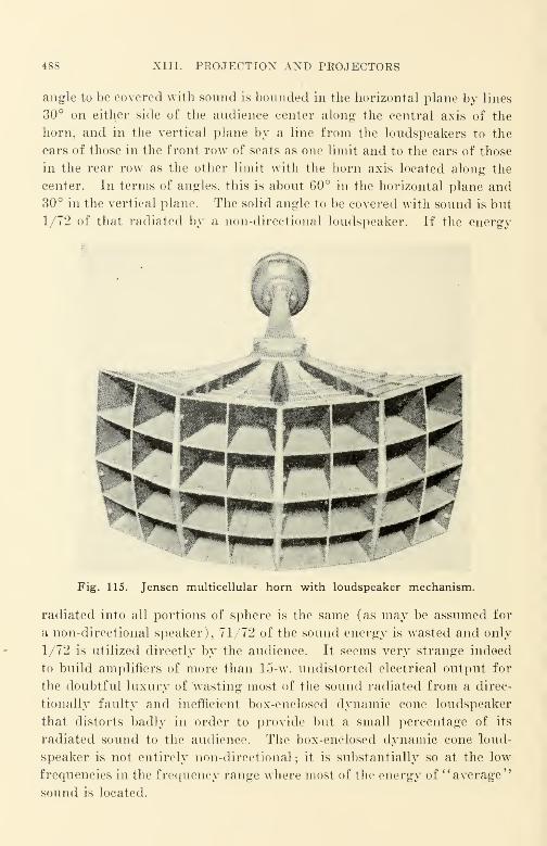
488 XIII. PROJECTION AND PROJECTORS
angle to be covered with sound is bounded in the horizontal plane by lines
30° on either side of the audience center along the central axis of the
horn, and in the vertical plane by a line from the loudspeakers to the
ears of those in the front row of seats as one limit and to the ears of those
in the rear row as the other limit with the horn axis located along the
center. In terms of angles, this is about 60° in the horizontal plane and30° in the vertical plane. The solid angle to be covered with sound is but
1/72 of that radiated by a non-directional loudspeaker. If the energy
W
,
Fig. 115. Jensen multicellular horn with loudspeaker mechanism.
radiated into all portions of sphere is the same (as may be assumed for
a non-directional speaker), 71/72 of the sound energy is wasted and only
1/72 is utilized directly by the audience. It seems very strange indeed
to build amplifiers of more than 15-w. undistorted electrical output for
the doubtful luxury of 'wasting most of the sound radiated from a direc-
tionally faulty and inefficient box-enclosed dynamic cone loudspeaker
that distorts badly in order to provide but a small percentage of its
radiated sound to the audience. The box-enclosed dynamic cone loud-
speaker is not entirely non-directional ; it is substantially so at the low
frequencies in the frequency range where most of the energy of "average"
sound is located.

SOUND PROJECTION AM» THE AUDIENCE 489
In reverberant auditoria such as schoolrooms, and the assembly halls,
of schools or churches, reverberation is a serious deterrent to the intelligi-
bility of recorded speech sounds. As it is usually more serious at Low-
frequencies than at the higher frequencies, attenuation of the low fre-
quencies is desirable. A really good, but expensive, permanent arrange-
ment is to mount a Jensen K4-244 horn (Fig. 115) at the top center of
the screen, ''pointing" it downward toward the center of the audience.
For most films, no low frequency loudspeaker unit is needed; a Jensen
Type F high-pass filter should be connected to the Jensen XP-191 loud-
speaker unit (or equivalent to prevent mechanical overload and con-
sequent damage. The high-pass filter is designed for cutoff at 220 cps.
This eutoff is quite satistactory for most filni^ in most reproducing spaces.
The recommended horn is designed for 90° horizontal and 45° vertical
coverage ; these angles represent sufficient overlapping for the largest
audience that can be suitably served with picture from a conventional
16-mm projector. The use of such a loudspeaker will result in several
other benefits simultaneously ; these are :
(1) Superior transient response—better than any other type.
Superior uniformity of horn impedance, resulting in better performance from
the amplifier due to the excellent loudspeaker damping.
Superior efficiency—several times as high as that of the cheap box-enclosed
dynamic cone.
(4) Excellent horn directivity with minimum variation in intensity level at any
useful frequency for different distances from the horn. The man in the hack row of
seats hears almost as well as the man in the front row; this is quite different from the
customary situation in which the man in the front row is "blasted out of his seat/'
while the man in the back row can hear and understand very little.
Excellent high-frequency directional uniformity—no serious discrimination in
high frequencies at the boundaries of the audience area where sound from the box
enclosed dynamic cone speaker is often almost unintelligible.
(6) Excellent fidelity—negligible distortion compared with that of the conven-
tional box-enclosed speaker.
To arrange a suitable mounting for this loudspeaker in the recom-
mended position, with the loudspeaker mouth slightly forward of the
plane of the screen, i> not a simple matter as it is almost 4 ft. long and has
a mouth almost 3 ft. across. The effort, however, will be well repaid in
the improvement of the reception.
Good picture projection and good sound projection can be obtained
consistently from good film with good equipment. In sound projection,
as in picture projection, meticulous attention to detail is capable of pro-
ducing eminently satisfactory results where marginal or inferior results

490 XIII. PROJECTION AND PROJECTORS
were obtained before. Manufacturers would do well to consider seriously
the loudspeaker and its mounting relation to the screen and to the audi-
ence. For conventional reflection projection the mounting' of a suitable
horn-type loudspeaker at the top center of the screen would go a long waytoward eliminating the unnecessarily deficient sound performance with
which much 16-mm sound projection is afflicted.
Practical Projector Performance
A good sound projector should provide a very steady, sharply focused
picture that is evenly illuminated, together with clear, steady, un-
wavering, undistorted, naturally reproduced sound. It is reasonable to
expect this performance not only at the beginning of the first reel pro-
jected with the machine, but also throughout each and every reel to be
projected. Ordinarily, if a machine provides such performance whennew, its performance does not deteriorate suddenly. An effect commonto all machines is that the picture focus adjustment changes as the
machine heats up, making slight focus readjustment necessary during
projection if the machine is used for the projection of several consecutive
reels. In most machines this effect, although noticeable, is small.
A good projector should be expected to project film with a minimumof film damage and wear and tear. Library-circulated prints are ex-
pected to provide from 50 showings upward before they are discarded
;
each user of a machine is morally bound to make certain that his machine
does not mutilate the film ; the 50th user has as much right to a satisfac-
tory showing as the first user. Some well-known machines are "very
hard on film," while others are "easy on film." If a loop of film is made
up that will run continuously in a projector, that loop should run through
the machine at least 750 times without evidence of scratching or damage
;
it should show no injury to sprocket holes, to the picture area, or to the
sound track area. Better grade machines such as the Bell and Howell*
can ordinarily run such a loop 3000 times; in a series of tests at the
Bureau of Standards just before World War II, one machine proved
capable of running such a loop 5200 times.
In the Bureau of Standards tests, a well-known machine with some of
the very best features, failed because it proved destructive to film. The
maximum life of a test loop obtained with this machine was 700 times, a
minimum of about 50 times, and an average life of about 100 times. Such* The new Bell and Howell Military Model machine, now in development, bids
fair to exceed this enviable record and to provide exceptional picture steadiness.

PRACTICAL PROJECTOR PERFORM A \« IE 491
0°- 15°
!
rY y
KA \1 1
v^
82
78
t
I
I
1
- AV
98
94
J 90Ui
8 86
82
102
98
94
90
86
0°"15°
>A \II
II
a/ \f\f\l\V 'J 1 / \ r*
-V 1/ u?
7 !i
1*
1
-
\
- B
-
0°- 15°
- IN- ri t' ' 11AM 1 v-
J^w /''IF *
i
v
- A-
0°" 15°
|A /f\ /i
92 'f^ LI \A
\ i\
84 iV>
801 1
"\
'/
D
76
i
0°- 15°
-
_^ jf\r'i'<-
h Y v- ftA1
V1
\/t
- 7 Ei
\\
ri
\
0°" 15°
- 1 \Is*. /' A
L'\\
-Itli
1/
\
\\ \
-
"\ I
- F
100 300 1000 4000 100 300 1000 4000
FREQUENCY, cps
Fig. 116. Over-all response-frequency characteristics of sound reproducing
systems of commercial projectors A to F inclusive. Pressure level measurements
were made with the test microphone placed 5 ft. in front of the fronl grille of the
Joudspeaker.
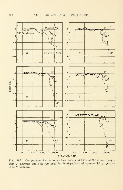
492 XIII. PROJECTION AND PROJECTORS
-',
0* Azimuth Angle
- 15*/izimuth Anc lie *—x.
-
-\ /
- A 30* Azimut h Angle
-
-8
-12
-16
-
-Jl-^**^ 0*-
- i
\
- i
i\
-"1
I
\
- D1
»30.
-
-4
-8
12
16
:
r-,°°
1 VN,-"'hi \ •^
8
'30
0°
^T tl 15*
-4 \ \
\\
1
l
-8
30#
-12
E-16
1 _L_ 1 1 II
2
-2
^^p^ 0°
\p
-61
M
10
c\
\ 30°
14
-
-2S"_ --p\,y
0*
~"*N,•*v| a
_ \"\-6
-
1/1v 1
\
-10
-14
- \
\
•
F 1
130°1
-18 1
!1
100 300 1000 4000 100
FREQUENCY, cps
300 1000 4000
Fig. 116A. Comparison of directional characteristic at 15° and 30° azimuth angle
with 0° azimuth angle as reference for loudspeakers of commercial projectors
A to t\ inclusive.

PRACTICAL PROJECTOR PERFORMANCE 493
10
-10
-20
-30
ui
5 -ioo
Res stive Lood
-
-
-i \\ \\
- 4\
-
Voi(
Res
10
-10
20
30
stive Lood
g^VN*V
\\\\
-
20
-30
!,_._"_ ,._;,
Resistive Lood
-~ !,__
->
-
- B
-
Voit
Res
1
istive Lood
-
-"*»-._—,
" \\
vS
- E
-
Resistive Lood
- 1^^ »
- >\ \
-
- c
-
VOK
Resistive Lood10
-10\
\\
-20J»
- F-30
-
OO 300 1000 300 1000 40004000 100
FREQUENCY, cps
Fig. 116B. Response-frequency characteristics of amplifiers of commercial soundprojectors, including the scanning beam for machines -1 to F, inclusive. A warble
film was run in the projector; the output of the amplifier was measured both across
a dummy loud resistor, and across the voice coil of the loudspeaker. Powei output
level was 1 watt at 1000 cps.

494 XIII. PROJECTION AND PROJECTORS
50
40in_iLU
59 30oUlQ
~I2:00 —--f-»—
xZ,.-
~* ^^^:00 *~^r
10:00
7:00
~t?n
^00N
"
- A
-
20
10
50
40
-
m 1 "^_ ,.iii mm
yfe-.oi .S»"
' 10:00
~~a~6b 5^
- /VOO
" B
"
_730_
10:00
A^
vj *^—
%^
~7:30.
'"i:00^__
12:00
\-<lb:00
\r^: 4:30
00 \-
- E
-
. 4:00
.-^^^v5..~*~~ii* tl 12:00^
^-122..^
*•.. "s V-
\/
V:30
""' 8-.oo^
- V 1 >:30\%
- F
"
100 300 300 1000 40001000 4000 100
FREQUENCY.eps
Fig. 116C. Response-frequency characteristics of amplifiers of commercial sound
projectors A to F, inclusive, for various tone control settings.

PEACTICAL PROJECTOR PERFORMANCE 495
-
-\
Jf- 0°
IS*J" f\
\-I5# /
D\)
94-O
_T90UJ>UJ-1 86UJtr
£ 82UJ(X0-
^n f\ /J
1 \J IM-
It A V
- 0° V \ V- J
- 15° / B
96
92
88
84
V\- 0° /
-v 1
JVj
/\J
- 15° / C
100 300 1000
92
98 88
94 84
90 80
86
98
98 94
94 90
90 86
86
4000 100
FREOUENCY.eps
- 0° /'
-15' / E
-
rA)1-
-, P\
I
/\J V
\ ,/\ r- 0° /,\P^JP-
\ vl
- 15° / F
100
96
92
88
300 1000 4000
Fig. 116D. Response-frequency characteristics of loudspeakers of commercial
sound projectors A to F, inclusive, at 0° and 15° azimuth. Approximately 1 watt
was fed into the loudspeaker under test, from a constant voltage source.
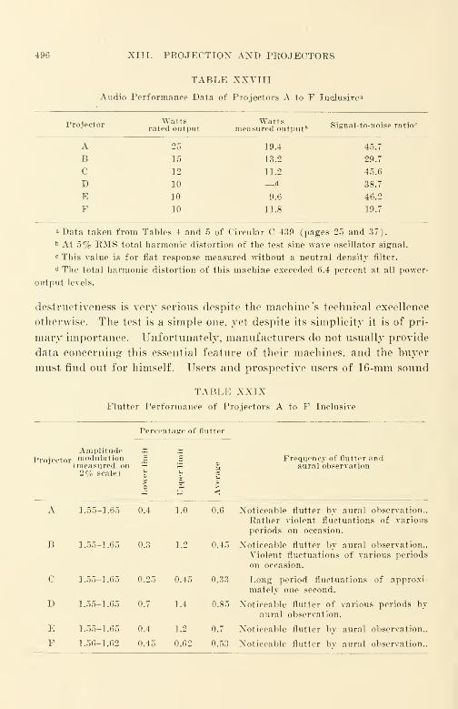
496 XIII. PROJECTION AND PROJECTORS
TABLE XXVIII
Audio Performance Data of Projectors A to F Inclusive 3
Projector Wattsrated output
Wattsmeasured ou tput ft
Signal-to-noise ratio c
A 25 19.4 45.7
B 15 13.2 29.7
C 12 11.2 45.6
D 10 —
d
38.7
E 10 9.6 46.2
F 10 11.8 19.7
a Data taken from Tables 4 and 5 of Circular C 439 (pages 25 and 37).
b At 5% RMS total harmonic distortion of the test sine wave oscillator signal.
c This value is for flat response measured without a neutral density filter.
d The total harmonic distortion of this machine exceeded 6.4 percent at all power-
output levels.
destructiveness is very serious despite the machine's technical excellence
otherwise. The test is a simple one, yet despite its simplicity it is of pri-
mary importance. Unfortunately, manufacturers do not usually provide
data concerning this essential feature of their machines, and the buyer
must find out for himself. Users and prospective users of 16-mm sound
TABLE XXIXFlutter Performance of Projectors A to F Inclusive
Percentage of flutter
Projector
Amplitudemodulation(measured ou2% scale) u
Vit
Frequency of flutter andaural observation
ss
><
A 1.55-1.65 0.4 1.0 0.6 Noticeable flutter by aural observation..
Rather violent fluctuations of various
periods on occasion.
B 1.55-1.65 0.3 1.2 0.45 Noticeable flutter by aural observation..
Violent fluctuations of various periods
on occasion.
C 1.55-1.65 0.25 0.45 0.33 Long period fluctuations of approxi-
mately one second.
D 1.55-1.65 0.7 1.4 0.85 Noticeable flutter of various periods byaural observation.
E 1.55-1.65 0.4 1.2 0.7 Noticeable flutter by aural observation..
F 1.56-1.62 0.45 0.62 0.53 Noticeable flutter by aural observation..
SELECTED BIBLIOGRAPHY 497
projectors will find it worthwhile to familiarize themselves with the fea-
tures of 16-mm sound projectors as described in detail in the Bureau of
Standards Circulars C-437 and C-439. Although the data is now quite
old, there have been few truly significant improvements beyond the pub-
lished information; certain of the better grade machines have improved
slightly, most of the others have not.
Figures 116, 116A, 116B, 116C, and 116D describe the audio per-
formance of 6 commercial 16-mm sound projectors tested by the National
Bureau of Standards; these data are reported in Circular C439 previously
referred to. Table XXVIII describes the output performance of the
same six machines with regard to power and to signal-to-noise ratio.
Table XXIX describes the flutter performance of the same six machines.
It is data such as appear in the foregoing figures and tables that describe
the performance of machines for a user; it is regrettable that such data
is not published or made otherwise readily available to prospective pur-
chasers of sound projectors. The Committee on Scientific Aids To Learn-
ing of the National Research Council is to be warmly congratulated for
its planning of this most-needed measurement activity, and the National
Bureau of Standards is also to be congratulated for carrying it out with
its characteristic methodical precision and efficiency.
Armed with a little knowledge of the design and performance char-
acteristics and requirements of 16-mm projection and projectors, there is
little reason why a user should not find current 16-mm equipment emi-
nently satisfactory for projecting good quality current 16-mm films.
Test films that may be required for comparative testing of machines or
for a routine check of the performance of machines already in service are
available through the Society of Motion Picture Engineers. For the
serious user, such films are imperative in preventive maintenance ; small
depredations in projector and in film performance can be detected before
a breakdown or serious defect in performance occurs.
Selected Bibliography
"Non-theatrical Equipment Report—Recommendations for Educational 16-Mm Pro-
jection," JSMPE, 37, 22 (July 1941).
Stephens, R. E., "Optical and Mechanical Characteristics of 16-Millimeter Motion Pic-
ture Projectors, M Natl. Bureau of Standards Circular C437, Washington, 1942.
Snyder, W. F., '' Acoustic Performance of 16-Millimeter Sound Motion Picture Pro-
jectors, " Natl. Bureau of Standards Circular C439, Washington, 1942.
Olson, H. F., "Extending the Range of Acoustic Reproducers," Proo. Radio Club of
Am. 18, 1 (Jan. 1941).

498 XIII. PROJECTION AND PROJECTORS
Jensen Technical Monographs Nos. 1 to 5, inch, Jensen Radio Manufacturing Co.,
Chicago, 1945.
Hilliard, J. K., '' Theater Loudspeaker Design, Performance, and Measurement, '
'
JSMPE, 52, 629 (June 1949).
Veneklasen, P. S., "Physical Measurements of Loudspeaker Performance," JSMPE,52, 641 (June 1949).
Angevine and Anderson, " Facts about Loudspeakers" (a series), Audio Eng., NewYork, 1948.
Hilliard, J. K., "Portable and Semiportable Loudspeaker Systems for Reproducing
16-Mm Sound on Film," JSMPE, 49, 431 (Nov. 1947).
For further bibliographic material the reader should refer to the following indexesto the Journal of the Society of Motion Picture Engineers.
July 1916-June 1930
' Apertures, " page 118.
'Arcs, Projection," page 118.
' Committee Reports—Projection," page 121.
* Condensers, '' page 122.
' Film Reels, " page 128.
'Home Motion Picture Equipment," page 131.
'Illumination, Projectors," page 133.
'Incandescent Lamps for Projection," page 134.
'Loud Speakers," page 135.
'Objectives," page 136.
' Optics, " page 137.
'Perspective," page 138.
'Projection, General Information," page 141.
' Projection Optics and Intensity Measurement, '' page 142.
'Projection Room, Cost and Equipment," page 143.
' Projectors, Continuous, '' page 143.
' Projectors, Intermittent, '
' page 144.
' Projectors, Special Type, '' page 144.
'Sixteen Millimeter Equipment," page 146.
'Sound Film Projection," page 146.
'Sound Installations in Theaters," page 147.
' Sound Reproduction, General Information Concerning, '' page 147.
' Theater Design and Equipment, '' page 152.
January 1930-December 1935
"Apertures," page 7.
"Amplifiers," page 7.
"Arcs," page 9.
"Auditory Perspective," page 10.
"Change-overs," page 11.
SELECTED BIBLIOGRAPHY 499
"Committee Reports—Projection Practice," page 16.
Projection Screen Brightness," page 17.
Projection Screens," page 17.
Projection Theory, '
' page 18.
" Electron Tubes," page 24.
•' l\\c-strain, " page 25.
" Illumination in Projection," page 33.
"Incandescent Lamps," page 34.
"Lamps," page 37.
"Loud Speakers," page 39.
'
' Motor Generators, '' page 41.
• Naval Projection Equipment," page 42.
" Non-theatrical, '' page 42.
"Optical Intermittents, " page 44.
"Optics," page 44.
"Photoelectric Cells," page 46.
"Portable Equipment," page 47.
"Power Supply, for Reproducing Equipment," page 47.
"Projection, General Information," page 51.
"Projectors, Continuous," page 53.
Intermittent, '' page 53.
Portable," page 53.
Special Type, '' page 53.
'' Rectifiers, '
' page 54.
"Screens," page 55.
"Servicing Motion Picture Equipment," page 57.
"Sixteen-Millimeter Equipment," page 57.
"Sound Installations in Theaters," page 58.
"Sound Reproduction, General Information," page 62.
"Test-Films," page 67.
'
' Theater Characteristics, '' page 67.
' < Theater Design, '' page 68.
'
' Theater Equipment, '' page 68.
"Theater Noises," page 68.
"Theater Operation," page 68.
'
' Vision,' ' page 69.
"Visual Fatigue," page 70.
1936-1945
Amplifiers," page 73.
Arcs," page 74.
Loudspeakers," page 106.
optics," page 111.
Projection," page 122.
Projectors," page 126.

500 XIII. PROJECTION AXD PROJECTORS
''Rectifiers," page 127.
" Research Council," page 127.
"SMPE Activities, Projection Practice Reports," page 129.
Theater Engineering Reports," page 131.
Non-theatrical Equipment Reports," page 129.
"Screens," page 133.
"Screen Brightness," page 142.
"Sound Reproduction," page 143.
"Sprockets," pagfe 148.
"Theater," page 152.
'' Vision, '
' page 154.
"War Committee on Photography, Z52," page 155.
CHAPTER XIV
Duplication of Tri-pack Color Films
Years ago when color in motion pictures was just a matter of scientific
speculation, Thomas A. Edison expressed the thought that the combina-
tion of color and sound in motion pictures would represent the highest
pinnacle in motion picture technological achievement. By Edison's cri-
terion, it would appear that we have already arrived at that millennium.
As in the case of prior arts, the daydreams of the pioneers became the
realities of a later day. The embodiment of a daydream usually brings
forth new problems that must be solved in turn. AVe may view this as the
secondary stage in the development of an art. And so it is with integral
tri-pack color films ; they are entering the stage of application and inten-
sive secondary technological improvement.
The idea of multilayer films for color purposes traces back to the
earlier stages of the motion picture long before sound became a com-
mercial feature. The dye-coupler concept likewise harks back to an
early time ; its potentialities were appreciated to a remarkable degree as
early as 1907. The names of Homolka, Lewy, and Fischer will be remem-
bered as early pioneers with vision.
It has taken a long time for the processes described by these investi-
gators prior to 1914 to become commercial realities. Just as the photo-
electric cell had to wait for the coming of electron tubes and amplifiers
before sound films could be commercialized, the integral tripack color films
had to wait for suitable dyes and other chemicals. As in other fields of in-
vention, each new discovery added to the total store of knowledge and. in
turn, each new discovery was found to have its limitations. It appears
that there is no solution that will meet all the requirements of an "ideal"
color process; there is no "perfect" film or "perfect" process.
Kodachrome Processing and Duplicating: Some History
Additive processes such as the old Kodacolor process gave way com-
mercially to substractive processes. No filters or other gadgets are
needed for either camera or projector when integral tri-pack subtractive
color films are used; this was considered a "must" for color film for the
501

502 XIV. DUPLICATION OF TRI-PACK COLOR FILMS
amateur. Kodachronie—introduced in 1935—is the most widely used
16-mm motion picture color film. It was made simple for the user despite
the fact that it was complex in manufacture and in processing. Whenit was first introduced the developing process included approximately 30
stages, each of which required precise control. The process worked well
;
amateurs and others bought film, exposed it in their cameras, and pro-
jected the results in color. Kodachrome is a 3-color subtractive rever-
sal film.
To an operator of a commercial film laboratory, the requirement that
a particular piece of film must go through about 30 control stages auto-
matically brought the reaction "I'm glad that it is the manufacturer's
problem and not mine." In black-and-white commercial laboratory
work we still seem to have considerable difficulty today with but a frac-
tion of that number of control stages.
It was logical to expect the Eastman Kodak Company to simplify such
a complex developing process in order to cut operation costs and to reduce
the risks of damage during processing. Such simplifications had to be
introduced while commercial film was being processed daily; if the cus-
tomer were to be aware of the difference at all, he should observe it as an
improvement. Obviously, something in the process had to be "tied
down." It is fair to say that the average user was not aware that
changes in the process were constantly being made;yet there were un-
mistakable signs that Kodachrome was improving. There was close con-
trol of emulsion manufacture and of color developing as well as coordi-
nation between them. The selling price of the raw film included the
developing cost; there was little opportunity on the part of the manu-
facturer's laboratory to "pass the buck." (No commercial laboratory
attempted to color-develop Kodachrome; no such laboratory, regardless
of its personnel and equipment, could ever hope to operate at a profit
under such strict control requirements especially since the developing
cost was already included in the price of the raw film and when the pro-
cess itself was in a "fluid" state.)
When Kodachrome first made its appearance, it was logical to expect
that attempts would be made to duplicate it. In the earliest stages, dupli-
cation was little more than placing Type A raw film in a contact printer
with the original picture and then snapping the switch. The printed
film was hopefully shipped to Rochester; occasionally, a commercially
usable developed roll would return. Oftentimes, there was an apologetic
letter together with a new roll of raw film.
When commercially usable films started to return from Rochester a
16-MM COLOR METHODS 503
little over a decade ago, a commercial duplicating business was born.
Even at that early stage, the advantages of color and sound in 16-mm
were appreciated ; a survey of certain industrial film users showed that
more than 90% of those canvassed wanted color in their 16-mm sound
films—and only Kodachronie was able to give it to them. The rapid
growth of Kodachrome duplication, therefore, was not entirely un-
expected.
Available Types of Kodachrome
Kodachrome for duplicating is sold in a single contrast and color
balance : duplicating, for 2900K source temperature, code EK 5265.
16-mm Kodachrome is designed to be used with a specified arrangement
of filters for "balancing" purposes and with the lamp operated at the
specified temperature of 2900K. Further data on the process will be
given later.
The duplication of Kodachrome has grown in volume to the point
where each of several laboratories not connected with the film manufac-
turer is printing several million feet per year. The total handled by all
users is a truly large item when we remember that the average cost is
approximately 12 cents per foot compared with approximately 2.5 cents
per foot black and white.
Ansco is also marketing duplicating film ; although the result is quite
different from that with Kodachrome, the general methods are quite sim-
ilar. The competition can be expected to become especially keen when
simplified methods for reducing resolving power losses in duplication
have been satisfactorily worked out. As a step in that direction, Ansco
has anounced a one-strip separation black-and-white film in which the
contrast has been adjusted to the requirements of color duplication and
each color frame is represented by its three components printed sequen-
tially along the one-strip separation film.
Competitive Positions of Present-Day 16-Mm Color Methods
It would seem worth while at this point to give some thought to the
future, as signs point to a still further increase in volume of 16-mm color
film. For most purposes, the present Kodachrome product is quite satis-
factory. There are several competitive factors, however, that are the
imponderables of the future.
First, there is the marketing of AnscoColor Film. At first glance,
AnscoColor film would seem to be in the fortunate position of sharing the
504 XIV. DUPLICATION OF TRI-PACK COLOR FILMS
future 16-mm market with Kodaehrome. The color printing techniques
are similar.. With good sensitometric control, color development should
not encounter any very serious obstacles, although most prospective users
will have to begin to learn what quality control and process control really
mean if they hope to be commercially successful. This is a very real and
serious problem ; even the most optimistic of us would hardly dare to say
that good control has been widely achieved when we screen prints of 16-
mm black-and-white films.
The second imponderable is sound. The sound quality available with
present-day Kodaehrome does not compare with the quality obtainable
under properly controlled conditions with high resolving power films,
such as the blue-dyed EK 5372 or the yellow-dyed EK 5365. (The rated
resolving power of both is 150 lines per millimeter.) Bruno does not
hold much hope for conventional methods of improvement when he states
that both AnscoColor Film and Kodaehrome exhibit resolving power of
the order of 40 lines per millimeter. It would seem that the difference
between Bruno's measurements and the Kodak rating of 75 lines per
millimeter can be attributed to a difference in measuring technique. It
would be desirable to evolve some empirical method for evaluating re-
solving power. This would avoid apparent discrepancies ; to paraphrase
Mark Twain, "An argument arises when two people use the same words
to describe different things.'
' Possibly two figures might be established
:
one representing the performance of the picture portion of the film (this
could establish agreement upon a single visual method), and the other
representing the performance of the sound portion of the film. It would
seem that the sound art has already reached the point where some such
evaluation method could be used for expressing the performance of a
sound record when scanned by the scanning beam of a representative
projector. Such evaluations would be useful in comparing the perform-
ance of black-and-white with color film ; a standard projector will project
either.
Gorisch and Gorlich discussed some of the criteria for a satisfactory
sound track on multilayer films and reported upon some of their tests.
Their conclusion is significant: that the usual caesium-surface photo-
electric cell is well suited to the reproduction of silver-emulsion films, but
should be modified with antimony if it is to reproduce dyed films satis-
factorily. No doubt much undisclosed progress has already been made
in making the cell to fit the film and the film to fit the cell. While the
general trends that the characteristics should take seem indicated, the
16-MM COLOR METHODS 505
problem is really a knotty one and will require considerable further
thought before it is satisfactorily solved in terms of the high resolving
power of 90 lines per millimeter required of projection lenses. It maywell turn out that the major part of the 16-mm color film market will be
initially awarded to the film manufacturer whose product delivers out-
standing sound quality as the color problems for the picture seem less
difficult to solve.
The third and very serious imponderable is picture detail. The loss
in detail in a very well-made Kodachrome or AnscoColor duplicate is
excessive when we think in terms of lenses with resolving power of 90
lines per millimeter used on a projector with 50 amp. on the arc throwing
light upon a 15-ft. screen. Low resolving power is inherent in multilayer
films, as it is necessary that relatively fast individual emulsions be used
for even a slow-speed final product. Bruno reports an immediately
available increase from 40 to 55 lines per millimeter if certain sacrifices
are made in color rendition. In the making of duplicates, Bruno further
reports that the number of filters used in printing will have to be kept to
a minimum since there is evidence of considerable loss of resolution
(about 10%) for every filter introduced in an imaging optical system.*
The fourth and final imponderable is the competitive position of
imbibition printing. (Technicolor is an example.) Where the number
of prints in an order runs to 500 or more, imbibition printing should show
some very generous profits at present duplicate bulk price. An addi-
tional factor in its favor is that the resolving power problem does not
loom so large when compared with integral tri-packs. Laboratories that
duplicate Kodachrome have experienced 500-print orders, and it is likely
that they will fight hard to boost quality as imbibition color printing
enters the field as a strong and able competitor.
The foregoing and other marketing factors seem to point to the con-
clusion that 16-mm color-sound printing will probably become com-
petitive in quality and price at the same time. Because of the importance
of production methods and their influence on production costs, some notes
upon the present Kodachrome duplicating techniques are indicated.
* The Wratten gelatin filters supplied by the Eastman Kodak Com-
pany for color printing are considered "optically inert'" and do not
introduce losses as serious as the more permanent glass filters. They are, however,
somewhat unstable when subjected to heat and must be checked periodically when they
are used in commercial duplicating. The loss in resolution caused by a particular filter
in an imaging system varies quite widely when used in different parts of an optical
system. Barring heating and similar deteriorating effects, correction filters are best
used over the light source since it is here that they introduce minimum loss in resolution.

506 XIV. DUPLICATION OF TRI-PACK COLOR FILMS
Picture Duplication
The general instructions for making 16-mm Kodachrome duplicates
are found in a booklet "Instructions for Making 16-mm Kodachrome
Duplicates on Kodachrome Duplicating Film Code 5265," Issue No. 8,
March 30, 1944. This should be in the hands of all those engaged in the
business of making Kodachrome duplicates. It is issued by the Motion
Picture Film Department of the Eastman Kodak Co ; minor revisions are
made from time to time.
The basic method is simple. The lamp in the printer is first set and
maintained at the color temperature of 2900 K. The intensity is then
reduced to the appropriate value by means of neutral density filters or
equivalent after the specified printing filters are mounted in place in the
light beam.* A test original is then printed;production prints are made
after the minor corrections indicated by the test are made. All tests
should be made upon the same emulsion lot of film that is used for pro-
duction printing. Slightly different "balances" are required for dif-
ferent emulsion lots. In other respects, the printing process is compar-
able to black-and-white printing.
Some Limitation of the Duplicating Process
When certain films are duplicated in the specified manner, the result
on the screen may leave something to be desired. There are several pos-
sible sources
:
(1) An accurate copy of the original may not be desired; the color balance of the
original may be quite different from that desired in the duplicate. It often happens
that colors '' ideal '
' for Kodachrome are not possible or convenient in the original
photographing; photomicrography, where bacteria dyes and stains are involved, is a
typical example.
(2) The exposure of the original may be quite different from that desired in the
duplicate. One example would be the exposure required for a short sky shot inter-
posed between two shots of dark woodland ; such a sequence might be found in a train-
ing film dealing with the landing of airborne troops.
(3) The duplicating process itself has limitations. Some practical duplicating
problems cannot be solved satisfactorily by merely following the printed Kodak in-
structions ; they require an understanding of the pertinent limitations of the process.
* A filter pack includes an infrared limiting filter and an ultraviolet limiting
filter; these are intended to limit the exposing radiation to the 400 to 700 mjx range.
In practice, the former filter may be a Corning Aklo #3966, the latter a KodakWratten #2B. If the printer has a single light beam, it uses subtractive filters as
"balancing" filters; these may be a CC-30C (cyan filter of 0.3 peak density) and ;i
CC-10M (magenta filter of 0.1 peak density). Other color compensating filters avail-
able are yellow (minus blue) and red, bine, and green; all are available in peak
density steps of 0.05.

THE COLOR PROCESS 507
Theoretical Elements of the Color Process
As a starting point, we may say that the color spectrum has been
arbitrarily (yet with good reason) divided into three major parts. For
the purpose of duplicating, a color compensating filter may be considered
theoretically to provide attenuation in only one or two desired parts of
the spectrum without affecting the remainder. As will be seen on pages
510 and 511 this idealistic state of affairs was not strictly true of the
color-compensating niters available around 194!), and although changes
and improvements in filter dyes have been made, it is not practical to
assume it true for commercial niters today. Table XXX lists the rat-
ings of the present (1953) Kodak Wratten color-compensating niters.
TABLE XXX
Ratings of Kodak Wratten Color-Compensating Filters
Peak Yellow Magenta Cyan m <; rppn Rprldensity (-blue) (-green) (-red) ^lue creen Kea
0.05 CC-05Y CC-05M CC-05C CC-05B CC-05G CC-05R
0.10 CC-10Y CC-10M CC-10C CC-10B CC-10G CC-10R
0.20 CC-20Y CC-20M CC-20C CC-20B CC-20G CC-20R
0.30 CC-30Y CC-30M CC-30C CC-30B CC-30G CC-30R
0.40 CC-40Y CC-40M CC-40C CC-40B CC-40G CC-40R0.50 CC-50Y CC-50M CC-50C CC-50B CC-50G CC-50R
Since 1952 negative-positive color films have become available in ad-
dition to color reversal film. Color reversal films have decided advan-
tages in ability to render fine detail ; negative-positive films have decided
advantages in gamut of color reproduction, especially where copies of a
film are required. The quality of both can be improved materially bythe use of the new commercial 3-color printers such as DeBrie intro-
duced in 1953 ; this printer utilizes a single light source and employs a
beam splitter to divide the exposing beam at the aperture into the three
additive primaries—green, red, and blue. Filters used : #57A and #12—green; #29—red; #47 and 2B—blue. In practice, the Kodak set of
filters is adequate in most cases, but there is a small number, particularly
those cases in which large-order corrections are to be introduced, in which
508 XIV. DUPLICATION OF TRI-PACK COLOR FILMS
the simplified Kodak procedure leaves something to be desired. A study
of the process should explain the discrepancies.
Color Standardization. As a starting point, we have a standard called
The Specification and Description of Color issued as American
Standard Z44-1942 by the American Standards Association. Section 2.1
reads : '' the spectrophotometer shall be recognized as the basic instrument
in the fundamental standardization of color.'
' A convenient instrument
that is commercially available is the General Electric Recording Spectro-
photometer. This instrument is widely used; it is available in commer-
cial testing laboratories such as Electrical Testing Laboratories in NewYork. Curves* shown in this chapter were taken on this instrument.
Gage has reviewed color measurement and sets forth some of the terms
regularly used to describe the attributes of color. There is a generous
list of references at the end of the paper for those who are interested in
the many scientific aspects of color.
No discussion of color standardization, however brief, can be con-
sidered complete without mention of the ICI Standard Observer and
Coordinate System for Colorimetry. Color specifications prepared in
accordance with this internationally accepted method can be computed
from spectrophotometric data. Unless otherwise specified, standard ICI
illuminant C (representative of average daylight) is assumed. Results
of the computations are expressed in a table of three values for each wave-
length in the spectrum. These data are then plotted as a curve for con-
venience. Owing to the computations required, this method of de-
scribing color is limited in its use ; for most purposes, curves taken by the
recording spectrophotometer are preferred.
The Munsell Book of Color must also be mentioned as a catalog or
atlas of color that is in wide use. This book is made up of a large number
of color samples. The characteristics of many of these have been meas-
ured on the recording spectrophotometer and also translated into ICI
terms. The colors in this book were used as a standard prior to 1931 at
which time the ICI formulated the present system. The Munsell Book
is still of real value as a reference not only because of the great variety
of colors included, but also because of the uniformity and the permanence
of the materials used for them.f
* Furnished through the courtesy of Dr. J. L. Michaelson of General Engineering
Laboratory of General Electric at Schenectady.
t The Ridgway color standards (1912) arc of considerable interest to naturalists,
botanists, and biologists. Unfortunately, many of the reference color chips fade.
THE COLOR PROCESS 509
The Textile Color Card Association of America has taken the lead in
recommending- the use of standard names for colors used in the textile
industry. The Association has not only selected suitable names for the
colors but has also been analyzing each color spectrophotometrically. It
is not uncommon for specifications to describe the colors of radio hookup
wire insulation and of color coding of the resistance values of resistors
used in radio equipment in terms of the Textile Color Card Association
colors.
Mention must also be made of the influence of the graphic arts in color
standardization, particularly the Offset Color Guide published by the
International Printing Ink Division of the Interchemical Corporation.
This guide contains over 100 separate test frames (of the same subject)
and not only illustrates a large variety of color shades arranged according
to dominant color, but also gives the specification for each illustration in
terms of both the spectrophotometric and the Munsell color factors in
accordance with ASA Standard Z44. This booklet represents a conven-
ient and reliable source of color illustrations for color photographing and
like tests. Mention must also be made at this point of the Three Mono-
graphs on Color published by the same company. These volumes are
delightful in addition to being scientifically correct. They should be of
interest to scientist and layman alike interested in color in any aspect.
Color Filter Criteria. One of the first items to be investigated is the
transmission characteristics of the filters used. To the electrical engi-
neer with communications experience, the mention of the word " filters"
brings three questions to mind
:
(1) What are the actual transmission characteristics in the pass band?
(2) What are the attenuation rates at cutoff and at crossover, and where are the
points of inflection located?
(3) What are the transmission " discontinuities" and irregularities?
The concept of Q is so firmly established in the electrical engineer's
mind that he would prefer to think of optical filters in the same manner.
Although we have not yet learned how to design optical filters with knobs
on them that will permit ready adjustment of their resistance, inductance,
and capacitance equivalents, the electrical engineer is not stopped fromthinking of their performance in such equivalent terms.
In the transmission of black-and-white films by television, gamma and
brightness are controlled by knobs, and transmission may be changed
from positive to negative by means of a switch. In the transmission of
color films by television, not only are these switches and controls at hand,
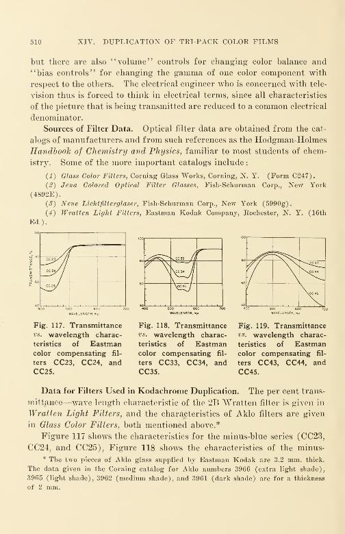
510 XIV. DUPLICATION OF TRI-PACK COLOR FILMS
but there are also "volume" controls for changing color balance and
"bias controls" for changing the gamma of one color component with
respect to the others. The electrical engineer who is concerned with tele-
vision thus is forced to think in electrical terms, since all characteristics
of the picture that is being transmitted are reduced to a common electrical
denominator.
Sources of Filter Data. Optical filter data are obtained from the cat-
alogs of manufacturers and from such references as the Hodgman-HolmesHandbook of Chemistry and Physics, familiar to most students of chem-
istry. Some of the more important catalogs include
:
(1) Glass Color Filters, Corning Glass Works, Corning, N. Y. (Form C247).
(#) Jena Colored Optical Filter Glasses, Fish-Schurman Corp., New York
(4892E).
(3) Neue Lichtfilterglaser, Fish-Schurman Corp., New York (5990g).
(4) Wratten Light Filters, Eastman Kodak Company, Rochester, N. Y. (16th
Rd.).
CC23//J
CC24/ /
CC25/
S^^S^>NCC33 J
I
rf N\Hw
500 600WAVELENGTH, m»i
"
. /
^^^CC43
\sCC44
\cC45
W&VELENGTf
Fig. 117. Transmittancevs. wavelength charac-
teristics of Eastmancolor compensating fil-
ters CC23, CC24, andCC25.
Fig. 118. Transmittancevs. wavelength charac-
teristics of Eastmancolor compensating fil-
ters CC33, CC34, andCC35.
Fig. 119. Transmittancevs. wavelength charac-
teristics of Eastmancolor compensating fil-
ters CC43, CC44, and
CC45.
Data for Filters Used in Kodachrome Duplication. The per cent trans-
mittance—wave length characteristic of the 2B Wratten filter is given in
Wratten Light Filters, and the characteristics of Aklo filters are given
in Glass Color Filters, both mentioned above.*
Figure 117 shows the characteristics for the minus-blue series (CC23,
CC24, and CC25), Figure 118 shows the characteristics of the minus-
* The two pieces of Aklo glass supplied by Eastman Kodak are 3.2 mm. thick.
The data given in the Corning catalog for Aklo numbers 3966 (extra light shade),
3965 (light shade), 3962 (medium shade), and 3961 (dark shade) are for a thickness
of 2 mm.
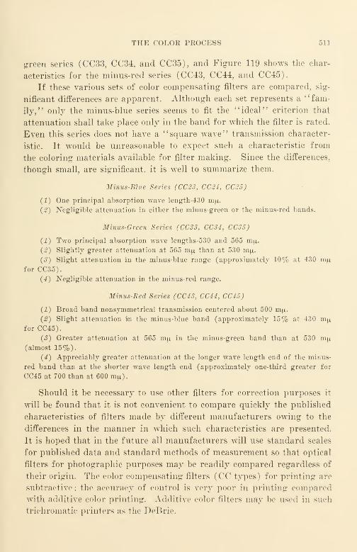
THE COLOR PROCESS 511
green series (CC33, CC34?and CC35)
?and Figure 119 shows the char-
acteristics for the minus-red series (CC43, CC44, and CC45).
If these various sets of color compensating filters are compared, sig-
nificant differences are apparent. Although each set represents a "fam-
ily," only the minus-blue series seems to fit the "ideal" criterion that
attenuation shall take place only in the band for which the filter is rated.
Even this series does not have a "square wave" transmission character-
istic. It would be unreasonable to expect such a characteristic from
the coloring materials available for filter making. Since the differences,
though small, are significant, it is well to summarize them.
Minus-Blue Series (CC23, CC24, CC25)
(1) One principal absorption wave length-430 mu.
(2) Negligible attenuation in either the minus-green or the minus-red bands.
Minus-Green Series (CC33, CC34, CC35)
(1) Two principal absorption wave lengths-530 and 565 mu,.
(2) Slightly greater attenuation at 565 mu than at 530 mu.
(3) Slight attenuation in the minus-blue range (approximately 10% at 430 mufor CC35).
(4) Negligible attenuation in the minus-red range.
Minus-Bed Series (CC43, CC44, CC45)
(1) Broad band nonsymmetrical transmission centered about 500 mu.
(2) Slight attenuation in the minus-blue band (approximately 15% at 430 mpi
for CC45).
(3) Greater attenuation at 565 niu in the minus-green band than at 530 mu.
(almost 15%).
(4) Appreciably greater attenuation at the longer wave length end of the minus-
red band than at the shorter wave length end (approximately one-third greater for
CC45 at 700 than at 600 mu).
Should it be necessary to use other filters for correction purposes it
will be found that it is not convenient to compare quickly the published
characteristics of filters made by different manufacturers owing to the
differences in the manner in which such characteristics are presented.
It is hoped that in the future all manufacturers will use standard scales
for published data and standard methods of measurement so that optical
filters for photographic purposes may be readily compared regardless of
their origin. The color compensating filters (CC types) for printing are
subtractive; the accuracy of control is very poor in printing compared
with additive color printing. Additive color filters may be used in such
trichromatic printers as the DeBrie.
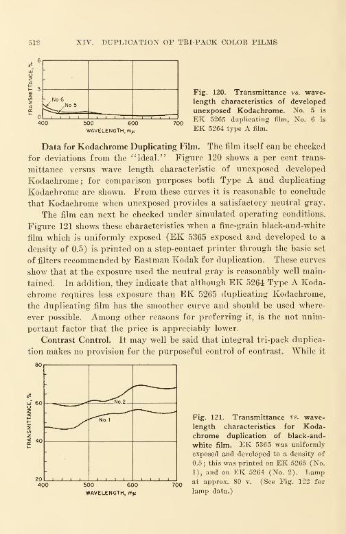
512 XIV. DUPLICATION OF TEI-PACK COLOR FILMS
o<E 32
400
-
- No.6v/ ,No5
i i i i
500 600
WAVELENGTH, mji
700
Fig. 120. Transmittance vs. wave-
length characteristics of developed
unexposed Kodachrome. No. 5 is
EK 5265 duplicating film, No. 6 is
EK 5264 type A film.
Data for Kodachrome Duplicating Film. The film itself can be checked
for deviations from the "ideal." Figure 120 shows a per cent trans-
mittance versus wave length characteristic of unexposed developed
Kodachrome; for comparison purposes both Type A and duplicating
Kodachrome are shown. From these curves it is reasonable to conclude
that Kodachrome when unexposed provides a satisfactory neutral gray.
The film can next be checked under simulated operating conditions.
Figure 121 shows these characteristics when a fine-grain black-and-white
film which is uniformly exposed (EK 5365 exposed and developed to a
density of 0.5) is printed on a step-contact printer through the basic set
of filters recommended by Eastman Kodak for duplication. These curves
show that at the exposure used the neutral gray is reasonably well main-
tained. In addition, they indicate that although EK 5264 Type A Koda-
chrome requires less exposure than EK 5265 duplicating Kodachrome,
the duplicating film has the smoother curve and should be used where-
ever possible. Among other reasons for preferring it, is the not unim-
portant factor that the price is appreciably lower.
Contrast Control. It may well be said that integral tri-pack duplica-
tion makes no provision for the purposeful control of contrast. While it
80
uj 60oz<
2
2 40
20400
-
""N" 2
—/ ""^Nol
1 1 1 1 till i l i i.
500 600
WAVELENGTH, m^700
Fig. 121. Transmittance vs. wave-
length characteristics for Koda-chrome duplication of black-and-
white film. EK 5365 was uniformly
exposed and developed to a density of
0.5; this was printed on EK 5265 (No.
1), and on EK 5264 (No. 2). Lampat approx. 80 v. (See Fig. 122 for
lamp data.)

THE COLOR PROCESS 513
is true that a decade ago there was little need owing to the limited
useful contrast range, subsequent control improvement has brought
forth that need.
The problem is a very difficult one. It means the introduction of still
another variable into a process where the number of variables is already
large compared with commercial black-and-white processes. At first
glance, AnscoColor Film would seem to present the possibility in the
color developing of the film, but so far there has been little encourage-
ment in this direction. In the case of Kodachrome the need for constant
developing is considered very important and it is felt that contrast con-
trol is better accomplished in some other manner.
A number of solutions to the contrast problem has been suggested and
a certain amount of laboratory experience has been obtained with one
possibility-masking film.* So far, the complexities of use are such that
it has not been considered suitable for motion picture use although it is
well suited for still pictures. It would not seem impossible to incorporate
this in the form of an additional sensitized layer in the duplicating raw
stock. Such a layer might have the further advantage of being suitable
for the sound record, thereby avoiding some of the seemingly insur-
mountable problems associated with the multi-layer color sound track.
As the increase in contrast due to even a single printing step is quite
high, Kodachrome Commercial, a low contrast color positive material,
has been introduced as an original material from which duplicates can be
made that will have approximately the same contrast characteristics as
a Kodachrome original made on Kodachrome Regular.
Ansco has recommended the use of a separate mask optically super-
imposed. Because of the high order of registration accuracy required,
this method is not in wide use now. It is felt that there are also some
simpler methods possible that will be commercially satisfactory, despite
the fact that a certain amount of sacrifice of color fidelity may be re-
quired; one possibility is the use of light sources emitting band spectra
rather than a continuous spectrum.
* Masking film when so used is an unexposed sensitized thin film cemented or
otherwise attached to the developed original Kodachrome picture. Each scene is
given a predetermined exposure in a printer and then developed in a black-and-white
developer bath, producing a complementary negative of the picture on the masking
film as a mask. When the picture is then printed (with the masking film still at-
tached), the contrast of the original is effectively reduced. (Should an increase in
contrast be desired, this might be accomplished by developing the masking film as a
reversal. It is rare that an increase in contrast is desired; most duplicated films
suffer from excessive rather than too little contrast.)

514 XIV. DUPLICATION OF TRI-PACK COLOR FILMS
Production Quality Control of Prints
There is much to recommend the routine testing of every roll of film
printed. It is necessary to establish quality control in printing and to
maintain control once it has been established. Routine testing is re-
quired for every other element entering into the process. Commerical
color duplication in Kodachrome is therefore exacting and demanding,
yet interesting work.
The starting point is a lamp, the color temperature of which is known.
3300
3200
3100
5 2900
2800
2700
2600
2500
/°K
// ^
/ Ampere s
J',r
70
65
60
55 E
50
45
40
35
3050 60 70 80 90
VOLTS
Fig. 122. Volts vs. color-temperature and amperes
characteristics of 500-w, 105-v, T-10 lamp.
The color temperature is not known, however, unless the limits to which
it has been measured are also known. The same electrical testing lab-
oratories that provide recording spectrophotometer services can also de-
termine the current at which a particular lamp will reach the desired
color temperature. If a lot of 50 lamps of the same type is tested, the
cost for a measurement within a tolerance of ± 10 K is but a fraction of
the cost of the lamp itself. Should seasoning or aging be required, these
laboratories can provide such service at very low cost. With such reliable
services available at low rates, no commercial laboratory engaged in the

PRODUCTION QUALITY CONTROL OF PRINTS 515
duplication of color film, such as Kodachrome, can afford to be without
control aids. Figure 122 shows a color-temperature-voltage-current re-
lationship of a typical 500-w., 105-v. T-10 printing lamp. Other valu-
able lamp data are found in the bulletin Mazda Lamps published by Gen-
eral Electric.
Exposure is most readily measured directly at the printer aperture
with the machine stationary; the better grade illuminometers such as
the Weston (priced approximately at 100 dollars) are suitable. In-
direct methods, such as the use of black-and-white film as a control, are
not practicable in most commercial laboratories as they introduce addi-
tional variables whose variations are usually unknown.* In using il-
luminometers and similar direct-measuring instruments, it is necessary
to make up suitable jig-adapters so that readings of the instrument will
be reproduced without significant personal error. Provision should also
be made for periodically calibrating the measuring instruments. It is
necessary that the variation in slip of belt-driven printers be known. It
is still better to use direct-gear drive with a 3-phase synchronous motor
or equivalent to eliminate machine speed variation as a possible source of
exposure variation.
The regulation of the current supply for the printing lamp is very
important. It is obviously a sheer waste of time and money to cali-
brate lamps to ± 10 K when the motor generator or other supply has
poor regulation, and other loads are indiscriminately " placed on the
line" and "taken off." A simple check is to connect a recording volt-
meter to a printer under suspicion, using that printer without current
changes meanwhile. Often the local power company will be glad to lend
a suitable meter if one is available.
From the user's point of view, Kodachrome duplicating film (EK5265) is quite consistent. The major variation that occurs is the variation
from lot to lot, similar to that occurring in black-and-white materials.
With fresh film, the variation in sensitivity from one lot to another ap-
pears to be less than one of the smallest compensating filter steps (CC23,
CC33, or CC43). The variation in layer sensitivity from one layer to
another appears to be likewise small and of comparable order. Forfilm that has aged slightly (for example, less than 6 months old whenstored at a constant temperature not over 70 F), there is a slight loss in
* Such indirect methods can be satisfactory if the sensitonietric control on black
and white is of a superior order compared with usual commercial control. In such
cases, however, the direct methods are still more convenient and more precise.
516 XIV. DUPLICATION OF TRI-PACK COLOR FILMS
speed and a slight change in color balance, bnt the sum total of such varia-
tions does not appear to exceed the equivalent of the single filter step
already mentioned. When film has been improperly stored or is old it
is likely to be "off balance" by more than a single filter step. It is
prudent to make an exposure and color balance test not only for every
emulsion lot of film received, but also on every lot received at different
times. A log with the results of such tests quickly shows up not only
errors and variations, but also indicates when properly interpreted the
magnitude of the exposure variation actually encountered in printing
the tests.
Routine testing of filters in the arrangements in which they are used
is helpful. The cost for several curves is no more than the price of a
single 800-ft. roll of raw film. Testing of this kind is in reality inex-
pensive quality insurance.
Routine testing of the duplicates made commercially is readily ac-
complished if a test strip is attached to every roll of preprint material
and printed as a part of the routine printing operation. The test strip
can be designed to fit whatever situation is required. A simple yet
informative test leader might include a few frames of each of the follow-
ing:
(1) A fine-grain silver film (such as EK 5265) uniformly exposed to a density of
1.0.
(2) Clear leader (made by running EK 5365 through hypo).
(3) The 16-mm Kodak color test chart.
(4) Kodachrome printed through a Wratten 49 (blue filter) to yield a color
density of 1.0.
(5) Same as (4) except through a Wratten 61 (green filter).
(6) Same as (4) except through a Wratten 29 (red filter).
(7) A resolving power test chart.
The test strip should be printed at " normal " exposure for the particu-
lar lot of raw film.
Sections 1, 2, 4, 5, and 6 of the strip can be read with an ordinary
Eastman densitometer. The results of these readings can be plotted
in a "scatter diagram" in accordance with the methods described
in ASA Standards for Quality Control, Zl.l, Z1.2, and Z1.3. A check
lasting over even a few weeks will indicate where the'
' tightening-up '
'
process should be applied for quality improvement and in what amounts
it should be applied. If more accurate results are required in specific
cases, other checks such as per cent transmittance versus wavelength
curves may be taken on the pertinent parts of the printed strip.
CONCLUSION 517
Conclusion
Integral tri-paek films such as Kodachrome are good materials in
good control at the present time. It must be remembered, however, that
there is no " perfect" color process. The usual requirements of a color
process are
:
(1) A suitable gray scale.
(2) Comparable color scales for the components.
(3) Accurate reproduction of color.
(4) Good differentiation of color.
Each of these requirements conflicts in some measure with at least one
of the other three. Ordinarily 1 and 4 are favored over 3.
The most recent edition of "Photomicrography" (1944) carries the
admonition concerning photometric filters in these words: "There are
no colored pigments or dyes actually available for making the three colored
components of a picture that do not absorb light outside of their ownspectral domain and thus degrade the hues of the final result". Curves
are essential in describing the performance of filters for color dupli-
cating purposes.
For convenience, wave lengths shorter than approximately 420 m/*
are usually filtered out of the exposing illumination. This is accom-
plished with the Wratten 2A filter or equivalent. The near ultraviolet
and the shorter blue rays increase the exposure in the blue layer, but as
it is not practicable to evaluate this exposure accurately by either an
illuminometer or by the indirect film method, it is usually better to
remove these wave lengths from the light beam. With these wave lengths
removed, results are usually more reproducible.
Generally speaking, colors that have components in the filter cross-
over regions of 500 m/x and 600 m/x are difficult to control for accuracy
of color reproduction. In most practical cases good color differentiation
will suffice and such filters as the Corning 5120 (light didymium) and
its approximate equivalent, BG11, in moderate thicknesses, such as 1 mm.and 2 mm., are often quite useful. These filters are likewise helpful
in retaining face and skin detail in a duplicate that is printed from a
slightly overexposed original, as well as in the reproduction of certain
biological stains and dyes whose absorption points are "unfortunately"
located.
It should be remembered that even a "perfect" copy is of little value
if the print is not projected properly. The importance of correct illumi-
518 XIV. DUPLICATION OF TRI-PACK COLOR FILMS
nation level can hardly be overemphasized. At present, even when
screen illumination is in the uppermost range found in practice, it is
rarely within 20% of what might be called the optimum value. Because
screen illumination is of such a low general order, film laboratories have
often deliberately chosen to overexpose duplicates in printing by as much
as one-third, thereby wiping out much detail and further aggravating
an already serious condition of low resolving power. The magnitude of
this effect can be roughly judged by comparing the detail and quality
of a Technicolor picture projected in a neighborhood theater with the
usual 16-mm projection of a Kodachrome duplicate. Such a comparison
is reasonable; several Technicolor releases have been made from 16-mmKodachrome originals. There are other factors, but these are beyond the
scope of this chapter.
Although the method recommended by Eastman Kodak of dupli-
cating Kodachrome is relatively simple and places the major part of
the control burden upon the film manufacturer, it is imperative that
the commercial laboratory accept its share of the control responsibility
knowingly and willingly, and appreciate the importance of process
control by applying its basic principles. The control of emulsion
quality in manufacture and the control of color developing have reached
such a high point that it is no longer possible to indiscriminately ''pass
the buck" to the film manufacturer if prints do not come up to expecta-
tions. We must first learn to control the single parameter of good mono-
chrome successfully before we can expect to be successful with the 3
parameters of integral tri-pack duplication. This is a challenge to all
concerned; a rapidly growing industry will be awarded as the prize to
those who produce the best product at the lowest price.
Selected Bibliography
Wall, E. J., History of Three Color Photography. Am. Phot. Pub. Co., Boston,
1925.
Friedman, J. S., History of Color Photography. Am. Phot. Pub. Co., Boston, 1944.
Hardy, A. C, Handbook of Color Analysis. Technical Press, Cambridge, 1936.
Evans, R. M., An Introduction to Color. Wiley, New York, 1948.
Wright, W. D., Measurement of Colour.
Bouma, P. J., Physical Aspects of Colour. Philips Research Laboratories, Eind-
hoven, 1949.
Weigert, Optische Methoden der Chemie. Akad. Verlagsgesellschaft, Leipzig, 1924.
Gibb, Optical Methods of Chemical Analysis. McGraw-Hill, New York, 1942.
Weissberger, (ed.) Physical Methods of Organic Chemistry. New York, Interscience,
1949.

SELECTED BIBLIOGRAPHY 519
Kendall, O. K., "16-Mm Film Color Compensation," JSMPE, in press (1949).
Hanson and Richer, "Three-color Subtractive Photography," JSMPE, 52, 119
(Feb. 1949).
Miller, T. H., "Masking," JSMPE, 52, 133 (Feb. 1949).
Keith, C. R., "Inter-society Color Council Symposium," JSMPE, 52, 156 (Feb. 1949).
Macbeth and Nickerson, "Spectral Characteristics of Light," JSMPE, 52, 157 (Feb.
1949).
Foss, C. E., "Color-Order Systems," JSMPE, 52, 184 (Feb. 1949).
Guilford, J. P., "System in Color Preference," JSMPE, 52, 197 (Feb. 1949).
Forrest, J. L., "Machine Processing of 16-Mm AnscoColor Film, JSMPE, 45, 313
(Nov. 1945).
Clarke, C. G., "Practical Utilization of Monopack Film," JSMPE, 45, 327 (Nov.
1945).
Aex, P. S., "Photoelectric Method for Determining Color Balance of 16-Mm Koda-
chrome Duplicating Printers," JSMPE, 49. 425 (Nov. 1947).
Harsh and Friedman, '' One-Strip Color Separation Film in Motion Picture Pro-
duction," JSMPE, 50, 8 (Jan. 1948).
Bates and Runyan, "Processing Control Procedures for AnscoColor Film," JSMPE,53, 3 (July 1949).
Brunner et al. "Analysis of Developers and Bleach for AnscoColor Film," JSMPE,53, 25 (July 1949).
Braun, T. J., "Improved Filter Holder for Color Printing," JSMPE, 53, 36 (July
1949).
Forrest, J. L., "Metallic Salt Track on AnscoColor Film." 53, 40 (July 1949).
Harsh and Schadlich, "Laboratory for Development Work on Color Motion Pic-
tures," JSMPE, 53, 50 (July 1949 .
Gorisch and Gorlich, "Reproduction of Color Film Sound Records," JSMPE, 43,
206 (Sept. 1944).
Gage, H. P., "Color Theories and the Inter-society Council," JSMPE, 35, 361 (Oct.
1940).
Bruno, M., "Maps on Microfilm," JSMPE, 41, 423 (Nov. 1943).
Duerr and Harsh, "AnscoColor for Professional Motion Pictures," JSMPE, 46,
357 (May 1946).
Bingham, R. H., "Sensitometric Evaluation of Reversible Color Film," JSMPE. 46,
368 (May 1946).
Drew and Johnson, "Preliminary Sound Recording Tests with Variable Area DyeTracks," JSMPE, 46, 387 (May 1946).
Hamly, D. H., "Robert Ridgway 's Color Standards," Science, 109, 605 (June 17,
1949).
Walsh. J. W. T., "The Measurement of Coloured Light," Endeavour (Londo)i), T,
142 (Oct. 1946).
Mees, C. E. K., "Modern Colour Photography," Endeavour, VII, 131 (Oct. 1948).
"The Agfacolor Process—Report PB 79559," Office of Technical Services, Dept. of
Commerce, Washington, 1949.
Homolka, Brit. J. Photog., 54, 136, 196, 216 (1907).
Lewy, German Pat. 250,647 (1909).
520 XIV. DUPLICATION OF TRI-PACK COLOR FILMS
Fischer, Brit. J. Photog., 60, 595 (1913).
Fischer, Brit.- Pat. 15,055 (1912).
"Mazda Lamps—Bulletin 1D-1," General Electric Co., Cleveland, 1940.
For further bibliographic material the reader should refer to the following indexes
to the Journal of the Society of Motion Picture Engineers.
July 1916-June 19301
' Color Photography, '' page 120.
" Patents—Color Photography," page 138.
"Tinting and Toning," page 152.
January 1930-December 1935
"Color Cinematography, '' page 12.
"Coloring," page 13.
'' Committee Reports—Color, '
' page 13.
"Dufaycolor," page 23.
"Filters," page 26.
"Hand Coloring," page 31.
"Handschiegl," page 31.
1 i Multicolor, '' page 41.
'' Psychology of Color, '
' page 54.
1936-1945
"Color," page 82.
1
1
SMPE Activities—Color Reports, '' page 128
CHAPTER XV
Industrial Applications of Current 16-Mm SoundMotion Picture Equipment
When Edison started his developmental work on motion picture ap-
paratus some 50 years ago, he ventured the opinion that motion pictures
would become a most powerful influence over people. We have seen this
prophecy come true in a fraction of a century, a really short space of
time in the history of man.
Edison also viewed the motion picture as potentially a most im-
portant instrument of education. A review of early history, however,
shows numerous uncoordinated efforts by many to introduce motion
pictures into elementary and other schools in an attempt to establish its
place properly and adequately in mass compulsory education quite as muchas in other branches. Despite the many advances in application since,
motion pictures are still far from having reached their rightful place
in bringing to all people the full benefits of films in education. To an
unbiased observer, it would seem that there are far too few films and far
too few machines being used today. One of the causes is a shortage of
funds set aside for such purposes. Teachers seem hesitant to suggest and
taxpayers hesitant to approve greatly enlarged budgets for teaching
films. One possible reason is that for years motion pictures and enter-
tainment were always synonymous, and they had little in common with
education.
Fortunately the use of film in industry has not been retarded to
quite the same degree. Manufacturers, despite all that may be said to
the contrary, seek to maintain competitive advantage by selling a better
product in the marketplace at a lower price. Films have aided in this
objective; one of the earliest applications was in selling. Selling films
had the double objective of showing the employee how to sell and of en-
couraging the buyer to increase the size of his purchase. As the per-
formance results of such films could be quickly measured in terms of
increased sales and lower cost per sales dollar, industry was quick to em-
brace this potentially efficient communication tool. The results were
quite impressive, so impressive, in fact, that a number of films were pro-
521

522 XV. INDUSTRIAL APPLICATIONS
duced of the misguided extravaganza variety that are far better suited
to entertainment than to business or to education.
It should be obvious that any communication medium is particu-
larly fitted to specific classes of intelligence transmission; this prin-
ciple applies no less to the film than to any other communication medium.
As we review the films produced by education and those produced by
business, we are struck with the similarity of the aims of the two fields
and the dissimilarity of the films produced. "We are tempted to con-
clude, if a cryptic summary may be ventured, that business has produced
much film and little theory as to how films should be made and used,
whereas education has produced much theory and few films in accordance
with the established theory. Since the aim of both films is to "put an
idea across,' ' it is reasonable for us to extrapolate the experience of one
into the field of the other to the mutual benefit of both.
One of the simplest and best reports on the subject of films for edu-
cational purposes is that of the Committee on Intellectual Cooperation of
the League of Nations, written in 1924. The findings of this Committee
may be considered a reference standard through which the efficiency of
instructional films may be gaged. The following is a resume of the
report.
(1) Slides and motion pictures should be used for maximum ef-
fectiveness. As a general rule the use of these two adjuncts is not
judiciously proportioned, one oftentimes being used to the complete
exclusion of the other. We can no doubt agree that the conclusion of
some twenty-five years ago is still a valid one today. Too many projects
use but one medium to the complete exclusion of the other.
(2) All objects and scenes that the audience is intended to watch
and remember in movement should be shown in movement. Still pic-
tures representing objects and scenes that ought to be seen in movement
should be banned as giving a distorted impression of the actual facts.
While our films are improving in this regard, we still find countless in-
stances where we photograph stationary objects with a motion picture
camera and moving objects with a still camera.
A corollary that may reasonably be added at this point is that all
objects and scenes that the audience is intended to watch and remember
in sound should be shown in sound. Silent pictures representing objects
and scenes that ought to be heard in sound should be banned as giving
a distorted impression of the actual facts.
(3) The screen cannot displace the personal element; it can to some

INDUSTRIAL APPLICATION'S 523
extent displace printed matter, and it should, in all events, be used in
combination with it. The use of the screen in conjunction with text-books
and printed matter is still quite undeveloped despite significant advances
in teaching methods; its effectiveness when properly used is in the top
rank of communication media.
(4) The screen should be used in combination with personal contact
in " getting the idea across." It should be used at the location where the
salesman or teacher ordinarily operates whenever it is of advantage to do
so. It should be possible to repeat the picture several times, if necessary;
the picture should be definitely constructed in such a manner that it will
bear repetition.
Industry has shown a growing tendency to bring the screen to the
customer instead of the customer to the screen. This tendency is in the
proper direction.
It is not true, however, that films are always constructed in such a
manner as to bear repetition, as is particularly necessary in films for in-
structional purposes. Too often a large number of diverting technical
effects such as fancy wipes, dissolves, and the like, have been used in a
single reel. Such technical effects do not cover up glaring defects in
plot, continuity, and lack of logical presentation that are also usually
present. Our technical effects shall aid the story, not make it.
(5) The screen cannot be used in the proper manner unless there is
very wide distribution of effective yet inexpensive apparatus, so that
every user of films can have his own projection equipment. The simplest
apparatus to handle will be best, and at the same time there must be no
risk of fire. If the screen is to do its proper work the apparatus must
quickly become a thing in daily use.
The 16-mm size affords the best means of very wide distribution of
effective yet inexpensive apparatus with minimum risk of fire. It is the
simplest to handle and makes possible the daily use of the equipment
because of its very simplicity and low cost of operation and maintenance.
That this is true of equipment for making films as well as of equipment
for reproducing films is only now beginning to be appreciated in its
broader aspects.
(6) The mode of use of the screen must be improved, having regard
to the fact that it can act upon the mind of the spectator
:
(a) By faithful presentation of the subject.
(&) By the representation of the subject simplified.
(c) By the representation of the subject in sections.

524 XV. INDUSTRIAL APPLICATIONS
(d) By the representation of the subject intensified, magnified, represented,
speeded up, slowed down, built up by degrees, or superposed. These different methods
must be employed according to a logical scheme, taking into account the subject to be
dealt with and the specific character of the audience to which the film is planned to
be shown.
"Too often they (the producers) have sold companies on the idea of
producing films, not as integrated parts of a well rounded-out program, but
as special bits of magic for one-time splurges. Even in the larger efforts
it is almost as common for a film to be designed for no particular audience
as it is in the case of the film produced by the fly-by-night "Hollywood"
director who "has his office in his hat." There is still the feeling among
a number of picture purchasers, and to a lesser degree among picture
producers, that one magic superspectacle is better than a large number
of modest films each telling its complete part of an integrated story.
It is of utmost importance that the exhibition plans for a film be
fully completed before the first camera exposes the first foot of film.
Maximum effectiveness presumes the gearing of the subject matter of the
film to the audience.
(7) The screen is a valuable means of suggestion; it will be used as
a time-saver, often a valuable one, in "putting across" all matters that
depend largely on visual memory.
Psychologically, the lighted screen in the darkened room compels con-
centration upon the material presented. It is not only possible to "putacross" details of mechanisms and their operation, but also to explain the
coordination of the activities of groups that cannot be observed in the
usual course of events. This field is practically a virgin field for in-
dustry.
(8) In order to economize effort and to save expense in making films,
and to derive maximum profit from them, it is advisable to decide defi-
nitely beforehand to what extent regular photographing and animation,
respectively, are to be used.
Due to the high cost of animation per foot in comparison with regular
photographing, animation is used to a much smaller degree than in manycases seems desirable for maximum effectiveness.
If we reexamine the field of business films as a whole, we are struck
with the fact that the external film, in particular, the film developing the
customer-to-sales-organization relationship, is widely used. The internal
business film is less widely used and still less widely heralded.
Many organizations that have used both have found that dollar-for-dollar
INDUSTRIAL APPLICATIONS 525
the second type usually produces better results wherever it has been 1 ried.
The obvious use of the internal film is in sales training, and many organi-
zations have set up photographic departments to make use of the advan-
tages of this type of film.
The well-managed industrial organization is always looking for aew
opportunities to achieve and maintain competitive advantage. When a
unit for the production of internal business films is first organized, its
personnel complement is small and its activities few. These few activi-
ties are usually related in some manner or other to the selling operation.
But when the film production unit gets under way, its scope of activity
expands far beyond its original purposes into fields that have little to
do with the sales operation per se.
An excellent example of this is a pre-war film produced by the Fisher
Body Division of the General Motors Corporation showing how container-
packed automobile body parts may be advantageously handled by trans-
portation companies between the manufacturing plant and the assembly
plant, to the simultaneous profit of both the transportation companies and
the Fisher Body Division. This film was produced wholly within the
company organization. While it was necessarily photographed in'
' catch-
as-catch-can' , manner, the film tells its story forcefully as well as effec-
tively and needs no technical embellishment whatever to establish the
straightforward points of the presentation.
The establishment of such internal motion picture departments in
industry is now becoming quite common. Some organizations, such as
the Fisher Body Division, in the case just cited, prefer to produce the
film completely within the organization. Other organizations, such as
the Skelly Oil Company with its salesman-training films, prefer to work
out the script and shoot the basic material, leaving the editing and scoring
work in the hands of a commercial 16-mm film producer. The proper
procedure depends upon the circumstances; each has its respective ad-
vantages. The 16-mm industry is prepared to supply not only all the
necessary equipment but also all production and other services required
for all such needs.
The advantages of 16-mm equipment for internal production purposes
hardly need repetition here. In 16-mm production equipment as in pro-
jection equipment, relative simplicity, portability, freedom from fire risk,
and relatively long operating time per pound of film are already well
known. The picture quality and the sound quality may be made as good
as required. In the case of the sound, for example, the quality may

526 XV. INDUSTRIAL APPLICATIONS
readily approach that of 35-mm theater reproduction if desired, as has
been demonstrated at a recent meeting 0/ the Society of Motion Picture
Engineers by J. A. Maurer.
In internal films it is the subject matter that is of predominant im-
portance. Such subject matter does not need and may not even tolerate
dramatization; it is best presented in straightforward expository style.
Subject matter need not be created and staged; there is an abundance
of it to be found in the industrial processes, in the plants, in the men, and
in the routines of organization. All people, whether here or abroad, are
eager to learn how things are made and what is done in their making.
There is far more grass roots good will value obtained from presenting
the story of the manufacture of a product that far out-performs and out-
wears its competitors, than can be obtained by all the glittering super-
latives that may be culled from a dictionary.
The all-important qualification of a producer of internal films is an
intimate knowledge of the organization for which he intends to produce.
He must be thoroughly familiar with its policies, its plans, and its objec-
tives. He must be on a firm footing with the personnel; he must knowexecutives and managers and have their full confidence. Most of all, he
must know and understand the various problems existing in the company.
Only with qualifications such as these can he expect to make his work
appear convincing and authentic.
It would seem difficult to find men answering these requirements any-
where except among the company's seasoned employees. Can such em-
ployees become the producers of internal organization films? The answer
is definitely "yes"; the required technical ability is readily developed by
a person with the necessary aptitude, as anyone familiar with the char-
acteristics of direct 16-mm camera and sound-recording equipment can
understand. The technic of the medium is, as a general rule, readily ac-
quired by a person who has the other necessary qualifications.
There are two general classifications of business films for internal
use: those that convey a message from management to personnel, and
those that convey a message from personnel to management. The films
in the former group are primarily instructive; they may therefore be
expected to follow the usual four-step instructional method of prepara-
tion, presentation, application, and examination. Other media of in-
struction, such as the lecture, the slide-film, and the printed word, should
be integrated parts of the instruction method. Since the films in the
latter group are primarily informative, the examination step usually is

INDUSTRIAL APPLICATION'S 527
not involved in the presentation. The use of other media of communica-
tion such as the lecture, printed word, slide-film, and so forth, is also indi-
cated here just as in the case of instructional film.
Figure 123 shows a general outline of films for internal business use.
Certain of the applications shown have been widely used ; others are still
relatively little developed. Most of the classifications can be readily
understood by inspection and need little explanation.
A few notes on some of the lesser understood classifications are indi-
cated at this point. These notes deal with the management-to-personnel
films on the non-sales-service group.
Interdepartmental Organization. In larger organizations particularly,
the loss of the personal touch is a morale factor that should engage the
attention of every business manager. Specialization makes such demands
BUSINESS FILMS FOR INTERNAL USE
•,-:-'.':' .-.
5ENERALSi-ES
UETHOC i
SALES>.-;--::-:
FORi-i: -_
PRODUCTS
: -: - . IE-SALES
' VE-MOTlON5 - . : E s
£•-_: EE5
••:" :•.
STUC ES••-:- '.ES
AND
DESCfl -":
-
PRODUCTINSTALLATION
-.:INSTALLATION
PRODUCT
; :-
JOBt- . ;„e
nstruci :.
SAFETYAND
HEALTHINSTRUCTION
PflER-:-;-- = "•.£•. '--
DRGAN ZAT ON
PRODUCT-USERESEARCHAve. 3
wstomer:
RECORDS''
----- :-:'--
EMPLOYMENT
Fig. 123. Applications chart—business films for internal use.
upon the time of a particular individual that it is not only impracticable
but usually also impossible to maintain that desirable form of contact.
There are numerous companies today where a film outlining the organiza-
tion of the company would not only reestablish the personal contact but
would also depict clearly the personalities of the men performing the
various functions in the organization. This type of film can materially
aid the esprit de corps and improve the efficiency of the organization.
Safety Promotion and Health Conservation. The loss of time and effi-
ciency of personnel due to sickness and accidents is still a major problem

528 XV. INDUSTEIAL APPLICATIONS
to industry. Most industrial plants have safety and health programs,
varying in scope from weekly bulletin board cartoons to elaborate sys-
tems including medical service, health furloughs, and other features. In
industrial plants particularly, it has been found that motion pictures are
the most graphic means of safety and health education. The work that
is now being done in connection with safety training in the mining in-
dustry is a typical example. The motion picture makes it possible to show
clearly all the details of the little items of carelessness that result in an
accident.
Job Technic Training. Job technic training is one of the foremost
non-sales uses for internal films. It is not unusual to find that older em-
ployees are poor teachers, and, because of possible jealousy of new em-
ployees such older employees may even intentionally pass on instruction
that is not of the best. The film permits standardized instruction in which
no error is introduced through repetition. This standardized instruction
may readily be that of the most efficient method of performing a particu-
lar task.
New technics must be acquired by old employees, not only to improve
their productivity on old products but also to produce new products. If
an employee is left to devise his own methods, time-and-motion study
—
also best done with motion pictures—will show that he usually develops a
definitely inferior technic.
Employee Relations. Employee relations is a wide subject that takes
in practically all matters that improve the feeling of the employee toward
his company. It is now recognized as good management practice to do
whatever is possible toward making each employee feel that he is impor-
tant to his company, and that his work makes him an important member
of society and of his community as well.
The ways in which films can contribute to the improvement of such
employee relations are almost limitless. Films can be made that give
direct educational treatment to such subjects as the aims and problems
of the company as well as the soundness of our traditional economic sys-
tem. Films can be made to provide entertainment for specific employee
groups, catering to their particular tastes. Films can be made of em-
ployee outings, athletic events, and social events. Films can be made of
a documentary or newsreel type depicting existing technics and dealing
with local conditions. Such films may be used for historical purposes or
for comparing the employee activities in one plant with those in another.
Most executives engaged in personnel work can readily visualize a host
of other applications.
INDUSTRIAL APPLICATIONS 529
Employee Advancement. In progressive organization it is a cardinal
principle of management that anything that increases the intrinsic value
of an employee automatically increases his value to the company. In line
with this management principle is the organization principle that a manwho fills a particular position should gradually acquire wider and wider
experience in the work of the position directly above him. In this man-
ner each man in the organization is progressively relieved of more and
more routine work by capable, trained assistants. This condition makes
for organization flexibility in that it not only makes possible the replace-
ment of personnel losses resulting from ordinary causes such as sickness
and death and the usual labor turnover, but also the replenishment and
even expansion of personnel required by market and product expansion,
or by emergency causes of whatever nature.
In employee training for advancement, as well as in job technic in-
struction, the 16-mm sound motion picture finds a logical application.
The initial source of basic film material may be film produced for other
purposes but edited into an appropriate version, or it may preferably be
a film made especially for the purpose. Inasmuch as employee advance-
ment must ordinarily be carried on outside of regular business hours and
in addition to the usual duties and routine of the employee concerned, it
is doubly important that a wide range of essentials be covered in the most
effective and the most efficient manner. Sound-films offer a means of
greatly reducing the time allotments for the presentation of facts without
sacrificing the quality of instruction.
In almost every broad generalization concerning films, some notable
exceptions to the general rule can usually be found. In the field of train-
ing films, one such exception is the work of the Photographic Section of
the U. S. Army Signal Corps, over a decade ago. In attacking this film
problem with its characteristic thoroughness, the Army found that no de-
viations from the fundamental rules governing training-film production
can be tolerated. Each film must be specifically prepared for a particu-
lar audience and every effort made to avoid entertainment features or to
produce a film suited to what is often called "the general audience." Anumber of papers on the subject of the Army training film program were
presented to the Society of Motion Picture Engineers and all are worthy
of very thorough study by anyone concerned with personnel training.
The Army, Navy, and Air Forces demonstration films shown before the
Society prove that the practical development of the training film has
reached an advanced stage quite beyond anything done elsewhere on a
scale of appreciable scope.
530 XV. INDUSTRIAL APPLICATIONS
The second notable exception is best described in an announcement
(Feb. 10, 1939) from the Harvard Film Service of the Biological Labora-
tories of Harvard University concerning film material for the improve-
ment of reading.
The Harvard Film Service in cooperation with the Psycho-Educational Clinic,
Harvard University, announces a new type of film material for the improvement of
reading.
In brief, these films consist of reading material so presented that successive
phrases of the separate lines are exposed rapidly across and down the screen. The
film serves as a 'pacer' and the pupil is stimulated to keep up with the rate of ex-
posure. As the training progresses, selections with longer and longer lines are pre-
sented thereby gradually increasing the eye span.
During the first half of the current academic year, these films were tested out in
an experiment on a group of slow readers among Harvard freshmen. The group met
for a 45-minute training period three times a week for eight weeks. The results were
as follows: at the close of the experiment, the trained group averaged gains of 41
percentiles on a speed-of-reading test (the Minnesota Speed-of-Reading Test for Col-
lege Students) and of 24 percentiles on a test of accuracy of reading (Whipple's
High-School and College Reading Test) in excess of those made by a non-trained con-
trol group. When measured in terms of a difference between initial and final eye-
movement records, the average gain in rate of reading of the former was 52 per cent.
An analysis of these records in terms of individual measures showed that the average
number of fixations per line was reduced from 10.8 to 6.5; the average number of
regressions from 1.6 to 0.5.
This material is designed to be run at silent speed (16 frames per second) on any
16-mm projector. It may be used for a single pupil or for a group and requires only
a semi-darkened room. Twenty selections averaging 125 feet each, adapted to the
senior-high and college levels, together with a teacher's manual and a set of com-
prehension tests for each film, will be ready for release on March first. . . . Although
a smaller number of films may be purchased, the best results will be secured when the
complete series for any given level are used. By April first, in time for a two months
'
training period this year, we shall have ready for release thirty selections for Grades
3 to 5 ; by next September, a third set for Grades 6 to 9.
Life is daily becoming more complex not only in its social and eco-
nomic aspects but also in its business aspects. It is imperative that our
training methods become more effective from the standpoint of saving
time and improving quality of instruction. In addition, training of ever-
increasing scope must be made available to an ever-expanding group of
our trained citizens. Business has already shown an eager interest in
the development, and if present indications can be relied upon, it should
not be very long before we shall be hearing of further experimental re-
sults of applied programs of internal training development such as is
now suggested.
SELECTED BIBLIOGRAPHY 531
Selected Bibliography
"Camera—Action—Sales," Report to Executives, Business Week (May 27, 1939),
38.
Seabury, Wm, M., "Motion Picture Problems—The Cinema and the League of
Nations.
'
'
Exton, Win., Jr., Audio-Visual Aids to Instruction. McGraw-Hill, New York, 1948.
Haas and Packer, The Preparation and Use of Visual Aids. Prentice-Hall, NewYork, 1948.
Dale, E., Audio-Visual Methods in Teaching. Dryden, New York, 1946.
Devine, J. E., Films as an Aid in Training Public Employees." Report to the Com-
mittee on Public Administration, Social Science Research Council, New York.
Lloyd, B., Science in Films. Sampson, Low & Marston, London, 1948.
Elliot, G., Film and Education. Philosophical Library, New York, 1948.
Sponsored Films in Education. J. Walter Thompson Co., New York.
Sources of Visual Aids for Instructional Use in Schools. Pamphlet No. 80, U. S.
Office of Education, Washington, 1941.
U. S. Government Films for School and Industry. Castle Films, New York, 1948.
The Index of Training Films. Business Screen, Chicago, 1946.
The Principal and Audio-Visual Education. National Education Association, Wash-
ington, 1948.
Bibliography on Audio-Visual Instructional Materials for Teachers in the Elementary
School. Bu. Publications, Teachers College, Columbia Univ., New York, 1948.
Educational Film Guide—A Monthly and Quarterly List of New Films. H. W.
Wilson Co., New York.
Selected References on Photographic Visual Aids. Eastmann Kodak Co., Rochester,
New York, 1948.
The Film for Your Need. National Film Board of Canada, New York, 1948 (pub-
lished every few weeks).
Educational Screen. A Magazine (Chicago).
Prosser, W. E., "Motion Picture Activities of the United States Army, " Trans.
SMPE, 38, 355 (May 1929).
Hoorn, F. W., "Military Training and Historical Films," JSMPE, 21 337 (Oct.
1933).
Gillette, M. E., "The Use of Films in the U. S. Army," JSMPE, 26, 173 (Feb.
1936).
Gillette, M. E., "Some Psychological Factors in Training Films," JSMPE, 41, 210
(Sept. 1943).
Goldner, O., "Problems in the Production of U. S. Navy Training Films," JSMPE,41, 146 (Aug. 1943).
Exton, W., "Developments in the Use of Motion Pictures by the Navy," JSMPE,41, 141 (Aug. 1943).
Holslag, R., "Planning for 16-Mm Production," JSMPE, 41, 389 (Nov. 1943).
Morkovin, B. V., "Interrelation of Technical and Dramatic Devices of Motion
Pictures," JSMPE, 26, 270 (Mar. 1936).
For further bibliographic material the reader should refer to the following indexes
to the Journal of the Society of Motion Picture Engineers:
532 XV. INDUSTRIAL APPLICATIONS
July 1916-June 19301
1
Directing, '' page 124.
'' Education, Visual, '
' page 124.
"Educational," page 125.
"General/ 7 page 129.
1' Home Motion Picture Equipment, '
' page 131.
"Make-up," page 135.
"Medical Photography," page 135.
"Physiological Optics," page 139.
"Production," page 140.
"Scenarios," page 145.
" Stereoscopy, " page 150.
"Submarine Photography," page 151.
"Taking under Special Conditions," page 151.'
' Technical Motion Picture Photography, '' page 151.
January 1930-December 1935"Acting," page 6.
"Advertising Equipment," page 6.
"Applied Motion Picture Photography," page 9.
"Artistic Considerations," page 10.
"Directing," page 22.
"Educational," page 23.
"General," page 27.
' f Industrial Cinematography, '' page 35.
'
' Medical Photography, '' page 39.
"Music," page 41.
"Psychology of Color," page 54.
1936-1945"Army, U. S.," page 76.
"Distribution," page 85.
"Education," page 86.
<
' Film, Commercial, '' page 96.
'' Educational and Documentary, '
' page 88.
"Slide," page 93.
"General," page 94.
"Libraries," page 106.
"Motion Picture Photography," page 108.
"Navy, U. S.," page 109.
"Production," page 119.
"Scenario Writing," page 132.
"Scoring," page 132.
"Sound Recording," page 134.
"Sound Reproduction," page 143.
"Special Effects," page 147.
'' Stereoscopy, '
' page 150.
"Time Studies," page 154.
"Vision," page 154.
CHAPTER XVI
Television and Film
In recent decades the United States motion picture industry has risen
to major rank, bringing its influence to bear not only upon the United
States itself but also upon all other parts of the world. For many years,
the entertainment motion picture industr}r has provided more than a fair
percentage of the largest incomes in the country for its actors and pro-
ducers ; it has also provided employment for a large number of ordinary
people—just as in any other large industry. Technology has reached a
high level; it draws upon all associated arts and industries to make it "agoing concern." Yet, despite its age (50 years or more) and its high
level of technological development (as evidenced by the superb technical
smoothness of even the average Hollywood production), its technical
literature is surprisingly sparse and spotty. By comparison, no other
industry that relies as heavily upon technology has produced so few books.
It may well be that, because the technological processes of the motion
picture were the sole concern of a very small, non-expanding, and very
highly specialized and elite group of engineers and technicians, its mem-bers saw little need of a literature in which books were included. The
literature of the technological side of the entertainment motion picture
industry is found almost entirely in short papers published in the Journal
of a single society, the Society of Motion Picture Engineers. A scien-
tifically trained person who has no knowledge of the motion picture
industry would find these papers as pieces of a large jig-saw puzzle in
which there is no over-all scheme or guide by which to put the pieces
together or to determine whether all the necessary pieces are present.
Farsighted pioneers in the development of the motion picture, such
as Edison, although dependent upon the monies received from entertain-
ment films for the income necessary to turn wheels quickly, saw far be-
yond the entertainment applications into applications of education, ad-
vertising, and similar fields, where the knowledge of the technique and the
technology must necessarily be widely spread and widely appreciated.
World War II saw the realization of these dreams in terms of raw stock
consumed ; the consumption of raw stock for nonentertainment purposes
533
534 XVI. TELEVISION AND FILM
far outstripped that for entertainment purposes, reversing the situation
that had existed in the industry since its birth. The change appears per-
manent ; 16-mm is now considered symbolic of a new and rapidly growing
industry. And now the voracious appetite of 16-mm for raw stock has
been still further whetted by the wants of the television industry, which,
according to some interested persons, may eventually consume more raw
stock than entertainment films and to require much more program mate-
rial* each year than all Hollywood films produced
!
Technologically, television has represented a continuous uphill fight
to overcome obstacles that at any particular moment seemed difficult if
not impossible of solution. As each such obstacle was reached, a solu-
tion was found making the obstacle less important; the effect of the ad-
vance is to transfer interest to the next item as the "bottleneck" to be
overcome. Progress has been very costly and slow, yet progress is defi-
nitely being made. Much research is involved; television research like
any other research activity means the investigation of very many projects
that are unsuccessful in order to find a very few that are successful. De-
velopment is also very slow and very costly; fortunately, much of the
development in radar equipment has been directly applicable to television
uses. Thanks to radar development, the industry now knows how to build
stable high-power, high-frequency transmitters with wide modulation
bands, and stable amplifiers and timing circuits with long-life cathode-ray
tubes that are capable of withstanding the intense electron beams necessary
to produce high brightnesses without '
' burning '' of the picture screen phos-
phors. War development also financed high-sensitivity camera pickup
tubes such as the image orthicon which in today's designs show photo-
graphic speeds appreciably better than the ASA 100 speed rating of the
fastest commercial films. The manufacturing and engineering branches
of the industry have been quick to put these improved components to
work in the equipment being developed for commercial use.
Television, like 16-mm motion pictures, suffers from a marked absence
of performance standards for the material being transmitted. In sound,
for example, the FCC requirements call for a frequency range extending
to 15,000 cps, yet it is next to impossible to obtain useful output from
a 16-mm commercial film above about 5000 cps or from a 35-mm com-
mercial film above 7500 cps. Despite the known limitations of com-
* NBC reports that it is currently producing an average of 700 hours of movies
a year: this is greater than the 1948 movie industry output, which is reported as
369 feature films, or 550 hours.
TELEVISION AND FILM 535
merical films, it is strange how sound reproduction from film
seems so much better in a good theater than the sound* obtained from
live pickup in studio television shows. The same may be said for picture
quality if due allowance is made for the fact that the films so often tele-
vised are so very old. There is a marked dearth of good program material
that is especially noticeable in television—because of the tremendous de-
mands imposed by the long transmission schedules. As transmission
schedules are further lengthened, it will become even more difficult to
keep pace, and new sources of program material must be found. Motion
picture films would seem to hold at least a partial solution to this pro-
gram material problem.
Despite much talk in recent years as to whether films have a place
in television, they are widely used. Today, station equipment is not con-
sidered complete without motion picture film transmission facilities.
There seems little doubt that as television service grows, the use of films
in television will grow accordingly.
Films are used in television in a variety of ways. One of the most
widely used is the advertising film produced especially for television
showing. This type of film is widely used, since the result that appears
"on the air" can be carefully checked before transmission to make certain
that no editorial errors or "slips" occur in the advertising of a product.
One story that is almost legendary points out the importance of such '
' can-
ned" program material. In a television ad for dog food, a puppy was to
be televised while going to a dish containing the dog food being adver-
tised. The dishes were plainly marked "Ours" and "Competitor's."
The puppy rushed off in the direction of the competitor's dish and
lapped it up with gusto—much to the consternation of the sponsor.
Such things can't happen with film; if the film is correct when checked
during the rehearsal showing, it is bound to be correct when the film goes1
' on the air.'
'
Films may be used as "reference recordings" in the same mannerthat disk records are used for reference recordings in sound broadcasting.
In making a reference recording, a motion picture camera is used to
photograph the face of a kinescope picture tube to obtain the picture
image ; the sound may be recorded as a single-system record on the same
film, or by any one of a number of sound recording means that can be
* Loudspeakers in television receivers are no better than in radio sets. Audio
amplifiers in many are likewise no better than their radio counterparts—especially
from the standpoint of distortion.
536 XVI. TELEVISION AND FILM
synchronized with the picture film. Eastman Kodak and others have
developed 16-mm picture cameras that are being used for this purpose.
Films may be used at the receiving end to obtain a bright, large-
screen picture that cannot be obtained directly with television equipmentwithout excessive geometric distortion, if at all. The technique consists
of photographing the face of a picture receiving tube, developing the
film, and projecting the film in a conventional motion picture projector.
Dumont (affiliated with Paramount) has used this technique for showing
a prizefight in a motion picture theater.
The most obvious is the use of motion picture films made for motion
picture purposes. Films may be either 35-mm or 16-mm ; the latter seems
to be the more common.
Artistic Relations of Television and Motion Pictures
If television is thought of as a newly developed art form, it is reason-
able to expect it to draw upon all prior art forms. The motion picture
draws upon the art of painting and static representation as found in
still pictures, adding the representations of movement that are the
peculiar province of the motion picture. Television likewise draws uponthe experience of both ; and since its equipment provides the possibility of
readily obtaining many dramatic technical effects very quickly and very
easily, it is often limited more by the physical coordination of the opera-
tors rather than by the amount of time necessary to produce the effect.
There seems little doubt that in future each medium will learn from the
other.
If television is thought of merely as a means of transmission, we are
reminded that television, like the motion picture, is "the application of
engineering equipment to an art." The equipment is merely the tool of
the artist ; if the tool is good and '
' easy to use,'
' the artist is little ham-
pered in his self-expression. Unfortunately, there are other kinds of
tools; some are good yet "hard to use," some are poor and "easy to use,"
still others are poor and "hard to use." Each condition places a differ-
ent kind and amount of restraint upon the artist seeking self-expression.
From the point of view of the audience seeing the show, the back-
stage mechanics and props that produce the illusion become better as they
become more and more subordinated to the subject matter being por-
trayed. Ideally, their existence should be quite unnoticed. If two
pictures are of equal size and quality, one transmitted by television and
the other projected as a motion picture, it makes little difference to the
TECHNICAL RELATIONS 537
audience what technical arrangements are used to provide the images.
At present, the advantage is with the motion picture, since television
images are small* and of poor detail by comparison. It should be re-
membered that natural viewing by persons with normal vision provides
sharp images with much detail ; fuzzy images with poor detail tend to
destroy the desired illusion and interfere with normal vision.
Technical Relations of Television and Motion Pictures
Film Scanning. Standard black-and-white television transmission
calls for a line-by-line scanning of each picture frame to be transmitted.
The present television frame frequency is 30 per second. The scanning
is interlaced 2 to 1. The number of lines per frame is 525 ; no doubt this
will be increased in the not-too-distant future.
In pickup, as in reproduction, the picture is scanned as a series
of horizontal parallel lines from left to right (as the viewer faces the re-
producing cathode-ray tube or screen). At the end of a scanned line,
the trace returns quickly from left to right. The odd lines of the picture
(1, 3, 5, 7, etc.) are scanned first; when the right-hand edge of the bottom
of the frame is reached, the trace quickly returns to the top left side
where it begins scanning the even lines (2, 4, 6, 8, etc.) of the frame.
The alternate scanning of the odd picture lines and the even picture lines
is called 2-to-l interlace ; the purpose of interlacing is to reduce flicker
viewed on the reproducing cathode-ray tube.
It cannot be assumed that the choice of any or all picture trans-
mission parameters necessarily represent the very best possible. The use
of 30 frames per second as the television frame frequency, as one example,
would seem to have little scientific justification today. It would seem,
rather "a cure for a disease that no longer exists." About two decades
ago it was hoped that the 60-cycle power line might be relied on for frame
synchronization; accordingly, the frame frequency chosen was a sub-
multiple of 60. Technical difficulties such as phasing and frequency
drift were so serious that the power line synchronizing idea was aban-
doned; synchronization pulses are now transmitted as an essential part
of the signal. There would seem to be no more justification for the selec-
tion of 30 frames per second than for any other. Because of the artistic
relationships of the motion picture and television, there would be far
more just justification for the selection of a multiple of 2-i frames per
* There is unmistakable evidence that the buying public is beginning to consider
the 10-inch tube television set too small despite its "loss leader" price.
538 XVI. TELEVISION AND FILM
second; that frame frequency has been standardized internationally for
sound films in both 35-mm and 16-mm.
Apertures and Shapes. The shape of the television frame is sub-
stantially the same as that of motion picture, since the standard aspect
ratio (width-to-height ratio) is 4 to 3. Composition for television photo-
graphing should be little different from that for motion pictures if pro-
vision is made for a greater percentage of closeups than longshots.
Ideally, it would seem that there should be a much higher percentage of
closeups than found in the average 16-mm film.
Generally speaking, it is a good idea to compose pictures within the
motion picture frame in such manner that most of the detail of interest
is located farther from the edges of the picture than is customary
for motion pictures. Although camera apertures and projector aper-
tures have been standardized for 16-mm, this standardization does not
carry over accurately when 16-mm films are transmitted by television.*
* A situation bordering on a minor technological chaos momentarily faces the
unwitting television set buyer in the matter of the size and shape of the picture pro-
vided by the set that he proposes to buy. When he looks at competitive sets, it seems
reasonable for him to assume that the one that he chooses will provide him with sub
stantially all the picture image that is transmitted as a part of the standard signal
The primary difference that he expects to find is a difference in picture size only
manufacturers' and sales advertising makes him acutely conscious of the size differ
ences (in terms of square inches) and the price differences of the competing receivers
Commercial sets presently marketed range from a directly viewed 3 -inch tube to a
projected image of about 18 by 24 inches; in the latter case the image is projected
on a translucent screen. The number of projection receivers sold at present is still
small relative to the directly-viewed tube type; prices are still too high for a very big
market.
It is obvious that the manufacturers of sets providing small pictures are at a seri-
ous marketing disadvantage as the images are small, and the detail often seems notice-
ably poorer when viewed in the user's home. If the standard aspect ratio is to be
adhered to, the maximum picture height is only 3/5 of the tube diameter, and the maxi-
mum picture width is only 4/5 of the tube diameter. Thus a receiver using a 5-inch
tube can not provide a picture larger than 3 by 4 inches if the standard aspect ratio
is retained.
In a number of smaller sizes (particularly for tube diameters of 10 inches and
less), manufacturers have unwisely chosen to "cheat on the picture" by providing
an arbitrarily selected image different from the standard. Five or more manufac-
turers, including Zenith, Garod, Hallicrafters, Tele-Tone, and Belmont, provide circu-
lar pictures; in all of these the circle represents a circle of diameter smaller by some
unknown amount than the smallest dimension of the transmitted image, namely, its
height. Over 20 manufacturers (Philco, Scott, Andrea, Packard-Bell, Emerson, Olym-
pic, Stromberg-Carlson, U.S. Televsion, etc.) provide "expanded" pictures—that cut

TECHNICAL RELATIONS 539
Ordinarily, there are two independent sets of adjustments for picture
height and width, one for the transmitter and one for the receiver. Veryoften the adjustments in transmission are not accurately made ; because
of the curvature of the face of the cathode-ray receiving tube which
often results in appreciable geometric distortion of the picture at the
edges, the vertical and horizontal scanning controls are often "turned
up" to the point where a substantial portion along the edges of the
picture does not appear on the face of the tube at all but is cut off. Atpresent, it can be considered a fairly safe rule to keep significant picture
detail within about 80% of the projector aperture area.
Resolving Power. The methods of determining resolving power in
motion pictures and in television, although similar in principle, differ
in detail. In a line test chart with equal spacings between succeeding
lines, the practice in television counts as lines both the lines themselves
and the spaces between them; motion picture practice counts only the
lines. Therefore, to translate "television lines" to "motion picture
lines," it is necessary to divide the former by 2. Thus, a 525 line tele-
vision picture provides a theoretical resolving power of 525/2 divided by
10 mm. (the height of the equivalent film gate) or 26 lines per millimeter
(motion picture lines). If in the case of present standard transmission
it is assumed that an increase in film resolving power is needed to offset
the slower frame frequency of motion pictures, an increase in the ratio
off a major portion of the outer frame area to permit magnification of the central
portion of the screen. It is fortunate in many cases that the set owner can omit pic-
ture expansion by merely ignoring the button or knob that controls it. It is respect-
fully urged that television set manufacturers review the history of professional and
of amateur motion pictures to extrapolate the experiences of these fields directly
into television, if the economic waste due to impulsive engineering decisions without
benefit of standardization is to be avoided.
There would seem to be little reason for an aperture sensibly different from the
standard motion picture projection aperture. Despite this, Zenith apertures are circu-
lar, Philco and Olympic apertures have rounded ends (somewhat similar to the ends
of the negative perforation that the motion picture industry has been hoping to elim-
inate as outmoded), while the General Electric aperture has curved corners compar-
able with the corners or a rounded 35-mm projection aperture. (The General Electric
aperture is the nearest approach to the standard motion picture aperture of the last
sets mentioned.') To "cheat on the picture," manufacturers of circular picture re-
ceivers (such as Zenith, etc.) have chosen to put the circle of the tube within the
rectangle of the picture, rather than to put the rectangle of the picture within the
circle of the tube. If, for example, Zenith and G.E. make receivers with an identic,! 1
type of 10-ineh tube, Zenith can claim the full tube-face area of 78} sq. in., while G.E.
would be limited to only 48 sq. in. Such trade practices encourage improper ad-
vertising.
540 XVI. TELEVISION AND FILM
of 30/24 would be needed; the (motion picture lines) resolving powerrequired is 33 lines per millimeter. 16-mm films can readily provide
resolving power of this order ; release print black-and-white raw stock is
currently rated at 90 lines per millimeter. As in the case of films for
16-mm projection, care in film processing is necessary if the required
resolving power is to be retained in release prints to be used for television
transmission.
Special Transmission Characteristics. Commercial television trans-
mission equipment is capable of using film with negative picture images
and transmitting it in such manner that conventional positive picture
images are produced at the receivers. This can be accomplished just as
readily as conventional positive transmission ; it is called negative trans-
mission. There is no technical equivalent in films; the nearest similar
non-electrical arrangement is the dark-field vs. light-field microscope
illumination systems common in the microscopj^ of biology and metal-
lography.
Density and Contrast Characteristics. The density and contrast
characteristics required of release prints of picture for television trans-
mission seem to differ but little in a practical way from good
motion picture prints projected with standard screen illumination levels
in the order of 10 ft.-lamberts. Theoretical considerations derived from
the known characteristics of pickup tubes, such as the iconoscope, and
receiving tubes, such as the kinescope, would appear to show some con-
trast deviations. At the present state of the art, these do not seem to be
of much practical significance. Just as in the case of motion pictures,
some stations prefer light prints where the projector illumination level
is low, or similar factors peculiar to the particular equipment obtain.
In the case of negative transmission, conventional motion picture
negative and duplicate negative raw stocks are not well suited to tele-
vision transmission due to the contrast characteristics of the pickup and
the receiving tubes. The special raw stocks supplied by films manufac-
turers especially for this purpose should be used ; should any major change
occur in the contrast characteristics of the receiving system, such as a
radical change in the contrast of the tube phosphors used, it might be
well to review once again the over-all contrast characteristics of the tele-
vision transmission system. Such major change does not appear to be
on the horizon at present, but the possibility of it should not be over-
looked.
Photographing Television Images and Transmitting Film Images.
The use of different frame frequencies for television and for motion

TECHNICAL TCELATTOXS 541
pictures is something of a nuisance and usually makes it necessary to
use more complicated arrangements than would be the case if the same
frame frequencies were used. The ratio between the television frame
frequency and the motion picture frame frequency is 5 to 4—a difficult
ratio to handle in a straightforward way in equipment design. In es-
sence, what is necessary for television transmission from films is to derive
5 television frames from every 4 motion picture frames ; for photograph-
ing motion pictures derived from television signals it is necessary to de-
rive 4 motion picture frames from every 5 television frames.
Several machines are on the market for deriving suitable television
signals of 30 frames per second suitably interlocked with the television
transmitting system from motion picture film of 24 frames per second.
All have more or less complicated arrangements to accomplish this; in
most cases a storage-type transmission tube, such as an iconoscope, is used
in preference to a direct transmission tube, such as a dissector. Anearlier form of system used an arc lamp as the light source, cutting off
the light at the appropriate times by means of a special shutter arrange-
ment ; this was manufactured by General Electric. Another arrangement
also developed by General Electric used a flashlamp as a light source ; in
this latter arrangement the illumination interval could be made quite
short, and the amount of film heating kept to a minimum for the illumina-
tion actually used.
Photographing television images is a more special problem. Onesimple arrangement for accomplishing this is to use a" wild" camera
that has a large shutter-opening time. The disadvantage of this arrange-
ment is that frame lines and fuzzy pictures appear in the projected film
as a "beat note" between the television frequency of 30 frames per
second and the frequency of 24 frames per second. The results may be
somewhat more satisfactory if the camera is speeded up to 30 frames per
second; in this case the projected film will show a thin "frame line"
drifting slowly upward or downard through the picture as the television
frequency and the camera drive frequency drift with respect to one an-
other. For commercial purposes, electrical interlock of the photograph-
ing camera with the television signals by means of the synchronizing
pulses of the signal would seem imperative.
As yet there is relatively little commercial equipment available on
the open market to accomplish either 30-frames-per-second or 24-frames-
per-second photographing in satisfactory interlock. This has of course
been done when films are used at the receiving end to obtain pictures
large enough for projection to audiences in a motion picture theater.
542 XVI. TELEVISION AND FILM
Sound. It should not be entirely unexpected that sound transmitted
from 16-mm combination release prints will often be ''not up to network
standards." Since there are no over-all sound characteristics or sound
quality standards for motion picture film for television, there is no more
assurance that sound quality of a combination release print will be satis-
factory than for picture quality. In the absence of a check of a particu-
lar film by a television technician or engineer familiar with transmission
quality, it is reasonable to believe that if the quality of a film is very good
when measured by current motion picture performance levels, it will
probably be satisfactory for television transmission.
Standardization. As a practical matter, television operating organi-
zations would do well to push aggressively for national standardization
through the American Standards Association of the technical character-
istics of television projection equipment and of release prints. Without
such standardization, it is likely that no two films to be transmitted will
look alike in picture quality, or sound alike in sound quality. Informal
standardization of this kind has been accomplished for over a decade
among the major Hollywood motion picture companies for their 35-mmfilms run in theaters ; there is even a reference sound projection character-
istic for theater equipment that, despite its known shortcomings, has
been quite effective in maintaining uniformity of sound quality amongthe many theaters. A sample 35-mm picture and sound test reel has
been available for more than a decade; it has short excerpts of repre-
sentative scenes from most of the major studios. This reel is brought
up to date periodically as improvements in quality are made. This
35-mm reel and its 16-mm counterpart are currently available through
the Society of Motion Picture Engineers.
Once reference sound and picture characteristics have been de-
termined for television films, it should be possible to standardize upon a
reference 16-mm sound film projector that may be used for previewing
films to be checked for television transmission. Such a machine will
act as a tool by which the television film program director of a station
can determine whether or not the pictorial quality and the sound quality
of a submitted film is satisfactory for transmission without actually
"piping" it into the television equipment. Television is due for further
accelerated growth, and the 16-mm sound motion picture is technologi-
cally and artistically prepared to grow with it, The standardization of
16-mm projection equipment and film characteristics will do much to
cause such growth to occur in the most economical and quickest manner
SELECTED BIBLIOGRAPHY 543
and provide even better performance at still lower cost to the ultimate
consumer—the avowed object of voluntary standardization and of mass
production methods.
Selected Bibliography
Maloff and Epstein, Electron Optics in Television. McGraw-Hill, New York, 1938.
Jacobs, F., Fundamentals of Optical Engineering. McGraw-Hill, New York, 1943.
Fink, D. G., Principles of Television Engineering. McGraw-Hill, New York, 194X.
Zworykin and Morton, Television, the Electronics of Image Transmission. Wiley,
Xew York, 194X.
"Theater Television," JSMPE, 52, 268 (March 1949).
"Television Progress," JSMPE, 51, 228 (Sept. 1948).
General
Goldsmith, A. N., "Theater Television—A General Analysis," JSMPE, 50, 95-122
(Feb. 1948).
Wolfe, W. V., "Report of the SMPE Committee on Progress," JSMPE, 48, 304-317
(April 1947).
"Statement of SMPE on Revised Frequency Allocations," JSMPE, 48, 183-203
(March 1947).
Isaac, L. B., "Television and the Motion Picture Theater," JSMPE, 47, 482-487
(Dec. 1946).
Rose, A., "A Unified Approach to the Performance of Photographic Film, Television
Pickup Tubes, and the Human Eye," JSMPE, 47, 273-295 (Oct. 1946).
DuMont, A. B., "The Relation of Television to Motion Pictures," JSMPE, 47, 238-
248 (Sept. 1946).
Larsen, P. J., "Report of the Committee on Television Projection Practice," JSMPE,47, 118-120 (Aug. 1946).
Rose, A., '' Photographic Film, Television Pickup Tubes, and the Eye, '
' Intern. Proj.
(May 1946).
"Technical News," JSMPE, 46, 81 (Jan. 1946).
Austrian, R. B., "Some Economic Aspects of Theater Television," JSMPE, 44, 377-
386 (May 1945).
Larsen, P. J., "Statement Presented before the Federal Communications Commission
Relating to Television Broadcasting," JSMPE, 44, 123-128 (Feb. 1945).
"Technical News," JSMPE, 43, 303-304 (Oct. 1944).
Miner, W. C, "Film in Television: Television Production as Viewed by a Radio
Broadcaster," JSMPE, 43, 79-93 (Aug. 1944).
Cooper, W., "Film in Television: Television Production as Viewed by a Motion Pic-
ture Producer," JSMPE, 43, 73-79 (Aug. 1944).
"Television Report, Order Rules, and Regulations of the Federal Communications
Commission," JSMPE, 37, 87-98 (July 1941).
"Report of the Television Committee" (Flicker, Visual Fatigue, Bibliography),
JSMPE, 35, 569-584 (Dec. 1940).
Baldwin, M. W., '' The Subjective Sharpness of Simulated Television Images, '
' Bell
Sys. Tech. Jour., 19, 563 (Oct. 1940).

544 XVI. TELEVISION AND FILM
Goldmark, P. C, and J. X. Dyer, (' Quality in Television Pictures, '
' JSMPE, 35, 234-
254 (Sept. 1940).
Skellett, A. M., "Transmission System of Narrow Band-Width for Animated Line
Images," JSMPE, 33, 670-677 (Dec. 1939).
Schubert, G., W. Dillenburger, and H. Zschau, '' Das Zwischen Film verfahren, '
' Fern-
seh A. G. Hausmitteilungen, 1, Part I, 65 (April 1939) ; Part II, 162 (Aug. 1939);
Part III, 201 (Dec. 1939).
Moller, R., and G. Schubert, "Zehn Jahre Fernsehtechnik, '' Fernsch A. G. Hausmit-
teilungen, 1, 111 (July 1939).
"Report of the Television Committee," JSMPE, 33, 75-80 (July 1939).
Beers, G. L., E. W. Engstrom, and I. G. Maloff ,'
' Some Television Problems from the
Motion Picture Standpoint," JSMPE, 32, 121-139 (Feb. 1939).
Blumlein, A. D., C. O. Browne, X. E. Davis, and E. Green, "The Marconi-EMI Tele-
vision System," J.I.E.E., {London), p. 758 (Dec. 1938).
Ives, H. E., "Transmission of Motion Pictures over a Coaxial Cable," JSMPE, 31,
256-273 (Sept. 1938).
Strieby, M. E., ' * Coaxial-Cable System for Television Transmission, '' Bell Sys. Tech.
Jour., 17, 438 (July 1938).
"Television Demonstration at the Fall Convention," JSMPE, 29, 596-603 (Dec.
1937).'
' Television from the Standpoint of the Motion Picture Producing Industry, '' JSMPE,
29, 144-149 (Aug. 1937).
Beal, R, R., "RCA Developments in Television," JSMPE, 29, 121-144 (Aug. 1937).
Goldsmith, A. X., "Television and the Motion Picture Theater," Intern. Proj., May1935.
Schade, O. II., "Electrooptical Characteristics of Television System," Part I, "Char-
acteristics of Vision and Visual Systems," RCA Eev., 9, 5 (March 1948) ; Part
II, "Electrooptical Specifications for Television Systems," ECA Eev., 9, 245
June 1948).
Television from FilmBoyer, M. R., "Test Reel for Television Broadcast Stations," JSMPE, 49, 391-395
(Nov. 1947).
Little, R. V., "Film Projectors for Television," Intern. Proj., May 1947.
Little, R. V., Jr., "Film Projectors for Television," JSMPE, 48, 93-111 (Feb. 1947).
Meschter, E., <' Television Reproduction from Negative Films, '
' JSMPE, 47, 165-182
(Aug. 1946).
Cook, E. D., "General Electric Television Film Projector," JSMPE, 41, 273-292
(Oct, 1943).
Fuller, R. B., and L. S. Rhodes, "Production of 16-Mm Motion Pictures for Televi-
sion Projection," JSMPE, 39, 195-202 (Sept. 1942).
Jensen, A. G., "Film Scanner for Use in Television Transmission Tests," Proc. I.B.E.,
29, 243-250 (May 1941).
Lubcke, H. R., "Photographic Aspects of Television Operations," JSMPE, 36, 185-
191 (Feb. 1941).
Wolcott, C. F., <' Problems in Television Image Resolution, '
' JSMPE, 36, 65-82 (Jan.
1941).
SELECTED BIBLIOGRAPHY 545
Campbell, R. L., " Television Control Equipment for Film Transmission," JSMPE,33, 677-690 (Dec. 1939).
Goldmark, P. C., "Continuous Type Television Film Scanner," JSMPE, 33, 18-26
(July 1939).
Engstrom, E. W., G. L. Beers, and A. V. Bedford, "Application of Motion Picture
Film to Television, " JSMPE, 33, 3-18 (July 1939) ; RCA Rev., 4, 48 (July 1939).
Bamford, H. S., "Non-intermittent Projector for Television Film Transmission,"
JSMPE, 31, 453-462 (Nov. 1938).
Thorn, K., "Neuer mechanisclier Filmabtaster, " Fernseh A. G. Hausmitteilungen, 1,
24 (Aug. 1938).
Ives, H. E., "A Multi-channel Television Apparatus," Bell Sys. Tech. Jour., 10, 33
(Jan. 1931).
Fraser, R. M., "Motion Picture Photography of Television Images," ECA Rev., 9,
202 (June 1948).
White, C. F., and M. R. Boyer, "A New Film for Photographing the Television Moni-
tor Tube," JSMPE, 47, 152-165 (Aug. 1946).
Albin, F. G., '' Sensitometric Aspect of Television Monitor-Tube Photography, '
'
JSMPE, 51, 595-613 (Dec. 1948).
Boon, J. L., W. Feldman, and J. Stoiber, "Television Recording Camera," JSMPE,51, 117-127 (Aug. 1948).
Goldsmith, T. T. Jr., and H. Milholland, "Television Transcription by Motion Pic-
ture Film," JSMPE, 51, 107-117 (Aug. 1948).
Film from Television
Cherry, W. H., "Colorimetry in Television," RCA Rev., S, 427-460 (Sept. 1947);
JSMPE, 51, 613-643 (Dec. 1948).
Kell, R. D., "An Experimental Simultaneous Color-Television System, Part I, Intro-
duction," Proc. I.R.E., 35, 861-862 (Sept. 1947).
Sziklai, G. C, R. C. Ballard, and A. C. Schroeder, "Part II, Pickup Equipment,"
Proc. I.R.E., 35, 862-871 (Sept. 1947).
Wendt, K. R., G. L. Fredendall, and A. C. Schroeder, "Part II, Radio-Frequency and
Reproducing Equipment," Proc. I.R.E., 35, 871-875 (Sept. 1947).
Statements and Exhibits of CBS and RCA at FCC Hearing on Color Television, De-
cember 9, 1946.
UHF Television Systems, Reports by RMA Committees, Data Bureau, RMA, Novem-
ber 26, 1946.
Interim Report, UHF Color Television, RTPB Panel 6, RMA Television Systems
Committee, Data Bureau, RMA, November 25, 1946.
"Simultaneous All Electronic Color Television," RCA Rev., 7, 459 (Dec. 1946).
Kell, R. D., G. L. Fredendall, A. C. Schroeder, and R. C. Webb, "An Experimental
Color Television System," RCA Rev., 7, 141 (June 1946).
Goldmark, P. C, J. N. Dyer, E R. Piore, and J. M. Hollywood, "Color Television—
"Color Television—Part II," Proc. I.R.E., 31, 465-479 (Sept. 1943).
Goldmark, P. C, J. N. Dyer, E. R. Piore, and J. M. Hollywood, '' Color Television-
Part I," Proc. I.R.E., 30, 162-182 (April 1942).
Goldmark, P. C, J. N. Dyer, E. R. Piore, and J. M. Hollywood, "Color Television,"
JSMPE, 38, 311-352 (April 1942).
546 XVI. TELEVISION AND FILM
Marchant, F. W., "New Baird Color Television System," Telev. and Short WaveWorld, 12, 541 (Sept. 1939).
Baird, J. L., "Color Television," Telev. and Short Wave World, p. 151 (March 1938).
Ives, H. E., "Television in Color from Motion Picture Film," J. Opt. Soc. Am., 21,
2 (Jan. 1931).
Ives, H. E., and A. L. Johnsrud, '' Television in Colors by a Beam Scanning Method, '
'
J. Opt. Soc. Am., 20, 11 (Jan. 1930).
Erde, B., "Color-Television Film Scanner," JSMPE, 51, 351-373 (Oct. 1948).
For further bibliographic material the reader is referred to the following indexes
to the Journal of the Society of Motion Picture Engineers.
July 1916-June 1930
"Television and Telephonic Transmission of Pictures," page 152.
January 1930—December 1935
1
1
Television and Telephonic Transmission of Pictures, '' page 67.
1936-1945
"SMPE Activities, Television Eeports," page 131.
"Television," page 151.

APPENDIX A
(asa z 22. 56-1947)
Nomenclature for Motion Picture Film Used in
Studios and Processing Laboratories
1. General
1.1 Motion Picture Film. Motion picture film is
a thin flexible ribbon of transparent material hav-
ing perforations along one or both edges and
bearing a sensitized layer or other coating capable
of producing photographic images.
Note: The term "film" may be applied to unexposedfilm, to exposed but unprocessed film, and to exposed andprocessed film.
1.1.1 Rate Stock. Raw stock is film which has
not been exposed or processed.
1.1.2 Film Bate. Film base is the transparent
or nearly transparent material upon which a photo-
graphic emulsion is coated; namely, the support
for the emulsion in photographic film.
Note: All 35-mm film i- usually understood to be a
flammable base ( nitrate >, unless otherwise specified.
1.1.2.1 Safety Base. Safety base is the slow
burning film base used in motion picture film.
Note: At the present time, safety base and acetate base
an- synonymous and 16mm film manufactured in the United
State is of this form. All safety base must comply with
.American Standard Definition for Motion Picture Safety-
Film. Z22.31-1946.
1.1.3 Film Perforations. Film perforations
are the regularly and accurately spaced holes that
are punched throughout the length of motion pic-
ture film. These holes are engaged by the teeth of
various sprockets and pins by which the film is
propelled and positioned as it travels through cam-
eras, processing machines, projectors, and other
film machinery.
1.1.3.1 35-Mm Negative Perforation. A35-mm negative perforation is the perforation used
for negative and some special-purpose 35-mm films.
Note: It is a perforation with sharp corners, curved
sides and a straight top and bottom, and its dimensions are
as shown in American Standard for Cutting and Perforat-
ing Negative Raw Stock, Z22.34-1944 or latest revision
thereof.
1.1.3.2 35-Mm Positive Perforation. A35-mm positive perforation is the perforation used
for positive 35-mm film.
Note: This perforation is rectangular in shape with fil-
lets in the corners, and its dimensions are as shown in
American Standard for Cutting and Perforating Dimensions
for 35-Millimeter Motion Picture Positive Raw Slock.
Z22.36-1947 or the latest revision thereot.
1.1.3.3 16-Mm Perforation. A 16-mm per-
foration is the perforation which is used in all 16-
mm film.
Note: This perforation is rectangular in 'hape withfillets in the corners, and its dimensions are as shown in
American Standard for Cutting and Perforating Dimensionsfor 16-Millimeter Sound Motion Pictures Negative and Posi-
tive Raw Stock. Z22.12-1947, or the latest revision thereof.
1.1.4 Fine^Grain. Fine-grain is the term used
to designate film emulsions in which the grain size
is smaller or finer than in the older type emulsions
commonly employed prior to about 1936.
Note: This term is relative as there is a wide variation
in grain size among various fine-grain films. It is probablethat the term will become obsolete when all film emulsions
become fine grain. There is no inverse term such as coarse
grain.
1.2 Direct Play-Back Positive. A direct play-
back positive is a sound film which is so originally
exposed that upon development in a single devel-
oper bath, the resulting image is in positive form
available for normal sound reproduction.
Note: It is often a variable-area sound record.
1.3 Dupe (Duplicate) Negative. A dupe (dupli-
cate) negative is a negative film that is produced
by printing from a positive.
Note: A dupe negative is used for producing prints
which are, in effect, duplicates of prints which might be
made from the original negative.
1.3.1 Temporary Picture Dupe Negative.
A temporary picture dupe negative is a low-quality
dupe negative and is made on positive stock.
Note: It is used to make low-quality prints for use in
editing. It usually contains picture only, but may also have
the sound track on the same film.
547

548 APPENDIX A
1.3.2 Print from a Temporary Picture
Dupe Negative. A print from a temporary picture
dupe negative is a low-quality print made from the
temporary picture dupe negative.
1.4 Image (Photographic). An image is any
photographically obtained likeness on a film emul-
1.5.2 Editorial Synchronism. Editorial syn-
chronism is the relationship between the picture
and sound film during the editorial processes.
Note: During the editorial process, the sound track
and corresponding picture, whether on the same or separatefilms, are kept in alignment and not offset as for projection.
Thus, cutting a picture and sound can be a" simultaneousoperation. Many composite release negatives are suppliedin editorial synchronism.
1.4.1 Latent Image. A latent image is the in-
visible image registered on a photographic emul-
sion due to the reaction produced in the emulsion
by exposure to light.
Note: This image becomes visible after development.
1.4.2 Picture Image. A picture image is a
photographically obtained likeness of any object
on photographic film.
1.4.3 Sound Image. A sound image is a pho-
tographically obtained sound track or sound record.
1.5.3 Camera Synchronism. Camera syn-
chronism is the relationship between picture and
sound on an original composite negative.
Note: Camera synchronism is generally not the same as
projection synchronism and is never the same as editorial
synchronism. The relationship between picture and soundmay vary among different type cameras.
1.6 Exposure. Exposure is the process of sub-
jecting a photographic film to any given intensity
of light in such a manner that it may produce a
latent image on the emulsion.
1.4.4 Negative Image. A negative image is a
photographic image in which the values of light
and shade of the original photographed subject are
represented in inverse order.
Note: in a negative image, light objects of the original
subject are represented by high densities and dark objects
are represented by low densities.
1.4.5 Positive Image. A positive image is a
photographic replica in which the values of light
and shade of the original photographed subject are
represented in their natural order.
Note: In a positive image, the light objects of the
original subject are represented by low densities and the
dark objects are represented by high densities.
1.7 Development. Development is the process of
treating an exposed photographic emulsion to make
the latent image visible.
Note: This term is sometimes incorrectly used in the
trade, to include both fixation and washing of the developedimage and drying of the film. The cqrrect term for these
operations as a group is processing.
1.7.1 Fixing (Fixation). Fixing (fixation
I
is the process of removing the residual sensitive
silver halides from a developed film to render the
developed image permanent.
Note: During the process of fixation, films are custom-
arily treated to preserve and harden the developed image.
1.5 Synchronism. Synchronism is the relation
between the picture and sound films with respect
either to the physical location on the film or film9,
or to the time at which corresponding picture and
sound are seen and heard.
1.5.1 Projection Synchronism. Projection
synchronism is the time relation between picture
and corresponding sound in a projection print.
Note: Correct projection synchronism is indicated by
exact coincidence of picture and sound as seen and heard.
To attain this result, it is necessary to place the soundtrack 20 frames ahead of the center of the corresponding
picture for 35-mm film and 26 frames ahead of the center
of the corresponding picture for 16-mm film, since sound
motion picture projection ecpuipment is designed for pro-
jection synchronism with this relationship existing between
the locations of the projected picture and corresponding
sound.
1.8 Printing. Printing is the process of exposing
raw stock by using the image of another film as
the light modulator.
Note: Through printing, one may produce a positive
print from a negative film; a negative film from a positive
film; or, if the reversal process is employed, printing maybe used to produce positives from positives or negatives
from negatives. When the verb "to print" is used, any of
the above processes may be implied.
1.8.1 Contact Printing. Contact printing is
that method of printing in which the raw stock is
held in intimate contact with the film bearing the
image to be copied.
1.8.2 Projection Printing (Optical Print-
ing). Projection printing (optical printing) is

APPENDIX A 549
printing by projecting the image to be copied on
the raw stock.
Note: When projection printing, the Image being copied
may be enlarged, reduced, or made the same size.
1.8.2.1 Reduction Printing. Reduction print-
ing is the process of producing and recording pho-
tographically a smaller image, usually on a smaller
film, from a larger image.
Note: This process is commonly used in making 16-nnn
negatives or prints from 35-mm originals. Film thus made is
referred to as a reduction negati\e or reduction print, as
the case may be.
1.9 Projection. Projection is the process of pre-
senting a film for either visual or aural review, or
both.
1.10 Production. Production is the general term
used to describe the processes involved in making
all the original material* that is the basis for thp
finished motion picture.
1.11 Editorial Process. Editorial process is the
term used to describe the combining, cutting, edit-
ing, and other preparation of material obtained
from the original material to make the finished
motion picture.
1.12 Re-recording. Re-recording is the electrical
process of transferring sound records from one or
more films or discs to other films or discs.
Note: Re-recording may be used to combine different
sound records into a single record; to adjust the response-
frequency characteristic; or to adjust the relative levels be-
tween different scenes and sequences.
1.13 Release. Release is a generic term used to
designate films used for or intended for general dis-
tribution and exhibition.
Note: Unless specifically slated, releax? refers only t"
the normal or domestic release of 3o-mm motion picture,
production through agencies within the United Slates.
1.13.1 16-Mm Release. A 16-mm release des-
ignates any or all the releases made on 16-mm film.
1.13.2 Foreign Release. A foreign release is
any release made to agencies outside the United
States.
Note: A descriptive adjective is usually applied to iiame
the specific country or territory to which the release will
go. As an example, a release made to Spain would betermed a Spanish release.
1.13.2.1 16-Mm Foreign Release. A 16-mmforeign release is a foreign release made on 16-mm
film.
NolL: As an example, a release made to Spain on 16-niui
film would be termed a 16-mm Spanish release.
1.13.3 Release Negative. A release negative
is a complete negative prepared specifically for
printing release prints.
Note: A release negative nuv consist of separate pic-
ture and sound negatives and may be in either projection
.r editorial svnchronism. depending upon the film ^
n
ing technique to be employed in making release prints
1.14 35-Mm Negative Blow-up. A 35-mm nega-
tive blow-up is a negative made by the optical print-
ing process in which a larger negative image is
produced from a smaller positive image.
Note: 35-mm negative blow-ups may be made from a
16-mm or possibly an 8-mm positive by the use of the opti-
cal printing proces-.
1.15 Matte Rolls (Traveling Masks). Matte
rolls (traveling masks! are a pair of film rolls used
as light modulators.
Note: Matte rolls are complementary in that whereone roll is clear, the other is effectively opaque. They are
usually matched to rolls of original black and white, or of
color reversal positives in the printing of black and whit>-
or color duplicates.
2. Negative Film
2.1 Negative. The term "negative" is used lu
designate any of the following:
[a] the raw stock specifically designed for neg-
ative images
(6 i the negative image
(c) negative raw stock which has been exposed
but has not been processed
(d> film bearing a negative image which has
been processed.
2.2 Picture Negative. A picture negative is an>
negative film which, after exposure to a subject or
positive image and subsequent processing, pro-
duces a negative picture image on the film.
2.2.1 Original Picture Megative. The origi-
nal picture negative is the negative film which i*
exposed in the camera and subsequently processed
to produce an original negative picture image.
2.2.2 Background Plate Negative. A back-
ground plate negative is a picture negative which
is used to print background plates.
2.2.3 Picture Library \egalive. A picture
library negative is a picture negative which is
usually held in a stock library fur use in reproduc-
ing scenes which would otherwise have to be made
as original material for each production.
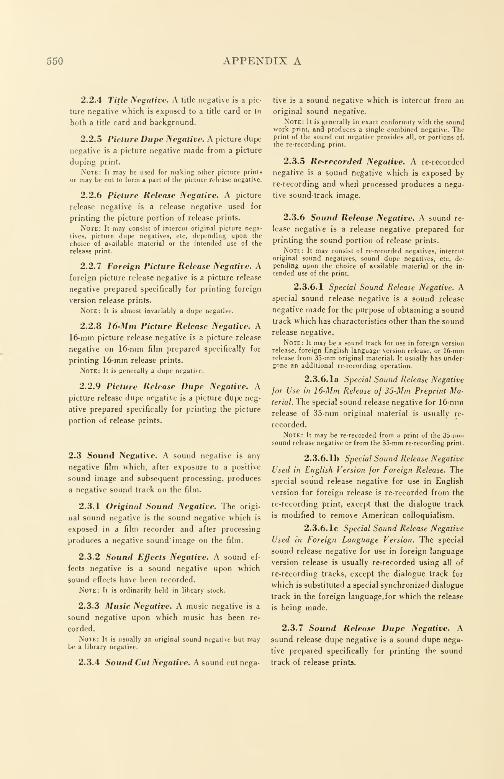
550 APPENDIX A
2.2.4 Title Negative. A title negative is a pic-
ture negative which is exposed to a title card or to
both a title card and background.
2.2.5 Picture Dupe Negative. A picture dupe
negative is a picture negative made from a picture
duping print.
Note: It may be used for making other picture prints
or may be cut to form a part of the picture release negative.
2.2.6 Picture Release Negative. A picture
release negative is a release negative used for
printing the picture portion of release prints.
Note: It may consist of intercut original picture nega-
tives, picture dupe negatives, etc, depending upon the
choice of available material or the intended use of the
release print.
2.2.7 Foreign Picture Release Negative. Aforeign picture release negative is a picture release
negative prepared specifically for printing foreign
version release prints.
Note: It is almost invariably a dupe negative.
2.2.8 16-Mm Picture Release Negative. A16-mm picture release negative is a picture release
negative on 16-mm film prepared specifically for
printing 16-mm release prints.
Note: It is generally a dupe negative.
2.2.9 Picture Release Dupe Negative. Apicture release dupe negative is a picture dupe neg-
ative prepared specifically for printing the picture
portion of release prints.
2.3 Sound Negative. A sound negative is any
negative film which, after exposure to a positive
sound image and subsequent processing, produces
a negative sound track on the film.
2.3.1 Original Sound Negative. The origi-
nal sound negative is the sound negative which is
exposed in a film recorder and after processing
produces a negative sound image on the film.
2.3.2 Sound Effects Negative. A sound ef-
fects negative is a sound negative upon which
sound effects have been recorded.
Note: It is ordinarily held in library stock.
2.3.3 Music Negative. A music negative is a
sound negative upon which music has been re-
corded.
Note: It is usually an original sound negative but maybe a library negative.
2.3.4 Sound Cut Negative. A sound cut nega-
tive is a sound negative which is intercut from an
original sound negative.
Note: It is generally in exact conformity with the soundwork print, and produces a single combined negative. Theprint of the sound cut negative provides all, or portions of.
the re-recording print.
2.3.5 Re-recorded Negative. A re-recorded
negative is a sound negative which is exposed by
re-recording and when processed produces a nega-
tive sound-track image.
2.3.6 Sound Release Negative. A sound re-
lease negative is a release negative prepared for
printing the sound portion of release prints.
Note: It may consist of rerecorded negatives, intercut
original sound negatives, sound dupe negatives, etc, de-
pending upon the choice of available material or the in-
tended use of the print.
2.3.6.1 Special Sound Release Negative. Aspecial sound release negative is a sound release
negative made for the purpose of obtaining a sound
track which has characteristics other than the sound
release negative.
Note: It may be a sound track for use in foreign version
release, foreign English language version release, or 16-mmrelease from 35mm original material. It usually has under-gone an additional re-recording operation.
2.3.6.1a Special Sound Release Negative
Jor Use in 16-Mm Release of 35-Mm Preprint Ma-
terial. The special sound release negative for 16-mm
release of 35-mm original material is usually re-
recorded.
Note: It may be re-recorded from a print of the 35-nuii
sound release negative or from the 35-mm re-recording print.
2.3.6.1b Special Sound Release Negative
Used in English Version for Foreign Release. The
special sound release negative for use in English
version for foreign release is re-recorded from the
re-recording print, except that the dialogue track
is modified to remove American colloquialism.
2.3.6.1c Special Sound Release Negative
Used in Foreign Language Version. The special
sound release negative for use in foreign language
version release is usually re-recorded using all of
re-recording tracks, except the dialogue track for
which is substituted a special synchronized dialogue
track in the foreign language for which the release
is being made.
2.3.7 Sound Release Dupe Negative. Asound release dupe negative is a sound dupe nega-
tive prepared specifically for printing the sound
track of release prints.
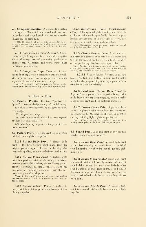
APPENDIX A 551
2.4 Composite Negative. 'A composite negative
is a negative film which is exposed and processed
to produce both sound track and picture negative
images on the same film.
Note: The sound and picture may be in editorial, pro-
jection or camera synchronism, depending upon the mannerin \%hich the composite negative is made and its intended
3.2.4 Background Plate (BackgroundFilm). A background. plate (background film) is
a picture print made specifically for use in pro-
jection backgrounds or similar process work, and
is a print of a background plate negative.
Note: Background plates are usually made on special
stock hating negative perforations.
2.4.1 Composite Original Negative. A com-
posite original negative is a composite negative
which, after exposure and processing, produces an
original negative picture and sound track image
in camera synchronism.
2.4.2 Composite Dupe Negative. A com-
posite dupe negative is a composite negative which,
after exposure and processing, produces a 'dupe
negative picture and sound track image.
Note: It is usually used for printing foreign version
release prints and is frequently in editorial synchronism.
3. Positive Film
3.1 Print or Positive. The term "positive" or
"print" is used to designate any of the following:
(a) the raw stock specifically designed for posi-
tive images
(6) the positive image
(c) positive raw stock which has been exposed
but has not been processed
id) film bearing a positive image which has
been processed.
3.2 Picture Print. A picture print is any positive
printed from a picture negative.
3.2.1 Picture Daily Print. A picture daily
print is the first picture print made from the
original picture negative for use in checking pho-
tographic quality, camera technique, action, etc.
3.2.2 Picture Work Print. A picture work
print is a positive print which usually consists of
intercut picture daily prints, picture library prints,
prints of dissolves, montages, titles, etc, and has
synchronism constantly maintained with the cor-
responding sound work print.
Note: A picture work print is used to edit and combinethe various picture scenes of a motion picture into the
desired form.
3.2.3 Picture Library Print. A picture li-
brary print is a picture print made from a picture
library negative.
3.2.5 Picture Duping Print. A picture dup-
ing print is a picture print made on a special film
for the purpose of producing a duplicate negative
or for producing dissolves, montages, titles, etc.
Note: Duping print is synonymous with master positive
except that duping print is the term used in the editorial
process, while master positive is used in release.
3.2.5.1 Picture Master Positive. A picture
master positive is a picture duping print usually
made for the purpose of producing a picture dupe
negative for release printing.
3.2.6 Print from Picture Dupe Negative.
A print from a picture dupe negative is any print
made from a picture dupe negative, and is usually
a projection print used for editorial purposes.
3.2.7 Picture Check Print. A picture check
print is a picture print made from the picture re-
lease negative for the purpose of checking negative
rutting, printing lights, picture quality, etc.
Note: When a picture check print is required, it is
usually made prior to the first trial composite print.
3.3 Sound Print. A sound print is any positive
printed from a sound negative.
3.3.1 Sound Daily Print. A sound daily print
is the first sound print made from the original
sound negative for checking sound quality, tech-
nique, etc.
3.3.2 Sound Work Print. A sound work print
is a sound print which usually consists of intercut
sound daily prints, but may also include other
sound tracks of sound effects or music, or both, on
the same or separate films with synchronism con-
stantly maintained with the corresponding picture
work print.
3.3.3 Sound Effects Print. A sound effects
print is a sound print made from a sound effects
negative.
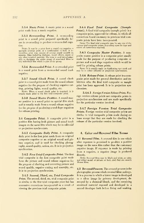
552 APPENDIX A
3.3.4 Music Print. A music print is a sound
print made from a music negative.
3.3.5 Re-recording Print. A re-recording
print is a sound print prepared specifically for
use in re-recording to produce a re-recorded nega-
tive.
Note: It may be a print from a sound cut negative, a
specially intercut print, or a combination of both. A re-
recording print may consist of several sound records on
separate films including dialogue, sound effects, music or
any other required material. The term is used interchange-
ably to designate the entire group of associated films or
any individual film which is part of the gToup.
3.3.6 Re-recorded Print. A re-recorded print
is a sound print from a re-recorded sound track
negative.
3.3.7 Sound Check Print. A sound check
print is a sound print made from the sound release
negative for the purpose of checking negative cut-
ting, printing lights, sound quality, etc.
Note: When a sound check print is required, it is
usually made prior to the first trial composite print.
3.3.8 Sound Master Positive. A sound mas-
ter positive is a sound print on special film stock
and is usually made from a sound release negative
for the purpose of producing sound dupe negatives
for release printing.
3.4 Composite Print. A composite print is a
positive film having both picture and sound track
images on the same film which may be in editorial
or projection synchronism.
3.4.1 Composite Daily Print. A composite
daily print is the first print made from an original
composite negative or an original sound and pic-
ture negative, and is used for checking photog-
raphy, sound quality, action, etc. It is in projection
synchronism.
3.4.2 First Trial Composite Print. The first
trial composite is the first composite print made
from the picture and sound release negatives for
the purpose of checking and correcting picture and
sound qualify, negative cutting and assembly, etc.
It is in projection synchronism.
3.4.3 Second, Third, etc, Trial Composite
Print. The second, third, etc, trial composite print
is similar to the first trial composite print but has
successive corrections incorporated as a result of
viewing the previous trial composite prints.
3.4.4 Final Trial Composite (Sample
Print). A final trial composite (sample print) is a
composite print, approved for release, in which all
corrections found necessary in previous trial com-
posite prints have been incorporated.
Note: The final trial composite may be any one of the
various trial composite prints, depending upon the type andextent of corrections required.
3.4.5 Composite Master Positive. A com-
posite master positive is a composite print usually
made for the purpose of producing composite or
picture and sound dupe negatives which would be
used for printing release prints.
Note: It is usually made on duplicating raw stock andmay be in either editorial or projection synchronism.
3.4.6 Release Print. A release print is a com-
posite print made for general distribution and ex-
hibition after the final trial composite or sample
print has been approved. It is in projection syn-
chronism.
3.4.6.1 Foreign Version Release Prints. For-
eign version release prints are composite prints in
projection synchronism and are made specifically
for the particular version involved.
3.4.7 Foreign Version Trial Composite
Prints. Foreign version trial composite print* are
similar to trial composite prints made during re-
lease except that they are made for checking the
release of the particular version involved.
4. Color and Reversal Film Terms
4.1 Reversal Film. A reversal film is one which
after exposure is processed to produce a positive
image on the same film rather than the customary
negative image. If exposure is made by printing
from a negative, a negative image is produced
directly.
Note: Reversal films may be black and white, or color,
and either sound or picture or both, and they are usually
16-mm films.
4.2 Reversal Process. The reversal process is the
photographic process which reversal films undergo.
It is a process in which a latent image is developed
to a silver image by primary development, de-
stroyed by a chemical bleach, and the remaining
sensitized material exposed and developed in a
second developer bath before fixing and washing.

APPENDIX A 553
4.3 Reversal Original. A reversal original is the
film which is originally exposed in a camera or
recorder and is processed by reversal to produce
a positive image.
Note: This positive image is not the same as a print
from a negative inasmuch as right and left are transposed.
A reversal original may be a black and white, or color, film.
4.3.1 Composite Reversal Original. A com-
posite reversal original is a reversal original which
has both picture and sound on the same film.
4.3.2 Original Color Positive. An original
color positive is a color reversal original which is
developed by the reversal process to produce a posi-
tive color image.
4.3.3 Composite Original Color Positive.
A composite original color positive is an original
color positive with sound track and picture on the
same film.
4.4 Dupe Negative from Original Reversal,
16-Mm. A dupe negative from an original reversal
is a negative made from an original reversal posi-
tive or an original color positive. The image on
such a dupe negative is not transposed right to left.
It is usually used to make black and white prints.
4.5 Reversal Print. A reversal print is a print
which is made on reversal film and developed by
the reversal process.
Note: A reversal print is usually a positive.
4.5.1 Reversal Dupe Print, 16-Mm. A re-
versal dupe print is a reversal print which is print-
ed from a black and white, or color, reversal
original and processed by reversal to obtain a posi-
tive black and white image.
4.5.2 Color Dupe Print. A color dupe print
is a color reversal which is printed from a color
reversal original and processed to obtain a positive
color image.
4.5.3 Composite Color Dupe Print. A com-
posite color dupe print is a print made from an
original composite color positive or from an orig-
inal picture color positive and a sound track, and
is processed to obtain a positive color print of both
picture and sound track.
4.5.4 Composite Reversal Dupe Print,
16-Mm. A composite reversal dupe print is a re-
versal dupe print having both picture and sound
tracks on the same film.
4.5.5 Reduction Reversal Print, 16-Mm.A reduction reversal print is a reversal print made
on 16-mm reversal film from a 35-mm positive by
reduction printing and development by the reversal
process.
4.5.6 Reversal Master Print, 16-Mm. A re-
versal master print is a 16-mm reversal print made
specifically for use in producing other prints.
Note: It is sometimes referred to as a first generation
dupe, prints from it then being referred to as secondgeneration dupes.
NOTE : A process diagram showing the relationships of terms is on pages 554 and 555.
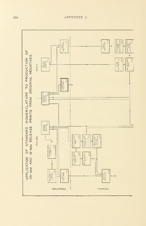
554 APPENDIX A
LUCO
<LU
QDC
<az Hi< <rh-(0 2
fc?O co
Noiionaoad

APPENDIX A 555
ifr_-
t.
fT Sis
Iw
ill*
r.._L
1
i
ssg
'IIz
1
L
!_ z"p
a
iIts
i^
£ E E-s
•- c g £
& it
II;
i=* ^ EF
as
F
- IC~ CO B
S ~.
. b
~ E
-f §
E
E §
c oR v «jj T E
- —
4 I
c
1B si
n - -= E Hs-2
Cw E *z iH
a c Z Ji
. • - c >-ESS EW B ° 0,
l« — S
V
S*3-. <-3 2.
.TO
wz S *S *
u _ .= B
- - -QU
C
5 2:
gsi Su- JC4
-J*'. 2u
u =•
e
-
s ~ Q
E
s
^ t d b3- CEeEt
— — < Mi u- cSz
H 2C -z a
—U ll
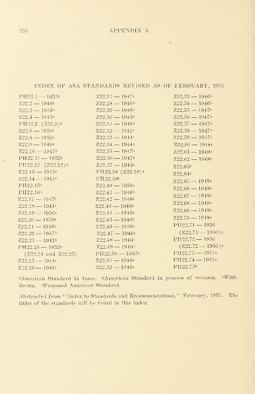
556 APPENDIX A
INDEX OF ASA STANDARDS REVISED AS OF FEBRUARY, 1953
PH22.1— 1953a Z22.27 — 1947a
Z22.2 — 1946b Z22.28— 1946b
Z22.3— 1946b Z22.29 — 1948a
Z22.4— 1941b Z22.30 — 1941c
PH22.5 (Z22.5)b Z22.31 — 1946"
Z22.6— 1950c Z22.32 — 1941c
Z22.8 — 1950a Z22.33 — 1941c
Z22.9— 1946a Z22.34 — 1944a
Z22.10— 1947b Z22.35 — 1947b
PH22. 11— 1952b Z22.36 — 1947a
PH22.12 (Z22.12)b Z22.37 — 1944a
Z22.13 — 1941c PH22.38 (Z22.38)'
Z22. 14— 1941c PH22.39b
PH22.15b Z22.40 — 1950a
PH22.16b Z22.41 — 1946b
Z22.17— 1947b Z22.42— 1946"
Z22.18— 1941c Z22.43 — 1946a
Z22.19— 1950a Z22.44— 1946a
Z22.20— 1950a Z22.45 — 1946b
Z22.21— 1946b Z22.46 — 1946a
Z22.22— 1947b Z22.47 — 1946«
Z22.23— 1941b Z22.48 — 1 946"
PH22.24 — 1952a Z22.49 — 1946"
(Z22.24 and Z22.25) PH22.50— 1952a
Z22.25 — 1941c Z22.51 — 1946a
Z22.26— 1941c Z22.52 — 1946a
Z22.53
Z22.54
Z22.55
Z22.56
Z22.57
Z22.58
Z22.59
Z22.60
Z22.61
Z22.62
Z22.63c
Z22.64c
Z22.65
Z22.66
Z22.67
Z22.68
Z22.69
Z22.70
PH22.7
(Z22.
PH22.7(Z22.
PH22.7
PH22.7
PH22.7
— 1946b
— 1946b
— 1947"
— 1947"
— 1947"
— 1947"
— 1947"
— 1948a
— 1949a
— 1948a
— 1948a
— 1948a
— 1948a
— 1949a
— 1948a
— 1948a
'1 — 1950
,71— 1950)a
2 — 1950
72— 1950) a
3 _ 1951a
4 — 1951a
5b
aAmerican Standard in force. bArnerican Standard in process of revision. cWith-
drawn. ^Proposed American Standard.
Abstracted from "Index to Standards and Recommendations," February, 1953.
titles of the standards will be found in this index.
The
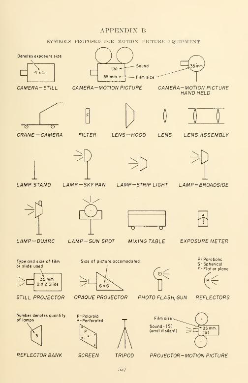
APPENDIX B
SYMBOLS PROPOSED FOR MOTION PICTURE EQUIPMENT
Denotes exposure size
-v-4 x 5
CAMERA -STILL CAMERA-MOTION PICTURE
~0 0~
CRANE-CAMERA
CAMERA-MOTION PICTUREHAND HELD
B TJFILTER LENS -HOOD LENS LENS ASSEMBLY
1
DD ^D
LAMP STAND LAMP-SKY PAN LAMP-STRIP LIGHT LAMP-BROADSIDE
\P rO]
"Q" TJ
LAMP-DUARC LAMP-SUN SPOT MIXING TABLE EXPOSURE METER
Type ond size of film
or slide used
Size of picture occomodoted
35 mm.2 x 2 Slide
P-PorobolicS- Spherical
F-Flat or plane
6x6
STILL PROJECTOR OPAQUE PROJECTOR PHOTO FLASH, GUN REFLECTORS
Number denotes quantity P- Polaroidof lamps o- Perforated
Film size
Sound- (S)(omit if silent)
REFLECTOR BANK SCREEN TRIPOD PROJECTOR-MOTION PICTURE
557
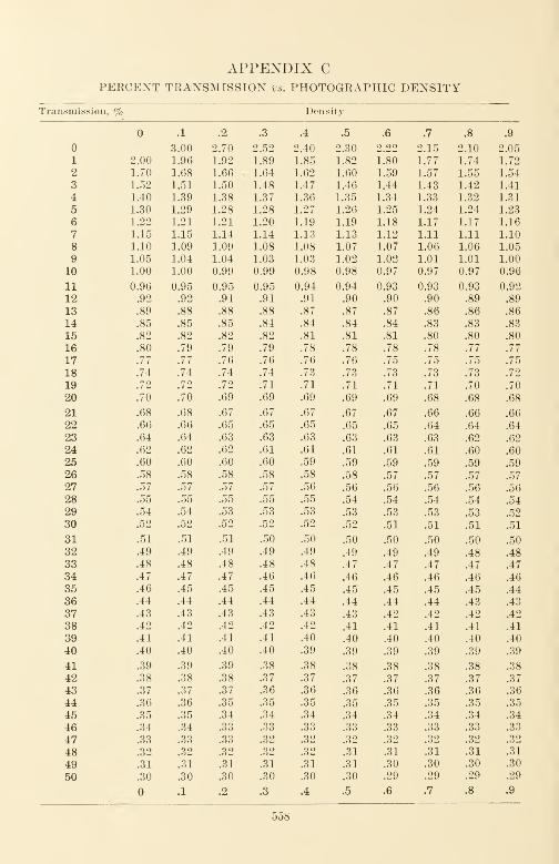
APPENDIX CPEKCENT TRANSMISSION vs. PHOTOGRAPHIC DENSITY
Transmission, % Density
.1 .2 .3 .4 .5 .6 .7 .8 .9
3.00 2.70 2.52 2.40 2.30 2.22 2.15 2.10 2.05
1 2.00 1.96 1.92 1.89 1.85 1.82 L80 1.77 1.74 1.72
2 1.70 1.68 1.66 1.64 1.62 1.60 1.59 1.57 1.55 1.54
3 1.52 1.51 1.50 1.48 1.47 1.46 1.44 1.43 1.42 1.41
4 1.40 1.39 1.38 1.37 1.36 1.35 1.34 1.33 1.32 1.31
5 1.30 1.29 1.28 1.28 1.27 1.26 1.25 1.24 1.24 1.23
6 1.22 1.21 1.21 1.20 1.19 1.19 1.18 1.17 1.17 1.16
7 1.15 1.15 1.14 1.14 1.13 1.13 1.12 1.11 1.11 1.10
8 1.10 1.09 1.09 1.08 1.08 1.07 1.07 1.06 1.06 1.05
9 1.05 1.04 1.04 1.03 1.03 1.02 1.02 1.01 1.01 1.00
10 1.00 1.00 0.99 0.99 0.98 0.98 0.97 0.97 0.97 0.96
11 0.96 0.95 0.95 0.95 0.94 0.94 0.93 0.93 0.93 0.92
12 .92 .92 .91 .91 .91 .90 .90 .90 .89 .89
13 .89 .88 .88 .88 .87 .87 .87 .86 .86 .86
14 .85 .85 .85 .84 .84 .84 .84 .83 .83 .83
15 .82 .82 .82 .82 .81 .81 .81 .80 .80 .80
16 .80 .79 .79 .79 .78 .78 .78 .78 .77 .77
17 .77 .77 .76 .76 .76 .76 .75 .75 .75 .75
18 .74 .74 .74 .74 .73 .73 .73 .73 .73 .72
19 .72 .72 .72 .71 .71 .71 .71 .71 .70 .70
20 .70 .70 .69 .69 .69 .69 .69 .68 .68 .68
21 .68 .68 .67 .67 .67 .67 .67 .66 .66 .66
22 .66 .66 .65 .65 .65 .65 .65 .64 .64 .64
23 .64 .64 .63 .63 .63 .63 .63 .63 .62 .62
24 .62 .62 .62 .61 .61 .61 .61 .61 .60 .60
25 .60 .60 .60 .60 .59 .59 .59 .59 .59 .59
26 .58 .58 .58 .58 .58 .58 .57 .57 .57 .57
27 .57 .57 .57 .57 .56 .56 .56 .56 .56 .56
28 .55 .55 .55 .55 .55 .54 .54 .54 .54 .54
29 .54 .54 .53 .53 .53 .53 .53 .53 .53 .52
30 .52 .52 .52 .52 .52 .52 .51 .51 .51 .51
31 .51 .51 .51 .50 .50 .50 .50 .50 .50 .50
32 .49 .49 .49 .49 .49 .49 .49 .49 .48 .48
33 .48 .48 .48 .48 .48 .47 .47 .47 .47 .47
34 .47 .47 .47 .46 .46 .46 .46 .46 .46 .46
35 .46 .45 .45 .45 .45 .45 .45 .45 .45 .44
36 .44 .44 .44 .44 .44 .44 .44 .44 .43 .43
37 .43 .43 .43 .43 .43 .43 .42 .42 .42 .42
38 .42 .42 .42 .42 .42 .41 .41 .41 .41 .41
39 .41 .41 .41 .41 .40 .40 .40 .40 .40 .40
40 .40 .40 .40 .40 .39 .39 .39 .39 .39 .39
41 .39 .39 .39 .38 .38 .38 .38 .38 .38 .38
42 .38 .38 .38 .37 .37 .37 .37 .37 .37 .37
43 .37 .37 .37 .36 .36 .36 .36 .36 .36 .36
44 .36 .36 .35 .35 .35 .35 .35 .35 .35 .35
45 .35 .35 .34 .34 .34 .34 .34 .34 .34 .34
46 .34 .34 .33 .33 .33 .33 .33 .33 .33 .33
47 .33 .33 .33 .32 .32 .32 .32 .32 .32 .32
48 .32 .32 .32 .32 .32 .31 .31 .31 .31 .31
49 .31 .31 .31 .31 .31 .31 .30 .30 .30 .30
50 .30 .30 .30 .30 .30 .30 .29 .29 .29 .29
.1 .2 .3 .4 .5 .6 .7 .8 .9
558

APPENDIX C 559
APPENDIX C
Transmission, % Density
.1 .2 .3 .4 .5 .6 .7 .8 .9
51 0.29 0.29 0.29 0.29 0.29 0.29 0.29 0.29 0.29 0.28
52 .28 .28 .28 .28 .28 .28 .28 .28 .28 .28
53 .28 .28 .27 .27 .27 .27 .27 .27 .27 .27
54 .27 .27 .27 .27 .26 .26 .26 .26 .26 .26
55 .26 .26 .26 .26 .26 .25 .25 .25 .25 .25
56 .25 .25 .25 .25 .25 .25 .25 .25 .25 .24
57 .24 .24 .24 .24 .24 .24 .24 .24 .24 .24
58 .24 .24 .24 .23 .23 .23 .23 .23 .23 .23
59 .23 .23 .23 .23 .23 .23 .22 .22 .22 .22
60 .22 .22 .22 .22 .22 .22 .22 .22 .22 .22
61 .21 .21 .21 .21 .21 .21 .21 .21 .21 .21
62 .21 .21 .21 .21 .20 .20 .20 .20 .20 .20
63 .20 .20 .20 .20 .20 .20 .20 .20 .19 .19
64 .19 .19 .19 .19 .19 .19 .19 .19 .19 .19
65 .19 .19 .19 .19 .18 .18 .18 .18 .18 .18
66 .18 .18 .18 .18 .18 .18 .18 .18 .17 .17
67 .17 .17 .17 .17 .17 .17 .17 .17 .17 .17
68 .17 .17 .17 .17 .16 .16 .16 .16 .16 .16
69 .16 .16 .16 .16 .16 .16 .16 .16 .16 .16
70 .15 .15 .15 .15 .15 .15 .15 .15 .15 .15
71 .15 .15 .15 .15 .15 .15 .14 .14 .14 .14
72 .14 .14 .14 .14 .14 .14 .14 .14 .14 .14
73 .14 .14 .14 .13 .13 .13 .13 .13 .13 .13
74 .13 .13 .13 .13 .13 .13 .13 .13 .13 .13
75 .12 .12 .12 .12 .12 .12 .12 .12 .12 .12
76 .12 .12 .12 .12 .12 .12 .12 .11 .11 .11
77 .11 .11 .11 .11 .11 .11 .11 .11 .11 .11
78 .11 .11 .11 .11 .11 .10 .10 .10 .10 .10
79 .10 .10 .10 .10 .10 .10 .10 .10 .10 .10
80 .10 .10 .10 .10 .09 .09 .09 .09 .09 .09
81 .09 .09 .09 .09 .09 .09 .09 .09 .09 .09
82 .09 .09 .08 .08 .08 .08 .08 .08 .08 .08
83 .08 .08 .08 .08 .08 .08 .08 .08 .08 .08
84 .08 .07 .07 .07 .07 .07 .07 .07 .07 .07
85 .07 .07 .07 .07 .07 .07 .07 .07 .07 .07
86 .07 .06 .06 .06 .06 .06 .06 .06 .06 .06
87 .06 .06 .06 .06 .06 .06 .06 .06 .06 .06
88 .06 .05 .05 .05 .05 .05 .05 .05 .05 .05
89 .05 .05 .05 .05 .05 .05 .05 .05 .05 .05
90 .05 .04 .04 .04 .04 .04 .04 .04 .04 .04
91 .04 .04 .04 .04 .04 .04 .04 .04 .04 .04
92 .04 .04 .04 .03 .03 .03 .03 .03 .03 .03
93 .03 .03 .03 .03 .03 .03 .03 .03 .03 .03
94 .03 .03 .03 .03 .02 .02 .02 .02 .02 .02
95 .02 .02 .02 .02 .02 .02 .02 .02 .02 .02
96 .02 .02 .02 .02 .02 .02 .01 .01 .01 .01
97 .01 .01 .01 .01 .01 .01 .01 .01 .01 .01
98 .01 .01 .01 .01 .01 .01 .01 .01 .01 .00
99 .00 .00 .00 .00 .00 .00 .00 .00 .00 .00
100 .00 .00 .00 .00 .00 .00 .00 .00 .00 .00
.1 .2 .3 .4 .5 .6 .7 .8 .9
a D - log10 1/Transmission.
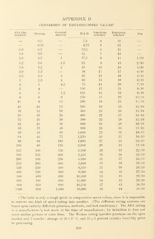
APPENDIX DCOMPARISON OF EMULSIOX-SPEED VALUESa
ASA filmnumbers Weston General
electricH&D American
seheinerEuropeanseheiner Din
— 0.3 — 7.5 4 10 —— 0.35 — 8.75 5 11 —0.6 0.5 — 12.5 6 12 —0.8 0.6 — 15 7 13 —1.0 0.7 1 17.5 8 14 1/10
1.2 1.0 1.5 25 9 15 2/10
1.6 1.2 2 30 10 16 3/10
2.0 1.5 — 38 11 17 4/10
2.5 2.0 3 50 12 18 5/10
3 2.5 4 63 13 19 6/10
4 3 4.5 75 14 20 7/10
5 4 — 100 15 21 8/10
6 5 7.5 125 16 22 9/10
8 6 9 150 17 23 10/10
10 8 12 200 18 24 11/10
12 10 15 250 19 25 12/10
16 12 18 300 20 26 13/10
20 16 24 400 21 27 14/10
25 20 30 500 22 28 15/10
32 24 36 600 23 29 16/10
40 32 48 800 24 30 17/10
50 40 60 1,000 25 31 18/10
64 50 75 1,250 26 32 19/10
80 64 100 1,600 27 33 20/10
100 80 120 2,000 28 34 21/10
125 100 150 2,500 29 35 22/10
160 125 200 3,120 30 36 23/10
200 160 250 4,000 31 37 24/10
250 200 300 5,000 32 38 25/10
320 250 400 6,250 33 39 26/10
400 320 500 8,000 34 40 27/10
500 400 600 10,000 35 41 28/10
650 500 800 12,500 36 42 29/10
800 650 900 16,250 37 43 30/10
1000 800 1,000 20,000 38 44 31/10
a The table is only a rough guide to comparative speed values, since it is impossible
to convert one kind of speed rating into another. (The different rating systems nre
based upon entirely different premises, methods, and test conditions.) The ASA rating
is a manufacturer's test made at the time of manufacture; by definition it does not
cover motion picture or color films. The Weston rating specifies purchase on the open
market and 3 months' storage at 20 ± 5° C. and 55 ± 5 percent relative humidity prior
to processing.
560
APPENDIX EDECIBELS GAIN OR LOSS VS. VOLTAGE AND CURRENT RATIO AND POWER RATIO"
Decibels 15Powerratiob
Voltageand current
ratiobDecibels Power
ratio
Voltageand current
ratio
0.1 1.0233 1.0116 13.0 19.953 4.4668
0.2 1.0471 1.0233 14.0 25.119 5.0119
0.3 1.0715 1.0351 15.0 31.623 5.6234
0.4 1.0965 1.0471 16.0 39.811 6.3096
0.5 1.1220 1.0593 17.0 50.119 7.0795
0.6 1.1482 1.0715 18.0 63.096 7.9433
0.7 1.1749 1.0839 19.0 79.433 8.9125
0.8 1.2023 1.0965 20.0 100.00 10.0000
0.9
1.0
1.2303
1.2589
1.1092
1.122022.0
24.0
158.49
251.19
12.589
15.849
1.2 1.3183 1.1482 26.0 398.11 19.953
1.4 1.3804 1.1749 28.0 630.96 25.119
1.6 1.4454 1.2023 30.0 1000.0 31.623
1.8
2.0
2.2
2.4
2.6
2.8
1.5136
1.5849
1.6595
1.7378
1.8197
1.9055
1.2303
1.2589
1.2882
1.3183
1.3490
1.3804
32.0
34.0
36.0
38.0
40.0
1584.9
2511.9
3981.1
6309.6
10*
39.811
50.119
63.096
79.433
100.000
3.0 1.9953 1.4125 42.0 10* x 1.5849 125.89
3.5 2.2387 1.4962 44.0 10* x 2.5119 158.494.0 2.5119 1.5849 46.0 10* X 3.9811 199.534.5 2.8184 1.6788 48.0 10* x 6.3096 251.195.0 3.1623 1.7783 50.0 103 316.235.5 3.5481 1.8836
6.0 3.9811 1.9953 52.0 105 x 1.5849 398.11
7.0 5.0119 2.2387 54.0 10" x 2.5119 501.19
8.0 6.3096 2.5119 56.0 103 x 3.9811 630.96
9.0 7.9433 2.8184 58.0 10 3 x 6.3096 794.33
10.0 10.0000 3.1623 60.0 106 1,000.00
11.0
12.0
12.589
15.849
3.5481
3.9811
70.0
80.0
90.0
107
108
10°
3,162.3
10,000.0
31,623
100.0 10 10 100,000
a To convert
Decibels to nepers multiply by 0.1151
Nepers to decibels multiply by 8.686
Where the power ratio is less than unity, invert the fraction
and express the result as a decibel loss.
bDb = 20xlog 10_ 20 log10 T-*2
10 log10 —561

APPENDIX FASA STANDARDS VS. GOVERNMENT SPECIFICATIONS
The ASA Sectional Committee for Motion Pictures, Z22, has been in existencesince 1932. Its function is to coordinate the standardization work of manufacturers,trade associations, engineering and professional societies, and other interested andactive parties, such as the representatives of government. Z22 is sponsored by theSociety of Motion Picture Engineers; such sponsorship assures that a project sug-gested for standardization will receive thorough study and consideration by specialists
in the field of motion pictures, especially since most projects are brought to the atten-
tion of Z22 through the SMPE.During World War II, the United States Armed Forces requested standardization
efforts of ASA and the SMPE in preparing performance specifications for motionpicture equipment, accessories, and processes. This activity resulted in two groupsof motion picture standards, one of permanent interest that was referred to Z22, andanother of interest only for the duration of the war that was referred to a War Com-mittee, Z52. Some Z52 standards were modified and approved through Z22 at the endof the War, others were dropped. A number of the standards that were dropped are
still of interest to the government ; accordingly they have been studied by governmenttechnical committees and adopted (usually with modifications) as government specifi-
cations. The table following describes comparable specifications, and the status of
such government specifications as of mid-1949.
American Standards
American Standards Association, Inc., 70 East 45 Street, New York, 17, N. Y.,
issues without charge a price list of American Standards. A set of current motionpicture standards can be obtained from the Society of Motion Picture Engineers at
342 Madison Ave., New York, 17, N. Y. The SMPE also offers a service of keeping
a Standards subscriber up-to-date by sending each new motion picture standard as it
is approved. Inquiries should be addressed to the secretaries of the respective organi-
zations.
ASA standard Applicable government specification Specification status
Z22.2—1946
Z22.3—1946
Z22.4—1941
Z22.5—1941
Z22.6—1941
Z22.7—1941
Z22.8—1941
Z22.9—1946
Z22.10—1941
Z22.ll—1941
Z22.12—1941
Z22.13—1941
Z22.14—1941
Z22.15—1946
Nonei i
USA 75-189
JAN-S-424
JAN-S-424
JAN-S-424
JAN-S-424
JAN-S-424
JAN-S-424
JAN-E-214
JAN-S-424
JAN-S-424
JAN-S-424
JAN-S-424
Under revision
Approved
562
APPENDIX F 563
ASA standard Applicable government specification Specification status
Z22.16—1941 JAN-S-424 1
1
Z22.17—1941 None —Z22.18—1941 —Z22.19—1941 —Z22.20—1941 —Z22.21—1946 —Z22.22—1941 —Z22.23—1941 —Z22.24—1941
Z22.25—1941
JAN-S-424
JAN-S-424Approved
< t
Z22.26—1941 None —Z22.27—1941 n —Z22.28—1946 tt —Z22.29—1946 JAN-S-258
JAN-S-259In press
1
1
t ( 1
1
JAN-S-260 i i
a tt JAN-S-261 1
1
Z22.30—1941 None —Z22.31—1946 tt —Z22.32—1941 i i —Z22.33—1941 (
i
Z22.34—1944 t (
Z22.35—1930 a
Z22.36—1944 1
1
Z22.37—1944 (
i
Z22.38—1944
Z22.39—1944JAN-S-424
NoneApproved
Z22.40—1946 < i
Z22.41—1946
Z22.42—1946
Z22.43—1946
JAN-S-424
No numbertt i i
assigned
Approved
In preparationtt tt
Z22.44—1946 c ( tt 1
1
a aZ22.45—1946 a 1
1
< t a i i
Z22.46—1946 None Under consideration for
Z22.47—1946 i i
JAN-S-424tt tt t (
Z22.48—1946 i i ti i i a
Z22.49—1946 i i tt tt ti
Z22.50—1946
Z22.51—1946JAN-S-424
NoneApproved
Z22.52—1946 1
1
Z22.53—1946 1
1
Under consideration for
Z22.54—1946 No number assigned
JAN-S-424
In preparation
[Table Continued)
564 APPENDIX F
AMERICAN WAR STANDARDS
ASA standard Applicable government specification Specification status
Z52.1—1944 JAN-P-49 Approved
Z52.2—1944 No number assigned In preparation
Z52.3—1944 JAN-P-55 Approved
Z52.6—1944 No number assigned In preparation
Z52.7—1944 tt i i 1
1
a (i
Z52.10—1944 i i tt i c tt tt
Z52.12—1944 JAN-M-58 Approved
Z52.14—1944 None —Z52.18—1945 JAN-C-250 Approved
Z52.19—1944 None Under consideration for
JAN-S-424
Z52.20—1944 JAN-S-424 Approved
Z52.21—1944 None —Z52.22—1944 i t —Z52.29—1945 t < —Z52.30—1944 1
1
—Z52.31—1945 tt Under consideration for
JAN-S-424
Z52.33—1945 JAN-K-214 Approved
Z52.35—1944 None —Z52.37—1944 < i —Z52.38—1945 < < —Z52.41—1945 (See Z22.29) —Z52.42—1945 None —Z52.43—1944 Fed W-L-122 Approved
Z52.44—1945 None —Z52.45—1945 i i —Z52.46—1945 c i —Z52.47—1946 JAN-S-424 Approved
Z52.48—1946 JAN-S-424 i c
Z52.50—1946 JAN-S-424 t <
Z52.51—1946 JAN-S-424 (
i
Z52.53—1945 None Under consideration for
JAN-S-424
Z52.55—1945 1
1
—Z52.60—1945 1
1
—Z52.61—1945 i ( —Z52.62—1946 (
i
—

APPENDIX F 565
AMERICAN WAR STANDARDS {Continued)
ASA standard Applicable government specification Specification status
Z52.63—1946
Z52.65—1946
Z52.68—1946
Z52.69—1945
Z52.70—1945
NOTE: 1. Symbol JAN—Joint Army Navy Specification.
tt FED—Federal Specification.
2. In some cases, individual standard pertaining to methods of test are
included in equipment specifications, e.g., Z52.45 is included in the
four JAN screen specifications.
Bibliography
Hyndman, D. E., "War Standards for Motion Picture Equipment and Processes,
"
JSMPE, 42, 211 (Apr. 1944).
JSMPE, 43, July 1949, papers by D. E. Hyndman, J. W. McNair, S. L. Chertok, M. E.
Boyer. A. G. Zimmerman, J. M. WMttenton, M. G. Townsley, M. G. Townsley, and
M. G. Townsley.
Zimmerman, A. G., "War Standards for Photographic Equipment Speed Military
Instruction," JSMPE, 43, 115 (Aug. 1944).

SUBJECT INDEX
A-B tests, 412
Acoustical characteristics, sound projec-
tors, 490-497
Acoustic disturbances, 174
Acoustic phase inverter cardioid micro-
phone, 232
Acres, Birt, 2
Adjuncts for camera, 154
Adsit, 279
Aeolight, 245
AGN, 279
Alkali of a developer bath, 374
Altec condenser microphone, 223
Altec-Lansing loudspeakers, 481
Ambient illumination of screens, 457, 460American Standards Association stand-
ards (see also p. 556)C16.5, 304
Z22.12, 106
Z22.16, 140
Z22.24, 113
Z22.38, 338
Z22.41, 108
Z22.5, 106
Z22.50, 342
Z22.51, 183
Z22.52, 183
Z22.ll, 110
Z22.8, 116, 442
Z52.38, 186
emulsion position, 140
vs. Government specifications, table,
562-565
measurement of sound track process-
ing distortion, 183
quality control, 516
variable area, 183
variable density, 183
American War Standard, 7
bibliography, 565
Ammeter, lamp current, 309
Amplifier (s), 268. See also Audio char-
acteristics.
bypass condensers, 270
Amplifier (s) (continued) ;
component parts, 268
coupling condensers, 270
hermetic sealing, 268
mica condensers, 270
monitoring, 300
projection, 477, 491
recording, 15
characteristics, 277
checking, 271
component parts, 268
functional components, 260
monitoring, 300
semi-portable, 276
resistors, 270
standards, 270
Amplitude distortion, 182
Ampro projector, 461, 469
Animatograph, 2
AnscoColor, 69, 503
Answer print, 330, 334
Anticipation, bias, 284
Anti-ground noise (AGN), 279. See also
Noise reduction.
Aperture effect, 249-251
Aperture plate, 157
Aperture relations, sound, 93
Apertures and shapes, 538
ASA. See American Standards Associa-
tion.
Aspect ratio, 5
Assembly, 328
Attack time, 282, 288, 289
Attenuator for VU meter, 305
Audible monitoring, 299-303
Audience, and picture projection, 483
and sound projection, 485
Audience noise, 175
Audience psychology, 329
Audio characteristics. See also Ampli-
fier^).
commercial recording amplifiers, 277
commercial sound projectors, 490-
497
distortion, 496
566
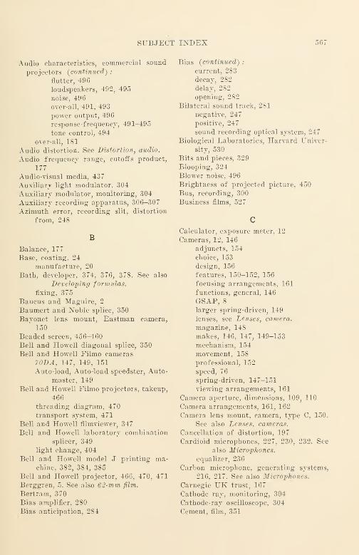
SUBJECT INDEX 567
Audio characteristics, commercial sound
projectors (continued) :
nutter, 496
loudspeakers, 492, 495
noise, 496
over-all, 491, 493
power output, 496
response-frequency, 491-495
tone control, 494
over-all, 181
Audio distortion. See Distortion, audio.
Audio frequency range, cutoffs product,
177
Audio-visual media, 437
Auxiliary light modulator. 304
Auxiliary modulator, monitoring, 304
Auxiliary recording apparatus, 306-307
Azimuth error, recording slit, distortion
from, 248
B
Balance, 177
Base, coating. 24
manufacture, 20
Bath, developer, 374. 376, 378. See also
Developing formulas.
fixing, 375
Baucus and Maguire, 2
Baumert and Xoble splice, 350
Bayonet lens mount, Eastman camera,
150
Beaded screen, 456-460
Bell and Howell diagonal splice, 350
Bell and Howell Filmo cameras70DA, 147, 149, 151
Auto-load, Auto-load speedster, Auto-
master, 149
Bell and Howell Filmo projectors, takeup,
466
threading diagram, 470
transport system, 471
Bell and Howell filmviewer, 347
Bell and Howell laboratory combination
splicer, 349
light change, 404
Bell and Howell model J printing ma-chine, 382, 384, 385
Bell and Howell projector, 466, 470, 471
Berggren, 5. See also 6 2-mm film.
Bertram, 370
Bias amplifier, 280
Bias anticipation, 284
Bias (continued) ;
current, 283
decay, 282
delay, 282
opening, 282
Bilateral sound track, 281
negative, 247
positive, 247
sound recording optical system, 247
Biological Laboratories, Harvard Univer-
sity, 530
Bits and pieces, 329
Blooping, 324
Blower noise, 496
Brightness of projected picture, 450
Bus, recording, 300
Business films, 527
Calculator, exposure meter, 12
Cameras, 12, 146
adjuncts, 154
choice, 153
design, 156
features, 150-152, 156
focusing arrangements, 161
functions, general, 146
GSAP, 8
larger spring-driven, 149
lenses, see Lenses, camera.
magazine, 148
makes, 146, 147, 149-153
mechanism, 154
movement. 158
professional, 152
speed, 76
spring-driven. 147-151
viewing arrangements, 161
Camera aperture, dimensions. 109, 110
Camera arrangements, 161, 162
Camera lens mount, camera, type C, 150.
See also Lenses, cameras.
Cancellation of distortion, 197
Cardioid microphones. 227, 230, 232. See
also Microphones.
equalizer, 236
Carbon microphone, generating systems,
216, 217. See also Microphones.
Carnegie UK trust, 167
Cathode ray, monitoring, 304
Cathode-ray oscilloscope, 304
Cement, film, 351
568 SUBJECT INDEX
Channel, recording. Maurer, 294
RCA, 293
Western. Electric, 292
Channel check, 271
Characteristic
response-frequency. See Response-
frequency characteristic.
over-all, 182
recommended ranges, 210
Characteristic impedance of equalizers,
215
Chatter, monkey, 297
Check, channel, 271, 272
Checking the amplifier, 271
Chromatic aberrations of projection
lenses, 452
Cinematograph, 2. See also Lumiere.
Cinematography, 146, 166
Cine Kodak Special, 148
Cine-Special camera, 147, 150
Cinex timer, 401, 402
Clipping peaks, 298
Closeup, 328
Closing time, 282
Color, 6, 329, 501
duplication, 501
limitations, 506
methods, 503
monographs, 509
reproduction, theoretical elements,
507
specification of, 508
Color compensating filters, 505, 507, 510,
511
Color film, 67
duplicate negative, 70
negative, 70
picture detail, 505
reversal, 45
reversal print, 53
test strip, 516
Colorimetry, 508
Color reversal, 135
Color reversal print, measuring the sound
track, 130
standardization, 508
Color temperature, 514, 515
Combination printer, Depue, 381
Commentary, recording, 352
Committee on Intellectual Cooperation,
League of Nations, 5, 167, 522. See
also Luchaire.
Compensation adjustment, film speed, 399
Composition, 329
Compression, 288
sound, threshold volume, 288
volume, 285
Compression ratio, 288
Compressors, 207
Condenser microphone, generating sys-
tems, 216
Contact printing machine, 380-386, 387-
390
Depue, 381
Contact sound printing machine, 387
Continuity, 329
Contrast, characteristics, 540
control, 512
development, 31
increase, 395
Cook, E. D., 103, 249
Cook, Willard B., 3
Copies, number from an original, 359
Core, 16-mm film, for raw stock, 338
Corrective networks, 207, 212
Craig filmviewer, 347
Creative editing, 329
Cross-modulation distortion, 182-183. See
also Distortion.
Crystal microphone, generating systems,
216, 217
Cumulative deterioration, 361
Curved field in projection lenses, 452
Cut-in, 329
Cutoff, just-perceptible, 176
low-frequency, factors affecting, 178
Cutoff frequencies of slits, 254
Cutoffs product, frequency range, 177
Cutter, original, 331
work print, 331
Cutting, 328. See also Editing.
original, 351
Cutting and perforating film, dimensions,
106
Cutting room, 339
Darkroom printing, 400
DeBrie pre-perforated strip light change,
405
DeBrie printing machine, 384, 385
Decibels gain or loss, table, 561
De-esser, 291
Definition, preservation, 357
projector, motion picture, 441
SUBJECT INDEX 569
Delay, 284
starting time, 282
transmission time, 184
Densitometers, 30
Density, 29, 31
and contrast characteristics, 540
diffuse, 30
vs. percent transmission, table, 558,
559
Density - sound output relations, 102
Depue combination printing machine, 381
Description of color, 508
Detail, in color film, 505
of projected picture, 449
in projection lenses, 452
Deterioration, film, 360, 361
Developer baths, 374, 376, 378
Developing, 374
color, 45, 47
formulas, 376, 378
picture, 16
and printing for editing, 16
sound track, 16
Developing machines, 100, 368-373
Developing tank, 370
Developing time, reference, 409
Development, 367
spray jet, 370
Development fog, 196
Diagonal Bell and Howell splice, 350
Diazo film, 19
Diffusion, 40
Diffusive screen, 456-460
Dimensions, film, 105
cutting and perforating, silent
film, ASA, 106
sound film, ASA, 106
Direct positive sound tracks, standard sta-
tus, 119
Direct 16-mm production, 59
Direct 16-mm sound, current status, 137
Directional microphones, 226-235
Discards, editing, 331
Discrimination, frequency, 182
Distortion
audio, 181, 182, 184, 185, 197, 198,
223, 291
amplitude, 182
azimuth, 248
cancellation, 197
cross-modulation, 182
envelope, 184, 185, 223, 291
harmonic, 182
Distortion, audio (continued) :
increase of, 198
intermodulation, 182, 473, 477,
478
measurement, 182
over-all characteristics, 183
phase, 184, 185, 223, 291
piling up of, 323
photocell, 473, 4 77
processing, 182, 183
sibilant sounds, 184, 185, 223,
291
slit tilt, 248
sound processing, 182, 183
spectral energy, 291
tonal, 182
transient sounds, 184
photographic, 452, 536
geometric, 536
projection lenses, 452Distortion, light modulators, 246
Distractions in viewing projected pictures,
445
Double system sound recording, 14, 59,
165
Driye, synchronous, 352Drybox, first stage, 370
second stage, 371Drying film, 371
Duddell oscillograph, 243
Duplex sound track, 281Duplicates, 7, 18
Duplicating, sound, Kodachrome, 138
Duplication, picture, 506
Dye-coupler, 501
Dyed films, sound on, 504, 505Dynamic composition, 329
Dynamic cone, 478Dynamic microphones, 218-223
Dynamic noise suppression, 297
Dynamic range, 206
Eastman Cine Kodak Special, 148
Eastman filmviewer, 347
Eastman magazine Cine-Kodak camera,149
Eastman sensitometer, 31, 408Eberhard effect, 40
Eden Musee, 3
Edge-notching, original, 358Edge-numbered raw stock, 332
Edge-numbering, 332
570 SUBJECT INDEX
Edison, 1, 6, 501
Edison Kinetoscope, 1
Edited negatives, 7
Editing, 328 '
and assembly, 328
equipment and tools, 339furniture and equipment, 339-349
statistics, 330
table, 343
tight, 331
Editing discards, 331
Editing flanges, 343
8-mm film, 4
Einthoven galvanometer, 242
Electric wave filters, 215
Electron tubes, 261-268
Electron tube microphone, generating sys-
tems, 218
Elevator, 369
takeup and tail-end, 372
Employee advancement, 529
Employee relations, 528
Emulsion, after-ripening of, 23
comments on, 26
emulsification and initial ripening of,
22
Lippman, 34, 40
manufacture, 21
removal of excess soluble salts from,
23
sensitizing, 23
Emulsion hardness, 29
Emulsion position, 35-mm, 133
16-mm, 132
ASA standard, 140
classifications of production
methods, 139
correction for in sound repro-
ducers, 144
current status, 141
history, 133
prints, 139
processes for nonstandard posi-
tion, 143
for standard emulsion posi-
tion, 142
Emulsion speed, standardization for
sound, 96
Emulsion speed comparison, table, 560
Emulsion turbidity, 40
Envelope distortion, 183, 184, 185, 223,
291. See also Distortion.
Equalizers, 207, 209, 235-237
characteristic impedance, 215
Equalizers (continued) ;
functions, 212
microphone, 235-237
W.E. BA 1142, 236
Error, azimuth, recording, 248
printer light setting, 403
Establishing shot, 329
Exciter lamp, 475Exposure, 31
actinic value, 74
consistency, 62
printer, 406
control, printer lamp, 406measurement, 71
meter, 12, 73
calculator, 12
printer, 397
Exposure error, printing, 403
Exposure lamp, sound recording, 16
current ammeter, 309
Exposure test, sound, direct-positive, 96
camera, 81
sound, 87-96
Exposure time, 76
Eye timing, 401
Farrington, 297
Feed and takeup, camera arrangements,
162
Feed reel, 369
Fidelity, complete perception, 178
high. See High fidelity sound.
of recorded sound, 171
Field flatness in projection lenses, 453
Film(s), available types, 41
cleaning, 360
color, 45, 53, 70. See also Color.
color reversal, 48
comments on, 56
deterioration, 360, 361
handling, 360
rewinding, 360
scratches, 360
wear in projectors, 465
diazo, 19
dupe negative, 51
duplicating, 50
fine-grain, application, 430
green. See Green film.
master positive, 52
negative, for special purposes, 49
picture, 13
release positive, black-and-white, 52
SUBJECT INDEX 571
Film(s) [continued):
release print, 52
reversal, black-and-Avhite, 42
reversal print, black-and-white, 54
silver emulsion, 19
consistency, 62
deterioration, 360, 361
dimensions, 105
gammas of, 33
manufacture, 20
original, materials, 42
physical characteristics, 8
preservative, 371
preserving, 371
reversal, early history, 134
sound, 35-mm, early history, 136
16-mm, early history, 137
SMPE test, 312
16-mm picture original, 60
sizes, 4-5
sound, resolving power, 192
sound recording, 15
for variable area, 49
speed, linear, standard, 107
standards, 105-119
storage, 362
titles, 353
transmission, 29
Film application, 521
commentary, 352
education, 522
filmic representation, 329film in national life, 167
film technique, 167
military, 6
television, 535
sound, 542
Film cement, 351
Film core, standard, 338
Film drying, 371
Film edge-numbering, 332
Film grain. See Grain, film.
Film hardener, processing, 370, 378
Film loss, sound, 192, 252
Film measuring, 344, 345
Film noise, 174
Film phonograph, 295, 414
Film scanning, 537
Film speed compensation in
printing, 399
Film transport, 237
guiding, 241
sound projector, 461
Filmo camera, Bell and Howell, 70DA,147, 149, 151
magazine type, Auto-load, Auto-load
speedster, Auto-master, 149
Filmviewers, 347
Filters, electrical, characteristic imped-
ance, 215
Filters, optical, 505-510
color compensating, 505, 507, 510
compensating, 505, 507, 510
criteria, 509
data sources, 510
Fine-grain film, 430-432
Fischer, 501
Fisher Body Division, 525
Fixing, 375
Flanges, laboratory, 343
Flare light, 396
Flash scenes, 331
Flutter, 192, 389, 467-473, 496in sound recording machine, 237, 239
Flutter testing, printing, 383
Focal lengths of lenses, 12
vs. projector distance, 460
Focus, splitting the, 453
Focus in projection picture objective
lenses, 453
projector sound, correction for emul-
sion position in, 144
Focusing, camera arrangements, 161
Fog, development, 196
sound track, 98
measurement of, 103
significance, 101
Fonda developing machine, 372, 373
Footage counter, 344, 345
Footage meter, 344, 345
Footage numbers, 333
Formulas, developer bath. See Develop-
ing, bath formulas.
Fox-Case Aeolight, 245
Fox-Grandeur, 5. See also 70-mm film.
Frame, photographed, and the cameralens, 159
Frame line shift, 159
Frame size of picture, 442
Frequency discrimination, 182
Frequency range. See also Response-fre-
quency range and Hearing per-
ception.
balance, 177
cutoffs product, 177
/ stop, 77

572 SUBJECT INDEX
Full-wave rectification, 283
Furniture, editing, 340
Galvanometer, dry, for light modulation,
243, 244
string, for light modulation, 243
Gamma, 31
development, 33
Gelatin, in emulsions, 21—22
Generating systems, microphone, 215
Generations of prints, 358, 361
Geometric distortion in projection lenses,
453
Georgiades, George, 1
Glossary, 547-555
Glow lamp, light modulating, 245
Gorisch and Gorlich, 504
Grain, film, 34
clumping, 35
size, 34
skewed distribution of, 35
Graininess, 34-37
Grandeur, 5. See also 70-mm film.
Green film, 371
Grindstone test machine, 239
Griswold junior splicer, 348
Ground-noise reduction. See Noise re-
duction.
GSAP camera, 8
Guiding of film, 241
Gun sight aiming point (GSAP) camera,
HH & D, 31
Halation, light, 40
Half-wave rectification, 283
Hardener, film processing, 370, 378
Harmonic distortion. See Distortion.
Harvard Film Service, 530
Haze in projection lenses, 452
Head telephones, monitoring, 299
Health conservation, 527
Hearing contours, 173-175
Hearing preception, 172
Heater operation of electron tubes, 267
High fidelity sound, 5
High frequency loss, 196
High light, 399
High temperature processing, 370
Hiss in electron tubes, 263
Hollaman, 3. See also Eden Musee, Cine-
matograph, and Lumiere.
Homolka, 501
Horn loudspeaker, 487
Hot processing, film, 370
Houston developing machine, 367
Howl in electron tubes, 263
Hum, in electron tubes, 263
in printing, 407
Hurd, 2. See also Lumiere and Cinemato-
graph.
Hurter and Driffeld, 31
Hypo tank, 370
ICI standard observer, 508
Identification, footage, 331
Illumination of projected picture, 450
Illumination uniformity, screen, 460
Illusion loss in viewed pictures, 447
Image smearing, 394
Image spread, 40
Image transfer, 192
Imbibition printing, 505
Impedance (s), characteristic, 214
of equalizers, 215
microphone connection, 215
Industrial applications of films, 521
Industrial management and films, 525
Initial bias, 283
Inspection, picture, 413
print, 409
cost, 412
sound, 414
Integral tri-pack duplication, 501
Interchemical Corp., 509
Intermodulation distortion 182. See also
Distortion.
audio, 473, 477, 478
Internal films, outline, 527
International Printing Ink, 509
Invercone, Weston, 73
J printer, Bell and Howell, 382
Jensen loudspeaker, 482, 487, 488
Job technic training, 528
Just-perceptible cutoffs, 176
Karolus cell, light modulating, 245
Kerr cell, light modulating, 245
SUBJECT INDEX 573
Kinetoscope, 1
Klipsch loudspeaker, 482
Kodachrome, 6, 503
duplicating film, 512
measuring the sound track of, 130
Regular, 68
sound duplicating, 138
types, 503
Commercial, 69
Type A, 68
Kodak color duplicating instructions, 506
Kodak magazine camera, 149
Kodak Special, 148
Laboratory functions, 366
Laboratory operation, 418
Lamp, conservation, 97
cooling noise, 496
exciter, sound projector, 475
exposure, sound recording, 16
standardization, 88
supply regulation, 515
Lamp current ammeter, 309
Lamp data sources, 515
Lamp supply regulation, printing, 515
Laport, 5. See also 65-mm film.
Lateral color in projection lenses, 452
League of Nations, Committee on Intel-
lectual Cooperation, 5, 522. See also
Luchaire.
Lens(es), camera, 77
aperture markings, 77
mount, Eastman bayonet, 150
Type C, 80
relation to the photographedframe, 159
relative aperture, 78
resolution test, 160
standard aperture markings, 77
transmission, 78, 79
projection objective, 452-454
Level, reproducing, vs. recording, 187
Lewin, 324
Lewy, 501
Library, stock-shot, 331
Light, "flare, 396
high, 399
middle, 399
low, 399
Light board, Depue, 402, 403
Light change board, 403
Light change, Bell and Howell, 404
pre-perforated strip, 405
printer, 383-386, 405
Light change methods, printing, 380, 399
inertia in, 382
Light halation. See Halation.
Lighting, 11
Light modulator, 242
Light-setting error, 403
Lim, 176
Liminal unit for speech and music, 176-
177
Limiting, 207, 288,
Line microphones, 235
Line-of-light, monitoring, 304
Lippman emulsion, 34, 40
Long shot, 329
Loss. See also Film loss and Transfer
loss.
of high frequencies, 196
of illusion in viewed pictures, 447
of perspective in viewed pictures,
445-447
resolving power, 40
Loudspeakers, for projection, 479, 481,
482, 487, 488
recording, monitoring, 300-303
sound projection, 478-483
television receiver, 535
Low light, 399
Low microphonic electron tubes, 261
Low-temperature storage, 362
LP picture Moviola, 347
Luchaire, 5, 167
Luchaire report, 522
Lumiere, 2
MMagazine cameras, 15, 148
Magazine Cine-Kodak camera, 149
Magnetic tape recording, 169
Magnification of projected picture, 449
Maguire and Baucus, 2
Manufacturers, test equipment, 275
Margin, noise reduction, 283
Masking effect of noise, 175
Masking film, 513
Master exposure meter, Weston, 73
Masters, printing, 18
Matipo printer, DeBrie, 384, 385
Matte, traveling, 382
Maurer amplifier, 276
574 SUBJECT INDEX
Maurer film phonograph, 295
Maurer light modulator, 246
Maurer Becording System, 294
Maurer shrinkage gage, 388
Maurer sound printing machine, 392
Maurer sound recording machine, 239, 240
May, E.P., 5
Media, communications, 437-438
Medium shot, 328
Meter, exposure, 12, 73
photoelectric, 71
Weston, 73
VU, sound level, standard, 304
attenuator for, 305
Microphone (s), 14, 215-235
connection impedances, 215
equalizers, 235-237
generating systems, 215-218
types, 218-235
hybrid, 226-234
other types, highly directional,
234-235
pressure gradient operated, 224-
226
pressure operated, 218-223
Microphone boom, 14
Middle light, 399
Military film, 6
Modulator, light, 16, 242-246
Monitoring, 299-306
Monitoring equipment, 299-306
Monkey chatter, 297
Montagu, Ivor, 167
Motion picture film. See also Film, silver
emulsion.
Motion Picture Patents Co., 3
Motor for camera, 13
Mottled screens, 457
Mount, camera lens, 157
Eastman bayonet, 150
type C, 150
Movement, camera, 158
Movietone Aeolight, 245
Moving coil microphones,
Western Electric 633A, 218, 219
KCA 88A, 220, 221
Moving conductor microphone generating
systems, 216
Moviola, filmviewer, 347
picture, 347
Multilayer films, 501
Multiple-head printing, 365
Munsell Book of Color, 508
NNAB-EMA pre- and post-equalizer, 213
Near-pain intensity of sound, 173
Negative (s), 4
edited, 7
Negative sound track, bilateral, 247
unilateral unbiased, 205
Negative splice, 350
Newsreel theaters, 7
9.5-mm film, 4
Noble splice, 350
Noise, 174-176. See also Noise reduction
and Noise suppression.
masking effect of, 175
printing, 407
projector, 174, 496
sources, 174
Noiseless recording. See Noise reduction.
Noise reduction, 279, 284. See also Noise
and Noise suppression.
bias, 283
closing time, 282
design, 282-284
equipment testing, 284
margin, 283
principles, 279-282
release time, 282
starting-time delay, 282
unlocking time, 282
Noise suppression, 294-299. See also
Noise and Noise reduction.
compression, 285-292
dynamic band width control, 297
Farrington method, 297
Kryter method, 298
limiting, 285-292
peak clipping method, 298
preferred response-frequency bands,
177
pulse methods, 298
Scott method, 297
Westermijze method, 298
Nomenclature, 547-555
Nonslip printing machine, 389-390
Nonstandard emulsion position, processes
for, 143
Notch, printing machine, 336, 400
Offset color guide, 509
Oils, camera, 76, 77
One-light black-and-white work print, 335

SUBJECT INDEX o"j
One-light color dupe work print, 335
One-light reversal dupe work print, 335
Opacity, film, 29
Optical one-to-one sound printing ma-chine, 390
Optical printing machine, 386, 390-392
one-to-one, 386
reducing, 391
Optical reduction, 5, 7
Optical reduction sound printing machine,
392
Optical system, sound recording, variable-
area bilateral track, 247
Original film, cutting, 17, 351
edge-notching, 358
making of, 58
picture, 16-mm, 60
consistency of quality, 61
preservation, 356
sizes for 16-mm release prints, 58
splice, 350
Oscillator channel check, 271
Oscillograph, Duddell, 243
string, for light modulation, 242, 243
Oscilloscope, cathode ray, 304
Out-takes, editing, 331*
Over-all sound characteristics, 181
quality, factors affecting, 207
response-frequency, recommendedranges, 182, 210
Overdrive of developing machines, 374Ozaphane, 19, 132
Panning, 13
Parabolic reflector microphones, 234
Paramount-Laport. See 65-mm film.
Paul, Eobert. 2
Peak clipping, 298
Peak limiting, 288
Perceived range for music in absence of
noise, 173
Perception, hearing, 172
Perception fidelity, complete, 178
Perforating of films, 25
Perspective. 12
of projected picture, 443
viewing, 443-448
Phase distortion, 184, 223, 291
Photocell coupling, 476Photocell distortion, 473Photographic recording, 169. See also Re-
cording.
Photographic transmission, 29
Physical editing, 329
Picture, developing, 16
duplication, 506
frame size, 442
inspection, 413
printing, 420-424
16-mm from 35-mm, 422
smearing, 406
test of contact printing, 383
and sound records, spacing between,
107
and sound synchronization, 164
work print, 16
Picture detail in color film, 505
Picture machine, continuous contact, 380-
386
Picture Moviola, 347
Picture original, quality consistency, 61
Picture projection, recommendations, 484
Piezoelectric crystal microphone, generat-
ing systems, 216, 217
Plate, aperture, 157
Polishing roller, 371
Positive developing machine, Fonda, 372,
373
Positive print, measuring for center line,
127
measuring for printer aperture andweave, 129
Positive sound track, bilateral, 247
unilateral unbiased, 205
Post-equalizing, 211
Power output, sound projectors, 496
Preamplifiers, low noise operation, 267
Pre-equalizing, 211
Pre-perforated strip light change, 405
Preservation and storage of film, 355-357
Preservative, film, 371
of a developer bath, 374
Pressure-operated microphones, 219
Print (s), emulsion positions, 139
inspection, 409-411
production planning, 408
quality, 358
release, quality. 1 8
trial composite, 18
work, 16, 17, 330, 334
Print generations, 194-195, 358, 361
Printed noise, 407
Printing, color, imbibition, 505
effect of machine vibration in. 406
exposure error. 103
576 SUBJECT INDEX
Printing (continued) ;
graininess in, 36
light changes, 380, 399
light setting error, 403
noise introduced in, 407
release, 18, 364
16-mm picture from 16-mmoriginals, 420
from 35-mm originals, 422
16-mm sound from 16-mmoriginals, 426
from 35-mm originals, 425
sound, variable area sound track to
variable density, 183
variable density sound track to
variable area, 183
with test leaders, 395
Printing machines, 364-436
belt drive in, 406
exposure, 397
consistency, 406
lamp control, 406
lamp regulation, 515
loss, 192
notch, 400
performance, 393
resolution loss in, 394
scale, 399
slip, 395sound, 387-393
Printing matte, traveling, 382
Print inspection, objectives, 411
standards, 410
Processing, 364
consistency, 63
distortion, sound track, 182-183
high temperature, 36, 370
Professional cameras, 152
Projected picture, shape, 442
size, 442
Projection, 437-497. See also Sound re-
production.
Projection amplifier, 477
Projection lenses, 452
splitting the focus, 453
Projection media, 438-441
Projection objective lenses, 452-454
Projection printing machines, 386. See
also Optical printing machine.
Projection systems, 455Projectors, 437, 461-472
aperture, standard, 116
Projectors (continued) ;
noise, 496sound, 179, 466-497
focusing, correction for emul-
sion position in, 144
performance, 179, 460, 490-497
sound track scanning beam,standard width, 108, 109,
119, 124
Psycho-educational clinic, Harvard Uni-
versity, 530Pudvokin, 167
Pulse methods in noise suppression, 298
Quality control, 514
statistical, 409, 516
Quality deterioration, 361
Ramsaye, Terry, 3, 9
Random pops in electron tubes, 263
Range, wide, 5
Raw stock edge-numbering, 332
Raw stock cores, 338
RCA compressor, 292
RCA light modulator, 243
RCA microphones44BX-pressure-gradient, 224-226
77A, 77B, 77C, 77D—hybrid (cardi-
oid), 227-231
88A—pressure, 220, 221
MI-10,001—hybrid (cardioid), 233,
234
connection impedances, 215
RCA PM-32 sound recording machine,
238, 239
RCA projector, 472
RCA recording system, 293
RCA sound reduction printing machine,
392
Reading, improvement, 530
Recorded noise, 17. See also Noise, Noise
reduction, and Noise suppression.
Recording. See also Sound recording,
Photographic recording, Mag-netic tape recording.
channel, commercial, 292-294
disk, 272-273
media, 169
method suggestions, 200
procedures, 199
SUBJECT INDEX
Recording (continued) ;
vs. reproducing level, 187
sound. See Sound recording.
Recording equipment. 215. 312
components, 204
control adjuncts, 307-312
amplifier. 260. 276-279. See
Amplifier.
semi-portable, 276
auxiliary apparatus, 306-307
control adjuncts. 307—312
microphone. See Microphones.
recording machine. See Soundrecording equipment.
performance, 206, 259
placement. 312
semi-portable. 276
Recording lamp ammeter, 309
Recording spectrophotometer, photoelec-
tric. 508. 514
Rectification, signal, 283
Red top electron tubes. 263
Reducing agent of a developer bath. 374
Reels. 345-346
test. See Test film.
Reel spindles. 342
Reference (standard) developing time,
409
Reference recordings, television, 535
Reflection factors of screens, 458
Reflective screens, 456-460
Reflector microphones, parabolic, 234
Regular reversal film. 44
Release printing, 364
effect upon sound, 193, 194
Release prints, splices in, proposal for di-
mensions, 113
Release time, sound compression, 288
Reprints, 419
Reproduced sound, 179
frequency range. 179
volume range, 179
Reproducer, film photograph, 295
Reproducing vs. recording level, 187
Reproduction, color, 47
Re-recording, 201, 316. 319
variable area sound track to variable
density, 183
variable density sound track to vari-
able area. 183
Research Council pre- and post-equalizer,
213
Resolution loss in printers, 394
Resolution test, camera lens, 160
Resolving power, of film. 37-38
of projection lenses, 454
of television systems, 539
test charts, 394
Response-frequency characteristics, in
sound recording, 186
compression. 292
over-all, 182
Response-frequency discrimination, 182
Response-frequency range, 172, 206, 207.
See also Audio characteristic.
balance, 177
cutoffs product, 177
of over-all characteristic, recom-
mended, 210
preferred. 177
Restrainer, of a developer bath. 375
Retake, 328
Reversal, color, 66, 135
Reversal film, 4, 135
materials, black-and-white, 63
original, exposure, 70
print stock, 54
regular, 44, 64
universal. 44. 64
Rewinding, film, 360
Rewinds, 340-343
RKO. See 62-mm film.
RKO Spoor-Berggren. See 62-mm film.
Roller, polishing, 371
Room noise. See Xoise.
Sacia. 279
Safety promotion via films. 527
Salt-shaker microphone. See Western
Electric 633A.
Scale, printer, 399
Scanning area. ASA Standard, 108
Scanning beam, projector, measuring for
center bine and width. 124
sound track, in projector, standard
width, 109. 119, 124
Scanning beam distortion, 473
Scoring projector, 352
Scott noise suppression method. 297
Screen border, 44 s*
Screen flashes, 351
Screens, reflective. 456-460
illumination, uniformity, 459
Script, 11, 328Sensitometer. Eastman IIB, 31. 408
578 SUBJECT INDEX
Sensitometry, 29
Setting, aperture, 12
focus, 12'
opening, 12
relative aperture, 12
17.5-mm film, 4
70DA filmo camera, Bell and Howell, 151
70-mm film, 5
Sharpness, emulsions, 40Shot, establishing, 329
Shot list, 333, 352
Shrinkage, film, 28
>
gage, 388
Sibilant distortion, 291
Signal delay, 284
Signal-to-noise ratio, 185-186, 496Silver emulsion films. See Films, silver
emulsion.
Simultaneity, 13
Single-element cardioid microphone, 230
Single-system sound, 14, 59, 164
16-mm emulsion position, 132
16-mm originals, 58
16-mm picture, 11
16-mm picture original, 60
62-mm film, 5
65-mm film, 5
Slating, 334
Slit azimuth, 248, 473, 474Slit cutoff frequencies, 254
Slit output, theoretical, 249-251
Slit tilt. See Slit azimuth.
Slit width, 249-251, 473, 47435-mm, 253
vs. cutoff frequency, 16-mm, 254Slitting of film, 25
Smearing, image, 394, 406SMPE test films, 312
Soft emulsion, 371
Solvent, of a developer bath, 375Sound, 5, 169, 504. See also Sound print-
ing, Sound recording, Sound re-
production, and Sound tracks.
16-mm, current status, 137
early history, 137
aperture relations, 93
compression, threshold volume,
288
double system, 165
inspection, 414Kodachrome, duplicating, 138multilayer dyed films, 504, 505nature, 171
Sound, 16-mm {continued) :
output vs. photographic density,
102
over-all characteristics, 181performance, 179-180
processing distortion, 182-183quality, factors affecting, 207single system, 164television, from film, 542transfer losses, 209
transient, distortion, 184variable area, present status, 85
35-mm, early history, 136Sound equipment, speed variations, 192Sound level, reproducing vs. recording,
187
Sound printing, 424imperfect contact in, 387
noise, 407printing machine, 387
Maurer, 392optical one-to-one, 390printing sprocket, 388
ECA, 39216-mm from 16-mm, 42616-mm from 35-mm, 425whine, 407
Sound projection, recommendations, 486,
487Sound projectors, performance, 490-497
Sound Eecord, Standard, 108
Sound record and scanning area, 108
Sound recorder. See Sound recording
equipment.
Sound recording, 13. 169
double system, 14, 59, 165
equipment, 14, 204
components, 204
fidelity, 171
machines, 15, 237, 238, 239, 240
optical system, bilateral, 247
variable area, 247
negative, initial bias setting of, 123
performance limitations, 428preparing for, 352
procedures, 199
response - frequency characteristics,
186
standardization of exposure, 87
technique, 316
Sound reproduction, 179, 460, 490-497.
See also Projection.
projector (s). See also Projectors.

SUBJECT INDEX 579
Sound reproduction (continued) ;
translation, 465, 466
drive systems, 467-473
nutter in, 467
transport, 466, 467
wows, 473
Sound scanning, 248-254, 473-474
Sound track (s), dimensions, checking, 119
center line, standard, 108, 109, 120
direct positive, standard status, 119
fog, 98
negative, bilateral, 247
checking the width, 122
locating the center line of, 120
standard width, 107-109, 119,
122
unilateral unbiased, 205
positive, bilateral, 247
print, unilateral unbiased, 205
printed area, on release print, 108,
119
processing distortion, 182-183
scanning beam in projector, standard
width, 108, 109, 124
types, 258, 281
unilateral unbiased, negative, 205
unilateral unbiased, print, 205
Special, Cine-Kodak camera, Eastman,
147, 150
Spectral energy distortion, 291
Spectrophotometer, 508, 514
Specular screen, 456-460
Spindles, 340-343
Splicers, 348-350
Splices, 350
proposal for dimensions in release
prints, 113
Splitting the focus, 453
Spoor-Berggren. See 62-mm film.
Spray jet development, 370Spring-driven cameras, 147
Sprocket hole distance, 170
Sprocket hole spacing. See Sprocket hole
distance.
Standardization, 1, 3, 7
of color, 508
Standard (reference) developing time,
409
Standards. See also American StandardsAssociation standards.
basic, 107
film, 105-119
of print inspection, 410
Starting time delay, 282
Static composition, 329
Statistical quality control, 409Statistics, editing, 330
Step-contact printer, 383-384Stephens loudspeaker, 482
Step printer, DeBrie, 384, 385Stereo projection, screens for, 440Stock-shot library, 331
Storage of films, 355
recommendations, 362
stages, 357
Studio arrangement, 314
Sweep Frequency Channel Check, 272
Symbols, equipment, 557
Sync (synchronism) marks, editing, 353error, 352
Synchronization of picture with sound,
164
synchronous (motor) drive, 352
Synchronizer, 344, 345
Tail-end elevator, 372
Tail-end takeup, 372
Takeup, camera arrangements, 162
tail-end, developing machines, 372Takeup elevator, 372
Takeup reels, projectors, 465, 466Tanks, hypo, 370
wash, 370
Tape recording, magnetic, 169Technical control, 407
use of a lib sensitometer, 408Technicolor, 6, 505
Telephones, head, 299Television, and film, 533
standardization, 534, 542Television images, distortion, 536
photographing, 540Television sound, 534, 542Tempo, editing, 331Terminology, 547-555
Test(s), color film strip, 516
picture printing, 383
printing leaders, 395sound printing, 383
Test charts, resolving power, 394Test equipment, 275Test films, SMPE, 312, 542Testing, noise reduction, 284
Test leaders, printing, 395Test reels, 312, 542

580 SUBJECT INDEX
Test strip, color film, 516
Textile Color Card Association of
America, 509
Theaters, newsreel, 7
35-mm slit width, 253
35 to 16 reduction sound printer, 392
32-mm printing, 365
Threading path, sound projector, 461
Threshold volume of sound compression,
288
Tight editing, 331
Timing, compressor, 290
film for printing, 336, 401
noise reduction, 290
a recording for synchronism, 352
Titles of films, 353
Tonal distortion, 182
Tracks, sound. See Sound tracks.
Training of the soldier, use of films, 6
Trajedis, George, 1
Transfer loss, 190, 209. See also Loss.
Transfer steps, 190-193, 322
losses, 190, 209
Transient sounds, distortion, 184
Transition in editing, 330
Transmission, 29
Transmission characteristics, 540
Transmission time delay, 184
Transmitting film images, 540
Transport, film, 237
Traveling matte, 382
Trigger lamps, 304
Tri-pack duplication, 501
Tripod, camera, 13
friction head, 13
gyro head, 13
Tubes, electron, 261-268
noise, 263-264
Turbidity, 40
lib sensitometer, 408
Two-element cardioid microphone, 227
Type C camera lens mount, 150
UUniversal reversal, 44
Unlocking, 282
Valve, light, modulating, 244
Variable area to variable density sound
track by printing, 183
Variable area sound, present status, 85
processing distortion, 182
Variable area sound recording optical
system, 247
Velocity microphones. See Microphones.
Velocity-operated microphones. See Mi-crophones.
Viewing, camera, arrangements, 161
Viewing angle, for stereo projection, 440Viewing distance of projected picture, for
correct perspective, 448
for observable detail, 449
average, 443-445
Visual-audio media, 437
Visual graininess, 37
Visual monitoring, 303-306
Voice effort, 188-189
Voice quality, 189
alteration of, 291
correction for, 190
Volume, prospective, of 16-mm films, 59
Volume compression, 285-292
threshold, 288
Volume indicator, 304
Volume range, 206, 207
projectors, 496
Volume Unit meter, 304
VU meter, 304
attenuator, 305
WWash tank, 370
Wave filters, electric, 215
Western Electric light modulator, 244
Western Electric loudspeaker, 479
Western Electric microphones
633A, 218, 219
639A, 639B, 227-230
640AA, 222, 223
connection impedances, 215
Western Electric 1126C Compressor, 290
Western Electric recording system, 292
Westmijze, 298
Weston ammeter, 307
Weston exposure lamp current meter, 309
Weston exposure meter, 73
Weston VU meter, 304
Whine in sound printing, 407
Wide film, 5
Wide range, 5
Work print, 330, 334-335
Wows, 192